state of alaska library archives museum
505
-
Upload
khangminh22 -
Category
Documents
-
view
2 -
download
0
Transcript of state of alaska library archives museum


STATE OF ALASKA LIBRARY ARCHIVES MUSEUM PROJECT NO. 68816SECTION 02 41 00 DEMOLITION
05.01.2012 CONSTRUCTION DOCUMENTS 02 41 00 - 1
SECTION 02 41 00DEMOLITION
PART 1 GENERAL1.01 SECTION INCLUDES
A. Building demolition including abatement of hazardous materials and toxic substances.B. Selective demolition of built site elements.C. Abandonment and removal of existing utilities and utility structures.D. Salvage of building and site elements.
1.02 RELATED DOCUMENTSA. Drawings and general provisions of the Contract, including General and Supplementary
Conditions and other Division 1 Specification Sections, apply to this Section.B. Section 00800 - Supplementary Conditions: Explorations and Reports. Contractor is to become
familiar with these documents prior to development of a demolition plan, and prior to any work inthe building.
1.03 RELATED REQUIREMENTSA. Bid Schedule: Unit prices for salvage of exterior precast concrete wall panels.B. Section 01 11 13 - Summary of Work: Contractor's use of site and premises.C. Section 01 50 99 - Temporary Facilities for Museum Collections Relocation and Storage:
Existing Trees.D. Section 01 51 00 - Construction Facilities.E. Section 01 60 00 - Material and Equipment: Handling and storage of items removed for salvage
and relocation.F. Section 31 23 16 - Remove and Dispose of Culvert Pipe.G. Section 31 23 17 - Storm and Sanitary Structure Removal.H. Section 32 12 18 - Remove Existing Asphalt Surfacing.I. Section 32 13 16 - Remove Existing Sidewalk, Concrete Slab, or Curb and Gutter.
1.04 REFERENCE STANDARDSA. 29 CFR 1926 - U.S. Occupational Safety and Health Standards; current edition.B. NFPA 241 - Standard for Safeguarding Construction, Alteration, and Demolition Operations;
2009.1.05 DEFINITIONS
A. Remove: Detach items from existing construction and legally dispose of them off-site, unlessindicated to be removed and salvaged or removed and reinstalled.
B. Remove and Salvage: Detach items from existing construction and deliver them to Department.C. Remove and Reinstall: Detach items from existing construction, prepare them for reuse, and
reinstall them where indicated.D. Existing to Remain: Existing items of construction that are not to be removed and that are not
otherwise indicated to be removed, removed and salvaged, or removed and reinstalled.1.06 SUBMITTALS
A. Section 01 33 00 - Submittal Procedures, for submittal procedures.B. Site Plan: Showing:

STATE OF ALASKA LIBRARY ARCHIVES MUSEUM PROJECT NO. 68816SECTION 02 41 00 DEMOLITION
05.01.2012 CONSTUCTION DOCUMENTS 02 41 00 - 2
1. Vegetation to be protected.2. Areas for temporary construction and field offices.3. Areas for temporary and permanent placement of removed materials.
C. Demolition Plan: Submit demolition plan as specified by OSHA and local authorities.1. Indicate extent of demolition, removal sequence, bracing and shoring, and location and
construction of barricades and fences.2. Provide a Schedule of Selective Demolition Activities with the following activities indicated:
a. Detailed sequence of selective demolition and removal work, with starting and endingdates for each activity. Ensure Department's on-site operations are uninterrupted.
b. Interruption of utility services. Indicate how long utility services will be interrupted.c. Coordination for shutoff, capping, and continuation of utility services.d. Locations of proposed dust- and noise-control temporary partitions and means of
egress.e. Coordination of Department's continuing occupancy of portions of existing building
and of Department's partial occupancy of completed Work.1) Means of protection for items to remain and items in path of waste removal from
building.3. Haz-Mat Abatement Plan: Prepared by an EPA Accredited Project Designer. To include
remediation plan for hazardous materials located at the existing Alaska State Museum andAnnex Building. To develop the plan, Contractor may use existing reports and may includedestructive testing results from additional field investigation.a. Submittal to include:
1) Work area setup and preparation.2) Worker protection.3) Material decontamination (if required).4) Personnel decontamination.5) Waste transport and disposal
b. Asbestos Disposal Authorization: Submit authorization to dispose of asbestos wasteby the proposed disposal site operator.
c. Waste Transporter: Submit the name and address of the proposed wastetransporter.
d. Notification of Certificates:1) Submit a copy of the Contractor's written "Notification of Demolition and
Renovation" to the Environmental Protection Agency.2) Submit a copy of the written notification listing proposed workers to the State of
Alaska Department of Labor.3) Submit legible copies of worker's current EPA and State of Alaska Asbestos
Abatement Certificates.e. Competent Person: Submit the name of the proposed Competent Person and list of
his/her previous projects.f. At completion of Work the Contractor shall submit copies of the following documents:
1) Employee's daily sign-in sheets, field logs.2) Waste Shipment Records (40 CFR 61, Figure 4).3) Disposal Site Receipts.
4. Inventory: After selective demolition is complete, submit a list of items that have beenremoved and salvaged.
5. Identify demolition firm and submit qualifications.6. Include a summary of safety procedures.
D. Project Record Documents: Accurately record actual locations of capped and active utilitiesand subsurface construction.
1.07 QUALITY CONTROLA. Demolition Firm Qualifications: Company specializing in the type of work required.
1. Minimum of 5 years of documented experience.

STATE OF ALASKA LIBRARY ARCHIVES MUSEUM PROJECT NO. 68816SECTION 02 41 00 DEMOLITION
05.01.2012 CONSTUCTION DOCUMENTS 02 41 00 - 3
1.08 ASBESTOS REMOVAL AND DISPOSALA. The work requires the removal and disposal of the asbestos containing materials at the Alaska
State Museum. The contractor shall verify quantity and location of all materials. The Contractorhas the option to demolish the structure with non-friable asbestos left in place.
B. EPA and OSHA have stringent requirements for worker safety and removal of hazardousmaterials. Reports from prior investigations performed at the Alaska State Museum areavailable for information. The existing Alaska State Museum property and adjacent structuresare available for additional destructive testing at the Contractor’s option. The Contractor mayperform additional testing and inspections in order to define the hazardous materials, toestablish quantities, means and methods for removal and demolition in accordance with theContract Documents.
C. General Requirements: All work shall be done in compliance with the publications listed in thissection as well as all Occupational Safety and Health Standards, the International BuildingCode, the International Fire Code, and as specified herein.1. Title 29 CFR Part 1910.2. Title 29 CFR Part 1926.3. Title 40 CFR Part 61.4. Title 49 CFR 100-199.
D. Air Monitoring: Airborne concentrations of asbestos fibers shall be monitored in accordancewith 29 CFR 1926.1101, current EPA guidance, and as specified herein. The Contractor willperform baseline, environmental, work area and clearance sampling as required. theContractor is responsible for all personnel exposure monitoring required by 29 CFR 1926.1101and State of Alaska Administrative Code. All monitoring shall be performed by a trained airmonitoring technician. all sampling pumps shall be calibrated in the field with a secondarycalibration device before and after each sample. Built-in rotometers on pumps and notacceptable.1. The minimum number of daily samples per work area without a negative exposure
assessment are as follows:a. Four (4) air samples located at the perimeter of the work area.b. The Contractor shall conduct personnel monitoring continuously during asbestos
removal operations to determine the eight-hour time weighted exposure of workers toairborne fibers.
c. The Contractor shall direct its laboratory, in writing, to release all employees and worksite air monitoring data, and all other pertinent date and records, to the Department.
d. A laboratory rated as proficient by AIHA shall perform all analysis.e. The Contractor shall have its laboratory archive all air samples until the successful
completion of the project.f. Laboratory results from air monitoring will+ be submitted to the Department's
representative within 20 hours from the end of the work shift for which air monitoringwas performed.
g. Clearance Air Monitoring: Where the building is being demolished with asbestosintact, no clearance will be required.
E. Testing Laboratory and Laboratory Personnel: Independent testing laboratory shall meet thefollowing requirements:1. The laboratories shall be rated proficient by AIHA for the analysis required and shall be
accredited by the National Institute of Science and Technology (NIST) under their NationalVoluntary Laboratory Accreditation Program (NVLAP) for bulk asbestos analysis andairborne asbestos fibers as appropriate.
1.09 PERSONNEL PROTECTION PROCEDURESA. Post the decontamination, safety, and work procedures to be followed by workers.B. Provide continuous on-site supervision by the approved Competent Person.C. Follow all worker protection procedures as described in the approved work plan
STATE OF ALASKA LIBRARY ARCHIVES MUSEUM PROJECT NO. 68816SECTION 02 41 00 DEMOLITION
05.01.2012 CONSTUCTION DOCUMENTS 02 41 00 - 4
D. Provide the highest level of respiratory protection unless approved and documented exposureassessments establish that a lower level of protection is adequate.
E. Maintain a daily log of all workers and visitors entering regulated work area. Log shall containthe name of each individual, social security number of each individual, his or her organization,accurate time of entering and leaving, and purpose of visit.
F. Monitor worker exposure to airborne asbestos fibers as required by 29 CRF 1926.1101.G. Provide approved filters for other airborne contaminants (solvents, etc.) which may be present.
These filters shall be used in combination with approved asbestos filters. At no time shall thispermissible exposure limit (PEL) for any airborne contaminant exceed the PEL listed in 29 CFR1910, Subpart Z.
1.10 ASBESTOS REMOVAL PROCEDURESA. Asbestos removal shall be in accordance with the Contractor's Approved Work Plan, applicable
regulations, and this specification.1.11 DISPOSAL
A. Dispose of asbestos wastes in and EPA and DEC-permitted asbestos landfill.B. Comply with current waste handling, storage, transportation, and disposal requirements of the
waste disposal facility, US Department of Transportation (DOT) and EPA regulations.C. Label waste containers and vehicles in accordance with 40 CFR part 61 and 49 CFR 100-199.
Affix warning labels having waterproof print and permanent adhesive to all waste containers.D. Affix a Class 9 label with ID number 2212 on all four sides of the waste transport vehicle.E. Waste transport vehicles shall be lined with 6-mil polyethylene and be fully enclosed.F. Waste shipping papers shall identify wast as "Asbestos 9, NA 2212 III, RQ" and list the total
quantity be transported in addition to the requirements of 40 CFR 61.1.12 OTHER HAZARDOUS MATERIALS
A. The existing building contain lead-based paint. Remove and dispose of painted items inaccordance with applicable regulations.
B. Contractors are responsible for the removal and disposal of any or all other miscellaneoushazardous material that may be present to include, but not necessarily limited to:1. Fluorescent light fixture ballasts and bulbs.2. Mercury containing thermostats.3. Exit signs.4. Lead acid batteries.5. Fire Extinguishers.6. Lead through roof vents.
1.13 SALVAGE ITEMS FOR DELIVERY TO DEPARTMENTA. Existing Museum Displays: Coordinate salvage of existing displays prior to building demolition
and in accordance with Section 01 50 99 - Temporary Facilities for Museum CollectionsRelocation and Storage.1. Identified Items: See Schedule below.2. Storage Location(s): Rooms 128 and/or 132 as directed by Department.
B. Existing Exterior Precast Wall Panels: The Department desires to salvage at least ten existingexterior precast wall panels for reuse, not for use in this Project. See Bid Schedule.
PART 2 PRODUCTS (NOT USED)PART 3 EXECUTION3.01 SCOPE
A. Remove the entire buildings designated existing Alaska State Musuem and Annex.B. Remove all site features and utilities as indicated on the Site Demolition Plans.

STATE OF ALASKA LIBRARY ARCHIVES MUSEUM PROJECT NO. 68816SECTION 02 41 00 DEMOLITION
05.01.2012 CONSTUCTION DOCUMENTS 02 41 00 - 5
C. Remove other items indicated, for salvage, relocation, and recycling.D. Fill excavations, open pits, and holes in ground areas generated as result of removals, using
specified fill; compact fill as specified in Section 31 20 01. Fill only those locations not subject tosubsequent construction activities.
3.02 GENERAL PROCEDURES AND PROJECT CONDITIONSA. Comply with applicable codes and regulations for demolition operations and safety of adjacent
structures and the public.1. Obtain required permits.2. Comply with applicable requirements of NFPA 241.3. Use of explosives is not permitted.4. Take precautions to prevent catastrophic or uncontrolled collapse of structures to be
removed; do not allow worker or public access within range of potential collapse ofunstable structures.
5. Provide, erect, and maintain temporary barriers and security devices.6. Use physical barriers to prevent access to areas that could be hazardous to workers or the
public.7. Conduct operations to minimize effects on and interference with adjacent structures and
occupants.8. Do not close or obstruct roadways or sidewalks without permit.9. Conduct operations to minimize obstruction of public and private entrances and exits; do
not obstruct required exits at any time; protect persons using entrances and exits fromremoval operations.
10. Obtain written permission from Owners of adjacent properties when demolition equipmentwill traverse, infringe upon or limit access to their property.
B. Do not begin removal until receipt of notification to proceed from Department.C. Do not begin removal until built elements to be salvaged or relocated have been removed.D. Do not begin removal until vegetation to be relocated has been removed and specified
measures have been taken to protect vegetation to remain.E. Protect existing structures and other elements that are not to be removed.
1. Provide bracing and shoring.2. Prevent movement or settlement of adjacent structures.3. Stop work immediately if adjacent structures appear to be in danger.
F. Minimize production of dust due to demolition operations; do not use water if that will result inice, flooding, sedimentation of public waterways or storm sewers, or other pollution.
G. Hazardous Materials: Comply with 29 CFR 1926 and state and local regulations.H. Perform demolition in a manner that maximizes salvage and recycling of materials.
1. Dismantle existing construction and separate materials.2. Set aside reusable, recyclable, and salvageable materials; store and deliver to collection
point or point of reuse.I. Partial Removal of Paving and Curbs: Neatly saw cut at right angle to surface.
3.03 EXISTING UTILITIESA. Coordinate work with utility companies; notify before starting work and comply with their
requirements; obtain required permits.B. Protect existing utilities to remain from damage.C. Do not disrupt public utilities without permit from authority having jurisdiction.D. Do not close, shut off, or disrupt existing life safety systems that are in use without at least 7
days prior written notification to Department.E. Do not close, shut off, or disrupt existing utility branches or take-offs that are in use without at
least 3 days prior written notification to Department.

STATE OF ALASKA LIBRARY ARCHIVES MUSEUM PROJECT NO. 68816SECTION 02 41 00 DEMOLITION
05.01.2012 CONSTUCTION DOCUMENTS 02 41 00 - 6
F. Locate and mark utilities to remain; mark using highly visible tags or flags, with identification ofutility type; protect from damage due to subsequent construction, using substantial barricades ifnecessary.
G. Remove exposed piping, valves, meters, equipment, supports, and foundations of disconnectedand abandoned utilities.
H. Prepare building demolition areas by disconnecting and capping utilities outside the demolitionzone; identify and mark utilities to be subsequently reconnected, in same manner as otherutilities to remain.
3.04 PREPARATIONA. Site Access and Temporary Controls: Conduct selective demolition and debris-removal
operations to ensure minimum interference with roads, streets, walks, walkways, and otheradjacent occupied and used facilities.1. Comply with requirements for access and protection specified in Division 1 Section
a. "Temporary Facilities and Controls."B. Temporary Facilities: Provide temporary barricades and other protection required to prevent
injury to people and damage to adjacent buildings and facilities to remain.1. Provide protection to ensure safe passage of people around selective demolition area and
to and from occupied portions of building.2. Provide temporary weather protection, during interval between selective demolition of
existing construction on exterior surfaces and new construction, to prevent water leakageand damage to structure and interior areas.
3. Protect walls, ceilings, floors, and other existing finish work that are to remain or that areexposed during selective demolition operations.
4. Cover and protect furniture, furnishings, and equipment that have not been removed.5. Comply with requirements for temporary enclosures, dust control, heating, and cooling
specified in Division 1 Section "Temporary Facilities and Controls."C. Temporary Shoring: Provide and maintain shoring, bracing, and structural supports as required
to preserve stability and prevent movement, settlement, or collapse of construction and finishesto remain, and to prevent unexpected or uncontrolled movement or collapse of constructionbeing demolished.1. Strengthen or add new supports when required during progress of selective demolition.
3.05 DEMOLITION, GENERALA. General: Demolish and remove existing construction only to the extent required by new
construction and as indicated. Use methods required to complete the Work within limitations ofgoverning regulations and as follows:1. Proceed with demolition systematically, from higher to lower level. Complete demolition
operations above each floor or tier before disturbing supporting members on the nextlower level.
2. Neatly cut openings and holes plumb, square, and true to dimensions required. Usecutting methods least likely to damage construction to remain or adjoining construction.Use hand tools or small power tools designed for sawing or grinding, not hammering andchopping, to minimize disturbance of adjacent surfaces. Temporarily cover openings toremain.
3. Cut or drill from the exposed or finished side into concealed surfaces to avoid marringexisting finished surfaces.
4. Do not use cutting torches until work area is cleared of flammable materials. At concealedspaces, such as duct and pipe interiors, verify condition and contents of hidden spacebefore starting flame-cutting operations. Maintain portable fire-suppression devices duringflame-cutting operations.
5. Maintain adequate ventilation when using cutting torches.6. Remove structural framing members and lower to ground by method suitable to avoid free
fall and to prevent ground impact or dust generation.

STATE OF ALASKA LIBRARY ARCHIVES MUSEUM PROJECT NO. 68816SECTION 02 41 00 DEMOLITION
05.01.2012 CONSTUCTION DOCUMENTS 02 41 00 - 7
7. Locate demolition equipment and remove debris and materials so as not to imposeexcessive loads on supporting walls, floors, or framing.
8. Dispose of demolished items and materials promptly.B. Removed and Salvaged Items:
1. Clean salvaged items.2. Store items in a secure area until delivery to Department.3. Transport items to Department's storage area designated by Department.4. Protect items from damage during transport and storage.5. Items to be removed
C. Removed and Reinstalled Items:1. Clean and repair items to functional condition adequate for intended reuse. Paint
equipment to match new equipment.2. Protect items from damage during transport and storage.3. Reinstall items in locations indicated. Comply with installation requirements for new
materials and equipment. Provide connections, supports, and miscellaneous materialsnecessary to make item functional for use indicated.
D. Existing Items to Remain: Protect construction indicated to remain against damage and soilingduring selective demolition. When permitted by Department's Representative, items may beremoved to a suitable, protected storage location during selective demolition and cleaned andreinstalled in their original locations after selective demolition operations are complete.
3.06 SALVAGE OF EXISTING PRECAST CONCRETE WALL PANELSA. Panel Selection: The Contractor shall survey and select candidate panels for approval by the
Department with the fewest surface and structural defects.B. Remove panels in a manner to preserve structural and surface integrity.C. Store panels on site. Coordinate location with the remaining Work.
3.07 DISPOSITION OF MATERIALA. Title to Materials:
1. Title to all materials and equipment to be removed, except as specified otherwise, isvested in the Contractor upon receipt of Notice to Proceed. The Department will not beresponsible for the condition or loss of, or damage to, such property after Notice toProceed. Materials and equipment shall not be viewed by prospective purchasers or soldon site.
3.08 DEBRIS AND WASTE REMOVALA. Remove debris, junk, and trash from site.B. Remove from site all materials not to be reused on site; do not burn or bury.C. Leave site in clean condition, ready for subsequent work.D. Clean up spillage and wind-blown debris from public and private lands.
3.09 SALVAGE SCHEDULEA. Exterior Precast Wall Panels.B. Existing Museum Display Components: See following pages.

STATE OF ALASKA LIBRARY ARCHIVES MUSEUM PROJECT NO. 68816 SECTION 02 41 00 DEMOLITION
05.01.2012 CONSTRUCTION DOCUMENTS 02 41 00 - 8
EXISTING MUSEUM DISPLAY COMPONENTS FOR SALVAGE
Clan House 5/8” tempered glazing
5/8” tempered glazing
Two pieces 120” x 48” One piece 120” x 30”
Remove and store for future use
Disassemble, remove and store for future use. All portions of the Clan House. Does not include objects, poles or carvings.
Clan House Cedar Stock

STATE OF ALASKA LIBRARY ARCHIVES MUSEUM PROJECT NO. 68816 SECTION 02 41 00 DEMOLITION
05.01.2012 CONSTUCTION DOCUMENTS 02 41 00 - 9
END OF SECTION
Armature for Sphere
Disassemble, remove and store for future use. All portions of the aluminum armature for SOS. Sphere is considered an object and will be handled by museum staff.

STATE OF ALASKA LIBRARY ARCHIVES MUSEUM PROJECT NO. 68816 SECTION 02 41 00 DEMOLITION
05.01.2012 CONSTUCTION DOCUMENTS 02 41 00 - 10
THIS PAGE IS INTENTIONALLY LEFT BLANK

STATE OF ALASKA LIBRARY ARCHIVES MUSEUM PROJECT NO. 68816 SECTION 03 30 00 CAST-IN-PLACE CONCRETE
05.01.2012 CONSTRUCTION DOCUMENTS 03 30 00-1
SECTION 03 30 00
CAST-IN-PLACE CONCRETE PART 1 - GENERAL
1.1 SUMMARY A. Section includes cast-in-place concrete, including formwork, reinforcement, concrete materials,
mixture design, placement procedures, and finishes.
1.2 ACTION SUBMITTALS A. Product Data: For each type of product indicated.
B. Design Mixtures: For each concrete mixture.
C. Steel Reinforcement Shop Drawings: Placing drawings that detail fabrication, bending, and placement.
D. Formwork Shop Drawings: Prepared by or under the supervision of a qualified professional engineer detailing fabrication, assembly, and support of formwork.
E. Shoring and Bracing Shop Drawings: At areas of exposed concrete where scarring of surfaces would require patching, submit shop drawings of shoring and bracing layouts.
1.3 INFORMATIONAL SUBMITTALS A. Welding certificates.
B. Material certificates.
C. Material test reports.
D. Floor surface flatness and levelness measurements.
E. Notify Department following pour of first mock-up. Department, Contractor, and Subcontractor shall review mock-up on site and decide if acceptable. If not acceptable, provide new mock-up incorporating agreed-upon changes.
1.4 QUALITY ASSURANCE A. Manufacturer Qualifications: A firm experienced in manufacturing ready-mixed concrete
products and that complies with ASTM C 94 requirements for production facilities and equipment.
1. Manufacturer certified according to NRMCA's "Certification of Ready Mixed Concrete Production Facilities."
B. Testing Agency Qualifications: An independent agency, qualified according to ASTM C 1077 and ASTM E 329 for testing indicated.
C. Welding Qualifications: Qualify procedures and personnel according to AWS D1.4, "Structural Welding Code - Reinforcing Steel."
D. ACI Publications: Comply with the following unless modified by requirements in the Contract Documents:
1. ACI 301, "Specifications for Structural Concrete."
2. ACI 117, "Specifications for Tolerances for Concrete Construction and Materials."
3. ACI 303.1, “Specifications for Cast-in-Place Architectural Concrete”
E. Concrete Testing Service: Engage a qualified independent testing agency to perform material evaluation tests and to design concrete mixtures.

STATE OF ALASKA LIBRARY ARCHIVES MUSEUM PROJECT NO. 68816 SECTION 03 30 00 CAST-IN-PLACE CONCRETE
05.01.2012 CONSTRUCTION DOCUMENTS 03 30 00-2
F. Source limitation: Obtain each type or class of cementitious material of the same brand from the same manufacturer's plant, each aggregate from one source, and each admixture from the same manufacturer.
G. Preinstallation Conference: Conduct conference at Project site.
1. Before submitting design mixes, review concrete mix design and examine procedures for ensuring quality of concrete materials. Require representatives of each entity directly concerned with cast-in-place concrete to attend, including the following:
a. Contractor's superintendent.
b. Independent testing agency responsible for concrete design mixes.
c. Ready-mix concrete producer.
d. Concrete subcontractor
1.5 MOCK-UP A. Construct and erect mock-ups for all exposed architectural concrete surfaces to obtain a special
finish as a result of formwork.
1. Panel mock-ups: a. Size: Sufficient to illustrate full range of treatment. b. Quantity: As required to achieve the intended result, minimum quantity (3).
2. Architectural Quality (smooth surface) Column mock-ups, Pre-Construction Phase: a. Size: Minimum 18x18 cross section, of sufficient height to include form panel joint. b. Quantity: As required to achieve the intended result. c. Mock-ups shall remain on site for the duration of concrete work, but shall not be
incorporated into the Work. Remove after successful completion of construction phase mock-up(s).
3. Architectural Quality (smooth surface) Column mock-ups, Construction Phase: a. In-place, structural column(s) to remain as part of the Work. b. Construct mock-up(s) in pre-approved area(s) that will not be exposed to public
view. c. Include all forming and finishing methods to demonstrate intended quality of
appearance. d. Demonstrate repair methods of surface irregularities. Intentionally damage
concrete surfaces, if required, to simulate anticipated repair conditions.
4. Quality of finish to be approved by Department. Obtain acceptance of resulting surface finish prior to erecting formwork for exposed architectural concrete surfaces.
5. Accepted mock-ups are considered the basis of quality for finished Work. Keep mock-ups exposed to view for duration of concrete work.
PART 2 - PRODUCTS 2.1 FORM-FACING MATERIALS
A. Vertical Wall Installations Exposed to View: Use high-density overlay, Class 1 or better, mill-release agent treated and edge sealed.
1. Form Panels shall be new for each successive pour.
2. Reuse is allowed if form panels show no inclusions or surface deformations as accepted by Department.
3. Use 4 foot by 8 foot sheets at all locations exposed to view, unless otherwise noted.
4. Countersink and fill all screw holes.

STATE OF ALASKA LIBRARY ARCHIVES MUSEUM PROJECT NO. 68816 SECTION 03 30 00 CAST-IN-PLACE CONCRETE
05.01.2012 CONSTRUCTION DOCUMENTS 03 30 00-3
B. Smooth-Formed Finished Concrete: Form-facing panels that will provide continuous, true, and smooth concrete surfaces. Furnish in largest practicable sizes to minimize number of joints.
C. Rough-Formed Finished Concrete: Plywood, lumber, metal, or another approved material. Provide lumber dressed on at least two edges and one side for tight fit.
2.2 STEEL REINFORCEMENT A. Reinforcing Bars: ASTM A 615, deformed, Grade 60 for bars #4 and larger, Grade 40 for bars
#3 and smaller.
1. Epoxy-Coated Reinforcing Bars: ASTM A 775, epoxy coated, with less than 2 percent damaged coating in each 12-inch bar length.
2. Weldable Reinforcing Bars: ASTM A 706
B. Deformed-Steel Welded Wire Reinforcement: ASTM A 497, flat sheet.
C. Epoxy Repair Coating: Liquid, two-part epoxy repair coating, compatible with epoxy coating on reinforcement and complying with AASTN A 775.
D. Bar Supports: Bolsters, chairs, spacers, and other devices for spacing, supporting, and fastening reinforcing bars and welded wire reinforcement in place. Manufacture bar supports from steel wire, plastic, or precast concrete according to CRSI's "Manual of Standard Practice”.
1. For epoxy-coated reinforcement, use epoxy-coated or other dielectric-polymer-coated wire bar supports
2.3 CONCRETE MATERIALS A. Cementitious Material: Use the following cementitious materials, of the same type, brand, and
source, throughout Project:
1. Portland Cement: ASTM C 150, Type II. Supplement with the following:
a. Fly Ash: ASTM C 618, Class F. Do not use fly ash in flatwork or architecturally exposed concrete. Limit fly ash to 18 percent of cementitious materials. Replacement factor relative to cement shall be 1.2.
b. Ground Granulated Blast-Furnace Slag: ASTM C 989, Grade 100 or 120.
B. Normal-Weight Aggregates: ASTM C 33, graded.
1. Maximum Coarse-Aggregate Size: 1-1/2 inches nominal.
2. Fine Aggregate: Free of materials with deleterious reactivity to alkali in cement.
C. Water: ASTM C 94.
2.4 ADMIXTURES A. Air-Entraining Admixture: ASTM C 260.
B. Chemical Admixtures: Provide admixtures certified by manufacturer to be compatible with other admixtures and that will not contribute water-soluble chloride ions exceeding those permitted in hardened concrete. Do not use calcium chloride or admixtures containing calcium chloride.
1. Water-Reducing Admixture: ASTM C 494, Type A.
2. Retarding Admixture: ASTM C 494, Type B.
3. Water-Reducing and Retarding Admixture: ASTM C 494, Type D.
4. Plasticizing and Retarding Admixture: ASTM C 1017, Type II.
2.5 FORMWORK ACCESSORIES
A. Form Release Agent: Reactive agent that will not stain concrete, absorb moisture, or affect

STATE OF ALASKA LIBRARY ARCHIVES MUSEUM PROJECT NO. 68816 SECTION 03 30 00 CAST-IN-PLACE CONCRETE
05.01.2012 CONSTRUCTION DOCUMENTS 03 30 00-4
color characteristics of concrete finish coatings.
B. Provide reactive form release agent by one of the following:
1. BIONOX manufactured by Noxcrete Providers Group
2. Or approved equal.
C. Plastic Vapor Barrier: Reference Section 07 25 00 “Weather Barriers”.
D. Form Ties: Factory-fabricated, removable or snap-off stainless steel form ties designed to resist lateral pressure of fresh concrete on forms and to prevent spalling of concrete on removal. Form Ties shall be manufactured specifically for use as concrete ties and shall be designed to seal tightly to the form face material without fluid loss.
1. Furnish ties with integral water-barrier plates to walls indicated to receive dampproofing or waterproofing.
2. Ties shall not leave metal within 1-1/2 inches of concrete surface.
3. Plain wire “snapties” are not acceptable.
4. Form ties are not acceptable for use in architectural quality columns.
2.6 WATERSTOPS A. Non-Bentonite Waterstops for Non-Moving Construction Joints: Basis of design is Adcor ES
hydrophilic waterstop by Grace Construction Products.
2.7 CURING MATERIALS A. Absorptive Cover: AASHTO M 182, Class 2, burlap cloth made from jute or kenaf, weighing
approximately 9 oz./sq. yd. when dry.
B. Moisture-Retaining Cover: ASTM C 171, polyethylene film or white burlap-polyethylene sheet.
C. Water: Potable.
D. Clear, Waterborne, Membrane-Forming Curing Compound: ASTM C 309, Type 1, Class B, nondissipating, certified by curing compound manufacturer to not interfere with bonding of floor covering.
1. Apply curing compound on top of all wall pours in addition to vertical surfaces to prevent differential drying at top of wall.
2.8 RELATED MATERIALS A. Expansion- and Isolation-Joint-Filler Strips: ASTM D 1751, asphalt-saturated cellulosic fiber.
2.9 CONCRETE MIXTURES A. Prepare design mixtures for each type and strength of concrete, proportioned on the basis of
laboratory trial mixture or field test data, or both, according to ACI 301.
B. Cementitious Materials: Use fly ash, pozzolan, ground granulated blast-furnace slag, and silica fume as needed to reduce the total amount of portland cement, which would otherwise be used, by not less than 40 percent.
C. Admixtures: Use admixtures according to manufacturer's written instructions.
1. Use water-reducing and/or plasticizing admixture in concrete, as required, for placement and workability.
2. Use water-reducing and retarding admixture when required by high temperatures, low humidity, or other adverse placement conditions.

STATE OF ALASKA LIBRARY ARCHIVES MUSEUM PROJECT NO. 68816 SECTION 03 30 00 CAST-IN-PLACE CONCRETE
05.01.2012 CONSTRUCTION DOCUMENTS 03 30 00-5
3. Use water-reducing admixture in pumped concrete, concrete for heavy-use industrial slabs and parking structure slabs, concrete required to be watertight, and concrete with a water-cementitious materials ratio below 0.50.
D. Proportion normal-weight concrete mixture as follows:
1. Minimum Compressive Strength: As noted on the Contract Drawings.
2. Maximum Water-Cementitious Materials Ratio: 0.50.
3. Slump Limit: 4-1/2” inches before adding high-range water-reducing admixture or plasticizing admixture, plus or minus 1 inch.
4. Air Content: 5.5 percent, plus or minus 1.5 percent at point of delivery for 1-1/2-inch nominal maximum aggregate size.
5. Air Content: Do not allow air content of trowel-finished floors to exceed 3 percent.
6. Shrinkage: For elevated post-tensioned slabs, proportion mixes to achieve 0.02 percent or less shrinkage.
E. Self-consolidating concrete (SCC): SCC may be substituted for standard concrete mixtures for constructability and/or to achieve the specified finishes. Design, proportioning, mixing, formwork, placement, and finishing shall all meet the SCC manufacturer’s requirements.
2.10 FABRICATING REINFORCEMENT A. Fabricate steel reinforcement according to CRSI's "Manual of Standard Practice."
2.11 CONCRETE MIXING A. Ready-Mixed Concrete: Measure, batch, mix, and deliver concrete according to ASTM C 94,
and furnish batch ticket information.
PART 3 - EXECUTION 3.1 FORMWORK
A. Design, erect, shore, brace, and maintain formwork, according to ACI 301, to support vertical, lateral, static, and dynamic loads, and construction loads that might be applied, until structure can support such loads.
B. Construct formwork so concrete members and structures are of size, shape, alignment, elevation, and position indicated, within tolerance limits of ACI 117.
C. Unless noted otherwise, chamfer exterior corners and edges of permanently exposed concrete.
D. Provide 90 degree exterior corners and edges of permanently exposed concrete columns. Do not chamfer corners.
E. No pencil lines allowed on formwork. Use grey Crayon.
3.2 EMBEDDED ITEMS A. Place and secure anchorage devices and other embedded items required for adjoining work
that is attached to or supported by cast-in-place concrete. Use setting drawings, templates, diagrams, instructions, and directions furnished with items to be embedded.
B. Provide formed openings where required for items to be embedded in passing through concrete work.
C. Locate and set in place items that will be cast directly into concrete.
D. Coordinate with work of other sections in forming and placing openings, slots, reglets, recesses, sleeves, bolts, anchors, other inserts, and components of other work.
E. Install accessories in accordance with manufacturer's instructions, so they are straight, level, and plumb. Ensure items are not disturbed during concrete placement.

STATE OF ALASKA LIBRARY ARCHIVES MUSEUM PROJECT NO. 68816 SECTION 03 30 00 CAST-IN-PLACE CONCRETE
05.01.2012 CONSTRUCTION DOCUMENTS 03 30 00-6
F. Provide temporary ports or openings in formwork where required to facilitate cleaning and inspection. Locate openings at bottom of forms to allow flushing water to drain.
G. Close temporary openings with tight fitting panels, flush with inside face of forms, and neatly fitted so joints will not be apparent in exposed concrete surfaces.
3.3 STEEL REINFORCEMENT A. General: Comply with CRSI's "Manual of Standard Practice" for placing reinforcement.
1. Do not cut or puncture vapor retarder. Repair damage and reseal vapor retarder before placing concrete.
3.4 JOINTS A. General: Construct joints true to line with faces perpendicular to surface plane of concrete.
B. Construction Joints: Install so strength and appearance of concrete are not impaired, at locations indicated or as approved by Department.
C. Contraction Joints in Slabs-on-Grade: Form weakened-plane contraction joints, sectioning concrete into areas as indicated. Construct contraction joints for a depth equal to at least one-fourth of concrete thickness as follows:
1. Grooved Joints: Form contraction joints after initial floating by grooving and finishing each edge of joint to a radius of 1/8 inch. Repeat grooving of contraction joints after applying surface finishes. Eliminate groover tool marks on concrete surfaces.
2. Sawed Joints: Form contraction joints with power saws equipped with shatterproof abrasive or diamond-rimmed blades. Cut 1/8-inch-wide joints into concrete when cutting action will not tear, abrade, or otherwise damage surface and before concrete develops random contraction cracks.
D. Isolation Joints in Slabs-on-Grade: After removing formwork, install joint-filler strips at slab junctions with vertical surfaces, such as column pedestals, foundation walls, grade beams, and other locations, as indicated.
E. Waterstops: Install in construction joints and at other joints indicated according to manufacturer's written instructions.
3.5 CONCRETE PLACEMENT A. Before placing concrete, verify that installation of formwork, reinforcement, and embedded items
is complete and that required inspections have been performed.
B. Deposit concrete continuously in one layer or in horizontal layers of such thickness that no new concrete will be placed on concrete that has hardened enough to cause seams or planes of weakness. If a section cannot be placed continuously, provide construction joints as indicated. Deposit concrete to avoid segregation.
1. Consolidate placed concrete with mechanical vibrating equipment according to ACI 301.
C. Cold-Weather Placement: Comply with ACI 306.1.
3.6 FINISHING FORMED SURFACES A. Rough-Formed Finish: As-cast concrete texture imparted by form-facing material with tie holes
and defects repaired and patched. Remove fins and other projections that exceed specified limits on formed-surface irregularities.
1. Apply to concrete surfaces not exposed to public view.
B. Smooth-Formed Finish: As-cast concrete texture imparted by form-facing material, arranged in an orderly and symmetrical manner with a minimum of seams. Repair and patch tie holes and defects. Remove fins and other projections that exceed specified limits on formed-surface irregularities.

STATE OF ALASKA LIBRARY ARCHIVES MUSEUM PROJECT NO. 68816 SECTION 03 30 00 CAST-IN-PLACE CONCRETE
05.01.2012 CONSTRUCTION DOCUMENTS 03 30 00-7
C. Related Unformed Surfaces: At tops of walls, horizontal offsets, and similar unformed surfaces adjacent to formed surfaces, strike off smooth and finish with a texture matching adjacent formed surfaces. Continue final surface treatment of formed surfaces uniformly across adjacent unformed surfaces unless otherwise indicated.
D. Underside of Slabs, Decks, and Walls: Leave exposed and sand all exposed concrete with orbital sander.
E. Architect approved smooth finish per mock-up at exposed concrete.
3.7 FINISHING FLOORS AND SLABS A. General: Comply with ACI 302.1R recommendations for screeding, restraightening, and
finishing operations for concrete surfaces. Do not wet concrete surfaces.
B. Scratch Finish: While still plastic, texture concrete surface that has been screeded and bull-floated or darbied. Use stiff brushes, brooms, or rakes to produce a profile amplitude of 1/4 inch in one direction.
1. Apply scratch finish to surfaces to receive concrete floor toppings or to receive mortar setting beds for bonded cementitious floor finishes.
C. Float Finish: Consolidate surface with power-driven floats or by hand floating if area is small or inaccessible to power driven floats. Restraighten, cut down high spots, and fill low spots. Repeat float passes and restraightening until surface is left with a uniform, smooth, granular texture.
1. Apply float finish to surfaces to receive trowel finish and to be covered with sheet waterproofing.
D. Trowel Finish: After applying float finish, apply first troweling and consolidate concrete by hand or power-driven trowel. Continue troweling passes and restraighten until surface is free of trowel marks and uniform in texture and appearance. Grind smooth any surface defects that would telegraph through applied coatings or floor coverings.
1. Apply a trowel finish to surfaces exposed to view, [to be covered with resilient flooring, carpet, ceramic or quarry tile set over a cleavage membrane, paint, or another thin-film-finish coating system.
2. Finish and measure surface so gap at any point between concrete surface and an unleveled, freestanding, 10-ft.-long straightedge resting on two high spots and placed anywhere on the surface does not exceed [1/4 inch] [3/16 inch] [1/8 inch].
E. Trowel and Fine-Broom Finish: Apply a first trowel finish to surfaces where ceramic or quarry tile is to be installed by either thickset or thin-set method. While concrete is still plastic, slightly scarify surface with a fine broom.
1. Comply with flatness and levelness tolerances for trowel-finished floor surfaces.
F. Broom Finish: Apply a broom finish to exterior concrete platforms, steps, ramps, and elsewhere as indicated.
G. Minimum F(F) Floor Flatness and F(L) Floor Levelness Values:
1. Exposed to View and Foot Traffic: F(F) of 20; F(L) of 15
2. Parking Structure: F(F) of 20; F(L) of 15.
3. Under Thin Resilient Flooring and Thinset Tile: F(F) of 35; F(L) of 25
4. Polished concrete F(F) of 35; F(L) of 35.
3.8 FORM CLEANING
A. Clean forms as erection proceeds, to remove foreign matter within forms.

STATE OF ALASKA LIBRARY ARCHIVES MUSEUM PROJECT NO. 68816 SECTION 03 30 00 CAST-IN-PLACE CONCRETE
05.01.2012 CONSTRUCTION DOCUMENTS 03 30 00-8
B. Clean formed cavities of debris prior to placing concrete.
1. Flush with water or use compressed air to remove remaining foreign matter. Ensure that water and debris drain to exterior through clean-out ports.
2. During cold weather, remove ice and snow from within forms. Do not use de-icing salts. Do not use water to clean out forms, unless formwork and concrete construction proceed within heated enclosure. Use compressed air or other means to remove foreign matter.
3.9 REMOVING AND REUSING FORMS
A. General: Formwork for sides of beams, walls, columns, and similar parts of the Work that does not support weight of concrete may be removed after cumulatively curing at not less than 50 deg F for 3 days after placing concrete, if concrete is hard enough to not be damaged by form-removal operations and curing and protection operations are maintained.
1. Leave formwork for beam soffits, joists, slabs, and other structural elements that supports weight of concrete in place until concrete has achieved at least 90 percent of its 28-day design compressive strength. Shores should not be removed any sooner than 7 days for slabs and 15 days for beams.
2. Remove forms only if shores have been arranged to permit removal of forms without loosening or disturbing shores.
3. In no case shall forms be removed sooner than specified in ACI 347, paragraph 3.6.2.3
B. Clean and repair surfaces of forms to be reused in the Work. Split, frayed, delaminated, or otherwise damaged form-facing material will not be acceptable for exposed surfaces. Apply new form-release agent.
C. Remove formwork in same sequence as concrete placement to achieve similar concrete surface coloration. Remove formwork progressively so unbalanced loads are not imposed on the structure.
D. Department may allow form re-use to be permitted provided material is maintained to prevent excessive shrinking and warping and will result in uniform concrete surfaces for exposed concrete.
1. When forms are reused, clean surfaces, remove fins and laitance, and tighten to close joints. Align and secure joints to avoid offsets. Do not use patched forms for exposed concrete surfaces unless approved by Department.
3.10 FORMWORK TOLERANCES
A. Construct formwork to maintain tolerances required by ACI 117.
B. Plywood shall be installed with horizontal joints level, vertical joints plumb and with joints tight. Back joints by studs or solid blocking, and fill where necessary for smoothness. Reused plywood shall be thoroughly cleaned, damaged edges or surfaces repaired and both sides and edges coated with Noxcrete or equal. At all exposed interior concrete columns provide double layer of formwork to avoid having nailholes visible on the finished concrete. Nail backing layer to supports and backscrew concrete facing layer to backing layer. Nail backing layer of plywood along edges, and to intermediate supports, with common wire nails spaced as necessary to maintain alignment and prevent warping.
C. Limit concrete surface irregularities, designated by ACI 347R as abrupt or gradual, as follows:
1. Class A, 1/8 inch for smooth-formed finished surfaces (all exposed to view concrete).
2. Class C, 1/2 inch for rough-formed finished surfaces (all other concrete).
3.11 FINISHING FORMED SURFACES
A. Smooth-Formed Finish: As-cast concrete texture imparted by form-facing material, arranged in

STATE OF ALASKA LIBRARY ARCHIVES MUSEUM PROJECT NO. 68816 SECTION 03 30 00 CAST-IN-PLACE CONCRETE
05.01.2012 CONSTRUCTION DOCUMENTS 03 30 00-9
an orderly and symmetrical manner with a minimum of seams as shown on documents. Repair and patch tie holes and defects, and notify Department prior to any repairs and patches for review. Remove fins and other projections that exceed specified limits on formed-surface irregularities.
1. Sand all exposed vertical architectural concrete column surfaces in public areas with a palm sander with 80-grit sand paper.
3.12 CONCRETE PROTECTING AND CURING A. General: Protect freshly placed concrete from premature drying and excessive cold or hot
temperatures. Comply with ACI 306.1 for cold-weather protection and ACI 301 for hot-weather protection during curing.
B. Cure concrete according to ACI 308.1, by one or a combination of the following methods:
1. Moisture Curing: Keep surfaces continuously moist for not less than seven days.
2. Moisture-Retaining-Cover Curing: Cover concrete surfaces with moisture-retaining cover for curing concrete, placed in widest practicable width, with sides and ends lapped at least 12 inches, and sealed by waterproof tape or adhesive. Cure for not less than seven days. Immediately repair any holes or tears during curing period using cover material and waterproof tape.
3. Curing and Sealing Compound: Apply uniformly to floors and slabs indicated in a continuous operation by power spray or roller according to manufacturer's written instructions. Recoat areas subjected to heavy rainfall within three hours after initial application. Repeat process 24 hours later and apply a second coat. Maintain continuity of coating and repair damage during curing period.
3.13 PROTECTION OF FINISHED WORK
A. Do not use insulation with text side facing concrete, masonite or plywood panels to temporary protect the finished concrete work. Tanins from wood products may stain or leave a pattern on the surface. Protect by covering with breathable product, such as “Ramboard” over building paper or thin curing blanket. NO DIRECT CONTACT WITH MASONITE or PLYWOOD.
3.14 CONCRETE SURFACE REPAIRS A. Defective Concrete: Repair and patch defective areas when approved by Department.
Remove and replace concrete that cannot be repaired and patched to Department’s approval.
3.15 FIELD QUALITY CONTROL A. Testing and Inspecting: Contractor will engage a qualified testing and inspecting agency to
perform field tests and inspections and prepare test reports.
END OF SECTION

STATE OF ALASKA LIBRARY ARCHIVES MUSEUM PROJECT NO. 68816 SECTION 03 30 00 CAST-IN-PLACE CONCRETE
05.01.2012 CONSTRUCTION DOCUMENTS 03 30 00- 1 0
an orderly and symmetrical manner with a minimum of seams as shown on documents. Repair and patch tie holes and defects, and notify Department prior to any repairs and patches for review. Remove fins and other projections that exceed specified limits on formed-surface irregularities.
1. Sand all exposed vertical architectural concrete column surfaces in public areas with a palm sander with 80-grit sand paper.
3.12 CONCRETE PROTECTING AND CURING A. General: Protect freshly placed concrete from premature drying and excessive cold or hot
temperatures. Comply with ACI 306.1 for cold-weather protection and ACI 301 for hot-weather protection during curing.
B. Cure concrete according to ACI 308.1, by one or a combination of the following methods:
1. Moisture Curing: Keep surfaces continuously moist for not less than seven days.
2. Moisture-Retaining-Cover Curing: Cover concrete surfaces with moisture-retaining cover for curing concrete, placed in widest practicable width, with sides and ends lapped at least 12 inches, and sealed by waterproof tape or adhesive. Cure for not less than seven days. Immediately repair any holes or tears during curing period using cover material and waterproof tape.
3. Curing and Sealing Compound: Apply uniformly to floors and slabs indicated in a continuous operation by power spray or roller according to manufacturer's written instructions. Recoat areas subjected to heavy rainfall within three hours after initial application. Repeat process 24 hours later and apply a second coat. Maintain continuity of coating and repair damage during curing period.
3.13 PROTECTION OF FINISHED WORK
A. Do not use insulation with text side facing concrete, masonite or plywood panels to temporary protect the finished concrete work. Tanins from wood products may stain or leave a pattern on the surface. Protect by covering with breathable product, such as “Ramboard” over building paper or thin curing blanket. NO DIRECT CONTACT WITH MASONITE or PLYWOOD.
3.14 CONCRETE SURFACE REPAIRS A. Defective Concrete: Repair and patch defective areas when approved by Department.
Remove and replace concrete that cannot be repaired and patched to Department’s approval.
3.15 FIELD QUALITY CONTROL A. Testing and Inspecting: Contractor will engage a qualified testing and inspecting agency to
perform field tests and inspections and prepare test reports.
END OF SECTION
THIS PAGE IS INTENTIONALLY LEFT BLANK

STATE OF ALASKA LIBRARY ARCHIVES MUSEUM PROJECT NO. 68816 SECTION 03 38 16 UNBONDED POST-TENSIONED CONCRETE
05.01.2012 CONSTRUCTION DOCUMENTS 03 38 16-1
SECTION 03 38 16
UNBONDED POST-TENSIONED CONCRETE PART 1 - GENERAL
1.1 SUMMARY A. Section includes post-tensioning reinforcement and accessories and post-tensioning operations
including stressing.
1.2 PREINSTALLATION MEETINGS A. Preinstallation Conference: Conduct conference at Project site.
1.3 ACTION SUBMITTALS A. Product Data: For each type of product.
B. Shop Drawings: Prepared by or under the supervision of a qualified professional engineer, detailing tendon layout and installation procedures.
C. Delegated-Design Submittal: For post-tensioning system.
1. Sealed design calculations prepared by a qualified structural engineer indicating method of elongation calculation including values used for friction coefficients, anchorage seating loss, elastic shortening, creep, relaxation, and shrinkage.
1.4 INFORMATIONAL SUBMITTALS A. Qualification Data: For installer, manufacturer, and testing agency.
B. Product certificates.
C. Mill Test Reports: For prestressing strand.
D. Field quality-control reports.
E. Stressing Records: Submit the same day as stressing operations.
1.5 QUALITY ASSURANCE A. Manufacturer Qualifications: Fabricating plant certified by PTI according to procedures set
forth in PTI's "Manual for Certification of Plants Producing Unbonded Single Strand Tendons."
B. Installer Qualifications: A qualified installer whose full-time Project superintendent has successfully completed PTI's Level 1 - Field Fundamentals course or has equivalent verifiable experience and knowledge acceptable to Architect.
1. Superintendent must receive training from post-tensioning supplier in the operation of stressing equipment to be used on Project.
C. Testing Agency Qualifications: Qualified according to ASTM E 329 for testing indicated.
1. Testing Agency Inspector: Personnel performing field inspections and measuring elongations shall have successfully completed PTI's Level 1 - Field Fundamentals course or shall have equivalent verifiable experience and knowledge acceptable to Department.
1.6 DELIVERY, STORAGE, AND HANDLING A. Deliver, store, and handle post-tensioning materials according to PTI's "Field Procedures
Manual for Unbonded Single Strand Tendons."
PART 2 - PRODUCTS
2.1 PERFORMANCE REQUIREMENTS A. Delegated Design: Engage a qualified professional engineer, as defined in Section 01 40 00
“Quality Requirements,” to design post-tensioned reinforcement.

STATE OF ALASKA LIBRARY ARCHIVES MUSEUM PROJECT NO. 68816 SECTION 03 38 16 UNBONDED POST-TENSIONED CONCRETE
05.01.2012 CONSTRUCTION DOCUMENTS 03 38 16-2
B. Structural Performance: Design cast-in-place, post-tensioned concrete reinforcement as indicated in this Section. Show final effective forces, tendon profiles, and nonprestressed reinforcement on design installation drawings.
C. Design structure to withstand the loads indicated according to governing codes, within limits and under conditions indicated.
D. Average Precompression:
1. Minimum Average Slab Precompression: [125 psi] [200 psi].
2. Maximum Average Slab Precompression: [300 psi] [500 psi].
3. Minimum Precompression in Slab Section Not Included in T- or L-Beam Section: 100 psi.
E. Comply with ACI 318 requirements unless more stringent requirements are indicated.
F. Fire Resistance: Design members such that thickness and concrete cover over reinforcement comply with fire-resistance requirements of authorities having jurisdiction.
G. Fire Resistance: Design members such that thickness and concrete cover over reinforcement comply with the following fire-resistance requirements:
1. Slabs: as indicated on Drawings.
2. Beam: as indicated on Drawings.
H. Deflection Limits Including Creep and Shrinkage Effects:
1. Total Dead Load: L/600.
2. Total Dead Plus Live Load: L/360.
I. Closure Strips: Locate closure strips at midspan and adjust tendon forces and profiles accordingly. Calculate moments in spans with closure strips assuming a continuous slab. Provide only nonprestressed reinforcement within closure strips. Design reinforcement in closure strip to carry ultimate moment at midspan.
2.2 PRESTRESSING TENDONS A. ACI Publications: Comply with ACI 423.6, "Specification for Unbonded Single Strand
Tendons," unless otherwise indicated in the Contract Documents.
B. Prestressing Strand: ASTM A 416, Grade 270, uncoated, seven-wire, low-relaxation, 0.5-inch-diameter strand.
C. Post-Tensioning Coating: Compound with friction-reducing, moisture-displacing, and corrosion-inhibiting properties; chemically stable and nonreactive with prestressing steel, nonprestressed reinforcement, sheathing material, and concrete.
D. Tendon Sheathing:
1. Minimum Thickness: 0.050 inch for polyethylene or polypropylene with a minimum density of 0.034 lb/cu. in.
2. Continuous over length of tendon to provide watertight encapsulation of strand and between anchorages to prevent intrusion of cement paste or loss of coating for a non-encapsulated system.
E. Anchorage Device and Coupler Assembly: Assembly of strand, wedges, and anchorage device or coupler complying with static and fatigue testing requirements and capable of developing 95 percent of actual breaking strength of strand.
F. Encapsulation System: Watertight encapsulation of prestressing strand consisting of the following:

STATE OF ALASKA LIBRARY ARCHIVES MUSEUM PROJECT NO. 68816 SECTION 03 38 16 UNBONDED POST-TENSIONED CONCRETE
05.01.2012 CONSTRUCTION DOCUMENTS 03 38 16-3
1. Wedge-Cavity Caps: Attached to anchorages with a positive mechanical connection and completely filled with post-tensioning coating.
2. Sleeves: Attached to anchorage device with positive mechanical connection; overlapped a minimum of 4 inches with sheathing and completely filled with post-tensioning coating.
2.3 NONPRESTRESSED STEEL BARS A. Support Bars, Reinforcing Bars, Hairpins:
1. Steel: ASTM A 615, Grade 60, deformed.
2. Low-Alloy Steel: ASTM A 706, deformed.
B. Supports: Bolsters, chairs, spacers, and other devices for spacing, supporting, and fastening tendons and tendon support bars in place. Manufacture bar supports, according to CRSI's "Manual of Standard Practice," from steel wire, plastic, or precast concrete of greater compressive strength than concrete, and as follows:
1. For uncoated bars, use all-plastic bar supports.
2.4 ACCESSORIES A. Pocket Formers: Capable of completely sealing wedge cavity; sized to provide the required
cover over the anchorage and allow access for cutting strand tail.
B. Anchorage Fasteners: Stainless steel nails, wires, and screws used to attach anchorage devices to formwork.
C. Sheathing Repair Tape: Elastic, self-adhesive, moistureproof tape with minimum width of 2 inches, in contrasting color to tendon sheathing; nonreactive with sheathing, coating, or prestressing steel.
2.5 PATCHING MATERIAL A. One-component, polymer-modified, premixed patching material containing selected silica
aggregates and portland cement, suitable for vertical and overhead applications. Do not use material containing chlorides or other chemicals known to be deleterious to prestressing steel or material that is reactive with prestressing steel, anchorage device material, or concrete.
PART 3 - EXECUTION 3.1 FORMWORK
A. Provide formwork for post-tensioned elements as specified in Section 03 30 00 “Cast-in-Place Concrete.” Design formwork to support load redistribution that may occur during stressing operation. Ensure that formwork does not restrain elastic shortening, camber, or deflection resulting from application of prestressing force.
B. Do not remove forms supporting post-tensioned elements until tendons have been fully stressed and elongations have been approved by Architect.
C. Do not place concrete in supported floors until tendons on supporting floors have been stressed and elongations have been approved by Architect.
3.2 NONPRESTRESSED STEEL REINFORCEMENT PLACEMENT A. Placement of nonprestressed steel reinforcement is specified in Section 03 30 00 “Cast-in-Place
Concrete.” Coordinate placement of nonprestressed steel reinforcement with installation of post-tensioning tendons.
3.3 TENDON INSTALLATION A. Install tendons according to installation drawings and procedures stated in PTI's "Field
Procedures Manual for Unbonded Single Strand Tendons."

STATE OF ALASKA LIBRARY ARCHIVES MUSEUM PROJECT NO. 68816 SECTION 03 38 16 UNBONDED POST-TENSIONED CONCRETE
05.01.2012 CONSTRUCTION DOCUMENTS 03 38 16-4
1. Tolerances: Comply with tolerances in ACI 423.6 for beams and slabs.
B. Tendon Supports: Provide continuous slab bolsters or bars supported on individual high chairs spaced at a maximum of 42 inches o.c. to ensure tendons remain in their designated positions during construction operations and concrete placement.
1. Support tendons as required to provide profiles shown on installation drawings. Position supports at high and low points and at intervals not exceeding 48 inches. Ensure that tendon profiles between high and low points are smooth parabolic curves.
2. Attach tendons to supporting chairs and reinforcement without damaging tendon sheathing.
3. Support slab tendons independent of beam reinforcement.
C. Maintain tendon profile within maximum allowable deviations from design profile as follows:
1. 1/4 inch for member depth less than or equal to 8 inches.
2. 3/8 inch for member depth greater than 8 inches and less than or equal to 24 inches.
3. 1/2 inch for member depth greater than 24 inches.
D. Maintain minimum radius of curvature of 480-strand diameters for lateral deviations to avoid openings, ducts, and embedded items. Maintain a minimum of 2 inches of separation between tendons at locations of curvature.
E. Limit tendon bundles to five tendons. Do not twist or entwine tendons within a bundle. Maintain a minimum distance of 12 inches between center of adjacent bundles.
F. If tendon locations conflict with nonprestressed reinforcement or embedded items, tendon placement governs. Obtain Architect's approval before relocating tendons or tendon anchorages that interfere with one another.
G. Deviations in horizontal spacing and location of slab tendons are permitted when required to avoid openings and inserts.
H. Installation of Anchorage Devices:
1. Place anchorage devices at locations shown on approved installation drawings.
2. Do not switch fixed- and stressing-end anchorage locations.
3. Attach pocket formers, intermediate anchorage devices, and stressing-end anchorage devices securely to bulkhead forms. Install stressing-end and intermediate anchorage devices perpendicular to tendon axis.
4. Install tendons straight, without vertical or horizontal curvature, for a minimum of 12 inches behind stressing-end and intermediate anchorages.
5. Embed intermediate anchorage devices at construction joints in first concrete placed at joint.
6. Minimum splice length in reinforcing bars at anchorages is 24 inches. Stagger splices a minimum of 60 inches.
7. Place fixed-end anchorage devices in formwork at locations shown on installation drawings. Support anchorages firmly to avoid movement during concrete placement.
8. Remove loose caps on fixed-end anchorages, refill with post-tensioning coating, and re-attach caps to achieve a watertight enclosure.
I. Maintain minimum concrete cover according to ACI 423.6.
J. Maintain minimum clearance of 6 inches between tendons and openings.
K. Prior to concrete placement, mark tendon locations on formwork with spray paint.

STATE OF ALASKA LIBRARY ARCHIVES MUSEUM PROJECT NO. 68816 SECTION 03 38 16 UNBONDED POST-TENSIONED CONCRETE
05.01.2012 CONSTRUCTION DOCUMENTS 03 38 16-5
L. Do not install sleeves within 36 inches of anchorages after tendon layout has been inspected.
M. Do not install conduit, pipe, or embeds requiring movement of tendons after tendon layout has been inspected.
N. Do not use couplers unless location has been approved by Department.
3.4 SHEATHING INSPECTION AND REPAIR A. Inspect sheathing for damage after installing tendons. Repair damaged areas by restoring
post-tensioning coating and repairing or replacing tendon sheathing.
1. Ensure that sheathing is watertight and there are no air voids.
2. Follow tape repair procedures in PTI's "Field Procedures Manual for Unbonded Single Strand Tendons."
B. Maximum length of exposed strand behind anchorages is as follows:
1. Fixed End: 12 inches.
2. Intermediate and Stressing End: 1 inch.
a. Cover exposed strand with sheathing repair tape to prevent contact with concrete.
C. Immediately remove and replace tendons that have damaged strand.
3.5 CONCRETE PLACEMENT A. Place concrete as specified in Section 03 30 00 “Cast-in-Place Concrete.” Ensure compaction
of concrete around anchorages.
B. Ensure that position of tendon and nonprestressed-steel reinforcement does not change during concrete placement. Reposition tendons and nonprestressed-steel reinforcement moved during concrete placement to original location.
C. Ensure that method of concrete placement does not damage tendon sheathing. Do not support pump lines, chutes, or other concrete-placing equipment on tendons.
3.6 TENDON STRESSING A. Calibrate stressing jacks and gages at start of project and at least every six months thereafter.
Keep copies of calibration certificates for each jack-and-gage pair on Project site that are available for inspection. Exercise care in handling stressing equipment to ensure that proper calibration is maintained.
B. Stress tendons only under supervision of a qualified post-tensioning superintendent.
C. Do not begin stressing operations until concrete strength has reached 3,000 psi as indicated by compression tests of field-cured cylinders.
D. Complete stressing within 96 hours of concrete placement.
E. If concrete has not reached required strength, obtain Department’s approval to partially stress tendons and delay final stressing until concrete has reached required strength.
F. Stage stress transfer girders according to schedule shown on the Contract Drawings.
G. If detensioning and restressing of tendon is required, discard wedges used in original stressing and provide new wedges.
H. Mark and measure elongations according to PTI's "Field Procedures Manual for Unbonded Single Strand Tendons." Measure elongations to closest 1/8 inch.
I. Submit stressing records within one day of completion of stressing. If discrepancies between measured and calculated elongations exceed plus or minus 7 percent, resolve these discrepancies to satisfaction of Department.

STATE OF ALASKA LIBRARY ARCHIVES MUSEUM PROJECT NO. 68816 SECTION 03 38 16 UNBONDED POST-TENSIONED CONCRETE
05.01.2012 CONSTRUCTION DOCUMENTS 03 38 16-6
J. Prestressing will be considered acceptable if gage pressures shown on stressing record correspond to required stressing force and calculated and measured elongations agree within 7 percent.
K. If measured elongations deviate from calculated elongations by more than 7 percent, additional testing, restressing, strengthening, or replacing of affected elements may be required.
3.7 TENDON FINISHING A. Do not cut strand tails or cover anchorages until stressing records have been reviewed and
approved by Architect.
B. Cut strand tails as soon as possible after approval of elongations.
C. Install caps and sleeves on intermediate anchorages within one day of stressing.
D. Cut strand tails and install caps on stressing-end anchorages within one day of Department’s acceptance of elongations.
E. Patch stressing pockets within one day of cutting strand tail. Clean inside surface of pocket to remove laitance or post-tensioning coating before installing patch material. Finish patch material flush with adjacent concrete.
3.8 FIELD QUALITY CONTROL A. Testing Agency: Owner will engage a qualified testing agency to perform tests and
inspections.
1. Before concrete placement, special inspector will inspect the following for compliance with post-tensioning installation drawings and the Contract Documents:
a. Location and number of tendons.
b. Tendon profiles and cover.
c. Installation of backup bars, hairpins, and other nonprestressed reinforcement shown on post-tensioning installation drawings.
d. Installation of pocket formers and anchorage devices.
e. Repair of damaged sheathing.
f. Connections between sheathing and anchorage devices.
2. Special inspector will record tendon elongations during stressing.
3. Special inspector will immediately report deviations from the Contract Documents to Department.
3.9 PROTECTION A. Do not expose tendons to electric ground currents, welding sparks, or temperatures that would
degrade components.
B. Protect exposed components within one workday of their exposure during installation.
C. Prevent water from entering tendons during installation and stressing.
D. Provide weather protection to stressing-end anchorages if strand tails are not cut within 10 days of stressing the tendons.
3.10 REPAIRS A. Submit repair procedure to Department for evaluation and approval.
B. Do not proceed with repairs requiring removal of concrete unless authorized in writing by Department.
END OF SECTION

STATE OF ALASKA LIBRARY ARCHIVES MUSEUM PROJECT NO. 68816SECTION 03 46 00 PRECAST WHEEL STOPS AND SANITARY PERIMETER
05.01.2012 CONSTRUCTION DOCUMENTS 03 46 00 - 1
SECTION 03 46 00PRECAST WHEEL STOPS AND SANITARY PERIMETER
PART 1 GENERAL1.01 SECTION INCLUDES
A. Precast concrete wheel stops and anchorage at the garage level.B. Precast 'sanitary perimeter' around building perimeter.
1.02 REFERENCE STANDARDSA. ASTM A615/A615M - Standard Specification for Deformed and Plain Billet-Steel Bars for
Concrete Reinforcement; 2009b.B. ASTM C33 - Standard Specification for Concrete Aggregates; 2011.C. ASTM C150 - Standard Specification for Portland Cement; 2011.D. ASTM C260 - Standard Specification for Air-Entraining Admixtures for Concrete; 2010a.
1.03 SUBMITTALSA. See Section 01 33 00 - Submittal Procedures, for submittal procedures.B. Product Data: Provide unit configuration, dimensions and mix design.
PART 2 PRODUCTS2.01 MATERIALS
A. Parking Bumpers: Precast concrete, conforming to the following:1. Nominal Size: 5 to 8 inches high, 8 to 9 inches wide, 6 feet long, hexagonal style.2. Cement: ASTM C150, Portland Type I - Normal; white color.3. Concrete Materials: ASTM C 33 aggregate, water, and sand.4. Reinforcing Steel: ASTM A615/A615M, deformed steel bars; unfinished finish, strength
and size commensurate with precast unit design. Provide two #4 bars along length ofwheel stop.
5. Air Entrainment Admixture: ASTM C260.6. Concrete Mix: Minimum 4000 psi, 28 day strength, air entrained to 5 to 7 percent.7. Use rigid molds, constructed to maintain precast units uniform in shape, size and finish.
Maintain consistent quality during manufacture.8. Embed reinforcing steel, and drill or sleeve for two dowels.9. Cure units to develop concrete quality, and to minimize appearance blemishes such as
non-uniformity, staining, or surface cracking.10. Minor patching in plant is acceptable, providing appearance of units is not impaired.
B. Sanitary Perimiter (CONCRETE BAND): Precast concrete, conforming to the following:1. Size:
a. 12 inches wide x 6 inches high.b. Slope top surface 1/2 inch per foot.c. Length: Provide minimum 8 foot long sections; miter corners or provide 12 inch x 12
inch corner block, sloped each way.2. Provide 1/2 inch radius on top edges.3. All other requirements of 'Parking Bumpers' for materials, mix, reinforcing and finish apply.
C. Dowels: Steel, galvanized finish long, pointed tip.PART 3 EXECUTION3.01 INSTALLATION
A. Install units without damage to shape or finish. Replace or repair damaged units.

STATE OF ALASKA LIBRARY ARCHIVES MUSEUM PROJECT NO. 68816SECTION 03 46 00 PRECAST WHEEL STOPS AND SANITARY PERIMETER
05.01.2012 CONSTUCTION DOCUMENTS 03 46 00 - 2
B. Wheel Stops:1. Install wheel stops where located on Drawings.2. Fasten wheel stops in place with 2 dowels per unit. Embed 8 inches into concrete slab. Do
not penetrate bottom of slab. Grout top of dowel hole after placement.C. Sanitary Perimeter:
1. Install units continuously around building perimeter except at hardscape elements abuttingbuilding.
2. Set into grade on compacted sub-base as indicated on Drawings.3. Fit units tightly, end-to-end and aligned along top and edges.
END OF SECTION

STATE OF ALASKA LIBRARY ARCHIVES MUSEUM PROJECT NO. 68816 SECTION 05 12 00 STRUCTURAL STEEL FRAMING
05.01.2012 CONSTRUCTION DOCUMENTS 05 12 00-1
SECTION 05 12 00
STRUCTURAL STEEL FRAMING PART 1 - GENERAL
1.1 SUMMARY A. Section includes structural steel and grout.
1.2 DEFINITIONS A. Structural Steel: Elements of structural-steel frame, as classified by AISC 303, "Code of
Standard Practice for Steel Buildings and Bridges."
1.3 ACTION SUBMITTALS A. Product Data: For each type of product indicated.
B. Shop Drawings: Show fabrication of structural-steel components.
1.4 INFORMATIONAL SUBMITTALS A. Qualification Data: For qualified installer, fabricator, and testing agency.
B. Welding certificates.
C. Mill test reports for structural steel, including chemical and physical properties.
D. Source quality-control reports.
1.5 QUALITY ASSURANCE A. Fabricator Qualifications: Successfully demonstrate competence to fabricate steel in
accordance with AISC 360-05 Chapter M.
B. Installer Qualifications: Successfully demonstrate competence to erect steel in accordance with AISC 360-05 Chapter M.
C. Welding Qualifications: Qualify procedures and personnel according to AWS D1.1, "Structural Welding Code - Steel."
D. Comply with applicable provisions of the following specifications and documents:
1. AISC 303.
2. AISC 360-05.
3. RCSC's "Specification for Structural Joints Using ASTM A 325 or A 490 Bolts."
E. Preinstallation Conference: Conduct conference at Project site.
PART 2 - PRODUCTS
2.1 STRUCTURAL-STEEL MATERIALS A. W-Shapes: ASTM A 992, Grade 50.
B. Channels, Angles: ASTM A 36.
C. Plate and Bar: ASTM A 36 or ASTM A 572, as noted on the Contract Drawings.
D. Cold-Formed Hollow Structural Sections: ASTM A 500, Grade B, structural tubing.
E. Steel Pipe: ASTM A 53, Type E or S, Grade B.
F. Welding Electrodes: Comply with AWS requirements.

STATE OF ALASKA LIBRARY ARCHIVES MUSEUM PROJECT NO. 68816 SECTION 05 12 00 STRUCTURAL STEEL FRAMING
05.01.2012 CONSTRUCTION DOCUMENTS 05 12 00-2
2.2 BOLTS, CONNECTORS, AND ANCHORS A. High-Strength Bolts, Nuts, and Washers: ASTM A 325, Type 1, heavy-hex steel structural
bolts; ASTM A 563, Grade C heavy-hex carbon-steel nuts; and ASTM F 436, Type 1, hardened carbon-steel washers; all with plain finish.
1. Direct-Tension Indicators: ASTM F 959, Type 325, compressible-washer type with plain finish.
B. High-Strength Bolts, Nuts, and Washers: ASTM A 490, Type 1, heavy-hex steel structural bolts; ASTM A 563, Grade DH, heavy-hex carbon-steel nuts; and ASTM F 436, Type 1, hardened carbon-steel washers with plain finish.
1. Direct-Tension Indicators: ASTM F 959, Type 490, compressible-washer type with plain finish.
C. Tension-Control, High-Strength Bolt-Nut-Washer Assemblies: ASTM F 1852, Type 1, heavy-hex or round head assemblies consisting of steel structural bolts with splined ends, heavy-hex carbon-steel nuts, and hardened carbon-steel washers.
1. Finish: Plain.
D. Shear Connectors: ASTM A 108, Grades 1015 through 1020, headed-stud type, cold-finished carbon steel; AWS D1.1, Type B.
E. Unheaded Anchor Rods: ASTM F 1554, Grade 36.
1. Configuration: Straight.
2. Finish: Plain.
F. Headed Anchor Rods: ASTM F 1554, Grade 36 or ASTM F 1554, Grade 55, weldable, as indicated on the Contract Drawings, straight.
1. Finish: Plain.
G. Threaded Rods: ASTM A 36.
1. Finish: Plain.
H. Clevises and Turnbuckles: Made from cold-finished carbon steel bars, ASTM A 108, Grade 1035.
2.3 PRIMER A. Primer: Fabricator's standard lead- and chromate-free, nonasphaltic, rust-inhibiting primer
complying with MPI#79 and compatible with topcoat.
2.4 GROUT A. Nonmetallic, Shrinkage-Resistant Grout: ASTM C 1107, factory-packaged, nonmetallic
aggregate grout, noncorrosive and nonstaining, mixed with water to consistency suitable for application and a 30-minute working time.
2.5 FABRICATION A. Structural Steel: Fabricate and assemble in shop to greatest extent possible. Fabricate
according to AISC's "Code of Standard Practice for Steel Buildings and Bridges" and AISC 360.
B. Shear Connectors: Prepare steel surfaces as recommended by manufacturer of shear connectors. Use automatic end welding of headed-stud shear connectors according to AWS D1.1 and manufacturer's written instructions.
2.6 SHOP CONNECTIONS A. High-Strength Bolts: Shop install high-strength bolts according to RCSC's "Specification for
Structural Joints Using ASTM A 325 or A 490 Bolts" for type of bolt and type of joint specified.

STATE OF ALASKA LIBRARY ARCHIVES MUSEUM PROJECT NO. 68816 SECTION 05 12 00 STRUCTURAL STEEL FRAMING
05.01.2012 CONSTRUCTION DOCUMENTS 05 12 00-3
1. Joint Type: Snug tightened unless otherwise indicated on the Contract Drawings.
B. Weld Connections: Comply with AWS D1.1 for tolerances, appearances, welding procedure specifications, weld quality, and methods used in correcting welding work.
2.7 SHOP PRIMING A. Shop prime steel surfaces except the following:
1. Surfaces embedded in concrete or mortar. Extend priming of partially embedded members to a depth of 2 inches.
2. Surfaces to be field welded.
3. Surfaces to be high-strength bolted with slip-critical connections.
4. Surfaces to receive sprayed fire-resistive materials (applied fireproofing).
5. Galvanized surfaces.
B. Surface Preparation: Clean surfaces to be painted. Remove loose rust and mill scale and spatter, slag, or flux deposits. Prepare surfaces according to the following specifications and standards:
1. SSPC-SP 2, "Hand Tool Cleaning" for surfaces not exposed to view.
2. SSPC-SP 3, "Power Tool Cleaning” for surfaces exposed to view but not specifically indicated as AESS.
3. SSPC-SP 6, “Commercial Blast Cleaning” for surfaces indicated as AESS.
C. Priming: Immediately after surface preparation, apply primer according to manufacturer's written instructions and at rate recommended by SSPC to provide a minimum dry film thickness of 1.5 mils. Use priming methods that result in full coverage of joints, corners, edges, and exposed surfaces.
2.8 SOURCE QUALITY CONTROL A. Testing Agency: Contractor will engage an independent testing and inspecting agency to
perform shop tests and inspections and prepare test reports.
1. Provide testing agency with access to places where structural-steel work is being fabricated or produced to perform tests and inspections.
B. Correct deficiencies in Work that test reports and inspections indicate does not comply with the Contract Documents.
C. Bolted Connections: Shop-bolted connections will be inspected according to RCSC's "Specification for Structural Joints Using ASTM A 325 or A 490 Bolts."
D. Welded Connections: In addition to visual inspection, shop-welded connections will be tested and inspected according to AWS D1.1 and the following inspection procedures, at testing agency's option:
1. Liquid Penetrant Inspection: ASTM E 165.
2. Magnetic Particle Inspection: ASTM E 709; performed on root pass and on finished weld. Cracks or zones of incomplete fusion or penetration will not be accepted.
3. Ultrasonic Inspection: ASTM E 164.
4. Radiographic Inspection: ASTM E 94.
STATE OF ALASKA LIBRARY ARCHIVES MUSEUM PROJECT NO. 68816 SECTION 05 12 00 STRUCTURAL STEEL FRAMING
05.01.2012 CONSTRUCTION DOCUMENTS 05 12 00-4
PART 3 - EXECUTION
3.1 EXAMINATION A. Verify, with steel Erector present, elevations of concrete- and masonry-bearing surfaces and
locations of anchor rods, bearing plates, and other embedments for compliance with requirements.
B. Proceed with installation only after unsatisfactory conditions have been corrected.
3.2 ERECTION A. Set structural steel accurately in locations and to elevations indicated and according to
AISC 303 and AISC 360.
B. Base Plates: Clean concrete-bearing surfaces of bond-reducing materials, and roughen surfaces prior to setting plates. Clean bottom surface of plates.
1. Set plates for structural members on wedges, shims, or setting nuts as required.
2. Weld plate washers to top of baseplate.
3. Snug-tighten anchor rods after supported members have been positioned and plumbed. Do not remove wedges or shims but, if protruding, cut off flush with edge of plate before packing with grout.
4. Promptly pack grout solidly between bearing surfaces and plates so no voids remain. Neatly finish exposed surfaces; protect grout and allow to cure. Comply with manufacturer's written installation instructions for shrinkage-resistant grouts.
C. Maintain erection tolerances of structural steel within AISC's "Code of Standard Practice for Steel Buildings and Bridges."
3.3 FIELD CONNECTIONS A. High-Strength Bolts: Install high-strength bolts according to RCSC's "Specification for
Structural Joints Using ASTM A 325 or A 490 Bolts" for type of bolt and type of joint specified.
1. Joint Type: Snug tightened unless otherwise indicated on the Contract Drawings.
B. Weld Connections: Comply with AWS D1.1 for tolerances, appearances, welding procedure specifications, weld quality, and methods used in correcting welding work.
1. Comply with AISC 303 and AISC 360 for bearing, alignment, adequacy of temporary connections, and removal of paint on surfaces adjacent to field welds.
3.4 FIELD QUALITY CONTROL A. Testing Agency: Contractor will engage a qualified independent testing and inspecting agency
to inspect field welds and high-strength bolted connections.
B. Bolted Connections: Bolted connections will be inspected according to RCSC's "Specification for Structural Joints Using ASTM A 325 or A 490 Bolts."
C. Welded Connections: Field welds will be visually inspected according to AWS D1.1.
1. In addition to visual inspection, field welds will be tested and inspected according to AWS D1.1 and the following inspection procedures, at testing agency's option:
a. Liquid Penetrant Inspection: ASTM E 165.
b. Magnetic Particle Inspection: ASTM E 709; performed on root pass and on finished weld. Cracks or zones of incomplete fusion or penetration will not be accepted.
c. Ultrasonic Inspection: ASTM E 164.
d. Radiographic Inspection: ASTM E 94.

STATE OF ALASKA LIBRARY ARCHIVES MUSEUM PROJECT NO. 68816 SECTION 05 12 00 STRUCTURAL STEEL FRAMING
05.01.2012 CONSTRUCTION DOCUMENTS 05 12 00-5
D. Correct deficiencies in Work that test reports and inspections indicate does not comply with the Contract Documents.
END OF SECTION

STATE OF ALASKA LIBRARY ARCHIVES MUSEUM PROJECT NO. 68816 SECTION 05 12 00 STRUCTURAL STEEL FRAMING
05.01.2012 CONSTRUCTION DOCUMENTS 05 12 00- 6
D. Correct deficiencies in Work that test reports and inspections indicate does not comply with the Contract Documents.
END OF SECTION
THIS PAGE IS INTENTIONALLY LEFT BLANK

STATE OF ALASKA LIBRARY ARCHIVES MUSEUM PROJECT NO. 68816 SECTION 05 12 13 ARCHITECTURALLY EXPOSED STRUCTURAL STEEL FRAMING
05.01.2012 CONSTRUCTION DOCUMENTS 05 12 13-1
SECTION 05 12 13
ARCHITECTURALLY EXPOSED STRUCTURAL STEEL FRAMING
PART 1 - GENERAL
1.1 SUMMARY A. Section includes architecturally exposed structural steel framing (AESS).
1. Requirements in Section 05 12 00 "Structural Steel Framing" also apply to AESS framing.
1.2 DEFINITIONS A. Architecturally Exposed Structural Steel: Structural steel designated as "architecturally
exposed structural steel" or "AESS" in the Contract Documents. Only the portions of the designated members or assemblies that are exposed to view in the finished state need to meet the requirements of this section.
1.3 ACTION SUBMITTALS A. Shop Drawings: Show fabrication of AESS components.
1. Indicate welds by standard AWS symbols. Show backing bars that are to be removed and supplemental fillet welds where backing bars are to remain. Indicate grinding, finish, and profile of welds.
2. Indicate type, size, and length of bolts. Indicate orientation of bolt heads.
1.4 QUALITY ASSURANCE A. Refer to Section 05 12 00 "Structural Steel Framing".
B. Preinstallation Conference: Conduct conference at Project site.
1.5 DELIVERY, STORAGE, AND HANDLING A. Use special care in handling to prevent twisting, warping, nicking, and other damage. Store
materials to permit easy access for inspection and identification. Keep steel members off ground and spaced by using pallets, dunnage, or other supports and spacers.
1. Do not store materials on structure in a manner that might cause distortion, damage, or overload to members or supporting structures.
1.6 PROJECT CONDITIONS A. Field Measurements: Where AESS is indicated to fit against other construction, verify actual
dimensions by field measurements before fabrication.
PART 2 - PRODUCTS
2.1 BOLTS, CONNECTORS, AND ANCHORS A. Tension-Control, High-Strength Bolt-Nut-Washer Assemblies: ASTM F 1852, Type 1,
round-head assemblies, plain finish.
B. Corrosion-Resisting (Weathering Steel), Tension-Control, High-Strength Bolt-Nut-Washer Assemblies: ASTM F 1852, Type 3, round-head assemblies.
2.2 PRIMER A. Primer: Reference Section 09 90 00 “Painting and Coating”
2.3 FABRICATION A. In addition to special care used to handle and fabricate AESS, comply with the following:
1. Fabricate with exposed surfaces smooth, square, and free of surface blemishes.

STATE OF ALASKA LIBRARY ARCHIVES MUSEUM PROJECT NO. 68816 SECTION 05 12 13 ARCHITECTURALLY EXPOSED STRUCTURAL STEEL FRAMING
05.01.2012 CONSTRUCTION DOCUMENTS 05 12 13-2
2. Grind sheared, punched, and flame-cut edges smooth.
3. Fabricate with exposed surfaces free of mill marks.
4. Orient hollow structural section (HSS) members with the seams oriented to the least visible location.
5. Remove blemishes by filling or grinding or by welding and grinding, before cleaning, treating, and shop priming.
6. Fabricate with piece marks fully hidden in the completed structure or made with media that permits full removal after erection.
7. Tolerances, as a minimum, shall be consistent with the AISC tolerances for Architecturally Exposed Structural Steel, Section 10 of the Code of Standard Practice, except where more stringent tolerances are indicated.
8. Tolerances for fabrication and installation shall be half those normally acceptable for structural steel.
9. Seal-weld open ends of hollow structural sections with 1/4-inch closure plates.
B. Bolt Holes: Cut, drill, or punch standard bolt holes perpendicular to metal surfaces.
C. Cleaning Corrosion-Resisting Structural Steel: Clean and prepare steel surfaces that are to remain unpainted according to SSPC-SP 6/NACE No. 3, "Commercial Blast Cleaning."
D. Holes: Provide holes required for securing other work to structural steel and for other work to pass through steel framing members.
1. Cut, drill, or punch holes perpendicular to steel surfaces. Do not thermally cut bolt holes or enlarge holes by burning.
2. Baseplate Holes: Cut, drill, mechanically thermal cut, or punch holes perpendicular to steel surfaces.
3. Weld threaded nuts to framing and other specialty items indicated to receive other work.
2.4 SHOP CONNECTIONS A. High-Strength Bolts: Shop install high-strength bolts according to RCSC's "Specification for
Structural Joints Using ASTM A 325 or A 490 Bolts" for type of bolt and type of joint specified.
1. Joint Type: As indicated.
B. Weld Connections: Comply with AWS D1.1 and AWS D1.8 for tolerances, appearances, welding procedure specifications, weld quality, and methods used in correcting welding work, and comply with the following:
1. Assemble and weld built-up sections by methods that will maintain true alignment of axes without exceeding specified tolerances.
2. Use weld sizes, fabrication sequence, and equipment that limit distortions to allowable tolerances.
3. Provide continuous, sealed welds at angle to gusset-plate connections and similar locations where AESS is exposed to weather.
4. Provide continuous welds of uniform size and profile where AESS is welded.
5. Grind butt and groove welds flush to adjacent surfaces within tolerance of plus 1/16 inch, minus 0 inch.
6. Make butt and groove welds flush to adjacent surfaces within tolerance of plus 1/16 inch, minus 0 inch. Do not grind unless required for clearances or for fitting other components, or unless directed to correct unacceptable work.

STATE OF ALASKA LIBRARY ARCHIVES MUSEUM PROJECT NO. 68816 SECTION 05 12 13 ARCHITECTURALLY EXPOSED STRUCTURAL STEEL FRAMING
05.01.2012 CONSTRUCTION DOCUMENTS 05 12 13-3
7. Remove backing bars or runoff tabs; back-gouge and grind steel smooth.
8. At locations where welding on the far side of an exposed connection of AESS occurs, grind distortions and marking of the steel to a smooth profile aligned with adjacent material.
9. Make fillet welds oversize and grind to uniform profile with smooth face and transition.
10. Make fillet welds of uniform size and profile with exposed face smooth and slightly concave. Do not grind unless directed to correct unacceptable work.
2.5 SHOP PRIMING A. Shop prime steel surfaces except the following:
1. Surfaces embedded in concrete or mortar. Extend priming of partially embedded members to a depth of 2 inches.
2. Surfaces to be field welded.
3. Surfaces to be high-strength bolted with slip-critical connections.
4. Surfaces to receive sprayed fire-resistive materials.
5. Galvanized surfaces.
B. Surface Preparation:
1. SSPC-SP 6/NACE No. 3, "Commercial Blast Cleaning."
C. Priming: Immediately after surface preparation, apply primer according to manufacturer's written instructions and at rate recommended by SSPC to provide a minimum dry film thickness of 1.5 mils. Use priming methods that result in full coverage of joints, corners, edges, and exposed surfaces.
PART 3 - EXECUTION 3.1 EXAMINATION
A. Verify, with steel erector present, elevations of concrete- and masonry-bearing surfaces and locations of anchor rods, bearing plates, and other embedments for compliance with requirements.
1. Prepare a certified survey of bearing surfaces, anchor rods, bearing plates, and other embedments showing dimensions, locations, angles, and elevations.
B. Proceed with installation only after unsatisfactory conditions have been corrected.
3.2 ERECTION A. Provide temporary shores, guys, braces, and other supports during erection to keep AESS
secure, plumb, and in alignment.
1. If possible, locate welded tabs for attaching temporary bracing and safety cabling where they will be concealed from view in the completed Work.
B. Set AESS accurately in locations and to elevations indicated and according to AISC 303 and AISC 360.
C. Do not use thermal cutting during erection unless approved by Architect. Finish thermally cut sections within smoothness limits in AWS D1.1.
3.3 FIELD CONNECTIONS A. High-Strength Bolts: Install high-strength bolts according to RCSC's "Specification for
Structural Joints Using ASTM A 325 or A 490 Bolts" for type of bolt and type of joint specified.
1. Joint Type: As indicated.

STATE OF ALASKA LIBRARY ARCHIVES MUSEUM PROJECT NO. 68816 SECTION 05 12 13 ARCHITECTURALLY EXPOSED STRUCTURAL STEEL FRAMING
05.01.2012 CONSTRUCTION DOCUMENTS 05 12 13-4
2. Orient bolt heads in same direction for each connection and to maximum extent possible in same direction for similar connections.
B. Weld Connections: Comply with requirements in "Weld Connections" Paragraph in "Shop Connections" Article.
1. Remove backing bars or runoff tabs; back-gouge and grind steel smooth.
2. Remove erection bolts, fill holes, and grind smooth.
3. Fill weld access holes and grind smooth.
3.4 FIELD QUALITY CONTROL A. Testing Agency: Contractor will engage a qualified independent testing and inspecting agency
to inspect AESS as specified in Section 05 12 00 "Structural Steel Framing." The testing agency will not be responsible for enforcing requirements relating to aesthetic effect.
B. Department will observe AESS in place to determine acceptability relating to aesthetic effect.
3.5 REPAIRS AND PROTECTION A. Remove welded tabs that were used for attaching temporary bracing and safety cabling and
that are exposed to view in the completed Work. Grind steel smooth.
END OF SECTION 05 12 13

STATE OF ALASKA LIBRARY ARCHIVES MUSEUM PROJECT NO. 68816 SECTION 05 31 00 STEEL DECKING
05.01.2012 CONSTRUCTION DOCUMENTS 05 31 00-1
SECTION 05 31 00
STEEL DECKING PART 1 - GENERAL
1.1 SUMMARY A. Section Includes:
1. Roof deck.
2. Noncomposite form deck.
1.2 ACTION SUBMITTALS A. Product Data: For each type of deck, accessory, and product indicated.
B. Shop Drawings:
1. Include layout and types of deck panels, anchorage details, reinforcing channels, pans, cut deck openings, special jointing, accessories, and attachments to other construction.
1.3 INFORMATIONAL SUBMITTALS A. Welding certificates.
B. Product certificates.
C. Evaluation reports.
D. Field quality-control reports.
1.4 QUALITY ASSURANCE A. Testing Agency Qualifications: Qualified according to ASTM E 329 for testing indicated.
B. Welding Qualifications: Qualify procedures and personnel according to AWS D1.3, "Structural Welding Code - Sheet Steel."
1.5 DELIVERY, STORAGE, AND HANDLING A. Protect steel deck from corrosion, deformation, and other damage during delivery, storage, and
handling.
B. Stack steel deck on platforms or pallets and slope to provide drainage. Protect with a waterproof covering and ventilate to avoid condensation.
PART 2 - PRODUCTS
2.1 PERFORMANCE REQUIREMENTS A. AISI Specifications: Comply with calculated structural characteristics of steel deck according to
AISI's "North American Specification for the Design of Cold-Formed Steel Structural Members."
B. Low-Emitting Materials: Paints and coatings shall comply with the testing and product requirements of the California Department of Health Services' "Standard Practice for the Testing of Volatile Organic Emissions from Various Sources Using Small-Scale Environmental Chambers."
2.2 ROOF DECK A. Manufacturers: Subject to compliance with requirements, available manufacturers offering
products that may be incorporated into the Work include, but are not limited to, the following:
1. Nucor Corp.; Vulcraft Group.
2. Verco Manufacturing Co.

STATE OF ALASKA LIBRARY ARCHIVES MUSEUM PROJECT NO. 68816 SECTION 05 31 00 STEEL DECKING
05.01.2012 CONSTRUCTION DOCUMENTS 05 31 00-2
B. Roof Deck: Fabricate panels, without top-flange stiffening grooves, to comply with "SDI Specifications and Commentary for Steel Roof Deck," in SDI Publication No. 31, and with the following:
1. Galvanized-Steel Sheet: ASTM A 653, Structural Steel (SS), G60 zinc coating.
2. Deck Profile: As indicated.
3. Profile Depth: As indicated.
4. Design Uncoated-Steel Thickness: As indicated.
2.3 NONCOMPOSITE FORM DECK A. Manufacturers: Subject to compliance with requirements, available manufacturers offering
products that may be incorporated into the Work include, but are not limited to, the following:
1. Nucor Corp.; Vulcraft Group.
2. Verco Manufacturing Co.
B. Noncomposite Form Deck: Fabricate ribbed-steel-sheet noncomposite form-deck panels to comply with "SDI Specifications and Commentary for Noncomposite Steel Form Deck," in SDI Publication No. 31, with the minimum section properties indicated, and with the following:
1. Galvanized-Steel Sheet: ASTM A 653, Structural Steel (SS), G60 zinc coating.
2. Profile Depth: 9/16 inch.
3. Design Uncoated-Steel Thickness: As indicated.
2.4 ACCESSORIES A. General: Provide manufacturer's standard accessory materials for deck that comply with
requirements indicated.
B. Mechanical Fasteners: Corrosion-resistant, low-velocity, power-actuated or pneumatically driven carbon-steel fasteners; or self-drilling, self-threading screws.
C. Side-Lap Fasteners: Corrosion-resistant, hexagonal washer head; self-drilling, carbon-steel screws, No. 10 minimum diameter.
D. Flexible Closure Strips: Vulcanized, closed-cell, synthetic rubber.
E. Miscellaneous Sheet Metal Deck Accessories: Steel sheet, minimum yield strength of 33,000 psi, not less than 0.0359-inch design uncoated thickness, of same material and finish as deck; of profile indicated or required for application.
F. Flat Sump Plates: Single-piece steel sheet, 0.0747 inch thick, of same material and finish as deck. For drains, cut holes in the field.
G. Galvanizing Repair Paint: ASTM A 780
H. Repair Paint: Manufacturer's standard rust-inhibitive primer of same color as primer.
PART 3 - EXECUTION
3.1 INSTALLATION, GENERAL A. Install deck panels and accessories according to applicable specifications and commentary in
SDI Publication No. 31, manufacturer's written instructions, and requirements in this Section.
B. Place deck panels on supporting frame and adjust to final position with ends accurately aligned and bearing on supporting frame before being permanently fastened. Do not stretch or contract side-lap interlocks.
C. Place deck panels flat and square and fasten to supporting frame without warp or deflection.

STATE OF ALASKA LIBRARY ARCHIVES MUSEUM PROJECT NO. 68816 SECTION 05 31 00 STEEL DECKING
05.01.2012 CONSTRUCTION DOCUMENTS 05 31 00-3
D. Cut and neatly fit deck panels and accessories around openings and other work projecting through or adjacent to deck.
E. Provide additional reinforcement and closure pieces at openings as required for strength, continuity of deck, and support of other work.
F. Comply with AWS requirements and procedures for manual shielded metal arc welding, appearance and quality of welds, and methods used for correcting welding work.
G. Mechanical fasteners may be used in lieu of welding to fasten deck. Locate mechanical fasteners and install according to deck manufacturer's written instructions.
H. Roof Sump Pans and Sump Plates: Install over openings provided in roof deck and weld or mechanically fasten flanges to top of deck. Space welds or mechanical fasteners not more than 12 inches apart with at least one weld or fastener at each corner.
1. Install reinforcing channels or zees in ribs to span between supports and weld or mechanically fasten.
I. Miscellaneous Roof-Deck Accessories: Install ridge and valley plates, finish strips, end closures, and reinforcing channels according to deck manufacturer's written instructions. Weld or mechanically fasten to substrate to provide a complete deck installation.
1. Weld cover plates at changes in direction of roof-deck panels unless otherwise indicated.
J. Pour Stops and Girder Fillers: Weld steel-sheet pour stops and girder fillers to supporting structure according to SDI recommendations unless otherwise indicated.
K. Floor-Deck Closures: Weld steel-sheet column closures, cell closures, and Z-closures to deck, according to SDI recommendations, to provide tight-fitting closures at open ends of ribs and sides of deck.
3.2 FIELD QUALITY CONTROL A. Testing Agency: Contractor will engage a qualified testing agency to perform tests and
inspections.
B. Field welds will be subject to inspection.
C. Testing agency will report inspection results promptly and in writing to Contractor and Department.
D. Remove and replace work that does not comply with specified requirements.
E. Additional inspecting, at Contractor's expense, will be performed to determine compliance of corrected work with specified requirements.
3.3 PROTECTION A. Galvanizing Repairs: Prepare and repair damaged galvanized coatings on both surfaces of
deck with galvanized repair paint according to ASTM A 780 and manufacturer's written instructions.
END OF SECTION

ZSTATE OF ALASKA LIBRARY ARCHIVES MUSEUM PROJECT NO. 68816 SECTION 05 31 00 STEEL DECKING
05.01.2012 CONSTRUCTION DOCUMENTS 05 31 00- 4
D. Cut and neatly fit deck panels and accessories around openings and other work projecting through or adjacent to deck.
E. Provide additional reinforcement and closure pieces at openings as required for strength, continuity of deck, and support of other work.
F. Comply with AWS requirements and procedures for manual shielded metal arc welding, appearance and quality of welds, and methods used for correcting welding work.
G. Mechanical fasteners may be used in lieu of welding to fasten deck. Locate mechanical fasteners and install according to deck manufacturer's written instructions.
H. Roof Sump Pans and Sump Plates: Install over openings provided in roof deck and weld or mechanically fasten flanges to top of deck. Space welds or mechanical fasteners not more than 12 inches apart with at least one weld or fastener at each corner.
1. Install reinforcing channels or zees in ribs to span between supports and weld or mechanically fasten.
I. Miscellaneous Roof-Deck Accessories: Install ridge and valley plates, finish strips, end closures, and reinforcing channels according to deck manufacturer's written instructions. Weld or mechanically fasten to substrate to provide a complete deck installation.
1. Weld cover plates at changes in direction of roof-deck panels unless otherwise indicated.
J. Pour Stops and Girder Fillers: Weld steel-sheet pour stops and girder fillers to supporting structure according to SDI recommendations unless otherwise indicated.
K. Floor-Deck Closures: Weld steel-sheet column closures, cell closures, and Z-closures to deck, according to SDI recommendations, to provide tight-fitting closures at open ends of ribs and sides of deck.
3.2 FIELD QUALITY CONTROL A. Testing Agency: Contractor will engage a qualified testing agency to perform tests and
inspections.
B. Field welds will be subject to inspection.
C. Testing agency will report inspection results promptly and in writing to Contractor and Department.
D. Remove and replace work that does not comply with specified requirements.
E. Additional inspecting, at Contractor's expense, will be performed to determine compliance of corrected work with specified requirements.
3.3 PROTECTION A. Galvanizing Repairs: Prepare and repair damaged galvanized coatings on both surfaces of
deck with galvanized repair paint according to ASTM A 780 and manufacturer's written instructions.
END OF SECTION
THIS PAGE IS INTENTIONALLY LEFT BLANK

STATE OF ALASKA LIBRARY ARCHIVES MUSEUM PROJECT NO. 68816 SECTION 05 40 00 COLD-FORMED METAL FRAMING
05.01.2012 CONSTRUCTION DOCUMENTS 05 40 00-1
SECTION 05 40 00
COLD-FORMED METAL FRAMING PART 1 - GENERAL
1.1 SUMMARY A. This Section includes the following:
1. Interior load-bearing wall framing.
2. Exterior non-load-bearing wall framing.
3. Floor and roof joist framing.
1.2 ACTION SUBMITTALS A. Product Data: For each type of product and accessory indicated.
B. Shop Drawings: Show layout, spacings, sizes, thicknesses, and types of cold-formed metal framing; fabrication; and fastening and anchorage details, including mechanical fasteners.
1.3 INFORMATIONAL SUBMITTALS A. Qualification data.
B. Welding certificates.
C. Product test reports.
D. Research/evaluation reports.
1.4 QUALITY ASSURANCE A. Product Tests: Mill certificates or data from a qualified independent testing agency indicating
steel sheet complies with requirements.
B. Welding: Qualify procedures and personnel according to AWS D1.3, "Structural Welding Code--Sheet Steel."
C. Fire-Test-Response Characteristics: Where indicated, provide cold-formed metal framing identical to that of assemblies tested for fire resistance per ASTM E 119 by a testing and inspecting agency acceptable to authorities having jurisdiction.
D. AISI Specifications and Standards: Comply with AISI's "North American Specification for the Design of Cold-Formed Steel Structural Members" and its "Standard for Cold-Formed Steel Framing - General Provisions."
PART 2 - PRODUCTS
2.1 MATERIALS A. Steel Sheet: ASTM A 1003, Structural Grade, Type H, metallic coated, of grade and coating
weight as follows:
1. Grade: ST33H or ST50H, as indicated.
2. Coating: G60 zinc coating.
2.2 INTERIOR LOAD-BEARING WALL FRAMING A. Steel Studs: Manufacturer's standard C-shaped steel studs, punched, with stiffened flanges,
as indicated.
B. Steel Track: Manufacturer's standard U-shaped steel track, of web depths indicated, unpunched, with unstiffened flanges, and same minimum base-metal thickness as steel studs.

STATE OF ALASKA LIBRARY ARCHIVES MUSEUM PROJECT NO. 68816 SECTION 05 40 00 COLD-FORMED METAL FRAMING
05.01.2012 CONSTRUCTION DOCUMENTS 05 40 00-2
C. Steel Box or Back-to-Back Headers: Manufacturer's standard C-shapes used to form header beams, of web depths indicated, punched, with stiffened flanges, and as follows:
1. Minimum Base-Metal Thickness: As indicated on the Drawings.
2. Flange Width: 1-5/8 inches.
2.3 EXTERIOR NON-LOAD-BEARING WALL FRAMING A. Steel Studs: Manufacturer's standard C-shaped steel studs, punched, with stiffened flanges,
as indicated.
B. Steel Track: Manufacturer's standard U-shaped steel track, of web depths indicated, unpunched, with unstiffened flanges, and same minimum base-metal thickness as steel studs.
C. Vertical Deflection Clips: Manufacturer's standard bypass clips, capable of accommodating upward and downward vertical displacement of primary structure through positive mechanical attachment to stud web.
D. Single Deflection Track: Manufacturer's single, deep-leg, U-shaped steel track; unpunched, with unstiffened flanges, of web depth to contain studs while allowing free vertical movement, with flanges designed to support horizontal and lateral loads.
E. Double Deflection Tracks: Manufacturer's double, deep-leg, U-shaped steel tracks, consisting of nested inner and outer tracks; unpunched, with unstiffened flanges.
2.4 FLOOR AND ROOF JOIST FRAMING A. Steel Joists: Manufacturer's standard C-shaped steel joists, unpunched, with stiffened flanges,
as indicated.
B. Steel Joist Track: Manufacturer's standard U-shaped steel joist track, of web depths indicated, unpunched, with unstiffened flanges, and as follows:
1. Minimum Base-Metal Thickness: Matching steel joists.
2. Flange Width: 2 inches minimum.
2.5 FRAMING ACCESSORIES A. Fabricate steel-framing accessories from steel sheet, ASTM A 1003, Structural Grade, Type H,
metallic coated, of same grade and coating weight used for framing members, unless otherwise indicated.
B. Steel Shapes and Clips: ASTM A 36, zinc coated by hot-dip process according to ASTM A 123.
C. Anchor Bolts: ASTM F 1554, Grade 36, threaded carbon-steel headless, hooked bolts and carbon-steel nuts; and flat, hardened-steel washers; zinc coated by hot-dip process according to ASTM A 153, Class C.
D. Expansion Anchors: Fabricated from corrosion-resistant materials, with capability to sustain, without failure, a load equal to 5 times design load, as determined by testing per ASTM E 488 conducted by a qualified independent testing agency.
E. Power-Actuated Anchors: Fastener system of type suitable for application indicated, fabricated from corrosion-resistant materials, with capability to sustain, without failure, a load equal to 10 times design load, as determined by testing per ASTM E 1190 conducted by a qualified independent testing agency.
F. Mechanical Fasteners: ASTM C 1513, corrosion-resistant-coated, self-drilling, self-tapping steel drill screws.
1. Head Type: Low-profile head beneath sheathing, manufacturer's standard elsewhere.

STATE OF ALASKA LIBRARY ARCHIVES MUSEUM PROJECT NO. 68816 SECTION 05 40 00 COLD-FORMED METAL FRAMING
05.01.2012 CONSTRUCTION DOCUMENTS 05 40 00-3
2.6 MISCELLANEOUS MATERIALS A. Galvanizing Repair Paint: ASTM A 780.
B. Cement Grout: Portland cement, ASTM C 150, Type I; and clean, natural sand, ASTM C 404. Mix at ratio of 1 part cement to 2-1/2 parts sand, by volume, with minimum water required for placement and hydration.
C. Shims: Load bearing, high-density multimonomer plastic, nonleaching.
D. Sealer Gaskets: Closed-cell neoprene foam, 1/4 inch thick, selected from manufacturer's standard widths to match width of bottom track or rim track members.
PART 3 - EXECUTION
3.1 PREPARATION A. Install load bearing shims or grout between the underside of wall bottom track or rim track and
the top of foundation wall or slab at stud or joist locations to ensure a uniform bearing surface on supporting concrete or masonry construction.
B. Install sealer gaskets to isolate the underside of wall bottom track or rim track and the top of foundation wall or slab at stud or joist locations.
3.2 INSTALLATION, GENERAL A. Install cold-formed metal framing according to AISI's "Standard for Cold-Formed Steel Framing -
General Provisions" and to manufacturer's written instructions unless more stringent requirements are indicated.
B. Install cold-formed metal framing and accessories plumb, square, and true to line, and with connections securely fastened.
C. Install framing members in one-piece lengths.
D. Install temporary bracing and supports to secure framing and support loads comparable in intensity to those for which structure was designed. Maintain braces and supports in place, undisturbed, until entire integrated supporting structure has been completed and permanent connections to framing are secured.
E. Do not bridge building expansion and control joints with cold-formed metal framing. Independently frame both sides of joints.
F. Install insulation, specified in Section 07 21 00 "Thermal Insulation," in built-up exterior framing members, such as headers, sills, boxed joists, and multiple studs at openings, that are inaccessible on completion of framing work.
G. Fasten hole reinforcing plate over web penetrations that exceed size of manufacturer's standard punched openings.
H. Erection Tolerances: Install cold-formed metal framing level, plumb, and true to line to a maximum allowable tolerance variation of 1/8 inch in 10 feet and as follows:
1. Space individual framing members no more than plus or minus 1/8 inch from plan location. Cumulative error shall not exceed minimum fastening requirements of sheathing or other finishing materials.
3.3 INTERIOR LOAD-BEARING WALL INSTALLATION A. Install continuous top and bottom tracks sized to match studs. Align tracks accurately and
securely anchor at corners and ends, and at spacings as follows:
1. Anchor Spacing: As indicated.

STATE OF ALASKA LIBRARY ARCHIVES MUSEUM PROJECT NO. 68816 SECTION 05 40 00 COLD-FORMED METAL FRAMING
05.01.2012 CONSTRUCTION DOCUMENTS 05 40 00-4
B. Squarely seat studs against top and bottom tracks with gap not exceeding of 1/8 inch between the end of wall framing member and the web of track. Fasten both flanges of studs to top and bottom tracks. Space studs as follows:
1. Stud Spacing: As indicated.
C. Set studs plumb, except as needed for diagonal bracing or required for non-plumb walls or warped surfaces and similar configurations.
D. Align studs vertically where floor framing interrupts wall-framing continuity. Where studs cannot be aligned, continuously reinforce track to transfer loads.
E. Align floor and roof framing over studs in accordance with AISI S200, Section C1. Where framing cannot be aligned, continuously reinforce track to transfer loads.
F. Anchor studs abutting structural columns or walls, including masonry walls, to supporting structure as indicated.
G. Install headers over wall openings wider than stud spacing. Locate headers above openings as indicated. Fabricate headers of compound shapes indicated or required to transfer load to supporting studs, complete with clip-angle connectors, web stiffeners, or gusset plates.
1. Frame wall openings with not less than a double stud at each jamb of frame as indicated on Shop Drawings. Fasten jamb members together to uniformly distribute loads.
2. Install runner tracks and jack studs above and below wall openings. Anchor tracks to jamb studs with clip angles or by welding, and space jack studs same as full-height wall studs.
H. Install supplementary framing, blocking, and bracing in stud framing indicated to support fixtures, equipment, services, casework, heavy trim, furnishings, and similar work requiring attachment to framing.
1. If type of supplementary support is not indicated, comply with stud manufacturer's written recommendations and industry standards in each case, considering weight or load resulting from item supported.
I. Install horizontal bridging in stud system, spaced vertically 48 inches. Fasten at each stud intersection.
1. Bridging: Cold-rolled steel channel, welded or mechanically fastened to webs of punched studs with a minimum of 2 screws into each flange of the clip angle for framing members up to 6 inches deep.
2. Bridging: Combination of flat, taut, steel sheet straps of width and thickness indicated and stud-track solid blocking of width and thickness to match studs. Fasten flat straps to stud flanges and secure solid blocking to stud webs or flanges.
3. Bridging: Proprietary bridging bars installed according to manufacturer's written instructions.
J. Install steel sheet diagonal bracing straps to both stud flanges, terminate at and fasten to reinforced top and bottom tracks. Fasten clip-angle connectors to multiple studs at ends of bracing and anchor to structure.
K. Install miscellaneous framing and connections, including supplementary framing, web stiffeners, clip angles, continuous angles, anchors, and fasteners, to provide a complete and stable wall-framing system.
3.4 EXTERIOR NON-LOAD-BEARING WALL INSTALLATION A. Install continuous tracks sized to match studs. Align tracks accurately and securely anchor to
supporting structure as indicated.

STATE OF ALASKA LIBRARY ARCHIVES MUSEUM PROJECT NO. 68816 SECTION 05 40 00 COLD-FORMED METAL FRAMING
05.01.2012 CONSTRUCTION DOCUMENTS 05 40 00-5
B. Fasten both flanges of studs to bottom track, unless otherwise indicated. Space studs as indicated.
C. Set studs plumb, except as needed for diagonal bracing or required for non-plumb walls or warped surfaces and similar requirements.
D. Isolate non-load-bearing steel framing from building structure to prevent transfer of vertical loads while providing lateral support.
1. Install single deflection tracks and anchor to building structure.
2. Install double deflection tracks and anchor outer track to building structure.
3. Connect vertical deflection clips to studs and anchor to primary building structure.
E. Install horizontal bridging in wall studs, spaced in rows indicated on Shop Drawings but not more than 48 inches apart. Fasten at each stud intersection.
1. Top Bridging for Single Deflection Track: Install row of horizontal bridging within 12 inches of single deflection track. Install a combination of flat, taut, steel sheet straps of width and thickness indicated and stud or stud-track solid blocking of width and thickness matching studs. Fasten flat straps to stud flanges and secure solid blocking to stud webs or flanges.
a. Install solid blocking at centers indicated on Shop Drawings.
2. Bridging: Cold-rolled steel channel, welded or mechanically fastened to webs of punched studs.
3. Bridging: Combination of flat, taut, steel sheet straps of width and thickness indicated and stud-track solid blocking of width and thickness to match studs. Fasten flat straps to stud flanges and secure solid blocking to stud webs or flanges.
4. Bridging: Proprietary bridging bars installed according to manufacturer's written instructions.
F. Install miscellaneous framing and connections, including stud kickers, web stiffeners, clip angles, continuous angles, anchors, fasteners, and stud girts, to provide a complete and stable curtain-wall-framing system.
G. Provide continuous support for termination bars and similar attachments, even if not shown on the drawings.
3.5 JOIST INSTALLATION A. Install perimeter joist track sized to match joists. Align and securely anchor or fasten track to
supporting structure at corners, ends, and spacings indicated on Shop Drawings.
B. Install joists bearing on supporting frame, level, straight, and plumb; adjust to final position, brace, and reinforce. Fasten joists to both flanges of joist track.
1. Install joists over supporting frame with a minimum end bearing of 1-1/2 inches.
2. Reinforce ends and bearing points of joists with web stiffeners, end clips, joist hangers, steel clip angles, or steel-stud sections as indicated on Shop Drawings.
C. Space joists as indicated, not more than 2 inches from abutting walls.
D. Frame openings with built-up joist headers consisting of joist and joist track, nesting joists, or another combination of connected joists if indicated.
E. Install joist reinforcement at interior supports with single, short length of joist section located directly over interior support, with lapped joists of equal length to joist reinforcement, or as indicated on Shop Drawings.
1. Install web stiffeners to transfer axial loads of walls above.

STATE OF ALASKA LIBRARY ARCHIVES MUSEUM PROJECT NO. 68816 SECTION 05 40 00 COLD-FORMED METAL FRAMING
05.01.2012 CONSTRUCTION DOCUMENTS 05 40 00-6
F. Install bridging at intervals indicated on Shop Drawings. Fasten bridging at each joist intersection as follows:
1. Bridging: Joist-track solid blocking of width and thickness indicated, secured to joist webs.
2. Bridging: Combination of flat, taut, steel sheet straps of width and thickness indicated and joist-track solid blocking of width and thickness indicated. Fasten flat straps to bottom flange of joists and secure solid blocking to joist webs.
G. Secure joists to load-bearing interior walls to prevent lateral movement of bottom flange.
H. Install miscellaneous joist framing and connections, including web stiffeners, closure pieces, clip angles, continuous angles, hold-down angles, anchors, and fasteners, to provide a complete and stable joist-framing assembly.
3.6 FIELD QUALITY CONTROL A. Testing: Contractor will engage a qualified independent testing and inspecting agency to
perform field tests and inspections and prepare test reports.
B. Field and shop welds will be subject to testing and inspecting.
C. Testing agency will report test results promptly and in writing to Contractor and Department.
D. Remove and replace work where test results indicate that it does not comply with specified requirements.
E. Additional testing and inspecting, at Contractor's expense, will be performed to determine compliance of replaced or additional work with specified requirements.
3.7 REPAIRS AND PROTECTION A. Galvanizing Repairs: Prepare and repair damaged galvanized coatings on fabricated and
installed cold-formed metal framing with galvanized repair paint according to ASTM A 780 and manufacturer's written instructions.
B. Provide final protection and maintain conditions, in a manner acceptable to manufacturer and Installer, which ensure that cold-formed metal framing is without damage or deterioration at time of Substantial Completion.
END OF SECTION
STATE OF ALASKA LIBRARY ARCHIVES MUSEUM PROJECT NO. 68816SECTION 05 50 00 METAL FABRICATIONS
05.01.2012 CONSTRUCTION DOCUMENTS 05 50 00 - 1
SECTION 05 50 00METAL FABRICATIONS
PART 1 GENERAL1.01 SECTION INCLUDES
A. Shop fabricated steel and aluminum items.B. Shop fabricated ladders.C. Supplying and installing metal anchors and wire rope fall restraint on roof levels.D. Stainless steel countertops.
1.02 RELATED REQUIREMENTSA. Section 03 30 00 - Cast-in-Place Concrete: Placement of metal fabrications in concrete.B. Section 05 51 00 - Metal Stairs.C. Section 05 52 13 - Pipe, Tube, Bar and Cable Railings.D. Section 09 90 00 - Painting and Coating: Paint finish.
1.03 REFERENCE STANDARDSA. AAMA 611 - Voluntary Specification for Anodized Architectural Aluminum; American
Architectural Manufacturers Association; 1998.B. ANSI A14.3 - American National Standard for Ladders -- Fixed -- Safety Requirements; 2008.C. ASTM A36/A36M - Standard Specification for Carbon Structural Steel; 2008.D. ASTM A53/A53M - Standard Specification for Pipe, Steel, Black and Hot-Dipped, Zinc-Coated,
Welded and Seamless; 2010.E. ASTM A123/A123M - Standard Specification for Zinc (Hot-Dip Galvanized) Coatings on Iron and
Steel Products; 2009.F. ASTM A153/A153M - Standard Specification for Zinc Coating (Hot-Dip) on Iron and Steel
Hardware; 2009.G. ASTM A283/A283M - Standard Specification for Low and Intermediate Tensile Strength Carbon
Steel Plates; 2003 (Reapproved 2007).H. ASTM A325 - Standard Specification for Structural Bolts, Steel, Heat Treated, 120/105 ksi
Minimum Tensile Strength; 2009a.I. ASTM A325M - Standard Specification for Structural Bolts, Steel, Heat Treated 830 MPa
Tensile Strength (Metric); 2009.J. ASTM A500/A500M - Standard Specification for Cold-Formed Welded and Seamless Carbon
Steel Structural Tubing in Rounds and Shapes; 2010a.K. ASTM A666 - Stainless Steel.L. ASTM A1008 - Steel, Sheet, Cold-Rolled, Carbon, Structural, High-Strength Low-Alloy and
High-Strength Low-Alloy with Improved Formability.M. ASTM B209 - Standard Specification for Aluminum and Aluminum-Alloy Sheet and Plate; 2007.N. ASTM B209M - Standard Specification for Aluminum and Aluminum-Alloy Sheet and Plate
[Metric]; 2007.O. ASTM B211 - Standard Specification for Aluminum and Aluminum-Alloy Bar, Rod, and Wire;
2003.P. ASTM B221 - Standard Specification for Aluminum and Aluminum-Alloy Extruded Bars, Rods,
Wire, Profiles, and Tubes; 2008.
STATE OF ALASKA LIBRARY ARCHIVES MUSEUM PROJECT NO. 68816SECTION 05 50 00 METAL FABRICATIONS
05.01.2012 CONSTUCTION DOCUMENTS 05 50 00 - 2
Q. ASTM B221M - Standard Specification for Aluminum and Aluminum-Alloy Extruded Bars, Rods,Wire, Profiles, and Tubes [Metric]; 2007.
R. AWS A2.4 - Standard Symbols for Welding, Brazing, and Nondestructive Examination;American Welding Society; 2007.
S. AWS D1.1/D1.1M - Structural Welding Code - Steel; American Welding Society; 2010.T. AWS D1.2/D1.2M - Structural Welding Code - Aluminum; American Welding Society; 2003, and
Errata 2004.U. SSPC-Paint 15 - Steel Joist Shop Primer; Society for Protective Coatings; 1999 (Ed. 2004).V. SSPC-Paint 20 - Zinc-Rich Primers (Type I, "Inorganic," and Type II, "Organic"); Society for
Protective Coatings; 2002 (Ed. 2004).W. SSPC-SP 2 - Hand Tool Cleaning; Society for Protective Coatings; 1982 (Ed. 2004).
1.04 SUBMITTALSA. See Section 01 33 00 - Submittal Procedures, for submittal procedures.B. Shop Drawings: Indicate profiles, sizes, connection attachments, reinforcing, anchorage, size
and type of fasteners, and accessories. Include erection drawings, elevations, and detailswhere applicable.1. Indicate welded connections using standard AWS A2.4 welding symbols. Indicate net weld
lengths.C. Welders' Certificates: Submit certification for welders employed on the project, verifying AWS
qualification within the previous 12 months.1.05 QUALITY CONTROL
A. Design work under direct supervision of a Professional Engineer experienced in design of thisWork and licensed in the State in which the Project is located.
PART 2 PRODUCTS2.01 MATERIALS - STEEL
A. Steel Sections: ASTM A 36/A 36M.B. Steel Tubing: ASTM A 500, Grade B cold-formed structural tubing.C. Plates: ASTM A36/A36M, sizes and thickness as shown on Drawings.D. Stainless Steel: ASTM A 666.E. Pipe: ASTM A 53/A 53M, Grade B Schedule 40, hot-dip galvanized finish.F. Bolts, Nuts, and Washers: ASTM A 325 (ASTM A 325M), Type 1 , galvanized to ASTM A 153/A
153M where connecting galvanized components.G. Threaded Rods: ASTM A36/36M, galvanized, sizes as indicated on Drawings.H. Wire Rope:
1. 6x19 IWRC with a minimum breaking strength of 35,400 pounds.2. Wire Rope: Federal specification RR-W-410E.3. Wire Rope shall be 5/8 inch diameter, galvanized.4. Rope Terminations: Galvanized wire rope clips with thimbles as shown on drawings.
I. Welding Materials: AWS D1.1/D1.1M; type required for materials being welded.J. Shop and Touch-Up Primer: SSPC-Paint 15, complying with VOC limitations of authorities
having jurisdiction.K. Touch-Up Primer for Galvanized Surfaces: SSPC-Paint 20, Type I - Inorganic, complying with
VOC limitations of authorities having jurisdiction.2.02 MATERIALS - ALUMINUM
A. Extruded Aluminum: ASTM B221 (ASTM B221M), 6063 alloy, T6 temper.B. Sheet Aluminum: ASTM B209 (ASTM B209M), 5052 alloy, H32 or H22 temper.

STATE OF ALASKA LIBRARY ARCHIVES MUSEUM PROJECT NO. 68816SECTION 05 50 00 METAL FABRICATIONS
05.01.2012 CONSTUCTION DOCUMENTS 05 50 00 - 3
C. Bolts, Nuts, and Washers: Stainless steel.D. Welding Materials: AWS D1.2/D1.2M; type required for materials being welded.
2.03 FABRICATIONA. Fit and shop assemble items in largest practical sections, for delivery to site.B. Fabricate items with joints tightly fitted and secured.C. Grind exposed joints flush and smooth with adjacent finish surface. Make exposed joints butt
tight, flush, and hairline. Ease exposed edges to small uniform radius.D. Plates shall have eased corners and edges and to specific radiuses where indicated.E. Supply components required for anchorage of fabrications. Fabricate anchors and related
components of same material and finish as fabrication, except where specifically notedotherwise.1. Anchors shall be fabricated, assembled and welded in ship prior to galvanizing.2. Galvanize anchor assemblies according to ASTM A123.
2.04 FABRICATED ITEMSA. Interior Vertical Ladders: Steel; in compliance with ANSI A14.3; with mounting brackets and
attachments; prime paint finish.1. Jointing and Finish Quality Level: Industrial, as defined above.2. Accommodation Height and Side Rail Extensions:
a. Elevator Pit: In accordance with applicable regulations and as indicated on Drawings.b. Roof Access: Maximum 12 inches above finished floor to roof access hatch.
3. Side Rails: 3/8 x 2 inches members spaced at 20 inches.4. Rungs: one inch diameter solid round bar spaced 12 inches on center.5. Rung Spacing from Wall Surface:
a. Elevator Pit: 4-1/2 inches.b. Roof Access: 7 inches.
B. Interior Ship's Ladder: Steel; in compliance with ANSI A14.3; with mounting brackets andattachments; shop prime paint finish.1. Jointing and Finish Quality Level: Industrial, as defined above.2. Accommodation Height: Stair landing as indicated on Drawings to roof access hatch.3. Angle of Inclination: 60 degrees.4. Risers: Open.5. Treads: Steel; 24 inch width; minimum 4 inch depth; 1 1/4 inch height; serrated or
checkered plate surface.a. Anchorage to Stringers: End plates welded to tread, bolted or welded to stringers.
6. Stringers: Rolled steel channels; 6 inch depth; 2 inch width.7. Railings: Steel pipe railings; 1 1/2 inch; Schedule 40.
a. Form returns with 6 inch radius.b. Attach pipe sections to stringer spaced at approximately 30 inches on center such
that railing projects 12 3/4 inches above and perpendicular to stringer.c. Locate bottom of handrail 36 inches above finished floor.
C. Exterior Vertical Roof Ladder with Platform: Steel; in compliance with ANSI A14.3; withmounting brackets and attachments.1. Jointing and Finish Quality Level: Industrial, as defined above.2. Side Rails: 3/8 x 2 inches members spaced at 20 inches.
a. Extend side rails 36 inches above platform; 3/8 x 2 inch cross member connectingopposite side rails.
3. Rungs: one inch diameter solid round bar spaced 12 inches on center.4. Space rungs 7 inches from wall surface.5. Platform: Steel; checkered plate surface.

STATE OF ALASKA LIBRARY ARCHIVES MUSEUM PROJECT NO. 68816SECTION 05 50 00 METAL FABRICATIONS
05.01.2012 CONSTUCTION DOCUMENTS 05 50 00 - 4
D. Stainless Steel Countertops (SS): ASTM A666 Type 304 stainless steel sheet; 16 gage, 0.06inch nominal sheet thickness.1. Edge and Backsplash Details: As indicated on drawings.2. Exposed Edge Shape: Straight turndown with return; 1-1/2 inch high face, 1/2 inch return
to face of case; reinforced with hardwood or steel.3. Exposed Edge Shape: Bullnose with return; 5/8 inch radius, return to face of case;
reinforced with hardwood or steel.4. Exposed Edge Shape in Sink Areas: Marine edge with return; edge raised 3/16 inch
above counter with 45 degree transition, minimum 1 inch flat rim; 1-1/2 inch high turndown,1/2 inch return to face of case; reinforced with hardwood or steel.
5. Back and End Splashes: Same material; welded 1/4 inch radius coved joint to countertop;square top edge with 1 inch wide top surface and minimum 1/2 inch turndown;
6. Splash Dimensions: 4 inch high by 1 inch thick, unless otherwise indicated.7. Splash Depth Where Faucets are Mounted in Splash: 2 inches.8. Sinks: Same material, same thickness; flush welded to counter; bottom sloped to outlet;
radiused interior corners; drain outlet located in back corner.2.05 FINISHES - STEEL
A. Prime paint all steel items.1. Exceptions: Galvanize items to be embedded in concrete or masonry.2. Exceptions: Stainless steel.
B. Prepare surfaces to be primed in accordance with SSPC-SP2, except at exterior ladder.C. Clean surfaces of rust, scale, grease, and foreign matter prior to finishing.D. Prime Painting: One coat, compatible with galvanizing where occurs.E. Galvanizing of Structural Steel Members: Galvanize after fabrication to ASTM A123/A123M
requirements. Provide minimum 1.7 oz/sq ft galvanized coating.F. Galvanizing of Non-structural Items: Galvanize after fabrication to ASTM A123/A123M
requirements.G. Finishing of Exterior Ladder:
1. Basis of Design Paint Manufacturer: Tnemec, www.tnemec.com.a. Substitutions: See Section 01 60 00 - Material and Equipment.
2. Surface Preparation: SSPC - SP 10, near white blast cleaning.3. Shop prime painted with Series 1 zinc-rich polyurethane primer, min. 5 mils dry thickness.4. Shop Top Coat: Series 750 UVX polyurethane, semi-gloss; min. 3 to 5 mils dry thickness.5. Field Touch-Up: Same as shop top coat.6. Color: Dark, neutral color to be selected from manufacturer's full range.
H. Stainless Steel for Countertops: No. 4, satin brushed.2.06 FINISHES - ALUMINUM
A. Exterior Aluminum Surfaces: Class I natural anodized.B. Interior Aluminum Surfaces: Class I natural anodized.C. Class I Natural Anodized Finish: AAMA 611 AA-M12C22A41 Clear anodic coating not less than
0.7 mils thick.2.07 FABRICATION TOLERANCES
A. Squareness: 1/8 inch maximum difference in diagonal measurements.B. Maximum Offset Between Faces: 1/16 inch.C. Maximum Misalignment of Adjacent Members: 1/16 inch.D. Maximum Bow: 1/8 inch in 48 inches.E. Maximum Deviation From Plane: 1/16 inch in 48 inches.

STATE OF ALASKA LIBRARY ARCHIVES MUSEUM PROJECT NO. 68816SECTION 05 50 00 METAL FABRICATIONS
05.01.2012 CONSTUCTION DOCUMENTS 05 50 00 - 5
PART 3 EXECUTION3.01 EXAMINATION
A. Verify that field conditions are acceptable and are ready to receive work.1. Examine locations where assemblies are to be installed. If conflicts exist regarding the
installation of the assemblies, notify the engineer before proceeding. Do not installassemblies until receiving written instruction from the engineer.
2. Roof Anchors: Verify location of PT tendons and reinforcing steel in concrete substratesby predrilling at fastener locations with small diameter drill bit. If PT tendons or rebar isencountered, modify anchor placement as required to avoid. If anchor placement isneeding to be modified by more than 12 inches, notify the engineer before proceeding. Donot install anchors until receiving written instruction from the engineer.
3. Installation of assemblies indicates acceptance of the conditions.3.02 PREPARATION
A. Clean and strip primed steel items to bare metal where site welding is required.B. Supply setting templates to the appropriate entities for steel items required to be cast into
concrete or embedded in masonry.3.03 INSTALLATION
A. Install items plumb and level, accurately fitted, free from distortion or defects.B. Provide for erection loads, and for sufficient temporary bracing to maintain true alignment until
completion of erection and installation of permanent attachments.C. Perform field welding in accordance with AWS D1.1/D1.1M.D. Obtain approval prior to site cutting or making adjustments not scheduled.E. After erection, prime welds, abrasions, and surfaces not shop primed or galvanized , except
surfaces to be in contact with concrete.F. Ladders:
1. Securely anchor support brackets with fasteners of type and size recommended byfabricator's engineer as indicated above.
2. Place brackets top and bottom and at intermediate locations as required.a. Attach roof ladder to parapet wall only, not roof surface.
3. Inspect ladders to verify proper and secure attachment.G. Roof Mounted Anchor Installation:
1. Verify that anchor being installed will not conflict with existing framing.H. Roof Mounted Anchor Plate Installation:
1. 1. Threaded rod embeds.a. Locate anchor plates as shown on the drawings. Use plates as templates to locate
threaded rod locations.b. Drill holes for threaded rods.
I. Roof Mounted Anchor Threaded Rod Installation:1. Use single nut on top and bottom side of threaded rod. Minimum of three threads
extending beyond nut. At top nut, deform threads beyond nut after installation. At bottomnut, lock nuts I place with Locktite Threadlocker “Red” 271.
2. Double nut may be used on bottom side as alternative to above.J. Roof Mounted Wire Rope Installation:
1. Field verify anchor locations for anchor tab orientation and wire rope length as described indrawings.
2. Clean roof surface at anchor locations.3. Install anchor assemblies.4. Tighten cable such that there is no slack in cable. Do not overtighten cable.5. Provide galvanized wire rope clips with thimbles for end terminations.

STATE OF ALASKA LIBRARY ARCHIVES MUSEUM PROJECT NO. 68816SECTION 05 50 00 METAL FABRICATIONS
05.01.2012 CONSTUCTION DOCUMENTS 05 50 00 - 6
3.04 TOLERANCESA. Maximum Variation From Plumb: 1/4 inch per story, non-cumulative.B. Maximum Offset From True Alignment: 1/4 inch.C. Maximum Out-of-Position: 1/4 inch.
3.05 FIELD QUALITY CONTROLA. Load Testing Roof Anchors:
1. Upon completion of all anchor installations, the engineer will inspect and proof load test allanchors. If anchors are found to be deficient due to fabrication or installation errors,thenthe defective anchors shall be promptly repaired or replaced without additional cost tothe Department.
B. Field inspection by engineer required after installation of horizontal roof anchor lifelines.END OF SECTION

STATE OF ALASKA LIBRARY ARCHIVES MUSEUM PROJECT NO. 68816SECTION 05 51 00 METAL STAIRS
05.01.2012 CONSTRUCTION DOCUMENTS 05 51 00 - 1
SECTION 05 51 00METAL STAIRS
PART 1 GENERAL1.01 SECTION INCLUDES
A. Stairs with concrete treads.B. Stairs with grating treads.C. Stairs with precast terrazzo treads.D. Structural steel stair framing and supports.
1.02 RELATED REQUIREMENTSA. Section 03 30 00 - Cast-in-Place Concrete: Concrete fill in stair pans and landings ; mesh
reinforcement for landings.B. Section 03 30 00 - Cast-in-Place Concrete: Placement of metal anchors in concrete.C. Section 05 50 00 - Metal Fabrications.D. Section 05 52 13 - Pipe, Tube, Bar and Cable Railings: Metal handrails for the stairs specified
in this section.E. Section 09 66 23 Resinous Matrix Terrazzo Flooring: Precast terrazzo stair treads.F. Section 09 90 00 - Painting and Coating: Paint finish.
1.03 REFERENCE STANDARDSA. ASTM A6/A6M - Standard Specification for General Requirements for Rolled Structural Steel
Bars, Plates, Shapes, and Sheet Piling; 2011.B. ASTM A36/A36M - Standard Specification for Carbon Structural Steel; 2008.C. ASTM A53/A53M - Standard Specification for Pipe, Steel, Black and Hot-Dipped, Zinc-Coated,
Welded and Seamless; 2010.D. ASTM A123/A123M - Standard Specification for Zinc (Hot-Dip Galvanized) Coatings on Iron and
Steel Products; 2009.E. ASTM A153/A153M - Standard Specification for Zinc Coating (Hot-Dip) on Iron and Steel
Hardware; 2009.F. ASTM A325 - Standard Specification for Structural Bolts, Steel, Heat Treated, 120/105 ksi
Minimum Tensile Strength; 2009a.G. ASTM A325M - Standard Specification for Structural Bolts, Steel, Heat Treated 830 MPa
Tensile Strength (Metric); 2009.H. ASTM A653/A653M - Standard Specification for Steel Sheet, Zinc-Coated (Galvanized) or
Zinc-Iron Alloy-Coated (Galvannealed) by the Hot-Dip Process; 2010.I. ASTM A786/A786M - Standard Specification for Hot-Rolled Carbon, Low-Alloy, High-Strength
Low-Alloy, and Alloy Steel Floor Plates; 2005 (Reapproved 2009).J. ATBCB ADAAG - Americans with Disabilities Act Accessibility Guidelines; 2002.K. AWS A2.4 - Standard Symbols for Welding, Brazing, and Nondestructive Examination;
American Welding Society; 2007.L. AWS D1.1/D1.1M - Structural Welding Code - Steel; American Welding Society; 2010.M. NAAMM AMP 510 - Metal Stairs Manual; The National Association of Architectural Metal
Manufacturers; 1992, Fifth Edition.

STATE OF ALASKA LIBRARY ARCHIVES MUSEUM PROJECT NO. 68816SECTION 05 51 00 METAL STAIRS
05.01.2012 CONSTUCTION DOCUMENTS 05 51 00 - 2
N. NAAMM MBG 531 - Metal Bar Grating Manual; The National Association of Architectural MetalManufacturers; 2009.
O. NAAMM MBG 532 - Heavy Duty Metal Bar Grating Manual; 2009 (ANSI/NAAMM MBG 532).P. SSPC-Paint 15 - Steel Joist Shop Primer; Society for Protective Coatings; 1999 (Ed. 2004).Q. SSPC-Paint 20 - Zinc-Rich Primers (Type I, "Inorganic," and Type II, "Organic"); Society for
Protective Coatings; 2002 (Ed. 2004).R. SSPC-SP 2 - Hand Tool Cleaning; Society for Protective Coatings; 1982 (Ed. 2004).
1.04 SUBMITTALSA. See Section 01 33 00 - Submittal Procedures, for submittal procedures.B. Shop Drawings: Indicate profiles, sizes, connection attachments, reinforcing, anchorage, size
and type of fasteners, and accessories.1. Indicate welded connections using standard AWS A2.4 welding symbols. Indicate net weld
lengths.2. Include the design engineer's stamp or seal on each sheet of shop drawings.
C. Welders' Certificates.1.05 QUALITY CONTROL
A. Structural Designer Qualifications: Professional Structural Engineer experienced in design ofthis work and licensed in the State in which the Project is located, or personnel under directsupervision of such an engineer.
B. Welder Qualifications: Show certification of welders employed on the Work, verifying AWSqualification within the previous 12 months.
PART 2 PRODUCTS2.01 METAL STAIRS - GENERAL
A. Metal Stairs: Provide stairs of the design specified, complete with landing platforms, verticaland horizontal supports, railings, and guards, fabricated accurately for anchorage to each otherand to building structure.1. Regulatory Requirements: Provide stairs and railings complying with the most stringent
requirements of local, state, and federal regulations; where requirements of the contractdocuments exceed those of regulations, comply with the contract documents.
2. Architectural Design: Provide stairs and railings complying with materials, dimensions,appearance and finish as indicated on the Drawings.
3. Structural Design: Provide complete stair and railing assemblies complying with theapplicable local code and loads as indicated on the Drawings.a. Deflection of stringer, landing framing and treads not to exceed 1/360 of span.
4. Dimensions: As indicated on drawings.5. Shop assemble components; disassemble into largest practical sections suitable for
transport and access to site.6. No sharp or rough areas on exposed travel surfaces and surfaces accessible to touch.7. Separate dissimilar metals using paint or permanent tape.
B. Metal Jointing and Finish Quality Levels:1. Architectural: All joints as inconspicuous as possible, whether welded or mechanical.
a. Welded Joints: Continuously welded and ground smooth and flush.b. Mechanical Joints: Butted tight, flush, and hairline; concealed fastenings only.c. Exposed Edges and Corners: Eased to small uniform radius.d. Metal Surfaces to be Painted: Sanded or ground smooth, suitable for highest quality
gloss finish.2. Industrial: All joints made neatly.
a. Welded Joints: Welded on back side wherever possible.b. Welds Exposed to Touch: Ground smooth.c. Bolts Exposed to Touch in Travel Area: No nuts or screw threads exposed to touch.

STATE OF ALASKA LIBRARY ARCHIVES MUSEUM PROJECT NO. 68816SECTION 05 51 00 METAL STAIRS
05.01.2012 CONSTUCTION DOCUMENTS 05 51 00 - 3
C. Fasteners: Same material or compatible with materials being fastened; type consistent withdesign and specified quality level.
D. Anchors and Related Components: Same material and finish as item to be anchored, exceptwhere specifically indicated otherwise; provide all anchors and fasteners required.
2.02 METAL STAIRS WITH PRECAST TERRAZZO TREADS (STAIR NO. 1)A. Jointing and Finish Quality Level: Architectural, as defined above.B. Risers: Closed, formed of continuous steel bent plate as indicated on Drawings.C. Treads: Steel bent plate support with precast terrazzo tread. Size and profile as indicated on
Drawings.1. Tread Support Material: Steel bent plate.2. Tread Support Thickness: As required by design; 1/4 inch minimum; sized for load and
deflection criteria.3. Tread Support Anchorage to Stringers: Continuously welded, from bottom of bent plate
where in contact with top of tube stringers, each side of plate.4. Precast Terrazzo Tread Attachment to Tread Support: Minimum of two machine bolts per
tread into underside of precast tread with cast-in, threaded inserts.D. Risers: Same material and thickness as bent plate tread supports.
1. Riser/Nosing Profile: Vertical riser, continous with tread support; minimal radius attransition between riser and tread.
E. Stringers: Steel tubes.1. Stringer Depth: 10 inches.2. Stringer Width: 3 inches.3. End Closure: Sheet steel of same thickness as risers welded across ends.
F. Landings: Similar construction as treads, using steel plate, supported and reinforced asrequired to achieve design load capacity.1. Precast terrazzo planks as indicated on drawings with tread to match above at descending
stair.G. Railings: Custom Steel picket railings. See section 055213 Pipe, Tube, Bar and Cable Railings.H. Finish of Exposed Steel Components: Painted.
2.03 METAL STAIRS WITH CONCRETE TREADS (STAIR NOS. 2 AND 3)A. Jointing and Finish Quality Level: Architectural, as defined above.B. Risers: Closed.C. Treads: Metal pan with concrete fill.
1. Concrete Depth: 1-1/2 inches, minimum.2. Tread Pan Material: Steel sheet.3. Tread Pan Thickness: As required by design; 14 gage, 0.075 inch minimum.4. Pan Anchorage to Stringers: Welded to carrier angles welded to stringers.5. Concrete Reinforcement: Welded wire mesh.6. Concrete Finish: Steel troweled.
D. Risers, Sloped Metal Pan: Same material and thickness as tread pans.1. Riser/Nosing Profile: Sloped riser with rounded nosing of minimum radius.2. Nosing Depth: Not less than 1 inch; not more than 1-1/2 inch overhang.3. Nosing Slope: Maximum 30 degree from vertical.
E. Abrasive Nosing Insert: Basis of Design Product: Wooster Products,www.wooster-products.com, Supergrit 231BF Safety Treads, extruded aluminum base withaluminum oxide abrasive filler; color as selected by Department from manufacturer's full rangeof colors.
F. Stringers: Steel tubes.1. Stringer Depth: 10 inches.
STATE OF ALASKA LIBRARY ARCHIVES MUSEUM PROJECT NO. 68816SECTION 05 51 00 METAL STAIRS
05.01.2012 CONSTUCTION DOCUMENTS 05 51 00 - 4
2. Stringer Width: 3 inches.3. End Closure: Sheet steel of same thickness as risers welded across ends.
G. Landings: Same construction as treads, supported and reinforced as required to achievedesign load capacity. Intermediate supporting members, if required, shall be tube steel of 3"width.
H. Railings: Custom Steel picket railings. See section 055213 Pipe, Tube, Bar and Cable Railings.I. Finish: Painted.
2.04 METAL STAIRS WITH GRATING TREADS (FOR STAIRS IN INTERIOR MECHANICAL AREAS)A. Jointing and Finish Quality Level: Industrial, as defined above.B. Risers: Open.C. Treads: Steel bar grating.
1. Size: Nominal 12 inch width x 48 inch length.2. Grating Type: Welded.3. Bearing Bar Depth: 1 1/2 inch minimum; sized for required load and span.4. Bearing Bar Spacing: 1 3/16 inch on center; cross bars spaced 4 inch on center.5. Top Surface: Standard.6. Nosing: Checkered plate.7. Nosing Width: 1-1/4 inch, minimum.8. Finish: Galvanized after fabrication.9. Anchorage to Stringers: End plates welded to grating, bolted to stringers.
D. Stringers: Rolled steel channels.1. Stringer Depth: 10 or 12 inches, sized for spans.2. End Closure: Sheet steel of same thickness as risers welded across ends.
E. Landings: Same construction as treads, supported and reinforced as required to achievedesign load capacity.
F. Railings: Steel pipe railings. See Section 05 52 13 - Pipe, Tube, Bar and Cable Railings.G. Finish (except treads): Shop- or factory-prime painted.
2.05 EXTERIOR METAL STAIRS WITH GRATING TREADSA. Jointing and Finish Quality Level: Architectural, as defined above.B. Risers: Open at Loading Dock; Closed, consisting of steel bar grating at south stair at Vestibule
111.C. Treads at Loading Dock Stairs: Steel bar grating.
1. Size: Nominal 12 inch wide x 48 inch length.2. Grating Type: Welded.3. Bearing Bar Depth: 1 1/4 inch, minimum.4. Bearing Bar Spacing: 1 3/16 inch on center; cross bars spaced 4 inch on center.5. Top Surface: Serrated.6. Nosing: Checkered plate.7. Nosing Width: 1-1/4 inch, minimum.8. Finish: Galvanized after fabrication.9. Anchorage to Stringers: End plates welded to grating, bolted to stringers.
D. Treads at South Exit Stair (Vestibule 111): Steel bar grating.1. Size: Nominal 12 inch wide x 40 inch length.2. Grating Type: Welded; close-mesh style.3. Bearing Bar Depth: 1 1/4 inch, minimum.4. Bearing Bar Spacing: 7/16 inch on center; cross bars spaced 4 inch on center.5. Top Surface: Standard.6. Nosing: Abrasive cast aluminum.7. Nosing Width: 1-1/4 inch, minimum.

STATE OF ALASKA LIBRARY ARCHIVES MUSEUM PROJECT NO. 68816SECTION 05 51 00 METAL STAIRS
05.01.2012 CONSTUCTION DOCUMENTS 05 51 00 - 5
8. Finish: Galvanized after fabrication.9. Anchorage to Stringers: End plates welded to grating, bolted to stringers.
E. Stringers: Rolled steel channels.1. Stringer Depth: 10 inches minimum, sized for spans.
a. Provide intermediate tube steel stringer on south exit stair at Vestibule 111.2. End Closure: Sheet steel of same thickness as risers welded across ends.
F. Landings: Same construction as treads, supported and reinforced as required to achievedesign load capacity.
G. Railings: Steel bar and cable. See Section 05 52 13 - Pipe, Tube, Bar and Cable RailingsH. Finish: Galvanized after fabrication.
2.06 MATERIALSA. Steel Sections: ASTM A 36/A 36M.B. Ungalvanized Steel Sheet: Cold-rolled only.
1. Cold-Rolled Steel Sheet: ASTM A1008/A1008M, Designation CS (commercial steel).C. Galvanized Steel Sheet: ASTM A653/A653M, Structural Steel (SS) Grade 33/230 with
G40/Z120 coating.D. Gratings: Bar gratings complying with NAAMM MBG 531 or NAAMM MBG 532, whichever
applies based on bar sizes.E. Concrete Fill: Type specified in Section 03300.
1. For Stair 2 and 3: type specified in Section 03300F. Precast Terrazzo Planks: See Section 09 66 23 - Resinous Matrix Terrazzo Flooring.G. Concrete Reinforcement: Mesh type , galvanized.H. Steel Bolts, Nuts, and Washers:, galvanized to ASTM A 153/A 153M where connecting
galvanized components.I. Welding Materials: AWS D1.1; type required for materials being welded.J. Shop and Touch-Up Primer: SSPC-Paint 15, complying with VOC limitations of authorities
having jurisdiction.K. Touch-Up Primer for Galvanized Surfaces: SSPC-Paint 20, Type I - Inorganic, complying with
VOC limitations of authorities having jurisdiction.2.07 SHOP FINISHING
A. Clean surfaces of rust, scale, grease, and foreign matter prior to finishing.B. Do not prime surfaces in direct contact with concrete or where field welding is required.C. Prime Painting: Use specified shop- and touch-up primer.
1. Preparation of Steel: In accordance with SSPC-SP 2, Hand Tool Cleaning.2. Number of Coats: One.
D. Galvanizing: Hot-dip galvanize to minimum requirements of ASTM A123/A123M.1. Touch up abraded areas after fabrication using specified touch-up primer for galvanized
surfaces.PART 3 EXECUTION3.01 EXAMINATION
A. Verify that field conditions are acceptable and are ready to receive work.3.02 PREPARATION
A. When field welding is required, clean and strip primed steel items to bare metal.B. Supply items required to be cast into concrete with setting templates.

STATE OF ALASKA LIBRARY ARCHIVES MUSEUM PROJECT NO. 68816SECTION 05 51 00 METAL STAIRS
05.01.2012 CONSTUCTION DOCUMENTS 05 51 00 - 6
3.03 INSTALLATIONA. Install components plumb and level, accurately fitted, free from distortion or defects.B. Provide anchors, plates, angles, hangers, and struts required for connecting stairs to structure.C. Allow for erection loads, and for sufficient temporary bracing to maintain true alignment until
completion of erection and installation of permanent attachments.D. Provide welded field joints where specifically indicated on drawings. Perform field welding in
accordance with AWS D1.1.E. Other field joints may be either welded or bolted provided the result complies with the limitations
specified for jointing quality levels.F. Obtain approval prior to site cutting or creating adjustments not scheduled.G. After erection, prime welds, abrasions, and surfaces not shop primed or galvanized, except
surfaces to be in contact with concrete.3.04 TOLERANCES
A. Maximum Variation From Plumb: 1/4 inch per story, non-cumulative.B. Maximum Offset From True Alignment: 1/4 inch.
END OF SECTION

STATE OF ALASKA LIBRARY ARCHIVES MUSEUM PROJECT NO. 68816SECTION 05 52 13 PIPE, TUBE, BAR AND CABLE RAILINGS
05.01.2012 CONSTRUCTION DOCUMENTS 05 52 13 - 1
SECTION 05 52 13PIPE, TUBE, BAR AND CABLE RAILINGS
PART 1 GENERAL1.01 SECTION INCLUDES
A. Interior stair picket style, bar guardrails and tube handrails for stairs S-1, S-2, and S-3B. Interior stair pipe guardrails and handrails for mechanical room stairs.C. Exterior stair bar and cable guardrails and pipe handrails.D. Free-standing railings at plaza steps.
1.02 RELATED REQUIREMENTSA. Section 03 30 00 - Cast-in-Place Concrete: Placement of anchors in concrete.B. Section 05 51 00 - Metal StairsC. Section 05 73 00 - Decorative Railings: Handrail associated with glass guardrail system.
1.03 REFERENCE STANDARDSA. ASTM A53/A53M - Standard Specification for Pipe, Steel, Black and Hot-Dipped, Zinc-Coated,
Welded and Seamless; 2010.B. ASTM A123/A123M - Standard Specification for Zinc (Hot-Dip Galvanized) Coatings on Iron and
Steel Products; 2009.C. G. ASTM A283/A283M - Standard Specification for Low and Intermediate Tensile Strength
Carbon Steel Plates; 2003 (Reapproved 2007)D. ASTM E935 - Standard Test Methods for Performance of Permanent Metal Railing Systems
and Rails for Buildings; 2000 (Reapproved 2006).E. ASTM E985 - Standard Specification for Permanent Metal Railing Systems and Rails for
Buildings; 2000 (Reapproved 2006).1.04 SUBMITTALS
A. See Section 01 33 00 - Submittal Procedures, for submittal procedures.B. Product Data: All cable railing components including woven wire, terminations and accessories.C. Shop Drawings: Indicate profiles, sizes, connection attachments, anchorage, size and type of
fasteners, and accessories.D. Samples: Submit two, 6 inch long samples of stainless steel handrail. Submit two samples of
elbow, wall bracket, and end stop.E. Manufacturer's Installation Instructions: Cable railing system.
PART 2 PRODUCTS2.01 RAILINGS - GENERAL REQUIREMENTS
A. Design, fabricate, and test railing assemblies in accordance with the most stringentrequirements of ASTM E985 and applicable local code.
B. Distributed Loads: Design railing assembly, wall rails, and attachments to resist distributedforce of 75 pounds per linear foot applied to the top of the assembly and in any direction, withoutdamage or permanent set. Test in accordance with ASTM E 935.
C. Concentrated Loads: Design railing assembly, wall rails, and attachments to resist aconcentrated force of 200 pounds applied at any point on the top of the assembly and in anydirection, without damage or permanent set. Test in accordance with ASTM E 935.

STATE OF ALASKA LIBRARY ARCHIVES MUSEUM PROJECT NO. 68816SECTION 05 52 13 PIPE, TUBE, BAR AND CABLE RAILINGS
05.01.2012 CONSTUCTION DOCUMENTS 05 52 13 - 2
D. Allow for expansion and contraction of members and building movement without damage toconnections or members.
E. Dimensions: See drawings for configurations and dimensions.F. Provide anchors and other components as required to attach to structure, made of same
materials as railing components unless otherwise indicated; where exposed fasteners areunavoidable provide flush countersunk fasteners.
G. Provide welding fittings to join lengths, seal open ends, and conceal exposed mounting boltsand nuts, including but not limited to elbows, T-shapes, splice connectors, flanges,escutcheons, and wall brackets.
2.02 STEEL PIPE RAILINGS AT MECHANICAL ROOMSA. Provide steel pipe guardrails and handrails at mechanical room stairs.
1. Top Rail, Intermediate Rails, Posts and Handrails: 1-1/2 inches diameter, round.2. Steel Pipe: ASTM A 53/A 53M, Grade B Schedule 40.3. Welding Fittings: Factory- or shop-welded from matching pipe or tube; seams
continuously welded; joints and seams ground smooth.4. Exposed Fasteners: No exposed bolts or screws5. Finish: Galvanized.
2.03 STEEL BAR AND CABLE RAILINGS AT EXTERIOR STAIRS, RAMP AND RETAINING WALLS,EXCEPT ENTRY PLAZA STEPSA. Provide steel bar and cable guardrails with pipe handrails at the exterior stairs and ramp at
loading dock, south stair at Vestibule 111 and parking garage ramp retaining walls as indicatedon Drawings.1. Top Rail and Posts: Steel bar of sizes indicated on drawings.
a. Plate: ASTM A283/A283M.2. Cable Railing Manufacturers:
a. Feeney Architectural Products, www.feeneyarchitectural.com, Cable Rail system.b. The Wagner Companies, www.wagnercablerailing.com; Ultra-Tec Cable Railing
System.c. Precision Cable and Swaging: www.prescable.com.d. Substitutions: See Section 01 60 00 - Material and Equipment.
3. Woven Wire Ropea. Wire Rope: ASTM A475, galvanized steel wire; 3/16 inch diameter, 1x19
configuration, conforming to dimensional properties specified in MIL-W-87161.1) Orientation and spacing: See drawings.
4. Tensioning and Anchoring Assemblies:a. Finish: Galvanized.b. Cable Tensioner: Internally-threaded adjuster.c. Swagging Stud: Thru-post style, self-locking with flat end cap.d. Beveled Washer: Of angle required to transition between anchoring assemblies and
fixed posts.e. Cable Grommets: Provide cable grommets at each railing post penetration; length to
match post thickness.5. Handrails: 1-1/2 inch OD, Steel pipe, ASTM A 53/A 53M, Grade B Schedule 40,
galvanized.6. Welding Fittings: Factory- or shop-welded from matching pipe; seams continuously
welded; joints and seams ground smooth.7. Exposed Fasteners: No exposed bolts or screws8. Finish: Galvanized after fabrication.
2.04 STEEL BAR RAILINGS AT INTERIOR STAIR NOS. 1, 2 AND 3A. Provide steel picket style bar guardrails with tube handrails at Stairs 1, 2 and 3.
1. Top Rail and Pickets: Steel bar of sizes indicated on drawings.

STATE OF ALASKA LIBRARY ARCHIVES MUSEUM PROJECT NO. 68816SECTION 05 52 13 PIPE, TUBE, BAR AND CABLE RAILINGS
05.01.2012 CONSTUCTION DOCUMENTS 05 52 13 - 3
a. Plate: ASTM A283/A283M.2. Handrails:.
a. Stairs 1 and 2: Finish: 1-1/2 inch OD, Type 304 stainless steel tube, ASTM A 500,Grade B cold formed structural tubing, No. 4 radial brushed finish.
b. Stair 3: 1-1/2 inch OD, steel pipe, ASTM A 53/A 53M, Grade B Schedule 40, painted.3. Handrail Brackets: Custom, welded assembly as indicated on Drawings.4. Welding Fittings: Factory or shop-welded from matching tube; seams continuously
welded; joints and seams ground smooth.5. Exposed Fasteners: No exposed bolts or screws.6. Discharge Gate (Barrier Gate):
a. 4-sided, 3/4 x 1-1/2 inch steel flat bar perimeter with 3/4 inch square steel picket infillto match guardrail.
b. Active Leaf Size: 36 inches wide x 30 inches tall.c. Hardware:
1) Hinges: Provide two gravity barrel hinges.2) Striker Plate: 2 inch high x 1/8 inch steel bent plate welded to active leaf; rubber
silencers.7. Finish: Painted.
2.05 STAINLESS STEEL HANDRAILS AT ENTRY PLAZA STEPSA. Provide stainless steel handrails at exterior steps at entry plaza.
1. Handrails: Type 316 stainless steel. See Drawings for sizes.a. Railings: Stainless steel tube; ASTM A 500, Grade B cold formed structural tubing;
No. 4 radial brushed finish.b. Railing Posts: Type 316 stainless steel plate; ASTM A 240, No. 4 brushed finish.
2. Anchoring to Ground Surface: Recess sleeve as indicated on Drawings.2.06 FABRICATION
A. Accurately form components to suit specific project conditions and for proper connection tobuilding structure.
B. Fit and shop assemble components in largest practical sizes for delivery to site.C. Fabricate components with joints tightly fitted and secured. Provide spigots and sleeves to
accommodate site assembly and installation.D. Welded Joints:
1. Exterior Components: Continuously seal joined pieces by intermittent welds and plasticfiller. Drill condensate drainage holes at bottom of members at locations that will notencourage water intrusion.
2. Interior Components: Continuously seal joined pieces by intermittent welds and plasticfiller.
3. Grind exposed joints flush and smooth with adjacent finish surface. Make exposed jointsbutt tight, flush, and hairline. Ease exposed edges to small uniform radius.
PART 3 EXECUTION3.01 EXAMINATION
A. Verify that field conditions are acceptable and are ready to receive work.3.02 INSTALLATION
A. Install in accordance with manufacturer's instructions.B. Install components plumb and level, accurately fitted, free from distortion or defects, with tight
joints.C. Anchor railings securely to structure.D. Conceal anchor bolts and screws whenever possible. Where not concealed, use flush
countersunk fastenings.

STATE OF ALASKA LIBRARY ARCHIVES MUSEUM PROJECT NO. 68816SECTION 05 52 13 PIPE, TUBE, BAR AND CABLE RAILINGS
05.01.2012 CONSTUCTION DOCUMENTS 05 52 13 - 4
E. Tension cable railings such that a 4 inch sphere cannot pass between cables and a 6" spherecannot pass between bottom cable and stair treads.
3.03 TOLERANCESA. Maximum Variation From Plumb: 1/4 inch per floor level, non-cumulative.B. Maximum Offset From True Alignment: 1/4 inch.C. Maximum Out-of-Position: 1/4 inch.
END OF SECTION

STATE OF ALASKA LIBRARY ARCHIVES MUSEUM PROJECT NO. 68816SECTION 05 53 05 METAL GRATINGS
05.01.2012 CONSTRUCTION DOCUMENTS 05 53 05 - 1
SECTION 05 53 05METAL GRATINGS
PART 1 GENERAL1.01 SECTION INCLUDES
A. Formed stainless steel gratings at mechanical ventilation areaways serving parking garage.1.02 REFERENCE STANDARDS
A. AWS A2.4 - Standard Symbols for Welding, Brazing, and Nondestructive Examination;American Welding Society; 2007.
B. NAAMM MBG 531 - Metal Bar Grating Manual; The National Association of Architectural MetalManufacturers; 2009 (ANSI/NAAMM MBG 531).
1.03 PERFORMANCE REQUIREMENTSA. Design Live (Pedestrian) Load: Uniform load of 100 lb/sq ft minimum; concentrated load of 300
lbs.B. Maximum Allowable Deflection Under Live Load: 1/240 of span; size components by single
support design.C. Maximum Spacing Between Bars: 1-3/16 inches.
1.04 SUBMITTALSA. See Section 01 33 00 - Submittal Procedures, for submittal procedures.B. Product Data: Provide grating information, span and deflection tables.C. Shop Drawings: Indicate details of component supports, openings, perimeter construction
details, and tolerances.1. Indicate welded connections using standard AWS A2.4 welding symbols. Indicate net weld
lengths.1.05 QUALITY CONTROL
A. Designer Qualifications: Design gratings and plates under direct supervision of a licensedProfessional Engineer experienced in design of this type of work.
PART 2 PRODUCTS2.01 MANUFACTURERS
A. Basis of Design: McNichols Product GW 150, Welded.B. Ohio Gratings, Inc.: www.ohiogratings.com.C. Grating Pacific: www.gratingpacific.com.D. Substitutions: See Section 01 60 00 - Material and Equipment.
2.02 MATERIALSA. Stainless Steel Type 304L
2.03 ACCESSORIESA. Fasteners and Saddle Clips: Stainless steel:
2.04 FABRICATIONA. Grating Type: NAAMM MBG 531, Welded Type.B. Weld joints of intersecting metal sections.C. Bearing Bar: 1-1/2 x 3/16 inch size, spaced 1-3/16" inches on center.D. Cross Bar: spaced 4" on center

STATE OF ALASKA LIBRARY ARCHIVES MUSEUM PROJECT NO. 68816SECTION 05 53 05 METAL GRATINGS
05.01.2012 CONSTUCTION DOCUMENTS 05 53 05 - 2
2.05 FINISHESA. Clean surfaces of rust, scale, grease, and foreign matter prior to finishing.B. Mill Finish
PART 3 EXECUTION3.01 EXAMINATION
A. Verify that opening sizes and dimensional tolerances are acceptable.B. Verify that supports are correctly positioned.
3.02 INSTALLATIONA. Install components in accordance with manufacturer's instructions.B. Anchor by bolting through saddle clips with ability to remove by maintenance personnel.
3.03 TOLERANCESA. Conform to NAAMM MBG 531.
END OF SECTION

STATE OF ALASKA LIBRARY ARCHIVES MUSEUM PROJECT NO. 68816SECTION 05 73 00 DECORATIVE RAILINGS
05.01.2012 CONSTRUCTION DOCUMENTS 05 73 00 - 1
SECTION 05 73 00DECORATIVE RAILINGS
PART 1 GENERAL1.01 SECTION INCLUDES
A. Railing and guardrail assemblies with glass infill.B. Illuminated railings.
1.02 RELATED REQUIREMENTSA. Section 05 50 00 - Metal Fabrications: Supports.B. Section 05 75 00 Decorative Formed Metal: Sill trim.C. Section 08 80 00 - GlazingD. Section 09 21 16 - Gypsum Board Assemblies: Placement of backing plates in stud wall
construction.E. Division 26 - Electrical: For connections to illuminated railing.
1.03 REFERENCE STANDARDSA. 16 CFR 1201 - Safety Standard for Architectural Glazing Materials; current edition.B. ANSI Z97.1 - American National Standard for Safety Glazing Materials Used in Buildings, Safety
Performance Specifications and Methods of Test; 2010.C. ASTM A666 - Standard Specification for Annealed or Cold-Worked Austenitic Stainless Steel
Sheet, Strip, Plate, and Flat Bar; 2010.D. ASTM E935 - Standard Test Methods for Performance of Permanent Metal Railing Systems
and Rails for Buildings; 2000 (Reapproved 2006).E. ASTM E985 - Standard Specification for Permanent Metal Railing Systems and Rails for
Buildings; 2000 (Reapproved 2006).F. AWS C 3.4/C3.4M - Specification for Torch Brazing; 2007.G. AWS C 3.5/C 3.5M - Specification for Induction Brazing; 2007.H. AWS C 3.9/C 3.9M - Specification for Resistance Brazing; 2009.I. AWS D1.1/D1.1M - Structural Welding Code - Steel; 2010.J. AWS D1.6 - Structural Welding Code - Stainless Steel; 1999.
1.04 ADMINISTRATIVE REQUIREMENTSA. Pre-Installation Meeting: Schedule and conduct a preinstallation meeting one week before
starting work of this section. Attendees shall include, but not be limited to:1. Contractor.2. Department.3. Other subcontractors of adjacent work.
1.05 SUBMITTALSA. See Section 01 33 00 - Submittal Procedures, for submittal procedures.B. Product Data: Submit manufacturer's product data including description of materials,
components, finishes, fabrication details, glass, anchors, handrail brackets and accessories.C. Samples: Submit minimum 6 inch long handrail of each type including typical radius elbow,
internal splice and bracket.

STATE OF ALASKA LIBRARY ARCHIVES MUSEUM PROJECT NO. 68816SECTION 05 73 00 DECORATIVE RAILINGS
05.01.2012 CONSTUCTION DOCUMENTS 05 73 00 - 2
D. Shop Drawings: Indicate railing system elevations and sections, details of profile, dimensions,sizes, connection attachments, anchorage, size and type of fasteners, and accessories. Indicateanchor and joint locations, brazed connections, transitions, and terminations.
E. Test Reports: Submit test reports from an independent testing agency showing compliance withspecified design and performance requirements.
F. Manufacturer's Installation Instructions.G. Maintenance Data: Manufacturer's instructions for care and cleaning.
1.06 QUALITY CONTROLA. Installer Qualifications: Company specializing in installing glazed railing systems and acceptable
to manufacturer.B. Engineering: Handrail design shall performed by a Professional Engineer to meet the structural
requirements of the Project. Submittals shall bear professional stamp.C. Mock-ups: Construct a railing of each type specified. Locate mock-ups where directed.
Mockups may remain as part of the work.1.07 DELIVERY, STORAGE, AND HANDLING
A. Deliver railing materials in factory provided protective coverings and packaging.B. Protect railing materials against damage during transit, delivery, storage, and installation at site.C. Inspect railing materials upon delivery for damage. Repair damage to be indistinguishable from
undamaged areas; if damage cannot be repaired to be indistinguishable from undamaged partsand finishes, replace damaged items.
D. Prior to installation, store materials and components under cover, in a dry location.PART 2 PRODUCTS2.01 RAILING SYSTEMS
A. Railings - General: Factory- or shop-fabricated in design indicated, to suit specific projectconditions, and for proper connection to building structure, and in largest practical sizes fordelivery to site.1. Design Criteria: Design and fabricate railings and anchorages to resist the following loads
without failure, damage, or permanent set; loads do not need to be appliedsimultaneously.a. Lateral Force: 75 lb minimum, at any point, when tested in accordance with ASTM
E935.b. Distributed Load: 50 pounds per foot minimum, applied in any direction at the top of
the handrail, when tested in accordance with ASTM E935.c. Concentrated Loads on Intermediate Rails: 50 pounds per square ft, minimum.d. Concentrated Load: 200 pounds minimum, applied in any direction at any point along
the handrail system, when tested in accordance with ASTM E935.2. Assembly: Join lengths, seal open ends, and conceal exposed mounting bolts and nuts
using slip-on non-weld mechanical fittings, flanges, escutcheons, and wall brackets.3. Joints: Tightly fitted and secured, machined smooth with hairline seams.4. Field Connections: Provide sleeves to accommodate site assembly and installation.5. Welded and Brazed Joints: Make exposed joints butt tight, flush, and hairline; use
methods that avoid discoloration and damage of finish; grind smooth, polish, and restore torequired finish.a. Ease exposed edges to small uniform radius.b. Welded Joints:
1) Carbon Steel: Perform welding in accordance with AWS D 1.1/D1.1M.2) Stainless Steel: Perform welding in accordance with AWS D 1.6.
c. Brass/Bronze Brazed Joints:1) Perform torch brazing in accordance with AWS C3.4/3.4M.2) Perform induction brazing in accordance with AWS C3.5/3.5M.

STATE OF ALASKA LIBRARY ARCHIVES MUSEUM PROJECT NO. 68816SECTION 05 73 00 DECORATIVE RAILINGS
05.01.2012 CONSTUCTION DOCUMENTS 05 73 00 - 3
3) Perform resistance brazing in accordance with AWS C3.9/3.9MB. Structural Glass Guardrail System: Engineered, base supported railing system
with structural glass.1. Basis of design manufacturer: Wagner Companies, PanelGrip Dry-Glaze structural glass
railing system: www.wagnercompanies.com.2. C.R. Laurence, Taper Loc X Dry Glazed Railing System: www.crlaurence.com.3. Glass: See type GL-7 in section 088000.
a. Coordinate handrail support locations before drilling and tempering.4. Non-Illuminated Handrail:
a. Wagnerail; Stainless steel tube; Type 304; No. 4 satin radial brushed finish.b. Diameter: 1.66 inch OD.c. Radius Elbows, Connector Sleeves and End Caps: Manufacturer's standard,
internally sleeved; finish to match handrail.5. Illuminated Handrail:
a. The Wagner Companies, Lumenrail LED Railing: www.lumenrail.com.b. Diameter: 1.66 inch OD.c. Radius Elbows and Connector Sleeves: Manufacturer's standard, internally sleeved;
finish to match handrail.d. LED Specifications
1) Color Temperature: 3100K2) Lens Angle: 60 Degrees3) Matte Lens, light output: 57.9 lm/ft4) Luminaire Efficacy: 43.8 lm/W5) Housing: Aluminum6) Size: Length to match rail length7) Listings: ETL - for wet and dry locations*8) Ambient Temperature: Approximately 87° F (30° C)
e. Electrical Specifications1) Power Requirements:
(a) Input Voltage: 277VAC(b) Output Voltage: 24VDC(c) Power consumption: 2 watts per foot
2) Power Supply:(a) Wagner provided Class 2 - 24VDC power supply(b) Provide number of drivers necessary for rail length
3) Temperature Range: -22° F to 120° F (-30° C to 49° C)4) LED Life: 50,000 hours (approximately)5) NEMA Rating: NEMA 3R
f. Location: As indicated on electrical drawings.6. Handrail Bracket:
a. Basis of Design: Architectural Fittings, www.architecturalfittings.com; Virtu PanelMounted Handrail Support, No. 911, satin brushed stainless steel.
7. Accessories: Provide all anchors, gaskets, joint spacing pads and accessories to providea complete railing system.
8. Substitutions: See Section 01 60 00 - Material and Equipment.2.02 MATERIALS
A. Aluminum Components: ASTM B221/B221M.B. Stainless Steel Components:
1. ASTM A666, Type 304.2. Stainless Steel Finish: No. 4 Satin.
STATE OF ALASKA LIBRARY ARCHIVES MUSEUM PROJECT NO. 68816SECTION 05 73 00 DECORATIVE RAILINGS
05.01.2012 CONSTUCTION DOCUMENTS 05 73 00 - 4
PART 3 EXECUTION3.01 EXAMINATION
A. Verify that substrate and site conditions are acceptable and ready to receive work.B. Verify field dimensions of locations and areas to receive work.C. Verify rough-in installation of electrical provisions for illuminated handrail.D. Notify Department immediately of conditions that would prevent satisfactory installation.E. Do not proceed with work until detrimental conditions have been corrected.F. Furnish components to be installed in other work to installer of that other work, including but not
limited to blocking, sleeves, inserts, anchor bolts, embedded plates and supports for attachmentof anchors.
3.02 PREPARATIONA. Protect existing work.B. Review installation drawings before beginning installation. Coordinate diagrams, templates,
instructions and directions for installation of anchorages and fasteners.C. Clean surfaces to receive units. Remove materials and substances detrimental to the
installation.3.03 INSTALLATION
A. Comply with manufacturer's drawings and written instructions.B. Install components plumb and level, accurately fitted, free from distortion or defects and with
tight joints, except where necessary for expansion.C. Anchor securely to structure.D. Conceal anchor bolts and screws whenever possible. Where not concealed, use flush
countersunk fastenings.E. Isolate dissimilar materials with bituminous coating, bushings, grommets or washers to prevent
electrolytic corrosion.F. Coordinate gasket installation with metal panel trim as indicated on Drawings.G. Provide max 1/4 inch joint between glass panels using manufacturer's standard spacer.H. Unless otherwise indicated on drawings: Maximum 4 inch opening between edge of railing
panels and adjoining construction.I. Unless otherwise indicated on Drawings: Maximum 4 inch opening between glass panels and
glass or railing posts at changes in direction.J. Handrails continuous at all turns; radius as indicated on drawings.
3.04 TOLERANCESA. Maximum Variation From Plumb: 1/4 inch per floor level, non-cumulative.B. Maximum Offset From True Alignment: 1/4 inch.C. Maximum Out-of-Position: 1/4 inch.
3.05 CLEANINGA. Remove protective film from exposed metal surfaces.B. Metal: Clean exposed metal finishes with potable water and mild detergent, in accordance with
manufacturer recommendations; do not use abrasive materials or chemicals, detergents orother substances that may damage the material or finish.
C. Glass and Glazing: Clean glazing surfaces; remove excess glazing sealant compounds, dirt,and other substances.

STATE OF ALASKA LIBRARY ARCHIVES MUSEUM PROJECT NO. 68816SECTION 05 73 00 DECORATIVE RAILINGS
05.01.2012 CONSTUCTION DOCUMENTS 05 73 00 - 5
3.06 PROTECTIONA. Protect installed components and finishes from damage after installation.B. Repair damage to exposed finishes to be indistinguishable from undamaged areas.
1. If damage to finishes and components cannot be repaired to be indistinguishable fromundamaged finishes and components, replace damaged items.
END OF SECTION

STATE OF ALASKA LIBRARY ARCHIVES MUSEUM PROJECT NO. 68816SECTION 05 73 00 DECORATIVE RAILINGS
05.01.2012 CONSTUCTION DOCUMENTS 05 73 00 - 6
THIS PAGE INTENTIONALLY LEFT BLANK

STATE OF ALASKA LIBRARY ARCHIVES MUSEUM PROJECT NO. 68816SECTION 05 74 00 CHAIN LINK FENCES AND GATES
05.01.2012 CONSTRUCTION DOCUMENTS 05 74 00 - 1
SECTION 05 74 00CHAIN LINK FENCES AND GATES
PART 1 GENERAL1.01 SECTION INCLUDES
A. Fence framework, fabric, accessories at the exterior equipment enclosure and in the SiteMaintenance Storage Room P01.
B. Manual gates and related hardware.1.02 RELATED REQUIREMENTS
A. Section 03 30 00 - Cast-in-Place Concrete: Concrete anchorage for posts.1.03 REFERENCE STANDARDS
A. ASTM A392 - Standard Specification for Zinc-Coated Steel Chain-Link Fence Fabric; 2011.B. ASTM F567 - Standard Practice for Installation of Chain-Link Fence; 2011.C. ASTM F1083 - Standard Specification for Pipe, Steel, Hot-Dipped Zinc-Coated (Galvanized)
Welded, for Fence Structures; 2010.D. CLFMI CLF 2445 - Product Manual; Chain Link Fence Manufacturers Institute; 1997.
1.04 SUBMITTALSA. See Section 01 33 00 - Submittal Procedures, for submittal procedures.B. Provide a copy of standards ASTM F 567 for the owner's representative present on site during
construction.C. Product Data: Provide data on fabric, posts, accessories, fittings and hardware.D. Shop Drawings: Indicate plan layout, spacing of components, post foundation dimensions,
hardware anchorage, gates, and schedule of components.E. Manufacturer's Installation Instruction.
PART 2 PRODUCTS2.01 MATERIALS AND COMPONENTS
A. Materials and Components: Conform to CLFMI Product Manual.B. Fabric Size: CLFMI Standard Industrial, Heavy Residential service.C. Gates: Of frame and fabric construction to match fence panels..
2.02 MATERIALSA. Posts, Rails, and Frames: ASTM F1083 Schedule 40 hot-dipped galvanized steel pipe, welded
construction, minimum yield strength of 30 ksi.B. Wire Fabric: ASTM A 392 zinc coated steel chain link fabric.
2.03 COMPONENTSA. Line Posts: 2.38 inch diameter.B. Corner and Terminal Posts: 2.38 inch.C. Gate Posts: 3.5 inch diameter.D. Top and Brace Rail: 1.66 inch diameter, plain end, sleeve coupled.E. Gate Frame: 1.66 inch diameter for welded fabrication.F. Gate Sizes:
1. Single Gate: 48 inches x 84 inches.

STATE OF ALASKA LIBRARY ARCHIVES MUSEUM PROJECT NO. 68816SECTION 05 74 00 CHAIN LINK FENCES AND GATES
05.01.2012 CONSTUCTION DOCUMENTS 05 74 00 - 2
2. Double Gate: 144 inches x 96 inches.G. Fabric: 2 inch diamond mesh interwoven wire, 6 gage thick, top selvage knuckle end closed,
bottom selvage twisted tight.H. Tension Wire: 6 gage thick steel, single strand.I. Fence Height:
1. Exterior: 8 feet above ground surface.2. Interior : Floor to ceiling (see below).
2.04 ACCESSORIESA. Caps: Cast steel galvanized; sized to post diameter, set screw retainer.B. Fittings: Sleeves, bands, clips, rail ends, tension bars, fasteners and fittings; steel galvanized.C. Hardware for Single Swinging Gates: 3 hinges; fork latch with gravity drop and padlock hasp;
keeper to hold gate in fully open position.D. Hardware for Double Swinging Gates: 180 degree hinges, 2 for gates up to 60 inches high, 3
for taller gates; drop bolt on inactive leaf engaging socket stop set in concrete slab; active leaflatched to inactive leaf; padlock keyed to building master system. .
E. Hardware for Double Swinging Gates: 3 hinges; drop bolt on inactive leaf engaging socket stopset in concrete slab; active leaf latched to inactive leaf with padlock hasp.
F. Padlocks: Keyed to building master system.2.05 FINISHES
A. Accessories: Same finish as framing.PART 3 EXECUTION3.01 INSTALLATION
A. Install framework, fabric, and accessories in accordance with ASTM F 567.B. Place fabric on exterior of posts and rails.C. Post Footings: Min. 3000 psi, 12 inch diameter, reinforced concrete foundation; depth below
frost line; ASTM F 567.D. Provide top rail through line post tops and splice with 6 inch long rail sleeves.E. Install center brace rail on corner gate leaves.F. Do not stretch fabric until concrete foundation has cured 28 days.G. Position bottom of fabric 4 inches above ground or floor surface.H. Position top rail 6 feet above gound surface at exterior installation.I. Position top rail 6 inches below ceiling surface at interior installation.J. Install termination posts within 4 inches of wall surfaces.K. Install bottom tension wire stretched taut between terminal posts.L. Install gate with fabric to match fence. Install hardware.
3.02 TOLERANCESA. Maximum Variation From Plumb: 1/4 inch.B. Maximum Offset From True Position: 1 inch.C. Components shall not infringe adjacent property lines.
END OF SECTION

STATE OF ALASKA LIBRARY ARCHIVES MUSEUM PROJECT NO. 68816SECTION 05 75 00 DECORATIVE FORMED METAL
05.01.2012 CONSTRUCTION DOCUMENTS 05 75 00 - 1
SECTION 05 75 00DECORATIVE FORMED METAL
PART 1 GENERAL1.01 SECTION INCLUDES
A. Fabrications made of formed metal sheet, secondary supports, and anchors to structure,including:1. Interior closures, trim and filler panels.2. Interior aluminum composite wall panels.3. Interior and exterior rain leader covers.
1.02 RELATED REQUIREMENTSA. Section 08 44 00 Curtain Walls, Storefronts and Entrances: Painting of interior and exterior
panels and trim.1.03 REFERENCE STANDARDS
A. ASTM A480/A480M - Standard Specification for General Requirements for Flat-Rolled Stainlessand Heat-Resisting Steel Plate, Sheet, and Strip; 2011a.
B. ASTM A653/A653M - Standard Specification for Steel Sheet, Zinc-Coated (Galvanized) orZinc-Iron Alloy-Coated (Galvannealed) by the Hot-Dip Process; 2010.
C. ASTM A792/A792M - Standard Specification for Steel Sheet, 55% Aluminum-Zinc Alloy-Coatedby the Hot-Dip Process; 2010.
D. ASTM B209 - Standard Specification for Aluminum and Aluminum-Alloy Sheet and Plate; 2007.E. ASTM B221 - Standard Specification for Aluminum and Aluminum-Alloy Extruded Bars, Rods,
Wire, Profiles, and Tubes; 2008.F. ASTM D523 - Standard Test Method for Specular Gloss; 2008.G. ASTM D2244 - Standard Practice for Calculation of Color Differences from Instrumentally
Measured Color Coordinates; 2009b.H. ASTM D4214 - Standard Test Methods for Evaluating the Degree of Chalking of Exterior Paint
Films; 2007.I. NAAMM AMP 500-06 - Metal Finishes Manual; 2006.
1.04 SUBMITTALSA. See Section 01 33 00 - Submittal Procedures, for submittal procedures.B. Fabricator Qualifications.C. Product Data - Sheet Metal Material: Manufacturer's data sheets on each product to be used,
including:1. Accessories.2. Paint systems.3. Preparation instructions and recommendations.4. Storage and handling requirements and recommendations.5. Installation methods.6. Specimen warranty for paint finish, as specified herein.
D. Product Data - ACM Sheets: Manufacturer's data sheets on each product to be used, includingthickness, physical characteristics, components and finish, and:1. Finish manufacturer's data sheet showing physical and performance characteristics.2. Storage and handling requirements and recommendations.3. Fabrication instructions and recommendations.

STATE OF ALASKA LIBRARY ARCHIVES MUSEUM PROJECT NO. 68816SECTION 05 75 00 DECORATIVE FORMED METAL
05.01.2012 CONSTUCTION DOCUMENTS 05 75 00 - 2
4. Specimen warranty for paint finish, as specified herein.E. Shop Drawings: Show layout and elevations, dimensions and thickness of panels, connections,
details and location of joints, sealants and gaskets, method of anchorage, number of anchors,supports, reinforcement, trim, flashings, and accessories.1. Differentiate between shop and field fabrication.2. Indicate substrates and adjacent work with which the fabrications must be coordinated.3. Include large-scale details of anchorages and connecting elements.
F. Verification Samples: For each finish product specified, minimum size 12 inches square,representing actual product in color and texture.
G. Installer’s Qualifications.H. Maintenance Data: Care of finishes and warranty requirements.I. Specimen Warranty.
1.05 QUALITY CONTROLA. Fabricator Qualifications: Company specializing in fabricating products specified in this section.
1. With not less than three years of documented experience.B. Installer Qualifications: Company specializing in performing work of the type specified in this
section.1. With minimum 3 years of documented experience.
C. Mock-Up: Provide a mock-up of each type of product for evaluation of fabrication workmanship.1. Locate where approved by Department.2. Provide products finished as specified.3. Mock-up may remain as part of the Work.
1.06 DELIVERY, STORAGE, AND HANDLINGA. Deliver products in manufacturer's original, unopened, undamaged containers with identification
labels intact.1. Protect finishes by applying heavy duty removable plastic film during production.2. Package for protection against transportation damage.3. Provide markings to identify components consistently with drawings.4. Exercise care in unloading, storing and installing panels to prevent bending, warping,
twisting and surface damage.B. Store products protected from exposure to harmful weather conditions and at temperature
conditions recommended by manufacturer.1. Store in well ventilated space out of direct sunlight.2. Protect from moisture and condensation with tarpaulins or other suitable weather tight
covering installed to provide ventilation.3. Store at a slope to ensure positive drainage of any accumulated water.4. Do not store in any enclosed space where ambient temperature can exceed 120 degrees
F.5. Avoid contact with any other materials that might cause staining, denting, or other surface
damage.1.07 WARRANTY
A. See Section 01 77 00 - Contract Closeout Procedures for additional warranty requirements.B. Formed Sheet and ACM Manufacturer’s Finish Warranties: Provide manufacturer's written
warranty stating that the finish will perform as follows for minimum of 5 years:1. Chalking: No more than that represented by a No.8 rating based on ASTM D4214.2. Color Retention: No fading or color change in excess of 5 Hunter color difference units,
calculated in accordance with ASTM D2244.3. Gloss Retention: Minimum of 30 percent gloss retention, when tested in accordance with
ASTM D523.

STATE OF ALASKA LIBRARY ARCHIVES MUSEUM PROJECT NO. 68816SECTION 05 75 00 DECORATIVE FORMED METAL
05.01.2012 CONSTUCTION DOCUMENTS 05 75 00 - 3
PART 2 PRODUCTS2.01 MANUFACTURERS
A. Rain Leader Covers:1. Basis of Design: NorthClad, www.northclad.com; CL Series Column Covers.2. Substitutions: See Section 01 60 00 - Material and Equipment.
B. Aluminum Composite Material Sheet Manufacturers:1. Alcoa, Inc; Reynobond ACM: www.alcoa.com.2. ALPOLIC Materials; ACM: www.alpolic-usa.com.3. NorthClad; ACM Panel System: www.northclad.com.4. Substitutions: See Section 01 60 00 - Material and Equipment.
2.02 FORMED METAL FABRICATIONS - GENERALA. Shop Assembly: Preassemble items to greatest extent possible. Minimize field splices and
field assembly. Disassemble only as necessary for transportation and handling. Mark itemsclearly for assembly and installation.
B. Coordination: Match dimensions and attachment of formed metal items to adjacentconstruction. Produce integrated assemblies. Closely fit joints; align edges and flat surfacesunless indicated otherwise.
C. Forming: Profiles indicated. Maximize lengths. Fold exposed edges to form hem indicated orease edges to radius indicated with concealed stiffener. Cut or rout back side of panel at bendsto form tight radius. Provide flat, flush surfaces without cracking or grain separation at bends.
D. Reinforcement: Use concealed stiffeners, backing materials or both. Provide stretcher leveledstandard of flatness and stiffness required to maintain flatness and hold adjacent items in flushalignment.
E. Anchors: Straps, plates and anchors as required to support and anchor items to adjacentconstruction.
F. Supports: Miscellaneous framing, mounting, clips, sleeves, fasteners and accessories requiredfor installation. Concealed fastener installation unless indicated otherwise in Drawings.
G. Welding and Brazing: Weld or braze joints continuously. Grind, fill or dress to produce smooth,flush, exposed surfaces. Do not discolor metal.
2.03 FORMED METAL FABRICATIONS - SHEET METALA. Closures, Trim, Filler Panels (INT MTL PNL SYS 1):
1. 0.125 inch sheet aluminum, shop formed & shop painted.2. Conceal fasteners unless indicated otherwise in Drawings.3. Provide longest practical lengths between joints; 120 inches minimum unless noted below
or indicated on Drawings.a. Where adjacent to decorative glass railings align panel joints with each vertical joint in
glass railing or alternate joints if material length permits.b. At floor slab edges at Low Roof level, align joints with exterior mullions.c. Where adjacent to exterior curtain wall system align panel joints with mullions.
4. Pre-score or rout rear of sheet at all panel bends to form sharp corners.5. Miter or cope at outside corners and reinforce with bent metal plate. Form tight joints. Fill
and sand smooth with manufacturer's recommended filler or weld and grind smooth priorto finishing.
6. Provide concealed attachment to supporting structure by adhering attachment members toback of panel; attachment members may also function as stiffeners.
B. Finish: As specified in Section 08 44 00 Curtain Walls, Storefronts, and Entrances, 2.4, F.1. One-Coat Acrylic or Polyester Resin.2. Color: As specified in Section 08 44 00 Curtain Walls, Storefronts, and Entrances, 2.4, A.

STATE OF ALASKA LIBRARY ARCHIVES MUSEUM PROJECT NO. 68816SECTION 05 75 00 DECORATIVE FORMED METAL
05.01.2012 CONSTUCTION DOCUMENTS 05 75 00 - 4
2.04 FORMED METAL FABRICATIONS - RAIN LEADER COVERS (MTL PNL COLUMN COVER SYS)A. Sheet Fabrications, General: Assemble metal panels, fasteners, and anchors in configurations
and dimensions shown on the drawings.1. Provide panel jointing using hook and pin tight joint.2. Anchor panels to supporting framing without exposed fasteners.
B. Panels: Formed of metal sheet by forming to indicated radius and folding edges to form joints.1. Aluminum mill-finished sheet, post painted: ASTM B209, thickness: 0.050 to 0.080 inches.
C. Finish:1. Polyvinylidene Fluoride (PVDF) coil coating with 70 percent Kynar 500 or Hylar 5000 resin
content.2. Color: As specified in Section 08 44 00 Curtain Walls, Storefronts, and Entrances, 2.4, F.
2.05 ALUMINUM COMPOSITE (ACM) PANELS (INT MTL PNL SYS 2)A. Aluminum Composite Panels, General: Assemble composite panels, fasteners, and anchors in
configurations and dimensions shown on the drawings.1. Provide dry panel jointing using matching ACM spline.2. Anchor panels to supporting framing with flush fasteners concealed within panel joints.3. Panels rated Class A when tested in accordance with ASTM E84 (Steiner Tunnel Test).
B. Panels: One inch deep pans formed of ACM sheet using rout-and-return method.1. Aluminum composite material comprised of a thermoplastic core sandwiched between two
aluminum sheets formed in a continuous process with no applied glues or adhesives2. Aluminum mill-finished sheet, post painted: ASTM B209, thickness: 0.050 to 0.080 inches.3. Provide concealed attachment to supporting structure by adhering attachment members to
back of panel; attachment members may also function as stiffeners.4. Maintain maximum panel bow of 0.8 percent of panel dimension in width and length;
provide stiffeners of sufficient size and strength to maintain panel flatness without showinglocal stresses or read-through on panel face.
5. Reinforce panels over 48 inches long with metal angle braces 24 inches on center in shortdirection.
6. Secure members to back face of panels using structural silicone sealant approved by ACMsheet manufacturer.
7. Fabricate panels under controlled shop conditions.8. Where final dimensions cannot be established by field measurement before
commencement of manufacturing, make allowance for field adjustments without requiringfield fabrication of panels.
9. Fabricate as indicated on drawings and as recommended by manufacturer.a. Make panel lines, breaks, curves and angles sharp and true.b. Keep plane surfaces free from warp or buckle.c. Keep panel surfaces free of scratches or marks caused during fabrication.
C. Finish:1. Polyvinylidene Fluoride (PVDF) coil coating with 70 percent Kynar 500 or Hylar 5000 resin
content.2. Alternate Finish: As specified in Section 08 44 00 Curtain Walls, Storefronts, and
Entrances, 2.4, F.a. One-Coat Acrylic or Polyester Resin.
3. Color: As specified in Section 08 44 00 Curtain Walls, Storefronts, and Entrances, 2.4, F.2.06 MATERIALS
A. General: Provide sheet metal without pitting, seam marks, roller marks, stains, discolorations,or other imperfections exposed to view on finished units.
B. Aluminum Sheet: ASTM B209/B 209M, 5005-H32 minimum; alloy and temper recommendedby aluminum producer and finisher for use and finish indicated.

STATE OF ALASKA LIBRARY ARCHIVES MUSEUM PROJECT NO. 68816SECTION 05 75 00 DECORATIVE FORMED METAL
05.01.2012 CONSTUCTION DOCUMENTS 05 75 00 - 5
C. Metal Framing Members: Include all sub-girts, zee-clips, base and sill angles and channels,hat-shaped and rigid channels, and furring channels required for complete installation.1. Provide material strength, dimensions, configuration as required to meet the applied loads
applied and in compliance with applicable building code.2. Sheet Steel Components: ASTM A653/A653M galvanized to G90/Z275 or zinc-iron
alloy-coated to A60; or ASTM A792/A792M aluminum-zinc coated to AZ60.3. Stainless Steel Sheet Components: ASTM A480/A480M.4. Aluminum Components: ASTM B209 or B221.
D. Fasteners, General: Same basic metal and alloy as formed metal sheet unless indicatedotherwise. Do not use metals incompatible with the materials joined.
2.07 FINISHESA. Finishes, General: Comply with NAAMM 500-06.
1. Complete mechanical finishes before fabrication. After fabrication, finish joints, bends,abrasions and surface blemishes to match sheet.
2. Protect mechanical finishes on exposed surfaces from damage.3. Apply organic and anodic finishes to formed metal after fabrication unless otherwise
indicated.4. Appearance: Limit variations in appearance of adjacent to one-half the range represented
in approved samples. Noticeable variations in the same piece are not acceptable. Installcomponents within the range of approved samples to minimize contrast.
PART 3 EXECUTION3.01 EXAMINATION
A. Verify dimensions, tolerances, and interfaces with other work.B. Verify substrate on-site to determine that conditions are acceptable for product installation in
accordance with manufacturer's written instructions.C. If substrate preparation is the responsibility of another installer, notify Department of
unsatisfactory preparation before proceeding.D. Notify Department in writing of conditions detrimental to proper and timely completion of work.
Do not proceed with erection until unsatisfactory conditions have been corrected.3.02 PREPARATION
A. Protect adjacent work areas and finish surfaces from damage during installation.B. Deliver anchorage items to be cast into concrete to appropriate installer(s) together with setting
templates.3.03 INSTALLATION - SHEET METAL FABRICATIONS
A. Locate and place decorative formed sheet metal items level and plumb; align with adjacentconstruction. Cut, drill and fit as required to install.
B. Do not cut or abrade sheet metal finishes that cannot be completely restored in the field.Return such items to manufacturer or fabricator for required alterations and refinishing orprovide new items.
C. Use concealed anchorages where indicated.D. Form tight joints with exposed connections accurately fitted together. Provide reveals and
openings for sealants and joint fillers indicated.3.04 INSTALLATION - ACM FABRICATIONS
A. Do not install products that are defective, including warped, bowed, dented, and brokenmembers, and members with damaged finishes.
B. Comply with instructions and recommendations of ACM sheet manufacturer and fabricator, aswell as with approved shop drawings.

STATE OF ALASKA LIBRARY ARCHIVES MUSEUM PROJECT NO. 68816SECTION 05 75 00 DECORATIVE FORMED METAL
05.01.2012 CONSTUCTION DOCUMENTS 05 75 00 - 6
C. Install wall system securely allowing for necessary thermal and structural movement; complywith fabricator's instructions for installation of concealed fasteners.
D. Do not handle or tool products during erection in manner that damages finish, decreasesstrength, or results in visual imperfection or failure in performance. Return component partsthat require alteration to shop for refabrication, if possible, or for replacement with new parts.
E. Do not form panels in field unless required by fabricator and approved by the Department;comply with ACM sheet manufacturer's instructions and recommendations for field forming.
F. Separate dissimilar metals; use gasket fasteners, isolation shims, or isolation tape whereneeded to eliminate possibility of electrolytic action between metals.
G. Install square, plumb, straight, and true, accurately fitted, with tight joints and intersectionsmaintaining the following installation tolerances:1. Variation From Plane or Location: 1/2 inch in 30 feet of length and up to 3/4 inch in 300
feet, maximum.2. Deviation of Vertical Member From True Line: 0.1 inch in 25 feet run, maximum.3. Deviation of Horizontal Member From True Line: 0.1 inch in 25 feet run, maximum.4. Offset From True Alignment Between Two Adjacent Members Abutting End To End, In
Line: 0.03 inch, maximum.H. Replace damaged products.
3.05 CLEANINGA. Restore finishes damaged during installation and construction period. Return items that cannot
be refinished in the field to manufacturer or fabricator. Refinish entire unit or provide new units.B. Remove protective film after installation of joint sealers, after cleaning of adjacent materials,
and immediately prior to completion of work.C. Remove temporary coverings and protection of adjacent work areas.D. Clean installed products in accordance with manufacturer's instructions.
3.06 PROTECTIONA. Protect installed products from damage during construction.
END OF SECTION

STATE OF ALASKA LIBRARY ARCHIVES MUSEUM PROJECT NO. 68816SECTION 06 10 00 ROUGH CARPENTRY
05.01.2012 CONSTRUCTION DOCUMENTS 06 10 00 - 1
SECTION 06 10 00ROUGH CARPENTRY
PART 1 GENERAL1.01 SECTION INCLUDES
A. Sheathing.B. Roofing nailers.C. Preservative treated wood materials.D. Fire retardant treated wood materials.
1.02 RELATED REQUIREMENTSA. Section 05 50 00 - Metal Fabrications: Miscellaneous steel connectors and support angles for
wood framing.B. Section 07 62 00 - Sheet Metal Flashing and Trim: Sill flashings.C. Section 09 21 16 - Gypsum Board Assemblies: Gypsum-based sheathing.D. Section 09 22 16 - Non-Structural Metal Framing: Steel stud blocking, nailers and supports.E. 27 20 10 - Telecom Distribution System: Termination backboards.
1.03 REFERENCE STANDARDSA. ANSI A208.1 - American National Standard for Particleboard; 2009.B. ASTM A153/A153M - Standard Specification for Zinc Coating (Hot-Dip) on Iron and Steel
Hardware; 2009.C. ASTM A653/A653M - Standard Specification for Steel Sheet, Zinc-Coated (Galvanized) or
Zinc-Iron Alloy-Coated (Galvannealed) by the Hot-Dip Process; 2010D. ASTM C1177/C1177M - Standard Specification for Glass Mat Gypsum Substrate for Use as
Sheathing; 2008.E. ASTM D2898 - Standard Test Methods for Accelerated Weathering of Fire-Retardant-Treated
Wood for Fire Testing; 2010.F. ASTM E84 - Standard Test Method for Surface Burning Characteristics of Building Materials;
2010b.G. AWPA U1 - Use Category System: User Specification for Treated Wood; American Wood
Protection Association; 2010.H. PS 1 - Structural Plywood; 2007.I. PS 20 - American Softwood Lumber Standard; National Institute of Standards and Technology
(Department of Commerce); 2005.J. WWPA G-5 - Western Lumber Grading Rules; Western Wood Products Association; 2011.
1.04 SUBMITTALSA. Section 01 33 00 - Submittal procedures, for submittal procedures.B. Product Data: Provide technical data on wood preservative materials and fire-retardant
treatments.1.05 DELIVERY, STORAGE, AND HANDLING
A. General: Cover wood products to protect against moisture. Support stacked products to preventdeformation and to allow air circulation.
B. Fire Retardant Treated Wood: Prevent exposure to precipitation during shipping, storage, orinstallation.
STATE OF ALASKA LIBRARY ARCHIVES MUSEUM PROJECT NO. 68816SECTION 06 10 00 ROUGH CARPENTRY
05.01.2012 CONSTUCTION DOCUMENTS 06 10 00 - 2
PART 2 PRODUCTS2.01 GENERAL REQUIREMENTS
A. Dimension Lumber: Comply with PS 20 and requirements of specified grading agencies.1. Species: Western Woods, unless otherwise indicated.2. If no species is specified, provide any species graded by the agency specified; if no
grading agency is specified, provide lumber graded by any grading agency meeting thespecified requirements.
3. Grading Agency: Any grading agency whose rules are approved by the Board of Review,American Lumber Standard Committee (www.alsc.org) and who provides grading servicefor the species and grade specified; provide lumber stamped with grade mark unlessotherwise indicated.
4. Lumber of other species or grades is acceptable provided structural and appearancecharacteristics are equivalent to or better than products specified.
B. Lumber fabricated from old growth timber is not permitted.2.02 DIMENSION LUMBER
A. Grading Agency: Western Wood Products Association (WWPA).B. Sizes: Nominal sizes as indicated on drawings, S4S.C. Moisture Content: S-dry or MC19.D. Miscellaneous Framing, Blocking, Nailers, Grounds, and Furring:
1. Lumber: Fire retardant, S4S, No. 2 or Standard Grade.2. Boards: Fire retardant, Standard or No. 3.
2.03 CONSTRUCTION PANELSA. Wall Sheathing: Plywood, PS 1, Grade C-D, Exposure I. 1/2 inch thickness unless noted
otherwise; Fire-retardant treated for use in interior wall assemblies; Backing for gypsum wallboard at locations as shown on Drawings.
2.04 ACCESSORIESA. Fasteners and Anchors:
1. Metal and Finish: Stainless steel.B. Sill Flashing: As specified in Section 07 62 00.
2.05 FACTORY WOOD TREATMENTA. Treated Lumber and Plywood: Comply with requirements of AWPA U1 - Use Category System
for wood treatments determined by use categories, expected service conditions, and specificapplications. 1. Fire-Retardant Treated Wood: Mark each piece of wood with producer's stamp indicating
compliance with specified requirements.2. Preservative-Treated Wood: Provide lumber and plywood marked or stamped by an
ALSC-accredited testing agency, certifying level and type of treatment in accordance withAWPA standards.
B. Fire Retardant Treatment:1. All concealed wood products shall be fire retardant treated.2. Exterior Type: AWPA U1, Category UCFB, Commodity Specification H, chemically treated
and pressure impregnated; capable of providing a maximum flame spread rating of 25when tested in accordance with ASTM E84, with no evidence of significant combustionwhen test is extended for an additional 20 minutes both before and after acceleratedweathering test performed in accordance with ASTM D2898.a. Kiln dry wood after treatment to a maximum moisture content of 19 percent for lumber
and 15 percent for plywood.b. Treat all exterior rough carpentry items.c. Do not use treated wood in direct contact with the ground.

STATE OF ALASKA LIBRARY ARCHIVES MUSEUM PROJECT NO. 68816SECTION 06 10 00 ROUGH CARPENTRY
05.01.2012 CONSTUCTION DOCUMENTS 06 10 00 - 3
3. Interior Type A: AWPA U1, Use Category UCFA, Commodity Specification H, lowtemperature (low hygroscopic) type, chemically treated and pressure impregnated;capable of providing a maximum flame spread rating of 25 when tested in accordance withASTM E84, with no evidence of significant combustion when test is extended for anadditional 20 minutes.a. Kiln dry wood after treatment to a maximum moisture content of 19 percent for lumber
and 15 percent for plywood.b. Treat rough carpentry items as indicated .c. Do not use treated wood in applications exposed to weather or where the wood may
become wet.C. Preservative Treatment:
1. Preservative Pressure Treatment of Lumber Above Grade: AWPA U1, Use CategoryUC3B, Commodity Specification A using waterborne preservative to 0.25 lb/cu ft retention.a. Kiln dry lumber after treatment to maximum moisture content of 19 percent.b. Treat lumber exposed to weather.c. Treat lumber in contact with roofing, flashing, or waterproofing.
2. Preservative Pressure Treatment of Plywood Above Grade: AWPA U1, Use CategoryUC2 and UC3B, Commodity Specification F using waterborne preservative to 0.25 lb/cu ftretention.a. Kiln dry plywood after treatment to maximum moisture content of 19 percent.b. Treat plywood in contact with roofing, flashing, or waterproofing.c. Treat plywood in contact with masonry or concrete.
3. Preservative Pressure Treatment of Lumber in Contact with Soil: AWPA U1, Use CategoryUC4A, Commodity Specification A using waterborne preservative to 0.4 lb/cu ft retention.a. Preservative for Field Application to Cut Surfaces: As recommended by manufacturer
of factory treatment chemicals for brush-application in the field.b. Restrictions: Do not use lumber or plywood treated with chromated copper arsenate
(CCA) in exposed exterior applications subject to leaching.PART 3 EXECUTION3.01 PREPARATION
A. Install sill gasket under sill plate of framed walls bearing on foundations; puncture gasketcleanly to fit tightly around protruding anchor bolts.
B. Coordinate installation of rough carpentry members specified in other sections.C. All concealed wood blocking, nailers and similar supports shall be fire-retardant treated in
accordance with applicable codes.3.02 INSTALLATION - GENERAL
A. Select material sizes to minimize waste.B. Reuse scrap to the greatest extent possible; clearly separate scrap for use on site as accessory
components, including: shims, bracing, and blocking.C. Where treated wood is used on interior, provide temporary ventilation during and immediately
after installation sufficient to remove indoor air contaminants.3.03 BLOCKING, NAILERS, AND SUPPORTS
A. In metal stud assemblies, all blocking, nailers and supports for wall-mounted items shall be bymetal framing in accordance with the provisions of Section 05 40 00 - Cold-Formed MetalFraming and Section 09 22 16 - Non-Structural Metal Framing. Any exceptions shall beapproved the Department prior to installation.
3.04 INSTALLATION OF CONSTRUCTION PANELSA. Wall Sheathing: Secure with long dimension perpendicular to wall studs, with ends over firm
bearing and staggered, using nails, screws, or staples.
STATE OF ALASKA LIBRARY ARCHIVES MUSEUM PROJECT NO. 68816SECTION 06 10 00 ROUGH CARPENTRY
05.01.2012 CONSTUCTION DOCUMENTS 06 10 00 - 4
3.05 CLEANINGA. Waste Disposal: Comply with the requirements of Section 01 74 19.
1. Comply with applicable regulations.2. Do not burn scrap on project site.3. Do not burn scraps that have been pressure treated.4. Do not send materials treated with pentachlorophenol, CCA, or ACA to co-generation
facilities or “waste-to-energy” facilities.B. Do not leave any wood, shavings, sawdust, etc. on the ground or buried in fill. C. Prevent sawdust and wood shavings from entering the storm drainage system.
END OF SECTION

STATE OF ALASKA LIBRARY ARCHIVES MUSEUM PROJECT NO. 68816SECTION 06 15 00 WOOD DECKING
05.01.2012 CONSTRUCTION DOCUMENTS 06 15 00 - 1
SECTION 06 15 00WOOD DECKING
PART 1 GENERAL1.01 SECTION INCLUDES
A. Glued laminated structural wood decking at canopies.B. Preservative treated sleepers and shims
1.02 RELATED REQUIREMENTSA. Section 05 40 00 - Cold-Formed Metal Framing: Supports.B. Section 09 90 00 - Painting and Coating: Field finishing.
1.03 REFERENCE STANDARDSA. AITC 110 - Standard Appearance Grades for Structural Glued Laminated Timber; American
Institute of Timber Construction; 2001.B. AITC 113 - Standard for Dimensions of Structural Glued Laminated Timber; American Institute
of Timber Construction; 2010.C. AITC A190.1 - American National Standard for Wood Products - Structural Glued Laminated
Timber; American Institute of Timber Construction; 2007.D. ASTM D2559 - Standard Specification for Adhesives for Structural Laminated Wood Products
for Use Under Exterior (Wet Use) Exposure Conditions; 2010a.1.04 SUBMITTALS
A. Section 01 33 00 - Submittal Procedures, for submittal procedures.B. Product Data: Manufacturer's data sheets on each product to be used, including:
1. Technical data indicating compliance with specifications and standards.2. Storage and handling requirements and recommendations.3. Installation methods.4. Finish products and installation methods.
C. Samples of Wood Deck Exposed To View: Submit two samples, 6x12 inch in size illustratingwood species, grain, size, pattern, stain, texture, and finish.
1.05 QUALITY CONTROLA. Manufacturer Qualifications: Company specializing in manufacturing the products specified in
this section with minimum five years of documented experience .B. Manufacturing Standard: Conform to ANSI/AITC A190.1.C. Labeling Requirements: Each length of lumber shall be stamped at the mill indicating
certification mark, mill identification, grade name, and inspection certificate. All labels shall beplaced on surfaces where it will not be exposed to view when installed.
1.06 DELIVERY, STORAGE, AND HANDLINGA. Store products in manufacturer's unopened packaging until ready for installation.B. Store and dispose of solvent-based materials, and materials used with solvent-based materials,
in accordance with requirements of local authorities having jurisdiction.C. Maintain environmental conditions (temperature, humidity, and ventilation) within limits
recommended by manufacturer for optimum results. Do not install products underenvironmental conditions outside manufacturer's absolute limits.

STATE OF ALASKA LIBRARY ARCHIVES MUSEUM PROJECT NO. 68816SECTION 06 15 00 WOOD DECKING
05.01.2012 CONSTUCTION DOCUMENTS 06 15 00 - 2
D. Material stored on jobsite must have adequate protection against damage. Store on blockingthat raises material at least 6" above ground. Do not stack more than three units high. Covermaterial with vapor barrier that allows at least a 2" air space around units for proper ventilation.
PART 2 PRODUCTS2.01 MANUFACTURERS
A. Glued Laminated Decking:1. Basis of Design: Disdero Lumber; P.O. Box 469, Clackamas, OR 97015. Tel: (800)
547-4209. Fax: (503) 607-2492. Website: www.lockdeck.com.2. Filler King Company: www.fillerking.com.3. Substitutions: See Section 01 60 00 - Material and Equipment.
2.02 WOOD MATERIALSA. Wood fabricated from old growth timber is not permitted.B. Glued Laminated Decking: fabricated to comply with AITC 190.1 and certified by an
independent inspection agency..1. Face Species: Douglas Fir/Larch.2. Grade: Supreme.3. Edge Pattern: Channel groove.4. End Pattern: End matched.5. Lengths: Random 8'-0" to 16'-0".6. Size: 2 x 6 nominal.7. Surface Texture: Smooth Surfaced.8. Moisture Content: 10% to 12% average, maximum 15%.9. Laminating Adhesive: Exterior 100 percent waterproof type, meeting ASTM D 2559.
Laminated decking shall be cured under pressure using high frequency electronics in aradio frequency (RF) press.
10. Tongue-And Groove Edges: Center laminations shall be offset and machined to form atongue and groove on both the edges.
11. Factory Finish Base Coat: clear, water repellent Aqua Seal12. Factory Finish End Coat: clear polyurethane; matte finish13. Field Finish Touch-ups: any exposed unfinished decking, such as end grain exposed due
to field-cuts, should be field finished with a water repellent base coat and clear top coatthat match factory finish. Field Finishing products and methods to be approved bymanufacturer.
14. After end trimming, seal with a water repellent base coat and clear top coat that matchfactory finish. Field applied sealer products and methods to be approved by manufacturerand applied in accordance with AITC requirements.a. Treat all site sawn cuts
15. Wood Border: Same product and finish as wood decking. Join with continuoustongue-and-groove to wood decking. See Drawings for size.
C. Glued Laminated Decking supports1. 14 ga (3/4" x 68 mil) Galv (G90) metal hat channels.
D. Sleepers, Shims, and Blocking:1. Sleeper Species: Douglas Fir-Larch; Grade 2.2. Sleeper Size: Minimum 3/4 inch x 2-1/2 inches. See Drawings for thickness criteria.3. All canopy sleepers, shims, and blocking to be preservative treated.4. Treated Lumber and Plywood: Comply with requirements of AWPA U1 - Use Category
System for wood treatments determined by use categories, expected service conditions,and specific applications.a. Preservative-Treated Wood: Provide lumber and plywood marked or stamped by an
ALSC-accredited testing agency, certifying level and type of treatment in accordancewith AWPA standards.
5. Preservative Treatment:

STATE OF ALASKA LIBRARY ARCHIVES MUSEUM PROJECT NO. 68816SECTION 06 15 00 WOOD DECKING
05.01.2012 CONSTUCTION DOCUMENTS 06 15 00 - 3
a. Preservative Pressure Treatment of Lumber Above Grade: AWPA U1, Use CategoryUC3B, Commodity Specification A using waterborne preservative to 0.25 lb/cu ftretention.1) Kiln dry lumber after treatment to maximum moisture content of 18 percent.
6. Site Applied Preservative Treatmenta. Treat all site-sawn cutsb. Apply preservative treatment in accordance with manufacturer's instructions.c. Allow preservative to dry prior to erecting or attaching to members.
2.03 ACCESSORIESA. Fasteners and Anchors:
1. Fastener Type and Finish: Stainless steel see section 3.03 C for Installation.PART 3 EXECUTION3.01 EXAMINATION
A. Verify that support framing is ready to receive decking. Do not begin installation until substrateshave been properly prepared.
B. If substrate preparation is the responsibility of another installer, notify Architect of unsatisfactorypreparation before proceeding
3.02 PREPARATIONA. Coordinate placement of support items.B. Clean surfaces thoroughly prior to installation.C. Prepare surfaces using the methods recommended by the manufacturer for achieving the best
result for the substrate under the project conditions.3.03 INSTALLATION - SUPPORTS
A. Hat Channels: Fasten hat channels with #10 stainless steel or galvanized metal screws in eachleg at each steel beam - 2 fasteners per beam1. Coordinated hat channel spacing with recessed light fixtures.
B. Wood Sleepers: Space wood sleepers at 16 inches on cente with two (2) #10 stainless steelscrews
3.04 INSTALLATION - BOARD DECKING AND WOOD SLEEPERSA. Install decking perpendicular to supports, with ends staggered over firm bearing.B. Secure with fasteners: All attachments to be concealed; countersinking with plugs is
unacceptable.1. Method: Toenail screw attachments at at 45 degree angle minimum, 60 degree maximum
angle.2. Embedment: fasteners to penetrate and anchor to substrate a minimum of 3/4"3. Fastener spacing: Provide two (2) #10 stainless steel screws spaced 16" on center
C. Provide preservative blocking and supplementary supports above decking, where othermethods of support are not explicitly indicated.
D. Field finish cut ends of decking as indicated above.E. Finish wood surface should be level and true.F. Maintain tight decking joint spacing.G. Install wood border using tongue-and-groove joinery to edge of wood decking. Miter all corners.
3.05 CLEANINGA. Do not leave any wood, shavings, sawdust, etc. on the ground or buried in fill.B. Prevent sawdust and wood shavings from entering the storm drainage system.
END OF SECTION

STATE OF ALASKA LIBRARY ARCHIVES MUSEUM PROJECT NO. 68816SECTION 06 15 00 WOOD DECKING
05.01.2012 CONSTUCTION DOCUMENTS 06 15 00 - 4
THIS PAGE IS INTENTIONALLY LEFT BLANK

STATE OF ALASKA LIBRARY ARCHIVES MUSEUM PROJECT NO. 68816SECTION 06 20 00 FINISH CARPENTRY
05.01.2012 CONSTRUCTION DOCUMENTS 06 20 00 - 1
SECTION 06 20 00FINISH CARPENTRY
PART 1 GENERAL1.01 SECTION INCLUDES
A. Finish carpentry items.B. Solid wood trim.C. Wood door frames, glazed frames.D. Plywood wainscot wall panels.E. Fiberglass-reinforced (FRP) wall panels.F. Hardware and attachment accessories.
1.02 RELATED REQUIREMENTSA. Section 06 41 00 - Architectural Wood Casework: Shop fabricated custom cabinet work.B. Section 06 42 16 - Wood-Veneer Paneling: Shop fabricated custom paneling.C. Section 08 14 16 - Flush Wood Doors.D. Section 08 14 33 - Stile and Rail Wood Doors.E. 08 44 00 Curtain Walls, Storefronts and Entrances: Wood light louvers.F. Section 08 71 00 - Door Hardware: For attachment to wood door frames.G. Section 08 80 00 - Glazing: Glass.H. Section 09 90 00 - Painting and Coating: Field finishing of wood components.
1.03 REFERENCE STANDARDSA. ASTM E84 - Standard Test Method for Surface Burning Characteristics of Building Materials;
2010b.B. AWI/AWMAC/WI (AWS) - Architectural Woodwork Standards; 2009.C. BHMA A156.9 - American National Standard for Cabinet Hardware; Builders Hardware
Manufacturers Association; 2010 (ANSI/BHMA A156.9).D. HPVA HP-1 - American National Standard for Hardwood and Decorative Plywood; Hardwood
Plywood & Veneer Association; 2004.1.04 SUBMITTALS
A. See Section 01 33 00 - Submittal Procedures, for submittal procedures.B. Product Data:
1. Provide data on fire retardant treatment materials and application instructions.2. Provide instructions for attachment hardware and finish hardware.3. FRP material specifications, color charts, and manufacturer's intallation instructions.
C. Shop Drawings: Indicate materials, component profiles, fastening methods, jointing details, andaccessories.1. Provide the information required by AWI/AWMAC/WI Architectural Woodwork Standards.
D. Samples: Submit two samples of finish plywood, 12 x 12 inch in size illustrating wood grain andspecified finish.
E. Samples: Submit two samples of wood trim 12 inch long illustrating wood grain and specifiedfinish.
F. Samples: Submit two samples of FRP panels, 4 x 4 inch in size illustrating texture and color.

STATE OF ALASKA LIBRARY ARCHIVES MUSEUM PROJECT NO. 68816SECTION 06 20 00 FINISH CARPENTRY
05.01.2012 CONSTUCTION DOCUMENTS 06 20 00 - 2
1.05 QUALITY CONTROLA. Fabricator Qualifications: Company specializing in fabricating the products specified in this
section with minimum five years of documented experience.1.06 DELIVERY, STORAGE, AND HANDLING
A. Protect work from moisture damage.PART 2 PRODUCTS2.01 FINISH CARPENTRY ITEMS
A. Quality Grade: Unless otherwise indicated provide products of quality specified byAWI/AWMAC/WI Architectural Woodwork Standards for Premium Grade.
B. Surface Burning Characteristics: Provide materials having fire and smoke properties asrequired by applicable code.
C. Interior Woodwork Items: Red Alder, Grade 1, clear, vertical grain; prepare for transparentfinish. Dimensions and profiles as indicated in Drawings.1. Wood wall base not associated with Veneer Wood Paneling System.2. Wood light louvers at exterior curtain wall system.
D. Wood-Based Components1. Wood fabricated from old growth timber is not permitted.
E. Lumber Materials1. Hardwood Lumber: maximum moisture content of 6 percent
a. Solid Red Alder; no heart wood; grade no. 1.F. Sheet Materials
1. Plywood Wainscot in Crate Storage 131:a. MDO plywood, Exterior type with one face of MDO as described in Voluntary Product
Standard PS-1. Each panel shall be identified with the trademark of the APA.b. Thickness: 3/4 inch.c. Finish: Painted.
2. FRP Paneling:a. Basis of Design: Crane Composites; Sequentia Smooth Wall Panel, Class C:
www.cranecomposites.com/industries/bp.html.b. Additional Acceptable Manufacturers:
1) Eplastics: www.eplastics.com.2) Marlite: www.marlite.com.
c. Substitutions: See Section 01 60 00 - Material and Equipment.d. Provide complete system with splines and edge trim.e. Color: White.
G. Fastenings1. Adhesive for Purposes Other Than Laminate Installation: Suitable for the purpose; not
containing formaldehyde or other volatile organic compounds.a. Blind nailing and concealed fastening requires construction adhesive.
2. Fasteners: Of size and type to suit application and meeting Grade requirements; anyfinish permitted by grade; countersunk and filled finish in exposed locations.
3. Concealed Joint Fasteners: As permitted by Grade.H. Accessories
1. Wood Edge Trim and Wood Edge Band: species to match adjacent wood veneer panel2. Primer: Alkyd primer sealer.3. Wood Filler: Solvent base, tinted to match surface finish color.
I. Fabrication1. Shop assemble work for delivery to site, permitting passage through building openings.2. When necessary to cut and fit on site, provide materials with ample allowance for cutting.
Provide trim for scribing and site cutting.

STATE OF ALASKA LIBRARY ARCHIVES MUSEUM PROJECT NO. 68816SECTION 06 20 00 FINISH CARPENTRY
05.01.2012 CONSTUCTION DOCUMENTS 06 20 00 - 3
J. Shop Finishing1. Apply wood filler in exposed nail and screw indentations.2. Finish work in accordance with AWI/AWMAC/WI Architectural Woodwork Standards,
Section 5.a. Transparent: See Section 09 90 00 - Painting and Coating.
PART 3 EXECUTION3.01 EXAMINATION
A. Verify adequacy of backing and support framing.B. Verify mechanical, electrical, and building items affecting work of this section are placed and
ready to receive this work.3.02 INSTALLATION
A. Install work in accordance with AWI/AWMAC/WI Architectural Woodwork Standardsrequirements for grade indicated.
B. Set and secure materials and components in place, plumb and level.C. Carefully scribe work abutting other components, with maximum gaps of 1/32 inch. Do not use
additional overlay trim to conceal larger gaps.D. Install hardware supplied by Section 08 71 00 - Door Hardware in accordance with
manufacturer's instructions.E. Install FRP paneling with adhesive as recommended and in accordance with panel
manufacturer's instructions.3.03 PREPARATION FOR SITE FINISHING
A. Set exposed fasteners. Apply wood filler in exposed fastener indentations. Sand work smooth.B. Site Finishing: See Section 09 90 00.C. Before installation, prime paint surfaces of items or assemblies to be in contact with
cementitious materials.3.04 TOLERANCES
A. Maximum Variation from True Position: 1/16 inch.B. Maximum Offset from True Alignment with Abutting Materials: 1/32 inch.
END OF SECTION

STATE OF ALASKA LIBRARY ARCHIVES MUSEUM PROJECT NO. 68816SECTION 06 20 00 FINISH CARPENTRY
05.01.2012 CONSTUCTION DOCUMENTS 06 20 00 - 4
THIS PAGE INTENTIONALLY LEFT BLANK

STATE OF ALASKA LIBRARY ARCHIVES MUSEUM PROJECT NO. 68816SECTION 06 41 00 ARCHITECTURAL WOOD CASEWORK
05.01.2012 CONSTRUCTION DOCUMENTS 06 41 00 - 1
SECTION 06 41 00ARCHITECTURAL WOOD CASEWORK
PART 1 GENERAL1.01 SECTION INCLUDES
A. Specially fabricated cabinet units.B. Built-in display cases.C. Countertops.D. Cabinet hardware.E. Adjustable shelving.F. Cable shelving system.G. Factory finishing.H. Preparation for installing utilities.
1.02 RELATED REQUIREMENTSA. Section 05 50 00 - Metal Fabrications: Support framing.B. Section 06 10 00 - Rough Carpentry: Support framing, grounds, and concealed blocking.C. Section 06 20 00 - Finish CapentryD. Section 08 80 00 - Glazing: Glass for casework.E. Section 10 28 01 - Toilet, Bath and Public Space Accessories: Deck mounted soap dispensersF. Section 09 90 00 - Painting and CoatingG. Section 22 40 00 - Plumbing Fixtures: Undermount lavatories, sinks, hot water dispensers and
faucets.1.03 REFERENCE STANDARDS
A. ANSI Z124.3 OR ANSI Z124.G - American National Standard for Solid Polymer MaterialsB. ASTM F2034 - Standard Testing Method for Sheet LinoleumC. AWI/AWMAC/WI (AWS) - Architectural Woodwork Standards; 2009.D. BHMA A156.9 - American National Standard for Cabinet Hardware; Builders Hardware
Manufacturers Association; 2010 (ANSI/BHMA A156.9).E. HPVA HP-1 - American National Standard for Hardwood and Decorative Plywood; Hardwood
Plywood & Veneer Association; 2004 (ANSI/HPVA HP-1).F. NEMA LD 3 - High-Pressure Decorative Laminates; National Electrical Manufacturers
Association; 2005.G. NHLA G-101 - Rules for the Measurement & Inspection of Hardwood & Cypress; National
Hardwood Lumber Association; 2007.H. PS 20 - American Softwood Lumber Standard; National Institute of Standards and Technology
(Department of Commerce); 2005.1.04 SUBMITTALS
A. See Section 01 33 00 - Submittal Procedures, for submittal procedures.B. Shop Drawings: Indicate materials, component profiles, fastening methods, jointing details, and
accessories.C. Product Data: Provide data for shelving systems, hardware accessories.

STATE OF ALASKA LIBRARY ARCHIVES MUSEUM PROJECT NO. 68816SECTION 06 41 00 ARCHITECTURAL WOOD CASEWORK
05.01.2012 CONSTUCTION DOCUMENTS 06 41 00 - 2
D. Samples: Submit actual samples of architectural cabinet materials, minimum 8 inches square,illustrating proposed cabinet, countertop, and shelf unit substrates and finishes.
E. Samples: Submit actual sample items of proposed pulls, hinges, shelf standards, locksets, anddrawer slides, demonstrating hardware design, quality, and finish.
F. Maintenance Instructions: Submit maintenance instruction for specified finishes.1.05 QUALITY CONTROL
A. Fabricator Qualifications: Company specializing in fabricating the products specified in thissection with minimum five years of documented experience.
1.06 DELIVERY, STORAGE, AND HANDLINGA. Protect units from moisture damage.
1.07 FIELD CONDITIONSA. For 72 hours prior, during and after installation of custom cabinets, maintain temperature and
humidity conditions in building spaces at same levels planned for occupancy.PART 2 PRODUCTS2.01 CABINETS
A. Quality Grade: Unless otherwise indicated provide products of quality specified byAWI//AWMAC/WI Architectural Woodwork Standards for Grades as indicated.
B. Wood Veneer Faced Cabinets: Premium grade.1. Exposed Surfaces: Grade AA, Red Alder, plain sliced, slip-matched.2. Semi-Exposed Surfaces: Grade A, Red Alder, plain sliced, slip-matched.3. Concealed Surfaces: Grade B, Birch or Red Alder, plain sliced, random-matched.4. Edge Treatment: Select solid Red Alder, color and grain to match face.
C. Plastic Laminate Faced Cabinets: Custom grade HPDL.1. Semi-Exposed Surfaces: HPDL.2. Concealed Surfaces: Thermoset decorative overlay, solid color.3. Edge Treatment:
a. Cabinets - HPDL edge banding to match pattern and color of face material2.02 WOOD-BASED COMPONENTS
A. Wood fabricated from old growth timber is not permitted.B. WD-1 Hardwood Plywood: Face species select Red Alder, plain sawn, slip matched, veneer
core; HPVA HP-1, Grade AA; glue type as recommended for application.1. Provide solid Red Alder wood trim at all locations where edge grain will be visible, including
all locations with reveals greater than 1/2". Match color and grain of face material.2. Thickness: 1/2" and 3/4" as indicated.
C. Solid Wood Trim: Solid select Red Alder, Grade 1, clear, vertical grain; in size and configurationindicated; no heart.
2.03 LAMINATE MATERIALSA. Manufacturers:
1. PLAM-1 Basis of Design: Pionite; Grandiose Grid, AT 106 'Suede': www.pionite.com.2. PLAM-2 Basis-of-Design: LaminArt; Abaca, 8013 'Slate': www.laminart.com.3. Nevamar: www.nevamar.com.4. Substitutions: See Section 01 60 00 - Material and Equipment.
B. High Pressure Decorative Laminate (HPDL): NEMA LD 3, types as recommended for specificapplications.
2.04 COUNTERTOPS AND SINKSA. Solid Polymer Components - Solid surface material countertops (SSM):
1. Manufacturers:

STATE OF ALASKA LIBRARY ARCHIVES MUSEUM PROJECT NO. 68816SECTION 06 41 00 ARCHITECTURAL WOOD CASEWORK
05.01.2012 CONSTUCTION DOCUMENTS 06 41 00 - 3
a. Basis of Design: DuPont; Corian: www.dupont.com.b. Formica; Solid Surfacing: www.formica.com.c. LG Hausys; Hi-Macs: www.lghausys.com.d. Substitutions: See Section 01 33 00 - Submittal Procedures, for submittal
procedures.2. Cast non-porous, filled polymer, not coated, laiminate or of composite construction, with
through body colors.3. Superficial damage to a depth of 0.010 inch shall be repariable by sanding and or polishing4. Dimensions:
a. Counter Edge Thickness: Nominal 1-1/2”.5. Color, Finish:
a. SSM-1 Basis of Design: Corian Glacier Whiteb. SSM-2 Basis of Design: Corian Medea
B. Sinks: Solid surface sink.1. Basis of Design: Corian 810, seamed undermount with offset overflow.2. Color: Glacier White.
C. Linoleum (LIN-1) countertops:1. Homogeneous sheet material made primarily of linseed oil, rosin hardeners, wood flour,
limestone and dry pigments; calendared to a jute backing.a. Width: 79 inch wide materialb. Guage: 1/10 inchc. Counter Edge: 1-1/2 inch thick x 3/4 inch deep solid Red Alder.d. Color: Basis of design - Forbo Marmoleum Real # 3235 Tabacco Leaf
2.05 CABLE SHELVING SYSTEMA. Manufacturers:
1. Basis of Design Manufacturer: Arakawa Hanging Systems, www.arakawagrip.com.2. Nova Display: novadisplay.com.3. Grip Lock: www.griplock.com.4. Substitutions: See Section 01 60 00 - Material and Equipment.
B. Cable: 3/32 inch, 1x19 stainless steel aircraft cable.C. Components:
1. One sided shelf anchor: BRG12. Two sided shelf anchor: BRG23. Floor/Ceiling cable anchor: BS1R4. Floor/Ceiling track: CRB1800-a5. Finish: Satin Stainless Steel
2.06 ADJUSTABLE SHELVING BRACKETS HPDL AND FINISHED WOOD SHELVINGA. Basis of Design: Knape and Vogt; Super-Duty Industrial Grade Standards and Brackets:
www.knapevogt.com.B. Substitutions: See Section 01 60 00 - Material and Equipment.C. Components:
1. Standards: 87 SS Series Super-Duty Industrial Grade Standards, 14 gauge, 304 stainlesssteel.
2. Brackets: 187 LL SS, 14 gauge, 304 stainless steel; depth as indicated on Drawings.3. Shelf Anchors: Front and End shelf rests, anochrome finish.4. HPDL-Faced Wood Shelves: 3/4 inch medium-density fiberboard with HPDL facing top
and bottom; red alder wood edge band.2.07 ACCESSORIES
A. Adhesive: Type recommended by fabricator to suit application.B. Fasteners: Size and type to suit application.

STATE OF ALASKA LIBRARY ARCHIVES MUSEUM PROJECT NO. 68816SECTION 06 41 00 ARCHITECTURAL WOOD CASEWORK
05.01.2012 CONSTUCTION DOCUMENTS 06 41 00 - 4
C. Concealed Joint Fasteners: Threaded steel.D. Grommets: 2 1/2 inch diameter plastic grommets with cap for cut-outs, in color black.
2.08 HARDWAREA. Hardware: BHMA A156.9, types as indicated for quality grade specified.B. Drawer and Door Pulls:
1. Basis of Design Product: DP128 - 6-11/16" Round Top Pull manufactured by DougMockett & Company (www.mockett.com).
2. Finish: Satin stainless steel.C. Catches: Magnetic.D. Drawer Slides:
1. Type: Full extension.2. Static Load Capacity: Heavy Duty grade.3. Mounting: Side mounted.4. Stops: Integral type.5. Features: Provide self closing/stay closed type.
E. Hinges: European style concealed self-closing type, BHMA No. 156.9, b01602 135 degrees ofopening, self closing,, steel with polished finish.
F. Shelf Pins: Metal.G. Swinging Display Case Door System:
1. Basis of Design: Blumcraft Series 1301-CM (www.blumcraft.com)2. Finish: Stainless steel; satin US32D.3. Locks: Cylinder locks in door head; key to building master key system.
H. Locker Locks: Digital, shared use keypad.1. Basis of Design Product: Digilock, DK-ATV battery powered, shared-use, self-selected
four-digit code, vertical housing with pull and1/2" motorized deadbolt: www.digilock.com.2. Manager By-Pass Key: Two keys.3. Mounting: Recessed.4. Strike and tamper plate: Provide manufacturer's strike and tamper plates.5. Finish: Brushed nickel.
I. Recessed Sliding Door Track Assemblies: Upper and lower double tracks of zinc-plated steelwith matching shoe equipped with ball bearing rollers, for glass doors.1. Basis of Design Products: Knape and Vogt, Roll-Ezy Ball Bearing Track: www.kv.com.2. Components: Provide a complete sliding door track system including tracks, shoes, ball
bearing carriers and rubber bumpers for recessed track installation.3. Ratchet Locks: Knape and Vogt; 965 Ratchet Lock.
J. Substitutions: See Section 01 60 00 - Material and Equipment.2.09 FABRICATION
A. Assembly: Shop assemble cabinets for delivery to site in units easily handled and to permitpassage through building openings.
B. Edging: Fit shelves, doors, and exposed edges with specified edging. Do not use more thanone piece for any single length.
C. Fitting: When necessary to cut and fit on site, provide materials with ample allowance forcutting. Provide matching trim for scribing and site cutting.
D. Plastic Laminate: Apply plastic laminate finish in full uninterrupted sheets consistent withmanufactured sizes. Fit corners and joints hairline; secure with concealed fasteners. Slightlybevel arises. Locate counter butt joints minimum 2 feet from sink cut-outs.1. Apply laminate backing sheet to reverse side of plastic laminate finished surfaces.
E. Matching Wood Grain: Comply with requirements of quality standard for specified Grade and asfollows:

STATE OF ALASKA LIBRARY ARCHIVES MUSEUM PROJECT NO. 68816SECTION 06 41 00 ARCHITECTURAL WOOD CASEWORK
05.01.2012 CONSTUCTION DOCUMENTS 06 41 00 - 5
1. Provide balance matched panels at each elevation.2.10 SHOP FINISHING
A. Sand work smooth and set exposed nails and screws.B. For opaque finishes, apply wood filler in exposed nail and screw indentations and sand smooth.C. On items to receive transparent finishes, use wood filler matching or blending with surrounding
surfaces and of types recommended for applied finishes.D. Finish work in accordance with AWI/AWMAC/WI Architectural Woodwork Standards, Section 5
- Finishing for Grade specified and as follows:1. Transparent:
a. Refer to Section 09 90 00 - Painting and Coatings.2. Stain and Coating for Display Case Accent Panels: Custom color and finish for rear wall of
display cases in Lobby 101 (1st and 2nd floors) and Gallery M101. Finish to becoordinated closely with Department . Assume a minimum of six iterative submittals willbe required to finalize color and finish.
PART 3 EXECUTION3.01 EXAMINATION
A. Verify adequacy of backing and support framing.B. Verify location and sizes of utility rough-in associated with work of this section.
3.02 INSTALLATIONA. Set and secure custom cabinets in place, assuring that they are rigid, plumb, and level.B. Use fixture attachments in concealed locations for wall mounted components.C. Use concealed joint fasteners to align and secure adjoining cabinet units.D. Carefully scribe casework abutting other components, with maximum gaps of 1/32 inch. Do not
use additional overlay trim for this purpose.E. Secure cabinets to floor using appropriate angles and anchorages.F. Countersink anchorage devices at exposed locations. Conceal with solid wood plugs of species
to match surrounding wood; finish flush with surrounding surfaces.G. Install display case doors secure to structural supports and in accordance with manufacturer's
instructions.3.03 ADJUSTING
A. Adjust installed work.B. Adjust moving or operating parts to function smoothly and correctly.
3.04 CLEANINGA. Clean casework, counters, shelves, hardware, fittings, and fixtures.
3.05 SCHEDULESA. Cable Shelving System:
1. Casework between Reading Room 200 and Research Room 201:a. Cables: Provide two pair (4 total), full-height cables per display case.b. Glass Shelving: 19 inches deep; 2 shelves per display case.c. Shelf Grippers: 4 single-sided grippers per shelf.
2. Lobby Display Cases (Gallery and 2nd Floor Levels):a. Cables: Provide 7 pair (14 total), full-height cables per display case. Align each pair
with door edges.b. Glass Shelving: 12 inches deep; 24 shelves per display case.c. Shelf Grippers: 4 grippers per shelf; single-sided grippers at end cables; double-sided
grippers at interior cables.

STATE OF ALASKA LIBRARY ARCHIVES MUSEUM PROJECT NO. 68816SECTION 06 41 00 ARCHITECTURAL WOOD CASEWORK
05.01.2012 CONSTUCTION DOCUMENTS 06 41 00 - 6
3. Cable Rails: Provide recessed rails full length of display case; top and bottom.END OF SECTION

STATE OF ALASKA LIBRARY ARCHIVES MUSEUM PROJECT NO. 68816SECTION 06 42 16 WOOD-VENEER PANELING
05.01.2012 CONSTRUCTION DOCUMENTS 06 42 16 - 1
SECTION 06 42 16WOOD-VENEER PANELING
PART 1 GENERAL1.01 SECTION INCLUDES
A. Custom wood veneer paneling.B. Solid wood panel trim.C. Shop finishing.
1.02 RELATED REQUIREMENTSA. Section 06 10 00 - Rough Carpentry: Grounds and concealed blocking.B. Section 09 90 00 - Painting and Coating: Shop finishing of wood veneer faced paneling.
1.03 REFERENCE STANDARDSA. ASTM E84 - Standard Test Method for Surface Burning Characteristics of Building Materials;
2010b.B. AWI/AWMAC/WI (AWS) - Architectural Woodwork Standards; 2009.C. HPVA HP-1 - American National Standard for Hardwood and Decorative Plywood; Hardwood
Plywood & Veneer Association; 2004 (ANSI/HPVA HP-1).1.04 SUBMITTALS
A. Section 01 33 00 - Submittal Procedures, for submittal procedures.B. Product Data: Provide data on fire retardant treatment materials and application instructions.
Provide data on finishing products.C. Shop Drawings: Indicate materials, component profiles, fastening methods, jointing details, and
accessories.1. Minimum Scale of Detail Drawings: 1-1/2 inch to 1 foot.
D. Samples: Submit two samples of finished plywood, 12x12 inch in size, illustrating wood grainand specified finish.
E. Samples: Submit two samples of wood trim, 12 inch long.1.05 QUALITY CONTROL
A. Fabricator Qualifications: Company specializing in fabricating the products specified in thissection with minimum five years of documented experience.
1.06 MOCK-UPA. Construct mock-up, min. 8 feet high by min. 8 feet wide, illustrating full panel sheet, edge trim,
typical joints, applied finish .B. Mock-up may remain as part of the Work.
1.07 DELIVERY, STORAGE, AND HANDLINGA. Protect work from moisture damage.B. Do not deliver wood materials to project site until building is fully enclosed and interior
temperature and humidity are in accordance with recommendations of AWI//AWMAC/WIArchitectural Woodwork Standards.

STATE OF ALASKA LIBRARY ARCHIVES MUSEUM PROJECT NO. 68816SECTION 06 42 16 WOOD-VENEER PANELING
05.01.2012 CONSTUCTION DOCUMENTS 06 42 16 - 2
PART 2 PRODUCTS2.01 PANELING
A. Quality Grade: Unless otherwise indicated provide products of quality specified byAWI//AWMAC/WI Architectural Woodwork Standards for Premium Grade.
B. Flat Paneling:1. Species: Red Alder.2. Cut: Plain sliced.3. Panels: Veneer of full width or selectively reduced slip matched.
a. Panels more than one leaf high: continuous sequenced end matching.b. All panels in an single area: Sequence matched uniform size sets .
4. Thickness: 3/4 inch.5. Grain Orientation: As indicated on the Drawings.6. Visible Edges and Reveals: Matching 1/8 inch hardwood edge band with face veneer
overlaid.7. Outside Corners: As indicated on the Drawings.
2.02 SOLID WOOD TRIMA. Solid Red Alder, Grade 1, clear, vertical grain.
2.03 WOOD-BASED MATERIALS - GENERALA. Wood fabricated from old growth timber is not permitted.B. Hardwood Plywood: HPVA HP-1 Grade A; veneer core, type of glue recommended for
application; of grain quality suitable for transparent finish.C. Lumber: Maximum moisture content of 6 percent; with vertical grain , of quality suitable for
transparent finish.2.04 ADHESIVES AND FASTENERS
A. Adhesives: Type suitable for intended purpose, complying with applicable air qualityregulations.
B. Fasteners: Of size and type permitted by Grade; any finish permitted by Grade in concealedlocations and set and filled finish in exposed locations where permitted or otherwise shown onDrawings.
C. Panel Attachment: Continous French Cleat system.2.05 ACCESSORIES
A. Lumber for Shimming, Blocking , and Furring: Softwood lumber of Douglas Fir-Larch species.B. Wood Filler: Tinted to match surface finish color.
2.06 WOOD TREATMENT PROCESSESA. Fire Retardant Treatment (FR-S Type) for Lumber: Chemically treated and pressure
impregnated; capable of providing flame spread index of 25, maximum, and smoke developedindex of 450, maximum, when tested in accordance with ASTM E84.
2.07 FABRICATIONA. Shop prepare and identify panels for grain matching during site erection.B. Prepare panels for delivery to site, permitting passage through building openings.C. Finish exposed edges of panels as specified by grade requirements.D. When necessary to cut and fit on site, provide materials with ample allowance for cutting and
scribing.2.08 SHOP FINISHING
A. Sand work smooth and set exposed nails and screws.B. Apply wood filler in exposed nail and screw indentations.

STATE OF ALASKA LIBRARY ARCHIVES MUSEUM PROJECT NO. 68816SECTION 06 42 16 WOOD-VENEER PANELING
05.01.2012 CONSTUCTION DOCUMENTS 06 42 16 - 3
C. Finish work in accordance with AWI/AWMAC/WI Architectural Woodwork Standards, Section 5- Finishing for Grade specified.1. Refer to Section 09 90 00 - Painting and Coating.
D. Prime paint surfaces that will be in contact with cementitious materials.E. Back prime woodwork items to be field finished, prior to installation.
PART 3 EXECUTION3.01 EXAMINATION
A. Verify that field measurements are as indicated.B. Verify adequacy of backing and support framing.C. Verify mechanical, electrical, and building items affecting work of this section are placed and
ready to receive this work.3.02 INSTALLATION
A. Install work in accordance with AWI/AWMAC/WI Architectural Woodwork Standardsrequirements for grade indicated.
B. Do not begin installation until wood materials have been fully acclimated to interior conditions.C. Set and secure materials and components in place, plumb and level, using concealed fasteners
wherever possible.D. Where necessary to cut and fit on site, scribe work abutting other components. Do not use
additional overlay trim to conceal gaps.E. Coordinate the installation of firestopping behind paneling in accordance with International
Building Code, 2009, Section 803.11.F. Set exposed fasteners, fill with wood filler, and finish to match panel finish.G. Touch up damaged finish to match original, using materials provided by fabricator; replace
components that cannot be refinished like new.3.03 SITE APPLIED WOOD TREATMENT
A. Apply preservative treatment in accordance with manufacturer's instructions.B. Brush apply one coats of preservative treatment on wood in contact with cementitious materials.
Treat site-sawn cuts.C. Allow preservative to dry prior to erecting paneling.
3.04 PREPARATION FOR FIELD FINISHINGA. Set exposed fasteners. Apply wood filler in exposed fastener indentations. Sand work smooth.B. Site Finishing: Refer to Section 09 90 00.
3.05 TOLERANCESA. Maximum Variation from True Position: 1/16 inch.B. Maximum Offset from True Alignment with Abutting Materials: 1/32 inch.
END OF SECTION

STATE OF ALASKA LIBRARY ARCHIVES MUSEUM PROJECT NO. 68816SECTION 06 42 16 WOOD-VENEER PANELING
05.01.2012 CONSTUCTION DOCUMENTS 06 42 16 - 4
THIS PAGE INTENTIONALLY LEFT BLANK

STATE OF ALASKA LIBRARY ARCHIVES MUSEUM PROJECT NO. 68816 SECTION 07 13 10 SELF-ADHERING SHEET WATERPROOFING (Waterproofing Type WP1)
05.01.2012 CONSTUCTION DOCUMENTS 07 13 10-1
SECTION 07 13 10 SELF-ADHERING SHEET WATERPROOFING (Waterproofing Type WP1)
PART 1 GENERAL 1.01 SECTION INCLUDES
A. Furnish all labor, materials, tools, and equipment, and perform all Work necessary for and incidental to designing, fabricating, and installing self-adhering, rubberized-asphalt system, including primers, mastics, termination bars, protection course materials, drainage panels, and related materials as shown on the Drawings and specified herein; in accordance with the provisions of the Contract, the performance requirements specified herein, and completely coordinated with the Work of all other trades.
B. Work to include all below grade exterior walls (accessible after concrete placement) unless otherwise indicated to be pre-applied waterproofing membrane waterproofing, and as indicated on the Drawings.
1.02 RELATED SECTIONS A. Related requirements specified elsewhere:
1. Section 03 30 00 - Cast-in-Place Concrete 2. Section 07 13 26 - Pre-Applied Sheet Waterproofing (Waterproofing Type WP2)
1.03 SUBMITTALS A. In accordance with the requirements of Section 01 33 00, submit a complete listing of all
manufacturers, products, model numbers, and designs proposed for use in the Work of this Section.
B. Maintain two copies of all shop drawings, product data, and samples, manufacturer's specifications, recommendations, installation instructions, and maintenance data at the Project Site. At Project Closeout, turn over both copies to the DEPARTMENT who will transmit one copy to the Owner.
C. Submit only the items listed below to the DEPARTMENT for review in accordance with Conditions of the Contract and Division 01 sections.
D. Product Data: Include manufacturer's written instructions for evaluating, preparing, and treating substrate, technical data, installation procedures and tested physical and performance properties of each component of the waterproofing system.
E. Written certification from the manufacturer that the materials and their application as noted in this Specification and on the Drawings is appropriate and approved for this project.
F. Shop Drawings: Show locations and extent of waterproofing. Include details for substrate joints and anchors, tie-backs and soil anchors, sheet flashings, penetrations, inside and outside corners, tie-ins with adjoining waterproofing, and other termination conditions. Submit only project specific details that have been reviewed and approved by the membrane manufacturer prior to submission to the DEPARTMENT. Manufacturer’s standard installation details are not sufficient to be shop drawings.
G. Samples: 1. 6 inch by 6 inch (min,) of each type of sheet membrane material 2. 6 inch by 6 inch (min,) of each type of prefabricated drainage composite. 3. 6 inch by 6 inch (min,) of protection coarse material
H. Product Test Reports: From a qualified independent testing agency indicating and interpreting test results of waterproofing for compliance with requirements, based on comprehensive testing of current waterproofing formulations.
I. Installer Qualifications: 1. Certification signed by waterproofing manufacturer, certifying that Installer is trained and
licensed or approved by the manufacturer to install specified, warranted, waterproofing system.

STATE OF ALASKA LIBRARY ARCHIVES MUSEUM PROJECT NO. 68816 SECTION 07 13 10 SELF-ADHERING SHEET WATERPROOFING (Waterproofing Type WP1)
05.01.2012 CONSTUCTION DOCUMENTS 07 13 10-2
2. Submit evidence that Installer’s existing company has minimum of 5-years continuous experience in application of specified materials. Submit list of at least five completed projects of similar scope and size, including: a. Project name. b. Owner’s name. c. DEPARTMENT name, address, and telephone number. d. Description of work.
1) Sheet membrane materials used. 2) Project supervisor. 3) Total cost of waterproofing work and total cost of project. 4) Completion date.
J. Sample Warranties: Copies of specified waterproofing manufacturer’s warranty, Installer’s warranty, and CONTRACTOR’s warranty, all stating obligations, remedies, limitations, and exclusions. Submitted with Bid.
K. Prior to sending submittals to the DEPARTMENT, submit to waterproofing manufacturer’s technical services department for review and approval: 1. Manufacturer’s Project Registration Form, with information filled out completely and
accurately, including deviations from Specification. 2. Complete set of drawings of waterproofing system installation showing substrate limits,
outline, dimensions, transitions, terminations and types and locations of penetrations. 3. Atypical or special condition details which are to be used. 4. Manufacturer's Letter of Acceptance: Submit a letter from the waterproofing manufacturer
stating the specified materials and applications are appropriate for this project and are eligible for the specified warranty.
L. Following completion of Work, submit waterproofing manufacturer’s warranty inspection report(s) and completed warranty; submit completed Installer’s warranty and CONTRACTOR’s warranty.
M. Inspection Reports: Installer to submit manufacturer's representative's site visit reports to CONTRACTOR, Owner and DEPARTMENT within 3 days of manufacturers' representative's site visit or sooner if necessary to prevent delays in the Work.
N. As-Built Drawings: Installer to provide as-built drawings for waterproofing components and details under this section documenting changes to specified work.
1.04 QUALITY ASSURANCE A. Installer Qualifications: Qualified firm that is approved, authorized, or licensed by waterproofing
manufacturer to install specified waterproofing and that is eligible to receive waterproofing manufacturer’s warranty. Must have installations of specified materials in use for minimum of five years.
B. Employ foreman trained by waterproofing manufacturer and with minimum of 5 years’ experience as foreman on similar projects installing all specified waterproofing membrane systems, who is fluent in English, to be on site at all times during Work. 1. The manufacturer’s technical representative will attend the pre-installation meeting and a
minimum of five (5) site visits during installation of the waterproofing products. A written report for each site visit will be submitted to the DEPARTMENT within three (3) days of the site visit.
C. The manufacturer’s technical (non-sales) representative will attend the pre-installation meeting and mock-ups, and a minimum of five (5) site visits during installation of the waterproofing products, and at least once per phase of work. A written report for each site visit will be submitted to the DEPARTMENT within three (3) days of the site visit.
D. Inspection Agency: 1. Owner will engage an inspection agency or qualified independent construction
professional to inspect the waterproofing application to determine if it complies with the manufacturer’s installation requirements.

STATE OF ALASKA LIBRARY ARCHIVES MUSEUM PROJECT NO. 68816 SECTION 07 13 10 SELF-ADHERING SHEET WATERPROOFING (Waterproofing Type WP1)
05.01.2012 CONSTUCTION DOCUMENTS 07 13 10-3
2. Inspector will review the waterproofing at the following times on every phase of construction: a. After substrate preparation b. After waterproofing installation
3. Inspector will submit written field reports to the Installer, CONTRACTOR, Owner and DEPARTMENT within 3 days of inspector’s site visit or sooner if necessary to prevent delays in the Work.
E. Pre-Construction Meeting. The meeting shall be attended by the Owner, DEPARTMENT, CONTRACTOR, Installer, waterproofing manufacturer’s representative, earth retention system designer and earth retention system installer. The following items shall be included in the meeting agenda as a minimum: 1. Forming system for the foundation walls.
a. Form work penetrations b. Bulk head penetrations c. Form-release agents
2. Site-dewatering 3. Project specifications, drawings and details. 4. Penetrations 5. Review critical details and site conditions. 6. Minimum requirements specified for the Project and required by the Manufacturer. 7. Phasing of project 8. Substrate acceptance. 9. Weather conditions. 10. Quality control methods. 11. Protection of completed areas from other trades. 12. Warranty. 13. Mock-ups.
F. Mockups: Apply waterproofing to (minimum) 200 square feet of substrate to demonstrate surface preparation, crack and joint treatment, corner treatment, penetrations and execution quality. 1. Document precipitation prior to the mock-up, surface preparation, use of primers,
temperature, humidity, and sun exposure. 2. If DEPARTMENT determines mockup does not comply with requirements, modify mockup
or construct new mockup until mockup is approved. 3. Approved mockups may become part of completed Work if undisturbed at time of
Substantial Completion. G. Pre-installation Meeting
1. Conduct meeting at Project site. 2. Review requirements for waterproofing, including:
a. Construction schedule and availability of materials, Installer’s personnel, equipment, and facilities needed to make progress and avoid delays.
b. Site use, access, staging, and set-up location limitations. c. Forecast weather conditions. d. Surface preparation and substrate condition and pretreatment. e. Installation procedures. f. Special details and sheet flashings. g. Testing and inspection requirements. h. Minimum curing period. i. Mock-ups j. Temporary protection and repair of waterproofing. k. Structural loading limitations of deck. l. Governing regulations if applicable.

STATE OF ALASKA LIBRARY ARCHIVES MUSEUM PROJECT NO. 68816 SECTION 07 13 10 SELF-ADHERING SHEET WATERPROOFING (Waterproofing Type WP1)
05.01.2012 CONSTUCTION DOCUMENTS 07 13 10-4
3. CONTRACTOR’s site foreman, waterproofing manufacturer’s technical representative, waterproofing Installer, and DEPARTMENT shall attend.
1.05 DELIVERY, STORAGE, AND HANDLING A. Deliver materials to Project site in original containers with seals unbroken, labeled with
waterproofing manufacturer’s name, product brand name and type, date of manufacture, lot number, and directions for storing and mixing with other components.
B. Keep materials dry and do not allow materials to be exposed to moisture during transportation, storage, handling, and installation. Reject and remove from Site new materials which exhibit evidence of moisture during application, or have been exposed to moisture.
C. Store materials in original, undamaged containers in clean, dry, protected location on raised platforms with weather-protective coverings, within temperature range required by waterproofing manufacturer. Protect stored materials from direct sunlight. Waterproofing manufacturer’s standard packaging and covering is not considered adequate weather protection. Tarps are preferred protection of all waterproofing materials. If visqueen is used, venting of each package is required. Do not store materials where waterproofing materials have been installed.
D. Store rolled goods on ends only. Discard rolls which have been flattened, creased, or otherwise damaged.
E. Limit stored materials on structures to safe loading of structure at time materials are stored, and to avoid permanent deck deflection.
F. Handle materials to avoid damage. G. Conspicuously mark damaged or opened containers or containers with contaminated materials,
and remove from site as soon as possible. H. Remove and replace materials that cannot be applied within stated shelf life.
1.06 PROJECT CONDITIONS A. Verify existing dimensions and details prior to installation of materials. Notify DEPARTMENT of
conditions found to be different than those indicated in Contract Documents. Notify DEPARTMENT of conditions that may interfere with proper execution of Work or jeopardize integrity of new waterproofing prior to proceeding with Work. DEPARTMENT will review situation and inform CONTRACTOR and Installer of changes.
B. Comply with Owner’s limitations and restrictions for site use and accessibility. C. Environmental Limitations: Apply waterproofing when existing and forecast weather conditions
permit waterproofing to be installed according to waterproofing manufacturer’s written instructions and warranty requirements. 1. Do not apply when substrate or ambient temperature is below 32 degrees F, or outside of
range recommended by waterproofing manufacturer. 2. Do not apply to damp or wet substrate.
D. Install materials in strict accordance with safety requirements required by waterproofing manufacturer, Material Safety Data Sheets, and local, state, and federal rules and regulations.
E. Coordinate with other trades to ensure that Work done by others is complete and ready to receive waterproofing.
F. Coordinate with other trades to avoid or minimize Work on, in the immediate vicinity of installation Work in progress.
G. Maintain adequate ventilation during application and curing of waterproofing materials. 1.07 WARRANTY
A. Special Manufacturer's Warranty: Written warranty, No Dollar Limit (NDL), signed by waterproofing manufacturer agreeing to: 1. Repair or replace waterproofing or sheet flashings that do not comply with requirements;
that do not remain watertight; that fail in adhesion, cohesion, or general durability; or that
DEPARTMENT

STATE OF ALASKA LIBRARY ARCHIVES MUSEUM PROJECT NO. 68816 SECTION 07 13 10 SELF-ADHERING SHEET WATERPROOFING (Waterproofing Type WP1)
05.01.2012 CONSTUCTION DOCUMENTS 07 13 10-5
deteriorate in manner not clearly specified by submitted waterproofing manufacturer’s data as inherent quality of material for application indicated.
2. Warranty does not include failure of waterproofing due to failure of substrate prepared and treated according to requirements or formation of new joints and cracks in substrate exceeding 1/16 inch (1.6 mm) in width.
3. Warranty Period: Ten years after date of Substantial Completion. B. Installer’s Warranty:
1. Written warranty on form at end of Section, signed by Installer and CONTRACTOR, including a. Repair or replace waterproofing or sheet flashings that do not comply with
requirements; that do not remain watertight; that fail in adhesion, cohesion, or general durability; or that deteriorate in manner not clearly specified by submitted waterproofing manufacturer’s data as inherent quality of material for application indicated.
b. Removal and reinstallation of protection board and drainage panels. Warranty includes replacing materials as necessary.
c. Repair or replacement, to satisfaction of Owner, of other work or items which may have been displaced or damaged as consequence of defective work.
d. Make immediate emergency repairs within 48 hours of notice of leakage. e. Warranty does not include removal or reinstallation of plantings, soil overburden, or
backfill in planters; or concrete or asphalt toppings. 2. Warranty Period: 2 years after Substantial Completion date.
C. CONTRACTOR Warranty: 1. Written warranty signed by CONTRACTOR, including
a. Removal and reinstallation of plantings, soil overburden, and backfill in planters; and concrete and asphalt toppings. Provide new materials to replace materials that are not suitable for reuse, in opinion of DEPARTMENT.
b. Repair or replacement, to satisfaction of Owner, other work or items which may have been displaced or damaged as consequence of defective work.
c. Make immediate emergency repairs within 48 hours of notice of leakage. 2. Warranty Period: 2 years after Substantial Completion date.
PART 2 PRODUCTS 2.01 Self-Adhering Sheet Waterproofing - Below Grade (WP1)
A. Source Limitations: Obtain materials through one source from single waterproofing manufacturer, or from sources approved by waterproofing manufacturer. For materials not available from the selected waterproofing manufacturer, provide materials recommended and approved by the selected waterproofing manufacturer.
B. General: 60-mil-(0.060-inch) thick, self-adhering sheet; consisting of 56 mils of rubberized asphalt laminated to 4-mil-thick, polyethylene film with release liner on adhesive side; with following properties measured per test methods referenced. The basis of design is Bituthene 3000, manufactured by W. R. Grace & Co. 1. Tensile Strength: ASTM D 412, Die C, modified - 250 pounds per square inch minimum. 2. Ultimate Elongation: ASTM D 412, Die C, modified - 300 percent minimum. 3. Low-Temperature Flexibility: ASTM D 1970 - Pass at minus 20 degrees F. 4. Crack Cycling: ASTM C 836 - Unaffected after 100 cycles of 1/8-inch movement. 5. Puncture Resistance: ASTM E 154 - 40 pounds-force minimum. 6. Hydrostatic-Head Resistance: ASTM D 5385 - 150 feet minimum. 7. Water Absorption: ASTM D 570 - 0.15 percent weight-gain maximum after 48-hour
immersion at 70 degrees F. 8. Vapor Permeance: ASTM E 96, Water Method - 0.05 perms.

STATE OF ALASKA LIBRARY ARCHIVES MUSEUM PROJECT NO. 68816 SECTION 07 13 10 SELF-ADHERING SHEET WATERPROOFING (Waterproofing Type WP1)
05.01.2012 CONSTUCTION DOCUMENTS 07 13 10-6
2.02 AUXILIARY MATERIALS A. Furnish auxiliary materials recommended by waterproofing manufacturer for intended use and
compatible with sheet waterproofing. Basis of design is per W. R. Grace & Co 1. Furnish liquid-type auxiliary materials that comply with VOC limits of authorities having
jurisdiction. B. Primer: Low VOC material. Basis of design is B2 LVC by W. R. Grace & Co. C. Sheet Strips: Self-adhering, rubberized-asphalt composite sheet strips of same material and
thickness as sheet waterproofing. D. Liquid Membrane: Elastomeric, two-component liquid; cold-fluid-applied, trowel-grade or low
viscosity. E. Substrate Patching Membrane: Low-viscosity, two-component, asphalt-modified coating. F. Mastic, Adhesives, and Tape: Liquid mastic and adhesives, and adhesive tapes recommended
by waterproofing manufacturer. G. Semi-rigid sheets of fiberglass or mineral-reinforced-asphaltic core, pressure laminated
between two asphalt-saturated fibrous liners. 1. Nominal Thickness:
a. For horizontal applications: 1/4 inch. b. For vertical applications: 1/8 inch.
2. Protection Course Adhesive: As recommended by waterproofing manufacturer for type of protection course.
H. Metal Termination Bars: Stainless steel (Type 304) bars, approximately 1 by 1/8 inch (25 by 3 mm) thick, predrilled at 4-inch (203-mm) centers.
I. Fasteners 1. For fastening into concrete substrates: Mushroom-head, type 304 stainless steel; 1/4-inch
diameter with 1-1/4-inch-minimum embedment, such as Zamac Nailin fasteners manufactured by Power Fastening, Inc. or Rawl Plug Company, Inc.
2. For fastening into sheet metal substrates: No. 8-18 by 1-1/4-inch long, made of corrosion-resistant materials or coated for corrosion resistance, such as TEK screws manufactured by ITW Builders, Elco Industries, Inc. or Rawl Plug Company, Inc.
3. For fastening into wood: Hot dipped galvanized steel nails with 1-inch-minimum diameter, hot dipped galvanized, washer heads of same material as nail. Nail length shall be sufficient to provide 1-1/2-inch-minimum embedment into wood substrate.
J. Draw bands: Stainless steel draw band as recommended by waterproofing manufacturer to terminate around round pipes.
2.03 DRAINAGE PANELS A. Nonwoven-Geotextile-Faced, Low-Profile Molded-Sheet Drainage Panel: Manufactured
composite subsurface drainage panels consisting of a nonwoven, needle-punched geotextile facing. The basis of design is Hydroduct 220 by Grace Construction Products. 1. Physical Properties
a. Compressive Strength (Drainage Core) 15,000 lbs/sq ft (718 kPa) b. Flow Rate (Drainage Core) 16 gal/min./ft (200 L/min./m) c. Tensile Strength (Geotextile) 110 lbs (485 N) d. Apparent Opening Size (Geotextile) 100 U.S. sieve (0.150 mm) e. Flow Rate (Geotextile) 150 gal/min./ft2 (6095 L/min./m2) f. Puncture Strength (Geotextile) 65 lbs (285 N)
B. Nonwoven-Geotextile-Faced, High-Profile Molded-Sheet Drainage Panel: Manufactured composite subsurface drainage panels consisting of a nonwoven, needle-punched geotextile facing. The basis of design is Hydroduct 600 Coil by Grace Construction Products. 1. Physical Properties
a. Compressive Strength (Drainage Core) 9,500 lbs/sq ft (464 kPa) b. Flow Rate (Drainage Core) 16 - 100 gal/min./ft (200 - 1250 L/min./m)

STATE OF ALASKA LIBRARY ARCHIVES MUSEUM PROJECT NO. 68816 SECTION 07 13 10 SELF-ADHERING SHEET WATERPROOFING (Waterproofing Type WP1)
05.01.2012 CONSTUCTION DOCUMENTS 07 13 10-7
c. Tensile Strength (Geotextile) 110 lbs (485 N) d. Apparent Opening Size (Geotextile) 100 U.S. sieve (0.150 mm) e. Flow Rate (Geotextile) 150 gal/min./ft2 (6095 L/min./m2) f. Puncture Strength (Geotextile) 65 lbs (285 N)
C. Hydroduct Tape by Grace Construction Products. D. Corner Guards by Grace Construction Products. E. Universal Outlets and Connector Tees by Grace Construction Products.
2.04 INSULATION A. Board Insulation: ASTM C578; Square-edged, extruded-polystyrene, board insulation.
1. Type VI, 1.8-pounds-per-cubic-food minimum density and 40-pounds-per-square-inch minimum compressive strength.
PART 3 EXECUTION 3.01 EXAMINATION
A. Examine substrates and conditions with Installer and waterproofing manufacturer’s representative to ascertain that conditions are ready to accept work, and for compliance with requirements and other conditions affecting performance of waterproofing. 1. Ensure that Work done by other trades is complete and ready to receive waterproofing. 2. Prepare written examination report in cooperation with the testing agency noting
conditions adversely affect installation or long term performance of composite sheet waterproofing. Submit report.
3. Notify DEPARTMENT in writing of conditions which may adversely affect waterproofing system installation or performance. Do not proceed with waterproofing installation until these conditions have been corrected and reviewed by DEPARTMENT.
C. Verify that work of other Installers that will penetrate membrane sheet waterproofing is complete and rigidly installed.
D. Proceed with installation only after unsatisfactory conditions have been corrected. 3.02 COORDINATION
A. Coordinate Work to ensure that adjacent areas are not adversely affected. Coordinate: 1. With DEPARTMENT. 2. With other trades to avoid or minimize work on, or in immediate vicinity of, installation in
progress. 3.03 SURFACE PREPARATION
A. Clean and prepare concrete substrate according to waterproofing manufacturer’s written instructions and recommendations in ASTM D 5295. Provide clean, dust-free, and dry substrate for waterproofing application. 1. Verify that concrete has cured and aged for minimum time period recommended by
waterproofing manufacturer. 2. Verify that substrate is sound and is visibly dry and free of moisture. Test for moisture
vapor emission by plastic sheet or rubber mat method according to ASTM D 4263. Other dryness testing can be performed with the approval of the DEPARTMENT.
3. Verify that concrete curbs, expansion joints, and transitions from one surface plane to another (inside and outside corners) are cleanly formed and free of broken edges and excess concrete.
4. Remove concrete fins and projections, concrete splatter, and other irregularities which would prevent monolithic, continuous application of waterproofing.
5. Properly patch substrate defects (such as voids, form tie holes, honeycombing, and cracks) with latex-modified concrete or another material acceptable to waterproofing manufacturer and DEPARTMENT.
6. Remove grease, oil, asphalt solids, form-release agents, paints, curing compounds, and other penetrating contaminants or film-forming coatings from concrete.

STATE OF ALASKA LIBRARY ARCHIVES MUSEUM PROJECT NO. 68816 SECTION 07 13 10 SELF-ADHERING SHEET WATERPROOFING (Waterproofing Type WP1)
05.01.2012 CONSTUCTION DOCUMENTS 07 13 10-8
7. Shotblast or scarify concrete to provide clean surface, free of laitance, dirt, and other loose or foreign material.
8. Uniformly clean concrete surfaces by abrasive blast, according to ASTM D 4259, to expose top surface of fine aggregate and provide sound surface, free of laitance, dirt, and other loose or foreign material. Use self-contained, recirculating, blast-cleaning apparatus. Remove remaining loose material and clean surfaces according to ASTM D 4258. Produce surface texture equal to CSP 3 or 4 from the International Concrete Repair Institute’s Selecting and Specifying Concrete Surface Preparation for Sealers, Coatings, and Polymer Overlays (No. 03732).
9. Thoroughly sweep substrate and clean with compressed air. B. Mask off adjoining surfaces not receiving waterproofing to prevent spillage and overspray
affecting other construction. C. Installer and waterproofing manufacturer’s representative shall examine substrate to ensure
that it is properly prepared and ready to receive waterproofing. Waterproofing manufacturer’s representative shall report in writing to Installer and DEPARTMENT conditions which will adversely affect waterproofing system installation or performance. Do not proceed with waterproofing installation until these conditions have been corrected and reviewed by DEPARTMENT.
D. Proceed with installation only after unsatisfactory conditions have been corrected. Commencing installation constitutes acceptance of work surfaces and conditions.
3.04 FLASHING INSTALLATION AND PRETREATMENT A. At Non-Moving Cracks and Joints.
1. Prepare and seal joints and cracks in substrate according to manufacturer’s requirements. Remove dust and dirt from surface by air blast in general accordance with ASTM D 4258.
2. Cracks and Joints over 1/16 inch wide: Install 6 inch wide minimum sheet strips, centered over sealed crack or joint.
3. Deck-to-Wall Transitions: Prepare, prime, and treat inside and outside corners according to ASTM D 6135. a. At vertical inside corners, install membrane strips centered at intersection. b. At horizontal inside corners, install 1-inch minimum fillets of liquid membrane.
1) At footing-to-wall intersections, extend liquid membrane each direction from corner.
4. Membrane to be well rolled in place with firm pressure, using a steel lap roller to ensure complete adhesion and continuity between the membrane and substrate.
B. At Walls: Terminate top of wall flashing with termination bar and fasteners at 8 inches on center maximum.
C. At Expansion Joints, Isolation Joints, and Discontinuous Deck-to-Wall and Deck-to-Deck Joints (joint with possible movement): Bridge joint with overlapping sheet strips. 1. Invert and loosely lay first sheet strip over center of joint. Firmly adhere second sheet strip
to first and overlap to substrate. D. Penetrations shall be detailed with liquid membrane and sheet membrane as per the
manufacturer’s requirements and ASTM D 6135. E. Seal exposed edges of sheets at terminations and transitions with liquid membrane. F. Install sheet waterproofing auxiliary materials to tie into adjacent waterproofing.
3.05 SELF-ADHERING SHEET INSTALLATION A. Install self-adhering sheets according to waterproofing manufacturer’s written instructions and
recommendations in ASTM D 6135. B. Apply primer to substrates at required rate and allow to dry. Limit priming to areas that will be
covered by sheet waterproofing in same day. Reprime areas exposed for more than 24 hours.

STATE OF ALASKA LIBRARY ARCHIVES MUSEUM PROJECT NO. 68816 SECTION 07 13 10 SELF-ADHERING SHEET WATERPROOFING (Waterproofing Type WP1)
05.01.2012 CONSTUCTION DOCUMENTS 07 13 10-9
C. Apply and firmly adhere sheets over area to receive waterproofing. Accurately align sheets and maintain uniform 2-1/2-inch-minimum lap widths and end laps. Overlap and seal seams and stagger end laps to ensure watertight installation. 1. For horizontal applications, apply sheets from low point to high point of decks to ensure
that side laps shed water. 2. When ambient and substrate temperatures range between 25 and 40 deg F, use self-
adhering, rubberized-asphalt sheets produced for low-temperature application. Do not use low-temperature sheets if ambient or substrate temperature is higher than 60 deg F.
3. Membrane to be well rolled in place with firm pressure, using a steel lap roller to ensure complete adhesion and continuity between the membrane and substrate.
D. Apply continuous sheets over sheet strips bridging substrate cracks, construction, and contraction joints.
E. At locations where the self-adhering membrane is to interface with the pre-applied sheet membrane waterproofing, there shall be a 12 inch minimum overlap of the self-adhering and the pre-applied sheet. The edges of the lap are to be sealed with liquid membrane or mastic.
F. Seal exposed edges of sheets at terminations with liquid membrane. G. All membrane edges that are not shingled to shed water (leading and side edges) are to be
sealed with liquid membrane material. H. Provide temporary water cut-offs to prevent water from getting under new membrane. Install
water cut-offs at end of each workday and completely remove prior to installation of new membrane on following day. Use specific materials recommended by membrane manufacturer.
I. Correct deficiencies in or remove and replace sheet waterproofing that does not comply with requirements. 1. Repair tears, voids, and lapped seams in waterproofing not complying with requirements. 2. Slit and flatten fishmouths and blisters. 3. Patch defects with sheets extending 6 inches beyond repaired areas in all directions.
J. Before installing protection course, perform integrity testing of waterproofing and repair any punctures or damage.
3.06 PROTECTION COURSE, INSULATION, AND DRAINAGE PANEL INSTALLATION A. Protect membrane in accordance with manufacturer’s recommendations until placement of
concrete. Inspect for damage just prior to placement of concrete and make repairs in accordance with manufacturer’s recommendations.
B. Install protection course with end joints butted tightly together, before starting subsequent construction operations.
C. Install board insulations. Cut and fit to within 3/4 inch of projections and penetrations. 1. On vertical surfaces, adhere insulation units with adhesive or tape according to
waterproofing manufacturer’s written instructions. 2. On horizontal surfaces, loosely lay insulation units according to waterproofing
manufacturer’s written instructions. Stagger end joints and tightly abut insulation units. Do no jam or deform boards.
D. Place and secure drainage panels to substrate according to waterproofing manufacturer’s written instructions. Do not penetrate waterproofing. Lap edges and ends of geotextile to maintain continuity. Protect installed drainage panels during subsequent construction. 1. Splice panels together by peeling back fabric on bottom panel to expose cores,
overlapping top panel 4 inches, interlocking and snapping in place, and reattaching fabric. 2. Neatly trim drainage panels to fit closely at base of projections. Cut core around
penetrations; cut “X” in filter fabric and tape fabric to sides of penetration. 3. Trim drainage panel edge to ensure that water will flow freely from panel into drain.
Extend fabric over drain cover. 4. Cover cut edges of drainage panels with integral fabric flap by tucking fabric over edge of
core and adhering to bottom of core.

STATE OF ALASKA LIBRARY ARCHIVES MUSEUM PROJECT NO. 68816 SECTION 07 13 10 SELF-ADHERING SHEET WATERPROOFING (Waterproofing Type WP1)
05.01.2012 CONSTUCTION DOCUMENTS 07 13 10-10
5. Do not use tape to seal joints between drainage panels or to secure lapping fabric. E. For installation of the high-profile drainage composite, follow the manufacturer’s requirements
and the following procedures: 1. Interlock one row of the high-profile section and secure connection. Overlap fabric and
apply 3 in. (75 mm) wide underground tape from the top the bottom of the joint to prevent soil intrusion.
2. All edges of drain should have extra fabric tucked behind core edge seal to prevent soil from entering core.
3. For drain connections at edges of drain panels, attach universal outlet to bottom corner of high-profile drainage panel with fabric up (as required to tie into underslab drainage system). Fold fabric around exposed edge of core and tape with 3 in. (75 mm) underground tape. Secure all edges with 3 in. (75 mm) tape to prevent soil intrusion. Insert 4 in. (100 mm) pipe into end of outlet and secure connection with 3 in. (75 mm) tape. Connect to underslab drainage system.
4. For drain connections at intermediate locations along bottom of drain panels, cut a “V” notch in the bottom portion of high-profile panel approximately 3 in. (75 mm) wide at the bottom and 4 in. (100 mm) high and discard. Insert connector tee over notch and tape bottom of the high-profile drain panel. Make sure all edges of connector tee are covered with tape. Insert pipe into tee and secure with tape. Connect to underslab drainage system.
3.07 FIELD QUALITY CONTROL A. Site Visits by Waterproofing Manufacturer’s Technical Representative: Waterproofing
manufacturer’s representative shall visit site at following times. 1. At beginning of waterproofing installation to establish standard of quality to be used for
remainder of waterproofing Work. 2. Periodically during Work at critical times and as required to meet provisions of
waterproofing manufacturer’s warranty (minimum of three visits). 3. Submit written report with observations, field decisions, and request for design changes to
DEPARTMENT for each site visit within 3 days. a. Inspect substrate prior to application of the waterproofing system. b. Inspect installation of the protection and drainage layer. c. Inspect composite sheet waterproofing installation at regular intervals; and at
completion of installation. 4. Coordinate site visits with DEPARTMENT.
3.08 CLEANING AND PROTECTION A. Clean spillage and soiling from adjacent construction using cleaning agents and procedures
recommended by manufacturer of affected construction. B. Protect waterproofing from damage and wear during remainder of construction period.
1. Do not permit foot or vehicular traffic on unprotected waterproofing. 2. Do not allow waste products (petroleum, grease, oil, solvents, vegetable oil, mineral oil,
animal fat, etc.) to come into contact with waterproofing. Exposure to foreign materials or chemical discharges must be presented to waterproofing manufacturer for evaluation to determine impact on waterproofing performance.
C. Protect installed drainage panels from damage due to ultraviolet light, harmful weather exposures, physical abuse, and other causes. Provide temporary coverings where insulation will be subject to abuse and cannot be concealed and protected by permanent construction immediately after installation.
D. Over service life, do not expose waterproofing or accessories to constant temperature in excess of 180 degrees F (i.e., hot pipes and vents, direct steam venting, etc.) unless the high temperature membranes are used.

STATE OF ALASKA LIBRARY ARCHIVES MUSEUM PROJECT NO. 68816 SECTION 07 13 10 SELF-ADHERING SHEET WATERPROOFING (Waterproofing Type WP1)
05.01.2012 CONSTUCTION DOCUMENTS 07 13 10-11
INSTALLER’S WARRANTY
WHEREAS <Insert name> of <Insert address>, herein called Waterproofing Installer, has performed waterproofing and associated work, and designated Work, on following project:
Owner: <Insert name of Owner.> Address: <Insert address.> Building Name/Type: <Insert information.> Address: <Insert address.> Area of Work: <Insert information.> Acceptance Date: <Insert date.> Warranty Period: 2 years. Expiration Date: <Insert date.>
AND WHEREAS WATERPROOFING INSTALLER HAS CONTRACTED, EITHER DIRECTLY WITH OWNER OR INDIRECTLY AS SUBCONTRACTOR, TO WARRANT SAID WORK AGAINST LEAKS AND FAULTY OR DEFECTIVE MATERIALS AND WORKMANSHIP FOR DESIGNATED WARRANTY PERIOD.
NOW THEREFORE Waterproofing Installer hereby warrants, subject to terms and conditions herein set forth, that during Warranty Period it will, at its own cost and expense, make or cause to be made such repairs to or replacement of said Work as are necessary to correct faulty and defective work and as are necessary to maintain said Work in watertight condition, and warrants against following.
1. Components of waterproofing system that do not comply with requirements; that do not remain watertight; that fail in adhesion, cohesion, or general durability; or that deteriorate in manner not clearly specified by submitted waterproofing manufacturer’s data as inherent quality of material for application indicated, regardless of whether Work was previously accepted by Owner.
Warranty is made subject to following terms and conditions: 1. Specifically excluded from Warranty is damage to Work due to unusual abuse or neglect. When
Work has been damaged by unusual abuse or neglect, Warranty shall be null and void until such damage has been repaired by Waterproofing Installer and until cost and expense thereof have been paid by Owner or by another responsible party so designated.
2. Waterproofing Installer is responsible for damage to Work covered by Warranty but is not liable for consequential damages to building or building contents resulting from leaks or faults or defects of Work.
3. Owner will promptly notify Waterproofing Installer of observed, known, or suspected leaks, defects, or deterioration and will afford reasonable opportunity for Waterproofing Installer to inspect Work and to examine evidence of such leaks, defects, or deterioration. Waterproofing Installer shall inspect leak, defect, or deterioration within 7 days of notification.
4. If permanent repair or replacement of warranted condition cannot be made immediately, due to weather conditions, availability of appropriate labor or materials, building occupancy, etc., Waterproofing Installer must make, or cause to be made, immediate temporary repairs to prevent any further damage, deterioration, or unsafe conditions. Permanent repair or replacement of warranted condition shall be scheduled as soon thereafter as practical, and with Owner's consent and approval.
5. If Owner notifies Waterproofing Installer of warranted condition that requires immediate attention to prevent potential injury or damage, and Waterproofing Installer cannot or does not promptly inspect and repair same, either permanently or temporarily, then Owner may make, or cause to be made, such temporary repairs as may be essential and Waterproofing Installer will reimburse Owner for cost of such repairs. Such action will not relieve Waterproofing Installer of its obligation to perform any necessary permanent repairs, and Warranty shall remain in full force and effect for remaining portion of its original term.
6. Waterproofing Installer shall provide equipment, labor, and material required to remedy warranted conditions, including repair or replacement of damage to other work resulting there from, and removal and replacement of other work required to access warranted condition. Additional required work will be at Waterproofing Installer’s sole expense for full term of Warranty. Warranty

STATE OF ALASKA LIBRARY ARCHIVES MUSEUM PROJECT NO. 68816 SECTION 07 13 10 SELF-ADHERING SHEET WATERPROOFING (Waterproofing Type WP1)
05.01.2012 CONSTUCTION DOCUMENTS 07 13 10-12
includes removal and replacement of protection board, drainage panels, and insulation. Warranty shall also include removing and replacing pedestals and pavers on plaza decks, soil and plantings in planters, and other items that conceal defect, for all components of waterproofing system.
7. Warranty is recognized to be only Warranty of Waterproofing Installer on said Work and shall not operate to restrict or cut off Owner from other remedies and resources lawfully available to Owner in cases of roofing failure. Specifically, Warranty shall not operate to relieve Waterproofing Installer of responsibility for performance of original Work according to requirements of Contract Documents, regardless of whether Contract was directly with Owner or with Owner’s CONTRACTOR.
IN WITNESS THEREOF, and intending to be legally bound hereby, Waterproofing Installer has caused this document to be executed by undersigned, duly-authorized officer.
Corporate Seal: (Waterproofing Installer)
By: (Signature) (Name) (Date)
Corporate Seal: (Contractor)
By: (Signature) (Name) (Date) Subscribed and sworn to before me this day of , 20__. Notary Public My commission expires
END OF SECTION

STATE OF ALASKA LIBRARY ARCHIVES MUSEUM PROJECT NO. 68816 SECTION 07 13 26 PRE-APPLIED SHEET WATERPROOFING (Waterproofing Type WP2)
05.01.2012 CONSTUCTION DOCUMENTS 07 13 26-1
SECTION 07 13 26 PRE-APPLIED SHEET WATERPROOFING (Waterproofing Type WP2)
PART 1 GENERAL 1.01 SECTION INCLUDES
A. Furnish all labor, materials, tools, and equipment, and perform all Work necessary for and incidental to designing, fabricating, and installing pre-applied composite sheet waterproofing system, including flashings, and accessories, drainage panels, and related materials as shown on the Drawings and specified herein; in accordance with the provisions of the Contract, the performance requirements specified herein, and completely coordinated with the Work of all other trades.
B. This waterproofing is to be used at locations where the slab and footings will be concrete cast directly against the waterproofing membrane. The waterproofing also applies to the underslab areas as designated on the Drawings.
1.02 RELATED SECTIONS A. Related requirements specified elsewhere:
1. Section 03 30 00 - Cast-in-Place Concrete 2. Section 07 13 10 - Self-Adhering Sheet Waterproofing (WP1)
1.03 SUBMITTALS A. In accordance with the requirements of Section 01 33 00, submit a complete listing of all
manufacturers, products, model numbers, and designs proposed for use in the Work of this Section.
B. Maintain two copies of all shop drawings, product data, and samples, manufacturer's specifications, recommendations, installation instructions, and maintenance data at the Project Site. At Project Closeout, turn over both copies to the DEPARTMENT who will transmit one copy to the Owner.
C. Submit only the items listed below to the DEPARTMENT for review in accordance with Conditions of the Contract and Division 01 sections.
D. Product Data: Include manufacturer's written instructions for evaluating, preparing, and treating substrate, technical data, installation procedures and tested physical and performance properties of each component of the waterproofing system.
E. Written certification from the manufacturer that the materials and their application as noted in this Specification and on the Drawings is appropriate and approved for this project.
F. Shop Drawings: Show locations and extent of waterproofing. Include details for substrate joints and anchors, sheet flashings, penetrations, inside and outside corners, tie-ins with adjoining waterproofing, and other termination conditions. Submit only project specific details that have been reviewed and approved by the membrane manufacturer prior to submission to the DEPARTMENT. Manufacturer’s standard installation details are not sufficient to be shop drawings.
G. Samples: 1. 6 inch by 6 inch (min,) of each type of sheet membrane material 2. 6 inch by 6 inch (min,) of each type of prefabricated drainage composite. 3. Termination bars and accessories.
H. Product Test Reports: From a qualified independent testing agency indicating and interpreting test results of waterproofing for compliance with requirements, based on comprehensive testing of current waterproofing formulations.

STATE OF ALASKA LIBRARY ARCHIVES MUSEUM PROJECT NO. 68816 SECTION 07 13 26 PRE-APPLIED SHEET WATERPROOFING (Waterproofing Type WP2)
05.01.2012 CONSTUCTION DOCUMENTS 07 13 26-2
I. Installer Qualifications: 1. Certification signed by waterproofing manufacturer, certifying that Installer is trained and
licensed or approved by the manufacturer to install specified, warranted, waterproofing system.
2. Submit evidence that Installer’s existing company has minimum of 5-years continuous experience in application of specified materials. Submit list of at least five completed projects of similar scope and size, including: a. Project name. b. Owner’s name. c. DEPARTMENT name, address, and telephone number. d. Description of work.
1) Sheet membrane materials used. 2) Project supervisor. 3) Total cost of waterproofing work and total cost of project. 4) Completion date.
J. Sample Warranties: Copies of specified waterproofing manufacturer’s warranty, Installer’s warranty, and CONTRACTOR’s warranty, all stating obligations, remedies, limitations, and exclusions. Submitted with Bid.
K. Prior to sending submittals to the DEPARTMENT, submit to waterproofing manufacturer’s technical services department for review and approval: 1. Manufacturer’s Project Registration Form, with information filled out completely and
accurately, including deviations from Specification. 2. Complete set of drawings of waterproofing system installation showing substrate limits,
outline, dimensions, transitions, terminations and types and locations of penetrations. 3. Atypical or special condition details which are to be used. 4. Manufacturer's Letter of Acceptance: Submit a letter from the waterproofing manufacturer
stating the specified materials and applications are appropriate for this project and are eligible for the specified warranty.
L. Following completion of Work, submit waterproofing manufacturer’s warranty inspection report(s) and completed warranty; submit completed Installer’s warranty and CONTRACTOR’s warranty.
M. Inspection Reports: Installer to submit manufacturer's representative's site visit reports to CONTRACTOR, Owner and DEPARTMENT within 3 days of manufacturers' representative's site visit or sooner if necessary to prevent delays in the Work.
N. As-Built Drawings: Installer to provide as-built drawings for waterproofing components and details under this section documenting changes to specified work.
1.04 QUALITY ASSURANCE A. Installer Qualifications: Qualified firm that is approved, authorized, or licensed by waterproofing
manufacturer to install specified waterproofing and that is eligible to receive waterproofing manufacturer’s warranty. Must have installations of specified materials in use for minimum of five years.
B. Employ foreman trained by waterproofing manufacturer and with minimum of 5-years’ experience as foreman on similar projects installing all specified waterproofing membrane systems, who is fluent in English, to be on site at all times during Work.
C. The manufacturer’s technical (non-sales) representative will attend the pre-installation meeting and mock-ups, and a minimum of five (5) site visits during installation of the waterproofing products, and at least once per phase of work. A written report for each site visit will be submitted to the DEPARTMENT within three (3) days of the site visit.
D. Inspection Agency: 1. Owner will engage an inspection agency or qualified independent construction
professional to inspect the waterproofing application to determine if it complies with the manufacturer’s installation requirements.

STATE OF ALASKA LIBRARY ARCHIVES MUSEUM PROJECT NO. 68816 SECTION 07 13 26 PRE-APPLIED SHEET WATERPROOFING (Waterproofing Type WP2)
05.01.2012 CONSTUCTION DOCUMENTS 07 13 26-3
2. Inspector will review the waterproofing at the following times on every phase of construction: a. After substrate preparation b. After waterproofing installation c. After steel placement d. During concrete placement
3. Inspector will submit written field reports to the Installer, CONTRACTOR, Owner and DEPARTMENT within 3 days of inspector’s site visit or sooner if necessary to prevent delays in the Work.
E. Coordination with Earth Retention, Formwork, Reinforcing Steel and Utilities: CONTRACTOR shall coordinate the following: 1. Earth retention shall not restrict access to the waterproofing substrates. 2. CONTRACTOR to minimize form tie and bulkhead related fasteners through the
waterproofing. a. Externally braced, one-sided wall forming systems are preferred. b. Gang forms with load gathering form ties are acceptable. c. Hand set forms with conventional ties are not compatible.
3. Utility pipes and conduits shall be installed with at least 6 inches of clear space on all sides to allow for the proper detailing of the waterproofing. Do not gang penetrations.
4. Slab Reinforcing steel shall be installed on concrete blocks, bricks, chairs with plastic caps, or plastic dipped chairs. Rebar chairs that do not have plastic caps or are not plastic dipped are prohibited.
F. Pre-Construction Meeting. The meeting shall be attended by the Owner, DEPARTMENT, CONTRACTOR, Installer, waterproofing manufacturer’s representative, earth retention system designer and earth retention system installer. The following items shall be included in the meeting agenda as a minimum: 1. Forming system for the foundation walls.
a. Form work penetrations b. Bulk head penetrations c. Form-release agents
2. Site-dewatering 3. Project specifications, drawings and details. 4. Penetrations 5. Review critical details and site conditions. 6. Minimum requirements specified for the Project and required by the Manufacturer. 7. Phasing of project 8. Substrate acceptance. 9. Weather conditions. 10. Quality control methods. 11. Protection of completed areas from other trades. 12. Warranty. 13. Mock-ups.
G. Pre-installation Meeting 1. Conduct meeting at Project site. 2. Review requirements for waterproofing, including:
a. Construction schedule and availability of materials, Installer’s personnel, equipment, and facilities needed to make progress and avoid delays.
b. Site use, access, staging, and set-up location limitations. c. Forecast weather conditions. d. Surface preparation and substrate condition and pretreatment. e. Installation procedures. f. Special details and sheet flashings. g. Testing and inspection requirements.

STATE OF ALASKA LIBRARY ARCHIVES MUSEUM PROJECT NO. 68816 SECTION 07 13 26 PRE-APPLIED SHEET WATERPROOFING (Waterproofing Type WP2)
05.01.2012 CONSTUCTION DOCUMENTS 07 13 26-4
h. Mock-ups i. Temporary protection and repair of waterproofing. j. Structural loading limitations of deck. k. Governing regulations if applicable.
3. CONTRACTOR’s site foreman, waterproofing manufacturer’s technical representative, waterproofing Installer, and DEPARTMENT shall attend.
H. Mockups: Apply waterproofing to (minimum) 200 square feet of substrate to be protected to demonstrate surface preparation, crack and joint treatment, corner treatment, penetration treatment and execution quality. 1. Document precipitation prior to the mock-up, surface preparation, use of primers,
temperature, humidity, and sun exposure. 2. If DEPARTMENT determines mockup does not comply with requirements, modify mockup
or construct new mockup until mockup is approved. 3. Approved mockups may become part of completed Work if undisturbed at time of
Substantial Completion. 1.05 DELIVERY, STORAGE, AND HANDLING
A. Deliver materials to Project site in original containers with seals unbroken, labeled with waterproofing manufacturer’s name, product brand name and type, date of manufacture, lot number, and directions for storing and mixing with other components.
B. Keep materials dry and do not allow materials to be exposed to moisture during transportation, storage, handling, and installation. Reject and remove from Site new materials which exhibit evidence of moisture during application, or have been exposed to moisture.
C. Store materials in original, undamaged containers in clean, dry, protected location on raised platforms with weather-protective coverings, within temperature range required by waterproofing manufacturer. Protect stored materials from direct sunlight. Waterproofing manufacturer’s standard packaging and covering is not considered adequate weather protection. Tarps are preferred protection of all waterproofing materials. If visqueen is used, venting of each package is required. Do not store materials where waterproofing materials have been installed.
D. Store rolled goods on ends only. Discard rolls which have been flattened, creased, or otherwise damaged.
E. Limit stored materials on structures to safe loading of structure at time materials are stored, and to avoid permanent deck deflection.
F. Handle materials to avoid damage. G. Conspicuously mark damaged or opened containers or containers with contaminated materials,
and remove from site as soon as possible. H. Remove and replace materials that cannot be applied within stated shelf life.
1.06 PROJECT CONDITIONS A. Verify existing and as-built dimensions and details prior to installation of materials. Notify
DEPARTMENT of conditions found to be different than those indicated in Contract Documents. Notify DEPARTMENT of conditions that may interfere with proper execution of Work or jeopardize integrity of new waterproofing prior to proceeding with Work. DEPARTMENT will review situation and inform CONTRACTOR and Installer of changes.
B. Comply with Owner’s limitations and restrictions for site use and accessibility. C. Environmental Limitations: Apply waterproofing when existing and forecast weather conditions
permit waterproofing to be installed according to waterproofing manufacturer’s written instructions and warranty requirements. 1. Do not apply when substrate or ambient temperature is below 0 degrees F, or outside of
range recommended by waterproofing manufacturer. 2. Do not apply to damp or wet substrate.
DEPARTMENT

STATE OF ALASKA LIBRARY ARCHIVES MUSEUM PROJECT NO. 68816 SECTION 07 13 26 PRE-APPLIED SHEET WATERPROOFING (Waterproofing Type WP2)
05.01.2012 CONSTUCTION DOCUMENTS 07 13 26-5
D. Install materials in strict accordance with safety requirements required by waterproofing manufacturer, Material Safety Data Sheets, and local, state, and federal rules and regulations.
E. Coordinate with other trades to ensure that Work done by others is complete and ready to receive waterproofing.
F. Coordinate with other trades to avoid or minimize Work on, in the immediate vicinity of installation Work in progress.
G. Maintain adequate ventilation during application and curing of waterproofing materials. 1.07 WARRANTY
A. Special Manufacturer's Warranty: Written warranty, No Dollar Limit (NDL), signed by waterproofing manufacturer agreeing to: 1. Repair or replace waterproofing or sheet flashings that do not comply with requirements;
that do not remain watertight; that fail in adhesion, cohesion, or general durability; or that deteriorate in manner not clearly specified by submitted waterproofing manufacturer’s data as inherent quality of material for application indicated.
2. Warranty does not include failure of waterproofing due to failure of substrate prepared and treated according to requirements or formation of new joints and cracks in substrate exceeding 1/16 inch (1.6 mm) in width.
3. Warranty Period: Ten years after date of Substantial Completion. B. Installer’s Warranty:
1. Written warranty on form at end of Section, signed by Installer and CONTRACTOR, including a. Repair or replace waterproofing or sheet flashings that do not comply with
requirements; that do not remain watertight; that fail in adhesion, cohesion, or general durability; or that deteriorate in manner not clearly specified by submitted waterproofing manufacturer’s data as inherent quality of material for application indicated.
b. Removal and reinstallation of protection board and drainage panels. Warranty includes replacing materials as necessary.
c. Repair or replacement, to satisfaction of Owner, of other work or items which may have been displaced or damaged as consequence of defective work.
d. Make immediate emergency repairs within 48 hours of notice of leakage. e. Warranty does not include removal or reinstallation of plantings, soil overburden, or
backfill in planters; or concrete or asphalt toppings. 2. Warranty Period: 2 years after Substantial Completion date.
C. CONTRACTOR Warranty: 1. Written warranty signed by CONTRACTOR, including
a. Removal and reinstallation of plantings, soil overburden, backfill; and concrete and asphalt toppings. Provide new materials to replace materials that are not suitable for reuse, in opinion of DEPARTMENT.
b. Repair or replacement, to satisfaction of Owner, other work or items which may have been displaced or damaged as consequence of defective work.
c. Make immediate emergency repairs within 48 hours of notice of leakage. 2. Warranty Period: 2 years after Substantial Completion date.
PART 2 PRODUCTS 2.01 SHEET WATERPROOFING (WP2)
A. Grace Construction Products, Preprufe 300R (for cast-in-place slab on ground construction). No substitutions.
B. Source Limitations: obtain materials from a single source approved by Grace Construction Products. For materials not available from Grace Construction Products, provide materials recommended and approved by Grace Construction Products.

STATE OF ALASKA LIBRARY ARCHIVES MUSEUM PROJECT NO. 68816 SECTION 07 13 26 PRE-APPLIED SHEET WATERPROOFING (Waterproofing Type WP2)
05.01.2012 CONSTUCTION DOCUMENTS 07 13 26-6
2.02 AUXILIARY MATERIALS A. Furnish auxiliary materials recommended by Grace Construction Products for intended use and
compatible with sheet waterproofing. 1. Furnish liquid-type auxiliary materials that comply with VOC limits of authorities having
jurisdiction. B. Primer: Liquid primer recommended for substrate by manufacturer of sheet waterproofing
material. C. Surface Conditioner: Liquid, waterborne surface conditioner recommended for substrate by
manufacturer of sheet waterproofing material. D. Sheet Strips: Self-adhering, rubberized-asphalt composite sheet strips of same material and
thickness as sheet waterproofing. E. Liquid Membrane: Elastomeric, two-component liquid, cold fluid applied, trowel grade or low
viscosity. F. Waterstop: Adcor ES hydrophilic non-bentonite waterstop by Grace Construction Products for
non-moving concrete construction joints. G. Substrate Patching Membrane: Low-viscosity, two-component, asphalt-modified coating. H. Mastic, Adhesives, and Tape: Liquid mastic and adhesives, and adhesive tapes recommended
by waterproofing manufacturer. 1. Preprufe Tape LT - for covering cut edges, roll ends, penetrations and detailing
(temperatures between -4°C (25°F) and +30°C (86°F)). 2. Preprufe Tape HC - as above for use in Hot Climates (minimum 10°C (50°F)).
I. Metal Termination Bars: Stainless steel (Type 304) bars, approximately 1 by 1/8 inch (25 by 3 mm) thick, predrilled at 8-inch (203-mm) centers.
J. Fasteners 1. For fastening into concrete substrates: Mushroom-head, type 304 stainless steel; 1/4-inch
diameter with 1-1/4-inch-minimum embedment, such as Zamac Nailin fasteners manufactured by Power Fastening, Inc. or Rawl Plug Company, Inc.
2. For fastening into sheet metal substrates: No. 8-18 by 1-1/4-inch long, made of corrosion-resistant materials or coated for corrosion resistance, such as TEK screws manufactured by ITW Builders, Elco Industries, Inc. or Rawl Plug Company, Inc.
3. For fastening into wood: Hot dipped galvanized steel nails with 1-inch-minimum diameter, washer heads of same material as nail. Nail length shall be sufficient to provide 1-1/2-inch-minimum embedment into wood substrate.
K. Draw bands: Stainless steel draw band as recommended by waterproofing manufacturer to terminate around round pipes.
2.03 INSULATION A. Board Insulation: ASTM C578; Square-edged, extruded-polystyrene, board insulation.
1. Type VI, 1.8-pounds-per-cubic-food minimum density and 40-pounds-per-square-inch minimum compressive strength.
PART 3 EXECUTION 3.01 EXAMINATION
A. Examine substrates and conditions with Installer and waterproofing manufacturer’s representative to ascertain that conditions are ready to accept work, and for compliance with requirements and other conditions affecting performance of waterproofing. 1. Ensure that Work done by other trades is complete and ready to receive waterproofing. 2. Prepare written examination report in cooperation with the testing agency noting
conditions adversely affect installation or long term performance of composite sheet waterproofing. Submit report.

STATE OF ALASKA LIBRARY ARCHIVES MUSEUM PROJECT NO. 68816 SECTION 07 13 26 PRE-APPLIED SHEET WATERPROOFING (Waterproofing Type WP2)
05.01.2012 CONSTUCTION DOCUMENTS 07 13 26-7
3. Notify DEPARTMENT in writing of conditions which may adversely affect waterproofing system installation or performance. Do not proceed with waterproofing installation until these conditions have been corrected and reviewed by DEPARTMENT.
C. Verify that work of other Installers that will penetrate membrane sheet waterproofing is complete and rigidly installed.
D. Proceed with installation only after unsatisfactory conditions have been corrected. 3.02 INSULATION INSTALLATION
A. Coordinate with installation of mud slab as shown on drawings. B. Install board insulations. Cut and fit to within 3/4 inch of projections and penetrations.
1. On vertical surfaces, adhere insulation units with adhesive or tape according to waterproofing manufacturer’s written instructions.
2. On horizontal surfaces, loosely lay insulation units according to waterproofing manufacturer’s written instructions. Stagger end joints and tightly abut insulation units. Do no jam or deform boards.
3.03 SURFACE PREPARATION
A. Clean, prepare, and treat substrates according to manufacturer's written instructions. Provide clean, dust-free, and dry substrates for waterproofing application.
B. At locations where self-adhered membrane is to be applied to tie-in with the pre-applied waterproofing membrane system, perform the following: 1. Remove grease, oil, bitumen, form-release agents, paints, curing compounds, and other
penetrating contaminants or film-forming coatings from concrete. 2. Remove fins, ridges, mortar, and other projections and fill honeycomb, aggregate pockets,
holes, and other voids. 3. Prepare, fill, prime, and treat joints and cracks in substrates. Remove dust and dirt from
joints and cracks according to ASTM D4258. a. Install sheet strips and center over treated construction and contraction joints and
cracks exceeding 1/16 inch in width. 4. Bridge and cover isolation joints, expansion joints, and discontinuous deck-to-wall and
deck-to-deck joints with overlapping sheet strips. a. Invert and loosely lay first sheet strip over center of joint. Firmly adhere second sheet
strip to first and overlap to substrate. 5. Corners: Prepare, prime, and treat inside and outside corners according to ASTM D6135.
a. Install membrane strips centered over vertical inside corners. Install 3/4-inch (19-mm) fillets of liquid membrane on horizontal inside corners and as follows: 1) At footing-to-wall intersections, extend liquid membrane each direction from
corner or install membrane strip centered over corner. 2) At horizontal to vertical intersections, extend liquid membrane or sheet strips
onto horizontal waterproofing and to finished height of sheet flashing. 6. Prepare, treat, and seal vertical and horizontal surfaces at terminations and penetrations
through waterproofing and at protrusions according to ASTM D6135. 3.04 PREPRUFE 300R MEMBRANE INSTALLATION
A. Earth and stone substrates shall be well compacted to produce an even, solid substrate. Remove loose aggregate or sharp protrusions. Concrete substrates shall be smooth or broom finished and monolithic. Fill gaps or voids greater than 0.5 in. (13 mm). Remove standing water prior to membrane applications.
B. Start installing waterproofing in presence of manufacturer's technical representative. Manufacturer's technical representative to approve the surface preparation, waterproofing application and terminations. Manufacturer's representative will document the substrate conditions, weather conditions and waterproofing application and submit written field reports to the Installer. Installer shall submit manufacturer's representative's site visit reports to

STATE OF ALASKA LIBRARY ARCHIVES MUSEUM PROJECT NO. 68816 SECTION 07 13 26 PRE-APPLIED SHEET WATERPROOFING (Waterproofing Type WP2)
05.01.2012 CONSTUCTION DOCUMENTS 07 13 26-8
CONTRACTOR, Owner and DEPARTMENT within 7 days of manufacturers' representative's site visit or sooner if necessary to prevent delays in the Work.
C. Strictly comply with installation instructions in manufacturer’s published literature, including but not limited to, the following: 1. Apply membrane with the HDPE film facing the prepared substrate. Remove the release
liner during application. 2. Apply succeeding sheets by overlapping the previous sheet 3 in. (75 mm) along the
uncoated edge of the membrane. Lap area must be firmly rolled to ensure a tight seal. 3. Stagger end laps 12 inches minimum. Remove the release liner. Firmly roll the side laps. .
Install tape centered over end laps. Firmly roll end laps and tape. Roll offsets in laps and tape with a rounded, "V"-shaped roller. Overlap the ends of the membrane a minimum of 3 in. (75 mm) and apply Preprufe® Tape centered over the lap and roll firmly to ensure a tight seal.
D. Vertical Applications: Install adhesive-coated HDPE sheet with HDPE side against substrate. Fasten to substrate along top edge of sheet with large head nails. Fasten to substrate along sides of sheet with large head nails 24 inches on center maximum. If the sheets are vertically oriented, center the side fasteners on the self-adhesive selvedge. Accurately align sheets and maintain uniform 3-inch minimum side and end laps. Stagger end laps 12 inches minimum. Install tape centered over side and end laps. Firmly roll laps and tape. Roll offsets in each lap with a rounded, "V"-shaped roller. Remove the release liner. 1. Securely fasten top termination of sheet with continuous metal termination bar anchored
into substrate and cover with detailing tape. 2. Where the sheets will be tied into adjacent waterproofing systems, install an additional 12
inch length of sheet beyond the standard termination detail. Do not remove the release liner from this exposed edge. Protect this exposed edge from the elements and concrete pours.
3. Do not remove formwork until concrete has reached a minimum of 1,500 psi. E. Cold Weather Applications: When ambient air temperatures are less than 55 degrees F use low
temperature tape at all laps and details. When ambient air temperatures are less the 25 degrees F, the waterproofing sheets become stiff and difficult to shape. Do not install waterproofing when ambient air temperatures are less than 25 degrees F.
F. Corners: Seal lapped terminations and cut edges of sheet waterproofing at inside and outside corners with detail tape.
G. Seal penetrations through sheet waterproofing to provide watertight seal with detail tape, target sheets and liquid membrane according to manufacturer's written instructions.
H. Repair tears, voids, and lapped seams in waterproofing not complying with requirements. Slit and flatten fishmouths and blisters. 1. Repair deficiencies less than 1/2 inch with tape. Center the tape on the damage, remove
the release liner and roll firmly. 2. Repair deficiencies greater than 1/2 inch with an additional sheet of membrane. Extend
the patch 6 inches beyond the damaged area. Seal all edges of the patch with tape, remove the release liner and roll firmly.
I. Install sheet waterproofing and auxiliary materials to produce a continuous watertight tie into adjacent waterproofing.
J. Correct deficiencies in or remove sheet waterproofing that does not comply with requirements, repair substrates, reapply waterproofing, and repair sheet flashings.
3.05 PROTECTION A. Protect membrane in accordance with manufacturer’s recommendations until placement of
concrete. Inspect for damage just prior to placement of concrete and make repairs in accordance with manufacturer’s recommendations.
STATE OF ALASKA LIBRARY ARCHIVES MUSEUM PROJECT NO. 68816 SECTION 07 13 26 PRE-APPLIED SHEET WATERPROOFING (Waterproofing Type WP2)
05.01.2012 CONSTUCTION DOCUMENTS 07 13 26-9
3.06 FIELD QUALITY CONTROL A. Site Visits by Waterproofing Manufacturer’s Technical Representative: Waterproofing
manufacturer’s representative shall visit site at following times. 1. At beginning of waterproofing installation to establish standard of quality to be used for
remainder of waterproofing Work. 2. Periodically during Work at critical times and as required to meet provisions of
waterproofing manufacturer’s warranty (minimum of three visits). 3. Submit written report with observations, field decisions, and request for design changes to
DEPARTMENT for each site visit within 3 days. a. Inspect soil prior to application of the waterproofing system. b. Inspect installation of the drainage layer. c. Inspect composite sheet waterproofing installation at regular intervals; and at
completion of installation before start of bar reinforcement. d. Inspect composite sheet after the completion of bar reinforcement installation. e. Coordinate site visits with DEPARTMENT.
3.07 CLEANING AND PROTECTION A. Clean spillage and soiling from adjacent construction using cleaning agents and procedures
recommended by manufacturer of affected construction. B. Protect waterproofing from damage and wear during remainder of construction period.
1. Do not permit foot or vehicular traffic on unprotected waterproofing. 2. Do not allow waste products (petroleum, grease, oil, solvents, vegetable oil, mineral oil,
animal fat, etc.) to come into contact with waterproofing. Exposure to foreign materials or chemical discharges must be presented to waterproofing manufacturer for evaluation to determine impact on waterproofing performance.
C. Protect installed drainage mat from damage due to ultraviolet light, harmful weather exposures, physical abuse, and other causes. Provide temporary coverings where drainage mat will be subject to abuse and cannot be concealed and protected by permanent construction immediately after installation.
D. Over service life, do not expose waterproofing or accessories to constant temperature in excess of 180 degrees F (i.e., hot pipes and vents, direct steam venting, etc.).

STATE OF ALASKA LIBRARY ARCHIVES MUSEUM PROJECT NO. 68816 SECTION 07 13 26 PRE-APPLIED SHEET WATERPROOFING (Waterproofing Type WP2)
05.01.2012 CONSTUCTION DOCUMENTS 07 13 26-10
INSTALLER’S WARRANTY
WHEREAS <Insert name> of <Insert address>, herein called Waterproofing Installer, has performed waterproofing and associated work, and designated Work, on following project:
Owner: <Insert name of Owner.> Address: <Insert address.> Building Name/Type: <Insert information.> Address: <Insert address.> Area of Work: <Insert information.> Acceptance Date: <Insert date.> Warranty Period: 2 years. Expiration Date: <Insert date.>
AND WHEREAS WATERPROOFING INSTALLER HAS CONTRACTED, EITHER DIRECTLY WITH OWNER OR INDIRECTLY AS SUBCONTRACTOR, TO WARRANT SAID WORK AGAINST LEAKS AND FAULTY OR DEFECTIVE MATERIALS AND WORKMANSHIP FOR DESIGNATED WARRANTY PERIOD.
NOW THEREFORE Waterproofing Installer hereby warrants, subject to terms and conditions herein set forth, that during Warranty Period it will, at its own cost and expense, make or cause to be made such repairs to or replacement of said Work as are necessary to correct faulty and defective work and as are necessary to maintain said Work in watertight condition, and warrants against following.
1. Components of waterproofing system that do not comply with requirements; that do not remain watertight; that fail in adhesion, cohesion, or general durability; or that deteriorate in manner not clearly specified by submitted waterproofing manufacturer’s data as inherent quality of material for application indicated, regardless of whether Work was previously accepted by Owner.
Warranty is made subject to following terms and conditions: 1. Specifically excluded from Warranty is damage to Work due to unusual abuse or neglect. When
Work has been damaged by unusual abuse or neglect, Warranty shall be null and void until such damage has been repaired by Waterproofing Installer and until cost and expense thereof have been paid by Owner or by another responsible party so designated.
2. Waterproofing Installer is responsible for damage to Work covered by Warranty but is not liable for consequential damages to building or building contents resulting from leaks or faults or defects of Work.
3. Owner will promptly notify Waterproofing Installer of observed, known, or suspected leaks, defects, or deterioration and will afford reasonable opportunity for Waterproofing Installer to inspect Work and to examine evidence of such leaks, defects, or deterioration. Waterproofing Installer shall inspect leak, defect, or deterioration within 7 days of notification.
4. If permanent repair or replacement of warranted condition cannot be made immediately, due to weather conditions, availability of appropriate labor or materials, building occupancy, etc., Waterproofing Installer must make, or cause to be made, immediate temporary repairs to prevent any further damage, deterioration, or unsafe conditions. Permanent repair or replacement of warranted condition shall be scheduled as soon thereafter as practical, and with Owner's consent and approval.
5. If Owner notifies Waterproofing Installer of warranted condition that requires immediate attention to prevent potential injury or damage, and Waterproofing Installer cannot or does not promptly inspect and repair same, either permanently or temporarily, then Owner may make, or cause to be made, such temporary repairs as may be essential and Waterproofing Installer will reimburse Owner for cost of such repairs. Such action will not relieve Waterproofing Installer of its obligation to perform any necessary permanent repairs, and Warranty shall remain in full force and effect for remaining portion of its original term.
6. Waterproofing Installer shall provide equipment, labor, and material required to remedy warranted conditions, including repair or replacement of damage to other work resulting there from, and removal and replacement of other work required to access warranted condition. Additional required work will be at Waterproofing Installer’s sole expense for full term of Warranty. Warranty

STATE OF ALASKA LIBRARY ARCHIVES MUSEUM PROJECT NO. 68816 SECTION 07 13 26 PRE-APPLIED SHEET WATERPROOFING (Waterproofing Type WP2)
05.01.2012 CONSTUCTION DOCUMENTS 07 13 26-11
includes removal and replacement of protection board, drainage panels, and insulation. Warranty shall also include removing and replacing pedestals and pavers on plaza decks, soil and plantings in planters, and other items that conceal defect, for all components of waterproofing system.
7. Warranty is recognized to be only Warranty of Waterproofing Installer on said Work and shall not operate to restrict or cut off Owner from other remedies and resources lawfully available to Owner in cases of roofing failure. Specifically, Warranty shall not operate to relieve Waterproofing Installer of responsibility for performance of original Work according to requirements of Contract Documents, regardless of whether Contract was directly with Owner or with Owner’s CONTRACTOR.
IN WITNESS THEREOF, and intending to be legally bound hereby, Waterproofing Installer has caused this document to be executed by undersigned, duly-authorized officer.
Corporate Seal: (Waterproofing Installer)
By: (Signature) (Name) (Date)
Corporate Seal: (Contractor)
By: (Signature) (Name) (Date) Subscribed and sworn to before me this day of , 20__. Notary Public My commission expires
END OF SECTION

STATE OF ALASKA LIBRARY ARCHIVES MUSEUM PROJECT NO. 68816SECTION 07 21 00 THERMAL INSULATION
05.01.2012 CONSTRUCTION DOCUMENTS 07 21 00 - 1
SECTION 07 21 00THERMAL INSULATION
PART 1 GENERAL1.01 SECTION INCLUDES
A. Board insulation at perimeter foundation wall, underside of floor slabs, exterior wall behindexterior wall finish, and parapets.
B. Batt insulation and vapor retarder in exterior wall, ceiling, and roof construction.C. Semi-rigid insulation at locations as indicated.D. Separator sheet.
1.02 RELATED REQUIREMENTSA. Section 06 10 00 - Rough Carpentry: Supporting construction for batt insulation.B. Section 07 21 19 - Foamed-In-Place Insulation: Plastic foam insulation other than boards.C. Section 07 25 00 - Weather Barriers: Separate air barrier and vapor retarder materials.D. Section 07 54 00 - Thermoplastic Membrane Roofing: Insulation specified as part of roofing
system.E. Section 07 84 00 - Firestopping: Insulation as part of fire-rated through-penetration assemblies.F. Sectio 08 44 00 - Curtain Wall, Storefront and Entrances: Insulation as part of unitized curtain
wall system.G. Section 09 21 16 - Gypsum Board Assemblies: Acoustic insulation inside walls and partitions.
1.03 REFERENCE STANDARDSA. ASTM C578 - Standard Specification for Rigid, Cellular Polystyrene Thermal Insulation; 2010a.B. ASTM C612 - Standard Specification for Mineral Fiber Block and Board Thermal Insulation;
2010.C. ASTM C665 - Standard Specification for Mineral-Fiber Blanket Thermal Insulation for Light
Frame Construction and Manufactured Housing; 2006.D. ASTM C1289 - Standard Specification for Faced Rigid Cellular Polyisocyanurate Thermal
Insulation Board; 2010.E. ASTM D2842 - Standard Test Method for Water Absorption of Rigid Cellular Plastics; 2006.F. ASTM E84 - Standard Test Method for Surface Burning Characteristics of Building Materials;
2010b.G. ASTM E136 - Standard Test Method for Behavior of Materials in a Vertical Tube Furnace At 750
Degrees C; 2011.H. NFPA 255 - Standard Method of Test of Surface Burning Characteristics of Building Materials;
National Fire Protection Association; 2006.I. UL 723 - Standard for Test for Surface Burning Characteristics of Building Materials;
Underwriters Laboratories Inc.; Current Edition, Including All Revisions.1.04 SUBMITTALS
A. See Section 01 33 00 - Submittal Procedures, for submittal procedures.B. Product Data: Provide data on product characteristics, performance criteria, and product
limitations.

STATE OF ALASKA LIBRARY ARCHIVES MUSEUM PROJECT NO. 68816SECTION 07 21 00 THERMAL INSULATION
05.01.2012 CONSTUCTION DOCUMENTS 07 21 00 - 2
1.05 FIELD CONDITIONSA. Do not install insulation adhesives when temperature or weather conditions are detrimental to
successful installation.PART 2 PRODUCTS2.01 APPLICATIONS
A. Insulation Under Concrete Slabs: Extruded polystyrene or expanded polystyrene board.B. Insulation at Perimeter of Foundation: Expanded polystyrene or extruded polystyrene board.C. Insulation in Metal Framed Walls: Batt insulation in stud cavity with separate vapor retarder.D. Continuous Insulation on Metal Framed Walls: Extruded polystyrene, expanded polystyrene or
polyisocyanurate, except mineral fiber insulation where indicated on Drawings.E. Parapets: Extruded polystyrene or expanded polystyrene.F. Mineral fiber board insulation at locations indicated on Drawings.
2.02 FOAM BOARD INSULATION MATERIALSA. Expanded Polystyrene Board Insulation: ASTM C 578; with the following characteristics:
1. Flame Spread Index: 75 or less, when tested in accordance with ASTM E84.2. Smoke Developed Index: 450 or less, when tested in accordance with ASTM E84.3. Board Thickness: 2 1/2 inches under slab-on-grade; 2 1/2 inches at perimeter foundation
walls; 3" between first floor slab and concrete topping slab;elsewhere as indicated.4. Water Absorption: 2 percent by volume, maximum, when tested In accordance with ASTM
C272.5. Board Density: 1.35 lb/cu ft., except 3 lb/cu ft under slabs.6. Compressive Resistance: 15 psi, except 60 psi under slabs.7. Thermal Conductivity (k factor) at 25 degrees F: 0.28.
B. Extruded Polystyrene Board Insulation: ASTM C 578, Type X; Extruded polystyrene board witheither natural skin or cut cell surfaces; with the following characteristics:1. Flame Spread Index: 75 or less, when tested in accordance with ASTM E84.2. Smoke Developed Index: 450 or less, when tested in accordance with ASTM E84.3. Board Thickness: Match requirements for Expanded Polystyrene.4. Thermal Conductivity (k factor) at 25 degrees F: 0.2.5. Compressive Resistance: 15 psi, except 60 psi under slabs.6. Board Density: 1.3 lb/cu ft., except 3 lb/cu ft under slabs.7. Water Absorption, maximum: 0.3 percent, volume.
C. Polyisocyanurate Board Insulation: Rigid cellular foam, complying with ASTM C1289; Type I,aluminum foil both faces; Class 1, non-reinforced foam core.1. Flame Spread Index: 75 or less, when tested in accordance with ASTM E84.2. Smoke Developed Index: 450 or less, when tested in accordance with ASTM E84.3. Compressive Strength: 16 psi4. Board Thickness: Match requirements for Expanded Polystyrene.
2.03 MINERAL FIBER BOARD INSULATION MATERIALSA. Mineral Fiber Board Insulation: Rigid mineral fiber, ASTM C612; unfaced flame spread index of
0 (zero) when tested in accordance with ASTM E84.1. Smoke Developed Index: 0 (zero), when tested in accordance with ASTM E84.2. Board Thickness: 2 1/2 inches, unless indicated otherwise on Drawings.3. Minimum Thermal Resistance: R of 4.0 per inch.4. Maximum Density: 6 lb/cu ft.
2.04 BATT INSULATION MATERIALSA. Where batt insulation is indicated, either glass fiber or mineral fiber batt insulation may be used,
at Contractor's option.

STATE OF ALASKA LIBRARY ARCHIVES MUSEUM PROJECT NO. 68816SECTION 07 21 00 THERMAL INSULATION
05.01.2012 CONSTUCTION DOCUMENTS 07 21 00 - 3
B. Glass Fiber Batt Insulation: Flexible preformed batt or blanket, complying with ASTM C665;friction fit.1. Flame Spread Index: 25 or less, when tested in accordance with ASTM E84.2. Smoke Developed Index: 450 or less, when tested in accordance with ASTM E84.3. Combustibility: Non-combustible, when tested in accordance with ASTM E136.4. Formaldehyde Content: Zero.5. Facing: Unfaced.
C. Mineral Fiber Batt Insulation: Flexible preformed batt or blanket, complying with ASTM C665;friction fit; unfaced flame spread index of 0 (zero) when tested in accordance with ASTM E84.1. Smoke Developed Index: 0 (zero), when tested in accordance with ASTM E84.
2.05 ACCESSORIESA. Insulation Fasteners: Impaling clip of galvanized steel with washer retainer and clips, to be
adhered to surface to receive insulation, length to suit insulation thickness and substrate,capable of securely and rigidly fastening insulation in place.
B. Adhesive: Type recommended by insulation manufacturer for application.C. Separator Sheet: ASTM D4397 polyethylene film; 10 mil thickness.
PART 3 EXECUTION3.01 EXAMINATION
A. Verify that substrate, adjacent materials, and insulation materials are dry and that substrates areready to receive insulation and adhesive.
B. Verify substrate surfaces are flat, free of honeycomb, fins, irregularities, or materials orsubstances that may impede adhesive bond.
3.02 BOARD INSTALLATION AT FOUNDATION PERIMETERA. Install boards horizontally on foundation perimeter. Adhere with adhesive in accordance with
manufacturer's instructions.B. Cut and fit insulation tightly to protrusions or interruptions to the insulation plane.
3.03 BOARD INSTALLATION AT EXTERIOR WALLSA. Install boards horizontally on walls.B. Cut and fit insulation tightly to protrusions or interruptions to the insulation plane.
3.04 BOARD INSTALLATION UNDER RADIANT HEATING SLAB-ON-GRADEA. Place insulation over compacted fill.B. Cut and fit insulation tightly to protrusions or interruptions to the insulation plane.C. Prevent insulation from being displaced or damaged while placing vapor retarder, radiant heat
tubing and placing slab.3.05 BOARD INSTALLATION BETWEEN STRUCTURAL SLAB AND AND CONCRETE TOPPING
A. Place insulation over structural slab after approved curing period.B. Cut and fit insulation tightly to protrusions or interruptions to the insulation plane.C. Prevent insulation from being displaced or damaged while placing vapor retarder and radiant
heat tubing and placing slab.3.06 BATT INSTALLATION
A. Install insulation and vapor retarder in accordance with manufacturer's instructions.B. Install in exterior wall spaces without gaps or voids. Do not compress insulation.C. Trim insulation neatly to fit spaces. Insulate miscellaneous gaps and voids.D. Fit insulation tightly in cavities and tightly to exterior side of mechanical and electrical services
within the plane of the insulation.
STATE OF ALASKA LIBRARY ARCHIVES MUSEUM PROJECT NO. 68816SECTION 07 21 00 THERMAL INSULATION
05.01.2012 CONSTUCTION DOCUMENTS 07 21 00 - 4
E. At metal framing, place vapor retarder on warm side of insulation; lap and seal sheet retarderjoints over member face.
F. Tape seal tears or cuts in vapor retarder.G. Extend vapor retarder tightly to full perimeter of adjacent window and door frames and other
items interrupting the plane of the membrane. Tape seal in place.3.07 SEPARATOR SHEET
A. Install separator sheet between insulation and snowmelt concrete slabs where indicated onDrawings. Include separator sheet between insulation and exterior vehicle ramp wheresnowmelt is indicated.
3.08 PROTECTIONA. Do not permit installed insulation to be damaged prior to its concealment.
END OF SECTION

STATE OF ALASKA LIBRARY ARCHIVES MUSEUM PROJECT NO. 68816SECTION 07 21 19 FOAMED-IN-PLACE INSULATION
05.01.2012 CONSTRUCTION DOCUMENTS 07 21 19 - 1
SECTION 07 21 19FOAMED-IN-PLACE INSULATION
PART 1 GENERAL1.01 SECTION INCLUDES
A. Foamed-in-place insulation.1. At garage soffits.
1.02 REFERENCE STANDARDSA. ASTM C518 - Standard Test Method for Steady-State Thermal Transmission Properties by
Means of the Heat Flow Meter Apparatus; 2010.B. ASTM D2842 - Standard Test Method for Water Absorption of Rigid Cellular Plastics; 2006.C. ASTM E84 - Standard Test Method for Surface Burning Characteristics of Building Materials;
2010b.D. ASTM E96/E96M - Standard Test Methods for Water Vapor Transmission of Materials; 2010.E. ASTM E2178 - Standard Test Method for Air Permeance of Building Materials; 2003.
1.03 SUBMITTALSA. See Secton 01 33 00 - Submittal Procedures, for submittal procedures.B. Product Data: Provide product description, insulation properties, surface burning
characteristics, and preparation requirements.C. Manufacturer's Installation Instructions: Indicate special procedures, and perimeter conditions
requiring special attention.1.04 REGULATORY REQUIREMENTS
A. Conform to applicable code for flame and smoke limitations.1.05 FIELD CONDITIONS
A. Do not apply foam when temperature is below that specified by the manufacturer for ambient airand substrate.
PART 2 PRODUCTS2.01 MANUFACTURERS
A. Foamed-In-Place Insulation:1. Demilec (USA) LLC; HEATLOK SOY 200: www.demilecusa.com.2. Substitutions: See Section 01 60 00 - Product Requirements.
2.02 MATERIALSA. Foamed-In-Place Insulation: Medium-density, rigid or semi-rigid, closed cell polyurethane foam;
foamed on-site, using blowing agent of water or non-ozone-depleting gas.1. a. Density (ASTM D 1622): 2.1 lb/cf (0.034 gm/cu. cm)2. Aged Thermal Resistance (R-value): 7.4 (deg F hr sq ft)/Btu, minimum, when tested at 1
inch thickness in accordance with ASTM C518 after aging for 180 days at 73 degrees F.3. Water Vapor Permeance: Vapor retarder; 0.79 perm, maximum, when tested at intended
thickness in accordance with ASTM E96/E96M, dessicant method.4. Water Absorption: 1 percent by volume, maximum, when tested in accordance with ASTM
D2842.5. Air Permeance: 0.004 cfm/sq ft, maximum, when tested at intended thickness in
accordance with ASTM E2178 at 1.5 psf.6. Closed Cell Content: At least 90 percent.
STATE OF ALASKA LIBRARY ARCHIVES MUSEUM PROJECT NO. 68816SECTION 07 21 19 FOAMED-IN-PLACE INSULATION
05.01.2012 CONSTUCTION DOCUMENTS 07 21 19 - 2
7. Surface Burning Characteristics: Flame spread/Smoke developed index of 25/450,maximum, when tested in accordance with ASTM E84.
2.03 ACCESSORIESA. Primer: As required by insulation manufacturer.
PART 3 EXECUTION3.01 EXAMINATION
A. Verify work within construction spaces or crevices is complete prior to insulation application.B. Verify that surfaces are clean, dry, and free of matter that may inhibit insulation adhesion.
3.02 PREPARATIONA. Mask and protect adjacent surfaces from over spray or dusting.B. Apply primer in accordance with manufacturer's instructions.
3.03 APPLICATIONA. Apply insulation in accordance with manufacturer's instructions.B. Apply insulation by spray method, to a uniform monolithic density without voids.C. Apply thermal barrier in accordance with manufacturer's instructions including any required
bonding primers. Protect from moisture during and after installation in accordance withmanufacturer's instructions.
3.04 PROTECTIONA. Do not permit subsequent construction work to disturb applied insulation.
END OF SECTION

STATE OF ALASKA LIBRARY ARCHIVES MUSEUM PROJECT NO. 68816SECTION 07 25 00 WEATHER BARRIERS
05.01.2012 CONSTRUCTION DOCUMENTS 07 25 00 - 1
SECTION 07 25 00WEATHER BARRIERS
PART 1 GENERAL1.01 SECTION INCLUDES
A. Air and Water-Resistive Barrier: Under exterior wall cladding, over sheathing or other substrate;not air tight or vapor retardant.1. Locations that are not included in unitized wall assembly or roof assembly.
B. Vapor Retarders: Materials to make exterior walls, joints between exterior walls and roof, andjoints around frames of openings in exterior walls water vapor-resistant and air tight.1. Locations that are not included in unitized wall assembly or roof assembly.
1.02 RELATED REQUIREMENTSA. Section 07 21 00 - Thermal Insulation: Vapor retarder installed in conjunction with batt
insulation.B. Section 07 54 00 - Thermoplastic Membrane Roofing: Weather barriers specified as part of
roofing system.C. Section 07 62 00 - Sheet Metal Flashing and Trim: Metal flashings installed in conjunction with
weather barriers.D. Section 07 90 05 - Joint Sealers: Sealant materials and installation techniques.E. Section 08 44 00 - Curtain Walls, Storefronts, and Entrances: Weather barriers specified as
part of that section.F. Section 09 21 16 - Gypsum Board Assemblies: Water-resistive barrier under exterior cladding.
1.03 DEFINITIONSA. Weather Barrier: Assemblies that form either water-resistive barriers, air barriers, or vapor
retarders.B. Air Barrier: Air tight barrier made of material that is relatively air impermeable but water vapor
permeable, both to the degree specified, with sealed seams and with sealed joints to adjacentsurfaces. Note: For the purposes of this specification, vapor impermeable air barriers areclassified as vapor retarders.
C. Vapor Retarder: Air tight barrier made of material that is relatively water vapor impermeable, tothe degree specified, with sealed seams and with sealed joints to adjacent surfaces.1. Water Vapor Permeance: For purposes of conversion, 57.2 ng/(Pa s sq m) = 1 perm.
1.04 REFERENCE STANDARDSA. AATCC Test Method 127 - Water Resistance: Hydrostatic Pressure Test; 2008.B. ASTM D1970 - Standard Specification for Self-Adhering Polymer Modified Bituminous Sheet
Materials Used as Steep Roofing Underlayment for Ice Dam Protection; 2009.C. ASTM D4397 - Standard Specification for Polyethylene Sheeting for Construction, Industrial,
and Agricultural Applications; 2010.D. ASTM E84 - Standard Test Method for Surface Burning Characteristics of Building Materials;
2010b.E. ASTM E96/E96M - Standard Test Methods for Water Vapor Transmission of Materials; 2010.F. ASTM E2178 - Standard Test Method for Air Permeance of Building Materials; 2003.
1.05 SUBMITTALSA. See Section 01 33 00 - Submittal Procedures, for submittal procedures.

STATE OF ALASKA LIBRARY ARCHIVES MUSEUM PROJECT NO. 68816SECTION 07 25 00 WEATHER BARRIERS
05.01.2012 CONSTUCTION DOCUMENTS 07 25 00 - 2
B. Product Data: Provide data on material characteristics. Include sheet products andaccessories.
C. Manufacturer's Installation Instructions: Indicate preparation and installation methods.PART 2 PRODUCTS2.01 AIR BARRIER MATERIALS
A. Air Barrier Sheet, Self-Adhered (AIR BARRIER):1. Air Permeance: 0.004 cubic feet per square foot, maximum, when tested in accordance
with ASTM E2178.2. Water Vapor Permeance: 10 perms, minimum, when tested in accordance with ASTM
E96/E96M Procedure A (desiccant method).3. Water Penetration Resistance: Withstand a water head of 21 inches, minimum, for
minimum of 5 hours, when tested in accordance with AATCC 127.4. Ultraviolet and Weathering Resistance: Approved in writing by manufacturer for minimum
of 150 days weather exposure.5. Surface Burning Characteristics: Flame spread index of 25 or less, smoke developed
index of 50 or less, when tested in accordance with ASTM E84.6. Products:
a. Basis of Design: Grace Construction Products; Perm-A-Barrier VPS:www.na.graceconstruction.com.
b. VaproShield, LLC; WrapShield SA: www.vaproshield.com.c. Substitution: See Section 01 60 00 - Material and Equipment.
2.02 VAPOR RETARDER MATERIALSA. Self-Adhered Vapor Retarder Sheet : Rubberized asphalt bonded to sheet polyethylene ,
self-adhesive, complying with ASTM D1970.1. Thickness: 40 mil (0.040 inch) , nominal.2. Water Vapor Permeance: 0.05 perm, maximum, when tested in accordance with ASTM
E96/E96M.3. Manufacturers:
a. Basis of Design Product: Blueskin SA manufactured by Henry Company,www.henry.com.
b. Carlisle Coatings and Waterproofing, Inc.; CCW-705 Air and Vapor Barrier Sheet:www.carlisle-ccw.com
c. Substitution: See Section 01 60 00 - Material and Equipment.B. Vapor Retarder Sheet : ASTM D4397 polyethylene film reinforced with glass fiber square mesh,
clear.1. Thickness: 10 mil.2. Water Vapor Permeance: As required by referenced standard for thickness specified.
C. Vapor Retarder Tape: Bright aluminum self adhering type, mesh reinforced, 2 inches wide,compatible with sheet material.
2.03 SEPARATOR SHEETA. ASTM D4397 polyethylene film; 10 mil thickness.
2.04 ACCESSORIESA. Detail Membranes and Flashings:
1. Air Barrier: Provide detail membranes and flashings as recommended by primarymembrane manufacturer to form a complete, continuous air barrier system.
2. Vapor Retarder: Provide detail membranes and flashings as recommended by primarymembrane manufacturer to form a complete, continuous vapor retarder system.
B. Termination Bars: 6063-T6 extruded aluminum; pre-punched at 6 inches o.c.1. Basis of Design: Carlisle Coatings and Waterproofing; Sure-Seal Termination Bar:2. Substitutions: See Section 01 60 00 - Material and Equipment.

STATE OF ALASKA LIBRARY ARCHIVES MUSEUM PROJECT NO. 68816SECTION 07 25 00 WEATHER BARRIERS
05.01.2012 CONSTUCTION DOCUMENTS 07 25 00 - 3
PART 3 EXECUTION3.01 INSTALLATION
A. Install materials in accordance with manufacturer's instructions.B. Air Barriers: Install continuous air and moisture barrier tight barrier over surfaces indicated, with
sealed seams and with sealed joints to adjacent surfaces.C. Vapor Retarders: Install continuous vapor tight barrier over surfaces indicated, with sealed
seams and with sealed joints to adjacent surfaces.D. Mechanically Fastened Sheets - On Exterior:E. Mechanically Fastened Sheets - Vapor Retarder On Interior:
1. When insulation is to be installed in assembly, install vapor retarder on warm side ofinsulation.
2. Anchor to metal framing using seam tape, adhering at least one-half of tape width tosubstrate.
3. Seal seams, laps, perimeter edges, penetrations, tears, and cuts with self-adhesive tape,making air tight seal.
4. Locate laps at a framing member; at laps fasten one sheet to framing member then tapeoverlapping sheet to first sheet.
5. Seal entire perimeter to structure, window and door frames, and other penetrations.6. Where conduit, pipes, wires, ducts, outlet boxes, and other items are installed in insulation
cavity, pass vapor retarder sheet behind item but over insulation and maintain air tightseal.
F. Self-Adhesive Sheets:1. Prepare substrate in manner recommended by sheet manufacturer; fill and tape joints in
substrate and between dissimilar materials.2. Lap sheets shingle-fashion to shed water and seal laps air tight.3. Once sheets are in place, press firmly into substrate with resilient hand roller; ensure that
all laps are firmly adhered with no gaps or fishmouths.4. Use same material, or other material approved by sheet manufacturer for the purpose, to
seal to adjacent construction and as flashing.5. At wide joints, provide extra flexible membrane allowing joint movement.
G. Openings and Penetrations in Exterior Weather Barriers:1. Install flashing over sills, covering entire sill frame member, extending at least 5 inches
onto weather barrier and at least 6 inches up jambs; mechanically fasten stretched edges.2. At openings to be filled with frames having nailing flanges, seal head and jamb flanges
using a continuous bead of sealant compressed by flange and cover flanges with at least 4inches wide; do not seal sill flange.
3. At openings to be filled with non-flanged frames, seal weather barrier to all sides ofopening framing, using flashing at least 9 inches wide, covering entire depth of framing.
4. At head of openings, install flashing under weather barrier extending at least 2 inchesbeyond face of jambs; seal weather barrier to flashing.
5. At interior face of openings, seal gap between window/door frame and rough framing,using joint sealant over backer rod.
6. Service and Other Penetrations: Form flashing around penetrating item and seal toweather barrier surface.
H. Termination Bars:1. Verify installation of continuous support.2. Seal membrane to substrate behind termination bar in accordance with membrane
manufacturer's instructions.3. Install termination bar where indicated on Drawings with manufacturer's recommended
fasteners spaced minimum 12 inches o.c.
STATE OF ALASKA LIBRARY ARCHIVES MUSEUM PROJECT NO. 68816SECTION 07 25 00 WEATHER BARRIERS
05.01.2012 CONSTUCTION DOCUMENTS 07 25 00 - 4
3.02 FIELD QUALITY CONTROLA. Do not cover installed weather barriers until required inspections have been completed.
3.03 PROTECTIONA. Do not leave materials exposed to weather longer than recommended by manufacturer.
END OF SECTION

STATE OF ALASKA LIBRARY ARCHIVES MUSEUM PROJECT NO. 688616 SECTION 07 54 19 THERMOPLASTIC POLYVINYLCHLORIDE (PVC)
05.01.2012 CONSTRUCTION DOCUMENTS 07 54 19-1
SECTION 07 54 19 THERMOPLASTIC POLYVINYLCHLORIDE (PVC) ROOFING
PART 1 GENERAL 1.01 SUMMARY
A. Furnish all labor, materials, tools, and equipment, and perform all Work necessary for and incidental to designing, fabricating, and installing a fully adhered thermoplastic polyvinylchloride (PVC) roofing membrane system, including adhesives, fasteners, termination accessories, flashings, walkway pads, insulation, self-adhering vapor retarder, substrate boards and cover boards, and all related materials or components as shown on the Drawings and specified herein to provide a complete and watertight assembly; in accordance with the provisions of the Contract, the performance requirements specified herein, and completely coordinated with the Work of all other trades.
B. Work to include application of components for all roof levels as indicated on the Drawings. C. The initial work includes, but is not limited to, the following:
1. Substrate Preparation 2. Insulation 3. Grounding Screen 4. Cover and Substrate Boards 5. Roofing Membrane 6. Membrane Flashings 7. Metal Trim and Flashings 8. Sealants and Adhesives 9. Ballast Pavers and Accessories
D. General System Description 1. Vault Roof (Post-tensioned concrete deck): Self-adhered/vapor retarder, adhesive applied
tapered expanded polystyrene insulation (5 inch minimum at roof drains, roof average R 40 minimum), adhesive applied cover board, fully adhered 80 mil PVC membrane system.
2. Lower Roof (Post-tensioned concrete deck): Self-adhered/vapor retarder, adhesive applied expanded polystyrene insulation (5 inch minimum at roof drains, roof average R 27 minimum), adhesive applied cover board, fully adhered 80 mil PVC membrane system.
3. Atrium Roof (Sloped metal deck): Mechanical fastened substrate board, self-adhered vapor retarder, adhesive applied expanded polystyrene insulation (5 inch minimum at roof drains, roof average R 27 minimum), adhesive applied cover board, fully adhered 80 mil PVC membrane system.
4. Vestibule Roof (Metal deck): Mechanically fastened substrate board, self-adhered vapor retarder, adhesive applied tapered polyisocyanurate insulation (4 inch at roof drains; roof average R-37 minimum), adhesive applied cover board, fully adhered 80 mil PVC membrane system, non-wicking geofabric, ballast paver system.
5. Main Entry and North Canopy (Metal deck): Mechanically fastened tapered polyisocyanurate insulation, adhesive applied cover board, fully adhered 80 mil PVC membrane system, non-wicking geofabric (omit at North Entry Canopy), ballast paver system (omit at North Entry Canopy).
6. Loading Dock Canopy (Metal deck): Mechanically fastened tapered polyisocyanurate insulation, adhesive applied cover board, fully adhered 80 mil PVC membrane.
1.02 DEFINITIONS A. Roofing Terminology: Refer to ASTM D1079 and NRCA “The NRCA Roofing Manual” (four
volume set) for definitions of terms related to roofing work not otherwise defined in this Section. B. Uplift Pressure: The uplift pressure, calculated according to procedures in ASCE/SEI 7-05. C. Roofing System: Includes but is not limited to the vapor retarder, substrate boards, insulation,
cover boards, wood blocking and framing, adhesives, roofing membrane and base flashings, preformed flashing components, related termination accessories and fasteners.

STATE OF ALASKA LIBRARY ARCHIVES MUSEUM PROJECT NO. 688616 SECTION 07 54 19 THERMOPLASTIC POLYVINYLCHLORIDE (PVC)
05.01.2012 CONSTRUCTION DOCUMENTS 07 54 19-2
1.03 RELATED SECTIONS A. Section 07 72 00 - Roof Accessories
1.04 PERFORMANCE REQUIREMENTS A. General: Install watertight, thermoplastic single-ply membrane roofing assembly as indicated
with flashing system and compatible components that will not permit the passage or liquid water and will withstand wind loads, thermally induced movement, and exposure to weather without failure.
B. Roofing System Design: 1. Provide membrane roofing system that is identical to systems that have been successfully
tested by a qualified testing and inspecting agency to resist uplift pressure calculated according to ASCE/SEI 7-05. Wind Loading is based on the following for Juneau, Alaska: a. Basic Wind Speed: 105 mph b. Exposure Category: C c. Importance Factor: 1.0 d. Wind Pressure (ASCE 7-05): P = qn[(GCp)-(GCpi)]
2. Wind uplift pressure (per ASCE/SEI 7-05) a. Roof Zone 3: 78.1 psf b. Roof Zone 2: 51.9 psf c. Roof Zone 1: 30.9 psf
C. Underwriters Laboratories (UL) Listed Products: Provide materials which have been tested and listed by UL, and bear UL label on each package, or are shipped to the project with a UL Certification of Compliance. A copy of said UL certificates shall be submitted to the DEPARTMENT for each noted shipment received at the site.
D. Fire Performance Characteristics: Provide roofing system with materials and components that meet or exceed UL Class A requirements.
E. Performance Responsibility: This is a performance specification and the CONTRACTOR shall be responsible for complete design and engineering required, provided by the roofing membrane manufacturer, to meet specified performance requirements within physical and aesthetic requirements established by the Contract Documents.
1.05 SUBMITTALS A. In accordance with the requirements of Section 01 33 00, submit a complete listing of all
manufacturers, products, model numbers, and designs proposed for use in the Work of this Section.
B. Shop Drawings: For roofing system at all roof areas. Include project specific fully detailed and dimensioned plans, elevations, sections, details, and attachments to and relationships with other work. Roofing-system manufacturer’s literature, including written instructions for evaluating, preparing, and treating substrate; technical data including tested physical and performance properties; and application instructions. 1. Provide for membrane and base flashing materials, and roofing cement, primer,
adhesives, sealant, and fasteners. 2. Include temperature ranges for storage and application of materials, and special weather
application requirements or limitations. 3. Membrane material courses, laps, and terminations; distinguish between field, perimeter
and corner attachment requirements. 4. Submit drawing showing layout and blocking placement for mechanical fastener
attachment for the roofing membrane system. 5. Submit for each metal and membrane flashing item showing interface and relationship to
adjacent materials, layout, profiles, methods of joining, and anchorage details. 6. Include details for conditions not indicated, but anticipated due to work by others
penetrating, attaching to, bearing on, or otherwise interfacing with the roofing membrane or associated flashings.

STATE OF ALASKA LIBRARY ARCHIVES MUSEUM PROJECT NO. 688616 SECTION 07 54 19 THERMOPLASTIC POLYVINYLCHLORIDE (PVC)
05.01.2012 CONSTRUCTION DOCUMENTS 07 54 19-3
C. Shop Drawings: For ballast paver system at all areas to receive ballast paver system. Include project specific fully detailed and dimensioned plans, elevations, sections, details, and attachments to and relationships with other work. Paver-system manufacturer’s literature, including written instructions for evaluating, preparing, and treating substrate; technical data including tested physical and performance properties; and application instructions. 1. Ballast paver size, length, thickness, and dimensions, including partial length (cut) pavers. 2. Ballast paver layout, including direction. 3. Perimeter edge trim. 4. Perimeter and individual paver mechanical attachments. Show interface and relationship
to adjacent materials, layout, profiles, methods of joining, and anchorage details. 5. Include details for conditions not indicated, but anticipated due to work by others
penetrating, attaching to, bearing on, or otherwise interfacing with the roofing membrane or associated flashings and drains.
D. Samples for Verification: For the following products: 1. 12x12 inch square, Sheet roofing, of color specified, including T-shaped side and end lap
seam (2 sets). 2. 12x12 inch square, Coated Metal Flashings, (2 sets). 3. 12 inch long section of Prefabricated Perimeter Edge System and related components (2
sets of each assembly). 4. 12x12 inch square, Grounding Mesh, (2 sets). 5. 12x12 inch square, Walkway Protection: Submit 8 by 10 samples of walkway pads (2
sets). 6. 12x12 inch square, Vapor retarder membrane, (2 sets). 7. 12x12 inch square, substrate and cover boards, (2 sets). 8. 12 inch length of termination bars, accessories, roofing membrane fasteners (2 sets). 9. Miscellaneous fasteners and accessories (2 sets of each type). 10. Ballast pavers (2 sets or each type and profile). 11. 12x12 inch square, non-wicking geofabric (2 sets). 12. Mechanical connection clips (2 sets of each type). 13. 12 inch long section of perimeter edge trim and related components (2 sets of each
assembly). E. Installer Certificate:
1. Signed by roofing system manufacturer, certifying that Roofing Installer complies with manufacturer’s requirements to install specified, warranted, roofing system.
2. Submit evidence that Installer’s existing company has minimum of 5 years continuous experience in application of specified materials. Submit list of at least five completed projects of similar scope and size, including: a. Project name. b. Owner’s name. c. Architect’s name, address, and telephone number. d. Description of work. e. Thermoplastic materials used. f. Project supervisor. g. Total cost of roofing work and total cost of project. h. Completion date
F. Manufacturer Certificates: Signed by roofing and paver manufacturers certifying that roofing system complies with requirements specified in “Performance Requirements” Article and herein. 1. Written approval by membrane manufacturer for use and performance of membrane in
this application, including that materials supplied for project comply with requirements of cited ASTM standards and Project Documents. Approval should also indicate materials are suitable for ASTM E 108, Class 1A roof and meet specified wind uplift classification.
2. Submit evidence of compliance with performance requirements including relevant assembly numbers.
STATE OF ALASKA LIBRARY ARCHIVES MUSEUM PROJECT NO. 688616 SECTION 07 54 19 THERMOPLASTIC POLYVINYLCHLORIDE (PVC)
05.01.2012 CONSTRUCTION DOCUMENTS 07 54 19-4
3. Certify that materials are free of asbestos. 4. Manufacturer’s Project Acceptance Document: Submit certification that manufacturer and
installer will warrant roofing system for the specific site, design, details and application indicated for this Project.
G. Sample Warranty: Copy of roofing and pavers systems manufacturers’ warranty, stating obligations, remedies, limitations, and exclusions. Submitted with bid.
H. Following completion of Work, submit roofing-system manufacturer’s inspection report of completed roofing installation and completed warranty; submit Installer’s completed warranty.
I. Installer's Qualifications: Submit data for firm and principal personnel specified in the “Quality Assurance” Article below to demonstrate their capabilities and experience. Include lists of projects completed within the previous 10 years, similar in scope of this Project, with project names and addresses, names and addresses of owners and architects, and data describing the work performed on the project.
J. Maintenance Instructions: For inclusion in operation and maintenance manual required by Division 1, submit manufacturer's instructions for maintenance of installed work, including methods and frequency for maintaining optimum condition under anticipated use. Include precautions against cleaning materials and methods which may be detrimental to finishes and performance. lnclude name, address, and telephone number of manufacturer’s nearest authorized service representative.
K. Product Test Reports: Based on evaluation of comprehensive tests performed by manufacturer and witnessed by a qualified testing agency, for components of membrane roofing system.
L. Research/Evaluation Reports: For components of membrane roofing system, from the ICC-ES. M. Field quality-control reports from the manufacturer’s representative or other outside testing
agencies. N. Inspection Reports: Copy of roofing system manufacturer's inspection reports of interim and
completed roofing installation. 1.06 DELIVERY, STORAGE, AND HANDLING
A. Deliver materials to Site in original packages with seals unbroken, labeled with roofing-system manufacturer’s name, product brand name and type, date of manufacture, lot number, and directions for storing and mixing with other components.
B. Keep materials dry and do not allow materials to be exposed to moisture during transportation, storage, handling, or installation. Reject and remove from Site new materials which exhibit evidence of moisture during application or which have been exposed to moisture.
C. Store materials in original, undamaged containers in clean, dry, protected location on raised platforms with weather-protective coverings, within temperature range required by roofing-system manufacturer. Use canvas tarps for protection of moisture-sensitive roofing materials. Protect stored materials from direct sunlight. Roofing-system manufacturer’s standard packaging and covering is not considered adequate weather protection.
D. Store rolled materials on ends only, unless otherwise required by roofing-system manufacturer’s written instructions. Discard rolls that have been flattened, creased, or otherwise damaged.
E. Do not store materials at locations where new roofing materials have been installed. F. Limit stored materials on structures to safe loading of structure at time materials are stored, and
to avoid permanent deflection of deck. G. Handle materials to avoid damage. H. Conspicuously mark wet or damaged materials and promptly remove from Site. I. Remove and replace materials that cannot be applied within stated shelf life.

STATE OF ALASKA LIBRARY ARCHIVES MUSEUM PROJECT NO. 688616 SECTION 07 54 19 THERMOPLASTIC POLYVINYLCHLORIDE (PVC)
05.01.2012 CONSTRUCTION DOCUMENTS 07 54 19-5
1.07 QUALITY ASSURANCE A. Installer Qualifications: A qualified firm that is approved, authorized, or licensed by membrane
roofing system manufacturer to install manufacturer’s product. B. Source Quality Control:
1. Manufacturer’s Products: Obtain roofing materials from only one manufacturer. Provide materials that are not available from the manufacturer from sources that are recommended and approved by the manufacturer.
2. Materials shall be obtained only from manufacturers who will, if required, send a qualified technical representative to the project site for the purpose of advising the CONTRACTOR on the procedures and precautions for use of the specified materials.
C. Compatibility: Provide materials that are compatible with one another under conditions of service and application required, as demonstrated by manufacturer based on testing and field experience.
D. Exterior Fire-Test Exposure: ASTM E 108, Class A; for application and roof slopes indicated, as determined by testing identical membrane roofing materials by a qualified testing agency. Materials shall be identified with appropriate markings of applicable testing agency.
E. Installer Qualifications: 1. Experience:
a. lnstaller shall be experienced in performing roofing and flashing work, and shall have specialized in installing thermoplastic single-ply membrane roofing similar to that required for this Project.
b. Installer shall have completed at least one installation of not less than 10,000 square feet using same roofing system products within 6 months of original date of this specification.
2. Acceptance: Installer shall be acceptable, approved or certified by the membrane manufacturer.
F. Supervision; Installer shall maintain a full-time supervisor/foreman for each major area of work, who is on job site during times that roofing work is in progress, who is experienced in installing roofing systems similar to type and scope required for this Project, and is not performing actual installation work.
G. Manufacturer Training: Technical representatives of the membrane manufacturer shall train the installer’s installation personnel (supervisor and installers), at the Project, and shall cover the following: 1. Proper installation of the products, materials and components, including review of general
roofing Instructions as well as instructions for this specific Project. 2. Work that will be necessary for conditions that will be concealed within the roofing
membrane assembly or other construction. 3. Proper sequence of application of the system components. 4. Situations that require special attention or care during application. 5. Situations and conditions that should be avoided. 6. Other topics relevant to installation on this Project.
H. Manufacturer’s Technical Representative Qualifications: Direct employee of technical services department of manufacturer with minimum of 5 years’ experience in providing recommendations, observations, evaluations, and problem diagnostics. Sales representatives are not acceptable.
I. Quality Standards: 1. Cited Standards and specified manufacturers’ catalogs, current at the date of bidding
documents, unless otherwise specified, are incorporated herein by reference and govern the work. If conflict is discovered between referenced Standards or catalogs and the project specifications, request written clarification from the DEPARTMENT. Do not proceed with the work until receiving clarification.
2. Comply with recommendations of the latest edition of the following standards:

STATE OF ALASKA LIBRARY ARCHIVES MUSEUM PROJECT NO. 688616 SECTION 07 54 19 THERMOPLASTIC POLYVINYLCHLORIDE (PVC)
05.01.2012 CONSTRUCTION DOCUMENTS 07 54 19-6
a. SMACNA -”Architectural Sheet Metal Manual.” b. NRCA “The NRCA Roofing Manual” (four volume set). c. Underwriters Laboratories (UL). d. American Standard Testing and Materials (ASTM).
J. Pre-installation Roofing Conference: Conduct conference at Project site. K. Pre-installation Conference: Before installing roofing system, conduct conference at Project site
to comply with requirements of Division 1 Section - Project Meetings. 1. Meet with Owner, DEPARTMENT, Installer, independent inspection agency
representative, manufacturer's technical representative, installer of wood blocking, and installers whose work interfaces with or affects roofing including installers of roof accessories and roof-mounted equipment, and other adjoining work, and representatives of other entities directly concerned with performance of roofing work.
2. Review methods and procedures related to roofing installation, including manufacturer's written instructions.
3. Review roof vapor retarder, base flashings, special roofing details, roof drainage, roof penetrations, equipment curbs, and condition of other construction that will affect roofing system.
4. Review requirements for inspections, testing, certifications, forecasted weather conditions, governing regulations, insurance requirements, and proposed installation procedures.
5. Examine deck substrate conditions and finishes for compliance with requirements, including flatness and attachment to structural members.
6. Review loading limitations of deck during and after roofing. 7. Review flashings, special roofing details, roof drainage, roof penetrations, equipment
curbs, and condition of other construction that will affect roofing. 8. Review governing regulations and requirements for insurance, certifications, and
inspection and testing, if applicable. 9. Review temporary protection requirements for roofing system during and after installation, 10. Review roof observation and repair procedures after roofing installation. 11. Review field constructed mock-ups. 12. CONTRACTOR shall record discussions of conference, including decisions and
agreements (or disagreements) reached, and furnish copy of record to each party attending. If substantial disagreements exist at conclusion of conference, determine how disagreements will be resolved and set date for reconvening conference.
L. Membrane Testing for Water Tightness 1. Electronic Leak Detection Testing – The roofing applicator shall arrange for testing
through the membrane manufacturer. Testing may be either high or low voltage membrane integrity testing. See Subparagraph 3.13.
1.08 WORK SEQUENCING A. Install only as much insulation as can be completely roofed by the end of each workday. B. Schedule and execute work to prevent leaks and excessive traffic on completed roof sections.
Take care to protect interior of building and to ensure water does not flow beneath completed sections of membrane.
1.09 PROJECT CONDITIONS A. Weather Limitations: Proceed with roofing work only when existing and forecasted weather
conditions will permit roofing to be installed in accordance with manufacturers' recommendations and warranty requirements.
B. Apply roofing products in dry weather conditions. C. Do not expose roof products and components to inclement weather or when It is predicted 30
percent or more possibility for inclement weather. D. When ambient temperature is below 40 degrees F, expose only enough sensitive cements,
sealants, and adhesives as required for use within a 4 hour period.

STATE OF ALASKA LIBRARY ARCHIVES MUSEUM PROJECT NO. 688616 SECTION 07 54 19 THERMOPLASTIC POLYVINYLCHLORIDE (PVC)
05.01.2012 CONSTRUCTION DOCUMENTS 07 54 19-7
E. Do not expose roofing membrane and accessories to constant temperature in excess of 180 degrees F.
F. Protection: Provide special protection provisions for personnel traffic, and avoid traffic on completed areas of membrane installation.
G. Emergency Provisions: Maintain on see, equipment necessary to apply emergency temporary edge seal in event of sudden rain storms or inclement weather.
H. The Applicator is cautioned that PVC membranes are incompatible with asphalt, coal-tar, polystyrene, oil-based and plastic-based cements, creosote, penta-based materials, grease, fats, oils, and solvents. Such materials shall not come in contact with the roofing membrane at any time. If such contact occurs, the material shall be cut-out, discarded and patched.
1.10 PROTECTION A. Temporary tie-offs and water cut-offs shall be provided by the CONTRACTOR at the end of
each day, and where and when a danger exists that water caused by precipitation may get under the new roofing membrane. Tie-offs or cut-offs shall extend beyond new insulation and membrane, and be adhered to the existing roof system. All temporary tie-offs and water cut-offs shall be removed prior to proceeding with the work by uncovering the edge of the insulation and removing all temporary materials.
B. When installing temporary tie-offs or water cut-offs, do not cut any staggered insulation pieces that are already installed. Rather, straighten the staggered insulation with unattached pieces of insulation. Remove all temporary insulation pieces prior to proceeding with the work.
C. At completion of the project, water test and verify that all drain lines are unblocked. If any drain line blockages are found, CONTRACTOR is responsible for all costs to unblock these drain lines.
D. Avoid heavy traffic on completed work. E. Restore to original condition or replace all work and materials damaged by roofing operations. F. Protect paving and building surfaces adjacent to hoists and other roofing equipment. G. Remove protection upon completion of roofing work.
1.11 WARRANTY A. Manufacturer’s Roofing System Warranty
1. Written system warranty, without monetary limitation, signed by roofing-system manufacturer, including a. Repair or replace components of roofing system that do not comply with
requirements; that do not remain watertight; that fail in adhesion, cohesion, or general durability; or that deteriorate in manner not clearly specified by submitted roofing-system manufacturer’s data as inherent quality of material for application indicated.
b. Manufacturer warranty includes roofing membrane, base flashings, roofing membrane accessories and other components of the roofing system.
c. Failure includes roof leaks, and defects that do not result in roof leaks such as blisters, partial seam voids, and wrinkles.
d. Labor and materials to perform warranty work. 2. Warranty Period: 20 years from date of completion of roofing system.
B. Roofing Installer’s Warranty 1. Completed warranty form at end of Section, signed by Roofing Installer.
a. Repair or replace components of roofing system that do not comply with requirements; that do not remain watertight; that fail in adhesion, cohesion, or general durability; or that deteriorate in manner not clearly specified by submitted roofing-system manufacturer’s data as inherent quality of material for application indicated. Warranty includes defects such as blisters, partial seam voids, and wrinkles.
b. Removal and replacement of all other components of roofing system. Warranty includes replacing materials as necessary.
c. Labor and materials to perform warranty work.

STATE OF ALASKA LIBRARY ARCHIVES MUSEUM PROJECT NO. 688616 SECTION 07 54 19 THERMOPLASTIC POLYVINYLCHLORIDE (PVC)
05.01.2012 CONSTRUCTION DOCUMENTS 07 54 19-8
2. Warranty Period: 2 years from date of completion of roofing. C. Manufacturer’s Ballast Paver System Warranty
1. Ballast paver system 10 year standard material warranty from date of completion of paver system.
2. Ballast paver system 10 year standard uplift warranty from date of completion of paver system.
1.12 CHANGES IN THE WORK A. In the event of discrepancies within the Drawings, with the Specifications, or between the
Drawings and Specifications, the more stringent of the two items shown or described shall be considered to be shown or specified at all locations where the discrepancies occur. The DEPARTMENT shall be notified of such discrepancies.
B. When a substitute or alternate is requested by the CONTRACTOR, and such substitute or alternate is accepted by the DEPARTMENT, the CONTRACTOR shall bear all additional costs that may arise directly or indirectly from the use of the substitute or alternate.
1.13 MAINTENANCE A. Maintenance Service:
1. Beginning at substantial completion, installer shall provide 12 months' full maintenance service by skilled, competent technicians of the Installer. Include monthly preventive maintenance, repair or replacement of defective components. Use products and materials as used in the installation of original roofing system.
2. Perform maintenance, including emergency callback service, during normal working hours, with not less than 24 hours’ notice to Owner.
3. Include 24 hour per day, 7 days per week emergency callback service within 2 hours or less.
4. If requested by the Owner, provide a continuing maintenance proposal, in the form of a standard maintenance agreement, starting on date construction contract maintenance requirements are concluded. State services, obligations, conditions, and terms for agreement period and for future renewal options.
B. Maintenance Kit: Furnish maintenance kit to Owner that includes products and materials to make minor repairs.
PART 2 PRODUCTS 2.01 THERMOPLASTIC MEMBRANE ROOFING
A. PVC Sheet: ASTM D 4434, Type II, Grade 1, fiberglass fabric reinforced, fully adhered Feltback (typical roof areas) 1. Products: Subject to compliance with requirements, provide one of the following:
a. Sika Sarnafil Inc.; Sarnafil G410-20 Feltback. (Basis of design) b. Carlisle Syntec Systems c. Johns Manville
2. Thickness: a. General: 80 mils.
3. Exposed Face Color: Light gray. 4. Typical Physical Properties (1) 5. Feltback.

STATE OF ALASKA LIBRARY ARCHIVES MUSEUM PROJECT NO. 688616 SECTION 07 54 19 THERMOPLASTIC POLYVINYLCHLORIDE (PVC)
05.01.2012 CONSTRUCTION DOCUMENTS 07 54 19-9
Parameters ASTM
Test Method ASTM D-4434 Spec.
Requirement Typical Physical
Properties
Reinforcing Material - - Fiberglass Overall Thickness(1), min., inches (mm) D638 0.045 (1.14) [0.080 inches)] Thickness Above Scrim - - 0.023 (avg.) Tensile Strength, min., psi (MPa) D638 1500 (10.4) 1600 (11.1) Elongation at Break, min. (machine / transverse) D638 250% / 220% 250% / 220% Seam strength(2), min. (% of tensile strength) D638 75 80 Retention of Properties After Heat Aging D3045 - - Tensile Strength, min., (% of original) D638 90 95 Elongation, min., (% of original) D638 90 90 Tearing Resistance, min., lbf (N) D1004 10 (45.0) 14 (63.0) Low Temperature Bend, -40º F (-40º C) D2136 Pass Pass Accelerated Weathering Test (florescent light, uv exposure)
G154 5,000 Hours 10,000 Hours
Cracking (7x magnification) - None None Discoloration (by observation) - Negligible Negligible Crazing (7x magnification) - None None Linear Dimensional Change D1204 0.10 % max. 0.02% Weight Change After Immersion in Water D570 ± 3.0% max. 2.5% Static Puncture Resistance, 33 lbf (15 kg) D5602 Pass Pass Dynamic Puncture Resistance, 7.3 ft-lbf (10 J) D5635 Pass Pass
Notes (1) Typical Physical Properties data is applicable for 0.048 in (1.2 mm) membrane thickness and greater. (2) Failure occurs through membrane rupture not seam failure.
2.02 INSULATION A. All insulation components provided for roofing systems shall be recommended or approved by
primary membrane manufacturer such that specified system warranties for the roofing membrane systems can be achieved.
B. Board sizes shall not exceed 4 feet by 4 feet maximum. Largest appropriate sized approaching, but not exceeding 4 feet by 4 feet or as appropriate, shall be installed where possible. Using multiple smaller sized sections of insulation where larger sections would be more appropriate shall not be allowed.
C. Rigid Board Insulation: “R” values indicated are “aged” values in accordance with RIC/TIMA technical bulletin 28 1 and ASHRAE Handbook table 3 A when tested at 75°F and in accordance with NRCA/MRCA Joint Technical Bulletin regarding “in-place” R value of insulation. Provide materials that conform to the following reference specifications and are approved by the primary membrane manufacturer: 1. Expanded polystyrene (EPS), meeting requirements of ASTM C578, with 1-1/2 inch
minimum thickness, and 3 inch maximum thickness. a. As recommended by the roofing membrane manufacturer for a system warranty and
as approved by the DEPARTMENT. b. Thermal performance: 20 year aged R-values of 4.55 and 4.17 per inch minimum at
40 degrees F and 70 degrees F, respectively. c. Provide multiple layers including tapered layers.
2. Polyisocyanurate Foam Board Insulation for flat stock and tapered insulation: ASTM C 1289, Type II, Rigid boards of minimum 2.0 pcf density polyisocyanurate based foam core, permanently bonded to felt or glass-fiber mat facer. Provide in 1-1/2 inch minimum and 3 inch maximum thickness and slope indicated, with a minimum LTTR R-value of 5.56 per inch. a. As recommended by the roofing membrane manufacturer for a system warranty and
as approved by the DEPARTMENT. D. Tapered Insulation: Provide factory-tapered insulation boards fabricated to slope of 1/4 inch per
12 inches (1:48) unless otherwise indicated.

STATE OF ALASKA LIBRARY ARCHIVES MUSEUM PROJECT NO. 688616 SECTION 07 54 19 THERMOPLASTIC POLYVINYLCHLORIDE (PVC)
05.01.2012 CONSTRUCTION DOCUMENTS 07 54 19-10
1. Maintain minimum 5 inches of insulation at roof drains. E. Provide preformed saddles, crickets, tapered edge strips, and other insulation shapes where
indicated. Fabricate to slopes at 1/2 inch per foot minimum to provide slope to drains. F. Spray-Applied Polyurethane Foam Insulation: Foam shall be pre-packaged containers of spray-
applied polyurethane foam to fill gaps at outside perimeter edge of main roof where rigid boards cannot fill transition and prior to installation of cover boards. 1. Foam as manufactured by Insta-Foam products, Inc., Joliet, Illinois or approved equal.
2.03 INSULATION ACCESSORIES A. General: Furnish roof insulation accessories recommended by insulation manufacturer for
intended use and compatibility with membrane roofing. B. Full-Spread Applied Insulation Adhesive: Insulation manufacturer's recommended spray-
applied, low-rise, two-component urethane adhesive formulated to attach roof insulation to substrate or to another insulation layer.
2.04 SUBSTRATE AND COVER BOARDS A. Substrate Boards at metal decks:
1. Fiberglass mat faced preprimed gypsum roof board, Type X a. Thickness: 5/8 inch. b. Width: 4 feet. c. Length: 4 feet. d. Weight: 1.975 psf. e. Surfacing: Fiberglass mat with non-asphaltic coating. f. Flexural strength, parallel (ASTM C473): 80 pound force, minimum. g. Flute span (ASTM E661): 8 inches. h. Permeance (ASTM E96): Not more than 32 perms. i. R-value (ASTM C518): Not less than 0.67. j. Water absorption (ASTM C1177): Less than 10 percent of weight. k. Compressive strength (applicable sections of ASTM C472): 500 to 900 pounds per
square inch. l. Surface water absorption (ASTM C473): Not more than 2 grams. m. Acceptable products:
1) DensDeck Prime Fireguard Type X, Georgia-Pacific Gypsum. (Basis of design) 2. Corrosion resistant screws and plates as required by manufacturer and roof system
manufacturer. B. Cover Boards over Horizontal Insulation
1. Fiberglass mat faced preprimed gypsum roof board, Type X a. Thickness: 5/8 inch. b. Width: 4 feet. c. Length: 4 feet. d. Weight: 1.975 psf. e. Surfacing: Fiberglass mat with non-asphaltic coating. f. Flexural strength, parallel (ASTM C473): 80 pound force, minimum. g. Flute span (ASTM E661): 8 inches. h. Permeance (ASTM E96): Not more than 32 perms. i. R-value (ASTM C518): Not less than 0.67. j. Water absorption (ASTM C1177): Less than 10 percent of weight. k. Compressive strength (applicable sections of ASTM C472): 500 to 900 pounds per
square inch. l. Surface water absorption (ASTM C473): Not more than 2 grams. m. Acceptable products:
1) DensDeck Prime Fireguard Type X, Georgia-Pacific Gypsum. (Basis of design) 2. Corrosion resistant screws and plates as required by manufacturer and roof system
manufacturer.

STATE OF ALASKA LIBRARY ARCHIVES MUSEUM PROJECT NO. 688616 SECTION 07 54 19 THERMOPLASTIC POLYVINYLCHLORIDE (PVC)
05.01.2012 CONSTRUCTION DOCUMENTS 07 54 19-11
C. Cover Boards over Horizontal Components (non-insulation) 1. Fiberglass mat faced preprimed gypsum roof board.
a. Thickness: 1/4 inch. b. Width: 4 feet. c. Length: 8 feet. d. Weight: 1.975 psf. e. Surfacing: Fiberglass mat with non-asphaltic coating. f. Flexural strength, parallel (ASTM C473): 80 pound force, minimum. g. Flute span (ASTM E661): 8 inches. h. Permeance (ASTM E96): Not more than 32 perms. i. R-value (ASTM C518): Not less than 0.67. j. Water absorption (ASTM C1177): Less than 10 percent of weight. k. Compressive strength (applicable sections of ASTM C472): 500 to 900 pounds per
square inch. l. Surface water absorption (ASTM C473): Not more than 2 grams. m. Acceptable products:
1) DensDeck Prime, Georgia-Pacific Gypsum. (Basis of design) 2. Corrosion resistant screws and plates as required by manufacturer and roof system
manufacturer. 2.05 AUXILIARY MEMBRANE ROOFING MATERIALS
A. General: Auxiliary membrane roofing materials recommended by roofing system manufacturer for intended use, and compatible with membrane roofing. 1. Liquid-type auxiliary materials shall comply with VOC limits of authorities having
jurisdiction. 2. Adhesives and sealants that are not on the exterior side of weather barrier shall comply
with the following limits for VOC content when calculated according to 40 CFR 59, Subpart D (EPA Method 24): a. Plastic Foam Adhesives: 50 g/L. b. Gypsum Board and Panel Adhesives: 50 g/L. c. Multipurpose Construction Adhesives: 70 g/L. d. Fiberglass Adhesives: 80 g/L. e. Contact Adhesive: 80 g/L. f. Other Adhesives: 250 g/L. g. Single-Ply Roof Membrane Sealants: 450 g/L. h. Non-membrane Roof Sealants: 300 g/L. i. Sealant Primers for Nonporous Substrates: 250 g/L. j. Sealant Primers for Porous Substrates: 775 g/L.
B. Sheet Flashing: 1. General: Furnish flashings manufactured or provided by membrane manufacturer that will
be included under warranty. a. Typical Roof Areas
1) Sarnafil G410-20 Feltback, 80 mil reinforced membrane (Basis of design) C. Vapor Retarder Membrane:
1. Vapor retarder membrane to be applied to the surface of the concrete substrate, substrate boards and other locations as shown on drawings, prior to installation of the insulation materials and cover board. Membrane is to be a fully adhered SBS modified bitumen membrane: a. Sarnavap Self-Adhered (Basis of design)
2. Primers: Primes for the vapor retarder shall be as recommended and supplied by the vapor retarder membrane manufacturer. a. Sarnavap Self-Adhered Primer WB (Basis of design)

STATE OF ALASKA LIBRARY ARCHIVES MUSEUM PROJECT NO. 688616 SECTION 07 54 19 THERMOPLASTIC POLYVINYLCHLORIDE (PVC)
05.01.2012 CONSTRUCTION DOCUMENTS 07 54 19-12
D. Pre-Fabricated Penetration Flashings: Components pre-fabricated from same reinforced thermoplastic material as roofing membrane, or as recommended by membrane sheet manufacturer, including pipe flashing boots, corners and T-joint covers.
E. Membrane Faced Metal Flashings: Manufacturer's standard heat weldable membrane product fabricated of not less than 20 mils of same colored roofing membrane permanently bonded to commercial quality steel sheet, not less than 24 gage, that has been hot-dipped galvanized according to ASTM A 527, G90.
F. Bonding Adhesive: As required by membrane system manufacturer. G. Metal Termination Bars: Manufacturer’s standard, predrilled stainless-steel or aluminum bars,
approximately 1 by 1/8 inch (25 by 3 mm) thick; with anchors. 1. Sarnastop bars (Basis of design) 2. Flat bars meeting the above (for termination of the membrane on vertical surfaces)
H. Fasteners: Factory-coated steel fasteners and corrosion-resistant metal plates, designed for fastening membrane to substrate, and acceptable to membrane roofing system manufacturer. 1. Fasteners shall be as approved by for substrates encountered including laboratory uplift
resistance in accordance with Underwriters Laboratories (UL580). Tests for uplift resistance of roof assemblies.
2. Provide all mechanical fasteners, and related items such as washers and plates, galvanized after fabrication and coated with two coats of corrosion resistant coating.
3. Where “toggle bolts” are to be used, provide manufacturer’s recommended locking device to prevent “wings” from backing off after installation.
I. Miscellaneous Accessories: Provide pourable sealers, preformed cone and vent sheet flashings, preformed inside and outside corner sheet flashings, T-joint covers, lap sealants, termination reglets, and other accessories including but not limited to: 1. Sarnasolv (Basis of design) 2. Sikaflex - 1a (Basis of design) 3. Sarnareglet (Basis of design) 4. Multi-purpose tape (Basis of design) 5. Aluminum tape (Basis of design) 6. Elastomeric tape (Basis of design)
J. Equipment: Hot Air Welding Equipment: Self-propelled machine suitable for type of hot air welding required and calibrated prior to beginning work of this project. 1. Sanamatic
2.06 WALKWAYS A. Flexible Walkways: Factory-formed, nonporous, heavy-duty, slip-resisting, surface-textured
walkway pads or rolls, approximately 3/16 inch thick, and acceptable to membrane roofing system manufacturer. 1. Sarnatread (light gray color)
2.07 BALLAST PAVERS A. Interlocking Concrete Pavers
1. Size: 11-3/4 x 16-1/2 x 1-1/2 inch nominal (finished surface) 2. Weight: 12 ± 0.75 pounds per square foot 3. Compressive Strength: 5,000 psi at 28 days cure 4. Density: 125 pcf minimum 5. Water Absorption: 5% (nominal) 6. Bottom surface ribbed for drainage 7. Acceptable products: Oldcastle Precast Westile (basis of design)
B. Retainer Bars: Non-fastening ballast paver termination bars as required and approved by paver manufacturer 1. WL200-1, as manufactured by Metal-Era 2. WL200-B, as manufactured by Metal-Era

STATE OF ALASKA LIBRARY ARCHIVES MUSEUM PROJECT NO. 688616 SECTION 07 54 19 THERMOPLASTIC POLYVINYLCHLORIDE (PVC)
05.01.2012 CONSTRUCTION DOCUMENTS 07 54 19-13
C. Mechanical clips as required and approved by paver manufacturer. 1. Mechanical clips between all pavers
D. Protection Mat 1. Westile Pavement 600
2.08 PREFABRICATED PERIMETER EDGE SYSTEM AT LOADING DOCK CANOPY A. Edge Grip Extruded by Sika Sarnafil (Basis of design)
1. Two-part heavy duty fabricated perimeter edge system. 2. Retainer: Heavy duty 0.10 inch extruded aluminum base plate with pre-punched
0.187 inch diameter slotted holes at 12 inches on center, in 10 foot lengths. 3. Fascia: Snap-on cover, 0.063 inch aluminum, with Kynar-500 custom color (selected by
DEPARTMENT), in 10 foot lengths. a. One-component prefabricated inside and outside corners welded watertight,
fabricated prior to Kynar-500 finish coat application b. End caps, with Kynar-500 custom color (selected by DEPARTMENT).
4. Concealed fasteners with no penetrations on horizontal roof surface. 5. Fascia splice plates, as required by system manufacturer, with Kynar-500 custom color
(selected by DEPARTMENT). 6. Retainer splice with gaskets as required by system manufacturer. 7. Stainless steel fasteners as required by system manufacturer.
PART 3 EXECUTION 3.01 SITE INSPECTION
A. Examine substrates and conditions, with Installer and roofing-system manufacturer’s technical representative for compliance with requirements and for other conditions affecting performance of roofing system. 1. Verify that roof openings and penetrations are in place and curbs are set and braced and
that roof drain bodies are securely clamped in place. 2. Verify that wood blocking, curbs, and nailers are securely anchored to roof deck at
penetrations and terminations and that nailers match thicknesses of insulation. 3. Verify that minimum concrete drying period recommended by roofing system manufacturer
has passed. 4. Verify that concrete substrate is visibly dry and free of moisture. Test for capillary moisture
by plastic sheet method according to ASTM D 4263. 5. Verify that concrete curing compounds that will impair adhesion of roofing components to
roof deck have been removed. B. Verify that flatness and fastening of metal roof decks comply with installation tolerances
specified in respective Division 5 Sections. C. CONTRACTOR shall verify that areas to have new roofing membrane materials meet slope
requirements. CONTRACTOR will notify the DEPARTMENT in writing if unsatisfactory conditions are encountered.
D. Test concrete substrate for excessive moisture by method recommended by roofing manufacturer's at start of each day's work and at start of each roof area or plane. Do not proceed with roofing work then substrate is too wet. Keep records of moisture test.
E. Ensure that Work done by other trades is complete and ready to receive roofing system, including:
F. Notify DEPARTMENT in writing of conditions which may adversely affect roofing-system installation or performance. Do not proceed with roofing-system installation until these conditions have been corrected and reviewed by the DEPARTMENT.
3.02 COORDINATION A. Coordinate Work to ensure that new insulation and roofing materials and building interior are
kept continuously dry and that continuous, watertight, new roofing system is provided. Coordinate:

STATE OF ALASKA LIBRARY ARCHIVES MUSEUM PROJECT NO. 688616 SECTION 07 54 19 THERMOPLASTIC POLYVINYLCHLORIDE (PVC)
05.01.2012 CONSTRUCTION DOCUMENTS 07 54 19-14
1. With DEPARTMENT. 2. With other trades to avoid or minimize work on, or in immediate vicinity of, installation in
progress and completed new roofing. 3. To avoid or minimize adverse effects on completed new roofing. 4. Ensure that drains are operational at end of each workday or if precipitation is forecast.
B. Set all rooftop equipment support and curbs as required for proper installation of membrane and flashings. Include any electrical, duct, and piping connections as required to complete the work.
3.03 SURFACE PREPARATION A. Clean and prepare concrete substrate according to roofing-system manufacturer’s written
instructions. Provide clean, dust-free, and dry substrate. B. Concrete substrate:
1. Verify that concrete has cured and aged for minimum time period recommended by roofing-system manufacturer.
2. Verify that substrate is sound and is visibly dry and free of moisture. 3. Verify that concrete curbs, expansion joints, and transitions from one surface plane to
another (inside and outside corners) are cleanly formed and free of broken edges and excess concrete.
4. Remove concrete fins and projections, concrete splatter, and other irregularities which would prevent monolithic, continuous application of roofing.
5. Properly patch substrate defects (such as voids, form tie holes, honeycombing, and cracks) with latex-modified concrete or another material acceptable to roofing-system manufacturer and the DEPARTMENT.
6. Remove grease, oil, asphalt solids, form-release agents, paints, curing compounds, and other penetrating contaminants or film-forming coatings from concrete.
7. Lightly sandblast, the thoroughly sweep substrate and clean with oil-free compressed air. 8. Fill gaps and voids between substrate materials that are wider than 114 inch with similar
materials as substrate. B. Mask adjoining surfaces not receiving roofing system to prevent spillage or migration affecting
other construction. C. Close off roof drains and other penetrations to prevent materials from entering and clogging
drains and conductors, and from spilling or migrating onto adjacent surfaces. Remove roof-drain plugs when no work is taking place or when rain is forecast.
D. Installer and roofing-system manufacturer’s representative shall examine substrate to ensure that it is properly prepared and ready to receive roofing system. Roofing-system manufacturer’s representative shall report in writing to Installer and DEPARTMENT conditions which will adversely affect roofing-system installation or performance. Do not proceed with roofing-system installation until these conditions have been corrected and reviewed by the DEPARTMENT.
E. Proceed with installation only after unsatisfactory conditions have been corrected. Commencing installation constitutes acceptance of work surfaces and conditions.
3.04 SUBSTRATE BOARD AT METAL DECKS A. Spray foam insulation for metal decking edge: Sprayed-applied polyurethane to fill gaps at
edge of metal decking and as shown in Drawings prior to installation of glass mat boards. B. Mechanically fasten substrate board with long joints in continuous straight lines, perpendicular
to roof slopes with end joints staggered between rows. Tightly butt substrate boards together. 1. Fasten substrate board to top flanges of steel deck. 2. Fasten in accordance with roofing system manufacturer’s written requirements.
3.05 VAPOR RETARDER MEMBRANE INSTALLATION A. Primer Application
1. The substrate must be clean, dry and free of dust, grease or other contaminants. Shake well before using. Apply to clean and dry surfaces with a paint brush, roller or sprayer.

STATE OF ALASKA LIBRARY ARCHIVES MUSEUM PROJECT NO. 688616 SECTION 07 54 19 THERMOPLASTIC POLYVINYLCHLORIDE (PVC)
05.01.2012 CONSTRUCTION DOCUMENTS 07 54 19-15
Application rates will vary depending on substrate. Vapor barrier must be installed on the same day as the primer application. Acceptable substrates for primer application include wood, concrete, lightweight concrete, gypsum boards and decks. Drying time is typically 30 minutes to 3 hours.
2. Spraying equipment recommendations: a. Spray tip size: between 20 and 25 mils. b. Pressure: 1300 psi continuous
3. To Install: a. Apply primer to prepared substrate. b. Allow primer to dry completely. c. Install vapor barrier.
4. Do not install when it is raining, snowing, or on wet/humid surfaces. 5. Install primer WB at temperatures 41 degree F (5 degree C) and above. Average
coverage rate is 0.25 to 0.75 gallon per square (0.1 to 0.3 L per m²). Keep from freezing. 6. Do not use primer to seal vapor barrier membrane joints. 7. Primer is not suitable for plastic surfaces. 8. Do not use primer on asphaltic boards.
B. Membrane Application: 1. Install vapor barrier over a clean and dry substrate. In concrete applications allow
concrete to cure for at least 28 days. Do not install when it is raining, snowing, or on wet/humid surfaces. Install in temperatures 32 degree F (0 degree C) and above.
2. Begin application at the bottom of the slope. Unroll membrane onto the substrate without adhering for alignment. Overlap each preceding sheet by 3 inches (75 mm) lengthwise following the reference line and by 6 inches (150 mm) at each end. Stagger end laps by at least 12 inches (300 mm). Do not immediately remove the silicone release sheet.
3. Once aligned, peel back a portion of the silicone release sheet and press the membrane onto the substrate for initial adherence. Hold membrane tight and peel back the release sheet by pulling diagonally.
4. Use a 75 lb. (34 kg) roller to press membrane down into the substrate including the laps. Finish by aligning the edge of the roller with the lower end of the side laps and rolling up the membrane. Do not cut the membrane to remove air bubbles trapped under the laps. Squeeze out air bubbles by pushing the roller to the edge of the laps.
C. Vapor retarder membrane to be turned up vertical surfaces at walls, curbs and similar penetration a minimum of 6 inches.
D. Completely seal vapor retarder at terminations, obstructions, and penetrations to prevent air movement into membrane roofing system.
E. All laps between sections of membrane are to be treated according to the membrane manufacturer’s installation instructions.
3.06 WOOD BLOCKING INSTALLATION A. Refer to Section 07 72 00 Roof Accessories
3.07 HORIZONTAL INSULATION INSTALLATION A. Coordinate installing membrane roofing system components so insulation is not exposed to
precipitation or left exposed at the end of the workday. B. Comply with membrane roofing system and insulation manufacturer's written instructions for
installing roof insulation. C. Install tapered insulation under area of roofing to conform to slopes indicated. D. Install multiple layers of insulation under area of roofing to achieve required thickness. Where
overall insulation thickness is 5 inches or greater, install 2 or more layers with joints of each succeeding layer staggered from joints of previous layer a minimum of 6 inches in each direction.

STATE OF ALASKA LIBRARY ARCHIVES MUSEUM PROJECT NO. 688616 SECTION 07 54 19 THERMOPLASTIC POLYVINYLCHLORIDE (PVC)
05.01.2012 CONSTRUCTION DOCUMENTS 07 54 19-16
E. Trim surface of insulation where necessary so completed surface is flush and does not restrict flow of water.
F. Install insulation with long joints of insulation in a continuous straight line with end joints staggered between rows, abutting edges and ends between boards. Fill gaps exceeding 1/4 inch with insulation. 1. Cut and fit insulation within 1/4 inch of nailers, projections, and penetrations.
G. Adhered Insulation at Building Roofs: Install each layer of insulation and adhere to substrate as follows: 1. Set each layer of insulation in a cold fluid-applied adhesive or as recommended by
manufacturer. 2. Insulation boards must be no larger than 4 feet by 4 feet. 3. “Walk in” insulation boards to ensure complete adhesion to deck substrate.
3.08 VERTICAL INSULATION INSTALLATION A. Mechanically fasten insulation boards through substrate board into metal studs in accordance
with manufacturer’s requirements. B. Fit boards tightly. Fill any voids with spray foam. C. Install insulation in layers as required. Spot adhere insulation boards between layers with
adhesive approved by roof system manufacturer. 3.09 COVER BOARD OVER VERTICAL INSULATION
A. Cover board attachment to vertical metal stud framing: 1. Mechanically attach the new DensDeck prime board to vertical framing. Fastener quality
and spacing shall be in conformance with the fastener manufacturer’s and cover board manufacturer’s requirements including increased fastening at perimeters and corners and meet roof system design intent.
B. Apply over board panels where indicated perpendicular to supports, with end joints staggered and located over supports. 1. Install with 1/4 inch space where panels abut structural penetrations and other
construction. 2. Fasten in accordance with roof system manufacturer’s written requirements.
3.10 GROUNDING SCREEN AND COVER BOARD INSTALLATION A. Grounding Screen Installation
1. Lay the grounding screen over the insulation. Overlap adjacent grounding screen edges a minimum of 3 inches (75 mm). Positive contact between adjacent sheets is required at both side and end laps. Adjacent sheets may be taped together using duct or aluminum tape to prevent shifting.
2. Connect the grounding screen to a conductive part of the structure at several separate locations – examples: metal deck or metal curb, metal vent stack, etc. Use 2 inch (50 mm) wide strip of the grounding layer extended from the grounding layer to the structure, and tape it into place. Extend 2 inch (50 mm) strips behind wall flashing and under counterflashing periodically for future connection as described in Sika Sarnafil grounding screen installation instructions.
3.11 COVER BOARD OVER HORIZONTAL INSULATION A. Cover Board Installation
1. Install in accordance with manufacturer’s written instructions. 2. Install cover boards in adhesive over insulation with long joints in continuous straight lines
with end joints staggered between rows. Offset joints of insulation below a minimum of 6 inches in each direction. Loosely butt cover boards together.
3. Apply adhesive as approved and recommended by the roofing system manufacturer over top layer of insulation (on horizontal applications) at the rate recommended by the adhesive manufacturer for the surface being covered (may require application of adhesive

STATE OF ALASKA LIBRARY ARCHIVES MUSEUM PROJECT NO. 688616 SECTION 07 54 19 THERMOPLASTIC POLYVINYLCHLORIDE (PVC)
05.01.2012 CONSTRUCTION DOCUMENTS 07 54 19-17
to both mating surfaces for certain types of applications). Adhesive manufacturer’s recommended procedures must be followed.
4. The cover board shall be adhered to the insulation, through the grounding screen, with insulation adhesive. Follow insulation adhesive application instructions. Apply the adhesive over the screen allowing it to penetrate to the insulation. Place the cover board over the grounding screen and into the adhesive. Ensure positive contact is made between the cover board and insulation board.
5. “Walk in” the individual boards before the adhesive dries to ensure maximum contact. 3.12 GENERAL INSTALLATION REQUIREMENTS
A. Install thermoplastic single-ply membrane roofing and components according to roofing manufacturer's instructions, approved submittals and Contract Documents.
B. Coordinate installing roofing system components so insulation and work-in-progress areas are not exposed to precipitation or left exposed at the end of the workday or when rain is forecast. 1. Provide cutoffs at end of each day's work to cover exposed sheets and insulation with a
course of roofing membrane with joints and edges sealed. 2. Complete terminations and base flashings and provide temporary seals to prevent Water
from entering completed sections of roofing system. 3. Remove and discard temporary seals before beginning work on adjoining roofing.
C. Use mechanical fastener tools with depth locator to ensure proper installations. 3.13 ADHERED MEMBRANE ROOFING INSTALLATION
A. Adhere membrane roofing over area to receive roofing and install according to membrane roofing system manufacturer’s written instructions.
B. Apply primer to all horizontal and vertical cover board substrates to which the self-adhered membrane is to be applied when the ambient temperature or substrate temperature is below 40 degrees F (5 degrees C). Primer to be applied in strict accordance with the membrane manufacturer’s application instructions. Do not apply primer during periods of inclement weather or when ambient temperatures are below 25 degrees F (-4 degrees C). Temperature must be a minimum of 25 degrees F (-4 degrees C) for primer application.
C. Accurately align membrane roofing and maintain uniform side and end laps of minimum dimensions required by manufacturer. Stagger end laps.
D. Bonding Adhesive: Apply to substrate and underside of membrane roofing at rate required by manufacturer and allow to partially dry before installing membrane roofing. Do not apply to splice area of membrane roofing.
E. Clean insulation and concrete surfaces of debris, and ensure material is dry, smooth with no excessive surface imperfections that would telegraph through roofing membrane, and that there are no contaminated or unsound surfaces. Broken, delaminated, damaged, or wet insulation boards shall be replaced with dry, sound material.
F. Unroll membrane to complete length and position without stretching, allow to relax for amount of time recommended by manufacturer, inspect for damage, creases, or deficiencies, then reroll as recommended for installation.
G. Carefully unroll membrane sheets into adhesive overlapping edges as required by manufacturer for amount of material required for lapping. Keep sheets even and continue unrolling until sheet is laid flat. Wrinkles in material are not acceptable and should be removed and replaced. Remove and clean adhesive left exposed after sheet installation. Use large, weighted roller to embed sheet into adhesive.
H. In addition to adhering, mechanically fasten membrane roofing securely at terminations, penetrations, and perimeter of roofing as required by membrane manufacturer for each roofing system.
I. Apply membrane roofing with side laps shingled with slope of roof deck where possible.

STATE OF ALASKA LIBRARY ARCHIVES MUSEUM PROJECT NO. 688616 SECTION 07 54 19 THERMOPLASTIC POLYVINYLCHLORIDE (PVC)
05.01.2012 CONSTRUCTION DOCUMENTS 07 54 19-18
J. Seams: Clean seam areas, overlap membrane roofing, and hot-air weld side and end laps of membrane roofing and sheet flashings according to manufacturer’s written instructions to ensure a watertight seam installation. 1. Test lap edges with probe to verify seam weld continuity. Apply lap sealant to seal cut
edges of sheet membrane. 2. Verify field strength of seams a minimum of twice daily and repair seam sample areas. 3. Repair tears, voids, and lapped seams in roofing that does not comply with requirements.
K. Install supplemental mechanical fastening system including wood blocking as required by the membrane manufacturer near roof perimeter at the base of all tapered edge strips and at transitions, peaks, valleys, and other locations according to manufacturer’s requirements.
L. Along overlapped areas of membrane, attach metal battens and fastener plates as required, then cover with strips of roofing membrane and hot-air weld strips to membrane below.
3.14 BASE FLASHING INSTALLATION A. Install sheet membrane and metal flashings and preformed flashing accessories and adhere to
substrates according to membrane roofing system manufacturer’s written instructions. 1. Anchor units of work securely in place providing for thermal expansion of units; conceal
fasteners where possible, and set units true to line and level. 2. Install work to fit substrates with laps, joints, and seams that will be permanently watertight
and weatherproof. 3. Install exposed work that is without excessive oil canning, buckling, and tool marks with
exposed edges folded back to form hems. 4. Provide for thermal expansion of exposed sheet metal work. Space movement joints at
maximum of 10 feet with no joints allowed within 24 inches of corners or intersections. B. Apply bonding adhesive to substrate and underside of sheet flashing at required rate and allow
to partially dry. Do not apply to seam area of flashing. C. Flash inside and outside corners with prefabricated inside and outside membrane corner
components. D. Clean seam areas, overlap, and firmly roll sheet flashings into the adhesive. Hot-air weld side
and end laps to ensure a watertight seam installation. E. Install termination bar and fasteners according to the detail drawings and manufacturer’s
requirements with approved fasteners into the structural deck at the base of parapets, walls and curbs.
F. All flashing membranes shall be consistently adhered to substrates. All interior and exterior corners and miters shall be cut and hot-air welded into place. No bitumen shall be in contact with the flashing membrane.
G. Terminate and seal top of sheet flashings and mechanically anchor to substrate through termination bars at 8 inches on center maximum. Install elastomeric tape between termination bar and membrane.
H. A minimum of 8 inch wide cover strip shall be used where self-adhered flashing membranes meet at end laps, butt joints, and all non-selvedge edges. Butt adjoining sheets closely, center the cover strip over both membranes and hot-air weld.
I. All membranes and membrane flashings that exceed 30 inches (0.75 m) in height shall receive additional securement.
J. Test seams by probe, apply install 6 x 6 inch minimum patch to repair open/damaged seam. K. Lapped Joints in Running Metal Flashings:
1. Lapping one piece over another, of running flashings is not permitted. 2. Joints in running metal flashings shall be formed with adjacent pieces butted together end-
to-end with a 1/4 to 3/8 inch space between the ends. The joint shall then be covered with a splice plate with bed of bonding adhesive between the splice plate and the flashing pieces.

STATE OF ALASKA LIBRARY ARCHIVES MUSEUM PROJECT NO. 688616 SECTION 07 54 19 THERMOPLASTIC POLYVINYLCHLORIDE (PVC)
05.01.2012 CONSTRUCTION DOCUMENTS 07 54 19-19
3.15 INSTALLATION OF PREFINISHED PERIMETER EDGE SYSTEM AT LOADING DOCK CANOPY A. Install in accordance with manufacturer’s written instructions. B. All flashings shall be installed concurrently with the roof membrane as the job progresses. No
temporary flashings shall be allowed without the prior written approval of the DEPARTMENT and system manufacturer. Acceptance shall only be for specific locations on specific dates. If any water is allowed to enter under the newly complete roofing due to incomplete flashings, the affected area shall be removed and replaced at the Applicator’s expenses.
C. Cut roofing membrane at the roof perimeter edge. Weld one side of a membrane flashing strip (not feltback) along the perimeter edge to the top of the cut feltback membrane. Position membrane flashing over roof edge and down outside face of wall covering the wood nailer(s) completely. Allow 1/2 inch (13 mm) of excess membrane to extend beyond the wood nailer(s). Hot-air weld all seams making sure there are no voids in welds.
D. All visible fascia splices shall align with centerline of canopy columns. E. Edge Grip Extruded
1. Position membrane flashing over edge of roof and down outside face of wall covering wood nailer(s) completely. Allow 1/2 inch (13 mm) of excess membrane to extend beyond the wood nailer. Hot-air weld all seams making sure there are no voids in welds.
2. Apply a 3/8 inch (10 mm) continuous bead of sealant as recommended by membrane manufacturer to the clean bottom of heavy-duty extruded retainer. Installer extruded retainer from right to left as seen from rooftop. Field cut sections as necessary.
3. Install retainer splice under intersecting sections of extruded retainer. 4. Fasten extruded retainer into side of nailer 12 inches (0.3 m) on center. Use fasteners
provided with Edge Grip Extruded system; 1-1/2 inch (38 mm) hex head stainless steel fasteners with neoprene washers. Allow 1/8 inch (3 mm) gap between extruded retainer sections for thermal expansion [1/4 inch (6 mm) if temperature is below 40 degrees F (4 C)].
5. Fasteners shall provide a minimum 240 pounds (109 kg) pull-out resistance; suitable for the substrates to which being installed.
6. Install concealed joint splice plates at intersecting sections of snap-on fascia cover joints. 7. Position snap-on fascia cover so that its top engages the extruded retainer top. Rotate
downward engaging bottoms of snap-on fascia cover and extruded retainer base plate. Allow 1/4 inch (6 mm) gap between snap-on fascia sections for thermal expansion. Field cut where necessary.
3.16 WALKWAY INSTALLATION A. Flexible Walkways: Install walkway products in locations indicated. Roofing membrane to
receive walkway shall be clean and dry. Place chalk lines on deck sheet to indicate location of walkway.
B. Apply a continuous coat of adhesive to the deck sheet and the back of walkway in accordance with manufacturer’s technical requirements and press walkway into place with a water-filled, foam-covered lawn roller. Clean the deck membrane in areas to be welded. Hot-air weld the entire perimeter of the walkway to the field sheet.
C. Test seams by probe, apply seam sealant to seal edges. D. Do not run walkway over securement bars for the membrane.
3.17 FIELD QUALITY CONTROL A. DEPARTMENT will inspect roofing system at various stages of construction and at completion. B. If indicated by inspections, test cuts may be made to evaluate observed problems with roofing
system. 1. Approximate quantities of components within roofing membrane will be determined
according to ASTM D 3617. 2. Test specimens will be examined for adhesive voids and seam voids.

STATE OF ALASKA LIBRARY ARCHIVES MUSEUM PROJECT NO. 688616 SECTION 07 54 19 THERMOPLASTIC POLYVINYLCHLORIDE (PVC)
05.01.2012 CONSTRUCTION DOCUMENTS 07 54 19-20
C. Final Roof Inspection: Arrange for roofing-system manufacturer’s technical personnel to inspect roofing installation on completion and submit report to the DEPARTMENT. Notify DEPARTMENT 48 hours in advance of date and time of inspection.
D. Repair or remove and replace components of roofing system where test results or inspections indicate that they do not comply with specified requirements.
E. Additional testing and inspecting, at CONTRACTOR’s expense, will be performed to determine compliance of replaced or additional work with specified requirements.
F. Testing responsibilities shall include the following: 1. Seam Quality: Conduct testing of welded seams by obtaining 2 inch wide cross- section
samples thorough completed seams, not less than 3 times a day with first sample at beginning of the day’s work, and evaluated immediately to verify that roofing membrane material will display failure from shearing prior to separation of seam. Note location of samples on submittals. If sample fails, exam seam further to determine reasons for failure. The samples must be dated and saved for evaluation by a Sika Sarnafil Technical Representative. Each test cut shall be patched by the Applicator.
2. Seam integrity: Conduct testing of all welded seams using a blunt-ended probing instrument, acceptable to membrane manufacturer, after seam has cooled for period of time recommended by membrane manufacturer.
3. Hot Air Welding Machine Calibration: Conduct daily testing of equipment and ensure air temperatures are within range recommended by manufacturer.
4. Agency shall submit reports as indicated in the Quality Assurance” Article above. G. Manufacturers Field Service:
1. Manufacturers shall provide qualified technical representative on-site continuously during entire roofing work.
2. Representative shall continuously inspect material and installation to insure installation is proceeding in accordance with manufacturer's designs, recommendations and warranty requirements.
3. Representative shall submit reports as indicated in the “Quality Assurance” Article above. H. Patching of sample cuts and retesting of materials failing to meet specified requirements shall
be at CONTRACTOR's expense. 3.18 ELECTRONIC LEAK DETECTION TESTING
A. Provide electronic leak detection testing over the completed roofing membrane for testing of capillary defects and/or breaches in the membrane prior to the installation of subsequent layers.
B. Membrane integrity testing may be either high voltage or low voltage type as approved by the membrane manufacturer and as required to obtain specified system warranty.
C. Should leaks be discovered, the Applicator shall locate leak source(s) and make repairs. Re-test to assure watertightness. All costs associated with the repairs shall be borne by the Applicator.
3.19 BALLAST PAVER SYSTEM INSTALLATION AT MAIN ENTRY CANOPY AND VESTIBULE A. Install in accordance with latest manufacturer’s printed instructions and guidelines. B. Install in accordance with Design System No. 4 as indicated in Oldcastle Precast Westile
Design and Installation Guide. 1. Protection Mat: Install under entire paver system. 2. Install paver system in staggered bond patter. 3. Mechanical clips: Install in between all pavers. 4. Perimeter attachment: Install around entire perimeter of paver system. Do not puncture
roofing membrane. 3.20 CLEANING AND PROTECTION
A. Clean overspray and spillage from adjacent construction using cleaning agents and procedures recommended by manufacturer of affected construction.

STATE OF ALASKA LIBRARY ARCHIVES MUSEUM PROJECT NO. 688616 SECTION 07 54 19 THERMOPLASTIC POLYVINYLCHLORIDE (PVC)
05.01.2012 CONSTRUCTION DOCUMENTS 07 54 19-21
B. Protect roofing system from damage and wear during remainder of construction period. When remaining construction will not affect or endanger roofing, inspect roofing for deterioration and damage, and describe nature and extent in written report, with copies to the DEPARTMENT.
C. Repair or remove and replace roofing system that does not comply with requirements, to condition free of damage and deterioration at time of Substantial Completion and according to warranty requirements.
3.21 ROOF SIGNS A. At access point to each roof level, provide a 24 inch wide x 18 inch tall metal sign notifying
maintenance, and service personnel of the guaranteed roof system. Coordinate placement of signs with Owner.
B. Professionally letter sign using 2 coats of high quality exterior enamel with black lettering on white background; containing the following information:
NOTICE: GUARANTEED ROOF SYSTEM
DO NOT INSTALL NEW EQUIPMENT ON
OR THROUGH THIS ROOF WITHOUT OWNER’S SPECIFIC AUTHORIZATION
REPORT CHANGES OR DAMAGE IMMEDIATELY TO OWNER
Owner: Phone: Contractor: Phone: Manufacturer: Phone:

STATE OF ALASKA LIBRARY ARCHIVES MUSEUM PROJECT NO. 688616 SECTION 07 54 19 THERMOPLASTIC POLYVINYLCHLORIDE (PVC)
05.01.2012 CONSTRUCTION DOCUMENTS 07 54 19-22
ROOFING INSTALLER’S WARRANTY
WHEREAS <Insert name> of <Insert address>, herein called Roofing Installer, has performed roofing and associated work, designated Work, on following project:
Owner: <Insert name of Owner.> Address: <Insert address.> Building Name/Type: <Insert information.> Address: <Insert address.> Area of Work: <Insert information.> Acceptance Date: <Insert date.> Warranty Period: 2 years. Expiration Date: <Insert date.>
AND WHEREAS Roofing Installer has contracted, either directly with Owner or indirectly as subcontractor, to warrant said Work against leaks and faulty or defective materials and workmanship for designated Warranty Period,
NOW THEREFORE Roofing Installer hereby warrants, subject to terms and conditions herein set forth, that during Warranty Period it will, at its own cost and expense, make or cause to be made such repairs to or replacement of said Work as necessary to correct faulty and defective work and as are necessary to maintain said Work in watertight condition and warrants against following:
1. Components of roofing system that do not comply with requirements; that do not remain watertight; that fail in adhesion, cohesion, or general durability; or that deteriorate in manner not clearly specified by submitted roofing-system manufacturer’s data as inherent quality of material for application indicated, regardless of whether Work was previously accepted by Owner. Warranty includes defects such as blisters, ridging, and excessive surfacing loss.
2. Damage by exposure to foreseeable weather; damage from leaks in roof system or related components; and damage by intrusion of foreseeable wind-borne moisture. Damage is understood to include accumulation of subsurface roof system moisture (i.e. wet insulation board), even if no other visible interior damage or moisture exists.
Warranty is made subject to following terms and conditions: 1. Specifically excluded from Warranty are damages to Work and other parts of building, and to
building contents, caused by: a. lightning;
b. peak gust wind speed exceeding <Insert wind speed> miles per hour; c. fire; d. failure of roof structure; e. faulty construction of parapet walls, copings, chimneys, skylights, vents, equipment supports,
and other edge conditions and penetrations of Work; f. activity on roofing by others, including construction contractors and maintenance personnel,
whether authorized or unauthorized by Owner. 2. When Work has been damaged by any of foregoing causes, Warranty shall be null and void until
such damage has been repaired by Roofing Installer and until cost and expense thereof have been paid by Owner or by another responsible party so designated.
3. Roofing Installer is responsible for damage to Work covered by Warranty but is not liable for consequential damages to building or building contents resulting from leaks or faults or defects of Work.
4. During Warranty Period, if Owner allows alteration of Work by anyone other than Roofing Installer, including cutting, patching, and maintenance in connection with penetrations, attachment of other work, and positioning of anything on roof, Warranty will become null and void on date of said alterations, but only to extent said alterations affect Work covered by Warranty. If Owner engages Roofing Installer to perform said alterations, Warranty shall not become null and void unless Roofing Installer, before starting said work, shall have notified Owner in writing,

STATE OF ALASKA LIBRARY ARCHIVES MUSEUM PROJECT NO. 688616 SECTION 07 54 19 THERMOPLASTIC POLYVINYLCHLORIDE (PVC)
05.01.2012 CONSTRUCTION DOCUMENTS 07 54 19-23
showing reasonable cause for claim, that said alterations would likely damage or deteriorate Work, thereby reasonably justifying limitation or termination of Warranty.
5. During Warranty Period, if original use of roof is changed and it becomes used for, but was not originally specified for, promenade, work deck, spray-cooled surface, flooded basin, or other use or service more severe than originally specified, Warranty will become null and void on date of said change, but only to extent said change affects Work covered by Warranty.
6. Owner will promptly notify Roofing Installer of observed, known, or suspected leaks, defects, or deterioration and will afford reasonable opportunity for Roofing Installer to inspect Work and to examine evidence of such leaks, defects, or deterioration. Roofing Installer shall inspect leak, defect, or deterioration within 24 hours of notification.
7. If permanent repair or replacement of warranted condition cannot be made immediately, due to weather conditions, availability of appropriate labor or materials, building occupancy, etc., Roofing Installer must make, or cause to be made, immediate temporary repairs to prevent any further damage, deterioration, or unsafe conditions. Permanent repair or replacement of warranted condition shall be scheduled as soon thereafter as practical, and with Owner's consent and approval.
8. If Owner notifies Roofing Installer of warranted condition that requires immediate attention to prevent potential injury or damage, and Roofing Installer cannot or does not promptly inspect and repair same, either permanently or temporarily, then Owner may make, or cause to be made, such temporary repairs as may be essential and Roofing Installer will reimburse Owner for cost of such repairs. Such action will not relieve Roofing Installer of its obligation to perform any necessary permanent repairs, and Warranty shall remain in full force and effect for remaining portion of its original term.
9. Roofing Installer shall provide equipment, labor, and material required to remedy warranted conditions, including repair or replacement of damage to other work resulting therefrom, and removal and replacement of other work required to access warranted condition. Additional required work will be at Roofing Installer’s sole expense for full term of Warranty. Warranty includes removal and replacement of roof-deck boards, base sheets, temporary roof/vapor retarder, insulation, cover boards, walkway products, and work that conceals defect, for all components of roofing system.
10. Roofing Installer shall perform a thorough inspection of roof system and other Work, within 30 day period preceding first and second anniversaries of start of Warranty period, in presence of roofing-system manufacturer's representative and Owner's Representative. Roofing Installer shall make, or cause to be made, necessary repairs or replacement to remedy conditions noted during inspections, under the terms of this Warranty. Repairs to be made within 30 days of inspection date or as otherwise agreed by Owner, even if such time extends beyond Warranty period.
11. Warranty is recognized to be only Warranty of Roofing Installer on said Work and shall not operate to restrict or cut off Owner from other remedies and resources lawfully available to Owner in cases of roofing failure. Specifically, Warranty shall not operate to relieve Roofing Installer of responsibility for performance of original Work according to requirements of Contract Documents, regardless of whether Contract was directly with Owner or with Owner’s General Contractor.
IN WITNESS THEREOF, and intending to be legally bound hereby, Roofing Installer has caused this document to be executed by undersigned, duly-authorized officer. Corporate Seal: (Roofing Installer) By: (Signature) (Name)

STATE OF ALASKA LIBRARY ARCHIVES MUSEUM PROJECT NO. 688616 SECTION 07 54 19 THERMOPLASTIC POLYVINYLCHLORIDE (PVC)
05.01.2012 CONSTRUCTION DOCUMENTS 07 54 19-24
(Date) Subscribed and sworn to before me this day of , 20__ Notary Public My commission expires _____________
END OF SECTION

STATE OF ALASKA LIBRARY ARCHIVES MUSEUM PROJECT NO. 68816SECTION 07 62 00 SHEET METAL FLASHING AND TRIM
05.01.2012 CONSTRUCTION DOCUMENTS 07 62 00 - 1
SECTION 07 62 00SHEET METAL FLASHING AND TRIM
PART 1 GENERAL1.01 SECTION INCLUDES
A. Fabricated sheet metal items, including flashings, counterflashings, and closures.B. Seismic joint cover plate.
1.02 RELATED REQUIREMENTSA. Section 06 10 00 - Rough Carpentry: Wood nailers.B. Section 07 54 19 - Thermoplastic Polyvinylchloride (PVC) Roofing: For flashing and trim
specified in that section.C. Section 07 72 00 - Roof Accessories: Roof-mounted units.D. Section 08 44 00 - Curtain Walls, Storefronts and Entrances. Flashings and trim specified as
part of the unitized curtain wall system.E. Section 09 90 00 - Painting and Coating: Field painting.
1.03 REFERENCE STANDARDSA. AAMA 611 - Voluntary Specification for Anodized Architectural Aluminum; American
Architectural Manufacturers Association; 1998.B. ASTM A653/A653M - Standard Specification for Steel Sheet, Zinc-Coated (Galvanized) or
Zinc-Iron Alloy-Coated (Galvannealed) by the Hot-Dip Process; 2010.C. ASTM A666 - Standard Specification for Annealed or Cold-Worked Austenitic Stainless Steel
Sheet, Strip, Plate, and Flat Bar; 2010.D. ASTM B32 - Standard Specification for Solder Metal; 2008.E. ASTM B209 - Standard Specification for Aluminum and Aluminum-Alloy Sheet and Plate; 2007.F. ASTM B209M - Standard Specification for Aluminum and Aluminum-Alloy Sheet and Plate
[Metric]; 2007.G. ASTM D4586 - Standard Specification for Asphalt Roof Cement, Asbestos-Free; 2007.H. SMACNA (ASMM) - Architectural Sheet Metal Manual; Sheet Metal and Air Conditioning
Contractors' National Association; 2003.1.04 SUBMITTALS
A. See Section 01 33 00 - Submittal Procedures, for submittal procedures.B. Shop Drawings: Indicate material profile, jointing pattern, jointing details, fastening methods,
flashings, terminations, and installation details.C. Samples: Submit two samples 4 x 4 inch in size illustrating metal finish color.
1.05 QUALITY ASSURANCEA. Perform work in accordance with SMACNA Architectural Sheet Metal Manual requirements and
standard details, except as otherwise indicated.1.06 DELIVERY, STORAGE, AND HANDLING
A. Stack material to prevent twisting, bending, and abrasion, and to provide ventilation. Slopemetal sheets to ensure drainage.
B. Prevent contact with materials that could cause discoloration or staining.

STATE OF ALASKA LIBRARY ARCHIVES MUSEUM PROJECT NO. 68816SECTION 07 62 00 SHEET METAL FLASHING AND TRIM
05.01.2012 CONSTUCTION DOCUMENTS 07 62 00 - 2
PART 2 PRODUCTS2.01 SHEET MATERIALS
A. Pre-Finished Aluminum: ASTM B209 (ASTM B209M); 0.040 inch thick; plain finish shoppre-coated with fluoropolymercoating.1. Fluoropolymer Coating: See Section 08 44 00 - Curtain Walls, Storefronts, and Entrances,
Para. 2.4, E. Organic Coating, Three-Coat Metallic (PVDF)2. Color: See Section 08 44 00 - Curtain Walls, Storefronts, and Entrances, Para. 2.4, A, 1,
Finish Type A-1.B. Stainless Steel: ASTM A666 Type 316, soft temper; mill finish; 22 gauge, unless indicated
otherwise on Drawings.2.02 SEISMIC JOINT COVER PLATE (ALUM COVER PLATE)
A. Basis of Design: Construction Specialties, ASM-X: www.c-sgroup.com.B. Substitutions: See Section 01 33 00 - Submittal Procedures, for submittal procedures.
2.03 ACCESSORIESA. Fasteners: Stainless steel , with soft neoprene washers.B. Primer: Zinc chromate type.C. Sealants: Type as specified in Section 07 90 05.D. Plastic Cement: ASTM D4586, Type I.E. Solder: ASTM B32; Sn50 (50/50) type.
2.04 FABRICATIONA. Form sections true to shape, accurate in size, square, and free from distortion or defects.B. Form pieces in longest possible lengths.C. Hem exposed edges on underside 1/2 inch; miter and seam corners.D. Form material with flat lock seams, except where otherwise indicated. At moving joints, use
sealed lapped, bayonet-type or interlocking hooked seams.E. Fabricate corners from one piece with minimum 18 inch long legs; seam for rigidity, seal with
sealant.PART 3 EXECUTION3.01 INSTALLATION
A. Secure flashings in place using concealed fasteners. Use exposed fasteners only wherepermitted.
B. Fit flashings tight in place. Make corners square, surfaces true and straight in planes, and linesaccurate to profiles.
C. Solder stainless steel joints for full metal surface contact. After soldering, wash metal cleanwith neutralizing solution and rinse with water.
END OF SECTION

STATE OF ALASKA LIBRARY ARCHIVES MUSEUM PROJECT NO. 688616 SECTION 07 72 00 ROOF ACCESSORIES
05.01.2012 CONSTRUCTION DOCUMENTS 07 72 00-1
SECTION 07 72 00 ROOF ACCESSORIES
PART 1 GENERAL 1.01 SECTION INCLUDES
A. Furnish all labor, materials, tools, and equipment, and perform all Work necessary for and incidental to designing, fabricating, and installing roofing accessories as shown on the Drawings and specified herein to provide a complete and watertight assembly; in accordance with the provisions of the Contract, the performance requirements specified herein, and completely coordinated with the Work of all other trades.
B. Work to include application of components for all roof levels as indicated on the Drawings. 1.02 RELATED SECTIONS
A. Related requirements specified elsewhere: 1. Section 07 54 19 - Thermoplastic Polyvinylchloride (PVC) Roofing
1.03 QUALITY ASSURANCE A. Reference Standards: Except as modified by the Drawings and Specifications, the latest
editions of the following documents or applicable portions thereof govern the work: 1. National Roofing Contractors Association (NRCA) “Roofing and waterproofing Manual -
Fifth Edition.” 2. American Society for Testing and Materials (ASTM). 3. Sheet Metal and Air Conditioning Contractors National Association (SMACNA)
“Architectural Sheet Metal Manual.” B. Manufacturer’s Products: Obtain related materials from only one manufacturer. Provide
materials not available from the manufacturer from sources that are recommended and approved by the manufacturer.
C. Underwriters Laboratories (UL) Listed Products: Provide materials which have been tested and listed by UL, and bear UL label on each package, or are shipped to the project with a UL Certification of Compliance. A copy of said UL certifications shall be submitted to DEPARTMENT for each noted shipment received at the site.
D. Source Limitations: Obtain components including but not limited to, roof insulation, fasteners, and related components for the specified membrane roofing system from same manufacturer as membrane roofing or as approved by membrane roofing manufacturer.
E. Compatibility: Provide materials that are compatible with one another under conditions of service and application required, as demonstrated by manufacturer based on testing and field experience.
1.04 SUBMITTALS A. In accordance with the requirements of Section 01 33 00, submit a complete listing of all
manufacturers, products, model numbers, and designs proposed for use in the Work of this Section.
B. Maintain two copies of all shop drawings, product data, and samples, manufacturer's specifications, recommendations, installation instructions, and maintenance data at the Project Site. At Project Closeout, turn over both copies to the DEPARTMENT who will transmit one copy to the Owner.
C. Submit only the items listed below to the DEPARTMENT for review in accordance with Conditions of the Contract and Division 01 sections.
D. Product Data: Roof accessory manufacturer’s literature, including material descriptions, dimensions of individual components and profiles, finishes, and installation details.
E. Shop Drawings: Submit project specific shop drawings showing fabrication and installation details for roof accessories; and layouts of roof accessories including plans, elevations, and

STATE OF ALASKA LIBRARY ARCHIVES MUSEUM PROJECT NO. 688616 SECTION 07 72 00 ROOF ACCESSORIES
05.01.2012 CONSTRUCTION DOCUMENTS 07 72 00-2
sections. Shop drawing shall also indicated dimensions, weights, loadings, required clearances, method of field assembly, components and attachments to other work.
F. Include details for conditions not indicated, but anticipated due to work by others penetrating, attaching to, bearing on, or otherwise interfacing with the roofing membrane or associated flashings.
G. Submit samples for each type of exposed, factory-applied color and finish specified. H. Manufacturer Compliance Letter: Signed by roof accessory manufacturer, stating that materials
and units supplied comply with requirements. I. Contract Closeout: Roof hatch manufacturer shall provide the manufacturer’s Warranty prior to
the contract closeout. J. Maintenance information for roof accessories.
1.05 DELIVERY, STORAGE, AND HANDLING A. Pack, handle, and ship roof accessories properly labeled in heavy-duty packaging to prevent
damage. B. Deliver accessories to Project site in original packages with seals unbroken, labeled with roof
accessory manufacturer’s name, product brand name and type, date of manufacture, and directions for storing.
C. Store accessories in original, undamaged containers in clean, dry, protected location on raised platforms with weather-protective coverings, within temperature range required by roofing system manufacturer. Protect UV-sensitive accessories from direct sunlight.
D. Do not store accessories at locations where new roofing materials have been installed. E. Limit stored materials on structures to safe loading of structure at time materials are stored, and
to avoid permanent deck deflection. F. Handle accessories to avoid damage. G. Conspicuously mark damaged accessories and remove from site as soon as possible.
1.06 PROJECT CONDITIONS A. Verify existing dimensions and details prior to fabrication and installation of accessories. Notify
DEPARTMENT of conditions found to be different than those indicated in Contract Documents. DEPARTMENT will review situation and inform CONTRACTOR and roof accessory manufacturer of changes.
B. Comply with Owner’s limitations and restrictions for site use and accessibility. C. Environmental Limitations: Install roof accessories when existing and forecast weather
conditions permit roof accessories to be installed according to roof accessory manufacturer’s written instructions and warranty requirements. 1. Do not proceed with installation during inclement weather except for temporary work
necessary to protect building interior and installed materials. Remove temporary work and Work that becomes moisture damaged.
D. Verify that other trades with related work are complete before installing roof hatch(s). 1.07 WARRANTY / GUARANTEE
A. Manufacturer’s standard warranty: Materials shall be free of defects in material and workmanship for a period of ten years from the date of purchase. Should a part fail to function in normal use within this period, manufacturer shall furnish a new part at no charge. Electrical motors, special finishes, and other special equipment (if applicable) shall be warranted separately by the manufacturers of those products.
PART 2 PRODUCTS 2.01 ROOF HATCHES
A. Manufacturers - Roof Hatches: 1. Basis of Design Manufacturer: Bilco Company: www.bilco.com.

STATE OF ALASKA LIBRARY ARCHIVES MUSEUM PROJECT NO. 688616 SECTION 07 72 00 ROOF ACCESSORIES
05.01.2012 CONSTRUCTION DOCUMENTS 07 72 00-3
a. Roof Hatch - 1: E-50T. b. Roof Hatch - 2: NB-50T.
2. Substitutions: See Section 01 33 00 - Material and Equipment. B. Roof Hatches: Factory-assembled aluminum frame and cover, complete with operating and
release hardware. 1. Style: Provide flat metal covers unless otherwise indicated. 2. Mounting: Provide frames and curbs suitable for mounting on flat roof deck. 3. Size(s): 4. For Ladder Access: Single leaf; 36 by 36 inches. 5. For Ships Ladder Access: Single leaf; 30 by 54 inches.
C. Frames/Curbs: One-piece curb and frame with integral cap flashing to receive roof flashings; extended bottom flange to suit mounting. 1. Material: Mill finished aluminum, 11 gage, 0.125 inch thick. 2. Insulation: 2 inches rigid glass fiber, located on outside face of curb. 3. Curb Height: 12 inches from finished surface of roof, minimum.
D. Metal Covers: Flush, insulated, hollow metal construction. 1. Capable of supporting 40 psf live load. 2. Material: Mill finished aluminum; outer cover 0.125 inch thick, liner 0.04 inch thick. 3. Insulation: 2 inches rigid polyisocyanurate. 4. Gasket: Neoprene, continuous around cover perimeter.
E. Hardware: Type 316 stainless steel, unless otherwise indicated or required by manufacturer. 1. Lifting Mechanisms: Compression or torsion spring operator with shock absorbers that
automatically opens upon release of latch; capable of lifting covers despite 10 psf load. 2. Hinges: Heavy duty pintle type. 3. Hold open arm with vinyl-coated handle for manual release. 4. Latch: Upon closing, engage latch automatically and reset manual release. 5. Manual Release: Pull handle on interior. 6. Locking: Cylinder lock on interior.
2.02 PREFABRICATED CURBS AND EQUIPMENT SUPPORTS A. Comply with loading and strength requirements as indicated where units support other work.
Coordinate dimensions with rough in information or shop drawings of equipment to be supported. 1. Fabricate of structural quality, hot dip galvanized or galvalume sheet steel, factory primed
and prepared for painting with welded or sealed mechanical corner joints. 2. Provide wood nailers at tops of curbs, coordinate with thickness of insulation and roof
flashing as indicated, tapered as necessary to compensate for roof deck slopes of 1/4 inch per foot and less.
3. Unless otherwise indicated or required for strength, fabricate units of minimum 14 gage (0.0747 inch thick) metal, and to minimum height of 8 inches above the finished roof surface.
4. Sloping Roofs: Where slope of roof deck exceeds 1/4 inch per foot, fabricate curb/support units with height tapered to match slope to level tops of units.
5. All curbs shall be provided with or incorporate insulation as required to meet the specified thermal resistance of insulation and roofing assembly as specified in related technical sections.
B. Where curbs are not completely covered by mechanical units, provide curb manufacturer's standard curb cover appropriate to the specific installation and penetration. Fabricate covers from galvanized sheet metal with flexible EPDM boots designed specifically for the penetration(s).
C. Prefabricated Curb and Equipment Support Units: 1. Custom Curb, Inc. Model CRC-3/CES-3. 2. The Pate Co. Model PC-2/ES-2.
STATE OF ALASKA LIBRARY ARCHIVES MUSEUM PROJECT NO. 688616 SECTION 07 72 00 ROOF ACCESSORIES
05.01.2012 CONSTRUCTION DOCUMENTS 07 72 00-4
3. Roof Products and Systems Corp. Model RC-2A/ER-2A. 4. ThyCurb Div./ThyBar Corp. Model TC-3/TEMS-3.
2.03 EQUIPMENT SUPPORTS A. Provide pre-fabricated equipment supports that rest on the roof surface and do not penetrate
the finished membrane. B. Manufacturers:
1. Portable Pipe Hangers, Inc. 2. Thater Metal Industries Ltd. 3. ThyCurb
2.04 AUXILIARY MATERIALS A. General: Auxiliary materials recommended by roof accessory manufacturer for intended use
and compatible with roof accessories. B. Fasteners:
1. Wood Screws: Galvanized, 10-to-12-gauge, wood screws, lengths as required and noted on Drawings.
2. Wood-Blocking-and-Framing Nails: Hot dipped galvanized; 8d, 10d, and 16d common nails; as required and noted on Drawings.
3. Wood-Blocking Screws at Steel Shapes: Countersunk steel screws, 3/16 inch by 2 1/2 inch-long. Treat screws for corrosion resistance.
4. Wood Blocking to Concrete: Heavy-duty, coated, corrosion-resistant fasteners in lengths as needed to provide 1-5/8-inch-minimum embedment into concrete substrate, unless otherwise noted. a. Stainless-steel, sleeve, anchor bolts; 1/4-inch-diameter by 2-1/2-inches-long; Type
HX 304SS 516-212; manufactured by Hilti Corporation. b. Confas Concrete Fastener, manufactured by SFS Intec, Inc. c. Rawl-Stud, manufactured by Rawlplug Co. Inc. d. Gripcon, manufactured by Gripcon Masonry Fastening.
5. Wood to Steel Deck: Heavy duty, coated fasteners in lengths as needed to engage steel deck at least 1-inch minimum, and as approved by roof membrane system manufacturer for wind uplift rating. Fasteners coated for corrosion resistance, as recommended and approved by roof membrane manufacturer. a. SFS Stadler, Inc., Brunswick, OH: HD Insul-Fixx. b. Fabco Fastening Systems, West Newton, PA: HD Insul-Fixx. c. Olympic, Agawam, MA: #14-10 with CR-10 coating. d. ITW Buildex, Itasca, IL: #14-10 Climasealed Roofgrip. e. Construction Fastener, Inc., Wyomissing, PA: #14 Dekfast.
C. Fasteners: Same metal as metals being fastened; or non-magnetic, stainless steel; or other non-corrosive metal recommended by roof accessory manufacturer. Match finish of exposed fasteners with finish of material being fastened. Provide non-removable fastener heads to exterior, exposed fasteners. Install neoprene or EPDM washers at exposed fasteners.
D. Drawbands: ASTM A 167, Type 304 or 316; adjustable, stainless-steel drawbands. E. Clamps: ASTM A 167, Type 304, stainless-steel clamps; or galvanized clamps; to secure pipes
and conduits to wood blocking. PART 3 EXECUTION 3.01 EXAMINATION
A. Examine substrates and conditions with Installer and roof accessory manufacturer’s representative for compliance with requirements and for other conditions affecting performance of roofing accessories. 1. Ensure that Work done by other trades is complete and ready to receive roof accessories,
including:

STATE OF ALASKA LIBRARY ARCHIVES MUSEUM PROJECT NO. 688616 SECTION 07 72 00 ROOF ACCESSORIES
05.01.2012 CONSTRUCTION DOCUMENTS 07 72 00-5
a. Actual locations, dimensions, and other conditions affecting installation and performance of roof accessories.
b. Roof openings and penetrations are in place and set and braced. c. Substrate is sound, dry, smooth, clean, sloped for drainage, and securely anchored,
and is ready to receive roof accessories. 2. Notify DEPARTMENT in writing of conditions which may adversely affect roof accessory
installation or performance. Do not proceed with roof accessory installation until these conditions have been corrected and reviewed by DEPARTMENT.
3. Installation of roof accessories indicates acceptance of surfaces and conditions. 3.02 COORDINATION
A. Coordinate layout and installation of roof accessories with installation of roofing membrane, and base flashing and with adjacent construction to provide weathertight, secure, and non-corrosive installation, and to avoid or minimize adverse effects on completed new roofing. 1. With DEPARTMENT’s approval, adjust location of roof accessories that would interrupt
roof drainage routes, and roof expansion joints. 2. Verify that roof hatch installation will not disrupt other trades. Verify that the substrate is
dry, clean, and free of foreign matter. Report and correct defects prior to any installation. 3.03 INSTALLATION
A. General: Install roof accessories according to roof accessory manufacturer’s written instructions, to resist exposure to weather without failing, rattling, leaking, and fastener disengagement. 1. Install level, plumb, true to line and elevation, and without warping, jogs in alignment,
excessive oil canning, buckling, or tool marks. 2. Fit to substrate and anchor securely in place. Use fasteners, separators, sealants, and
other miscellaneous items as required. 3. Metal Protection: Where dissimilar metals will contact each other or corrosive substrates,
protect against galvanic action by painting contact surfaces with bituminous coating or by other permanent separation recommended by roof accessory manufacturer. a. Coat concealed side of uncoated aluminum and stainless-steel roof accessories with
bituminous coating where in contact with wood, ferrous metal, or cementitious construction.
b. Where installing exposed-to-view components of roof accessories directly on cementitious or wood substrates, install felt underlayment covered with slip sheet, or install polyethylene underlayment.
c. Bed flanges in thick coat of asphalt roofing cement where required by roof accessory manufacturer for waterproof performance.
4. Seal joints in roof accessories with sealant recommended in writing by roof accessory manufacturer.
5. Flash into roofing system as recommended by roofing system manufacturer’s written instructions.
B. Duct, pipe, and conduit supports: 1. Install supports 4 feet maximum on center unless noted otherwise. 2. Install special, wide supports at duct corners. 3. Use hanging, strap-style supports for ducts with 6 inches or less of clearance from roof
surface. 4. Install a layer of walkway pad below each non-penetrating support base and adhere to
roofing membrane. C. Roof Hatch Installation:
1. Check for proper operation. Adjust operating mechanism as required. Clean and lubricate joints and hardware.
2. The installer shall check as-built conditions and verify the manufacturer’s roof hatch details for accuracy to fit the application prior to fabrication. The installer shall comply with the roof hatch Manufacturer's installation instructions.

STATE OF ALASKA LIBRARY ARCHIVES MUSEUM PROJECT NO. 688616 SECTION 07 72 00 ROOF ACCESSORIES
05.01.2012 CONSTRUCTION DOCUMENTS 07 72 00-6
3. Attach safety railing system to roof hatch curb. 4. Attach ladder safety post according to ladder manufacturer’s written instructions. 5. The installer shall furnish mechanical fasteners consistent with the roof requirements.
D. Preformed Flashing Installation: 1. Fit flashing over or around pipe, conduit, or davit roof penetration with top cut to fit tightly. 2. Secure to pipe, conduit, or davit with drawband or other means, and seal top edge against
pipe, conduit, or davit. 3.04 INSTALLATION OF WOOD BLOCKING
A. Discard units of material with defects that impair quality of miscellaneous carpentry and in sizes that would require an excessive number of poor arrangements of joints.
B. Cut and fit miscellaneous carpentry accurately. Install members plumb and true to line and level.
C. Install new wood blocking where shown on Drawings, at intersections of deck and walls, at deck penetrations, and at locations as required by roofing membrane system manufacturer.
D. Securely fasten miscellaneous carpentry as indicated and according to applicable codes and recognized standards. At a minimum: 1. Attach multiple layers of wood blocking utilizing nails in a double 12 inch on center
staggered profile. 2. Fasteners shall be installed in two rows staggered. Spacing in any one row shall not
exceed 24 inches. Within 8 feet of outside corners, spacing shall not exceed 12 inch on center staggered pattern.
3. Offset additional blocking layers 12 inches and weave corners. Additional layers of blocking may be secured to bottom layer with nails in a double 12 inch on center staggered pattern.
E. Blocking thickness: Equal to final insulation thickness or as required by roofing membrane system manufacturer. Minimum width shall be a nominal 4 inches.
3.05 CLEANING AND PROTECTION A. Clean exposed surfaces according to roof accessory manufacturer’s written instructions. B. Protect roof accessories from damage and wear during remainder of construction period. When
remaining construction will not affect or endanger roof accessories, inspect roof accessories for deterioration and damage, and describe nature and extent of deterioration and damage in written report, with copies to DEPARTMENT.
C. Repair or remove and replace roof accessories that do not comply with requirements, to condition free of damage and deterioration at time of Substantial Completion.
END OF SECTION

STATE OF ALASKA LIBRARY ARCHIVES MUSEUM PROJECT NO. 68816SECTION 07 81 23 INTUMESCENT MASTIC FIREPROOFING
05.01.2012 CONSTRUCTION DOCUMENTS 07 81 23 - 1
SECTION 07 81 23INTUMESCENT MASTIC FIREPROOFING
PART 1 GENERAL1.01 SECTION INCLUDES
A. Spray application of water based, thin-film intumescent fire-resistive coating for interiorstructural steel.
1.02 RELATED REQUIREMENTSA. Section 05 12 00 - Structural Steel Framing.B. Section 09 90 00 - Painting and Coating: Field-applied paints for intumescent fireproofing top
coat.1.03 REFERENCE STANDARDS
A. ASTM D2240 - Standard Test Method for Rubber Property -- Durometer Hardness; 2005(Reapproved 2010).
B. ASTM E84 - Standard Test Method for Surface Burning Characteristics of Building Materials;2010b.
C. ASTM E119 - Standard Test Methods for Fire Tests of Building Construction and Materials;2011.
D. SSPC-PA 2 - Measurement of Dry Coating Thickness with Magnetic Gages; 2004.E. ASTM E760 - 92(2011) Standard Test Method for Effect of Impact on Bonding of Sprayed
Fire-Resistive Material Applied to Structural Members1.04 SUBMITTALS
A. See Section 01 33 00 - Submittal Procedures, for submittal procedures.B. Product Data: Manufacturer's data sheets on each product to be used, including:
1. Performance characteristics and test results.2. Preparation instructions and recommendations.3. Storage and handling requirements and recommendations.4. Installation methods.
C. Test Reports: Published fire-resistive designs for structural elements of the types required forthe project, indicating hourly ratings of each assembly.
D. Certificates: Certify that intumescent fireproofing provided for this project meets or exceedsspecified requirements in all respects, including:1. U.L. Design Listings from U.L., Inc.2. Fire test reports of fireproofing application to substrate materials similar to project
conditions.3. Bond Strength of Fireproofing: ASTM E 760, tested to provide minimum bond strength
twenty times weight of fireproofing materials.1.05 WARRANTY
A. Provide one year manufacturer's warranty.B. Provide one year applicator's warranty.C. Warranty: Fireproofing to remain free from cracking, checking, dusting, flaking, spalling,
separation, and blistering. Reinstall or repair such defects or failures.

STATE OF ALASKA LIBRARY ARCHIVES MUSEUM PROJECT NO. 68816SECTION 07 81 23 INTUMESCENT MASTIC FIREPROOFING
05.01.2012 CONSTUCTION DOCUMENTS 07 81 23 - 2
1.06 QUALITY CONTROLA. Manufacturer Qualifications: Company that specializes in manufacturing the type of products
specified, with minimum of 10 years of documented experience.B. Installer Qualifications: Approved, certified, or supervised by manufacturer of intumescent
fireproofing, with not less than 5 years of documented experience.C. Mock-Up: Provide a mock-up for evaluation of surface preparation techniques and application
workmanship. Approved mock-up will serve as a standard of comparison for subsequent workof this section.1. Finish one column that is indicated to receive intumescent painting treatement in location
approved by Department.2. Department will evaluate mock-up for finish texture only.3. Do not proceed with remaining work until workmanship, color, and sheen are approved by
Department.4. Refinish mock-up area as required to produce acceptable work.5. Approved mock-up may remain as part of the project.
1.07 DELIVERY, STORAGE, AND HANDLINGA. Deliver materials in manufacturer’s original, unopened containers with identification labels and
testing agency markings intact and legible.B. Store products in manufacturer's unopened packaging until ready for installation.
1. Store at temperatures not less than 50 degrees F in dry, protected area.2. Protect from freezing, and do not store in direct sunlight.3. Dispose of any materials that have come into contact with contaminants of any kind prior
to application.1.08 FIELD CONDITIONS
A. Protect areas of application from windblown dust and rain.B. Maintain environmental conditions (temperature, humidity, and ventilation) within limits
recommended by manufacturer for optimum results. Do not install products underenvironmental conditions outside manufacturer's absolute limits.1. Provide temporary enclosures as required to control environmental conditions.2. Do not apply intumescent fireproofing when ambient temperatures are below 50 degrees F
without specific approval from manufacturer.3. Maintain relative humidity between 40 and 60 percent in areas of application.4. Do not apply when surface temperature is less than 5 degrees F above the dew point.5. Maintain ventilation in enclosed spaces during application and for not less than 72 hours
afterward.6. Maintain non-toxic, unpolluted working area. Provide temporary enclosure to prevent
spray from contaminating air.PART 2 PRODUCTS2.01 MANUFACTURERS
A. Intumescent Fireproofing:1. Albi Manufacturing Division of StanChem Inc Albi Clad TF: www.albi.com.2. Carboline Company; A/D Firefilm III: www.carboline.com.3. Isolatek International; CAFCO SprayFilm WB5 5 (interior): www.isolatek.com.4. Substitutions: See Section 01 60 00 - Material and Equipment.
2.02 SYSTEM REQUIREMENTSA. Fireproofing: Provide water based, intumescent thin-film fire-resistive coating systems tested by
an independent testing agency in accordance with ASTM E119 and acceptable to authoritieshaving jurisdiction.1. Coordinate compatible primer and topcoat indicated for interior structural steel in section
09 90 00.

STATE OF ALASKA LIBRARY ARCHIVES MUSEUM PROJECT NO. 68816SECTION 07 81 23 INTUMESCENT MASTIC FIREPROOFING
05.01.2012 CONSTUCTION DOCUMENTS 07 81 23 - 3
B. Structural Steel Frame: Fire resistance rating of 1 hour.1. Protect structural steel in the Primary Structural Frame, as defined by the 2009 IBC, to
achieve a one hour rating and as indicated in Schedule below:a. All interior steel columns; protection to extend full height of column, including
concealed spaces.b. All Primary Structural Frame steel roof members of Vestibule 100.
2.03 MATERIALSA. Fire-Resistive Coating System: Thin film intumescent coating system for the fire protection of
structural steel.1. For Interior Use:
B. Primer and non-intumescent finish topcoat: See section 09 90 001. Comply with MPI system indicated for interior structural steel applications.2. Comply with intumescent paint manufacturer's instruction for coordination with intumescent
product.PART 3 EXECUTION3.01 EXAMINATION
A. Examine substrates to determine if they are in satisfactory condition to receive intumescentfireproofing. Verify that they are clean and free of oil, grease, incompatible primers, or otherforeign substances capable of impairing bond to fireproofing system.
B. Do not begin installation until substrates have been properly prepared. If substrate preparationis the responsibility of another installer, notify Department of unsatisfactory preparation beforeproceeding.
C. Verify that clips, hangers, supports, sleeves, and other items required to penetrate fireproofingare in place.
D. Verify ducts, piping, equipment, or other items which would interfere with application offireproofing are not positioned until fireproofing work is complete.
E. Beginning of installation means applicator accepts existing substrate.3.02 PREPARATION
A. Thoroughly clean surfaces to receive fireproofing.B. Repair substrates to remove surface imperfections that could affect uniformity of texture and
thickness of fireproofing system. Remove minor projections and fill voids that could telegraphthrough the finished work.
C. Cover or otherwise protect other work that might be damaged by fallout or overspray offireproofing system. Provide temporary enclosures as necessary to confine operations andmaintain required environmental conditions.
D. Close off and seal ductwork in areas where fireproofing is being applied.3.03 INSTALLATION
A. Comply with manufacturer's instructions for particular conditions of installation in each case.B. Apply primer to required coating thickness.C. Apply fireproofing to full thickness over entire area of each substrate to be protected. Apply
coats at manufacturer’s recommended rate to achieve dry film thickness required for fireresistance ratings designated for each condition.
D. Apply intumescent fireproofing by spraying to maximum extent possible. If necessary, completecoverage by roller application or other method acceptable to manufacturer; use as many passesnecessary to cover with monolithic blanket of uniform hardness, density and texture.
E. Apply finish topcoat, coordinate with intumescent paint per intumescent paint manufacturer'srecommendations.
F. Achieve uniform finished appearance complying with approved mock-up.

STATE OF ALASKA LIBRARY ARCHIVES MUSEUM PROJECT NO. 68816SECTION 07 81 23 INTUMESCENT MASTIC FIREPROOFING
05.01.2012 CONSTUCTION DOCUMENTS 07 81 23 - 4
3.04 FIELD QUALITY CONTROLA. Patch fireproofing, which has been cut away to facilitate work of other trades, so as to maintain
complete coverage of full thickness on appropriate substrate. Patch must match finish ofmock-up and be imperceptible once installed.
B. Quality Assurance: Department will employ and pay for field quality control testing ofintumescent fireproofing by an independent testing laboratory.
C. Repair or replace fireproofing at locations where test results indicate fireproofing does not meetspecified requirements.
3.05 CLEANINGA. Immediately after installation of fireproofing in each area, remove overspray and fallout from
other surfaces and clean soiled areas.3.06 PROTECTION
A. Protect installed intumescent fireproofing from damage due to subsequent constructionactivities, so fireproofing is without damage or deterioration at time of Substantial Completion.
B. Touch-up, repair or replace damaged products before Date of Substantial Completion.3.07 INTUMESCENT FIREPROOFING SCHEDULE
A. Protect structural steel in the Primary Structural Frame, as defined by the 2009 IBC, to achievea one hour rating at location defined below:1. All interior steel columns: Protection to extend full height of column, including concealed
spaces.2. All Primary Structural Frame steel roof members of Vestibule 100.
B. Not Included: Steel beams and joists of High Roof where protected by one-hour gypsumwallboard ceiling construction.
END OF SECTION

STATE OF ALASKA LIBRARY ARCHIVES MUSEUM PROJECT NO. 68816SECTION 07 84 00 FIRESTOPPING
05.01.2012 CONSTRUCTION DOCUMENTS 07 84 00 - 1
SECTION 07 84 00FIRESTOPPING
PART 1 GENERAL1.01 SECTION INCLUDES
A. Firestopping systems.B. Firestopping of all joints and penetrations in fire-resistance rated and smoke-resistant
assemblies , whether indicated on drawings or not , and other openings indicated.C. Perimeter firestopping not included with unitized curtain walls, storefronts and entrances.
1.02 RELATED REQUIREMENTSA. Section 08 44 00 - Curtain Walls, Storefronts, and Entrances: Related perimeter firestopping.B. Section 09 21 16 - Gypsum Board Assemblies: Gypsum wallboard fireproofing.
1.03 REFERENCE STANDARDSA. ASTM E119 - Standard Test Methods for Fire Tests of Building Construction and Materials;
2011.B. ASTM E814 - Standard Test Method for Fire Tests of Through-Penetration Fire Stops; 2011a.C. SCAQMD 1168 - South Coast Air Quality Management District Rule No.1168; current edition;
www.aqmd.gov.D. UL (FRD) - Fire Resistance Directory; Underwriters Laboratories Inc.; current edition.
1.04 SUBMITTALSA. See Section 01 33 00 - Submittal Procedures, for submittal procedures.B. Schedule of Firestopping: List each type of penetration, fire rating of the penetrated assembly,
and firestopping test or design number.C. Product Data: Provide data on product characteristics, performance ratings, and limitations.D. Manufacturer's Installation Instructions: Indicate preparation and installation instructions.
1.05 QUALITY CONTROLA. Fire Testing: Provide firestopping assemblies of designs that provide the specified fire ratings
when tested in accordance with ASTM E 814 and ASTM E 119.1.06 FIELD CONDITIONS
A. Comply with firestopping manufacturer's recommendations for temperature and conditionsduring and after installation. Maintain minimum temperature before, during, and for 3 days afterinstallation of materials.
B. Provide ventilation in areas where solvent-cured materials are being installed.PART 2 PRODUCTS2.01 MANUFACTURERS
A. Manufacturers:1. Grace Construction Products.2. Hilti, Inc.3. Johns Manville.4. Specified Technologies Inc.5. 3M Fire Protection Products.6. Tremco, Inc.; Tremco Fire Protection Systems Group.7. USG Corporation

STATE OF ALASKA LIBRARY ARCHIVES MUSEUM PROJECT NO. 68816SECTION 07 84 00 FIRESTOPPING
05.01.2012 CONSTUCTION DOCUMENTS 07 84 00 - 2
B. Substitutions: See Section 01 60 00 - Material and Equipment.2.02 FIRESTOPPING SYSTEMS
A. Firestopping: Any material meeting requirements.1. Fire Ratings: Use any system listed by UL or tested in accordance with ASTM E 814 that
has F Rating equal to fire rating of penetrated assembly and T Rating Equal to F Ratingand that meets all other specified requirements.
2.03 MATERIALSA. Firestopping Sealants: Provide only products having lower volatile organic compound (VOC)
content than required by South Coast Air Quality Management District Rule No.1168.B. Primers, Sleeves, Forms, Insulation, Packing, Stuffing, and Accessories: Type required for
tested assembly design.PART 3 EXECUTION3.01 EXAMINATION
A. Verify openings are ready to receive the work of this section.3.02 PREPARATION
A. Clean substrate surfaces of dirt, dust, grease, oil, loose material, or other matter that couldadversely affect bond of firestopping material.
B. Remove incompatible materials that could adversely affect bond.C. Install backing materials to arrest liquid material leakage.
3.03 INSTALLATIONA. Install materials in manner described in fire test report and in accordance with manufacturer's
instructions, completely closing openings.B. Do not cover installed firestopping until inspected by authority having jurisdiction.C. Install labelling required by code.
3.04 CLEANINGA. Clean adjacent surfaces of firestopping materials.
3.05 PROTECTIONA. Protect adjacent surfaces from damage by material installation.
END OF SECTION

STATE OF ALASKA LIBRARY ARCHIVES MUSEUM PROJECT NO. 68816SECTION 07 90 05 JOINT SEALERS
05.01.2012 CONSTRUCTION DOCUMENTS 07 90 05 - 1
SECTION 07 90 05JOINT SEALERS
PART 1 GENERAL1.01 SECTION INCLUDES
A. Sealants and joint backing.B. Precompressed foam sealers.C. Compressible filler for concrete slab joints.
1.02 RELATED REQUIREMENTSA. Section 07 25 00 - Weather Barriers: Sealants required in conjunction with air barriers and
vapor retarders:B. Section 07 84 00 - Firestopping: Firestopping sealants.C. Section 08 44 00 - Curtain Walls, Storefronts, and Entrances: For related joint sealers.D. Section 08 80 00 - Glazing: Glazing sealants and accessories.E. Section 09 21 16 - Gypsum Board Assemblies: Acoustic sealant.F. Section 09 30 00 - Tiling: Sealant used as tile grout.
1.03 REFERENCE STANDARDSA. ASTM C834 - Standard Specification for Latex Sealants; 2010.B. ASTM C919 - Standard Practice for Use of Sealants in Acoustical Applications; 2008.C. ASTM C920 - Standard Specification for Elastomeric Joint Sealants; 2011.D. ASTM C1193 - Standard Guide for Use of Joint Sealants; 2010.E. SCAQMD 1168 - South Coast Air Quality Management District Rule No.1168; current edition;
www.aqmd.gov.1.04 SUBMITTALS
A. See Section 01 33 00 - Submittal Procedures, for submittal procedures.B. Product Data: Provide data indicating sealant chemical characteristics, performance criteria,
substrate preparation, limitations, and color availability.C. Samples: Submit two samples, 1/4 x 3 inch in size illustrating sealant colors for selection.D. Manufacturer's Installation Instructions: Indicate special procedures, surface preparation, and
perimeter conditions requiring special attention.E. Provide a copy of standards ASTM C1193 and ASTM C919 to the owner's representative
present onsite during construction.1.05 FIELD CONDITIONS
A. Maintain temperature and humidity recommended by the sealant manufacturer during and afterinstallation.
PART 2 PRODUCTS2.01 SEALANTS
A. Sealants and Primers - General: Provide only products having lower volatile organic compound(VOC) content than required by South Coast Air Quality Management District Rule No.1168.
B. General Purpose Exterior Sealant: Silicone; ASTM C920, Grade NS, Class 50, Uses A, G, M,and O; single component.1. Color: To be selected by Department from manufacturer's standard range.

STATE OF ALASKA LIBRARY ARCHIVES MUSEUM PROJECT NO. 68816SECTION 07 90 05 JOINT SEALERS
05.01.2012 CONSTUCTION DOCUMENTS 07 90 05 - 2
2. Acceptable Products:a. 795, manufactured by Dow Corning: www.dowcorning.com.b. GE Silpruf SCS2000, Momentive Performance Materials.
3. Applications: Use for:a. Joints between concrete and other materials.b. Joints between metal frames and other materials.c. Other exterior joints for which no other sealant is indicated.
C. General Purpose Interior Sealant: Acrylic emulsion latex; ASTM C834, Type OP, Grade NFsingle component, paintable.1. Color: To be selected by Department from manufacturer's standard range.2. Applications: Use for:
a. Interior wall and ceiling control joints.b. Joints between door and window frames and wall surfaces.c. Other interior joints for which no other type of sealant is indicated.
D. Acoustical Sealant for Concealed Locations: Permanently tacky non-hardening butyl sealant.1. Applications: Use for concealed locations only:
a. Sealant bead between top stud runner and structure and between bottom stud trackand floor.
E. General Purpose Interior Sealant: Silicone; ASTM C920, Grade NS, Class 25, Uses NT, A, G,M , O; single component, , non-sagging, non-staining, fungus resistant, non-bleeding.1. Color: To be selected by Department from manufacturer's full range.2. Basis of Design Product: 790 Building Sealant manufactured by Dow Corning.3. Movement Capability: Plus 50 percent, minus 25 percent.4. Service Temperature Range: -65 to 180 degrees F.5. Shore A Hardness Range: 15 .6. Applications: Use for:
a. Interior standard sealant where not indicated by General Purpose Interior Sealantabove.
2.02 COMPRESSIBLE FILLER FOR CONCRETE SLAB JOINTSA. ASTM D 1751 asphalt-saturated cellulosic fiber or ASTM D 1752 cork or self-expanding cork.B. Joint Width: 1/4 inch unless indicated otherwise on Drawings.
2.03 ACCESSORIESA. Primer: Non-staining type, recommended by sealant manufacturer to suit application.B. Joint Cleaner: Non-corrosive and non-staining type, recommended by sealant manufacturer;
compatible with joint forming materials.C. Joint Backing: Round foam rod compatible with sealant; ASTM D 1667, closed cell PVC;
oversized 30 to 50 percent larger than joint width.D. Bond Breaker: Pressure sensitive tape recommended by sealant manufacturer to suit
application.PART 3 EXECUTION3.01 EXAMINATION
A. Verify that substrate surfaces and joint openings are ready to receive work.B. Verify that joint backing and release tapes are compatible with sealant.
3.02 PREPARATIONA. Remove loose materials and foreign matter that could impair adhesion of sealant.B. Clean and prime joints in accordance with manufacturer's instructions.C. Perform preparation in accordance with manufacturer's instructions and ASTM C1193.D. Protect elements surrounding the work of this section from damage or disfigurement.
STATE OF ALASKA LIBRARY ARCHIVES MUSEUM PROJECT NO. 68816SECTION 07 90 05 JOINT SEALERS
05.01.2012 CONSTUCTION DOCUMENTS 07 90 05 - 3
3.03 INSTALLATIONA. Perform work in accordance with sealant manufacturer's requirements for preparation of
surfaces and material installation instructions.B. Perform installation in accordance with ASTM C1193.C. Perform acoustical sealant application work in accordance with ASTM C919.D. Install bond breaker where joint backing is not used.E. Install sealant free of air pockets, foreign embedded matter, ridges, and sags.F. Apply sealant within recommended application temperature ranges. Consult manufacturer
when sealant cannot be applied within these temperature ranges.G. Tool joints concave.H. Compressible Fillers: Do not stretch; Minimize joints except at corners, ends, and intersections;
install with face 1/8 to 1/4 inch below adjoining surface.3.04 CLEANING
A. Clean adjacent soiled surfaces.3.05 PROTECTION
A. Protect sealants until cured.END OF SECTION
STATE OF ALASKA LIBRARY ARCHIVES MUSEUM PROJECT NO. 68816SECTION 07 90 05 JOINT SEALERS
05.01.2012 CONSTUCTION DOCUMENTS 07 90 05 - 4
THIS PAGE INTENTIONALLY LEFT BLANK

STATE OF ALASKA LIBRARY ARCHIVES MUSEUM PROJECT NO. 68816SECTION 08 11 13 HOLLOW METAL DOORS AND FRAMES
05.01.2012 CONSTRUCTION DOCUMENTS 08 11 13 - 1
SECTION 08 11 13HOLLOW METAL DOORS AND FRAMES
PART 1 GENERAL1.01 SECTION INCLUDES
A. Non-fire-rated steel doors and frames.B. Steel frames for wood doors.C. Fire-rated steel doors and frames.D. Thermally insulated steel doors.E. Sound-rated steel doors and frames.F. Steel glazing frames.G. Accessories, including glazing, louvers, and matching panels.
1.02 RELATED REQUIREMENTSA. Section 08 44 00 - Curtain Walls, Storefronts, and Entrances: Doors and cladding as part of
unitized curtain wall system.B. Section 08 71 00 - Door Hardware.C. Section 08 80 00 - Glazing.D. Section 09 90 00 - Painting and Coating: Field painting.E. Section 28 12 33 - Security Management System: Access controls and monitoring.
1.03 REFERENCE STANDARDSA. ANSI/ICC A117.1 - American National Standard for Accessible and Usable Buildings and
Facilities; International Code Council; 2003.B. ANSI A250.3 - Test Procedure and Acceptance Criteria for Factory-Applied Finish Painted Steel
Surfaces for Steel Doors and Frames; 2007.C. ANSI A250.8 - SDI-100 Recommended Specifications for Standard Steel Doors and Frames;
2003.D. ANSI A250.10 - Test Procedure and Acceptance Criteria for Prime Painted Steel Surfaces for
Steel Doors and Frames; 1998 (R2004).E. ASTM A653/A653M - Standard Specification for Steel Sheet, Zinc-Coated (Galvanized) or
Zinc-Iron Alloy-Coated (Galvannealed) by the Hot-Dip Process; 2010.F. ASTM E90 - Standard Test Method for Laboratory Measurement of Airborne Sound
Transmission Loss of Building Partitions and Elements; 2009.G. ASTM E413 - Classification for Rating Sound Insulation; 2010.H. ASTM E1408 - Standard Test Method for Laboratory Measurement of the Sound Transmission
Loss of Door Panels and Door Systems; 1991 (Reapproved 2000).I. BHMA A156.115 - Hardware Preparation in Steel Doors and Steel Frames; 2006.J. NAAMM HMMA 840 - Guide Specifications for Installation and Storage of Hollow Metal Doors
and Frames; The National Association of Architectural Metal Manufacturers; 2007.K. NFPA 80 - Standard for Fire Doors and Other Opening Protectives; 2010.L. UL (BMD) - Building Materials Directory; Underwriters Laboratories Inc.; current edition.M. UL 10C - Standard for Positive Pressure Fire Tests of Door Assemblies; Current Edition,
Including All Revisions.

STATE OF ALASKA LIBRARY ARCHIVES MUSEUM PROJECT NO. 68816SECTION 08 11 13 HOLLOW METAL DOORS AND FRAMES
05.01.2012 CONSTUCTION DOCUMENTS 08 11 13 - 2
1.04 SUBMITTALSA. See Section 01 33 00 - Submittal Procedures, for submittal procedures.B. Product Data: Materials and details of design and construction, hardware locations,
reinforcement type and locations, anchorage and fastening methods, and finishes; and onecopy of referenced grade standard.
C. Shop Drawings: Details of each opening, showing elevations, glazing, frame profiles, andidentifying location of different finishes, if any.
D. Installation Instructions: Manufacturer's published instructions, including any special installationinstructions relating to this project.
E. Provide a copy of standard NAAMM HMMA 840 to the Department's representative presentonsite during construction.
F. Manufacturer's Certificate: Certification that products meet or exceed specified requirements.1.05 QUALITY CONTOL
A. Manufacturer Qualifications: Company specializing in manufacturing the products specified inthis section with minimum five years documented experience.
B. Maintain at the project site a copy of all reference standards dealing with installation.1.06 DELIVERY, STORAGE, AND HANDLING
A. Store in accordance with NAAMM HMMA 840.B. Protect with resilient packaging; avoid humidity build-up under coverings; prevent corrosion.
PART 2 PRODUCTS2.01 DOORS AND FRAMES
A. Requirements for All Doors and Frames:1. Accessibility: Comply with ANSI/ICC A117.1.2. Door Top Closures: Flush with top of faces and edges.3. Door Edge Profile: Beveled on both edges.4. Door Texture: Smooth faces.5. Glazed Lights: Non-removable stops on non-secure side; sizes and configurations as
indicated on drawings.6. Hardware Preparation: In accordance with BHMA A156.115, with reinforcement welded in
place, in addition to other requirements specified in door grade standard.7. Galvanizing for Units in Wet Areas: All components hot-dipped zinc-iron alloy-coated
(galvannealed), manufacturer's standard coating thickness.8. Finish: Factory primed, for field finishing.
B. Combined Requirements: If a particular door and frame unit is indicated to comply with morethan one type of requirement, comply with all the specified requirements for each type; forinstance, an exterior door that is also indicated as being sound-rated must comply with therequirements specified for exterior doors and for sound-rated doors; where two requirementsconflict, comply with the most stringent.
2.02 STEEL DOORSA. Exterior Doors :
1. Grade: ANSI A250.8 Level 3, physical performance Level A, Model 2, seamless.2. Core: Polystyrene foam.3. Galvanizing: All components hot-dipped zinc-iron alloy-coated (galvannealed) in
accordance with ASTM A653/A653M, with manufacturer's standard coating thickness.4. Weatherstripping: Separate, see Section 08 71 00 - Door Hardware.5. Where indicated on Drawings, clad all exterior doors with panels which match the
appearance of the adjacent wall exterior finish materials including metal panel reveals.a. See exterior details for specific configurations and attachments of materials.

STATE OF ALASKA LIBRARY ARCHIVES MUSEUM PROJECT NO. 68816SECTION 08 11 13 HOLLOW METAL DOORS AND FRAMES
05.01.2012 CONSTUCTION DOCUMENTS 08 11 13 - 3
B. Interior Doors , Non-Fire-Rated:1. Grade: ANSI A250.8 Level 3, physical performance Level A, Model 2, seamless.2. Core: Cardboard honeycomb.3. Thickness: 1-3/4 inches.4. Undercut door base 1/2"
C. Interior Doors , Fire-Rated:1. Grade: ANSI A250.8 Level 3, physical performance Level A, Model 2, seamless.2. Fire Rating: As indicated on Door and Frame Schedule, tested in accordance with UL 10C
("positive pressure").a. Provide units listed and labeled by UL.b. Attach fire rating label to each fire rated unit.
3. Core: Mineral fiberboard.D. Interior Smoke and Draft Control Doors : Same construction as fire-rated doors with indicated
fire rating, plus:1. Gasketing: Provide additional gasketing or edge sealing if necessary to achieve leakage
limit.2. Label: UL "S" label.
E. Interior Doors , Sound-Rated:1. Grade: ANSI A250.8 Level 2, physical performance Level B, Model 2, seamless.2. STC Rating of Assembled Door, Frame, and Seals: 35, calculated in accordance with
ASTM E413, tested in accordance with ASTM E90 or ASTM E1408.3. Sound Seals: Integral, concealed in door or frame.
F. Interior Doors, Oversized, Non-Fire Rated:1. Oversized doors 117 and 119 at musuem exhibit access and storage.
a. Basis of Design Manufacturer: Ceco; Medallion Series; reinforced steel door panel;mineral wool acoustic insulation, www.cecodoor.com.
b. Door Faces: 16 gage.c. Hinges: Quantity 5, HD 5 inch hinges per door leaf.
G. Panels: Same construction, performance, and finish as doors.2.03 STEEL FRAMES
A. General:1. Comply with the requirements of grade specified for corresponding door.
a. Frames for Wood Doors: Comply with frame requirements specified in ANSI A250.8for Level 1, 18 gage
b. Frames for Sound-Rated Wood Doors: Comply with frame requirements specified inANSI A250.8 for Level 1, 16 gage
2. Finish: Factory primed, for field finishing.B. Exterior Door Frames: Fully welded with thermal break.
1. Galvanizing: All components hot-dipped zinc-iron alloy-coated (galvannealed) inaccordance with ASTM A653/A653M, with manufacturer's standard coating thickness.
2. Weatherstripping: Separate, see Section 08 71 00.C. Interior Door Frames , Non-Fire-Rated: Fully welded type.D. Interior Door Frames , Fire-Rated: Fully welded type.
1. Fire Rating: Same as door, labeled.E. Sound-Rated Door Frames: Fully welded type.F. Frames for Interior Oversized Doors, Non-Fire Rated:
1. Basis of Design Manufacturer: Ceco, www.cecodoor.com.2. Frame: SU; 14 gage; fully-welded.3. Anchors: Welded-in; minimum six anchors each at jamb and head.

STATE OF ALASKA LIBRARY ARCHIVES MUSEUM PROJECT NO. 68816SECTION 08 11 13 HOLLOW METAL DOORS AND FRAMES
05.01.2012 CONSTUCTION DOCUMENTS 08 11 13 - 4
G. Frames for Interior Glazing or Borrowed Lights: Construction and face dimensions to matchdoor frames, and as indicated on drawings.
2.04 ACCESSORY MATERIALSA. Glazing: As specified in Section 08 80 00 , factory installed.B. Removable Stops: Formed sheet steel, shape as indicated on drawings, mitered or butted
corners ; prepared for countersink style tamper proof screws on interior room or secure side ofdoor.
2.05 FINISH MATERIALSA. Primer: Rust-inhibiting, complying with ANSI A250.10 , door manufacturer's standard.B. Factory Finish for Exterior Doors and Frames: Complying with ANSI A 250.3, thermosetting
epoxy.1. Color: To be selected by Department from manufacturer's custom range.
PART 3 EXECUTION3.01 EXAMINATION
A. Verify existing conditions before starting work.B. Verify that opening sizes and tolerances are acceptable.
3.02 INSTALLATIONA. Install in accordance with the requirements of the specified door grade standard and NAAMM
HMMA 840.B. In addition, install fire rated units in accordance with NFPA 80.C. Coordinate frame anchor placement with wall construction.D. Coordinate installation of exterior door cladding where occurs.E. Coordinate installation of hardware.F. Coordinate installation of glazing.G. Coordinate installation of electrical connections to electrical hardware items.H. Touch up damaged factory finishes.
3.03 TOLERANCESA. Maximum Diagonal Distortion: 1/16 in measured with straight edge, corner to corner.
3.04 ADJUSTINGA. Adjust for smooth and balanced door movement.B. Adjust sound control doors so that seals are fully engaged when door is closed.
3.05 SCHEDULE - SEE DRAWINGSEND OF SECTION

STATE OF ALASKA LIBRARY ARCHIVES MUSEUM PROJECT NO. 68816SECTION 08 14 16 FLUSH WOOD DOORS
05.01.2012 CONSTRUCTION DOCUMENTS 08 14 16 - 1
SECTION 08 14 16FLUSH WOOD DOORS
PART 1 GENERAL1.01 SECTION INCLUDES
A. Flush wood doors; flush configuration; fire rated, non-rated, and acoustical.1.02 RELATED REQUIREMENTS
A. Section 06 20 00 - Finish Carpentry.B. Section 08 11 13 - Hollow Metal Doors and Frames.C. Section 08 71 00 - Door Hardware.D. Section 08 80 00 - Glazing.
1.03 REFERENCE STANDARDSA. ASTM E413 - Classification for Rating Sound Insulation; 2010.B. ASTM E1408 - Standard Test Method for Laboratory Measurement of the Sound Transmission
Loss of Door Panels and Door Systems; 1991 (Reapproved 2000).C. AWI/AWMAC/WI (AWS) - Architectural Woodwork Standards; 2009.D. ICC (IBC) - International Building Code; 2009.E. ITS (DIR) - Directory of Listed Products; Intertek Testing Services NA, Inc.; current edition.F. NFPA 80 - Standard for Fire Doors and Other Opening Protectives; 2010.G. NFPA 252 - Standard Methods of Fire Tests of Door Assemblies; National Fire Protection
Association; 2008.H. UBC Std 7-2, Part II - Test Standard for Smoke- and Draft-control Assemblies; International
Conference of Building Officials; 1997.I. UL (BMD) - Building Materials Directory; Underwriters Laboratories Inc.; current edition.J. UL 10B - Standard for Fire Tests of Door Assemblies; Current Edition, Including All Revisions.K. UL 1784 - Standard for Air Leakage Tests of Door Assemblies; Current Edition, Including All
Revisions.1.04 SUBMITTALS
A. See Section 01 33 00 - Submittal Requirements for submittal procedures.B. Product Data: Indicate door core materials and construction; veneer species, type and
characteristics.C. Shop Drawings: Show doors and frames, elevations, sizes, types, swings, undercuts, beveling,
blocking for hardware, factory machining, factory finishing, cutouts for glazing and other details.D. Test Reports: Show compliance with specified requirements for the following:
1. Sound-retardant doors and frames; sealed panel tests are not acceptable.E. Samples: Submit two samples of door veneer, 6x6 inch in size illustrating wood grain, finish
and sheen.F. Manufacturer's Installation Instructions: Indicate special installation instructions.G. Manufacturer's specimen warranty.H. Manufacturer's maintenance instructions.

STATE OF ALASKA LIBRARY ARCHIVES MUSEUM PROJECT NO. 68816SECTION 08 14 16 FLUSH WOOD DOORS
05.01.2012 CONSTUCTION DOCUMENTS 08 14 16 - 2
1.05 QUALITY CONTROLA. Maintain one copy of the specified door quality standard on site for review during installation and
finishing.B. Manufacturer Qualifications: Company specializing in manufacturing the products specified in
this section with minimum three years of documented experience.C. Installed Fire Rated Door and Transom Panel Assembly: Conform to NFPA 80 for fire rated
class as indicated.1.06 DELIVERY, STORAGE, AND HANDLING
A. Package, deliver and store doors in accordance with specified quality standard.B. Accept doors on site in manufacturer's packaging. Inspect for damage.C. Protect doors with resilient packaging sealed with heat shrunk plastic. Do not store in damp or
wet areas; or in areas where sunlight might bleach veneer. Seal top and bottom edges withtinted sealer if stored more than one week. Break seal on site to permit ventilation.
1.07 WARRANTYA. See Section 01 77 00 - Project Closeout Procedures for additional warranty requirements.B. Interior Doors: Provide manufacturer's warranty for the life of the installation.C. Include coverage for delamination of veneer, warping beyond specified installation tolerances,
defective materials, and telegraphing core construction.PART 2 PRODUCTS2.01 DOORS
A. All Doors: See drawings for locations and additional requirements.1. Quality Level: Premium Grade with A grade veneer, in accordance with AWI/AWMAC/WI
Architectural Woodwork Standards.a. Locations: All doors bordering the following rooms: Lobby 101 (all floors), Lecture
Hall 154, Vestibule 158, Lockers 160, Gallery M10, Lobby 258, Reading Room 200,Research Room 201.
2. Quality Level: Custom Grade, in accordance with AWI/AWMAC/WI ArchitecturalWoodwork Standards.a. Locations: All doors not indicated Premium Grade above.
3. Wood Veneer Faced Doors: 5-ply or 7-ply unless otherwise indicated.B. Interior Doors: 1-3/4 inches thick unless otherwise indicated; flush construction.
1. Provide solid core doors at all locations .2. Fire Rated Doors: Tested to ratings indicated on drawings in accordance with NFPA 252,
UL 10B, or UBC Standard 7-2-94 ("neutral pressure"); UL or WH (ITS) labeled without anyvisible seals when door is closed.
3. Smoke and Draft Control Doors : In addition to required fire rating, provide doorassemblies tested in accordance with UL 1784 with maximum air leakage of 3.0 cfm persq ft of door opening at 0.10 inch w.g. pressure at both ambient and elevatedtemperatures; with "S" label; if necessary, provide additional gasketing or edge sealing.
4. Smoke and Draft Control Doors : In addition to required fire rating, provide doorassemblies tested in accordance with UBC Standard 7-2, Part II; with "S" label; ifnecessary, provide additional gasketing or edge sealing.
5. Sound Retardant Doors: Minimum STC of 37, calculated in accordance with ASTM E413,tested in accordance with ASTM E1408.
6. Wood veneer facing with factory transparent finish .2.02 DOOR AND PANEL CORES
A. Non-Rated Solid Core and 20 Minute Rated Doors: Type particleboard core (PC), plies andfaces as indicated above.

STATE OF ALASKA LIBRARY ARCHIVES MUSEUM PROJECT NO. 68816SECTION 08 14 16 FLUSH WOOD DOORS
05.01.2012 CONSTUCTION DOCUMENTS 08 14 16 - 3
B. Fire Rated Doors: Mineral core, Type FD, plies and faces as indicated above; with coreblocking as required to provide adequate anchorage of hardware without through-bolting.
C. Sound Retardant Doors: Equivalent to Type PC construction with core as required to achieverating specified; plies and faces as indicated above.
2.03 DOOR FACINGSA. Wood Veneer Facing for Transparent Finish: Red Alder, veneer grade as specified by quality
standard, , slip veneer match, balance assembly match; unless otherwise indicated.1. Vertical Edges: Any option allowed by quality standard for grade.
2.04 ACCESSORIESA. Glazing Stops: Wood, of same species as door facing, mitered corners; prepared for
countersink style wood screws.2.05 DOOR CONSTRUCTION
A. Fabricate doors in accordance with door quality standard specified.B. Cores Constructed with stiles and rails:
1. Provide solid blocks at lock edge for hardware reinforcement.2. Provide solid blocking for other throughbolted hardware.
C. Factory machine doors for hardware other than surface-mounted hardware, in accordance withhardware requirements and dimensions.
D. Factory fit doors for frame opening dimensions identified on shop drawings, with edgeclearances in accordance with specified quality standard.1. Exception: Doors to be field finished.2. Undercut all door bases with no required UL or STC ratings by 1/2 inch.
E. Provide edge clearances in accordance with the quality standard specified.2.06 FACTORY FINISHING - WOOD VENEER DOORS
A. Finish work in accordance with AWI/AWMAC/WI Architectural Woodwork Standards, Section 5- Finishing for Grade specified and as follows:1. Transparent:
a. TR-6, Polyurethane, Catalyzed.b. Sheen: Satin.
PART 3 EXECUTION3.01 EXAMINATION
A. Verify existing conditions before starting work.B. Verify that opening sizes and tolerances are acceptable.C. Do not install doors in frame openings that are not plumb or are out-of-tolerance for size or
alignment.3.02 INSTALLATION
A. Install doors in accordance with manufacturer's instructions and specified quality standard.1. Install fire-rated doors in accordance with NFPA 80 requirements.
B. Factory-Finished Doors: Do not field cut or trim; if fit or clearance is not correct, replace door.C. Use machine tools to cut or drill for hardware.D. Coordinate installation of doors with installation of frames and hardware.E. Coordinate installation of glazing.F. Install door louvers plumb and level.
3.03 TOLERANCESA. Conform to specified quality standard for fit and clearance tolerances.

STATE OF ALASKA LIBRARY ARCHIVES MUSEUM PROJECT NO. 68816SECTION 08 14 16 FLUSH WOOD DOORS
05.01.2012 CONSTUCTION DOCUMENTS 08 14 16 - 4
B. Conform to specified quality standard for telegraphing, warp, and squareness.3.04 ADJUSTING
A. Adjust doors for smooth and balanced door movement.B. Adjust closers for full closure.
3.05 SCHEDULE - SEE DRAWINGSA. Sound-Retardant Doors: Doors 154A, 154B and 152B.
END OF SECTION

STATE OF ALASKA LIBRARY ARCHIVES MUSEUM PROJECT NO. 68816SECTION 08 31 00 ACCESS DOORS AND PANELS
05.01.2012 CONSTRUCTION DOCUMENTS 08 31 00 - 1
SECTION 08 31 00ACCESS DOORS AND PANELS
PART 1 GENERAL1.01 SECTION INCLUDES
A. Access door and frame units, fire-rated and non-fire-rated, in wall and ceiling locations.1.02 REFERENCE STANDARDS
A. ITS (DIR) - Directory of Listed Products; Intertek Testing Services NA, Inc.; current edition.B. UL (FRD) - Fire Resistance Directory; Underwriters Laboratories Inc.; current edition.C. ASTM A 591/A 591MD. ASTM A 1008/A 1008ME. NAAMM's "Metal Finishes Manual for Architectural and Metal Products"
1.03 DESIGN REQUIREMENTSA. Fabricate floor access assemblies to support live load of 100 lb/sq ft with deflection not to
exceed 1/180 of span.1.04 SUBMITTALS
A. See Section 01 33 00 - Submittals Procedures, for submittal procedures.B. Product Data: Provide sizes, types, finishes, hardware, scheduled locations, and details of
adjoining work.C. Manufacturer's Installation Instructions: Indicate installation requirements and rough-in
dimensions.D. Project Record Documents: Record actual locations of all access units.E. Shop Drawings: Show fabrication and installation details of access doors and frames for each
type of substrate. Include plans, elevations, sections, details, and attachments to other work.1.05 COORDINATION
A. Verification: Obtain specific locations and sizes for required access doors and frames fromtrades, including mechanical and electrical, requiring access to concealed equipment andindicate on submittal .
1.06 REGULATORY REQUIREMENTSA. Conform to applicable code for fire rated access doors.
1. Provide access doors of fire rating equivalent to the fire rated assembly in which they areto be installed.
B. Provide products listed and labeled by UL or ITS (Warnock Hersey) as suitable for the purposespecified and indicated.
PART 2 PRODUCTS2.01 MANUFACTURERS
A. Basis of Design: Babcock-Davis, 9300 73rd Ave. N, Brooklyn Park, MN 55428, :www.babcockdavis.com.
B. Acudor: www.acudor.com.C. Substitutions: See Section 01 60 00 - Material and Equipment.
2.02 MATERIALSA. Steel Materials:
STATE OF ALASKA LIBRARY ARCHIVES MUSEUM PROJECT NO. 68816SECTION 08 31 00 ACCESS DOORS AND PANELS
05.01.2012 CONSTUCTION DOCUMENTS 08 31 00 - 2
1. Steel Sheet: Electrolytic zinc-coated, ASTM A 591/A 591M with cold-rolled steel sheetsubstrate complying with ASTM A 1008/A 1008M, Commercial Steel (CS), exposed.
2. Steel Finishes: Comply with NAAMM's "Metal Finishes Manual for Architectural and MetalProducts" for recommendations for applying and designating finishes.a. Surface Preparation for Steel Sheet: Clean surfaces to comply with SSPC-SP 1,
"Solvent Cleaning," to remove dirt, oil, grease, or other contaminants that could impairpaint bond. Remove mill scale and rust, if present, from uncoated steel, complyingwith SSPC-SP 5/NACE No. 1, "White Metal Blast Cleaning," or SSPC-SP 8,"Pickling."
b. Factory-Primed Finish: Apply shop primer immediately after cleaning and pretreating.c. Powder-Coat Finish: Immediately after cleaning and pretreating, apply manufacturer's
standard thermosetting polyester or acrylic urethane powder coating with cured-filmthickness not less than 1.5 mils . Prepare, treat, and coat metal to comply with resinmanufacturer's written instructions.
B. Stainless Steel Materials1. Stainless-Steel Sheet, Strip, Plate, and Flat Bars: ASTM A 666, Type 316L. Remove tool
and die marks and stretch lines or blend into finish.a. Finish: Directional Satin Finish, No. 4.
2.03 ACCESS DOORSA. Access Door and Frames for Interior Walls and Ceilings:
1. Flush access doors.a. Basis of Design for doors in surfaces other than gypsum wallboard: Babcock-Davis
Model B-NT Stainless Steel finish -- 1 inch flange at perimeter.b. Basis of Design for doors within gypsum wallboard surfaces: Babcock-Davis Model
B-NW painted finish- - 22-gauge galvanized drywall bead at perimeter.c. Hinges: Spring-loaded, concealed-pin type.d. Lock: Cylinder or screwdriver cam latch unless otherwise indicated.
B. Insulated Fire-Rated Access Panels as Required for Rated Walls and Ceilings.1. Basis of Design: Babcock-Davis I series2. Maximum size horizontal applications = 24 inch x 36 inch.3. Maximum size vertical applications: B-IT= 48 inch x 48 inch, B-IW, and B-IP= 36 inch x 48
inch.4. Door: Fabricate from 20-gauge cold rolled sheet steel, insulated sandwich type
construction.5. Frame: Fabricate from 16-gauge cold rolled steel of configuration to suit material
application.a. B-IW - Wallboard surfaces - 22-gauge galvanized drywall bead at perimeter.b. Hinge: Flush continuous piano type on model B-IT. Concealed pin hinge on style
B-IW and B-IP.c. Latching/Locking mechanism: Knurled knob/flush key operated latch bolt - standard.
C. Access Door and Frame for Garage Soffit:1. Insulated fire-rated access panels (fire rating is not required; used for thermal insulation).
a. Basis of Design: Babcock-Davis, B-IW Series with Gasket.b. Maximum size horizontal applications = 24 inch x 36 inch.c. Door: Fabricate from 20-gauge cold rolled sheet steel, galvanized bonderized,
insulated sandwich type construction.1) Insulation: 2 inch thick mineral fiber; R-8 minimum.
d. Frame: Fabricate from 16-gauge cold rolled steel of configuration to suit materialapplication.1) 22-gauge galvanized drywall bead at perimeter.2) Hinge: Flush continuous piano type. Concealed pin.3) Latching/Locking mechanism: Mortise cylinder operated latch bolt.
e. Finish: Factory gray powder coat to receive field-applied finish coat.

STATE OF ALASKA LIBRARY ARCHIVES MUSEUM PROJECT NO. 68816SECTION 08 31 00 ACCESS DOORS AND PANELS
05.01.2012 CONSTUCTION DOCUMENTS 08 31 00 - 3
D. Access Door and Frame for Exterior Snowmelt Manifolds:1. Insulated access panels.
a. Basis of Design: Babcock-Davis; B-XTM Series with Drip Cap.b. Size: 24 inch high x 36 inch.
1) Height: 24 inches.2) Width: 36 inches.3) Hinge on 24" side.
c. Door: Fabricate from 24-gauge cold rolled sheet steel, galvanized bonderized,insulated sandwich type construction.1) Insulation: Foam, 2 1/4 lb. density, R-11.
d. Frame: Fabricate from Type 6063-T5 extruded aluminum with formed aluminumangle drip cap.1) Hinge: Flush continuous stainless steel piano type.2) Gasket: Continous, co-extruded PVC leaf gasket.3) Latching/Locking mechanism: Mortise cylinder operated latch bolt, keyed to
building master key system.e. Finish: Factory gray powder coat to receive field-applied finish coat
2.04 FABRICATIONA. General: Provide access door and frame assemblies manufactured as integral units ready for
installation.B. Metal Surfaces: For metal surfaces exposed to view in the completed Work, provide materials
with smooth, flat surfaces without blemishes. Do not use materials with exposed pitting, seammarks, roller marks, rolled trade names, or roughness.
C. Doors and Frames: Grind exposed welds smooth and flush with adjacent surfaces. Furnishattachment devices and fasteners of type required to secure access panels to types of supportsindicated.1. Provide mounting holes in frames for attachment of units to metal framing.
D. Latching Mechanisms: Furnish number required to hold doors in flush, smooth plane whenclosed.
PART 3 EXECUTION3.01 EXAMINATION
A. Verify that rough openings are correctly sized and located.3.02 INSTALLATION
A. Install units in accordance with manufacturer's instructions.B. Install frames plumb and level in openings. Secure rigidly in place.C. Position units to provide convenient access to the concealed work requiring access.D. Install doors flush with adjacent finish surfaces or recessed to receive finish material.
3.03 ADJUSTING AND CLEANINGA. Adjust doors and hardware after installation for proper operation.B. Remove and replace doors and frames that are warped, bowed, or otherwise damaged.
END OF SECTION

STATE OF ALASKA LIBRARY ARCHIVES MUSEUM PROJECT NO. 68816SECTION 08 31 00 ACCESS DOORS AND PANELS
05.01.2012 CONSTUCTION DOCUMENTS 08 31 00 - 4
THIS PAGE IS INTENTIONALLY LEFT BLANK

STATE OF ALASKA LIBRARY ARCHIVES MUSEUM PROJECT NO. 68816SECTION 08 33 23 OVERHEAD COILING DOORS
05.01.2012 CONSTRUCTION DOCUMENTS 08 33 23 - 1
SECTION 08 33 23OVERHEAD COILING DOORS
PART 1 GENERAL1.01 SECTION INCLUDES
A. Overhead coiling doors , operating hardware, fire-rated and non-fire-rated, manual and electricoperation.
B. Wiring from electric circuit disconnect to operator to control station.1.02 RELATED REQUIREMENTS
A. Section 08 71 00 - Door Hardware: Master keyed cylinder cores and keys.B. Section 09 90 00 - Painting and Coating: Field paint finish.C. Section 28 31 00 - Fire Detection and Alarm: Fire alarm interconnection.D. Section 26 27 17 - Equipment Wiring: Power to disconnect.E. Section 28 13 33 - Security Management System: For connection to access control system.
1.03 REFERENCE STANDARDSA. ASTM A653/A653M - Standard Specification for Steel Sheet, Zinc-Coated (Galvanized) or
Zinc-Iron Alloy-Coated (Galvannealed) by the Hot-Dip Process; 2010.B. ASTM A666 - Standard Specification for Annealed or Cold-Worked Austenitic Stainless Steel
Sheet, Strip, Plate, and Flat Bar; 2010.C. ITS (DIR) - Directory of Listed Products; Intertek Testing Services NA, Inc.; current edition.D. NEMA 250 - Enclosures for Electrical Equipment (1000 Volts Maximum); National Electrical
Manufacturers Association; 2008.E. NEMA ICS 2 - Industrial Control and Systems: Controllers, Contactors, and Overload Relays,
Rated Not More Than 2000 Volts AC or 750 Volts DC; National Electrical ManufacturersAssociation; 2000 (R2005).
F. NFPA 80 - Standard for Fire Doors and Other Opening Protectives; 2010.G. UL (BMD) - Building Materials Directory; Underwriters Laboratories Inc.; current edition.
1.04 SUBMITTALSA. See Section -1 33 00 - Submittal Procedures, for submittal procedures.B. Product Data: Provide general construction, component connections and details, electrical
equipment , including door operators, safety contacts and wire diagrams.C. Shop Drawings: Indicate pertinent dimensioning, anchorage methods, hardware locations, and
installation details. Show interface with adjacent work.D. Manufacturer's specimen warranty.E. Manufacturer's Instructions: Indicate installation sequence and procedures, adjustment and
alignment procedures.F. Maintenance Data: Indicate lubrication requirements and frequency and periodic adjustments
required.1.05 QUALITY CONTROL
A. Products Requiring Electrical Connection: Listed and classified by testing firm acceptable to theauthority having jurisdiction as suitable for the purpose specified and indicated.
1.06 WARRANTYA. Two years from date of Substantial Completion against defects in material and workmanship.

STATE OF ALASKA LIBRARY ARCHIVES MUSEUM PROJECT NO. 68816SECTION 08 33 23 OVERHEAD COILING DOORS
05.01.2012 CONSTUCTION DOCUMENTS 08 33 23 - 2
PART 2 PRODUCTS2.01 MANUFACTURERS
A. Overhead Coiling Doors, Electric:1. Basis of Design: Cornell Iron Works, Inc: www.cornelliron.com.2. The Cookson Company: www.cooksondoor.com.3. Wayne-Dalton, a Division of Overhead Door Corporation: www.wayne-dalton.com.
B. Non-Rated, Overhead Roll-Up Door, Manual Operation:1. Basis of Design: Rollok Rolling Doors; Roll-Up Door: www.rollok.com.
C. Substitutions: See Section 01 60 00 - Material and Equipment.2.02 OVERHEAD COILING DOORS
A. Non-Fire-Rated Interior Coiling Doors; Electric Operation: Stainless steel slat curtain.1. Cornell Iron Works; Rolling Service Door, Model ESD10.2. Electric operation. Provide UL listed operator, size and phase as recommended by
manufacturer.3. Coordinate door contact switch installation with access control system.4. Mounting: Face of wall, as indicated.
B. Fire-Rated Coiling Doors; Electric Operation: Stainless steel slat curtain; conform to NFPA 80.1. Cornell Iron Works; Smokeshield, Model ERD11.2. Fire rating as indicated in door schedule.3. Provide products listed and labeled by UL or ITS (Warnock Hersey) as suitable for the
purpose specified and indicated.4. Provide products tested in compliance with ANSI/UL 1784 'Air Leakage Test of Door
Assemblies''.5. Oversized Openings: Provide certificate of compliance from authority having jurisdiction
indicating approval of fire rated units and operating hardware assembly.6. Release Mechanism: Fire alarm system activated with automatically governed closing
speed.7. Electric operation. Provide UL listed operator, size and phase as recommended by
manufacturer.a. Cornell; M100 FireGard Motor Operated System.
8. Reset Procedure: Operation of control station after alarm is cleared and/or power isrestored; resetting of spring tension or mechanical dropouts shall not be required
9. Coordinate door contact switch installation with access control system.10. Mounting: Face of wall, as indicated.
2.03 NON-RATED ROLL-UP DOORA. Non-Fire-Rated Interior Manual Roll-Up Door:
1. Slats: 24 mm, single thickness, interlocking slats.2. Finish: Clear anodized aluminum.3. Guide Rails: Anodized aluminum, surface mounted; nylon brush inserts.4. Mounting: Between jamb style.5. Hood Enclosure: Manufacturer's standard.6. Manual Operation: Push-up.7. Handle: Style H4, black recessed flush into bottom rail.8. Lock: Style LO2 Cylinder lock.
B. Location: Volunteers 152.2.04 MATERIALS (EXCEPT MANUAL ROLL-UP DOOR)
A. Curtain Construction: Singe thickness, interlocking slats.1. Slat Ends: Alternate slats fitted with end locks to act as wearing surface in guides and to
prevent lateral movement.

STATE OF ALASKA LIBRARY ARCHIVES MUSEUM PROJECT NO. 68816SECTION 08 33 23 OVERHEAD COILING DOORS
05.01.2012 CONSTUCTION DOCUMENTS 08 33 23 - 3
2. Curtain Bottom: Fitted with AISI 300 series stainless steel angles to provide reinforcementand positive contact in closed position. Include electric sensing edge.
B. Stainless Steel Slats: Minimum 20 gage steel conforming to ASTM A 666, Type 304 stainlesssteel, rollable temper; flat faced, No. 4 satin finish.
C. Guide Construction: Continuous angles, of profile to retain door in place with snap-on trim,mounting brackets of same metal. Provide removable guide stoppers to prevent over travel ofcurtain and bar.1. Stainless Steel Guides: ASTM A 666, Type 304, rollable temper.
D. Roller Shaft Counterbalance:1. Barrel: Steel pipe capable of supporting curtain load with maximum deflection of 0.03
inches per foot of width.2. Spring Balance: Oil-tempered, heat-treated steel helical torsion spring assembly designed
for proper balance of DOOR to ensure that maximum effort to operate will not exceed 25lbs (110 N). Provide wheel for applying and adjusting spring torque.
E. Locking:1. 1. Masterkeyable cylinder operable from non-secure sides of bottom bar. Provide interlock
switches on motor operated units. See 08 71 00 - Door Hardware.2.05 ELECTRIC OPERATION
A. Door Manufacturer's Electric Operators:1. Mounting: Side mounted.2. Motor Rating: 1/3 hp; continuous duty.3. Motor Controller: NEMA ICS 2, full voltage, reversing magnetic motor starter.4. Controller Enclosure: NEMA 250 Type 1.5. Opening Speed: 8 to 9 inches per second.6. Brake: Adjustable friction clutch type, activated by motor controller.7. Manual override in case of power failure.
B. Control Station: Surface-mounted three button (OPEN-STOP-CLOSE) momentary control foreach operator; NEMA 1.1. 24 volt circuit.2. Access Control System Interface: Card reader momentarily unlocks three button control
station.C. Safety Edge: Provide a 2-wire, E.L.R. electric sensing/weather edge seal extending full width of
door bottom bar. Contact before door fully closes shall cause door to immediately stopdownward travel and reverse direction to the fully opened position. Provide a self-coiling cableconnection connection to control circuit.
PART 3 EXECUTION3.01 EXAMINATION
A. Verify that opening sizes, tolerances and conditions are acceptable.3.02 INSTALLATION
A. Install units in accordance with manufacturer's instructions.B. In addition, install fire-rated doors in accordance with NFPA 80.C. Use anchorage devices to securely fasten assembly to wall construction and building framing
without distortion or stress.D. Securely and rigidly brace components suspended from structure. ______E. Fit and align assembly including hardware; level and plumb, to provide smooth operation.F. Coordinate installation of electrical service with Section 26 27 17.G. Coordinate operator with access control system, Section 28 13 13 - Security Management
System.H. Complete wiring from disconnect to unit components.

STATE OF ALASKA LIBRARY ARCHIVES MUSEUM PROJECT NO. 68816SECTION 08 33 23 OVERHEAD COILING DOORS
05.01.2012 CONSTUCTION DOCUMENTS 08 33 23 - 4
I. Complete wiring from fire alarm system.3.03 TOLERANCES
A. Maintain dimensional tolerances and alignment with adjacent work.B. Maximum Variation From Plumb: 1/16 inch.C. Maximum Variation From Level: 1/16 inch.D. Longitudinal or Diagonal Warp: Plus or minus 1/8 inch per 10 ft straight edge.
3.04 ADJUSTINGA. Adjust operating assemblies for smooth and noiseless operation.
3.05 CLEANINGA. Clean installed components.B. Remove labels and visible markings.
END OF SECTION

STATE OF ALASKA LIBRARY ARCHIVES MUSEUM PROJECT NO. 68816SECTION 08 33 26 OVERHEAD COILING GRILLES
05.01.2012 CONSTRUCTION DOCUMENTS 08 33 26 - 1
SECTION 08 33 26OVERHEAD COILING GRILLES
PART 1 GENERAL1.01 SECTION INCLUDES
A. Overhead coiling metal grilles and operating hardware, electric operation.B. Wiring from electric circuit disconnect to operator to control station.
1.02 RELATED REQUIREMENTSA. Section 08 71 00 - Door Hardware: Master keyed cylinder cores and keys.B. Section 26 27 17 - Equipment Wiring: Power to disconnect.C. Section 26 05 34 - Conduit: Conduit from electric circuit to operator and from operator to control
station.D. Section 28 13 33 - Security Management System: Access control and opening detection.
1.03 REFERENCE STANDARDSA. ASTM A653/A653M - Standard Specification for Steel Sheet, Zinc-Coated (Galvanized) or
Zinc-Iron Alloy-Coated (Galvannealed) by the Hot-Dip Process; 2010.B. ASTM A666 - Standard Specification for Annealed or Cold-Worked Austenitic Stainless Steel
Sheet, Strip, Plate, and Flat Bar; 2010.C. NEMA 250 - Enclosures for Electrical Equipment (1000 Volts Maximum); National Electrical
Manufacturers Association; 2008.D. NEMA ICS 2 - Industrial Control and Systems: Controllers, Contactors, and Overload Relays,
Rated Not More Than 2000 Volts AC or 750 Volts DC; National Electrical ManufacturersAssociation; 2000 (R2005).
E. NEMA MG 1 - Motors and Generators; National Electrical Manufacturers Association; 2009,Revision 1 - 2010.
1.04 SUBMITTALSA. See Section -1 33 00 - Submittal Procedures, for submittal procedures.B. Product Data: Provide general construction, component connections and details, electrical
equipment , including door operators, safety contacts and wire diagrams.C. Shop Drawings: Indicate pertinent dimensioning, anchorage methods, hardware locations, and
installation details. Include interface with adjacent work.D. Samples: Provide partial full-size sample of grille illustrating finished surface, vertical and
horizontal curtain connections and polypropelene runners.E. Manufacturer's specimen warranty.F. Manufacturer's Instructions: Indicate installation sequence and procedures, adjustment and
alignment procedures.G. Maintenance Data: Indicate lubrication requirements and frequency and periodic adjustments
required.PART 2 PRODUCTS2.01 MANUFACTURERS
A. Overhead Coiling Grilles:1. Basis of Design: Cornell Iron Works ; Product Extreme Cycle Life; Straight Pattern Grilles:
www.cornelliron.com.2. The Cookson Company: www.cookson.com.

STATE OF ALASKA LIBRARY ARCHIVES MUSEUM PROJECT NO. 68816SECTION 08 33 26 OVERHEAD COILING GRILLES
05.01.2012 CONSTUCTION DOCUMENTS 08 33 26 - 2
3. Overhead Door: Product 670: www.overheaddoor.com.4. Substitutions: See Section 01 60 00 - Product Requirements.
2.02 GRILLE AND COMPONENTSA. Grille: Extruded Aluminum; horizontal bar curtain with reinforced aluminum angles, coiling on
overhead counterbalanced shaft.1. Finish: Anodized, clear color.2. Electric operation.Provide Ul listed electric operator, size as recommeded by manufacturer
to move door in either direction at not less than 2/3 foot nor more than 1 foot per second.3. Mounting: As indicated.4. Operation: Card reader control during non-business hours.5. Operation controls: Control stations with open, close and stop functions.
B. Curtain: Round aluminum horizontal bars connected with vertical links.1. Horizontal bars: 5/16 inch diameter.2. Bar spacing: 2 inch on center.3. Tube spacers: 1/2 inch diameter. Composite tube spacers on every rod.4. Vertical links: 5/16 inch diameter.5. Link spacing: 9 inch on center.6. Bar Ends: Provide with nylon runners for quiet operation.7. Bottom Bar: Back-to-back angles with tubular resilient cushion.
C. Guides: Extruded aluminum angles, of profile to retain grille in place , mounting brackets ofsame metal. Provide snap-on covers to conceal fasteners.
D. Hood Enclosure: 24 gage aluminum sheet; internally reinforced to maintain rigidity and shape,easily removable for maintenance.1. Finish: Anodized, clear color.
E. Roller Shaft Counterbalance:1. Barrel: Steel pipe capable of supporting curtain load with maximum deflection of 0.03
inches per foot of width.2. 2. Spring Balance: Oil-tempered, heat-treated steel helical torsion spring assembly
designed for proper balance of grille to ensure that maximum effort to operate will notexceed 25 lbs (110 N). Provide wheel for applying and adjusting spring torque.
2.03 ELECTRIC OPERATIONA. Electric Operators:
1. Mounting: Side mounted.2. Motor Enclosure: UL listed.3. Motor Rating: 1/2 hp; continuous duty, as recommended by manufacturer.4. Motor Voltage: 120 volt, single phase, 60 Hz.5. Motor Controller: NEMA ICS 2, full voltage, reversing magnetic motor starter.6. Controller Enclosure: NEMA 250 Type 1.7. Opening Speed: 8 to 12 inches per second.8. Brake: Adjustable friction clutch type, activated by motor controller.9. Manual override in case of power failure. Provide manual release pull handle.
B. Operator Control: Surface-mounted, standard three button (OPEN-STOP-CLOSE) momentarycontrol for each operator, located on garage side of each grille; 24 volt circuit.1. Primary Entry Lane Activation: Card reader and in-slab loop detector as indicated on
electrical Drawings and Section 28 12 33 - Security Management System.2. Primary Exit Lane Activation: Loop detector in slab as indicated on electrical Drawings and
Section 28 12 33 - Security Management System.3. Three button control to require initial activation by card reader as indicated on electrical
Drawings and Section 28 12 33 - Security Management System.C. Safety Edge: Provide a 2-wire, E.L.R. electric sensing/weather edge seal extending full width of
grille bottom bar. Contact before grille fully closes shall cause grille to immediately stop
STATE OF ALASKA LIBRARY ARCHIVES MUSEUM PROJECT NO. 68816SECTION 08 33 26 OVERHEAD COILING GRILLES
05.01.2012 CONSTUCTION DOCUMENTS 08 33 26 - 3
downward travel and reverse direction to the fully opened position. Provide a self-coiling cableconnection to control circuit.
PART 3 EXECUTION3.01 EXAMINATION
A. Verify that opening sizes, tolerances and conditions are acceptable.3.02 INSTALLATION
A. Install grille unit assembly in accordance with manufacturer's instructions.B. Use anchorage devices to securely fasten assembly to wall construction and building framing
without distortion or stress.C. Securely and rigidly brace components suspended from structure. Secure guides to structural
members only.D. Fit and align assembly including hardware; level and plumb, to provide smooth operation.E. Coordinate installation of electrical service with Division 26.F. Coordinate controls with access control system; Section 28 13 33 - Security Management
System.G. Complete wiring from disconnect to unit components.H. Locate push button control station on interior to prohibit activation from exterior side of grille.
Coordinate location with Department prior to installation.3.03 TOLERANCES
A. Maintain dimensional tolerances and alignment with adjacent work.B. Maximum Variation From Plumb: 1/16 inch.C. Maximum Variation From Level: 1/16 inch.D. Longitudinal or Diagonal Warp: Plus or minus 1/8 inch per 10 ft straight edge.
3.04 ADJUSTINGA. Adjust grille, hardware and operating assemblies for smooth and noiseless operation.
3.05 CLEANINGA. Clean grille and components.B. Remove labels and visible markings.
END OF SECTION

STATE OF ALASKA LIBRARY ARCHIVES MUSEUM PROJECT NO. 68816SECTION 08 33 26 OVERHEAD COILING GRILLES
05.01.2012 CONSTUCTION DOCUMENTS 08 33 26 - 4
THIS PAGE IS INTENTIONALLY LEFT BLANK

STATE OF ALASKA LIBRARY ARCHIVES MUSEUM PROJECT NO. 68816SECTION 08 34 33 LIGHTPROOF DOORS
05.01.2012 CONSTRUCTION DOCUMENTS 08 34 33 - 1
SECTION 08 34 33LIGHTPROOF DOORS
PART 1 GENERAL1.01 SECTION INCLUDES
A. Darkroom doors.1.02 REFERENCE STANDARDS
A. ASTM E 84 - Standard Test Method for Surface Burning Characteristics of Building Materials;2010.
B. NFPA 70 - National Electrical Code; National Fire Protection Association; Most Recent EditionAdopted by Authority Having Jurisdiction, Including All Applicable Amendments andSupplements.
1.03 ADMINISTRATIVE REQUIREMENTSA. Coordination: Coordinate the installation of darkroom doors with size, location and installation
of service utilities.1.04 SUBMITTALS
A. See Section 01 33 - Submittal Procedures, for submittal procedures.B. Product Data: Provide for data for all darkroom doors and their major components.C. Shop Drawings: Indicate product sizes and components, framing, rough openings,
attachments, location of doors and ADA ramps, handrails, light fixtures, revolving door glides,and light seals.
D. Manufacturer's Installation Instructions.E. Maintenance Data: Manufacturer's maintenance instructions.F. Warranty: Submit manufacturer's specimen warranty.
1.05 QUALITY CONTROLA. Manufacturer Qualifications: Company specializing in manufacturing products specified in this
section, with not less than three years of documented experience.1.06 WARRANTY
A. See Section 01 77 00 - Contract Closeout Procedures for additional warranty requirements.B. Correct defective Work within a thirty month period after Date of Substantial Completion.
PART 2 PRODUCTS2.01 MANUFACTURED UNITS
A. Basis of Design Manufacturer: ESECO-Speedmaster, www.eseco-speedmaster.com.B. Other Acceptable Manufacturers:
1. Regal Arkay.C. Substitutions: See Section 01 60 00 - Material and Equipment.D. ADA compliant revolving darkroom door
1. Material: Lustran ABS (acrylonitrile butadiene styrene).2. Material Flame Class: UL-94 HB3. Type: Safety pop-out; provide all necessary accessories for egress4. Style: 2-way5. Size:
a. Height: 82 1/4"

STATE OF ALASKA LIBRARY ARCHIVES MUSEUM PROJECT NO. 68816SECTION 08 34 33 LIGHTPROOF DOORS
05.01.2012 CONSTUCTION DOCUMENTS 08 34 33 - 2
b. Diameter: 54"c. Overall Width: 62.88"
6. Color: darkroom approved matte black.7. Finish: Polane matte paint8. Products Requiring Electrical Connection: Listed and classified by UL as suitable for the
purpose specified and indicated.9. Components:
a. Safe Light: Provide all necessary electrical wiring and connections.b. Interior Handrail.c. Wheelchair Thresholds.d. Non-slip Black Rubber Floor Mat.e. Double Felt or Similar Light Seals.
E. Assembly:1. Shop fabricate to the greatest extent possible.
PART 3 EXECUTION3.01 INSTALLATION
A. Install in accordance with manufacturer's instructions.B. Outer wall must be flat for a distance of 5" top and sides.C. Floor must be leveled and smooth.D. Darkroom doors arrive pre-assembled and must be coordinated with construction sequencing
due to their large size.3.02 ADJUSTING
A. Adjust revoloving door glides for smooth, noiseless operation.B. Ensure that doors block all light transmission into darkroom .C. Ensure that pop-out function is fully operational.
END OF SECTION

STATE OF ALASKA LIBRARY ARCHIVES MUSEUM PROJECT NO. 68816SECTION 08 36 13 SECTIONAL DOORS
05.01.2012 CONSTRUCTION DOCUMENTS 08 36 13 - 1
SECTION 08 36 13SECTIONAL DOORS
PART 1 GENERAL1.01 SECTION INCLUDES
A. Overhead sectional doors, electrically operated.B. Operating hardware and supports.C. Electrical controls.
1.02 RELATED REQUIREMENTSA. Section 05 50 00 - Metal Fabrications: Steel channel opening frame.B. Section 07 90 05 - Joint Sealers: Perimeter sealant and backup materials.C. Section 08 71 00 - Door Hardware: Cylinder locks.D. Section 08 80 00 - Glazing: Glazing for door lights.E. Section 26 05 34 - Conduit: Empty conduit from control units to door operator.F. Section 26 27 17 - Equipment Wiring.G. Section 28 13 33 - Security Management System: Access control and door position detection.
1.03 REFERENCE STANDARDSA. ASTM A653/A653M - Standard Specification for Steel Sheet, Zinc-Coated (Galvanized) or
Zinc-Iron Alloy-Coated (Galvannealed) by the Hot-Dip Process; 2010.B. ASTM E330 - Standard Test Method for Structural Performance of Exterior Windows, Doors,
Skylights and Curtain Walls by Uniform Static Air Pressure Difference; 2002 (Reapproved2010).
C. DASMA 102 - American National Standard Specifications for Sectional Overhead Type Doors;Door & Access Systems Manufacturers' Association, International; 2004.
D. NFPA 70 - National Electrical Code; National Fire Protection Association; Most Recent EditionAdopted by Authority Having Jurisdiction, Including All Applicable Amendments andSupplements.
1.04 SUBMITTALSA. See Section 01 33 00 - Submittal Procedures, for submittal procedures.B. Shop Drawings: Indicate opening dimensions and required tolerances, connection details,
anchorage spacing, hardware locations, and installation details.C. Product Data: Show component construction, anchorage method, and hardware.D. Operation Data: Include normal operation, troubleshooting, and adjusting.E. Maintenance Data: Include data for motor and transmission, shaft and gearing, lubrication
frequency, spare part sources.F. Warranty: Submit manufacturer's specimen warranty.
1.05 QUALITY ASSURANCEA. Manufacturer Qualifications: Company specializing in manufacturing the products specified in
this section with minimum five years of documented experience.B. Products Requiring Electrical Connection: Listed and classified by Underwriters Laboratories
Inc., as suitable for the purpose specified.

STATE OF ALASKA LIBRARY ARCHIVES MUSEUM PROJECT NO. 68816SECTION 08 36 13 SECTIONAL DOORS
05.01.2012 CONSTUCTION DOCUMENTS 08 36 13 - 2
1.06 WARRANTYA. See Section 01 77 00 - Contract Closeout Procedures for additional warranty requirements.B. Correct defective Work within a five year period after Date of Substantial Completion.C. Provide three year manufacturer warranty for electric operating equipment.
PART 2 PRODUCTS2.01 MANUFACTURERS
A. Basis of Design Manufacturer: Overhead Door: www.overheaddoor.com ; Product: Thermacore599.
B. Other Acceptable Manufacturers:1. Wayne-Dalton, a Division of Overhead Door Corporation; Product Thermospan 200-20:
www.wayne-dalton.com.2. Raynor ; Product TC 320: www.raynor.com.
C. Substitutions: See Section 01 60 00 - Material and Equipment.2.02 STEEL DOOR COMPONENTS
A. Steel Doors: Flush steel, insulated; PVC thermal break; ship lap design; custom lift operatingstyle with track and hardware; complying with DASMA 102, Commercial application.1. Performance: Withstand positive and negative wind loads equal to 1.5 times design wind
loads specified by local code without damage or permanent set, when tested inaccordance with ASTM E330, using 10 second duration of maximum load.
2. Door Nominal Thickness: 2 inches thick.3. Exterior and Interior Sheet Thickness: Manufacturer's standard for listed Product.4. Exterior Finish: Pre-finished with manufacturer's zinc enriched powder coating; custom
color to match PPG UC65936 "Pewter".5. Interior Finish: Pre-finished with manufacturer's standard white color.6. End Stiles: 16 gauge with thermal break.7. Springs: 50,000 cycles.8. Operation: Electric.
2.03 DOOR COMPONENTSA. Track: Rolled galvanized steel, 0.090 inch thick; 2 inch wide, continuous one piece per side;
galvanized steel mounting brackets 1/4 inch thick; custom track configuration for optimalclearances, see Drawings.
B. Hinge and Roller Assemblies: Heavy duty hinges and adjustable roller holders of galvanizedsteel; floating hardened steel bearing rollers, located at top and bottom of each panel, eachside.
C. Lift Mechanism: Torsion spring on cross head shaft, with braided galvanized steel lifting cables.
D. Sill Weatherstripping: Resilient hollow rubber strip, one piece; fitted to bottom of door panel, fulllength contact.
E. Jamb Weatherstripping: Roll formed steel section full height of jamb, fitted with resilientweatherstripping, placed in moderate contact with door panels.
F. Head Weatherstripping: EPDM rubber seal, one piece full length.G. Panel Joint Weatherstripping: Neoprene foam seal, one piece full length.H. Lock: Inside side mounted, keyed lock; interior and exterior handle.I. Lock Cylinders: See Section 08 71 00.
2.04 MATERIALSA. Sheet Steel: Hot-dipped galvanized steel sheet, ASTM A653/A653M, with G60/Z180 coating,
plain surface.

STATE OF ALASKA LIBRARY ARCHIVES MUSEUM PROJECT NO. 68816SECTION 08 36 13 SECTIONAL DOORS
05.01.2012 CONSTUCTION DOCUMENTS 08 36 13 - 3
B. Insulation: Rigid polyurethane .1. R value of 17.5 (RSI value of 3.08 ).
2.05 ELECTRICAL OPERATIONA. Electrical Characteristics:B. Motor: Provide UL listed electric operator, size and type as recommended by manufacturer to
move door in either direction at not less than 2/3 foot nor more than 1 foot per second.Operator shall meet US325/2010 requirements for continous monitoring of saftey devices.
C. Wiring Terminations: Provide terminal lugs to match branch circuit conductor quantities, sizes,and materials indicated. Enclose terminal lugs in terminal box sized to NFPA 70.
D. Disconnect Switch: Factory mount disconnect switch in control panel.E. Electric Operator: Side mounted on cross head shaft, adjustable safety friction clutch; brake
system actuated by independent voltage solenoid controlled by motor starter; enclosed geardriven limit switch; enclosed magnetic cross line reversing starter; mounting brackets andhardware.
F. Safety Edge: At bottom of door panel, full width; electro-mechanical sensitized type, wired tostop door upon striking object; hollow neoprene covered to provide weatherstrip seal.
G. Control Station: Standard three button (open-close-stop) momentary type control for eachelectric operator.1. 24 volt circuit.2. Surface mounted.3. Locate at inside door jamb.
H. Interconnection to Security System: Door contact switch. See Electrical.PART 3 EXECUTION3.01 EXAMINATION
A. Verify that wall openings are ready to receive work and opening dimensions and tolerances arewithin specified limits.
B. Verify that electric power is available and of the correct characteristics.3.02 INSTALLATION
A. Install door unit assembly in accordance with manufacturer's instructions.B. Anchor assembly to wall construction and building framing without distortion or stress.C. Securely brace door tracks suspended from structure. Secure tracks to structural members
only.D. Fit and align door assembly including hardware.E. Coordinate installation of electrical service. Complete power and control wiring from disconnect
to unit components.F. Coordinate installation of sealants and backing materials at frame perimeter as specified in
Section 07 90 05.3.03 TOLERANCES
A. Maximum Variation from Plumb: 1/16 inch.B. Maximum Variation from Level: 1/16 inch.C. Longitudinal or Diagonal Warp: Plus or minus 1/8 inch from 10 ft straight edge.D. Maintain dimensional tolerances and alignment with adjacent work.
3.04 ADJUSTINGA. Adjust door assembly for smooth operation and full contact with weatherstripping.B. Have manufacturer's field representative present to confirm proper operation and identify
adjustments to door assembly for specified operation.

STATE OF ALASKA LIBRARY ARCHIVES MUSEUM PROJECT NO. 68816SECTION 08 36 13 SECTIONAL DOORS
05.01.2012 CONSTUCTION DOCUMENTS 08 36 13 - 4
3.05 CLEANINGA. Clean doors and frames and glazing.B. Remove temporary labels and visible markings.
3.06 PROTECTIONA. Protect installed products from damage during subsequent construction.B. Do not permit construction traffic through overhead door openings after adjustment and
cleaning.END OF SECTION

STATE OF ALASKA LIBRARY ARCHIVES MUSEUM PROJECT NO. 68816SECTION 08 41 26 ALL-GLASS ENTRANCES AND STOREFRONTS
05.01.2012 CONSTRUCTION DOCUMENTS 08 41 26 - 1
SECTION 08 41 26ALL-GLASS ENTRANCES AND STOREFRONTS
PART 1 GENERAL1.01 SECTION INCLUDES
A. All-glass storefronts.B. Swinging doors.C. Door hardware.
1.02 RELATED REQUIREMENTSA. Section 03 30 00 - Cast-in-Place Concrete: Cast-in floor components.B. Section 05 50 00 - Metal Fabrications: Steel support assemblies.C. Division 26 - Electrical: Wiring.D. Section 28 13 33 - Security Management System: Access control system.
1.03 REFERENCE STANDARDSA. ASTM A666 - Standard Specification for Annealed or Cold-Worked Austenitic Stainless Steel
Sheet, Strip, Plate, and Flat Bar; 2010.B. ASTM B221 - Standard Specification for Aluminum and Aluminum-Alloy Extruded Bars, Rods,
Wire, Profiles, and Tubes; 2008.C. ASTM B221M - Standard Specification for Aluminum and Aluminum-Alloy Extruded Bars, Rods,
Wire, Profiles, and Tubes [Metric]; 2007.D. ASTM C920 - Standard Specification for Elastomeric Joint Sealants; 2011.E. ASTM C1036 - Standard Specification for Flat Glass; 2006.F. ASTM C1048 - Standard Specification for Heat-Treated Flat Glass--Kind HS, Kind FT Coated
and Uncoated Glass; 2004.1.04 SUBMITTALS
A. See Section 01 33 00 - Submittal Procedures, for submittal procedures.B. Product Data: Manufacturer's descriptive literature for each component in all-glass entrance
assembly including door hardware.C. Shop Drawings: Drawings showing layout, dimensions, identification of components, and
interface with adjacent construction.1. Include field measurements of openings.2. Include elevations showing:
a. Appearance of all-glass entrance layouts.b. Locations and identification of manufacturer-supplied door hardware and fittings.c. Locations and sizes of cut-outs and drilled holes for other door hardware.
3. Include details of:a. Requirements for support and bracing at openings.b. Installation details.c. Appearance of manufacturer-supplied door hardware and fittings.
4. Schedule: Listing of each type component in all-glass entrance assemblies,cross-referenced to shop drawing plans, elevations, and details.
D. Verification Samples: Two samples, minimum size 2 by 3 inches, representing actual materialand finish of exposed metal.

STATE OF ALASKA LIBRARY ARCHIVES MUSEUM PROJECT NO. 68816SECTION 08 41 26 ALL-GLASS ENTRANCES AND STOREFRONTS
05.01.2012 CONSTUCTION DOCUMENTS 08 41 26 - 2
E. Design Data: Design calculations, bearing seal and signature of structural engineer licensed topractice in the State in which the Project is located, documenting compliance with structuralcriteria including seismic requirements.
F. Certificates: Contractor's certification that installer of entrance assemblies meets specifiedqualifications.
G. Operation and Maintenance Data: For manufacturer-supplied operating hardware.1.05 QUALITY CONTROL
A. Designer Qualifications: Design under direct supervision of a Professional Engineerexperienced in design of this type of work and licensed in the State in which the Project islocated.
B. Installer Qualifications: Minimum three years of experience installing entrance assembliessimilar to those specified in this section.
1.06 DELIVERY, STORAGE, AND HANDLINGA. Store products in manufacturer's unopened packaging until installation.
PART 2 PRODUCTS2.01 MANUFACTURERS
A. All-Glass Entrances and Storefronts:1. Basis of design: C. R. Laurence Co., Inc: www.crlaurence.com.2. Dorma; Dri-Fit System: www.dorma-usa.com.
B. Automatic Door Operator:1. Basis of Design: Tormax USA: www.tormaxusa.com.
C. Substitutions: See Section 01 60 00 - Material and Equipment.2.02 ASSEMBLIES
A. Entrances and Storefronts: Provide complete factory fabricated assemblies consisting offrameless glass panels fastened with metal structural fittings in configuration indicated on thedrawings including all hardware and accessories.1. Operational Loads: Designed to withstand door operation under normal traffic without
damage, racking, sagging, or deflection.2. Prepared for all specified hardware whether specified in this section or not.3. Finished metal surfaces protected with strippable film.4. Factory assembled to greatest extent practicable; may be disassembled to accommodate
shipping constraints.2.03 FITTINGS
A. Exposed Fittings: Stainless steel, Number 4, satin polish finish.B. Fixed Glazed Panel Fittings: Sufficient to structurally support glazing and doors under specified
loads; including but not limited to head and sill clamp fittings.1. Sill Channels (see Drawings): CRL wet glaze, 1 x 1 inch U-channel; unless otherwise
noted; use dry gasketing.2. Sill Rail at Floor: CRL 2-5/16 inch low-profile sidelite rail; to match door rail.3. Head Channel (see Drawings): CRL wet glaze 1-1/2 x 1 inch U-Channel; use dry
gasketing.C. Swinging Door Fittings: Continuous rail at top and bottom of door.
1. Rail Cross-Section: 1-3/4 inches wide by 3-1/2 inches high.2. Rails: CRL 2-5/16 inch low-profile single door rail.3. Rail Profile: Square.
2.04 DOOR HARDWAREA. Finish of Exposed Metals: Match finish of fittings.

STATE OF ALASKA LIBRARY ARCHIVES MUSEUM PROJECT NO. 68816SECTION 08 41 26 ALL-GLASS ENTRANCES AND STOREFRONTS
05.01.2012 CONSTUCTION DOCUMENTS 08 41 26 - 3
B. Swinging Door Hardware: Provided by storefront manufacturer. All doors unless notedotherwise:1. Floor closer: Dorma BTS-80, recessed, with recommended spindel inserts.2. Top Pivots: As recommended by door manufacturer to accommodate details shown on
Drawings. Single spindle into concealed mounting block in head assembly.3. Push Pull: Back-to-back mounting thru glass.
a. Basis of Design: Rockwood RM6230b. Finish: Satin stainless steel with brown leather wrap.c. Length: Approximately 114 inches; height to match door glass height; verify prior to
fabrication; center post.4. Bottom Rail Deadbolt: Cylinder lock with recessed floor strike.5. Magnetic Lock: Schlage M420.6. Automatic Operator: Tormax iMotion TN 110 In-Floor Swing Door Operator.
a. Locate at door 200A, RHR leaf.b. Provide manufacturer's recessed cover to accommodate floor finish.
7. Substitutions: See Section 01 60 00 - Material and Equipment.2.05 MATERIALS
A. Glass: Tempered float glass meeting requirements of ASTM C1036, Type I, Quality Q3, fullytempered in accordance with ASTM C1048, Kind FT, and as follows:1. Fixed Glass Thickness: 1/2 inch.2. Door Glass Thickness: 3/4 inch.3. Color: PPG Starphire UltraClear, Class 1.4. Prepare glazing panels for indicated fittings and hardware before tempering.5. Polish edges that will be exposed in finished work to bright flat polish.6. Temper glass materials horizontally; visible tong marks or tong mark distortions are not
permitted.B. Aluminum Components: Conforming to ASTM B221 (ASTM B221M), Alloy 6063, Temper T5.C. Stainless Steel Components: Conforming to ASTM A666, Type 304.D. Sealant: One-part silicone sealant, conforming to ASTM C920, clear.
PART 3 EXECUTION3.01 EXAMINATION
A. Verify that openings are acceptable.B. Do not begin installation until substrates and openings have been properly prepared.C. If substrate preparation is the responsibility of another installer, notify Department of
unsatisfactory preparation before proceeding.3.02 PREPARATION
A. Clean substrates thoroughly prior to installation.B. Prepare substrates using the methods recommended by the manufacturer for achieving the
best result for the substrate under the project conditions.3.03 INSTALLATION
A. Install in accordance with manufacturer's instructions.B. Tolerances:
1. Horizontal Components and Sight Lines: Not more than 1/8 inch in 10 feet variation fromlevel, non-cumulative.
2. Vertical Components and Sight Lines: Not more than 1/8 inch in 10 feet variation fromplumb, non-cumulative.
3. Variation from Plane or Indicated Location: Not more than 1/16 inch.C. Coordinate electrical requirements of automatic door operator and access control system with
Electrical Sections. Locate control unit in location approved by Department prior to installation.

STATE OF ALASKA LIBRARY ARCHIVES MUSEUM PROJECT NO. 68816SECTION 08 41 26 ALL-GLASS ENTRANCES AND STOREFRONTS
05.01.2012 CONSTUCTION DOCUMENTS 08 41 26 - 4
3.04 ADJUSTINGA. Adjust doors to operate correctly, without binding to frame, sill, or adjacent doors.B. Adjust door hardware for smooth operation.
3.05 CLEANINGA. Clean installed work to like-new condition.
3.06 PROTECTIONA. Protect installed products until completion of project.B. Touch-up, repair or replace damaged products before Substantial Completion.
END OF SECTION
STATE OF ALASKA LIBRARY ARCHIVES MUSEUM PROJECT NO. 68816 SECTION 08 44 00 CURTAIN WALLS, STOREFRONTS, AND ENTRANCES
05.01.2012 CONSTRUCTION DOCUMENTS 08 44 00-1
SECTION 08 44 00
CURTAIN WALLS, STOREFRONTS, AND ENTRANCES
PART 1 GENERAL
1.1 SUBSTITUTIONS
A. The term “or approved equal” shall be deemed to have been inserted after all products, materials, and equipment referred to in the Specification or on the Drawings for work of this Section.
1.2 SECTION INCLUDES
A. Work of this Section includes all materials, labor, equipment, and services necessary to design, engineer, test, fabricate, deliver, install, and guarantee the Curtain Walls, Storefronts, and Entrances (CWSE). The CWSE shall provide an airtight and watertight enclosure of the building, complete in every respect, notwithstanding any omissions or inadequacies of Drawings and/or Specifications. The CWSE shall incorporate a continuous and uninterrupted exterior weatherseal, interior airseal, and a pressure-equalized drainage system throughout, including all perimeter conditions and connections to adjacent construction. The CWSE shall incorporate a continuous vapor barrier system throughout, including all perimeter conditions and connections to adjacent construction. The CWSE includes, but is not limited to, the following:
B. Components of the Work:
1. Glazed Curtain Wall System (Wall Type 1) System consists of high-performance insulating glass units, Glass Type GL1 or GL5 as indicated, structurally glazed onto unitized frames of custom profile extruded aluminum. Where indicated on drawings, system incorporates ceramic frit-coated insulating span-drel glass, Glass Type GL4, mineral fiber thermal insulation, and continuous galvanized steel sheet backpan/vapor barrier. Where indicated, system incorporates aluminum sunshades supported from curtain wall system. Where required to meet indicated per-formance criteria, system incorporates steel reinforcing. Where indicated, system in-cludes flush spandrel glass-clad hollow-metal doors. Dead load of system shall be sup-ported at grade level. Finish of exterior aluminum shall be three-coat metallic custom color PVDF. Finish of interior aluminum shall be one-coat acrylic enamel or polyester resin.
2. Glazed Curtain Wall System (Wall Type 1A)
System consists of high-performance insulating glass units, Glass Type GL1, GL2, or GL3 as indicated, structurally glazed onto unitized frames of custom profile extruded aluminum. Where indicated on drawings, system incorporates mineral fiber thermal insulation and continuous galvanized steel sheet backpan/vapor barrier. System incorporates painted aluminum backpans where visible to interior. Where indicated, system includes interior wood sunscreen assemblies on aluminum sub-frames. Where required to meet indicated performance criteria, system incorporates steel reinforcing. Finish of exterior aluminum shall be three-coat metallic custom color PVDF. Finish of interior aluminum, including exposed anchor assemblies, shall be one-coat acrylic enamel or polyester resin.
3. Zinc Panel Curtain Wall System (Wall Type 2)

STATE OF ALASKA LIBRARY ARCHIVES MUSEUM PROJECT NO. 68816 SECTION 08 44 00 CURTAIN WALLS, STOREFRONTS, AND ENTRANCES
05.01.2012 CONSTRUCTION DOCUMENTS 08 44 00-2
System consists of zinc-composite cladding panels anchored onto unitized frames of custom profile extruded aluminum. System incorporates open joints with recessed rain-screen gaskets. System includes mineral fiber thermal insulation and continuous galva-nized steel sheet backpan/vapor barrier. Where required to meet indicated performance criteria, system incorporates steel reinforcing. Where indicated, system incorporates flush zinc panel-clad hollow-metal doors. Dead load of system shall be supported at grade level. Finish of exterior aluminum shall be three-coat metallic custom color PVDF. Finish of interior aluminum shall be one-coat acrylic enamel or polyester resin.
4. Terra Cotta Panel Curtain Wall System (Wall Type 3)
System consists of custom profile double-skinned terra cotta panels anchored onto unit-ized frames of custom profile extruded aluminum. System includes mineral fiber thermal insulation and continuous galvanized steel sheet backpan/vapor barrier. Dead load of system shall be supported at grade level. Finish of exterior aluminum shall be three-coat metallic custom color PVDF. Finish of interior aluminum shall be one-coat acrylic enam-el or polyester resin.
5. Louver System (Wall Type 4) System consists of extruded aluminum storm-proof, sight-proof louvers with continuous-blade appearance anchored onto unitized frames of custom profile extruded aluminum. System includes painted aluminum sheet blank-off panels with mineral fiber thermal in-sulation at inactive areas. Finish of aluminum shall be three-coat metallic custom color PVDF.
6. Zinc Panel Cladding System
System consists of zinc-composite cladding panels with perimeter frames of custom profile extruded aluminum, anchored to an aluminum support system. System incorporates open joints with recessed rainscreen gaskets. System includes galvanized steel sub-framing and thermal insulation. Finish of exterior aluminum shall be three-coat metallic custom color PVDF.
C. Elements of the Work: 1. Systems described above. 2. Glass and glazing. 3. Anchors, brackets, attachments, and internal or external reinforcements, except those
specifically indicated as being provided by other trades. 4. Entrances and entrance swing doors, including all hardware and accessories required
for a complete and operable assembly. 5. Copings, fasciae, soffits, and backpans. 6. End-closures or splice sleeves at all caps, trim, fins, or projections. 7. Mechanically fastened and sealed end dams, cover plates, or other accessories
required for joint sealant substrate continuity across open extrusion profiles, gutters, and splices.
8. Aluminum profiles, glazing adaptors, and/or varying gasket sizes as required to accommodate indicated glazing thicknesses
9. Louvers, grilles, or gratings occurring in the CWSE. 10. All thermal insulation and firesafing attached to or within the CWSE including seals,
supports, backing, and reinforcements. 11. Mullion-wrap insulation at spandrel areas. 12. Sound deadening at all horizontal surfaces. 13. Thermal breaks or isolation, as required to meet the specified performance criteria. 14. All gaskets, sealants, and elastomeric or metal flashing including sealing at junctions
with roofing and ground floor waterproofing.

STATE OF ALASKA LIBRARY ARCHIVES MUSEUM PROJECT NO. 68816 SECTION 08 44 00 CURTAIN WALLS, STOREFRONTS, AND ENTRANCES
05.01.2012 CONSTRUCTION DOCUMENTS 08 44 00-3
15. Finishes, protective coatings and treatments. 16. Cutouts and seals at penetrations for electrical, plumbing, and other building systems,
including electrical outlets, conduits, lighting, hose bibs, and standpipes. 17. Proposal drawings, data, and samples. 18. Design engineering, shop drawings, calculations, engineering data, and test reports. 19. Field measurements of adjacent and/or supporting construction and verification of
existing conditions where feasible. 20. Material samples, trial installation mock-ups, and visual and performance mock-ups. 21. Drawings, test procedures, testing and verification of design, components, and
complete assemblies as required for the Pre-Construction Laboratory Performance Mock-Ups associated with each CWSE system.
22. Scheduling and monitoring of the Work. 23. Coordination with the work of other trades. 24. Field testing. 25. Storage, handling, and protection. 26. Guarantees, warranties and indemnities. 27. Exterior and interior cleaning of the CWSE.
1.3 RELATED SECTIONS
A. Section 03 30 00 – Cast-In-Place Concrete; for movements and tolerances of concrete building structure elements, and for installation of cast-in inserts specified in this section.
B. Section 05 12 00 – Structural Steel Framing; for movements and tolerances of steel building structure elements.
C. Section 06 20 00 - Finish Carpentry; for wood sunscreen blades incorporated within the CWSE.
D. Section 07 21 00 - Thermal Insulation
E. Section 07 62 00 - Sheet Metal Flashing and Trim
F. Section 07 71 00 - Roof Specialties
G. Section 08 36 13 - Sectional Doors
H. Section 08 11 13 - Hollow Metal Doors & Frames; for hollow metal doors within the CWSE.
I. Section 08 71 00 - Door Hardware; for hardware associated with doors in the CWSE.
J. Section 26 50 00 - Lighting Fixtures
1.4 REGULATIONS AND STANDARDS
A. All Work of this Section shall comply with the requirements of the 2009 International Building Code, and all local, state, and county regulations.
B. All standards and codes referenced in this Specification shall be those editions, including amendments, current at the date of this Specification.
C. In the event of a conflict between referenced codes and standards and/or the Drawings and Specifications, the code or standard having the more stringent requirements shall govern.

STATE OF ALASKA LIBRARY ARCHIVES MUSEUM PROJECT NO. 68816 SECTION 08 44 00 CURTAIN WALLS, STOREFRONTS, AND ENTRANCES
05.01.2012 CONSTRUCTION DOCUMENTS 08 44 00-4
D. The Work of this Section shall comply with the following Standards, unless more stringent requirements are indicated or are required by an approved product manufacturer:
1. American Institute of Steel Construction (AISC): “Code of Standard Practice for Steel Buildings and Bridges,” “Seismic Provisions for Structural Steel Buildings,” “Specification for Structural Steel Buildings,” and “Specification for the Design of Steel Hollow Structural Sections.”
2. American Iron and Steel Institute (AISI): Steel designations. 3. American Welding Society (AWS): D1.1 “Structural Welding Code - Steel,” D1.2
“Structural Welding Code - Aluminum,” D1.3 “Structural Welding Code - Sheet Steel,” D1.6 “Structural Welding Code - Stainless Steel.”
4. Aluminum Association (AA): “Aluminum Design Manual,” and “Aluminum Standards and Data.”
5. American Society for Testing and Materials (ASTM): Documents specified herein. 6. American National Standards Institute (ANSI): Documents specified herein. 7. American Architectural Manufacturers Association (AAMA): Documents specified
herein. 8. Building Hardware Manufacturers Association (BHMA): Hardware finish designations. 9. Consumer Products Safety Commission (CPSC): Documents specified herein. 10. Glass Association of North America (GANA): “Glazing Manual,” “Laminated Glazing
Reference Manual,” and “Tempering Division Engineering Standards Manual.” 11. Insulating Glass Manufacturers Association (IGMA): TM-3000 “North American Glazing
Guidelines for Sealed Insulating Glass Units for Commercial and Residential Use.” 12. National Association of Architectural Metal Manufacturers (NAAMM): “Metal Finishes
Manual.” 13. Research Council on Structural Connections (RCSC): “Specification for Structural Joints
Using ASTM A 325 or A 490 Bolts.” 14. Sheet Metal and Air Conditioning Contractors National Association (SMACNA):
“Architectural Sheet Metal Manual.” 15. Steel Structures Painting Council (SSPC): “Steel Structures Painting Manual, Vols. 1 &
2.”
1.5 PERFORMANCE CRITERIA
A. General: 1. The CWSE shall be capable of withstanding, without failure, the loads, pressures,
movements, temperatures, tolerances, and other conditions specified. 2. Failure includes the following:
a. Damage of any kind. b. Abnormal deterioration, discoloration, or weathering c. Deflections exceeding limits specified. d. Panel flatness less than that specified. e. Transfer of thermal stresses to building structure. f. Transfer of stresses due to thermal or structural movement to glazing. g. Water penetration. h. Air infiltration or exfiltration in excess of that specified. i. Condensation resistance less than that specified. j. Offset from true alignment between consecutive components in line in excess of
1/32 inch. k. Glass breakage due to defective design, manufacture, or installation. l. Loosening or weakening of fasteners, attachments, or other components. m. Noise or vibration created by wind, thermal, or structural movements. n. Sound transmission exceeding limits specified. o. Failure of operating parts to function normally

STATE OF ALASKA LIBRARY ARCHIVES MUSEUM PROJECT NO. 68816 SECTION 08 44 00 CURTAIN WALLS, STOREFRONTS, AND ENTRANCES
05.01.2012 CONSTRUCTION DOCUMENTS 08 44 00-5
3. Analysis:
a. All requirements specified herein shall be analytically and mathematically proven, except for those requirements called for to be proven exclusively by physical testing methods. Calculations and related data and their application in engineering, fabrication, assembly and installation shall be the responsibility of the CONTRACTOR’s registered Professional Engineer.
B. Design Loads: 1. Individual and aggregate components of CWSE shall withstand the loads, or
combinations of loads, acting normal to the surfaces described below. Load combinations and durations shall be as per the specific requirements of ASCE 7-05.
2. Dead load of all elements of the CWSE and any associated materials shall be considered in the design of the CWSE.
3. Wind loads: a. Field: +29 psf, -31 psf b. Corner: +29 psf, -38 psf c. Definition of corner zones as per ASCE 7-05. d. Reductions to the above values based on area of member or lite of glass may be
taken as allowed by ASCE 7-05. 4. Seismic loading in accordance with the 2009 International Building Code. 5. Uniform snow load on horizontal or sloping aluminum panels and projections of 50 psf. 6. Uniform snow load on horizontal sunshades of 152 psf. 7. Uniform live load on horizontal or sloping aluminum panels, and projections of 20 psf. 8. Point live load on horizontal or sloping aluminum panels, sunshades, and projections of
250 lbs. acting over an area of 2.5 square feet. 9. A concentrated load of 10 lbs. at any point on snap-engaged components. 10. Human impact loads on glass in accordance with CPSC 16 CFR 1201 Category II in
those locations designated as hazardous locations by code.
C. Deflection limits, when subjected to design loads: 1. Vertical members spanning floor to floor or sill to head: For members supporting terra
cotta panels: Deflection normal to the plane of construction shall not exceed 1/360 of the clear span between structural supports. For all other members: Deflection normal to the plane of construction shall not exceed 1/175 of the clear span between structural supports for spans up to 13’-6” and 1/240 of the clear span plus 1/4” for spans over 13’-6”. Wherever infill members combine to form a continuous member spanning floor to floor, the deflection criteria shall be as that for a monolithic member.
2. Horizontal members: For members supporting terra cotta panels: Deflection normal to the plane of construction shall not exceed 1/360 of the clear span between supports; deflection in the plane of construction shall not exceed 1/500 of the span between supports or 1/16 inch, whichever is less. For all other members: Deflection normal to the plane of construction shall not exceed 1/175 of the clear span; deflection in the plane of construction shall not exceed 1/360 of the span between supports, or 1/8 inch, whichever is less. Twist due to dead load of glass shall not exceed one degree.
3. Cantilevered members: Deflection normal to the plane of construction shall not exceed 2/175 (2/360 for members supporting terra cotta panels) of the span beyond the structural support or 3/8 inch, whichever is less. When cantilever members comprise a part of a continuous mullion system, the deflection of the composite member shall not exceed the deflection limitations specified in Items 1 or 2.
4. Framing at edges of glass: Deflection normal to the plane of construction, measured over the length of the individual glass edge supported, shall not exceed 1/175 of that length or 3/4 inch, whichever is less. Minimum requirements for gasket compression

STATE OF ALASKA LIBRARY ARCHIVES MUSEUM PROJECT NO. 68816 SECTION 08 44 00 CURTAIN WALLS, STOREFRONTS, AND ENTRANCES
05.01.2012 CONSTRUCTION DOCUMENTS 08 44 00-6
and glass bite shall be maintained at all times under applied loads acting normal to or in the plane of construction.
5. Anchors: Combined movement of anchor relative to building structure and framing member relative to anchor shall not exceed 1/8 inch in any direction.
6. Glass lites: Deflection at center of glass lites shall not exceed 1/60 of the span between framing members or 1 inch, whichever is less. Deflection at 1.5 times design wind load shall be limited to prevent disengagement from the framing.
7. Metal panels: Deflection at center of panels shall not exceed 1/120 of the clear span of the face material between supporting or stiffening members. This deflection shall be measured relative to the actual (deflected) position of the supporting members.
8. Louver blades: Deflection in the plane of construction shall not exceed 1/360 of the span between structural supports, or 1/8 inch, whichever is less.
D. Glass Design: 1. The glass manufacturer/fabricator shall be responsible for determining the appropriate
size, thickness, and heat treating requirements for each lite, based on the performance criteria herein, the Contract Documents, and project conditions. Glass thicknesses indicated are for convenience of detailing only. Glass thickness shall in no case be less than that shown on the Drawings or the minimum thickness specified herein.
2. Glass shall be of appropriate thickness and strength to withstand the greater of the above design loads or combinations thereof, acting normal to the surface, without center point deflections in excess of those specified. Glass design shall be in accordance with ASTM E1300.
a. The thicknesses determined shall be based upon a probability of breakage not to exceed 8 lites per 1000 for vertical glazing (less than 15° from vertical) and 1 lite per 1000 for sloped glazing (15° or more from vertical).
b. The above probabilities shall be based on a statistical analysis of destructive testing in which glass, representative of that described in the Drawings and Specifications, is exposed to uniform static loads held for one minute per 1/8 inch increment of center point deflection until destruction.
3. Glass shall be of the appropriate thickness and strength to withstand anticipated thermal stresses based on a probability of breakage not to exceed 8 lites per 1000 for vertical glazing and 1 lite per 1000 for sloped glazing or guardrails.
4. Glass shall in no case be considered to provide lateral or dead load support to metal framing members.
E. Air Infiltration/Exfiltration: 1. Air infiltration or exfiltration through the CWSE shall not exceed the following when
tested in accordance with ASTM E283 or ASTM E783: a. For fixed areas, 0.04 cfm/ft2 of exterior surface area when subjected to a uniform
static air pressure differential of 6.24 psf.
F. Water Penetration: 1. Water penetration through the CWSE shall not occur when tested in accordance with
AAMA 501.1, ASTM E331, or ASTM E1105 at the following inward pressures acting normal to any surface for the specified time periods, using a water spray discharge rate of 5 gallons per hour/ft2 of frontal surface area:
Pressure Type Pressure Time Period
a. Static Pressure 10 psf 15 minutes b. Dynamic Pressure 10 psf 15 minutes
2. Water penetration through the CWSE shall not occur when subjected to field tests specified in Part 3 of this Section.

STATE OF ALASKA LIBRARY ARCHIVES MUSEUM PROJECT NO. 68816 SECTION 08 44 00 CURTAIN WALLS, STOREFRONTS, AND ENTRANCES
05.01.2012 CONSTRUCTION DOCUMENTS 08 44 00-7
3. Water penetration shall be defined as any uncontrolled water, other than condensation, that appears on any interior surface of the CWSE, or on any surface inside the concealed spaces of the CWSE or adjacent construction not designed specifically to function as part of the rainwater management system for the building enclosure. This definition of water penetration governs over those found in referenced documents.
4. Any leakage or condensation which might take place within the CWSE shall be drained within the CWSE and discharged to the exterior face of the CWSE.
G. Energy Performance: 1. Average U-factor of the vision-glazed areas of the CWSE shall not exceed 0.40 BTU/sf
x hr x °F as determined according to NFRC 100. Average U-factor of the opaque areas of the CWSE shall not exceed 0.067 BTU/sf x hr x °F as determined according to NFRC 100.
2. Solar Heat Gain Coefficient of the vision-glazed areas of the CWSE shall not exceed 0.28 as determined according to NFRC 200.
H. Condensation Resistance: 1. The CWSE shall be designed to prevent condensation on its interior under the following
conditions: a. Outdoor ambient air temperature of +4°F, 15 mph wind. b. Indoor ambient air temperature as follows:
1) Secure Storage: 64°F, 45% relative humidity. 2) Wood Shop: 74°F, 30% relative humidity. 3) All other areas: 74°F, 45% relative humidity
2. Condensation is defined as water, ice, or frost occurring inboard of the air barrier line of the CWSE or water that is not collected and managed by drainage or evaporation in a gutter system. Gutter systems shall not compromise the air infiltration, water penetration, or thermal performance of the CWSE.
3. Condensation resistance shall be demonstrated through computer simulation of critical conditions or temperature data from NFRC or AAMA 1503 testing. Conditions to be analyzed include, but are not limited to:
a. Typical vertical mullion at each system, including vision and spandrel b. Typical starter sill at foundation wall, stack joint, and intermediate horizontal at each
system c. Starter sill at clerestory d. Head, jamb, and sill at transition from glass to terra cotta e. Head condition at overhang f. Typical parapet
4. Provide a sealing mechanism at the back plane of the system to prevent interior air from entering mullion cavities.
I. Thermal Movement: 1. The CWSE shall allow for differential thermal movements and/or stresses, resulting
from an exterior surface temperature range of -15°F to 170°F, and a building interior temperature range of 55°F to 90°F, without noise, buckling, or other detrimental effects.
J. Building Structure Movements and Tolerances: 1. The CWSE shall accommodate differential structural movements, deflections, interstory
drift, and thermal movement of the building structure due to gravity loads, wind loads, seismic loads and temperature.
2. The CWWE shall accommodate the following without distress or damage: a. Perimeter deflection due to live load, creep, and shrinkage:
1) 2nd floor concrete slab: span/360; 1 inch maximum

STATE OF ALASKA LIBRARY ARCHIVES MUSEUM PROJECT NO. 68816 SECTION 08 44 00 CURTAIN WALLS, STOREFRONTS, AND ENTRANCES
05.01.2012 CONSTRUCTION DOCUMENTS 08 44 00-8
2) Roof level concrete slab: span/360; 1 inch maximum 3) Reading room roof: 3 inches downward; 1 inch upward
b. Interstory lateral displacement (serviceability): story height/600 3. The CWWE shall accommodate the following without detachment of components from
the building or glass fallout: a. Interstory lateral displacement (maximum): story height/400
4. The CWSE, including its connections to the building structure, shall accommodate the fabrication and erection tolerances allowed for the building structure.
5. Notwithstanding the above, it is the responsibility of the CONTRACTOR to refer to the appropriate specifications of Cast-In-Place Concrete and Structural Steel for the full description of structural movements and tolerances.
K. Animal Nuisance Control: 1. The CWSE shall inhibit the entry of insects or other small animals which would
constitute a nuisance by their presence.
L. Fire Safety: 1. Provide fire-resistance rated assemblies as required by building code. 2. Provide fire-safe insulation and an airtight smoke seal at all exterior wall-to-floor or
exterior wall-to-roof junctures, equal in rating to that required of the adjacent floor or roof assembly.
1.6 TESTING AND MOCK-UPS:
A. Visual Mock-Up: 1. Within three (3) months following award of contract, provide a freestanding on-site
Visual Mock-Up for DEPARTMENT’s review and acceptance. 2. The Visual Mock-Up shall be a minimum of 100 sq. ft. in size, and shall include all major
visible system components, including zinc, terra cotta, aluminum, glass, and sealants, as specified, in order to verify selections made under sample submittals and to demonstrate aesthetic effects, qualities of materials, and execution. Flexibility to interchange colors or materials shall be provided.
3. Submit shop drawings of the Visual Mock-Up for review by the DEPARTMENT. 4. Approval of the Visual Mock-Up by the DEPARTMENT must be obtained before
fabrication of any components or ordering of materials for further work. 5. Provide, install, and test full scale portions of the CWSE for compliance with
performance criteria specified herein.
B. Laboratory Mock-Up: 1. The Mock-Up shall be of the shape, size, and dimensions indicated in the Appendix to
this Section. 2. The Mock-Up shall incorporate the materials, profiles, finishes, colors and design
approved for the finished Work, complete in all respects, including glass and glazing and interface conditions between each CWSE system and the adjacent construction. The test assembly shall also serve as a visual representation of the Work subject to review and approval by the DEPARTMENT.
3. Submit samples of all materials, shop drawings, and structural calculations for the test assembly in accordance with Article 1.8: Submittals, for approval prior to mock-up fabrication.
4. Submit building structure simulation drawings, proposed test schedules, test procedures and instrumentation locations in accordance with Article 1.8: Submittals, for approval prior to mock-up erection.

STATE OF ALASKA LIBRARY ARCHIVES MUSEUM PROJECT NO. 68816 SECTION 08 44 00 CURTAIN WALLS, STOREFRONTS, AND ENTRANCES
05.01.2012 CONSTRUCTION DOCUMENTS 08 44 00-9
5. Testing shall be conducted in accordance with ASTM E2099 and the test sequence specified herein by and at an independent Testing Laboratory proposed by the CONTRACTOR and approved by the DEPARTMENT.
6. No pre-testing of the Mock-Up shall be allowed except by express written consent from the DEPARTMENT.
7. The Mock-Up shall be erected under supervision of the same personnel that will supervise installation of the CWSE at the project site.
8. Aesthetic Review: a. Upon completion of Mock-Up erection, but prior to any testing, allow time for review
by the DEPARTMENT for compliance with the visual design concepts of the CWSE. b. Prior to the Aesthetic Review, clean the exposed surfaces of the Mock-Up and clear
the area around the Mock-Up of visual obstructions. c. Do not commence with testing until all questions of compliance with the visual
design concepts have been answered to the approval of the DEPARTMENT. 9. Corrective work:
a. When a defect in the Mock-Up is revealed by an unsuccessful test, make all necessary corrections, as approved by the DEPARTMENT, and re-test until successful completion at the CONTRACTOR’s expense. Corrections required to be made on the Mock-Ups shall be incorporated into the CWSE at no additional cost to the DEPARTMENT.
b. Provide at least one extra lite for each glass type and size on the test assembly for use in the event of breakage. Repeated glass breakage shall constitute failure.
10. Final Report: a. The Testing Agency shall prepare a final report for submittal by the CONTRACTOR.
The report shall include the relevant information on each test performed and shall note any pre-testing, remedial work, non-conformance with the performance requirements of the Contract Documents, deviation from the approved shop drawings, or any deficiencies in the Mock-Up disclosed by the tests.
11. Video Recording: a. CONTRACTOR shall submit two (2) copies of high quality DVD format video
recordings taken throughout the construction and testing of the Mock-Up. 1) Record the installation of each individual component or trades work
incorporated into the Mock-Up. Carefully note any deviations from the approved shop drawings.
2) Record the testing program including any pre-testing and carefully note all failures and remedial action undertaken.
3) Record the replacement procedure for the removal and re-installation of selected components.
12. Record Drawings: a. Following completion of the Testing Program, submit revised “as-built” shop
drawings and engineering analyses, incorporating all changes made to Mock-Up during the course of the testing, for approval prior to project engineering and fabrication.
13. Approval of the test assembly and the test results rest with the DEPARTMENT.
C. Laboratory Mock-up Testing Program: 1. The following tests shall be conducted in the order listed and conform to the following
requirements: a. Re-glazing:
1) Remove and re-glaze one vision and one spandrel lite, as selected by the DEPARTMENT, using proposed field re-glazing techniques and materials. Allow for full cure of sealant as required by the sealant manufacturer prior to continuation of the testing program.

STATE OF ALASKA LIBRARY ARCHIVES MUSEUM PROJECT NO. 68816 SECTION 08 44 00 CURTAIN WALLS, STOREFRONTS, AND ENTRANCES
05.01.2012 CONSTRUCTION DOCUMENTS 08 44 00-10
b. Preload: 1) Load the test assembly to 0.5 times the specified design wind pressure and
inspect the Assembly for detrimental effects. c. Air Infiltration / Exfiltration:
1) ASTM E283 Standard Test Method for Rate of Air Leakage Through Exterior Skylights, Curtain Walls, and Doors
2) Test pressure shall conform to the requirements of Article 1.5.E. d. Static Water Penetration:
1) ASTM E331 Standard Test Method for Water Penetration of Exterior Skylights, Curtain Walls, and Doors by Uniform Static Air Pressure Difference
2) Test pressures shall conform to the requirements of Article 1.5.F. e. Dynamic Water Penetration:
1) AAMA 501.1 Standard Test Method for Water Penetration of Windows, Curtain Walls and Doors Using Dynamic Pressure:
2) Test pressures shall conform to the requirements of Article 1.5.F. f. Structural Performance:
1) ASTM E330 Structural Performance of Exterior Skylights, Curtain Walls, and Doors by Uniform Static Air Pressure Difference:
2) Deflection shall not exceed the specified deflection ratio or limit at structural test loads equal to the specified design wind loads. Test pressures / suctions shall each be held for a period of 10 seconds.
g. Repeat Air Infiltration/Exfiltration. If results of this test are not satisfactory, repairs or revisions shall be made, and the Structural Performance test above shall be re-conducted prior to re-testing.
h. Repeat Static Water Penetration. If results of this test are not satisfactory, repairs or revisions shall be made, and the Structural Performance test above shall be re-conducted prior to re-testing.
i. Thermal Cycling 1) AAMA 501.5 Test Method for Thermal Cycling of Exterior Walls 2) Temperature conditions shall conform to the requirements of Article 1.5.I.
j. Condensation Resistance Evaluation 1) Evaluate interior surface temperatures at critical locations at design conditions
specified in Article 1.5.H. k. Repeat Air Infiltration/Exfiltration. If results of this test are not satisfactory, repairs or
revisions shall be made, and the Thermal Cycling test above shall be re-conducted prior to re-testing.
l. Repeat Static Water Penetration. If results of this test are not satisfactory, repairs or revisions shall be made, and the Thermal Cycling test above shall be re-conducted prior to re-testing.
m. Interstory Vertical Displacement: 1) AAMA 501.4 Recommended Test Method for Evaluating Curtain Wall and
Storefront Systems Subjected to Seismic and Wind Induced Interstory Drifts (modified for vertical displacement):
2) The intermediate support beam representing the intermediate slab shall be displaced within the plane of the wall of the test assembly in relation to the steel supports representing the slabs above and below.
3) Move the center of beam 1 inch downward, return to start position. Repeat this cycle three times. Inspect test assembly for damage after each cycle. There shall be no damage to the test assembly.
n. Interstory Lateral Displacement: 1) AAMA 501.4 Recommended Test Method for Evaluating Curtain Wall and
Storefront Systems Subjected to Seismic and Wind Induced Interstory Drifts:

STATE OF ALASKA LIBRARY ARCHIVES MUSEUM PROJECT NO. 68816 SECTION 08 44 00 CURTAIN WALLS, STOREFRONTS, AND ENTRANCES
05.01.2012 CONSTRUCTION DOCUMENTS 08 44 00-11
2) The intermediate support beam representing the intermediate slab shall be displaced within the plane of the wall of the test assembly in relation to the steel supports representing the slabs above and below.
3) Move the entire beam to the left, return to start position, move entire beam to the right, return to start position. Repeat this cycle three times. Inspect test assembly for damage after each cycle. There shall be no damage to the test assembly. Movements shall be determined based on requirements of Article 1.5.F.
o. Repeat Static Water Penetration. If results of this test are not satisfactory, repairs or revisions shall be made, and the Interstory Displacement tests above shall be re-conducted prior to re-testing.
p. Structural Proof Load: 1) ASTM E330 2) No glass breakage, permanent damage to panels, fasteners or anchors shall
occur and permanent deformation to wall framing members shall not exceed 0.2 percent of their clear spans (L/500) at a structural test load equal to 1.5 times the specified design wind pressures (positive and negative) for a period of 10 seconds each.
D. Trial Installations: 1. Prior to general installation of any given typical portion or system of the Work, erect on
the building a representative trial installation for the DEPARTMENT's approval. 2. The CONTRACTOR shall propose the scope and location of trial installations for the
DEPARTMENT’s approval. 3. Notify the DEPARTMENT well in advance of each such trial installation. If approved,
this portion of the work shall become part of the final installation.
E. Product Engineering Tests: 1. All products and individual or aggregate components of the CWSE for which acceptable
engineering or test data are not available shall be physically tested. 2. Unless otherwise specified herein, the CONTRACTOR shall propose the specific test
procedures for approval by the DEPARTMENT.
F. Pre-Construction Sealant Testing 1. Proposed sealants shall be tested for adhesion and compatibility with each type and
color of substrate or material coming into contact with them. 2. Proposed sealants shall be tested for staining of each type and color of porous
substrate or material coming into contact with them, including other sealants. 3. Test specimens shall be of the size required by the manufacturer’s testing laboratory
and shall be composed of the specified materials, colors and finishes. 4. Adhesion testing: ASTM C794. 5. Compatibility testing: ASTM C1087. 6. Stain testing: ASTM C1248. 7. Tests shall be performed by the sealant manufacturer whose products are being
considered.
G. Structural Silicone Testing: 1. Silicone joints proposed for structural glazing shall be tested for performance in tension,
shear, and tension and shear combined, in accordance with ASTM C1135. 2. Test specimens shall be approximately 2 inches in length, full dimension in width and
depth, and be composed of the specified materials, colors and finishes.

STATE OF ALASKA LIBRARY ARCHIVES MUSEUM PROJECT NO. 68816 SECTION 08 44 00 CURTAIN WALLS, STOREFRONTS, AND ENTRANCES
05.01.2012 CONSTRUCTION DOCUMENTS 08 44 00-12
3. Ten specimens for each condition shall be tested and the values for elongation-to-failure vs. stress recorded for each specimen, and the mean and standard deviation calculated for each condition.
4. Tests shall be performed by the structural silicone sealant manufacturer whose products are being considered.
5. In addition to the above, production testing shall be performed at regular intervals during assembly of the CWSE, as specified.
1.7 BID SUBMITTALS:
A. Proposal Drawings: 1. Proposal Drawings for typical areas of the CWSE Work shall be submitted with the bid.
Comply with all design requirements as described in the Contract Documents. 2. The Proposal Drawings shall show all typical items of work, at full scale as far as
practical, metal, stone and glass thicknesses, arrangement of components, panel construction and jointing, details of all field connections and anchorage, system diagrams, and details explaining sealing methods, glazing methods, flashing methods, and all other pertinent information.
3. Proposal Drawings shall include typical details for each typical CWSE system. Although all systems should be described, it should be noted that Proposal Drawings will be reviewed for the quality of engineering design and the compliance with the architectural requirements and not for the quantity of drawings submitted.
B. Preliminary Structural Calculations: 1. The bidder shall submit preliminary structural calculations to substantiate that the
proposed system is capable of withstanding the design loads specified.
C. Add/deduct Alternates: 1. As a condition of the bid, the bidder shall submit additive/deductive costs for each of the
alternates described in the Contract Documents.
D. Proposed Construction Schedule: 1. The bidder shall submit a proposed construction schedule with their bid. The schedule
shall include start and completion dates and time required for mock-up drawings, shop drawings, dies, fabrications, shipping of materials, assembly, installation of anchors/inserts, first installation on site, installation cycles and periods, etc. for each component of the Project.
E. Review of Bid Submissions: 1. Review of Bid Submissions by the DEPARTMENT is to ensure basic compliance with
the Contract Documents and shall not constitute approval of the Proposal Drawings/Submittals nor be considered as waiving, abridging, nullifying, or otherwise relieving the CONTRACTOR of his responsibilities, as described in the Contract Documents.
1.8 SUBMITTALS:
A. General: 1. Submit shop drawings, samples, data, reports, and engineering calculations for the
DEPARTMENT's approval before proceeding with the Work of this Section. In addition to submission requirements as described in Section 01 33 00, within fifteen (15) days after date of written authorization to proceed, submit a completed copy of the shop drawing log and a list of major products proposed to be furnished, including

STATE OF ALASKA LIBRARY ARCHIVES MUSEUM PROJECT NO. 68816 SECTION 08 44 00 CURTAIN WALLS, STOREFRONTS, AND ENTRANCES
05.01.2012 CONSTRUCTION DOCUMENTS 08 44 00-13
manufacturer's data. Submissions shall be made according to a schedule that allows adequate time for review and approval by the DEPARTMENT as stated in the General Conditions. The CONTRACTOR shall be considered solely liable for any delays resulting from failure to allow review time as stipulated by the Contract Documents.
2. Submissions shall be complete and comprehensive and include all shop drawings, samples, material data submissions, and engineering calculations for the part of the CWSE addressed. All work shall be coordinated by the CONTRACTOR prior to submission. Incomplete, non-conforming, or uncoordinated submissions shall be subject to rejection or return without action by the DEPARTMENT. Any work executed which deviates from the approved shop drawings and submittals shall be subject to rejection.
B. Shop Drawings: 1. Submit hard copies of shop drawings in addition to electronic submissions. 2. Shop Drawings shall clearly illustrate all aspects of the CWSE including:
a. The relationship of the CWSE to the building structure, roofing and waterproofing systems, interior finishes, and other adjacent construction;
b. The arrangement of components; c. The sequence and details of fabrication, assembly, and erection; d. Full size details indicating sealing, flashing and jointing; all dimensions and
thicknesses, materials and finishes; material, type, size, location, and spacing of screws, bolts, welds, anchoring devices, and accessories.
e. Shop drawings shall include details of all connections and seals to contiguous work as approved by the Subcontractor for the work adjacent, and shall include all assumptions regarding the tolerances of that work.
3. Provide isometric details or three dimensional drawings of any condition as requested by the DEPARTMENT.
4. Clearly indicate all revisions to shop drawings on resubmissions. 5. Submit shop drawings concurrently with corresponding engineering calculations. 6. All shop drawing sheets shall be of one size and shall bear the seal of a Professional
Engineer licensed in the State of Alaska.
C. Samples: 1. Submit samples of all materials and finishes, including:
a. Samples matching the appearance, color, texture, and other characteristics of each finish required;
b. Range samples showing the complete range of variation in color, texture, and other characteristics resulting from the carefully controlled manufacture, finishing, fabricating, delivery, assembly, installation and cleaning processes;
c. Finished samples of major extrusions; d. Finished samples of each sheet in thickness and type required; e. Samples showing finishes over welds and over materials welded.
2. Sample submissions shall include three identical pieces of each sample required. In addition, the CONTRACTOR shall have available an adequate quantity of matching samples, approved by the DEPARTMENT, in order to coordinate the construction and finishes of other trades.
3. Samples of production materials shall be the following sizes: a. Anchor assembly: Each type b. Fastening devices: Each type. c. Finish hardware: Each type. d. Finish samples: 12 inch x 12 inch, each type and finish. e. Finished extrusions: 12 inches in length. f. Finished sheet: 12 inch x 12 inch, each type.

STATE OF ALASKA LIBRARY ARCHIVES MUSEUM PROJECT NO. 68816 SECTION 08 44 00 CURTAIN WALLS, STOREFRONTS, AND ENTRANCES
05.01.2012 CONSTRUCTION DOCUMENTS 08 44 00-14
g. Flashing: 12 inches long, each type. Include lap or splice jointing. h. Glass: 12 inch x 12 inch, each type and edge finish.
1) For insulating glass units provide assemblies representative of units to be used in the finished work, including scheduled glass, coatings, spacers, edge seals, and edge deletion.
i. Gaskets: 12 inches long, each type, and 12 inch x 12 inch, each corner. j. Setting blocks, shims, and other glazing accessories: Each type. k. Louvers: 12 inch x 12 inch assembly l. Sealants: Cured sample, 12 inches long, each type. m. Terra cotta panels: full size, each type.
4. Submit “table-top mock-up” samples including final profiles, finishes, seals, joinery, and connections: Approx. 24 inches x 24 inches. These samples need not be submitted in triplicate.
1) Typical 4-way stack joint/vertical joint intersection including glass, terra cotta, and zinc panels.
2) Inside corner at cut terra cotta panel.
D. Engineering Calculations: 1. Submit engineering calculations as described herein and in the General Conditions. 2. Submit Engineering calculations concurrently with corresponding shop drawings. 3. All calculations shall bear the seal of a Professional Engineer licensed in the State of
Alaska.
E. Test Reports: 1. Submit test reports for all required tests. 2. Submit test reports in a timely manner and well before execution of any related
component of the CWSE.
F. Inspection and Production Testing Programs: 1. Submit detailed descriptions of inspection and production testing programs and
inspection reports for: a. Organic coating of aluminum. b. Structural glazing.
G. Condensation Resistance Simulations: 1. Submit computer simulation results confirming conformance with specified
condensation resistance performance criteria.
H. Reference Standards: Submit the following reference standards for use by the DEPARTMENT during installation of the Work:
1. GANA “Glazing Manual” 2. AAMA 501.2 3. ASTM E783 4. ASTM E1105 5. ASTM C1193
I. Warranties: Samples of special warranties
J. Closeout Submittals: 1. Record Shop Drawings:
a. At the completion of the Project, submit four bound sets of half-size prints of all final approved shop drawings.
2. Maintenance Manual:

STATE OF ALASKA LIBRARY ARCHIVES MUSEUM PROJECT NO. 68816 SECTION 08 44 00 CURTAIN WALLS, STOREFRONTS, AND ENTRANCES
05.01.2012 CONSTRUCTION DOCUMENTS 08 44 00-15
a. At the completion of the Project, submit four bound copies of a maintenance manual for all CWSE components. Include instructions for cleaning, repair, and maintenance of the work. Include warranties, manufacturer’s data and contact information for all components.
3. Maintenance Material Submittals: a. Touch-up paint matching approved finishes, for artist-brush (not spray) application. b. Glass: 2 vision and 2 spandrel units for each typical module size. c. Terra cotta panels: 5 of each typical panel type d. Zinc composite panels: 5 typical panels
1.9 CONTRACTORS, MANUFACTURERS, AND SUPPLIERS:
A. The Work of this Section shall be the responsibility of one CONTRACTOR.
B. The CONTRACTOR of the Work of this Section shall have a minimum of seven (7) years experience in the design, engineering, fabrication, and installation of custom-designed, structural silicone glazed unit system curtain walls of similar scale and complexity as this project, and is subject to final approval by the DEPARTMENT.
C. Manufacturers and suppliers of all materials or components of the CWSE are subject to approval by the DEPARTMENT.
1.10 ENGINEERING DESIGN AND DEVELOPMENT:
A. Delegated Design: Design the CWSE, including comprehensive structural analysis by a registered professional engineer, using performance requirements and design criteria indicated. Engineering design development, materials and methods of construction other than that indicated or implied by the Contract Documents may be employed when such materials and methods conform to all of the following:
1. Design intent; 2. Performance criteria; 3. All applicable codes and standards; 4. Approval by the DEPARTMENT.
B. Contractor’s Professional Engineer: 1. The CONTRACTOR shall retain an experienced Professional Engineer, registered in
the State of Alaska, acceptable to the DEPARTMENT. 2. The Contractor’s Professional Engineer shall prepare and endorse complete
engineering design and calculations and shall check and monitor the preparation of all shop drawings for conformance with the engineering design and calculations, and for compliance with the Contract Documents.
3. Submit structural calculations for all components of the CWSE and indicate ultimate factors of safety. A 1/3 increase in allowable stress for wind loads is not allowed.
4. As evidence of conformance to these requirements, each shop drawing and calculation sheet shall bear the seal and self-written signature of the Contractor’s Professional Engineer.
C. Manufacturers' and Fabricators' Calculations: 1. Submit glass fabricator/manufacturer’s calculations for wind pressure and thermal
stress showing that the specified probabilities of breakage are not exceeded. Submit written confirmation that the glass fabricator/manufacturer has reviewed the pertinent shop drawings and has confirmed the acceptability of the proposed use of the specified glass products.

STATE OF ALASKA LIBRARY ARCHIVES MUSEUM PROJECT NO. 68816 SECTION 08 44 00 CURTAIN WALLS, STOREFRONTS, AND ENTRANCES
05.01.2012 CONSTRUCTION DOCUMENTS 08 44 00-16
2. Submit sealant manufacturer’s calculations for structural glazing sealant showing that sealant bite is adequate to resist specified loads. Submit written confirmation that the sealant manufacturer has reviewed the pertinent shop drawings and has confirmed the acceptability of the proposed use of the specified sealant products.
1.11 QUALITY CONTROL(QC):
A. Prior to the start of fabrication, submit for approval a comprehensive Quality Control Program covering all phases of the CWSE including, but not necessarily limited to, the following:
1. Procurement of materials, including quality control programs of major suppliers. 2. Fabrication of components. 3. Production testing. 4. Final assembly of components. 5. Installation and site quality control.
B. The DEPARTMENT shall be allowed access to the CONTRACTOR’s facilities and those of the major suppliers to monitor QC procedures. The CONTRACTOR shall make available all QC Program records upon request.
1.12 WARRANTY:
A. General Warranty: The CONTRACTOR shall agree to indemnify the DEPARTMENT against any defects in the design, workmanship, quality of materials, watertightness or performance of the Work of this Section and to repair or replace defective design, workmanship or materials of the CWSE during the warranty period(s).
1. Defective materials and workmanship include: a. Abnormal deterioration, aging and weathering of the CWSE; b. Leakage of water or air exceeding specified limits; c. Structural failure of components resulting from exposure to pressures and forces
within specified limits; d. Failure of operating parts to function normally; e. Deterioration/discoloration of finishes in excess of normal weathering and aging; f. Glass breakage; g. Edge separation or any other deterioration whatsoever of laminated glass; h. Failure of the CWSE to meet any other specified performance requirements. i. Warranty Period: Five years from date of Substantial Completion.
B. Warranty, Organic Coatings: 1. Written warranty in which coating manufacturer and applicator agree to repair finishes
or replace aluminum that shows evidence of deterioration of factory-applied finishes within the specified warranty period.
a. Deterioration includes, but is not limited to, the following: 1) Color change exceeding 5 Delta E (Hunter) units when measured according to
ASTM D 2244. 2) Chalking in excess of a No. 8 rating when measured according to
ASTM D 4214. 3) Cracking, checking, peeling, or failure of paint to adhere to substrate.
2. Warranty Period: 20 years from date of Substantial Completion
C. Warranty, Acrylic Enamel Coatings:

STATE OF ALASKA LIBRARY ARCHIVES MUSEUM PROJECT NO. 68816 SECTION 08 44 00 CURTAIN WALLS, STOREFRONTS, AND ENTRANCES
05.01.2012 CONSTRUCTION DOCUMENTS 08 44 00-17
1. Written warranty in which coating manufacturer and applicator agree to repair finishes or replace aluminum that shows evidence of deterioration of factory-applied finishes within the specified warranty period.
a. Deterioration includes, but is not limited to, the following: 1) Color change exceeding 8 Delta E (Hunter) units when measured according to
ASTM D 2244. 2) Chalking in excess of a No. 6 rating when measured according to
ASTM D 4214. 2. Cracking, checking, peeling, or failure of paint to adhere to substrate. 3. Warranty Period: Five years from date of Substantial Completion
D. Manufacturer’s Special Warranty for Coated Glass: 1. Written warranty in which coated glass manufacturer agrees to furnish replacements for
coated glass units that develop peeling, cracking, or other indications of deterioration of the coating.
2. Warranty Period: 10 years from date of Substantial Completion
E. Manufacturer’s Special Warranty for Fully Tempered Glass: 1. Written warranty in which fully tempered glass manufacturer agrees to furnish
replacements for glass units that do not meet the requirements of ASTM C1048 or that break as a result of nickel-sulfide inclusions within the specified warranty period.
2. Warranty Period: 5 years from date of Substantial Completion
F. Manufacturer’s Special Warranty for Laminated Glass: 1. Written warranty in which laminated glass manufacturer agrees to furnish replacements
for laminated glass units that develop edge separation, delamination materially obstructing vision through the glass, and blemishes exceeding those allowed by the referenced laminated glass standard within the specified warranty period. Evidence of failure is the obstruction of vision by dust, moisture, or film-formation on the internal surfaces of the laminated assembly.
2. Warranty Period: 5 years from date of Substantial Completion
G. Manufacturer’s Special Warranty for Insulating Glass: 1. Written warranty in which insulating glass manufacturer agrees to furnish replacements
for insulating glass units whose hermetic seal has failed within the specified warranty period. Evidence of failure is the obstruction of vision by dust, moisture, or film on interior surfaces of glass.
2. Warranty Period: 10 years from date of Substantial Completion
H. Manufacturer’s Special Warranties for Structural and Weatherseal Sealants: 1. Written warranties in which elastomeric sealant manufacturer agrees to furnish and
install elastomeric joint sealants to repair or replace those that fail to provide airtight and watertight joints, or fail in adhesion, cohesion, abrasion resistance, stain resistance, weather resistance, or general durability or appear to deteriorate in any other manner not clearly specified in the manufacturers data as an inherent quality of the material.
2. Warranty Period: 20 years from date of Substantial Completion
I. Manfacturer’s Special Warranty for Zinc Composite Panels: 1. Written warranty in which panel manufacturer agrees to furnish replacements for
composite panels that fail within the specified warranty period. Evidence of failure includes, but is not limited to, the following:
a. Structural failures, including delamination, blistering, rupturing, cracking, or puncturing.

STATE OF ALASKA LIBRARY ARCHIVES MUSEUM PROJECT NO. 68816 SECTION 08 44 00 CURTAIN WALLS, STOREFRONTS, AND ENTRANCES
05.01.2012 CONSTRUCTION DOCUMENTS 08 44 00-18
b. Deterioration of metals and other materials beyond normal weathering. 2. Warranty Period: 10 years from date of Substantial Completion
PART 2 PRODUCTS
2.1 GENERAL
A. Materials and components used shall be as specified or shall be suitable equivalents in accordance with the General Conditions.
B. Materials not specified shall be of the best quality and suitable for the purpose intended and as approved by the DEPARTMENT.
C. All materials shall be free from any defect that may impair the strength, functioning, durability, or appearance of the Work of this Section or of adjacent construction.
2.2 METALS
A. It shall be the responsibility of the CONTRACTOR to select the alloy, degree of alloy control, homogeneity, temper, metallurgical quality, degree of hardness or softness, mill tolerances, cutting tolerances and flatness, required to achieve the requirements of design, quality, and color matching of finish set forth in Drawings and Specifications.
B. Aluminum: 1. Flat sheet: AA 3003 H14 or 5005 H14, ASTM B209.
a. Sheet shall be stretcher-leveled and stress-relieved 2. Extrusions: ASTM B221. Minimum wall thickness of typical framing members: 0.100
inches. Minimum wall thickness for non-structural trim: 0.062 inches.
C. Carbon Steel: 1. Rolled shapes, plates and bars: ASTM A36. 2. Hollow steel sections (HSS): ASTM A500 3. Cold rolled sheet: ASTM A1008. 4. Fasteners:
a. Bolts and Screws: ASTM A307 or A325. b. Nuts: ASTM A563.
D. Stainless Steel: 1. Sheet, plate, bars and strip: ASTM A240, sulfur not to exceed 0.005%; ASTM A480,
stretcher-leveled and stress-relieved. a. Exposed: AISI Type 316 b. Concealed: AISI Type 304
1) Concealed Flashing: 24 gauge minimum thickness, dead-soft 2. Fasteners: AISI Type 303, 304 or 316 non-magnetic.
a. Bolts and screws: ASTM F593. b. Nuts: ASTM F594. c. Button and countersunk head screws: ASTM F879.
E. Zinc: 1. Architectural rolled zinc alloy, ASTM B69. 2. Dark gray finish appearance, luminance “Y” between 22 and 25 as measured to
CIELAB 0/45 values. 3. Acceptable product: Quartz Zinc, VM Zinc
STATE OF ALASKA LIBRARY ARCHIVES MUSEUM PROJECT NO. 68816 SECTION 08 44 00 CURTAIN WALLS, STOREFRONTS, AND ENTRANCES
05.01.2012 CONSTRUCTION DOCUMENTS 08 44 00-19
2.3 PROTECTIVE TREATMENTS FOR METALS:
A. Galvanizing Carbon Steel (hot dip): 1. For shapes, plates, bars and strip: ASTM A123 (2 oz/ft2 minimum coating thickness). 2. For fasteners and hardware: ASTM A153. 3. For sheet: ASTM A653 (G90). 4. For protection against hydrogen embrittlement: ASTM A143. 5. For repair of damage to HDG coatings: ASTM A780.
B. Zinc-Rich Coating: 1. Surface preparation: SSPC-SP6 Commercial Blast Cleaning. 2. Painting system: SSPC-PS12 Zinc-Rich Coating System(2-coats). 3. Primer: SSPC-Paint 20 Zinc-Rich Primer(Type II). 4. Acceptable products:
a. 90-97 Tneme-Zinc, Tnemec Company, Inc (2.5 - 3.5 mils DFT per coat). b. Carboline 858, Carboline (2.0 - 4.0 mils DFT per coat).
C. Bituminous Paint: SSPC-Paint 12 or ASTM D1187, 30 mil minimum thickness.
D. Surface Protection Film: 1. Colored, strippable PVC film specifically intended for the temporary protection of metal. 2. Film thickness shall be a minimum of 3.0 mil.
2.4 FINISHES OF ALUMINUM:
A. The following aluminum finishes are used for the Work of this Section. The finish designation given is for general information only; final finishes to be selected by the DEPARTMENT from actual samples to be submitted by the CONTRACTOR.
1. Finish Type A-1: Three-coat metallic PVDF, PPG UC51713XL “Pewter” 2. Finish Type A-2: One coat acrylic enamel or polyester resin, PPG UC65936
“Pewter”
B. All surfaces shall be finished after fabrication; no mill finish aluminum shall be permitted.
C. Surfaces shall match the appearance, color and texture of samples submitted to and approved by the DEPARTMENT.
D. All surfaces not exposed to the exterior or the interior and not intended to be wet shall receive the chemical conversion coat pretreatment associated with organic coating. All conversion coatings shall meet the minimum requirements of ASTM B 449. Approved coatings:
1. Alodine, Amchem Products, Inc. 2. Bonderite, The Parker Company.
E. Organic Coating, Three-Coat Metallic (PVDF): 1. Surfaces shall receive a thermally-cured, pigmented, polyvinylidene fluoride resin
(PVDF) coating system, containing not less than 70 percent of the fluoropolymer resin Kynar 500 or Hylar 5000.
2. The coating system shall be spray applied under factory conditions to pretreated base metal in a three-coat process in strict accordance with the coating system manufacturers recommendations, and to the minimum standards of AAMA 2605-05 “Voluntary Specification, Performance Requirements, and Test Procedures for Superior Performing Organic Coatings on Aluminum Extrusions and Panels”.
3. Finished coating thickness: 1.6 mils DFT minimum.
STATE OF ALASKA LIBRARY ARCHIVES MUSEUM PROJECT NO. 68816 SECTION 08 44 00 CURTAIN WALLS, STOREFRONTS, AND ENTRANCES
05.01.2012 CONSTRUCTION DOCUMENTS 08 44 00-20
4. The coating system shall be applied by a licensed applicator approved by the coating system manufacturer. The applicator shall propose a program of records and samples of the entire coating production for approval by the DEPARTMENT, and which records and samples shall be made available to the DEPARTMENT upon request.
5. The surface quality of the coating shall be smooth and free of flow lines, streaks, blistering or other imperfections. The coating shall be opaque and shall be uniform in color and tonality; within the range of approved upper and lower limit samples when viewed under a uniform light source such as north daylight.
6. To assure consistency of paint color and tonality in the finished Work, the CONTRACTOR shall propose and implement a quality control program to the approval of the DEPARTMENT. The quality control program shall be vertically integrated, and include controls by the coating manufacturer and applicator, as well as by the CONTRACTOR during assembly and installation of the finished work. If necessary, such a quality control program shall include the use of coordinated empirical inspection methods, such as the use of calibrated multi-angle spectrophotometers to provide three independent checks of paint color and tonality at the point of paint application, during assembly, and during installation.
7. No production coating application shall commence prior to approval of this quality control program by the DEPARTMENT. Notwithstanding the implementation of an approved quality control program, any installed work with coating defects or variation in color or tonality in excess of the approved sample range shall be subject to rejection.
8. Prior to production coating, present for approval full-size sample panels representative of the maximum proposed range of color and tonality to be expected in the finished work. Samples shall be properly mounted, facing north, for viewing from various distances and angles.
9. Provide and furnish a compatible field touch-up PVDF coating system formulated for air-drying at ambient temperature, based on the fluorinated-ethylene-vinyl-ether (FEVE) fluoropolymer resin, in color to match the factory applied finish. Submit samples of the air dry system as well as samples of actual touch-up work to factory applied coating system, subject to sample approval procedures described herein.
10. Acceptable organic coatings: PPG Industries Duranar XL; Akzo-Nobel Trinar TMC; Valspar Fluropon Classic.
F. One-Coat Acrylic or Polyester Resin: 1. At all surfaces exposed to the interior and wherever else indicated on Drawings,
aluminum surfaces shall receive an acrylic or polyester resin coating meeting the minimum requirements of AAMA 2603-02 "Specification for High Performance Organic Coatings on Architectural Aluminum Extrusions and Panels".
2. The coating shall be spray-applied under factory conditions to pretreated base metals in strict accordance with the coating system manufacturer's recommendations.
3. Finish coating thickness: 0.8 mils DFT minimum. 4. The coating system shall be applied by an applicator licensed by the coating system
manufacturer. The applicator shall propose a quality control program of records and samples for the entire coating production for approval by the DEPARTMENT.
5. The surface quality of the coating shall be smooth and free of imperfections such as excessive roughness, flow lines, bubbles, orange peel effect, inclusions, craters, blisters, scratches, or any other unacceptable flaws. The coating shall be opaque and uniform, within the range of approved upper and lower limit samples when viewed under a uniform light source such as indirect daylight.
6. Acceptable products: PPG Duracron; Valspar Flurocryl. 7. Provide and furnish a compatible field touch-up system formulated for air drying at
ambient temperature, to match the factory applied finish. The system shall meet the minimum requirements of AAMA 2603-02.

STATE OF ALASKA LIBRARY ARCHIVES MUSEUM PROJECT NO. 68816 SECTION 08 44 00 CURTAIN WALLS, STOREFRONTS, AND ENTRANCES
05.01.2012 CONSTRUCTION DOCUMENTS 08 44 00-21
G. Material shall not be shipped, delivered or supplied when the finish of such material: 1. Has not been inspected and tested in the manner and by the means prescribed above
and as approved; 2. Does not meet all the specifications for the finishes set forth in the alloy manufacturer’s
instructions; 3. Does not fall within the color and tonality range approved by the DEPARTMENT; 4. Has been rejected by the DEPARTMENT; 5. Has not otherwise been processed in accordance with these instructions.
2.5 FINISHES OF STEEL:
A. Carbon Steel: 1. All surfaces of steel members incorporated in the CWSE shall be finished. 2. If concealed from view, individual and aggregate members shall be hot-dip galvanized
or receive a zinc-rich coating system as per Article 2.3.
B. Stainless Steel: 1. Finish shall be uniform and free from blemishes, scratches, and other defects. 2. Finish for stainless steel shall be AISI No. 2D. 3. All stainless steel shall be cleaned and passivated as per the recommendations of
ASTM A 380.
2.6 LOW FRICTION MATERIALS:
A. Wherever materials are subject by design to relative movement, provide suitable low friction material(s), such as:
1. Teflon strip, 0.030 inch thick; and Teflon tape, 0.005 inch thick. 2. High-impact polystyrene or Nylatron equal to Eel-Slip pads as manufactured by Scan-
Pac.
B. Low friction materials shall be impervious to moisture.
2.7 SEALANTS AND SEALANT BACKING MATERIAL:
A. Cellular Glazing Tapes: 1. Open cell, semi-rigid, adhesive-backed foam tape. 2. Acceptable products:
a. Norton Thermalbond V2100, for structural glazing. b. Norton Thermalbond V2200.
B. Structural Glazing Sealant: 1. Neutral cure silicone, medium or high modulus, non-staining, matte finish, color to
match DEPARTMENT’s sample, and specifically intended for use specified. 2. Multi-component: ASTM C1184; ASTM C920, Type M, Grade NS, Class 12.5.
a. Acceptable products: 1) 983, Dow Corning. 2) GE Ultraglaze 4400, Momentive Performance Materials.
3. Single-component: ASTM C1184; ASTM C920, Type S, Grade NS, Class 25. a. Acceptable products:
1) 995, Dow Corning. 2) GE Ultraglaze 4000/4000AC, Momentive Performance Materials.
C. Weatherseal Sealant:

STATE OF ALASKA LIBRARY ARCHIVES MUSEUM PROJECT NO. 68816 SECTION 08 44 00 CURTAIN WALLS, STOREFRONTS, AND ENTRANCES
05.01.2012 CONSTRUCTION DOCUMENTS 08 44 00-22
1. Neutral cure silicone, low or medium modulus, non-staining, matte finish, custom color to match DEPARTMENT’s sample, and specifically intended for use specified.
2. Single-component: ASTM C920, Type S, Grade NS, Class 50, Use A, G, and O. 3. Acceptable products:
a. 795, Dow Corning. b. GE Silpruf SCS2000, Momentive Performance Materials.
D. Sealant Backing Materials: 1. Preformed foam plastics and synthetic rubbers, compressible, non-gassing, non
staining, and compatible with sealants and as recommended by sealant manufacturers. Backing shall be of the sizes and shapes to suit the various conditions and shall be a color different than the sealant color. Backer rods shall be 25 percent wider than the joint width.
2. Open/closed cell extruded polyolefin backer rod: ASTM C1330, Type B. a. Acceptable product: SOF-ROD, Nomaco Inc.
3. Extruded silicone rubber: as indicated in Article 2.8. 4. Cellular glazing tape: as indicated above. 5. Bond Breaker Tape: Lithographer Tape, 3M Company.
E. Weep Hole Filter: PVC-coated reticulated open cell polyurethane foam, 30 to 40 pores per linear inch.
2.8 PRE-FORMED SYNTHETICS:
A. The particular alloy, compound, etc. shall be appropriate to the intended function of the preformed synthetic and is subject to approval by the DEPARTMENT.
B. Base gasket material manufacturers and gasket extruders are subject to approval by the DEPARTMENT.
C. All material shall be non-staining, UV stabilized, and ozone-resistant.
D. All corners of weatherstripping shall be vulcanized, heat-welded, or injection-molded to form a continuous seal around the panel.
E. Glazing Gaskets (Not in contact with silicone): 1. Interior closed cell sponge gaskets: Neoprene (polychloroprene) or EPDM (ethylene
propylene diene terpolymer) gaskets: ASTM C 509, 60 ±5 Shore A durometer. 2. Exterior non-cellular dense wedge gaskets: Non-cellular Neoprene (polychloroprene),
EPDM (ethylene propylene diene terpolymer), or Santoprene (EPDM-polypropylene alloy) gaskets: ASTM C 864, 70 ±5 Shore A durometer.
3. Setting blocks: Non-cellular (dense) extruded Neoprene (polychloroprene) or EPDM (ethylene propylene-diene terpolymer): ASTM C 864, 90 ±5 Shore A durometer.
4. Spacers and edge blocks: Non-cellular (dense) extruded Neoprene (polychloroprene) or EPDM: ASTM C 864, 60 ±5 Shore A durometer.
F. Glazing Gaskets (In contact with silicone): 1. Setting blocks:
a. Non-cellular (dense) extruded silicone: ASTM C 1115 Type C, 90 ±5 Shore A durometer.
b. Non-cellular (dense) extruded Alcryn (silicone compatible rubber): ASTM C 864, 90±5 Shore A durometer.
2. Spacers and edge blocks: a. Non-cellular (dense) extruded silicone: ASTM C 1115, 60 ±5 Shore A durometer.

STATE OF ALASKA LIBRARY ARCHIVES MUSEUM PROJECT NO. 68816 SECTION 08 44 00 CURTAIN WALLS, STOREFRONTS, AND ENTRANCES
05.01.2012 CONSTRUCTION DOCUMENTS 08 44 00-23
b. Non-cellular (dense) extruded Alcryn (silicone compatible rubber): ASTM C 864, 60 ±5 Shore A durometer.
G. Thermal isolators: 1. Clamped between metal components:
a. Rigid polyvinylchloride: ASTM D 4216. 2. Integral to extruded aluminum framing: AAMA TIR-A8.
a. Continuous extruded polyamide 6/6 (Nylon) with 25% glass fiber reinforcement, mechanically crimped to extrusions with knurled cavities.
b. Polyurethane poured into a cavity of a single extrusion; debridged after polyurethane hardens. The cavity shall have closely spaced indentations to mechanically lock the polyurethane in place.
3. Provide separation distance as required to comply with specified thermal performance requirements.
2.9 FLEXIBLE FLASHING MATERIALS:
A. Pre-Formed Silicone Sheet: ASTM C1518, Movement Class 200, Tear Class PT. 1. 1-2-3, Dow Corning 2. Ultraspan, Momentive Performance Materials 3. Spectrem Simple Seal, Tremco
2.10 INSULATION, FIRESAFING AND SOUND DEADENING:
A. High-Density Semi-Rigid Mineral Fiber Board (Water-Resistant): 1. Semi-rigid mineral wool fiberboard with water-resistant binders, specifically intended for
use in rain screen applications, conforming to the following requirements: a. ASTM C612, Type III. b. ASTM C518, maximum thermal conductivity of ‘k’ = 0.24 btu-in/hr ft2 °F at 75°F. c. Nominal density: 4.4 lbs/ft3. d. ASTM E84, flame spread 0, smoke developed 0. e. Thickness: 7 inches minimum unless indicated otherwise.
2. Provide sizes to fit specific panel applications. 3. Acceptable product: CavityRock, Roxul; RainBarrier45, Thermafiber, Inc.
B. High-Density Semi-Rigid Mineral Fiber Board: 1. Semi-rigid mineral wool fiberboard with water-resistant binders conforming to the
following requirements: a. ASTM C612, Type III, faced on one side with foil-scrim-kraft vapor retarder. b. ASTM C518, maximum thermal conductivity of ‘k’ = 0.24 btu-in/hr ft2 °F at 75°F. c. Nominal density: 8 lbs/ft3. d. ASTM E84, flame spread 25, smoke developed 0. e. Thickness: 2 inches minimum unless indicated otherwise.
2. Provide sizes to fit specific panel applications. 3. Acceptable product: CurtainRock 80, Roxul; FireSpan 90, Thermafiber, Inc.
C. Mineral Fiber Firesafing: 1. Mineral wool fiber blanket with water-resistant binders conforming to the following
requirements: a. ASTM C612, Type III. b. ASTM C518, thermal conductivity k =0.24 btu-in/hr ft2 °F at 75°F. c. ASTM E84; flame spread 0, smoke-developed 0. d. Nominal density: 4 lbs/ft3.

STATE OF ALASKA LIBRARY ARCHIVES MUSEUM PROJECT NO. 68816 SECTION 08 44 00 CURTAIN WALLS, STOREFRONTS, AND ENTRANCES
05.01.2012 CONSTRUCTION DOCUMENTS 08 44 00-24
e. Thickness: 4 inches minimum unless indicated otherwise. 2. Provide widths to fit specific safing applications and secure with galvanized steel
impaling clips. 3. Acceptable product: Safe, Roxul; Safing Insulation, Thermafiber, Inc.
D. All insulation shall comply with ASTM E84; E119 (2 hours); E136.
E. Foil Tape: Manufacturers standard scrim-reinforced foil tape.
F. Smoke Seal Compound: 1. Compound specifically intended for inhibiting the passage of smoke and conforming to
the following requirements: 2. ASTM E84; flame spread 5, smoke-developed 0. 3. Acceptable product: Smoke Seal Compound, Thermafiber LLC.
2.11 GLASS
A. All glass of the same type shall be the manufactured product of one company.
B. Annealed Glass: 1. ASTM C 1036; Type I, Class I, Glazing Select q3.
C. Heat-Strengthened (Kind HS) and Fully Tempered (Kind FT) Safety Glass: 1. ASTM C 1048; Type I, Class I, Glazing Select q3, Kind HS, Kind FT Coated and
Uncoated Glass. 2. Heat strengthening shall be achieved by heat treating for a surface compressive stress
of not less than 4000 psi nor more than 7000 psi for glass 1/4 inch thick or less, and not less than 5000 psi nor more than 8000 psi for glass over 1/4 inch thick. The level of pre-stress shall be such to resist wind and thermally induced forces. Throughout production, the manufacturer shall maintain a quality control program of destructive testing to ensure that allowable maximum stresses have not been exceeded. Submit this program for the DEPARTMENT's approval.
3. All fully tempered glass shall be heat-soaked at a glass surface temperature of 290°C ±10°C for a minimum of two hours in accordance with European Standard EN14179.
4. Glass shall be heat-treated through the horizontal tempering process. Roller distortion or ripples, as well as quench patterns, shall run in the same direction for the entire job.
5. Roller distortion, measured peak to valley, shall not exceed 0.003 inches in the central area or 0.008 inches within 10.5 inches of the leading or trailing edge.
6. Local bow shall not exceed 1/32 inch in 12 inches.
D. Low-Iron Glass: 1. Acceptable products:
a. Optiwhite, Pilkington. b. Starphire, PPG c. Ultrawhite, Guardian
E. Safety Glass: 1. At locations required by code; ANSI Z97.1 and CPSC 16-CFR, Part 1201, Category II.
F. Insulating Glass: 1. Insulating glass units shall be fabricated using the dual-seal system, consisting of two
lites of glass (primary seal of polyisobutylene specifically intended for primary insulating glass seals and secondary seal of silicone insulating glass sealant).

STATE OF ALASKA LIBRARY ARCHIVES MUSEUM PROJECT NO. 68816 SECTION 08 44 00 CURTAIN WALLS, STOREFRONTS, AND ENTRANCES
05.01.2012 CONSTRUCTION DOCUMENTS 08 44 00-25
2. Spacer frame shall be fabricated of stainless steel or of stainless steel-clad polypropylene, with corners welded, soldered, or formed by bending. Care shall be taken to produce corners free from pinholes, gaps and other defects to ensure water vapor-tight construction. Desiccant used within spacer shall be of type and quantity to ensure proper performance of the unit.
3. Insulating Glass units shall be certified by the Insulating Glass Certification Council to comply with the requirements of ASTM E 2190 “Standard Specification for Insulating Glass Unit Performance and Evaluation.” Insulating glass shall meet these requirements considering the climatic conditions of the location of manufacture as well as the location of the installation.
G. Spectrally-Selective Coated Glass: 1. Spectrally selective coating(s) shall exhibit the visual and performance characteristics of
the products specified. 2. Coating quality: ASTM C1376 as modified below:
a. Pinholes with diameters in excess of 1/16 inches are not acceptable. b. Mottling and streaking of the coating are not permitted.
3. Edge deletion of spectrally-selective coatings shall be provided at all insulating glass and structural glazing.
H. Laminated Glass: 1. With PVB interlayer:
a. Two lites of glass bonded to a .060 in. clear plastic, puncture resistant, polyvinyl butyral (PVB) interlayer conforming to the requirements of ASTM C 1172.
b. Interlayer shall be compatible with all glazing sealants. c. Approved Products:
1) Saflex, Solutia Inc. 2) Butacite, E.I. DuPont de Nemours & Co., Inc.
2. With ionomer interlayer: a. Two lites of glass bonded to a .060 in. clear plastic, puncture resistant, ionomer
interlayer conforming to the requirements of ASTM C 1172. b. Interlayer shall be compatible with all glazing sealants. c. Approved Products:
1) SentryGlas, E.I. DuPont de Nemours & Co., Inc.
I. Ceramic Coated Vision Glass: 1. ASTM C1048, Kind HS or Kind FT, Condition C (other coated glass); Specification
No. 95-1-31 in GANA’s Tempering Division’s “Engineering Standards Manual”, and other requirements specified.
2. Apply ceramic coating by silk-screen process.
J. Ceramic Coated Spandrel Glass: 1. ASTM C1048, Kind HS or Kind FT, Condition B, and other requirements specified.
K. Glass Edges: 1. Edges of heat-treated glass and of glass at butt joints shall be ground and seamed or
seamed and polished. 2. Exposed edges, such as at corners, shall be seamed and polished. 3. All other edges shall have a high quality factory clean-cut edge. 4. All glass edges shall conform to the following requirements:
a. Shark teeth shall not penetrate more than half the glass thickness. b. Serration hackle shall not penetrate more than 10 percent of the glass thickness.

STATE OF ALASKA LIBRARY ARCHIVES MUSEUM PROJECT NO. 68816 SECTION 08 44 00 CURTAIN WALLS, STOREFRONTS, AND ENTRANCES
05.01.2012 CONSTRUCTION DOCUMENTS 08 44 00-26
c. Flare shall not exceed 1/16 inch as measured perpendicular to the glass surface at edge.
d. Bevel shall not exceed 1/16 inch. e. Flake chips shall not exceed 1/16 inch in depth or 1/4 inch in diameter. f. Rough chips shall not exceed 1/16 inch in depth or 1/4 inch in diameter.
L. Glass Products: 1. Glass Type GL1:
a. Insulating glass assembly consisting of: 1) Outer lite: 1/4 inch minimum thickness low-iron with high performance
spectrally selective coating on the no. 2 surface 2) Airspace: 1/2 inch airspace with Argon fill; black Technoform TGI spacer or
stainless steel spacer as required to meet system U-value and condensation resistance requirements
3) Inner lite: 1/4 inch minimum thickness low-iron. b. Performance characteristics shall be equal to or better than the following:
1) Light Transmittance 55 percent 2) U-Value (Winter) 0.25 Btu/hr/ft2/°F 3) Solar Heat Gain Coefficient 0.28
c. Acceptable coating: Sunguard SuperNeutral 54, Guardian. 2. Glass Type GL2:
a. Insulating glass assembly consisting of: 1) Outer lite: 1/4 inch minimum thickness low-iron with high performance
spectrally selective coating on the no. 2 surface 2) Airspace: 1/2 inch airspace with Argon fill; black Technoform TGI spacer or
stainless steel spacer as required to meet system U-value and condensation resistance requirements
3) Inner lite: 3/8 inch minimum thickness PVB-laminated low-iron. b. Performance characteristics shall be equal to or better than the following:
1) Light Transmittance 55 percent 2) U-Value (Winter) 0.25 Btu/hr/ft2/°F 3) Solar Heat Gain Coefficient 0.28
c. Acceptable coating: Sunguard SuperNeutral 54, Guardian. 3. Glass Type GL3:
a. Insulating glass assembly consisting of: 1) Outer lite: 6mm minimum thickness low-iron, fully-tempered 2) Airspace: 2mm airspace with expanded copper mesh 3) Middle lite: 6mm minimum thickness clear, fully-tempered 4) Airspace: 4mm 5) Inner lite: 6m minimum clear, fully-tempred, with full coverage ceramic frit
coating on the no.6 surface. b. Acceptable product: Okatech glazing with integrated copper inlay, Okalux GmbH.
4. Glass Type GL4 (spandrel): a. Same as Glass Type GL1 with full coverage ceramic frit coating on the no. 4
surface. b. Frit color: Custom color to match DEPARTMENT’s sample
5. Glass Type GL5: a. Insulating glass assembly consisting of:
1) Outer lite: 1/4 inch minimum thickness low-iron with high performance spectrally selective coating on the no. 2 surface.
2) Airspace: 1/2 inch airspace with Argon fill; black Technoform TGI spacer or stainless steel spacer as required to meet system U-value and condensation resistance requirements

STATE OF ALASKA LIBRARY ARCHIVES MUSEUM PROJECT NO. 68816 SECTION 08 44 00 CURTAIN WALLS, STOREFRONTS, AND ENTRANCES
05.01.2012 CONSTRUCTION DOCUMENTS 08 44 00-27
3) Inner lite: 3/8 inch minimum thickness PVB-laminated low-iron. b. Performance characteristics shall be equal to or better than the following:
1) Light Transmittance 78 percent min. 2) U-Value (Winter) 0.26 Btu/hr/ft2/°F
c. Solar Heat Gain Coefficient 0.60 d. Acceptable coating: VE15-85, Viracon.
6. Approved Glass Suppliers: a. The following are approved base glass manufacturers. Alternate manufacturers are
subject to approval. 1) AGC 2) Guardian Industries 3) Pilkington 4) PPG 5) Saint-Gobain Glass
b. The following are approved glass fabricators. Alternate fabricators are subject to approval. 1) Northwestern Industries 2) Oldcastle Glass 3) Viracon
2.12 TERRA COTTA PANELS:
A. Double-skin, unglazed, extruded terracotta panels with vertical cellular cavities which are open at panel ends. Provide custom profiles as indicated on drawings.
B. Material: Unglazed, frost proof, fired clay complying with EN539.2 Method C –NFP 13.304. 1. Compressive strength tested in accordance with ASTM C880-96: 6000 psi min. avg. 2. Absorption when tested in accordance ASTM C97, for average of 5 panels: 3.5 percent
after 24 hours cold water soak.
C. Support system: Aluminum clips and rails as approved by the terra cotta panel manufacturer.
D. Color and finish: To match NBK Ceramic “8944-1 blue/grey reduction, fired/grooved.”
E. Acceptable manufacturers: 1. NBK Ceramic 2. ArGeTon GmbH
2.13 COMPONENTS:
A. General: 1. Components shall be manufactured from extruded or sheet aluminum, except where
indicated otherwise. Substitutions for aluminum may be considered only for such components that are not finished or exposed to the weather.
B. Aluminum Panels: 1. Aluminum panels shall be fabricated prior to finishing from the specified alloys of
aluminum. 2. Aluminum panels shall follow the profiles indicated. 3. At formed panels, the perimeter arris to panels (i.e. the arris between the face plane and
the edge plane) shall be consistent throughout the work. 4. Panels shall be fabricated to ensure that the grain of all panels is oriented in the same
direction upon installation.

STATE OF ALASKA LIBRARY ARCHIVES MUSEUM PROJECT NO. 68816 SECTION 08 44 00 CURTAIN WALLS, STOREFRONTS, AND ENTRANCES
05.01.2012 CONSTRUCTION DOCUMENTS 08 44 00-28
5. Aluminum sheet thickness shall be a minimum of 1/8 inch. 6. Horizontal aluminum panels shall be reinforced with corrugated sheet, extruded
stiffeners, etc. as required to meet the load requirements specified in Part 1, Article 1.5. 7. Extruded aluminum stiffeners or any alternate panel stiffening devices shall be designed
to prevent “telegraphing” or “read through” of the stiffening device on the exposed face of the panel. Stiffeners applied with structural silicone shall be installed parallel to the grain of the panel.
8. Panel anchorage shall be designed to permit ease of replacement without disturbing contiguous work.
9. Flatness of Aluminum Panels: a. Exposed flat exterior panels of the CWSE shall be designed, fabricated, and
installed in such a manner that they are visually flat when viewed from any angle. Any short length distortions, ripples, waves, oil canning, or telegraphing of supports or fasteners shall not be permitted. Provisions shall be made to allow for differential thermal expansion between framing members and the exposed metal of the CWSE without noise and without distortion of the exposed face.
b. Visual flatness shall be to the approval of the DEPARTMENT. c. In the event that metal flatness requires interpretation by measurement, this shall be
done by measuring and calculating the slope between any two points on the exposed surface 12 inches apart. The slope shall not exceed 0.5 percent from the nominal plane of the surface, when measured at an ambient temperature of 75°F.
C. Zinc Composite Panels: 1. Composite panels shall be a thermally-bonded assembly consisting of a zinc face sheet
and zinc inner sheet bonded to a thermoplastic core. Composite panel thickness shall be 4 mm (+.2 mm / - .15 mm).
a. Exterior skin: Zinc. b. Core: Thermoplastic material which in composite assembly meets performance
characteristics specified. c. Interior skin: Zinc.
2. Component materials shall be securely bonded together to form a stable and durable composite unit.
3. Composite assembly shall meet minimum performance characteristics as follows: a. Bond Integrity: When testing for bond integrity, simulating resistance to
delamination: 1) Bond Strength: 1,000 psi minimum in accordance with ASTM C297-88. 2) Peel Strength: 22.5 lbs/in. minimum in accordance with ASTM D1781-76. 3) Shall have had no change in bond performance after 8 hours of submersion in
boiling water and 21 days immersion in 70 degree water. b. Flame Spread: ASTM E84, 25 or less. c. Smoke Developed: ASTM E84, 450 or less.
4. All panels for any given elevation shall be fabricated from the same coil of zinc sheet. 5. Panels shall be fabricated to ensure that the grain of all panels is oriented in the same
direction upon installation. 6. V-cuts on the back of the panels shall not extend all the way to the back of the face
sheet; a minimum of 0.008 inches of core material shall remain. 7. Panels shall be fabricated with a perimeter “cassette” frame of extruded aluminum with
integral rain-screen gaskets. Panel anchorage shall be designed to permit ease of replacement without disturbing contiguous work.
8. Flatness of Zinc Composite Panels: a. Exposed flat exterior panels of the CWSE shall be designed, fabricated, and
installed in such a manner that they are visually flat when viewed from any angle. Any short length distortions, ripples, waves, oil canning, or telegraphing of supports

STATE OF ALASKA LIBRARY ARCHIVES MUSEUM PROJECT NO. 68816 SECTION 08 44 00 CURTAIN WALLS, STOREFRONTS, AND ENTRANCES
05.01.2012 CONSTRUCTION DOCUMENTS 08 44 00-29
or fasteners shall not be permitted. Provisions shall be made to allow for differential thermal expansion between framing members and the exposed metal of the CWSE without noise and without distortion of the exposed face.
b. Visual flatness shall be to the approval of the DEPARTMENT. c. In the event that metal flatness requires interpretation by measurement, this shall be
done by measuring and calculating the slope between any two points on the exposed surface 12 inches apart. The slope shall not exceed 0.5 percent from the nominal plane of the surface, when measured at an ambient temperature of 75°F. Overall bow shall not exceed 0.5 percent of the length and/or width.
9. Acceptable product: a. Alpolic Natural Metals Series, Zinc Composite Metal (ZCM), Mitsubishi Plastics
Composites America, Inc.
D. Shadowbox Construction: 1. Shadowboxes shall be designed to be vented to the pressure equalized zone of the
mullions. Vent holes shall be located at the bottom and the top of the cavity and shall be baffled as required against water penetration.
2. Maintain a minimum dimension of one inch from the back surface of the glass to any surface of the shadowbox backpan.
E. Backpans: 1. 22 gauge minimum thickness G90 galvanized steel, screw-fastened to curtain wall
framing and sealed air- and water-tight with butyl sealing tape or sealant. 2. Designed to withstand the full structural loading indicated for their location on the
building.
F. Embeds: 1. Hot-dipped galvanized steel.
a. Acceptable manufacturer: Halfen.
G. Louvers: 1. Provide continuous storm-proof fixed blade sight-proof louver assemblies of extruded
aluminum with 0.060 inch minimum thickness blades and 0.075 inch minimum thickness frames. Louvers shall incorporate custom perimeter profiles for continuous blade appearance and integration with unitized curtain wall system as indicated on Drawings. Provide intermediate concealed vertical mullions as required to meet deflection criteria specified herein. Assembly shall include framed bird screen at interior side of active louvers; provide insulation and blank-off panels at all non-active louvers.
2. Louver depth: 5 inches 3. Blade Spacing: 2 inches. Maintain equal blade spacing, including separations between
blades and frames at head and sill, for a uniform appearance. 4. Louver assemblies shall be designed to be removable. 5. Performance requirements:
a. Free Area: 45.8% minimum, based on a four foot by four foot assembly. b. Water Penetration: Not to exceed 0.01 oz/sq. ft. of free area (Class A) when tested
per AMCA Standard 500-L-99 at an 1169 fpm free area intake velocity. 6. Louver Accessories:
a. Bird Screen: 300 series stainless steel, 16 gauge woven wire mesh, 1/2 inch spacing.
b. Blank-Off Panels: 0.125 inch minimum thickness painted aluminum sheet with two-coat black PVDF finish. Insulate blank-off panels with mineral fiber thermal insulation as indicated.
7. Acceptable Products:

STATE OF ALASKA LIBRARY ARCHIVES MUSEUM PROJECT NO. 68816 SECTION 08 44 00 CURTAIN WALLS, STOREFRONTS, AND ENTRANCES
05.01.2012 CONSTRUCTION DOCUMENTS 08 44 00-30
a. RSH-5700, C/S Louvers
H. Wood Sunscreens: 1. Provide wood sunscreens on aluminum sub-frames. 2. Sub-frames shall pivot for glass cleaning and shall be removable for maintenance. 3. Wood sunscreen slats as indicated in Section 06 20 00.
I. Entrance Doors: 1. Doors shall include insulating glass, thermally broken rails and stiles of 1/8 inch
minimum thickness extruded aluminum, and all hardware and accessories indicated in Section 08 71 00 or required to achieve a complete and serviceable installation. Where indicated, provide automatic operators.
2. Door design: Stile width: 5 inches (medium stile); bottom rail height: 10 inches minimum.
3. Framing shall be assembled with concealed fasteners to the extent possible. 4. Finish of all aluminum shall match adjacent storefront framing. 5. Acceptable products:
a. D302 ThermaStile, EFCO b. AA 425, Kawneer c. Tubelite Therml=Block Door, Wausau
J. Concealed Swing Doors: 1. Integrally framed within curtain wall system for flush exterior appearance. 2. Hollow metal doors as specified in Section 08 11 13. 3. Clad outer face of doors with zinc panels or spandrel glass as indicated. 4. Hardware and accessories as indicated in Section 08 71 00.
K. Hollow Metal Swing Doors: 1. Integrally framed within curtain wall system. 2. Hollow metal doors as specified in Section 08 11 13. 3. Hardware and accessories as indicated in Section 08 71 00.
L. Door Hardware: Refer to Section 08 71 00 - Door Hardware
PART 3 EXECUTION
3.1 FABRICATION AND ASSEMBLY:
A. General: 1. Use no materials, equipment or practices that may adversely affect the function,
appearance, performance, or long-term durability of the completed CWSE or adjacent construction.
2. The CWSE shall be accomplished in compliance with the specified criteria without buckling, opening of joints, undue stress on fasteners, sealants and gaskets, opening of welds, cracking of glass, leakage, noises or other harmful effects.
3. Conform strictly to the materials, finishes, shapes, profiles, sizes, thicknesses, and joint locations required by the Drawings and Specifications.
4. Match all materials to produce continuity of line, texture and color. 5. All work shall be of the highest quality, in accordance with the best trade practices, and
performed by skilled workmen. All work shall be accomplished to the satisfaction of the DEPARTMENT.

STATE OF ALASKA LIBRARY ARCHIVES MUSEUM PROJECT NO. 68816 SECTION 08 44 00 CURTAIN WALLS, STOREFRONTS, AND ENTRANCES
05.01.2012 CONSTRUCTION DOCUMENTS 08 44 00-31
6. To the fullest extent practicable, fabrication and assembly shall be executed in the shop. Work not shop-assembled shall be shop-fitted.
7. All components exposed in the finished work shall be free from warping, oil-canning effects; the telegraphing of welds, studs, and other fasteners; streaks, tool and die marks.
8. Exposed metal edges shall be finished to match typical finished surfaces.
B. Manufacturer’s Standards: 1. Materials, components and systems incorporated in the Work shall be mixed, applied,
installed and otherwise used in strict accordance with the recommended standards and procedures of the respective manufacturers.
C. Storage and Handling: 1. Materials shall be stored in a dry, well ventilated location. Handling of materials shall be
kept to a minimum, and all materials shall be carefully protected from soiling and from condensation and other harmful moisture.
D. Jointing and Reinforcing: 1. Accurately fit and firmly secure all exposed metal joints with metal to metal hairline
contacts. 2. Fastenings shall be installed at an approved spacing. 3. Fasteners shall not penetrate gutters and drainage systems. 4. Screws and bolts up to and including 5/16 inch diameter and all that are drilled and/or
tapped into aluminum shall be 300 series stainless steel. 5. Bolts 3/8 inch diameter and heavier shall be stainless steel or hot-dip galvanized. 6. Jointing and splicing of members shall be concealed. Exposed fasteners shall occur
only where expressly permitted by the DEPARTMENT. Where exposed in finished surfaces, screw heads shall be Phillips oval-head countersunk type, finish to match adjacent surfaces.
7. Conceal all joint sealants except as noted on the Drawings. 8. Elements shall be properly reinforced to resist loads imposed upon them by doors,
hardware, anchors, and other attachments.
E. Welding: 1. Welding of steel shall be in accordance with the recommendations of the American
Welding Society. 2. Welding shall be done by skilled mechanics qualified by test in the last 12 months as
prescribed in the American Welding Society Code and as applicable to the material thickness and type of welded joint on which the welders will be employed.
3. Welding shall be done with electrodes and/or methods recommended by the suppliers of the metals being welded. The type, size, and spacing of welds shall be as shown on the approved shop drawings. Welding materials and methods shall be such as not to cause distortion, discoloration, or result in any other adverse effect on the required profiles and finishes of visible surfaces of the CWSE.
4. Welding of aluminum alloys and the qualifications of aluminum welders shall conform to the requirements of the Aluminum Association “Specifications for Structures of Aluminum Alloys, Aluminum Construction Manual”.
5. Welding of Stainless Steel shall be by TIG welding or other methods subject to approval. Use double bevel butt welds, backing bars to remove heat, jigging, tack welds and any other measures necessary to minimize distortion.
6. Weld splatter and welding oxides on exposed surfaces shall be removed. Exposed welds shall be finished to match and blend with adjacent parent metal prior to final finish application.

STATE OF ALASKA LIBRARY ARCHIVES MUSEUM PROJECT NO. 68816 SECTION 08 44 00 CURTAIN WALLS, STOREFRONTS, AND ENTRANCES
05.01.2012 CONSTRUCTION DOCUMENTS 08 44 00-32
7. Stud welding shall be done by mechanics trained by the manufacturer of the stud setting system. The manufacturer shall develop specific programs and instructions in cooperation with the fabricator to suit the needs of the specific details. The fabricator shall exercise particular care that all recommendations of the manufacturer are closely followed. Visible marks (telegraphing) on finished surfaces due to welding of studs shall not be acceptable.
F. Sealant and Gasket Applications: 1. Sealing mechanisms (sealants and gaskets) shall be provided where shown on the
drawing or required for a permanently weathertight installation. The sealing mechanism for each location and use shall be as indicated on drawings. In those locations where a mechanism is necessary but is not indicated, it shall be of a type recommended by the CONTRACTOR and approved by the DEPARTMENT.
2. The design of all sealed joints shall be in accordance with the recommendation of the sealant and/or gasket manufacturer.
3. Specific alloys, compounds, etc. of gasket materials shall be appropriate for the function intended and are subject to approval by the DEPARTMENT.
4. Submit test samples of all substrate materials to the sealant manufacturer for compatibility and peel adhesion testing.
5. Protect all adjoining surfaces not to receive sealants against staining by masking and/or other methods. Sealant joints shall be concealed from view to the extent possible. Do not allow sealants to contact interlayers of laminated glass.
6. Joints and joint surfaces shall be clean, dry, and free of any materials that may have an adverse effect on the performance of the sealant and gasket materials.
7. Sealant application shall comply with ASTM C1193. 8. Apply sealants and gaskets under the climatic conditions recommended by the
manufacturer(s). Sealant shall not be installed when substrates are wet or when ambient or surface temperature is below 40°F. All surfaces to receive sealants shall be treated (cleaned, primed or unprimed) in accordance with the recommendations of the sealant manufacturer. Use no sealant that has started to set in its container or a sealant that has exceeded the shelf life published by the manufacturer.
9. Glazing gaskets shall be vulcanized, injection molded or heat-welded at the corners to form a continuous closure.
10. Fill all joints continuously and completely with sealant, forming a neat uniform, concave bead. Finish the material flush with adjoining surface unless otherwise shown on the Drawings. All sealant surfaces shall be tooled smooth. Upon completion of tooling, immediately remove masking tape from adjacent surfaces.
G. Glass and Glazing: 1. Comply with the GANA “Glazing Manual.” 2. Glazing shall be performed by skilled workmen in accordance with the best trade
practices, and without springing or forcing. All instructions of the glass and glazing materials manufacturers shall be followed.
3. Tong marks shall be concealed within sill rabbet. 4. Glass and glazing materials shall be compatible with each other and adequate for their
intended purpose. Each material type shall be as per details and approved Shop Drawings.
5. Protect all adjoining surfaces not to receive glazing materials against staining or damage of any kind.
6. Glazing rabbets shall be clean, dry, and free of any materials that might adversely affect the bond and seal of the glazing materials or the drainage of the rabbet.
7. Install glass and glazing materials under the climatological conditions recommended by the fabricator.

STATE OF ALASKA LIBRARY ARCHIVES MUSEUM PROJECT NO. 68816 SECTION 08 44 00 CURTAIN WALLS, STOREFRONTS, AND ENTRANCES
05.01.2012 CONSTRUCTION DOCUMENTS 08 44 00-33
8. Prime all surfaces to receive glazing materials unless recommended otherwise, in writing, by the manufacturers and approved by the DEPARTMENT.
9. Use no sealant that has started to set in its container, nor a sealant that has exceeded the shelf life published by the manufacturer.
10. Do not install sealant if the ambient or joint surface temperature is below 40°F. 11. Exposed sealants shall be installed so that the top surfaces of the sealant beads are
sloped to drain water away from the glass. Exposed sealant surfaces shall be tooled smooth.
12. Setting blocks shall be at least 1/4 inch in thickness, full width of the rabbet, and placed at the glass quarter points. They shall be of a length recommended by the glass manufacturer and be configured in such a way as not to impede water drainage of the glazing rabbet.
13. Jamb blocks shall be used on each glass unit supported on four sides. The blocks shall be placed at the top and bottom of the rabbet, 1/8 inch clear of the glass edge.
14. Face spacers shall be applied around the perimeter of each glazed opening on both inside and outside faces.
15. Glass shall be centered in each opening to provide the bite and clearances recommended by the glass manufacturer and approved by the DEPARTMENT.
16. Apply no tapes, ribbons or markings to the glass.
H. Structural Glazing: 1. Comply with ASTM C1401. 2. Structural glazing shall utilize medium or high modulus silicone sealant. 3. Sealant shall be of the configuration and dimensions necessary to provide the following
allowable stresses and attendant safety factors when the CWSE are subject to the requirements of Part 1, Article 1.5. Stress Type Allowable Stress Safety Factor
(Maximum) (Minimum) Tension 20 psi 5 Compression 20 psi 5 Shear 20 psi 5 Dead Load Shear 1 psi 5
4. Structural silicone shall not be used for primary dead load support. 5. Wherever possible, silicone glazing design shall permit glazing to the major framing
members in the factory. 6. All substrate framing extrusions for structural glazing shall provide for an aluminum
insert with a finish approved for adhesion of structural glazing sealant by the sealant manufacturer.
7. Provide test samples of all substrate materials to the sealant manufacturer for peel adhesion and accelerated weathering testing, and shall submit the results of all tests. Conduct testing with materials and finishes identical in every respect to approved production materials and finishes.
8. Prior to undertaking any structural glazing, submit complete structural glazing procedures, including permissible conditions, temperatures, cure times, temporary restraint design, surface preparation and all other procedures, including quality control inspection program that may be employed.
I. Zinc Panels: 1. Form zinc panels so as not to trap water against zinc. 2. Do not fabricate panels when ambient or surface temperature of metal is less than 50
degrees F.

STATE OF ALASKA LIBRARY ARCHIVES MUSEUM PROJECT NO. 68816 SECTION 08 44 00 CURTAIN WALLS, STOREFRONTS, AND ENTRANCES
05.01.2012 CONSTRUCTION DOCUMENTS 08 44 00-34
3.2 INSTALLATION:
A. Prior to start of installation, inspect the building and verify all conditions and dimensions as being acceptable to receive the Work of this Section.
B. Should any conditions be found that may prohibit proper execution of the Work, immediately notify the DEPARTMENT in writing of these conditions. Installation shall not proceed until remedial action, acceptable to the DEPARTMENT, has been executed.
C. CWSE shall be erected plumb, square, level, and correctly aligned within the following limitations:
1. Offset from true horizontal, vertical, and design location shall not exceed +/- 1/8 inch per 12 feet nor 1/2 inch over any one length or part thereof the building.
2. Maximum offset from true alignment between abutting components or components separated by less than 1 inch shall not exceed 1/32 inch.
3. All tolerances are non-cumulative.
D. Joint widths as noted in the Contract Documents are the design joint width at an ambient temperature of 60°F. Installation procedures should be adjusted to take into account the ambient temperature at the time of installation.
E. Care shall be exercised to properly brace and reinforce units against racking during hoisting and installation.
F. Anchors and Connections: 1. Anchors and connections shall be provided to fully satisfy their required purpose of
adjustability, movement and load transfer. 2. Connections between different materials shall be designed to allow for the differential
thermal movement of the respected materials. 3. Anchors and connections that do not provide for movement shall prevent such
movement by appropriate means. 4. Anchors and connections that are designed for movement shall be of such construction
that friction is low enough to allow for such movement without buckling and other damage and without causing binding and noises.
5. Self-drilling, self-threading fasteners shall not be permitted for use into concrete or masonry.
6. Metal surfaces shall be separated in such a manner that metal does not move on metal. Materials used for this purpose shall be low friction components, sealants or gaskets as applicable.
7. Anchorages to Structural Steel shall not induce rotational forces in supporting members. 8. All anchors, connections and fixings outboard of the air-seal shall be 300 series
stainless steel. 9. Avoid excess shimming that may induce additional stress on fasteners. The total
thickness (t) of a shim pack shall not exceed a dimension equal to the diameter (d) of the fastener/anchor. Where t > d, the fastener/anchor shall be recalculated to take into account the additional stress from bending on the fastener with the assumption that the shim does not contribute to resistance to fastener bending. Additional stress due to bending shall be added to tension stress and the tension/ shear interaction analyzed.
10. Shim packs that resist compressive forces only may be solid high-impact plastic, Korolath type or equal. Shim packs subject to bending or shear forces shall be stainless steel or HDG steel plates pinned together to form a monolithic shim.
G. Corrosion Protection:

STATE OF ALASKA LIBRARY ARCHIVES MUSEUM PROJECT NO. 68816 SECTION 08 44 00 CURTAIN WALLS, STOREFRONTS, AND ENTRANCES
05.01.2012 CONSTRUCTION DOCUMENTS 08 44 00-35
1. Ensure by design that no metals, including alloys of the same base metal, are placed together in a manner, combination or location likely to give rise to damage by electrolytic action or other corrosion. In particular avoid metal to metal contact between aluminum and metals other than an appropriate grade and composition of stainless steel as per the recommendations of the material manufacturer and to the approval of the DEPARTMENT. Ensure that dissimilar aluminum alloys in contact with each other are compatible with each other or isolated. Any other dissimilar materials are to be treated or protected in such a manner as necessary to prevent corrosive action.
2. Isolation of dissimilar metal surfaces to prevent electrolytic action shall be accomplished by materials which are impervious to moisture and non-absorptive.
3. All steel parts shall receive a protective treatment commensurate with their respective functions and locations. The treatment shall be one or more of those described above, and as approved by the DEPARTMENT.
4. Where used to the exterior of air-seals, or in any location vulnerable to moisture, steel shall be hot-dip galvanized after fabrication.
5. Field welds on galvanized steel shall be treated with an approved field cold galvanizing process (e.g. ZRC Worldwide). Remediation of finish of galvanized steel shall be as per the requirements of ASTM A 780.
6. Aluminum surfaces in contact with mortar, concrete, fireproofing, plaster, masonry, or absorptive materials of any kind shall be coated with an anti-galvanic material, impervious to moisture.
H. Insulation and Firesafing: 1. Install thermal insulation and firesafing where indicated on the Contract Documents and
as required to meet overall fire separation requirements. 2. Install insulation using welded or mechanically fixed impaling and/or retaining clips.
Adhesive attachment of insulation is not permitted. 3. Install foil tape around perimeter of foil-face of insulation board to adjacent metal
framing to achieve positive vapor barrier. 4. Install 4 inch thick (minimum) compacted fire safing at perimeter of floor slab between
back of curtain wall and edge of slab onto galvanized steel impaling clips spaced at 24 inches o.c. maximum. Seal fire safing to curtain wall and edge of slab with appropriate smoke resistant sealant to provide a positive smoke barrier.
5. At all opaque wall (not vision glass) locations, wrap vertical and horizontal mullions with foil-faced thermal insulation, taped to adjacent backpans with foil tape.
I. Flashings: 1. Install flashings in accordance with SMACNA “Architectural Sheet Metal Manual.” 2. All copings, parapets, sills, offsets and setbacks shall have continuous through wall
flashing to direct water penetration and seepage back to the exterior, unless otherwise noted.
3. Where indicated on the Drawings and where required to accommodate movement, an elastomeric flashing system shall be used.
4. Elastomeric flashing connecting to work of other Sections shall be provided by the CONTRACTOR for the work of this Section, including the attachment to his Work and to other work.
5. Where elastomeric or other flashing connects to roofing and waterproofing work provide 8 inches of flashing beyond the point of attachment to the Work of this Section.
6. Elastomeric flashing exposed to view shall be carefully bonded to the substrates without blistering; joints shall be neat and as infrequent as possible.
STATE OF ALASKA LIBRARY ARCHIVES MUSEUM PROJECT NO. 68816 SECTION 08 44 00 CURTAIN WALLS, STOREFRONTS, AND ENTRANCES
05.01.2012 CONSTRUCTION DOCUMENTS 08 44 00-36
3.3 FIELD QUALITY CONTROL
A. Air and Water Leakage Testing: 1. Fixed glazing systems, terra cotta cladding, and metal panels (Wall Types 1, 1A, 2, and
3): a. Representative portions of the constructed system shall be field tested for water
leakage in accordance with the following methods: 1) ASTM E1105.
a) Testing shall be performed on each system immediately following approval of the trial installation. Static pressure differential shall be as specified in Article 1.5.F.
b) At least one initially successful test shall be performed on each system. 2) AAMA 501.2
a) Initial testing shall be performed on each system immediately following approval of the trial installation. Subsequent tests shall be carried out at 30% and 60% completion of each system.
b) At least three initially successful water tests per system shall be performed at different stages of installation of each system.
3) An initially successful test shall be defined as one wherein no water leakage is observed. If leakage occurs at any point in the test area, the test shall be immediately declared unsuccessful.
4) Test areas shall be at least two units in width and two units in height, at locations to be designated by the DEPARTMENT.
b. Representative portions of the constructed system shall be field tested for air leakage in accordance with the following methods: 1) ASTM E783.
a) Testing shall be performed on each system immediately following approval of the trial installation. Static pressure differential and allowable leakage shall be as specified in Article 1.5.E.
b) At least two initially successful tests shall be performed on each system. c) An initially successful test shall be defined as one in which air leakage is
within the allowed limit. If leakage exceeding the allowed limit occurs, the test shall be immediately declared unsuccessful.
2. For each failure condition discovered, make corrective repairs approved by the DEPARTMENT and retest until the water leakage or excessive air leakage is eliminated. All failures shall be considered systemic failures requiring corrective work at all similar conditions. Remedial measures shall maintain standards of aesthetics, quality, and durability, and are subject to approval by the DEPARTMENT.
3. Engage an Independent Testing Agency to perform the tests. Approval of all test areas, test procedures, remediation measures, and test results rests with the DEPARTMENT.
3.4 PROTECTION, CLEANING, AND ACCEPTANCE:
A. Protect the CWSE from any material, equipment or practices that may impair the functioning, appearance or durability of the CWSE or other construction.
B. Package and store materials in a manner that shall prevent damage, contamination, distortion, breakage or structural weakening.
C. Pre-glazed units shall be stored upright or shall be crated and packaged with a rigid protection board top to prevent damage from ponding of water or by the work of other trades.

STATE OF ALASKA LIBRARY ARCHIVES MUSEUM PROJECT NO. 68816 SECTION 08 44 00 CURTAIN WALLS, STOREFRONTS, AND ENTRANCES
05.01.2012 CONSTRUCTION DOCUMENTS 08 44 00-37
D. Units and related components shall not be staged more than one week in advance of installation in order to avoid damage by other trades. Units shall not be uncrated more than one day in advance of installation.
E. Replace any material damaged during manufacture, shipping, storage or erection.
F. Protect the installed CWSE from damage by other trades.
G. Protection materials, such as plastic membrane tapes and adhesive sheeting, shall be suitable for the intended protection application and protection period.
H. Protection materials shall be installed in a manner that will not trap harmful moisture or otherwise contaminate the Work in any way.
I. Provide heavy-duty strippable protective UV-resistant film on zinc panels; leave film on panels until after installation.
J. Submit samples and manufacturer’s performance data, as well as application and removal procedures for all protection materials.
K. Remove and replace any portion of the CWSE that has been damaged by other trades. All rejected or damaged material shall be promptly removed from the site.
L. Acceptance of the completed installation of the CWSE requires the installation be sound, watertight and free from defects of materials and workmanship.
M. Immediately prior to completion of the Work, completely clean the entire CWSE as follows: 1. Clean all components of the Work as per the recommendations of the specific product
manufacturer. 2. Clean the CWSE from the top most levels down in order to avoid staining of cleaned
surfaces from cleaning solution residue and run-off. 3. Clean glass with approved glass cleaning solutions only and ensure that cleaning
solution is completely removed from the surface after cleaning. Do not clean glass when it is exposed to direct sunlight.
END OF SECTION
THIS PAGE IS INTENTIONALLY LEFT BLANK
38

STATE OF ALASKA LIBRARY ARCHIVES MUSEUM PROJECT NO. 68816 SECTION 08 71 00 DOOR HARDWARE
05.01.2012 CONSTRUCTION DOCUMENTS 08 71 00 - 1
SECTION 08 71 00 DOOR HARDWARE
PART 1 GENERAL
1.1 SUMMARY
A. Section Includes: 1. Complete Finish Hardware for the Project in accordance with drawings, specifications and
schedules. 2. Automatic Operators 3. Items not specifically mentioned but required to complete the work. 4. Wiring diagrams for electric hardware furnish under this section.
B. Related Documents: 1. Drawings and general provisions of the Contract, including General and Supplementary
Conditions and Division 1 Specification Sections apply to this Section. 2. Division 08 Section Hollow Metal Doors and Frames 3. Division 08 Section Wood Doors 4. Division 08 Aluminum Doors and Frames 5. Division 08 Glass Doors 6. Division 26 Electrical 7. Division 28 Electronic Safety and Security
1.2 REFERENCES:
A. ANSI - American National Standards Institute. 1. ANSI 156.18 – Materials and Finishes. 2. ANSI A117.1 – Specifications for making buildings and facilities usable by physically hand-
icapped people.
B. BHMA – Builders Hardware Manufacturers Association
C. DHI – Door and Hardware Institute
D. NFPA – National Fire Protection Association 1. NFPA 80 – Fire Doors and Windows 2. NFPA 101 – Life Safety Code 3. NFPA 105 – Smoke and Draft Control Door Assemblies 4. NFPA 252 – Fire Tests of Door Assemblies
1.3 SUBMITTALS
A. Product Data: 1. Submit six copies of schedule per Division 1. 2. Organize vertically formatted schedule into “Hardware Sets” with index of doors and head-
ings, indicating complete designations of every item required for each door or opening. 3. Include following information:
a. Type, style, function, size, quantity and finish of hardware items. b. Use BHMA Finish codes per ANSI A156.18. c. Name, part number and manufacturer of each item. d. Fastenings and other pertinent information. e. Location of hardware set coordinated with floor plans and door schedule. f. Explanation of abbreviations, symbols, and codes contained in schedule. g. Mounting locations for hardware. h. Door and frame sizes, materials and degrees of swing. i. Catalog cuts. j. Make substitution requests in accordance with Division 1.
1) Include product data and indicate benefit to the Project.

STATE OF ALASKA LIBRARY ARCHIVES MUSEUM PROJECT NO. 68816 SECTION 08 71 00 DOOR HARDWARE
05.01.2012 CONSTRUCTION DOCUMENTS 08 71 00 - 2
2) Furnish operating samples on request. k. Furnish as-built/as-installed schedule with closeout documents, including keying
schedule, wiring/riser diagrams, manufacturers’ installation, adjustment and mainte-nance information, and supplier’s final inspection report.
1.4 QUALITY ASSURANCE:
A. Qualifications: 1. Hardware supplier; a direct factory contract supplier who employs a certified architectural
hardware consultant (AHC) who is: a. available at reasonable times during course Work for project hardware consultation to
Department, Architect and Contractor. b. responsible for detailing, scheduling and ordering of finish hardware.
B. Hardware: 1. Provide new, free of defects, blemishes and excessive play. 2. Obtain each kind of hardware (latch and locksets, exit devices, hinges and closers) from
one manufacturer.
C. Exit Doors: 1. Make operable from inside with single motion without the use of a key or special
knowledge or effort.
D. Pre-Installation Meetings: 1. Initiate and conduct with supplier, installer and related trades, coordinate materials and
techniques, and sequence complex hardware items and systems installation. 2. Convene at least one week prior to commencement of related work.
1.5 DELIVERY, STORAGE AND HANDLING:
A. Delivery: 1. Coordinate delivery to appropriate locations (shop or field). 2. Secure delivery of permanent keys and cores to Owner’s representative.
B. Site Acceptance: 1. Deliver items individually packaged in manufacturers’ original containers, complete with
proper fasteners and related pieces. 2. Clearly mark packages to indicate contents, locations in hardware schedule and door
numbers.
C. Storage: 1. Provide locked storage area for hardware, protect from moisture, sunlight, paint, chemi-
cals, etc.
1.6 PROJECT CONDITIONS:
A. Where exact types of hardware specified are not adaptable to finished shape or size of mem-bers requiring hardware, provide suitable types having as nearly as practical as the same op-eration and quality as type specified, subject to Architect’s approval.
1.7 SEQUENCING:
A. Furnish manufacturer templates to door and frame fabricators.
B. Use hardware consultant to check Shop Drawings for doors and entrances to confirm that ade-quate provisions will be made for proper hardware installation. 1. Confirm that door manufacturers furnish necessary UBC-7-2 compliant seal packages.
1.8 WARRANTY:
A. Furnish warranty as part of respective manufacturers’ regular terms of sale.
B. Provide manufacturers’ warranties as follows:

STATE OF ALASKA LIBRARY ARCHIVES MUSEUM PROJECT NO. 68816 SECTION 08 71 00 DOOR HARDWARE
05.01.2012 CONSTRUCTION DOCUMENTS 08 71 00 - 3
1. Closers: Ten years mechanical, two years electrical. 2. Hinges: Life of Building. 3. Locksets 3 years 4. Exit Devices 3 years mechanical, 1 year electrical 5. Other Hardware: One year.
C. Provide to the Department/GC factory order numbers for hardware warranty purposes.
1.9 COMMISSIONING:
A. Test door hardware operation with climate control system and stairwell pressurization system both at rest and while in full operation.
PART 2 PRODUCTS
2.1 MANUFACTURERS:
A. Comply with list of acceptable and alternate manufacturers.
B. Submit for review products with equivalent function and features of scheduled products below: 1. ITEM: (ABRV) MANUFACTURER: ACCEPTABLE SUB:
a. Hinges/Pivots (IVE) Ives Bommer, Stanley/Rixson b. Locks (SCH) Schlage Lock Co. Best, Sargent c. Cylinders (SCH) Schlage None, Departments Standard d. Exit Devices (VON) Von Duprin Precision e. Closers (LCN) LCN Norton f. Silencers (IVE) H. B. Ives Hager, Rockwood g. Push & Pull Plates (IVE) H. B. Ives Hager, Rockwood h. Kickplates (IVE) H. B. Ives Hager, Rockwood i. Wall, Floor stops (IVE) H. B. Ives Hager, Rockwood j. Overhead Stops (GLY) Glynn-Johnson Rixson, ABH k. Thresholds (NGP) National Guard Pemko, Reese l. Seals & Bottoms (NGP) National Guard Pemko, Reese m. Continous Gear Hinges (MAR) Markar Select n. Electric Strikes (VON) Von Duprin Folger Adams o. Automatic Operators (LCN) LCN Keene Monroe p. Magnetic Door Releases (LCN) Rixson q. Power supply/transfer (VON) Von Duprin Precision
C. Provide hardware items required to complete the work in accordance with these specifications and manufacturers’ instructions. 1. Include items inadvertently omitted from this specification and note these items in submittal
for review. 2. Where scheduled item is now obsolete, bid and furnish manufacturers updated item at no
additional cost to the project.
2.2 HANGING MEANS:
A. Conventional Hinges: 1. Hinge open widths minimum, but, of sufficient throw to permit maximum door swing.
2. Provide steel or stainless steel pins and concealed bearings. 3. Three hinges per leaf to 7 foot, 6 inch height. Add one for each additional 30 inches in
height, or any fraction thereof. 4. Extra heavy weight hinges on doors over 3 foot, 5 inches in width and exterior doors. 5. Outswinging exterior doors: non-ferrous with non-removable (NRP) pins. 6. Non-ferrous material exteriors and at doors subject to corrosive atmospheric conditions. 7. Shims and shimming instructions for proper door adjustment. 8. Continous Hinges: As scheduled.

STATE OF ALASKA LIBRARY ARCHIVES MUSEUM PROJECT NO. 68816 SECTION 08 71 00 DOOR HARDWARE
05.01.2012 CONSTRUCTION DOCUMENTS 08 71 00 - 4
2.3 LOCKING A. Extra Heavy Duty Cylindrical Locks and Latches: as scheduled.
1. ANSI A156.2 Series 4000, Grade 1 Strength and Operational requirements. 2. UL listed for A label and lesser class single doors up to 4ft x 8ft. 3. Meets A117.1 Accessibility Codes. 4. Latch bolts shall be steel with minimum ½” throw, deadlocking on keyed and exterior func-
tions. ¾” throw anti-friction latch bolt on pairs of fire doors. 5. Lock case steel. 6. Lock shall incorporate one piece spring cage and spindle. 7. Locksets to be tested to exceed 3,000,000 cycles. 8. .Strikes: 16 gage curved steel, bronze or brass with 1” deep box construction, lips of sufficient
length to clear trim and protect clothing. 9. Provide seven year warranty. 10. Lock Series and Design: Schlage ND series, “Sparta” design.
2.4 EXIT DEVICES/PANIC HARDWARE
A. General features: 1. Push-through touch pad design. No exposed touch bar fasteners, no exposed cavities when
operated. Return stroke fluid dampeners and rubber bottoming dampeners, plus anti-rattle devices.
2. ¾” throw deadlocking latchbolts. 3. No exposed screws to show through glass doors. 4. Non-handed basic device design with center case interchangeable with all functions, no extra
parts required to effect change of function. 5. Releasable with 32 lb. maximum pressure under 250 lb. load to the door. 6. Lever Trim: Breakaway type, forged brass or bronze escutcheon min .130” thickness, match
lockset lever design. 7. Fire-Labeled Devices: UL label indicating “Fire Exit Hardware”. Vertical rod devices less bot-
tom rod (LBR) unless otherwise scheduled. 8. Electrically Operated Devices: Single manufacturer source for electric latch retraction devic-
es, electrically controlled trim, power transfers, power supplies, monitoring switches and con-trols.
2.5 CLOSERS
A. General: One manufacturer for closer units throughout the Work, including surface closers, high security closers, overhead concealed closers, floor closers, low-energy door operators and elec-tromagnetic hold-open closers.
B. Surface Closers: [4010/4111]
1. Full rack-and-pinion type cylinder with removable non-ferrous cover and cast iron body. Double heat-treated pinion shaft, single piece forged piston, chrome-silicon steel spring.
2. ISO 2000 certified. Units stamped with date-of-manufacture code. 3. Thru-bolts at wood doors unless doors are provided with closer blocking. Non-sized and ad-
justable. Place closers inside building, stairs and rooms. 4. Plates, brackets and special templating when needed for interface with particular header,
door and wall conditions and neighboring hardware. 5. Opening pressure: Exterior doors 8.5 lb., interior doors 5 lb., labeled fire doors 15 lb. 6. Separate adjusting valves for closing speed, latching speed and backcheck, fourth valve for
delayed action where scheduled. 7. Extra-duty arms (EDA) at exterior doors scheduled with parallel arm units. 8. Exterior door closers: tested to 100 hours of ASTM B117 salt spray test, furnish data on re-
quest.

STATE OF ALASKA LIBRARY ARCHIVES MUSEUM PROJECT NO. 68816 SECTION 08 71 00 DOOR HARDWARE
05.01.2012 CONSTRUCTION DOCUMENTS 08 71 00 - 5
9 Exterior doors do not require seasonal adjustments in temperatures from 120 degrees F to –30 degrees F, furnish data on request.
10 Non-flaming fluid will not fuel door or floor covering fires.
2.6 OTHER HARDWARE
A. Overhead Stops: 1. Series 100, 900
a. Stainless steel. b. Non-plastic mechanisms and finished metal end caps. c. Field-changeable hold-open, friction and stop-only functions.
B. Kick Plates: 1. . Four beveled edges, .050 inches minimum thickness, height and width as scheduled. 2. . Sheet-metal screws of bronze or stainless steel to match other hardware.
C. Door Stops: 1. Provide stops to protect walls, casework or other hardware.
a. Unless otherwise noted in Hardware Sets, provide wall type with appropriate fasten-ers.
b. Where wall type cannot be used, provide floor type. c. If neither can be used, provide overhead type.
D. Thresholds: 1. Provide as scheduled and per details. 2. Proposed substitutions: Submit for approval.
a. Substitute products: Certify that the products equal or exceed specified material’s thickness.
E. Fasteners: 1. For typical exposed screws, use Phillips or Robertson drive. 2. For high security areas, use pinned TORX drive. 3. For flat head sleeve anchors (FHSL), allow slotted drive. 4. For sheet metal and wood screws, use full-thread. 5. For sleeve nuts, use full length to prevent door compression.
F. Silencers: 1. For interior hollow metal frames, provide 3 for single doors, 4 for pairs of doors. 2. Omit where adhesive mounted seal occurs. 3. Leave no unfilled/uncovered pre-punched silencer holes.
2.7 FINISH:
A. Door Hardware: 1. Finishes in general to be Dull Chrome (626), Stainless Steel (630) Clear Anodized Alumi-
num (628, Sprayed Aluminum (689) 2. See hardware groups for scheduled finish.
B. Door Closers: 1. Factory powder coated to match other hardware, unless otherwise noted.
2.8 KEYING REQUIREMENTS:
A. Key System: 1. Provide Schlage Primus Key System, interchangeable cores where listed, and Everest D
where listed 2. All locks to be construction keyed. 3. Initiate and conduct meeting(s) with Department to determine system keyway(s) and struc-
ture, furnish Department’s written approval of the system. 4. Provide the following quantities of keys
a. 6 Master Keys

STATE OF ALASKA LIBRARY ARCHIVES MUSEUM PROJECT NO. 68816 SECTION 08 71 00 DOOR HARDWARE
05.01.2012 CONSTRUCTION DOCUMENTS 08 71 00 - 6
b. 2 Control Keys c. 6 construction keys. d. 2 construction control keys. e. 3 keys per lock or cylinder
PART 3 EXECUTION
3.1 ACCEPTABLE INSTALLERS:
A. Installer: Factory trained, certified, and carries a factory-issued card certifying that person as a “Certified Installer”.
B. Substitute Installer: Use installer that can demonstrate suitably equivalent competence and ex-perience.
3.2 PREPARATION:
A. Ensure that walls and frames are square and plumb before hardware installation.
B. Locate hardware per SDI-100 and applicable building, fire, life-safety, accessibility, and security codes. 1. Notify Architect of any code conflicts before ordering material. 2. Where new hardware is to be installed near existing doors/hardware scheduled to remain,
match locations of existing hardware.
3.3 INSTALLATION
A. Install hardware per manufacturer’s instructions and recommendations. Do not install surface-mounted items until finishes have been completed on substrate. Set units level, plumb and true to line and location. Adjust and reinforce attachment substrate for proper installation and opera-tion.
B. Do not install surface-mounted items until finishes have been completed on substrate.
C. Set units level, plumb and true to line and location.
D. Adjust and reinforce attachment substrate for proper installation and operation. 1. Install jamb-applied gaskets before closers, overhead stops, rim strikes, etc. Install
sweeps across bottoms of doors before astragals, cope sweeps around bottom pivots, trim astragals to tops of sweeps.
2. When hardware is to be attached to existing metal surface and insufficient reinforcement exists, use RivNuts, NutSerts or similar anchoring device for screws.
3. Locate floor stops not more than 4 inches from the wall. 4. Drill pilot holes for fasteners in wood doors and/or frames.
3.4 ADJUSTING
A. Adjust and check for proper operation and function.
B. Replace units, which cannot be adjusted to operate freely and smoothly. 1. Repair or replace hardware damaged by improper installation or adjustment methods to
Owner’s satisfaction. 2. For inspection, use hardware supplier; include suppliers with closeout documents. 3. For follow-up inspection, provide letter of agreement to Owner that approximately 6 months
after substantial completion, installer will visit Project with representatives of the Contractor a. Re-adjust hardware. b. Evaluate maintenance procedures and recommend changes or additions, and instruct
Owner’s personnel. c. Identify items that have deteriorated or failed. d. Submit written report identifying problems and likely future problems.
3.5 PROTECTION/CLEANING:

STATE OF ALASKA LIBRARY ARCHIVES MUSEUM PROJECT NO. 68816 SECTION 08 71 00 DOOR HARDWARE
05.01.2012 CONSTRUCTION DOCUMENTS 08 71 00 - 7
A. Cover installed hardware, protect from paint, cleaning agents, weathering, carts/barrows, etc. 1. Remove covering materials and clean hardware just prior to substantial completion.
B. Clean adjacent wall, frame and door surfaces soiled from installation/reinstallation process.
3.6 SCHEDULE OF FINISH HARDWARE
A. See Hardware Set Index at end of this Section.
3.7 HARDWARE SETS
HW SET: 01 EA HINGE 5BB1 4.5 X 4.5 NRP 652 IVE
2 EA MANUAL FLUSH BOLT FB458 626 IVE 1 EA DUST PROOF STRIKE DP2 626 IVE 1 EA STOREROOM LOCK ND80TD SPA 626 SCH 1 EA CORE ONLY 23-030 626 SCH 1 EA ASTRAGAL 139A X 5050B 600 NGP 1 EA SURFACE CLOSER 4110 SCUSH 689 LCN 2 EA KICK PLATE 8400 34" X 1" LDW 630 IVE 1 SET SEALS 5050B BRN NGP
HW SET: 02 EA HINGE 5BB1 4.5 X 4.5 NRP 652 IVE
1 EA ELECTRIC HINGE 5BB1 4.5 X 4.5 TW4 652 IVE 1 SET AUTO FLUSH BOLT FB41P 630 IVE 1 EA DUST PROOF STRIKE DP2 626 IVE 1 EA PRIMUS CORE ONLY 20-740 626 SCH 1 EA EU STOREROOM
LOCK ND80TDEU SPA 626 SCH
1 EA COORDINATOR COR X FL 628 IVE 2 EA MOUNTING BRACKET MB1 OR MB2 600 IVE 1 EA ASTRAGAL 139A X 5050B 600 NGP 2 EA SURFACE CLOSER 4110 EDA 689 LCN 2 EA OVERHEAD STOP 100S 630 GLY 1 SET SEALS 5050B BRN NGP
CARD READER BY OTHERS B/O HW SET: 03 EA HINGE 5BB1 4.5 X 4.5 NRP 652 IVE
1 EA STOREROOM LOCK ND80TD SPA 626 SCH 1 EA CORE ONLY 23-030 626 SCH 1 EA SURFACE CLOSER 4110 SCUSH 689 LCN 1 EA KICK PLATE 8400 10" X 2" LDW 630 IVE 3 EA SILENCER SR64 GRY IVE
HW SET: 04 EA HINGE 5BB1 4.5 X 4.5 652 IVE

STATE OF ALASKA LIBRARY ARCHIVES MUSEUM PROJECT NO. 68816 SECTION 08 71 00 DOOR HARDWARE
05.01.2012 CONSTRUCTION DOCUMENTS 08 71 00 - 8
1 EA STOREROOM LOCK ND80TD SPA 626 SCH 1 EA CORE ONLY 23-030 626 SCH 1 EA ELECTRIC STRIKE 6211 FSE 24VDC 630 VON 1 EA SURFACE CLOSER 4011 689 LCN 1 EA KICK PLATE 8400 10" X 2" LDW 630 IVE 1 EA WALL STOP WS401CVX 626 IVE
CARD READER BY OTHERS B/O DOOR CONTACT BY OTHERS B/O
3 EA SILENCER SR64 GRY IVE HW SET: 05 EA HINGE 5BB1 4.5 X 4.5 652 IVE
1 SET AUTO FLUSH BOLT FB31P 630 IVE 1 EA DUST PROOF STRIKE DP2 626 IVE 1 EA STOREROOM LOCK ND80TD SPA 626 SCH 1 EA CORE ONLY 23-030 626 SCH 1 EA COORDINATOR COR X FL 628 IVE 1 EA SURFACE CLOSER 4011 689 LCN 1 EA SURFACE CLOSER 4011 X ST1544 X 4020-18 689 LCN 1 EA OVERHEAD STOP 100S 630 GLY 2 EA KICK PLATE 8400 10" X 2" LDW 630 IVE 1 EA WALL STOP WS401CVX 626 IVE 1 EA LOCK GUARD LG10 600 IVE 2 EA SILENCER SR64 GRY IVE
HW SET: 06 EA HINGE 5BB1HW 4.5 X 4.5 NRP 630 IVE
1 EA STOREROOM LOCK ND80TD SPA 626 SCH 1 EA PRIMUS CORE ONLY 20-740 626 SCH 1 EA ELECTRIC STRIKE 6211 FSE 24VDC 630 VON 1 EA SURFACE CLOSER 4110 EDA 689 LCN 1 EA OVERHEAD STOP 100S 630 GLY 1 SET SEALS 9605A HEAD AND JAMB CL NGP 1 EA DOOR SWEEP C627A CL NGP 1 EA THRESHOLD 8430 MS/LA AL NGP
CARD READER BY OTHERS B/O DOOR CONTACT BY OTHERS B/O
1 EA LOCK GUARD LG10 600 IVE 3 EA SILENCER SR64 GRY IVE
HW SET: 07 EA HINGE 5BB1 4.5 X 4.5 652 IVE
1 EA STOREROOM LOCK ND80TD SPA 626 SCH 1 EA PRIMUS CORE ONLY 20-740 626 SCH 1 EA ELECTRIC STRIKE 6211 FSE 24VDC 630 VON 1 EA SURFACE CLOSER 4011 X ST1544 X 4020-18 689 LCN 1 EA OVERHEAD STOP 100S 630 GLY
CARD READER BY OTHERS B/O

STATE OF ALASKA LIBRARY ARCHIVES MUSEUM PROJECT NO. 68816 SECTION 08 71 00 DOOR HARDWARE
05.01.2012 CONSTRUCTION DOCUMENTS 08 71 00 - 9
3 EA SILENCER SR64 GRY IVE HW SET: 08 EA HINGE 5BB1 4.5 X 4.5 652 IVE
1 EA STOREROOM LOCK ND80TD SPA 626 SCH 1 EA PRIMUS CORE ONLY 20-740 626 SCH 1 EA ELECTRIC STRIKE 6211 FSE 24VDC 630 VON 1 EA SURFACE CLOSER 4011 689 LCN 1 EA KICK PLATE 8400 10" X 1" LDW 630 IVE 1 EA KICK PLATE 8400 10" X 2" LDW 630 IVE 1 EA WALL STOP WS401CVX 626 IVE
CARD READER BY OTHERS B/O 3 EA SILENCER SR64 GRY IVE
CARD READER ON WORKSHOP SIDE OF DOOR. HW SET: 09 EA HINGE 5BB1 4.5 X 4.5 NRP 652 IVE
1 EA STOREROOM LOCK ND80TD SPA 626 SCH 1 EA CORE ONLY 23-030 626 SCH 1 EA ELECTRIC STRIKE 6211 FSE 24VDC 630 VON 1 EA SURFACE CLOSER 4110 EDA 689 LCN 1 EA WALL STOP WS401CVX 626 IVE
CARD READER BY OTHERS B/O 3 EA SILENCER SR64 GRY IVE
HW SET: 10
2 SET PIVOT SET 7226 626 IVE 2 EA PIVOT 7226 INT 626 IVE 1 EA PANIC HARDWARE 9847EO 626 VON 1 EA PANIC HARDWARE 9847NL-OP 626 VON 1 EA RIM CYLINDER 20-757 626 SCH 2 EA OFFSET DOOR PULL 8190-0 630 IVE 2 EA SURFACE CLOSER 4020 X 4020-18G 689 LCN 2 EA FLOOR STOP FS444 626 IVE 1 SET MEETING STILE SEAL FURNISHED UNDER SECTION 08400 B/O 1 SET SEAL FURNISHED UNDER SECTION 08400 B/O 2 EA DOOR SWEEP C607A CL NGP 1 EA THRESHOLD 8427 MS/LA AL NGP
DOOR CONTACT BY OTHERS AT P05 B/O HW SET: 11 EA HINGE 5BB1 4.5 X 4.5 652 IVE
1 EA POWER TRANSFER EPT-10 689 VON 1 EA PANIC HARDWARE CX9875L 996L 626 VON 1 EA MORTISE CYLINDER 20-771 626 SCH

STATE OF ALASKA LIBRARY ARCHIVES MUSEUM PROJECT NO. 68816 SECTION 08 71 00 DOOR HARDWARE
05.01.2012 CONSTRUCTION DOCUMENTS 08 71 00 - 10
1 EA SURFACE CLOSER 4011 X ST1544 X 4020-18 689 LCN 1 EA WALL STOP WS401CVX 626 IVE 1 SET SEALS 5050B BRN NGP
CARD READER BY OTHERS BOTH SIDES OF DOOR B/O 1 EA POWER SUPPLY PS914-2RS GRY VON
DOOR IS LOCKED ON EXHIBIT SIDE BY DELAYED EGRESS EXIT DEVICE. FROM EXHIBIT SIDE EXIT TO STAIR VIA CARD READER OR IN EMERGENCY PUSHING ON DOOR WILL SOUND AN ALARM AND EXIT DEVICE WILL RELEASE AFTER 15 SECONDS. FROM INSIDE STAIRWELL DOOR LOCKED AND WILL RELEASE IN ALARM. CARD ON STAIR SIDE WILL SHUNT ALARM MOMENTARILY AND ALLOW ENTRY. HW SET: 12 EA HINGE 5BB1 4.5 X 4.5 652 IVE
2 EA FIRE EXIT HARDWARE 9827L-BE-F-LBR 996L-BE 626 VON 1 SET ASTRAGAL 9605A CL NGP 2 EA SURFACE CLOSER 4110 EDA 689 LCN 2 EA MAGNETIC HOLD-
OPEN SEM 7850 AL LCN
1 SET SEALS 5050B BRN NGP ASTRAGAL BY DOOR SUPPLIER B/O HW SET: 13 ALL HARDWARE BY DOOR MFGR EXCEPT B/O
1 EA MORTISE CYLINDER 20-771 626 SCH HW SET: 14 ALL HARDWARE COMPLETE BY DOOR MFGR B/O HW SET: 15 EA HINGE 5BB1 4.5 X 4.5 652 IVE
1 EA STOREROOM LOCK ND80TD SPA 626 SCH 1 EA CORE ONLY 23-030 626 SCH 1 EA SURFACE CLOSER 4011 X ST1544 X 4020-18 689 LCN 1 EA OVERHEAD STOP 100S 630 GLY 3 EA SILENCER SR64 GRY IVE
HW SET: 16 EA HINGE FBB168 8 X 8 652 STA
1 EA STOREROOM LOCK L9080T 06A LESS O/S TRIM X L283-150 X 1068-516 626 SCH 1 EA MORTISE CYLINDER 26-091 FOR 3" DOOR 626 SCH 1 EA SURFACE CLOSER 4110 EDA 689 LCN 1 EA OVERHEAD STOP 100S 630 GLY 1 SET SEALS 5050B BRN NGP

STATE OF ALASKA LIBRARY ARCHIVES MUSEUM PROJECT NO. 68816 SECTION 08 71 00 DOOR HARDWARE
05.01.2012 CONSTRUCTION DOCUMENTS 08 71 00 - 11
3" THICK DOOR. MOUNT LOCK IN DOOR. EXTEND OUTSIDE CYLINDER AND FLUSH CUP. HW SET: 17 EA HINGE 5BB1 4.5 X 4.5 652 IVE
1 EA STOREROOM LOCK ND80TD SPA 626 SCH 1 EA CORE ONLY 23-030 626 SCH 1 EA SURFACE CLOSER 4011 689 LCN 1 EA KICK PLATE 8400 10" X 2" LDW 630 IVE 1 EA WALL STOP WS401CVX 626 IVE 3 EA SILENCER SR64 GRY IVE
HW SET: 18 EA HINGE 5BB1 4.5 X 4.5 652 IVE
1 EA POWER TRANSFER EPT-10 689 VON 1 EA FIRE EXIT HARDWARE 98L-F E996L 17 626 VON 1 EA RIM CYLINDER 20-057 626 SCH 1 EA SURFACE CLOSER 4011 689 LCN 1 EA WALL STOP WS401CVX 626 IVE 1 SET SEALS 5050B BRN NGP 1 EA POWER SUPPLY PS902 SCE
DOOR TIED INTO FIRE ALARM AND WILL RELEASE IN ALARM DOOR CONTACT AT S-3B HW SET: 19
2 SET PIVOT SET 7226 626 IVE 2 EA PIVOT 7226 INT 626 IVE 2 EA POWER TRANSFER EPT-10 689 VON 2 EA PANIC HARDWARE EL9847EO 626 VON 2 EA OFFSET DOOR PULL 8190-0 630 IVE 2 EA SURFACE CLOSER 4011 X ST1544 X 4020-18 689 LCN 2 EA OVERHEAD STOP 100S 630 GLY 1 SET MEETING STILE SEAL FURNISHED UNDER SECTION 08400 B/O 1 SET SEAL FURNISHED UNDER SECTION 08400 B/O 2 EA DOOR SWEEP C627A CL NGP 1 EA THRESHOLD 8427 MS/LA AL NGP 1 EA POWER SUPPLY PS914-2RS GRY VON
HW SET: 20
2 SET PIVOT SET 7226 626 IVE 2 EA PIVOT 7226 INT 626 IVE 2 EA POWER TRANSFER EPT-10 689 VON 1 EA PANIC HARDWARE EL9847EO 626 VON 1 EA PANIC HARDWARE EL9847NL-OP 626 VON

STATE OF ALASKA LIBRARY ARCHIVES MUSEUM PROJECT NO. 68816 SECTION 08 71 00 DOOR HARDWARE
05.01.2012 CONSTRUCTION DOCUMENTS 08 71 00 - 12
1 EA RIM CYLINDER 20-757 626 SCH 2 EA OFFSET DOOR PULL 8190-0 630 IVE 1 EA SURFACE CLOSER 4011 X ST1544 X 4020-18 689 LCN 1 EA AUTO. OPERATOR 9542 REG X 9540-18 MTG PLATE SEE DETAIL 628 LCN 1 EA OVERHEAD STOP 100S 630 GLY 1 SET MEETING STILE SEAL FURNISHED UNDER SECTION 08400 B/O 1 SET SEAL FURNISHED UNDER SECTION 08400 B/O 2 EA DOOR SWEEP C627A CL NGP 1 EA THRESHOLD 8427 MS/LA AL NGP
CARD READER BY OTHERS B/O DOOR CONTACT BY OTHERS B/O
1 EA POWER SUPPLY PS914-4RL GRY VON 2 EA ACTUATOR, WALL
MOUNT 8310-853T LCN
MOUNT OPENER ON LHR LEAF HW SET: 21
1 EA CONTINUOUS HINGE FM-300-WT WITH UNEQUAL LEAFS 630 MAR 1 EA PANIC HARDWARE 98EO 626 VON 1 EA SURFACE CLOSER 4110 EDA 689 LCN 1 EA OVERHEAD STOP 100S 630 GLY 1 EA KICK PLATE 8400 10" X 2" LDW 630 IVE 1 SET SEALS 9605A HEAD AND JAMB CL NGP 1 EA DOOR SWEEP C627A CL NGP 1 EA THRESHOLD 8430 MS/LA AL NGP
DOOR CONTACT BY OTHERS B/O HW SET: 22 EA HINGE 5BB1 4.5 X 4.5 NRP 652 IVE
1 EA ELECTRIC HINGE 5BB1 4.5 X 4.5 TW4 652 IVE 1 SET AUTO FLUSH BOLT FB31P 630 IVE 1 EA DUST PROOF STRIKE DP2 626 IVE 1 EA CORE ONLY 23-030 626 SCH 1 EA EU STOREROOM
LOCK ND80TDEU SPA 626 SCH
1 EA COORDINATOR COR X FL 628 IVE 2 EA MOUNTING BRACKET MB1 OR MB2 600 IVE 1 SET ASTRAGAL 9605A CL NGP 2 EA SURFACE CLOSER 4110 EDA 689 LCN 2 EA OVERHEAD STOP 100S 630 GLY 1 SET SEALS 5050B BRN NGP
CARD READER BY OTHERS B/O HW SET: 23 ALL HARDWARE BY DOOR MFG B/O

STATE OF ALASKA LIBRARY ARCHIVES MUSEUM PROJECT NO. 68816 SECTION 08 71 00 DOOR HARDWARE
05.01.2012 CONSTRUCTION DOCUMENTS 08 71 00 - 13
HW SET: 24 EA HINGE 5BB1 4.5 X 4.5 NRP 652 IVE
1 EA FIRE EXIT HARDWARE 98EO-F 626 VON 1 EA ALARM KIT 99-ALK LX 628 VON 1 EA MORTISE CYLINDER 20-771 626 SCH 1 EA SURFACE CLOSER 4110 EDA 689 LCN 1 EA WALL STOP WS401CVX 626 IVE 1 SET SEALS 5050B BRN NGP
DOOR CONTACT BY OTHERS B/O HW SET: 25 EA HINGE 5BB1 4.5 X 4.5 652 IVE
1 EA ELECTRIC HINGE 5BB1 4.5 X 4.5 TW4 652 IVE 1 SET AUTO FLUSH BOLT FB31P 630 IVE 1 EA DUST PROOF STRIKE DP2 626 IVE 1 EA CORE ONLY 23-030 626 SCH 1 EA EU STOREROOM
LOCK ND80TDEU SPA 626 SCH
1 EA COORDINATOR COR X FL 628 IVE 1 EA SURFACE CLOSER 4011 689 LCN 1 EA SURFACE CLOSER 4011 X ST1544 X 4020-18 689 LCN 1 EA OVERHEAD STOP 100S 630 GLY 1 EA WALL STOP WS401CVX 626 IVE
CARD READER BY OTHERS B/O 2 EA SILENCER SR64 GRY IVE
HW SET: 26 EA HINGE 5BB1 4.5 X 4.5 652 IVE
1 EA ELECTRIC HINGE 5BB1 4.5 X 4.5 TW4 652 IVE 1 SET AUTO FLUSH BOLT FB31P 630 IVE 1 EA DUST PROOF STRIKE DP2 626 IVE 1 EA PRIMUS CORE ONLY 20-740 626 SCH 1 EA CORE ONLY 23-030 626 SCH 1 EA EU STOREROOM
LOCK ND80TDEU SPA 626 SCH
1 EA COORDINATOR COR X FL 628 IVE 2 EA SURFACE CLOSER 4011 689 LCN 4 EA KICK PLATE 8400 10" X 1" LDW 630 IVE 2 EA WALL STOP WS401CVX 626 IVE
CARD READER BY OTHERS B/O 2 EA SILENCER SR64 GRY IVE
HW SET: 27 EA HINGE 5BB1 4.5 X 4.5 652 IVE
1 EA MORTISE DEADBOLT L463T XB11-720 626 SCH 1 EA MORTISE CYLINDER 26-091 626 SCH 1 EA PUSH PLATE 8200 4" X 16" 630 IVE

STATE OF ALASKA LIBRARY ARCHIVES MUSEUM PROJECT NO. 68816 SECTION 08 71 00 DOOR HARDWARE
05.01.2012 CONSTRUCTION DOCUMENTS 08 71 00 - 14
1 EA PULL PLATE 8302-8 4" X 16" 630 IVE 1 EA SURFACE CLOSER 4110 EDA 689 LCN 1 EA OVERHEAD STOP 100S 630 GLY 1 EA KICK PLATE 8400 10" X 2" LDW 630 IVE 1 EA WALL STOP WS401CVX 626 IVE 3 EA SILENCER SR64 GRY IVE
HW SET: 28 EA HINGE 5BB1 4.5 X 4.5 652 IVE
1 EA MORTISE DEADBOLT L463T XB11-720 626 SCH 1 EA MORTISE CYLINDER 26-091 626 SCH 1 EA PUSH PLATE 8200 4" X 16" 630 IVE 1 EA PULL PLATE 8302-8 4" X 16" 630 IVE 1 EA SURFACE CLOSER 4011 689 LCN 1 EA KICK PLATE 8400 10" X 2" LDW 630 IVE 1 EA MOP PLATE 8400 4" X 1" LDW 630 IVE 1 EA WALL STOP WS401CVX 626 IVE 3 EA SILENCER SR64 GRY IVE
HW SET: 29 EA HINGE 5BB1 4.5 X 4.5 NRP 652 IVE
1 EA POWER TRANSFER EPT-10 689 VON 1 EA PANIC HARDWARE 9847EO 626 VON 1 EA PANIC HARDWARE EL9847NL-OP 626 VON 1 EA RIM CYLINDER 20-757 626 SCH 1 EA OFFSET DOOR PULL 8190-0 630 IVE 2 EA SURFACE CLOSER 4111 AVB SCUSH 689 LCN 2 EA KICK PLATE 8400 10" X 1" LDW 630 IVE
CARD READER BY OTHERS B/O 1 EA POWER SUPPLY PS914-2RS GRY VON
HW SET: 30 EA HINGE 5BB1 4.5 X 4.5 652 IVE
1 EA ELECTRIC HINGE 5BB1 4.5 X 4.5 TW4 652 IVE 1 SET AUTO FLUSH BOLT FB41P 630 IVE 1 EA DUST PROOF STRIKE DP2 626 IVE 1 EA CORE ONLY 23-030 626 SCH 1 EA EU STOREROOM
LOCK ND80TDEU SPA 626 SCH
1 EA COORDINATOR COR X FL 628 IVE 1 EA SURFACE CLOSER 4011 689 LCN 1 EA SURFACE CLOSER 4011 X ST1544 X 4020-18 689 LCN 1 EA OVERHEAD STOP 100S 630 GLY 1 EA WALL STOP WS401CVX 626 IVE
CARD READER BY OTHERS B/O 2 EA SILENCER SR64 GRY IVE
DOOR TO BE UNLOCKED DURING CLASS
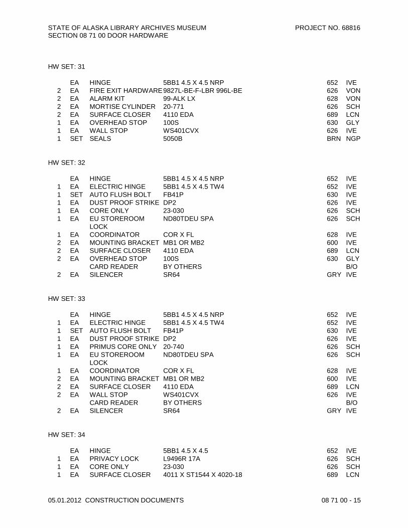
STATE OF ALASKA LIBRARY ARCHIVES MUSEUM PROJECT NO. 68816 SECTION 08 71 00 DOOR HARDWARE
05.01.2012 CONSTRUCTION DOCUMENTS 08 71 00 - 15
HW SET: 31 EA HINGE 5BB1 4.5 X 4.5 NRP 652 IVE
2 EA FIRE EXIT HARDWARE 9827L-BE-F-LBR 996L-BE 626 VON 2 EA ALARM KIT 99-ALK LX 628 VON 2 EA MORTISE CYLINDER 20-771 626 SCH 2 EA SURFACE CLOSER 4110 EDA 689 LCN 1 EA OVERHEAD STOP 100S 630 GLY 1 EA WALL STOP WS401CVX 626 IVE 1 SET SEALS 5050B BRN NGP
HW SET: 32 EA HINGE 5BB1 4.5 X 4.5 NRP 652 IVE
1 EA ELECTRIC HINGE 5BB1 4.5 X 4.5 TW4 652 IVE 1 SET AUTO FLUSH BOLT FB41P 630 IVE 1 EA DUST PROOF STRIKE DP2 626 IVE 1 EA CORE ONLY 23-030 626 SCH 1 EA EU STOREROOM
LOCK ND80TDEU SPA 626 SCH
1 EA COORDINATOR COR X FL 628 IVE 2 EA MOUNTING BRACKET MB1 OR MB2 600 IVE 2 EA SURFACE CLOSER 4110 EDA 689 LCN 2 EA OVERHEAD STOP 100S 630 GLY
CARD READER BY OTHERS B/O 2 EA SILENCER SR64 GRY IVE
HW SET: 33 EA HINGE 5BB1 4.5 X 4.5 NRP 652 IVE
1 EA ELECTRIC HINGE 5BB1 4.5 X 4.5 TW4 652 IVE 1 SET AUTO FLUSH BOLT FB41P 630 IVE 1 EA DUST PROOF STRIKE DP2 626 IVE 1 EA PRIMUS CORE ONLY 20-740 626 SCH 1 EA EU STOREROOM
LOCK ND80TDEU SPA 626 SCH
1 EA COORDINATOR COR X FL 628 IVE 2 EA MOUNTING BRACKET MB1 OR MB2 600 IVE 2 EA SURFACE CLOSER 4110 EDA 689 LCN 2 EA WALL STOP WS401CVX 626 IVE
CARD READER BY OTHERS B/O 2 EA SILENCER SR64 GRY IVE
HW SET: 34 EA HINGE 5BB1 4.5 X 4.5 652 IVE
1 EA PRIVACY LOCK L9496R 17A 626 SCH 1 EA CORE ONLY 23-030 626 SCH 1 EA SURFACE CLOSER 4011 X ST1544 X 4020-18 689 LCN

STATE OF ALASKA LIBRARY ARCHIVES MUSEUM PROJECT NO. 68816 SECTION 08 71 00 DOOR HARDWARE
05.01.2012 CONSTRUCTION DOCUMENTS 08 71 00 - 16
1 EA OVERHEAD STOP 100S 630 GLY 1 EA KICK PLATE 8400 10" X 2" LDW 630 IVE 1 EA MOP PLATE 8400 4" X 1" LDW 630 IVE 3 EA SILENCER SR64 GRY IVE
HW SET: 35 EA HINGE 5BB1 4.5 X 4.5 652 IVE
1 EA PRIVACY LOCK L9496R 17A 626 SCH 1 EA CORE ONLY 23-030 626 SCH 1 EA ELECTRIC STRIKE 55E LBM/LCM/DBM 630 SDC 1 EA RECTIFIER BR64XL SDC 1 EA AUTO-EQUALIZER 4642 FLUSH CEILING MOUNT 689 LCN 1 EA OVERHEAD STOP 100S 630 GLY 1 EA KICK PLATE 8400 10" X 2" LDW 630 IVE 1 EA MOP PLATE 8400 4" X 1" LDW 630 IVE 3 EA SILENCER SR64 GRY IVE 2 EA ACTUATOR, WALL
MOUNT 8310-853T LCN
DOOR TO BE NORMALLY UNLOCKED. PUSHING OUTSIDE ACTUATOR WILL RELEASE STRIKE MOMENTARILY AND AUTO OPEN DOOR. INSIDE THUMBTURN WILL THROW DEADBOLT LOCKING OUTSIDE LEVER AND DEACTIVATING OUTSIDE ACTUATOR. INSIDE LEVER WILL RETRACT DEADBOLT AND PUSHING INSIDE ACTUATOR WILL RELEASE ELECTRIC STRIKE MOMENTARILY AND AUTO OPEN DOOR. HW SET: 36 EA HINGE 5BB1 4.5 X 4.5 NRP 652 IVE
1 SET AUTO FLUSH BOLT FB31P 630 IVE 1 EA DUST PROOF STRIKE DP2 626 IVE 1 EA CLASSROOM LOCK ND70TD SPA 626 SCH 1 EA CORE ONLY 23-030 626 SCH 1 EA COORDINATOR COR X FL 628 IVE 2 EA MOUNTING BRACKET MB1 OR MB2 600 IVE 2 EA SURFACE CLOSER 4110 EDA 689 LCN 2 EA OVERHEAD STOP 100S 630 GLY 4 EA KICK PLATE 8400 10" X 1" LDW 630 IVE 2 EA SILENCER SR64 GRY IVE
ASTRAGAL BY DOOR SUPPLIER B/O HW SET: 37 EA HINGE 5BB1 4.5 X 4.5 652 IVE
1 EA ELECTRIC HINGE 5BB1 4.5 X 4.5 TW4 652 IVE 1 SET AUTO FLUSH BOLT FB31P 630 IVE 1 EA DUST PROOF STRIKE DP2 626 IVE 1 EA PRIMUS CORE ONLY 20-740 626 SCH 1 EA EU STOREROOM
LOCK ND80TDEU SPA 626 SCH
1 EA COORDINATOR COR X FL 628 IVE

STATE OF ALASKA LIBRARY ARCHIVES MUSEUM PROJECT NO. 68816 SECTION 08 71 00 DOOR HARDWARE
05.01.2012 CONSTRUCTION DOCUMENTS 08 71 00 - 17
2 EA SURFACE CLOSER 4011 X ST1544 X 4020-18 689 LCN 2 EA OVERHEAD STOP 100S 630 GLY 2 EA KICK PLATE 8400 10" X 1" LDW 630 IVE
CARD READER BY OTHERS B/O 2 EA SILENCER SR64 GRY IVE
HW SET: 38 EA HINGE 5BB1 4.5 X 4.5 NRP 652 IVE
1 EA FIRE EXIT HARDWARE 98EO-F 626 VON 1 EA ALARM KIT 99-ALK LX 628 VON 1 EA MORTISE CYLINDER 20-771 626 SCH 1 EA SURFACE CLOSER 4110 EDA 689 LCN 1 EA WALL STOP WS401CVX 626 IVE 1 SET SEALS 5050B BRN NGP
HW SET: 39 EA HINGE 5BB1 4.5 X 4.5 NRP 652 IVE
1 EA FIRE EXIT HARDWARE 98NL-F 626 VON 1 EA RIM CYLINDER 20-057 626 SCH 1 EA SURFACE CLOSER 4110 EDA 689 LCN 1 EA OVERHEAD STOP 100S 630 GLY 1 SET SEALS 5050B BRN NGP
HW SET: 40 EA HINGE 5BB1 4.5 X 4.5 652 IVE
1 EA CLASSROOM LOCK ND70TD SPA 626 SCH 1 EA CORE ONLY 23-030 626 SCH 1 EA SURFACE CLOSER 4110 EDA 689 LCN 1 EA WALL STOP WS401CVX 626 IVE 3 EA SILENCER SR64 GRY IVE
HW SET: 41 EA HINGE 5BB1 4.5 X 4.5 652 IVE
1 EA ELECTRIC HINGE 5BB1 4.5 X 4.5 TW4 652 IVE 1 EA FIRE EXIT HARDWARE 98L-F E996L 17 626 VON 1 EA ALARM KIT 99-ALK LX 628 VON 1 EA RIM CYLINDER 20-057 626 SCH 1 EA MORTISE CYLINDER 20-771 626 SCH 1 EA SURFACE CLOSER 4011 689 LCN 1 EA KICK PLATE 8400 10" X 1" LDW 630 IVE 1 EA WALL STOP WS401CVX 626 IVE 1 SET SEALS 5050B BRN NGP
DOOR TIED INTO FIRE ALARM AND WILL RELEASE IN ALARM

STATE OF ALASKA LIBRARY ARCHIVES MUSEUM PROJECT NO. 68816 SECTION 08 71 00 DOOR HARDWARE
05.01.2012 CONSTRUCTION DOCUMENTS 08 71 00 - 18
HW SET: 42
2 EA CONTINUOUS HINGE FM-300-WT WITH UNEQUAL LEAFS 630 MAR 1 EA MULLION STABILIZER 154 689 VON 1 EA MULLION KR4954 689 VON 2 EA PANIC HARDWARE 98EO 626 VON 1 EA MORTISE CYLINDER 20-771 626 SCH 2 EA SURFACE CLOSER 4110 EDA 689 LCN 2 EA OVERHEAD STOP 100S 630 GLY 1 SET SEALS 9605A HEAD AND JAMB CL NGP 2 EA DOOR SWEEP C627A CL NGP 1 EA THRESHOLD 8427 MS/LA AL NGP
DOOR CONTACT BY OTHERS B/O HW SET: 43 EA HINGE 5BB1 4.5 X 4.5 NRP 652 IVE
1 EA ELECTRIC HINGE 5BB1 4.5 X 4.5 TW4 652 IVE 1 SET AUTO FLUSH BOLT FB41P 630 IVE 1 EA DUST PROOF STRIKE DP2 626 IVE 1 EA STOREROOM LOCK ND80TD SPA 626 SCH 1 EA PRIMUS CORE ONLY 20-740 626 SCH 1 EA ELECTROMAGNETIC
LOCK M492 628 SCE
1 EA ELECTRIC STRIKE 6224 FSE 24VDC 630 VON 1 EA COORDINATOR COR X FL 628 IVE 2 EA MOUNTING BRACKET MB1 OR MB2 600 IVE 1 EA SURFACE CLOSER 4110 EDA 689 LCN 1 EA AUTO. OPERATOR 9542 REG 628 LCN 2 EA WALL STOP WS401CVX 626 IVE
CARD READER BY OTHERS B/O 2 EA SILENCER SR64 GRY IVE 1 EA POWER SUPPLY PS902 SCE 2 EA DOOR POSITION
SWITCH 679-05 WD SCE
1 EA ACTUATOR, WALL MOUNT
8310-853T LCN
SHOWING CARD WILL RELEASE ELECTRIC STRIKE AND AUTO OPEN DOOR. FROM INSIDE PUSHING ACTUATOR WILL RELEASE ELECTRIC STRIKE AND DOOR WILL AUTO OPEN. MAGNETIC LOCK NORMALLY NOT POWERED. DOOR CONTACTS IN DOORS 219 OR 227F WILL SEND SIGNAL IF ONE PAIR IS OPEN THE OTHER WILL LOCK DOWN BY THE MAGNETIC LOCK. HW SET: 44 EA HINGE 5BB1 4.5 X 4.5 NRP 652 IVE
1 EA PANIC HARDWARE 98L-NL 996L 626 VON 1 EA RIM CYLINDER 20-057 626 SCH 1 EA SURFACE CLOSER 4110 EDA 689 LCN 1 EA WALL STOP WS401CVX 626 IVE 3 EA SILENCER SR64 GRY IVE

STATE OF ALASKA LIBRARY ARCHIVES MUSEUM PROJECT NO. 68816 SECTION 08 71 00 DOOR HARDWARE
05.01.2012 CONSTRUCTION DOCUMENTS 08 71 00 - 19
HW SET: 45 EA HINGE 5BB1 4.5 X 4.5 NRP 652 IVE
1 SET AUTO FLUSH BOLT FB31P 630 IVE 1 EA DUST PROOF STRIKE DP2 626 IVE 1 EA STOREROOM LOCK ND80TD SPA 626 SCH 1 EA CORE ONLY 23-030 626 SCH 1 EA COORDINATOR COR X FL 628 IVE 2 EA MOUNTING BRACKET MB1 OR MB2 600 IVE 2 EA SURFACE CLOSER 4110 EDA 689 LCN 2 EA OVERHEAD STOP 100S 630 GLY 1 SET SEALS 5050B BRN NGP
ASTRAGAL BY DOOR SUPPLIER B/O HW SET: 46 EA HINGE 5BB1 4.5 X 4.5 652 IVE
1 EA CLASSROOM LOCK ND70TD SPA 626 SCH 1 EA CORE ONLY 23-030 626 SCH 1 EA SURFACE CLOSER 4111 AVB SCUSH 689 LCN 3 EA SILENCER SR64 GRY IVE
HW SET: 47 EA HINGE 5BB1 4.5 X 4.5 NRP 652 IVE
1 EA STOREROOM LOCK ND80TD SPA 626 SCH 1 EA PRIMUS CORE ONLY 20-740 626 SCH 1 EA SURFACE CLOSER 4110 SCUSH 689 LCN 3 EA SILENCER SR64 GRY IVE
KEY CONSERVATON SIDE HW SET: 48 EA HINGE 5BB1 4.5 X 4.5 652 IVE
2 EA FIRE EXIT HARDWARE 9827EO-F-LBR 626 VON 1 EA ELECTROMAGNETIC
LOCK M490DE 628 SCE
2 EA SURFACE CLOSER 4110 EDA 689 LCN 2 EA WALL STOP WS401CVX 626 IVE 1 SET SEALS 5050B BRN NGP
CARD READER BY OTHERS B/O 1 EA POWER SUPPLY PS902 SCE
DOOR IS LOCKED ON LOBBY SIDE BY DELAYED EGRESS MAG LOCK. FROM LOBBY SIDE ENTRY BY CARD. PUSHING ON DOOR WILL RELEASE DOOR AFTER 15 SECONDS. FREE EXIT FROM SECURE SIDE.

STATE OF ALASKA LIBRARY ARCHIVES MUSEUM PROJECT NO. 68816 SECTION 08 71 00 DOOR HARDWARE
05.01.2012 CONSTRUCTION DOCUMENTS 08 71 00 - 20
HW SET: 49 EA HINGE 5BB1 4.5 X 4.5 NRP 652 IVE
2 EA MANUAL FLUSH BOLT FB458 626 IVE 1 EA DUST PROOF STRIKE DP2 626 IVE 1 EA STOREROOM LOCK ND80TD SPA 626 SCH 1 EA PRIMUS CORE ONLY 20-740 626 SCH 1 EA SURFACE CLOSER 4110 SCUSH 689 LCN 1 EA LOCK GUARD LG10 600 IVE 2 EA SILENCER SR64 GRY IVE
HW SET: 50 EA HINGE 5BB1 4.5 X 4.5 NRP 652 IVE
1 EA STOREROOM LOCK ND80TD SPA 626 SCH 1 EA CORE ONLY 23-030 626 SCH 1 EA ELECTRIC STRIKE 6211 FSE 24VDC 630 VON 1 EA SURFACE CLOSER 4011 X ST1544 X 4020-18 689 LCN 1 EA OVERHEAD STOP 100S 630 GLY
CARD READER BY OTHERS B/O DOOR CONTACT BY OTHERS B/O
3 EA SILENCER SR64 GRY IVE CARD READER ON ADMIN SIDE HW SET: 51 EA HINGE 5BB1 4.5 X 4.5 652 IVE
1 EA ELECTRIC HINGE 5BB1 4.5 X 4.5 TW4 652 IVE 1 SET CONST LATCHING
BOLT FB51P 630 IVE
1 EA DUST PROOF STRIKE DP2 626 IVE 1 EA CORE ONLY 23-030 626 SCH 1 EA EU STOREROOM
LOCK ND80TDEU SPA 626 SCH
1 EA COORDINATOR COR X FL 628 IVE 2 EA SURFACE CLOSER 4011 689 LCN 2 EA KICK PLATE 8400 34" X 2" LDW 630 IVE 2 EA WALL STOP WS401CVX 626 IVE
CARD READER BY OTHERS B/O 1 EA LOCK GUARD LG10 600 IVE 2 EA SILENCER SR64 GRY IVE
HW SET: 52 EA HINGE 5BB1HW 4.5 X 4.5 NRP 630 IVE
1 EA PANIC HARDWARE 98NL 626 VON 1 EA RIM CYLINDER 20-757 626 SCH 1 EA ELECTRIC STRIKE 6111 FSE 24VDC 630 VON 1 EA SURFACE CLOSER 4110 EDA 689 LCN 1 EA OVERHEAD STOP 100S 630 GLY
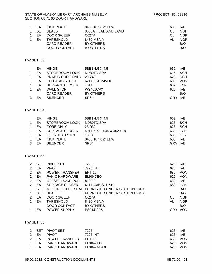
STATE OF ALASKA LIBRARY ARCHIVES MUSEUM PROJECT NO. 68816 SECTION 08 71 00 DOOR HARDWARE
05.01.2012 CONSTRUCTION DOCUMENTS 08 71 00 - 21
1 EA KICK PLATE 8400 10" X 2" LDW 630 IVE 1 SET SEALS 9605A HEAD AND JAMB CL NGP 1 EA DOOR SWEEP C627A CL NGP 1 EA THRESHOLD 8430 MS/LA AL NGP
CARD READER BY OTHERS B/O DOOR CONTACT BY OTHERS B/O HW SET: 53 EA HINGE 5BB1 4.5 X 4.5 652 IVE
1 EA STOREROOM LOCK ND80TD SPA 626 SCH 1 EA PRIMUS CORE ONLY 20-740 626 SCH 1 EA ELECTRIC STRIKE 6211 FSE 24VDC 630 VON 1 EA SURFACE CLOSER 4011 689 LCN 1 EA WALL STOP WS401CVX 626 IVE
CARD READER BY OTHERS B/O 3 EA SILENCER SR64 GRY IVE
HW SET: 54 EA HINGE 5BB1 4.5 X 4.5 652 IVE
1 EA STOREROOM LOCK ND80TD SPA 626 SCH 1 EA CORE ONLY 23-030 626 SCH 1 EA SURFACE CLOSER 4011 X ST1544 X 4020-18 689 LCN 1 EA OVERHEAD STOP 100S 630 GLY 1 EA KICK PLATE 8400 10" X 2" LDW 630 IVE 3 EA SILENCER SR64 GRY IVE
HW SET: 55
2 SET PIVOT SET 7226 626 IVE 2 EA PIVOT 7226 INT 626 IVE 2 EA POWER TRANSFER EPT-10 689 VON 2 EA PANIC HARDWARE EL9847EO 626 VON 2 EA OFFSET DOOR PULL 8190-0 630 IVE 2 EA SURFACE CLOSER 4111 AVB SCUSH 689 LCN 1 SET MEETING STILE SEAL FURNISHED UNDER SECTION 08400 B/O 1 SET SEAL FURNISHED UNDER SECTION 08400 B/O 2 EA DOOR SWEEP C627A CL NGP 1 EA THRESHOLD 8430 MS/LA AL NGP
DOOR CONTACT BY OTHERS B/O 1 EA POWER SUPPLY PS914-2RS GRY VON
HW SET: 56
2 SET PIVOT SET 7226 626 IVE 2 EA PIVOT 7226 INT 626 IVE 2 EA POWER TRANSFER EPT-10 689 VON 1 EA PANIC HARDWARE EL9847EO 626 VON 1 EA PANIC HARDWARE EL9847NL-OP 626 VON

STATE OF ALASKA LIBRARY ARCHIVES MUSEUM PROJECT NO. 68816 SECTION 08 71 00 DOOR HARDWARE
05.01.2012 CONSTRUCTION DOCUMENTS 08 71 00 - 22
1 EA RIM CYLINDER 20-757 626 SCH 2 EA OFFSET DOOR PULL 8190-0 630 IVE 1 EA SURFACE CLOSER 4111 AVB SCUSH 689 LCN 1 EA AUTO. OPERATOR 9542 REG 628 LCN 1 SET MEETING STILE SEAL FURNISHED UNDER SECTION 08400 B/O 1 SET SEAL FURNISHED UNDER SECTION 08400 B/O 2 EA DOOR SWEEP C627A CL NGP 1 EA THRESHOLD 8430 MS/LA AL NGP
CARD READER BY OTHERS B/O DOOR CONTACT BY OTHERS B/O
1 EA POWER SUPPLY PS914-4RL GRY VON 2 EA ACTUATOR, JAMB
MOUNT 8310-818T LCN
MOUNT OPENER ON LHR LEAF HW SET: 57 EA HINGE 5BB1 4.5 X 4.5 NRP 652 IVE
1 EA ELECTRIC HINGE 5BB1 4.5 X 4.5 TW4 652 IVE 1 SET AUTO FLUSH BOLT FB31P 630 IVE 1 EA DUST PROOF STRIKE DP2 626 IVE 1 EA STOREROOM LOCK ND80TD SPA 626 SCH 1 EA PRIMUS CORE ONLY 20-740 626 SCH 1 EA ELECTROMAGNETIC
LOCK M492 628 SCE
1 EA ELECTRIC STRIKE 6224 FSE 24VDC 630 VON 1 EA COORDINATOR COR X FL 628 IVE 2 EA MOUNTING BRACKET MB1 OR MB2 600 IVE 1 EA SURFACE CLOSER 4110 EDA 689 LCN 1 EA AUTO. OPERATOR 9542 REG 628 LCN 2 EA WALL STOP WS401CVX 626 IVE
CARD READER BY OTHERS B/O 2 EA SILENCER SR64 GRY IVE 1 EA POWER SUPPLY PS902 SCE 2 EA DOOR POSITION
SWITCH 679-05 HM SCE
2 EA ACTUATOR, WALL MOUNT
8310-853T LCN
SHOWING CARD WILL RELEASE ELECTRIC STRIKE AND AUTO OPEN DOOR. FROM INSIDE PUSHING ACTUATOR WILL RELEASE ELECTRIC STRIKE AND DOOR WILL AUTO OPEN. MAGNETIC LOCK NORMALLY NOT POWERED. DOOR CONTACTS IN DOORS 219 OR 227F WILL SEND SIGNAL IF ONE PAIR IS OPEN THE OTHER WILL LOCK DOWN BY THE MAGNETIC LOCK. HW SET: 58 EA HINGE 5BB1 4.5 X 4.5 652 IVE
1 EA FIRE EXIT HARDWARE 98L-BE-F 996L-BE 626 VON 1 EA SURFACE CLOSER 4011 689 LCN 1 EA WALL STOP WS401CVX 626 IVE 1 SET SEALS 5050B BRN NGP

STATE OF ALASKA LIBRARY ARCHIVES MUSEUM PROJECT NO. 68816 SECTION 08 71 00 DOOR HARDWARE
05.01.2012 CONSTRUCTION DOCUMENTS 08 71 00 - 23
HW SET: 59 EA HINGE 5BB1 4.5 X 4.5 652 IVE
1 EA ELECTROMAGNETIC LOCK
M492DE-2 628 SCE
2 EA PUSH PLATE 8200 4" X 16" 630 IVE 2 EA PULL PLATE 8302-8 4" X 16" 630 IVE 2 EA SURFACE CLOSER 4110 EDA 689 LCN 2 EA OVERHEAD STOP 100S 630 GLY 2 EA KICK PLATE 8400 10" X 1" LDW 630 IVE
CARD READER BY OTHERS BOTH SIDES OF DOOR B/O 2 EA SILENCER SR64 GRY IVE
HW SET: 60 EA HINGE 5BB1 4.5 X 4.5 NRP 652 IVE
1 EA ELECTRIC HINGE 5BB1 4.5 X 4.5 TW4 652 IVE 1 SET AUTO FLUSH BOLT FB41P 630 IVE 1 EA DUST PROOF STRIKE DP2 626 IVE 1 EA CORE ONLY 23-030 626 SCH 1 EA EU STOREROOM
LOCK ND80TDEU SPA 626 SCH
1 EA COORDINATOR COR X FL 628 IVE 2 EA MOUNTING BRACKET MB1 OR MB2 600 IVE 2 EA SURFACE CLOSER 4011 X ST1544 X 4020-18 689 LCN 2 EA OVERHEAD STOP 100S 630 GLY 1 SET SEALS 5050B BRN NGP
CARD READER BY OTHERS B/O ASTRAGAL BY DOOR SUPPLIER B/O HW SET: 61 EA HINGE FBB168 8 X 8 652 STA
1 EA STOREROOM LOCK ND80TD SPA 626 SCH 1 EA CORE ONLY 23-030 626 SCH 1 EA SURFACE CLOSER 4110 EDA 689 LCN 1 EA WALL STOP WS401CVX 626 IVE 1 SET SEALS 120NA CL NGP
3" THICK DOOR. MOUNT LOCK IN DOOR. EXTEND OUTSIDE CYLINDER AND FLUSH CUP. HW SET: 62 EA HINGE 5BB1 4.5 X 4.5 652 IVE
1 EA STOREROOM LOCK ND80TD SPA 626 SCH 1 EA CORE ONLY 23-030 626 SCH 1 EA SURFACE CLOSER 4011 689 LCN 1 EA WALL STOP WS401CVX 626 IVE 3 EA SILENCER SR64 GRY IVE

STATE OF ALASKA LIBRARY ARCHIVES MUSEUM PROJECT NO. 68816 SECTION 08 71 00 DOOR HARDWARE
05.01.2012 CONSTRUCTION DOCUMENTS 08 71 00 - 24
HW SET: 63 EA HINGE 5BB1 4.5 X 4.5 652 IVE
1 EA STOREROOM LOCK ND80TD SPA 626 SCH 1 EA CORE ONLY 23-030 626 SCH 1 EA SURFACE CLOSER 4011 689 LCN 1 EA KICK PLATE 8400 10" X 2" LDW 630 IVE 1 EA WALL STOP WS401CVX 626 IVE 1 SET SEALS 5050B BRN NGP
HW SET: 64 EA HINGE 5BB1HW 4.5 X 4.5 NRP 630 IVE
1 EA ELECTRIC HINGE 5BB1HW 4.5 X 4.5 TW4 630 IVE 1 SET AUTO FLUSH BOLT FB31P 630 IVE 1 EA DUST PROOF STRIKE DP2 626 IVE 1 EA PRIMUS CORE ONLY 20-740 626 SCH 1 EA EU STOREROOM
LOCK ND80TDEU SPA 626 SCH
1 EA COORDINATOR COR X FL 628 IVE 2 EA MOUNTING BRACKET MB1 OR MB2 600 IVE 1 EA ASTRAGAL 139A X 5050B 600 NGP 2 EA SURFACE CLOSER 4110 EDA 689 LCN 2 EA OVERHEAD STOP 100S 630 GLY 4 EA KICK PLATE 8400 10" X 1" LDW 630 IVE 1 SET SEALS 5050B BRN NGP 1 SET SEALS 9605A HEAD AND JAMB CL NGP 2 EA DOOR SWEEP C627A CL NGP 1 EA THRESHOLD 8430 MS/LA AL NGP
CARD READER BY OTHERS B/O HW SET: 65 EA HINGE 5BB1 4.5 X 4.5 652 IVE
1 EA CLASSROOM LOCK ND70TD SPA 626 SCH 1 EA CORE ONLY 23-030 626 SCH 1 EA WALL STOP WS401CVX 626 IVE 3 EA SILENCER SR64 GRY IVE
HW SET: 66 EA HINGE 5BB1 4.5 X 4.5 652 IVE
1 EA OFFICE LOCK ND50TD SPA 626 SCH 1 EA CORE ONLY 23-030 626 SCH 1 EA WALL STOP WS401CVX 626 IVE 3 EA SILENCER SR64 GRY IVE
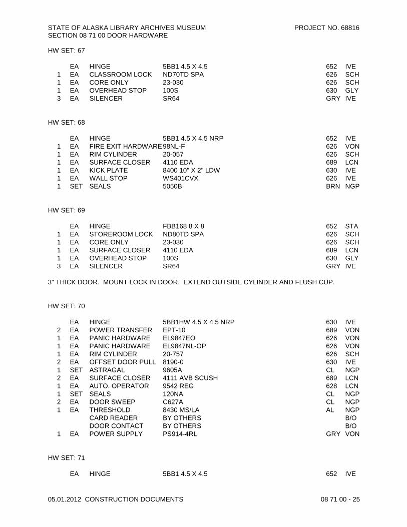
STATE OF ALASKA LIBRARY ARCHIVES MUSEUM PROJECT NO. 68816 SECTION 08 71 00 DOOR HARDWARE
05.01.2012 CONSTRUCTION DOCUMENTS 08 71 00 - 25
HW SET: 67 EA HINGE 5BB1 4.5 X 4.5 652 IVE
1 EA CLASSROOM LOCK ND70TD SPA 626 SCH 1 EA CORE ONLY 23-030 626 SCH 1 EA OVERHEAD STOP 100S 630 GLY 3 EA SILENCER SR64 GRY IVE
HW SET: 68 EA HINGE 5BB1 4.5 X 4.5 NRP 652 IVE
1 EA FIRE EXIT HARDWARE 98NL-F 626 VON 1 EA RIM CYLINDER 20-057 626 SCH 1 EA SURFACE CLOSER 4110 EDA 689 LCN 1 EA KICK PLATE 8400 10" X 2" LDW 630 IVE 1 EA WALL STOP WS401CVX 626 IVE 1 SET SEALS 5050B BRN NGP
HW SET: 69 EA HINGE FBB168 8 X 8 652 STA
1 EA STOREROOM LOCK ND80TD SPA 626 SCH 1 EA CORE ONLY 23-030 626 SCH 1 EA SURFACE CLOSER 4110 EDA 689 LCN 1 EA OVERHEAD STOP 100S 630 GLY 3 EA SILENCER SR64 GRY IVE
3" THICK DOOR. MOUNT LOCK IN DOOR. EXTEND OUTSIDE CYLINDER AND FLUSH CUP. HW SET: 70 EA HINGE 5BB1HW 4.5 X 4.5 NRP 630 IVE
2 EA POWER TRANSFER EPT-10 689 VON 1 EA PANIC HARDWARE EL9847EO 626 VON 1 EA PANIC HARDWARE EL9847NL-OP 626 VON 1 EA RIM CYLINDER 20-757 626 SCH 2 EA OFFSET DOOR PULL 8190-0 630 IVE 1 SET ASTRAGAL 9605A CL NGP 2 EA SURFACE CLOSER 4111 AVB SCUSH 689 LCN 1 EA AUTO. OPERATOR 9542 REG 628 LCN 1 SET SEALS 120NA CL NGP 2 EA DOOR SWEEP C627A CL NGP 1 EA THRESHOLD 8430 MS/LA AL NGP
CARD READER BY OTHERS B/O DOOR CONTACT BY OTHERS B/O
1 EA POWER SUPPLY PS914-4RL GRY VON HW SET: 71 EA HINGE 5BB1 4.5 X 4.5 652 IVE

STATE OF ALASKA LIBRARY ARCHIVES MUSEUM PROJECT NO. 68816 SECTION 08 71 00 DOOR HARDWARE
05.01.2012 CONSTRUCTION DOCUMENTS 08 71 00 - 26
2 EA MANUAL FLUSH BOLT FB458 626 IVE 1 EA DUST PROOF STRIKE DP2 626 IVE 1 EA STOREROOM LOCK ND80TD SPA 626 SCH 2 EA OVERHEAD STOP 100S 630 GLY 2 EA SILENCER SR64 GRY IVE
HW SET: 72 EA HINGE 5BB1 4.5 X 4.5 652 IVE
1 EA ELECTROMAGNETIC LOCK
M492 628 SCE
2 EA PULL/PUSHBAR 9190-0 630 IVE 2 EA SURFACE CLOSER 4110 EDA 689 LCN 2 EA OVERHEAD HOLDER 100H 630 GLY 1 SET SEALS 5050B BRN NGP
CARD READER BY OTHERS B/O 1 EA POWER SUPPLY PS902 SCE
HW SET: 73 EA HINGE 5BB1 4.5 X 4.5 652 IVE
1 SET AUTO FLUSH BOLT FB31P 630 IVE 1 EA DUST PROOF STRIKE DP2 626 IVE 1 EA STOREROOM LOCK ND80TD SPA 626 SCH 1 EA CORE ONLY 23-030 626 SCH 1 EA COORDINATOR COR X FL 628 IVE 2 EA MOUNTING BRACKET MB1 OR MB2 600 IVE 2 EA SURFACE CLOSER 4110 SCUSH 689 LCN 2 EA KICK PLATE 8400 10" X 1" LDW 630 IVE 1 SET SEALS 5050B BRN NGP
HW SET: 74 EA HINGE 5BB1 4.5 X 4.5 652 IVE
1 SET AUTO FLUSH BOLT FB31P 630 IVE 1 EA DUST PROOF STRIKE DP2 626 IVE 1 EA STOREROOM LOCK ND80TD SPA 626 SCH 1 EA CORE ONLY 23-030 626 SCH 1 EA COORDINATOR COR X FL 628 IVE 2 EA MOUNTING BRACKET MB1 OR MB2 600 IVE 2 EA SURFACE CLOSER 4110 EDA 689 LCN 2 EA KICK PLATE 8400 10" X 1" LDW 630 IVE 2 EA WALL STOP WS401CVX 626 IVE 1 SET SEALS 5050B BRN NGP
HW SET: 75
1 EA CONTINUOUS HINGE FM-3500-WT 630 MAR 1 EA EXIT LOCK ND25D SPA 626 SCH 1 EA SURFACE CLOSER 4110 EDA 689 LCN

STATE OF ALASKA LIBRARY ARCHIVES MUSEUM PROJECT NO. 68816 SECTION 08 71 00 DOOR HARDWARE
05.01.2012 CONSTRUCTION DOCUMENTS 08 71 00 - 27
1 EA OVERHEAD STOP 100S 630 GLY 1 SET SEALS 9605A HEAD AND JAMB CL NGP 1 EA DOOR SWEEP C627A CL NGP 1 EA THRESHOLD 8430 MS/LA AL NGP
DOOR CONTACT BY OTHERS B/O 1 EA LOCK GUARD LG10 600 IVE
CUT OUT FOR FUTURE CARD READER HW SET: 76 EA HINGE 5BB1HW 4.5 X 4.5 NRP 630 IVE
1 EA PANIC HARDWARE 98EO 626 VON 1 EA ALARM KIT 99-ALK LX 628 VON 1 EA MORTISE CYLINDER 20-771 626 SCH 1 EA SURFACE CLOSER 4110 EDA 689 LCN 1 EA OVERHEAD STOP 100S 630 GLY 1 EA KICK PLATE 8400 10" X 2" LDW 630 IVE 1 SET SEALS 9605A HEAD AND JAMB CL NGP 1 EA DOOR SWEEP C627A CL NGP 1 EA THRESHOLD 8427 MS/LA AL NGP
DOOR CONTACT BY OTHERS B/O HW SET: 77
2 EA SPRING HINGE 3SP1 4.5 X 4.5 652 IVE 4 EA HINGE 5BB1 4.5 X 4.5 652 IVE 1 SET AUTO FLUSH BOLT FB31P 630 IVE 1 EA DUST PROOF STRIKE DP2 626 IVE 1 EA PANIC HARDWARE 9875L E996L 626 VON 1 EA ALARM KIT 99-ALK LX 628 VON 2 EA MORTISE CYLINDER 26-091 626 SCH 1 EA COORDINATOR COR X FL 628 IVE 2 EA MOUNTING BRACKET MB1 OR MB2 600 IVE 1 EA SURFACE CLOSER 4110 EDA 689 LCN 1 EA OVERHEAD STOP 100S 630 GLY 2 EA SILENCER SR64 GRY IVE
HW SET: 78 EA HINGE 5BB1 4.5 X 4.5 652 IVE
1 EA INSTITUTION LOCK ND82TD SPA 626 SCH 1 EA PRIMUS CORE ONLY 20-740 626 SCH 1 EA ELECTRIC STRIKE 6211 FSE 24VDC 630 VON 1 EA SURFACE CLOSER 4011 X ST1544 X 4020-18 689 LCN 1 EA OVERHEAD STOP 100S 630 GLY
CARD READER BY OTHERS B/O CARD READER BY OTHERS BOTH SIDES OF DOOR B/O
3 EA SILENCER SR64 GRY IVE

STATE OF ALASKA LIBRARY ARCHIVES MUSEUM PROJECT NO. 68816 SECTION 08 71 00 DOOR HARDWARE
05.01.2012 CONSTRUCTION DOCUMENTS 08 71 00 - 28
HW SET: 79 EA HINGE 5BB1HW 5 X 4.5 652 IVE
1 EA MANUAL FLUSH BOLT FB458 BOTTOM ONLY 626 IVE 1 EA INSTITUTION LOCK ND82TD RHO 626 SCH 1 EA PRIMUS CORE ONLY 20-740 626 SCH 1 EA ELECTRIC STRIKE 6223 FSE 24VDC 630 VON 1 EA ASTRAGAL 139A X 5050B 600 NGP 1 EA SURFACE CLOSER 4011 H 689 LCN 1 EA OVERHEAD STOP 100S 630 GLY 1 SET SEALS 120NA CL NGP 2 EA DOOR SWEEP C607A CL NGP 1 EA SPRING BOLT 0514.00038 TOP OF DOOR RIC
CARD READER BY OTHERS BOTH SIDES OF DOOR B/O THIS DOOR IS NOT A REQUIRED EXIT HW SET: 80 ALL HARDWARE BY DOOR MFGR EXCEPT B/O
1 EA MORTISE CYLINDER 26-091 626 SCH HW SET: 81 EA HINGE 5BB1 4.5 X 4.5 652 IVE
1 SET AUTO FLUSH BOLT FB41P 630 IVE 1 EA DUST PROOF STRIKE DP2 626 IVE 1 EA STOREROOM LOCK ND80TD SPA 626 SCH 1 EA CORE ONLY 23-030 626 SCH 1 EA COORDINATOR COR X FL 628 IVE 1 EA SURFACE CLOSER 4011 689 LCN 1 EA SURFACE CLOSER 4011 X ST1544 X 4020-18 689 LCN 1 EA OVERHEAD STOP 100S 630 GLY 1 EA WALL STOP WS401CVX 626 IVE 2 EA SILENCER SR64 GRY IVE
HW SET: 82 EA HINGE 5BB1 4.5 X 4.5 NRP 652 IVE
1 EA PANIC HARDWARE 9827DT-LBR 626 VON 1 EA PANIC HARDWARE 9827NL-LBR 626 VON 1 EA RIM CYLINDER 20-057 626 SCH 1 SET ASTRAGAL 9605A CL NGP 2 EA SURFACE CLOSER 4110 EDA 689 LCN 2 EA OVERHEAD STOP 100S 630 GLY 1 SET SEALS 120NA CL NGP
HW SET: 83 EA HINGE 5BB1 4.5 X 4.5 652 IVE

STATE OF ALASKA LIBRARY ARCHIVES MUSEUM PROJECT NO. 68816 SECTION 08 71 00 DOOR HARDWARE
05.01.2012 CONSTRUCTION DOCUMENTS 08 71 00 - 29
1 EA CLASSROOM LOCK ND70TD SPA 626 SCH 1 EA CORE ONLY 23-030 626 SCH 1 EA SURFACE CLOSER 4111 HEDA 689 LCN 1 EA WALL STOP WS401CVX 626 IVE 3 EA SILENCER SR64 GRY IVE
HW SET: 84 EA HINGE 5BB1HW 5 X 4.5 652 IVE
1 EA MANUAL FLUSH BOLT FB458 BOTTOM ONLY 626 IVE 1 EA STOREROOM LOCK ND80TD SPA 626 SCH 1 EA PRIMUS CORE ONLY 20-740 626 SCH 1 EA ASTRAGAL 139A X 5050B 600 NGP 1 EA SURFACE CLOSER 4011 H 689 LCN 1 EA OVERHEAD STOP 100S 630 GLY 1 SET SEALS 120NA CL NGP 2 EA DOOR SWEEP C607A CL NGP 1 EA SPRING BOLT 0514.00038 TOP OF DOOR RIC
HW SET: 85 EA HINGE 5BB1HW 4.5 X 4.5 NRP 630 IVE
1 EA STOREROOM LOCK ND80TD SPA 626 SCH 1 EA PRIMUS CORE ONLY 20-740 626 SCH 1 EA ELECTRIC STRIKE 6211 FSE 24VDC 630 VON 1 EA SURFACE CLOSER 4110 EDA 689 LCN 1 EA OVERHEAD STOP 100S 630 GLY 1 EA KICK PLATE 8400 34" X 2" LDW 630 IVE 1 SET SEALS 9605A HEAD AND JAMB CL NGP 1 EA DOOR SWEEP C627A CL NGP 1 EA THRESHOLD 8430 MS/LA AL NGP
CARD READER BY OTHERS B/O DOOR CONTACT BY OTHERS B/O
1 EA LOCK GUARD LG10 600 IVE 3 EA SILENCER SR64 GRY IVE
HW SET: 86 EA HINGE 5BB1 4.5 X 4.5 652 IVE
1 EA ELECTROMAGNETIC LOCK
M490DE 628 SCE
1 EA PASSAGE SET ND10S SPA 626 SCH 1 EA SURFACE CLOSER 4011 689 LCN 1 EA KICK PLATE 8400 10" X 1" LDW 630 IVE 1 EA KICK PLATE 8400 10" X 2" LDW 630 IVE 1 EA WALL STOP WS401CVX 626 IVE
CARD READER BY OTHERS B/O 3 EA SILENCER SR64 GRY IVE 1 EA POWER SUPPLY PS902 SCE 1 EA PUSHBUTTON 623RD 630 SCE 1 EA SCANNER SCAN II-B SCE

STATE OF ALASKA LIBRARY ARCHIVES MUSEUM PROJECT NO. 68816 SECTION 08 71 00 DOOR HARDWARE
05.01.2012 CONSTRUCTION DOCUMENTS 08 71 00 - 30
DOOR TO BE LOCKED FROM CRATE STORAGE SIDE BY DELAYED EGRESS MAGNETIC LOCK. SHOWING CARD WILL RELEASE MAG LOCK AND ALLOW EXIT WITH OUT ALARM. PUSHING ON DOOR WILL SET ALARM IN MOTION AFTER 3 SECONDS AND WILL RELEASE DOOR IN 16 SECONDS WITH ALARM. FROM CORRIDOR SIDE MOTION SENSOR OR PUSH BUTTON WILL RELEASE MAG MOMENTARILY AND ALLOW ENTRY. HW SET: 87 EA HINGE 5BB1 4.5 X 4.5 NRP 652 IVE
2 EA PANIC HARDWARE 9827EO-LBR 626 VON 2 EA ALARM KIT 99-ALK LX 628 VON 2 EA MORTISE CYLINDER 20-771 626 SCH 2 EA SURFACE CLOSER 4110 EDA 689 LCN 1 EA OVERHEAD STOP 100S 630 GLY 1 EA WALL STOP WS401CVX 626 IVE 2 EA SILENCER SR64 GRY IVE
HW SET: 88 EA HINGE 5BB1 4.5 X 4.5 652 IVE
1 EA OFFICE LOCK ND50TD SPA 626 SCH 1 EA CORE ONLY 23-030 626 SCH 1 EA OVERHEAD STOP 100S 630 GLY 3 EA SILENCER SR64 GRY IVE
HW SET: 89 EA HINGE 5BB1 4.5 X 4.5 652 IVE
2 EA FIRE EXIT HARDWARE 9827EO-F-LBR 626 VON 1 EA ELECTROMAGNETIC
LOCK M490DE 628 SCE
2 EA SURFACE CLOSER 4110 EDA 689 LCN 2 EA OVERHEAD STOP 100S 630 GLY 2 EA WALL STOP WS401CVX 626 IVE
CARD READER BY OTHERS B/O 1 EA POWER SUPPLY PS902 SCE
DOOR IS LOCKED ON LOBBY SIDE BY DELAYED EGRESS MAG LOCK. FROM LOBBY SIDE ENTRY BY CARD. PUSHING ON DOOR WILL RELEASE DOOR AFTER 15 SECONDS. FREE EXIT FROM SECURE SIDE.

STATE OF ALASKA LIBRARY ARCHIVES MUSEUM PROJECT NO. 68816 SECTION 08 71 00 DOOR HARDWARE
05.01.2012 CONSTRUCTION DOCUMENTS 08 71 00 - 31
HARDWARE SET INDEX
100A 19 128B 26 154A 82
100B 19 129 66 154B 82
100C 20 130 66 155 69
100D 10 131A 80 156 16
100E 16 131B 80 157 28
100F 16 131C 86 159 28
102 23 132 08 161 72
103 15 133 36 162 65
104 23 134 67 163 35
108 15 137B 48 164 03
109 11 137D 30 165 17
110 17 138 04 166 17
111 31 139B 29 200A 23
113 81 139C 02 200B 77
115 27 141 67 201A 02
116 27 142 65 201B 87
117 84 144 49 201C 02
118 53 145 17 202 17
119 79 146 34 204 88
120 17 148 49 205 88
122 68 149 47 206A 07
123 63 150A 33 206B 07
124A 38 150B 47 207 88
124B 13 150C 47 208 88
124C 37 150D 67 211 15
124D 13 152A 40 212 88
124E 38 152B 61 213 88
125 25 152C 71 214 88
126 62 152D 13 216 32
128A 80 153 04 217A 78
Door Number HwSet Door Number HwSet Door Number HwSet

STATE OF ALASKA LIBRARY ARCHIVES MUSEUM PROJECT NO. 68816 SECTION 08 71 00 DOOR HARDWARE
05.01.2012 CONSTRUCTION DOCUMENTS 08 71 00 - 32
217B 53 243 28 E139 70
218A 40 244 28 E161 06
219 43 245A 07 EP00A 75
220 83 245C 07 EP00B 14
221 83 246 50 EP00C 14
222 09 247 23 ES-1 76
223A 65 248 14 ES-2 55
224 44 249 66 ES-3 21
226A 04 250 66 M101 06
226B 03 251 66 P01 01
227A 23 252 66 P02A 73
227B 23 253 66 P02B 74
227C 23 254 66 P03 17
227D 24 255 14 P04 04
227E 24 256 54 P05 10
227F 57 257 17 P06 05
228 14 259 28 P07 51
229 14 260 28 P08 59
230 14 262 60 S-1A 12
231 46 E-2C 03 S-1B 12
232 67 E100A 55 S-1C 12
233 67 E100B 55 S-1D 12
234 37 E100C 56 S-2A 58
235 62 E111 42 S-2D 18
237 45 E120 64 S-3B 18
238 07 E121 64 S-3C 18
239 62 E122 52 S-3D 41
240 39 E131 13
241 89 E132A 85
242 22 E132B 13
Door Number HwSet Door Number HwSet Door Number HwSet
END OF SECTION

STATE OF ALASKA LIBRARY ARCHIVES MUSEUM PROJECT NO. 68816SECTION 08 80 00 GLAZING
05.01.2012 CONSTRUCTION DOCUMENTS 08 80 00 - 1
SECTION 08 80 00GLAZING
PART 1 GENERAL1.01 SECTION INCLUDES
A. Glass.B. Mirrors and mirror adhesive.C. Glazing compounds and accessories.
1.02 RELATED REQUIREMENTSA. Section 05 73 00 - Decorative Railings: For railing glass.B. Section 06 20 00 - Finish Carpentry: Wood partition components with requirement for glass.C. Section 06 41 00 - Architectural Wood Casework: Cabinets with requirements for glass shelves
and doors.D. Section 08 11 13 - Hollow Metal Doors and Frames: Glazed doors and borrowed lites.E. Section 08 14 16 - Flush Wood Doors: Glazed doors.F. Section 08 41 26 - All Glass Entrances and Storefronts: For glass specified in that section.G. Section 08 44 00 - Curtain Walls, Storefronts, and Entrances: For glass specified in that section.
1.03 REFERENCE STANDARDSA. ASTM C1036 - Standard Specification for Flat Glass; 2006.B. ASTM C1048 - Standard Specification for Heat-Treated Flat Glass--Kind HS, Kind FT Coated
and Uncoated Glass; 2004.C. ASTM C1172 - Standard Specification for Laminated Architectural Flat Glass; 2009e1.D. GANA (GM) - GANA Glazing Manual; Glass Association of North America; 2009.E. GANA (SM) - FGMA Sealant Manual; Glass Association of North America; 2008.
1.04 SUBMITTALSA. See Section 01 33 00 - Submittal Procedures, for submittal procedures.B. Product Data on Glass Types: Provide structural, physical and environmental characteristics,
size limitations, special handling or installation requirements.C. Samples: Submit two samples 12x12 inch in size of glass units, showing coloration and design.
1.05 QUALITY CONTROLA. Perform Work in accordance with GANA Glazing Manual and FGMA Sealant Manual for glazing
installation methods. B. Installer Qualifications: Company specializing in performing the work of this section with
minimum three years documented experience.1.06 FIELD CONDITIONS
A. Do not install glazing when ambient temperature is less than 50 degrees F.B. Maintain minimum ambient temperature before, during and 24 hours after installation of glazing
compounds.1.07 WARRANTY
A. See Section 01 77 00 - Contract Closeout Procedures, for additional warranty requirements.

STATE OF ALASKA LIBRARY ARCHIVES MUSEUM PROJECT NO. 68816SECTION 08 80 00 GLAZING
05.01.2012 CONSTUCTION DOCUMENTS 08 80 00 - 2
PART 2 PRODUCTS2.01 GLAZING TYPES
A. Type GL-1 to GL-5: See Section 08 44 00 - Curtain Walls, Storefronts, and Entrances.B. Type GL-6 - Interior Vision Glazing:
1. Applications: All interior glazing unless otherwise indicated.2. Type: Annealed float glass, except fully tempered where required by code.3. Tint: Clear.4. Thickness: 3/8 - 1/2 inch depending on location5. Basis of design: PPG Starphire
C. Type GL-7 - Railing Glazing:1. Applications: Stair and Guardrail Glazing.2. Type: Fully tempered float glass.3. Tint: Clear.4. Thickness: 1/2 inch5. Polish all exposed edges to a bright flat polish.6. Basis of design: PPG Starphire
D. Type GL-8 - Shelf Glazing:1. Type: Anealed float glass.2. Thickness: 3/8 inch.3. Polish all exposed edges to a bright flat polish.
E. Type GL-9 - Interior Vision Glazing:1. Applications: Display Cases.2. Type: Laminated float glass.3. Tint: Clear.4. Thickness: 1/2 inch in the gallery and 3/8 inch in the Reading and Research Rooms.
a. Basis of design manufacturer: Pilkington - OptiView.b. Substitutions: Refer to Section 01 60 00 - Product Requirements.
F. Type MR-1 - Mirrors: Float glass, ASTM C1036 Type I, Class 1, Quality Q2, with silvering,protective and physical characteristics complying with ASTM C1503; thickness: 1/4 inch.
2.02 GLASS MATERIALSA. Float Glass: All glazing is to be float glass unless otherwise indicated.
1. Annealed Type: ASTM C1036, Type I, transparent flat, Class 1 clear, Quality Q3 (glazingselect).
2. Heat-Strengthened and Fully Tempered Types: ASTM C1048.3. Tinted Types: Color and performance characteristics as indicated.4. Thicknesses: As indicated; for exterior glazing comply with specified requirements for
wind load design regardless of specified thickness.B. Laminated Glass: Float glass laminated in accordance with ASTM C1172.
1. Plastic Interlayer: 0.060 inch thick, minimum.2. Where fully tempered is specified or required, provide glass that has been tempered by the
tong-less horizontal method.3. Basis of Design: DuPont SentryGlas , as manufactured by DuPont™ Glass Laminating
Solutions; 4417 Lancaster Pike, Wilmington, DE 19805; www.sentryglas.com2.03 GLAZING ACCESSORIES
A. Mirror Adhesive: Provide approved mirror adhesive suitable for mirror size and substrate.PART 3 EXECUTION3.01 EXAMINATION
A. Verify that openings for glazing are correctly sized and within tolerance.

STATE OF ALASKA LIBRARY ARCHIVES MUSEUM PROJECT NO. 68816SECTION 08 80 00 GLAZING
05.01.2012 CONSTUCTION DOCUMENTS 08 80 00 - 3
B. Verify that surfaces of glazing channels or recesses are clean, free of obstructions that mayimpede moisture movement, weeps are clear, and ready to receive glazing.
3.02 INSTALLATIONA. Mirrors: Install mirrors in accordance with adhesive manufacturer's instructions. Provide
temporary support for the required curing time.3.03 CLEANING
A. Remove glazing materials from finish surfaces.B. Remove labels after Work is complete.C. Clean glass and adjacent surfaces.
3.04 PROTECTIONA. After installation, mark pane with an 'X' by using removable plastic tape or paste.
3.05 SAFETY GLAZING LOCATIONSA. Provide safety glazing in types listed above at locations required by the current version of IBC
Section 2406.END OF SECTION

STATE OF ALASKA LIBRARY ARCHIVES MUSEUM PROJECT NO. 68816SECTION 08 80 00 GLAZING
05.01.2012 CONSTUCTION DOCUMENTS 08 80 00 - 4
THIS PAGE IS INTENTIONALLY LEFT BLANK

STATE OF ALASKA LIBRARY ARCHIVES MUSEUM PROJECT NO. 68816SECTION 09 21 16 GYPSUM BOARD ASSEMBLIES
05.01.2012 CONSTRUCTION DOCUMENTS 09 21 16 - 1
SECTION 09 21 16GYPSUM BOARD ASSEMBLIES
PART 1 GENERAL1.01 SECTION INCLUDES
A. Fire rated area separation walls.B. Acoustic insulation.C. Acoustic sealantD. Gypsum sheathing.E. Tile backer board.F. Gypsum wallboard.G. Joint treatment and accessories.H. Water-resistive barrier over exterior wall sheathing.I. Drywall Finishing.J. Gypsum ceilings.K. Reglet reveals, J-molding, end closure and other gypsum board finish accessories.L. Thermal barriers
1.02 RELATED REQUIREMENTSA. Section 01 60 00 - Material and Equipment: Fundamental product requirements, substitutions
and product options, delivery, storage, and handling.B. Section 09 51 00 - Acoustic Ceilings & Suspended Metal Grid.C. Fiberglass-Faced Gypsum Board: No paper facing.D. Section 07 25 00 - Weather Barriers: Water-resistive barrier over sheathing.E. Section 07 84 00 - Firestopping: Top-of-wall assemblies at fire rated walls.F. Section 07 90 05 - Joint Sealers: Acoustic sealant.G. Section 09 22 16 - Non-Structural Metal Framing.H. Section 09 51 00 - Acoustic Ceilings & Suspended Metal Grid.I. Section 09 51 26 - Acoustic Wood Ceiling Systems
1.03 REFERENCE STANDARDSA. ASTM C475/C475M - Standard Specification for Joint Compound and Joint Tape for Finishing
Gypsum Board; 2002 (Reapproved 2007).B. ASTM C665 - Standard Specification for Mineral-Fiber Blanket Thermal Insulation for Light
Frame Construction and Manufactured Housing; 2006.C. ASTM C840 - Standard Specification for Application and Finishing of Gypsum Board; 2008.D. ASTM C1002 - Standard Specification for Steel Self-Piercing Tapping Screws for the
Application of Gypsum Panel Products or Metal Plaster Bases to Wood Studs or Steel Studs;2007.
E. ASTM C1278/C1278M - Standard Specification for Fiber-Reinforced Gypsum Panel; 2007a.F. ASTM C1280 - Standard Specification for Application of Gypsum Sheathing; 2009.G. ASTM C1396/C1396M - Standard Specification for Gypsum Board; 2009a.H. ASTM C1658/C1658M - Standard Specification for Glass Mat Gypsum Panels; 2006.

STATE OF ALASKA LIBRARY ARCHIVES MUSEUM PROJECT NO. 68816SECTION 09 21 16 GYPSUM BOARD ASSEMBLIES
05.01.2012 CONSTUCTION DOCUMENTS 09 21 16 - 2
I. ASTM D3273 - Standard Test Method for Resistance to Growth of Mold on the Surface ofInterior Coatings in an Environmental Chamber; 2000 (Reapproved 2005).
J. ASTM E72 - Standard Test Methods of Conducting Strength Tests of Panels for BuildingConstruction; 2010.
K. GA-216 - Application and Finishing of Gypsum Board; Gypsum Association; 2010.L. GA-600 - Fire Resistance Design Manual; Gypsum Association; 2009.M. ICC (IBC) - International Building Code; 2009.
1.04 SYSTEM DESCRIPTIONA. Description of Work: The extent of the work is shown on the Drawings and specified within this
document and includes furnishing and installing gypsum wallboard, wallboard accessories andfinishing materials.
1.05 SUBMITTALSA. See Section 01 33 00 - Submittal Procedures, for submittal requirements.B. Product Data: Provide data on gypsum board products, accessories and joint finishing systems.C. Submit ASTM C 840 and GA-214 for use by Department's representative during installation.
1.06 QUALITY ASSURANCEA. Perform in accordance with ASTM C 840. Comply with requirements of GA-600 for fire-rated
assemblies.B. Installer Qualifications: Company specializing in performing the installation and finishing of
gypsum board products , with minimum three years of documented experience.C. Copies of Documents at Site: Maintain at the project site a copy of each referenced document
that prescribes execution requirements.D. Fire-Resistance-Rated Assemblies: For fire-resistance-rated assemblies, provide materials and
construction identical to those tested in assembly indicated according to ASTM E 119 by anindependent testing agency.
E. STC-Rated Assemblies: For STC-rated assemblies, provide materials and constructionidentical to those tested in assembly indicated according to ASTM E 90 and classified accordingto ASTM E 413 by an independent testing agency.
F. Tolerances: Do not exceed 1/8 inch in 8 feet variation from plumb or level in any exposed lineor surface except at joints between units; do not exceed 1/16 inch variation between planes ofabutting edges or ends. Space between the bottom of gypsum wallboard panels andsubflooring shall not exceed 1/4 inch
1.07 STORAGE AND HANDLINGA. Store materials inside under cover and keep them dry and protected against damage from
weather, condensation, direct sunlight, construction traffic, and other causes. Stack panels flatto prevent sagging.
1.08 PROJECT CONDITIONSA. Environmental Limitations: Comply with ASTM C 840 requirements or gypsum board
manufacturer's written recommendations, whichever are more stringent.B. Do not install interior products until installation areas are enclosed and conditioned.C. Do not install panels that are wet, those that are moisture damaged, and those that are mold
damaged.1. Indications that panels are wet or moisture damaged include, but are not limited to,
discoloration, sagging, or irregular shape.2. Indications that panels are mold damaged include, but are not limited to, fuzzy or splotchy
surface contamination and discoloration.
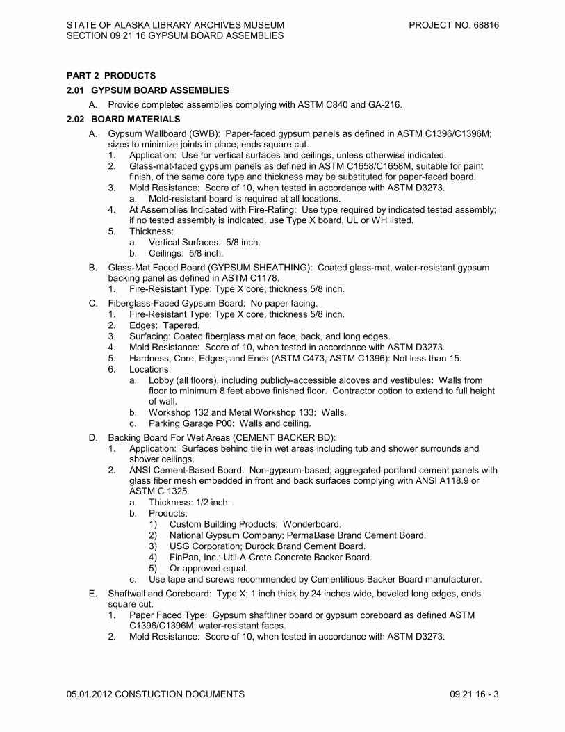
STATE OF ALASKA LIBRARY ARCHIVES MUSEUM PROJECT NO. 68816SECTION 09 21 16 GYPSUM BOARD ASSEMBLIES
05.01.2012 CONSTUCTION DOCUMENTS 09 21 16 - 3
PART 2 PRODUCTS2.01 GYPSUM BOARD ASSEMBLIES
A. Provide completed assemblies complying with ASTM C840 and GA-216.2.02 BOARD MATERIALS
A. Gypsum Wallboard (GWB): Paper-faced gypsum panels as defined in ASTM C1396/C1396M;sizes to minimize joints in place; ends square cut.1. Application: Use for vertical surfaces and ceilings, unless otherwise indicated.2. Glass-mat-faced gypsum panels as defined in ASTM C1658/C1658M, suitable for paint
finish, of the same core type and thickness may be substituted for paper-faced board.3. Mold Resistance: Score of 10, when tested in accordance with ASTM D3273.
a. Mold-resistant board is required at all locations.4. At Assemblies Indicated with Fire-Rating: Use type required by indicated tested assembly;
if no tested assembly is indicated, use Type X board, UL or WH listed.5. Thickness:
a. Vertical Surfaces: 5/8 inch.b. Ceilings: 5/8 inch.
B. Glass-Mat Faced Board (GYPSUM SHEATHING): Coated glass-mat, water-resistant gypsumbacking panel as defined in ASTM C1178.1. Fire-Resistant Type: Type X core, thickness 5/8 inch.
C. Fiberglass-Faced Gypsum Board: No paper facing.1. Fire-Resistant Type: Type X core, thickness 5/8 inch.2. Edges: Tapered.3. Surfacing: Coated fiberglass mat on face, back, and long edges.4. Mold Resistance: Score of 10, when tested in accordance with ASTM D3273.5. Hardness, Core, Edges, and Ends (ASTM C473, ASTM C1396): Not less than 15.6. Locations:
a. Lobby (all floors), including publicly-accessible alcoves and vestibules: Walls fromfloor to minimum 8 feet above finished floor. Contractor option to extend to full heightof wall.
b. Workshop 132 and Metal Workshop 133: Walls.c. Parking Garage P00: Walls and ceiling.
D. Backing Board For Wet Areas (CEMENT BACKER BD):1. Application: Surfaces behind tile in wet areas including tub and shower surrounds and
shower ceilings.2. ANSI Cement-Based Board: Non-gypsum-based; aggregated portland cement panels with
glass fiber mesh embedded in front and back surfaces complying with ANSI A118.9 orASTM C 1325.a. Thickness: 1/2 inch.b. Products:
1) Custom Building Products; Wonderboard.2) National Gypsum Company; PermaBase Brand Cement Board.3) USG Corporation; Durock Brand Cement Board.4) FinPan, Inc.; Util-A-Crete Concrete Backer Board.5) Or approved equal.
c. Use tape and screws recommended by Cementitious Backer Board manufacturer.E. Shaftwall and Coreboard: Type X; 1 inch thick by 24 inches wide, beveled long edges, ends
square cut.1. Paper Faced Type: Gypsum shaftliner board or gypsum coreboard as defined ASTM
C1396/C1396M; water-resistant faces.2. Mold Resistance: Score of 10, when tested in accordance with ASTM D3273.

STATE OF ALASKA LIBRARY ARCHIVES MUSEUM PROJECT NO. 68816SECTION 09 21 16 GYPSUM BOARD ASSEMBLIES
05.01.2012 CONSTUCTION DOCUMENTS 09 21 16 - 4
2.03 ACCESSORIESA. General: Provide auxiliary materials that comply with referenced installation standards and
manufacturer's written recommendations.B. Laminating Adhesive: Adhesive or joint compound recommended for directly adhering gypsum
panels to continuous substrate.1. Use adhesives that have a VOC content of 50 g/L or less when calculated according to 40
CFR 59, Subpart D (EPA Method 24).C. Acoustic Insulation: ASTM C665; preformed glass fiber, friction fit type, unfaced. D. Acoustical Sealant: Commercially formulated single component, non-skinning, non-hardening
synthetic sealant. The product is to be specifically manufactured for sound rated partition andceiling systems. Provide Tremco Acoustical Sealant or approved equal product.
E. Firestopping: see division 7 section “Firestopping”F. Water-Resistive Barrier: No. 15 asphalt felt.G. Joint Materials: ASTM C475 and as recommended by gypsum board manufacturer for project
conditions.1. Ready-mixed vinyl-based joint compound.2. Chemical hardening type compound.
H. Screws for Attachment to Steel Members Less Than 0.03 inch In Thickness, to WoodMembers, and to Gypsum Board: ASTM C1002; self-piercing tapping type; cadmium-plated forexterior locations.
I. Screws: ASTM C 1002; self-piercing tapping type.1. Use screws complying with ASTM C 954 for fastening panels to steel members from 0.033
to 0.112 inch thick.2. For fastening cementitious backer units, use screws of type and size recommended by
panel manufacturer.J. Screws: ASTM C 954; steel drill screws for application of gypsum board to loadbearing steel
studs.K. Anchorage to Substrate: Tie wire, nails, screws, and other metal supports, of type and size to
suit application; to rigidly secure materials in place.L. Joint Compound for Tile Backing Panels:
1. Water-Resistant Gypsum Backing Board: Use setting-type taping compound andsetting-type, sandable topping compound.
M. Trim Accessories1. Trim: ASTM C 1047.
a. Material: Galvanized for concealed trims; aluminum for exposed trims.b. Shapes:
1) Cornerbead: Galvanized steel corner reinforcement, US Gypsum Company'Dur-A-Bead' or approved. All corners unless noted otherwise.
2) LC-Bead: J-shaped; exposed long flange receives joint compound.3) L-Bead: L-shaped; exposed long flange receives joint compound.4) Expansion (control) joint.- "V" Expansion Bead: Trim Tex: 093V Expansion Bead
(PVC WITH ZIP STRIP, or if need Galv.then Protek or sim."Galv Double-V"5) End Closure: Fry-Reglet DMEC-4875.6) F-Mold: Fry-Reglet FDM 625-507) J-Mold: Fry-Reglet JPM-100.8) T-Mold: Fry-Reglet TDM-50-50.9) T-Mold-1: Fry-Reglet TRM-75-75.10) Z- Reveal Mold: Fry-Reglet DRMZ-625-50.11) W-Mold: Fry-Reglet DRWT 200-200.12) End Bead : Fry-Reglet DRML-625

STATE OF ALASKA LIBRARY ARCHIVES MUSEUM PROJECT NO. 68816SECTION 09 21 16 GYPSUM BOARD ASSEMBLIES
05.01.2012 CONSTUCTION DOCUMENTS 09 21 16 - 5
13) Reglet Reveal: Fry-Reglet DRM-625-375.14) Reveal Base: Fry-Reglet DRMB-625-400.15) Other reveal and trim profiles as indicated on drawings. Basis of design
products Fry Reglet Architectural Metals http://www.fry reglet.com16) Reglet Reveal at concrete/gwb intersection: Fry-Reglet DRMZ-625-375.
PART 3 EXECUTION3.01 EXAMINATION
A. Verify that project conditions are appropriate for work of this section to commence.B. Examine areas and substrates, with Installer present, and including welded hollow-metal frames
and framing, for compliance with requirements and other conditions affecting performance.C. Examine panels before installation. Reject panels that are wet, moisture damaged, and mold
damaged.D. Proceed with installation only after unsatisfactory conditions have been corrected.
3.02 APPLYING AND FINISHING PANELS, GENERALA. Comply with ASTM C 840.B. Install ceiling panels across framing to minimize the number of abutting end joints and to avoid
abutting end joints in central area of each ceiling. Stagger abutting end joints of adjacent panelsnot less than one framing member.1. Finish edges of suspended gypsum ceiling panels with End Bead in locations where
suspended gypsum ceiling assemblies meet suspended acoustic tile assemblies.C. Install panels with face side out. Butt panels together for a light contact at edges and ends with
not more than 1/16 inch of open space between panels. Do not force into place.D. Locate edge and end joints over supports, except in ceiling applications where intermediate
supports or gypsum board back-blocking is provided behind end joints. Do not place taperededges against cut edges or ends. Stagger vertical joints on opposite sides of partitions. Do notmake joints other than control joints at corners of framed openings.
E. Form control and expansion joints with space between edges of adjoining gypsum panels.F. Cover both faces of support framing with gypsum panels in concealed spaces (above ceilings,
etc.), except in chases braced internally or as otherwise shown on Drawings for wall type.1. Unless concealed application is indicated or required for sound, fire, air, or smoke ratings,
coverage may be accomplished with scraps of not less than 8 sq. ft. in area.2. Fit gypsum panels around ducts, pipes, and conduits.3. Where partitions intersect structural members projecting below underside of floor/roof
slabs and decks, cut gypsum panels to fit profile formed by structural members; allow 1/4-to 3/8-inch- wide joints to install sealant.
4. Detail perimeter isolation on Drawings. See "Crack Control" Article in the Evaluations.G. Isolate perimeter of gypsum board applied to non-load-bearing partitions at structural
abutments, except floors. Provide 1/4- to 1/2-inch- wide spaces at these locations, and trimedges with edge trim where edges of panels are exposed. Seal joints between edges andabutting structural surfaces with acoustical sealant.
H. Attachment to Steel Framing: Attach panels so leading edge or end of each panel is attachedto open (unsupported) edges of stud flanges first
3.03 ACOUSTIC ACCESSORIES INSTALLATIONA. Acoustic Insulation: Place tightly within spaces, around cut openings, behind and around
electrical and mechanical items within partitions, and tight to items passing through partitions.B. Acoustic Sealant: Install in accordance with manufacturer's instructions.
1. Place continuous bead at perimeter of each layer of gypsum board.2. In non-fire-rated construction, seal around all penetrations by conduit, pipe, ducts, and
rough-in boxes.
STATE OF ALASKA LIBRARY ARCHIVES MUSEUM PROJECT NO. 68816SECTION 09 21 16 GYPSUM BOARD ASSEMBLIES
05.01.2012 CONSTUCTION DOCUMENTS 09 21 16 - 6
3.04 BOARD INSTALLATIONA. Comply with ASTM C 840 and manufacturer's instructions. Install to minimize butt end joints,
especially in highly visible locations.B. Fire-Rated Construction: Install gypsum board in strict compliance with requirements of
assembly listing.C. Applying interior Gypsum Board
1. Install interior gypsum board in the following locations:a. Type X: Use type X board for all locations.
2. Single-Layer Application:a. On ceilings, apply gypsum panels before wall/partition board application to greatest
extent possible and at right angles to framing, unless otherwise indicated.b. On partitions/walls, apply gypsum panels horizontally (perpendicular to framing),
unless otherwise indicated or required by fire-resistance-rated assembly, andminimize end joints.1) Stagger abutting end joints not less than one framing member in alternate
courses of panels.c. On Z-furring members, apply gypsum panels vertically (parallel to framing) with no
end joints. Locate edge joints over furring members.d. Fastening Methods: Apply gypsum panels to supports with corrosion resistant drill
screws.3. Multilayer Application:
a. On ceilings, apply gypsum board indicated for base layers before applying base layerson walls/partitions; apply face layers in same sequence. Apply base layers at rightangles to framing members and offset face-layer joints 1 framing member, 16 inchesminimum, from parallel base-layer joints, unless otherwise indicated or required byfire-resistance-rated assembly.
b. On partitions/walls, apply gypsum board indicated for base layers and face layersvertically (parallel to framing) with joints of base layers located over stud or furringmember and face-layer joints offset at least one stud or furring member withbase-layer joints, unless otherwise indicated or required by fire-resistance-ratedassembly. Stagger joints on opposite sides of partitions.
c. On Z-furring members, apply base layer vertically (parallel to framing) and face layereither vertically (parallel to framing) or horizontally (perpendicular to framing) withvertical joints offset at least one furring member. Locate edge joints of base layerover furring members.
d. Fastening Methods: Fasten base layers with screws; fasten face layers with adhesiveand supplementary fasteners.
D. Exterior Sheathing: Comply with ASTM C1280. Install sheathing vertically, with edges buttedtight and ends occurring over firm bearing.1. Apply panels with end joints staggered and located over supports.
a. Install with 1/4-inch open space where panels abut other construction or structuralpenetrations.
b. Fasten with corrosion-resistant screws.2. Paper-Faced Sheathing: Immediately after installation, protect from weather by application
of water-resistive barrier.E. Where tile backing panels abut other types of panels in same plane, shim surfaces to produce a
uniform plane across panel surfaces.3.05 INSTALLATION OF TRIM AND ACCESSORIES
A. General: For trim with back flanges intended for fasteners, attach to framing with samefasteners used for panels. Otherwise, attach trim according to manufacturer's writteninstructions.

STATE OF ALASKA LIBRARY ARCHIVES MUSEUM PROJECT NO. 68816SECTION 09 21 16 GYPSUM BOARD ASSEMBLIES
05.01.2012 CONSTUCTION DOCUMENTS 09 21 16 - 7
B. Control Joints: Install control joints according to ASTM C 840 and in specific locations approvedby Department for visual effect.1. NOTE: At a minimim, control joints to be provided no less frequently than 20 feet
horizontally and 12 feet vertically. Provide control joints above either side of all doorheads, window heads and relite heads unless noted otherwise. Seek approval ofDepartment before proceeding with installation of control joints.
C. Interior Trim: Install in the following locations:1. Cornerbead: Use at outside corners, unless otherwise indicated.2. J-Mold: Install at locations where gypsum board abuts dissimilar materials and as
indicated.3. Additional trims, reveals and accessories as indicated on Drawings.
3.06 JOINT TREATMENTA. Glass Mat Faced Gypsum Board and Exterior Glass Mat Faced Sheathing: Use fiberglass joint
tape, bedded and finished with chemical hardening type joint compound.B. Paper Faced Gypsum Board: Use paper joint tape, bedded with ready-mixed vinyl-based joint
compound and finished with ready-mixed vinyl-based joint compound.C. Tape, fill, and sand exposed joints, edges, and corners to produce smooth surface ready to
receive finishes.1. Feather coats of joint compound so that camber is maximum 1/32 inch.
D. Fill and finish joints and corners of cementitious backing board as recommended bymanufacturer.
3.07 TOLERANCESA. Maximum Variation of Finished Gypsum Board Surface from True Flatness: 1/8 inch in 10 feet
in any direction.3.08 FINISHING GYPSUM BOARD
A. General: Treat gypsum board joints, interior angles, edge trim, control joints, penetrations,fastener heads, surface defects, and elsewhere as required to prepare gypsum board surfacesfor decoration. Promptly remove residual joint compound from adjacent surfaces.
B. Prefill open joints, and damaged surface areas.C. Apply joint tape over gypsum board joints, except those with trim having flanges not intended for
tape.D. See "Gypsum Board Finish Levels" Article in the Evaluations for a discussion of requirements of
various levels.E. Where required, use 'hot mud' where panels meet structural connectors and bolts.F. Gypsum Board Finish Levels: Finish panels to levels indicated below, according to GA-214 and
ASTM C 840, for locations indicated:1. Level 2: In concealed spaces including concealed ceiling spaces (plenum and
non-plenum), and on backing board to receive tile finish and panels that are substrate foracoustical tile.a. Embed tape and apply separate first and fill coat of joint compound to tape, fasteners,
and trim flanges2. Level 3: Mechanical and utility rooms, surfaces receiving heavy wallcoverings and in
closets.a. Embed tape and apply separate first and fill coats of joint compound to tape,
fasteners, and trim flanges3. Level 4: Smooth wall, typical where visible in all non-public spaces not indicated above.
ASTM C 840 requires application of "drywall primer" on surfaces before final decoration.Priming of gypsum board surfaces specified in Section 09 90 00 - Painting and Coating.a. Embed tape in joint compound and apply first, fill (second), and finish (third) coats of
joint compound over joints, angles, fastener heads, and accessories. Touch up and

STATE OF ALASKA LIBRARY ARCHIVES MUSEUM PROJECT NO. 68816SECTION 09 21 16 GYPSUM BOARD ASSEMBLIES
05.01.2012 CONSTUCTION DOCUMENTS 09 21 16 - 8
sand between coats and after last coat as needed to produce a surface free of visualdefects and ready for decoration.
4. Level 5: smooth wall, typical where visible in all public spaces including, but not limited tolobbies, coffee bar, lecture hall, museum, classrooms, library reading and research roomsand public restrooms:a. Embed tape in joint compound and apply first, fill (second), fill (third), and finish
(fourth) coats of joint compound over joints, angles, fastener heads, and accessories.Touch up and sand between coats as need to produce a surface free of visualdefects. Apply primer prior to application of finish coat. Touch up and sand afterfinish coat as need to produce a surface free of visual defects and ready fordecoration.
G. Use the following joint compound combinations as applicable to finish levels:1. Level 3:
a. Embedding and first coat: Ready mixed, drying type, all purpose or toppingcompound.
b. Fill (second) coat: Ready mixed, drying type, all purpose or topping compound.2. Level 4:
a. Embedding and first coat: Setting type joint compound.b. Fill (second) coat: Setting type joint compound.c. Finish (third) coat: Ready mixed, drying type, all purpose or topping compound.
3. Level 5:a. Embedding and first coat: Setting type joint compound.b. Fill (second) coat: Setting type joint compound.c. Fill (third) coat: Setting type joint compound.d. Finish (fourth) coat: Ready mixed, drying type, all purpose or topping compound.
3.09 PROTECTIONA. Protect installed products from damage from weather, condensation, direct sunlight,
construction, and other causes during remainder of the construction period.B. Remove and replace panels that are wet, moisture damaged, and mold damaged.
1. Indications that panels are wet or moisture damaged include, but are not limited to,discoloration, sagging, or irregular shape.
2. Indications that panels are mold damaged include, but are not limited to, fuzzy or splotchysurface contamination and discoloration.
END OF SECTION

STATE OF ALASKA LIBRARY ARCHIVES MUSEUM PROJECT NO. 68816SECTION 09 22 16 NON-STRUCTURAL METAL FRAMING
05.01.2012 CONSTRUCTION DOCUMENTS 09 22 16 - 1
SECTION 09 22 16NON-STRUCTURAL METAL FRAMING
PART 1 GENERAL1.01 SECTION INCLUDES
A. Metal partition, ceiling, and soffit framing.B. Framing accessories.
1.02 RELATED REQUIREMENTSA. Section 06 10 00 - Rough Carpentry: Wall sheathing for gypsum wallboard backing.
1.03 REFERENCE STANDARDSA. AISI SG02-1 - North American Specification for the Design of Cold-Formed Steel Structural
Members; American Iron and Steel Institute; 2001 with 2004 supplement. (replaced SG-971)B. ASTM C645 - Standard Specification for Nonstructural Steel Framing Members; 2009a.C. ASTM C754 - Standard Specification for Installation of Steel Framing Members to Receive
Screw-Attached Gypsum Panel Products; 2009a.D. ASTM C1002 - Standard Specification for Steel Self-Piercing Tapping Screws for the
Application of Gypsum Panel Products or Metal Plaster Bases to Wood Studs or Steel Studs;2007.
E. SSPC-Paint 20 - Zinc-Rich Primers (Type I, "Inorganic," and Type II, "Organic"); Society forProtective Coatings; 2002 (Ed. 2004).
1.04 SUBMITTALSA. See Section 01 33 00 - Submittal Procedures, for submittal procedures.B. Shop Drawings:
1. Indicate prefabricated work, component details, stud layout, framed openings, anchorageto structure, acoustic details, type and location of fasteners, accessories, and items ofother related work.
2. Describe method for securing studs to tracks, splicing, and for blocking and reinforcementof framing connections.
C. Product Data: Provide data describing framing member materials and finish, product criteria,load charts, and limitations.
D. Product Data: Provide manufacturer's data on partition head to structure connectors, showingcompliance with requirements.
E. Manufacturer's Installation Instructions: Indicate special procedures and perimeter conditionsrequiring special attention.
F. Provide a copy of standards ASTM C754 for the owner's representative present on site duringconstruction.
PART 2 PRODUCTS2.01 FRAMING MATERIALS
A. Non-Loadbearing Framing System Components: ASTM C645; galvanized sheet steel, of sizeand properties necessary to comply with ASTM C754 for the spacing indicated, with maximumdeflection of wall framing of L/240 at 5 psf.1. Studs: C shaped with flat or formed webs with knurled faces.2. Runners: U shaped, sized to match studs.3. Ceiling Channels: C shaped.4. Furring: Hat-shaped sections, minimum depth of 7/8 inch.

STATE OF ALASKA LIBRARY ARCHIVES MUSEUM PROJECT NO. 68816SECTION 09 22 16 NON-STRUCTURAL METAL FRAMING
05.01.2012 CONSTUCTION DOCUMENTS 09 22 16 - 2
B. Ceiling Hangers: Type and size as specified in ASTM C754 for spacing required.C. Partition Head to Structure Connections: Provide mechanical anchorage devices that
accommodate deflection using slotted holes, screws and anti-friction bushings, preventingrotation of studs while maintaining structural performance of partition.1. Structural Performance: Maintain lateral load resistance and vertical movement capacity
required by applicable code, when evaluated in accordance with AISI North AmericanSpecification for the Design of Cold-Formed Steel Structural Members.
2. Material: ASTM A653/A653M steel sheet, SS Grade 50, with G60/Z180 hot dippedgalvanized coating.
3. Provide components UL-listed for use in UL-listed fire-rated head of partition joint systemsindicated on drawings.
4. Provide top track preassembled with connection devices spaced to fit stud spacingindicated on drawings; minimum track length of 12 feet.
D. Tracks and Runners: Same material and thickness as studs, bent leg retainer notched toreceive studs with provision for crimp locking to stud.
E. Furring and Bracing Members: Of same material as studs; thickness to suit purpose; complyingwith applicable requirements of ASTM C754.
F. Fasteners: ASTM C1002 self-piercing tapping screws.G. Sheet Metal Backing: 0.036 inch thick, galvanized.H. Touch-Up Primer for Galvanized Surfaces: SSPC-Paint 20, Type I - Inorganic.
2.02 FABRICATIONA. Fabricate assemblies of framed sections to sizes and profiles required.B. Fit, reinforce, and brace framing members to suit design requirements.C. Fit and assemble in largest practical sections for delivery to site, ready for installation.
PART 3 EXECUTION3.01 EXAMINATION
A. Verify existing conditions before starting work.B. Verify that rough-in utilities are in proper location.
3.02 INSTALLATION OF STUD FRAMINGA. Extend partition framing to structure where indicated and to ceiling in other locations.B. Partitions Terminating at Ceiling: Attach ceiling runner securely to ceiling track in accordance
with manufacturer's instructions.C. Partitions Terminating at Structure: Attach top runner to structure, maintain clearance between
top of studs and structure, and connect studs to track using specified mechanical devices inaccordance with manufacturer's instructions; verify free movement of top of stud connections;do not leave studs unattached to track.
D. Align and secure top and bottom runners at 24 inches on center.E. Fit runners under and above openings; secure intermediate studs to same spacing as wall
studs.F. Align stud web openings horizontally.G. Secure studs to tracks using crimping method. Do not weld.H. Fabricate corners using a minimum of three studs.I. Double stud at wall openings, door and window jambs, not more than 2 inches from each side
of openings.J. Coordinate installation of bucks, anchors, and blocking with electrical, mechanical, and other
work to be placed within or behind stud framing.

STATE OF ALASKA LIBRARY ARCHIVES MUSEUM PROJECT NO. 68816SECTION 09 22 16 NON-STRUCTURAL METAL FRAMING
05.01.2012 CONSTUCTION DOCUMENTS 09 22 16 - 3
K. Blocking: Use steel channels secured to studs. Provide blocking for support of, but notnecessarily limited to, plumbing fixtures, toilet partitions, wall cabinets, toilet accessories,hardware, and opening frames, wall brackets, railings, marker boards and shelf supports.
3.03 CEILING AND SOFFIT FRAMINGA. Comply with requirements of ASTM C754.B. Install furring after work above ceiling or soffit is complete. Coordinate the location of hangers
with other work.C. Install furring independent of walls, columns, and above-ceiling work.D. Securely anchor hangers to structural members or embed in structural slab. Space hangers as
required to limit deflection to criteria indicated. Use rigid hangers at exterior soffits.E. Space main carrying channels at maximum 72 inch on center, and not more than 6 inches from
wall surfaces. Lap splice securely.F. Securely fix carrying channels to hangers to prevent turning or twisting and to transmit full load
to hangers.G. Place furring channels perpendicular to carrying channels, not more than 2 inches from
perimeter walls, and rigidly secure. Lap splices securely.H. Reinforce openings in suspension system that interrupt main carrying channels or furring
channels with lateral channel bracing. Extend bracing minimum 24 inches past each opening.I. Laterally brace suspension system.
3.04 TOLERANCESA. Maximum Variation From True Position: 1/8 inch in 10 feet.B. Maximum Variation From Plumb: 1/8 inch in 10 feet.
END OF SECTION

STATE OF ALASKA LIBRARY ARCHIVES MUSEUM PROJECT NO. 68816SECTION 09 22 16 NON-STRUCTURAL METAL FRAMING
05.01.2012 CONSTUCTION DOCUMENTS 09 22 16 - 4
THIS PAGE IS INTENTIONALLY LEFT BLANK

STATE OF ALASKA LIBRARY ARCHIVES MUSEUM PROJECT NO. 68816SECTION 09 30 00 TILING
05.01.2012 CONSTRUCTION DOCUMENTS 09 30 00 - 1
SECTION 09 30 00TILING
PART 1 GENERAL1.01 SECTION INCLUDES
A. Tile for wall applications.B. Non-ceramic trim.
1.02 RELATED REQUIREMENTSA. Section 01 60 00 - Material and Equipment: Fundamental product requirements.B. Section 09 21 16 - Gypsum Board Assemblies: Installation of tile backer board.
1.03 REFERENCE STANDARDSA. ANSI A108 Series/A118 Series/A136.1 - American National Standard Specifications for the
Installation of Ceramic Tile (Compendium); 2009.B. ANSI A108.4 - American National Standard Specifications for Installation of Ceramic Tile with
Organic Adhesives or Water Cleanable Tile-Setting Epoxy Adhesive; 2009.C. ANSI A108.5 - American National Standard Specifications for Installation of Ceramic Tile with
Dry-Set Portland Cement Mortar or Latex-Portland Cement Mortar; 1999 (R2010).D. ANSI A108.10 - American National Standard Specifications for Installation of Grout in Tilework;
1999 (R2010).E. ANSI A108.11 - American National Standard for Interior Installation of Cementitious Backer
Units; 2010.F. ANSI A118.3 - American National Standard Specifications for Chemical Resistant, Water
Cleanable Tile Setting and -Grouting Epoxy and Water Cleanable Tile-Setting Epoxy Adhesive;2009.
G. ANSI A118.4 - American National Standard Specifications for Latex-Portland Cement Mortar;2010.
H. ANSI A136.1 - American National Standard for Organic Adhesives for Installation of CeramicTile; 2008.
I. ANSI A137.1 - American National Standard Specifications for Ceramic Tile; 2008.J. ASTM C1178/C1178M - Standard Specification for Coated Glass Mat Water-Resistant Gypsum
Backing Panel; 2008.K. TCNA (HB) - Handbook for Ceramic Tile Installation; 2011.
1.04 ADMINISTRATIVE REQUIREMENTSA. Preinstallation Meeting: Convene a preinstallation meeting one week before starting work of
this section; require attendance by all affected installers.1.05 SUBMITTALS
A. See Section 01 33 00 submittal procedures for submittal prcedures.B. Product Data: Provide manufacturers' data sheets on tile, mortar, grout, and accessories.
Include instructions for using grouts and adhesives.C. Shop Drawings: Indicate tile layout, patterns, color arrangement, perimeter conditions, junctions
with dissimilar materials, control and expansion joints, and setting details.D. Samples: Submit full size tiles or one sheet of samples of each type listed.

STATE OF ALASKA LIBRARY ARCHIVES MUSEUM PROJECT NO. 68816SECTION 09 30 00 TILING
05.01.2012 CONSTUCTION DOCUMENTS 09 30 00 - 2
E. Maintenance Data: Include recommended cleaning methods, cleaning materials, stain removalmethods, and polishes and waxes.
F. Maintenance Materials: Furnish the following for Department's use in maintenance of project.1. Extra Tile: Provide 2 cartons of each wall tile and 3 percent of each accent tile.
G. Provide a copy of standards ANSI A108.1 to ANSI A108.13 for the owner's representativepresent on site during construction.
1.06 QUALITY ASSURANCEA. Maintain one copy of The Tile Council of North America Handbook and ANSI A108 Series/A118
Series on site.B. Manufacturer Qualifications: Company specializing in manufacturing the types of products
specified in this section, with minimum 5 years of documented experience.C. Installer Qualifications: Company specializing in performing tile installation, with minimum of 5
years of documented experience.1.07 DELIVERY, STORAGE, AND HANDLING
A. Protect adhesives from freezing or overheating in accordance with manufacturer's instructions.1.08 FIELD CONDITIONS
A. Do not install adhesives in an unventilated environment.B. Maintain ambient and substrate temperature of 50 degrees F during installation of mortar
materials.PART 2 PRODUCTS2.01 TILE
A. Suppliers/Manufacturers: 1. United Tile, Royal Mosa, www.unitedtile.com (425) 264-2969.2. Pental Granite and Marble, www.pentalonline.com (206) 768-32003. Substitutions: See Section 01 60 00 - Product Requirements.
B. CT-1 Ceramic Wall Tile : ANSI A137.11. Royal Mosa 10Thirty supplied by United Tile2. Size and Shape: 10 x 30 cm 4" x 12" Nominal.3. Edges: Cushioned.4. Surface Finish: Matte glaze.5. Colors: 13010 White Matt.6. Pattern: Refer to drawings.
C. CT-2 Porcelain Wall Tile : ANSI A137.11. Atlas ConcordeTune supplied by Pental Granite & Marble2. Size and Shape: 30 x 60 cm 12" x 24" Nominal.3. Edges: Square.4. Surface Finish: Textured Pattern.5. Colors: Wood.6. Pattern: Refer to drawings.
D. CT-3 Porcelain Accent Mosaic Tile : ANSI A137.11. Streamline Pagoda Mosaic supplied by Pental Granite and Marble2. Size and Shape: 3/8 - 1" x 6" in 12 x 12 sheet.3. Edges: Square.4. Surface Finish: Matte.5. Colors: Mosaic Brown.6. Pattern: Refer to drawings.
STATE OF ALASKA LIBRARY ARCHIVES MUSEUM PROJECT NO. 68816SECTION 09 30 00 TILING
05.01.2012 CONSTUCTION DOCUMENTS 09 30 00 - 3
2.02 TRIM AND ACCESSORIESA. NCT-1 Non-Ceramic Trim: Brushed stainless steel, style and dimensions to suit application, for
setting using tile mortar or adhesive.1. Applications: Use in the following locations:
a. Exposed edges of wall tile.b. Wall corners, outside.c. Fin wall end caps.
2. Manufacturer:a. Schluter-Systems: 1-800-472-4588 www.schluter.com.b. QUADEC Stainless Steel, in thickness to match tile.
2.03 ADHESIVE MATERIALSA. Organic Adhesive: ANSI A136.1, thinset bond type; use Type I in areas subject to prolonged
moisture exposure.2.04 GROUTS
A. Manufacturers:1. Mapei Corporation ; Product Opticolor www.mapei.com
B. Grout: Non-Staining Resiin Grout wiht BioBlock TM Technology.1. Colors: To be selected by Department from manufacturer's standard range.
PART 3 EXECUTION3.01 EXAMINATION
A. Verify that wall surfaces are smooth and flat within the tolerances specified for that type of work,are dust-free, and are ready to receive tile.
B. Coordinate all MEP devices and locations with tile layoutsC. Coordinate wall opening locations for accessories with tile layouts
3.02 PREPARATIONA. Protect surrounding work from damage.B. Vacuum clean surfaces and damp clean.C. Prepare substrate surfaces for adhesive installation in accordance with adhesive manufacturer's
instructions.3.03 INSTALLATION - GENERAL
A. Install tile and grout in accordance with applicable requirements of ANSI A108.1 throughA108.13, manufacturer's instructions, and The Tile Council of North America Handbookrecommendations.
B. Lay tile to pattern indicated. Do not interrupt tile pattern through openings.C. Cut and fit tile to penetrations through tile, leaving sealant joint space. Form corners neatly.
Align wall joints.D. Place tile joints uniform in width, subject to variance in tolerance allowed in tile size. Make joints
watertight, without voids, cracks, excess mortar, or excess grout.E. Align grout joints at adjacent surfaces and in pattern as shown on the drawings.F. Install non-ceramic trim in accordance with manufacturer's instructions.G. Sound tile after setting. Replace hollow sounding units.H. Keep expansion joints free of adhesive or grout. Apply sealant to joints.I. Allow tile to set for a minimum of 48 hours prior to grouting.J. Grout tile joints.

STATE OF ALASKA LIBRARY ARCHIVES MUSEUM PROJECT NO. 68816SECTION 09 30 00 TILING
05.01.2012 CONSTUCTION DOCUMENTS 09 30 00 - 4
3.04 INSTALLATION - WALL TILEA. Over coated glass mat backer board on studs, install in accordance with The Tile Council of
North America Handbook Method W245.3.05 CLEANING
A. Clean tile and grout surfaces.3.06 PROTECTION
A. Protect finished installation in accordance with manufacturers recommendations.END OF SECTION

STATE OF ALASKA LIBRARY ARCHIVES MUSEUM SECTION 09 51 01 ACOUSTICAL CEILINGS
PROJECT NO. 68816
05.01.2012 CONSTRUCTION DOCUMENTS 09 51 01 - 1
PART 1 GENERAL 1.01 SECTION INCLUDES
SECTION 09 51 01 ACOUSTICAL CEILINGS
A. Suspended metal grid ceiling system. B. Acoustical units. C. Supplementary acoustical insulation above ceiling.
1.02 RELATED REQUIREMENTS A. Section 01 60 00 - Product Requirements: Fundamental product requirements. B. Section 05 31 00 - Steel Deck: Placement of special anchors or inserts for suspension system. C. Section 08 31 00 - Access Doors and Panels: Access panels. D. Section 28 31 00 - Fire Detection and Alarm: Fire alarm components in ceiling system. E. Section 21 13 00 - Fire-Suppression Sprinkler Systems: Sprinkler heads in ceiling system. F. Section 23 37 00 - Air Outlets and Inlets: Air diffusion devices in ceiling. G. Section 26 51 00 - Interior Lighting: Light fixtures in ceiling system. H. Section 27 51 17 - Public Address Systems: Speakers in ceiling system.
1.03 REFERENCE STANDARDS A. ASTM C635 - Standard Specification for the Manufacture, Performance, and Testing of Metal
Suspension Systems for Acoustical Tile and Lay-in Panel Ceilings; 2007. B. ASTM C636/C636M - Standard Practice for Installation of Metal Ceiling Suspension Systems for
Acoustical Tile and Lay-in Panels; 2008. C. ASTM E-84 - Surface Burning Characteristics: All panel components shall meet Class A
requirements and have a Flame Spread rating of less than 25 D. ASTM E580/E580M - Standard Practice for Installation of Ceiling Suspension Systems for
Acoustical Tile and Lay-in Panels in Areas Subject to Earthquake Ground Motions; 2011. E. ASTM E1264 - Standard Classification for Acoustical Ceiling Products; 2008e1. F. NFPA 286 - Standard Methods of Fire Tests for Evaluating Contribution of Wall and Ceiling
Interior Finish to Room Fire Growth; 2011. 1.04 ADMINISTRATIVE REQUIREMENTS
A. Sequence work to ensure acoustical ceilings are not installed until building is enclosed, sufficient heat is provided, dust generating activities have terminated, and overhead work is completed, tested, and approved.
B. On-site storage shall be such as to assure that all panels and associated materials are protected from damage and climactically controlled to normal operational levels
1.05 SUBMITTALS A. See Section 01 33 00 – Submittal Procedures, for submittal procedures. B. Shop Drawings: Indicate grid layout and related dimensioning, junctions with other ceiling
finishes, and mechanical and electrical items installed in the ceiling.

STATE OF ALASKA LIBRARY ARCHIVES MUSEUM SECTION 09 51 01 ACOUSTICAL CEILINGS
PROJECT NO. 68816
05.01.2012 CONSTUCTION DOCUMENTS 09 51 01 - 2
C. Product Data: Provide data on suspension system components and metal panels and acoustical insulation.
D. Samples: Submit two samples 8 x 8 inch in size illustrating material, edging and finish of acoustical units.
E. Manufacturer's Installation Instructions: Indicate special procedures. F. Maintenance Materials: Furnish the following for Department's use in maintenance of project.
1. See Section 01 77 00 – Contract Closeout Procedures, for additional provisions. 2. Extra Acoustical Units: Quantity equal to 3 percent of total installed.
1.06 QUALITY CONTROL A. Suspension System Manufacturer Qualifications: Company specializing in manufacturing the
products specified in this section with minimum 5 years documented experience. B. Acoustical Unit Manufacturer Qualifications: Company specializing in manufacturing the
products specified in this section with minimum 5 years documented experience. 1.07 FIELD CONDITIONS
A. Do not install acoustical tile or metal panel ceilings until after spaces are enclosed and weather tight and after wet work and work above ceilings is complete and accepted by the Department.
B. Maintain environmental conditions (temperature, humidity and ventilation) at normal operational levels and within limits recommended by manufacturer for optimum results: a temperature range of 20ºC - 27ºC (68ºF - 81ºF), and a relative humidity of less than 60%. . Do not install products under environmental conditions outside manufacturer’s absolute limits.
C. Allow materials to reach ambient temperature and humidity for a minimum of 48 hours prior to starting installation.
PART 2 PRODUCTS 2.01 ACOUSTICAL UNITS
A. Manufacturers: 1. Armstrong World Industries, Inc: www.armstrong.com. 2. Chicago Metallic: wwwchicagometallic.com 3. Decoustics www.decoustics.ca. 4. Substitutions: See Section 01 60 00 - Product Requirements.
B. Acoustical Units - General: ASTM E1264, Class A. C. ACT-1 Acoustical Tiles, Open Office: Painted mineral fiber, ASTM E 1264 Type III, with the
following characteristics: 1. VOC Content: Certified as Low Emission by one of the following :
a. Product listing in the CHPS Low-Emitting Materials Product List at; www.chps.net/manual/lem_table.htm.
2. Size: 24 x 24 inches. 3. Thickness: 3/4 inches. 4. Composition: Wet felted. 5. Light Reflectance: 0.85 percent, determined as specified in ASTM E 1264. 6. NRC Range: 0.75, determined as specified in ASTM E 1264. 7. Articulation Class (AC): 170, determined as specified in ASTM E 1264. 8. Ceiling Attenuation Class (CAC): 35, determined as specified in ASTM E 1264. 9. Sag Resistance - HumiGuard Plus 10. Edge: Angled, tegular. 11. Surface Color: White. 12. Surface Pattern: fine texture. 13. Product: Basis of Design - Cirrus Open Plan #556 by Armstrong. 14. Suspension System: Exposed grid Type 15/16 inch.

STATE OF ALASKA LIBRARY ARCHIVES MUSEUM SECTION 09 51 01 ACOUSTICAL CEILINGS
PROJECT NO. 68816
05.01.2012 CONSTUCTION DOCUMENTS 09 51 01 - 3
D. ACT-2 Acoustical Panels, Public Corridor : high acoustic layer laminated to a fiberglass core, with the following characteristics: 1. Size: custom size 2'-9" x 5'-9" up to 8'-8" inches. 2. Thickness: 1 1/16 inches. 3. Light Reflectance: 0.90 percent, determined as specified in ASTM E1264. 4. NRC Range: 0.90, determined as specified in ASTM E 1264. 5. Joint: 1/4 inch reveal. 6. Edge: Square. 7. Edge Trim: Extruded aluminum edging with finish to match panel. 8. Surface Color: White. 9. Product: Basis of Design - Claro by Decoustics. 10. Suspension System: Custom concealed suspension grid Type 15/16 inch Tee. a.
Suspension System Product: Ceilencio b. Accessibility: 100% downward access. c. Edge Mold: Shadow Molding
E. ACT-3 Acoustical Tiles, High CAC: Painted mineral fiber, ASTM E 1264 Type III, with the following characteristics: 1. VOC Content: Certified as Low Emission by one of the following :
a. Product listing in the CHPS Low-Emitting Materials Product List at; www.chps.net/manual/lem_table.htm.
2. Size: 24 x 24 inches. 3. Thickness: 3/4 inches. 4. Composition: Wet felted. 5. Light Reflectance: 0.86 percent, determined as specified in ASTM E1264. 6. NRC Range: 0.70, determined as specified in ASTM E 1264. 7. Ceiling Attenuation Class (CAC): 40, determined as specified in ASTM E1264. 8. Sage Resistance: HumiGuard Plus. 9. Edge: Angled, tegular. 10. Surface Color: White. 11. Surface Pattern: fine texture. 12. Product: Basis of Design - Cirrus High CAC #572 by Armstrong. 13. Suspension System: Exposed grid Type 15/15 inch.
2.02 SUSPENSION SYSTEM(S) A. Manufacturers:
1. Same as for acoustical units. B. Suspension Systems - General: ASTM C 635; die cut and interlocking components, with stabilizer
bars, clips, splices, perimeter moldings, and hold down clips as required. C. Exposed Steel Suspension System for lay-in ceiling tiles: Formed steel, commercial quality cold rolled;
heavy-duty. 1. Profile: Tee; 15/16 inch wide face. 2. Finish: White painted.
D. Fire-Rated Concealed Steel Suspension System Type Gypsum Ceiling: Formed steel, commercial quality cold rolled; heavy-duty. 1. Profile: Tee; 15/16 inch wide face. 2. Fire Rating: Listed and classified for use in a 1 hour fire-resistive assembly. 3. Finish: White painted.
E. Concealed Suspension System: Formed steel, commercial quality cold rolled; light-duty.
2.03 ACCESSORIES A. Support Channels and Hangers: Galvanized steel; size and type to suit application, seismic
requirements, and ceiling system flatness requirement specified.

STATE OF ALASKA LIBRARY ARCHIVES MUSEUM SECTION 09 51 01 ACOUSTICAL CEILINGS
PROJECT NO. 68816
05.01.2012 CONSTUCTION DOCUMENTS 09 51 01 - 4
B. Perimeter Moldings: Same material and finish as grid.
1. At Exposed Grid: Provide L-shaped molding for mounting at same elevation as face of grid. 2. At Concealed Grid: Provide exposed L-shaped molding.
C. Acoustical Sealant For Perimeter Moldings: Specified in Section 07 90 05. PART 3 EXECUTION 3.01 EXAMINATION
A. Verify existing conditions before starting work. B. Verify that layout of hangers will not interfere with other work.
3.02 INSTALLATION - SUSPENSION SYSTEM A. Install suspension system in accordance with ASTM E 580/E 580M and manufacturer's
instructions and as supplemented in this section. B. Rigidly secure system, including integral mechanical and electrical components, for maximum deflection
of 1:360. C. Lay out system to a balanced grid design with edge units no less than 50 percent of acoustical unit size.
Or for large sized tiles and planks, as shown on the drawings D. Install after major above-ceiling work is complete. Coordinate the location of hangers with other work. E. Provide hanger clips during steel deck erection. Provide additional hangers and inserts as required. F. Hang suspension system independent of walls, columns, ducts, pipes and conduit. Where carrying
members are spliced, avoid visible displacement of face plane of adjacent members. G. Where ducts or other equipment prevent the regular spacing of hangers, reinforce the nearest affected
hangers and related carrying channels to span the extra distance. H. Do not support components on main runners or cross runners if weight causes total dead load to
exceed deflection capability. I. Support fixture loads using supplementary hangers located within 6 inches of each corner, or support
components independently. J. Do not eccentrically load system or induce rotation of runners. K. Perimeter Molding: Install at intersection of ceiling and vertical surfaces and at junctions with other
interruptions. 1. Install in bed of acoustical sealant. 2. Use longest practical lengths. 3. Overlap and rivet corners.
3.03 INSTALLATION - ACOUSTICAL UNITS A. Install acoustical units in accordance with manufacturer's instructions. B. Fit acoustical units in place, free from damaged edges or other defects detrimental to
appearance and function. C. Fit border trim neatly against abutting surfaces. D. Install units after above-ceiling work is complete. E. Install acoustical units level, in uniform plane, and free from twist, warp, and dents. F. Cutting Acoustical Units:
1. Make field cut edges of same profile as factory edges. G. Install hold-down clips on panels within 20 ft of an exterior door.
3.04 TOLERANCES A. Maximum Variation from Flat and Level Surface: 1/8 inch in 10 feet. B. Maximum Variation from Flat and Level Surface: 1/8 inch in 10 feet (3 mm in 3 m).
END OF SECTION

STATE OF ALASKA LIBRARY ARCHIVES MUSEUM PROJECT NO. 68816SECTION 09 51 26 ACOUSTICAL WOOD CEILING SYSTEMS
05.01.2012 CONSTRUCTION DOCUMENTS 09 51 26 - 1
SECTION 09 51 26ACOUSTICAL WOOD CEILING SYSTEMS
PART 1 GENERAL1.01 SECTION INCLUDES
A. Custom Wood Panel and Custom Linear Wood Ceiling Systems.1.02 RELATED REQUIREMENTS
A. Section 01 33 00 - submittal Procedures, for submittal proceduresB. Section 01 60 00 - Product Requirements: Fundamental product requirements.C. Section 05 31 00 - Steel Deck: Placement of special anchors or inserts for suspension system.D. Section 05 40 00 - Cold-Formed Metal Framing: Placement of special anchors or inserts for
suspension system.E. Section 08 31 00 - Access Doors and Panels: Access panels.F. Section 09 21 16 - Gypsum Board AssembliesG. Section 09 51 26 - Acoustic CeilingsH. Section 28 31 00 - Fire Detection and Alarm: Fire alarm components in ceiling system.I. Section 21 13 00 - Fire-Suppression Sprinkler Systems: Sprinkler heads in ceiling system.J. Section 23 37 00 - Air Outlets and Inlets: Air diffusion devices in ceiling.K. Section 26 51 00 - Interior Lighting: Light fixtures in ceiling system.L. Section 27 51 17 - Public Address Systems: Speakers in ceiling system.
1.03 REFERENCE STANDARDSA. ASTM A641 - Standard Specification for Zinc Coated (Galvanized) Carbon Steel Wire.B. ASTM C423 - Standard Test Method for Sound Absorption and Sound Absorption Coefficients
by the Reverberation Room Method.C. ASTM C635 - Standard Specification for the Manufacture, Performance, and Testing of Metal
Suspension Systems for Acoustical Tile and Lay-in Panel Ceilings; 2009b.D. ASTM C636: Standard Practice for Installation of Metal Ceiling Suspension Systems for
Acoustical Tile and Lay-in Panels; 1992.E. ASTM E84 - Standard Test Method for Surface Burning Characteristics of Building Materials;
2010.F. ASTM E580/E 580M - Standard Practice for Installation of Ceiling Suspension Systems for
Acoustical Tile and Lay-in Panels in Areas Subject to Earthquake Ground Motions; 2009a.G. AWI (QAI): Architectural Woodwork Quality Standards Illustrated.H. CISCA: Ceiling Systems Handbook.I. NFPA 286 - Standard Methods of Fire Tests for Evaluating Contribution of Wall and Ceiling
Interior Finish to Room Fire Growth; 2011.J. FSC - Forest Stewardship Council Certified forest Products
1.04 ADMINISTRATIVE REQUIREMENTSA. Sequencing: Sequence work to ensure wood ceilings are not installed until building is enclosed,
sufficient heat is provided, dust generating activities have terminated, and overhead work iscompleted, tested, and approved..
B. Do not install wood ceilings until after interior wet work is dry.

STATE OF ALASKA LIBRARY ARCHIVES MUSEUM PROJECT NO. 68816SECTION 09 51 26 ACOUSTICAL WOOD CEILING SYSTEMS
05.01.2012 CONSTUCTION DOCUMENTS 09 51 26 - 2
1.05 SUBMITTALSA. See Section 01 33 00 - Submittal Procedures, for submittal proceduresB. Product Data: Provide data for each product specified, including materials, finishes,
accessories, and standard suspension system components.C. Samples: Submit twowood ceiling samples12 x 18 inch in size, illustrating wood species, grain,
color, pattern, panel surface design, connections, and acoustical qualities. Where finishesinvolve normal color and texture variations, include sample sets showing the range of variationsexpected.
D. Warranty: Submit manufacturer's speciment warranty.E. Maintenance Materials: Furnish the following for Department's use in maintenance of project.
1. See Section 01 60 00 - Product Requirements, for additional provisions.2. Extra Stock Materials: Five of each kind of wood panel.3. Operation and Maintenance materials - including access instructions and details.
F. Shop Drawings1. Provide Shop Drawings/Coordination Drawings for all ceiling installations2. Provide reflected ceiling plans, elevations, and product details.3. Coordinate wood panel layouts and installation of wood panels and suspension system
components with other construction elements, such as penetrations and supports,including light fixtures, HVAC equipment, fire-suppression and alarm system components,partition assemblies and all perimeter conditions.
4. Indicate attachments and attachment spacing.5. Indicate location of other construction elements that penetrate or support ceiling panels,
including light fixtures, HVAC elements, fire suppression and alarm components, andelectrical components
1.06 MOCK UPA. Construct ceiling mock-ups where indicated on the drawings, incorporating all components
specified for the location.B. Minimum size of mock-up is indicated on the drawings.C. Approved mock-up may remain as part of the Work.D. Demolish mock-up if directed by Architect, and remove debris from the site.
1.07 QUALITY ASSURANCEA. Manufacturer Qualifications: Company specializing in manufacturing products specified in this
section, with not less than 5 years of documented experience.B. Fabricator Qualifications: not less than 5 years of documented experience.C. Installer Qualifications: Company specializing in performing the work of this section with
minimum 5 years of experience. Company should have completed panel ceilings similar inspecies, design, and extent to that indicated for this Project and with a record of successfulin-service performance.
D. Pre-Installation Conference: Conduct conference at Project site to comply with requirements ofDivision 1 Section "Project Meetings."
E. Single-Source Responsibility: Obtain each type of Linear Wood Ceiling from a single fabricator,with in-house Shop Drawing capabilities, in-house assembly and finishing capabilities, and withresources to provide products of consistent quality in appearance and physical propertieswithout delaying the project.
F. Single-Source responsibility: Wall panel systems should be of the same manufacturer asceiling panel systems in the same room.
G. Single-Source Responsibility for Suspension System: Obtain each type of suspension systemfrom a single source with resources to provide products of consistent quality in appearance andphysical properties without delaying project.

STATE OF ALASKA LIBRARY ARCHIVES MUSEUM PROJECT NO. 68816SECTION 09 51 26 ACOUSTICAL WOOD CEILING SYSTEMS
05.01.2012 CONSTUCTION DOCUMENTS 09 51 26 - 3
1.08 DELIVERY, STORAGE, AND HANDLINGA. Deliver Wood ceiling materials to project site in the original labeled unopened packages.B. Store Flat and level in a fully enclosed conditioned space for a minimum of 72 hours
immediately prior to installation. The Wood components shall be stored within the room inwhich they will be installed. The temperature and humidity shall closely approximate thefinished building conditions.
C. Handling: Handle panels carefully to avoid chipping edges or damaging units in any way.1.09 FIELD CONDITIONS
A. Ambient Conditions: Maintain uniform tempurature of a minimum of 60 degrees F (16 degreesC) and a maximum humididty of 55 percent prior to, during and after installation of acousticalwood ceilings.
B. Space Enclosure and Environmental Limitations: Do not install wood panel ceilings until spacesare enclosed and weatherproof, wet-work in spaces is completed and dry, work above ceilingsis complete.
1.10 WARRANTYA. See Section 01 77 00 - Contract Closeout Procedures, for additional warranty requirements.B. Correct defective Work within a five year period after Date of Substantial Completion.C. Provide one year manufacturer warranty for material and workmanship.D. Installer: All work shall be warranted for (5) years from Substantial Completion.
PART 2 PRODUCTS2.01 MANUFACTURERS
A. 9Wood, Inc.: 888-767-9990, www.9wood.comB. Richter USA, Inc.: 888-872-4780, www.www.richter-veneertechnology.comC. Rulon Company: 800-227-8566, www.rulonco.comD. Substitutions: See Section 01 60 00 - Material and Equipment.
2.02 WOOD SLAT SYSTEM - WDC-1A. Basis of Design Manufacturer: custom application: 9Wood, Inc.B. Description:
1. Product: 1000 S Wood Grille Series2. Style: 1100 Style Crosspiece Backer Grille, 1112-83. Assembly Style: Cross Piece Backer4. Member Size: 5/8" x 1 1/4" (Net)5. Panel Size: Varies,12" wide x11' long minimum; length varies.6. Members per Linear Foot: 87. Edge Style: Square8. Species: Red Alder, (Solid, Clear, Vertical Grain)9. Finish: Prefinished with Clear Pre-Catalyzed Lacquer with Satin Sheen10. Reveal Scrim: Black Reveal Scrim - provide in conjunction with installation of ACB-1 only
2.03 ACOUSTIC BACKINGA. ACB-1: Fiberglass Acoustic Duct Liner
1. Thickness: 1"2. Color: Black3. Finish: Matte4. NRC Rating: .6 minimum5. Installation method: See drawings6. To be installed in conjunction with 9Wood black reveal scrim

STATE OF ALASKA LIBRARY ARCHIVES MUSEUM PROJECT NO. 68816SECTION 09 51 26 ACOUSTICAL WOOD CEILING SYSTEMS
05.01.2012 CONSTUCTION DOCUMENTS 09 51 26 - 4
B. Coordination: Provide a continuous layer of duct liner directly behind all acoustic ceilingsystems
C. Manufacturers:1. Industrial Noise Control, www.industrialnoisecontrol.com2. Knauf Insulation, www.knaufusa.com3. Owens Corning, www.owenscorning.com4. Johns Manville Insulation, www.jm.com
PART 3 EXECUTION3.01 EXAMINATION
A. Verification of Conditions: Verify that existing atmospheric conditions meet the manufacturer'srequirements before beginning work.
B. Verify that ceiling panel layout will not interfere with other work.C. Do not proceed with installation until unsatisfactory conditions have been corrected.
3.02 PREPARATIONA. Coordination: coordinate layouts for metal suspension system and gypsum ceiling, cast-in-place
anchors, clips, and other anchors whose installation is specified in other sections.B. Layout: Measure each ceiling area and establish the layout of wood panels to balance border
widths at opposite edges of each ceiling. Avoid using less-than-half-width panels at borders,and conform to the layout shown on reflected ceiling plans and elevations in accordance withwood ceiling panel manufacturer’s approved Shop Drawings.
3.03 INSTALLATIONA. Install in accordance with manufacturer's instructions, for the ceiling type and the substrate.B. Coordinate Installation with suspension system in accordance with ASTM E 580/E 580M and
manufacturer's instructions and as supplemented in this section.C. Systems Integration: Integrate the ceiling systems with all other related work.D. Install all work in accordance with manufacturer’s installation instructions and in compliance with
all local codes and regulations. Install with undamaged edges and fitted accurately tosuspension system runners and edge moldings. Scribe and cut panels at borders andpenetrations to provide a neat, precise fit.
E. Install ceiling suspension system runners so they are square and securely interlocked with oneanother. Install number and use on-center spacing per wood ceiling manufacturer’s instructions,as indicated on approved Shop Drawings and in compliance with all local codes.
3.04 TOLERANCESA. Maximum Variation from Flat and Level Surface: 1/8 inch in 10 feet (3 mm in 3 m).B. Maximum Variation from Flat and Level Surface: 1/8 inch in 10 feet (3 mm in 3 m).
3.05 CLEANINGA. Clean exposed wood surfaces.B. Dust backer insulation as necessary to eliminate all visible dust.C. Remove and replace wood ceiling components that cannot be successfully cleaned and
repaired to permanently eliminate evidence of damage.3.06 PROTECTION
A. Protect installed ceiling panels from subsequent construction operations and changes inclimactic conditions.
END OF SECTION
STATE OF ALASKA LIBRARY ARCHIVES MUSEUM PROJECT NO. 68816SECTION 09 54 23 LINEAR METAL CEILINGS
05.01.2012 CONSTRUCTION DOCUMENTS 09 54 23 - 1
SECTION 09 54 23LINEAR METAL CEILINGS
PART 1 GENERAL1.01 SECTION INCLUDES
A. Linear, formed metal ceiling panels at loading dock.1.02 REFERENCE STANDARDS
A. ASTM A653/A653M - Standard Specification for Steel Sheet, Zinc-Coated (Galvanized) orZinc-Iron Alloy-Coated (Galvannealed) by the Hot-Dip Process; 2010.
B. ASTM C636/C636M - Standard Practice for Installation of Metal Ceiling Suspension Systems forAcoustical Tile and Lay-In Panels; 2008.
C. ASTM E580/E580M - Standard Practice for Application of Ceiling Suspension Systems forAcoustical Tile and Lay-in Panels in Areas Requiring Seismic Restraint; 2011.
1.03 SUBMITTALSA. See Section 01 33 00 - Submittal Requirements, for submittal procedures.B. Product Data: Furnish for component profiles, materials, perimeter and integral trim, and space
closures.C. Shop Drawings: Indicate reflected plan.D. Samples: Submit two samples of ceiling pan, minimum 6 inches long illustrating color and finish
of exposed to view components.1.04 QUALITY CONTROL
A. Manufacturer Qualifications: Company specializing in manufacturing the Products specified inthis section with minimum three years documented experience.
1.05 DELIVERY, STORAGE, AND HANDLINGA. Accept factory-finished products on site in manufacturer's unopened factory packaging only;
reject opened packages.B. Protect factory-finished products from damage to appearance by storing products in
manufacturer's unopened factory packaging in dry storage area.1.06 WARRANTY
A. See Section 01 77 00 - Contract Closeout Procedures for additional warranty requirements.B. Provide five year manufacturer warranty; include coverage for corrosion resistance and
discoloration of surface finish.PART 2 PRODUCTS2.01 MANUFACTURERS
A. Linear Metal Ceilings:1. Basis of Design: Armstrong ; Product Metalworks Linear Exterior: www.armstrong.com.2. Chicago Metallic Corporation; Product Planar Plus Exterior: www.chicagometallic.com.3. Hunter Douglas Contract; Product Box Series Exterior: www.hunterdouglascontract.com.4. Substitutions: See Section 01 60 00 - Material and Equipment.
2.02 LINEAR METAL CEILINGA. Linear Metal Ceiling System: Panels, suspension members, trim and accessories as required
to provide a complete system.B. Performance Requirements:

STATE OF ALASKA LIBRARY ARCHIVES MUSEUM PROJECT NO. 68816SECTION 09 54 23 LINEAR METAL CEILINGS
05.01.2012 CONSTUCTION DOCUMENTS 09 54 23 - 2
1. Design to support imposed loads of indicated items without eccentric loading of supports.2. Design for maximum deflection of 1/360 of span.3. Design to resist seismic load by using practices specified in ASTM E 580.4. Systems Located Outside Building Envelope:
a. Accommodate wind and suction loads and wind uplift without damage in accordancewith applicable code and loads as indicated on Drawings.
2.03 COMPONENTSA. Linear Panels:
1. Material: Hot-dipped galvanized steel sheet, ASTM A653/A653M, with G90/Z275 coating.2. Profile: Channel shape, 1 x 4 inch.3. Edge: Square.4. Length: Equal.5. Sight-exposed Surface Finish: Powder coat finish; of selected color from manufacturer's
standard range.B. End Caps: Formed metal; same color and finish as sight-exposed surfaces of linear panels.C. Space Closures: Recessed formed steel sections, black; snap fit between exposed linear
panels, or integral formed metal closure as part of panels. Provide closures at ceiling perimeterto close all gaps to adjoining materials.
D. Suspension Members: Formed steel sections, with integral attachment points; galvanizedfinish; size and type to suit application , seismic requirements, and ceiling system flatnessrequirement specified.
E. Suspension Wire: Size and type as required for application, seismic requirements, and ceilingsystem flatness requirement specified.
F. Touch-up Paint For Concealed Items: Zinc rich type.PART 3 EXECUTION3.01 INSTALLATION
A. Suspension Components:1. Install after above-ceiling work is complete in accordance with manufacturer's instructions,
ASTM C 636/C 636M, and ASTM E 580/E 580M.2. Hang carrying members independent of walls, columns, ducts, light fixtures, pipe, and
conduit; where carrying members are spliced, avoid visible displacement of face panelswith adjacent panels.
3. Where structure or other equipment prevent regular spacing of hangers, reinforce nearestadjacent hangers to span the required distance.
B. Linear Panels:1. Install linear panels and other system components in accordance with manufacturer's
instructions.2. Butt interior end joints tight.3. Install space closures between linear panels at exterior locations.4. Install edge moldings at junctions with other finishes and at vertical surfaces; use
maximum piece lengths.3.02 TOLERANCES
A. Maximum Variation from Flat and Level Surface: 1/8 inch in 10 feet.B. Maximum Variation From Dimensioned Position: 1/4 inch.
3.03 CLEANINGA. Replace damaged or abraded components.
END OF SECTION

STATE OF ALASKA LIBRARY ARCHIVES MUSEUM PROJECT NO. 68816SECTION 09 65 00 RESILIENT FLOORING AND WALL BASE
05.01.2012 CONSTRUCTION DOCUMENTS 09 65 00 - 1
SECTION 09 65 00RESILIENT FLOORING AND WALL BASE
PART 1 GENERAL1.01 SECTION INCLUDES
A. Resilient sheet flooring.B. Resilient tile flooring.C. Resilient base.D. Installation accessories.
1.02 RELATED REQUIREMENTSA. Section 01 60 00 - Material and Equipment: Fundamental product requirements, substitutions
and product options, delivery, storage, and handling.B. Section 03 30 00 - Cast-in-Place Concrete: Restrictions on curing compounds for concrete
slabs and floors.1.03 REFERENCE STANDARDS
A. ASTM E648 - Standard Test Method for Critical Radiant Flux of Floor-Covering Systems Usinga Radiant Heat Energy Source; 2010e1.
B. ASTM F710 - Standard Practice for Preparing Concrete Floors to Receive Resilient Flooring;2008.
C. ASTM F970 - Static Load Limit/Modified - 125/800 psi.D. ASTM F1700 - Standard Specification for Solid Vinyl Floor Tile; 2004 (reapproved 2010).E. ASTM F1861 - Standard Specification for Resilient Wall Base; 2008.F. ASTM D2047 - Static Coefficient of FrictionG. BAAQMD 8-51 - Bay Area Air Quality Management District Regulation 8, Rule 51, Adhesive and
Sealant Products; www.baaqmd.gov; 2002.H. NFPA 253 - Standard Method of Test for Critical Radiant Flux of Floor Covering Systems Using
a Radiant Heat Energy Source; National Fire Protection Association; 2011.I. SCAQMD 1168 - South Coast Air Quality Management District Rule No.1168; current edition;
www.aqmd.gov.1.04 SUBMITTALS
A. See Section 01 33 00 - Submittal Procedures, for submittal proceduresB. Product Data: Provide data on specified products, describing physical and performance
characteristics; including sizes, patterns and colors available; and installation instructions.C. Shop Drawings: Indicate seaming plan.D. Selection Samples: Submit manufacturer's complete set of color samples for Department's
initial selection.E. Verification Samples: Submittwo samples8 x 8 inch in size illustrating color and pattern for
each resilient flooring product specified.F. Concrete Testing Standard: Submit a copy of ASTM F710.G. Certification: Prior to installation of flooring, submit written certification by flooring manufacturer
and adhesive manufacturer that condition of sub-floor is acceptable.H. Maintenance Data: Include maintenance procedures, recommended maintenance materials,
and suggested schedule for cleaning, stripping, and re-waxing.

STATE OF ALASKA LIBRARY ARCHIVES MUSEUM PROJECT NO. 68816SECTION 09 65 00 RESILIENT FLOORING AND WALL BASE
05.01.2012 CONSTUCTION DOCUMENTS 09 65 00 - 2
I. Maintenance Materials: Furnish the following for Department's use in maintenance of project.1. See Section 01 60 00 - Material and Equipment, for additional provisions.2. Extra Flooring Material: 100 square feet of each type and color.3. Extra Wall Base: 25 linear feet of each type and color.
1.05 DELIVERY, STORAGE, AND HANDLINGA. Protect roll materials from damage by storing on end.
1.06 FIELD CONDITIONSA. Maintain temperature in storage area between 55 degrees F and 90 degrees F.B. Store materials for not less than 48 hours prior to installation in area of installation at a
temperature of 70 degrees F to achieve temperature stability. Thereafter, maintain conditionsabove 55 degrees F.
PART 2 PRODUCTS2.01 TILE FLOORING
A. Static Conductive Vinyl Tile: Solid vinyl with color and pattern throughout thickness, and:1. Minimum Requirements: Comply with ASTM F1700, of Class 1, Type A.2. Critical Radiant Flux (CRF): Class 1,Class 1 when tested in accordance with ASTM E 648
or NFPA 253.3. Electic Resistance: 2.5 x 10e4 to 10e6 in accordance with ANCI/ESD 7.1 and ASTM F1504. Static Coefficient of Friction: > 0.5 in accordance with ASTM D20475. Size: 24 x 24 inch.6. Wear Layer Thickness: 2.0 inch.7. Total Thickness: 2.0 inch.8. Pattern: multi-color chip.9. Manufacturers:
a. Tarkett Inc; Product Toro SC: www.tarkett.com.b. Forbo ; Product Colorex EC Plusc. Substitutions: See Section 01 60 00 - Product Requirements.
2.02 RESILIENT BASEA. Resilient Base: ASTM F1861, Type TS rubber, vulcanized thermoset; top set Style A, Straight,
and as follows:1. Critical Radiant Flux (CRF): Minimum 0.45 watt per square centimeter, when tested in
accordance with ASTM E 648 or NFPA 253.2. Height: 4 inch.3. Thickness: 0.125 inch thick.4. Finish: Satin.5. Length: Roll.6. Color: Color as selected from manufacturer's standards.7. Manufacturers:
a. Burke Flooring: www.burkemercer.com.b. Roppe Corp: www.roppe.com.c. Subsitutions: See Section 01 60 00 - Material and Equipment.
2.03 ACCESSORIESA. Primers, Adhesives, and Seaming Materials: Waterproof; types recommended by flooring
manufacturer.1. Provide only products having lower volatile organic compound (VOC) content than required
by the more stringent of the South Coast Air Quality Management District Rule No.1168and the Bay Area Air Quality Management District Regulation 8, Rule 51.
B. Moldings, Transition and Edge Strips: Metal.C. Copper Grounding Strips - Type, length and frequency as recommended by flooring
manufacturer.

STATE OF ALASKA LIBRARY ARCHIVES MUSEUM PROJECT NO. 68816SECTION 09 65 00 RESILIENT FLOORING AND WALL BASE
05.01.2012 CONSTUCTION DOCUMENTS 09 65 00 - 3
D. Conductive Adhesive - Type and covereage as recommended by flooring manuafacturer.E. Sealer and Wax: Types recommended by flooring manufacturer.
PART 3 EXECUTION3.01 EXAMINATION
A. Verify that surfaces are flat to tolerances acceptable to flooring manufacturer, free of cracks thatmight telegraph through flooring, clean, dry, and free of curing compounds, surface hardeners,and other chemicals that might interfere with bonding of flooring to substrate.
B. Verify that wall surfaces are smooth and flat within the tolerances specified for that type of work,are dust-free, and are ready to receive resilient base.
C. Verify that concrete sub-floor surfaces are dry enough and ready for resilient flooring installationby testing for moisture emission rate and alkalinity in accordance with ASTM F710; obtaininstructions if test results are not within limits recommended by resilient flooring manufacturerand adhesive materials manufacturer.
D. Verify that required floor-mounted utilities are in correct location.3.02 PREPARATION
A. Prepare floor substrates as recommended by flooring and adhesive manufacturers.B. Remove sub-floor ridges and bumps. Fill minor low spots, cracks, joints, holes, and other
defects with sub-floor filler to achieve smooth, flat, hard surface.C. Prohibit traffic until filler is cured.
3.03 INSTALLATIONA. Starting installation constitutes acceptance of sub-floor conditions.B. Install in accordance with manufacturer's instructions.C. Install copper gounding strips prior to flooring installation.D. Fit joints tightly.E. Set flooring in place, press with heavy roller to attain full adhesion.F. Where type of floor finish, pattern, or color are different on opposite sides of door, terminate
flooring under centerline of door.G. Extend flooring fully under casework prior to casework installation.H. Install edge strips at unprotected or exposed edges, where flooring terminates, and where
indicated.3.04 TILE FLOORING
A. Mix tile from container to ensure shade variations are consistent when tile is placed, unlessmanufacturer's instructions say otherwise.
3.05 RESILIENT BASEA. Fit joints tightly and make vertical. Maintain minimum dimension of 18 inches between joints.B. Miter internal corners. At external corners, 'V' cut back of base strip to 2/3 of its thickness and
fold. At exposed ends, use premolded units.C. Install base on solid backing. Bond tightly to wall and floor surfaces.D. Scribe and fit to door frames and other interruptions.
3.06 CLEANINGA. Remove excess adhesive from floor, base, and wall surfaces without damage.B. Clean in accordance with manufacturer's instructions.
3.07 PROTECTIONA. Prohibit traffic on resilient flooring for 72 hours after installation.
STATE OF ALASKA LIBRARY ARCHIVES MUSEUM PROJECT NO. 68816SECTION 09 65 00 RESILIENT FLOORING AND WALL BASE
05.01.2012 CONSTUCTION DOCUMENTS 09 65 00 - 4
B. Cover resilient products until substancial completion.END OF SECTION

STATE OF ALASKA LIBRARY ARCHIVES MUSEUM PROJECT NO. 68816SECTION 09 66 23 RESINOUS MATRIX TERRAZZO FLOORING
05.01.2012 CONSTRUCTION DOCUMENTS 09 66 23 - 1
SECTION 09 66 23RESINOUS MATRIX TERRAZZO FLOORING
PART 1 GENERAL1.01 SECTION INCLUDES
A. Poured in Place Epoxy Resin Matrix Terrazzo floor and base.B. Precast stairs treads and precast terrazzo planks at landings.
1.02 RELATED REQUIREMENTSA. Section 01 60 00 - Material and Equipment: Fundamental product requirements, substitutions
and product options, delivery, storage, and handling.B. Section 03 30 00 - Cast-in-Place Concrete: Concrete subfloor with wood float or steel trowel
finish.C. Section 05 51 00 - Metal Stairs: Formed steel stair pans.D. Section 05 52 13 - Pipe, Tube, Bar and Cable Railings.E. Section 08 11 13 - Hollow Metal Doors and Frames: Metal and wood door frames.F. Section 08 41 26 - All Glass Entrances and Storefronts: Glass storefronts, swinging doors and
sliding doors.G. Section 22 40 00 - Plumbing Fixtures: Floor drains
1.03 REFERENCE STANDARDSA. NTMA (SPECS) - Terrazzo Specifications; The National Terrazzo and Mosaic Association, Inc.;
current edition located at www.ntma.com.B. ASTM-F-1869 – Standard Test Method for Measuring Moisture Vapor Emission Rate of
Concrete Subfloor Using Anhydrous Calcium ChlorideC. ASTM F-2170 – Standard Test Method for Determining Relative Humidity in Concrete Floor
Slabs Using In Situ ProbesD. ASTM-D-4263 – Plastic Sheet Test
1.04 SUBMITTALSA. See Section 01 33 00 - Submittal Procedures, for submittal proceduresB. Product Data: Provide data for divider strips, control joint strips, expansion joints, and sealer;
include printed copy of current NTMA recommendations for type of terrazzo involved.C. Shop Drawings: Indicate divider strip and control joint layout, transitions and details of adjacent
components.D. Samples: Submit twosamples, 24 x 24 inch in size illustrating color, chip size and variation, chip
gradation, matrix color and typical divider strip.E. Cleaning and Maintenance Data: Include procedures for stain removal, stripping, and sealing.
1.05 ADMINISTRATIONA. Contractor shall be provided an electronic vector-based or other scalable map of lobby floor
graphic as indicated on Drawings. Level of detail will vary from that indicated on Drawings andgenerally omit all interior landmass features other than the Yukon river and Denali mountain.City logos or seals will be included as indicated below.
1.06 QUALITY CONTROLA. Perform work in accordance with NTMA recommendations as posted at their web site at
www.ntma.com.

STATE OF ALASKA LIBRARY ARCHIVES MUSEUM PROJECT NO. 68816SECTION 09 66 23 RESINOUS MATRIX TERRAZZO FLOORING
05.01.2012 CONSTUCTION DOCUMENTS 09 66 23 - 2
B. Applicator Qualifications: Company specializing in performing the type of work specified in thissection with minimum 5 years of documented experience.
1.07 MOCK-UPA. Construct mock-up of terrazzo flooring illustrating appearance of finished work including
colors, divider strips, border and base. Size mock-up to be not less than 6 x 6 feet. FamilyRestroom 163 may be used for mock-up.
B. Mock-up may remain as part of the Work.1.08 DELIVERY, STORAGE, AND HANDLING
A. Store resin materials in a dry, secure area.B. Maintain minimum temperature of 55 degrees F.C. Keep products away from fire or open flame.
1.09 FIELD CONDITIONSA. Do not install terrazzo when temperature is below 60 degrees F or above 90 degrees F.B. New concrete must be cured for a minimum of 30 days. Any curing compounds, oil, grease or
similar contaminates must be removed using the manufacturers recommended methods.C. Maintain temperature within specified range 24 hours before, during, and 72 hours after
installation of flooring.PART 2 PRODUCTS2.01 MANUFACTURERS
A. Epoxy Matrix Terrazzo:1. Basis of Design: Terroxy Resin Systems (877) 867-5227 www.tmsupply.com.2. Substitutions: See section 01 60 00 - Material and Equipment.
B. Aggregate, Marble and Stone Mix:1. Basis of Design: Terrazzo & Marble Supply Companies (870) 867-5227
www.tmsupply.com2. Substitutions: See section 01 60 00 - Material and Equipment.
2.02 EPOXY MATRIX TERRAZZOA. Floors & Base: TZ-1 Epoxy matrix, 3/8 inch thick.
1. Matrix Color: Terroxy Resin System, 2143 Catfish.2. Aggregate Color and Size: 30% Recycled Concrete #2; 40% Recycled Concrete #1; 30%
Recycled Concrete #0.B. Floors: TZ-2 Epoxy matrix, 3/8 inch thick.
1. Matrix Color: Terroxy Resin System, 3780 Wrought Iron.2. Aggregate Color adn Size: 40% Recycled Concrete #2; 40% Recycled Concrete #1; 20%
Recycled Concrete #0.C. Floors: TZ-3 Epoxy Matrix, 3/8 inch thick.
1. Matrix Color: Terroxy Resin System, 2313 Igloo.2. Aggregate Color and Size: 35% Recycled Concrete #2; 40% Recycled Concrete #1; 25%
Recycled Concrete #0D. Base: Same type, mix and thickness as floors.E. Stairs: 2 inch thick Epoxy matrix treads and landings; same type and mix as floors.
1. Treads and landings to be precast planks:a. Matrix Color: Terroxy Resin System, 2143 Catfish.b. Aggregate Color and Size: 30% Recycled Concrete #2; 40% Recycled Concrete #1;
30% Recycled Concrete #0.

STATE OF ALASKA LIBRARY ARCHIVES MUSEUM PROJECT NO. 68816SECTION 09 66 23 RESINOUS MATRIX TERRAZZO FLOORING
05.01.2012 CONSTUCTION DOCUMENTS 09 66 23 - 3
2.03 MATERIALSA. Epoxy Matrix: Two component resin and epoxy hardener with mineral filler and color pigment,
non-volatile, thermo-setting.2.04 ACCESSORIES
A. Divider Strips:1. 1/8 inch zinc exposed top strip at all other locations
B. Control Joint Strips: 1/8 inch nominal width zinc exposed top strips, zinc coated steel concealedbottom strips, 1/8 inch wide neoprene filler strip between vertical strips, with anchoring features.
C. Divider and Control Joint Strip Height: To suit thickness of terrazzo topping, with allowance forgrinding.
D. Base Cap, Base Divider Strip, and Separator Strip: Match divider strips.E. Alaska City Medallions: Inset brass medallions with relief of city logo or seal.
1. Quantity: 10; each with different city logo or seal.2. Size: Allow two sizes; 4 inch maximum diameter.
F. Alaska Geological Features:1. Yukon River: Brass strip; width to be determined.2. Denali Mountain: Two dimensional graphic as a brass inlay; size and design to be
determined.G. Non-Slip Stair Tread Inserts: Zinc, 3/8 x 3/8 inches x 20 gage dove-tail shaped channels, with
anchors, filled with aluminum oxide non-slip filler.H. Cleaner: Neutralizing liquid type, pH of 7.I. Sealer: Colorless, non-yellowing, penetrating liquid type to completely seal matrix surface; not
detrimental to terrazzo components.2.05 MIXES
A. Topping: Three parts aggregate chip; one part aggregate dust; one part matrix binder andhardener.
PART 3 EXECUTION3.01 EXAMINATION
A. Verify that sub-floor surfaces are smooth and flat within the tolerances specified for that type ofwork and are ready to receive terrazzo.
B. Verify that wall surfaces are smooth and flat within the tolerances specified for that type of work,are dust-free, and are ready to receive terrazzo.
C. Verify that sub-floor surfaces are dust-free and free of substances that could impair bonding ofmaterials to sub-floor surfaces.
D. Verify that concrete sub-floor surfaces are ready for terrazzo installation by testing for moistureemission rate and alkalinity; obtain instructions if test results are not within the following limits:1. Moisture emission rate: Not greater than 3 lb per 1000 sq ft per 24 hours when tested
using calcium chloride moisture test kit for 72 hours.2. Alkalinity: pH range of 5-9.3. Slab temperature shall be maintained at ambient temperature levels per manufacturers
recommendation.E. Verify that no curing agents or other additives have been used in concrete.F. Verify that concrete saw cuts for control joints were done between 12 and 24 hours after
placement of structural concrete.G. Verify that required floor-mounted utilities are in correct location.
3.02 PREPARATIONA. Clean substrate of foreign matter.

STATE OF ALASKA LIBRARY ARCHIVES MUSEUM PROJECT NO. 68816SECTION 09 66 23 RESINOUS MATRIX TERRAZZO FLOORING
05.01.2012 CONSTUCTION DOCUMENTS 09 66 23 - 4
3.03 INSTALLATION - ACCESSORIESA. Install divider and control joint strips straight and in radiuses as shown; level to locations
indicated.1. Install map lines of latitude divider strips with continous radius and no angular bends.2. Install map landmass boundaries divider strips at level of detail indicated on electronic map
(see Administration above).B. Install non-slip inserts in stair nosings where indicated.C. Install base divider and control joint strips to match floor pattern.D. Install terminating cap strip at top of base; attach securely to wall substrate.E. Where terrazzo base is scheduled, form 1-1/2 inch wide border with divider strips.
3.04 APPLICATION - TERRAZZOA. Place terrazzo mix over prepared substrate to thickness indicated.B. Flush Cove Base: Bond topping strip to wall. Poured in place base shall be the same color as
the main terrazzo field and placed at the time of the terrazzo floor installation.1. Protect wall finishes when installing and finishing terrazzo base.2. Completely finish wall base prior to installing wall tile where scheduled.3. 3/4 inch radius.
C. Extend terrazzo flooring fully under built-in casework prior to installation of casework.3.05 CURING
A. Cure terrazzo topping by sheet polyethylene curing method.B. Close area to allow undisturbed curing.
3.06 FINISHINGA. Produce terrazzo finish surface to match approved mockup, with 70 percent chip exposed.B. Grind terrazzo surfaces with power disc machine; sequence with coarse to fine grit abrasive,
using a wet method.C. Apply patch mix to match mortar over ground surface to fill honeycomb exposed during
grinding.D. Remove patch coat by grinding, using a fine grit abrasive.E. Hand grind base and cove similarly.
3.07 TOLERANCESA. Maximum Variation from Flat Surface: 1/8 inch in 10 feet.B. Maximum Variation from Level (Except Surfaces Sloping to Drain): 1/8 inch.
3.08 CLEANINGA. Scrub and clean terrazzo surfaces with cleaner in accordance with manufacturer's instructions.
Let dry.B. Immediately after terrazzo has dried, apply sealer in accordance with manufacturer's
instructions.C. Seal and polish surfaces, in accordance with manufacturer's instructions.
3.09 PROTECTIONA. Do not permit construction traffic over finished terrazzo surfaces.
END OF SECTION

STATE OF ALASKA LIBRARY ARCHIVES MUSEUM PROJECT NO. 68816SECTION 09 67 00 FLUID-APPLIED FLOORING
05.01.2012 CONSTRUCTION DOCUMENTS 09 67 00 - 1
SECTION 09 67 00FLUID-APPLIED FLOORING
PART 1 GENERAL1.01 SECTION INCLUDES
A. Waterproof seamless cement system with integral cove base.B. Flooring sealerC. Cleaning, preparation and color finishing of specified concrete surfaces.
1.02 RELATED REQUIREMENTSA. Section 01 60 00 - Material and Equipment: Fundamental product requirements, substitutions
and product options, delivery, storage, and handling.B. Section 03 30 00: Cast-In-Place Concrete.C. Section [03 38 16]: [Unbonded Post-Tensioned Concrete].D. Section 07 90 05: Joint SealersE. Section 09 21 16: Gypsum Board AssembliesF. Section 11 53 00: Laboratory Equipment
1.03 REFERENCE STANDARDSA. Standard Test Method for bond strength adhesive systems used with concrete as measured by
direct tension: ASTM - C1404/C1404M-98(2003)B. Standard Test Method for pull off strength of coatings using portable adhesion testers: ASTM -
D541-02C. Determination of depth of penetration of clear penetrating water repellents on concrete: ASTM -
WK5956D. Standard Test Method Volatile Organic Content: ASTM D-3960E. Standard Test Method Water Content: ASTM D-3792F. Standard Test Method Solvent Content: ASTM D-4457G. Standard Test Method Non Volatile Residue: ASTM D-2369H. Standard Test Method Density: ASTM D-1457I. Static Coefficient of Friction: ASTM C-1028-06
1.04 ADMINISTRATIVE REQUIREMENTSA. Preinstallation Meeting: Conduct a preinstallation meeting prior to the start of the work of this
section; require attendance by all affected installers.1.05 SUBMITTALS
A. See Section 01 33 00 - Submittal Procedures, for submittal proceduresB. Product Data: Provide product data, manufacturer installation instructions, and MSDS sheets
for all materials, including stains and sealers.C. Samples: Submit twosamples, 6x6 inch in size, illustrating color, finish, and texture prior to
installing mock-up.D. Installer's Qualification Statement.E. Maintenance Data: manufacturer approved cleaning, maintenance, stripping, and sealing data.

STATE OF ALASKA LIBRARY ARCHIVES MUSEUM PROJECT NO. 68816SECTION 09 67 00 FLUID-APPLIED FLOORING
05.01.2012 CONSTUCTION DOCUMENTS 09 67 00 - 2
1.06 QUALITY ASSURANCEA. Installer Qualifications: Company specializing in performing of the work of this section,
including in sandblast etching, coloring, and finishing, with minimum 2 years of experience.Installer to be licensed and certified by the manufacturer.
1.07 MOCK-UPA. Provide one mock-up, 9 feet long by 9 feet wide, illustrating material, color, finish, texture, and
seamless cove base.B. Locate where directed utilizing the same concrete materials as provided at the project siteC. Obtain Department's acceptance of visual qualities of the test panels before start of the project
coloring.D. Unsatisfactory panel(s) shall be removed and replaced with satisfactory panel.E. Retain test panels during construction as standards for judging completed work.F. Disposal of test panel when work is complete the sole responsibility of the General Contractor.
1.08 DELIVERY, STORAGE, AND HANDLINGA. All materials shall be delivered, handled, and stored according to product manufacturer
directions with special attention given to recommended temperature range for finish systems.1.09 WARRANTY
A. See Section 01 77 00 - Contract Closeout Procedures, for additional warranty requirements.B. Provide five year manufacturer warranty for sealer.C. Provide five year manufacturer warranty for waterproof seamless cement system.
PART 2 PRODUCTS2.01 MANUFACTURERS
A. SEMCO, Inc. 4180 W. Desert Inn Rd. #A1, Las Vegas, Nevada 89102. Phone: (702)222-9495 Fax: (702) 222-1788 or approved equal.
B. Substitutions: See Section 01 60 00 - Product Requirements.2.02 MATERIALS
A. FAF-1: Basis of Design: Semco X-BOND SYSTEM with integral color to match final approvedsurface color. Superior Adhesion, UV Resistance, Waterproof seamless cement system.TT-P-001411.1. The color agent shall be a penetrating mix, compatible color finish for the exterior
application on new concrete with field evidence of resistance to moisture, alkali, acid andmildew, mold and fungus, or degradation. The coloring agent shall be breathable, allowingmoisture and vapor transmission.
2. Finish: Natural Grain, Color: Grey Marble3. Thickness: 1/8"4. Integral, continuous, seamless cove base:
a. Height: 4"b. install base prior to installation of floor.
5. Slip Resistance: Coefficient of Friction - Meets or exceeds 0.78 dry, 0.63 wet inaccordance with ASTM D1028-6
6. Compressive Strength: 27MPa = 3,800 psi in accordance with ASTM C109 / C109M7. Module of Rupture: 1,200 psi in accordance with ASTM C6748. Abrasion Reistance, Metal Water Permeability Test: 1022 cycles w/ 0.05 mil loss, no
dampness or formation of water in accordance with ASTM D4060-079. VOC Content: 145 grams / liter or less.
2.03 ACCESSORIESA. Sealer: Basis of Design: SEMCO WB 500 Sealer

STATE OF ALASKA LIBRARY ARCHIVES MUSEUM PROJECT NO. 68816SECTION 09 67 00 FLUID-APPLIED FLOORING
05.01.2012 CONSTUCTION DOCUMENTS 09 67 00 - 3
1. Single source requirement: sealer to be provided by the same manufacturer as thewaterproof seamless cement system.
PART 3 EXECUTION3.01 PREPARATION
A. Clean concrete to ensure the surface is free of all latency, dirt, dust, grease, efflorescence,paint, and any foreign material prior to the color application in accordance with manufacturer’srecommendations. All surfaces must check pH balance and use solution to meetmanufacturer’s recommendations. The subcontractor shall correct, at his own cost, any surfaceproblems created as a direct result of the surface preparation methods used.
3.02 INSTALLATIONA. Install in accordance with manufacturer's instructions.B. While substrate is damp apply manufacturer recommended cleaner in recommended
concentration to all areas receiving product. Use a low speed scrubber with a blue nylonconcrete cleaning brush to help agitate the surface and then pressure wash clean. Do not usehydrochloric acids or other chemicals that may react or allow discoloration of the substrate.
C. Concrete should be at least 28 days old, free from dark alkali spots, and clean from grease,paint, oil, soap, and other foreign matter, which would prevent necessary bonding, penetrationand subsequent reaction of the color with the concrete surface to be colored.
D. Remove oil, wax, and grease by raising the cement dust from the concrete without scratchingthe surface.
E. Apply pre-stain color according to approved sample; only to areas or graphics intended toreceive color. Apply color to provide coverage as recommended by manufacturer or to achievethe colors selected and to match the approved “test panel” for coloration. Apply each coat thinand evenly. Always test small area first. Allow pre-stain system to completely dry.
F. Special surface colors shall be performed using approved colors suitable for the purposeintended and applied in a manner consistent with the design intent of the project. TheArchitects approved “test panel” shall act as the basis for determining the appropriate colorapplication.
G. Fully extend flooring under casework prior to casework installation.3.03 PROTECTION
A. Protect installed product from subsequent construction operations.B. Protect applied colors from adverse climatic conditions during application and curing stages.
Apply only if weather conditions are between 50 and 100 degrees. Do not store in excessiveheat or leave containers in direct sunlight.
C. All special finishes and concrete surfaces shall be protected prior to and up until finalacceptance of the project.
END OF SECTION

STATE OF ALASKA LIBRARY ARCHIVES MUSEUM PROJECT NO. 68816SECTION 09 67 00 FLUID-APPLIED FLOORING
05.01.2012 CONSTUCTION DOCUMENTS 09 67 00 - 4
THIS PAGE IS INTENTIONALLY LEFT BLANK

STATE OF ALASKA LIBRARY ARCHIVES MUSEUM PROJECT NO. 68816SECTION 09 68 13 TILE CARPETING
05.01.2012 CONSTRUCTION DOCUMENTS 09 68 13 - 1
SECTION 09 68 13TILE CARPETING
PART 1 GENERAL1.01 SECTION INCLUDES
A. Carpet tile, fully adhered.1.02 RELATED REQUIREMENTS
A. Section 01 60 00 - Material and Equipment: Fundamental product requirements, substitutionsand product options, delivery, storage, and handling.
B. Section 03 30 00 - Cast-in-Place Concrete: Restrictions on curing compounds for concreteslabs and floors.
1.03 REFERENCE STANDARDSA. ASTM D2859 - Standard Test Method for Ignition Characteristics of Finished Textile Floor
Covering Materials; 2006.B. ASTM E648 - Standard Test Method for Critical Radiant Flux of Floor-Covering Systems Using
a Radiant Heat Energy Source; 2010e1.C. ASTM F710 - Standard Practice for Preparing Concrete Floors to Receive Resilient Flooring;
2008.D. CRI (GLA) - Green Label Testing Program - Approved Adhesive Products; Carpet and Rug
Institute; Current Edition.E. CRI (GLP) - Green Label Plus Carpet Testing Program - Approved Products; Carpet and Rug
Institute; Current Edition.F. NFPA 253 - Standard Method of Test for Critical Radiant Flux of Floor Covering Systems Using
a Radiant Heat Energy Source; National Fire Protection Association; 2011.1.04 SUBMITTALS
A. See Section 01 33 00 - Submittal Procedures, for submittal procedures.B. Shop Drawings: Indicate layout of joints and direction of carpet pile.C. Product Data: Provide data on specified products, describing physical and performance
characteristics; sizes, patterns, colors available, and method of installation.D. Samples: Submit two carpet tiles illustrating color and pattern design for each carpet color
selected.E. Submit two, 12 inch long samples of each style of edge strip.F. Manufacturer's Installation Instructions: Indicate special procedures.G. Maintenance Data: Include maintenance procedures, recommended maintenance materials,
and suggested schedule for cleaning.H. Maintenance Materials: Furnish the following for Department's use in maintenance of project.
1. Extra Carpet Tiles: Quantity equal to 5 percent of total installed of each color and patterninstalled.
I. Warranty: provide manufacturer's standard warranty for each product, including backing whereapplicable.
J. Provide a copy of standards ASTM F710 for the owner's representative present on site duringconstruction.

STATE OF ALASKA LIBRARY ARCHIVES MUSEUM PROJECT NO. 68816SECTION 09 68 13 TILE CARPETING
05.01.2012 CONSTUCTION DOCUMENTS 09 68 13 - 2
1.05 QUALITY ASSURANCEA. Manufacturer Qualifications: Company specializing in manufacturing specified carpet tile with
minimum 5 years documented experience.B. Installer Qualifications: Company specializing in installing carpet with minimum 5 years
experience.1.06 FIELD CONDITIONS
A. Store materials in area of installation for minimum period of 24 hours prior to installation.PART 2 PRODUCTS2.01 MANUFACTURERS
A. Carpet Tile 1: Basis of Design: Milliken Tessellate www.millikencarpetportfolioonline.com.B. Carpet Tile 2: Basis of Design: Tandus Flooring http://tandus.com.C. Carpet Tile 3: Basis of Design: Tandus Flooring http://tandus.com.D. Substitutions: See Section 01 33 00 - Submittal Procedures, for submittal procedures.
2.02 MATERIALSA. CPT-1: Type Textured Tip-Shear: Tufted, manufactured in one color dye lot.
1. Product: Paste Up manufactured by Milliken Tessellate.2. Color: Fog Shadow TE018.3. Tile Size: 50x50 centimeters (19.7x19.7 inches), nominal4. Face Fiber: Universal Fibers Solution-Dyed Nylon Type 6.6 Nylon5. Stain Repel/ Stain Resist/ Soil Release: StainSmart6. Antimicrobial: AlphaSan Built-In Protection7. VOC Content and Indoor Air Quality: CRI Green Label Plus certified: GLP0793, Carpet
Category 13X.8. Recycled Content by Total Product Weight: ESP backing: 16.7% Pre-Consumer, 8.8%
Post-Consumer9. Static Control Fiber: (AATCC-134) 20% R.H., 70 degrees F.less than or equal to 3.5 kV
permanent conductive fiber10. Gage: 1/12 inch.11. Stitches: 10.5 per inch.12. Finish Pile Height: 0.125 in13. Pile Weight: 28 oz/sq yd.14. Density Factor: 403,428 kilotex.15. Average Density: 6,87816. Light Fastness: AATCC 16E greater than or equal to 4.0 at 80 hours.17. Texture Appearance Retention Rating (TARR): Severe Traffic End-Use Applications18. Primary Backing Material: Comfort Plus ESP cushion.19. Total Weight: 110.5 oz/sq yd.20. Flammability (Radiant Panel ASTM-E-648): Minimum of 0.45. Class 1.21. Smoke Density (NFPA-258-T or ASTM-E-662): less than or equal to 45022. Surface Flamability - Methenamine Pill Test: CPSC FF-1-70 OR ASTM-D-2859:
Self-extinguishing23. Crocking (AATCC 165): greater than or equal to 4.0 wet or dry24. Dimensional Stability - Aachener Test (DIN Std 54318): less than or equal to .2%
B. CPT-2 Type Accuweave Patterned Loop: Tufted, manufactured in one color dye lot.1. Product: TEKTON #03380 manufactured by Tandus Flooring.2. Color: [Foundry 19317].3. Tile Size: 24 x 24 inch, nominal.4. Nominal Total Thickness: .36 inch5. Nominal Total Weight: 110.5 oz./sq. yd.6. Tufted Face Weight: 24 oz./sq. yd

STATE OF ALASKA LIBRARY ARCHIVES MUSEUM PROJECT NO. 68816SECTION 09 68 13 TILE CARPETING
05.01.2012 CONSTUCTION DOCUMENTS 09 68 13 - 3
7. Face Fiber: TDX Nylon8. Stain Repel/ Stain Resist/ Soil Release: Ensure9. Gauge: 1/1210. Stitches: 10.5/inch11. Finish Pile Height: .187 in12. Texture Appearance Retention Rating (TARR): 3.4 heavy Traffic End-Use Applications13. Flammability (Radiant Panel ASTM-E-648): Minimum of 0.45. Class 1.14. Smoke Density (NFPA-258-T or ASTM-E-662): less than or equal to 45015. Surface Flamability - Methenamine Pill Test: CPSC FF-1-70 OR ASTM-D-2859:
Self-extinguishing16. Light fastness (AATCC 16E): greater than or equal to 4.0 at 80 hours17. Crocking (AATCC 165): greater than or equal to 4.0 wet or dry18. Static Electricity (AATCC-134) 20% R.H., 70 degrees F: less than or equal to 1.7 kV,
permanent conductive fiber19. Backing Product: Ethos Modular by Tandus
a. 33.6% Recycled Content; 15.6% pre-consumer and 18% post-consumerb. NSF-140 Platinum Ratingc. CRI Green Label Plus Certification: GLP8320d. Secondary Backing: 50% recycled contente. Intermediate Layer: Fiberglass Reinforced Sealantf. Product Construction: No delamination per ASTM D-3936g. Total Weight: 91.2 oz/sq yd +/- 5%
20. VOC Content and Indoor Air Quality: CRI Green Label Plus certified: GLP0793, CarpetCategory 13X.
C. CPT-3 Type Symtex: manufactured in one color dye lot.1. Product: Plexus Colour II #02875 manufactured by Tandus.
a. Color 1: Blue Ash 18527.b. Color 2: Red Wood #18524.
2. Tile Size: 24 x 24 inch, nominal.3. Fiber System: Dynex SD Nylon4. Stitches per inch: 10.55. Gage: [1/13]6. Face Weight: 24 oz/ sq yd.7. Dye Method: Solution Dyed8. Soil/Stain Protection: Ensure9. Critical Radiant Flux: Minimum of 0.45 watts/sq cm, when tested in accordance with
ASTM E648 or NFPA 253. Class 1.10. Surface Flamability - Methenamine Pill Test: CPSC FF-1-70 OR ASTM-D-2859:
Self-extinguishing11. Flooring Radiant Panel: Class 1 (mean average CRF: .45 w/sq cm or higher) (ASTM
E-648)12. Smoke Generation: Less than 450 (ASTM E-662)13. No antimicrobial chemicals added to product (ASTM E2471-05)14. SCS Certified15. Max. Electrostatic Charge: 1.7 Kv. permanent conductive fiber (AATCC 134) Permanent
Conductive Fiber.16. Colorfastness to Light: less than or equal to 4 after 100 hours (AATCC 16E)17. Backing Product: Ethos Modular by Tandus
a. 33.6% Recycled Content; 15.6% pre-consumer and 18% post-consumerb. NSF-140 Platinum Ratingc. CRI Green Label Plus Certification: GLP8320d. Secondary Backing: 50% recycled contente. Intermediate Layer: Fiberglass Reinforced Sealantf. Product Construction: No delamination per ASTM D-3936

STATE OF ALASKA LIBRARY ARCHIVES MUSEUM PROJECT NO. 68816SECTION 09 68 13 TILE CARPETING
05.01.2012 CONSTUCTION DOCUMENTS 09 68 13 - 4
g. Total Weight: 91.2 oz/sq yd +/- 5%2.03 ACCESSORIES
A. Edge Strips: Rubber, color as selected.B. Reducer Strip: Under Door Pemko V2320, color as selectedC. Adhesives: Acceptable to carpet tile manufacturer, compatible with materials being adhered;
maximum VOC of 50 g/L; CRI Green Label certified; in lieu of labeled product, independent testreport showing compliance is acceptable.
PART 3 EXECUTION3.01 EXAMINATION
A. Verify that sub-floor surfaces are dust-free and free of substances that could impair bonding ofadhesive materials to sub-floor surfaces.
B. Verify that concrete sub-floor surfaces are dry enough and ready for flooring installation bytesting for moisture emission rate and alkalinity in accordance with ASTM F710; obtaininstructions if test results are not within limits recommended by carpet tile manufacturer andadhesive materials manufacturer.
C. Verify that required floor-mounted utilities are in correct location.3.02 PREPARATION
A. Prepare floor substrates as recommended by flooring and adhesive manufacturers.B. Remove sub-floor ridges and bumps. Fill minor or local low spots, cracks, joints, holes, and
other defects with sub-floor filler.C. Apply, trowel, and float filler to achieve smooth, flat, hard surface. Prohibit traffic until filler is
cured.D. Vacuum clean substrate.
3.03 INSTALLATIONA. Starting installation constitutes acceptance of sub-floor conditions.B. Install carpet tile in accordance with manufacturer's instructions and CRI Carpet Installation
Standard.C. Blend carpet from different cartons to ensure minimal variation in color match.D. Cut carpet tile clean. Fit carpet tight to intersection with vertical surfaces without gaps.E. Lay carpet tile in ashlar pattern, with pile direction parallel to next unit, set parallel to building
lines.F. Fully adhere carpet tile to substrate.G. Trim carpet tile neatly at walls and around interruptions.H. Complete installation of edge strips, concealing exposed edges.
3.04 CLEANINGA. Remove excess adhesive without damage, from floor, base, and wall surfaces.B. Clean and vacuum carpet surfaces.
END OF SECTION

STATE OF ALASKA LIBRARY ARCHIVES MUSEUM PROJECT NO. 68816SECTION 09 90 00 PAINTING AND COATING
05.01.2012 CONSTRUCTION DOCUMENTS 09 90 00 - 1
SECTION 09 90 00PAINTING AND COATING
PART 1 GENERAL1.01 SECTION INCLUDES
A. Surface preparation.B. Field application of paints, stains, varnishes, and other coatings.C. Surfaces to be finished are indicated in this section and on the Drawings.
1.02 RELATED REQUIREMENTSA. Section 01 61 16 - Volatile Organic Compound (VOC) Content Restrictions.B. Section 03 12 16 Asphalt PavingC. Section 03 13 13 Concrete PavingD. Section 05 50 00 - Metal Fabrications: Shop-primed items.E. Section 07 81 23 - Intumescent Mastic FireproofingF. Section 09 21 16 Gypsum Board AssembliesG. Section 32 30 02 - Painted Traffic Markings: Pavement markings, including parking garage.H. Section 05 51 00 - Metal Stairs: Shop-primed items.I. Section 05 52 23 - Pipe, Tube, Bar and Cable Railings: Shop-primed items.J. Section 08 44 00 - Curtain Wall, Storefronts, and Entrances: For paints and coatings provided
under that section.1.03 SUBMITTALS
A. See Section 01 33 00 - Submittal Procedures, for submittal procedures.B. Product Data: Provide complete list of all products to be used, with the following information for
each:1. Manufacturer's name, product name and/or catalog number, and general product category
(e.g. "alkyd enamel").2. MPI product number (e.g. MPI #47).3. Cross-reference to specified paint system(s) product is to be used in; include description of
each system (copy of relevant MPI Manual page is acceptable).4. VOC content for all coatings used.5. Manufacturer's installation instructions: Indicate special surface preparation procedures
and substrate conditions requiring special attention.C. Certification: By manufacturer that all paints and coatings do not contain any of the prohibited
chemicals specified; GreenSeal GS-11 certification is not required but if provided shallconstitute acceptable certification.
D. Samples: Submit three paper "drop" samples, 8-1/2 by 11 inches in size on rigid backing,illustrating range of colors available for each finishing product specified.1. Where sheen is specified, submit samples in only that sheen.2. Label each coat of each Sample.3. Label each Sample for location and application area.
E. Product List: For each product indicated, include the following:1. Cross-reference to paint system and locations of application areas. Use same
designations indicated on Drawings and in schedules.a. Where sheen is not specified, submit each color in each sheen available.

STATE OF ALASKA LIBRARY ARCHIVES MUSEUM PROJECT NO. 68816SECTION 09 90 00 PAINTING AND COATING
05.01.2012 CONSTUCTION DOCUMENTS 09 90 00 - 2
F. Maintenance Data: Submit data on cleaning, touch-up, and repair of painted and coatedsurfaces.
1.04 QUALITY ASSURANCEA. Applicator Qualifications: Company specializing in performing the work of this section with
minimum five years documented experience.B. Maintain one copy of relevant portions of MPI Architectural Painting Specification Manual on
project site at all times.1.05 DELIVERY, STORAGE, AND HANDLING
A. Deliver products to site in sealed and labeled containers; inspect to verify acceptability.B. Container Label: Include manufacturer's name, type of paint, brand name, lot number, brand
code, coverage, surface preparation, drying time, cleanup requirements, color designation, andinstructions for mixing and reducing.
C. Paint Materials: Store at minimum ambient temperature of 45 degrees F and a maximum of 90degrees F, in ventilated area, and as required by manufacturer's instructions.1. Maintain containers in clean condition, free of foreign materials and residue.2. Remove rags and waste from storage areas daily.
1.06 FIELD CONDITIONSA. Do not apply materials when surface and ambient temperatures are outside the temperature
ranges required by the paint product manufacturer.B. Follow manufacturer's recommended procedures for producing best results, including testing of
substrates, moisture in substrates, and humidity and temperature limitations.C. Do not apply exterior coatings during rain or snow, or when relative humidity is outside the
humidity ranges required by the paint product manufacturer.D. Do not apply paints when relative humidity exceeds 85 percent; at temperatures less than 5 deg
F (3 deg C) above the dew point; or to damp or wet surfaces.E. Provide lighting level of 80 ft candles measured mid-height at substrate surface.
1.07 EXTRA MATERIALSA. Supply 1 gallon of each color; store where directed.B. Label each container with color in addition to the manufacturer's label.
1.08 DEFINITIONSA. Conform to ASTM D 16 for interpretation of terms used in this section.
PART 2 PRODUCTS2.01 MANUFACTURERS
A. Provide all paint and coating products used in any individual system from the samemanufacturer; no exceptions.
B. Paints:1. Benjamin Moore & Co: www.benjaminmoore.com.2. PPG Architectural Finishes, Inc: www.ppgaf.com.3. Pratt & Lambert Paints: www.prattandlambert.com.4. Sherwin Williams, www.sherwin-williams.com.5. Devoe Paint, www.devoe.com6. ICI Paints, www.icipaints.com
2.02 MATERIALS - GENERALA. Volatile Organic Compound (VOC) Content:
1. Provide coatings that comply with the most stringent requirements specified in thefollowing:
STATE OF ALASKA LIBRARY ARCHIVES MUSEUM PROJECT NO. 68816SECTION 09 90 00 PAINTING AND COATING
05.01.2012 CONSTUCTION DOCUMENTS 09 90 00 - 3
a. 40 CFR 59, Subpart D--National Volatile Organic Compound Emission Standards forArchitectural Coatings.
b. Ozone Transport Commission (OTC) Model Rule, Architectural, Industrial, andMaintenance Coatings; www.otcair.org; specifically:1) Opaque, Flat: 50 g/L, maximum.2) Opaque, Nonflat: 150 g/L, maximum.3) Opaque, High Gloss: 250 g/L, maximum.4) Varnishes: 350 g/L, maximum.
2. Determination of VOC Content: Testing and calculation in accordance with 40 CFR 59,Subpart D (EPA Method 24), exclusive of colorants added to a tint base and water addedat project site; or other method acceptable to authorities having jurisdiction.
B. Chemical Content: The following compounds are prohibited:1. Aromatic Compounds: In excess of 1.0 percent by weight of total aromatic compounds
(hydrocarbon compounds containing one or more benzene rings).2. Acrolein, acrylonitrile, antimony, benzene, butyl benzyl phthalate, cadmium, di
(2-ethylhexyl) phthalate, di-n-butyl phthalate, di-n-octyl phthalate, 1,2-dichlorobenzene,diethyl phthalate., dimethyl phthalate, ethylbenzene, formaldehyde, hexavalent chromium,isophorone, lead, mercury, methyl ethyl ketone, methyl isobutyl ketone, methylenechloride, naphthalene, toluene (methylbenzene), 1,1,1-trichloroethane, vinyl chloride.
C. Paints and Coatings: Provide products listed in Master Painters Institute Approved Product List,current edition available at www.paintinfo.com, for specified MPI Categories, except asotherwise indicated.1. Provide ready mixed paints and coatings , except field-catalyzed coatings.2. Provide materials that are compatible with one another and the substrates indicated under
conditions of service and application, as demonstrated by manufacturer based on testingand field experience.
2.03 PAINT SYSTEMSA. Provide Premium Grade systems (2 top coats) as defined in MPI Architectural Painting
Specification Manual, except as otherwise indicated.B. Where sheen is not specified or more than one sheen is specified, sheen will be selected later
by Department from the manufacturer's full line. Assume most expensive sheen.C. Provide colors as scheduled on Drawings.
2.04 EXTERIOR PAINT AND COATING SYSTEMSA. Structural Steel and Metal Fabrications:
1. High-Build Urethane Coating for ferrous metals:2. Tenemec:
a. Apply coating in the thickness recommended by manufacturers written instructions.b. Shop applied primer: 394 PerimePrimec. Basecoat: 115 Uni-bond DFd. Topcoats: 1081 Endura Shield WB
3. Carboline:a. Shop applied primer: Carbozinc 859 applied at 3 to 5 mil dry film thicknessb. Field Repair Primer: Carbomastic applied at 5 to 7 mil dry film thickness.c. Basecoat: Carboguard 890 applied at 4 to 6 mils dry film thicknessd. Topcoat: Carbothane 133HB applied at 3 to 5 mils dry film thickness
B. Galvanized Metal, Not Chromate Passivated:1. Coating: EXT 5.3J W.B. Light Industrial Coating: W.B. Primer MPI #134, W.B. Light
Industrial Coating MPI #163, semi-gloss.C. Canvas and Cotton Pipe Coverings and Duct Coverings:
1. Paint: EXT 10.1A Latex: Latex MPI #11, semi-gloss.

STATE OF ALASKA LIBRARY ARCHIVES MUSEUM PROJECT NO. 68816SECTION 09 90 00 PAINTING AND COATING
05.01.2012 CONSTUCTION DOCUMENTS 09 90 00 - 4
2.05 INTERIOR PAINT AND COATING SYSTEMSA. Concrete Vertical and Overhead Surfaces :
1. Applications include but are not limited to walls and underside of structural slab.2. Paint: INT 3.1C High Performance Architectural Latex: Latex Primer Seal MPI #3, HIPAC
Latex MPI #139, gloss level 3.a. Environmental/Performance Rating: 6 minimumb. E-Rating: 3
B. Concrete Horizontal Surfaces:1. Sealer: INT 3.2G Concrete Floor Sealer, W.B.: Concrete Floor Sealer MPI #99.
C. Structural Steel and Metal Fabrications:1. Paint: INT 5.1S Institutional Low Odor/VOC: Rust Inhibitive Primer #107, Institutional Low
Odor/VOC MPI #147, gloss level 5.D. Galvanized Metal, Not Chromate Passivated:
1. Applications include but are not limited to doors, frames, railings, and piping.2. Paint: INT 5.3N Institutional Low Odor/VOC: W.B. Galvanized Primer MPI #134,
Institutional Low Odor/VOC MPI #147, gloss level 5.E. Aluminum (Not Specified Elsewhere):
1. Applications limited to miscellaneous interior trim.2. Paint: See Section 08 44 00 - Curtain Walls, Storefronts, and Entrances, 2.4, A, Finish
A-2.F. Woodwork (Not Floors or Stairs):
1. Applications include but are not limited to paneling, partitions, casework, cabinets, andtrim:
2. Varnish: Basis of Design - Target Coatings; [EmTech 8000 PreCatalyzed WaterborneConversion Varnish ]; satin sheen; (www.targetcoatings.com)
3. Paint: INT 6.4S High Performance Architectural Latex: Latex Primer MPI #39, HIPACLatex MPI #139, gloss level 3.
G. Gypsum Board:1. Applications include but are not limited to walls, ceilings, soffits, and bulkheads.2. Paint: INT 9.2A Latex: Latex Primer Sealer MPI #50, Latex #52, gloss level 3.3. Paint: INT 9.2L W.B. Light Industrial Coating: Latex Primer Sealer MPI #50, W.B. Light
Industrial Coating MPI #151, 'eggshell-like'.4. Paint: INT 9.2L W.B. Light Industrial acrylic Coating: Latex Primer Sealer MPI #50, W.B.
Light Industrial Acrylic Coating MPI #153 semi-gloss.H. Intumescent Coatings:
1. Intumescent Fireproofing Topcoat: Paint type and thickness as recommended byintumescent fireproofing manufacturer.
2. Color: Match PPG UC65936 "Pewter".I. Canvas and Cotton Pipe Coverings and Duct Coverings:
1. Paint: INT 10.1A Latex: Latex Primer Sealer MPI #50, Latex #52, gloss level 3.PART 3 EXECUTION3.01 SCOPE -- SURFACES TO BE FINISHED
A. Paint all exposed surfaces except where indicated not to be painted or to remain natural; theterm "exposed" includes areas visible through permanent and built-in fixtures when they are inplace. It is the intent of this Section to include finish for all new material and surfaces includingfactory primed or unfinished materials, unless specifically indicated as not requiring finish
B. Paint the surfaces described in PART 2, indicated on the Drawings, and as follows:1. If a surface, material, or item is not specifically mentioned, paint in the same manner as
similar surfaces, materials, or items, regardless of whether colors are indicated or not orobtain clarification from Architect.

STATE OF ALASKA LIBRARY ARCHIVES MUSEUM PROJECT NO. 68816SECTION 09 90 00 PAINTING AND COATING
05.01.2012 CONSTUCTION DOCUMENTS 09 90 00 - 5
2. Surface preparation, prime coats and finish coats specified are in addition to surfacetreatments and prime coats specified in other Sections of the Specification.
3. The number of coats specified is to be interpreted as the minimum number required.Apply additional coats if required to achieve complete coverage and concealment ofsurface receiving finish or to achieve uniformity of color, sheen and texture.
4. Paint surfaces behind movable equipment and furnishings the same as similar exposedsurfaces.
5. Paint surfaces to be concealed behind permanently installed fixtures, equipment, andfurnishings, using primer only, prior to installation of the permanent item.
6. Paint back sides of access panels and removable and hinged covers to match exposedsurfaces.
C. Paint pavement markings on parking lot.D. Paint interior surfaces of air ducts and convector and baseboard heating cabinets with flat,
nonspecular black paint where visible through registers, grilles, or louvers.E. Paint dampers exposed behind louvers, grilles, and convector and baseboard cabinets to match
face panels.F. Use products specified in this section and on schedules to finish all surfaces, unless otherwise
indicated, including but not limited to the following:1. Interior wall and ceiling surfaces.2. Interior concrete floors.3. Interior and exterior concrete masonry.4. Opening frames and trim.5. Exterior wood.6. Exterior concrete.7. Exterior metal items.8. All shop-primed items.
G. Do Not Paint or Finish the Following Items:1. Items fully factory-finished unless specifically noted; factory-primed items are not
considered factory-finished.2. Items indicated to receive other finish.3. Items indicated to remain naturally finished.4. Fire rating labels, equipment serial number and capacity labels, and operating parts of
equipment.5. Anodized aluminum.6. Polished and brushed stainless steel items.7. Polished and brushed stainless steel, anodized aluminum, bronze, terne, and lead.8. Acoustical materials.9. Concealed piping, ductwork, and conduit.
3.02 EXAMINATIONA. Verify that surfaces are ready to receive Work as instructed by the product manufacturer.B. Examine surfaces scheduled to be finished prior to commencement of work. Report any
condition that may potentially affect proper application.C. Test shop-applied primer for compatibility with subsequent cover materials; report incompatible
primer conditions and submit recommended changes for Department's approval.D. Measure moisture content of surfaces using an electronic moisture meter. Do not apply finishes
unless moisture content of surfaces are below the following maximums:1. Plaster and Gypsum Board: 12 percent.2. Masonry, Concrete, and Concrete Unit Masonry: 12 percent.3. Interior Wood: 15 percent, measured in accordance with ASTM D4442.4. Concrete Floors: 8 percent.

STATE OF ALASKA LIBRARY ARCHIVES MUSEUM PROJECT NO. 68816SECTION 09 90 00 PAINTING AND COATING
05.01.2012 CONSTUCTION DOCUMENTS 09 90 00 - 6
E. Measure the ph factor of concrete, masonry, and mortar before starting any finishing process,using the method specified in MPI Architectural Painting Manual.1. Report results in writing to Department before starting work.2. If results of test indicates need for remedial action, provide written description of remedial
action. If a different primer or paint systems is required, state the total cost of the change.Do not proceed with remedial action or change without receiving written authorization fromDepartment.
3.03 PREPARATIONA. Prepare surfaces as specified in MPI Architectural Painting Specification Manual and as follows
for the applicable surface and coating; if multiple preparation treatments are specified, use asmany as necessary for best results; where the Manual references external standards forpreparation (e.g. SSPC standards), prepare as specified in those standards; comply withcoating manufacturer's specific preparation methods or treatments, if any.
B. Coordinate painting work with cleaning and preparation work so that dust and othercontaminants do not fall on newly painted, wet surfaces.
C. Surface Appurtenances: Prior to preparing surfaces or finishing, remove electrical plates,hardware, light fixtures, light fixture trim, escutcheons, machined surfaces, fittings, and similaritems already installed that are not to be painted.1. If removal is impractical or impossible because of the size or weight of the item, provide
surface-applied protection before preparation and finishing.2. After completing painting in each space or area, reinstall items removed using workers
skilled in the trades involved.D. Surfaces: Correct defects and clean surfaces which affect work of this section. Remove or
repair existing coatings that exhibit surface defects.E. Marks: Seal with shellac those which may bleed through surface finishes.F. Impervious Surfaces: Remove mildew by scrubbing with solution of tetra-sodium phosphate
and bleach. Rinse with clean water and allow surface to dry.G. Concrete, Cement Plaster and Unit Masonry Surfaces to be Painted: Remove dirt, loose
mortar, scale, salt or alkali powder, and other foreign matter. Remove oil and grease with asolution of tri-sodium phosphate; rinse well and allow to dry. Remove stains caused byweathering of corroding metals with a solution of sodium metasilicate after thoroughly wettingwith water. Allow to dry.1. Determine alkalinity and moisture content of surfaces by performing appropriate tests as
specified in MPI Manual. If surfaces are sufficiently alkaline to cause the finish paint toblister and burn, correct this condition before application. Do not paint surfaces wheremoisture is present.
H. Gypsum Board Surfaces to be Painted: Fill minor defects with filler compound. Spot primedefects after repair.
I. Insulated Coverings to be Painted: Remove dirt, grease, and oil from canvas and cotton.J. Concrete Floors to be Painted: Remove contamination, acid etch, and rinse floors with clear
water. Verify required acid-alkali balance is achieved. Allow to dry.K. Aluminum Surfaces to be Painted: Remove surface contamination by steam or high pressure
water. Remove oxidation with acid etch and solvent washing. Apply etching primer immediatelyfollowing cleaning.
L. Galvanized Surfaces to be Painted: Remove surface contamination and oils and wash withsolvent. Apply coat of etching primer.
M. Uncoated Steel and Iron Surfaces to be Painted: Remove grease, mill scale, weld splatter, dirt,and rust. Where heavy coatings of scale are evident, remove by hand wire brushing orsandblasting; clean by washing with solvent. Apply a treatment of phosphoric acid solution,ensuring weld joints, bolts, and nuts are similarly cleaned. Prime paint entire surface; spotprime after repairs.

STATE OF ALASKA LIBRARY ARCHIVES MUSEUM PROJECT NO. 68816SECTION 09 90 00 PAINTING AND COATING
05.01.2012 CONSTUCTION DOCUMENTS 09 90 00 - 7
1. Exterior structural Steel and Metal Fabrications:a. Solvent clean.b. Remove loose rust, loose mill scale, and other foreign substances using blast
cleaning according to SSPC-SP 11 Power Tool Cleaning to an SP-6.N. Shop-Primed Steel Surfaces to be Finish Painted: Sand and scrape to remove loose primer
and rust. Feather edges to make touch-up patches inconspicuous. Clean surfaces withsolvent. Prime bare steel surfaces. Re-prime entire shop-primed item.
O. Interior Wood Items to Receive Opaque Finish: Wipe off dust and grit prior to priming. Sealknots, pitch streaks, and sappy sections with sealer. Fill nail holes and cracks after primer hasdried; sand between coats. Back prime concealed surfaces before installation.
3.04 APPLICATIONA. Apply products in accordance with manufacturer's instructions and as specified or
recommended by MPI Manual, using the preparation, products, sheens, textures, and colors asindicated.1. Remove, refinish, or repaint work not complying with requirements.
B. Do not apply finishes over dirt, rust, scale, grease, moisture, scuffed surfaces, or otherconditions detrimental to formation of a durable coating film; do not apply finishes to surfacesthat are not dry.
C. Use applicators and methods best suited for substrate and type of material being applied andaccording to manufacturer's instructions.1. Brush Application: Use brushes best suited for the type of material applied; use brush of
appropriate size for the surface or item being painted; produce results free of visible brushmarks.
2. Roller Application: Use rollers of carpet, velvet back, or high-pile sheep's wool asrecommended by manufacturer for material and texture required.
3. Spray Application: Use airless spray equipment with orifice size as recommended bymanufacturer for material and texture required.
4. Where application method is listed in the MPI Manual for the paint system that applicationmethod is required; otherwise any application method recommended by manufacturer formaterial used and objects to be painted is acceptable.
D. Minimum Coating Thickness: Apply paint materials no thinner than manufacturer'srecommended spreading rate; provide total dry film thickness of entire system as recommendedby manufacturer.1. Number of coats and film thickness required are the same regardless of application
method.2. If undercoats, stains, or other conditions show through final coat of paint, apply additional
coats until paint film is of uniform finish, color, and appearance. 3. Give special attention to ensure edges, corners, crevices, welds, and exposed fasteners
receive dry film thickness equivalent to that of flat surfaces.E. Apply finish to completely cover surfaces with uniform appearance without brush marks, runs,
sags, laps, ropiness, holidays, spotting, cloudiness, or other surface imperfections. 1. Before applying finish coats, apply a prime coat of material recommended by
manufacturer, unless the surface has been prime coated by others; where evidence ofsuction spots or unsealed areas in first coat appear, recoat primed and sealed surfaces toensure finish coat with no burn through or other defects due to insufficient sealing.
2. Apply first coat to surface that has been cleaned, pretreated, or otherwise prepared assoon as practical after preparation and before subsequent surface deterioration.
3. Do not apply succeeding coats until the previous coat has cured as recommended bymanufacturer.
4. Do not recoat until paint has dried to where it feels firm, does not deform or feel stickyunder moderate thumb pressure, and application of another coat will not cause theundercoat to lift or lose adhesion.
STATE OF ALASKA LIBRARY ARCHIVES MUSEUM PROJECT NO. 68816SECTION 09 90 00 PAINTING AND COATING
05.01.2012 CONSTUCTION DOCUMENTS 09 90 00 - 8
5. If manufacturer's instructions recommend sanding to produce a smooth, even surface,sand between coats.
6. Before applying next coat vacuum clean surfaces of loose particles. Use tack cloth toremove dust and particles just prior to applying next coat.
F. Where adjacent sealant is to be painted, do not apply finish coats until sealant is applied.3.05 CLEANING AND PROTECTION
A. Collect waste material which may constitute a fire hazard, place in closed metal containers, andremove daily from site.
B. At the end of each workday, remove empty cans, rags, rubbish, and other discarded paintmaterials from site.
C. Protect other work, whether being painted or not, against damage by painting. Correct damageby cleaning, repairing or replacing, and repainting as approved by Department.
D. Provide "Wet Paint" signs to protect newly painted finishes. Remove temporary protectivewrappings provided by others to protect their work after completing painting operations.
E. At completion of construction activities of other trades, touch up and restore damaged ordefaced painted surfaces. Comply with procedures specified in MPI Manual.
END OF SECTION

STATE OF ALASKA LIBRARY ARCHIVES MUSEUM PROJECT NO. 68816SECTION 10 11 01 VISUAL DISPLAY BOARDS
05.01.2012 CONSTRUCTION DOCUMENTS 10 11 01 - 1
SECTION 10 11 01VISUAL DISPLAY BOARDS
PART 1 GENERAL1.01 SECTION INCLUDES
A. Whiteboards and Tackboards.1.02 RELATED REQUIREMENTS
A. Section 06 10 00 - Rough Carpentry: Blocking and supports.B. Section 09 22 16 - Non-Structural Metal Framing: Concealed supports in metal stud walls.C. Section 09 21 16 - Gypsum Board Assemblies: Concealed supports in metal stud walls.
1.03 REFERENCE STANDARDSA. ANSI A208.1 - American National Standard for Particleboard; 2009.B. ASTM A424 - Standard Specification for Steel, Sheet, for Porcelain Enameling; 2009a.C. ASTM E84 - Standard Test Method for Surface Burning Characteristics of Building Materials;
2010b.1.04 SUBMITTALS
A. See Section 01 33 00 - Submittal Procedures, for submittal procedures.B. Product Data: Provide manufacturer's data on whiteboards (markerboards), trim and
accessories.C. Shop Drawings: Indicate wall elevations, dimensions, joint locations , special anchor details.D. Samples: Submit color charts for selection of color and texture of whiteboard trim.E. Manufacturer's printed installation instructions.F. Maintenance Data: Include data on regular cleaning, stain removal .
1.05 QUALITY ASSURANCEA. Manufacturer Qualifications: Company specializing in manufacturing the products specified in
this section with minimum three years documented experience.1.06 WARRANTY
A. See Section 01 77 00 - Contract Closeout Procedures, for additional warranty requirements.B. Provide five year warranty for markerboard to include warranty against discoloration due to
cleaning, crazing or cracking, and staining.PART 2 PRODUCTS2.01 MANUFACTURERS
A. Visual Display Boards:1. Claridge Products and Equipment, Inc; Product Series 5: www.claridgeproducts.com.2. Platinum Visual Systems; Product Drop-In Tray System: www.pvsusa.com.3. Substitutions: See Section 01 60 00 - Material and Equipment.
2.02 VISUAL DISPLAY BOARDSA. Whiteboards (Markerboards): Porcelain enamel on steel, laminated to core.
1. Color: White.2. Metal Face Sheet Thickness: 0.024 inch (24 gage).3. Core: Particleboard, manufacturer's standard thickness, laminated to face sheet.4. Backing: Aluminum foil, laminated to core.

STATE OF ALASKA LIBRARY ARCHIVES MUSEUM PROJECT NO. 68816SECTION 10 11 01 VISUAL DISPLAY BOARDS
05.01.2012 CONSTUCTION DOCUMENTS 10 11 01 - 2
5. Size: As indicated on drawings; single unbroken face.6. Frame: Anodized aluminum; 5/8 inch face; square corners , with concealed fasteners.7. Accessories: Provide chalk tray.
2.03 MATERIALSA. Porcelain Enameled Steel Sheet: ASTM A424, Type I, Commercial Steel, with fired-on vitreous
finish.B. Particleboard: ANSI A208.1; wood chips, set with waterproof resin binder, sanded faces.C. Foil Backing: Aluminum foil sheet, 0.005 inch thick.
2.04 ACCESSORIESA. Temporary Protective Cover: Sheet polyethylene, 8 mil thick.B. Mounting Brackets: Concealed.
PART 3 EXECUTION3.01 EXAMINATION
A. Verify that field measurements are as indicated.B. Verify that internal wall blocking is ready to receive work and positioning dimensions are as
indicated on shop drawings.3.02 INSTALLATION
A. Install boards in accordance with manufacturer's instructions.B. Secure units level and plumb.
3.03 CLEANINGA. Clean board surfaces in accordance with manufacturer's instructions.B. Cover with protective cover, taped to frame.C. Remove temporary protective cover at date of Substantial Completion.
END OF SECTION

STATE OF ALASKA LIBRARY ARCHIVES MUSEUM PROJECT NO. 68816SECTION 10 14 00 SIGNAGE
05.01.2012 CONSTRUCTION DOCUMENTS 10 14 00 - 1
SECTION 10 14 00SIGNAGE
PART 1 GENERAL1.01 SECTION INCLUDES
A. Cash allowance for signs.B. Room and door signs.C. Interior directional and informational signs.D. Emergency evacuation maps.E. Building identification signs.F. Garage height indicator signs.
1.02 PRICE AND PAYMENT PROCEDURESA. See Bid Schedule for cash allowances affecting this section.B. Room and door signs are not covered by the allowance.C. Allowance amount covers purchase, delivery, and installation.D. Signs included by allowance shall generally be of the quality, materials and design of the
specified signs, adapted for use and location.1.03 REFERENCE STANDARDS
A. ANSI/ICC A117.1 - American National Standard for Accessible and Usable Buildings andFacilities; International Code Council; 2003.
B. ATBCB ADAAG - Americans with Disabilities Act Accessibility Guidelines; 2002.1.04 SUBMITTALS
A. See Section 01 33 00 - Submittal Procedures, for submittal procedures.B. Product Data: Manufacturer's printed product literature for each type of sign, indicating sign
styles, materials, font, foreground and background colors, locations, overall dimensions of eachsign.
C. Shop Drawings: Include plans, elevations, and large-scale sections of typical members andother components. Show mounting methods, grounds, mounting heights, layout, spacing,reinforcement, accessories, and installation details.
D. Signage Schedule: Provide information sufficient to completely define each sign for fabrication,including materials, room number, room name, other text to be applied, sign and letter sizes,fonts, and colors.1. When room numbers to appear on signs differ from those on the drawings, include the
drawing room number on schedule.2. Provide message list for each sign, including large-scale details of wording, lettering,
artwork, and Braille layout.3. When content of signs is indicated to be determined later, request such information from
Department through Department at least 2 months prior to start of fabrication; uponrequest, submit preliminary schedule.
4. Submit for approval by Department through Department prior to fabrication.E. Samples: Submit two samples typical room signs, of size similar to that required for project,
illustrating sign style, materials, finish, color, fonts, braille, and method of attachment.F. Manufacturer's Installation Instructions: Include installation templates and attachment devices.

STATE OF ALASKA LIBRARY ARCHIVES MUSEUM PROJECT NO. 68816SECTION 10 14 00 SIGNAGE
05.01.2012 CONSTUCTION DOCUMENTS 10 14 00 - 2
G. Maintenance Data: For signage cleaning and maintenance requirements to include inmaintenance manuals.
1.05 QUALITY CONTROLA. Manufacturer Qualifications: Company specializing in manufacturing the products specified in
this section with minimum three years of documented experience.B. Source Limitations: Obtain each sign type through one source from a single manufacturer.C. Regulatory Requirements: Comply with the Americans with Disabilities Act (ADA) and with code
provisions as adopted by authorities having jurisdiction.1. Interior Code Signage: Provide signage as required by accessibility regulations and
requirements of authorities having jurisdiction. These include, but are not limited to, thefollowing:a. Room Capacity: occupancy load for rooms specified.b. Fire Evacuation Plan.
1.06 COORDINATIONA. For signs supported by or anchored to permanent construction, advise installers of anchorage
devices about specific requirements for placement of anchorage devices and similar items to beused for attaching signs.1. For signs supported by or anchored to permanent construction, furnish templates for
installation of anchorage devices1.07 PROJECT CONDITIONS
A. Field Measurements: Where sizes of signs are determined by dimensions of surfaces on whichthey are installed, verify dimensions by field measurement before fabrication and indicatemeasurements on Shop Drawings.
1.08 DELIVERY, STORAGE, AND HANDLINGA. Package signs as required to prevent damage before installation.B. Package room and door signs in sequential order of installation, labeled by floor or building.C. Store tape adhesive at normal room temperature.
1.09 FIELD CONDITIONSA. Do not install tape adhesive when ambient temperature is lower than recommended by
manufacturer.B. Maintain this minimum temperature during and after installation of signs.
PART 2 PRODUCTS2.01 MANUFACTURERS
A. Manufacturers - Interior Room Plaque Signs:1. Basis of Design: SSS Siedle Communications System.www.siedle.com.2. ASI Sign Systems: www.asisignage.com.3. Substitutions: See Section 01 60 00 - Material and Equipment.
2.02 ACCESSIBILITY COMPLIANCE:A. All signs are required to comply with ADAAG and ANSI/ICC A 117.1 and applicable building
codes, unless otherwise indicated; in the event of conflicting requirements, comply with themost comprehensive and specific requirements.
2.03 INTERIOR SIGNS:A. Interior Signs to be Included in Cash Allowance:
1. Seal of the State of Alaska.2. Directories.3. Directional signs.4. Departmental signs.

STATE OF ALASKA LIBRARY ARCHIVES MUSEUM PROJECT NO. 68816SECTION 10 14 00 SIGNAGE
05.01.2012 CONSTUCTION DOCUMENTS 10 14 00 - 3
5. Other signs to be determined.B. Room and Door Signs, General:
1. Locations: Provide a sign for every doorway, whether it has a door or not, not includingcorridors, lobbies, and similar open areas unless indicated otherwise. Coordinate finalpositioning with Department prior to installation.
2. "ADA-Ready" tactile lettering and braille.3. Changable information strip where indicated by sign type.4. Wall mounted with mechanical fasteners and foam spacers.
C. Interior Sign Materials: Refer to sign types drawings for sign materials.D. Interior Sign Types:
1. Room Plaque Signs: Identify with the room numbers and room names as shown on theincluded Signage Schedule . Include braille strip where required by applicable regulations.a. Type IS-1: Room name only.b. Type IS-2: Room number and room name.c. Type IS-3: Room number, room name and one-line changeable insert.d. Type IS-4: Room number, room name and two-line changeable insert.
2. Rest Rooms:a. Type IS-5: Identify with pictograms, the names "MEN" and "WOMEN", and braille.b. Type IS-6: Identify with male, female and wheelchair pictograms, the name "FAMILY
RESTROOM" and braille.3. Stair Signage, Each Level:
a. Type IS-7: Outside Stair Door: Identify with stair pictogram, name "STAIR" andbraille.
b. Type IS-8: Inside Stair: Identify with stair number, floor level and text "FLOORS P-2".4. Elevator Signage:
a. Type IS-9: Identify with pictogram, name "ELEVATOR" and braille.5. Library Stacks Signage:
a. Type IS-10: Insert supplied by using agency.6. Maximum Occupancy Signs:
a. Indicate "MAXIMUM OCCUPANCY" and number (to be verified).7. Fire Evacuation Route Signage:
a. Provide one mounted in elevator lobby on each level.b. Rectangular profile.c. Digital Graphic Appliqued. Wall mounted with mechanical fasteners and foam spacerse. Size: 12 inch tall x 12 inch wide wall plaque of materials to match room plaque signs.
2.04 EXTERIOR SIGNS:A. Exterior Signs to be Included in Cash Allowance:
1. Building identification monument sign.2. Vehicle control signage at Whittier Street entrance.3. Vehicle control signage at Willoughby Avenue entrance.4. Vehicle clearance sign at top of parking garage ramp; cantilevered with hanging bump bar.5. Bus drop-off, no parking signage.6. Nimbus sculpture signage.7. Building address sign to meet fire department requirements.
B. Refer to Civil drawings for signage not included in this Section.C. Garage Clearance Height Identification
1. Coordinate with Department for height, location, and text.2. Non-illuminated, Free Swinging, Ceiling Mounted, Bang Bar with Clearance Height
Identificationa. 6 inch OD, 10'-0" width, round steel bar with welded end caps.b. Chain or cable suspension from ceiling with escutcheon and concealed supports.

STATE OF ALASKA LIBRARY ARCHIVES MUSEUM PROJECT NO. 68816SECTION 10 14 00 SIGNAGE
05.01.2012 CONSTUCTION DOCUMENTS 10 14 00 - 4
c. Text: black, Background: traffic yellow, with black traffic indicator hash stripes.d. Quantity: 2.
2.05 ACCESSORIESA. Concealed Screws: Stainless steel, galvanized steel, chrome plated, or other non-corroding
metal.B. Exposed Screws: Stainless steel.C. Tape Adhesive: Double sided tape, permanent adhesive.D. Mounting Methods: Use double-sided vinyl tape fabricated from materials that are not corrosive
to sign material and mounting surface unless indicated otherwise.E. Anchors and Inserts: Provide nonferrous-metal or hot-dip galvanized anchors and inserts for
exterior installations and elsewhere as required for corrosion resistance. Use toothed steel orlead expansion-bolt devices for drilled-in-place anchors. Furnish inserts, as required, to be setinto concrete or masonry work. Ensure compatibility of all materials with exterior sidingsystems.
2.06 FINISHES, GENERALA. Protect mechanical finishes on exposed surfaces from damage by applying strippable,
temporary protective covering before shipping.B. Appearance of Finished Work: Variations in appearance of abutting or adjacent pieces are
acceptable if they are within one-half of range of approved Samples. Noticeable variations insame piece are not acceptable. Variations in appearance of other components are acceptableif they are within range of approved Samples and are assembled or installed to minimizecontrast as judged solely by the Department.
PART 3 EXECUTION3.01 EXAMINATION
A. Verify that substrate surfaces are ready to receive work.3.02 INSTALLATION
A. Install in accordance with manufacturer's instructions.B. Install neatly, with horizontal edges level.C. Locate signs where indicated:
1. Room and Door Signs: Locate on wall at latch side of door with centerline of sign at 60inches above finished floor and 9 inches centered horizontally from edge of door or reliteframe.
2. If no location is indicated obtain Department's Representative's instructions.D. Protect from damage until Substantial Completion; repair or replace damage items.E. General: Locate signs and accessories where indicated, using mounting methods of types
described and in compliance with manufacturer's written instructions.1. Install signs level, plumb, and at heights indicated, with sign surfaces free from distortion
and other defects in appearance.2. Exterior Lettering and Logos: Install in locations indicated on the drawings.3. Interior Wall Signs: Install signs on walls adjacent to latch side of door where applicable.
Where not indicated or possible, such as double doors, install signs on nearest adjacentwalls. Locate to allow approach within 3 inches of sign without encountering protrudingobjects or standing within swing of door.
F. Wall-Mounted Panel Signs: Attach panel signs to wall surfaces using methods indicated below:1. Vinyl-Tape Mounting: Use double-sided foam tape to mount signs to smooth, nonporous
surfaces. Do not use this method for vinyl-covered or rough surfaces.2. Shim Plate Mounting: Provide 1/8-inch- thick, concealed aluminum shim plates with
predrilled and countersunk holes. Attach plate with fasteners and anchors suitable forsecure attachment to substrate. Attach panel signs to plate using method specified above.

STATE OF ALASKA LIBRARY ARCHIVES MUSEUM PROJECT NO. 68816SECTION 10 14 00 SIGNAGE
05.01.2012 CONSTUCTION DOCUMENTS 10 14 00 - 5
3.03 CLEANING AND PROTECTIONA. After installation, clean soiled sign surfaces according to manufacturer's written instructions.
Protect signs from damage until acceptance by Department.3.04 SIGN SCHEDULE (FOLLOWING PAGES)

STATE OF ALASKA LIBRARY ARCHIVES MUSEUM PROJECT NO. 68816 SECTION 10 14 00 SIGNAGE
05.01.2012 CONSTRUCTION DOCUMENTS 10 14 00 - 6
FIRST FLOOR RM # Qty Rm # on Sign Sign Text Location
Sign Type
S1 1
Stair 1 No Roof Access Level 1 Level P to 2 Inside stair IS-8
S1 1 "Stair" with pictogram Outside stair at level 1 IS-7
S2 1
Stair 2 No Roof Access Level 1 Level P to 2 Inside stair IS-8
S2 1 "Stair" with pictogram Outside stair at level 1 IS-7
S3 1
Stair 3 No Roof Access Level 1 Level P to 2 Inside stair IS-8
S3 1 "Stair" with pictogram Outside stair at level 1 IS-7
E1 1 Elevator, Level 1 IS-9
E2 1 Elevator, Level 1 IS-9 103 1 103 Storage/Office IS-2 108 1 108 SOS A/V IS-2 110 1 110 Electrical IS-2 113 1 113 Classroom IS-2 115 1 Women IS-5 116 1 Men IS-5 117 1 117 Exhibit Supply IS-2 118 1 118 Telecom IS-2 120 1 120 Fan Room, AHU-3 IS-2 121 2 121 Boiler IS-2 122 1 122 Main Electrical IS-2 123 1 123 Electrical IS-2 124 2 124 Secure Collections IS-2 125 1 125 Isolation IS-2 126 1 126 Electrical IS-2 128 3 128 Collections Processing IS-2 129 1 129 Office (with slot for name) IS-3 130 1 130 Office (with slot for name) IS-3 131 2 131 Crate Storage IS-2 132 1 132 Workshop IS-2 133 1 133 Metal Workshop IS-2 134 1 134 Office (with slot for 2 names) IS-4 136 1 136 Spray Booth IS-2

STATE OF ALASKA LIBRARY ARCHIVES MUSEUM PROJECT NO. 68816 SECTION 10 14 00 SIGNAGE
05.01.2012 CONSTUCTION DOCUMENTS 10 14 00 - 7
RM # Qty Rm # on Sign Sign Text Location
Sign Type
138 1 138 Security IS-2 139c 1 139c Paper Conservation IS-2 141 1 141 Office (with slot for 2 names) IS-4 142 1 142 Office (with slot for name) IS-3 144 3 144 Paper Conservation IS-2 145 1 145 Janitor IS-2 146 1 146 Restroom IS-2 147 1 147 Chemistry IS-2 148 2 148 Lab Support IS-2 149 2 149 Lab Supplies IS-2 150 3 150 Object Conservation IS-2 151 151 Office (with slot for name) IS-3 152 152 Volunteers IS-2 153 153 Control Room IS-2 154 2 154 Lecture Hall IS-2 155 155 Electrical IS-2 156 156 Storage IS-2 157 Women IS-5 159 Men IS-5 163 Family Restroom IS-6 164 164 Storage IS-2 165 165 Storage IS-2 166 166 Storage IS-2
GALLERY LEVEL (MEZZANINE)
RM # Qty Rm # on Sign Sign Text (Interior) Location Sign Type
E1 1 Elevator - Level M
M100 1 Mechanical (door sign) IS-1
1 1
Stair 1 No Roof Access Level M Level P to 2 Inside stair IS-8
1 1 "Stair" with pictogram Outside stair at gallery level IS-7

STATE OF ALASKA LIBRARY ARCHIVES MUSEUM PROJECT NO. 68816 SECTION 10 14 00 SIGNAGE
05.01.2012 CONSTUCTION DOCUMENTS 10 14 00 - 8
2ND FLOOR Rm # Qty Rm # on Sign Sign Text Location
Sign Type
E1 1 Elevator, Level 2 IS-9 E2 2 Elevator, Level 2 IS-9
S1 1
Stair 1 No Roof Access Level 2 Level P to 2 Add inside stair IS-8
S1 1 Stair, Level 1 (with pictogram) Add outside stair at level 2 IS-7
S2 1
Stair 2 No Roof Access Level 2 Level P to 2 Add inside stair IS-8
S2 1 Stair, Level 2 (with pictogram) Add outside stair at level 2 IS-7
S3 1
Stair 3 No Roof Access Level 2 Level P to 2 Add inside stair IS-8
S3 1 Stair, Level 3 (with pictogram) Add outside stair at level 2 IS-7
200 2 200 Reading Room IS-2 201 3 201 Research Room IS-2 202 1 202 Electrical IS-2 203 1 203 Staff Office Place by door 216 IS-2 204 1 204 Office (with slot for name) IS-3 205 1 205 Office (with slot for name) IS-3 206 1 206 Copier IS-2 206a 1 206a Staff Office IS-2 206b 1 206b Staff Office IS-2 207 1 207 Office (with slot for name) IS-3 208 1 208 Office (with slot for name) IS-3
210 2 210 Staff Office Place at doors 201C and 216. IS-2
213 1 213 Projects IS-2 212 1 212 Projects IS-2 211 1 211 Files IS-2 214 1 214 Projects IS-2 216 1 216 Mail IS-2 217 2 217 Telecom IS-2 218 2 218 Office (with slot for 2 names) IS-4 220 1 220 Projects IS-2 221 1 221 Projects IS-2 222 1 222 Electronic Records IS-2 223 1 223 Camera Room IS-2 225 1 225 Fan Room, AHU-4 IS-2

STATE OF ALASKA LIBRARY ARCHIVES MUSEUM PROJECT NO. 68816 SECTION 10 14 00 SIGNAGE
05.01.2012 CONSTUCTION DOCUMENTS 10 14 00 - 9
RM # Qty Rm # on Sign Sign Text Location Sign Type
226 1 226 Fan Room, AHU-2 IS-2 226A 1 226A Fan Room, AHU-1 IS-2 227 1 227 Secure Storage IS-2
227A 1 227A 40 Degree Storage IS-2 227B 1 227B 50 Degree Storage IS-2 227C 1 227C 0 Degree Storage IS-2 235 1 235 Storage IS-2 240 1 240 Electrical IS-2 230 1 230 Film Duplication IS-2 229 1 229 Darkroom IS-2 228 1 228 Darkroom IS-2 232 1 232 Studio IS-2 233 1 233 Studio IS-2 231 1 231 Film Duplication IS-2 234 1 234 Micrographics IS-2 238 1 238 Isolation IS-2 237 1 237 Storage IS-2 242 1 242 Fan Room, AHU-5&6 IS-2 243 1 Men IS-5 244 1 Women IS-5 245 1 245 Conference IS-2 246 1 246 Office (with slot for name) IS-3 247 1 247 Administration IS-2 248 1 248 Office (with slot for name) IS-3 249 1 249 Office (with slot for name) IS-3 250 1 250 Office (with slot for name) IS-3 251 1 251 Office (with slot for name) IS-3 252 1 252 Office (with slot for name) IS-3 253 1 253 Office (with slot for name) IS-3 254 1 254 Office (with slot for name) IS-3 255 1 255 Conference IS-2 256 1 256 Electrical IS-2 257 1 257 Maintenance IS-2 259 1 Women IS-5 260 1 Men IS-5 262 1 262 Multipurpose IS-2 239 1 239 Storage IS-2

STATE OF ALASKA LIBRARY ARCHIVES MUSEUM PROJECT NO. 68816 SECTION 10 14 00 SIGNAGE
05.01.2012 CONSTUCTION DOCUMENTS 10 14 00 - 10
PARKING LEVEL RM
# Qty Rm # on Sign Sign Text (Interior) Location Sign Type
S-1 1
Stair 1 No Roof Access Level P Level P to 2 Inside stair IS-8
S-1 1 "Stair" with pictogram Outside stair at level P IS-7
S-2 1
Stair 2 No Roof Access Level P Level P to 2 Inside stair IS-8
S-2 1 "Stair" with pictogram Outside stair at level P IS-7
E-1 1 Elevator, Level P IS-9
E-2 1 Elevator, Level P IS-9
E-2C 1 Elevator Equipment E-1
P01 1 P01 Maintenance IS-1
P02 2 P02 Maintenance Outside doors IS-1
P03 1 P03 Electrical IS-2
P04 1 P04 Telecom IS-2
P05 1 To Lobby IS-1
P06 1 P06 Maintenance IS-1
P07 1 P07 Storage IS-2
P08 1 Staff Only IS-1

STATE OF ALASKA LIBRARY ARCHIVES MUSEUM PROJECT NO. 68816 SECTION 10 14 00 SIGNAGE
05.01.2012 CONSTUCTION DOCUMENTS 10 14 00 - 11
MISCELLANEOUS RM # Qty Rm # on Sign Sign Text (Interior) Location
Sign Type
11 Maximum Occupancy (Load Signs) Locations as follows: Coffee bar IS-11 Museum galleries IS-11 Lobby first floor IS-11 Lecture Hall IS-11 Gallery (mezzanine) IS-11 Classroom IS-11
Library reading
room IS-11 Research room IS-11 Multipurpose IS-11
Conference (at
admin.) IS-11 Video conference IS-11
TBD Evacuation Signs Location - TBD
E120 1 Maintenance Exterior beside door IS-1
E121 1 Maintenance Exterior beside door IS-1
E122 1 Maintenance Exterior beside door

STATE OF ALASKA LIBRARY ARCHIVES MUSEUM PROJECT NO. 68816 SECTION 10 14 00 SIGNAGE
05.01.2012 CONSTUCTION DOCUMENTS 10 14 00 - 12
SIGN TYPE ELEVATIONS
6”
ROOMNAME
Brushed stainless steelCutout text/numberFont style: Avante GardeFont size: 154pts. Leading: 84pts.
6”
Type IS-1
6”
020COLLECTIONSPROCESSING
Brushed stainless steelCutout room number Tactile room number Font style: Avante GardeFont size: 154pts.
Brushed stainless steelCutout room nameFont style: Avante GardeFont size: 54pts.Leading: 62pts.
1/16” Relief
6”
Braille
Type IS-2
3”

STATE OF ALASKA LIBRARY ARCHIVES MUSEUM PROJECT NO. 68816 SECTION 10 14 00 SIGNAGE
05.01.2012 CONSTUCTION DOCUMENTS 10 14 00 - 13
6”
020Brushed stainless steelCutout room numberTactile room number Font style: Avante GardeFont size: 154pts.
1/16” Relief
Plexiglass plate for slide out room name insert
Font style: Avante GardeFont size: 66pts. Leading: 72pts.
6”3”
Braille
Brushed stainless steel
NAME
1.5”1.5”
Type IS-3
6”
020Brushed stainless steelCutout room numberTactile room number Font style: Avante GardeFont size: 154pts.
1/16” Relief
Plexiglass plate for slide out room name insert
Font style: Avante GardeFont size: 54pts. Leading: 60pts.
6”3”
Braille
Brushed stainless steel
1.5”1.5”
NAMENAME
Type IS-4

STATE OF ALASKA LIBRARY ARCHIVES MUSEUM PROJECT NO. 68816 SECTION 10 14 00 SIGNAGE
05.01.2012 CONSTUCTION DOCUMENTS 10 14 00 - 14
RESTROOM
6”2”
6”
Brushed stainless steelRoom nameFont style: Avante GardeFont size: 66pts Tactile Room Name
6”
8”
Brushed stainless steelTactile pictogram
1/16” Relief
Braille
Type IS-5
RESTROOM
6”2”
6”
Brushed stainless steelRoom nameFont style: Avante GardeFont size: 66pts Tactile Room Name
6”
8”
Brushed stainless steelTactile pictogram
1/16” Relief
Braille
Type IS-5

STATE OF ALASKA LIBRARY ARCHIVES MUSEUM PROJECT NO. 68816 SECTION 10 14 00 SIGNAGE
05.01.2012 CONSTUCTION DOCUMENTS 10 14 00 - 15
FAMILYRESTROOM
6”
Type IS-6
2.5”6”
Brushed stainless steelRoom nameFont style: Avante GardeFont size: 60pts.Leading: 60pts. Tactile Room Name
6”
8.5”
Brushed stainless steelTactile pictogram
1/16” Relief
Braille
STAIR
6”2”
6”
Brushed stainless steelRoom NameTactile Room Name
6”
8”
Brushed stainless steelTactile pictogram
1/16” Relief
Braille
Type IS-7

STATE OF ALASKA LIBRARY ARCHIVES MUSEUM PROJECT NO. 68816 SECTION 10 14 00 SIGNAGE
05.01.2012 CONSTUCTION DOCUMENTS 10 14 00 - 16
10”
10”
STAIR
2NO ROOF ACCESS
LEVEL 1LEVEL P TO 3
Brushed stainless steelCut out text/numberFont style: Avante GardeFloor number:Font size: 315pts.Leading: 272pts.FOther text:Font size: 66pts.Leading: 66pts.
Type IS-8

STATE OF ALASKA LIBRARY ARCHIVES MUSEUM PROJECT NO. 68816 SECTION 10 14 00 SIGNAGE
05.01.2012 CONSTUCTION DOCUMENTS 10 14 00 - 17
ELEVATOR
6”2”
6”
Brushed stainless steelRoom NameTactile Room Name
6”
8”
Brushed stainless steelTactile pictogram
1/16” Relief
Braille
Type IS-9

STATE OF ALASKA LIBRARY ARCHIVES MUSEUM PROJECT NO. 68816 SECTION 10 14 00 SIGNAGE
05.01.2012 CONSTUCTION DOCUMENTS 10 14 00 - 18
12”
1.5”1.5”
12”
Brushed SST
Plexiglass plate for slide out stack inserts
Type IS-10 (STACKS)

STATE OF ALASKA LIBRARY ARCHIVES MUSEUM PROJECT NO. 68816 SECTION 10 14 00 SIGNAGE
05.01.2012 CONSTUCTION DOCUMENTS 10 14 00 - 19
END OF SECTION
6”
MAXIMUMOCCUPANCY
000
Brushed stainless steelCutout text/numberFont style: Avante GardeFont size: 154pts. Leading: 84pts.
6”
Type IS-11
1/12” Anodized black aluminum plate1/8” Foam spacerBrushed stainless steel plate, GAGE 14
Concealed bracket mechanical mount
1/12” Anodized black aluminum plate1/8” Foam spacerBrushed stainless steeel plate, GAGE 14
1/12” Plexiglass plate
Concealed bracket mechanical mount
SIGNAGE MATERIALS

STATE OF ALASKA LIBRARY ARCHIVES MUSEUM PROJECT NO. 68816SECTION 10 14 00 SIGNAGE
05.01.2012 CONSTUCTION DOCUMENTS 10 14 00 - 6
THIS PAGE IS INTENTIONALLY LEFT BLANK
20

STATE OF ALASKA LIBRARY ARCHIVES MUSEUM PROJECT NO. 68816SECTION 10 21 13 METAL TOILET COMPARTMENTS
05.01.2012 CONSTRUCTION DOCUMENTS 10 21 13 - 1
SECTION 10 21 13METAL TOILET COMPARTMENTS
PART 1 GENERAL1.01 SECTION INCLUDES
A. Metal toilet compartments.B. Urinal screens.
1.02 RELATED REQUIREMENTSA. Section 06 10 00 - Rough Carpentry: Blocking and supports.B. Section 09 22 16 - Non-Structural Metal Framing: Blocking and supports.C. Section 09 30 00 Tiling: Attachment substrate.D. Section 09 66 23 - Resinous Matrix Terrazzo Flooring: Attachment substrate.E. Section 10 28 00 - Toilet, Bath and Public Space Accessories.
1.03 REFERENCE STANDARDSA. ASTM A666 - Standard Specification for Annealed or Cold-Worked Austenitic Stainless Steel
Sheet, Strip, Plate, and Flat Bar; 2010.1.04 ADMINISTRATIVE REQUIREMENTS
A. Coordination: Coordinate the work with placement of support framing and anchors in walls andceilings.
1.05 SUBMITTALSA. See Section 01 33 00 - Submittal Procedures, for submittal procedures.B. Shop Drawings: Indicate partition plan, elevation views, dimensions, details of wall and floor
supports, door swings.C. Product Data: Provide data on panel construction, hardware, and accessories.D. Samples: Submit two samples, 4 x 4 inch in size illustrating panel finish, color, and sheen.E. Manufacturer's Installation Instructions: Indicate special procedures and perimeter conditions
requiring special attention.PART 2 PRODUCTS2.01 MANUFACTURERS
A. Metal Toilet Compartments:1. General Partitions Mfg. Corp; Product Stainless Steel Partition:
www.generalpartitions.com.2. Global Steel Products Corp; Product Stainless Steel Partition: www.globalpartitions.com.3. Accuate Partitions ; Product Stainless Steel Partition. www.accuratepartitions.com4. Substitutions: Section 01 60 00 - Product Requirements.
2.02 MATERIALSA. Textures Stainless Steel Sheet: ASTM A666, Type 304.
1. Diamond Pattern Finish2.03 COMPONENTS
A. Toilet Compartments: Stainless steel, floor-mounted headrail-braced.B. Doors, Panels, and Pilasters: Sheet steel faces, pressure bonded to sound deadening core,
formed and closed edges; corners made with corner clips or mitered, welded, and groundsmooth.

STATE OF ALASKA LIBRARY ARCHIVES MUSEUM PROJECT NO. 68816SECTION 10 21 13 METAL TOILET COMPARTMENTS
05.01.2012 CONSTUCTION DOCUMENTS 10 21 13 - 2
1. Panel Faces: 20 gage.2. Door Faces: 22 gage.3. Pilaster Faces: 20 gage.4. Edges: die drawn stainless steel molding on all four sides of panels.5. Reinforcement: 12 gage.6. Internal Reinforcement: Provide in areas of attached hardware and fittings. Mark
locations of reinforcement for partition mounted washroom accessories.C. Door and Panel Dimensions:
1. Thickness: 1 inch double wall construction.2. Door Width: 24 inch.3. Door Width for Handicapped Use: 36 inch , out-swinging.4. Height: 58 inch.
D. Pilasters: 1-1/4 inch thick, of sizes required to suit compartment width and spacing. Sameconstruction as panel. Anchored to floor to allow vertical adjustment.
E. Urinal Screen Splash Panels: Stainless steel sheet 24 inch wide x 42 inch high mounted onpartitions adjacent to urinals. Fasten with stainless steel screws spaced 8 inches on center.
2.04 ACCESSORIESA. Pilaster Shoes: Formed ASTM A 666, Type 304 stainless steel with No. 4 finish, 3 inch high,
concealing floor fastenings.B. Head Rails: Hollow chrome-plated steel tube, 1 x 1-5/8 inch size, with anti-grip strips and cast
socket wall brackets.C. Brackets: Satin stainless steel.D. Attachments, Screws, and Bolts: Stainless steel , tamper proof type.E. Hardware: Polished stainless steel:
1. Pivot hinges, gravity type, adjustable for door close positioning; two per door.2. Thumb turn or sliding door latch with exterior emergency access feature.3. Door strike and keeper with rubber bumper; mounted on pilaster in alignment with door
latch.4. Coat hook with rubber bumper; one per compartment, mounted on door.5. Provide door pull for outswinging doors.
2.05 FINISHINGA. Stainless Steel Compartments: No. 4 brushed finish; pattern to be selected from
manufacturer's standard materials.PART 3 EXECUTION3.01 EXAMINATION
A. Verify existing conditions before starting work.B. Verify that field measurements are as indicated.C. Verify correct spacing of and between plumbing fixtures.D. Verify correct location of built-in framing, anchorage, and bracing.
3.02 INSTALLATIONA. Install partitions secure, rigid, plumb, and level in accordance with manufacturer's instructions.B. Maintain 3/8 to 1/2 inch space between wall and panels and between wall and end pilasters.C. Attach panel brackets securely to walls using anchor devices.D. Attach panels and pilasters to brackets. Locate head rail joints at pilaster center lines.
3.03 TOLERANCESA. Maximum Variation From True Position: 1/4 inch.B. Maximum Variation From Plumb: 1/8 inch.

STATE OF ALASKA LIBRARY ARCHIVES MUSEUM PROJECT NO. 68816SECTION 10 21 13 METAL TOILET COMPARTMENTS
05.01.2012 CONSTUCTION DOCUMENTS 10 21 13 - 3
3.04 ADJUSTINGA. Adjust and align hardware to uniform clearance at vertical edge of doors, not exceeding 3/16
inch.B. Adjust adjacent components for consistency of line or plane.
END OF SECTION

STATE OF ALASKA LIBRARY ARCHIVES MUSEUM PROJECT NO. 68816SECTION 10 21 13 METAL TOILET COMPARTMENTS
05.01.2012 CONSTUCTION DOCUMENTS 10 21 13 - 4
THIS PAGE IS INTENTIONALLY LEFT BLANK

STATE OF ALASKA LIBRARY ARCHIVES MUSEUM PROJECT NO. 68816 SECTION 10 21 23 CUBICLE CURTAINS
05.01.2012 CONSTRUCTION DOCUMENTS 10 21 23-1
SECTION 10 21 23 CUBICLE CURTAINS
PART 1 – GENERAL 1.01 SECTION INCLUDES
A. Suspended overhead metal curtain track and guides, mounted at underside of suspended
acoustic ceilings. B. Blackout curtains.
1.02 RELATED SECTIONS
A. Section 09 51 00 – Suspended Acoustical Ceilings: suspended ceiling system to support track.
1.03 REFERENCES
A. ASTM E 84 – Standard Test Method for Surface Burning Characteristics of Building Materials;
2005 B. NFPA 701 – Standard Methods of Fire Tests for Flame-Resistant Textiles and Films; National
Fire Protection Association; 2004 1.04 SUBMITTALS
A. See Division 1 General Requirements for submittal procedures. B. Product Data: Provide data for curtain fabric characteristics. C. Shop Drawings: Indicate a reflected ceiling plan view of curtain track, hangers and
suspension points, attachment details, schedule of curtain sizes. D. Samples: Submit 12 x 12 inch sample patch of curtain cloth with representative hem stitch
detail, heading with reinforcement, and carrier attachment to curtain header. E. Samples: Submit 12 inch sample length of curtain track including typical splice and wall and
ceiling hanger and escutcheon. F. Maintenance Data: Include recommended cleaning methods and materials and stain removal
methods. 1.05 DELIVERY, STORAGE AND HANDLING
A. Accept curtain materials on site and inspect for damage. B. Store curtain materials on site and deliver to Owner for installation when requested.
1.06 WARRANTY
A. Provide manufacturer’s standard one year parts and labor warranty.
PART 2 - PRODUCTS 2.1 MANUFACTURERS
A. Blackout Cubicle Curtains: 1. A.R. Nelson Co.: www.arnelson.com 2. General Cubicle Co., Inc: www.generalcubicle.com 3. Imperial Fastener Co., Inc: www.imperialfastener.com

STATE OF ALASKA LIBRARY ARCHIVES MUSEUM PROJECT NO. 68816 SECTION 10 21 23 CUBICLE CURTAINS
05.01.2012 CONSTUCTION DOCUMENTS 10 21 23-2
4. Substitutions: See Division 1 General Requirements for substitution request procedures.
2.2 TRACKS AND TRACK COMPONMENTS
A. Track: Extruded aluminum sections; one piece per cubicle track run; I-beam profile. 1. Structural Performance: Capable of supporting vertical test load of 50 lbs without
visible deflection of track or damage to supports, safely supporting moving loads, and sufficiently rigid to resist visible deflection and without permanent set.
2. Track End Stop, Tees, Y’s, and Switches: To fit track section. 3. Track Bends: Minimum 12 inch radius; fabricated without deformation of track
section or impeding movement of carriers. 4. Suspension Rods: Tubular Aluminum sections, sized to support design loads and
designed to receive attachment from track and ceiling support. 5. Escutcheons to Suspension Rods: Aluminum. 6. Finish on Exposed Surfaces: Clear anodized finish.
B. Curtain Carriers: Nylon slider to accurately fit track; designed to eliminate bind when curtain is pulled; fitted to curtain to prevent accidental curtain removal; one carrier for each 8 inches of fabric width.
C. Wand: Aluminum hollow section, attached to lead carrier, for pull-to-close action. 2.3 CURTAINS
A. All Curtain Materials: 1. Naturally flame resistant or flameproofed; capable of passing NFPA 701 test.
2.4 CURTAIN FABRIC A. Pattern and Color: Manufacturer’s standard black.
B. Curtain Fabrication: 1. Manufacture curtains of one piece, sized 10 percent wider than track length.
Terminate curtain 15 inches from floor. 2. Curtain heading: Triple thickness 2 inches wide, with stitched button holes for carriers
6 inches on center, double fold bottom hem 2 inches wide with lead weights included. Lock stitch seams in two rows. Turn seam edges and lock stitch.
PART 3 – EXECUTION 3.1 EXAMINATION
A. Verify that surfaces and supports above ceiling are ready to receive work of this Section. B. Verify that field measurements are as indicated.
3.2 INSTALLATION
A. Install curtain track to be secure, rigid, and true to ceiling line. B. Suspend track from ceiling system; provide additional bracing and ties to structure above. C. Install curtains on carriers ensuring smooth operation.
END OF SECTION

STATE OF ALASKA LIBRARY ARCHIVES MUSEUM PROJECT NO. 68816SECTION 10 26 01 WALL AND CORNER GUARDS
05.01.2012 CONSTRUCTION DOCUMENTS 10 26 01 - 1
SECTION 10 26 01WALL AND CORNER GUARDS
PART 1 GENERAL1.01 SECTION INCLUDES
A. Bumper rails.B. Corner guards.
1.02 RELATED REQUIREMENTSA. Section 06 10 00 - Rough Carpentry: Blocking for wall and corner guard anchors.
1.03 SUBMITTALSA. See Section 01 33 00 - Submittal Procedures, for submittal procedures.B. Product Data: Indicate physical dimensions, features, anchorage details, and rough-in
measurements.C. Samples: Submit two sections of corner guard, 12 inch long, illustrating component design,
configuration, color and finish.PART 2 PRODUCTS2.01 MANUFACTURERS
A. Wall and Corner Guards:1. Basis of Design: Construction Specialties, Inc: www.c-sgroup.com.
a. Wall Guards: Model ECR-32S.b. Corner Guards: Model CO-8.
2. InPro Corporation: www.inprocorp.com.3. Babcock Davis: www.babcockdavis.com.4. Substitutions: See Section 01 60 00 - Material and Equipment.
2.02 COMPONENTSA. Wall Guards: Factory-fabricated, with preformed end caps and internal and external corners:
1. Material: Type 304 stainless steel, No. 4 finish.2. Mounting: Surface.3. Return rail to wall.4. Length: Minimum one piece length not less than 120 inches; flush splicing.
B. Corner Guards - Surface Mounted: Extruded one-piece unit without splices, installed withadhesive.1. Material: Stainless steel; No. 4 satin brushed finish.2. Width of Wings: 3-1/2 inches.3. Length: From top of wall base to 86 inches above finished floor.
PART 3 EXECUTION3.01 EXAMINATION
A. Verify that rough openings, concealed blocking, and anchors are correctly sized and located.3.02 INSTALLATION
A. Install components in accordance with manufacturer's instructions, level and plumb, securedrigidly in position to wall framing members only.
B. Coordinate top of bumper rail height with Department prior to installation of support blockingand bumper rail.
C. Position corner guard from top of wall base to 86 inches above finished floor.

STATE OF ALASKA LIBRARY ARCHIVES MUSEUM PROJECT NO. 68816SECTION 10 26 01 WALL AND CORNER GUARDS
05.01.2012 CONSTUCTION DOCUMENTS 10 26 01 - 2
D. Terminate rails 6 inches short of door opening.3.03 TOLERANCES
END OF SECTION

STATE OF ALASKA LIBRARY ARCHIVES MUSEUM PROJECT NO. 68816SECTION 10 28 00 TOILET, BATH, AND PUBLIC SPACE ACCESSORIES
05.01.2012 CONSTRUCTION DOCUMENTS 10 28 00 - 1
SECTION 10 28 00TOILET, BATH, AND PUBLIC SPACE ACCESSORIES
PART 1 GENERAL1.01 SECTION INCLUDES
A. Accessories for toilet rooms, showers, and utility rooms.B. Grab bars.C. Office coat hooks.
1.02 RELATED REQUIREMENTSA. Section 08 80 00 - Glazing: MirrorsB. Section 09 30 00 - TilingC. Section 10 21 13.13 - Metal Toilet Compartments.
1.03 REFERENCE STANDARDSA. ASTM A269 - Standard Specification for Seamless and Welded Austenitic Stainless Steel
Tubing for General Service; 2010.B. ASTM A666 - Standard Specification for Annealed or Cold-Worked Austenitic Stainless Steel
Sheet, Strip, Plate, and Flat Bar; 2010.C. ASTM C1036 - Standard Specification for Flat Glass; 2006.D. ASTM F2285 - Standard Consumer Safety Performance Specification for Diaper Changing
Tables for Commercial Use; 2004 (Reapproved 2010).E. GSA CID A-A-3002 - Mirrors, Glass; U.S. General Services Administration; 1996.
1.04 SUBMITTALSA. See Section 01 33 00 - Submittals, for submittal procedures.B. Product Data: Provide data on accessories describing size, finish, details of function,
attachment methods.C. Manufacturer's Data: Submit manufacturer's specifications and installation instructions for toilet
and bath accessory items. Include data substantiating compliance with specified requirements.Note required recess depth for all recessed equipment.
D. Manufacturer's Maintenance Instructions.1.05 COORDINATION
A. Coordinate the work with the placement of internal wall reinforcement, concealed ceilingsupports, and reinforcement of toilet partitions to receive anchor attachments.
B. The contractor is responsible to coordinate delivery and blocking requirements. All items arecontractor furnished and contractor installed (CFCI).
PART 2 PRODUCTS2.01 MANUFACTURERS
A. Basis of Design: Bobrick Washroom Equipment1. General: Unless other trade name is listed below, the product numbers refer to materials
as manufactured by Bobrick Washroom Equipment, which shall establish a minimumstandard of quality. Materials of equal quality and features may be substituted.
B. All items of each type to be made by the same manufacturer.

STATE OF ALASKA LIBRARY ARCHIVES MUSEUM PROJECT NO. 68816SECTION 10 28 00 TOILET, BATH, AND PUBLIC SPACE ACCESSORIES
05.01.2012 CONSTUCTION DOCUMENTS 10 28 00 - 2
2.02 MATERIALSA. Accessories - General: Shop assembled, free of dents and scratches and packaged complete
with anchors and fittings, steel anchor plates, adapters, and anchor components for installation.1. Fabricate units made of metal sheet of seamless sheets, with flat surfaces.
B. Keys: Provide two keys for each accessory to Department ; master key all lockableaccessories.
C. Stainless Steel Sheet: ASTM A666, Type 304.D. Stainless Steel Tubing: ASTM A269, Type 304 or 316.
2.03 FINISHESA. Stainless Steel: 18-8 S, type 304 heavy gauge satin finish, unless otherwise noted.
2.04 TOILET AND SHOWER ROOM ACCESSORIES (ALL TYPES LISTED MAY NOT BE USED)A. TPD-1R - Toilet Paper Dispenser: Double roll, surface mounted bracket type, stainless steel
unit with pivot hinge, tumbler lock.1. Basis of Design: Bobrick, model # B-28882. See drawings for locations, Provide two side-by-side at each toilet.
B. PTD-2R - Paper Towel Dispenser: Folded paper type, stainless steel, fully-recessed, withconcealed flange and tumbler lock.1. Basis of Design: Bobrick, model # B-35903.2. See drawings for locations. Provide at all sink locations outside of restrooms, labs and
darkrooms.C. PTD-1R - Combination Towel Dispenser/Waste Receptacle: Recessed with projecting waste
receptacle, stainless steel; seamless wall flanges, continuous piano hinges, tumbler locks onupper and lower doors.1. Basis of Design: Bobrick, model # B-3974.2. Waste receptacle liner: Reusable, heavy-duty vinyl B-3736.Vinyl Liner: Bobrick model #
B-3944-123. See drawings for locations.4. Waste receptacle capacity: 12 gallons.
D. PTW-1R - Paper Towel Waste Receptacle: Recessed with projecting waste receptacle,stainless steel seamless wall flanges, continuous piano hinge.1. Basis of design: Bobrick model # B-36442. Vinyl Liner: Bobrick model # B-3944-123. Waste Receptacle capacity: 12 gallon.4. See Drawings for locations: In all toilet rooms where PTD-1R is not next to the exit door.
E. SD-1R - Soap Dispenser: Foam soap dispenser, top-filling, deck-mounted on lavatory withpolyethylene container concealed below deck; spring loaded 6-3/4 inch rotatable lid withconcealed locking mechanism.1. Basis of Design: Bobrick model # B-828td2. Provide one at each counter mounted sink
F. TSD-1R - Toilet Seat Cover Dispenser: Stainless steel, surface-mounted, reloading by hingedfront panel , tumbler lock.1. Basis of Design: Bobrick, model # B-30132. See drawings for locations.
G. GB-1S - Grab Bars: Stainless steel, 1-1/4 inches outside diameter, minimum 0.05 inch wallthickness, nonslip grasping surface finish, concealed flange mounting; 1-1/2 inches clearancebetween wall and inside of grab bar.1. Basis of Design: Bobrick, model # B-5837.99, Fasten with No. 252-30 concealed anchors
for stud wall construction.2. Horizontal Water Closet Grab Bars , See drawings for locations.
STATE OF ALASKA LIBRARY ARCHIVES MUSEUM PROJECT NO. 68816SECTION 10 28 00 TOILET, BATH, AND PUBLIC SPACE ACCESSORIES
05.01.2012 CONSTUCTION DOCUMENTS 10 28 00 - 3
H. GB-2S - Grab Bars: Stainless steel, 1-1/4 inches outside diameter, minimum 0.05 inch wallthickness, nonslip grasping surface finish, concealed flange mounting; 1-1/2 inches clearancebetween wall and inside of grab bar.1. Basis of Design: Bobrick, model # B-6861.99. Fasten with No. 252-30 concealed
anchors for stud wall construction.2. Horizontal Shower Grab Bars , See drawings for locations.3. See drawings for locations.
I. GB-3S - Grab Bars: Stainless steel, 1-1/4 inches outside diameter, minimum 0.05 inch wallthickness, nonslip grasping surface finish, concealed flange mounting; 1-1/2 inches clearancebetween wall and inside of grab bar.1. Basis of Design: Bobrick, model # B-5806.99x18". Fasten with No. 252-30 concealed
anchors for stud wall construction.2. Vertical Water Closet Grab Bars , See drawings for locations.3. See drawings for locations.
J. SNV - ADA Compliant Napkin/Tampon Vendor: Stainless steel, recessed1. Basis of Design: Bobrick model # B-2706_252. See Drawings for locations. Provide one in each women's toilet room.
K. SND-1R - Sanitary Napkin Disposal Unit: Stainless steel, surface-mounted, self-closing door,locking bottom panel with full-length stainless steel piano-type hinge, removable receptacle.1. Basis of Design: Bobrick, model # B-2542. Locate in each toilet stall in womens' restrooms.
L. Shower Curtain Rod: Stainless steel tube, 1-1/4 inch outside diameter, 0.04 inch wall thickness,satin-finished, with 3 inch outside diameter, minimum 0.04 inch thick satin-finished stainlesssteel flanges, for installation with exposed fasteners.1. Basis of Design: Bobrick, model # B-61072. See drawings for locations.
M. Shower Curtain:1. Basis of Design: Bobrick, model # B-204-3
a. Accessories: Shower Curtain Hooks2. Locations: Each shower stall.
N. Biohazard Wall Cabinet for Sharps Storage: 4 Quart, 11-1/2"x7"x12"; polished viewing windowson four sides; lockable1. Basis of Design: Unimed-Midwest, Inc, model #UMISLWC0196242. Mounting: provide separately, concealed anchors3. All cabinets to be keyed alike4. Provide 20 disposable containers for attic stock
2.05 BABY CHANGING STATION (DCS-1R)A. Basis of Design Manufacturer: BobrickB. Basis of Design Products:
1. Stainless Steel Recessed Mounted Horizontal Design (Model KB110-SSRE)a. Sanitary Liner Refills. Liners are for use with all Koala Baby Changing Station designs
(Model KB150-99).b. Child Protection Seat: Koala Child Protection Seat (Model KB102-00)c. Materials:
1) 18 gauge, type 304 satin stainless steel exterior finish with grey polyethyleneinterior
2) Hinges: reinforced, full-length steel-on-steel.3) Operation: hidden pneumatic gas spring mechanism for safe open/close
motions.d. Accessories:
1) Integral, built-in Liner Dispenser for use with 3-ply chemical-free biodegradable13" x 19" sanitary liners.
STATE OF ALASKA LIBRARY ARCHIVES MUSEUM PROJECT NO. 68816SECTION 10 28 00 TOILET, BATH, AND PUBLIC SPACE ACCESSORIES
05.01.2012 CONSTUCTION DOCUMENTS 10 28 00 - 4
2) Replaceable snap-lock protective holding straps.3) Molded graphic instructions and safety messages in 6 languages and Braille.
Identifying door plaque.4) Antimicrobial polyethylene.
2. See drawings for locations.2.06 UTILITY ROOM ACCESSORIES
A. UTL-1S: Mop and Broom Holders: Bobrick Washroom Equipment, Inc., No. B-239 with threemop holders and four hooks, stainless steel.1. Locate in each Janitor Closets.
B. MSB Mop Sink Backsplash: 18 gauge seamless stainless steel, 36" high, commercial adhesivemounting; folded edge trim1. Locate at each mop sink; width to match sink on all sides adjacent to walls2. Seal all edges; adhesive mounting only: screw attachments unacceptable3. Edge trim: folded 1/4" wide, 18 gauge stainless steel edging at all exposed edges
2.07 COAT HOOKSA. Coat Hook Type 1 - Heavy-duty stainless steel, multi-prong, bracket and backplate for
concealed attachment, satin finish.1. Basis of Design: Gamco (Bobrick), model HCS-2, 36 inch strip with 4 holders.2. Locations: Provide one in each shower room
B. Coat Hook Type 2: Doug Mockett CH23 button coat hook.1. Locations and Quantities: Provide one for each single occupant office and two for each
shared office.PART 3 EXECUTION3.01 EXAMINATION
A. Verify existing conditions before starting work.B. Verify exact location of accessories for installation.
3.02 PREPARATIONA. Deliver inserts and rough-in frames to site for timely installation.B. Provide templates and rough-in measurements as required.C. Provide solid blocking/backing for all equipment mentioned in this section.
3.03 INSTALLATIONA. Locate toilet accessories as shown on the Drawings or, if not shown, as directed by the
Facilities Director. Install in a rigid and secure manner in accordance with manufacturer'sprinted instructions, using theft and vandal resistant anchorages and attachments. Adjust toiletand bath accessories for proper operation after installation. Clean surfaces. Remove andreplace defective or damaged units as directed or as necessary.
B. Install accessories in accordance with manufacturers' instructions.C. Install plumb and level, securely and rigidly anchored to substrate.D. Mounting Heights and Locations: As required by accessibility regulations and as indicated on
drawingsEND OF SECTION

STATE OF ALASKA LIBRARY ARCHIVES MUSEUM PROJECT NO. 68816SECTION 10 44 00 FIRE PROTECTION SPECIALTIES
05.01.2012 CONSTRUCTION DOCUMENTS 10 44 00 - 1
SECTION 10 44 00FIRE PROTECTION SPECIALTIES
PART 1 GENERAL1.01 SECTION INCLUDES
A. Fire extinguishers.B. Fire extinguisher cabinets.C. Accessories.
1.02 REFERENCE STANDARDSA. NFPA 10 - Standard for Portable Fire Extinguishers; 2010.B. UL (FPED) - Fire Protection Equipment Directory; Underwriters Laboratories Inc.; current
edition.1.03 PERFORMANCE REQUIREMENTS
A. Conform to NFPA 10.B. Provide extinguishers classified and labeled by Underwriters Laboratories Inc. for the purpose
specified and indicated.1.04 SUBMITTALS
A. See Section 01 33 00 - Submittal Procdures, for submittal procedures.B. Shop Drawings: Indicate cabinet physical dimensions, rough-in measurements for recessed
cabinets, and location.C. Product Data: Provide extinguisher operational features, color and finish, anchorage details,
and cabinet data.D. Manufacturer's Installation Instructions: Indicate special criteria and wall opening coordination
requirements.E. Maintenance Data: Include test, refill or recharge schedules and recertification requirements.F. Manufacturer's Data: Submit copies of manufacturer's specifications and installation
instructions for fire extinguishers and cabinets. Include data substantiating compliance withrequirements for this Specification.
1.05 FIELD CONDITIONSA. Do not install extinguishers when ambient temperature may cause freezing of extinguisher
ingredients.1.06 PRODUCT DELIVERY, HANDLING AND STORAGE
A. General: Afford materials the degree of preservation, packaging and packing necessary toprevent deterioration and/or damage which might result from the hazards to which they will besubjected during shipment, handling and storage. Store in a safe, dry, clean and well ventilatedspace, protected from damage, soiling and moisture.
PART 2 PRODUCTS2.01 MANUFACTURERS
A. Fire Extinguisher Cabinets and Accessories:1. JL Industries, Inc: www.jlindustries.com.2. Larsen's Manufacturing Co: www.larsensmfg.com.3. Potter-Roemer: www.potterroemer.com.4. Substitutions: See Section 01 60 00 - Material and Equipment.

STATE OF ALASKA LIBRARY ARCHIVES MUSEUM PROJECT NO. 68816SECTION 10 44 00 FIRE PROTECTION SPECIALTIES
05.01.2012 CONSTUCTION DOCUMENTS 10 44 00 - 2
2.02 FIRE EXTINGUISHERSA. Fire Extinguishers - General: Comply with product requirements of NFPA 10 and applicable
codes, whichever is more stringent.2.03 FIRE EXTINGUISHER CABINETS (FEC)
A. Basis of Design Product: Larsen's Architectural Series Fire Extinguisher Cabinet,semi-recessed, solid door, aluminum, type A, black lettering.
B. Metal: Formed aluminum;C. Cabinet Configuration: Semi-recessed type, except surface-mounted in Secure Collections
124, Secure Storage 227.1. Sized to accommodate Fire extinguishers and accessories.
D. Door: 0.036 inch thick, reinforced for flatness and rigidity; latch. Hinge doors for 180 degreeopening with two butt hinge. Provide nylon catch.
E. Cabinet Mounting Hardware: Appropriate to cabinet. Predrill for anchors.F. Weld, fill, and grind components smooth.G. Finish of Cabinet Exterior Trim and Door: Anodized to clear color.H. Finish of Cabinet Interior: White enamel.
2.04 ACCESSORIESA. Extinguisher Brackets (FE): Formed steel, galvanized and enamel finished.
PART 3 EXECUTION3.01 EXAMINATION
A. Verify existing conditions before starting work.B. Verify rough openings for cabinet are correctly sized and located.
3.02 INSTALLATIONA. Install items included in this section in locations shown or as necessary to comply with
applicable regulations of governing authorities.1. Prepare recesses in walls for fire extinguisher cabinets as required by type and size of
cabinet and to comply with manufacturer's instructions. Maintain fire separation integrity offire rated walls.
2. Securely fasten mounting brackets and fire extinguisher to structure, square and plumb, tocomply with manufacturer's instructions.
3. Where exact location of bracketmounted fire extinguishers is not indicated, located asdirected by Department.
B. Install in accordance with manufacturer's instructions.C. Secure rigidly in place.D. Place extinguishers in cabinets and on wall brackets.
3.03 IDENTIFICATIONA. Identify fire extinguisher in cabinet with lettering spelling "FIRE EXTINGUISHER" painted on
door by silkscreen process. Provide lettering on door as selected by Department frommanufacturer's standard letter sizes, styles, colors and layouts.
B. Identify bracket mounted extinguisher with red letter decals spelling "FIRE EXTINGUISHER"applied to wall surface. Letter size, style and location as selected by Department.
END OF SECTION
STATE OF ALASKA LIBRARY ARCHIVES MUSEUM PROJECT NO. 68816SECTION 10 56 13 METAL STORAGE SHELVING
05.01.2012 CONSTRUCTION DOCUMENTS 10 56 13 - 1
SECTION 10 56 13METAL STORAGE SHELVING
PART 1 GENERAL1.01 SECTION INCLUDES
A. Heavy-Duty Pallet Racks.1.02 RELATED REQUIREMENTS
A. Section 09 22 16 - Non-Structural Metal Framing: Blocking and reinforcement in walls foranchorage shelving units.
1.03 REFERENCE STANDARDSA. ANSI MH28.1 - American National Standard for the Design, Testing, Utilization and Application
of Industrial Grade Steel Shelving - Specifications; 1997.B. ASCE 7 - Minimum Design Loads for Buildings and Other Structures; American Society of Civil
Engineers; 2011.1.04 SUBMITTALS
A. Section 01 33 00 - Submittal Procedures, for submittal procedures.B. Product Data: Manufacturer's data sheets on each product to be used, including:
1. Rated uniform shelf loads.2. Details of shelving assemblies, including reinforcement.3. Accessories.
C. Test Reports: Provide independent agency test reports documenting compliance with specifiedstructural requirements.
D. Selection Samples: For each finish product specified, color chips representing manufacturer'sfull range of available colors and finishes.
E. Warranty: Submit manufacturer's specimen warranty.1.05 DELIVERY, STORAGE, AND HANDLING
A. Inspect for dents, scratches, or other damage. Replace damaged units.B. Store in manufacturer's unopened packaging until ready for installation.C. Store under cover and elevated above grade.
1.06 WARRANTYA. See Section 01 77 00 - Contract Closeout Procedures, for additional warranty requirements.B. Provide one year manufacturer warranty covering defects of manufacturing and workmanship
and rust and corrosion.PART 2 PRODUCTS2.01 SHELVING - GENERAL
A. See drawings for layout and sizes.B. Shelving: Provide products tested to comply with ANSI MH28.1 for design criteria, lateral
stability, shelf connections, and shelf capacity.C. Seismic Design: Design for seismic loads indicated on Drawings, in accordance with ASCE 7,
Section 9.D. Anchors: Provide anchoring hardware to secure each shelving unit to floor and wall.
1. Provide hardware of type recommended by manufacturer for substrate.

STATE OF ALASKA LIBRARY ARCHIVES MUSEUM PROJECT NO. 68816SECTION 10 56 13 METAL STORAGE SHELVING
05.01.2012 CONSTUCTION DOCUMENTS 10 56 13 - 2
2.02 HEAVY-DUTY PALLET RACKSA. Pallet Racks: Steel post-and-beam type with sway bracing, shelving brackets, shelving
surfaces, and accessories as specified.1. Basis of Design: Action Wholesale Products; Tear Drop Style Pallet Rack:
www.actionwp.com.2. Other Acceptable Manufacturers:
a. Wireway Husky; Product Invincible: www.wirewayhusky.com.b. Republic Storage Systems; Product Keystone Storage Rack:
www.republicstorage.com.3. Unit Width: 108 inches, center to center of posts.4. Shelf Capacity: Rated uniform load of 100 psf, minimum, tested in accordance with ANSI
MH28.1.5. Shelf Depth: 36 inches.6. Shelves per Unit: As indicated on drawings.7. Unit Height: 144 inches, overall .8. Finish: Baked enamel, medium gloss.9. Color: As selected by Department from manufacturer’s standard range.
B. Posts and Beams: Formed sheet members; perforations exposed on face of members are notacceptable, except posts for adjustable height brackets.1. Metal Thickness: 14 gage.2. Post Shape and Size: Rectangular tube intermediate posts, rectangular tube end posts
forming corners, 3 x 1-5/8 inch with 5 x 7 inch foot plates; 16,000 lb. capacity.3. Load Beams:4. Connecting Hardware: Manufacturer's standard.5. Post Bases: Flat steel foot plate , with manufacturer’s recommended adjustable leveling
device.C. Bracing: Formed sheet members.
1. Manufacturer's standard bracing.D. Shelves: Formed stainless steel wire; brushed or satin finish; cut ends concealed or smoothed
for safety.1. Wire Diameter: 1/8 inch, minimum.2. Maximum Opening Dimension: 3 inch, maximum.3. Shelf Edge Profile: Extending 3/4 inch high, maximum, below top surface of shelf.4. Shelf Connection to Load Beams: Manufacturer's standard.
PART 3 EXECUTION3.01 INSTALLATION
A. Install in accordance with manufacturer's instructions.B. Anchor and reinforce as specified, as indicated on drawings, and as recommended by
manufacturer.C. Install shelving with shelf surfaces level and vertical supports plumb; adjust feet and bases as
required.D. Out-Of-Square Tolerance - Pallet Racks: Maximum of 1/8 inch difference in distance between
bottom shelf and canopy top, measured along any post in any direction.END OF SECTION

STATE OF ALASKA LIBRARY ARCHIVES MUSEUM PROJECT NO. 68816SECTION 10 56 26 MOBILE STORAGE SHELVING UNITS
05.01.2012 CONSTRUCTION DOCUMENTS 10 56 26 - 1
SECTION 10 56 26MOBILE STORAGE SHELVING UNITS
PART 1 GENERAL1.01 SECTION INCLUDES
A. Mechanical Assist High-Density Mobile Storage Systems with manufactured 4-post shelving andDepartment-furnished shelving.
1.02 RELATED SECTIONSA. Concrete topping slab at rails, power to units, and fire alarm interface.B. Indoor air quality requirements - Section 01 57 21.
1.03 SYSTEM DESCRIPTIONA. General: The system consists of manufacturer furnished storage units mounted on
manufacturer’s track-guided carriages to form a compact storage system. System designpermits access to any single aisle by moving units until the desired aisle is opened. Thecarriage/rail system provides uniform carriage movement along the total length of travel, evenwith unbalanced loads.
1.04 PERFORMANCE REQUIREMENTSA. Seismic Loads: Provide assemblies capable of withstanding the effects of earthquake motions
determined according to the International Building Code and the requirements indicated on theDrawings.
1.05 SUBMITTALSA. Product Data: For each type of metal storage shelving specified. Include details of construction
and connections relative to materials, dimensions of individual components, accessories, andfinishes.
B. Shop Drawings: Include plan views and elevations, fabrication and assembly of metal storageshelving post-to-shelf connections, bracing, and attachments to other work. Due upon awardbut must be submitted with RFP, including all capacities of media stored.
C. Samples: Of each exposed product and for each color and texture required, not less than 3 by3 inches (75 by 75 mm) in size. Submit manufacturer standard color card with proposal.
D. Manufacturer Certification: Separate written certifications by manufacturers on manufacturer’sletterhead at time of bid required stating compliance with all specifications of both the mobileand shelving systems.
E. Installer Certification: Signed by manufacturer certifying that installers comply with specifiedrequirements. Engage an experienced installation supervisor who is an authorized and certifiedrepresentative of the mobile storage unit manufacturer for both installing carriages andanchoring shelving units to carriages required for this Project with not less than 10 yearsexperience installing systems similar to those required for this project, and licensed or certifiedby mobile storage system manufacturer. Certification required by manufacturer onmanufacturer's letterheaD.1. Certifications by sales reps, dealers or distributors are unacceptable. Guaranteed
maximum response time to service call of 24 hours required, and must be part ofsubmittal. Qualification must include resume of certified installation supervisor.
F. For installed metal storage shelving indicated to comply with indicated design loadings, includestructural analysis data signed and sealed by an independent qualified professional engineerresponsible for their preparation.1. Provide layout, position, and configuration of tracks on all floors.2. Provide plan layouts of positions of carriages, including all required clearances.

STATE OF ALASKA LIBRARY ARCHIVES MUSEUM PROJECT NO. 68816SECTION 10 56 26 MOBILE STORAGE SHELVING UNITS
05.01.2012 CONSTUCTION DOCUMENTS 10 56 26 - 2
3. Provide details of shelving, indicating method and configuration of installation on carriages.4. Provide locations and details of anchorage devices to be embedded in or fastened to other
construction.G. Manufacturer's Specimen Warranty.
1.06 QUALITY CONTROLA. Professional Engineer Qualifications: A professional engineer who is legally qualified to practice
in the jurisdiction where the Project is located and who is experienced in providing engineeringservices of the kind indicated. Engineering services are defined as those performed forinstallations of assemblies that are similar to those indicated for this Project in material, design,and extent.
B. Source Limitations: Obtain metal storage shelving through one source from a singlemanufacturer.
C. Preinstallation Conference: At least one week prior to installation, attended by Department'srepresentative, Contractor and installer.
1.07 DELIVERY, STORAGE, AND HANDLINGA. Store shelving in a manner to avoid significant or permanent deflection of shelves and posts.
1.08 PROJECT CONDITIONSA. Field Measurements: Verify metal storage shelving placement by field measurements and
indicate measurements on Shop Drawings.B. Space Enclosure and Environmental Limitations: Do not install metal storage shelving until
spaces are enclosed and weatherproof, wet-work in spaces is completed and nominally dry,work above ceilings is complete, and ambient temperature and humidity conditions are beingmaintained at the levels indicated for Project when occupied for its intended use.
1.09 COORDINATIONA. Coordinate layout and installation of metal storage shelving with other construction to which it is
attached including floor, partition, wall, and ceiling assemblies.1.10 WARRANTY
A. Provide a written warranty, executed by Contractor, Installer, and Manufacturer, agreeing torepair or replace units which fail in materials or workmanship within the established warrantyperiod. This warranty shall be in addition to, and not a limitation of, other rights the Owner mayhave under General Conditions provisions of the Contract Documents.
B. Warrant the entire movable compact shelving installation against defects in materials andworkmanship for a period of five years from date of acceptance by the Department.
PART 2 - PRODUCTS2.01 MANUFACTURERS
A. Basis-of-Design: Spacesaver Corporation; Mechanical Assist Mobile Shelving Storage System:www.spacesaver.com.
B. Aurora (Richards Wilcox) - http://www.aurorastorage.com.C. Substitutions: See Section 01 60 00 - Material and Equipment.
2.02 MECHANICAL ASSIST MOBILE SHELVING STORAGE SYSTEMSA. Shelf Load Carrying Capacity: Each carriage has a minimum load carrying capacity of 1,000 lbs.
per linear foot.1. Standard Profile Carriages: Carriages shall be minimum 1,000 lbs. (1500 kg) per linear
carriage foot (meter) capacity, robotic and/or fixture unit welded, uniframe assembliesconstructed of 12 ga. Steel with main supporting structural face section 5 ¾” (146 mm)high with two reinforcing flanges running the full length of the carriage. Main supportingstructural face sections shall provide a ¾” (19 mm) shelf mounting recess for positiveshelving alignment and attachment. Wheel support sections shall be 12 ga. Steel and

STATE OF ALASKA LIBRARY ARCHIVES MUSEUM PROJECT NO. 68816SECTION 10 56 26 MOBILE STORAGE SHELVING UNITS
05.01.2012 CONSTUCTION DOCUMENTS 10 56 26 - 3
shall be welded between the main support face sections, one per rail assembly. Aminimum of two carriage face panel supports shall be provided for each face panel to fullysupport its weight and provide positive alignment. Carriage face sections shall provide asmooth, clean appearance without any exposed assembly holes or protruding hardware.Carriage shall be powder coat painted from manufacturer’s standard colors. (Top mountcarriages unacceptable). All carriage splices shall be tongue and groove, offset angle,tension bolted type, designed to maintain proper unit alignment and weight loaddistribution.a. Stationary platforms shall be of the same construction and height as the moveable
carriages, and shall be anchored to the rails/floor.B. Rail/Track System: Recessed in concrete floor. Concrete back pour by others.
1. Provide manufacturer’s standard design units with the following properties. Materialshould be ASTM/AISI Type 1035 or 1045 steel, manufacturer’s selection. Minimumcontact surface to be 5/8” wide top surface. Rail configuration shall permit attachment totop of structural floor system with provision for leveling rails to compensate for variations inthe floor surface level. All rails joints to be tongue and groove and/or overlapped andbolted. Rail shall have two leveling screws and two permanently mounted floor anchorsmaximum 36” o.c. All rail assembles shall be fully grouted with a non-shrink hydrauliccement type grout with an 8,000 psi strength after curing. Shimmed rails and butt jointrails are unacceptable. In rail anti-tips required for user safety and seismic compliance.
2. Anti-Tip Rail Form Covers: Manufacturer shall provide for protection to prevent damage torails during concrete back pours.
C. Drive system1. Provide drive system which prevents carriage whipping, binding and excessive wheel/rail
wear under normal operation.2. If line-shafts are used, all wheels on one side of carriage shall drive. If synchronized drives
are used, a minimum of one wheel assembly driving both sides of the carriage at centerlocation required. Drive shaft shall exhibit no play or looseness over the entire length ofthat assembly. Shafts shall be solid steel rod or tube, connections shall be securedcouplings. Bearing surfaces shall provide rotating load bearing members with ball or rollerbearings. Provide shafts with pillow block or flanged self-aligning type bearings.
D. Wheels/ guidance system1. Due to carriage lengths, only guidance systems guiding all wheels will be acceptable, i.e.
dual flange.2. Provide two opposing in-rail anti-tip assemblies per wheel channel that intermember with
the rail system’s anti-tip channels.3. Drive wheels shall be 5” outside diameter 1045 solid steel or machined ductile cast iron.
Minimum load capacity per wheel should be 3,200 pounds.E. Steel Face Panels: All exposed ends (refer to drawings) shall have steel face panels covering
the full width and height of the carriage and storage housing. Face panels shall be constructedof 18 gauge (1.2 mm thick) steel using a 4-bend structural design that forms a 2 ¼” (57 mm)thick edge channel that runs the full length of each vertical edge. A minimum of three 18 gauge(1.2 mm thick) structural hat channel supports shall be welded into the back of the panel at thetop, base and center to provide unit rigidity. Face panels shall be free of any exposed assemblyholes or protruding hardware, and shall be assembled without any exposed sharp edges. Facepanels shall be powder coat painted from manufacturer’s standard colors. For mobileapplications with platforms, two 3” x 5” (76 mm x 127 mm) cardholders shall be provided peraisle entry location and attached to the end panels with centers located 60” (1524 mm) abovethe finished floor.
F. Mechanical-assist controls:1. Movement Controls: Triple arm operating wheels with rotating hand knobs shall be
provided on the accessible (drive) ends of shelf units, centered on the end panel, located40 inches (1051MM) from the base of each unit to permit units to be moved to create a
STATE OF ALASKA LIBRARY ARCHIVES MUSEUM PROJECT NO. 68816SECTION 10 56 26 MOBILE STORAGE SHELVING UNITS
05.01.2012 CONSTUCTION DOCUMENTS 10 56 26 - 4
single aisle opening. Turning the handle transmits power through chain drive to drivewheels on each carriage.
2. Drive System: The system shall be designed with a positive type mechanically-assisteddrive which minimizes end play, ensures there is no play in the drive handle, and thatcarriages will stop without drifting.
3. System shall include a chain sprocket drive system for each movable carriage to ensurethat carriages move uniformly along the total length of travel. Drive system gearing shallbe designed to permit 1 lb. of force applied to the drive handle to move a minimum of4,000 lbs. of load.
4. A tensioning device shall be provided on each chain drive with provision for adjustingtension without removing end panels.
5. All bearings used in the drive mechanism shall be permanently shielded and lubricated.G. Safety Features to include color-coded visual indicators to provide verification that carriages are
in a locked or unlocked mode. Safety aisle lock button should be located on each operatingwheel hub, and permit moving a carriage in either direction to create a new access aisle whenpulled out (unlocked), or locking the carriage when pushed in (locked).
2.03 LATERAL MOVING ART RACKSA. Track: Recessed in concrete floor. Concrete back pour by others. Track shall be a cold drawn,
one piece low profile “T” section with anti-tip groove of 1035 steel 1 1/16” high with a baseflange of 2 1/8” and a top surface of 5/8”. All rail joints to be tongue and groove. Leveling screwadjustability (shims are not acceptable). Each rail is supported by a full bed of non-shrinkhydraulic grout with 8,000 psi at full cure.
B. Anti-Tip Rail Form Covers: Manufacturer shall provide for protection to prevent damage to railsduring concrete back pours.
C. Carriage & Frame: Modular steel construction consisting of mesh panels constructed of 10gauge).135) steel wire, woven into 2” x 1” rectangular mesh and securely welded to a 1 ¼” x 1¼” x 1/8” steel angle frame. Frames have 7/8” x 7/16” slotted holes for mounting to posts andadjacent panel assemblies. Panels 4’ to 7’ wide have one ¼” x ¾” stiffener welded to the frame.Wider panels have tow stiffeners. Panels are bolted back to back to 3” x 1 ½” x 1/8” carbonvertical steel tube posts. This forms a unique double face unite with no protruding frameassemblies. The vertical posts are bolted to a horizontal 12 gauge hot rolled steel base channel,which is bolted at pre-engineered locations to 12 gauge hot rolled wheel housing assemblies. Apowder coat finish is applied to all components. Finish is inert; free of emissions and volatiles(wet spray applications unacceptable).
D. Wheels: Hardened steel wheels to be a minimum 3” in diameter with two (2) permanentlyshielded ball bearing assemblies. Wheels shall be hardened. Provide spacers at both sides ofwheel bearings to eliminate all friction between wheels and carriage. Provide four (4) roller-typeguide bearings and two (2) anti-tip mechanisms per track assembly at the leading edge of thecarriage. Guide rollers to be adjustable to insure proper alignment of carriages. (Cast ironwheels and/or dual flange wheels are unacceptable).
E. Nesting: Art racks may be nested by utilizing offset track placements at wheel assembly tomaximize capacity within the footprint of the system. (Pull out type racks unacceptable).
F. Shelving: 4-Post (nut & bolt or clip type unacceptable)1. Shelves: Shelves shall be 9/16” (14 mm) in height and be formed of 22 ga. (.75 mm) cold
rolled steel with flanges on all four sides. Front and rear flanges shall also be turned“down” and “in”. Shelves to be adjustable on 1-1/2” (38 mm) centers vertically. Shelves tobe supported front and back by two shelf supports of 14 ga. (1.9 mm) min. hot rolled steel.Full depth (or through) shelves shall have mounting holes for attachment of a center stop.
2. Multi-function slots (for optional file dividers, bin dividers and divider rods) shall beprovided and placed on 2” (50 mm) centers across entire shelf length (starting 2” [50 mm]from each end) for future flexibility. Height of shelf (including supports) shall be ¾” (19mm).

STATE OF ALASKA LIBRARY ARCHIVES MUSEUM PROJECT NO. 68816SECTION 10 56 26 MOBILE STORAGE SHELVING UNITS
05.01.2012 CONSTUCTION DOCUMENTS 10 56 26 - 5
a. Provide center stops at all double face shelves and back stops on all single faceshelves except where noted on drawings. Center stops minimum 20 ga. steel, 4 ½” Hbolted to shelf. Back stops minimum 20 ga. 2 ½” H, lock into upright key holes.
b. Provide canopy tops (top shelves), 22 ga., on all units as noted on elevation drawings. Same construction as shelves but without slots.
3. Uprights: Uprights shall consist of 18 ga. (1.2 mm) cold rolled steel formed into either a 2”(50 mm) wide “Tee” shape common post, or a 1” (25 mm) wide “Angle” shape end post.Keyhole-shaped slots are placed on 1-1/2” (38 mm) centers vertically on the inner face ofthe posts. All uprights closed and shall have a 22 ga. (.60 mm) closure panel between theposts. Refer to drawing for heights and elevations. Exposed face of posts to be free ofholes, slots.
4. Heights per elevations.5. Width: 38” clear mandatory (40” w sections) or others as noted on drawing.6. Depth: 32” mandatory or as noted on drawing.7. Maximum shelf deflection under load L/140. Provide shelf reinforcements as required to
maintain loads and deflection standards. Each shelf shall have a minimum capacity of 250 lbs. evenly distributed. Provide reinforcements to maintain specified load and deflectionstandards.
8. Finish specifications all components: All components to be painted with an electrostaticallyapplied Powder Coat paint that meets or exceeds specifications set forth by the AmericanLibrary Association.a. Gloss: Average specular gloss values must be between 30 and 60 measured with a
60-degree gloss meter in accordance to A.S.T.M. Method 0523-53T.b. Adhesion of Finish:c. Bending: Finish must show no adverse effects, other than cracks at either end of the
test panel no greater than 1/4" when bent around 180 degrees at 1/4" mandrel in onesecond. This test must be performed with the grain of the steel parallel andtransverse to the mandrel (modification of Federal Test Standard No. 141a. Method6221).
d. Impact: Finish must show no cracks or chipping when a 2" diameter steel ball isdropped 10-1/2" onto a painted test panel laid over a 1-1/4" diameter opening.
e. Resistance of the finish to abrasion: Finish must resist falling sand abrasion test inaccordance to A.S.T.M. method D968-51. The minimum number of liters of sandneeded to expose a 5/32" area of substratum should be 30.
f. Resistance of the finish to acids and chemicals: Finish must be capable ofwithstanding exposure to 95% solution of alcohol, 10% solution of acetic acid,machine oil, and undiluted household ammonia for 30 minutes and a 10% solution oflye for 15 minutes and show no signs of discoloration, softening or blemishes.
g. Resistance of the finish to a lighted cigarette: Finish must show no adverse effectswhen a cigarette is placed on the surface and allowed to burn until it is completelyconsumed. After the cigarette has ceased burning, the surface is wiped with a dampcloth and a mild detergent and rinsed with cold water
9. Shelves shall be supported by two 14 ga. minimum shelf supports. Supports shall have 2rivets on each ear for attachment to uprights.
10. Existing Lyon 8000 Shelving: Bidder shall reuse existing shelving (locations indicated ondrawings.). Bidder is required to field survey existing shelving to verify quantities, and tocut down existing uprights based on a maximum 12’-0” finished system height.
11. Flat Files2.04 FABRICATION
A. Fabricate metal storage shelving square and rigid with posts plumb and true, and shelves flatand free of dents or distortion. Fabricate exposed metal edges free of sharp edges and burrs.Fabricate connections to form a rigid structure, free of buckling and warping.
B. Fabricate shelves from one-piece steel sheet.

STATE OF ALASKA LIBRARY ARCHIVES MUSEUM PROJECT NO. 68816SECTION 10 56 26 MOBILE STORAGE SHELVING UNITS
05.01.2012 CONSTUCTION DOCUMENTS 10 56 26 - 6
PART 3 - EXECUTION3.01 EXAMINATION
A. Examine areas and conditions for compliance with requirements for installation tolerances,clearances, and other conditions affecting performance of metal storage shelving.
B. Examine floors for suitable conditions where metal storage shelving is to be installed.C. Proceed with installation only after unsatisfactory conditions have been corrected.
3.02 INSTALLATIONA. General: Comply with metal storage shelving manufacturer's written installation instructions,
unless more stringent requirements apply.1. Install metal storage shelving level, plumb, square, and true.
B. Rails:1. Lay out rails using full length units. Use cut lengths only at ends to attain total length
required.2. Verify level, allowing for a minimum 1/4-inch (6 mm) of grout under high points. Position
and support rails so that no movement occurs during grouting.3. Set rails in full grout bed, completely filling any voids entire length of all rails including rail
connectors. Trim up sides flush with rails to ensure proper load transfer from rail tosupporting floor. Using shims in lieu of full grouting is not permitted.
4. Installation Tolerances:a. Maximum Variation from True Level within any Module: 3/32-inch (2.4 mm).b. Maximum Variation between Adjacent (Parallel) Rails: 1/16-inch (1.6 mm),
perpendicular to rail direction.c. Maximum Variation in Height: 1/32-inch (.8 mm), measured along any 10-foot (3.05
m) rail length.5. Verify rail; position and level; anchor to floor system with anchor type and spacings
indicated on approved Shop Drawings.C. Carriages:
1. Place movable carriages on rails. Ensure that all wheels track properly and centeringwheels are properly seated on centering rails. Fasten multiple carriage units together toform single movable base where required.
2. Position fixed carriage units to align with movable units.D. Anchor shelves to fixed and movable carriages with vibration-proof fasteners.
1. Position units’ level, plumb; at proper location relative to adjoining units and related work.E. Install shelves at spacing indicated or, if not indicated, at equal spacing in each unit.F. Install bracing as recommended by manufacturer and as required for stability, extending and
fastening members to supporting structure.3.03 FIELD QUALITY CONTROL
A. Verify shelving unit alignment and plumb after installation. Correct if required by Architect.3.04 ADJUSTING AND CLEANING
A. Verify that shelves adjust easily and properly.B. Touch up marred finishes or replace metal shelving that cannot be restored to factory-finished
appearance. Use only materials and procedures recommended or furnished by metal shelvingmanufacturer.
C. Replace metal shelving that has been damaged or has deteriorated beyond successful repair byfinish touchup or similar minor repair procedures.
D. On completion of installation, clean exposed surfaces as recommended by manufacturer.E. Clean finish floor over which metal storage shelving is to be installed as follows:

STATE OF ALASKA LIBRARY ARCHIVES MUSEUM PROJECT NO. 68816SECTION 10 56 26 MOBILE STORAGE SHELVING UNITS
05.01.2012 CONSTUCTION DOCUMENTS 10 56 26 - 7
1. Vacuum flooring.END OF SECTION

STATE OF ALASKA LIBRARY ARCHIVES MUSEUM PROJECT NO. 68816SECTION 10 56 26 MOBILE STORAGE SHELVING UNITS
05.01.2012 CONSTUCTION DOCUMENTS 10 56 26 - 8
THIS PAGE IS INTENTIONALLY LEFT BLANK

STATE OF ALASKA LIBRARY ARCHIVES MUSEUM PROJECT NO. 68816SECTION 11 05 00 LIBRARY SHELVING
05.01.2012 CONSTRUCTION DOCUMENTS 11 05 00 - 1
SECTION 11 05 00LIBRARY SHELVING
PART 1 - GENERAL1.01 RELATED DOCUMENTS
A. Drawings and general provisions of the Contract, including General and SupplementaryConditions and Division 1 Specification Sections, apply to this Section.
B. Section 10 14 00 - Signage: For shelf end panel signage.1.02 SUMMARY
A. This Section includes the following: Library Shelving Units.1.03 SUBMITTALS
A. Product data for each type of library equipment specified, including details ofconstruction-relative materials, dimensions, profiles, component parts, accessories, andfinishes.
B. Shop drawings from manufacturer for each type of library shelving assembly, indicating layout,details, individual unit dimensions, required clearances, component parts, method of fieldassembly, and anchorage to surrounding construction.
C. Samples: 6 x 6 inch (150 x 150 mm) sample of each exposed finish required.D. Seismic Calculations: Detailed calculations of seismic forces for fully loaded bookstacks,
indicating compliance with seismic design requirements, signed and sealed by a registeredProfessional Engineer legally authorized to practice in the State of Alaska.
1.04 QUALITY CONTROLA. Single-Source Responsibility: Obtain each type of library equipment from a single manufacturer
for entire Project.B. Delegated Design: Shelving shall be designed to meet the seismic requirements of the 2009
IBC. Design to be completed and/or verified by an Alaska Registered Engineer. Design toinclude anchorage to building slab where required.
C. Qualifications of Fabricators and Installers:1. The manufacturer and installer of the equipment shall have a minimum of five (5) years of
satisfactory experience in the fabrication and installation of this type, scope, and class ofWork.
2. Regulatory Requirements: Provide bookstack design complying with structural andanchoring requirements for seismic loads as indicated.
1.05 DELIVERY, STORAGE AND HANDLINGA. Immediately upon delivery to job site, place materials in area protected from weather.B. Store materials a minimum of six (6) inches above floor on framework or blocking and cover
with protective waterproof covering providing for adequate air circulation or ventilation.C. Do not store or install bookstack units in wet or damp portions of building.
PART 2 - PRODUCTS2.01 MATERIALS, GENERAL
A. Sheet Steel: ASTM A 366 (ASTM A 366M), cold-rolled sheet, commercial quality, Class 1,matte finish, stretcher-leveled.
B. Fasteners: Cadmium-plated or zinc-plated steel, manufacturer's standard types and sizes.
STATE OF ALASKA LIBRARY ARCHIVES MUSEUM PROJECT NO. 68816SECTION 11 05 00 LIBRARY SHELVING
05.01.2012 CONSTUCTION DOCUMENTS 11 05 00 - 2
C. Sheet Steel Finish: Manufacturer's standard baked enamel finish; minimum of 1.0 mil 0.03 mm)dry film thickness.1. Provide coating with abrasion coefficient of 25 liters per mil when tested in accordance
with ASTM D 968.2. Manufacturer's standard color: Selected from standard range of colors by architect..
2.02 METAL BOOKSTACK UNITSA. Basis of Design: Spacesaver Corporation; Welded Frame Cantilever Book:
www.spacesaver.com.B. Other Acceptable Manufacturers:
1. Estey Company2. Library Bureau Steel3. Borroughs Corporation
C. Substitutions: See Section 01 60 00 - Material and Equipment.D. Construction: Fabricate individual units with support provided by vertical columns slotted to
receive cantilevered shelf brackets that are completely adjustable in 1-inch (25mm) increments.Provide manufacturer's standard sway welded construction to ensure rigidity for freestandingunits or ranges.
E. Standard Unit Sizes: Except as otherwise indicated, provide units of standard 36-inch (919mm)-nominal width.
F. Cantilever Shelving1. Design: Cantilever bracket type metal library bookstack as defined by the American Library
Association and published in their library technology reports.G. Heights: As indicated on drawings and below (variable in 1" increments as required).H. Depths: As indicated on drawings.I. Book Stack Frame:
1. Shelving heights and quantities are indicated on the floor plan.J. Book Stack Shelves:
1. Plumbness of completed shelving: 1/8" maximum deviation between level of bottom shelfand canopy top, measured on the edge of any upright in any direction.
2. Resistance of completed shelving to lateral forces: 1/4" maximum deflection from verticalunder a horizontal force of 100# applied against any upright in any direction at a point 48"above the floor or raised floor.
3. Deflection of uprights under load: Maximum deflection of upright in any direction with allshelves evenly spaced and all shelves on one side of the range evenly loaded at 50# perlineal shelf foot shall not exceed 1.00" at top of upright. Permanent set after load isremoved shall not be more than 1/8 of an inch.
4. Shelf loading and deflection: Shelves shall support loads of 50# per lineal shelf foot withoutdeflection in excess of 3/16" and without permanent set after load is removed.
5. All shelving components shall be free of burrs, sharp edges, projecting hardware and otherdefects which could present a hazard to books or people. All surfaces and edges shall besmooth and non-abrasive.
6. Shelving components shall exhibit no dents, oil-canning, buckling, or other surfaceirregularities.
7. Vertical adjustment interval for shelves shall be on 1" centers.8. Gaps between adjoining shelf end bracket assemblies shall not exceed 3/32 of an inch.9. Adjustable shelf assemblies shall be easily and readily adjustable by one person without
tools or disassembly of the end brackets from the shelf base, and without affecting othershelves or the stability of the section or the range.
10. Partially loaded shelves shall be easily and readily adjustable by one person by being ableto reposition one shelf's end bracket attaching hooks in the adjoining upper or lower
STATE OF ALASKA LIBRARY ARCHIVES MUSEUM PROJECT NO. 68816SECTION 11 05 00 LIBRARY SHELVING
05.01.2012 CONSTUCTION DOCUMENTS 11 05 00 - 3
upright slots. To be followed by repositioning the opposite shelf bracket's attaching hooks,so as to easily be able to "walk" the shelf either up or down the column.
11. The top of the base shelf shall be 3" from the base of the upright assembly.K. Materials and Workmanship: Only the finest materials and quality of workmanship will be
acceptable. Commercial grade or case-type shelving will not be considered. Sheet metal is tobe furniture grade. Gauge thicknesses are U.S. standard with the following minimumrequirements.1. Welded frame upright - #14 gauge furniture grade.2. Tubular top spreader - #14 gauge furniture grade.3. Bottom channel spreader - #16 gauge cold rolled steel.4. Shelves - #18 gauge cold rolled steel.5. Shelf end brackets - #16 gauge cold rolled steel.6. Welded frame upright: The welded frame shall consist of 2 vertical upright columns
constructed of 14-gauge steel. Upright column shall be 2" deep with a 1 1/4" face with 1/2"return flanges. The uprights are fully welded to a tubular top spreader and a channelbottom spreader. The uprights shall have shelf attachment slots on 1" increments theentire length of the upright. Slots shall be 5/8" x 1/4". Uprights shall include locationindicators the entire length of upright on a minimum of 6" centers. The tubular top spreadershall be a minimum of 14 gauge steel tube 2 1/2" tall x 1" wide. The bottom spreaderchannel shall be a 16 gauge channel 1 3/4" tall x 1" wide with two 3/8"-16 UNC weld nutsprovided for optional levelers. 20. Base support (standard and/or gusseted): A basesupport shall be provided to provide lateral unit stability. The support shall be of 14 gaugesteel 9" high with a 1" return on the bottom for support. Support shall attach to frameupright with two 3/8" UNC bolts. Support shall be designed and constructed with sheartabs that interlock/mate with the upright to provide a positive connection that will giveadditional stability to welded frame in addition to the bolted connectors. Shear tabs ensuresquareness and alignment of the base support to the welded frame. (Add for optionalGusseted Base for mobile system and/or seismic/static application.) A gusseted basesupport shall be provided to provide lateral unit stability for mobile and/or seismicapplications or conditions. The gusset will be a minimum #14 gauge steel welded to thetop of the standard base support.
L. Leveler Kits:1. Single Faced: Consists of one or two (depending upon base support depth) 3/8-16 UNC
cage nut(s) and leveler(s) held by the single faced base support. Two additional cage nutsand levelers are provided to be used in the welded frame itself.
2. Double Faced: Consists of two or four (depending upon base support depth) 3/8-16 UNCcage nuts and levelers held by the double-faced base support. Two additional cage nutsand levelers are provided to be used in the welded frame itself.
M. Shelf end brackets: Shall be made of minimum 16 gauge steel of a depth not less than that ofthe shelf on which they are used and shall extend not less than 6" above the top surface of theshelf. The top and front edges shall be flanged outwardly to a half round profile to preventaccidental knifing of material. Shelf brackets shall have a minimum of two hooks at the top forengaging into the column (post) and one safety lug to prevent accidental dislodgment at thebottom. Outward embossment in the upper front corner of the shelf brackets shall act as shelfspacers and prevent overlapping of shelf end brackets. For aesthetic reasons as well as toprevent sharp corners, the upper front corner of the shelf brackets shall have a radius of notless than 1 inch. The base of the end brackets will have two lanced tabs that interlock with theshelf and provide firm support for the shelf. Lance tabs and shelf shall be provided with 1/4"diameter holes for optional bolting of components. The front edge of the end bracket shall havea 15-degree slope.
N. Base Shelves: Shelves shall be formed from minimum 18 gauge cold rolled steel with a triple90-degree bend on the rear of shelf and a double bend with a 3" surface at the front. Shelf endsto be turned down 90 degrees to engage and interlock into the shelf end brackets.
STATE OF ALASKA LIBRARY ARCHIVES MUSEUM PROJECT NO. 68816SECTION 11 05 00 LIBRARY SHELVING
05.01.2012 CONSTUCTION DOCUMENTS 11 05 00 - 4
O. Plain Shelves: Shelves shall be formed from minimum 18 gauge cold rolled steel with a triple 90degree bend on both front and rear edges with a shelf thickness to be 3/4". Shelf ends to beturned down 90 degrees to engage and interlock into the shelf end brackets.
P. Color: To be selected from Manufacturer's standard color range.Q. Finish Specification: All components to be painted with an electrostatically applied Powder Coat
paint that meets or exceeds specifications set forth by the American Library Association forCantilever Bracket Type Metal Library Bookstacks published in their Library TechnologyReports. Gloss: Average specular gloss values must be between 30 and 60 measured with a60-degree gloss meter in accordance to A.S.T.M. Method 0523-53T.1. Adhesion of Finish:
a. Bending: Finish must show no adverse effects, other than cracks at either end of thetest panel no greater than 1/4" when bent around 180 degrees at 1/4" mandrel in onesecond. This test must be performed with the grain of the steel parallel and transverseto the mandrel (modification of Federal Test Standard No. 141a. Method 6221).
b. Finish must show no cracks or chipping when a 2" diameter steel ball is dropped10-1/2" onto a painted test panel laid over a 1-1/4" diameter opening.
c. Resistance of the finish to abrasion: Finish must resist falling sand abrasion test inaccordance to A.S.T.M. method D968-51. The minimum number of liters of sandneeded to expose a 5/32" area of substratum should be 30.
d. Resistance of the finish to acids and chemicals: Finish must be capable ofwithstanding exposure to 95% solution of alcohol, 10% solution of acetic acid,machine oil, and undiluted household ammonia for 30 minutes and a 10% solution oflye for 15 minutes and show no signs of discoloration, softening or blemishes.Resistance of the finish to a lighted cigarette: Finish must show no adverse effectswhen a cigarette is placed on the surface and allowed to burn until it is completelyconsumed. After the cigarette has ceased burning, the surface is wiped with a dampcloth and a mild detergent and rinsed with cold water.
PART 3 - EXECUTION3.01 SURFACE CONDITIONS
A. Field Measurements: Take all necessary measurements in field to ensure proper dimensionsfor Library equipment.
B. Inspection: Prior to all Work of this Section, carefully inspect the installedC. Work of all other trades and verify that all such Work is complete to the point where this portion
of the Work may properly commence.1. Verify that casework may be fabricated and installed in complete accordance with the
original design, approved shop drawings, and with referenced standards.D. Discrepancies: In the event of discrepancies, immediately notify the Architect/Engineer.
1. Do not proceed with installation in areas of discrepancy until all such discrepancies havebeen fully resolved.
3.02 BOOKSTACK INSTALLATIONA. Install units at locations shown, in continuous ranges made up of number of units shown,
complying with manufacturer's instructions. Set units plumb and level, using adjustable levelingdevices.
B. Anchor single-faced ranges less than 12 inches (300 mm) deep and over 42 inches (1050 mm)in height directly to building wall or partition construction, using manufacturer's recommendedmethod.
C. Assemble overhead bracing system at ±5'-0” o.c. required for stability, extending and fasteningframe members to supporting structure in accordance with manufacturer's latest printedinstruction and recommendations.
D. Install shelves at spacings indicated or, if not intended, at equal spacing in each unit.E. Install accessory items in locations indicated.

STATE OF ALASKA LIBRARY ARCHIVES MUSEUM PROJECT NO. 68816SECTION 11 05 00 LIBRARY SHELVING
05.01.2012 CONSTUCTION DOCUMENTS 11 05 00 - 5
3.03 ADJUST AND CLEANA. Adjust units after installation to ensure that units are level and that moving parts operate freely
and in manner intended. Clean exposed surfaces and touch-up or replace damaged marredfinishes.
END OF SECTION

STATE OF ALASKA LIBRARY ARCHIVES MUSEUM PROJECT NO. 68816SECTION 11 05 00 LIBRARY SHELVING
05.01.2012 CONSTUCTION DOCUMENTS 11 05 00 - 6
THIS PAGE IS INTENTIONALLY LEFT BLANK

STATE OF ALASKA LIBRARY ARCHIVES MUSEUM PROJECT NO. 68816SECTION 11 13 13 LOADING DOCK BUMPERS
05.01.2012 CONSTRUCTION DOCUMENTS 11 13 13 - 1
SECTION 11 13 13LOADING DOCK BUMPERS
PART 1 GENERAL1.01 SECTION INCLUDES
A. Dock bumpers of reinforced rubber with attachment frame.1.02 RELATED REQUIREMENTS
A. Section 03 30 00 - Cast-in-Place Concrete: Placement of bumper anchors into concrete.1.03 SUBMITTALS
A. See Section 01 33 00 - Submittal Procedures, for submittal procedures.B. Product Data: Indicate products, unit dimensions, method of anchorage, and details of
construction.PART 2 PRODUCTS2.01 LOADING DOCK BUMPERS
A. Bumpers: Fabric reinforced rubber pads, ozone resistant, laminated and compressed inposition with two galvanized steel rods with threaded ends, washers and nuts; between 3 x2-1/2 x 1/4 inch galvanized steel angle end plates:1. Projection From Wall: 4-1/2 inches.2. Vertical Height: 10 inches.3. Length: 15 inches.
PART 3 EXECUTION3.01 EXAMINATION3.02 INSTALLATION
A. Install dock bumpers in accordance with manufacturer's instructions.B. Set plumb and level.C. Secure angle end frames to concrete.
END OF SECTION

STATE OF ALASKA LIBRARY ARCHIVES MUSEUM PROJECT NO. 68816SECTION 11 13 13 LOADING DOCK BUMPERS
05.01.2012 CONSTUCTION DOCUMENTS 11 13 13 - 2
THIS PAGE IS INTENTIONALLY LEFT BLANK

STATE OF ALASKA LIBRARY ARCHIVES MUSEUM PROJECT NO. 68816SECTION 11 13 19 LOADING DOCK LEVELERS
05.01.2012 CONSTRUCTION DOCUMENTS 11 13 19 - 1
SECTION 11 13 19LOADING DOCK LEVELERS
PART 1 - GENERAL1.01 SUMMARY
A. Related Documents: Provisions established within General and Supplementary Conditions ofthe Contract, Division 1 - General Requirements and Drawings are collectively applicable to thisSection.
B. Related Sections:1. Section 11 13 13 - Loading Dock Bumpers.
1.02 SYSTEM DESCRIPTIONA. Design Requirements: Provide fixed-in-place adjustable loading and unloading platform for
difference in height and gap between truck bed and building loading dock.B. Provide loading dock equipment, which has been manufactured, fabricated, and installed to
withstand loads specified and to maintain performance criteria stated by manufacturer withoutdefects or failure.
C. Comply with ANSI MH14.1-1987.1.03 SUBMITTALS
A. General: Submit in accordance with Section 01 33 00 - Submittal Procedures.B. Product Data: Submit product data for dock equipment.C. Shop Drawings: Submit drawings indicating fabrication and erection of dock equipment
including plans, elevations and large scale details.1. Show anchorage, pit sizes, critical installation clearances, connections, and accessory
items.2. Provide location template drawings for items supported or anchored to permanent
construction.3. Provide rough-in drawings for electrical service in advance of concrete work.
D. Informational Submittals: Submit following:1. Manufacturer's instructions.
E. Closeout Submittals: Submit following in accordance with Section 01 77 00 - Contract CloseoutProcedures:1. Maintenance data.2. Warranty: Specified warranty.
1.04 QUALITY CONTROLA. Single Source Responsibility: Each component of dock equipment is required to be from same
manufacturer.B. Manufacturer Qualifications: Company specializing in manufacturing Products specified in this
Section with minimum ten years documented experience.C. Regulatory Requirements: In compliance with ANSI MH14.1-1987 and the safety and labeling
requirements of ANSI MH30.1-2007.D. Certifications: Submit manufacturer's certification that products furnished for Project meet or
exceed specified requirements.E. Manufacturer to hold current ISO 9001 certification.

STATE OF ALASKA LIBRARY ARCHIVES MUSEUM PROJECT NO. 68816SECTION 11 13 19 LOADING DOCK LEVELERS
05.01.2012 CONSTUCTION DOCUMENTS 11 13 19 - 2
1.05 WARRANTYA. Special Warranty: Prepare and submit in accordance with Section 01 77 00 - Project Closeout
Procedures:1. Manufacturer's standard prorated ten-year warranty for structural components upon
approval of written application.2. Manufacturer's limited 5-year parts & labor warranty on lifting system (bag, motor, hoses,
gaskets, fittings, & seals). Limited 1-year parts and labor warranty on remainingcomponents.
PART 2 - PRODUCTS2.01 MANUFACTURERS
A. Basis of Design: 4Front Engineered Solutions - Kelley; aFX-Air Powered Leveler:www.kelley.4frontes.com.
B. Rite-Hite; RHA Air-Powered Leveler: www.ritehite.com.C. Substitutions: See Section 01 60 00 - Material and Equipment.
2.02 AIR POWERED DOCK LEVELERSA. General:
1. Capacity: 35,000 lbs. (per ANSI MH14.1-1987).2. Platform Width: 6 feet.3. Platform Length: 8 feet.4. Platform Deck Thickness: 1/4 inch high tensile steel safety tread plate with abrasive
non-skid finish].5. Lip Length: 16 inch extension; 5/8 inch high tensile steel safety tread plate with abrasive
non-skid finish.6. Vertical Compensation: Floating travel up and down to compensate for loading and
unloading of truck.7. Service Range: 12 inches above and 12 inches below dock level.8. Side to Side Cross-Tilt: 4 inches maximum over width of ramp.9. Pit Floor Slope: Minimum 1/2 inch, back to front.10. Pit Frame: 3 inch x 3 inch x 1/4 inch steel angle, welded corners and anchors for casting
into concrete.11. Identification: Attach to dock leveler in conspicuous place stating:
a. Capacityb. Name of Manufacturer.c. Model Number.d. Serial Number.
12. Standard Features:a. Full operating range toe guard protection.b. Dual-Position patented airDefense® Structural Safety Legs.c. Integral Maintenance strut.d. Open frame design-open front structure to allow easy clean out.e. High volume, low pressure air bag lifting mechanism.f. Direct connection of fan unit to air bag, no hoses or clamps accepted.g. Shimless front and rear frame design.
B. Motor Operation:1. 10 amp fan with two-stage, single speed, self-cleaning filter, UL-approved motor; powered
by 110 volt single-phase electrical power.2. Remote Control Station: Constant pressure push button station complying with NEMA 4.
a. Constant Pressure on Control Button: Raise unit.2.03 FABRICATION
A. Dock Equipment:1. Welded base frame construction.

STATE OF ALASKA LIBRARY ARCHIVES MUSEUM PROJECT NO. 68816SECTION 11 13 19 LOADING DOCK LEVELERS
05.01.2012 CONSTUCTION DOCUMENTS 11 13 19 - 3
2. Unit supplied completely assembled, ready for use2.04 FINISHES
A. Dock Equipment Finish:1. Preparation: Clean surfaces free from slag and splatter, loose mill scale, oil, grease, or
rust.2. Dock Leveler: Factory apply manufacturer's standard DTM (Direct to Metal) Water based
Paint with built in rust inhibitors.3. Color: Manufacturer’s standard color.
PART 3 - EXECUTION3.01 PREPARATION
A. Coordinate forming of recess to receive dock leveler.1. Pit angle curbing and embeds by others.2. Ensure curb angles are square, level and flush with pit surfaces.3. Ensure that curb angles are in proper place and pit is of adequate size to receive leveler.
a. Pit Design:1) 20 inch pit depth.
4. Ensure that power accessories have been installed and made ready for installation.a. Coordinate location of control station with Department prior to installation.
3.02 INSTALLATIONA. Install in flat or sloped prepared pit in accordance with manufacturers installation instructions.B. Set square and level; anchor securely flush to dock floor; shim where applicable to keep flush;
weld back and front of subframe to curb angles.C. Adjust installed unit for operation as specified by manufacturer.
3.03 ADJUSTING AND CLEANINGA. Adjust installed unit for smooth, safe, efficient and balanced operation.B. Remove temporary labels and coverings and protection of adjacent work areas.C. Repair or replace damaged products.D. Remove construction debris from site and dispose.
3.04 INSTRUCTION OF OWNER’S PERSONNELA. Instruct Department's personnel in operation and maintenance of installed units. Provide bound
copy of manufacturer’s operation and maintenance manual at time of instruction.END OF SECTION

STATE OF ALASKA LIBRARY ARCHIVES MUSEUM PROJECT NO. 68816SECTION 11 13 19 LOADING DOCK LEVELERS
05.01.2012 CONSTUCTION DOCUMENTS 11 13 19 - 4
THIS PAGE IS INTENTIONALLY LEFT BLANK

STATE OF ALASKA LIBRARY ARCHIVES MUSEUM PROJECT NO. 68816SECTION 11 51 19 BOOK THEFT DETECTION EQUIPMENT
05.01.2012 CONSTRUCTION DOCUMENTS 11 51 19 - 1
SECTION 11 51 19BOOK THEFT DETECTION EQUIPMENT
PART 1 GENERAL1.01 SECTION INCLUDES
A. Electromagnetic book theft detection gates..1.02 RELATED REQUIREMENTS
A. Section 03 30 00 - Cast-in-Place Concrete: Buried electrical components.B. Division 26 - Electrical
1.03 REFERENCE STANDARDSA. NFPA 70 - National Electrical Code; National Fire Protection Association; Most Recent Edition
Adopted by Authority Having Jurisdiction, Including All Applicable Amendments andSupplements.
1.04 ADMINISTRATIVE REQUIREMENTSA. Coordination: Coordinate the installation of book theft detection system with size, location and
installation of service utilities. Coordinate installation of buried services with manufacturer priorto service installation.
B. Preinstallation Meeting: Conduct a preinstallation meeting prior to the start of the work of thissection; require attendance by all affected installers.
C. Sequencing: Ensure that utility connections are achieved in an orderly and expeditious manner.1.05 SUBMITTALS
A. See Section 01 33 00 - Submittal Procedures, for submittal procedures.B. Product Data: Provide product information on gates, and all accessories..C. Shop Drawings: Indicate layout, floor attachments and electrical rough-in requirements..D. Samples: Submit two samples of finish, 4 x 4 inch in size, illustrating material, color and
texture.E. Specimen Warranty.F. Manufacturer's Installation Instructions.G. Operation and Maintenance Instructions.H. Warranty: Submit manufacturer's sample warranty.
1.06 QUALITY ASSURANCEA. Manufacturer Qualifications: Company specializing in manufacturing products specified in this
section, with not less than three years of documented experience.1.07 DELIVERY, STORAGE, AND HANDLING
A. Deliver detection gate system to project site in manufacturer's original, unopened packaging.Inspect for damage before accepting delivery..
1.08 WARRANTYA. See Sectino 01 77 00 - Contract Closeout Procedures, for additional warranty requirements.B. Correct defective Work within the manufacturer's standard warranty period following the Date of
Substantial Completion.

STATE OF ALASKA LIBRARY ARCHIVES MUSEUM PROJECT NO. 68816SECTION 11 51 19 BOOK THEFT DETECTION EQUIPMENT
05.01.2012 CONSTUCTION DOCUMENTS 11 51 19 - 2
PART 2 PRODUCTS2.01 APPLICATIONS2.02 BOOK THEFT DETECTION EQUIPMENT
A. Basis of Design Manufacturer: MK Sorting Systems: www.mk-sorting-systems.com.B. Other Acceptable Manufacturers:
1. 3M Library Systems; Model EM-500: www.3M.comC. Substitutions: See Section 01 60 00 - Material and Equipment.D. Description:
1. Detection System: MK Model SGEM Clear.2. Type: Dual-corridor, electromagnetic.3. Integral audible and visual alarms.4. Service Connections and Lattice Interties: Buried cable.5. Finish: To be selected by Department from full range.6. Products Requiring Electrical Connection: Listed and classified by UL as suitable for the
purpose specified and indicated.E. Design Criteria:
1. Provide a complete system inclusive of all accessories to provide a fully-functioningdetection system..
PART 3 EXECUTION3.01 INSTALLERS
A. Detection system shall be installed by a fully-trained, manufacturer's representative.3.02 EXAMINATION
A. Verification of Conditions: Verify that electrical services and conduit are properly installed.3.03 INSTALLATION
A. Install in accordance with manufacturer's instructions.3.04 SYSTEM STARTUP
A. Provide manufacturer's field representative to perform systems startup.3.05 PROTECTION
A. Protect installed components from subsequent construction operations.END OF SECTION

STATE OF ALASKA LIBRARY ARCHIVES MUSEUM PROJECT NO. 68816SECTION 11 52 13 PROJECTION SCREENS
05.01.2012 CONSTRUCTION DOCUMENTS 11 52 13 - 1
SECTION 11 52 13PROJECTION SCREENS
PART 1 GENERAL1.01 RELATED REQUIREMENTS
A. Section 09 21 16 - Gypsum Board Assemblies: Suspended gypsum board ceilings for recessedscreens, and openings in gypsum board partitions for fixed and rear projection screens.
B. Section 09 51 00 - Acoustical Ceilings: Suspended panel ceilings for recessed screens.C. Section 26 27 17 - Equipment Wiring: Electrical supply, conduit, and wiring for electric motor
operated projection screens.1.02 SUBMITTALS
A. See Section 01 33 00 - Submittal Procedures, for submittal procedures.B. Product Data: Manufacturer's catalog cuts and descriptive information on each product to be
used, including:1. Preparation instructions and recommendations.2. Storage and handling requirements and recommendations.3. Installation methods.4. Wiring diagrams for motor operators and actuators, and controls and switches.
C. Samples: For screen fabrics, submit two 4 by in size.D. Operation and Maintenance Data: Provide manufacturer's operation and maintenance
instructions.E. Warranty: Submit manufacturer's sample warranty.
1.03 DELIVERY, STORAGE, AND HANDLINGA. Deliver projection screens to project site in manufacturer's original unopened packaging.
Inspect for damage and size before accepting delivery.B. Store in a protected, clean, dry area with temperature maintained above 50 degrees F. Stack
according to manufacturer's recommendations.C. Acclimate screens to building temperatures for 24 hours prior to installation, or in accordance
with manufacturer's recommendations.1.04 FIELD CONDITIONS
A. Maintain building temperature during and after installation in accordance with manufacturer'sinstructions.
1.05 WARRANTYA. See Section 01 77 00 - Contract Closeout Procedures, for additional warranty requirements.B. Provide manufacturer's standard warranty for projection screen assembly.
PART 2 PRODUCTS2.01 FRONT PROJECTION SCREENS
A. Manufacturers:1. Basis of Design: Da-Lite Screen Company, Model Tensioned Large Advantage Electrol:
www.da-lite.com.2. Draper, Inc: www.draperinc.com.3. Substitutions: See Section 01 60 00 - Material and Equipment.
B. Front Projection Screens: Factory assembled.1. Viewing Area Dimensions: 192 inch horizontal by 120 inch vertical (16:10).

STATE OF ALASKA LIBRARY ARCHIVES MUSEUM PROJECT NO. 68816SECTION 11 52 13 PROJECTION SCREENS
05.01.2012 CONSTUCTION DOCUMENTS 11 52 13 - 2
C. Matte Light Diffusing Fabric: Light diffusing screen fabric; washable, flame retardant andmildew resistant.1. Material: High contrast, seamless gray vinyl on fiberglass backing, with nominal gain of
0.9 over viewing angle not less than 85 degrees from axis, horizontally and vertically.2. Borders: Black masking borders.
D. Concealed-in-Ceiling Screen Cases: Steel; integral roller brackets.1. Door Slat: Self trim; self-closing and -opening.2. Case Finish: Powder coat.3. Case Color: Black.4. End Caps: Steel; finished to match case.
E. Electrically-Operated Screens:1. Roller: 4-1/2 inch aluminum, with locking device.2. Vertical Tensioning: Screen fabric weighted at bottom with steel bar with plastic end caps.3. Horizontal Tensioning: Tab-guided cable system.
F. Provide mounting hardware, brackets, supports, fasteners, and other mounting accessoriesrequired for a complete installation, in accordance with manufacturer's recommendations forspecified substrates and mountings.
2.02 ELECTRICAL COMPONENTSA. Electrical Components: Listed and classified by UL as suitable for the purpose specified and
indicated.B. Motors: Direct drive, 110 V, 60 Hz.
1. Screen Motor: Mounted inside roller; three wire with ground; quick reverse type; equippedwith thermal overload cut-off.a. Electrical Characteristics: 2.4 amps.b. Motor mounted on sound absorber.
C. Controls: 3 position control switch with plate.1. Provide 2 control stations to screens, with internal override to prevent more than one
signal reaching the screen.2. In Lecture Hall, provide control stations at side of room and in control room. Verify location
of control stations with Department prior to installation. Coordinate controls with A/Vconsole in control room.
3. Remote Control: Infrared; provide one transmitter.PART 3 EXECUTION3.01 EXAMINATION
A. Verify that substrate is finished and ready to accept screen installation.B. If substrate preparation is the responsibility of another installer, notify Department of
unsatisfactory preparation before proceeding.C. Verify that openings for recessed screens are correctly sized.D. Verify type and location of electrical connections.E. Do not install projection screens until climate control systems are in place and interior painting
and other finishes are completed.3.02 PREPARATION
A. Coordinate screen installation with installation of projection systems.B. Coordinate installation with adjacent construction and fixtures, including ceilings, walls, lighting,
fire suppression, and registers and grilles.3.03 INSTALLATION
A. Install in accordance with manufacturer's instructions, using manufacturer's recommendedhardware for relevant substrates.

STATE OF ALASKA LIBRARY ARCHIVES MUSEUM PROJECT NO. 68816SECTION 11 52 13 PROJECTION SCREENS
05.01.2012 CONSTUCTION DOCUMENTS 11 52 13 - 3
B. Do not field cut screens.C. Install screens in mountings as specified and as indicated on drawings.D. Install plumb and level.E. Install electrically operated screens ready for connection to power and control systems by
others.F. Adjust projection screens and related hardware in accordance with manufacturer's instructions
for proper placement and operation.G. Test electrical screens for proper working condition. Adjust as needed.
3.04 PROTECTIONA. Protect installed products until completion of project.B. Touch up, repair, or replace damaged products before Substantial Completion.
END OF SECTION

STATE OF ALASKA LIBRARY ARCHIVES MUSEUM PROJECT NO. 68816SECTION 11 52 13 PROJECTION SCREENS
05.01.2012 CONSTUCTION DOCUMENTS 11 52 13 - 4
THIS PAGE IS INTENTIONALLY LEFT BLANK

STATE OF ALASKA LIBRARY ARCHIVES MUSEUM PROJECT NO. 68816 SECTION 11 53 00 LABORATORY EQUIPMENT
05.01.2012 CONSTRUCTION DOCUMENTS 11 53 00-1
SECTION 11 53 00 LABORATORY EQUIPMENT
PART 1 GENERAL
1.01 SUMMARY
A. This Section includes the following: Requirements for laboratory glassware washers.
B. Description: Installation of all equipment shall be performed by factory authorized or certified installers. Qualifications shall be submitted with shop drawings for review and approval. Furnish and install all laboratory equipment with necessary components and accessories required to ensure a complete installation and ready for intended use as specified.
1.02 SUBMITTALS
A. Shop Drawings: Submit in 11 inch by 17 inch electronic PDF format; fully dimensioned scale drawings; large scale plans indicating equipment locations, elevations, cross sections, details, required clearances, rough-in and anchor placement dimensions and tolerances. Show wiring and piping diagrams and electrical, plumbing and exhaust ductwork service requirements.
B. Miscellaneous Submittals:
1. Operation and Maintenance Manuals: Complete information on operation procedures under
all conditions, emergency shutdown, trouble-shooting, and replacement parts listing, and maintenance procedures and requirements.
2. Quality Assurance: Submit quality assurance qualifications.
3. Quality Control: Source and Field Quality Control test reports for each hood type and configuration; demonstrate conformance design and performance requirements.
1.03 DELIVERY AND IDENTIFICATION
A. Schedule delivery of laboratory equipment only after wet operations in the building are completed. Provide receiving, distribution, and storage areas of sufficient size and capacity to accommodate crated equipment. Store laboratory equipment in a ventilated place, protected from the weather, with relative humidity therein of 50% or less at 70 degrees F. Protect finished surfaces from soiling and damage during handling and installation. Keep covered with polyethylene film or other protective covering.

STATE OF ALASKA LIBRARY ARCHIVES MUSEUM PROJECT NO. 68816 SECTION 11 53 00 LABORATORY EQUIPMENT
05.01.2012 CONSTUCTION DOCUMENTS 11 53 00-2
PART 2 - PRODUCTS 2.01 MANUFACTURERS
A. UNDERCOUNTER GLASSWARE WASHER
1. Basis of Design: Miele G7883 2. Design Requirements: Undercounter type, electrically heated, with the following features:
a. Automatic programmable laboratory glassware washer with eight automatic wash programs, two utility programs and one custom program; accepts baskets and optional inserts designed to hold laboratory glassware, including baskets for direct injection cleaning of narrow-necked glassware on one or two levels.
b. Spray System: Built-in upper and lower spray arms. Lower spray arm includes spray
nozzles and speed adjustment for optimal performance. c. Flow Meters: Water intakes include flow meters to measure water fill level. Allows for
adjustable water levels. System includes back-up float switch to protect against over-fill.
d. Steam Condenser: Water cooled condenser removes steam and sends it to drain. e. Water-Proof System: Incoming and hot, cold and DI water lines are double wall with
electronically activated solenoids with float sensor in wash pan. In the event of leak the float sensor is tripped and shuts off incoming water and activates drain pump.
f. Dual Temperature Sensors: Provide two NTC sensors; one to measure water
temperature and a second to check tolerance of first sensor for back up. g. Dual Dump System: Provide separate pumps for circulation and draining. h. Water Softener: Built-up adjustable water hardness control. Automatically softens
water. i. Detergent Dispenser: Provide automatic powder detergent dispenser with spring loaded
type cup door. j. Neutralizer Dispenser: Provide automatic liquid acid neutralizer dispensing from
off-board container. k. Circulation Pump: Provide pump rated at 106 gallons per minute, constructed with ABS
plastic impeller and housing. Pump to include a speed sensor to shut motor off in the event of blockage.
l. Wash Water Temperature: Adjustable up to 93 degree C maximum temperature. m. Final Rinse Water Temperature: Adjustable up to 93 degree C maximum temperature. n. Heater Rating: 6000 watts high efficiency heater. o. Test Port: Provide test port for monitoring of wash temperature for validation.

STATE OF ALASKA LIBRARY ARCHIVES MUSEUM PROJECT NO. 68816 SECTION 11 53 00 LABORATORY EQUIPMENT
05.01.2012 CONSTUCTION DOCUMENTS 11 53 00-3
p. Liquid Detergent Dispenser: Provide manufacturer’s standard liquid detergent dispenser.
q. Electrical Requirements: 208V, 3 phase, 20 amps, 6.0 kW total load.
PART 3 - EXECUTION 3.01 APPROVAL
A. No equipment shall be provided at the job site until project submittals have been reviewed and approved by the Owner's Representative.
3.02 INSTALLATION
A. Installation: Coordinate with installation of laboratory equipment, and building services. Ensure mechanical and electrical characteristics of laboratory equipment are selected to function with building services provided. Install equipment utilizing manufacturers factory authorized or certified installers.
B. Install in accordance with manufacturer’s instructions, plumb, square, and true with no distortion
and securely anchored as required. C. Utility Connections: Make final connection between equipment and building services. Provide
specialized fittings, adapters and other components necessary for connections. Final connections other than typical plug in or quick disconnects shall be performed by licensed trades people. Examine surfaces designated to receive work for conditions that would adversely affect the finished work. Repair or replace surfaces not meeting tolerances or quality requirements governing substrate construction prior to start of work.
D. Verify surfaces and prepared opening are ready to receive work. E. Verify field measurements and opening dimensions are as shown on shop drawings. F. Inspect and verify that required utilities are available, in proper locations prior to equipment
installation.
3.03 CLEANING AND ADJUSTING
A. Prior to final acceptance, clean soiled surfaces and repair or replace items that become damaged.
B. Adjust equipment and apparatus installed to ensure performance meets specified requirement. C. Readjust and re-test any units not meeting requirements.
3.04 PROTECTION OF FINISHED WORK
A. Provide all necessary protective measures to prevent damage to equipment from exposure to other construction activity.
STATE OF ALASKA LIBRARY ARCHIVES MUSEUM PROJECT NO. 68816 SECTION 11 53 00 LABORATORY EQUIPMENT
05.01.2012 CONSTUCTION DOCUMENTS 11 53 00-4
B. Advise contractor of procedures and precautions for protection of material from damage by work of other trades.
3.05 DEMONSTRATION
A. Demonstrate operation, function and maintenance of equipment in the presence of the Owner. Provide instruction on operation and maintenance for each type of equipment to Owners operating personnel.
END OF SECTION

STATE OF ALASKA LIBRARY ARCHIVES MUSEUM PROJECT NO. 68816 SECTION 11 53 13 LABORATORY FUME HOODS
05.01.2012 CONSTRUCTION DOCUMENTS 11 53 13-1
SECTION 11 53 13 LABORATORY FUME HOODS
PART 1 GENERAL
1.01 SUMMARY
A. This Section includes the following:
1. Floor-mounted laboratory fume hoods as indicated.
2. Laboratory sinks and cup sinks in fume hoods.
3. Water, laboratory gas, and electrical service fittings in fume hoods.
4. Piping and wiring within fume hoods for service fittings, light fixtures, blower switches, and other electrical devices.
5. Onsite commissioning of fume hoods to verify proper installation and operation of fume hood and accessories.
B. Related Section include the following: 1. Section 12 3553.13 Metal Laboratory Casework 2. Section 22 Plumbing 3. Section 23 Heating, Ventilation and Air Conditioning 4. Section 26 Electrical 5. Section 01-6000-01 Materials and Material Finishes
1.02 REFERENCES
A. NFPA 45: Standard on fire protection for laboratories using chemicals; chapter 6 Ventilating System, Chapter 9-2.8 Laboratory Hoods.
B. NFPA 56C: Safety standard for laboratories in health - related institutions, chapter 3-3.5: Fume Hoods.
C. SAMA Fume Hoods Standards: LF-10, latest edition.
D. ASHRAE Current Applications: Chapter 14 - Laboratories: Part VIII: Laboratory Fume Hoods - American Society of Heating, Refrigeration, and Air Conditioning Engineers.
E. USDA: Science and Educational Administration manual for laboratory Chemical Fume Hoods - Standards - United States Department of Agriculture.
F. SEFA: Scientific Equipment and Furniture Association 1.
G. ANSI standard for laboratory ventilation: ANSI.AIHA Z9.5
H. ANSI/ASHRAE 110-1995: Method of testing performance of laboratory fume hoods.
I. International Building Code with local amendments; including DPD Director's Rules.

STATE OF ALASKA LIBRARY ARCHIVES MUSEUM PROJECT NO. 68816 SECTION 11 53 13 LABORATORY FUME HOODS
05.01.2012 CONSTRUCTION DOCUMENTS 11 53 13-2
J. International Building Code with local amendments; including SFD Administrative Rulings.
K. Local rules and interpretations required by the authority having jurisdiction, including Bend Building and Fire Codes.
1.03 DESIGN REQUIREMENTS
A. High Performance Floor-mounted Fume Hood: Function as ventilated, enclosed work-space, that
captures, confines and exhausts fumes, vapors and particulate matter produced or generated in the enclosure within the performance parameters specified when tested in accordance with ASHRAE 110 1995 including modifications specified herein. Hoods shall be convertible in the field to function as Variable Air Volume (VAV) operation at an average face velocity 100 FPM.
1. Fume hoods shall function as ventilated, enclosed workspaces, designed to capture, confine and exhaust fumes, vapors and particulate matter produced or generated within the enclosure.
2. Provide uniform airflow through the hood face for any sash position.
3. Maintain essentially constant exhaust volume at any baffle position.
4. Size and Configuration Required: As indicated on LF drawings.
5. Hood Size: Configurations and dimensions as indicated LF drawings.
6. Sash: Provide vertical rising sash with a minimum, unobstructed vertical opening of 60 inches and a view height of 5 feet 8 inches using a vertical rising frame having the required open dimensions measured at the fume hood face.
7. Liner: Molded composite board liner, durable, highly chemical resistant material and finish.
8. Baffle: Material to be same as liner; fixed horizontal slot or perforated baffle designed to enhance horizontal laminar flow of air into hood and, minimize air roll within the hood. Baffle to be non-adjustable type.
9. Light Fixture: High efficiency, rapid start, UL listed fluorescent with sound rated ballast with laminated safety glass lens cemented and sealed to the hood liner. Fixture shall be serviceable from the front of the hood. Maintenance of fixture from within the hood shall not be acceptable.
10. Exterior Finish Color: To be selected by Department from Manufacturer's standard color palette.
1.04 PERFORMANCE REQUIREMENTS
A. Variations of Face Velocity: 20 percent of the average face velocity at any designated measuring
point as defined in this Section for any combination of sash position. B. Static Pressure Loss: Average of four measurements taken 90 degrees apart, shall not exceed
the listed maximums when measured three diameters above the hood outlet. C. Variation in exhaust CFM, static pressure and average face velocity shall not exceed 10 percent
for any specified face velocity. D. Average illumination of Work Area: 80 foot-candles for the area inside the superstructure from
side to side and from face of baffle to the inside face of the sash, 36” above finish floor.

STATE OF ALASKA LIBRARY ARCHIVES MUSEUM PROJECT NO. 68816 SECTION 11 53 13 LABORATORY FUME HOODS
05.01.2012 CONSTRUCTION DOCUMENTS 11 53 13-3
E. Sound Pressure Level Over Mechanical Exhaust System: 55dBA with sash at 18 inch; measured three feet from open sash and five feet above the floor. Sound pressure levels will be measured during Performance testing.
1.05 SUBMITTALS
A. Shop Drawings: Submit in 11 inch by 17 inch electronic PDF format; fully dimensioned scale drawings; large scale plans indicating equipment locations, elevations, cross sections, casework details, required clearances, rough-in and anchor placement dimensions and tolerances.
1. Templates: Obtain as necessary for shop preparation of fume hoods to receive components
installed by others and field installed components. Coordinate mounting heights for standard fume hoods and installation requirements.
B. Product Data: For each component and item of equipment. Include technical and performance
characteristics, dimensions, construction details, and attachments.
1. Include all information necessary for coordination of mechanical systems and building services to accommodate installation of fume hood.
C. Samples: Three of each, one sample will be returned.
1. Finished Materials: work surfaces, liner and shell.
2. Cabinet Hardware, service fixtures and exposed accessories.
D. Miscellaneous Submittals:
1. Operation and Maintenance Manuals: Complete information on operation procedures under
all conditions, emergency shutdown, trouble-shooting, and replacement parts listing, and maintenance procedures and requirements.
2. Quality Assurance: Submit quality assurance qualifications.
3. Quality Control: Source and Field Quality Control test reports for each hood type and configuration; demonstrate conformance design and performance requirements.
E. ASHRAE 110 test report.
1.06 QUALITY ASSURANCE
A. Manufacturer's and Installer's Qualifications: Five years successful experience in the manufacture
and installation of equipment of the type specified. 1. Five installations similar in scope and nature to the work required. At least two of these shall
have been installed by the entity proposed to perform installation for this Project.
2. Manufacturer: Provide a single point of supply for work of this Section.
3. Installer: Certified by the manufacturer, three years experience with installation of this manufacturer's equipment.
a. Foreman: Employed by this firm at least five years and shall be on site at all times
installation work is being performed.

STATE OF ALASKA LIBRARY ARCHIVES MUSEUM PROJECT NO. 68816 SECTION 11 53 13 LABORATORY FUME HOODS
05.01.2012 CONSTRUCTION DOCUMENTS 11 53 13-4
1.07 SITE CONDITIONS
A. The Contractor is expected to provide all miscellaneous parts and labor required to install a complete workable system.
B. The Contractor shall coordinate to define areas the installer can store tools, equipment and other
materials for this project. C. The area is to be keep clean and neat at all time; construction debris shall be removed daily. D. The Contractor will be responsible for the security of all items stored in this area.
1.08 DELIVERY AND IDENTIFICATION
A. Deliver fume hoods to the jobsite, clearly identified in plain view with easy to read lettering specifying hood manufacturer, size and type of hood and any special features included. In addition both the shipping container and the fume hood shall be clearly labeled in plain view with the serial number. Include installation manual with each hood.
PART 2 - PRODUCTS 2.01 MANUFACTURERS
A. Subject to compliance with Project requirements provide products of one of the following
manufacturer's for floor-mounted laboratory fume hoods: Protector XL fume hood by Labconco, Vanguard fume hood by Bedcolab, Safeguard fume hood by Mott Manufacturing. 1. Labconco Corporation
8811 Prospect Avenue Kansas City, Missouri 64132 2. Bedcolab Ltd.
2305 Francis Hughes Ave. Laval, Quebec Canada H7S 1N5
3. Mott Manufacturing 425 Hardy Rd. Brantford, Ontario Canada N3T 5L8
B. Service Fittings: WaterSaver or approved.
1. Basis of Design: WaterSaver

STATE OF ALASKA LIBRARY ARCHIVES MUSEUM PROJECT NO. 68816 SECTION 11 53 13 LABORATORY FUME HOODS
05.01.2012 CONSTRUCTION DOCUMENTS 11 53 13-5
2.02 MATERIALS
A. Steel: Furniture grade, high quality, cold rolled, mild steel meeting requirements of ASTM A 366; gauges US Standard. Conform to flatness tolerances for stretcher-leveled material in ASTM A 568.
B. Stainless Steel: AISI Type 316, gauges as required.
1. Bar Stock: ASTM A 276.
2. Plate: ASTM A 167.
3. Tubing: ASTM A 269.
4. Sheet: ASTM A 480. 5. Cable: 7 strand, 0.125 inch diameter.
C. Glass: Comply with ANSI Z97.1 and testing requirements of 16 CFR Part 1201 for category II
materials.
1. Provide two panes clear tempered float laminated to a 0.030 inch thick clear polyvinyl butyryl interlayer in manufacturer’s standard thickness, but not less than 0.2188 inch thick.
D. Epoxy Resin Components: Specifically for laboratory use, in the thicknesses required. Solid,
homogeneous modified epoxy resin not dependent on finish or coatings for performance characteristics. Comply with Section 12 3553 requirements. Polyester fabrications are not acceptable. 1. Color: Integral and homogeneous; Match work of Section 12 3553.
E. Polyester, Fiberglass Reinforced Components: ASTM D 3841, 0.1875 inch thick sheet.
1. Sheets: Laminated to acceptable backing or otherwise supported to provide a smooth stable surface and prevent deflection. Integral and homogeneous white color unless otherwise required.
2. Flame Spread: 15 or less per ASTM E84-80.
F. Mineral Fiberboard: Asbestos free, chemically resistant, homogeneous mixture of portland cement and mineral fibers formed under heat and pressure into rigid, dense, and smooth 0.25 inch thick boards.
1. Flame Spread: ASTM E 84, 0.
2. Modulus of Rupture (longitudinal): 5,511 psi.
G. Fasteners: Concealed from view and match base metal, alloy and finish of metal fastened unless
otherwise required.
1. Exterior Structural Member Attachment: Sheet metal screws, zinc plated.
H. Elastomeric Sealant: ASTM C 920, chemically curing, chemical resistant clear silicone.
1. Grade and Hardness: Recommended by manufacturer for optimal performance in application, self-leveling for horizontal joints otherwise non-sag.

STATE OF ALASKA LIBRARY ARCHIVES MUSEUM PROJECT NO. 68816 SECTION 11 53 13 LABORATORY FUME HOODS
05.01.2012 CONSTRUCTION DOCUMENTS 11 53 13-6
a. Self Leveling: Hardness 55; modulus not greater than 150 psi. b. Non-sag: Hardness 20 to 30; modulus not greater than 75 psi.
2. Modulus of Elasticity: Unless otherwise required, lowest available consistent with joint
configuration, and conditions of service, including movement. 3. Tooling of Sealant Joints: Flush and conforming to ASTM C 1193, Figure 8. Smooth, uniform
bead, free of air pockets, ensure contact, and full adhesion with no excess sealant.
2.03 FUME HOODS
A. Variable Air Volume (VAV): Minimal bypass; size to allow 25 percent airflow with sash closed.
Face velocity shall stay constant and exhaust volume shall be adjustable by sash position. Provide louver face lintel for bypass.
1. Face Velocity for VAV Hoods: 100 FPM at 18 inch open sash as measured from the floor to
the bottom of the sash. 2. Sash: Vertical rising sash in fixed frame. 3. Liner: Chemically resistant molded composite panel liner with flame spread rating less than
25 per ASTM E-84; smooth finish and white color finish. 2.04 MANUFACTURED COMPONENTS
A. Provide packaged unit pre-wired and plumbed to top of fume hood, complete with factory
installed utilities, fixtures, controls, accessories, monitors and alarms as required. Hoods shall require only final connection to building utility services for normal operation.
B. Superstructure: Rigid, self supporting assembly of double wall construction, maximum 5 inches
thick.
1. Frame: 16 gauge galvanized steel. 2. Shell: Fully conceal the frame, vertical rising sash, attaching brackets and remote operating
services, and fixtures.
a. Outer Shell: 20 gauge sheet steel. b. Fasteners: Concealed, corrosion resistant.
c. Color: To be selected by Department from Manufacturer's standard color palette.
3. Ceiling Closure Panels: 18 gauge steel; chemical resistant finish to match shell exterior.
a. Color: To be selected by Department from Manufacturer's standard color palette.
C. Cup Sinks: Solid epoxy resin fabrication; provide 6 inches wide by 3 inches deep by 6 inches tall located at side wall of hood.
D. Vertical Sash: Provide a minimum, unobstructed vertical opening of 60 inches and a view height
of 5 feet 8 inches using a vertical rising frame containing glazing having the required open

STATE OF ALASKA LIBRARY ARCHIVES MUSEUM PROJECT NO. 68816 SECTION 11 53 13 LABORATORY FUME HOODS
05.01.2012 CONSTRUCTION DOCUMENTS 11 53 13-7
dimensions measured at the fume hood face. Maximum 7 pounds pull required to raise or lower sash at any point on bottom rail, throughout its full length of travel.
1. Glazing: 0.25 inch thick clear, laminated or tempered safety glass in .025 inch deep stainless
steel channel on sides, top and bottom. 2. Provide automatic sash stop with manual override capability at 18 inches as measured from
the floor to the bottom of the sash. 3. Sash counterbalance: Single weight, pulley, and stainless steel cable counter balance.
Prevent tilting of sash, hold sash at any position without creep and prevent sash drop in the event of cable failure.
4. Sash frame: Extruded epoxy-coated aluminum and PVC.
a. Color: To be selected by Department from Manufacturer's standard color palette. 5. Pulley Assembly: 2 inch dia. ball bearing type with zinc dichromate finish and cable retainer.
Nylon is not acceptable. 6. Sash Cable: Stainless steel. 7. Sash Guides: PVC
E. Baffles: Fabricated of the same material as the liner and providing controlled laminar air flow
vectors into and through the fume hood; baffle is non-adjustable. The baffle shall direct air in a non-turbulent laminar flow pattern from the hood face into the baffle in a single pass. Baffle shall be removable for cleaning. Moving baffle parts will not be accepted.
1. Baffle Supports, Fasteners and Brackets: epoxy coated stainless steel brackets.
F. Utility Services: Concealed within hood shell. Factory piped and wired to top of hood for each
service type, from controls and receptacles required, to connection points with building services as indicated. Coordinate service characteristics with requirements for building utility requirements.
1. Utility Access: Through removable front posts, exterior access panels and gasketed interior
panels. 2. Electrical Service: Comply with Division 26 requirements. Provide single point of connection
for all electrical service to hood.
a. Receptacles: Provide two (2) three wire duplex polarized receptacles, grounding type rated at 120 VAC at 20 amperes, same as Harvey Hubbel Inc's. No. 5252, Arrow Hart, Leviton or approved. Receptacles shall be GFI. Provide dedicated circuit for electrical receptacles separate from lighting circuit.
b. Plate Covers: Meet usage.
3. Mechanical Service: Comply with Division 23 requirements.
a. Exhaust Duct Collar: 18 gauge stainless steel, rectangular to round, 12.81 inch inside diameter for insertion into building hood exhaust duct with a maximum 0.124 inch wide joint. Final connection to building HVAC system is work of Division 23.

STATE OF ALASKA LIBRARY ARCHIVES MUSEUM PROJECT NO. 68816 SECTION 11 53 13 LABORATORY FUME HOODS
05.01.2012 CONSTRUCTION DOCUMENTS 11 53 13-8
4. Plumbing Service: Provide visible vacuum breaker for ICW water fixture. Vacuum breaker to be mounted through front post or exterior closure panel at the front of fume hood; vacuum breaker to be visible for inspection without removal of post or exterior closure panel.
G. Service Fittings: Comply with requirements of Section 11 53 43 and fixture schedule on drawings.
1. Control Valves: Mounted at face of hood through front corner post as indicated. The center-line of the valve inlet and outlet shall be parallel and 1.125 inches apart. Valves shall have a threaded collar to hold the valve in place. Provide valves as list in LF series drawings.
H. Light Fixture: Two lamp, rapid start, UL listed vapor proof fluorescent fixture with sound rated
ballast installed on exterior of roof. Provide laminated safety glass lens cemented and sealed to the hood roof. Provide dedicated circuit for lighting separate from electrical circuit.
1. Interior of fixture: White, high reflecting plastic enamel. 2. Size of fixture: Largest possible up to 48 inches for hoods with superstructures up to six feet. 3. Lamps: Include with fixtures, replaceable without removing lens. Accessible from face of
hood without neither accessing nor disturbing hood interior. 4. Work Surface Lighting Level: 80 foot candles at 36 inches above floor. 5. Lamps and Ballast: Heavy duty vapor proof fluorescent strip light with 420Ma rapid-start
lamps and 120-volt HPF ballasts. Garcy #RN9942-36H; Columbia Lighting Inc., Smoot-Holman Company, Benjamin Products of Thomas Industries, Inc., or approved.
I. Air Flow Monitor and Alarm: Provide cutout to accept VAV airflow monitor. Coordinate cutout
dimensions with monitor to be provided with specification section 23 0995 Laboratory Airflow Control System.
2.06 TESTING EQUIPMENT
A. For air velocity tests, equipment must be maintained and calibrated in accordance with the
manufacturer's specifications and must have been calibrated within the past year. Indicate calibration dates and equipment type on test data form.
B. For sound level readings, use a Type 2 sound level meter manufactured to meet ANSI S1.4
standard and capable of measuring decibels in dBA. Sound level meter must be maintained and calibrated in accordance with manufacturer's specifications. Indicate calibration dates and equipment type on test data form.
2.07 FINISHES
A. Polyester fiberglass boards: White, 1.8 mils chemical resistant, thermo-setting epoxy paint.
Apply to all surfaces and edges. B. Steel: Manufacturer's standard zinc phosphate and chromic acid rinse pretreatment, and electro
statically applied, baked on dry powder epoxy powder coat finish with primer coat and two finish coats (surfaces not exposed to view at any time may have one finish coat over primer).
C. Stainless Steel: No. 4.
STATE OF ALASKA LIBRARY ARCHIVES MUSEUM PROJECT NO. 68816 SECTION 11 53 13 LABORATORY FUME HOODS
05.01.2012 CONSTRUCTION DOCUMENTS 11 53 13-9
D. Service Fittings: Three-coating process of chrome over nickel over copper over the base metal with transparent epoxy protective over-coating. Provide uniform coverage free of defects and imperfections. Finish components prior to assembly and testing.
1. Coating Thickness: Copper 0.000050 inch, Nickel 0.000350 inch, Chromium 0.000015 inch,
Protective Coating 2.5 mils. 2. Protective Coating: 6 mil dry film thickness, transparent, acid and solvent resistant, spray
applied and baked in 3 applications. 3. Colors shall correspond to index disc colors.
2.08 SIGNAGE
A. Service Fitting Color Indexing: Integrally colored plastic discs.
Service Name Disc Color Letters Letter Color 1. Nitrogen: Grey N2 Black 2. Vacuum: Yellow VAC Black 3. Gas: Dark Blue GAS White 4. Ind. Cold Water: Dark Green ICW White 5. Ind. Hot Water: Red IHW White 6. Deionized Water: White DI Black 7. Air: Orange AIR Black
2.09 SOURCE QUALITY CONTROL
A. Testing: Perform ANSI/ASHRAE 110 1995 for each hood shown on LF drawings. Tracer gas
test shall comply with Specification for AI Performance Criteria, paragraphs b, c and d.
1. Overall Performance: Rating of 4.0 AI 0.01 with 4.0 equal to 4.0 liters per minute “intermediate flow rate", AI equal to "as installed" and 0.01 equal to highest average concentration from the 3 required ejector locations.
2. Recorder shall indicate the Y-axis 100 percent equal to 0.360 ppm on a 3x scale. 3. Owner reserves the right at time of testing to increase rate to 8 liters per minute which
approximates violent boiling of water on a 500 watt hotplate. 4. Face velocity test shall have an overall average velocity as required for each type of hood
with a maximum range plus or minus of 10 percent. B. Tolerances:
1. Horizontal Epoxy Components: Warpage, maximum deviation of 0.0625 inch in any 36 inches, and 0.0938 inch in any 96 inches when measured unrestrained on Grade B Tool Room plate.
C. Service Fittings: Protective coating shall comply with tests requirements in Section 11 53 43 and
the following. Show only slight discoloration or softening when subjected to droppings from burette of the listed reagents at the rate of 60 drops per minute for ten minutes.
1. Hydrochloric Acid 37 percent (specific gravity 1.10), Nitric Acid 70 percent (specific gravity
1.42), Sulfuric Acid 94 percent (specific gravity 1.84), Glacial Acetic acid, Ethyl and Methyl

STATE OF ALASKA LIBRARY ARCHIVES MUSEUM PROJECT NO. 68816 SECTION 11 53 13 LABORATORY FUME HOODS
05.01.2012 CONSTRUCTION DOCUMENTS 11 53 13-10
Alcohol, Toluene, Xylene, Benzene, Formaldehyde 40 percent, Carbon Tetrachloride and Mineral Oil.
D. Test for Quality Control of Finishes for Steel: At 68 to 70 degrees F ( 20 - 22 C) ten drops of the
listed reagents on level finished surface, and allow a one hour dwell time. Rinse test area with water and wash with soap and 150 degree water and clean with alcohol. Examine test area under 100 foot candles illumination and record test effect as follows; Excellent, No change to slight detectable change in color or gloss. Good, Clear discernible change in color or gloss, but finish remains intact with no reduction in useful service life. Failure Alteration to finish that reduces useful service life, or reduces aesthetic quality.
1. Reagents: Acetic Acid 93 percent Excellent Formic Acid 33 percent Good Hydrochloric Acid 37 percent Good Nitric Acid 60 percent Good Phosphoric Acid 75 percent Excellent Sulfuric Acid 28 percent Excellent Sulfuric Acid 85 percent Good Ammonium Hydroxide 28 percent Excellent Sodium Hydroxide 25 percent Excellent Acetone Excellent Carbon Tetrachloride Excellent Ethyl Acetate Excellent Ethyl Alcohol Excellent Ethyl Ether Excellent Formaldehyde 37 percent Excellent Hydrogen Peroxide 5 percent Excellent Methylethyl Ketone Excellent Phenol 85 percent All concentrations Xylene Excellent
2. Physical Test: Pass the following, test surface clean and dry for evaluation.
a. Abrasion: 5,5 mg maximum weight loss per 100 cycles, Taber tester E4010 with 1000 gm wheel pressure and Calibrase CS 10 wheel.
b. Hardness: 5H. c. Bend: ASTM D522, 180 degree bend over a 0.375 inch diameter Gardner Conical
Mandrel Number 1620; no chipping nor flaking of finish. d. Impact: using a Gardner Number 167 Impact Tester with a 5/8" diameter spherical punch
providing 6.4 pounds of impact with no chipping nor crazing. e. Salt Spray: ASTM-B117, 200 hours salt spray exposure. f. Humidity Resistance: Finish shall withstand 1,000 hours exposure in saturated humidity
at 100 degrees F. g. Moisture Resistance: Five minute boiling water test on 45 degree slopped surface. h. Adhesion: ASTM D 3359 modified as follows; no peel test, scoring to be 10 by 10 lines
space 0.0625 inch apart, brush surface after scoring. Classification 4B.

STATE OF ALASKA LIBRARY ARCHIVES MUSEUM PROJECT NO. 68816 SECTION 11 53 13 LABORATORY FUME HOODS
05.01.2012 CONSTRUCTION DOCUMENTS 11 53 13-11
E. Test for Quality Control of Fume Hood Liner: At 68 to 70 degrees F ( 20 - 22 C). Drip test; apply five drops of reagent to a suspended strip 0.75 inch wide and 12 inches long. Allow reagent to flow down the length of the strip. Fume test; 2 inch squares of liner material placed over 100 milliliter beaker containing 25 ml of reagent. Expose to fumes for 24 hours (do not block beaker pouring lip). Rinse test area with water and clean with naptha and detergent. Examine test area under 100 foot candles illumination and record test effect as follows; No effect, No detectable change. Excellent, Slight detectable change in color or gloss, no reduction in performance. Good, Clear discernible change in color or gloss, but finish remains intact with no significant reduction in useful service life. Fair Objectionable change in appearance and possible reduced service life. Failure Pitting, cratering or erosion of surface, obvious and significant deterioration. Reagents having an effect on a specific liner material are listed for that material, other reagents and concentrations from the comprehensive listing shall have no effect. Test the following reagents and concentrations (by weight) for each liner material.
1. Reagents: Sodium Hydroxide Flake Sodium Hydroxide( 10, 20 & 40 %) Acetone Ammonium Hydroxide (28 %) Methylene Chloride Chloroform Carbon Tetrachloride MonoChlor Benzene Methol lcohol Ethyl Alcohol Butyl Alcohol Phenol (85%) Cresol Sodium Sulfide, Saturated Furfural Dioxane Zinc Chloride (Saturated) Benzene Toluene Xylene Gasoline Naphthalene Methyl Ethyl Ketone Hydrofluoric Acid (48 %) Ethyl Acetate Amyl Acetate Ethyl Ether Silver Nitrate Di Methyl Formamide Formaldehyde (37 %) Formic Acid (88 %) Acetic Acid (Glacial) Dichlor Acetic Acid Chromic Acid (Saturated) Phosphoric Acid (85 %) Sulfuric Acid (33, 77, & 93 %) Hydrogen Peroxide (30%) Acid Dichromate Nitric Acid (20, 30 & 70%) Hydrochloric Acid (37 %) Sulfuric & Nitric Acid (1 to 1 mix of 77 & 70 percent)
2. Polyester Fabrications: Concentration Drip Test Fume Test
Sodium Hydroxide 40 percent Excellent No effect Sodium Sulfide, Saturated Good Excellent Furfural Good No effect Silver Nitrate 10 percent Excellent No effect Chromic Acid, Saturated Fair No effect Phosphoric Acid 85 percent Excellent No effect Sulfuric Acid 93 percent Excellent No effect Acid Dichromate Excellent Excellent Sulfuric & Nitric Acid No effect Excellent Hydrochloric Acid 48 percent Excellent Excellent Tincture of Iodine Good Phenol 85 percent No effect Excellent Ethyl Acetate No effect Excellent
3. Stainless Steel Fabrications: Concentration Drip Test Fume Test
Phenol 85 percent No effect Excellent Furfural Excellent No effect Dioxane No effect Good

STATE OF ALASKA LIBRARY ARCHIVES MUSEUM PROJECT NO. 68816 SECTION 11 53 13 LABORATORY FUME HOODS
05.01.2012 CONSTRUCTION DOCUMENTS 11 53 13-12
Sulfuric Acid 33 percent Fair No effect Sulfuric Acid 77 percent Good Good Sulfuric Acid 93 percent Good No effect Hydrochloric Acid 37 percent Fair Fair Hydrofluoric Acid 48 percent Good Fair
F. Verification of Performance: Owner reserves the right to require random testing of the work to verify compliance with required tests and performances.
PART 3 - EXECUTION 3.01 APPROVAL
A. No equipment shall be provided at the job site until project submittals have been reviewed and approved by the Owner's Representative.
3.02 INSTALLATION
A. Installation: Coordinate with requirements for Section 11 53 43.
1. Install fume hoods and equipment in accordance with manufacturer's instructions. 2. Install equipment plumb, square, and straight with no distortion and securely anchored as
required. 3. Secure hood superstructure to solid wall support at top of cabinet. 4. Ensure ceiling closure is tightly sealed and will prevent air leaks from plenum space via top of
cabinet which may alter the intended route of air flow through front of the hood and compromise performance.
B. Utility Connections: Make final connection between utility services in fume hood and building
services. C. Accessories: Install accessories and fittings in accordance with manufacturer's
recommendations.
3.03 CONTRACTOR TESTING
A. Contractor and testing and balancing agency shall schedule and attend a pre-test meeting with the Owner Representative to coordinate the contractor's testing. The testing and balancing contractor may use a Shortridge Velgrid or anemometer to measure hood face velocity. The device and method must be capable of measuring individual points at the face of the hood at approximately 12 inch intervals.
B. On-site testing shall not start until the following is completed: testing, adjusting and balancing of
the air and water systems; calibration and tuning of controls systems; ceiling tiles are replaced, laboratory doors are closed, and other aspects of building commissioning that affects fume hood performance are completed.

STATE OF ALASKA LIBRARY ARCHIVES MUSEUM PROJECT NO. 68816 SECTION 11 53 13 LABORATORY FUME HOODS
05.01.2012 CONSTRUCTION DOCUMENTS 11 53 13-13
C. Fume hoods must meet the following performance measures. Hoods that fail any of the following test criteria must be corrected by the contractor and re-tested.
1. Air Velocity:
a. For low velocity high performance fume hoods the target velocity at the specified sash
height is 100 fpm plus/minus ten percent. b. Sash Height: 18 inch height as specified.
2. Sound Levels:
a. Sound levels must be at or below 55 dBA; measured with the sash at 18 inches and the sound level meter located three feet from the sash and five feet above the floor.
3. Monitor Functionality:
a. Confirm that the monitor has power and that it is properly calibrated. Verify that the face velocity is displayed.
b. Raise the sash to reduce the face velocity. Confirm that both the visible and audible
alarm signals function when the face velocity drops below 65 fpm for high performance fume hoods.
c. Test the monitors' mute function by pressing the mute button. Test reset button. d. This test fails if the monitor does not alarm, is more than 10 fpm out of calibration, or if the
monitor fails any functional test or is damaged.
D. Record Keeping and Submittals:
1. Record all field data on test data field forms. 2. Submit copy of tests reports for each individual fume hood to the Owner's Representative for
review and acceptance. 3.02 ADJUSTING
A. Repair or remove and replace defective work, as directed by Owner's Representative upon
completion of installation. B. Adjust sash, fixtures, accessories and other moving or operation parts to function smoothly.
3.03 CLEANING
A. Prior to installation of hoods clean areas that will not be accessible after installation, vacuum
damp mop, and wipe down all surfaces to remove dust, dirt and debris. B. After Installation and Field Testing: Clean equipment and surfaces as recommended by
manufacturer; remove dust, debris and dirt.

STATE OF ALASKA LIBRARY ARCHIVES MUSEUM PROJECT NO. 68816 SECTION 11 53 13 LABORATORY FUME HOODS
05.01.2012 CONSTRUCTION DOCUMENTS 11 53 13-14
3.04 PROTECTION OF FINISHED WORK
A. Provide all necessary protective measures to prevent damage to equipment from exposure to other construction activity.
B. Advise contractor of procedures and precautions for protection of material and installed fume hoods from damage by work of other trades.
END OF SECTION

STATE OF ALASKA LIBRARY ARCHIVES MUSEUM PROJECT NO. 68816 SECTION 11 53 34 SNORKELS
05.01.2012 CONSTRUCTION DOCUMENTS 11 53 34-1
SECTION 11 53 34 SNORKELS
PART 1 GENERAL
1.01 SUMMARY
A. Section includes requirements for adjustable source exhaust devices. B. Design Requirements: Provide articulated rigid and flexible arm extractors as required.
1. Provide manifold to gang multiple snorkels of either type to a single in-line exhaust fan. Manifold will gang a minimum of 3 snorkels together with an in-line fan serving to supplement building exhaust fans as necessary to ensure snorkels effectively contains and exhausts the required materials. Ductwork, in-line-fans, and accessory components for the manifold assembly shall be provided as work of Division 23 Sections. Coordinate work of this Section with Division 23 mechanical work, and assist in sizing of fans and manifold ductwork as necessary to ensure highest performance possible for the installed snorkels.
C. Performance Requirements: Variations of Face Velocity: 20 percent of the average face
velocity at any designated measuring point as defined in this Section for any combination of sash position.
1. Static Pressure Loss: For a nominal total arm length of 5 feet; flexible snorkel 3 in. WG at
500 CPM; Articulated snorkel 1.4 in. WG at 120 CFM. 2. Sound Level: Measured 3 feet from inlet at 120 CFM; Flexible Snorkel 65 dB(A);
Articulate Snorkel 50 dB(A). 1.02 SUBMITTALS A. Shop Drawings: Submit in 11 inch by 17 inch electronic PDF format; fully dimensioned scale
drawings. Indicate snorkel locations, mounting details, reach range, coordination with multiple-unit manifold and connection to ductwork and building exhaust system.
1. Coordination: As necessary for supplementary supports required for ceiling mounting of
snorkels – work of Section 055000, and to comply with requirements for multiple unit manifolds and coordinate with work of Division 23. a. Field verify dimensions and confirm installation points allow complete range of
movement for each snorkel – mark-up drawings to indicate inadequate clearances and encroachment on normal zone of operation.
B. Product Data: For each component and item of equipment. Include technical and
performance characteristics, dimensions, construction details, and attachments.
1. Provide performance data for installation as proposed including effects of manifold requirements; provide typical operational characteristics including CFM, and pressure drop and sound level data for operation at 120 CFM for both articulated and flexible units.

STATE OF ALASKA LIBRARY ARCHIVES MUSEUM PROJECT NO. 68816 SECTION 11 53 34 SNORKELS
05.01.2012 CONSTUCTION DOCUMENTS 11 53 34-2
1.03 DELIVERY AND IDENTIFICATION
A. Schedule delivery of laboratory equipment only after wet operations in the building are completed. Provide receiving, distribution, and storage areas of sufficient size and capacity to accommodate crated equipment. Store laboratory equipment in a ventilated place, protected from the weather, with relative humidity therein of 50% or less at 70 degrees F. Protect finished surfaces from soiling and damage during handling and installation. Keep covered with polyethylene film or other protective covering.
PART 2 - PRODUCTS 2.01 MANUFACTURERS
A. Snorkels: Subject to compliance with Project requirements products of the following are acceptable.
1. Nederman Incorporated; 39115 Warren Road; Westland, Michigan. (734) 729-3344 Voice
(734) 729-3358 Fax; www.nederman.com
2.02 SNORKELS
A. Articulated Rigid Arm: Nederman FX Original with internal suspension system mini hood
(#70570544), for ceiling mounted connection to building services, wall mount kit as required.
1. Pipe Diameter: 4 inches. 2. Arm Sections and Total Arm Length: Three-piece, clear anodized aluminum arm, having
total length of 96 inches. Arm segments shall have 360 degree rotation and vertical adjustment with friction joint controls.
B. Flexible Arm: Nederman Extraction Arm Telescopic with original hood (#10502331) for ceiling
mounted connection to building services, wall mount kit as required.
1. Hose Diameter: 6.3 inches. 2. Total Arm Length: 5 feet, balanced telescopic action by an adjustable balance block
permitting horizontal and vertical adjustment and suspended by 360 degree swivel.
PART 3 - EXECUTION 3.01 APPROVAL
A. No equipment shall be provided at the job site until project submittals have been reviewed and approved by the Owner's Representative.
3.02 INSTALLATION
A. Coordinate with requirements for ganged manifold installation of ceiling mounted units.
1. Install snorkels and accessory components in accordance with manufacturer's instructions, securely anchored at the ceiling and braced to building as necessary for stable and durable installation.
STATE OF ALASKA LIBRARY ARCHIVES MUSEUM PROJECT NO. 68816 SECTION 11 53 34 SNORKELS
05.01.2012 CONSTUCTION DOCUMENTS 11 53 34-3
2. Installed equipment shall operate freely throughout entire range of movement in both vertical and horizontal axis.
B. Utility Connections: Make final connection between equipment and building services. Provide
specialized fittings, adapters and other components necessary for connections. Final connections other than typical plug in or quick disconnects shall be performed by licensed trades people. Examine surfaces designated to receive work for conditions that would adversely affect the finished work. Repair or replace surfaces not meeting tolerances or quality requirements governing substrate construction prior to start of work. Coordinate with Division 15 requirements for mechanical work.
C. Test and demonstrate effective operation of snorkels to Owner personnel include normal
operation, trouble-shooting and maintenance procedures.
3.03 CLEANING AND ADJUSTING
A. Prior to final acceptance, clean soiled surfaces and repair or replace items that become damaged.
B. Adjust equipment and apparatus installed to ensure performance meets specified requirement. C. Readjust and re-test any units not meeting requirements.
3.04 PROTECTION OF FINISHED WORK
A. Provide all necessary protective measures to prevent damage to equipment from exposure to other construction activity.
B. Advise contractor of procedures and precautions for protection of material from damage by work
of other trades. 3.05 DEMONSTRATION
A. Demonstrate operation, function and maintenance of equipment in the presence of the Owner. Provide instruction on operation and maintenance for each type of equipment to Owners operating personnel.
END OF SECTION
4
THIS PAGE IS INTENTIONALLY LEFT BLANK

STATE OF ALASKA LIBRARY ARCHIVES MUSEUM PROJECT NO. 68816 SECTION 11 61 60 WATER PURIFICATION SYSTEM
05.01.2012 CONSTRUCTION DOCUMENTS 11 61 60-1
SECTION 11 61 60 WATER PURIFICATION SYSTEM
PART 1 GENERAL 1.01 SUMMARY
A. This Section includes the following:
1. Requirements for laboratory water purification system.
1.02 SUBMITTALS
A. Product Data:
1. For each component and item of equipment. Include technical and performance characteristics, dimension, construction details, and attachments.
a. Provide performance data for installation as proposed.
B. Shop Drawings: Submit in 11 inch by 17 inch electronic PDF format; fully dimensioned scale
drawings.
1. Indicate laboratory water purification system location, mounting details and indicate connection detail to delivery attachments. a. Field verify dimensions and confirm installation location. Mark up drawings to indicate
inadequate clearances and encroachment on normal zone of operation. C. Informational Submittals:
1. Operations and maintenance data: include parts manual, control diagram, wiring diagrams
and procedures for maintenance. 1.03 QUALITY ASSURANCE
A. Process: Provider shall have been manufacturing specified equipment for a minimum of five years.
1.04 DELIVERY, STORAGE, AND HANDLING
A. Schedule delivery of laboratory equipment only after wet operations in the building are completed. B. Provide receiving, distribution, and storage areas of sufficient size and capacity to accommodate
crated equipment. C. Store laboratory equipment in a ventilated place, protected from the weather, with relative humidity
therein of 50% or less at 70 degrees F.

STATE OF ALASKA LIBRARY ARCHIVES MUSEUM PROJECT NO. 68816 SECTION 11 61 60 WATER PURIFICATION SYSTEM
05.01.2012 CONSTUCTION DOCUMENTS 11 61 60-2
D. Protect finished surfaces from soiling and damage during handling and installation. Keep covered with polyethylene film or other protective covering.
1.05 COORDINATION
A. Painting or Other Finish Trades: At no time shall tradesmen use the installed equipment as a
workbench, scaffolding or other uses. Protect installed laboratory equipment from debris, paint and damage in the course of the construction sequence.
1.06 WARRANTY
A. Provide manufacturer’s standard one year parts and labor warranty.
PART 2 - PRODUCTS 2.01 MANUFACTURERS
A. Subject to compliance with Project requirements, products of the following are acceptable.
1. Millipore Elix Advantage 5 with Q-Pod dispenser, 30L reservoir and wall-mounting kit, or approved equal.
PART 3 - EXECUTION 3.01 APPROVAL
A. No equipment shall be provided at the job site until project submittals have been reviewed and approved by the Owner's Representative.
3.02 INSTALLATION
A. Installation: Coordinate with installation of laboratory equipment, and building services. Ensure mechanical and electrical characteristics of laboratory equipment are selected to function with building services provided.
1. Install equipment utilizing manufacturer certified and trained personnel.
2. Install in accordance with manufacturer’s instructions, plumb, square, and true with no
distortion and securely anchored as required. Provide backing as required.
B. Utility Connections: Make final connection between laboratory equipment and building services. Provide specialized fittings, adapters and other components necessary for connections.
C. Examine surfaces designated to receive work for conditions that would adversely affect the finished
work. Repair or replace surfaces not meeting tolerances or quality requirements governing substrate construction prior to start of work.

STATE OF ALASKA LIBRARY ARCHIVES MUSEUM PROJECT NO. 68816 SECTION 11 61 60 WATER PURIFICATION SYSTEM
05.01.2012 CONSTUCTION DOCUMENTS 11 61 60-3
D. Verify surfaces and prepared opening are ready to receive work.
E. Verify field measurements and opening dimensions are as shown on shop drawings.
F. Inspect and verify that required utilities are available, in proper locations prior to equipment installation. Coordinate with Division 22, 23 and 26 for location, size and type of services required.
3.03 MANUFACTURER’S FIELD SERVICES
A. Provide manufacturer’s field services to supervise installation.
3.04 CLEANING AND ADJUSTING
A. Prior to final acceptance, clean soiled surfaces and repair or replace items that become damaged. B. Adjust equipment and apparatus installed to ensure performance meets specified requirement. C. Readjust and re-test any units not meeting requirements.
3.05 PROTECTION OF FINISHED WORK
A. Provide all necessary protective measures to prevent damage to equipment from exposure to other construction activity.
B. Advise contractor of procedures and precautions for protection of material from damage by work of
other trades. 3.06 DEMONSTRATION
A. Demonstrate operation, function and maintenance of equipment in the presence of the Owner.
B. Provide instruction on operation and maintenance for each type of equipment to Owners operating personnel.
END OF SECTION
4
THIS PAGE IS INTENTIONALLY LEFT BLANK

STATE OF ALASKA LIBRARY ARCHIVES MUSEUM PROJECT NO. 68816 SECTION 12 35 53.13 METAL LABORATORY CASEWORK
05.01.2012 CONSTRUCTION DOCUMENTS 12 35 53.13-1
SECTION 12 35 53.13 METAL LABORATORY CASEWORK
PART 1 GENERAL 1.1 SUMMARY
A. Section includes requirements for modular, sheet steel casework with wood drawer and door faces in typical lab spaces unless noted otherwise. Casework includes base cabinets, full height and wall-mounted cabinets, cantilevered shelving, work-surfaces, countertops, umbilical's, ceiling service panels, tack panels, white boards and similar components manufactured and finished off site, as indicated on LF series drawings. The Contractor must certify, in writing, that all components of the laboratory furniture included in this section are guaranteed for a period of three years starting at the date of achievement of his work. 1. Provide surface raceways and accessory components as work of Division 26. 2. Coordinate casework, umbilical's and utility chases with building services, required
configuration of laboratory furniture and laboratory equipment to ensure each service fixture is located as required and is connected to the appropriate utility. Prevent the need for alteration to installed work due to ineffective and untimely coordination among work of different trades.
3. Final Connection of Service Fittings to Building Services: Work of Divisions 22, 23 and 26 regardless of whether component is installed as work of this Section or others.
4. Heavy Gauge Formed Metal Framing Components: Provided as work of this Section for utility service chases, gas cylinder racks and applications shown on LF series drawings.
5. Stainless Steel Wire Shelving System: Provide as indicated in lab areas and cold rooms.
B. Products Furnished But Not Installed Under This Section: 1. Service Fittings: Furnish as work of this section for installation as work of Divisions 22 and
26; except for epoxy resin sinks which shall be provided and set in place as work of this Section.
1.2 CASEWORK PERFORMANCE REQUIREMENTS
A. Structural performance requirements: Casework components shall withstand the following minimum loads as listed below or SEFA 8, whichever is greater, without damage to the component or to the casework operation: 1. Steel base unit load capacity: 500 lbs. per lineal foot. 2. Suspended units: 300 lbs. 3. Drawers in a cabinet: 150 lbs. 4. Utility tables (4 legged): 300 lbs. (with levelers) 5. Structural Tables (ST-1): 600 lbs 6. Mobile Robotics Table (RT-1): 800 lbs 7. Hanging wall cases: 300 lbs. 8. Load capacity for shelves of base units, wall cases and tall cases: 40 lbs. per square foot,
maximum load – 200 lbs. up to 48” wide.
B. Metal Finish Performance Requirements:

STATE OF ALASKA LIBRARY ARCHIVES MUSEUM PROJECT NO. 68816 SECTION 12 35 53.13 METAL LABORATORY CASEWORK
05.01.2012 CONSTUCTION DOCUMENTS 12 35 53.13-2
1. Abrasion resistance: Maximum weight loss of 5.5 mg. per 100 cycle when tested on a Taber Abrasion Tester #E40101 with 1000 gm wheel pressure and Calibrase #CS10 wheel.
2. Hardness: Surface hardness equivalent to 4H or 5H pencil. 3. Humidity resistance: Withstand 1000 hour exposure in saturated humidity at 100 degrees F 4. Moisture resistance:
a. No visible effect to surface finish after boiling water trickled over test panel inclined at 45 degrees for five minutes.
b. No visible effect to surface finish following 100 hour continuous application of a water soaked cellulose sponge, maintained in a wet condition throughout the test period.
5. Adhesion: Score finish surface of test panel with razor blade into 100 squares, 1/16" x 1/16", cutting completely through the finish but with minimum penetration of the substrate, and brush away particles with soft brush. Minimum 90 squares shall maintain their finish.
6. Salt spray: Withstand minimum 200 hour salt spray test. 1.3 RELATED SECTIONS
A. Section 09 65 00 Resilient Flooring B. Section 11 53 13 High Performance Laboratory Fume Hoods. C. Divisions 22, 23 and 26
1.4 REFERENCES
A. All casework, work surface and service fixture construction and performance characteristics shall be in full compliance with SEFA (Scientific Equipment and Furniture Association) standards. At the owner’s request, independent, third party testing must be submitted validating compliance and adheres to the architectural specifications. 1. SEFA 1.2 – Fume Hoods 2. SEFA 2.3 – Installation of Scientific Laboratory Furniture and Equipment. 3. SEFA 3 – Work Surface. 4. SEFA 7 – Laboratory and Hospital Fixtures 5. SEFA 8 – Laboratory Furniture
1.5 SUBMITTALS
A. Product Data: Submit manufacturer's data for each component and item of laboratory equipment specified. Include component dimensions, configurations, construction details, joint details, and attachments, utility and service requirements and locations.
B. Shop Drawings: Submit in electronic copy in PDF format fully dimensioned scale drawings of plans, elevations, cross sections, rough-in and anchor placements, tolerances and clearances and large scale details (including mounting, supports and backing) of casework, work surfaces, cantilevered shelves, cabinet shelves and open shelves and accessory components and coordination of casework with electrical and plumbing work. Indicate relation of units to surrounding walls, windows, doors and other building components. 1. Accessory Components: Include but are not limited to drying racks, tack boards, marker
boards and similar.

STATE OF ALASKA LIBRARY ARCHIVES MUSEUM PROJECT NO. 68816 SECTION 12 35 53.13 METAL LABORATORY CASEWORK
05.01.2012 CONSTUCTION DOCUMENTS 12 35 53.13-3
2. Coordination Drawings: Document utility service runs at umbilical's and chases, final connection points to building services, and coordination for laboratory fume hoods, specialized storage cabinets, and equipment. Provide 1/4" = 1'-0" rough-in plan drawings for coordination with trades. Rough-in shall show free area.
C. Samples: Three of each.
1. Panel material; provide 1 foot by 1 foot, linear material, 1-foot length. 2. Finished Steel Sheet: Form two side with 1 inch return on edges and one corner; finish as
required for the work. 3. Service Fixtures: One of each type required, indicate those components to be installed as
work of other Sections. 4. Wood Products: For each species, cut, profile, and finish. Provide sufficient samples to
demonstrate range of color and grain variation expected in Work, but not less than three pieces. Two feet by board, or molding, width; One foot by panel width with edges finished as required for final work.
5. Work Surfaces: Each finish surface and type required. 6. Shelves: Each shelf type include "seismic lip." 7. Hardware: Each component type and finish required for approval of function and
appearance.
D. Provide stamped and signed structure calculations for reagent shelving base plate anchor as specified herein from a structural engineer registered in the state for which the work is to be completed.
1.6 QUALITY ASSURANCE
A. Fabricator and Installer Qualifications: Demonstrate successful experience in the manufacture and installation of modular laboratory casework similar to that required for this Project by submitting documentation for five installations and similar in scope and nature to the work of this Project. At least two of these projects shall have used the same fabricator and installation team proposed to perform installation for this Project. 1. Manufacturer: Member of the Scientific Equipment & Furniture Association with
ISO-9001-2000 accreditation. Provide a single point of supply for work of this Section. 2. Installer: Certified by the manufacturer, three years experience with installation of this
manufacturer's equipment. 3. Foreman: Employed by this firm at least five years, and have worked in this capacity on at
least two of the Projects submitted per paragraph A above.
B. All casework construction and performance characteristics shall be in full compliance with SEFA 8 standards.
C. Fabricator and Installer Certification: Five recent jobs similar to this Project, include project and
contact name, location, and date.
D. Pre-Installation Conference: Prior to delivery of the Work. Review coordination with services, installation sequence and protection.

STATE OF ALASKA LIBRARY ARCHIVES MUSEUM PROJECT NO. 68816 SECTION 12 35 53.13 METAL LABORATORY CASEWORK
05.01.2012 CONSTUCTION DOCUMENTS 12 35 53.13-4
E. Single Source Responsibility: Casework, work surfaces, laboratory fume hoods, equipment and accessories shall be manufactured or furnished by a single laboratory furniture company.
1.7 SEQUENCING
A. Coordinate installation of laboratory casework with building services, fume hoods, laboratory equipment and architectural finishes. 1. Sequence laboratory casework, including installation of utility chase frames, to permit
installation of finish flooring prior to work of this Section. Coordinate with Division 9 Finishes.
PART 2 PRODUCTS 2.1 MANUFACTURERS
A. Design, materials, construction and finish of casework specified is the minimum acceptable standard of quality for flush overlay laboratory casework. The basis of design for specified laboratory casework and components is Bedcolab’s Forte Casework System.
B. Subject to compliance with Project requirements provide products by one of the following
manufacturer's; provide options and modify standard offerings as necessary. 1. Bedcolab Ltd.
2305 Francis Hughes Ave. Laval, Quebec Canada H7S 1N5
Contact: Mr Jason DeVore Saxton & Bradley 5701 6th Ave. South Suite 466 Seattle, WA 98108 (P) 503.519.6162 2. Mott Manufacturing 452 Hardy Road Brantford, Ontario N3T 5L8 Contact: Scientific Environments Ms. Donna Frei 2010 Front Street Ferdinand, ID 83526 (P) 208.962.5546 3. Kewaunee Scientific Corporation
2700 West Front Street Statesville, NC 28677-2927 Contact: ISEC
Ms. Tina Hawkins 11807 North Creek Parkway South Bothell, WA 98011 (P) 425.488.1333

STATE OF ALASKA LIBRARY ARCHIVES MUSEUM PROJECT NO. 68816 SECTION 12 35 53.13 METAL LABORATORY CASEWORK
05.01.2012 CONSTUCTION DOCUMENTS 12 35 53.13-5
C. Service Fittings: WaterSaver or approved equal. D. Epoxy Sinks: Durcon or approved equal.
2.2 MATERIALS
A. Steel Shapes: High quality, cold rolled, mild steel meeting requirements of ASTM A 36. B. Sheet Steel: ASTM A 366 furniture grade, conform to flatness tolerances for stretcher leveled
material in ASTM A 568 as a minimum. 1. Minimum gauges:
a. 11 gauge: for top front rails of the cabinets. b. 14 gauge: for all leveling devices and drawer suspension tracks. c. 16 gauge: for top rear gussets, intermediate horizontal rails, table legs d. 18 gauge: for all the other cabinet’s components including cabinet frames, door and
shelves. e. 20 gauge: for all the drawer boxes, drawer front’s interior and exterior panels and the
door’s interior panels.
C. Stainless Steel: ASTM A 240, AISI 300 Series having necessary physical properties for chemical resistance and strength in the gauges required. 1. Sheet: conform to flatness tolerances for stretcher leveled material in ASTM A 568 as a
minimum. 2. Cable: ASTM A 368, 7 strand, 0.125 inch diameter.
D. For selected laboratory casework with wood door and drawer fronts provide select eastern white
maple free of mineral streaks and heart, and complying with AWI Premium Grade standards. 1. Veneer: plain sliced, slip match with closely matched color and grain for uniformity in
appearance. 2. Solid Stock: Plain Sawn lumber, veneered composite is not acceptable; built-up, finger
joined stock is only acceptable if fabricator demonstrates consistent visual match of grain and color will be maintained in the Work and that joints are smooth, tight and not visible at distance of 6 feet. The Department may reject built-up components based solely on their visual evaluation. a. Provide solid stock lumber for all apron and bull nose components at tech
workstations as indicated on LF drawings. 3. Finish: To be selected by Department from manufacturer’s list of standard finishes.
E. Substrate for all cabinet construction; industrial grade MDF Board: ANSI A 208.2 45 pound
moisture resistant, formaldehyde free adhesive system. 1. Substrate for Wood Veneer Doors and Drawer Fronts: 0.75 inch Medex core formaldehyde
free MDF.
F. Glazing: Laminated Safety glass composed of two layers of ASTM C 1048 clear glass, tempered by horizontal method with roll wave distortion parallel to bottom edge; Kind FT, Condition A, laminated to a 0.030 inch thick clear polyvinyl butyryl interlayer in manufacturers standard thickness, but not less than 0.2188 inch thick.

STATE OF ALASKA LIBRARY ARCHIVES MUSEUM PROJECT NO. 68816 SECTION 12 35 53.13 METAL LABORATORY CASEWORK
05.01.2012 CONSTUCTION DOCUMENTS 12 35 53.13-6
G. Epoxy Resin Components: Specifically for laboratory use, in the thicknesses required. Solid, homogeneous modified epoxy resin not dependent on finish or coatings for performance characteristics. Products of Durcon shall establish the acceptable performance standard for this material. Polyester fabrications are not acceptable. 1. Color: Integral and homogeneous; manufacturer's standard Black color.
H. Cabinet Hardware: Comply with ANSI-BHMA A156.9. Provide cabinet hardware and
accessories standard with manufacturer and complying with the following level of performance and quality; modify manufacturer's standard types where necessary to comply with these requirements. 1. Finishes: Comply with BHMA 1301 unless otherwise required.
a. 32D. 2. Pulls: Wire type stainless steel; provide two pulls on drawers over 24 inches wide.
Provide 4 inch center, 0.312 inch constant diameter pull. 3. Shelf Supports for Adjustable Shelves in Cabinet Case: Manufacturer's standard
integrated zinc plated die formed steel supports, adjustable support allowing adjustment on 1.5 inch centers. Support each shelf at not less than four points, ensure shelf remains stable under any loading condition, including uplift but not less than four points. Shelves shall be adjustable without the need of tools.
4. Shelf Support Standards and Supports for Open, Wall-Mounted Shelves and Reagent Shelves: Custom fabrication; Top suspension, gusset plate type providing end closure on shelf with a return edge to support underside of shelf in direct bearing and allow for mechanical attachment of shelf to support. Epoxy painted, 16 gauge steel with 500 pound load rating. Coordinate bracket mounting with standards.
5. Hinges: For overlay and inset casework, heavy duty, 2.75 inch, five knuckle, fixed pin with hospital tips. Provide one pair for doors up to 48 inches high, one-and-one-half pair for doors over 48 inches. Each leaf shall have three anchors; Rockford Process Control Model 376.
6. Catches: Adjustable type standard with manufacturer providing a range of 3 to 6 pounds pull resistance (nominal).
7. Drawer Slides: Manufacturer's standard integrated assembly complying with the following; provide full extension with stop, allow drawer removal without tools. Self-closing on drawers 4 inches and deeper. 150 pound capacity drawers. Drawer slides must be SEFA compliant.
I. Heavy Gauge Steel Framing: Cold rolled steel, 16 gauge and heavier, factory fabricated tubular
sections and other shapes as required; Unistrut® P1000 series components or approved. Provide manufacturer's standard steel components channels, struts, columns, tubing, specialized fittings runners and accessories modified where necessary and acceptable to comply with Project requirements. 1. Channels: ASTM A 570 Grade 33 or ASTM A 653 Grade 33 2. Fittings: ASTM A 575, ASTM A 576, or ASTM A 635 3. Galvanize all components and accessories after fabrication: Electrolytically coated per
ASTM B 633 Type III SC 1, or hot-dipped galvanize per ASTM A 123 or 153 4. Painted Finish: Pretreat galvanized substrate and provide two coats shop-applied
thermally cured epoxy finish. J. Peg Boards (Drying Racks): Epoxy resin (color to match bench top) with removable molded
polypropylene pegs of matching color and stainless steel drip trough with 0.25 inch diameter

STATE OF ALASKA LIBRARY ARCHIVES MUSEUM PROJECT NO. 68816 SECTION 12 35 53.13 METAL LABORATORY CASEWORK
05.01.2012 CONSTUCTION DOCUMENTS 12 35 53.13-7
drain outlet and clear flexible rubber tubing drain line to sink. Coordinate trough drain outlet with sink position.
K. Backsplash: Transparent acrylic resin backboard as indicated at sinks; 0.50 inches thick; height as indicated. Set in stainless steel "U" channel; mechanically fasten and seal channel to bench top.
2.3 FABRICATION
A. Requirements Common to all Components: Self-supporting modular casework; fabricate to dimensions, profiles, and configurations indicated with openings and mortises prefabricated to receive hardware, services, and other work. Shop fabricate and assemble, disassemble only as necessary for shipping and installation. Modify manufacturer's standard assemblies as necessary to comply with Project requirements. 1. Flush Overlay Construction: Surfaces of doors and drawers shall overlay the cabinet ends,
top or bottom rails. Horizontal and vertical case shell members (panels, top rails and bottoms) shall be concealed behind drawer and door fronts. Reveals shall be a uniform 1/8", vertically and horizontally, between adjacent drawer and door's fronts (on Wood and Plastic Laminate fronts). Reveals shall be a uniform 1/8" horizontally between drawer and door fronts and 5/16" vertically between adjacent drawer and door fronts (on Steel fronts).
2. Slimline Styling: Front width of end panels 3/4" and front height of top and bottom members 1".
3. Self-supporting units: Completely welded shell assembly without applied panels at ends, backs or bottoms, so that cases can be used interchangeably or as a single, stand-alone unit.
4. Interior of case units: Easily cleanable, flush interior. Base cabinets, 30"-48” wide, with double swinging doors shall provide full access to complete interior without center vertical post.
5. Drawers: Sized on a modular basis for interchange to meet varying storage needs, and designed to be easily removable in field without the use of special tools.
6. Case openings: Rabbeted joints all four sides of case opening for hinged doors and two sides for sliding doors in order to provide structural integrity.
7. Framed glazed doors: Identical in construction, hardware and installation to solid panel doors. Design frame glazed doors to be removable for glass replacement.
8. Welded Joints: Finish and grind smooth and flush at all exposed and semi-exposed locations.
9. Reinforcements and Gussets: 11, 14 and 16 gauge steel as standard with manufacturer. Provide at all case corners, leveling bolts, hinges drawer suspensions, aprons and similar locations.
B. Base Cabinet, Doors, and Drawers:
1. Case Panels and Bottom: 18 gauge steel sheet with integral channel edges. Sides and back of bottom panel shall be turned-up 1 inch to form a pan to contain spills. Grind all exposed welds smooth and flush for seamless appearance.
2. Face Rails: 11 gauge front rail and 16 gauge intermediate rail. Rails integral with case panels shall be same gauge as panel.
3. Removable Back Panels: 18 gauge steel sheet, completely removable for access to utility chase; provide at cabinets enclosing utility chase except at drawer units.

STATE OF ALASKA LIBRARY ARCHIVES MUSEUM PROJECT NO. 68816 SECTION 12 35 53.13 METAL LABORATORY CASEWORK
05.01.2012 CONSTUCTION DOCUMENTS 12 35 53.13-8
4. Fixed Back Panels: 18 gauge steel sheet, provide behind drawers and locations where removable backs are not required.
5. Drawer Boxes and Subfronts: 20 gauge steel sheet, one-piece welded construction with fully coved bottom. Provide double-walled, sound deafened drawer front 0.75 inch thick. Reinforce for pulls and shop-prep for locks at required locations.
6. Wood Drawer Fronts: Eastern White Maple on 0.75 inch thick MDF substrate for mounting to steel subfront. For each door and drawer set provide consistent appearance of wood color and grain per AWI figure 500-20, and coordinate veneer matching with adjacent panels and doors for uniform appearance - abrupt changes in grain and color are not acceptable. a. Edge Band: Edges shall be 6mm hardwood veneer to match species specified on all
4 edges. 7. Wood Door Fronts: Eastern White Maple on 0.75 inch thick MDF substrate. For each door
set provide consistent appearance of wood color and grain per AWI figure 500-20, and coordinate veneer matching with adjacent panels and doors for uniform appearance - abrupt changes in grain and color are not acceptable. a. Edge Band: Edges shall be 6mm hardwood veneer to match species specified on all
4 edges. b. Door Glazing and Solid Glass Doors: Clear laminated safety glass in size and
configuration required. 8. Filler Panels: Provide as required for case panels in the configuration necessary for closure
of casework to building lines, exposed-to-view areas, and between back of cabinets and walls, peninsula and island bench chase ends. Fabricate to fit abutting surfaces and edges.
9. Base Rail (Toe Kick): 3 inches deep by height indicated (but not less than 4 inches). Configure for fully closed sanitary installation and to accommodate leveling screws. Reinforce to support required dead loads per SEFA performance tests.
C. Wall Cases, Uppers and Full Height Cabinets: As required for similar components of Base
Cabinets. D. Wood Frame Glazed Doors: Solid core construction: 0.75 inches x 2.75 inches frame stock
machined to accept glass. Provide extruded vinyl retaining molding designed so glass can be replaced without tools. At tall cabinets meeting edges of pairs of doors to include overlapping astrogal - right over left. In all other respects, framed glazed door construction and quality shall match solid panel doors.
E. Shelves: Epoxy coated steel; fabricate with edges turned-down 0.75 inches and returned a
minimum depth of 0.75 inches. Reinforce shelves over 36 inches in length to prevent deflection. Coordinate with case requirements for fixed and adjustable shelves.
F. Umbilicals: 18 gauge steel sheet. Provide removable sections as indicated for access to
services. Exposed fasteners are not acceptable. To support free standing umbilicals, provide Unistrut channel frame welded to fixed enclosure section.
G. Pre-Cut Openings: For hardware, appliances, plumbing fixtures, electrical work and similar
items. Locate openings accurately and use templates or roughing-in diagrams for proper size and shape. Reinforce openings with required gauge of material.

STATE OF ALASKA LIBRARY ARCHIVES MUSEUM PROJECT NO. 68816 SECTION 12 35 53.13 METAL LABORATORY CASEWORK
05.01.2012 CONSTUCTION DOCUMENTS 12 35 53.13- 9
H. Frame for Service Chase: 2 by 0.25 inch flat steel bar stock, and P1000 Unistrut® posts as required for casework assemblies and configurations indicated. Provide connection of flat bar and post assembly and anchorage of complete frame to floor structure as indicated. Provide frame dimensions and configurations indicated and as necessary for required chase.
I. Peg Boards (Drying Racks): Epoxy resin (color to match bench top) with removable molded
polypropylene pegs and stainless steel drip trough with 0.25 inch diameter drain outlet. Provide drain outlet on same side as sink location.
J. Laboratory Gas Cylinder Racks: Bolted assembly of cold formed framing components indicated
complying with Section 05400 in configuration required with angle fittings and cylinder strap holders. 1. Strap Holders: Nylon webbing with over-center cam buckles; McMaster-Carr for 1 inch
wide nylon webbing safety belt with 8870T9 end fitting, and quick disconnect buckle, or other approved components.
K. Heavy Duty Mobile Robotics Table (AHT-1): Free standing with epoxy resin top; retractable
levelers and heavy duty stainless steel construction swivel base casters with nylon wheels; capable of supporting up to 800 pounds, provide height, size, and configuration indicated. 1. Basis of Design: Thermo Fisher Hamilton Mobile Robotics Table. 1. Height: 36 inches high table including top. 2. Legs: Cold rolled steel with epoxy paint coating in configuration and sizes indicated.
a. Casters: Swivel base heavy duty casters; four, 4 inch diameter self-lubricating rubber tire wheels; lockable, swivel base rated to 365 pounds.
b. Levelers: Retractable; levelers extend to lift table and caster off floor in stable and stationary position.
3. Caster: Combination of leveler and caster with 650 pound load capacity per caster; products of Carrymaster AC series caster/levelers shall set the standard.
4. Steel Finish: Epoxy as required for steel substrates.
2.4 ADAPTABLE LABORATORY FURNITURE SYSTEM
A. System Design Requirements: 1. Panels: Support structures for tables, storage units and shelves.
a. Modular units shall be suitable for wall, peninsula or island configurations. b. Panels can be supported with adjoining perpendicular panels or structural tables or
base units. c. Equipped with easy to remove access panels with integral fasteners.
2. Tables: Modular, interchangeable work surface support structures in both fixed height and adjustable height configurations.
B. System requirements:
1. Independently support work surfaces, undercounter cabinets, and overhead storage components.
2. Structural components are essentially self supporting and independent of the building structure.
3. Core type support structures support cupsinks, service fittings, fixtures, and supply and waste lines using commercially available pipe clamps.

STATE OF ALASKA LIBRARY ARCHIVES MUSEUM PROJECT NO. 68816 SECTION 12 35 53.13 METAL LABORATORY CASEWORK
05.01.2012 CONSTUCTION DOCUMENTS 12 35 53.13-10
4. Cabinet fastening devices cannot be accidentally released from framing system. Intentional release can be easily accomplished without disturbing the cabinet contents by simply loosening two bolts.
5. Core access panels feature integral snap-on "hook and loop" fasteners for quick, easy access to service chase area. All access panels are half width and can be removed even when cabinets are directly in front of the panel.
6. Suspended base cabinets can be removed without removal of the work surface. 7. Wall cabinets are adjustable vertically and laterally and can be removed without the use of
tools. 8. Suspended base cabinets can be relocated while fully loaded and slide laterally to any
position between table legs. 9. Vertical height of table work surfaces, wall cases and shelves can be adjusted with simple,
but positive mechanisms.
2.5 TABLES A. General requirements for tables:
1. Work surface support frame: 11 gauge cold rolled steel tubing. Cabinet support channels: 14 gauge cold rolled steel. Weld members using the inert gas process.
2. Support arms: a. Cantilever support arms: 11 gauge cold rolled steel. b. 4 leg adjustable height support arms: 11 gauge rolled steel.
3. End caps: Flame resistant ABS plastic, color matched. 4. Finish: Chemical resistant powder paint finish in manufacturer's standard color to be
selected.
2.6 SUPPORT STRUCTURES
A. General requirements for cores and panel type support structures: 1. Riser uprights: 16 gauge rolled steel supplied with leveling guides. 2. Frames: Rolled steel, resistance welded. Frame members and tie rail brackets: 16 gauge;
corner gussets: 14 gauge. 3. Tie rails: 16 gauge cold rolled steel. 4. Base cover: 18 gauge cold rolled steel. 5. Slotted adjustment punched into riser upright: notched for one inch adjustment of
components supported off riser upright. 6. Riser cap: Flame resistant ABS plastic, color matched. 7. Closure panels: 20 gauge cold rolled steel. 8. Closure panel fasteners: "Dual-lock". 9. Adjustable floor clamps: Two per core or frame; 80-55-06 ductile cast iron. 10. Plug caps: ABS flame retardant plastic, color matched.
2.7 SHELVES
A. General requirements for shelves: 1. Shelves, hat channel supports, and separate shelf lip: 18 gauge rolled steel. 2. Shelf brackets: 11 gauge rolled steel.

STATE OF ALASKA LIBRARY ARCHIVES MUSEUM PROJECT NO. 68816 SECTION 12 35 53.13 METAL LABORATORY CASEWORK
05.01.2012 CONSTUCTION DOCUMENTS 12 35 53.13-11
3. Vertical shelf adjustment: One inch increments. 4. Depth and weight capacity: Provide 12 and 18 inch deep shelves with 200 pound weight
capacity. 5. All shelves to be constructed with hat channel supports and double-pan construction.
B. Outside Shelf:
1. Nominal dimensions: a. Length: As indicated on lab furnishing drawings. b. Depth: 12 or 18 inches, as indicated on lab furnishing drawings.
2. Shelf shall be capable of being locked into position. 3. Shelf brackets shall rise above the shelf surface to provide sides
2.10 COUNTERTOPS
A. Epoxy Resin: 1 inch thick, provided in 8 ft - 1 inch lengths with 0.125 inch drip set-back 0.5 inch from edge. Manufacturer's standard edge finish. Provide tops in the longest lengths possible and coordinate with casework to align breaks in top and base cabinet module; layout shall provide the minimum number of seams in the work surface. Indicate joints on shop drawings 1. Coordinate with Division 16 work for installation of plug mold. 2. Curbs: 4 inches tall, field installed where tops abut walls and fume hoods 3. Color: Integral and homogeneous; Black. 4. Marine Edge: Provide integral marine edge detail at all island, peninsula and wall sink
locations. 5. Radius exposed outside corners to 0.75 inch radius unless noted otherwise.
B. Stainless Steel: 16 gauge with sinks and back splashes integrally welded. Provide 0.375 Inch formed edge to contain spills, turn edges down to match adjacent tops, but not less than 1 inch and return 0.5 inch, provide mastic coating or other acceptable sound deafening. 1. Reinforce with 16 gauge channels for rigidity and sound dampening. 2. Seams and Joints: Welded, ground smooth and flush for seamless appearance without
discoloration. 3. Provide perimeter particle board backing or other acceptable means for simplified
mounting to cabinet case.
2.11 LABORATORY SERVICE FITTINGS
A. Fittings and Accessories: Cast brass with a minimum copper content of 85 percent, except forged and bar stock items. Specifically designed for laboratory use and products of a single manufacturer. Parts subject to wear and moving parts shall be easily replaceable. Provide a uniform, well ordered appearance for all types of components. 1. Assembly Components, Replaceable and Operating Parts, Valve Stems, Packing Nuts,
Outlet Nozzles and Straight Serrated Hose Ends: Solid brass, except as otherwise required.
2. Replaceable Seats, Needle Cones, Valve Disc Screws and Accessories: Monel or stainless steel alloy designed for the use required.
3. Flanges: Brass forging of approved design with 0.375 inch IPS female inlet and outlet.

STATE OF ALASKA LIBRARY ARCHIVES MUSEUM PROJECT NO. 68816 SECTION 12 35 53.13 METAL LABORATORY CASEWORK
05.01.2012 CONSTUCTION DOCUMENTS 12 35 53.13-12
4. Serrated Tip: 0.375 inch IPS thread, 0.125 inch diameter tapered hose end with 10 serration.
5. Turrets: Brass drop forging in configuration indicated, with brass shanks, locknuts and washers having 0.375 inch IPS female inlet thread for connections. Provide one or two type as required.
6. Integral Vacuum Breaker: Required on all domestic water fixtures. 7. Fittings Located on Same Plane: Handles shall project the same distance from plane of
reference regardless of valve type construction. 8. High Purity and Deionized Water Fittings: Polypropylene lined.
B. Faucets, Valves and Fittings for Gases and Fluids: Certified to have passed pressure testing to
100 psi, except 80 psi for water fittings. 1. Units for Use With Gases: Tested under water.
C. Hot and Cold Water Goosenecks: Swivel type mixers, with swivel point at turret or valve level for
wall and panel mounted units. Provide heavy Teflon packings and full thread attachment of antisplash outlet fittings.
D. Water Valves: Replaceable unit containing all working parts subject to wear, including seats,
screw, seat disk and Teflon packing. Provide integral or external adjustable volume control. 1. Convertible, without disturbing faucet body, between compression and self-closing
operation, and from water to needle or stem valve construction with outside packing gland. 2. Sealed in valve body with special composition gasket. Metal-to-metal and ground-joint type
sealing not acceptable.
E. Fine Needle Valves: Self-centering, replaceable, stainless steel, floating cone. Slow compression valve action for fine control under pressure up to 100 psi.
2.12 SINKS
A. Provide epoxy resin sinks in the sizes and configurations indicated on LF series drawings. Bond epoxy sinks to countertops with epoxy resin sealant; finished smooth. 1. Interior Corners: Coved to 1.5 inch radius with bottom pitched to outlet. 2. Outlet: 1.5 inch diameter (38 mm) with similar sized overflow 2 inches shorter than depth of
sink. 3. Swivel Strainer: Complete with gasket, R&G Sloane No. 7218.
2.13 EMERGENCY DRENCH HOSE
A. Eye and Face Drench Hose: Deck mounted, hand held with integral vacuum breaker and undercounter hose guide.

STATE OF ALASKA LIBRARY ARCHIVES MUSEUM PROJECT NO. 68816 SECTION 12 35 53.13 METAL LABORATORY CASEWORK
05.01.2012 CONSTUCTION DOCUMENTS 12 35 53.13-13
2.14 FINISHES
A. Steel: Manufacturer's standard zinc phosphate and chromic acid rinse pretreatment, and electrostatically applied, baked enamel finish with primer coat and two finish coats (surfaces not exposed to view at any time may have one finish coat over primer). 1. Chemical Resistance: Products of Bedcolab Ltd. shall establish the acceptable
performance standard for chemical resistance. 2. Color: Selected by Department from manufacturer's complete range of color options.
B. Stainless Steel: No. 4. C. Service Fittings: Three-coating process of chrome over nickel over copper over the base metal
with transparent protective over-coating. Provide uniform coverage free of defects and imperfections. Finish components prior to assembly and testing. 1. Coating Thickness: Copper 0.000050 inch, Nickel 0.000350 inch, Chromium 0.000015
inch, Protective Coating 2.5 mils. 2. Protective Coating: 2 mil dry film thickness, transparent, acid and solvent resistant, spray
applied and baked. 3. Colors shall correspond to index disc colors.
D. Service Fitting Color Indexing: Integrally colored plastic discs.
Service Name Disc Color Letters Letter Color 1. Nitrogen: Grey N2 Black 2. Vacuum: Yellow VAC Black 3. Gas: Dark Blue GAS White 4. Ind. Cold Water: Dark Green ICW White 5. Ind. Hot Water: Red IHW White 6. R.O. Water: White DI Black 7. Air: Orange AIR Black
E. Wood Components: Chemically resistant, transparent finish; Comply with AWI Premium grade
requirements for UV cured polyurethane finish. 2.15 SOURCE QUALITY CONTROL
A. Fabrication Tolerances: Plus or minus, except where total deviation is stated. 1. Epoxy Countertops: Thickness 0.0313 inch; Warpage, maximum deviation of 0.0625 inch
in any 36 inches, and 0.0938 inch in any 96 inches when measured unrestrained on Grade B Tool Room plate.
2. Stainless Steel Countertops: Length, 0.125 inch, width 0.0625 inch, square 0.0156 inch for each 12 inches but not more than 0.0625.
3. Cut Outs: Location, 0.125 inch; Size 0.125 inch plus, minus 0.
B. Casework Tests: 1. Wall Cabinet: 48 inches square by 13 inches deep with three shelves anchored to framed
wall with studs 16 inches on center and 0.625 inch gypsum board with three No. 10, 1.75

STATE OF ALASKA LIBRARY ARCHIVES MUSEUM PROJECT NO. 68816 SECTION 12 35 53.13 METAL LABORATORY CASEWORK
05.01.2012 CONSTUCTION DOCUMENTS 12 35 53.13-14
inch screws located 3 inches from top and bottom of cabinet and driven into studs. Cabinet shall with stand a 600 pound horizontal load pulling away from the wall at the side corner of the case while simultaneously loaded with a total weight of 1200 pounds. There shall be no sign of stress or failure to the case or shelves.
2. Shelf: 46.5 inches long, 12 inches deep shall be supported and restrained at each end and loaded to 400 pounds without failure.
3. Drawer: 24 by 5 by 21 inches load uniformly with 75 pounds and operated through 50,000 cycles opening 75 percent each time at 20 cycles per minute. Drawer shall operate freely at all times and shall operate normally at the conclusion of the test.
C. Fume Tests for Service Fitting Quality Control: After exposure for 150 hours to fumes, finish and
protective coating on fittings samples suspended in a 6 cubic foot container 12 inches above beakers containing 199 cc of 75 percent nitric acid, 94 percent sulfuric acid, and 37 percent hydrochloric acid shall show no effect beyond slight discoloration or softening. 1. Fittings located in fume hoods shall comply with requirements of Section 12 53 13.
D. Drip Tests for Service Fitting Quality Control: After ten minutes exposure to the following
reagents, dropping from a burette at the rate of 60 drops per minute, finish and protective coating shall show no effect beyond slight discoloration or softening.
Hydrochloric Acid 37 percent solution Nitric Acid 70 percent solution Sulfuric Acid 94 percent solution Glacial Acetic 99.5 percent solution Ethyl and Other Alcohols Toluene and Other Hydrocarbons Carbon Tetrachloride Mineral Oil USP
E. Test for Quality Control of Finishes for Steel: Highly resistant to acids alkalis, salts and solvents;
tested with ten drops of the listed reagents covered with a watch crystal, and allowed a one hour dwell time. Rinse test area with soap and water and clean with naphtha; record test effect 24 hours later. Test shall cause no effect other than slight discoloration or dulling of gloss, with only temporary softening of film and no reduction in adhesion nor substrate protection.
1. Reagents: Sulfuric Acid 50 percent solution Glacial Acetic Acid 90 percent solution Sodium Hydroxide 40 percent solution Potassium Hydroxide 40 percent solution Trisodium Phosphate Nitric Acid 30 percent solution Phosphoric Acid 75 percent solution Ammonium Hydroxide All concentrations
2. Solvents: Ethyl Alcohol 190 Proof Ethyl Ether Acetone

STATE OF ALASKA LIBRARY ARCHIVES MUSEUM PROJECT NO. 68816 SECTION 12 35 53.13 METAL LABORATORY CASEWORK
05.01.2012 CONSTUCTION DOCUMENTS 12 35 53.13-15
VM and P Chloroform Toluene Carbon Tetrachloride Ethyl Acetate
Lacquer Thinner
3. Physical Test: Pass the following, test surface clean and dry for evaluation.
a. Abrasion: 9 mg maximum weight loss per 100 cycles, Taber tester E4010 with 1000 GM wheel and calibrated number CS 10 wheels.
b. Hardness: 5H. c. Bend: ASTM D522, 180 degree bend over a 0.375 inch diameter Gardner Conical
Mandrel Number 1620; no chipping nor flaking of finish d. Impact: Using a Gardner Number 167 Impact Tester with a 5/8" diameter spherical
punch providing 6.4 pounds of impact with no chipping nor crazing e. Salt Spray: ASTM-B117, 200 hours salt spray exposure. f. Humidity Resistance: Finish shall withstand 1,000 hours exposure in saturated
humidity at 100 degrees F. g. Moisture Resistance: Five minute boiling water test on 45 degree slopped surface.
F. Tests (Spot Tests) for Chemical Resistance of Epoxy Fabrication: Cover test with wide mouth
bottle to prevent evaporation of chemical agents, and allow a 16 hour dwell time. Following required duration of exposure wash surface with soap and water, rinse and dry for evaluation. For nonvolatile reagents use 0.5 cc applied directly to test surface. For volatile reagents saturate a 1 inch glass wool ball and cover as required. Evaluate as A No Effect, B Slight Spotting, C Pronounced Spotting.
Acetic Acid, Glacial A Acetone A Ammonium Hydroxide 28% A Aniline Oil A Benzene A Carbon Tetrachloride A Chromic Acid 40% B Citric Acid10% A Cottonseed Oil A Dichromate Cleaning Solution B Diethyl Ether A Dimethyl Formamide A Distilled Water A Detergent Solution1/4% A Ethyl Acetate A Ethyl Alcohol 95% A Ethyl Alcohol 50% A Ethylene Dichloride A Heptane A (Dichloroethane) Hydrochloric Acid 37% B Hydrochloric Acid 20% A Hydrogen Peroxide 28% A Hydrogen Peroxide, 3% A Iso-Octane A Kerosene A Methyl Alcohol A Mineral Oil A Nitric Acid 70% A Nitric Acid, 10% A Oleic Acid A Olive Oil A Phenol A Soap Solution, 1 A Sodium Carbonate 20% A Sodium Carbonate 2% A Sodium Chloride10% A Sodium Hydroxide 10% A Sodium Hydroxide 50% A Sodium Hypochlorite5% A Sulfuric Acid 96% B Sulfuric Acid 60% A

STATE OF ALASKA LIBRARY ARCHIVES MUSEUM PROJECT NO. 68816 SECTION 12 35 53.13 METAL LABORATORY CASEWORK
05.01.2012 CONSTUCTION DOCUMENTS 12 35 53.13-16
Sulfuric Acid 33% A Toluene A Transformer Oil A Turpentine A Acetic Acid 5% A 100-Hour Soaked Cellulose Sponge Test A
1. Boiling Water Resistance Test: Surface inclined at a 45-degree angle, and subject to a
trickling of boiling water from condensation of steam blown against surface for five (5) minutes shall have no effect.
2. Heat Resistance Tests: The following shall have no effect on epoxy test surface. a. A 15 ml, high form porcelain crucible, heated until bottom attains a dull, red heat, and
placed on the test surface and left to cool to room temperature. b. 5 minute exposure to 0.375 inch Bunsen burner, with a 1.5 inch inner cone quiet
flame.
G. Test for Chemical Resistance of Stainless Steel: At 68 to 70 degrees F (20 - 22 C). Drip test; apply five drops of reagent to a suspended strip 0.75 inch wide and 12 inches long. Allow reagent to flow down the length of the strip. Fume test; 2 inch squares of metal placed over 100 milliliter beaker containing 25 ml of reagent. Expose to fumes for 24 hours (do not block beaker pouring lip). Rinse test area with water and clean with naptha and detergent. Examine test area under 100 foot candles illumination and record test effect as follows; No effect, No detectable change. Excellent, Slight detectable change in color or gloss, no reduction in performance. Good, Clear discernible change in color or gloss, but finish remains intact with no significant reduction in useful service life. Fair, Objectionable change in appearance and possible reduced service life. Failure, Pitting, cratering or erosion of surface, obvious and significant deterioration. Reagents having an affect on the sample are specified with the acceptable affect. Other reagents and concentrations listed shall have no effect. Test the following reagents and concentrations (by weight).
1. Reagents Having no Affect:
Sodium Hydroxide Flake Sodium Hydroxide(10, 20 & 40%) Acetone Ammonium Hydroxide (28%) Methylene Chloride Chloroform Carbon Tetrachloride MonoChlor Benzene Methyl Alcohol Ethyl Alcohol Butyl Alcohol Phenol (85%) Cresol Sodium Sulfide, Saturated Furfural Dioxane Zinc Chloride (Saturated) Benzene Toluene Xylene Gasoline Naphthalene Methyl Ethyl Ketone Hydrofluoric Acid (48%) Ethyl Acetate Amyl Acetate Ethyl Ether Silver Nitrate Di Methyl Formamide Formaldehyde (37%) Formic Acid (88%) Acetic Acid (Glacial) Dichlor Acetic Acid Chromic Acid (Saturated) Phosphoric Acid (85%) Acid Dichromate Sulfuric Acid (33, 77, & 93%) Hydrogen Peroxide (30%) Hydrochloric Acid (37%) Nitric Acid (20, 30 & 70%) Sulfuric & Nitric Acid (1 to 1 mix of 77 & 70 percent)
2. Reagents Having Affect Specified:
Concentration Drip Test Fume Test

STATE OF ALASKA LIBRARY ARCHIVES MUSEUM PROJECT NO. 68816 SECTION 12 35 53.13 METAL LABORATORY CASEWORK
05.01.2012 CONSTUCTION DOCUMENTS 12 35 53.13-17
Phenol 85% No effect Excellent Furfural Excellent No effect Dioxane No effect Good Sulfuric Acid 33% Fair No effect Sulfuric Acid 77% Good Good Sulfuric Acid 93% Good No effect Hydrochloric Acid 37% Fair Fair Hydrofluoric Acid 48% Good Fair
H. Verification of Performance: Owner reserves the right to require random testing of the work to
verify compliance with required tests and performances. PART 3 EXECUTION
3.1 PREPARATION
A. Clean areas that will be concealed and areas where access will be obstructed once work is installed, vacuum, dust and mop as necessary to remove dust and debris.
3.2 MODULAR CASEWORK INSTALLATION
A. Install work plumb, level, true and straight with no distortions. Scribe and cut to fit to adjoining work including variations in finish floors, and refinish cut surfaces or repair damaged finish at cuts. Coordinate installation with electrical and plumbing work. 1. Provide filler strips where necessary for neat orderly fit. Use concealed fasteners where
practicable.
B. Where required assemble units into one integral unit with joints flush, tight and uniform. Align similar adjoining doors and drawers.
C. Countertops: Abut top and edge surfaces in one true plane with hairline tight joints. Support
joints to prevent any deflection. 1. Field Joints: Factory prepared and identical to factory joints, locate only where indicated on
approved shop drawings. Field processing of top and edge surfaces is not acceptable. 2. Cut-Outs: Shop fabricated to the greatest extent possible; where field fabrication is
acceptable, provide 0.125 inch radius at inside corners, rout and file cutouts. Prevent cracks and seal cut edges with waterproof coating recommended by countertop manufacturer.
3. Anchorage: Z-Type, angle-type, or other acceptable fastening, spaced maximum of 36 inches on-center.
D. Tolerances:
1. Plumb and Level: 0.125 inch in 8 feet for case and countertop. 1. Flushness of Adjoining Surfaces: Zero.

STATE OF ALASKA LIBRARY ARCHIVES MUSEUM PROJECT NO. 68816 SECTION 12 35 53.13 METAL LABORATORY CASEWORK
05.01.2012 CONSTUCTION DOCUMENTS 12 35 53.13-18
E. Where casework or epoxy bench tops or epoxy curbs abut adjoining surfaces seal interface with clear silicone sealant suitable for laboratory installations.
3.3 METAL SUPPORT SYSTEMS
A. Coordinate installation with supporting structure, inserts, imbeds, anchors, supplementary framing, and blocking to develop full strength of metal support assembly, and comply with Project requirements. 1. Furnish inserts, and imbeds to other trades for installations well in advance of time needed
for coordination with other work. 2. Wall Mounted Components: Contractor shall coordinate wall assembly and provide
reinforcing and backing as necessary for durable and secure installation of metal support components.
B. Metal Support Assembly: Conform to approved submittals, and manufacturer's
recommendations, unless otherwise indicated. Install true to line and level, plumb and effectively anchored to building structure to resist required loads. 1. Provide neat orderly appearance in installed assembly, fully integrated into ceilings,
casework and other adjacent assemblies.
C. Installed metal support assembly shall provide for support and distribution of each type of building service required, in the configuration indicated with service outlets and connection points as required.
3.4 ADJUSTING AND PROTECTION
A. Repair damaged and defective work where possible to eliminate defects functionally and visually; where work cannot be acceptably repaired, it shall be replaced.
B. Clean, lubricate and adjust hardware. C. Clean exposed and semi-exposed surfaces. D. Provide final protection and maintain conditions to ensure work will be without damage or
deterioration at time of substantial completion. Do not use countertops as work nor standing surfaces. Tops that are scratched or otherwise damaged will be rejected. 1. Epoxy Resin Fabrications may be softer and more easily scratched than other plastic
laminate. Contractor shall provide protection as necessary to ensure these surfaces are not scratched nor damaged.
END OF SECTION

STATE OF ALASKA LIBRARY ARCHIVES MUSEUM PROJECT NO. 68816SECTION 12 48 13 ENTRY FLOOR MATS AND FRAMES
05.01.2012 CONSTRUCTION DOCUMENTS 12 48 13 - 1
SECTION 12 48 13ENTRY FLOOR MATS AND FRAMES
PART 1 GENERAL1.01 SECTION INCLUDES
A. Entrance Mat Tiles.1.02 RELATED REQUIREMENTS
A. Section 01 60 00 - Material and Equipment: Fundamental product requirements, substitutionsand product options, delivery, storage, and handling.
B. Section 03 30 00 - Cast-in-Place Concrete: Restricitons on curing compounds for concreteslabs and floors.
C. Section 08 71 00 - Door HardwareD. Section 09 66 23 - Resinous Matrix Terrazzo FlooringE. Section 09 67 00 - Fluid Applied FlooringF. Section 09 68 13 - Tile Carpeting
1.03 REFERENCE STANDARDSA. ASTM D2859 - Standard Test Method for Ignition Characteristics of Finished Textile Floor
Covering Materials; 2006.B. ASTM E648 - Standard Test Method for Critical Radiant Flux of Floor-Covering Systems Using
a Radiant Heat Energy Source; 2010e1.C. ASTM F710 - Standard Practice for Preparing Concrete Floors to Receive Resilient Flooring;
2008.D. CRI (GLA) - Green Label Testing Program - Approved Adhesive Products; Carpet and Rug
Institute; Current Edition.E. CRI (GLP) - Green Label Plus Carpet Testing Program - Approved Products; Carpet and Rug
Institute; Current Edition.F. NFPA 253 - Standard Method of Test for Critical Radiant Flux of Floor Covering Systems Using
a Radiant Heat Energy Source; National Fire Protection Association; 2011.G.
1.04 SUBMITTALSA. See Section 01 33 00 - Submittal Procedures, for submittal Procedures.B. Shop Drawings: Indicate transitions at thresholds and adjacent surfaces.C. Samples: Submit two samples, 12 x 12 inch in size illustrating pattern, color, finish and edging .D. Maintenance Data: Include cleaning instructions and stain removal procedures.
PART 2 PRODUCTS2.01 MANUFACTURERS
A. Tile Mats:1. Mannington Commercial; Product Ruffian II.2. The Mohawk Group; Product Lees First Step Modular
2.02 TILE MATSA. Tile Mat: Modular carpet tile mat
1. Pattern: Textured tip sheered loop2. Color: Mannington Commercial Tan Tetons 8404

STATE OF ALASKA LIBRARY ARCHIVES MUSEUM PROJECT NO. 68816SECTION 12 48 13 ENTRY FLOOR MATS AND FRAMES
05.01.2012 CONSTUCTION DOCUMENTS 12 48 13 - 2
3. Tile Size: 24 x 24 inch4. Face Fiber: 100% Nylon, Type 6,65. Stitches per Inch: 96. Density: 8,8257. Backing: Reinforced Composite Closed Cell Polymer with minimum 30% recycled content8. Flammability: Class 1 in accordance with ASTM E648 Radiant Panel Test9. Smoke Density: Less than 450 in accordance with ASTM E66210. Dimensional Stability: Passes the AACHEN test11. Installation Method: Monolithic
PART 3 EXECUTION3.01 EXAMINATION
A. Verify that sub-floor surfaces are dust-free and free of substances that could impair bonding ofadhesive materials to sub-floor surfaces.
B. Verify that concrete sub-floor surfaces are dry enough and ready for flooring installation bytesting for moisture emission rate and alkalinity in accordance with ASTM F710; obtaininstructions if test results are not within limits recommended by carpet tile manufacturer andadhesive materials manufacturer.
C. Verify that required floor-mounted utilities are in correct location.3.02 INSTALLATION
A. Coordinate top of product surfaces with swinging doors to provide under-door clearance.B. Install tile mat in accordance with manufacturer's instructions and CRI Carpet Installation
Standard.C. Blend tile from different cartons to ensure minimal variation in color match.D. Cut tile clean. Fit carpet tight to intersection with vertical surfaces without gaps.
3.03 PROTECTIONA. Install product when no further wheeled construction traffic will occur and wet type operations
including painting and decorating are complete.B. Protect Product from traffic as recommended by the manufcturer until final completion.
END OF SECTION

STATE OF ALASKA LIBRARY ARCHIVES MUSEUM PROJECT NO. 68816SECTION 12 49 50 ROLLER SHADES
05.01.2012 CONSTRUCTION DOCUMENTS 12 49 50 - 1
SECTION 12 49 50ROLLER SHADES
PART 1 - GENERAL1.01 SECTION INCLUDES
A. Manually operated roller shades.B. Motorized roller shades.
1.02 SUBMITTALSA. See Section 01 33 00 - Submittal Procedures, for submittal procedures.B. Product Data: For each type of product indicated. Include styles, material descriptions,
construction details, dimensions of individual components and profiles, features, finishes, andoperating instructions.
C. Shop Drawings: Show location and extent of roller shades. Include elevations, sections,details, and dimensions not shown in Product Data. Show installation details, mountings,attachments to other work, operational clearances, and relationship to adjoining work.
D. Samples: Provide two samples for each colored component of each type of shade indicated.1. Include similar Samples of accessories involving color selection.
E. Window Treatment Schedule: For roller shades. Use same designations indicated onDrawings.
F. Maintenance Data: For roller shades to include in maintenance manuals. Include the following:1. Methods for maintaining roller shades and finishes.2. Precautions about cleaning materials and methods that could be detrimental to fabrics,
finishes, and performance.3. Operating hardware.
G. Warranty: Submit manufacturer's specimen warranty.1.03 QUALITY ASSURANCE
A. Source Limitations: Obtain roller shades through one source from a single manufacturer.B. Fire-Test-Response Characteristics: Provide roller shade band materials with the
fire-test-response characteristics indicated, as determined by testing identical products per testmethod indicated below by UL or another testing and inspecting agency acceptable toauthorities having jurisdiction:1. Flame-Resistance Ratings: Passes NFPA 701.
1.04 DELIVERY, STORAGE, AND HANDLINGA. Deliver shades in factory packages, marked with manufacturer and product name, and location
of installation using same designations indicated on Drawings and in a window treatmentschedule.
1.05 PROJECT CONDITIONSA. Environmental Limitations: Do not install roller shades until construction and wet and dirty finish
work in spaces, including painting, is complete and ambient temperature and humidityconditions are maintained at the levels indicated for Project when occupied for its intended use.
B. Field Measurements: Where roller shades are indicated to fit to other construction, verifydimensions of other construction by field measurements before fabrication and indicatemeasurements on Shop Drawings. Allow clearances for operable glazed units' operationhardware throughout the entire operating range. Notify Owner's Representative ofdiscrepancies. Coordinate fabrication schedule with construction progress to avoid delaying theWork.
STATE OF ALASKA LIBRARY ARCHIVES MUSEUM PROJECT NO. 68816SECTION 12 49 50 ROLLER SHADES
05.01.2012 CONSTUCTION DOCUMENTS 12 49 50 - 2
1.06 WARRANTYA. Roller Shade Hardware, Chain and Shadecloth: Manufacturer's standard non-depreciating
twenty-five year limited warranty.B. Roller Shade Motors and Motor Control Systems: Manufacturer's standard non-depreciating
five-year warranty.PART 2 - PRODUCTS2.01 ROLLER SHADES
A. Basis-of-Design Product: Subject to compliance with requirements, provide MechoshadeSystems: www.mechoshade.com1. Manual 'Mecho/5'.2. Motorized 'Electro/1 and Electro/3'.
B. Substitutions: See Section 01 60 00 - Material and Equipment.C. Shade 1 - Shade Cloth, Typical:
1. Visually Transparent Single-Fabric Shadecloth width: As indicated on Drawings.2. Pattern: Dense Basket Weave.3. Style: 1000 series4. Colors: As selected from manufacturer's full range.5. Material Openness Factor: 2 to 3 percent.6. Anti-Microbial Charteristics: No Growth per ASTM G 21.
D. Shade 2 - Shade Cloth, Blackout:1. Blackout Shade Cloth2. Equinox 0100 Series.
E. Shade Type Schedule:1. Shade 1:
a. Provide at all exterior windows except as noted below.2. Include Dual Shade 1 and Shade 2:
a. P CONS-LAB and O-CONS-LABb. STAFF LOUNGE/TRAINING 241c. CONFERENCE 235d. MICROGRAPHICS 223
3. Shade not required:e. VESTIBULE 100f. LOBBY 101
F. Rollers: Electrogalvanized or epoxy primed steel or extruded-aluminum tube of diameter andwall thickness required to support and fit internal components of operating system and theweight and width of shade band material without sagging. Provide shade hardware that allowsfor removal and re-mounting of the shade bands without having to remove the shade tube.
G. Shade Operation: Manual; with universal offset.1. Clutch: Capacity to lift size and weight of shade; sized to fit roller or provide adaptor.2. Lift-Assist Mechanism: Manufacturer's standard spring assist for balancing roller shade
weight and lifting heavy roller shades.3. Loop Length: Full length of roller shade convenient from floor level.4. Bead Chain: Stainless steel.5. Chain Keeper Hold Down: Wall Mounted spring tension.6. Operating Function: Stop and hold shade at any position in ascending or descending
travel.7. Location: Shades not otherwise identified as motorized.8. Dual Shades: At rooms indicated to provide both glare reducing and blackout shades,
provide manual operation for both.H. Shade Operation: Motorized Shade System.

STATE OF ALASKA LIBRARY ARCHIVES MUSEUM PROJECT NO. 68816SECTION 12 49 50 ROLLER SHADES
05.01.2012 CONSTUCTION DOCUMENTS 12 49 50 - 3
1. Tubular, asynchronous motor, totally enclosed, maintenance free, low voltage hardwired.2. Total hanging weight of shade band shall not exceed 80 percent of the rated lifting capacity
of the shade motor and tube assembly.3. IQ/MLC: Specifications and design of shade motor and motor control system are based on
the IQ/MLC motor logic control system.4. Provide power to each shade motor via individual 3 conductor line voltage circuits
connecting each motor to the relay based motor logic controllers. (IQ/MLC)5. Control system shall have two standard operating modes: Normal mode allowing the
shades to be stopped anywhere in the windows height and uniform mode, allowing theshades to only be stopped at the predefined intermediate stop positions.
6. Daisy chain local or master switch ports to form motor networks.7. Master wall switches.8. Location: As indicated.9. Dual Shades: At rooms indicated to provide both glare reducing and blackout shades,
provide motorized operation for both shades.I. Shade Operation Schedule:
1. Provide motorized shades in the following locations, manual shades elsewhere:a. READING ROOM 200 east wall and south clerestoryb. RESEARCH 201 clerestory
J. Fascia: Continuous removable extruded aluminum fascia that attaches to shade mountingbrackets without the use of adhesives, magnetic strips, or exposed fasteners.1. Fascia shall be installed across two or more shade bands in one piece.2. Fascia shall fully conceal brackets, shade roller and fabric on the tube.3. Notching of fascia for manual chain shall not be acceptable.
K. Air Return Pockets: Provided air-return style pockets. Custom free area of 20 square inchesper linear foot.
L. Warranty:1. Roller Shade Hardware: Chain and Shadecloth: Non-depreciating twenty-five year limited
warranty2. Roller Shade Motors and Motor Control Systems: Non-depreciating five year warranty.
2.02 ROLLER SHADE FABRICATIONA. Fabricate units to completely fill existing openings from head to sill and jamb to jamb, unless
specifically indicated otherwise.B. Fabricate shadecloth to hang flat without bucking or distortion. Fabricate with heat-sealed
trimmed edges to hang straight without curving or raveling.1. Lifting Mechanism: With permanently lubricated moving parts.
C. Unit Sizes: Obtain units fabricated in sizes to fill window and other openings as follows,measured at 74 deg F :1. Shade Units Installed between (Inside) Jambs: Edge of shade not more than 1/4 inch from
face of jamb. Length equal to head to sill dimension of opening in which each shade isinstalled.
2. Shade Units Installed Outside Jambs: Width and length as indicated, with terminationsbetween shades of end-to-end installations at centerlines of mullion or other definedvertical separations between openings.
D. Installation Fasteners: Provide all anchors and fasteners necessary for a complete installationin required quantities in varieties recommended by the window blinds manufacturer for theparticular conditions of installation.
E. Color-Coated Finish: For metal components exposed to view, apply manufacturer's standardbaked finish complying with manufacturer's written instructions for surface preparation includingpretreatment, application, baking, and minimum dry film thickness.
F. Colors of Metal and Plastic Components Exposed to View: Selected by Architect frommanufacturer's full range.

STATE OF ALASKA LIBRARY ARCHIVES MUSEUM PROJECT NO. 68816SECTION 12 49 50 ROLLER SHADES
05.01.2012 CONSTUCTION DOCUMENTS 12 49 50 - 4
PART 3 - EXECUTION3.01 EXAMINATION
A. Examine substrates, areas, and conditions, with Installer present, for compliance withrequirements for installation tolerances, operational clearances, and other conditions affectingperformance.1. Proceed with installation only after unsatisfactory conditions have been corrected.
3.02 ROLLER SHADE INSTALLATIONA. Install roller shades level, plumb, and aligned with adjacent units according to manufacturer's
written instructions. Allow clearances for window operation hardware. Install in locations asnoted on Drawings.
3.03 ADJUSTINGA. Adjust and balance roller shades to operate smoothly, easily, safely, and free from binding or
malfunction throughout entire operational range.3.04 CLEANING AND PROTECTION
A. Clean roller shade surfaces after installation, according to manufacturer's written instructions.B. Provide final protection and maintain conditions, in a manner acceptable to manufacturer and
Installer, that ensure that roller shades are without damage or deterioration at time ofSubstantial Completion.
C. Replace damaged roller shades that cannot be repaired, in a manner approved by Architect,before time of Substantial Completion.
END OF SECTION

STATE OF ALASKA LIBRARY ARCHIVES MUSEUM PROJECT NO. 68816 SECTION 12 93 00 SITE FURNISHINGS
05.01.2012 CONSTUCTION DOCUMENTS 12 93 00-1
SECTION 12 9300
SITE FURNISHINGS PART 1 - GENERAL 1.01 SUMMARY
A. This Section includes the following site furnishings: 1. Benches. 2. Trash Receptacles. 3. Bike Racks. 4. Bollards. 5. Flag Poles.
1.02 RELATED SECTIONS: Drawings and general provisions of the Contract, including General and Supplementary Conditions and other Division 01 Specification Sections apply to this section.
1.03 QUALITY ASSURANCE: A. Manufacturing Standards: Provide each item of equipment as a complete unit produced by a
single manufacturer, including fittings, accessories, bases and anchorage devices. B. Construction: Construct each item and ship to the site in minimum number of sections. C. Conflicts: Compare manufacturer's shop drawings of all products with the products shown on
the Drawings. If conflicts arise between shop drawings and the Drawings, notify the DEPARTMENT before proceeding with the Work.
1.04 SUBMITTALS A. Product Data: For each type of product indicated. Include construction details, material
descriptions, dimensions of individual components and profiles, finishes, field-assembly requirements, and installation details.
B. Product Schedule: For site furnishings. Use same designations indicated on Drawings. C. Shop Drawings: Submit manufacturer's shop drawings of all products for approval by
DEPARTMENT prior to fabrication or supplying. Shop drawing shall include installation and leveling methods for each type of site furnishing, including hardware intended to be utilized.
D. Maintenance Data: For site furnishings to include in maintenance manuals. PART 2 - PRODUCTS 2.01 SITE FURNISHINGS
A. Products: Subject to compliance with requirements, provide the following: 1. Bench:
a. Manufacturer: Custom fabrication. b. Frame: Hot dipped Galvinized Steel. c. Fasteners: Type 316 Stainless Steel. d. Bench: IPE WOOD, IPE Depot (887) 232-3915.
2. Trash Receptacles- Large: a. Manufacturer: Bear Saver b. Model: RCE195F 95 gallons c. Finish: Powder Coated d. Color: Match building canopy e. Size: 39 inches deep by 35 inches wide by 59 inches tall.
3. Trash Receptacles- Small a. Manufacturer: Bear Saver b. Model: RCE130F 30 gallons c. Finish: Powder Coated

STATE OF ALASKA LIBRARY ARCHIVES MUSEUM PROJECT NO. 68816 SECTION 12 93 00 SITE FURNISHINGS
05.01.2012 CONSTUCTION DOCUMENTS 12 93 00-2
d. Color: Match building canopy e. Size: 29 inches deep by 21 inches wide by 43 inches tall.
4. Bike Racks: a. Manufacturer: Custom Fabricated. b. Style: Single rack for double side locking.
Finish: Brushed Stainless Steel to match entry Handrails. 5. Bollards:
a. Fixed Bollard 1. Manufacturer: Cal Pipe Bollards, Downey, CA 90241, telephone: 562 803 4388.
www.calpipebollards.com 2. Model: 6TR” CS fixed, standard flat top. 3. Finish: Powdercoat to match color of building canopy. Apply reflective tape as
shown on drawings. 6. Flag Poles:
a. Manufacturer: American Flagpole, Abingdon, VA, Telephone:1 800 368 7171. www.americanflagpole.com
b. Model: ICC35C72; Internal Halyard, Cam Cleat and locking access cover c. Finish: Clear Anodized Aluminum pole with Clear anodized Ball and cover plate. d. Height: 35’
2.02 ACCESSORIES A. Anchors, Fasteners, Fittings, and Hardware: Manufacturer's standard, corrosion-resistant-
coated or non-corrodible materials; commercial quality; tamperproof, vandal and theft resistant; concealed, recessed, and capped or plugged. Provide as required for site furnishings' assembly, mounting, and secure attachment.
B. Non-shrink, Nonmetallic Grout: Premixed, factory-packaged, non-staining, noncorrosive, nongaseous grout complying with ASTM C 1107. Provide grout, recommended in writing by manufacturer, for exterior applications.
C. Reflective Tape: Vinyl self-adhesive reflective safety tape, 2 inches wide and 6 mils thick. Color: White.
PART 3 - EXECUTION 3.01 EXAMINATION
A. Examine areas and conditions, with Installer present, for compliance with requirements for correct and level finished grade, mounting surfaces, installation tolerances, and other conditions affecting performance.
B. Notify the DEPARTMENT of any conditions detrimental to the proper and timely completion of the work. Do not proceed with installation until unsatisfactory conditions have been corrected and are acceptable to the installer. Notify DEPARTMENT for observation of layout prior to installation.
3.02 INSTALLATION, GENERAL A. Comply with manufacturer's written installation instructions, unless more stringent requirements
are indicated. Complete field assembly of site and street furnishings, where required. B. Unless otherwise indicated, install site furnishings after landscaping and paving have been
completed. Obtain approval of layout location from the DEPARTMENT prior to installing. C. Install site furnishings level, plumb, true, and securely anchored at locations indicated on
Drawings. D. For installing items requiring concrete footings within concrete, asphalt or gravel paving, install
item and footing prior to paving. Allow paving to be placed over top of footing. Where this is not feasible, see subparagraph below.
E. For installing products in sawcut or blocked-out concrete or asphalt paving, match exposed grout, concrete, or asphalt with color and texture of surrounding pavement.

STATE OF ALASKA LIBRARY ARCHIVES MUSEUM PROJECT NO. 68816 SECTION 12 93 00 SITE FURNISHINGS
05.01.2012 CONSTUCTION DOCUMENTS 12 93 00-3
F. Where anchor bolts are exposed after setting of site furnishing, cut tops of bolts flush with nut and grind smooth. Apply matching finish.
3.03 BENCH INSTALLATION A. Bench: Install as shown on the Drawings and in accordance with manufacturers printed
instruction. Treat end grain of wood with paraffin wax water based liquid emulsion. 3.04 FLAG POLE INSTALLATION
A. Flag Poles: Install as shown on the Drawings and in accordance with manufacturers printed instruction.
3.05 CLEANING A. After completing site furnishing installation, inspect components. Remove protective coverings
as required. Remove spots, dirt, and debris from exposed surfaces. Repair damaged finishes to match original finish or replace component.
END OF SECTION

STATE OF ALASKA LIBRARY ARCHIVES MUSEUM PROJECT NO. 68816 SECTION 12 93 00 SITE FURNISHINGS
05.01.2012 CONSTUCTION DOCUMENTS 12 93 00-3
F. Where anchor bolts are exposed after setting of site furnishing, cut tops of bolts flush with nut and grind smooth. Apply matching finish.
3.03 BENCH INSTALLATION A. Bench: Install as shown on the Drawings and in accordance with manufacturers printed
instruction. Treat end grain of wood with paraffin wax water based liquid emulsion. 3.04 FLAG POLE INSTALLATION
A. Flag Poles: Install as shown on the Drawings and in accordance with manufacturers printed instruction.
3.05 CLEANING A. After completing site furnishing installation, inspect components. Remove protective coverings
as required. Remove spots, dirt, and debris from exposed surfaces. Repair damaged finishes to match original finish or replace component.
END OF SECTION
THIS PAGE IS INTENTIONALLY LEFT BLANK
4

STATE OF ALASKA LIBRARY ARCHIVES MUSEUM PROJECT NO. 68816SECTION 12 93 13 BICYCLE RACKS
05.01.2012 CONSTRUCTION DOCUMENTS 12 93 13 - 1
SECTION 12 93 13BICYCLE RACKS
PART 1 GENERAL1.01 SECTION INCLUDES
A. Bicycle racks.1.02 RELATED REQUIREMENTS
A. Section 03 30 00 - Cast-in-Place Concrete: Mounting surface for bicycle racks.B. Section 09 22 16 - Non-Structural Metal Framing: Wall reinforcement and backing for
wall-mounted bicycle racks.C. Section 12 93 00 - Site Furnishings: Exterior bicycle racks.
1.03 REFERENCE STANDARDSA. ASTM A53/A53M - Standard Specification for Pipe, Steel, Black and Hot-Dipped, Zinc-Coated,
Welded and Seamless; 2010.B. ASTM A269 - Standard Specification for Seamless and Welded Austenitic Stainless Steel
Tubing for General Service; 2010.C. ASTM A666 - Standard Specification for Annealed or Cold-Worked Austenitic Stainless Steel
Sheet, Strip, Plate, and Flat Bar; 2010.1.04 SUBMITTALS
A. See Section 01 33 00 - Submittal Procedures, for submittal procedures.B. Product Data: Manufacturer's data sheets on each product to be used, including:
1. Preparation instructions and recommendations.2. Storage and handling requirements and recommendations.3. Installation methods.
1.05 DELIVERY, STORAGE, AND HANDLINGA. Store products in manufacturer's unopened packaging until ready for installation.B. Handle racks with sufficient care to prevent scratches and other damage to the finish.
PART 2 PRODUCTS2.01 MANUFACTURERS
A. Outdoor Bicycle Racks:2.02 BICYCLE RACKS
A. Public Bicycle Racks:1. Basis of Design: Creative Pipe, Inc.: Cityscape CP-7-F-SS; www.creativepipe.com.
a. For substitutions see Section 01 60 00 - Material and Equipment.2. Style: Serpentine rack formed from No. 304 square stainless steel tube.3. Capacity:7 bicycles; Provide three units for 21 bicycle total capacity.4. Mounting, Ground: Surface flange.5. Finish: Satin brushed.6. Accessories: Surface flange cover.
B. Staff Bicycle Racks:1. Basis of Design: Saris Cycling Group: Model 6006 Locking Vertical Rack;
www.sarisparking.com.a. For substitutions see Section 01 60 00 - Material and Equipment.

STATE OF ALASKA LIBRARY ARCHIVES MUSEUM PROJECT NO. 68816SECTION 12 93 13 BICYCLE RACKS
05.01.2012 CONSTUCTION DOCUMENTS 12 93 13 - 2
2. Style: Indoor, wall mounted, single level, vertical storage rack with fixed arm and lockingloop.
3. Capacity:16 units to store16 total bicycles.4. Finish: Powder coat, maintenance-free and weather-resistant; color black.
C. Materials:1. Bar Round and Flat, Stainless Steel: ASTM A666, Type 304.
PART 3 EXECUTION3.01 EXAMINATION
A. Examine surfaces to receive bicycle racks.B. If substrate preparation is the responsibility of another installer, notify Department of
unsatisfactory preparation before proceeding.C. Do not begin installation until unsatisfactory substrates have been properly repaired.
3.02 PREPARATIONA. Ensure surfaces to receive bicycle racks are clean, flat, and level.
3.03 INSTALLATIONA. Install in accordance with manufacturer's instructions.B. Install bicycle racks level, plumb, square, and correctly located as indicated on the drawings.C. Surface Flange Installation: Anchor bicycle racks securely in place with 1/2 inch by 4 inch
anchor bolts through flange holes or as recommended by rack manufacturer.D. Wall Installation: Secure to wall using manufacturer's approved method. Verify adequate wall
reinforcement prior to installation.3.04 CLEANING
A. Clean installed work to like-new condition. Do not use cleaning materials or methods that coulddamage finish.
3.05 PROTECTIONA. Protect installed products until completion of project.B. Touch-up, repair or replace damaged products before Substantial Completion.
END OF SECTION

STATE OF ALASKA LIBRARY ARCHIVES MUSEUM PROJECT NO. 68816SECTION 13 21 26 COLD STORAGE ROOMS
05.01.2012 CONSTRUCTION DOCUMENTS 13 21 26 - 1
SECTION 13 21 26COLD STORAGE ROOMS
PART 1 - GENERAL1.01 SUMMARY
A. Section Includes: Furnishing all labor, materials, equipment and services necessary tocomplete the Prefabricated Rooms. Rooms shall include modular metal clad construction withall the essential controls, and equipment required to meet the specified conditions of thecontract documents.1. Factory assemble and test major components prior to delivery.2. Complete self contained refrigeration systems.3. Dehumidification system.4. Controls and Instrumentation.5. Light fixtures.6. Delivery of equipment to the final location.7. Assemble rooms including refrigeration piping, electrical power connections, interwiring
and perform all other work to provide a complete operational room.8. Start-up and field testing of rooms.
1.02 RELATED SECTIONS:A. Section 07 90 05 Joint Sealers.B. Division 23 - Mechanical.C. Division 26 - Electrical.
1.03 SUBMITTALSA. Shop drawings/Product data:
1. Prior to fabrication submit shop drawings and product data to the Department for approvalunder the provisions of Section 01 33 00 - Submittal Procedures and under therequirements of this section.
2. Indicate on shop drawings, layout, finishes, power requirements, room dimensions, andcomponent locations.
3. Provide a sample of proposed wall panel assembly with the joint method including camlock and seal.
B. Certifications:1. By Contractor; Certify that the field tests specified have been performed and that products
meet or exceed specified requirements.C. Operation and Maintenance Manuals:
1. Include instructions for sequential operation, start-up and shut-down, with pertinent controldata and schematics, room arrangement, and component parts list.
1.04 QUALITY CONTROLA. Qualifications:
1. Manufacturer: An ISO 9001 registered company specializing in the manufacture ofcomplete packaged Cold Rooms. Only single source suppliers will be acceptablesupplying all components as specified, with satisfactory installations of similar equipment,in operation for at least 5 years.
2. Installer: Company specializing in the work of this section with a minimum five yearsexperience.
1.05 DESIGN CRITERIAA. Provide mechanical systems to maintain temperature and humidity levels as indicated below:

STATE OF ALASKA LIBRARY ARCHIVES MUSEUM PROJECT NO. 68816SECTION 13 21 26 COLD STORAGE ROOMS
05.01.2012 CONSTUCTION DOCUMENTS 13 21 26 - 2
1. Relative Humidity, All Rooms: 45%, plus or minus 10%.2. Storage 227A: 40 degrees F., plus or minus 3 degrees F.3. Storage 227B: 50 degrees F., plus or minus 3 degrees F.4. Storage 227C: 0 degrees F., plus or minus 3 degrees F.
1.06 REGULATORY REQUIREMENTS:A. APA - American Plywood Association #1 Rated, PS - 183 - PlywoodB. ASHRAE - American Society of Heating, Refrigeration and Air Conditioning Engineers.
Standards - Refrigeration Components, Safety And Use Of Refrigerants.C. ASTM - American Society for Testing and Materials #A204 - Aluminum Alloy, Sheet and Plate.D. ASTM - American Society for Testing and Materials #A240 - Stainless Chromium-Nickel-Steel
Plate, Sheet and Strip.E. ASTM - American Society for Testing and Materials #A-525 - Steel Sheet, Zinc-Coated
(Galvanized by the Hot Dip Process), Physical Structural Quality.F. UL - Underwriters Laboratories Inc., #723 - Room Panel Flame Spread Ratings, Class 1 Rating,
Aluminum Panels.G. NEC - National Electrical Code Article 310 and 440 - Electric Motors.H. NSF - National Sanitary Foundation Seal of Approval - Cold Room.I. SIGMA - Sealed Insulating Glass Units. #65-7-2 Vu-Port Glass.J. FM - Factory Mutual #E84 Burn Test, Class 1 Rating, Core Material.K. CSA - Canadian Standards Association Standard C22.2.L. ISO - International Organization for Standardization. ISO 9001 registered.
1.07 DELIVERY, STORAGE, AND HANDLINGA. General:
1. Wrap and crate finished components and assemblies at factory to prevent damage ormarring of surfaces during shipping and handling.
2. Protect products and exposed finishes against physical damage during room erection.3. Do not deliver materials or assemblies to site until installation spaces are ready to receive
room(s).1.08 SITE CONDITIONS
A. Field Measurements: The installing contractor shall examine and verify project conditions at thesite to assure acceptable access, dimensions, and general conditions.
1.09 SEQUENCING AND SCHEDULINGA. General Requirements: Install and complete room(s) in close coordination with the
Construction Manager and with the work of other trades as specified in the ContractDocuments.
1.10 WARRANTYA. Manufacturer shall provide a written warranty to the Owner stating the product is free from
defects in material or workmanship under normal use and service. Warranty shall becomeeffective following the acceptance date and cover the following items for the noted duration:1. Fifteen year insulated panel warranty.2. Five year compressor warranty.3. One year parts warranty.4. One year labor warranty.
PART 2 - PRODUCTS2.01 ACCEPTABLE MANUFACTURERS
A. Basis of Design: Nor-Lake, Inc.: www.norlake.com.B. BioCold Environmental, Inc.: www.biocold.com.
STATE OF ALASKA LIBRARY ARCHIVES MUSEUM PROJECT NO. 68816SECTION 13 21 26 COLD STORAGE ROOMS
05.01.2012 CONSTUCTION DOCUMENTS 13 21 26 - 3
C. Harris Environmental Systems: www.harris.env.com.D. Substitutions: See Section 01 60 00 - Material and Equipment.
2.02 MATERIALSA. Modular Panel Construction: Wall, ceiling and floor panels shall be prefabricated modular
construction consisting of 100% foamed-in-place polyurethane insulation 4" thick, bonded by anadhesive to the interior and the exterior metal pan skins and heat cured for life long stability.Each wall panel skin is to be formed using a double 90° bend on each edge to add strength andrigidity. Panels are to be in widths of 6 inch increments, with a minimum width of 6 inches and amaximum width of 48 inches. All panels are to bear the UL label. The panels shall incorporatecam lock type fasteners as joining devices for the adjacent tongue and groove panels. Eachdevice is to consist of a cam action locking arm and a steel rod in the adjoining panel so that byrotating the locking arm the hook engages over the rod and the cam action draws the panelstogether. The resulting panel joints shall be sealed by a foamed-in-place, continuous one piecegasket.1. Panel joints are to be precisely formed male and female tongue and groove shapes
fabricated to force the male edge to contact the female edge, providing additional seal.The panel edge shall have a gasket which provides a positive seal that meets NSFstandards. Gasket shall be “locked” to the skins and run in a continuous piece, completelyaround the panel with only one break to provide the optimal seal. Gasket is locked to theskins by means of being foamed-in-place as an integral part of the finished panel. Thegasket is to fit completely around the double 90° bend on the edge of the panel skin.
2. Mechanical panel fasteners shall have wings which provide the necessary strength tosupport the cam action of the locking mechanism when the panels are drawn together.Locks are to be factory oiled prior to assembly within panel. Access holes to the lockingmechanism shall be cleared of foam and concealed with NSF listed synthetic plug buttonsto provide a sanitary seal.
3. Insulation shall be a full 4 inches thick, UL Class 1 rigid foamed-in-place polyurethane witha 2.0 cubic foot density ± 10%. Foam polyurethane shall be injected into the panels bymeans of a high output, high impingement, froth mixer. Poured-in-place foam injection isnot acceptable. The “K” factor shall be no more than 0.135 BTU per hour per square foottested at -20°F mean core temperature, per inch thickness, per degree Fahrenheit oftemperature difference. Heat transfer “U” factor shall not exceed .033 . The “R” valueshall be a minimum of 30.00 tested at -20°F mean core temperature. Insulation shall be95% closed cell structure. Flame spread rating according to ASTM E-84/ UL 723 shall be25 or less. Polyurethane foam shall be expanded with HFC-134a. The use of a ozonedepleting CFC or HCFC as a blowing agent is specifically prohibited.
4. Wall Panel Reinforcement: Shall be included where wall hung shelving and wall mountedcasework is to be provided. Support shall be 1/2 inch APA rated plywood backing,permanently foamed within Cold Room panel. See Architectural plans for locations.
B. Floor panels: Shall be a full 4 inches thick with one piece foamed-in-place edge caps. Floorpanels shall be designed to withstand uniformly distributed loads of 600 pounds per square foot. The joint between the floor and wall shall form a 45° angle to allow for easy cleaning.1. Provide 1/8 inch aluminum diamond tread plate covering the complete interior floor.2. Additional support shall be provided by the use of 3/4 inch APA rated plywood backing,
permanently foamed within prefabricated floor panel.C. Less floor room shall be supplied with foam screed sealer. Screed shall be of similar
construction to wall panels with matching finish.D. Ceiling panels: Shall be a full 4 inches thick with one piece foamed-in-place edge caps. Metal
face skins are to incorporate seams using a double 90° bend at a maximum width of two feetfor additional strength. The joint between the ceiling and wall shall form a 45° angle to allow foreasy cleaning.1. Supply posts, beams and necessary accessories required to support the ceiling span.
Retaining strips shall fasten the beam directly to ceiling panels.

STATE OF ALASKA LIBRARY ARCHIVES MUSEUM PROJECT NO. 68816SECTION 13 21 26 COLD STORAGE ROOMS
05.01.2012 CONSTUCTION DOCUMENTS 13 21 26 - 4
E. Finishes:1. Ceiling Topside; 26 gauge smooth galvanized steel.2. Floor Underside; 26 gauge smooth galvanized steel.3. Interior Floor; 0.100 smooth aluminum.4. Interior Walls and Ceiling; 26 gauge embossed galvanized with aluminum coating.5. Exposed Exterior Walls; 26 gauge embossed galvanized with aluminum coating.6. Unexposed Exterior Walls; 26 gauge embossed galvanized with aluminum coating.
F. Door Construction: Entrance door shall be infitting, flush design with a minimum opening of 36inches width by 78 inches height, mounted in a 48 inch wide panel. The door section shallprovide a full 4 inches of polyurethane,
G. HFC-134a insulation, construction and finish shall be the same as the adjoining wall panels.The door shall be constructed to incorporate heavy duty, molded ABS breaker strip, which ispermanently foamed-in-place. Bottom of door shall seal with an adjustable double sweepgasket, uniquely designed to provide complete seal between door, threshold, and door jamb.Door jamb to be a fully coved, extruded, welded, structural anodized aluminum, rigid framedesign for easy cleaning and maintenance. Threshold plate provided shall be constructed ofextruded aluminum for bearing strength. Rooms operating at or below 4 degrees Centigrade(35 degrees Fahrenheit) shall have an anti-sweat heater wire around the entire perimeter of thedoor opening and under threshold. The heater wire shall provide enough heat to preventcondensation. Heater wire shall be provided in an electrically safe housing and be easilyreplaceable without the need for clips or special tools. All conduit for the inner-wiring of thedoor panel shall be totally concealed in the polyurethane foam panel, exposed conduit is notacceptable. Door section to be field wired to surface mounted light fixture base on the interiordoor panel. The complete door section shall be UL listed and so labeled. The door location andswing to be as indicated in Specifications Drawings.1. Door Hardware: Shall be high pressure die-cast zinc with a polished chrome finish.
Hardware shall include a hydraulic piston driven door closer, cam lift hinges, door handleassembly with bumpers and inside safety release. Door handle assembly shall include adeadbolt lock capable of being locked with a key and padlock. For added security thedeadbolt mechanism of the assembly shall be mounted to the door frame section securingthe door if the handle is removed. All hardware shall be attached to extra large 1/2 inchthick, nonconducting synthetic tapping plates.
2. Door Observation Window: Shall be 14 inches by 24 inches three-pane tempered SIGMAapproved safety glass. Rooms operating at or below 4 degrees Centigrade (35 degreesFahrenheit) to have heated frames around the glass. Rooms operating below 0 degreesCentigrade (32 degrees Fahrenheit) shall have heated frames and heated glass.
3. Dial thermometer: Calibrated to indicate interior room temperatures in both Centigradeand Fahrenheit shall be provided with each entrance door. Thermometer to be 2 1/2inches in diameter, mounted at eye level.
4. Kickplate: Made of (Select One: 16 gauge stainless steel, 1/8 inch aluminum diamondtread) shall be factory installed to the interior and exterior of door surface. Kickplate is toextend up 36 inches from floor. The door shall also include a third hinge for additionalsupport.
2.03 EQUIPMENTA. Lighting: Rooms operating above freezing shall utilize cool white, 4 foot 0 inch fluorescent
lamps. Lamps and low temperature ballasts are to be mounted in vaporproof gasketed ULlisted fixtures, designed for use in damp and wet locations. Rooms operating below freezingshall utilize incandescent vaporproof gasketed UL listed light fixtures, made of cast aluminumwith Lexan globes. All light fixtures are to be surface mounted on the ceiling and are to beprovided in sufficient quantity to maintain a light intensity of 20 foot candles average whenmeasured 40 inches above floor. Locate light switch with pilot light adjacent to door with all innerwiring in concealed conduit inside the polyurethane foam of the door section and terminated at asurface mounted light fixture base on the interior door frame. All light fixtures shall operate on115 VAC.

STATE OF ALASKA LIBRARY ARCHIVES MUSEUM PROJECT NO. 68816SECTION 13 21 26 COLD STORAGE ROOMS
05.01.2012 CONSTUCTION DOCUMENTS 13 21 26 - 5
B. Instruments and Control Systems:1. General: A control panel incorporating a key locked door with a smoked acrylic cover shall
be required for viewing and protecting the controls from damage or unauthorizedadjustments. The control panel is to be mounted onto the wall panel adjacent to the dooror as noted in the Specification Drawings and shall comply to the Americans withDisabilities Act. The conduit is to be stubbed to the ceiling topside and covered withmatching trim closure. All line voltage components including circuit breakers for lights,outlets, and unit coolers are to be located in a NEMA 1 line voltage enclosure directlyabove the controls.
2. Temperature Controller: To be a fully programmable microprocessor providing userinterface through a liquid crystal alphanumeric display with 4X20 characters. Dials, toggleswitches, calibration via setpot and non alphanumeric controls are not acceptable. All setpoints are to be adjustable by the multi function interface key pad. To ensureuninterrupted operation the interface shall be completely separate from the control boardallowing all systems to continue to operate with the interface disconnected. Controlfeatures are to include sensors with a repeatability of better than +/-0.07°C. Product andair temperature display selectable for Fahrenheit or Centigrade scale. System modeindicator heating/cooling. Controller must have high/low audible and visual alarms for boththe product and air temperature, limits adjustable by the user with alarm silence feature.Provide dry contacts for product alarm. Power failure alarm. Controller shall have useradjustable service prompts to provide working hour display for the mechanical devicesindicating service times and maintenance information. Sensor failure alarms with userselectable system shutdown feature. User password entry system. System shall includeexpansion slots on control board for the ability to add at a later date the option of a realtime clock, and serial communication interface with capabilities for operation or monitoringof the entire system via a host computer. System shall have a minimum of 12 digitalinputs, 6 analog inputs, 13 digital outputs and 2 analog outputs to allow for additional userselected operating devices. The control panel is to operate on low voltage 24V VAC foruser safety with 50-60 Hz capabilities.
3. For safety purposes, the controller shall shut off all power to the controlled Cold Roomwhenever product alarm preset limits are exceeded.
4. Humidity Controller: Shall be incorporated into temperature controller providing a singlecontrol board and interface through the liquid crystal alphanumeric display. Humiditycontroller will utilize a capacitance type sensor for rapid response to humidity changes with+/- 2.0% accuracy. Controller shall have system mode indicator display. Controller musthave user selectable high/low audible and visual alarms for humidity settings. Providehumidity controller to achieve and maintain humidity as required.
5. Temperature Recorder: Shall be housed in main control panel case and have a 10 inchcircular chart capable of recording seven days of operation with a -50 degrees Centigradeto +75 degrees Centigrade recording range. Ambient temperature error shall be no morethan .04% of span per degree Centigrade deviation from 25 degrees Centigrade. Chartmaking shall be by means of a disposable felt tip pen. Input to the recorder shall be from a100 ohm RTD sensor. The sensor shall be immersed in a glycerin solution and thecontainer secured to the interior wall of the Cold Room. Power input to the recorder shallbe 115VAC / 60 Hertz provided by the NEMA 1 line voltage panel.
6. Humidity Recorder: To be housed in main control panel case and shall have two pens witha 10 inch circular chart capable of recording seven days of operation with a 0° Centigradeto 100° Centigrade and 0% to 100% R.H. recording range. Ambient temperature errorshall be no more than 0.04% of span per degree Centigrade deviation from 25 degreesCentigrade. Chart making shall be by means of a disposable felt tip pens. Temperatureinput to the recorder shall be from a 100 ohm RTD temperature sensor and a capacitancetype humidity sensor. The sensor shall be immersed in a glycerin solution and thecontainer secured to the interior wall of the Cold Room. Power input to the recorder shallbe 115VAC / 60 Hertz provided by the NEMA 1 line voltage panel. Provide as required bycontrolled temperature room schedule.

STATE OF ALASKA LIBRARY ARCHIVES MUSEUM PROJECT NO. 68816SECTION 13 21 26 COLD STORAGE ROOMS
05.01.2012 CONSTUCTION DOCUMENTS 13 21 26 - 6
2.04 MECHANICAL SYSTEMSA. Refrigeration System:
1. General: Refrigeration system shall be specifically designed, engineered andmanufactured to achieve and maintain the scheduled room temperature requirements andperformance. System shall include high/low pressure controls, receiver, sight glass, liquidline dryer, suction accumulator, vibration eliminators, expansion valves and otherequipment required to achieve the performance specified.
2. Condensing Unit: Shall use water cooled, welded hermetic; compressors, designed forindustrial use. Condensing units shall be factory assembled and UL listed. Thecondensing units shall be mounted remotely on roof (See Drawings). Compressor is to bemounted in a rack with hood and any equipment necessary to perform in the ambientconditions of its specified location. Outdoor units shall have all weather hoods, crankcaseheaters and head pressure controls. Provide separate condensing units for each ColdRoom.
3. The Evaporator Coil: Is to be of copper tube aluminum fin design having 6 fins per inch.Evaporators shall be UL listed and be forced air type designed for ceiling installation. Fanmotors, guards, multi-fin and tube-type coil shall be housed in heavy gauge aluminumhousing. Unit shall have drain pan with suitable drain pipe connection. Evaporators foruse at or below 0° Centigrade (32° Fahrenheit) shall use electric defrost and be timeinitiated and temperature terminated with built-in fail-safe. Rooms requiring heaters tomaintain specified temperature shall have strip heaters mounted to unit cooler housing.Strip heaters shall have chrome steel sheath with large finned area for increased workingtemperatures and faster heat transfer. Final hookup to evaporator drains shall be providedby Division 15.
4. Continuous operation shall be incorporated by the use of hot gas by-pass to provide closecontrol of room temperature. Compressor and matching evaporator shall be designed tooperate continuously for longer life and greater efficiency.
5. Hot gas shall be controlled by a fully modulating three way electronic proportional valve.Proportional valve shall receive input from a programmable microprocessor control to varycapacity based on changes in load conditions. To prevent leaks the valve shall contain nomoving parts other than a floating core. The use of solenoids, mechanical actuatedproportional valves or valves with external valve stems are not acceptable.
B. Dehumidifier:1. Dryer shall use desiccant in conjunction with the application of heat controlled by the main
humidity controller. System shall be designed to achieve Specified humidity levels.2.05 ROOM SERVICES
A. Electrical Requirements:1. General: All electrical components utilized for each room shall be UL listed or recognized
with interior wiring practices in accordance with Underwriters Laboratories and the NationalElectrical Code. Conductors to conform to Article 310 of N.E.C. and all motors to conformto Article 440 of the N.E.C.
2. Related Work: Work performed under Division 26 shall make complete final powerservice connections to room components, providing power wiring, conduit and shall furnishand install fused disconnect switches as required. Work performed under Division 15 shallprovide required water service and drain line provisions including all final hookups.
2.06 PLUMBING REQUIREMENTSA. Related Work: Work performed under Division 23 shall make complete final service hookups
including drain lines, water supply and compressed air as required in the Specifications.2.07 ACCESSORIES
A. Doors Accessories:1. Dead Bolt Lock: Shall be provided with all Cold Room doors. The dead bolt lock shall be
operated by a key from the outside and shall have an inside safety release. The interiorrelease shall be protected by a 16 gauge stainless steel ramped guard.

STATE OF ALASKA LIBRARY ARCHIVES MUSEUM PROJECT NO. 68816SECTION 13 21 26 COLD STORAGE ROOMS
05.01.2012 CONSTUCTION DOCUMENTS 13 21 26 - 7
2. Door Closer/Pneumatic: Shall be installed on door section to positively close door. Thedoor closer shall allow door to open more than 120 degrees and shall be equipped withhold open feature. Additional adjustments for closing speed and backcheck shall bestandard.
B. Electrical and Instrument Accessories:1. Concealed through panel electrical: All panels requiring 115/60/1 electrical will be provided
with concealed through panel electrical. Panels are foamed with conduit concealed withinthe polyurethane and stubbed to junction box on the exterior ceiling ready for finalconnection. Exposed conduit on the interior or exterior of the refrigerated room shall notbe accepted.
2. Digital Thermometer/High-Low Alarm: Shall be combined into one instrument and besurface mounted onto wall panel in a Lexan case. To be a fully calibrated, electronic solidstate thermometer with LED displays for product air temperature in a selectableCentigrade or Fahrenheit scale. Thermometer must have high/low audible and visualalarms for air temperature which sounds when limits have been exceeded for 15 minutes,limits adjustable by user. Thermometer shall have a battery backup system and duringnormal operation power imput shall be 115/60/1. Locate thermometer adjacent to ColdRoom door handle at eye level height.
3. Personnel Emergency Alarm: Provide each Cold Room with reset type electronicallypowered personnel emergency alarm system, power shall be provided by the roomelectrical input. The system shall consist of a heavy duty actuator with a red buttonmarked, “EMERGENCY ALARM - PULL TO RESET.” The actuator shall be mounted onthe interior wall of the room adjacent to the door jamb and 12 inches above the floor level.The system shall have audible and visual alarms affixed to the front exterior of the room.The audible alarm will provide a high decibel level of sound output at a frequency distinctfrom room parameter alarms. The visual alarm shall be prominently labeled“PERSONNEL EMERGENCY.” Alarm shall also include a set of dry contacts for userhook-up to a remote alarm station.
2.08 SHELVING:A. Heavy Duty Free Standing Shelving: Adjustable wire shelving made of high quality wire and
steel. Shelves to have #8 (.162") gauge crosswires spaced 1-1/16" on centers withcrossbraces 5/16" (.3125") minimum of 6" on center and running perpendicular to crosswires.Cross-braces welded at each end inside 5/8" leg of channel 9/16" x 1-1/4" x .090" thick with legsof channel pointed to center of shelf. A square tapered 1-3/4" high steel collar is to be weldedat each corner. Additionally a suitable number of 5/16" (.3125") rebrace wires are welded to theunderside of 18" and 24" wide shelves in lengths of 54" and longer. All contact points arewelded. Finish to be:1. Stainless Steel - Type 304 prefabricated drawn annealed brite-finish stainless steel and
wire. Electro-Polished after fabrication.2. Sizes: As shown on Drawings.
2.09 TRIM STRIPS AND CLOSURES PANELS:A. Trim Strips: Shall be of the same finish as the Cold Room exterior to be provided and installed
to fill the area between the building wall and the sides of the Cold Room. All dimensions are toverified by the Contractor.
B. Closure panels are to be installed between top and bottom rails for easy removal.)2.10 VENTILATION:
A. Unheated Air Vent: Shall be provided for each Cold Room operating above freezing, locate asshown on Specification Drawings. Unheated air vent shall function as a pressure equalizerwithin the Cold Room compartment.
B. Heated Air Vent: Shall be provided for each Cold Room operating at or below freezing, locatevent as shown on Specification Drawings. Heated air vent shall function as a two-way pressureequalizer within the freezer compartment and operate on 115/60/1 electrical.

STATE OF ALASKA LIBRARY ARCHIVES MUSEUM PROJECT NO. 68816SECTION 13 21 26 COLD STORAGE ROOMS
05.01.2012 CONSTUCTION DOCUMENTS 13 21 26 - 8
PART 3 - EXECUTION3.01 EXAMINATION
A. Inspection: Installing Contractor shall examine and verify areas and work of other trades forcorrect dimensions, properly located electrical and mechanical utilities. Report anyunsatisfactory conditions to the Construction Manager and Architect in writing.
3.02 3.02 INSTALLATIONA. General: The installer shall conduct the pre-site inspection, install the Cold Room as indicated
on the drawings. This installation shall include receiving, unloading, inspection, and unpackingof Cold Room components, the panel erection, light fixture mounting, installation of the ceilingplenum, the interwiring of the electrical components, piping, leak testing and start-up of therefrigeration system, testing of complete Cold Room and the piping of the condensate drains. Itis the responsibility of others to provide all final hookup of utilities to the Cold Room. All otherequipment not provided by the Cold Room manufacturer such as casework, water fixtures,piping for air, water, gas, vacuum, final electrical hookups or other utilities are the responsibilityof other Divisions.
B. Install Cold Rooms in accordance with the accepted manufacture’s standards andSpecifications.
C. Seal or otherwise insure that fastenings to Cold Rooms do not compromise vapor barriers orinsulation. Seal all service penetrations for piping and sleeves. Seal all electrical conduit toprevent condensation from accumulating in light fixtures/junction boxes.
D. Insulate refrigeration lines with Armaflex insulation or equal in accordance with ASHRAEstandards.
3.03 PERFORMANCEA. Operating Temperature: After Cold Room has reached operating temperature door shall be
fully opened to 75° Fahrenheit ambient for a period of one full minute, room shall recover tooperating temperature within 5 minutes after closing door.
B. Control Setpoint: The Cold Rooms shall be designed to operate at temperature and humiditySpecified in Design Criteria. Control sensitivity is defined as the temperature measured at thepoint where the Cold Room temperature control sensing element is placed, at a given point intime. The control sensitivity is to be ± 0.5° Centigrade within specified setpoint.
C. Temperature Uniformity: The Cold Rooms are to be designed to provide a temperatureuniformity as specified in the Design Criteria. This is to be defined as an area on a horizontalplane 48 inches above the floor and within 24 inches of the walls. The uniformity is the variationbetween points across this plane as measured by a twelve point strip chart recorder with thesensors evenly distributed and measured at a given point in time.
D. Humidity Performance: The Cold Rooms are to be designed to provide a humidity variation asspecified in the Design Criteria. This is to be defined as the total variation measured at thecontrol sensing element with a circular chart recorder. All Cold Rooms shall be factory set upand test run with a twelve point strip recorder for twenty four hours to insure Specifiedperformance. Test results shall be forwarded to Department.
3.04 FIELD QUALITY CONTROLA. Acceptance Testing: Acceptance of the Cold Room shall come only after each room has met
the parameters as outlined in the performance section of Specifications. It is the responsibilityof the Contractor in the presence of a factory trained representative, to verify the operation ofthe Cold Rooms and obtain Departments written approval. A copy of this document mustremain with the Department, with an additional copy sent to the room manufacturer. The ColdRooms operation will then become the Departments responsibility and the warranty period willcoincide with acceptance.

STATE OF ALASKA LIBRARY ARCHIVES MUSEUM PROJECT NO. 68816SECTION 13 21 26 COLD STORAGE ROOMS
05.01.2012 CONSTUCTION DOCUMENTS 13 21 26 - 9
3.05 CLEANINGA. General: Remove protective material from surfaces. Clean interior and exterior of Cold Room
including components. Remove surplus materials, debris and tools.3.06 DEMONSTRATION
A. General: Manufacturer’s Representative shall provide a demonstration for designatedDepartment’s Representative to inform them of proper Cold Room operation and maintenance.
3.07 PROTECTIONA. General: Shut off equipment and lock doors to prevent access by unauthorized persons. Verify
in writing that Cold Room condition is undamaged and acceptable with Construction Manager.Forward all Cold Room keys to Construction Manager for final acceptance of PrefabricatedRooms.
END OF SECTION

STATE OF ALASKA LIBRARY ARCHIVES MUSEUM PROJECT NO. 68816SECTION 13 21 26 COLD STORAGE ROOMS
05.01.2012 CONSTUCTION DOCUMENTS 13 21 26 -10
THIS PAGE IS INTENTIONALLY LEFT BLANK
10

STATE OF ALASKA LIBRARY ARCHIVES MUSEUM PROJECT NO. 68816 SECTION 13 48 00 VIBRATION AND SEISMIC CONTROL
SECTION 13 48 00 VIBRATION AND SEISMIC CONTROL
PART 1 - GENERAL
1.1 SUMMARY A. Section Includes:
1. This section specifies performance requirements for the design, furnishment, installation, supervision, and administration for all aspects of thermal expansion and contraction, vibration isolation, and seismic control of non-structural mechanical and electrical elements of the Project as shown on the drawings and/or specified in this and other Divisions
2. It is the design intent to anchor, brace and support the facility’s non-structural elements, including pre-engineered equipment, to the building’s structure such that equipment and systems will remain in place and operational following a design seismic or high wind event. This includes mechanical and electrical equipment, system piping and conduit, and equipment and assemblies that may be specified in other Divisions.
3. The design of the facilities overall vibration and seismic control restraint system and the products used to implement the design shall be provided by a single source manufacturing/design firm with a specialized and certified engineering staff capable of designing, overseeing installation and certifying the facilities completed vibration and seismic control systems.
B. Related Sections and Divisions: 1. 01 91 00 - Commissioning 2. 03 30 00 - Cast-in-Place Concrete 3. 13 48 00 - Vibration and Seismic Control 4. 21 11 00 - Fire Protection 5. Division 11 – Equipment 6. Divisions 20, 21, 22, 23 and 25 - Mechanical 7. Divisions 26, 27, and 28 - Electrical
1.2 RELATED WORK A. The building’s roof and interior steel structure shall be designed to support and make
connections to the projects specified equipment. The design shall comply with IBC requirements including load path to structure.
B. Roof steel supporting roof-mounted equipment shall be designed for seismic and wind forces including, but not limited to, tension, compression and moment loads.
C. See Section 03 30 00 Cast-in-Place Concrete for housekeeping pad material and construction/attachment methods. Actual housekeeping pad locations, dimensions and through penetrations shall be coordinated with approved equipment base dimensions, weights and anchoring requirements utilizing the product submittal and shop drawing process.
D. Equipment attachment and housekeeping pad embedment requirements shall be designed and certified by the seismic restraint applications engineer in accordance with this section. 1. Housekeeping pads are typically sized for a minimum of 6 inch clearance all around the
equipment or 12 times the anchor bolt diameter, whichever is greater. 2. Where exterior isolators are used, this distance is measured from the outermost holes in
the isolator base plate to the edge of the housekeeping pad.
1.3 REFERENCES A. Perform work in accordance with the legally enacted editions and amendments of the
following codes and standards:: 1. International Building Code - 2009, IBC.
05.01.2012 CONSTRUCTION DOCUMENTS 13 48 00 - 1

STATE OF ALASKA LIBRARY ARCHIVES MUSEUM PROJECT NO. 68816 SECTION 13 48 00 VIBRATION AND SEISMIC CONTROL
2. International Mechanical Code -2009, IMC. 3. International Fire Code - 2009, IFC. 4. Uniform Plumbing Code -2009, UPC. 5. NFPA 70 - 2008, National Electrical Code – NEC. 6. NFPA 101 – 2009, Life Safety Code. 7. ASCE 07, Minimum Design Loads for Buildings and Other Structures. 8. Underwriters Laboratory (UL) or approved equal.
B. Provide materials, equipment, and installation methods which comply with the current standards of the following trade organizations: 1. American National Standards Institute – ANSI. 2. American Society of Heating Refrigerating and Air Conditioning Engineers – ASHRAE. 3. American Society of Mechanical Engineers – ASME. 4. American Society for Testing and Materials – ASTM. 5. Federal Emergency Management Agency -FEMA.
a. Installation of Seismic Restraints for Mechanical Equipment FEMA 412/2004. b. Installation of Seismic Restraints for Electrical Equipment FEMA 413/2004. c. Installation of Seismic Restraints for Duct and Pipe FEMA 414/2004.
6. Institute of Electrical and Electronics Engineers – IEEE. 7. Insulated Cable Engineers Association – ICEA. 8. National Fire Protection Association – NFPA. 9. National Electrical Manufacturers' Association – NEMA. 10. National Roofing Contractors Association – NRCA. 11. SMACNA Guidelines for Seismic Restraint of Mechanical Systems. 12. Underwriters Laboratories, UL. 13. VISCMA (Vibration Isolation and Seismic Controls Manufacturers Association).
1.4 DEFINITIONS A. Essential Facilities: Buildings and other structures that are intended to remain operational in
the event of extreme environmental loading from flood, wind, snow or earthquakes. B. Life Safety and High Hazard:
1. Flammable or combustible Fire Protection and fire alarm systems including actuated dampers.
2. Mechanical and electrical systems connected to and including emergency power generation equipment and system components.
3. Medical and life support systems. 4. Flammable and/or combustible gases and fluids which must be contained within a closes
system (i.e. any gases which pose a health hazard if released into the environment (High Hazard)).
5. Heating systems in any facility in IBC Occupancy Category IV where the ambient temperature can fall below 32 degrees Fahrenheit. (Life Safety)
C. General: 1. Anchor: A device, such as an expansion bolt, for connecting equipment bracing
members to the structure of a building. 2. Approved Agency: An established and recognized agency regularly engaged in
conducting tests or furnishing analytical or inspection services, when such agency has been approved.
3. Attachment: See Positive Attachment below 4. Basic Wind Speed: The basic wind speed (MPH) for determination of the wind loads
shall be as per IBC, or local code, if more severe. Local jurisdictions shall determine wind speeds for indicated special wind regions located near gorges or mountainous terrain.
5. Bracing: Metal channels, cables or hanger angles that prevent components from breaking away from the structure during an earthquake or high winds. See also
05.01.2012 CONSTRUCTION DOCUMENTS 13 48 00 - 2

STATE OF ALASKA LIBRARY ARCHIVES MUSEUM PROJECT NO. 68816 SECTION 13 48 00 VIBRATION AND SEISMIC CONTROL
Longitudinal Bracing and Transverse Bracing. Together, they resist environmental loads from any direction.
6. Certificate of Compliance: A certificate stating that materials and products meet specified standards or that work was done in compliance with approved construction documents, provided by an approved agency. (Certificate to be supplied by equipment component manufacturer)
7. Component: A non-structural part or element of an architectural, electrical, mechanical, plumbing or Fire Protection System within or without of a building system.
8. Component (Flexible): Component, including its attachments, having a fundamental period greater than 0.06 seconds.
9. Component (Rigid): Component, including its attachments, having a fundamental period less than or equal to 0.06 seconds.
10. Dynamic properties of piping: The tendency of pipe to change in weight and size because of the movement and temperature of fluids in them. This does not refer to movement due to seismic forces.
11. Equipment: Systems associated with ducts, pipes and conduits also called components. 12. Failure is defined as the discontinuance of any attachment point or load path between
component and structure. Permanent deformation is acceptable as long as the component continues to operate without failure and if permanent, it is within acceptable manufacturing or structural tolerances.
13. Gas pipes: For the purposes of this specification, gas pipe is any pipe that carries fuel, gas, fuel oil, medical gas, or compressed air.
14. Hazardous Contents: A material that is highly toxic or potentially explosive or corrosive and in sufficient quantity to pose a significant life-safety threat to the general public if an uncontrolled release were to occur.
15. High Hazard System: Any system handling flammable, combustible or toxic material. 16. Inspection Certificate: An identification applied on a product by an approved agency
containing the name of the manufacturer, the function and performance characteristics, and the name and identification of an approved agency that indicates that the product or material has been inspected and evaluated by an approved agency.
17. Label: Identification applied on a product by the manufacturer that contains the name of the manufacturer, the function and performance characteristics, and the name and identification of an approved agency that indicates that the representative sample of the product or material has been tested and evaluated by an approved agency.
18. Lateral forces: Force acting on a component in the horizontal plane. This force can be in any direction.
19. Life Safety Components: Components required for the continued operation of the facility and whose failure could impair the facility’s continued operation regardless of the governing Code.
20. Longitudinal bracing: Bracing that prevents a component from moving in the direction of its run.
21. Longitudinal force: An applied force that happens to be in the same direction as the duct or pipe run.
22. Mark: Identification applied on a product by the manufacturer indicating the name of the manufacturer and the function of a product or material (see also “Inspection Certificate”, “Label” and “Manufacturer’s Designation”).
23. Manufacturer’s Designation: An identification applied on a product by the manufacturer indicating that a product or material complies with a specified standard or set of rules (see also “Inspection Certificate” and “Label”).
24. NRCA: National Roofing Contractors Association. 25. Occupancy Category: A classification used to determine structural load requirements
including those imposed by wind, flood, snow and seismic based on occupancy of the structure.
26. Occupancy Importance Factor: A factor assigned to each structure according to its Seismic Use Group as prescribed in the IBC.
05.01.2012 CONSTRUCTION DOCUMENTS 13 48 00 - 3

STATE OF ALASKA LIBRARY ARCHIVES MUSEUM PROJECT NO. 68816 SECTION 13 48 00 VIBRATION AND SEISMIC CONTROL
27. Positive Attachment: A mechanical device, designed to resist seismic forces, which connects a non-structural element, such as a duct, to a structural element, such as a beam. Bolts and welding are examples of positive attachments. Surface glue and friction anchorage do not constitute positive attachment. Examples of positive attachment are epoxy cast in anchors and drill in wedge shaped anchor bolts to concrete and welded or bolted connections directly to the building structure. Double-sided beam clamps, C type are not acceptable as either brace point attachments to the structure of for the support of the component at the bracing location.
28. Seismic: Related to an earthquake. Seismic loads on a structure are caused by wave movements in the earth during an earthquake.
29. Seismic Design Category: A classification assigned to a structure based on its Seismic Use Group or Occupancy Category and the severity of the design earthquake ground motion at the site.
30. Seismic Forces: The assumed forces prescribed herein, related to the response of the structure to earthquake motions, to be used in the design of the structure and its components.
31. Occupancy Category: A classification assigned to a building based on its use as defined in IBC.
32. Site Class: A classification assigned to a site based on the types of soils present and their engineering properties as defined in IBC.
33. Special Inspection: Inspection as herein required of the materials, installation, fabrication, erection or placement of components and connections requiring special documents and referenced standards as defined in IBC.
34. Special Inspection (Continuous): The full-time observation of work requiring special inspection by an approved special inspector who is present in the area where the work is being performed.
35. Special Inspection (Periodic): The part-time or intermittent observation of work requiring special inspection by an approved special inspector who is present in the area where the work has been or is being performed and at the completion of the work.
36. Story Drift Ratio: The story drift (Lateral displacement) divided by the story height. 37. Transverse Bracing: Bracing that prevents a component from moving from side to side.
1.5 SYSTEM DESCRIPTION AND CRITERIA A. Building Design Data:
1. Wind Design Data: See Structural General Notes drawing. 2. Seismic Design Data: See Structural General Notes drawing. 3. Seismic Design Loads: See Structural General Notes drawing 4. Fire Protection Components: See 21 11 00 - Fire Protection
B. General Performance Criteria: 1. Administrative Services:
a. Provide direct supervision, quality control, quality assurance, and administrative duties such that the requirements of this section are deemed to come from one source. These duties include, but are not limited to: 1). Submission of a written statement of responsibility; see Submittal Section
below. 2). Management and coordination of performance requirements and design duties
as described herein to make sure all elements are coordinated and specific to this project.
3). Assembly of submittal data: a) Including but not limited to calculations, details, shop drawings, and
product cut sheets into one coordinated and indexed submittal package.
05.01.2012 CONSTRUCTION DOCUMENTS 13 48 00 - 4

STATE OF ALASKA LIBRARY ARCHIVES MUSEUM PROJECT NO. 68816 SECTION 13 48 00 VIBRATION AND SEISMIC CONTROL
b) Pre-engineered equipment, including calculations, details, and shop drawings shall be incorporated into submittal data.
C. Performance Requirements 1. Responsibilities of the Contractor's seismic designer(s) shall include, but not be limited to:
a. Engineering calculations for the restraint of non-structural elements, thermal stress, and vibration isolated equipment.
b. Final determination, coordination, and implementation of vibration isolation and restraint product sizes and locations.
c. Coordination and approval of non-structural element attachment techniques and design loads with the project’s structural design Engineer of Record.
d. Provision of detailed shop drawings, installation instructions, and trained field supervision to ensure proper installation and performance.
e. Review, with submission of written comments, of Certificates of Compliance from Original Equipment Manufacturers (OEM) furnishing seismically designed pre-engineered equipment or assemblies.
f. Certification of the correctness of installation upon completion. 2. Equipment with internally isolated and restrained components shall meet the vibration
and seismic control requirements of this section. 3. Thermal expansion and contraction shall be included in the analysis and performance
design and installation of equipment and systems in addition to elements identified or specified elsewhere in the contract documents.
4. Floor Mounted Equipment: Coordinate for concrete housekeeping pads properly sized and doweled or expansion shielded to the deck to meet acceleration design criteria. Unless otherwise noted housekeeping pads shall extend beyond equipment base rails/floor mounting plates to meet anchor embedment requirements.
5. Design seismic restraint devices to accept (without failure) the detailed forces acting through the anchored equipment center of gravity.
6. The responsibilities of the manufacturer/application design engineer of the vibration isolation, seismic, and wind load control equipment shall have the following responsibilities: a. Determine vibration isolation and restraint sizes and locations. b. Provide vibration isolation and restraints. c. Provide calculations and materials as required for the restraint of non-isolated
equipment. d. Provide installation instructions, engineering drawings and trained field supervision
to insure proper installation and performance. e. Certify correctness of installation upon completion. f. All manufacturers, including Original Equipment Manufacturers (OEM), providing
equipment and/or vibration control, seismic or wind restraining systems must provide a Seismic Design Error and Omissions Insurance Certificate for their firm or their design consultant to certify their ability to provide engineering and design as required by this section.
7. Equipment with factory mounted internal vibration and seismic restraint devices shall meet the vibration and seismic control requirements of this section. a. In addition, the approved seismic design engineer shall review and approve the
equipments factory mounted internal vibration and seismic restraint devices and submit a written approval letter accompanying the equipments initial product submittal for approval by the Department’s Representative.
8. In the event that the equipment is internally isolated and restrained, the entire unit assembly shall be seismically attached to structure.
9. For roof curb or roof rail mounted equipment, provide seismic and wind attachment between the equipment and the roof curb or rail and also between the roof curb or rail and the roof structure. Sheet metal screw attachment is acceptable provided that the following three conditions are met and verified.
05.01.2012 CONSTRUCTION DOCUMENTS 13 48 00 - 5

STATE OF ALASKA LIBRARY ARCHIVES MUSEUM PROJECT NO. 68816 SECTION 13 48 00 VIBRATION AND SEISMIC CONTROL
a. Calculations support quantity and size of sheet metal screws to handle all loads including shear.
b. Space or gap between inside overhang of the rooftop unit and curb at each screw location is closed with structural material and tapered to contour to both the curb and components’ inside structural edge.
c. Method of attachment complies with NRCA curb rating without violating roof membrane waterproofing.
1.6 VIBRATION AND SEISMIC CONTROL DESIGN A. Contractor Responsibilities and Approvals: Prior to the first product data submittal, submit a
written Contractor’s Statement of Responsibility to the Department’s Representative for approval. In addition, submit Forms CQAP & SQA-1 for equipment and systems which require Special Inspection. Copies of the forms are provided at the end of this specification section. 1. Identify the components that are part of the Quality Control Plan. 2. Identify Special Inspection and Testing for installed components 3. Submit Contractor’s Quality Control/Quality Control procedures for the administration and
tracking of special inspections and testing to include: a. Methods b. Frequency of reporting. c. Distribution of inspection and testing reports.
4. Submit list of Contractor’s personnel with qualifications directly responsible for overseeing the Vibration and Seismic Control aspects of the project. Typically the Contractor’s Commissioning Representative will serve in this roll.
B. Seismic & Wind Load Certification and Analysis: 1. Prepare calculations substantiating the mounting system, seismic and/or wind restraints
and recommended anchor bolts for each piece of mechanical and electrical equipment. 2. Design seismic loads: 3. Design wind loads: 4. Certify and stamp calculations by a registered professional having an Alaskan PE license
or state of restraint manufacturer. C. For Occupancy Category IV Facilities:
1. Comply with IBC Sections 16 and 17 using manufacturers that comply with the provisions stated herein and submitting the special inspections listed within these specifications.
2. When compliance is not possible, submit a vendor report (form CVC-1) indicating that none of the specified, listed or other manufacturers known to the Contractor meet the compliance, testing and certification portions of the IBC specifications Section 16 and 17.
3. Conduct special inspections of components installations even if the manufacturers do not comply with IBC Sections 16 and 17. All non-isolated and isolated equipment (components) shall be secured to the structure in accordance with IBC.
D. Vibration Isolation Selection and Performance: 1. Isolate and/or restrain equipment and systems in accordance with Parts 1, 2, and 3 and
Tables. 2. Coordinate type and use of vibration isolation products with seismic restraint
requirements and techniques. 3. Vibration isolation not required for the following:
a. Fire Protection. E. Seismic Performance Requirements:
1. Design seismic restraint devices to accept without failure the detailed forces acting through the anchored equipment center of gravity for the non-structural components of this project.
2. Prepare certified and professionally sealed calculations substantiating the mounting system, seismic and/or wind restraints and specific anchor connections to structure for
05.01.2012 CONSTRUCTION DOCUMENTS 13 48 00 - 6

STATE OF ALASKA LIBRARY ARCHIVES MUSEUM PROJECT NO. 68816 SECTION 13 48 00 VIBRATION AND SEISMIC CONTROL
each piece of isolated and non-isolated mechanical and electrical equipment in accordance with the requirements of the IBC and as described below. a. Minimum design load:
1). Calculate loads for both internal or external isolation and/or anchorage of components for the actual project location but not less than: a) 0.4g for statically mounted components. b) 0.5g for resiliently mounted components.
b. Minimum horizontal restraint capability: 1). 0.4g horizontal. 2). 0.9g horizontal (Life safety equipment). 3). 0.27g vertical. 4). 0.6g horizontal (Life safety equipment).
c. Minimum vertical load: 1). Calculate at 1/3 the horizontal load.
d. Analysis for anchorage to include: 1). Calculated dead loads. 2). Static seismic loads 3). Material strength of anchoring material (system). 4). Detail of anchoring methods including”
a) Bolt diameter. b) Embedment and/or welded length.
F. Design Wind Loads: 1. Positively fasten outdoor mounted components to their supporting structure(s) to prevent
failure due to wind load. a. For outdoor mounted equipment, provide Base Type B-3 for isolated equipment and
Base Type B-4 for non-isolated equipment. b. For roof mounted equipment requiring waterproofed rail supports, provide Base
Type B-5 for isolated equipment and Base Type B-6 for non-isolated equipment. c. If equipment is mounted to a pre-engineered or field fabricated support bracket,
provide positive attachment through welding or bolting of equipment to the support system. 1). Base loads and calculations on IBC and related ASCE7-05 sections. 2). Base equivalent basic wind speed on IBC. 3). Do not de-rate calculated wind load on outdoor equipment due to adjacent
buildings, structures or screens. G. Additional Seismic Design Requirements for Fire Protection Components. See 21 00 00 –
Fire Protection Piping and Specialties, Installation.
1.7 SUBMITTALS A. See Section 20 00 00 General Mechanical Requirements B. Seismic Design Letter of Intent:
1. Submit Vibration and Seismic Control Product Manufacturer/Applications Engineering firm qualifications.
2. Submit Contractor’s Statement of Responsibility. 3. Submit a letter of special inspections in accordance with IBC. Letter shall be submitted
with plans for permitting. 4. Submit Forms CQAP & SQA-1 for equipment and systems which require Special
Inspection. C. Product Data
1. Catalog cuts or data sheets on vibration isolators and specific restraints detailing compliance with the specification.
2. Detailed schedules of flexible and rigidly mounted equipment, showing vibration isolators and restraints by referencing numbered descriptive drawings.
05.01.2012 CONSTRUCTION DOCUMENTS 13 48 00 - 7

STATE OF ALASKA LIBRARY ARCHIVES MUSEUM PROJECT NO. 68816 SECTION 13 48 00 VIBRATION AND SEISMIC CONTROL
D. For Seismic Design Categories C thru F: 1. For Life Safety Components: Submit approved agencies Analytical or Shaker Test
“Certificate of Compliance” certification. Analytical or Shaker Test through the component’s load path including structure at its center of gravity shall include anchorage, structural and online capability.*
2. Components Needed for the Continued Operation of the Facility: Submit approved agencies Analytical or Shaker Test “Certificate of Compliance” certification. Analytical or Shaker Test through the component’s load path including structure at its center of gravity shall include online capability.*
3. Components Containing Hazardous or Flammable Materials: Submit approved agencies Analytical or Shaker Test “Certificate of Compliance” certification. Analytical or Shaker Test through the component’s load path including structure at its center of gravity shall include anchorage, structural, online capability and hazardous material containment.* Testing shall prove that no internal component will rupture to insure against loss of hazardous or flammable (explosive) material which could support combustion, ignite or contaminate.
4. * Use of historical data is permitted if evidence confirms historical based component having the same construction and weight with accompanying center of gravity as the submitted unit and basis of historical claim conforms to loads derived in testing with accompanying accelerations based on AC-156.
5. Components not listed and requiring only anchorage compliance, submit a PE stamped calculation package demonstrating their project specific equipment will accept anchorage through the component’s load path to structure at its center of gravity at the designated anchorage locations.
E. Additional Engineering Calculations 1. Submit engineering calculations (Stamped by an Alaska register professional engineer)
to support the product selection and installation configuration for each Vibration and Seismic Control restraint application.
F. Substitutions 1. Equipment manufacturers’ substitution of internally or externally isolated and/or
restrained equipment supplied by the equipment vendor, in lieu of the isolation and restraints is acceptable provided design conditions of this Section are met.
2. The Equipment manufacturer shall provide a letter of guarantee from their Engineering Department, PE stamped and certified stating that the seismic restraints are in full compliance with these specifications.
3. Where used on an Essential or High Hazard Facility manufacturer’s certification proving on line capability shall also be required. Letters from field offices or representatives are unacceptable.
4. All costs for converting to the specified vibration isolation and/or restraints shall be borne by the equipment vendor in the event of non-compliance.
G. Shop Drawings 1. Submit fabrication details for equipment bases including dimensions, structural member
sizes and support point locations. 2. Provide details of suspension and support for ceiling hung equipment. 3. Where walls, floors, slabs or supplementary steel work are used for restraint locations,
details of acceptable attachment methods for ducts and pipe must be included and approved before the condition is accepted for installation.
4. Restraint manufacturer’s Submittals must include spacing, and maximum static loads and seismic/wind loads at all attachment and support points.
5. Provide specific details of restraints and anchor including number, size and locations for each piece of equipment.
H. Quality Control/Control Submittals 1. Design Data, Test Reports 2. Certificates, Manufacturer’s Instructions, Manufacturer’s Field Reports
05.01.2012 CONSTRUCTION DOCUMENTS 13 48 00 - 8

STATE OF ALASKA LIBRARY ARCHIVES MUSEUM PROJECT NO. 68816 SECTION 13 48 00 VIBRATION AND SEISMIC CONTROL
I. Operation and Maintenance (O&M) Manual: 1. Provide a copy of the manufacturer’s written installation, operation and maintenance
manual to include the following information: a. Manufacturer’s descriptive literature neatly annotated to clearly indicate information
applicable to the equipment installed. b. Certified seismic design calculations and installation details.
J. Close-out Submittals 1. Project record drawings:
a. Annotate a clean copy of the project Contract Drawings to clearly indicate the actual installation location of each vibration and seismic restraint device type and keyed to the appropriate installation detail.
2. Provide a certificate from the Manufacturer's Representative indicating that the vibration and seismic restraint systems of the facility are installed and operational as designed.
1.8 QUALITY CONTROL A. Manufacturer qualifications:
1. Company specializing in manufacturing the products specified in this section with a minimum of three (3) years documented experience.
B. Installers' qualifications: 1. Minimum three (3) years experience in the installation of specialized Vibration and
Seismic Control systems. C. Certifications
1. Errors and Omissions Insurance Certificate: Submit copy of Vibration and Seismic Control system design firms E&O Insurance Certificate with the seismic restraint equipment manufacturer’s certification. Product liability insurance certificates are not acceptable.
D. Pre-Installation Meetings 1. Conduct a coordination meeting prior to the installation of vibration isolation and seismic
restraint equipment. Discuss the equipment and systems affected by this section and the method to be used to coordinate the effect installation and inspection of vibration isolation and seismic restraint equipment.
2. Conduct additional meetings as required to coordinate the work. 3. The meeting will be attended by the Contractor, Contractor’s Commissioning
Representative, applicable trade foremen, the vibration isolator/seismic restraint manufacturer’s representative(s) and Engineer of record.
1.9 DELIVERY, STORAGE, AND HANDLING A. Acceptance at Site:
1. Verify vibration isolator/seismic restraint components are delivered in original factory packaging/crating and are free from damage and corrosion.
2. Replace equipment delivered to job site that does not comply with above requirements at no expense to the Department.
B. Storage and Protection: 1. Store products in covered storage area, protected from the elements, outside the general
construction area until installed.
1.10 WARRANTY A. Provide warranty in accordance with Section 20 00 00 – General Mechanical Requirements.
05.01.2012 CONSTRUCTION DOCUMENTS 13 48 00 - 9

STATE OF ALASKA LIBRARY ARCHIVES MUSEUM PROJECT NO. 68816 SECTION 13 48 00 VIBRATION AND SEISMIC CONTROL PART 2 - PRODUCTS
2.1 DESCRIPTION A. Provide vibration isolators and seismic restraint products for the project from the same
manufacturer. B. Provide vibration and seismic application engineering design services from the same
manufacturer as the products or from an approved Alaska licensed professional structural engineer (PE).
2.2 MANUFACTURERS A. The VMC Group:
1. Vibration Mountings & Controls (VMC) 2. Amber Booth (AB) 3. Korfund Dynamics
B. Vibro Acoustics C. International Seismic Application Technology (ISAT). D. Mason Industries. E. Pre-approved equal
2.3 VIBRATION ISOLATION TYPES A. Type A: Spring Isolator – Free Standing
1. Manufacturers: a. VA Model: FS b. VMC Model: A*C c. AB Model: SW
2. Spring isolators: Free standing and laterally stable without housing and include a molded elastomeric cup or ¼” elastomeric acoustical friction pad between the bottom of the isolator and its support.
3. Mountings shall include leveling bolts rigidly bolted to the equipment. 4. Springs:
a. Diameters not less than 80% of the compressed height of the spring at rated load. b. Minimum additional travel to solid equal to 50% of the operating deflection.
5. Submittals: Include spring diameters, deflection, compressed spring height and solid spring height.
B. Type B: Seismically Restrained Spring Isolator 1. Manufacturers:
a. VA Model: SCSR b. VMC Models: AWRS and ASCM c. AB Models: CT and SWSR
2. Restrained spring mountings with Type A spring isolator within a rigid housing with vertical limit stops to prevent spring extension when weight is removed.
3. The housing shall serve as blocking during erection. 4. A minimum clearance of ¼” shall be maintained around restraining bolts and internal
elastomeric deceleration bushings so as not to interfere with spring action. 5. Limit stops shall be out of contact during normal operation. As housings may be bolted or
welded in position, there must be an internal isolation pad. 6. Housing designed to resist all seismic forces.
05.01.2012 CONSTRUCTION DOCUMENTS 13 48 00 - 10

STATE OF ALASKA LIBRARY ARCHIVES MUSEUM PROJECT NO. 68816 SECTION 13 48 00 VIBRATION AND SEISMIC CONTROL
C. Type C: Combination Spring/Elastomer Hanger Isolator (30° Type) 1. Manufacturers:
a. VA Model: SHR b. VMC Models: RSH30 c. AB Model: BRSA
2. Rigid steel frame hanger with steel spring (general characteristics similar to Type A) with top mounted 1¼” thick (minimum) elastomeric element. The element shall have resilient bushings projecting through the steel box.
3. Spring diameters and hanger box lower hole sizes large enough to permit hanger rod to swing through a 30° arc from side to side before contacting rod bushing and short circuiting the spring.
4. Hanger locations requiring pre-compression for holding piping at fixed elevation; Type pre-compressed or pre-positioning.
5. Submittals: Include hanger-drawing showing the 30 degree swing capability. D. Type D: Elastomer Double Deflection Hanger Isolator
1. Manufacturers: a. VA Model: NH b. VMC Models: RHD c. AB Model: HRD and BRB
2. Molded elastomeric element 1 ¼” thick (Minimum) with projecting bushing lining the rod clearance hole.
3. Static deflection at rated load; 0.35 inch (minimum). 4. Steel retainer box encasing elastomeric mounting capable of supporting equipment up to
four times the rated capacity of the element. E. Type E: Combination Spring/Elastomer Hanger Isolator
1. Manufacturers: a. VA Model: SHR b. VMC Models: RSH c. AB Model: BSR
2. Spring and elastomeric elements in a steel retainer box with the features similar to Type C and D isolators.
3. Hanger locations requiring pre-compression for holding piping at fixed elevation; Type pre-compressed or pre-positioning.
4. Angularity swing feature (30 percent) not required. F. Type F: Seismically Restrained Elastomer Floor Isolator
1. Manufacturers: a. VA Model: RD b. VMC Models: RSM and MB c. AB Model: RSM
2. Bridge-bearing elastomeric mountings with 0.2 inch minimum static deflection and all directional seismic capability.
3. Mounting consisting of ductile iron or aluminum casting containing two separated and opposing molded elastomeric elements.
4. The elements shall prevent the central threaded sleeve and attachment bolt from contacting the casting during normal operation.
5. Elastomeric materials compounded to bridge-bearing specification. G. Type G: Pad Type Elastomer Isolator (Standard)
1. Manufacturers: a. VA Model: NSN b. VMC Model: Maxiflex c. AB Model: Maxiflex
2. One layer of ¾ inch thick elastomeric pad consisting of 2” square modules for size required.
05.01.2012 CONSTRUCTION DOCUMENTS 13 48 00 - 11

STATE OF ALASKA LIBRARY ARCHIVES MUSEUM PROJECT NO. 68816 SECTION 13 48 00 VIBRATION AND SEISMIC CONTROL
3. Load distribution plates provided as required. 4. Provide bolting as required for seismic compliance. 5. Provide elastomeric duck washers and bushings to prevent short-circuiting.
H. Type H: Pad Type Elastomer Isolator (High Density) 1. Manufacturers:
a. VMC Model: Fabriflex b. AB Model: NCB
2. Laminated canvas duck & neoprene (1/2 inch thick minimum). 3. Maximum loading: 1000 PSI 4. Load distribution plates provided as required. 5. Provide bolting as required for seismic compliance. 6. Provide elastomeric duck washers and bushings to prevent short-circuiting.
I. Type I: Thrust Restraints 1. Manufacturers:
a. VA Model: AHCS b. VMC Model: RSHTR c. AB Model: TRK
2. Spring element similar to Type A isolator combined with steel angles, backup plates, threaded rod, washers and nuts to produce a pair of devices capable of limiting movement of air handling equipment to ¼ inch. Hardware may be supplied by the Contractor.
3. Restraint easily converted in the field from compression type to tension type. 4. Provide thrust restraints on all cabinet fan heads, axial or centrifugal Fans whose thrust
exceeds 10% of unit weight. J. Type J: Pipe Anchors
1. Manufacturers: a. VMC Model: MDPA b. AB Models: AB and AG
2. All-directional acoustical pipe anchor consisting of two sizes of steel tubing separated by a ½ inch thick (minimum) elastomer.
3. Vertical restraint provided by similar material arranged to prevent vertical travel in either direction.
4. Allowable loads on the isolation material not to exceed 500 PSI. 5. Design balanced for equal resistance in any direction.
K. Type K: Pipe Guides 1. Manufacturers:
a. VMC Model: PG b. AB Model: PG
2. Telescopic arrangement of two sizes of steel tubing separated by a ½ inch thick (minimum) elastomer.
3. Guide height preset with shear pin to allow vertical motion due to pipe expansion or contraction.
4. Shear pin removable and re-insertable to allow for pipe movement. 5. Guides capable of ± 1-5/8 inch motion or as required to meet specific installation location
requirements. L. Type L: Isolated Pipe Hanger System
1. Manufacturers: a. VA Model: PSHR b. VMC Models: CIH, CIR, TIH or PIH c. AB Models: CIH, CIR, TIH or PIH
2. Pre-compressed spring and elastomer isolation hanger combined with pipe support into one assembly (Replaces standard clevis, single or double rod roller, or double rod fixed support).
05.01.2012 CONSTRUCTION DOCUMENTS 13 48 00 - 12

STATE OF ALASKA LIBRARY ARCHIVES MUSEUM PROJECT NO. 68816 SECTION 13 48 00 VIBRATION AND SEISMIC CONTROL
3. Spring element (same as Type A) with steel lower spring retainer and an upper elastomer retainer cup with an integral bushing to insulate support rod from the isolation hanger.
4. The elastomeric element under the lower steel spring retainer shall have an integral bushing to insulate the support rod from the steel spring retainer.
5. Hangers shall be designed and constructed to support loads over three times the rated load without failure.
6. Systems shall be pre-compressed to allow for rod insertion and standard leveling.
2.4 SEISMIC RESTRAINT TYPES A. Type I: Spring Isolator, Restrained
1. Manufacturers: a. VA Model: SCSR b. VMC Models: ASCM and AWRS c. AB Models: CT and SWSR
2. See Vibration Isolation Type B. B. Type II: Seismically Restrained Elastomer Floor Isolator
1. Manufacturers: a. VA Model: RD with Snubbers b. VMC Model: RSM c. AB Model: RSM
2. See Vibration Isolation Type F. C. Type III: All Directional Seismic Snubber
1. Manufacturers: a. VA Model: Snubber b. VMC Model: SR c. AB Model: ER
2. Interlocking steel members restrained by a replaceable ¼ inch thick (minimum) elastomeric bushing.
3. Rated loading (Maximum): 1000 PSI. 4. Design incorporates a 1/8 inch minimum air gap in all directions between the rigid and
resilient surfaces. 5. Removable snubber end caps to allow visual inspection of internal clearances. 6. Elastomeric bushings shall be rotated to insure no short circuits exist before systems are
activated. D. Type IV: Floor or Roof Anchorage
1. Manufacturers: a. VA Model: Anchorage b. VMC Model: Cast-In Plates c. AB Model: FA
2. Rigid attachment to structure utilizing wedge type anchor bolts, anchored plates machine screw, bolting or welding. “Power shots” are unacceptable.
E. Type V: Seismic Cable Restraints 1. Manufacturers:
a. VA Model: SRK b. VMC Model: SCR c. AB Model: ERS
2. Seismic Cable Restraints consisting of galvanized steel aircraft cables sized to resist seismic loads. (Minimum safety factor of two).
3. Cables installed to provide all-directional restraint. 4. Steel cable end connection assemblies that swivel to final installation angle and utilize
two clamping bolts for secure cable engagement. 5. Cables must not bend across sharp edges.
05.01.2012 CONSTRUCTION DOCUMENTS 13 48 00 - 13

STATE OF ALASKA LIBRARY ARCHIVES MUSEUM PROJECT NO. 68816 SECTION 13 48 00 VIBRATION AND SEISMIC CONTROL
6. Single arm braces with resilient bushings may be substituted for seismic cable restraints when pre-approved.
F. Type VI: Rigid Arm Brace 1. Manufacturers:
a. VA Model: Arm Brace b. VMC Model: SAB c. AB Model: SAB
2. Seismic solid braces consisting of steel angles or channels to resist seismic loads (minimum safety factor of two) and arranged to provide all directional restraint.
3. Solid steel seismic end connection assemblies that swivel to final installation angle and utilize two through bolts for secure attachment.
G. Type VII: Internal Clevis Cross Brace 1. Manufacturers:
a. VA Model: Arm Brace b. VMC Model: SAB c. AB Model: SAB
2. Internal clevis hanger cross braces at seismic locations utilizing pre-cut steel pipe sized for internal dimensions.
2.5 EQUIPMENT BASES A. General
1. Provide curbs and roof rails which are bolted or welded to the building structural steel or anchored to the concrete deck (4 inch minimum concrete thickness) for resisting seismic/wind load for the project location. Fastening to metal decking is unacceptable.
B. Type B-1: Integral Structural Steel Base 1. Manufacturers:
a. VA Model: ISB b. VMC Model: WFB c. AB Models: SFB and WSB
2. Typically provide rectangular bases for base mounted equipment. Centrifugal refrigeration machines and pump bases may be T or L shaped in areas where space is a concern.
3. For split case and end suction pumps, provide base pads with integral suction and discharge elbow supports.
4. Construct perimeter members from structural steel beams with a minimum depth equal to 1/12 of the longest dimension of the base.
5. Maximum base depth is 12 inches provided deflection and misalignment is within acceptable tolerance as determined by the manufacturer.
6. Provide height saving brackets with a minimum base clearance of 2 inches. C. Type B-2: Concrete Inertia Base
1. Manufacturers: a. VA Model: CIB b. VMC Models: MPF and WPF c. AB Models: CPF
2. Vibration isolation manufacturer shall furnish rectangular welded or bolted modular steel concrete pouring forms for floating and inertia foundations.
3. Bases for split case and end suction pumps shall be large enough to provide for suction and discharge elbows.
4. Bases shall be a minimum of 1/12 of the longest dimension of the base but not less than 6”.
5. The base depth need not exceed 12” unless specifically recommended by the base manufacturer for mass or rigidity.
05.01.2012 CONSTRUCTION DOCUMENTS 13 48 00 - 14
STATE OF ALASKA LIBRARY ARCHIVES MUSEUM PROJECT NO. 68816 SECTION 13 48 00 VIBRATION AND SEISMIC CONTROL
6. Forms shall include a minimum concrete reinforcing consisting of ½” bars welded in place a maximum of 12” on centers running both ways in a layer 1 ½” above the bottom.
7. Forms shall be furnished with steel templates to hold the anchor bolts sleeves and anchors while concrete is being poured.
8. Height saving brackets shall be employed in all mounting locations to maintain a 2” minimum clearance below the base.
D. Type B-3: Seismic Isolation Base Curb 1. Manufacturers:
a. VA Model: VCR b. VMC Models: P6200/P6300 c. AB Models: RTIC
2. Sound Package Option: a. VMC/AB Models: RPFMA and SRPFMA
3. Equipment load forces shall only pass through contact load points between equipment, base curb and building structure. Base curb waterproofing designed to meet NRCA requirements.
4. Captive upper frame (weld or bolt-on equipment connection) providing continuous support for equipment and resilient resistance to seismic and wind forces which will not violate NRCA ratings of the membrane waterproofing.
5. Lower frame which accepts point support for seismic attachment and leveling. 6. Continuous air seal between the upper floating member and the stationary wood nailer. 7. All directional elastomeric snubber bushings: ¼ inch minimum thickness. 8. Steel springs: Laterally stable, powder coated or cadmium plated, resting on ¼ inch thick
elastomeric acoustical pads. Access ports at spring locations with removable waterproof covers.
9. Adjustable, removable and interchangeable isolators. 10. Plated hardware. 11. Sound Package Option #1:
a. Where sound barrier package is required, provide base sound attenuation panels having a minimum STC rating of 60 when combined with the roof deck’s rating.
b. Sound attenuation panels stall include: 1). Structural floor capable of spanning the curb’s width and designed for live loads
up to 20 PSF. 2). Maximum attenuation panel weight: 6 PSF. 3). Four (4) inch thick nominal galvanized steel water-proof construct with air-tight
joints. 4). Structural support system provided when required (i.e. below an outside
condenser section). c. Provide 4 inches of insulation in the space between the curb panels and the roof
deck. d. Base curb wall construction to include roofer’s standard insulation where curbs use
TAS open thermal acoustical screening system. e. For solid curbs, provide 2 inches of factory installed duct liner. f. Base curb lined with a continuous neoprene elastomeric air seal. g. For Type RPFMA base curbs provide an open return system with the roof return
opening set as far as possible from the unit’s return opening. 12. Sound Package Option #2:
a. When curb type SRPFMA (Supply Return Plenum Construction) is required (in addition to Option # 1), provide supply section walls with 2 inch sound attenuating panels, a continuous inner elastomeric air seal and isolated plenum divider.
b. Seal both supply and return ducts directly to the curb base floor attenuation panels. E. Type B-4: Seismic Non-Isolated Curbs
1. Manufacturers: a. VA Model: RC
05.01.2012 CONSTRUCTION DOCUMENTS 13 48 00 - 15
STATE OF ALASKA LIBRARY ARCHIVES MUSEUM PROJECT NO. 68816 SECTION 13 48 00 VIBRATION AND SEISMIC CONTROL
b. VMC Model: P6000 c. AB Models: RTC
2. Sound Package Option: a. VMC Models: RPFMA and SRPFMA
3. Seismic curb similar to Type B-3 curbs without spring isolation. 4. Designed for positive anchorage or welding of equipment to supports and welding of
supports to building structural steel. F. Type B-5: Isolated Equipment Supports
1. Manufacturers: a. VMC Models: R7200 and R7300 b. AB Models: R7200 and R7300
2. Continuous structural equipment support rails combining equipment support and isolation mounting into one unitized roof flashed assembly with features similar to Type B-3.
3. System designed for positive anchorage or welding of equipment to supports and welding of supports to the building structural steel.
G. Type B-6: Non-Isolated Equipment Supports 1. Manufacturers:
a. VMC Model: R7000 b. AB Model: R7000
2. Seismic curb similar to Type B-3 curbs without spring isolation. H. Type B-7: Computer Room Unit Base
1. Manufacturers: a. VMC Model: CRC b. AB Model: CRC
2. Structural steel, elastomer isolated, floor stand having a minimum 0.5 G certified lateral acceleration capability and 0.25 inch static deflection (Bolting or welding is required to meet seismic criteria).
3. Positive fastening provisions for bolting of unit to seismic floor stand and fastening of seismic isolated floor stand to structure.
4. One inch leveling adjustment to accommodate floor irregularities.
2.6 FLEXIBLE CONNECTORS A. Type FC-2: Flexible Stainless Steel Hose
1. Manufacturers: a. VA Model: SMN,SMP,SVG b. VMC Model: BS c. AB Model: SSFP and SSPM
2. Flexible stainless steel braid hose with carbon steel fittings. a. Sizes 3 inch diameter and larger: Flanged connections. b. Smaller sizes: Male nipples.
B. Type BC-2 connector: Braided bronze for refrigerant connections. 1. Manufacturers:
a. VA Model: BSW 2. Minimum lengths shall be as tabulated:
Flanged Male Nipples 3 x 14 10 x 26 ½ x 9 1 ½ x 13 4 x 15 12 x 28 ¾ x 10 2 x 14 5 x 19 14 x 30 1 x 11 2 ½ x 18 6 x 20 16 x 32 1 ¼ x 12 8 x 22
05.01.2012 CONSTRUCTION DOCUMENTS 13 48 00 - 16

STATE OF ALASKA LIBRARY ARCHIVES MUSEUM PROJECT NO. 68816 SECTION 13 48 00 VIBRATION AND SEISMIC CONTROL
3. Hoses installed on equipment side of the shut-off valves horizontally and parallel to the equipment shafts wherever possible.
PART 3 - EXECUTION
3.1 EXAMINATION A. Visually inspect each location that will receive equipment and systems requiring vibration,
seismic control and/or wind load bracing. Examine “rough-ins,” anchors and reinforcements. B. Correct deficiencies which will affect the proper installation and/or performance of vibration,
seismic control or wind load bracing prior to the installation.
3.2 INSTALLATION OF EQUIPMENT A. Install equipment into position (at operating height of the isolators) using temporary support
blocks or shims prior to the installation of the equipment, isolators and restraints. 1. After the installation is complete and under full load (i.e. equipment filled with operating
fluid), adjust isolators to transfer load from the temporary blocks to the isolators. 2. Remove blocks, shims and debris from beneath the equipment and verify that there are
no short circuits of isolation. Verify the equipment is free move in all directions, within the limits of the restraints.
3. Minimum operating clearance between housekeeping pads and under of isolated equipment is 2 inches.
3.3 GENERAL INSTALLATION OF VIBRATION ISOLATION/SEISMIC CONTROL, AND WIND RESTRAINT SYSTEM COMPONENTS A. Install vibration isolators, seismic control and wind restraint systems in strict compliance with
the manufacturer’s written instructions and certified and approved application engineering installation details.
B. Install vibration isolators, seismic control, and wind restraints so as not to stress or misalign equipment, piping, conduit, or ductwork and allow for thermal compensation.
C. Do not install rigid connections between isolated equipment and building structure that degrades the noise and vibration control system.
D. Submit equipment loads to Department’s Representative for pre-approval prior to equipment installation to avoid overstressing of the building structure.
E. Provide general bracing from structural beam flanges, upper truss cords in bar joist construction, cast in place inserts or wedge type drill-in concrete anchors approved for application.
F. Install seismic cable assemblies taut on non-vibration isolated systems and with a slight amount of slack for vibration isolated systems to avoid short circuiting of isolated equipment and piping.
G. Seismic single arm braces may be used in place of cables on rigidly attached systems and in place of cables on isolated systems when resilient bushings are used.
H. At locations where seismic cable restraints or seismic single arm braces are located, brace support rods when necessary to accept compressive loads as shown on contractor's engineering drawings.
I. At locations where seismic cable braces and seismic cable restraints are attached to pipe clevis hangers, reinforce the clevis hanger bolt with cross bolt braces or double inside nuts if required for the specific seismic acceleration levels.
J. Provide integral vibration isolation structural steel bases as specified when required. Independent steel rails are not permitted.
05.01.2012 CONSTRUCTION DOCUMENTS 13 48 00 - 17
STATE OF ALASKA LIBRARY ARCHIVES MUSEUM PROJECT NO. 68816 SECTION 13 48 00 VIBRATION AND SEISMIC CONTROL
K. Protect air handling equipment and centrifugal Fans from excessive displacement resulting from air thrust in relation to equipment weight. Provide horizontal thrust restraints when horizontal motion exceeds 3/8 inch.
L. Conduct Special and Periodic Inspections and submit reports in a timely basis ( a maximum of 2 working days between site inspection and receipt of written report)
3.4 INSTALLATION OF EQUIPMENT A. Isolate and/or restrain equipment as scheduled. B. Install floor mounted equipment on concrete housekeeping pads properly sized and doweled
or expansion shielded to the deck to meet acceleration design criteria. Extend housekeeping pads beyond equipment base rails/floor mounting plates to meet anchor embedment requirements. Anchor equipment to housekeeping pads in accordance with certified and approved anchoring details. 1. Central air handling unit housekeeping pads: 5-1/2 inches thick (2x6 nominal form) 2. Other equipment housekeeping pads: 3-1/2 inches thick (2x4 nominal form)
C. Install equipment bases into position (at operating height of the isolators) using temporarily support blocks or shims prior to the installation of the equipment, isolators and restraints. 1. After the installation is complete and under full load (i.e. equipment filled with operating
fluid), adjust isolators to transfer load from the temporary blocks to the isolators. 2. Remove blocks, shims and all debris from beneath the equipment and verify that there
are no short circuits of isolation. Verify the equipment is free move in all directions, within the limits of the restraints.
3. Minimum operating clearance between housekeeping pads and under of isolated equipment is 2 inches.
D. Provide earthquake ceiling slips or other approved means of positive attachment of ceiling mounted diffusers and lighting fixtures (less than 75 pounds) to the ceilings T-bar support grid. 1. Where ceilings are not braced, provide lay-in lighting fixtures with independent 4 corner
diagonal wire ties to structure.
3.5 INSTALLATION OF PIPING, DUCTWORK AND ELECTRICAL VIBRATION ISOLATION A. HVAC Water Piping:
1. All spring type isolation hangers shall be pre-compressed if isolators are installed prior to fluid charge. If installed afterwards, field pre-compressed isolators can be used.
2. All HVAC piping in mechanical rooms shall be isolated as well as pressurized runs in other locations of the building 6” and larger.
3. Horizontal pressurized runs in all other locations of the building shall be isolated by Type E hangers.
4. Floor supported piping shall rest on Type B isolators. 5. Heat exchangers and expansion tanks are considered part of the piping run. 6. The first 3 isolators from the isolated equipment will have the same static deflection as
specified for the mountings under the connected equipment. 7. For piping supported from ceilings under occupied spaces, the first 3 hangers shall have
0.75” deflection for pipe sizes up to and including 3”, 1 3/8” deflection for pipe sizes thereafter. Where column spacing exceeds 35’, isolation hanger deflection shall be 2 ½” for pipes exceeding 3” diameter. Type L hangers may be substituted for the above where isolation hangers are required.
B. Plumbing Piping: 1. Provide vibration isolation for domestic water piping located in mechanical rooms only
when connected to vibration isolated equipment. 2. Plumbing risers: Support plumbing risers on Type J or K anchors or guide restraints
positively attached to both the riser and structure. “Spiders” welded to the pipe can substitute for Type K guides using J Type anchors.
05.01.2012 CONSTRUCTION DOCUMENTS 13 48 00 - 18

STATE OF ALASKA LIBRARY ARCHIVES MUSEUM PROJECT NO. 68816 SECTION 13 48 00 VIBRATION AND SEISMIC CONTROL
C. Control Air Piping: 1. Connect control air piping to mechanical piping equipment to provide flexibly in both the
horizontal and vertical planes with Type FC-2 flexible connectors. D. Ductwork
1. Isolate fan discharge duct runs from the building structure for a distance of 50 feet from the connected fan with Type E combination spring/elastomer hangers or Type A floor spring isolators (0.75 inch minimum spring deflection).
2. Isolate ductwork with an internal air velocity of greater than 1,500 FPM (medium pressure) from the building structure with Type E combination spring/elastomer hangers or Type A floor spring isolators (0.75 inch minimum spring deflection).
E. Fire Protection and Fuel Gas Piping: 1. Vibration isolation not required.
3.6 INSTALLATION OF PIPING, DUCTWORK AND ELECTRICAL SEISMIC RESTRAINT A. High Hazard and Life Safety Systems:
1. Seismically restrain High Hazard and Life Safety Systems regardless of piping diameter in accordance with IBC. No exclusions for size or distance in this category.
2. High Hazard and Life Safety Piping Systems to include: a. Fuel oil piping. b. Fire protection mains, risers and standpipes. (See Section 21 11 00 – Fire
Protection). c. Compressed air piping.
3. Other non-excluded systems include but are not limited to: a. Electrical: Standby or emergency power components including conduit (1 inch
diameter and larger) cable trays and bus duct, lighting, panels and communication lines involving 911, etc.
b. Ductwork: Generator exhaust and boiler breeching. c. Equipment: Previously excluded non life safety duct mounted systems such as fans,
variable air volume terminals, heat exchangers and humidifiers having a weight greater than 75 lbs require independent seismic bracing.
4. For vibration isolated piping systems, provide Type V seismic cable restraints (slightly slacked cables) or resilient single arm braces.
5. For non-isolated piping, provide Type V seismic cable restraints (tight cables of Type VI single arm braces.
6. For fuel oil piping, provide transverse restraints at 20 foot maximum intervals and longitudinal restraints at 40 foot maximum intervals.
7. See Table D for maximum seismic bracing distances. B. Piping, Conduit, Bus Duct and Cable Trays:
1. Piping located in boiler rooms, fan rooms and other mechanical rooms that is 1-1/4 inch diameter and larger. a. For vibration isolated piping systems, provide Type V seismic cable restraints
(slightly slacked cables) or resilient single arm braces. b. For non-isolated piping, provide Type V seismic cable restraints (tight cables of Type
VI single arm braces. 2. Piping located in the remaining areas of the building that is 2-1/2 inch diameter and
larger. a. For vibration isolated piping systems, provide Type V seismic cable restraints
(slightly slacked cables) or resilient single arm braces. b. For non-isolated piping, provide Type V seismic cable restraints (tight cables of Type
VI single arm braces. c. See approved seismic engineering drawings.
05.01.2012 CONSTRUCTION DOCUMENTS 13 48 00 - 19
STATE OF ALASKA LIBRARY ARCHIVES MUSEUM PROJECT NO. 68816 SECTION 13 48 00 VIBRATION AND SEISMIC CONTROL
3. PVC, HDPE, and fiberglass piping: a. Bracing of PVC, HDPE, and fiberglass piping less than 3 inches in diameter is not
required unless the piping systems contain hazardous or toxic materials. Brace PVC and glass piping greater than 3 inches in diameter transversely at 20 foot maximum intervals and longitudinally at 40 foot maximum intervals. Provide galvanized steel bottom shields at each brace location.
b. See approved seismic engineering drawings. 4. Piping passing through walls:
a. Piping passing through two-sided sheetrock walls: If the sheetrock penetration is tight to the pipe, the penetration may act as the lateral/transverse brace for pipe sizes up to and including 4 inches provided the hole is reinforced with metal corner beading.
5. Seismic/building drift joints: a. Where horizontal pipe crosses a building’s expansion joint (drift or seismic), provide
piping expansion joints designed to accommodate the design differential motion at the joint (Metraflex – Metraloop of equal).
6. Vertical Piping Risers: a. For vertical risers between floors, calculate their differential movement as part of the
seismic design for building drift and restrain piping risers in accordance with certified and approved design details.
7. Chimneys, stacks and boiler breeching; a. Bolt chimney, stack and boiler breeching assemblies passing through floors at each
floor level or secure above and below each floor with riser clamps. b. Provide pre-engineered chimney/stack systems with seismic support assemblies as
part of the integrated system when possible. 8. Miscellaneous piping restraint requirements:
a. For multiple piping runs utilizing the same support, brace spacing distance must be determined by certified and approved design calculations.
b. Provide hanger rod braces for hanger rod lengths in accordance with approved seismic engineering drawings.
c. Clevis hangers: Connect seismic brace to the inside of hanger at seismic brace locations.
d. Thermal expansion guides and anchors may be used as transverse and longitudinal restraints provided they have a capacity equal to or greater than the restraint loads in addition to the loads induced by expansion of contraction.
e. Transverse restraint for one pipe section may also act as the longitudinal restraint for a second pipe section of the same diameter and connected perpendicular to the first if the restraint is installed within 24 inches of the elbow or Tee fitting or the combined stresses are within allowable limits at longer distances.
f. Provide “hold down” clamps to attach piping runs to trapeze members before applying restraints. Type V or VI restraints may be used for trapeze hangers less than 48 inches long.
g. Do not use branch piping to restrain main piping runs. C. Ductwork
1. Restrain rectangular and flat oval ductwork (of the same nominal size) with cross sectional area of 6 square feet or larger with Type V seismic cable restraints or Type VI single arm braces.
2. Restrain round ducts (28 inch diameter and larger) with Type V seismic cable restraints or Type VI single arm braces.
3. Brace ductwork serving a life safety function or carrying toxic materials in an “Essential or High Hazard Facility” with no exceptions and regardless of duct size or length requirements.
4. See approved seismic engineering drawings for maximum seismic bracing distances.
05.01.2012 CONSTRUCTION DOCUMENTS 13 48 00 - 20

STATE OF ALASKA LIBRARY ARCHIVES MUSEUM PROJECT NO. 68816 SECTION 13 48 00 VIBRATION AND SEISMIC CONTROL
5. Reinforce ductwork at each restraint location with an additional angle on top of the ductwork attached to the support hanger rods. Attach the ductwork to both upper angle and lower trapeze. Additional reinforcement is not required if duct sections are mechanically fastened together with frame bolts and positively fastened to the duct support suspension system.
6. At duct locations supported by angles, channels or strut and requiring seismic restraint, connect seismic bracing to support in lieu of duct reinforcement.
7. A group of ducts may be combined in a single larger frame if the weights and dimensions of the smaller combined ducts are less than or equal to the maximum weight and dimensions of the duct for which the bracing system was designed.
8. Walls with duct penetrations (including gypsum board non-bearing partitions) may be used as a typical transverse duct brace if the penetration is framed with steel channel and the void space between the channel and duct is filled with solid blocking.
3.7 CONSTRUCTION A. Interface with other Work:
1. Coordinate and sequence installation of vibration, seismic control and wind load bracing with trades responsible for portions of this and other related sections of the Project Manual.
2. Rework required as a result of failure to follow the manufacturer’s written installation instructions, contractor's seismic engineer, or to properly coordinate with related Work shall be completed at no additional expense to the Department.
3.8 REPAIR/RESTORATION A. Repair product components broken during installation or startup with replacement parts
supplied by the product manufacturer. B. Substitute replacement parts from other manufacturers are not acceptable.
3.9 FIELD QUALITY CONTROL A. Document each installation and operational step utilizing the approved PC/FC checklists in
accordance with Section 01 91 00 – Commissioning. B. Special Inspections
1. Independent Special and Periodic Inspections shall be performed and written reports submitted for the specific components as indicated at the expense of the Department.
2. Special Periodic Inspections: The following systems shall require Special Inspection (SI) and Periodic Special Inspection (PSI) for seismic installation and anchorage during the course of construction, as defined earlier in this section for all buildings in Seismic Design Categories C-F. a. Electrical components for standby or emergency power systems (PSI). b. Electrical equipment in Seismic Design Categories E and F (PSI). c. Flammable, combustible piping and their associated mechanical systems (PSI). d. Ductwork containing hazardous materials (PSI). e. Equipment using combustible or toxic energy sources (SI) f. Electric Motors, transformers, switchgear unit substations and motor control centers.
(SI) g. Reciprocating and rotating type machinery (SI). h. Piping systems three (3) inch diameter and larger (SI). i. Tanks, heat exchangers and pressure vessels (SI). j. Isolators for seismic isolation systems (PSI). k. Manufacturer’s Quality Control Program for projects in Seismic Design Categories E
or F.
05.01.2012 CONSTRUCTION DOCUMENTS 13 48 00 - 21

STATE OF ALASKA LIBRARY ARCHIVES MUSEUM PROJECT NO. 68816 SECTION 13 48 00 VIBRATION AND SEISMIC CONTROL
C. Manufacturer’s Field Services 1. Upon completion of installation of all vibration isolation/seismic restraint devices and
systems, the vibration isolator/seismic restraint manufacturer’s qualified representative shall inspect the completed project and certify in writing to the Contractor that all systems are installed properly or provide detailed corrective action required. a. If corrections are required, additional inspections will be completed by the
manufacturer’s representative until all the work is certified to be installed properly. 2. The Contractor shall submit a report to the Department’s Representative which includes
the manufacturer’s qualified representative letter certifying correctness of the installation.
3.10 CLEANING A. Upon completion of installation remove construction debris from around vibration isolated and
seismically restrained components to allow free motion in all directions within the limits of the seismic restraining devices.
3.11 EQUIPMENT STARTUP A. During equipment start-up, verify proper installation and operation of associated vibration
isolators and seismic restraints as applicable.
3.12 ADJUSTING A. Adjust vibration isolators and seismic restraints as required during equipment operation to
minimize the transmission of equipment sound and vibration through the building structure and attached ductwork and piping systems.
05.01.2012 CONSTRUCTION DOCUMENTS 13 48 00 - 22

STATE OF ALASKA LIBRARY ARCHIVES MUSEUM PROJECT NO. 68816 SECTION 13 48 00 VIBRATION AND SEISMIC CONTROL
HVAC EQUIPMENT TABLE “A” ON GRADE, BASEMENT OR SLAB ON GRADE AND ABOVE GRADE
(*3,4) refers to notes
EQUIPMENT (See Note1)
MTNG ISOL DEFL (in) BASE RESTR ISOL DEFL (in) BASE RESTR
Air Handling Units Indoor
Floor B 0.75 --- IV B 1.5 --- IV
Ceiling E 0.75 --- V E 0.75 --- V
Air Compressor Tanks To 10 HP Floor B 0.75 --- IV B 1.50 --- IV
>10 HP Floor B 0.75 B-2 IV B 1.50 B-2 IV
Dry Coolers Condensers and Outdoor Units Roof --- --- --- IV B 2.50
(minimum) B-5 IV
Axial Fans (Inline Type)
Floor B 0.75 --- IV B See Guide --- IV
Ceiling E 0.75 --- V E See Guide --- V
Base Mounted Pumps
To 15 HP Floor B 0.75 B-2 IV B 0.75 B-2 IV
>15 HP Floor B 0.75 B-2 IV B 1.50 B-2 IV
Boilers Floor G 0.10 --- IV B 0.75 --- IV
Cabinet Fans
To 1 HP Floor F 0.20 --- IV B 0.75 --- IV
Ceiling D 0.35 --- V E 0.75 --- V
>1 HP Floor B 0.75 --- IV B See Guide --- IV
Ceiling E 0.75 --- V E See Guide --- V
Centrifugal Chillers Floor B 0.75 --- IV B 1.50 --- IV
Centrifugal Fans Arrangement 1 & 3
Class 1 Floor B 0.75 B-1 IV B See Guide B-1 IV
Class 2 & 3 Floor B 0.75 B-2 IV B See Guide B-2 IV
Centrifugal Fans (Vent Sets)
Arrangements 9 & 10
Class 1 Floor B 0.75 --- IV B See Guide See Note 2 IV
Class 2 & 3 Ceiling E 0.75 B-2 V E See Guide B-2 V
Computer Room Units Floor F 0.20 B-7 IV B 1.5 B-7 IV
Condensate Pumps Floor F 0.20 If req. IV F 0.20 If req. IV
Curb-Mounted Equipment (Non-Isolated) Roof --- --- --- IV --- --- B-6 IV
Fan Coil Units Floor F 0.20 --- IV B 0.75 --- IV
Ceiling D 0.35 --- V E 0.75 --- V
Rooftop AHU/AC < 10 Ton Roof --- --- --- IV B 1.50 B-3 *(3,4) IV
> 10 Ton Roof --- --- --- IV B 2.50 B-3 *(3,4) IV
Unit/Cab Heaters Ceiling D 0.30 --- V D 0.30 --- V
05.01.2012 CONSTRUCTION DOCUMENTS 13 48 00 - 23

STATE OF ALASKA LIBRARY ARCHIVES MUSEUM PROJECT NO. 68816 SECTION 13 48 00 VIBRATION AND SEISMIC CONTROL
Minimum Deflection Guide for Table “A”
Table B
Units Lowest R.P.M. DEFLECTION
Less than 400 401 to 600 601 to 900 OVER 900
3.50” 2.50” 1.50” 0.75”
Abbreviation Key for TABLES A, B, & C:
ISOL= Isolator, DEFL= Deflection, RESTR = Seismic Restraint, MTNG= MOUNTING. All deflections indicated are in inches.
Note 1: For equipment with variable speed driven components having driven operating speed below 600 RPM, select isolation deflection from minimum deflection guide.
Note 2: For roof applications, use base Type B-5. Note 3: Specification Option #1 called out on equipment schedule in curb Type B-3 shall use
sound barrier RPFMA when there is no concrete under roof top units and this option is selected. Curbs can be used for return plenums. (See Option #1 under curb type B-3)
Note 4: Specification Option #2, called out on equipment schedule in curb Type B-3 shall be used where curbs require supply and return sound attenuation package type SPFMA shall be used. (See Option #2 under curb type B-3).
Note 5: Units may not be capable of point support. Refer to separate air handling unit specification section. If base is not provided by that section and external isolation is required, provide Type B-1 base by this section for entire unit.
Note 6: Static deflection shall be determined based on the deflection guide for Table “A”. Note 7: Deflections indicated are minimums at actual load and shall be selected for
manufacturer’s nominal 5”, 4”, 3” 2” and 1” deflection spring series, RPM is defined as the lowest operating speed of the equipment.
Note 8: Single stroke compressors may require inertia bases with thickness greater than 14” maximum as described for base B-2. Inertia base mass shall be sufficient to maintain double amplitude for 1/8”.
Note 9: Floor mounted fans, substitute base Type B-2 for class 2 or 3 or any fan having static pressure over 5”.
Note 10: Indoor utility sets with wheel diameters less than 24” need not have deflections greater than .75”.
Note 11: Curb mounted fans with curb area less than 9 square feet are excluded. Note 12: For equipment with multiple motors, horse power classification applies to largest single
motor.
05.01.2012 CONSTRUCTION DOCUMENTS 13 48 00 - 24

STATE OF ALASKA LIBRARY ARCHIVES MUSEUM PROJECT NO. 68816 SECTION 13 48 00 VIBRATION AND SEISMIC CONTROL
TABLE C
VIBRATION ISOLATION & SEISMIC RESTRAINT REQUIREMENTS FOR ELECTRICAL EQUIPMENT
INSTALLATION ATTACHMENT POINT
ON GRADE ABOVE GRADE
EQUIPMENT SIZE MTNG ISOL DEFL BASE RESTR ISOL DEFL BASE RESTR
TRANSFORMER Dry type
ALL Floor -- -- -- IV D 0.30 * IV
CEILING -- -- -- V E 0.20 * V
GENERATORS ALL Floor B 1.0 -- IV B 1.50 * IV
GENERATORS ALL Above
Occupied Space
B 2.50 * IV
UPS SYSTEMS M II .40 IV B 1.50 * IV
• where component cannot be point supported, provide base type B-1.
05.01.2012 CONSTRUCTION DOCUMENTS 13 48 00 - 25

STATE OF ALASKA LIBRARY ARCHIVES MUSEUM PROJECT NO. 68816 SECTION 13 48 00 VIBRATION AND SEISMIC CONTROL FORM CQAP FOR OCCUPANCY CATEGORY IV PROJECTS
SECTION 13 48 00 VIBRATION AND SEISMIC CONTROL Contractor Name: __________________________
Date: ____________________________________
PROJECT: __________________________________
SPECIFICATION SECTION: _______________________
Contractor IBC Quality Control Seismic Program
This form is to be filled out as the identifying document for the Contractor’s Quality Control program (see Contractor Responsibilities) before the first product submittal by the applicable installing sub-Contractor. The following items shall be part of that program.
1. Acknowledge special requirements contained in the Quality Control plan. 2. Acknowledge that control will be exercised to obtain conformance with the
Construction Documents. 3. Procedures for exercising control within the Contractor’s organization including
frequency and distributions of inspections and testing reports. 4. Identification and qualification of the persons exercising control of this program
within their organization. The Contractor shall submit this program acknowledging receipt and program implementation. Each of the 4 listed programs are to be submitted including applicable details as listed above.
_______________________ Signature
_______________________ Print Name
05.01.2012 CONSTRUCTION DOCUMENTS 13 48 00 - 26

STATE OF ALASKA LIBRARY ARCHIVES MUSEUM PROJECT NO. 68816 SECTION 13 48 00 VIBRATION AND SEISMIC CONTROL FORM CVC-1 FOR OCCUPANCY IV PROJECTS
SECTION 13 48 00 VIBRATION AND SEISMIC CONTROL Contractor Name: ____________________________________
Date: _______________________________________________
PROJECT: _____________________________________________
Specification Section: __________________________________
THE PURPOSE OF THIS FORM IS FOR THE CONTRACTOR IDENTIFY MANUFACTURES THAT ARE IBC COMPLIANT AS PART OF YOUR INITIAL SUBMISSION FOR ANY GROUP OF EQUIPMENT (I.E. FANS, PUMPS, ETC.). IT IS ACCEPTABLE TO SUBMIT MANUFACTURES THAT WILL BE COMPLIANT AS LONG AS A FACTORY LETTER IS ISSUED STATING FULL COMPLIANCE WILL OCCUR AT TIME OF SHIPMENT. ONLY IBC COMPLIANT VENDORS CAN PARTICIPATE ON THIS PROJECT. IN THE EVENT THAT NO VENDOR IN ANY GROUP IS IBC COMPLIANT, THIS INFORMATION MUST BE SUBMITTED TO THE DEPARTMENT’S REPRESENTATIVE FOR APPROVAL. Manufacturer Yes No
______________________
Signature
_______________________ PRINT NAME
05.01.2012 CONSTRUCTION DOCUMENTS 13 48 00 - 27

STATE OF ALASKA LIBRARY ARCHIVES MUSEUM PROJECT NO. 68816 SECTION 13 48 00 VIBRATION AND SEISMIC CONTROL
05.01.2012 CONSTRUCTION DOCUMENTS 13 48 00 - 28
FORM SQA-1 FOR OCCUPANCY CATEGORY IV PROJECTS SECTION 13 48 00 Vibration and Seismic Control Seismic Quality Control Plan for the Installation of Life Safety And High Hazard Systems, (Inspections) Contractor Name: __________________________ Date: ____________________________________ Project: __________________________________ Specification Section: _______________________ The following are required for the Seismic Quality Control Installation Plan for Life Safety and High Hazard systems to be prepared and submitted by each installing sub-Contractor (See Contractor’s Responsibilities). This plan must reflect the provisions and reports outlined in the paragraphs below. As part of this Contractor’s final requisition, this form must accompany satisfactorily completed tests and reports, the final payments request including all applicable certification reports.
Special field inspection and testing is required by the IBC during the installation of Life Safety and High Hazard System components including equipment, piping and all electrical connections. Components must be inspected by a Building Official or approved by an independent special inspector periodically during the course of installation. The Contractor shall submit such inspection reports as part of his project substantial completion for each group of equipment and/or components so requiring this program. All components, which are Life Safety designated or Handle Hazardous substances fall within this category.
_______________________ Signature
_______________________ Print Name
END OF SECTION 13 48 00
STATE OF ALASKA LIBRARY ARCHIVES MUSEUM PROJECT NO. 68816SECTION 14 20 10 PASSENGER ELEVATORS
05.01.2012 CONSTRUCTION DOCUMENTS 14 20 10 - 1
SECTION 14 20 10PASSENGER ELEVATORS
PART 1 GENERAL1.01 SECTION INCLUDES
A. Complete elevator systems.B. Elevator maintenance.
1.02 RELATED REQUIREMENTSA. Section 03 30 00 - Cast-in-Place Concrete: Elevator machine foundation.B. Section 05 12 00 - Structural Steel Framing: Hoistway framing and overhead hoist beams.C. Section 05 50 00 - Metal Fabrications: Pit ladder and Sill supports.D. Section 09 21 16 - Gypsum Board Assemblies: Gypsum shaft walls.
1.03 REFERENCE STANDARDSA. AISC 360 - Specification for Structural Steel Buildings; American Institute of Steel Construction,
Inc.; 2005.B. ASME A17.1 - Safety Code for Elevators and Escalators; The American Society of Mechanical
1. Engineers; 2007.2. AWS D1.1/D1.1M - Structural Welding Code - Steel; American Welding Society; 2010.3. NFPA 70 - National Electrical Code; National fire Protection Association; Most Recent
Edition Adopted by Authority Having Jurisdiction, Including All Applicable Amendments andSupplements.
4. NFPA 80 - Standard for Fire Doors and Other Opening Protectives; 2010.5. UL (BMD) - Building Materials Directory; Underwriters Laboratories Inc.; current edition.6. UL (ECMD) - Electrical Construction Materials Directory; Underwriters Laboratories Inc.;
current edition.7. Comply with applicable local elevator codes.
1.04 ADMINISTRATIVE REQUIREMENTSA. Preinstallation Meeting: Convene a meeting one week prior to starting work.
1. Review schedule of installation, installation procedures and conditions, and coordinationwith related work.
2. Review use of elevator for construction purposes, hours of use, scheduling of its use,cleanliness of cab, employment of operator, maintenance of system.
3. Construction Use of Elevator: Elevator may be used for transport of construction personneland materials.a. Enclose cab with protective plywood on floor, walls, and ceiling.b. Provide temporary lighting.c. Provide control panel with manual and emergency operation with key operation for
attendant operator.1.05 SUBMITTALS
A. See Section 01 33 00 - Submittal Procedures, for submittal procedures.B. Shop Drawings: Indicate the following information:
1. Locations of machine room equipment: driving machines, controllers, governors and othercomponent.
2. Hoistway components: Car machine and sheave beams, guide rails, buffers, ropes, andother components.

STATE OF ALASKA LIBRARY ARCHIVES MUSEUM PROJECT NO. 68816SECTION 14 20 10 PASSENGER ELEVATORS
05.01.2012 CONSTUCTION DOCUMENTS 14 20 10 - 2
3. Rail bracket spacing; maximum loads imposed on guide rails requiring load transfer tobuilding structural framing.
4. Individual weight of principal components; load reaction at points of support.5. Loads on hoisting beams .6. Clearances and over-travel of car and counterweight.7. Locations in hoistway and machine room of traveling cables and connections for car light
and telephone.8. Location and sizes of access doors, doors, and frames.9. Applicable seismic design data ; certified by a licensed Professional Structural Engineer.10. Interface with building security system.11. Electrical characteristics and connection requirements.12. Show arrangement of equipment in machine room so rotating elements, sheaves, and
other equipment can be removed for repairs or replaced without disturbing othercomponents. Arrange equipment for clear passage through access door.
13. Product Data: Provide data on the following items:a. Signal and operating fixtures, operating panels, indicators.b. Cab design, dimensions, layout, and components.c. Cab and hoistway door and frame details.d. Electrical characteristics and connection requirements.
14. Samples: Submit two samples, 4 X 4 inch in size illustrating cab floor material, cab interiorfinishes, cab and hoistway door and frame finishes, and handrail material and finish.
15. Provide a copy of standards ASME A17.1 to the owner's representative present onsiteduring construction.
16. Maintenance Contract.17. Maintenance Data: Include:
a. Parts catalog with complete list of equipment replacement parts; identify each entrywith equipment description and identifying code.
b. Technical information for servicing operating equipment.c. Legible schematic of wiring diagrams of installed electrical equipment and changes
made in the Work. List symbols corresponding to identity or markings on machineroom and hoistway apparatus.
1.06 QUALITY CONTROLA. Perform Work in accordance with applicable code .B. Designer Qualifications: Design guide rails, brackets, anchors, and machine anchors under
direct supervision of a Professional Structural Engineer experienced in design of work of thistype and licensed in the State in which the Project is located.
C. Perform structural steel design, fabrication, and installation in accordance with AISC 360,Specification for Structural Steel Buildings. Perform seismic design in accordance withapplicable code.
D. Perform welding of steel in accordance with AWS D1.1.E. Fabricate and install door and frame assemblies in accordance with NFPA 80. F.
Perform electrical work in accordance with NFPA 70.F. Manufacturer Qualifications: Company specializing in manufacturing the Products specified in
this section with minimum ten years documented experience.G. Installer Qualifications: Employees and supervisor on payroll of elevator equipment
manufacturer.H. Products Requiring Fire Resistance Rating: Listed and classified by UL.I. Products Requiring Electrical Connection: Listed and classified by Underwriters Laboratories
Inc. as suitable for the purpose specified and indicated.

STATE OF ALASKA LIBRARY ARCHIVES MUSEUM PROJECT NO. 68816SECTION 14 20 10 PASSENGER ELEVATORS
05.01.2012 CONSTUCTION DOCUMENTS 14 20 10 - 3
PART 2 PRODUCTS2.01 MANUFACTURERS
A. Manufacturers:1. Basis of Design Manufacturer: Otis Elevator Co; Product Gen2 Gearless Traction Elevator
with machine roomless application: www.otis.com. <http://www.otis.com/>2. ThyssenKrupp: www.thyssenkruppelevator.com.3. Substitutions: See Section 01 60 00 - Product Requirements.4. All components to be manufactured by same entity , unless otherwise indicated.
2.02 ELEVATORSA. Elevator Number 1: Passenger, gearless electric.
1. Basis of DesignOtis System Gen2 -150.2. Basis of Design: Operation and Controls: Elevonic Control System.3. Cab Design:
a. Wall Finishes, Forms & Surfaces: Modified Level e-103.1) Horizontal Panels - Stainless steel panels, Seastone finish, 4 sections2) Corner - Bonded White, Mara pattern vertical orientation, 8 sections b.
Ceiling: Manufacturer's 6 LED drop ceiling, stainless steel.3) Handrails: Forms & Surfaces: stainless steel Sextant handrail with cylinder
finials, satin finish.4) Control Buttons: 1/8" protruding LED illuminated, satin stainless steel.
b. Hoistway Doors and Frames: Stainless steel.c. Rated Net Capacity: 3,500 lbs.d. Rated Speed: 200 ft/min.e. Number of Stops: 4.f. Number of Openings: 4 Front ; 0 Rear.g. Traction Machine Location: Overhead.
B. Elevator Number 2: Passenger, gearless electric.1. Basis of Design: Otis, System: Gen22. Passenger, gearless, electric3. Cab Design:
a. Wall Finish: Vertical stainless steel panels, satin finish.b. Ceiling: Manufacturer's 6 LED drop ceiling, white.c. Handrails: Manufacturer's stainless steel flat bar, satin finish.d. Control Buttons: 1/8" protruding LED illuminated, satin stainless steel.e. Hoistway Doors and Frames: Stainless steel.f. Rated Net Capacity: 5000H lbs.g. Rated Speed: 350 ft/min.h. Number of Stops: 3.i. Number of Openings: 2 Front; 2 Rear; see Drawings.j. Traction Machine Location: Overhead.
2.03 CONTROLSA. Elevator Controls: Provide landing buttons and lobby panel.B. Door Controls:
1. Program door control to open doors automatically when car arrives at floor.2. Render "Door Close" button inoperative when car is standing at dispatching terminal with
doors open.3. If doors are prevented from closing for approximately ten seconds because of an
obstruction, automatically disconnect door reopening devices, close doors more slowlyuntil obstruction is cleared. Sound buzzer.
4. Door Safety Devices: Moveable, retractable safety edges, quiet in operation; equip withphoto-electric light rays.

STATE OF ALASKA LIBRARY ARCHIVES MUSEUM PROJECT NO. 68816SECTION 14 20 10 PASSENGER ELEVATORS
05.01.2012 CONSTUCTION DOCUMENTS 14 20 10 - 4
5. Landing Buttons: Stainless steel type, one for originating UP and one for originatingDOWN calls, one button only at terminating landings; marked "P" (garage), "1", "M"(gallery), "2".
6. Provide "Firefighter's Operation" in accordance with applicable code. Designated Landing:Level 1 (Main floor entry level).
PART 3 EXECUTION3.01 EXAMINATION
A. Verify existing conditions before starting work.B. Verify that hoistway, pit, and machine room are ready for work of this section.C. Verify hoistway shaft and openings are of correct size and within tolerance.D. Verify location and size of machine foundation and position of machine foundation bolts.E. Verify that electrical power is available and of the correct characteristics.
3.02 INSTALLATIONA. Install system components. Connect equipment to building utilities.B. Provide conduit, boxes, wiring, and accessories.C. Mount machines, motors, and pumps on vibration and acoustic isolators, on bed plate and
concrete pad. Place on structural supports and bearing plates. Securely fasten to buildingsupports. Prevent lateral displacement.
D. Accommodate equipment in space indicated.E. Install guide rails using threaded bolts with metal shims and lock washers under nuts.
Compensate for expansion and contraction movement of guide rails.F. Accurately machine and align guide rails. Form smooth joints with machined splice plates.G. Coordinate installation of hoistway wall construction.H. Install hoistway door sills, frames, and headers in hoistway walls. Grout sills in place. Set
entrances in vertical alignment with car openings and aligned with plumb hoistway lines.I. Structural Metal Surfaces: Clean surfaces of rust, oil or grease; wipe clean with solvent; prime
two coats.J. Machine Room Components: Clean and degrease; prime one coat, finish with one coat of
enamel.K. Adjust equipment for smooth and quiet operation.
3.03 ERECTION TOLERANCESA. Guide Rail Alignment: Plumb and parallel to each other in accordance with ASME A17.1.B. Cab Movement on Aligned Guide Rails: Smooth movement, with no objectionable lateral or
oscillating movement or vibration.3.04 ADJUSTING
A. Adjust for smooth acceleration and deceleration of car so not to cause passenger discomfort. B.Adjust automatic floor leveling feature at each floor to achieve 1/4 inch from flush.
3.05 CLEANINGA. Remove protective coverings from finished surfaces.B. Clean surfaces and components ready for inspection.
3.06 PROTECTIONA. Do not permit construction traffic within cab after cleaning.B. Protect installed products until project completion.C. Touch-up, repair, or replace damaged products before Date of Substantial Completion.

STATE OF ALASKA LIBRARY ARCHIVES MUSEUM PROJECT NO. 68816SECTION 14 20 10 PASSENGER ELEVATORS
05.01.2012 CONSTUCTION DOCUMENTS 14 20 10 - 5
3.07 MAINTENANCEA. See Section 01 73 00 - Execution Requirements, for additional requirements relating to
maintenance service.B. Provide a separate maintenance contract for specified maintenance service.C. Perform maintenance work using competent and qualified personnel under the supervision and
in the direct employ of the elevator manufacturer or original installer.D. Maintenance service shall not be assigned or transferred to any agent or subcontractor without
prior written consent of Department Representative.E. Provide service and maintenance of elevator system and components for one year from Date of
Substantial Completion.F. Examine system components monthly. Clean, adjust, and lubricate equipment.G. Include systematic examination, adjustment, and lubrication of elevator equipment. Maintain
hydraulic fluid levels. Repair or replace parts whenever required. Use parts produced by themanufacturer of the original equipment. Replace wire ropes when necessary to maintain therequired factor of safety.
H. Perform work without removing cars during peak traffic periods.I. Provide emergency call back service at all hours for this maintenance period.
END OF SECTION

STATE OF ALASKA LIBRARY ARCHIVES MUSEUM PROJECT NO. 68816SECTION 14 20 10 PASSENGER ELEVATORS
05.01.2012 CONSTUCTION DOCUMENTS 14 20 10 - 6
THIS PAGE IS INTENTIONALLY LEFT BLANK