
Start with Moeller
456
Start with Moeller starter products catalog
-
Upload
khangminh22 -
Category
Documents
-
view
0 -
download
0
Transcript of Start with Moeller

Start with Moellerstarter products catalog

A: contactorsContactors ...................................................................................... A2
B: motor protectionThermal Overload Relays ........................................................... B5Electronic Overload Relays ......................................................... B19Thermistor Protection Relays ..................................................... B29
C: manual motor controllersSelf-Protected Type E (Series PKZ0) .......................................... C2Series PKZ2 (with interchangeable trip module) .................. C44
D: combination motor startersType F Combination Motor Starters ......................................... D2Self-Protected Type E Combination Motor Starters ............. D46
E: busbar systemBusbar System SASY 60i .............................................................. E2
F: relaysControl Relays................................................................................ F3Timing Relays ................................................................................ F23Safety Relays .................................................................................. F37Monitoring Relays ........................................................................ F45
G: pre-assembled enclosed startersPre-Assembled Enclosed Starters SYST-M ............................... G3
H: softstartersSeries DS4 Softstarters ................................................................ H5Series DS6 Softstarters ................................................................ H21Series DM4 Softstarters ............................................................... H33
Start with Moeller


A
Co
ntacto
rs
contactors
General Information ......................................................................... A2
DIL M Contactors (7 – 1000 Amps) ................................................ A10
Miniature Contactors ....................................................................... A14
Four-pole Contactors ........................................................................ A16
Reversing Contactor Combinations .............................................. A17
Capacitor Switching Contactors .................................................... A18
NEMA Contactors .............................................................................. A19
Accessories .......................................................................................... A21
Replacement Coils ............................................................................. A36
Contact Travel Diagrams ................................................................. A38
Utilization Curves .............................................................................. A40
Technical Data ................................................................................... A48
Dimensions ......................................................................................... A91

A
Co
nta
cto
rs
R
A2
Moeller’s DIL M contactor line packs all the control you need into a smart, compact design. Our modern IEC contactors can handle up to 1000A in virtually any appli-cation worldwide. Their compliance with IEC standards ensures the most accurate match to your motor size – you’ll never buy more control than you need.
For a broad range of applicationsTwenty-four contactors in seven frame sizes cover all applications from fractional to 1000HP (@ 575V). This extensive range allows you to select exactly the right size for your application, whether it be resistive AC-1 environments; common starting and stopping AC-3 applications; or even extreme AC-4 situations involv-ing inching and plugging of motors.
Easy installation by designThe DIL M contactor series features dual power terminals on units up to 400A. The
clamping chambers are cleverly designed to apply sufficient holding pressure to cables of varying sizes. Conventional designs are often limited by the size of the largest cable in the chamber.
The line also features ingenious mechanical inter-locks (rocker and ball style) that allow fast and easy assembly of contactor combinations without requir-ing additional space.
Accessories extend flexibilitySeveral ranges within the DIL M series share common auxiliary contacts and oth-er components. This lowers inventories even when accommodating a complete range of control solutions. Voltage indicators, reversing kits, and many other op-tional accessories are also available that feature plug-in technology for error-free and fast installations.
SafetyAll DIL M series contactors provide isolation and protection from direct hand con-tact. Designed with safety and reliability in mind, Moeller contactors are ‘positively guided’ and are ‘mirror contact’ rated for safety circuits. Even the largest contactors accept terminal shields.
series DIL M contactorsreliable switching for applications up to 1000A
> 24 contactors
> 7 frame sizes
> Switches motors up to 1000HP
> Same compact dimensions for AC and DC units

A
Co
ntacto
rs
A3
DIL M Low RangeMoeller’s DIL M contactor series includes a completely NEW offering in the lower 7 to 150A range. Consisting of four frame sizes, this range is the newest and most modern of any control manufacturer!
Compact design for BOTH currentsConventional contactors designed for DC control applications can be up to 30% larger than their AC counterparts. Not anymore! Unique to Moeller’s DIL M contactors, AC and DC units are the same frame size throughout the entire range. The reduced size means smaller DC panels than ever before. This also means you can now design one panel for either AC or DC control, without having to plan for a larger DC contactor.
Easy to assembleCoil terminals are located on the front of the new con-
tactors to simplify wiring. Both two and four-pole auxiliary con-tacts snap on without tools. Units 40A and above accept both side and top mount auxiliaries for in-
creased flexibility. In addition, devices up to 32A include built-in auxiliary contacts for increased economy with no additional space requirement.
Contacts designed for safetyAuxiliary contact blocks for new DIL M contactors have pos-itively guided contacts for added safety in control circuits. Positively guided auxiliary contacts insure that, throughout the life of the contactor, NO and NC contacts will never close simultaneously…even if a contact welds. In addition, DIL M contactors to 65A have “mirror” contacts, which ensure that all auxiliary contacts (whether built-in or add-on) function correctly in relation to the power contacts.
Special advantages of going DCIn addition to sharing the same frame size as AC contac-tors, DC units of 17A and above also feature electronic drives that dramatically reduce pick-up and sealing con-sumption. These drives produce several benefits:
less heat is generated, eliminating the •need for a fan
smaller control transformers are required•
contactors up to DIL M32 can be directly •actuated from PLCs, eliminating the need for a coupling relay
These benefits lower your cost by consuming less pow-er, eliminating additional components, and permitting higher packing density in the panel.
DC units to 150A also carry a built-in high-speed sup-pressor circuit, eliminating the need for purchasing and installing a separate external suppressor. Again, lower total cost and smaller panel space result.
For additional safety and convenience, Moeller’s DIL M DC contactors feature an expanded voltage tolerance, beyond that specified by IEC/EN 60947. This accom-modates a range of -30% to +20% for DIL M contactors 17A and above. It is one of the largest voltage tolerance ranges of any control manufacturer.
+20%
-30%

A
Co
nta
cto
rs
A4
DIL M High Range For heavy-duty applications, Moeller’s contactor line continues with the DIL M185 to DIL M1000. This range includes 11 contactors in three frame sizes. All applica-tions and worldwide voltages, both AC and DC, can be accommodated with only four coils.
On-board electronics for efficient operationAll DIL M185 to 1000 contactors utilize electronically-controlled magnet systems. This feature provides flex-ible actuation, and contributes to lower panel tem-perature, smaller control transformer requirements and greater control voltage tolerance. Direct actuation from a PLC or other low level source is easily accom-plished. In addition, a built-in suppressor circuit for control protection is standard. All of this adds up to fewer external components and smaller panel space.
Vacuum contactors designed for small size, long lifeDIL M580 to DIL M1000 are vacuum contactors. This feature reduces contact damage caused by electrical arcing, leading to longer life of the contactor. It also permits tighter packing density in the panel because there are no open arcs or escaping gases that would typically require additional space for dissipation.
DIL EM Miniature ContactorsMoeller also offers a miniature contactor, the DIL EM. Designed for small loads, it is available in units up to 20A, and provides reliable performance for motors up to 5HP (@575V). AC and DC units are available.
The DIL EM miniature contactor features a large ambi-ent temperature range, and its low power consump-tion permits direct actuation from a PLC. The DC version of the DIL EM also includes an integrated suppressor to protect from voltage peaks that may occur when the coil is disconnected. Top-mount auxiliary contacts are available in both 2- and 4-pole configurations.
Standards and ApprovalsMoeller’s DIL M and DIL EM contactors carry UL, CSA, IEC/EN 60947 and VDE 0660 approvals. They are man-ufactured to ISO 9001 quality standards.

A
Co
ntacto
rs
STARTER-CAT-NA-0708 moellerNA.com A5
Device Description Range PagesAuxiliary Contacts
Auxiliary Contacts for Miniature
ContactorsTop Mount A21
Auxiliary Contacts for DILM7 – 32
Contactors
Top Mount A22 – A23
Side Mount A23
Top Mount High Version A23
Auxiliary Contacts for DILM40 – 1000
Contactors
Top Mount A24 – A25
Side Mount A24 – A25
Suppressors
RC, Varistor, with or without LED,
Free-Wheel Diode, Voltage indicator
24 – 500 V AC12 – 250 V DC A26 – A27
Timing Modules
Timing Modules A28
CMD Contactor Monitor Device
Contactor Monitor Device
24 V DC110 – 120 V AC220 – 240 V AC
A29
Accessories
Miscellaneous Accessories A30 – A35
Replacement Coils
Replacement Coils for Contactors
24 – 500 V AC24 – 250 V DC A36 – A37
Contactors
DILM Overview
DILM Contactors OverviewDevice Description Range Pages
Contactors
General Use Contactors
Up to 150 AmpsAC operated A10
Up to 150 AmpsDC operated A12
Electronic Coil AC Contactors Up to 155 Amps A11
Electronic CoilAC & DC Contactors 185 – 1000 Amps A13
Miniature Contactors
Up to 15 AmpsThree-pole A14
Up to 15 AmpsFour-pole A15
Four PoleContactors Up to 20 Amps A16
Reversing Contactors Up to 80 Amps A17
Capacitor Switching Contactors
Up to 75 kvar @ 600 V A18
NEMA/EEMACContactors Size 00 – 7 A19

A
Co
nta
cto
rs
A6 moellerNA.com STARTER-CAT-NA-0708
Frame Size Moeller Contactor
Maximum Horsepower (UL/CSA)Single Phase Three Phase
115 Volt 230 Volt 200 Volt 230 Volt 460 Volt 575 Volt
DIL M7 ¼ 1 1½ 2 3 51∕3 1 1½ 1½ 2 2 NEMA Size 00
Compare M
oeller’s 24 contactor sizes to just 10 equivalent NEMA sizes
DIL M9 ½ 1½ 3 3 5 7½1 2 3 3 5 5 NEMA Size 0
DIL M12 1 2 3 3 10 10DIL M17 2 3 5 5 10 15
2 3 7½ 7½ 10 10 NEMA Size 1
DIL M25 2 5 7½ 10 15 20DIL M32 3 5 10 10 20 25
3 7½ 10 15 25 25 NEMA Size 2
DIL M40 3 7½ 10 15 30 40DIL M50 3 10 15 20 40 50DIL M65 5 15 20 25 50 60
7½ 15 25 30 50 50 NEMA Size 3
DIL M80 7½ 15 25 30 60 75DIL M95 7½ 15 25 40 75 100
– – 40 50 100 100 NEMA Size 4
DIL M115 10 25 40 50 100 100DIL M150 10 30 40 60 125 125DIL M185 – – 50 60 125 150DIL M225 – – 60 75 150 200
– – 75 100 200 200 NEMA Size 5
DIL M250 – – 75 100 200 250DIL M300 – – 100 125 250 300DIL M400 – – 125 150 300 400
– – 150 200 400 400 NEMA Size 6
DIL M500 – – 150 200 400 500DIL M580 – – 200 200 400 600DIL M650 – – 200 250 500 600
– – – 300 600 600 NEMA Size 7
DIL M750 – – 250 300 600 700DIL M820 – – 290 350 700 860
– – – 450 900 900 NEMA Size 8
DIL M1000 – – 350 400 800 1000
Moeller Contactor Family
Equivalent NEMA sizes
A
Co
ntacto
rs
STARTER-CAT-NA-0708 moellerNA.com A7
Motor Rating (HP)
AC Induction Motor – Full Load Current (A)Single Phase Three Phase
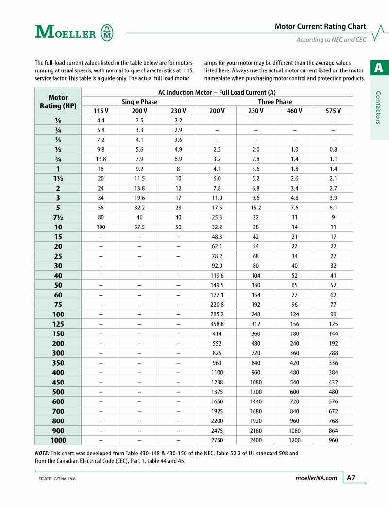
115 V 200 V 230 V 200 V 230 V 460 V 575 V1∕6 4.4 2.5 2.2 – – – –
¼ 5.8 3.3 2.9 – – – –
1∕3 7.2 4.1 3.6 – – – –
½ 9.8 5.6 4.9 2.3 2.0 1.0 0.8
¾ 13.8 7.9 6.9 3.2 2.8 1.4 1.1
1 16 9.2 8 4.1 3.6 1.8 1.4
1½ 20 11.5 10 6.0 5.2 2.6 2.1
2 24 13.8 12 7.8 6.8 3.4 2.7
3 34 19.6 17 11.0 9.6 4.8 3.9
5 56 32.2 28 17.5 15.2 7.6 6.1
7½ 80 46 40 25.3 22 11 9
10 100 57.5 50 32.2 28 14 11
15 – – – 48.3 42 21 17
20 – – – 62.1 54 27 22
25 – – – 78.2 68 34 27
30 – – – 92.0 80 40 32
40 – – – 119.6 104 52 41
50 – – – 149.5 130 65 52
60 – – – 177.1 154 77 62
75 – – – 220.8 192 96 77
100 – – – 285.2 248 124 99
125 – – – 358.8 312 156 125
150 – – – 414 360 180 144
200 – – – 552 480 240 192
300 – – – 825 720 360 288
350 – – – 963 840 420 336
400 – – – 1100 960 480 384
450 – – – 1238 1080 540 432
500 – – – 1375 1200 600 480
600 – – – 1650 1440 720 576
700 – – – 1925 1680 840 672
800 – – – 2200 1920 960 768
900 – – – 2475 2160 1080 864
1000 – – – 2750 2400 1200 960
NOTE: This chart was developed from Table 430-148 & 430-150 of the NEC, Table 52.2 of UL standard 508 and from the Canadian Electrical Code (CEC), Part 1, table 44 and 45.
The full-load current values listed in the table below are for motors running at usual speeds, with normal torque characteristics at 1.15 service factor. This table is a guide only. The actual full load motor
amps for your motor may be different than the average values listed here. Always use the actual motor current listed on the motor nameplate when purchasing motor control and protection products.
Motor Current Rating Chart
According to NEC and CEC

A
Co
nta
cto
rs
A8 moellerNA.com STARTER-CAT-NA-0708
Contactors
Notes
A
Co
ntacto
rs
STARTER-CAT-NA-0708 moellerNA.com A9
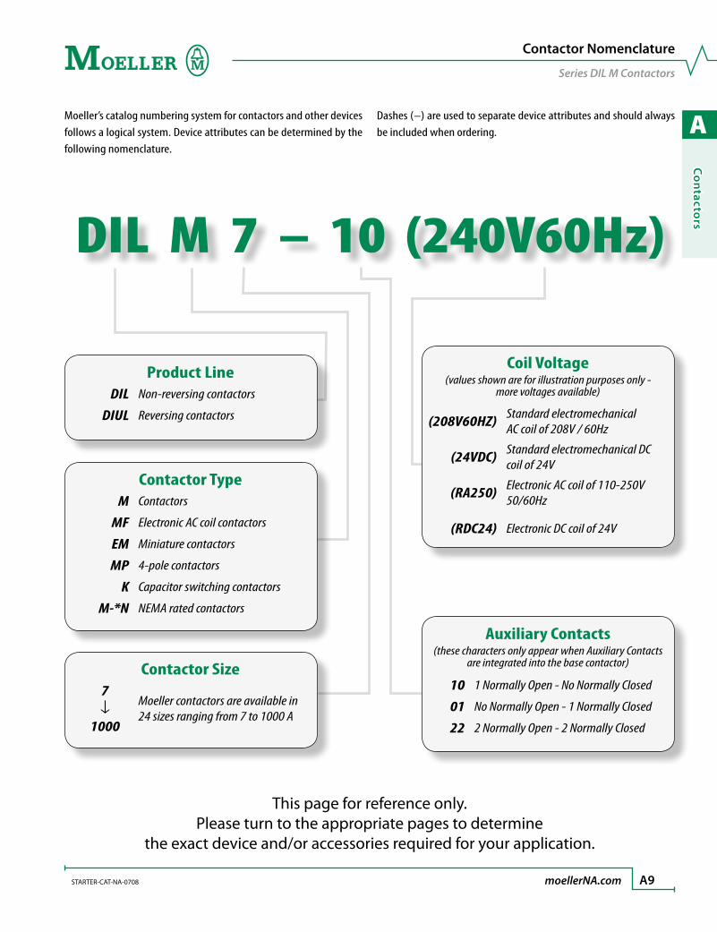
DIL M 7 – 10 (240V60Hz)
Moeller’s catalog numbering system for contactors and other devices follows a logical system. Device attributes can be determined by the following nomenclature.
Dashes (–) are used to separate device attributes and should always be included when ordering.
Contactor Nomenclature
Series DIL M Contactors
This page for reference only.Please turn to the appropriate pages to determine
the exact device and/or accessories required for your application.
Product LineDIL Non-reversing contactors
DIUL Reversing contactors
Contactor Size7↓
1000
Moeller contactors are available in 24 sizes ranging from 7 to 1000 A
Contactor TypeM Contactors
MF Electronic AC coil contactors
EM Miniature contactors
MP 4-pole contactors
K Capacitor switching contactors
M-*N NEMA rated contactors
Coil Voltage(values shown are for illustration purposes only -
more voltages available)
(208V60HZ) Standard electromechanical AC coil of 208V / 60Hz
(24VDC) Standard electromechanical DC coil of 24V
(RA250) Electronic AC coil of 110-250V 50/60Hz
(RDC24) Electronic DC coil of 24V
Auxiliary Contacts(these characters only appear when Auxiliary Contacts
are integrated into the base contactor)
10 1 Normally Open - No Normally Closed
01 No Normally Open - 1 Normally Closed
22 2 Normally Open - 2 Normally Closed
A
Co
nta
cto
rs
A10 moellerNA.com STARTER-CAT-NA-0708 Discount Code A11
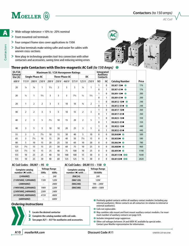
Three-pole Contactors with Electro-magnetic AC Coil (to 150 Amps) ➊UL/CSA General Use [A]
Maximum UL / CSA Horsepower Ratings Integrated Auxiliary Contacts
Catalog Number Price
Single Phase AC Three Phase AC DC
600 V 115 V 200 V 230 V 200 V 230 V 460 V 575 V 125 V 250 V NO NC
20 ¼ ¾ 1 1½ 2 3 5 ¼ 11 0 DILM7-10 ➋ 176
0 1 DILM7-01 ➋ 176
20 ½ 1 1½ 3 3 5 7½ ½ 1½1 0 DILM9-10 ➋ 200
0 1 DILM9-01 ➋ 200
20 1 2 2 3 3 10 10 ¾ 21 0 DILM12-10 ➋ 248
0 1 DILM12-01 ➋ 248
40 2 2 3 5 5 10 15 2 31 0 DILM17-10 260
0 1 DILM17-01 260
40 2 3 5 7½ 10 15 20 2 51 0 DILM25-10 350
0 1 DILM25-01 350
40 3 5 5 10 10 20 25 3 51 0 DILM32-10 440
0 1 DILM32-01 440
55 3 5 7½ 10 15 30 40 5 10 0 0 DILM40 ➌ 500
65 3 7½ 10 15 20 40 50 7½ 15 0 0 DILM50 ➌ 580
80 5 10 15 20 25 50 60 10 20 0 0 DILM65 ➌ 780
125 7½ 15 15 25 30 60 75 10 25 0 0 DILM80 ➌ 960
125 7½ 15 15 25 40 75 100 10 25 0 0 DILM95 ➌ 1190
155 10 25 25 40 50 100 100 15 30 0 0 DILM115 ➌➍ 1640
155 10 25 30 40 60 125 125 15 30 0 0 DILM150 ➌➍ 2020
➊ Positively guided contacts within all auxiliary contact modules (including any internal auxiliaries). Mirror contacts on all contactors (in relation to internal or external auxiliaries).
➋ Coils not replaceable.➌ May combine side mount and front mount auxiliary contact modules. For maxi-
mum number of auxiliary contacts see page A24.➍ Includes integrated surge suppressor.➎ Other coil voltages between 24 and 600V AC available by special order.
Contact your Moeller representative for information.
AC Coil Codes - DILM7 – 95 ➎
Complete catalog number () with…
Voltage Range
50Hz 60Hz
(24V60HZ) – 24V
(110V50HZ,120V60HZ) 110V 120V
(208V60HZ) – 208V
(190V50HZ,220V60HZ) 190V 220V
(230V50HZ,240V60HZ) 230V 240V
(415V50HZ,480V60HZ) 415V 480V
(600V60HZ) – 600V
AC Coil Codes - DILM115 – 150 ➍
Complete catalog number () with…
Voltage Range
50/60Hz
(RAC24) 24V
(RAC120) 120V
(RAC240) 190 – 240V
(RAC500) 480V – 500V
Contactors (to 150 amps)
AC Coil
> Wide voltage tolerance +10% to -20% nominal
> Front mounted coil terminals
> Four compact frame sizes cover applications to 150A
> Dual box terminals make wiring safer and easier for cables with uneven cross-sections
> New plug-in technology provides tool-less connection with other contactors and accessories, saving time and reducing wiring errors
Ordering Instructions
1 Locate the desired contactor
2 Complete the catalog number with coil code.
3 See pages A21 – A37 for auxiliaries and accessories.
AC operated
AC
A
Co
ntacto
rs
STARTER-CAT-NA-0708 moellerNA.com A11 Discount Code A16
Contactors (to 150 amps)
Electronic Actuation with AC Coil
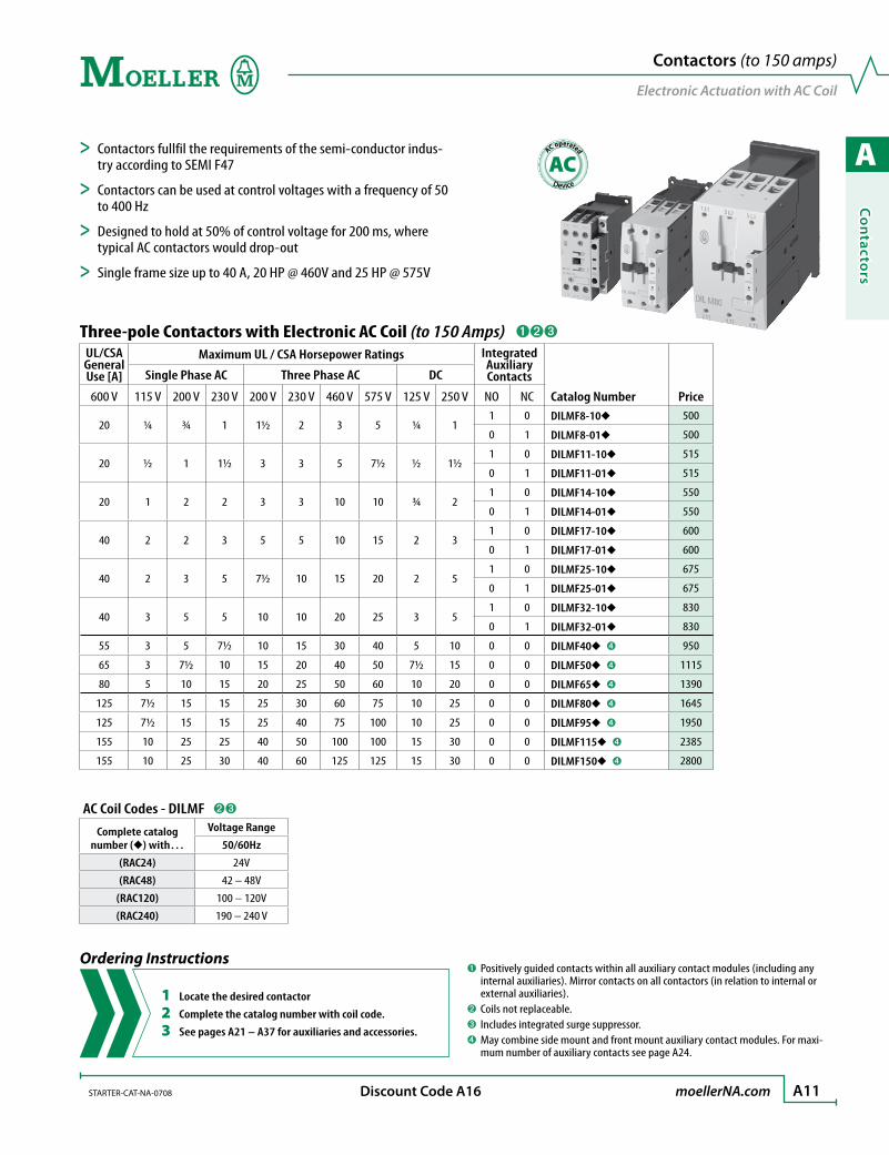
Three-pole Contactors with Electronic AC Coil (to 150 Amps) ➊➋➌UL/CSA General Use [A]
Maximum UL / CSA Horsepower Ratings Integrated Auxiliary Contacts
Catalog Number Price
Single Phase AC Three Phase AC DC
600 V 115 V 200 V 230 V 200 V 230 V 460 V 575 V 125 V 250 V NO NC
20 ¼ ¾ 1 1½ 2 3 5 ¼ 11 0 DILMF8-10 500
0 1 DILMF8-01 500
20 ½ 1 1½ 3 3 5 7½ ½ 1½1 0 DILMF11-10 515
0 1 DILMF11-01 515
20 1 2 2 3 3 10 10 ¾ 21 0 DILMF14-10 550
0 1 DILMF14-01 550
40 2 2 3 5 5 10 15 2 31 0 DILMF17-10 600
0 1 DILMF17-01 600
40 2 3 5 7½ 10 15 20 2 51 0 DILMF25-10 675
0 1 DILMF25-01 675
40 3 5 5 10 10 20 25 3 51 0 DILMF32-10 830
0 1 DILMF32-01 830
55 3 5 7½ 10 15 30 40 5 10 0 0 DILMF40 ➍ 950
65 3 7½ 10 15 20 40 50 7½ 15 0 0 DILMF50 ➍ 1115
80 5 10 15 20 25 50 60 10 20 0 0 DILMF65 ➍ 1390
125 7½ 15 15 25 30 60 75 10 25 0 0 DILMF80 ➍ 1645
125 7½ 15 15 25 40 75 100 10 25 0 0 DILMF95 ➍ 1950
155 10 25 25 40 50 100 100 15 30 0 0 DILMF115 ➍ 2385
155 10 25 30 40 60 125 125 15 30 0 0 DILMF150 ➍ 2800
➊ Positively guided contacts within all auxiliary contact modules (including any internal auxiliaries). Mirror contacts on all contactors (in relation to internal or external auxiliaries).
➋ Coils not replaceable.➌ Includes integrated surge suppressor.➍ May combine side mount and front mount auxiliary contact modules. For maxi-
mum number of auxiliary contacts see page A24.
> Contactors fullfil the requirements of the semi-conductor indus-try according to SEMI F47
> Contactors can be used at control voltages with a frequency of 50 to 400 Hz
> Designed to hold at 50% of control voltage for 200 ms, where typical AC contactors would drop-out
> Single frame size up to 40 A, 20 HP @ 460V and 25 HP @ 575V
AC Coil Codes - DILMF ➋➌
Complete catalog number () with…
Voltage Range
50/60Hz
(RAC24) 24V
(RAC48) 42 – 48V
(RAC120) 100 – 120V
(RAC240) 190 – 240 V
Ordering Instructions
1 Locate the desired contactor
2 Complete the catalog number with coil code.
3 See pages A21 – A37 for auxiliaries and accessories.
AC operated
AC
A
Co
nta
cto
rs
A12 moellerNA.com STARTER-CAT-NA-0708 Discount Code A11
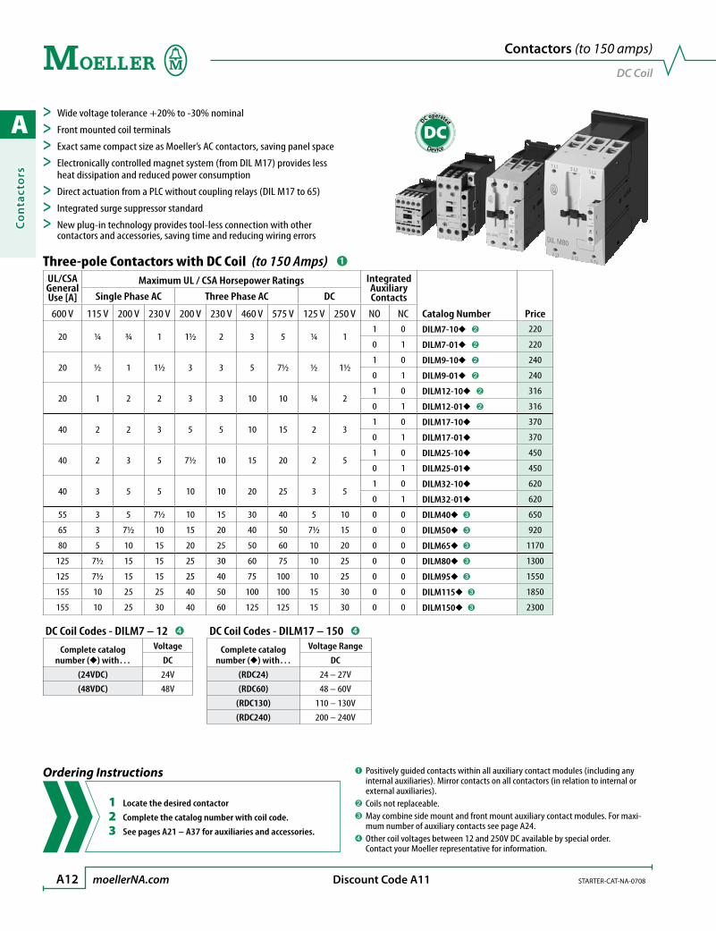
DC Coil Codes - DILM7 – 12 ➍
Complete catalog number () with…
Voltage
DC
(24VDC) 24V
(48VDC) 48V
DC Coil Codes - DILM17 – 150 ➍
Complete catalog number () with…
Voltage Range
DC
(RDC24) 24 – 27V
(RDC60) 48 – 60V
(RDC130) 110 – 130V
(RDC240) 200 – 240V
Three-pole Contactors with DC Coil (to 150 Amps) ➊UL/CSA General Use [A]
Maximum UL / CSA Horsepower Ratings Integrated Auxiliary Contacts
Catalog Number Price
Single Phase AC Three Phase AC DC
600 V 115 V 200 V 230 V 200 V 230 V 460 V 575 V 125 V 250 V NO NC
20 ¼ ¾ 1 1½ 2 3 5 ¼ 11 0 DILM7-10 ➋ 220
0 1 DILM7-01 ➋ 220
20 ½ 1 1½ 3 3 5 7½ ½ 1½1 0 DILM9-10 ➋ 240
0 1 DILM9-01 ➋ 240
20 1 2 2 3 3 10 10 ¾ 21 0 DILM12-10 ➋ 316
0 1 DILM12-01 ➋ 316
40 2 2 3 5 5 10 15 2 31 0 DILM17-10 370
0 1 DILM17-01 370
40 2 3 5 7½ 10 15 20 2 51 0 DILM25-10 450
0 1 DILM25-01 450
40 3 5 5 10 10 20 25 3 51 0 DILM32-10 620
0 1 DILM32-01 620
55 3 5 7½ 10 15 30 40 5 10 0 0 DILM40 ➌ 650
65 3 7½ 10 15 20 40 50 7½ 15 0 0 DILM50 ➌ 920
80 5 10 15 20 25 50 60 10 20 0 0 DILM65 ➌ 1170
125 7½ 15 15 25 30 60 75 10 25 0 0 DILM80 ➌ 1300
125 7½ 15 15 25 40 75 100 10 25 0 0 DILM95 ➌ 1550
155 10 25 25 40 50 100 100 15 30 0 0 DILM115 ➌ 1850
155 10 25 30 40 60 125 125 15 30 0 0 DILM150 ➌ 2300
➊ Positively guided contacts within all auxiliary contact modules (including any internal auxiliaries). Mirror contacts on all contactors (in relation to internal or external auxiliaries).
➋ Coils not replaceable.➌ May combine side mount and front mount auxiliary contact modules. For maxi-
mum number of auxiliary contacts see page A24.➍ Other coil voltages between 12 and 250V DC available by special order.
Contact your Moeller representative for information.
Contactors (to 150 amps)
DC Coil
> Wide voltage tolerance +20% to -30% nominal
> Front mounted coil terminals
> Exact same compact size as Moeller’s AC contactors, saving panel space
> Electronically controlled magnet system (from DIL M17) provides less heat dissipation and reduced power consumption
> Direct actuation from a PLC without coupling relays (DIL M17 to 65)
> Integrated surge suppressor standard
> New plug-in technology provides tool-less connection with other contactors and accessories, saving time and reducing wiring errors
Ordering Instructions
1 Locate the desired contactor
2 Complete the catalog number with coil code.
3 See pages A21 – A37 for auxiliaries and accessories.
DC operated
DC

A
Co
ntacto
rs
STARTER-CAT-NA-0708 moellerNA.com A13 Discount Code A12
Three-pole Contactors with AC or DC Electronic Coil (185 to 1000 Amps) ➊➋
UL/CSAGeneral Use
[A]
Maximum UL / CSA Horsepower Ratings
IntegratedAuxiliaryContacts
Catalog Number Price
Three Phase
Open Enclosed 200 V 230 V 460 V 575 V NO NC225 202 50 60 125 150 2 2 DILM185/22 3600
250 225 60 75 150 200 2 2 DILM225/22 4400
350 315 75 100 200 250 2 2 DILM250/22 5600
350 315 100 125 250 300 2 2 DILM300/22 6200
450 405 125 150 300 400 2 2 DILM400/22 7800
550 495 150 200 400 500 2 2 DILM500/22 11600
630 567 200 200 400 600 2 2 DILM580/22 ➍ 14800
700 630 200 250 500 600 2 2 DILM650/22 ➍ 15800
800 720 250 300 600 700 2 2 DILM750/22 ➍ 18200
850 765 290 350 700 860 2 2 DILM820/22 ➍ 20200
1000 900 – 400 800 1000 2 2 DILM1000/22 ➍ 23400
➊ May combine side mount and front mount auxiliary contact modules. For maxi-mum number of auxiliary contacts see page A24.
➋ Order lugs separately - see page A34➌ Standstill in an emergency (emergency stop).➍ When operating with frequency inverters or when performing a high-voltage test,
the suppressor on the load side must be removed.➎ Wide range electronic coils; all AC coils operate between 40Hz and 60Hz.
Electronic Coil - Application Notes Conventional coil connectionA1/A2 are applied to voltage in the usual manner.
Direct from the PLCA 24 V output from the PLC can be connected directly to connections A3/A4.
From low-consumption command devicesCommand devices that can only be subject to minimal loads such as circuit board relays, control circuit devices or position switches can be connected directly to A10/A11.
A10
A11
A2
A1
A3
A4
(+) L1 (–) N
A10
A11
A2
A1
A3
A4
24 V GND
(+) L1 (–) N
A10
A11
A2
A1
A3
A4
(+) L1 (–) N
➌
➌
➌
Contactors (185 to 1000 amps)
Electronic Actuation with AC & DC Coil
> Wide voltage tolerance +15% to -30% nominal
> Heavy duty contactors for demanding applications
> Electronically controlled magnet systems dramatically reduce pick-up and seal-in, DIL M500 and smaller are air-break contactors
> DIL M580 and larger are vacuum contactors, which increase lifespan and are extremely compact in size
> Direct connection to PLCs and low level input devices
> Built-in suppressor circuit for control protection standard
> High operational current
> Rated to 1000 V AC
Ordering Instructions
1 Locate the desired contactor
2 Complete the catalog number with coil code.
3 See pages A21 – A37 for auxiliaries and accessories.
4 See page A34 for terminal lug selection.
AC & DC Coil Codes ➎
Complete catalog number () with… Voltage
(RDC48) 24 – 48V DC(only for DILM185 – 500)
(RA110) 48 – 110V AC48 – 110V DC
(RA250) 110 – 250V AC110 – 250V DC
(RAC500) 250 – 500V AC
DC operated
DC
AC operated
AC

A
Co
nta
cto
rs
A14 moellerNA.com STARTER-CAT-NA-0708 Discount Code A11
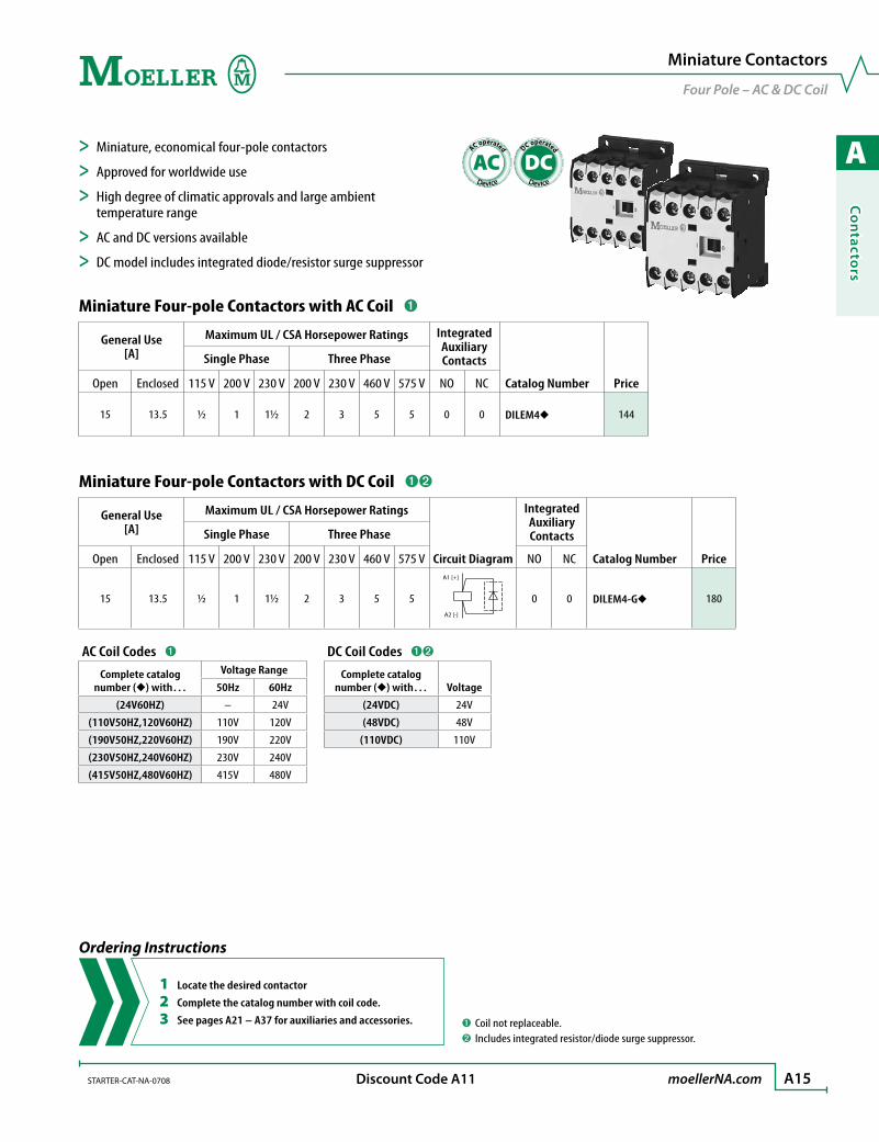
> Miniature, economical contactors for small motors and loads
> Approved for worldwide use
> High degree of climatic approvals and large ambient temperature range
> DC model includes integrated diode/resistor surge suppressor
Miniature Three-pole Contactors with AC Coil ➊
General Use[A]
Maximum UL / CSA Horsepower Ratings IntegratedAuxiliary Contacts
Catalog Number Price
Single Phase Three Phase
Open Enclosed 115 V 200 V 230 V 200 V 230 V 460 V 575 V NO NC
15 13.5 ½ 1 1½ 2 3 5 5 1 0 DILEM-10 144
15 13.5 ½ 1 1½ 2 3 5 5 0 1 DILEM-01 144
Miniature Three-pole Contactors with DC Coil ➊➋
General Use[A]
Maximum UL / CSA Horsepower Ratings
Circuit Diagram
IntegratedAuxiliary Contacts
Catalog Number Price
Single Phase Three Phase
Open Enclosed 115 V 200 V 230 V 200 V 230 V 460 V 575 V NO NC
15 13.5 ½ 1 1½ 2 3 5 5
A1
A1 [+]
A2 [-]
1 0 DILEM-10-G 180
15 13.5 ½ 1 1½ 2 3 5 5 0 1 DILEM-01-G 180
➊ Coil not replaceable.➋ Includes integrated resistor/diode surge suppressor.
Miniature Contactors
Three Pole – AC & DC Coil
Ordering Instructions
1 Locate the desired contactor
2 Complete the catalog number with coil code.
3 See pages A21 – A37 for auxiliaries and accessories.
AC Coil Codes ➊
Complete catalog number () with…
Voltage Range
50Hz 60Hz
(24V60HZ) – 24V
(110V50HZ,120V60HZ) 110V 120V
(208V60HZ) – 208V
(190V50HZ,220V60HZ) 190V 220V
(230V50HZ,240V60HZ) 230V 240V
(415V50HZ,480V60HZ) 415V 480V
(600V60HZ) – 600V
DC Coil Codes ➊➋
Complete catalog number () with… Voltage
(24VDC) 24V
(48VDC) 48V
(110VDC) 110V
DC operated
DC
AC operated
AC
A
Co
ntacto
rs
STARTER-CAT-NA-0708 moellerNA.com A15 Discount Code A11
> Miniature, economical four-pole contactors
> Approved for worldwide use
> High degree of climatic approvals and large ambient temperature range
> AC and DC versions available
> DC model includes integrated diode/resistor surge suppressor
Miniature Four-pole Contactors with AC Coil ➊
General Use[A]
Maximum UL / CSA Horsepower Ratings IntegratedAuxiliary Contacts
Catalog Number Price
Single Phase Three Phase
Open Enclosed 115 V 200 V 230 V 200 V 230 V 460 V 575 V NO NC
15 13.5 ½ 1 1½ 2 3 5 5 0 0 DILEM4 144
Miniature Four-pole Contactors with DC Coil ➊➋
General Use[A]
Maximum UL / CSA Horsepower Ratings
Circuit Diagram
IntegratedAuxiliary Contacts
Catalog Number Price
Single Phase Three Phase
Open Enclosed 115 V 200 V 230 V 200 V 230 V 460 V 575 V NO NC
15 13.5 ½ 1 1½ 2 3 5 5
A1
A1 [+]
A2 [-]
0 0 DILEM4-G 180
➊ Coil not replaceable.➋ Includes integrated resistor/diode surge suppressor.
Miniature Contactors
Four Pole – AC & DC Coil
Ordering Instructions
1 Locate the desired contactor
2 Complete the catalog number with coil code.
3 See pages A21 – A37 for auxiliaries and accessories.
AC Coil Codes ➊
Complete catalog number () with…
Voltage Range
50Hz 60Hz
(24V60HZ) – 24V
(110V50HZ,120V60HZ) 110V 120V
(190V50HZ,220V60HZ) 190V 220V
(230V50HZ,240V60HZ) 230V 240V
(415V50HZ,480V60HZ) 415V 480V
DC Coil Codes ➊➋
Complete catalog number () with… Voltage
(24VDC) 24V
(48VDC) 48V
(110VDC) 110V
DC operated
DC
AC operated
AC
A
Co
nta
cto
rs
A16 moellerNA.com STARTER-CAT-NA-0708 Discount Code A16
DC Coil Codes - DILMP20 ➊➋
Complete catalog number () with… Voltage
(24VDC) 24V
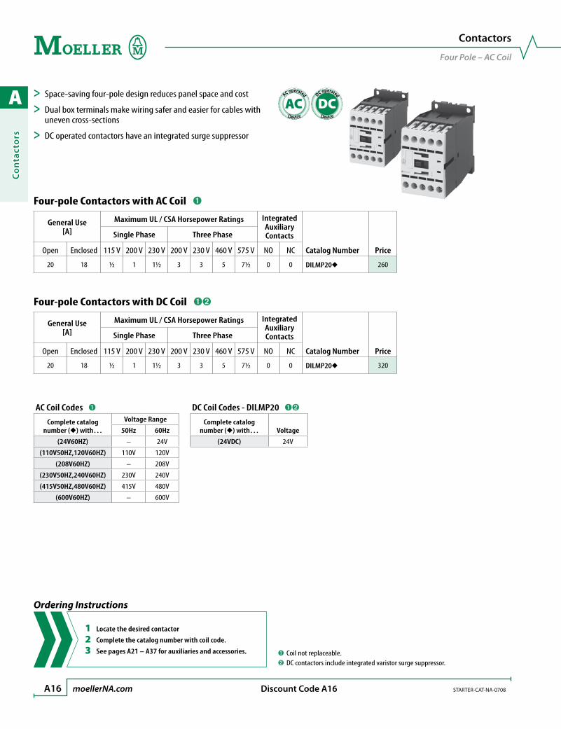
Four-pole Contactors with AC Coil ➊
General Use[A]
Maximum UL / CSA Horsepower Ratings IntegratedAuxiliary Contacts
Catalog Number Price
Single Phase Three Phase
Open Enclosed 115 V 200 V 230 V 200 V 230 V 460 V 575 V NO NC
20 18 ½ 1 1½ 3 3 5 7½ 0 0 DILMP20 260
Four-pole Contactors with DC Coil ➊➋
General Use[A]
Maximum UL / CSA Horsepower Ratings IntegratedAuxiliary Contacts
Catalog Number Price
Single Phase Three Phase
Open Enclosed 115 V 200 V 230 V 200 V 230 V 460 V 575 V NO NC
20 18 ½ 1 1½ 3 3 5 7½ 0 0 DILMP20 320
➊ Coil not replaceable.➋ DC contactors include integrated varistor surge suppressor.
Contactors
Four Pole – AC Coil
> Space-saving four-pole design reduces panel space and cost
> Dual box terminals make wiring safer and easier for cables with uneven cross-sections
> DC operated contactors have an integrated surge suppressor
Ordering Instructions
1 Locate the desired contactor
2 Complete the catalog number with coil code.
3 See pages A21 – A37 for auxiliaries and accessories.
AC Coil Codes ➊
Complete catalog number () with…
Voltage Range
50Hz 60Hz
(24V60HZ) – 24V
(110V50HZ,120V60HZ) 110V 120V
(208V60HZ) – 208V
(230V50HZ,240V60HZ) 230V 240V
(415V50HZ,480V60HZ) 415V 480V
(600V60HZ) – 600V
DC operated
DC
AC operated
AC

A
Co
ntacto
rs
STARTER-CAT-NA-0708 moellerNA.com A17 Discount Code A11
Contactor Combinations
DIUL M Reversing Contactors
Assembled Reversing Contactor Combinations with AC Coils ➊➋➌
General Use [A]
Maximum UL / CSA Horsepower Ratings
StandardAuxiliaryContacts
per contactor
Catalog Number Price
Three Phase
600 V 200 V 230 V 460 V 575 V NO NC
20 1½ 2 3 5 2 1 DIULM7/21 ➌ 730
20 3 3 5 7½ 2 1 DIULM9/21 ➌ 760
20 3 3 10 10 2 1 DIULM12/21 ➌ 800
40 5 5 10 15 2 1 DIULM17/21 ➌ 1000
40 7½ 10 15 20 2 1 DIULM25/21 1150
40 10 10 20 25 2 1 DIULM32/21 1340
55 10 15 30 40 1 1 DIULM40/11 1620
65 15 20 40 50 1 1 DIULM50/11 1720
80 20 25 50 60 1 1 DIULM65/11 1960
➊ Positively guided contacts within all auxiliary contact modules (including any internal auxiliaries). Mirror contacts on all contactors (in relation to internal or external auxiliaries).
➋ Contact elements of the contactor to EN 50012.➌ Coils not replaceable.
> Space-saving design reduces panel space and cost
> Units are pre-assembled with mechanical interlock and reversing wiring kit
> Ingenious mechanical interlocks add no additional space
> Dual box terminals make wiring safer and easier for cables with uneven cross-sections
AC Coil Codes ➌
Complete catalog number () with…
Voltage Range
50Hz 60Hz
(24V60HZ) – 24V
(110V50HZ,120V60HZ) 110V 120V
(208V60HZ) – 208V
(190V50HZ,220V60HZ) 190V 220V
(230V50HZ,240V60HZ) 230V 240V
(415V50HZ,480V60HZ) 415V 480V
(600V60HZ) – 600V
Ordering Instructions
1 Locate the desired contactor
2 Complete the catalog number with coil code.
3 See pages A21 – A37 for auxiliaries and accessories.
AC operated
AC

A
Co
nta
cto
rs
A18 moellerNA.com STARTER-CAT-NA-0708 Discount Code A16
Capacitor Switching Contactor; with Series Resistors ➊
Three-Phase Capacitors
StandardAuxiliaryContacts
Catalog Number Price
50 – 60 Hz
240 Vkvar
480 Vkvar
600 Vkvar NO NC
7.5 15 15 1 1 DILK12-11 325
12 20 30 1 1 DILK20-11 425
15 30 40 1 1 DILK25-11 550
20 40 50 1 0 DILK33-10 775
30 60 75 1 0 DILK50-10 1250
R11 R11
R11
C1
L1 L2 L3
1 3 5
642A2
A1
Circuit Without Quick Discharge Resistor
Application Note
In the case of group compensation, multi-stage capacitor banks are connect-ed to the main supply as required. In the process, transient currents of up to 180 x Ie can flow between the capacitors.
The capacitors are pre-charged via the early-make auxiliary contacts and the fitted wire resistors, thereby reducing the inrush current. The main contacts then close after a time lag and carry the uninterrupted current.
Moeller’s Capacitor Switching Contactors are weld-resistant with inrush current peaks up to 180 x Ie due to their special contact material.
➊ Coils not replaceable.
Special Use Contactors
Capacitor Switching Contactors
> Economical solution for both individual and group power factor correction applications
> Special weld resistant contact material ensures longer life
> All units pre-wired and ready to install
AC Coil Codes ➊
Complete catalog number () with…
Voltage Range
50Hz 60Hz
(24V60HZ) – 24V
(110V50HZ,120V60HZ) 110V 120V
(208V60HZ) – 208V
(190V50HZ,220V60HZ) 190V 220V
(230V50HZ,240V60HZ) 230V 240V
(415V50HZ,480V60HZ) 415V 480V
(600V60Hz) – 600V
Ordering Instructions
1 Locate the desired contactor
2 Complete the catalog number with coil code.
3 See pages A21 – A37 for auxiliaries and accessories.
AC operated
AC

A
Co
ntacto
rs
STARTER-CAT-NA-0708 moellerNA.com A19 Discount Code A11
NEMA/EEMAC Contactors
Size 00 to Size 7
3-Pole NEMA/EEMAC Rated Contactors with Electro-magnetic AC Coil (to 810 Amps) ➊
NEMA/EEMAC Size
Continuous Current Rating [A]
Maximum UL / CSA Horsepower Ratings IntegratedAuxiliary Contacts
Catalog Number Price
Single Phase Three Phase
Open Enclosed 115 V 230 V 200 V 230 V 460 V 575 V NO NC
00 – 9 1∕3 1 1½ 1½ 2 2 1 0 DILM00N-10 ➋ 200
0 – 18 1 2 3 3 5 5 1 0 DILM0N-10 ➋ 248
1 32 27 2 3 7½ 7½ 10 10 1 0 DILM1N-10 350
2 52 45 3 7½ 10 15 25 25 0 0 DILM2N ➌ 500
3 104 90 7½ 15 25 30 50 50 0 0 DILM3N ➌ 960
4 156 135 – – 40 50 100 100 0 0 DILM4N ➌ 1640
5 311 270 – – 75 100 200 200 0 0 DILM5N ➌ 5600
6 – 540 – – 150 200 400 400 0 0 DILM6N ➌ 11600
7 – 810 – – – 300 600 600 0 0 DILM7N ➌➍ 18200
UL/CSA approval pending. Contact your Moeller representative for availability.
➊ Positively guided contacts within all auxiliary contact modules (including any internal auxiliaries). Mirror contacts on all contactors (in relation to internal or external auxiliaries).
➋ Coils not replaceable.➌ May combine side mount and front mount auxiliary contact modules. For maxi-
mum number of auxiliary contacts see page A24.➍ When operating with frequency inverters or when performing a high-voltage test,
the suppressor on the load side must be removed.➎ Other coil voltages between 24 and 600V AC available by special order.
Contact your Moeller representative for information.
> Wide voltage tolerance +10% to -20% nominal
> Front mounted coil terminals
> Seven compact frame sizes cover applications to 810A
> Dual box terminals make wiring safer and easier for cables with uneven cross-sections
> New plug-in technology provides tool-less connection with other contactors and accessories, saving time and reducing wiring errors
Ordering Instructions
1 Locate the desired contactor
2 Complete the catalog number with coil code.
3 See pages A21 – A37 for auxiliaries and accessories.
AC Coil Codes - DILM00N – 3N ➎
Complete catalog number () with…
Voltage Range
50Hz 60Hz
(24V60HZ) – 24V
(110V50HZ,120V60HZ) 110V 120V
(208V60HZ) – 208V
(190V50HZ,220V60HZ) 190V 220V
(230V50HZ,240V60HZ) 230V 240V
(415V50HZ,480V60HZ) 415V 480V
(600V60HZ) – 600V
AC Coil Codes - DILM4N
Complete catalog number () with…
Voltage Range
50/60Hz
(RAC24) 24V
(RAC120) 120V
(RAC240) 190 – 240 V
(RAC500) 480V – 500V
AC Coil Codes - DILM5N – 7N
Complete catalog number () with…
Voltage Range
40 – 60Hz
(RA110) 48 – 110V AC
(RA250) 110 – 250V AC
(RAC500) 250 – 500V AC
AC operated
AC

A
Co
nta
cto
rs
A20 moellerNA.com STARTER-CAT-NA-0708
DILM32 – X HI V 11 – SI
Moeller’s catalog numbering system for most Accessories follows a logical system. Device attributes can be determined by the following nomenclature.
Dashes (–) are used to separate device attributes and should always be included when ordering.
Accessories
DIL M Contactors
This page for reference only.Please turn to the appropriate pages to determine
the exact device and/or accessories required for your application.
Code for Accessories
X Signifies that the remaining characters in the part number describe an Accessory
Accessory TypeX Auxiliary contacts
MV Mechanical interlocking
SP Replacement coils
Auxiliary Contact Mounting PositionSI Side mounting - inside
SA Side mounting - outside
Type of Basic Unit
DILM32↓
DILM1000
Refers to the frame size of the device on which the Accessory is used. The numeric value (“32”) is the largest device on which the Accessory will fit.
Characteristic of Auxiliary ContactsV 1 Early Make - 1 Late Break Contact
Auxiliary Contacts10 1 Normally Open - No Normally Closed
20 2 Normally Open - No Normally Closed
31 3 Normally Open - 1 Normally Closed
40 4 Normally Open - No Normally Closed
01 No Normally Open - 1 Normally Closed
02 No Normally Open - 2 Normally Closed
13 1 Normally Open - 3 Normally Closed
04 No Normally Open - 4 Normally Closed
22 2 Normally Open - 2 Normally Closed

A
Co
ntacto
rs
STARTER-CAT-NA-0708 moellerNA.com A21 Discount Code A11
Auxiliary Contact Modules (for DILEM Miniature Contactors) ➊➋
Auxiliary NO NC Schematic For use with… Catalog Number PriceTop Mount - Standard Terminal Markings
0 221
22
31
32
DILEM-10DILEM-4
02DILEM 40
1 121
22
33
3411DILEM 40
2 221
22
31
32
43
44
53
54
DILEM-10DILEM-4 22DILEM 64
Top Mount - Alternative Terminal Markings
0 251
52
61
62
DILEMDILER
02DILE 40
1 154
53 61
6211DILE 40
2 054
63
64
53
20DILE 40
1EM ➌ 1LB ➌58
57 65
6611DDILE 80
0 451
52
61
62
71
72 82
81
DILEMDILER
04DILE 64
1 353 61 71 81
8272625413DILE 64
2 254
53 61
62
71
72
83
8422DILE 64
3 154
53 61
62
73
74
83
8431DILE 64
4 054
63 73
64 74
53 83
8440DILE 64
1 + 1EM ➌
1 +1LB ➌ 58
57 65
66
71
72
83
8422DDILE 120
➊ DILE Terminal Markings comply with European Standards EN 50005 while DILEM Terminal Markings comply with EN 50005 and EN 50012.
➋ Auxiliary Contact Modules have interlocked opposing contacts (does not apply to early-make or late-break contacts).
➌ EM = Early Make. LB = Late Break.
Accessories
DIL EM Contactors

A
Co
nta
cto
rs
A22 moellerNA.com STARTER-CAT-NA-0708 Discount Code A11
Auxiliary Contact Modules (for DILM7 – DILM32 Contactors) ➊➋➌
Auxiliary NO NC Schematic For use with... Catalog Number PriceTop Mount - Standard Terminal Markings
1 121
22
33
34
DILM7-10 – DILM32-10➍
DILM32-XHI11 52
0 221
22
31
32
DILM32-XHI02 52
2 221
22
31
32
43
44
53
54
DILM32-XHI22 92
Top Mount - Alternative Terminal Markings
2 054
63
64
53
DILM7 – DILM32DILA
DILA-XHI20 52
1 154
53 61
62
DILA-XHI11 52
0 251
52
61
62
DILA-XHI02 52
1EM ➎ 1LB ➎58
57 65
66DILA-XHIV11 100
4 054
63 73
64 74
53 83
84DILA-XHI40 92
3 154
53 61
62
73
74
83
84DILA-XHI31 92
2 254
53 61
62
71
72
83
84DILA-XHI22 92
1 353 61 71 81
82726254
DILA-XHI13 92
0 451
52
61
62
71
72 82
81
DILA-XHI04 92
1 + 1EM ➎
1 +1LB ➎ 58
57 65
66
71
72
83
84DILA-XHIV22 144
➊ DILM-7 – DILM-32 contactors include a built-in one pole auxiliary contact.➋ Positively guided contacts with DILM7 – DILM32 between the integrated auxiliary
contact and auxiliary contact module, as well as within the auxiliary contact modules (except DILA-XHIV11 early make/late break).
➌ Mirror contact with DILM7-01 – DILM32-01, as well as in combination with auxiliary contact modules.
Accessories
DIL M Contactors
➍ The 2 and 4-pole DILM32-XHI… auxiliary contact modules with terminal markings 21/22 cannot be used with DILM…-01 contactors. Use Top Mount DILA-XHI… with Alternative Terminal Markings instead.
➎ EM = Early Make LB = Late Break

A
Co
ntacto
rs
STARTER-CAT-NA-0708 moellerNA.com A23 Discount Code A11
Auxiliary Contact Modules (for DILM7 – DILM32 Contactors) ➊➋➌
Auxiliary NO NC Schematic For use with… Catalog Number PriceSide Mount - Alternative Terminal Markings
1 154
53 61
62
DILM17 – DILM32 ➍➎
DILM32-XHI11-S 100
Top Mount Electronic Compatible Auxiliary
1 154
53 61
62
DILM17 – DILM32DILMP20 – DILMP45
10 mA @ 24V DC
DILA-XHIR11 335
Top Mount - High Version for MSC Starter Applications
2 054
63
64
53
DILM7 – DILM12 contactors when using the PKZM0-XDM12 Quick Connector or DILM12-XRL Reversing Kit.
DILA-XHIT20 54
1 154
53 61
62
DILA-XHIT11 54
0 251
52
61
62
DILA-XHIT02 54
2 254
53 61
62
71
72
83
84
DILA-XHIT22 96
Application Note:Top Mount-High Version auxiliary contact blocks are intended for use when combining DILM7 – 12 contactors with Moeller’s PKZM0 self-protected starter. These contactors are designed to accept a “tool-less” plug connection (PKZM0-XDM12) that physically connects the two devices. The high profile of the auxiliary contact blocks allows access to the terminals after the plug connector is in place.
➊ DILM7 – DILM32 contactors include a built-in one pole auxiliary contact.➋ Positively guided contacts with DILM7 – DILM32 between the integrated auxiliary
contact and auxiliary contact module, as well as within the auxiliary contact modules (except DILA-XHIV11 early make/late break).
➌ Mirror contact with DILM7-01 – DILM32-01, as well as in combination with auxiliary contact modules.
4
1
2
3
1 PKZM0
2 DILM7 - DILM12
3 DILA-XHIT
4 PKZM0-XDM12
Accessories
DIL M Contactors
➍ Snaps on to left side of contactor only. Cannot be combined with top-mount auxiliary contacts or mechanical interlocks.
➎ Designed for use with contactors manufactured after date code of “4405” (4405 = week 44 of year 2005).

A
Co
nta
cto
rs
A24 moellerNA.com STARTER-CAT-NA-0708
Accessory Guide
Auxiliary Contact Options for DILM40 – 1000 Contactors
➊ Can only be mounted to Type …-SI contact module; Will not fit directly on contactor.
Accessory Guide Maximum possible combinations of accessories
Maximum possible combinations of auxiliary contacts when using the
following contactors
Standard Side-Mount Auxiliary Contacts
(see page A25)
Alt. Markings Side-Mount Aux. Contacts
(see page A25)
Standard 2-pole Top-Mount Auxiliary Contacts
(see page A25)
Standard 4-pole Top-Mount Auxiliary Contacts
(see page A25)
Alt. Markings 2-pole Top-Mount Aux. Contacts
(see page A25)
Alt. Markings 4-pole Top-Mount Aux. Contacts
(see page A25)
DILM1000-XHI(V)11-SI DILM1000-XHI(V)11-SA DILM150-XHI(20)(11)(02)
DILM150-XHI(40)(04)DILM150-XHI(31)(13)
DILM150-XHI(V)22 DILM150-XHIA11 DILM150-XHIA22
Contactor Frame Size DILM40 – 65
DILM40 – 65(see page A10)
Option #1 2x 1x
Option #2 2x 1x
Option #3 1x 1x
Option #4 1x 1xContactor Frame Size DILM80 – 150
DILM80 – 150(see page A10)
Option #1 2x 2xOption #2 2x 1xOption #3 2x 1xOption #4 2x 1xOption #5 2x 1x
Large Contactor Frame Size DILM185 – 1000
DILM185 – 1000(see page A13)
Option #1 2x 2x ➊
Use this guide to determine which auxiliary contacts will fit on the devices listed below. Order the desired auxiliary contacts on the following page.
DILM1000-XHI…
DILM40 –DILM65
+ +
DILM1000-XHI…-SI
DILM1000-XHI…-SA
DILM80 –DILM1000
+ + ++
A
Co
ntacto
rs
STARTER-CAT-NA-0708 moellerNA.com A25 Discount Code A11
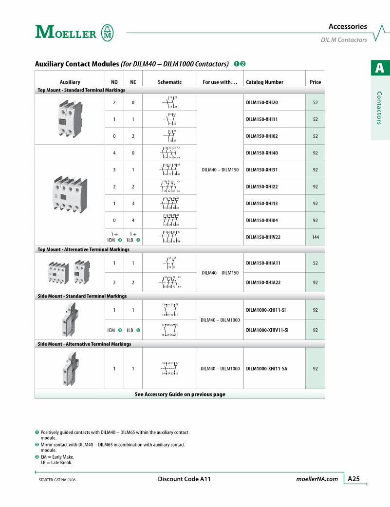
Auxiliary Contact Modules (for DILM40 – DILM1000 Contactors) ➊➋
Auxiliary NO NC Schematic For use with… Catalog Number PriceTop Mount - Standard Terminal Markings
2 014 24
13 23
DILM40 – DILM150
DILM150-XHI20 52
1 114
13 21
22DILM150-XHI11 52
0 212
11 21
22DILM150-XHI02 52
4 014
13 23
24
33
34
43
44
DILM150-XHI40 92
3 114
13 21
22
33
34
43
44
DILM150-XHI31 92
2 214
13 21
22
31
32
43
44
DILM150-XHI22 92
1 314
13 21
22
31
32
41
42
DILM150-XHI13 92
0 412
11 21
22
31
32
41
42
DILM150-XHI04 92
1 + 1EM ➌
1 +1LB ➌ 14
13 21
22
35
36
47
48DILM150-XHIV22 144
Top Mount - Alternative Terminal Markings
1 154
53 61
62
DILM40 – DILM150
DILM150-XHIA11 52
2 254
53 61
62
71
72
83
84DILM150-XHIA22 92
Side Mount - Standard Terminal Markings
1 113
44
14
43
21
32
31
22
DILM40 – DILM1000
DILM1000-XHI11-SI 92
1EM ➌ 1LB ➌17
48
18
47
25
36
26
35
DILM1000-XHIV11-SI 92
Side Mount - Alternative Terminal Markings
1 153
84
54 62
61
72
7183
DILM40 – DILM1000 DILM1000-XHI11-SA 92
See Accessory Guide on previous page
➊ Positively guided contacts with DILM40 – DILM65 within the auxiliary contact module.
➋ Mirror contact with DILM40 – DILM65 in combination with auxiliary contact module.
➌ EM = Early Make. LB = Late Break.
Accessories
DIL M Contactors
A
Co
nta
cto
rs
A26 moellerNA.com STARTER-CAT-NA-0708 Discount Code A11
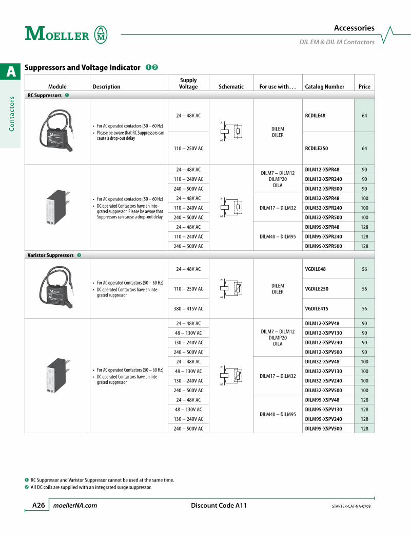
Suppressors and Voltage Indicator ➊➋
Module DescriptionSupplyVoltage Schematic For use with… Catalog Number Price
RC Suppressors ➊
For AC operated contactors (50 – 60 Hz)•Please be aware that RC Suppressors can •cause a drop-out delay
24 – 48V ACA1
A2
DILEMDILER
RCDILE48 64
110 – 250V AC RCDILE250 64
For AC operated contactors (50 – 60 Hz)•DC operated Contactors have an inte-•grated suppressor. Please be aware that Suppressors can cause a drop-out delay
24 – 48V AC
A1
A2
DILM7 – DILM12DILMP20
DILA
DILM12-XSPR48 90
110 – 240V AC DILM12-XSPR240 90
240 – 500V AC DILM12-XSPR500 90
24 – 48V AC
DILM17 – DILM32
DILM32-XSPR48 100
110 – 240V AC DILM32-XSPR240 100
240 – 500V AC DILM32-XSPR500 100
24 – 48V AC
DILM40 – DILM95
DILM95-XSPR48 128
110 – 240V AC DILM95-XSPR240 128
240 – 500V AC DILM95-XSPR500 128
Varistor Suppressors ➊
For AC operated Contactors (50 – 60 Hz)•DC operated Contactors have an inte-•grated suppressor
24 – 48V AC
A2
A1
DILEMDILER
VGDILE48 56
110 – 250V AC VGDILE250 56
380 – 415V AC VGDILE415 56
For AC operated Contactors (50 – 60 Hz)•DC operated Contactors have an inte-•grated suppressor
24 – 48V AC
A2
A1
DILM7 – DILM12DILMP20
DILA
DILM12-XSPV48 90
48 – 130V AC DILM12-XSPV130 90
130 – 240V AC DILM12-XSPV240 90
240 – 500V AC DILM12-XSPV500 90
24 – 48V AC
DILM17 – DILM32
DILM32-XSPV48 100
48 – 130V AC DILM32-XSPV130 100
130 – 240V AC DILM32-XSPV240 100
240 – 500V AC DILM32-XSPV500 100
24 – 48V AC
DILM40 – DILM95
DILM95-XSPV48 128
48 – 130V AC DILM95-XSPV130 128
130 – 240V AC DILM95-XSPV240 128
240 – 500V AC DILM95-XSPV500 128
➊ RC Suppressor and Varistor Suppressor cannot be used at the same time.➋ All DC coils are supplied with an integrated surge suppressor.
Accessories
DIL EM & DIL M Contactors
A
Co
ntacto
rs
STARTER-CAT-NA-0708 moellerNA.com A27 Discount Code A11
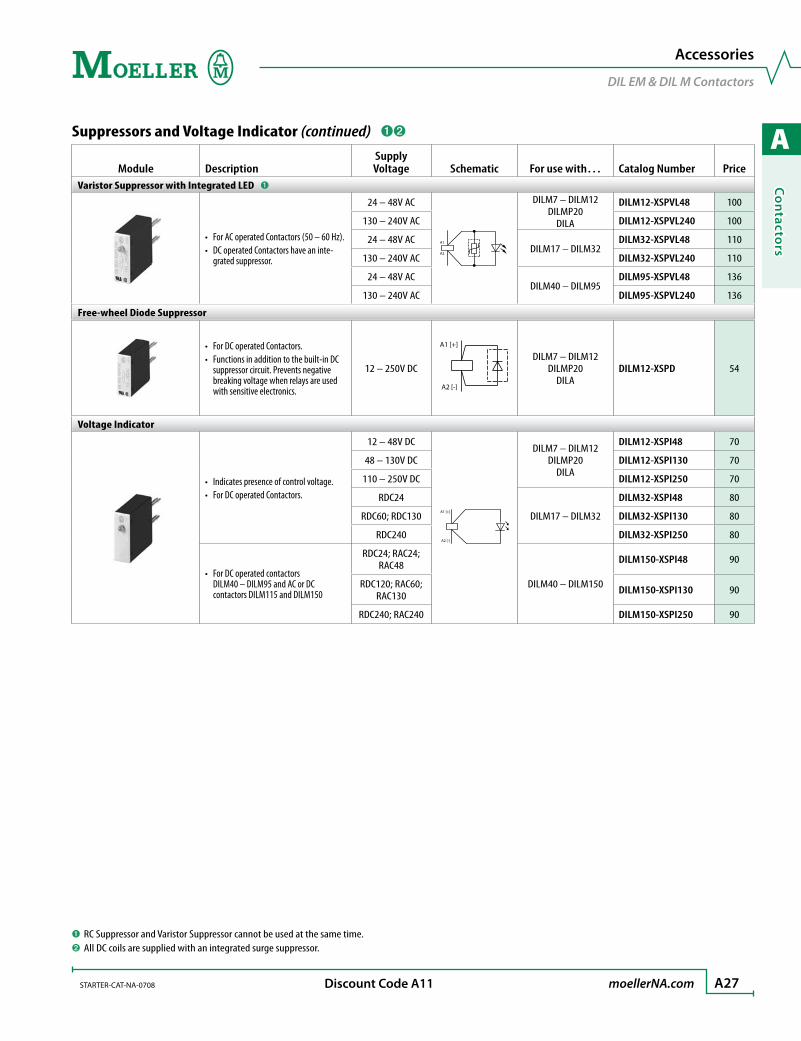
Suppressors and Voltage Indicator (continued) ➊➋
Module DescriptionSupplyVoltage Schematic For use with… Catalog Number Price
Varistor Suppressor with Integrated LED ➊
For AC operated Contactors (50 – 60 Hz).•DC operated Contactors have an inte-•grated suppressor.
24 – 48V AC
A1
A2
DILM7 – DILM12DILMP20
DILA
DILM12-XSPVL48 100
130 – 240V AC DILM12-XSPVL240 100
24 – 48V ACDILM17 – DILM32
DILM32-XSPVL48 110
130 – 240V AC DILM32-XSPVL240 110
24 – 48V ACDILM40 – DILM95
DILM95-XSPVL48 136
130 – 240V AC DILM95-XSPVL240 136
Free-wheel Diode Suppressor
For DC operated Contactors.•Functions in addition to the built-in DC •suppressor circuit. Prevents negative breaking voltage when relays are used with sensitive electronics.
12 – 250V DC
A1
A1 [+]
A2 [-]
DILM7 – DILM12DILMP20
DILADILM12-XSPD 54
Voltage Indicator
Indicates presence of control voltage.•For DC operated Contactors.•
12 – 48V DC
A1 [+]
A2 [-]
DILM7 – DILM12DILMP20
DILA
DILM12-XSPI48 70
48 – 130V DC DILM12-XSPI130 70
110 – 250V DC DILM12-XSPI250 70
RDC24
DILM17 – DILM32
DILM32-XSPI48 80
RDC60; RDC130 DILM32-XSPI130 80
RDC240 DILM32-XSPI250 80
For DC operated contactors •DILM40 – DILM95 and AC or DC contactors DILM115 and DILM150
RDC24; RAC24; RAC48
DILM40 – DILM150
DILM150-XSPI48 90
RDC120; RAC60; RAC130 DILM150-XSPI130 90
RDC240; RAC240 DILM150-XSPI250 90
➊ RC Suppressor and Varistor Suppressor cannot be used at the same time.➋ All DC coils are supplied with an integrated surge suppressor.
Accessories
DIL EM & DIL M Contactors

A
Co
nta
cto
rs
A28 moellerNA.com STARTER-CAT-NA-0708 Discount Code A11
Electronic Timing Modules
Module Description Supply Voltage
Timing Range (sec) Schematic For use with… Catalog Number Price
ON delayMay not be combined with Auxiliary Contact Blocks, Suppressors or Voltage Indicator.
24V AC/DCSelectable:
0.05 – 10.5 – 105 – 100
57
58
65
66
A1
A2
DILM7 – DILM32DILMP20
DILA
DILM32-XTEE11(RA24) 314
100 – 130V AC DILM32-XTEE11(RAC130) 314
200 – 240V AC DILM32-XTEE11(RAC240) 314
OFF delayMay not be combined with Auxiliary Contact Blocks, Suppressors or Voltage Indicator.
24V AC/DC
0.05 – 1
57
58
65
66
A1
A2
DILM7 – DILM32DILMP20
DILA
DILM32-XTED11-1(RA24) 350
0.5 – 10 DILM32-XTED11-10(RA24) 350
5 – 100 DILM32-XTED11-100(RA24) 350
100 – 130V AC
0.05 – 1 DILM32-XTED11-1(RAC130) 350
0.5 – 10 DILM32-XTED11-10(RAC130) 350
5 – 100 DILM32-XTED11-100(RAC130) 350
200 – 240V AC
0.05 – 1 DILM32-XTED11-1(RAC240) 350
0.5 – 10 DILM32-XTED11-10(RAC240) 350
5 – 100 DILM32-XTED11-100(RAC240) 350
STAR-DELTA applicationsMay not be combined with Auxiliary Contact Blocks, Suppressors or Voltage Indicator.
24V AC/DC1 – 30
Switching break, 50ms
57
58
67
68
A1
A2
DILM7 – DILM32DILMP20
DILM32-XTEY20(RA24) 350
100 – 130V AC DILM32-XTEY20(RAC130) 350
200 – 240V AC DILM32-XTEY20(RAC240) 350
Transparent Cover
Snap-mounts onto the Timing Module to prevent tampering
DILM32-XTE… DILM32-XTEPLH 18
Accessories
DIL EM & DIL M Contactors
A
Co
ntacto
rs
STARTER-CAT-NA-0708 moellerNA.com A29 Discount Code A11
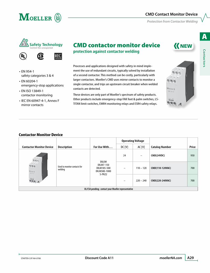
CMD Contact Monitor Device
Protection from Contactor Welding
CMD contactor monitor deviceprotection against contactor welding
R
EN 954-1 •safety categories 3 & 4
EN 60204-1 •emergency-stop applications
EN ISO 13849-1 •contactor monitoring
IEC EN 60947-4-1, Annex F •mirror contacts
Processes and applications designed with safety in mind imple-ment the use of redundant circuits, typically solved by installation of a second contactor. This method can be costly, particularly with larger contactors. Moeller’s CMD uses mirror contacts to monitor a single contactor, and trips an upstream circuit breaker when welded contacts are detected.
These devices are only part of Moeller’s spectrum of safety products. Other products include emergency-stop FAK foot & palm switches, LS-TITAN limit switches, EMR4 monitoring relays and ESR4 safety relays.
Contactor Monitor Device
Contactor Monitor Device Description For Use With…
Operating Voltage
Catalog Number PriceDC [V] AC [V]
Used to monitor contacts for welding
DILEMDILM7-150
DILM185-500DILM580-1000
S-PKZ2
24 – CMD(24VDC) 950
– 110 – 120 CMD(110-120VAC) 700
– 220 – 240 CMD(220-240VAC) 700
UL/CSA pending; contact your Moeller representative
A
Co
nta
cto
rs
A30 moellerNA.com STARTER-CAT-NA-0708 Discount Code A11
Accessories
Miscellaneous Accessories
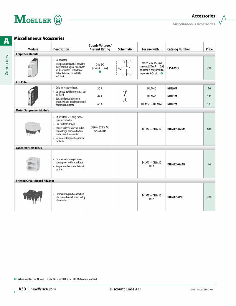
Miscellaneous Accessories
Module Description Supply Voltage /
Current Rating Schematic For use with... Catalog Number PriceAmplifier Module
DC operated •Interposing relay that provides •a dry contact signal to activate an AC operated Contactor or Relay; Actuates on as little as 25mA
24V DC[25mA…2A]
➊
13
14
21
22
When 24V DC low current [25mA…2A] control is required to operate AC coils ➊
ETS4-VS3 200
4th Pole
Only for resistive loads.•Up to two auxiliary contacts can •be fittedSuitable for isolating non-•grounded and poorly grounded neutral conductors
30 A
8 7
7 8DILM40 NDIL0M 76
44 A DILM40 NDIL1M 133
60 A DILM50 – DILM65 NDIL2M 183
Motor Suppressor Module
Utilizes tool-less plug connec-•tion on contactorEMC suitable design•Reduces interferance of induc-•tion voltage produced when motors are disconnectedIncreases lifespan of contactor •contacts
380 – 575 V AC @50/60Hz DILM7 – DILM12 DILM12-XMSM 830
Contactor Test Block
For manual closing of main •power poles without voltageSimple and fast control circuit •testing
DILM7 – DILM32DILA DILM32-XMAN 44
Printed Circuit Board Adapter
For mounting and connection •of a printed circuit board to top of contactor
DILM7 – DILM12DILA DILM12-XPBC 200
➊ When contactor AC coil is over 2A, use DILER or DILEM-G relay instead.
A
Co
ntacto
rs
STARTER-CAT-NA-0708 moellerNA.com A31 Discount Code A11
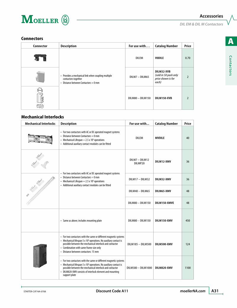
Connectors
Connector Description For use with… Catalog Number Price
Provides a mechanical link when coupling multiple •contactors togetherDistance between Contactors = 0 mm•
DILEM V0DILE 0.70
DILM7 – DILM65
DILM32-XVB(sold in 50 pack only price shown is for each)
2
DILM80 – DILM150 DILM150-XVB 2
Mechanical InterlocksMechanical Interlocks Description For use with... Catalog Number Price
For two contactors with AC or DC operated magnet systems•Distance between Contactors = 0 mm•Mechanical Lifespan = 2.5 x 10• 6 operationsAdditional auxiliary contact modules can be fitted•
DILEM MVDILE 40
For two contactors with AC or DC operated magnet systems•Distance between Contactors = 0 mm•Mechanical Lifespan = 2.5 x 10• 6 operationsAdditional auxiliary contact modules can be fitted•
DILM7 – DILM12DILMP20 DILM12-XMV 36
DILM17 – DILM32 DILM32-XMV 36
DILM40 – DILM65 DILM65-XMV 48
DILM80 – DILM150 DILM150-XMVE 48
Same as above; includes mounting plate• DILM80 – DILM150 DILM150-XMV 450
For two contactors with the same or different magnetic systems•Mechanical lifespan 5 x 10• 6 operations. No auxiliary contact is possible between the mechanical interlock and contactorCombination with same frame size only•Distance between contactors: 15 mm•
DILM185 – DILM500 DILM500-XMV 124
For two contactors with the same or different magnetic systems•Mechanical lifespan 5 x 10• 6 operations. No auxiliary contact is possible between the mechanical interlock and contactorDILM820-XMV consists of interlock element and mounting •support plate
DILM580 – DILM1000 DILM820-XMV 1100
Accessories
DIL EM & DIL M Contactors
A
Co
nta
cto
rs
A32 moellerNA.com STARTER-CAT-NA-0708 Discount Code A11
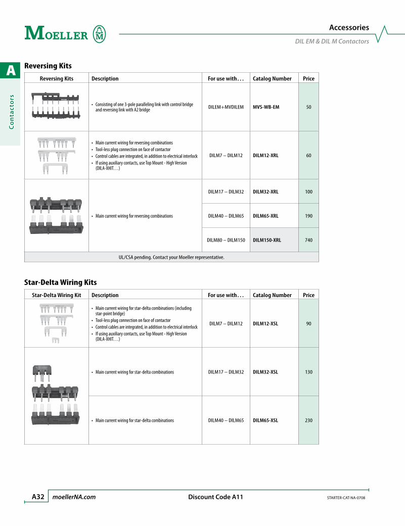
Reversing Kits
Reversing Kits Description For use with… Catalog Number Price
Consisting of one 3-pole paralleling link with control bridge •and reversing link with A2 bridge DILEM+MVDILEM MVS-WB-EM 50
Main current wiring for reversing combinations•Tool-less plug connection on face of contactor•Control cables are integrated, in addition to electrical interlock•If using auxiliary contacts, use Top Mount - High Version •(DILA-XHIT…)
DILM7 – DILM12 DILM12-XRL 60
Main current wiring for reversing combinations•
DILM17 – DILM32 DILM32-XRL 100
DILM40 – DILM65 DILM65-XRL 190
DILM80 – DILM150 DILM150-XRL 740
UL/CSA pending. Contact your Moeller representative.
Star-Delta Wiring Kits
Star-Delta Wiring Kit Description For use with… Catalog Number Price
Main current wiring for star-delta combinations (including •star-point bridge)Tool-less plug connection on face of contactor•Control cables are integrated, in addition to electrical interlock•If using auxiliary contacts, use Top Mount - High Version •(DILA-XHIT…)
DILM7 – DILM12 DILM12-XSL 90
Main current wiring for star-delta combinations• DILM17 – DILM32 DILM32-XSL 130
Main current wiring for star-delta combinations• DILM40 – DILM65 DILM65-XSL 230
Accessories
DIL EM & DIL M Contactors

A
Co
ntacto
rs
STARTER-CAT-NA-0708 moellerNA.com A33 Discount Code A11
Bridges, Links and Jumpers
Bridges Description For use with… Catalog Number PriceStar-Point Bridges
Finger-safe (in accordance with IEC 536)•
DILEM S1DILEM 40
DILM7 – DILM12 DILM12-XS1 ➊ 40
DILM17 – DILM32 DILM32-XS1 40
DILM40 – DILM65 DILM65-XS1 56
DILM80 – DILM150 DILM150-XS1 126
A cover is included for protection against accidental contact•
DILM185 – DILM400 DILM400-XS1 280
DILM500 DILM500-XS1 360
Paralleling Bridges (Consisting of two paralleling links)
4th pole can be broken off.•AC-1 current carrying capacity of the open contactor increases •by a factor of 2.5.Protected against accidental contact (in accordance with •IEC 536).
Terminal capacity can be found in the Technical Data section.
DILEM P1DILEM 50
DILM7 – DILM12 DILM12-XP1 32
DILM17 – DILM32 DILM32-XP1 60
DILM40 – DILM65 DILM65-XP1 80
DILM80 – DILM150 DILM150-XP1 330
3-pole•AC-1 current carrying capacity of the open Contactor increases •by a factor of 2.5.A cover is included for protection against accidental contact.•
DILM185 DILM185-XP1 536
Three-phase Commoning Links
For linking three contactors; length 135mm•Rated to 690V; 63A general purpose•Protected against accidental contact; short circuit proof•
DILM7 – DILM12
DILM12-XDSB0/3 60
For linking four contactors; length 180mm•Rated to 690V; 63A general purpose•Protected against accidental contact; short circuit proof•
DILM12-XDSB0/4 70
For linking five contactors; length 225mm•Rated to 690V; 63A general purpose•Protected against accidental contact; short circuit proof•
DILM12-XDSB0/5 76
Jumper
For parallel connection of auxiliary contacts•Not insulated•Standard quantity: 100•
Must be ordered in standard quantity
DILEMDILER BT480 0.70
➊ Tool-less plug connection on face of contactor. If using auxiliary contacts, use Top Mount, High Version (DILA-XHIT…).
Accessories
DIL EM & DIL M Contactors

A
Co
nta
cto
rs
A34 moellerNA.com STARTER-CAT-NA-0708 Discount Code A11
Terminal Blocks, Lugs, Kits and Accessories ➊
Terminal Blocks & Kits Description For use with… Catalog Number PriceCable Terminal Blocks
Terminal capacity: 1 x (AWG 6 – MCM 350) • or 2 x (AWG 6 – MCM 300)
DILM185 DILM225 DILM225-XKU-S 240
Terminal capacity: 1 x (1/Ø – MCM 600) • or 2 x (1/Ø – MCM 500) DILM250 – DILM400 DILM400-XKU-S 250
Terminal cover included•Consists of three individual terminals (Cu, Al), with integrated •control circuit terminalTerminal capacity: 2 x (AWG 4 – MCM 500)•
DILM500/22 DILM500-XK-CNA 280
Terminal cover included•Consists of three individual terminals (Cu, Al), with integrated •control circuit terminalTerminal capacity: 2 x (AWG 2 – MCM 500)•
DILM580/22 DILM650/22 DILM650-XK-CNA 500
Terminal cover included•Consists of three individual terminals (Cu, Al)•Terminal capacity: 4 x (AWG 2 – MCM 500)•
DILM750/22DILM820/22 DILM820-XK-CNA 1060
Flat Strip Conductor Terminal Kit
Includes three flat strip conductor terminals and control circuit •terminalFor bus and flexibus connection•
See Technical Data for terminal capacity.
DILM500 – DILM650 DILM650-XKB-S 220
DILM750 DILM820 DILM820-XKB-S 230
Control Circuit Tap
Pressure connector that mounts directly to a power terminal for •feeding a control circuit15A, 600V maximum; AWG 18 – 14•
DILM80 – DILM150 DILM150-XZK 16
Accessories
DIL EM & DIL M Contactors
➊ No factory lugs available for DILM1000 size contactors
A
Co
ntacto
rs
STARTER-CAT-NA-0708 moellerNA.com A35 Discount Code A11
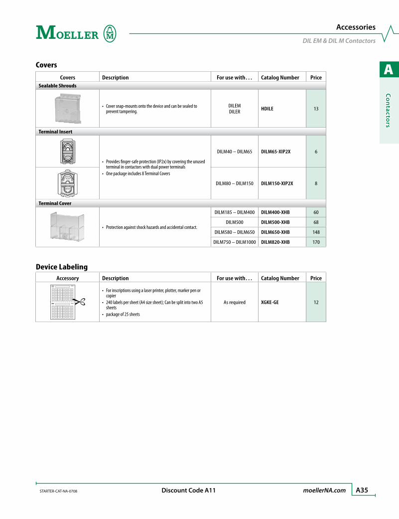
Covers
Covers Description For use with… Catalog Number PriceSealable Shrouds
Cover snap-mounts onto the device and can be sealed to •prevent tampering.
DILEMDILER HDILE 13
Terminal Insert
Provides finger-safe protection (IP2x) by covering the unused •terminal in contactors with dual power terminalsOne package includes 8 Terminal Covers •
DILM40 – DILM65 DILM65-XIP2X 6
DILM80 – DILM150 DILM150-XIP2X 8
Terminal Cover
Protection against shock hazards and accidental contact.•
DILM185 – DILM400 DILM400-XHB 60
DILM500 DILM500-XHB 68
DILM580 – DILM650 DILM650-XHB 148
DILM750 – DILM1000 DILM820-XHB 170
Device LabelingAccessory Description For use with… Catalog Number Price
For inscriptions using a laser printer, plotter, marker pen or •copier240 labels per sheet (A4 size sheet); Can be split into two A5 •sheetspackage of 25 sheets•
As required XGKE-GE 12
Accessories
DIL EM & DIL M Contactors

A
Co
nta
cto
rs
A36 moellerNA.com STARTER-CAT-NA-0708 Discount Code A13
AC Coils DILM17 – DILM65 Contactors ➊
Coil Voltage For Use With…
Catalog Number(Shading indicates standard voltages) Price50Hz 60Hz
24 –
DILM17DILM25DILM32
DIULM17DIULM25DIULM32
DILK20DILK25DILK33
DILM32-XSP(24V50HZ) 144
48 – DILM32-XSP(48V50HZ) 144
240 – DILM32-XSP(240V50HZ) 144
500 – DILM32-XSP(500V50HZ) 144
– 24 DILM32-XSP(24V60HZ) 144
– 110 DILM32-XSP(110V60HZ) 144
– 115 DILM32-XSP(115V60HZ) 144
– 208 DILM32-XSP(208V60HZ) 144
– 600 DILM32-XSP(600V60HZ) 144
42 48 DILM32-XSP(42V50HZ,48V60HZ) 144
110 120 DILM32-XSP(110V50HZ,120V60HZ) 144
190 220 DILM32-XSP(190V50HZ,220V60HZ) 144
220 240 DILM32-XSP(220V50HZ,240V60HZ) 144
230 240 DILM32-XSP(230V50HZ,240V60HZ) 144
380 440 DILM32-XSP(380V50HZ,440V60HZ) 144
400 440 DILM32-XSP(400V50HZ,440V60HZ) 144
415 480 DILM32-XSP(415V50HZ,480V60HZ) 144
24 24 DILM32-XSP(24V50/60HZ) 144
42 42 DILM32-XSP(42V50/60HZ) 144
110 110 DILM32-XSP(110V50/60HZ) 144
220 220 DILM32-XSP(220V50/60HZ) 144
230 230 DILM32-XSP(230V50/60HZ) 144
380 380 DILM32-XSP(380V50/60HZ) 144
24 –
DILM40DILM50DILM65
DIULM40DIULM50DIULM65
DILK50
DILM65-XSP(24V50HZ) 180
48 – DILM65-XSP(48V50HZ) 180
240 – DILM65-XSP(240V50HZ) 180
500 – DILM65-XSP(500V50HZ) 180
– 24 DILM65-XSP(24V60HZ) 180
– 110 DILM65-XSP(110V60HZ) 180
– 115 DILM65-XSP(115V60HZ) 180
– 208 DILM65-XSP(208V60HZ) 180
– 600 DILM65-XSP(600V60HZ) 180
42 48 DILM65-XSP(42V50HZ,48V60HZ) 180
110 120 DILM65-XSP(110V50HZ,120V60HZ) 180
190 220 DILM65-XSP(190V50HZ,220V60HZ) 180
220 240 DILM65-XSP(220V50HZ,240V60HZ) 180
230 240 DILM65-XSP(230V50HZ,240V60HZ) 180
380 440 DILM65-XSP(380V50HZ,440V60HZ) 180
400 440 DILM65-XSP(400V50HZ,440V60HZ) 180
415 480 DILM65-XSP(415V50HZ,480V60HZ) 180
24 24 DILM65-XSP(24V50/60HZ) 180
42 42 DILM65-XSP(42V50/60HZ) 180
110 110 DILM65-XSP(110V50/60HZ) 180
220 220 DILM65-XSP(220V50/60HZ) 180
230 230 DILM65-XSP(230V50/60HZ) 180
380 380 DILM65-XSP(380V50/60HZ) 180
Replacement Coils
AC & DC
AC Coils DILM80 – DILM95 Contactors ➊
Coil Voltage For Use With…
Catalog Number(Shading indicates standard voltages) Price50Hz 60Hz
24 –
DILM80DILM95
DILM95-XSP(24V50HZ) 246
48 – DILM95-XSP(48V50HZ) 246
240 – DILM95-XSP(240V50HZ) 246
500 – DILM95-XSP(500V50HZ) 246
– 24 DILM95-XSP(24V60HZ) 246
– 110 DILM95-XSP(110V60HZ) 246
– 115 DILM95-XSP(115V60HZ) 246
– 208 DILM95-XSP(208V60HZ) 246
– 600 DILM95-XSP(600V60HZ) 246
42 48 DILM95-XSP(42V50HZ,48V60HZ) 246
110 120 DILM95-XSP(110V50HZ,120V60HZ) 246
190 220 DILM95-XSP(190V50HZ,220V60HZ) 246
220 240 DILM95-XSP(220V50HZ,240V60HZ) 246
230 240 DILM95-XSP(230V50HZ,240V60HZ) 246
380 440 DILM95-XSP(380V50HZ,440V60HZ) 246
400 440 DILM95-XSP(400V50HZ,440V60HZ) 246
415 480 DILM95-XSP(415V50HZ,480V60HZ) 246
24 24 DILM95-XSP(24V50/60HZ) 246
42 42 DILM95-XSP(42V50/60HZ) 246
110 110 DILM95-XSP(110V50/60HZ) 246
220 220 DILM95-XSP(220V50/60HZ) 246
230 230 DILM95-XSP(230V50/60HZ) 246
380 380 DILM95-XSP(380V50/60HZ) 246
DC Coils DILM17 – DILM150 Contactors ➊➋
Coil VoltageV DC For Use With…
Catalog Number(Shading indicates standard voltages) Price
24 – 27
DILM17 – DILM32
DILM32-XSP(RDC24) 380
48 – 60 DILM32-XSP(RDC60) 380
110 – 130 DILM32-XSP(RDC130) 380
200 – 240 DILM32-XSP(RDC240) 380
24 – 27
DILM40 – DILM65
DILM65-XSP(RDC24) 500
48 – 60 DILM65-XSP(RDC60) 500
110 – 130 DILM65-XSP(RDC130) 500
200 – 240 DILM65-XSP(RDC240) 500
24 – 27
DILM80 – DILM95
DILM95-XSP(RDC24) 486
48 – 60 DILM95-XSP(RDC60) 486
110 – 130 DILM95-XSP(RDC130) 486
200 – 240 DILM95-XSP(RDC240) 486
24 – 27
DILM115 – 150
DILM150-XSP(RDC24) 520
48 – 60 DILM150-XSP(RDC60) 520
110 – 130 DILM150-XSP(RDC130) 520
200 – 240 DILM150-XSP(RDC240) 520
➊ Special Voltage Coils are available - Contact your Moeller Representative. ➋ All DC coils are supplied with integrated surge suppressor.
Note: Coils are not replaceable with DILEM…-G; DILM7 – 12 or DILMP20

A
Co
ntacto
rs
STARTER-CAT-NA-0708 moellerNA.com A37 Discount Code A13
Replacement Coils, Contacts and Arc Chutes
AC & DC
➊ DILM115 – 1000 electronic coils are supplied with integrated surge suppressor.
DILM115 – DILM1000 Contactors (Electronic Modules including coil) ➊
Coil VoltageFor Use With…
Catalog Number(Shading indicates standard voltages) PriceAC DC
24V50 – 60Hz
See preceding page for
DC voltagesDILM115 – 150
DILM150-XSP(RAC24) 420
42 – 48V50 – 60Hz DILM150-XSP(RAC48) 420
100 – 120V50 – 60Hz DILM150-XSP(RAC120) 420
190 – 240V50 – 60Hz DILM150-XSP(RAC240) 420
380 – 440V50Hz DILM150-XSP(RAC440) 420
480 – 500V50 – 60Hz DILM150-XSP(RAC500) 420
– 24 – 48V
DILM185 – 250
DILM250-XSP/E(RDC48) 1200
48 – 110V40…60Hz 48 – 110V DILM250-XSP/E(RA110) 1200
110 – 250V40 – 60Hz 110 – 250V DILM250-XSP/E(RA250) 1200
250…500V40 – 60Hz – DILM250-XSP/E(RAC500) 1200
– 24 – 48V
DILM300 – 500
DILM500-XSP/E(RDC48) 1820
48 – 110V40 – 60Hz 48 – 110V DILM500-XSP/E(RA110) 1820
110 – 250V40 – 60Hz 110 – 250V DILM500-XSP/E(RA250) 1820
250 – 500V40 – 60Hz – DILM500-XSP/E(RAC500) 1820
48 – 110V40 – 60Hz 48 – 110V
DILM580 – DILM1000
DILM1000-XSP/E(RA110) 2960
110 – 250V40 – 60Hz 110 – 250V DILM1000-XSP/E(RA250) 2960
250 – 500V40 – 60Hz – DILM1000-XSP/E(RAC500) 2960
Replacement Contacts (set of 3)
For Use With…Catalog Number Price
DILM40 – 65 DILM65-XCT 508
DILM80 – 150 DILM150-XCT 736
DILM185 – 250 DILM250-XCT 874
DILM300 – 500 DILM500-XCT 1800
DILM580 DILM580-XCT 5900
DILM650 DILM650-XCT 6712
DILM750 DILM750-XCT 7530
DILM820 DILM820-XCT 8610
DILM32-XSP… replacement coil. (typical)
Replacement Arc Chutes
For Use With…Catalog Number Price
DILM185 DILM185-XOT 490
DILM225 DILM225-XOT 490
DILM250 DILM250-XOT 432
DILM300 DILM300-XOT 690
DILM400 DILM400-XOT 690
DILM500 DILM500-XOT 690
A
Co
nta
cto
rs
A38 moellerNA.com STARTER-CAT-NA-0708
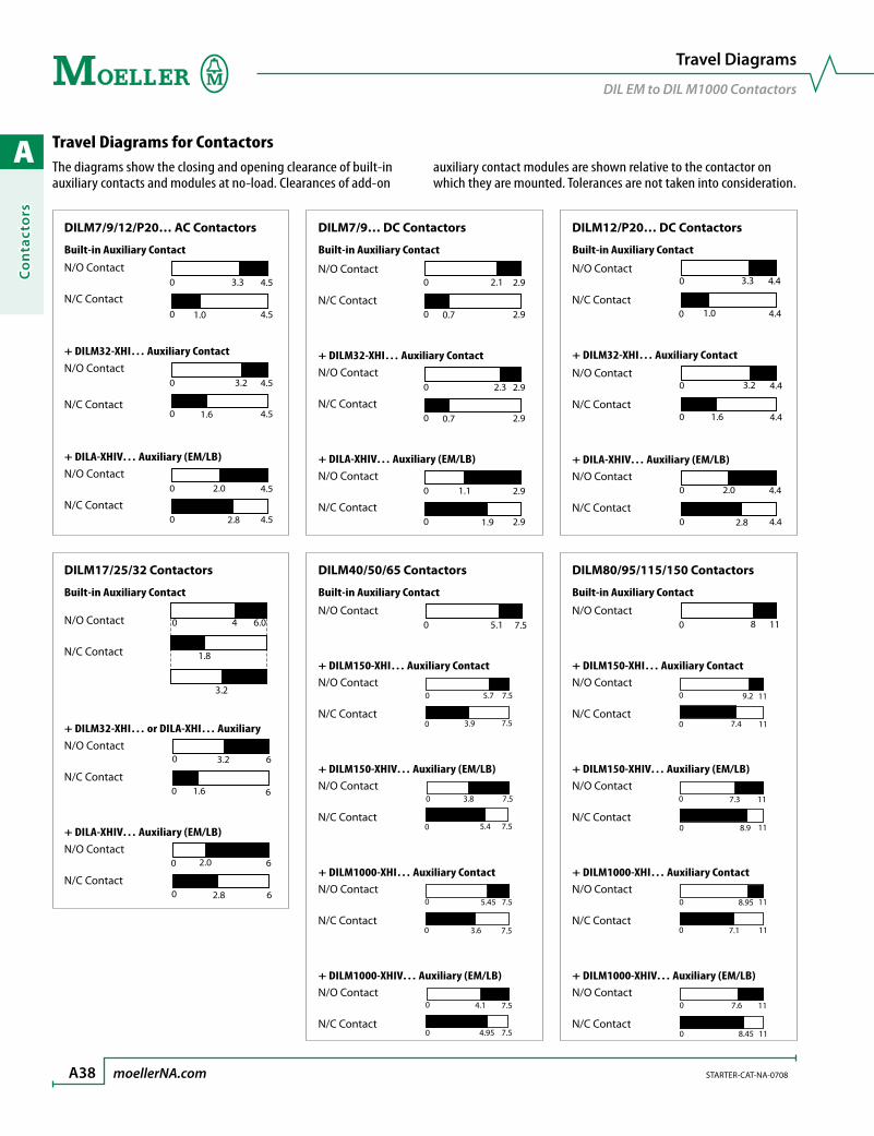
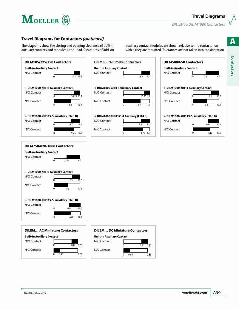
The diagrams show the closing and opening clearance of built-in auxiliary contacts and modules at no-load. Clearances of add-on
auxiliary contact modules are shown relative to the contactor on which they are mounted. Tolerances are not taken into consideration.
DILM17/25/32 Contactors
Built-in Auxiliary Contact
N/O Contact 0 4 6.0
1.8
3.2
N/C Contact
+ DILM32-XHI… or DILA-XHI… AuxiliaryN/O Contact
0 3.2 6
0 1.6 6N/C Contact
+ DILA-XHIV… Auxiliary (EM/LB)N/O Contact
0 2.0 6
0 2.8 6N/C Contact
DILM40/50/65 Contactors
Built-in Auxiliary Contact
N/O Contact 7.55.10
+ DILM150-XHI… Auxiliary ContactN/O Contact
0
0
5.7
3.9
7.5
7.5N/C Contact
+ DILM150-XHIV… Auxiliary (EM/LB)N/O Contact
0
0
3.8 7.5
7.55.4N/C Contact
+ DILM1000-XHI… Auxiliary ContactN/O Contact
0 5.45 7.5
0 7.53.6N/C Contact
+ DILM1000-XHIV… Auxiliary (EM/LB)N/O Contact
0 4.1 7.5
0 4.95 7.5N/C Contact
DILM7/9/12/P20… AC Contactors
Built-in Auxiliary Contact
N/O Contact
4.5
4.53.30
0 1.0
N/C Contact
+ DILM32-XHI… Auxiliary ContactN/O Contact
4.5
4.53.20
0 1.6N/C Contact
+ DILA-XHIV… Auxiliary (EM/LB)N/O Contact
4.5
4.52.00
0 2.8N/C Contact
DILM7/9… DC Contactors
Built-in Auxiliary Contact
N/O Contact
2.9
2.92.10
0 0.7N/C Contact
+ DILM32-XHI… Auxiliary ContactN/O Contact
2.9
2.92.30
0 0.7N/C Contact
+ DILA-XHIV… Auxiliary (EM/LB)N/O Contact
2.9
2.91.10
0 1.9N/C Contact
DILM12/P20… DC Contactors
Built-in Auxiliary Contact
N/O Contact 0
0
3.3
1.0
4.4
4.4N/C Contact
+ DILM32-XHI… Auxiliary Contact
N/O Contact 0
0
3.2
1.6
4.4
4.4N/C Contact
+ DILA-XHIV… Auxiliary (EM/LB)N/O Contact
0
0
2.0
2.8
4.4
4.4N/C Contact
DILM80/95/115/150 Contactors
Built-in Auxiliary Contact
N/O Contact 1180
+ DILM150-XHI… Auxiliary ContactN/O Contact
0
0
9.2
7.4
11
11N/C Contact
+ DILM150-XHIV… Auxiliary (EM/LB)N/O Contact
0
0
7.3
8.9
11
11N/C Contact
+ DILM1000-XHI… Auxiliary ContactN/O Contact
0
0
8.95
7.1
11
11N/C Contact
+ DILM1000-XHIV… Auxiliary (EM/LB)N/O Contact
0
0
7.6 11
118.45N/C Contact
Travel Diagrams
DIL EM to DIL M1000 Contactors
Travel Diagrams for Contactors
A
Co
ntacto
rs
STARTER-CAT-NA-0708 moellerNA.com A39
DILEM… AC Miniature Contactors
Built-in Auxiliary ContactN/O Contact
0 1.89 2.78
0 0.95 2.78
N/C Contact
DILM750/820/1000 Contactors
Built-in Auxiliary ContactN/O Contact
2.00 4.1
+ DILM1000-XHI11 Auxiliary ContactN/O Contact
10.5
10.57.40
0 5.5N/C Contact
+ DILM1000-XHI11V-SI Auxiliary (EM/LB)N/O Contact
10.5
10.56.00
0 6.8N/C Contact
DILM185/225/250 Contactors
Built-in Auxiliary ContactN/O Contact
10.10 13.1
+ DILM1000-XHI11 Auxiliary ContactN/O Contact
13.110.250
0 8.4 13.1N/C Contact
+ DILM1000-XHI11V-SI Auxiliary (EM/LB)N/O Contact
13.1
13.18.70
0 9.75N/C Contact
DILM300/400/500 Contactors
Built-in Auxiliary ContactN/O Contact
0 13.18.9
+ DILM1000-XHI11 Auxiliary ContactN/O Contact
13.110.250
0 8.4 13.1N/C Contact
+ DILM1000-XHI11V-SI Auxiliary (EM/LB)N/O Contact
13.1
13.18.70
0 9.75N/C Contact
DILM580/650 Contactors
Built-in Auxiliary ContactN/O Contact
2.00 4.1
+ DILM1000-XHI11 Auxiliary ContactN/O Contact
10.5
10.57.40
0 5.5N/C Contact
+ DILM1000-XHI11V-SI Auxiliary (EM/LB)N/O Contact
10.5
10.56.00
0 6.8N/C Contact
DILEM… DC Miniature Contactors
Built-in Auxiliary ContactN/O Contact
0 1.91 2.85
0 0.95 2.85
N/C Contact
The diagrams show the closing and opening clearance of built-in auxiliary contacts and modules at no-load. Clearances of add-on
auxiliary contact modules are shown relative to the contactor on which they are mounted. Tolerances are not taken into consideration.
Travel Diagrams
DIL EM to DIL M1000 Contactors
Travel Diagrams for Contactors (continued)
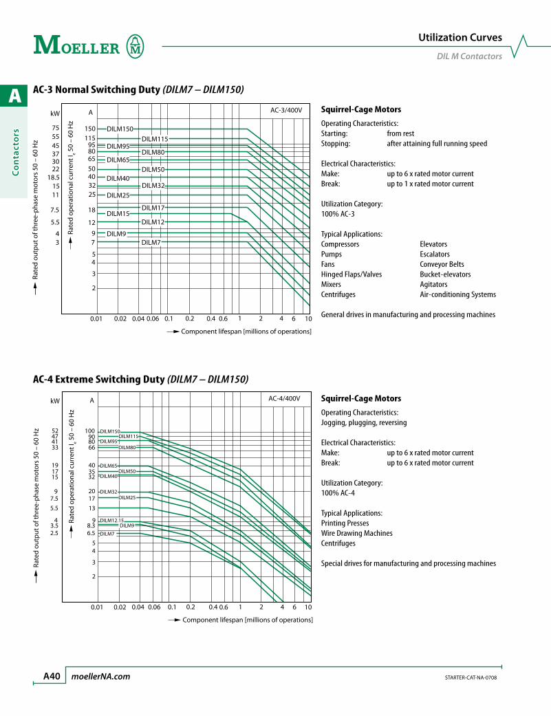
A
Co
nta
cto
rs
A40 moellerNA.com STARTER-CAT-NA-0708
1064210.60.40.20.10.060.040.020.01
AC-4/400VA
2
3
45
6.58.3
9
131720
323540
668090
100
2.53.5
4
5.57.5
9
151719
33414752
kW
DILM7
DILM9DILM12.15
DILM25DILM32
DILM40DILM50
DILM65
DILM80DILM95
DILM115DILM150
Component lifespan [millions of operations]
Rate
d op
erat
iona
l cur
rent
I e 50
– 60
Hz
Rate
d ou
tput
of t
hree
-pha
se m
otor
s 50
– 6
0 H
z
AC-3/400V
0.01
DILM7DILM9
DILM12DILM15
DILM17
DILM25DILM32
DILM40DILM50
DILM65DILM80
DILM95DILM115
DILM150
2
3
45
79
12
18
25324050658095
115150
A
34
5.5
7.5
1115
18.5223037455575
Component lifespan [millions of operations]
Rate
d op
erat
iona
l cur
rent
I e 50
– 60
Hz
Rate
d ou
tput
of t
hree
-pha
se m
otor
s 50
– 6
0 H
z
kW
0.02 0.04 0.06 0.1 0.2 0.4 0.6 1 2 4 6 10
AC-3 Normal Switching Duty (DILM7 – DILM150)
Utilization Curves
DIL M Contactors
Squirrel-Cage MotorsOperating Characteristics:Starting: from restStopping: after attaining full running speed
Electrical Characteristics:Make: up to 6 x rated motor currentBreak: up to 1 x rated motor current
Utilization Category:100% AC-3
Typical Applications:Compressors ElevatorsPumps EscalatorsFans Conveyor BeltsHinged Flaps/Valves Bucket-elevatorsMixers AgitatorsCentrifuges Air-conditioning Systems
General drives in manufacturing and processing machines
Squirrel-Cage MotorsOperating Characteristics:Jogging, plugging, reversing
Electrical Characteristics:Make: up to 6 x rated motor currentBreak: up to 6 x rated motor current
Utilization Category:100% AC-4
Typical Applications:Printing PressesWire Drawing MachinesCentrifuges
Special drives for manufacturing and processing machines
AC-4 Extreme Switching Duty (DILM7 – DILM150)
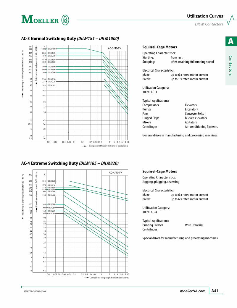
A
Co
ntacto
rs
STARTER-CAT-NA-0708 moellerNA.com A41
AC-3 Normal Switching Duty (DILM185 – DILM1000)
AC-3/400 V kW
132 110
90
75
55
45
37
30
22
18.5
15
11 7.5
A
820 750
650 580
500 400
300
250
450
560
400
355 315
250 200
160
225
185
145
104
85
72
58
43
36
30
23 16
DILM185
DILM225 DILM250
DILM300 DILM400 DILM500
DILM580 DILM650
DILM750 DILM820
0.01 0.02 0.04 0.06 0.1 0.2 0.4 0.6 0.75 1 2 3 4 5 6 8 10
1000 DILM1000
Rate
d ou
tput
of t
hree
-pha
se m
otor
s 50
– 6
0 H
z
Rate
d op
erat
iona
l cur
rent
Ie 5
0 –
60 H
z
Component lifespan [millions of operations]
kW
0.01 0.02 0.04 0.06 0.1 0.2 0.4 0.6 1 2 3 4 5 6 8 10
315 280
200
160
110
90 75
55
45 37
30
22 18.5
15
0.03 0.3
11
7.5
5.5
4
3
2.2
1.5
576
355 656
512
360 250 456
296
200
132 240
164 140
104
85 72
58
43 36
30
23
16
12
8.8
6.5
5
3.5
DILM185 DILM225
DILM250
DILM300
DILM750
DILM820
DILM650 DILM580 DILM500
DILM400
AC-4/400 V A
Rate
d ou
tput
of t
hree
-pha
se m
otor
s 50
– 6
0 H
z
Rate
d op
erat
iona
l cur
rent
Ie 5
0 –
60 H
z
Component lifespan [millions of operations]
Utilization Curves
DIL M Contactors
Squirrel-Cage MotorsOperating Characteristics:Jogging, plugging, reversing
Electrical Characteristics:Make: up to 6 x rated motor currentBreak: up to 6 x rated motor current
Utilitzation Category:100% AC-4
Typical Applications:Printing Presses Wire DrawingCentrifuges
Special drives for manufacturing and processing machines
AC-4 Extreme Switching Duty (DILM185 – DILM820)
Squirrel-Cage MotorsOperating Characteristics:Starting: from restStopping: after attaining full running speed
Electrical Characteristics:Make: up to 6 x rated motor currentBreak: up to 1 x rated motor current
Utilization Category:100% AC-3
Typical Applications:Compressors ElevatorsPumps EscalatorsFans Conveyor BeltsHinged Flaps Bucket-elevatorsMixers AgitatorsCentrifuges Air-conditioning Systems
General drives in manufacturing and processing machines
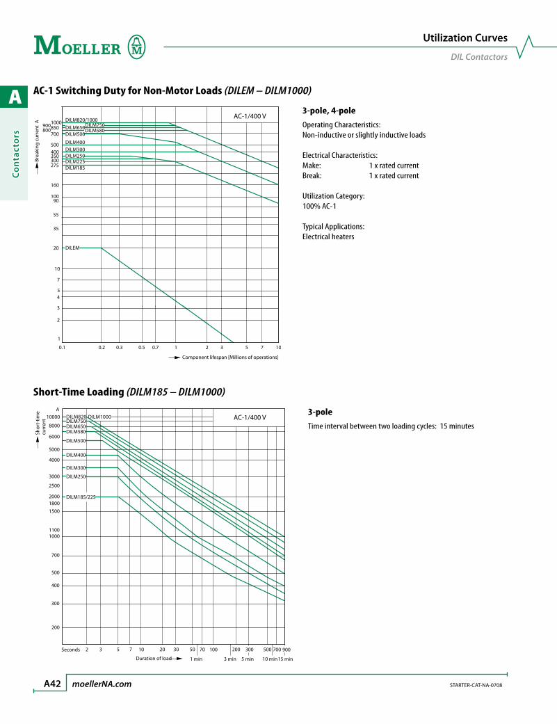
A
Co
nta
cto
rs
A42 moellerNA.com STARTER-CAT-NA-0708
AC-1 Switching Duty for Non-Motor Loads (DILEM – DILM1000)
AC-1/400 V
0.1 0.2 0.5 7 0.7 1 3 5 10
2
1
3
4
0.3 2
5
900 850 1000
700 800
500 400
275 300 350
160
100
55
35
20
10
7
90
DILM185 DILM225
DILM400 DILM300 DILM250
DILEM
DILM750 DILM650 DILM500
DILM580
DILM820/1000
Component lifespan [Millions of operations]
Brea
king
cur
rent
A
DILM1000
900 300 70 100 50 7 30 20 3 5 10 2
A
8000
10000
6000
5000
4000
3000
2500
2000 1800
1100 1000
700
500
400
300
1500
DILM185/225
DILM250
DILM300
DILM400
DILM500
700 200 500
200
10 min 15 min 1 min 3 min 5 min
AC-1/400 V
DILM580 DILM650 DILM750 DILM820
Seconds
Duration of load
Shor
t-tim
e cu
rren
t
Short-Time Loading (DILM185 – DILM1000)
Utilization Curves
DIL Contactors
3-pole, 4-poleOperating Characteristics:Non-inductive or slightly inductive loads
Electrical Characteristics:Make: 1 x rated currentBreak: 1 x rated current
Utilization Category:100% AC-1
Typical Applications:Electrical heaters
3-poleTime interval between two loading cycles: 15 minutes
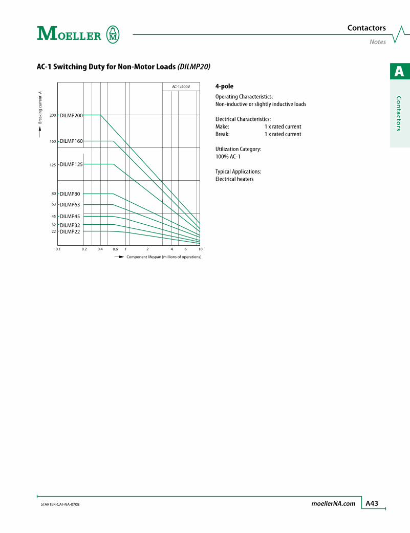
A
Co
ntacto
rs
STARTER-CAT-NA-0708 moellerNA.com A43
AC-1 Switching Duty for Non-Motor Loads (DILMP20)
Contactors
NotesBr
eaki
ng c
urre
nt A
AC-1/400 V
0.1 0.2 1 10
22
32
0.4 0.6 2 4 6
200
63
45
DILMP22 DILMP32
DILMP45
DILMP63
DILMP80
DILMP125
DILMP160
DILMP200
160
Component lifespan [millions of operations]
80
125
4-poleOperating Characteristics:Non-inductive or slightly inductive loads
Electrical Characteristics:Make: 1 x rated currentBreak: 1 x rated current
Utilization Category:100% AC-1
Typical Applications:Electrical heaters

A
Co
nta
cto
rs
A44 moellerNA.com STARTER-CAT-NA-0708
Maximum Operating Frequency
DIL Contactors
Maximum Operating Frequency for 400 V(dependant on rating and utilization category)
Maximum Operating Frequency for 400 V(dependant on rating and utilization category)
6000
4000
2000
1000
800
600
400
200
100
0 10 20 30 40 50 60 70 80 90 100 %
a
b
c
g
de
f
h
PN [kW]
Ops./h
Contactor(s)
Characteristic
AC-1 AC-3AC-2AC-4
DILEM e b h
DILM7, 9, 12 d a g
DILM17, 25, 32 d c g
DILM40, 50, 65 d c g
DILM80, 95, 115, 150 d f g
Contactor(s)
Characteristic
AC-1 AC-3 AC-4DILM185 b a f
DILM225 b a f
DILM250 b a f
DILM300 c b g
DILM400 c b g
DILM500 c b g
DILM580 c d e
DILM650 c d e
DILM750 c d e
DILM820 c d e
DILM1000 c d e
4000
3000
2000
600
500
400
300
200
150
100
500 10 20 30 40 50 60 70 80 90 100 %
abc
e
f
g
1500
1000
800
d
PN [kW]
Ops./h

A
Co
ntacto
rs
STARTER-CAT-NA-0708 moellerNA.com A45
Circuit Diagrams
DC Switching
Switching of DC Currents
Contactor(s)
1 Pole 2 Pole
with Overload Relay≤ 60 V DC > 60 V DC
with Overload Relay> 60 V DC
with Overload Relay≤ 60 V DC > 60 V DC
with Overload Relay> 60 V DC
DILEM – DILM500
– – – –: connection supplied by customer
DILEM4DILMP20
– – – –: connection supplied by customer
– –
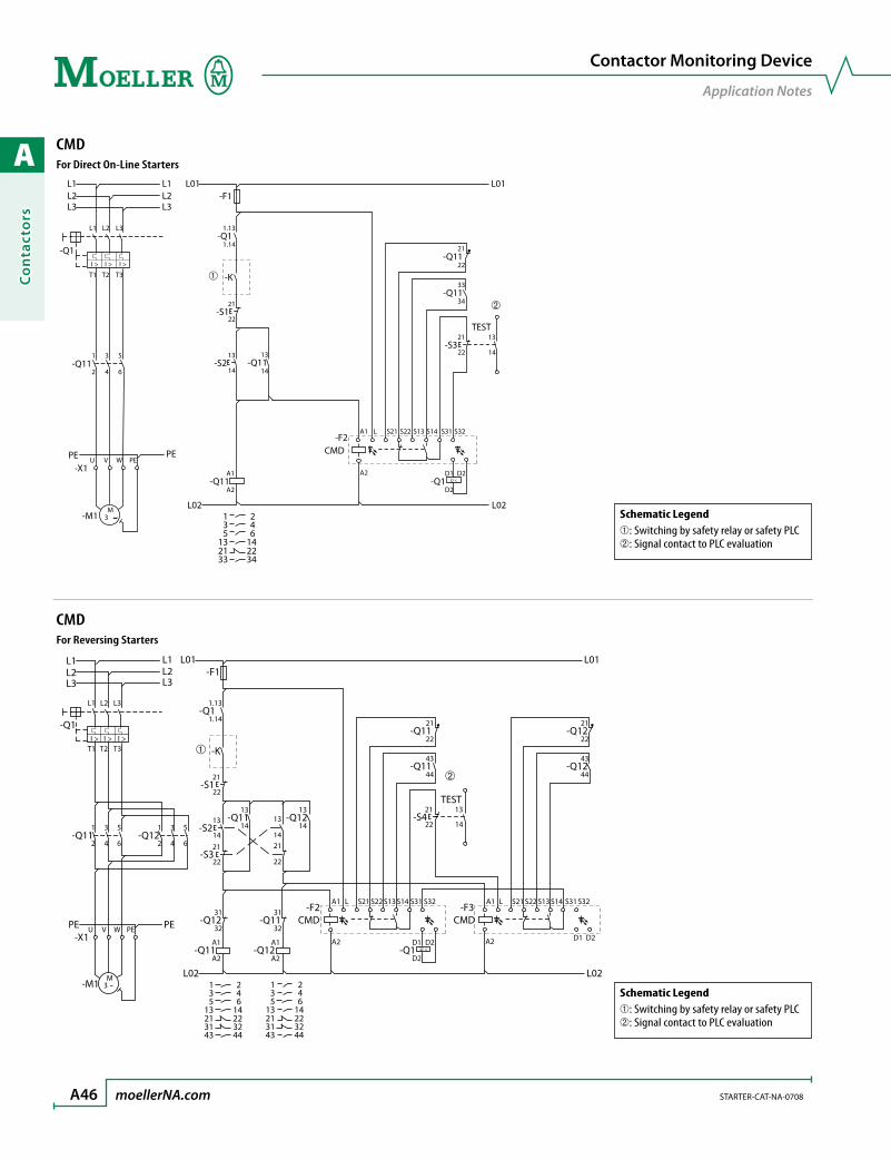
A
Co
nta
cto
rs
A46 moellerNA.com STARTER-CAT-NA-0708
Contactor Monitoring Device
Application Notes
CMDFor Direct On-Line Starters
I > I > I >
U <
M3 ˜
-Q1-Q1
-K
-S1
-F1
-Q11
-X1
-M1
L1 L2 L3 1.13
21
22
1.14
-Q1113
14
-Q1133
34
-Q1121
22
-F2CMD
-Q1D1
D2
D2
A1
A2
L S21 S22 S13 S14 S31 S32
-Q11A1
1 2
A2
T1
1 3 5
2 4 6
T2 T3
L1 L01 L01
L02 L02
L2
PEU V W PE
PE
L3
L1L2L3
-S213
14
-S321
22
13
14
TEST
3 45 6
13 1421 2233 34
CMDFor Reversing Starters
L1L2L3
L1L2L3
-Q1-Q1
-K
-S1
-F1
-Q11
-X1
-M1
-Q12
-Q11 -Q12
-Q11
-Q11
-Q12 -Q11-F2
CMD
-Q12 -Q1-Q11
L01 L01
L02 L02
PE PE
-F3CMD
-S2
-S3
-S4
TEST
1 23 45 6
13 1421 2231 3243 44
-Q12
-Q12
1 23 45 6
13 1421 2231 3243 44
I > I > I >
U <
M3 ˜
L1 L2 L3 1.13
21
22
1.14
13
1413
1421
22
13
14
43
44
21
22
31
32
31
32
A1
A2
D1
D2
D2 D1 D2
A1 A1
A2
L LS21 S22 S13 S14 S31 S32
A1
A2
T1
1 3 5
2 4 6
1 3 5
2 4 6
T2 T3
U V W PE
A2
13
1421
22
21
22
13
14
43
44
21
22
S21 S22 S13 S14 S31S32
Schematic Legend➀: Switching by safety relay or safety PLC➁: Signal contact to PLC evaluation
Schematic Legend➀: Switching by safety relay or safety PLC➁: Signal contact to PLC evaluation
A
Co
ntacto
rs
STARTER-CAT-NA-0708 moellerNA.com A47
Contactors
Notes
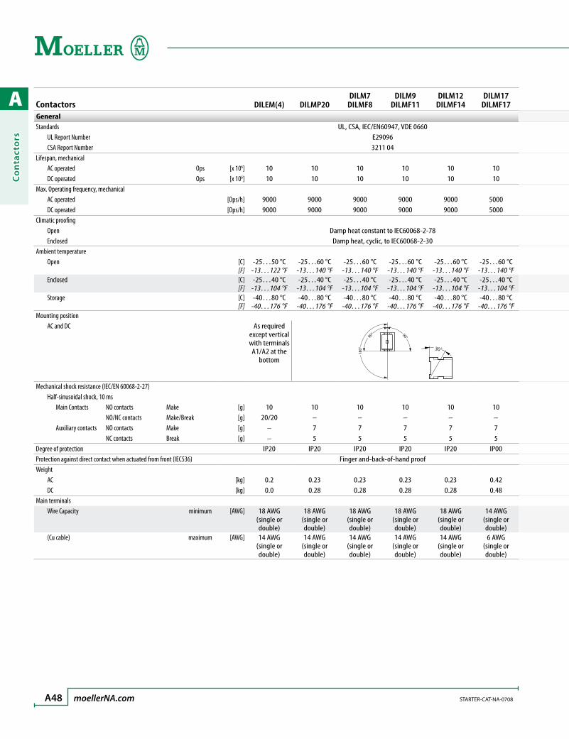
A
Co
nta
cto
rs
A48 moellerNA.com STARTER-CAT-NA-0708
Contactors DILEM(4) DILMP20DILM7
DILMF8DILM9
DILMF11DILM12
DILMF14DILM17
DILMF17GeneralStandards UL, CSA, IEC/EN60947, VDE 0660 UL Report Number E29096 CSA Report Number 3211 04Lifespan, mechanical AC operated Ops [x 106] 10 10 10 10 10 10 DC operated Ops [x 106] 10 10 10 10 10 10Max. Operating frequency, mechanical AC operated [Ops/h] 9000 9000 9000 9000 9000 5000 DC operated [Ops/h] 9000 9000 9000 9000 9000 5000Climatic proofing Open Damp heat constant to IEC60068-2-78 Enclosed Damp heat, cyclic, to IEC60068-2-30Ambient temperature Open [C]
[F]-25…50 °C
-13…122 °F -25…60 °C
-13…140 °F -25…60 °C
-13…140 °F -25…60 °C
-13…140 °F -25…60 °C
-13…140 °F -25…60 °C
-13…140 °F Enclosed [C]
[F]-25…40 °C
-13…104 °F-25…40 °C
-13…104 °F-25…40 °C
-13…104 °F-25…40 °C
-13…104 °F-25…40 °C
-13…104 °F-25…40 °C
-13…104 °F Storage [C]
[F]-40…80 °C
-40…176 °F-40…80 °C
-40…176 °F-40…80 °C
-40…176 °F-40…80 °C
-40…176 °F-40…80 °C
-40…176 °F-40…80 °C
-40…176 °FMounting position AC and DC As required
except vertical with terminals A1/A2 at the
bottom 18
0°
90° 90°
30˚
Mechanical shock resistance (IEC/EN 60068-2-27) Half-sinusoidal shock, 10 ms Main Contacts NO contacts Make [g] 10 10 10 10 10 10 NO/NC contacts Make/Break [g] 20/20 – – – – – Auxiliary contacts NO contacts Make [g] – 7 7 7 7 7 NC contacts Break [g] – 5 5 5 5 5Degree of protection IP20 IP20 IP20 IP20 IP20 IP00Protection against direct contact when actuated from front (IEC536) Finger and-back-of-hand proofWeight AC [kg] 0.2 0.23 0.23 0.23 0.23 0.42 DC [kg] 0.0 0.28 0.28 0.28 0.28 0.48Main terminals Wire Capacity minimum [AWG] 18 AWG
(single or double)
18 AWG (single or double)
18 AWG (single or double)
18 AWG (single or double)
18 AWG (single or double)
14 AWG (single or double)
(Cu cable) maximum [AWG] 14 AWG (single or double)
14 AWG (single or double)
14 AWG (single or double)
14 AWG (single or double)
14 AWG (single or double)
6 AWG(single or double)

A
Co
ntacto
rs
STARTER-CAT-NA-0708 moellerNA.com A49
Technical Data
DIL EM to DIL M(F)150 Contactors
Contactors DILEM(4) DILMP20DILM7
DILMF8DILM9
DILMF11DILM12
DILMF14DILM17
DILMF17GeneralStandards UL, CSA, IEC/EN60947, VDE 0660 UL Report Number E29096 CSA Report Number 3211 04Lifespan, mechanical AC operated Ops [x 106] 10 10 10 10 10 10 DC operated Ops [x 106] 10 10 10 10 10 10Max. Operating frequency, mechanical AC operated [Ops/h] 9000 9000 9000 9000 9000 5000 DC operated [Ops/h] 9000 9000 9000 9000 9000 5000Climatic proofing Open Damp heat constant to IEC60068-2-78 Enclosed Damp heat, cyclic, to IEC60068-2-30Ambient temperature Open [C]
[F]-25…50 °C
-13…122 °F -25…60 °C
-13…140 °F -25…60 °C
-13…140 °F -25…60 °C
-13…140 °F -25…60 °C
-13…140 °F -25…60 °C
-13…140 °F Enclosed [C]
[F]-25…40 °C
-13…104 °F-25…40 °C
-13…104 °F-25…40 °C
-13…104 °F-25…40 °C
-13…104 °F-25…40 °C
-13…104 °F-25…40 °C
-13…104 °F Storage [C]
[F]-40…80 °C
-40…176 °F-40…80 °C
-40…176 °F-40…80 °C
-40…176 °F-40…80 °C
-40…176 °F-40…80 °C
-40…176 °F-40…80 °C
-40…176 °FMounting position AC and DC As required
except vertical with terminals A1/A2 at the
bottom
Mechanical shock resistance (IEC/EN 60068-2-27) Half-sinusoidal shock, 10 ms Main Contacts NO contacts Make [g] 10 10 10 10 10 10 NO/NC contacts Make/Break [g] 20/20 – – – – – Auxiliary contacts NO contacts Make [g] – 7 7 7 7 7 NC contacts Break [g] – 5 5 5 5 5Degree of protection IP20 IP20 IP20 IP20 IP20 IP00Protection against direct contact when actuated from front (IEC536) Finger and-back-of-hand proofWeight AC [kg] 0.2 0.23 0.23 0.23 0.23 0.42 DC [kg] 0.0 0.28 0.28 0.28 0.28 0.48Main terminals Wire Capacity minimum [AWG] 18 AWG
(single or double)
18 AWG (single or double)
18 AWG (single or double)
18 AWG (single or double)
18 AWG (single or double)
14 AWG (single or double)
(Cu cable) maximum [AWG] 14 AWG (single or double)
14 AWG (single or double)
14 AWG (single or double)
14 AWG (single or double)
14 AWG (single or double)
6 AWG(single or double)
DILM25DILMF25
DILM32DILMF32
DILM40DILMF40
DILM50DILMF50
DILM65DILMF65
DILM80DILMF80
DILM95DILMF95
DILM115DILMF115
DILM150DILMF150
UL, CSA, IEC/EN60947, VDE 0660E290963211 04
10 10 10 10 10 10 10 10 1010 10 10 10 10 10 10 10 10
5000 5000 5000 5000 5000 3600 3600 3600 36005000 5000 5000 5000 5000 3600 3600 3600 3600
Damp heat constant to IEC60068-2-78Damp heat, cyclic, to IEC60068-2-30
-25…60 °C -13…140 °F
-25…60 °C -13…140 °F
-25…60 °C -13…140 °F
-25…60 °C -13…140 °F
-25…60 °C -13…140 °F
-25…60 °C -13…140 °F
-25…60 °C -13…140 °F
-25…60 °C -13…140 °F
-25…60 °C -13…140 °F
-25…40 °C -13…104 °F
-25…40 °C -13…104 °F
-25…40 °C -13…104 °F
-25…40 °C -13…104 °F
-25…40 °C -13…104 °F
-25…40 °C -13…104 °F
-25…40 °C -13…104 °F
-25…40 °C -13…104 °F
-25…40 °C -13…104 °F
-40…80 °C -40…176 °F
-40…80 °C -40…176 °F
-40…80 °C -40…176 °F
-40…80 °C -40…176 °F
-40…80 °C -40…176 °F
-40…80 °C -40…176 °F
-40…80 °C -40…176 °F
-40…80 °C -40…176 °F
-40…80 °C -40…176 °F
180°
90° 90°
30˚
180˚
90˚ 90˚
30˚
10 10 10 10 10 10 10 10 10– – – – – – – – –7 7 7 7 7 7 7 7 75 5 5 5 5 5 5 5 5
IP00 IP00 IP00 IP00 IP00 IP00 IP00 IP00 IP00Finger and-back-of-hand proof
0.42 0.42 0.9 0.9 0.9 2 2 2 20.48 0.48 1.1 1.1 1.1 2.1 2.1 2.1 2.1
14 AWG(single or double)
14 AWG(single or double)
14 AWG(single or double)
14 AWG(single or double)
14 AWG(single or double)
10 AWG(single or double)
10 AWG(single or double)
8 AWG(single or double)
8 AWG(single or double)
6 AWG(single or double)
6 AWG(single or double)
1 AWG(2 x 2 AWG)
1 AWG(2 x 2 AWG)
1 AWG(2 x 2 AWG)
3/0 AWG(2 x 2/0 AWG)
3/0 AWG(2 x 2/0 AWG)
3/0 AWG(2 x 2/0 AWG)
3/0 AWG(2 x 2/0 AWG)
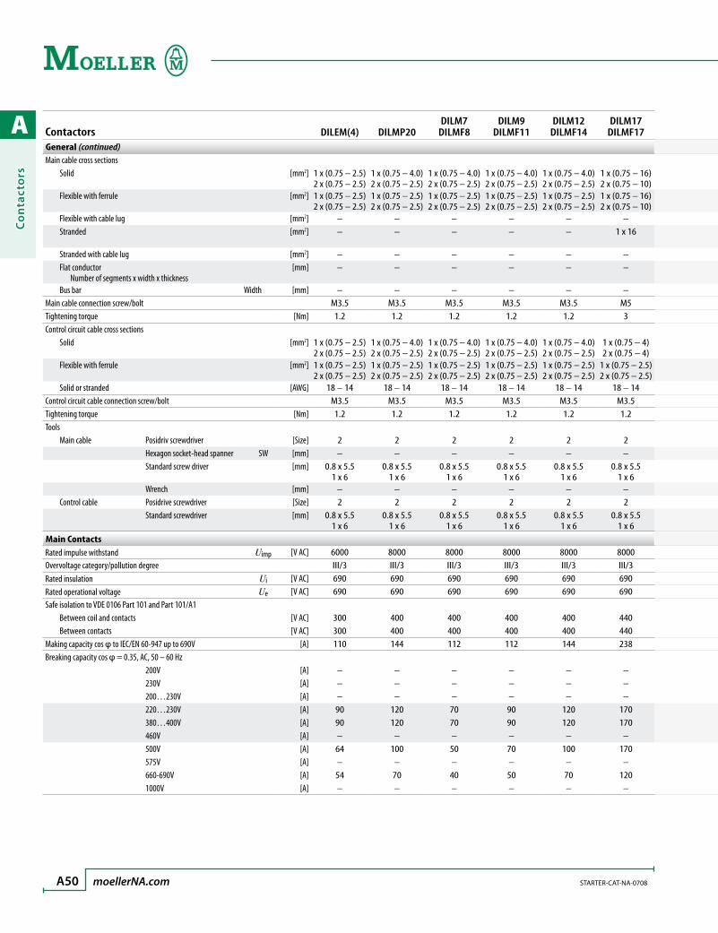
A
Co
nta
cto
rs
A50 moellerNA.com STARTER-CAT-NA-0708
Contactors DILEM(4) DILMP20DILM7
DILMF8DILM9
DILMF11DILM12
DILMF14DILM17
DILMF17General (continued)Main cable cross sections Solid [mm2] 1 x (0.75 – 2.5)
2 x (0.75 – 2.5)1 x (0.75 – 4.0)2 x (0.75 – 2.5)
1 x (0.75 – 4.0)2 x (0.75 – 2.5)
1 x (0.75 – 4.0)2 x (0.75 – 2.5)
1 x (0.75 – 4.0)2 x (0.75 – 2.5)
1 x (0.75 – 16)2 x (0.75 – 10)
Flexible with ferrule [mm2] 1 x (0.75 – 2.5)2 x (0.75 – 2.5)
1 x (0.75 – 2.5)2 x (0.75 – 2.5)
1 x (0.75 – 2.5)2 x (0.75 – 2.5)
1 x (0.75 – 2.5)2 x (0.75 – 2.5)
1 x (0.75 – 2.5)2 x (0.75 – 2.5)
1 x (0.75 – 16)2 x (0.75 – 10)
Flexible with cable lug [mm2] – – – – – – Stranded [mm2] – – – – – 1 x 16
Stranded with cable lug [mm2] – – – – – – Flat conductor Number of segments x width x thickness
[mm] – – – – – –
Bus bar Width [mm] – – – – – –Main cable connection screw/bolt M3.5 M3.5 M3.5 M3.5 M3.5 M5Tightening torque [Nm] 1.2 1.2 1.2 1.2 1.2 3Control circuit cable cross sections Solid [mm2] 1 x (0.75 – 2.5)
2 x (0.75 – 2.5)1 x (0.75 – 4.0)2 x (0.75 – 2.5)
1 x (0.75 – 4.0)2 x (0.75 – 2.5)
1 x (0.75 – 4.0)2 x (0.75 – 2.5)
1 x (0.75 – 4.0)2 x (0.75 – 2.5)
1 x (0.75 – 4)2 x (0.75 – 4)
Flexible with ferrule [mm2] 1 x (0.75 – 2.5)2 x (0.75 – 2.5)
1 x (0.75 – 2.5)2 x (0.75 – 2.5)
1 x (0.75 – 2.5)2 x (0.75 – 2.5)
1 x (0.75 – 2.5)2 x (0.75 – 2.5)
1 x (0.75 – 2.5)2 x (0.75 – 2.5)
1 x (0.75 – 2.5)2 x (0.75 – 2.5)
Solid or stranded [AWG] 18 – 14 18 – 14 18 – 14 18 – 14 18 – 14 18 – 14Control circuit cable connection screw/bolt M3.5 M3.5 M3.5 M3.5 M3.5 M3.5Tightening torque [Nm] 1.2 1.2 1.2 1.2 1.2 1.2Tools Main cable Posidriv screwdriver [Size] 2 2 2 2 2 2 Hexagon socket-head spanner SW [mm] – – – – – – Standard screw driver [mm] 0.8 x 5.5
1 x 60.8 x 5.5
1 x 60.8 x 5.5
1 x 60.8 x 5.5
1 x 60.8 x 5.5
1 x 60.8 x 5.5
1 x 6 Wrench [mm] – – – – – – Control cable Posidrive screwdriver [Size] 2 2 2 2 2 2 Standard screwdriver [mm] 0.8 x 5.5
1 x 60.8 x 5.5
1 x 60.8 x 5.5
1 x 60.8 x 5.5
1 x 60.8 x 5.5
1 x 60.8 x 5.5
1 x 6Main ContactsRated impulse withstand Uimp [V AC] 6000 8000 8000 8000 8000 8000Overvoltage category/pollution degree III/3 III/3 III/3 III/3 III/3 III/3Rated insulation Ui [V AC] 690 690 690 690 690 690Rated operational voltage Ue [V AC] 690 690 690 690 690 690Safe isolation to VDE 0106 Part 101 and Part 101/A1 Between coil and contacts [V AC] 300 400 400 400 400 440 Between contacts [V AC] 300 400 400 400 400 440Making capacity cos φ to IEC/EN 60-947 up to 690V [A] 110 144 112 112 144 238Breaking capacity cos φ = 0.35, AC, 50 – 60 Hz 200V [A] – – – – – – 230V [A] – – – – – – 200…230V [A] – – – – – – 220…230V [A] 90 120 70 90 120 170 380…400V [A] 90 120 70 90 120 170 460V [A] – – – – – – 500V [A] 64 100 50 70 100 170 575V [A] – – – – – – 660-690V [A] 54 70 40 50 70 120 1000V [A] – – – – – –
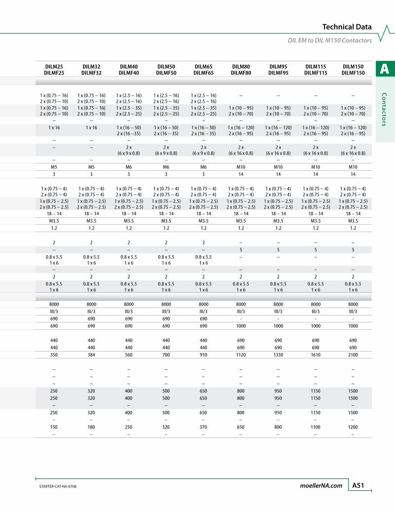
A
Co
ntacto
rs
STARTER-CAT-NA-0708 moellerNA.com A51
Technical Data
DIL EM to DIL M150 Contactors
Contactors DILEM(4) DILMP20DILM7
DILMF8DILM9
DILMF11DILM12
DILMF14DILM17
DILMF17General (continued)Main cable cross sections Solid [mm2] 1 x (0.75 – 2.5)
2 x (0.75 – 2.5)1 x (0.75 – 4.0)2 x (0.75 – 2.5)
1 x (0.75 – 4.0)2 x (0.75 – 2.5)
1 x (0.75 – 4.0)2 x (0.75 – 2.5)
1 x (0.75 – 4.0)2 x (0.75 – 2.5)
1 x (0.75 – 16)2 x (0.75 – 10)
Flexible with ferrule [mm2] 1 x (0.75 – 2.5)2 x (0.75 – 2.5)
1 x (0.75 – 2.5)2 x (0.75 – 2.5)
1 x (0.75 – 2.5)2 x (0.75 – 2.5)
1 x (0.75 – 2.5)2 x (0.75 – 2.5)
1 x (0.75 – 2.5)2 x (0.75 – 2.5)
1 x (0.75 – 16)2 x (0.75 – 10)
Flexible with cable lug [mm2] – – – – – – Stranded [mm2] – – – – – 1 x 16
Stranded with cable lug [mm2] – – – – – – Flat conductor Number of segments x width x thickness
[mm] – – – – – –
Bus bar Width [mm] – – – – – –Main cable connection screw/bolt M3.5 M3.5 M3.5 M3.5 M3.5 M5Tightening torque [Nm] 1.2 1.2 1.2 1.2 1.2 3Control circuit cable cross sections Solid [mm2] 1 x (0.75 – 2.5)
2 x (0.75 – 2.5)1 x (0.75 – 4.0)2 x (0.75 – 2.5)
1 x (0.75 – 4.0)2 x (0.75 – 2.5)
1 x (0.75 – 4.0)2 x (0.75 – 2.5)
1 x (0.75 – 4.0)2 x (0.75 – 2.5)
1 x (0.75 – 4)2 x (0.75 – 4)
Flexible with ferrule [mm2] 1 x (0.75 – 2.5)2 x (0.75 – 2.5)
1 x (0.75 – 2.5)2 x (0.75 – 2.5)
1 x (0.75 – 2.5)2 x (0.75 – 2.5)
1 x (0.75 – 2.5)2 x (0.75 – 2.5)
1 x (0.75 – 2.5)2 x (0.75 – 2.5)
1 x (0.75 – 2.5)2 x (0.75 – 2.5)
Solid or stranded [AWG] 18 – 14 18 – 14 18 – 14 18 – 14 18 – 14 18 – 14Control circuit cable connection screw/bolt M3.5 M3.5 M3.5 M3.5 M3.5 M3.5Tightening torque [Nm] 1.2 1.2 1.2 1.2 1.2 1.2Tools Main cable Posidriv screwdriver [Size] 2 2 2 2 2 2 Hexagon socket-head spanner SW [mm] – – – – – – Standard screw driver [mm] 0.8 x 5.5
1 x 60.8 x 5.5
1 x 60.8 x 5.5
1 x 60.8 x 5.5
1 x 60.8 x 5.5
1 x 60.8 x 5.5
1 x 6 Wrench [mm] – – – – – – Control cable Posidrive screwdriver [Size] 2 2 2 2 2 2 Standard screwdriver [mm] 0.8 x 5.5
1 x 60.8 x 5.5
1 x 60.8 x 5.5
1 x 60.8 x 5.5
1 x 60.8 x 5.5
1 x 60.8 x 5.5
1 x 6Main ContactsRated impulse withstand Uimp [V AC] 6000 8000 8000 8000 8000 8000Overvoltage category/pollution degree III/3 III/3 III/3 III/3 III/3 III/3Rated insulation Ui [V AC] 690 690 690 690 690 690Rated operational voltage Ue [V AC] 690 690 690 690 690 690Safe isolation to VDE 0106 Part 101 and Part 101/A1 Between coil and contacts [V AC] 300 400 400 400 400 440 Between contacts [V AC] 300 400 400 400 400 440Making capacity cos φ to IEC/EN 60-947 up to 690V [A] 110 144 112 112 144 238Breaking capacity cos φ = 0.35, AC, 50 – 60 Hz 200V [A] – – – – – – 230V [A] – – – – – – 200…230V [A] – – – – – – 220…230V [A] 90 120 70 90 120 170 380…400V [A] 90 120 70 90 120 170 460V [A] – – – – – – 500V [A] 64 100 50 70 100 170 575V [A] – – – – – – 660-690V [A] 54 70 40 50 70 120 1000V [A] – – – – – –
DILM25DILMF25
DILM32DILMF32
DILM40DILMF40
DILM50DILMF50
DILM65DILMF65
DILM80DILMF80
DILM95DILMF95
DILM115DILMF115
DILM150DILMF150
1 x (0.75 – 16)2 x (0.75 – 10)
1 x (0.75 – 16)2 x (0.75 – 10)
1 x (2.5 – 16)2 x (2.5 – 16)
1 x (2.5 – 16)2 x (2.5 – 16)
1 x (2.5 – 16)2 x (2.5 – 16)
– – – –
1 x (0.75 – 16)2 x (0.75 – 10)
1 x (0.75 – 16)2 x (0.75 – 10)
1 x (2.5 – 35)2 x (2.5 – 25)
1 x (2.5 – 35)2 x (2.5 – 25)
1 x (2.5 – 35)2 x (2.5 – 25)
1 x (10 – 95)2 x (10 – 70)
1 x (10 – 95)2 x (10 – 70)
1 x (10 – 95)2 x (10 – 70)
1 x (10 – 95)2 x (10 – 70)
– – – – – – – – –1 x 16 1 x 16 1 x (16 – 50)
2 x (16 –35)1 x (16 – 50)2 x (16 – 35)
1 x (16 – 50)2 x (16 – 35)
1 x (16 – 120)2 x (16 – 95)
1 x (16 – 120)2 x (16 – 95)
1 x (16 – 120)2 x (16 – 95)
1 x (16 – 120)2 x (16 – 95)
– – – – – – – – –– – 2 x
(6 x 9 x 0.8)2 x
(6 x 9 x 0.8)2 x
(6 x 9 x 0.8)2 x
(6 x 16 x 0.8)2 x
(6 x 16 x 0.8)2 x
(6 x 16 x 0.8)2 x
(6 x 16 x 0.8)– – – – – – – – –
M5 M5 M6 M6 M6 M10 M10 M10 M103 3 3 3 3 14 14 14 14
1 x (0.75 – 4)2 x (0.75 – 4)
1 x (0.75 – 4)2 x (0.75 – 4)
1 x (0.75 – 4)2 x (0.75 – 4)
1 x (0.75 – 4)2 x (0.75 – 4)
1 x (0.75 – 4)2 x (0.75 – 4)
1 x (0.75 – 4)2 x (0.75 – 4)
1 x (0.75 – 4)2 x (0.75 – 4)
1 x (0.75 – 4)2 x (0.75 – 4)
1 x (0.75 – 4)2 x (0.75 – 4)
1 x (0.75 – 2.5)2 x (0.75 – 2.5)
1 x (0.75 – 2.5)2 x (0.75 – 2.5)
1 x (0.75 – 2.5)2 x (0.75 – 2.5)
1 x (0.75 – 2.5)2 x (0.75 – 2.5)
1 x (0.75 – 2.5)2 x (0.75 – 2.5)
1 x (0.75 – 2.5)2 x (0.75 – 2.5)
1 x (0.75 – 2.5)2 x (0.75 – 2.5)
1 x (0.75 – 2.5)2 x (0.75 – 2.5)
1 x (0.75 – 2.5)2 x (0.75 – 2.5)
18 – 14 18 – 14 18 – 14 18 – 14 18 – 14 18 – 14 18 – 14 18 – 14 18 – 14M3.5 M3.5 M3.5 M3.5 M3.5 M3.5 M3.5 M3.5 M3.51.2 1.2 1.2 1.2 1.2 1.2 1.2 1.2 1.2
2 2 2 2 2 – – – –– – – – – 5 5 5 5
0.8 x 5.51 x 6
0.8 x 5.51 x 6
0.8 x 5.51 x 6
0.8 x 5.51 x 6
0.8 x 5.51 x 6
– – – –
– – – – – – – – –2 2 2 2 2 2 2 2 2
0.8 x 5.51 x 6
0.8 x 5.51 x 6
0.8 x 5.51 x 6
0.8 x 5.51 x 6
0.8 x 5.51 x 6
0.8 x 5.51 x 6
0.8 x 5.51 x 6
0.8 x 5.51 x 6
0.8 x 5.51 x 6
8000 8000 8000 8000 8000 8000 8000 8000 8000III/3 III/3 III/3 III/3 III/3 III/3 III/3 III/3 III/3690 690 690 690 690 - - - -690 690 690 690 690 1000 1000 1000 1000
440 440 440 440 440 690 690 690 690440 440 440 440 440 690 690 690 690350 384 560 700 910 1120 1330 1610 2100
– – – – – – – – –– – – – – – – – –– – – – – – – – –
250 320 400 500 650 800 950 1150 1500250 320 400 500 650 800 950 1150 1500
– – – – – – – – –250 320 400 500 650 800 950 1150 1500
– – – – – – – – –150 180 250 320 370 650 800 1100 1200
– – – – – – – – –
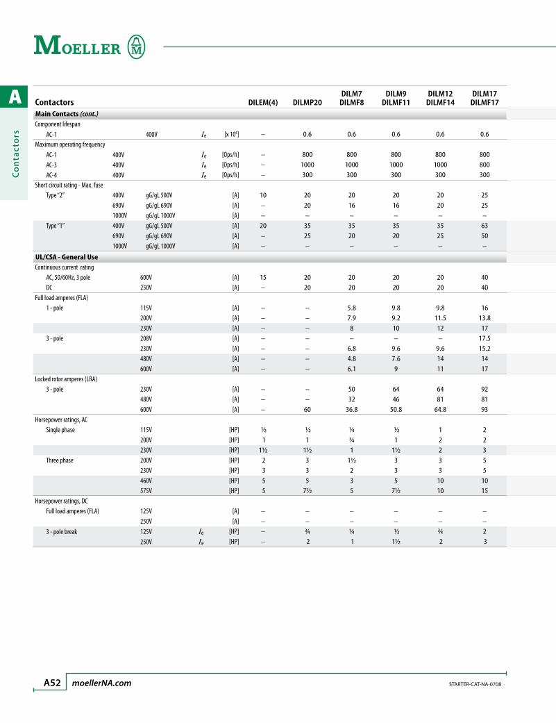
A
Co
nta
cto
rs
A52 moellerNA.com STARTER-CAT-NA-0708
Contactors DILEM(4) DILMP20DILM7
DILMF8DILM9
DILMF11DILM12
DILMF14DILM17
DILMF17Main Contacts (cont.)Component lifespan AC-1 400V Ie [x 106] – 0.6 0.6 0.6 0.6 0.6Maximum operating frequency AC-1 400V Ie [Ops/h] – 800 800 800 800 800 AC-3 400V Ie [Ops/h] – 1000 1000 1000 1000 800 AC-4 400V Ie [Ops/h] – 300 300 300 300 300Short circuit rating - Max. fuse Type “2” 400V gG/gL 500V [A] 10 20 20 20 20 25 690V gG/gL 690V [A] – 20 16 16 20 25 1000V gG/gL 1000V [A] – – – – – – Type “1” 400V gG/gL 500V [A] 20 35 35 35 35 63 690V gG/gL 690V [A] – 25 20 20 25 50 1000V gG/gL 1000V [A] – – – – – –
UL/CSA - General UseContinuous current rating AC, 50/60Hz, 3 pole 600V [A] 15 20 20 20 20 40 DC 250V [A] – 20 20 20 20 40Full load amperes (FLA) 1 - pole 115V [A] – – 5.8 9.8 9.8 16 200V [A] – – 7.9 9.2 11.5 13.8 230V [A] – – 8 10 12 17 3 - pole 208V [A] – – – – – 17.5 230V [A] – – 6.8 9.6 9.6 15.2 480V [A] – – 4.8 7.6 14 14 600V [A] – – 6.1 9 11 17Locked rotor amperes (LRA) 3 - pole 230V [A] – – 50 64 64 92 480V [A] – – 32 46 81 81 600V [A] – 60 36.8 50.8 64.8 93Horsepower ratings, AC Single phase 115V [HP] ½ ½ ¼ ½ 1 2 200V [HP] 1 1 ¾ 1 2 2 230V [HP] 1½ 1½ 1 1½ 2 3 Three phase 200V [HP] 2 3 1½ 3 3 5 230V [HP] 3 3 2 3 3 5 460V [HP] 5 5 3 5 10 10 575V [HP] 5 7½ 5 7½ 10 15Horsepower ratings, DC Full load amperes (FLA) 125V [A] – – – – – – 250V [A] – – – – – – 3 - pole break 125V Ie [HP] – ¾ ¼ ½ ¾ 2 250V Ie [HP] – 2 1 1½ 2 3

A
Co
ntacto
rs
STARTER-CAT-NA-0708 moellerNA.com A53
Technical Data
DIL EM to DIL M150 Contactors
Contactors DILEM(4) DILMP20DILM7
DILMF8DILM9
DILMF11DILM12
DILMF14DILM17
DILMF17Main Contacts (cont.)Component lifespan AC-1 400V Ie [x 106] – 0.6 0.6 0.6 0.6 0.6Maximum operating frequency AC-1 400V Ie [Ops/h] – 800 800 800 800 800 AC-3 400V Ie [Ops/h] – 1000 1000 1000 1000 800 AC-4 400V Ie [Ops/h] – 300 300 300 300 300Short circuit rating - Max. fuse Type “2” 400V gG/gL 500V [A] 10 20 20 20 20 25 690V gG/gL 690V [A] – 20 16 16 20 25 1000V gG/gL 1000V [A] – – – – – – Type “1” 400V gG/gL 500V [A] 20 35 35 35 35 63 690V gG/gL 690V [A] – 25 20 20 25 50 1000V gG/gL 1000V [A] – – – – – –
UL/CSA - General UseContinuous current rating AC, 50/60Hz, 3 pole 600V [A] 15 20 20 20 20 40 DC 250V [A] – 20 20 20 20 40Full load amperes (FLA) 1 - pole 115V [A] – – 5.8 9.8 9.8 16 200V [A] – – 7.9 9.2 11.5 13.8 230V [A] – – 8 10 12 17 3 - pole 208V [A] – – – – – 17.5 230V [A] – – 6.8 9.6 9.6 15.2 480V [A] – – 4.8 7.6 14 14 600V [A] – – 6.1 9 11 17Locked rotor amperes (LRA) 3 - pole 230V [A] – – 50 64 64 92 480V [A] – – 32 46 81 81 600V [A] – 60 36.8 50.8 64.8 93Horsepower ratings, AC Single phase 115V [HP] ½ ½ ¼ ½ 1 2 200V [HP] 1 1 ¾ 1 2 2 230V [HP] 1½ 1½ 1 1½ 2 3 Three phase 200V [HP] 2 3 1½ 3 3 5 230V [HP] 3 3 2 3 3 5 460V [HP] 5 5 3 5 10 10 575V [HP] 5 7½ 5 7½ 10 15Horsepower ratings, DC Full load amperes (FLA) 125V [A] – – – – – – 250V [A] – – – – – – 3 - pole break 125V Ie [HP] – ¾ ¼ ½ ¾ 2 250V Ie [HP] – 2 1 1½ 2 3
DILM25DILMF25
DILM32DILMF32
DILM40DILMF40
DILM50DILMF50
DILM65DILMF65
DILM80DILMF80
DILM95DILMF95
DILM115DILMF115
DILM150DILMF150
0.6 0.6 0.6 0.6 0.6 0.6 0.6 1 1
800 800 800 800 800 – – – –800 800 800 800 800 – – – –300 300 300 300 300 – – – –
35 63 63 80 125 160 160 250 25035 35 50 63 80 160 160 – –– – – – – – – – –
100 125 125 160 250 250 250 250 25050 63 80 80 100 200 200 – –– – – – – – – – –
40 40 55 65 80 125 125 155 15540 40 63 80 80 125 125 160 180
20 24 34 34 56 80 80 100 10019.6 19.6 32.2 46 57.5 68 68 110 13628 28 40 50 68 68 68 110 136
25.3 32.2 32.2 48.3 62.1 78.2 78.2 120 12022 28 42 54 68 80 104 130 15421 27 40 52 65 77 96 124 15622 27 41 52 62 77 99 99 125
127 162 232 290 365 435 580 725 870116 145 218 290 363 435 543 725 908116 146 232 290 348 434 580 580 726
2 3 3 3 5 7½ 7½ 10 103 5 5 7½ 10 15 15 25 255 5 7½ 10 15 15 15 25 30
7½ 10 10 15 20 25 25 40 4010 10 15 20 25 30 40 50 6015 20 30 40 50 60 75 100 12520 25 40 50 60 75 100 100 125
– – – – – 76 76 110 110– – – – – 89 89 106 106 2 3 5 7½ 10 10 10 15 15 5 5 10 15 20 25 25 30 30

A
Co
nta
cto
rs
A54 moellerNA.com STARTER-CAT-NA-0708
Contactors DILEM(4) DILMP20DILM7
DILMF8DILM9
DILMF11DILM12
DILMF14DILM17
DILMF17UL/CSA - Special PurposeLighting ratings Electrical discharge lamps (Ballast) Three phase, 60Hz 480V [A] – 20 12 18 20 27 600V [A] – 20 12 18 20 27 Two phase, 60Hz 277V [A] – 20 12 18 20 27 347V [A] – 20 12 18 20 27 Incandescent lamps (Tungsten) Three phase, 60Hz 480V [A] – 14 8 11 14 23 600V [A] – 14 8 11 14 23 Two phase, 60Hz 277V [A] – 14 8 11 14 23 347V [A] – 14 8 11 14 23Resistance heating ratings Three phase, 60Hz 480V [A] – 20 12 18 20 27 600V [A] – 20 12 18 20 27 Two phase, 60Hz 277V [A] – 20 12 18 20 27 347V [A] – 20 12 18 20 27Refrigeration ratings (CSA only) Locked rotor amperes (LRA) Three phase, 60Hz 480V [A] – 60 60 60 60 240 600V [A] – 60 60 60 60 180 3 - pole break Three phase, 60Hz 480V FLA [A] – 10 6 7.5 10 23 600V FLA [A] – 10 6 7.5 10 17Elevator ratings Three phase, 60Hz, Amperes 200V [A] – 7.8 3.7 7.8 7.8 11 240V [A] – 6.8 6.0 6.8 6.8 9.6 480V [A] – 11 3.4 4.8 11 11 600V [A] – 9.6 3.9 6.1 9.6 11 Three phase, 60Hz, Horsepower 200V [HP] – 2 ¾ 2 2 3 240V [HP] – 2 1½ 2 2 3 480V [HP] – 7½ 2 3 7½ 7½ 600V [HP] – 7½ 3 5 7½ 10

A
Co
ntacto
rs
STARTER-CAT-NA-0708 moellerNA.com A55
Technical Data
DIL EM to DIL M150 Contactors
Contactors DILEM(4) DILMP20DILM7
DILMF8DILM9
DILMF11DILM12
DILMF14DILM17
DILMF17UL/CSA - Special PurposeLighting ratings Electrical discharge lamps (Ballast) Three phase, 60Hz 480V [A] – 20 12 18 20 27 600V [A] – 20 12 18 20 27 Two phase, 60Hz 277V [A] – 20 12 18 20 27 347V [A] – 20 12 18 20 27 Incandescent lamps (Tungsten) Three phase, 60Hz 480V [A] – 14 8 11 14 23 600V [A] – 14 8 11 14 23 Two phase, 60Hz 277V [A] – 14 8 11 14 23 347V [A] – 14 8 11 14 23Resistance heating ratings Three phase, 60Hz 480V [A] – 20 12 18 20 27 600V [A] – 20 12 18 20 27 Two phase, 60Hz 277V [A] – 20 12 18 20 27 347V [A] – 20 12 18 20 27Refrigeration ratings (CSA only) Locked rotor amperes (LRA) Three phase, 60Hz 480V [A] – 60 60 60 60 240 600V [A] – 60 60 60 60 180 3 - pole break Three phase, 60Hz 480V FLA [A] – 10 6 7.5 10 23 600V FLA [A] – 10 6 7.5 10 17Elevator ratings Three phase, 60Hz, Amperes 200V [A] – 7.8 3.7 7.8 7.8 11 240V [A] – 6.8 6.0 6.8 6.8 9.6 480V [A] – 11 3.4 4.8 11 11 600V [A] – 9.6 3.9 6.1 9.6 11 Three phase, 60Hz, Horsepower 200V [HP] – 2 ¾ 2 2 3 240V [HP] – 2 1½ 2 2 3 480V [HP] – 7½ 2 3 7½ 7½ 600V [HP] – 7½ 3 5 7½ 10
DILM25DILMF25
DILM32DILMF32
DILM40DILMF40
DILM50DILMF50
DILM65DILMF65
DILM80DILMF80
DILM95DILMF95
DILM115DILMF115
DILM150DILMF150
35 40 63 79 88 85 100 136 16035 40 63 79 88 85 100 136 16035 40 63 79 88 85 100 136 16035 40 63 79 88 85 100 136 160
32 40 55 74 88 85 100 136 16032 40 55 74 88 85 100 136 16032 40 55 74 88 85 100 136 16032 40 55 74 88 85 100 136 160
35 40 63 79 88 94 110 136 16035 40 63 79 88 94 110 136 16035 40 63 79 88 94 110 136 16035 40 63 79 88 94 110 136 160
240 240 270 270 270 540 540 540 540180 180 270 270 270 420 420 540 540
32 40 26 36 45 63 70 84 9024 30 26 36 45 63 70 84 90
11 25.3 25.3 32.2 32.2 62.1 62.1 92 9215.2 22 28 42 42 68 80 104 10414 27 34 40 40 65 77 96 9617 22 32 41 41 62 77 99 99
3 7½ 7½ 10 10 20 20 30 305 7½ 10 15 15 25 30 40 40
10 20 25 30 30 50 60 75 7515 20 30 40 40 60 75 100 100

A
Co
nta
cto
rs
A56 moellerNA.com STARTER-CAT-NA-0708
Contactors DILEM(4) DILMP20DILM7
DILMF8DILM9
DILMF11DILM12
DILMF14DILM17
DILMF17IEC (AC) Application RatingsAC-1 Duty 3-pole, conventional free air, thermal current, 50 – 60 Hz Open 40 °C / 104 °F Ith [A] 22 22 22 22 22 40 50 °C / 122 °F Ith [A] 20 21 21 21 21 38 55 °C / 137 °F Ith [A] 19 21 21 21 21 37 60 °C / 140 °F Ith [A] – 20 20 20 20 35 Enclosed (at maximum permissible ambient temperature) Ith [A] 16 18 18 18 18 32 1-pole, conventional free air, thermal current, 50 – 60 Hz Open (at maximum permissible ambient temperature) Ith [A] 50 50 50 50 50 85 Enclosed (at maximum permissible ambient temperature) Ith [A] 40 45 45 45 45 80AC-3 Duty
Rated operational current, 50 – 60 Hz Open ➊ 200V Ie [A] – – – – – – 220/230V Ie [A] 9 12 7 9 12 18 230V Ie [A] – – – – – – 240V Ie [A] 9 12 7 9 12 18 380/400 Ie [A] 9 12 7 9 12 18 415V Ie [A] 9 12 7 9 12 18 440V Ie [A] 9 12 7 9 12 18 460V Ie [A] – – – – – – 500V Ie [A] – 10 5 7 10 18 550V Ie [A] 6.4 – – – – – 575V Ie [A] – – – – – – 660V Ie [A] – – – – – – 660/690V Ie [A] 4.8 7 4 5 7 12 1000V Ie [A] – – – – – –
Rated power, 50 – 60 Hz Open ➊ 220/230V Pn [kW] 2.2 3.5 2.2 2.5 3.5 5 240V Pn [kW] 2.5 4 2.2 3 4 5.5 380/400V Pn [kW] 4 5.5 3 4 5.5 7.5 415V Pn [kW] 4.3 7 4 5.5 7 10 440V Pn [kW] 4.6 7.5 4.5 5.5 7.5 10.5 500V Pn [kW] 4 7 3.5 4.5 7 12 660/690V Pn [kW] 4 6.5 3.5 4.5 6.5 11 1000V Pn [kW] – – – – – –
➊ At maximum permissible ambient temperature.
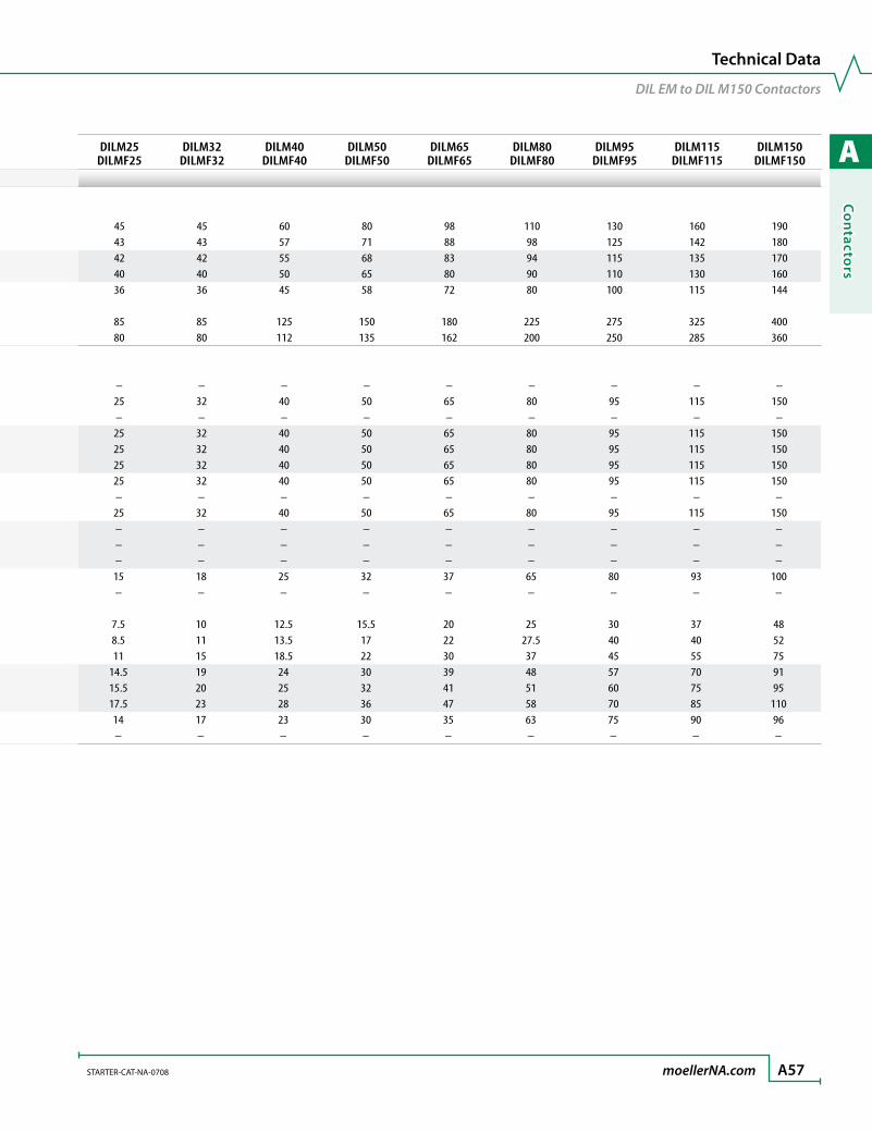
A
Co
ntacto
rs
STARTER-CAT-NA-0708 moellerNA.com A57
Technical Data
DIL EM to DIL M150 Contactors
Contactors DILEM(4) DILMP20DILM7
DILMF8DILM9
DILMF11DILM12
DILMF14DILM17
DILMF17IEC (AC) Application RatingsAC-1 Duty 3-pole, conventional free air, thermal current, 50 – 60 Hz Open 40 °C / 104 °F Ith [A] 22 22 22 22 22 40 50 °C / 122 °F Ith [A] 20 21 21 21 21 38 55 °C / 137 °F Ith [A] 19 21 21 21 21 37 60 °C / 140 °F Ith [A] – 20 20 20 20 35 Enclosed (at maximum permissible ambient temperature) Ith [A] 16 18 18 18 18 32 1-pole, conventional free air, thermal current, 50 – 60 Hz Open (at maximum permissible ambient temperature) Ith [A] 50 50 50 50 50 85 Enclosed (at maximum permissible ambient temperature) Ith [A] 40 45 45 45 45 80AC-3 Duty
Rated operational current, 50 – 60 Hz Open ➊ 200V Ie [A] – – – – – – 220/230V Ie [A] 9 12 7 9 12 18 230V Ie [A] – – – – – – 240V Ie [A] 9 12 7 9 12 18 380/400 Ie [A] 9 12 7 9 12 18 415V Ie [A] 9 12 7 9 12 18 440V Ie [A] 9 12 7 9 12 18 460V Ie [A] – – – – – – 500V Ie [A] – 10 5 7 10 18 550V Ie [A] 6.4 – – – – – 575V Ie [A] – – – – – – 660V Ie [A] – – – – – – 660/690V Ie [A] 4.8 7 4 5 7 12 1000V Ie [A] – – – – – –
Rated power, 50 – 60 Hz Open ➊ 220/230V Pn [kW] 2.2 3.5 2.2 2.5 3.5 5 240V Pn [kW] 2.5 4 2.2 3 4 5.5 380/400V Pn [kW] 4 5.5 3 4 5.5 7.5 415V Pn [kW] 4.3 7 4 5.5 7 10 440V Pn [kW] 4.6 7.5 4.5 5.5 7.5 10.5 500V Pn [kW] 4 7 3.5 4.5 7 12 660/690V Pn [kW] 4 6.5 3.5 4.5 6.5 11 1000V Pn [kW] – – – – – –
DILM25DILMF25
DILM32DILMF32
DILM40DILMF40
DILM50DILMF50
DILM65DILMF65
DILM80DILMF80
DILM95DILMF95
DILM115DILMF115
DILM150DILMF150
45 45 60 80 98 110 130 160 19043 43 57 71 88 98 125 142 18042 42 55 68 83 94 115 135 17040 40 50 65 80 90 110 130 16036 36 45 58 72 80 100 115 144
85 85 125 150 180 225 275 325 40080 80 112 135 162 200 250 285 360
– – – – – – – – –25 32 40 50 65 80 95 115 150– – – – – – – – –25 32 40 50 65 80 95 115 15025 32 40 50 65 80 95 115 15025 32 40 50 65 80 95 115 15025 32 40 50 65 80 95 115 150– – – – – – – – –25 32 40 50 65 80 95 115 150– – – – – – – – –– – – – – – – – –– – – – – – – – –15 18 25 32 37 65 80 93 100– – – – – – – – –
7.5 10 12.5 15.5 20 25 30 37 488.5 11 13.5 17 22 27.5 40 40 5211 15 18.5 22 30 37 45 55 75
14.5 19 24 30 39 48 57 70 9115.5 20 25 32 41 51 60 75 9517.5 23 28 36 47 58 70 85 11014 17 23 30 35 63 75 90 96– – – – – – – – –
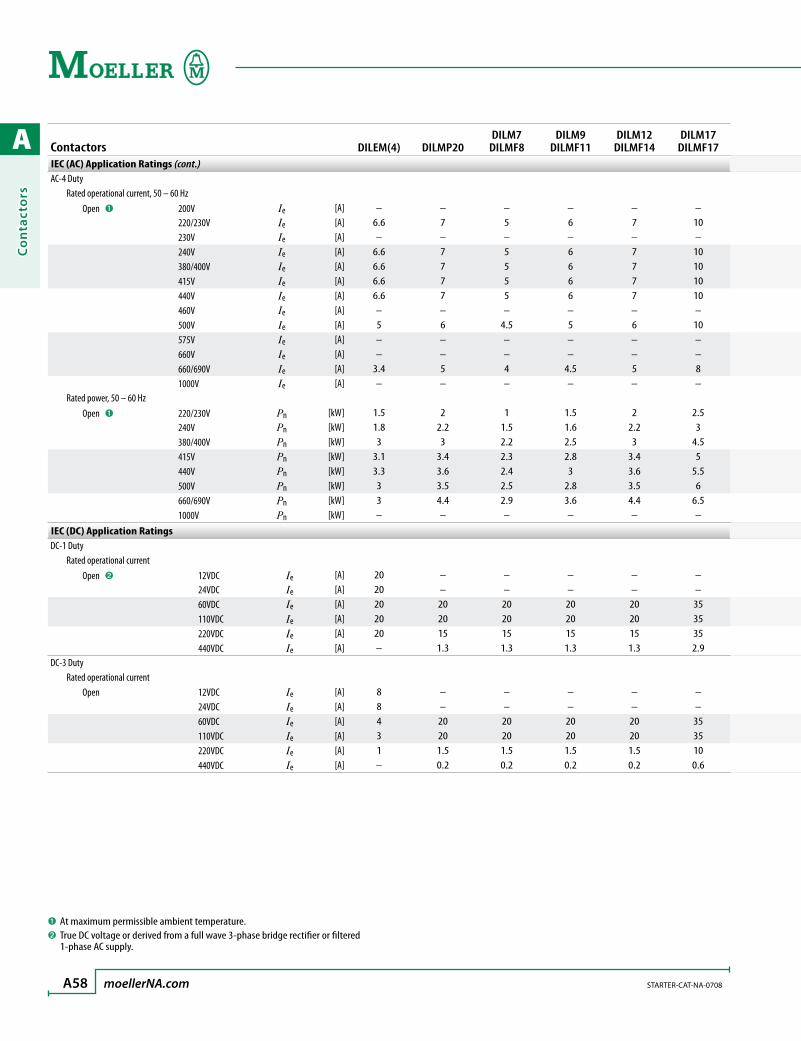
A
Co
nta
cto
rs
A58 moellerNA.com STARTER-CAT-NA-0708
Contactors DILEM(4) DILMP20DILM7
DILMF8DILM9
DILMF11DILM12
DILMF14DILM17
DILMF17IEC (AC) Application Ratings (cont.)AC-4 Duty
Rated operational current, 50 – 60 Hz Open ➊ 200V Ie [A] – – – – – – 220/230V Ie [A] 6.6 7 5 6 7 10 230V Ie [A] – – – – – – 240V Ie [A] 6.6 7 5 6 7 10 380/400V Ie [A] 6.6 7 5 6 7 10 415V Ie [A] 6.6 7 5 6 7 10 440V Ie [A] 6.6 7 5 6 7 10 460V Ie [A] – – – – – – 500V Ie [A] 5 6 4.5 5 6 10 575V Ie [A] – – – – – – 660V Ie [A] – – – – – – 660/690V Ie [A] 3.4 5 4 4.5 5 8 1000V Ie [A] – – – – – –
Rated power, 50 – 60 Hz Open ➊ 220/230V Pn [kW] 1.5 2 1 1.5 2 2.5 240V Pn [kW] 1.8 2.2 1.5 1.6 2.2 3 380/400V Pn [kW] 3 3 2.2 2.5 3 4.5 415V Pn [kW] 3.1 3.4 2.3 2.8 3.4 5 440V Pn [kW] 3.3 3.6 2.4 3 3.6 5.5 500V Pn [kW] 3 3.5 2.5 2.8 3.5 6 660/690V Pn [kW] 3 4.4 2.9 3.6 4.4 6.5 1000V Pn [kW] – – – – – –
IEC (DC) Application RatingsDC-1 Duty
Rated operational current Open ➋ 12VDC Ie [A] 20 – – – – – 24VDC Ie [A] 20 – – – – – 60VDC Ie [A] 20 20 20 20 20 35 110VDC Ie [A] 20 20 20 20 20 35 220VDC Ie [A] 20 15 15 15 15 35 440VDC Ie [A] – 1.3 1.3 1.3 1.3 2.9DC-3 Duty Rated operational current Open 12VDC Ie [A] 8 – – – – – 24VDC Ie [A] 8 – – – – – 60VDC Ie [A] 4 20 20 20 20 35 110VDC Ie [A] 3 20 20 20 20 35 220VDC Ie [A] 1 1.5 1.5 1.5 1.5 10 440VDC Ie [A] – 0.2 0.2 0.2 0.2 0.6
➊ At maximum permissible ambient temperature.➋ True DC voltage or derived from a full wave 3-phase bridge rectifier or filtered
1-phase AC supply.
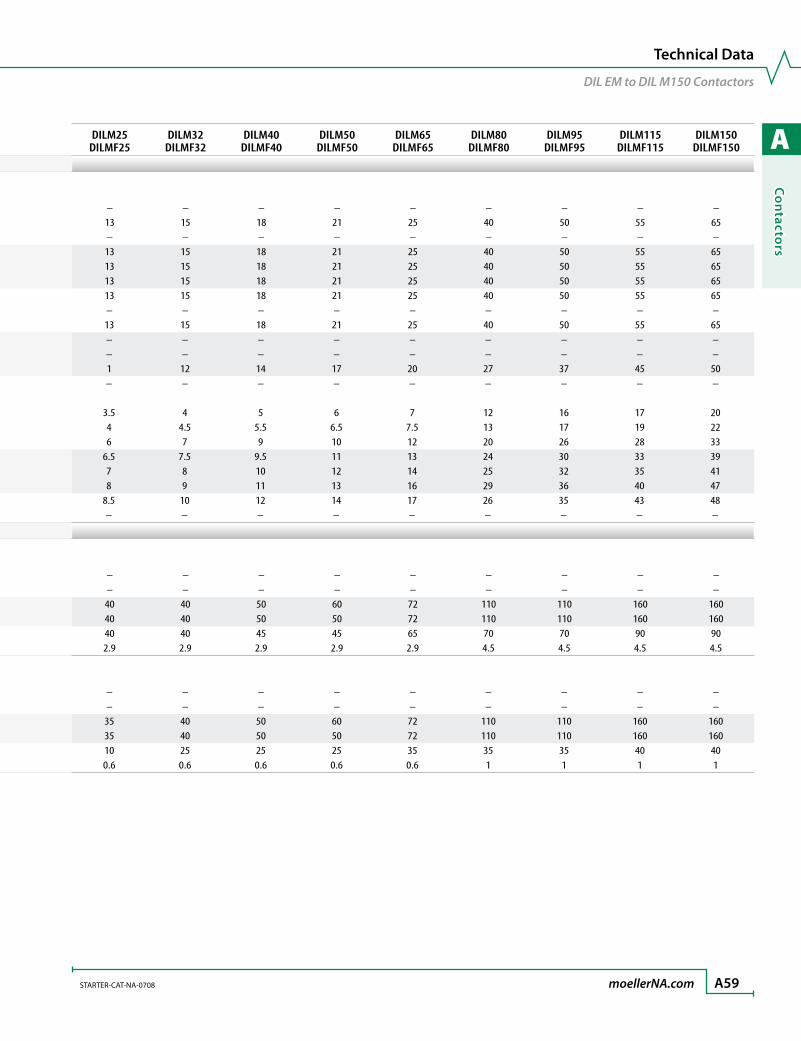
A
Co
ntacto
rs
STARTER-CAT-NA-0708 moellerNA.com A59
Technical Data
DIL EM to DIL M150 Contactors
Contactors DILEM(4) DILMP20DILM7
DILMF8DILM9
DILMF11DILM12
DILMF14DILM17
DILMF17IEC (AC) Application Ratings (cont.)AC-4 Duty
Rated operational current, 50 – 60 Hz Open ➊ 200V Ie [A] – – – – – – 220/230V Ie [A] 6.6 7 5 6 7 10 230V Ie [A] – – – – – – 240V Ie [A] 6.6 7 5 6 7 10 380/400V Ie [A] 6.6 7 5 6 7 10 415V Ie [A] 6.6 7 5 6 7 10 440V Ie [A] 6.6 7 5 6 7 10 460V Ie [A] – – – – – – 500V Ie [A] 5 6 4.5 5 6 10 575V Ie [A] – – – – – – 660V Ie [A] – – – – – – 660/690V Ie [A] 3.4 5 4 4.5 5 8 1000V Ie [A] – – – – – –
Rated power, 50 – 60 Hz Open ➊ 220/230V Pn [kW] 1.5 2 1 1.5 2 2.5 240V Pn [kW] 1.8 2.2 1.5 1.6 2.2 3 380/400V Pn [kW] 3 3 2.2 2.5 3 4.5 415V Pn [kW] 3.1 3.4 2.3 2.8 3.4 5 440V Pn [kW] 3.3 3.6 2.4 3 3.6 5.5 500V Pn [kW] 3 3.5 2.5 2.8 3.5 6 660/690V Pn [kW] 3 4.4 2.9 3.6 4.4 6.5 1000V Pn [kW] – – – – – –
IEC (DC) Application RatingsDC-1 Duty
Rated operational current Open ➋ 12VDC Ie [A] 20 – – – – – 24VDC Ie [A] 20 – – – – – 60VDC Ie [A] 20 20 20 20 20 35 110VDC Ie [A] 20 20 20 20 20 35 220VDC Ie [A] 20 15 15 15 15 35 440VDC Ie [A] – 1.3 1.3 1.3 1.3 2.9DC-3 Duty Rated operational current Open 12VDC Ie [A] 8 – – – – – 24VDC Ie [A] 8 – – – – – 60VDC Ie [A] 4 20 20 20 20 35 110VDC Ie [A] 3 20 20 20 20 35 220VDC Ie [A] 1 1.5 1.5 1.5 1.5 10 440VDC Ie [A] – 0.2 0.2 0.2 0.2 0.6
DILM25DILMF25
DILM32DILMF32
DILM40DILMF40
DILM50DILMF50
DILM65DILMF65
DILM80DILMF80
DILM95DILMF95
DILM115DILMF115
DILM150DILMF150
– – – – – – – – –13 15 18 21 25 40 50 55 65– – – – – – – – –13 15 18 21 25 40 50 55 6513 15 18 21 25 40 50 55 6513 15 18 21 25 40 50 55 6513 15 18 21 25 40 50 55 65– – – – – – – – –13 15 18 21 25 40 50 55 65– – – – – – – – –– – – – – – – – –1 12 14 17 20 27 37 45 50– – – – – – – – –
3.5 4 5 6 7 12 16 17 204 4.5 5.5 6.5 7.5 13 17 19 226 7 9 10 12 20 26 28 33
6.5 7.5 9.5 11 13 24 30 33 397 8 10 12 14 25 32 35 418 9 11 13 16 29 36 40 47
8.5 10 12 14 17 26 35 43 48– – – – – – – – –
– – – – – – – – –– – – – – – – – –40 40 50 60 72 110 110 160 16040 40 50 50 72 110 110 160 16040 40 45 45 65 70 70 90 902.9 2.9 2.9 2.9 2.9 4.5 4.5 4.5 4.5
– – – – – – – – –– – – – – – – – –35 40 50 60 72 110 110 160 16035 40 50 50 72 110 110 160 16010 25 25 25 35 35 35 40 400.6 0.6 0.6 0.6 0.6 1 1 1 1

A
Co
nta
cto
rs
A60 moellerNA.com STARTER-CAT-NA-0708
Contactors DILEM(4) DILMP20DILM7
DILMF8DILM9
DILMF11DILM12
DILMF14DILM17
DILMF17IEC (DC) Application Ratings (cont.)DC-5 Duty Rated operational current Open 12VDC Ie [A] 2.5 – – – – – 24VDC Ie [A] 2.5 – – – – – 60VDC Ie [A] 2.5 20 20 20 20 35 110VDC Ie [A] 1.5 20 20 20 20 35 220VDC Ie [A] 0.3 1.5 1.5 1.5 1.5 10 440VDC Ie [A] – 0.2 0.2 0.2 0.2 0.6
Current Heat Loss (3 or 4 pole)Current heat loss at Ith Ith [W] 2.7 4.7 4.7 4.7 4.7 7.3Current heat loss at Ie to AC-3/400V Ie [W] 0.5 1.1 0.37 0.6 1.1 1.7Impedance per pole [mΩ] – 2.5 2.5 2.5 2.5 2
Magnet SystemVoltage tolerance AC operated Single Voltage coil 60Hz Pick-up x V coil [x Uc] – 0.8 – 1.1 0.8 – 1.1 0.8 – 1.1 0.8 – 1.1 0.8 – 1.1 Drop-out x V coil [x Uc] – 0.3 – 0.6 0.3 – 0.6 0.3 – 0.6 0.3 – 0.6 0.3 – 0.6 Single Voltage coil 50Hz Pick-up x V coil [x Uc] 0.8 – 1.1 0.8 – 1.1 0.8 – 1.1 0.8 – 1.1 0.8 – 1.1 0.8 – 1.1 Drop-out x V coil [x Uc] – 0.3 – 0.6 0.3 – 0.6 0.3 – 0.6 0.3 – 0.6 0.3 – 0.6 Dual Voltage coil 50Hz, 60Hz Pick-up x V coil [x Uc] 0.8 – 1.1 0.8 – 1.1 0.8 – 1.1 0.8 – 1.1 0.8 – 1.1 0.8 – 1.1 Drop-out x V coil [x Uc] – 0.3 – 0.6 0.3 – 0.6 0.3 – 0.6 0.3 – 0.6 0.3 – 0.6 Dual Frequency coil 50/60Hz Pick-up x V coil [x Uc] 0.85 – 1.1 – – – – – Drop-out x V coil [x Uc] – – – – – – DC operated ➊ Pick-up x V coil [x Uc] 0.8 – 1.1 0.8 – 1.1 ➋ 0.8 – 1.1 ➋ 0.8 – 1.1 ➋ 0.8 – 1.1 ➋ 0.7 – 1.2 ➌
Drop-out x V coil [x Uc] – 0.15 – 0.6 0.15 – 0.6 0.15 – 0.6 0.15 – 0.6 0.15 – 0.6Power consumption of the coil in a cold state and 1.0 X Uc AC operated Single Voltage coil 60Hz Pick-up [VA] – 30 30 30 30 67 Sealed [VA/W] – 4.4/1.4 4.4/1.4 4.4/1.4 4.4/1.4 8.7/2.6 Single Voltage coil 50Hz Pick-up [VA] 25 24 24 24 24 52 Sealed [VA/W] 4.6/1.3 3.4/1.2 3.4/1.2 3.4/1.2 3.4/1.2 7.1/2.1 Dual Voltage coil 50Hz, 60Hz Pick-up [VA] 25 – – – – – Sealed [VA/W] 4.6/1.3 – – – – – Dual Frequency coil 50/60Hz Pick-up [VA] 29 25 – 27 25 – 27 25 – 27 25 – 27 58 – 62 Sealed [VA/W] 3.9/1.1 3.3 – 4.2/
1.2 – 1.43.3 – 4.2/ 1.2 – 1.4
3.3 – 4.2/ 1.2 – 1.4
3.3 – 4.2/ 1.2 – 1.4
6.5 – 9.1/ 2 – 2.5
DC operated ➊ Pick-up [W] 2.6 4.5 3 3 4.5 12@24V Sealed [W] 2.6 4.5 3 3 4.5 0.5@24V
➊ True DC voltage or derived from a full wave 3-phase bridge rectifier or filtered 1-phase AC supply.
➋At 24V: 0.7…1.3 without additional auxiliary contact modules and ambient temperature 40 °C
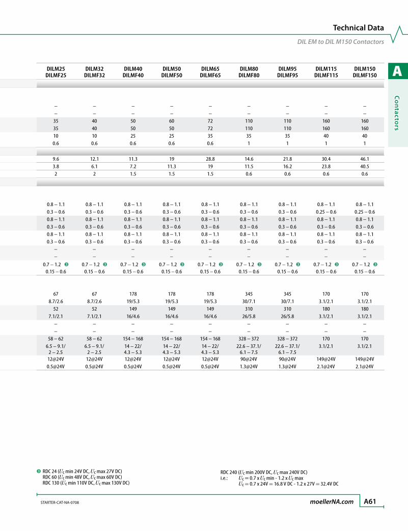
A
Co
ntacto
rs
STARTER-CAT-NA-0708 moellerNA.com A61
Technical Data
DIL EM to DIL M150 Contactors
Contactors DILEM(4) DILMP20DILM7
DILMF8DILM9
DILMF11DILM12
DILMF14DILM17
DILMF17IEC (DC) Application Ratings (cont.)DC-5 Duty Rated operational current Open 12VDC Ie [A] 2.5 – – – – – 24VDC Ie [A] 2.5 – – – – – 60VDC Ie [A] 2.5 20 20 20 20 35 110VDC Ie [A] 1.5 20 20 20 20 35 220VDC Ie [A] 0.3 1.5 1.5 1.5 1.5 10 440VDC Ie [A] – 0.2 0.2 0.2 0.2 0.6
Current Heat Loss (3 or 4 pole)Current heat loss at Ith Ith [W] 2.7 4.7 4.7 4.7 4.7 7.3Current heat loss at Ie to AC-3/400V Ie [W] 0.5 1.1 0.37 0.6 1.1 1.7Impedance per pole [mΩ] – 2.5 2.5 2.5 2.5 2
Magnet SystemVoltage tolerance AC operated Single Voltage coil 60Hz Pick-up x V coil [x Uc] – 0.8 – 1.1 0.8 – 1.1 0.8 – 1.1 0.8 – 1.1 0.8 – 1.1 Drop-out x V coil [x Uc] – 0.3 – 0.6 0.3 – 0.6 0.3 – 0.6 0.3 – 0.6 0.3 – 0.6 Single Voltage coil 50Hz Pick-up x V coil [x Uc] 0.8 – 1.1 0.8 – 1.1 0.8 – 1.1 0.8 – 1.1 0.8 – 1.1 0.8 – 1.1 Drop-out x V coil [x Uc] – 0.3 – 0.6 0.3 – 0.6 0.3 – 0.6 0.3 – 0.6 0.3 – 0.6 Dual Voltage coil 50Hz, 60Hz Pick-up x V coil [x Uc] 0.8 – 1.1 0.8 – 1.1 0.8 – 1.1 0.8 – 1.1 0.8 – 1.1 0.8 – 1.1 Drop-out x V coil [x Uc] – 0.3 – 0.6 0.3 – 0.6 0.3 – 0.6 0.3 – 0.6 0.3 – 0.6 Dual Frequency coil 50/60Hz Pick-up x V coil [x Uc] 0.85 – 1.1 – – – – – Drop-out x V coil [x Uc] – – – – – – DC operated ➊ Pick-up x V coil [x Uc] 0.8 – 1.1 0.8 – 1.1 ➋ 0.8 – 1.1 ➋ 0.8 – 1.1 ➋ 0.8 – 1.1 ➋ 0.7 – 1.2 ➌
Drop-out x V coil [x Uc] – 0.15 – 0.6 0.15 – 0.6 0.15 – 0.6 0.15 – 0.6 0.15 – 0.6Power consumption of the coil in a cold state and 1.0 X Uc AC operated Single Voltage coil 60Hz Pick-up [VA] – 30 30 30 30 67 Sealed [VA/W] – 4.4/1.4 4.4/1.4 4.4/1.4 4.4/1.4 8.7/2.6 Single Voltage coil 50Hz Pick-up [VA] 25 24 24 24 24 52 Sealed [VA/W] 4.6/1.3 3.4/1.2 3.4/1.2 3.4/1.2 3.4/1.2 7.1/2.1 Dual Voltage coil 50Hz, 60Hz Pick-up [VA] 25 – – – – – Sealed [VA/W] 4.6/1.3 – – – – – Dual Frequency coil 50/60Hz Pick-up [VA] 29 25 – 27 25 – 27 25 – 27 25 – 27 58 – 62 Sealed [VA/W] 3.9/1.1 3.3 – 4.2/
1.2 – 1.43.3 – 4.2/ 1.2 – 1.4
3.3 – 4.2/ 1.2 – 1.4
3.3 – 4.2/ 1.2 – 1.4
6.5 – 9.1/ 2 – 2.5
DC operated ➊ Pick-up [W] 2.6 4.5 3 3 4.5 12@24V Sealed [W] 2.6 4.5 3 3 4.5 0.5@24V
DILM25DILMF25
DILM32DILMF32
DILM40DILMF40
DILM50DILMF50
DILM65DILMF65
DILM80DILMF80
DILM95DILMF95
DILM115DILMF115
DILM150DILMF150
– – – – – – – – –– – – – – – – – –35 40 50 60 72 110 110 160 16035 40 50 50 72 110 110 160 16010 10 25 25 35 35 35 40 400.6 0.6 0.6 0.6 0.6 1 1 1 1
9.6 12.1 11.3 19 28.8 14.6 21.8 30.4 46.13.8 6.1 7.2 11.3 19 11.5 16.2 23.8 40.52 2 1.5 1.5 1.5 0.6 0.6 0.6 0.6
0.8 – 1.1 0.8 – 1.1 0.8 – 1.1 0.8 – 1.1 0.8 – 1.1 0.8 – 1.1 0.8 – 1.1 0.8 – 1.1 0.8 – 1.1 0.3 – 0.6 0.3 – 0.6 0.3 – 0.6 0.3 – 0.6 0.3 – 0.6 0.3 – 0.6 0.3 – 0.6 0.25 – 0.6 0.25 – 0.60.8 – 1.1 0.8 – 1.1 0.8 – 1.1 0.8 – 1.1 0.8 – 1.1 0.8 – 1.1 0.8 – 1.1 0.8 – 1.1 0.8 – 1.10.3 – 0.6 0.3 – 0.6 0.3 – 0.6 0.3 – 0.6 0.3 – 0.6 0.3 – 0.6 0.3 – 0.6 0.3 – 0.6 0.3 – 0.60.8 – 1.1 0.8 – 1.1 0.8 – 1.1 0.8 – 1.1 0.8 – 1.1 0.8 – 1.1 0.8 – 1.1 0.8 – 1.1 0.8 – 1.10.3 – 0.6 0.3 – 0.6 0.3 – 0.6 0.3 – 0.6 0.3 – 0.6 0.3 – 0.6 0.3 – 0.6 0.3 – 0.6 0.3 – 0.6
– – – – – – – – –– – – – – – – – –
0.7 – 1.2 ➌ 0.7 – 1.2 ➌ 0.7 – 1.2 ➌ 0.7 – 1.2 ➌ 0.7 – 1.2 ➌ 0.7 – 1.2 ➌ 0.7 – 1.2 ➌ 0.7 – 1.2 ➌ 0.7 – 1.2 ➌
0.15 – 0.6 0.15 – 0.6 0.15 – 0.6 0.15 – 0.6 0.15 – 0.6 0.15 – 0.6 0.15 – 0.6 0.15 – 0.6 0.15 – 0.6
67 67 178 178 178 345 345 170 1708.7/2.6 8.7/2.6 19/5.3 19/5.3 19/5.3 30/7.1 30/7.1 3.1/2.1 3.1/2.1
52 52 149 149 149 310 310 180 1807.1/2.1 7.1/2.1 16/4.6 16/4.6 16/4.6 26/5.8 26/5.8 3.1/2.1 3.1/2.1
– – – – – – – – –– – – – – – – – –
58 – 62 58 – 62 154 – 168 154 – 168 154 – 168 328 – 372 328 – 372 170 1706.5 – 9.1/
2 – 2.56.5 – 9.1/
2 – 2.514 – 22/ 4.3 – 5.3
14 – 22/ 4.3 – 5.3
14 – 22/ 4.3 – 5.3
22.6 – 37.1/ 6.1 – 7.5
22.6 – 37.1/ 6.1 – 7.5
3.1/2.1 3.1/2.1
12@24V 12@24V 12@24V 12@24V 12@24V 90@24V 90@24V 149@24V [email protected]@24V 0.5@24V 0.5@24V 0.5@24V 0.5@24V 1.3@24V 1.3@24V 2.1@24V 2.1@24V
➌ RDC 24 (Uc min 24V DC, Uc max 27V DC) RDC 60 (Uc min 48V DC, Uc max 60V DC) RDC 130 (Uc min 110V DC, Uc max 130V DC)
RDC 240 (Uc min 200V DC, Uc max 240V DC) i.e.: Uc = 0.7 x Uc min - 1.2 x Uc max Uc = 0.7 x 24V = 16.8 V DC - 1.2 x 27V = 32.4V DC
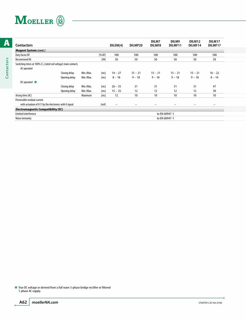
A
Co
nta
cto
rs
A62 moellerNA.com STARTER-CAT-NA-0708
Contactors DILEM(4) DILMP20DILM7
DILMF8DILM9
DILMF11DILM12
DILMF14DILM17
DILMF17Magnet System (cont.)Duty factor DF [% DF] 100 100 100 100 100 100Recommend VA [VA] 50 50 50 50 50 50Switching times at 100% Uc (rated coil voltage) main contacts AC operated Closing delay Min./Max. [ms] 14 – 27 15 – 21 15 – 21 15 – 21 15 – 21 16 – 22 Opening delay Min./Max. [ms] 8 – 18 9 – 18 9 – 18 9 – 18 9 – 18 8 – 14 DC operated ➊
Closing delay Min./Max. [ms] 26 – 35 31 31 31 31 47 Opening delay Min./Max. [ms] 15 – 25 12 12 12 12 30Arcing time (AC) Maximum [ms] 12 10 10 10 10 10Permissible residual current with actuation of A11 by the electronics with 0 signal [mA] – – – – – –
Electromagnetic Compatibility (EC)Emitted interference to EN 60947-1Noise immunity to EN 60947-1
➊ True DC voltage or derived from a full wave 3-phase bridge rectifier or filtered 1-phase AC supply.
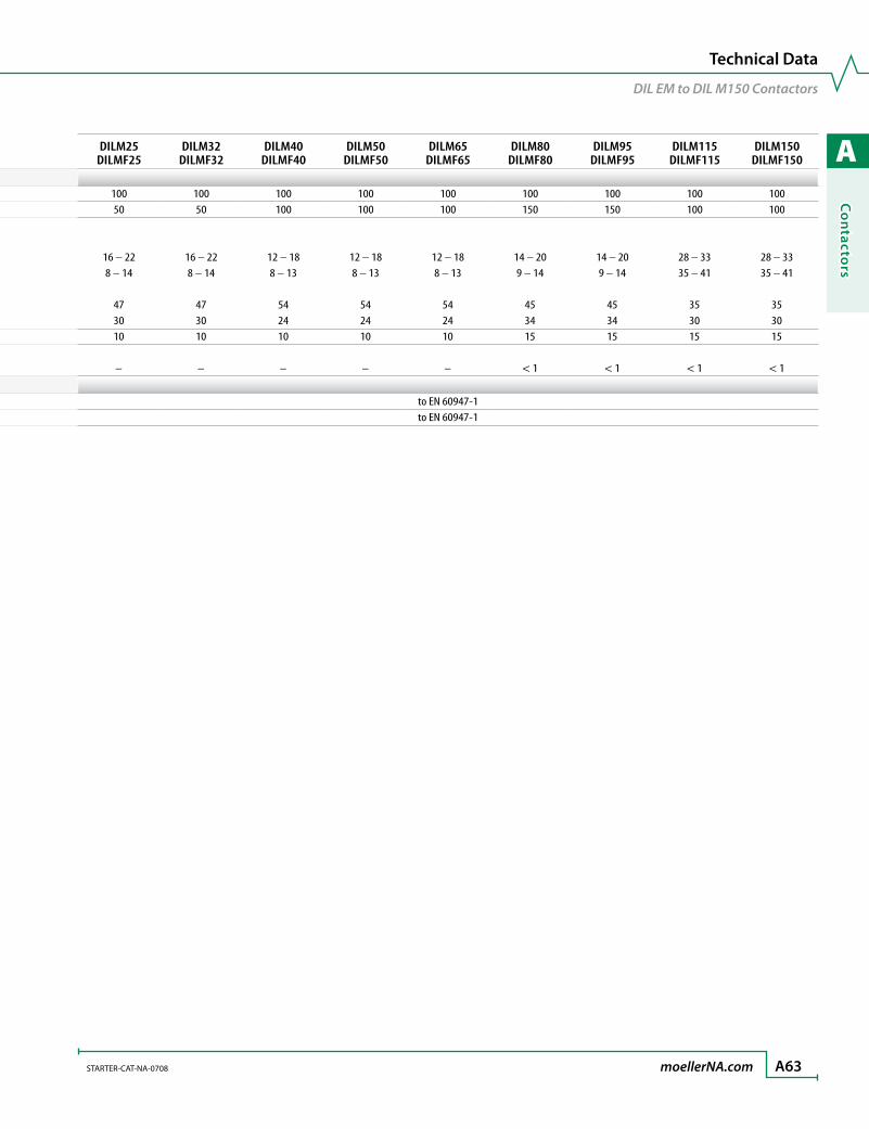
A
Co
ntacto
rs
STARTER-CAT-NA-0708 moellerNA.com A63
Technical Data
DIL EM to DIL M150 Contactors
Contactors DILEM(4) DILMP20DILM7
DILMF8DILM9
DILMF11DILM12
DILMF14DILM17
DILMF17Magnet System (cont.)Duty factor DF [% DF] 100 100 100 100 100 100Recommend VA [VA] 50 50 50 50 50 50Switching times at 100% Uc (rated coil voltage) main contacts AC operated Closing delay Min./Max. [ms] 14 – 27 15 – 21 15 – 21 15 – 21 15 – 21 16 – 22 Opening delay Min./Max. [ms] 8 – 18 9 – 18 9 – 18 9 – 18 9 – 18 8 – 14 DC operated ➊
Closing delay Min./Max. [ms] 26 – 35 31 31 31 31 47 Opening delay Min./Max. [ms] 15 – 25 12 12 12 12 30Arcing time (AC) Maximum [ms] 12 10 10 10 10 10Permissible residual current with actuation of A11 by the electronics with 0 signal [mA] – – – – – –
Electromagnetic Compatibility (EC)Emitted interference to EN 60947-1Noise immunity to EN 60947-1
DILM25DILMF25
DILM32DILMF32
DILM40DILMF40
DILM50DILMF50
DILM65DILMF65
DILM80DILMF80
DILM95DILMF95
DILM115DILMF115
DILM150DILMF150
100 100 100 100 100 100 100 100 10050 50 100 100 100 150 150 100 100
16 – 22 16 – 22 12 – 18 12 – 18 12 – 18 14 – 20 14 – 20 28 – 33 28 – 338 – 14 8 – 14 8 – 13 8 – 13 8 – 13 9 – 14 9 – 14 35 – 41 35 – 41
47 47 54 54 54 45 45 35 3530 30 24 24 24 34 34 30 3010 10 10 10 10 15 15 15 15
– – – – – < 1 < 1 < 1 < 1
to EN 60947-1to EN 60947-1
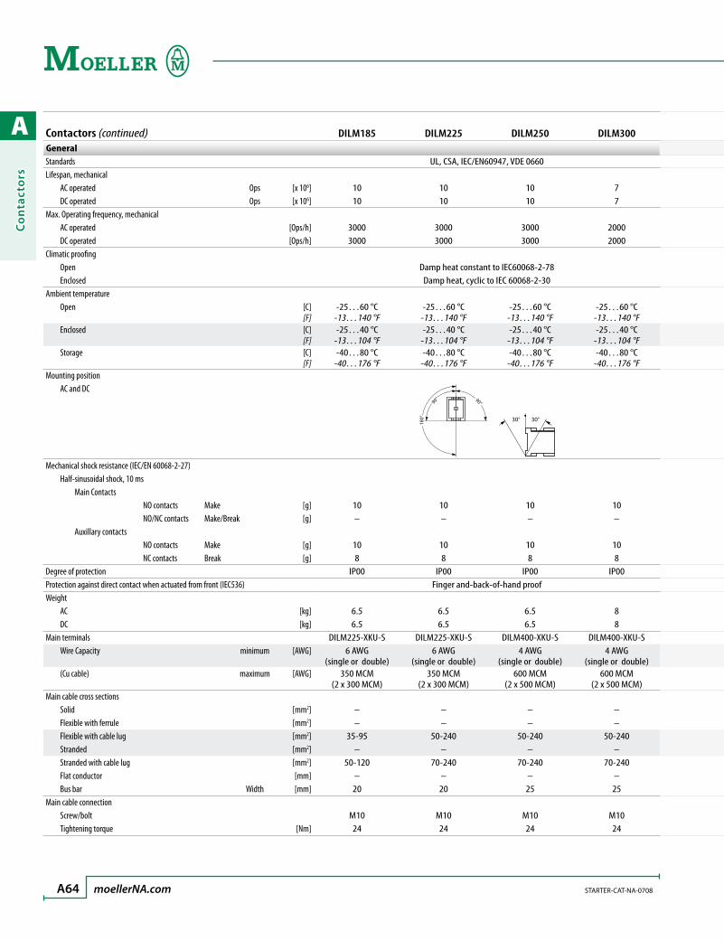
A
Co
nta
cto
rs
A64 moellerNA.com STARTER-CAT-NA-0708
Contactors (continued) DILM185 DILM225 DILM250 DILM300GeneralStandards UL, CSA, IEC/EN60947, VDE 0660Lifespan, mechanical AC operated Ops [x 106] 10 10 10 7 DC operated Ops [x 106] 10 10 10 7Max. Operating frequency, mechanical AC operated [Ops/h] 3000 3000 3000 2000 DC operated [Ops/h] 3000 3000 3000 2000Climatic proofing Open Damp heat constant to IEC60068-2-78 Enclosed Damp heat, cyclic to IEC 60068-2-30Ambient temperature Open [C]
[F]-25…60 °C
-13…140 °F-25…60 °C
-13…140 °F-25…60 °C
-13…140 °F-25…60 °C
-13…140 °F Enclosed [C]
[F]-25…40 °C
-13…104 °F-25…40 °C
-13…104 °F-25…40 °C
-13…104 °F-25…40 °C
-13…104 °F Storage [C]
[F]-40…80 °C
-40…176 °F-40…80 °C
-40…176 °F-40…80 °C
-40…176 °F-40…80 °C
-40…176 °FMounting position AC and DC
180°
90° 90°
30°30°
Mechanical shock resistance (IEC/EN 60068-2-27) Half-sinusoidal shock, 10 ms Main Contacts NO contacts Make [g] 10 10 10 10 NO/NC contacts Make/Break [g] – – – – Auxillary contacts NO contacts Make [g] 10 10 10 10 NC contacts Break [g] 8 8 8 8Degree of protection IP00 IP00 IP00 IP00Protection against direct contact when actuated from front (IEC536) Finger and-back-of-hand proofWeight AC [kg] 6.5 6.5 6.5 8 DC [kg] 6.5 6.5 6.5 8Main terminals DILM225-XKU-S DILM225-XKU-S DILM400-XKU-S DILM400-XKU-S Wire Capacity minimum [AWG] 6 AWG
(single or double)6 AWG
(single or double)4 AWG
(single or double)4 AWG
(single or double) (Cu cable) maximum [AWG] 350 MCM
(2 x 300 MCM)350 MCM
(2 x 300 MCM)600 MCM
(2 x 500 MCM)600 MCM
(2 x 500 MCM)Main cable cross sections Solid [mm2] – – – – Flexible with ferrule [mm2] – – – – Flexible with cable lug [mm2] 35-95 50-240 50-240 50-240 Stranded [mm2] – – – – Stranded with cable lug [mm2] 50-120 70-240 70-240 70-240 Flat conductor [mm] – – – – Bus bar Width [mm] 20 20 25 25Main cable connection Screw/bolt M10 M10 M10 M10 Tightening torque [Nm] 24 24 24 24

A
Co
ntacto
rs
STARTER-CAT-NA-0708 moellerNA.com A65
Technical Data
DIL M185 to DIL M1000 Contactors
Contactors (continued) DILM185 DILM225 DILM250 DILM300GeneralStandards UL, CSA, IEC/EN60947, VDE 0660Lifespan, mechanical AC operated Ops [x 106] 10 10 10 7 DC operated Ops [x 106] 10 10 10 7Max. Operating frequency, mechanical AC operated [Ops/h] 3000 3000 3000 2000 DC operated [Ops/h] 3000 3000 3000 2000Climatic proofing Open Damp heat constant to IEC60068-2-78 Enclosed Damp heat, cyclic to IEC 60068-2-30Ambient temperature Open [C]
[F]-25…60 °C
-13…140 °F-25…60 °C
-13…140 °F-25…60 °C
-13…140 °F-25…60 °C
-13…140 °F Enclosed [C]
[F]-25…40 °C
-13…104 °F-25…40 °C
-13…104 °F-25…40 °C
-13…104 °F-25…40 °C
-13…104 °F Storage [C]
[F]-40…80 °C
-40…176 °F-40…80 °C
-40…176 °F-40…80 °C
-40…176 °F-40…80 °C
-40…176 °FMounting position AC and DC
Mechanical shock resistance (IEC/EN 60068-2-27) Half-sinusoidal shock, 10 ms Main Contacts NO contacts Make [g] 10 10 10 10 NO/NC contacts Make/Break [g] – – – – Auxillary contacts NO contacts Make [g] 10 10 10 10 NC contacts Break [g] 8 8 8 8Degree of protection IP00 IP00 IP00 IP00Protection against direct contact when actuated from front (IEC536) Finger and-back-of-hand proofWeight AC [kg] 6.5 6.5 6.5 8 DC [kg] 6.5 6.5 6.5 8Main terminals DILM225-XKU-S DILM225-XKU-S DILM400-XKU-S DILM400-XKU-S Wire Capacity minimum [AWG] 6 AWG
(single or double)6 AWG
(single or double)4 AWG
(single or double)4 AWG
(single or double) (Cu cable) maximum [AWG] 350 MCM
(2 x 300 MCM)350 MCM
(2 x 300 MCM)600 MCM
(2 x 500 MCM)600 MCM
(2 x 500 MCM)Main cable cross sections Solid [mm2] – – – – Flexible with ferrule [mm2] – – – – Flexible with cable lug [mm2] 35-95 50-240 50-240 50-240 Stranded [mm2] – – – – Stranded with cable lug [mm2] 50-120 70-240 70-240 70-240 Flat conductor [mm] – – – – Bus bar Width [mm] 20 20 25 25Main cable connection Screw/bolt M10 M10 M10 M10 Tightening torque [Nm] 24 24 24 24
DILM400 DILM500 DILM580 DILM650 DILM750 DILM820 DILM1000
UL, CSA, IEC/EN60947, VDE 0660
7 5 5 5 5 5 57 5 5 5 5 5 5
2000 2000 1000 1000 1000 1000 10002000 2000 1000 1000 1000 1000 1000
Damp heat constant to IEC60068-2-78Damp heat, cyclic to IEC 60068-2-30
-25…60 °C-13…140 °F
-25…60 °C-13…140 °F
-25…60 °C-13…140 °F
-25…60 °C-13…140 °F
-25…60 °C-13…140 °F
-25…60 °C-13…140 °F
-25…60 °C-13…140 °F
-25…40 °C-13…104 °F
-25…40 °C-13…104 °F
-25…40 °C-13…104 °F
-25…40 °C-13…104 °F
-25…40 °C-13…104 °F
-25…40 °C-13…104 °F
-25…40 °C-13…104 °F
-40…80 °C-40…176 °F
-40…80 °C-40…176 °F
-40…80 °C-40…176 °F
-40…80 °C-40…176 °F
-40…80 °C-40…176 °F
-40…80 °C-40…176 °F
-40…80 °C-40…176 °F
180°
90° 90°
90˚ 90˚
30°30°
10 10 10 10 10 10 10– – – – – – –
10 10 10 10 10 10 108 8 8 8 8 8 8
IP00 IP00 IP00 IP00 IP00 IP00 IP00Finger and-back-of-hand proof
8 8 15 15 15 15 158 8 15 15 15 15 15
DILM400-XKU-S DILM500-XK-CNA DILM650-XK-CNA DILM650-XK-CNA DILM820-XK-CNA DILM820-XK-CNA –4 AWG
(single or double)2 x 4 AWG 2 x 2 AWG 2 x 2 AWG 4 x 2 AWG 4 x 2 AWG Terminal pad
600 MCM (2 x 500 MCM)
2 x 500 MCM 2x 500 MCM 2x 500 MCM 4 x 500 MCM 4 x 500 MCM Terminal pad
– – – – – – –– – – – – – –
50-240 50-240 50-240 50-240 50-240 50-240 50-240– – – – – – –
70-240 70-240 70-240 70-240 70-240 70-240 70-240– – – – – – –25 30 50 50 60 60 60
M10 M10 M10 M10 M12 M12 M1224 24 24 24 35 35 35
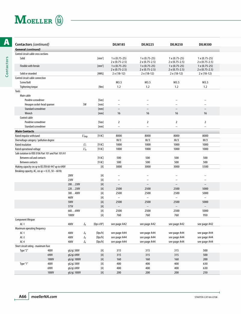
A
Co
nta
cto
rs
A66 moellerNA.com STARTER-CAT-NA-0708
Contactors (continued) DILM185 DILM225 DILM250 DILM300General (continued)Control circuit cable cross sections Solid [mm2] 1 x (0.75-25)
2 x (0.75-2.5)1 x (0.75-25)2 x (0.75-2.5)
1 x (0.75-25)2 x (0.75-2.5)
1 x (0.75-25)2 x (0.75-2.5)
Flexible with ferrule [mm2] 1 x (0.75-25)2 x (0.75-2.5)
1 x (0.75-25)2 x (0.75-2.5)
1 x (0.75-25)2 x (0.75-2.5)
1 x (0.75-25)2 x (0.75-2.5)
Solid or stranded [AWG] 2 x (18-12) 2 x (18-12) 2 x (18-12) 2 x (18-12)Control circuit cable connection Screw/bolt M3.5 M3.5 M3.5 M3.5 Tightening torque [Nm] 1.2 1.2 1.2 1.2Tools Main cable Posidriv screwdriver [Size] – – – – Hexagon socket-head spanner SW [mm] – – – – Standard screwdriver [mm] – – – – Wrench [mm] 16 16 16 16 Control cable Posidrive screwdriver [Size] 2 2 2 2 Standard screwdriver [mm] – – – –
Main ContactsRated impulse withstand Uimp [V AC] 8000 8000 8000 8000Overvoltage category / pollution degree III/3 III/3 III/3 III/3Rated insulation Ui [V AC] 1000 1000 1000 1000Rated operational voltage Ue [V AC] 1000 1000 1000 1000Safe isolation to VDE 0106 Part 101 and Part 101/A1
Between coil and contacts [V AC] 500 500 500 500
Between contacts [V AC] 500 500 500 500Making capacity cos φ to IEC/EN 60-947 up to 690V [A] 3000 3000 3000 5500Breaking capacity, AC, cos φ = 0.35, 50 – 60 Hz 200V [A] – – – – 230V [A] – – – – 200…230V [A] – – – – 220…230V [A] 2500 2500 2500 5000 380…400V [A] 2500 2500 2500 5000 460V [A] – – – – 500V [A] 2500 2500 2500 5000 575V [A] – – – – 660…690V [A] 2500 2500 2500 5000 1000V [A] 760 760 760 950Component lifespan AC-1 400V Ie [Ops x106] see page A42 see page A42 see page A42 see page A42Maximum operating frequency AC-1 400V Ie [Ops/h] see page A44 see page A44 see page A44 see page A44 AC-3 400V Ie [Ops/h] see page A44 see page A44 see page A44 see page A44 AC-4 400V Ie [Ops/h] see page A44 see page A44 see page A44 see page A44Short circuit rating - maximum fuse Type “2” 400V gG/gL 500V [A] 315 315 315 500 690V gG/gL 690V [A] 315 315 315 500 1000V gG/gL 1000V [A] 160 160 160 200 Type “1” 400V gG/gL 500V [A] 400 400 400 630 690V gG/gL 690V [A] 400 400 400 630 1000V gG/gL 1000V [A] 200 200 200 250

A
Co
ntacto
rs
STARTER-CAT-NA-0708 moellerNA.com A67
Technical Data
DIL M185 to DIL M1000 Contactors
Contactors (continued) DILM185 DILM225 DILM250 DILM300General (continued)Control circuit cable cross sections Solid [mm2] 1 x (0.75-25)
2 x (0.75-2.5)1 x (0.75-25)2 x (0.75-2.5)
1 x (0.75-25)2 x (0.75-2.5)
1 x (0.75-25)2 x (0.75-2.5)
Flexible with ferrule [mm2] 1 x (0.75-25)2 x (0.75-2.5)
1 x (0.75-25)2 x (0.75-2.5)
1 x (0.75-25)2 x (0.75-2.5)
1 x (0.75-25)2 x (0.75-2.5)
Solid or stranded [AWG] 2 x (18-12) 2 x (18-12) 2 x (18-12) 2 x (18-12)Control circuit cable connection Screw/bolt M3.5 M3.5 M3.5 M3.5 Tightening torque [Nm] 1.2 1.2 1.2 1.2Tools Main cable Posidriv screwdriver [Size] – – – – Hexagon socket-head spanner SW [mm] – – – – Standard screwdriver [mm] – – – – Wrench [mm] 16 16 16 16 Control cable Posidrive screwdriver [Size] 2 2 2 2 Standard screwdriver [mm] – – – –
Main ContactsRated impulse withstand Uimp [V AC] 8000 8000 8000 8000Overvoltage category / pollution degree III/3 III/3 III/3 III/3Rated insulation Ui [V AC] 1000 1000 1000 1000Rated operational voltage Ue [V AC] 1000 1000 1000 1000Safe isolation to VDE 0106 Part 101 and Part 101/A1
Between coil and contacts [V AC] 500 500 500 500
Between contacts [V AC] 500 500 500 500Making capacity cos φ to IEC/EN 60-947 up to 690V [A] 3000 3000 3000 5500Breaking capacity, AC, cos φ = 0.35, 50 – 60 Hz 200V [A] – – – – 230V [A] – – – – 200…230V [A] – – – – 220…230V [A] 2500 2500 2500 5000 380…400V [A] 2500 2500 2500 5000 460V [A] – – – – 500V [A] 2500 2500 2500 5000 575V [A] – – – – 660…690V [A] 2500 2500 2500 5000 1000V [A] 760 760 760 950Component lifespan AC-1 400V Ie [Ops x106] see page A42 see page A42 see page A42 see page A42Maximum operating frequency AC-1 400V Ie [Ops/h] see page A44 see page A44 see page A44 see page A44 AC-3 400V Ie [Ops/h] see page A44 see page A44 see page A44 see page A44 AC-4 400V Ie [Ops/h] see page A44 see page A44 see page A44 see page A44Short circuit rating - maximum fuse Type “2” 400V gG/gL 500V [A] 315 315 315 500 690V gG/gL 690V [A] 315 315 315 500 1000V gG/gL 1000V [A] 160 160 160 200 Type “1” 400V gG/gL 500V [A] 400 400 400 630 690V gG/gL 690V [A] 400 400 400 630 1000V gG/gL 1000V [A] 200 200 200 250
DILM400 DILM500 DILM580 DILM650 DILM750 DILM820 DILM1000
1 x (0.75-25)2 x (0.75-2.5)
1 x (0.75-25)2 x (0.75-2.5)
1 x (0.75-25)2 x (0.75-2.5)
1 x (0.75-25)2 x (0.75-2.5)
1 x (0.75-25)2 x (0.75-2.5)
1 x (0.75-25)2 x (0.75-2.5)
1 x (0.75-25)2 x (0.75-2.5)
1 x (0.75-25)2 x (0.75-2.5)
1 x (0.75-25)2 x (0.75-2.5)
1 x (0.75-25)2 x (0.75-2.5)
1 x (0.75-25)2 x (0.75-2.5)
1 x (0.75-25)2 x (0.75-2.5)
1 x (0.75-25)2 x (0.75-2.5)
1 x (0.75-25)2 x (0.75-2.5)
2 x (18-12) 2 x (18-12) 2 x (18-12) 2 x (18-12) 2 x (18-12) 2 x (18-12) 2 x (18-12)
M3.5 M3.5 M3.5 M3.5 M3.5 M3.5 M3.51.2 1.2 1.2 1.2 1.2 1.2 1.2
– – – – – – –– – – – – – –– – – – – – –16 16 16 16 18 18 18
2 2 2 2 2 2 2– – – – – – –
8000 8000 8000 8000 8000 8000 8000III/3 III/3 III/3 III/3 III/3 III/3 III/31000 1000 1000 1000 1000 1000 10001000 1000 1000 1000 1000 1000 1000
500 500 500 500 500 500 500500 500 500 500 500 500 500
5500 5500 7800 7800 9840 9840 9840
– – – – – – –– – – – – – –– – – – – – –
5000 5000 6500 6500 8200 8200 82005000 5000 6500 6500 8200 8200 8200
– – – – – – –5000 5000 6500 6500 8200 8200 8200
– – – – – – –5000 5000 6500 6500 8200 8200 8200950 950 4350 4350 5800 5800 5800
see page A42 see page A42 see page A42 see page A42 see page A42 see page A42 see page A42
see page A44 see page A44 see page A44 see page A44 see page A44 see page A44 see page A44see page A44 see page A44 see page A44 see page A44 see page A44 see page A44 see page A44see page A44 see page A44 see page A44 see page A44 see page A44 see page A44 see page A44
500 500 630 630 630 630 630500 500 630 630 630 630 630200 200 500 500 630 630 630630 630 1000 1000 1200 1200 1200630 630 1000 1000 1200 1200 1200250 250 630 630 800 800 800
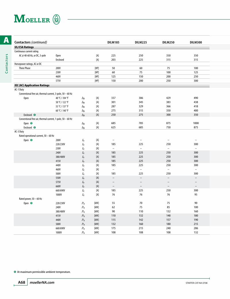
A
Co
nta
cto
rs
A68 moellerNA.com STARTER-CAT-NA-0708
Contactors (continued) DILM185 DILM225 DILM250 DILM300UL/CSA RatingsContinuous current rating AC @ 40-60 Hz, or DC, 3-pole Open [A] 225 250 350 350 Enclosed [A] 203 225 315 315Horsepower ratings, AC or DC Three Phase 200V [HP] 50 60 75 100 230V [HP] 60 75 100 125 460V [HP] 125 150 200 250 575V [HP] 150 200 250 300
IEC (AC) Application RatingsAC-1 Duty Conventional free air, thermal current, 3-pole, 50 – 60 Hz Open 40 °C / 104 °F Ith [A] 337 386 429 490 50 °C / 122 °F Ith [A] 301 345 383 438 55 °C / 137 °F Ith [A] 287 329 366 418 60 °C / 140 °F Ith [A] 275 315 350 400 Enclosed ➊ Ith [A] 250 275 300 350 Conventional free air, thermal current, 1-pole, 50 – 60 Hz Open ➊ Ith [A] 685 785 875 1000 Enclosed ➊ Ith [A] 625 685 750 875AC-3 Duty Rated operational current, 50 – 60 Hz Open ➊ 200V Ie [A] – – – – 220/230V Ie [A] 185 225 250 300 230V Ie [A] – – – – 240V Ie [A] 185 225 250 300 380/400V Ie [A] 185 225 250 300 415V Ie [A] 185 225 250 300 440V Ie [A] 185 225 250 300 460V Ie [A] – – – – 500V Ie [A] 185 225 250 300 550V Ie [A] – – – – 575V Ie [A] – – – – 660V Ie [A] – – – – 660/690V Ie [A] 185 225 250 300 1000V Ie [A] 76 76 76 95 Rated power, 50 – 60 Hz Open ➊ 220/230V Pn [kW] 55 70 75 90 240V Pn [kW] 62 75 85 100 380/400V Pn [kW] 90 110 132 160 415V Pn [kW] 110 132 148 180 440V Pn [kW] 115 142 157 190 500V Pn [kW] 132 160 180 215 660/690V Pn [kW] 175 215 240 286 1000V Pn [kW] 108 108 108 132
➊ At maximum permissible ambient temperature.
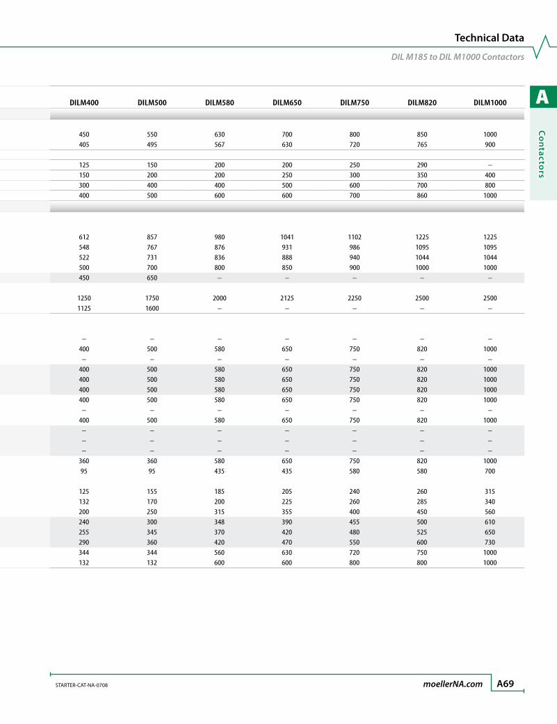
A
Co
ntacto
rs
STARTER-CAT-NA-0708 moellerNA.com A69
Technical Data
DIL M185 to DIL M1000 Contactors
Contactors (continued) DILM185 DILM225 DILM250 DILM300UL/CSA RatingsContinuous current rating AC @ 40-60 Hz, or DC, 3-pole Open [A] 225 250 350 350 Enclosed [A] 203 225 315 315Horsepower ratings, AC or DC Three Phase 200V [HP] 50 60 75 100 230V [HP] 60 75 100 125 460V [HP] 125 150 200 250 575V [HP] 150 200 250 300
IEC (AC) Application RatingsAC-1 Duty Conventional free air, thermal current, 3-pole, 50 – 60 Hz Open 40 °C / 104 °F Ith [A] 337 386 429 490 50 °C / 122 °F Ith [A] 301 345 383 438 55 °C / 137 °F Ith [A] 287 329 366 418 60 °C / 140 °F Ith [A] 275 315 350 400 Enclosed ➊ Ith [A] 250 275 300 350 Conventional free air, thermal current, 1-pole, 50 – 60 Hz Open ➊ Ith [A] 685 785 875 1000 Enclosed ➊ Ith [A] 625 685 750 875AC-3 Duty Rated operational current, 50 – 60 Hz Open ➊ 200V Ie [A] – – – – 220/230V Ie [A] 185 225 250 300 230V Ie [A] – – – – 240V Ie [A] 185 225 250 300 380/400V Ie [A] 185 225 250 300 415V Ie [A] 185 225 250 300 440V Ie [A] 185 225 250 300 460V Ie [A] – – – – 500V Ie [A] 185 225 250 300 550V Ie [A] – – – – 575V Ie [A] – – – – 660V Ie [A] – – – – 660/690V Ie [A] 185 225 250 300 1000V Ie [A] 76 76 76 95 Rated power, 50 – 60 Hz Open ➊ 220/230V Pn [kW] 55 70 75 90 240V Pn [kW] 62 75 85 100 380/400V Pn [kW] 90 110 132 160 415V Pn [kW] 110 132 148 180 440V Pn [kW] 115 142 157 190 500V Pn [kW] 132 160 180 215 660/690V Pn [kW] 175 215 240 286 1000V Pn [kW] 108 108 108 132
DILM400 DILM500 DILM580 DILM650 DILM750 DILM820 DILM1000
450 550 630 700 800 850 1000405 495 567 630 720 765 900
125 150 200 200 250 290 –150 200 200 250 300 350 400300 400 400 500 600 700 800400 500 600 600 700 860 1000
612 857 980 1041 1102 1225 1225548 767 876 931 986 1095 1095522 731 836 888 940 1044 1044500 700 800 850 900 1000 1000450 650 – – – – –
1250 1750 2000 2125 2250 2500 25001125 1600 – – – – –
– – – – – – –400 500 580 650 750 820 1000
– – – – – – –400 500 580 650 750 820 1000400 500 580 650 750 820 1000400 500 580 650 750 820 1000400 500 580 650 750 820 1000
– – – – – – –400 500 580 650 750 820 1000
– – – – – – –– – – – – – –– – – – – – –
360 360 580 650 750 820 100095 95 435 435 580 580 700
125 155 185 205 240 260 315132 170 200 225 260 285 340200 250 315 355 400 450 560240 300 348 390 455 500 610255 345 370 420 480 525 650290 360 420 470 550 600 730344 344 560 630 720 750 1000132 132 600 600 800 800 1000

A
Co
nta
cto
rs
A70 moellerNA.com STARTER-CAT-NA-0708
Contactors (continued) DILM185 DILM225 DILM250 DILM300IEC (AC) Application Ratings (cont.)AC-4 Duty Rated operational current, 50 – 60 Hz Open ➊ 200V Ie [A] – – – – 220/230V Ie [A] 136 164 200 240 230V Ie [A] – – – – 240V Ie [A] 136 164 200 240 380/400V Ie [A] 136 164 200 240 415V Ie [A] 136 164 200 240 440V Ie [A] 136 164 200 240 460V Ie [A] – – – – 500V Ie [A] 136 164 200 240 575V Ie [A] – – – – 660V Ie [A] – – – – 660/690V Ie [A] 136 164 200 240 1000V Ie [A] 76 76 76 95 Rated power, 50 – 60 Hz 220/230V Pn [kW] 41 51 62 75 240V Pn [kW] 45 54 68 82 380/400V Pn [kW] 75 90 110 132 415V Pn [kW] 80 96 117 142 440V Pn [kW] 85 102 125 151 500V Pn [kW] 96 116 143 172 660/690V Pn [kW] 127 155 189 229 1000V Pn [kW] 108 108 108 132
IEC Capacitor Duty RatingsIndividual compensation rated operational current of three-phase capacitors Open up to 525V Ie [A] 220 220 220 307 690V Ie [A] 133 133 133 177Making capacity (I - peak value) without damping [x Ie] 30 30 30 30Component lifespan [Ops x106] 0.1 0.1 0.1 0.1Maximum operating frequency [Ops/h] 200 200 200 200
IEC (DC) Application RatingsDC-1 Duty Rated operational current Open ➊ 12V DC Ie [A] – – – – 24V DC Ie [A] – – – – 60V DC Ie [A] 300 300 300 400 110V DC Ie [A] 300 300 300 400 220V DC Ie [A] 300 300 300 400 440V DC Ie [A] 11 11 11 11DC-3 Duty Rated operational current Open 12V DC Ie [A] – – – – 24V DC Ie [A] – – – – 60V DC Ie [A] 300 300 300 400 110V DC Ie [A] 300 300 300 400 220V DC Ie [A] 300 300 300 400 440V DC Ie [A] – – – –
➊ At maximum permissible ambient temperature.
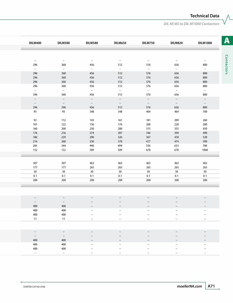
A
Co
ntacto
rs
STARTER-CAT-NA-0708 moellerNA.com A71
Technical Data
DIL M185 to DIL M1000 Contactors
Contactors (continued) DILM185 DILM225 DILM250 DILM300IEC (AC) Application Ratings (cont.)AC-4 Duty Rated operational current, 50 – 60 Hz Open ➊ 200V Ie [A] – – – – 220/230V Ie [A] 136 164 200 240 230V Ie [A] – – – – 240V Ie [A] 136 164 200 240 380/400V Ie [A] 136 164 200 240 415V Ie [A] 136 164 200 240 440V Ie [A] 136 164 200 240 460V Ie [A] – – – – 500V Ie [A] 136 164 200 240 575V Ie [A] – – – – 660V Ie [A] – – – – 660/690V Ie [A] 136 164 200 240 1000V Ie [A] 76 76 76 95 Rated power, 50 – 60 Hz 220/230V Pn [kW] 41 51 62 75 240V Pn [kW] 45 54 68 82 380/400V Pn [kW] 75 90 110 132 415V Pn [kW] 80 96 117 142 440V Pn [kW] 85 102 125 151 500V Pn [kW] 96 116 143 172 660/690V Pn [kW] 127 155 189 229 1000V Pn [kW] 108 108 108 132
IEC Capacitor Duty RatingsIndividual compensation rated operational current of three-phase capacitors Open up to 525V Ie [A] 220 220 220 307 690V Ie [A] 133 133 133 177Making capacity (I - peak value) without damping [x Ie] 30 30 30 30Component lifespan [Ops x106] 0.1 0.1 0.1 0.1Maximum operating frequency [Ops/h] 200 200 200 200
IEC (DC) Application RatingsDC-1 Duty Rated operational current Open ➊ 12V DC Ie [A] – – – – 24V DC Ie [A] – – – – 60V DC Ie [A] 300 300 300 400 110V DC Ie [A] 300 300 300 400 220V DC Ie [A] 300 300 300 400 440V DC Ie [A] 11 11 11 11DC-3 Duty Rated operational current Open 12V DC Ie [A] – – – – 24V DC Ie [A] – – – – 60V DC Ie [A] 300 300 300 400 110V DC Ie [A] 300 300 300 400 220V DC Ie [A] 300 300 300 400 440V DC Ie [A] – – – –
DILM400 DILM500 DILM580 DILM650 DILM750 DILM820 DILM1000
– – – – – – –296 360 456 512 576 656 800
– – – – – – –296 360 456 512 576 656 800296 360 456 512 576 656 800296 360 456 512 576 656 800296 360 456 512 576 656 800
– – – – – – –296 360 456 512 576 656 800
– – – – – – –– – – – – – –
296 296 456 512 576 656 80095 95 348 348 464 464 700
92 112 143 161 181 209 260101 122 156 176 200 228 280160 200 250 280 315 355 450176 216 274 307 346 394 490186 229 290 326 367 418 520214 260 330 370 417 474 590283 344 440 494 556 633 780132 132 509 509 678 678 1000
307 307 463 463 463 463 463177 177 265 265 265 265 26530 30 30 30 30 30 300.1 0.1 0.1 0.1 0.1 0.1 0.1200 200 200 200 200 200 200
– – – – – – –– – – – – – –
400 400 – – – – –400 400 – – – – –400 400 – – – – –11 11 – – – – –
– – – – – – –– – – – – – –
400 400 – – – – –400 400 – – – – –400 400 – – – – –
– – – – – – –
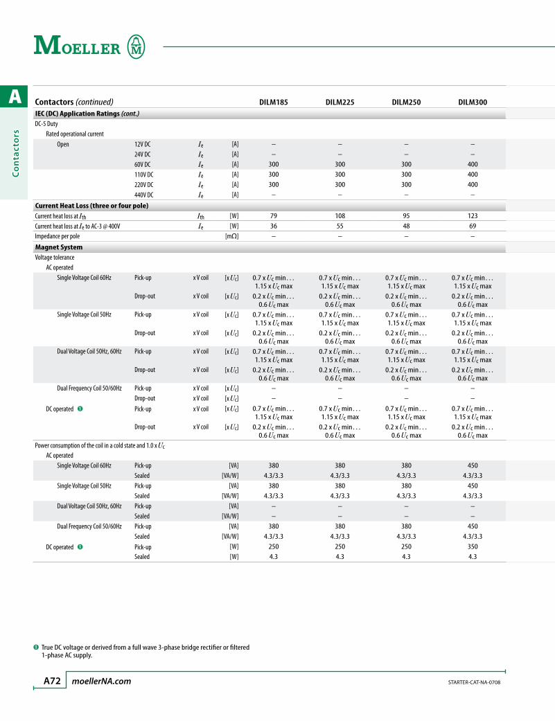
A
Co
nta
cto
rs
A72 moellerNA.com STARTER-CAT-NA-0708
Contactors (continued) DILM185 DILM225 DILM250 DILM300IEC (DC) Application Ratings (cont.)DC-5 Duty Rated operational current Open 12V DC Ie [A] – – – – 24V DC Ie [A] – – – – 60V DC Ie [A] 300 300 300 400 110V DC Ie [A] 300 300 300 400 220V DC Ie [A] 300 300 300 400 440V DC Ie [A] – – – –
Current Heat Loss (three or four pole)Current heat loss at Ith Ith [W] 79 108 95 123Current heat loss at Ie to AC-3 @ 400V Ie [W] 36 55 48 69Impedance per pole [mΩ] – – – –
Magnet SystemVoltage tolerance AC operated Single Voltage Coil 60Hz Pick-up x V coil [x Uc] 0.7 x Uc min…
1.15 x Uc max0.7 x Uc min… 1.15 x Uc max
0.7 x Uc min… 1.15 x Uc max
0.7 x Uc min… 1.15 x Uc max
Drop-out x V coil [x Uc] 0.2 x Uc min… 0.6 Uc max
0.2 x Uc min… 0.6 Uc max
0.2 x Uc min… 0.6 Uc max
0.2 x Uc min… 0.6 Uc max
Single Voltage Coil 50Hz Pick-up x V coil [x Uc] 0.7 x Uc min… 1.15 x Uc max
0.7 x Uc min… 1.15 x Uc max
0.7 x Uc min… 1.15 x Uc max
0.7 x Uc min… 1.15 x Uc max
Drop-out x V coil [x Uc] 0.2 x Uc min… 0.6 Uc max
0.2 x Uc min… 0.6 Uc max
0.2 x Uc min… 0.6 Uc max
0.2 x Uc min… 0.6 Uc max
Dual Voltage Coil 50Hz, 60Hz Pick-up x V coil [x Uc] 0.7 x Uc min… 1.15 x Uc max
0.7 x Uc min… 1.15 x Uc max
0.7 x Uc min… 1.15 x Uc max
0.7 x Uc min… 1.15 x Uc max
Drop-out x V coil [x Uc] 0.2 x Uc min… 0.6 Uc max
0.2 x Uc min… 0.6 Uc max
0.2 x Uc min… 0.6 Uc max
0.2 x Uc min… 0.6 Uc max
Dual Frequency Coil 50/60Hz Pick-up x V coil [x Uc] – – – – Drop-out x V coil [x Uc] – – – – DC operated ➊ Pick-up x V coil [x Uc] 0.7 x Uc min…
1.15 x Uc max0.7 x Uc min… 1.15 x Uc max
0.7 x Uc min… 1.15 x Uc max
0.7 x Uc min… 1.15 x Uc max
Drop-out x V coil [x Uc] 0.2 x Uc min… 0.6 Uc max
0.2 x Uc min… 0.6 Uc max
0.2 x Uc min… 0.6 Uc max
0.2 x Uc min… 0.6 Uc max
Power consumption of the coil in a cold state and 1.0 x Uc AC operated Single Voltage Coil 60Hz Pick-up [VA] 380 380 380 450 Sealed [VA/W] 4.3/3.3 4.3/3.3 4.3/3.3 4.3/3.3 Single Voltage Coil 50Hz Pick-up [VA] 380 380 380 450 Sealed [VA/W] 4.3/3.3 4.3/3.3 4.3/3.3 4.3/3.3 Dual Voltage Coil 50Hz, 60Hz Pick-up [VA] – – – – Sealed [VA/W] – – – – Dual Frequency Coil 50/60Hz Pick-up [VA] 380 380 380 450 Sealed [VA/W] 4.3/3.3 4.3/3.3 4.3/3.3 4.3/3.3 DC operated ➊ Pick-up [W] 250 250 250 350 Sealed [W] 4.3 4.3 4.3 4.3
➊ True DC voltage or derived from a full wave 3-phase bridge rectifier or filtered 1-phase AC supply.

A
Co
ntacto
rs
STARTER-CAT-NA-0708 moellerNA.com A73
Technical Data
DIL M185 to DIL M1000 Contactors
Contactors (continued) DILM185 DILM225 DILM250 DILM300IEC (DC) Application Ratings (cont.)DC-5 Duty Rated operational current Open 12V DC Ie [A] – – – – 24V DC Ie [A] – – – – 60V DC Ie [A] 300 300 300 400 110V DC Ie [A] 300 300 300 400 220V DC Ie [A] 300 300 300 400 440V DC Ie [A] – – – –
Current Heat Loss (three or four pole)Current heat loss at Ith Ith [W] 79 108 95 123Current heat loss at Ie to AC-3 @ 400V Ie [W] 36 55 48 69Impedance per pole [mΩ] – – – –
Magnet SystemVoltage tolerance AC operated Single Voltage Coil 60Hz Pick-up x V coil [x Uc] 0.7 x Uc min…
1.15 x Uc max0.7 x Uc min… 1.15 x Uc max
0.7 x Uc min… 1.15 x Uc max
0.7 x Uc min… 1.15 x Uc max
Drop-out x V coil [x Uc] 0.2 x Uc min… 0.6 Uc max
0.2 x Uc min… 0.6 Uc max
0.2 x Uc min… 0.6 Uc max
0.2 x Uc min… 0.6 Uc max
Single Voltage Coil 50Hz Pick-up x V coil [x Uc] 0.7 x Uc min… 1.15 x Uc max
0.7 x Uc min… 1.15 x Uc max
0.7 x Uc min… 1.15 x Uc max
0.7 x Uc min… 1.15 x Uc max
Drop-out x V coil [x Uc] 0.2 x Uc min… 0.6 Uc max
0.2 x Uc min… 0.6 Uc max
0.2 x Uc min… 0.6 Uc max
0.2 x Uc min… 0.6 Uc max
Dual Voltage Coil 50Hz, 60Hz Pick-up x V coil [x Uc] 0.7 x Uc min… 1.15 x Uc max
0.7 x Uc min… 1.15 x Uc max
0.7 x Uc min… 1.15 x Uc max
0.7 x Uc min… 1.15 x Uc max
Drop-out x V coil [x Uc] 0.2 x Uc min… 0.6 Uc max
0.2 x Uc min… 0.6 Uc max
0.2 x Uc min… 0.6 Uc max
0.2 x Uc min… 0.6 Uc max
Dual Frequency Coil 50/60Hz Pick-up x V coil [x Uc] – – – – Drop-out x V coil [x Uc] – – – – DC operated ➊ Pick-up x V coil [x Uc] 0.7 x Uc min…
1.15 x Uc max0.7 x Uc min… 1.15 x Uc max
0.7 x Uc min… 1.15 x Uc max
0.7 x Uc min… 1.15 x Uc max
Drop-out x V coil [x Uc] 0.2 x Uc min… 0.6 Uc max
0.2 x Uc min… 0.6 Uc max
0.2 x Uc min… 0.6 Uc max
0.2 x Uc min… 0.6 Uc max
Power consumption of the coil in a cold state and 1.0 x Uc AC operated Single Voltage Coil 60Hz Pick-up [VA] 380 380 380 450 Sealed [VA/W] 4.3/3.3 4.3/3.3 4.3/3.3 4.3/3.3 Single Voltage Coil 50Hz Pick-up [VA] 380 380 380 450 Sealed [VA/W] 4.3/3.3 4.3/3.3 4.3/3.3 4.3/3.3 Dual Voltage Coil 50Hz, 60Hz Pick-up [VA] – – – – Sealed [VA/W] – – – – Dual Frequency Coil 50/60Hz Pick-up [VA] 380 380 380 450 Sealed [VA/W] 4.3/3.3 4.3/3.3 4.3/3.3 4.3/3.3 DC operated ➊ Pick-up [W] 250 250 250 350 Sealed [W] 4.3 4.3 4.3 4.3
DILM400 DILM500 DILM580 DILM650 DILM750 DILM820 DILM1000
– – – – – – –– – – – – – –
400 400 – – – – –400 400 – – – – –400 400 – – – – –
– – – – – – –
188 236 227 257 288 355 355120 120 120 150 200 239 355
– – – – – – –
0.7 x Uc min… 1.15 x Uc max
0.7 x Uc min… 1.15 x Uc max
0.7 x Uc min… 1.15 x Uc max
0.7 x Uc min… 1.15 x Uc max
0.7 x Uc min… 1.15 x Uc max
0.7 x Uc min… 1.15 x Uc max
0.7 x Uc min… 1.15 x Uc max
0.2 x Uc min… 0.6 Uc max
0.2 x Uc min… 0.6 Uc max
0.2 x Uc min… 0.6 Uc max
0.2 x Uc min… 0.6 Uc max
0.2 x Uc min… 0.6 Uc max
0.2 x Uc min… 0.6 Uc max
0.2 x Uc min… 0.6 Uc max
0.7 x Uc min… 1.15 x Uc max
0.7 x Uc min… 1.15 x Uc max
0.7 x Uc min… 1.15 x Uc max
0.7 x Uc min… 1.15 x Uc max
0.7 x Uc min… 1.15 x Uc max
0.7 x Uc min… 1.15 x Uc max
0.7 x Uc min… 1.15 x Uc max
0.2 x Uc min… 0.6 Uc max
0.2 x Uc min… 0.6 Uc max
0.2 x Uc min… 0.6 Uc max
0.2 x Uc min… 0.6 Uc max
0.2 x Uc min… 0.6 Uc max
0.2 x Uc min… 0.6 Uc max
0.2 x Uc min… 0.6 Uc max
0.7 x Uc min… 1.15 x Uc max
0.7 x Uc min… 1.15 x Uc max
0.7 x Uc min… 1.15 x Uc max
0.7 x Uc min… 1.15 x Uc max
0.7 x Uc min… 1.15 x Uc max
0.7 x Uc min… 1.15 x Uc max
0.7 x Uc min… 1.15 x Uc max
0.2 x Uc min… 0.6 Uc max
0.2 x Uc min… 0.6 Uc max
0.2 x Uc min… 0.6 Uc max
0.2 x Uc min… 0.6 Uc max
0.2 x Uc min… 0.6 Uc max
0.2 x Uc min… 0.6 Uc max
0.2 x Uc min… 0.6 Uc max
– – – – – – –– – – – – – –
0.7 x Uc min… 1.15 x Uc max
0.7 x Uc min… 1.15 x Uc max
0.7 x Uc min… 1.15 x Uc max
0.7 x Uc min… 1.15 x Uc max
0.7 x Uc min… 1.15 x Uc max
0.7 x Uc min… 1.15 x Uc max
0.7 x Uc min… 1.15 x Uc max
0.2 x Uc min… 0.6 Uc max
0.2 x Uc min… 0.6 Uc max
0.2 x Uc min… 0.6 Uc max
0.2 x Uc min… 0.6 Uc max
0.2 x Uc min… 0.6 Uc max
0.2 x Uc min… 0.6 Uc max
0.2 x Uc min… 0.6 Uc max
450 800 800 800 800 800 8004.3/3.3 7.5/6.5 7.5/6.5 7.5/6.5 7.5/6.5 7.5/6.5 7.5/6.5
450 800 800 800 800 800 8004.3/3.3 7.5/6.5 7.5/6.5 7.5/6.5 7.5/6.5 7.5/6.5 7.5/6.5
– – – – – – –– – – – – – –
450 800 800 800 800 800 8004.3/3.3 7.5/6.5 7.5/6.5 7.5/6.5 7.5/6.5 7.5/6.5 7.5/6.5
350 350 900 900 900 900 9004.3 4.3 9.5 9.5 9.5 9.5 9.5

A
Co
nta
cto
rs
A74 moellerNA.com STARTER-CAT-NA-0708
Contactors (continued) DILM185 DILM225 DILM250 DILM300Magnet System (cont.)Duty factor DF [%DF] 100 100 100 100Switching times at 100% Uc (rated coil voltage) main contacts AC operated Closing Delay Min./Max. [ms] < 100 < 100 < 80 < 80 Opening Delay Min./Max. [ms] < 80 < 80 < 80 < 80 DC operated ➊ Closing Delay Min./Max. [ms] < 100 < 100 < 80 < 80 Opening Delay Min./Max. [ms] < 80 < 80 < 80 < 80Arcing time (AC) Maximum [ms]Permissible contact resistance (of the external command device with actuation of A11)
[mΩ] < 500 < 500 < 500 < 500
Permissible residual current (with actuation of A11 by the electronics with 0 signal)
[mA] < 1 < 1 < 1 < 1
SPS signal level (A3 - A4) to IEC/EN61131-2 (Type 2) High [V] 15 15 15 15 Low [V] 5 5 5 5
Electromagnetic Compatibility (EC)Emitted interference This product is designed for operation in industrial environments (Environment 2). Usage in
domestic areas (Environment 1) can cause radio frequency interference (RFI) so that additional interference to noise suppression measures must be provided.Noise immunity
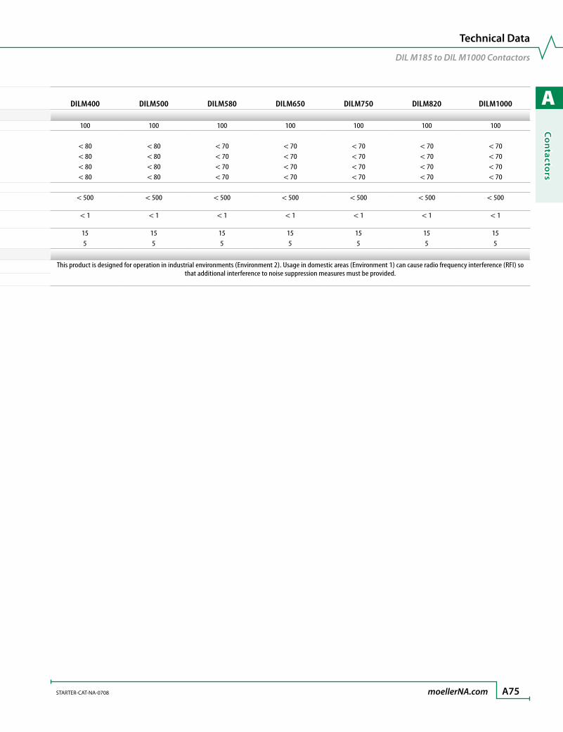
A
Co
ntacto
rs
STARTER-CAT-NA-0708 moellerNA.com A75
Technical Data
DIL M185 to DIL M1000 Contactors
Contactors (continued) DILM185 DILM225 DILM250 DILM300Magnet System (cont.)Duty factor DF [%DF] 100 100 100 100Switching times at 100% Uc (rated coil voltage) main contacts AC operated Closing Delay Min./Max. [ms] < 100 < 100 < 80 < 80 Opening Delay Min./Max. [ms] < 80 < 80 < 80 < 80 DC operated ➊ Closing Delay Min./Max. [ms] < 100 < 100 < 80 < 80 Opening Delay Min./Max. [ms] < 80 < 80 < 80 < 80Arcing time (AC) Maximum [ms]Permissible contact resistance (of the external command device with actuation of A11)
[mΩ] < 500 < 500 < 500 < 500
Permissible residual current (with actuation of A11 by the electronics with 0 signal)
[mA] < 1 < 1 < 1 < 1
SPS signal level (A3 - A4) to IEC/EN61131-2 (Type 2) High [V] 15 15 15 15 Low [V] 5 5 5 5
Electromagnetic Compatibility (EC)Emitted interference This product is designed for operation in industrial environments (Environment 2). Usage in
domestic areas (Environment 1) can cause radio frequency interference (RFI) so that additional interference to noise suppression measures must be provided.Noise immunity
DILM400 DILM500 DILM580 DILM650 DILM750 DILM820 DILM1000
100 100 100 100 100 100 100
< 80 < 80 < 70 < 70 < 70 < 70 < 70< 80 < 80 < 70 < 70 < 70 < 70 < 70< 80 < 80 < 70 < 70 < 70 < 70 < 70< 80 < 80 < 70 < 70 < 70 < 70 < 70
< 500 < 500 < 500 < 500 < 500 < 500 < 500
< 1 < 1 < 1 < 1 < 1 < 1 < 1
15 15 15 15 15 15 155 5 5 5 5 5 5
This product is designed for operation in industrial environments (Environment 2). Usage in domestic areas (Environment 1) can cause radio frequency interference (RFI) so that additional interference to noise suppression measures must be provided.
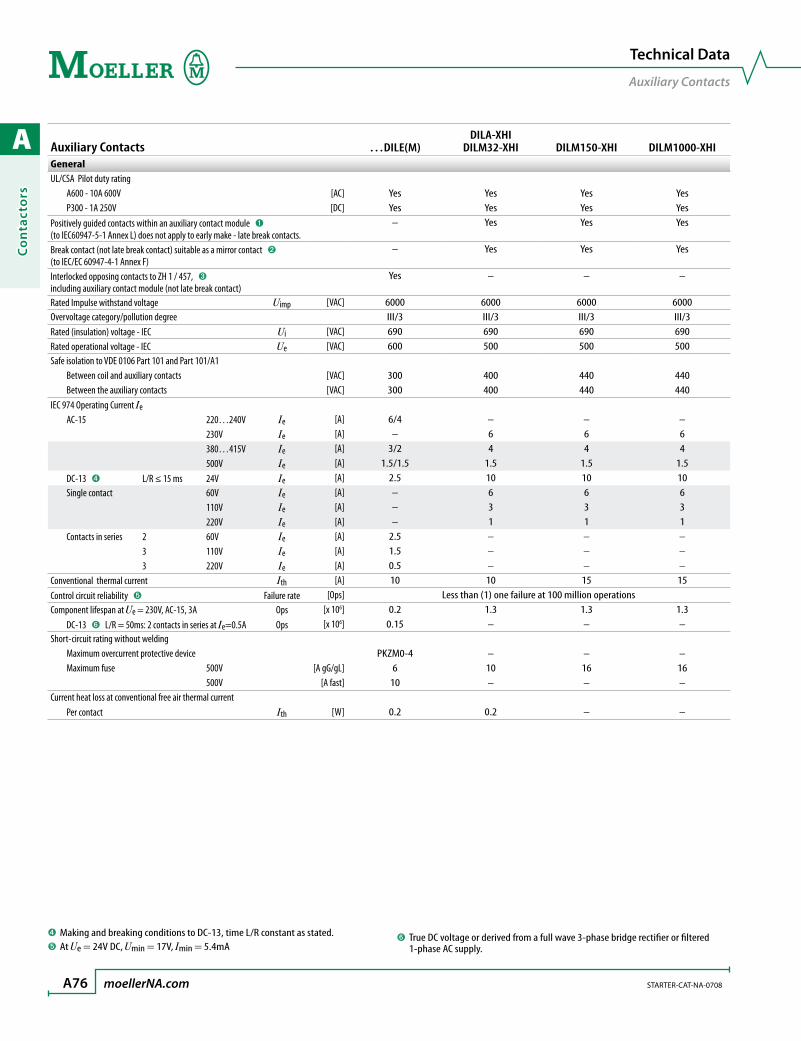
A
Co
nta
cto
rs
A76 moellerNA.com STARTER-CAT-NA-0708
Auxiliary Contacts …DILE(M)DILA-XHI
DILM32-XHI DILM150-XHI DILM1000-XHIGeneralUL/CSA Pilot duty rating A600 - 10A 600V [AC] Yes Yes Yes Yes P300 - 1A 250V [DC] Yes Yes Yes YesPositively guided contacts within an auxiliary contact module ➊ (to IEC60947-5-1 Annex L) does not apply to early make - late break contacts.
– Yes Yes Yes
Break contact (not late break contact) suitable as a mirror contact ➋ (to IEC/EC 60947-4-1 Annex F)
– Yes Yes Yes
Interlocked opposing contacts to ZH 1 / 457, ➌ including auxiliary contact module (not late break contact)
Yes – – –
Rated Impulse withstand voltage Uimp [VAC] 6000 6000 6000 6000Overvoltage category/pollution degree III/3 III/3 III/3 III/3Rated (insulation) voltage - IEC Ui [VAC] 690 690 690 690Rated operational voltage - IEC Ue [VAC] 600 500 500 500Safe isolation to VDE 0106 Part 101 and Part 101/A1 Between coil and auxiliary contacts [VAC] 300 400 440 440 Between the auxiliary contacts [VAC] 300 400 440 440IEC 974 Operating Current Ie AC-15 220…240V Ie [A] 6/4 – – – 230V Ie [A] – 6 6 6 380…415V Ie [A] 3/2 4 4 4 500V Ie [A] 1.5/1.5 1.5 1.5 1.5 DC-13 ➍ L/R ≤ 15 ms 24V Ie [A] 2.5 10 10 10 Single contact 60V Ie [A] – 6 6 6 110V Ie [A] – 3 3 3 220V Ie [A] – 1 1 1 Contacts in series 2 60V Ie [A] 2.5 – – – 3 110V Ie [A] 1.5 – – – 3 220V Ie [A] 0.5 – – –Conventional thermal current Ith [A] 10 10 15 15Control circuit reliability ➎ Failure rate [Ops] Less than (1) one failure at 100 million operationsComponent lifespan at Ue = 230V, AC-15, 3A Ops [x 106] 0.2 1.3 1.3 1.3 DC-13 ➏ L/R = 50ms: 2 contacts in series at Ie=0.5A Ops [x 106] 0.15 – – –Short-circuit rating without welding Maximum overcurrent protective device PKZM0-4 – – – Maximum fuse 500V [A gG/gL] 6 10 16 16 500V [A fast] 10 – – –Current heat loss at conventional free air thermal current Per contact Ith [W] 0.2 0.2 – –
Technical Data
Auxiliary Contacts
➍ Making and breaking conditions to DC-13, time L/R constant as stated.➎ At Ue = 24V DC, Umin = 17V, Imin = 5.4mA
➏ True DC voltage or derived from a full wave 3-phase bridge rectifier or filtered 1-phase AC supply.
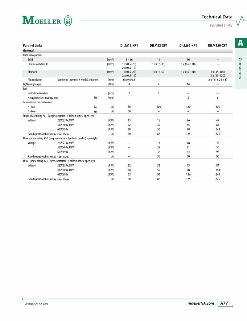
A
Co
ntacto
rs
STARTER-CAT-NA-0708 moellerNA.com A77
Parallel Links DILM12-XP1 DILM32-XP1 DILM65-XP1 DILM150-XP1GeneralTerminal capacities Solid [mm2] 1 - 16 16 16 – Flexible with ferrule [mm2] 1 x (0.5-25)
2 x (0.5-16)1 x (16-35) 1 x (16-120) –
Stranded [mm2] 1 x (0.5-25)2 x (0.5-16)
1 x (16-50) 1 x (16-120) 1 x (35-300)2 x (35-120)
Flat conductor Number of segments X width X thickness [mm] 6 x 9 x 0.8 – – 2 x (11 x 21 x 1)Tightening torque [Nm] 4 4 14 –Tool Pozidriv screwdriver [Size] 2 2 – – Hexagon socket-head spanner SW [mm] – – 5 6Conventional thermal current 3 - Pole Ith [A] 50 100 180 400 4 - Pole Ith [A] 60 – – –Single phase rating AC-1 (single contactor - 3 poles in series) open style Voltage 220V,230V,240V [KW] 13 18 26 47 380V,400V,440V [KW] 22 32 45 81 660V,690V [KW] 38 55 78 141 Rated operational current Ie = Ith or Ithe [A] 60 88 125 225Three - phase rating AC-1 (single contactor - 3 poles in parallel) open style Voltage 220V,230V,240V [KW] – 13 18 33 380V,400V,440V [KW] – 22 31 56 660V,690V [KW] – 38 54 98 Rated operational current Ie = Ith or Ithe [A] – 35 50 90Three - phase rating AC-1 (three contactors - 3 poles in series) open style Voltage 220V,230V,240V [KW] 22 32 45 81 380V,400V,440V [KW] 38 55 78 141 660V,690V [KW] 65 95 136 244 Rated operational current Ie = Ith or Ithe [A] 60 88 125 225
Technical Data
Parallel Links

A
Co
nta
cto
rs
A78 moellerNA.com STARTER-CAT-NA-0708
Amplifier Module; Timing Relay ETS4-VS3 Amplifier Module DILM32-XTE Timing RelayGeneralStandards UL, CSA, IEC/EN 60947, VDE 0660 UL, CSA, DIN EN61812, IEC/EN 60947,
VDE 0660Lifespan, mechanical AC operated Ops [x 106] – 3 DC operated Ops [x 106] 30 3Maximum operating frequency 220V 230V Ops [x 106] 72000 –Climatic proofing Damp heat, constant to IEC 60068-2-78;
Damp heat, cyclical, to IEC 60068-2-30Ambient temperature Storage [°C / °F] 10 °C / 50 °F -40…80 °C / -40…176 °F Open [°C / °F] -25…60 °C / -13…140 °F -25…60 °C / -13…140 °F Enclosed [°C / °F] -25…45 °C / -13…113 °F -25…40 °C / -13…104 °FMounting position As required As required, not suspendedMechanical shock resistance (IEC/EN 60068-2-27) Half-sinusoidal shock 20 ms NO contact [g] 10 – Hald-sinusoidal shock 10 ms NO contact [g] 10 6 NC contact [g] 8 6Degree of protection IP20 IP20Protection against direct contact when actuated from the front (IEC 536) Finger and back-of-hand proofWeight [kg / oz] 0.09 / 3.17 0.09 / 3.17Terminal capacity Solid [mm2] 1 x (0.75 – 2.5)
2 x (0.75 – 2.5) ➊1 x (0.75 – 2.5)2 x (0.75 – 2.5)
Flexible with ferrule [mm2] 1 x (0.75 – 2.5)2 x (0.75 – 1.5) ➊
1 x (0.75 – 1.5)2 x (0.75 – 1.5)
Solid or stranded [AWG] 16 – 14 18 – 14Terminal screw M3.5 M3.5Tools Pozidriv screwdriver [Size] 2 2 Standard screwdriver [mm] 0.8 x 5.5 – 1 x 6 0.8 x 5.5 – 1 x 6Tightening torque [Nm] 1.2 1.2
ContactsRated impulse withstand voltage Uimp [V AC] 6000 6000Overvoltage category/pollution degree III/3 III/3Rated insulation voltage UL / CSA Ui [V AC] 250 – IEC Ui [V AC] 440 600Rated operational voltage Ue [V AC] 440 400
➊ Use only equal cross sections.
Technical Data
Amplifier Module and Timing Relay
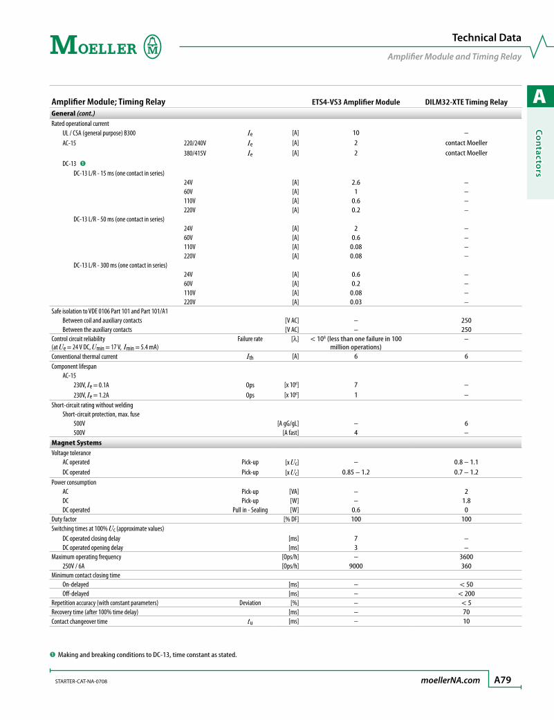
A
Co
ntacto
rs
STARTER-CAT-NA-0708 moellerNA.com A79
Amplifier Module; Timing Relay ETS4-VS3 Amplifier Module DILM32-XTE Timing RelayGeneral (cont.)Rated operational current UL / CSA (general purpose) B300 Ie [A] 10 – AC-15 220/240V Ie [A] 2 contact Moeller 380/415V Ie [A] 2 contact Moeller DC-13 ➊
DC-13 L/R - 15 ms (one contact in series) 24V [A] 2.6 – 60V [A] 1 – 110V [A] 0.6 – 220V [A] 0.2 – DC-13 L/R - 50 ms (one contact in series) 24V [A] 2 – 60V [A] 0.6 – 110V [A] 0.08 – 220V [A] 0.08 – DC-13 L/R - 300 ms (one contact in series) 24V [A] 0.6 – 60V [A] 0.2 – 110V [A] 0.08 – 220V [A] 0.03 –Safe isolation to VDE 0106 Part 101 and Part 101/A1 Between coil and auxiliary contacts [V AC] – 250 Between the auxiliary contacts [V AC] – 250Control circuit reliability Failure rate(at Ue = 24 V DC, Umin = 17 V, Imin = 5.4 mA)
[l] < 108 (less than one failure in 100 million operations)
–
Conventional thermal current Ith [A] 6 6Component lifespan AC-15 230V, Ie = 0.1A Ops [x 106] 7 – 230V, Ie = 1.2A Ops [x 106] 1 –Short-circuit rating without welding Short-circuit protection, max. fuse 500V [A gG/gL] – 6 500V [A fast] 4 –Magnet SystemsVoltage tolerance AC operated Pick-up [x Uc] – 0.8 – 1.1 DC operated Pick-up [x Uc] 0.85 – 1.2 0.7 – 1.2Power consumption AC Pick-up [VA] – 2 DC Pick-up [W] – 1.8 DC operated Pull in - Sealing [W] 0.6 0Duty factor [% DF] 100 100Switching times at 100% Uc (approximate values) DC operated closing delay [ms] 7 – DC operated opening delay [ms] 3 –Maximum operating frequency [Ops/h] – 3600 250V / 6A [Ops/h] 9000 360Minimum contact closing time On-delayed [ms] – < 50 Off-delayed [ms] – < 200Repetition accuracy (with constant parameters) Deviation [%] – < 5Recovery time (after 100% time delay) [ms] – 70Contact changeover time tu [ms] – 10
➊ Making and breaking conditions to DC-13, time constant as stated.
Technical Data
Amplifier Module and Timing Relay
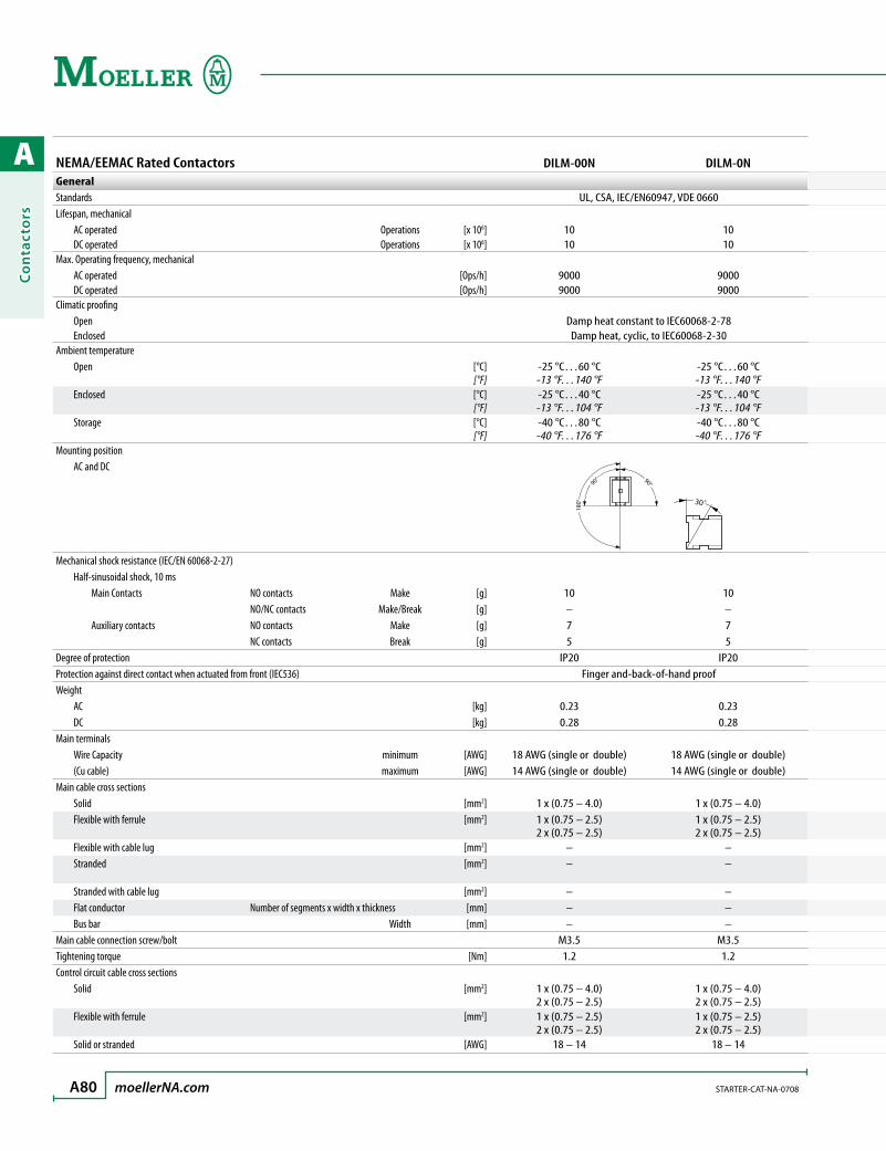
A
Co
nta
cto
rs
A80 moellerNA.com STARTER-CAT-NA-0708
NEMA/EEMAC Rated Contactors DILM-00N DILM-0NGeneralStandards UL, CSA, IEC/EN60947, VDE 0660Lifespan, mechanical AC operated Operations [x 106] 10 10 DC operated Operations [x 106] 10 10Max. Operating frequency, mechanical AC operated [Ops/h] 9000 9000 DC operated [Ops/h] 9000 9000Climatic proofing Open Damp heat constant to IEC60068-2-78 Enclosed Damp heat, cyclic, to IEC60068-2-30Ambient temperature Open [°C]
[°F]-25 °C…60 °C-13 °F…140 °F
-25 °C…60 °C-13 °F…140 °F
Enclosed [°C][°F]
-25 °C…40 °C-13 °F…104 °F
-25 °C…40 °C-13 °F…104 °F
Storage [°C][°F]
-40 °C…80 °C-40 °F…176 °F
-40 °C…80 °C-40 °F…176 °F
Mounting position AC and DC
180°
90° 90°
30˚
Mechanical shock resistance (IEC/EN 60068-2-27) Half-sinusoidal shock, 10 ms Main Contacts NO contacts Make [g] 10 10 NO/NC contacts Make/Break [g] – – Auxiliary contacts NO contacts Make [g] 7 7 NC contacts Break [g] 5 5Degree of protection IP20 IP20Protection against direct contact when actuated from front (IEC536) Finger and-back-of-hand proofWeight AC [kg] 0.23 0.23 DC [kg] 0.28 0.28Main terminals Wire Capacity minimum [AWG] 18 AWG (single or double) 18 AWG (single or double) (Cu cable) maximum [AWG] 14 AWG (single or double) 14 AWG (single or double)Main cable cross sections Solid [mm2] 1 x (0.75 – 4.0) 1 x (0.75 – 4.0) Flexible with ferrule [mm2] 1 x (0.75 – 2.5)
2 x (0.75 – 2.5)1 x (0.75 – 2.5)2 x (0.75 – 2.5)
Flexible with cable lug [mm2] – – Stranded [mm2] – –
Stranded with cable lug [mm2] – – Flat conductor Number of segments x width x thickness [mm] – – Bus bar Width [mm] – –Main cable connection screw/bolt M3.5 M3.5Tightening torque [Nm] 1.2 1.2Control circuit cable cross sections Solid [mm2] 1 x (0.75 – 4.0)
2 x (0.75 – 2.5)1 x (0.75 – 4.0)2 x (0.75 – 2.5)
Flexible with ferrule [mm2] 1 x (0.75 – 2.5)2 x (0.75 – 2.5)
1 x (0.75 – 2.5)2 x (0.75 – 2.5)
Solid or stranded [AWG] 18 – 14 18 – 14

A
Co
ntacto
rs
STARTER-CAT-NA-0708 moellerNA.com A81
Technical Data
NEMA/EEMAC Rated Contactors
NEMA/EEMAC Rated Contactors DILM-00N DILM-0NGeneralStandards UL, CSA, IEC/EN60947, VDE 0660Lifespan, mechanical AC operated Operations [x 106] 10 10 DC operated Operations [x 106] 10 10Max. Operating frequency, mechanical AC operated [Ops/h] 9000 9000 DC operated [Ops/h] 9000 9000Climatic proofing Open Damp heat constant to IEC60068-2-78 Enclosed Damp heat, cyclic, to IEC60068-2-30Ambient temperature Open [°C]
[°F]-25 °C…60 °C-13 °F…140 °F
-25 °C…60 °C-13 °F…140 °F
Enclosed [°C][°F]
-25 °C…40 °C-13 °F…104 °F
-25 °C…40 °C-13 °F…104 °F
Storage [°C][°F]
-40 °C…80 °C-40 °F…176 °F
-40 °C…80 °C-40 °F…176 °F
Mounting position AC and DC
Mechanical shock resistance (IEC/EN 60068-2-27) Half-sinusoidal shock, 10 ms Main Contacts NO contacts Make [g] 10 10 NO/NC contacts Make/Break [g] – – Auxiliary contacts NO contacts Make [g] 7 7 NC contacts Break [g] 5 5Degree of protection IP20 IP20Protection against direct contact when actuated from front (IEC536) Finger and-back-of-hand proofWeight AC [kg] 0.23 0.23 DC [kg] 0.28 0.28Main terminals Wire Capacity minimum [AWG] 18 AWG (single or double) 18 AWG (single or double) (Cu cable) maximum [AWG] 14 AWG (single or double) 14 AWG (single or double)Main cable cross sections Solid [mm2] 1 x (0.75 – 4.0) 1 x (0.75 – 4.0) Flexible with ferrule [mm2] 1 x (0.75 – 2.5)
2 x (0.75 – 2.5)1 x (0.75 – 2.5)2 x (0.75 – 2.5)
Flexible with cable lug [mm2] – – Stranded [mm2] – –
Stranded with cable lug [mm2] – – Flat conductor Number of segments x width x thickness [mm] – – Bus bar Width [mm] – –Main cable connection screw/bolt M3.5 M3.5Tightening torque [Nm] 1.2 1.2Control circuit cable cross sections Solid [mm2] 1 x (0.75 – 4.0)
2 x (0.75 – 2.5)1 x (0.75 – 4.0)2 x (0.75 – 2.5)
Flexible with ferrule [mm2] 1 x (0.75 – 2.5)2 x (0.75 – 2.5)
1 x (0.75 – 2.5)2 x (0.75 – 2.5)
Solid or stranded [AWG] 18 – 14 18 – 14
DILM-1N DILM-2N DILM-3N DILM-4N DILM-5N
UL, CSA, IEC/EN60947, VDE 0660
10 10 10 10 1010 10 10 10 10
5000 5000 3600 3600 36005000 5000 3600 3600 3600
Damp heat constant to IEC60068-2-78Damp heat, cyclic, to IEC60068-2-30
-25 °C…60 °C-13 °F…140 °F
-25 °C…60 °C-13 °F…140 °F
-25 °C…60 °C-13 °F…140 °F
-25 °C…60 °C-13 °F…140 °F
-25 °C…60 °C-13 °F…140 °F
-25 °C…40 °C-13 °F…104 °F
-25 °C…40 °C-13 °F…104 °F
-25 °C…40 °C-13 °F…104 °F
-25 °C…40 °C-13 °F…104 °F
-25 °C…40 °C-13 °F…104 °F
-40 °C…80 °C-40 °F…176 °F
-40 °C…80 °C-40 °F…176 °F
-40 °C…80 °C-40 °F…176 °F
-40 °C…80 °C-40 °F…176 °F
-40 °C…80 °C-40 °F…176 °F
180°
90° 90°
30˚
18
0˚
90˚ 90˚
30˚
10 10 10 10 10– – – – –7 7 7 7 75 5 5 5 5
IP00 IP00 IP00 IP00 IP00Finger and-back-of-hand proof
0.42 0.9 2 2 20.48 1.1 2.1 2.1 2.1
14 AWG (single or double) 14 AWG (single or double) 10 AWG (single or double) 8 AWG (single or double) 8 AWG (single or double)6 AWG (single or double) 1 AWG (2 x 2 AWG) 3/0 AWG (2 x 2/0 AWG) 3/0 AWG (2 x 2/0 AWG) 3/0 AWG (2 x 2/0 AWG)
1 x (0.75 – 16) 1 x (2.5 – 16) – – –1 x (0.75 – 16)2 x (0.75 – 10)
1 x (2.5 – 35)2 x (2.5 – 25)
1 x (10 – 95)2 x (10 – 70)
1 x (10 – 95)2 x (10 – 70)
1 x (10 – 95)2 x (10 – 70)
– – – – –1 x 16 1 x (16 – 50)
2 x (16 – 35)1 x (16 – 120)2 x (16 – 95)
1 x (16 – 120)2 x (16 – 95)
1 x (16 – 120)2 x (16 – 95)
– – – – –– 12 x (6 x 9 x 0.8) 2 x (6 x 16 x 0.8) 2 x (6 x 16 x 0.8) 2 x (6 x 16 x 0.8)– – – – –
M5 M6 M10 M10 M103 3 14 14 14
1 x (0.75 – 4)1 x (0.75 – 4)
1 x (0.75 – 4)1 x (0.75 – 4)
1 x (0.75 – 4)2 x (0.75 – 4)
1 x (0.75 – 4)2 x (0.75 – 4)
1 x (0.75 – 4)2 x (0.75 – 4)
1 x (0.75 – 2.5)2 x (0.75 – 2.5)
1 x (0.75 – 2.5)2 x (0.75 – 2.5)
1 x (0.75 – 2.5)2 x (0.75 – 2.5)
1 x (0.75 – 2.5)2 x (0.75 – 2.5)
1 x (0.75 – 2.5)2 x (0.75 – 2.5)
18 – 14 18 – 14 18 – 14 18 – 14 18 – 14
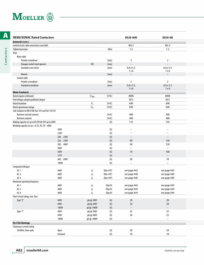
A
Co
nta
cto
rs
A82 moellerNA.com STARTER-CAT-NA-0708
NEMA/EEMAC Rated Contactors DILM-00N DILM-0NGeneral (cont.)Control circuit cable connection screw/bolt M3.5 M3.5Tightening torque [Nm] 1.2 1.2Tools Main cable Posidriv screwdriver [Size] 2 2 Hexagon socket-head spanner SW [mm] – – Standard screw driver [mm] 0.8 x 5.5
1 x 60.8 x 5.5
1 x 6 Wrench [mm] – – Control cable Posidriv screwdriver [Size] 2 2 Standard screwdriver [mm] 0.8 x 5.5
1 x 60.8 x 5.5
1 x 6Main ContactsRated impulse withstand Uimp [V AC] 8000 8000Overvoltage category/pollution degree III/3 III/3Rated insulation Ui [V AC] 690 690Rated operational voltage Ue [V AC] 690 690Safe isolation to VDE 0106 Part 101 and Part 101/A1 Between coil and contacts [V AC] 400 400 Between contacts [V AC] 400 400Making capacity cos φ to IEC/EN 60-947 up to 690V [A] 112 144Breaking capacity cos φ = 0.35, AC, 50 – 60Hz 200V [A] – – 230V [A] – – 200…230V [A] – – 220…230V [A] 90 120 380…400V [A] 90 120 460V [A] – – 500V [A] 70 100 575V [A] – – 660…690V [A] 50 70 1000V [A] – –Component lifespan AC-1 400V Ie [Ops x106] see page A42 see page A42
AC-3 400V Ie [Ops x106] see page A40 see page A40 AC-4 400V Ie [Ops x106] see page A40 see page A40Maximum operating frequency AC-1 400V Ie [Ops/h] see page A44 see page A44 AC-3 400V Ie [Ops/h] see page A44 see page A44 AC-4 400V Ie [Ops/h] see page A44 see page A44Short-circuit rating, max. fuse Type “2” 400V gG/gL 500V [A] 20 20 690V gG/gL 690V [A] 16 20 1000V gG/gL 1000V [A] – – Type “1” 400V gG/gL 500V [A] 35 35 690V gG/gL 690V [A] 20 25 1000V gG/gL 1000V [A] – –
UL/CSA RatingsContinuous current rating 50/60Hz, three-pole Open [A] 20 20 Enclosed [A] 18 18
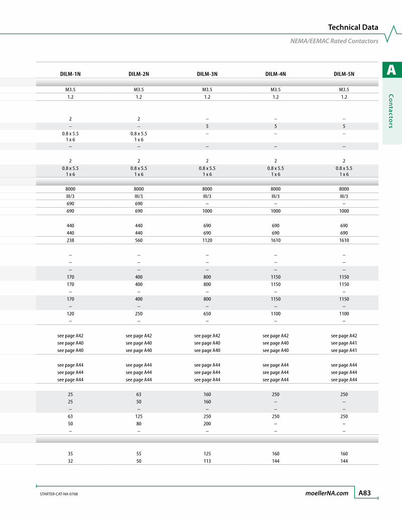
A
Co
ntacto
rs
STARTER-CAT-NA-0708 moellerNA.com A83
Technical Data
NEMA/EEMAC Rated Contactors
NEMA/EEMAC Rated Contactors DILM-00N DILM-0NGeneral (cont.)Control circuit cable connection screw/bolt M3.5 M3.5Tightening torque [Nm] 1.2 1.2Tools Main cable Posidriv screwdriver [Size] 2 2 Hexagon socket-head spanner SW [mm] – – Standard screw driver [mm] 0.8 x 5.5
1 x 60.8 x 5.5
1 x 6 Wrench [mm] – – Control cable Posidriv screwdriver [Size] 2 2 Standard screwdriver [mm] 0.8 x 5.5
1 x 60.8 x 5.5
1 x 6Main ContactsRated impulse withstand Uimp [V AC] 8000 8000Overvoltage category/pollution degree III/3 III/3Rated insulation Ui [V AC] 690 690Rated operational voltage Ue [V AC] 690 690Safe isolation to VDE 0106 Part 101 and Part 101/A1 Between coil and contacts [V AC] 400 400 Between contacts [V AC] 400 400Making capacity cos φ to IEC/EN 60-947 up to 690V [A] 112 144Breaking capacity cos φ = 0.35, AC, 50 – 60Hz 200V [A] – – 230V [A] – – 200…230V [A] – – 220…230V [A] 90 120 380…400V [A] 90 120 460V [A] – – 500V [A] 70 100 575V [A] – – 660…690V [A] 50 70 1000V [A] – –Component lifespan AC-1 400V Ie [Ops x106] see page A42 see page A42
AC-3 400V Ie [Ops x106] see page A40 see page A40 AC-4 400V Ie [Ops x106] see page A40 see page A40Maximum operating frequency AC-1 400V Ie [Ops/h] see page A44 see page A44 AC-3 400V Ie [Ops/h] see page A44 see page A44 AC-4 400V Ie [Ops/h] see page A44 see page A44Short-circuit rating, max. fuse Type “2” 400V gG/gL 500V [A] 20 20 690V gG/gL 690V [A] 16 20 1000V gG/gL 1000V [A] – – Type “1” 400V gG/gL 500V [A] 35 35 690V gG/gL 690V [A] 20 25 1000V gG/gL 1000V [A] – –
UL/CSA RatingsContinuous current rating 50/60Hz, three-pole Open [A] 20 20 Enclosed [A] 18 18
DILM-1N DILM-2N DILM-3N DILM-4N DILM-5N
M3.5 M3.5 M3.5 M3.5 M3.51.2 1.2 1.2 1.2 1.2
2 2 – – –– – 5 5 5
0.8 x 5.51 x 6
0.8 x 5.51 x 6
– – –
– – – – –
2 2 2 2 20.8 x 5.5
1 x 60.8 x 5.5
1 x 60.8 x 5.5
1 x 60.8 x 5.5
1 x 60.8 x 5.5
1 x 6
8000 8000 8000 8000 8000III/3 III/3 III/3 III/3 III/3690 690 – – –690 690 1000 1000 1000
440 440 690 690 690440 440 690 690 690238 560 1120 1610 1610
– – – – –– – – – –– – – – –
170 400 800 1150 1150170 400 800 1150 1150
– – – – –170 400 800 1150 1150
– – – – –120 250 650 1100 1100
– – – – –
see page A42 see page A42 see page A42 see page A42 see page A42see page A40 see page A40 see page A40 see page A40 see page A41see page A40 see page A40 see page A40 see page A40 see page A41
see page A44 see page A44 see page A44 see page A44 see page A44see page A44 see page A44 see page A44 see page A44 see page A44see page A44 see page A44 see page A44 see page A44 see page A44
25 63 160 250 25025 50 160 – –– – – – –63 125 250 250 25050 80 200 – –– – – – –
35 55 125 160 16032 50 113 144 144

A
Co
nta
cto
rs
A84 moellerNA.com STARTER-CAT-NA-0708
NEMA/EEMAC Rated Contactors DILM-00N DILM-0NUL/CSA Ratings (cont.)Horsepower ratings (AC) Single phase 115V [HP] 1⁄3 1 200V [HP] – – 230V [HP] 1 2 Three phase 200V [HP] 1½ 3 230V [HP] 1½ 3 460V [HP] 2 5 575V [HP] 2 5NEMA Size (non-jogging duty) [Size] 00 0Current heat loss at Ith Ith [W] 4.7 4.7Current heat loss at Ie to AC-3; 400V Ie [W] 0.6 1.1Impedance per pole [mΩ] 2.5 2.5
Magnet SystemVoltage tolerance AC operated Single voltage coil 60Hz Pick-up x V coil [x Uc] 0.8 – 1.1 0.8 – 1.1 Drop-out x V coil [x Uc] 0.3 – 0.6 0.3 – 0.6 Single voltage coil 50Hz Pick-up x V coil [x Uc] 0.8 – 1.1 0.8 – 1.1 Drop-out x V coil [x Uc] 0.3 – 0.6 0.3 – 0.6 Dual voltage coil 50Hz, 60Hz Pick-up x V coil [x Uc] 0.8 – 1.1 0.8 – 1.1 Drop-out x V coil [x Uc] 0.3 – 0.6 0.3 – 0.6 Dual frequency coil 50/60Hz Pick-up x V coil [x Uc] – – Drop-out x V coil [x Uc] – – DC operated ➊ Pick-up x V coil [x Uc] 0.8 – 1.1 ➋ 0.8 – 1.1 ➋
Drop-out x V coil [x Uc] 0.15 – 0.6 0.15 – 0.6Power consumption of the coil in a cold state and 1.0 x Uc AC operated Single voltage coil 60Hz Pick-up [VA] 30 30 Sealed [VA/W] 4.4/1.4 4.4/1.4 Single voltage coil 50Hz Pick-up [VA] 24 24 Sealed [VA/W] 3.4/1.2 3.4/1.2 Dual voltage coil 50Hz, 60Hz Pick-up [VA] – – Sealed [VA/W] – – Dual frequency coil 50/60Hz Pick-up [VA] 25 – 27 25 – 27 Sealed [VA/W] 3.3 – 4.2/1.2 – 1.4 3.3 – 4.2/1.2 – 1.4 DC operated Pick-up [W] 3 4.5 Sealed [W] 3 4.5Duty factor (DF) [%DF] 100 100Switching times at 100% Uc (rated coil voltage main contacts AC operated Closing delay Min./Max. [ms] 15 – 21 15 – 21 Opening delay Min./Max. [ms] 9 – 18 9 – 18 DC operated ➊ Closing delay Min./Max. [ms] 31 31 Opening delay Min./Max. [ms] 12 12Arcing time (AC) Maximum [ms] 10 10Permissible residual current (with actuation of A11 by the electronics with no signal) [mA] – –
Electromagnetic Cmopatibility (EC)Emitted interference to EN 60947-1Noise immunity to EN 60947-1
➊ True DC voltage or derived from a full wave 3-phase bridge rectifier or filtered 1-phase AC supply.
➋At 24V: 0.7…1.3 without additional auxiliary contact modules and ambient temperature 40 °C
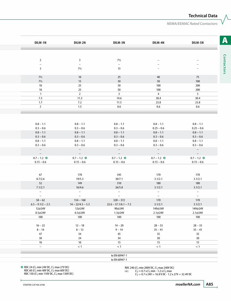
A
Co
ntacto
rs
STARTER-CAT-NA-0708 moellerNA.com A85
Technical Data
NEMA/EEMAC Rated Contactors
NEMA/EEMAC Rated Contactors DILM-00N DILM-0NUL/CSA Ratings (cont.)Horsepower ratings (AC) Single phase 115V [HP] 1⁄3 1 200V [HP] – – 230V [HP] 1 2 Three phase 200V [HP] 1½ 3 230V [HP] 1½ 3 460V [HP] 2 5 575V [HP] 2 5NEMA Size (non-jogging duty) [Size] 00 0Current heat loss at Ith Ith [W] 4.7 4.7Current heat loss at Ie to AC-3; 400V Ie [W] 0.6 1.1Impedance per pole [mΩ] 2.5 2.5
Magnet SystemVoltage tolerance AC operated Single voltage coil 60Hz Pick-up x V coil [x Uc] 0.8 – 1.1 0.8 – 1.1 Drop-out x V coil [x Uc] 0.3 – 0.6 0.3 – 0.6 Single voltage coil 50Hz Pick-up x V coil [x Uc] 0.8 – 1.1 0.8 – 1.1 Drop-out x V coil [x Uc] 0.3 – 0.6 0.3 – 0.6 Dual voltage coil 50Hz, 60Hz Pick-up x V coil [x Uc] 0.8 – 1.1 0.8 – 1.1 Drop-out x V coil [x Uc] 0.3 – 0.6 0.3 – 0.6 Dual frequency coil 50/60Hz Pick-up x V coil [x Uc] – – Drop-out x V coil [x Uc] – – DC operated ➊ Pick-up x V coil [x Uc] 0.8 – 1.1 ➋ 0.8 – 1.1 ➋
Drop-out x V coil [x Uc] 0.15 – 0.6 0.15 – 0.6Power consumption of the coil in a cold state and 1.0 x Uc AC operated Single voltage coil 60Hz Pick-up [VA] 30 30 Sealed [VA/W] 4.4/1.4 4.4/1.4 Single voltage coil 50Hz Pick-up [VA] 24 24 Sealed [VA/W] 3.4/1.2 3.4/1.2 Dual voltage coil 50Hz, 60Hz Pick-up [VA] – – Sealed [VA/W] – – Dual frequency coil 50/60Hz Pick-up [VA] 25 – 27 25 – 27 Sealed [VA/W] 3.3 – 4.2/1.2 – 1.4 3.3 – 4.2/1.2 – 1.4 DC operated Pick-up [W] 3 4.5 Sealed [W] 3 4.5Duty factor (DF) [%DF] 100 100Switching times at 100% Uc (rated coil voltage main contacts AC operated Closing delay Min./Max. [ms] 15 – 21 15 – 21 Opening delay Min./Max. [ms] 9 – 18 9 – 18 DC operated ➊ Closing delay Min./Max. [ms] 31 31 Opening delay Min./Max. [ms] 12 12Arcing time (AC) Maximum [ms] 10 10Permissible residual current (with actuation of A11 by the electronics with no signal) [mA] – –
Electromagnetic Cmopatibility (EC)Emitted interference to EN 60947-1Noise immunity to EN 60947-1
DILM-1N DILM-2N DILM-3N DILM-4N DILM-5N
2 3 7½ – –– – – – –3 7½ 15 – –
7½ 10 25 40 757½ 15 30 50 10010 25 50 100 20010 25 50 100 200 1 2 3 4 5
7.3 11.3 14.6 30.4 30.41.7 7.2 11.5 23.8 23.82 1.5 0.6 0.6 0.6
0.8 – 1.1 0.8 – 1.1 0.8 – 1.1 0.8 – 1.1 0.8 – 1.10.3 – 0.6 0.3 – 0.6 0.3 – 0.6 0.25 – 0.6 0.25 – 0.60.8 – 1.1 0.8 – 1.1 0.8 – 1.1 0.8 – 1.1 0.8 – 1.10.3 – 0.6 0.3 – 0.6 0.3 – 0.6 0.3 – 0.6 0.3 – 0.60.8 – 1.1 0.8 – 1.1 0.8 – 1.1 0.8 – 1.1 0.8 – 1.10.3 – 0.6 0.3 – 0.6 0.3 – 0.6 0.3 – 0.6 0.3 – 0.6
– – – – –– – – – –
0.7 – 1.2 ➌ 0.7 – 1.2 ➌ 0.7 – 1.2 ➌ 0.7 – 1.2 ➌ 0.7 – 1.2 ➌
0.15 – 0.6 0.15 – 0.6 0.15 – 0.6 0.15 – 0.6 0.15 – 0.6
67 178 345 170 1708.7/2.6 19/5.3 30/7.1 3.1/2.1 3.1/2.1
52 149 310 180 1807.1/2.1 16/4.6 26/5.8 3.1/2.1 3.1/2.1
– – – – –– – – – –
58 – 62 154 – 168 328 – 372 170 1706.5 – 9.1/2 – 2.5 14 – 22/4.3 – 5.3 22.6 – 37.1/6.1 – 7.5 3.1/2.1 3.1/2.1
12@24V 12@24V 90@24V 149@24V [email protected]@24V 0.5@24V 1.3@24V 2.1@24V 2.1@24V
100 100 100 100 100
16 – 22 12 – 18 14 – 20 28 – 33 28 – 338 – 14 8 – 13 9 – 14 35 – 41 35 – 41
47 54 45 35 3530 24 34 30 3010 10 15 15 15– < 1 < 1 < 1 < 1
to EN 60947-1to EN 60947-1
➌ RDC 24 (Uc min 24V DC, Uc max 27V DC) RDC 60 (Uc min 48V DC, Uc max 60V DC) RDC 130 (Uc min 110V DC, Uc max 130V DC)
RDC 240 (Uc min 200V DC, Uc max 240V DC) i.e.: Uc = 0.7 x Uc min - 1.2 x Uc max Uc = 0.7 x 24V = 16.8 V DC - 1.2 x 27V = 32.4V DC
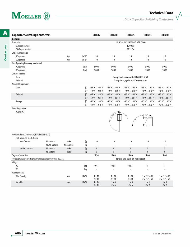
A
Co
nta
cto
rs
A86 moellerNA.com STARTER-CAT-NA-0708
Capacitor Switching Contactors DILK12 DILK20 DILK25 DILK33 DILK50GeneralStandards UL, CSA, IEC/EN60947, VDE 0660 UL Report Number E29096 CSA Report Number 3211 04Lifespan, mechanical AC operated Ops [x 106] 10 10 10 10 10 DC operated Ops [x 106] 10 10 10 10 10Max. Operating frequency, mechanical AC operated Ops/h 9000 5000 5000 5000 5000 DC operated Ops/h 9000 5000 5000 5000 5000Climatic proofing Open Damp heat constant to IEC60068-2-78 Enclosed Damp heat, cyclic to IEC 60068-2-30Ambient temperature Open [C] -25 °C…60 °C -25 °C…60 °C -25 °C…60 °C -25 °C…60 °C -25 °C…60 °C
[F] -13 °F…140 °F -13 °F…140 °F -13 °F…140 °F -13 °F…140 °F -13 °F…140 °F Enclosed [C] -25 °C…40 °C -25 °C…40 °C -25 °C…40 °C -25 °C…40 °C -25 °C…40 °C
[F] -13 °F…104 °F -13 °F…104 °F -13 °F…104 °F -13 °F…104 °F -13 °F…104 °F Storage [C] -40 °C…80 °C -40 °C…80 °C -40 °C…80 °C -40 °C…80 °C -40 °C…80 °C
[F] -40 °F…176 °F -40 °F…176 °F -40 °F…176 °F -40 °F…176 °F -40 °F…176 °FMounting position AC and DC
180°
90° 90°
90°
30°
Mechanical shock resistance (IEC/EN 60068-2-27) Half-sinusoidal shock, 10 ms Main Contacts NO contacts Make [g] 10 10 10 10 10 NO/NC contacts Make/Break [g] – – – – – Auxiliary contacts NO contacts Make [g] 7 7 7 7 7 NC contacts Break [g] 5 5 5 5 5Degree of protection IP20 IP00 IP00 IP00 IP00Protection against direct contact when actuated from front (IEC536) Finger and-back-of-hand proofWeight AC [kg] 0.41 0.55 0.55 1 1 DC [kg] – – – – –Main terminals Wire Capacity min [AWG] 1 x 18
2 x 181 x 18 2 x 18
1 x 18 2 x 18
1 x (12 – 2) 2 x (12 – 2)
1 x (12 – 2) 2 x (12 – 2)
(Cu cable) max [AWG] 1 x 14 2 x 14
1 x 6 2 x 6
1 x 6 2 x 6
1 x 1 2 x 2
1 x 1 2 x 2
Technical Data
DIL K Capacitor Switching Contactors

A
Co
ntacto
rs
STARTER-CAT-NA-0708 moellerNA.com A87
Technical Data
DIL K Capacitor Switching Contactors
Capacitor Switching Contactors DILK12 DILK20 DILK25 DILK33 DILK50General (cont.)Main cable cross sections Solid [mm2] 1 x (0.75 – 4.0) 1 x (0.75 – 16) 1 x (0.75 – 16) 1 x (2.5 – 16) 1 x (2.5 – 16)
2 x (0.75 – 2.5) 2 x (0.75 – 10) 2 x (0.75 – 10) 2 x (2.5 – 16) 2 x (2.5 – 16) Flexible with ferrule [mm2] 1 x (0.75 – 2.5) 1 x (0.75 – 16) 1 x (0.75 – 16) 1 x (2.5 – 35) 1 x (2.5 – 35)
2 x (0.75 – 2.5) 2 x (0.75 – 10) 2 x (0.75 – 10) 2 x (2.5 – 25) 2 x (2.5 – 25) Flexible with cable lug [mm2] – – – – – Stranded [mm2] – 1 x 16 1 x 16 1 x (16 – 50) 1 x (16 – 50)
– – – 2 x (16 – 35) 2 x (16 – 35) Stranded with cable lug [mm2] – – – – – Flat conductor Number of segments x width x thickness [mm] – – – 12 x (6 x 9 x 0.8) 12 x (6 x 9 x 0.8) Bus bar Width [mm] – – – – –Main cable connection screw/bolt M3.5 M5 M5 M6 M6Tightening torque [Nm] 1.2 3 3 3 3Control circuit cable cross sections Solid [mm2] 1 x (0.75 – 4.0) 1 x (0.75 – 4) 1 x (0.75 – 4) 1 x (0.75 – 4) 1 x (0.75 – 4)
2 x (0.75 – 2.5) 1 x (0.75 – 4) 1 x (0.75 – 4) 1 x (0.75 – 4) 1 x (0.75 – 4) Flexible with ferrule [mm2] 1 x (0.75 – 2.5) 1 x (0.75 – 2.5) 1 x (0.75 – 2.5) 1 x (0.75 – 2.5) 1 x (0.75 – 2.5)
2 x (0.75 – 2.5) 2 x (0.75 – 2.5) 2 x (0.75 – 2.5) 2 x (0.75 – 2.5) 2 x (0.75 – 2.5) Solid or stranded [AWG] 18 – 14 18 – 14 18 – 14 18 – 14 18 – 14Control circuit cable connection screw/bolt M3.5 M3.5 M3.5 M3.5 M3.5Tightening torque [Nm] 1.2 1.2 1.2 1.2 1.2Tools Main cable Posidriv screwdriver [Size] 2 2 2 2 2 Hexagon socket-head spanner SW [mm] – – – – – Standard screw driver [mm] 0.8 x 5.5 0.8 x 5.5 0.8 x 5.5 0.8 x 5.5 0.8 x 5.5
1 x 6 1 x 6 1 x 6 1 x 6 1 x 6 Wrench [mm] – – – – – Control cable Posidriv screwdriver [Size] 2 2 2 2 2 Standard screwdriver [mm] 0.8 x 5.5 0.8 x 5.5 0.8 x 5.5 0.8 x 5.5 0.8 x 5.5
1 x 6 1 x 6 1 x 6 1 x 6 1 x 6
Main ContactsRated impulse withstand Uimp [V AC] 8000 8000 8000 8000 8000Overvoltage category/pollution degree III/3 III/3 III/3 III/3 III/3Rated insulation Ui [V AC] 690 690 690 690 690Rated operational voltage Ue [V AC] 690 690 690 690 690Safe isolation to VDE 0106 Part 101 and Part 101/A1 Between coil and contacts [V AC] 400 440 440 440 440 Between contacts [V AC] 400 440 440 440 440

A
Co
nta
cto
rs
A88 moellerNA.com STARTER-CAT-NA-0708
Technical Data
DIL K Capacitor Switching Contactors
Capacitor Switching Contactors DILK12 DILK20 DILK25 DILK33 DILK50Main Contacts (cont.)Making capacity cos φ to IEC/EN 60-947 up to 690V [A] 144 238 384 560 910Breaking capacity cos φ = 0.35, AC, 50 – 60Hz 200V [A] – – – – – 230V [A] – – – – – 200…230V [A] – – – – – 220…230V [A] 120 170 320 400 650 380…400V [A] 120 170 320 400 650 460V [A] – – – – – 500V [A] 100 170 320 400 650 575V [A] – – – – – 660…690V [A] 70 120 180 250 370 1000V [A] – – – – –Short circuit rating Max. fuse Type “2” 400V gG/gL 500V [A] 20 25 63 63 125 690V gG/gL 690V [A] 20 25 35 50 80 1000V gG/gL 1000V [A] – – – – – Type “1” 400V gG/gL 500V [A] 35 63 125 125 250 690V gG/gL 690V [A] 25 50 63 80 100 1000V gG/gL 1000V [A] – – – – –
UL/CSA RatingsContinuous current rating 50/60Hz, 3-pole Open [A] 20 35 40 55 80 Enclosed [A] 18 32 36 50 72Capacitive switching ratings Three phase, 60Hz, Amperes 240V [A] 18 28 36 48 72 480V [A] 18 28 36 48 72 600V [A] 14.4 28 38.4 48 72 Three phase, 60Hz, kVAR 240V [kVAR] 7.5 12 15 20 30 480V [kVAR] 15 20 30 40 60 600V [kVAR] 15 30 40 50 75
IEC Capacitor Duty RatingsGroup compensation motor rating of three phase capacitors 230V [kVAR] 7.5 11 15 20 25 400V [kVAR] 12.5 20 25 33.3 50 525V [kVAR] 16.7 25 33.3 40 65 690V [kVAR] 20 33.3 40 55 85
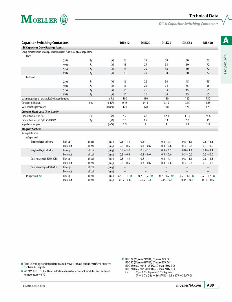
A
Co
ntacto
rs
STARTER-CAT-NA-0708 moellerNA.com A89
Technical Data
DIL K Capacitor Switching Contactors
➊ True DC voltage or derived from a full wave 3-phase bridge rectifier or filtered 1-phase AC supply.
➋At 24V: 0.7…1.3 without additional auxiliary contact modules and ambient temperature 40 °C
Capacitor Switching Contactors DILK12 DILK20 DILK25 DILK33 DILK50IEC Capacitor Duty Ratings (cont.)Group compensation rated operational current Ie of three phase capacitors Open 230V Ie [A] 18 29 38 50 72 400V Ie [A] 18 29 38 50 72 525V Ie [A] 18 29 38 50 72 690V Ie [A] 18 29 38 50 72 Enclosed 230V Ie [A] 16 26 34 45 65 400V Ie [A] 16 26 34 45 65 525V Ie [A] 16 26 34 45 65 690V Ie [A] 16 26 34 45 65Making capacity (I - peak value) without damping [x Ie] 180 180 180 180 180Component lifespan Ops [x 106] 0.15 0.15 0.15 0.15 0.15Max. operating frequency [Ops/h] 120 120 120 120 120
Current Heat Loss (3 or 4 pole)Current heat loss at Ith Ith [W] 4.7 7.3 12.1 11.3 28.8Current heat loss at Ie to AC-3/400V Ie [W] 1.1 1.7 6.1 7.2 19Impedance per pole [mΩ] 2.5 2 2 1.5 1.5
Magnet SystemVoltage tolerance AC operated Single voltage coil 60Hz Pick-up x V coil [x Uc] 0.8 – 1.1 0.8 – 1.1 0.8 – 1.1 0.8 – 1.1 0.8 – 1.1 Drop-out x V coil [x Uc] 0.3 – 0.6 0.3 – 0.6 0.3 – 0.6 0.3 – 0.6 0.3 – 0.6 Single voltage coil 50Hz Pick-up x V coil [x Uc] 0.8 – 1.1 0.8 – 1.1 0.8 – 1.1 0.8 – 1.1 0.8 – 1.1 Drop-out x V coil [x Uc] 0.3 – 0.6 0.3 – 0.6 0.3 – 0.6 0.3 – 0.6 0.3 – 0.6 Dual voltage coil 50Hz, 60Hz Pick-up x V coil [x Uc] 0.8 – 1.1 0.8 – 1.1 0.8 – 1.1 0.8 – 1.1 0.8 – 1.1 Drop-out x V coil [x Uc] 0.3 – 0.6 0.3 – 0.6 0.3 – 0.6 0.3 – 0.6 0.3 – 0.6 Dual frequency coil 50/60Hz Pick-up x V coil [x Uc] – – – – – Drop-out x V coil [x Uc] – – – – – DC operated ➊ Pick-up x V coil [x Uc] 0.8 – 1.1 ➋ 0.7 – 1.2 ➌ 0.7 – 1.2 ➌ 0.7 – 1.2 ➌ 0.7 – 1.2 ➌
Drop-out x V coil [x Uc] 0.15 – 0.6 0.15 – 0.6 0.15 – 0.6 0.15 – 0.6 0.15 – 0.6
➌ RDC 24 (Uc min 24V DC, Uc max 27V DC) RDC 60 (Uc min 48V DC, Uc max 60V DC) RDC 130 (Uc min 110V DC, Uc max 130V DC) RDC 240 (Uc min 200V DC, Uc max 240V DC) i.e.: Uc = 0.7 x Uc min - 1.2 x Uc max Uc = 0.7 x 24V = 16.8 V DC - 1.2 x 27V = 32.4V DC
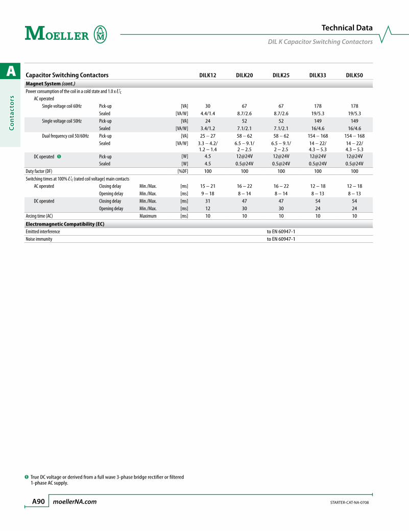
A
Co
nta
cto
rs
A90 moellerNA.com STARTER-CAT-NA-0708
Technical Data
DIL K Capacitor Switching Contactors
Capacitor Switching Contactors DILK12 DILK20 DILK25 DILK33 DILK50Magnet System (cont.)Power consumption of the coil in a cold state and 1.0 x Uc AC operated Single voltage coil 60Hz Pick-up [VA] 30 67 67 178 178 Sealed [VA/W] 4.4/1.4 8.7/2.6 8.7/2.6 19/5.3 19/5.3 Single voltage coil 50Hz Pick-up [VA] 24 52 52 149 149 Sealed [VA/W] 3.4/1.2 7.1/2.1 7.1/2.1 16/4.6 16/4.6 Dual frequency coil 50/60Hz Pick-up [VA] 25 – 27 58 – 62 58 – 62 154 – 168 154 – 168 Sealed [VA/W] 3.3 – 4.2/
1.2 – 1.46.5 – 9.1/
2 – 2.56.5 – 9.1/
2 – 2.514 – 22/ 4.3 – 5.3
14 – 22/ 4.3 – 5.3
DC operated ➊ Pick-up [W] 4.5 12@24V 12@24V 12@24V 12@24V Sealed [W] 4.5 0.5@24V 0.5@24V 0.5@24V 0.5@24VDuty factor (DF) [%DF] 100 100 100 100 100Switching times at 100% Uc (rated coil voltage) main contacts AC operated Closing delay Min./Max. [ms] 15 – 21 16 – 22 16 – 22 12 – 18 12 – 18 Opening delay Min./Max. [ms] 9 – 18 8 – 14 8 – 14 8 – 13 8 – 13 DC operated Closing delay Min./Max. [ms] 31 47 47 54 54 Opening delay Min./Max. [ms] 12 30 30 24 24Arcing time (AC) Maximum [ms] 10 10 10 10 10
Electromagnetic Compatibility (EC)Emitted interference to EN 60947-1Noise immunity to EN 60947-1
➊ True DC voltage or derived from a full wave 3-phase bridge rectifier or filtered 1-phase AC supply.

A
Co
ntacto
rs
STARTER-CAT-NA-0708 moellerNA.com A91
Miniature ContactorDILEM-…
Reversing CombinationDIULEM…
Star-Delta Starter CombinationsSDAINLEM…
35
58
83
52
50
M4
45
61
108
180 83
61
108
90 94
Dimensions
DIL EM Miniature Contactors
Dimensions are in millimeters.Not intended for manufacturing purposes.
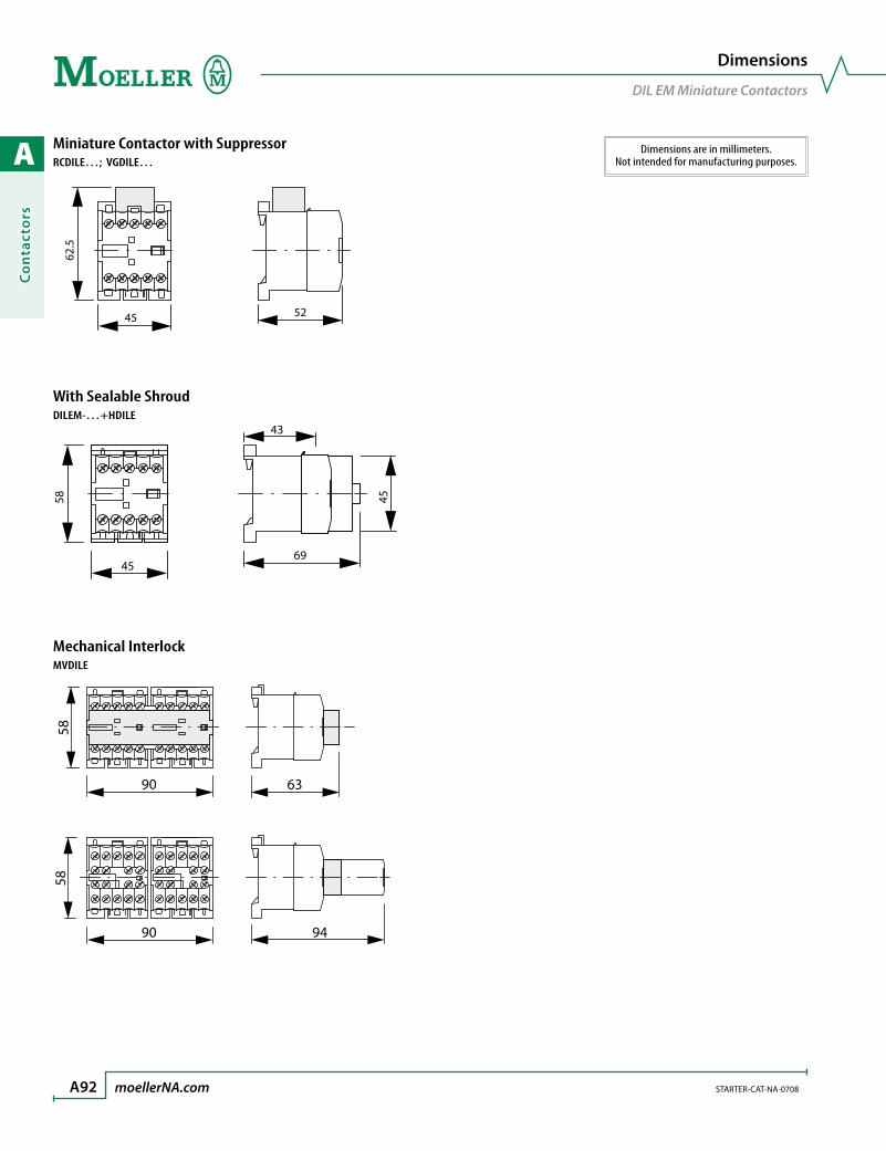
A
Co
nta
cto
rs
A92 moellerNA.com STARTER-CAT-NA-0708
Miniature Contactor with SuppressorRCDILE…; VGDILE…
5245
62.5
With Sealable ShroudDILEM-…+HDILE
Mechanical InterlockMVDILE
43
45
58
69
45
90
90 94
63
58
58
Dimensions
DIL EM Miniature Contactors
Dimensions are in millimeters.Not intended for manufacturing purposes.

A
Co
ntacto
rs
STARTER-CAT-NA-0708 moellerNA.com A93
Contactors (low range)DILM7-…; DILM9-…; DILM12-…
DILMF8-…; DILMF11-…; DILMF14-…; DILM(F)17-…; DILM(F)25-…; DILM(F)32-…
18 45 68
45
36
8.7 8.7 8.7 8.7 (5.1)
6.5
75
c
3.2
35
2 x M4
60
11.6 11.6
4.5
17.7
10.6(6.4)
38 7160.4
85
45
4.8
138
6.5
97.4
4.5
35
2 x M4
75
Auxiliary Contact cDILM32-XHI 117
DILA-XHI 117DILA-XHI…T 125
Sideways distance to grounding parts: 6mm
Dimensions
DIL M Contactors
Dimensions are in millimeters.Not intended for manufacturing purposes.
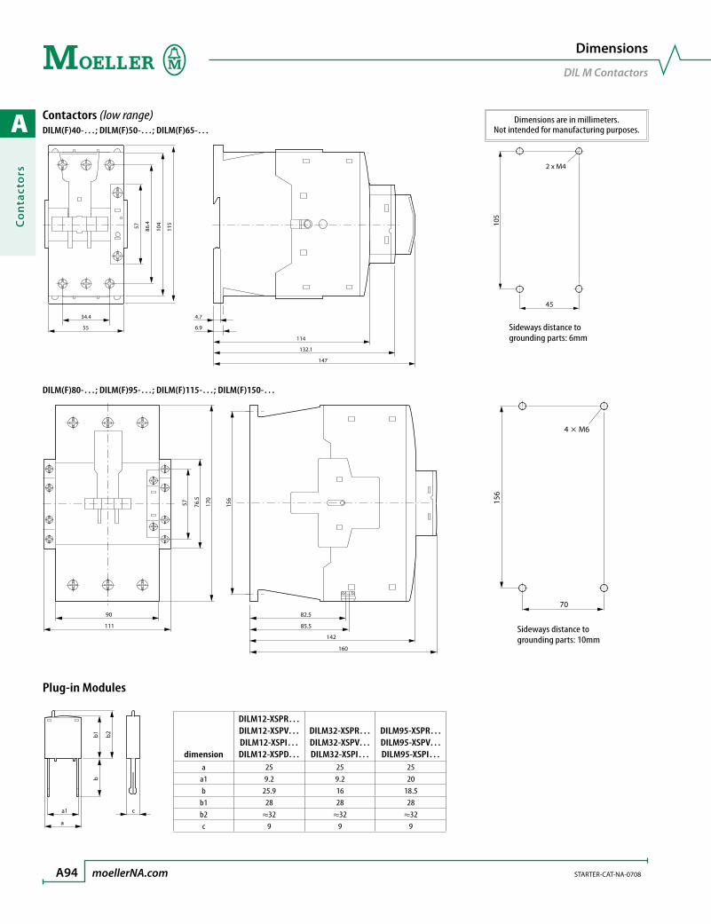
A
Co
nta
cto
rs
A94 moellerNA.com STARTER-CAT-NA-0708
Contactors (low range)DILM(F)40-…; DILM(F)50-…; DILM(F)65-…
DILM(F)80-…; DILM(F)95-…; DILM(F)115-…; DILM(F)150-…
Plug-in Modules
6.9
4.734.4
114
132.1
147
55
57 86.4
104
115
45
2 x M4
105
a1 c
a
b1
b2
b
dimension
DILM12-XSPR… DILM12-XSPV…DILM12-XSPI…DILM12-XSPD…
DILM32-XSPR… DILM32-XSPV…DILM32-XSPI…
DILM95-XSPR…DILM95-XSPV…DILM95-XSPI…
a 25 25 25a1 9.2 9.2 20b 25.9 16 18.5
b1 28 28 28b2 ≈32 ≈32 ≈32c 9 9 9
Sideways distance to grounding parts: 6mm
160
142
85.5
82.5
156
170
76.5
57
111
90
4 M6
156
70
Sideways distance to grounding parts: 10mm
Dimensions
DIL M Contactors
Dimensions are in millimeters.Not intended for manufacturing purposes.
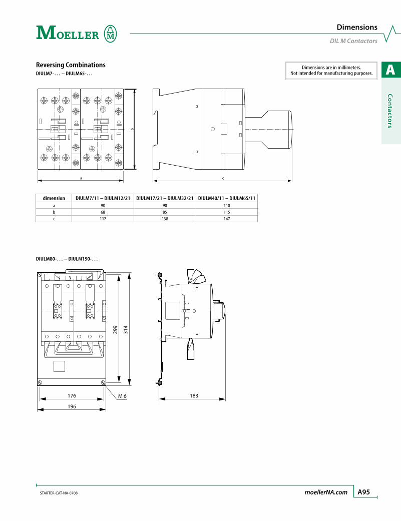
A
Co
ntacto
rs
STARTER-CAT-NA-0708 moellerNA.com A95
Reversing CombinationsDIULM7-… – DIULM65-…
dimension DIULM7/11 – DIULM12/21 DIULM17/21 – DIULM32/21 DIULM40/11 – DIULM65/11a 90 90 110b 68 85 115c 117 138 147
DIULM80-… – DIULM150-…
b
c a
176
196
M 6
299
314
183
Dimensions are in millimeters.Not intended for manufacturing purposes.
Dimensions
DIL M Contactors
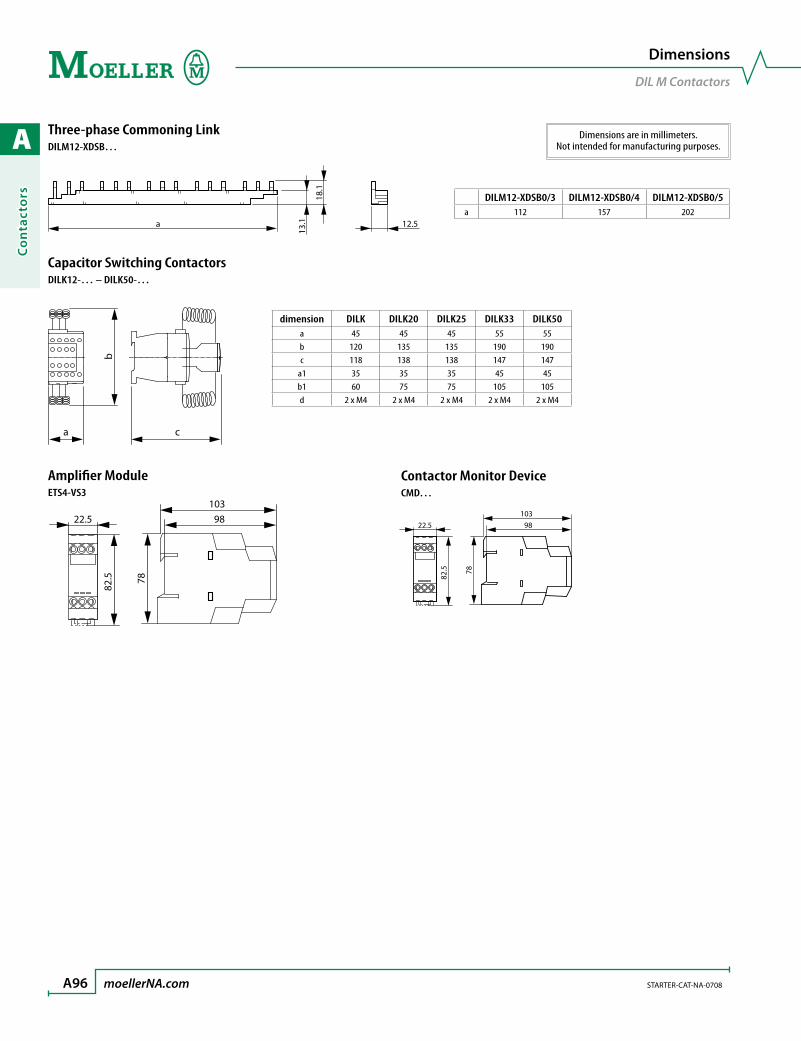
A
Co
nta
cto
rs
A96 moellerNA.com STARTER-CAT-NA-0708
Three-phase Commoning LinkDILM12-XDSB…
Capacitor Switching ContactorsDILK12-… – DILK50-…
Amplifier ModuleETS4-VS3
13.1a
18.1
12.5
b
ca
dimension DILK DILK20 DILK25 DILK33 DILK50a 45 45 45 55 55b 120 135 135 190 190c 118 138 138 147 147
a1 35 35 35 45 45b1 60 75 75 105 105d 2 x M4 2 x M4 2 x M4 2 x M4 2 x M4
DILM12-XDSB0/3 DILM12-XDSB0/4 DILM12-XDSB0/5a 112 157 202
10398
78
22.5
82.5
Dimensions
DIL M Contactors
Dimensions are in millimeters.Not intended for manufacturing purposes.
Contactor Monitor DeviceCMD…
10398
78
22.5
82.5

A
Co
ntacto
rs
STARTER-CAT-NA-0708 moellerNA.com A97
Contactors (high range)DILM185-… – DILM500-…
dimension DILM185 DILM225 DILM250 DILM300 DILM400 DILM500a 140 140 140 160 160 160
a1 120 120 120 130 130 130a2 160 160 160 180 180 180b 180 180 180 200 200 200
b1 160 160 160 180 180 180b2 164 164 164 184 184 189b3 189 189 189 209 209 219d1 20 20 25 25 25 38d2 48 48 48 48 48 57e 5 5 5 6 6 6c 208 208 208 216 216 216
c 8
140
b1
a1
M6
e
d1
b2
b3
b
d2
a
Ø11
a2
➊ DILM1000-XHI…-SI➋ DILM1000-XHI11-SA
Dimensions
DIL M Contactors
Dimensions are in millimeters.Not intended for manufacturing purposes.
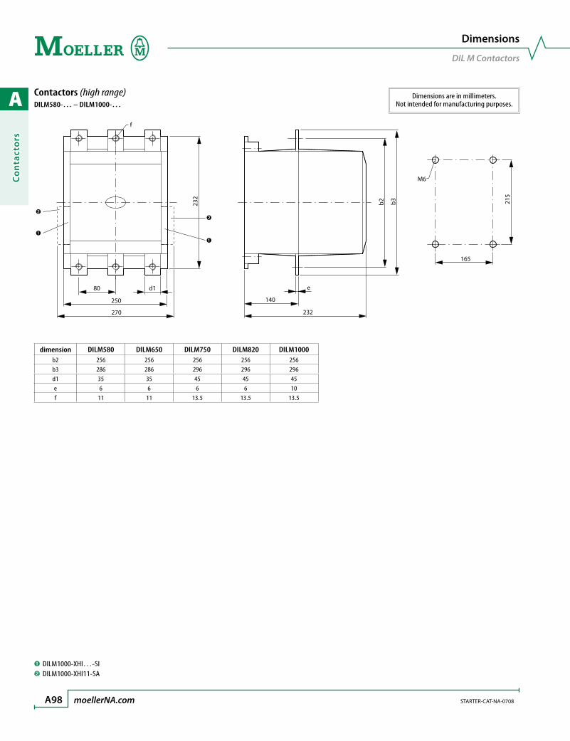
A
Co
nta
cto
rs
A98 moellerNA.com STARTER-CAT-NA-0708
Contactors (high range)DILM580-… – DILM1000-…
dimension DILM580 DILM650 DILM750 DILM820 DILM1000b2 256 256 256 256 256b3 286 286 296 296 296d1 35 35 45 45 45e 6 6 6 6 10f 11 11 13.5 13.5 13.5
250
80 d1
f
232
232
b3
140
b2
270
e
165
215
M6
➊ DILM1000-XHI…-SI➋ DILM1000-XHI11-SA
Dimensions
DIL M Contactors
Dimensions are in millimeters.Not intended for manufacturing purposes.

A
Co
ntacto
rs
STARTER-CAT-NA-0708 moellerNA.com A99
Contactor with Terminal ShroudDILM185-… – DILM1000-… + DILM…-XHB
dimension
DILM185DILM225DILM250
DILM185-XP1DILM300DILM400 DILM500
DILM580DILM650DILM750DILM820
DILM1000a 150 150 174 236b 384 404 426 506
Contactor with Start-Point Bridge + Terminal ShroudDILM…-XS1
a b
150
34
523
110
328
~144
a
b
dimension DILM185 – DILM250 DILM300 - DILM400 DILM500a 150 150 176
b 127 137 146
Dimensions
Contactor with Terminal Shroud
DILM185-… – DILM250-… + Z5-…/FF250
Dimensions are in millimeters.Not intended for manufacturing purposes.
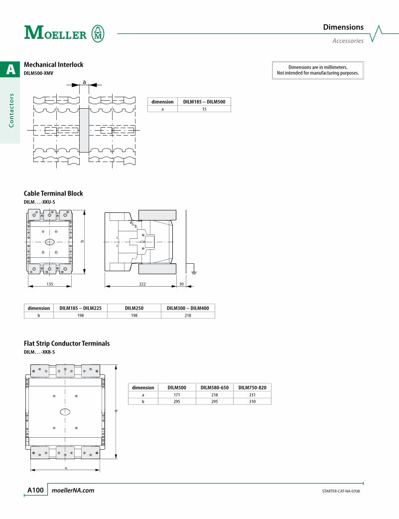
A
Co
nta
cto
rs
A100 moellerNA.com STARTER-CAT-NA-0708
Mechanical InterlockDILM500-XMV
dimension DILM185 – DILM500a 15
Cable Terminal BlockDILM…-XKU-S
dimension DILM185 – DILM225 DILM250 DILM300 – DILM400b 198 198 218
Flat Strip Conductor TerminalsDILM…-XKB-S
a
135 222
b
30
a
d
dimension DILM500 DILM580-650 DILM750-820a 171 218 231b 295 295 310
Dimensions
Accessories
Dimensions are in millimeters.Not intended for manufacturing purposes.

B
Mo
tor Pro
tection
motor protection
Thermal Overload Relays B5Selection Tables .................................................................................. B6
Accessories .......................................................................................... B11
Technical Data ................................................................................... B13
Dimensions ......................................................................................... B15
Electronic Overload Relays B19Selection Tables .................................................................................. B20
Accessories .......................................................................................... B21
Technical Data ................................................................................... B24
Dimensions ......................................................................................... B26
Thermistor Protection Relays B29Selection Tables .................................................................................. B30
Accessories .......................................................................................... B31
Technical Data ................................................................................... B32
Dimensions ......................................................................................... B33
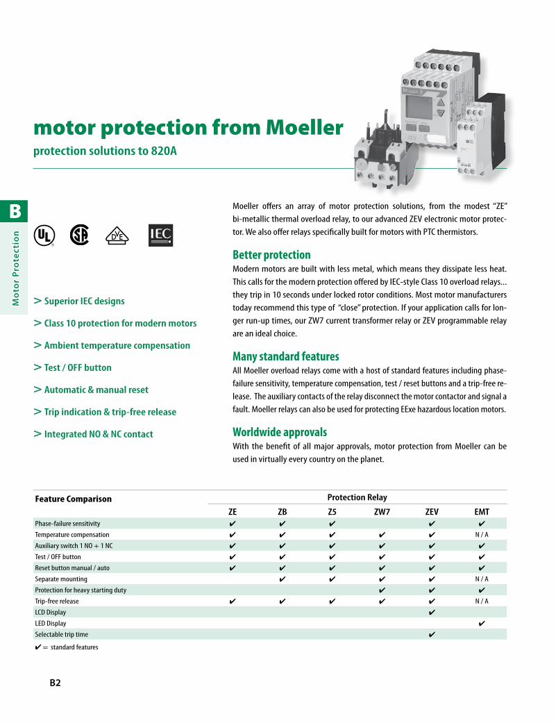
B
Mo
tor
Pro
tect
ion
B2
Feature Comparison Protection Relay
ZE ZB Z5 ZW7 ZEV EMTPhase-failure sensitivity
Temperature compensation N / A
Auxiliary switch 1 NO + 1 NC
Test / OFF button
Reset button manual / auto
Separate mounting N / A
Protection for heavy starting duty
Trip-free release N / A
LCD Display
LED Display
Selectable trip time
= standard features
Moeller offers an array of motor protection solutions, from the modest “ZE” bi-metallic thermal overload relay, to our advanced ZEV electronic motor protec-tor. We also offer relays specifically built for motors with PTC thermistors.
Better protectionModern motors are built with less metal, which means they dissipate less heat. This calls for the modern protection offered by IEC-style Class 10 overload relays...they trip in 10 seconds under locked rotor conditions. Most motor manufacturers today recommend this type of “close” protection. If your application calls for lon-ger run-up times, our ZW7 current transformer relay or ZEV programmable relay are an ideal choice.
Many standard featuresAll Moeller overload relays come with a host of standard features including phase-failure sensitivity, temperature compensation, test / reset buttons and a trip-free re-lease. The auxiliary contacts of the relay disconnect the motor contactor and signal a fault. Moeller relays can also be used for protecting EExe hazardous location motors.
Worldwide approvalsWith the benefit of all major approvals, motor protection from Moeller can be used in virtually every country on the planet.
motor protection from Moellerprotection solutions to 820A
> Superior IEC designs
> Class 10 protection for modern motors
> Ambient temperature compensation
> Test / OFF button
> Automatic & manual reset
> Trip indication & trip-free release
> Integrated NO & NC contact
R

B
Mo
tor Pro
tection
B3
Select Contactor
Locate contactor first, then scan down to determine appropriate overload relay DILEM DILM7
DILM9 DILM12
DILM17DILM25DILM32
DILM40DILM50DILM65
DILM80DILM95
DILM150
DILM185DILM225DILM250
DILM300 to
DILM1000
Overload Protection Guide
Thermal Overload Relays
ZE - Direct Mount0.1 – 12A setting range
See page B6
ZB12 - Direct Mount0.1 – 16A setting range
See page B7
ZB32 - Direct Mount0.1 – 32A setting range
See page B7
ZB65 - Direct Mount6 – 65A setting range
See page B8
ZB150 - Direct or Separate Mount25 – 150A setting range
See page B8
Z5-…/FF250 - Direct or Separate Mount50 – 250A setting range
See page B9
Current Transformer-operated Overload Relay
ZW7-… ➊42 – 540A setting range
See page B10
Electronic Motor-protective Relay
ZEV ➋1 – 820A setting range
See page B20
Thermistor Protection Relays
EMT6(DB)K
See page B30
➊ Can only be used from DILM50 to DILM580.➋ Can only be used up to DILM820.
B
Mo
tor
Pro
tect
ion
B4 moellerNA.com STARTER-CAT-NA-0708
Motor Protection
Notes
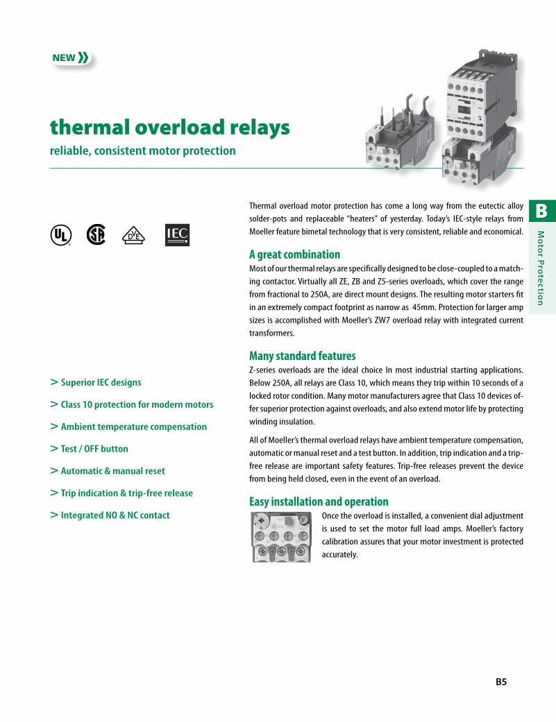
B
Mo
tor Pro
tection
B5
thermal overload relaysreliable, consistent motor protection
Thermal overload motor protection has come a long way from the eutectic alloy solder-pots and replaceable “heaters” of yesterday. Today’s IEC-style relays from Moeller feature bimetal technology that is very consistent, reliable and economical.
A great combinationMost of our thermal relays are specifically designed to be close-coupled to a match-ing contactor. Virtually all ZE, ZB and Z5-series overloads, which cover the range from fractional to 250A, are direct mount designs. The resulting motor starters fit in an extremely compact footprint as narrow as 45mm. Protection for larger amp sizes is accomplished with Moeller’s ZW7 overload relay with integrated current transformers.
Many standard featuresZ-series overloads are the ideal choice In most industrial starting applications. Below 250A, all relays are Class 10, which means they trip within 10 seconds of a locked rotor condition. Many motor manufacturers agree that Class 10 devices of-fer superior protection against overloads, and also extend motor life by protecting winding insulation.
All of Moeller’s thermal overload relays have ambient temperature compensation, automatic or manual reset and a test button. In addition, trip indication and a trip-free release are important safety features. Trip-free releases prevent the device from being held closed, even in the event of an overload.
Easy installation and operationOnce the overload is installed, a convenient dial adjustment is used to set the motor full load amps. Moeller’s factory calibration assures that your motor investment is protected accurately.
> Superior IEC designs
> Class 10 protection for modern motors
> Ambient temperature compensation
> Test / OFF button
> Automatic & manual reset
> Trip indication & trip-free release
> Integrated NO & NC contact
R

B
Mo
tor
Pro
tect
ion
B6 moellerNA.com STARTER-CAT-NA-0708 Discount Code A14
Direct Mount ZE Thermal Overload Relays for DILEM Miniature Contactors ➊
Overload Relay
AdjustableSetting Range
[A]
AuxiliaryContacts
For use with…
Short-CircuitProtection
(Max 600V AC)
Catalog Number PriceNO NC Fuses [A]Circuit
Breaker [A]
0.1 – 0.16 1 1
DILEMDIULEM
1 15 ZE-0,16 144
0.16 – 0.24 1 1 1 15 ZE-0,24 144
0.24 – 0.4 1 1 1 15 ZE-0,4 144
0.4 – 0.6 1 1 1 15 ZE-0,6 144
0.6 – 1 1 1 3 15 ZE-1,0 144
1 – 1.6 1 1 6 15 ZE-1,6 144
1.6 – 2.4 1 1 6 15 ZE-2,4 144
2.4 – 4 1 1 15 15 ZE-4 144
4 – 6 1 1 20 15 ZE-6 144
6 – 9 1 1 35 15 ZE-9 144
9 – 12 1 1 45 – ZE-12 ➋ 144
➊ When using DILEM and ZE, a distance of at least 5mm should be maintained between overload relays mounted side-by-side.
➋ Max. 480V AC.
Thermal Overload Relays
Type ZE
> Designed for Moeller’s DIL EM miniature contactors
> Class 10 overload; trip response from 2 to 10 seconds
> Ambient compensated, bimetallic overload tripping mechanism
> Phase failure sensitive to IEC/EN 60947
> Manual / Automatic reset button
> Built-in NO and NC auxiliary contacts
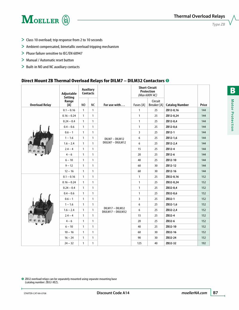
B
Mo
tor Pro
tection
STARTER-CAT-NA-0708 moellerNA.com B7 Discount Code A14
Direct Mount ZB Thermal Overload Relays for DILM7 – DILM32 Contactors ➊
Overload Relay
AdjustableSetting Range
[A]
AuxiliaryContacts
For use with…
Short-CircuitProtection
(Max 600V AC)
Catalog Number PriceNO NC Fuses [A]Circuit
Breaker [A]0.1 – 0.16 1 1
DILM7 – DILM12DIULM7 – DIULM12
1 25 ZB12-0,16 144
0.16 – 0.24 1 1 1 25 ZB12-0,24 144
0.24 – 0.4 1 1 1 25 ZB12-0,4 144
0.4 – 0.6 1 1 1 25 ZB12-0,6 144
0.6 – 1 1 1 3 25 ZB12-1 144
1 – 1.6 1 1 6 25 ZB12-1,6 144
1.6 – 2.4 1 1 6 25 ZB12-2,4 144
2.4 – 4 1 1 15 25 ZB12-4 144
4 – 6 1 1 20 25 ZB12-6 144
6 – 10 1 1 40 25 ZB12-10 144
9 – 12 1 1 60 30 ZB12-12 144
12 – 16 1 1 60 30 ZB12-16 144
0.1 – 0.16 1 1
DILM17 – DILM32DIULM17 – DIULM32
1 25 ZB32-0,16 152
0.16 – 0.24 1 1 1 25 ZB32-0,24 152
0.24 – 0.4 1 1 1 25 ZB32-0,4 152
0.4 – 0.6 1 1 1 25 ZB32-0,6 152
0.6 – 1 1 1 3 25 ZB32-1 152
1 – 1.6 1 1 6 25 ZB32-1,6 152
1.6 – 2.4 1 1 6 25 ZB32-2,4 152
2.4 – 4 1 1 15 25 ZB32-4 152
4 – 6 1 1 20 25 ZB32-6 152
6 – 10 1 1 40 25 ZB32-10 152
10 – 16 1 1 60 30 ZB32-16 152
16 – 24 1 1 90 30 ZB32-24 152
24 – 32 1 1 125 40 ZB32-32 192
Thermal Overload Relays
Type ZB
> Class 10 overload; trip response from 2 to 10 seconds
> Ambient compensated, bimetallic overload tripping mechanism
> Phase failure sensitive to IEC/EN 60947
> Manual / Automatic reset button
> Built-in NO and NC auxiliary contacts
➊ ZB32 overload relays can be separately mounted using separate mounting base (catalog number: ZB32-XEZ).
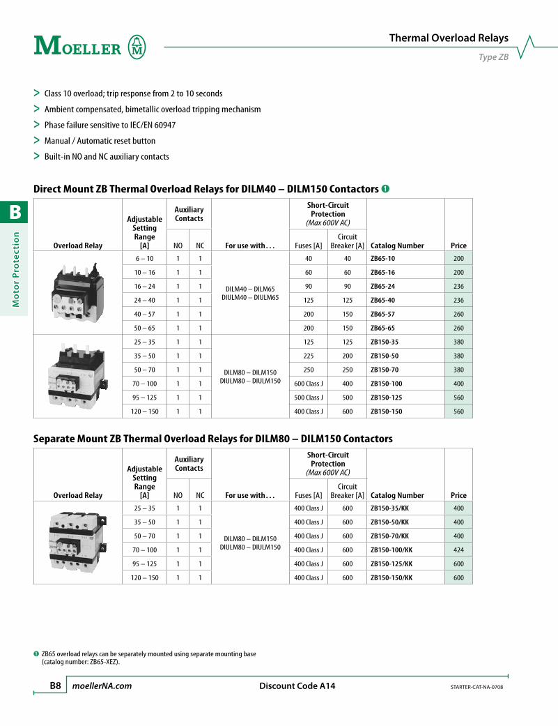
B
Mo
tor
Pro
tect
ion
B8 moellerNA.com STARTER-CAT-NA-0708 Discount Code A14
Direct Mount ZB Thermal Overload Relays for DILM40 – DILM150 Contactors ➊
Overload Relay
AdjustableSetting Range
[A]
AuxiliaryContacts
For use with…
Short-CircuitProtection
(Max 600V AC)
Catalog Number PriceNO NC Fuses [A]Circuit
Breaker [A]
6 – 10 1 1
DILM40 – DILM65DIULM40 – DIULM65
40 40 ZB65-10 200
10 – 16 1 1 60 60 ZB65-16 200
16 – 24 1 1 90 90 ZB65-24 236
24 – 40 1 1 125 125 ZB65-40 236
40 – 57 1 1 200 150 ZB65-57 260
50 – 65 1 1 200 150 ZB65-65 260
25 – 35 1 1
DILM80 – DILM150DIULM80 – DIULM150
125 125 ZB150-35 380
35 – 50 1 1 225 200 ZB150-50 380
50 – 70 1 1 250 250 ZB150-70 380
70 – 100 1 1 600 Class J 400 ZB150-100 400
95 – 125 1 1 500 Class J 500 ZB150-125 560
120 – 150 1 1 400 Class J 600 ZB150-150 560
Separate Mount ZB Thermal Overload Relays for DILM80 – DILM150 Contactors
Overload Relay
AdjustableSetting Range
[A]
AuxiliaryContacts
For use with…
Short-CircuitProtection
(Max 600V AC)
Catalog Number PriceNO NC Fuses [A]Circuit
Breaker [A]
25 – 35 1 1
DILM80 – DILM150DIULM80 – DIULM150
400 Class J 600 ZB150-35/KK 400
35 – 50 1 1 400 Class J 600 ZB150-50/KK 400
50 – 70 1 1 400 Class J 600 ZB150-70/KK 400
70 – 100 1 1 400 Class J 600 ZB150-100/KK 424
95 – 125 1 1 400 Class J 600 ZB150-125/KK 600
120 – 150 1 1 400 Class J 600 ZB150-150/KK 600
Thermal Overload Relays
Type ZB
> Class 10 overload; trip response from 2 to 10 seconds
> Ambient compensated, bimetallic overload tripping mechanism
> Phase failure sensitive to IEC/EN 60947
> Manual / Automatic reset button
> Built-in NO and NC auxiliary contacts
➊ ZB65 overload relays can be separately mounted using separate mounting base (catalog number: ZB65-XEZ).

B
Mo
tor Pro
tection
STARTER-CAT-NA-0708 moellerNA.com B9 Discount Code A14
Direct or Separate Mount Z5 Thermal Overload Relays for DILM185 – DILM250 Contactors
Overload Relay
AdjustableSetting Range
[A]
AuxiliaryContacts
For use with…
Short-CircuitProtection
(Max 600V AC) ➊
Catalog Number PriceNO NC Fuses [A]Circuit
Breaker [A]
50 – 70 1 1
DILM185 – DILM250DIULM185 – DIULM250
250 250 Z5-70/FF250 760
70 – 100 1 1 400 class J 400 Z5-100/FF250 790
95 – 125 1 1 500 class J 500 Z5-125/FF250 790
120 – 160 1 1 600 class J 600 Z5-160/FF250 820
160 – 220 1 1 800 class L 800 Z5-220/FF250 860
200 – 250 1 1 700 class L 600 Z5-250/FF250 860
➊ When directly mounting device observe the maximum permissible fuse of the contactor.
Thermal Overload Relays
Type Z5
> Class 10 overload; trip response from 2 to 10 seconds
> Ambient compensated, bimetallic overload tripping mechanism
> Phase failure sensitive to IEC/EN 60947
> Manual / Automatic reset button
> Built-in NO and NC auxiliary contacts
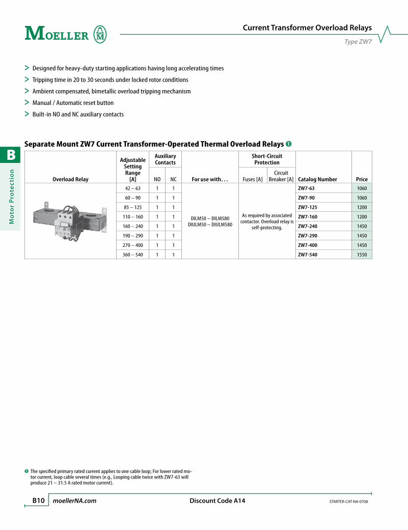
B
Mo
tor
Pro
tect
ion
B10 moellerNA.com STARTER-CAT-NA-0708 Discount Code A14
Separate Mount ZW7 Current Transformer-Operated Thermal Overload Relays ➊
Overload Relay
AdjustableSetting Range
[A]
AuxiliaryContacts
For use with…
Short-CircuitProtection
Catalog Number PriceNO NC Fuses [A]Circuit
Breaker [A]42 – 63 1 1
DILM50 – DILM580DIULM50 – DIULM580
As required by associated contactor. Overload relay is
self-protecting.
ZW7-63 1060
60 – 90 1 1 ZW7-90 1060
85 – 125 1 1 ZW7-125 1200
110 – 160 1 1 ZW7-160 1200
160 – 240 1 1 ZW7-240 1450
190 – 290 1 1 ZW7-290 1450
270 – 400 1 1 ZW7-400 1450
360 – 540 1 1 ZW7-540 1550
➊ The specified primary rated current applies to one cable loop; For lower rated mo-tor current, loop cable several times (e.g., Looping cable twice with ZW7-63 will produce 21 – 31.5 A rated motor current).
Current Transformer Overload Relays
Type ZW7
> Designed for heavy-duty starting applications having long accelerating times
> Tripping time in 20 to 30 seconds under locked rotor conditions
> Ambient compensated, bimetallic overload tripping mechanism
> Manual / Automatic reset button
> Built-in NO and NC auxiliary contacts
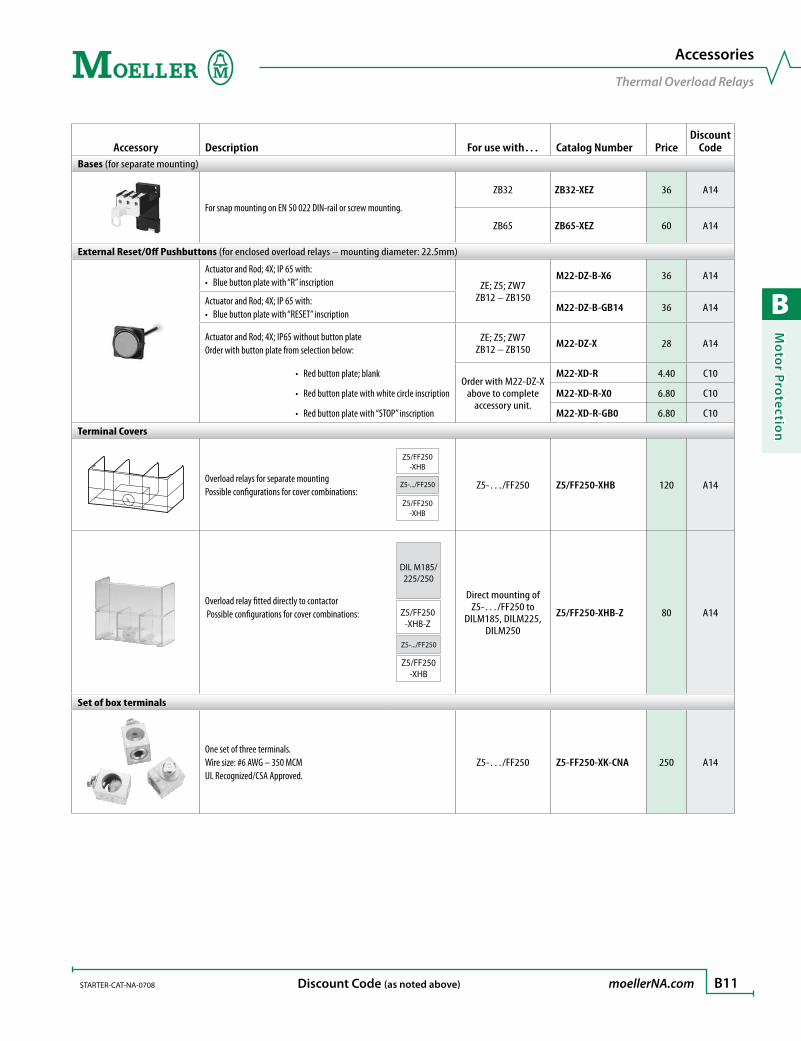
B
Mo
tor Pro
tection
STARTER-CAT-NA-0708 moellerNA.com B11 Discount Code (as noted above)
Accessory Description For use with… Catalog Number PriceDiscount
CodeBases (for separate mounting)
For snap mounting on EN 50 022 DIN-rail or screw mounting.
ZB32 ZB32-XEZ 36 A14
ZB65 ZB65-XEZ 60 A14
External Reset/Off Pushbuttons (for enclosed overload relays – mounting diameter: 22.5mm)
Actuator and Rod; 4X; IP 65 with:Blue button plate with “R” inscription• ZE; Z5; ZW7
ZB12 – ZB150
M22-DZ-B-X6 36 A14
Actuator and Rod; 4X; IP 65 with: Blue button plate with “RESET” inscription•
M22-DZ-B-GB14 36 A14
Actuator and Rod; 4X; IP65 without button plateOrder with button plate from selection below:
ZE; Z5; ZW7ZB12 – ZB150 M22-DZ-X 28 A14
Red button plate; blank •Order with M22-DZ-X
above to complete accessory unit.
M22-XD-R 4.40 C10
Red button plate with white circle inscription• M22-XD-R-X0 6.80 C10
Red button plate with “STOP” inscription• M22-XD-R-GB0 6.80 C10
Terminal Covers
Overload relays for separate mounting Possible configurations for cover combinations:
Z5/FF250-XHB
Z5-.../FF250
Z5/FF250-XHB
Z5-…/FF250 Z5/FF250-XHB 120 A14
Overload relay fitted directly to contactor Possible configurations for cover combinations:
Z5-.../FF250
Z5/FF250-XHB-Z
DIL M185/225/250
Z5/FF250-XHB
Direct mounting ofZ5-…/FF250 to
DILM185, DILM225,DILM250
Z5/FF250-XHB-Z 80 A14
Set of box terminals
One set of three terminals.Wire size: #6 AWG – 350 MCMUL Recognized/CSA Approved.
Z5-…/FF250 Z5-FF250-XK-CNA 250 A14
Accessories
Thermal Overload Relays

B
Mo
tor
Pro
tect
ion
B12 moellerNA.com STARTER-CAT-NA-0708
Tripping characteristics:These tripping characteristics are mean values of the spread at 20 °C ambient temperature in a cold state. Tripping time depends on re-sponse current. With devices at operating temperature, the tripping time of the overload relay reduces to approximately 25% of the read off value.
EC prototype test certification number:ZE PTB 01 ATEX 3331ZB PTB 04 ATEX 3022Z5 PTB 02 ATEX 3165
Protection of single-phase and DC current motors:1-pole 2-pole
Cannot be Mounted in these positions:ZE ZB12 – ZB150; Z5
2h100
60402010
6421
402010
6421
0.6
Z5
6 8 1015 20 3 41 1.5 2x Setting current
2-phaseSeco
nds
Min
utes
3-phase
2 h10060402010
6421
402010
6421
1 1.5 2 3 4 6 8 1015 200.6
ZW7
Min
utes
Seco
nds
Rated current
Lowest level
Highest level
x
2h 100
60 40 20 10
6 4 2 1
40 20 10
6 4 2 1
0.6
ZB12, ZB32, ZB65, ZE
1 1.5 2 3 4 6 8 10 15 20 x Setting current
2-phase Seco
nds
Min
utes
3-phase
Thermal Overload Relays
Selection Aids
100 ZB1506040201064214020106421
0.6 6 4 108 15 20 31 21.5
x Setting current
2-phaseSeco
nds
Min
utes
3-phase
2 h

B
Mo
tor Pro
tection
STARTER-CAT-NA-0708 moellerNA.com B13
Thermal Overload Relays ZEZB12 ZB32 ZB65 ZB150 Z5-…/FF250 ZW7
GeneralStandards IEC/EN 60947, VDE 0660, UL, CSAClimatic proofing Damp heat, constant, to IEC 60068-2-78; Damp heat, cyclic, to IEC 60068-2-30Ambient temperature Open [°C]
[°F]-25…50 °C
-13…122 °F-25…55 °C
-13…131 °F-25…55 °C
-13…131 °F-25…55 °C
-13…131 °F-25…50 °C
-13…122 °F-25…50 °C
-13…122 °F Enclosed [°C]
[°F]-25…40 °C
-13…104 °F-25…40 °C
-13…104 °F-25…40 °C
-13…104 °F-25…40 °C
-13…104 °F-25…40 °C
-13…104 °F-25…40 °C
-13…104 °FTemperature compensation ContinuousMounting position See previous pageWeight [kg] 0.09 0.15 0.25 1.64 1.8 0.95Mechanical shock resistance half-sinusoidal shock 10ms [g] 10 10 10 10 10 10Degree of protection IP20 IP00 IP00 IP00 IP00 IP00Protection against direct contact when actuated from front
Finger and back-of-hand proof
Finger and back-of-hand proof
Finger and back-of-hand proof
Finger and back-of-hand proof
With terminal cover
Finger and back-of-hand proof
Main ContactsRated impulse withstand voltage Uimp [V AC] 6000 6000 6000 6000 8000 6000Overvoltage category / pollution degree III/3 III/3 III/3 III/3 III/3 III/3Rated insulation voltage Ui [V AC] 690 690 690 690 1000 690Rated operational voltage Ue [V AC] 690 690 690 690 1000 690Safe isolation to VDE 0106 Part 101 and Part 101/A1 Between auxiliary contacts and main contacts [V AC] 300 440 440 440 440 440 Between the main contacts [V AC] 300 440 440 440 440 440Overload relay setting range [A] 0.1 – 9 0.1 – 32 6 – 65 25 – 150 50 – 250 40 – 540Temperature compensation residual error > 20 °C [% / K] ≤ 0.25 ≤ 0.25 ≤ 0.25 ≤ 0.25 ≤ 0.25 –Short-circuit protection rating maximum fuse see selection pages ➊
Current heat loss (3 conductors) Lower value of setting range [W] 2.5 2.5 3 16 16 3 Upper value of setting range [W] 6 6 7.5 28 28 10Terminal capacity Solid [mm2] 2 x (0.75 – 2.5) 2 x (1 – 6) 2 x (1 – 6) 2 x (4 – 16) – – Flexible without ferrules [mm2] – – – – – – Flexible with ferrule [mm2] 2 x (0.5 – 1.5) 2 x (1 – 4)
2 x (1 – 6) ➋1 x 25
2 x (1 – 10) ➌1 x (4 – 70)2 x (4 – 50)
– –
Stranded [mm2] – – 1 x 35; 2 x 10 – – – Flexible with cable lug [mm2] – – – – 95 – Stranded with cable lug [mm2] – – – – 120 – Solid or stranded [AWG] 18 – 14 14 – 8 14 – 2 2/0 250 MCM – Flat conductor Number of segments x width x thickness [mm] – – – – 6 x 15 x 0.8 ➍ – Busbar Width [mm] – – – – 20 x 3 –Push-through opening Ø [mm] – – – – – 27Terminal screw M3.5 M4 M6 M10 M8 x 25 –Tightening torque [Nm] 1.2 1.8 3.5 10 24 –Tools Pozidriv screwdriver [Size] 2 2 2 – – – Standard screwdriver [mm] 0.8 x 5.5 1 x 6 1 x 6 – – – Hexagon socket-head screw SW [mm] – – – 5 13 –
➊ As required by the contactor.➋ 6 mm2 flexible with ferrules to DIN 46228.
Technical Data
Thermal Overload Relays
➌ When using 2 conductors, use identical cross-section.➍ Fixing with box terminals.
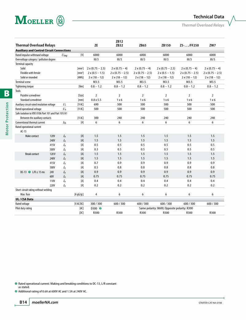
B
Mo
tor
Pro
tect
ion
B14 moellerNA.com STARTER-CAT-NA-0708
Thermal Overload Relays ZEZB12 ZB32 ZB65 ZB150 Z5-…/FF250 ZW7
Auxiliary and Control Circuit ConnectionsRated impulse withstand voltage Uimp [V] 6000 6000 6000 6000 6000 6000Overvoltage category / pollution degree III/3 III/3 III/3 III/3 III/3 III/3Terminal capacity Solid [mm2] 2 x (0.75 – 2.5) 2 x (0.75 – 4) 2 x (0.75 – 4) 2 x (0.75 – 2.5) 2 x (0.75 – 4) 2 x (0.75 – 4) Flexible with ferrule [mm2] 2 x (0.5 – 1.5) 2 x (0.75 – 2.5) 2 x (0.75 – 2.5) 2 x (0.5 – 1.5) 2 x (0.75 – 2.5) 2 x (0.75 – 2.5) Solid or stranded [AWG] 2 x (18 – 12) 2 x (18 – 12) 2 x (18 – 12) 2 x (18 – 12) 2 x (18 – 12) 2 x (18 – 12)Terminal screw M3.5 M3.5 M3.5 M3.5 M3.5 M3.5Tightening torque [Nm] 0.8 – 1.2 0.8 – 1.2 0.8 – 1.2 0.8 – 1.2 0.8 – 1.2 0.8 – 1.2Tools Pozidriv screwdriver [Size] 2 2 2 2 2 2 Standard screwdriver [mm] 0.8 x 5.5 1 x 6 1 x 6 1 x 6 1 x 6 1 x 6Auxiliary circuit rated insulation voltage Ui [V AC] 690 500 500 500 500 500Rated operational voltage Ue [V AC] 500 500 500 500 500 500Safe isolation to VDE 0106 Part 101 and Part 101/A1 Between the auxiliary contacts [V AC] 300 240 240 240 240 240Conventional thermal current Ith [A] 6 6 6 6 6 6Rated operational current AC-15 Make contact 120V Ie [A] 1.5 1.5 1.5 1.5 1.5 1.5 240V Ie [A] 1.5 1.5 1.5 1.5 1.5 1.5 415V Ie [A] 0.5 0.5 0.5 0.5 0.5 0.5 500V Ie [A] 0.3 0.5 0.5 0.5 0.5 0.5 Break contact 120 V Ie [A] 1.5 1.5 1.5 1.5 1.5 1.5 240V Ie [A] 1.5 1.5 1.5 1.5 1.5 1.5 415V Ie [A] 0.7 0.9 0.9 0.9 0.9 0.9 500V Ie [A] 0.5 0.8 0.8 0.8 0.8 0.8 DC-13 ➊ L/R ≤ 15 ms 24V Ie [A] 0.9 0.9 0.9 0.9 0.9 0.9 60V Ie [A] 0.75 0.75 0.75 0.75 0.75 0.75 110V Ie [A] 0.4 0.4 0.4 0.4 0.4 0.4 220V Ie [A] 0.2 0.2 0.2 0.2 0.2 0.2Short-circuit rating without welding Max. fuse [A gG/gL] 4 6 6 6 6 6
UL / CSA DataRated voltage [V AC/DC] 300 / 300 600 / 300 600 / 300 600 / 300 600 / 300 600 / 300Pilot duty rating [AC] D300 ➋ Same polarity: B600; Opposite polarity: R300
[DC] R300 R300 R300 R300 R300 R300
➊ Rated operational current: Making and breaking conditions to DC-13, L/R constant as stated.
➋ Additional rating of 0.6A at 600V AC and 1.5A at 240V AC.
Technical Data
Thermal Overload Relays
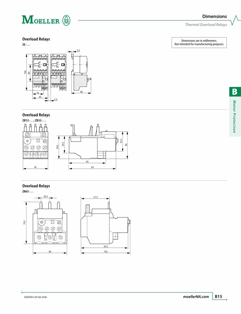
B
Mo
tor Pro
tection
STARTER-CAT-NA-0708 moellerNA.com B15
Dimensions
Thermal Overload Relays
Dimensions are in millimeters.Not intended for manufacturing purposes.
Overload RelaysZE-…
5.5
58
= 5 45
32
49
106
>
Overload RelaysZB12-…; ZB32-…
45 83
65
48
35.5
39.5 29
.5
Overload RelaysZB65-…
60 102
95.5
51.5
79.2
20.3

B
Mo
tor
Pro
tect
ion
B16 moellerNA.com STARTER-CAT-NA-0708
Dimensions are in millimeters.Not intended for manufacturing purposes.
Dimensions
Thermal Overload Relays
Overload RelaysZB32-XEZ; ZB65-XEZ
5
b
16.5
c2
b1
a
c
c1
Overload RelaysZB150-…
138
63
129100
134
74
118
99
80
95
73
ZB32-XEZ ZB65-XEZa 45 60b 85 86
b1 42.5 42.5c 90.5 112
c1 58.3 80.5c2 3.8 4.7
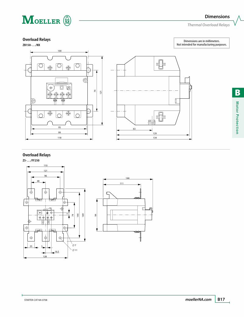
B
Mo
tor Pro
tection
STARTER-CAT-NA-0708 moellerNA.com B17
Dimensions are in millimeters.Not intended for manufacturing purposes.
Dimensions
Thermal Overload Relays
Overload RelaysZB150-…/KK
12174
63
129
134
100
118
99
95
Overload RelaysZ5-…/FF250
110
121
96
128
74
144
169
48
25 5
16.5
144
111
94 7
7
11
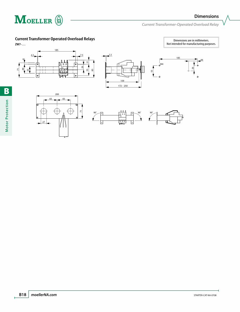
B
Mo
tor
Pro
tect
ion
B18 moellerNA.com STARTER-CAT-NA-0708
Dimensions
Current Transformer-Operated Overload Relay
Dimensions are in millimeters.Not intended for manufacturing purposes.
Current Transformer Operated Overload RelaysZW7-…
7.5
26
55
21
85
185
71
44
33
8
4.3 1.5
159
172 – 250
185
M4
44
26
55
90˚ 90˚ 90˚
200
65 65
71
27

B
Mo
tor Pro
tection
B19
Moeller’s ZEV electronic overload relay offers the ultimate motor protection at an economical price. The base unit protects against overloads, phase failure and phase imbalance in motors from 1 to 820A. Thermistor connections and optional ground-fault protection make the ZEV a great choice for virtually all applications where sophisticated, yet economical motor protection is required.
The new standard in protectionNewly-developed sensor systems and tripping units make the ZEV electronic over-load relay the “top-of-the-range” in motor protection. Enhanced tripping classes provide reliable protection for motors with run-up times as long as 40 seconds. Trip classes are selectable from 5 to 40 seconds, allowing precise protection for a range of applications.
Additional features and optionsOptional core-balance transformers detect ground faults quickly, while an inte-grated thermistor connection makes it easy to upgrade to a full motor-protection system. Check out other great features of the ZEV relay listed on the left.
Easy to operateA built-in LCD guides you through set-up and operation. In the event of a fault, the display indicates the origin – speeding the process of troubleshooting and re-pair. Configurable auxiliary contacts may be added for communication of ground faults, thermistor trips, internal faults or early warning of an overload.
Flexibility for multiple environmentsThe multi-voltage module automatically adapts to different voltages from 24-240V AC/ DC, providing a fast and flexible connection to all conventional control.
Compact design Ring-type current sensors make the ZEV a great choice for protection of even small motors. There’s no need for main current wiring or back pan drilling. The sensor is installed quickly and easily with hook & loop fasteners. With small light-weight sensors and extremely wide current ranges, making the right sensor selection is easy. A compact design with a 58 to 1 current ratio reduces inventory cost and saves valuable panel space compared to traditional transformers.
Safety and approvalsThe ZEV electronic overload relay is touch safe to IP20 specifications. It meets ap-proval standards of UL, CSA, IEC/EN 60 947 and VDE 0660.
ZEV electronic overload relaythe ultimate motor protection for applications to 820A
> Early warning of an overload
> Internal fault detection
> Ambient temperature compensation
> Test / OFF button
> Automatic & manual reset
> Trip indication & trip-free release
> Integrated NO & NC contact
R

B
Mo
tor
Pro
tect
ion
B20 moellerNA.com STARTER-CAT-NA-0708 Discount Code A14
ZEV Electronic Motor-Protective Relays (Complete Unit Selection)
Overload Relay
AdjustableSetting
Range [A]Length[mm]
Diameter[mm] For use with… Catalog Number Price
ZEV Electronic Motor-Protective Relay
1 – 820 – – DILEMDILM7 – DILM820 ZEV 496
Current Sensors
1 – 25 – 6 DILEM; DILM7 – DILM25 ZEV-XSW-25 320
3 – 65 – 13 DILM32 – DILM50 ZEV-XSW-65 320
10 – 145 – 21 DILM65 – DILM115 ZEV-XSW-145 780
40 – 820 – 110 DILM185 – DILM820 ZEV-XSW-820 960
Connecting Cables
– 200 – ZEV-XSW-25ZEV-XSW-65
ZEV-XSW-145ZEV-XSW-820
ZEV-XVK-20 24
– 400 – ZEV-XVK-40 28
– 800 – ZEV-XVK-80 32
Electronic Overload Relays
Type ZEV
> Protects against overloads, phase failure, phase imbalance, internal fault, thermistor tripping and optional ground-fault
> Eight tripping classes from Class 5 to Class 40 protection
> LCD guides set-up and ensures straightforward operation during a fault condition
> DIN-rail or optional screw mounting
Ordering Instructions
1 A complete ZEV Electronic Motor Protective Relay con-sists of One ZEV Base Unit, One Current Sensor and One Connecting Cable
2 For optional ground leakage protection, select one Core Balance Transformer
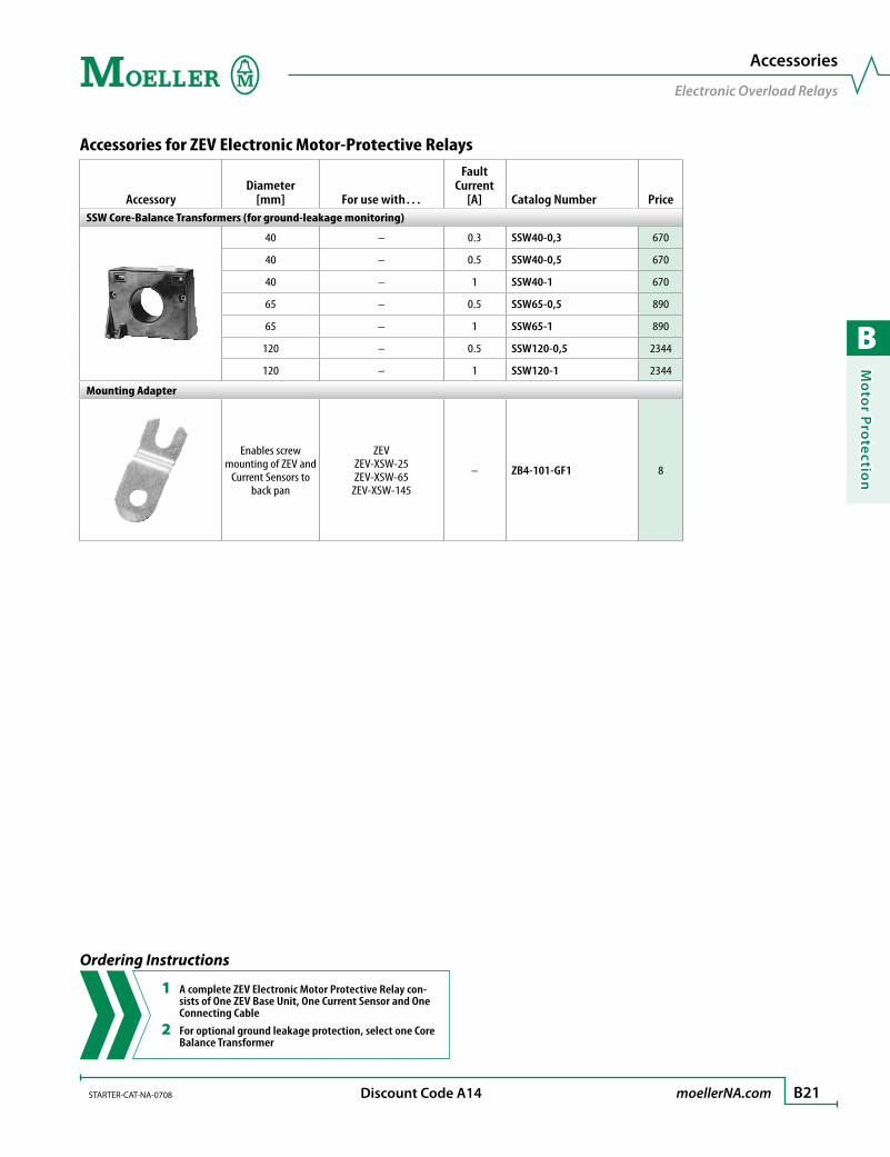
B
Mo
tor Pro
tection
STARTER-CAT-NA-0708 moellerNA.com B21 Discount Code A14
Accessories for ZEV Electronic Motor-Protective Relays
AccessoryDiameter
[mm] For use with…
FaultCurrent
[A] Catalog Number PriceSSW Core-Balance Transformers (for ground-leakage monitoring)
40 – 0.3 SSW40-0,3 670
40 – 0.5 SSW40-0,5 670
40 – 1 SSW40-1 670
65 – 0.5 SSW65-0,5 890
65 – 1 SSW65-1 890
120 – 0.5 SSW120-0,5 2344
120 – 1 SSW120-1 2344
Mounting Adapter
Enables screw mounting of ZEV and
Current Sensors to back pan
ZEVZEV-XSW-25ZEV-XSW-65
ZEV-XSW-145
– ZB4-101-GF1 8
Accessories
Electronic Overload Relays
Ordering Instructions
1 A complete ZEV Electronic Motor Protective Relay con-sists of One ZEV Base Unit, One Current Sensor and One Connecting Cable
2 For optional ground leakage protection, select one Core Balance Transformer

B
Mo
tor
Pro
tect
ion
B22 moellerNA.com STARTER-CAT-NA-0708
5 10 15 20 25 30 35 40
IF 1)
IF 1)
Class
Mode
Test Reset
Up
Down
Y1
T1
T2
Y2 C2 C1 A1 A2 95 97 05 07
96 98 06 08
~ =
N L3 L2 L1
M 3~
Z2
Z1
l %
L1 L2 L3
1) IF: internal fault
P
Menu
ON OFF
ON OFF
! > 105%
! > 105%
0 – 820 A
Free parameter
1
Free parameter 1
Free parameter 2
Free parameter
1
Fault
Hand Auto
Reset
Reset
Class
e
Inputs Outputs
A 1 / A 2 Rated control voltage 95 / 96 NC contact for overload / thermistor
T 1 / T 2 Thermistor sensor 97 / 98 NO contact for overload / thermistor
C 1 / C 2 SSW core-balance transformers 05 / 06 NC contact freely assignable
Y 1 / Y 2 Remote reset 07 / 08 NO contact freely assignable
Switchgear and cable sizing corresponding to the respective starting inertia (CLASS)The switchgear is designed for “CLASS 10” in normal and overload operation. To ensure that the switchgear (circuit-breaker and contactor) as well as the cables are not overloaded with extended tripping times, they must be over-dimensioned accordingly. The rated operational current Ie for switchgear and cables can be calculated with the following current factor while taking the tripping class into account:
Tripping Class Class 5 Class 10 Class 15 Class 20 Class 25 Class 30 Class 35 Class 40
Current factor for rated operational current Ie
1.00 1.00 1.22 1.41 1.58 1.73 1.89 2.00
Relays with integrated sensorWith the ZEV-XSW-25 to ZEV-XSW-145 push-through sensors, the motor supply leads for each phase are pushed through the respective push-through openings. On motor currents which are less than 1 A, the motor supply leads with the ZEV-XSW-25 are inserted in loops. The number of loops depends on the rated motor current involved.
Number of loops n 4 3 2
Rated motor current IN [A] 0.31 – 0.4 0.41 – 0.62 0.63 – 1.24
Current settings on relay IE between lowest and highest value [A] 1.24 – 1.6 1.23 – 1.86 1.26 – 2.48
The current setting IE of the device is calculated as: IE = n x IN
Electronic Overload Relays
Selection Aids
Circuit for Manual Restart

B
Mo
tor Pro
tection
STARTER-CAT-NA-0708 moellerNA.com B23
Tripping times for ZEV electronic motor-protective relay
Tripping class, can be selected 5 10 15 20 25 30 35 40Tripping time in s (± 20 %) With 3-pole symmetric loading from cold state
Setting current IE x 3 11.3 22.6 34 45.3 56.6 67.9 79.2 90.5
x 4 8 15.9 23.9 31.8 39.8 47.7 55.7 63.6
x 5 6.1 12.3 18.4 24.6 30.7 36.8 43 49.1
x 6 5 10 15 20 25 30 35 40
x 7.2 4.1 8.2 12.3 16.4 20.5 24.5 28.6 32.7
x 8 3.6 7.3 10.9 14.6 18.2 21.9 25.5 29.2
x 10 2.9 5.7 8.6 11.5 14.4 17.2 20.1 23
Recovery time after tripClass 5 10 15 20 25 30 35 40
trecovery after overload trip [min] 5 6 7 8 9 10 11 12
trecovery after test button trip [sec] 5 5 5 5 5 5 5 5
Tripping characteristics:These tripping characteristics are mean values of the spread at 20°C ambient temperature in a cold state. Tripping time depends on response current. With devices at operating temperature, the tripping time of the overload relay reduces to approximately 25% of the read off value.
2h
15 10
100
1
20 10
5
2 1
1 2 5 8
3
7
9 7 10 6 4 3
2
5
ZEV
20 15 10
CLASS 5
CLASS 40 35 30 25
x Setting current
Seco
nds
Min
utes
3-pole With a phase failure or unbalance > 50%, the ZEV will trip within 2.5 seconds.
Electronic Overload Relays
Selection Aids
Thermistor tripping
Rated trip resistance R = 3200 Ω ± 15%
Recovery resistance R = 1500 Ω ± 10%
Total PTC thermistor resistance ∑ RK ≤ 1500 Ω at RK ≤ 250 Ω per sensor: 6 sensors at RK ≤ 100 Ω per sensor: 9 sensors
Ready to respond after trip at 5 °C under response temperature
EC prototype test certification number:ZEV PTB 01 ATEX 3233
For protection of motors in EEx e area, also order AWB2300-1433G “ZEV motor-protective system, Overload monitoring of motors in EEX e areas”.
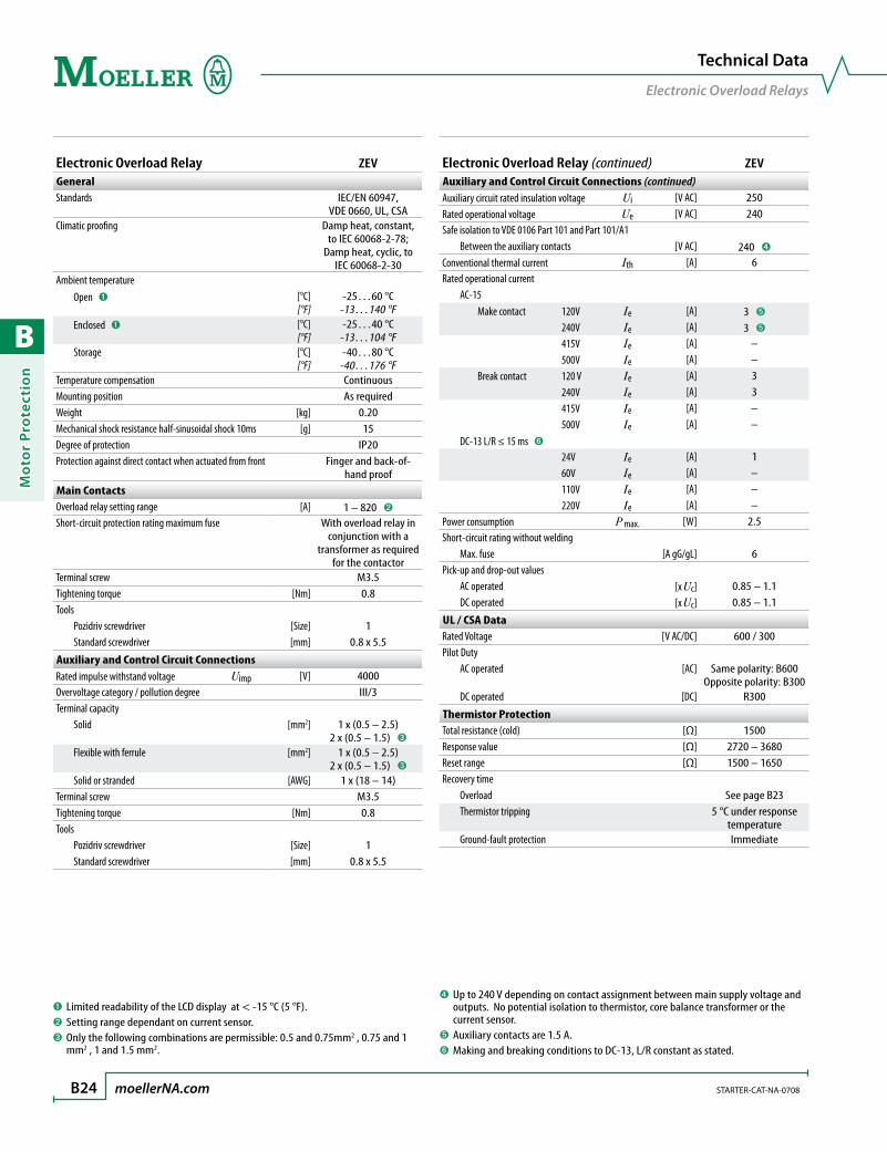
B
Mo
tor
Pro
tect
ion
B24 moellerNA.com STARTER-CAT-NA-0708
Electronic Overload Relay ZEVGeneralStandards IEC/EN 60947,
VDE 0660, UL, CSAClimatic proofing Damp heat, constant,
to IEC 60068-2-78; Damp heat, cyclic, to
IEC 60068-2-30Ambient temperature Open ➊ [°C]
[°F]-25…60 °C
-13…140 °F Enclosed ➊ [°C]
[°F]-25…40 °C
-13…104 °F Storage [°C]
[°F]-40…80 °C
-40…176 °FTemperature compensation ContinuousMounting position As requiredWeight [kg] 0.20Mechanical shock resistance half-sinusoidal shock 10ms [g] 15Degree of protection IP20Protection against direct contact when actuated from front Finger and back-of-
hand proofMain ContactsOverload relay setting range [A] 1 – 820 ➋
Short-circuit protection rating maximum fuse With overload relay in conjunction with a
transformer as required for the contactor
Terminal screw M3.5Tightening torque [Nm] 0.8Tools Pozidriv screwdriver [Size] 1 Standard screwdriver [mm] 0.8 x 5.5
Auxiliary and Control Circuit ConnectionsRated impulse withstand voltage Uimp [V] 4000Overvoltage category / pollution degree III/3Terminal capacity Solid [mm2] 1 x (0.5 – 2.5)
2 x (0.5 – 1.5) ➌
Flexible with ferrule [mm2] 1 x (0.5 – 2.5)2 x (0.5 – 1.5) ➌
Solid or stranded [AWG] 1 x (18 – 14)Terminal screw M3.5Tightening torque [Nm] 0.8Tools Pozidriv screwdriver [Size] 1 Standard screwdriver [mm] 0.8 x 5.5
➊ Limited readability of the LCD display at < -15 °C (5 °F).➋ Setting range dependant on current sensor.➌ Only the following combinations are permissible: 0.5 and 0.75mm2 , 0.75 and 1
mm2 , 1 and 1.5 mm2.
Technical Data
Electronic Overload Relays
Electronic Overload Relay (continued) ZEVAuxiliary and Control Circuit Connections (continued)Auxiliary circuit rated insulation voltage Ui [V AC] 250Rated operational voltage Ue [V AC] 240Safe isolation to VDE 0106 Part 101 and Part 101/A1 Between the auxiliary contacts [V AC] 240 ➍
Conventional thermal current Ith [A] 6Rated operational current AC-15 Make contact 120V Ie [A] 3 ➎
240V Ie [A] 3 ➎
415V Ie [A] – 500V Ie [A] – Break contact 120 V Ie [A] 3 240V Ie [A] 3 415V Ie [A] – 500V Ie [A] – DC-13 L/R ≤ 15 ms ➏
24V Ie [A] 1 60V Ie [A] – 110V Ie [A] – 220V Ie [A] –Power consumption P max. [W] 2.5Short-circuit rating without welding Max. fuse [A gG/gL] 6Pick-up and drop-out values AC operated [x Uc] 0.85 – 1.1 DC operated [x Uc] 0.85 – 1.1
UL / CSA DataRated Voltage [V AC/DC] 600 / 300Pilot Duty AC operated [AC] Same polarity: B600
Opposite polarity: B300 DC operated [DC] R300
Thermistor ProtectionTotal resistance (cold) [Ω] 1500Response value [Ω] 2720 – 3680Reset range [Ω] 1500 – 1650Recovery time Overload See page B23 Thermistor tripping 5 °C under response
temperature Ground-fault protection Immediate
➍ Up to 240 V depending on contact assignment between main supply voltage and outputs. No potential isolation to thermistor, core balance transformer or the current sensor.
➎ Auxiliary contacts are 1.5 A.➏ Making and breaking conditions to DC-13, L/R constant as stated.

B
Mo
tor Pro
tection
STARTER-CAT-NA-0708 moellerNA.com B25
Current Sensors ZEV-XSW-25 ZEV-XSW-65 ZEV-XSW-145 ZEV-XSW-820GeneralStandards IEC/EN 60947, VDE 0660, UL, CSAClimatic proofing Damp heat, constant, to IEC 60068-2-78; Damp heat, cyclic, to IEC 60068-2-30Ambient temperature Open [°C]
[°F]-25…60 °C
-13…140 °F-25…60 °C
-13…140 °F-25…60 °C
-13…140 °F-25…60 °C
-13…140 °F Enclosed [°C]
[°F]-25…40 °C
-13…104 °F-25…40 °C
-13…104 °F-25…40 °C
-13…104 °F-25…40 °C
-13…104 °F Storage [°C]
[°F]-40…80 °C
-40…176 °F-40…80 °C
-40…176 °F-40…80 °C
-40…176 °F-40…80 °C
-40…176 °FTemperature compensation ContinuousMounting position As requiredWeight [kg] 0.21 0.37 0.45 0.30Mechanical shock resistance half-sinusoidal shock 10ms [g] 15 15 15 15Degree of protection IP20 IP20 IP20 IP20Protection against direct contact when actuated from front Finger and back-of-hand proof
Main ContactsRated impulse withstand voltage Uimp [V AC] ➊ ➊ ➊ 8000Overvoltage category / pollution degree ➊ ➊ ➊ III/3Rated insulation voltage Ui [V AC] ➊ ➊ ➊ 1000Rated operational voltage Ue [V AC] ➊ ➊ ➊ 1000Safe isolation to VDE 0106 Part 101 and Part 101/A1 Between busbar and sensor [V AC] – – – 500Overload relay setting range [A] 1 – 25 3 – 65 10 – 145 40 – 820Short-circuit protection rating maximum fuse With overload relay in conjunction with a transformer, as required for the contactorPush-through opening Ø [mm] 6 13 21 110
➊ Dependant on the current wiring that is used.
Technical Data
Current Sensors

B
Mo
tor
Pro
tect
ion
B26 moellerNA.com STARTER-CAT-NA-0708
Overload RelaysZEV
29
4.5 7.2
45
93
37
59.2
78
103
75
Current SensorsZEV-XSW-…
93
37
35
78
103
c
8
a1
4.5
a
d2
d2
35
d1
Dimensions
Electronic Overload Relays
Dimensions are in millimeters.Not intended for manufacturing purposes.
ZEV-XSW-… 25 65 145a 45 70 90
a1 24 49 68c 50 58 65
d1 6 13 21d2 11.2 19 26

B
Mo
tor Pro
tection
STARTER-CAT-NA-0708 moellerNA.com B27
Overload Relays with Current SensorZEV + ZEV-XSW-…
c1
Current SensorZEV-XSW-820
3 125
~150
35
26 37
Core-balance TransformerSSW40-…; SSW65-…; SSW120-…
a1
a2
b b1
c
e
a
d
Dimensions
Electronic Overload Relays
Dimensions are in millimeters.Not intended for manufacturing purposes.
SSW… 40-… 65-… 120-…a 64 75 86.5
a1 50 60 70a2 38 43 54.5b 100 124 200
b1 80 100 170c 86 112 205d 4.5 4.5 4.5e 40 65 120
ZEV + ZEV-XSW-… 25 65 145c1 120 128 134

B
Mo
tor
Pro
tect
ion
B28 moellerNA.com STARTER-CAT-NA-0708
Motor Protection
Notes

B
Mo
tor Pro
tection
B29
EMT thermistor protection relaysfor motors with imbedded P.T.C. thermistors
Moeller’s EMT Thermistor Protection Relays are specifically designed to monitor positive temperature coefficient (PTC) thermistors embedded in the motor wind-ings. Typically used in “mission critical” applications, PTC thermistors, coupled with EMT Thermistor Protection Relays provide extremely precise thermal feedback and increased motor protection.
Three designs to chooseAll EMT relays feature automatic reset with Power-ON and fault-indicating LED. De-pending on the model chosen, the following additional features are also available:
Selectable manual or automatic reset•
Remote reset•
Short circuit recognition in the sensor circuit•
Reliable fault signaling even under supply voltage failure •(zero voltage safety)
Short circuit recognition and zero-voltage safety can be switched off•
Test button•
Universal input voltageMoeller EMT Thermistor Protection relays accept voltage inputs of 24 – 240V AC 50-60Hz; and 24 – 240V DC making them ideal for the majority of normal control circuit applications.
Zero-voltage safetyThe EMT6-DBK includes fault signaling even with a loss of supply voltage. This important safety feature stores the condition of the relay prior to the loss of power. When power is restored, the relay’s output and LED fault indication retain state and act accordingly.
> Extremely accurate overload protection
> Universal supply voltage
> Choose from basic to advanced protection
R
Feature Comparison Protection Relay
EMT-6 EMT6-DB EMT6-DBKLED power-ON and fault indication
Thermal overload protection (from PTC sensors)
Automatic reset
Universal control voltage
Short circuit recognition in the sensor circuit (option) (option)
Manual or automatic reset
Remote or local reset
Test button
Fault signaling with loss of supply voltage (zero-voltage safety)
Short circuit recognition and zero voltage safety can be turned off
= standard features

B
Mo
tor
Pro
tect
ion
B30 moellerNA.com STARTER-CAT-NA-0708 Discount Code A14
Thermistor Protection Relays
Protection Relay Description
IEC RatedOperating Current UL/CSA
Catalog Number Price
AC-15220 – 240 V
[A]
AC-14380 – 400 V
[A]
PilotDuty
Rating
RatedOperational
Voltage RangeAutomatic Reset
Automatic RESET•Power ON and fault indicating LED display•
3 3 B 300 24 – 240 V 50/60 Hz;24 – 240 V DC EMT6 630
Automatic RESET•Power ON and fault indicating LED display•Short-circuit recognition in the sensor circuit•
3 3 B 300 24 – 240 V 50/60 Hz;24 – 240 V DC EMT6-K 510
Automatic RESET•Power ON and fault indicating LED display•
3 3 B 300 230 V 50/60 Hz EMT6(230V) 630
Manual + Automatic Reset
Manual or automatic RESET•For manual or remote resetting•Test button•Power ON and fault indicating LED display•
3 3 B 300 24 – 240 V 50/60 Hz;24 – 240 V DC EMT6-DB 930
Manual or automatic RESET•For manual or remote resetting•Test button•Power ON and fault indicating LED display•Short-circuit recognition in the sensor circuit•
3 3 B 300 24 – 240 V 50/60 Hz;24 – 240 V DC EMT6-KDB 880
Manual or automatic RESET•For manual or remote resetting•Test button•Power ON and fault indicating LED display•
3 3 B 300 230 V 50/60 Hz EMT6-DB(230V) 930
Manual + Automatic Reset / Multi-function Device
Manual or automatic reset / Multi-function device•Short-circuit recognition in the sensor circuit•Reliable fault signalling even under supply voltage •failure (zero-voltage safety)For manual or remote resetting•Test button•Short-circuit recognition and zero-voltage safety can •be switched offPower ON and fault indicating LED display•
3 3 B 300 24 – 240 V 50/60 Hz;24 – 240 V DC EMT6-DBK 1080
Thermistor Overload Relays
Type EMT
> For protection of motors with P.T.C. thermistors embedded in their windings
> LED display of operational status
> Manual / Automatic reset or remote reset available
Supply voltage is applied
Device has tripped
Device has tripped/shortcircuit in the sensor circuit
green
red
red
LEDdisplay
Flowdiagrams Notes
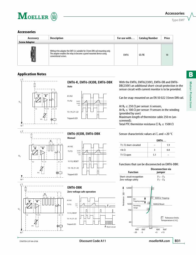
B
Mo
tor Pro
tection
STARTER-CAT-NA-0708 moellerNA.com B31 Discount Code A11
With the EMT6, EMT6(230V), EMT6-DB and EMT6-DB(230V) an additional short-circuit protection in the sensor circuit with current monitor is to be provided.
Can be snap-mounted on an EN 50 022 35mm DIN rail.
At Rk ≤ 250 Ω per sensor: 6 sensors, At Rk ≤ 100 Ω per sensor: 9 sensors in the winding (provided by user) Maximum length of thermistor cable 250 m (un-screened); Total PTC thermistor resistance Σ Rk ≤ 1500 Ω
Sensor characteristic values at Us and +20 °C
EMT6…
T1, T2 short-circuited – 1.9
4 k Ω 3 0.8
T1-T2 open 5.1 –
Functions that can be disconnected on EMT6-DBK:
FunctionDisconnection via
jumper
Short-circuit recognitionZero-voltage safety
Y1 – Y3Y1 – Y4
Application Notes
Accessories
Accessory Description For use with… Catalog Number PriceScrew Adapter
Without the adaptor the EMT 6 is suitable for 35mm DIN-rail mounting only. The adapter enables the relay to become a panel mounted device using conventional screws. EMT6 CS-TE 18
Accessories
Type EMT
L +~
~N
US
A1 21 13
A2 T1 T2 22 14
PTC
Power Tripped
EMT6-K, EMT6-(K)DB, EMT6-DBKAuto
A1/A2
T1/T2 3,6 KΩ1,6 KΩ
0 Ω
Tripped LED
13–14, 21–22
+L ~
~N
US
A1 21
A2 T1 T2 22 14
PTC
13Y2Y1
Power Tripped
EMT6-(K)DB, EMT6-DBKManual
A1/A2
T1/T2 3,6 KΩ
1,6 kΩ0 Ω
13–14, 21–22
Tripped LED
Y1/Y2, RESET
L +~
~N –
US
A1 21
A2 T1 T2 22 14
PTC
13Y2Y1 Y4Y3
Power Tripped
EMT6-DBKZero-voltage safe operation
A1/A2
T1/T2 3.6 K
1.6 K 0
13–14, 21–22
Y1/Y2, RESET
Short-circuit
Tripped LED60
750
1650
4000
12000
–20 –5 +5 +15
3600 Tripping
1600 Reset
Tolerance limits Temperature
NAT NAT
NAT NAT NAT
Resi
stan
ce
[ ]
Resetting range
IEC- Tripping range
[ºC]

B
Mo
tor
Pro
tect
ion
B32 moellerNA.com STARTER-CAT-NA-0708
Thermistor Overload Relays EMT6…GeneralStandards IEC/EN 60947, VDE 0660, UL, CSAEC Prototype test certification number PTB 02 ATEX 3162Climatic proofing Damp heat, constant, to IEC 60068-2-78; Damp heat, cyclic, to IEC 60068-2-30Ambient temperature Open [°C / °F] -25…60 °C / -13…140 °F Enclosed [°C / °F] -25…45 °C / -13…113 °F Storage [°C / °F] -45…60 °C / -49…140 °FMounting position As requiredWeight [kg] 0.13Mechanical shock resistance half-sinusoidal shock 10ms [g] 10Degree of protection IP20Protection against direct contact when actuated from front Finger and back-of-hand proofSafe isolation to VDE 0106 Part 101 and Part 101/A1 Between the contacts [V AC] 250 Between contacts and supply voltage [V AC] 250
Auxiliary and Control Circuit ConnectionsRated impulse withstand voltage Uimp [V AC] 6000Overvoltage category / pollution degree III/3Auxiliary and control circuit terminal capacity Solid [mm2] 1 x 2.5; 2 x (0.5 – 1.5) Flexible with ferrule [mm2] 1 x 2.5; 2 x (0.5 – 1.5) Solid or stranded [AWG] 20 – 14Terminal screw M3.5Tightening torque [Nm] 1.2Tools Pozidriv screwdriver [Size] 2 Standard screwdriver [mm] 1 x 6
Auxiliary CircuitRated insulation voltage Ui [V] 400Rated operational current AC-14 Make contact 415V Ie [A] 3 Break contact 415V Ie [A] 3 AC-15 Make contact 240V Ie [A] 3 415V Ie [A] 1 Break contact 240V Ie [A] 3 415V Ie [A] 1Short-circuit protective device Max. fuse [A gG/gL] 6
Control CircuitRated insulation voltage Ui [V] 240Rated operational voltage Ue [V] 240 ➊
Pick-up and drop-out values [x Ue] 0.85 – 1.1Power consumption AC [VA] 3.5 DC [W] 2Trip at approx. [Ω] ≥ 3600Recovery at approx. [Ω] ≥ 1600
➊ EMT6(-DB)230 V; Ue = 230 V
Technical Data
Thermistor Overload Relays
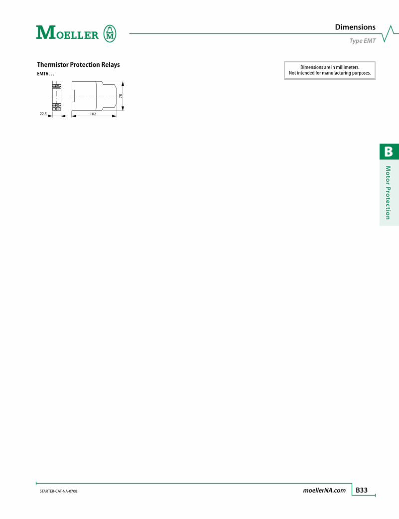
B
Mo
tor Pro
tection
STARTER-CAT-NA-0708 moellerNA.com B33
Dimensions
Type EMT
Dimensions are in millimeters.Not intended for manufacturing purposes.
Thermistor Protection RelaysEMT6…
102
78
22.5

B
Mo
tor
Pro
tect
ion
B34 moellerNA.com STARTER-CAT-NA-0708
Motor Protection
Notes

C
Man
ual M
oto
r C
on
trollers
manual motor controllers
Self-Protected Type E (Series PKZM) C2Selection Tables .................................................................................. C6
Accessories .......................................................................................... C14
Technical Data ................................................................................... C28
Dimensions ......................................................................................... C35
Series PKZ2 (with interchangeable trip module) C44Selection Tables .................................................................................. C48
Accessories .......................................................................................... C51
Technical Data ................................................................................... C58
Dimensions ......................................................................................... C69

C
Man
ual
Mo
tor
Co
ntr
oll
ers
C2
R
Never confuse imitation with innovation! Moeller designed the first PKZ “motor protective controller” in 1932! Since then,
the term “PKZ” has become synonymous worldwide with these types of devices,
regardless of manufacturer. Eight decades of continuous innovation has resulted
in today’s best technology, built from the ground up, only by Moeller.
The Swiss Army Knife® of motor controlThe base PKZM controller combines single-break power contacts with Class
10 thermal overload protection and current limiting short circuit protection to
manually control motor loads. The PKZM can also be equipped with a DIL M con-
tactor for remote control of individual or group motor loads. Collectively, the
PKZM family is UL and CSA listed for a wide range of uses including:
• Manual Starter applications
• Group Fusing applications
• Motor Disconnect means
• Type E, Self-protected, Combination Starter applications
• Multi-motor Starter Combination applications
• Tap Conductor protection
Information on PKZM starter applications can be found in Tab D of this catalog.
PKZM series of manual motor controllersThe “all-in-one” starter solution
> Starts and protects motors to 40HP @ 460V (50HP @ 575V) with two frame sizes
> UL/CSA listed as a Type E self-protected motor controller and “at motor” disconnect
> Adjustable Class 10 overload protection with ambient temperature compensation
> Models available to handle high efficiency motors without nuisance tripping
> Extensive range of accessories and enclosures
> Worldwide approvals
® Swiss Army Knife is a registered trademark of Wenger, SA.
Up to 25A – 50kA
Up to 58A – 50kA
Up to 25A – 50kA(for high or premium efficiency motors with 15-22x typical inrush)
Up to 32A – 50kA
Type PKZM01
Type PKZM0-T
Type PKZM0
Type PKZM4
0.10A 25A 32A 58A
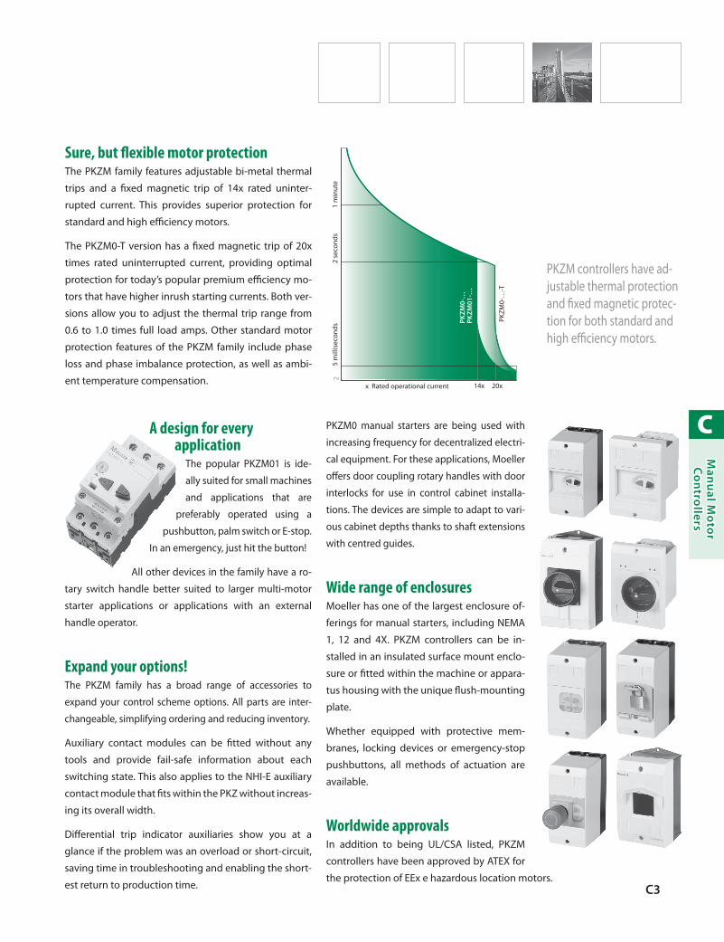
C
Man
ual M
oto
r C
on
trollers
C3
Sure, but flexible motor protectionThe PKZM family features adjustable bi-metal thermal
trips and a fixed magnetic trip of 14x rated uninter-
rupted current. This provides superior protection for
standard and high efficiency motors.
The PKZM0-T version has a fixed magnetic trip of 20x
times rated uninterrupted current, providing optimal
protection for today’s popular premium efficiency mo-
tors that have higher inrush starting currents. Both ver-
sions allow you to adjust the thermal trip range from
0.6 to 1.0 times full load amps. Other standard motor
protection features of the PKZM family include phase
loss and phase imbalance protection, as well as ambi-
ent temperature compensation.
PKZM
0-…
-T
PKZM
0-…
PK
ZM01
-…
2
14x 20xx Rated operational current
2 se
cond
s5
mill
isec
onds
1 m
inut
e
A design for every application
The popular PKZM01 is ide-
ally suited for small machines
and applications that are
preferably operated using a
pushbutton, palm switch or E-stop.
In an emergency, just hit the button!
All other devices in the family have a ro-
tary switch handle better suited to larger multi-motor
starter applications or applications with an external
handle operator.
Expand your options!The PKZM family has a broad range of accessories to
expand your control scheme options. All parts are inter-
changeable, simplifying ordering and reducing inventory.
Auxiliary contact modules can be fitted without any
tools and provide fail-safe information about each
switching state. This also applies to the NHI-E auxiliary
contact module that fits within the PKZ without increas-
ing its overall width.
Differential trip indicator auxiliaries show you at a
glance if the problem was an overload or short-circuit,
saving time in troubleshooting and enabling the short-
est return to production time.
PKZM0 manual starters are being used with
increasing frequency for decentralized electri-
cal equipment. For these applications, Moeller
offers door coupling rotary handles with door
interlocks for use in control cabinet installa-
tions. The devices are simple to adapt to vari-
ous cabinet depths thanks to shaft extensions
with centred guides.
Wide range of enclosuresMoeller has one of the largest enclosure of-
ferings for manual starters, including NEMA
1, 12 and 4X. PKZM controllers can be in-
stalled in an insulated surface mount enclo-
sure or fitted within the machine or appara-
tus housing with the unique flush-mounting
plate.
Whether equipped with protective mem-
branes, locking devices or emergency-stop
pushbuttons, all methods of actuation are
available.
Worldwide approvalsIn addition to being UL/CSA listed, PKZM
controllers have been approved by ATEX for
the protection of EEx e hazardous location motors.
PKZM controllers have ad-justable thermal protection and fixed magnetic protec-tion for both standard and high efficiency motors.

C
Man
ual
Mo
tor
Co
ntr
oll
ers
C4 moellerNA.com STARTER-CAT-NA-0708
Manual Motor Controllers
Overview - PKZM01, PKZM0 and PKZM4
PushbuttonController
Type PKZM01
Rotary HandleController
Type PKZM0(-T)
Trip-indicatingAuxiliaryContact
StandardAuxiliaryContact
Up to 65 ARotary Handle
ControllerType PKZM4
Front MountAuxiliaryContacts
Door CouplingHandle
Shunt Release /Undervoltage
Release
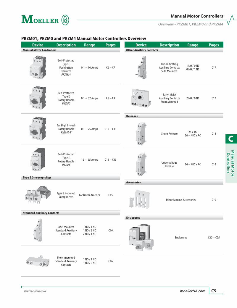
C
Man
ual M
oto
r C
on
trollers
STARTER-CAT-NA-0708 moellerNA.com C5
Manual Motor Controllers
Overview - PKZM01, PKZM0 and PKZM4
PKZM01, PKZM0 and PKZM4 Manual Motor Controllers OverviewDevice Description Range Pages
Manual Motor Controllers
Self-Protected Type E
Pushbutton Operated PKZM01
0.1 – 16 Amps C6 – C7
Self-Protected Type E
Rotary HandlePKZM0
0.1 – 32 Amps C8 – C9
For High In-rush Rotary Handle
PKZM0-T0.1 – 25 Amps C10 – C11
Self-Protected Type E
Rotary Handle PKZM4
16 – 65 Amps C12 – C13
Type E One-stop-shop
Type E Required Components For North America C15
Standard Auxiliary Contacts
Side-mounted Standard Auxiliary
Contacts
1 NO / 1 NC1 NO / 2 NC2 NO / 1 NC
C16
Front-mounted Standard Auxiliary
Contacts
1 NO / 1 NC1 NO / 0 NC C16
Device Description Range PagesOther Auxiliary Contacts
Trip-Indicating Auxiliary Contacts
Side Mounted
1 NO / 0 NC0 NO / 1 NC C17
Early-Make Auxiliary Contacts
Front Mounted2 NO / 0 NC C17
Releases
Shunt Release 24 V DC 24 – 480 V AC C18
Undervoltage Release 24 – 480 V AC C18
Accessories
Miscellaneous Accessories C19
Enclosures
Enclosures C20 – C25

C
Man
ual
Mo
tor
Co
ntr
oll
ers
C6 moellerNA.com STARTER-CAT-NA-0708 Discount Code A31
See Next Page for UL/CSA Application
Ratings Guide
Pushbutton manual motor controller type PKZM01
Rated Un-interrupted
Current ➊
Setting ➊ Maximum Motor Rating
Catalog Number Price
Overload Releases
Short-Circuit
Releases Typical Single Phase [HP]
Typical Three Phase [HP]Ie Ir Irm
[A] [A] [A] 115V 200V 240V 200V 240V 480V 600V0.16 0.1 – 0.16 2.2
See note below
PKZM01-0,16 190
0.25 0.16 – 0.25 3.5 PKZM01-0,25 190
0.4 0.25 – 0.4 5.6 PKZM01-0,4 190
0.63 0.4 – 0.63 8.8 PKZM01-0,63 210
1 0.63 – 1 14 ½ ½ PKZM01-1 212
1.6 1 – 1.6 22 1⁄10 ¾ 1 PKZM01-1,6 212
2.5 1.6 – 2.5 35 1⁄8 1⁄6 ½ ½ 1 1½ PKZM01-2,5 212
4 2.5 – 4 56 1⁄8 ¼ 1⁄3 1 1 2 3 PKZM01-4 230
6.3 4 – 6.3 88 ¼ ½ ½ 1½ 1½ 3 5 PKZM01-6,3 230
10 6.3 – 10 140 ½ 1 1½ 3 3 7½ 10 PKZM01-10 276
12 8 – 12 168 ½ 1½ 2 3 3 7½ 10 PKZM01-12 276
16 10 – 16 224 1 2 2 3 5 10 10 PKZM01-16 276
20 16 – 20 280 1½ 3 3 5 5 10 15 PKZM01-20 276
25 20 – 25 350 1½ 3 3 5 7½ 15 20 PKZM01-25 330
Horsepower ratings shown in the table are for reference only. The final selection of the manual starter depends on the actual motor full load current and service factor on the motor nameplate.Overload should be set at motor FLA full load current and is calibrated to 1.15 S.F.Specified values to NEC table 430-150.
> Approved by UL 508/CSA C 22.2 No. 14 for use as a self-protected Type E manual starter
> Suitable for use in group motor applications
> Common accessories with PKZM0, PKZM0-T and PKZM4 series helps reduce inventories
> Phase failure sensitive and ambient temperature compensated
> Pushbutton operation; ideal for manual starter applications
➊ All types have adjustable dial for setting motor full load current. Trip current is 125% of set value. For motors with a service factor (SF) of 1.0, set dial to 90% of motor full load current.
Ordering Instructions
1 Determine the motor FLA and Service Factor.
2 Use the application rating guide on next page.
3 Locate the desired manual motor controller.
4 See pages C14 – C27 for auxiliaries and accessories.
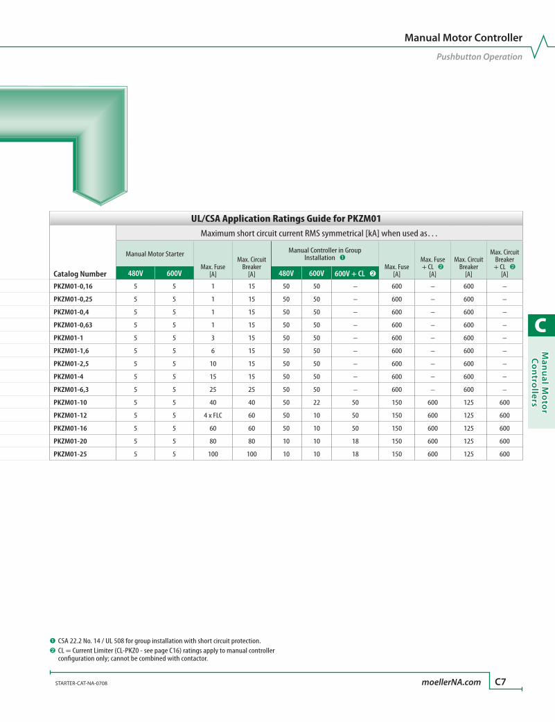
C
Man
ual M
oto
r C
on
trollers
STARTER-CAT-NA-0708 moellerNA.com C7
Pushbutton manual motor controller type PKZM01
Rated Un-interrupted
Current ➊
Setting ➊ Maximum Motor Rating
Catalog Number Price
Overload Releases
Short-Circuit
Releases Typical Single Phase [HP]
Typical Three Phase [HP]Ie Ir Irm
[A] [A] [A] 115V 200V 240V 200V 240V 480V 600V0.16 0.1 – 0.16 2.2
See note below
PKZM01-0,16 190
0.25 0.16 – 0.25 3.5 PKZM01-0,25 190
0.4 0.25 – 0.4 5.6 PKZM01-0,4 190
0.63 0.4 – 0.63 8.8 PKZM01-0,63 210
1 0.63 – 1 14 ½ ½ PKZM01-1 212
1.6 1 – 1.6 22 1⁄10 ¾ 1 PKZM01-1,6 212
2.5 1.6 – 2.5 35 1⁄8 1⁄6 ½ ½ 1 1½ PKZM01-2,5 212
4 2.5 – 4 56 1⁄8 ¼ 1⁄3 1 1 2 3 PKZM01-4 230
6.3 4 – 6.3 88 ¼ ½ ½ 1½ 1½ 3 5 PKZM01-6,3 230
10 6.3 – 10 140 ½ 1 1½ 3 3 7½ 10 PKZM01-10 276
12 8 – 12 168 ½ 1½ 2 3 3 7½ 10 PKZM01-12 276
16 10 – 16 224 1 2 2 3 5 10 10 PKZM01-16 276
20 16 – 20 280 1½ 3 3 5 5 10 15 PKZM01-20 276
25 20 – 25 350 1½ 3 3 5 7½ 15 20 PKZM01-25 330
Horsepower ratings shown in the table are for reference only. The final selection of the manual starter depends on the actual motor full load current and service factor on the motor nameplate.Overload should be set at motor FLA full load current and is calibrated to 1.15 S.F.Specified values to NEC table 430-150.
UL/CSA Application Ratings Guide for PKZM01
Catalog Number
Maximum short circuit current RMS symmetrical [kA] when used as…
Manual Motor Starter
Max. Fuse [A]
Max. Circuit Breaker
[A]
Manual Controller in Group Installation ➊
Max. Fuse [A]
Max. Fuse + CL ➋
[A]
Max. Circuit Breaker
[A]
Max. Circuit Breaker
+ CL ➋ [A]480V 600V 480V 600V 600V + CL ➋
PKZM01-0,16 5 5 1 15 50 50 – 600 – 600 –
PKZM01-0,25 5 5 1 15 50 50 – 600 – 600 –
PKZM01-0,4 5 5 1 15 50 50 – 600 – 600 –
PKZM01-0,63 5 5 1 15 50 50 – 600 – 600 –
PKZM01-1 5 5 3 15 50 50 – 600 – 600 –
PKZM01-1,6 5 5 6 15 50 50 – 600 – 600 –
PKZM01-2,5 5 5 10 15 50 50 – 600 – 600 –
PKZM01-4 5 5 15 15 50 50 – 600 – 600 –
PKZM01-6,3 5 5 25 25 50 50 – 600 – 600 –
PKZM01-10 5 5 40 40 50 22 50 150 600 125 600
PKZM01-12 5 5 4 x FLC 60 50 10 50 150 600 125 600
PKZM01-16 5 5 60 60 50 10 50 150 600 125 600
PKZM01-20 5 5 80 80 10 10 18 150 600 125 600
PKZM01-25 5 5 100 100 10 10 18 150 600 125 600
Manual Motor Controller
Pushbutton Operation
➊ CSA 22.2 No. 14 / UL 508 for group installation with short circuit protection.➋ CL = Current Limiter (CL-PKZ0 - see page C16) ratings apply to manual controller
configuration only; cannot be combined with contactor.
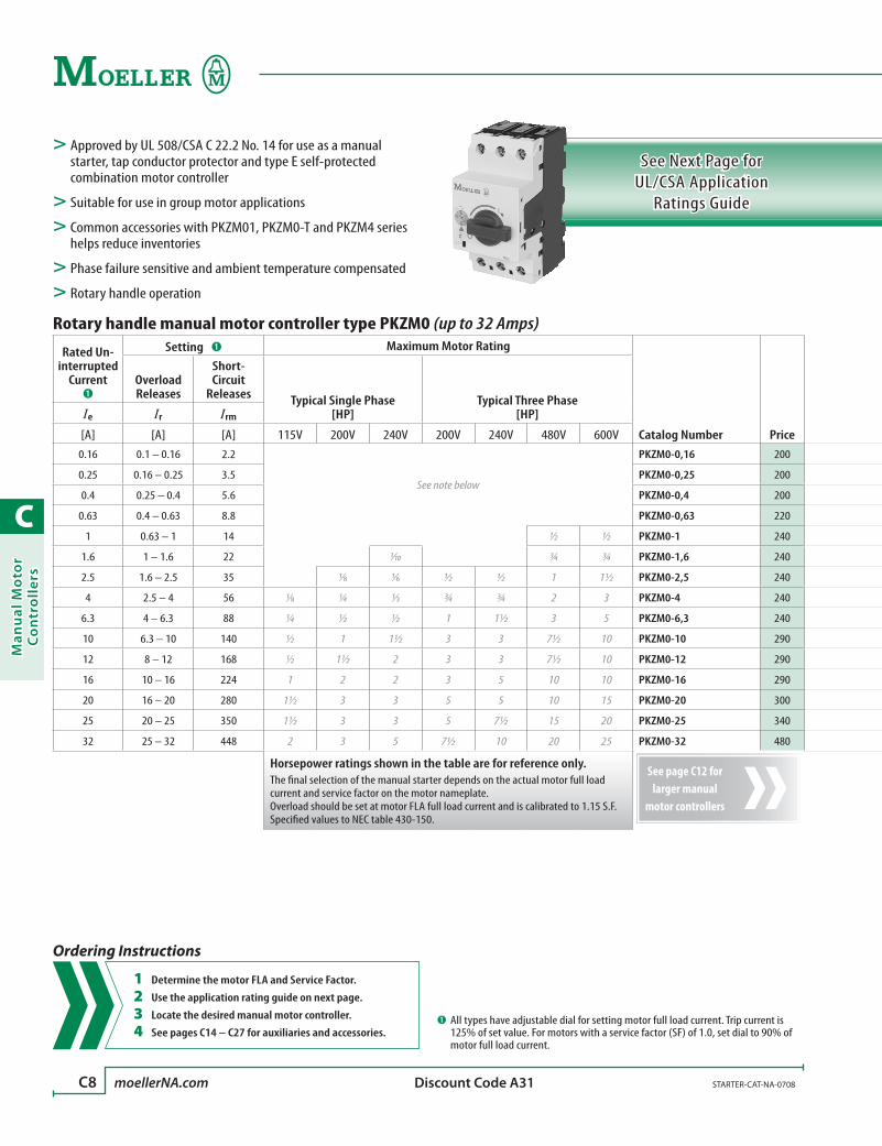
C
Man
ual
Mo
tor
Co
ntr
oll
ers
C8 moellerNA.com STARTER-CAT-NA-0708 Discount Code A31
See Next Page for UL/CSA Application
Ratings Guide
Rotary handle manual motor controller type PKZM0 (up to 32 Amps)
Rated Un-interrupted
Current ➊
Setting ➊ Maximum Motor Rating
Catalog Number Price
Overload Releases
Short-Circuit
Releases Typical Single Phase [HP]
Typical Three Phase [HP]Ie Ir Irm
[A] [A] [A] 115V 200V 240V 200V 240V 480V 600V0.16 0.1 – 0.16 2.2
See note below
PKZM0-0,16 200
0.25 0.16 – 0.25 3.5 PKZM0-0,25 200
0.4 0.25 – 0.4 5.6 PKZM0-0,4 200
0.63 0.4 – 0.63 8.8 PKZM0-0,63 220
1 0.63 – 1 14 ½ ½ PKZM0-1 240
1.6 1 – 1.6 22 1⁄10 ¾ ¾ PKZM0-1,6 240
2.5 1.6 – 2.5 35 1⁄8 1⁄6 ½ ½ 1 1½ PKZM0-2,5 240
4 2.5 – 4 56 1⁄8 ¼ 1⁄3 ¾ ¾ 2 3 PKZM0-4 240
6.3 4 – 6.3 88 ¼ ½ ½ 1 1½ 3 5 PKZM0-6,3 240
10 6.3 – 10 140 ½ 1 1½ 3 3 7½ 10 PKZM0-10 290
12 8 – 12 168 ½ 1½ 2 3 3 7½ 10 PKZM0-12 290
16 10 – 16 224 1 2 2 3 5 10 10 PKZM0-16 290
20 16 – 20 280 1½ 3 3 5 5 10 15 PKZM0-20 300
25 20 – 25 350 1½ 3 3 5 7½ 15 20 PKZM0-25 340
32 25 – 32 448 2 3 5 7½ 10 20 25 PKZM0-32 480
Horsepower ratings shown in the table are for reference only. The final selection of the manual starter depends on the actual motor full load current and service factor on the motor nameplate.Overload should be set at motor FLA full load current and is calibrated to 1.15 S.F.Specified values to NEC table 430-150.
> Approved by UL 508/CSA C 22.2 No. 14 for use as a manual starter, tap conductor protector and type E self-protected combination motor controller
> Suitable for use in group motor applications
> Common accessories with PKZM01, PKZM0-T and PKZM4 series helps reduce inventories
> Phase failure sensitive and ambient temperature compensated
> Rotary handle operation
➊ All types have adjustable dial for setting motor full load current. Trip current is 125% of set value. For motors with a service factor (SF) of 1.0, set dial to 90% of motor full load current.
Ordering Instructions
1 Determine the motor FLA and Service Factor.
2 Use the application rating guide on next page.
3 Locate the desired manual motor controller.
4 See pages C14 – C27 for auxiliaries and accessories.
See page C12 for larger manual
motor controllers

C
Man
ual M
oto
r C
on
trollers
STARTER-CAT-NA-0708 moellerNA.com C9
Rotary handle manual motor controller type PKZM0 (up to 32 Amps)
Rated Un-interrupted
Current ➊
Setting ➊ Maximum Motor Rating
Catalog Number Price
Overload Releases
Short-Circuit
Releases Typical Single Phase [HP]
Typical Three Phase [HP]Ie Ir Irm
[A] [A] [A] 115V 200V 240V 200V 240V 480V 600V0.16 0.1 – 0.16 2.2
See note below
PKZM0-0,16 200
0.25 0.16 – 0.25 3.5 PKZM0-0,25 200
0.4 0.25 – 0.4 5.6 PKZM0-0,4 200
0.63 0.4 – 0.63 8.8 PKZM0-0,63 220
1 0.63 – 1 14 ½ ½ PKZM0-1 240
1.6 1 – 1.6 22 1⁄10 ¾ ¾ PKZM0-1,6 240
2.5 1.6 – 2.5 35 1⁄8 1⁄6 ½ ½ 1 1½ PKZM0-2,5 240
4 2.5 – 4 56 1⁄8 ¼ 1⁄3 ¾ ¾ 2 3 PKZM0-4 240
6.3 4 – 6.3 88 ¼ ½ ½ 1 1½ 3 5 PKZM0-6,3 240
10 6.3 – 10 140 ½ 1 1½ 3 3 7½ 10 PKZM0-10 290
12 8 – 12 168 ½ 1½ 2 3 3 7½ 10 PKZM0-12 290
16 10 – 16 224 1 2 2 3 5 10 10 PKZM0-16 290
20 16 – 20 280 1½ 3 3 5 5 10 15 PKZM0-20 300
25 20 – 25 350 1½ 3 3 5 7½ 15 20 PKZM0-25 340
32 25 – 32 448 2 3 5 7½ 10 20 25 PKZM0-32 480
Horsepower ratings shown in the table are for reference only. The final selection of the manual starter depends on the actual motor full load current and service factor on the motor nameplate.Overload should be set at motor FLA full load current and is calibrated to 1.15 S.F.Specified values to NEC table 430-150.
UL/CSA Application Ratings Guide for PKZM0
Catalog Number
Maximum short circuit current RMS symmetrical [kA] when used as…
Manual Motor Starter
Max. Fuse [A]
Max. Circuit
Breaker [A]
Manual Controller in Group Installation ➊ Max.
Fuse [A]
Max. Circuit
Breaker [A]
Suitable for Tap Conductor Protection
Self-Protected Type E Manual Controller ➋➌
480V 600V 480V 600V 600V +CL ➍ 480Y/277V 600Y/347V 480Y/277V 600Y/347V
PKZM0-0,16 5 5 1 15 50 50 – 600 600 42 65 42 65
PKZM0-0,25 5 5 1 15 50 50 – 600 600 42 65 42 65
PKZM0-0,4 5 5 1 15 50 50 – 600 600 42 65 42 65
PKZM0-0,63 5 5 1 15 50 50 – 600 600 42 65 42 65
PKZM0-1 5 5 3 15 50 50 – 600 600 42 65 42 65
PKZM0-1,6 5 5 6 15 50 50 – 600 600 42 65 42 65
PKZM0-2,5 5 5 10 15 50 50 – 600 600 42 65 42 65
PKZM0-4 5 5 15 15 50 50 – 600 600 42 65 42 65
PKZM0-6,3 5 5 25 25 50 50 – 600 600 42 65 42 65
PKZM0-10 5 5 40 40 50 22 50 150 125 42 65 42 65
PKZM0-12 5 5 4 x FLA 60 50 22 50 150 125 42 – 42 –
PKZM0-16 5 5 60 60 50 22 50 150 125 42 – 42 –
PKZM0-20 5 5 80 80 50 10 18 150 125 18 – 18 –
PKZM0-25 5 5 100 100 50 10 18 150 125 18 – 18 –
PKZM0-32 5 5 4 x FLA 100 50 10 18 150 125 18 – 18 –
Type E Manual Motor Controller
Rotary Handle Operation
➊ CSA 22.2 No. 14 / UL 508 for group installation with short circuit protection.➋ In USA and Canada: Type E requires a line side connector feeder terminal
(BK25/3-PKZ0-E see page C15). This terminal is not a requirement for tap conduc-tor protection. In Canada only: Type E also requires the handle to be padlockable (AK-PKZ0, SVB-PKZ0, or PKZ0-X(R)H see pages C15, C26).
➌ According to UL 508, Part IV.➍ CL = Current Limiter (CL-PKZ0 - see page C16) ratings apply to manual controller
configuration only; cannot be combined with contactor.
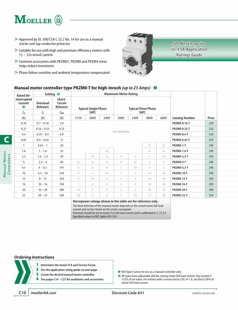
C
Man
ual
Mo
tor
Co
ntr
oll
ers
C10 moellerNA.com STARTER-CAT-NA-0708 Discount Code A31
See Next Page for UL/CSA Application
Ratings Guide
Manual motor controller type PKZM0-T for high-inrush (up to 25 Amps) ➊
Rated Un-interrupted
Current ➋
Setting ➋ Maximum Motor Rating
Catalog Number Price
Overload Releases
Short-Circuit
Releases Typical Single Phase [HP]
Typical Three Phase [HP]Ie Ir Irm
[A] [A] [A] 115V 200V 240V 200V 240V 480V 600V0.16 0.1 – 0.16 2.4
See note below
PKZM0-0,16-T 220
0.25 0.16 – 0.25 4.25 PKZM0-0,25-T 220
0.4 0.25 – 0.4 6.8 PKZM0-0,4-T 220
0.63 0.4 – 0.63 12 PKZM0-0,63-T 220
1 0.63 – 1 20 ½ ½ PKZM0-1-T 240
1.6 1 – 1.6 32 1⁄10 ¾ ¾ PKZM0-1,6-T 240
2.5 1.6 – 2.5 50 1⁄8 1⁄6 ½ ½ 1 1½ PKZM0-2,5-T 240
4 2.5 – 4 84 1⁄8 ¼ 1⁄3 ¾ ¾ 2 3 PKZM0-4-T 240
6.3 4 – 6.3 141 ¼ ½ ½ 1 1½ 3 5 PKZM0-6,3-T 240
10 6.3 – 10 224 ½ 1 1½ 3 3 7½ 10 PKZM0-10-T 290
12 8 – 12 224 ½ 1½ 2 3 3 7½ 10 PKZM0-12-T 290
16 10 – 16 358 1 2 2 3 5 10 10 PKZM0-16-T 290
20 16 – 20 380 1½ 3 3 5 5 10 15 PKZM0-20-T 300
25 20 – 25 420 1½ 3 3 5 7½ 15 20 PKZM0-25-T 354
Horsepower ratings shown in the table are for reference only. The final selection of the manual starter depends on the actual motor full load current and service factor on the motor nameplate.Overload should be set at motor FLA full load current and is calibrated to 1.15 S.F.Specified values to NEC table 430-150.
> Approved by UL 508/CSA C 22.2 No. 14 for use as a manual starter and tap conductor protector
> Suitable for use with high and premium efficiency motors with 15 – 22x inrush current
> Common accessories with PKZM01, PKZM0 and PKZM4 series helps reduce inventories
> Phase failure sensitive and ambient temperature compensated
➊ Not Type E rated; for use as a manual controller only.➋ All types have adjustable dial for setting motor full load current. Trip current is
125% of set value. For motors with a service factor (SF) of 1.0, set dial to 90% of motor full load current.
Ordering Instructions
1 Determine the motor FLA and Service Factor.
2 Use the application rating guide on next page.
3 Locate the desired manual motor controller.
4 See pages C14 – C27 for auxiliaries and accessories.

C
Man
ual M
oto
r C
on
trollers
STARTER-CAT-NA-0708 moellerNA.com C11
Manual motor controller type PKZM0-T for high-inrush (up to 25 Amps) ➊
Rated Un-interrupted
Current ➋
Setting ➋ Maximum Motor Rating
Catalog Number Price
Overload Releases
Short-Circuit
Releases Typical Single Phase [HP]
Typical Three Phase [HP]Ie Ir Irm
[A] [A] [A] 115V 200V 240V 200V 240V 480V 600V0.16 0.1 – 0.16 2.4
See note below
PKZM0-0,16-T 220
0.25 0.16 – 0.25 4.25 PKZM0-0,25-T 220
0.4 0.25 – 0.4 6.8 PKZM0-0,4-T 220
0.63 0.4 – 0.63 12 PKZM0-0,63-T 220
1 0.63 – 1 20 ½ ½ PKZM0-1-T 240
1.6 1 – 1.6 32 1⁄10 ¾ ¾ PKZM0-1,6-T 240
2.5 1.6 – 2.5 50 1⁄8 1⁄6 ½ ½ 1 1½ PKZM0-2,5-T 240
4 2.5 – 4 84 1⁄8 ¼ 1⁄3 ¾ ¾ 2 3 PKZM0-4-T 240
6.3 4 – 6.3 141 ¼ ½ ½ 1 1½ 3 5 PKZM0-6,3-T 240
10 6.3 – 10 224 ½ 1 1½ 3 3 7½ 10 PKZM0-10-T 290
12 8 – 12 224 ½ 1½ 2 3 3 7½ 10 PKZM0-12-T 290
16 10 – 16 358 1 2 2 3 5 10 10 PKZM0-16-T 290
20 16 – 20 380 1½ 3 3 5 5 10 15 PKZM0-20-T 300
25 20 – 25 420 1½ 3 3 5 7½ 15 20 PKZM0-25-T 354
Horsepower ratings shown in the table are for reference only. The final selection of the manual starter depends on the actual motor full load current and service factor on the motor nameplate.Overload should be set at motor FLA full load current and is calibrated to 1.15 S.F.Specified values to NEC table 430-150.
UL/CSA Application Ratings Guide for PKZM0-T
Catalog Number
Maximum short circuit current RMS symmetrical [kA] when used as…
Manual Motor Starter
Max. Fuse [A]
Max. Circuit
Breaker [A]
Manual Controller in Group Installation ➊ Max.
Fuse [A]
Max. Circuit
Breaker [A]
Suitable for Tap Conductor Protection
480V 600V 480V 600V 600V +CL ➋ 480Y/277V 600Y/347V
PKZM0-0,16-T 5 5 1 15 50 50 – 600 600 42 65
PKZM0-0,25-T 5 5 1 15 50 50 – 600 600 42 65
PKZM0-0,4-T 5 5 1 15 50 50 – 600 600 42 65
PKZM0-0,63-T 5 5 1 15 50 50 – 600 600 42 65
PKZM0-1-T 5 5 3 15 50 50 – 600 600 42 65
PKZM0-1,6-T 5 5 6 15 50 50 – 600 600 42 65
PKZM0-2,5-T 5 5 10 15 50 50 – 600 600 42 65
PKZM0-4-T 5 5 15 15 50 50 – 600 600 42 65
PKZM0-6,3-T 5 5 25 25 50 50 – 600 600 42 65
PKZM0-10-T 5 5 40 40 50 22 50 150 125 42 65
PKZM0-12-T 5 5 4 x FLA 60 50 10 50 150 125 42 –
PKZM0-16-T 5 5 60 60 50 10 50 150 125 42 –
PKZM0-20-T 5 5 80 80 50 10 18 150 125 18 –
PKZM0-25-T 5 5 100 100 50 10 18 150 125 18 –
Manual Motor Controller
For High In-Rush Applications
➊ CSA 22.2 No. 14 / UL 508 for group installation with short circuit protection.➋ CL = Current Limiter (CL-PKZ0 - see page C16) ratings apply to manual controller
configuration only; cannot be combined with contactor.

C
Man
ual
Mo
tor
Co
ntr
oll
ers
C12 moellerNA.com STARTER-CAT-NA-0708 Discount Code A31
See Next Page for UL/CSA Application
Ratings Guide
Manual motor controller for larger applications type PKZM4
Rated Un-interrupted
Current ➊
Setting ➊ Maximum Motor Rating
Catalog Number Price
Overload Releases
Short-Circuit
Releases Typical Single Phase [HP]
Typical Three Phase [HP]Ie Ir Irm
[A] [A] [A] 115V 200V 240V 200V 240V 480V 600V16 10 – 16 224 1 2 3 3 5 10 15 PKZM4-16 434
25 16 – 25 350 2 3 3 7½ 7½ 15 20 PKZM4-25 508
32 25 – 32 448 3 5 5 10 10 25 30 PKZM4-32 590
40 32 – 40 560 3 – 7½ 10 – 30 30 PKZM4-40 690
50 40 – 50 700 – – – – 15 30 40 PKZM4-50 784
58 50 – 58 ➋ 812 – – 10 – – 40 50 PKZM4-58 932
58 55 – 63 ➋ 882 – – – – – 40 50 PKZM4-63 932
Horsepower ratings shown in the table are for reference only. The final selection of the manual starter depends on the actual motor full load current and service factor on the motor nameplate.Overload should be set at motor FLA full load current and is calibrated to 1.15 S.F.Specified values to NEC table 430-150.
> Approved by UL 508/CSA C 22.2 No. 14 for use as a manual starter, tap conductor protector and type E self-protected combination motor controller
> Suitable for use in group motor applications
> Common accessories with PKZM01, PKZM0 and PKZM0-T series helps reduce inventories
> Phase failure sensitive and ambient compensated
> Rotary handle operation
➊ All types have adjustable dial for setting motor full load current. Trip current is 125% of set value. For motors with a service factor (SF) of 1.0, set dial to 90% of motor full load current.
➋ Maximum three-phase at 480V is 58A; at 600V is 52A.
Ordering Instructions
1 Determine the motor FLA and Service Factor.
2 Use the application rating guide on next page.
3 Locate the desired manual motor controller.
4 See pages C14 – C27 for auxiliaries and accessories.
See page C8 for smaller manual
motor controllers

C
Man
ual M
oto
r C
on
trollers
STARTER-CAT-NA-0708 moellerNA.com C13
Manual motor controller for larger applications type PKZM4
Rated Un-interrupted
Current ➊
Setting ➊ Maximum Motor Rating
Catalog Number Price
Overload Releases
Short-Circuit
Releases Typical Single Phase [HP]
Typical Three Phase [HP]Ie Ir Irm
[A] [A] [A] 115V 200V 240V 200V 240V 480V 600V16 10 – 16 224 1 2 3 3 5 10 15 PKZM4-16 434
25 16 – 25 350 2 3 3 7½ 7½ 15 20 PKZM4-25 508
32 25 – 32 448 3 5 5 10 10 25 30 PKZM4-32 590
40 32 – 40 560 3 – 7½ 10 – 30 30 PKZM4-40 690
50 40 – 50 700 – – – – 15 30 40 PKZM4-50 784
58 50 – 58 ➋ 812 – – 10 – – 40 50 PKZM4-58 932
58 55 – 63 ➋ 882 – – – – – 40 50 PKZM4-63 932
Horsepower ratings shown in the table are for reference only. The final selection of the manual starter depends on the actual motor full load current and service factor on the motor nameplate.Overload should be set at motor FLA full load current and is calibrated to 1.15 S.F.Specified values to NEC table 430-150.
UL/CSA Application Ratings Guide for PKZM4
Catalog Number
Maximum short circuit current RMS symmetrical [kA] when used as…
Manual Motor Starter (NTD) OTS
Fuse [A]
Circuit Breaker
[A]
Manual Controller in Group
Installation ➊ Max. Fuse
[A] ➋
Max. Circuit
Breaker [A] ➋
Suitable for Tap Conductor Protection
Self-Protected Type E Manual Controller ➌➍
480V 600V 480V 600V 480Y/277V 600Y/347V 480Y/277V 600Y/347V
PKZM4-16 5 5 60 60 65 42 600 600 50 25 50 25
PKZM4-25 5 5 100 100 65 42 600 600 50 25 50 25
PKZM4-32 5 5 125 125 65 42 600 600 50 25 50 25
PKZM4-40 5 5 150 150 65 42 600 600 50 25 50 25
PKZM4-50 5 5 150 150 65 42 600 600 50 – 50 –
PKZM4-58 5 5 150 150 65 42 600 600 50 – 50 –
PKZM4-63 5 5 150 150 65 42 600 600 50 – 50 –
Type E Manual Motor Controller
for Larger Applications
➊ CSA 22.2 No. 14 / UL 508 for group installation with short circuit protection. ➋ Tests have been performed successfully without fuse or circuit breaker protection.➌ In USA and Canada: Type E requires a line side connector feeder terminal
(BK50/3-PKZ4-E see page C15). This terminal is not a requirement for tap conduc-tor protection. In Canada only: Type E also requires the handle to be padlockable (AK-PKZ0, SVB-PKZ0, or PKZ0-X(R)H see pages C15, C26).
➍ According to UL 508, Part IV.

C
Man
ual
Mo
tor
Co
ntr
oll
ers
C14 moellerNA.com STARTER-CAT-NA-0708
Accessory Guide
Accessory Options
Accessory Guide Maximum possible combinations of accessories
Maximum possible combinations of accessories when using the
following manual motor controllers
Auxiliary Contacts(see page C16)
Trip-Indicating Auxiliary Contacts
(see page C17)
Front-mounted Auxiliary Contacts
(see page C16)
Early-make Auxiliary Contacts
(see page C17)Shunt Trip
(see page C18)Undervoltage Trip
(see page C18)Padlockable Handle
(see page C15)
NHI(11)(12)(21)-PKZ0 AGM2…PKZ0 NHI-E…PKZ0 VHI20-PKZ0(1) A-PKZ0… U-PKZ0… AK-PKZ0
Manual Motor Controller PKZM01
PKZM01…(see page C6)
Option #1 1x 1x 1xOption #2 1x 1x 1xOption #3 1x 1x 1xOption #4 1x 1x 1xOption #5 1x 1x 1xOption #6 1x 1x 1xOption #7 1x 1x 1xOption #8 1x 1x 1x
Manual Motor Controller PKZMO(-T)
PKZM0…(-T)(see pages C8 – C10)
Option #1 1x 1x 1x 1xOption #2 1x 1x 1x 1xOption #3 1x 1x 1xOption #4 1x 1x 1xOption #5 1x 1x 1x 1xOption #6 1x 1x 1x 1xOption #7 1x 1x 1xOption #8 1x 1x 1x
Manual Motor Controller PKZM4
PKZM4…(see page C12)
Option #1 1x 1x 1x 1x
Option #2 1x 1x 1x 1x
Option #3 1x 1x 1x 1x
Option #4 1x 1x 1x 1x
Use this guide to determine which accessories fit on the devices listed below. Order the desired accessories on the pages that follow.
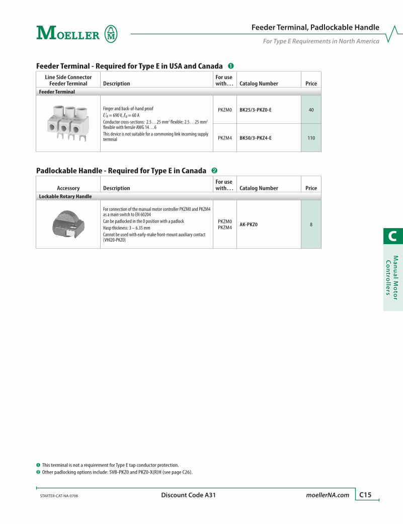
C
Man
ual M
oto
r C
on
trollers
STARTER-CAT-NA-0708 moellerNA.com C15 Discount Code A31
Feeder Terminal, Padlockable Handle
For Type E Requirements in North America
➊ This terminal is not a requirement for Type E tap conductor protection.➋ Other padlocking options include: SVB-PKZ0 and PKZ0-X(R)H (see page C26).
Feeder Terminal - Required for Type E in USA and Canada ➊
Line Side Connector Feeder Terminal Description
For use with… Catalog Number Price
Feeder Terminal
Finger and back-of-hand proofUe = 690 V, Iu = 60 AConductor cross-sections: 2.5…25 mm2 flexible; 2.5…25 mm2 flexible with ferrule AWG 14…6This device is not suitable for a commoning link incoming supply termnial
PKZM0 BK25/3-PKZ0-E 40
PKZM4 BK50/3-PKZ4-E 110
Padlockable Handle - Required for Type E in Canada ➋
Accessory DescriptionFor use with… Catalog Number Price
Lockable Rotary Handle
For connection of the manual motor controller PKZM0 and PKZM4 as a main switch to EN 60204Can be padlocked in the 0 position with a padlockHasp thickness: 3 – 6.35 mmCannot be used with early-make front-mount auxiliary contact (VHI20-PKZ0)
PKZM0PKZM4 AK-PKZ0 8
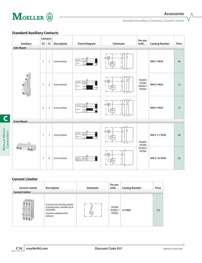
C
Man
ual
Mo
tor
Co
ntr
oll
ers
C16 moellerNA.com STARTER-CAT-NA-0708 Discount Code A31
Accessories
Standard Auxiliary Contacts, Current Limiter
Standard Auxiliary Contacts
Auxiliary
Contacts
Description Travel Diagram SchematicFor use with… Catalog Number PriceNO NC
Side Mount
1 1 Screw terminalsNHI11
L1L2L3
1.14 1.22
1.13 1.21
I >
PKZM01PKZM0
PKZM0-TPKZM4
NHI11-PKZ0 48
1 2 Screw terminalsL1L2L3
NHI12
1.13
1.14 1.22
1.21 1.31
1.32
I >
NHI12-PKZ0 72
2 1 Screw terminalsL1L2L3
NHI21
1.13 1.21 1.33
1.14 1.22 1.34
I >
NHI21-PKZ0 72
Front Mount
1 1 Screw terminalsL1L2L3
NHI-E-11
1.53
1.54
1.61
1.62
I >
PKZM01PKZM0
PKZM0-TPKZM4
NHI-E-11-PKZ0 40
1 0 Screw terminals L1L2L3
NHI-E-10
1.53
1.54
I >
NHI-E-10-PKZ0 28
Current Limiter
Current Limiter Description SchematicFor use with… Catalog Number Price
Current Limiter
To increase the switching capacity of manual motor controllers up to 50 kA/600VCannot be combined with a contactor
L
TI >>
PKZM0PKZM0-TPKZM4
CL-PKZ0 120

C
Man
ual M
oto
r C
on
trollers
STARTER-CAT-NA-0708 moellerNA.com C17 Discount Code A31
Other Auxiliary Contacts
Auxiliary
Contacts
Description Travel Diagram SchematicFor use with… Catalog Number PriceNO NC
Trip-indicating auxiliary contact
1 0
Trips on short circuit or overcurrentA600 / Q300 pilot duty5A @ 600V AC; 1A @ 250V DC
L1L2L3
"+"
"I >"
On/O
L1L2L3
"+"
"I >"
Trip "+"
I >
"+"4.43 4.13
"I >"
4.44 4.14 PKZM01PKZM0
PKZM0-TPKZM4
AGM2-10-PKZ0 80
0 1
A600 / Q300 pilot duty5A @ 600V AC; 1A @ 250V DC
L1L2L3
"+""I >"
On/O
L1L2L3
"+"
"I >"
Trip "+"
4.21"I >""+"
4.31
4.32 4.22
I >
AGM2-01-PKZ0 80
Early-make auxiliary contact
2 0
E150 pilot duty0.5A @ 250V ACCannot be used with padlockable handle (AK-PKZ0)
3.13 3.23
3.14 3.24
I >
PKZM0PKZM0-T VHI20-PKZ0 48
PKZM01 VHI20-PKZ01 48
Accessories
Trip-indicating and Early-make Auxiliaries
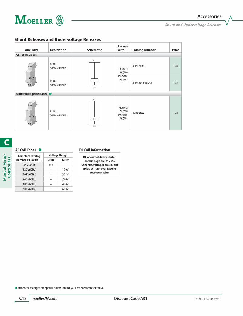
C
Man
ual
Mo
tor
Co
ntr
oll
ers
C18 moellerNA.com STARTER-CAT-NA-0708 Discount Code A31
Shunt Releases and Undervoltage Releases
Auxiliary Description SchematicFor use with… Catalog Number Price
Shunt Releases
AC coil Screw Terminals
C1
C2
PKZM01PKZM0
PKZM0-TPKZM4
A-PKZ0 128
DC coil Screw Terminals
A-PKZ0(24VDC) 152
Undervoltage Releases ➊
AC coilScrew Terminals
U <
D1
D2
PKZM01PKZM0
PKZM0-TPKZM4
U-PKZ0 128
AC Coil Codes ➊
Complete catalog number () with…
Voltage Range
50 Hz 60Hz
(24V50Hz) 24V –
(120V60Hz) – 120V
(208V60Hz) – 208V
(240V60Hz) – 240V
(480V60Hz) – 480V
(600V60Hz) – 600V
Accessories
Shunt and Undervoltage Releases
DC Coil Information
DC operated devices listed on this page are 24V DC.
Other DC voltages are special order; contact your Moeller
representative.
➊ Other coil voltages are special order; contact your Moeller representative.

C
Man
ual M
oto
r C
on
trollers
STARTER-CAT-NA-0708 moellerNA.com C19 Discount Code A31
Accessories
Miscellaneous Accessories
Accessories
Accessory DescriptionFor use with… Catalog Number Price
Terminal Shroud
White•Enhances the degree of protection of PKZM4 to IP2X•
PKZM4 HB-PKZ4 16
Tamper Shield
To prevent tampering with the overload release and the test func-tion, it can be sealed using industry standard sealing wireFor use with manual motor controllers PKZM0 and PKZM4
PKZM0PKZM0-TPKZM4
PL-PKZ0 4
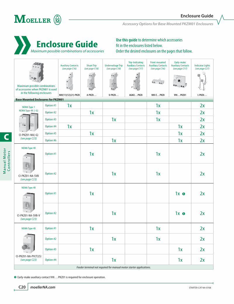
C
Man
ual
Mo
tor
Co
ntr
oll
ers
C20 moellerNA.com STARTER-CAT-NA-0708
Enclosure Guide
Accessory Options for Base Mounted PKZM01 Enclosures
Enclosure Guide Maximum possible combinations of accessories
Maximum possible combinations of accessories when PKZM01 is used
in the following enclosures
Auxiliary Contacts(see page C16)
Shunt Trip(see page C18)
Undervoltage Trip(see page C18)
Trip-Indicating Auxiliary Contacts
(see page C17)
Front-mounted Auxiliary Contacts
(see page C16)
Early-make Auxiliary Contacts
(see page C17)Indicator Lights(see page C27)
NHI(11)(12)(21)-PKZ0 A-PKZ0… U-PKZ0… AGM2…PKZ0 NHI-E…PKZ0 VHI…PKZ01 L-PKZ0…
Base Mounted Enclosures for PKZM01
NEMA Type 1NEMA Type 4X: (-G)
CI-PKZ01-NA(-G)(see page C23)
Option #1 1x 1x 2xOption #2 1x 1x 2xOption #3 1x 1x 2xOption #4 1x 1x 2xOption #5 1x 1x 2xOption #6 1x 1x 2x
NEMA Type 4X
CI-PKZ01-NA-SVB(see page C23)
Option #1 1x 1x 2x
Option #2 1x 1x 2x
NEMA Type 4X
CI-PKZ01-NA-SVB-V(see page C23)
Option #1 1x 1x ➊ 2x
Option #2 1x 1x ➊ 2x
NEMA Type 4X
CI-PKZ01-NA-PV(T)(S)(see page C23)
Option #1 1x 1x 2x
Option #2 1x 1x 2x
Option #3 1x 1x 2x
Option #4 1x 1x 2xFeeder terminal not required for manual motor starter applications.
➊ Early-make auxiliary contact VHI…PKZ01 is required for enclosure operation.
Use this guide to determine which accessories fit in the enclosures listed below. Order the desired enclosures on the pages that follow.
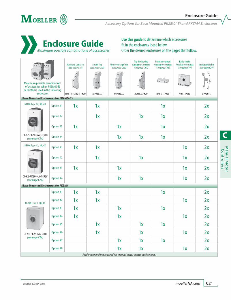
C
Man
ual M
oto
r C
on
trollers
STARTER-CAT-NA-0708 moellerNA.com C21
Enclosure Guide
Accessory Options for Base Mounted PKZM0(-T) and PKZM4 Enclosures
Enclosure Guide Maximum possible combinations of accessories
Maximum possible combinations of accessories when PKZM0(-T)
or PKZM4 is used in the following enclosures
Auxiliary Contacts(see page C16)
Shunt Trip(see page C18)
Undervoltage Trip(see page C18)
Trip-Indicating Auxiliary Contacts
(see page C17)
Front-mounted Auxiliary Contacts
(see page C16)
Early-make Auxiliary Contacts
(see page C17)Indicator Lights(see page C27)
NHI(11)(12)(21)-PKZ0 A-PKZ0… U-PKZ0… AGM2…PKZ0 NHI-E…PKZ0 VHI…PKZ0 L-PKZ0…
Base Mounted Enclosures for PKZM0(-T)
NEMA Type 12, 3R, 4X
CI-K2-PKZ0-NA(-G)(R)(see page C24)
Option #1 1x 1x 1x 2x
Option #2 1x 1x 1x 2x
Option #3 1x 1x 1x 2x
Option #4 1x 1x 1x 2xNEMA Type 12, 3R, 4X
CI-K2-PKZ0-NA-G(R)V(see page C24)
Option #1 1x 1x 1x 2x
Option #2 1x 1x 1x 2x
Option #3 1x 1x 1x 2x
Option #4 1x 1x 1x 2xBase Mounted Enclosures for PKZM4
NEMA Type 1, 3R, 4X
CI-K4-PKZ4-NA-G(R)(see page C24)
Option #1 1x 1x 1x 2xOption #2 1x 1x 1x 2xOption #3 1x 1x 1x 2xOption #4 1x 1x 1x 2xOption #5 1x 1x 1x 2xOption #6 1x 1x 1x 2xOption #7 1x 1x 1x 2xOption #8 1x 1x 1x 2x
Feeder terminal not required for manual motor starter applications.
Use this guide to determine which accessories fit in the enclosures listed below. Order the desired enclosures on the pages that follow.

C
Man
ual
Mo
tor
Co
ntr
oll
ers
C22 moellerNA.com STARTER-CAT-NA-0708
Enclosure Guide
Accessory Options for Flush Mounted PKZM01 and PKZM0(-T) Enclosures
Enclosure Guide Maximum possible combinations of accessories
Maximum possible combinations of accessories when PKZM01 or
PKZM0(-T) is used in the following enclosures
Auxiliary Contacts(see page C16)
Shunt Trip(see page C18)
Undervoltage Trip(see page C18)
Trip-Indicating Auxiliary Contacts
(see page C17)
Front-mounted Auxiliary Contacts
(see page C16)
Early-make Auxiliary Contacts
(see page C17)Indicator Lights(see page C27)
NHI(11)(12)(21)-PKZ0 A-PKZ0… U-PKZ0… AGM2…PKZ0 NHI-E…PKZ0 VHI…PKZ01 L-PKZ0…
Flush Mounted Enclosures for PKZM01
NEMA Type 1NEMA Type 4X: (-G)
E-PKZ01(-G)(see page C25)
Option #1 1x 1x 2xOption #2 1x 1x 2xOption #3 1x 1x 2xOption #4 1x 1x 2xOption #5 1x 1x 2xOption #6 1x 1x 2x
NEMA Type 4X
E-PKZ01-SVB(-V ➊) E-PKZ01-PV(T)(S)
(see page C25)
Option #1 1x 1x ➊ 2x
Option #2 1x 1x ➊ 2xOption #3 not for (-V) 1x 1x 2xOption #4 not for (-V) 1x 1x 2x
Flush Mounted Enclosures for PKZM0(-T)
CSA: NEMA Type 1
E-PKZ0(see page C25)
Option #1 1x 2x
Option #2 1x 2x
Option #3 1x 2x
CSA: NEMA Type 1
E-PKZ0-G(R)(see page C25)
Option #1 1x 1x 2x
Option #2 1x 1x 2x
Option #3 1x 1x 2xFeeder terminal not required for manual motor starter applications.
➊ Enclosure E-PKZ01-SVB-V requires early-make auxiliary contact VHI…PKZ01 for operation.
Use this guide to determine which accessories fit in the enclosures listed below. Order the desired enclosures on the pages that follow.
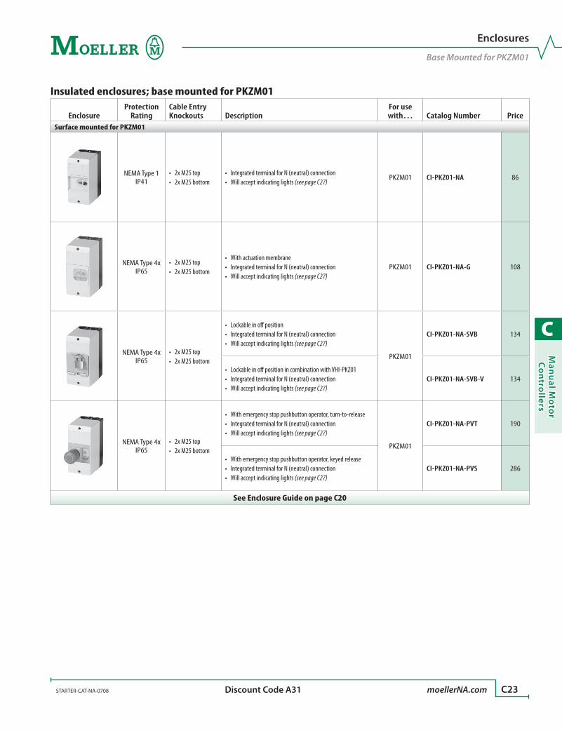
C
Man
ual M
oto
r C
on
trollers
STARTER-CAT-NA-0708 moellerNA.com C23 Discount Code A31
Insulated enclosures; base mounted for PKZM01
EnclosureProtection
RatingCable Entry Knockouts Description
For use with… Catalog Number Price
Surface mounted for PKZM01
NEMA Type 1IP41
2x M25 top•2x M25 bottom•
Integrated terminal for N (neutral) connection•Will accept indicating lights • (see page C27)
PKZM01 CI-PKZ01-NA 86
NEMA Type 4xIP65
2x M25 top•2x M25 bottom•
With actuation membrane•Integrated terminal for N (neutral) connection•Will accept indicating lights • (see page C27)
PKZM01 CI-PKZ01-NA-G 108
NEMA Type 4xIP65
2x M25 top•2x M25 bottom•
Lockable in off position•Integrated terminal for N (neutral) connection•Will accept indicating lights • (see page C27)
PKZM01
CI-PKZ01-NA-SVB 134
Lockable in off position in combination with VHI-PKZ01•Integrated terminal for N (neutral) connection•Will accept indicating lights • (see page C27)
CI-PKZ01-NA-SVB-V 134
NEMA Type 4xIP65
2x M25 top•2x M25 bottom•
With emergency stop pushbutton operator, turn-to-release•Integrated terminal for N (neutral) connection•Will accept indicating lights • (see page C27)
PKZM01
CI-PKZ01-NA-PVT 190
With emergency stop pushbutton operator, keyed release•Integrated terminal for N (neutral) connection•Will accept indicating lights • (see page C27)
CI-PKZ01-NA-PVS 286
See Enclosure Guide on page C20
Enclosures
Base Mounted for PKZM01
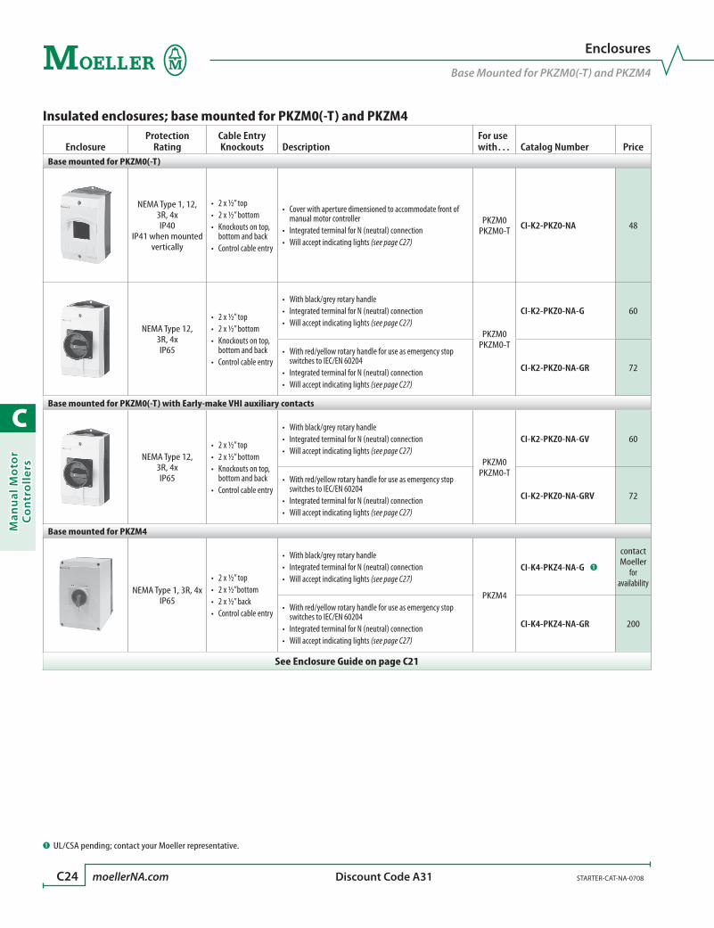
C
Man
ual
Mo
tor
Co
ntr
oll
ers
C24 moellerNA.com STARTER-CAT-NA-0708 Discount Code A31
Insulated enclosures; base mounted for PKZM0(-T) and PKZM4
EnclosureProtection
RatingCable Entry Knockouts Description
For use with… Catalog Number Price
Base mounted for PKZM0(-T)
NEMA Type 1, 12, 3R, 4xIP40
IP41 when mounted vertically
2 x ½” top•2 x ½” bottom•Knockouts on top, •bottom and backControl cable entry•
Cover with aperture dimensioned to accommodate front of •manual motor controllerIntegrated terminal for N (neutral) connection•Will accept indicating lights • (see page C27)
PKZM0PKZM0-T CI-K2-PKZ0-NA 48
NEMA Type 12, 3R, 4xIP65
2 x ½” top•2 x ½” bottom•Knockouts on top, •bottom and backControl cable entry•
With black/grey rotary handle•Integrated terminal for N (neutral) connection•Will accept indicating lights • (see page C27)
PKZM0PKZM0-T
CI-K2-PKZ0-NA-G 60
With red/yellow rotary handle for use as emergency stop •switches to IEC/EN 60204Integrated terminal for N (neutral) connection•Will accept indicating lights • (see page C27)
CI-K2-PKZ0-NA-GR 72
Base mounted for PKZM0(-T) with Early-make VHI auxiliary contacts
NEMA Type 12, 3R, 4xIP65
2 x ½” top•2 x ½” bottom•Knockouts on top, •bottom and backControl cable entry•
With black/grey rotary handle•Integrated terminal for N (neutral) connection•Will accept indicating lights • (see page C27)
PKZM0PKZM0-T
CI-K2-PKZ0-NA-GV 60
With red/yellow rotary handle for use as emergency stop •switches to IEC/EN 60204Integrated terminal for N (neutral) connection•Will accept indicating lights • (see page C27)
CI-K2-PKZ0-NA-GRV 72
Base mounted for PKZM4
NEMA Type 1, 3R, 4xIP65
2 x ½” top•2 x ½”bottom•2 x ½” back•Control cable entry•
With black/grey rotary handle•Integrated terminal for N (neutral) connection•Will accept indicating lights • (see page C27)
PKZM4
CI-K4-PKZ4-NA-G ➊
contact Moeller
for availability
With red/yellow rotary handle for use as emergency stop •switches to IEC/EN 60204Integrated terminal for N (neutral) connection•Will accept indicating lights • (see page C27)
CI-K4-PKZ4-NA-GR 200
See Enclosure Guide on page C21
Enclosures
Base Mounted for PKZM0(-T) and PKZM4
➊ UL/CSA pending; contact your Moeller representative.

C
Man
ual M
oto
r C
on
trollers
STARTER-CAT-NA-0708 moellerNA.com C25 Discount Code A31
Insulated enclosures; flush mounted for PKZMO1 and PKZM0(-T)
EnclosureProtection
Rating Description For use with… Catalog Number PriceFlush mounted for PKZM01
NEMA Type 1IP40
Integrated terminal for N (neutral) connection•Will accept indicating lights • (see page C27)
PKZM01 E-PKZ01 46
NEMA Type 4xFront IP65
With actuation membrane•Integrated terminal for N (neutral) connection•Will accept indicating lights • (see page C27)
PKZM01 E-PKZ01-G 68
NEMA Type 4xFront IP65
Lockable in off position•Integrated terminal for N (neutral) connection•Will accept indicating lights • (see page C27)
PKZM01
E-PKZ01-SVB 98
Lockable in off position in combination with VHI-PKZ01•Integrated terminal for N (neutral) connection•Will accept indicating lights • (see page C27)
E-PKZ01-SVB-V 98
NEMA Type 4xFront IP65
With emergency stop pushbutton operator, turn-to-release•Integrated terminal for N (neutral) connection•Will accept indicating lights • (see page C27)
PKZM01
E-PKZ01-PVT 152
With emergency stop pushbutton operator, keyed release•Integrated terminal for N (neutral) connection•Will accept indicating lights • (see page C27)
E-PKZ01-PVS 248
Flush mounted for PKZM0(-T)
CSA: NEMA Type 1Front IP65
Cover with aperture dimensioned to accommodate front of manual •motor controllerIntegrated terminal for N (neutral) connection•Will accept indicating lights • (see page C27)
PKZM0PKZM0-T E-PKZ0 50
CSA: NEMA Type 1Front IP55
With black/grey rotary handle•Integrated terminal for N (neutral) connection•Will accept indicating lights • (see page C27)
PKZM0PKZM0-T
E-PKZ0-G 70
With red/yellow rotary handle, for use as emergency-stop switch in •accordance with EN 60204Integrated terminal for N (neutral) connection•Will accept indicating lights • (see page C27)
E-PKZ0-GR 80
See Enclosure Guide on page C22
Enclosures
Flush mounted for PKZM01 and PKZM0
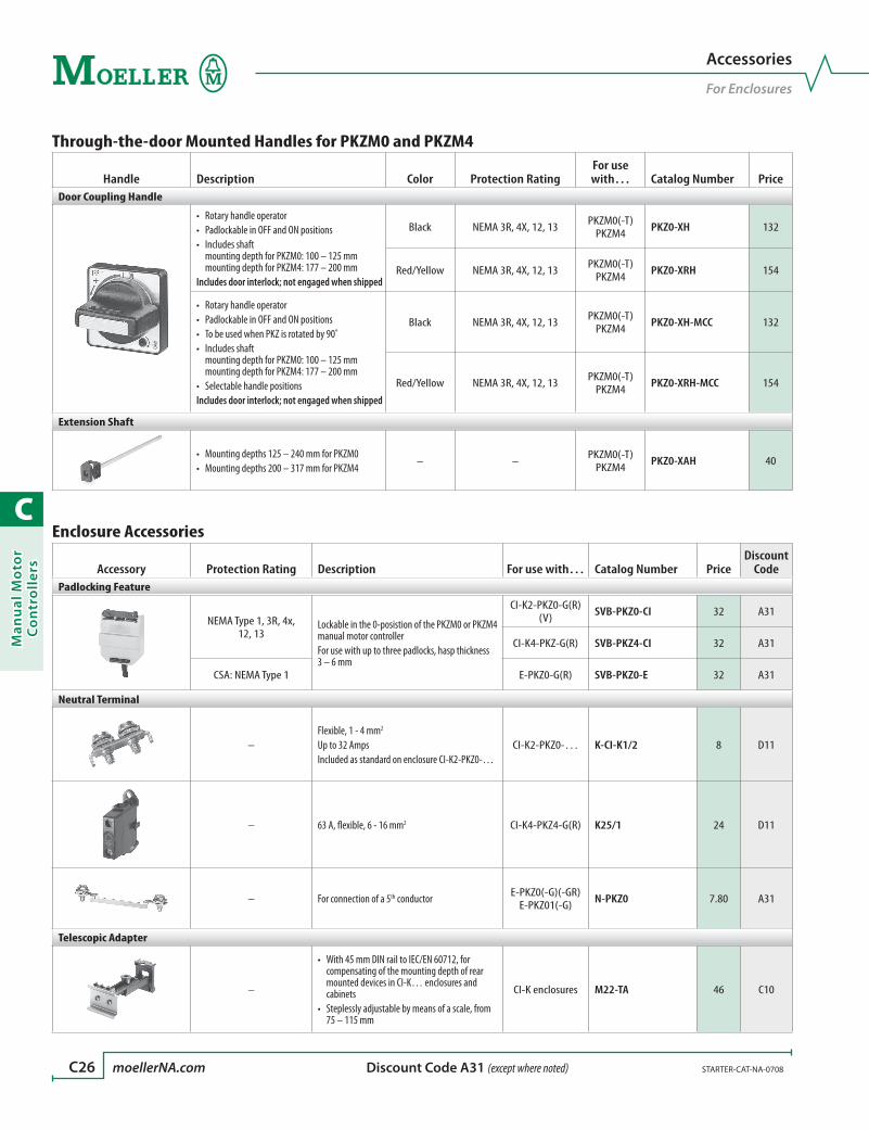
C
Man
ual
Mo
tor
Co
ntr
oll
ers
C26 moellerNA.com STARTER-CAT-NA-0708 Discount Code A31 (except where noted)
Through-the-door Mounted Handles for PKZM0 and PKZM4
Handle Description Color Protection RatingFor use with… Catalog Number Price
Door Coupling Handle
Rotary handle operator•Padlockable in OFF and ON positions•Includes shaft •mounting depth for PKZM0: 100 – 125 mm mounting depth for PKZM4: 177 – 200 mm
Includes door interlock; not engaged when shipped
Black NEMA 3R, 4X, 12, 13 PKZM0(-T)PKZM4 PKZ0-XH 132
Red/Yellow NEMA 3R, 4X, 12, 13 PKZM0(-T)PKZM4 PKZ0-XRH 154
Rotary handle operator•Padlockable in OFF and ON positions•To be used when PKZ is rotated by 90˚•Includes shaft •mounting depth for PKZM0: 100 – 125 mm mounting depth for PKZM4: 177 – 200 mmSelectable handle positions•
Includes door interlock; not engaged when shipped
Black NEMA 3R, 4X, 12, 13 PKZM0(-T)PKZM4 PKZ0-XH-MCC 132
Red/Yellow NEMA 3R, 4X, 12, 13 PKZM0(-T)PKZM4 PKZ0-XRH-MCC 154
Extension Shaft
Mounting depths 125 – 240 mm for PKZM0•Mounting depths 200 – 317 mm for PKZM4•
– – PKZM0(-T)PKZM4 PKZ0-XAH 40
Enclosure Accessories
Accessory Protection Rating Description For use with… Catalog Number PriceDiscount
CodePadlocking Feature
NEMA Type 1, 3R, 4x, 12, 13
Lockable in the 0-posistion of the PKZM0 or PKZM4 manual motor controllerFor use with up to three padlocks, hasp thickness 3 – 6 mm
CI-K2-PKZ0-G(R)(V) SVB-PKZ0-CI 32 A31
CI-K4-PKZ-G(R) SVB-PKZ4-CI 32 A31
CSA: NEMA Type 1 E-PKZ0-G(R) SVB-PKZ0-E 32 A31
Neutral Terminal
–Flexible, 1 - 4 mm2
Up to 32 AmpsIncluded as standard on enclosure CI-K2-PKZ0-…
CI-K2-PKZ0-… K-CI-K1/2 8 D11
– 63 A, flexible, 6 - 16 mm2 CI-K4-PKZ4-G(R) K25/1 24 D11
– For connection of a 5th conductor E-PKZ0(-G)(-GR)E-PKZ01(-G) N-PKZ0 7.80 A31
Telescopic Adapter
–
With 45 mm DIN rail to IEC/EN 60712, for •compensating of the mounting depth of rear mounted devices in CI-K… enclosures and cabinetsSteplessly adjustable by means of a scale, from •75 – 115 mm
CI-K enclosures M22-TA 46 C10
Accessories
For Enclosures
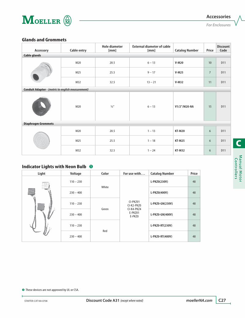
C
Man
ual M
oto
r C
on
trollers
STARTER-CAT-NA-0708 moellerNA.com C27 Discount Code A31 (except where noted)
Glands and Grommets
Accessory Cable entryHole diameter
[mm]External diameter of cable
[mm] Catalog Number PriceDiscount
CodeCable glands
M20 20.5 6 – 13 V-M20 10 D11
M25 25.5 9 – 17 V-M25 7 D11
M32 32.5 13 – 21 V-M32 11 D11
Conduit Adapter - (metric to english measurement)
M20 ½” 6 – 13 V1/2”/M20-NA 15 D11
Diaphragm Grommets
M20 20.5 1 – 13 KT-M20 6 D11
M25 25.5 1 – 18 KT-M25 6 D11
M32 32.5 1 – 24 KT-M32 6 D11
Indicator Lights with Neon Bulb ➊
Light Voltage Color For use with… Catalog Number Price
110 – 230
White
CI-PKZ01CI-K2-PKZ0CI-K4-PKZ4
E-PKZ01E-PKZ0
L-PKZ0(230V) 48
230 – 400 L-PKZ0(400V) 48
110 – 230
Green
L-PKZ0-GN(230V) 48
230 – 400 L-PKZ0-GN(400V) 48
110 – 230
Red
L-PKZ0-RT(230V) 48
230 – 400 L-PKZ0-RT(400V) 48
Accessories
For Enclosures
➊ These devices are not approved by UL or CSA.
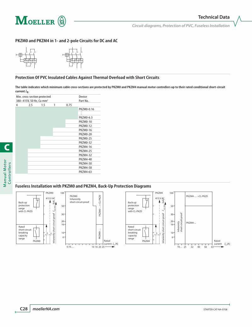
C
Man
ual
Mo
tor
Co
ntr
oll
ers
C28 moellerNA.com STARTER-CAT-NA-0708
Technical Data
Circuit diagrams, Protection of PVC, Fuseless Installation
PKZM0 and PKZM4 in 1- and 2-pole Circuits for DC and AC
Protection Of PVC Insulated Cables Against Thermal Overload with Short Circuits
The table indicates which minimum cable cross-sections are protected by PKZM0 and PKZM4 manual motor controllers up to their rated conditional short-circuit current Iq.
Min. cross-section protected Device380–415V, 50 Hz, Cu mm2 Part No.4 2.5 1.5 1 0.75
PKZM0-0.16
…
PKZM0-6.3PKZM0-10PKZM0-12PKZM0-16PKZM0-20PKZM0-25PKZM0-32PKZM4-16PKZM4-25PKZM4-32PKZM4-40PKZM4-50PKZM4-58PKZM4-63
Fuseless Installation with PKZM0 and PKZM4, Back-Up Protection Diagrams
1 3 5
2 4 6I > I > I >
1 3 5
2 4 6I > I > I >
PKZM0
PKZM0
415 V AC
Inhe
rent
ly s
hort
-circ
uit p
roof
I cc
rms [
kA]
I ccI cn
Back-upprotectionrangewith CL-PKZ0
Ratedshort-circuitbreakingcapacityrange
100
50
30
2016
10
6
0.16… 10 16 20 25
PKZM
0-…
+ CL
-PKZ
0PK
ZM0-
…
PKZM0
Ratedcurrent In [A]
Inherentlyshort-circuit-proof
PKZM4
PKZM4
415 V AC
Inhe
rent
ly s
hort
-circ
uit p
roof
I
cc rm
s [kA
]
I cn I cc
Back-upprotectionrangewith CL-PKZ0
Ratedshort-circuitbreakingcapacityrange
100
50
30
2016
10
6
16… 3225 40 50 63 In [A]
PKZM4-… +CL-PKZ0
PKZM4-...
Ratedcurrent
Inhe
rent
lysh
ort-
circ
uit-
proo
f
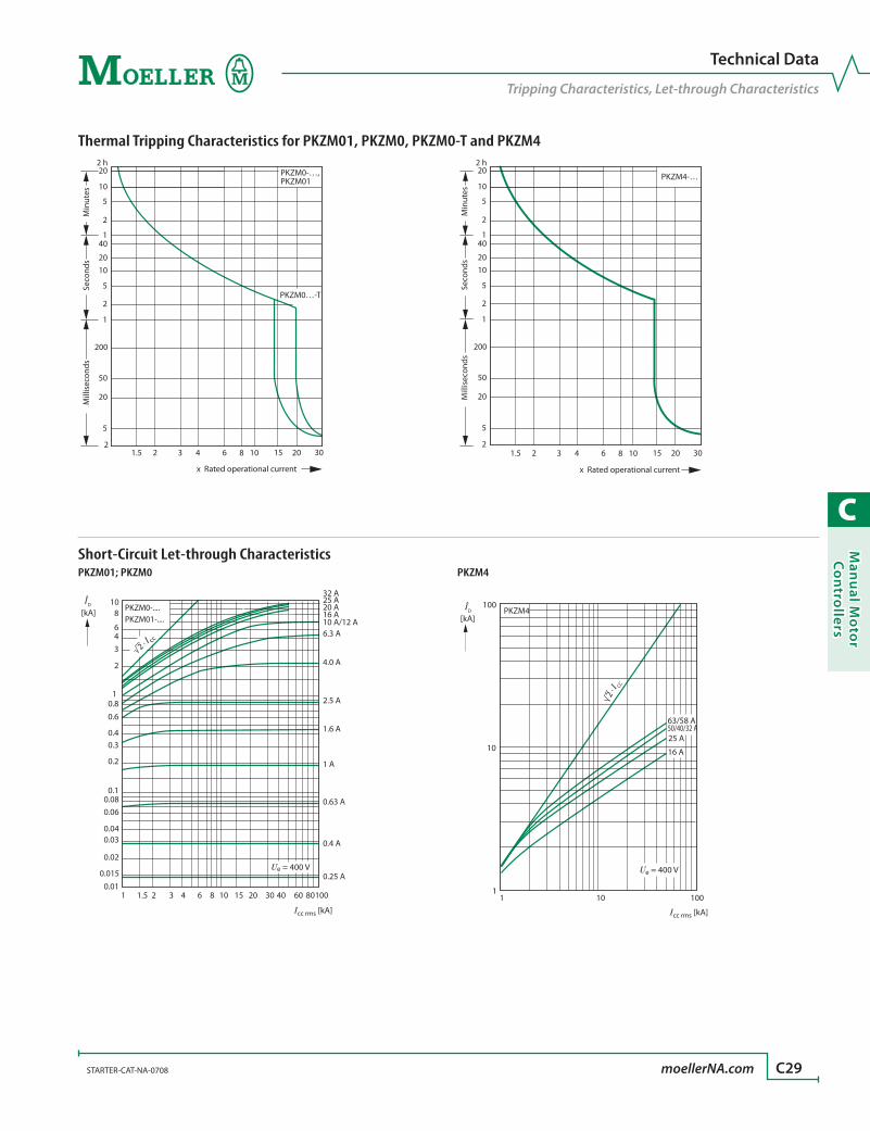
C
Man
ual M
oto
r C
on
trollers
STARTER-CAT-NA-0708 moellerNA.com C29
Ue = 400 V
10
10 100
63/58 A50/40/32 A25 A
16 A
PKZM4
11
100
[kA] 2
· I CC
ÎD
Icc rms [kA]
Technical Data
Tripping Characteristics, Let-through Characteristics
Thermal Tripping Characteristics for PKZM01, PKZM0, PKZM0-T and PKZM4
Short-Circuit Let-through Characteristics
PKZM0…-T
PKZM0-…, PKZM01
2
5
20
50
200
1
2
5
1020
401
2
5
10
202 h
1.5 2 3 4 6 8 10 15 20 30
x Rated operational current
Seco
nds
Mill
isec
onds
Min
utes
2
5
20
50
200
1
2
5
1020
401
2
5
10
202 h
1.5 2 3 4 6 8 10 15 20 30
PKZM4-…
x Rated operational currentSe
cond
sM
illis
econ
dsM
inut
es
[kA]
1
2
3
64
810
4.0 A
6.3 A
2.5 A
1.6 A
0.25 A
10 A/12 A
0.1
0.2
0.30.4
0.60.8
0.01
0.02
0.015
0.030.04
0.060.08
1 21.5 3 4 6 8 10 2015 30 40 60 80100
Ue = 400 V
16 A20 A25 A32 A
1 A
0.4 A
0.63 A
PKZM0-....PKZM01-....
2 · I cc
Icc rms [kA]
ÎD
PKZM4PKZM01; PKZM0
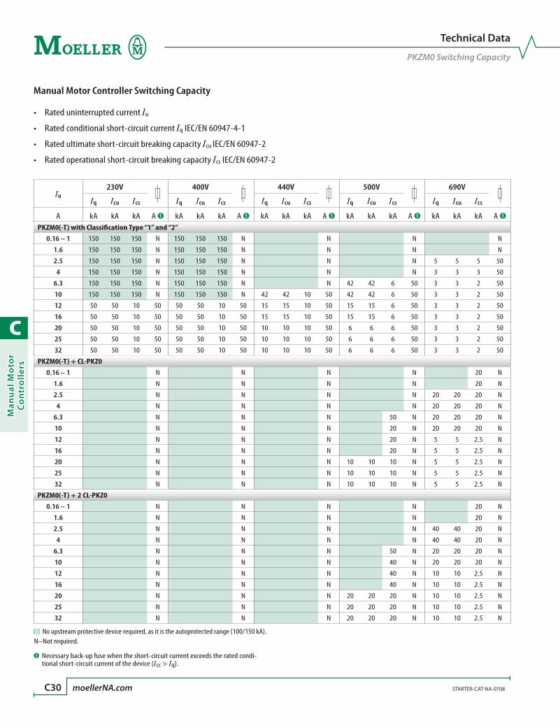
C
Man
ual
Mo
tor
Co
ntr
oll
ers
C30 moellerNA.com STARTER-CAT-NA-0708
Technical Data
PKZM0 Switching Capacity
Manual Motor Controller Switching Capacity
• RateduninterruptedcurrentIu
• Ratedconditionalshort-circuitcurrentIq IEC/EN 60947-4-1
• Ratedultimateshort-circuitbreakingcapacityIcu IEC/EN 60947-2
• Ratedoperationalshort-circuitbreakingcapacityIcs IEC/EN 60947-2
Iu230V 400V 440V 500V 690V
Iq Icu Ics Iq Icu Ics Iq Icu Ics Iq Icu Ics Iq Icu Ics
A kA kA kA A ➊ kA kA kA A ➊ kA kA kA A ➊ kA kA kA A ➊ kA kA kA A ➊PKZM0(-T) with Classification Type “1” and “2”
0.16 – 1 150 150 150 N 150 150 150 N N N N
1.6 150 150 150 N 150 150 150 N N N N
2.5 150 150 150 N 150 150 150 N N N 5 5 5 50
4 150 150 150 N 150 150 150 N N N 3 3 3 50
6.3 150 150 150 N 150 150 150 N N 42 42 6 50 3 3 2 50
10 150 150 150 N 150 150 150 N 42 42 10 50 42 42 6 50 3 3 2 50
12 50 50 10 50 50 50 10 50 15 15 10 50 15 15 6 50 3 3 2 50
16 50 50 10 50 50 50 10 50 15 15 10 50 15 15 6 50 3 3 2 50
20 50 50 10 50 50 50 10 50 10 10 10 50 6 6 6 50 3 3 2 50
25 50 50 10 50 50 50 10 50 10 10 10 50 6 6 6 50 3 3 2 50
32 50 50 10 50 50 50 10 50 10 10 10 50 6 6 6 50 3 3 2 50
PKZM0(-T) + CL-PKZ00.16 – 1 N N N N 20 N
1.6 N N N N 20 N
2.5 N N N N 20 20 20 N
4 N N N N 20 20 20 N
6.3 N N N 50 N 20 20 20 N
10 N N N 20 N 20 20 20 N
12 N N N 20 N 5 5 2.5 N
16 N N N 20 N 5 5 2.5 N
20 N N N 10 10 10 N 5 5 2.5 N
25 N N N 10 10 10 N 5 5 2.5 N
32 N N N 10 10 10 N 5 5 2.5 N
PKZM0(-T) + 2 CL-PKZ00.16 – 1 N N N N 20 N
1.6 N N N N 20 N
2.5 N N N N 40 40 20 N
4 N N N N 40 40 20 N
6.3 N N N 50 N 20 20 20 N
10 N N N 40 N 20 20 20 N
12 N N N 40 N 10 10 2.5 N
16 N N N 40 N 10 10 2.5 N
20 N N N 20 20 20 N 10 10 2.5 N
25 N N N 20 20 20 N 10 10 2.5 N
32 N N N 20 20 20 N 10 10 2.5 N
➊ Necessary back-up fuse when the short-circuit current exceeds the rated condi-tional short-circuit current of the device (Icc > Iq).
No upstream protective device required, as it is the autoprotected range (100/150 kA).N–Not required.
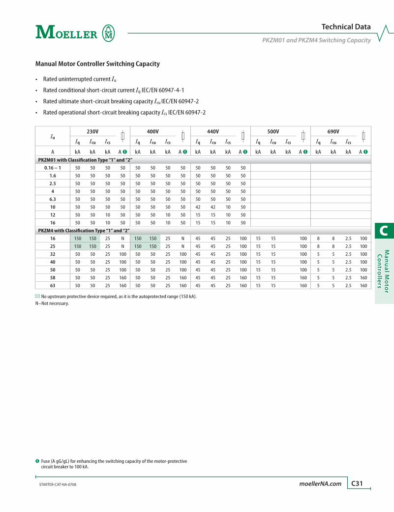
C
Man
ual M
oto
r C
on
trollers
STARTER-CAT-NA-0708 moellerNA.com C31
Technical Data
PKZM01 and PKZM4 Switching Capacity
Manual Motor Controller Switching Capacity
• RateduninterruptedcurrentIu
• Ratedconditionalshort-circuitcurrentIq IEC/EN 60947-4-1
• Ratedultimateshort-circuitbreakingcapacityIcu IEC/EN 60947-2
• Ratedoperationalshort-circuitbreakingcapacityIcs IEC/EN 60947-2
Iu230V 400V 440V 500V 690V
Iq Icu Ics Iq Icu Ics Iq Icu Ics Iq Icu Ics Iq Icu Ics
A kA kA kA A ➊ kA kA kA A ➊ kA kA kA A ➊ kA kA kA A ➊ kA kA kA A ➊PKZM01 with Classification Type “1” and “2”
0.16 – 1 50 50 50 50 50 50 50 50 50 50 50 50
1.6 50 50 50 50 50 50 50 50 50 50 50 50
2.5 50 50 50 50 50 50 50 50 50 50 50 50
4 50 50 50 50 50 50 50 50 50 50 50 50
6.3 50 50 50 50 50 50 50 50 50 50 50 50
10 50 50 50 50 50 50 50 50 42 42 10 50
12 50 50 10 50 50 50 10 50 15 15 10 50
16 50 50 10 50 50 50 10 50 15 15 10 50
PKZM4 with Classification Type “1” and “2”16 150 150 25 N 150 150 25 N 45 45 25 100 15 15 100 8 8 2.5 100
25 150 150 25 N 150 150 25 N 45 45 25 100 15 15 100 8 8 2.5 100
32 50 50 25 100 50 50 25 100 45 45 25 100 15 15 100 5 5 2.5 100
40 50 50 25 100 50 50 25 100 45 45 25 100 15 15 100 5 5 2.5 100
50 50 50 25 100 50 50 25 100 45 45 25 100 15 15 100 5 5 2.5 100
58 50 50 25 160 50 50 25 160 45 45 25 160 15 15 160 5 5 2.5 160
63 50 50 25 160 50 50 25 160 45 45 25 160 15 15 160 5 5 2.5 160
➊ Fuse (A gG/gL) for enhancing the switching capacity of the motor-protective circuit breaker to 100 kA.
No upstream protective device required, as it is the autoprotected range (150 kA).N–Not necessary.
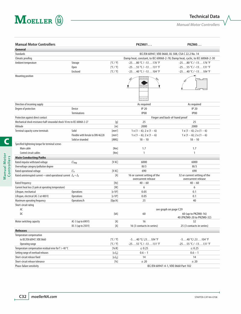
C
Man
ual
Mo
tor
Co
ntr
oll
ers
C32 moellerNA.com STARTER-CAT-NA-0708
Manual Motor Controllers PKZM01… PKZM0…GeneralStandards IEC/EN 60947, VDE 0660, UL 508, CSA C 22.2 No. 14Climatic proofing Damp heat, constant, to IEC 60068-2-78; Damp heat, cyclic, to IEC 60068-2-30Ambient temperature Storage [°C / °F] -25…80 °C / -13…176 °F -25…80 °C / -13…176 °F Open [°C / °F] -25…55 °C / -13…131 °F -25…55 °C / -13…131 °F Enclosed [°C / °F] -25…40 °C / -13…104 °F -25…40 °C / -13…104 °FMounting position
90º 90º90º
Direction of incoming supply As required As required Degree of protection Device IP 20 IP 20 Terminations IP00 IP00 Protection against direct contact Finger and back-of-hand proof Mechanical shock resistance half-sinusoidal shock 10 ms to IEC 60068-2-27 [g] 25 25Altitude [m] 2000 2000Terminal capacity screw terminals Solid [mm2] 1 x (1 – 6); 2 x (1 – 6) 1 x (1 – 6); 2 x (1 – 6) Flexible with ferrule to DIN 46228 [mm2] 1 x (1 – 6); 2 x (1 – 6) 1 x (1 – 6); 2 x (1 – 6) Solid or stranded [AWG] 18 – 10 18 – 10 Specified tightening torque for terminal screws Main cable [Nm] 1.7 1.7 Control circuit cables [Nm] 1 1
Main Conducting PathsRated impulse withstand voltage Uimp [V AC] 6000 6000Overvoltage category/pollution degree III/3 III/3 Rated operational voltage Ue [V AC] 690 690Rated uninterrupted current = rated operational current Iu = Ie [A] 16 or current setting of the
overcurrent release32 or current setting of the
overcurrent releaseRated frequency [Hz] 40 – 60 40 – 60 Current heat loss (3 pole at operating temperature) [W] 6 6Lifespan, mechanical Operations [x 106] 0.05 0.1Lifespan, electrical (AC-3 at 400 V) Operations [x 106] 0.05 0.1Maximum operating frequency Operations/h [Ops/h] 25 40Short-circuit rating AC see graph on page C29 DC [kA] 60 60 (up to PKZM0-16)
40 (PKZM0-20 to PKZM0-32)Motor switching capacity AC-3 (up to 690 V) [A] 16 32 DC-5 (up to 250 V) [A] 16 (3 contacts in series) 25 (3 contacts in series)
ReleasesTemperature compensation to IEC/EN 60947, VDE 0660 [°C / °F] -5…40 °C/ 23…104 °F -5…40 °C/ 23…104 °F Operating range [°C / °F] -25…55 °C / -13…131 °F -25…55 °C / -13…131 °FTemperature compensation residual error for T > 40 °C [%/K] ≤ 0.25 ≤ 0.25 Setting range of overload releases [x Iu] 0.6 – 1 0.6 – 1 Short-circuit release fixed [x Iu] 14 14Short-circuit release tolerance [%] ± 20 ± 20 Phase-failure sensitivity IEC/EN 60947-4-1, VDE 0660 Part 102
Technical Data
Manual Motor Controllers
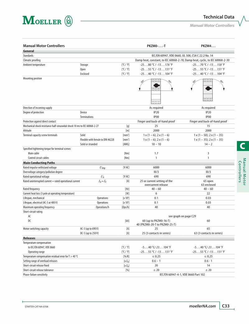
C
Man
ual M
oto
r C
on
trollers
STARTER-CAT-NA-0708 moellerNA.com C33
Manual Motor Controllers PKZM0-…-T PKZM4…GeneralStandards IEC/EN 60947, VDE 0660, UL 508, CSA C 22.2 No. 14Climatic proofing Damp heat, constant, to IEC 60068-2-78; Damp heat, cyclic, to IEC 60068-2-30Ambient temperature Storage [°C / °F] -25…80 °C / -13…176 °F -25…70 °C / -13…158 °F Open [°C / °F] -25…55 °C / -13…131 °F -25…55 °C / -13…131 °F Enclosed [°C / °F] -25…40 °C / -13…104 °F -25…40 °C / -13…104 °FMounting position
90º 90º 90º 90º
Direction of incoming supply As required As requiredDegree of protection Device IP20 IP20 Terminations IP00 IP00 Protection against direct contact Finger and back-of-hand proof Finger and back-of-hand proofMechanical shock resistance half-sinusoidal shock 10 ms to IEC 60068-2-27 [g] 25 15Altitude [m] 2000 2000Terminal capacity screw terminals Solid [mm2] 1 x (1 – 6); 2 x (1 – 6) 1 x (1 – 50); 2 x (1 – 35) Flexible with ferrule to DIN 46228 [mm2] 1 x (1 – 6); 2 x (1 – 6) 1 x (1 – 35); 2 x (1 – 35) Solid or stranded [AWG] 18 – 10 14 – 2Specified tightening torque for terminal screws Main cable [Nm] 1.7 3 Control circuit cables [Nm] 1 1
Main Conducting PathsRated impulse withstand voltage Uimp [V AC] 6000 6000Overvoltage category/pollution degree III/3 III/3 Rated operational voltage Ue [V AC] 690 690Rated uninterrupted current = rated operational current Iu = Ie [A] 25 or current setting of the
overcurrent release65 open
63 enclosedRated frequency [Hz] 40 – 60 40 – 60 Current heat loss (3 pole at operating temperature) [W] 6 22Lifespan, mechanical Operations [x 106] 0.1 0.03Lifespan, electrical (AC-3 at 400 V) Operations [x 106] 0.1 0.03Maximum operating frequency Operations/h [Ops/h] 40 40Short-circuit rating AC see graph on page C29 DC [kA] 60 (up to PKZM0-16-T)
40 (PKZM0-20-T to PKZM0-25-T)60
Motor switching capacity AC-3 (up to 690 V) [A] 25 65 DC-5 (up to 250 V) [A] 25 (3 contacts in series) 63 (3 contacts in series)
ReleasesTemperature compensation to IEC/EN 60947, VDE 0660 [°C / °F] -5…40 °C/ 23…104 °F -5…40 °C/ 23…104 °F Operating range [°C / °F] -25…55 °C / -13…131 °F -25…55 °C / -13…131 °FTemperature compensation residual error for T > 40 °C [%/K] ≤ 0.25 ≤ 0.25 Setting range of overload releases [x Iu] 0.6 – 1 0.6 - 1 Short-circuit release fixed [x Iu] 20 14Short-circuit release tolerance [%] ± 20 ± 20 Phase-failure sensitivity IEC/EN 60947-4-1, VDE 0660 Part 102
Technical Data
Manual Motor Controllers

C
Man
ual
Mo
tor
Co
ntr
oll
ers
C34 moellerNA.com STARTER-CAT-NA-0708
Auxiliary Contacts NHI…PKZ0 NHI-E-…PKZ0 VHI…PKZ0 AGM Trip Indication
GeneralRated impulse withstand voltage Uimp [V AC] 6000 4000 4000 6000Overvoltage category/pollution degree III/3 III/3 III/3 III/3Rated operational voltage Ue [V AC] 500 440 440 500 Ue [V DC] 250 250 250 250Safe isolation to VDE 0106 Part 101 and Part 101/A1 Between auxiliary contacts and main contacts [V AC] 690 690 690 690Rated operational current AC-15 220–240V Ie [A] 3.5 1 1 3.5 380–415V Ie [A] 2 – – 2 440–500V Ie [A] 1 – – 1 DC-13 L/R–100 ms 24V Ie [A] 2 2 2 2 60V Ie [A] 1.5 – – 1.5 110V Ie [A] 1 – – 1 220V Ie [A] 0.25 – – 0.25Lifespan Mechanical Operations [x 106] 0.1 0.1 0.1 0.01 Electrical Operations [x 106] 0.05 0.1 0.1 0.005Control circuit reliability (at Ue = 24V DC, Umin = 17 V, Imin=5.4 mA) Failure Rate [l] < 10-8 (less than 1 failure in 108 operations)Interlocked opposing contacts to ZH 1/457 Yes – – –Short-circuit rating without welding Fuseless FAZ-B4/1-HI – – FAZ-B4/1-HI Fuse [A gG/gL] 10 10 10 10Terminal Capacities Solid or flexible conductor with ferrule [mm2] 0.75 – 2.5 0.75 – 1.5 0.75 – 1.5 0.75 – 2.5 Solid or stranded [AWG] 18 – 14 18 – 16 18 – 16 18 – 14
UL / CSA RatingsPilot Duty A600, Q300 E150 E150 A600, Q300General Use 5A @ 600V AC;
1A @ 250V DC0.5A @ 250V AC 0.5A @ 250V AC 5A @ 600V AC;
1A @ 250V DC
Undervoltage Trips, Shunt Trips U-PKZ0… A-PKZ0…GeneralTerminal capacities Solid or flexible conductor with ferrule [mm2] 2 x (0.75 – 2.5) 2 x (0.75 – 2.5) Solid or stranded [AWG] 2 x (18 – 14) 2 x (18 – 14)
Main Conducting PathsRated operating voltage Ue [V AC] 42 – 480 42 – 480 Ue [V DC] 24 – 250 24 – 250Pick-up voltage [x Us] 0.85 – 1.1 –Drop-out voltage [x Us] 0.7 – 0.35 –Operating range AC [x Us] – 0.7 – 1.1 DC [x Us] – 0.7 – 1.1Power consumption AC Pick-up AC Pick-up [VA] 5 5 Sealing AC Sealing [VA] 3 3 DC Pick-up DC Pick-up [W] – 3 Pick-up DC Sealing [W] – 3
Technical Data
Auxiliary Contacts, Undervoltage Trips, Shunt Trips

C
Man
ual M
oto
r C
on
trollers
STARTER-CAT-NA-0708 moellerNA.com C35
Dimensions are in millimeters.Not intended for manufacturing purposes.
Dimensions
PKZM01 and PKZM0(-T)
Manual Motor ControllerPKZM01…
5.545
45 93
4474
85
Manual Motor Controller Manual Motor ControllerPKZM0…(-T) with Standard Auxiliary Contact NHI-E-…-PKZ0 PKZM0…(-T) with Early-make Auxiliary Contact VHI-…-PKZ0
NHI-E-..-PKZ0 NHI-E-..-PKZ0
70
55
45
25
93
50
7668
45
4.5
VHI...-PKZ0
80
55
45
93
50
86
68
45
VHI...-PKZ0
Manual Motor Controller Current LimiterPKZM0…(-T) with Lockable Rotary Handle AK-PKZ0 CL-PKZ0
45
AK-PKZ 0
AK-PKZ 0
93
508894
45
707.5
49.5447.5
4528
90 73 93
DIN rail
PKZM0
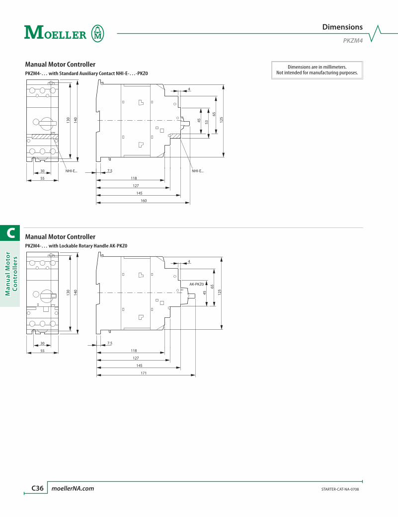
C
Man
ual
Mo
tor
Co
ntr
oll
ers
C36 moellerNA.com STARTER-CAT-NA-0708
Dimensions are in millimeters.Not intended for manufacturing purposes.
Dimensions
PKZM4
Manual Motor ControllerPKZM4-… with Standard Auxiliary Contact NHI-E-…-PKZ0
30 NHI-E... 7.5
118
127
145
160
55
130
140
125
65
5345
4
NHI-E...
Manual Motor ControllerPKZM4-… with Lockable Rotary Handle AK-PKZ0
30 7.5
118
127
145
171
55
130
140
125
65
45
4
AK-PKZ0

C
Man
ual M
oto
r C
on
trollers
STARTER-CAT-NA-0708 moellerNA.com C37
Dimensions are in millimeters.Not intended for manufacturing purposes.
Dimensions
Auxiliary Contacts, Shunt & Undervoltage Releases
Standard Auxiliary ContactsNHI…-PKZ…
9 26
68
45 9036
Trip-indicating Auxiliary Contacts Shunt Releases / Undervoltage ReleasesAGM2…-PKZ… A-PKZ0…; U-PKZ0…
9 26
68
45 9036
18 49
68
36 45 90

C
Man
ual
Mo
tor
Co
ntr
oll
ers
C38 moellerNA.com STARTER-CAT-NA-0708
Dimensions are in millimeters.Not intended for manufacturing purposes.
Dimensions
Enclosures PKZM01
Base Mounted Insulated EnclosureCI-PKZ01-NA(-G)
80
158
116.5
Base Mounted Insulated Enclosure Base Mounted Insulated EnclosureCI-PKZ01-NA-SVB(-V) CI-PKZ01-PV(T)(S)
80
158
116.5
129.5
80
158
116.5
177.2
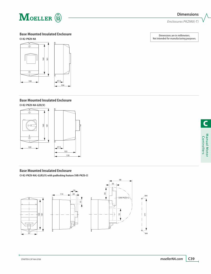
C
Man
ual M
oto
r C
on
trollers
STARTER-CAT-NA-0708 moellerNA.com C39
Dimensions are in millimeters.Not intended for manufacturing purposes.
Dimensions
Enclosures PKZM0(-T)
Base Mounted Insulated EnclosureCI-K2-PKZ0-NA
100
160
47.5
104
181
Base Mounted Insulated EnclosureCI-K2-PKZ0-NA-G(R)(V)
100
160
47.5
103
130
181
Base Mounted Insulated EnclosureCI-K2-PKZ0-NA(-G)(R)(V) with padlocking feature SVB-PKZ0-CI
97
181
28
33
114
171
M4
M4
30
160
98
30
44
55
SVB-PKZ0-CI
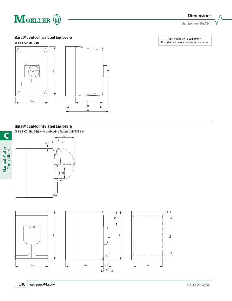
C
Man
ual
Mo
tor
Co
ntr
oll
ers
C40 moellerNA.com STARTER-CAT-NA-0708
Dimensions are in millimeters.Not intended for manufacturing purposes.
Dimensions
Enclosures PKZM4
Base Mounted Insulated EnclosureCI-K4-PKZ4-NA-G(R)
160
240
134
181
197
Base Mounted Insulated EnclosureCI-K4-PKZ4-NA-G(R) with padlocking feature SVB-PKZ4-CI
160 186 28
30
240
240
193
142
ø 5.6
72
32
98
SVB-PKZ4-CI
72
3
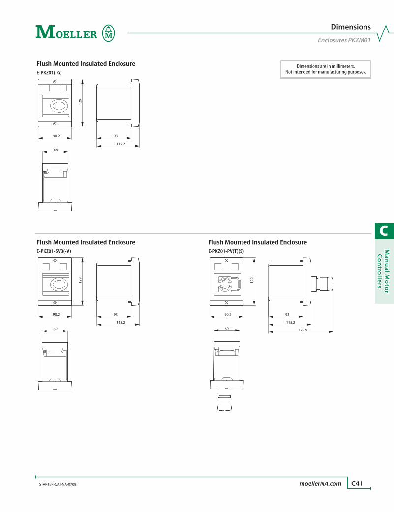
C
Man
ual M
oto
r C
on
trollers
STARTER-CAT-NA-0708 moellerNA.com C41
Dimensions are in millimeters.Not intended for manufacturing purposes.
Dimensions
Enclosures PKZM01
Flush Mounted Insulated EnclosureE-PKZ01(-G)
69
90.2 93
115.2
129
Flush Mounted Insulated Enclosure Flush Mounted Insulated EnclosureE-PKZ01-SVB(-V) E-PKZ01-PV(T)(S)
69
90.2 93
115.2
129
69
90.2 93
115.2
175.9
129
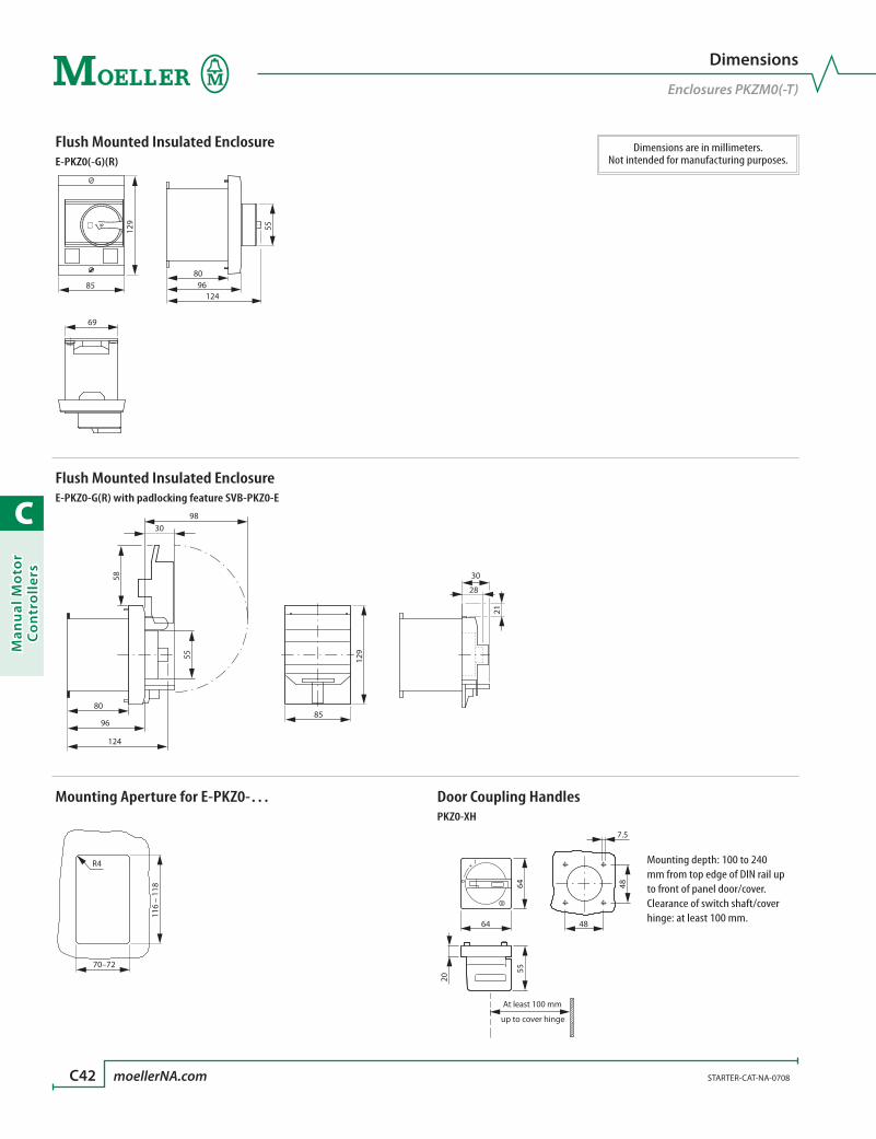
C
Man
ual
Mo
tor
Co
ntr
oll
ers
C42 moellerNA.com STARTER-CAT-NA-0708
Dimensions are in millimeters.Not intended for manufacturing purposes.
Dimensions
Enclosures PKZM0(-T)
Flush Mounted Insulated EnclosureE-PKZ0(-G)(R)
69
85
129
9680
124
55
Flush Mounted Insulated EnclosureE-PKZ0-G(R) with padlocking feature SVB-PKZ0-E
9830
58
55
80
96
124
85
129
30
28
21
Mounting Aperture for E-PKZ0-… Door Coupling HandlesPKZ0-XH
R4
70–72
116
– 11
8
55
20
+ l
o
64
64
48
48
7.5
At least 100 mm
up to cover hinge
Mounting depth: 100 to 240 mm from top edge of DIN rail up to front of panel door/cover.Clearance of switch shaft/cover hinge: at least 100 mm.
C
Man
ual M
oto
r C
on
trollers
STARTER-CAT-NA-0708 moellerNA.com C43
Manual Motor Controllers
Notes

C
Man
ual
Mo
tor
Co
ntr
oll
ers
C44
R
Never confuse imitation with innovation! Moeller designed the first PKZ “motor protective controller” in 1932! Since then,
the term “PKZ” has become synonymous worldwide with these types of devices,
regardless of manufacturer. Eight decades of continuous innovation has resulted
in today’s best technology, built from the ground up, only by Moeller.
The Swiss Army Knife® of motor controlThe base PKZ2 controller combines single-break power contacts with Class 10
thermal overload protection and current limiting short circuit protection to
manually control motor loads. The PKZ2 can also be equipped with a high capac-
ity contactor for remote control of individual or group motor loads. Collectively,
the PKZ2 family is UL and CSA listed for a wide range of uses including:
• Manual Starter applications
• Group Fusing applications
• Motor Disconnect means
• Type E, Self-protected, Combination Starter applications
• Multi-motor Starter Combination applications
• Tap Conductor protection
Information on PKZ2 starter applications can be found in Tab D of this catalog.
Excellent control & protection with one frame size!PKZ2 devices have a 42 amp continu-
ous current rating. They control and
protect motors to 30HP at 480V or
25HP @ 600V with one frame size.
Their excellent current-limiting de-
sign clears fault currents of 100 KAIC
at 240VAC; 65KAIC at 480VAC; and
42KAIC at 600VAC (all values RMS
Symmetrical). The total clearing time
of the device at the highest fault condition is a maximum of 3.5ms at 480V and
4.0ms at 600VAC.
PKZ2 manual motor controllersthe industry standard
> Starts and protects motors to 25HP @ 460V (30HP @ 575V) with one frame size
> Eleven different interchangeable trip modules reduce inventory
> Incorporates both adjustable over-current and short-circuit protection for motors
> Remote over-current or short-circuit trip differentiation
> Extensive range of accessories
> Worldwide approvals
100KAIC
65KAIC
42KAIC
240V AC 480V AC 600V AC
® Swiss Army Knife is a registered trademark of Wenger, SA.
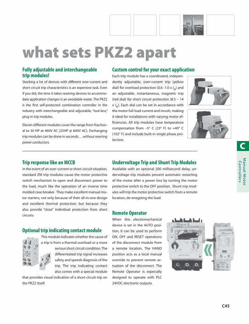
C
Man
ual M
oto
r C
on
trollers
C45
Fully adjustable and interchangeable trip modules! Stocking a lot of devices with different over-current and
short circuit trip characteristics is an expensive task. Even
if you did, the time it takes rewiring devices to accommo-
date application changes is an avoidable waste. The PKZ2
is the first self-protected combination controller in the
industry with interchangeable and adjustable, “tool-less,”
plug-in trip modules.
Eleven different modules cover the range from fraction-
al to 30 HP at 460V AC (25HP @ 600V AC). Exchanging
trip modules can be done in seconds… without rewiring
power conductors.
Custom control for your exact applicationEach trip module has a coordinated, indepen-
dently adjustable, over-current trip (yellow
dial) for overload protection (0.6 -1.0 x Iu) and
an adjustable, instantaneous, magnetic trip
(red dial) for short circuit protection (8.5 – 14
x Iu). Each dial can be set in accordance with
the motor full load current and inrush, making
it ideal for installations with varying motor ef-
ficiencies. All trip modules have temperature
compensation from –5° C (23° F) to +40° C
(102° F) and include built-in single phase pro-
tection.
what sets PKZ2 apart
Trip response like an MCCBIn the event of an over-current or short-circuit situation,
standard ZM trip modules cause the motor protective
switch mechanism to open and disconnect power to
the load, much like the operation of an inverse time
molded case breaker. They make excellent manual mo-
tor starters, not only because of their all-in-one design
and excellent thermal protection, but because they
also provide “close” individual protection from short
circuits.
Optional trip indicating contact moduleThis module indicates whether the cause of
a trip is from a thermal overload or a more
serious short circuit condition. The
differentiated trip signal increases
safety and speeds diagnosis of the
trip. The trip indicating contact
also comes with a special module
that provides visual indication of a short-circuit trip on
the PKZ2 itself.
Undervoltage Trip and Shunt Trip ModulesAvailable with an optional 200 millisecond delay, un-
dervoltage trip modules prevent automatic restarting
of the motor after a power loss by turning the motor
protective switch to the OFF position. Shunt trip mod-
ules will trip the motor protective switch from a remote
location, de-enegizing the load.
Remote OperatorWhen this electromechanical
device is set in the AUTO posi-
tion, it can be used to perform
ON, OFF and RESET operations
of the disconnect module from
a remote location. The HAND
position acts as a local manual
override to prevent remote ac-
tuation of the disconnect. The
Remote Operator is especially
designed to operate with PLC
24VDC electronic outputs.
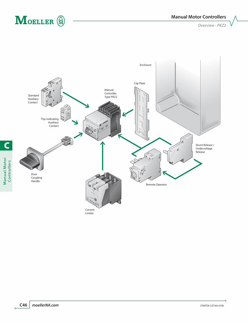
C
Man
ual
Mo
tor
Co
ntr
oll
ers
C46 moellerNA.com STARTER-CAT-NA-0708
Manual Motor Controllers
Overview - PKZ2
ManualControllerType PKZ2
Shunt Release /UndervoltageRelease
Remote Operator
CurrentLimiter
Clip Plate
Enclosure
StandardAuxiliaryContact
Trip-indicatingAuxiliaryContact
DoorCouplingHandle

C
Man
ual M
oto
r C
on
trollers
STARTER-CAT-NA-0708 moellerNA.com C47
Manual Motor Controllers
Overview - PKZ2
PKZ2 Manual Motor Controllers OverviewDevice Description Range Pages
Manual Motor Controllers
With Interchangeable
Trip Module0.4 – 42 Amps C48 – C49
Main Switch Component – C50
Trip Module Components 0.4 – 42 Amps C50
Auxiliary Contacts
Side-mounted Standard Auxiliary
Contacts
1 NO / 1 NC2 NO / 2 NC C53
Trip-indicating Auxiliary Contacts 1 NO / 1 NC C53
Current Limiter
Current Limiterto 100 kA / 500 V
Ue = 690 VIu = 40 A C51
Device Description Range PagesReleases
Shunt Release 24 – 250 V DC24 – 600 V AC C54
Undervoltage Release
24 V DC48 V DC
24 – 440 V ACC54
Remote Operators
Remote Operator 24 – 240 V DC24 – 415 V DC C55
Accessories
Miscellaneous Accessories C56
Enclosures
Enclosures C57

C
Man
ual
Mo
tor
Co
ntr
oll
ers
C48 moellerNA.com STARTER-CAT-NA-0708 Discount Code A31
> Interchangeable trip module makes changing tripping characteristics a snap, even after wiring
> Adjustable thermal and magnetic trip settings
> Overcurrent, short-circuit protection and motor switching functions are combined in one compact unit; all functions are ambient compensated and phase failure sensitive
> Worldwide approvals, including UL 508/CSA 22.2 No. 14
> One frame size simplifies engineering and reduces stocking cost
See Next Page for UL/CSA Application
Ratings Guide
➊ All types have adjustable dial for setting motor full load current. Trip current is 125% of set value. For motors with a service factor (SF) of 1.0, set dial to 90% of motor full load current.
Ordering Instructions
1 Determine the motor FLA and Service Factor.
2 Use the application rating guide on next page.
3 Locate the desired manual motor controller.
4 See pages C51 – C56 for auxiliaries and accessories.
Manual motor controller with adjustable magnetic and thermal standard trip module
UL/CSA Short-circuit current rating kA RMS
sym @
Adjustable thermal
range set to motor FLC ➊
Adjustable trip setting current of magnetic trips ➊
“Typical” Maximum Horsepower
Auxiliary Contacts Catalog
Number Price
Typical Single Phase [HP]
Typical Three Phase [HP]
480 V AC 600 V AC [A] [A] 115V 200V 240V 200V 240V 480V 600V NO NC65 42 0.4 – 0.6 5 – 8
See note below0 0 PKZ2/ZM-0,6 480
65 42 0.6 – 1 8 – 14 ½ ½ 0 0 PKZ2/ZM-1 480
65 42 1 – 1.6 14 – 22 1⁄10 1⁄3 ¾ 1 0 0 PKZ2/ZM-1,6 488
65 42 1.6 – 2.4 20 – 35 1⁄8 1⁄6 ½ ½ 1 1½ 0 0 PKZ2/ZM-2,4 488
65 42 2.4 – 4 35 – 55 1⁄8 ¼ 1⁄3 1 1 2 3 0 0 PKZ2/ZM-4 488
65 42 4 – 6 50 – 80 ¼ ½ ½ 1½ 1½ 3 5 0 0 PKZ2/ZM-6 488
65 42 6 – 10 80 – 140 ½ 1 1½ 2 3 5 7½ 0 0 PKZ2/ZM-10 488
65 42 10 – 16 130 – 220 1 2 2 3 5 10 10 0 0 PKZ2/ZM-16 488
65 42 16 – 25 200 – 350 2 3 3 5 7½ 20 25 0 0 PKZ2/ZM-25 552
65 42 24 – 32 275 – 425 2 5 5 10 10 20 – 0 0 PKZ2/ZM-32 680
65 42 32 – 42 350 – 500 3 5 7½ 10 15 30 – 0 0 PKZ2/ZM-40 780
Horsepower ratings shown in the table are for reference only. The final selection of the manual starter depends on the actual motor full load current and service factor on the motor nameplate.Overload should be set at motor FLA full load current and is calibrated to 1.15 S.F.Specified values to NEC table 430-150.

C
Man
ual M
oto
r C
on
trollers
STARTER-CAT-NA-0708 moellerNA.com C49
Manual motor controller with adjustable magnetic and thermal standard trip module
UL/CSA Short-circuit current rating kA RMS
sym @
Adjustable thermal
range set to motor FLC ➊
Adjustable trip setting current of magnetic trips ➊
“Typical” Maximum Horsepower
Auxiliary Contacts Catalog
Number Price
Typical Single Phase [HP]
Typical Three Phase [HP]
480 V AC 600 V AC [A] [A] 115V 200V 240V 200V 240V 480V 600V NO NC65 42 0.4 – 0.6 5 – 8
See note below0 0 PKZ2/ZM-0,6 480
65 42 0.6 – 1 8 – 14 ½ ½ 0 0 PKZ2/ZM-1 480
65 42 1 – 1.6 14 – 22 1⁄10 1⁄3 ¾ 1 0 0 PKZ2/ZM-1,6 488
65 42 1.6 – 2.4 20 – 35 1⁄8 1⁄6 ½ ½ 1 1½ 0 0 PKZ2/ZM-2,4 488
65 42 2.4 – 4 35 – 55 1⁄8 ¼ 1⁄3 1 1 2 3 0 0 PKZ2/ZM-4 488
65 42 4 – 6 50 – 80 ¼ ½ ½ 1½ 1½ 3 5 0 0 PKZ2/ZM-6 488
65 42 6 – 10 80 – 140 ½ 1 1½ 2 3 5 7½ 0 0 PKZ2/ZM-10 488
65 42 10 – 16 130 – 220 1 2 2 3 5 10 10 0 0 PKZ2/ZM-16 488
65 42 16 – 25 200 – 350 2 3 3 5 7½ 20 25 0 0 PKZ2/ZM-25 552
65 42 24 – 32 275 – 425 2 5 5 10 10 20 – 0 0 PKZ2/ZM-32 680
65 42 32 – 42 350 – 500 3 5 7½ 10 15 30 – 0 0 PKZ2/ZM-40 780
Horsepower ratings shown in the table are for reference only. The final selection of the manual starter depends on the actual motor full load current and service factor on the motor nameplate.Overload should be set at motor FLA full load current and is calibrated to 1.15 S.F.Specified values to NEC table 430-150.
Manual Motor Controller
with Adjustable Thermal and Magnetic Standard Trip Module
UL/CSA Application Ratings Guide for PKZ2/ZM
Catalog Number
Maximum short circuit current [kA] when used as…
Manual Motor Starter Manual Controller in Group Installation
Max. Fuse [A]
Max. Circuit Breaker
[A]240V 480V 600V 480V 600V
PKZ2/ZM-0,6 100 65 42 65 42 500 600
PKZ2/ZM-1 100 65 42 65 42 500 600
PKZ2/ZM-1,6 100 65 42 65 42 500 600
PKZ2/ZM-2,4 100 65 42 65 42 500 600
PKZ2/ZM-4 100 65 42 65 42 500 600
PKZ2/ZM-6 100 65 42 65 42 500 600
PKZ2/ZM-10 100 65 42 65 42 500 600
PKZ2/ZM-16 100 65 42 65 42 500 600
PKZ2/ZM-25 100 65 42 65 42 500 600
PKZ2/ZM-32 100 65 42 65 42 500 600
PKZ2/ZM-40 100 65 42 65 42 500 600

C
Man
ual
Mo
tor
Co
ntr
oll
ers
C50 moellerNA.com STARTER-CAT-NA-0708 Discount Code A31
Basic Components
Base Modules, Trip Modules
Ordering Instructions
1 Determine the motor FLA and Service Factor.
2 Locate the desired trip module.
3 Order trip module and base module separately.
4 See pages C51 – C56 for auxiliaries and accessories.
Basic Components
Module Description
Adjustable thermal
range set to motor FLC ➊
Adjustable trip setting current of magnetic trips ➊
“Typical” Maximum Horsepower
Contacts For use with…
Catalog Number Price
Typical Three Phase [HP]
[A] [A] 200V 240V 480V 600V NO NCBase Module
Maximum con-tinuous motor load current 42A
As per the trip module inserted (see below for selection) 0 0
all other PKZ2
devicesPKZ2 320
Standard Trip Module
Standard trip module for PKZ2Adjustable thermal and magnetic tripsIncludes a manual test feature and tamper-preventive settings cover
0.4 – 0.6 5 – 8
see note below
0 0
PKZ2PKZ2/S-SP
ZM-0,6-PKZ2 160
0.6 – 1 8 – 14 ½ ½ 0 0 ZM-1-PKZ2 160
1 – 1.6 14 – 22 ¾ 1 0 0 ZM-1,6-PKZ2 168
1.6 – 2.4 20 – 35 ½ ½ 1 1½ 0 0 ZM-2,4-PKZ2 168
2.4 – 4 35 – 55 1 1 2 3 0 0 ZM-4-PKZ2 168
4 – 6 50 – 80 1½ 1½ 3 5 0 0 ZM-6-PKZ2 168
6 – 10 80 – 140 2 3 5 7½ 0 0 ZM-10-PKZ2 168
10 – 16 130 – 220 3 5 10 10 0 0 ZM-16-PKZ2 168
16 – 25 200 – 350 7½ 7½ 20 25 0 0 ZM-25-PKZ2 232
24 – 32 275 – 425 10 10 20 30 0 0 ZM-32-PKZ2 360
32 – 42 350 – 500 10 15 30 30 0 0 ZM-40-PKZ2 460
Horsepower ratings shown in the table are for reference only. The final selection of the manual starter depends on the actual motor full load current and service factor on the motor nameplate.Overload should be set at motor FLA full load current and is calibrated to 1.15 S.F.Specified values to NEC table 430-150.
➊ All types have adjustable dial for setting motor full load current. Trip current is 125% of set value. For motors with a service factor (SF) of 1.0, set dial to 90% of motor full load current.
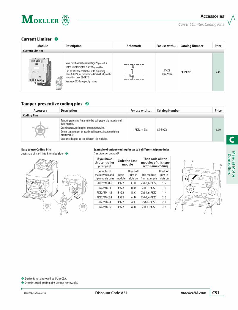
C
Man
ual M
oto
r C
on
trollers
STARTER-CAT-NA-0708 moellerNA.com C51 Discount Code A31
Accessories
Current Limiter, Coding Pins
1 23 4
A BC D
Example of unique coding for up to 6 different trip modules (see diagram on right)
If you have this controller
(examples)
Code the base module
Then code all trip modules of this type
with same codingExamples of
main switch and trip module pairs
Base module
Break off pins in
slots onTrip module
from example
Break off pins in
slots on
PKZ2/ZM-0,6 PKZ2 C, D ZM-0,6-PKZ2 1, 2
PKZ2/ZM-1 PKZ2 B, D ZM-1-PKZ2 1, 3
PKZ2/ZM-1,6 PKZ2 B, C ZM-1,6-PKZ2 1, 4
PKZ2/ZM-2,4 PKZ2 A, D ZM-2,4-PKZ2 2, 3
PKZ2/ZM-4 PKZ2 A, C ZM-4-PKZ2 2, 4
PKZ2/ZM-6 PKZ2 A, B ZM-6-PKZ2 3, 4
Easy to use Coding PinsJust snap pins off into intended slots ➋
Current Limiter ➊
Module Description Schematic For use with… Catalog Number PriceCurrent Limiter
Max. rated operational voltage Ue = 690 VRated uninterrupted current Iu = 40 ACan be fitted to controller with mounting plate C-PKZ2, or can be fitted individually with mounting base EZ-PKZ2See page C65 for capacity ratings
L
TI >>
PKZ2PKZ2/ZM CL-PKZ2 436
Tamper-preventive coding pins ➋
Accessory Description For use with… Catalog Number PriceCoding Pins
Tamper-preventive feature used to pair proper trip module with base module. Once inserted, coding pins are not removable.Deters tampering or an accidental incorrect insertion during maintenance.Unique coding for up to 6 different trip modules.
PKZ2 + ZM CS-PKZ2 6.90
➊ Device is not approved by UL or CSA.➋ Once inserted, coding pins are not removable.
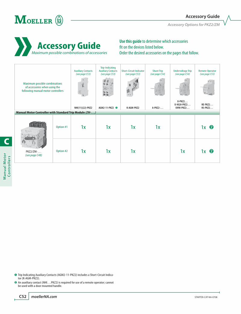
C
Man
ual
Mo
tor
Co
ntr
oll
ers
C52 moellerNA.com STARTER-CAT-NA-0708
Accessory Guide
Accessory Options for PKZ2/ZM
➊ Trip Indicating Auxiliary Contacts (AGM2-11-PKZ2) includes a Short-Circuit Indica-tor (K-AGM-PKZ2).
➋ An auxiliary contact (NHI…PKZ2) is required for use of a remote operator; cannot be used with a door mounted handle.
Accessory Guide Maximum possible combinations of accessories
Maximum possible combinations of accessories when using the
following manual motor controllers
Auxiliary Contacts(see page C53)
Trip-Indicating Auxiliary Contacts
(see page C53)Short-Circuit Indicator
(see page C53)Shunt Trip
(see page C54)Undervoltage Trip
(see page C54)Remote Operator
(see page C55)
NHI(11)(22)-PKZ2 AGM2-11-PKZ2 ➊ K-AGM-PKZ2 A-PKZ2-…
U-PKZ2…U-HI20-PKZ2…
UVHI-PKZ2…RE-PKZ2…RS-PKZ2…
Manual Motor Controller with Standard Trip Module (ZM-…)
PKZ2/ZM-…(see page C48)
Option #1 1x 1x 1x 1x 1x ➋
Option #2 1x 1x 1x 1x 1x ➋
Use this guide to determine which accessories fit on the devices listed below. Order the desired accessories on the pages that follow.

C
Man
ual M
oto
r C
on
trollers
STARTER-CAT-NA-0708 moellerNA.com C53 Discount Code A31
Auxiliary contacts (see Accessory Guide on page C52)
Auxiliary
Contacts
Description Travel Diagram SchematicFor use with…
Catalog Number PriceNO NC
Standard Auxiliary Contacts
1 1 Can be used in conjunction with trip indicating auxiliary contact (AGM2-11-PKZ2).Maximum of one per device.This device is required for remote operator use.
NHI11
L1L2L3
NHI22
NHI11
1.13
1.14
1.21
1.22
1.211.13
1.14 1.22
1.31
1.32
1.43
1.44
PKZ2/ZM...
I >
or
PKZ2PKZ2/S-SP
NHI11-PKZ2 80
2 2
L1L2L3
NHI22NHI22-PKZ2 130
Trip-indicating Auxiliary Contact
2x1
2x1
Includes short-circuit indicator K-AGM-PKZ2 (below)Can be used in conjunction with standard auxiliary contactsMaximum of one per device.1 NO & 1 NC switches state during overcurrent condition or short-circuit; 1 NO & 1 NC switches state during short-circuit only (see schematic on right)
L1L2L3
AGM
Trip"+""I >"
4.43 4.31 4.21 4.13
4.44 4.32 4.22 4.14PKZ2/ZM... AGM 2-11
"+"
I >
PKZ2PKZ2/S-SP AGM2-11-PKZ2 140
Short-circuit Indicator
0 0Provides a resettable red flag indicator of a short-circuit tripMaximum of one per device.
L1L2L3
"+"
" "
Trip "+"
L1L2L3
"+"
" "
On/O
PKZ2PKZ2/S-SP K-AGM-PKZ2 60
See Accessory Guide on page C52
Accessories
Auxiliary Contacts

C
Man
ual
Mo
tor
Co
ntr
oll
ers
C54 moellerNA.com STARTER-CAT-NA-0708 Discount Code A31
Accessories
Shunt Trips, Undervoltage Trips
➊ Maximum of either one shunt trip or one undervoltage trip can be used for each controller device.
Shunt trips; undervoltage trips (see Accessory Guide on page C52) ➊
Module Description Travel Diagram Schematic
Contacts
Operating Voltage
Catalog Number PriceDC
AC
NO NC 50 Hz 60 HzShunt Trips
Used to disengage the main switch when voltage is applied.Units will operate with specific voltages and fre-quency applied
C1
C2
0 0244860
2448
2448 A-PKZ2-A 240
0 0110125250
110127220230240
110120208220240
A-PKZ2-B 240
0 0 –
380400415440500
480600 A-PKZ2-C 240
Undervoltage Trips - non delayed
Can be used for Emergency-stop applications as per IEC/EN 60 204
U <
D1
D2
0 0 24 – – U-PKZ2(24VDC) 220
0 0 – 24 – U-PKZ2(24V50HZ) 220
0 0 – 230 240 U-PKZ2(230V50HZ,240V60HZ) 220
L1L2L3
HI20
On
L1L2L3
HI20
O/Trip
U <
D1
D2 2.14
2.13 2.23
2.24
2 0 – 24 24 U-HI20-PKZ2(24V50/60HZ) 240
2 0 – 110 120 U-HI20-PKZ2(110V50HZ,120V60HZ) 240
2 0 – 230 240 U-HI20-PKZ2(230V50HZ,240V60HZ) 240
Undervoltage Trips - delayed
Has a built-in time delay to pre-vent tripping due to momentary power loss of 200 ms or less
L1L2L3
UVHI
On
L1L2L3
UVHI
O/Trip
U <
D1 2.13
2.14D2
1 0 – 230 240 UVHI-PKZ2(230V50HZ,240V60HZ) 240
See Accessory Guide on page C52

C
Man
ual M
oto
r C
on
trollers
STARTER-CAT-NA-0708 moellerNA.com C55 Discount Code A31
Accessories
Remote Operators
➊ An auxiliary contact is required for use of this product - see page C53.➋ Can be used in conjunction with either a shunt trip or undervoltage trip; cannot be
used with a door mounted handle.
Remote Operators (see Accessory Guide on page C52) ➊➋
Module Description Schematic Circuit DiagramFor use with…
Operating Voltage Catalog Number Price
Remote operator
Used to electri-cally operate the motor controllerAn auxiliary con-tact is required for use of this product - see page C53.
72
A20
74L
A40 B20T
I >
L(+) N(-)
72 74
A20 A40 B20OI
33
34
LINE
CONTROL
ON OFF RESET
L(+) N(-)
72 74
A20 A40 B20OI
33
34
LINE
CONTROL
ON OFF RESET
PKZ2/ZMPKZ2/S-SP
24 V50/60 Hz AC
24 VDC
RE-PKZ2(24V50/60HZ,DC) 700
110 – 120 V50/60 Hz AC
110 – 120 VDC
RE-PKZ2(110-120V50/60HZ,DC) 700
Remote operator that uses separate power supply
Used to electri-cally operate the motor controllerAn auxiliary con-tact is required for use of this product - see page C53.
72 74
A20 A30 A0
L
T
I >
L(+) N(–)
72 74
33
34
A20 A30 A0
24 V DC
LINE
CONTROL
OFF/RESETON
L(+) N(-)
72 74
33
34
A20 A30 A0I O
24V DC
AC/DC
LINE
CONTROL
OFF/RESETON
PKZ2/ZMPKZ2/S-SP
24 V50/60 Hz AC
24 VDC
RS-PKZ2(24V50/60HZ,DC) 700
110 – 120 V50/60 Hz AC
110 – 120 VDC
RS-PKZ2(110-120V50/60HZ,DC) 700
See Accessory Guide on page C52
≥ 15
O
I
t (ms)
I
O
t (ms)
I
O
t (ms)
CONTROL
ON
LINE
CONTROL
ON
OFF/RESET
CONTROLOFF/RESET
ON
OFF
≥ 15
≥ 300
≥ 30 ≥ 30
Main contact
Minimum Command Time
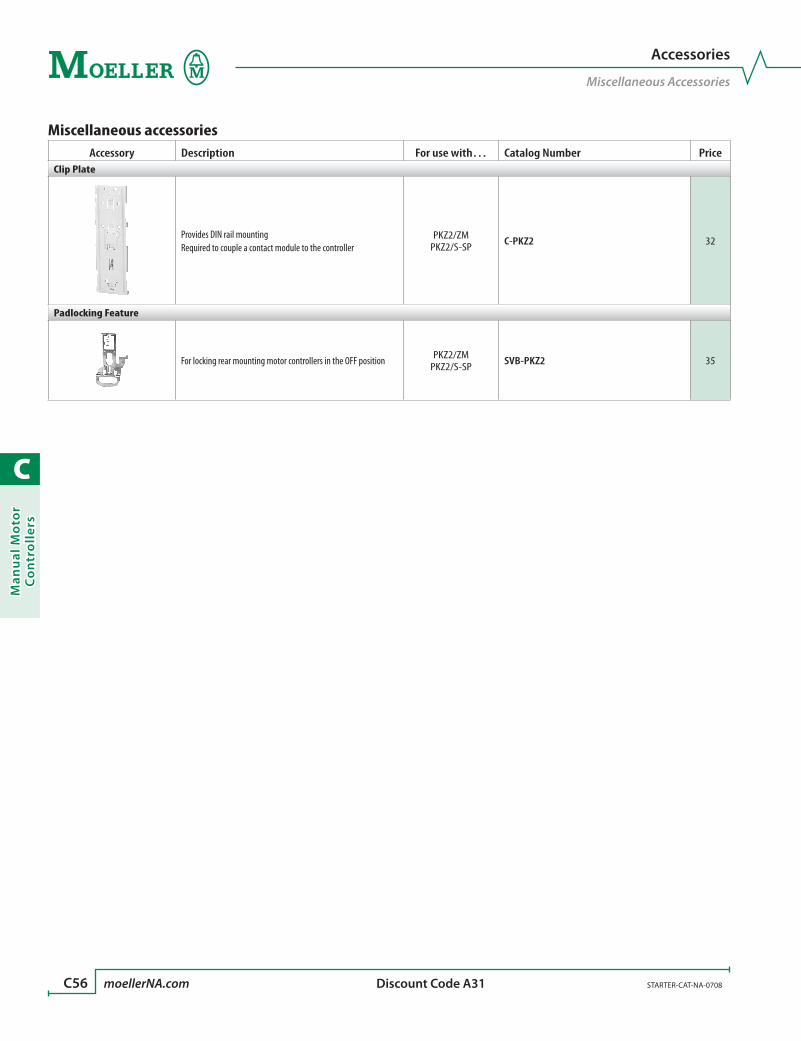
C
Man
ual
Mo
tor
Co
ntr
oll
ers
C56 moellerNA.com STARTER-CAT-NA-0708 Discount Code A31
Accessories
Miscellaneous Accessories
Miscellaneous accessoriesAccessory Description For use with… Catalog Number Price
Clip Plate
Provides DIN rail mounting Required to couple a contact module to the controller
PKZ2/ZMPKZ2/S-SP C-PKZ2 32
Padlocking Feature
For locking rear mounting motor controllers in the OFF position PKZ2/ZMPKZ2/S-SP SVB-PKZ2 35

C
Man
ual M
oto
r C
on
trollers
STARTER-CAT-NA-0708 moellerNA.com C57 Discount Code A31 (except where noted)
Accessories
Enclosures
Enclosures
EnclosureProtection
Rating DescriptionFor use with… Catalog Number Price
Discount Code
Enclosures for Manual Motor Controller
NEMA Type 12dust-tight
Plastic enclosure200 x 150 x 150 (H x W x D in mm)
PKZ2PKZ2/ZM CI19EE-PKZ2-NA 220 A31
NEMA Type 1general purpose
Steel enclosure240 x 170 x 120 (H x W x D in mm)
PKZ2PKZ2/ZM CS3-PKZ2 286 D12
Through-the-door Mounted Handles for PKZ2
Accessory Description Color Protection RatingFor use with… Catalog Number Price
Door Coupling Handle
Rotary handle operator•Padlockable in OFF and ON positions•Includes handle coupling mechanism that •accommodates mounting depth of 132 mm
Includes door interlock; not engaged when shipped
Black NEMA 3R, 4X, 12, 13 PKZ2/ZMPKZ2/S-SP PKZ2-XH 80
Red/Yellow NEMA 3R, 4X, 12, 13 PKZ2/ZMPKZ2/S-SP PKZ2-XRH 100
Rotary handle operator•Padlockable in OFF and ON positions•To be used when PKZ is rotated by 90˚•Selectable handle positions•Includes handle coupling mechanism that •accommodates mounting depth of 132 mm
Includes door interlock; not engaged when shipped
Black NEMA 3R, 4X, 12, 13 PKZ2/ZMPKZ2/S-SP PKZ2-XH-MCC 80
Extension Shaft
For mounting depths 171 – 300 mm•Includes shaft interlock mechanism•
– – PKZ2/ZMPKZ2/S-SP PKZ2-XAH 40

C
Man
ual
Mo
tor
Co
ntr
oll
ers
C58 moellerNA.com STARTER-CAT-NA-0708
Technical Data
Circuit diagrams, Protection of PVC, Fuseless Installation
PKZ2 in 1- and 2-pole Circuits for DC and AC
Protection of PVC Insulated Cables Against Thermal Overload with Short Circuits
The table indicates which minimum cable cross-sections are protected by PKZ2 manual motor controller up to their rated conditional short-circuit current Iq.
Min. cross-section protected Device380–415V, 50 Hz, Cu mm2 Part No.4 2.5 1.5 1 0.75
PKZ2/ZM-0,6
…
PKZ2/ZM-2.4PKZ2/ZM-4PKZ2/ZM-6PKZ2/ZM-10PKZ2/ZM-16PKZ2/ZM-25PKZ2/ZM-32PKZ2/ZM-40
Fuseless Installation with PKZ2, Back-Up Protection Diagrams
1 3 5
2 4 6I > I > I >
1 3 5
2 4 6I > I > I >
PKZ2/ZM
I ccI cn
atBack-upprotectionrangewith CL-PKZ2
Ratedshort-circuitbreakingcapacityrange
Inhe
rent
ly s
hort
-circ
uit p
roof
Icc
rms [
kA]
PKZ2
415 V AC
100
50
30
20
4
106
0.6… …16 25
PKZ2/ZM-…+CL
PKZ2/ZM-…
32 40
PKZ2
Ratedcurrent In [A]
Inherentlyshort-circuit-proof

C
Man
ual M
oto
r C
on
trollers
STARTER-CAT-NA-0708 moellerNA.com C59
Technical Data
Tripping Characteristics
Tripping Characteristics, Manual Motor ControllerPKZ2/ZM-0,6
Tripping Characteristics, Manual Motor ControllerPKZ2/ZM-1
a
b
3
2
1
40
20
10864
10.80.6
0.4
0.2
0.10.080.06
0.04
0.02
0.010.0080.006
0.0040.003
2
t
min
s
1 1.5 2 3 4 5 6 7 8 9 10 15 20 30 40 50 6070x Ir
PKZ2/ZM-0,6
2-phase 3-phase
NM HM NM HMCurve b b a a
3 x Ir Trip time [s] 12.2 12.2 21 217.2 x Ir Trip time [s] 3.2 3.2 4.5 4.5
PKZ2/ZM-1
2-phase 3-phase
NM HM NM HMCurve b c a a
3 x Ir Trip time [s] 19 14 23 237.2 x Ir Trip time [s] 4.4 3.4 5.3 5.3
min
s
a
bc
3
2
1
40
20
10864
10.80.6
0.4
0.2
0.10.080.06
0.04
0.02
0.010.0080.006
0.0040.003
2
t
1 1.5 2 3 4 5 6 7 8 9 10 15 20 30 40 50 6070x Ir

C
Man
ual
Mo
tor
Co
ntr
oll
ers
C60 moellerNA.com STARTER-CAT-NA-0708
Technical Data
Tripping Characteristics
Tripping Characteristics, Manual Motor ControllerPKZ2/ZM-1,6
Tripping Characteristics, Manual Motor ControllerPKZ2/ZM-2,4
PKZ2/ZM-1,6
2-phase 3-phase
NM HM NM HMCurve b c a a
3 x Ir Trip time [s] 17.5 13.5 25 257.2 x Ir Trip time [s] 4.5 3.6 5.5 5.5
PKZ2/ZM-2,4
2-phase 3-phase
NM HM NM HMCurve b b a a
3 x Ir Trip time [s] 18.2 18.2 27 277.2 x Ir Trip time [s] 5.4 5.4 6.5 6.5
3
2
1
40
20
10864
10.80.6
0.4
0.2
0.10.080.06
0.04
0.02
0.010.0080.006
0.0040.003
2
1 1.5 2 3 4 5 6 7 8 9 10 15 20 30 40 50 6070x Ir
a
bc
t
min
sm
ins
a
b
3
2
1
40
20
10864
10.80.6
0.4
0.2
0.10.080.06
0.04
0.02
0.010.0080.006
0.0040.003
2
1 1.5 2 3 4 5 6 7 8 9 10 15 20 30 40 50 6070x Ir
t

C
Man
ual M
oto
r C
on
trollers
STARTER-CAT-NA-0708 moellerNA.com C61
Technical Data
Tripping Characteristics
Tripping Characteristics, Manual Motor ControllerPKZ2/ZM-4
Tripping Characteristics, Manual Motor ControllerPKZ2/ZM-6
PKZ2/ZM-4
2-phase 3-phase
NM HM NM HMCurve b c a a
3 x Ir Trip time [s] 23 18.2 31 317.2 x Ir Trip time [s] 5.8 4.7 6.8 6.8
PKZ2/ZM-6
2-phase 3-phase
NM HM NM HMCurve b c a a
3 x Ir Trip time [s] 26 20.1 30 307.2 x Ir Trip time [s] 5.6 4.7 6.5 6.5
min
s
3
2
1
40
20
10864
10.80.6
0.4
0.2
0.10.080.06
0.04
0.02
0.010.0080.006
0.0040.003
2
1 1.5 2 3 4 5 6 7 8 9 10 15 20 30 40 50 6070x Ir
ab
c
t
min
s
3
2
1
40
20
10864
10.80.6
0.4
0.2
0.10.080.06
0.04
0.02
0.010.0080.006
0.0040.003
2
1 1.5 2 3 4 5 6 7 8 9 10 15 20 30 40 50 6070x Ir
ab
c
t
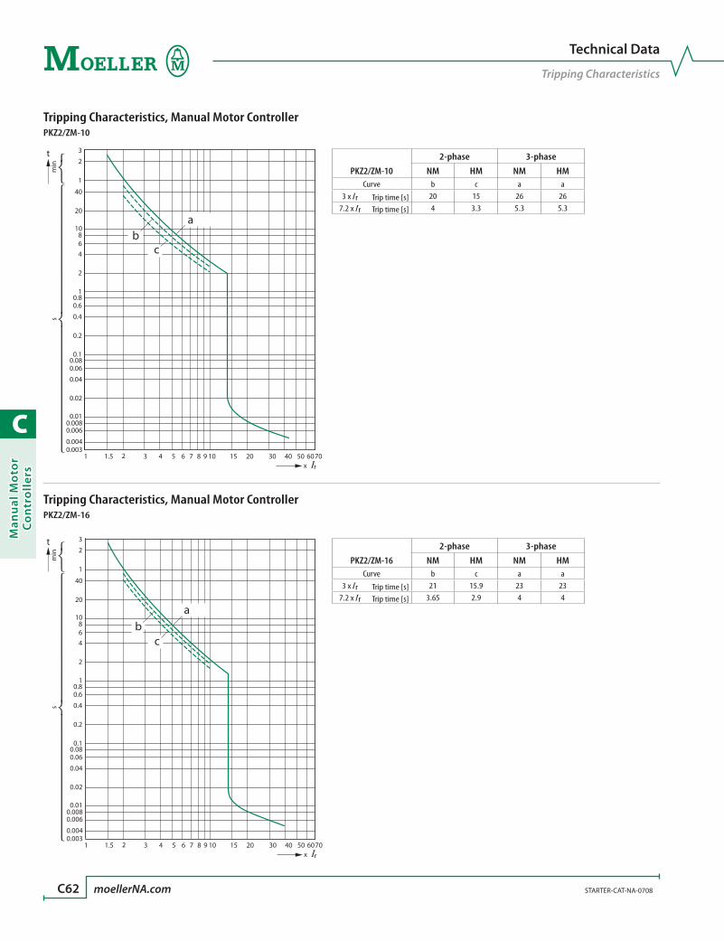
C
Man
ual
Mo
tor
Co
ntr
oll
ers
C62 moellerNA.com STARTER-CAT-NA-0708
Technical Data
Tripping Characteristics
Tripping Characteristics, Manual Motor ControllerPKZ2/ZM-10
Tripping Characteristics, Manual Motor ControllerPKZ2/ZM-16
PKZ2/ZM-10
2-phase 3-phase
NM HM NM HMCurve b c a a
3 x Ir Trip time [s] 20 15 26 267.2 x Ir Trip time [s] 4 3.3 5.3 5.3
PKZ2/ZM-16
2-phase 3-phase
NM HM NM HMCurve b c a a
3 x Ir Trip time [s] 21 15.9 23 237.2 x Ir Trip time [s] 3.65 2.9 4 4
min
s
3
2
1
40
20
10864
10.80.6
0.4
0.2
0.10.080.06
0.04
0.02
0.010.0080.006
0.0040.003
2
1 1.5 2 3 4 5 6 7 8 9 10 15 20 30 40 50 6070x Ir
ab
c
t
min
s
3
2
1
40
20
10864
10.80.6
0.4
0.2
0.10.080.06
0.04
0.02
0.010.0080.006
0.0040.003
2
1 1.5 2 3 4 5 6 7 8 9 10 15 20 30 40 50 6070x Ir
ab
c
t
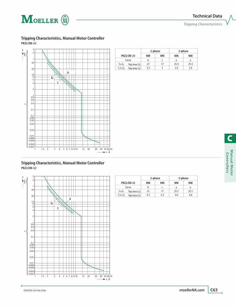
C
Man
ual M
oto
r C
on
trollers
STARTER-CAT-NA-0708 moellerNA.com C63
Technical Data
Tripping Characteristics
Tripping Characteristics, Manual Motor ControllerPKZ2/ZM-25
Tripping Characteristics, Manual Motor ControllerPKZ2/ZM-32
PKZ2/ZM-25
2-phase 3-phase
NM HM NM HMCurve b c a a
3 x Ir Trip time [s] 21 17 25.4 25.47.2 x Ir Trip time [s] 3.5 3 3.9 3.9
PKZ2/ZM-32
2-phase 3-phase
NM HM NM HMCurve b c a a
3 x Ir Trip time [s] 21 17 25.5 25.57.2 x Ir Trip time [s] 4.2 3.5 4.8 4.8
min
s
3
2
1
40
20
10864
10.80.6
0.4
0.2
0.10.080.06
0.04
0.02
0.010.0080.006
0.0040.003
2
1 1.5 2 3 4 5 6 7 8 9 10 15 20 30 40 50 6070x Ir
ab
c
t
min
s
3
2
1
40
20
10864
10.80.6
0.4
0.2
0.10.080.06
0.04
0.02
0.010.0080.006
0.0040.003
2
1 1.5 2 3 4 5 6 7 8 9 10 15 20 30 40 50 6070x Ir
ab
c
t
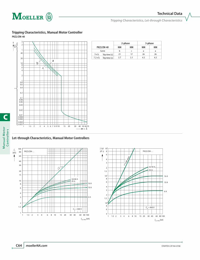
C
Man
ual
Mo
tor
Co
ntr
oll
ers
C64 moellerNA.com STARTER-CAT-NA-0708
Technical Data
Tripping Characteristics, Let-through Characteristics
Let-through Characteristics, Manual Motor Controllers
PKZ2/ZM-…
11
1.5
2
3
4
6
8
10
15
20
30
40
60
80
100
1.5 2 3 4 6 8 10 15 20 30 40 60 80 100
32/40 A25 A
16 A
10 A
6 A
[kA]
2 · I cc
Ue = 400 V
ÎD
Icc rms [kA]1 1.5 2 3 4 6 8 10 15 20 30 40 60 80 100
4
6
8
1.5
2
3
4
6
8
1.5
2
3
4
6
8
105
104
106
PKZ2/ZM-…
16 A
10 A
6 A
32/40 A
25 A
[A s]2
Ue = 400 V
∫ i2dt
1st h
alf-w
ave
Icc rms [kA]
Tripping Characteristics, Manual Motor ControllerPKZ2/ZM-40
PKZ2/ZM-40
2-phase 3-phase
NM HM NM HMCurve b c a a
3 x Ir Trip time [s] 21 17 26 267.2 x Ir Trip time [s] 3.7 3.1 4.3 4.3
min
s
3
2
1
40
20
10864
10.80.6
0.4
0.2
0.10.080.06
0.04
0.02
0.010.0080.006
0.0040.003
2
1 1.5 2 3 4 5 6 7 8 9 10 15 20 30 40 50 6070x Ir
ab
c
t

C
Man
ual M
oto
r C
on
trollers
STARTER-CAT-NA-0708 moellerNA.com C65
Technical Data
Switching Capacity
Manual Motor Controller Switching Capacity
• RateduninterruptedcurrentIu
• Ratedconditionalshort-circuitcurrentIq IEC/EN 60947-4-1
• Ratedultimateshort-circuitbreakingcapacityIcu IEC/EN 60947-2
• Ratedoperationalshort-circuitbreakingcapacityIcs IEC/EN 60947-2
Iu230V 400V 440V 500V 690V
Iq Icu Ics Iq Icu Ics Iq Icu Ics Iq Icu Ics Iq Icu Ics
A kA kA kA A ➊ kA kA kA A ➊ kA kA kA A ➊ kA kA kA A ➊ kA kA kA A ➊PKZ2/ZM with classification type ‘1’ and ‘2’
0.16 – 1.6 N N N N N
2.4 N N N N N
4 N N N N 4.5 4.5 2.5 63
6 N N N N 4.5 4.5 2.5 80
10 30 N 30 N 10 10 5 80 7 7 3.5 80 4.5 4.5 2.5 80
16 30 N 30 N 10 10 5 100 7 7 3.5 100 4.5 4.5 2.5 100
25 30 30 7.5 160 30 30 7.5 160 10 10 5 125 7 7 3.5 125 4.5 4.5 2.5 125
32 30 30 7.5 160 30 30 7.5 160 10 10 5 160 7 7 3.5 160 4.5 4.5 2.5 160
40 30 30 7.5 160 30 30 7.5 160 10 10 5 160 7 7 3.5 160 4.5 4.5 2.5 160
PKZ2/ZM + CL-PKZ2 with classification type ‘1’ and ‘2’0.16 – 1.6 N N N N N
2.4 N N N N N
4 N N N N 10 4.5 2.5 N
6 N N N N 10 4.5 2.5 N
10 30 N 30 N 5 N 3.5 N 10 4.5 2.5 N
16 30 N 30 N 5 N 3.5 N 10 4.5 2.5 N
25 7.5 N 7.5 N 5 N 3.5 N 10 4.5 2.5 N
32 7.5 N 7.5 N 5 N 3.5 N 10 4.5 2.5 N
40 7.5 N 7.5 N 5 N 3.5 N 10 4.5 2.5 N
➊ Fuse (A gG/gL) for enhancing the switching capacity of the motor-protective circuit breaker to 100 kA.
No upstream protective device required, as it is the autoprotected range (150 kA).N–Not necessary.
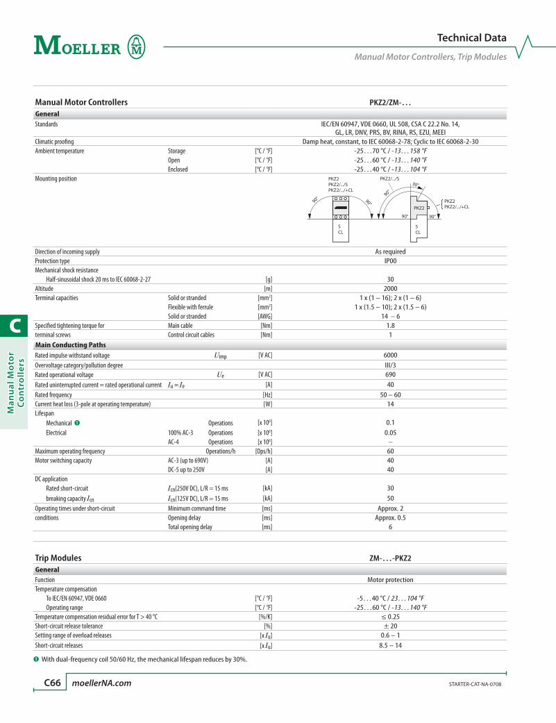
C
Man
ual
Mo
tor
Co
ntr
oll
ers
C66 moellerNA.com STARTER-CAT-NA-0708
Manual Motor Controllers PKZ2/ZM-…GeneralStandards IEC/EN 60947, VDE 0660, UL 508, CSA C 22.2 No. 14,
GL, LR, DNV, PRS, BV, RINA, RS, EZU, MEEIClimatic proofing Damp heat, constant, to IEC 60068-2-78; Cyclic to IEC 60068-2-30Ambient temperature Storage [°C / °F] -25…70 °C / -13…158 °F Open [°C / °F] -25…60 °C / -13…140 °F Enclosed [°C / °F] -25…40 °C / -13…104 °FMounting position
SCL
SCL
90°
90° 90°
90°
90°
30°PKZ2PKZ2/.../SPKZ2/.../+CL
PKZ2/.../S
PKZ2PKZ2/.../+CLPKZ2
Direction of incoming supply As requiredProtection type IP00Mechanical shock resistance Half-sinusoidal shock 20 ms to IEC 60068-2-27 [g] 30Altitude [m] 2000Terminal capacities Solid or stranded [mm2] 1 x (1 – 16); 2 x (1 – 6) Flexible with ferrule [mm2] 1 x (1.5 – 10); 2 x (1.5 – 6) Solid or stranded [AWG] 14 – 6Specified tightening torque for Main cable [Nm] 1.8terminal screws Control circuit cables [Nm] 1Main Conducting PathsRated impulse withstand voltage Uimp [V AC] 6000Overvoltage category/pollution degree III/3Rated operational voltage Ue [V AC] 690Rated uninterrupted current = rated operational current Iu = Ie [A] 40Rated frequency [Hz] 50 – 60Current heat loss (3-pole at operating temperature) [W] 14Lifespan Mechanical ➊ Operations [x 106] 0.1 Electrical 100% AC-3 Operations [x 106] 0.05 AC-4 Operations [x 106] –Maximum operating frequency Operations/h [Ops/h] 60Motor switching capacity AC-3 (up to 690V) [A] 40 DC-5 up to 250V [A] 40DC application Rated short-circuit Icn(250V DC), L/R = 15 ms [kA] 30 breaking capacity Icn Icn(125V DC), L/R = 15 ms [kA] 50Operating times under short-circuit Minimum command time [ms] Approx. 2conditions Opening delay [ms] Approx. 0.5 Total opening delay [ms] 6
Trip Modules ZM-…-PKZ2GeneralFunction Motor protectionTemperature compensation To IEC/EN 60947, VDE 0660 [°C / °F] -5…40 °C / 23…104 °F Operating range [°C / °F] -25…60 °C / -13…140 °FTemperature compensation residual error for T > 40 °C [%/K] ≤ 0.25Short-circuit release tolerance [%] ± 20Setting range of overload releases [x Iu] 0.6 – 1Short-circuit releases [x Iu] 8.5 – 14
Technical Data
Manual Motor Controllers, Trip Modules
➊ With dual-frequency coil 50/60 Hz, the mechanical lifespan reduces by 30%.
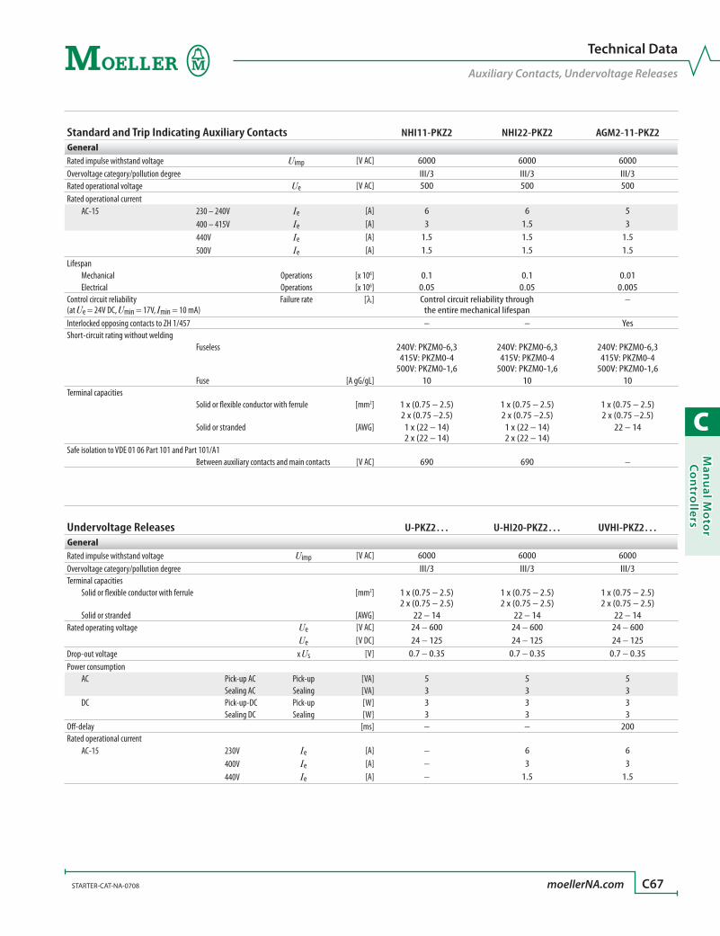
C
Man
ual M
oto
r C
on
trollers
STARTER-CAT-NA-0708 moellerNA.com C67
Standard and Trip Indicating Auxiliary Contacts NHI11-PKZ2 NHI22-PKZ2 AGM2-11-PKZ2GeneralRated impulse withstand voltage Uimp [V AC] 6000 6000 6000Overvoltage category/pollution degree III/3 III/3 III/3Rated operational voltage Ue [V AC] 500 500 500Rated operational current AC-15 230 – 240V Ie [A] 6 6 5 400 – 415V Ie [A] 3 1.5 3 440V Ie [A] 1.5 1.5 1.5 500V Ie [A] 1.5 1.5 1.5Lifespan Mechanical Operations [x 106] 0.1 0.1 0.01 Electrical Operations [x 106] 0.05 0.05 0.005Control circuit reliability Failure rate (at Ue = 24V DC, Umin = 17V, Imin = 10 mA)
[l] Control circuit reliability through the entire mechanical lifespan
–
Interlocked opposing contacts to ZH 1/457 – – YesShort-circuit rating without welding Fuseless 240V: PKZM0-6,3
415V: PKZM0-4 500V: PKZM0-1,6
240V: PKZM0-6,3 415V: PKZM0-4
500V: PKZM0-1,6
240V: PKZM0-6,3 415V: PKZM0-4
500V: PKZM0-1,6 Fuse [A gG/gL] 10 10 10Terminal capacities Solid or flexible conductor with ferrule [mm2] 1 x (0.75 – 2.5)
2 x (0.75 –2.5)1 x (0.75 – 2.5) 2 x (0.75 –2.5)
1 x (0.75 – 2.5) 2 x (0.75 –2.5)
Solid or stranded [AWG] 1 x (22 – 14) 2 x (22 – 14)
1 x (22 – 14) 2 x (22 – 14)
22 – 14
Safe isolation to VDE 01 06 Part 101 and Part 101/A1 Between auxiliary contacts and main contacts [V AC] 690 690 –
Undervoltage Releases U-PKZ2… U-HI20-PKZ2… UVHI-PKZ2…GeneralRated impulse withstand voltage Uimp [V AC] 6000 6000 6000Overvoltage category/pollution degree III/3 III/3 III/3Terminal capacities Solid or flexible conductor with ferrule [mm2] 1 x (0.75 – 2.5)
2 x (0.75 – 2.5)1 x (0.75 – 2.5) 2 x (0.75 – 2.5)
1 x (0.75 – 2.5) 2 x (0.75 – 2.5)
Solid or stranded [AWG] 22 – 14 22 – 14 22 – 14Rated operating voltage Ue [V AC] 24 – 600 24 – 600 24 – 600 Ue [V DC] 24 – 125 24 – 125 24 – 125Drop-out voltage x Us [V] 0.7 – 0.35 0.7 – 0.35 0.7 – 0.35Power consumption AC Pick-up AC Pick-up [VA] 5 5 5 Sealing AC Sealing [VA] 3 3 3 DC Pick-up-DC Pick-up [W] 3 3 3 Sealing DC Sealing [W] 3 3 3Off-delay [ms] – – 200Rated operational current AC-15 230V Ie [A] – 6 6 400V Ie [A] – 3 3 440V Ie [A] – 1.5 1.5
Technical Data
Auxiliary Contacts, Undervoltage Releases

C
Man
ual
Mo
tor
Co
ntr
oll
ers
C68 moellerNA.com STARTER-CAT-NA-0708
Shunt Releases A-PKZ2…GeneralRated impulse withstand voltage Uimp [V AC] 6000Overvoltage category/pollution degree III/3Terminal capacities Solid or flexible conductor with ferrule [mm2] 1 x (0.75 – 2.5); 2 x (0.75 – 2.5) Solid or stranded [AWG] 22 – 14Rated operating voltage Ue [V AC] 24 – 600 Ue [V DC] 24 – 250Operating range Alternating voltage [x Us] 0.7 – 1.1 DC [x Us] 0.7 – 1.1Power consumption AC Pick-up AC Pick-up [VA] 5 Sealing AC Sealing [VA] 3 DC Pick-up DC Pick-up [W] 3 Sealing DC Sealing [W] 0.3
Incoming Terminals BK…-PKZ2, B3.1/…-PKZ2GeneralRated impulse withstand voltage Uimp [V AC] 6000Overvoltage category/pollution degree III/3Rated operational voltage Ue [V AC] 690Rated uninterrupted current Iu [A] 120
Remote Operators RE-PKZ2… RS-PKZ2…GeneralRated impulse withstand voltage Uimp [V AC] 6000 6000Overvoltage category/pollution degree III/3 III/3Rated operating voltage Ue [V AC] 380 – 440 380 – 440 Ue [V DC] 24 – 240 24 – 240Safe isolation to VDE 0106 Part 101 and Part 101 A1 between auxiliary contacts and main contacts
[V AC] 500 500
Required short-time rating (30 ms) [VA/W] 700 700Control transformer short-time rating [VA] 1000 1000Short-circuit voltage [%] 4.4 4.4Closing delay [ms] 30 30Opening delay [ms] 30 30Reset time to Off [ms] 30 30Maximum operating frequency [Ops/h] 60 60Operating range Alternating voltage [x Us] 0.85 – 1.1 0.85 – 1.1 DC [x Us] 0.85 – 1 0.85 – 1Lifespan, electrical Operations [x 106] 0.05 0.05Integral auxiliary contacts (make contact 33/34 HAND/AUTO Indication) Conventional free air thermal current th Ith [A] 1.5 1.5Rated operational current AC-14 230/240V Ie [A] 1.5 1.5 400/415V Ie [A] 1 1 440V Ie [A] 0.5 0.5Terminal capacities Solid or flexible conductor with ferrule [mm2] 1 x (0.75 – 2.5); 2 x (0.75 – 2.5) 1 x (0.75 – 2.5); 2 x (0.75 – 2.5) Solid or stranded [AWG] 22 – 14 22 – 14
Technical Data
Shunt Releases, Incoming Terminals, Remote Operators

C
Man
ual M
oto
r C
on
trollers
STARTER-CAT-NA-0708 moellerNA.com C69
Dimensions are in millimeters.Not intended for manufacturing purposes.
Dimensions
PKZ2
Manual Motor Controller with Trip ModulePKZ2/ZM-…
6
0
+
M4
105
1962.571.5
83 105
44.5109
133.5
62
45 68
15
Standard Auxiliary Contacts Trip-indicating Auxiliary ContactsNHI…-PKZ2 AGM2-11-PKZ2
1818
NHI22 NHI11
105
68
44
77
18
31.5
45
AGM
Shunt / Undervoltage Release Remote OperatorA-PKZ2… / U-PKZ2… RE-PKZ2… / RS-PKZ2…
18 44109113
105 10
5
45
109
122
126
36

C
Man
ual
Mo
tor
Co
ntr
oll
ers
C70 moellerNA.com STARTER-CAT-NA-0708
Dimensions
PKZ2
NEMA 12 Plastic EnclosureCI19EE-PKZ2-NA
200
150150
NEMA 1 Steel Enclosure Door Coupling HandlesCS3-PKZ2 PKZ2-X…
240
120170
28
55
20
+ l
o
64
64
48
48
7.5
At least 100 mm
up to cover hinge
Dimensions are in millimeters.Not intended for manufacturing purposes.

D
Co
mb
inatio
n M
oto
r Starters
combination motor starters
Type F D2Selection Tables .................................................................................. D8
Accessories .......................................................................................... D36
Technical Data ................................................................................... D41
Dimensions ......................................................................................... D42
Self-Protected Type E D46Selection Tables .................................................................................. D50
Accessories .......................................................................................... D60
Technical Data ................................................................................... D64
Dimensions ......................................................................................... D70

D
Co
mb
inat
ion
Mo
tor
Star
ters
D2
R
series MSC combinationmotor circuit controllersReplaces the combination starter
When PKZM manual motor controllers are combined with our new high perfor-
mance DIL M contactors, the result is a combination motor circuit controller we
call “MSC.” The assemblies are UL listed and CSA certified, which means they can
be used to replace traditional combination starters in many applications.
For use in over 90% of industrial applicationsMSC combination starters control and protect motors up to 40HP @ 460V and
50HP at 575V. This covers well over 90% of industrial motor applications. The ex-
cellent current limiting design of MSC combination starters clears faults to 50kA
@ 460V and 18kA at 575V. This eliminates the need for an upstream fuse or circuit
breaker.
A compact, space-saving alternative to the traditional combination starterMany users are un-
familiar with the
rules covering MSC
self-protected com-
bination controllers.
According to NEC
Article 430 and CEC
Rule 28, governing
motor branch circuit
requirements, MSC
controllers provide
a motor discon-
nect means, motor
branch-circuit protection, a motor controller, overload protection and remote
operation without the need for any additional protection or devices.
These rules allow a compact, space-saving alternative to the conventional com-
bination starter. When the MSC motor controller is paired with a DIL M contactor
for control circuit operation, the resulting compact starter saves significant cost
and panel space by eliminating a separate MCCB or other disconnect. Straight-
through wiring also reduces the time and labor it takes to build the assembly.
> Starts and protects motors to 40HP @ 460V (50HP @ 575V) with two frame sizes
> Replaces the traditional combination starter
> Features a fuseless, high fault interrupting current limiting design
> Suitable for manual control or fully automatic (HAND-AUTO) PLC applications
> Over-current or short-circuit trip differentiation
> Worldwide approvals
Motor Disconnect means
Motor Branch-Circuit, Short Circuit, Ground Fault Protection
Thermal Overload Protection
Contactor for operation via conventional control circuit
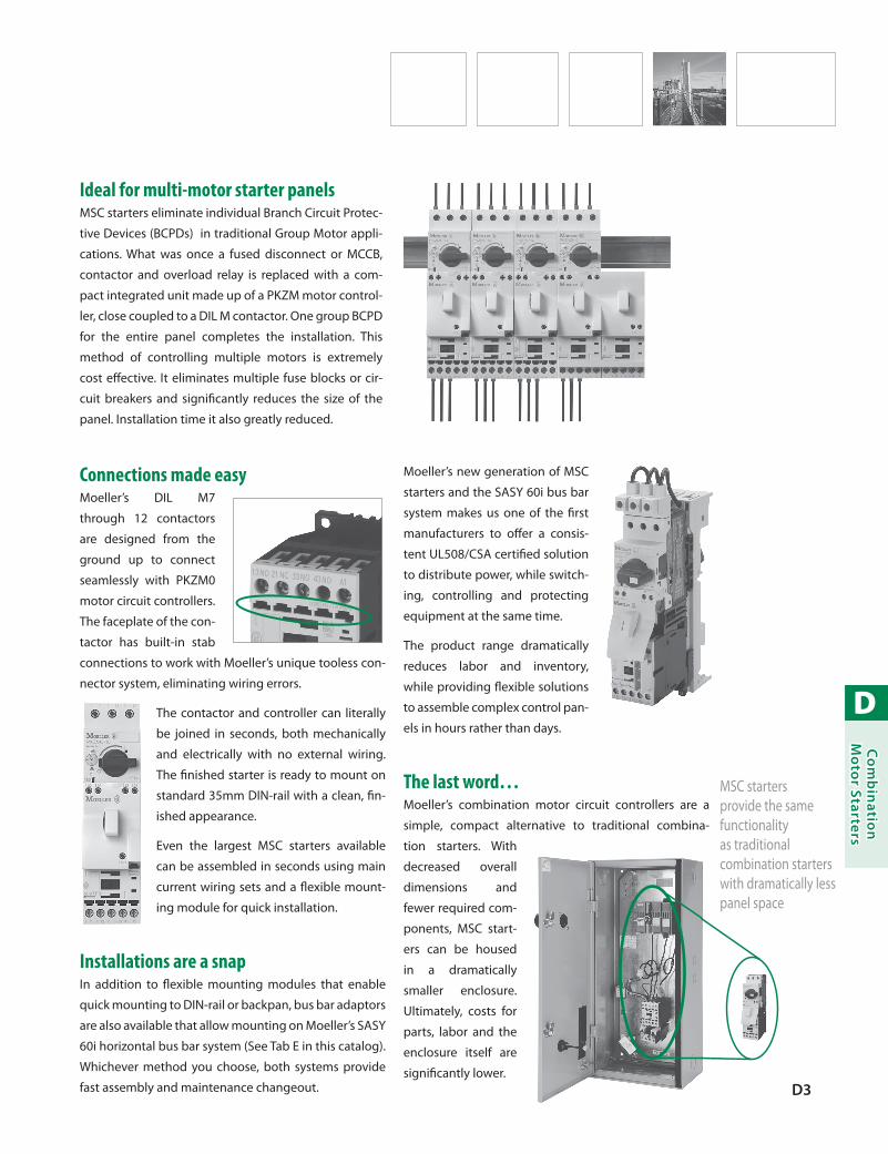
D
Co
mb
inatio
n M
oto
r Starters
D3
Ideal for multi-motor starter panelsMSC starters eliminate individual Branch Circuit Protec-
tive Devices (BCPDs) in traditional Group Motor appli-
cations. What was once a fused disconnect or MCCB,
contactor and overload relay is replaced with a com-
pact integrated unit made up of a PKZM motor control-
ler, close coupled to a DIL M contactor. One group BCPD
for the entire panel completes the installation. This
method of controlling multiple motors is extremely
cost effective. It eliminates multiple fuse blocks or cir-
cuit breakers and significantly reduces the size of the
panel. Installation time it also greatly reduced.
Connections made easyMoeller’s DIL M7
through 12 contactors
are designed from the
ground up to connect
seamlessly with PKZM0
motor circuit controllers.
The faceplate of the con-
tactor has built-in stab
connections to work with Moeller’s unique tooless con-
nector system, eliminating wiring errors.
The contactor and controller can literally
be joined in seconds, both mechanically
and electrically with no external wiring.
The finished starter is ready to mount on
standard 35mm DIN-rail with a clean, fin-
ished appearance.
Even the largest MSC starters available
can be assembled in seconds using main
current wiring sets and a flexible mount-
ing module for quick installation.
Installations are a snapIn addition to flexible mounting modules that enable
quick mounting to DIN-rail or backpan, bus bar adaptors
are also available that allow mounting on Moeller’s SASY
60i horizontal bus bar system (See Tab E in this catalog).
Whichever method you choose, both systems provide
fast assembly and maintenance changeout.
Moeller’s new generation of MSC
starters and the SASY 60i bus bar
system makes us one of the first
manufacturers to offer a consis-
tent UL508/CSA certified solution
to distribute power, while switch-
ing, controlling and protecting
equipment at the same time.
The product range dramatically
reduces labor and inventory,
while providing flexible solutions
to assemble complex control pan-
els in hours rather than days.
The last word…Moeller’s combination motor circuit controllers are a
simple, compact alternative to traditional combina-
tion starters. With
decreased overall
dimensions and
fewer required com-
ponents, MSC start-
ers can be housed
in a dramatically
smaller enclosure.
Ultimately, costs for
parts, labor and the
enclosure itself are
significantly lower.
MSC starters provide the same functionality as traditional combination starters with dramatically less panel space
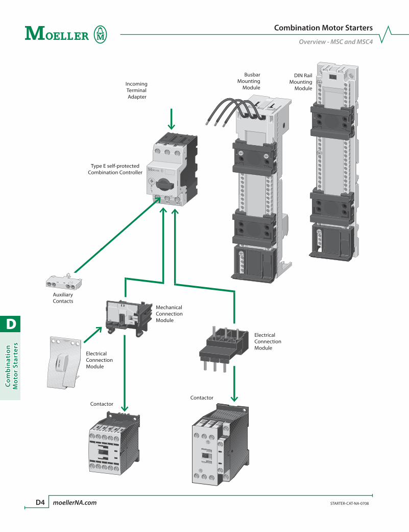
D
Co
mb
inat
ion
Mo
tor
Star
ters
D4 moellerNA.com STARTER-CAT-NA-0708
Combination Motor Starters
Overview - MSC and MSC4
MechanicalConnectionModule
ElectricalConnectionModule
ElectricalConnectionModule
AuxiliaryContacts
ContactorContactor
BusbarMounting
Module
Type E self-protectedCombination Controller
Incoming Terminal Adapter
DIN RailMounting
Module

D
Co
mb
inatio
n M
oto
r Starters
STARTER-CAT-NA-0708 moellerNA.com D5
MSC and MSC4 Combination Motor Starters OverviewDevice Description Range Pages
Combination Motor Starters
Non-Reversing Combination
Starters
Up to 65 AmpsAC operated D8 – D9
Up to 65 AmpsDC operated D10 – D11
Non-Reversing Combination Starters with
Busbar Mounting Module
Up to 32 AmpsAC operated D12
Up to 32 AmpsDC operated D13
Reversing Combination
Starters
Up to 65 AmpsAC operated D14 – D15
Up to 65 AmpsDC operated D16 – D17
Reversing Combination Starters with
Busbar Mounting Module
Up to 32 AmpsAC operated D18
Up to 32 AmpsDC operated D19
Type F One-stop-shop
Type F Required Components For North America D36
Combination Motor Starters
Overview - MSC and MSC4
Device Description Range PagesWiring Sets
Connectors for Reversing and Non-Reversing Starters D37
DIN Rail Mounting Modules
Mounting Modules D38
Commoning Links
Connection for Multiple
Controllers or Starters in Series
Ue = 690 VIu = 63 – 128 A D39 – D40
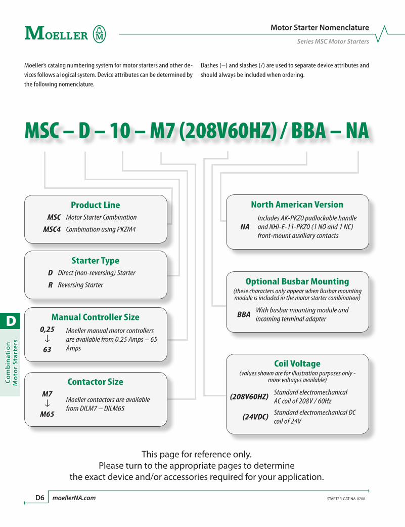
D
Co
mb
inat
ion
Mo
tor
Star
ters
D6 moellerNA.com STARTER-CAT-NA-0708
Motor Starter Nomenclature
Series MSC Motor Starters
MSC – D – 10 – M7 (208V60HZ) / BBA – NA
Moeller’s catalog numbering system for motor starters and other de-vices follows a logical system. Device attributes can be determined by the following nomenclature.
Dashes (–) and slashes (/) are used to separate device attributes and should always be included when ordering.
This page for reference only.Please turn to the appropriate pages to determine
the exact device and/or accessories required for your application.
Product LineMSC Motor Starter Combination
MSC4 Combination using PKZM4
Starter TypeD Direct (non-reversing) Starter
R Reversing Starter
Manual Controller Size0,25↓63
Moeller manual motor controllers are available from 0.25 Amps – 65 Amps
Contactor SizeM7↓M65
Moeller contactors are available from DILM7 – DILM65
North American Version
NAIncludes AK-PKZ0 padlockable handle and NHI-E-11-PKZ0 (1 NO and 1 NC) front-mount auxiliary contacts
Coil Voltage(values shown are for illustration purposes only -
more voltages available)
(208V60HZ) Standard electromechanical AC coil of 208V / 60Hz
(24VDC) Standard electromechanical DC coil of 24V
Optional Busbar Mounting(these characters only appear when Busbar mounting module is included in the motor starter combination)
BBA With busbar mounting module and incoming terminal adapter
D
Co
mb
inatio
n M
oto
r Starters
STARTER-CAT-NA-0708 moellerNA.com D7
Combination Motor Starters
Notes
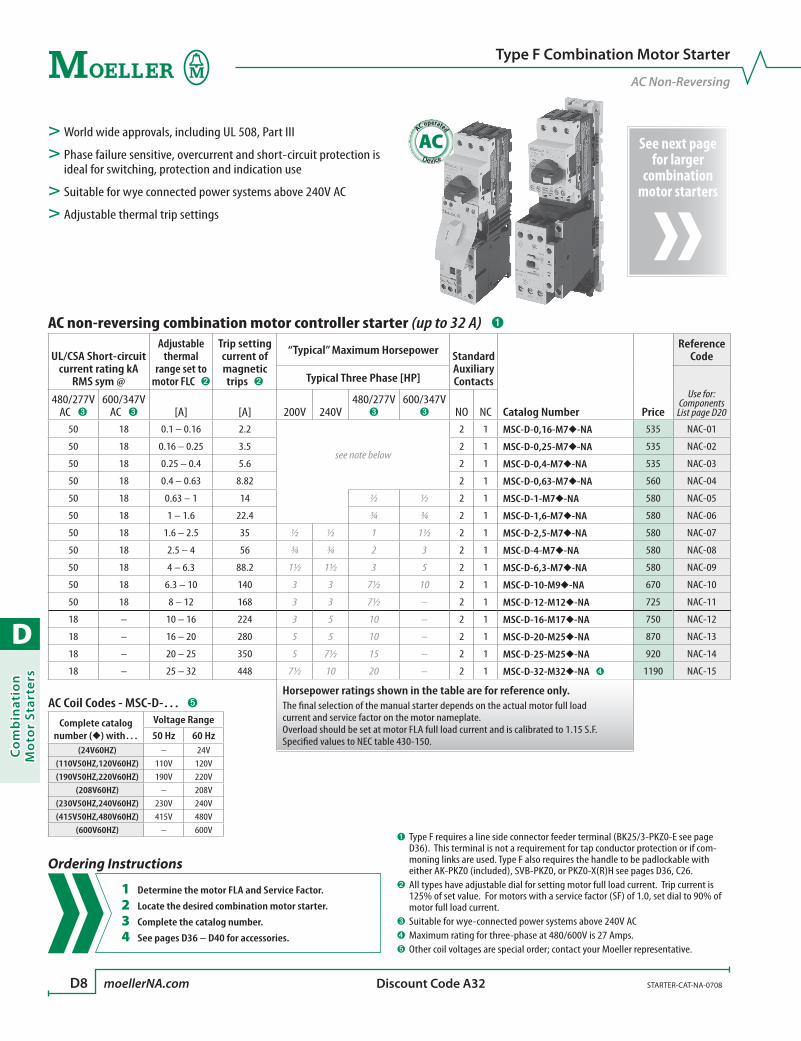
D
Co
mb
inat
ion
Mo
tor
Star
ters
D8 moellerNA.com STARTER-CAT-NA-0708 Discount Code A32
See next page for larger
combination motor starters
AC operated
AC> World wide approvals, including UL 508, Part III
> Phase failure sensitive, overcurrent and short-circuit protection is ideal for switching, protection and indication use
> Suitable for wye connected power systems above 240V AC
> Adjustable thermal trip settings
AC Coil Codes - MSC-D-… ➎
Complete catalog number () with…
Voltage Range
50 Hz 60 Hz(24V60HZ) – 24V
(110V50HZ,120V60HZ) 110V 120V(190V50HZ,220V60HZ) 190V 220V
(208V60HZ) – 208V(230V50HZ,240V60HZ) 230V 240V(415V50HZ,480V60HZ) 415V 480V
(600V60HZ) – 600V
Type F Combination Motor Starter
AC Non-Reversing
AC non-reversing combination motor controller starter (up to 32 A) ➊
UL/CSA Short-circuit current rating kA
RMS sym @
Adjustable thermal
range set to motor FLC ➋
Trip setting current of magnetic trips ➋
“Typical” Maximum Horsepower Standard Auxiliary Contacts
Catalog Number Price
Reference Code
Typical Three Phase [HP]Use for:
Components List page D20
480/277V AC ➌
600/347V AC ➌ [A] [A] 200V 240V
480/277V ➌
600/347V ➌ NO NC
50 18 0.1 – 0.16 2.2
see note below
2 1 MSC-D-0,16-M7-NA 535 NAC-01
50 18 0.16 – 0.25 3.5 2 1 MSC-D-0,25-M7-NA 535 NAC-02
50 18 0.25 – 0.4 5.6 2 1 MSC-D-0,4-M7-NA 535 NAC-03
50 18 0.4 – 0.63 8.82 2 1 MSC-D-0,63-M7-NA 560 NAC-04
50 18 0.63 – 1 14 ½ ½ 2 1 MSC-D-1-M7-NA 580 NAC-05
50 18 1 – 1.6 22.4 ¾ ¾ 2 1 MSC-D-1,6-M7-NA 580 NAC-06
50 18 1.6 – 2.5 35 ½ ½ 1 1½ 2 1 MSC-D-2,5-M7-NA 580 NAC-07
50 18 2.5 – 4 56 ¾ ¾ 2 3 2 1 MSC-D-4-M7-NA 580 NAC-08
50 18 4 – 6.3 88.2 1½ 1½ 3 5 2 1 MSC-D-6,3-M7-NA 580 NAC-09
50 18 6.3 – 10 140 3 3 7½ 10 2 1 MSC-D-10-M9-NA 670 NAC-10
50 18 8 – 12 168 3 3 7½ – 2 1 MSC-D-12-M12-NA 725 NAC-11
18 – 10 – 16 224 3 5 10 – 2 1 MSC-D-16-M17-NA 750 NAC-12
18 – 16 – 20 280 5 5 10 – 2 1 MSC-D-20-M25-NA 870 NAC-13
18 – 20 – 25 350 5 7½ 15 – 2 1 MSC-D-25-M25-NA 920 NAC-14
18 – 25 – 32 448 7½ 10 20 – 2 1 MSC-D-32-M32-NA ➍ 1190 NAC-15
Horsepower ratings shown in the table are for reference only. The final selection of the manual starter depends on the actual motor full load current and service factor on the motor nameplate.Overload should be set at motor FLA full load current and is calibrated to 1.15 S.F.Specified values to NEC table 430-150.
➊ Type F requires a line side connector feeder terminal (BK25/3-PKZ0-E see page D36). This terminal is not a requirement for tap conductor protection or if com-moning links are used. Type F also requires the handle to be padlockable with either AK-PKZ0 (included), SVB-PKZ0, or PKZ0-X(R)H see pages D36, C26.
➋ All types have adjustable dial for setting motor full load current. Trip current is 125% of set value. For motors with a service factor (SF) of 1.0, set dial to 90% of motor full load current.
➌ Suitable for wye-connected power systems above 240V AC➍ Maximum rating for three-phase at 480/600V is 27 Amps.➎ Other coil voltages are special order; contact your Moeller representative.
Ordering Instructions
1 Determine the motor FLA and Service Factor.
2 Locate the desired combination motor starter.
3 Complete the catalog number.
4 See pages D36 – D40 for accessories.
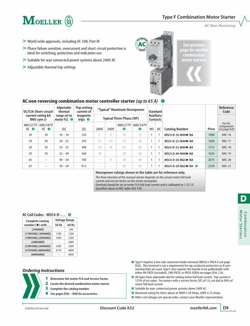
D
Co
mb
inatio
n M
oto
r Starters
STARTER-CAT-NA-0708 moellerNA.com D9 Discount Code A32
See previous page for smaller
combination motor starters
AC Coil Codes - MSC4-D-… ➎
Complete catalog number () with…
Voltage Range
50 Hz 60 Hz(24V60HZ) – 24V
(110V50HZ,120V60HZ) 110V 120V(190V50HZ,220V60HZ) 190V 220V
(208V60HZ) – 208V(230V50HZ,240V60HZ) 230V 240V(415V50HZ,480V60HZ) 415V 480V
(600V60HZ) – 600V
AC operated
AC> World wide approvals, including UL 508, Part III
> Phase failure sensitive, overcurrent and short-circuit protection is ideal for switching, protection and indication use
> Suitable for wye connected power systems above 240V AC
> Adjustable thermal trip settings
Type F Combination Motor Starter
AC Non-Reversing
AC non-reversing combination motor controller starter (up to 65 A) ➊
UL/CSA Short-circuit current rating kA
RMS sym @
Adjustable thermal
range set to motor FLC ➋
Trip setting current of magnetic trips ➋
“Typical” Maximum Horsepower Standard Auxiliary Contacts
Catalog Number Price
Reference Code
Typical Three Phase [HP]Use for:
Components List page D20
480/277V AC ➌
600/347V AC ➌ [A] [A] 200V 240V
480/277V ➌
600/347V ➌ NO NC
50 50 10 – 16 224 3 5 10 15 1 1 MSC4-D-16-M40-NA 1400 NAC-16
50 50 20 – 25 350 7½ 7½ 15 20 1 1 MSC4-D-25-M40-NA 1420 NAC-17
50 50 25 – 32 448 10 10 25 30 1 1 MSC4-D-32-M40-NA 1515 NAC-18
50 50 32 – 40 560 10 – 30 30 1 1 MSC4-D-40-M40-NA 1635 NAC-19
65 – 40 – 50 700 – 15 30 40 1 1 MSC4-D-50-M65-NA 2075 NAC-20
65 – 50 – 58 812 – – 40 50 1 1 MSC4-D-58-M65-NA ➍ 2250 NAC-21
Horsepower ratings shown in the table are for reference only. The final selection of the manual starter depends on the actual motor full load current and service factor on the motor nameplate.Overload should be set at motor FLA full load current and is calibrated to 1.15 S.F.Specified values to NEC table 430-150.
➊ Type F requires a line side connector feeder terminal (BK50/3-PKZ4-E see page D36). This terminal is not a requirement for tap conductor protection or if com-moning links are used. Type F also requires the handle to be padlockable with either AK-PKZ0 (included), SVB-PKZ0, or PKZ0-X(R)H see pages D36, C26.
➋ All types have adjustable dial for setting motor full load current. Trip current is 125% of set value. For motors with a service factor (SF) of 1.0, set dial to 90% of motor full load current.
➌ Suitable for wye-connected power systems above 240V AC➍ Maximum rating for three-phase at 480V is 58 Amps, 600V is 52 Amps.➎ Other coil voltages are special order; contact your Moeller representative.
Ordering Instructions
1 Determine the motor FLA and Service Factor.
2 Locate the desired combination motor starter.
3 Complete the catalog number.
4 See pages D36 – D40 for accessories.
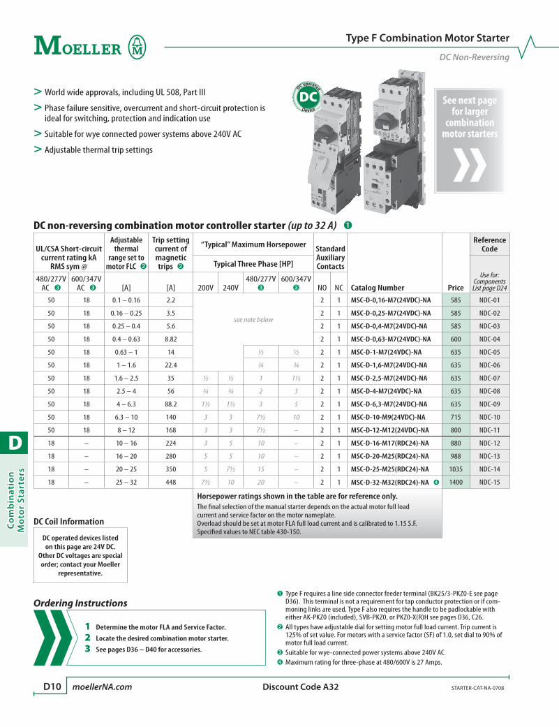
D
Co
mb
inat
ion
Mo
tor
Star
ters
D10 moellerNA.com STARTER-CAT-NA-0708 Discount Code A32
See next page for larger
combination motor starters
DC operated
DC> World wide approvals, including UL 508, Part III
> Phase failure sensitive, overcurrent and short-circuit protection is ideal for switching, protection and indication use
> Suitable for wye connected power systems above 240V AC
> Adjustable thermal trip settings
Type F Combination Motor Starter
DC Non-Reversing
DC non-reversing combination motor controller starter (up to 32 A) ➊
UL/CSA Short-circuit current rating kA
RMS sym @
Adjustable thermal
range set to motor FLC ➋
Trip setting current of magnetic trips ➋
“Typical” Maximum Horsepower Standard Auxiliary Contacts
Catalog Number Price
Reference Code
Typical Three Phase [HP]Use for:
Components List page D24
480/277V AC ➌
600/347V AC ➌ [A] [A] 200V 240V
480/277V ➌
600/347V ➌ NO NC
50 18 0.1 – 0.16 2.2
see note below
2 1 MSC-D-0,16-M7(24VDC)-NA 585 NDC-01
50 18 0.16 – 0.25 3.5 2 1 MSC-D-0,25-M7(24VDC)-NA 585 NDC-02
50 18 0.25 – 0.4 5.6 2 1 MSC-D-0,4-M7(24VDC)-NA 585 NDC-03
50 18 0.4 – 0.63 8.82 2 1 MSC-D-0,63-M7(24VDC)-NA 600 NDC-04
50 18 0.63 – 1 14 ½ ½ 2 1 MSC-D-1-M7(24VDC)-NA 635 NDC-05
50 18 1 – 1.6 22.4 ¾ ¾ 2 1 MSC-D-1,6-M7(24VDC)-NA 635 NDC-06
50 18 1.6 – 2.5 35 ½ ½ 1 1½ 2 1 MSC-D-2,5-M7(24VDC)-NA 635 NDC-07
50 18 2.5 – 4 56 ¾ ¾ 2 3 2 1 MSC-D-4-M7(24VDC)-NA 635 NDC-08
50 18 4 – 6.3 88.2 1½ 1½ 3 5 2 1 MSC-D-6,3-M7(24VDC)-NA 635 NDC-09
50 18 6.3 – 10 140 3 3 7½ 10 2 1 MSC-D-10-M9(24VDC)-NA 715 NDC-10
50 18 8 – 12 168 3 3 7½ – 2 1 MSC-D-12-M12(24VDC)-NA 800 NDC-11
18 – 10 – 16 224 3 5 10 – 2 1 MSC-D-16-M17(RDC24)-NA 880 NDC-12
18 – 16 – 20 280 5 5 10 – 2 1 MSC-D-20-M25(RDC24)-NA 988 NDC-13
18 – 20 – 25 350 5 7½ 15 – 2 1 MSC-D-25-M25(RDC24)-NA 1035 NDC-14
18 – 25 – 32 448 7½ 10 20 – 2 1 MSC-D-32-M32(RDC24)-NA ➍ 1400 NDC-15
Horsepower ratings shown in the table are for reference only. The final selection of the manual starter depends on the actual motor full load current and service factor on the motor nameplate.Overload should be set at motor FLA full load current and is calibrated to 1.15 S.F.Specified values to NEC table 430-150.
➊ Type F requires a line side connector feeder terminal (BK25/3-PKZ0-E see page D36). This terminal is not a requirement for tap conductor protection or if com-moning links are used. Type F also requires the handle to be padlockable with either AK-PKZ0 (included), SVB-PKZ0, or PKZ0-X(R)H see pages D36, C26.
➋ All types have adjustable dial for setting motor full load current. Trip current is 125% of set value. For motors with a service factor (SF) of 1.0, set dial to 90% of motor full load current.
➌ Suitable for wye-connected power systems above 240V AC➍ Maximum rating for three-phase at 480/600V is 27 Amps.
Ordering Instructions
1 Determine the motor FLA and Service Factor.
2 Locate the desired combination motor starter.
3 See pages D36 – D40 for accessories.
DC Coil Information
DC operated devices listed on this page are 24V DC.
Other DC voltages are special order; contact your Moeller
representative.

D
Co
mb
inatio
n M
oto
r Starters
STARTER-CAT-NA-0708 moellerNA.com D11 Discount Code A32
See previous page for smaller
combination motor starters
DC operated
DC> World wide approvals, including UL 508, Part III
> Phase failure sensitive, overcurrent and short-circuit protection is ideal for switching, protection and indication use
> Suitable for wye connected power systems above 240V AC
> Adjustable thermal trip settings
Type F Combination Motor Starter
DC Non-Reversing
DC non-reversing combination motor controller starter (up to 65 A) ➊
UL/CSA Short-circuit current rating kA
RMS sym @
Adjustable thermal
range set to motor FLC ➋
Trip setting current of magnetic trips ➋
“Typical” Maximum Horsepower Standard Auxiliary Contacts
Catalog Number Price
Reference Code
Typical Three Phase [HP]Use for:
Components List page D24
480/277V AC ➌
600/347V AC ➌ [A] [A] 200V 240V
480/277V ➌
600/347V ➌ NO NC
50 50 10 – 16 224 3 5 10 15 1 1 MSC4-D-16-M40(RDC24)-NA 1580 NDC-16
50 50 20 – 25 350 7½ 7½ 15 20 1 1 MSC4-D-25-M40(RDC24)-NA 1595 NDC-17
50 50 25 – 32 448 10 10 25 30 1 1 MSC4-D-32-M40(RDC24)-NA 1690 NDC-18
50 50 32 – 40 560 10 – 30 30 1 1 MSC4-D-40-M40(RDC24)-NA 1800 NDC-19
65 – 40 – 50 700 – 15 30 40 1 1 MSC4-D-50-M65(RDC24)-NA 2530 NDC-20
65 – 50 – 58 812 – – 40 50 1 1 MSC4-D-58-M65(RDC24)-NA ➍ 2700 NDC-21
Horsepower ratings shown in the table are for reference only. The final selection of the manual starter depends on the actual motor full load current and service factor on the motor nameplate.Overload should be set at motor FLA full load current and is calibrated to 1.15 S.F.Specified values to NEC table 430-150.
➊ Type F requires a line side connector feeder terminal (BK50/3-PKZ4-E see page D36). This terminal is not a requirement for tap conductor protection or if com-moning links are used. Type F also requires the handle to be padlockable with either AK-PKZ0 (included), SVB-PKZ0, or PKZ0-X(R)H see pages D36, C26.
➋ All types have adjustable dial for setting motor full load current. Trip current is 125% of set value. For motors with a service factor (SF) of 1.0, set dial to 90% of motor full load current.
➌ Suitable for wye-connected power systems above 240V AC➍ Maximum rating for three-phase at 480V is 58 Amps, 600V is 52 Amps.
Ordering Instructions
1 Determine the motor FLA and Service Factor.
2 Locate the desired combination motor starter.
3 See pages D36 – D40 for accessories.
DC Coil Information
DC operated devices listed on this page are 24V DC.
Other DC voltages are special order; contact your Moeller
representative.

D
Co
mb
inat
ion
Mo
tor
Star
ters
D12 moellerNA.com STARTER-CAT-NA-0708 Discount Code A32
AC operated
AC> World wide approvals, including UL 508, Part III
> Phase failure sensitive, overcurrent and short-circuit protection is ideal for switching, protection and indication use
> Suitable for wye connected power systems above 240V AC
> Adjustable thermal trip settings
Type F Combination Motor Starter
AC Non-Reversing with Included Busbar Mounting Module
AC non-reversing combination motor controller starter with busbar mounting module ➊
UL/CSA Short-circuit current rating kA
RMS sym @
Adjustable thermal
range set to motor FLC ➋
Trip setting current of magnetic trips ➋
“Typical” Maximum Horsepower Standard Auxiliary Contacts
Catalog Number Price
Reference Code
Typical Three Phase [HP]Use for:
Components List page D22
480/277V AC ➌
600/347V AC ➌ [A] [A] 200V 240V
480/277V ➌
600/347V ➌ NO NC
50 18 0.1 – 0.16 2.2
see note below
2 1 MSC-D-0,16-M7/BBA-NA 710 NAC-22
50 18 0.16 – 0.25 3.5 2 1 MSC-D-0,25-M7/BBA-NA 710 NAC-23
50 18 0.25 – 0.4 5.6 2 1 MSC-D-0,4-M7/BBA-NA 710 NAC-24
50 18 0.4 – 0.63 8.82 2 1 MSC-D-0,63-M7/BBA-NA 735 NAC-25
50 18 0.63 – 1 14 ½ ½ 2 1 MSC-D-1-M7/BBA-NA 760 NAC-26
50 18 1 – 1.6 22.4 ¾ ¾ 2 1 MSC-D-1,6-M7/BBA-NA 760 NAC-27
50 18 1.6 – 2.5 35 ½ ½ 1 1½ 2 1 MSC-D-2,5-M7/BBA-NA 760 NAC-28
50 18 2.5 – 4 56 ¾ ¾ 2 3 2 1 MSC-D-4-M7/BBA-NA 760 NAC-29
50 18 4 – 6.3 88.2 1½ 1½ 3 5 2 1 MSC-D-6,3-M7/BBA-NA 760 NAC-30
50 18 6.3 – 10 140 3 3 7½ 10 2 1 MSC-D-10-M9/BBA-NA 845 NAC-31
50 18 8 – 12 168 3 3 7½ – 2 1 MSC-D-12-M12/BBA-NA 900 NAC-32
18 – 10 – 16 224 3 5 10 – 2 1 MSC-D-16-M17/BBA-NA 915 NAC-33
18 – 16 – 20 280 5 5 10 – 2 1 MSC-D-20-M25/BBA-NA 1035 NAC-34
18 – 20 – 25 350 5 7½ 15 – 2 1 MSC-D-25-M25/BBA-NA 1080 NAC-35
18 – 25 – 32 448 7½ 10 20 – 2 1 MSC-D-32-M32/BBA-NA ➍ 1350 NAC-36
Horsepower ratings shown in the table are for reference only. The final selection of the manual starter depends on the actual motor full load current and service factor on the motor nameplate.Overload should be set at motor FLA full load current and is calibrated to 1.15 S.F.Specified values to NEC table 430-150.
AC Coil Codes - MSC-D-…/BBA ➎
Complete catalog number () with…
Voltage Range
50 Hz 60 Hz(24V60HZ) – 24V
(110V50HZ,120V60HZ) 110V 120V(190V50HZ,220V60HZ) 190V 220V
(208V60HZ) – 208V(230V50HZ,240V60HZ) 230V 240V(415V50HZ,480V60HZ) 415V 480V
(600V60HZ) – 600V
➊ Type F requires the handle to be padlockable with either AK-PKZ0 (included), SVB-PKZ0, or PKZ0-X(R)H see pages D36, C26.
➋ All types have adjustable dial for setting motor full load current. Trip current is 125% of set value. For motors with a service factor (SF) of 1.0, set dial to 90% of motor full load current.
➌ Suitable for wye-connected power systems above 240V AC➍ Maximum rating for three-phase at 480/600V is 27 Amps.➎ Other coil voltages are special order; contact your Moeller representative.
Ordering Instructions
1 Determine the motor FLA and Service Factor.
2 Locate the desired combination motor starter.
3 Complete the catalog number.
4 See pages D36 – D40 for accessories.

D
Co
mb
inatio
n M
oto
r Starters
STARTER-CAT-NA-0708 moellerNA.com D13 Discount Code A32
DC operated
DC> World wide approvals, including UL 508, Part III
> Phase failure sensitive, overcurrent and short-circuit protection is ideal for switching, protection and indication use
> Suitable for wye connected power systems above 240V AC
> Adjustable thermal trip settings
Type F Combination Motor Starter
DC Non-Reversing with Included Busbar Mounting Module
DC non-reversing combination motor controller starter with busbar mounting module ➊
UL/CSA Short-circuit current rating kA
RMS sym @
Adjustable thermal
range set to motor FLC ➋
Trip setting current of magnetic trips ➋
“Typical” Maximum Horsepower Standard Auxiliary Contacts
Catalog Number Price
Reference Code
Typical Three Phase [HP]Use for:
Components List page D26
480/277V AC ➌
600/347V AC ➌ [A] [A] 200V 240V
480/277V ➌
600/347V ➌ NO NC
50 18 0.1 – 0.16 2.2
see note below
2 1 MSC-D-0,16-M7(24VDC)/BBA-NA 760 NDC-22
50 18 0.16 – 0.25 3.5 2 1 MSC-D-0,25-M7(24VDC)/BBA-NA 760 NDC-23
50 18 0.25 – 0.4 5.6 2 1 MSC-D-0,4-M7(24VDC)/BBA-NA 760 NDC-24
50 18 0.4 – 0.63 8.82 2 1 MSC-D-0,63-M7(24VDC)/BBA-NA 785 NDC-25
50 18 0.63 – 1 14 ½ ½ 2 1 MSC-D-1-M7(24VDC)/BBA-NA 800 NDC-26
50 18 1 – 1.6 22.4 ¾ ¾ 2 1 MSC-D-1,6-M7(24VDC)/BBA-NA 800 NDC-27
50 18 1.6 – 2.5 35 ½ ½ 1 1½ 2 1 MSC-D-2,5-M7(24VDC)/BBA-NA 800 NDC-28
50 18 2.5 – 4 56 ¾ ¾ 2 3 2 1 MSC-D-4-M7(24VDC)/BBA-NA 800 NDC-29
50 18 4 – 6.3 88.2 1½ 1½ 3 5 2 1 MSC-D-6,3-M7(24VDC)/BBA-NA 800 NDC-30
50 18 6.3 – 10 140 3 3 7½ 10 2 1 MSC-D-10-M9(24VDC)/BBA-NA 890 NDC-31
50 18 8 – 12 168 3 3 7½ – 2 1 MSC-D-12-M12(24VDC)/BBA-NA 980 NDC-32
18 – 10 – 16 224 3 5 10 – 2 1 MSC-D-16-M17(RDC24)/BBA-NA 1045 NDC-33
18 – 16 – 20 280 5 5 10 – 2 1 MSC-D-20-M25(RDC24)/BBA-NA 1150 NDC-34
18 – 20 – 25 350 5 7½ 15 – 2 1 MSC-D-25-M25(RDC24)/BBA-NA 1200 NDC-35
18 – 25 – 32 448 7½ 10 20 – 2 1 MSC-D-32-M32(RDC24)/BBA-NA ➍ 1560 NDC-36
Horsepower ratings shown in the table are for reference only. The final selection of the manual starter depends on the actual motor full load current and service factor on the motor nameplate.Overload should be set at motor FLA full load current and is calibrated to 1.15 S.F.Specified values to NEC table 430-150.
➊ Type F requires the handle to be padlockable with either AK-PKZ0 (included), SVB-PKZ0, or PKZ0-X(R)H see pages D36, C26.
➋ All types have adjustable dial for setting motor full load current. Trip current is 125% of set value. For motors with a service factor (SF) of 1.0, set dial to 90% of motor full load current.
➌ Suitable for wye-connected power systems above 240V AC➍ Maximum rating for three-phase at 480/600V is 27 Amps.
Ordering Instructions
1 Determine the motor FLA and Service Factor.
2 Locate the desired combination motor starter.
3 See pages D36 – D40 for accessories.
DC Coil Information
DC operated devices listed on this page are 24V DC.
Other DC voltages are special order; contact your Moeller
representative.
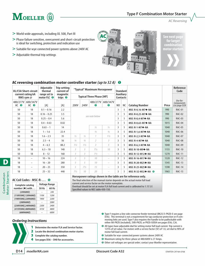
D
Co
mb
inat
ion
Mo
tor
Star
ters
D14 moellerNA.com STARTER-CAT-NA-0708 Discount Code A32
See next page for larger
combination motor starters
AC operated
AC> World wide approvals, including UL 508, Part III
> Phase failure sensitive, overcurrent and short-circuit protection is ideal for switching, protection and indication use
> Suitable for wye connected power systems above 240V AC
> Adjustable thermal trip settings
Type F Combination Motor Starter
AC Reversing
AC reversing combination motor controller starter (up to 32 A) ➊
UL/CSA Short-circuit current rating kA
RMS sym @
Adjustable thermal
range set to motor FLC ➋
Trip setting current of magnetic trips ➋
“Typical” Maximum Horsepower Standard Auxiliary Contacts
Catalog Number Price
Reference Code
Typical Three Phase [HP]Use for:
Components List page D28
480/277V AC ➌
600/347V AC ➌ [A] [A] 200V 240V
480/277V ➌
600/347V ➌ NO NC
50 18 0.1 – 0.16 2.2
see note below
3 5 MSC-R-0,16-M7-NA 990 RAC-01
50 18 0.16 – 0.25 3.5 3 5 MSC-R-0,25-M7-NA 990 RAC-02
50 18 0.25 – 0.4 5.6 3 5 MSC-R-0,4-M7-NA 990 RAC-03
50 18 0.4 – 0.63 8.82 3 5 MSC-R-0,63-M7-NA 1015 RAC-04
50 18 0.63 – 1 14 ½ ½ 3 5 MSC-R-1-M7-NA 1040 RAC-05
50 18 1 – 1.6 22.4 ¾ ¾ 3 5 MSC-R-1,6-M7-NA 1040 RAC-06
50 18 1.6 – 2.5 35 ½ ½ 1 1½ 3 5 MSC-R-2,5-M7-NA 1040 RAC-07
50 18 2.5 – 4 56 ¾ ¾ 2 3 3 5 MSC-R-4-M7-NA 1040 RAC-08
50 18 4 – 6.3 88.2 1½ 1½ 3 5 3 5 MSC-R-6,3-M7-NA 1040 RAC-09
50 18 6.3 – 10 140 3 3 7½ 10 3 5 MSC-R-10-M9-NA 1155 RAC-10
50 18 8 – 12 168 3 3 7½ – 3 5 MSC-R-12-M12-NA 1270 RAC-11
18 – 10 – 16 224 3 5 10 – 3 5 MSC-R-16-M17-NA 1320 RAC-12
18 – 16 – 20 280 5 5 10 – 3 5 MSC-R-20-M25-NA 1545 RAC-13
18 – 20 – 25 350 5 7½ 15 – 3 5 MSC-R-25-M25-NA 1590 RAC-14
18 – 25 – 32 448 7½ 10 20 – 3 5 MSC-R-32-M32-NA ➍ 1965 RAC-15
Horsepower ratings shown in the table are for reference only. The final selection of the manual starter depends on the actual motor full load current and service factor on the motor nameplate.Overload should be set at motor FLA full load current and is calibrated to 1.15 S.F.Specified values to NEC table 430-150.
AC Coil Codes - MSC-R-… ➎
Complete catalog number () with…
Voltage Range
50 Hz 60 Hz(24V60HZ) – 24V
(110V50HZ,120V60HZ) 110V 120V(190V50HZ,220V60HZ) 190V 220V
(208V60HZ) – 208V(230V50HZ,240V60HZ) 230V 240V(415V50HZ,480V60HZ) 415V 480V
(600V60HZ) – 600V➊ Type F requires a line side connector feeder terminal (BK25/3-PKZ0-E see page
D36). This terminal is not a requirement for tap conductor protection or if com-moning links are used. Type F also requires the handle to be padlockable with either AK-PKZ0 (included), SVB-PKZ0, or PKZ0-X(R)H see pages D36, C26.
➋ All types have adjustable dial for setting motor full load current. Trip current is 125% of set value. For motors with a service factor (SF) of 1.0, set dial to 90% of motor full load current.
➌ Suitable for wye-connected power systems above 240V AC➍ Maximum rating for three-phase at 480/600V is 27 Amps.➎ Other coil voltages are special order; contact your Moeller representative.
Ordering Instructions
1 Determine the motor FLA and Service Factor.
2 Locate the desired combination motor starter.
3 Complete the catalog number.
4 See pages D36 – D40 for accessories.
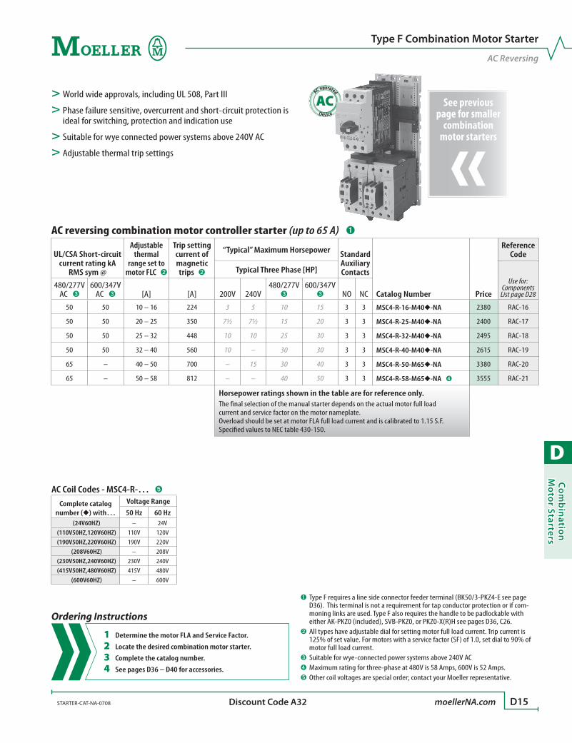
D
Co
mb
inatio
n M
oto
r Starters
STARTER-CAT-NA-0708 moellerNA.com D15 Discount Code A32
See previous page for smaller
combination motor starters
AC operated
AC> World wide approvals, including UL 508, Part III
> Phase failure sensitive, overcurrent and short-circuit protection is ideal for switching, protection and indication use
> Suitable for wye connected power systems above 240V AC
> Adjustable thermal trip settings
Type F Combination Motor Starter
AC Reversing
AC reversing combination motor controller starter (up to 65 A) ➊
UL/CSA Short-circuit current rating kA
RMS sym @
Adjustable thermal
range set to motor FLC ➋
Trip setting current of magnetic trips ➋
“Typical” Maximum Horsepower Standard Auxiliary Contacts
Catalog Number Price
Reference Code
Typical Three Phase [HP]Use for:
Components List page D28
480/277V AC ➌
600/347V AC ➌ [A] [A] 200V 240V
480/277V ➌
600/347V ➌ NO NC
50 50 10 – 16 224 3 5 10 15 3 3 MSC4-R-16-M40-NA 2380 RAC-16
50 50 20 – 25 350 7½ 7½ 15 20 3 3 MSC4-R-25-M40-NA 2400 RAC-17
50 50 25 – 32 448 10 10 25 30 3 3 MSC4-R-32-M40-NA 2495 RAC-18
50 50 32 – 40 560 10 – 30 30 3 3 MSC4-R-40-M40-NA 2615 RAC-19
65 – 40 – 50 700 – 15 30 40 3 3 MSC4-R-50-M65-NA 3380 RAC-20
65 – 50 – 58 812 – – 40 50 3 3 MSC4-R-58-M65-NA ➍ 3555 RAC-21
Horsepower ratings shown in the table are for reference only. The final selection of the manual starter depends on the actual motor full load current and service factor on the motor nameplate.Overload should be set at motor FLA full load current and is calibrated to 1.15 S.F.Specified values to NEC table 430-150.
➊ Type F requires a line side connector feeder terminal (BK50/3-PKZ4-E see page D36). This terminal is not a requirement for tap conductor protection or if com-moning links are used. Type F also requires the handle to be padlockable with either AK-PKZ0 (included), SVB-PKZ0, or PKZ0-X(R)H see pages D36, C26.
➋ All types have adjustable dial for setting motor full load current. Trip current is 125% of set value. For motors with a service factor (SF) of 1.0, set dial to 90% of motor full load current.
➌ Suitable for wye-connected power systems above 240V AC➍ Maximum rating for three-phase at 480V is 58 Amps, 600V is 52 Amps.➎ Other coil voltages are special order; contact your Moeller representative.
AC Coil Codes - MSC4-R-… ➎
Complete catalog number () with…
Voltage Range
50 Hz 60 Hz(24V60HZ) – 24V
(110V50HZ,120V60HZ) 110V 120V(190V50HZ,220V60HZ) 190V 220V
(208V60HZ) – 208V(230V50HZ,240V60HZ) 230V 240V(415V50HZ,480V60HZ) 415V 480V
(600V60HZ) – 600V
Ordering Instructions
1 Determine the motor FLA and Service Factor.
2 Locate the desired combination motor starter.
3 Complete the catalog number.
4 See pages D36 – D40 for accessories.

D
Co
mb
inat
ion
Mo
tor
Star
ters
D16 moellerNA.com STARTER-CAT-NA-0708 Discount Code A32
See next page for larger
combination motor starters
DC operated
DC> World wide approvals, including UL 508, Part III
> Phase failure sensitive, overcurrent and short-circuit protection is ideal for switching, protection and indication use
> Suitable for wye connected power systems above 240V AC
> Adjustable thermal trip settings
Type F Combination Motor Starter
DC Reversing
DC reversing combination motor controller starter (up to 32 A) ➊
UL/CSA Short-circuit current rating kA
RMS sym @
Adjustable thermal
range set to motor FLC ➋
Trip setting current of magnetic trips ➋
“Typical” Maximum Horsepower Standard Auxiliary Contacts
Catalog Number Price
Reference Code
Typical Three Phase [HP]Use for:
Components List page D32
480/277V AC ➌
600/347V AC ➌ [A] [A] 200V 240V
480/277V ➌
600/347V ➌ NO NC
50 18 0.1 – 0.16 2.2
see note below
3 5 MSC-R-0,16-M7(24VDC)-NA 1095 RDC-01
50 18 0.16 – 0.25 3.5 3 5 MSC-R-0,25-M7(24VDC)-NA 1095 RDC-02
50 18 0.25 – 0.4 5.6 3 5 MSC-R-0,4-M7(24VDC)-NA 1095 RDC-03
50 18 0.4 – 0.63 8.82 3 5 MSC-R-0,63-M7(24VDC)-NA 1120 RDC-04
50 18 0.63 – 1 14 ½ ½ 3 5 MSC-R-1-M7(24VDC)-NA 1145 RDC-05
50 18 1 – 1.6 22.4 ¾ ¾ 3 5 MSC-R-1,6-M7(24VDC)-NA 1145 RDC-06
50 18 1.6 – 2.5 35 ½ ½ 1 1½ 3 5 MSC-R-2,5-M7(24VDC)-NA 1145 RDC-07
50 18 2.5 – 4 56 ¾ ¾ 2 3 3 5 MSC-R-4-M7(24VDC)-NA 1145 RDC-08
50 18 4 – 6.3 88.2 1½ 1½ 3 5 3 5 MSC-R-6,3-M7(24VDC)-NA 1145 RDC-09
50 18 6.3 – 10 140 3 3 7½ 10 3 5 MSC-R-10-M9(24VDC)-NA 1250 RDC-10
50 18 8 – 12 168 3 3 7½ – 3 5 MSC-R-12-M12(24VDC)-NA 1425 RDC-11
18 – 10 – 16 224 3 5 10 – 3 5 MSC-R-16-M17(RDC24)-NA 1580 RDC-12
18 – 16 – 20 280 5 5 10 – 3 5 MSC-R-20-M25(RDC24)-NA 1780 RDC-13
18 – 20 – 25 350 5 7½ 15 – 3 5 MSC-R-25-M25(RDC24)-NA 1825 RDC-14
18 – 25 – 32 448 7½ 10 20 – 3 5 MSC-R-32-M32(RDC24)-NA ➍ 2390 RDC-15
Horsepower ratings shown in the table are for reference only. The final selection of the manual starter depends on the actual motor full load current and service factor on the motor nameplate.Overload should be set at motor FLA full load current and is calibrated to 1.15 S.F.Specified values to NEC table 430-150.
➊ Type F requires a line side connector feeder terminal (BK25/3-PKZ0-E see page D36). This terminal is not a requirement for tap conductor protection or if com-moning links are used. Type F also requires the handle to be padlockable with either AK-PKZ0 (included), SVB-PKZ0, or PKZ0-X(R)H see pages D36, C26.
➋ All types have adjustable dial for setting motor full load current. Trip current is 125% of set value. For motors with a service factor (SF) of 1.0, set dial to 90% of motor full load current.
➌ Suitable for wye-connected power systems above 240V AC➍ Maximum rating for three-phase at 480/600V is 27 Amps.
Ordering Instructions
1 Determine the motor FLA and Service Factor.
2 Locate the desired combination motor starter.
3 See pages D36 – D40 for accessories.
DC Coil Information
DC operated devices listed on this page are 24V DC.
Other DC voltages are special order; contact your Moeller
representative.

D
Co
mb
inatio
n M
oto
r Starters
STARTER-CAT-NA-0708 moellerNA.com D17 Discount Code A32
See previous page for smaller
combination motor starters
DC reversing combination motor controller starter (up to 65 A) ➊
UL/CSA Short-circuit current rating kA
RMS sym @
Adjustable thermal
range set to motor FLC ➋
Trip setting current of magnetic trips ➋
“Typical” Maximum Horsepower Standard Auxiliary Contacts
Catalog Number Price
Reference Code
Typical Three Phase [HP]Use for:
Components List page D32
480/277V AC ➌
600/347V AC ➌ [A] [A] 200V 240V
480/277V ➌
600/347V ➌ NO NC
50 50 10 – 16 224 3 5 10 15 3 3 MSC4-R-16-M40(RDC24)-NA 2735 RDC-16
50 50 20 – 25 350 7½ 7½ 15 20 3 3 MSC4-R-25-M40(RDC24)-NA 2750 RDC-17
50 50 25 – 32 448 10 10 25 30 3 3 MSC4-R-32-M40(RDC24)-NA 2850 RDC-18
50 50 32 – 40 560 10 – 30 30 3 3 MSC4-R-40-M40(RDC24)-NA 2965 RDC-19
65 – 40 – 50 700 – 15 30 40 3 3 MSC4-R-50-M65(RDC24)-NA 4300 RDC-20
65 – 50 – 58 812 – – 40 50 3 3 MSC4-R-58-M65(RDC24)-NA ➍ 4475 RDC-21
Horsepower ratings shown in the table are for reference only. The final selection of the manual starter depends on the actual motor full load current and service factor on the motor nameplate.Overload should be set at motor FLA full load current and is calibrated to 1.15 S.F.Specified values to NEC table 430-150.
DC operated
DC> World wide approvals, including UL 508, Part III
> Phase failure sensitive, overcurrent and short-circuit protection is ideal for switching, protection and indication use
> Suitable for wye connected power systems above 240V AC
> Adjustable thermal trip settings
Type F Combination Motor Starter
DC Reversing
➊ Type F requires a line side connector feeder terminal (BK50/3-PKZ4-E see page D36). This terminal is not a requirement for tap conductor protection or if com-moning links are used. Type F also requires the handle to be padlockable with either AK-PKZ0 (included), SVB-PKZ0, or PKZ0-X(R)H see pages D36, C26.
➋ All types have adjustable dial for setting motor full load current. Trip current is 125% of set value. For motors with a service factor (SF) of 1.0, set dial to 90% of motor full load current.
➌ Suitable for wye-connected power systems above 240V AC➍ Maximum rating for three-phase at 480V is 58 Amps, 600V is 52 Amps.
Ordering Instructions
1 Determine the motor FLA and Service Factor.
2 Locate the desired combination motor starter.
3 See pages D36 – D40 for accessories.
DC Coil Information
DC operated devices listed on this page are 24V DC.
Other DC voltages are special order; contact your Moeller
representative.

D
Co
mb
inat
ion
Mo
tor
Star
ters
D18 moellerNA.com STARTER-CAT-NA-0708 Discount Code A32
AC operated
AC> World wide approvals, including UL 508, Part III
> Phase failure sensitive, overcurrent and short-circuit protection is ideal for switching, protection and indication use
> Suitable for wye connected power systems above 240V AC
> Adjustable thermal trip settings
Type F Combination Motor Starter
AC Reversing with Included Busbar Mounting Module
AC reversing combination motor controller starter with busbar mounting module ➊
UL/CSA Short-circuit current rating kA
RMS sym @
Adjustable thermal
range set to motor FLC ➋
Trip setting current of magnetic trips ➋
“Typical” Maximum Horsepower Standard Auxiliary Contacts
Catalog Number Price
Reference Code
Typical Three Phase [HP]Use for:
Components List page D30
480/277V AC ➌
600/347V AC ➌ [A] [A] 200V 240V
480/277V ➌
600/347V ➌ NO NC
50 18 0.1 – 0.16 2.2
see note below
3 5 MSC-R-0,16-M7/BBA-NA 1320 RAC-22
50 18 0.16 – 0.25 3.5 3 5 MSC-R-0,25-M7/BBA-NA 1320 RAC-23
50 18 0.25 – 0.4 5.6 3 5 MSC-R-0,4-M7/BBA-NA 1320 RAC-24
50 18 0.4 – 0.63 8.82 3 5 MSC-R-0,63-M7/BBA-NA 1340 RAC-25
50 18 0.63 – 1 14 ½ ½ 3 5 MSC-R-1-M7/BBA-NA 1365 RAC-26
50 18 1 – 1.6 22.4 ¾ ¾ 3 5 MSC-R-1,6-M7/BBA-NA 1365 RAC-27
50 18 1.6 – 2.5 35 ½ ½ 1 1½ 3 5 MSC-R-2,5-M7/BBA-NA 1365 RAC-28
50 18 2.5 – 4 56 ¾ ¾ 2 3 3 5 MSC-R-4-M7/BBA-NA 1365 RAC-29
50 18 4 – 6.3 88.2 1½ 1½ 3 5 3 5 MSC-R-6,3-M7/BBA-NA 1365 RAC-30
50 18 6.3 – 10 140 3 3 7½ 10 3 5 MSC-R-10-M9/BBA-NA 1480 RAC-31
50 18 8 – 12 168 3 3 7½ – 3 5 MSC-R-12-M12/BBA-NA 1595 RAC-32
18 – 10 – 16 224 3 5 10 – 3 5 MSC-R-16-M17/BBA-NA 1690 RAC-33
18 – 16 – 20 280 5 5 10 – 3 5 MSC-R-20-M25/BBA-NA 1715 RAC-34
18 – 20 – 25 350 5 7½ 15 – 3 5 MSC-R-25-M25/BBA-NA 1760 RAC-35
18 – 25 – 32 448 7½ 10 20 – 3 5 MSC-R-32-M32/BBA-NA ➍ 2140 RAC-36
Horsepower ratings shown in the table are for reference only. The final selection of the manual starter depends on the actual motor full load current and service factor on the motor nameplate.Overload should be set at motor FLA full load current and is calibrated to 1.15 S.F.Specified values to NEC table 430-150.
AC Coil Codes - MSC-R-…/BBA ➎
Complete catalog number () with…
Voltage Range
50 Hz 60 Hz(24V60HZ) – 24V
(110V50HZ,120V60HZ) 110V 120V(190V50HZ,220V60HZ) 190V 220V
(208V60HZ) – 208V(230V50HZ,240V60HZ) 230V 240V(415V50HZ,480V60HZ) 415V 480V
(600V60HZ) – 600V
➊ Type F requires the handle to be padlockable with either AK-PKZ0 (included), SVB-PKZ0, or PKZ0-X(R)H see pages D36, C26.
➋ All types have adjustable dial for setting motor full load current. Trip current is 125% of set value. For motors with a service factor (SF) of 1.0, set dial to 90% of motor full load current.
➌ Suitable for wye-connected power systems above 240V AC➍ Maximum rating for three-phase at 480/600V is 27 Amps.➎ Other coil voltages are special order; contact your Moeller representative.
Ordering Instructions
1 Determine the motor FLA and Service Factor.
2 Locate the desired combination motor starter.
3 Complete the catalog number.
4 See pages D36 – D40 for accessories.
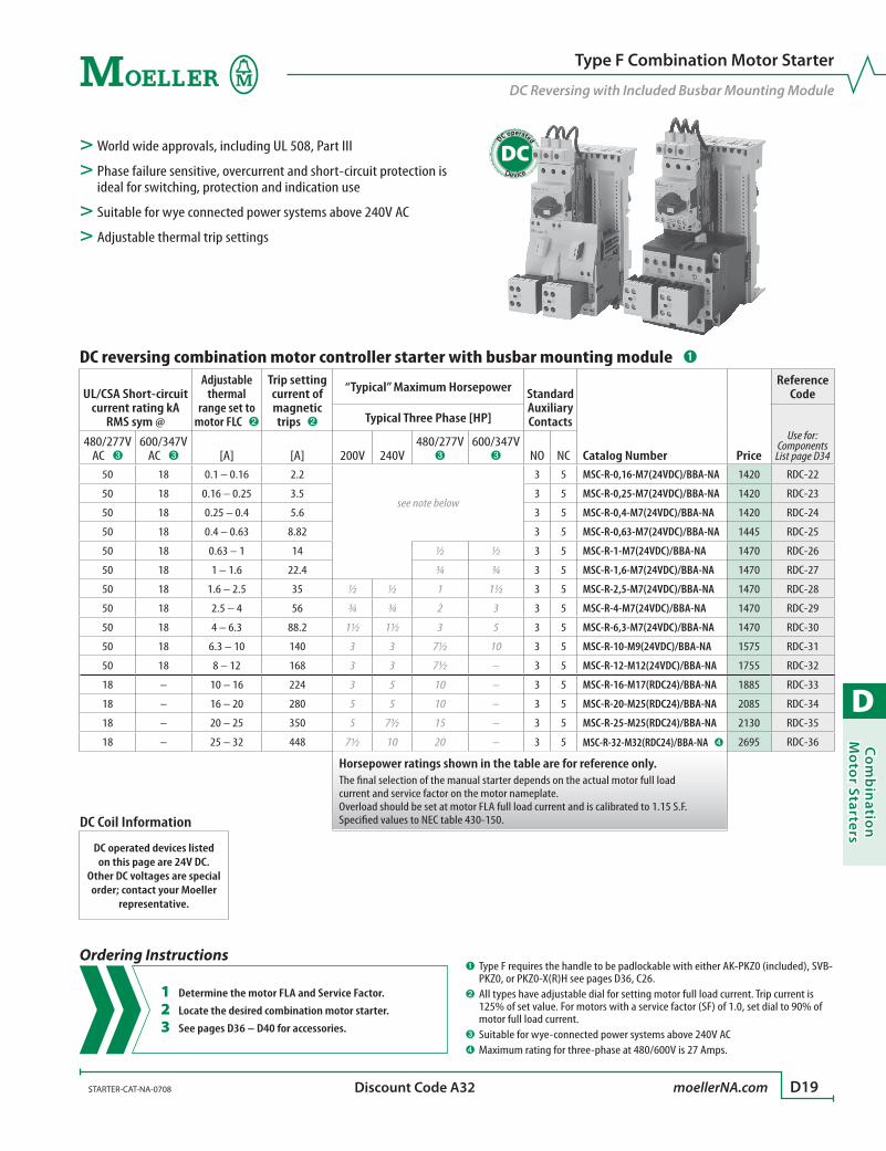
D
Co
mb
inatio
n M
oto
r Starters
STARTER-CAT-NA-0708 moellerNA.com D19 Discount Code A32
DC operated
DC> World wide approvals, including UL 508, Part III
> Phase failure sensitive, overcurrent and short-circuit protection is ideal for switching, protection and indication use
> Suitable for wye connected power systems above 240V AC
> Adjustable thermal trip settings
Type F Combination Motor Starter
DC Reversing with Included Busbar Mounting Module
DC reversing combination motor controller starter with busbar mounting module ➊
UL/CSA Short-circuit current rating kA
RMS sym @
Adjustable thermal
range set to motor FLC ➋
Trip setting current of magnetic trips ➋
“Typical” Maximum Horsepower Standard Auxiliary Contacts
Catalog Number Price
Reference Code
Typical Three Phase [HP]Use for:
Components List page D34
480/277V AC ➌
600/347V AC ➌ [A] [A] 200V 240V
480/277V ➌
600/347V ➌ NO NC
50 18 0.1 – 0.16 2.2
see note below
3 5 MSC-R-0,16-M7(24VDC)/BBA-NA 1420 RDC-22
50 18 0.16 – 0.25 3.5 3 5 MSC-R-0,25-M7(24VDC)/BBA-NA 1420 RDC-23
50 18 0.25 – 0.4 5.6 3 5 MSC-R-0,4-M7(24VDC)/BBA-NA 1420 RDC-24
50 18 0.4 – 0.63 8.82 3 5 MSC-R-0,63-M7(24VDC)/BBA-NA 1445 RDC-25
50 18 0.63 – 1 14 ½ ½ 3 5 MSC-R-1-M7(24VDC)/BBA-NA 1470 RDC-26
50 18 1 – 1.6 22.4 ¾ ¾ 3 5 MSC-R-1,6-M7(24VDC)/BBA-NA 1470 RDC-27
50 18 1.6 – 2.5 35 ½ ½ 1 1½ 3 5 MSC-R-2,5-M7(24VDC)/BBA-NA 1470 RDC-28
50 18 2.5 – 4 56 ¾ ¾ 2 3 3 5 MSC-R-4-M7(24VDC)/BBA-NA 1470 RDC-29
50 18 4 – 6.3 88.2 1½ 1½ 3 5 3 5 MSC-R-6,3-M7(24VDC)/BBA-NA 1470 RDC-30
50 18 6.3 – 10 140 3 3 7½ 10 3 5 MSC-R-10-M9(24VDC)/BBA-NA 1575 RDC-31
50 18 8 – 12 168 3 3 7½ – 3 5 MSC-R-12-M12(24VDC)/BBA-NA 1755 RDC-32
18 – 10 – 16 224 3 5 10 – 3 5 MSC-R-16-M17(RDC24)/BBA-NA 1885 RDC-33
18 – 16 – 20 280 5 5 10 – 3 5 MSC-R-20-M25(RDC24)/BBA-NA 2085 RDC-34
18 – 20 – 25 350 5 7½ 15 – 3 5 MSC-R-25-M25(RDC24)/BBA-NA 2130 RDC-35
18 – 25 – 32 448 7½ 10 20 – 3 5 MSC-R-32-M32(RDC24)/BBA-NA ➍ 2695 RDC-36
Horsepower ratings shown in the table are for reference only. The final selection of the manual starter depends on the actual motor full load current and service factor on the motor nameplate.Overload should be set at motor FLA full load current and is calibrated to 1.15 S.F.Specified values to NEC table 430-150.
➊ Type F requires the handle to be padlockable with either AK-PKZ0 (included), SVB-PKZ0, or PKZ0-X(R)H see pages D36, C26.
➋ All types have adjustable dial for setting motor full load current. Trip current is 125% of set value. For motors with a service factor (SF) of 1.0, set dial to 90% of motor full load current.
➌ Suitable for wye-connected power systems above 240V AC➍ Maximum rating for three-phase at 480/600V is 27 Amps.
Ordering Instructions
1 Determine the motor FLA and Service Factor.
2 Locate the desired combination motor starter.
3 See pages D36 – D40 for accessories.
DC Coil Information
DC operated devices listed on this page are 24V DC.
Other DC voltages are special order; contact your Moeller
representative.
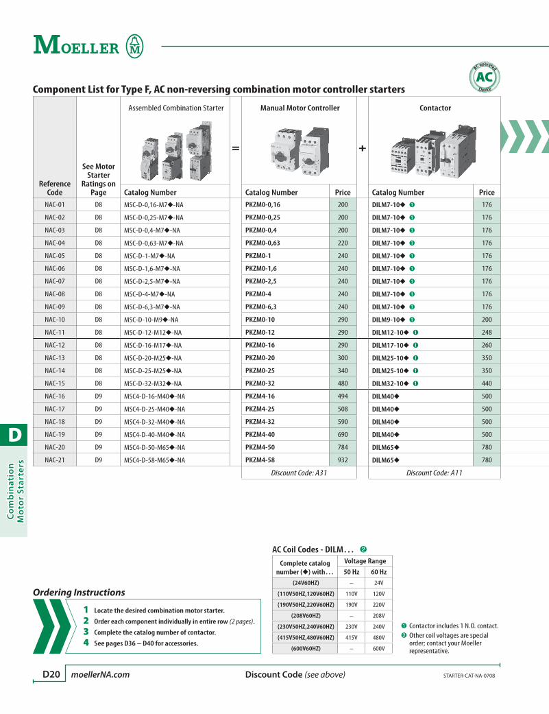
D
Co
mb
inat
ion
Mo
tor
Star
ters
D20 moellerNA.com STARTER-CAT-NA-0708 Discount Code (see above)
Component List for Type F, AC non-reversing combination motor controller starters
Reference Code
See Motor Starter
Ratings on Page
Assembled Combination Starter
=
Manual Motor Controller
+
Contactor
Catalog Number Catalog Number Price Catalog Number PriceNAC-01 D8 MSC-D-0,16-M7-NA PKZM0-0,16 200 DILM7-10 ➊ 176
NAC-02 D8 MSC-D-0,25-M7-NA PKZM0-0,25 200 DILM7-10 ➊ 176
NAC-03 D8 MSC-D-0,4-M7-NA PKZM0-0,4 200 DILM7-10 ➊ 176
NAC-04 D8 MSC-D-0,63-M7-NA PKZM0-0,63 220 DILM7-10 ➊ 176
NAC-05 D8 MSC-D-1-M7-NA PKZM0-1 240 DILM7-10 ➊ 176
NAC-06 D8 MSC-D-1,6-M7-NA PKZM0-1,6 240 DILM7-10 ➊ 176
NAC-07 D8 MSC-D-2,5-M7-NA PKZM0-2,5 240 DILM7-10 ➊ 176
NAC-08 D8 MSC-D-4-M7-NA PKZM0-4 240 DILM7-10 ➊ 176
NAC-09 D8 MSC-D-6,3-M7-NA PKZM0-6,3 240 DILM7-10 ➊ 176
NAC-10 D8 MSC-D-10-M9-NA PKZM0-10 290 DILM9-10 ➊ 200
NAC-11 D8 MSC-D-12-M12-NA PKZM0-12 290 DILM12-10 ➊ 248
NAC-12 D8 MSC-D-16-M17-NA PKZM0-16 290 DILM17-10 ➊ 260
NAC-13 D8 MSC-D-20-M25-NA PKZM0-20 300 DILM25-10 ➊ 350
NAC-14 D8 MSC-D-25-M25-NA PKZM0-25 340 DILM25-10 ➊ 350
NAC-15 D8 MSC-D-32-M32-NA PKZM0-32 480 DILM32-10 ➊ 440
NAC-16 D9 MSC4-D-16-M40-NA PKZM4-16 494 DILM40 500
NAC-17 D9 MSC4-D-25-M40-NA PKZM4-25 508 DILM40 500
NAC-18 D9 MSC4-D-32-M40-NA PKZM4-32 590 DILM40 500
NAC-19 D9 MSC4-D-40-M40-NA PKZM4-40 690 DILM40 500
NAC-20 D9 MSC4-D-50-M65-NA PKZM4-50 784 DILM65 780
NAC-21 D9 MSC4-D-58-M65-NA PKZM4-58 932 DILM65 780
Discount Code: A31 Discount Code: A11
AC Coil Codes - DILM… ➋
Complete catalog number () with…
Voltage Range
50 Hz 60 Hz(24V60HZ) – 24V
(110V50HZ,120V60HZ) 110V 120V
(190V50HZ,220V60HZ) 190V 220V
(208V60HZ) – 208V
(230V50HZ,240V60HZ) 230V 240V
(415V50HZ,480V60HZ) 415V 480V
(600V60HZ) – 600V
➊ Contactor includes 1 N.O. contact.➋ Other coil voltages are special
order; contact your Moeller representative.
AC operated
AC
Ordering Instructions
1 Locate the desired combination motor starter.
2 Order each component individually in entire row (2 pages).
3 Complete the catalog number of contactor.
4 See pages D36 – D40 for accessories.
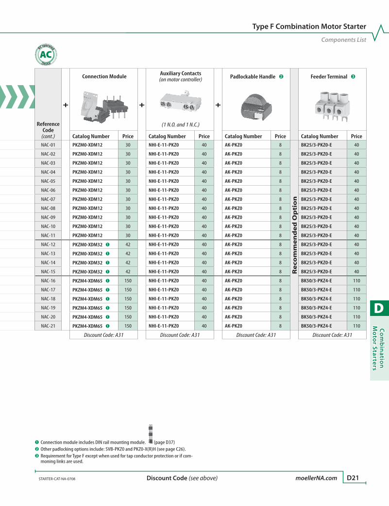
D
Co
mb
inatio
n M
oto
r Starters
STARTER-CAT-NA-0708 moellerNA.com D21 Discount Code (see above)
Component List for Type F, AC non-reversing combination motor controller starters
Reference Code
See Motor Starter
Ratings on Page
Assembled Combination Starter
=
Manual Motor Controller
+
Contactor
Catalog Number Catalog Number Price Catalog Number PriceNAC-01 D8 MSC-D-0,16-M7-NA PKZM0-0,16 200 DILM7-10 ➊ 176
NAC-02 D8 MSC-D-0,25-M7-NA PKZM0-0,25 200 DILM7-10 ➊ 176
NAC-03 D8 MSC-D-0,4-M7-NA PKZM0-0,4 200 DILM7-10 ➊ 176
NAC-04 D8 MSC-D-0,63-M7-NA PKZM0-0,63 220 DILM7-10 ➊ 176
NAC-05 D8 MSC-D-1-M7-NA PKZM0-1 240 DILM7-10 ➊ 176
NAC-06 D8 MSC-D-1,6-M7-NA PKZM0-1,6 240 DILM7-10 ➊ 176
NAC-07 D8 MSC-D-2,5-M7-NA PKZM0-2,5 240 DILM7-10 ➊ 176
NAC-08 D8 MSC-D-4-M7-NA PKZM0-4 240 DILM7-10 ➊ 176
NAC-09 D8 MSC-D-6,3-M7-NA PKZM0-6,3 240 DILM7-10 ➊ 176
NAC-10 D8 MSC-D-10-M9-NA PKZM0-10 290 DILM9-10 ➊ 200
NAC-11 D8 MSC-D-12-M12-NA PKZM0-12 290 DILM12-10 ➊ 248
NAC-12 D8 MSC-D-16-M17-NA PKZM0-16 290 DILM17-10 ➊ 260
NAC-13 D8 MSC-D-20-M25-NA PKZM0-20 300 DILM25-10 ➊ 350
NAC-14 D8 MSC-D-25-M25-NA PKZM0-25 340 DILM25-10 ➊ 350
NAC-15 D8 MSC-D-32-M32-NA PKZM0-32 480 DILM32-10 ➊ 440
NAC-16 D9 MSC4-D-16-M40-NA PKZM4-16 494 DILM40 500
NAC-17 D9 MSC4-D-25-M40-NA PKZM4-25 508 DILM40 500
NAC-18 D9 MSC4-D-32-M40-NA PKZM4-32 590 DILM40 500
NAC-19 D9 MSC4-D-40-M40-NA PKZM4-40 690 DILM40 500
NAC-20 D9 MSC4-D-50-M65-NA PKZM4-50 784 DILM65 780
NAC-21 D9 MSC4-D-58-M65-NA PKZM4-58 932 DILM65 780
Discount Code: A31 Discount Code: A11
Type F Combination Motor Starter
Components List
Reference Code
(cont.)
+
Connection Module
+
Auxiliary Contacts (on motor controller)
+
Padlockable Handle ➋ Feeder Terminal ➌
(1 N.O. and 1 N.C.)
Catalog Number Price Catalog Number Price Catalog Number Price Catalog Number PriceNAC-01 PKZM0-XDM12 30 NHI-E-11-PKZ0 40 AK-PKZ0 8
Re
com
me
nd
ed
Op
tio
n
BK25/3-PKZ0-E 40
NAC-02 PKZM0-XDM12 30 NHI-E-11-PKZ0 40 AK-PKZ0 8 BK25/3-PKZ0-E 40
NAC-03 PKZM0-XDM12 30 NHI-E-11-PKZ0 40 AK-PKZ0 8 BK25/3-PKZ0-E 40
NAC-04 PKZM0-XDM12 30 NHI-E-11-PKZ0 40 AK-PKZ0 8 BK25/3-PKZ0-E 40
NAC-05 PKZM0-XDM12 30 NHI-E-11-PKZ0 40 AK-PKZ0 8 BK25/3-PKZ0-E 40
NAC-06 PKZM0-XDM12 30 NHI-E-11-PKZ0 40 AK-PKZ0 8 BK25/3-PKZ0-E 40
NAC-07 PKZM0-XDM12 30 NHI-E-11-PKZ0 40 AK-PKZ0 8 BK25/3-PKZ0-E 40
NAC-08 PKZM0-XDM12 30 NHI-E-11-PKZ0 40 AK-PKZ0 8 BK25/3-PKZ0-E 40
NAC-09 PKZM0-XDM12 30 NHI-E-11-PKZ0 40 AK-PKZ0 8 BK25/3-PKZ0-E 40
NAC-10 PKZM0-XDM12 30 NHI-E-11-PKZ0 40 AK-PKZ0 8 BK25/3-PKZ0-E 40
NAC-11 PKZM0-XDM12 30 NHI-E-11-PKZ0 40 AK-PKZ0 8 BK25/3-PKZ0-E 40
NAC-12 PKZM0-XDM32 ➊ 42 NHI-E-11-PKZ0 40 AK-PKZ0 8 BK25/3-PKZ0-E 40
NAC-13 PKZM0-XDM32 ➊ 42 NHI-E-11-PKZ0 40 AK-PKZ0 8 BK25/3-PKZ0-E 40
NAC-14 PKZM0-XDM32 ➊ 42 NHI-E-11-PKZ0 40 AK-PKZ0 8 BK25/3-PKZ0-E 40
NAC-15 PKZM0-XDM32 ➊ 42 NHI-E-11-PKZ0 40 AK-PKZ0 8 BK25/3-PKZ0-E 40
NAC-16 PKZM4-XDM65 ➊ 150 NHI-E-11-PKZ0 40 AK-PKZ0 8 BK50/3-PKZ4-E 110
NAC-17 PKZM4-XDM65 ➊ 150 NHI-E-11-PKZ0 40 AK-PKZ0 8 BK50/3-PKZ4-E 110
NAC-18 PKZM4-XDM65 ➊ 150 NHI-E-11-PKZ0 40 AK-PKZ0 8 BK50/3-PKZ4-E 110
NAC-19 PKZM4-XDM65 ➊ 150 NHI-E-11-PKZ0 40 AK-PKZ0 8 BK50/3-PKZ4-E 110
NAC-20 PKZM4-XDM65 ➊ 150 NHI-E-11-PKZ0 40 AK-PKZ0 8 BK50/3-PKZ4-E 110
NAC-21 PKZM4-XDM65 ➊ 150 NHI-E-11-PKZ0 40 AK-PKZ0 8 BK50/3-PKZ4-E 110
Discount Code: A31 Discount Code: A31 Discount Code: A31 Discount Code: A31
➊ Connection module includes DIN rail mounting module. (page D37)➋ Other padlocking options include: SVB-PKZ0 and PKZ0-X(R)H (see page C26).➌ Requirement for Type F except when used for tap conductor protection or if com-
moning links are used.
AC operated
AC

D
Co
mb
inat
ion
Mo
tor
Star
ters
D22 moellerNA.com STARTER-CAT-NA-0708 Discount Code (see above)
Component List for Type F, AC non-reversing combination motor controller starters
Reference Code
See Motor Starter Ratings on Page
Assembled Combination Starter
=
Manual Motor Controller
+
Contactor ➊
+
Connection Module
Catalog Number Catalog Number Price Catalog Number Price Catalog Number Price
NAC-22 D12 MSC-D-0,16-M7/BBA-NA PKZM0-0,16 200 DILM7-10 176 PKZM0-XDM12 30
NAC-23 D12 MSC-D-0,25-M7/BBA-NA PKZM0-0,25 200 DILM7-10 176 PKZM0-XDM12 30
NAC-24 D12 MSC-D-0,4-M7/BBA-NA PKZM0-0,4 200 DILM7-10 176 PKZM0-XDM12 30
NAC-25 D12 MSC-D-0,63-M7/BBA-NA PKZM0-0,63 220 DILM7-10 176 PKZM0-XDM12 30
NAC-26 D12 MSC-D-1-M7/BBA-NA PKZM0-1 240 DILM7-10 176 PKZM0-XDM12 30
NAC-27 D12 MSC-D-1,6-M7/BBA-NA PKZM0-1,6 240 DILM7-10 176 PKZM0-XDM12 30
NAC-28 D12 MSC-D-2,5-M7/BBA-NA PKZM0-2,5 240 DILM7-10 176 PKZM0-XDM12 30
NAC-29 D12 MSC-D-4-M7/BBA-NA PKZM0-4 240 DILM7-10 176 PKZM0-XDM12 30
NAC-30 D12 MSC-D-6,3-M7/BBA-NA PKZM0-6,3 240 DILM7-10 176 PKZM0-XDM12 30
NAC-31 D12 MSC-D-10-M9/BBA-NA PKZM0-10 290 DILM9-10 200 PKZM0-XDM12 30
NAC-32 D12 MSC-D-12-M12/BBA-NA PKZM0-12 290 DILM12-10 248 PKZM0-XDM12 30
NAC-33 D12 MSC-D-16-M17/BBA-NA PKZM0-16 290 DILM17-10 260 PKZM0-XM32DE 10
NAC-34 D12 MSC-D-20-M25/BBA-NA PKZM0-20 300 DILM25-10 350 PKZM0-XM32DE 10
NAC-35 D12 MSC-D-25-M25/BBA-NA PKZM0-25 340 DILM25-10 350 PKZM0-XM32DE 10
NAC-36 D12 MSC-D-32-M32/BBA-NA PKZM0-32 480 DILM32-10 440 PKZM0-XM32DE 10
Discount Code: A31 Discount Code: A11 Discount Code: A31
AC Coil Codes - DILM… ➋
Complete catalog number () with…
Voltage Range
50 Hz 60 Hz(24V60HZ) – 24V
(110V50HZ,120V60HZ) 110V 120V
(190V50HZ,220V60HZ) 190V 220V
(208V60HZ) – 208V
(230V50HZ,240V60HZ) 230V 240V
(415V50HZ,480V60HZ) 415V 480V
(600V60HZ) – 600V
➊ Contactor includes 1 N.O. contact.➋ Other coil voltages are special
order; contact your Moeller representative.
AC operated
AC
Ordering Instructions
1 Locate the desired combination motor starter.
2 Order each component individually in entire row (2 pages).
3 Complete the catalog number of contactor.
4 See pages D36 – D40 for accessories.
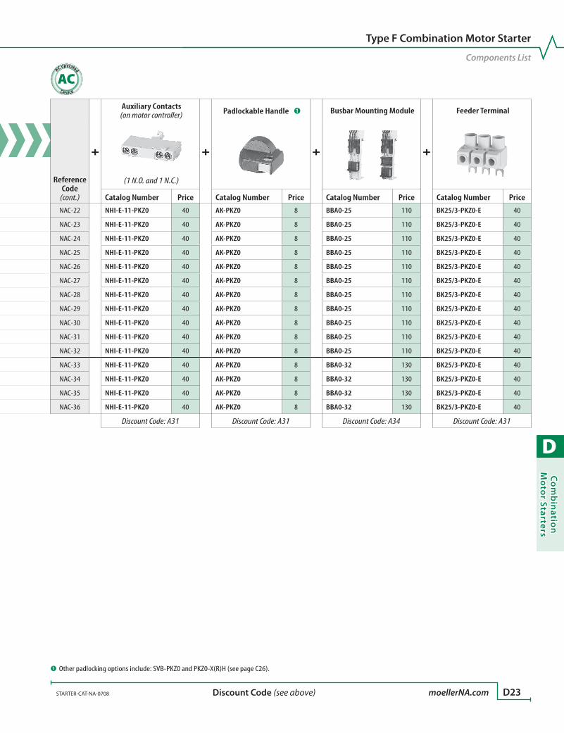
D
Co
mb
inatio
n M
oto
r Starters
STARTER-CAT-NA-0708 moellerNA.com D23 Discount Code (see above)
Component List for Type F, AC non-reversing combination motor controller starters
Reference Code
See Motor Starter Ratings on Page
Assembled Combination Starter
=
Manual Motor Controller
+
Contactor ➊
+
Connection Module
Catalog Number Catalog Number Price Catalog Number Price Catalog Number Price
NAC-22 D12 MSC-D-0,16-M7/BBA-NA PKZM0-0,16 200 DILM7-10 176 PKZM0-XDM12 30
NAC-23 D12 MSC-D-0,25-M7/BBA-NA PKZM0-0,25 200 DILM7-10 176 PKZM0-XDM12 30
NAC-24 D12 MSC-D-0,4-M7/BBA-NA PKZM0-0,4 200 DILM7-10 176 PKZM0-XDM12 30
NAC-25 D12 MSC-D-0,63-M7/BBA-NA PKZM0-0,63 220 DILM7-10 176 PKZM0-XDM12 30
NAC-26 D12 MSC-D-1-M7/BBA-NA PKZM0-1 240 DILM7-10 176 PKZM0-XDM12 30
NAC-27 D12 MSC-D-1,6-M7/BBA-NA PKZM0-1,6 240 DILM7-10 176 PKZM0-XDM12 30
NAC-28 D12 MSC-D-2,5-M7/BBA-NA PKZM0-2,5 240 DILM7-10 176 PKZM0-XDM12 30
NAC-29 D12 MSC-D-4-M7/BBA-NA PKZM0-4 240 DILM7-10 176 PKZM0-XDM12 30
NAC-30 D12 MSC-D-6,3-M7/BBA-NA PKZM0-6,3 240 DILM7-10 176 PKZM0-XDM12 30
NAC-31 D12 MSC-D-10-M9/BBA-NA PKZM0-10 290 DILM9-10 200 PKZM0-XDM12 30
NAC-32 D12 MSC-D-12-M12/BBA-NA PKZM0-12 290 DILM12-10 248 PKZM0-XDM12 30
NAC-33 D12 MSC-D-16-M17/BBA-NA PKZM0-16 290 DILM17-10 260 PKZM0-XM32DE 10
NAC-34 D12 MSC-D-20-M25/BBA-NA PKZM0-20 300 DILM25-10 350 PKZM0-XM32DE 10
NAC-35 D12 MSC-D-25-M25/BBA-NA PKZM0-25 340 DILM25-10 350 PKZM0-XM32DE 10
NAC-36 D12 MSC-D-32-M32/BBA-NA PKZM0-32 480 DILM32-10 440 PKZM0-XM32DE 10
Discount Code: A31 Discount Code: A11 Discount Code: A31
Type F Combination Motor Starter
Components List
Reference Code
(cont.)
+
Auxiliary Contacts (on motor controller)
+
Padlockable Handle ➊
+
Busbar Mounting Module
+
Feeder Terminal
(1 N.O. and 1 N.C.)
Catalog Number Price Catalog Number Price Catalog Number Price Catalog Number Price
NAC-22 NHI-E-11-PKZ0 40 AK-PKZ0 8 BBA0-25 110 BK25/3-PKZ0-E 40
NAC-23 NHI-E-11-PKZ0 40 AK-PKZ0 8 BBA0-25 110 BK25/3-PKZ0-E 40
NAC-24 NHI-E-11-PKZ0 40 AK-PKZ0 8 BBA0-25 110 BK25/3-PKZ0-E 40
NAC-25 NHI-E-11-PKZ0 40 AK-PKZ0 8 BBA0-25 110 BK25/3-PKZ0-E 40
NAC-26 NHI-E-11-PKZ0 40 AK-PKZ0 8 BBA0-25 110 BK25/3-PKZ0-E 40
NAC-27 NHI-E-11-PKZ0 40 AK-PKZ0 8 BBA0-25 110 BK25/3-PKZ0-E 40
NAC-28 NHI-E-11-PKZ0 40 AK-PKZ0 8 BBA0-25 110 BK25/3-PKZ0-E 40
NAC-29 NHI-E-11-PKZ0 40 AK-PKZ0 8 BBA0-25 110 BK25/3-PKZ0-E 40
NAC-30 NHI-E-11-PKZ0 40 AK-PKZ0 8 BBA0-25 110 BK25/3-PKZ0-E 40
NAC-31 NHI-E-11-PKZ0 40 AK-PKZ0 8 BBA0-25 110 BK25/3-PKZ0-E 40
NAC-32 NHI-E-11-PKZ0 40 AK-PKZ0 8 BBA0-25 110 BK25/3-PKZ0-E 40
NAC-33 NHI-E-11-PKZ0 40 AK-PKZ0 8 BBA0-32 130 BK25/3-PKZ0-E 40
NAC-34 NHI-E-11-PKZ0 40 AK-PKZ0 8 BBA0-32 130 BK25/3-PKZ0-E 40
NAC-35 NHI-E-11-PKZ0 40 AK-PKZ0 8 BBA0-32 130 BK25/3-PKZ0-E 40
NAC-36 NHI-E-11-PKZ0 40 AK-PKZ0 8 BBA0-32 130 BK25/3-PKZ0-E 40
Discount Code: A31 Discount Code: A31 Discount Code: A34 Discount Code: A31
➊ Other padlocking options include: SVB-PKZ0 and PKZ0-X(R)H (see page C26).
AC operated
AC
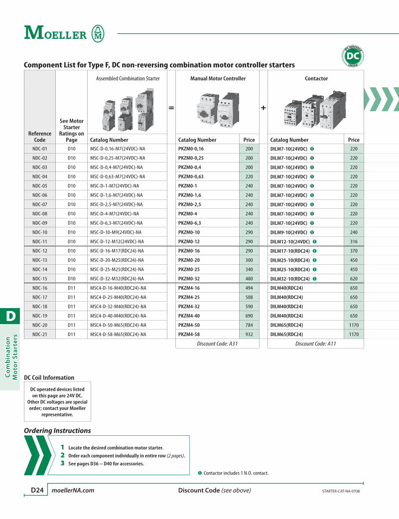
D
Co
mb
inat
ion
Mo
tor
Star
ters
D24 moellerNA.com STARTER-CAT-NA-0708 Discount Code (see above)
Component List for Type F, DC non-reversing combination motor controller starters
Reference Code
See Motor Starter
Ratings on Page
Assembled Combination Starter
=
Manual Motor Controller
+
Contactor
Catalog Number Catalog Number Price Catalog Number PriceNDC-01 D10 MSC-D-0,16-M7(24VDC)-NA PKZM0-0,16 200 DILM7-10(24VDC) ➊ 220
NDC-02 D10 MSC-D-0,25-M7(24VDC)-NA PKZM0-0,25 200 DILM7-10(24VDC) ➊ 220
NDC-03 D10 MSC-D-0,4-M7(24VDC)-NA PKZM0-0,4 200 DILM7-10(24VDC) ➊ 220
NDC-04 D10 MSC-D-0,63-M7(24VDC)-NA PKZM0-0,63 220 DILM7-10(24VDC) ➊ 220
NDC-05 D10 MSC-D-1-M7(24VDC)-NA PKZM0-1 240 DILM7-10(24VDC) ➊ 220
NDC-06 D10 MSC-D-1,6-M7(24VDC)-NA PKZM0-1,6 240 DILM7-10(24VDC) ➊ 220
NDC-07 D10 MSC-D-2,5-M7(24VDC)-NA PKZM0-2,5 240 DILM7-10(24VDC) ➊ 220
NDC-08 D10 MSC-D-4-M7(24VDC)-NA PKZM0-4 240 DILM7-10(24VDC) ➊ 220
NDC-09 D10 MSC-D-6,3-M7(24VDC)-NA PKZM0-6,3 240 DILM7-10(24VDC) ➊ 220
NDC-10 D10 MSC-D-10-M9(24VDC)-NA PKZM0-10 290 DILM9-10(24VDC) ➊ 240
NDC-11 D10 MSC-D-12-M12(24VDC)-NA PKZM0-12 290 DILM12-10(24VDC) ➊ 316
NDC-12 D10 MSC-D-16-M17(RDC24)-NA PKZM0-16 290 DILM17-10(RDC24) ➊ 370
NDC-13 D10 MSC-D-20-M25(RDC24)-NA PKZM0-20 300 DILM25-10(RDC24) ➊ 450
NDC-14 D10 MSC-D-25-M25(RDC24)-NA PKZM0-25 340 DILM25-10(RDC24) ➊ 450
NDC-15 D10 MSC-D-32-M32(RDC24)-NA PKZM0-32 480 DILM32-10(RDC24) ➊ 620
NDC-16 D11 MSC4-D-16-M40(RDC24)-NA PKZM4-16 494 DILM40(RDC24) 650
NDC-17 D11 MSC4-D-25-M40(RDC24)-NA PKZM4-25 508 DILM40(RDC24) 650
NDC-18 D11 MSC4-D-32-M40(RDC24)-NA PKZM4-32 590 DILM40(RDC24) 650
NDC-19 D11 MSC4-D-40-M40(RDC24)-NA PKZM4-40 690 DILM40(RDC24) 650
NDC-20 D11 MSC4-D-50-M65(RDC24)-NA PKZM4-50 784 DILM65(RDC24) 1170
NDC-21 D11 MSC4-D-58-M65(RDC24)-NA PKZM4-58 932 DILM65(RDC24) 1170
Discount Code: A31 Discount Code: A11
➊ Contactor includes 1 N.O. contact.
DC operated
DC
Ordering Instructions
1 Locate the desired combination motor starter.
2 Order each component individually in entire row (2 pages).
3 See pages D36 – D40 for accessories.
DC Coil Information
DC operated devices listed on this page are 24V DC.
Other DC voltages are special order; contact your Moeller
representative.
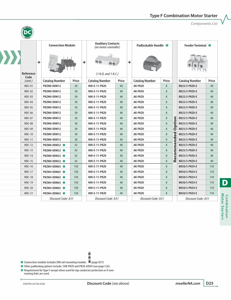
D
Co
mb
inatio
n M
oto
r Starters
STARTER-CAT-NA-0708 moellerNA.com D25 Discount Code (see above)
Component List for Type F, DC non-reversing combination motor controller starters
Reference Code
See Motor Starter
Ratings on Page
Assembled Combination Starter
=
Manual Motor Controller
+
Contactor
Catalog Number Catalog Number Price Catalog Number PriceNDC-01 D10 MSC-D-0,16-M7(24VDC)-NA PKZM0-0,16 200 DILM7-10(24VDC) ➊ 220
NDC-02 D10 MSC-D-0,25-M7(24VDC)-NA PKZM0-0,25 200 DILM7-10(24VDC) ➊ 220
NDC-03 D10 MSC-D-0,4-M7(24VDC)-NA PKZM0-0,4 200 DILM7-10(24VDC) ➊ 220
NDC-04 D10 MSC-D-0,63-M7(24VDC)-NA PKZM0-0,63 220 DILM7-10(24VDC) ➊ 220
NDC-05 D10 MSC-D-1-M7(24VDC)-NA PKZM0-1 240 DILM7-10(24VDC) ➊ 220
NDC-06 D10 MSC-D-1,6-M7(24VDC)-NA PKZM0-1,6 240 DILM7-10(24VDC) ➊ 220
NDC-07 D10 MSC-D-2,5-M7(24VDC)-NA PKZM0-2,5 240 DILM7-10(24VDC) ➊ 220
NDC-08 D10 MSC-D-4-M7(24VDC)-NA PKZM0-4 240 DILM7-10(24VDC) ➊ 220
NDC-09 D10 MSC-D-6,3-M7(24VDC)-NA PKZM0-6,3 240 DILM7-10(24VDC) ➊ 220
NDC-10 D10 MSC-D-10-M9(24VDC)-NA PKZM0-10 290 DILM9-10(24VDC) ➊ 240
NDC-11 D10 MSC-D-12-M12(24VDC)-NA PKZM0-12 290 DILM12-10(24VDC) ➊ 316
NDC-12 D10 MSC-D-16-M17(RDC24)-NA PKZM0-16 290 DILM17-10(RDC24) ➊ 370
NDC-13 D10 MSC-D-20-M25(RDC24)-NA PKZM0-20 300 DILM25-10(RDC24) ➊ 450
NDC-14 D10 MSC-D-25-M25(RDC24)-NA PKZM0-25 340 DILM25-10(RDC24) ➊ 450
NDC-15 D10 MSC-D-32-M32(RDC24)-NA PKZM0-32 480 DILM32-10(RDC24) ➊ 620
NDC-16 D11 MSC4-D-16-M40(RDC24)-NA PKZM4-16 494 DILM40(RDC24) 650
NDC-17 D11 MSC4-D-25-M40(RDC24)-NA PKZM4-25 508 DILM40(RDC24) 650
NDC-18 D11 MSC4-D-32-M40(RDC24)-NA PKZM4-32 590 DILM40(RDC24) 650
NDC-19 D11 MSC4-D-40-M40(RDC24)-NA PKZM4-40 690 DILM40(RDC24) 650
NDC-20 D11 MSC4-D-50-M65(RDC24)-NA PKZM4-50 784 DILM65(RDC24) 1170
NDC-21 D11 MSC4-D-58-M65(RDC24)-NA PKZM4-58 932 DILM65(RDC24) 1170
Discount Code: A31 Discount Code: A11
Type F Combination Motor Starter
Components List
Reference Code
(cont.)
+
Connection Module
+
Auxiliary Contacts (on motor controller)
+
Padlockable Handle ➋ Feeder Terminal ➌
(1 N.O. and 1 N.C.)
Catalog Number Price Catalog Number Price Catalog Number Price Catalog Number PriceNDC-01 PKZM0-XDM12 30 NHI-E-11-PKZ0 40 AK-PKZ0 8
Re
com
me
nd
ed
Op
tio
n
BK25/3-PKZ0-E 40
NDC-02 PKZM0-XDM12 30 NHI-E-11-PKZ0 40 AK-PKZ0 8 BK25/3-PKZ0-E 40
NDC-03 PKZM0-XDM12 30 NHI-E-11-PKZ0 40 AK-PKZ0 8 BK25/3-PKZ0-E 40
NDC-04 PKZM0-XDM12 30 NHI-E-11-PKZ0 40 AK-PKZ0 8 BK25/3-PKZ0-E 40
NDC-05 PKZM0-XDM12 30 NHI-E-11-PKZ0 40 AK-PKZ0 8 BK25/3-PKZ0-E 40
NDC-06 PKZM0-XDM12 30 NHI-E-11-PKZ0 40 AK-PKZ0 8 BK25/3-PKZ0-E 40
NDC-07 PKZM0-XDM12 30 NHI-E-11-PKZ0 40 AK-PKZ0 8 BK25/3-PKZ0-E 40
NDC-08 PKZM0-XDM12 30 NHI-E-11-PKZ0 40 AK-PKZ0 8 BK25/3-PKZ0-E 40
NDC-09 PKZM0-XDM12 30 NHI-E-11-PKZ0 40 AK-PKZ0 8 BK25/3-PKZ0-E 40
NDC-10 PKZM0-XDM12 30 NHI-E-11-PKZ0 40 AK-PKZ0 8 BK25/3-PKZ0-E 40
NDC-11 PKZM0-XDM12 30 NHI-E-11-PKZ0 40 AK-PKZ0 8 BK25/3-PKZ0-E 40
NDC-12 PKZM0-XDM32 ➊ 42 NHI-E-11-PKZ0 40 AK-PKZ0 8 BK25/3-PKZ0-E 40
NDC-13 PKZM0-XDM32 ➊ 42 NHI-E-11-PKZ0 40 AK-PKZ0 8 BK25/3-PKZ0-E 40
NDC-14 PKZM0-XDM32 ➊ 42 NHI-E-11-PKZ0 40 AK-PKZ0 8 BK25/3-PKZ0-E 40
NDC-15 PKZM0-XDM32 ➊ 42 NHI-E-11-PKZ0 40 AK-PKZ0 8 BK25/3-PKZ0-E 40
NDC-16 PKZM4-XDM65 ➊ 150 NHI-E-11-PKZ0 40 AK-PKZ0 8 BK50/3-PKZ4-E 110
NDC-17 PKZM4-XDM65 ➊ 150 NHI-E-11-PKZ0 40 AK-PKZ0 8 BK50/3-PKZ4-E 110
NDC-18 PKZM4-XDM65 ➊ 150 NHI-E-11-PKZ0 40 AK-PKZ0 8 BK50/3-PKZ4-E 110
NDC-19 PKZM4-XDM65 ➊ 150 NHI-E-11-PKZ0 40 AK-PKZ0 8 BK50/3-PKZ4-E 110
NDC-20 PKZM4-XDM65 ➊ 150 NHI-E-11-PKZ0 40 AK-PKZ0 8 BK50/3-PKZ4-E 110
NDC-21 PKZM4-XDM65 ➊ 150 NHI-E-11-PKZ0 40 AK-PKZ0 8 BK50/3-PKZ4-E 110
Discount Code: A31 Discount Code: A31 Discount Code: A31 Discount Code: A31
DC operated
DC
➊ Connection module includes DIN rail mounting module. (page D37)➋ Other padlocking options include: SVB-PKZ0 and PKZ0-X(R)H (see page C26).➌ Requirement for Type F except when used for tap conductor protection or if com-
moning links are used.

D
Co
mb
inat
ion
Mo
tor
Star
ters
D26 moellerNA.com STARTER-CAT-NA-0708 Discount Code (see above)
Component List for Type F, DC non-reversing combination motor controller starters
Reference Code
See Motor Starter Ratings on Page
Assembled Combination Starter
=
Manual Motor Controller
+
Contactor ➊
+
Connection Module
Catalog Number Catalog Number Price Catalog Number Price Catalog Number Price
NDC-22 D13 MSC-D-0,16-M7(24VDC)/BBA-NA PKZM0-0,16 200 DILM7-10(24VDC) 220 PKZM0-XDM12 30
NDC-23 D13 MSC-D-0,25-M7(24VDC)/BBA-NA PKZM0-0,25 200 DILM7-10(24VDC) 220 PKZM0-XDM12 30
NDC-24 D13 MSC-D-0,4-M7(24VDC)/BBA-NA PKZM0-0,4 200 DILM7-10(24VDC) 220 PKZM0-XDM12 30
NDC-25 D13 MSC-D-0,63-M7(24VDC)/BBA-NA PKZM0-0,63 220 DILM7-10(24VDC) 220 PKZM0-XDM12 30
NDC-26 D13 MSC-D-1-M7(24VDC)/BBA-NA PKZM0-1 240 DILM7-10(24VDC) 220 PKZM0-XDM12 30
NDC-27 D13 MSC-D-1,6-M7(24VDC)/BBA-NA PKZM0-1,6 240 DILM7-10(24VDC) 220 PKZM0-XDM12 30
NDC-28 D13 MSC-D-2,5-M7(24VDC)/BBA-NA PKZM0-2,5 240 DILM7-10(24VDC) 220 PKZM0-XDM12 30
NDC-29 D13 MSC-D-4-M7(24VDC)/BBA-NA PKZM0-4 240 DILM7-10(24VDC) 220 PKZM0-XDM12 30
NDC-30 D13 MSC-D-6,3-M7(24VDC)/BBA-NA PKZM0-6,3 240 DILM7-10(24VDC) 220 PKZM0-XDM12 30
NDC-31 D13 MSC-D-10-M9(24VDC)/BBA-NA PKZM0-10 290 DILM9-10(24VDC) 240 PKZM0-XDM12 30
NDC-32 D13 MSC-D-12-M12(24VDC)/BBA-NA PKZM0-12 290 DILM12-10(24VDC) 316 PKZM0-XDM12 30
NDC-33 D13 MSC-D-16-M17(RDC24)/BBA-NA PKZM0-16 290 DILM17-10(RDC24) 370 PKZM0-XM32DE 10
NDC-34 D13 MSC-D-20-M25(RDC24)/BBA-NA PKZM0-20 300 DILM25-10(RDC24) 450 PKZM0-XM32DE 10
NDC-35 D13 MSC-D-25-M25(RDC24)/BBA-NA PKZM0-25 340 DILM25-10(RDC24) 450 PKZM0-XM32DE 10
NDC-36 D13 MSC-D-32-M32(RDC24)/BBA-NA PKZM0-32 480 DILM32-10(RDC24) 620 PKZM0-XM32DE 10
Discount Code: A31 Discount Code: A11 Discount Code: A31
➊ Contactor includes 1 N.O. contact.
DC operated
DC
Ordering Instructions
1 Locate the desired combination motor starter.
2 Order each component individually in entire row (2 pages).
3 See pages D36 – D40 for accessories.
DC Coil Information
DC operated devices listed on this page are 24V DC.
Other DC voltages are special order; contact your Moeller
representative.
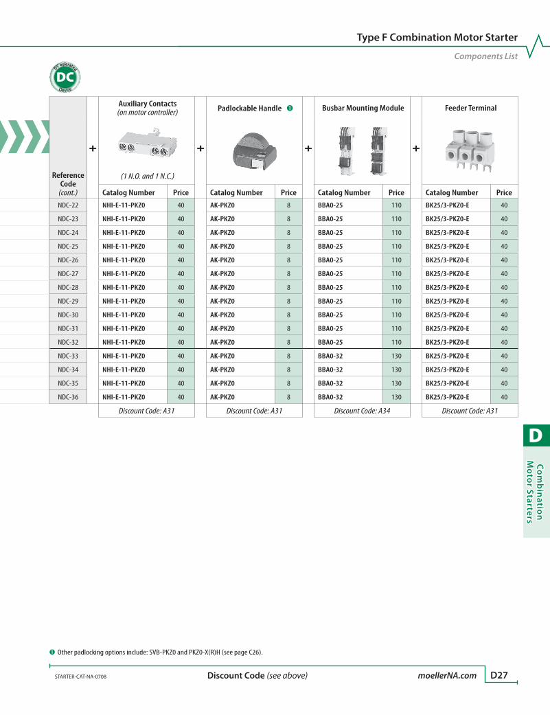
D
Co
mb
inatio
n M
oto
r Starters
STARTER-CAT-NA-0708 moellerNA.com D27 Discount Code (see above)
Component List for Type F, DC non-reversing combination motor controller starters
Reference Code
See Motor Starter Ratings on Page
Assembled Combination Starter
=
Manual Motor Controller
+
Contactor ➊
+
Connection Module
Catalog Number Catalog Number Price Catalog Number Price Catalog Number Price
NDC-22 D13 MSC-D-0,16-M7(24VDC)/BBA-NA PKZM0-0,16 200 DILM7-10(24VDC) 220 PKZM0-XDM12 30
NDC-23 D13 MSC-D-0,25-M7(24VDC)/BBA-NA PKZM0-0,25 200 DILM7-10(24VDC) 220 PKZM0-XDM12 30
NDC-24 D13 MSC-D-0,4-M7(24VDC)/BBA-NA PKZM0-0,4 200 DILM7-10(24VDC) 220 PKZM0-XDM12 30
NDC-25 D13 MSC-D-0,63-M7(24VDC)/BBA-NA PKZM0-0,63 220 DILM7-10(24VDC) 220 PKZM0-XDM12 30
NDC-26 D13 MSC-D-1-M7(24VDC)/BBA-NA PKZM0-1 240 DILM7-10(24VDC) 220 PKZM0-XDM12 30
NDC-27 D13 MSC-D-1,6-M7(24VDC)/BBA-NA PKZM0-1,6 240 DILM7-10(24VDC) 220 PKZM0-XDM12 30
NDC-28 D13 MSC-D-2,5-M7(24VDC)/BBA-NA PKZM0-2,5 240 DILM7-10(24VDC) 220 PKZM0-XDM12 30
NDC-29 D13 MSC-D-4-M7(24VDC)/BBA-NA PKZM0-4 240 DILM7-10(24VDC) 220 PKZM0-XDM12 30
NDC-30 D13 MSC-D-6,3-M7(24VDC)/BBA-NA PKZM0-6,3 240 DILM7-10(24VDC) 220 PKZM0-XDM12 30
NDC-31 D13 MSC-D-10-M9(24VDC)/BBA-NA PKZM0-10 290 DILM9-10(24VDC) 240 PKZM0-XDM12 30
NDC-32 D13 MSC-D-12-M12(24VDC)/BBA-NA PKZM0-12 290 DILM12-10(24VDC) 316 PKZM0-XDM12 30
NDC-33 D13 MSC-D-16-M17(RDC24)/BBA-NA PKZM0-16 290 DILM17-10(RDC24) 370 PKZM0-XM32DE 10
NDC-34 D13 MSC-D-20-M25(RDC24)/BBA-NA PKZM0-20 300 DILM25-10(RDC24) 450 PKZM0-XM32DE 10
NDC-35 D13 MSC-D-25-M25(RDC24)/BBA-NA PKZM0-25 340 DILM25-10(RDC24) 450 PKZM0-XM32DE 10
NDC-36 D13 MSC-D-32-M32(RDC24)/BBA-NA PKZM0-32 480 DILM32-10(RDC24) 620 PKZM0-XM32DE 10
Discount Code: A31 Discount Code: A11 Discount Code: A31
Type F Combination Motor Starter
Components List
Reference Code
(cont.)
+
Auxiliary Contacts (on motor controller)
+
Padlockable Handle ➊
+
Busbar Mounting Module
+
Feeder Terminal
(1 N.O. and 1 N.C.)
Catalog Number Price Catalog Number Price Catalog Number Price Catalog Number Price
NDC-22 NHI-E-11-PKZ0 40 AK-PKZ0 8 BBA0-25 110 BK25/3-PKZ0-E 40
NDC-23 NHI-E-11-PKZ0 40 AK-PKZ0 8 BBA0-25 110 BK25/3-PKZ0-E 40
NDC-24 NHI-E-11-PKZ0 40 AK-PKZ0 8 BBA0-25 110 BK25/3-PKZ0-E 40
NDC-25 NHI-E-11-PKZ0 40 AK-PKZ0 8 BBA0-25 110 BK25/3-PKZ0-E 40
NDC-26 NHI-E-11-PKZ0 40 AK-PKZ0 8 BBA0-25 110 BK25/3-PKZ0-E 40
NDC-27 NHI-E-11-PKZ0 40 AK-PKZ0 8 BBA0-25 110 BK25/3-PKZ0-E 40
NDC-28 NHI-E-11-PKZ0 40 AK-PKZ0 8 BBA0-25 110 BK25/3-PKZ0-E 40
NDC-29 NHI-E-11-PKZ0 40 AK-PKZ0 8 BBA0-25 110 BK25/3-PKZ0-E 40
NDC-30 NHI-E-11-PKZ0 40 AK-PKZ0 8 BBA0-25 110 BK25/3-PKZ0-E 40
NDC-31 NHI-E-11-PKZ0 40 AK-PKZ0 8 BBA0-25 110 BK25/3-PKZ0-E 40
NDC-32 NHI-E-11-PKZ0 40 AK-PKZ0 8 BBA0-25 110 BK25/3-PKZ0-E 40
NDC-33 NHI-E-11-PKZ0 40 AK-PKZ0 8 BBA0-32 130 BK25/3-PKZ0-E 40
NDC-34 NHI-E-11-PKZ0 40 AK-PKZ0 8 BBA0-32 130 BK25/3-PKZ0-E 40
NDC-35 NHI-E-11-PKZ0 40 AK-PKZ0 8 BBA0-32 130 BK25/3-PKZ0-E 40
NDC-36 NHI-E-11-PKZ0 40 AK-PKZ0 8 BBA0-32 130 BK25/3-PKZ0-E 40
Discount Code: A31 Discount Code: A31 Discount Code: A34 Discount Code: A31
➊ Other padlocking options include: SVB-PKZ0 and PKZ0-X(R)H (see page C26).
DC operated
DC

D
Co
mb
inat
ion
Mo
tor
Star
ters
D28 moellerNA.com STARTER-CAT-NA-0708 Discount Code (see above)
AC Coil Codes - DILM… ➌
Complete catalog number () with…
Voltage Range
50 Hz 60 Hz(24V60HZ) – 24V
(110V50HZ,120V60HZ) 110V 120V
(190V50HZ,220V60HZ) 190V 220V
(208V60HZ) – 208V
(230V50HZ,240V60HZ) 230V 240V
(415V50HZ,480V60HZ) 415V 480V
(600V60HZ) – 600V
AC operated
AC
➊ Contactors include 1 N.C. contact.➋ Connection module includes DIN rail mounting module. (page D37)➌ Other coil voltages are special order; contact your Moeller representative.
Component List for Type F, AC reversing combination motor controller starters
Ref. Code
See Motor Starter Ratings on Page
Assembled Combination Starter
=
Manual Motor Controller
+
Contactors (x2)
+
Connection Module
+
Power Wiring Set
Catalog Number Catalog No. Price Catalog Number Price x2 Catalog No. Price Catalog No. PriceRAC-01 D14 MSC-R-0,16-M7-NA PKZM0-0,16 200 DILM7-01 ➊ 176 x2 PKZM0-XRM12 100 – –
RAC-02 D14 MSC-R-0,25-M7-NA PKZM0-0,25 200 DILM7-01 ➊ 176 x2 PKZM0-XRM12 100 – –
RAC-03 D14 MSC-R-0,4-M7-NA PKZM0-0,4 200 DILM7-01 ➊ 176 x2 PKZM0-XRM12 100 – –
RAC-04 D14 MSC-R-0,63-M7-NA PKZM0-0,63 220 DILM7-01 ➊ 176 x2 PKZM0-XRM12 100 – –
RAC-05 D14 MSC-R-1-M7-NA PKZM0-1 240 DILM7-01 ➊ 176 x2 PKZM0-XRM12 100 – –
RAC-06 D14 MSC-R-1,6-M7-NA PKZM0-1,6 240 DILM7-01 ➊ 176 x2 PKZM0-XRM12 100 – –
RAC-07 D14 MSC-R-2,5-M7-NA PKZM0-2,5 240 DILM7-01 ➊ 176 x2 PKZM0-XRM12 100 – –
RAC-08 D14 MSC-R-4-M7-NA PKZM0-4 240 DILM7-01 ➊ 176 x2 PKZM0-XRM12 100 – –
RAC-09 D14 MSC-R-6,3-M7-NA PKZM0-6,3 240 DILM7-01 ➊ 176 x2 PKZM0-XRM12 100 – –
RAC-10 D14 MSC-R-10-M9-NA PKZM0-10 290 DILM9-01 ➊ 200 x2 PKZM0-XRM12 100 – –
RAC-11 D14 MSC-R-12-M12-NA PKZM0-12 290 DILM12-01 ➊ 248 x2 PKZM0-XRM12 100 – –
RAC-12 D14 MSC-R-16-M17-NA PKZM0-16 290 DILM17-01 ➊ 260 x2 PKZM0-XRM32 ➋ 124 – –
RAC-13 D14 MSC-R-20-M25-NA PKZM0-20 300 DILM25-01 ➊ 350 x2 PKZM0-XRM32 ➋ 124 – –
RAC-14 D14 MSC-R-25-M25-NA PKZM0-25 340 DILM25-01 ➊ 350 x2 PKZM0-XRM32 ➋ 124 – –
RAC-15 D14 MSC-R-32-M32-NA PKZM0-32 480 DILM32-01 ➊ 440 x2 PKZM0-XRM32 ➋ 124 – –
RAC-16 D15 MSC4-R-16-M40-NA PKZM4-16 494 DILM40 500 x2 PKZM4-XM65DE 60 DILM65-XRL 190
RAC-17 D15 MSC4-R-25-M40-NA PKZM4-25 508 DILM40 500 x2 PKZM4-XM65DE 60 DILM65-XRL 190
RAC-18 D15 MSC4-R-32-M40-NA PKZM4-32 590 DILM40 500 x2 PKZM4-XM65DE 60 DILM65-XRL 190
RAC-19 D15 MSC4-R-40-M40-NA PKZM4-40 690 DILM40 500 x2 PKZM4-XM65DE 60 DILM65-XRL 190
RAC-20 D15 MSC4-R-50-M65-NA PKZM4-50 784 DILM65 780 x2 PKZM4-XM65DE 60 DILM65-XRL 190
RAC-21 D15 MSC4-R-58-M65-NA PKZM4-58 932 DILM65 780 x2 PKZM4-XM65DE 60 DILM65-XRL 190
Discount Code: A31 Discount Code: A11 Discount Code: A31 Discount Code:
A11
Ordering Instructions
1 Locate the desired combination motor starter.
2 Order each component individually in entire row (2 pages).
3 Complete the catalog number of contactors.
4 See pages D36 – D40 for accessories.

D
Co
mb
inatio
n M
oto
r Starters
STARTER-CAT-NA-0708 moellerNA.com D29 Discount Code (see above)
Type F Combination Motor Starter
Components ListAC operated
ACComponent List for Type F, AC reversing combination motor controller starters
Ref. Code
See Motor Starter Ratings on Page
Assembled Combination Starter
=
Manual Motor Controller
+
Contactors (x2)
+
Connection Module
+
Power Wiring Set
Catalog Number Catalog No. Price Catalog Number Price x2 Catalog No. Price Catalog No. PriceRAC-01 D14 MSC-R-0,16-M7-NA PKZM0-0,16 200 DILM7-01 ➊ 176 x2 PKZM0-XRM12 100 – –
RAC-02 D14 MSC-R-0,25-M7-NA PKZM0-0,25 200 DILM7-01 ➊ 176 x2 PKZM0-XRM12 100 – –
RAC-03 D14 MSC-R-0,4-M7-NA PKZM0-0,4 200 DILM7-01 ➊ 176 x2 PKZM0-XRM12 100 – –
RAC-04 D14 MSC-R-0,63-M7-NA PKZM0-0,63 220 DILM7-01 ➊ 176 x2 PKZM0-XRM12 100 – –
RAC-05 D14 MSC-R-1-M7-NA PKZM0-1 240 DILM7-01 ➊ 176 x2 PKZM0-XRM12 100 – –
RAC-06 D14 MSC-R-1,6-M7-NA PKZM0-1,6 240 DILM7-01 ➊ 176 x2 PKZM0-XRM12 100 – –
RAC-07 D14 MSC-R-2,5-M7-NA PKZM0-2,5 240 DILM7-01 ➊ 176 x2 PKZM0-XRM12 100 – –
RAC-08 D14 MSC-R-4-M7-NA PKZM0-4 240 DILM7-01 ➊ 176 x2 PKZM0-XRM12 100 – –
RAC-09 D14 MSC-R-6,3-M7-NA PKZM0-6,3 240 DILM7-01 ➊ 176 x2 PKZM0-XRM12 100 – –
RAC-10 D14 MSC-R-10-M9-NA PKZM0-10 290 DILM9-01 ➊ 200 x2 PKZM0-XRM12 100 – –
RAC-11 D14 MSC-R-12-M12-NA PKZM0-12 290 DILM12-01 ➊ 248 x2 PKZM0-XRM12 100 – –
RAC-12 D14 MSC-R-16-M17-NA PKZM0-16 290 DILM17-01 ➊ 260 x2 PKZM0-XRM32 ➋ 124 – –
RAC-13 D14 MSC-R-20-M25-NA PKZM0-20 300 DILM25-01 ➊ 350 x2 PKZM0-XRM32 ➋ 124 – –
RAC-14 D14 MSC-R-25-M25-NA PKZM0-25 340 DILM25-01 ➊ 350 x2 PKZM0-XRM32 ➋ 124 – –
RAC-15 D14 MSC-R-32-M32-NA PKZM0-32 480 DILM32-01 ➊ 440 x2 PKZM0-XRM32 ➋ 124 – –
RAC-16 D15 MSC4-R-16-M40-NA PKZM4-16 494 DILM40 500 x2 PKZM4-XM65DE 60 DILM65-XRL 190
RAC-17 D15 MSC4-R-25-M40-NA PKZM4-25 508 DILM40 500 x2 PKZM4-XM65DE 60 DILM65-XRL 190
RAC-18 D15 MSC4-R-32-M40-NA PKZM4-32 590 DILM40 500 x2 PKZM4-XM65DE 60 DILM65-XRL 190
RAC-19 D15 MSC4-R-40-M40-NA PKZM4-40 690 DILM40 500 x2 PKZM4-XM65DE 60 DILM65-XRL 190
RAC-20 D15 MSC4-R-50-M65-NA PKZM4-50 784 DILM65 780 x2 PKZM4-XM65DE 60 DILM65-XRL 190
RAC-21 D15 MSC4-R-58-M65-NA PKZM4-58 932 DILM65 780 x2 PKZM4-XM65DE 60 DILM65-XRL 190
Discount Code: A31 Discount Code: A11 Discount Code: A31 Discount Code:
A11
Ref. Code
(cont.)
+
Mechanical Interlock
+
Auxiliary Contacts (on motor controller)
+
Auxiliary Contacts (x2) (on contactors)
+
Padlockable Handle ➊
+
DIN Rail Mounting Module
Feeder Terminal ➋
(1 N.O. and 1 N.C.) (1 N.O. and 1 N.C.)
Catalog No. Price Catalog No. Price Catalog No. Price x2 Cat. No. Price Catalog No. Price Catalog No. PriceRAC-01 DILM12-XMV 36 NHI-E-11-PKZ0 40 DILA-XHIT11 54 x2 AK-PKZ0 8 – –
Re
com
me
nd
ed
Op
tio
n
BK25/3-PKZ0-E 40
RAC-02 DILM12-XMV 36 NHI-E-11-PKZ0 40 DILA-XHIT11 54 x2 AK-PKZ0 8 – – BK25/3-PKZ0-E 40
RAC-03 DILM12-XMV 36 NHI-E-11-PKZ0 40 DILA-XHIT11 54 x2 AK-PKZ0 8 – – BK25/3-PKZ0-E 40
RAC-04 DILM12-XMV 36 NHI-E-11-PKZ0 40 DILA-XHIT11 54 x2 AK-PKZ0 8 – – BK25/3-PKZ0-E 40
RAC-05 DILM12-XMV 36 NHI-E-11-PKZ0 40 DILA-XHIT11 54 x2 AK-PKZ0 8 – – BK25/3-PKZ0-E 40
RAC-06 DILM12-XMV 36 NHI-E-11-PKZ0 40 DILA-XHIT11 54 x2 AK-PKZ0 8 – – BK25/3-PKZ0-E 40
RAC-07 DILM12-XMV 36 NHI-E-11-PKZ0 40 DILA-XHIT11 54 x2 AK-PKZ0 8 – – BK25/3-PKZ0-E 40
RAC-08 DILM12-XMV 36 NHI-E-11-PKZ0 40 DILA-XHIT11 54 x2 AK-PKZ0 8 – – BK25/3-PKZ0-E 40
RAC-09 DILM12-XMV 36 NHI-E-11-PKZ0 40 DILA-XHIT11 54 x2 AK-PKZ0 8 – – BK25/3-PKZ0-E 40
RAC-10 DILM12-XMV 36 NHI-E-11-PKZ0 40 DILA-XHIT11 54 x2 AK-PKZ0 8 – – BK25/3-PKZ0-E 40
RAC-11 DILM12-XMV 36 NHI-E-11-PKZ0 40 DILA-XHIT11 54 x2 AK-PKZ0 8 – – BK25/3-PKZ0-E 40
RAC-12 DILM32-XMV 36 NHI-E-11-PKZ0 40 DILA-XHI11 52 x2 AK-PKZ0 8 ➌ – BK25/3-PKZ0-E 40
RAC-13 DILM32-XMV 36 NHI-E-11-PKZ0 40 DILA-XHI11 52 x2 AK-PKZ0 8 ➌ – BK25/3-PKZ0-E 40
RAC-14 DILM32-XMV 36 NHI-E-11-PKZ0 40 DILA-XHI11 52 x2 AK-PKZ0 8 ➌ – BK25/3-PKZ0-E 40
RAC-15 DILM32-XMV 36 NHI-E-11-PKZ0 40 DILA-XHI11 52 x2 AK-PKZ0 8 ➌ – BK25/3-PKZ0-E 40
RAC-16 DILM65-XMV 48 NHI-E-11-PKZ0 40 DILM150-XHI11 52 x2 AK-PKZ0 8 PKZM4-XC55/2 80 BK50/3-PKZ4-E 110
RAC-17 DILM65-XMV 48 NHI-E-11-PKZ0 40 DILM150-XHI11 52 x2 AK-PKZ0 8 PKZM4-XC55/2 80 BK50/3-PKZ4-E 110
RAC-18 DILM65-XMV 48 NHI-E-11-PKZ0 40 DILM150-XHI11 52 x2 AK-PKZ0 8 PKZM4-XC55/2 80 BK50/3-PKZ4-E 110
RAC-19 DILM65-XMV 48 NHI-E-11-PKZ0 40 DILM150-XHI11 52 x2 AK-PKZ0 8 PKZM4-XC55/2 80 BK50/3-PKZ4-E 110
RAC-20 DILM65-XMV 48 NHI-E-11-PKZ0 40 DILM150-XHI11 52 x2 AK-PKZ0 8 PKZM4-XC55/2 80 BK50/3-PKZ4-E 110
RAC-21 DILM65-XMV 48 NHI-E-11-PKZ0 40 DILM150-XHI11 52 x2 AK-PKZ0 8 PKZM4-XC55/2 80 BK50/3-PKZ4-E 110
Discount Code: A11 Discount Code: A31 Discount Code: A11 Discount Code:
A31 Discount Code: A31 Discount Code: A31
➊ Other padlocking options include: SVB-PKZ0 and PKZ0-X(R)H (see page C26).➋ Requirement for Type F except when used for tap conductor protection or if com-
moning links are used. ➌ Connection module includes DIN rail mounting module. (page D37)
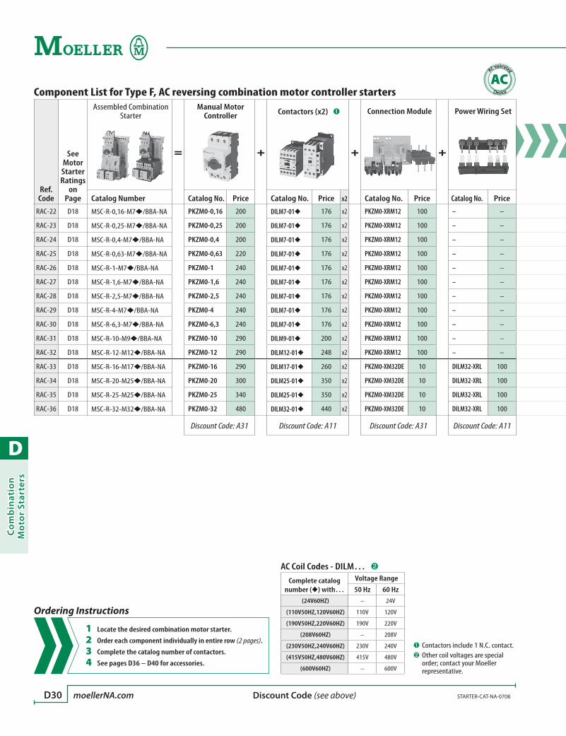
D
Co
mb
inat
ion
Mo
tor
Star
ters
D30 moellerNA.com STARTER-CAT-NA-0708 Discount Code (see above)
Component List for Type F, AC reversing combination motor controller starters
Ref. Code
See Motor Starter Ratings
on Page
Assembled Combination Starter
=
Manual Motor Controller
+
Contactors (x2) ➊
+
Connection Module
+
Power Wiring Set
Catalog Number Catalog No. Price Catalog No. Price x2 Catalog No. Price Catalog No. Price
RAC-22 D18 MSC-R-0,16-M7/BBA-NA PKZM0-0,16 200 DILM7-01 176 x2 PKZM0-XRM12 100 – –
RAC-23 D18 MSC-R-0,25-M7/BBA-NA PKZM0-0,25 200 DILM7-01 176 x2 PKZM0-XRM12 100 – –
RAC-24 D18 MSC-R-0,4-M7/BBA-NA PKZM0-0,4 200 DILM7-01 176 x2 PKZM0-XRM12 100 – –
RAC-25 D18 MSC-R-0,63-M7/BBA-NA PKZM0-0,63 220 DILM7-01 176 x2 PKZM0-XRM12 100 – –
RAC-26 D18 MSC-R-1-M7/BBA-NA PKZM0-1 240 DILM7-01 176 x2 PKZM0-XRM12 100 – –
RAC-27 D18 MSC-R-1,6-M7/BBA-NA PKZM0-1,6 240 DILM7-01 176 x2 PKZM0-XRM12 100 – –
RAC-28 D18 MSC-R-2,5-M7/BBA-NA PKZM0-2,5 240 DILM7-01 176 x2 PKZM0-XRM12 100 – –
RAC-29 D18 MSC-R-4-M7/BBA-NA PKZM0-4 240 DILM7-01 176 x2 PKZM0-XRM12 100 – –
RAC-30 D18 MSC-R-6,3-M7/BBA-NA PKZM0-6,3 240 DILM7-01 176 x2 PKZM0-XRM12 100 – –
RAC-31 D18 MSC-R-10-M9/BBA-NA PKZM0-10 290 DILM9-01 200 x2 PKZM0-XRM12 100 – –
RAC-32 D18 MSC-R-12-M12/BBA-NA PKZM0-12 290 DILM12-01 248 x2 PKZM0-XRM12 100 – –
RAC-33 D18 MSC-R-16-M17/BBA-NA PKZM0-16 290 DILM17-01 260 x2 PKZM0-XM32DE 10 DILM32-XRL 100
RAC-34 D18 MSC-R-20-M25/BBA-NA PKZM0-20 300 DILM25-01 350 x2 PKZM0-XM32DE 10 DILM32-XRL 100
RAC-35 D18 MSC-R-25-M25/BBA-NA PKZM0-25 340 DILM25-01 350 x2 PKZM0-XM32DE 10 DILM32-XRL 100
RAC-36 D18 MSC-R-32-M32/BBA-NA PKZM0-32 480 DILM32-01 440 x2 PKZM0-XM32DE 10 DILM32-XRL 100
Discount Code: A31 Discount Code: A11 Discount Code: A31 Discount Code: A11
AC Coil Codes - DILM… ➋
Complete catalog number () with…
Voltage Range
50 Hz 60 Hz(24V60HZ) – 24V
(110V50HZ,120V60HZ) 110V 120V
(190V50HZ,220V60HZ) 190V 220V
(208V60HZ) – 208V
(230V50HZ,240V60HZ) 230V 240V
(415V50HZ,480V60HZ) 415V 480V
(600V60HZ) – 600V
➊ Contactors include 1 N.C. contact.➋ Other coil voltages are special
order; contact your Moeller representative.
AC operated
AC
Ordering Instructions
1 Locate the desired combination motor starter.
2 Order each component individually in entire row (2 pages).
3 Complete the catalog number of contactors.
4 See pages D36 – D40 for accessories.

D
Co
mb
inatio
n M
oto
r Starters
STARTER-CAT-NA-0708 moellerNA.com D31 Discount Code (see above)
Component List for Type F, AC reversing combination motor controller starters
Ref. Code
See Motor Starter Ratings
on Page
Assembled Combination Starter
=
Manual Motor Controller
+
Contactors (x2) ➊
+
Connection Module
+
Power Wiring Set
Catalog Number Catalog No. Price Catalog No. Price x2 Catalog No. Price Catalog No. Price
RAC-22 D18 MSC-R-0,16-M7/BBA-NA PKZM0-0,16 200 DILM7-01 176 x2 PKZM0-XRM12 100 – –
RAC-23 D18 MSC-R-0,25-M7/BBA-NA PKZM0-0,25 200 DILM7-01 176 x2 PKZM0-XRM12 100 – –
RAC-24 D18 MSC-R-0,4-M7/BBA-NA PKZM0-0,4 200 DILM7-01 176 x2 PKZM0-XRM12 100 – –
RAC-25 D18 MSC-R-0,63-M7/BBA-NA PKZM0-0,63 220 DILM7-01 176 x2 PKZM0-XRM12 100 – –
RAC-26 D18 MSC-R-1-M7/BBA-NA PKZM0-1 240 DILM7-01 176 x2 PKZM0-XRM12 100 – –
RAC-27 D18 MSC-R-1,6-M7/BBA-NA PKZM0-1,6 240 DILM7-01 176 x2 PKZM0-XRM12 100 – –
RAC-28 D18 MSC-R-2,5-M7/BBA-NA PKZM0-2,5 240 DILM7-01 176 x2 PKZM0-XRM12 100 – –
RAC-29 D18 MSC-R-4-M7/BBA-NA PKZM0-4 240 DILM7-01 176 x2 PKZM0-XRM12 100 – –
RAC-30 D18 MSC-R-6,3-M7/BBA-NA PKZM0-6,3 240 DILM7-01 176 x2 PKZM0-XRM12 100 – –
RAC-31 D18 MSC-R-10-M9/BBA-NA PKZM0-10 290 DILM9-01 200 x2 PKZM0-XRM12 100 – –
RAC-32 D18 MSC-R-12-M12/BBA-NA PKZM0-12 290 DILM12-01 248 x2 PKZM0-XRM12 100 – –
RAC-33 D18 MSC-R-16-M17/BBA-NA PKZM0-16 290 DILM17-01 260 x2 PKZM0-XM32DE 10 DILM32-XRL 100
RAC-34 D18 MSC-R-20-M25/BBA-NA PKZM0-20 300 DILM25-01 350 x2 PKZM0-XM32DE 10 DILM32-XRL 100
RAC-35 D18 MSC-R-25-M25/BBA-NA PKZM0-25 340 DILM25-01 350 x2 PKZM0-XM32DE 10 DILM32-XRL 100
RAC-36 D18 MSC-R-32-M32/BBA-NA PKZM0-32 480 DILM32-01 440 x2 PKZM0-XM32DE 10 DILM32-XRL 100
Discount Code: A31 Discount Code: A11 Discount Code: A31 Discount Code: A11
Type F Combination Motor Starter
Components ListAC operated
AC
➊ Other padlocking options include: SVB-PKZ0 and PKZ0-X(R)H (see page C26).
Ref. Code
(cont.)
+
Mechanical Interlock
+
Auxiliary Contacts (on motor controller)
+
Auxiliary Contacts (x2) (on contactors)
+
Padlockable Handle ➊
+
Busbar Mounting Module
+
Feeder Terminal
(1 N.O. and 1 N.C.) (1 N.O. and 1 N.C.)
Catalog No. Price Catalog No. Price Catalog No. Price x2 Cat. No. Price Cat. No. Price Catalog No. Price
RAC-22 DILM12-XMV 36 NHI-E-11-PKZ0 40 DILA-XHIT11 54 x2 AK-PKZ0 8 BBA0R-25 220 BK25/3-PKZ0-E 40
RAC-23 DILM12-XMV 36 NHI-E-11-PKZ0 40 DILA-XHIT11 54 x2 AK-PKZ0 8 BBA0R-25 220 BK25/3-PKZ0-E 40
RAC-24 DILM12-XMV 36 NHI-E-11-PKZ0 40 DILA-XHIT11 54 x2 AK-PKZ0 8 BBA0R-25 220 BK25/3-PKZ0-E 40
RAC-25 DILM12-XMV 36 NHI-E-11-PKZ0 40 DILA-XHIT11 54 x2 AK-PKZ0 8 BBA0R-25 220 BK25/3-PKZ0-E 40
RAC-26 DILM12-XMV 36 NHI-E-11-PKZ0 40 DILA-XHIT11 54 x2 AK-PKZ0 8 BBA0R-25 220 BK25/3-PKZ0-E 40
RAC-27 DILM12-XMV 36 NHI-E-11-PKZ0 40 DILA-XHIT11 54 x2 AK-PKZ0 8 BBA0R-25 220 BK25/3-PKZ0-E 40
RAC-28 DILM12-XMV 36 NHI-E-11-PKZ0 40 DILA-XHIT11 54 x2 AK-PKZ0 8 BBA0R-25 220 BK25/3-PKZ0-E 40
RAC-29 DILM12-XMV 36 NHI-E-11-PKZ0 40 DILA-XHIT11 54 x2 AK-PKZ0 8 BBA0R-25 220 BK25/3-PKZ0-E 40
RAC-30 DILM12-XMV 36 NHI-E-11-PKZ0 40 DILA-XHIT11 54 x2 AK-PKZ0 8 BBA0R-25 220 BK25/3-PKZ0-E 40
RAC-31 DILM12-XMV 36 NHI-E-11-PKZ0 40 DILA-XHIT11 54 x2 AK-PKZ0 8 BBA0R-25 220 BK25/3-PKZ0-E 40
RAC-32 DILM12-XMV 36 NHI-E-11-PKZ0 40 DILA-XHIT11 54 x2 AK-PKZ0 8 BBA0R-25 220 BK25/3-PKZ0-E 40
RAC-33 DILM32-XMV 36 NHI-E-11-PKZ0 40 DILA-XHI11 52 x2 AK-PKZ0 8 BBA0R-32 220 BK25/3-PKZ0-E 40
RAC-34 DILM32-XMV 36 NHI-E-11-PKZ0 40 DILA-XHI11 52 x2 AK-PKZ0 8 BBA0R-32 220 BK25/3-PKZ0-E 40
RAC-35 DILM32-XMV 36 NHI-E-11-PKZ0 40 DILA-XHI11 52 x2 AK-PKZ0 8 BBA0R-32 220 BK25/3-PKZ0-E 40
RAC-36 DILM32-XMV 36 NHI-E-11-PKZ0 40 DILA-XHI11 52 x2 AK-PKZ0 8 BBA0R-32 220 BK25/3-PKZ0-E 40
Discount Code: A11 Discount Code: A31 Discount Code: A11 Discount Code: A31
Discount Code: A34 Discount Code: A31

D
Co
mb
inat
ion
Mo
tor
Star
ters
D32 moellerNA.com STARTER-CAT-NA-0708 Discount Code (see above)
Component List for Type F, DC reversing combination motor controller starters
Ref. Code
See Motor Starter Ratings on Page
Assembled Combination Starter
=
Manual Motor Controller
+
Contactors (x2)
+
Connection Module
+
Power Wiring Set
Catalog Number Catalog No. Price Catalog Number Price x2 Catalog No. Price Catalog No. PriceRDC-01 D16 MSC-R-0,16-M7(24VDC)-NA PKZM0-0,16 200 DILM7-01(24VDC) ➊ 220 x2 PKZM0-XRM12 100 – –
RDC-02 D16 MSC-R-0,25-M7(24VDC)-NA PKZM0-0,25 200 DILM7-01(24VDC) ➊ 220 x2 PKZM0-XRM12 100 – –
RDC-03 D16 MSC-R-0,4-M7(24VDC)-NA PKZM0-0,4 200 DILM7-01(24VDC) ➊ 220 x2 PKZM0-XRM12 100 – –
RDC-04 D16 MSC-R-0,63-M7(24VDC)-NA PKZM0-0,63 220 DILM7-01(24VDC) ➊ 220 x2 PKZM0-XRM12 100 – –
RDC-05 D16 MSC-R-1-M7(24VDC)-NA PKZM0-1 240 DILM7-01(24VDC) ➊ 220 x2 PKZM0-XRM12 100 – –
RDC-06 D16 MSC-R-1,6-M7(24VDC)-NA PKZM0-1,6 240 DILM7-01(24VDC) ➊ 220 x2 PKZM0-XRM12 100 – –
RDC-07 D16 MSC-R-2,5-M7(24VDC)-NA PKZM0-2,5 240 DILM7-01(24VDC) ➊ 220 x2 PKZM0-XRM12 100 – –
RDC-08 D16 MSC-R-4-M7(24VDC)-NA PKZM0-4 240 DILM7-01(24VDC) ➊ 220 x2 PKZM0-XRM12 100 – –
RDC-09 D16 MSC-R-6,3-M7(24VDC)-NA PKZM0-6,3 240 DILM7-01(24VDC) ➊ 220 x2 PKZM0-XRM12 100 – –
RDC-10 D16 MSC-R-10-M9(24VDC)-NA PKZM0-10 290 DILM9-01(24VDC) ➊ 240 x2 PKZM0-XRM12 100 – –
RDC-11 D16 MSC-R-12-M12(24VDC)-NA PKZM0-12 290 DILM12-01(24VDC) ➊ 316 x2 PKZM0-XRM12 100 – –
RDC-12 D16 MSC-R-16-M17(RDC24)-NA PKZM0-16 290 DILM17-01(RDC24) ➊ 370 x2 PKZM0-XRM32 ➋ 124 – –
RDC-13 D16 MSC-R-20-M25(RDC24)-NA PKZM0-20 300 DILM25-01(RDC24) ➊ 450 x2 PKZM0-XRM32 ➋ 124 – –
RDC-14 D16 MSC-R-25-M25(RDC24)-NA PKZM0-25 340 DILM25-01(RDC24) ➊ 450 x2 PKZM0-XRM32 ➋ 124 – –
RDC-15 D16 MSC-R-32-M32(RDC24)-NA PKZM0-32 480 DILM32-01(RDC24) ➊ 620 x2 PKZM0-XRM32 ➋ 124 – –
RDC-16 D17 MSC4-R-16-M40(RDC24)-NA PKZM4-16 494 DILM40(RDC24) 650 x2 PKZM4-XM65DE 60 DILM65-XRL 190
RDC-17 D17 MSC4-R-25-M40(RDC24)-NA PKZM4-25 508 DILM40(RDC24) 650 x2 PKZM4-XM65DE 60 DILM65-XRL 190
RDC-18 D17 MSC4-R-32-M40(RDC24)-NA PKZM4-32 590 DILM40(RDC24) 650 x2 PKZM4-XM65DE 60 DILM65-XRL 190
RDC-19 D17 MSC4-R-40-M40(RDC24)-NA PKZM4-40 690 DILM40(RDC24) 650 x2 PKZM4-XM65DE 60 DILM65-XRL 190
RDC-20 D17 MSC4-R-50-M65(RDC24)-NA PKZM4-50 784 DILM65(RDC24) 1170 x2 PKZM4-XM65DE 60 DILM65-XRL 190
RDC-21 D17 MSC4-R-58-M65(RDC24)-NA PKZM4-58 932 DILM65(RDC24) 1170 x2 PKZM4-XM65DE 60 DILM65-XRL 190
Discount Code: A31 Discount Code: A11 Discount Code: A31 Discount Code: A11
DC operated
DC
➊ Contactors include 1 N.C. contact.➋ Connection module includes DIN rail mounting module. (page D37)
Ordering Instructions
1 Locate the desired combination motor starter.
2 Order each component individually in entire row (2 pages).
3 See pages D36 – D40 for accessories.
DC Coil Information
DC operated devices listed on this page are 24V DC.
Other DC voltages are special order; contact your Moeller
representative.

D
Co
mb
inatio
n M
oto
r Starters
STARTER-CAT-NA-0708 moellerNA.com D33 Discount Code (see above)
Component List for Type F, DC reversing combination motor controller starters
Ref. Code
See Motor Starter Ratings on Page
Assembled Combination Starter
=
Manual Motor Controller
+
Contactors (x2)
+
Connection Module
+
Power Wiring Set
Catalog Number Catalog No. Price Catalog Number Price x2 Catalog No. Price Catalog No. PriceRDC-01 D16 MSC-R-0,16-M7(24VDC)-NA PKZM0-0,16 200 DILM7-01(24VDC) ➊ 220 x2 PKZM0-XRM12 100 – –
RDC-02 D16 MSC-R-0,25-M7(24VDC)-NA PKZM0-0,25 200 DILM7-01(24VDC) ➊ 220 x2 PKZM0-XRM12 100 – –
RDC-03 D16 MSC-R-0,4-M7(24VDC)-NA PKZM0-0,4 200 DILM7-01(24VDC) ➊ 220 x2 PKZM0-XRM12 100 – –
RDC-04 D16 MSC-R-0,63-M7(24VDC)-NA PKZM0-0,63 220 DILM7-01(24VDC) ➊ 220 x2 PKZM0-XRM12 100 – –
RDC-05 D16 MSC-R-1-M7(24VDC)-NA PKZM0-1 240 DILM7-01(24VDC) ➊ 220 x2 PKZM0-XRM12 100 – –
RDC-06 D16 MSC-R-1,6-M7(24VDC)-NA PKZM0-1,6 240 DILM7-01(24VDC) ➊ 220 x2 PKZM0-XRM12 100 – –
RDC-07 D16 MSC-R-2,5-M7(24VDC)-NA PKZM0-2,5 240 DILM7-01(24VDC) ➊ 220 x2 PKZM0-XRM12 100 – –
RDC-08 D16 MSC-R-4-M7(24VDC)-NA PKZM0-4 240 DILM7-01(24VDC) ➊ 220 x2 PKZM0-XRM12 100 – –
RDC-09 D16 MSC-R-6,3-M7(24VDC)-NA PKZM0-6,3 240 DILM7-01(24VDC) ➊ 220 x2 PKZM0-XRM12 100 – –
RDC-10 D16 MSC-R-10-M9(24VDC)-NA PKZM0-10 290 DILM9-01(24VDC) ➊ 240 x2 PKZM0-XRM12 100 – –
RDC-11 D16 MSC-R-12-M12(24VDC)-NA PKZM0-12 290 DILM12-01(24VDC) ➊ 316 x2 PKZM0-XRM12 100 – –
RDC-12 D16 MSC-R-16-M17(RDC24)-NA PKZM0-16 290 DILM17-01(RDC24) ➊ 370 x2 PKZM0-XRM32 ➋ 124 – –
RDC-13 D16 MSC-R-20-M25(RDC24)-NA PKZM0-20 300 DILM25-01(RDC24) ➊ 450 x2 PKZM0-XRM32 ➋ 124 – –
RDC-14 D16 MSC-R-25-M25(RDC24)-NA PKZM0-25 340 DILM25-01(RDC24) ➊ 450 x2 PKZM0-XRM32 ➋ 124 – –
RDC-15 D16 MSC-R-32-M32(RDC24)-NA PKZM0-32 480 DILM32-01(RDC24) ➊ 620 x2 PKZM0-XRM32 ➋ 124 – –
RDC-16 D17 MSC4-R-16-M40(RDC24)-NA PKZM4-16 494 DILM40(RDC24) 650 x2 PKZM4-XM65DE 60 DILM65-XRL 190
RDC-17 D17 MSC4-R-25-M40(RDC24)-NA PKZM4-25 508 DILM40(RDC24) 650 x2 PKZM4-XM65DE 60 DILM65-XRL 190
RDC-18 D17 MSC4-R-32-M40(RDC24)-NA PKZM4-32 590 DILM40(RDC24) 650 x2 PKZM4-XM65DE 60 DILM65-XRL 190
RDC-19 D17 MSC4-R-40-M40(RDC24)-NA PKZM4-40 690 DILM40(RDC24) 650 x2 PKZM4-XM65DE 60 DILM65-XRL 190
RDC-20 D17 MSC4-R-50-M65(RDC24)-NA PKZM4-50 784 DILM65(RDC24) 1170 x2 PKZM4-XM65DE 60 DILM65-XRL 190
RDC-21 D17 MSC4-R-58-M65(RDC24)-NA PKZM4-58 932 DILM65(RDC24) 1170 x2 PKZM4-XM65DE 60 DILM65-XRL 190
Discount Code: A31 Discount Code: A11 Discount Code: A31 Discount Code: A11
Type F Combination Motor Starter
Components List
Ref. Code
(cont.)
+
Mechanical Interlock
+
Auxiliary Contacts (on motor controller)
+
Auxiliary Contacts (x2) (on contactors)
+
Padlockable Handle ➊
+
DIN Rail Mounting Module
Feeder Terminal ➋
(1 N.O. and 1 N.C.) (1 N.O. and 1 N.C.)
Catalog No. Price Catalog No. Price Catalog No. Price x2 Cat. No. Price Catalog No. Price Catalog No. PriceRDC-01 DILM12-XMV 36 NHI-E-11-PKZ0 40 DILA-XHIT11 54 x2 AK-PKZ0 8 –
Re
com
me
nd
ed
Op
tio
n
BK25/3-PKZ0-E 40
RDC-02 DILM12-XMV 36 NHI-E-11-PKZ0 40 DILA-XHIT11 54 x2 AK-PKZ0 8 – BK25/3-PKZ0-E 40
RDC-03 DILM12-XMV 36 NHI-E-11-PKZ0 40 DILA-XHIT11 54 x2 AK-PKZ0 8 – BK25/3-PKZ0-E 40
RDC-04 DILM12-XMV 36 NHI-E-11-PKZ0 40 DILA-XHIT11 54 x2 AK-PKZ0 8 – BK25/3-PKZ0-E 40
RDC-05 DILM12-XMV 36 NHI-E-11-PKZ0 40 DILA-XHIT11 54 x2 AK-PKZ0 8 – BK25/3-PKZ0-E 40
RDC-06 DILM12-XMV 36 NHI-E-11-PKZ0 40 DILA-XHIT11 54 x2 AK-PKZ0 8 – BK25/3-PKZ0-E 40
RDC-07 DILM12-XMV 36 NHI-E-11-PKZ0 40 DILA-XHIT11 54 x2 AK-PKZ0 8 – BK25/3-PKZ0-E 40
RDC-08 DILM12-XMV 36 NHI-E-11-PKZ0 40 DILA-XHIT11 54 x2 AK-PKZ0 8 – BK25/3-PKZ0-E 40
RDC-09 DILM12-XMV 36 NHI-E-11-PKZ0 40 DILA-XHIT11 54 x2 AK-PKZ0 8 – BK25/3-PKZ0-E 40
RDC-10 DILM12-XMV 36 NHI-E-11-PKZ0 40 DILA-XHIT11 54 x2 AK-PKZ0 8 – BK25/3-PKZ0-E 40
RDC-11 DILM12-XMV 36 NHI-E-11-PKZ0 40 DILA-XHIT11 54 x2 AK-PKZ0 8 – BK25/3-PKZ0-E 40
RDC-12 DILM32-XMV 36 NHI-E-11-PKZ0 40 DILA-XHI11 52 x2 AK-PKZ0 8 ➌ BK25/3-PKZ0-E 40
RDC-13 DILM32-XMV 36 NHI-E-11-PKZ0 40 DILA-XHI11 52 x2 AK-PKZ0 8 ➌ BK25/3-PKZ0-E 40
RDC-14 DILM32-XMV 36 NHI-E-11-PKZ0 40 DILA-XHI11 52 x2 AK-PKZ0 8 ➌ BK25/3-PKZ0-E 40
RDC-15 DILM32-XMV 36 NHI-E-11-PKZ0 40 DILA-XHI11 52 x2 AK-PKZ0 8 ➌ BK25/3-PKZ0-E 40
RDC-16 DILM65-XMV 48 NHI-E-11-PKZ0 40 DILM150-XHI11 52 x2 AK-PKZ0 8 PKZM4-XC55/2 80 BK50/3-PKZ4-E 110
RDC-17 DILM65-XMV 48 NHI-E-11-PKZ0 40 DILM150-XHI11 52 x2 AK-PKZ0 8 PKZM4-XC55/2 80 BK50/3-PKZ4-E 110
RDC-18 DILM65-XMV 48 NHI-E-11-PKZ0 40 DILM150-XHI11 52 x2 AK-PKZ0 8 PKZM4-XC55/2 80 BK50/3-PKZ4-E 110
RDC-19 DILM65-XMV 48 NHI-E-11-PKZ0 40 DILM150-XHI11 52 x2 AK-PKZ0 8 PKZM4-XC55/2 80 BK50/3-PKZ4-E 110
RDC-20 DILM65-XMV 48 NHI-E-11-PKZ0 40 DILM150-XHI11 52 x2 AK-PKZ0 8 PKZM4-XC55/2 80 BK50/3-PKZ4-E 110
RDC-21 DILM65-XMV 48 NHI-E-11-PKZ0 40 DILM150-XHI11 52 x2 AK-PKZ0 8 PKZM4-XC55/2 80 BK50/3-PKZ4-E 110
Discount Code: A11 Discount Code: A31 Discount Code: A11 Discount Code:
A31 Discount Code: A31 Discount Code: A31
DC operated
DC
➊ Other padlocking options include: SVB-PKZ0 and PKZ0-X(R)H (see page C26).➋ Requirement for Type F except when used for tap conductor protection or if com-
moning links are used. ➌ Connection module includes DIN rail mounting module. (page D37)
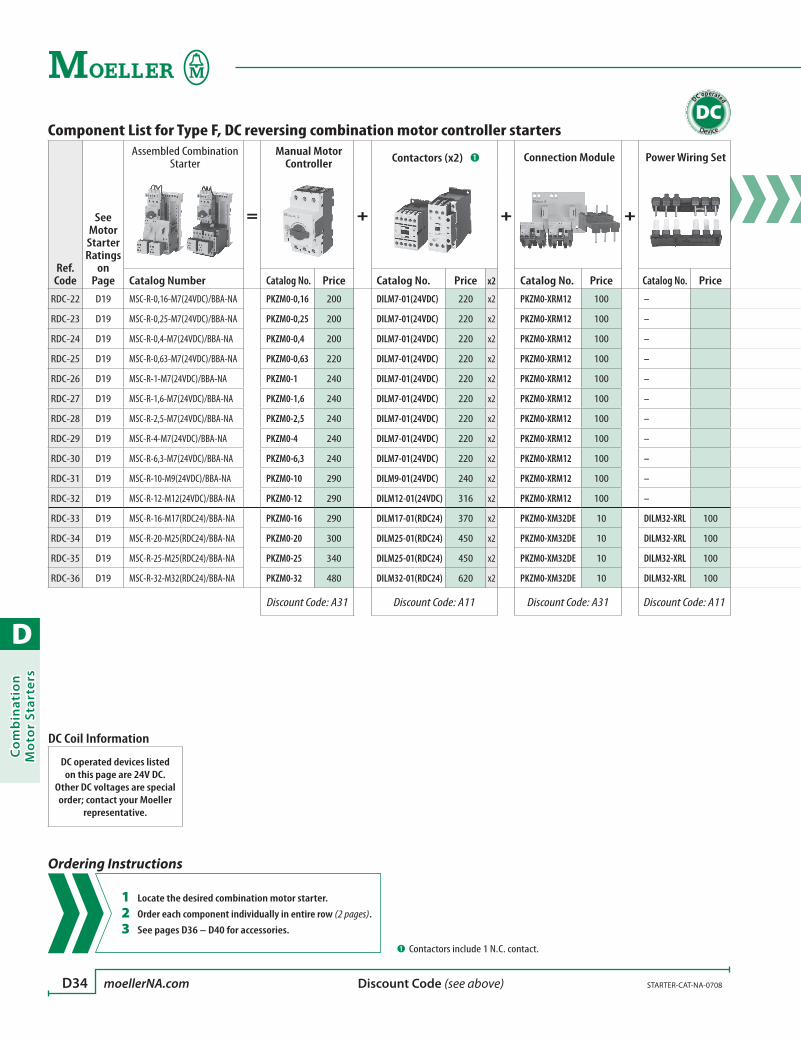
D
Co
mb
inat
ion
Mo
tor
Star
ters
D34 moellerNA.com STARTER-CAT-NA-0708 Discount Code (see above)
Component List for Type F, DC reversing combination motor controller starters
Ref. Code
See Motor Starter Ratings
on Page
Assembled Combination Starter
=
Manual Motor Controller
+
Contactors (x2) ➊
+
Connection Module
+
Power Wiring Set
Catalog Number Catalog No. Price Catalog No. Price x2 Catalog No. Price Catalog No. Price
RDC-22 D19 MSC-R-0,16-M7(24VDC)/BBA-NA PKZM0-0,16 200 DILM7-01(24VDC) 220 x2 PKZM0-XRM12 100 –
RDC-23 D19 MSC-R-0,25-M7(24VDC)/BBA-NA PKZM0-0,25 200 DILM7-01(24VDC) 220 x2 PKZM0-XRM12 100 –
RDC-24 D19 MSC-R-0,4-M7(24VDC)/BBA-NA PKZM0-0,4 200 DILM7-01(24VDC) 220 x2 PKZM0-XRM12 100 –
RDC-25 D19 MSC-R-0,63-M7(24VDC)/BBA-NA PKZM0-0,63 220 DILM7-01(24VDC) 220 x2 PKZM0-XRM12 100 –
RDC-26 D19 MSC-R-1-M7(24VDC)/BBA-NA PKZM0-1 240 DILM7-01(24VDC) 220 x2 PKZM0-XRM12 100 –
RDC-27 D19 MSC-R-1,6-M7(24VDC)/BBA-NA PKZM0-1,6 240 DILM7-01(24VDC) 220 x2 PKZM0-XRM12 100 –
RDC-28 D19 MSC-R-2,5-M7(24VDC)/BBA-NA PKZM0-2,5 240 DILM7-01(24VDC) 220 x2 PKZM0-XRM12 100 –
RDC-29 D19 MSC-R-4-M7(24VDC)/BBA-NA PKZM0-4 240 DILM7-01(24VDC) 220 x2 PKZM0-XRM12 100 –
RDC-30 D19 MSC-R-6,3-M7(24VDC)/BBA-NA PKZM0-6,3 240 DILM7-01(24VDC) 220 x2 PKZM0-XRM12 100 –
RDC-31 D19 MSC-R-10-M9(24VDC)/BBA-NA PKZM0-10 290 DILM9-01(24VDC) 240 x2 PKZM0-XRM12 100 –
RDC-32 D19 MSC-R-12-M12(24VDC)/BBA-NA PKZM0-12 290 DILM12-01(24VDC) 316 x2 PKZM0-XRM12 100 –
RDC-33 D19 MSC-R-16-M17(RDC24)/BBA-NA PKZM0-16 290 DILM17-01(RDC24) 370 x2 PKZM0-XM32DE 10 DILM32-XRL 100
RDC-34 D19 MSC-R-20-M25(RDC24)/BBA-NA PKZM0-20 300 DILM25-01(RDC24) 450 x2 PKZM0-XM32DE 10 DILM32-XRL 100
RDC-35 D19 MSC-R-25-M25(RDC24)/BBA-NA PKZM0-25 340 DILM25-01(RDC24) 450 x2 PKZM0-XM32DE 10 DILM32-XRL 100
RDC-36 D19 MSC-R-32-M32(RDC24)/BBA-NA PKZM0-32 480 DILM32-01(RDC24) 620 x2 PKZM0-XM32DE 10 DILM32-XRL 100
Discount Code: A31 Discount Code: A11 Discount Code: A31 Discount Code: A11
➊ Contactors include 1 N.C. contact.
DC operated
DC
Ordering Instructions
1 Locate the desired combination motor starter.
2 Order each component individually in entire row (2 pages).
3 See pages D36 – D40 for accessories.
DC Coil Information
DC operated devices listed on this page are 24V DC.
Other DC voltages are special order; contact your Moeller
representative.
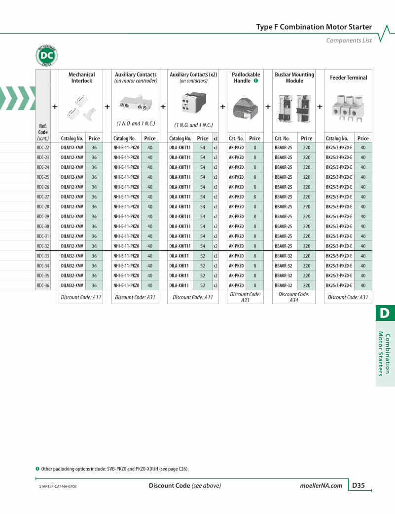
D
Co
mb
inatio
n M
oto
r Starters
STARTER-CAT-NA-0708 moellerNA.com D35 Discount Code (see above)
Component List for Type F, DC reversing combination motor controller starters
Ref. Code
See Motor Starter Ratings
on Page
Assembled Combination Starter
=
Manual Motor Controller
+
Contactors (x2) ➊
+
Connection Module
+
Power Wiring Set
Catalog Number Catalog No. Price Catalog No. Price x2 Catalog No. Price Catalog No. Price
RDC-22 D19 MSC-R-0,16-M7(24VDC)/BBA-NA PKZM0-0,16 200 DILM7-01(24VDC) 220 x2 PKZM0-XRM12 100 –
RDC-23 D19 MSC-R-0,25-M7(24VDC)/BBA-NA PKZM0-0,25 200 DILM7-01(24VDC) 220 x2 PKZM0-XRM12 100 –
RDC-24 D19 MSC-R-0,4-M7(24VDC)/BBA-NA PKZM0-0,4 200 DILM7-01(24VDC) 220 x2 PKZM0-XRM12 100 –
RDC-25 D19 MSC-R-0,63-M7(24VDC)/BBA-NA PKZM0-0,63 220 DILM7-01(24VDC) 220 x2 PKZM0-XRM12 100 –
RDC-26 D19 MSC-R-1-M7(24VDC)/BBA-NA PKZM0-1 240 DILM7-01(24VDC) 220 x2 PKZM0-XRM12 100 –
RDC-27 D19 MSC-R-1,6-M7(24VDC)/BBA-NA PKZM0-1,6 240 DILM7-01(24VDC) 220 x2 PKZM0-XRM12 100 –
RDC-28 D19 MSC-R-2,5-M7(24VDC)/BBA-NA PKZM0-2,5 240 DILM7-01(24VDC) 220 x2 PKZM0-XRM12 100 –
RDC-29 D19 MSC-R-4-M7(24VDC)/BBA-NA PKZM0-4 240 DILM7-01(24VDC) 220 x2 PKZM0-XRM12 100 –
RDC-30 D19 MSC-R-6,3-M7(24VDC)/BBA-NA PKZM0-6,3 240 DILM7-01(24VDC) 220 x2 PKZM0-XRM12 100 –
RDC-31 D19 MSC-R-10-M9(24VDC)/BBA-NA PKZM0-10 290 DILM9-01(24VDC) 240 x2 PKZM0-XRM12 100 –
RDC-32 D19 MSC-R-12-M12(24VDC)/BBA-NA PKZM0-12 290 DILM12-01(24VDC) 316 x2 PKZM0-XRM12 100 –
RDC-33 D19 MSC-R-16-M17(RDC24)/BBA-NA PKZM0-16 290 DILM17-01(RDC24) 370 x2 PKZM0-XM32DE 10 DILM32-XRL 100
RDC-34 D19 MSC-R-20-M25(RDC24)/BBA-NA PKZM0-20 300 DILM25-01(RDC24) 450 x2 PKZM0-XM32DE 10 DILM32-XRL 100
RDC-35 D19 MSC-R-25-M25(RDC24)/BBA-NA PKZM0-25 340 DILM25-01(RDC24) 450 x2 PKZM0-XM32DE 10 DILM32-XRL 100
RDC-36 D19 MSC-R-32-M32(RDC24)/BBA-NA PKZM0-32 480 DILM32-01(RDC24) 620 x2 PKZM0-XM32DE 10 DILM32-XRL 100
Discount Code: A31 Discount Code: A11 Discount Code: A31 Discount Code: A11
Type F Combination Motor Starter
Components List
Ref. Code
(cont.)
+
Mechanical Interlock
+
Auxiliary Contacts (on motor controller)
+
Auxiliary Contacts (x2) (on contactors)
+
Padlockable Handle ➊
+
Busbar Mounting Module
+
Feeder Terminal
(1 N.O. and 1 N.C.) (1 N.O. and 1 N.C.)
Catalog No. Price Catalog No. Price Catalog No. Price x2 Cat. No. Price Cat. No. Price Catalog No. Price
RDC-22 DILM12-XMV 36 NHI-E-11-PKZ0 40 DILA-XHIT11 54 x2 AK-PKZ0 8 BBA0R-25 220 BK25/3-PKZ0-E 40
RDC-23 DILM12-XMV 36 NHI-E-11-PKZ0 40 DILA-XHIT11 54 x2 AK-PKZ0 8 BBA0R-25 220 BK25/3-PKZ0-E 40
RDC-24 DILM12-XMV 36 NHI-E-11-PKZ0 40 DILA-XHIT11 54 x2 AK-PKZ0 8 BBA0R-25 220 BK25/3-PKZ0-E 40
RDC-25 DILM12-XMV 36 NHI-E-11-PKZ0 40 DILA-XHIT11 54 x2 AK-PKZ0 8 BBA0R-25 220 BK25/3-PKZ0-E 40
RDC-26 DILM12-XMV 36 NHI-E-11-PKZ0 40 DILA-XHIT11 54 x2 AK-PKZ0 8 BBA0R-25 220 BK25/3-PKZ0-E 40
RDC-27 DILM12-XMV 36 NHI-E-11-PKZ0 40 DILA-XHIT11 54 x2 AK-PKZ0 8 BBA0R-25 220 BK25/3-PKZ0-E 40
RDC-28 DILM12-XMV 36 NHI-E-11-PKZ0 40 DILA-XHIT11 54 x2 AK-PKZ0 8 BBA0R-25 220 BK25/3-PKZ0-E 40
RDC-29 DILM12-XMV 36 NHI-E-11-PKZ0 40 DILA-XHIT11 54 x2 AK-PKZ0 8 BBA0R-25 220 BK25/3-PKZ0-E 40
RDC-30 DILM12-XMV 36 NHI-E-11-PKZ0 40 DILA-XHIT11 54 x2 AK-PKZ0 8 BBA0R-25 220 BK25/3-PKZ0-E 40
RDC-31 DILM12-XMV 36 NHI-E-11-PKZ0 40 DILA-XHIT11 54 x2 AK-PKZ0 8 BBA0R-25 220 BK25/3-PKZ0-E 40
RDC-32 DILM12-XMV 36 NHI-E-11-PKZ0 40 DILA-XHIT11 54 x2 AK-PKZ0 8 BBA0R-25 220 BK25/3-PKZ0-E 40
RDC-33 DILM32-XMV 36 NHI-E-11-PKZ0 40 DILA-XHI11 52 x2 AK-PKZ0 8 BBA0R-32 220 BK25/3-PKZ0-E 40
RDC-34 DILM32-XMV 36 NHI-E-11-PKZ0 40 DILA-XHI11 52 x2 AK-PKZ0 8 BBA0R-32 220 BK25/3-PKZ0-E 40
RDC-35 DILM32-XMV 36 NHI-E-11-PKZ0 40 DILA-XHI11 52 x2 AK-PKZ0 8 BBA0R-32 220 BK25/3-PKZ0-E 40
RDC-36 DILM32-XMV 36 NHI-E-11-PKZ0 40 DILA-XHI11 52 x2 AK-PKZ0 8 BBA0R-32 220 BK25/3-PKZ0-E 40
Discount Code: A11 Discount Code: A31 Discount Code: A11 Discount Code: A31
Discount Code: A34 Discount Code: A31
➊ Other padlocking options include: SVB-PKZ0 and PKZ0-X(R)H (see page C26).
DC operated
DC
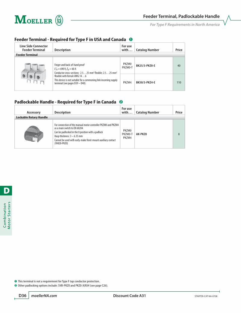
D
Co
mb
inat
ion
Mo
tor
Star
ters
D36 moellerNA.com STARTER-CAT-NA-0708 Discount Code A31
Feeder Terminal, Padlockable Handle
For Type F Requirements in North America
Feeder Terminal - Required for Type F in USA and Canada ➊
Line Side Connector Feeder Terminal Description
For use with… Catalog Number Price
Feeder Terminal
Finger and back-of-hand proofUe = 690 V, Iu = 60 AConductor cross-sections: 2.5…25 mm2 flexible; 2.5…25 mm2 flexible with ferrule AWG 14…6This device is not suitable for a commoning link incoming supply termnial (see pages D39 – D40).
PKZM0PKZM0-T BK25/3-PKZ0-E 40
PKZM4 BK50/3-PKZ4-E 110
Padlockable Handle - Required for Type F in Canada ➋
Accessory DescriptionFor use with… Catalog Number Price
Lockable Rotary Handle
For connection of the manual motor controller PKZM0 and PKZM4 as a main switch to EN 60204Can be padlocked in the 0 position with a padlockHasp thickness: 3 – 6.35 mmCannot be used with early-make front-mount auxiliary contact (VHI20-PKZ0)
PKZM0PKZM0-TPKZM4
AK-PKZ0 8
➊ This terminal is not a requirement for Type F tap conductor protection.➋ Other padlocking options include: SVB-PKZ0 and PKZ0-X(R)H (see page C26).

D
Co
mb
inatio
n M
oto
r Starters
STARTER-CAT-NA-0708 moellerNA.com D37 Discount Code A31
Accessories
Wiring Sets
Connection ModulesConnection Sets Description For use with… Catalog Number Price
Non-Reversing Starters
Comprised of:Mechanical connection element for PKZM0 and contactor•Main current wiring between PKZM0 and contactor in tool-less plug connection•Cable routing•
MSC-D-0,16-M7 to
MSC-D-12-M12PKZM0-XDM12 ➊ 30
Comprised of:DIN rail mounting module•Main current wiring between PKZ and contactor•
MSC-D-10-M17 to
MSC-D-32-M32PKZM0-XDM32 42
MSC4-D-40-M40 to
MSC4-D-63-M65PKZM4-XDM65 150
Reversing Starters
Comprised of:Mechanical connection element for PKZM0 and contactor•Reversing starter main current wiring in tool-less plug connection•Control cables for electrical interlocking in tool-less plug connection: •K1M: A1; K2M: 21; K1M: 21; K2M: A1; K1M: A2; K2M: A2Cable routing•
Cannot be combined with Trip-indicating auxiliary contacts AGM…-PKZ0 (page C17)
MSC-R-0,16-M7 to
MSC-R-12-M12PKZM0-XRM12 ➊ 100
Comprised of:DIN rail mounting module•Reversing starter main current wiring•Order mechanical interlock separately•
MSC-R-10-M17 to
MSC-R-32-M32PKZM0-XRM32 124
Star-delta Starter
Comprised of:DIN rail mounting module•Main current wiring between PKZM0 and contactor•Electrical interlock between delta and star connector•
PKZM0 + DILM7PKZM0 + DILM9
PKZM0 + DILM12PKZM0-XSM12 ➊ 210
Comprised of:DIN rail mounting module•Main current wiring between PKZM0 and contactor•
PKZM0 + DILM17PKZM0 + DILM25PKZM0 + DILM32
PKZM0-XSM32 180
Electrical Connection Module
Main current wiring between PKZM0 and contactor•Use only in combination with busbar mounting module•
MSC-(D)(R)-10-M17 to
MSC-(D)(R)-32-M32PKZM0-XM32DE 10
Main current wiring between PKZM4 and contactor•Use only in combination with busbar mounting module•
MSC4-D-40-M40 to
MSC4-D-63-M65PKZM4-XM65DE 60
➊ Only Top Mount - High Version auxiliary contacts may be used with this wiring set.

D
Co
mb
inat
ion
Mo
tor
Star
ters
D38 moellerNA.com STARTER-CAT-NA-0708 Discount Code A31
Accessories
DIN Rail Mounting Modules
DIN rail mounting modulesMounting Module Description For use with… Catalog Number Price
DIN Rail Mounting Module
Comprised of:45 mm wide mounting module•Connection element for side-by-side positioning of further plates•
MSC-D-0,16-M7 to
MSC-D-32-M32PKZM0-XC45/2 44
Comprised of:55 mm wide mounting module•Connection cams for further plates•For use with reversing and star-delta starters•
MSC4-D-40-M40 to
MSC4-D-63-M65PKZM4-XC55/2 80
for Side Mounted Module
Can be grouped on the DIN rail mounting module.Expansion of the mounting width by 9 mm.
All mounting modules PKZM0-XS 20
Connection Element
For connection of multiple DIN rail mounting modules All mounting modules PKZM0-XCM 1.60
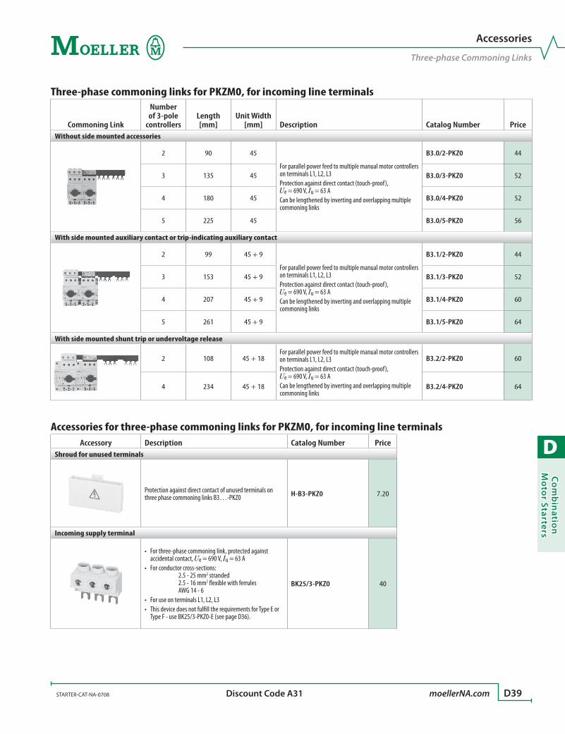
D
Co
mb
inatio
n M
oto
r Starters
STARTER-CAT-NA-0708 moellerNA.com D39 Discount Code A31
Accessories
Three-phase Commoning Links
Three-phase commoning links for PKZM0, for incoming line terminals
Commoning Link
Number of 3-pole
controllersLength [mm]
Unit Width [mm] Description Catalog Number Price
Without side mounted accessories
2 90 45
For parallel power feed to multiple manual motor controllers on terminals L1, L2, L3Protection against direct contact (touch-proof), Ue = 690 V, Iu = 63 ACan be lengthened by inverting and overlapping multiple commoning links
B3.0/2-PKZ0 44
3 135 45 B3.0/3-PKZ0 52
4 180 45 B3.0/4-PKZ0 52
5 225 45 B3.0/5-PKZ0 56
With side mounted auxiliary contact or trip-indicating auxiliary contact
2 99 45 + 9
For parallel power feed to multiple manual motor controllers on terminals L1, L2, L3Protection against direct contact (touch-proof), Ue = 690 V, Iu = 63 ACan be lengthened by inverting and overlapping multiple commoning links
B3.1/2-PKZ0 44
3 153 45 + 9 B3.1/3-PKZ0 52
4 207 45 + 9 B3.1/4-PKZ0 60
5 261 45 + 9 B3.1/5-PKZ0 64
With side mounted shunt trip or undervoltage release
2 108 45 + 18For parallel power feed to multiple manual motor controllers on terminals L1, L2, L3Protection against direct contact (touch-proof), Ue = 690 V, Iu = 63 ACan be lengthened by inverting and overlapping multiple commoning links
B3.2/2-PKZ0 60
4 234 45 + 18 B3.2/4-PKZ0 64
Accessories for three-phase commoning links for PKZM0, for incoming line terminalsAccessory Description Catalog Number Price
Shroud for unused terminals
Protection against direct contact of unused terminals on three phase commoning links B3…-PKZ0 H-B3-PKZ0 7.20
Incoming supply terminal
For three-phase commoning link, protected against •accidental contact, Ue = 690 V, Iu = 63 AFor conductor cross-sections: • 2.5 - 25 mm2 stranded 2.5 - 16 mm2 flexible with ferrules AWG 14 - 6For use on terminals L1, L2, L3•This device does not fulfill the requirements for Type E or •Type F - use BK25/3-PKZ0-E (see page D36).
BK25/3-PKZ0 40

D
Co
mb
inat
ion
Mo
tor
Star
ters
D40 moellerNA.com STARTER-CAT-NA-0708 Discount Code A31
Accessories
Three-phase Commoning Links
Three-phase commoning links for PKZM4, for incoming line terminals
Commoning Link
Number of Circuit Breakers
Length [mm]
Unit Width [mm] Description Catalog Number Price
Without side mounted auxiliary contact or voltage release
2 110 55
For parallel power feed to multiple manual motor controllers on terminals L1, L2, L3 Protection against direct contact (touch-proof), Ue = 690 V, Iu = 128 A
B3.0/2-PKZ4 84
3 165 55 B3.0/3-PKZ4 110
4 220 55 B3.0/4-PKZ4 136
With side mounted auxiliary contact or trip-indicating auxiliary contact
2 119 55 + 9
For parallel power feed to multiple manual motor controllers on terminals L1, L2, L3 Protection against direct contact (touch-proof), Ue = 690 V, Iu = 63 A
B3.1/2-PKZ4 88
3 183 55 + 9 B3.1/3-PKZ4 112
4 247 55 + 9 B3.1/4-PKZ4 140
With side mounted shunt trip or undervoltage release
2 128 55 + 18For parallel power feed to multiple manual motor controllers on terminals L1, L2, L3 Protection against direct contact (touch-proof), Ue = 690 V, Iu = 63 A
B3.2/2-PKZ4 96
4 274 55 + 18 B3.2/4-PKZ4 146
Accessories for three-phase commoning links for PKZM4Accessory Description Catalog Number Price
Shroud for unused terminals
Protection against direct contact of unused terminals on three phase commoning links B3…-PKZ4 H-B3-PKZ4 10
Incoming power cables can be directly wired into PKZM4 devices. An incoming supply terminal is not needed for PKZM4 commoning links.
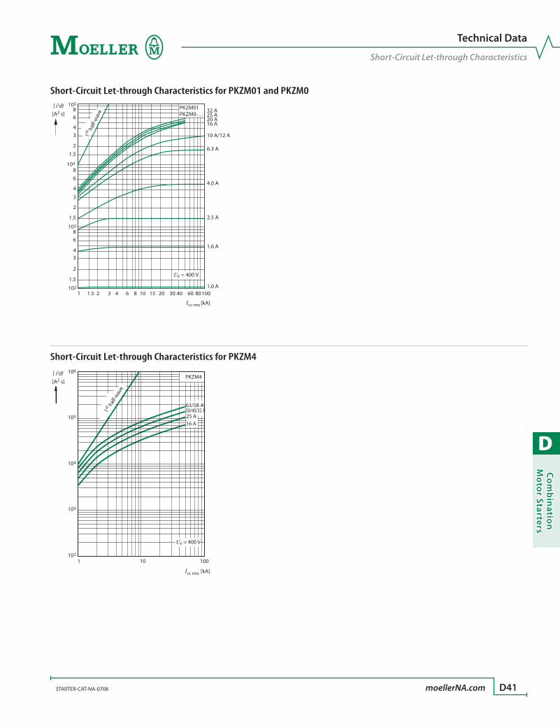
D
Co
mb
inatio
n M
oto
r Starters
STARTER-CAT-NA-0708 moellerNA.com D41
Technical Data
Short-Circuit Let-through Characteristics
Short-Circuit Let-through Characteristics for PKZM01 and PKZM0
Short-Circuit Let-through Characteristics for PKZM4
Ue = 400 V
PKZM01PKZM0-…
104
1.52
3
6
4
8105
4.0 A
6.3 A
2.5 A
1.6 A
1.0 A
10 A/12 A
103
2
1.5
3
4
68
102
2
1.5
34
68
1 21.5 3 4 6 8 10 2015 30 40 60 80100
16 A20 A25 A32 A
[kA]
[A2 s]
1st h
alf-w
ave
Icc rms
∫ i2dt
105
106
104
102
1 10 100
103
Ue = 400 V
63/58 A50/40/32 A25 A16 A
PKZM4
[kA]
[A2 s] ∫ i2dt
1st h
alf-w
ave
Icc rms
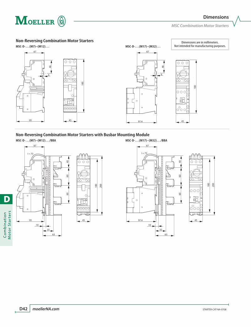
D
Co
mb
inat
ion
Mo
tor
Star
ters
D42 moellerNA.com STARTER-CAT-NA-0708
Dimensions
MSC Combination Motor Starters
Non-Reversing Combination Motor StartersMSC-D-…(M7)–(M12)… MSC-D-…(M17)–(M32)…
95 45
67
6
46
180
45
180
97.4
67
6
46
Non-Reversing Combination Motor Starters with Busbar Mounting ModuleMSC-D-…(M7)–(M12)…/BBA MSC-D-…(M17)–(M32)…/BBA
95
35
63
10
45
67
4060
60
180
200
I = 73
35
63
10
45
67
4060
60
180
200
I = 73
97.4
Dimensions are in millimeters.Not intended for manufacturing purposes.
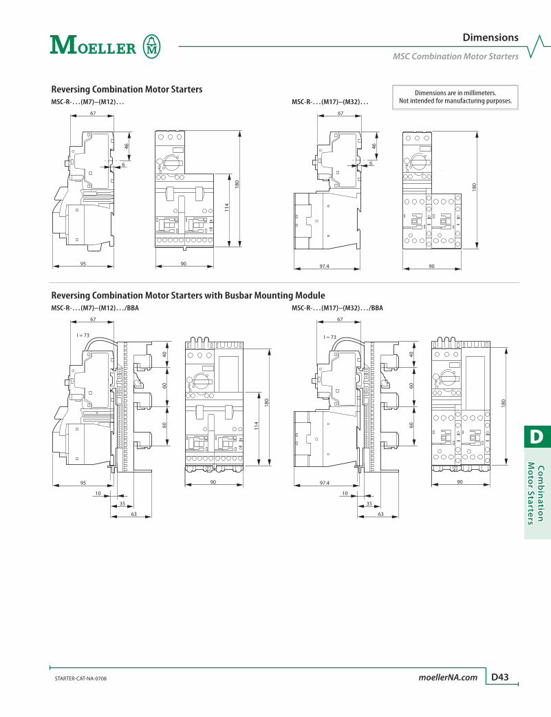
D
Co
mb
inatio
n M
oto
r Starters
STARTER-CAT-NA-0708 moellerNA.com D43
Dimensions
MSC Combination Motor Starters
Reversing Combination Motor StartersMSC-R-…(M7)–(M12)… MSC-R-…(M17)–(M32)…
95 90
67
6
46
114
180
90
180
97.4
67
6
46
Reversing Combination Motor Starters with Busbar Mounting ModuleMSC-R-…(M7)–(M12)…/BBA MSC-R-…(M17)–(M32)…/BBA
95
35
63
10
67
4060
60
I = 73
90
114
180
35
63
10
67
4060
60
I = 73
97.4 90
180
Dimensions are in millimeters.Not intended for manufacturing purposes.
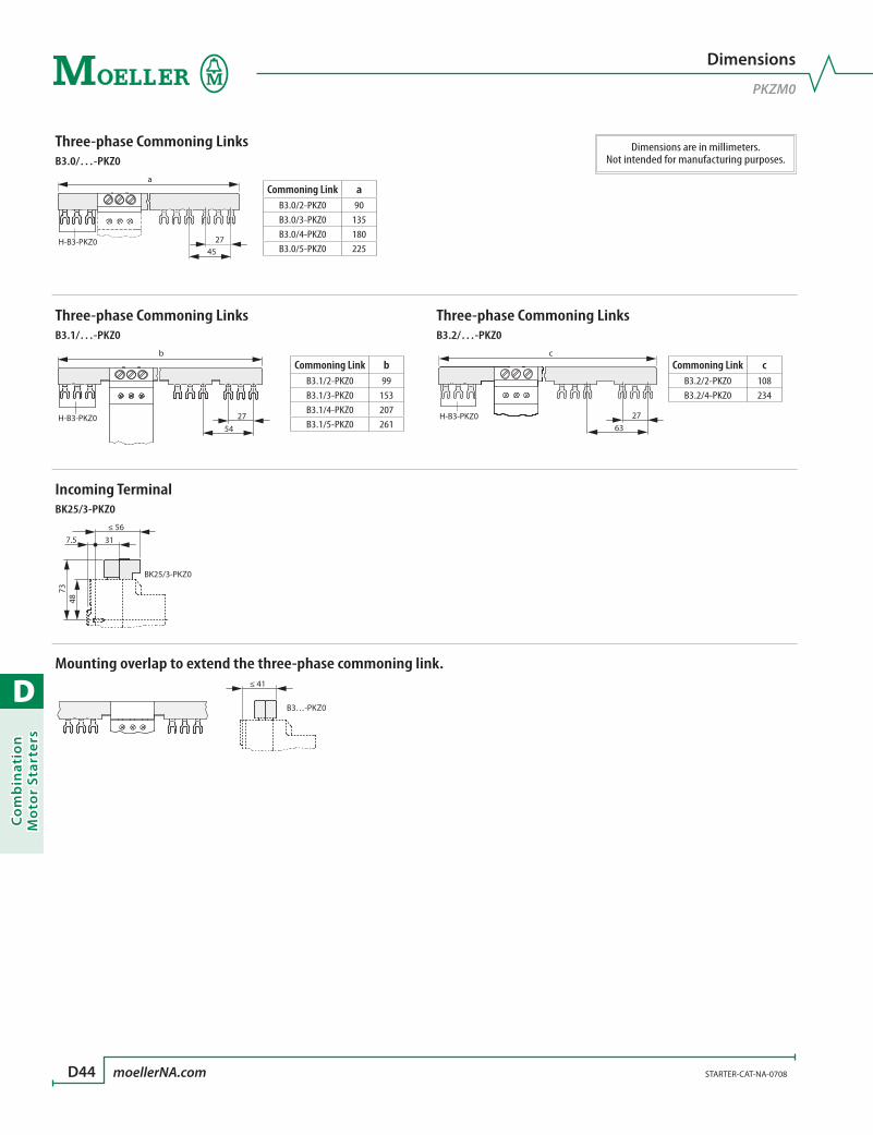
D
Co
mb
inat
ion
Mo
tor
Star
ters
D44 moellerNA.com STARTER-CAT-NA-0708
Dimensions
PKZM0
Three-phase Commoning LinksB3.0/…-PKZ0
a
H-B3-PKZ0 2745
Three-phase Commoning Links Three-phase Commoning LinksB3.1/…-PKZ0 B3.2/…-PKZ0
H-B3-PKZ0 27
b
54
c
H-B3-PKZ0 2763
Incoming TerminalBK25/3-PKZ0
BK25/3-PKZ0
73
7.5 31
48
≤ 56
Mounting overlap to extend the three-phase commoning link.≤ 41
B3…-PKZ0
Commoning Link aB3.0/2-PKZ0 90B3.0/3-PKZ0 135B3.0/4-PKZ0 180B3.0/5-PKZ0 225
Commoning Link bB3.1/2-PKZ0 99B3.1/3-PKZ0 153B3.1/4-PKZ0 207B3.1/5-PKZ0 261
Commoning Link cB3.2/2-PKZ0 108B3.2/4-PKZ0 234
Dimensions are in millimeters.Not intended for manufacturing purposes.

D
Co
mb
inatio
n M
oto
r Starters
STARTER-CAT-NA-0708 moellerNA.com D45
Dimensions
PKZM4
Dimensions are in millimeters.Not intended for manufacturing purposes.
Three-phase Commoning LinksB3.0/2-PKZ4
14
98
36
33
Three-phase Commoning Links Three-phase Commoning LinksB3.0/3-PKZ4 B3.0/4-PKZ4
14
151
36
33
14
205
36
33
Three-phase Commoning Links Three-phase Commoning LinksB3.1/2-PKZ4 B3.1/3-PKZ4
33
14
117
36
33
14
170
36
Three-phase Commoning Links Three-phase Commoning LinksB3.1/4-PKZ4 B3.2/2-PKZ4
33
14
232
36
14
115
36
33
Three-phase Commoning LinksB3.2/4-PKZ4
33
14
260
36

D
Co
mb
inat
ion
Mo
tor
Star
ters
D46
R
PKZ2 devices were the first to be UL Listed and CSA Certified as Type E, self-pro-
tected, combination motor controllers. This means they can be used to replace
traditional combination starters in many applications.
“Type E” designates a device that functions as intended after a short-circuit
event, with no effect on performance. This designation is the highest rating for
devices with this functionality.
Excellent control & protection with one frame size!PKZ2 self-protected combination
controllers have a 42 amp continu-
ous current rating. They control and
protect motors to 30HP at 480V or
25HP @ 600V with one frame size.
Their excellent current-limiting
design clears fault currents of 100
KAIC at 240VAC; 65KAIC at 480VAC;
and 42KAIC at 600VAC (all values
RMS Symmetrical). The total clearing time of the device at the highest fault con-
dition is a maximum of 3.5ms at 480V and 4.0ms at 600VAC.
Two sets of main contacts for ultimate protectionPKZ2 combination motor controllers contain two sepa-
rate sets of current limiting main contacts. This provides a
high interrupting rating and the capacity to protect itself
against damage under fault conditions. The controller
has single break, current-limiting contacts and is first in
line to interrupt overloads and low level short circuits. The
high capacity contactor has double-break current limiting
contacts and a built-in magnetic trip. In the event of a high
fault, both portions will join and act in a coordinated fashion to
severely limit the short circuit let-through current and energy.
PKZ2, Type E, self protected combination controllersReplaces the combination starter
> Starts and protects motors to 25HP @ 460V (30HP @ 575V) with one frame size
> Replaces the traditional combination starter
> Features a fuseless, high fault interrupting unique current limiting design, with separate contacts for controller and contactor
> Suitable for manual control or fully automatic (HAND-AUTO) PLC applications
> Remote over-current or short-circuit trip differentiation
> Worldwide approvals
100KAIC
65KAIC
42KAIC
240V AC 480V AC 600V AC
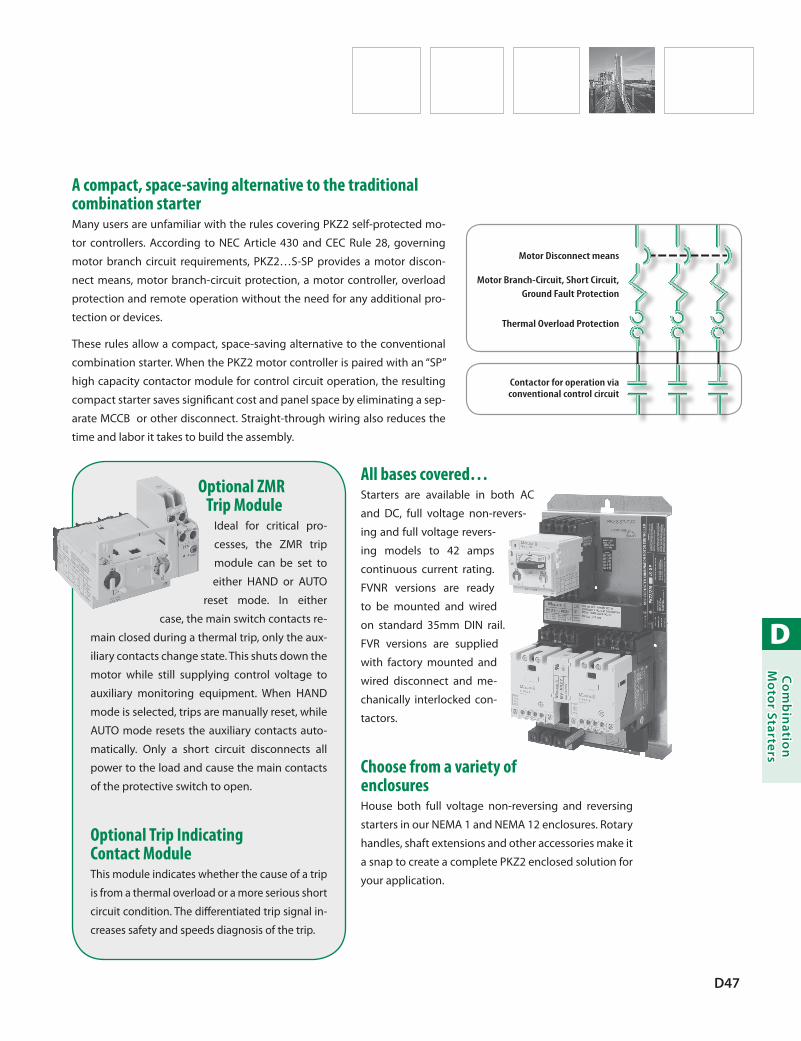
D
Co
mb
inatio
n M
oto
r Starters
D47
All bases covered…Starters are available in both AC
and DC, full voltage non-revers-
ing and full voltage revers-
ing models to 42 amps
continuous current rating.
FVNR versions are ready
to be mounted and wired
on standard 35mm DIN rail.
FVR versions are supplied
with factory mounted and
wired disconnect and me-
chanically interlocked con-
tactors.
Choose from a variety of enclosuresHouse both full voltage non-reversing and reversing
starters in our NEMA 1 and NEMA 12 enclosures. Rotary
handles, shaft extensions and other accessories make it
a snap to create a complete PKZ2 enclosed solution for
your application.
A compact, space-saving alternative to the traditional combination starterMany users are unfamiliar with the rules covering PKZ2 self-protected mo-
tor controllers. According to NEC Article 430 and CEC Rule 28, governing
motor branch circuit requirements, PKZ2…S-SP provides a motor discon-
nect means, motor branch-circuit protection, a motor controller, overload
protection and remote operation without the need for any additional pro-
tection or devices.
These rules allow a compact, space-saving alternative to the conventional
combination starter. When the PKZ2 motor controller is paired with an “SP”
high capacity contactor module for control circuit operation, the resulting
compact starter saves significant cost and panel space by eliminating a sep-
arate MCCB or other disconnect. Straight-through wiring also reduces the
time and labor it takes to build the assembly.
Optional ZMR Trip Module
Ideal for critical pro-
cesses, the ZMR trip
module can be set to
either HAND or AUTO
reset mode. In either
case, the main switch contacts re-
main closed during a thermal trip, only the aux-
iliary contacts change state. This shuts down the
motor while still supplying control voltage to
auxiliary monitoring equipment. When HAND
mode is selected, trips are manually reset, while
AUTO mode resets the auxiliary contacts auto-
matically. Only a short circuit disconnects all
power to the load and cause the main contacts
of the protective switch to open.
Optional Trip Indicating Contact ModuleThis module indicates whether the cause of a trip
is from a thermal overload or a more serious short
circuit condition. The differentiated trip signal in-
creases safety and speeds diagnosis of the trip.
Motor Disconnect means
Motor Branch-Circuit, Short Circuit, Ground Fault Protection
Thermal Overload Protection
Contactor for operation via conventional control circuit
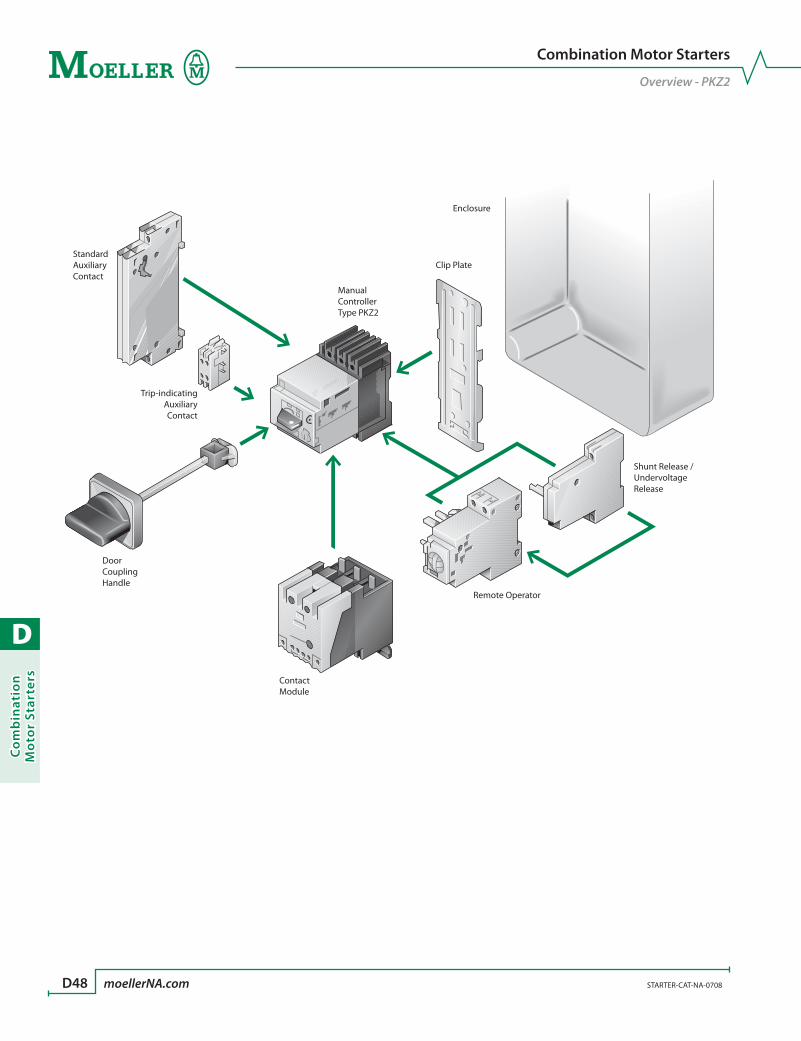
D
Co
mb
inat
ion
Mo
tor
Star
ters
D48 moellerNA.com STARTER-CAT-NA-0708
Combination Motor Starters
Overview - PKZ2
ManualControllerType PKZ2
Shunt Release /UndervoltageRelease
Remote Operator
ContactModule
Clip Plate
Enclosure
StandardAuxiliaryContact
Trip-indicatingAuxiliaryContact
DoorCouplingHandle
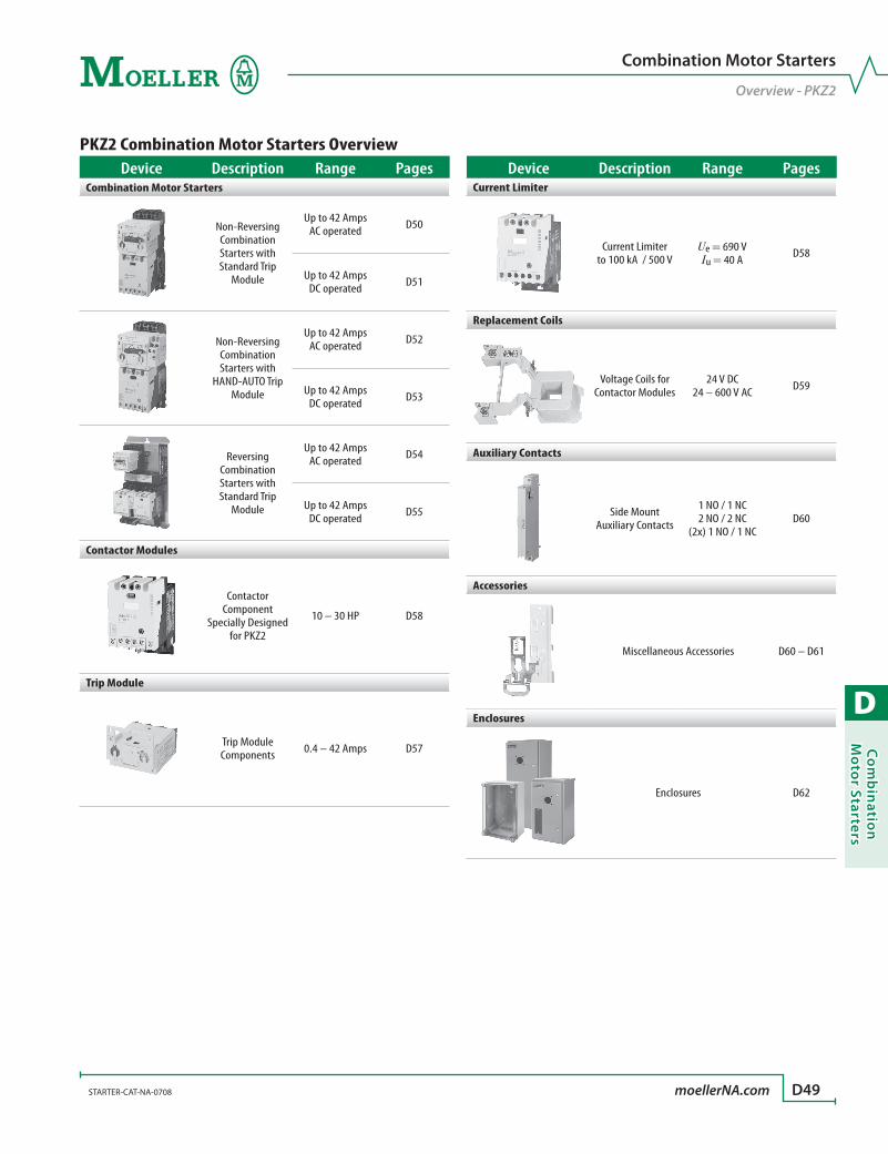
D
Co
mb
inatio
n M
oto
r Starters
STARTER-CAT-NA-0708 moellerNA.com D49
Combination Motor Starters
Overview - PKZ2
PKZ2 Combination Motor Starters OverviewDevice Description Range Pages
Combination Motor Starters
Non-Reversing Combination Starters with Standard Trip
Module
Up to 42 AmpsAC operated D50
Up to 42 AmpsDC operated D51
Non-Reversing Combination Starters with
HAND-AUTO Trip Module
Up to 42 AmpsAC operated D52
Up to 42 AmpsDC operated D53
Reversing Combination Starters with Standard Trip
Module
Up to 42 AmpsAC operated D54
Up to 42 AmpsDC operated D55
Contactor Modules
Contactor Component
Specially Designed for PKZ2
10 – 30 HP D58
Trip Module
Trip Module Components 0.4 – 42 Amps D57
Device Description Range PagesCurrent Limiter
Current Limiterto 100 kA / 500 V
Ue = 690 VIu = 40 A D58
Replacement Coils
Voltage Coils for Contactor Modules
24 V DC24 – 600 V AC D59
Auxiliary Contacts
Side Mount Auxiliary Contacts
1 NO / 1 NC2 NO / 2 NC
(2x) 1 NO / 1 NCD60
Accessories
Miscellaneous Accessories D60 – D61
Enclosures
Enclosures D62
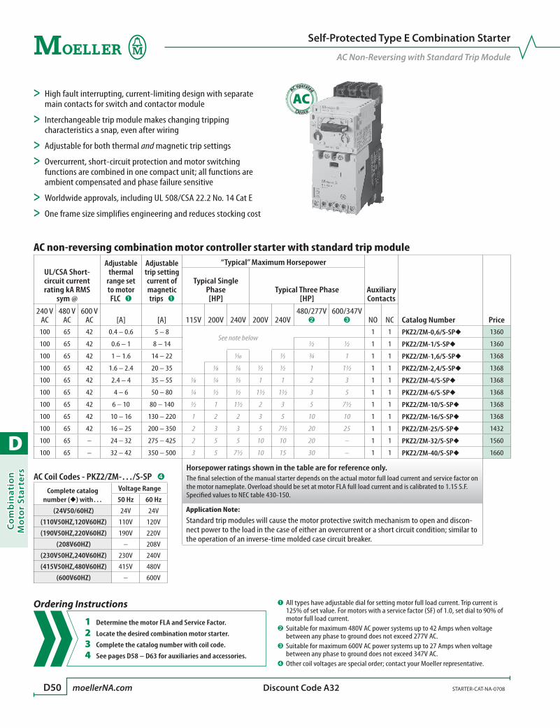
D
Co
mb
inat
ion
Mo
tor
Star
ters
D50 moellerNA.com STARTER-CAT-NA-0708 Discount Code A32
Self-Protected Type E Combination Starter
AC Non-Reversing with Standard Trip Module
AC operated
AC
AC non-reversing combination motor controller starter with standard trip module
UL/CSA Short-circuit current rating kA RMS
sym @
Adjustable thermal
range set to motor FLC ➊
Adjustable trip setting current of magnetic trips ➊
“Typical” Maximum Horsepower
Auxiliary Contacts
Catalog Number Price
Typical Single Phase [HP]
Typical Three Phase [HP]
240 V AC
480 V AC
600 V AC [A] [A] 115V 200V 240V 200V 240V
480/277V ➋
600/347V ➌ NO NC
100 65 42 0.4 – 0.6 5 – 8See note below
1 1 PKZ2/ZM-0,6/S-SP 1360
100 65 42 0.6 – 1 8 – 14 ½ ½ 1 1 PKZ2/ZM-1/S-SP 1360
100 65 42 1 – 1.6 14 – 22 1⁄10 1⁄3 ¾ 1 1 1 PKZ2/ZM-1,6/S-SP 1368
100 65 42 1.6 – 2.4 20 – 35 1⁄8 1⁄6 ½ ½ 1 1½ 1 1 PKZ2/ZM-2,4/S-SP 1368
100 65 42 2.4 – 4 35 – 55 1⁄8 ¼ 1⁄3 1 1 2 3 1 1 PKZ2/ZM-4/S-SP 1368
100 65 42 4 – 6 50 – 80 ¼ ½ ½ 1½ 1½ 3 5 1 1 PKZ2/ZM-6/S-SP 1368
100 65 42 6 – 10 80 – 140 ½ 1 1½ 2 3 5 7½ 1 1 PKZ2/ZM-10/S-SP 1368
100 65 42 10 – 16 130 – 220 1 2 2 3 5 10 10 1 1 PKZ2/ZM-16/S-SP 1368
100 65 42 16 – 25 200 – 350 2 3 3 5 7½ 20 25 1 1 PKZ2/ZM-25/S-SP 1432
100 65 – 24 – 32 275 – 425 2 5 5 10 10 20 – 1 1 PKZ2/ZM-32/S-SP 1560
100 65 – 32 – 42 350 – 500 3 5 7½ 10 15 30 – 1 1 PKZ2/ZM-40/S-SP 1660
Horsepower ratings shown in the table are for reference only. The final selection of the manual starter depends on the actual motor full load current and service factor on the motor nameplate. Overload should be set at motor FLA full load current and is calibrated to 1.15 S.F.Specified values to NEC table 430-150.
Application Note:Standard trip modules will cause the motor protective switch mechanism to open and discon-nect power to the load in the case of either an overcurrent or a short circuit condition; similar to the operation of an inverse-time molded case circuit breaker.
> High fault interrupting, current-limiting design with separate main contacts for switch and contactor module
> Interchangeable trip module makes changing tripping characteristics a snap, even after wiring
> Adjustable for both thermal and magnetic trip settings
> Overcurrent, short-circuit protection and motor switching functions are combined in one compact unit; all functions are ambient compensated and phase failure sensitive
> Worldwide approvals, including UL 508/CSA 22.2 No. 14 Cat E
> One frame size simplifies engineering and reduces stocking cost
➊ All types have adjustable dial for setting motor full load current. Trip current is 125% of set value. For motors with a service factor (SF) of 1.0, set dial to 90% of motor full load current.
➋ Suitable for maximum 480V AC power systems up to 42 Amps when voltage between any phase to ground does not exceed 277V AC.
➌ Suitable for maximum 600V AC power systems up to 27 Amps when voltage between any phase to ground does not exceed 347V AC.
➍ Other coil voltages are special order; contact your Moeller representative.
Ordering Instructions
1 Determine the motor FLA and Service Factor.
2 Locate the desired combination motor starter.
3 Complete the catalog number with coil code.
4 See pages D58 – D63 for auxiliaries and accessories.
AC Coil Codes - PKZ2/ZM-…/S-SP ➍
Complete catalog number () with…
Voltage Range
50 Hz 60 Hz
(24V50/60HZ) 24V 24V
(110V50HZ,120V60HZ) 110V 120V
(190V50HZ,220V60HZ) 190V 220V
(208V60HZ) – 208V
(230V50HZ,240V60HZ) 230V 240V
(415V50HZ,480V60HZ) 415V 480V
(600V60HZ) – 600V

D
Co
mb
inatio
n M
oto
r Starters
STARTER-CAT-NA-0708 moellerNA.com D51 Discount Code A32
DC operated
DC
Self-Protected Type E Combination Starter
DC Non-Reversing with Standard Trip Module
DC non-reversing combination motor controller starter with standard trip module
UL/CSA Short-circuit current rating kA RMS
sym @
Adjustable thermal
range set to motor FLC ➊
Adjustable trip setting current of magnetic trips ➊
“Typical” Maximum Horsepower
Auxiliary Contacts
Catalog Number Price
Typical Single Phase [HP]
Typical Three Phase [HP]
240 V AC
480 V AC
600 V AC [A] [A] 115V 200V 240V 200V 240V
480/277V ➋
600/347V ➌ NO NC
100 65 42 0.4 – 0.6 5 – 8See note below
1 0 PKZ2/ZM-0,6/S-G-SP(24VDC) 1548
100 65 42 0.6 – 1 8 – 14 ½ ½ 1 0 PKZ2/ZM-1/S-G-SP(24VDC) 1548
100 65 42 1 – 1.6 14 – 22 1⁄10 1⁄3 ¾ 1 1 0 PKZ2/ZM-1,6/S-G-SP(24VDC) 1548
100 65 42 1.6 – 2.4 20 – 35 1⁄8 1⁄6 ½ ½ 1 1½ 1 0 PKZ2/ZM-2,4/S-G-SP(24VDC) 1548
100 65 42 2.4 – 4 35 – 55 1⁄8 ¼ 1⁄3 1 1 2 3 1 0 PKZ2/ZM-4/S-G-SP(24VDC) 1548
100 65 42 4 – 6 50 – 80 ¼ ½ ½ 1½ 1½ 3 5 1 0 PKZ2/ZM-6/S-G-SP(24VDC) 1548
100 65 42 6 – 10 80 – 140 ½ 1 1½ 2 3 5 7½ 1 0 PKZ2/ZM-10/S-G-SP(24VDC) 1548
100 65 42 10 – 16 130 – 220 1 2 2 3 5 10 10 1 0 PKZ2/ZM-16/S-G-SP(24VDC) 1548
100 65 42 16 – 25 200 – 350 2 3 3 5 7½ 20 25 1 0 PKZ2/ZM-25/S-G-SP(24VDC) 1612
100 65 – 24 – 32 275 – 425 2 5 5 10 10 20 – 1 0 PKZ2/ZM-32/S-G-SP(24VDC) 1900
100 65 – 32 – 42 350 – 500 3 5 7½ 10 15 30 – 1 0 PKZ2/ZM-40/S-G-SP(24VDC) 1950
Horsepower ratings shown in the table are for reference only. The final selection of the manual starter depends on the actual motor full load current and service factor on the motor nameplate. Overload should be set at motor FLA full load current and is calibrated to 1.15 S.F.Specified values to NEC table 430-150.
Application Note:Standard trip modules will cause the motor protective switch mechanism to open and discon-nect power to the load in the case of either an overcurrent or a short circuit condition; similar to the operation of an inverse-time molded case circuit breaker.
> High fault interrupting, current-limiting design with separate main contacts for switch and contactor module
> Interchangeable trip module makes changing tripping characteristics a snap, even after wiring
> Adjustable for both thermal and magnetic trip settings
> Overcurrent, short-circuit protection and motor switching functions are combined in one compact unit; all functions are ambient compensated and phase failure sensitive
> Worldwide approvals, including UL 508/CSA 22.2 No. 14 Cat E
> One frame size simplifies engineering and reduces stocking cost
➊ All types have adjustable dial for setting motor full load current. Trip current is 125% of set value. For motors with a service factor (SF) of 1.0, set dial to 90% of motor full load current.
➋ Suitable for maximum 480V AC power systems up to 42 Amps when voltage between any phase to ground does not exceed 277V AC.
➌ Suitable for maximum 600V AC power systems up to 27 Amps when voltage between any phase to ground does not exceed 347V AC.
Ordering Instructions
1 Determine the motor FLA and Service Factor.
2 Locate the desired combination motor starter.
3 See pages D58 – D63 for auxiliaries and accessories.
DC Coil InformationDC operated devices listed on this
page are 24V DC. Other DC voltages are special order; contact your Moeller
representative.
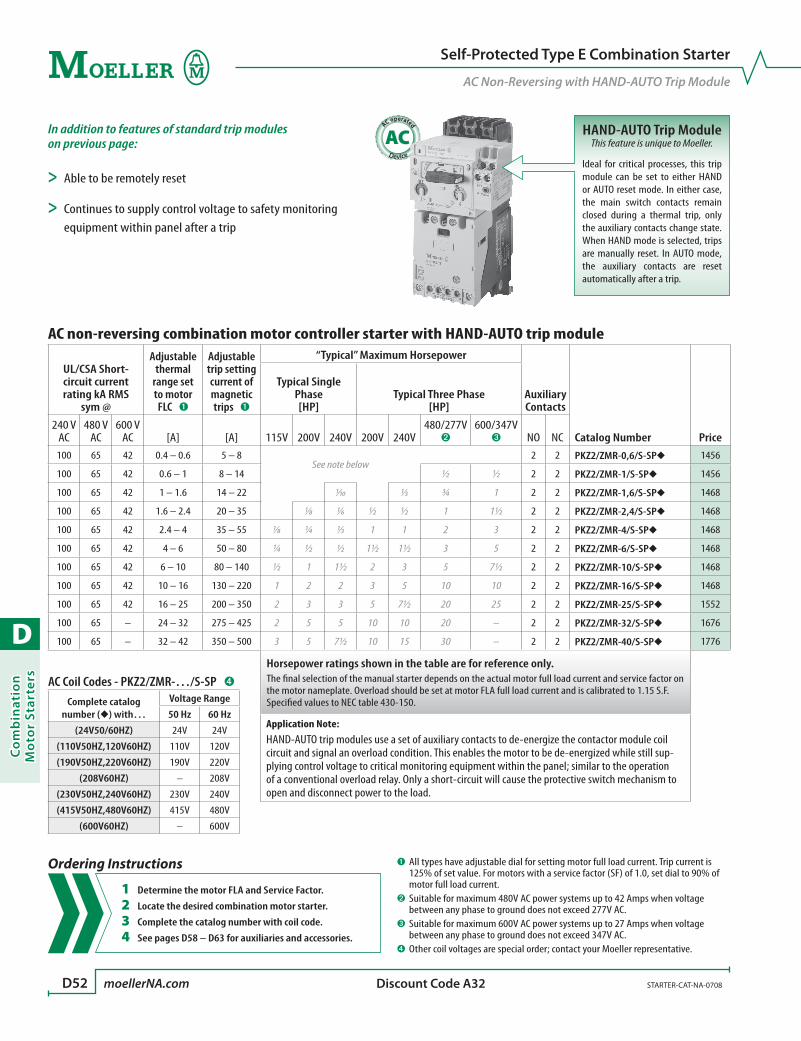
D
Co
mb
inat
ion
Mo
tor
Star
ters
D52 moellerNA.com STARTER-CAT-NA-0708 Discount Code A32
Self-Protected Type E Combination Starter
AC Non-Reversing with HAND-AUTO Trip Module
AC operated
AC HAND-AUTO Trip ModuleThis feature is unique to Moeller.
Ideal for critical processes, this trip module can be set to either HAND or AUTO reset mode. In either case, the main switch contacts remain closed during a thermal trip, only the auxiliary contacts change state. When HAND mode is selected, trips are manually reset. In AUTO mode, the auxiliary contacts are reset automatically after a trip.
Ordering Instructions
1 Determine the motor FLA and Service Factor.
2 Locate the desired combination motor starter.
3 Complete the catalog number with coil code.
4 See pages D58 – D63 for auxiliaries and accessories.
AC non-reversing combination motor controller starter with HAND-AUTO trip module
UL/CSA Short-circuit current rating kA RMS
sym @
Adjustable thermal
range set to motor FLC ➊
Adjustable trip setting current of magnetic trips ➊
“Typical” Maximum Horsepower
Auxiliary Contacts
Catalog Number Price
Typical Single Phase [HP]
Typical Three Phase [HP]
240 V AC
480 V AC
600 V AC [A] [A] 115V 200V 240V 200V 240V
480/277V ➋
600/347V ➌ NO NC
100 65 42 0.4 – 0.6 5 – 8See note below
2 2 PKZ2/ZMR-0,6/S-SP 1456
100 65 42 0.6 – 1 8 – 14 ½ ½ 2 2 PKZ2/ZMR-1/S-SP 1456
100 65 42 1 – 1.6 14 – 22 1⁄10 1⁄3 ¾ 1 2 2 PKZ2/ZMR-1,6/S-SP 1468
100 65 42 1.6 – 2.4 20 – 35 1⁄8 1⁄6 ½ ½ 1 1½ 2 2 PKZ2/ZMR-2,4/S-SP 1468
100 65 42 2.4 – 4 35 – 55 1⁄8 ¼ 1⁄3 1 1 2 3 2 2 PKZ2/ZMR-4/S-SP 1468
100 65 42 4 – 6 50 – 80 ¼ ½ ½ 1½ 1½ 3 5 2 2 PKZ2/ZMR-6/S-SP 1468
100 65 42 6 – 10 80 – 140 ½ 1 1½ 2 3 5 7½ 2 2 PKZ2/ZMR-10/S-SP 1468
100 65 42 10 – 16 130 – 220 1 2 2 3 5 10 10 2 2 PKZ2/ZMR-16/S-SP 1468
100 65 42 16 – 25 200 – 350 2 3 3 5 7½ 20 25 2 2 PKZ2/ZMR-25/S-SP 1552
100 65 – 24 – 32 275 – 425 2 5 5 10 10 20 – 2 2 PKZ2/ZMR-32/S-SP 1676
100 65 – 32 – 42 350 – 500 3 5 7½ 10 15 30 – 2 2 PKZ2/ZMR-40/S-SP 1776
Horsepower ratings shown in the table are for reference only. The final selection of the manual starter depends on the actual motor full load current and service factor on the motor nameplate. Overload should be set at motor FLA full load current and is calibrated to 1.15 S.F.Specified values to NEC table 430-150.
Application Note:HAND-AUTO trip modules use a set of auxiliary contacts to de-energize the contactor module coil circuit and signal an overload condition. This enables the motor to be de-energized while still sup-plying control voltage to critical monitoring equipment within the panel; similar to the operation of a conventional overload relay. Only a short-circuit will cause the protective switch mechanism to open and disconnect power to the load.
In addition to features of standard trip modules on previous page:
> Able to be remotely reset
> Continues to supply control voltage to safety monitoring equipment within panel after a trip
AC Coil Codes - PKZ2/ZMR-…/S-SP ➍
Complete catalog number () with…
Voltage Range
50 Hz 60 Hz
(24V50/60HZ) 24V 24V
(110V50HZ,120V60HZ) 110V 120V
(190V50HZ,220V60HZ) 190V 220V
(208V60HZ) – 208V
(230V50HZ,240V60HZ) 230V 240V
(415V50HZ,480V60HZ) 415V 480V
(600V60HZ) – 600V
➊ All types have adjustable dial for setting motor full load current. Trip current is 125% of set value. For motors with a service factor (SF) of 1.0, set dial to 90% of motor full load current.
➋ Suitable for maximum 480V AC power systems up to 42 Amps when voltage between any phase to ground does not exceed 277V AC.
➌ Suitable for maximum 600V AC power systems up to 27 Amps when voltage between any phase to ground does not exceed 347V AC.
➍ Other coil voltages are special order; contact your Moeller representative.

D
Co
mb
inatio
n M
oto
r Starters
STARTER-CAT-NA-0708 moellerNA.com D53 Discount Code A32
Self-Protected Type E Combination Starter
DC Non-Reversing with HAND-AUTO Trip Module
DC operated
DC HAND-AUTO Trip ModuleThis feature is unique to Moeller.
Ideal for critical processes, this trip module can be set to either HAND or AUTO reset mode. In either case, the main switch contacts remain closed during a thermal trip, only the auxiliary contacts change state. When HAND mode is selected, trips are manually reset. In AUTO mode, the auxiliary contacts are reset automatically after a trip.
Ordering Instructions
1 Determine the motor FLA and Service Factor.
2 Locate the desired combination motor starter.
3 See pages D58 – D63 for auxiliaries and accessories.
DC non-reversing combination motor controller starter with HAND-AUTO trip module
UL/CSA Short-circuit current rating kA RMS
sym @
Adjustable thermal
range set to motor FLC ➊
Adjustable trip setting current of magnetic trips ➊
“Typical” Maximum Horsepower
Auxiliary Contacts
Catalog Number Price
Typical Single Phase [HP]
Typical Three Phase [HP]
240 V AC
480 V AC
600 V AC [A] [A] 115V 200V 240V 200V 240V
480/277V ➋
600/347V ➌ NO NC
100 65 42 0.4 – 0.6 5 – 8See note below
2 1 PKZ2/ZMR-0,6/S-G-SP(24VDC) 1636
100 65 42 0.6 – 1 8 – 14 ½ ½ 2 1 PKZ2/ZMR-1/S-G-SP(24VDC) 1648
100 65 42 1 – 1.6 14 – 22 1⁄10 1⁄3 ¾ 1 2 1 PKZ2/ZMR-1,6/S-G-SP(24VDC) 1648
100 65 42 1.6 – 2.4 20 – 35 1⁄8 1⁄6 ½ ½ 1 1½ 2 1 PKZ2/ZMR-2,4/S-G-SP(24VDC) 1648
100 65 42 2.4 – 4 35 – 55 1⁄8 ¼ 1⁄3 1 1 2 3 2 1 PKZ2/ZMR-4/S-G-SP(24VDC) 1648
100 65 42 4 – 6 50 – 80 ¼ ½ ½ 1½ 1½ 3 5 2 1 PKZ2/ZMR-6/S-G-SP(24VDC) 1648
100 65 42 6 – 10 80 – 140 ½ 1 1½ 2 3 5 7½ 2 1 PKZ2/ZMR-10/S-G-SP(24VDC) 1648
100 65 42 10 – 16 130 – 220 1 2 2 3 5 10 10 2 1 PKZ2/ZMR-16/S-G-SP(24VDC) 1648
100 65 42 16 – 25 200 – 350 2 3 3 5 7½ 20 25 2 1 PKZ2/ZMR-25/S-G-SP(24VDC) 1732
100 65 – 24 – 32 275 – 425 2 5 5 10 10 20 – 2 1 PKZ2/ZMR-32/S-G-SP(24VDC) 1856
100 65 – 32 – 42 350 – 500 3 5 7½ 10 15 30 – 2 1 PKZ2/ZMR-40/S-G-SP(24VDC) 1956
Horsepower ratings shown in the table are for reference only. The final selection of the manual starter depends on the actual motor full load current and service factor on the motor nameplate. Overload should be set at motor FLA full load current and is calibrated to 1.15 S.F.Specified values to NEC table 430-150.
Application Note:HAND-AUTO trip modules use a set of auxiliary contacts to de-energize the contactor module coil circuit and signal an overload condition. This enables the motor to be de-energized while still sup-plying control voltage to critical monitoring equipment within the panel; similar to the operation of a conventional overload relay. Only a short-circuit will cause the protective switch mechanism to open and disconnect power to the load.
In addition to features of standard trip modules on previous page:
> Able to be remotely reset
> Continues to supply control voltage to safety monitoring equipment within panel after a trip
DC Coil InformationDC operated devices listed on this
page are 24V DC. Other DC voltages are special order; contact your Moeller
representative.
➊ All types have adjustable dial for setting motor full load current. Trip current is 125% of set value. For motors with a service factor (SF) of 1.0, set dial to 90% of motor full load current.
➋ Suitable for maximum 480V AC power systems up to 42 Amps when voltage between any phase to ground does not exceed 277V AC.
➌ Suitable for maximum 600V AC power systems up to 27 Amps when voltage between any phase to ground does not exceed 347V AC.
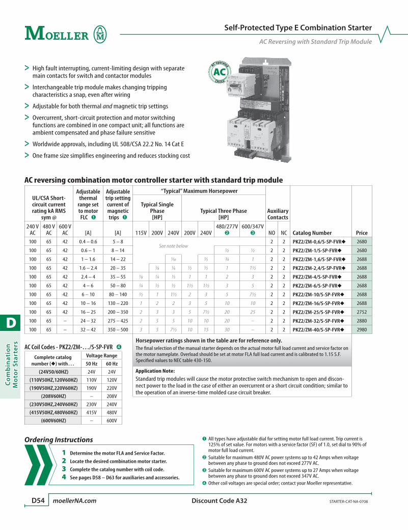
D
Co
mb
inat
ion
Mo
tor
Star
ters
D54 moellerNA.com STARTER-CAT-NA-0708 Discount Code A32
Self-Protected Type E Combination Starter
AC Reversing with Standard Trip Module
AC operated
AC
AC reversing combination motor controller starter with standard trip module
UL/CSA Short-circuit current rating kA RMS
sym @
Adjustable thermal
range set to motor FLC ➊
Adjustable trip setting current of magnetic trips ➊
“Typical” Maximum Horsepower
Auxiliary Contacts
Catalog Number Price
Typical Single Phase [HP]
Typical Three Phase [HP]
240 V AC
480 V AC
600 V AC [A] [A] 115V 200V 240V 200V 240V
480/277V ➋
600/347V ➌ NO NC
100 65 42 0.4 – 0.6 5 – 8See note below
2 2 PKZ2/ZM-0,6/S-SP-FVR 2680
100 65 42 0.6 – 1 8 – 14 ½ ½ 2 2 PKZ2/ZM-1/S-SP-FVR 2680
100 65 42 1 – 1.6 14 – 22 1⁄10 1⁄3 ¾ 1 2 2 PKZ2/ZM-1,6/S-SP-FVR 2688
100 65 42 1.6 – 2.4 20 – 35 1⁄8 1⁄6 ½ ½ 1 1½ 2 2 PKZ2/ZM-2,4/S-SP-FVR 2688
100 65 42 2.4 – 4 35 – 55 1⁄8 ¼ 1⁄3 1 1 2 3 2 2 PKZ2/ZM-4/S-SP-FVR 2688
100 65 42 4 – 6 50 – 80 ¼ ½ ½ 1½ 1½ 3 5 2 2 PKZ2/ZM-6/S-SP-FVR 2688
100 65 42 6 – 10 80 – 140 ½ 1 1½ 2 3 5 7½ 2 2 PKZ2/ZM-10/S-SP-FVR 2688
100 65 42 10 – 16 130 – 220 1 2 2 3 5 10 10 2 2 PKZ2/ZM-16/S-SP-FVR 2688
100 65 42 16 – 25 200 – 350 2 3 3 5 7½ 20 25 2 2 PKZ2/ZM-25/S-SP-FVR 2752
100 65 – 24 – 32 275 – 425 2 5 5 10 10 20 – 2 2 PKZ2/ZM-32/S-SP-FVR 2880
100 65 – 32 – 42 350 – 500 3 5 7½ 10 15 30 – 2 2 PKZ2/ZM-40/S-SP-FVR 2980
Horsepower ratings shown in the table are for reference only. The final selection of the manual starter depends on the actual motor full load current and service factor on the motor nameplate. Overload should be set at motor FLA full load current and is calibrated to 1.15 S.F.Specified values to NEC table 430-150.
Application Note:Standard trip modules will cause the motor protective switch mechanism to open and discon-nect power to the load in the case of either an overcurrent or a short circuit condition; similar to the operation of an inverse-time molded case circuit breaker.
> High fault interrupting, current-limiting design with separate main contacts for switch and contactor modules
> Interchangeable trip module makes changing tripping characteristics a snap, even after wiring
> Adjustable for both thermal and magnetic trip settings
> Overcurrent, short-circuit protection and motor switching functions are combined in one compact unit; all functions are ambient compensated and phase failure sensitive
> Worldwide approvals, including UL 508/CSA 22.2 No. 14 Cat E
> One frame size simplifies engineering and reduces stocking cost
Ordering Instructions
1 Determine the motor FLA and Service Factor.
2 Locate the desired combination motor starter.
3 Complete the catalog number with coil code.
4 See pages D58 – D63 for auxiliaries and accessories.
AC Coil Codes - PKZ2/ZM-…/S-SP-FVR ➍
Complete catalog number () with…
Voltage Range
50 Hz 60 Hz
(24V50/60HZ) 24V 24V
(110V50HZ,120V60HZ) 110V 120V
(190V50HZ,220V60HZ) 190V 220V
(208V60HZ) – 208V
(230V50HZ,240V60HZ) 230V 240V
(415V50HZ,480V60HZ) 415V 480V
(600V60HZ) – 600V
➊ All types have adjustable dial for setting motor full load current. Trip current is 125% of set value. For motors with a service factor (SF) of 1.0, set dial to 90% of motor full load current.
➋ Suitable for maximum 480V AC power systems up to 42 Amps when voltage between any phase to ground does not exceed 277V AC.
➌ Suitable for maximum 600V AC power systems up to 27 Amps when voltage between any phase to ground does not exceed 347V AC.
➍ Other coil voltages are special order; contact your Moeller representative.
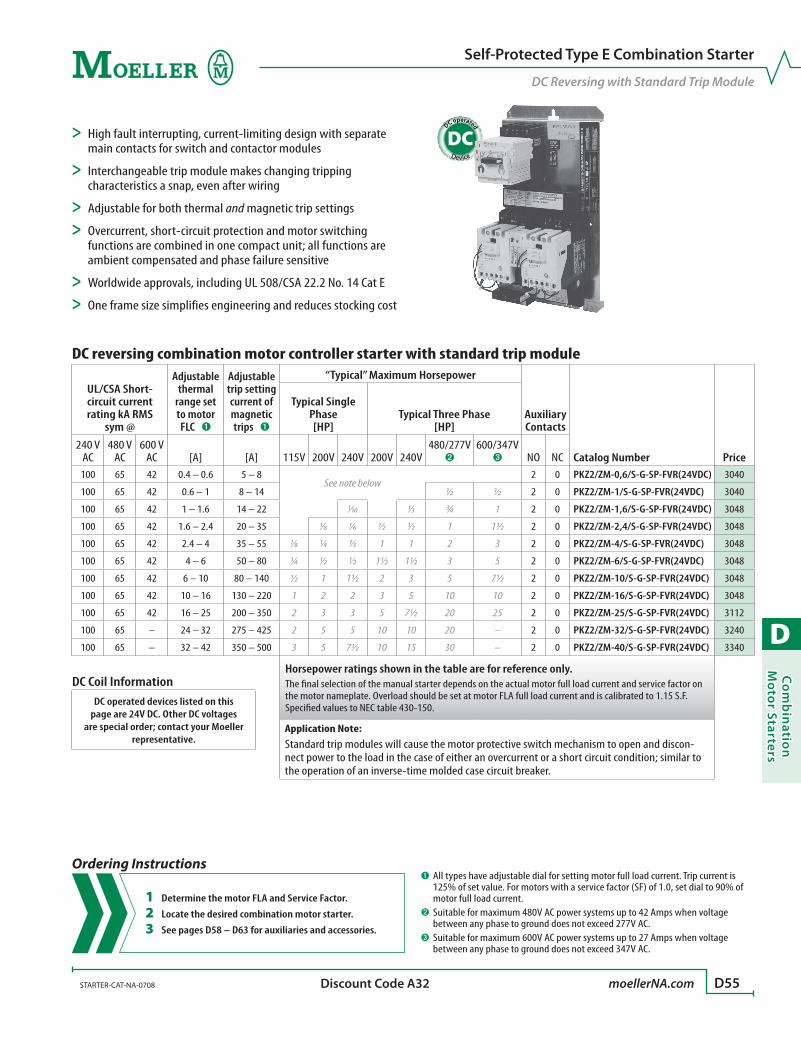
D
Co
mb
inatio
n M
oto
r Starters
STARTER-CAT-NA-0708 moellerNA.com D55 Discount Code A32
DC operated
DC
Self-Protected Type E Combination Starter
DC Reversing with Standard Trip Module
Ordering Instructions
1 Determine the motor FLA and Service Factor.
2 Locate the desired combination motor starter.
3 See pages D58 – D63 for auxiliaries and accessories.
DC reversing combination motor controller starter with standard trip module
UL/CSA Short-circuit current rating kA RMS
sym @
Adjustable thermal
range set to motor FLC ➊
Adjustable trip setting current of magnetic trips ➊
“Typical” Maximum Horsepower
Auxiliary Contacts
Catalog Number Price
Typical Single Phase [HP]
Typical Three Phase [HP]
240 V AC
480 V AC
600 V AC [A] [A] 115V 200V 240V 200V 240V
480/277V ➋
600/347V ➌ NO NC
100 65 42 0.4 – 0.6 5 – 8See note below
2 0 PKZ2/ZM-0,6/S-G-SP-FVR(24VDC) 3040
100 65 42 0.6 – 1 8 – 14 ½ ½ 2 0 PKZ2/ZM-1/S-G-SP-FVR(24VDC) 3040
100 65 42 1 – 1.6 14 – 22 1⁄10 1⁄3 ¾ 1 2 0 PKZ2/ZM-1,6/S-G-SP-FVR(24VDC) 3048
100 65 42 1.6 – 2.4 20 – 35 1⁄8 1⁄6 ½ ½ 1 1½ 2 0 PKZ2/ZM-2,4/S-G-SP-FVR(24VDC) 3048
100 65 42 2.4 – 4 35 – 55 1⁄8 ¼ 1⁄3 1 1 2 3 2 0 PKZ2/ZM-4/S-G-SP-FVR(24VDC) 3048
100 65 42 4 – 6 50 – 80 ¼ ½ ½ 1½ 1½ 3 5 2 0 PKZ2/ZM-6/S-G-SP-FVR(24VDC) 3048
100 65 42 6 – 10 80 – 140 ½ 1 1½ 2 3 5 7½ 2 0 PKZ2/ZM-10/S-G-SP-FVR(24VDC) 3048
100 65 42 10 – 16 130 – 220 1 2 2 3 5 10 10 2 0 PKZ2/ZM-16/S-G-SP-FVR(24VDC) 3048
100 65 42 16 – 25 200 – 350 2 3 3 5 7½ 20 25 2 0 PKZ2/ZM-25/S-G-SP-FVR(24VDC) 3112
100 65 – 24 – 32 275 – 425 2 5 5 10 10 20 – 2 0 PKZ2/ZM-32/S-G-SP-FVR(24VDC) 3240
100 65 – 32 – 42 350 – 500 3 5 7½ 10 15 30 – 2 0 PKZ2/ZM-40/S-G-SP-FVR(24VDC) 3340
Horsepower ratings shown in the table are for reference only. The final selection of the manual starter depends on the actual motor full load current and service factor on the motor nameplate. Overload should be set at motor FLA full load current and is calibrated to 1.15 S.F.Specified values to NEC table 430-150.
Application Note:Standard trip modules will cause the motor protective switch mechanism to open and discon-nect power to the load in the case of either an overcurrent or a short circuit condition; similar to the operation of an inverse-time molded case circuit breaker.
> High fault interrupting, current-limiting design with separate main contacts for switch and contactor modules
> Interchangeable trip module makes changing tripping characteristics a snap, even after wiring
> Adjustable for both thermal and magnetic trip settings
> Overcurrent, short-circuit protection and motor switching functions are combined in one compact unit; all functions are ambient compensated and phase failure sensitive
> Worldwide approvals, including UL 508/CSA 22.2 No. 14 Cat E
> One frame size simplifies engineering and reduces stocking cost
DC Coil InformationDC operated devices listed on this
page are 24V DC. Other DC voltages are special order; contact your Moeller
representative.
➊ All types have adjustable dial for setting motor full load current. Trip current is 125% of set value. For motors with a service factor (SF) of 1.0, set dial to 90% of motor full load current.
➋ Suitable for maximum 480V AC power systems up to 42 Amps when voltage between any phase to ground does not exceed 277V AC.
➌ Suitable for maximum 600V AC power systems up to 27 Amps when voltage between any phase to ground does not exceed 347V AC.
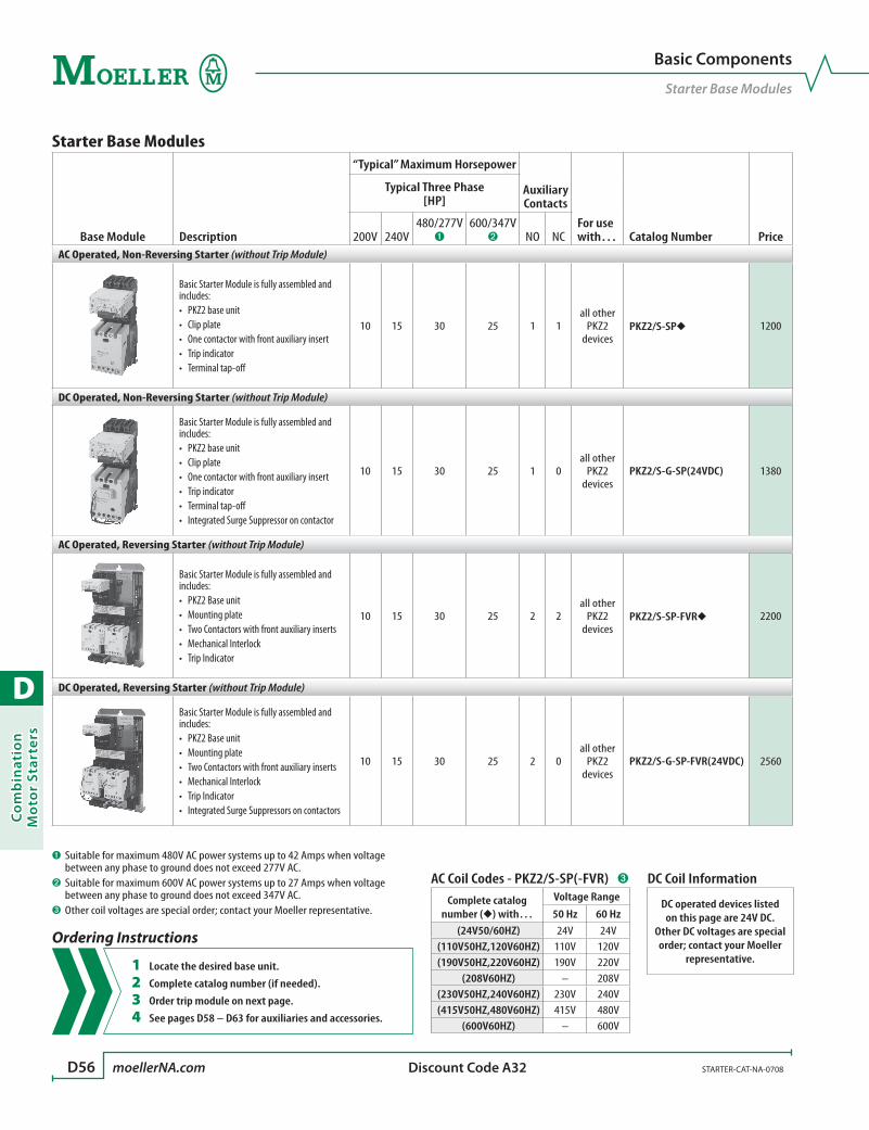
D
Co
mb
inat
ion
Mo
tor
Star
ters
D56 moellerNA.com STARTER-CAT-NA-0708 Discount Code A32
Basic Components
Starter Base Modules
Starter Base Modules
Base Module Description
“Typical” Maximum Horsepower
Auxiliary Contacts
For use with… Catalog Number Price
Typical Three Phase [HP]
200V 240V480/277V
➊600/347V
➋ NO NCAC Operated, Non-Reversing Starter (without Trip Module)
Basic Starter Module is fully assembled and includes:
PKZ2 base unit•Clip plate•One contactor with front auxiliary insert•Trip indicator•Terminal tap-off•
10 15 30 25 1 1all other
PKZ2devices
PKZ2/S-SP 1200
DC Operated, Non-Reversing Starter (without Trip Module)
Basic Starter Module is fully assembled and includes:
PKZ2 base unit•Clip plate•One contactor with front auxiliary insert•Trip indicator•Terminal tap-off•Integrated Surge Suppressor on contactor•
10 15 30 25 1 0all other
PKZ2devices
PKZ2/S-G-SP(24VDC) 1380
AC Operated, Reversing Starter (without Trip Module)
Basic Starter Module is fully assembled and includes:
PKZ2 Base unit•Mounting plate•Two Contactors with front auxiliary inserts•Mechanical Interlock•Trip Indicator•
10 15 30 25 2 2all other
PKZ2devices
PKZ2/S-SP-FVR 2200
DC Operated, Reversing Starter (without Trip Module)
Basic Starter Module is fully assembled and includes:
PKZ2 Base unit•Mounting plate•Two Contactors with front auxiliary inserts•Mechanical Interlock•Trip Indicator•Integrated Surge Suppressors on contactors•
10 15 30 25 2 0all other
PKZ2devices
PKZ2/S-G-SP-FVR(24VDC) 2560
AC Coil Codes - PKZ2/S-SP(-FVR) ➌
Complete catalog number () with…
Voltage Range
50 Hz 60 Hz(24V50/60HZ) 24V 24V
(110V50HZ,120V60HZ) 110V 120V(190V50HZ,220V60HZ) 190V 220V
(208V60HZ) – 208V(230V50HZ,240V60HZ) 230V 240V(415V50HZ,480V60HZ) 415V 480V
(600V60HZ) – 600V
Ordering Instructions
1 Locate the desired base unit.
2 Complete catalog number (if needed).
3 Order trip module on next page.
4 See pages D58 – D63 for auxiliaries and accessories.
DC Coil Information
DC operated devices listed on this page are 24V DC.
Other DC voltages are special order; contact your Moeller
representative.
➊ Suitable for maximum 480V AC power systems up to 42 Amps when voltage between any phase to ground does not exceed 277V AC.
➋ Suitable for maximum 600V AC power systems up to 27 Amps when voltage between any phase to ground does not exceed 347V AC.
➌ Other coil voltages are special order; contact your Moeller representative.

D
Co
mb
inatio
n M
oto
r Starters
STARTER-CAT-NA-0708 moellerNA.com D57 Discount Code A31
Modules
Trip Modules
Trip Modules
Module Description
Adjustable thermal
range set to motor FLC ➊
Adjustable trip setting current of magnetic trips ➊
“Typical” Maximum Horsepower
Auxiliary Contacts For use
with…Catalog Number Price
Typical Three Phase [HP]
[A] [A] 200V 240V 480V 600V NO NCStandard Trip Module
Standard trip module for PKZ2Adjustable thermal and magnetic tripsIncludes a manual test feature and tamper-preventive settings cover
0.4 – 0.6 5 – 8
see note below
0 0
PKZ2PKZ2/S-SP
ZM-0,6-PKZ2 160
0.6 – 1 8 – 14 ½ ½ 0 0 ZM-1-PKZ2 160
1 – 1.6 14 – 22 ¾ 1 0 0 ZM-1,6-PKZ2 168
1.6 – 2.4 20 – 35 ½ ½ 1 1½ 0 0 ZM-2,4-PKZ2 168
2.4 – 4 35 – 55 1 1 2 3 0 0 ZM-4-PKZ2 168
4 – 6 50 – 80 1½ 1½ 3 5 0 0 ZM-6-PKZ2 168
6 – 10 80 – 140 2 3 5 7½ 0 0 ZM-10-PKZ2 168
10 – 16 130 – 220 3 5 10 10 0 0 ZM-16-PKZ2 168
16 – 25 200 – 350 7½ 7½ 20 25 0 0 ZM-25-PKZ2 232
24 – 32 275 – 425 10 10 20 30 ➋ 0 0 ZM-32-PKZ2 360
32 – 42 350 – 500 10 15 30 30 ➋ 0 0 ZM-40-PKZ2 460
Trip Module with HAND-AUTO Feature
Main switch contacts only open during short-circuit; auxiliary contacts de-energize contactor module coil circuit during overload conditionAdjustable thermal and magnetic tripsIncludes a manual test feature and tamper-preventive settings cover
0.4 – 0.6 5 – 8
see note below
1 1
PKZ2PKZ2/S-SP
ZMR-0,6-PKZ2 256
0.6 – 1 8 – 14 ½ ½ 1 1 ZMR-1-PKZ2 256
1 – 1.6 14 – 22 ¾ 1 1 1 ZMR-1,6-PKZ2 268
1.6 – 2.4 20 – 35 ½ ½ 1 1½ 1 1 ZMR-2,4-PKZ2 268
2.4 – 4 35 – 55 1 1 2 3 1 1 ZMR-4-PKZ2 268
4 – 6 50 – 80 1½ 1½ 3 5 1 1 ZMR-6-PKZ2 268
6 – 10 80 – 140 2 3 5 7½ 1 1 ZMR-10-PKZ2 268
10 – 16 130 – 220 3 5 10 10 1 1 ZMR-16-PKZ2 268
16 – 25 200 – 350 7½ 7½ 20 25 1 1 ZMR-25-PKZ2 352
24 – 32 275 – 425 10 10 20 30 ➋ 1 1 ZMR-32-PKZ2 476
32 – 42 350 – 500 10 15 30 30 ➋ 1 1 ZMR-40-PKZ2 576
Horsepower ratings shown in the table are for reference only. The final selection of the manual starter depends on the actual motor full load current and service factor on the motor nameplate.Overload should be set at motor FLA full load current and is calibrated to 1.15 S.F.Specified values to NEC table 430-150.
Ordering Instructions
1 Determine the motor FLA and Service Factor.
2 Locate the desired trip module.
3 Order base module on previous page.
4 See pages D58 – D63 for auxiliaries and accessories.
➊ All types have adjustable dial for setting motor full load current. Trip current is 125% of set value. For motors with a service factor (SF) of 1.0, set dial to 90% of motor full load current.
➋ Rating applies to manual motor controller only; not suitable for combination mo-tor starter.

D
Co
mb
inat
ion
Mo
tor
Star
ters
D58 moellerNA.com STARTER-CAT-NA-0708 Discount Code A31
Modules
Contactor Modules, Current Limiter
Replacement Contactor Modules
Module Schematic
“Typical” Maximum Horsepower
Auxiliary Contacts
For use with… Catalog Number Price
Typical Three Phase [HP]
200V 240V480/277V
➊600/347V
➋ NO NCAC Contactor Modules
T
13
14 22
A1
A2
21
I >>
10 15 30 25 1 1 PKZ2PKZ2/ZM S-PKZ2 620
DC Contactor Modules
T
A2
13
14
24 V DC
A1
I >>10 15 30 25 1 0 PKZ2
PKZ2/ZM S-G-PKZ2(24VDC) 800
Special note about UL approval of Contactor Modules:Replacing the contactor module in a PKZ2 combination motor starter results in a device no longer UL approved. If UL approval is required, purchase starter base module (page D56) and add desired trip module (page D57).
Current Limiter ➍
Module Description Schematic For use with… Catalog Number PriceCurrent Limiter
Max. rated operational voltage Ue = 690 VRated uninterrupted current Iu = 40 ACan be fitted to controller with mounting plate C-PKZ2, or can be fitted individually with mounting base EZ-PKZ2See page C65 for capacity ratings
L
TI >>
PKZ2PKZ2/ZM CL-PKZ2 436
DC Coil Information
DC operated devices listed on this page are 24V DC.
Other DC voltages are special order; contact your Moeller
representative.
AC Coil Codes - S-PKZ2 ➌
Complete catalog number () with…
Voltage Range
50 Hz 60 Hz(24V50/60HZ) 24V 24V
(110V50HZ,120V60HZ) 110V 120V(190V50HZ,220V60HZ) 190V 220V
(208V60HZ) – 208V(230V50HZ,240V60HZ) 230V 240V(415V50HZ,480V60HZ) 415V 480V
(600V60HZ) – 600V
➊ Suitable for maximum 480V AC power systems up to 42 Amps when voltage between any phase to ground does not exceed 277V AC.
➋ Suitable for maximum 600V AC power systems up to 27 Amps when voltage between any phase to ground does not exceed 347V AC.
➌ Other coil voltages are special order; contact your Moeller representative.➍ Device is not approved by UL or CSA.
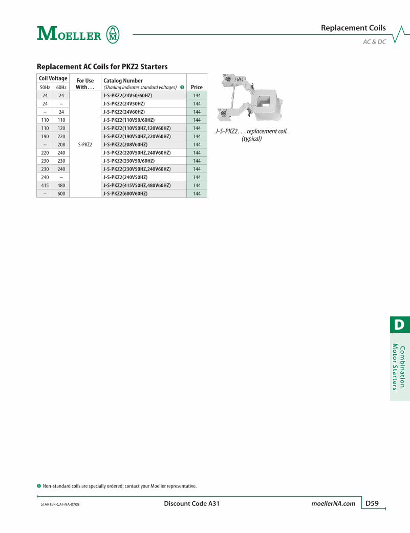
D
Co
mb
inatio
n M
oto
r Starters
STARTER-CAT-NA-0708 moellerNA.com D59 Discount Code A31
Replacement Coils
AC & DC
Replacement AC Coils for PKZ2 StartersCoil Voltage For Use
With…Catalog Number(Shading indicates standard voltages) ➊ Price50Hz 60Hz
24 24
S-PKZ2
J-S-PKZ2(24V50/60HZ) 144
24 – J-S-PKZ2(24V50HZ) 144
– 24 J-S-PKZ2(24V60HZ) 144
110 110 J-S-PKZ2(110V50/60HZ) 144
110 120 J-S-PKZ2(110V50HZ,120V60HZ) 144
190 220 J-S-PKZ2(190V50HZ,220V60HZ) 144
– 208 J-S-PKZ2(208V60HZ) 144
220 240 J-S-PKZ2(220V50HZ,240V60HZ) 144
230 230 J-S-PKZ2(230V50/60HZ) 144
230 240 J-S-PKZ2(230V50HZ,240V60HZ) 144
240 – J-S-PKZ2(240V50HZ) 144
415 480 J-S-PKZ2(415V50HZ,480V60HZ) 144
– 600 J-S-PKZ2(600V60HZ) 144
J-S-PKZ2… replacement coil. (typical)
➊ Non-standard coils are specially ordered; contact your Moeller representative.

D
Co
mb
inat
ion
Mo
tor
Star
ters
D60 moellerNA.com STARTER-CAT-NA-0708 Discount Code A31
Combination Motor Starter
Accessories
Accessories for combination motor starters
Accessory
Contacts
Description Travel Diagram SchematicFor use with… Catalog Number PriceNO NC
Standard Auxiliary Contacts - side mount
1 1Standard auxiliary contact for combina-tion motor starters.Maximum of one per device.This device is required for remote operator use.
NHI11S
L1L2L3
I >
13
PKZ2/ZM.../S
A1
14
21
22A2
NHI2-11SNHI11S NHI22S
1.131.13 1.21 1.13 1.31 311.21 431.431.21
1.141.14 1.22 1.14 1.32 321.22 441.441.22
I >>
PKZ2/S-SP
NHI11S-PKZ2 110
2 2
L1L2L3
NHI22SNHI22S-PKZ2 170
2x 1
2x 1
1 NO & 1 NC connect to main switch; 1 NO & 1 NC connect to contactor module (see schematic on right)
L1L2L3
NHI2-11SNHI2-11S-PKZ2 176
Auxiliary Contact for Separately Mounted Contactor - side mount
1 1
For separately mount-ed contactorsMaximum of one per device.
L1L2L3
HI
On
L1L2L3
HI
O
32 44
31 43
S(-G)-PKZ2 HI11-S/EZ-PKZ2 100
Auxiliary Contacts - front insert
1 1 Supplied with AC contactor
PKZ2/S-SPS(-G)-PKZ2
HI11-S-PKZ2 80
2 0 HI20-S-PKZ2 80
Surge Suppressor
– – 24 – 48 V ACA1
A2
PKZ2/S-SPS(-G)-PKZ2
VGSPKZ48 44
– – 110 – 250 V AC VGSPKZ250 44
– – 380 – 415 V AC VGSPKZ415 44
Mounting Base
– –
For separate mount-ing of a contactor used for reversing startersDIN rail mountable
S(-G)-PKZ2CL-PKZ2 EZ-PKZ2 120
Mechanical Interlock
– –
Used to interlock two contactors in reversing starter applications
S(-G)-PKZ2 MV-PKZ2 110
Control Terminal Tap-off
– –
Used to tap-off control voltage or control transformers from main terminals
S(-G)-PKZ2 ST-PKZ2 24
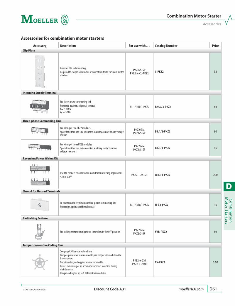
D
Co
mb
inatio
n M
oto
r Starters
STARTER-CAT-NA-0708 moellerNA.com D61 Discount Code A31
Accessories for combination motor starters
Accessory Description For use with… Catalog Number PriceClip Plate
Provides DIN rail mounting Required to couple a contactor or current limiter to the main switch module
PKZ2/S-SPPKZ2 + CL-PKZ2 C-PKZ2 32
Incoming Supply Terminal
For three-phase commoning linkProtected against accidental contact Ue = 690 V Iu = 120 A
B3.1/(2)(3)-PKZ2 BK50/3-PKZ2 64
Three-phase Commoning Link
For wiring of two PKZ2 modulesSpace for either one side-mounted auxiliary contact or one voltage release
PKZ2/ZMPKZ2/S-SP B3.1/2-PKZ2 80
For wiring of three PKZ2 modulesSpace for either two side-mounted auxiliary contacts or two voltage releases
PKZ2/ZMPKZ2/S-SP B3.1/3-PKZ2 96
Reversing Power Wiring Kit
Used to connect two contactor modules for reversing applications42A @ 600V
PKZ2…/S-SP WB3.1-PKZ2 200
Shroud for Unused Terminals
To cover unused terminals on three-phase commoning linkProtection against accidental contact
B3.1/(2)(3)-PKZ2 H-B3-PKZ2 16
Padlocking Feature
For locking rear mounting motor controllers in the OFF position PKZ2/ZMPKZ2/S-SP SVB-PKZ2 80
Tamper-preventive Coding Pins
See page C51 for examples of use.Tamper-preventive feature used to pair proper trip module with base module. Once inserted, coding pins are not removable.Deters tampering or an accidental incorrect insertion during maintenance.Unique coding for up to 6 different trip modules.
PKZ2 + ZMPKZ2 + ZMR CS-PKZ2 6.90
Combination Motor Starter
Accessories

D
Co
mb
inat
ion
Mo
tor
Star
ters
D62 moellerNA.com STARTER-CAT-NA-0708 Discount Code D12 (except where noted)
NEMA 1 Enclosures
Enclosure Description For use with… Catalog Number PriceFor Non-Reversing PKZ2 Combination Motor Starters
NEMA Type 1General purposeSteel enclosure400 x 230 x 202 (H x W x D in mm)
PKZ2/S-SP S1GK23X40X20-PP 452
For Reversing PKZ2 Combination Motor Starters
NEMA Type 1General purposeSteel enclosure600 x 270 x 202 (H x W x D in mm)
PKZ2/S-SP-FVR S1GK27X60X20-PP 500
NEMA 12 Enclosures
Enclosure Description For use with… Catalog Number PriceDiscount
CodeFor Non-Reversing PKZ2 Combination Motor Starters
NEMA Type 12Dust-tightPlastic enclosure373 x 248 x 176 (H x W x D in mm)
PKZ2/S-SP CI43X-150-PKZ2-SP 400 A31
NEMA Type 12Dust-tightSteel enclosureIncludes wall-mount brackets400 x 230 x 200 (H x W x D in mm)
PKZ2/S-SP GKSD23X40X20+W 679 D12
For Reversing PKZ2 Combination Motor Starters
NEMA Type 12Dust-tightSteel enclosureIncludes wall-mount brackets600 x 270 x 200 (H x W x D in mm)
PKZ2/S-SP-FVR GKSD27X60X20+W 690 D12
Enclosures
NEMA 1 and NEMA 12

D
Co
mb
inatio
n M
oto
r Starters
STARTER-CAT-NA-0708 moellerNA.com D63 Discount Code A31
Enclosure Accessories
Handles
Through-the-door Mounted Handles for PKZ2
Accessory Description Color Protection RatingFor use with… Catalog Number Price
Door Coupling Handle
Rotary handle operator•Padlockable in OFF and ON positions•Includes handle coupling mechanism that •accommodates mounting depth of 132 mm
Includes door interlock; not engaged when shipped
Black NEMA 3R, 4X, 12, 13 PKZ2/ZMPKZ2/S-SP PKZ2-XH 80
Red/Yellow NEMA 3R, 4X, 12, 13 PKZ2/ZMPKZ2/S-SP PKZ2-XRH 100
Rotary handle operator•Padlockable in OFF and ON positions•To be used when PKZ is rotated by 90˚•Selectable handle positions•Includes handle coupling mechanism that •accommodates mounting depth of 132 mm
Includes door interlock; not engaged when shipped
Black NEMA 3R, 4X, 12, 13 PKZ2/ZMPKZ2/S-SP PKZ2-XH-MCC 80
Extension Shaft
For mounting depths 171 – 300 mm•Includes shaft interlock mechanism•
– – PKZ2/ZMPKZ2/S-SP PKZ2-XAH 40

D
Co
mb
inat
ion
Mo
tor
Star
ters
D64 moellerNA.com STARTER-CAT-NA-0708
Technical Data
Tripping Characteristics, Let-through Characteristics
Tripping Characteristics, Combination Motor Starters
2
5
20
50
200
1
2
5
10
20
401
2
5
20
10
2h
1,5 2 3 4 6 8 10 15 20 30
PKZ2/ZM-…/S
Seco
nds
Mill
isec
onds
Min
utes
x Rated operational current
Combination Motor Starter with Current Limiter Let-through Characteristics
11
1.5
2
3
4
6
8
10
15
20
30
40
60
80
100
1.5 2 3 4 6 8 10 15 20 30 40 60 80 100
PKZ2/ZM-…+CLPKZ2/ZM-…/S-SP
2 · I cc
32/40 A25 A
16 A
10 A
6 A
Ue = 400 V
[kA] ÎD
Icc rms [kA]
1st h
alf-w
ave
Icc rms [kA]
1 1.5 2 3 4 6 8 10 15 20 30 40 60 80 1004
6
8
1.5
2
3
4
6
8
1.5
2
3
4
6
8
10
10
10
16 A
10 A
PKZ2/ZM-…+CLPKZ2/ZM-…/S-SP
6 A
25 A32 A40 A
[A s]2
Ue = 400 V
5
4
6∫ i2dt
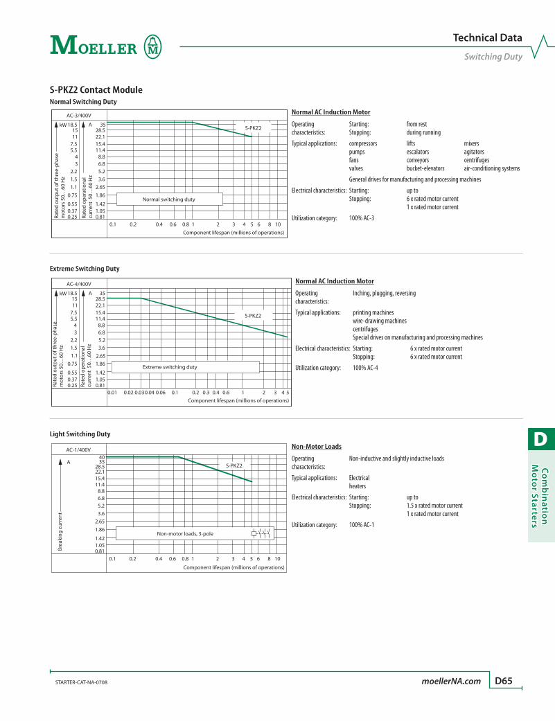
D
Co
mb
inatio
n M
oto
r Starters
STARTER-CAT-NA-0708 moellerNA.com D65
Technical Data
Switching Duty
S-PKZ2 Contact ModuleNormal Switching Duty
Normal AC Induction Motor
Operating characteristics:
Starting: Stopping:
from rest during running
Typical applications: compressors pumps fans valves
lifts escalators conveyors bucket-elevators
mixers agitators centrifuges air-conditioning systems
General drives for manufacturing and processing machines
Electrical characteristics: Starting: Stopping:
up to 6 x rated motor current 1 x rated motor current
Utilization category: 100% AC-3
Extreme Switching Duty
Normal AC Induction Motor
Operating characteristics:
Inching, plugging, reversing
Typical applications: printing machines wire-drawing machines centrifuges Special drives on manufacturing and processing machines
Electrical characteristics: Starting: Stopping:
6 x rated motor current 6 x rated motor current
Utilization category: 100% AC-4
Light Switching Duty
Non-Motor Loads
Operating characteristics:
Non-inductive and slightly inductive loads
Typical applications: Electrical heaters
Electrical characteristics: Starting: Stopping:
up to 1.5 x rated motor current 1 x rated motor current
Utilization category: 100% AC-1
0.1 0.2 0.4 0.6 0.8 1 2 3 4 5 6 8 100.811.051.42
1.862.65
5.26.88.8
11.415.422.128.5
35
3.6
0.250.370.55
0.751.1
2.234
5.57.51115
18.5
1.5
AC-3/400V
kW A S-PKZ2
Rate
d ou
tput
of t
hree
-pha
se
mot
ors
50…
60 H
z
Component lifespan (millions of operations)
Rate
d op
erat
iona
lcu
rren
t 50
…60
Hz
Normal switching duty
0.811.051.42
1.862.65
5.26.88.8
11.415.422.128.5
35
3.6
0.250.370.55
0.751.1
2.234
5.57.51115
18.5
1.5
AC-4/400V
kW A
0.01 0.02 0.030.04 0.06 0.1 0.2 0.3 0.4 0.6 1 2 3 4
S-PKZ2
5
Rate
d op
erat
iona
lcu
rren
t 50
…60
Hz
Rate
d ou
tput
of t
hree
-pha
sem
otor
s 50
…60
Hz
Component lifespan (millions of operations)
Extreme switching duty
0.1 0.2 0.4 0.6 0.8 1 2 3 4 5 6 8 100.811.051.42
1.862.65
5.26.88.8
11.415.422.128.5
35
3.6
AC-1/400V
S-PKZ2A
40
Brea
king
cur
rent
Component lifespan (millions of operations)
Non-motor loads, 3-pole

D
Co
mb
inat
ion
Mo
tor
Star
ters
D66 moellerNA.com STARTER-CAT-NA-0708
Technical Data
Maximum Operating Frequency
Determination of the maximum operating frequency dependent on the rating and utilization category (recommended values) for (high-capacity) contact modulesPN = max. motor rating (kW) ops/h = max. operations per hour
100
150
200
300
400500600
8001000
1500
2000
3000
400050006000
70009000
100 20 30 40 50 60 70 80 90 100%
AC-3
AC-4
PN (kW)
Ops./h

D
Co
mb
inatio
n M
oto
r Starters
STARTER-CAT-NA-0708 moellerNA.com D67
Combination Motor Starters, Contact Modules PKZ2/ZM(R)-…/S(-G)-SP(…) S(-G)-PKZ2(…)GeneralStandards IEC/EN 60947, VDE 0660, UL 508, CSA C 22.2 No. 14,
GL, LR, DNV, PRS, BV, RINA, RS, EZU, MEEIClimatic proofing Damp heat, constant, to IEC 60068-2-78; Cyclic to IEC 60068-2-30Ambient temperature Storage [°C / °F] -25…70 °C / -13…158 °F -25…70 °C / -13…158 °F Open [°C / °F] -25…60 °C / -13…140 °F -25…60 °C / -13…140 °F Enclosed [°C / °F] -25…40 °C / -13…104 °F -25…40 °C / -13…104 °FMounting position
SCL
SCL
90°
90° 90°
90°
90°
30°PKZ2PKZ2/.../SPKZ2/.../+CL
PKZ2/.../S
PKZ2PKZ2/.../+CLPKZ2
Direction of incoming supply As required As requiredProtection type IP00 IP00Mechanical shock resistance Half-sinusoidal shock 20 ms to IEC 60068-2-27 [g] 8 8Altitude [m]Terminal capacities Solid or stranded [mm2] 1 x (1 – 16); 2 x (1 – 6) Flexible with ferrule [mm2] 1 x (1.5 – 10); 2 x (1.5 – 6) Solid or stranded [AWG] 14 – 6 14 – 6Specified tightening torque for Main cable [Nm] 1.8 1.8Terminal screws Control circuit cables [Nm] 1 1
Main Conducting PathsRated impulse withstand voltage Uimp [V AC] 6000 6000Overvoltage category/pollution degree III/3 III/3Rated operational voltage Ue [V AC] 690 690Rated uninterrupted current = rated operational current Iu = Ie [A] 40 40Rated frequency [Hz] 50 – 60 50 – 60Current heat loss (3-pole at operating temperature) [W] 23 9Lifespan Mechanical ➊ Operations [x 106] 5 5 Electrical 100% AC-3 Operations [x 106] 1 1 AC-4 Operations [x 106] 0.03 0.03Maximum operating frequency Operations/h [Ops/h] See graph on page D66Motor switching capacity AC-3 (up to 690V) [A] 40 40 DC-5 up to 250V [A] 40 40DC application Rated short-circuit Icn(250V DC), L/R = 15 ms [kA] 50 50 Breaking capacity Icn Icn(125V DC), L/R = 15 ms [kA] 65 65Operating times under short-circuit Minimum command time [ms] Approx. 2 Approx. 2Conditions Opening delay [ms] Approx. 0.5 Approx. 0.5 Total opening delay [ms] 4 4
Technical Data
Combination Motor Starters, Contact Modules
➊ With dual-frequency coil 50/60 Hz, the mechanical lifespan reduces by 30%.
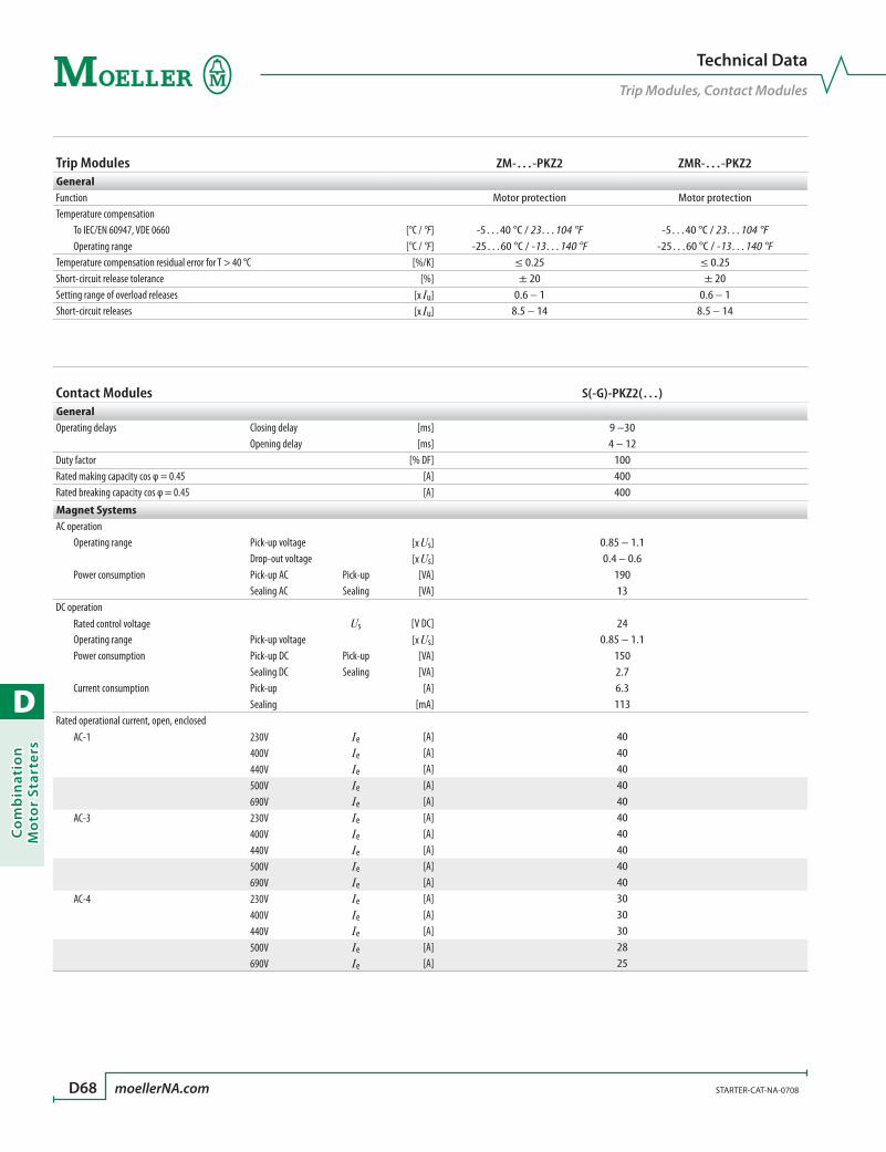
D
Co
mb
inat
ion
Mo
tor
Star
ters
D68 moellerNA.com STARTER-CAT-NA-0708
Trip Modules ZM-…-PKZ2 ZMR-…-PKZ2GeneralFunction Motor protection Motor protectionTemperature compensation To IEC/EN 60947, VDE 0660 [°C / °F] -5…40 °C / 23…104 °F -5…40 °C / 23…104 °F Operating range [°C / °F] -25…60 °C / -13…140 °F -25…60 °C / -13…140 °FTemperature compensation residual error for T > 40 °C [%/K] ≤ 0.25 ≤ 0.25Short-circuit release tolerance [%] ± 20 ± 20Setting range of overload releases [x Iu] 0.6 – 1 0.6 – 1Short-circuit releases [x Iu] 8.5 – 14 8.5 – 14
Contact Modules S(-G)-PKZ2(…)GeneralOperating delays Closing delay [ms] 9 –30 Opening delay [ms] 4 – 12Duty factor [% DF] 100Rated making capacity cos φ = 0.45 [A] 400Rated breaking capacity cos φ = 0.45 [A] 400
Magnet SystemsAC operation Operating range Pick-up voltage [x Us] 0.85 – 1.1 Drop-out voltage [x Us] 0.4 – 0.6 Power consumption Pick-up AC Pick-up [VA] 190 Sealing AC Sealing [VA] 13DC operation Rated control voltage Us [V DC] 24 Operating range Pick-up voltage [x Us] 0.85 – 1.1 Power consumption Pick-up DC Pick-up [VA] 150 Sealing DC Sealing [VA] 2.7 Current consumption Pick-up [A] 6.3 Sealing [mA] 113Rated operational current, open, enclosed AC-1 230V Ie [A] 40 400V Ie [A] 40 440V Ie [A] 40 500V Ie [A] 40 690V Ie [A] 40 AC-3 230V Ie [A] 40 400V Ie [A] 40 440V Ie [A] 40 500V Ie [A] 40 690V Ie [A] 40 AC-4 230V Ie [A] 30 400V Ie [A] 30 440V Ie [A] 30 500V Ie [A] 28 690V Ie [A] 25
Technical Data
Trip Modules, Contact Modules

D
Co
mb
inatio
n M
oto
r Starters
STARTER-CAT-NA-0708 moellerNA.com D69
Auxiliary Contacts NHI11S-PKZ2 NHI22S-PKZ2 NHI2-11S-PKZ2GeneralRated impulse withstand voltage Uimp [V AC] 6000 6000 6000Overvoltage category/pollution degree III/3 III/3 III/3Rated operational voltage Ue [V AC] 500 500 500Rated operational current AC-15 230 – 240V Ie [A] 6 6 6 400 – 415V Ie [A] 3 1.5 3 440V Ie [A] 1.5 1.5 1.5 500V Ie [A] 1.5 1.5 1.5Lifespan Mechanical Operations [x 106] 0.1 0.1 5 Electrical Operations [x 106] 0.05 0.05 1Control circuit reliability (at Ue = 24V DC, Umin = 17V, Imin = 10 mA) Failure rate [l] Control circuit reliability through the entire mechanical lifespanInterlocked opposing contacts to ZH 1/457 – – YesShort-circuit rating without welding Fuseless 240V: PKZM0-6,3
415V: PKZM0-4 500V: PKZM0-1,6
240V: PKZM0-6,3 415V: PKZM0-4
500V: PKZM0-1,6
240V: PKZM0-6,3 415V: PKZM0-4
500V: PKZM0-1,6 Fuse [A gG/gL] 10 10 10Terminal capacities Solid or flexible conductor with ferrule [mm2] 1 x (0.75 – 2.5)
2 x (0.75 –2.5)1 x (0.75 – 2.5) 2 x (0.75 –2.5)
1 x (0.75 – 2.5) 2 x (0.75 –2.5)
Solid or stranded [AWG] 1 x (22 – 14) 2 x (22 – 14)
1 x (22 – 14) 2 x (22 – 14)
1 x (22 – 14) 2 x (22 – 14)
Safe isolation to VDE 01 06 Part 101 and Part 101/A1 Between auxiliary contacts and main contacts [V AC] 690 690 500
Auxiliary Contacts (cont.) HI…-S-PKZ2 HI11-S/EZ-PKZ2 ZMR-…(95–96) ZMR-…(97–98)GeneralRated impulse withstand voltage Uimp [V AC] 6000 6000 6000 6000Overvoltage category/pollution degree III/3 III/3 III/3 III/3Rated operational voltage Ue [V AC] 500 500 500 500Rated operational current AC-15 230 – 240V Ie [A] 6 6 1.5 1.5 400 – 415V Ie [A] 1.5 3 0.7 0.5 440V Ie [A] 1.5 1.5 0.5 0.3 500V Ie [A] 1.5 1.5 0.5 0.3Lifespan Mechanical Operations [x 106] 5 5 0.01 0.01 Electrical Operations [x 106] 1 1 0.005 0.005Control circuit reliability (at Ue = 24V DC, Umin = 17V, Imin = 10 mA) Failure rate [l] Control circuit reliability through the entire mechanical lifespan –Interlocked opposing contacts to ZH 1/457 – – – –Short-circuit rating without welding Fuseless 240V: PKZM0-6,3
415V: PKZM0-4 500V: PKZM0-1,6
240V: PKZM0-6,3 415V: PKZM0-4
500V: PKZM0-1,6
– –
Fuse [A gG/gL] 10 10 10 10Terminal capacities Solid or flexible conductor with ferrule [mm2] 1 x (0.75 – 2.5)
2 x (0.75 –2.5)1 x (0.75 – 2.5) 2 x (0.75 –2.5)
1 x (0.75 – 2.5) 2 x (0.75 –2.5)
1 x (0.75 – 2.5) 2 x (0.75 –2.5)
Solid or stranded [AWG] 22 – 14 22 – 14 22 – 14 22 – 14Safe isolation to VDE 01 06 Part 101 and Part 101/A1 Between auxiliary contacts and main contacts [V AC] 500 500 – –
Technical Data
Auxiliary Contacts
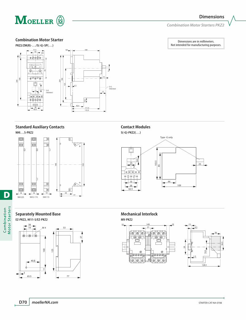
D
Co
mb
inat
ion
Mo
tor
Star
ters
D70 moellerNA.com STARTER-CAT-NA-0708
Dimensions are in millimeters.Not intended for manufacturing purposes.
Dimensions
Combination Motor Starters PKZ2
Combination Motor StarterPKZ2/ZM(R)-…/S(-G)-SP(…)
8.5
6
6.1
11
3862.5
168
204
11
27
1971.5
M4
I>
0
+12
519
020
4
46.4111.4135.9
25
15
109
83
18.5
S-G(Varistor)
S-G(Varistor)
Standard Auxiliary Contacts Contact ModulesNHI…S-PKZ2 S(-G)-PKZ2(…)
18 18 18
NHI 22S NHI 2-11S
190
4477
153
NHI 11S
85103.
5
44
109
27
19
3862.5
10
25
Type -G only
Separately Mounted Base Mechanical InterlockEZ-PKZ2, HI11-S/EZ-PKZ2 MV-PKZ2
77
37
53
125
3819 M 4
65.53
1110
0
40.8
1.5
14.6
10 1014921
15
59
56.5
36
128.5
4.5

D
Co
mb
inatio
n M
oto
r Starters
STARTER-CAT-NA-0708 moellerNA.com D71
Dimensions are in millimeters.Not intended for manufacturing purposes.
Dimensions
PKZ2
Three-phase Commoning LinkB3.1/2-PKZ2
140
33
60
Three-phase Commoning Link Incoming TerminalB3.1/3-PKZ2 BK50/3-PKZ2
222
33
60
4.5
4.2
7518
84.5
78.5
Shroud for Unused Terminals Door Coupling HandlesH-B3-PKZ2 PKZ2-X…
50
25
55
20
+ l
o
64
64
48
48
7.5
At least 100 mm
up to cover hinge

D
Co
mb
inat
ion
Mo
tor
Star
ters
D72 moellerNA.com STARTER-CAT-NA-0708
Dimensions
Combination Motor Starters PKZ2
Dimensions are in millimeters.Not intended for manufacturing purposes.
Mounting Plate for Reversing StartersPKZ2/…-FVR
a
c
r
e
b
d
f
s g
t u
i j
h
k
v
L
w
m np q
82.5 20 4.3 DIA. (2 HOLES)
8.5
185
350

D
Co
mb
inatio
n M
oto
r Starters
STARTER-CAT-NA-0708 moellerNA.com D73
Dimensions
Combination Motor Starter Enclosures
Dimensions are in millimeters.Not intended for manufacturing purposes.
NEMA 1 Steel EnclosureS1GK23X40X20-PP
400
202230
NEMA 1 Steel Enclosure NEMA 12 Plastic EnclosureS1GK27X60X20-PP CI43X-150-PKZ2-SP
600
202270
373
176248
NEMA 12 Steel Enclosure NEMA 12 Steel EnclosureGKSD23X40X20-W GKSD27X60X20-W
400
200230
11
600
200270
11
D
Co
mb
inat
ion
Mo
tor
Star
ters
D74 moellerNA.com STARTER-CAT-NA-0708
Combination Motor Starters
Notes

E
Bu
sbar System
busbar system - SASY 60i
General Information ......................................................................... E3
Busbar Adapters................................................................................. E5
Flat Busbar Supports ........................................................................ E8
Flat Busbar .......................................................................................... E8
Flat Busbar Covers ............................................................................. E9
Flat Busbar Terminals ....................................................................... E10
Double-T Busbar Supports .............................................................. E12
Double-T Busbar ................................................................................ E12
Double-T Busbar Covers ................................................................... E13
Double-T Busbar Terminals ............................................................. E14
Busbar Feeder Adapters ................................................................... E15
Copper Banding ................................................................................. E16
Technical Data ................................................................................... E17
Dimensions ......................................................................................... E22

E
Bu
sbar
Sys
tem
Start with Moellerbusbar system SASY 60i
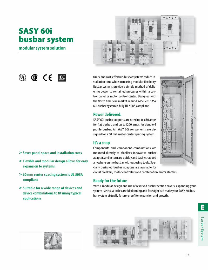
E
Bu
sbar System
E3
R
> Saves panel space and installation costs
> Flexible and modular design allows for easy expansion to systems
> 60 mm center spacing system is UL 508A compliant
> Suitable for a wide range of devices and device combinations to fit many typical applications
Quick and cost-effective, busbar systems reduce in-stallation time while increasing modular flexibility. Busbar systems provide a simple method of deliv-ering power to contained processes within a con-trol panel or motor control center. Designed with the North American market in mind, Moeller’s SASY 60i busbar system is fully UL 508A compliant.
Power delivered.SASY 60i busbar supports are rated up to 630 amps for flat busbar, and up to1200 amps for double-T profile busbar. All SASY 60i components are de-signed for a 60 millimeter center spacing system.
It’s a snapComponents and component combinations are mounted directly to Moeller’s innovative busbar adapter, and in turn are quickly and easily snapped anywhere on the busbar without using tools. Spe-cially designed busbar adapters are available for circuit breakers, motor controllers and combination motor starters.
Ready for the futureWith a modular design and use of reserved busbar section covers, expanding your system is easy. A little careful planning and foresight can make your SASY 60i bus-bar system virtually future-proof for expansion and growth.
SASY 60i busbar systemmodular system solution
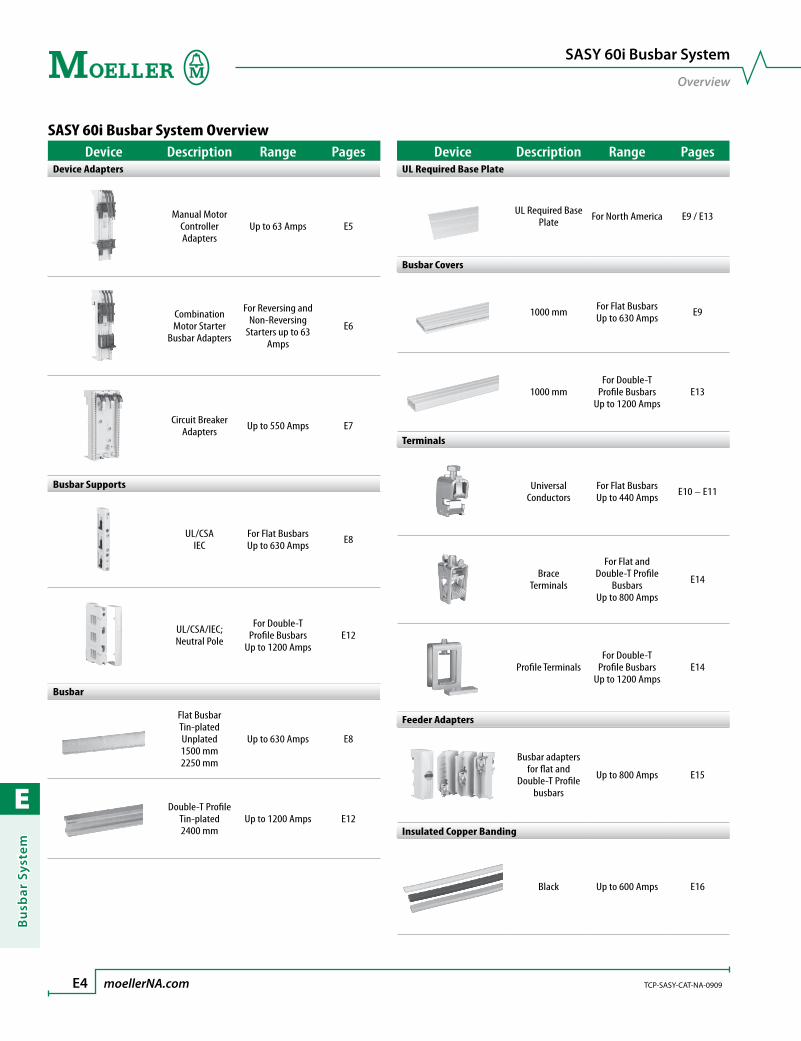
E
Bu
sbar
Sys
tem
E4 moellerNA.com TCP-SASY-CAT-NA-0909
SASY 60i Busbar System
Overview
Device Description Range PagesUL Required Base Plate
UL Required Base Plate For North America E9 / E13
Busbar Covers
1000 mm For Flat Busbars Up to 630 Amps E9
1000 mmFor Double-T
Profile Busbars Up to 1200 Amps
E13
Terminals
Universal Conductors
For Flat BusbarsUp to 440 Amps E10 – E11
Brace Terminals
For Flat and Double-T Profile
BusbarsUp to 800 Amps
E14
Profile TerminalsFor Double-T
Profile BusbarsUp to 1200 Amps
E14
Feeder Adapters
Busbar adapters for flat and
Double-T Profile busbars
Up to 800 Amps E15
Insulated Copper Banding
Black Up to 600 Amps E16
SASY 60i Busbar System OverviewDevice Description Range Pages
Device Adapters
Manual Motor Controller Adapters
Up to 63 Amps E5
Combination Motor Starter
Busbar Adapters
For Reversing and Non-Reversing
Starters up to 63 Amps
E6
Circuit Breaker Adapters Up to 550 Amps E7
Busbar Supports
UL/CSA IEC
For Flat Busbars Up to 630 Amps E8
UL/CSA/IEC; Neutral Pole
For Double-T Profile Busbars
Up to 1200 AmpsE12
Busbar
Flat BusbarTin-platedUnplated 1500 mm2250 mm
Up to 630 Amps E8
Double-T ProfileTin-plated 2400 mm
Up to 1200 Amps E12

E
Bu
sbar System
TCP-SASY-CAT-NA-0909 moellerNA.com E5 Discount Code A34
Busbar Adapters
for Manual Motor Controllers
Manual Motor Controller Busbar Adapters
Adapter
Max. Rated Operating
Current Ie [A]
Rated Operating Voltage Ue
[V]
Wire Cross
Section
Adapter Width [mm]
Adapter Length [mm]
Number of
Support Rails
For Use With… Description Catalog Number Price
for Manual Motor Controllers
63 690 AWG 8 54 200 1 PKZM4
• Combi-base suitable for busbars both 5 and 10 mm thick
• Base body temperature resistant to 120 °C / 248 °F
• Support rails temperature resistant to 100 °C / 212 °F
• PVC conductor insulation temperature resistant to 105 °C / 221 °F
• Self-extinguishing according to UL 94
• Creepage resistance CTI 200• Silicon and chlorine free
BBA4-63 140
63 690 AWG 8 72 200 1 PKZ2 BBA2-63 175
SASY 60i busbar adaptersconnecting components is a snap
Components and component combinations are mounted directly to Moeller’s innovative busbar adapter, and in turn are quickly and easily snapped anywhere on the busbar without using tools. Specially de-signed busbar adapters are available for circuit breakers, motor con-trollers and combination motor starters.
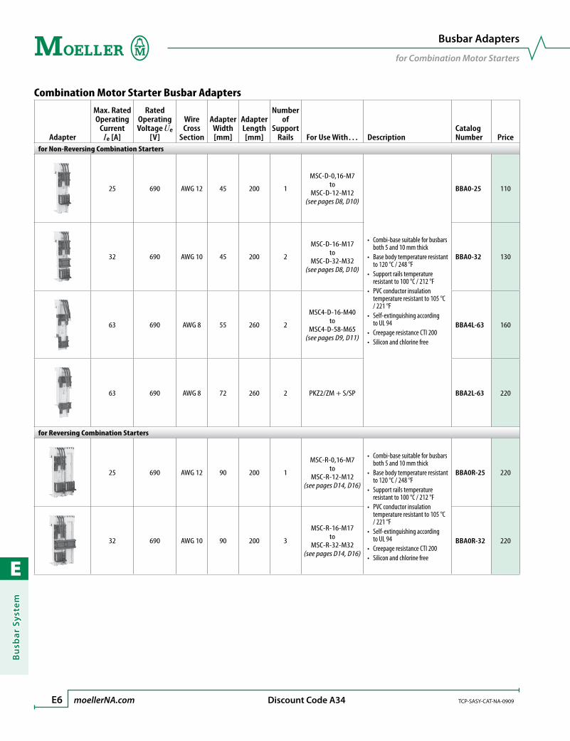
E
Bu
sbar
Sys
tem
E6 moellerNA.com TCP-SASY-CAT-NA-0909 Discount Code A34
Busbar Adapters
for Combination Motor Starters
Combination Motor Starter Busbar Adapters
Adapter
Max. Rated Operating
Current Ie [A]
Rated Operating Voltage Ue
[V]
Wire Cross
Section
Adapter Width [mm]
Adapter Length [mm]
Number of
Support Rails For Use With… Description
Catalog Number Price
for Non-Reversing Combination Starters
25 690 AWG 12 45 200 1
MSC-D-0,16-M7 to
MSC-D-12-M12(see pages D8, D10)
• Combi-base suitable for busbars both 5 and 10 mm thick
• Base body temperature resistant to 120 °C / 248 °F
• Support rails temperature resistant to 100 °C / 212 °F
• PVC conductor insulation temperature resistant to 105 °C / 221 °F
• Self-extinguishing according to UL 94
• Creepage resistance CTI 200• Silicon and chlorine free
BBA0-25 110
32 690 AWG 10 45 200 2
MSC-D-16-M17to
MSC-D-32-M32(see pages D8, D10)
BBA0-32 130
63 690 AWG 8 55 260 2
MSC4-D-16-M40to
MSC4-D-58-M65(see pages D9, D11)
BBA4L-63 160
63 690 AWG 8 72 260 2 PKZ2/ZM + S/SP BBA2L-63 220
for Reversing Combination Starters
25 690 AWG 12 90 200 1
MSC-R-0,16-M7to
MSC-R-12-M12(see pages D14, D16)
• Combi-base suitable for busbars both 5 and 10 mm thick
• Base body temperature resistant to 120 °C / 248 °F
• Support rails temperature resistant to 100 °C / 212 °F
• PVC conductor insulation temperature resistant to 105 °C / 221 °F
• Self-extinguishing according to UL 94
• Creepage resistance CTI 200• Silicon and chlorine free
BBA0R-25 220
32 690 AWG 10 90 200 3
MSC-R-16-M17to
MSC-R-32-M32(see pages D14, D16)
BBA0R-32 220

E
Bu
sbar System
TCP-SASY-CAT-NA-0909 moellerNA.com E7 Discount Code A34
Busbar Adapters
for Circuit Breakers; Universal Adapters
Circuit Breaker Busbar Adapters
Adapter
Max. Rated Operating
Current Ie [A]
Rated Operating Voltage Ue
[V]
Adapter Width [mm]
Adapter Length [mm]
For Use With… Description Catalog Number Price
for Circuit Breakers
160 690 90 200NZM1
N1NS1
• Combi-base suitable for busbars both 5 and 10 mm thick• Base body: Thermoplast
Temperature resistant to 120 °C / 248 °F Halogen free
• Cover Cap: Thermoplast Temperature resistant to 125 °C / 257 °F Bromine and chlorine free
• Conductor insulation: PVC Temperature resistant to 105 °C / 221 °F
• Self-extinguishing according to UL 94• Creepage resistance CTI 200• Connects at top
NZM1-XAD160 380
250 690 106 190NZM2
N2NS2
• Claw-type terminal• Base body:
Thermoplast Temperature resistant to 120 °C / 248 °F Halogen free
• Self-extinguishing according to UL 94• Creepage resistance CTI 200• Connects to top or bottom
NZM2-XAD250 420
550 690 140 270 NZM3N3
• Claw-type terminal• Base body:
Thermoplast Temperature resistant to 120 °C / 248 °F Halogen free
• Self-extinguishing according to UL 94• Creepage resistance CTI 200• Connects at top
NZM3-XAD550 590
Universal Busbar Adapters
Adapter
Max. Rated Operating
Current Ie [A]
Rated Operating Voltage Ue
[V]
Wire Cross
Section
Adapter Width [mm]
Adapter Length [mm]
Number of
Support Rails Description Catalog Number Price
for Universal Use
25 690 AWG 12 45 200 2 • Mounting rail can be offset on 1.25mm grid BBA0-25/2TS 114
Empty Module without electrical contacts
– – –
45 200 2 • Mounting rail can be offset on 1.25mm grid
• For use with reversing and star-delta starters.
BBA0/2TS-L 84
54 200 2 BBA4/2TS-L 110
Side Mount Module
– – – 9 200 – • Can be used to extend mounting width BBA-XSM 36
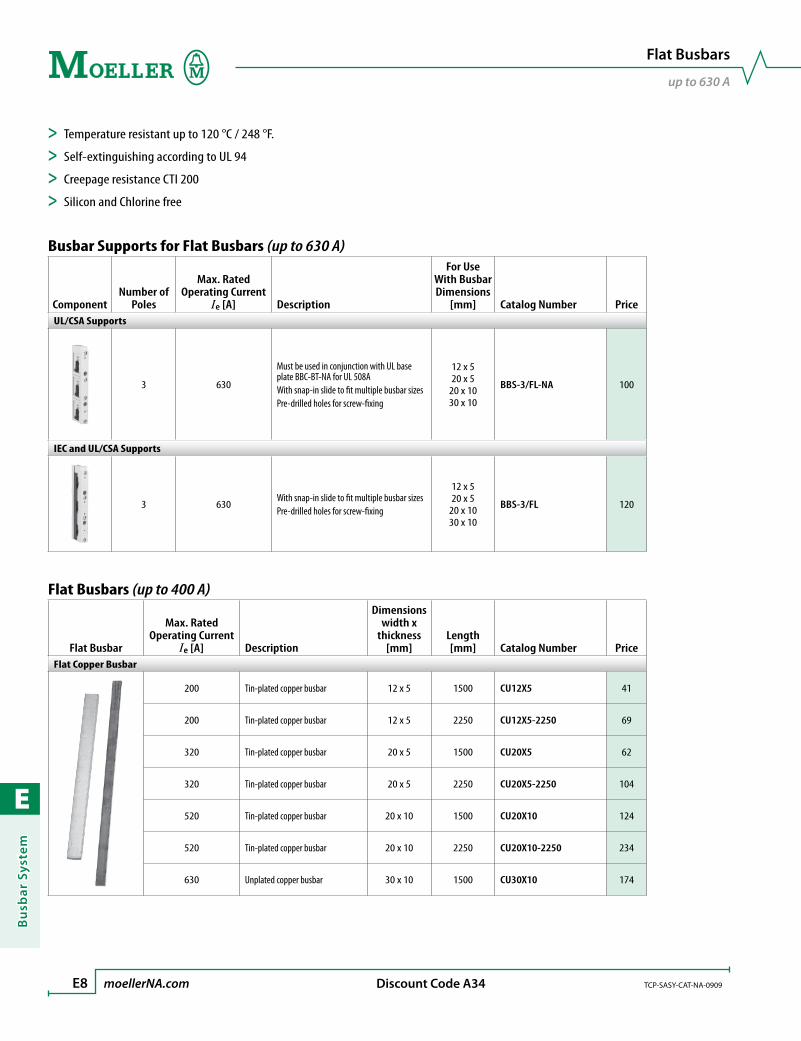
E
Bu
sbar
Sys
tem
E8 moellerNA.com TCP-SASY-CAT-NA-0909 Discount Code A34
Flat Busbars
up to 630 A
Busbar Supports for Flat Busbars (up to 630 A)
ComponentNumber of
Poles
Max. Rated Operating Current
Ie [A] Description
For Use With Busbar Dimensions
[mm] Catalog Number PriceUL/CSA Supports
3 630
Must be used in conjunction with UL base plate BBC-BT-NA for UL 508A With snap-in slide to fit multiple busbar sizesPre-drilled holes for screw-fixing
12 x 5 20 x 5
20 x 1030 x 10
BBS-3/FL-NA 100
IEC and UL/CSA Supports
3 630With snap-in slide to fit multiple busbar sizesPre-drilled holes for screw-fixing
12 x 5 20 x 5
20 x 10 30 x 10
BBS-3/FL 120
Flat Busbars (up to 400 A)
Flat Busbar
Max. Rated Operating Current
Ie [A] Description
Dimensionswidth x
thickness [mm]
Length[mm] Catalog Number Price
Flat Copper Busbar
200 Tin-plated copper busbar 12 x 5 1500 CU12X5 41
200 Tin-plated copper busbar 12 x 5 2250 CU12X5-2250 69
320 Tin-plated copper busbar 20 x 5 1500 CU20X5 62
320 Tin-plated copper busbar 20 x 5 2250 CU20X5-2250 104
520 Tin-plated copper busbar 20 x 10 1500 CU20X10 124
520 Tin-plated copper busbar 20 x 10 2250 CU20X10-2250 234
630 Unplated copper busbar 30 x 10 1500 CU30X10 174
> Temperature resistant up to 120 °C / 248 °F.
> Self-extinguishing according to UL 94
> Creepage resistance CTI 200
> Silicon and Chlorine free

E
Bu
sbar System
TCP-SASY-CAT-NA-0909 moellerNA.com E9 Discount Code A34
Flat Busbars
up to 630 A
UL / CSA Required Busbar Base Plate
Component Description Catalog Number PriceUL/CSA Base Plate
Base plate required for UL 508A operation1100 mm in length
BBC-BT-NA 180
Busbar Covers for Flat Busbars (up to 630 A)
Component Description
For Use With Busbar Dimensions
[mm] Catalog Number PriceBusbar Covers
1000 mm in length 12 x 5 20 x 5 BBC-FL5 50
1000 mm in length 20 x 1030 x 10 BBC-FL10 54
End Cover
Covers side of busbar supportsBBS-3/FL-NABBS-3/FL
– ES-BBS-3/FL 12
Reserved Busbar Section CoversCover System For Use With… Description Catalog Number Price
• Flat Busbar: 12 x 5 20 x 5 20 x 10 30 x 10
To cover unused sections of flat busbar1100 mm in lengthSupport for single busbar cover system
Front, top and bot-tom protection BBC-RCOV1 144
Side support BBC-MRCOV1 22
> Temperature resistant up to 110 °C / 230 °F.
> Self-extinguishing according to UL 94
> Silicon and Chlorine free
Required for R
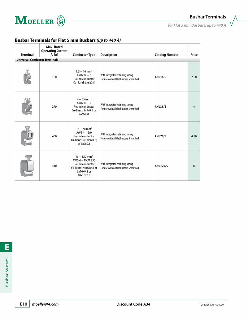
E
Bu
sbar
Sys
tem
E10 moellerNA.com TCP-SASY-CAT-NA-0909 Discount Code A34
Busbar Terminals
for Flat 5 mm Busbars; up to 440 A
Busbar Terminals for Flat 5 mm Busbars (up to 440 A)
Terminal
Max. Rated Operating Current
Ie [A] Conductor Type Description Catalog Number PriceUniversal Conductor Terminals
180
1.5 – 16 mm2
AWG 14 – 6Round conductorCu-Band: 8x6x0.5
With integrated retaining springFor use with all flat busbars 5mm thick
AKU16/5 2.60
270
4 – 35 mm2
AWG 10 – 2Round conductor
Cu-Band: 3x9x0.8 or 6x9x0.8
With integrated retaining springFor use with all flat busbars 5mm thick
AKU35/5 4
400
16 – 70 mm2
AWG 4 – 2/0Round conductor
Cu-Band: 2x(3x9x0.8) or 6x9x0.8
With integrated retaining springFor use with all flat busbars 5mm thick
AKU70/5 4.70
440
16 – 120 mm2
AWG 4 – MCM 250Round conductor
Cu-Band: 4x16x0.8 or 6x16x0.8 or 10x16x0.8
With integrated retaining springFor use with all flat busbars 5mm thick
AKU120/5 10
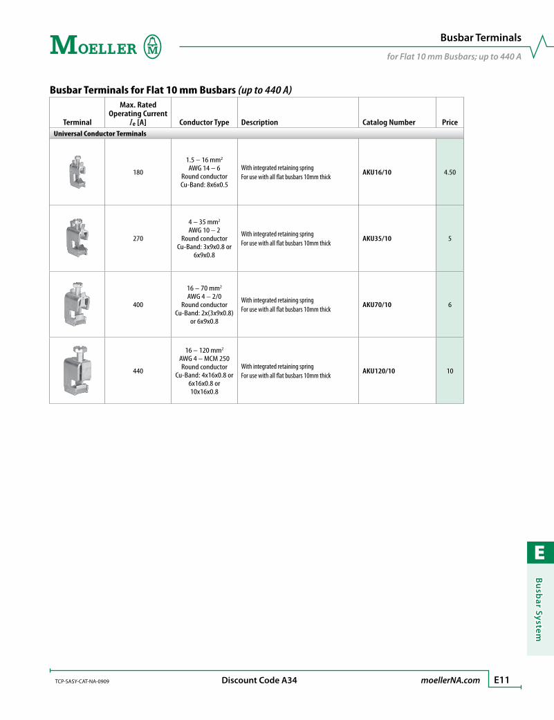
E
Bu
sbar System
TCP-SASY-CAT-NA-0909 moellerNA.com E11 Discount Code A34
Busbar Terminals
for Flat 10 mm Busbars; up to 440 A
Busbar Terminals for Flat 10 mm Busbars (up to 440 A)
Terminal
Max. Rated Operating Current
Ie [A] Conductor Type Description Catalog Number PriceUniversal Conductor Terminals
180
1.5 – 16 mm2
AWG 14 – 6Round conductorCu-Band: 8x6x0.5
With integrated retaining springFor use with all flat busbars 10mm thick
AKU16/10 4.50
270
4 – 35 mm2
AWG 10 – 2Round conductor
Cu-Band: 3x9x0.8 or 6x9x0.8
With integrated retaining springFor use with all flat busbars 10mm thick
AKU35/10 5
400
16 – 70 mm2
AWG 4 – 2/0Round conductor
Cu-Band: 2x(3x9x0.8) or 6x9x0.8
With integrated retaining springFor use with all flat busbars 10mm thick
AKU70/10 6
440
16 – 120 mm2
AWG 4 – MCM 250Round conductor
Cu-Band: 4x16x0.8 or 6x16x0.8 or 10x16x0.8
With integrated retaining springFor use with all flat busbars 10mm thick
AKU120/10 10

E
Bu
sbar
Sys
tem
E12 moellerNA.com TCP-SASY-CAT-NA-0909 Discount Code A34
Double-T Profile Busbars
up to 1200A
Busbar Supports for Double-T Profile Busbars (up to 1200 A)
ComponentNumber of
Poles
Max. Rated Operating Current
Ie [A] Description Catalog Number PriceSupports
3 1200Must be used in conjunction with UL base plate BBC-BT-NA for UL 508APre-drilled holes for screw-fixing
BBS-3/PR 480
Neutral Supports
1 1200 Pre-drilled holes for screw-fixing BBS-1/PR 39
Double-T Profile Busbars (up to 950 A and 1200 A)
Busbar
Max. Rated Operating Current
Ie [A] Description Catalog Number PriceDouble-T Profile Busbar
950Tin-platedCross-section 500 mm2
2400 mm in lengthCU-BAR-500/T 1550
1200Tin-platedCross-section 720 mm2
2400 mm in lengthCU-BAR-720/T 2390
> Temperature resistant up to 120 °C / 248 °F.
> Self-extinguishing according to UL 94
> Creepage resistance CTI 200
> Silicon and Chlorine free
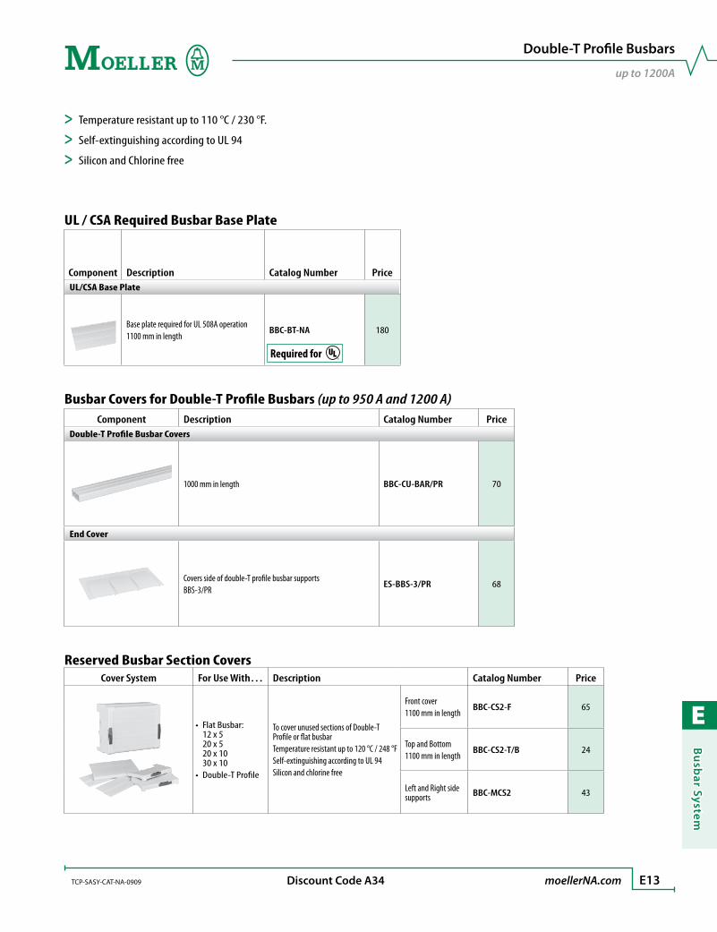
E
Bu
sbar System
TCP-SASY-CAT-NA-0909 moellerNA.com E13 Discount Code A34
Double-T Profile Busbars
up to 1200A
UL / CSA Required Busbar Base Plate
Component Description Catalog Number PriceUL/CSA Base Plate
Base plate required for UL 508A operation1100 mm in length
BBC-BT-NA 180
Busbar Covers for Double-T Profile Busbars (up to 950 A and 1200 A)Component Description Catalog Number Price
Double-T Profile Busbar Covers
1000 mm in length BBC-CU-BAR/PR 70
End Cover
Covers side of double-T profile busbar supportsBBS-3/PR
ES-BBS-3/PR 68
Reserved Busbar Section CoversCover System For Use With… Description Catalog Number Price
• Flat Busbar: 12 x 5 20 x 5 20 x 10 30 x 10
• Double-T Profile
To cover unused sections of Double-T Profile or flat busbarTemperature resistant up to 120 °C / 248 °FSelf-extinguishing according to UL 94Silicon and chlorine free
Front cover1100 mm in length
BBC-CS2-F 65
Top and Bottom1100 mm in length
BBC-CS2-T/B 24
Left and Right side supports BBC-MCS2 43
> Temperature resistant up to 110 °C / 230 °F.
> Self-extinguishing according to UL 94
> Silicon and Chlorine free
Required for R
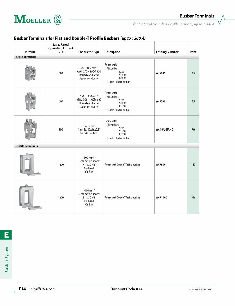
E
Bu
sbar
Sys
tem
E14 moellerNA.com TCP-SASY-CAT-NA-0909 Discount Code A34
Busbar Terminals
for Flat and Double-T Profile Busbars; up to 1200 A
Busbar Terminals for Flat and Double-T Profile Busbars (up to 1200 A)
Terminal
Max. Rated Operating Current
Ie [A] Conductor Type Description Catalog Number PriceBrace Terminals
500
95 – 185 mm2
AWG 3/0 – MCM 350Round conductorSector conductor
For use with: • Flat busbars:
20 x 5 20 x 10 30 x 10
• Double-T Profile busbars
AKS185 33
600
150 – 300 mm2
MCM 300 – MCM 600Round conductorSector conductor
For use with: • Flat busbars:
20 x 5 20 x 10 30 x 10
• Double-T Profile busbars
AKS300 55
800Cu-Band:
from 2x(10x16x0,8)to 2x(11x21x1)
For use with: • Flat busbars:
20 x 5 20 x 10 30 x 10
• Double-T Profile busbars
AKS-CU-BAND 70
Profile Terminals
1200
800 mm2
Termination space: 41 x 20-42Cu-BandCu-Bar
For use with Double-T Profile busbars AKP800 147
1200
1000 mm2
Termination space: 51 x 20-42Cu-BandCu-Bar
For use with Double-T Profile busbars AKP1000 166
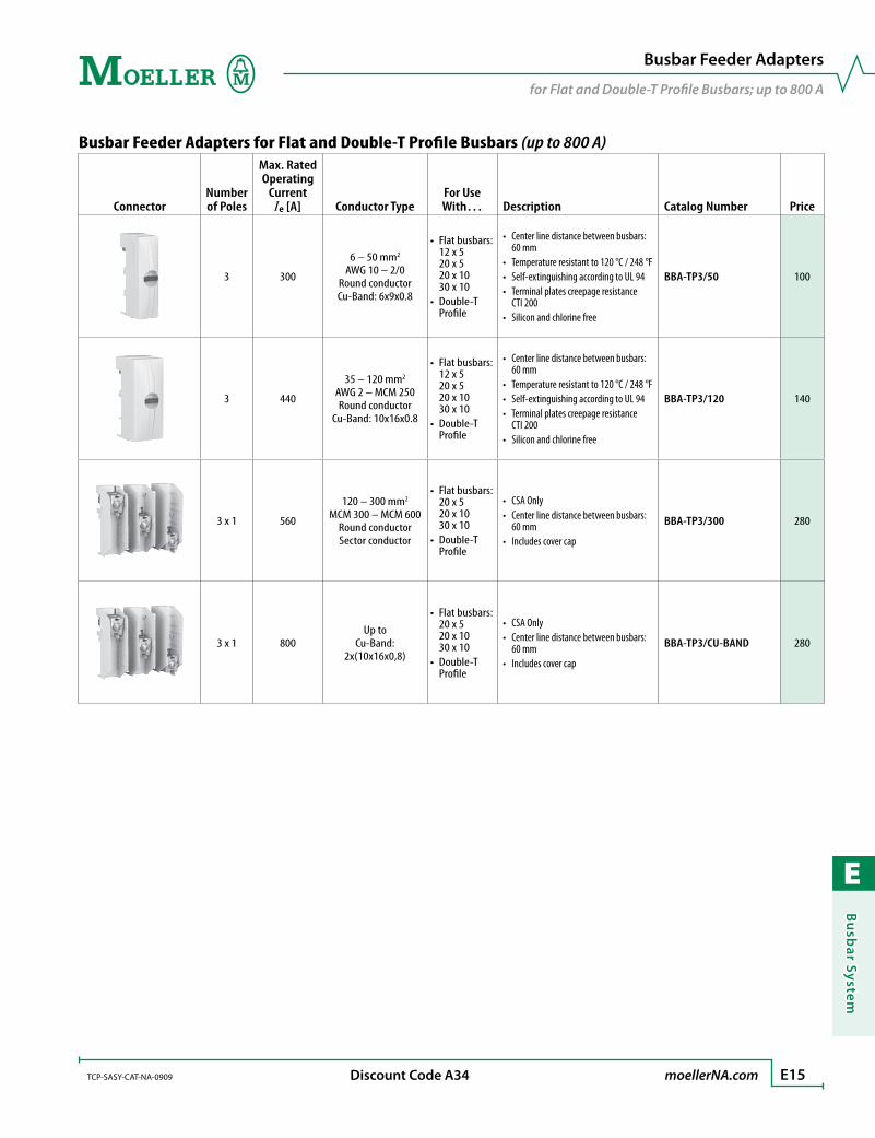
E
Bu
sbar System
TCP-SASY-CAT-NA-0909 moellerNA.com E15 Discount Code A34
Busbar Feeder Adapters
for Flat and Double-T Profile Busbars; up to 800 A
Busbar Feeder Adapters for Flat and Double-T Profile Busbars (up to 800 A)
ConnectorNumber of Poles
Max. Rated Operating
Current Ie [A] Conductor Type
For Use With… Description Catalog Number Price
3 300
6 – 50 mm2
AWG 10 – 2/0Round conductorCu-Band: 6x9x0.8
• Flat busbars: 12 x 5 20 x 5 20 x 10 30 x 10
• Double-T Profile
• Center line distance between busbars: 60 mm
• Temperature resistant to 120 °C / 248 °F• Self-extinguishing according to UL 94• Terminal plates creepage resistance
CTI 200• Silicon and chlorine free
BBA-TP3/50 100
3 440
35 – 120 mm2
AWG 2 – MCM 250Round conductor
Cu-Band: 10x16x0.8
• Flat busbars: 12 x 5 20 x 5 20 x 10 30 x 10
• Double-T Profile
• Center line distance between busbars: 60 mm
• Temperature resistant to 120 °C / 248 °F• Self-extinguishing according to UL 94• Terminal plates creepage resistance
CTI 200• Silicon and chlorine free
BBA-TP3/120 140
3 x 1 560
120 – 300 mm2
MCM 300 – MCM 600Round conductorSector conductor
• Flat busbars: 20 x 5 20 x 10 30 x 10
• Double-T Profile
• CSA Only• Center line distance between busbars:
60 mm• Includes cover cap
BBA-TP3/300 280
3 x 1 800Up to
Cu-Band: 2x(10x16x0,8)
• Flat busbars: 20 x 5 20 x 10 30 x 10
• Double-T Profile
• CSA Only• Center line distance between busbars:
60 mm• Includes cover cap
BBA-TP3/CU-BAND 280
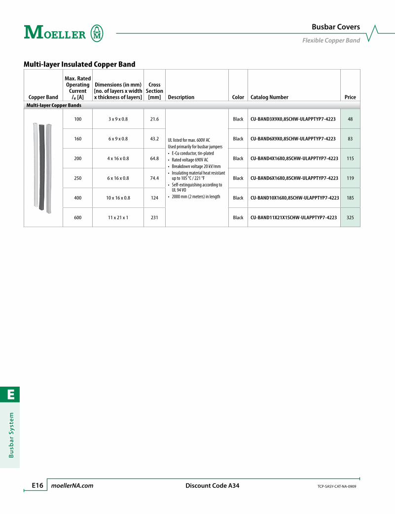
E
Bu
sbar
Sys
tem
E16 moellerNA.com TCP-SASY-CAT-NA-0909 Discount Code A34
Busbar Covers
Flexible Copper Band
Multi-layer Insulated Copper Band
Copper Band
Max. Rated Operating
Current Ie [A]
Dimensions (in mm)[no. of layers x width x thickness of layers]
Cross Section[mm] Description Color Catalog Number Price
Multi-layer Copper Bands
100 3 x 9 x 0.8 21.6
UL listed for max. 600V ACUsed primarily for busbar jumpers• E-Cu conductor, tin-plated• Rated voltage 690V AC• Breakdown voltage 20 kV/mm• Insulating material heat resistant
up to 105 °C / 221 °F• Self-extinguishing according to
UL 94 VO• 2000 mm (2 meters) in length
Black CU-BAND3X9X0,8SCHW-ULAPPTYP7-4223 48
160 6 x 9 x 0.8 43.2 Black CU-BAND6X9X0,8SCHW-ULAPPTYP7-4223 83
200 4 x 16 x 0.8 64.8 Black CU-BAND4X16X0,8SCHW-ULAPPTYP7-4223 115
250 6 x 16 x 0.8 74.4 Black CU-BAND6X16X0,8SCHW-ULAPPTYP7-4223 119
400 10 x 16 x 0.8 124 Black CU-BAND10X16X0,8SCHW-ULAPPTYP7-4223 185
600 11 x 21 x 1 231 Black CU-BAND11X21X1SCHW-ULAPPTYP7-4223 325

E
Bu
sbar System
TCP-SASY-CAT-NA-0909 moellerNA.com E17
SASY 60i Busbar System
Application Notes
UL / CSA Approvals List
Catalog Number USA ➊ CanadaAKP800
AKP1000
AKS185
AKS300
AKS-CU-BAND
AKU16/5
AKU16/10
AKU35/5
AKU35/10
AKU70/5
AKU70/10
AKU120/5
AKU120/10
BBA0-25
BBA0-32
BBA0R-25
BBA0R-32
BBA2-63
BBA2L-63
BBA4-63
BBA4L-63
BBA-TP3/50
BBA-TP3/120
BBA-TP3/300
BBA-TP3/CU-BAND
BBC-BT-NA
BBC-CS2-F
BBC-CS2-T/B
BBC-CU-BAR/PR
BBC-FL5
BBC-FL10
BBC-MCS2
BBC-MRCOV1
BBC-RCOV1
BBS-1/PR
BBS-3/FL
BBS-3/FL-NA
BBS-3/PR
CU-BAR-500/T
CU-BAR-720/T
ES-BBS-3/FL
ES-BBS-3/PR
NZM1-XAD160
NZM2-XAD250
NZM3-XAD550
➊ Tested for feeder circuits according to UL-508A up to 600V.
UL–Approbation File No: E307559, E300273CSA–Approbation Report No: 236217, 232140UL File No. for CU-Band: E248096
Cross Sections vs AWG/MCM Sizes reference table
Cross Section [mm2] AWG/MCM [Size]
1.5 16 AWG
2.5 14 AWG
4 12 AWG
6 10 AWG
10 8 AWG
16 6 AWG
25 4 AWG
35 2 AWG
50 0 AWG
70 2/0 AWG
95 3/0 AWG
120 250 MCM
150 300 MCM
185 350 MCM
240 500 MCM
300 600 MCM
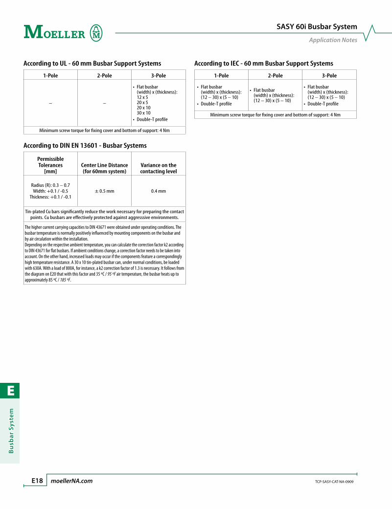
E
Bu
sbar
Sys
tem
E18 moellerNA.com TCP-SASY-CAT-NA-0909
SASY 60i Busbar System
Application Notes
According to IEC - 60 mm Busbar Support Systems
1-Pole 2-Pole 3-Pole
• Flat busbar (width) x (thickness): (12 – 30) x (5 – 10)
• Double-T profile
• Flat busbar (width) x (thickness): (12 – 30) x (5 – 10)
• Flat busbar (width) x (thickness): (12 – 30) x (5 – 10)
• Double-T profile
Minimum screw torque for fixing cover and bottom of support: 4 Nm
According to UL - 60 mm Busbar Support Systems
1-Pole 2-Pole 3-Pole
– –
• Flat busbar (width) x (thickness): 12 x 5 20 x 5 20 x 10 30 x 10
• Double-T profile
Minimum screw torque for fixing cover and bottom of support: 4 Nm
According to DIN EN 13601 - Busbar Systems
Permissible Tolerances
[mm]Center Line Distance (for 60mm system)
Variance on the contacting level
Radius (R): 0.3 – 0.7 Width: +0.1 / -0.5
Thickness: +0.1 / -0.1± 0.5 mm 0.4 mm
Tin-plated Cu bars significantly reduce the work necessary for preparing the contact points. Cu busbars are effectively protected against aggresssive environments.
The higher current carrying capacities to DIN 43671 were obtained under operating conditions. The busbar temperature is normally positively influenced by mounting components on the busbar and by air circulation within the installation.Depending on the respective ambient temperature, you can calculate the correction factor k2 according to DIN 43671 for flat busbars. If ambient conditions change, a correction factor needs to be taken into account. On the other hand, increased loads may occur if the components feature a correspondingly high temperature resistance. A 30 x 10 tin-plated busbar can, under normal conditions, be loaded with 630A. With a load of 800A, for instance, a k2 correction factor of 1.3 is necessary. It follows from the diagram on E20 that with this factor and 35 ºC / 95 ºF air temperature, the busbar heats up to approximately 85 ºC / 185 ºF.
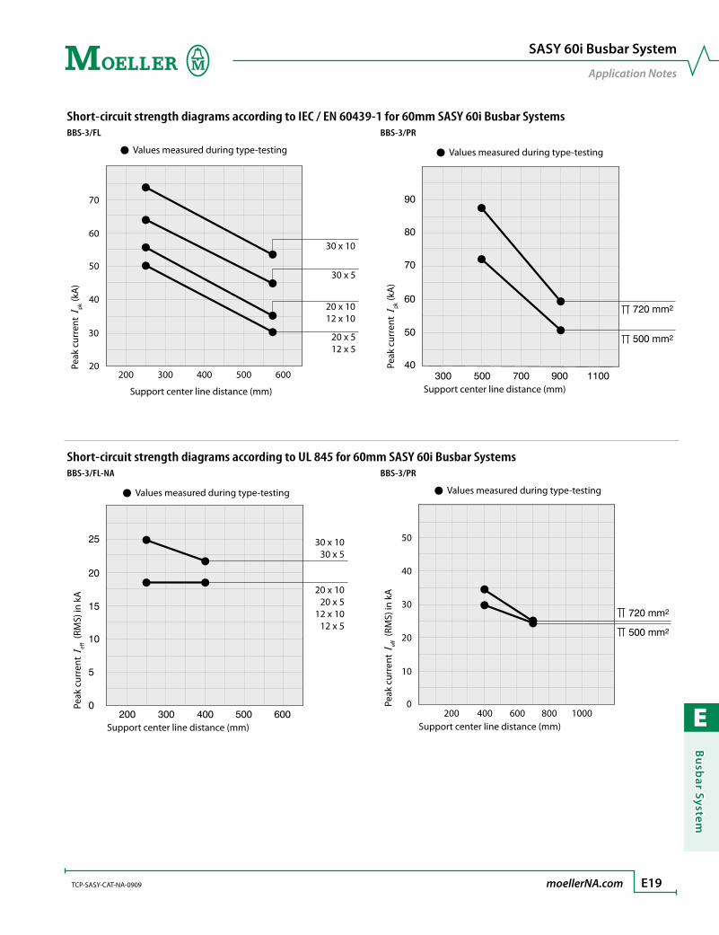
E
Bu
sbar System
TCP-SASY-CAT-NA-0909 moellerNA.com E19
SASY 60i Busbar System
Application Notes
Short-circuit strength diagrams according to IEC / EN 60439-1 for 60mm SASY 60i Busbar SystemsBBS-3/FL BBS-3/PR
Support center line distance (mm)
70
30 x 10
30 x 5
20 x 1012 x 10
20 x 512 x 5
60
50
40
30
20200 300 400 500 600
Values measured during type-testing
Peak
cur
rent
Ipk
(kA
)
Support center line distance (mm)
Values measured during type-testing
Peak
cur
rent
Ipk
(kA
)
Short-circuit strength diagrams according to UL 845 for 60mm SASY 60i Busbar SystemsBBS-3/FL-NA BBS-3/PR
Support center line distance (mm)
30 x 1030 x 5
20 x 1020 x 5
12 x 1012 x 5
Peak
cur
rent
Ie
(RM
S) in
kA
Values measured during type-testing
Support center line distance (mm)
50
40
30
20
10
0200 400 600 800 1000
Peak
cur
rent
Ie
(RM
S) in
kA
Values measured during type-testing
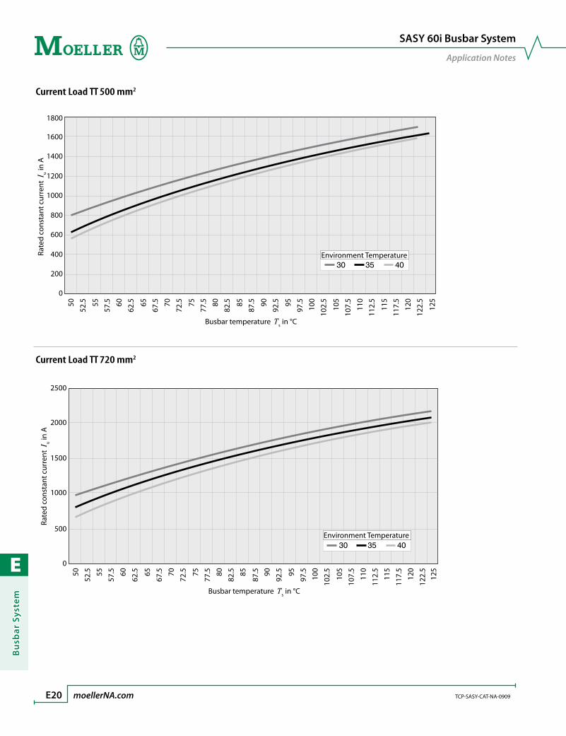
E
Bu
sbar
Sys
tem
E20 moellerNA.com TCP-SASY-CAT-NA-0909
SASY 60i Busbar System
Application Notes
Current Load TT 500 mm252
.550 5557
.5
62.560 65
67.5
72.570 75
77.5
82.580 85
87.5
92.590 95
97.5
102.
510
0
105
107.
5
112.
511
0
115
117.
5
122.
512
0
125
Busbar temperature Ts in °C
Rate
d co
nsta
nt c
urre
nt I
u in A
0
200
400
600
800
1000
1200
1400
1600
1800
Environment Temperature
Current Load TT 720 mm2
Environment Temperature
52.550 55
57.5
62.560 65
67.5
72.570 75
77.5
82.580 85
87.5
92.590 95
97.5
102.
510
0
105
107.
5
112.
511
0
115
117.
5
122.
512
0
125
0
500
1000
1500
2000
2500
Busbar temperature Ts in °C
Rate
d co
nsta
nt c
urre
nt I
u in A
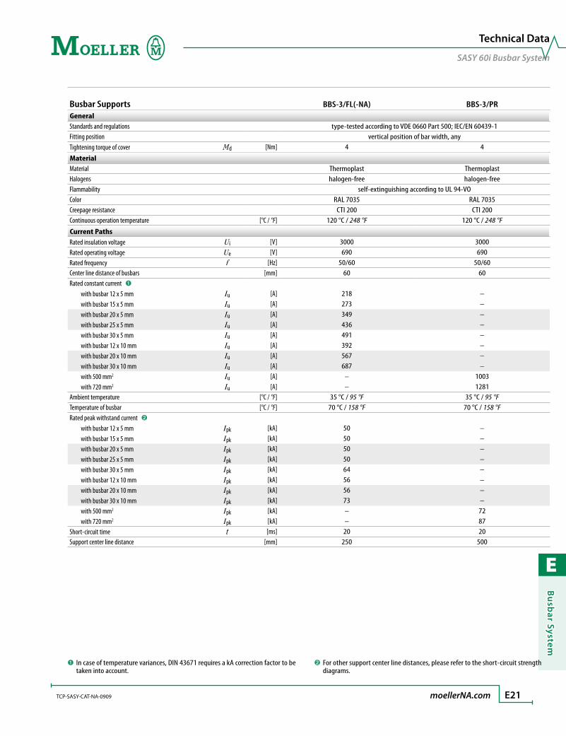
E
Bu
sbar System
TCP-SASY-CAT-NA-0909 moellerNA.com E21
Technical Data
SASY 60i Busbar System
Busbar Supports BBS-3/FL(-NA) BBS-3/PRGeneralStandards and regulations type-tested according to VDE 0660 Part 500; IEC/EN 60439-1Fitting position vertical position of bar width, anyTightening torque of cover Md [Nm] 4 4
MaterialMaterial Thermoplast ThermoplastHalogens halogen-free halogen-freeFlammability self-extinguishing according to UL 94-VOColor RAL 7035 RAL 7035Creepage resistance CTI 200 CTI 200Continuous operation temperature [°C / °F] 120 °C / 248 °F 120 °C / 248 °F
Current PathsRated insulation voltage Ui [V] 3000 3000Rated operating voltage Ue [V] 690 690Rated frequency f [Hz] 50/60 50/60Center line distance of busbars [mm] 60 60Rated constant current ➊ with busbar 12 x 5 mm Iu [A] 218 – with busbar 15 x 5 mm Iu [A] 273 – with busbar 20 x 5 mm Iu [A] 349 – with busbar 25 x 5 mm Iu [A] 436 – with busbar 30 x 5 mm Iu [A] 491 – with busbar 12 x 10 mm Iu [A] 392 – with busbar 20 x 10 mm Iu [A] 567 – with busbar 30 x 10 mm Iu [A] 687 – with 500 mm2 Iu [A] – 1003 with 720 mm2 Iu [A] – 1281Ambient temperature [°C / °F] 35 °C / 95 °F 35 °C / 95 °FTemperature of busbar [°C / °F] 70 °C / 158 °F 70 °C / 158 °FRated peak withstand current ➋ with busbar 12 x 5 mm Ipk [kA] 50 – with busbar 15 x 5 mm Ipk [kA] 50 – with busbar 20 x 5 mm Ipk [kA] 50 – with busbar 25 x 5 mm Ipk [kA] 50 – with busbar 30 x 5 mm Ipk [kA] 64 – with busbar 12 x 10 mm Ipk [kA] 56 – with busbar 20 x 10 mm Ipk [kA] 56 – with busbar 30 x 10 mm Ipk [kA] 73 – with 500 mm2 Ipk [kA] – 72 with 720 mm2 Ipk [kA] – 87Short-circuit time t [ms] 20 20Support center line distance [mm] 250 500
➊ In case of temperature variances, DIN 43671 requires a kA correction factor to be taken into account.
➋ For other support center line distances, please refer to the short-circuit strength diagrams.
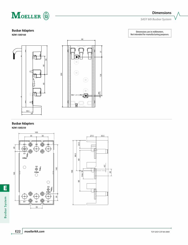
E
Bu
sbar
Sys
tem
E22 moellerNA.com TCP-SASY-CAT-NA-0909
Dimensions
SASY 60i Busbar System
Busbar AdaptersNZM1-XAD160
90
200
126
37M
4
Md 1, 5-1, 8Nm
9460
60
36.564
Busbar AdaptersNZM1-XAD250
105
145 19
0145
6060
23.5
89.5
4.5
max
. 30
20
27.5 35.535 35
20
20
35
L2
8 Nm
8 Nm
L1
L1 L2 L3
L1 L2 L3
L3
8 Nm
Dimensions are in millimeters.Not intended for manufacturing purposes.

E
Bu
sbar System
TCP-SASY-CAT-NA-0909 moellerNA.com E23
Dimensions
SASY 60i Busbar System
Busbar AdaptersNZM1-XAD550
140
270
234
45 45
L1 L2 L3
L1
12 Nm
L2
12 Nm
L3
12 Nm
L1 L2 L3
121.
555
.560
60m
ax. 3
0
27.5 35.5
Busbar Supports - Flat Busbar Busbar Supports - Flat BusbarBBS-3/FL-NA BBS-3/FL
5
21
240
7573
.5
20 49.5
12
33
6575
191
2760
60
011
06.5
Dimensions are in millimeters.Not intended for manufacturing purposes.
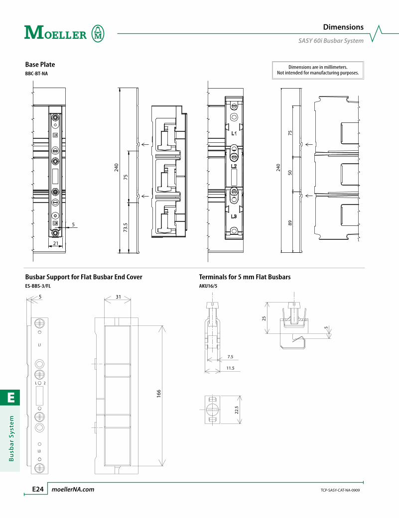
E
Bu
sbar
Sys
tem
E24 moellerNA.com TCP-SASY-CAT-NA-0909
Dimensions
SASY 60i Busbar System
Base PlateBBC-BT-NA
5
21
240
7573
.5
240
7550
89
Busbar Support for Flat Busbar End Cover Terminals for 5 mm Flat BusbarsES-BBS-3/FL AKU16/5
5 31
166
11.5
25
5
7.5
22.5
Dimensions are in millimeters.Not intended for manufacturing purposes.
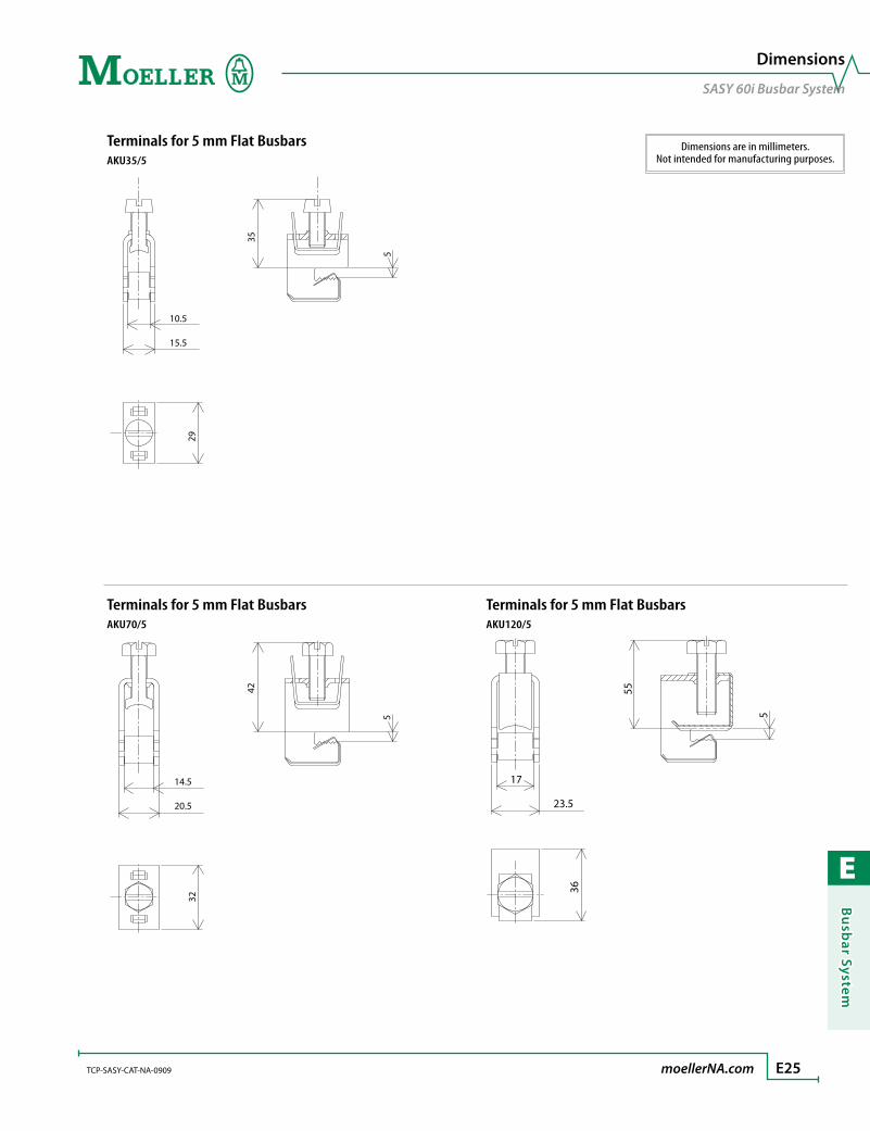
E
Bu
sbar System
TCP-SASY-CAT-NA-0909 moellerNA.com E25
Dimensions
SASY 60i Busbar System
Terminals for 5 mm Flat BusbarsAKU35/5
10.5
29
15.5
35
5
Terminals for 5 mm Flat Busbars Terminals for 5 mm Flat BusbarsAKU70/5 AKU120/5
14.5
32
20.5
42
5
36
23.5
55
517
Dimensions are in millimeters.Not intended for manufacturing purposes.

E
Bu
sbar
Sys
tem
E26 moellerNA.com TCP-SASY-CAT-NA-0909
Dimensions
SASY 60i Busbar System
Terminals for 10 mm Flat BusbarsAKU16/10
22.5
11.5
25
107.5
Terminals for 10 mm Flat Busbars Terminals for 10 mm Flat BusbarsAKU35/10 AKU70/10
29
15.5
35
10
10.5
32
20.5
42
10
14.5
Dimensions are in millimeters.Not intended for manufacturing purposes.
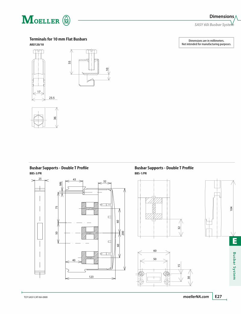
E
Bu
sbar System
TCP-SASY-CAT-NA-0909 moellerNA.com E27
Dimensions
SASY 60i Busbar System
Terminals for 10 mm Flat BusbarsAKU120/10
36
23.5
55
10
17
Busbar Supports - Double T Profile Busbar Supports - Double T ProfileBBS-3/PR BBS-1/PR
123
40
5075
6060
200
3243
M6
25
60
50
3215
30
104
Dimensions are in millimeters.Not intended for manufacturing purposes.
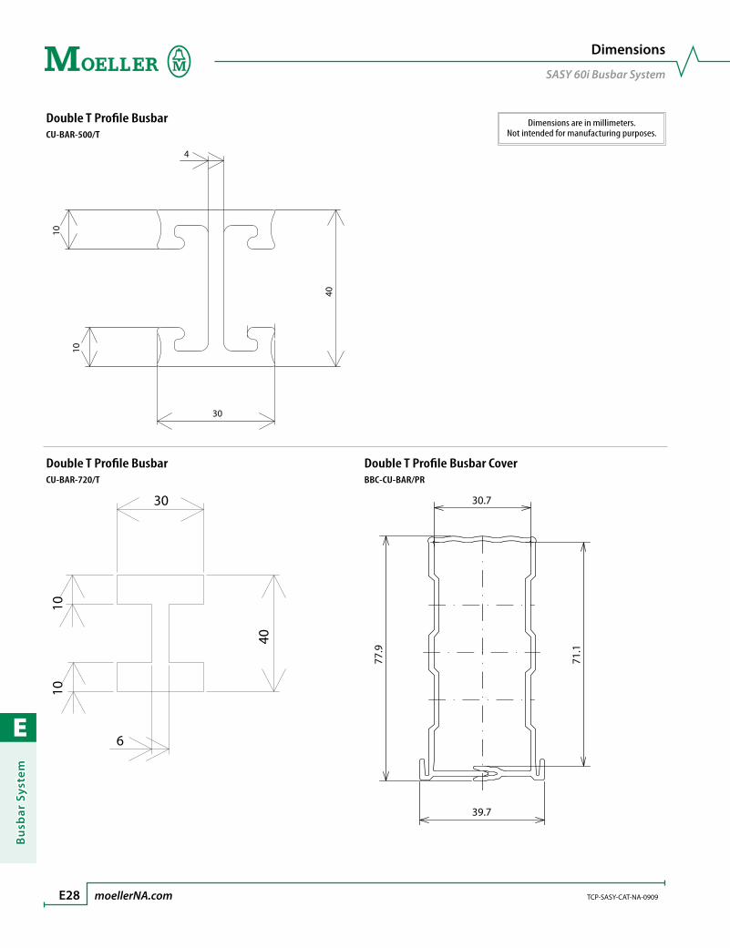
E
Bu
sbar
Sys
tem
E28 moellerNA.com TCP-SASY-CAT-NA-0909
Dimensions
SASY 60i Busbar System
Double T Profile BusbarCU-BAR-500/T
30
4
40
10
10
Double T Profile Busbar Double T Profile Busbar CoverCU-BAR-720/T BBC-CU-BAR/PR
30
40
1010
6
39.7
30.7
71.1
77.9
Dimensions are in millimeters.Not intended for manufacturing purposes.
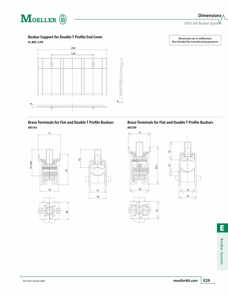
E
Bu
sbar System
TCP-SASY-CAT-NA-0909 moellerNA.com E29
Dimensions
SASY 60i Busbar System
Busbar Support for Double T Profile End CoverES-BBS-3/PR
200
120
6
6
Brace Terminals for Flat and Double T Profile Busbars Brace Terminals for Flat and Double T Profile BusbarsAKS185 AKS300
70
42
61 m
ax
38
38
3143
51
43
51
33
41
1042
85.5
41
Dimensions are in millimeters.Not intended for manufacturing purposes.

E
Bu
sbar
Sys
tem
E30 moellerNA.com TCP-SASY-CAT-NA-0909
Dimensions
SASY 60i Busbar System
Dimensions are in millimeters.Not intended for manufacturing purposes.
Brace Terminals for Flat and Double T Profile BusbarsAKS-CU-BAND
85.5
43
51
33
41
1041
51
Profile Terminals for Flat and Double T Profile Busbars Busbar Feeder AdaptersAKP1000 BBA-TP3/50
45
89
52
75
115.
5
153
51

E
Bu
sbar System
TCP-SASY-CAT-NA-0909 moellerNA.com E31
Dimensions
SASY 60i Busbar System
Dimensions are in millimeters.Not intended for manufacturing purposes.
Busbar Feeder AdaptersBBA-TP3/120
81
88
32
200
94
6060
194
Busbar Feeder Adapters Busbar Feeder AdaptersBBA-TP3/300 BBA-TP3/CU-BAND
153
51
153
51
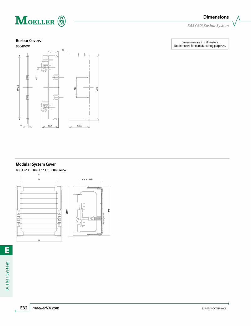
E
Bu
sbar
Sys
tem
E32 moellerNA.com TCP-SASY-CAT-NA-0909
Dimensions
SASY 60i Busbar System
Busbar CoversBBC-RCOV1
62.549.4
195.
4
Modular System CoverBBC-CS2-F + BBC-CS2-T/B + BBC-MCS2
Dimensions are in millimeters.Not intended for manufacturing purposes.

E
Bu
sbar System
STARTER-CAT-NA-0708 moellerNA.com E33
SASY 60i Busbar System
Notes

E
Bu
sbar
Sys
tem
E34 moellerNA.com STARTER-CAT-NA-0708
SASY 60i Busbar System
Notes

F
Relays
relays
Control Relays F3Selection tables .................................................................................. F6
Accessories .......................................................................................... F10
Technical Data ................................................................................... F14
Dimensions ......................................................................................... F21
Timing Relays F23Selection tables - DILET .................................................................... F24
Selection tables - ETR2...................................................................... F26
Selection tables - ETR4...................................................................... F28
Technical Data ................................................................................... F32
Dimensions ......................................................................................... F36
Safety Relays F37Selection tables .................................................................................. F38
Technical Data ................................................................................... F39
Dimensions ......................................................................................... F44
Monitoring Relays F45Selection tables .................................................................................. F46
Accessories .......................................................................................... F49
Technical Data ................................................................................... F50
Dimensions ......................................................................................... F63

F
Rela
ys
Start with Moellerrelays

F
Relays
F3
Flexibility, safety and economy… Moeller’s DIL series of control relays offer mod-ern features in a compact, smart design. The line is made up of two models; DIL A relays, which are based on Moeller’s new range of popular DIL M contactors; and DIL ER relays, which are built in the same compact frame as our miniature DIL EM contactors. Both lines share the same accessories with their contactor family. This simplifies stocking and makes ordering fast and efficient.
Ideal for fail-safe control circuitsModern applications requiring safety redundancy circuits ensure trouble free fault detection if the control relays have positively guided contacts. Both the DIL A and the miniature DIL ER control relays and auxiliary contacts (except overlapping con-tacts) meet these requirements. Positively-guided contacts are designed such that no NO contact can close before any NC contact can open. This important feature maintains a minimum contact clearance of 0.5mm and ensures that the NC con-tact stays open if a NO contact welds. This feature makes Moeller’s DIL series of control relays ideal for critical applications such as press control.
Moeller’s DC relays also include built-in surge suppressors that eliminate harm-ful voltage spikes caused when the relay is de-energized. This protects sensitive electronics, such as PLCs, that are within the same control circuit. Suppressors for AC relays are an available option.
DIL A – comprehensive and modernBase DIL A control relays have four-poles rated to 10 amps, (UL/CSA general purpose). Two and four-pole auxiliary con-tact blocks may be added to increase the relay’s capacity to a maximum of eight poles. Various NO and NC configurations are available, including late break and early make. Auxiliary contacts are also rated to 10 amps.
A comprehensive range of accessories from suppressors and voltage indicators to amplifiers and timing modules make DIL A relays a great choice for applications demanding maximum flexibility.
DIL ER – compact and economicalMoeller’s miniature DIL ER relays are small but rugged. These four-pole devices are housed in a package only 45mm (1.77”) wide, but provide up to 10 million operations! Two and four-pole auxiliary contact blocks can be used to create a six or eight pole relay. The base relay and auxiliaries are all rated to 10 amps (UL/CSA general purpose).
series DIL control relayscompact general purpose relays for industry
> 4, 6 and 8 pole general purpose relays
> Two product lines to choose
> Versatile and economical
> Broad line of accessories
(appphoto)
R
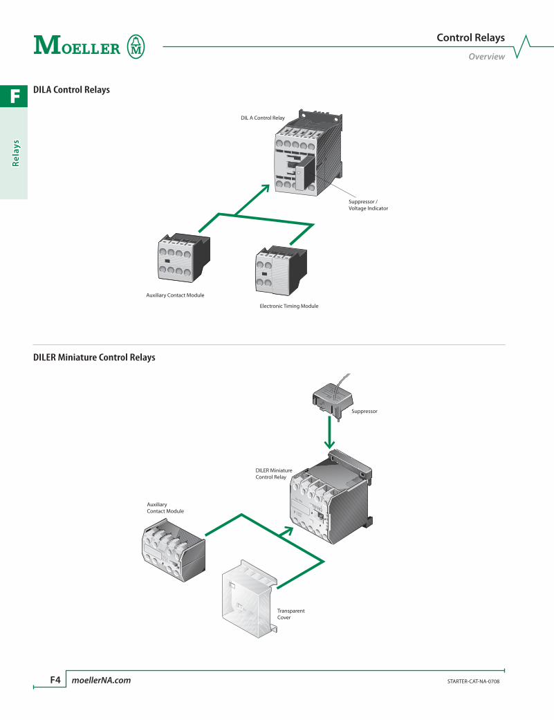
F
Rela
ys
F4 moellerNA.com STARTER-CAT-NA-0708
Control Relays
Overview
Suppressor
DILER MiniatureControl Relay
TransparentCover
AuxiliaryContact Module
DIL A Control Relay
Auxiliary Contact Module
Electronic Timing Module
Suppressor / Voltage Indicator
DILA Control Relays
DILER Miniature Control Relays

F
Relays
STARTER-CAT-NA-0708 moellerNA.com F5
Control Relays
Overview
Control Relays OverviewDevice Description Range Pages
Control Relays
Four-pole Control Relays
AC & DC 10 Amps
A600/P300F6 – F7
Miniature Control Relays
AC & DC 10 Amps
A600/P300F8 – F9
Auxiliary Contact Modules
For DILA Control Relays
10A @ 600V AC 1A @ 250V DC
A600/P300F10
For Miniature Control Relays
10A @ 600V AC 1A @ 250V DC
A600/P300F11
Suppressors
RC Suppressor 24 – 500V AC F12
Varistor Suppressor 24 – 500V AC F12
Free Wheel Diode Suppressor 12 – 250V DC F12
Device Description Range PagesVoltage Indicator
Voltage Indicator 24 – 250V DC F12
Amplifier Module
Amplifier Module 24V DC F12
Electronic Timing Modules
On-delay 24V DC 24 – 240V AC F13
Off-delay 24V DC 24 – 240V AC F13
Miscellaneous Accessories
Miscellaneous Accessories F13
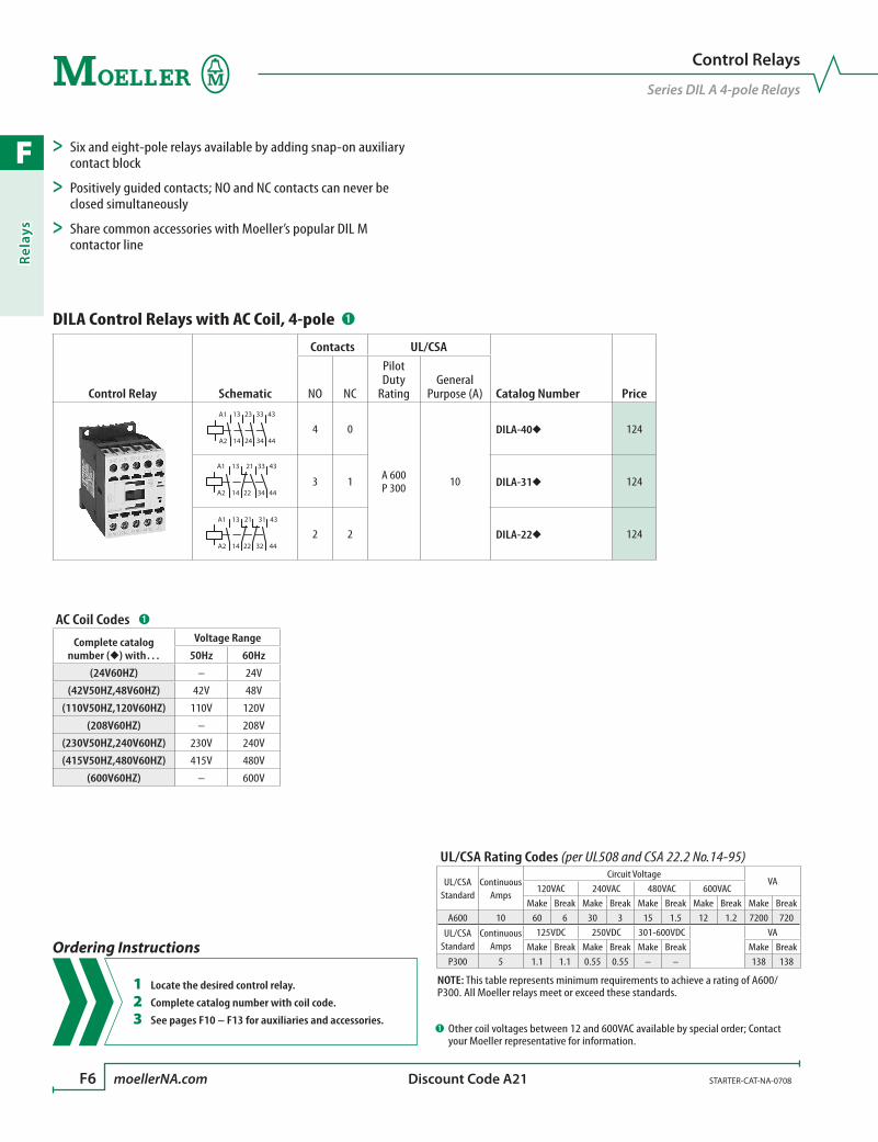
F
Rela
ys
F6 moellerNA.com STARTER-CAT-NA-0708 Discount Code A21
DILA Control Relays with AC Coil, 4-pole ➊
Control Relay Schematic
Contacts UL/CSA
Catalog Number PriceNO NC
Pilot Duty
RatingGeneral
Purpose (A)
14
13 33
34
43
44
A1
A2
23
24
4 0
A 600P 300 10
DILA-40u 124
14
13 21
22
33
34
43
44
A1
A23 1 DILA-31u 124
14
13 21
22
31
32
43
44
A1
A2
2 2 DILA-22u 124
AC Coil Codes ➊
Complete catalognumber (u) with…
Voltage Range
50Hz 60Hz
(24V60HZ) – 24V
(42V50HZ,48V60HZ) 42V 48V
(110V50HZ,120V60HZ) 110V 120V
(208V60HZ) – 208V
(230V50HZ,240V60HZ) 230V 240V
(415V50HZ,480V60HZ) 415V 480V
(600V60HZ) – 600V
UL/CSA Rating Codes (per UL508 and CSA 22.2 No.14-95)
UL/CSA Standard
Continuous Amps
Circuit VoltageVA
120VAC 240VAC 480VAC 600VACMake Break Make Break Make Break Make Break Make Break
A600 10 60 6 30 3 15 1.5 12 1.2 7200 720
UL/CSA Standard
Continuous Amps
125VDC 250VDC 301-600VDC VAMake Break Make Break Make Break Make Break
P300 5 1.1 1.1 0.55 0.55 – – 138 138
NOTE: This table represents minimum requirements to achieve a rating of A600/P300. All Moeller relays meet or exceed these standards.
➊ Other coil voltages between 12 and 600VAC available by special order; Contact your Moeller representative for information.
Control Relays
Series DIL A 4-pole Relays
> Six and eight-pole relays available by adding snap-on auxiliary contact block
> Positively guided contacts; NO and NC contacts can never be closed simultaneously
> Share common accessories with Moeller’s popular DIL M contactor line
Ordering Instructions
1 Locate the desired control relay.
2 Complete catalog number with coil code.
3 See pages F10 – F13 for auxiliaries and accessories.
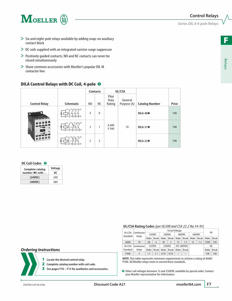
F
Relays
STARTER-CAT-NA-0708 moellerNA.com F7 Discount Code A21
DILA Control Relays with DC Coil, 4-pole ➊
Control Relay Schematic
Contacts UL/CSA
Catalog Number PriceNO NC
Pilot Duty
RatingGeneral
Purpose (A)
14
13 33
34
43
44
A1
A2
23
244 0
A 600P 300 10
DILA-40u 148
14
13 21
22
33
34
43
44
A1
A23 1 DILA-31u 148
14
13 21
22
31
32
43
44
A1
A22 2 DILA-22u 148
DC Coil Codes ➊
Complete catalog number (u) with…
Voltage
DC
(24VDC) 24V
(48VDC) 48V
UL/CSA Rating Codes (per UL508 and CSA 22.2 No.14-95)
UL/CSA Standard
Continuous Amps
Circuit VoltageVA
120VAC 240VAC 480VAC 600VACMake Break Make Break Make Break Make Break Make Break
A600 10 60 6 30 3 15 1.5 12 1.2 7200 720
UL/CSA Standard
Continuous Amps
125VDC 250VDC 301-600VDC VAMake Break Make Break Make Break Make Break
P300 5 1.1 1.1 0.55 0.55 – – 138 138
NOTE: This table represents minimum requirements to achieve a rating of A600/P300. All Moeller relays meet or exceed these standards.
➊ Other coil voltages between 12 and 250VDC available by special order; Contact your Moeller representative for information.
Control Relays
Series DIL A 4-pole Relays
> Six and eight-pole relays available by adding snap-on auxiliary contact block
> DC coils supplied with an integrated varistor surge suppressor
> Positively guided contacts; NO and NC contacts can never be closed simultaneously
> Share common accessories with Moeller’s popular DIL M contactor line
Ordering Instructions
1 Locate the desired control relay.
2 Complete catalog number with coil code.
3 See pages F10 – F13 for auxiliaries and accessories.
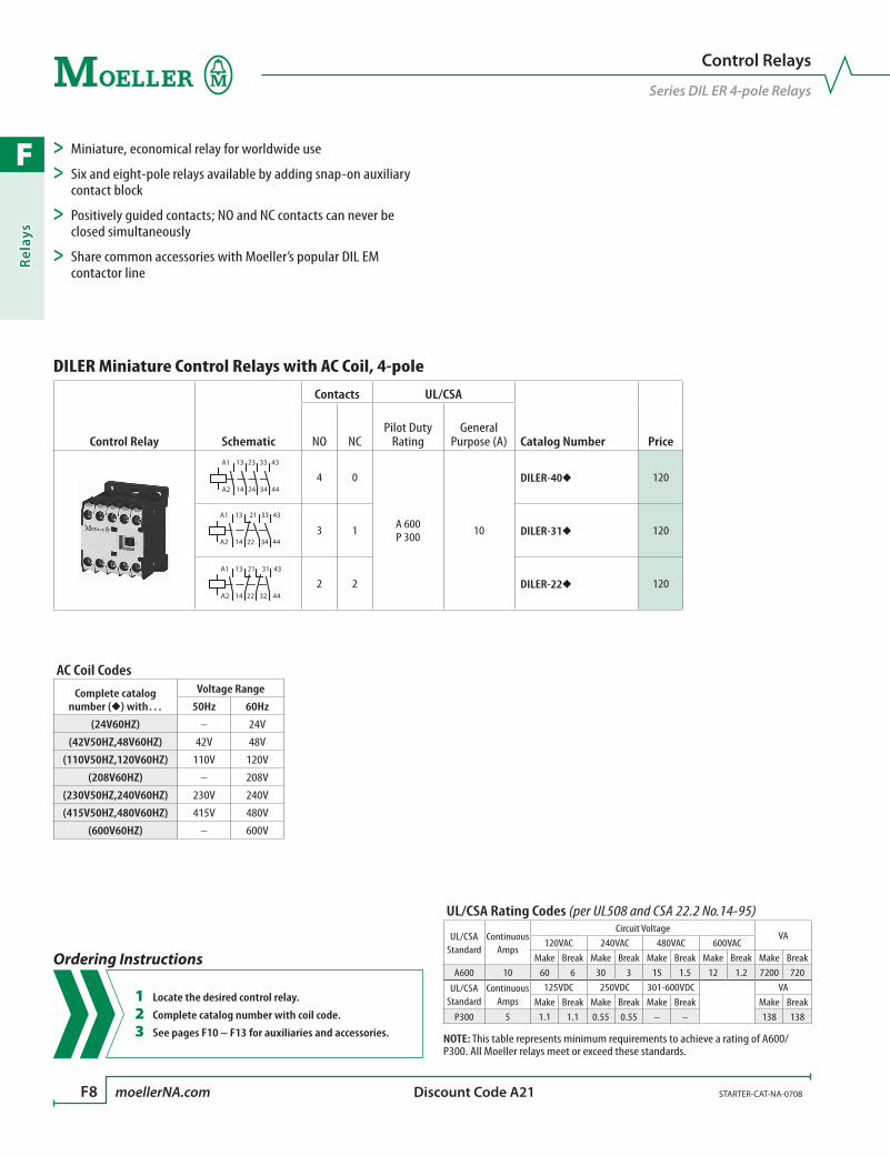
F
Rela
ys
F8 moellerNA.com STARTER-CAT-NA-0708 Discount Code A21
DILER Miniature Control Relays with AC Coil, 4-pole
Control Relay Schematic
Contacts UL/CSA
Catalog Number PriceNO NCPilot Duty
RatingGeneral
Purpose (A)
14
13 33
34
43
44
A1
A2
23
24
4 0
A 600P 300 10
DILER-40u 120
14
13 21
22
33
34
43
44
A1
A23 1 DILER-31u 120
14
13 21
22
31
32
43
44
A1
A2
2 2 DILER-22u 120
AC Coil Codes
Complete catalog number (u) with…
Voltage Range
50Hz 60Hz
(24V60HZ) – 24V
(42V50HZ,48V60HZ) 42V 48V
(110V50HZ,120V60HZ) 110V 120V
(208V60HZ) – 208V
(230V50HZ,240V60HZ) 230V 240V
(415V50HZ,480V60HZ) 415V 480V
(600V60HZ) – 600V
Control Relays
Series DIL ER 4-pole Relays
> Miniature, economical relay for worldwide use
> Six and eight-pole relays available by adding snap-on auxiliary contact block
> Positively guided contacts; NO and NC contacts can never be closed simultaneously
> Share common accessories with Moeller’s popular DIL EM contactor line
UL/CSA Rating Codes (per UL508 and CSA 22.2 No.14-95)
UL/CSA Standard
Continuous Amps
Circuit VoltageVA
120VAC 240VAC 480VAC 600VACMake Break Make Break Make Break Make Break Make Break
A600 10 60 6 30 3 15 1.5 12 1.2 7200 720
UL/CSA Standard
Continuous Amps
125VDC 250VDC 301-600VDC VAMake Break Make Break Make Break Make Break
P300 5 1.1 1.1 0.55 0.55 – – 138 138
NOTE: This table represents minimum requirements to achieve a rating of A600/P300. All Moeller relays meet or exceed these standards.
Ordering Instructions
1 Locate the desired control relay.
2 Complete catalog number with coil code.
3 See pages F10 – F13 for auxiliaries and accessories.
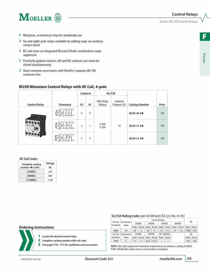
F
Relays
STARTER-CAT-NA-0708 moellerNA.com F9 Discount Code A21
DILER Miniature Control Relays with DC Coil, 4-pole
Control Relay Schematic
Contacts UL/CSA
Catalog Number PriceNO NCPilot Duty
RatingGeneral
Purpose (A)
14
13 33
34
43
44
A1
A2
23
24
+
–
4 0
A 600P 300 10
DILER-40-Gu 140
14
13 21
22
33
34
43
44
A1
A2
+
–
3 1 DILER-31-Gu 140
14
13 21
22
31
32
43
44
A1
A2
+
–
2 2 DILER-22-Gu 140
DC Coil Codes
Complete catalog number (u) with…
Voltage
DC
(24VDC) 24V
(48VDC) 48V
(110VDC) 110V
Control Relays
Series DIL ER 4-pole Relays
> Miniature, economical relay for worldwide use
> Six and eight-pole relays available by adding snap-on auxiliary contact block
> DC coils have an integrated Resistor/Diode combination surge suppressor
> Positively guided contacts; NO and NC contacts can never be closed simultaneously
> Share common accessories with Moeller’s popular DIL EM contactor line
UL/CSA Rating Codes (per UL508 and CSA 22.2 No.14-95)
UL/CSA Standard
Continuous Amps
Circuit VoltageVA
120VAC 240VAC 480VAC 600VACMake Break Make Break Make Break Make Break Make Break
A600 10 60 6 30 3 15 1.5 12 1.2 7200 720
UL/CSA Standard
Continuous Amps
125VDC 250VDC 301-600VDC VAMake Break Make Break Make Break Make Break
P300 5 1.1 1.1 0.55 0.55 – – 138 138
NOTE: This table represents minimum requirements to achieve a rating of A600/P300. All Moeller relays meet or exceed these standards.
Ordering Instructions
1 Locate the desired control relay.
2 Complete catalog number with coil code.
3 See pages F10 – F13 for auxiliaries and accessories.
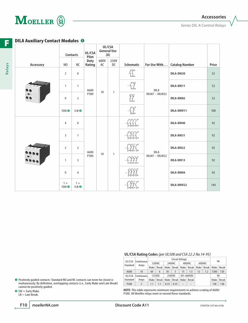
F
Rela
ys
F10 moellerNA.com STARTER-CAT-NA-0708 Discount Code A11
DILA Auxiliary Contact Modules ➊
Accessory
Contacts UL/CSA Pilot Duty
Rating
UL/CSA General Use
(A)
Schematic For Use With… Catalog Number PriceNO NC600V
AC250V
DC
2 0
A600P300 10 1
54
63
64
53
DILA DILM7 – DILM32
DILA-XHI20 52
1 154
53 61
62DILA-XHI11 52
0 251
52
61
62DILA-XHI02 52
1EM ➋ 1LB ➋58
57 65
66DILA-XHIV11 100
4 0
A600P300 10 1
54
63 73
64 74
53 83
84
DILA DILM7 – DILM32
DILA-XHI40 92
3 154
53 61
62
73
74
83
84DILA-XHI31 92
2 254
53 61
62
71
72
83
84DILA-XHI22 92
1 353 61 71 81
82726254DILA-XHI13 92
0 451
52
61
62
71
72 82
81
DILA-XHI04 92
1 + 1EM ➋
1 +1LB ➋ 58
57 65
66
71
72
83
84DILA-XHIV22 144
➊ Positively guided contacts: Standard NO and NC contacts can never be closed si-multaneously; By definition, overlapping contacts (i.e., Early Make and Late Break) cannot be positively guided.
➋ EM = Early Make. LB = Late Break.
Accessories
Series DIL A Control Relays
UL/CSA Rating Codes (per UL508 and CSA 22.2 No.14-95)
UL/CSA Standard
Continuous Amps
Circuit VoltageVA
120VAC 240VAC 480VAC 600VACMake Break Make Break Make Break Make Break Make Break
A600 10 60 6 30 3 15 1.5 12 1.2 7200 720
UL/CSA Standard
Continuous Amps
125VDC 250VDC 301-600VDC VAMake Break Make Break Make Break Make Break
P300 5 1.1 1.1 0.55 0.55 – – 138 138
NOTE: This table represents minimum requirements to achieve a rating of A600/P300. All Moeller relays meet or exceed these standards.
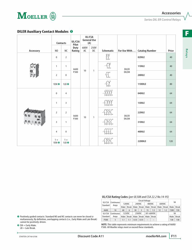
F
Relays
STARTER-CAT-NA-0708 moellerNA.com F11 Discount Code A11
➊ Positively guided contacts: Standard NO and NC contacts can never be closed si-multaneously; By definition, overlapping contacts (i.e., Early Make and Late Break) cannot be positively-driven.
➋ EM = Early Make. LB = Late Break.
DILER Auxiliary Contact Modules ➊
Accessory
Contacts UL/CSA Pilot Duty
Rating
UL/CSA General Use
(A)
Schematic For Use With… Catalog Number PriceNO NC600V
AC250V
DC
0 2
A600P300 10 1
51
52
61
62
DILER DILEM
02DILE 40
1 154
53 61
6211DILE 40
2 054
63
64
53
20DILE 40
1EM ➋ 1LB ➋58
57 65
6611DDILE 80
0 4
A600P300 10 1
51
52
61
62
71
72 82
81
DILER DILEM
04DILE 64
1 353 61 71 81
8272625413DILE 64
2 254
53 61
62
71
72
83
8422DILE 64
3 154
53 61
62
73
74
83
8431DILE 64
4 054
63 73
64 74
53 83
8440DILE 64
1 + 1EM ➋
1 +1LB ➋ 58
57 65
66
71
72
83
8422DDILE 120
Accessories
Series DIL ER Control Relays
UL/CSA Rating Codes (per UL508 and CSA 22.2 No.14-95)
UL/CSA Standard
Continuous Amps
Circuit VoltageVA
120VAC 240VAC 480VAC 600VACMake Break Make Break Make Break Make Break Make Break
A600 10 60 6 30 3 15 1.5 12 1.2 7200 720
UL/CSA Standard
Continuous Amps
125VDC 250VDC 301-600VDC VAMake Break Make Break Make Break Make Break
P300 5 1.1 1.1 0.55 0.55 – – 138 138
NOTE: This table represents minimum requirements to achieve a rating of A600/P300. All Moeller relays meet or exceed these standards.

F
Rela
ys
F12 moellerNA.com STARTER-CAT-NA-0708 Discount Code A11
Suppressors and Voltage Indicator ➊
Accessory Description Supply Voltage Schematic For use with… Catalog Number Price
RC Suppressors ➊
For AC operated relays (50-60 Hz).Please be aware that RC Suppres-sors can cause a drop-out delay.
24 – 48V AC A1
A2
DILER DILEM
RCDILE48 64
110 – 250V AC RCDILE250 64
For AC operated relays (50-60 Hz).DC operated relays have an integrated suppressor. Please be aware that Suppressors can cause a drop-out delay.
24 – 48V ACA1
A2
DILA DILM7 – 12
DILMP20
DILM12-XSPR48 90
110 – 240V AC DILM12-XSPR240 90
240 – 500V AC DILM12-XSPR500 90
Varistor Suppressors ➊
For AC operated Relays (50-60 Hz).DC operated Relays have an integrated suppressor.
24 – 48V AC
A2
A1
DILER DILEM
VGDILE48 56
110 – 250V AC VGDILE250 56
380 – 415V AC VGDILE415 56
For AC operated Relays (50-60 Hz).DC operated Relays have an integrated suppressor.
24 – 48V AC
A2
A1
DILA DILM7 – 12
DILMP20
DILM12-XSPV48 90
48 – 130V AC DILM12-XSPV130 90
130 – 240V AC DILM12-XSPV240 90
240 – 500V AC DILM12-XSPV500 90
Suppressor with LEDFor AC operated Relays (50-60 Hz).DC operated Relays have an integrated suppressor.
24 – 48V ACA1
A2
DILA DILM7 – 12
DILMP20
DILM12-XSPVL48 100
130 – 240V AC DILM12-XSPVL240 100
Free Wheel Diode Suppressor ➊
For DC operated Relays.Functions in addition to the built-in DC suppressor circuit. Prevents negative breaking voltage when relays are used with sensitive electronics.
12 – 250V DC
A1
A1 [+]
A2 [-]
DILA DILM7 – DILM12
DILMP20DILM12-XSPD 54
Voltage Indicator ➊
For DC operated Relays.Indicates presence of control voltage.
24 – 48V DCA1 [+]
A2 [-]
DILA DILM7 – 12
DILMP20
DILM12-XSPI48 70
48 – 130V DC DILM12-XSPI130 70
130 – 250V DC DILM12-XSPI250 70
Amplifier Module (separate mounting) ➊
DC operated Relays.Interposing relay that provides a dry contact signal to activate an AC operated Contactor or Relay; Actuates on as little as 25mA
24V DC[25mA…2A]
➋
13
14
21
22
When 24VDC low current [25mA…2A] control is required to operate AC coils ➋
ETS4-VS3 200
➊ Suppressors, voltage indicators and electronic timers cannot be mounted simulta-neously.
➋ When contactor AC coil is over 2A, use DILER or DILEM-G relay instead.
Accessories
Series DIL A & DIL ER Control Relays
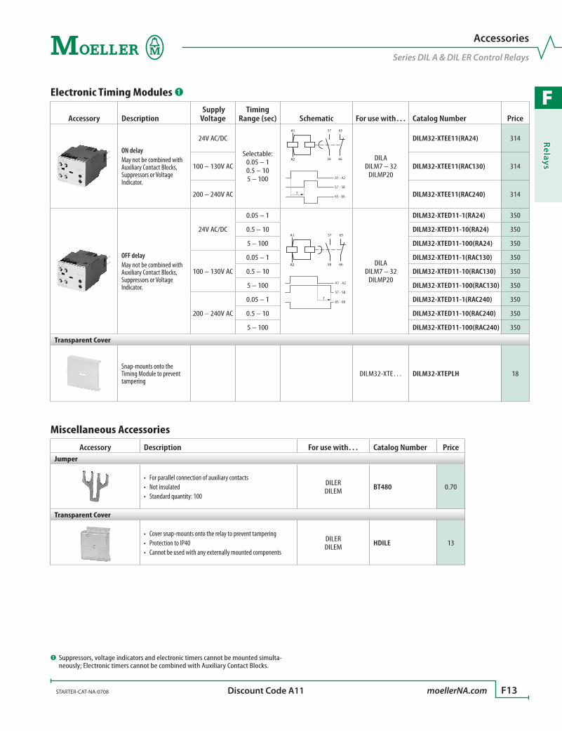
F
Relays
STARTER-CAT-NA-0708 moellerNA.com F13 Discount Code A11
Electronic Timing Modules ➊
Accessory Description Supply Voltage
Timing Range (sec) Schematic For use with… Catalog Number Price
ON delayMay not be combined with Auxiliary Contact Blocks, Suppressors or Voltage Indicator.
24V AC/DC
Selectable:0.05 – 10.5 – 105 – 100
57
58
65
66
A1
A2
t
57 - 58
65 - 66
A1 - A2
DILA DILM7 – 32
DILMP20
DILM32-XTEE11(RA24) 314
100 – 130V AC DILM32-XTEE11(RAC130) 314
200 – 240V AC DILM32-XTEE11(RAC240) 314
OFF delayMay not be combined with Auxiliary Contact Blocks, Suppressors or Voltage Indicator.
24V AC/DC
0.05 – 1
57
58
65
66
A1
A2
t
57 - 58
65 - 66
A1 - A2
DILA DILM7 – 32
DILMP20
DILM32-XTED11-1(RA24) 350
0.5 – 10 DILM32-XTED11-10(RA24) 350
5 – 100 DILM32-XTED11-100(RA24) 350
100 – 130V AC
0.05 – 1 DILM32-XTED11-1(RAC130) 350
0.5 – 10 DILM32-XTED11-10(RAC130) 350
5 – 100 DILM32-XTED11-100(RAC130) 350
200 – 240V AC
0.05 – 1 DILM32-XTED11-1(RAC240) 350
0.5 – 10 DILM32-XTED11-10(RAC240) 350
5 – 100 DILM32-XTED11-100(RAC240) 350
Transparent Cover
Snap-mounts onto the Timing Module to prevent tampering
DILM32-XTE… DILM32-XTEPLH 18
Miscellaneous Accessories
Accessory Description For use with… Catalog Number PriceJumper
For parallel connection of auxiliary contacts•Not insulated•Standard quantity: 100•
DILER DILEM BT480 0.70
Transparent Cover
Cover snap-mounts onto the relay to prevent tampering•Protection to IP40•Cannot be used with any externally mounted components•
DILER DILEM HDILE 13
➊ Suppressors, voltage indicators and electronic timers cannot be mounted simulta-neously; Electronic timers cannot be combined with Auxiliary Contact Blocks.
Accessories
Series DIL A & DIL ER Control Relays

F
Rela
ys
F14 moellerNA.com STARTER-CAT-NA-0708
DILA (AC-15)Component lifespan (operations) Ie = Rated operational current
AC-15
240 V
0.01 0.05 0.02 2 0.1 0.5 1 0.2 5 10 A
20
10
5
2
1
0.5
0.2
0.1
x 106
Ie
DILER (AC-15)Component lifespan (operations) Ie = Rated operational current
AC-15
240 V
0.01 0.05 0.02 2 0.1 0.5 1 0.2 5 10 A
20
10
5
2
1
0.5
0.2
0.1
x 106
Ie
➊ Making and breaking conditions to DC-13; time constant as stated on page F17.
Utilization Curves
DIL A & DIL ER Control Relays
0.01 0.05 0.02 2 0.1 0.5 1 0.2 5 10 A
20
10
5
2
1
0.5
0.2
0.1
X 106
L
R
DC-13
24 V
≈ 50 ms
Ie
DILA (DC-13) ➊Component lifespan (operations) Ie = Rated operational current

F
Relays
STARTER-CAT-NA-0708 moellerNA.com F15
Travel Diagrams for Control RelaysThe diagrams show the closing and opening of the auxiliary contacts of control relays and auxiliary contacts at no load. Tolerances are not taken into consideration.
Positively Guided ContactsBoth DIL A and DIL ER relays are designed with positively guided contacts. The break contact will not close if the make contact becomes welded.
➊
➌
➋➊
➌
➊ Break contact.➋ ≥0.25 mm with double-break contacts.➌ Make contact.
Travel Diagrams
DIL A & DIL ER Control Relays
DILA-... AC Relay
N/O Contact
4.5
4.53.30
0 1.0
N/C Contact
+ DILA-XHI... Auxiliary ContactN/O Contact
4.5
4.53.20
0 1.6
N/C Contact
+ DILA-XHIV... Auxiliary Contact (EM/LB)N/O Contact
4.5
4.52.00
0 2.8
N/C Contact
DILA-... DC Relay
N/O Contact
2.9
2.92.10
0 0.7
N/C Contact
+ DILA-XHI... Auxiliary ContactN/O Contact
2.9
2.92.30
0 0.7
N/C Contact
+ DILA-XHIV... Auxiliary Contact (EM/LB)N/O Contact
2.9
2.91.20
0 1.9
N/C Contact
DILER-... AC Relay
N/O Contact0 1,9 2,78 mm
0 0,95 2,78 mmN/C Contact
DILER-... DC Relay
N/O Contact0 1,9 2,85 mm
0 0,95 2,85 mm
N/C Contact
...DILE Auxiliary Contact
N/O Contact0 1,9 2,78 mm
0 0,89 2,78 mmN/C Contact
...DDILE Auxiliary Contact
N/O Contact (EM)0 1,06 2,88 mm
0 1,86 2,88 mm
0 1,9 2,78 mm
0 0,89 2,78 mm
N/C Contact (LB)
N/O Contact
N/C Contact

F
Rela
ys
F16 moellerNA.com STARTER-CAT-NA-0708
Control Relays DILA DILA-XHI DILER …(D)DILEGeneralStandards IEC/EN 60947, VDE 0660, UL, CSALifespan, mechanical AC operated Ops [x 106] 20 10 10 10 DC operated Ops [x 106] 20 10 20 20Maximum operating frequency Ops/h 9000 9000 9000 9000Climatic proofing Damp heat, constant to IEC 60068-2-78; Damp heat, cyclical, to IEC 60068-2-30Ambient temperature Open [°C]
[°F]-25…60 °C
-13…140 °F-25…60 °C
-13…140 °F-25…50 °C
-13…122 °F-25…50 °C
-13…122 °F Enclosed [°C]
[°F]-25…40 °C
-13…104 °F-25…40 °C
-13…104 °F-25…40 °C
-13…104 °F-25…40 °C
-13…104 °F Storage [°C]
[°F]-40…80 °C
-40…176 °F-40…80 °C
-40…176 °F––
––
Mounting position18
0˚90˚ 90˚ 90˚
30˚ As required, except vertically A1/A2
at the bottom
As required, except vertically A1/A2
at the bottom
Mechanical shock resistance (IEC/EN 60068-2-27) half-sinusoidal shock 10 ms Base unit with auxiliary contact module Make contact [g] 7 7 10 10 Break contact [g] 5 5 8 8Degree of protection IP20 IP20 IP20 IP20Protection against direct contact from the front (IEC 536) Finger and back-of-hand proofWeight AC operated [kg] 0.23 0.23 0.17 – DC operated [kg] 0.28 0.28 0.2 –Terminal capacity Solid [mm2] 1 x (0.75 – 4)
2 x (0.75 – 2.5)1 x (0.75 – 4)
2 x (0.75 – 2.5)1 x (0.75 – 2.5)2 x (0.75 – 2.5)
1 x (0.75 – 2.5)2 x (0.75 – 2.5)
Flexible with ferrule [mm2] 1 x (0.75 – 2.5)2 x (0.75 – 2.5)
1 x (0.75 – 2.5)2 x (0.75 – 2.5)
1 x (0.75 – 1.5)2 x (0.75 – 1.5)
1 x (0.75 – 1.5)2 x (0.75 – 1.5)
Solid or stranded [AWG] 18 – 14 18 – 14 18 – 14 18 – 14Terminal screw M3.5 M3.5 M3.5 M3.5Tightening torque [Nm] 1.2 1.2 1.2 1.2Tools Pozidriv screwdriver [Size] 2 2 2 2 Standard screwdriver [mm] 0.8 x 5.5 / 1 x 6 0.8 x 5.5 / 1 x 6 0.8 x 5.5 / 1 x 6 0.8 x 5.5 / 1 x 6
Technical Data
DIL A & DIL ER Control Relays
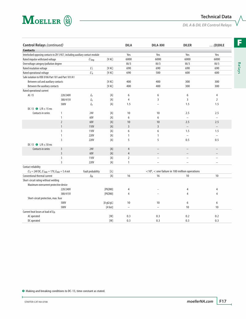
F
Relays
STARTER-CAT-NA-0708 moellerNA.com F17
Control Relays (continued) DILA DILA-XHI DILER …(D)DILEContactsInterlocked opposing contacts to ZH 1/457, including auxiliary contact module Yes Yes Yes YesRated impulse withstand voltage Uimp [V AC] 6000 6000 6000 6000Overvoltage category/pollution degree III/3 III/3 III/3 III/3Rated insulation voltage Ui [V AC] 690 690 690 690Rated operational voltage Ue [V AC] 690 500 600 600Safe isolation to VDE 0106 Part 101 and Part 101/A1 Between coil and auxiliary contacts [V AC] 400 400 300 300 Between the auxiliary contacts [V AC] 400 400 300 300Rated operational current AC-15 220/240V Ie [A] 6 6 6 4 380/415V Ie [A] 4 3 3 2 500V Ie [A] 1.5 – 1.5 1.5 DC-13 ➊ L/R ≤ 15 ms Contacts in series 1 24V [A] 10 10 2.5 2.5 1 60V [A] 6 6 – – 2 60V [A] 10 10 2.5 2.5 1 110V [A] 3 3 – – 3 110V [A] 6 6 1.5 1.5 1 220V [A] 1 1 – – 3 220V [A] 5 5 0.5 0.5 DC-13 ➊ L/R ≤ 50 ms Contacts in series 3 24V [A] 4 – – – 3 60V [A] 4 – – – 3 110V [A] 2 – – – 3 220V [A] 1 – – –Contact reliability Ue = 24V DC, Umin = 17V, Imin = 5.4 mA Fault probability [l] <108, < one failure in 100 million operationsConventional thermal current Ith [A] 16 16 10 10Short-circuit rating without welding Maximum overcurrent protective device 220/240V [PKZM0] 4 – 4 4 380/415V [PKZM0] 4 – 4 4 Short-circuit protection, max. fuse 500V [A gG/gL] 10 10 6 6 500V [A fast] – – 10 10Current heat losses at load of Ith AC operated [W] 0.3 0.3 0.2 0.2 DC operated [W] 0.3 0.3 0.3 0.3
➊ Making and breaking conditions to DC-13, time constant as stated.
Technical Data
DIL A & DIL ER Control Relays
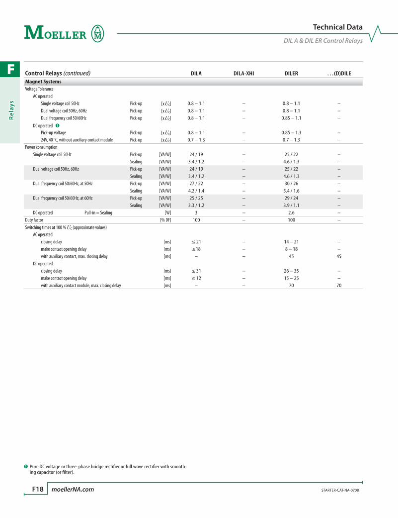
F
Rela
ys
F18 moellerNA.com STARTER-CAT-NA-0708
Control Relays (continued) DILA DILA-XHI DILER …(D)DILEMagnet SystemsVoltage Tolerance AC operated Single voltage coil 50Hz Pick-up [x Uc] 0.8 – 1.1 – 0.8 – 1.1 – Dual voltage coil 50Hz, 60Hz Pick-up [x Uc] 0.8 – 1.1 – 0.8 – 1.1 – Dual frequency coil 50/60Hz Pick-up [x Uc] 0.8 – 1.1 – 0.85 – 1.1 – DC operated ➊
Pick-up voltage Pick-up [x Uc] 0.8 – 1.1 – 0.85 – 1.3 – 24V, 40 °C, without auxiliary contact module Pick-up [x Uc] 0.7 – 1.3 – 0.7 – 1.3 –Power consumption Single voltage coil 50Hz Pick-up [VA/W] 24 / 19 – 25 / 22 – Sealing [VA/W] 3.4 / 1.2 – 4.6 / 1.3 – Dual voltage coil 50Hz, 60Hz Pick-up [VA/W] 24 / 19 – 25 / 22 – Sealing [VA/W] 3.4 / 1.2 – 4.6 / 1.3 – Dual frequency coil 50/60Hz, at 50Hz Pick-up [VA/W] 27 / 22 – 30 / 26 – Sealing [VA/W] 4.2 / 1.4 – 5.4 / 1.6 – Dual frequency coil 50/60Hz, at 60Hz Pick-up [VA/W] 25 / 25 – 29 / 24 – Sealing [VA/W] 3.3 / 1.2 – 3.9 / 1.1 – DC operated Pull-in = Sealing [W] 3 – 2.6 –Duty factor [% DF] 100 – 100 –Switching times at 100 % Uc (approximate values) AC operated closing delay [ms] ≤ 21 – 14 – 21 – make contact opening delay [ms] ≤18 – 8 – 18 – with auxiliary contact, max. closing delay [ms] – – 45 45 DC operated closing delay [ms] ≤ 31 – 26 – 35 – make contact opening delay [ms] ≤ 12 – 15 – 25 – with auxiliary contact module, max. closing delay [ms] – – 70 70
➊ Pure DC voltage or three-phase bridge rectifier or full wave rectifier with smooth-ing capacitor (or filter).
Technical Data
DIL A & DIL ER Control Relays
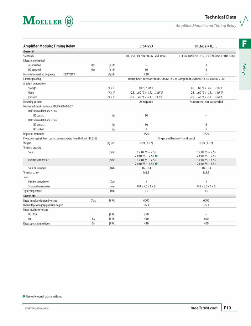
F
Relays
STARTER-CAT-NA-0708 moellerNA.com F19
Amplifier Module; Timing Relay ETS4-VS3 DILM32-XTE…GeneralStandards UL, CSA, IEC/EN 60947, VDE 0660 UL, CSA, DIN EN61812, IEC/EN 60947, VDE 0660Lifespan, mechanical AC operated Ops [x 106] – 3 DC operated Ops [x 106] 30 3Maximum operating frequency 220V/230V [Ops/h] 720 –Climatic proofing Damp heat, constant to IEC 60068-2-78; Damp heat, cyclical, to IEC 60068-2-30Ambient temperature Storage [°C / °F] 10 °C / 50 °F -40…80 °C / -40…176 °F Open [°C / °F] -25…60 °C / -13…140 °F -25…60 °C / -13…140 °F Enclosed [°C / °F] -25…45 °C / -13…113 °F -25…40 °C / -13…104 °FMounting position As required As required, not suspendedMechanical shock resistance (IEC/EN 60068-2-27) Half-sinusoidal shock 20 ms NO contact [g] 10 – Half-sinusoidal shock 10 ms NO contact [g] 10 6 NC contact [g] 8 6Degree of protection IP20 IP20Protection against direct contact when actuated from the front (IEC 536) Finger and back-of-hand proofWeight [kg (oz)] 0.09 (3.17) 0.09 (3.17)Terminal capacity Solid [mm2] 1 x (0.75 – 2.5)
2 x (0.75 – 2.5) ➊1 x (0.75 – 2.5)2 x (0.75 – 2.5)
Flexible with ferrule [mm2] 1 x (0.75 – 2.5)2 x (0.75 – 1.5) ➊
1 x (0.75 – 1.5)2 x (0.75 – 1.5)
Solid or stranded [AWG] 16 – 14 18 – 14Terminal screw M3.5 M3.5Tools Pozidriv screwdriver [Size] 2 2 Standard screwdriver [mm] 0.8 x 5.5 / 1 x 6 0.8 x 5.5 / 1 x 6Tightening torque [Nm] 1.2 1.2
ContactsRated impulse withstand voltage Uimp [V AC] 6000 6000Overvoltage category/pollution degree III/3 III/3Rated insulation voltage UL / CSA [V AC] 250 – IEC Ui [V AC] 440 600Rated operational voltage Ue [V AC] 440 400
➊ Use only equal cross sections.
Technical Data
Amplifier Module and Timing Relay

F
Rela
ys
F20 moellerNA.com STARTER-CAT-NA-0708
Amplifier Module; Timing Relay (continued) ETS4-VS3 DILM32-XTE…Contacts (continued)Rated operational current UL / CSA (general purpose) B300 Ie [A] 10 – AC-15 220/240V Ie [A] 2 contact Moeller 380/415V Ie [A] 2 contact Moeller DC-13 ➊ L/R - 15 ms Contacts in series 1 24V [A] 2.6 – 1 60V [A] 1 – 1 110V [A] 0.6 – 1 220V [A] 0.2 – DC-13 ➊ L/R - 50 ms Contacts in series 1 24V [A] 2 – 1 60V [A] 0.6 – 1 110V [A] 0.08 – 1 220V [A] 0.08 – DC-13 ➊ L/R - 300 ms Contacts in series 1 24V [A] 0.6 – 1 60V [A] 0.2 – 1 110V [A] 0.08 – 1 220V [A] 0.03 –Safe isolation to VDE 0106 Part 101 and Part 101/A1 Between coil and auxiliary contacts [V AC] – 250 Between the auxiliary contacts [V AC] – 250Control circuit reliability Ue = 24V DC, Umin = 17V, Imin = 5.4 mA Failure rate [l] <108, < one failure in 100 million operations –Conventional thermal current Ith [A] 6 6Component lifespan AC-15 Ie = 0.1 A 230V Ops [x 106] 7 – Ie = 1.2 A 230V Ops [ x 106] 1 –Short-circuit rating without welding Short-circuit protection, max. fuse 500V [A gG/gL] – 6 500V [A fast] 4 –
Magnet SystemsVoltage tolerance AC operated Pick-up [x Uc] – 0.8 – 1.1 DC operated Pick-up [x Uc] 0.85 – 1.2 0.7 – 1.2Power consumption AC operated Sealing [VA/W] – 2 / 1.8 DC operated Pull in = Sealing [W] 0.6 0Duty factor [% DF] 100 100Switching times at 100 % Uc (approximate values) DC operated closing delay [ms] 7 – DC operated opening delay [ms] 3 –Maximum operating frequency [Ops/h] – 3600 6A, 250V [Ops/h] 9000 360Minimum contact closing time On-delayed [ms] – < 50 Off-delayed [ms] – < 200Repetition accuracy (with constant parameters) Deviation [%] – < 5Recovery time (after 100% time delay) [ms] – 70Contact changeover time tu [ms] – 10
➊ Making and breaking conditions to DC-13, time constant as stated.
Technical Data
Amplifier Module and Timing Relay
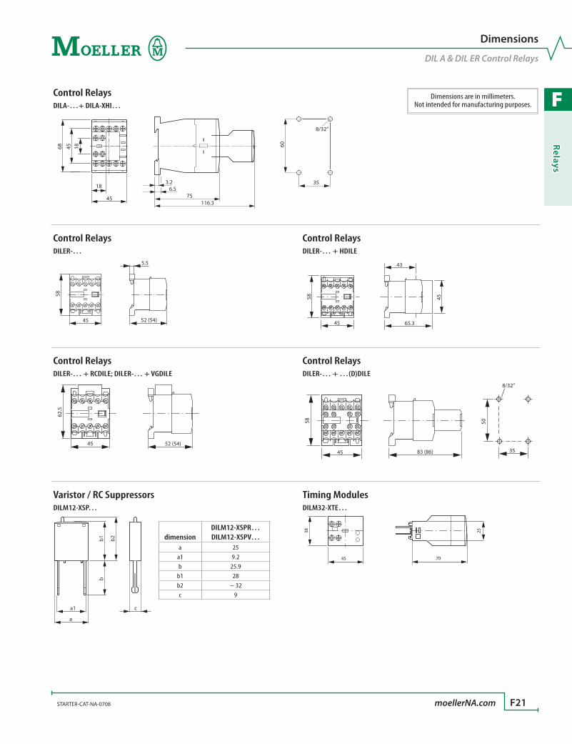
F
Relays
STARTER-CAT-NA-0708 moellerNA.com F21
Control RelaysDILA-…+ DILA-XHI…
184568
45
18 6.575
116.3
3.2
8/32”
60
35
Control Relays Control RelaysDILER-… DILER-… + HDILE
45
58
52 (54)
5.5
45
58
65.3
43
45
Control Relays Control RelaysDILER-… + RCDILE; DILER-… + VGDILE DILER-… + …(D)DILE
52 (54)45
62.5
45 83 (86)
58 50
35
8/32”
Varistor / RC Suppressors Timing ModulesDILM12-XSP… DILM32-XTE…
a1 c
a
b1 b2
b
45 70
38 25
Dimensions
DIL A & DIL ER Control Relays
dimensionDILM12-XSPR…DILM12-XSPV…
a 25a1 9.2b 25.9
b1 28b2 ~ 32c 9
Dimensions are in millimeters.Not intended for manufacturing purposes.
F
Rela
ys
F22 moellerNA.com STARTER-CAT-NA-0708
Relays
Notes
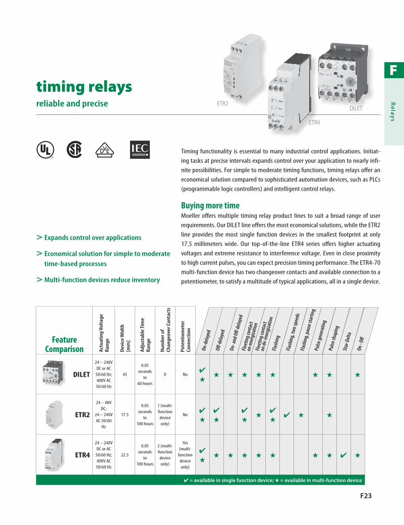
F
Relays
F23
> Expands control over applications
> Economical solution for simple to moderate time-based processes
> Multi-function devices reduce inventory
Timing functionality is essential to many industrial control applications. Initiat-ing tasks at precise intervals expands control over your application to nearly infi-nite possibilities. For simple to moderate timing functions, timing relays offer an economical solution compared to sophisticated automation devices, such as PLCs (programmable logic controllers) and intelligent control relays.
Buying more timeMoeller offers multiple timing relay product lines to suit a broad range of user requirements. Our DILET line offers the most economical solutions, while the ETR2 line provides the most single function devices in the smallest footprint at only 17.5 millimeters wide. Our top-of-the-line ETR4 series offers higher actuating voltages and extreme resistance to interference voltage. Even in close proximity to high current pulses, you can expect precision timing performance. The ETR4-70 multi-function device has two changeover contacts and available connection to a potentiometer, to satisfy a multitude of typical applications, all in a single device.
timing relaysreliable and precise
R
ETR2
ETR4
DILET
Feature Comparison Ac
tuat
ing
Volta
ge
Rang
e
Devi
ce W
idth
[m
m]
Adju
stab
le T
ime
Rang
e
Num
ber o
f Ch
ange
over
Con
tact
s
Pote
ntio
met
er
Conn
ectio
n
On-d
elaye
d
O-d
elaye
d
On- a
nd O
-de
layed
Fleet
ing c
onta
ct on
ener
giza
tion
Fleet
ing c
onta
ct on
de-e
nerg
izatio
nFla
shin
g
Flash
ing,
two s
peed
s
Pulse
gene
ratin
g
Flash
ing, p
ause
star
ting
Pulse
shap
ing
Star
-Delt
a
On - O
DILET
24 – 240V DC or AC
50/60 Hz;400V AC 50/60 Hz
45
0.05 seconds
to 60 hours
0 No
ETR2
24 – 48V DC;
24 – 240V AC 50/60
Hz
17.5
0.05 seconds
to 100 hours
1 (multi-function device only)
No
ETR4
24 – 240V DC or AC
50/60 Hz;400V AC 50/60 Hz
22.5
0.05 seconds
to 100 hours
2 (multi-function device only)
Yes (multi-
function device only)
= available in single function device; = available in multi-function device
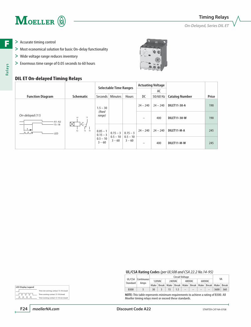
F
Rela
ys
F24 moellerNA.com STARTER-CAT-NA-0708 Discount Code A22
Timing Relays
On-Delayed, Series DIL ET
> Accurate timing control
> Most economical solution for basic On-delay functionality
> Wide voltage range reduces inventory
> Enormous time range of 0.05 seconds to 60 hours
DIL ET On-delayed Timing Relays
Function Diagram Schematic
Selectable Time RangesActuating Voltage
Catalog Number PriceDCAC
Seconds Minutes Hours 50/60 Hz
t
15–18
LED
A1–A2
On-delayed (11)A1
A2
15
16 18
1.5 – 30 (fixed range)
24 – 240 24 – 240 DILET11-30-A 190
– 400 DILET11-30-W 190
0.05 – 1 0.15 – 3 0.5 – 10 3 – 60
0.15 – 3 0.5 – 10 3 – 60
0.15 – 3 0.5 – 10 3 – 60
24 – 240 24 – 240 DILET11-M-A 245
– 400 DILET11-M-W 245
LED Display Legend
Time not running; contact 15-18 closed
Time running; contact 15-18 closed
Time running; contact 15-18 not closed
UL/CSA Rating Codes (per UL508 and CSA 22.2 No.14-95)
UL/CSA Standard
Continuous Amps
Circuit VoltageVA
120VAC 240VAC 480VAC 600VACMake Break Make Break Make Break Make Break Make Break
B300 5 30 3 15 1.5 – – – – 3600 360
NOTE: This table represents minimum requirements to achieve a rating of B300. All Moeller timing relays meet or exceed these standards.
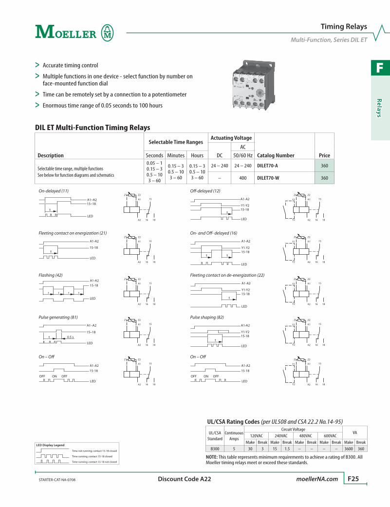
F
Relays
STARTER-CAT-NA-0708 moellerNA.com F25 Discount Code A22
Timing Relays
Multi-Function, Series DIL ET
DIL ET Multi-Function Timing Relays
Description
Selectable Time RangesActuating Voltage
Catalog Number PriceDCAC
Seconds Minutes Hours 50/60 Hz
Selectable time range, multiple functionsSee below for function diagrams and schematics
0.05 – 1 0.15 – 3 0.5 – 10 3 – 60
0.15 – 3 0.5 – 10 3 – 60
0.15 – 3 0.5 – 10 3 – 60
24 – 240 24 – 240 DILET70-A 360
– 400 DILET70-W 360
t
15–18
LED
A1–A2
On-delayed (11)
A1
A2
Z2Z1
15
16 18
O-delayed (12)
A1-A2
Y1-Y215-18
t
LED
A1
A2
Z2Z1
Y1
Y2
15
16 18
A1-A2
15-18t
LED
Fleeting contact on energization (21)
A1
A2
Z2Z1
15
16 18
On- and O- delayed (16)
A1-A2
Y1-Y215-18
tt
LED
A1
A2
Z2Z1
Y1
Y2
15
16 18
Flashing (42)
LED
ttt t
A1-A215-18 A1
A2
Z2Z1
15
16 18
Fleeting contact on de-energization (22)
A1-A2
Y1-Y215-18
t
LED
A1
A2
Z2Z1
Y1
Y2
15
16 18
Pulse generating (81)
0.5 st15–18
LED
A1–A2 A1
A2
Z2Z1
15
16 18
Pulse shaping (82)
A1-A2
Y1-Y215-18
t
LED
A1
A2
Z2Z1
Y1
Y2
15
16 18
On – O
A1-A215-18
OFFONOFF LED
A1
A2
Z2Z1
15
16 18
On – O
A1-A215-18
OFFONOFF LED
A1
A2
Z2Z1
Y1
Y2
15
16 18
> Accurate timing control
> Multiple functions in one device - select function by number on face-mounted function dial
> Time can be remotely set by a connection to a potentiometer
> Enormous time range of 0.05 seconds to 100 hours
LED Display Legend
Time not running; contact 15-18 closed
Time running; contact 15-18 closed
Time running; contact 15-18 not closed
UL/CSA Rating Codes (per UL508 and CSA 22.2 No.14-95)
UL/CSA Standard
Continuous Amps
Circuit VoltageVA
120VAC 240VAC 480VAC 600VACMake Break Make Break Make Break Make Break Make Break
B300 5 30 3 15 1.5 – – – – 3600 360
NOTE: This table represents minimum requirements to achieve a rating of B300. All Moeller timing relays meet or exceed these standards.
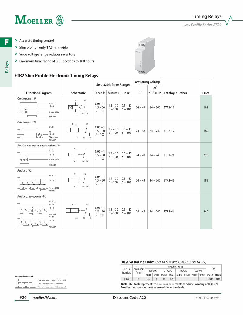
F
Rela
ys
F26 moellerNA.com STARTER-CAT-NA-0708 Discount Code A22
Timing Relays
Low Profile Series ETR2
> Accurate timing control
> Slim profile - only 17.5 mm wide
> Wide voltage range reduces inventory
> Enormous time range of 0.05 seconds to 100 hours
ETR2 Slim Profile Electronic Timing Relays
Function Diagram Schematic
Selectable Time RangesActuating Voltage
Catalog Number PriceDCAC
Seconds Minutes Hours 50/60 HzOn-delayed (11)
A1-A215-18
t
Rel LED
Power LED
A1
A2
15
16 18
0.05 – 1 1.5 – 30 5 – 100
1.5 – 30 5 – 100
0.5 – 10 5 – 100 24 – 48 24 – 240 ETR2-11 182
O-delayed (12)
Rel LED
A1-A2
B115-18tPower LED
A1
A2
B1 15
16 18
0.05 – 1 1.5 – 30 5 – 100
1.5 – 30 5 – 100
0.5 – 10 5 – 100 24 – 48 24 – 240 ETR2-12 182
Fleeting contact on energization (21)
A1-A2
15-18t
Rel LED
Power LED
A1
A2 16
15
18
0.05 – 1 1.5 – 30 5 – 100
1.5 – 30 5 – 100
0.5 – 10 5 – 100 24 – 48 24 – 240 ETR2-21 210
Flashing (42)
t t t t t
A1-A2
15-18
Power LEDRel LED
A1
A2 16
15
18
0.05 – 1 1.5 – 30 5 – 100
1.5 – 30 5 – 100
0.5 – 10 5 – 100 24 – 48 24 – 240 ETR2-42 182
Flashing, two speeds (44)
A1-B1
A1-A2
Rel LED
A1-B1
Rel LED
t1 t2 t2 t2
t2 t2 t2
t1t1
t1 t1t1
15-18
15-18
A1
A2
B1 15
16 18
0.05 – 1 1.5 – 30 5 – 100
1.5 – 30 5 – 100
0.5 – 10 5 – 100 24 – 48 24 – 240 ETR2-44 240
LED Display Legend
Time not running; contact 15-18 closed
Time running; contact 15-18 closed
Time running; contact 15-18 not closed
UL/CSA Rating Codes (per UL508 and CSA 22.2 No.14-95)
UL/CSA Standard
Continuous Amps
Circuit VoltageVA
120VAC 240VAC 480VAC 600VACMake Break Make Break Make Break Make Break Make Break
B300 5 30 3 15 1.5 – – – – 3600 360
NOTE: This table represents minimum requirements to achieve a rating of B300. All Moeller timing relays meet or exceed these standards.

F
Relays
STARTER-CAT-NA-0708 moellerNA.com F27 Discount Code A21
Timing Relays
Multi-Function, Low Profile Series ETR2
ETR2 Slim Profile Multi-Function Electronic Timing Relays
Description
Selectable Time RangesActuating Voltage
Catalog Number PriceDCAC
Seconds Minutes Hours 50/60 Hz
Selectable time range, multiple functionsSee below for function diagrams and schematics
0.05 – 1 1.5 – 30 5 – 100
1.5 – 30 5 – 100
0.5 – 10 5 – 100 24 – 48 24 – 240 ETR2-69 210
On-delayed (11)
A1-A215-18
t
Rel LED
Power LED
A1
A2 16
15
18
O-delayed (12)
Rel LED
A1-A2
B115-18tPower LED
A1
A2
B1 15
16 18
Fleeting contact on energization (21)
A1-A2
15-18t
Rel LED
Power LED
A1
A2 16
15
18
Fleeting contact on de-energization (22)
A1-A2
B115-18tPower LED
Rel LED
A1
A2
B1 15
16 18
Flashing (42)
t t t t t
A1-A2
15-18
Power LEDRel LED
A1
A2 16
15
18
Pulse shaping (82)
A1-A2
B115-18tPower LED
Rel LED
A1
A2
B1 15
16 18
Flashing, pause starting (43)
LED
ttt t
A1-A2
15-18t
A1
A2 16
15
18
> Accurate timing control
> Slim profile - only 17.5 mm wide
> Multiple functions in one device - select function by number on face-mounted function dial
> Enormous time range of 0.05 seconds to 100 hours
LED Display Legend
Time not running; contact 15-18 closed
Time running; contact 15-18 closed
Time running; contact 15-18 not closed
UL/CSA Rating Codes (per UL508 and CSA 22.2 No.14-95)
UL/CSA Standard
Continuous Amps
Circuit VoltageVA
120VAC 240VAC 480VAC 600VACMake Break Make Break Make Break Make Break Make Break
B300 5 30 3 15 1.5 – – – – 3600 360
NOTE: This table represents minimum requirements to achieve a rating of B300. All Moeller timing relays meet or exceed these standards.

F
Rela
ys
F28 moellerNA.com STARTER-CAT-NA-0708 Discount Code A22
Timing Relays
Series ETR4
> Accurate timing control
> High level of interference voltage resistance
> Time can be remotely set by a connection to a potentiometer
> Enormous time range of 0.05 seconds to 100 hours
ETR4 Single Function Electronic Timing Relays
Function Diagram Schematic
Selectable Time RangesActuating Voltage
Catalog Number PriceDCAC
Seconds Minutes Hours 50/60 Hz
Star-delta (51)
17-18
t tu
A1-A2
17-28
Power LED
LED LED
A1
A2 18
17
28
3 – 60 (fixed range)
24 – 240 24 – 240 ETR4-51-A 190
– 400 ETR4-51-W 200
On-delayed (11)
A1-A215-18
t
Rel LED
Power LED
A1
A2
15
16 18
0.05 – 1 0.15 – 3 0.5 – 10 1.5 – 30 5 – 100
15 – 300
1.5 – 30 15 – 300
1.5 – 30 5 – 100
24 – 240 24 – 240 ETR4-11-A 175
– 400 ETR4-11-W 185
LED Display Legend
Time not running; contact 15-18 closed
Time running; contact 15-18 closed
Time running; contact 15-18 not closed
UL/CSA Rating Codes (per UL508 and CSA 22.2 No.14-95)
UL/CSA Standard
Continuous Amps
Circuit VoltageVA
120VAC 240VAC 480VAC 600VACMake Break Make Break Make Break Make Break Make Break
B300 5 30 3 15 1.5 – – – – 3600 360
NOTE: This table represents minimum requirements to achieve a rating of B300. All Moeller timing relays meet or exceed these standards.
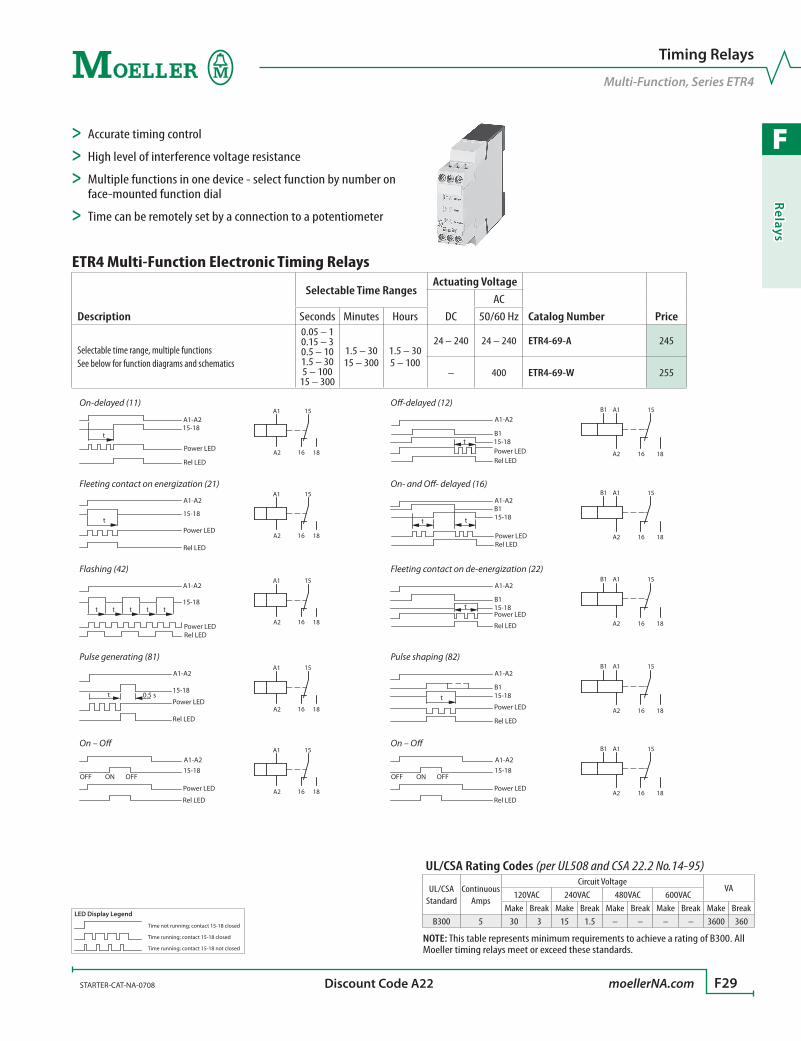
F
Relays
STARTER-CAT-NA-0708 moellerNA.com F29 Discount Code A22
Timing Relays
Multi-Function, Series ETR4
ETR4 Multi-Function Electronic Timing Relays
Description
Selectable Time RangesActuating Voltage
Catalog Number PriceDCAC
Seconds Minutes Hours 50/60 Hz
Selectable time range, multiple functionsSee below for function diagrams and schematics
0.05 – 1 0.15 – 3 0.5 – 10 1.5 – 30 5 – 100
15 – 300
1.5 – 30 15 – 300
1.5 – 30 5 – 100
24 – 240 24 – 240 ETR4-69-A 245
– 400 ETR4-69-W 255
On-delayed (11)
A1-A215-18
t
Rel LED
Power LED
A1
A2 16
15
18
O-delayed (12)
Rel LED
A1-A2
B115-18tPower LED
A1
A2
B1 15
16 18
Fleeting contact on energization (21)
A1-A2
15-18t
Rel LED
Power LED
A1
A2 16
15
18
On- and O- delayed (16)
A1-A2B115-18tt
Power LEDRel LED
A1
A2
B1 15
16 18
Flashing (42)
t t t t t
A1-A2
15-18
Power LEDRel LED
A1
A2 16
15
18
Fleeting contact on de-energization (22)
A1-A2
B115-18tPower LED
Rel LED
A1
A2
B1 15
16 18
Pulse generating (81)
t
A1-A2
15-180.5 s
Rel LED
Power LED
A1
A2 16
15
18
Pulse shaping (82)
A1-A2
B115-18tPower LED
Rel LED
A1
A2
B1 15
16 18
On – O
15-18A1-A2
OFFONOFF
Rel LED
Power LED
A1
A2 16
15
18
On – O
15-18A1-A2
OFFONOFF
Rel LED
Power LED
A1
A2
B1 15
16 18
> Accurate timing control
> High level of interference voltage resistance
> Multiple functions in one device - select function by number on face-mounted function dial
> Time can be remotely set by a connection to a potentiometer
LED Display Legend
Time not running; contact 15-18 closed
Time running; contact 15-18 closed
Time running; contact 15-18 not closed
UL/CSA Rating Codes (per UL508 and CSA 22.2 No.14-95)
UL/CSA Standard
Continuous Amps
Circuit VoltageVA
120VAC 240VAC 480VAC 600VACMake Break Make Break Make Break Make Break Make Break
B300 5 30 3 15 1.5 – – – – 3600 360
NOTE: This table represents minimum requirements to achieve a rating of B300. All Moeller timing relays meet or exceed these standards.
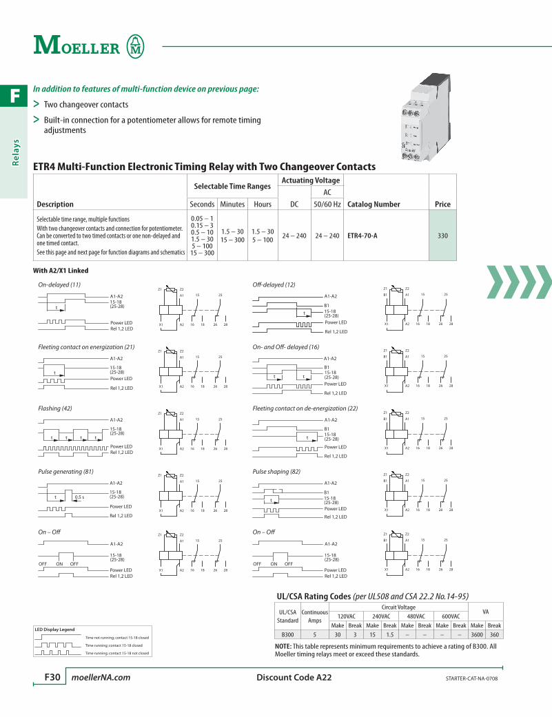
F
Rela
ys
F30 moellerNA.com STARTER-CAT-NA-0708 Discount Code A22
ETR4 Multi-Function Electronic Timing Relay with Two Changeover Contacts
Description
Selectable Time RangesActuating Voltage
Catalog Number PriceDCAC
Seconds Minutes Hours 50/60 Hz
Selectable time range, multiple functionsWith two changeover contacts and connection for potentiometer. Can be converted to two timed contacts or one non-delayed and one timed contact.See this page and next page for function diagrams and schematics
0.05 – 1 0.15 – 3 0.5 – 10 1.5 – 30 5 – 100
15 – 300
1.5 – 30 15 – 300
1.5 – 30 5 – 100 24 – 240 24 – 240 ETR4-70-A 330
With A2/X1 Linked
On-delayed (11)
(25-28)
A1-A215-18
t
Power LEDRel 1,2 LED
A1
A2X1
Z2Z1
15
16 18
25
26 28
O-delayed (12)
A1-A2
B115-18t (25-28)Power LED
Rel 1,2 LED
A1
A2X1
Z2Z1
15
16 18
25
26 28
B1
Fleeting contact on energization (21)
A1-A2
t (25-28)15-18
Rel 1,2 LED
Power LED
A1
A2X1
Z2Z1
15
16 18
25
26 28
On- and O- delayed (16)
A1-A2
B1
tt (25-28)15-18
Power LED
Rel 1,2 LED
A1
A2X1
Z2Z1
15
16 18
25
26 28
B1
Flashing (42)
A1-A2
15-18
t t t t(25-28)
Rel 1,2 LEDPower LED
A1
A2X1
Z2Z1
15
16 18
25
26 28
Fleeting contact on de-energization (22)
A1-A2
B1
t (25-28)15-18
Rel 1,2 LED
Power LED
A1
A2X1
Z2Z1
15
16 18
25
26 28
B1
Pulse generating (81)
15-18
A1-A2
0.5 st (25-28)
Rel 1,2 LED
Power LED
A1
A2X1
Z2Z1
15
16 18
25
26 28
Pulse shaping (82)
15-18
A1-A2
B1
t (25-28)
Rel 1,2 LED
Power LED
A1
A2X1
Z2Z1
15
16 18
25
26 28
B1
On – O
15-18(25-28)
A1-A2
Rel 1,2 LED
OFFONOFFPower LED
A1
A2X1
Z2Z1
15
16 18
25
26 28
On – O
15-18(25-28)
A1-A2
Rel 1,2 LED
OFFONOFFPower LED
A1
A2X1
Z2Z1
15
16 18
25
26 28
B1
In addition to features of multi-function device on previous page:
> Two changeover contacts
> Built-in connection for a potentiometer allows for remote timing adjustments
LED Display Legend
Time not running; contact 15-18 closed
Time running; contact 15-18 closed
Time running; contact 15-18 not closed
UL/CSA Rating Codes (per UL508 and CSA 22.2 No.14-95)
UL/CSA Standard
Continuous Amps
Circuit VoltageVA
120VAC 240VAC 480VAC 600VACMake Break Make Break Make Break Make Break Make Break
B300 5 30 3 15 1.5 – – – – 3600 360
NOTE: This table represents minimum requirements to achieve a rating of B300. All Moeller timing relays meet or exceed these standards.
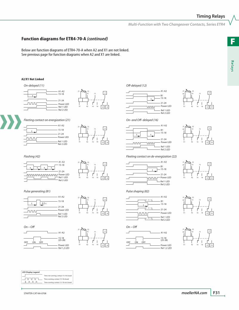
F
Relays
STARTER-CAT-NA-0708 moellerNA.com F31
Timing Relays
Multi-Function with Two Changeover Contacts, Series ETR4
A2/X1 Not Linked
On-delayed (11)
A1-A215-18
t
21-24
Power LEDRel 1 LEDRel 2 LED
A1
A2X1
Z1 Z215
16 18
21
22 24
O-delayed (12)
A1-A2
B115-18t
21-24Power LED
Rel 1 LEDRel 2 LED
A1
A2X1
Z1 Z2
15
16 18
21
22 24
B1
Fleeting contact on energization (21)
15-18t21-24
A1-A2
Rel 1 LED
Power LED
Rel 2 LED
A1
A2X1
Z1 Z215
16 18
21
22 24
On- and O- delayed (16)
A1-A2
B115-18
tt
21-24Power LED
Rel 1 LEDRel 2 LED
A1
A2X1
Z1 Z2
15
16 18
21
22 24
B1
Flashing (42)
15-18t t t t
21-24
A1-A2
Rel 2 LEDRel 1 LEDPower LED
A1
A2X1
Z1 Z215
16 18
21
22 24
Fleeting contact on de-energization (22)
A1-A2
B115-18t
21-24
Rel 1 LED
Power LED
Rel 2 LED
A1
A2X1
Z1 Z2
15
16 18
21
22 24
B1
Pulse generating (81)
A1-A2
15-180.5 st
21-24
Rel 1 LED
Power LED
Rel 2 LED
A1
A2X1
Z1 Z215
16 18
21
22 24
Pulse shaping (82)
B1
A1-A2
15-18t
21-24
Rel 1 LED
Power LED
Rel 2 LED
A1
A2X1
Z1 Z2
15
16 18
21
22 24
B1
On – O
15-18(25-28)
A1-A2
Rel 1,2 LED
OFFONOFFPower LED
A1
A2X1
Z1 Z215
16 18
21
22 24
On – O
15-18(25-28)
A1-A2
Rel 1,2 LED
OFFONOFFPower LED
A1
A2X1
Z1 Z2
15
16 18
21
22 24
B1
LED Display Legend
Time not running; contact 15-18 closed
Time running; contact 15-18 closed
Time running; contact 15-18 not closed
Function diagrams for ETR4-70-A (continued)
Below are function diagrams of ETR4-70-A when A2 and X1 are not linked. See previous page for function diagrams when A2 and X1 are linked.
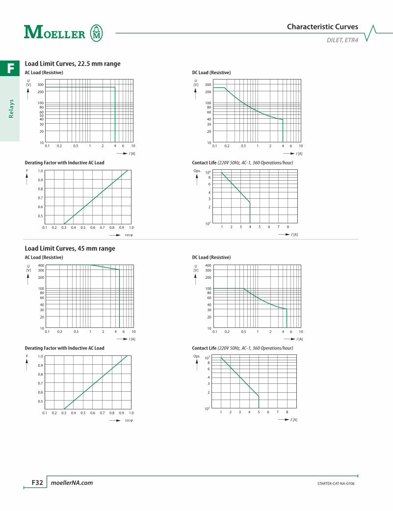
F
Rela
ys
F32 moellerNA.com STARTER-CAT-NA-0708
Characteristic Curves
DILET, ETR4
Load Limit Curves, 22.5 mm rangeAC Load (Resistive) DC Load (Resistive)
300
200
10
20
3040
6050
80100
0.1 0.2 0.5 1 2 4 6 10
[V]U
I [A]
300
200
10
20
3040
6080
100
0.1 0.2 0.5 1 2 4 6 10
I [A]
[V]U
Derating Factor with Inductive AC Load Contact Life (220V 50Hz, AC-1, 360 Operations/hour)
0.5
0.6
0.7
0.8
0.9
1.0
0.1 0.2 0.3 0.4 0.5 0.6 0.7 0.8 0.9 1.0
cos φ
F
I [A]
2
3
4
6
8
1 2 3 4 5 6 7 8105
106Ops.
Load Limit Curves, 45 mm rangeAC Load (Resistive) DC Load (Resistive)
400300
200
10
20
3040
6080
100
0.1 0.2 0.5 1 2 4 6 10
I [A]
[V]U 400
300
200
10
20
3040
6080
100
0.1 0.2 0.5 1 2 4 6 10
I [A]
[V]U
Derating Factor with Inductive AC Load Contact Life (220V 50Hz, AC-1, 360 Operations/hour)
0.5
0.6
0.7
0.8
0.9
1.0
0.1 0.2 0.3 0.4 0.5 0.6 0.7 0.8 0.9 1.0
cos φ
F
I [A]
2
3
4
6
8
1 2 3 4 5 6 7 8105
106Ops.

F
Relays
STARTER-CAT-NA-0708 moellerNA.com F33
Application Data
DILET
DILET (AC-11)Component lifespan (operations) Ie = Rated operational current
240 V
0.01 0.050.02 20.1 0.5 10.2 5 10 A
2010
5
21
0.5
0.20.1
x 106
Ie
AC-11
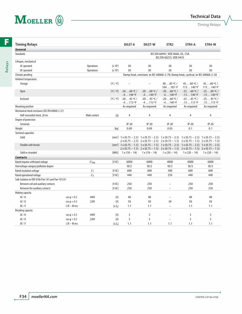
F
Rela
ys
F34 moellerNA.com STARTER-CAT-NA-0708
Technical Data
Timing Relays
Timing Relays DILET-A DILET-W ETR2 ETR4-A ETR4-WGeneralStandards IEC/EN 60947, VDE 0660, UL, CSA
IEC/EN 60255, VDE 0435Lifespan, mechanical AC operated Operations [x 106] 30 30 30 30 30 DC operated Operations [x 106] 30 30 30 30 30Climatic proofing Damp heat, constant, to IEC 60068-2-78; Damp heat, cyclical, to IEC 60068-2-30Ambient temperature Storage [ºC / ºF] – – 40…85 ºC /
104…185 ºF45…60 ºC / 113…140 ºF
45…60 ºC / 113…140 ºF
Open [ºC / ºF] -20…60 ºC / -4…140 ºF
-20…60 ºC / -4…140 ºF
-20…60 ºC / -4…140 ºF
-25…60 ºC / -13…140 ºF
-25…60 ºC / -13…140 ºF
Enclosed [ºC / ºF] -20…45 ºC / -4…113 ºF
-20…45 ºC / -4…113 ºF
-20…60 ºC / -4…140 ºF
-25…45 ºC / -13…113 ºF
-25…45 ºC / -13…113 ºF
Mounting position As required As required As required As required As requiredMechanical shock resistance (IEC/EN 60068-2-27) Half-sinusoidal shock, 20 ms Make contact [g] 4 4 4 4 4Degree of protection Terminals IP 20 IP 20 IP 20 IP 20 IP 20Weight [kg] 0.09 0.09 0.05 0.1 0.1Terminal capacities Solid [mm2] 1 x (0.75 – 2.5)
2 x (0.75 – 2.5)1 x (0.75 – 2.5) 2 x (0.75 – 2.5)
1 x (0.75 – 2.5) 2 x (0.75 – 1.5)
1 x (0.75 – 2.5) 2 x (0.75 – 1.5)
1 x (0.75 – 2.5) 2 x (0.75 – 1.5)
Flexible with ferrule [mm2] 1 x (0.75 – 1.5) 2 x (0.75 – 1.5)
1 x (0.75 – 1.5) 2 x (0.75 – 1.5)
1 x (0.75 – 2.5) 2 x (0.75 – 1.5)
1 x (0.75 – 2.5) 2 x (0.75 – 1.5)
1 x (0.75 – 2.5) 2 x (0.75 – 1.5)
Solid or stranded [AWG] 1 x (18 – 14) 1 x (18 – 14) 1 x (20 – 14) 1 x (20 – 14) 1 x (20 – 14)
ContactsRated impulse withstand voltage Uimp [V AC] 6000 6000 4000 6000 6000Overvoltage category/pollution degree III/2 III/2 III/3 III/3 III/3Rated insulation voltage Ui [V AC] 600 600 300 600 600Rated operational voltage Ue [V AC] 440 440 250 440 440Safe isolation to VDE 0106 Part 101 and Part 101/A1 Between coil and auxiliary contacts [V AC] 250 250 – 250 250 Between the auxiliary contacts [V AC] 250 250 – 250 250Making capacity AC-14 cos φ = 0.3 440V [A] 48 48 – 48 48 AC-15 cos φ = 0.3 220V [A] 50 50 30 50 50 DC-11 L/R – 40 ms [x Ie] 1.1 1.1 – 1.1 1.1Breaking capacity AC-14 cos φ = 0.3 440V [A] 3 3 – 3 3 AC-15 cos φ = 0.3 220V [A] 3 3 – 3 3 DC-11 L/R – 40 ms [x Ie] 1.1 1.1 1.1 1.1 1.1
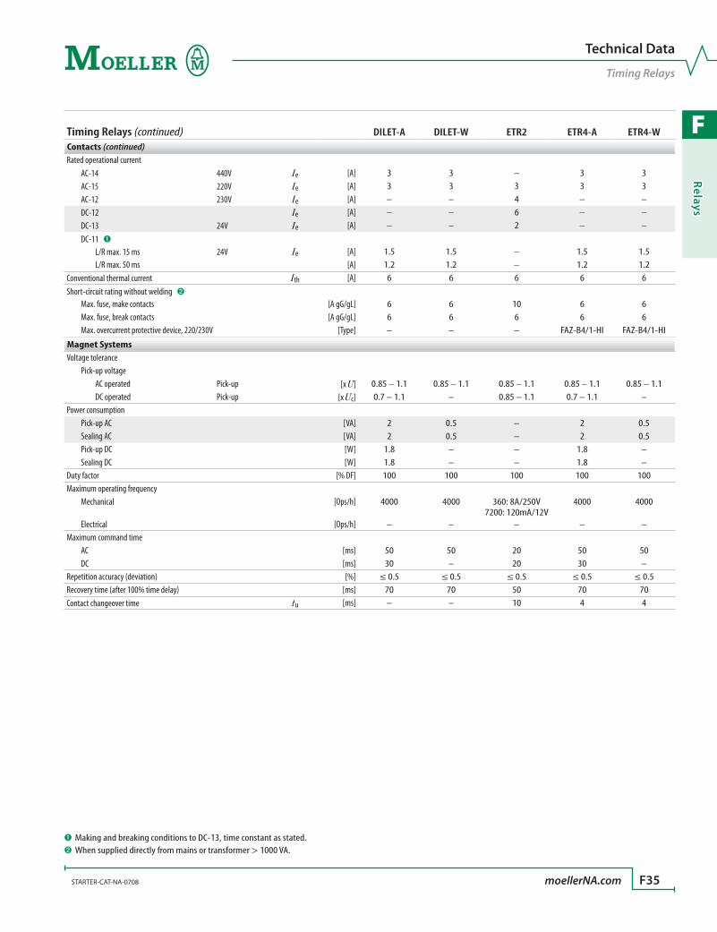
F
Relays
STARTER-CAT-NA-0708 moellerNA.com F35
Technical Data
Timing Relays
Timing Relays (continued) DILET-A DILET-W ETR2 ETR4-A ETR4-WContacts (continued)Rated operational current AC-14 440V Ie [A] 3 3 – 3 3 AC-15 220V Ie [A] 3 3 3 3 3 AC-12 230V Ie [A] – – 4 – – DC-12 Ie [A] – – 6 – – DC-13 24V Ie [A] – – 2 – – DC-11 ➊ L/R max. 15 ms 24V Ie [A] 1.5 1.5 – 1.5 1.5 L/R max. 50 ms [A] 1.2 1.2 – 1.2 1.2Conventional thermal current Ith [A] 6 6 6 6 6Short-circuit rating without welding ➋
Max. fuse, make contacts [A gG/gL] 6 6 10 6 6 Max. fuse, break contacts [A gG/gL] 6 6 6 6 6 Max. overcurrent protective device, 220/230V [Type] – – – FAZ-B4/1-HI FAZ-B4/1-HI
Magnet SystemsVoltage tolerance Pick-up voltage AC operated Pick-up [x U] 0.85 – 1.1 0.85 – 1.1 0.85 – 1.1 0.85 – 1.1 0.85 – 1.1 DC operated Pick-up [x Uc] 0.7 – 1.1 – 0.85 – 1.1 0.7 – 1.1 –Power consumption Pick-up AC [VA] 2 0.5 – 2 0.5 Sealing AC [VA] 2 0.5 – 2 0.5 Pick-up DC [W] 1.8 – – 1.8 – Sealing DC [W] 1.8 – – 1.8 –Duty factor [% DF] 100 100 100 100 100Maximum operating frequency Mechanical [Ops/h] 4000 4000 360: 8A/250V
7200: 120mA/12V4000 4000
Electrical [Ops/h] – – – – –Maximum command time AC [ms] 50 50 20 50 50 DC [ms] 30 – 20 30 –Repetition accuracy (deviation) [%] ≤ 0.5 ≤ 0.5 ≤ 0.5 ≤ 0.5 ≤ 0.5Recovery time (after 100% time delay) [ms] 70 70 50 70 70Contact changeover time tu [ms] – – 10 4 4
➊ Making and breaking conditions to DC-13, time constant as stated.➋ When supplied directly from mains or transformer > 1000 VA.

F
Rela
ys
F36 moellerNA.com STARTER-CAT-NA-0708
Dimensions
Timing Relays
Dimensions are in millimeters.Not intended for manufacturing purposes.
Electronic Timing RelaysDILET…
45
58
52
5.5
Electronic Timing RelaysDILET… with Sealable Shroud HDILE
65.3
43
45 50
35
M4
45
58
Electronic Timing Relays Electronic Timing RelaysETR2… ETR4…
17.5 5 43.4
58
70 45
10398
78
22.5
82.5
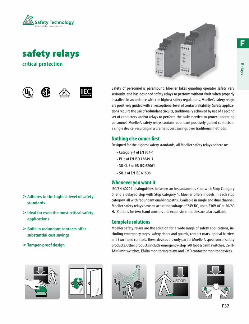
F
Relays
F37
> Adheres to the highest level of safety standards
> Ideal for even the most critical safety applications
> Built-in redundant contacts offer substantial cost savings
> Tamper-proof design
Safety of personnel is paramount. Moeller takes guarding operator safety very seriously, and has designed safety relays to perform without fault when properly installed. In accordance with the highest safety regulations, Moeller’s safety relays are positively guided with an exceptional level of contact reliability. Safety applica-tions require the use of redundant circuits, traditionally achieved by use of a second set of contactors and/or relays to perform the tasks needed to protect operating personnel. Moeller’s safety relays contain redundant positively guided contacts in a single device, resulting in a dramatic cost savings over traditional methods.
Nothing else comes firstDesigned for the highest safety standards, all Moeller safety relays adhere to:
Category 4 of EN 954-1•
PL e of EN ISO 13849-1•
SIL CL 3 of EN IEC 62061•
SIL 3 of EN IEC 61508•
Whenever you want itIEC/EN 60204 distinguishes between an instantaneous stop with Stop Category 0, and a delayed stop with Stop Category 1. Moeller offers models in each stop category, all with redundant enabling paths. Available in single and dual channel, Moeller safety relays have an actuating voltage of 24V DC, up to 230V AC at 50/60 Hz. Options for two-hand controls and expansion modules are also available.
Complete solutionsMoeller safety relays are the solution for a wide range of safety applications, in-cluding emergency stops, safety doors and guards, contact mats, optical barriers and two-hand controls. These devices are only part of Moeller’s spectrum of safety products. Other products include emergency-stop FAK foot & palm switches, LS-TI-TAN limit switches, EMR4 monitoring relays and CMD contactor monitor devices.
safety relayscritical protection
R

F
Rela
ys
F38 moellerNA.com STARTER-CAT-NA-0708 Discount Code A24
Safety Relays
Emergency Stop, Guard Monitoring, Two-Hand, Contact Expansion
Safety Relays
DescriptionCategory
(EN 954-1)
No. of enabling paths to Stop Category
(IEC/EN 60204)No. of
Signalling Contacts
Actuating Voltage
Catalog Number PriceDCAC
0 1 50/60 HzSingle Channel
Suitable for Emergency Stop or Protective Guard monitoring applications
2 3 – 1 24 24 ESR4-NO-31 595
2 3 – 1 – 115 ESR4-NO-31-115VAC 494
2 3 – 1 – 230 ESR4-NO-31-230VAC 494
Dual Channel - Without Delay
Suitable for Emergency Stop or Protective Guard monitoring applications
4 2 – 1 24 24 ESR4-NO-21 650
4 3 – – 24 24 ESR4-NO-30-24VAC-DC 720
4 3 – – – 115 ESR4-NO-30-115VAC 590
4 3 – – – 230 ESR4-NO-30-230VAC 676
Dual Channel - With Delay Option
Off-delayed; 0.15 – 3 seconds 4 (non-delayed) 3 (delayed) 2 1 – 24 – ESR4-NV3-30 1045
Off-delayed; 1.5 – 30 secondsSuitable for use with safety position switch with interlocking option, LS-S-…MT-ZBZ
4 (non-delayed) 3 (delayed) 2 1 – 24 – ESR4-NV30-30 1045
Dual Channel - Performance Level e (EN ISO 13849-1)
Safety integrity level 3 according to EN 61508Safety integrity level claim limit 3, according to EN 62061Approved for lifts according to EN 81-1 Approved for furnaces according to EN 50156-1 (Safety-level step 3)
4 3 – 1 24 24 ESR4-NOE-31-24VAC-DC 658
4 3 – 1 – 230 ESR4-NOE-31-230VAC 724
4 4 – – 24 24 ESR4-NOE-40-24VAC-DC 658
4 4 – – – 230 ESR4-NOE-40-230VAC 724
Two-hand Relay
Dual channel ➊ 2 – 1 24 24 ESR4-NZ-21 750
Contact Expansion Modules ➋
Without delay 4 4 – 2 24 24 ESR4-NE-42 550
Off-delayed; tA = 3 seconds 4 – 4 2 24 – ESR4-VE3-42 725
> Dual Channel relays offer up to EN 954-1 category 4 protection
> All Moeller safety relays contain redundant positively guided contacts in a single device
> Product available for both IEC/EN 60204 Stop Category 0 and Stop Category 1
➊ The base unit determines the maximum safety category.➋ The base unit determines the maximum stop category.
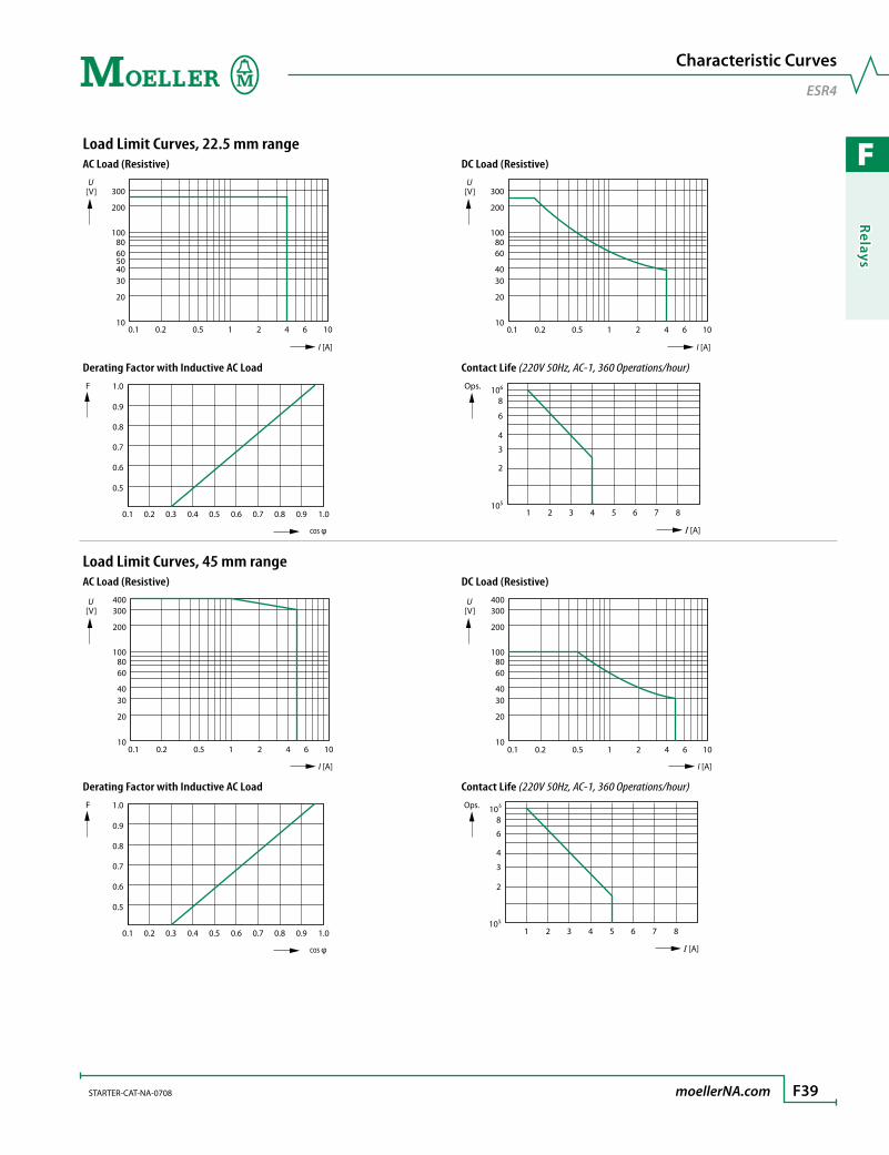
F
Relays
STARTER-CAT-NA-0708 moellerNA.com F39
Characteristic Curves
ESR4
Load Limit Curves, 22.5 mm rangeAC Load (Resistive) DC Load (Resistive)
300
200
10
20
3040
6050
80100
0.1 0.2 0.5 1 2 4 6 10
[V]U
I [A]
300
200
10
20
3040
6080
100
0.1 0.2 0.5 1 2 4 6 10
I [A]
[V]U
Derating Factor with Inductive AC Load Contact Life (220V 50Hz, AC-1, 360 Operations/hour)
0.5
0.6
0.7
0.8
0.9
1.0
0.1 0.2 0.3 0.4 0.5 0.6 0.7 0.8 0.9 1.0
cos φ
F
I [A]
2
3
4
6
8
1 2 3 4 5 6 7 8105
106Ops.
Load Limit Curves, 45 mm rangeAC Load (Resistive) DC Load (Resistive)
400300
200
10
20
3040
6080
100
0.1 0.2 0.5 1 2 4 6 10
I [A]
[V]U 400
300
200
10
20
3040
6080
100
0.1 0.2 0.5 1 2 4 6 10
I [A]
[V]U
Derating Factor with Inductive AC Load Contact Life (220V 50Hz, AC-1, 360 Operations/hour)
0.5
0.6
0.7
0.8
0.9
1.0
0.1 0.2 0.3 0.4 0.5 0.6 0.7 0.8 0.9 1.0
cos φ
F
I [A]
2
3
4
6
8
1 2 3 4 5 6 7 8105
106Ops.
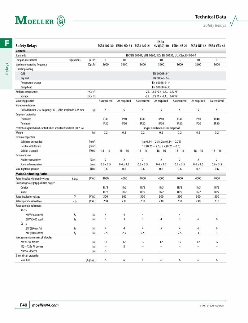
F
Rela
ys
F40 moellerNA.com STARTER-CAT-NA-0708
Technical Data
Safety Relays
Safety Relays ESR4-NO-30 ESR4-NO-31 ESR4-NO-21ESR4-
NV3(30)-30 ESR4-NZ-21 ESR4-NE-42 ESR4-VE3-42GeneralStandards IEC/EN 60947, VDE 0660, IEC/ EN 60255, UL, CSA, EN 954-1Lifespan, mechanical Operations [x 106] 1 10 10 10 10 10 10Maximum operating frequency [Ops/h] 3600 3600 3600 3600 3600 3600 3600Climatic proofing Cold EN 60068-2-1 Dry heat EN 60068-2-2 Temperature change EN 60068-2-14 Damp heat EN 60068-2-30Ambient temperature [ºC / ºF] -25…55 ºC / -13…131 ºF Storage [ºC / ºF] -25…75 ºC / -13…167 ºFMounting position As required As required As required As required As required As required As requiredVibration resistance To IEC/EN 60068-2-6; frequency: 10 – 55Hz; amplitude: 0.35 mm [g] 5 5 5 5 5 5 5Degree of protection Enclosures IP40 IP40 IP40 IP40 IP40 IP40 IP40 Terminals IP20 IP20 IP20 IP20 IP20 IP20 IP20Protection against direct contact when actuated from front (IEC 536) Finger and back-of-hand proofWeight [kg] 0.2 0.2 0.2 0.2 0.2 0.2 0.2Terminal capacities Solid core or stranded [mm2] 1 x (0.14 – 2.5); 2 x (0.14 – 0.75) Flexible with ferrule [mm2] 1 x (0.25 – 2.5); 2 x (0.25 – 0.5) Solid or stranded [AWG] 18 – 16 18 – 16 18 – 16 18 – 16 18 – 16 18 – 16 18 – 16Terminal screw Pozidriv screwdriver [Size] 2 2 2 2 2 2 2 Standard screwdriver [mm] 0.6 x 3.5 0.6 x 3.5 0.6 x 3.5 0.6 x 3.5 0.6 x 3.5 0.6 x 3.5 0.6 x 3.5Max. tightening torque [Nm] 0.6 0.6 0.6 0.6 0.6 0.6 0.6
Main Conducting PathsRated impulse withstand voltage Uimp [V AC] 4000 4000 4000 4000 4000 4000 4000Overvoltage category/pollution degree Outside III/3 III/3 III/3 III/3 III/3 III/3 III/3 Inside III/2 III/2 III/2 III/2 III/2 III/2 III/2Rated insulation voltage Ui [V AC] 300 300 300 300 300 300 300Rated operational voltage Ue [V AC] 230 230 230 230 230 230 230Rated operational current AC-15 230V (360 ops/h) Ie [A] 4 4 4 – 4 – – 230V (3600 ops/h) Ie [A] 3 3 3 4 3 6 6 DC-13 24V (360 ops/h) Ie [A] 4 4 4 5 4 6 6 24V (3600 ops/h) Ie [A] 2.5 2.5 2.5 – 2.5 3 3Max. summation current of all poles 24V AC/DC devices [A] 12 12 12 12 12 12 12 115 – 120V AC devices [A] – 8 – – – – – 230V AC devices [A] 8 – – – – – –Short-circuit protection Max. fuse [A gG/gL] 6 6 6 6 6 6 6

F
Relays
STARTER-CAT-NA-0708 moellerNA.com F41
Technical Data
Safety Relays
Safety Relays (continued) ESR4-NO-30 ESR4-NO-31 ESR4-NO-21ESR4-
NV3(30)-30 ESR4-NZ-21 ESR4-NE-42 ESR4-VE3-42Magnet SystemsActuating voltage, 50/60 Hz [V AC] 24, 115, 230 24, 115, 230 24 24 24 24 –Actuating voltage, DC Us [V DC] 24 24 24 24 24 24 24Voltage tolerance, Pick-up [x Ue] 0.85 – 1.1 0.85 – 1.1 0.85 – 1.1 0.85 – 1.1 0.85 – 1.1 0.85 – 1.1 0.85 – 1.1Power consumption AC operated, 50/60 Hz, 24V/230V [VA] 4.4 / 4.4 / 4.4 3.2 / 2.3 / 2.3 4.4 – 3.1 2.7 2.7 AC operated, 50/60 Hz, 24V/230V [W] 2.4 / 2.4 1.8 / 2.0 / 2.0 2.4 – 1.9 1.5 1.5 DC operated [W] 2.0 1.3 2.0 2.6 2.4 1 1
Control CircuitRated output voltage [V DC] ≤ 24 ≤ 24 ≤ 24 ≤ 24 ≤ 24 – –No-load voltage [V DC] ≤ 40 – – – – – –Rated current [mA] 40 40 50 50 60 – –Max. resistive load of the cable R [Ω] 70 70 70 70 70 – –Short-circuit current [A] 1 1.4 2.2 2.2 1 – –Fuse [W] Short-circuit
protected24V: PTC
resistance 230V: short-circuit proof transformer
PTC resistor PTC resistor PTC resistor – –
InputsRated current [mA] S12, S31, S32,
S33: 40; S34, S35: 5
Y2: 90; Y3: 1500
S12, S22, S31: 40;
S34, S35: 40
S12, S22, S31: 25;
S34, S35: 40
Y2: 60; Y11, Y21: 60
65 65
Response time with reset monitoring tA1 [ms] 20 – 40 40 (DC)180 (AC)
20 – 40 30 – – –
Response time without reset monitoring tA2 [ms] 200 – 600 40 200 – 500 700 40 20 20Reset time tR/tR1 [ms] < 2 > 60 < 25 25/adjustable < 50 40 500, 1000,
2000, 3000Minimum contact closing time tM [ms] > 80 > 60 > 50 200 – – 75Recovery time tW [ms] ≥ 100 < 200 ≥ 40 500 ≤ 250 – –Synchronous monitoring tS [ms] 200 – 200 > 100, < 500 ≤ 500 – –
Electromagnetic Compatibility (EMC)Emitted interference to EN 50081-1 and EN 50081-2Interference immunity EN 50082-2

F
Rela
ys
F42 moellerNA.com STARTER-CAT-NA-0708
Technical Data
Safety Relays
Safety Relays (continued) ESR4-NOE-31 ESR4-NOE-40GeneralStandards IEC/EN 60947, VDE 0660, IEC/EN 60255, UL, CSA, EN 81-1 EN 954-1 Category 4 prEN ISO 13849-1 PL e IEC/EN 62061 SILCL 3 IEC/EN 61508 SIL 3 EN 50156-1 Safety Level 3Lifespan, mechanical Operations [x 106] 10 10Maximum operating frequency [Ops/h] 3600 3600Climatic proofing Cold EN 60068-2-1 Dry heat EN 60068-2-2 Temperature change EN 60068-2-14 Damp heat EN 60068-2-30Ambient temperature [°C / °F] -25…65 ºC / -13…149 ºF -25…65 ºC / -13…149 ºF Storage [°C / °F] -25…70 ºC / -13…158 ºF -25…70 ºC / -13…158 ºFMounting position As required As requiredVibrations (IEC/EN 60068-2-6) 5 – 9 Hz: 1 g
9 – 150 Hz: 10 g5 – 9 Hz: 1 g
9 – 150 Hz: 10 gMechanical shock resistance (IEC 60068-2-27) 15 g, 11 ms 15 g, 11 msDegree of protection Enclosures IP40 IP40 Terminals IP 20 IP 20Protection against direct contact when actuated from front (IEC 536) Finger and back-of-hand proof Finger and back-of-hand proofWeight [kg] DC-device: 0.21
AC-device: 0.25DC-device: 0.21AC-device: 0.25
Terminal capacity screw terminals Solid core or stranded [mm2] 1 x (0.14 – 2.5); 2 x (0.14 – 0.75) 1 x (0.14 – 2.5); 2 x (0.14 – 0.75) Flexible with ferrule [mm2] 1 x (0.25 – 2.5); 2 x (0.25 – 0.5) 1 x (0.25 – 2.5); 2 x (0.25 – 0.5) Solid or stranded [AWG] 18 – 16 18 – 16Terminal screw Pozidriv screwdriver [Size] 2 2 Standard screwdriver [mm] 0.6 x 3.5 0.6 x 3.5Max. tightening torque [Nm] 0.6 0.6
Main Conducting PathsRated impulse withstand voltage Uimp [V AC] 4000 4000Overvoltage category/pollution degree Outside III/3 III/3 Inside III/2 III/2Rated insulation voltage Ui [V AC] 300 300Rated operational voltage Ue [V AC] 230 230Rated operational current AC-15, 230V (3600 ops/h) Ie [A] 5 5 DC-13, 24V (3600 ops/h) Ie [A] 5 5Max. summation current of all poles 24V AC/DC devices [A] 12 12 230V AC devices [A] 8 8Short-circuit protection Max. fuse [A gG/gL] 8 8

F
Relays
STARTER-CAT-NA-0708 moellerNA.com F43
Technical Data
Safety Relays
Safety Relays (continued) ESR4-NOE-31 ESR4-NOE-40Power Supply CircuitActuating voltage 50/60 Hz [V AC] 24, 230 24, 230Actuating voltage Us [V DC] 24 24Voltage tolerance, Pick-up [x Ue] 0.85 – 1.1 0.85 – 1.1Power consumption AC operated, 50/60Hz, 24V/230V [VA] 2.9 / 2.4 2.9 / 2.4 AC operated, 50/60Hz, 24V/230V [W] 1.6 / 2.1 1.6 / 2.1 DC operated [W] 1.6 / – 1.6 / –
Control CircuitRated output voltage [V DC] ≤ 24 ≤ 24No-load voltage [V DC] ≤ 40 ≤ 40Rated current [mA] S12, S52, S22: 25; S34: 5 S12, S52, S22: 25; S34: 5Peak current [mA] S12, S52, S22, S34: 100 S12, S52, S22, S34: 100Max. resistive load of the cable R [Ω] ≤ 25 ≤ 25Short-circuit current [A] 1 1Fuse 24V Electronic fuse Electronic fuse 115V/2320V Transformer TransformerResponse time [ms] 350 350Response time with reset monitoring tA1 [ms] 150 – 350 150 – 350Response time without reset monitoring tA2 [ms] 50 – 100 50 – 100Minimum contact closing time tM [ms] < 100 < 100
InputsResponse time with reset monitoring tA1 [ms] 150 – 350 150 – 350Response time without reset monitoring tA2 [ms] 50 – 100 50 – 100Permissible test pulse duration tTP [ms] ≤ 1 ≤ 1Minimum contact closing time tM [ms] < 100 < 100Recovery time tW [ms] Approx. ≤ 750 Approx. ≤ 750Reset time tR 10 10
Electromagnetic Compatibility (EMC)Emitted interference to EN 50081-1 and EN 50081-2 to EN 50081-1 and EN 50081-2Interference immunity EN 50082-2 EN 50082-2
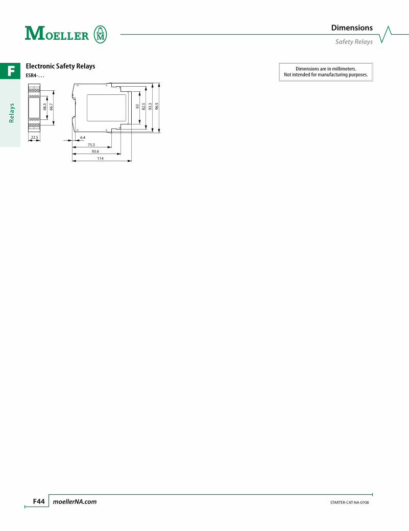
F
Rela
ys
F44 moellerNA.com STARTER-CAT-NA-0708
Dimensions
Safety Relays
Dimensions are in millimeters.Not intended for manufacturing purposes.
Electronic Safety RelaysESR4-…
6348.3
66.7
82.5
93.3
96.5
6.422.5
75.3
93.6
114
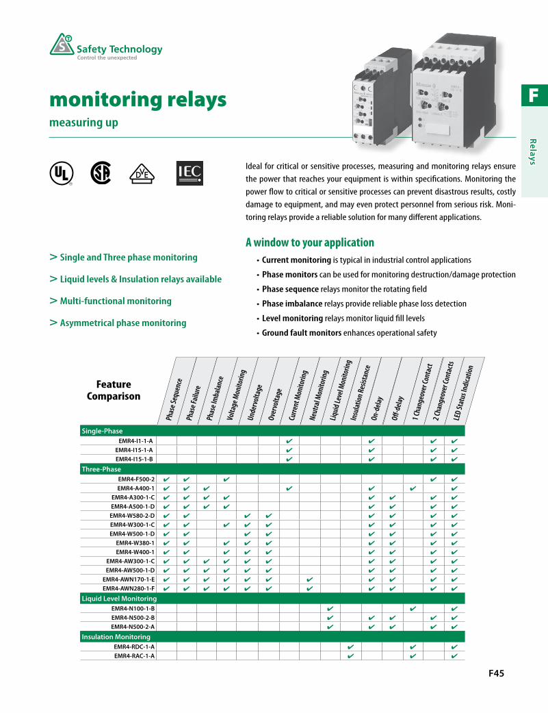
F
Relays
F45
> Single and Three phase monitoring
> Liquid levels & Insulation relays available
> Multi-functional monitoring
> Asymmetrical phase monitoring
Ideal for critical or sensitive processes, measuring and monitoring relays ensure the power that reaches your equipment is within specifications. Monitoring the power flow to critical or sensitive processes can prevent disastrous results, costly damage to equipment, and may even protect personnel from serious risk. Moni-toring relays provide a reliable solution for many different applications.
A window to your applicationCurrent monitoring• is typical in industrial control applications
Phase monitors• can be used for monitoring destruction/damage protection
Phase sequence• relays monitor the rotating field
Phase imbalance• relays provide reliable phase loss detection
Level monitoring• relays monitor liquid fill levels
Ground fault monitors• enhances operational safety
monitoring relaysmeasuring up
R
Feature Comparison
Phas
e Seq
uenc
ePh
ase F
ailur
ePh
ase I
mba
lance
Volta
ge M
onito
ring
Unde
rvolt
age
Over
volta
ge
Curre
nt M
onito
ring
Liqui
d Lev
el Mo
nito
ring
Neut
ral M
onito
ring
Insu
lation
Resis
tanc
eOn
-dela
y
O-d
elay
1 Cha
ngeo
ver C
onta
ct2 C
hang
eove
r Con
tacts
LED
Stat
us In
dica
tion
Single-PhaseEMR4-I1-1-A
EMR4-I15-1-A
EMR4-I15-1-B
Three-PhaseEMR4-F500-2
EMR4-A400-1
EMR4-A300-1-C
EMR4-A500-1-D
EMR4-W580-2-D
EMR4-W300-1-C
EMR4-W500-1-D
EMR4-W380-1
EMR4-W400-1
EMR4-AW300-1-C
EMR4-AW500-1-D
EMR4-AWN170-1-E
EMR4-AWN280-1-F
Liquid Level MonitoringEMR4-N100-1-B
EMR4-N500-2-B
EMR4-N500-2-A
Insulation MonitoringEMR4-RDC-1-A
EMR4-RAC-1-A

F
Rela
ys
F46 moellerNA.com STARTER-CAT-NA-0708 Discount Code A24
Monitoring Relays
Single-Phase, Three-Phase Sequence, Three-Phase Imbalance
Single-Phase Current Monitoring Relays
Description
Current Measuring
Range Contact Sequence
Supply Voltage
Catalog Number PriceDC ACSingle-Phase Current Monitoring
Switching hysteresis adjustable from 3 – 30%Response delay 0.1 – 30 secondsMonitoring of one upper or lower limitExtension of the measurement range possible with current transformers
3 – 30 mA10 – 100 mA
0.1 – 1 A
C
15 25B1 B2 B3
1816 26 28A1 A2
24 –240 24 –240 EMR4-I1-1-A 685
0.3 – 1.5 A1 – 5 A
3 – 15 A24 –240 24 –240 EMR4-I15-1-A 685
0.3 – 1.5 A1 – 5 A
3 – 15 A– 220 – 240 EMR4-I15-1-B 575
Three-Phase Sequence and Three-Phase Imbalance Monitoring Relays
Description Contact Sequence
Monitoring Voltage
Supply Voltage
Catalog Number PriceAC ACPhase Sequence Monitoring
Monitors three-phase systems for phase sequence and phase failure (< 0.6 x Ue)Supply voltage = voltage being monitored
15L1 L2 L3 11
1612 1814 2622 2824
2521
200 – 500 200 – 500 EMR4-F500-2 325
Phase Imbalance Monitoring
Monitors three-phase systems for phase imbalanceDetects phase failure even at 95% regeneration of the failed phaseResponse delay: 0.5 secondsSwitching threshold adjustable from 5 –15 % imbalancePhase sequence detectionSupply voltage = voltage being monitored
L1 L2 L3 15
16 18
380 – 415 50Hz
380 – 415 50Hz EMR4-A400-1 510
15 25L1 L2 L3
1816 26 28
160 – 300 50Hz
160 – 300 50Hz EMR4-A300-1-C 538
300 – 500 50Hz
300 – 500 50Hz EMR4-A500-1-D 538
> Ideal for critical or sensitive processes and equipment
> Available for single-phase and three-phase monitoring
> Delay available to prevent nuisance tripping
Ordering Instructions
1 Locate the desired monitoring relay.
2 See page F49 for auxiliaries and accessories.

F
Relays
STARTER-CAT-NA-0708 moellerNA.com F47 Discount Code A24
Monitoring Relays
Three-Phase with Undervoltage and Overvoltage Thresholds
Three-Phase Monitoring Relays with Undervoltage and Overvoltage Thresholds
Description Contact Sequence Threshold Value
Monitoring Voltage
Supply Voltage
Catalog Number Price50/60 Hz AC 50/60 Hz ACPhase Sequence Monitoring
Monitors Three-Phase:Phase Sequence•Phase Failure•Overvoltage•Undervoltage•Asymmetry: 2 – 15 %•
On-delay or Off-delay: 0.1 – 10 seconds
15 25L1 L2 L3
1816 26 28A1 A2
Umin 350 – 430 V ACUmax 500 – 580 V AC 300 – 500 300 – 500 EMR4-W580-2-D 630
15 25L1 L2 L3
1816 26 28
Umin 160 – 220 V ACUmax 220 – 300 V AC 160 – 300 160 – 300 EMR4-W300-1-C 578
Umin 300 – 380 V ACUmax 420 – 500 V AC 300 – 500 300 – 500 EMR4-W500-1-D 578
Umin 342 V AC (fixed)Umax 418 V AC (fixed) 380 380 EMR4-W380-1 465
Umin 360 V AC (fixed)Umax 440 V AC (fixed) 400 400 EMR4-W400-1 465
Phase Imbalance Monitoring
Monitors Three-Phase:Phase Sequence•Phase Failure•Overvoltage•Undervoltage•Asymmetry: 2 – 15 %•
On-delay or Off-delay: 0.1 – 10 secondsPower supply from the measuring circuit
15 25L1 L2 L3
1816 26 28
Umin 160 – 220 V ACUmax 220 – 300 V AC 160 – 300 160 – 300 EMR4-AW300-1-C 585
Umin 300 – 380 V ACUmax 420 – 500 V AC 300 – 500 300 – 500 EMR4-AW500-1-D 670
In addition to above:Neutral monitoring
15 25L1 L2 L3
1816N 26 28
Umin 90 – 120 V ACUmax 120 – 170 V AC 90 – 170 90 – 170 EMR4-AWN170-1-E 610
Umin 180 – 220 V ACUmax 240 – 280 V AC 180 – 280 180 – 280 EMR4-AWN280-1-F 610
> Ideal for critical or sensitive processes and equipment
> Three-phase monitoring includes undervoltage and overvoltage thresholds
> Adjustable delay setting to prevent nuisance tripping
Ordering Instructions
1 Locate the desired monitoring relay.
2 See page F49 for auxiliaries and accessories.

F
Rela
ys
F48 moellerNA.com STARTER-CAT-NA-0708 Discount Code A24
Monitoring Relays
Liquid Levels, Insulation
Liquid Level Monitoring Relays
Description
Response Sensitivity
Range Contact Sequence
Supply Voltage
Catalog Number PriceDC ACLiquid Level Monitoring
Monitors the level of conductive liquidsMonitors the ratio of mixtures of conductive liquidsDual-voltage protection against running dry or overflow
5 kΩ – 100 kΩ
15C MAX MIN
1816A1 A2
– 220 – 240 EMR4-N100-1-B 298
Monitors the level of conductive liquidsMonitors the ratio of mixtures of conductive liquidsSelectable On-delay or Off-delay: 0.5 – 10 seconds
250 Ω – 500 kΩ 15 25C
1816 26 28A1 A2
MAX MIN – 220 – 240 EMR4-N500-2-B 420
250 Ω – 500 kΩ 24 – 240 24 – 240 EMR4-N500-2-A 590
Insulation Monitoring Relays
Description
Insulation Resistance
Range Contact Sequence
Supply Voltage
Catalog Number PriceDC ACInsulation Monitoring - DC
Monitors the insulation resistance in non-earthed DC supply systemsSelector switch between open-circuit or closed circuit principleWith test and reset functionsStatus indication with LEDs
10 kΩ – 110 kΩ
15L+
R <
L–
1816A1 A2
24 – 240 24 – 240 EMR4-RDC-1-A 825
Insulation Monitoring - AC
Monitors the insulation resistance between non-earthed AC supply systems and protective conductor/earthTripping function memoryInsulation monitoring in Single and Three Phase AC supply systemsTest with local test button or by remote test operationStatus indication with LEDs to VDE 0413/Part 2
1 kΩ – 110 kΩ
15L
R <
1816A1 A2
24 – 240 24 – 240 EMR4-RAC-1-A 640
> Ideal for critical or sensitive processes and equipment
> Delay available to prevent nuisance tripping
> Available with one or two changeover contacts
> LED status indication
Ordering Instructions
1 Locate the desired monitoring relay.
2 See page F49 for auxiliaries and accessories.
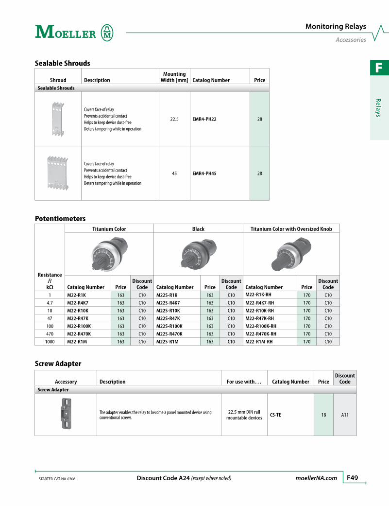
F
Relays
STARTER-CAT-NA-0708 moellerNA.com F49 Discount Code A24 (except where noted)
Monitoring Relays
Accessories
Sealable Shrouds
Shroud DescriptionMounting
Width [mm] Catalog Number PriceSealable Shrouds
Covers face of relayPrevents accidental contactHelps to keep device dust-freeDeters tampering while in operation
22.5 EMR4-PH22 28
Covers face of relayPrevents accidental contactHelps to keep device dust-freeDeters tampering while in operation
45 EMR4-PH45 28
Potentiometers
Resistance R
kΩ
Titanium Color Black Titanium Color with Oversized Knob
Catalog Number PriceDiscount
Code Catalog Number PriceDiscount
Code Catalog Number PriceDiscount
Code1 M22-R1K 163 C10 M22S-R1K 163 C10 M22-R1K-RH 170 C10
4.7 M22-R4K7 163 C10 M22S-R4K7 163 C10 M22-R4K7-RH 170 C10
10 M22-R10K 163 C10 M22S-R10K 163 C10 M22-R10K-RH 170 C10
47 M22-R47K 163 C10 M22S-R47K 163 C10 M22-R47K-RH 170 C10
100 M22-R100K 163 C10 M22S-R100K 163 C10 M22-R100K-RH 170 C10
470 M22-R470K 163 C10 M22S-R470K 163 C10 M22-R470K-RH 170 C10
1000 M22-R1M 163 C10 M22S-R1M 163 C10 M22-R1M-RH 170 C10
Screw Adapter
Accessory Description For use with… Catalog Number PriceDiscount
CodeScrew Adapter
The adapter enables the relay to become a panel mounted device using conventional screws.
22.5 mm DIN rail mountable devices CS-TE 18 A11

F
Rela
ys
F50 moellerNA.com STARTER-CAT-NA-0708
Characteristic Curves
EMR4
Load Limit Curves, 22.5 mm rangeAC Load (Resistive) DC Load (Resistive)
300
200
10
20
3040
6050
80100
0.1 0.2 0.5 1 2 4 6 10
[V]U
I [A]
300
200
10
20
3040
6080
100
0.1 0.2 0.5 1 2 4 6 10
I [A]
[V]U
Derating Factor with Inductive AC Load Contact Life (220V 50Hz, AC-1, 360 Operations/hour)
0.5
0.6
0.7
0.8
0.9
1.0
0.1 0.2 0.3 0.4 0.5 0.6 0.7 0.8 0.9 1.0
cos φ
F
I [A]
2
3
4
6
8
1 2 3 4 5 6 7 8105
106Ops.
Load Limit Curves, 45 mm rangeAC Load (Resistive) DC Load (Resistive)
400300
200
10
20
3040
6080
100
0.1 0.2 0.5 1 2 4 6 10
I [A]
[V]U 400
300
200
10
20
3040
6080
100
0.1 0.2 0.5 1 2 4 6 10
I [A]
[V]U
Derating Factor with Inductive AC Load Contact Life (220V 50Hz, AC-1, 360 Operations/hour)
0.5
0.6
0.7
0.8
0.9
1.0
0.1 0.2 0.3 0.4 0.5 0.6 0.7 0.8 0.9 1.0
cos φ
F
I [A]
2
3
4
6
8
1 2 3 4 5 6 7 8105
106Ops.
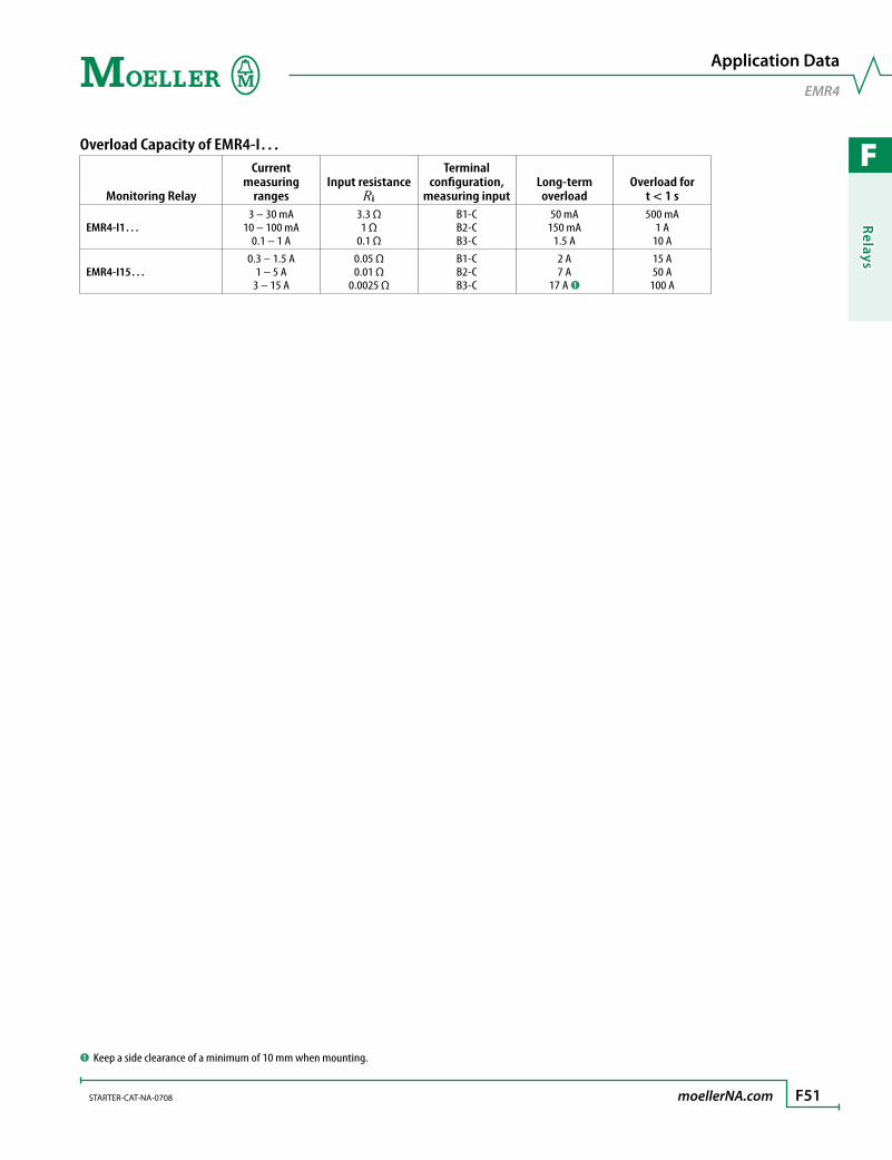
F
Relays
STARTER-CAT-NA-0708 moellerNA.com F51
Application Data
EMR4
Overload Capacity of EMR4-I…
Monitoring Relay
Current measuring
rangesInput resistance
Ri
Terminal configuration,
measuring inputLong-term overload
Overload for t < 1 s
EMR4-I1…3 – 30 mA
10 – 100 mA0.1 – 1 A
3.3 Ω1 Ω
0.1 Ω
B1-CB2-CB3-C
50 mA150 mA
1.5 A
500 mA1 A
10 A
EMR4-I15…0.3 – 1.5 A
1 – 5 A3 – 15 A
0.05 Ω0.01 Ω
0.0025 Ω
B1-CB2-CB3-C
2 A7 A
17 A ➊
15 A50 A
100 A
➊ Keep a side clearance of a minimum of 10 mm when mounting.
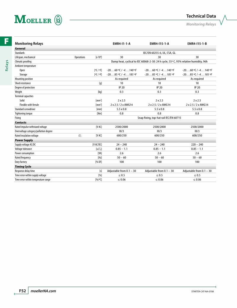
F
Rela
ys
F52 moellerNA.com STARTER-CAT-NA-0708
Technical Data
Monitoring Relays
Monitoring Relays EMR4-I1-1-A EMR4-I15-1-A EMR4-I15-1-BGeneralStandards IEC/EN 60255-6, UL, CSA, GLLifespan, mechanical Operations [x 106] 30 30 30Climatic proofing Damp heat, cyclical to IEC 60068-2-30: 24 h cycle, 55º C, 93% relative humidity, 96hAmbient temperature Open [ºC / ºF] -20…60 ºC / -4…140 ºF -20…60 ºC / -4…140 ºF -20…60 ºC / -4…140 ºF Storage [ºC / ºF] -20…85 ºC / -4…185 ºF -20…85 ºC / -4…185 ºF -20…85 ºC / -4…185 ºFMounting position As required As required As requiredShock resistance [g] 10 10 10Degree of protection IP 20 IP 20 IP 20Weight [kg] 0.3 0.3 0.3Terminal capacities Solid [mm2] 2 x 2.5 2 x 2.5 2 x 2.5 Flexible with ferrule [mm2] 2 x 2.5 / 2 x AWG14 2 x 2.5 / 2 x AWG14 2 x 2.5 / 2 x AWG14Standard screwdriver [mm] 5.5 x 0.8 5.5 x 0.8 5.5 x 0.8Tightening torque [Nm] 0.8 0.8 0.8Fixing Snap fixing, top-hat rail IEC/EN 60715
ContactsRated impulse withstand voltage [V AC] 2500/2000 2500/2000 2500/2000Overvoltage category/pollution degree III/3 III/3 III/3Rated insulation voltage Ui [V AC] 600/250 600/250 600/250
Power SupplySupply voltage AC/DC [V AC/DC] 24 – 240 24 – 240 220 – 240Voltage tolerance [x Uc] 0.85 – 1.1 0.85 – 1.1 0.85 – 1.1Power consumption [VA] 2.6 2.6 2.6Rated frequency [Hz] 50 – 60 50 – 60 50 – 60Duty factory [% DF] 100 100 100
Timing CycleResponse delay time [s] Adjustable from 0.1 – 30 Adjustable from 0.1 – 30 Adjustable from 0.1 – 30Time error within supply voltage [%] ≤ 0.5 ≤ 0.5 ≤ 0.5Time error within temperature range [%/ºC] ≤ 0.06 ≤ 0.06 ≤ 0.06

F
Relays
STARTER-CAT-NA-0708 moellerNA.com F53
Technical Data
Monitoring Relays
Monitoring Relays (continued) EMR4-I1-1-A EMR4-I15-1-A EMR4-I15-1-BMeasuring CircuitsInputs B1-C [A] 0.003 – 0.03 0.3 – 1.5 0.3 – 1.5 B2-C [A] 0.01 – 0.1 1 – 5 1 – 5 B3-C [A] 0.1 – 1 3 – 15 3 – 15Hysteresis [%] 3 – 30 3 – 30 3 – 30Measuring cycle [ms] 80 80 80Temperature error [%/ºC] 0.06 0.06 0.06Error within supply voltage [%] 0.5 0.5 0.5
Status IndicationSupply voltage LED: green LED: green LED: greenOutput relay energized LED: yellow LED: yellow LED: yellowMeasured value LED: red LED: red LED: red
Relay Output ContactsRated operational voltage Ue [V AC] 250 250 250Rated operational current AC-12 at 230V Ie [A] 4 4 4 AC-15 at 230V Ie [A] 3 3 3 DC-12 at 24V Ie [A] 4 4 4 DC-13 at 24V Ie [A] 2 2 2Lifespan, electrical (AC-12, 230V, 4A) Operations [x 106] 0.1 0.1 0.1Short-circuit rating Max. fuse Fast/gL [A] 10 10 10Load limit curves see page F50 see page F50 see page F50
Electromagnetic Compatibility (EMC)Electromagnetic compatibility IEC/EN 60947-6-2 IEC/EN 60947-6-2 IEC/EN 60947-6-2ESD IEC/EN 61000-4-2, Level 3 IEC/EN 61000-4-2, Level 3 IEC/EN 61000-4-2, Level 3HF-immunity to radiation IEC/EN 61000-4-3, Level 3 IEC/EN 61000-4-3, Level 3 IEC/EN 61000-4-3, Level 3Burst IEC/EN 61000-4-4, Level 3 IEC/EN 61000-4-4, Level 3 IEC/EN 61000-4-4, Level 3Surge IEC/EN 61000-4-9, Level 3 IEC/EN 61000-4-9, Level 3 IEC/EN 61000-4-9, Level 3HF-immunity to line-conducted interference IEC/EN 61000-4-6, Level 3 IEC/EN 61000-4-6, Level 3 IEC/EN 61000-4-6, Level 3

F
Rela
ys
F54 moellerNA.com STARTER-CAT-NA-0708
Technical Data
Monitoring Relays
Monitoring Relays (continued) EMR4-A400-1EMR4-A300-1-C EMR4-A500-1-D
GeneralStandards IEC/EN 60255-6, EN 61557, UL, CSA, GL IEC/EN 60255-6, IEC 255-6, UL, CELifespan, mechanical Operations [x 106] 30 30Climatic proofing Damp heat, cyclical to IEC 60068-2-30: 24 h cycle, 55º C, 93% relative humidity, 96 hAmbient temperature Open [°C / °F] -20…60 ºC / -4…140 ºF -20…60 ºC / -4…140 ºF Storage [°C / °F] -40…80 ºC / -40…176 ºF -20…60 ºC / -4…140 ºFMounting position As required As requiredShock resistance 10 g IEC/EN 60255-21-12, Class 12Degree of protection Terminals IP 20 IP 20 Enclosures IP 50 IP 50Weight [kg] 0.3 0.13Terminal capacities Solid [mm2] 2 x 2.5 – Flexible with ferrule [mm2] 2 x 2.5 2 x 2.5 / 2 x AWG14Standard screwdriver [mm] 5.5 x 0.8 5.5 x 0.8Tightening torque [Nm] 0.5 – 0.8 0.5 – 0.8Fixing Snap fixing, DIN rail IEC/EN 60715
ContactsRated impulse withstand voltage Uimp [V AC] 4000 4000Overvoltage category/pollution degree III/3 III/3Rated insulation voltage Ui [V AC] 600 600
Power SupplySupply voltage AC [V AC] 380 – 415 see selection pagesVoltage tolerance [x Uc] 0.8 – 1.2 0.8 – 1.2Power consumption [VA] 15 20Rated frequency f [Hz] 50 50Duty factor [% DF] 100 100
Timing CycleResponse delay time [s] 0.5 indication of phase balance Adjustable from 0.1 – 10 sTime error within supply voltage [%] 0.5 0.5Time error within temperature range [% / ºC] 0.06 0.06

F
Relays
STARTER-CAT-NA-0708 moellerNA.com F55
Technical Data
Monitoring Relays
Monitoring Relays (continued) EMR4-A400-1EMR4-A300-1-C EMR4-A500-1-D
Measuring CircuitsMonitoring voltage Un [V AC] 380 – 415 see selection pagesFrequency [Hz] 50 50/60 ± 10 %Phase imbalance level adjustable [%] 5 – 15 2 – 15, from mean value of phase voltageSwitching hysteresis [%] 20 20Temperature error [% / ºC] 0.06 0.06Error within supply voltage [%] 0.5 0.5
Status IndicationOutput relay energized LED: steady yellow LED R: flashing greenSupply voltage – LED R: steady greenPhase failure – LED F1: steady red;
LED F2: flashing redPhase sequence error – LED F1: flashing red;
LED F2: flashing redRelay Output ContactsRated operational voltage Ue [V AC] 500 500Rated operational current AC-12 at 230V Ie [A] 4 4 AC-15 at 230V Ie [A] 3 3 DC-12 at 24V Ie [A] 4 4 DC-13 at 24V Ie [A] 2 2Lifespan, electrical (AC-12, 230V, 4A) Operations [x 106] 0.3 0.1Short-circuit rating Max. fuse Fast/gL [A] 10 10Load limit curves see page F50 see page F50
Electromagnetic Compatibility (EMC)Electromagnetic compatibility IEC/EN 60947-6-2ESD IEC/EN 61000-4-2, Level 3HF-immunity to radiation IEC/EN 61000-4-3, Level 3Burst IEC/EN 61000-4-4, Level 3Surge IEC/EN 61000-4-5, Level 4HF-immunity to line-conducted interference IEC/EN 61000-4-6, Level 3

F
Rela
ys
F56 moellerNA.com STARTER-CAT-NA-0708
Technical Data
Monitoring Relays
Monitoring Relays (continued)
EMR4-W300-1-C EMR4-W380-1 EMR4-W400-1 EMR4-W500-1-D EMR4-W580-2-D EMR4-AW(N)…
GeneralStandards IEC/EN 60255-6,
IEC 255-6, UL, CEIEC/EN 60255-6, IEC 255-6, UL, CE
IEC/EN 60255-6, EN 61557, UL, CSA, GL
IEC/EN 60255-6, IEC 255-6, UL, CE
Lifespan, mechanical Operations [x 106] 30 30 30 30Climatic proofing Damp heat, cyclical to IEC 60068-2-30: 24 h cycle, 55º C, 93% relative humidity, 96 hAmbient temperature Open [°C / °F] -20…60 °C /
-4…140 °F-20…60 °C / -4…140 °F
-25…65 ºC / -13…149 ºF
-20…60 °C / -4…140 °F
Storage [°C / °F] -20…60 °C / -4…140 °F
-20…60 °C / -4…140 °F
-40...85 ºC / -40...185 ºF
-20…60 °C / -4…140 °F
Mounting position As required As required As required As requiredShock resistance 10 g 10 g 10 g IEC/EN 60255-21-12,
Class 2Degree of protection Terminals IP 20 IP 20 IP 20 IP 20 Enclosures IP 50 IP 50 IP 50 IP 50Weight [kg] 0.13 0.13 0.3 0.14Terminal capacities Solid [mm2] 2 x 2.5 2 x 2.5 2 x 2.5 2 x 2.5 Flexible with ferrule [mm2] 2 x 2.5 / 2 x AWG14 2 x 2.5 / 2 x AWG14 2 x 2.5 2 x 2.5 / 2 x AWG14Standard screwdriver [mm] 5.5 x 0.8 5.5 x 0.8 5.5 x 0.8 5.5 x 0.8Tightening torque [Nm] 0.5 – 0.8 0.5 – 0.8 0.5 – 0.8 0.5 – 0.8Fixing Snap fixing, DIN rail IEC/EN 60715
ContactsRated impulse withstand voltage Uimp [V AC] 4000 4000 4000 4000Overvoltage category/pollution degree III/3 III/3 III/3 III/3Rated insulation voltage Ui [V AC] 600 600 600 600
Power SupplySupply voltage AC [V AC] see page F47 300 – 500 300 – 500 see page F47Voltage tolerance [x Uc] 0.85 – 1.1 0.85 – 1.1 0.85 – 1.1 0.85 – 1.1Power consumption [VA] 3 3 3 20Rated frequency [Hz] 50 – 60 50 – 60 50 – 60 50 – 60Duty factor [% DF] 100 100 100 100
Timing CycleResponse delay time [s] Adjustable 0.1 – 10 Adjustable 0.1 – 10 Adjustable 0.1 – 10 Adjustable 0.1 – 10Reset delay/Off-delay time [s] Adjustable 0.1 – 10 Adjustable 0.1 – 10 Adjustable 0.1 – 10 Adjustable 0.1 – 10Time error within supply voltage [%] 0.5 0.5 0.5 0.5Time error within temperature range [%/ºC] 0.06 0.06 0.06 0.06
Measuring CircuitsResponse range for undervoltage Umin [V AC] see page F47 300 – 380 350 – 430 see page F47Response range for overvoltage Umax [V AC] see page F47 420 – 500 500 – 580 see page F47Hysteresis [%] 0 – 5 0 – 5 0 – 5 0 – 5Frequency [Hz] 50/60 ± 10% 50/60 ± 10% 50/60 ± 10% 50/60 ± 10%Phase imbalance level adjustable [%] – – – 2 – 15, from mean
value of the phase voltage
Measuring cycle [ms] 50 50 50 50Temperature error [%/ºC] 0.06 0.06 0.06 0.06Error within supply voltage [%] 0.5 0.5 0.5 0.5
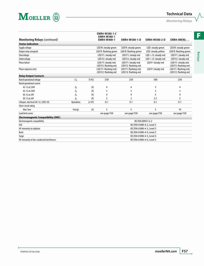
F
Relays
STARTER-CAT-NA-0708 moellerNA.com F57
Technical Data
Monitoring Relays
Monitoring Relays (continued)
EMR4-W300-1-C EMR4-W380-1 EMR4-W400-1 EMR4-W500-1-D EMR4-W580-2-D EMR4-AW(N)…
Status IndicationSupply voltage LED R: steady green LED R: steady green LED: steady green LED R: steady greenOutput relay energized LED R: flashing green LED R: flashing green LED: steady yellow LED R: flashing greenOvervoltage LED F1: steady red LED F1: steady red LED > U: steady red LED F1: steady redUndervoltage LED F2: steady red LED F2: steady red LED < U: steady red LED F2: steady redPhase failure LED F1: steady red;
LED F2: flashing redLED F1: steady red;LED F2: flashing red
LED P: steady red LED F1: steady red;LED F2: flashing red
Phase sequence error LED F1: flashing red;LED F2: flashing red
LED F1: flashing red;LED F2: flashing red
LED P: steady red LED F1: flashing red;LED F2: flashing red
Relay Output ContactsRated operational voltage Ue [V AC] 250 250 500 250Rated operational current AC-12 at 230V Ie [A] 4 4 5 4 AC-15 at 230V Ie [A] 3 3 3 3 DC-12 at 24V Ie [A] 4 4 5 4 DC-13 at 24V Ie [A] 2 2 2.5 2Lifespan, electrical (AC-12, 230V, 5A) Operations [x 106] 0.1 0.1 0.1 0.1Short-circuit rating Max. fuse Fast/gL [A] 5 5 5 10Load limit curves see page F50 see page F50 see page F50 see page F50
Electromagnetic Compatibility (EMC)Electromagnetic compatibility IEC/EN 60947-6-2ESD IEC/EN 61000-4-2, Level 3HF-immunity to radiation IEC/EN 61000-4-3, Level 3Burst IEC/EN 61000-4-4, Level 3Surge IEC/EN 61000-4-5, Level 4HF-immunity to line-conducted interference IEC/EN 61000-4-6, Level 3
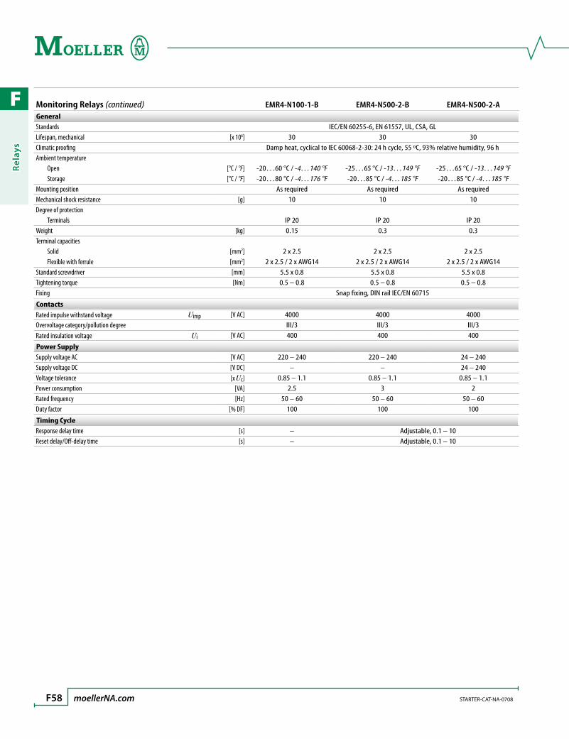
F
Rela
ys
F58 moellerNA.com STARTER-CAT-NA-0708
Monitoring Relays (continued) EMR4-N100-1-B EMR4-N500-2-B EMR4-N500-2-AGeneralStandards IEC/EN 60255-6, EN 61557, UL, CSA, GLLifespan, mechanical [x 106] 30 30 30Climatic proofing Damp heat, cyclical to IEC 60068-2-30: 24 h cycle, 55 ºC, 93% relative humidity, 96 hAmbient temperature Open [°C / °F] -20…60 °C / -4…140 °F -25…65 °C / -13…149 °F -25…65 °C / -13…149 °F Storage [°C / °F] -20…80 °C / -4…176 °F -20…85 °C / -4…185 °F -20…85 °C / -4…185 °FMounting position As required As required As requiredMechanical shock resistance [g] 10 10 10Degree of protection Terminals IP 20 IP 20 IP 20Weight [kg] 0.15 0.3 0.3Terminal capacities Solid [mm2] 2 x 2.5 2 x 2.5 2 x 2.5 Flexible with ferrule [mm2] 2 x 2.5 / 2 x AWG14 2 x 2.5 / 2 x AWG14 2 x 2.5 / 2 x AWG14Standard screwdriver [mm] 5.5 x 0.8 5.5 x 0.8 5.5 x 0.8Tightening torque [Nm] 0.5 – 0.8 0.5 – 0.8 0.5 – 0.8Fixing Snap fixing, DIN rail IEC/EN 60715
ContactsRated impulse withstand voltage Uimp [V AC] 4000 4000 4000Overvoltage category/pollution degree III/3 III/3 III/3Rated insulation voltage Ui [V AC] 400 400 400
Power SupplySupply voltage AC [V AC] 220 – 240 220 – 240 24 – 240Supply voltage DC [V DC] – – 24 – 240Voltage tolerance [x Uc] 0.85 – 1.1 0.85 – 1.1 0.85 – 1.1Power consumption [VA] 2.5 3 2Rated frequency [Hz] 50 – 60 50 – 60 50 – 60Duty factor [% DF] 100 100 100
Timing CycleResponse delay time [s] – Adjustable, 0.1 – 10Reset delay/Off-delay time [s] – Adjustable, 0.1 – 10

F
Relays
STARTER-CAT-NA-0708 moellerNA.com F59
Monitoring Relays (continued) EMR4-N100-1-B EMR4-N500-2-B EMR4-N500-2-AMeasuring CircuitsSensor inputs B1 Earth reference sensor Earth reference sensor Earth reference sensor B2 Maximum level Maximum level Maximum level B3 Minimum level Minimum level Minimum levelResponse range [kΩ] 5 – 100 5 – 100 5 – 100Sensor voltage [V AC] 30 20 20Reset range [kΩ] 1.3 – 2.3 – –Sensor current [mA] 1 – –Cable capacity [nF] 10 – –Cable length [m] 100 – –Response delay/On-delay [ms] 250 – –
Status IndicationSupply voltage LED: green LED: green LED: greenOutput relay energized LED: yellow LED: yellow LED: yellow
Relay Output ContactsRated operational voltage Ue [V AC] 250 400 400Rated operational current AC-12 at 230V Ie [A] 4 5 5 AC-15 at 230V Ie [A] 3 3 3 DC-12 at 24V Ie [A] 4 5 5 DC-13 at 24V Ie [A] 2 2.5 2.5Lifespan, electrical (AC-12, 30V, 5A) Operations [x 106] 0.3 0.1 0.1Short-circuit rating Max. fuse Fast/gL [A] 10 5 5Load limit curves see page F50 see page F50 see page F50
Electromagnetic Compatibility (EMC)Electromagnetic compatibility IEC/EN 60947-6-2ESD IEC/EN 61000-4-2, Level 3HF-immunity to radiation IEC/EN 61000-4-3, Level 3Burst IEC/EN 61000-4-4, Level 3Surge IEC/EN 61000-4-5, Level 4HF-immunity to line-conducted interference IEC/EN 61000-4-6, Level 3
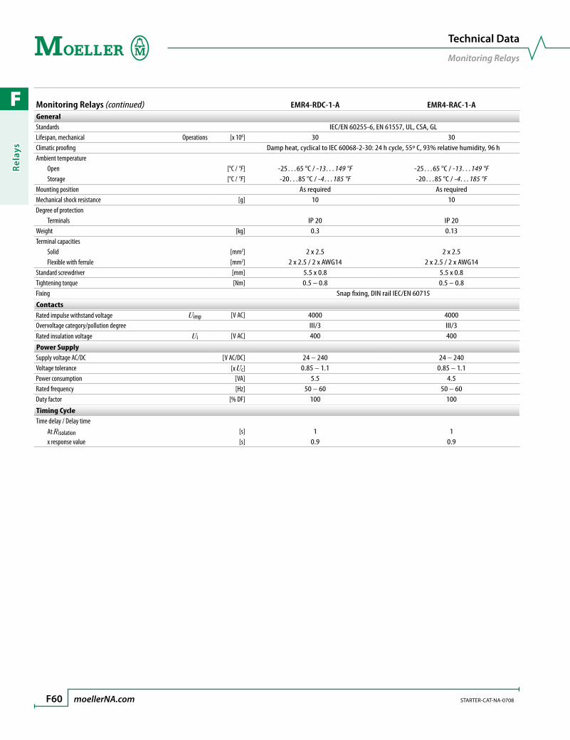
F
Rela
ys
F60 moellerNA.com STARTER-CAT-NA-0708
Technical Data
Monitoring Relays
Monitoring Relays (continued) EMR4-RDC-1-A EMR4-RAC-1-AGeneralStandards IEC/EN 60255-6, EN 61557, UL, CSA, GLLifespan, mechanical Operations [x 106] 30 30Climatic proofing Damp heat, cyclical to IEC 60068-2-30: 24 h cycle, 55º C, 93% relative humidity, 96 hAmbient temperature Open [°C / °F] -25…65 °C / -13…149 °F -25…65 °C / -13…149 °F Storage [°C / °F] -20…85 °C / -4…185 °F -20…85 °C / -4…185 °FMounting position As required As requiredMechanical shock resistance [g] 10 10Degree of protection Terminals IP 20 IP 20Weight [kg] 0.3 0.13Terminal capacities Solid [mm2] 2 x 2.5 2 x 2.5 Flexible with ferrule [mm2] 2 x 2.5 / 2 x AWG14 2 x 2.5 / 2 x AWG14Standard screwdriver [mm] 5.5 x 0.8 5.5 x 0.8Tightening torque [Nm] 0.5 – 0.8 0.5 – 0.8Fixing Snap fixing, DIN rail IEC/EN 60715
ContactsRated impulse withstand voltage Uimp [V AC] 4000 4000Overvoltage category/pollution degree III/3 III/3Rated insulation voltage Ui [V AC] 400 400
Power SupplySupply voltage AC/DC [V AC/DC] 24 – 240 24 – 240Voltage tolerance [x Uc] 0.85 – 1.1 0.85 – 1.1Power consumption [VA] 5.5 4.5Rated frequency [Hz] 50 – 60 50 – 60Duty factor [% DF] 100 100
Timing CycleTime delay / Delay time At Risolation [s] 1 1 x response value [s] 0.9 0.9
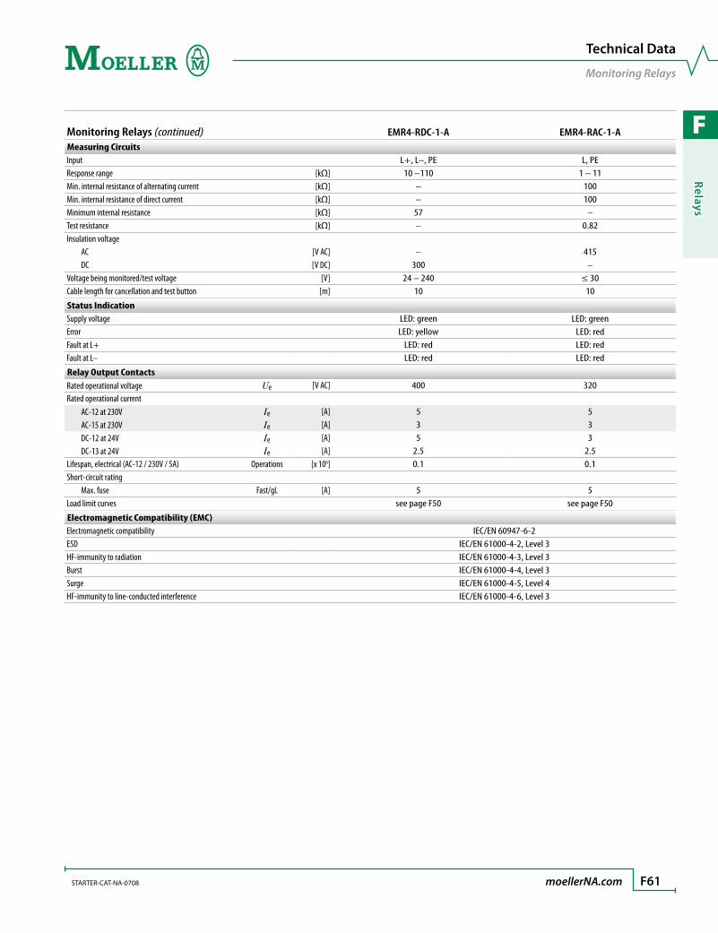
F
Relays
STARTER-CAT-NA-0708 moellerNA.com F61
Technical Data
Monitoring Relays
Monitoring Relays (continued) EMR4-RDC-1-A EMR4-RAC-1-AMeasuring CircuitsInput L+, L–, PE L, PEResponse range [kΩ] 10 –110 1 – 11Min. internal resistance of alternating current [kΩ] – 100Min. internal resistance of direct current [kΩ] – 100Minimum internal resistance [kΩ] 57 –Test resistance [kΩ] – 0.82Insulation voltage AC [V AC] – 415 DC [V DC] 300 –Voltage being monitored/test voltage [V] 24 – 240 ≤ 30Cable length for cancellation and test button [m] 10 10
Status IndicationSupply voltage LED: green LED: greenError LED: yellow LED: redFault at L+ LED: red LED: redFault at L– LED: red LED: red
Relay Output ContactsRated operational voltage Ue [V AC] 400 320Rated operational current AC-12 at 230V Ie [A] 5 5 AC-15 at 230V Ie [A] 3 3 DC-12 at 24V Ie [A] 5 3 DC-13 at 24V Ie [A] 2.5 2.5Lifespan, electrical (AC-12 / 230V / 5A) Operations [x 106] 0.1 0.1Short-circuit rating Max. fuse Fast/gL [A] 5 5Load limit curves see page F50 see page F50
Electromagnetic Compatibility (EMC)Electromagnetic compatibility IEC/EN 60947-6-2ESD IEC/EN 61000-4-2, Level 3HF-immunity to radiation IEC/EN 61000-4-3, Level 3Burst IEC/EN 61000-4-4, Level 3Surge IEC/EN 61000-4-5, Level 4HF-immunity to line-conducted interference IEC/EN 61000-4-6, Level 3

F
Rela
ys
F62 moellerNA.com STARTER-CAT-NA-0708
Technical Data
Monitoring Relays
Monitoring Relays (continued) EMR4-F500-2GeneralStandards IEC/EN 60255-6, EN 61557, UL, CSA, GLLifespan, mechanical Operations [x 106] 30Climatic proofing Damp heat, cyclical to IEC 60068-2-30: 24 h cycle, 55º C, 93% relative humidity, 96 hAmbient temperature Open [°C / °F] -20…60 °C / -4…140 °F Storage [°C / °F] -40…80 °C / -40…176 °FMounting position As requiredMechanical shock resistance [g] 10Degree of protection Terminals IP 20Weight [kg] 0.15Terminal capacities Solid [mm2] 2 x 2.5 Flexible with ferrule [mm2] 2 x 2.5 / 2 x AWG14Standard screwdriver [mm] 5.5 x 0.8Tightening torque [Nm] 0.5 – 0.8Fixing Snap fixing, DIN rail IEC/EN 60715
ContactsRated impulse withstand voltage Uimp [V AC] 4000Overvoltage category/pollution degree III/3Rated insulation voltage Ui [V AC] 400
Power SupplySupply voltage AC [V AC] 200 – 500Voltage tolerance [x Uc] 0.85 – 1.1Power consumption [VA] 15Rated frequency [Hz] 50 – 60Duty factor [% DF] 100
Measuring CircuitsMonitoring voltage Un [V AC] 200 – 500Frequency [Hz] 50 – 60Measuring cycle [ms] 500Temperature error [% / ºC] 0.06Error within supply voltage [%] 0.5
Status IndicationOutput relay energized LED: yellow
Relay Output ContactsRated operational voltage Ue [V AC] 500Rated operational current AC-12 at 230V Ie [A] 4 AC-15 at 230V Ie [A] 3 DC-12 at 24V Ie [A] 4 DC-13 at 24V Ie [A] 2Lifespan, electrical (AC-12, 230V, 4A) Operations [x 106] 0.3Short-circuit rating Max. fuse Fast/gL [A] 10Load limit curves see page F50
Electromagnetic Compatibility (EMC)Electromagnetic compatibility IEC/EN 60947-6-2ESD IEC/EN 61000-4-2, Level 3HF-immunity to radiation IEC/EN 61000-4-3, Level 3Burst IEC/EN 61000-4-4, Level 3Surge IEC/EN 61000-4-5, Level 4HF-immunity to line-conducted interference IEC/EN 61000-4-6, Level 3

F
Relays
STARTER-CAT-NA-0708 moellerNA.com F63
Dimensions
Monitoring Relays
Dimensions are in millimeters.Not intended for manufacturing purposes.
Monitoring RelaysEMR4-…
109.5
102
78
5.5 1
100
45 22.5
a b
PotentiometerM22-R…K…
29.7
29.232.9
Ø 2
9.5
1 – 6
Sealable Shroud Sealable ShroudsEMR4-PH22 EMR4-PH45
22.5 20
68.5
45
68.5
20
a (22.5 mm width)
b (45 mm width)
EMR4-F500-2 EMR4-W…2…EMR4-W…1… EMR4-N500…EMR4-A…1… EMR4-R…EMR4-N100-1-B EMR4-I…EMR4-AW…

F
Rela
ys
F64 moellerNA.com STARTER-CAT-NA-0708
Relays
Notes
G
Pre-assemb
led En
closed
Starters
pre-assembled enclosed starters
General Information ......................................................................... G3
SYST-M base units .............................................................................. G4
Overload Relays ................................................................................. G8
Pilot Device Kits .................................................................................. G9
Control Transformers ........................................................................ G11
Remote Control Adapter .................................................................. G11
G
Pre-
asse
mb
led
Encl
ose
d S
tart
ers
Start with Moellerpre-assembled enclosed starters
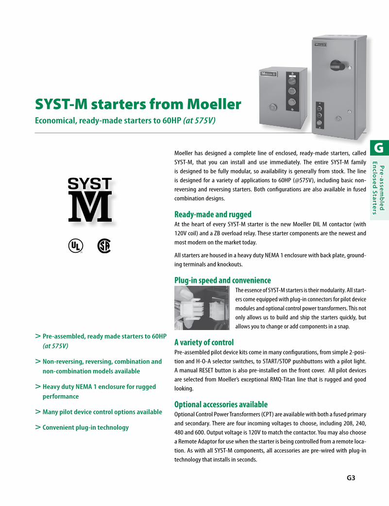
G
Pre-assemb
led En
closed
Starters
G3
Moeller has designed a complete line of enclosed, ready-made starters, called SYST-M, that you can install and use immediately. The entire SYST-M family is designed to be fully modular, so availability is generally from stock. The line is designed for a variety of applications to 60HP (@575V), including basic non-reversing and reversing starters. Both configurations are also available in fused combination designs.
Ready-made and ruggedAt the heart of every SYST-M starter is the new Moeller DIL M contactor (with 120V coil) and a ZB overload relay. These starter components are the newest and most modern on the market today.
All starters are housed in a heavy duty NEMA 1 enclosure with back plate, ground-ing terminals and knockouts.
Plug-in speed and convenienceThe essence of SYST-M starters is their modularity. All start-ers come equipped with plug-in connectors for pilot device modules and optional control power transformers. This not only allows us to build and ship the starters quickly, but allows you to change or add components in a snap.
A variety of controlPre-assembled pilot device kits come in many configurations, from simple 2-posi-tion and H-O-A selector switches, to START/STOP pushbuttons with a pilot light. A manual RESET button is also pre-installed on the front cover. All pilot devices are selected from Moeller’s exceptional RMQ-Titan line that is rugged and good looking.
Optional accessories availableOptional Control Power Transformers (CPT) are available with both a fused primary and secondary. There are four incoming voltages to choose, including 208, 240, 480 and 600. Output voltage is 120V to match the contactor. You may also choose a Remote Adaptor for use when the starter is being controlled from a remote loca-tion. As with all SYST-M components, all accessories are pre-wired with plug-in technology that installs in seconds.
SYST-M starters from MoellerEconomical, ready-made starters to 60HP (at 575V)
> Pre-assembled, ready made starters to 60HP (at 575V)
> Non-reversing, reversing, combination and non-combination models available
> Heavy duty NEMA 1 enclosure for rugged performance
> Many pilot device control options available
> Convenient plug-in technology
R
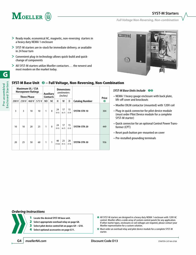
G
Pre-
asse
mb
led
Encl
ose
d S
tart
ers
G4 moellerNA.com STARTER-CAT-NA-0708 Discount Code D13
SYST-M Base Unit ➋ – Full Voltage, Non-Reversing, Non-CombinationMaximum UL / CSA
Horsepower RatingsAuxiliary Contacts
Dimensionscentimeters
(inches)
Catalog NumberPrice
➋
Three Phase200 V 230 V 460 V 575 V NO NC H W D
3 3 10 10 1 0 24(9.5)
17(6.7)
15(5.9)
SYSTM-STR-10 304
10 10 20 25 1 0 24(9.5)
17(6.7)
15(5.9)
SYSTM-STR-20 449
20 25 50 60 1 1 40(15.8)
23(9.1)
20(7.9)
SYSTM-STR-30 936
➊ All SYST-M starters are designed in a heavy duty NEMA 1 enclosure with 120V AC control. Moeller offers a wide array of custom control panels for any application. If other starter types, enclosures or coil voltages are required, please contact your Moeller representative for a custom solution.
➋ Must order an overload relay and pilot device module for a complete SYST-M starter.
SYST-M Starters
Full Voltage Non-Reversing, Non-combination
> Ready made, economical AC, magnetic, non-reversing starters in a heavy duty NEMA 1 enclosure
> SYST-M starters are in-stock for immediate delivery, or available in 24 hour turn
> Convenient plug-in technology allows quick-build and quick-change of components
> All SYST-M starters utilize Moeller contactors… the newest and most modern on the market today.
SYST-M Base Units Include ➊➋
•NEMA1heavygaugeenclosurewithbackplate, lift-off cover and knockouts
•MoellerDILMcontactor(mounted)with120Vcoil
•Plug-inquickconnectorforpilotdevicemodule(must order Pilot Device module for a complete SYST-M starter)
•QuickconnectorforanoptionalControlPowerTrans-former (CPT)
•Resetpushbuttonpre-mountedoncover
•Pre-installedgroundingterminals
Ordering Instructions
1 Locate the desired SYST-M base unit.
2 Select appropriate overload relay on page G8.
3 Select pilot device control kit on pages G9 – G10.
4 Select optional accessories on page G11.

G
Pre-assemb
led En
closed
Starters
STARTER-CAT-NA-0708 moellerNA.com G5 Discount Code D13
SYST-M Starters
Full Voltage Reversing, Non-combination
> Ready made, economical, AC reversing starters, in a heavy duty NEMA 1 enclosure
> SYST-M starters are in-stock for immediate delivery, or available in 24 hour turn
> Convenient plug-in technology allows quick-build and quick-change of components
> All SYST-M starters utilize Moeller contactors… the newest and most modern on the market today.
SYST-M Base Units Include ➊ ➋
•NEMA1heavygaugeenclosurewithbackplate, lift-off cover and knockouts
•MoellerDILMreversingcontactors(mounted)with120V coil
•Plug-inquickconnectorforpilotdevicemodule(must order Pilot Device module for a complete SYST-M starter)
•QuickconnectorforanoptionalControlPowerTrans-former (CPT)
•Resetpushbuttonpre-mountedoncover
•Pre-installedgroundingterminals
➊ All SYST-M starters are designed in a heavy duty NEMA 1 enclosure with 120V AC control. Moeller offers a wide array of custom control panels for any application. If other starter types, enclosures or coil voltages are required, please contact your Moeller representative for a custom solution.
➋ Must order an overload relay and pilot device module for a complete SYST-M starter.
SYST-M Base Unit ➋ – Full Voltage, Reversing, Non-CombinationMaximum UL / CSA
Horsepower RatingsAuxiliary Contacts
Dimensionscentimeters
(inches)
Catalog NumberPrice
➋
Three Phase200 V 230 V 460 V 575 V NO NC H W D
3 3 10 10 1 1 24(9.5)
17(6.7)
15(5.9)
SYSTM-STR-10R 734
10 10 20 25 1 1 40(15.8)
23(9.1)
20(7.9)
SYSTM-STR-20R 1245
20 25 50 60 1 1 40(15.8)
23(9.1)
20(7.9)
SYSTM-STR-30R 1798
Ordering Instructions
1 Locate the desired SYST-M base unit.
2 Select appropriate overload relay on page G8.
3 Select pilot device control kit on pages G9 – G10.
4 Select optional accessories on page G11.

G
Pre-
asse
mb
led
Encl
ose
d S
tart
ers
G6 moellerNA.com STARTER-CAT-NA-0708 Discount Code D13
SYST-M Starters
Full Voltage Non-Reversing, Combination
> Ready made, economical AC, combination fusible (HRC 1J), non-reversing starters in a heavy duty NEMA 1 enclosure
> SYST-M starters are in-stock for immediate delivery, or available in 24 hour turn
> Convenient plug-in technology allows quick-build and quick-change of components
> All SYST-M starters utilize Moeller contactors… the newest and most modern on the market today.
➊ All SYST-M starters are designed in a heavy duty NEMA 1 enclosure with 120V AC control. Moeller offers a wide array of custom control panels for any application. If other starter types, enclosures or coil voltages are required, please contact your Moeller representative for a custom solution.
➋ Must order an overload relay and pilot device module for a complete SYST-M starter.
SYST-M Base Units Include ➊➋
•NEMA1heavygaugeenclosurewithbackplate, lift-off cover and knockouts
•MoellerDILMcontactor(mounted)with120V coil
• Fuseddisconnect(HRC1J)withrotaryhandle (fuses not included)
•Plug-inquickconnectorforpilotdevicemodule (must order Pilot Device module for a complete SYST-M starter)
•QuickconnectorforanoptionalControlPower Transformer (CPT)
•Resetpushbuttonpre-mountedoncover
•Pre-installedgroundingterminals
SYST-M Base Unit ➋ – Full Voltage, Non-Reversing, Combination, Fusible (HRC 1J)Maximum UL / CSA
Horsepower RatingsFused
Disconnect [A]
Auxiliary Contacts
Dimensionscentimeters
(inches)
Catalog NumberPrice
➋
Three Phase200 V 230 V 460 V 575 V NO NC H W D
3 3 10 10 30 1 0 60(23.6)
27(10.6)
20(7.9)
SYSTM-STR-11C 1006
7½ 7½ 15 20 30 1 0 60(23.6)
27(10.6)
20(7.9)
SYSTM-STR-21C 1081
10 10 20 25 60 1 0 60(23.6)
27(10.6)
20(7.9)
SYSTM-STR-22C 1253
10 15 30 40 60 1 1 60(23.6)
27(10.6)
20(7.9)
SYSTM-STR-32C 1313
20 25 50 60 100 1 1 60(23.6)
50(19.7)
20(7.9)
SYSTM-STR-33C 1945
Ordering Instructions
1 Locate the desired SYST-M base unit.
2 Select appropriate overload relay on page G8.
3 Select pilot device control kit on pages G9 – G10.
4 Select optional accessories on page G11.

G
Pre-assemb
led En
closed
Starters
STARTER-CAT-NA-0708 moellerNA.com G7 Discount Code D13
SYST-M Starters
Full Voltage Reversing, Combination
> Ready made, economical AC reversing, combination fusible (HRC 1J) starters in a heavy duty NEMA 1 enclosure
> Popular SYST-M starters are in-stock for immediate delivery, or available in 24 hour turn
> Convenient plug-in technology allows quick-build and quick-change of components
> All SYST-M starters utilize Moeller contactors… the newest and most modern on the market today.
SYST-M Base Units Include ➊➋
•NEMA1heavygaugeenclosurewithbackplate, lift-off cover and knockouts
•MoellerDILMreversingcontactors(mounted)with 120V coil
• Fuseddisconnect(HRC1J)withrotaryhandle(fuses not included)
•Plug-inquickconnectorforpilotdevicemodule (must order Pilot Device module for a complete SYST-M starter)
•QuickconnectorforanoptionalControlPower Transformer (CPT)
•Resetpushbuttonpre-mountedoncover
•Pre-installedgroundingterminals
➊ All SYST-M starters are designed in a heavy duty NEMA 1 enclosure with 120V AC control. Moeller offers a wide array of custom control panels for any application. If other starter types, enclosures or coil voltages are required, please contact your Moeller representative for a custom solution.
➋ Must order an overload relay and pilot device module for a complete SYST-M starter.
SYST-M Base Unit ➋ – Full Voltage, Reversing, Combination, Fusible (HRC 1J)Maximum UL / CSA
Horsepower RatingsFused
Disconnect [A]
Auxiliary Contacts
Dimensionscentimeters
(inches)
Catalog NumberPrice
➋
Three Phase200 V 230 V 460 V 575 V NO NC H W D
3 3 10 10 30 1 1 60(23.6)
27(10.6)
20(7.9)
SYSTM-STR-11CR 1443
7½ 7½ 15 20 30 1 1 60(23.6)
27(10.6)
20(7.9)
SYSTM-STR-21CR 1496
10 10 20 25 60 1 1 60(23.6)
27(10.6)
20(7.9)
SYSTM-STR-22CR 1611
10 15 30 40 60 1 1 60(23.6)
27(10.6)
20(7.9)
SYSTM-STR-32CR 2264
20 25 50 60 100 1 1 60(23.6)
50(19.7)
20(7.9)
SYSTM-STR-33CR 2553
Ordering Instructions
1 Locate the desired SYST-M base unit.
2 Select appropriate overload relay on page G8.
3 Select pilot device control kit on pages G9 – G10.
4 Select optional accessories on page G11.

G
Pre-
asse
mb
led
Encl
ose
d S
tart
ers
G8 moellerNA.com STARTER-CAT-NA-0708 Discount Code A14
➊ Observe the maximum permissible fuse of the contactor with direct device mounting.
SYST-M Starters
Thermal Overload Relays
Direct Mount ZB Thermal Overload Relays for SYST-M Starters
Overload Relay
AdjustableSetting Range
AuxiliaryContacts
For use with SYST-M starter…
Short-CircuitProtection
(Max 600V AC) ➊
Catalog Number PriceNO NC Fuses[A]Circuit
Breaker[A]0.1 – 0.16 1 1
All series “10”
1 25 ZB12-0,16 144
0.16 – 0.24 1 1 1 25 ZB12-0,24 144
0.24 – 0.4 1 1 1 25 ZB12-0,4 144
0.4 – 0.6 1 1 1 25 ZB12-0,6 144
0.6 – 1 1 1 3 25 ZB12-1 144
1 – 1.6 1 1 6 25 ZB12-1,6 144
1.6 – 2.4 1 1 6 25 ZB12-2,4 144
2.4 – 4 1 1 15 25 ZB12-4 144
4 – 6 1 1 20 25 ZB12-6 144
6 – 10 1 1 40 25 ZB12-10 144
9 – 12 1 1 60 30 ZB12-12 144
12 – 16 1 1 60 30 ZB12-16 144
10 – 16 1 1
All series “20”
60 30 ZB32-16 152
16 – 24 1 1 90 30 ZB32-24 152
24 – 32 1 1 125 40 ZB32-32 192
24 – 40 1 1
All series “30”
125 125 ZB65-40 236
40 – 57 1 1 200 150 ZB65-57 260
50 – 65 1 1 200 150 ZB65-65 260
Ordering Instructions
1 Locate the desired SYST-M base unit.
2 Select appropriate overload relay on this page.
3 Select pilot device control kit on pages G9 – G10.
4 Select optional accessories on page G11.

G
Pre-assemb
led En
closed
Starters
STARTER-CAT-NA-0708 moellerNA.com G9 Discount Code D13
Kit Description Catalog No. Price
One green START pushbutton•One red STOP pushbutton•
SYSTM-SS 109
FrenchinscriptionsOne green MARCHE pushbutton•One red ARRÊT pushbutton•
SYSTM-SS-F 109
One green START pushbutton•One red STOP pushbutton•One red pilot light with ON •legend plate (LED element with 85 – 264V operating range)
SYSTM-SS/PL 174
FrenchinscriptionsOne green MARCHE pushbutton•One red ARRÊT pushbutton•One red pilot light with MARCHE •legend plate (LED element with 85 – 264V operating range)
SYSTM-SS/PL-F 174
One red pilot light with ON •legend plate (LED element with 85 – 264V operating range)
SYSTM-PL 91
FrenchinscriptionsOne red pilot light with MARCHE •legend plate (LED element with 85 – 264V operating range)
SYSTM-PL-F 91
Two-positionOFF-ONselector•switch SYSTM-OO 83
FrenchinscriptionsTwo-position MARCHE-ARRÊT •selector switch
SYSTM-OO-F 83
Kit Description Catalog No. Price
Two-positionOFF-ONselector•switchOne red pilot light with ON •legend plate (LED element with 85 – 264V operating range)
SYSTM-OO/PL 147
FrenchinscriptionsTwo-position MARCHE-ARRÊT •selector switchOne red pilot light with MARCHE •legend plate (LED element with 85 – 264V operating range)
SYSTM-OO/PL-F 147
Three-position HAND-O-AUTO •selector switch SYSTM-HOA 117
FrenchinscriptionsThree-position MAN-0-AUTO •selector switch
SYSTM-HOA-F 94
Three-position HAND-O-AUTO •selector switchOne red pilot light with ON •legend plate (LED element with 85 – 264V operating range)
SYSTM-HOA/PL 160
FrenchinscriptionsThree-position MAN-0-AUTO •selector switchOne red pilot light with MARCHE •legend plate (LED element with 85 – 264V operating range)
SYSTM-HOA/PL-F 160
Pilot Device Kits for Non-reversing SYST-M Starters
SYST-M Starters
Pilot Device Modules, Non-Reversing
Ordering Instructions
1 Locate the desired SYST-M base unit.
2 Select appropriate overload relay on page G8.
3 Select pilot device control kit on this page or next.
4 Select optional accessories on page G11.

G
Pre-
asse
mb
led
Encl
ose
d S
tart
ers
G10 moellerNA.com STARTER-CAT-NA-0708 Discount Code D13
Kit Description Catalog Number Price
OneblackFORWARDpushbutton•One black REVERSE pushbutton•One red STOP pushbutton, raised•
SYSTM-SFR 196
FrenchinscriptionsOne black AVANT pushbutton•One black ARRIÈRE pushbutton•One red ARRÊT pushbutton, raised•
SYSTM-SFR-F 196
Three-positionFWD-O-REVselector•switch with thumb grip handle SYSTM-FOR 102
FrenchinscriptionsThree-position AV-0-AR selector •switch with thumb grip handle
SYSTM-FOR-F 102
Three-positionFWD-O-REVselector•switch with thumb grip handleTwo red pilot lights (LED element •with 85 – 264V operating range): -onewithFORWARDlegendplate - one with REVERSE legend plate
SYSTM-FOR/PL/PL 221
FrenchinscriptionsThree-position AV-0-AR selector •switch with thumb grip handleTwo red pilot lights (LED element •with 85 – 264V operating range) – one with AVANT legend plate – one with ARRIÈRE legend plate
SYSTM-FOR/PL/PL-F 221
Pilot Device Kit for Reversing SYST-M Starters
SYST-M Starters
Pilot Device Modules, Reversing
Ordering Instructions
1 Locate the desired SYST-M base unit.
2 Select appropriate overload relay on page G8.
3 Select pilot device control kit on this page or previous.
4 Select optional accessories on page G11.

G
Pre-assemb
led En
closed
Starters
STARTER-CAT-NA-0708 moellerNA.com G11 Discount Code D13
SYST-M Starters
Accessories
Control Transformers (optional)
TransformerVA Rating
[VA]
MaximumPrimary Fuse [A]
Maximum Secondary
Fuse [A]Primary Voltage
Secondary Voltage Catalog Number Price
50 11∕8 6∕10 208 120 SYSTM-T50-208/120-NA
24050 1 6∕10 240 120 SYSTM-T50-240/120-NA
50 ½ 6∕10 480 120 SYSTM-T50-480/120-NA
50 4∕10 6∕10 600 120 SYSTM-T50-600/120-NA
Remote Control Adaptor (optional)
Adaptor Description Catalog Number Price
5-wireplug-inadaptor.Forusewhenthestarteriscontrolled from a remote location only. SYSTM-RA 21
G
Pre-
asse
mb
led
Encl
ose
d S
tart
ers
G12 moellerNA.com STARTER-CAT-NA-0708
Pre-Assembled Enclosed Starters
Notes

H
Softstarters
softstarters
Series DS4 H5Selection Tables .................................................................................. H6
Rated Component List ...................................................................... H10
Technical Data ................................................................................... H12
Dimensions ......................................................................................... H18
Series DS6 H21Selection Tables .................................................................................. H22
Accessories .......................................................................................... H23
Rated Component List ...................................................................... H26
Technical Data ................................................................................... H28
Dimensions ......................................................................................... H32
Series DM4 H33Selection Tables .................................................................................. H34
Accessories .......................................................................................... H36
Rated Component List ...................................................................... H40
Technical Data ................................................................................... H48
Dimensions ......................................................................................... H56
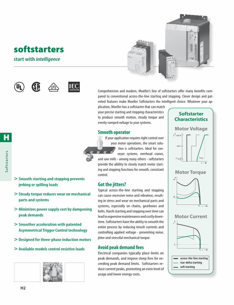
H
Soft
star
ters
H2
Comprehensive and modern, Moeller’s line of softstarters offer many benefits com-pared to conventional across-the-line starting and stopping. Clever design and pat-ented features make Moeller Softstarters the intelligent choice. Whatever your ap-plication, Moeller has a softstarter that can match your precise starting and stopping characteristics to produce smooth motion, steady torque and evenly-ramped voltage to your systems.
Smooth operatorIf your application requires tight control over
your motor operations, the smart solu-tion is softstarters. Ideal for con-
veyor systems, overhead cranes, and saw mills - among many others - softstarters provide the ablility to closely match motor start-ing and stopping functions for smooth, consistant control.
Got the jitters?Typical across-the-line starting and stopping can cause excessive noise and vibration, result-ing in stress and wear on mechanical parts and systems, especially on chains, gearboxes and belts. Harsh starting and stopping over time can lead to expensive maintenance and costly down-time. Softstarters have the ability to smooth the entire process by reducing inrush currents and controlling applied voltage - preventing noise, jitter and stressful mechanical torque.
Avoid peak demand feesElectrical companies typically place limits on peak demands, and impose steep fees for ex-ceeding peak demand limits. Softstarters re-duce current peaks, promoting an even level of usage and lower energy costs.
> Smooth starting and stopping prevents jerking or spilling loads
> Steady torque reduces wear on mechanical parts and systems
> Minimizes power supply cost by dampening peak demands
> Smoother acceleration with patented Asymmetrical Trigger Control technology
> Designed for three-phase induction motors
> Available models control resistive loads
softstarters start with intelligence
R
100 %
58 %
U
t
U Startt Start
Motor Voltage
nN
M
MN
n
Motor Torque
nN
IN
I
n
Motor Current
across-the-line starting star-delta starting soft starting
Softstarter Characteristics

H
Softstarters
H3
Vast knowledgeAvailable from 3 - 1300 HP for reversing or non-reversing applications, Moeller offers a wide array of softstarters. Optional features include:
built-in bypass circuitry•
control for resistive or inductive loads•
selectable application presets•
network enabled connections•
DIN rail or panel mount•
Patented technologyMoeller’s patented Asymmetrical Trigger Control can significantly reduce irregular acceleration of motors typically found in two phase controlled softstarters. This makes Moeller softstarters the ideal choice for even the most acceleration-sensitive applications.
Infinite wisdomUnlike other softstarters that offer a fixed number of starting voltage values, all Moeller softstarters are infinitely variable through dial adjustment. Two infinitely adjustable dials are also provided for starting and stopping times. All of these fea-tures combine to provide the exact starting and stopping characteristics you desire.
Asymmetrical Trigger Controlexclusive from Moeller
Typical Softstarter
Current characteristic in the uncontrolled phase
Feature ComparisonBu
ilt-in
Byp
ass C
onta
cts
Cont
rols
Res
istiv
e Lo
ads
For T
hree
-Pha
se M
otor
sDI
N-Ra
il M
ount
able
Netw
ork-
Capa
ble
Sele
ctab
le P
rese
tsRe
vers
ing
Func
tions
Softstarter Series Horsepower
DS4
DS4-…-M(-DC) 15 HP
DS4-…-MR 15 HP
DS4-…-MX10 HP 20 HP
DS4-…-MXR10 HP 20 HP
DS630 HP 150 HP
DM410 HP 1300 HP
By eliminating DC sine wave components within two-phase softstarters, Moeller has signifi-cantly reduced current peaks in the uncontrolled phase - resulting in smoother acceleration for your application.
H
Soft
star
ters
H4 moellerNA.com STARTER-CAT-NA-0708
Softstarters
Notes
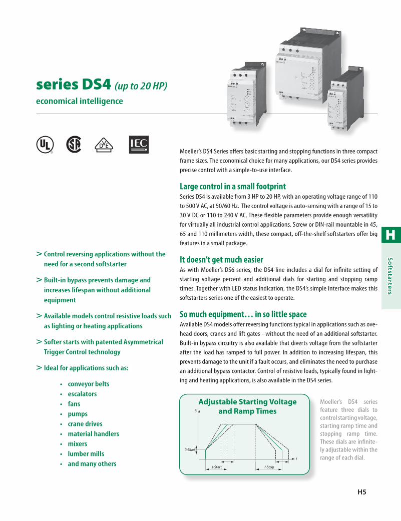
H
Softstarters
H5
series DS4 (up to 20 HP)economical intelligence
Moeller’s DS4 Series offers basic starting and stopping functions in three compact frame sizes. The economical choice for many applications, our DS4 series provides precise control with a simple-to-use interface.
Large control in a small footprintSeries DS4 is available from 3 HP to 20 HP, with an operating voltage range of 110 to 500 V AC, at 50/60 Hz. The control voltage is auto-sensing with a range of 15 to 30 V DC or 110 to 240 V AC. These flexible parameters provide enough versatility for virtually all industrial control applications. Screw or DIN-rail mountable in 45, 65 and 110 millimeters width, these compact, off-the-shelf softstarters offer big features in a small package.
It doesn’t get much easierAs with Moeller’s DS6 series, the DS4 line includes a dial for infinite setting of starting voltage percent and additional dials for starting and stopping ramp times. Together with LED status indication, the DS4’s simple interface makes this softstarters series one of the easiest to operate.
So much equipment… in so little spaceAvailable DS4 models offer reversing functions typical in applications such as ove-head doors, cranes and lift gates - without the need of an additional softstarter. Built-in bypass circuitry is also available that diverts voltage from the softstarter after the load has ramped to full power. In addition to increasing lifespan, this prevents damage to the unit if a fault occurs, and eliminates the need to purchase an additional bypass contactor. Control of resistive loads, typically found in light-ing and heating applications, is also available in the DS4 series.
> Control reversing applications without the need for a second softstarter
> Built-in bypass prevents damage and increases lifespan without additional equipment
> Available models control resistive loads such as lighting or heating applications
> Softer starts with patented Asymmetrical Trigger Control technology
> Ideal for applications such as:
conveyor belts•escalators•fans•pumps•crane drives•material handlers•mixers•lumber mills•and many others•
R
U-Start
U
t-Start t-Stop
t
Adjustable Starting Voltage and Ramp Times
Moeller’s DS4 series feature three dials to control starting voltage, starting ramp time and stopping ramp time. These dials are infinite-ly adjustable within the range of each dial.

H
Soft
star
ters
H6 moellerNA.com STARTER-CAT-NA-0708 Discount Code F21
Non-Reversing softstarters
Softstarter Description
Rated Operational Voltage Ue
Rated Operational
Current Ie
Rated Power for Motors
with Three-Phase
(AC 460 V)
Circuit Diagram Catalog Number PriceAC[V]
AC-51[A]
AC-53[A] [HP]
Non-Reversing
DC actuation only fast control inputsSuitable for resistive loads
110 – 500 11 6 3
L1 L2 L3
T1 T2 T3
DS4-340-2K2-M-DC 1220
AC actuatedSuitable for resistive loads
110 – 500 11 6 3 DS4-340-2K2-M 1220
110 – 500 17 9 5 DS4-340-4K0-M 1275
110 – 500 22 12 7½ DS4-340-5K5-M 1420
110 – 500 29 16 10 DS4-340-7K5-M 1500
110 – 500 41 23 15 DS4-340-11K-M 1680
With Built-in Bypass
With Built-in Bypass
110 – 500 – 16 10L1 L2 L3
T1 T2 T3
DS4-340-7K5-MX 1285
110 – 500 – 23 15 DS4-340-11K-MX 1390
110 – 500 – 31 20 DS4-340-15K-MX 1575
Softstarters
For Non-Reversing Motors
> Start and stop functions with infinitely adjustable ramp time of 0 – 10 seconds
> Infinite control of starting voltage between 30 – 92 percent of full voltage
> Simple-to-use interface with status LEDs
Ordering Instructions
1 Locate the desired softstarter.
2 See pages H10 – H11 for rated component list.
> Auto-sensing control voltage input
> Two-phase controlled softstarters with patented Asymmetrical Trigger technology produces smooth operations that rival three-phase controlled softstarters
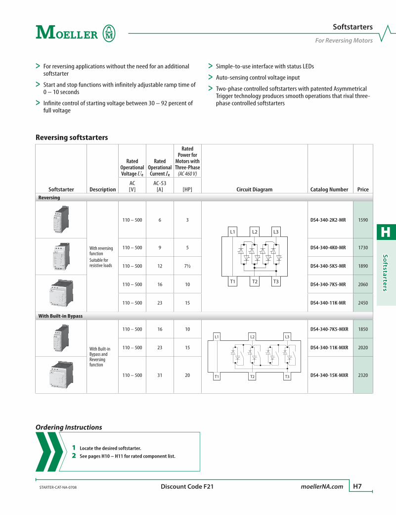
H
Softstarters
STARTER-CAT-NA-0708 moellerNA.com H7 Discount Code F21
Reversing softstarters
Softstarter Description
Rated Operational Voltage Ue
Rated Operational
Current Ie
Rated Power for
Motors with Three-Phase
(AC 460 V)
Circuit Diagram Catalog Number PriceAC[V]
AC-53[A] [HP]
Reversing
With reversing functionSuitable for resistive loads
110 – 500 6 3
L1 L2 L3
T1 T2 T3
DS4-340-2K2-MR 1590
110 – 500 9 5 DS4-340-4K0-MR 1730
110 – 500 12 7½ DS4-340-5K5-MR 1890
110 – 500 16 10 DS4-340-7K5-MR 2060
110 – 500 23 15 DS4-340-11K-MR 2450
With Built-in Bypass
With Built-in Bypass and Reversing function
110 – 500 16 10L1 L2 L3
T1 T2 T3
DS4-340-7K5-MXR 1850
110 – 500 23 15 DS4-340-11K-MXR 2020
110 – 500 31 20 DS4-340-15K-MXR 2320
Softstarters
For Reversing Motors
> For reversing applications without the need for an additional softstarter
> Start and stop functions with infinitely adjustable ramp time of 0 – 10 seconds
> Infinite control of starting voltage between 30 – 92 percent of full voltage
Ordering Instructions
1 Locate the desired softstarter.
2 See pages H10 – H11 for rated component list.
> Simple-to-use interface with status LEDs
> Auto-sensing control voltage input
> Two-phase controlled softstarters with patented Asymmetrical Trigger technology produces smooth operations that rival three-phase controlled softstarters

H
Soft
star
ters
H8 moellerNA.com STARTER-CAT-NA-0708
Softstarters, Non-ReversingDS4-340-M(X) Power Section
K1 Q21
K1S2
S1 K3
A1
A2K3
K1
K3
Q11
K1
F2
K2t
K2tt = 10 s
L01/L+
L00/L–
Soft Start
Soft Stop
F3
Q11
Q1
M3~
1L1
5L3
3L2
2T1
6T3
4T2
M1
Q21
F2
13 14
L1L2L3PE
I I I
Ready
Softstarters, ReversingDS4-340-M(X)R Power Section
K1
K1S2
S1 K2tt = 10 s
Q11
K1
F2
K2t K3 Q21
K3FWD
K3
FWD
0 VK4
K4
K4
K4 K3
K1
REV
REV
L01/L+
L00/L–
Soft Start
Soft Stop
Soft Start F3
Q11
Q1
M3~
1L1
5L3
3L2
2T1
6T3
4T2
M1
Q21
F2
13 14
L1L2L3PE
I I I
Ready
Application Notes
Series DS4 Softstarters
Schematic LegendQ1: Line ProtectionQ11: Mains Contactor (optional)F2: Overload RelayF3: Semiconductor Fuse, for type 2 coordination, in addition to Q1 (optional)Q21: SoftstarterS1: OffS2: On : Emergency Stop

H
Softstarters
STARTER-CAT-NA-0708 moellerNA.com H9
Softstarters
Notes

H
Soft
star
ters
H10 moellerNA.com STARTER-CAT-NA-0708
Assigned Switching and Protective Elements – DS4
Softstarter
Motor Rating
@ 460 V
Rated Operational Current ➊ Softstarter Function
Device Motor Rating ➋
Line Protection ➌
Mains Contactor (optional)
➍ Overload Relay ➎P
[HP]I
[A]Ie
[A]I
[A]Soft Starter for Three-Phase Power Supply, Low Operating Frequency (5 s, 3 x Ie, 10 starts/h)DS4-340-2K2-M(R)(-DC) 3 6 5 7 PKZM0-6,3 (+ CL-PKZ0) DILM7 ZB12-6
DS4-340-4K0-M(R) 5 9 8.5 10 PKZM0-10 (+ CL-PKZ0) DILM9 ZB12-10
DS4-340-5K5-M(R) 7.5 12 11.3 14 PKZM0-12 (+ CL-PKZ0) DILM12 ZB12-12
DS4-340-7K5-M(R) 10 16 15.2 18 PKZM0-16 (+ CL-PKZ0) DILM17 ZB32-16 (+ZB32-XEZ)
DS4-340-11K-M(R) 15 23 21.7 27 PKZM0-25 (+ CL-PKZ0) DILM25 ZB32-24 (+ZB32-XEZ)
DS4-340-7K5-MX(R) 10 16 15.2 18 PKZM0-16 (+ CL-PKZ0) DILM17 ZB32-16 (+ZB32-XEZ)
DS4-340-11K-MX(R) 15 23 21.7 27 PKZM0-25 (+ CL-PKZ0) DILM25 ZB32-24 (+ZB32-XEZ)
DS4-340-15K-MX(R) 20 31 29.3 37 PKZM0-32 (+ CL-PKZ0) DILM32 ZB32-32 (+ZB32-XEZ)
Soft Starter for Three-Phase Power Supply, High Operating Frequency (5 s, 6 x Ie, 20 starts/h), > Class 25DS4-340-2K2-M(R)(-DC) 3 6 5 9 PKZM0-10 (+ CL-PKZ0) DILM9 ZEV (+ ZEV-XSW-25)
DS4-340-4K0-M(R) 5 9 8.5 14 PKZM0-16 (+ CL-PKZ0) DILM17 ZEV (+ ZEV-XSW-25)
DS4-340-5K5-M(R) 7.5 12 11.3 19 PKZM0-20 (+ CL-PKZ0) DILM20 ZEV (+ ZEV-XSW-25)
DS4-340-7K5-M(R) 10 16 15.2 25 PKZM0-25 (+ CL-PKZ0) DILM25 ZEV (+ ZEV-XSW-25)
DS4-340-11K-M(R) 15 23 21.7 36 PKZM4-40 (+ CL-PKZ0) DILM40 ZEV (+ ZEV-XSW-65)
Semiconductor Contactor for Three-Phase Power Supply, High Operating Frequency (0,5 s, 6 x Ie, 600 starts/h), > Class 25DS4-340-2K2-M(R)(-DC) 3 6 5 12 PKZM0-10 (+ CL-PKZ0) DILM12 ZEV (+ ZEV-XSW-25)
DS4-340-4K0-M(R) 5 9 8.5 18 PKZM0-20 (+ CL-PKZ0) DILM25 ZEV (+ ZEV-XSW-25)
DS4-340-5K5-M(R) 7.5 12 11.3 24 PKZM0-25 (+ CL-PKZ0) DILM25 ZEV (+ ZEV-XSW-25)
DS4-340-7K5-M(R) 10 16 15.2 32 PKZM4-40 (+ CL-PKZ0) DILM32 ZEV (+ ZEV-XSW-25)
DS4-340-11K-M(R) 15 23 21.7 46 PKZM4-50 (+ CL-PKZ0) DILM50 ZEV (+ ZEV-XSW-65)
Semiconductor Contactor for for AC 51 Applications (1 s, 1.5 x Ie, 600 starts/h, 600 switching operations/h)DS4-340-2K2-M(R)(-DC) – 11 – – PKZM0-12 (+ CL-PKZ0) DILM7 –
DS4-340-4K0-M(R) – 17 – – PKZM0-20 (+ CL-PKZ0) DILM17 –
DS4-340-5K5-M(R) – 22 – – PKZM0-25 (+ CL-PKZ0) DILM17 –
DS4-340-7K5-M(R) – 29 – – PKZM0-32 (+ CL-PKZ0) DILM25 –
DS4-340-11K-M(R) – 41 – – PKZM4-50 DILM50 –
➊ Rated operational current relative to the specified load cycle.➋ Indicates the current for which the supply cable must be dimensioned at the
specified switching duty and motor current. At different switching duty (operating frequency, overcurrent, overcurrent time, DF), this value changes and must then be adapted accordingly. The same applies for higher motor currents.
➌Max. short-circuit current as per technical specifications of used circuit-breaker.➍ If the control section is configured so that the control signal is inhibited before the
mains contactor is disabled in the event of an Emergency-Stop, the contactors in the “Bypass Contactor” column can also be used as mains contactors.
➎ Alternatively, a motor-protective circuit-breaker with built-in overload protection can be used (e.g., PKZM0, NZM without the “-OBI” extension).

H
Softstarters
STARTER-CAT-NA-0708 moellerNA.com H11
Softstarter Series DS4
Rated Component List
Assigned Switching and Protective Elements – DS4
Softstarter
Motor Rating
@ 460 V
Rated Operational Current ➊ Softstarter Function
Device Motor Rating ➋
Line Protection ➌
Mains Contactor (optional)
➍ Overload Relay ➎P
[HP]I
[A]Ie
[A]I
[A]Soft Starter for Three-Phase Power Supply, Low Operating Frequency (5 s, 3 x Ie, 10 starts/h)DS4-340-2K2-M(R)(-DC) 3 6 5 7 PKZM0-6,3 (+ CL-PKZ0) DILM7 ZB12-6
DS4-340-4K0-M(R) 5 9 8.5 10 PKZM0-10 (+ CL-PKZ0) DILM9 ZB12-10
DS4-340-5K5-M(R) 7.5 12 11.3 14 PKZM0-12 (+ CL-PKZ0) DILM12 ZB12-12
DS4-340-7K5-M(R) 10 16 15.2 18 PKZM0-16 (+ CL-PKZ0) DILM17 ZB32-16 (+ZB32-XEZ)
DS4-340-11K-M(R) 15 23 21.7 27 PKZM0-25 (+ CL-PKZ0) DILM25 ZB32-24 (+ZB32-XEZ)
DS4-340-7K5-MX(R) 10 16 15.2 18 PKZM0-16 (+ CL-PKZ0) DILM17 ZB32-16 (+ZB32-XEZ)
DS4-340-11K-MX(R) 15 23 21.7 27 PKZM0-25 (+ CL-PKZ0) DILM25 ZB32-24 (+ZB32-XEZ)
DS4-340-15K-MX(R) 20 31 29.3 37 PKZM0-32 (+ CL-PKZ0) DILM32 ZB32-32 (+ZB32-XEZ)
Soft Starter for Three-Phase Power Supply, High Operating Frequency (5 s, 6 x Ie, 20 starts/h), > Class 25DS4-340-2K2-M(R)(-DC) 3 6 5 9 PKZM0-10 (+ CL-PKZ0) DILM9 ZEV (+ ZEV-XSW-25)
DS4-340-4K0-M(R) 5 9 8.5 14 PKZM0-16 (+ CL-PKZ0) DILM17 ZEV (+ ZEV-XSW-25)
DS4-340-5K5-M(R) 7.5 12 11.3 19 PKZM0-20 (+ CL-PKZ0) DILM20 ZEV (+ ZEV-XSW-25)
DS4-340-7K5-M(R) 10 16 15.2 25 PKZM0-25 (+ CL-PKZ0) DILM25 ZEV (+ ZEV-XSW-25)
DS4-340-11K-M(R) 15 23 21.7 36 PKZM4-40 (+ CL-PKZ0) DILM40 ZEV (+ ZEV-XSW-65)
Semiconductor Contactor for Three-Phase Power Supply, High Operating Frequency (0,5 s, 6 x Ie, 600 starts/h), > Class 25DS4-340-2K2-M(R)(-DC) 3 6 5 12 PKZM0-10 (+ CL-PKZ0) DILM12 ZEV (+ ZEV-XSW-25)
DS4-340-4K0-M(R) 5 9 8.5 18 PKZM0-20 (+ CL-PKZ0) DILM25 ZEV (+ ZEV-XSW-25)
DS4-340-5K5-M(R) 7.5 12 11.3 24 PKZM0-25 (+ CL-PKZ0) DILM25 ZEV (+ ZEV-XSW-25)
DS4-340-7K5-M(R) 10 16 15.2 32 PKZM4-40 (+ CL-PKZ0) DILM32 ZEV (+ ZEV-XSW-25)
DS4-340-11K-M(R) 15 23 21.7 46 PKZM4-50 (+ CL-PKZ0) DILM50 ZEV (+ ZEV-XSW-65)
Semiconductor Contactor for for AC 51 Applications (1 s, 1.5 x Ie, 600 starts/h, 600 switching operations/h)DS4-340-2K2-M(R)(-DC) – 11 – – PKZM0-12 (+ CL-PKZ0) DILM7 –
DS4-340-4K0-M(R) – 17 – – PKZM0-20 (+ CL-PKZ0) DILM17 –
DS4-340-5K5-M(R) – 22 – – PKZM0-25 (+ CL-PKZ0) DILM17 –
DS4-340-7K5-M(R) – 29 – – PKZM0-32 (+ CL-PKZ0) DILM25 –
DS4-340-11K-M(R) – 41 – – PKZM4-50 DILM50 –
Semiconductor Protection (optional; fuses required for
Type 2 coordination are in addition to the protective elements required for
Type 1 coordination) ➊
DC Braking Unit
Hilger & Kern Frenomat/Frenostat
Output Contactor for
Softstarter ➋ Line Protection
MainsReactor
➌Braking
Contactor
Fuse for Standstill
Monitoring ➍
Fuses Fuse Holders
Recommended @ 400V Mains VoltageNumber x Type Number x Type
3 x 50.140.06-50 3 x 51.060.04 Frenomat-6000.0309 DILM7 PKZM0-10 (+ CL-PKZ0) External DILM7 FAZ-B4/1-HI
3 x 50.140.06-63 3 x 51.060.04 Frenomat-6000.0185 DILM7 PKZM0-16 (+ CL-PKZ0) External DILM9 FAZ-B4/1-HI
3 x 50.140.06-80 3 x 51.060.04 Frenostat-6000.0304 DILM7 PKZM0-20 (+ CL-PKZ0) External Built-In FAZ-B4/1-HI
3 x 20.282.20-125 3 x 21.313.02 Frenostat-6000.0316 DILM7 PKZM0-25 (+ CL-PKZ0) External DILM17 FAZ-B4/1-HI
3 x 20.282.20-160 3 x 21.313.02 Frenostat-6000.0316 DILM17 PKZM0-40 (+ CL-PKZ0) External DILM25 FAZ-B4/1-HI
3 x 50.140.06-63 3 x 51.060.04 Frenostat-6000.0316 DILM7 PKZM0-25 (+ CL-PKZ0) External DILM17 FAZ-B4/1-HI
3 x 50.140.06-80 3 x 51.060.04 Frenostat-6000.0316 DILM17 PKZM0-40 (+ CL-PKZ0) External DILM25 FAZ-B4/1-HI
3 x 20.282.20-125 3 x 21.313.02 Frenostat-6000.0247 DILM17 PKZM0-50 (+ CL-PKZ0) Built-In DILM32 FAZ-B4/1-HI
3 x 50.140.06-50 3 x 51.060.04 Frenomat-6000.0309 DILM7 PKZM0-10 (+ CL-PKZ0) External DILM7 FAZ-B4/1-HI
3 x 50.140.06-63 3 x 51.060.04 Frenomat-6000.0185 DILM7 PKZM0-16 (+ CL-PKZ0) External DILM9 FAZ-B4/1-HI
3 x 50.140.06-80 3 x 51.060.04 Frenostat-6000.0304 DILM7 PKZM0-20 (+ CL-PKZ0) External Built-In FAZ-B4/1-HI
3 x 20.282.20-125 3 x 21.313.02 Frenostat-6000.0316 DILM17 PKZM0-25 (+ CL-PKZ0) External DILM17 FAZ-B4/1-HI
3 x 20.282.20-160 3 x 21.313.02 Frenostat-6000.0316 DILM17 PKZM0-40 (+ CL-PKZ0) External DILM25 FAZ-B4/1-HI
3 x 50.140.06-50 3 x 51.060.04 Frenomat-6000.0309 DILM7 PKZM0-10 (+ CL-PKZ0) External DILM7 FAZ-B4/1-HI
3 x 50.140.06-63 3 x 51.060.04 Frenomat-6000.0185 DILM7 PKZM0-16 (+ CL-PKZ0) External DILM9 FAZ-B4/1-HI
3 x 50.140.06-80 3 x 51.060.04 Frenostat-6000.0304 DILM17 PKZM0-20 (+ CL-PKZ0) External Built-In FAZ-B4/1-HI
3 x 20.282.20-125 3 x 21.313.02 Frenostat-6000.0316 DILM17 PKZM0-25 (+ CL-PKZ0) External DILM17 FAZ-B4/1-HI
3 x 20.282.20-160 3 x 21.313.02 Frenostat-6000.0316 DILM25 PKZM0-40 (+ CL-PKZ0) External DILM25 FAZ-B4/1-HI
3 x 50.140.06-50 3 x 51.060.04 – – – – – –
3 x 50.140.06-63 3 x 51.060.04 – – – – – –
3 x 50.140.06-80 3 x 51.060.04 – – – – – –
3 x 20.282.20-125 3 x 21.313.02 – – – – – –
3 x 20.282.20-160 3 x 21.313.02 – – – – – –
➊ Semiconductor fuses are required only for Type 2 coordination; max. short-circuit current 100 kA.
➋ If a DC braking unit is used, the softstarter's output must be isolated with this contactor before braking.
➌If external, included as standard.➍If a measuring line with a cross-section F 1.5 mm2 is used, the fuse can be omitted.
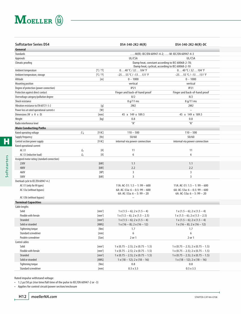
H
Soft
star
ters
H12 moellerNA.com STARTER-CAT-NA-0708
Softstarter Series DS4 DS4-340-2K2-M(R) DS4-340-2K2-M(R)-DCGeneralStandards …-M(R): IEC/EN 60947-4-2; …-M: IEC/EN 60947-4-3Approvals UL/CSA UL/CSAClimatic proofing Damp heat, constant according to IEC 60068-2-78;
Damp heat, cyclical, according to IEC 60068-2-10Ambient temperature [°C / °F] 0…40 °C / 32…104 °F 0…40 °C / 32…104 °FAmbient temperature, storage [°C / °F] -25…55 °C / -13…131 °F -25…55 °C / -13…131 °FAltitude [m] 0 – 1000 0 – 1000Mounting position vertical verticalDegree of protection (power connection) IP21 IP21Protection against direct contact Finger and back-of-hand proof Finger and back-of-hand proofOvervoltage category/pollution degree II/2 II/2Shock resistance 8 g/11 ms 8 g/11 msVibration resistance to EN 60721-3-2 [g] 2M2 2M2Power loss at rated operational current e [W] – –Dimensions (W x H x D) [mm] 45 x 149 x 189.5 45 x 149 x 189.5Weight [kg] 0.8 0.8Radio interference level "A" "A"
Main Conducting PathsRated operating voltage Ue [V AC] 110 – 500 110 – 500Supply frequency [Hz] 50/60 50/60Control section power supply [V AC] internal via power connection internal via power connectionRated operational current AC-51 Ie [A] 11 11 AC-53 (inductive load) Ie [A] 6 6Assigned motor rating (standard connection) 230V [kW] 1.1 1.1 400V [kW] 2.2 2.2 460V [HP] 3 3 500V [kW] 3 3Overload cycle to IEC/EN 60947-4-2 AC-51 (only for M types) 11A: AC-51: 1.5 – 1: 99 – 600 11A: AC-51: 1.5 – 1: 99 – 600 AC-53a (without bypass) 6A: AC-53a: 6 – 0.5: 99 – 600
6A: AC-53a: 6 – 5: 99 – 206A: AC-53a: 6 – 0.5: 99 – 600
6A: AC-53a: 6 – 5: 99 – 20 AC-53b (without bypass) – –
Terminal CapacitiesCable lengths Solid [mm2] 1 x (1.5 – 6); 2 x (1.5 – 4) 1 x (1.5 – 6); 2 x (1.5 – 4) Flexible with ferrule [mm2] 1 x (1.5 – 6); 2 x (1.5 – 2.5) 1 x (1.5 – 6); 2 x (1.5 – 2.5) Stranded [mm2] 1 x (1.5 – 6); 2 x (1.5 – 4) 1 x (1.5 – 6); 2 x (1.5 – 4) Solid or stranded [AWG] 1 x (16 – 8); 2 x (16 – 12) 1 x (16 – 8); 2 x (16 – 12) Tightening torque [Nm] 1.7 1.7 Standard screwdriver [mm] 6 6 Posidriv screwdriver [Size] 2 or 1 2 or 1Control cables Solid [mm2] 1 x (0.75 – 2.5); 2 x (0.75 – 1.5) 1 x (0.75 – 2.5); 2 x (0.75 – 1.5) Flexible with ferrule [mm2] 1 x (0.75 – 2.5); 2 x (0.75 – 1.5) 1 x (0.75 – 2.5); 2 x (0.75 – 1.5) Stranded [mm2] 1 x (0.75 – 2.5); 2 x (0.75 – 1.5) 1 x (0.75 – 2.5); 2 x (0.75 – 1.5) Solid or stranded [AWG] 1 x (18 – 12); 2 x (18 – 16) 1 x (18 – 12); 2 x (18 – 16) Tightening torque [Nm] 0.8 0.8 Standard screwdriver [mm] 0.5 x 3.5 0.5 x 3.5
Rated impulse withstand voltage:1.2 µs/50 µs (rise time/fall time of the pulse to IEC/EN 60947-2 or -3)•Applies for control circuit/power section/enclosure•

H
Softstarters
STARTER-CAT-NA-0708 moellerNA.com H13
Technical Data
Softstarters Series DS4
Softstarter Series DS4 DS4-340-2K2-M(R) DS4-340-2K2-M(R)-DCGeneralStandards …-M(R): IEC/EN 60947-4-2; …-M: IEC/EN 60947-4-3Approvals UL/CSA UL/CSAClimatic proofing Damp heat, constant according to IEC 60068-2-78;
Damp heat, cyclical, according to IEC 60068-2-10Ambient temperature [°C / °F] 0…40 °C / 32…104 °F 0…40 °C / 32…104 °FAmbient temperature, storage [°C / °F] -25…55 °C / -13…131 °F -25…55 °C / -13…131 °FAltitude [m] 0 – 1000 0 – 1000Mounting position vertical verticalDegree of protection (power connection) IP21 IP21Protection against direct contact Finger and back-of-hand proof Finger and back-of-hand proofOvervoltage category/pollution degree II/2 II/2Shock resistance 8 g/11 ms 8 g/11 msVibration resistance to EN 60721-3-2 [g] 2M2 2M2Power loss at rated operational current e [W] – –Dimensions (W x H x D) [mm] 45 x 149 x 189.5 45 x 149 x 189.5Weight [kg] 0.8 0.8Radio interference level "A" "A"
Main Conducting PathsRated operating voltage Ue [V AC] 110 – 500 110 – 500Supply frequency [Hz] 50/60 50/60Control section power supply [V AC] internal via power connection internal via power connectionRated operational current AC-51 Ie [A] 11 11 AC-53 (inductive load) Ie [A] 6 6Assigned motor rating (standard connection) 230V [kW] 1.1 1.1 400V [kW] 2.2 2.2 460V [HP] 3 3 500V [kW] 3 3Overload cycle to IEC/EN 60947-4-2 AC-51 (only for M types) 11A: AC-51: 1.5 – 1: 99 – 600 11A: AC-51: 1.5 – 1: 99 – 600 AC-53a (without bypass) 6A: AC-53a: 6 – 0.5: 99 – 600
6A: AC-53a: 6 – 5: 99 – 206A: AC-53a: 6 – 0.5: 99 – 600
6A: AC-53a: 6 – 5: 99 – 20 AC-53b (without bypass) – –
Terminal CapacitiesCable lengths Solid [mm2] 1 x (1.5 – 6); 2 x (1.5 – 4) 1 x (1.5 – 6); 2 x (1.5 – 4) Flexible with ferrule [mm2] 1 x (1.5 – 6); 2 x (1.5 – 2.5) 1 x (1.5 – 6); 2 x (1.5 – 2.5) Stranded [mm2] 1 x (1.5 – 6); 2 x (1.5 – 4) 1 x (1.5 – 6); 2 x (1.5 – 4) Solid or stranded [AWG] 1 x (16 – 8); 2 x (16 – 12) 1 x (16 – 8); 2 x (16 – 12) Tightening torque [Nm] 1.7 1.7 Standard screwdriver [mm] 6 6 Posidriv screwdriver [Size] 2 or 1 2 or 1Control cables Solid [mm2] 1 x (0.75 – 2.5); 2 x (0.75 – 1.5) 1 x (0.75 – 2.5); 2 x (0.75 – 1.5) Flexible with ferrule [mm2] 1 x (0.75 – 2.5); 2 x (0.75 – 1.5) 1 x (0.75 – 2.5); 2 x (0.75 – 1.5) Stranded [mm2] 1 x (0.75 – 2.5); 2 x (0.75 – 1.5) 1 x (0.75 – 2.5); 2 x (0.75 – 1.5) Solid or stranded [AWG] 1 x (18 – 12); 2 x (18 – 16) 1 x (18 – 12); 2 x (18 – 16) Tightening torque [Nm] 0.8 0.8 Standard screwdriver [mm] 0.5 x 3.5 0.5 x 3.5
DS4-340-4K0-M(R) DS4-340-5K5-M(R) DS4-340-7K5-M(R) DS4-340-11K-M(R)
…-M(R): IEC/EN 60947-4-2; …-M: IEC/EN 60947-4-3UL/CSA UL/CSA UL/CSA UL/CSA
Damp heat, constant according to IEC 60068-2-78; Damp heat, cyclical, according to IEC 60068-2-10
0…40 °C / 32…104 °F 0…40 °C / 32…104 °F 0…40 °C / 32…104 °F 0…40 °C / 32…104 °F-25…55 °C / -13…131 °F -25…55 °C / -13…131 °F -25…55 °C / -13…131 °F -25…55 °C / -13…131 °F
0 – 1000 0 – 1000 0 – 1000 0 – 1000vertical vertical vertical vertical
IP21 IP21 IP21 IP21Finger and back-of-hand proof Finger and back-of-hand proof Finger and back-of-hand proof Finger and back-of-hand proof
II/2 II/2 II/2 II/28 g/11 ms 8 g/11 ms 8 g/11 ms 8 g/11 ms
2M2 2M2 2M2 2M2– – – –
45 x 149 x 189.5 45 x 149 x 189.5 45 x 149 x 189.5 45 x 149 x 189.51.0 1.0 1.7 1.7"A" "A" "A" "A"
110 – 500 110 – 500 110 – 500 110 – 50050/60 50/60 50/60 50/60
internal via power connection internal via power connection internal via power connection internal via power connection
17 22 29 419 12 16 23
2.2 3 4 5.54 5.5 7.5 115 7 10 15
5.5 5.5 7.5 11
17A: AC-51: 1.5 – 1: 99 – 600 22A: AC-51: 1.5 – 1: 99 – 600 29A: AC-51: 1.5 – 1: 99 – 600 41A: AC-51: 1.5 – 1: 99 – 6009A: AC-53a: 6 – 0.5: 99 – 600
9A: AC-53a: 6 – 5: 99 – 2012A: AC-53a: 6 – 0.5: 99 – 600
12A: AC-53a: 6 – 5: 99 – 2016A: AC-53a: 6 – 0.5: 99 – 600
16A: AC-53a: 6 – 5: 99 – 2023A: AC-53a: 6 – 0.5: 99 – 600
23A: AC-53a: 6 – 5: 99 – 20– – – 41A AC-53b:3 – 5:360 (-M only)
1 x (1.5 – 35); 2 x (1.5 –10) 1 x (1.5 – 35); 2 x (1.5 –10) 1 x (2.5 – 50); 2 x (2.5 – 16) 1 x (2.5 – 50); 2 x (2.5 – 16)1 x (1.5 – 25); 2 x (1.5 – 6) 1 x (1.5 – 25); 2 x (1.5 – 6) 1 x (2.5 – 35); 2 x (2.5 – 10) 1 x (2.5 – 35); 2 x (2.5 – 10)
1 x (1.5 – 35); 2 x (1.5 – 10) 1 x (1.5 – 35); 2 x (1.5 – 10) 1 x (2.5 – 50); 2 x (2.5 – 16) 1 x (2.5 – 50); 2 x (2.5 – 16)1 x (16 – 4); 2 x (16 – 10) 1 x (16 – 4); 2 x (16 – 10) 1 x (14 – 2); 2 x (14 – 8) 1 x (14 – 2); 2 x (14 – 8)
3 3 3.5 3.56mm 6mm 6mm 6mm2 or 1 2 or 1 2 or 1 2 or 1
1 x (0.75 – 2.5); 2 x (0.75 – 1.5) 1 x (0.75 – 2.5); 2 x (0.75 – 1.5) 1 x (0.75 – 2.5); 2 x (0.75 – 1.5) 1 x (0.75 – 2.5); 2 x (0.75 – 1.5)1 x (0.75 – 2.5); 2 x (0.75 – 1.5) 1 x (0.75 – 2.5); 2 x (0.75 – 1.5) 1 x (0.75 – 2.5); 2 x (0.75 – 1.5) 1 x (0.75 – 2.5); 2 x (0.75 – 1.5)1 x (0.75 – 2.5); 2 x (0.75 – 1.5) 1 x (0.75 – 2.5); 2 x (0.75 – 1.5) 1 x (0.75 – 2.5); 2 x (0.75 – 1.5) 1 x (0.75 – 2.5); 2 x (0.75 – 1.5)
1 x (18 – 12); 2 x (18 – 16) 1 x (18 – 12); 2 x (18 – 16) 1 x (18 – 12); 2 x (18 – 16) 1 x (18 – 12); 2 x (18 – 16)0.8 0.8 0.8 0.8
0.5 x 3.5 0.5 x 3.5 0.5 x 3.5 0.5 x 3.5

H
Soft
star
ters
H14 moellerNA.com STARTER-CAT-NA-0708
Softstarter Series DS4 DS4-340-2K2-M(R) DS4-340-2K2-M(R)-DCPower SectionRated impulse withstand voltage Uimp [kV] 6 6Rated insulation voltage Ui [V AC] 500 500Short-circuit rating Type "1" coordination For AC-51: 1.5-1: 600-99 PKZM0-16 (+CL-PKZ0) PKZM0-16 (+CL-PKZ0) For AC-53a: 3-5: 10-99 and AC-53b: 3-5 : 360 PKZM0-6,3 (+CL-PKZ0) + Z00-6 (+EZ00) PKZM0-6,3 (+CL-PKZ0) + Z00-6 (+EZ00) For AC-53a: 6-0.5: 600-99 PKZM0-10 (+CL-PKZ0) + ZEV + ZEV-XSW-25 PKZM0-10 (+CL-PKZ0) + ZEV + ZEV-XSW-25
Type "2" coordination (in addition to coordination type "1") 3 x 50.140.06-50 3 x 50.140.06-50 Fuse base 3 x 51.060.04 3 x 51.060.04
Control CircuitCurrent consumption Minimum control voltage [V AC/DC] 110 / 24 24 Digital inputs 24V DC [mA] 14 14 230V AC [mA] 14 14Control section power supply [V AC] internal via power connection internal via power connectionControl voltage DC operated [V DC] 24 ±15% 24 ±15% AC operated [V AC] 110 – 240 ±15% –Pick-up voltage DC operated [V DC] 15 – 27 15 – 27 AC operated [V AC] 79 – 264 –Drop-out voltage DC operated [V DC] 0 – 3 0 – 3 AC operated [V AC] 0 – 22 –Pick-up time DC operated [ms] 95 45 AC operated [ms] 115 –Drop-out time DC operated [ms] 165 45 AC operated [ms] 165 –Programmable relay output Number 1 1 Voltage range [V AC] 250 250 AC-1 current range [A] 3 3
Soft Start FunctionRamp times Acceleration [s] 0 – 10 0 – 10 Deceleration [s] 0 – 10 0 – 10Start voltage (= turn-off voltage) [%] 30 – 92 30 – 92Voltage reduction at stop [%] 8 8Torque-free time for rotation direction reversal [ms] 60 60
Rated impulse withstand voltage:1.2 µs/50 µs (rise time/fall time of the pulse to IEC/EN 60947-2 or -3)•Applies for control circuit/power section/enclosure•

H
Softstarters
STARTER-CAT-NA-0708 moellerNA.com H15
Technical Data
Softstarters Series DS4
Softstarter Series DS4 DS4-340-2K2-M(R) DS4-340-2K2-M(R)-DCPower SectionRated impulse withstand voltage Uimp [kV] 6 6Rated insulation voltage Ui [V AC] 500 500Short-circuit rating Type "1" coordination For AC-51: 1.5-1: 600-99 PKZM0-16 (+CL-PKZ0) PKZM0-16 (+CL-PKZ0) For AC-53a: 3-5: 10-99 and AC-53b: 3-5 : 360 PKZM0-6,3 (+CL-PKZ0) + Z00-6 (+EZ00) PKZM0-6,3 (+CL-PKZ0) + Z00-6 (+EZ00) For AC-53a: 6-0.5: 600-99 PKZM0-10 (+CL-PKZ0) + ZEV + ZEV-XSW-25 PKZM0-10 (+CL-PKZ0) + ZEV + ZEV-XSW-25
Type "2" coordination (in addition to coordination type "1") 3 x 50.140.06-50 3 x 50.140.06-50 Fuse base 3 x 51.060.04 3 x 51.060.04
Control CircuitCurrent consumption Minimum control voltage [V AC/DC] 110 / 24 24 Digital inputs 24V DC [mA] 14 14 230V AC [mA] 14 14Control section power supply [V AC] internal via power connection internal via power connectionControl voltage DC operated [V DC] 24 ±15% 24 ±15% AC operated [V AC] 110 – 240 ±15% –Pick-up voltage DC operated [V DC] 15 – 27 15 – 27 AC operated [V AC] 79 – 264 –Drop-out voltage DC operated [V DC] 0 – 3 0 – 3 AC operated [V AC] 0 – 22 –Pick-up time DC operated [ms] 95 45 AC operated [ms] 115 –Drop-out time DC operated [ms] 165 45 AC operated [ms] 165 –Programmable relay output Number 1 1 Voltage range [V AC] 250 250 AC-1 current range [A] 3 3
Soft Start FunctionRamp times Acceleration [s] 0 – 10 0 – 10 Deceleration [s] 0 – 10 0 – 10Start voltage (= turn-off voltage) [%] 30 – 92 30 – 92Voltage reduction at stop [%] 8 8Torque-free time for rotation direction reversal [ms] 60 60
DS4-340-4K0-M(R) DS4-340-5K5-M(R) DS4-340-7K5-M(R) DS4-340-11K-M(R)
6 6 6 6500 500 500 500
PKZM0-20 (+CL-PKZ0) PKZM0-16 (+CL-PKZ0) PKZM4-32 PKZM4-50PKZM0-10 (+CL-PKZ0) + Z00-10 (+EZ00) PKZM0-16 (+CL-PKZ0) + Z00-16 (+EZ00) PKZM0-16 (+CL-PKZ0) + Z00-16 (+EZ00) PKZM0-25 (+CL-PKZ0) + Z00-24 (+EZ00)
PKZM0-20 (+CL-PKZ0) + ZEV + ZEV-XSW-25
PKZM0-25 (+CL-PKZ0) + ZEV + ZEV-XSW-25
PKZM4-40 (+CL-PKZ0) + ZEV + ZEV-XSW-65
PKZM4-50 (+CL-PKZ0) + ZEV + ZEV-XSW-65
3 x 50.140.06-63 3 x 50.140.06-80 3 x 50.140.06-125 3 x 50.140.06-1603 x 51.060.04 3 x 51.060.04 3 x 21.189.01 3 x 21.189.01
110 / 24 110 / 24 110 / 24 110 / 24
14 14 14 1414 14 14 14
internal via power connection internal via power connection internal via power connection internal via power connection
24 ±15% 24 ±15% 24 ±15% 24 ±15%110 – 240 ±15% 110 – 240 ±15% 110 – 240 ±15% 110 – 240 ±15%
15 – 27 15 – 27 15 – 27 15 – 2779 – 264 79 – 264 79 – 264 79 – 264
0 – 3 0 – 3 0 – 3 0 – 30 – 22 0 – 22 0 – 22 0 – 22
95 95 95 95115 115 115 115
165 165 165 165165 165 165 165
1 1 1 1250 250 250 250
3 3 3 3
0 – 10 0 – 10 0 – 10 0 – 100 – 10 0 – 10 0 – 10 0 – 10
30 – 92 30 – 92 30 – 92 30 – 928 8 8 8
60 60 60 60

H
Soft
star
ters
H16 moellerNA.com STARTER-CAT-NA-0708
Technical Data
Softstarters Series DS4
Softstarter Series DS4 DS4-340-7K5-MX(R) DS4-340-11K-MX(R) DS4-340-15K-MX(R)GeneralStandards IEC/EN 60947-4-2 IEC/EN 60947-4-2 IEC/EN 60947-4-2Approvals UL/CSA UL/CSA UL/CSAClimatic proofing Damp heat, constant according to IEC 60068-2-78;
Damp heat, cyclical, according to IEC 60068-2-10Ambient temperature [°C / °F] 0…40 °C / 32…104 °F 0…40 °C / 32…104 °F 0…40 °C / 32…104 °FAmbient temperature, storage [°C / °F] -25…55 °C / -13…131 °F -25…55 °C / -13…131 °F -25…55 °C / -13…131 °FAltitude [m] 0 – 1000 0 – 1000 0 – 1000Mounting position vertical vertical verticalDegree of protection (power connection) IP21 IP21 IP21Protection against direct contact Finger and back-of-hand proof Finger and back-of-hand proof Finger and back-of-hand proofOvervoltage category/pollution degree II/2 II/2 II/2Shock resistance 8 g/11 ms 8 g/11 ms 8 g/11 msDimensions (W x H x D) [mm] 45 x 149 x 189.5 45 x 149 x 189.5 45 x 149 x 189.5Weight [kg] 0.8 0.8 1.6Radio interference level "A" "A" "A"Vibration resistance to EN 60721-3-2 2M2 2M2 2M2Average heat dissipation at rated load cycle [W] 11.2 11.9 12.7
Main Conducting PathsRated operating voltage Ue [V AC] 110 – 500 110 – 500 110 – 500Supply frequency [Hz] 50/60 50/60 50/60Control section power supply [V AC] internal via power connection internal via power connection internal via power connectionRated operational current AC-53 (inductive load) Ie [A] 16 23 31Assigned motor rating (standard connection) 230V [kW] 4 5.5 7.5 400V [kW] 7.5 11 15 460V [HP] 10 15 20 500V [kW] 7.5 11 18.5Overload cycle to IEC/EN 60947-4-2 AC-53b (without bypass) 16A: AC-53b: 3 – 5; 360 23A: AC-53b: 3 – 5; 360 31A: AC-53b: 3 – 5; 360
Terminal CapacitiesCable lengths Solid [mm2] 1 x (1.5 – 6); 2 x (1.5 – 4) 1 x (1.5 – 6); 2 x (1.5 – 4) 1 x (2.5 – 50); 2 x (2.5 – 16) Flexible with ferrule [mm2] 1 x (1.5 – 6); 2 x (1.5 – 2.5) 1 x (1.5 – 6); 2 x (1.5 – 2.5) 1 x (2.5 – 35); 2 x (2.5 – 10) Stranded [mm2] 1 x (1.5 – 6); 2 x (1.5 – 4) 1 x (1.5 – 6); 2 x (1.5 – 4) 1 x (2.5 – 50); 2 x (2.5 – 16) Solid or stranded [AWG] 1 x (16 – 8); 2 x (16 – 12) 1 x (16 – 8); 2 x (16 – 12) 1 x (14 – 2); 2 x (14 – 8) Tightening torque [Nm] 1.7 1.7 3.5 Standard screwdriver [mm] 6 6 6 Posidriv screwdriver [Size] 2 or 1 2 or 1 2 or 1Control cables Solid [mm2] 1 x (0.75 – 2.5); 2 x (0.75 – 1.5) 1 x (0.75 – 2.5); 2 x (0.75 – 1.5) 1 x (0.75 – 2.5); 2 x (0.75 – 1.5) Flexible with ferrule [mm2] 1 x (0.75 – 2.5); 2 x (0.75 – 1.5) 1 x (0.75 – 2.5); 2 x (0.75 – 1.5) 1 x (0.75 – 2.5); 2 x (0.75 – 1.5) Stranded [mm2] 1 x (0.75 – 2.5); 2 x (0.75 – 1.5) 1 x (0.75 – 2.5); 2 x (0.75 – 1.5) 1 x (0.75 – 2.5); 2 x (0.75 – 1.5) Solid or stranded [AWG] 1 x (18 –12); 2 x (18 –16) 1 x (18 –12); 2 x (18 –16) 1 x (18 –12); 2 x (18 –16) Tightening torque [Nm] 0.8 0.8 0.8 Standard screwdriver [mm] 0.5 x 3.5 0.5 x 3.5 0.5 x 3.5
Rated impulse withstand voltage:1.2 µs/50 µs (rise time/fall time of the pulse to IEC/EN 60947-2 or -3)•Applies for control circuit/power section/enclosure•
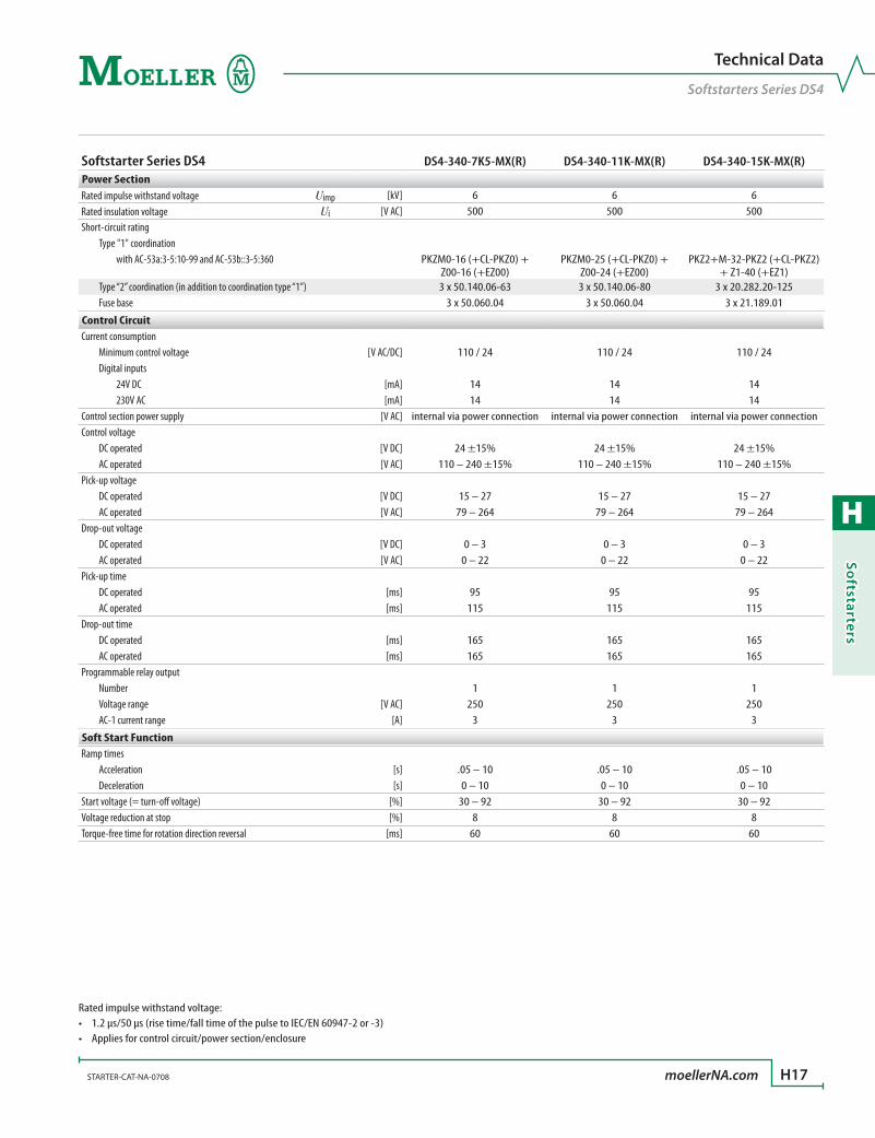
H
Softstarters
STARTER-CAT-NA-0708 moellerNA.com H17
Technical Data
Softstarters Series DS4
Softstarter Series DS4 DS4-340-7K5-MX(R) DS4-340-11K-MX(R) DS4-340-15K-MX(R)Power SectionRated impulse withstand voltage Uimp [kV] 6 6 6Rated insulation voltage Ui [V AC] 500 500 500Short-circuit rating Type "1" coordination with AC-53a:3-5:10-99 and AC-53b::3-5:360 PKZM0-16 (+CL-PKZ0) +
Z00-16 (+EZ00)PKZM0-25 (+CL-PKZ0) +
Z00-24 (+EZ00)PKZ2+M-32-PKZ2 (+CL-PKZ2)
+ Z1-40 (+EZ1) Type “2” coordination (in addition to coordination type “1”) 3 x 50.140.06-63 3 x 50.140.06-80 3 x 20.282.20-125 Fuse base 3 x 50.060.04 3 x 50.060.04 3 x 21.189.01
Control CircuitCurrent consumption Minimum control voltage [V AC/DC] 110 / 24 110 / 24 110 / 24 Digital inputs 24V DC [mA] 14 14 14 230V AC [mA] 14 14 14Control section power supply [V AC] internal via power connection internal via power connection internal via power connectionControl voltage DC operated [V DC] 24 ±15% 24 ±15% 24 ±15% AC operated [V AC] 110 – 240 ±15% 110 – 240 ±15% 110 – 240 ±15%Pick-up voltage DC operated [V DC] 15 – 27 15 – 27 15 – 27 AC operated [V AC] 79 – 264 79 – 264 79 – 264Drop-out voltage DC operated [V DC] 0 – 3 0 – 3 0 – 3 AC operated [V AC] 0 – 22 0 – 22 0 – 22Pick-up time DC operated [ms] 95 95 95 AC operated [ms] 115 115 115Drop-out time DC operated [ms] 165 165 165 AC operated [ms] 165 165 165Programmable relay output Number 1 1 1 Voltage range [V AC] 250 250 250 AC-1 current range [A] 3 3 3
Soft Start FunctionRamp times Acceleration [s] .05 – 10 .05 – 10 .05 – 10 Deceleration [s] 0 – 10 0 – 10 0 – 10Start voltage (= turn-off voltage) [%] 30 – 92 30 – 92 30 – 92Voltage reduction at stop [%] 8 8 8Torque-free time for rotation direction reversal [ms] 60 60 60
Rated impulse withstand voltage:1.2 µs/50 µs (rise time/fall time of the pulse to IEC/EN 60947-2 or -3)•Applies for control circuit/power section/enclosure•

H
Soft
star
ters
H18 moellerNA.com STARTER-CAT-NA-0708
Dimensions
Softstarters Series DS4
Dimensions are in millimeters.Not intended for manufacturing purposes.
Softstarters DS4DS4-340-2K2-M(R)(-DC); DS4-340-7K5-MX(R); DS4-340-11K-MX(R)
189.5
142
M4
13.65
149
137.
5
13.65
45
Softstarters DS4DS4-340-4K0-M(R); DS4-340-5K5-M(R)
M4
114.
8
149
137.
5
73
15 15
8.7
65 189.5
20 135.5
20
➀ 1L1, 3L2, 5L3 2T1, 4T2, 6T3
➀ 1L1, 3L2, 5L3 2T1, 4T2, 6T3

H
Softstarters
STARTER-CAT-NA-0708 moellerNA.com H19
Dimensions
Softstarters Series DS4
Dimensions are in millimeters.Not intended for manufacturing purposes.
Softstarters DS4DS4-340-7K5-M(R); DS4-340-11K-M(R); DS4-340-15K-MX(R)
M4
18 18
45
90
110
6.75
114.
8
149
137.
5
73
189.5
131.7➀ 1L1, 3L2, 5L3
2T1, 4T2, 6T3

H
Soft
star
ters
H20 moellerNA.com STARTER-CAT-NA-0708
Softstarters
Notes

H
Softstarters
H21
series DS6 (from 30 HP to 150 HP)powerful intelligence
Moeller’s DS6 series provides an array of power options in just two frame sizes. If your application requires more horsepower than DS4 series provides, our DS6 series is the likely choice. All softstarters in this range have built-in bypass circuitry that prevents damage if a fault occurs and increases lifespan.
Powerful and compactMoeller’s DS6 line offers surprising power capabilities in a minimal panel space of only 93 and 108 millimeters in width. Designed for medium horsepower ap-plications, the DS6 series softstarter is available from 30 HP to 150 HP, with an operating voltage of 230 to 460 V AC at 50/60 Hz. These devices are suitable for three-phase induction motors and have a control voltage of 24 V DC.
‘Keep it simple’ intelligenceThe DS6 line includes a dial for infinite setting of start-ing voltage percent and additional dials for starting and stopping ramp times. LED status indicators and a simple interface makes the DS6 softstarter series one of the easiest to operate.
Built-in benefitsAll DS6 softstarters contain an integrated heat sink and built-in bypass - features that are typically offered as separately purchased items. A bypass diverts voltage from the softstarter after the load has ramped to full power. This increases the lifespan of the softstarter and prevents damage to the unit if a fault occurs.
> Built-in bypass prevents damage and increases lifespan without additional equipment
> Softer starts with patented Asymmetrical Trigger Control technology
> Ideal for applications such as
conveyor belts•escalators•fans•pumps•crane drives•material handlers•mixers•lumber mills•and many others•
R
U-Start (%)
t-Start (s)
t-Stop (s)
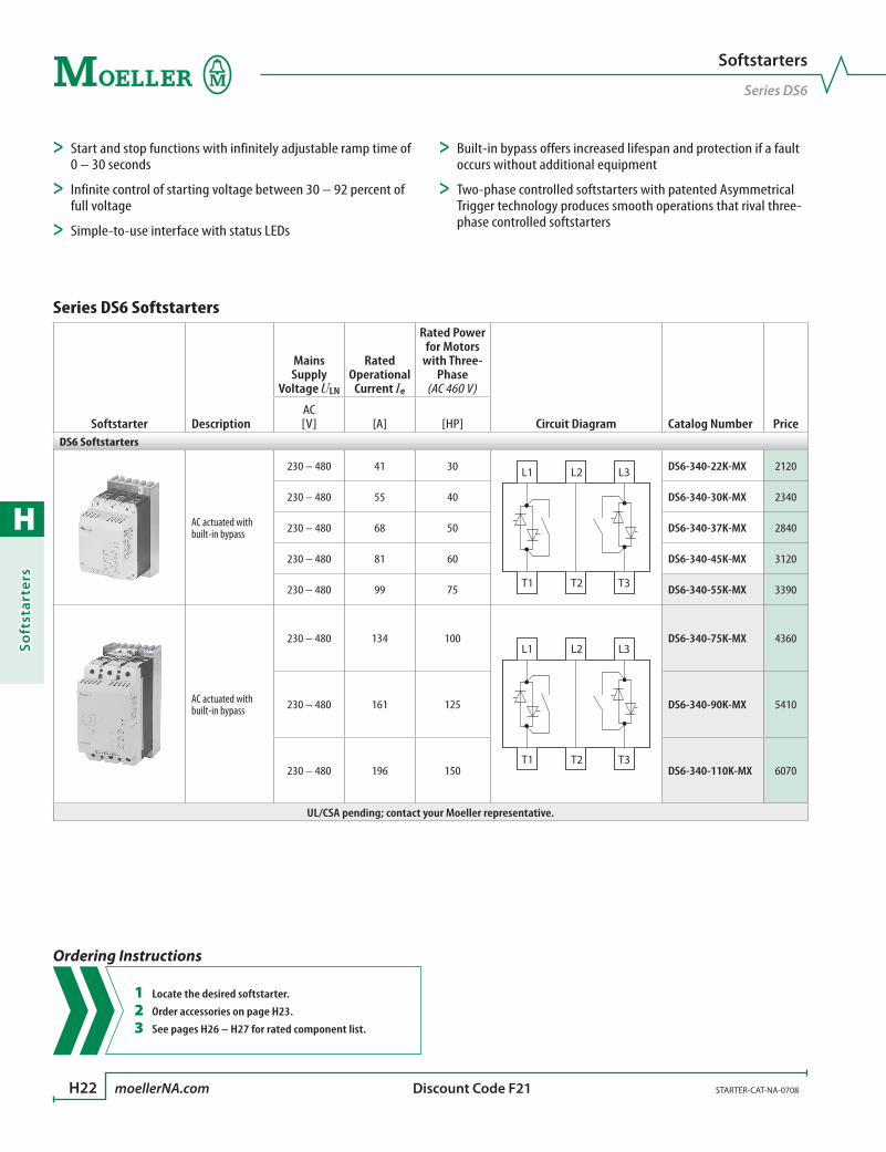
H
Soft
star
ters
H22 moellerNA.com STARTER-CAT-NA-0708 Discount Code F21
Series DS6 Softstarters
Softstarter Description
Mains Supply
Voltage ULN
Rated Operational
Current Ie
Rated Power for Motors
with Three-Phase
(AC 460 V)
Circuit Diagram Catalog Number PriceAC [V] [A] [HP]
DS6 Softstarters
AC actuated with built-in bypass
230 – 480 41 30 L1 L2 L3
T1 T2 T3
DS6-340-22K-MX 2120
230 – 480 55 40 DS6-340-30K-MX 2340
230 – 480 68 50 DS6-340-37K-MX 2840
230 – 480 81 60 DS6-340-45K-MX 3120
230 – 480 99 75 DS6-340-55K-MX 3390
AC actuated with built-in bypass
230 – 480 134 100L1 L2 L3
T1 T2 T3
DS6-340-75K-MX 4360
230 – 480 161 125 DS6-340-90K-MX 5410
230 – 480 196 150 DS6-340-110K-MX 6070
UL/CSA pending; contact your Moeller representative.
Softstarters
Series DS6
Ordering Instructions
1 Locate the desired softstarter.
2 Order accessories on page H23.
3 See pages H26 – H27 for rated component list.
> Start and stop functions with infinitely adjustable ramp time of 0 – 30 seconds
> Infinite control of starting voltage between 30 – 92 percent of full voltage
> Simple-to-use interface with status LEDs
> Built-in bypass offers increased lifespan and protection if a fault occurs without additional equipment
> Two-phase controlled softstarters with patented Asymmetrical Trigger technology produces smooth operations that rival three-phase controlled softstarters

H
Softstarters
STARTER-CAT-NA-0708 moellerNA.com H23 Discount Code B10
Softstarters
Fuses and Bases for Series DS6
Terminal Protection
Terminal Protection Description For Use With… Catalog Number PriceTerminal Covers
For Box Terminal
DS6-340-22K-MXDS6-340-30K-MXDS6-340-37K-MXDS6-340-45K-MXDS6-340-55K-MX
NZM1-XKSFA 48
Terminal CoverDS6-340-75K-MXDS6-340-90K-MX
DS6-340-110K-MXNZM2-XKSA 70
Terminal CoverDS6-340-75K-MXDS6-340-90K-MX
DS6-340-110K-MXNZM2-XKSFA 80
IP2X Protection
For Box TerminalDS6-340-75K-MXDS6-340-90K-MX
DS6-340-110K-MXNZM2-XIPK 70
For Cover NZM2-XKSADS6-340-75K-MXDS6-340-90K-MX
DS6-340-110K-MXNZM2-XIPA 44

H
Soft
star
ters
H24 moellerNA.com STARTER-CAT-NA-0708
Standard ConnectionDirect Soft Start
M3 ~
1L1
3L2
5L3
PEPE 0 V + 24
TOR Ready
- A2 EN + A1 13 14 24
+ 24 V
0 V
232T1
4T2
6T3
L1
L2
L3
PE
Q1
Q21
F3
M1
I > I > I >
Q1
+ A1, EN
+ 24 VReady(23/24)
UL1,L2,L3
UT1,T2,T3
UStart
t - Start
TOR(13/14)
Q1
Application Notes
Series DS6 Softstarters
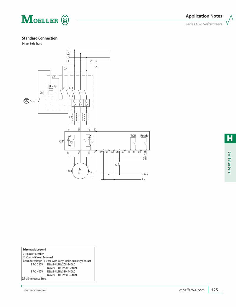
H
Softstarters
STARTER-CAT-NA-0708 moellerNA.com H25
Standard ConnectionDirect Soft Start
M3 ~
1L1
3L2
5L3
PEPE 0 V
D2
D1 3.13
3.14
+ 24
TOR Ready
- A2 EN + A1 13 14 24
+ 24 V
0 V
232T1
4T2
6T3
L1L2L3PE
Q1
Q1
S3
Q21
F3
M1
I >
U>
I > I >
Application Notes
Series DS6 Softstarters
Schematic LegendQ1: Circuit Breaker➀: Control Circuit Terminal➁: Undervoltage Release with Early-Make Auxiliary Contact 3 AC, 230V NZM1-XUHIV208-240AC NZM2/3-XUHIV208-240AC 3 AC, 400V NZM1-XUHIV380-440AC NZM2/3-XUHIV380-440AC : Emergency Stop
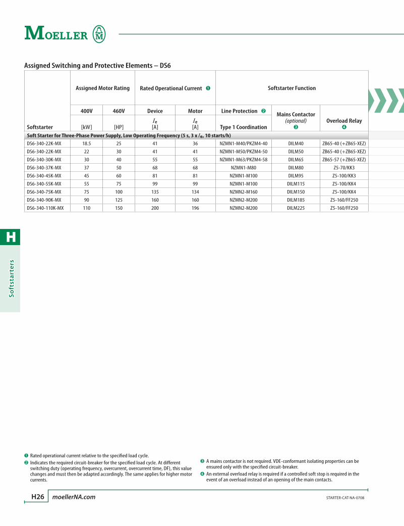
H
Soft
star
ters
H26 moellerNA.com STARTER-CAT-NA-0708
Assigned Switching and Protective Elements – DS6
Softstarter
Assigned Motor Rating Rated Operational Current ➊ Softstarter Function
400V 460V Device Motor Line Protection ➋ Mains Contactor (optional)
➌Overload Relay
➍[kW] [HP]Ie
[A]Ie
[A] Type 1 CoordinationSoft Starter for Three-Phase Power Supply, Low Operating Frequency (5 s, 3 x Ie, 10 starts/h)DS6-340-22K-MX 18.5 25 41 36 NZMN1-M40/PKZM4-40 DILM40 ZB65-40 (+ZB65-XEZ)
DS6-340-22K-MX 22 30 41 41 NZMN1-M50/PKZM4-50 DILM50 ZB65-40 (+ZB65-XEZ)
DS6-340-30K-MX 30 40 55 55 NZMN1-M63/PKZM4-58 DILM65 ZB65-57 (+ZB65-XEZ)
DS6-340-37K-MX 37 50 68 68 NZMN1-M80 DILM80 Z5-70/KK3
DS6-340-45K-MX 45 60 81 81 NZMN1-M100 DILM95 Z5-100/KK3
DS6-340-55K-MX 55 75 99 99 NZMN1-M100 DILM115 Z5-100/KK4
DS6-340-75K-MX 75 100 135 134 NZMN2-M160 DILM150 Z5-100/KK4
DS6-340-90K-MX 90 125 160 160 NZMN2-M200 DILM185 Z5-160/FF250
DS6-340-110K-MX 110 150 200 196 NZMN2-M200 DILM225 Z5-160/FF250
➊ Rated operational current relative to the specified load cycle.➋ Indicates the required circuit-breaker for the specified load cycle. At different
switching duty (operating frequency, overcurrent, overcurrent time, DF), this value changes and must then be adapted accordingly. The same applies for higher motor currents.
➌ A mains contactor is not required. VDE-conformant isolating properties can be ensured only with the specified circuit-breaker.
➍An external overload relay is required if a controlled soft stop is required in the event of an overload instead of an opening of the main contacts.
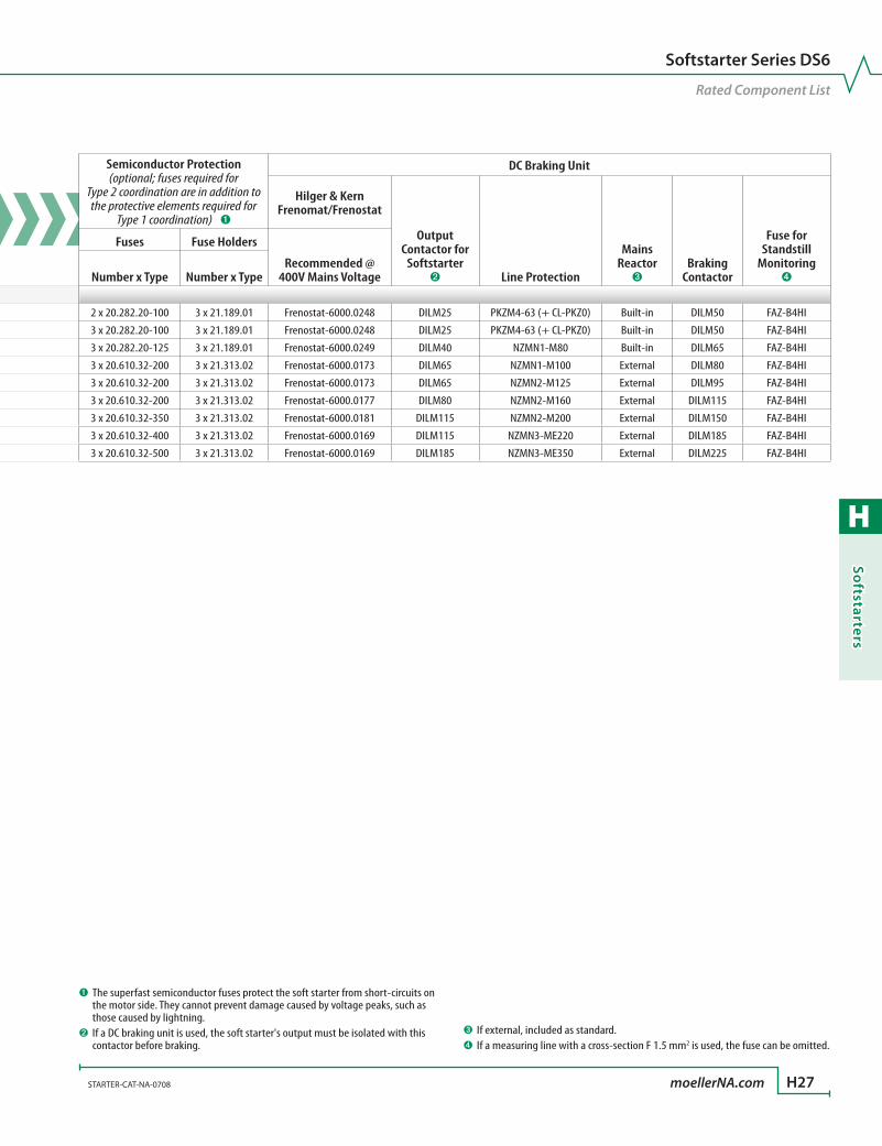
H
Softstarters
STARTER-CAT-NA-0708 moellerNA.com H27
Softstarter Series DS6
Rated Component List
Assigned Switching and Protective Elements – DS6
Softstarter
Assigned Motor Rating Rated Operational Current ➊ Softstarter Function
400V 460V Device Motor Line Protection ➋ Mains Contactor (optional)
➌Overload Relay
➍[kW] [HP]Ie
[A]Ie
[A] Type 1 CoordinationSoft Starter for Three-Phase Power Supply, Low Operating Frequency (5 s, 3 x Ie, 10 starts/h)DS6-340-22K-MX 18.5 25 41 36 NZMN1-M40/PKZM4-40 DILM40 ZB65-40 (+ZB65-XEZ)
DS6-340-22K-MX 22 30 41 41 NZMN1-M50/PKZM4-50 DILM50 ZB65-40 (+ZB65-XEZ)
DS6-340-30K-MX 30 40 55 55 NZMN1-M63/PKZM4-58 DILM65 ZB65-57 (+ZB65-XEZ)
DS6-340-37K-MX 37 50 68 68 NZMN1-M80 DILM80 Z5-70/KK3
DS6-340-45K-MX 45 60 81 81 NZMN1-M100 DILM95 Z5-100/KK3
DS6-340-55K-MX 55 75 99 99 NZMN1-M100 DILM115 Z5-100/KK4
DS6-340-75K-MX 75 100 135 134 NZMN2-M160 DILM150 Z5-100/KK4
DS6-340-90K-MX 90 125 160 160 NZMN2-M200 DILM185 Z5-160/FF250
DS6-340-110K-MX 110 150 200 196 NZMN2-M200 DILM225 Z5-160/FF250
Semiconductor Protection (optional; fuses required for
Type 2 coordination are in addition to the protective elements required for
Type 1 coordination) ➊
DC Braking Unit
Hilger & Kern Frenomat/Frenostat
Output Contactor for
Softstarter ➋ Line Protection
MainsReactor
➌Braking
Contactor
Fuse for Standstill
Monitoring ➍
Fuses Fuse Holders
Recommended @ 400V Mains VoltageNumber x Type Number x Type
2 x 20.282.20-100 3 x 21.189.01 Frenostat-6000.0248 DILM25 PKZM4-63 (+ CL-PKZ0) Built-in DILM50 FAZ-B4HI
3 x 20.282.20-100 3 x 21.189.01 Frenostat-6000.0248 DILM25 PKZM4-63 (+ CL-PKZ0) Built-in DILM50 FAZ-B4HI
3 x 20.282.20-125 3 x 21.189.01 Frenostat-6000.0249 DILM40 NZMN1-M80 Built-in DILM65 FAZ-B4HI
3 x 20.610.32-200 3 x 21.313.02 Frenostat-6000.0173 DILM65 NZMN1-M100 External DILM80 FAZ-B4HI
3 x 20.610.32-200 3 x 21.313.02 Frenostat-6000.0173 DILM65 NZMN2-M125 External DILM95 FAZ-B4HI
3 x 20.610.32-200 3 x 21.313.02 Frenostat-6000.0177 DILM80 NZMN2-M160 External DILM115 FAZ-B4HI
3 x 20.610.32-350 3 x 21.313.02 Frenostat-6000.0181 DILM115 NZMN2-M200 External DILM150 FAZ-B4HI
3 x 20.610.32-400 3 x 21.313.02 Frenostat-6000.0169 DILM115 NZMN3-ME220 External DILM185 FAZ-B4HI
3 x 20.610.32-500 3 x 21.313.02 Frenostat-6000.0169 DILM185 NZMN3-ME350 External DILM225 FAZ-B4HI
➊ The superfast semiconductor fuses protect the soft starter from short-circuits on the motor side. They cannot prevent damage caused by voltage peaks, such as those caused by lightning.
➋ If a DC braking unit is used, the soft starter's output must be isolated with this contactor before braking.
➌If external, included as standard.➍If a measuring line with a cross-section F 1.5 mm2 is used, the fuse can be omitted.
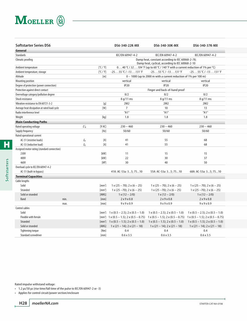
H
Soft
star
ters
H28 moellerNA.com STARTER-CAT-NA-0708
Softstarter Series DS6 DS6-340-22K-MX DS6-340-30K-MX DS6-340-37K-MXGeneralStandards IEC/EN 60947-4-2 IEC/EN 60947-4-2 IEC/EN 60947-4-2Climatic proofing Damp heat, constant according to IEC 60068-2-78;
Damp heat, cyclical, according to IEC 60068-2-10Ambient temperature [°C / °F] 0…40 °C / 32…104 °F (up to 60 °C / 140 °F with a current reduction of 1% per °C)Ambient temperature, storage [°C / °F] -25…55 °C / -13…131 °F -25…55 °C / -13…131 °F -25…55 °C / -13…131 °FAltitude [m] 0 – 1000 (up to 2000 m with a current reduction of 1% per 100 m)Mounting position vertical vertical verticalDegree of protection (power connection) IP20 IP20 IP20Protection against direct contact Finger and back-of-hand proofOvervoltage category/pollution degree II/2 II/2 II/2Shock resistance 8 g/11 ms 8 g/11 ms 8 g/11 msVibration resistance to EN 60721-3-2 [g] 2M2 2M2 2M2Average heat dissipation at rated load cycle [W] 7 10 13Radio interference level "A1" "A1" "A1"Weight [kg] 1.8 1.8 1.8
Main Conducting PathsRated operating voltage Ue [V AC] 230 – 460 230 – 460 230 – 460Supply frequency [Hz] 50/60 50/60 50/60Rated operational current AC-51 (resistive loads) Ie [A] 41 55 68 AC-53 (inductive load) Ie [A] 41 55 68Assigned motor rating (standard connection) 230V [kW] 11 15 15 400V [kW] 22 30 37 460V [HP] 30 40 50Overload cycle to IEC/EN 60947-4-2 AC-51 (built-in bypass) 41A: AC-53a: 3...5; 75...10 55A: AC-53a: 3...5; 75...10 68A: AC-53a: 3...5; 75...10
Terminal CapacitiesCable lengths Solid [mm2] 1 x (25 – 70); 2 x (6 – 25) 1 x (25 – 70); 2 x (6 – 25) 1 x (25 – 70); 2 x (6 – 25) Stranded [mm2] 1 x (25 –70); 2 x (6 – 25) 1 x (25 –70); 2 x (6 – 25) 1 x (25 –70); 2 x (6 – 25) Solid or stranded [AWG] 1 x (12 – 2/0) 1 x (12 – 2/0) 1 x (12 – 2/0) Band min. [mm] 2 x 9 x 0.8 2 x 9 x 0.8 2 x 9 x 0.8 max. [mm] 9 x 9 x 0.9 9 x 9 x 0.9 9 x 9 x 0.9Control cables Solid [mm2] 1 x (0.5 – 2.5); 2 x (0.5 – 1.0) 1 x (0.5 – 2.5); 2 x (0.5 – 1.0) 1 x (0.5 – 2.5); 2 x (0.5 – 1.0) Flexible with ferrule [mm2] 1 x (0.5 – 1.5); 2 x (0.5 – 0.75) 1 x (0.5 – 1.5); 2 x (0.5 – 0.75) 1 x (0.5 – 1.5); 2 x (0.5 – 0.75) Stranded [mm2] 1 x (0.5 – 1.5); 2 x (0.5 – 1.0) 1 x (0.5 – 1.5); 2 x (0.5 – 1.0) 1 x (0.5 – 1.5); 2 x (0.5 – 1.0) Solid or stranded [AWG] 1 x (21 – 14); 2 x (21 – 18) 1 x (21 – 14); 2 x (21 – 18) 1 x (21 – 14); 2 x (21 – 18) Tightening torque [Nm] 0.4 0.4 0.4 Standard screwdriver [mm] 0.6 x 3.5 0.6 x 3.5 0.6 x 3.5
Rated impulse withstand voltage:1.2 µs/50 µs (rise time/fall time of the pulse to IEC/EN 60947-2 or -3)•Applies for control circuit/power section/enclosure•

H
Softstarters
STARTER-CAT-NA-0708 moellerNA.com H29
Technical Data
Softstarters Series DS6
Softstarter Series DS6 DS6-340-22K-MX DS6-340-30K-MX DS6-340-37K-MXGeneralStandards IEC/EN 60947-4-2 IEC/EN 60947-4-2 IEC/EN 60947-4-2Climatic proofing Damp heat, constant according to IEC 60068-2-78;
Damp heat, cyclical, according to IEC 60068-2-10Ambient temperature [°C / °F] 0…40 °C / 32…104 °F (up to 60 °C / 140 °F with a current reduction of 1% per °C)Ambient temperature, storage [°C / °F] -25…55 °C / -13…131 °F -25…55 °C / -13…131 °F -25…55 °C / -13…131 °FAltitude [m] 0 – 1000 (up to 2000 m with a current reduction of 1% per 100 m)Mounting position vertical vertical verticalDegree of protection (power connection) IP20 IP20 IP20Protection against direct contact Finger and back-of-hand proofOvervoltage category/pollution degree II/2 II/2 II/2Shock resistance 8 g/11 ms 8 g/11 ms 8 g/11 msVibration resistance to EN 60721-3-2 [g] 2M2 2M2 2M2Average heat dissipation at rated load cycle [W] 7 10 13Radio interference level "A1" "A1" "A1"Weight [kg] 1.8 1.8 1.8
Main Conducting PathsRated operating voltage Ue [V AC] 230 – 460 230 – 460 230 – 460Supply frequency [Hz] 50/60 50/60 50/60Rated operational current AC-51 (resistive loads) Ie [A] 41 55 68 AC-53 (inductive load) Ie [A] 41 55 68Assigned motor rating (standard connection) 230V [kW] 11 15 15 400V [kW] 22 30 37 460V [HP] 30 40 50Overload cycle to IEC/EN 60947-4-2 AC-51 (built-in bypass) 41A: AC-53a: 3...5; 75...10 55A: AC-53a: 3...5; 75...10 68A: AC-53a: 3...5; 75...10
Terminal CapacitiesCable lengths Solid [mm2] 1 x (25 – 70); 2 x (6 – 25) 1 x (25 – 70); 2 x (6 – 25) 1 x (25 – 70); 2 x (6 – 25) Stranded [mm2] 1 x (25 –70); 2 x (6 – 25) 1 x (25 –70); 2 x (6 – 25) 1 x (25 –70); 2 x (6 – 25) Solid or stranded [AWG] 1 x (12 – 2/0) 1 x (12 – 2/0) 1 x (12 – 2/0) Band min. [mm] 2 x 9 x 0.8 2 x 9 x 0.8 2 x 9 x 0.8 max. [mm] 9 x 9 x 0.9 9 x 9 x 0.9 9 x 9 x 0.9Control cables Solid [mm2] 1 x (0.5 – 2.5); 2 x (0.5 – 1.0) 1 x (0.5 – 2.5); 2 x (0.5 – 1.0) 1 x (0.5 – 2.5); 2 x (0.5 – 1.0) Flexible with ferrule [mm2] 1 x (0.5 – 1.5); 2 x (0.5 – 0.75) 1 x (0.5 – 1.5); 2 x (0.5 – 0.75) 1 x (0.5 – 1.5); 2 x (0.5 – 0.75) Stranded [mm2] 1 x (0.5 – 1.5); 2 x (0.5 – 1.0) 1 x (0.5 – 1.5); 2 x (0.5 – 1.0) 1 x (0.5 – 1.5); 2 x (0.5 – 1.0) Solid or stranded [AWG] 1 x (21 – 14); 2 x (21 – 18) 1 x (21 – 14); 2 x (21 – 18) 1 x (21 – 14); 2 x (21 – 18) Tightening torque [Nm] 0.4 0.4 0.4 Standard screwdriver [mm] 0.6 x 3.5 0.6 x 3.5 0.6 x 3.5
DS6-340-45K-MX DS6-340-55K-MX DS6-340-75K-MX DS6-340-90K-MX DS6-340-110K-MX
IEC/EN 60947-4-2 IEC/EN 60947-4-2 IEC/EN 60947-4-2 IEC/EN 60947-4-2 IEC/EN 60947-4-2Damp heat, constant according to IEC 60068-2-78; Damp heat, cyclical, according to IEC 60068-2-10
0…40 °C / 32…104 °F (up to 60 °C / 140 °F with a current reduction of 1% per °C)-25…55 °C / -13…131 °F -25…55 °C / -13…131 °F -25…55 °C / -13…131 °F -25…55 °C / -13…131 °F -25…55 °C / -13…131 °F
0 – 1000 (up to 2000 m with a current reduction of 1% per 100 m)vertical vertical vertical vertical vertical
IP20 IP20 IP20 IP20 IP20Finger and back-of-hand proof
II/2 II/2 II/2 II/2 II/28 g/11 ms 8 g/11 ms 8 g/11 ms 8 g/11 ms 8 g/11 ms
2M2 2M2 2M2 2M2 2M218 25 24 30 42
"A1" "A1" "A1" "A1" "A1"1.8 3.7 3.7 3.7 3.7
230 – 460 230 – 460 230 – 460 230 – 460 230 – 46050/60 50/60 50/60 50/60 50/60
81 99 135 160 20081 99 135 160 200
22 30 30 45 5545 55 75 90 11060 75 100 125 150
81A: AC-53a: 3...5; 75...10 99A: AC-53a: 3...5; 75...10 135A: AC-53a: 3...5; 75...10 160A: AC-53a: 3...5; 75...10 200A: AC-53a: 3...5; 75...10
1 x (25 – 70); 2 x (6 – 25) 1 x (25 – 70); 2 x (6 – 25) 1 x (4 – 185); 2 x (4 – 70) 1 x (4 – 185); 2 x (4 – 70) 1 x (4 – 185); 2 x (4 – 70)1 x (25 –70); 2 x (6 – 25) 1 x (25 –70); 2 x (6 – 25) 1 x (4 – 185); 2 x (4 – 70) 1 x (4 – 185); 2 x (4 – 70) 1 x (4 – 185); 2 x (4 – 70)
1 x (12 – 2/0) 1 x (12 – 2/0) 1 x (12 – 350 kcmil); 2 x (12 – 00) 1 x (12 – 350 kcmil); 2 x (12 – 00) 1 x (12 – 350 kcmil); 2 x (12 – 00)2 x 9 x 0.8 2 x 9 x 0.8 2 x 9 x 0.8 2 x 9 x 0.8 2 x 9 x 0.89 x 9 x 0.9 9 x 9 x 0.9 10 x 16 x 0.8 10 x 16 x 0.8 10 x 16 x 0.8
1 x (0.5 – 2.5); 2 x (0.5 – 1.0) 1 x (0.5 – 2.5); 2 x (0.5 – 1.0) 1 x (0.5 – 2.5); 2 x (0.5 – 1.0) 1 x (0.5 – 2.5); 2 x (0.5 – 1.0) 1 x (0.5 – 2.5); 2 x (0.5 – 1.0)1 x (0.5 – 1.5); 2 x (0.5 – 0.75) 1 x (0.5 – 1.5); 2 x (0.5 – 0.75) 1 x (0.5 – 1.5); 2 x (0.5 – 0.75) 1 x (0.5 – 1.5); 2 x (0.5 – 0.75) 1 x (0.5 – 1.5); 2 x (0.5 – 0.75)1 x (0.5 – 1.5); 2 x (0.5 – 1.0) 1 x (0.5 – 1.5); 2 x (0.5 – 1.0) 1 x (0.5 – 1.5); 2 x (0.5 – 1.0) 1 x (0.5 – 1.5); 2 x (0.5 – 1.0) 1 x (0.5 – 1.5); 2 x (0.5 – 1.0)
1 x (21 – 14); 2 x (21 – 18) 1 x (21 – 14); 2 x (21 – 18) 1 x (21 – 14); 2 x (21 – 18) 1 x (21 – 14); 2 x (21 – 18) 1 x (21 – 14); 2 x (21 – 18)0.4 0.4 0.4 0.4 0.4
0.6 x 3.5 0.6 x 3.5 0.6 x 3.5 0.6 x 3.5 0.6 x 3.5
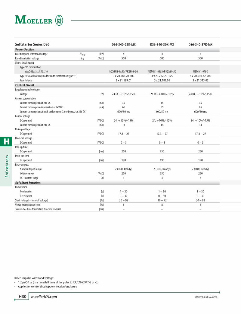
H
Soft
star
ters
H30 moellerNA.com STARTER-CAT-NA-0708
Softstarter Series DS6 DS6-340-22K-MX DS6-340-30K-MX DS6-340-37K-MXPower SectionRated impulse withstand voltage Uimp [kV] 4 4 4Rated insulation voltage Ui [V AC] 500 500 500Short-circuit rating Type "1" coordination at AC-53a: 3...5: 75...10 NZMN1-M50/PKZM4-50 NZMN1-M63/PKZM4-50 NZMN1-M80 Type “2” coordination (in addition to coordination type “1”) 3 x 20.282.20-100 3 x 20.282.20-125 3 x 20.610.32-200 Fuse holders 3 x 21.189.01 3 x 21.189.01 3 x 21.313.02
Control CircuitRegulator supply voltage Voltage [V] 24 DC, +10%/-15% 24 DC, +10%/-15% 24 DC, +10%/-15%Current consumption Current consumption at 24V DC [mA] 35 35 35 Current consumption in operation at 24V DC [mA] 65 65 65 Current consumption at peak performance (close bypass) at 24V DC 600/50 ms 600/50 ms 600/50 msControl voltage DC operated [V DC] 24, +10%/-15% 24, +10%/-15% 24, +10%/-15% Current consumption at 24V DC [mA] 14 14 14Pick-up voltage DC operated [V DC] 17.3 – 27 17.3 – 27 17.3 – 27Drop-out voltage DC operated [V DC] 0 – 3 0 – 3 0 – 3Pick-up time DC operated [ms] 250 250 250Drop-out time DC operated [ms] 190 190 190Relay outputs Number (top of ramp) 2 (TOR, Ready) 2 (TOR, Ready) 2 (TOR, Ready) Voltage range [V AC] 250 250 250 AC-1 current range [A] 3 3 3
Soft Start FunctionRamp times Acceleration [s] 1 – 30 1 – 30 1 – 30 Deceleration [s] 0 – 30 0 – 30 0 – 30Start voltage (= turn-off voltage) [%] 30 – 92 30 – 92 30 – 92Voltage reduction at stop [%] 8 8 8Torque-free time for rotation direction reversal [ms] – – –
Rated impulse withstand voltage:1.2 µs/50 µs (rise time/fall time of the pulse to IEC/EN 60947-2 or -3)•Applies for control circuit/power section/enclosure•

H
Softstarters
STARTER-CAT-NA-0708 moellerNA.com H31
Technical Data
Softstarters Series DS6
Softstarter Series DS6 DS6-340-22K-MX DS6-340-30K-MX DS6-340-37K-MXPower SectionRated impulse withstand voltage Uimp [kV] 4 4 4Rated insulation voltage Ui [V AC] 500 500 500Short-circuit rating Type "1" coordination at AC-53a: 3...5: 75...10 NZMN1-M50/PKZM4-50 NZMN1-M63/PKZM4-50 NZMN1-M80 Type “2” coordination (in addition to coordination type “1”) 3 x 20.282.20-100 3 x 20.282.20-125 3 x 20.610.32-200 Fuse holders 3 x 21.189.01 3 x 21.189.01 3 x 21.313.02
Control CircuitRegulator supply voltage Voltage [V] 24 DC, +10%/-15% 24 DC, +10%/-15% 24 DC, +10%/-15%Current consumption Current consumption at 24V DC [mA] 35 35 35 Current consumption in operation at 24V DC [mA] 65 65 65 Current consumption at peak performance (close bypass) at 24V DC 600/50 ms 600/50 ms 600/50 msControl voltage DC operated [V DC] 24, +10%/-15% 24, +10%/-15% 24, +10%/-15% Current consumption at 24V DC [mA] 14 14 14Pick-up voltage DC operated [V DC] 17.3 – 27 17.3 – 27 17.3 – 27Drop-out voltage DC operated [V DC] 0 – 3 0 – 3 0 – 3Pick-up time DC operated [ms] 250 250 250Drop-out time DC operated [ms] 190 190 190Relay outputs Number (top of ramp) 2 (TOR, Ready) 2 (TOR, Ready) 2 (TOR, Ready) Voltage range [V AC] 250 250 250 AC-1 current range [A] 3 3 3
Soft Start FunctionRamp times Acceleration [s] 1 – 30 1 – 30 1 – 30 Deceleration [s] 0 – 30 0 – 30 0 – 30Start voltage (= turn-off voltage) [%] 30 – 92 30 – 92 30 – 92Voltage reduction at stop [%] 8 8 8Torque-free time for rotation direction reversal [ms] – – –
DS6-340-45K-MX DS6-340-55K-MX DS6-340-75K-MX DS6-340-90K-MX DS6-340-110K-MX
4 4 4 4 4500 500 500 500 500
NZMN1-M100 NZMN1-M100 NZMN1-M160 NZMN1-M200 NZMN1-M2003 x 20.610.32-200 3 x 20.610.32-200 3 x 20.610.32-350 3 x 20.610.32-400 3 x 20.610.20-500
3 x 21.313.02 3 x 21.313.02 3 x 21.313.02 3 x 21.313.02 3 x 21.313.02
24 DC, +10%/-15% 24 DC, +10%/-15% 24 DC, +10%/-15% 24 DC, +10%/-15% 24 DC, +10%/-15%
35 35 35 35 3565 65 65 65 65
600/50 ms 600/50 ms 600/50 ms 600/50 ms 600/50 ms
24, +10%/-15% 24, +10%/-15% 24, +10%/-15% 24, +10%/-15% 24, +10%/-15%14 14 14 14 14
17.3 – 27 17.3 – 27 17.3 – 27 17.3 – 27 17.3 – 27
0 – 3 0 – 3 0 – 3 0 – 3 0 – 3
250 250 250 250 250
190 190 190 190 190
2 (TOR, Ready) 2 (TOR, Ready) 2 (TOR, Ready) 2 (TOR, Ready) 2 (TOR, Ready)250 250 250 250 250
3 3 3 3 3
1 – 30 1 – 30 1 – 30 1 – 30 1 – 300 – 30 0 – 30 0 – 30 0 – 30 0 – 30
30 – 92 30 – 92 30 – 92 30 – 92 30 – 928 8 8 8 8– – – – –

H
Soft
star
ters
H32 moellerNA.com STARTER-CAT-NA-0708
Dimensions
Softstarters Series DS6
Dimensions are in millimeters.Not intended for manufacturing purposes.
Softstarters DS6DS6-340-(22)(30)(37)(45)(55)K-MX
161
129
22.5PE
3030
22.5
93
e
PE
e17
5
35
139
Softstarters DS6DS6-340-(75)(90)(110)K-MX
15
3535
108
200
158
PE
15
e
PE
e
215
52.5
178
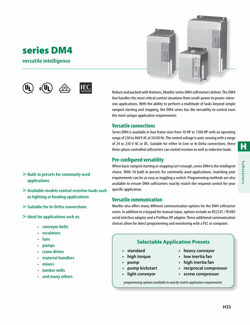
H
Softstarters
H33
series DM4 versatile intelligence
Robust and packed with features, Moeller series DM4 softstarters deliver. The DM4 line handles the most critical control situations from small-power to power-inten-sive applications. With the ability to perform a multitude of tasks beyond simple ramped starting and stopping, the DM4 series has the versatility to control even the most unique application requirements.
Versatile connectionsSeries DM4 is available in four frame sizes from 10 HP to 1300 HP with an operating range of 230 to 460 V AC at 50/60 Hz. The control voltage is auto-sensing with a range of 24 to 230 V AC or DC. Suitable for either In-Line or In-Delta connections, these three-phase controlled softstarters can control resistive as well as inductive loads.
Pre-configured versatilityWhen basic ramped starting or stopping isn’t enough, series DM4 is the intelligent choice. With 10 built-in presets for commonly used applications, matching your requirements can be as easy as toggling a switch. Programming methods are also available to ensure DM4 softstarters exactly match the required control for your specific application.
Versatile communicationMoeller also offers many different communication options for the DM4 softstarter series. In addition to a keypad for manual input, options include an RS232C / RS485 serial interface adapter and a Profibus DP adapter. These additional communication choices allow for direct programming and monitoring with a PLC or computer.
> Built-in presets for commonly used applications
> Available models control resistive loads such as lighting or heating applications
> Suitable for In-Delta connections
> Ideal for applications such as:
conveyor belts•escalators•fans•pumps•crane drives•material handlers•mixers•lumber mills•and many others•
R
standard•high torque•pump•pump kickstart•light conveyor•
heavy conveyor•low inertia fan•high inertia fan•reciprocal compressor•screw compressor•
Selectable Application Presets
programming options available to exactly match application requirements
R
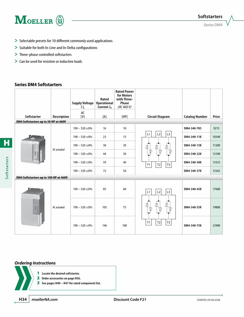
H
Soft
star
ters
H34 moellerNA.com STARTER-CAT-NA-0708 Discount Code F21
Series DM4 Softstarters
Softstarter Description
Supply Voltage UL
Rated Operational
Current Ie
Rated Power for Motors
with Three-Phase
(AC 460 V)
Circuit Diagram Catalog Number PriceAC [V] [A] [HP]
DM4 Softstarters up to 50 HP at 460V
AC actuated
190 – 520 ±0% 16 10
L1 L2 L3
T1 T2 T3
DM4-340-7K5 9215
190 – 520 ±0% 23 15 DM4-340-11K 10340
190 – 520 ±0% 30 20 DM4-340-15K 11200
190 – 520 ±0% 44 30 DM4-340-22K 12100
190 – 520 ±0% 59 40 DM4-340-30K 13325
190 – 520 ±0% 72 50 DM4-340-37K 15565
DM4 Softstarters up to 100 HP at 460V
AC actuated
190 – 520 ±0% 85 60L1 L2 L3
T1 T2 T3
DM4-340-45K 17600
190 – 520 ±0% 105 75 DM4-340-55K 19800
190 – 520 ±0% 146 100 DM4-340-75K 22900
Softstarters
Series DM4
Ordering Instructions
1 Locate the desired softstarter.
2 Order accessories on page H36.
3 See pages H40 – H47 for rated component list.
> Selectable presets for 10 different commonly used applications
> Suitable for both In-Line and In-Delta configurations
> Three-phase controlled softstarters
> Can be used for resistive or inductive loads

H
Softstarters
STARTER-CAT-NA-0708 moellerNA.com H35 Discount Code F21
Series DM4 Softstarters
Softstarter Description
Supply Voltage UL
Rated Operational
Current Ie
Rated Power for Motors
with Three-Phase
(AC 460 V)
Circuit Diagram Catalog Number PriceAC [V] [A] [HP]
DM4 Softstarters up to 300 HP at 460V
AC actuated
190 – 520 ±0% 174 125
L1 L2 L3
T1 T2 T3
DM4-340-90K 30000
190 – 520 ±0% 202 150 DM4-340-110K 32125
190 – 520 ±0% 242 200 DM4-340-132K 35250
190 – 520 ±0% 300 250 DM4-340-160K 39350
190 – 520 ±0% 370 300 DM4-340-200K 46190
DM4 Softstarters up to 750 HP at 460V
AC actuated
190 – 520 ±0% 500 400L1 L2 L3
T1 T2 T3
DM4-340-250K 57150
190 – 520 ±0% 600 500 DM4-340-315K 62000
190 – 520 ±0% 750 600 DM4-340-400K 74200
190 – 520 ±0% 900 750 DM4-340-500K 86160
Softstarters
Series DM4
Ordering Instructions
1 Locate the desired softstarter.
2 Order accessories on page H36.
3 See pages H40 – H47 for rated component list.
> Selectable presets for 10 different commonly used applications
> Suitable for both In-Line and In-Delta configurations
> Three-phase controlled softstarters
> Can be used for resistive or inductive loads
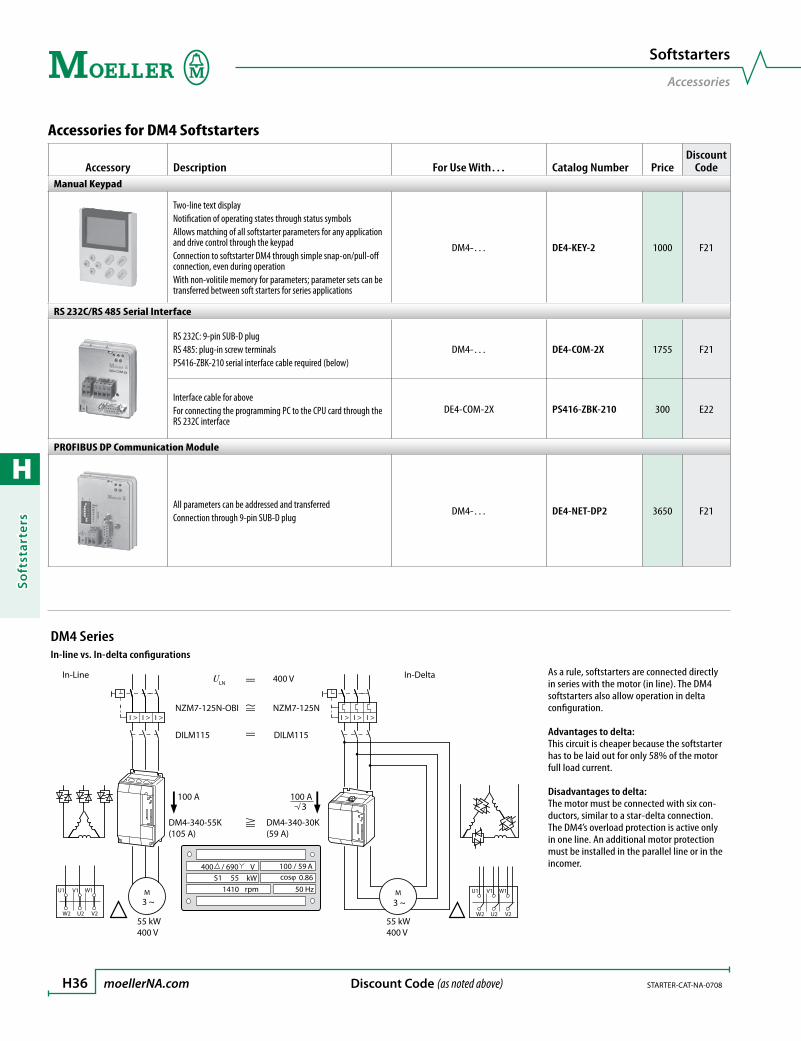
H
Soft
star
ters
H36 moellerNA.com STARTER-CAT-NA-0708 Discount Code (as noted above)
Accessories for DM4 Softstarters
Accessory Description For Use With… Catalog Number PriceDiscount
CodeManual Keypad
Two-line text displayNotification of operating states through status symbols Allows matching of all softstarter parameters for any application and drive control through the keypadConnection to softstarter DM4 through simple snap-on/pull-off connection, even during operationWith non-volitile memory for parameters; parameter sets can be transferred between soft starters for series applications
DM4-… DE4-KEY-2 1000 F21
RS 232C/RS 485 Serial Interface
RS 232C: 9-pin SUB-D plugRS 485: plug-in screw terminalsPS416-ZBK-210 serial interface cable required (below)
DM4-… DE4-COM-2X 1755 F21
Interface cable for aboveFor connecting the programming PC to the CPU card through the RS 232C interface
DE4-COM-2X PS416-ZBK-210 300 E22
PROFIBUS DP Communication Module
All parameters can be addressed and transferredConnection through 9-pin SUB-D plug
DM4-… DE4-NET-DP2 3650 F21
Softstarters
Accessories
DM4 SeriesIn-line vs. In-delta configurations
IIIIII
M3 ~
55 kW400 V
55 kW400 V
M3 ~
100 A
DM4-340-55K(105 A)
DILM115
NZM7-125N-OBI
DILM115
NZM7-125N
U1 V1 W1
W2 U2 V2
/ 690 V400 100 / 5955S1 0.86coskW
rpm1410 50 Hz
A
U1 V1 W1
W2 U2 V2
In-Line In-Delta
100 A3
DM4-340-30K(59 A)
ULN 400 VAs a rule, softstarters are connected directly in series with the motor (in line). The DM4 softstarters also allow operation in delta configuration.
Advantages to delta:This circuit is cheaper because the softstarter has to be laid out for only 58% of the motor full load current.
Disadvantages to delta:The motor must be connected with six con-ductors, similar to a star-delta connection.The DM4’s overload protection is active only in one line. An additional motor protection must be installed in the parallel line or in the incomer.

H
Softstarters
STARTER-CAT-NA-0708 moellerNA.com H37
With Separate Mains ContactorActuation
S1
S2
K1E1
39
E2
39
S4
S3
K1
K1
K2K1
Q11
K2 T1 RUNK2
T1 K2 T1 Q11
13
14
33
34
T1 OK(no error)
With Separate Mains ContactorSchematic
~=
~=
7
MM1
Q21
F3
3~
L1L2L3NPE
L N E1 E2 39
13
K1;RUN K2;TOR K3 K4
14 23 24 33 34 43
1L1
3L2
5L3
2T1
4T2
6T3
+12 8 17
62 63
PE
0 V
(E1;
E2)
+12
V D
C
REF
1: 0
–10
V
REF
2: 4
–20
mA
T1 T2
F11Q11
I >I > I >
Q1
I >I > I >
Q2
Imot
– Th
erm
isto
r
+ Th
erm
isto
r
0 V
Ana
log
Ana
log
Out
1
Ana
log
Out
2
0 V
Ana
log
Star
t/St
op
Enab
le
Application Notes
Series DM4 Softstarters
Schematic LegendS1: Off (unguided deceleration)S2: OnS3: Soft StartS4: Soft Stop➀: Enable➁: Soft Start / Soft Stop : Emergency Stop
Schematic Legend➀: See actuation➁: Control voltage through Q1 and F11 or through Q2➂: Motor current indication
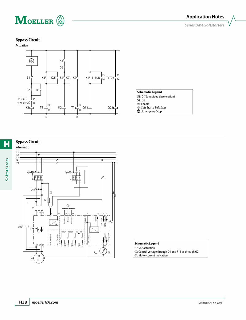
H
Soft
star
ters
H38 moellerNA.com STARTER-CAT-NA-0708
Bypass CircuitActuation
S2
K1E2
39
E1
39
S4Q21
K1
K1 K1K2
K1
T1 T1
K2
K2
T1 RUN
Q11
13
14
23
24T1 TOR
Q21
33
34
S1
S3
T1 OK(no error)
Bypass CircuitSchematic
~=
~=
7
MM1
Q21
F3
3~
L1L2L3NPE
L N E1 E2 39
13
K1;RUN K2;TOR K3 K4
14 23 24 33 34 43
1L1
3L2
5L3
2T1
4T2
6T3
+12 8
PE
17
62 63
0 V
(E1;
E2)
+12
V D
C
REF
1: 0
–10
V
REF
2: 4
–20
mA
T1 T2
F11
Q11
Q1 Q1
Q22
I> I> I> I> I> I>
Imot
– Th
erm
isto
r
+ Th
erm
isto
r
0 V
Ana
log
Ana
log
Out
1
Ana
log
Out
2
0 V
Ana
log
Star
t/St
op
Enab
le
Application Notes
Series DM4 Softstarters
Schematic LegendS1: Off (unguided deceleration)S2: On➀: Enable➁: Soft Start / Soft Stop : Emergency Stop
Schematic Legend➀: See actuation➁: Control voltage through Q1 and F11 or through Q2➂: Motor current indication
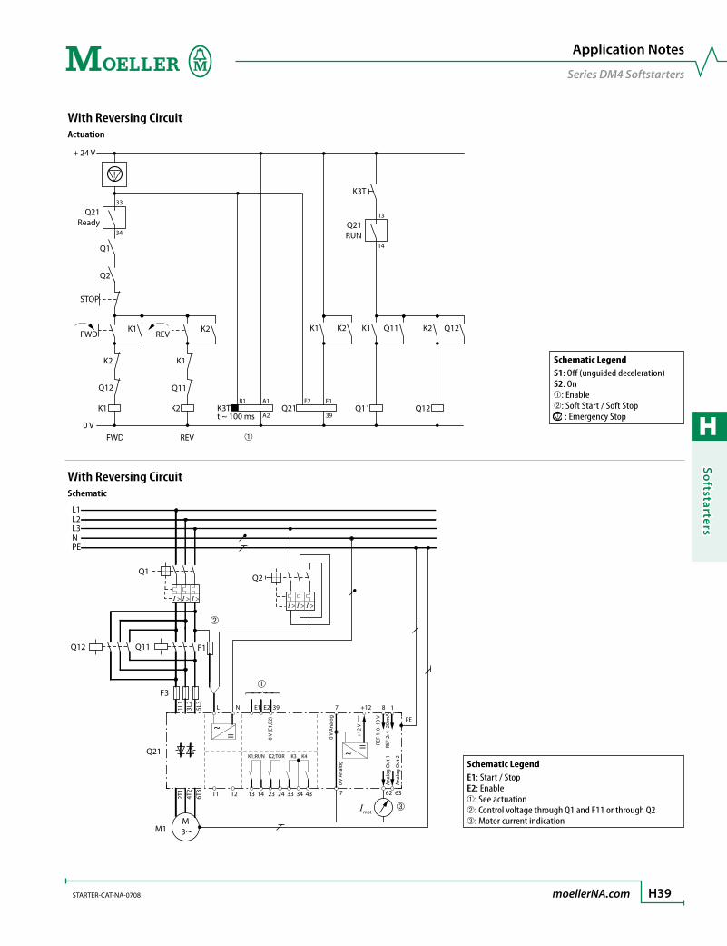
H
Softstarters
STARTER-CAT-NA-0708 moellerNA.com H39
With Reversing CircuitActuation
K1 K3T
FWD
B1 E2
A2
A1
Q12
K2
K2
Q11
K1
+ 24 V
0 V
33
34
REV
STOP
Q21Ready
Q1
t ~ 100 msQ21
39
E1
Q2
K2K1K2K1
FWD REV
Q11 Q12
K3T
Q12K2Q11K1
13
14
Q21RUN
With Reversing CircuitSchematic
~=
~=
7
MM1
Q21
F3
3~
L1L2L3NPE
L N E1 E2 39
13
K1;RUN K2;TOR K3 K4
14 23 24 33 34 43
1L1
3L2
5L3
2T1
4T2
6T3
+12 8 17
62 63
PE
0 V
(E1;
E2)
+12
V
REF
1: 0
–10
V
REF
2: 4
–20
mA
T1 T2
Q1
Q11Q12 F1
Q2
Imot
0 V
Ana
log
Ana
log
Out
1
Ana
log
Out
2
0 V
Ana
log
I > I > I >I > I > I >
Application Notes
Series DM4 Softstarters
Schematic LegendS1: Off (unguided deceleration)S2: On➀: Enable➁: Soft Start / Soft Stop : Emergency Stop
Schematic LegendE1: Start / StopE2: Enable➀: See actuation➁: Control voltage through Q1 and F11 or through Q2➂: Motor current indication

H
Soft
star
ters
H40 moellerNA.com STARTER-CAT-NA-0708
Assigned Switching and Protective Elements – DM4
Softstarter ➊
Motor Rating
@ 460 V
Rated Operational Current ➋ Softstarter Function
Bypass Contactor (optional)
➐
Device Motor Rating ➌
Line Protection ➍
Mains Contactor (optional)
➍Overload Relay
➎➏P
[HP]I
[A]Ie
[A]I
[A]Soft Starter for Three-Phase Power Supply, Short Start-up Time, Tripping Class 10 (15 s, 3.5 x Ie)
In-line Connection (Before the Load, Standard)
DM4-340-7K5 10 16 15.2 16 PKZM0-16 (+ CL-PKZ0) DILM17 ZB32-16 (+ZB32-XEZ) DILM7
DM4-340-11K 15 22 21.7 23 PKZM0-25 (+ CL-PKZ0) DILM25 ZB32-24 (+ZB32-XEZ) DILM7
DM4-340-15K 20 30 29.3 30 PKZM0-32 (+ CL-PKZ0) DILM32 ZB32-32 (+ZB32-XEZ) DILM17
DM4-340-22K 30 44 41 44 PKZM4-50 (+ CL-PKZ0) DILM50 ZB65-57 (+ZB65-XEZ) DILM25
DM4-340-30K 40 59 55 59 PKZM4-63 (+ CL-PKZ0) DILM65 ZB65-65 (+ZB65-XEZ) DILM40
DM4-340-37K 50 72 68 72 NZMN1-S80 DILM80 ZB150-100/KK DILM65
DM4-340-45K 60 85 81 85 NZMN1-S100 DILM95 ZB150-100/KK DILM65
DM4-340-55K 75 105 99 105 NZMN2-S125 DILM115 ZB150-125/KK DILM95
DM4-340-75K 100 146 134 146 NZMN2-S160 DILM150 ZB150-150/KK DILM150
DM4-340-90K 125 174 161 174 NZMN2-S200 DILM185 Z5-220/FF6 DILM150
DM4-340-110K 150 202 196 202 NZMN2-ME220 DILM225 Z5-220/FF6 DILM185
DM4-340-132K 200 242 231 242 NZMN3-ME350 ➑ DILM250 ZW7-290 DILM185
DM4-340-160K 250 300 279 300 NZMN3-ME350 ➑ DILM300 ZW7-400 DILM185
DM4-340-200K 300 370 349 370 NZMN3-ME350/…-ME450 ➑ DILM400 ZW7-400 DILM225
DM4-340-250K 400 500 437 500 NZMN3-ME450/…-ME550 ➑ DILM500 ZW7-540 DILM400
DM4-340-315K 500 600 544 600 NZMN3-ME550/…-ME875 ➑ DILM580/750 ➒ ZW7-630 DILM400
DM4-340-400K 600 750 683 750 NZMN3-ME875 DILM750 ZEV (+ZEV-XSW-820) DILM500
DM4-340-500K 750 900 860 900 NZMN3-ME875/…-ME1400 ➒ DILM1000 – DILM580
➊ At a different operating cycle, the r.m.s. current changes so that a higher-rated device may have to be used. The switching and protective elements are always dimensioned for the following operating cycles (no bypass for any operating cycle):
•DevicesDM4-340-7K5toDM4-340-90Keach10switchingoperationsperhour, continuous operation •DevicesDM4-340-110KandDM4-340-132K:each10switchingoperationsper hour with at least 3 minutes no-load pause before each start •DevicesfromDM4-340-160Keach3operationsperhourwithatleast8minutes no-load pause before each start.
For all other switching cycles or when a bypass is used, the effective rating changes and a different device is therefore required. The device's rated operational current must be greater than the motor current (in-line operation) or motor cur-rent √3 (delta operation) indicated on the motor's nameplate.
➋ Rated operational current relative to the specified load cycle.
➌ Indicates the current for which the supply cable must be dimensioned at the specified switching duty and motor current. At higher motor currents and different switching duty (operating frequency, overcurrent, overcurrent time, DF), the cur-rent value changes and must then be adapted accordingly.
➍ For motors with the same rating but a higher current than specified, a higher-rat-ed switch/contactor may have to be used. The decisive factor is the motor current.
➎ If the softstarter remains continually live, it can also act as overload relay. In delta connection, set the overload relay to the value motor current/ √3.
➏ In delta connection, the overload relay is connected in series with the motor wind-ing (set to value motor current/ √3.)
➐ The bypass is laid out to AC1. If it must be opened in an Emergency-Stop, it must be laid out to AC3. The contactors of the mains contactor column must then be used.
➑ Setting of overload trip block to tr = ∞.➒ If the device’s rated current is fully utilized, use the larger switch or contactor.

H
Softstarters
STARTER-CAT-NA-0708 moellerNA.com H41
Softstarter Series DM4
Rated Component List
Assigned Switching and Protective Elements – DM4
Softstarter ➊
Motor Rating
@ 460 V
Rated Operational Current ➋ Softstarter Function
Bypass Contactor (optional)
➐
Device Motor Rating ➌
Line Protection ➍
Mains Contactor (optional)
➍Overload Relay
➎➏P
[HP]I
[A]Ie
[A]I
[A]Soft Starter for Three-Phase Power Supply, Short Start-up Time, Tripping Class 10 (15 s, 3.5 x Ie)
In-line Connection (Before the Load, Standard)
DM4-340-7K5 10 16 15.2 16 PKZM0-16 (+ CL-PKZ0) DILM17 ZB32-16 (+ZB32-XEZ) DILM7
DM4-340-11K 15 22 21.7 23 PKZM0-25 (+ CL-PKZ0) DILM25 ZB32-24 (+ZB32-XEZ) DILM7
DM4-340-15K 20 30 29.3 30 PKZM0-32 (+ CL-PKZ0) DILM32 ZB32-32 (+ZB32-XEZ) DILM17
DM4-340-22K 30 44 41 44 PKZM4-50 (+ CL-PKZ0) DILM50 ZB65-57 (+ZB65-XEZ) DILM25
DM4-340-30K 40 59 55 59 PKZM4-63 (+ CL-PKZ0) DILM65 ZB65-65 (+ZB65-XEZ) DILM40
DM4-340-37K 50 72 68 72 NZMN1-S80 DILM80 ZB150-100/KK DILM65
DM4-340-45K 60 85 81 85 NZMN1-S100 DILM95 ZB150-100/KK DILM65
DM4-340-55K 75 105 99 105 NZMN2-S125 DILM115 ZB150-125/KK DILM95
DM4-340-75K 100 146 134 146 NZMN2-S160 DILM150 ZB150-150/KK DILM150
DM4-340-90K 125 174 161 174 NZMN2-S200 DILM185 Z5-220/FF6 DILM150
DM4-340-110K 150 202 196 202 NZMN2-ME220 DILM225 Z5-220/FF6 DILM185
DM4-340-132K 200 242 231 242 NZMN3-ME350 ➑ DILM250 ZW7-290 DILM185
DM4-340-160K 250 300 279 300 NZMN3-ME350 ➑ DILM300 ZW7-400 DILM185
DM4-340-200K 300 370 349 370 NZMN3-ME350/…-ME450 ➑ DILM400 ZW7-400 DILM225
DM4-340-250K 400 500 437 500 NZMN3-ME450/…-ME550 ➑ DILM500 ZW7-540 DILM400
DM4-340-315K 500 600 544 600 NZMN3-ME550/…-ME875 ➑ DILM580/750 ➒ ZW7-630 DILM400
DM4-340-400K 600 750 683 750 NZMN3-ME875 DILM750 ZEV (+ZEV-XSW-820) DILM500
DM4-340-500K 750 900 860 900 NZMN3-ME875/…-ME1400 ➒ DILM1000 – DILM580
Circuit Breaker
Controller Supply
Semiconductor Protection (optional; fuses required for
Type 2 coordination are in addition to the protective elements required for
Type 1 coordination)
DC Braking Unit
Hilger & Kern Frenomat/Frenostat
Output Contactor
➊ Line Protection
LineReactor
➋Braking
Contactor
Fuse for Standstill
Monitoring ➌
Fuses Fuse Switch
Recommended @ 400V Mains VoltageNumber x Type Number x Type
In-line Connection (Before the Load, Standard)
PKZM0-0,16 3 x 20.282.20-40 3 x 21.189.01 Frenostat-6000.0316 DILM7 PKZM0-25 (+ CL-PKZ0) External DILM17 FAZ-B4HI
PKZM0-0,16 3 x 20.282.20-80 3 x 21.189.01 Frenostat-6000.0316 DILM7 PKZM0-40 (+ CL-PKZ0) External DILM25 FAZ-B4HI
PKZM0-0,16 3 x 20.282.20-80 3 x 21.189.01 Frenostat-6000.0247 DILM17 PKZM0-50 (+ CL-PKZ0) Built-in DILM32 FAZ-B4HI
PKZM0-0,16 3 x 20.282.20-125 3 x 21.189.01 Frenostat-6000.0248 DILM25 PKZM0-63 (+ CL-PKZ0) Built-in DILM50 FAZ-B4HI
PKZM0-0,16 3 x 20.282.20-125 3 x 21.189.01 Frenostat-6000.0249 DILM40 NZMN1-M80 Built-in DILM65 FAZ-B4HI
PKZM0-0,16 3 x 20.189.20-200 3 x 21.189.01 Frenostat-6000.0173 DILM65 NZMN1-M100 External DILM80 FAZ-B4HI
PKZM0-0,16 3 x 20.189.20-200 3 x 21.189.01 Frenostat-6000.0173 DILM65 NZMN2-M125 External DILM95 FAZ-B4HI
PKZM0-0,16 3 x 20.610.32-350 3 x 21.313.02 Frenostat-6000.0177 DILM95 NZMN2-M160 External DILM150 FAZ-B4HI
PKZM0-0,16 3 x 20.610.32-350 3 x 21.313.02 Frenostat-6000.0181 DILM150 NZMN2-M200 External DILM150 FAZ-B4HI
PKZM0-0,16 3 x 20.610.32-450 3 x 21.313.02 Frenostat-6000.0169 DILM150 NZMN3-ME220 External DILM185 FAZ-B4HI
PKZM0-0,16 3 x 20.610.32-450 3 x 21.313.02 Frenostat-6000.0169 DILM185 NZMN3-ME350 External DILM225 FAZ-B4HI
PKZM0-0,16 3 x 20.610.32-500 3 x 21.313.02 Frenostat-6000.0307 DILM185 NZMN3-ME350 External DILM250 FAZ-B4HI
PKZM0-0,16 3 x 20.610.32-500 3 x 21.313.02 Frenostat-6000.0307 DILM185 NZMN4-ME450 External DILM300 FAZ-B4HI
PKZM0-0,16 3 x 20.610.32-630 3 x 21.313.02 Frenostat-6000.0308 DILM225 NZMN4-ME550 External DILM400 FAZ-B4HI
PKZM0-1,6 3 x 20.630.32-900 3 x 21.313.02 Frenostat-6000.0308 DILM400 NZMN4-ME875 External DILM500 FAZ-B4HI
PKZM0-1,6 3 x 20.630.32-900 3 x 21.313.02 Frenostat-6000.0171 DILM400 NZMN4-ME875 External DILM580/750 FAZ-B4HI
PKZM0-1,6 3 x 20.630.32-1250 3 x 21.313.02 Frenostat-6000.0171 DILM500 NZMN4-ME1400 External DILM750 FAZ-B4HI
PKZM0-1,6 3 x 20.630.32-1250 3 x 21.313.02 – – – – – –
➊ If a DC braking unit is used, the softstarter's output must be isolated with this contactor before braking. In delta connection, both the input and the output must be isolated. In this case, two contactors are required.
➋ On external surface mounting included as standard.➌ If a measuring line with a cross-section F 1.5 mm2 is used, the fuse can be omitted.

H
Soft
star
ters
H42 moellerNA.com STARTER-CAT-NA-0708
Assigned Switching and Protective Elements – DM4
Softstarter ➊
Motor Rating
@ 460 V
Rated Operational Current ➋ Softstarter Function
Bypass Contactor (optional)
➐
Device Motor Rating ➌
Line Protection ➍
Mains Contactor (optional)
➍Overload Relay
➎➏P
[HP]I
[A]Ie
[A]I
[A]Soft Starter for Three-Phase Power Supply, Short Start-up Time, Tripping Class 10 (15 s, 3.5 x Ie)
Delta Connection (In Series with Each Motor Winding)
DM4-340-7K5 20 16 21.7 21.7 PKZM0-25 (+ CL-PKZ0) DILM25 ZB32-16 (+EZ00) DILM7
DM4-340-11K 25 22 29.3 29.3 PKZM0-32 (+ CL-PKZ0) DILM32 ZB32-24 (+EZ00) DILM7
DM4-340-15K 30 30 41 41 PKZM0-50 (+ CL-PKZ0) DILM50 ZB32-32 (+EZ1) DILM17
DM4-340-22K 40 44 55 55 PKZM0-58 (+ CL-PKZ0) DILM65 ZB65-57 (+EZ1) DILM25
50 44 68 68 NZMN1-S80 DILM80 ZB65-57 (+EZ1) DILM25
DM4-340-30K 60 59 81 81 NZMN1-S100 DILM95 ZB65-65 (+EZ1) DILM40
75 59 99 99 NZMN1-S100 DILM115 ZB65-65 (+EZ1) DILM40
DM4-340-45K 100 85 134 134 NZMN2-S160 DILM150 ZB150-100/KK DILM65
DM4-340-55K 150 105 161 161 NZMN2-S200 ➑ DILM185 ZB150-125/KK DILM95
DM4-340-75K 150 146 196 196 NZMN2-ME220 ➑ DILM225 ZB150-150/KK DILM150
200 146 231 231 NZMN3-ME350 ➑ DILM250 ZB150-150/KK DILM150
DM4-340-90K 250 174 279 279 NZMN3-ME350 ➑ DILM300 Z5-220/FF6 DILM150
DM4-340-132K 350 242 349 349 NZMN3-ME350 ➑ DILM400 ZW7-290 DILM185
DM4-340-160K 400 300 437 437 NZMN3-ME450 ➑ DILM500 ZW7-400 DILM185
DM4-340-200K 500 370 544 544 NZMN3-ME550 ➑ DILM580 ZW7-400 DILM225
DM4-340-250K 600 500 683 683 NZMN4-ME875 ➑ DILM750 ZW7-540 DILM400
DM4-340-315K 750 600 860 860 NZMN4-ME875 ➑ DILM1000 ZW7-630 DILM400
850 600 960 960 NZMN4-ME1400 ➑ DILM1000 ZW7-630 DILM400
DM4-340-400K 1100 750 1280 1280 NZMN4-ME1400 (+NZM4-XR…) ➑ ZEV (+ZEV-XSW-820) DILM500
DM4-340-500K 1300 900 1540 1540 IZMB2-U2000 ➒ – DILM580
➊ At a different operating cycle, the r.m.s. current changes so that a higher-rated device may have to be used. The switching and protective elements are always dimensioned for the following operating cycles (no bypass for any operating cycle):
•DevicesDM4-340-7K5toDM4-340-90Keach10switchingoperationsperhour, continuous operation •DevicesDM4-340-110KandDM4-340-132K:each10switchingoperationsper hour with at least 3 minutes no-load pause before each start •DevicesfromDM4-340-160Keach3operationsperhourwithatleast8minutes no-load pause before each start.
For all other switching cycles or when a bypass is used, the effective rating changes and a different device is therefore required. The device's rated operational current must be greater than the motor current (in-line operation) or motor cur-rent √3 (delta operation) indicated on the motor's nameplate.
➋ Rated operational current relative to the specified load cycle.➌ Indicates the current for which the supply cable must be dimensioned at the
specified switching duty and motor current. At higher motor currents and different switching duty (operating frequency, overcurrent, overcurrent time, DF), the cur-rent value changes and must then be adapted accordingly.
➍ For motors with the same rating but a higher current than specified, a higher-rat-ed switch/contactor may have to be used. The decisive factor is the motor current.
➎ If the soft starter remains continually live, it can also act as overload relay. In delta connection, set the overload relay to the value motor current/ √3.
➏ In delta connection, the overload relay is connected in series with the motor wind-ing (set to value motor current/ √3.)
➐ The bypass is laid out to AC1. If it must be opened in an Emergency-Stop, it must be laid out to AC3. The contactors of the mains contactor column must then be used.
➑ Setting of overload trip block to tr = ∞.➒ To use IZM as “contactor”, accessories are required see IZM catalog. In that case,
the recommended circuits may not apply since different contacts may have to be assigned depending on the selected accessories.
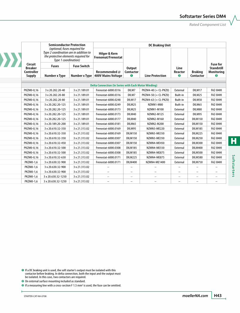
H
Softstarters
STARTER-CAT-NA-0708 moellerNA.com H43
Softstarter Series DM4
Rated Component List
Assigned Switching and Protective Elements – DM4
Softstarter ➊
Motor Rating
@ 460 V
Rated Operational Current ➋ Softstarter Function
Bypass Contactor (optional)
➐
Device Motor Rating ➌
Line Protection ➍
Mains Contactor (optional)
➍Overload Relay
➎➏P
[HP]I
[A]Ie
[A]I
[A]Soft Starter for Three-Phase Power Supply, Short Start-up Time, Tripping Class 10 (15 s, 3.5 x Ie)
Delta Connection (In Series with Each Motor Winding)
DM4-340-7K5 20 16 21.7 21.7 PKZM0-25 (+ CL-PKZ0) DILM25 ZB32-16 (+EZ00) DILM7
DM4-340-11K 25 22 29.3 29.3 PKZM0-32 (+ CL-PKZ0) DILM32 ZB32-24 (+EZ00) DILM7
DM4-340-15K 30 30 41 41 PKZM0-50 (+ CL-PKZ0) DILM50 ZB32-32 (+EZ1) DILM17
DM4-340-22K 40 44 55 55 PKZM0-58 (+ CL-PKZ0) DILM65 ZB65-57 (+EZ1) DILM25
50 44 68 68 NZMN1-S80 DILM80 ZB65-57 (+EZ1) DILM25
DM4-340-30K 60 59 81 81 NZMN1-S100 DILM95 ZB65-65 (+EZ1) DILM40
75 59 99 99 NZMN1-S100 DILM115 ZB65-65 (+EZ1) DILM40
DM4-340-45K 100 85 134 134 NZMN2-S160 DILM150 ZB150-100/KK DILM65
DM4-340-55K 150 105 161 161 NZMN2-S200 ➑ DILM185 ZB150-125/KK DILM95
DM4-340-75K 150 146 196 196 NZMN2-ME220 ➑ DILM225 ZB150-150/KK DILM150
200 146 231 231 NZMN3-ME350 ➑ DILM250 ZB150-150/KK DILM150
DM4-340-90K 250 174 279 279 NZMN3-ME350 ➑ DILM300 Z5-220/FF6 DILM150
DM4-340-132K 350 242 349 349 NZMN3-ME350 ➑ DILM400 ZW7-290 DILM185
DM4-340-160K 400 300 437 437 NZMN3-ME450 ➑ DILM500 ZW7-400 DILM185
DM4-340-200K 500 370 544 544 NZMN3-ME550 ➑ DILM580 ZW7-400 DILM225
DM4-340-250K 600 500 683 683 NZMN4-ME875 ➑ DILM750 ZW7-540 DILM400
DM4-340-315K 750 600 860 860 NZMN4-ME875 ➑ DILM1000 ZW7-630 DILM400
850 600 960 960 NZMN4-ME1400 ➑ DILM1000 ZW7-630 DILM400
DM4-340-400K 1100 750 1280 1280 NZMN4-ME1400 (+NZM4-XR…) ➑ ZEV (+ZEV-XSW-820) DILM500
DM4-340-500K 1300 900 1540 1540 IZMB2-U2000 ➒ – DILM580
Circuit Breaker
Controller Supply
Semiconductor Protection (optional; fuses required for
Type 2 coordination are in addition to the protective elements required for
Type 1 coordination)
DC Braking Unit
Hilger & Kern Frenomat/Frenostat
Output Contactor
➊ Line Protection
LineReactor
➋Braking
Contactor
Fuse for Standstill
Monitoring ➌
Fuses Fuse Switch
Recommended @ 400V Mains VoltageNumber x Type Number x Type
Delta Connection (In Series with Each Motor Winding)
PKZM0-0,16 3 x 20.282.20-40 3 x 21.189.01 Frenostat-6000.0316 DILM7 PKZM4-40 (+ CL-PKZ0) External DILM17 FAZ-B4HI
PKZM0-0,16 3 x 20.282.20-80 3 x 21.189.01 Frenostat-6000.0316 DILM7 PKZM4-50 (+ CL-PKZ0) Built-in DILM25 FAZ-B4HI
PKZM0-0,16 3 x 20.282.20-80 3 x 21.189.01 Frenostat-6000.0248 DILM17 PKZM4-63 (+ CL-PKZ0) Built-in DILM50 FAZ-B4HI
PKZM0-0,16 3 x 20.282.20-125 3 x 21.189.01 Frenostat-6000.0249 DILM25 NZMN1-M80 Built-in DILM65 FAZ-B4HI
PKZM0-0,16 3 x 20.282.20-125 3 x 21.189.01 Frenostat-6000.0173 DILM25 NZMN1-M100 External DILM80 FAZ-B4HI
PKZM0-0,16 3 x 20.282.20-125 3 x 21.189.01 Frenostat-6000.0173 DILM40 NZMN2-M125 External DILM95 FAZ-B4HI
PKZM0-0,16 3 x 20.282.20-125 3 x 21.189.01 Frenostat-6000.0177 DILM40 NZMN2-M160 External DILM150 FAZ-B4HI
PKZM0-0,16 3 x 20.189.20-200 3 x 21.189.01 Frenostat-6000.0181 DILM65 NZMN2-M200 External DILM150 FAZ-B4HI
PKZM0-0,16 3 x 20.610.32-350 3 x 21.313.02 Frenostat-6000.0169 DILM95 NZMN3-ME220 External DILM185 FAZ-B4HI
PKZM0-0,16 3 x 20.610.32-350 3 x 21.313.02 Frenostat-6000.0169 DILM150 NZMN3-ME350 External DILM225 FAZ-B4HI
PKZM0-0,16 3 x 20.610.32-350 3 x 21.313.02 Frenostat-6000.0307 DILM150 NZMN3-ME350 External DILM250 FAZ-B4HI
PKZM0-0,16 3 x 20.610.32-450 3 x 21.313.02 Frenostat-6000.0307 DILM150 NZMN4-ME450 External DILM300 FAZ-B4HI
PKZM0-0,16 3 x 20.610.32-500 3 x 21.313.02 Frenostat-6000.0308 DILM185 NZMN4-ME550 External DILM400 FAZ-B4HI
PKZM0-0,16 3 x 20.610.32-500 3 x 21.313.02 Frenostat-6000.0308 DILM185 NZMN4-ME875 External DILM500 FAZ-B4HI
PKZM0-0,16 3 x 20.610.32-630 3 x 21.313.02 Frenostat-6000.0171 DILM225 NZMN4-ME875 External DILM580 FAZ-B4HI
PKZM0-1,6 3 x 20.630.32-900 3 x 21.313.02 Frenostat-6000.0171 DILM400 NZMN4-ME1400 External DILM750 FAZ-B4HI
PKZM0-1,6 3 x 20.630.32-900 3 x 21.313.02 – – – – – –
PKZM0-1,6 3 x 20.630.32-900 3 x 21.313.02 – – – – – –
PKZM0-1,6 3 x 20.630.32-1250 3 x 21.313.02 – – – – – –
PKZM0-1,6 3 x 20.630.32-1250 3 x 21.313.02 – – – – – –
➊ If a DC braking unit is used, the soft starter's output must be isolated with this contactor before braking. In delta connection, both the input and the output must be isolated. In this case, two contactors are required.
➋ On external surface mounting included as standard.➌ If a measuring line with a cross-section F 1.5 mm2 is used, the fuse can be omitted.

H
Soft
star
ters
H44 moellerNA.com STARTER-CAT-NA-0708
Assigned Switching and Protective Elements – DM4
Softstarter ➊
Motor Rating
@ 460 V
Rated Operational Current ➋ Softstarter Function
Bypass Contactor (optional)
➐
Device Motor Rating ➌
Line Protection ➍
Mains Contactor (optional)
➍Overload Relay
➎➏P
[HP]I
[A]Ie
[A]I
[A]Soft Starter for Three-Phase Power Supply, Long Start-up Time, Tripping Class 20 (40 s, 3.5 x Ie)
In-line Connection (Before the Load, Standard)
DM4-340-11K 10 22 15.2 21 PKZM0-25 (+ CL-PKZ0) DILM17 ZB32-16 (+ZB32-XEZ) DILM7
DM4-340-15K 15 30 21.7 31 PKZM0-32 (+ CL-PKZ0) DILM25 ZB32-24 (+ZB32-XEZ) DILM17
DM4-340-22K 20 44 29.3 41 PKZM4-58 (+ CL-PKZ0) DILM32 ZB32-32 (+ZB32-XEZ) DILM25
DM4-340-30K 30 59 41 58 PKZM4-58 (+ CL-PKZ0) DILM50 ZB65-57 (+ZB65-XEZ) DILM40
DM4-340-37K 40 72 55 78 NZMN1-ME90 ➑ DILM65 ZB65-65 (+ZB65-XEZ) DILM65
DM4-340-45K 50 85 68 96 NZMN1-ME90 ➑ DILM80 ZEV (+ ZEV-XSW-145) DILM65
DM4-340-55K 60 105 81 114 NZMN1-ME90 ➑ DILM95 ZEV (+ ZEV-XSW-145) DILM95
DM4-340-75K 75 146 99 140 NZMN2-ME140 ➑ DILM115 ZEV (+ ZEV-XSW-145) DILM115
DM4-340-90K 100 174 134 189 NZMN2-ME140 ➑ DILM150 ZEV (+ ZEV-XSW-145) DILM150
DM4-340-110K 120 202 161 227 NZMN2-ME220 ➑ DILM185 ZEV (+ ZEV-XSW-820) DILM185
DM4-340-132K 150 242 196 276 NZMN2-ME220 ➑ DILM225 ZEV (+ ZEV-XSW-820) DILM185
DM4-340-160K 200 300 231 326 NZMN3-ME350 ➑ DILM250 ZEV (+ ZEV-XSW-820) DILM185
DM4-340-200K 250 370 279 393 NZMN3-ME350 ➑ DILM300 ZEV (+ ZEV-XSW-820) DILM225
DM4-340-250K 300 500 349 492 NZMN3-ME350 ➑ DILM400 ZEV (+ ZEV-XSW-820) DILM400
DM4-340-315K 350 600 437 616 NZMN3-ME450 ➑ DILM500 ZEV (+ ZEV-XSW-820) DILM400
DM4-340-400K 450 750 544 767 NZMN3-ME550 ➑ DILM580 ZEV (+ ZEV-XSW-820) DILM500
DM4-340-500K 500 900 683 963 NZMN3-ME875 ➑ DILM750 ZEV (+ ZEV-XSW-820) DILM580
➊ At a different operating cycle, the r.m.s. current changes so that a higher-rated device may have to be used. The switching and protective elements are always dimensioned for the following operating cycles (no bypass for any operating cycle):
•DevicesDM4-340-7K5toDM4-340-90Keach10switchingoperationsperhour, continuous operation •DevicesDM4-340-110KandDM4-340-132K:each10switchingoperationsper hour with at least 3 minutes no-load pause before each start •DevicesfromDM4-340-160Keach3operationsperhourwithatleast8minutes no-load pause before each start.
For all other switching cycles or when a bypass is used, the effective rating changes and a different device is therefore required. The device's rated operational current must be greater than the motor current (in-line operation) or motor cur-rent √3 (delta operation) indicated on the motor's nameplate.
➋ Rated operational current relative to the specified load cycle.
➌ Indicates the current for which the supply cable must be dimensioned at the specified switching duty and motor current. At higher motor currents and different switching duty (operating frequency, overcurrent, overcurrent time, DF), the cur-rent value changes and must then be adapted accordingly.
➍ For motors with the same rating but a higher current than specified, a higher-rat-ed switch/contactor may have to be used. The decisive factor is the motor current.
➎ If the softstarter remains continualy live, it can also act as overload relay. In delta connection, set the overload relay to the value motor current/ √3.
➏ In delta connection, the overload relay is connected in series with the motor wind-ing (set to value motor current/ √3.)
➐ The bypass is laid out to AC1. If it must be opened in an Emergency-Stop, it must be laid out to AC3. The contactors of the mains contactor column must then be used.
➑ ZMM trip block set to tr = ∞ (OBI).
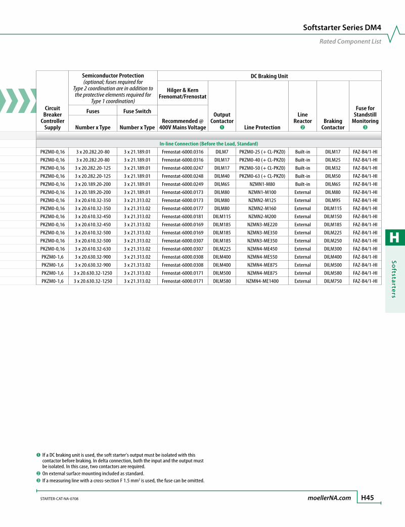
H
Softstarters
STARTER-CAT-NA-0708 moellerNA.com H45
Softstarter Series DM4
Rated Component List
Assigned Switching and Protective Elements – DM4
Softstarter ➊
Motor Rating
@ 460 V
Rated Operational Current ➋ Softstarter Function
Bypass Contactor (optional)
➐
Device Motor Rating ➌
Line Protection ➍
Mains Contactor (optional)
➍Overload Relay
➎➏P
[HP]I
[A]Ie
[A]I
[A]Soft Starter for Three-Phase Power Supply, Long Start-up Time, Tripping Class 20 (40 s, 3.5 x Ie)
In-line Connection (Before the Load, Standard)
DM4-340-11K 10 22 15.2 21 PKZM0-25 (+ CL-PKZ0) DILM17 ZB32-16 (+ZB32-XEZ) DILM7
DM4-340-15K 15 30 21.7 31 PKZM0-32 (+ CL-PKZ0) DILM25 ZB32-24 (+ZB32-XEZ) DILM17
DM4-340-22K 20 44 29.3 41 PKZM4-58 (+ CL-PKZ0) DILM32 ZB32-32 (+ZB32-XEZ) DILM25
DM4-340-30K 30 59 41 58 PKZM4-58 (+ CL-PKZ0) DILM50 ZB65-57 (+ZB65-XEZ) DILM40
DM4-340-37K 40 72 55 78 NZMN1-ME90 ➑ DILM65 ZB65-65 (+ZB65-XEZ) DILM65
DM4-340-45K 50 85 68 96 NZMN1-ME90 ➑ DILM80 ZEV (+ ZEV-XSW-145) DILM65
DM4-340-55K 60 105 81 114 NZMN1-ME90 ➑ DILM95 ZEV (+ ZEV-XSW-145) DILM95
DM4-340-75K 75 146 99 140 NZMN2-ME140 ➑ DILM115 ZEV (+ ZEV-XSW-145) DILM115
DM4-340-90K 100 174 134 189 NZMN2-ME140 ➑ DILM150 ZEV (+ ZEV-XSW-145) DILM150
DM4-340-110K 120 202 161 227 NZMN2-ME220 ➑ DILM185 ZEV (+ ZEV-XSW-820) DILM185
DM4-340-132K 150 242 196 276 NZMN2-ME220 ➑ DILM225 ZEV (+ ZEV-XSW-820) DILM185
DM4-340-160K 200 300 231 326 NZMN3-ME350 ➑ DILM250 ZEV (+ ZEV-XSW-820) DILM185
DM4-340-200K 250 370 279 393 NZMN3-ME350 ➑ DILM300 ZEV (+ ZEV-XSW-820) DILM225
DM4-340-250K 300 500 349 492 NZMN3-ME350 ➑ DILM400 ZEV (+ ZEV-XSW-820) DILM400
DM4-340-315K 350 600 437 616 NZMN3-ME450 ➑ DILM500 ZEV (+ ZEV-XSW-820) DILM400
DM4-340-400K 450 750 544 767 NZMN3-ME550 ➑ DILM580 ZEV (+ ZEV-XSW-820) DILM500
DM4-340-500K 500 900 683 963 NZMN3-ME875 ➑ DILM750 ZEV (+ ZEV-XSW-820) DILM580
Circuit Breaker
Controller Supply
Semiconductor Protection (optional; fuses required for
Type 2 coordination are in addition to the protective elements required for
Type 1 coordination)
DC Braking Unit
Hilger & Kern Frenomat/Frenostat
Output Contactor
➊ Line Protection
LineReactor
➋Braking
Contactor
Fuse for Standstill
Monitoring ➌
Fuses Fuse Switch
Recommended @ 400V Mains VoltageNumber x Type Number x Type
In-line Connection (Before the Load, Standard)
PKZM0-0,16 3 x 20.282.20-80 3 x 21.189.01 Frenostat-6000.0316 DILM7 PKZM0-25 (+ CL-PKZ0) Built-in DILM17 FAZ-B4/1-HI
PKZM0-0,16 3 x 20.282.20-80 3 x 21.189.01 Frenostat-6000.0316 DILM17 PKZM0-40 (+ CL-PKZ0) Built-in DILM25 FAZ-B4/1-HI
PKZM0-0,16 3 x 20.282.20-125 3 x 21.189.01 Frenostat-6000.0247 DILM17 PKZM0-50 (+ CL-PKZ0) Built-in DILM32 FAZ-B4/1-HI
PKZM0-0,16 3 x 20.282.20-125 3 x 21.189.01 Frenostat-6000.0248 DILM40 PKZM0-63 (+ CL-PKZ0) Built-in DILM50 FAZ-B4/1-HI
PKZM0-0,16 3 x 20.189.20-200 3 x 21.189.01 Frenostat-6000.0249 DILM65 NZMN1-M80 Built-in DILM65 FAZ-B4/1-HI
PKZM0-0,16 3 x 20.189.20-200 3 x 21.189.01 Frenostat-6000.0173 DILM80 NZMN1-M100 External DILM80 FAZ-B4/1-HI
PKZM0-0,16 3 x 20.610.32-350 3 x 21.313.02 Frenostat-6000.0173 DILM80 NZMN2-M125 External DILM95 FAZ-B4/1-HI
PKZM0-0,16 3 x 20.610.32-350 3 x 21.313.02 Frenostat-6000.0177 DILM80 NZMN2-M160 External DILM115 FAZ-B4/1-HI
PKZM0-0,16 3 x 20.610.32-450 3 x 21.313.02 Frenostat-6000.0181 DILM115 NZMN2-M200 External DILM150 FAZ-B4/1-HI
PKZM0-0,16 3 x 20.610.32-450 3 x 21.313.02 Frenostat-6000.0169 DILM185 NZMN3-ME220 External DILM185 FAZ-B4/1-HI
PKZM0-0,16 3 x 20.610.32-500 3 x 21.313.02 Frenostat-6000.0169 DILM185 NZMN3-ME350 External DILM225 FAZ-B4/1-HI
PKZM0-0,16 3 x 20.610.32-500 3 x 21.313.02 Frenostat-6000.0307 DILM185 NZMN3-ME350 External DILM250 FAZ-B4/1-HI
PKZM0-0,16 3 x 20.610.32-630 3 x 21.313.02 Frenostat-6000.0307 DILM225 NZMN4-ME450 External DILM300 FAZ-B4/1-HI
PKZM0-1,6 3 x 20.630.32-900 3 x 21.313.02 Frenostat-6000.0308 DILM400 NZMN4-ME550 External DILM400 FAZ-B4/1-HI
PKZM0-1,6 3 x 20.630.32-900 3 x 21.313.02 Frenostat-6000.0308 DILM400 NZMN4-ME875 External DILM500 FAZ-B4/1-HI
PKZM0-1,6 3 x 20.630.32-1250 3 x 21.313.02 Frenostat-6000.0171 DILM500 NZMN4-ME875 External DILM580 FAZ-B4/1-HI
PKZM0-1,6 3 x 20.630.32-1250 3 x 21.313.02 Frenostat-6000.0171 DILM580 NZMN4-ME1400 External DILM750 FAZ-B4/1-HI
➊ If a DC braking unit is used, the soft starter's output must be isolated with this contactor before braking. In delta connection, both the input and the output must be isolated. In this case, two contactors are required.
➋ On external surface mounting included as standard.➌ If a measuring line with a cross-section F 1.5 mm2 is used, the fuse can be omitted.
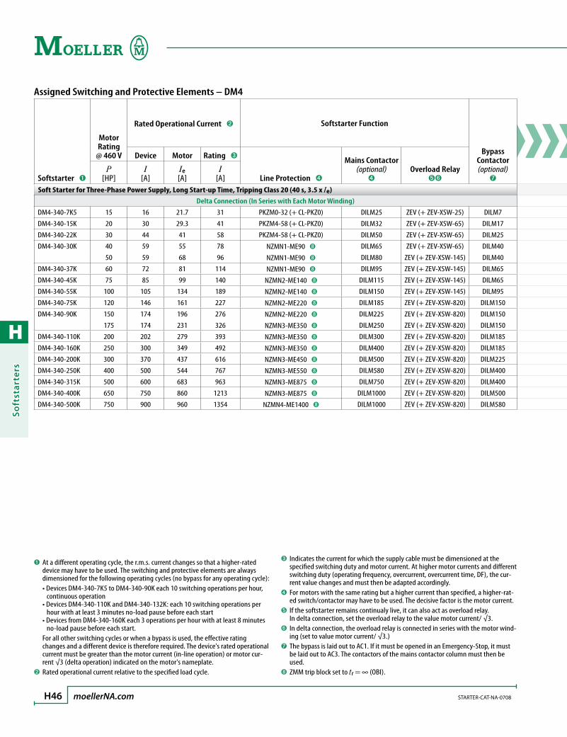
H
Soft
star
ters
H46 moellerNA.com STARTER-CAT-NA-0708
Assigned Switching and Protective Elements – DM4
Softstarter ➊
Motor Rating
@ 460 V
Rated Operational Current ➋ Softstarter Function
Bypass Contactor (optional)
➐
Device Motor Rating ➌
Line Protection ➍
Mains Contactor (optional)
➍Overload Relay
➎➏P
[HP]I
[A]Ie
[A]I
[A]Soft Starter for Three-Phase Power Supply, Long Start-up Time, Tripping Class 20 (40 s, 3.5 x Ie)
Delta Connection (In Series with Each Motor Winding)
DM4-340-7K5 15 16 21.7 31 PKZM0-32 (+ CL-PKZ0) DILM25 ZEV (+ ZEV-XSW-25) DILM7
DM4-340-15K 20 30 29.3 41 PKZM4-58 (+ CL-PKZ0) DILM32 ZEV (+ ZEV-XSW-65) DILM17
DM4-340-22K 30 44 41 58 PKZM4-58 (+ CL-PKZ0) DILM50 ZEV (+ ZEV-XSW-65) DILM25
DM4-340-30K 40 59 55 78 NZMN1-ME90 ➑ DILM65 ZEV (+ ZEV-XSW-65) DILM40
50 59 68 96 NZMN1-ME90 ➑ DILM80 ZEV (+ ZEV-XSW-145) DILM40
DM4-340-37K 60 72 81 114 NZMN1-ME90 ➑ DILM95 ZEV (+ ZEV-XSW-145) DILM65
DM4-340-45K 75 85 99 140 NZMN2-ME140 ➑ DILM115 ZEV (+ ZEV-XSW-145) DILM65
DM4-340-55K 100 105 134 189 NZMN2-ME140 ➑ DILM150 ZEV (+ ZEV-XSW-145) DILM95
DM4-340-75K 120 146 161 227 NZMN2-ME220 ➑ DILM185 ZEV (+ ZEV-XSW-820) DILM150
DM4-340-90K 150 174 196 276 NZMN2-ME220 ➑ DILM225 ZEV (+ ZEV-XSW-820) DILM150
175 174 231 326 NZMN3-ME350 ➑ DILM250 ZEV (+ ZEV-XSW-820) DILM150
DM4-340-110K 200 202 279 393 NZMN3-ME350 ➑ DILM300 ZEV (+ ZEV-XSW-820) DILM185
DM4-340-160K 250 300 349 492 NZMN3-ME350 ➑ DILM400 ZEV (+ ZEV-XSW-820) DILM185
DM4-340-200K 300 370 437 616 NZMN3-ME450 ➑ DILM500 ZEV (+ ZEV-XSW-820) DILM225
DM4-340-250K 400 500 544 767 NZMN3-ME550 ➑ DILM580 ZEV (+ ZEV-XSW-820) DILM400
DM4-340-315K 500 600 683 963 NZMN3-ME875 ➑ DILM750 ZEV (+ ZEV-XSW-820) DILM400
DM4-340-400K 650 750 860 1213 NZMN3-ME875 ➑ DILM1000 ZEV (+ ZEV-XSW-820) DILM500
DM4-340-500K 750 900 960 1354 NZMN4-ME1400 ➑ DILM1000 ZEV (+ ZEV-XSW-820) DILM580
➊ At a different operating cycle, the r.m.s. current changes so that a higher-rated device may have to be used. The switching and protective elements are always dimensioned for the following operating cycles (no bypass for any operating cycle):
•DevicesDM4-340-7K5toDM4-340-90Keach10switchingoperationsperhour, continuous operation •DevicesDM4-340-110KandDM4-340-132K:each10switchingoperationsper hour with at least 3 minutes no-load pause before each start •DevicesfromDM4-340-160Keach3operationsperhourwithatleast8minutes no-load pause before each start.
For all other switching cycles or when a bypass is used, the effective rating changes and a different device is therefore required. The device's rated operational current must be greater than the motor current (in-line operation) or motor cur-rent √3 (delta operation) indicated on the motor's nameplate.
➋ Rated operational current relative to the specified load cycle.
➌ Indicates the current for which the supply cable must be dimensioned at the specified switching duty and motor current. At higher motor currents and different switching duty (operating frequency, overcurrent, overcurrent time, DF), the cur-rent value changes and must then be adapted accordingly.
➍ For motors with the same rating but a higher current than specified, a higher-rat-ed switch/contactor may have to be used. The decisive factor is the motor current.
➎ If the softstarter remains continualy live, it can also act as overload relay. In delta connection, set the overload relay to the value motor current/ √3.
➏ In delta connection, the overload relay is connected in series with the motor wind-ing (set to value motor current/ √3.)
➐ The bypass is laid out to AC1. If it must be opened in an Emergency-Stop, it must be laid out to AC3. The contactors of the mains contactor column must then be used.
➑ ZMM trip block set to tr = ∞ (OBI).

H
Softstarters
STARTER-CAT-NA-0708 moellerNA.com H47
Softstarter Series DM4
Rated Component List
Assigned Switching and Protective Elements – DM4
Softstarter ➊
Motor Rating
@ 460 V
Rated Operational Current ➋ Softstarter Function
Bypass Contactor (optional)
➐
Device Motor Rating ➌
Line Protection ➍
Mains Contactor (optional)
➍Overload Relay
➎➏P
[HP]I
[A]Ie
[A]I
[A]Soft Starter for Three-Phase Power Supply, Long Start-up Time, Tripping Class 20 (40 s, 3.5 x Ie)
Delta Connection (In Series with Each Motor Winding)
DM4-340-7K5 15 16 21.7 31 PKZM0-32 (+ CL-PKZ0) DILM25 ZEV (+ ZEV-XSW-25) DILM7
DM4-340-15K 20 30 29.3 41 PKZM4-58 (+ CL-PKZ0) DILM32 ZEV (+ ZEV-XSW-65) DILM17
DM4-340-22K 30 44 41 58 PKZM4-58 (+ CL-PKZ0) DILM50 ZEV (+ ZEV-XSW-65) DILM25
DM4-340-30K 40 59 55 78 NZMN1-ME90 ➑ DILM65 ZEV (+ ZEV-XSW-65) DILM40
50 59 68 96 NZMN1-ME90 ➑ DILM80 ZEV (+ ZEV-XSW-145) DILM40
DM4-340-37K 60 72 81 114 NZMN1-ME90 ➑ DILM95 ZEV (+ ZEV-XSW-145) DILM65
DM4-340-45K 75 85 99 140 NZMN2-ME140 ➑ DILM115 ZEV (+ ZEV-XSW-145) DILM65
DM4-340-55K 100 105 134 189 NZMN2-ME140 ➑ DILM150 ZEV (+ ZEV-XSW-145) DILM95
DM4-340-75K 120 146 161 227 NZMN2-ME220 ➑ DILM185 ZEV (+ ZEV-XSW-820) DILM150
DM4-340-90K 150 174 196 276 NZMN2-ME220 ➑ DILM225 ZEV (+ ZEV-XSW-820) DILM150
175 174 231 326 NZMN3-ME350 ➑ DILM250 ZEV (+ ZEV-XSW-820) DILM150
DM4-340-110K 200 202 279 393 NZMN3-ME350 ➑ DILM300 ZEV (+ ZEV-XSW-820) DILM185
DM4-340-160K 250 300 349 492 NZMN3-ME350 ➑ DILM400 ZEV (+ ZEV-XSW-820) DILM185
DM4-340-200K 300 370 437 616 NZMN3-ME450 ➑ DILM500 ZEV (+ ZEV-XSW-820) DILM225
DM4-340-250K 400 500 544 767 NZMN3-ME550 ➑ DILM580 ZEV (+ ZEV-XSW-820) DILM400
DM4-340-315K 500 600 683 963 NZMN3-ME875 ➑ DILM750 ZEV (+ ZEV-XSW-820) DILM400
DM4-340-400K 650 750 860 1213 NZMN3-ME875 ➑ DILM1000 ZEV (+ ZEV-XSW-820) DILM500
DM4-340-500K 750 900 960 1354 NZMN4-ME1400 ➑ DILM1000 ZEV (+ ZEV-XSW-820) DILM580
Circuit Breaker
Controller Supply
Semiconductor Protection (optional; fuses required for
Type 2 coordination are in addition to the protective elements required for
Type 1 coordination)
DC Braking Unit
Hilger & Kern Frenomat/Frenostat
Output Contactor
➊ Line Protection
LineReactor
➋Braking
Contactor
Fuse for Standstill
Monitoring ➌
Fuses Fuse Switch
Recommended @ 400V Mains VoltageNumber x Type Number x Type
Delta Connection (In Series with Each Motor Winding)
PKZM0-0,16 3 x 20.282.20-40 3 x 21.189.01 Frenostat-6000.0316 DILM17 PKZM4-40 (+ CL-PKZ0) Built-in DILM25 FAZ-B4/1-HI
PKZM0-0,16 3 x 20.282.20-80 3 x 21.189.01 Frenostat-6000.0247 DILM17 PKZM4-50 (+ CL-PKZ0) Built-in DILM32 FAZ-B4/1-HI
PKZM0-0,16 3 x 20.282.20-125 3 x 21.189.01 Frenostat-6000.0248 DILM40 PKZM4-63 (+ CL-PKZ0) Built-in DILM50 FAZ-B4/1-HI
PKZM0-0,16 3 x 20.282.20-125 3 x 21.189.01 Frenostat-6000.0249 DILM65 NZMN1-M80 Built-in DILM65 FAZ-B4/1-HI
PKZM0-0,16 3 x 20.282.20-125 3 x 21.189.01 Frenostat-6000.0173 DILM80 NZMN1-M100 External DILM80 FAZ-B4/1-HI
PKZM0-0,16 3 x 20.189.20-200 3 x 21.189.01 Frenostat-6000.0173 DILM95 NZMN2-M125 External DILM95 FAZ-B4/1-HI
PKZM0-0,16 3 x 20.189.20-200 3 x 21.189.01 Frenostat-6000.0177 DILM115 NZMN2-M160 External DILM115 FAZ-B4/1-HI
PKZM0-0,16 3 x 20.610.32-350 3 x 21.313.02 Frenostat-6000.0181 DILM150 NZMN2-M200 External DILM150 FAZ-B4/1-HI
PKZM0-0,16 3 x 20.610.32-350 3 x 21.313.02 Frenostat-6000.0169 DILM185 NZMN3-ME220 External DILM185 FAZ-B4/1-HI
PKZM0-0,16 3 x 20.610.32-450 3 x 21.313.02 Frenostat-6000.0169 DILM185 NZMN3-ME350 External DILM225 FAZ-B4/1-HI
PKZM0-0,16 3 x 20.610.32-450 3 x 21.313.02 Frenostat-6000.0307 DILM185 NZMN3-ME350 External DILM250 FAZ-B4/1-HI
PKZM0-0,16 3 x 20.610.32-450 3 x 21.313.02 Frenostat-6000.0307 DILM225 NZMN4-ME450 External DILM300 FAZ-B4/1-HI
PKZM0-0,16 3 x 20.610.32-500 3 x 21.313.02 Frenostat-6000.0308 DILM400 NZMN4-ME550 External DILM400 FAZ-B4/1-HI
PKZM0-0,16 3 x 20.610.32-630 3 x 21.313.02 Frenostat-6000.0308 DILM400 NZMN4-ME875 External DILM500 FAZ-B4/1-HI
PKZM0-1,6 3 x 20.630.32-900 3 x 21.313.02 Frenostat-6000.0171 DILM500 NZMN4-ME875 External DILM580 FAZ-B4/1-HI
PKZM0-1,6 3 x 20.630.32-900 3 x 21.313.02 Frenostat-6000.0171 DILM500 NZMN4-ME1400 External DILM750 FAZ-B4/1-HI
PKZM0-1,6 3 x 20.630.32-1250 3 x 21.313.02 – – – – – –
PKZM0-1,6 3 x 20.630.32-1250 3 x 21.313.02 – – – – – –
➊ If a DC braking unit is used, the soft starter's output must be isolated with this contactor before braking. In delta connection, both the input and the output must be isolated. In this case, two contactors are required.
➋ On external surface mounting included as standard.➌ If a measuring line with a cross-section F 1.5 mm2 is used, the fuse can be omitted.
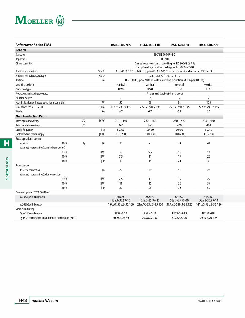
H
Soft
star
ters
H48 moellerNA.com STARTER-CAT-NA-0708
Softstarter Series DM4 DM4-340-7K5 DM4-340-11K DM4-340-15K DM4-340-22KGeneralStandards IEC/EN 60947-4-2Approvals UL, cULClimatic proofing Damp heat, constant according to IEC 60068-2-78;
Damp heat, cyclical, according to IEC 60068-2-30Ambient temperature [°C / °F] 0…40 °C / 32…104 °F (up to 60 °C / 140 °F with a current reduction of 2% per °C)Ambient temperature, storage [°C / °F] -25…55 °C / -13…131 °FAltitude [m] 0 – 1000 (up to 2000 m with a current reduction of 1% per 100 m)Mounting position vertical vertical vertical verticalProtection type IP20 IP20 IP20 IP20Protection against direct contact Finger and back-of-hand proofPollution degree 2 2 2 2Heat dissipation with rated operational current Ie [W] 50 63 91 120Dimensions (W x H x D) [mm] 222 x 290 x 195 222 x 290 x 195 222 x 290 x 195 222 x 290 x 195Weight [kg] 6.7 6.7 6.7 6.7
Main Conducting PathsRated operating voltage Ue [V AC] 230 – 460 230 – 460 230 – 460 230 – 460Rated insulation voltage Ui 460 460 460 460Supply frequency [Hz] 50/60 50/60 50/60 50/60Control section power supply [V AC] 110/230 110/230 110/230 110/230Rated operational current AC-53a 400V Ie [A] 16 23 30 44 Assigned motor rating (standard connection) 230V [kW] 4 5.5 7.5 11 400V [kW] 7.5 11 15 22 460V [HP] 10 15 20 30Phase current In-delta connection [A] 27 39 51 76 Assigned motor rating (delta connection) 230V [kW] 7.5 11 15 22 400V [kW] 11 15 22 37 460V [HP] 20 25 30 50Overload cycle to IEC/EN 60947-4-2 AC-53a (without bypass) 16A:AC-
53a:3-35:99-1023A:AC-
53a:3-35:99-1030A:AC-
53a:3-35:99-1044A:AC-
53a:3-35:99-10 AC-53b (with bypass) 16A:AC-53b:3-35:120 23A:AC-53b:3-35:120 30A:AC-53b:3-35:120 44A:AC-53b:3-35:120Short-circuit rating Type "1" coordination PKZM0-16 PKZM0-25 PKZ2/ZM-32 NZM7-63N Type “2” coordination (in addition to coordination type “1”) 20.282.20-40 20.282.20-80 20.282.20-80 20.282.20-125
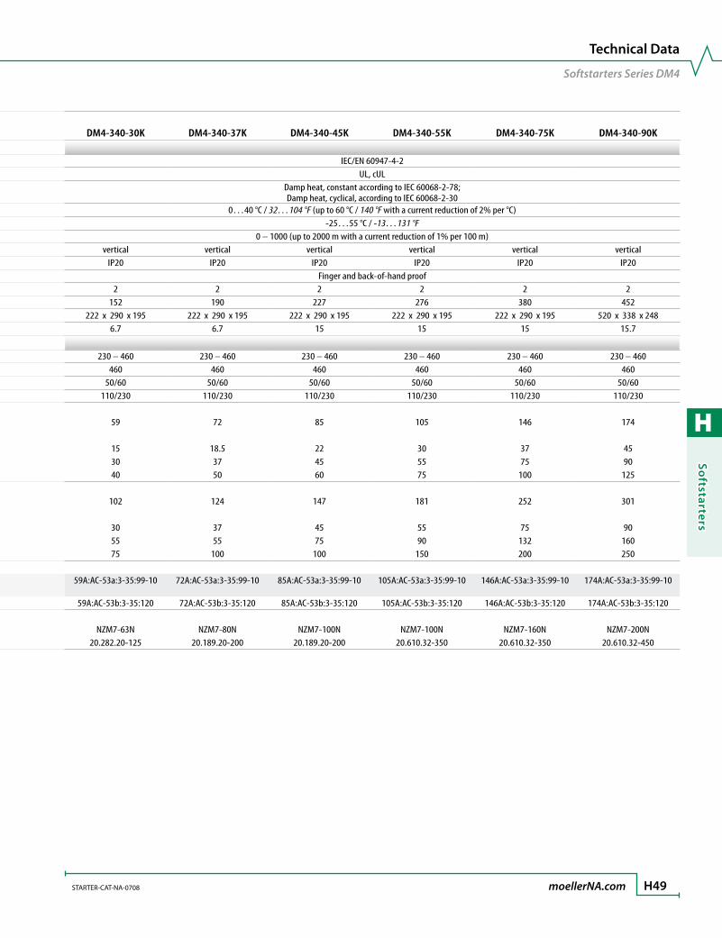
H
Softstarters
STARTER-CAT-NA-0708 moellerNA.com H49
Technical Data
Softstarters Series DM4
Softstarter Series DM4 DM4-340-7K5 DM4-340-11K DM4-340-15K DM4-340-22KGeneralStandards IEC/EN 60947-4-2Approvals UL, cULClimatic proofing Damp heat, constant according to IEC 60068-2-78;
Damp heat, cyclical, according to IEC 60068-2-30Ambient temperature [°C / °F] 0…40 °C / 32…104 °F (up to 60 °C / 140 °F with a current reduction of 2% per °C)Ambient temperature, storage [°C / °F] -25…55 °C / -13…131 °FAltitude [m] 0 – 1000 (up to 2000 m with a current reduction of 1% per 100 m)Mounting position vertical vertical vertical verticalProtection type IP20 IP20 IP20 IP20Protection against direct contact Finger and back-of-hand proofPollution degree 2 2 2 2Heat dissipation with rated operational current Ie [W] 50 63 91 120Dimensions (W x H x D) [mm] 222 x 290 x 195 222 x 290 x 195 222 x 290 x 195 222 x 290 x 195Weight [kg] 6.7 6.7 6.7 6.7
Main Conducting PathsRated operating voltage Ue [V AC] 230 – 460 230 – 460 230 – 460 230 – 460Rated insulation voltage Ui 460 460 460 460Supply frequency [Hz] 50/60 50/60 50/60 50/60Control section power supply [V AC] 110/230 110/230 110/230 110/230Rated operational current AC-53a 400V Ie [A] 16 23 30 44 Assigned motor rating (standard connection) 230V [kW] 4 5.5 7.5 11 400V [kW] 7.5 11 15 22 460V [HP] 10 15 20 30Phase current In-delta connection [A] 27 39 51 76 Assigned motor rating (delta connection) 230V [kW] 7.5 11 15 22 400V [kW] 11 15 22 37 460V [HP] 20 25 30 50Overload cycle to IEC/EN 60947-4-2 AC-53a (without bypass) 16A:AC-
53a:3-35:99-1023A:AC-
53a:3-35:99-1030A:AC-
53a:3-35:99-1044A:AC-
53a:3-35:99-10 AC-53b (with bypass) 16A:AC-53b:3-35:120 23A:AC-53b:3-35:120 30A:AC-53b:3-35:120 44A:AC-53b:3-35:120Short-circuit rating Type "1" coordination PKZM0-16 PKZM0-25 PKZ2/ZM-32 NZM7-63N Type “2” coordination (in addition to coordination type “1”) 20.282.20-40 20.282.20-80 20.282.20-80 20.282.20-125
DM4-340-30K DM4-340-37K DM4-340-45K DM4-340-55K DM4-340-75K DM4-340-90K
IEC/EN 60947-4-2UL, cUL
Damp heat, constant according to IEC 60068-2-78; Damp heat, cyclical, according to IEC 60068-2-30
0…40 °C / 32…104 °F (up to 60 °C / 140 °F with a current reduction of 2% per °C)-25…55 °C / -13…131 °F
0 – 1000 (up to 2000 m with a current reduction of 1% per 100 m)vertical vertical vertical vertical vertical vertical
IP20 IP20 IP20 IP20 IP20 IP20Finger and back-of-hand proof
2 2 2 2 2 2152 190 227 276 380 452
222 x 290 x 195 222 x 290 x 195 222 x 290 x 195 222 x 290 x 195 222 x 290 x 195 520 x 338 x 2486.7 6.7 15 15 15 15.7
230 – 460 230 – 460 230 – 460 230 – 460 230 – 460 230 – 460460 460 460 460 460 460
50/60 50/60 50/60 50/60 50/60 50/60110/230 110/230 110/230 110/230 110/230 110/230
59 72 85 105 146 174
15 18.5 22 30 37 4530 37 45 55 75 9040 50 60 75 100 125
102 124 147 181 252 301
30 37 45 55 75 9055 55 75 90 132 16075 100 100 150 200 250
59A:AC-53a:3-35:99-10 72A:AC-53a:3-35:99-10 85A:AC-53a:3-35:99-10 105A:AC-53a:3-35:99-10 146A:AC-53a:3-35:99-10 174A:AC-53a:3-35:99-10
59A:AC-53b:3-35:120 72A:AC-53b:3-35:120 85A:AC-53b:3-35:120 105A:AC-53b:3-35:120 146A:AC-53b:3-35:120 174A:AC-53b:3-35:120
NZM7-63N NZM7-80N NZM7-100N NZM7-100N NZM7-160N NZM7-200N20.282.20-125 20.189.20-200 20.189.20-200 20.610.32-350 20.610.32-350 20.610.32-450

H
Soft
star
ters
H50 moellerNA.com STARTER-CAT-NA-0708
Softstarter Series DM4 DM4-340-7K5 DM4-340-11K DM4-340-15K DM4-340-22KTerminal CapacitiesCable lengths Connection – – – – Solid [mm2] 1 x (1.5 – 16)
2 x (1 – 4)1 x (1.5 – 16)
2 x (1 – 4)1 x (1.5 – 16)
2 x (1 – 4)1 x (1.5 – 16)
2 x (1 – 4) Flexible with ferrule [mm2] 1 x (1.5 – 16)
2 x (1 – 4)1 x (1.5 – 16)
2 x (1 – 4)1 x (1.5 – 16)
2 x (1 – 4)1 x (1.5 – 16)
2 x (1 – 4) Flexible with cable lug [mm2] – – – – Stranded [mm2] 1 x (2.5 – 25)
2 x (2.5 – 4)1 x (2.5 – 25) 2 x (2.5 – 4)
1 x (2.5 – 25) 2 x (2.5 – 4)
1 x (2.5 – 25) 2 x (2.5 – 4)
Stranded with cable lug [mm2] – – – – Solid or stranded [AWG] 12 – 4 12 – 4 12 – 4 12 – 4 Flat conductor (Number of segments x width x thickness) [mm] – – – – Busbar Width [mm] – – – – Tightening torque [Nm] 1.2 1.2 1.2 1.2 Standard screwdriver [mm] 0.8 x 4 0.8 x 4 0.8 x 4 0.8 x 4Control cables Solid [mm2] 1 x (0.75 – 2.5) 1 x (0.75 – 2.5) 1 x (0.75 – 2.5) 1 x (0.75 – 2.5) Flexible with ferrule [mm2] 1 x (0.75 – 2.5) 1 x (0.75 – 2.5) 1 x (0.75 – 2.5) 1 x (0.75 – 2.5) Stranded [mm2] 1 x (0.75 – 2.5) 1 x (0.75 – 2.5) 1 x (0.75 – 2.5) 1 x (0.75 – 2.5) Solid or stranded [AWG] 22 – 12 22 – 12 22 – 12 22 – 12 Tightening torque [Nm] 0.5 0.5 0.5 0.5 Standard screwdriver [mm] 0.6 x 3.5 0.6 x 3.5 0.6 x 3.5 0.6 x 3.5
Control CircuitCurrent consumption Digital inputs 24V DC [mA] 0.45 0.45 0.45 0.45 230V AC [mA] 4.5 4.5 4.5 4.5 Analog inputs 10V [mA] 1 1 1 1Pick-up voltage DC operated [V DC] 24 – 230 24 – 230 24 – 230 24 – 230 AC operated [V AC] 24 – 230 24 – 230 24 – 230 24 – 230Drop-out voltage DC operated [V DC] 0 – 3 0 – 3 0 – 3 0 – 3 AC operated [V AC] 0 – 3 0 – 3 0 – 3 0 – 3Programmable relay outputs Number 4 4 4 4 Max. voltage [V AC] 250 250 250 250 Max. current AC-11 [A] 3 3 3 3With back-up fuse Number 2 2 2 2 Voltage range [V DC] 0 – 10 0 – 10 0 – 10 0 – 10 Current carrying capacity [mA] 10 10 10 10Programmable analog inputs Ref 1 [V DC] 0 – 10 0 – 10 0 – 10 0 – 10 Ref 2 [mA] 4 – 20 4 – 20 4 – 20 4 – 20
Soft Start FunctionRamp times Acceleration [s] 1 – 255 1 – 255 1 – 255 1 – 255 Deceleration [s] 0 – 255 0 – 255 0 – 255 0 – 255Start pedestal [%] 10 – 60 10 – 60 10 – 60 10 – 60Voltage reduction at stop [%] 0 – 100 0 – 100 0 – 100 0 – 100Kickstart Voltage [%] 60 – 90 60 – 90 60 – 90 60 – 90 Duration 50 Hz [ms] 100 – 400 100 – 400 100 – 400 100 – 400 60 Hz [ms] 166 – 664 166 – 664 166 – 664 166 – 664Current limitation (0.5 – 8) x Ie (0.5 – 8) x Ie (0.5 – 8) x Ie (0.5 – 8) x Ie
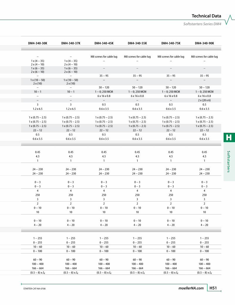
H
Softstarters
STARTER-CAT-NA-0708 moellerNA.com H51
Technical Data
Softstarters Series DM4
Softstarter Series DM4 DM4-340-7K5 DM4-340-11K DM4-340-15K DM4-340-22KTerminal CapacitiesCable lengths Connection – – – – Solid [mm2] 1 x (1.5 – 16)
2 x (1 – 4)1 x (1.5 – 16)
2 x (1 – 4)1 x (1.5 – 16)
2 x (1 – 4)1 x (1.5 – 16)
2 x (1 – 4) Flexible with ferrule [mm2] 1 x (1.5 – 16)
2 x (1 – 4)1 x (1.5 – 16)
2 x (1 – 4)1 x (1.5 – 16)
2 x (1 – 4)1 x (1.5 – 16)
2 x (1 – 4) Flexible with cable lug [mm2] – – – – Stranded [mm2] 1 x (2.5 – 25)
2 x (2.5 – 4)1 x (2.5 – 25) 2 x (2.5 – 4)
1 x (2.5 – 25) 2 x (2.5 – 4)
1 x (2.5 – 25) 2 x (2.5 – 4)
Stranded with cable lug [mm2] – – – – Solid or stranded [AWG] 12 – 4 12 – 4 12 – 4 12 – 4 Flat conductor (Number of segments x width x thickness) [mm] – – – – Busbar Width [mm] – – – – Tightening torque [Nm] 1.2 1.2 1.2 1.2 Standard screwdriver [mm] 0.8 x 4 0.8 x 4 0.8 x 4 0.8 x 4Control cables Solid [mm2] 1 x (0.75 – 2.5) 1 x (0.75 – 2.5) 1 x (0.75 – 2.5) 1 x (0.75 – 2.5) Flexible with ferrule [mm2] 1 x (0.75 – 2.5) 1 x (0.75 – 2.5) 1 x (0.75 – 2.5) 1 x (0.75 – 2.5) Stranded [mm2] 1 x (0.75 – 2.5) 1 x (0.75 – 2.5) 1 x (0.75 – 2.5) 1 x (0.75 – 2.5) Solid or stranded [AWG] 22 – 12 22 – 12 22 – 12 22 – 12 Tightening torque [Nm] 0.5 0.5 0.5 0.5 Standard screwdriver [mm] 0.6 x 3.5 0.6 x 3.5 0.6 x 3.5 0.6 x 3.5
Control CircuitCurrent consumption Digital inputs 24V DC [mA] 0.45 0.45 0.45 0.45 230V AC [mA] 4.5 4.5 4.5 4.5 Analog inputs 10V [mA] 1 1 1 1Pick-up voltage DC operated [V DC] 24 – 230 24 – 230 24 – 230 24 – 230 AC operated [V AC] 24 – 230 24 – 230 24 – 230 24 – 230Drop-out voltage DC operated [V DC] 0 – 3 0 – 3 0 – 3 0 – 3 AC operated [V AC] 0 – 3 0 – 3 0 – 3 0 – 3Programmable relay outputs Number 4 4 4 4 Max. voltage [V AC] 250 250 250 250 Max. current AC-11 [A] 3 3 3 3With back-up fuse Number 2 2 2 2 Voltage range [V DC] 0 – 10 0 – 10 0 – 10 0 – 10 Current carrying capacity [mA] 10 10 10 10Programmable analog inputs Ref 1 [V DC] 0 – 10 0 – 10 0 – 10 0 – 10 Ref 2 [mA] 4 – 20 4 – 20 4 – 20 4 – 20
Soft Start FunctionRamp times Acceleration [s] 1 – 255 1 – 255 1 – 255 1 – 255 Deceleration [s] 0 – 255 0 – 255 0 – 255 0 – 255Start pedestal [%] 10 – 60 10 – 60 10 – 60 10 – 60Voltage reduction at stop [%] 0 – 100 0 – 100 0 – 100 0 – 100Kickstart Voltage [%] 60 – 90 60 – 90 60 – 90 60 – 90 Duration 50 Hz [ms] 100 – 400 100 – 400 100 – 400 100 – 400 60 Hz [ms] 166 – 664 166 – 664 166 – 664 166 – 664Current limitation (0.5 – 8) x Ie (0.5 – 8) x Ie (0.5 – 8) x Ie (0.5 – 8) x Ie
DM4-340-30K DM4-340-37K DM4-340-45K DM4-340-55K DM4-340-75K DM4-340-90K
– – M8 screws for cable lug M8 screws for cable lug M8 screws for cable lug M8 screws for cable lug1 x (4 – 35) 2 x (4 – 10)
1 x (4 – 35) 2 x (4 – 10)
– – – –
1 x (6 – 35) 2 x (6 – 10)
1 x (6 – 35) 2 x (6 – 10)
– – – –
– – 35 – 95 35 – 95 35 – 95 35 – 951 x (10 – 50)
2 x (10)1 x (10 – 50)
2 x (10)– – – –
– – 50 – 120 50 – 120 50 – 120 50 – 12010 – 1 10 – 1 1 – 0; 250 MCM 1 – 0; 250 MCM 1 – 0; 250 MCM 1 – 0; 250 MCM
– – 6 x 16 x 0.8 6 x 16 x 0.8 6 x 16 x 0.8 6 x 16 x 0.8– – – – – 2 x (20 x 6)3 3 0.5 0.5 0.5 0.5
1.2 x 6.5 1.2 x 6.5 0.6 x 3.5 0.6 x 3.5 0.6 x 3.5 0.6 x 3.5
1 x (0.75 – 2.5) 1 x (0.75 – 2.5) 1 x (0.75 – 2.5) 1 x (0.75 – 2.5) 1 x (0.75 – 2.5) 1 x (0.75 – 2.5)1 x (0.75 – 2.5) 1 x (0.75 – 2.5) 1 x (0.75 – 2.5) 1 x (0.75 – 2.5) 1 x (0.75 – 2.5) 1 x (0.75 – 2.5)1 x (0.75 – 2.5) 1 x (0.75 – 2.5) 1 x (0.75 – 2.5) 1 x (0.75 – 2.5) 1 x (0.75 – 2.5) 1 x (0.75 – 2.5)
22 – 12 22 – 12 22 – 12 22 – 12 22 – 12 22 – 120.5 0.5 0.5 0.5 0.5 0.5
0.6 x 3.5 0.6 x 3.5 0.6 x 3.5 0.6 x 3.5 0.6 x 3.5 0.6 x 3.5
0.45 0.45 0.45 0.45 0.45 0.454.5 4.5 4.5 4.5 4.5 4.51 1 1 1 1 1
24 – 230 24 – 230 24 – 230 24 – 230 24 – 230 24 – 23024 – 230 24 – 230 24 – 230 24 – 230 24 – 230 24 – 230
0 – 3 0 – 3 0 – 3 0 – 3 0 – 3 0 – 30 – 3 0 – 3 0 – 3 0 – 3 0 – 3 0 – 3
4 4 4 4 4 4250 250 250 250 250 250
3 3 3 3 3 32 2 2 2 2 2
0 – 10 0 – 10 0 – 10 0 – 10 0 – 10 0 – 1010 10 10 10 10 10
0 – 10 0 – 10 0 – 10 0 – 10 0 – 10 0 – 104 – 20 4 – 20 4 – 20 4 – 20 4 – 20 4 – 20
1 – 255 1 – 255 1 – 255 1 – 255 1 – 255 1 – 2550 – 255 0 – 255 0 – 255 0 – 255 0 – 255 0 – 25510 – 60 10 – 60 10 – 60 10 – 60 10 – 60 10 – 600 – 100 0 – 100 0 – 100 0 – 100 0 – 100 0 – 100
60 – 90 60 – 90 60 – 90 60 – 90 60 – 90 60 – 90100 – 400 100 – 400 100 – 400 100 – 400 100 – 400 100 – 400166 – 664 166 – 664 166 – 664 166 – 664 166 – 664 166 – 664
(0.5 – 8) x Ie (0.5 – 8) x Ie (0.5 – 8) x Ie (0.5 – 8) x Ie (0.5 – 8) x Ie (0.5 – 8) x Ie

H
Soft
star
ters
H52 moellerNA.com STARTER-CAT-NA-0708
Softstarter Series DM4 DM4-340-110K DM4-340-132K DM4-340-160KGeneralStandards IEC/EN 60947-4-2 IEC/EN 60947-4-2 IEC/EN 60947-4-2Approvals UL, cUL UL, cUL UL, cULClimatic proofing Damp heat, constant according to IEC 60068-2-78;
Damp heat, cyclical, according to IEC 60068-2-30Ambient temperature [°C / °F] 0…40 °C / 32…104 °F (up to 60 °C / 140 °F with a current reduction of 2% per °C)Ambient temperature, storage [°C / °F] -25…55 °C / -13…131 °F -25…55 °C / -13…131 °F -25…55 °C / -13…131 °FAltitude [m] 0 – 1000 (up to 2000 m with a current reduction of 1% per 100 m)Mounting position vertical vertical verticalDegree of protection (power connection) IP20 IP20 IP20Protection against direct contact Finger and back-of-hand proofPollution degree 2 2 2Heat dissipation with rated operational current Ie [W] 545 662 795Dimensions (W x H x D) [mm] 338 x 520 x 248 338 x 520 x 248 338 x 520 x 248Weight [kg] 15.7 22 22
Main Conducting PathsRated operating voltage Ue [V AC] 230 – 460 230 – 460 230 – 460Rated insulation voltage Ui [V AC] 460 460 460Supply frequency [Hz] 50/60 50/60 50/60Control section power supply [V AC] 110/230 110/230 110/230Rated operational current AC-53a 400V Ie [A] 202 242 300 Assigned motor rating (standard connection) 230V [kW] 55 75 90 400V [kW] 110 132 160 460V [HP] 150 200 250Phase current In-delta connection [A] 349 419 519 Assigned motor rating (delta connection) 230V [kW] 110 132 160 400V [kW] 160 200 250 460V [HP] 250 350 400Overload cycle to IEC/EN 60947-4-2 AC-53a (without bypass) 202 A : AC-53a : 3–35 : 60–10 242 A : AC-53a : 3–35 : 60–10 300 A : AC-53a : 3–35 : 60–3 AC-53b (with bypass) 202 A : AC-53b : 3–35 : 360 242 A : AC-53b : 3–35 : 360 300 A : AC-53b : 3–35 : 360Short-circuit rating Type "1" coordination NZM7-200N NZM7-250N NZM10-400N/ZM-400 Type “2” coordination (in addition to coordination type “1”) 20.610.32-450 20.610.32-500 20.610.32-500

H
Softstarters
STARTER-CAT-NA-0708 moellerNA.com H53
Technical Data
Softstarters Series DM4
Softstarter Series DM4 DM4-340-110K DM4-340-132K DM4-340-160KGeneralStandards IEC/EN 60947-4-2 IEC/EN 60947-4-2 IEC/EN 60947-4-2Approvals UL, cUL UL, cUL UL, cULClimatic proofing Damp heat, constant according to IEC 60068-2-78;
Damp heat, cyclical, according to IEC 60068-2-30Ambient temperature [°C / °F] 0…40 °C / 32…104 °F (up to 60 °C / 140 °F with a current reduction of 2% per °C)Ambient temperature, storage [°C / °F] -25…55 °C / -13…131 °F -25…55 °C / -13…131 °F -25…55 °C / -13…131 °FAltitude [m] 0 – 1000 (up to 2000 m with a current reduction of 1% per 100 m)Mounting position vertical vertical verticalDegree of protection (power connection) IP20 IP20 IP20Protection against direct contact Finger and back-of-hand proofPollution degree 2 2 2Heat dissipation with rated operational current Ie [W] 545 662 795Dimensions (W x H x D) [mm] 338 x 520 x 248 338 x 520 x 248 338 x 520 x 248Weight [kg] 15.7 22 22
Main Conducting PathsRated operating voltage Ue [V AC] 230 – 460 230 – 460 230 – 460Rated insulation voltage Ui [V AC] 460 460 460Supply frequency [Hz] 50/60 50/60 50/60Control section power supply [V AC] 110/230 110/230 110/230Rated operational current AC-53a 400V Ie [A] 202 242 300 Assigned motor rating (standard connection) 230V [kW] 55 75 90 400V [kW] 110 132 160 460V [HP] 150 200 250Phase current In-delta connection [A] 349 419 519 Assigned motor rating (delta connection) 230V [kW] 110 132 160 400V [kW] 160 200 250 460V [HP] 250 350 400Overload cycle to IEC/EN 60947-4-2 AC-53a (without bypass) 202 A : AC-53a : 3–35 : 60–10 242 A : AC-53a : 3–35 : 60–10 300 A : AC-53a : 3–35 : 60–3 AC-53b (with bypass) 202 A : AC-53b : 3–35 : 360 242 A : AC-53b : 3–35 : 360 300 A : AC-53b : 3–35 : 360Short-circuit rating Type "1" coordination NZM7-200N NZM7-250N NZM10-400N/ZM-400 Type “2” coordination (in addition to coordination type “1”) 20.610.32-450 20.610.32-500 20.610.32-500
DM4-340-200K DM4-340-250K DM4-340-315K DM4-340-400K DM4-340-500K
IEC/EN 60947-4-2 IEC/EN 60947-4-2 IEC/EN 60947-4-2 IEC/EN 60947-4-2 IEC/EN 60947-4-2UL, cUL UL, cUL UL, cUL UL, cUL UL, cUL
Damp heat, constant according to IEC 60068-2-78; Damp heat, cyclical, according to IEC 60068-2-30
0…40 °C / 32…104 °F (up to 60 °C / 140 °F with a current reduction of 2% per °C)-25…55 °C / -13…131 °F -25…55 °C / -13…131 °F -25…55 °C / -13…131 °F -25…55 °C / -13…131 °F -25…55 °C / -13…131 °F
0 – 1000 (up to 2000 m with a current reduction of 1% per 100 m)vertical vertical vertical vertical vertical
IP20 IP20 IP20 IP20 IP20Finger and back-of-hand proof
2 2 2 2 2925 1371 1705 2106 2775
338 x 520 x 248 640 x 610 x 375 640 x 610 x 375 640 x 610 x 375 640 x 610 x 37522 56 65 72 72
230 – 460 230 – 460 230 – 460 230 – 460 230 – 460460 460 460 460 460
50/60 50/60 50/60 50/60 50/60110/230 110/230 110/230 110/230 110/230
370 500 600 750 900
110 132 160 200 250200 250 315 400 500300 400 500 600 750
640 866 1039 1299 1558
200 250 315 400 500315 400 560 750 900500 600 850 1100 1300
370 A : AC-53a : 3–35 : 60–3 500 A : AC-53a : 3–35 : 60–3 600 A : AC-53a : 3–35 : 60–3 750 A : AC-53a : 3–35 : 60–3 900 A : AC-53a : 3–35 : 60–3370 A : AC-53b : 3–35 : 360 500 A : AC-53b : 3–35 : 360 600 A : AC-53b : 3–35 : 360 750 A : AC-53b : 3–35 : 360 900 A : AC-53b : 3–35 : 360
NZM10-400N/ZM-400 NZM10-630N/ZM-630 NZM10-630N/ZM-630 NZM14-800S NZM14-1000S20.610.32-630 20.610.32-900 20.610.32-900 20.610.32-1250 20.610.32-1250

H
Soft
star
ters
H54 moellerNA.com STARTER-CAT-NA-0708
Softstarter Series DM4 DM4-340-110K DM4-340-132K DM4-340-160KTerminal CapacitiesCable lengths Connection M8 screws for cable lug M8 screws for cable lug M8 screws for cable lug Flexible with cable lug [mm2] 2 x (35 – 95) 2 x (35 – 95) 2 x (35 – 95) Stranded with cable lug [mm2] 2 x (50 – 120) 2 x (50 – 120) 2 x (50 – 120) Solid or stranded [AWG] 2 x 1/0; 2 x 250 MCM 2 x 1/0; 2 x 250 MCM 2 x 1/0; 2 x 250 MCM Flat conductor (Number of segments x width x thickness) [mm] 2 x (6 x 16 x 0.8) 2 x (6 x 16 x 0.8) 2 x (6 x 16 x 0.8) Busbar Width [mm] 2 x (20 x 6) 2 x (20 x 6) 2 x (20 x 6) Tightening torque [Nm] 0.5 0.5 0.5 Standard screwdriver [mm] 0.6 x 3.5 0.6 x 3.5 0.6 x 3.5Control cables Solid [mm2] 1 x (0.75 – 2.5) 1 x (0.75 – 2.5) 1 x (0.75 – 2.5) Flexible with ferrule [mm2] 1 x (0.75 – 2.5) 1 x (0.75 – 2.5) 1 x (0.75 – 2.5) Stranded [mm2] 1 x (0.75 – 2.5) 1 x (0.75 – 2.5) 1 x (0.75 – 2.5) Solid or stranded [AWG] 22 – 12 22 – 12 22 – 12 Tightening torque [Nm] 0.5 0.5 0.5 Standard screwdriver [mm] 0.6 x 3.5 0.6 x 3.5 0.6 x 3.5
Control CircuitCurrent consumption Digital inputs 24V DC [mA] 0.45 0.45 0.45 230V AC [mA] 4.5 4.5 4.5 Analog inputs 10V [mA] 1 1 1Pick-up voltage DC operated [V DC] 24 – 230 24 – 230 24 – 230 AC operated [V AC] 24 – 230 24 – 230 24 – 230Drop-out voltage DC operated [V DC] 0 – 3 0 – 3 0 – 3 AC operated [V AC] 0 – 3 0 – 3 0 – 3Programmable relay outputs Number 4 4 4 Max. voltage [V AC] 250 250 250 Max. current AC-11 [A] 3 3 3With back-up fuse Number 2 2 2 Voltage range [V DC] 0 – 10 0 – 10 0 – 10 Current carrying capacity [mA] 10 10 10Programmable analog inputs Ref 1 [V DC] 0 – 10 0 – 10 0 – 10 Ref 2 [mA] 4 – 20 4 – 20 4 – 20
Soft Start FunctionRamp times Acceleration [s] 1 – 255 1 – 255 1 – 255 Deceleration [s] 0 – 255 0 – 255 0 – 255Start pedestal [%] 10 – 60 10 – 60 10 – 60Voltage reduction at stop [%] 0 – 100 0 – 100 0 – 100Kickstart Voltage [%] 60 – 90 60 – 90 60 – 90 Duration 50 Hz [ms] 100 – 400 100 – 400 100 – 400 60 Hz [ms] 166 – 664 166 – 664 166 – 664Current limitation (0.5 – 8) x Ie (0.5 – 8) x Ie (0.5 – 8) x Ie
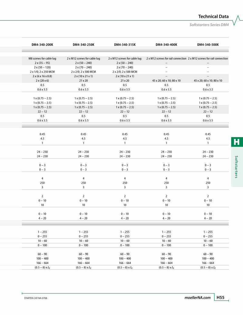
H
Softstarters
STARTER-CAT-NA-0708 moellerNA.com H55
Technical Data
Softstarters Series DM4
Softstarter Series DM4 DM4-340-110K DM4-340-132K DM4-340-160KTerminal CapacitiesCable lengths Connection M8 screws for cable lug M8 screws for cable lug M8 screws for cable lug Flexible with cable lug [mm2] 2 x (35 – 95) 2 x (35 – 95) 2 x (35 – 95) Stranded with cable lug [mm2] 2 x (50 – 120) 2 x (50 – 120) 2 x (50 – 120) Solid or stranded [AWG] 2 x 1/0; 2 x 250 MCM 2 x 1/0; 2 x 250 MCM 2 x 1/0; 2 x 250 MCM Flat conductor (Number of segments x width x thickness) [mm] 2 x (6 x 16 x 0.8) 2 x (6 x 16 x 0.8) 2 x (6 x 16 x 0.8) Busbar Width [mm] 2 x (20 x 6) 2 x (20 x 6) 2 x (20 x 6) Tightening torque [Nm] 0.5 0.5 0.5 Standard screwdriver [mm] 0.6 x 3.5 0.6 x 3.5 0.6 x 3.5Control cables Solid [mm2] 1 x (0.75 – 2.5) 1 x (0.75 – 2.5) 1 x (0.75 – 2.5) Flexible with ferrule [mm2] 1 x (0.75 – 2.5) 1 x (0.75 – 2.5) 1 x (0.75 – 2.5) Stranded [mm2] 1 x (0.75 – 2.5) 1 x (0.75 – 2.5) 1 x (0.75 – 2.5) Solid or stranded [AWG] 22 – 12 22 – 12 22 – 12 Tightening torque [Nm] 0.5 0.5 0.5 Standard screwdriver [mm] 0.6 x 3.5 0.6 x 3.5 0.6 x 3.5
Control CircuitCurrent consumption Digital inputs 24V DC [mA] 0.45 0.45 0.45 230V AC [mA] 4.5 4.5 4.5 Analog inputs 10V [mA] 1 1 1Pick-up voltage DC operated [V DC] 24 – 230 24 – 230 24 – 230 AC operated [V AC] 24 – 230 24 – 230 24 – 230Drop-out voltage DC operated [V DC] 0 – 3 0 – 3 0 – 3 AC operated [V AC] 0 – 3 0 – 3 0 – 3Programmable relay outputs Number 4 4 4 Max. voltage [V AC] 250 250 250 Max. current AC-11 [A] 3 3 3With back-up fuse Number 2 2 2 Voltage range [V DC] 0 – 10 0 – 10 0 – 10 Current carrying capacity [mA] 10 10 10Programmable analog inputs Ref 1 [V DC] 0 – 10 0 – 10 0 – 10 Ref 2 [mA] 4 – 20 4 – 20 4 – 20
Soft Start FunctionRamp times Acceleration [s] 1 – 255 1 – 255 1 – 255 Deceleration [s] 0 – 255 0 – 255 0 – 255Start pedestal [%] 10 – 60 10 – 60 10 – 60Voltage reduction at stop [%] 0 – 100 0 – 100 0 – 100Kickstart Voltage [%] 60 – 90 60 – 90 60 – 90 Duration 50 Hz [ms] 100 – 400 100 – 400 100 – 400 60 Hz [ms] 166 – 664 166 – 664 166 – 664Current limitation (0.5 – 8) x Ie (0.5 – 8) x Ie (0.5 – 8) x Ie
DM4-340-200K DM4-340-250K DM4-340-315K DM4-340-400K DM4-340-500K
M8 screws for cable lug 2 x M12 screws for cable lug 2 x M12 screws for cable lug 2 x M12 screws for rail connection 2 x M12 screws for rail connection2 x (35 – 95) 2 x (50 – 240) 2 x (50 – 240) – –
2 x (50 – 120) 2 x (70 – 240) 2 x (70 – 240) – –2 x 1/0; 2 x 250 MCM 2 x 2/0; 2 x 500 MCM 2 x 2/0; 2 x 500 MCM – –
2 x (6 x 16 x 0.8) 2 x (10 x 21 x 1) 2 x (10 x 21 x 1) – –2 x (20 x 6) 21 x 20 21 x 20 45 x 20; 60 x 10; 80 x 10 45 x 20; 60 x 10; 80 x 10
0.5 0.5 0.5 0.5 0.50.6 x 3.5 0.6 x 3.5 0.6 x 3.5 0.6 x 3.5 0.6 x 3.5
1 x (0.75 – 2.5) 1 x (0.75 – 2.5) 1 x (0.75 – 2.5) 1 x (0.75 – 2.5) 1 x (0.75 – 2.5)1 x (0.75 – 2.5) 1 x (0.75 – 2.5) 1 x (0.75 – 2.5) 1 x (0.75 – 2.5) 1 x (0.75 – 2.5)1 x (0.75 – 2.5) 1 x (0.75 – 2.5) 1 x (0.75 – 2.5) 1 x (0.75 – 2.5) 1 x (0.75 – 2.5)
22 – 12 22 – 12 22 – 12 22 – 12 22 – 120.5 0.5 0.5 0.5 0.5
0.6 x 3.5 0.6 x 3.5 0.6 x 3.5 0.6 x 3.5 0.6 x 3.5
0.45 0.45 0.45 0.45 0.454.5 4.5 4.5 4.5 4.51 1 1 1 1
24 – 230 24 – 230 24 – 230 24 – 230 24 – 23024 – 230 24 – 230 24 – 230 24 – 230 24 – 230
0 – 3 0 – 3 0 – 3 0 – 3 0 – 30 – 3 0 – 3 0 – 3 0 – 3 0 – 3
4 4 4 4 4250 250 250 250 250
3 3 3 3 3
2 2 2 2 20 – 10 0 – 10 0 – 10 0 – 10 0 – 10
10 10 10 10 10
0 – 10 0 – 10 0 – 10 0 – 10 0 – 104 – 20 4 – 20 4 – 20 4 – 20 4 – 20
1 – 255 1 – 255 1 – 255 1 – 255 1 – 2550 – 255 0 – 255 0 – 255 0 – 255 0 – 25510 – 60 10 – 60 10 – 60 10 – 60 10 – 600 – 100 0 – 100 0 – 100 0 – 100 0 – 100
60 – 90 60 – 90 60 – 90 60 – 90 60 – 90100 – 400 100 – 400 100 – 400 100 – 400 100 – 400166 – 664 166 – 664 166 – 664 166 – 664 166 – 664
(0.5 – 8) x Ie (0.5 – 8) x Ie (0.5 – 8) x Ie (0.5 – 8) x Ie (0.5 – 8) x Ie

H
Soft
star
ters
H56 moellerNA.com STARTER-CAT-NA-0708
Dimensions
Softstarters Series DM4
Dimensions are in millimeters.Not intended for manufacturing purposes.
Softstarters DM4DM4-340-(7K5)(11K)(15K)(22K)(30K)(37K)
125 195
275
290
222
Softstarters DM4 Softstarters DM4DM4-340-(45)(55)(75)K DM4-340-(90)(110)(132)(160)(200)K
125 195
400
420
222
250 248
500
520
338
Softstarters DM4DM4-340-(250)(315)(400)(500)K
375250 250
570
610
640
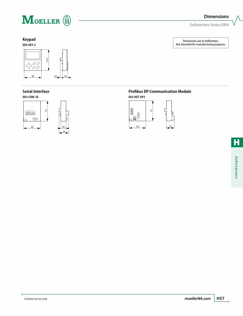
H
Softstarters
STARTER-CAT-NA-0708 moellerNA.com H57
Dimensions
Softstarters Series DM4
Dimensions are in millimeters.Not intended for manufacturing purposes.
KeypadDE4-KEY-2
60
73.5
188.5
Serial Interface Profibus DP Communication ModuleDE4-COM-2X DE4-NET-DP2
62 18
34
75
62
75
27
H
Soft
star
ters
H58 moellerNA.com STARTER-CAT-NA-0708
Softstarters
Notes
EffectiveDate:October16,2009STARTER-CAT-NA-0708 moellerNA.com TC1
ConditionsofSaleandShipment
ValidinUnitedStatesofAmerica
Note: The following terms are for general information only. All conditions of sales are subject to change and are valid as determined in the latest terms and con-ditions publication of CopperLogic, Inc. (referred to herein after as “The Company”).
1. Acceptance of ordersAll orders are subject to final acceptance by an authorized representative of the Company and are subject to the Company’s terms and conditions in effect at the time of acceptance. The Company takes exception to any other terms and conditions except for such terms and conditions as the Company may expressly accept in writing.
2. PricesPrices and discounts as shown in the company’s publications are subject to change without notice. In the event of a net price change, the price of equipment on order but unshipped will be the price in effect on the date of shipment. In no case will the amount of a price increase exceed 10% of the price at which the order was accepted, except that, if the delivery is delayed upon instructions from the purchaser, prices shall be those in effect when the instructions are received to proceed with the order. Price reductions shall only apply to un-shipped portions of outstanding orders. Any addition or alteration to an outstanding order will be accepted at prices in effect when the addition or alteration is accepted. Applicable taxes are additional.
3. QuotationsAll quotations are in accordance with the Company’s interpretation of plans and specifica-tions and only material shown on the Company’s quotations are included. Written quota-tions automatically expire thirty (30) days from the date of issue unless sooner terminated by notice. Quotations are subject to all existing or future limitations and regulations issued by any government agency. In the event that a quotation is not accepted in its entirety, the Company reserves the right to decline any parts of the order based on such quotation.
All Accounting, clerical or other errors are subject to correction.
4. Minimum BillingOrders amounting to less than $100.00 net will be billed at $100.00 plus the transportation charge, at a minimum of $25.00.
5. Terms - RegularTerms to purchasers of satisfactory credit are: 30 days net from the date of invoice. Cash dis-counts, when applicable, are indicated on the face of the Company’s invoice. To avoid delay in filling orders purchasers without previous experience with the Company should include credit references with the first order, or send a certified check or money order. Any amount owed to the Company becomes due and payable immediately in case of change of owner-ship of the purchaser, attachment or execution against the purchaser or it’s representatives, unless the Company otherwise agrees.
6. PaymentsPayments should be made to the address indicated on the invoice, or to CopperLogic, Inc., PO Box 62073, Houston, TX 77205.
7. DeliveryThe Company reserves the right to make delivery in installments, unless otherwise expressly stipulated in the contract for sale; and all such installments when separately invoiced shall be paid for when due per invoice, without regard to subsequent deliveries. Delay in delivery of any installment shall not relieve the purchaser of its obligations to accept remaining deliv-eries. Shipments delayed to accommodate the purchaser will be invoiced upon completion of fabrication and additional charges for warehousing, trucking and other incidental expens-es created by the delay will be at the expense of the purchaser. Delivery is dependent upon prompt receipt of all specifications, final approved prints and any other details essential to the proper execution of the purchaser’s order. Claims for shortages or other errors must be reported in writing to the Company within 10 days after receipt of shipment. Failure to do so will constitute a waiver of all claims by the purchaser.
8. Shipping TermsThe method and route of shipment is determined by the Company. All merchandise orders of $500.00 net or more will be shipped F.O.B. CopperLogic’s warehouse, freight prepaid, best way ground transportation. All engineered equipment orders will be shipped F.O.B. Copper-Logic’s loading dock, freight not allowed. When purchaser specifies a method or routing of
shipment other than that selected by the Company, the purchaser will be billed accordingly. No credits will be allowed in lieu of transportation in the case of pickups at the Company’s warehouses, branches, or factory. No transportation charges can be deducted from a selling price. Air freight, water freight, heavy lift charges, pier delivery charges, wharfage, marine insurance and the cost of stevedoring are chargeable to the purchaser. These terms include shipments to Alaska, Hawaii, Puerto Rico, and the Virgin Islands.
9. Packing other than standardIf other than standard commercial packing is required the cost of such special packing (de-terminable only after packing is completed) will be charged to the purchaser. Export packing shall be considered as packing other than standard.
10. Acceptance of ordersThe purchaser will be responsible for any applicable export license and all associated costs involved with said license on any export project.
11. Export ControlEquipment and associated materials supplied or licensed under this transaction may be sub-ject to various export laws and regulations. It is the responsibility of the exporter to comply with all such laws and regulations.
12. Responsibility and TitleTitle in the equipment shall remain with the Company as security only and until full pay-ment is received. Risk of loss for the equipment shall pass to purchaser upon shipment from F.O.B. point of shipment or date of invoicing, which ever is sooner.
13. Loss or Damage in TransitThe Company does not hold itself responsible for any loss, damage, (obvious or concealed) or pilferage sustained in transit. Claims of such character should be made, by the purchaser, promptly against the transportation company. If the Company is notified of such claims, the Company will offer to lend assistance to secure adjustment. The Company employs experi-enced packers and cannot be held responsible for breakage that occurs after the Company’s securing the “Received in Good Order” receipt from the transportation company.
14. Return of MerchandiseNo equipment may be returned unless authorization has been obtained from an authorized representative of the Company. Unauthorized returns of equipment cannot be accepted.
A. To be returned for creditOnly unused equipment of current design may be returned for credit. Where a pur-chaser returns equipment for reasons of his own, a minimum restocking charge of 20% of billing, plus transportation charges, will be made. Any cost incurred in putting the equipment into saleable condition shall also be deducted from allowed credit. If return of equipment is made necessary by fault of the Company, full credit will be allowed including transportation charges.
B. To be returned for replacementIf the equipment is under guarantee and the return is made necessary because of defect in material and/or workmanship, providing permission is obtained from the Company for its return, the Company will replace the defective goods “no charge”, and will assume the transportation charges.
C. Custom-built equipmentEquipment built based upon purchaser specification cannot be returned for credit.
15. Cancellations:Any order placed with the Company can be canceled by the purchaser provided that: a) the cancellation is agreed to in writing by the Company; and b) the purchaser agrees to compen-sate the Company for engineering, fabrication, outside sourcing of devices and any other demonstrated expenses incurred or commitments made by the Company up to the date of notice of cancellation and all charges incurred by the Company in respect of the cancella-tion.
16. Force MajeureThe Company shall not be liable for any delay in the performance of orders or contracts or in the delivery or shipment of equipment or for any loss and/or damages suffered by purchaser by reason of such delay when such delay is directly or indirectly caused by fire, floods, ac-cidents, riots, acts of God, war, invasion, sabotage, terrorism and governmental interference or embargoes, strikes, labor difficulties, shortage of labor, fuel, power, materials or supplies

EffectiveDate:October16,2009 TC2 moellerNA.com STARTER-CAT-NA-0708
ConditionsofSaleandShipment
ValidinUnitedStatesofAmerica
or any other cause beyond the Company’s reasonable control. In any event, the Company shall not be liable for special or consequential damages for loss of use. Should such a delay occur, the delivery date shall be extended as may be necessary to compensate for the delay. The Company shall not be liable for any change of dimensions, weights and materials as long as the change is nonessential for the proper performance of the product.
17. GuaranteeThe Company guarantees for a period of one (1) year from the date of the Company invoice that equipment furnished under the order will be of merchantable quality, free from defects in material, workmanship and design each as determined, at the date of shipment by the Company by generally recognized, applicable and accepted practices and procedures in the industry including any specifications furnished by the purchaser and agreed to in writing by the Company for incorporation into the equipment. Satisfaction of this guarantee, consistent with other provisions herein, will be limited to the replacement or repair or modification of, or issuance of a credit for, the equipment involved at the Company’s option, with the Company to determine the availability of service personnel and purchaser to pay associated service expenses: such guarantee satisfaction available only if: (a) the Company is promptly notified in writing upon discovery of an alleged defect and (b) the company’s examina-tion of the subject equipment discloses, to the Company’s satisfaction, that any defect has not been caused by misuse, neglect, improper installation, improper operation, improper maintenance, repair or alteration, accident, or unusual deterioration or degradation of the equipment parts, thereof due to physical environment or due to electrical or electromag-netic noise environment. THIS GUARANTEE IS IN LIEU OF ALL OTHER GUARANTEES WHETHER EXPRESSED, IMPLIED OR STATUTORY, INCLUDING IMPLIED GUARANTEES OF MERCHANTABIL-ITY OR FITNESS and thereby excludes certifications or the like for equipment performance, use or design with respect to any standard, regulation or the like (unless and to the extent independently approved in writing by the Company) AND EXTENDS ONLY TO THE CUSTOMER OR PURCHASER PURCHASING FROM THE COMPANY OR AN AUTHORIZED COMPANY DISTRIBU-TOR.
18. Limitation of LiabilityIN NO EVENT WILL THE COMPANY BE LIABLE FOR INCIDENTAL, INDIRECT OR AS IS CONSEQUEN-TIAL DAMAGES OF ANY KIND. THE COMPANY’S MAXIMUM CUMULATIVE LIABILITY RELATIVE TO ALL OTHER CLAIMS AND LIABILITIES, INCLUDING THAT WITH RESPECT TO DIRECT DAMAGES AND OBLIGATIONS UNDER ANY INDEMNITY, WHETHER OR NOT INSURED, WILL NOT EXCEED THE COST OF THE PRODUCTS GIVING RISE TO THE CLAIM OR LIABILITY. THE COMPANY DIS-CLAIMS ALL LIABILITY RELATIVE TO GRATUITOUS INFORMATION OR ASSISTANCE PROVIDED BY, BUT NOT REQUIRED OF THE COMPANY HEREUNDER. ANY ACTION AGAINST THE COMPANY MUST BE BROUGHT WITHIN EIGHTEEN (18) MONTHS AFTER THE CAUSE OF ACTIONS ACCRUES. THESE DISCLAIMERS AND LIMITATIONS OF LIABILITY WILL APPLY REGARDLESS OF ANY OTHER CONTRARY PROVISION OF THE AGREEMENT AND REGARDLESS OF THE FORM OF ACTION, WHETHER IN CONTRACT, TORT OR OTHERWISE AND FURTHER WILL EXTEND TO THE BENEFIT OF THE COMPANY’S VENDORS, APPOINTED DISTRIBUTORS AND OTHER AUTHORIZED RESELL-ERS AS THIRD-PARTY BENEFICIARIES. EACH PROVISION IN THE AGREEMENT WHICH PROVIDES FOR A LIMITATION OF LIABILITY, DISCLAIMER OF WARRANTY OR CONDITION OR EXCLUSION OF DAMAGES IS SEVERABLE AND INDEPENDENT OF ANY OTHER PROVISION AND IS TO BE EN-FORCED AS SUCH.
19. Penalty ClausesThe Company will not accept any liability for penalty clauses of any kind, written or implied, unless specifically approved in writing by the Company.
20. Nuclear ApplicationsUnless otherwise agreed to in writing by a duly authorized representative of the Company, equipment sold hereunder are not intended for use in connection with, any nuclear facility or activity. The Company disclaims all liability for any nuclear damage, injury or contamina-tion and purchaser shall indemnify the Company against such liability, whether as a result of breach of contract, warranty, tort (including negligence) or otherwise. The Company shall identify special controls which are manufactured and tested for use in connection with any nuclear installation or activity by the appropriate catalog number. The Company will charge a price addition for control devices sold for nuclear applications. Any questions by purchaser regarding products or pricing should be referred to the Company for clarification.
21. Government Clauses and ContractsNo government contract regulations or clauses will apply to the equipment agreement or act to bind the Company unless specifically agreed to by the Company in writing at the Company’s head-quarters. Equipment sold or licensed hereunder are not intended to be used, nor should they be used, in any nuclear-related application either as a ”Basic Component” under 10 CFR 21 (United States NRC) or otherwise under similar nuclear laws and regulations of this or any other country.
22. Intellectual Property (not applicable to third-party branded products as is)The Company will defend any suit or proceeding brought against the customer based on a claim that the design or construction of the Products sold or licensed hereunder by the Com-pany infringe any United States or Canadian Patent, Copyright or Mask Work Registration, provided that the customer promptly notifies the Company of any such claim and resulting suit or proceeding, in writing and further provided that, at the Company’s expense, (a) the customer gives the Company the sole right to defend or control the defense of the suit or proceeding including settlement, and (b) the customer provides all necessary information and assistance for that defense. Except for any consequential damages, the Company will pay all costs and damages finally awarded or agreed upon by Sell that are directly related to any such claim. In the event of a charge of infringement the Company’s obligation under the Agreement will be fulfilled if the Company, at its option and expense, either (i) procures for the customer the right to continue using such Products; (ii) replaces the same with non-in-fringing Products; (iii) modifies the same so as to make them non-infringing: or (iv) accepts the return of any infringing Products and refunds their purchase price, Notwithstanding the foregoing. The Company will have no liability with respect to any claim of infringement to the extent based on a configuration or modification incorporated in the Products at the re-quest of the customer, on any process application into which the Products are integrated by the customer, or on use of the Products in combination with other equipment or prod-ucts not supplied by the Company. THIS PARAGRAPH SETS FORTH THE COMPANY’S ENTIRE LIABILITY WITH RESPECT TO INTELLECTUAL PROPERTY AN INFRINGEMENT OF PATENTS BY ANY PRODUCTS (INCLUDING SOFTWARE PROGRAMS, EQUIPMENT OR PRODUCTS THEREOF) OR BY THEIR OPERATION, AND IS IN LIEU OF ALL WARRANTIES OR CONDITIONS RELATION TO INFRINGEMENT OR INTELLECTUAL PROPERTY, EITHER EXPRESS OR IMPLIED.
23. Third Party Branded ProductsTHE COMPANY MAKES NO REPRESENTATIONS AND DISCLAIMS ALL WARRANTIES OF ANY KIND, EXPRESS OR IMPLIED, RELATIVE TO ANY THIRD-PARTY BRANDED EQUIPMENT WHICH MAY BE SOLD BY THE COMPANY HEREUNDER. The only warranty associated with such equipment will be that provided directly by the original manufacturer, if any. The Company assumes no post-sale technical support or warranty repair obligation with respect to such equipment, however, at its discretion, the Company may assist the customer in processing warranties or representations made or provided relative to such equipment, which in all cases will be the responsibility of the original equipment solely for the convenience of the purchaser, and the purchaser must make its own determination as to the accuracy and completeness of such information.
24. DisputesThe parties will attempt in good faith promptly to resolve any dispute arising out of this transaction by negotiations between representatives who have authority to settle the con-troversy. If unsuccessful, the parties further will attempt in good faith to settle the dispute by non-binding third-party mediation, with fees and expenses of such mediation appor-tioned equally to each side. Any dispute not so resolved by negotiation or mediation may then be submitted to a court of competent jurisdiction in accordance with the terms of this transaction. These procedures are the exclusive procedures for the resolution of all such dis-putes between the parties.
25. Governing LawThis transaction and all disputes arising thereunder will be governed by and interpreted in accordance with the internal laws of the state, province or other governmental jurisdiction in which the Company’s principal place of business resides, but specifically excluding its con-flict of laws provisions and the provisions of the 1980 UN Convention on Contracts for the International Sales of Goods.
26. AssignmentThis transaction may not be assigned by either party without the written consent of the other (which consent will not be unreasonably withheld), however, consent will not be re-quired for internal transfers and assignments as between the company and its parent corpo-rations, subsidiaries or affiliates as part of consolidation, merger or other form of corporate reorganization.
27. LanguageThe parties acknowledge that they have required that this transaction be drawn up in Eng-lish, Les parties reconnaissent avoir exigE la rEdaction en anglais du Contrat. In the event of a conflict between the English and other language versions of this agreement, the English version will prevail.

EffectiveDate:October16,2009STARTER-CAT-NA-0708 moellerNA.com TC3
ConditionsofSaleandShipment
ValidinCanada
Note: The following terms are for general informa-tion only. All conditions of sales are subject to change and are valid as determined in the latest terms and conditions publication of CopperLogic Ltd. (referred to herein after as “The Company”).
1. Acceptance of orders:All orders are subject to final acceptance by an authorized representative of the Company and are subject to the Company’s terms and conditions in effect at the time of acceptance. The Company takes exception to any other terms and conditions except for such terms and conditions as the Company may expressly accept in writing.
2. Prices:Prices and discounts as shown in the company’s publications are subject to change without notice. In the event of a net price change, the price of equipment on order but unshipped will be the price in effect on the date of shipment. In no case will the amount of a price increase exceed 10% of the price at which the order was accepted, except that, if the delivery is delayed upon instructions from the purchaser, prices shall be those in effect when the instructions are received to proceed with the order. Price reductions shall only apply to un-shipped portions of outstanding orders. Any addition or alteration to an outstanding order will be accepted at prices in effect when the addition or alteration is accepted. Applicable taxes are additional.
3. Quotations:All quotations are in accordance with the Company’s interpretation of plans and specifica-tions and only material shown on the Company’s quotations are included. Written quota-tions automatically expire thirty (30) days from the date of issue unless sooner terminated by notice. Quotations are subject to all existing or future limitations and regulations issued by any government agency. In the event that a quotation is not accepted in its entirety, the Company reserves the right to decline any parts of the order based on such quotation.
All Accounting, clerical or other errors are subject to correction.
4. Minimum Billing:Orders amounting to less than $ 100.00 net will be billed at $ 100.00 plus the transportation charge, at a minimum of $25.00.
5. Terms - Regular:Terms to purchasers of satisfactory credit are: 30 days net from the date of invoice. Cash dis-counts, when applicable, are indicated on the face of the Company’s invoice. To avoid delay in filling orders purchasers without previous experience with the Company should include credit references with the first order, or send a certified check or money order. Any amount owed to the Company becomes due and payable immediately in case of change of owner-ship of the purchaser, attachment or execution against the purchaser or it’s representatives, unless the Company otherwise agrees.
6. Payments:Payments should be made to the address indicated on the invoice, or to CopperLogic Ltd, 6175 Kenway Drive, Mississauga, Ontario, L5T 2L3.
7. Delivery:The Company reserves the right to make delivery in installments, unless otherwise expressly stipulated in the contract for sale; and all such installments when separately invoiced shall be paid for when due per invoice, without regard to subsequent deliveries. Delay in delivery of any installment shall not relieve the purchaser of its obligations to accept remaining deliv-eries. Shipments delayed to accommodate the purchaser will be invoiced upon completion of fabrication and additional charges for warehousing, trucking and other incidental expens-es created by the delay will be at the expense of the purchaser. Delivery is dependent upon prompt receipt of all specifications, final approved prints and any other details essential to the proper execution of the purchaser’s order. Claims for shortages or other errors must be reported in writing to the Company within 10 days after receipt of shipment. Failure to do so will constitute a waiver of all claims by the purchaser.
8. Shipping Terms:The method and route of shipment is determined by the Company. All merchandise orders of $500.00 net or more will be shipped F.O.B. CopperLogic’s warehouse, freight prepaid, best way ground transportation. All engineered equipment orders will be shipped F.O.B. Copper-Logic’s loading dock, freight not allowed. When purchaser specifies a method or routing of shipment other than that selected by the Company, the purchaser will be billed accordingly. No credits will be allowed in lieu of transportation in the case of pickups at the Company’s
warehouses, branches, or factory. No transportation charges can be deducted from a selling price. Air freight, water freight, heavy lift charges, pier delivery charges, wharfage, marine insurance and the cost of stevedoring are chargeable to the purchaser.
9. Packing other than standard:If other than standard commercial packing is required the cost of such special packing (de-terminable only after packing is completed) will be charged to the purchaser. Export packing shall be considered as packing other than standard.10. Acceptance of orders:The purchaser will be responsible for any applicable export license and all associated costs involved with said license on any export project.
11. Export ControlEquipment and associated materials supplied or licensed under this transaction may be sub-ject to various export laws and regulations. It is the responsibility of the purchaser to comply with all such laws and regulations.
12. Responsibility and Title:Title in the equipment shall remain with the Company as security only and until full pay-ment is received. Risk of loss for the equipment shall pass to purchaser upon shipment from F.O.B. point of shipment or date of invoicing, which ever is sooner.
13. Loss or Damage in Transit:The Company does not hold itself responsible for any loss, damage, (obvious or concealed) or pilferage sustained in transit. Claims of such character should be made, by the purchaser, promptly against the transportation company. If the Company is notified of such claims, the Company will offer to lend assistance to secure adjustment. The Company employs experi-enced packers and cannot be held responsible for breakage that occurs after the Company’s securing the “Received in Good Order” receipt from the transportation company.
14. Return of Merchandise:No equipment may be returned unless authorization has been obtained from an authorized representative of the Company and if so authorized is subject to the conditions below. Un-authorized returns of equipment cannot be accepted.
A. To be returned for credit:Only unused equipment of current design may be returned for credit. Where a pur-chaser returns equipment for reasons of his own, a minimum restocking charge of 20% of billing, plus transportation charges, will be made. Any cost incurred in putting the equipment into saleable condition shall also be deducted from allowed credit. If return of equipment is made necessary by fault of the Company, full credit will be allowed including transportation charges.
B. To be returned for replacement:If the equipment is under guarantee and the return is made necessary because of de-fect in material and/or workmanship, the Company will replace the defective goods “no charge”, and will assume the transportation charges.
C. Custom-built equipment:Equipment built based upon purchaser specification cannot be returned for credit.
15. Cancellations:Any order placed with the Company can be canceled by the purchaser provided that: a) the cancellation is agreed to in writing by the Company; and b) the purchaser agrees to com-pensate the Company for engineering, fabrication, outside sourcing of devices and any other demonstrated expenses incurred or commitments made by the Company up to the date of notice of cancellation and all charges incurred by the Company in respect of the cancellation.
16. Force Majeure:The Company shall not be liable for any delay in the performance of orders or contracts or in the delivery or shipment of equipment or for any loss and/or damages suffered by purchaser by reason of such delay when such delay is directly or indirectly caused by fire, floods, ac-cidents, riots, acts of God, war, invasion, sabotage, terrorism and governmental interference or embargoes, strikes, labor difficulties, shortage of labor, fuel, power, materials or supplies or any other cause beyond the Company’s reasonable control. In any event, the Company shall not be liable for special or consequential damages for loss of use. Should such a delay occur, the delivery date shall be extended as may be necessary to compensate for the delay. The Company shall not be liable for any change of dimensions, weights and materials as long as the change is nonessential for the proper performance of the product.

EffectiveDate:October16,2009 TC4 moellerNA.com STARTER-CAT-NA-0708
ConditionsofSaleandShipment
ValidinCanada
17. Guarantee:The Company guarantees for a period of one (1) year from the date of the Company invoice that equipment furnished under the order will be of merchantable quality, free from defects in material, workmanship and design each as determined, at the date of shipment by the Company by generally recognized, applicable and accepted practices and procedures in the industry including any specifications furnished by the purchaser and agreed to in writing by the Company for incorporation into the equipment. Satisfaction of this guarantee, consistent with other provisions herein, will be limited to the replacement or repair or modification of, or issuance of a credit for, the equipment involved at the Company’s option, with the Company to determine the availability of service personnel and purchaser to pay associated service expenses: such guarantee satisfaction available only if: (a) the Company is promptly notified in writing upon discovery of an alleged defect and (b) the company’s examination of the subject equipment discloses, to the Company’s satisfaction, that any defect has not been caused by misuse, neglect, improper installation, improper operation, improper main-tenance, repair or alteration, accident, or unusual deterioration or degradation of the equip-ment parts, thereof due to physical environment or due to electrical or electromagnetic noise environment. THIS GUARANTEE IS IN LIEU OF ALL OTHER GUARANTEES WHETHER EX-PRESSED, IMPLIED OR STATUTORY, INCLUDING IMPLIED GUARANTEES OF MERCHANTABILITY OR FITNESS and thereby excludes certifications or the like for equipment performance, use or design with respect to any standard, regulation or the like (unless and to the extent inde-pendently approved in writing by the Company) AND EXTENDS ONLY TO THE CUSTOMER OR PURCHASER PURCHASING FROM THE COMPANY OR AN AUTHORIZED COMPANY DISTRIBUTOR.
18. Limitation of Liability:IN NO EVENT WILL THE COMPANY BE LIABLE FOR INCIDENTAL, INDIRECT OR AS IS CONSEQUEN-TIAL DAMAGES OF ANY KIND. THE COMPANY’S MAXIMUM CUMULATIVE LIABILITY RELATIVE TO ALL OTHER CLAIMS AND LIABILITIES, INCLUDING THAT WITH RESPECT TO DIRECT DAMAGES AND OBLIGATIONS UNDER ANY INDEMNITY, WHETHER OR NOT INSURED, WILL NOT EXCEED THE COST OF THE PRODUCTS GIVING RISE TO THE CLAIM OR LIABILITY. THE COMPANY DIS-CLAIMS ALL LIABILITY RELATIVE TO GRATUITOUS INFORMATION OR ASSISTANCE PROVIDED BY, BUT NOT REQUIRED OF THE COMPANY HEREUNDER. ANY ACTION AGAINST THE COMPANY MUST BE BROUGHT WITHIN EIGHTEEN (18) MONTHS AFTER THE CAUSE OF ACTIONS ACCRUES. THESE DISCLAIMERS AND LIMITATIONS OF LIABILITY WILL APPLY REGARDLESS OF ANY OTHER CONTRARY PROVISION OF THE AGREEMENT AND REGARDLESS OF THE FORM OF ACTION, WHETHER IN CONTRACT, TORT OR OTHERWISE AND FURTHER WILL EXTEND TO THE BENEFIT OF THE COMPANY’S VENDORS, APPOINTED DISTRIBUTORS AND OTHER AUTHORIZED RESELL-ERS AS THIRD-PARTY BENEFICIARIES. EACH PROVISION IN THE AGREEMENT WHICH PROVIDES FOR A LIMITATION OF LIABILITY, DISCLAIMER OF WARRANTY OR CONDITION OR EXCLUSION OF DAMAGES IS SEVERABLE AND INDEPENDENT OF ANY OTHER PROVISION AND IS TO BE EN-FORCED AS SUCH.
19. Penalty Clauses:The Company will not accept any liability for penalty clauses of any kind, written or implied, unless specifically approved in writing by the Company.
20. Nuclear Applications:Unless otherwise agreed to in writing by a duly authorized representative of the Company, equipment sold hereunder are not intended for use in connection with, any nuclear facility or activity. The Company disclaims all liability for any nuclear damage, injury or contamina-tion and purchaser shall indemnify the Company against such liability, whether as a result of breach of contract, warranty, tort (including negligence) or otherwise. Upon authorization by a representative of the Company for sale or use of equipment in a nuclear facility or activ-ity, the Company shall identify special controls which are manufactured and tested for use in connection with any nuclear installation or activity by the appropriate catalog number. The Company will charge a price addition for control devices sold for nuclear applications. Any questions by purchaser regarding products or pricing should be referred to the Company for clarification.
21. Government Clauses and Contracts:No government contract regulations or clauses will apply to the equipment agreement or act to bind the Company unless specifically agreed to by the Company in writing at the Com-pany’s headquarters. Equipment sold or licensed hereunder are not intended to be used, nor should they be used, in any nuclear-related application either as a ”Basic Component” under 10 CFR 21 (United States NRC) or otherwise under similar nuclear laws and regulations of this or any other country.
22. Intellectual Property: (not applicable to third-party branded products as is)The Company will defend any suit or proceeding brought against the customer based on a claim that the design or construction of the Products sold or licensed hereunder by the Com-
pany infringe any United States or Canadian Patent, Copyright or Mask Work Registration, provided that the customer promptly notifies the Company of any such claim and resulting suit or proceeding, in writing and further provided that, at the Company’s expense, (a) the customer gives the Company the sole right to defend or control the defense of the suit or proceeding including settlement, and (b) the customer provides all necessary information and assistance for that defense. Except for any consequential damages, the Company will pay all costs and damages finally awarded or agreed upon by the Company that are directly related to any such claim. In the event of a claim of infringement the Company’s obligation under the Agreement will be fulfilled if the Company, at its option and expense, either (i) procures for the customer the right to continue using such Products; (ii) replaces the same with non-infringing Products; (iii) modifies the same so as to make them non-infringing: or (iv) accepts the return of any infringing Products and refunds their purchase price, Notwith-standing the foregoing. The Company will have no liability with respect to any claim of in-fringement to the extent based on a configuration or modification incorporated in the Prod-ucts at the request of the customer, on any process application into which the Products are integrated by the customer, or on use of the Products in combination with other equipment or products not supplied by the Company. THIS PARAGRAPH SETS FORTH THE COMPANY’S EN-TIRE LIABILITY WITH RESPECT TO INTELLECTUAL PROPERTY AND INFRINGEMENT OF PATENTS BY ANY PRODUCTS (INCLUDING SOFTWARE PROGRAMS, EQUIPMENT OR PRODUCTS THEREOF) OR BY THEIR OPERATION, AND IS IN LIEU OF ALL WARRANTIES OR CONDITIONS RELATION TO INFRINGEMENT OR INTELLECTUAL PROPERTY, EITHER EXPRESS OR IMPLIED.
23. Third Party Branded Products:THE COMPANY MAKES NO REPRESENTATIONS AND DISCLAIMS ALL WARRANTIES OF ANY KIND, EXPRESS OR IMPLIED, RELATIVE TO ANY THIRD-PARTY BRANDED EQUIPMENT WHICH MAY BE SOLD BY THE COMPANY HEREUNDER. The only warranty associated with such equipment will be that provided directly by the original manufacturer, if any. The Company assumes no post-sale technical support or warranty repair obligation with respect to such equipment, however, at its discretion, the Company may assist the customer in processing warranties or representations made or provided relative to such equipment, which in all cases will be the responsibility of the original equipment solely for the convenience of the purchaser, and the purchaser must make its own determination as to the accuracy and completeness of such information.
24. Disputes:The parties will attempt in good faith promptly to resolve any dispute arising out of this transaction by negotiations between representatives who have authority to settle the con-troversy. If unsuccessful, the parties further will attempt in good faith to settle the dispute by non-binding third-party mediation, with fees and expenses of such mediation appor-tioned equally to each side. Any dispute not so resolved by negotiation or mediation may then be submitted to a court of competent jurisdiction in accordance with the terms of this transaction. These procedures are the exclusive procedures for the resolution of all such dis-putes between the parties.
25. Governing Law:This transaction and all disputes arising thereunder will be governed by and interpreted in accordance with the domestic-laws of the Province of Ontario. The provisions of the In-ternational Sale of Goods Act, R.S.O. (1990), C.I.10 as amended shall not be applicable to this transaction and are specifically excluded. At the sole discretion of the Company, for the purpose of legal proceedings, this transaction shall be deemed to have been performed in the Province of Ontario and the Courts of the Province of Ontario shall have jurisdiction to entertain any action arising under this transaction. The purchaser hereby attorns to the ju-risdiction of the Courts of the Province of Ontario. However, nothing contained herein shall derogate from the right of the Company to proceed in such other jurisdiction as, in its sole discretion, it deems necessary.
26. Assignment:This transaction may not be assigned by either party without the written consent of the other (which consent will not be unreasonably withheld), however, consent will not be re-quired for internal transfers and assignments as between the company and its parent corpo-rations, subsidiaries or affiliates as part of consolidation, merger or other form of corporate reorganization.
27. Language:The parties acknowledge that they have required that this transaction be drawn up in English, Les parties reconnaissent avoir exigE la rEdaction en anglais du Contrat. In the event of a conflict between the Eng-lish and other language versions of this agreement, the English version will prevail.
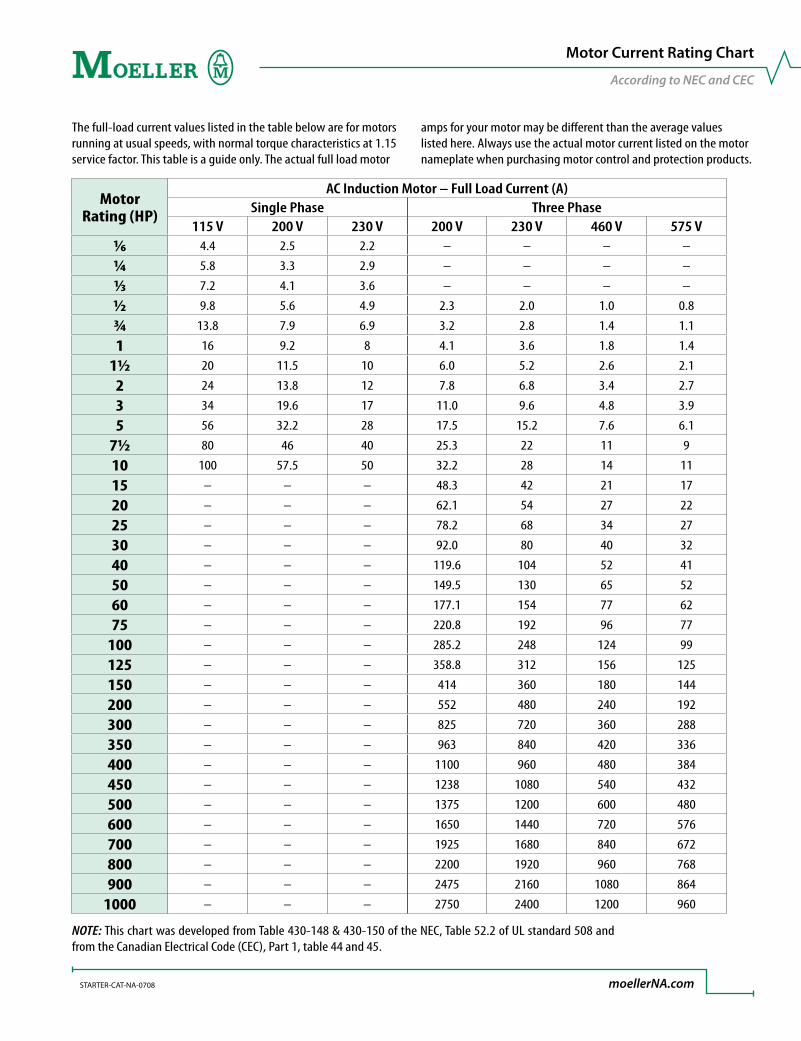
Motor Rating (HP)
AC Induction Motor – Full Load Current (A)Single Phase Three Phase
115 V 200 V 230 V 200 V 230 V 460 V 575 V1∕6 4.4 2.5 2.2 – – – –
¼ 5.8 3.3 2.9 – – – –
1∕3 7.2 4.1 3.6 – – – –
½ 9.8 5.6 4.9 2.3 2.0 1.0 0.8
¾ 13.8 7.9 6.9 3.2 2.8 1.4 1.1
1 16 9.2 8 4.1 3.6 1.8 1.4
1½ 20 11.5 10 6.0 5.2 2.6 2.1
2 24 13.8 12 7.8 6.8 3.4 2.7
3 34 19.6 17 11.0 9.6 4.8 3.9
5 56 32.2 28 17.5 15.2 7.6 6.1
7½ 80 46 40 25.3 22 11 9
10 100 57.5 50 32.2 28 14 11
15 – – – 48.3 42 21 17
20 – – – 62.1 54 27 22
25 – – – 78.2 68 34 27
30 – – – 92.0 80 40 32
40 – – – 119.6 104 52 41
50 – – – 149.5 130 65 52
60 – – – 177.1 154 77 62
75 – – – 220.8 192 96 77
100 – – – 285.2 248 124 99
125 – – – 358.8 312 156 125
150 – – – 414 360 180 144
200 – – – 552 480 240 192
300 – – – 825 720 360 288
350 – – – 963 840 420 336
400 – – – 1100 960 480 384
450 – – – 1238 1080 540 432
500 – – – 1375 1200 600 480
600 – – – 1650 1440 720 576
700 – – – 1925 1680 840 672
800 – – – 2200 1920 960 768
900 – – – 2475 2160 1080 864
1000 – – – 2750 2400 1200 960
NOTE: This chart was developed from Table 430-148 & 430-150 of the NEC, Table 52.2 of UL standard 508 and from the Canadian Electrical Code (CEC), Part 1, table 44 and 45.
The full-load current values listed in the table below are for motors running at usual speeds, with normal torque characteristics at 1.15 service factor. This table is a guide only. The actual full load motor
amps for your motor may be different than the average values listed here. Always use the actual motor current listed on the motor nameplate when purchasing motor control and protection products.
Motor Current Rating Chart
According to NEC and CEC
STARTER-CAT-NA-0708 moellerNA.com

Moeller products are represented exclusively in North America by CopperLogic Inc.
www.moellerNA.com www.copperLogic.comUS Headquarters4140 World Houston Parkway, No 100Houston, Texas USA 77032Tel 713.933.0999Fax 832.613.6255
Canadian Headquarters6175 Kenway DriveMississauga, Ontario CANADA L5T 2L3Tel 905.542.2323Fax 905.542.2321
© 2008 by CopperLogic, Inc.Technical and other changes reserved.Publication STARTER-CAT-NA-0708Printed in the USA 07/08Article No.: 1-024034