Standardization of Terra Cotta Anchorage - ScholarlyCommons
330
University of Pennsylvania University of Pennsylvania ScholarlyCommons ScholarlyCommons Theses (Historic Preservation) Graduate Program in Historic Preservation 2003 Standardization of Terra Cotta Anchorage: An Analysis of Shop Standardization of Terra Cotta Anchorage: An Analysis of Shop Drawings from the Northwestern Terra Cotta Company and the O. Drawings from the Northwestern Terra Cotta Company and the O. W. Ketcham Terra Cotta Works W. Ketcham Terra Cotta Works Amanda M. Didden University of Pennsylvania Follow this and additional works at: https://repository.upenn.edu/hp_theses Part of the Historic Preservation and Conservation Commons Didden, Amanda M., "Standardization of Terra Cotta Anchorage: An Analysis of Shop Drawings from the Northwestern Terra Cotta Company and the O. W. Ketcham Terra Cotta Works" (2003). Theses (Historic Preservation). 325. https://repository.upenn.edu/hp_theses/325 Copyright note: Penn School of Design permits distribution and display of this student work by University of Pennsylvania Libraries. Suggested Citation: Didden, Amanda M. (2003). Standardization of Terra Cotta Anchorage: An Analysis of Shop Drawings from the Northwestern Terra Cotta Company and the O. W. Ketcham Terra Cotta Works. (Masters Thesis). University of Pennsylvania, Philadelphia, PA. This paper is posted at ScholarlyCommons. https://repository.upenn.edu/hp_theses/325 For more information, please contact [email protected].
-
Upload
khangminh22 -
Category
Documents
-
view
3 -
download
0
Transcript of Standardization of Terra Cotta Anchorage - ScholarlyCommons
University of Pennsylvania University of Pennsylvania
ScholarlyCommons ScholarlyCommons
Theses (Historic Preservation) Graduate Program in Historic Preservation
2003
Standardization of Terra Cotta Anchorage: An Analysis of Shop Standardization of Terra Cotta Anchorage: An Analysis of Shop
Drawings from the Northwestern Terra Cotta Company and the O. Drawings from the Northwestern Terra Cotta Company and the O.
W. Ketcham Terra Cotta Works W. Ketcham Terra Cotta Works
Amanda M. Didden University of Pennsylvania
Follow this and additional works at: https://repository.upenn.edu/hp_theses
Part of the Historic Preservation and Conservation Commons
Didden, Amanda M., "Standardization of Terra Cotta Anchorage: An Analysis of Shop Drawings from the Northwestern Terra Cotta Company and the O. W. Ketcham Terra Cotta Works" (2003). Theses (Historic Preservation). 325. https://repository.upenn.edu/hp_theses/325
Copyright note: Penn School of Design permits distribution and display of this student work by University of Pennsylvania Libraries. Suggested Citation: Didden, Amanda M. (2003). Standardization of Terra Cotta Anchorage: An Analysis of Shop Drawings from the Northwestern Terra Cotta Company and the O. W. Ketcham Terra Cotta Works. (Masters Thesis). University of Pennsylvania, Philadelphia, PA.
This paper is posted at ScholarlyCommons. https://repository.upenn.edu/hp_theses/325 For more information, please contact [email protected].

Standardization of Terra Cotta Anchorage: An Analysis of Shop Drawings from Standardization of Terra Cotta Anchorage: An Analysis of Shop Drawings from the Northwestern Terra Cotta Company and the O. W. Ketcham Terra Cotta Works the Northwestern Terra Cotta Company and the O. W. Ketcham Terra Cotta Works
Disciplines Disciplines Historic Preservation and Conservation
Comments Comments Copyright note: Penn School of Design permits distribution and display of this student work by University of Pennsylvania Libraries.
Suggested Citation:
Didden, Amanda M. (2003). Standardization of Terra Cotta Anchorage: An Analysis of Shop Drawings from the Northwestern Terra Cotta Company and the O. W. Ketcham Terra Cotta Works. (Masters Thesis). University of Pennsylvania, Philadelphia, PA.
This thesis or dissertation is available at ScholarlyCommons: https://repository.upenn.edu/hp_theses/325

in111mmHIIIRBIi BfiP
$tiHH >'•*'''
illlmmMM
rHIliiiH
IB
iliHiHiHRttJu,hmrvmm1
_9bk1
nuitfl!ImJFffl
'lufL
i
'

university?*PENNSYLVANIA.
LIBRARIES


STANDARDIZATION OF TERRA COTTA ANCHORAGE: ANANALYSIS OF SHOP DRAWINGS FROM THE
NORTHWESTERN TERRA COTTA COMPANY AND THE O.
W. KETCHAM TERRA COTTA WORKS
Amanda M. Didden
A THESIS
in
Historic Preservation
Presented to the Faculties of the University of Pennsylvania in
Partial Fulfillment of the Requirements for the Degree of
MASTER OF SCIENCE
2003
/dvisor
)r. Rog^r W. Moss
june/i Professor of Architecture
/
Committee Chair
Fttujk G^Jvlatero
Associate Professor of Architecture
y^My^of
AssoTSat£j\o/essor of Architecture
Frank G. Matero
fw \^In /W

UNIVERSITYOF
PENNSYLVANIALIBRARIES

ACKNOWLEDGMENTS
The author wishes to thank the faculty of the Graduate Group ofHistoric Preservation at the University of Pennsylvania for their
instruction and guidance during the past two years. In particular, I
would like to thank my advisors, Dr. Roger Moss and Frank G.Matero, for their encouragement during this process. 1 would also
like to thank the staff at the Athenaeum of Philadelphia, the
National Building Museum, and Architectural Archives at AveryLibrary for their help in pulling endless drawings from of their
collections. Special thanks to Susan Tunick and Mary Oehrlein for
their professional insights. As always, I would like to thank myfamily for helping me set my goals high and encouraging me to
pursue my passions.


Table of Contents
Acknowledgments n
Table of Contents iii
List of Figures iv
Introduction 1
Chapter 1 : MATERIAL TECHNOLOGY 4
History 4
Manufacturing Process 8
technologyShift. 18
RISEANDFAU 24
Chapter 2 : ORGANIZATION OF THE INDUSTRY.. 28
business development 28
National Terra Cotta Society 38
Chapter 3: STANDARDIZATION 47
Early Specificationsand standardization 49
Advances in Specificationsand Standards in the 1920s 51
Later SPECiFicmoNS 59
Metal Coatings 61
Chapter 4: ANCHORS AND HANGING SYSTEMS .. 65
Anchors 70
Cornices 98
Conclusion 118
Appendix A: National Terra Cotta Society Members ( 1 927) 1 2
1
Appendix B: Correspondence and Advertisements 124
Glossary 132
Bibliography 144
Index 153
iii

List of Figures
Figure 1 : Drafting room at the Northwestern Terra Cotta Company. (NWTCCo.) 9
Figure 2: Sculpted Blocks, 1903 12
Figure 3: Cosmetic adjustments made to the blocks after molding 13
Figure 4: Blocks being sprayed with glaze 14
Figure 5: A muffle kiln 15
Figure 6: Fitting and numbering the blocks 17
Figure 7: The National Terra Cotta Society (1927) 38
Figure 8: A NWTCCo. manufacturing plant 65
Figure 9: The O.W. Ketcham factory in Cairn Lynne, Pennsylvania. (OWK) 68
Figure 10: Isometric Drawing from a NWTCCo. Trade Catalog (1906) 71
Figure 1 1: Installation variations from The Brickbuilder (1898) 73
List of Examples
Example 1: Fourth National Bank ( 1905). (NWTCCo.) 80
Example 2: Hotel Grunewald (1907). (NWTCCo.) 80
Example 3: Fourth National Bank (1905). (NWTCCo.) 81
Example 4: Hotel Grunewald (1907). (NWTCCo.) 82
Example 5: Hotel Grunewald (1907). (NWTCCo.) 83
Example 6: Hotel Grunewald (1907). (NWTCCo.) 84
Example 7: City Hall, Chicago (1909). (NWTCCo.) 87
Example 8: Market Street National Bank(1930). (OWK) 89
Example 9: Navy Annex Y. M. C. A. (1928). (OWK) 90
iv

Example 10: Market Street National Bank (1930). (OWK) 91
Example 11: Market Street National Bank ( 1930). (OWK) 92
Example 12: Market Street National Bank (1930). (OWK) 93
Example 13: Market Street National Bank (1930). (OWK) 94
Example 14: Temple Israel (1930). (OWK) 95
Example 15: West Side Y. M. C. A ( 1929-1930). (OWK) 96
Example 16: Sister's of Charity Mother House (1930-1931). (OWK) 97
Example 17: a) Court House, Greenville (1903). (NWTCCo.). b) U. S. Post Office,
Greenville (1903). (NWTCCo.) 99
Example 18: Le Moyne Public School (1915). (NWTCCo.) 103
Example 19: Fourth National Bank (1905). (NWTCCo.) 105
Example 20: Hotel Grunewald (1907). (NWTCCo.) 107
Example 21: Courthouse, Greenville (1903). (NWTCCo.) : 109
Example 22: Sister's of Charity Mother House (1930-1931). (OWK) 110
Example 23: Redemptorist Father's Community House (1932). (OWK) 1 12
Example 24: Sister's of Charity Mother House (1930-1931). (OWK) 115
List of Standard Drawings
Standard Drawing 1: 'Details of Iron Anchors' plate no. 70 from Architectural Terra
Cotta: Standard Construction (1914) 75
Standard Drawing 2: 'Details of Anchors' plate no. 67 from Terra Cotta: Standard
Construction {1921) 76
Standard Drawing 3: Taken from 'Lintels and Soffits' plate no. 35 in Architectural Terra
Cotta: Standard Construction (1914) 85
v


Standard Drawing 4: Taken from 'Modillion Cornice without Gutter' plate no. 23 in
Architectural Terra Cotta: Standard Construction (1914) 100
Standard Drawing 5: Taken from 'Cornice with Balustrade' plate no. 26 in Architectural
Terra Cotta: Standard Construction (1914) 102
Standard Drawing 6: Taken from 'Modillion Cornice' plate no. 22 in Architectural Terra
Cotta: Standard Construction (1914) 104
Standard Drawing 7: Taken from 'Louvered Dormer' plate no. 47 in Terra Cotta: Standard
Construction (1927) 1 1
1
Standard Drawing 8: Taken from 'Cornice with Parapet' plate no. 31 in Terra Cotta:
Standard Construction (1927) 1 13
Standard Drawing 9: Taken from 'Cornice with Balustrade' plate no. 26 in Terra Cotta:
Standard Construction (1927) 1 16
Introduction
While the manufacture of terra cotta is traceable to an ancient building practice, its
history of success and failure reflects shifts in architectural taste and technology. The
emergence of terra cotta as a building material in America was a nineteenth-century
phenomenon reflecting innovative building technologies. The transition from load-bearing
technology to the skeletal steel frame allowed the American city to grow in density and
complexity as larger buildings accommodated increasing populations. This new trend in
building technology embraced terra cotta and its complicated metal anchorage systems due
to the material's low cost and light weight. The popularity of terra cotta coincided with this
building boom resulting in the construction of thousands of terra cotta buildings in
American cities.
With new applications of the material, however, came new problems with
installation and durability. Over twenty of the terra cotta manufacturers across the nation
joined together to create the National Terra Cotta Society (NTCS ) in 191 1. The purpose of
this organization was to promote terra cotta during the construction boom and to enhance
its performance by using standardized construction techniques and durability testing.
Through an in-depth discussion of terra cotta anchoring systems, this paper will analyze
these standards, the reasons for their inception, the success of the recommendations, and
their use in common practice.
The standards attempted to demonstrate common practices among the terra cotta
manufacturers, inform architects and masons of proper installation techniques, and
eliminate faulty construction that accelerated deterioration. How well did the terra cotta
1


manufacturers adhere to the standards? Were installation methods constantly changing as
new trends in building technologies, such as structural concrete, were implemented in
construction? To illustrate these ideas, over twenty shop drawings from the Northwestern
Terra Cotta Company and the O.W. Ketcham Terra Cotta Works, both NTCS members,
were analyzed and compared to the NTCS standards published in 1914 and 1927. The
selected drawings from the Northwestern Terra Cotta Company date from 1900 to 1915
and provide context for the earlier set of standards. For the O. W. Ketcham Terra Cotta
Works, the selected drawings range from 1926 to 1932 and highlight revisions made to the
standards in 1927.
When a building deteriorates, the owner's options are: demolition, cost-effective
repair, or restoration. For terra cotta buildings, deterioration often manifests itself as loose
blocks due to failed anchorage, which on a skyscraper can be deadly. As a result, the
building is usually re-clad with another material -sometimes over the existing terra cotta or
sometimes replacing the terra cotta completely -if the building is not demolished
altogether. Restoring the anchoring systems is a costly endeavor especially as the
antiquated hangers and anchors are no longer used in modern construction practices. A
good restoration plan must take into account the engineering capacity of the original
builders as well as adapt to the existing anchorage configurations underneath the terra cotta
blocks. The uncertainty of the anchorage design in combination with inconsistent
adjustments made on-site during original construction indicates that any restoration plan
has the potential to repeat mistakes in the past and even accelerate deterioration.
The NTCS standards and manufacturer's shop drawings, when available, can
provide indispensable clues for preservationists attempting to restore terra cotta buildings.
2

Recent preservation efforts have raised awareness of the value of terra cotta's
craftsmanship as well as the proliferation of terra cotta buildings across the United States.
The purpose of this thesis is to provide an additional tool for the preservation of terra cotta
buildings. By detailing installation techniques, how the techniques were developed, and
how they were adapted to twenty buildings attributed to the Northwestern Terra Cotta
Company and the O. W. Ketcham Terra Cotta Works, this work will shed some light on the
forgotten building technology of terra cotta hanging systems.

Chapter 1 : MATERIAL TECHNOLOGY
History
"When once the architects ofNew York began to recognize the use of
architectural terra cotta they caused a vast amount of development in the
production of it."
-James Taylor, New York Architectural Terra Cotta Company
Terra cotta as a building material has endured many cycles of popularity and
decline since its inception in ancient Rome and the ancient Near East. It is defined in its
broadest sense as, "both pottery and structural objects made of burned clay and having a
porous body. The term architectural terracotta is usually applied to those clay products
employed for structural decorative work which cannot be formed by machinery; they are
moulded [sic] by hand."" It is characteristically different from brick in its clay
composition and higher firing temperature. After the decline of the Roman Empire, the
manufacture of terra cotta was discontinued and forgotten. It was not until the Renaissance
in Italy and Germany that terra cotta reemerged as a structural material. At this point, the
14th
century artisans revived the material complete with a sophisticated building technology
that included the colorful glazing practice of Faience.
Another period of decline ensued from the sixteenth century to the nineteenth
century. However, during the industrial age of the nineteenth century in England and
Germany, terra cotta regained popularity for its malleability, resistance to pollution, light
James Taylor, "The History of Terra Cotta in New York City," Architectural Record 2 (1892): 144.
Heinrich Ries,
Wiley and Sons, 1912).
2Heinrich Ries, Building Stones and Clay Products: A Handbookfor Architects (New York: John


weight, durability, and its low cost.3
In the late nineteenth century, after urban disasters
such as the Chicago Fire of 1871, terra cotta was also hailed as a fire-proof material.4Once
again, as technology shifted towards the glass skyscraper era in the 1930s, use of
architectural terra cotta declined as it was replaced by glass and thin ceramic veneers.5
Through preservation efforts, terra cotta is being rediscovered as a quality building material
and slowly becoming attractive again as a medium for modem architects.
The earliest history of terra cotta in the United States can be traced to 1849-1851
with the small manufacturers: Boyden & Ball, and Tolman, Luther & Co., both in
Worcester, Massachusetts. Simultaneously, New York architects such as Richard Upjohn
and James Renwick were experimenting with terra cotta ornament for their buildings.6
New Yorkers were skeptical of the material at first and questioned its durability in the
harsh American climate.7With quality examples such as Upjohn's Trinity Building and
the terra cotta display at the New York Crystal Palace Exhibition of 1853, a handful of terra
cotta manufacturers were inspired to open their businesses across the country.8
Undoubtedly, these early manufacturers were inspired by the popularity of "Mrs.
Coade's Stone" that was imported from England. Created in 1769, Coade's moldable
artificial stone was very durable and used to simulate all kinds of materials for ornamental
- Nancy D. Berryman and Susan M. Tindall. Terra Colta (Chicauo: Landmarks Preservation Councilof Illinois, 1984), 2.
"" Susan Tunick, Terra-Cotta Skyline : New York's Architectural Ornament, 1st ed. (New York:Princeton Architectural Press, 1997), 7.
5A. Daniel Barton, Jr., "O. W. Ketcham Terra Cotta: Reflections on an Industry in Chaos after
World War Two," APT Bulletin 32, no. 4 (200 1 ): 1 5.
6Susan McDaniel Ceccacci, "Architectural Terra Cotta in the United States before 1870" (Master of
Art, Boston University, 1991), 23-24.
7Taylor, "The History of Terra Cotta in New York City," 138.
8Ceccacci, "Architectural Terra Cotta in the United States before 1870", 30-40.Cecacci, 30-40
5
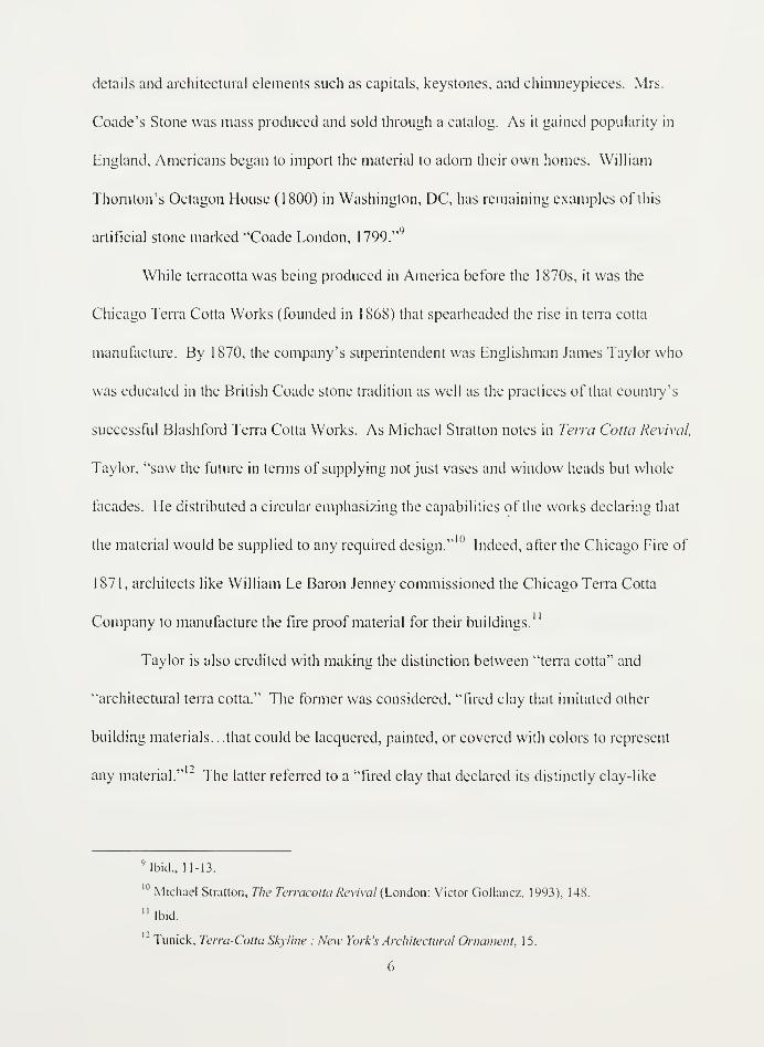
details and architectural elements such as capitals, keystones, and chimneypieces. Mrs.
Coade's Stone was mass produced and sold through a catalog. As it gained popularity in
England, Americans began to import the material to adorn their own homes. William
Thornton's Octagon House (1800) in Washington, DC, has remaining examples of this
artificial stone marked "Coade London, 1799."
While terracotta was being produced in America before the 1 870s, it was the
Chicago Terra Cotta Works (founded in 1868) that spearheaded the rise in terra cotta
manufacture. By 1870, the company's superintendent was Englishman James Taylor who
was educated in the British Coade stone tradition as well as the practices of that country's
successful B lash ford Terra Cotta Works. As Michael Stratton notes in Terra Cotta Revival,
Taylor, "saw the future in terms of supplying not just vases and window heads but whole
facades. He distributed a circular emphasizing the capabilities of the works declaring that
the material would be supplied to any required design."10
Indeed, after the Chicago Fire of
1871, architects like William Le Baron Jenney commissioned the Chicago Terra Cotta
Company to manufacture the fire proof material for their buildings."
Taylor is also credited with making the distinction between "terra cotta" and
"architectural terra cotta." The former was considered, "fired clay that imitated other
building materials. . .that could be lacquered, painted, or covered with colors to represent
any material." "" The latter referred to a "fired clay that declared its distinctly clay-like
Mbid.. 11-13.
10Michael Stratton, The Terracotta Revival (London: Victor Gollancz, 1993), 148.
"Ibid.
" Tunick, Terra-Cotta Skyline : New York's Architectural Ornament, 15.
6

properties. . . [and] that the finish be that of natural clay." This discussion of the true
character of the material mimics John Ruskin's aesthetic philosophy outlined in his 1849
treatise, The Seven Lamps ofArchitecture. In his chapter on the Lamp of Truth, he states,
"But in Architecture another and a less subtle, more contemptible, violation of truth is
possible; a direct of falsity of assertion respecting the nature of material, or the quantity of
labor. And this is, in the full sense of the word, wrong." With Ruskin's influence, it was
commonly held in the mid-nineteenth century that, "all materials are good, when used
honestly, each for the purpose to which it is best adapted, and bad when used for puiposes
to which it is not adapted, or to counterfeit some other material." "^ But in the twentieth
century, ironically, terra cotta production peaked precisely because it was a cheap imitation
of stone; and, as the material lost its "distinctness" as hailed by Taylor, it was forgotten
when the cheaper imitation stone became available in the form of concrete.
In the early stages of use in America, the characteristic hue of terra cotta was a rich
red that resulted from the type of clay used and the firing temperatures. By 1890, other
clay deposits were discovered and terra cotta was manufactured in yellow and buff colors
in addition to red. This range of colors meant that terra cotta could be used to imitate a
variety of stones such as brownstone or limestone. Often "slips" were applied to the terra
cotta body to even out the tone of the fired material. Slips are made from the same clay
body as the terra cotta pieces but are applied in a creamy state over the dried material
before firing. By 1 894, salt glazes were introduced as another way to manipulate the color
14John Ruskin, The Seven Lamps ofArchitecture (New York: Dover Publications, 1 880,1989).
Sanford E. Loring and William Le Baron Jenney, Principles and Practice ofArchitecture
(Chicago: Cobb, Pritchard, & Co., 1869), 36.
7


of the terra cotta pieces. Robert C. Mack states, "In this glazed form, terra cotta became
one of the most popular building materials for exterior surfaces of buildings until its decline
in the 1930's." These glazes were available in a number of colors and created a glassy
surface when fired.16 New applications of the material, technological advances, and
aesthetic trends shaped the industry of terra cotta throughout the history of its manufacture
in the United States.
Manufacturing Process
"A fine fire-clay free from lime or iron deposits, is moulded or carved into
the desired form, allowed to dry in rooms heated for the purpose, and there
burnt in air-tight kilns. While in the kilns 30-40 hours, it is subjected to a
heat sufficient to melt steel."17
-Sanford E. Loring
The terra cotta factory is divided into various departments: clay preparation,
drafting, modeling, molding, pressing, finishing, drying, glazing, firing, fitting and
numbering, shipping and handling, and installation. Once the architect specified terra cotta
for a building, elevation drawings were created at 1/4"- 1/8" scale indicating where the
material would be employed. The terra cotta manufacturers used these drawings to
produce a competitive bid for the project. After the manufacturer was selected, the
architect re-drafted the elevations at a larger scale (1/2" or 1") and sometimes included full
16Robert C. Mack, "The Manufacture and Use of Architectural Terra Cotta in the United States," in
The Technology ofHistoric American Buildings: Studies ofthe Materials, Processes, and the Mechanisms ofBuilding Construction, ed. Edward Jandl (Washington, DC: Foundation for Preservation Technology 1983)119.
Loring and Jenney, Principles and Practice ofArchitecture, 35.
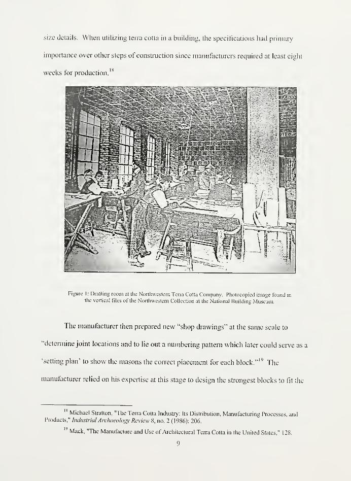
size details. When utilizing terra cotta in a building, the specifications had primary
importance over other steps of construction since manufacturers required at least eight
weeks for production.18
Figure 1:Drafting room at the Northwestern Terra Cotta Company. Photocopied image found in
the vertical files of the Northwestern Collection at the National Building Museum.
The manufacturer then prepared new "shop drawings" at the same scale to
"determine joint locations and to lie out a numbering pattern which later could serve as a
'setting plan' to show the masons the correct placement for each block."14
The
manufacturer relied on his expertise at this stage to design the strongest blocks to fit the
lsMichael Stratton, "The Terra Cotta Industry: Its Distribution, Manufacturing Processes, and
Products," Industrial Archaeology' Review 8, no. 2 (1986): 206.
19Mack, "The Manufacture and Use of Architectural Terra Cotta in the United States," 128.
9
building's structure as well as to conceal joints for aesthetic purposes. The drawings
required, "years of practical experience in the manufacture of terra cotta, knowledge of the
manufacturing methods of the factory in which the material is to be made, and intimate
knowledge of the characteristics of that factory's product, as well as thorough experience in
construction and drafting."20The block details included anchorage points for ties as well as
steel members. In addition, the manufacturer drafted an "iron schedule" detailing required
anchors, angles, straps, and clamps to secure the pieces to the building frame. Another step
in the drafting process included "shrinkage scale" drawings scaled at 13" to the 1' for
details to ensure the modelers compensated for the 1/8" to 1/4" shrinkage due to the loss of
water in the firing process. All of these drawings were submitted to the architect for final
approval.
Each project is designed with terra cotta blocks that are "made for each job
individually and with reference to the structural conditions to be met thereon."" To create
the blocks, a new batch of clay must be prepared to compensate for desired strength,
plasticity and color. The unique chemical identity of a specific clay bed influences the final
product. In order to stabilize the quarried material, the clay was allowed to weather which
helped to break down the raw material, increase its plasticity, and reduce the chemical
changes of the terra cotta after firing." Then the raw clay was processed through a mill to
loosen any impurities, such as stone or metal scraps, and crush the material into a
consistent powder. The clay was next cleaned to remove the impurities from the mix.
20 Edward Putnam, "Architectural Terra Cotta: Its Physical and Structural Properties," The
Brickbuilder (1911): 29.
:iWilliam Lockhardt, "Architectural Terra Cotta," General Building Contractor (1931).
"" W.A. Mclntyre, Investigations into the Durability ofArchitectural Terra Cotta and Faience.
Building Research Station Special Report, No. 12 (London: Building Research Station, 1929), 6.
10


Originally, this process required a slurry of water to transform the clay into a creamy slip
allowing foreign particles to settle out. Eventually, the process was streamlined with
machines that could eliminate the impurities while keeping the clay in a workable state.
Just as the final drawings had to compensate for shrinkage, so did the mixing
process. To reduce shrinkage, a sufficient amount of grog was added to the clay. Grog is
the, "ground up pieces of burned clay or brick"23which "retains the same size when
heated" and can "resist changes in temperature."24
Rough measurements of grog and clay
were blended and then treated with barium carbonate to prevent the formation of surface
scum caused by soluble salts.25
The grog was thoroughly mixed into the clay through a
pug mill which eventually extruded stiff clay that could be divided into manageable
chunks. Any excess water would have been driven off either with heat or with a sieve. At
this point, the clay was ready for ageing which was often called "souring." For about 12
months the clay body was placed in a cool, dark place that promoted the growth of bacteria
which integrated into the material and increased its plasticity.
" Ries. Building Stones and Clay Products: A Handbookfor Architects.
Emile Bourry and A. B. Searle, A Treatise on Structural Ceramic Industries: A Complete Manualfor Pottery, Tile, and Brick Manufacturers (London: Scott Greenwood and Son, 1919).
- 5Mclntyre, Investigations into the Durability ofArchitectural Terra Colta and Faience. Building
Research Station Special Report, No. 12, 7.
11


Figure 2: This is an example of some of the intricate detailing sculpted into the blocks. Image
found in the vertical files of the Northwestern Collection at the National Building Museum. 1903.
Before the aged clay body is transformed into blocks, plaster models were sculpted
according to the specifications of the architect using the "shrinkage scale." Often, the
blocks were made slightly larger on the face than required to provide "lugs" for cosmetic
adjustments of the final product during the fitting phase. Larger elements were sculpted as
a whole and then cut into manageable sized blocks with attention to joint location.
Projecting ornamentation was often molded with clay and attached to the plaster model.
After final approval from the architect, plaster of Paris molds were taken from the models.
The sectional molds interlocked to ensure accuracy while the multiple sections could be
disassembled without disturbing the fragile detail of the block when finished. Beyond the
interlocking nodules, each mold was reinforced with steel rods and bound with iron straps.


Figure 3: This image illustrates the cosmetic adjustments made to the blocks after molding. Image
found in the vertical fdes of the Northwestern Collection at the National Building Museum.
Once the molds were prepared, blocks of the aged clay were cut into slabs. The
presser, after kneading the material to remove any trapped air, forced the smoothed clay
body into the mold. After a few hours in the mold, the material stiffened allowing safe
removal of the mold sections. As the piece dried, the clay shrunk away from the mold.
The hygroscopic plaster of Paris absorbed water out of the clay body causing the surface of
the block to condense. When the block was fired in the kiln, this outer layer sintered into
the protective fire skin that made terra cotta so durable.
Before the molded pieces were sent to the kiln they must first undergo the finishing
process, be allowed to dry completely, and then glazed. The finishing process included
rubbing the surface smooth, removing seams, and tooling the surface for a decorative
13


finish. Each piece also had to be stabilized for installation. This included cutting holes for
anchors, scooping out the backing to lighten the material, and scoring grooves on the sides
to allow for better mortar adhesion. To strengthen the block, webs of clay would be
inserted on the back at six inch intervals following the contours of the piece.26
Once
prepared, the pieces would be taken to the drying room which was usually fitted with steam
heating. During this process, the manufacturers had to take extra precaution to prevent
cracking and warping due to uneven shrinkage. This occurred when the exterior surface of
the terra cotta dried faster than the interior. Sometimes this was prevented in a two step
drying process using dry heat and then steam heat; at other times the pieces were wrapped
with moist cloths to promote even desiccation.
Figure 4: This image shows the terra cotta blocks being sprayed with glaze. Image found in the
Ketcham Collection at the Athenaeum of Philadelphia.
-bNational Terra Cotta Society, Architectural Terra Cotta: Standard Construction (New York:
National Terra Cotta Society, 1914).
14


The last step before the pieces were baked involved the application of the glazes.
The two most common types of glazes included a "slip" and a "salt glaze." The "slip"
glaze was popular before the 1890s and consisted of fluid creamy clay that could be
brushed or sprayed on the surface of the blocks. This was often done to smooth out the
color tone of the piece and to weatherproof it by sealing any pores. The colors of slips
were limited whereas the color palette of the "salt glazes" varied widely. The "salt glaze"
consisted of mineral oxides including lead and could produce a glassy surface. The
popularity of terra cotta as a building material can be directly related to its glazes which
increased the architect's color palette and also duplicated costlier masonry materials like
carved granite.
*F#Ni,
J&fL " _**£
2 t*&
Figure 5: A muffle kiln at the Crum Lynne Factory of the O. W. Ketcham Terra Cotta Works.Image found in the Ketcham Collection at the Athenaeum of Philadelphia.
15


Firing the blocks in kilns transformed the carefully mixed and decorated clay ware
into actual terra cotta. At about 450 degrees, the clay began to sinter.27
Sintering is defined
as, "the sticking together of particles when heated to high temperature to form an
agglomerated mass, usually of greater density than the starting material. Complex
processes of chemical reaction, densification and consolidation take place, but without
substantial melting."28
Muffle kilns and down-draught kilns were the most popular forms
used to bake terra cotta. The muffle kiln had a conical shape and a brick lining that
separated the terra cotta from a direct heat source thus preventing discoloration. The down-
draught kiln was designed with a cavity wall that allowed the heat to spread around, in the
middle of, and underneath the structure.29
By radiating the heat throughout the kiln, the
pieces were more evenly baked. Over the course of eight to fourteen days the temperature
was controlled to make sure the blocks went through "the sweat" to evaporate any excess
water, "oxidation" to release any trapped gases, then "main shrinkage" to sinter the
material together. The kilns reached temperatures up to 2000 to 2500 degrees and were
closely monitored by the manufacturer.
27Ibid.
28 W. D. Kingrey and Pamela Vendever, Ceramics Masterpieces: Art, Structure, and Technology
(New York: Free Press, 1986).
29Stratton, "The Terra Cotta Industry: Its Distribution, Manufacturing Processes, and Products," 210.
16
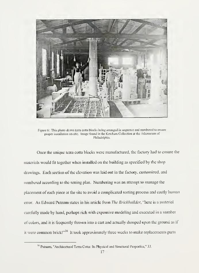
Figure 6: This photo shows terra cotta blocks being arranged in sequence and numbered to ensure
proper installation on-site. Image found in the Ketcham Collection at the Athenaeum of
Philadelphia.
Once the unique terra cotta blocks were manufactured, the factory had to ensure the
materials would fit together when installed on the building as specified by the shop
drawings. Each section of the elevation was laid out in the factory, customized, and
numbered according to the setting plan. Numbering was an attempt to manage the
placement of each piece at the site to avoid a complicated sorting process and costly human
error. As Edward Putnam states in his article from The Brickbuilder, "here is a material
carefully made by hand, perhaps rich with expensive modeling and executed in a number
of colors, and it is frequently thrown into a cart and actually dumped upon the ground as if
it were common brick!"3 "
It took approximately three weeks to make replacements parts
1,1
Putnam, "Architectural Terra Cotta: Its Physical and Structural Properties," 33.
17


and few extra pieces were made during original production due to the time and man-power
required to complete a cycle of the finished product. As a result, extra care was taken to
ensure the blocks were not broken during shipping. The manufacturer wedged courses of
the blocks into train boxcars using straw packing. Each block was then stacked at the site
in reverse order of installation to reduce sorting, breakage, and human error.
In the nineteenth century, the terra cotta manufactures, especially in the mid-west,
employed their own masons to install the terra cotta onto the building. By 1901, however,
"terra cotta setting was becoming a building specialty and subcontractors did most of the
setting."31
The blocks, filled with mortar, were attached to the load bearing structure with
hooks that embedded into the mortar. Each piece was held in place until the mortar set and
the hooks reinforced the block. With the advent of the steel skeletal frame, installing terra
cotta required a complex system of ties, anchors, straps, and clamps. Once the elevations
were erected, the surfaces of the terra cotta pieces were cleaned and the terra cotta portion
of the building was complete.
TECHNOLOG Y SHIFT
In modern times the creator of the skyscraper -the progressive American
architect -working with the responsive and enterprising manufacturer, re-
discovered, improved, and gave an appreciative public this most durable
and versatile of all building materials.
-Fritz Wagner, President of the National Terra Cotta Society, 1914.
Lightweight, fireproof, and economical: these characteristics of terra cotta
catapulted the material into a pivotal role for the advancement of building technology. The
1 Mack, "The Manufacture and Use of Architectural Terra Cotta in the United Stales," 137.
"" Society, Architectural Terra Cotta: Standard Construction, Foreword.
18

transition from load bearing structures to skeletal construction from the 1 840s to the 1 890s
in Chicago and New York led designers to rely on terra cotta as a cladding as a lightweight
material for architectural expression. In the age of disastrous urban fires, terra cotta was
promoted as a fireproof material used to protect the structural frames. The technological
advancement of the steel frame transformed the terra cotta industry as it adapted to meet
the needs of curtain wall construction. Consequently, the manufacture, delivery, and
installation of this material proved to be more cost-effective than masonry and highly
desirable. In order to understand the broader themes of standardization and anchoring
technology, it is important to examine the evolution of terra cotta in relation to building
trends of the time.
Like terra cotta, iron has been used in building construction since antiquity. Yet, its
use as the primary structural material is a fairly recent phenomenon. In the beginning, iron
was hand-wrought and applied to masonry buildings for extra support. Cast iron was
invented by the middle ages but it was not widely used until the late eighteenth century.
Popularized by English engineer John Smeaton, cast iron was first used for structural
members in England's St. Anne's Church (Liverpool, 1772) and the Calico Mill (Derby,
1792). These buildings set precedents for architects experimenting with design themes
such as increased light, fireproofing, and open space. Such themes required lighter wall
construction that could withstand greater open spans.33
In America, William Strickland was the first architect to employ cast iron elements
in his buildings. In Philadelphia, for example, his United States Bank (181 8-24) contained
Carl W. Condit, American Building Art: The Nineteenth Century (New York' Oxford UniversityPress, 1960), 25-26.
19


iron rods to reinforce the arched openings while he used cast iron columns in the Chestnut
Theater (1820-22; demolished) and United States Naval Home (1826-33). In New York
City, iron manufacturers Daniel Badger and James Bogardus are credited with the advent
of iron frame construction in the 1840s and 1850s. While Badger was influential in
promoting iron, Bogardus was pivotal in designing construction techniques for iron
framing systems. Badger declared iron should be used above all other materials because of
its:
strength, lightness and openness of structure, facility of construction, architectural
beauty, economy, durability, incombustibility, and ease of renovation andrestoration. .
.it had no competitor for a wide range of utilitarian structures, such as
stores, office buildings, factories, warehouses, arsenals, and ornamental details.34
Bogardus put this material to the test by creating a cast-iron frame consisting of columns
with flanged ends that were bolted to sills at their joints and bolted to spandrel girders
through the end flanges. These columns would in turn support another story of sills,
girders, and columns and could continue for a number of stories as illustrated in his four-
story factory building in New York (1848-48; demolished).35
Buildings could become
more spacious, allow for more light, and be constructed quickly.
Even with Bogardus' advancements, the construction industry did not immediately
accept the idea of an exclusively cast iron system. By the 1880s, most buildings were
constructed with cast iron columns but still relied on timber framing and load-bearing
masonry walls. The metal frames of this "cage" construction supported the floors but
14Ibid., 30-31.
35Ibid., 33-34.
20

relied on self-supporting walls.h
It was not until William Le Baron Jenney's eleven-story
Home Life Insurance Building in Chicago that the transition to skeletal construction was
initiated. This building employed square cast iron columns that were inset into brick piers
connected by cast iron lintels. Wrought iron beams and girders were bolted to the columns
and pocketed into the brick party walls for extra load support. Above the sixth floor,
Bessamer Steel beams were installed as a stronger substitute for wrought iron. This was
the first introduction of steel into American framing technology.
After careful investigation, it was determined that Le Baron's building truly
exhibited skeletal construction with, "bolted connections, cast iron columns and lintels,
wrought iron beams up to the sixth floor, and steel above. . .with brick piers that carried
none of the load of the iron."37
By the 1890s steel skeletal construction is widely adopted
in both Chicago and New York. With the steel frame supporting the load of the building,
the exterior cladding is tied to the frame but only carries its own weight and wind loads. In
the Guaranty Building (Buffalo, 1896), Louis Sullivan, "emphasizes rather than denies the
role of the wall-surface, supplanted in its structural role by the steel skeleton, by creating a
taut skin of decorative terra cotta."38The role of the exterior wall changes from serving a
structural function to being a palette for design and ornamentation.
Leading to and influencing the transition to skeletal frame buildings were a number
of urban disasters including earthquakes and fires. The Chicago Fire of 1871 destroyed
18,000 buildings in a four-mile long area resulting in 100,000 homeless and a loss of $200
36Susan Tunick, "The Evolution of Terra Cotta: Glazing New Trails," APT Bulletin 32, no. 4 (2001 ):
4.
37Condit, American Building Art: The Nineteenth Century, 53-54.
38Slratton, The Terracotta Revival, 180.
21

million worth of property.39
The Boston Fire of 1872 was less devastating but it wiped out
over 775 buildings in the central business district.uThe 1906 earthquake and subsequent
fire struck havoc on San Francisco. The fire spread over 4.7 miles destroying $250 million
dollars worth of property. Even before these disasters it was known, "that iron was
incombustible but not fireproof." Stratton explains:
A fierce fire would cause exposed tie-rods to expand and columns to crack, if they
had not already been destroyed by the heat of the flames. Extreme heat would
result in the metal melting, while a sudden drop in temperature produced by jets of
water could result in cracking and collapse. It was soon appreciated that structural
ironwork was best protected by being encased in ceramic, cement, or concrete.
In the aftermath of such disasters, some pieces of terra cotta still clung to the structural
ruins. Soon terra cotta was being used to encase iron joists, to clad cast-iron columns, and
to construct interior partitions.
Ironically, in 1871, Chicago builders were attempting fireproof construction with
techniques such as one-inch thick concrete layers on top of beams, brick floor arches
spanning the joists, and one-inch thick plaster ceilings. In order to prevent the collapse of
cast iron columns, John B. Cornell patented (1860), "a column consisting of two cast iron
tubes, one inside the other, the space between filled with fire-resistant clay."43
To protect
floor beams, Balthasar Kreischer patented (1871) the technique of cladding the beams with
tile. However, it was the use of fireproof, porous terra cotta tile that gave builders the
Chicago Fire 1871 ([cited 1/29/ 2003]); available from www.chicagohs.org/fire/ruin/index/htnil.
Boston Fire 1871 ([cited 1/30/ 2003]); available from www.fire-police-
ems.com/books/bg3730.htm.
41San Francisco Fire 1906 ([cited 1/30 2003]); available from
amcricahurrah.com/sanfrancisco/municipalreports/1906/index.htm.
42Stratton, The Terracotta Revival, 19.
" Condit, American Building Art: The Nineteenth Century; 44.
T>
confidence to construct with iron. Terra cotta fireproof tile was first patented by George H.
Johnson in 1872 but it was Peter B. Wight who promoted the new porous material as a
better alternative to the traditional denser variety in 1874.44
Terra cotta "lumber" as it was
called was infused with sawdust which burned off during the firing process. This resulted
in a, "lightweight block which could be sawed, nailed, screwed or otherwise worked like
wood." It was understood that the, "best practice for fireproofing involved the creation
of an impregnable armor against flames and heat. Column casings had to be able to
withstand high temperatures for some hours and to be of low heat conductivity."46
The tile
could be installed as hollow-tile arches between floor joists, as cladding for cast iron
columns, and as masonry blocks for interior partitions.47
The shift in building technology to the skeletal frame yielded major profits for
investors especially as buildings reached new heights and the population density increased.
Terra cotta fit into the budgets of these investors as it reduced manufacture and installation
costs within a relatively quick construction period. While each building required a unique
set of terra cotta pieces from the manufacturer, the use of molds for original and repeated
elements was significantly cheaper than carving each piece from stone. The light weight of
the material also resulted in cheaper shipping costs and on-site handling.
From the 1880s to the 1930s the terra cotta industry had to adapt its installation
methods from load-bearing masonry to the skeletal frame. Eckardt Eskesen, then president
Stratton, The Terracotta Revival, 149-50
45
46
Mack, "The Manufacture and Use of Architectural Terra Cotta in the United States," 120.
Stratton, The Terracotta Revival, 1 66.
47Ibid.
23


of the Kansas City Terra Cotta and Faience Co., and treasurer of the National Terra Cotta
Society, wrote in 1924:
with the introduction of the skyscraper and the concrete building, came before us
the problem of how to adapt our material to the changed conditions; how to support
a load of terra cotta, which now under the changed conditions, is used simply as a
veneer on the front of the building, and how to hang the projecting courses, and tie
down the tiers of ashlar work.48
New issues that needed to be addressed for this new construction included changes in
anchor hardware, assessment of water-tight construction, compression strength
assessments, and glaze compatibility. The National Terra Cotta Society published
standards of construction to illustrate proper methods to deal with these issues and
disseminated them to all members.
Rise and Fall
"The dream of the modern architect is to build houses entirely out of metal,
glass, and cement. ..In this construction, brick, tile, or terra cotta has noplace"
-E.V. Eskesen, President of the Federal Seaboard Terra Cotta Co
By the 1930s and 40s, American architecture streamlined designs to express the
verticality of the skyscraper. With the introduction of the International Style through
architects like Mies van der Rohe, traditional terra cotta ornament had no place on the
clean, sleek buildings. Conventional construction was replaced with steel and concrete
with an aesthetic that represented the machine age. The intricate craftsmanship and time-
49
4SE.V. Eskesen, "The Investigation of Terra Cotta Work at the Bureau of Standards," ACS Journal 4
(1924): 159.
49E.V. Eskesen, "Presidential Address for the Thirty-Fourth Annual Meeting of the American
Ceramic Society," Journal ofthe American Ceramic Society 15 (1932): 81.
24


intensive production of terra cotta did not fit into this aesthetic. Changing architectural
tastes in combination with the onset of the Depression in the 1930s caused a sharp decline
in the demand for architectural terra cotta. In fact, between 1925 and 1935 the volume of
sales for the industry dropped 93 percent.50
In order to remain in business, many manufacturers tried to promote a variety of
alternative products including bathtubs, caskets, and even golf tees.51
One such product
called ceramic veneer, an extruded form of terra cotta facing, revived the industry at first
but then drove demand into a steeper decline.
The manufacture of ceramic veneer took full advantage of the machine to mass
produce thin slabs of a clay material. The process extruded under high pressure a mixture
of clay and water through preset dies producing a flat surface on the front and grooved
surface on the back. When dry, the slab was machine-planed smooth, glazed, then fired.
This new material was stronger than traditional terra cotta and could be divided into larger
units without fear of warping.52
The units, ranging in thickness from 1 1/4" to 1", were
either applied to the wall with a simple anchoring system of metal ties or directly adhered
to the building with mortar.53
Ceramic Veneer was promoted heavily on the west coast as
earthquake proof and soon all hand-molded pieces were phased out the catalogs.54
By
50Susan Tindall, "How to Prepare Project Specific Terra Cotta Specifications," APT Bulletin XXI
no. 1 (1989): 29.
Tunick, Terra-Colla Skyline : New York's Architectural Ornament, 111.
52Robert E. Meadows, Historic Building Facades: A Manualfor Inspection and Rehabilitation
(New York: New York Landmarks Conservancy, 1986), 27.
" Tindall, "How to Prepare Project Specific Terra Cotta Specifications," 29.
Barton, "O. W. Ketcham Terra Cotta: Reflections on an Industry in Chaos after World War Two,"
25

losing their voice, and subsequently their market, many traditional terra cotta
manufacturers were forced to fend for themselves.
Many factories folded when fierce competition with the cheaper production costs of
materials such as concrete and glass was compounded with bad publicity from deteriorating
terra cotta buildings dating from the turn of the century. The transition to steel frame
construction forced terra cotta manufacturers to analyze the physical and chemical
properties of their material.
When terra cotta was first introduced in the construction industry it was hailed as a
cheaper substitute for stone. The use of plaster molds for the terra cotta repeater pieces
allowed for faster production as opposed to carving each piece individually as done with
stone. It was lightweight, durable, moldable, and colorful. It could be made to look like
many structural stones but was less susceptible to weathering.55
However, the industry
faced some problems during production in controlling warping and shrinkage of the blocks.
After construction, differences in temperature could not only affect the physical properties
of the internal structure of the wall but also enabled spalling of the glaze from the body of
the block. Cracked fire skins and weak mortar joints after installation allowed water to
penetrate the interior of the wall causing serious damage to the mortar filling or the iron
anchors supporting the block.5 '1
Water penetrating the wall through cracks, joints, or
spalled areas, threatened the structural integrity of the blocks as well as their aesthetic
qualities.
Meadows, Historic Building Facades: A Manualfor Inspection and Rehabilitation, 23
.
56Ibid.
26

The roots of these problems extended beyond the quality of the terra cotta being
produced by the companies to the fundamental business practices of the manufacturers
themselves. Failures were blamed on flimsy specifications, the installation of the blocks on
site, and faulty design of the wall construction systems. As explained in the previous
section, most manufacturers went through a laborious process of drafting, molding, firing,
and fitting the pieces to ensure quality. Once the pieces reached the site, however, there
was minimal guidance over the actual installation or protection against human error.
Additionally, since there had been little physical testing of the material, some the common
anchoring techniques were not sufficiently supporting their loads. As a result, the
companies tried to create standard specifications, investigated the physical properties of the
material, and hired their own masons. A definitive set of standards was not published until
1927 and even these did not include all the information learned from the testing. By the
time the depression hit in the 1930s, the public opinion of the material was severely
damaged.
27


Chapter 2: ORGANIZATION OF THE INDUSTRY
BUSINESS DEVELOPMENT
"More big contracts are closed over nuts and wine than across a desk."
—Andrew Carnegie of Carnegie Steel
From 1886 to 1960, terra cotta manufacturers endeavored to organize the industry
to stimulate business, protect individual investments, and standardize construction. Terra
cotta manufacturing came about during the age of "Big Business" in America where cut
throat competition from major competitors wiped out smaller companies. At the rum of the
century on the East Coast, a number of organizations were created to control the market
and evenly distribute the numerous contracts. Eventually, as the government began to
enforce the Sherman Antitrust Act of 1890, the organizations focused heavily on the
dissemination of information about the material in the forms of advertising, publications,
and trade literature. With the advent ofnew construction techniques and damaging
publicity about the failures of terra cotta, a group of manufacturers began to cooperate to
eliminate outdated construction techniques and harmful business practices. With issues
such as modernization, newer cost-effective materials, and loss of craftsmen in the 1960s,
the manufacturers once again organized to provide business opportunities for each
company and to inform the country about modern applications of the material.
Modem innovations have propelled industry throughout the history of the United
States. By the end of the nineteenth century, three important advancements led the way for
' "Architectural Terra Cotta," Brick and Clay Record, no. 33, Walter Geer, The Stoiy of Terra Cotta
(New York,: T. A. Wright, 1920), 97.
28

industrialization in America: the railroad, the telegraph, and steel.58
The terra cotta
industry, for example, flourished as factories located on rail lines could deliver materials to
clients in other states who wanted to clad and fireproof their skeletal frame skyscrapers.59
Businesses of this type grew "vertically" by usually engaging, "in a number of different
activities, such as purchasing or growing its raw materials, fabricating those materials into
goods, transporting its own products, wholesaling them, or even taking care of retailing
them to consumers." The other option was to grow "horizontally" when a "number of
producers who all did the same thing would join together to form a combination of their
interests."*' Like some of the larger enterprises of this period, the terra cotta industry
developed in both directions. The first chapter of this paper outlines the manufacturing
process of terra cotta which closely follows this pattern of "vertical growth." Taking a step
further, many manufacturers even installed their final product using their own masons and
company-supplied iron anchors.61
The following section traces the "horizontal growth" of
the industry as it endeavored to maximize demand, stabilize prices, and minimize
competition.
Standard Oil, American Sugar Refining, and American Tobacco -successful trusts
in the 1880s -undoubtedly influenced the terra cotta manufacturers with their ability to
effectively control the market. Before 1886, George M. Fiske of the Boston Terra Cotta
5SGlenn Porter, The Rise ofBig Business: 1860-1920, 2nd ed. (Arlington Heights, Ilinois: Harlan
Davidson, Inc., 1992), 41-45.
O. W. Ketcham specifically purchased the site for his factory because it was located on the
Pennsylvania Railroad. "It allowed for the large volumes of clay to come into the plant, and in the case of
distantly located large orders, allowing for the shipping of the finished terra cotta to a siding close to the job
site." See: Barton, "O. W. Ketcham Terra Cotta: Reflections on an Industry in Chaos after World War Two,"12.
60Porter, The Rise ofBig Business: 1860-1920, 46.
61Mack, "The Manufacture and Use of Architectural Terra Cotta in the United States," 137.
29


Company and Harry A. Lewis of the H. A. Lewis Architectural Terra Cotta Works
(Boston) realized they were not capitalizing on all the contracts available to them. '" As
Glenn Porter explains in The Rise ofBig Business: I860- J 920, this was a common
phenomenon among growing industries before 1895:
First, a number of manufacturers would enter an industry, producing goods in
volume in factories that sometimes required quite substantial capital investment.
For a time, all would be well. Profits would be good, and the business would
expand, often leading others to enter the industry to share in the promise of
prosperity. As the market began to fill up, however, producers found that they had
to compete vigorously in order to keep or to enlarge their share of the market. Most
manufacturers tried to do so by cutting the prices on their goods. After a period of
sharp price competition, they would find that profits and prices were not meeting
their expectations and would begin to search for a solution to this problem.
Fiske and Lewis' solution was the "Open Price" system in which they agreed to divide
contracts between them based on need in order to mutually benefit each other. William C.
Hall from the Perth Amboy Terra Cotta Company refined this plan and called a meeting in
the winter of 1886 to organize the major manufacturers on the East Coast. This meeting
resulted in the formation of the First Brown Association. The organization adopted an
"elaborate set of rules" for a contract distribution process and was administered by a central
agent in the New York office.64
Similar associations were known to provide a "convenient
format in which they might agree to fix prices, set output quotas, or divide the market in
some manner, such as by apportioning geographic territories among the members of the
association."1
The five members of the First Brown Association included: the Perth
62Geer, The Story ofTerra Cotta, 97-98.
63Porter, The Rise ofBig Business: 1860-1920, 58-59.
64Geer, The Story ofTerra Cotta, 98-100.
" 5Porter. The Rise ofBig Business: 1860-1920, 59.
30
Amboy Terra Cotta Company, the Boston Terra Cotta Company, the New York
Architectural Terra Cotta Works, the H. A. Lewis Terra Cotta Works, and the A. Hall Terra
Cotta Company.
The First Brown Association stabilized the industry for a few years but was soon
threatened by competition from a Philadelphia company: Stephens, Conkling and
Armstrong. Often these associations failed as periods of profit encouraged new
manufacturers to open shop, leading to increased competition, plummeting prices, and
eventually, profit losses.67
To overcome this zigzag in the bottom line, the Second Brown
Association was formed in 1893 to include the Philadelphia manufacturer. The group's
first attempt to smooth out the competition was to eliminate the smaller companies. Porter
states, "Often, the most effective way to maintain market position and profits was to
become more competitive by ordering the closing of the less efficient plants." A. Hall
Terra Cotta Company and the Boston Terra Cotta Company -the smaller companies -were
eventually disbanded. H. A. Lewis Terra Cotta Works was bought out by Perth Amboy
and became a Philadelphia branch for the company. Stephens, Conkling, and Armstrong
was annexed by New York Architectural Terra Cotta Company and served as a
Philadelphia branch for that company. For the next two years, the only members of the
Association were Perth Amboy and New York. Despite these attempts to suppress
competition, seven new manufacturers sprung up replacing the four companies that were
disbanded including: Standard (1890), White (1892), Staten Island (1893), New Jersey
'" Geer, The Sloiy of Terra Cotta, 99.
"7Porter. The Rise ofBig Business: 1860-1920, 60.
68Geer, The Story of Terra Cotta, 102-05.
69Porter, The Rise ofBig Business: 1860-1920, 6 1
.
31

( 1 893), Excelsior ( 1 894), Conkling-Armstrong ( 1 895), and Coming ( 1 896). At this point,
business conditions were worse than before any attempts at organization.7U
With the fledgling companies flailing and the established companies losing bids,
there was another attempt at organization by the manufacturers in 1 896. Porter explains,
"Usually, the next step after the failure of the association strategy was an attempt at
horizontal combination, in which all or many of the major producers in an industry would
form a single firm, at least in the legal sense."71
The producers of terra cotta created an
incorporated company with SI 0,000 in capital known as the Manhattan Material Company.
Walter Geer explains:
The Manhattan Company was to act as the general sales agency of the various
companies interested, and entered into contracts with different companiesindividually, agreeing to turn over to each company a certain percentage of the total
amount of orders secured by said Manhattan Company, these percentages being the
same as the percentage of stock held by each company. In the case the ManhattanCompany for any reason could not assign to any individual company its exact quotaof orders, it agreed to pay in cash a bonus of twenty percent of the amount of suchdeficit, and any company receiving more that its quota agreed to pay to the
Manhattan Company a similar amount by way of penalty.72
Such an agreement prevented a single company from getting more contracts than it could
handle as well as ensured each manufacturer would receive sufficient contracts to remain in
business. Of the six members -Perth Amboy, New York, Standard, Excelsior, Conkling-
Armstrong, White, and New Jersey -each signed a five year contract agreeing to these
terms and fixed percentages. Competition ensued, however, with the establishment of the
70Geer, The Story ofTerra Cotta, 96- 1 06, 2 1
.
71Porter, The Rise ofBig Business: 1860-1 920, 60.
72Geer, The Story ofTerra Cotta, 123.
32

,74
Brick Terra Cotta and Tile Company (Corning, 1896) and the Atlantic Terra Cotta
Company (1897) making the Manhattan Company defunct by 1901.73
The Eastern manufacturers were determined the only way to protect their interests
was to stabilize prices and output to ensure profits. This method in the early years of the
twentieth century was "especially common in new industries and in those that underwent
significant technological changes involving high capital investment and high fixed costs.'
In 1902, the Terra Cotta Manufacturer's Association was instituted following a similar
business plan as the Manhattan Company. Previously there were many complaints about
the assignment of fixed percentages which determined the amount of work a particular
company would receive. Now the percentages were assigned according to a sliding scale
determined by work acquired during a particular amount of time. Some felt " the
companies might just as well have installed a roulette wheel and left the fate of the business
to the decision of chance."75
Attempts at organization failed again and the association was
dissolved in 1904.
At this point, more terra cotta producers were entering the business: South Amboy
Terra Cotta Company ( 1 903), Maryland Terra Cotta Company (1905), O. W. Ketcham
Terra Cotta Works (1906), and anti-trust laws were fully enforced. Several schemes were
created to improve the industry including the formation of the National Terra Cotta
Company which was to merge all the major East Coast companies into one. This idea led
to the formation of the Atlantic Company in 1907 which detrimentally combined the old
,JIbid.
7" Poner, The Rise ofBig Business: 1 860-1920, 65.
" Gecr, The Sioiy oj Terra Colta, 145.
33


Atlantic, Perth Amboy, Excelsior, and Standard companies.76
For other similarly
combined industries from this period, "the new corporation often functioned for a time as a
loose amalgam of divisions that retained much of their former autonomy." The central
office did little more than make decisions on prices, output, and marketing unless outside
forces, such as increased competition, forced the company, "to take away the autonomy of
its subdivisions and exercise more unified control."77
With plenty of competition still alive
and a general depression in 1907, business was worse then ever before causing some major
executives to pull out of the company.78
The Sherman Act of 1890 was passed as an attempt to curtail "Big Business" and
encourage the smaller, specialized entrepreneurs that supported a healthy economy. This
vague law was intended to suppress "Big Business" but was being interpreted in the courts
to encourage incorporation. Porter explains this paradox:
The courts ruled that forms of cartel-like behavior were illegal under the act, butthat unified combinations were in most instances acceptable. That is, the lawforbade collusion by independent firms but did not necessarily outlaw the activities
of integrated holding companies created by the legal union of previously separatedbusinesses.
79
The evolution of organization within the terra cotta industry follows these business trends
at the turn of the twentieth century. In order to maximize the benefits in the 1880s, the
manufacturers entered into cartel-like associations to control the market. Soon after the
passage of the Sherman Antitrust Act in 1890, they began to incoiporate as holding
76Ibid., 143-50.
77Porter, The Rise ofBig Business: 1860-1920, 61.
78Geer, The Story ofTerra Cotta, 1 50
79Porter, The Rise ofBig Business: 1860-1920, 77.
34

companies. By 191 1, as the government began cracking down on "Big Business" as
exemplified in the forced dissolution of Standard Oil into multiple firms, terra cotta
manufacturers changed their goals from price-fixing towards production efficiency.
In the early twentieth century, "efficiency" to the manufacturers translated as
upsurges in demand, publicity, and technology. This attitude mimicked the new trends in
competition that strove for, "the most efficient systems of organization for production and
distribution, and a never-ending effort to plan, to react to changing circumstances, and to
allocate resources so as to keep the enterprise growing via new products and services." " In
1910, the terra cotta manufacturers proposed to create a "Literary and Publicity Bureau" to
"spread knowledge of the many advantageous qualities of good architectural terra cotta by
widely advocating its merits, particularly through the agency of wise advertising and the
publication of books, pamphlets, and other forms of trade literature."81
The bureau was
never created but its goal was incorporated into the National Terra Cotta Society formed in
1911. This was the most successful organization of manufacturers in the history of terra
cotta. For this first time, collaborative efforts focused on improvements to the material,
promotional strategies, and distribution of knowledge about terra cotta construction. This
valiant organization is described in detail in the next section of this chapter. Unfortunately,
the Society eventually shared the fate of previous organizations. It was dissolved in 1934
as a response to the depressed economy, competitive new materials, and high dues.82
As the market changed in the mid-twentieth century toward sleek, modem
materials, the few existing manufacturers continued attempts to organize themselves and
suIbid., 89.
SlGeer, The Stoiy ofTerra Coda, 151, 236.
35


protect the industry. In the mid- 1930s, the National Terra Cotta Manufacturers Association
was created followed by the Architectural Terra Cotta Institute (1947-59), the Structural
Clay Products Institute (1960s), and the Brick Institute of America83which still exists.
84
The National Terra Cotta Manufacturers Association was a short lived attempt to
boost the industry initiated by the mid-western companies -American, Indianapolis, Kansas
City, Midland, Northwestern, Western, and Winkle.85
The association was soon replaced
by the Architectural Terra Cotta Institute in 1947 which included the seven remaining
companies in the country: American Terra Cotta Corporation (Chicago), the Denver Terra
Cotta Company, the Federal Seaboard Terra Cotta Corporation (Perth Amboy, NJ),
Gladding, McBean and Co. (California), O.W. Ketcham Terra Cotta Works (Philadelphia),
the Northwestern Terra Cotta Corporation (Chicago), and the Winkle Terra Cotta
Incorporated (St. Louis). The goals of this organization were:
1
.
To educate building professionals about the uses and properties of terra cotta
2. To address the shortage of trained terra cotta craftsman
3. To compile statistics on the quantities of terra cotta being bought throughout the
United States
4. To manufacture new products that would be appropriate for the architectural styles
of the period
Tunick, Terra-Cotta Skyline : New York's Architectural Ornament, 107.
www.bia.org
Tunick, Terra-Cotta Skyline : New York's Architectural Ornament, 107.
Michael Fus, "Architectural Terra Cotta: Standards, Specifications, and Testing" (Master ofScience, Art Institute of Chicago, 1997), 59
36


As with previous terra cotta organizations, the dues structure based on sales percentages
and competition over new products forced many companies to withdraw from the
Institute.86
The Architectural Terra Cotta Institute and later the Structural Clay Products
Institute produced standard specifications for terra cotta in 1954 and 1961, respectively.
The theme of improving the product and standardizing construction began with the
proposed Literary and Publicity Bureau in 1910 and was implemented in the work of the
National Terra Cotta Society from 191 1-1934.87
These later institutions continued the
tradition but have since been absorbed into the Brick Institute of America which publishes
88information on brick products but not terra cotta.
The terra cotta industry has significantly diminished since its American debut in the
nineteenth century. Porter claims:
The most important factor in accounting for the rise and persistence of big business
has been that giant firms were most likely to appear and to succeed if they were in
technologically advanced industries that could achieve and sustain genuine
economies of scale and could link mass production to mass distribution.'
In the end, the terra cotta industry struggled with technology trends in new architecture,
wavering demand levels, and slow production rates. These are the fundamental reasons all
the attempts at organizing the industry eventually failed.
" Tunick, Terra-Cotta Skyline : New York's Architectural Ornament, 114-15.
87Goer, The Story of Terra Cotta, 151.
<sTindall, "How to Prepare Project Specific Terra Cotta Specifications." See Tindall's footnote #23.
89Porter. The Rise ofBig Business. 1860-1920, 86.
37


National Terra Cotta Society
"National Terra Cotta Society is a bureau of service and information
operating for the Terra Cotta manufacturers of the United States."
-NTCS Advertisement90
Figure 7: The National Terra Cotta Society (1927). Photo is from the Ketcham Collection at the
Athenaeum of Philadelphia. For list of those photographed see Appendix A: NTCS Members.
Until 1911 most efforts at organization for the terra cotta industry did little to
improve business. Walter Geer of the New York Architectural Terra Cotta Company had
been instrumental in the formation of the Second Brown Association, the Manhattan
Company, and the Literary and Publicity Bureau project. Therefore, it was not unusual that
Walter Geer opened correspondence with all the manufacturers to create a national
organization in 1911. This time the organization would serve as an advocate for terra cotta
National Terra Cotta Society, "A Campaign for Better Understanding," Pencil Points 1, no. 6
(November 1920).
38


interests. The National Terra Cotta Society (NTCS) not only worked to standardize the
industry but also to introduce a Code of Ethics, to conduct tests on the nature of the
material, and to inform other industries of their work.
The first meeting was arranged by Walter Geer, Gustav Hottinger of the
Northwestern Terra Cotta Company, and P. McGill McBean of Gladding, McBean and
Company. It was held on December 8, 191 1, in Chicago at the Hotel La Salle and attended
by 23 delegates from companies across the country.91 A set of by-laws and a constitution
were adopted at the meeting and officers were elected. The officers included: President-
Fritz Wagner of the Northwestern Terra Cotta Company, First VP: Walter Geer of the New
York Architectural Terra Cotta Works, Second VP: W.E. Dennison of Steiger Terra Cotta
and Pottery Works, Treasurer: E. V. Eskesen of the New Jersey Terra Cotta Company, and
Secretary: W. D. Gates of the American Terra Cotta and Ceramic Company.
Most importantly, five objectives were adopted at the meeting which clearly
outlined the purpose of the organization. These objectives were:
Delegates Represented- Brick Terra Cotta and Tile Co.- Corning, NY, M.E. Gregory; Conkling-Armstrong Terra Cotta Co.- Philadelphia, PA- I.L. Armstrong and T.F. Armstrong; Federal Terra Cotta
Co.-Woodbridge, NJ - De Forest Grant and Norman Grant; New Jersey Terra Cotta Company- Perth
Amboy, NJ- Karl Mathiasen and E. V. Eskesen; New York Architectural Terra Cotta Co.-New York,NY-Walter Geer, F. C. Townshend, and H.J. Lucas; South Amboy Terra Cotta Company-South Amboy,NJ- P.C. Olsen; American Terra Cotta and Ceramic Company- Chicago, II- W.D. Gates and E.D. Gates;
Northwestern Terra Cotta Co.- Chicago, Il.-G. Hottinger and F. Wagner; St. Louis Terra Cotta Co.- St.
Louis, MO-D.N. Burruss and R.F. Grady; Western Terra Cotta Co.- Kansas City, KS- WilliamTimmerman; Winkle Terra Cotta Co.- St. Louis, Mo.- Joseph Winkle and J.G. Hewitt; Gladding-McBean-and Co.-San Fran., CA- P. McGill McBean; N. Clark and Sons, San Fran., CA- Mr. McBean(Proxy) Northern Clay Co.- Auburn, WA- P.S. MacMichael; Steiger Terra Cotta and Pottery Works, SanFran., CA- W.E. Dennison (resigned or withdrew (1918)
Supported by but did not attend- O. W. Ketcham Terra Cotta Works- Philadelphia.Pa- O.W. Ketcham;Maryland Terra Cotta Co- Baltimore, MD- (resigned 1915); Indianapolis Terra Cotta Co. Indianapolis,
IN.; Denny-Renton Clay and Coal Co.- Seattle. WA; Washington Brick, Lime, and Sewer Pipe Co-Spokane Washington
Six other members admitted later- Midland and Denver ( 1912); Kansas City (1913); Atlanta and Atlantic
(1915); Los Angeles (1919)
Geer, The Story ofTerra Cotta, 234-35.
39

1
.
To encourage the production of the best materials and the maintenance of high and
uniform standards of work
2. To spread the knowledge of the many advantageous qualities of good architectural
terra cotta by widely advocating its merits, particularly through the agency of wise
advertising and the publication of books, pamphlets, and other forms of trade
literature.
3. To co-operate in the investigation and study of the more important technical and
other problems of the business
4. To advance mutual business interests in every legal and proper way, without in any
manner, directly or indirectly, agreeing to maintain prices or suppress competition
5. To promote a feeling of confidence and friendship among the members, so as to
secure the benefits of the several objects above set forth
The last two objectives clearly represent how the industry has struggled with organization
attempts in the past. Objective number four is a response to the anti-trust mentality of the
time and most likely the industry's previous attempts at controlling competition. Geer
states:
At this time, the government at Washington, under President Roosevelt's
Administration, had begun to vigorously enforce the Sherman Act, which had been
adopted over ten years before, and Big Business for the first time realized that the law
had teeth. . .The Terra Cotta manufacturers had no intention then, or at any other period,
of acting contrary to the law92
The last objective most likely refers to the messy hangover from the suppressed
competition that ensued after the merger of the Atlantic Company in 1907. Geer explains
that this company failed to respect the weaker competitors as well as the multi-pronged
business practices of the merged companies. By 1909, some executives left the company
and legal proceedings -including an investigation by the Federal Grand Jury-
92Ibid., 147-8.
40
unsuccessfully attempted to dissolve the company and return the old Atlantic company to
its original owners.93
The notion of cooperation and friendship among the manufacturers as implied in
the first objective was a crucial element for standardization and material improvement. The
Society functioned as a clearing house of information collected from all the members,
synthesized, and redistributed. For example, in 1914 there was growing concern about the
various qualities of terra cotta available on the market. Mr. O. Wenderoth, Supervising
Architect of the Treasury and potential client, wrote to the Society demanding, "a terra
cotta specification very exacting in the matter of quality, yet fair and reasonable for the first
class manufacturer."94He also explained to the Society, "unless he can get good
architectural terra cotta, he will use no architectural terra cotta. He appreciates that this
material has many qualities when well made, properly set and carefully pointed, but he also
knows that there are several qualities of ware on the market, good, bad, and indifferent."95
This correspondence was preceded by Wenderotrfs inquiry to various terra cotta
manufacturers about the specification of models in the factory and general manufacturing
processes. Hairy J. Lucas, Assistant Secretary of the NTCS, responded quickly by sending
notices to Society members about the request for standardization saying that:
This is an important matter and it is very desirable that we now attempt to
standardize the processes referred to by the Supervising Architect. . .The Eastern
Division will make a definite recommendation in this matter with the next few
93Ibid, 150.
94Harry J. Lucas to C. L. H. Wagner, September 10, 1914, New York Architectural Terra Cotta
Company Collection, Columbia University Avery Library. See Appendix B: Correspondence andAdvertisements
V5Ibid.
41

days, and same will be submitted to the larger companies in other Divisions for
general approval before transmission to Washington.
By September 10, 1914, Lucas sent out a draft of the model specifications for approval.
This process of communication and cooperation among the Society members enabled the
manufacturers to streamline production efforts as well as entice architects to use the
material.
Educating architects about the qualities of terra cotta was a primary goal of the
NTCS and this was done mostly through publications and advertising. A letter to all
members of the NTCS on April 15, 1915 states:
All publications of the Society are distributed by and in the name of the Society
from its executive officers. Agents who are sure that certain architects, owners, or
other can and will make good and valuable use of this literature should send names,
with facts, to the company they represent. . .These books are costly and should be
distributed only where they are likely to make terra cotta business.97
The Society believed that in order to sell its product, they had to show beautiful examples
of existing terra cotta buildings. In April of 1916 they collected 10 photographs from
members of terra cotta storefronts of all designs.98
These photographs would represent the
work of all the Society members in the 1915 brochure, "The Store." The Society depended
on the working knowledge of its members in order to produce such seminal publications as
"Architectural Terra Cotta: Standard Construction, 1914" and "Terra Cotta Standard
Harry J. Lucas to New York Architectural Terra Cotta Company, August 20, 1914, New YorkArchitectural Terra Cotta Company Collection, Columbia University Avery Library. See Appendix B.
Harry J. Lucas to Agents Representing Terra Cotta Manufacturers Who Are Members of the
National Terra Cotta Society, April 13, 1915, New York Architectural Terra Cotta Company Collection,
Columbia University Avery Library. See Appendix B.
9li
William H. Powell to The Members of the National Terra Cotta Society, April 10, 1916, NewYork Architectural Terra Cotta Company Collection, Columbia University Avery Library. See Appendix B.
42

Construction, 1927." These marketing tools were embellished by advertisements in
popular trade journals including The Architectural Forum, The Brickbuilder, and Pencil
Points. The title of one advertisement in a November 1920 issue of Pencil Points, "A
Campaign for Better Understanding," illustrates how the Society attempted to spread the
word about the merits of the material." This was one of many advertisements designed
"not only to increase public admiration for the Architect and his judgment, but to set forth,
as well, the practical and aesthetic qualities of Terra Cotta as an architectural material of
permanence, beauty, and profit."100
These advertisements and publications promoted the
industry as a whole yet benefited the manufacturers individually as their sales increased.
One of the most successful accomplishments of the National Terra Cotta Society
was the streamlining of business practices throughout the industry. This included not only
investigating technical aspects of the material but also uniformity of forms and contracts.
The American Institute of Architects initiated standardization of forms for their industry in
1907 and published, "The Standard Documents of the American Institute of Architects" in
1911. " They justified this effort as an attempt to, "improve the form of certain documents
currently used by architects, with a view to making these documents clear in thought and
statement, equitable as between owner and contractor, applicable to work on almost all
Society, "A Campaign for Belter Understanding." See Appendix A.
100Ibid.
Fus, "Architectural Terra Cotta: Standards, Specifications, and Testing", 162.
'" This document was found in the files of Walter Geer, then President of the New YorkArchitectural Terra Cotta Company and Vice President of the National Terra Cotta Society. Along with the
brochure in the files were copies of standard forms used by the company. These finds indicate Geer and the
Society were researching other industry techniques for standardization. New York Architectural Terra Cotta
Company Collection, Columbia University Avery Library, 1916. American Institute of Architects, The
Standard Documents ofthe American Institute ofArchitects (Washington, DC: The American Institute of
Architects, 1911).
43


classes, binding in law and a standard of good practice."103 To produce these documents,
the Standing Committee on Contracts and Specifications synthesized forms used by thirty
different architects. The NTCS followed this precedent by creating a Contract Committee
to collect forms used by the terra cotta manufacturers and standardize them. In a letter
addressed to all members in 1916, committee member William H. Powell, President of the
Atlantic Company, requests copies of estimate forms used by all members in order to make
sufficient revisions to the standard form.104
In the past, terra cotta manufacturers had
difficulty communicating with contractors and architects which led to installation problems
and premature deterioration. Standardized forms, particularly standard specifications,
allowed the architects, contractors, and terra cotta manufacturers to communicate on the
same level and construct better buildings.
The theme of improved communication can be traced through all of the NTCS
efforts whether it was with other terra cotta manufacturers, potential clients and contractors,
or even other professional organizations. For example, in 1919, the NTCS set up a
committee to serve as a liaison with the American Ceramic Society (ACS). ACS, highly
involved in the technical aspects of terra cotta, instituted ceramic departments at many
universities throughout the country.105
NTCS was able to set up a Terra Cotta Division within ACS which was coordinated
by the NTCS Standing Committee on Technical Matters. This division, in conjunction
with the United States Bureau of Standards, began investigations into, "fifteen separate and
103Ibid.
Powell to The Members of the National Terra Cotta Society, See Appendix B.
105Geer, The Story ofTerra Cotta, 240.
44


distinct subjects. . .covering practically all phases of terra cotta manufacture." Research
and testing at the United States Bureau of Standards was funded through a fellowship of the
NTCS and the ACS and lasted from 1915 to 1945. The investigation of terra cotta
determined physical properties of clays, grog, and bodies, expansion of glazes, expansion
of underslips, and sources of faulty construction. Further studies of construction techniques
examined movements in buildings, joints, filling for terra cotta, concrete construction,
anchoring metals, flashing, salt crystallization, and cracking. To accomplish this
enormous task, the Bureau examined samples two to thirty years old from 535 buildings in
every major city east of Kansas City, Missouri.108
The investigators additionally visited
fourteen different terra cotta plants to analyze and compare the different methods of
manufacture. This information was made available to Society members in bi-annual
reports that included recommendations for improving construction techniques.
Besides the American Ceramic Society, NTCS was in contact with many other
organizations. Often, a member of the Society would be a representative for the terra cotta
industry at various conventions or meetings. For example, H. G. Richey, President of the
Society of Constructors of Federal Buildings, requested that the Northwestern Terra Cotta
Company give, "a heart to heart talk from the manufacturer's or producer's standpoint" on
the use of terra cotta in United States Public Buildings at a meeting on January of 1915 in
106Ibid.
107National Terra Cotta Society, Summary and Index of Reports One to Eight Relating to the
Technical Work of the National Terra Cotta Society (The National Terra Cotta Society Fellowship at the
National Bureau of Standards, New York, 19 18- 1922),
"^"Architectural Terra Cotta Investigations," NBS Technical News Building 8, no. June (1925).
"Architectural Terra Cotta Investigations," 4.
uAssumed from the index of the report which two publication dates per year.
45

Washington, DC.110
This organization mostly consisted of employees from the United
States Treasury Department, Supervising Architect's Office. In this case, previous efforts
of the NTCS to work with this office over the modeling specifications in the Fall of 1914
paid off.' '
' Fritz Wagner of the Northwestern Terra Cotta Company re-routed this request
to the National Terra Cotta Society. The Society then dispatched the most appropriate
representative to deliver the speech and tout the advantages of terra cotta for potential
1 12government contracts.
The trade journals and especially the published standards of the NTCS have had a
lasting effect in the built environment as they provide insights into the original construction
practices of this historic building art. Despite the best efforts of the few manufacturers to
keep the industry alive in the mid-twentieth century, terra cotta fell out of favor with
architects and masons. Yet, a rich legacy of terra cotta buildings erected in the nineteenth
and early twentieth century survives throughout the United States. By tracing the evolution
of the material through the standards and specifications written during its peak of
production, the craftsmanship of the material can be revived through carefully implemented
preservation plans by terra cotta conservators.
110H.G. Richey to Northwestern Terra Cotta Company, November 6, 1914, New York Architectural
Terra Cotta Collection, Columbia University Avery Library. See Appendix B.
' '
' See page 10 for discussion on the correspondence between the Treasury Department, Supervising
Architect's Office and the National Terra Cotta Society about modeling specifications.
112F. Wagner to H. G. Richey, November 9, 1914, New York Architectural Terra Cotta Company
Collection, Columbia University Avery Library. See Appendix B.
46


Chapter 3: STANDARDIZATION
"Like many other things in the affairs of life, the use of iron as an ally to terra cotta
becomes censurable only when it is abused, by being applied in the wrong place, or
in an injudicious manner, and (as often happens) when no extraneous support is
required."
-Thomas Cusack
There are no specifications written to guide the replacement of terra cotta in historic
buildings."4 Beyond understanding the development of the material and its physical
properties, the conservator must acknowledge the technological abilities used at the time of
construction in order to develop a successful preservation plan. Specifications and
standards from this era provide insights into the construction knowledge and practices of
the terra cotta industry. While shop drawings illustrate size, form, location, and design of
the terra cotta blocks, "specifications, on the other hand, describe the quality of materials,
processes, and workmanship required to complete a building." In fact, "they are, by their
very nature, a device for organizing the information depicted on the drawings."
Standards are another tool used to simplify construction. In an attempt to inform those
outside the industry about proper installation techniques, the terra cotta industry produced a
booklet on standard construction for distribution to all of their clients. Specifications for
terra cotta, once written to describe the physical appearance of the final product, began to
delineate the roles of the contractors to facilitate the use of the material in construction
projects. The standards and specifications of terra cotta were intended to address the
113 Thomas Cusack, "Architectural Terra Cotta," The Brickbuilder 5 ( 1S96): 5 1-52.
114Tindall, "How to Prepare Project Specific Terra Cotta Specifications," 26.
'
'
5Harold J. Rosen, Principles ofSpecification Writing (New York: Reinhold Publishing
Corporation, 1967), 21.
47


material's issues of compatibility with structural steel, of design in the architect's plans,
and of quality construction (especially anchorage) at the project site.
Before the skeletal steel frame transformed architectural practices in the late
nineteenth century, the architect relied on terra cotta manufacturers' expertise for joint
placement, setting plans, and anchoring systems. As steel was integrated into the buildings,
each profession had to compensate for the learning curve associated with new installation
techniques, new load distribution, and new volumes of material. As for the terra cotta
manufacturer:
Hitherto, he had been able to discuss and determine all questions with the architect;
who in view of the points involved, would usually agree to any well-considered
alternative that might be proposed in jointing or otherwise. With the advent of an
independent skeleton, he soon found that a new terror had been added to his already
onerous existence. The architectural engineer -a veritable man of iron -had now to
be reckoned with.1 "'
Cooperation among the three professionals -architect, terra cotta manufacturer, and
engineer- was the key to successful construction. In the 1 890s, however, confusion ensued
as communication broke down during the fast paced construction period. Often, when
inconsistencies were discovered between the fit of the terra cotta and the steel, production
of either material was too far along to be modified. Trade journals from the time explain:
Instead of terra cotta being one of the first items pushed forward to a definite
settlement, it is often allowed to drag until nearly the last, or until some general
contractor can make satisfactory terms with one out of many subcontractors.
Meanwhile, the iron construction has been determined, and is then, perhaps, too far
advanced at the works to admit of any modification being made, however freely
certain oversights may be admitted."7
"' Thomas Cusack, "Architectural Terra Cotta," The Brickbuilder 7, no. 1 (1898): 7.
117Ibid., no. 3:55.
48


This resulted in costly adjustments to the building on-site either to the steel frame or most
likely to the terra cotta webbing. Such abominable decisions often led to premature
deterioration and highlighted the need for standard practices and procedures.
EarlySpecifica tionsand standardiza tion
We are aware of the objections that have been urged against the principle of
composite construction, such as we now propose to discuss, but they are all of a
purely academic kind and may be put to rest without extended argument. A bare
recital of the stubborn facts of everyday practice, in which iron and steel are being
so extensively used to supplement or displace other materials, furnishes a
conclusive answer. There is no inherent antagonism between these two materials
which in their natural state are closely allied.
-Thomas Cusack
The trade journals, such as The Brickbuilder, recognized this need for
standardization and began publishing articles about proper anchoring techniques and
division of labor. But it was not until 1905 that the first specifications were published in
The Brickbuilder and 1914 that the first standards were published by the NTCS. The
specifications written by Charles P. Warren, an architectural construction professor at
Columbia University, were organized by trade responsibility and accompanied by an
explanation of the manufacturing process and detailed drawings.
Most importantly, his specifications attempted to define the role of each
subcontractor -the mason, the iron contractor, the terra cotta contractor, and the carpenter
as previous failures to do so had, "led to no end of confusion and disputes and in some
118Cusack, "Architectural Terra Cotta," 51-52.
119Fus, "Architectural Terra Cotta: Standards, Specifications, and Testing". See chapter 11 for a
thorough discussion on the evolution of the terra cotta specifications from 1905- 1950s.
49


cases even to strikes."I2U
The mason was in charge of the terra cotta blocks from the
moment they were delivered to the moment they were installed on the building. He was
also responsible for providing "all ironwork which is not bolted or riveted to the structural
work" and all things necessary for setting the material from mortar to scaffolding. The iron
contractor "always furnishes and sets all iron or steel work which is fastened or connected
the structural work or frame of the building." The terra cotta contractor was required to
deliver the material in carefully packed rail cars, furnish detailed drawings showing all
necessary ironwork to the architects, and create setting plans for the masons. The carpenter
was required to set all arches as well as protect any projecting courses during the
construction phase. Above all, it was the architect's responsibility to coordinate all the sub-
contractor's activities. Warren attempted to ease on-site construction practices for terra
cotta but anchoring techniques still remained unclear.1 "'
The National Terra Cotta Society, in accordance with their fundamental goal "to
encourage the production of the best materials and the maintenance of high and uniform
standards of work," produced the seminal publication on standard construction practices for
terra cotta in 1914. This book included seventy plates of terra cotta drawings in section,
plan, and elevation for a variety of entrances, balconies, balustrades, wall copings,
windows, cornices, columns, domes and many other elements. The introduction to the
book addresses the controversial construction practices of the time as, "unfavorable shapes
or dimensions, or arbitrary arrangement of engaging or supporting materials may not only
increase the cost of production and of erection, but may also produce unsatisfactory results,
:uCharles P. Warren, "Notes on the Standard Form of Specifications for Architectural Terra Cotta,"
77»e Brickbuilder 14: 8.
,:|Ibid.
50

both aesthetically and constructively." As a result, the plates show ideal placement of
typical terra cotta blocks with typical iron framed buildings. They also illustrate common
hanging and anchoring systems used by the leading terra cotta manufacturers as well as
detailed information on the individual types of the iron anchors themselves. The Society
not only produced these standards to promote business, but also, "to save time, trouble and
expense to all concerned by disseminating accurate and dependable information on proper
methods ofjointing and construction."'"
Advances in Specificationsand Standards in the 1920s
Two essentials are involved in the use of a building material and often these
are practically of equal importance. The material itself: its manufacture,
physical and mechanical properties and durability are qualities that
determine its value. Placing in position: correct setting, suitable mortar,
anchorage or other means to maintain secure placement. . .and other things
that help to retain the original value of the material.
-The Chicago Department of Buildings'"'
In 1923, two sets of specifications for terra cotta were published. The first were
Setting Specifications" written by the Chicago Department of Buildings. " The second
were the all-inclusive "Standard Specifications" written and adopted by the National Terra
Cotta Society.125
In the first set, the Chicago Department of Buildings investigated the
elements of successful terra cotta installation. In their minds, "However good the material
"" Society, Architectural Terra Cotta: Standard Construction, Forward.
" Chicago Department of Buildings Committee, "Setting Terra Cotta," The American Architect/The
Architectural Review 123, no. 2419 ( 1923): 425.
124Ibid.
"' National Terra Cotta Society, Standard Specification for the Manufacture, Furnishing, and Setting
of Terra Cotta (National Terra Cotta Society, New York,1923), See also the journal Pencil Points. 1923.
51

may be, its usefulness and value may be depreciated or totally destroyed by improper
installation." The department created a committee, made up of terra cotta manufacturers
from the Northwestern, the Midland, and the American Terra Cotta Companies and
architects, engineers, to write a terra cotta specification with particular attention to
installation. While the 1914 standards show iron anchors with some measurements, these
specifications detail the type of material, the sizes, the protection, and the drainage of the
anchoring systems. The wrought iron was required to meet the American Society for
Testing Materials (ASTM) standards. Depending on the height of the course, the hanger
thicknesses ranged from 1/2" to 3/4" in diameter while the dowels ranged from 5/8" to 7/8"
in diameter. For the first time, it is suggested that the iron be "coated . . .with asphaltum
applied hot," and encased in mortar to prevent corrosion. Further protection of the
anchorage is suggested through proper pointing with sufficient mortar of a 3:1 mixture of
sand to Portland cement with a 1 :5 ratio of lime to cement.
Another important element to protecting anchorage is proper drainage of the blocks.
Washes and drips were included in the 1914 standards which shed water from the
decorative surface without running down the face of the block. The "Setting
Specifications" introduced the practice of weep holes, or voids, placed in areas, "in which
water is liable to accumulate, remain in the terra cotta after it has been backed up and
bonded properly and all supporting iron has been encased." This phenomenon most
often occurs on the inside comers of terra cotta blocks on the cornice or soffit.
26Committee, "Setting Terra Cotta," 426.
27Ibid.
52


The "Standard Specifications" combined the division of labor as set forth by
Warren in 1905 and the setting procedures as outlined by the Chicago Department of
Buildings into one definitive set of specifications. It further defined the terra cotta
manufacturer's responsibilities, anchor sizes and fitting, and techniques for the protection
of supporting metal work. The manufacturer, while not responsible to supply the iron, was
required to draw up an anchor schedule detailing all necessary metal supports for the terra
cotta. This was one of the many required drawings to be submitted to the architect as
specified. Additionally, the specifications outlined methods of the architect's approval for
models and surface finish including photography and samples. Further definitions of the
manufacturer's responsibilities were included as "Suggestions for Corollary Clauses" at the
end of the specifications to cover project-specific conditions."
The instructions under the subheading "Supporting Metal Work and Anchors" of
section E-Erection, defines metal work for terra cotta in terms of two framing technologies:
structural steel and structural concrete.129
Echoing the labor divisions set out by Warren in
1905, these specifications indicate the mason is responsible for supplying all non-structural
metals for securing the terra cotta including: anchors, hangers, bolts, clips, straps, rods, and
pins. With concrete construction, however, the contractor for structural concrete is
required to supply and set all supporting metal work imbedded in the concrete and all shelf
angles and continuous rods. With an additional contractor to work with, these
specifications set out to standardize the sizes of all metal terra cotta supports:130
Society, Standard Specification for the Manufacture, Furnishing, and Setting of Terra Cotta
Ibid.3.
,3UIbid.4.
53

Anchors:
a For ashlar or courses balanced on the wall: shall be 1/4" x 1/4," or 1/8" x
5/8," or No. 6 gauge galvanized wire.
D For projecting courses not balanced on the wall: shall be not less than 5/8"
round or square bars of equal cross section
Hangers: shall be 5/8" diameter round bars or other shapes of equal cross
section area.
Clips and Straps: shall be 3/8" x 2"
Pins: shall be 1/2" diameter round bars
Continuous Rods on concrete wallfaces to which Terra Cotta ashlar is clipped:
shall be 5/8" diameter round bars which shall be secured to the masonry with
1/2" diameter round anchors placed not more than T on centers.
These dimensions determined the size of anchor holes fabricated in the terra cotta blocks as
well as the surface area of potential deterioration due to exposure to water.
The NTCS specifications, revealing other advances in technology, indicated for the
first time that metal supports shall be of wrought iron or non-corroding soft steel. Similar
to the "Setting Specifications," there is a section devoted to the protection of the metal
pieces against corrosion recommending asphaltum applied hot and mortar encasements.
But these specifications take protection one step further by recommending "two coats of
pure red lead and linseed oil paint. . .or other protective compound." Corroding metal
supports affected the durability of the terra cotta construction and were a source of concern
1 ^^for the manufacturers.
Beyond technological advances and disputes over the division of labor, the
standards and specifications for terra cotta were integral to overcoming inconsistencies
within the material itself. Warping, shifting colors and anchorage failures prevented many
architects from utilizing terra cotta in their project specifications. Parameters and tests for
131Ibid.
" See "Metal Coatings" in this report page 61
54

physical properties were excluded from terra cotta specifications as the industry did not
have a full grasp on scientific knowledge of their material. Eskesen, treasurer of the NTCS,
explained:
The problems which troubled us years ago are still troubling us. Conditions are
constantly changing, and so today, as it was yesterday, the question is, if we musteliminate defects and failures, to adapt our material to the changed conditions. It is
among others a question of proper construction; it is also an engineering question; a
question of how to build so as to protect our product from the ravages of moistureand changing climate.
133
To address the failures of the material in manufacture, the industry attempted to standardize
the quality of the output at the plant. This was done in conjunction with the Bureau of
Standards but the results were never made publicly available before the era of terra cotta
ended in the 1930s and 1940s. To address the failures of the material in construction, the
National Terra Cotta Society planned to produce a revised edition of the 1914 standards
that included research from the Bureau of Standards as well as methods of accepted
practice from the manufacturers.
In 1926, the new NTCS Director of Engineering, Robert Smith Johnston, focused
his efforts on improving the structural failures resulting from connections between terra
cotta and the flexible steel frame. He concluded, "Failures of this type are based on the
accumulation of excessive loads from what appears to be improper support, lack of
allowance for thermal changes (expansion and contraction) and excessive strains from the
flecture of beams, girders, lintels, etc." As a response, he claimed the engineering division
must keep in mind the following guidelines when drawing the setting designs:
• Proper and economical block form
Proper methods of anchorage
" 3Eskesen, "The Investigation of Terra Cotta Work at the Bureau of Standards," 160.
55

Proper shelf supports
Proper allowance for thermal expansion and contraction
Proper allowance, in concrete buildings, for changes in length of the structure
from shrinkage in hardening or expansion from the absorption of moisture
Deflection of the beams and columns of the structural frame and flecture of the
building as a whole
The protection of the terra cotta from infiltrated water
The protection of the anchorage and structural frame from corrosion
The security of the construction as a whole
The economy of the construction
Though never printed, these principles were to be integrated into a series of simple plates
that clearly outlined the construction practices for particular architectural elements in a
publication called "The Principles of Terra Cotta Construction." Some of the new ideas
included: non-corrosive anchorage to prevent failures due to water exposure; unfilled terra
cotta blocks to increase flexibility in construction to adjust to temperature changes and load
deflection; and elastic expansion joints to allow for thermal expansion and contraction and
prevent cracking.
These findings met mixed reviews with the members of the National Terra Cotta
Society. The manufacturers resisted including structural steel information in their shop
drawings as they felt it was out of their realm of expertise and a hardship. To this notion
Johnston replied:
The principles on which we base secure construction should be developed. If weshow what we consider essential we are far more likely to secure what we desire
than if we neglect to do so, on the basis that it can be taken care of later. If we have
something to show we can educate the user to its desirability and acceptance. If wefail to show the type of support we feel is essential, we lose the initial opportunity
of incorporating it as one of our fundamentals of practice. We believe in cases like
4Robert Smith Johnston, Principles of Terra Cotta Construction (National Terra Cotta Society,
New York, 1926), This is taken from an excerpt in Johnston's report that is photocopied in the Papers of the
National Terra Cotta Society located at Carey and Company Architects, San Francisco, California. It has
been reproduced in Fus, "Architectural Terra Cotta: Standards, Specifications, and Testing". Appendix C.
Fus discusses Johnston's contribution in his section on the National Terra Cotta Society on page 39 of his
thesis.
56


this we should strive for security of construction even at the expense of having to
educate the user to its advantages.135
The Society also objected to the amount of expansion joints that Johnston recommended
claiming that his testing regimen was not a reflection of standard practice. But Johnston
emphatically declared the need for flexible construction and that expansion joints at the
shelf angles, "must be quite frequent throughout the building height so that the straight
section of ashlars between them are short enough to approximate the elastic curve of the
deflection of the building frame."136
In his quest to standardize construction practices,
Johnston collected sixty-nine sets of building codes from major cities across the country
out of which only eleven included terra cotta specifically. It became clear that there were
differing opinions on whether the blocks should be filled with mortar or not. This
difference of opinion spread throughout the National Terra Cotta Society members
impeding Johnston's investigations and publication of his book.137
Johnston's work revealed the standards produced in 1914 were insufficient for
modem construction. With his help, the National Terra Cotta Society published a revised
edition of the standards in 1927 as a precursor to the publication ofJohnston's "Principles
of Terra Cotta Construction." These revisions incorporated improved anchorage, proper
shelf supports, expansion joints, water protection and drainage techniques, and unfilled
blocks. The book contained 67 plates (three fewer than 1914) of detailed drawings, a
' ' Johnston, Principles of Terra Cotta Construction 3 1
.
136Ibid.l9.
37Fus, "Architectural Terra Cotta: Standards, Specifications, and Testing", 39-51. Opinion ofthe
National Terra Cotta Society was gleaned from the Minutes of the General Meetings and the ExecutiveCommittee Meetings as recorded by F.S. Laurence. These minutes are photocopied in the Papers oftheNational Terra Cotta Society, Carey and Company Architects, San Francisco, California.
57

synopsis on the manufacturing of terra cotta, a glossary of related terms, and standard and
short form specifications.
However, as indicated in the prevalent difference of opinion within the industry on
construction practices at that time, there was still little known information on the physical
and mechanical properties of the material despite ongoing tests at the National Bureau of
Standards. Yet, in The Summary ofthe Printed Reports 1-8 on the Technical Work ofthe
Society from 1922, proposed specifications were included for transverse strength,
absorption, freezing tests, and compressive strength. The transverse strength specification,
to be used instead of crushing strength, suggested a minimum modulus of rupture
requirement at 1 ,000 to 1 ,600 lbs. Tentatively, 11.5 percent maximum absorption was
recommended for terra cotta. To measure freezing resistance, a satisfactoiy resistance to a
Sodium Sulphate artificial freezing test was also tentatively recommended. For
compressive strength, a requirement of 2500 lbs per square inch minimum average on two
inch sample cubes was recommended.138
The Society did not feel confident about these
tentative tests and omitted such parameters for quality testing in their 1927 revision of
Standard Construction. The specifications, unchanged from 1923, still included the
statement:
In view of the researches now being conducted by the National Bureau of Standardsat the instance of the National Terra Cotta Society, it seems inadvisable to attempt,
at this time, to write either quality clauses in terms of crushing strengths, densities,
and elasticity, or specifications for tests.139
' The National Terra Cotta Society Fellowship, Summary of the Printed Reports 1-8 and theTechnical Work of the Society (National Bureau of Standards, Washington DC,1922), 16.
3National Terra Cotta Society, Terra Cotta: Standard Construction (New York: National Terra
Cotta Society, 1927).
58

Just at the point when the Bureau of Standards was beginning to make progress with their
tests, the Terra Cotta industry went into decline. By the end of the 1920s, the terra cotta
industry was faced with steep competition from new building materials causing budget
problems for individual plants and consequently for the NTCS. Due to this business
atmosphere in combination with the national depression after the stock market crash of
1929, The National Terra Cotta Society could no longer afford to produce publications.
Johnston's project was abandoned and the 1927 Standards, supposedly the precursor to a
comprehensive technical manual, became the most complete source for information on
terra cotta ever published.
La ter Specifica tions
The terra cotta industry has given serious thought to all of the difficulties
which may arise after the material has been erected in the building in order
to tiy to eliminate later trouble, due either to improper use of the material or
it its improper erection and construction in the building.
-E. V. EskesenMU
The 1940 specifications written by Harold Reeve Sleeper, co-author of the
Architectural Graphic Standards, included information on expansion joints, anchorage, and
water protection. Recognizing the work started by Robert Smith Johnston in 1926, Sleeper
integrated, "requirements for caulking compounds that were elastic, waterproof, and had
good adhesion qualities" to be used for flexible construction.1
"41
To prevent corrosion of
the anchors, stainless steel was offered as a viable material for the first time. Two anchors
became required for all ashlar pieces whereas previously it was assumed that anchors might
1411E.V. Eskesen, "Watertight Terra Cotta Construction," ACS Journal 13 (1934).
Fus, "Architectural Terra Cotta: Standards, Specifications, and Testing", 95.
59


not even be necessary. Ventilating holes, to allow moisture to escape, were required to
supplement weep holes and protect both the terra cotta block and its anchors. Sleeper
incorporated the seepage bar joint, patented by the Federal Seaboard Terra Cotta
Corporation in 1932, as an additional method of water protection. This method installs a
non-corroding metal such as zinc or copper into pre-cut grooves at the joint between two
blocks so that it is, "positively spanning and sealing the mortar joints and directing the
seepage, if any, to the place where it will do the least damage."142
The 1940 specifications
also hold significance as they finally incorporated testing data from the National Bureau of
Standards. Quality tests were specified for the detection of resistance to cracking, crazing,
peeling, and spalling. Tests for imperviousness, opacity, and acid resistance were
additional options to determine the quality of the material.143
In Susan Tindall's article, "How to Prepare Project-Specific Terra Cotta
Specifications," she concludes:
The last specifications published for terra cotta were geared toward ceramicveneer.
..The one change in this final specification which most clearly typifies the
evolving nature of the industry is the total absence of any specification for submittalof models to the architect prior to manufacture. Terra cotta had ceased to be anidiosyncratic material and had become standardized.
144
Standards and specifications for terra cotta evolved out of a need for inter-disciplinary
cooperation within new building technologies. The terra cotta manufacturers wanted to
prove the merits of their material by securing the fundamentals of construction across all
involved fields to ensure the durability of their product. To this end, the standards and
specifications were the means to avoiding costly on-site adjustments, defining the
42Eskesen, "Watertight Terra Cotta Construction," 160.
43Fus, "Architectural Terra Cotta: Standards, Specifications, and Testing"
60

responsibilities of each sub-contractor, disseminating accepted installation practices, and
ensuring structural integrity.
Metal Coatings
"The rusting of iron, the most familiar example of metallic corrosion, has
been associated since Biblical times with corruption of the treasures of the
earth."
-R. M. Burns145
To ensure the new technology of iron frame construction would be durable over
time, it was understood that the metal had to be protected against corrosion. One of the
first mentions of protecting the iron work occurs in the 1905 specifications written by
Warren. He indicated, "The anchors or rods used for fastening the terra cotta should be
wrought iron painted or galvanized to protect them from rust. .?"146
Rust is a reddish-
brown and crumbly corrosion product that occurs when iron is exposed to moisture and
oxygen. When this exposure occurs inconsistently, the surface is characterized by small
crevices that allow the rust to penetrate deep into the material.147
To prevent this
weakening of the iron a common solution was to use paint as a sacrificial protective layer.
For example, "A judiciously chosen film of paint, applied under the best conditions to suit
the particular needs of the situation in which the structure is exposed, may lengthen the
144
145
Tindall, "How to Prepare Project Specific Terra Cotta Specifications," 32.
' R. M. Bums and W. W. Bradley, Protective Coatingfor Metals, ed. F. Marshall Beringer, 3rd ed.American Chemical Society Monograph Series (New York: Reinhold Publishing Corporation, 1967), 1
.
I4(>
Warren, "Notes on the Standard Form of Specifications for Architectural Terra Cotta," 9.
147L. Reed Brantley and Ruth T. Brantley, Building Materials Technology (New York- McGraw
Hill, 1996), 147-53.
61


effective life of the metal many times."148
The best protection from paint depends on its
adherence to the material, its impermeability, and the corrosive properties of its pigments.
In the early twentieth century, lead paint was seen as the best coating for iron.149
Galvanized iron refers to a zinc coating over iron that is more corrosion resistant
and functions as a sacrificial layer to prevent premature deterioration of the iron.150
In the
early twentieth century, iron was often galvanized through hot-dipping. This process
consists of "dipping the article to be coated in a bath of molten metal and after a sufficient
time removing it with its adherent film of metal."151
While this process continues today to
be used to coat large surfaces, it is difficult to regulate the thicknesses of the coatings.
In the 1923 specifications, it was recommended to protect the supporting metal
work with lead paint or asphaltum applied hot. Asphalt is an organic compound that has
been used in construction as early as 3600 B.C.152
The benefit of an organic compound
coating is that "organic coatings protect metals by virtue of the interposition of a
continuous, inert, and adherent film between the surface of the metal and its
environment." - This is different from a metal coating in that metallic finishes depend on
"electrochemical relationships between the environment, coating, and base metal" for
4^ Ernest S. Hedges, Protective Films on Metals, ed. E. Howard Tripp, 2nd ed, vol. 5, A Series q)
Monographs on Applied Chemistry (New York: D. Van Nostrand Company, Inc., 1937), 365.
149Ibid, 367-74.
150Brantley and Brantley, Building Materials Technology, 159.
Hedges, Protective Films on Metals, 233.
152 Bums and Bradley, Protective Coatingfor Metals, 419.
'"ibid., 377
62

effective protection.15 "4
Asphalt is usually applied hot to metals in thick coatings to provide
the best protection.
After 1923, there were a series of specifications published that continued to define
the manufacturer's responsibilities and organize the material in a concise manner. Few
additions were made to anchorage hardware in 1929 and 1940 but some new
recommendations were made for metal protection. The 1929 specifications, copyrighted
by the New York Building Congress, introduced new methods of protecting metal supports
for terra cotta. " These included udyliting the iron or steel and also substituting bronze for
iron or steel. Udyliting refers to a thin coat of cadmium electroplated to iron.156 Cadmium
is considered to be competitive with zinc as a coating material for iron which both act as
barriers to the electrochemical corrosion of iron. Its advantages include less corrosion
products and better aesthetic appearance. Its disadvantages include pinhole corrosion of
the iron through pores in the coating.157
Electroplating involves the transfer of metallic
ions instigated by an electric current from one positively charged material to another
negatively charged material.158 When it first became popular in commercial construction
the cadmium carbonate, the anode, was dissolved in a solution of sodium cyanide, the
154ibid.
' There were two specifications published in The American Architect, one titled "Manufacture and
Furnishing of Terra Cotta" in the June 5, 1929 issue, and the other titled "Setting of Terra Cotta" in the June
20, 1929 issue. Both of these relied heavily on previous specifications and incorporated only slight changes.
56Fus, "Architectural Terra Cotta: Standards, Specifications, and Testing", 91
.
157 Bums and Bradley, Protective Coatingfor Metals, 172.
158Ibid., 76.
63

cathode. Electrodeposited coatings are characteristically more uniform than hot-dipped
coatings and have a purer concentration of the metal.160
The substitution of iron with more durable metals was used, especially for anchors,
to circumvent corrosion problems. Bronze, for example, is a copper and tin alloy that is
high in strength and hardness and is corrosive resistant.161
In the 1940s specifications,
Stainless steel was suggested as an appropriate anchor material. It is an iron and chromium
alloy that is highly corrosion resistant, low-maintenance, and extradable. While stainless
steel was introduced in America in 1916 but it was not widely used until the 1940s.162
Today, stainless steel is commonly specified for anchor material. For example, the Boston
Valley Terra Cotta Company produced a revision of the NTSC 1927 standards and
specifications in 1997. In section E-Installation under "Supporting Metal Work and
Anchors" they specify that anchors shall be of stainless steel or galvanized steel.163
159Ibid., 173.
16UIbid., 75.
'"'Dr. Agnes Segal, Copper Alloys- Bronzes (AZoM.com, 2002 [cited April 1 3, 2003]); available
fromhttp://metals.about.com/gi/dynamic/offsite.htm?site=http%3A%2F%2Fwww.azom.coin.
'" Thomas C. Jester, Twentieth Century Building Materials: History and Consen'ution (Washington,DC: McGraw-Hill Companies, 1995), 64-71.
63Boston Valley Terra Cotta Company, Architectural Terra Cotta- Standard Construction (Boston
Valley Terra Cotta Company, Orchard Park, New York, 1997),
64

Chapter 4 : ANCHORS AND HANGING SYSTEMS
After establishing manufacturing processes, business organization, and product
development, it is important to understand how these components of the terra cotta industry
were put into practice. The National Terra Cotta Standards were a comprehensive attempt
to regulate installation practices of all the terra cotta companies, but how well were they
adhered to? Was there a visible shift in the company shop drawings that reflects the move
toward standardization? Did the manufacturers continue to develop new techniques despite
the collective effort to streamline the installation systems? To answer these questions, the
following section compares the suggested techniques from Architectural Terra Cotta:
Standard Construction (1914 and 1927) with shop drawings from the Northwestern Terra
Cotta Company and the O. W. Ketcham Terra Cotta Works.
Figure 8: A Northwestern Terra Cotta Company manufacturing plant. Image found in the vertical
files of the Northwestern Collection at the National Building Museum.
65

Shop drawings for the Northwestern Terra Cotta Company are located in the
archives of the National Building Museum in Washington, D.C. Edward J. Mertes of
Mertes Contracting Corporation in Chicago, Illinois, rescued the drawings from the site of
the defunct Northwestern Terra Cotta Co. in Denver, Colorado, before major floods
destroyed the building in 1964. He loaned over 51,000 drawings dating from 1900 to 1954
to the National Building Museum. This report includes twelve selections from the archives
that specifically contained anchor schedules dating from 1900 to 1915. These projects
provide clues to company installation techniques prior to and just after the 1914 standards
produced by the National Terra Cotta Society. The twelve selected buildings include:
1
.
Stewart Brothers Building, Buffalo, New York. Green and Wicks, 1900
2. U.S. Post Office and Court House, Greenville, Tennessee. Jas. K. Taylor, 1903
3. Eye and Ear Hospital, Pittsburg, Pennsylvania. MacClure and Spalir, 1903
4. Fourth National Bank Building, Cincinnati, Ohio. DH Burnham and Co., 1905
5. Hotel Grunewald, New Orleans, Louisiana. H.C. Kock and Son, Toledano and
Wogan, 1907
6. Chemistry Building, University of Washington, Seattle, Washington. Howard
and Galloway, 1908
7. People's Gas Light and Coke Co., Chicago, Illinois. D.H. Burnham and Co.,
1909
8. City Hall, Chicago, Illinois. Holabird and Roche, 1909
9. Clay County Courthouse, Vermillion, South Dakota. Lloyd D. Willis, 1912
10. Curry Building, Winnepeg, Canada. J. D. Atchison and Co., 1915
11. Masonic Temple Building, Atchison, Kansas. Crumpacker and Wyatt, 1915.
12. Le Moyne Public School, Chicago, Illinois. A. F. Hussander, 1915.
As a large manufacturer, the Northwestern Terra Cotta Company had a major
impact on developments within the industry. In 1877, John R. True, Gustav Hottinger, and
John Brunkhorst left the Chicago Terra Cotta Co. to establish True, Brunkhorst and
Company. Sanford E. Loring of the Chicago Terra Cotta Works, went out of business and
leased the Chicago Terra Cotta plant at W. 15thand Laflin Streets in Chicago in 1880 to
66

this new company now calling itself "Northwestern." By 1883, a new factory was
constructed on the comer of Clyborne Ave, and Wrightwood Ave in Lake View with four
large kilns. The company experienced measured success as evidenced in an 1 886 article
in The Inland Architect and Builder that featured twenty-five buildings with Northwestern
terra cotta. In the article, the company claims:
"The demand for our red and brown semi-glazed terra cotta is such this year that wewere obliged to buy the works on corner West 15
lh
and Laflin Streets (the old Chicago
Terra Cotta Works), and build two new kilns at our works on comer Clyborne and
Wrightwood Avenues, giving us in all fourteen kilns, and enabling us to supply our
clients with usual promptness.165
The company was incorporated in 1888 as the Northwestern Terra Cotta Company166
and
by 1913, it reported to the National Terra Cotta Society $1,133,201 in total net contracts,
more than any other member of the Society by hundreds of thousands of dollars.167 By
1927, Northwestern was the largest terra cotta manufacturer in the United States with main
offices in Lake View, Illinois, and branches in Denver, St. Louis, and Chicago Heights. At
its prime, the company employed 650 persons.168
MSharon S. Darling, "The Northwestern Terra Cotta Works," Chicago Ceramics and Glass: 168-
69. Photocopied in the vertical files of the National Building Museum.
165The InlandArchitect and Builder 7, no. 1 1 (1886): 97.
16(1
Geer, The Sloiy ofTerra Cotta, 181.
67Comparative Recapitulation Sheet: Reports of Orders (National Terra Cotta Society, New
York,1913), From the New York Architectural Terra Cotta Company Collection at the Avery Archives,
Columbia University. Box 167, folder 4.
Vertical Files of the National Building Museum.
67
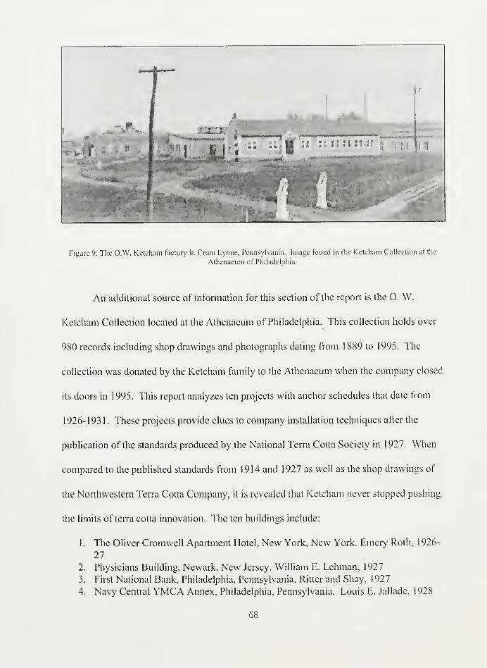
Figure 9: The O.W. Ketcham factory in Crum Lynne, Pennsylvania. Image found in the Ketcham Collection at the
Athenaeum of Philadelphia.
An additional source of information for this section of the report is the O. W.
Ketcham Collection located at the Athenaeum of Philadelphia. This collection holds over
980 records including shop drawings and photographs dating from 1889 to 1995. The
collection was donated by the Ketcham family to the Athenaeum when the company closed
its doors in 1995. This report analyzes ten projects with anchor schedules that date from
1926-193 1 . These projects provide clues to company installation techniques after the
publication of the standards produced by the National Terra Cotta Society in 1927. When
compared to the published standards from 1914 and 1927 as well as the shop drawings of
the Northwestern Terra Cotta Company, it is revealed that Ketcham never stopped pushing
the limits of terra cotta innovation. The ten buildings include:
1
.
The Oliver Cromwell Apartment Hotel, New York, New York. Emery Roth, 1926-
27
2. Physicians Building, Newark, New Jersey. William E. Lehman, 1927
3. First National Bank, Philadelphia, Pennsylvania. Ritter and Shay, 1927
4. Navy Central YMCA Annex, Philadelphia, Pennsylvania. Louis E. Jallade, 1928
68


5. West Side YMCA and Addition, New York, New York. Dwight James Baum,
1929-1930
6. Aldine Trust, Philadelphia, Pennsylvania. Arthur W. Hall, 1929.
7. Temple Israel, Lawrence, Long Island, New York. S. Brian Boylinson, 1930
8. Mother House, Sisters of Christian Charity, Mendham, New Jersey. Robert J.
Reiley, 1930-31
9. Market Street National Bank, Philadelphia, Pennsylvania. Ritter and Shay, 1930
10. Redemptorist Father's Community House, Washington, DC. Anthony F. A.
Schmitt, 1932
The O.W. Ketcham Terra Cotta Works was one of the smaller manufacturers but it
was well known for its vibrant glazing. Ketcham began his career as a building materials
distributor for such firms as Boston Terra Cotta, Fiske, Homes and Co., the Grueby Faience
Company, the Excelsior Terra Cotta Company, and the Pennsylvania Enameled Brick
Company. In 1895, he opened the O. W. Ketcham sales office in the Philadelphia
Builder's Exchange.169
Through his dealings, he realized that there was more demand for
terra cotta than there were suppliers. In 1906, he opened his own plant in Crum Lynne,
located southwest of Philadelphia on the Pennsylvania Railroad. He hired ceramicist
William Stephani, and together they, "developed glazing techniques that later became
identifying characteristics of the Ketcham plant's highly regarded polychrome work."
The clay body of the Ketcham Company consisted of approximately 33% grog from
Western Pennsylvania or Ohio, 20% Darlington Clay from Western Pennsylvania, 30%
Perrines Clay from Perth Amboy, NY, and 17% from Maryland including Campbell Dark
Red for red body.
169"Philadelphia," The Brickbuilder 4, no. 9 (1895): 199.
170Barton, "O. W. Ketcham Terra Cotta: Reflections on an Industry in Chaos after World War Two,'
12.
171Ibid.- 13.
69


In 1913, seven years after its inception, the company reported $95,475 in
contracts.172
The Ketcham Company was a founding member of the National Terra Cotta
Society and participated in the joint efforts of the organization to promote the industry. By
the 1960s, however, the demand for architectural terra cotta was in sharp decline and the
company was forced to rely on its brick and tile division. By 1995, sales were so low that
the company closed its doors for good.
Anchors
The use of anchors contributed to the success of terra cotta construction in the early
twentieth century. They secured blocks to each other as well as to the steel frame to create
a unified skin for a building. With advanced understanding of the steel frame, engineers
relied on anchors to compensate for thermal movement and load deflection in buildings.
Anchors are defined as horizontal straps tie the piece of terra cotta to the body of the steel
frame. The terra cotta is usually grooved at the top to hold the "J" or "Z" shape piece. The
simplest of anchors includes the "Z" strap which was partially embedded in the back-up
wall, either brick or concrete, and hooked into a recessed groove or hole in the terra cotta
block.
172Comparative Recapitulation Sheet: Reports of Orders (National Terra Cotta Society, New York,
1913)
70

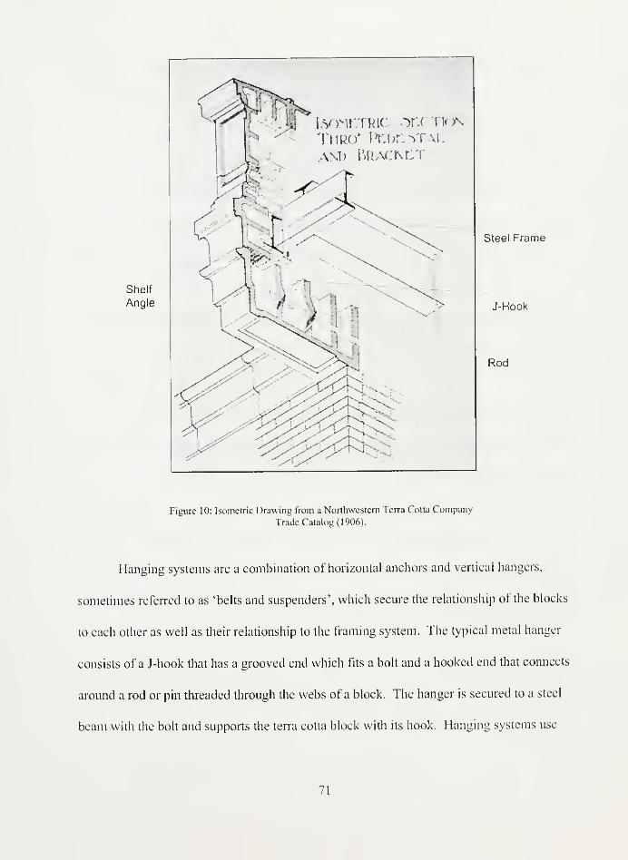
Shelf
Angle
isometric sectiontmro" pede5taland Bracm:t
-
Steel Frame
J-Hook
Rod
Figure 10: Isometric Drawing from a Northwestern Terra Cotta Company
Trade Catalog (1906).
Hanging systems are a combination of horizontal anchors and vertical hangers,
sometimes referred to as 'belts and suspenders', which secure the relationship of the blocks
to each other as well as their relationship to the framing system. The typical metal hanger
consists of a J-hook that has a grooved end which fits a bolt and a hooked end that connects
around a rod or pin threaded through the webs of a block. The hanger is secured to a steel
beam with the bolt and supports the terra cotta block with its hook. Hanging systems use
71


anchors and hangers in different configurations with the use of clips, clamps, plates, pins,
and rods to secure the terra cotta block to the steel beams.
Of these pieces, the most versatile in terra cotta construction is the clip. It attaches
to a steel member by overhanging one its flanges and provides a support base for a hanger.
By bolting the hanger to the clip, the steel member does not have to be pierced and its
structural integrity remains intact. The clip allows for adjustable construction which, at the
time, was necessary to compensate for irregular dimension of the structural steel.173
With
further knowledge of the material in the 1920s, it became evident that adjustable
construction was necessary for the material to withstand thermal changes and load
variations. Clips proved indispensable at a time when steel framing plans and terra cotta
installation plans did not always match.
Before standardization in 1914, manufacturers adjusted to the transition to the steel
frame by implementing these complicated hanging systems. As discussed in chapter three,
iron contractors and terra cotta contractors often operated independently at different phases
of the construction process. Their lack of communication frequently called for an
adjustment to either the framing plan or the design of the terra cotta pieces. The versatility
of the hanging system configuration made such adjustments easier to implement. Thomas
Cusack elucidates such a situation in lintel construction in a Brickbuilder article from 1898.
3Society, Architectural Terra Cotta: Standard Construction, 70.
72


Fin. ;o.
Figure 1 1 : Three iron beam installation variations from The Brickbuilder ( 1 8981. Notice the
different shapes of the terra cotta blocks made to fit the iron beams.
Drawing A illustrates an arbitrary placement of the I-beam at the lintel. This
configuration requires cutting the back edge of the terra cotta block to receive the beam,
yet, reduces support of the lintel and the cornice above. Drawing B calls for adjusting the
steel plan to raise the I-beam to directly support the cornice without weakening the blocks
below. Drawing C illustrates how the terra cotta must be altered if the steel is required to
stay in place. Cusack explains:
If, for any reason, the relative positions of I-beam and of lintel could not be altered,
then a channel might be substituted, and on it an "L" riveted at any desired height,
as at C. A lintel of this kind would be considered self-supporting up to 4', beyondwhich width of aperture it could be suspended by hangers, inserted in the mannerindicated in section...
73


While a new piece of terra cotta must be manufactured to fit the I-beam, the anchor
configuration ensures strength and durability to an otherwise objectionable design.
These hanging systems varied from manufacturer to manufacturer according to their
experience and training. By 1914, however, The National Terra Cotta Society attempted to
collect the best and most widely used examples of anchors for their publication
Architectural Terra Cotta: Standard Construction. Plate 70 arranged these details of
anchors, hangers, straps, and clips into sixteen figures.174
In 1927, the Society revised the
standards to reflect research data compiled by their new engineering department. The
section drawings changed dramatically with unfilled blocks, more anchors, and more steel
supports. Additionally, weep holes and proper Hashing techniques were to protect the
material from water damage. Yet, the new version of the anchor details changed only
slightly. Plate separators were introduced as a better way to brace the angles and steel
members. Clips and clamps were turned around so that the flat sides of the pieces fully
supported the units they were strengthening. These details illustrated in plate 67 were seen
as the best way to increase flexibility in construction while securing the blocks to the steel
or concrete frame.
174ibid.
74

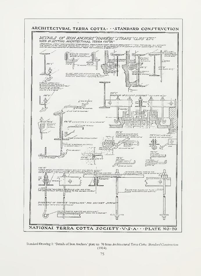
ARCHITECTVRAL TERRA COTTA- • 'STANDARD CON.TTRVCTION
DETAILS or /RONANCHORS "HANGERS "STRAPS "CLIPS "ETC
"
VJED INSETTING ARCHtTECTVRAJL TERRA COTTA "
A.*-./*Uif cnpaaawM* a-teuTwnm aau» IWMnrai tsaFuJiZir""fcT/UW" j-WJWj> *x- o*;sf<**tz> jv ax re- rrtemr csfAir AjwsveicsY v» WW
W'jV.Md'fi /IWKVWMir,
J?
.-Li""""
-J>it«<'./JVIfO*;>Mv fl&jU4 ,,vraAMClYiM^mxJ ntXM OtT 7/
f frrs Ar-j.vrtf
/'!<} "J/ Irrc <-< r/rro't
AWCS/9K /1W.- Ct-iWWXCS"
JMKMU
:%
fc_'./* In:., ».' /
WW
ET -0-
1A?.T O/- COX?Af-«.-j- wo'u'jjjj jj
"7>
5"
M
\jric-H-s
Jl ll /
re "MO&ILLION - ANt> &RACKET JVWOA
faVWNRX *>»W (*»i
<
TT ii
NATIONAX TERRA COTTA 50CIETY-V^-A- • -PLATE NCV70
Standard Drawing I: 'Details oflron Anchors' plate no. 70 torn Architectural Terra Cotta: Standard Constructic
(1914).
75

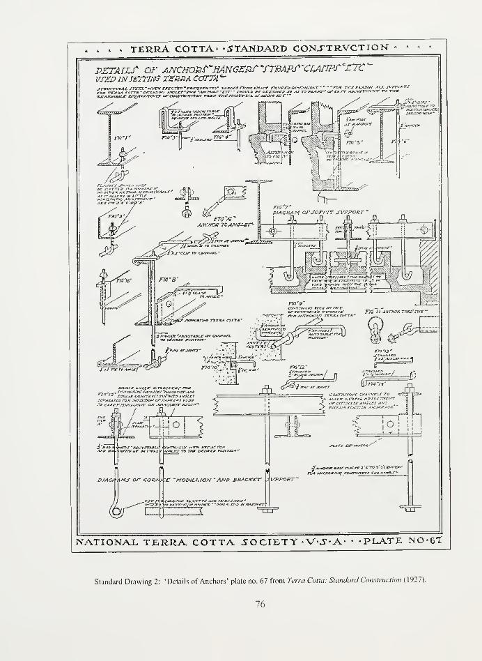
> * » TERRA COTTA' -STANDARD CONJTR.VCTION
VZTATLf or ANCHOR?'HANG£Rf*fTBAPS~CrtAnPT~£7Z'~
vrZP IN $£7TIN$ TEBHA COTTA"jrtr^rTVJLAt. srva.' wttvtf rjrrcTrp-rjwvi'Civrir' vajv^tj- rjeorr exact rxvxco Drxrzfjiox? ~
~ '~ra* tmv mcasw_ -m^. jvrrcxrs—*_ .— jftmrn a -nw-fuaMi AMjiAT'Baer *74ftc*aaJ* *rrr* " /oof!.* ,»* e>csfa**s?& j»^ro rsj^^rr of tAST AAWJTr-rzrxT ro TV**"
rtov
As /~ Aj-t-£*tj ortrrTLzr
f'jtfCzjr to Livvii
JO<§ » . -
rr$ az
*;awxr»rt
r/c'7'diagram orSomr svrponr~
#c : *
^
* J>T*VMnH* 7*C*AA COTTA'
fPTj'9'
/t*» MXWOttMfl rtTKA.4 CWTA '
"1
7>710 IJ jMmcuTrjurrtff
y sJ'rvrv ANtUf
povoLe Amu? ovn.QQxeJ>r rav. „ frrrwr.'MC cars*JCs,s~>Aio± ,<"zr-*>oria /3 J/HiLAM CQ.VJ-7Vtr77rW*>W7» 4MGUV
!^X"ACMrf£) j^p>t .ws.arTTo*' of."*.»#f*S ystrfl
n o/f/',w''i'rtvr cut .v.*cc*rr amew*
AXo
#Jgy^A^^.
pii^
5> CcvTVJ.-vovf CMA^-ve^J To
^ Ai.Lif z-tTzeAL. />Bxv^rrrr.'rr
*^ oro<*w»jx -(Njtr/ /i«JJ* rvrinJN rr.*rn'M Asxt*f-it-'~
iATS OT COCA
^ri
f -MODILL./ON • AND BRACKET iVTFORTJ,
ftATf CV.-i*A.'6<'~
'AS*Cf&e K4W rtA**v j.'t'ros'uf^^wAj*€MOwi*Jif exwrrj-rwr cw^^'^^^"^
"CO"
NATIONAL TERRA COTTA .SOCIETY-V-J-A' PLATE NO -61
Standard Drawing 2: 'Details of Anchors' plate no. 67 from Terra Cotla: Standard Construction (1927).
76


Figure 1 : Shows a J-hook, or hanger, inserted into a slotted flange of an I-beam secured
with a bolt and anchored by a rod. This configuration is only recommended when there is
no other alternative as it does not allow for horizontal adjustment.
Figure 2: This is similar to figure one except that the J-hook is inserted into a slotted L-
beam or angle.
Figure 3: This is a preferred alternative to slotting the steel member directly. 1/2" thick
and 2" wide clips support a 1/2" in diameter J-hook while attached to the front an angle.
The J-hook is secured to the clip by a bolt. This is a preferred configuration as it is
adjustable.
Figure 4: This configuration is similar to figure three except that the clip is attached to the
back of the angle.
Figure 5: While the first four examples show hanging configurations, figure five shows an
anchoring configuration. An anchor that is 1/2" in diameter is inserted into a slot in the
body of the I-beam and secured by a bolt. The other end is bent downward to connect to a
groove in the top of the terra cotta piece. An alternative configuration is suggested which
employs a continuous bar riveted to the outer side of the I-beam. A clamp is then used to
connect the terra cotta block with the I-beam. Both of these configurations are not
adjustable.
Figure 6: This is another alternative to figure five which uses a hanging system for
adjustability. A 1/2" thick clip that is 2" wide is attached to the flange of the I-beam and
supports a 1/2" hanger that is secured with a bolt.
Figure7: This hanging system is most often used for soffit construction. A Pin that is 5/8"
thick in diameter is threaded through the joint of two pieces of terra cotta. Two angles are
bolted together around 3/4" pipe separators. This allows enough space to thread through
the angles multiple 1/2" diameter J-hooks which are secured to the top of the angles with a
bolt. The J-hooks connect around the pins holding the terra cotta pieces in place. An
alternative to this configuration is to omit the pins by hooking the J-hooks into holes in
either end of the terra cotta blocks.
Figure 8 (1914): This is a complicated configuration that is most often used to support
cornices, lintels, or soffits. The primary structural beam is C-beam, or channel, that is
riveted to an angle with a 3/4" pipe separator. Threaded through the channel and angle is a
J-hook that is supported by a clip similar to figure six. The J-hook supports terra cotta
blocks that are pinned at the joints. The angle serves as a shelfjoint to support the terra
cotta blocks which are additionally anchored with clamps. Depending on the design, this
configuration can support a number of other anchors for the terra cotta blocks.
77

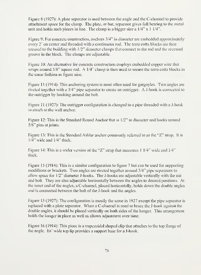
Figure 8 (1927): A plate separator is used between the angle and the C-channel to provide
attachment space for the clamp. The plate, or bar, separator gives full bearing to the metal
unit and holds such pieces in line. The clamp is a bigger size a 1/4" x 1 1/4".
Figure 9: For concrete construction, anchors 3/4" in diameter are embedded approximately
every 2' on center and threaded with a continuous rod. The terra cotta blocks are then
secured to the building with 1/2" diameter clamps that connect to the rod and the recessed
groove in the block. The clamps are adjustable.
Figure 10: An alternative for concrete construction employs embedded copper wire that
wraps around 5/8" square rod. A 1/4" clamp is then used to secure the terra cotta blocks in
the same fashion as figure nine.
Figure 11 (1914): This anchoring system is most often used for gargoyles. Two angles are
riveted together with a 3/4" pipe separator to create an outrigger. A J-hook is connected to
the outrigger by hooking around the bolt.
Figure 1 1 (1927): The outrigger configuration is changed to a pipe threaded with a J-hook
to attach to the wall anchor.
Figure 12: This is the Standard Round Anchor that is 1/2" in diameter and hooks around
5/8" pins at joints.
Figure 13: This is the Standard Ashlar anchor commonly referred to as the "Z" strap. It is
1/4" wide and 1/4" thick.
Figure 14: This is a wider version of the "Z" strap that measures 1 1/4" wide and 1/4"
thick.
Figure 15(1914): This is a similar configuration to figure 7 but can be used for supporting
modillions or brackets. Two angles are riveted together around 3/4" pipe separators to
allow space for 1/2" diameter J-hooks. The J-hooks are adjustable vertically with the nut
and bolt. They are also adjustable horizontally between the angles to desired positions. At
the inner end of the angles, a C-channel, placed horizontally, holds down the double angles
and is connected between the bolt of the J-hook and the angles.
Figure 15 (1927): The configuration is mostly the same in 1927 except the pipe separator is
replaced with a plate separator. When a C-channel is used to brace the J-hook against the
double angles, it should be placed vertically on both sides of the hanger. This arrangement
holds the hanger in place as well as allows adjustment over time.
Figure 16 (1914): This piece is a trapezoidal shaped clip that attaches to the top flange of
the angle. Its' wide top lip provides a support base for a J-hook.
78


Figure 16 (1927): The clip shape has been transformed from a trapezoid shape to an L-
shape. This new shape provides maximum spacing and counteracts the twisting of the
angles or hangers.5
The Northwestern Terra Cotta Company was one of the largest manufacturers of
terra cotta in the United States. As such, they were pioneers in terra cotta building
technology. A survey of iron schedules from ten projects from 1903-1915 reveal that the
configurations illustrated in the 1914 standards truly were a reflection ofcommon practice.
From the shop drawings examined, the Northwestern Terra Cotta Company often used
configurations similar to Figures 2, 4, 6, 7, and 8. Sometimes these hanging systems were
even used in tandem to provide extra support.
Yet, there are some differences between the standards and these early shop
drawings. For example, the use of slotted steel beams seems to dominate the construction
techniques whereas it is discouraged in the standards. The thicknesses of the anchors and
hangers range from project to project. Most noticeably, the drawings also revealed
different anchoring techniques not included in the 1914 standards.
" Tindall, "How to Prepare Project Specific Terra Cotta Specifications," 29. This information is
taken from the Common Clay chart that Tindall included in her article.
79

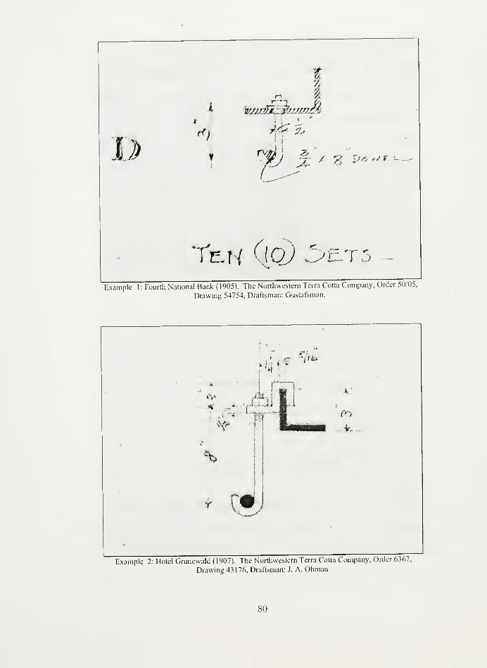
D
!
I ^r/m^k' mtrmrA
«) 7 r' 2j
jj %,?. *,* / F
«•-»-*
IE.H T5Example 1: Fourth National Bank (1905). The Northwestern Terra Cotta Company, Order 50/05,
Drawing 54754, Draftsman: Gustafsman.
if>
%
r \M /
Example 2: Hotel Grunewald (1907). The Northwestern Terra Cotta Company, Order 6367,
Drawing 43 176, Draftsman: J. A. Ohman
80


Example 1 shows a configuration similar to Figure 2 where the angle is slotted for
the hanger. This example is taken from Fourth National Bank built in 1905. The J-hook is
1/2" in diameter but the dowel, or pin, is V" in diameter which is thicker than the standard
pin at 1/2" in diameter. Example 2 illustrates the use of Figure 4 from the Hotel
Gninewald built in 1907. In this project, the clips are 1/2" thick and 2" wide just as in the
standards. The hangers, however, range from 3/8" to 1/2" in the various configurations.
•~£c+
i'**'*iJ
--- |
y
He £ r-~V
A3- ' ~
Example- 3: Founh Naaonal Bank (1905). The Northwestern Terra Cotta Company, Order 50/05.
Drawing 54754, Draftsman: Gustafsman
This example taken from the Fourth National Bank built in 1905 shows how the
different configurations were combined in common practice to provide more support. This
is a combination of Figure 2 and Figure 4 that was used to support the spandrel. Just as in
the standards, the hangers are lA" in diameter and the clips are 1/2" thick and 2" wide.
81


Again, the pins are 3/4" in diameter which is thicker than stipulated in the later standards.
These drawings prove that the 1914 Standards did reflect the practices of the leading
manufacturers but that there were many different ways to implement the basic patterns.
Example 4: Hotel Grunewald (1907). The Northwestern Terra Cotta Company,
Order 6367, Drawing 43176, Draftsman: J. A. Ohman
82


Example 5: Hotel Grunewald (1907). The Northwestern Terra Cotta
Company, Order 6367, Drawing 43 176, Draftsman: J. A. Ohman
Taken from the Hotel Grunewald from 1907, these examples show adaptations of
Figures 6 and 4, respectively. Both configurations use clips for versatility of construction.
By bending the hanger away from the steel beams, the hanging system attempts to provide
a stable fit between the frame and the terra cotta blocks. Through the standards'
illustrations, it is implied that hangers should be straight and the terra cotta blocks should
be manufactured to fit such a configuration properly.176 Most likely, these examples from
176Anchors are commonly bent throughout the standards but hangers are always straight.
83

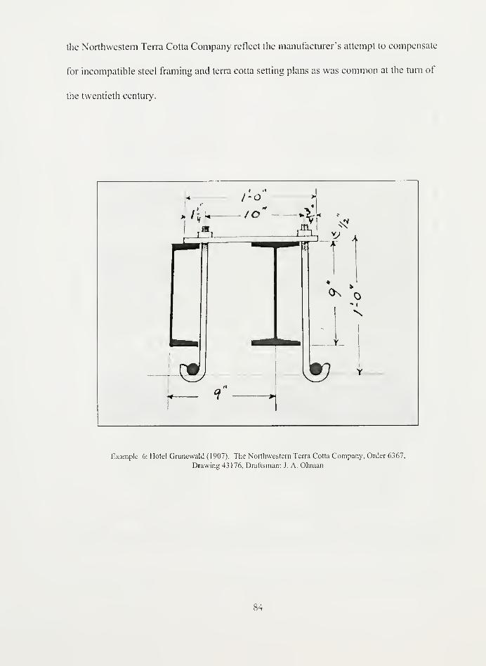
the Northwestern Terra Cotta Company reflect the manufacturer's attempt to compensate
for incompatible steel framing and terra cotta setting plans as was common at the turn of
the twentieth century.
Example 6: Hotel Grunewald (1907). The Northwestern Terra Cotta Company, Order 6367,
Drawing 43176, Draftsman: J. A. Ohman
84
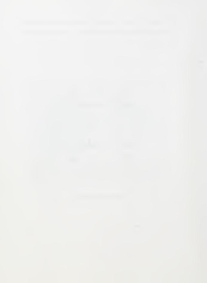

ARCHITECTVRAL TERRA COTTA- • -STANDARD CONJTRVCTION
LINTELS AND SOFFITSVARIOVS METHODS OF*
yVPFO/ST ANU ANCHORAGE
scale' out:Ant> oru'HAi.r wcmss couu.s <v/i'r'oor J
, - , r~ y,—
—
— ' r. . '—
i
WWmm
-n!
mmm
~H
^r""\
SECTION >-... 1 onf7 -*vc/./v:4'A .
NATIONAX TERRA COTTA SO CIETY •V-J1
- A- • -PLATE NO-35
Standard Drawing 3: Taken from 'Lintels and Soffits' plate no. 35 in Architectural Terra Cutta: Standard Construction
(1914).
85

The shop drawings from the Northwestern Terra Cotta Company reveal how plates
and clips could be used to extend the support of the steel framing members. Example 6,
taken from the iron schedule of the 1907 Hotel Grunewald, illustrates a plate resting on top
of a C-channel and an I-beam while supporting two J-hook hangers. The plate measures
1/2" thick and 2" wide while the J-hooks, secured by 3/4" diameter pins, range from 3/8" to
1/2" in diameter. The Northwest Terra Cotta Company often used this type of
configuration to support a soffit or lintel. While this alternative hanging system is not
included in the 1914 standards anchor illustrations, it is used in several section drawings
throughout the rest of the book. Plate 35, in particular, details that the bar, or plate, should
be 1/2" thick and 2" wide while the J-hooks should be 1/2" in diameter and connect to 5/8"
diameter pins in the joints.
It seems risky to secure lintels with bars that are not riveted or clipped to the steel
frame. If the lip of the bar or flange of the steel beam were exposed to water, rust
expansion and flaking could seriously undermine the strength of the configuration. If the
metal supports failed, the terra cotta would rely on the strength of the mortar joint and pin.
This type of situation could cause serious injuries to pedestrians walking below as pieces of
the soffit or lintel fall to the sidewalk. Yet even with such risks, it seems to have been
accepted common practice as it also appears in the 1927 revisions to the Standards.
86


t ". '/
I J If
>•>-
V
7
*L
5w 5iZC Pnmor oiiP 1
Example 7: City Hall, Chicago (1909). Northwestern Terra Cotta Company. Order
9001, Drawing 58308, Draftsman: Poulson
Shop drawings from Holabird and Roche's City Hall in Chicago from 1909 indicate
the Northwestern Terra Cotta Company developed a new clip to support a J-hook. This
clip retains the same dimension as those previously used at 1/2" thick and 2" wide. A 5/8"
diameter hole is made on the top of the clip to receive the J-hook. While one edge of the
clip is hooked around the flange of an angle, the other edge returns with an open-ended
5/8" slot to brace the J-hook to the angle. This design does not appear in the 1914
Standards, but figure 16 illustrates a similar piece that supports a J-hook adjacent to the
87
angle. Perhaps this clip construction used by the Northwestern Terra Cotta Company
prompted the National Terra Cotta Society to include this clip type in the Standards.
The O.W. Ketcham shop drawings reveal anchor details that indicate an
understanding of the standards but are widely adapted to fit individual projects. The sizes
for the metal pieces still vary from project to project but fall within the range of both the
1923 specifications and the 1927 standards. As with the Northwestern Terra Cotta
Company, some of the configurations are used directly while others are used in
combination to attain the desired strength. Yet, Ketcham deviates from the standards by
using bronze, chain, and other anchorage innovations to secure the terra cotta.
While the Northwestern Terra Cotta Company used Figures 2, 4, 6, 7, and 8 most
frequently, Ketcham used Figures 15, 16, as well as 2, 4, and 6. In both companies, the clip
is used consistently. Just as in the past, after 1927 the clip, used in Figures 1-4, 6-8 and 16,
provided easy installation that allowed for movement over time and was adjustable in the
field to adapt to change orders during construction. Figures 6, 7, and 8 as well as 1 5, are
hanging techniques which, despite the increased use of shelf angles and wall anchors, were
still seen in 1927 as an effective support mechanism. One of the differences between the
two companies is that Ketcham uses more arrangements adjusted for concrete construction.
This indicates the shift in technology from 1914 to 1927. The concrete industry begins to
take shape during this time as is indicated in the Standards in Plate 27, "This plate covers
only the construction anchorage and jointing of terra cotta. The engineering problems of
reinforced concrete are not especially considered. The terra cotta can be made to suit any


,,177such particular requirement." With concrete, the anchorage becomes simpler as more
pieces can simply be embedded into the material.
Example 8: Market Street National Bank (1930). O. W. Ketcham
Terra Cotta Works, Order 2220, Drawing 16, Draftsman: n/a..
Society, Terra Cotta: Standard Construction.
89


JJ
7
i
r
Fv.o >&^I
1-01
4
(..,-h
lO
I"- n
r
4-
sUr
I
fl
>
£-o"
\\.
U2
fig) Ifen
i
-2:
_i i_
- Fin.
Example 9: Navy Annex Y. M. C. A. (1928). O. W. Ketcham Terra Cotta
Works, Order 2091, Drawing 5, Draftsman: Naugle.
This example from the Market Street National Bank in Philadelphia (1930) shows a
clip arrangement similar to Figure 4 from the standards. The clip size is much wider and
thinner than the standard at 4"x 3/8." Also, the clip extends the 3" length of the angle.
This practice is similar to idea behind the plate separator in that the full extension of the
clip is fully supported against the length of the angle to prevent twisting. This is certainly
an improvement over the 1914 standards. Despite the pervasiveness of the clip, slotted
angles were still being used even 1927. Example 9 from the Navy Central YMCA Annex
90


in 1928 shows the hanging of a soffit with a J-hook supported by an angle. The practice of
slotting iron beams, while discouraged, proves to have been widely used by the terra cotta
manufacturers.
Example 10: Market Street National Bank (1930). O. W. Ketcham Terra Cotta Works, Order 2220, Drawing 12x,
Draftsman: n/a.
91

*»


steel beam. In this case, also from the Market Street National Bank, the 1/2" hanger is
supported by a 2" x 3/8" clip that is embedded into the wall.
i> U»1" VHi .
1
d•« i^4
* 4.
Example 12: Market Street National Bank (1930). O. W. Ketcham Terra
Cotta Works, Order 2220, Drawing 12x, Draftsman: n/a.
With a little creativity, some manufacturers were able to combine more than one
standard anchorage practice to achieve a particular effect. In Example 12, Ketcham
combines the ubiquitous Figure 2 with the more complicated Figure 7 to achieve soffit
support. Here, a double angle is bolted to a T-beam with eye-bolts that also serve as
hangers. In all of these scenarios, the Ketcham Terra Cotta Works was able to take the
93


principles outlined in the standards -adjustability, strength -and use the anchorage to fit the
individual project.
T
i
a
i
£3
Ipffi
—
M
fa
•HI
J L
I
"*
®
£ OS- &
1 G>nT >E
JL
A i
Example 13: Market Street National Bank (1930). O. W. Ketcham
Terra Cotta Works. Order 2220, Drawing lx, Draftsman: Moore.
Concrete construction used steel members as reinforcement for the framing system.
The anchor system, while dependent on the combined strength of the steel and the concrete,
was able to brace flat surfaces against the concrete edge. So in Example 13, the clip is
anchored to a threaded eye bolt that is set in the concrete around the flange of the I-beam.
The flat edge of the clip is braced against the edge of the concrete and projects slightly to
94


support a J-hook that holds the terra cotta in place. Such a type of construction was seen as
reducing twisting in the anchorage system. It was not used in the ca. 1914 drawings of the
Northwestern Terra Cotta Company indicating that its inclusion in the standards was a
response to common failures.
KJ


.4
Q&M ^Jf^f
/ & pott. 2%, Uff}
tortZE fa ^|| ,^j
/$
Example 15: West Side Y. M. C. A (1929-1930). O. W. Ketcham Terra Cotta Works, Order
2142, Drawing Sections A-Z and AA-AW, Draftsman: Roger.
96
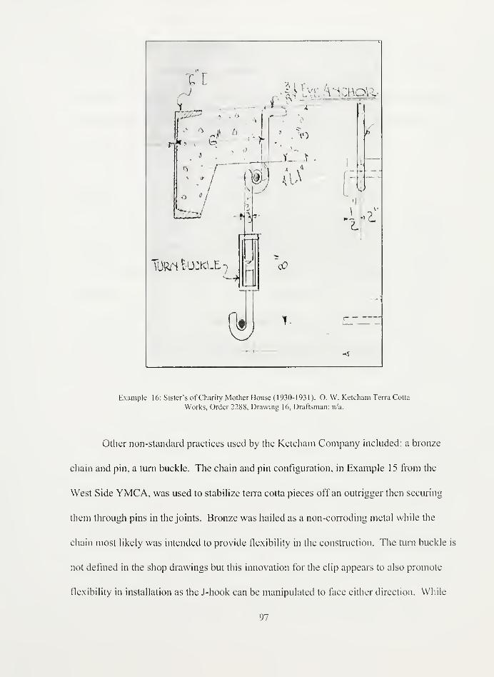
n,Mh\ \ scroti
-
av 1>
4,
^
TORfi Buckle-•--
>
•. to
.4
] fHf/
acO
ni
17
i .?"V
Example 16: Sister's of Charity Mother House (1930-1931). O. W. Ketcham Terra Cotta
Works, Order 2288, Drawing 16, Draftsman: n/a.
Other non-standard practices used by the Ketcham Company included: a bronze
chain and pin, a turn buckle. The chain and pin configuration, in Example 15 from the
West Side YMCA, was used to stabilize terra cotta pieces off an outrigger then securing
them through pins in the joints. Bronze was hailed as a non-corroding metal while the
chain most likely was intended to provide flexibility in the construction. The turn buckle is
not defined in the shop drawings but this innovation for the clip appears to also promote
flexibility in installation as the J-hook can be manipulated to face either direction. While
97


anchoring systems must always allow for movement over time, the buckle, as seen in
Example 16 from the Sister's of Charity Mother House, seems to act as twist control for the
J-hooks that are screwed into it. If screwed in correctly, the turn buckle seems to allow for
movement of the J-hook while maintaining the strength of the connection between the terra
cotta block and the back-up wall.
Cornices
The construction of terra cotta cornices involves some of the most intricate hanging
systems to accommodate multiple projections and often highly ornate terra cotta sculpture.
Many of the anchoring and hanging techniques outlined in the previous section were used
simultaneously to provide the right support for the terra cotta blocks. Anchors, rods, and
pins were used to hold the terra cotta courses to the steel frame while double angles, T-
beams, and C-channels were used as outriggers for the projecting courses. J-hooks, clips,
and plates were used to hang soffits from these outriggers. Warren notes, ".. .wherever iron
is used for tying the cornice to the walls it is necessary to determine the method of
anchoring before the pieces are molded, as in manufacturing them holes or slots must be
made for inserting the beams, rods and anchors."I7S
The cornice was the most important
terra cotta element to secure on a building because if the anchorage failed, its pieces had the
farthest to fall. The consequences of such a failure jeopardizes the safety of pedestrians
walking below let alone the damage to the building itself.
At the turn of the twentieth century, the skyscraper cornice was equivalent to the
capital of the ancient Greek column. This crowning element, however, was also the most
nWarren, "Notes on the Standard Form of Specifications for Architectural Terra Cotta." 14.
98


susceptible to water damage. Improper roof drainage or drainage within the terra cotta
blocks themselves exposes the iron hanging systems to water, therefore causing corrosion
in the form of rust. This can cause cracking in the terra cotta blocks as the rust expands
making the intricate hanging system even more susceptible to water infiltration. The
stabilization techniques for deteriorated cornices vary on the type of cornice construction,
the system of anchorage used, and the extent of deterioration. An analysis of the shop
drawing cornices provides insight into one of these elements, the system of anchorage. The
following examples of cornices from the Northwestern Terra Cotta Company and the O.
W. Ketcham Terra Cotta Works illustrate the variability in construction both before and
after the standards were published.
.1, " '.a /
\'iii\/4: ;'
'•/
;
'i' /fr.
•
Example 17: a) Court House, Greenville (1903). Northwestern Terra Cotta Company, Order
317/1903, Drawing 30745, Draftsman: Markle. b) U. S. Post Office, Greenville (1903). Northwestern
Terra Cotta Company, Order 317/1903, Drawing 30520, Draftsman: Markle.
See the case study on the Land Title Building, Philadelphia, PA. Jeffery S. Levine, "Stabilization
and Repair of a Historic Terra Cotta Cornice," Presentation Tech Notes: Masonry, no. 2 (199 1).
99


• 'STANDARD CONXTRVCTION
I
MODILUON CORNIC£YtlTHWT GVTTZP.
'
snot/UK temx» otsvppourAra> /VKiKiiAoi:
"
LApjoirmriG of WASH
'
sotTir co/irrk-wnofj •
4 WWWi
rZCT/ON TtlKO'COJL'NlfcE "&
'
U*U r; .A\\ff M
Standard Drawing 4: Taken from 'Modillion Cornice without Gutter'
plate no. 23 in Architectural Terra Cotta: Standard Construction
(1914).
The bracing structure in the modillion cornice illustration from the 1914 standards
consists of 3" x 3" double angles that serve as an outrigger for the modillion soffit. This
outrigger is secured to the steel frame of the building a few courses below with a bolted
100

anchor rod. The modillion course as well as the course above it is supported by anchors
that connect to the outrigger. The course above the modillions is pinned together at the
joints. An anchor wraps around the joint pin and connects around the pipe separator
between the double angles of the outrigger. The modillion soffit is hung from the outrigger
in a Figure 15 configuration with a J-hook that connects to pins in the joints of the blocks.
Every course below the soffit is back-filled with mortar and some courses are anchored to
the back up wall. In the Northwestern Terra Cotta Company shop drawing of the
Greenville U.S. Post Office (1903) cornice, the soffit is not as large and ornate as the
standards' cornice but the construction is identical.
The consequences of back-filling the terra cotta blocks include excess weight,
cracking, and low strength. In the early twentieth century, light weight back-filling
materials such as mortar breeze, or even mortar with wood shavings, often expanded when
wet. This caused pressure build-up inside the voids of the blocks and resulted in stress
cracking. As the cracking became worse, more water infiltrated the block, seeped through
the porous mortar, and began to corrode the unprotected iron anchors.18 An additional
problem with back-filling the terra cotta with such inferior mortars was the loss of support
for the anchor straps. In the Land Title Trust Building in Philadelphia, the pull-out test for
the replacement anchors revealed that the mortar had only a 60 psi reading when 500 to
1800 psi was desirable. Not only is this kind of anchorage system vulnerable from
cracking and corrosion, but it is also susceptible to complete detachment from the building
suJohn Fidler, "The Conservation of Architectural Terra Cotta and Faience," Friends of Terra Cotta
Newsletter 3, no. 1 (1983): 12.
101

frame. For this reason, the standards illustrate all anchors firmly embedded into the brick
back-up wall and hooked into a web of the terra cotta block.
JEf.rriK\r 3£!oanwam
;qf?)—
*-l| i[
_ir?r~rT'"S~
i-i! v-<'~
^3?ir:^riij"j'.;
: ^!ivi:
>; :'•..
j
f^j
Standard Drawing 5: Taken from 'Cornice with Balustrade' plate no. 26 in Architectural Tern: Cotta:
Standard Construction (1914).
102


Example 18: Le Moyne Public School (1915). Northwestern Terra Cotta Company, Order 151
Drawing 9813, Draftsman: ASG
These details illustrate a soffit section of a cornice. The terra cotta blocks depend
on the steel beam configuration for support. In the example from the 1914 standards, a
steel channel is placed in front of an I-beam. The face blocks are anchored to the C-
channel with standard Figure 12 anchors. Additionally, an angle is bolted to the bottom of
the C-channel and serves as shelf support for the block above. The comer block where the
soffit returns underneath the steel frame is hung from the shelf angle in a Figure 2
configuration with a J-hook. The soffit itself is hung with a J-hook which is bolted to a
plate that spans the C-channel and the I-beam. All of the blocks that comprise the soffit are
secured together with pins at the joints. The hangers connected to the I-beam support
additional soffit pieces.
103


In the example from the Northwestern Terra Cotta Company shop drawing for the
Curry Building (1915), the soffit hanging system exhibits similar construction as the 1914
standards. This example is a smaller soffit than illustrated in the standards, therefore the
steel support beams consist of two C-channels facing each other. The corner block is
supported in the exact same configuration with the shelf angle. The soffit block is hung
with a J-hook that is bolted to a plate that spans the tops of the C-channels. The wall block
of the soffit is hung in the same manner as the comer block. All of the blocks of the soffit
are secured to each other with pins in the joints.
- -.,-
:
:
'" ""'-..'. !:
- ,. I^•0
PLAN OF COX/J/C£"<**'* -iookinc, vp'
ELEVATION' sjzct/on rmbcoanxx]
Standard Drawing 6: Taken from 'Modillion Cornice' plate no. 22 in Architectural Terra Cotta:
Standard Construction (1914).
104


«
i -
' -iI
.X»
I«
?r
'*,
=3_
—
mi
Example 19: Fourth National Bank (1905). Northwestern Terra Cotta Company, Order 50/05,
Drawing 34297, Draftsman: Reading.
While the first few examples from the Northwestern Terra Cotta Company illustrate
the ideas published by the National Terra Cotta Society fairly closely, other examples from
the shop drawings reveal similar ideas but different executions. One example in particular
is from the Fourth National Bank Building (1905). The shop drawings indicate more iron
beams are necessary to support the different courses of the cornice. The 1914 standards
suggest using an I-beam outrigger to support the top course that projects the furthest out.
To support the outrigger, a diagonal I-beam is riveted to the outrigger and the I-beam
embedded in the building column to form a steel bracket. Pipes, anchors, and J-hooks are
then used to support the blocks.
105


In the Fourth National Bank Building, the top course of the cornice is framed in the
same way as the standards with a series of J-hooks to secure the brackets. Instead of the
outrigger being support by the diagonal I-beam, it is supported by two I-beams running
perpendicular to it. The course below the brackets is anchored to two C-channels. An
angle attached to the lower part of one C-channel cuts into the webs of the blocks and
serves as a shelf angle for an un-anchored course. This is an important distinction from the
1914 standards. The lack of shelf angles has proven to be one of the most problematic
elements of terra cotta construction from this era. For this particular project, the
Northwestern Terra Cotta Company seems to have been in the forefront of construction
technology for terra cotta as shelf angles were omitted from the 1914 model of cornice
construction.
A common theme in the deterioration problems of terra cotta construction is excess
pressure build-up due to rigid construction. Shelf angles are intended to cany loads at each
floor level and relieve undue stress on the terra cotta. Conservators have discovered that
even when buildings are constructed with shelf angles, however, the stress problem is not
always solved. Expansion joints, rarely included in historic terra cotta construction, below
the shelf angle are necessary to allow the building to move with thermal expansion or wind
loads. Indications of shelf angle problems include: buckling, cracking, and partial loss at
the joints.L
Another problem with shelf angles in construction is their placement in the
wall. Modern terra cotta manufacturers, the Boston Valley Terra Cotta Company, specify
that all shelf angles should be placed at the joints of the terra cotta blocks to protect the
C.L. Searls and S.E. Thomasen, "Repair of the Terra Cotta Facade of Atlanta City Hall," in
Structural Repair and Maintenance ofHistorical Buildings li: Proceedings ofthe Second International
Conference Held in Seville, Spain, ed. Brebbia et al (Seville, Spain: May 14- 16, 1991), 250-53.
106

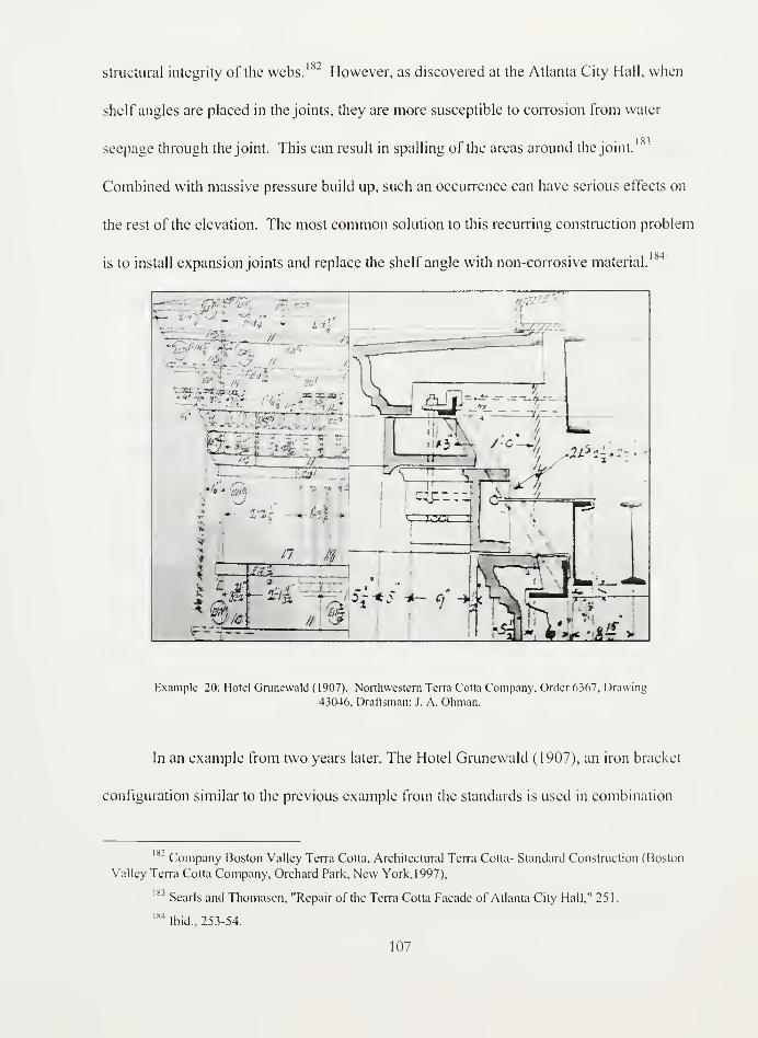
182structural integrity of the webs. " However, as discovered at the Atlanta City Hall, when
shelf angles are placed in the joints, they are more susceptible to corrosion from water
seepage through the joint. This can result in spalling of the areas around the joint.
Combined with massive pressure build up, such an occurrence can have serious effects on
the rest of the elevation. The most common solution to this recurring construction problem
is to install expansion joints and replace the shelf angle with non-corrosive material.
... _' '" '''
''
"I -.
V-Ll' '-: '-„• V—
l
'J~z'-< . „
"m/; 7T
••
~zr
- <* - Q-
'
• 1
^,
4 —
.
-rr
E3y. an 3
/74
-&L
Of* I
#
trffr"**4^^5 "'
a *&c . _
Example 20: Hotel Grunewald ( 1907). Northwestern Terra Cotta Company, Order 6367, Drawing
43046, Draftsman: J. A. Ohman.
In an example from two years later, The Hotel Grunewald (1907), an iron bracket
configuration similar to the previous example from the standards is used in combination
~ Company Boston Valley Terra Cotta, Architectural Terra Cotta- Standard Construction (Boston
Valley Terra Cotta Company, Orchard Park, New York, 1997),
s3Searls and Thomasen, "Repair of the Terra Cotta Facade of Atlanta City Hall," 251.
1S4Ibid., 253-54.
107


with extra steel beams. Instead of using an I-beam to support the top course of the cornice,
Northwestern specifies a double angle for support. The soffit course is hung from an angle
with a figure three anchoring arrangement using a clip and J-hook. The terra cotta blocks
are not tied directly to the diagonal angles but to the C-channels in the wall plane. This
indicates the diagonal bracket configuration was meant to stiffen the outrigger construction.
As with the Fourth National Bank Building, the lower course of the cornice is supported by
an angle that is bolted to the C-channel as a shelf support.
John Fidler explains, "It is especially true of extremely tall or large terra cotta
buildings that the semi-structural curtain walls tend to move differentially to the steel or
concrete frames to which they were fixed originally without the provision of adequate
movement joints." The iron bracket was initially installed as protection against the
overturning of the cornice construction. However, one component of this arrangement
often required the support of a hanger threaded through multiple courses of terra cotta webs
in order to obtain the best rigidity. Possibly due to its stiffness or maybe the loss of
integrity to the terra cotta, the iron bracket was phased out of the 1927 version of the
standards and replaced with more traditional horizontal outriggers.
(1
' Fidler, "The Conservation of Architectural Terra Cotta and Faience," 14.
S(' Harry Huridernian and Deborah Slaton, "Final Touch: Cornice Detail," APT Bulkim XX, no.
108


'* :"'''''"'
1
'I'.
/'/.,
^ i
.- 1 ^IX. "'•'
'-jl'-T 'l"'w 3 (
/ V < Q: /v/ /
I
/
Example 2 1 : Courthouse, Greenville (1903). Northwestern Terra Cotta Company, Order
317/1903, Drawing 30745, Draftsman: Markle.
The application of the Northwestern Terra Cotta Company's anchorage
experiments can be identified in the cornice drawings for the Greenville Courthouse
(1903). In every cornice example either from the shop drawings or the standards, the sotfit
of the cornice is suspended from an iron beam with a J-hook configuration. In Example 2 1
,
the soffit construction principle is unchanged but the mechanism is different. The J-hook is
hung from the I-beam with a metal harness that slips around the I-beam like a garter belt, to
borrow from the 'belt and suspenders' anchorage metaphor. This harness is then bolted to
an I-beam. Therein lays the difference between the accepted practice after 1914 and
before. Bolting the harness to the beam creates rigid structure that is unable to adjust to
movement within the building over time.
109

Adjustability is emphasized repeatedly in the anchorage details of the standards.
An indication that the anchorage system is inadequately adjusting to movement in the terra
cotta construction is the presence of vertical cracks. Such cracking is the result stresses due
1 87to thermal movement or water absorption.
I!.
t i
','.t.~ • >( - ;- •i
>i .
/„' i Vjv- -'- - /<v
,
:" -', W :'
^—=. L- rLl n-i
,. . .
^ r -M * • i:
'- . - i
cr
^_
,- n i
1
1
1
1' I
s»<
Example 22: Sister's of Charity Mother House (1930-1931). O. W.
Ketcham Terra Cotta Works, Order 2288, Drawing 11, Draftsman:
Moore.
Meadows, Historic Building Facades: A Manualfor Inspection and Rehabilitation, 65.
110


Standard Drawing 7: Taken from 'Louvered Dormer' plate no. 47 in Terra Cotta:
Standard Construction ( 1 927).
One of the more elaborate projects from the Ketcham examples includes the Mother
House for the Sisters of Christian Charity (1930-31). Ironically, this ornate pedimented
cornice uses a fairly simple anchoring system similar to the standards' 'Louvered Dormer'
example on Plate 47. In both examples, a pipe is threaded through the decorative final to
give the vulnerable piece proper anchorage. The pipe is not meant to protect the cornice
from water but flashing is specified where the parapet meets the wall line to prevent water
infiltration. Each terra cotta block is then tied to the back up brick wall with standard
111


Figure 13 anchors. The main difference between the two section drawings lays in the
indication of weep holes at drainage points. The 1927 standards strongly emphasized the
use of weep holes to prevent water from pooling within the blocks and cause failures. It is
possible that Ketcham used weep holes but did not include them in shop drawings
especially as flashing and drips are included throughout all the sample shop drawings.
-3
nt via
W
Tin*
. * wo tn * J;-.. v .!
»^ •
4-
f-«A jft'i.113'.
L-6 .
-ti
J
;. Bh^J^l- •
r-o
I itnn
I'iO »&•<
H
- :itoRfS
Example 23: Redemptorist Father's Community House (1932). O.
W. Ketcham Terra Cotta Works, Order 2348. Drawing 5, Draftsman:
Moore.


Standard Drawing 8: Taken from 'Cornice with Parapet' plate no. 3
1
in Terra Cotta: Standard Construction ( 1 927).
These examples display cornice section drawings for parapet construction. The
system of anchoring is fairly straightforward with every block tied to the back-up wall. It
is significant to note that the copings on the parapets from both examples are not anchored
but set in place by mortar. While it is not clearly visible in the Ketcham example from the
Redemptorist Father's Community House (1932), both drawings incorporate flashing at the
roof line with different techniques. The standard example extends the flashing underneath
113


the coping down to the roof line. To prevent water infiltration where the flashing sheets
come together, the sheets are folded over like a paper bag in roll joint. The flashing
technique of the Community House does not install flashing underneath the entire coping
of the parapet. Instead, a smaller piece of flashing wraps around the edge of the parapet
beneath the coping which extends over the piece of copper flashing at the roof line in a lap
joint. It this situation, it would have been prudent for the Ketcham Company to follow the
standards. Extending the flashing across the width of the coping prevents the saturation of
I CO
the wall below thus protecting the anchorage system from corrosion.
Eskesen explains faulty parapet construction:
It is obvious that there are instances where infiltration of water is caused by
defective architectural engineering, causing faulty structural conditions, for
instance, at the back of parapet walls, where the roofing material is joined to the
wall stmcture. If defective material is used, leaks will develop within two or three
years. This will also happen if good material is used improperly or if no flashing or
insufficient flashing is used. The roof becomes a reservoir from which water is
distributed into the exterior wall structure.I89
Indeed, conservators examining the cornice of the Land Title Trust Building in
Philadelphia, Pennsylvania, discovered that the primary reason for the terra cotta
deterioration and anchor corrosion was inadequate flashing at the roofline. New stainless
steel anchors had to be inserted through the face of the terra cotta blocks to stabilize the
stmcture.
Samuel Y. Harris, Building Pathology: Deterioration, Diagtiostics, and Intervention (New York:
John Wiley & Sons, 2001 ), 589-90.
189Eskesen, "Watertight Ten-a Cotta Construction," 159.
Levine, "Stabilization and Repair of a Historic Terra Cotta Cornice."
114

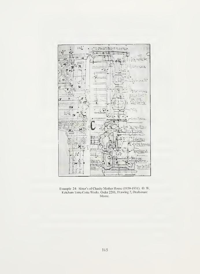
* 5•
=fS
ft E_ '-'-# i
IB - ?
at
- e=
t •-
*'. i I
'-'
MK,
J^*^
c* -^ - <lZL_LiXliii_i--•
-----
'
Example 24: Sister's of Charity Mother House (1930-1931). O. W.
Ketcham Terra Cotta Works, Order 2288, Drawing 2, Draftsman:
Moore.
115


s
innnnr^fnTiJLJUuLJLi ilL!
T^iHrfeaiVjaJii 1'^
(-.
Standard Drawing 9: Taken from 'Cornice with Balustrade' plate no. 26 in Terra Cotta: Standard
Construction (1927)
As a further example of the variety of work within one company, this section
drawing from the Mother House for the Sisters of Christian Charity (1930-3 1 ) illustrates
the standard method flashing a parapet wall. Example 24 and Standard Drawing 9 are
cornice sections with balustrades and soffits. The scale between the two examples is
slightly different but comparisons can be made regarding the soffit configurations. The
standard illustration uses a double J-hook configuration similar to the one discussed in
Example 6. The J-hooks are suspended from a C-channel and an I-beam to support the
soffit blocks. A third J-hook in a Figure 2 assembly off the shelf angle supports the comer
block of the soffit. In the Ketcham example, a different kind of double J-hook hanger is
used. Here, a Figure 3 clip resting on an angle bolted to the C-channel supports J-hooks
that secure two different soffit blocks. Additionally, the angle serves as a shelf support for
116


the block above it. The wall edge block of the soffit is supported by a turn buckle that
connects around a concrete eye-bolt. In the standard section drawing, the deeper soffit is
hung in a standard Figure 7 configuration. Once again, the terra cotta company has
deviated from the standards to accommodate project specific requirements.
This research into the shop drawing details of anchorage systems has revealed that
the NTCS standards did indeed evolve from common practice. The use of clips and slotted
angles seems to have been used widely for a considerable period. If one were to study the
standards as a guide, however, one would ignore the widely applied practice after 1914 and
1 927 of adapting the standards configurations to fit the design of a particular building. The
anchorage systems often were combined, inverted, and substituted to fit the steel frame and
the terra cotta block design. One of the most surprising discoveries is that even the
anchorage thicknesses, something that seems easily regulated, varied from project to
project. While most pieces measured within a small percentage of the desired size, there
was still a wide variety employed in terra cotta buildings.
Even though the standards were not followed as closely as one might expect, the
ideas implied in plates 70 and 67 -non-corrosive metal, adjustable construction, multiple
anchors -were followed fairly closely in the practices of the Northwestern Terra Cotta
Company and the O. W. Ketcham Terra Cotta Works. The shift of technology to including
new water protection techniques and concrete construction can most definitely be seen in
the shop drawings. In many ways, these shifts in technology can be traced through the use
of innovative new techniques that go beyond the understanding of the National Terra Cotta
Society at the time they produced the revisions to the Standards in 1927.
117

Conclusion
T_RRA/ _ O T T A / ANC_ORAG_
Like the dots and dashes of the Morse Code, the configurations of anchors appear at
first glance like an encrypted code on the terra cotta manufacturer's shop drawings. When
using the standards as a code breaker most of the construction message becomes clear but
additional information is required to fill in the gaps. As the analysis of the shop drawings
indicates, the terra cotta industiy was constantly evolving to adapt to new building
technologies. Unfortunately, what was specified on the shop drawings was not always
implemented during construction.191
On-site investigations provide the most conclusive
confirmation of the anchorage systems used within the building but can also be destructive
to original fabric. Using all three of these tools together -the standards, the shop drawings,
and site analysis -the conservator can decode the anchorage system of a particular project
and begin to translate the technology for modem use.
While the 'belt and suspenders' technique of securing terra cotta bocks to the steel
frame with anchors and hangers is no longer a modem construct, Architects, Engineers, and
Preservationists have to understand how the system worked, or didn't work, in order to
restore terra cotta buildings. In most cases, it is impractical and too costly to dismantle an
entire terra cotta facade, design a new engineering plan to anchor the existing blocks, and
the reconstruct the building.192
Instead, the conservation professionals have to implement a
91Deborah Slaton and Mark Robert Morden, "Issues in the Salvage and Reuse of Terra Cotta: Two
Case Studies," in Standardsfor Preservation and Rehabilitation, Astm Sip 1258, ed. S. J. Kelley (American
Society for Testing and Materials, 1996).
192Interview with Neal Quenzel, John Milner and Associates, March 25, 2003.
118


restoration plan that reinforces, by-passes, or replaces existing systems. Deborah Slaton
explains:
Where terra cotta units are removed and reinstalled in a new building facade, the
opportunity exists for redesign of details for better anchorage and flashing. The
reinstallation design and new anchorage should be adapted to accommodate the
existing terra cotta units wherever possible by conforming to the shapes, sizes, and
configuration of the existing units. If modifications to the existing units are
required to permit reinstallation, these should be made without intrusion to the
original appearance of the units.
Professionals with experience in terra cotta restoration claim the most common techniques
include reinforcing the structural system with new stainless steel anchors, by-passing the
steel frame system by installing new anchors into the back-up wall, or replacing the
insufficient shelf angles with stainless steel angles complete with expansion joints.
With the transition in building technology from load bearing structures to skeletal
steel frame structures, the terra cotta industry was forced to reassess anchor hardware,
water-tight construction, and material strength. The National Terra Cotta Society published
standards to aid architects and engineers with their designs for terra cotta buildings during
the transition in the early twentieth century. Standards and specifications were written to
facilitate communication between manufacturers, architects, and engineers so that the
material would be installed at its optimal performance. Today, the same structural
elements are being challenged in historic terra cotta buildings as the buildings deteriorate
from neglect or from the retrofitting of unsympathetic modem mechanical systems. The
NTCS standards and the specifications written during the age of terra cotta construction
193Slaton and Morden, "Issues in the Salvage and Reuse of Terra Cotta: Two Case Studies," 3 1 0.
194Interview with F. Neale Quenzel, A.I.A., Vice President at John Milner and Associates, 3/25/03;
Interview with Carl Baumert, E.N., Senior Consultant at Keast and Hood Engineering Company, 3/25/03;
Interview with Mary Oehrlein, A.I.A., Principal at Oehrlein and Associates, 3/26/03.
119

continue to aid an inter-disciplinary approach to addressing building problems. Architects,
Engineers and Preservationists must work together to decode the historic terra cotta
anchorage systems and ensure the building functions at optimum performance until the
next shift in building technology.
120


Appendix A: National Terra Cotta Society Members (1927)
121

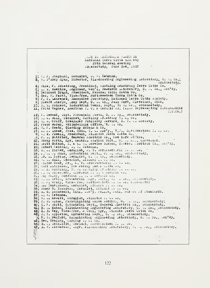
i.j! iw .iwioG.--.-— i : a-i>o: 26iiational .uin. *otta ;>oc. oty
-iUi Gjj.ornj. liaatifl/
-oi.enec tudy, Cuno 2-4, 1.^27
l; •: . i. Ctephaai, ^ori_iiat, u< B« Ketonam.8, 5, C'Arcy iiyan, Director, 111main sting inglneon ig ^jiboretory, S, ... Co.;
->eiio»i9C tady,
4; i'iios, ". Armstrong, rreaident, ^jijcung .iiutr^.; Xorro Cotta Co,6; -. a. Hawkins. -nglnaar, Can'i, lieaaarch ^bjrtiif;, C, ... Co., -vco'dy,
6; -o. orost Grant, Presided, i'ecorax iarrc Cotta Co,7; Geo. r. .-(.ckt, . iuo-:tb», iior timeatom lorro Cotta Co.S; ?, a, iAurance, itaoutlTO Couialary, iiatiooal ierru Co tt& j^oiotj,9; iioaerfl -juerpo, -amp £cpt, G. C. Co., Sola iark, Cxcvoland, CaiO,
1C; 2, r.. Joimaon, laduBtri&l Comxi, Copt,, 3; ... Co,, -cnecoctouy.11. irlti Wagner, xrcorlcan i. C. i v«rt.ic ^.o. (bxoo representing i;,di.iin.-.polie
C.C.Co.)it; •'. wermalc, -upt, i-.rcuui;. norka, G. -. CO,, oc.enectady,13; ^, o, dill. Ceramist, Coiiicxing ,.r_utro/;g i' . t. to,14; a. S, Oroff, iowepapcr -
Jublioity -arrlca, i. 2. C. oociuty,16; ;n;u Moraa, r'clxadelpula CXfiae, '8, -. -o.
16; *« <?i Keeth, Oloddiiig tfcBesii ft Co,17; ii, v. xucea, ires, iiati, I. C, ^ac'y., V..',, J.ri vsostarii i. ». Co.6; *, X, -mini, President, ..t.M.Uo iorrs Cotta Co.
..3; ?, *, fluttriok, General .iiaotric Co., low iork Ci.'lca.
£0. ioroy tfortA, iigr. Centrcx -itation iiopt., C. ... vs..
, Cxevex&j.d.21; -jcott Button, ». o. v, ^, oorvloo Sureau, Couarai xootric Co., ..c.:'jy.
22; .ooort ..atcr.a-, .< . n. Ketchsc,£3; c. ... iucker, vertiist, ,. . i. «rciiiti»cturfii J. .. -j.£4; .'-. -. liuujo, -.nduBtri&i i;o.,t,, C, ... -o,, ocj.i.j.i c t&dy.26; -*r. i<. !.£iYliie, ^arec;iot, o. . . >.o., -C:. jneottdj ,
26; . ... liuxi, .o.-L-iit, liidlcod .... Co,
27; -ui-tor Coor, Cr., K, 1. ->racitoe t^tx .. c . Co.£fi; .-.srl -.^tiiiueei., Jiub Csraoi -or. i. -. tta -j.29; -. -. Oor./nlxig, V. -• . »o. .".»i..£ ,.r ..t:j..,- .. -. .-.
30; .. i. xOuaopara, y^oriOiin .. - - v.orii.:.j.c ^o.3i; -
c.a; .-^iioy, Altarless ., -. - ».>r. lc ^j,
32; -. Hm Irwin, lii'juatriai .:^r . -opt., S. . Co., ..canootady.33. ... e, Crtdy, Vica-.raii. aortlrsaiitorn .. -. -o . (-..i-.o-ri)
34; -uo rourxiunuiii, wenaist, iiuaua -. .. -o
.
36; uoxer C, Eaoapoort, .or-; .ul, aSidlaiid .. -. oo.36; a. G. oo/iureoit, l>atx. Jic'j. .-on-a, fcatl, ^>ur >.•• J otsaiuiirde.
37; U. ". tlatciuuB.
5c; K, «• iiouatt, Coroaiat, AtxAUtie i. C« -J.29i «. v. oioan, /loodiigntlng ^aios -oCtlo^i, G, .. .... ^c^ijiioctidy;
40; C, i. -Cott, li.dudtrioi. i#pt,, Cu.iorax aucUit Co., ^Caonootudy.41 i B. '. iishau, liiuailQstiiis -ngii'.ooMr^ .-a&^retory, C. .. Co;, _c/.unact»dy
,
it. ii. S. ('«;, Vlao-.'roa. a Cor.l. Bgr., . t.....t& ierm vOtta Co.*fi C, l. i-pploton, induatricil Copt., u. ... UO», oonojiootudy
.
\; y. .'. . io.-.i..r'i, liiumliibtlug .nginaarxng uabora tor;, G. .. Co., ..cii'dy,
«£; Gao. Gregory, ^jzning i, v. Co,46; B. .. lUSuCilffo, .oriiiiit, ..ortrr-^a^ torn .. v. -o.
47» « '« Wckoraoa, -jigr. liiualaotiae ^aborator;, 3. •• -o., johoiioefcady,
122


• £ -
46; a. jcrutswlii. Goal, outdoor AfiV, Co., Cr±i.oi£0.
49; ~, w. Urocorj, »Jroeidui:t, Cjruir.g i. C. Co,
fcO; •% «. aatoa, C^ioi, Certaic M.T., iutA. iiuruou 01 ^Innthraa.
61; o, iidx«r, -.iigineor of otuidsrdu, .itxa;. tie i. C. Co.'
62; ueosr iattiicsar., Coroaiut, jo» ;oraoy Sena CoUo Co.
63; a. -,. voaattton, ^lrsctor oX «Ji«r., ileUonoX 2. C. jycioty.
64; ii, i'. i/oitOii. i'roslfiont, i. X. Areiutocturul X. C< to,
66; i'«tar C. Olaac, ireasuror & Sfliioroi. M&na^or, JjuUi ,«b«j' -. d« c»,
66; &• i>« 0*ar«, *>u?t, Certoiet, iraaorai. S« t»« Co."
67; ". -. »rigiit, laauatrisl ^agr. ^»Pt,» 0. -. Co,
68; «<Jalpii Hottiogef, Vioo-^rsi. iorth*06tarn i". c. ^o.
6S; Jack Curry, ££X, i«rre Cotta joitico Uuro6U, Chicago.
6C; -. ii. i'utaaa, iTiolicity iSgr., «tJ.oxitio 1'; C. »o,
61. to, £, Gatoe, African i. c« * C«reaie Co,
123


Appendix B: Correspondence and Advertisements
124

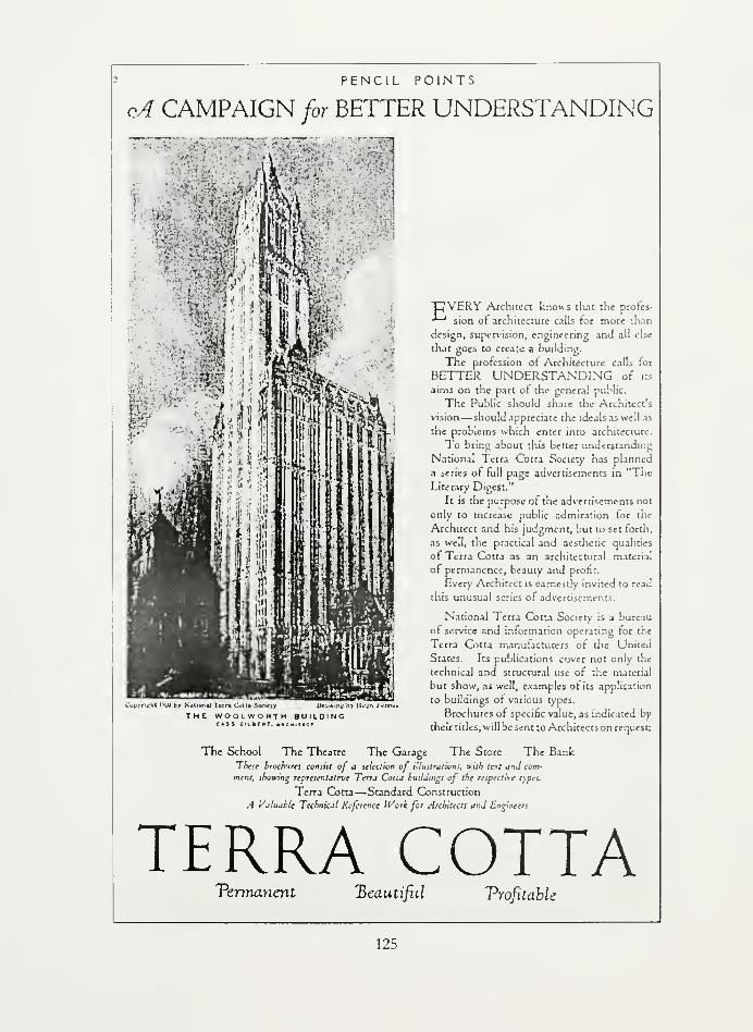
PENCIL POINTS
oA CAMPAIGN for BETTER UNDERSTANDING
CwpyritfM '•JU by National lerr* CvU» Soctciy Dm*THE WOOLWOHTH BUILDING
C*S» CultHT. MtHlTMV
"DVERV Architect knows that the protes-
-*-"' sion of architecture calls for more than
design, supervision, engineering and all else
that goes to create a building.
The profession of Architecture calls tor
BETTER UNDERSTANDING of its
aims on the part of the general public.
The Public should share the Architect's
vision— should appreciate the ideals as well as
the problems which enter into architecture.
To bring about this better understanding
National Terra Cotta Society has planned
a series of full page advertisements in "The
Literary Digest."
It is the purpose of the advertisements not
only to increase public admiration for the
Architect and his judgment, but to set forth,
as well, the practical and aesthetic qualities
of Terra Cotta as an architectural material
of permanence, beauty and profit.
Every Architect is earnestly invited to read
this unusual scries of advertisements.
National I erra Cotta Society is a bureau
of service and information operating for the
Terra Cotta manufacturers of the United
States. Its publications cover not only the
technical and structural use of the material
but show, as well, examples ot its application
to buildings of various types.
Brochures of specific value, as indicated by
their titles, will be sent to Architects on request:
The School The Theatre The Garage The Store The BankThese broch-ircs consul of a selection of illustrations, with text and com-
ment, thosvtng representative Terra Cotta buiUuigs of the respective types.
Terra Cotta— Standard Construction
A Valuable Technical Reference Work for Architects and Engineers
TERRA COTTAPermanent jBeauti/u Vrofitable
125


September 10, 1914.
ilr. 0. L. H. Wagner,Horthweetera Terra Cotta Company,
2525 Clybourn Avenue,Chicago, Illinois.
Dear Mx. Wi.n:-
I had a Tory delightful oonferenoe with Mr. 0.
Wenderoth, Supervising Irahlteot of the Treasury. He is a
soet estimable gentleman,- fair, square and businesslike,
-
and there la every reaeon for believing that, under hla ad-
ministration, Tery much of Government red tape, oharacterla-tlo of thla offloe In the paet, will be eliminated If Mr.
lenderotb. la given a good, fair ohanoe.
He frankly atated that, unless he oan get good arch-itectural terra ootta, he will use no architectural terra cot-ca. He appreolatea that thla material has many qualities when"well made, properly set and carefully polnte*!*, but he alsoknows that there are several qualities of ware on the market,
-
•good, bad and Indifferent,' and that, In the past, no way of
controlling a contractor In the selection of sub-cent ractorehas been possible so far as hla offloe Is concamed.
He finds that he cannot follow the rule of privatepraotltlcnors and specify the best companies by name; neitherdoes he feel at liberty, Just yet, to reserve the right to ap-prove the selected suo-oontraotor for arohlteotural terra oot-
ta. To do so, he says, would Inevitably result In a lot of
wire-pulling aa the part of rejected sub-oontractcra, and thiswould keep himself and hie offloe In hot water oontlnually.
For the present he desires a terra cotta specifica-tion very exacting In the matter of quality, yet fair ana reas-
onable for the first class manufacturer. If thla falls he willlimit the use of arohlteotural terra cotta unless some othermeans oan oe founo, by which only the beet quality of materialcan beoome part of hla construction. The difficulties of ex-actly working this out are rather numerous, tut here la an In-
stance In which in Important Government Department la greatly-leslrous of "restraining trade* by Uniting free and open co-pe-tition, ^e are writing you the substance of the interview as
regsris thla point and hope ycu may have aome practical sugges-tions to make.
In .the matter of models, Mr. Wenderoth was very reas-
onable, and i; will, I am sure, get together on a apoolf lcatlon
that will give more satisfactory reaulta than were obtainable In
the past. He still Insists, however, on all models of ornament
being made In Washington under his supervision, but It la very
probable that. In tha future, only units of ornament will be_
Tent to manufacturer, and all plain and moulded surfaces will be
made into models at manufacturer's shop. •
Before preparing the text of a suggested specif loatlon,
it was thought wise to lay out a plan, so tc speak, upon w.lloh
to build said soeolf lcatlon, and I u enclosing herewith an out-
line whlob ©ratenda to oover the ground fairly well. Pleaae
look this over, and if you have any suggestions tc make, let them
come along as early as ooselble. Hr, Wenderoth haB agreed, tan-
datively, to moat of the Items contained en •nolosad unoracte,1 though Mr. Clsen and I have an engagement with Ur. Wenderoth
;nd hie expert in Washington for next Wednesday to take up each
one of the oroposltions Item By item. In view of thla, I hope
to have In hand by next Tuesday, any suggestions you may ^.talre
to make.
Tours truly.
Assistant Secretary.
126


f. -.-. mi. ^i»u>4»r
. V. ESKEStN,^*<
ROOMS 002A.00Z9
TtLtrMONC1921 SRAMERCV
.J
w*LTfRoee«. iti v«( .Pt«irt«.
W. 0. GATES. S«««nrr
W. E. 06NNI5ON, 2«Vio«. Pm*>
National Terra Cotta Society 51, nd A1_ L
OrKICIAL COMMUNICATIONSMETROPOLITAN BUILDING
to New vohk orncc.
NEW YORK CITY
sngust 20, 1914
"ow York Architectural Terra Cctta "o.
401 Vernon Avonuu,
Lone Island City, H.T.
^ear 3ir:-
?hi3 office has recoivod fron the Treasury Der-artizor.t
at ',7asbJLntTton, coasuhicat ions as jer cc?ie3 attached hereto. This
is an important natter and it is very desirable that ~e van atton;rt
to standardize the processes roferred to by the S-orervisiris
Architect.
Vo therefore -.-.Tito to as:: that your Bonjaay, if it has
received 3inilar letters, refrain froa replying definitely thereto
lezcor/'t by vray of ac'/r.ov/l rlcenient ) until "o :^: Whip into shape
ruloo of yrccedure Which -.TOuld be mutually a-jreoabie to all -r^r^i^-
turers arid satisfactory ~c all coniorr.jd,
The Eastern Divisic^ will r^l:e z. dofir.ito roccr:-.er.dation lr.
thio ~tter with the r.ort fen days, end sac* will be submitted to the
lar-jer Co=C-.les ir. other ^ivisicr-S for cenorjJ. approval bofsro
trananission to T.'ashix^tcn .
'/ours truly
/Aiss'istor.t Cecrotary
'.'-./-
127


£. V LSttEbt*. T«.«y»(»
THOMAS'- A«M$T«iONG. 1»T V.CI P<t».i«*'
TELEPHONEf«2l CRAMCRCY
National Terra Cotta Society
METROPOLITAN BUILDING
NEW YORK CITY
AODHMSOrflCIAL COMMUNICATIONS
to Ntw vohk o^nce.
April 13th, 1915.
COHwr.
TO AGENTS REPRESENTINGTERRA COTTA MANUFACTURERS 57H3 ARE
MEMBERS 0? THE NATIONAL TERRA COTTA SOCIETY -'
fr1 H) (5) V
.•
Dear Sirsi-
Thij Society is sanding today to Agents representing Terra
Cctta "Janufaoturers who are members of this Society, one copy each of
.".rchiioctural Terra Cofcta, Brochure Series, Voluce 1, "The School";
Voluas 2, "The Theatre". All agents have previously receive:
"Standard Construction". Liku "Standard Construction", these no:.
Booklets ire For office use and general inforiatio!. of Agents, and
not for distribution.
All publications of the Society are distributed by a:-.i in
ihj nase of the Society frca its Executive Offices. Ag-jn-.j who ;we
sure that certain Architects, tamers or others car. :>..•.;: »ill make ;cod
ar.i valuable use c' this literature, should seni .-.aires, with facts, to
the Cospany they represent. Booklets -.Till be sent to the parti.
the facts justify and if the Coxpanies endorse fcbe application and send
saae to the Society; provided, of o-urse, that copies have not
previously been presented to sase parties. Those books are costly and
should be di stri '-<.'... ! cr.ly -hero they are likely to cake terra cotta
business
.
Your3 trul^7,*. y^ ...
Assistant Secrstary
128


>*• « taxiTwoi-o ClhNDOH
. C«Kla«M. <-aa*«u»t<
National Terra Cotta Society•dOxi sola vol*
t.c.TTon. METROPOLITAN BUILDINGTO N«*» TO"* Ornci
NEW YORK CITY
April 10th, 191G.
To the Members of the3atlonal Torra Cotta society
Dear Slra:- tawj-
The oosxoittee appointed at the December mooting of the Society toprepare a revision of the uniform contract roqueoto the members to furnishthe otomlttee with suggestions for ohangea In the present form. It la par-ticularly desired that they shall point out any provisions in the existing
form that are In any ray unsatisfactory.
At the December meeting there were acne ffuggostion3 :aade to theeffoot that a simple fora of acceptance might be used for orders snail Inamount. The oomulttee would ILko to havo the viow3 of tho aenbora on thispoint and asks that tliose wno are In favor of an aocafitance shall submita draft of a proposed fora.
The consnlttee would like to havo a reply from each rsenbor on thofollowing specific points In connection with ti;o fora of eatiriate blankadopted socio tine ago by the Society:
lat: Are you ualn,™ this standard fom?
2nd; If not. are you willir.g to do 30?
3rd: VThat ohangeo. If any, do you suggest In thoprooent fora?
4th: Do you think 15 would be a good thing toprint on tho blank substantially the fol-lowing: "Standard fora of outUaato blankado^tod by tho National Terra Cotta Society .'•
The ocsanittee would ooialdor it a favor if each monbor would supply a copyof their eutinata fom »a now used.
The oocmlttoe would aloo approciato an answer to tho following:.ire you generally using tho present standard fom of contract and If youare not using It plooae furnish a oopy of mtiat you usually use?
The committee haa received fom of agrooaont and eati-oato blankfrom Gladding, itcJoan £ Company, fora of agreeoont from H. Clark le Sons,estimate blank from American Terra Cotta Company and contract and ostliruteblank from Korthorn Clay Company, accompanlad by suggested amendment toartiole #5. T.o conaunlsatiou on this subject haa bean received from anyother member.
It la requested that reply to thia latter bo sent to the under-
signed at #1170 Broadway, How York, by liay 15th, 191o.
M Tours truly.
Contract Cocraittoo*
6- /,//•,. I *y 1J&&&P Cbaira
129
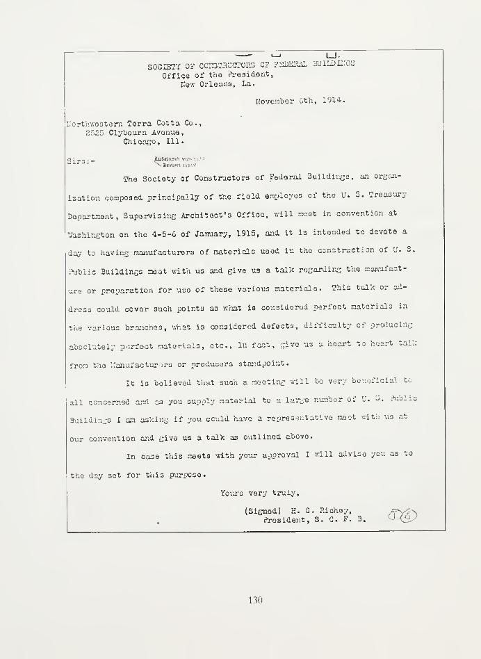
Northwestern Terra Cotta Co.,
2525 Clybourn Avenue
,
Chicago, 111.
Sir™ • - jBBBWNn v
i_i l_J.
SOCIETY 0? COE3THDCTOI5S OF K2DEHAL 3UILDIEGS
Office of the coresident,
Kew Orleans, La.
November Gth, 1914.
The Society of Constructors of Fedoral Buildings, an organ-
ization conpoaed principally Of the field employes of the U. 3. Treasury
Dopartxont, Supervising Architect's Office, will meet In convention at
Washington on the 4-5-6 Of January, 1915, and it is intended to devote a
day to having manufacturers of materials used in the construction of U. 3.
Public Building meat with us and give us a talk regarding the manufact-
ure or preparation for use of those various materials. This talk or ad-
dress could cover such points as what is considered perfect rnatorials in
the various branches, '.mat is considered defects, difficulty of producing
absolutely perfect materials, etc., In fact, give us a heart to hoart talk
from the Manufacturers or producers standpoint.


Glossary
132


anchor:
a piece or connected pieces of metal for securing together more or less permanently two or
more pieces of material or members of construction; used generally in connection with
masonry. It may be comparatively small and simple, as a cramp to connect two stones in a
wall, or a large and important member, as a tie rod passing through the opposite walls of a
building and secured on the outside by means of plates and nuts (Sturgis 1902)
a metal tie or plate used to fasten together timbers or masonry (Getty 1990)
a specially shaped metal or ceramic pin to hold ceramic fiber blankets or panels in place to
form furnace linings. Other unshaped linings (or refractory concrete) are also anchored to
the furnace bynotched or shaped rods and bars (Dodd & Murfin 1994)
an L-shaped supporting device used to mount glass, masonry, concrete and other hollow
blocks, panels or units to a wall or other surface (McColm 1994)
For ashlar or courses balanced on the wall, shall be V" x V", 1/8" x 5/8" or No. 6
galvanized wire; for projecting courses not balanced on the wall, shall not be less than 5/8"
round or square bars of equal cross section; (NTCS 1927 Specifications)
Anchoring materials are designed and selected at the same time as the mortar. Nonferrous
materials must be used. Stainless steel is durable and does not rust, but it is expensive.
More economical materials are hot-dip galvanized steel and epoxy-coated steel. Zinc
plated steel is also acceptable if baked to avoid hydrogen embrittlement. Sizes and shapes
of anchors depend on the original design, the work to be installed and the state of the back-
up masonry. Existing anchors or hangers should never be reused. (Berryman 1984)
Where for any reason anchor or tie rods are necessary in free-standing work, they should be
of bronze, stainless steel, or other non-corroding metal; For projecting work, such as
gargoyles, cornices, etc, or for exposed situations, such as the rail of a balustrade, only
bronze, stainless steel, udylited (cadmium plated) steel, everdur, or other assuredly non-
corroding metals should be employed. Galvanizing or dipping in asphaltic paints are of
little value. (Lockhardt NTCS 193 1
)
Davis System: The face of the structural concrete is cast to form a series of recessed steps,
with anchor rods projecting. As the terra cotta is set, the mason slushes it full with what is
really a concrete mortar, which keys into the recesses already provided, and is further
anchored to the structure by means of tie rods engaging those previously left projecting
from the concrete. (Lockhardt NTCS 1931)
The terra cotta blocks were anchored to the supporting wall with metal members, usually
iron. These anchors had to be protected against corrosion, and this usually was done by
133


coating them with cement or asphalt. In pieces which were not backfilled and this subject
to water penetration, bronze anchor rods were recommended because of their resistance to
corrosion. (Mack 1983)
Flat or simply profiled blocks of terra cotta were usually anchored to the masonry backing
with "z"-shaped anchor straps. Theoretically, each block was anchored individually with a
strap anchor fitted into a recessed slot at the top, so that it would not interfere with the joint.
(Meadows 1986)
Stainless steel, for example, has generally replaced galvanized iron in anchors and rods to
prevent corrosion damage. (Meadows 1986)
Where protection against corrosion is attempted, it may be an asphaltic dip, a copper,
galvanized or udylite coating or a relatively non-corrosive metal like copper that is used. It
is our belief that a rust resisting medium should be used for all anchors, bolts, etc. Where
in present practices blocks are left unfilled a thin protection of mortar that may or may not
adhere to an anchor is questionable protection. We believe in the necessity of a protected
anchor and a protection that is a certain one. For this purpose there are several materials or
alloys available that show high rust resistance. (Johnston 1926)
Anchoring was provided for the terra cotta and ceramic veneer. For wall blocks, a strap
anchor was sufficient, but for other sections more complicated systems were devised. Agreat variety of connectors was used to suspend and attach complicated terra cotta elements
to masonry, steel or concrete back-up. Depending on the structural system and the back-up
selected, sufficient tolerance was left in the connectors to allow for installation. (Prudon
1978)
For regular wall anchors, cracking may be found mostly to extend over the full height of
the block; when corrosion is advanced sufficiently, it may even extend into the adjoining
blocks or mortar joints. (Prudon 1978)
Backfilling:
Once set, the terra cotta blocks frequently were backfilled. This filling was intended to knit
the block to the main body of the building, not to actually support the blocks...There was
little agreement as to the best material for filling the blocks. (Mack 1983)
In fact, one portion of this organization believe in complete filling, while there seems to be
another group who are doubtful about its value.
Advantages: (Johnston 1926)
1
.
It makes rigid a construction
2. It offers come protection to corrosion of anchors
3. By the mechanical bond it may tend to hold pieces in place, perhaps even when
cracked
4. It tends to carry the terra cotta block weight immediately to the back wall (thus
minimizing the load on individual blocks.)
134


5. It may reduce the accumulation of large water pockets
6. It acts as a sound absorbent, getting away from the resonating box effect of unfilled
sections.
7. It furnishes a tie system in many conditions, where the metallic tie anchor system is
hard to place.
8. It tends toward a complete unit construction which possibly is an advantage in
localities subject to heavy vibrations or earthquake shocks.
9. By some, it is claimed that filling strengthens the terra cotta block
Disadvantages:
1
.
Concrete is known to expand under certain conditions with age, especially if it
becomes water soaked and such expansion may rupture the terra cotta.
2. The absorption of water and subsequent freezing may cause damage.
3. A system of filled blocks keyed tightly and quite individually to the backing wall
will not permit full play to the blocks in the adjustment necessary for temperature
changes and the deflections from various causes.
4. The thermal expansion of concrete is different and greater than that of terra cotta,
and it is in general a better conductor of heat, besides, the terra cotta would be
subjected directly to the sun's rays, while the fdling is protected, so that possibly
the combination may set up differential strains that would prove undesirable,
especially in some climates.
5. The increased rigidity of filled construction may throw heavy stresses on the terra
cotta in buildings subjected to heavy wind pressure.
6. The dead weight of the fill, if not properly keyed and supported by the backing
wall, may add just so much more load to the lower block courses and thus cause
crushing of the terra cotta.
7. Filling adds extra weight to the structure, which in modern buildings means heavier
structural sections with resultant increased cost, to which of course must be added
the extra cost of the fill itself.
When unfilled, the flectural and torsional resistances of the anchor system will permit the
desired movement. (Johnston 1926)
If the blocks remain unfilled as a whole, we must be sure that the recommended
construction is otherwise protected against corrosion. The parts that would need protection
are the anchors, anchor bolts, shelf angles, and structural supports for cornices, etc.
(Johnston 1926)
Blocks:
Because it was not considered economical to use blocks larger than 27" x 24" x 36", the
blocks themselves were designed to be fairly small. Recommended sizes ranged from 4" to
14" high, 12" to 24" wide, and 4" to 18" deep. (Mack 1983)
Most terra cotta block was approximately 4" deep, with a wall thickness of about 1" to 1
V" ...Regular, narrow face area of basic blocks was usually between 2 and 2 Yi square feet.
135

The blocks were made with internal webbing for strength, but were open at the back,
permitting them to be keyed to the backup masonry. (Meadows 1986)
Although terra cotta can be made solid, making it hollow requires less raw material, the
pieces dry quicker, can be burned quicker and, of course, are less expensive. Then the
weight of hollow terra cotta, which is much less per cubic foot, also effects saving in
freight, cartage and cost of handling at the building. The hollow blocks are generally made
from 18" to 2' long, from 6" to 12" deep and of a height determined by the character of the
work, although pieces have been made from 6 to 8 cubic feet in volume and weighing one-
quarter of a ton. The outer shell is made 1 V" thick and the webs and partitions about 1"
thick. The partitions should have numerous holes in them for convenience in handling and
to afford a clinch for the mortar and brickwork used for the filling and backing, and they
should be so arranged that the open spaces shall not exceed 6". In fact, all the work should
be divided into as short lengths as practicable. Short lengths are more easily handled and
are less liable to break and warp than long ones, although, contrary to the general belief,
small pieces are more expensive to manufacture than large pieces... (Warren 1905)
Provisions for anchoring systems were also made in the block. Small holes at the side
allowed for the insertion of dowels, and a recessed slot at the top made it possible to insert
a strap anchor. The recessing prevented these anchors from blocking the mortar joint and
made repointing possible. (Prudon 1978)
Clips:
Shall be 3/8" x 2" (NTCS 1927 Specisfications)
When facing reinforced concrete... Metal keyways may be lightly attached to the forms at
suitable intervals, so that when the forms are stripped the keyways are anchored in the
concrete. Clips which are shaped to fit the keyway have a hole in them through which the
anchor rods may be passes. As the clips can be placed in the vertical keyways at any point
the system is very flexible. (Lockhardt 193 1
)
The iron clip shown in fig. 5 gives the maximum liberty of spacing of supporting member
and makes an effective clamp to counteract any twisting of angles or bars. (Tindall 1989)
Clamps:
All blocks not solidly built into the walls should be anchored with galvanized iron clamps,
the same as for stonework, and, as a rule, all projecting members over 6" in height should
be anchored in this way. (Fitzsimmons 1984)
Columns:
The maximum distance between columns being about 9', the necessary support is supplied
by two 5" channels placed back to back and bolted together at intervals of 4' with just
enough room to receive the 3/4" hangers: which passing between them, take the place of
separators. (Cusack 1896)
136

Cornice:
Projecting cornice units were suspended from anchorage systems by steel J-bolts, which
held horizontal bars threaded through holes formed in the webs of the terra cotta block.
(Hunderman 52)
The top of the cornice is protected by a copper roof with regleted copper flashing.
Scuppers extending through the wall permit water to drain back from the cornice onto the
roof of the building. The cornice is supported by brackets at each exterior wall column.
Horizontal I-beams span between these brackets, along the entire length of the cornice.
The uppermost terra cotta course is also supported against overturning by a horizontally
oriented steel hanger... This hanger, which is tied to a horizontal rod, projected through the
webs of the terra cotta unit. The weight of this uppermost course of terra cotta is supported
by a continuous angle, which is in turn supported by a series of steel brackets on the web of
the main I-beam in the cornice. The support for the dentils and the course of terra cotta
directly above the dentils is provided by a series of steel hangers. These hangers are
hooked around the top flange of the I-beams above, and ran vertically downward to a
horizontal rod inside each of the dentils. (Hunderman 1988)
Two concentric rings of structural steel channels which are tied to steel girt outlookers
provide the main support for the cornice. The outlookers, in rum, are cantilevered from the
structural steel columns of the budding. The interior of the cornice is tilled with
lightweight masonry material and lacks any ventilation. (Levine 1991)
For larger overhanging horizontal elements, such as major cornices or balconies, different
and sometimes elaborate support systems were necessary. Blocks were attached to angles
or rods, or suspended from steel members used as outriggers with standard hook and dowel
systems. If the system was properly designed, it allowed for some adjustment during
installation. Frequently, these sections were backfdled with concrete, more for protecting
the anchoring systems from corrosion that for structural reasons. (Levine 1991
)
Spandrel panels, soffits, sections of cornices, and lintels were connected by being
suspended from a steel member. That is, dowels were placed in the sides of the block.
These dowels fitted into a hook suspended from the steel structural member. The hook was
fitted into a slot and bolted in the steel, allowing from some adjustment. (Prudon 1978)
With stone cornices it is necessary that the various pieces be of sufficient depth to balance
on the wall. With terra cotta cornices, however, this is not necessary or customary, the
various pieces being made to build into the wall only 8" or 12" and to be supported by iron
work. Generally small steel L's and T's, as shown in Plate I, are used for supporting the
projecting members, and where the projection is so great as to overbalance the weight of
the masonry on the built-in end, allowing for the weight of snow on the projection, the
inner ends of the supports are anchored by rods carried down into the wall until the weight
of the masonry above the anchor is ample to counteract the leverage of the projection.
Therefore, wherever iron is used for tying the cornice to the walls it is necessary to
137

determine the method of anchoring before the pieces are molded, as in manufacturing them
holes or slots must be made for inserting the beams, rods and anchors. (Warren 1905)
Large cornices or belt courses required extensive anchoring and support systems, especially
when the cornices protruded far. Cornices were initially not anchored to the wall but kept
in place by the masonry on top. The detailing was similar to stone masonry construction.
For larger structures, the cornices and belt courses had steel angles and outriggers attached
to structural frames or the masonry to support the large units. Soffits, brackets and dentils
could be suspended from these outriggers by standard hook and dowel systems. When the
voids of the cornices were not completely back-filled, weep holes would be provided.
(Prudon 1978)
Large overhanging elements, such as cornices, belt-courses, or balconies, are very
susceptible to damage caused by corrosion of anchoring and support systems. Leaking
roofs, flashing, and faulty caulking or pointing are very likely to exist in these locations.
Terra cotta units suspended from steel outriggers with anchoring devices may crack and
shatter because of corrosion, not just of the anchors but also of the steel outriggers, creating
very hazardous conditions. In these cases, the suspended terra cotta units are no longer
secured and may be in danger of falling...Window lintels may also be affected in that
manner. (Prudon 1978)
Dowels:
For each piece less than 1'8" long, use one dowel !4" shorter than the piece. For each piece
1'8" or longer use two 10" dowels for each running length. (Tindall 1989)
Hangers:
Shall be 5/8" diameter round bars or other shapes of equal cross section area (NTCS 1927
Specifications)
Excepting very short pieces, there should be two hangers for each running length; and for
wide soffit courses there should be two rows of hangers to each course. (Tindall 1989)
The '/:" hangers and 5/8" dowels are proper for all ordinary work, though for very light
sections where space is limited, 3/8" hangers and I/2" dowels may be used. (Tindall 1989)
Hooks:
Prior to 1885, terra cotta was 'hung' on the walls as window caps, or other types of surface
decoration. In this process the terra cotta blocks were filled with mortar and pressed into
place. Hooks which previously had been driven into the wall joints then penetrated the
mortar grout. The terra cotta was held in place until the mortar had hardened, at which
time the hooks held the blocks in position. Around 1885 it was realized that the pieces
could be built into the wall, leading to rapid development in its use. (Mack 1983)
138

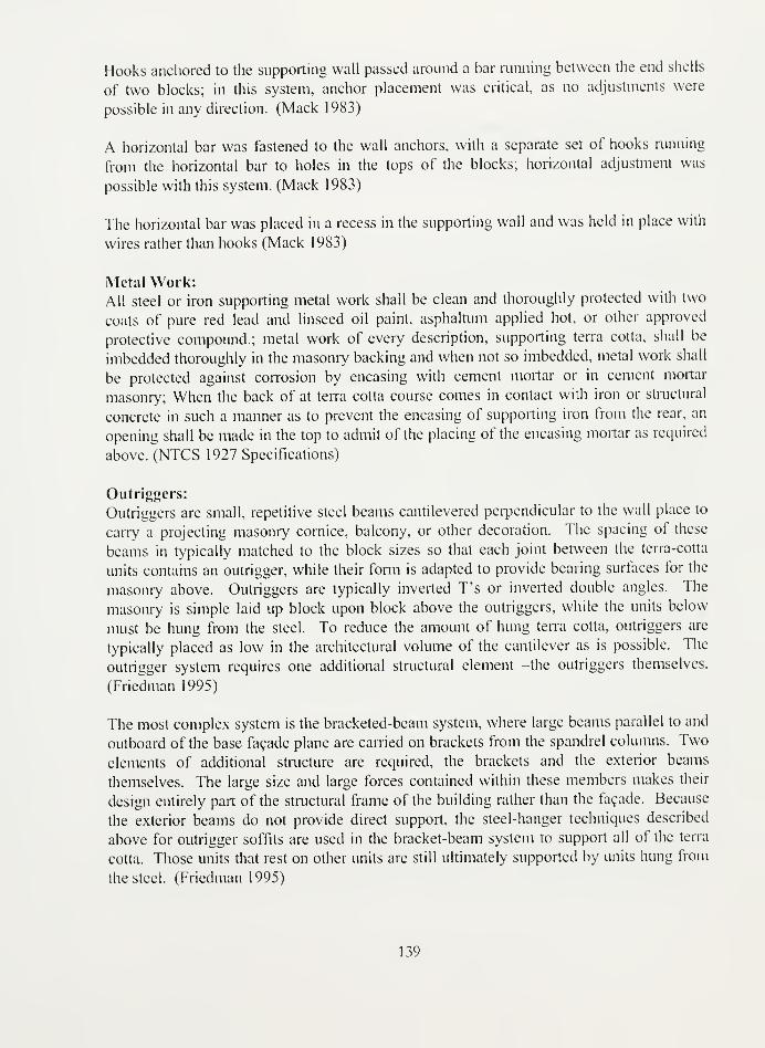
Hooks anchored to the supporting wall passed around a bar running between the end shells
of two blocks; in this system, anchor placement was critical, as no adjustments were
possible in any direction. (Mack 1983)
A horizontal bar was fastened to the wall anchors, with a separate set of hooks running
from the horizontal bar to holes in the tops of the blocks; horizontal adjustment was
possible with this system. (Mack 1983)
The horizontal bar was placed in a recess in the supporting wall and was held in place with
wires rather than hooks (Mack 1983)
Metal Work:All steel or iron supporting metal work shall be clean and thoroughly protected with two
coats of pure red lead and linseed oil paint, asphaltum applied hot, or other approved
protective compound.; metal work of every description, supporting terra cotta, shall be
imbedded thoroughly in the masonry backing and when not so imbedded, metal work shall
be protected against corrosion by encasing with cement mortar or in cement mortar
masonry; When the back of at terra cotta course comes in contact with iron or structural
concrete in such a manner as to prevent the encasing of supporting iron from the rear, an
opening shall be made in the top to admit of the placing of the encasing mortar as required
above. (NTCS 1927 Specifications)
Outriggers:
Outriggers are small, repetitive steel beams cantilevered perpendicular to the wall place to
carry a projecting masonry cornice, balcony, or other decoration. The spacing of these
beams in typically matched to the block sizes so that each joint between the terra-cotta
units contains an outrigger, while their form is adapted to provide bearing surfaces for the
masonry above. Outriggers are typically inverted T's or inverted double angles. The
masonry is simple laid up block upon block above the outriggers, while the units below
must be hung from the steel. To reduce the amount of hung terra cotta, outriggers are
typically placed as low in the architectural volume of the cantilever as is possible. The
outrigger system requires one additional structural element -the outriggers themselves.
(Friedman 1995)
The most complex system is the bracketed-beam system, where large beams parallel to and
outboard of the base facade plane are earned on brackets from the spandrel columns. Two
elements of additional structure are required, the brackets and the exterior beams
themselves. The large size and large forces contained within these members makes their
design entirely part of the structural frame of the building rather than the facade. Because
the exterior beams do not provide direct support, the steel-hanger techniques described
above for outrigger soffits are used in the bracket-beam system to support all of the terra
cotta. Those units that rest on other units are still ultimately supported by units hung from
the steel. (Friedman 1995)
139

Pins:
Shall be '/2" diameter round bars (NTCS 1927 specs)
The installation of pins through the face of the units should be avoided because this is
difficult to conceal. Where pinning through the face is required to stabilize a unit, the pin
location may be covered with a small cementitious patch, painted to match the color of the
adjacent terracotta. (Slaton 1996)
Rods:
Continuous rods on concrete wall faces to which terra cotta ashlar is clipped, shall be 5/8"
diameter round bars which shall be secured to the masonry with 14" diameter round anchors
placed not more than 2'0" on centers. (NTCS 1927 specs)
Otherwise, if wire anchors embedded in the concrete are not used, rods are left projecting
from the face of the wall at suitable intervals, and after the forms have been removed, the
projecting ends are turned up to engage and hold horizontal rods over which the anchor-
irons are slipped. (Lockhardt 193 1
)
Angle irons are frequently used in lintel construction. A short metal rod is placed in one of
the holes shown in the terra cotta pieces and in a corresponding aperture in the adjacent
piece. An iron anchor engages with this rod between the two pieces and the rebates are
slushed with mortar to protect the iron from rust. The anchoring rod is engaged with the
structural steel. (Mack 1983)
Soffits:
The soffit blocks are made in lengths of I'lO" with two hangers placed 3" from the ends.
The %" rod having been inserted in the hole, which passes longitudinally through each
piece, the chambers are then filled with concrete before being set in position. (Cusack
1898)
Straps:
Shall be 3/8" x 2" (NTCS 1927 Specifications)
Steel straps were set into slots at the back of each unit for horizontal support and tied to the
anchorage system of the wall behind. (Hunderman 1988)
Shelf Angles:
"Shelf Supports": In concrete or steel frame buildings, the veneer or facing material should
be fully and continuously supported, at each floor level on shelf supports, of adequate
strength and stiffness, rigidly constructed to the structural frame. Steel shelf angles or
supports, in all cases, should be located in mortar joints. The strength of the terra cotta
should not be necessarily reduced by cutting the webs to receive the steel. (NTCS 1927)
140

When used as cladding, the units were typically supported by steel shelf angles at floor
levels, above wall openings, and at projections such as cornices. (Hunderman 1988)
When the blocks were used as a veneer with anchors rather than backfill, shelf angles were
required at regular intervals to prevent crushing of the blocks. Blocks resting on this angle
then either were wired directly to it or were anchored to the wall to prevent movement
away from the wall. (Mack 1983)
Some shelf angles were missing, others had corroded away all of them stopped 2 to 3 feet
short of the wall corners. The uneven vertical support, especially at the corners, caused
extensive vertical cracking free from shear failure between supported and unsupported terra
cotta... Rust scale expansion at the tow of the shelf angle caused cracking and spalling of
the terra cotta blocks just above and below the shelf angle. (Searls 1991)
A steel beam bolted through its flanges to shelf angle supports on a column is not as fully
fixed as one riveted to the column through its web. (Johnston 1926)
Study of your past details of shelf angles indicated that preference was given to the angle
placed with the attaching leg up. Further, there is the apparently universal acceptance of a
two inch clearance between the face of the terra cotta and the outer edge of the shelf angle.
Such a construction necessitates first, the use of a three inch leg angle; secondly it gives
only two inches maximum bearing of the shelf block on the angle; thirdly it means that
wherever an anchor boltgoes through the shelf angle a piece of the terra cotta block has to
be cut out in erection of the block to clear the bolt and nut; fourthly, with the angle placed
with attaching leg up and bearing leg down, advantage is taken of a slightly stronger
construction due to the 'thrust' reaction furnished by the wall, at the heel of the angle... a
two inch bearing is too small... in reality a two inch bearing will seldom be secured on
account of the warping of the block in diying and burning. This latter makes it necessary to
set the block out to clear the angle edge and this reduces the bearing by the amount the
block it set out. Secondly, this construction necessitates cutting the shelf block wherever
an anchor bolt occurs. Field cutting on general principles is undesirable. Such cutting will
never be done as carefully as shop cutting, so that there is great liability of damage to the
block, and in this instance, the damage is done to the shelf block which is the one under
greatest superimposed load. (Johnston 1926)
It was decided first that the back of the block should be set 1 V" from the backing wall, so
as to eliminate as far as possible field cutting with its extra hazards and costs... In order to
make sure that any excess projection of the bolt would not cause injury to a basic block, if
cutting was necessary, we turned the shelf angle over, attaching leg downward so that if
interference did occur, it would necessitate cutting only on the blocks immediately below
the shelf angle and thus the cutting of blocks carrying minimum load. It is true that by
doing this we may lose a slight advantage in strength, through loss of the wall thrust at the
angle heel... a standard shelf angle of this type is generally overstrong for the loads coming
on it; secondly, with the shelf angle placed as shown, a wider surface is available for block
bearing; thirdly, the position of the block load is so close to the wall face that it is doubtful
141


if there is any great difference in the kind of stress coming on the anchor bolt... it was
considered to better to use a 3 V2" leg and secure the advantages of greater bearing for the
block. (Johnston 1926)
When a proper shelf angle has been used, corrosion may develop at the front of the angle
closest to the exterior surface. The corrosion will cause the terra cotta to crack and spall
along the front of the angle. Where the cladding was continued over the support steel, as
was frequently the case in early terra cotta construction, the corrosion will cause horizontal
cracking in the terra cotta. This horizontal cracking may be detected in its earlier stages by
a slight bulging of the terracotta. (Prudon 1978)
Expansion Joints:
Proper provision should be made for expansion joints, at shelf supports, over column caps,
etc., to prevent the development of disruptive stresses caused by deflection, wind pressure,
temperature changes, settlement, and like forces (NTCS 1927)
Expansion Joints may sometimes now be installed to decrease the excessive facade stresses
characteristic of many early high-rise buildings. (Meadows 1986)
Parapets had cracked due to thermal expansion and an absence of expansion joints. (Searls
1991)
In the vertical height of the building we have the same necessity for allowing for thermal
changes, for shrinkage in concrete, for flectural movements...This discussion shows the
necessity of preventing the accumulation of heavy strains on the terra cotta facing from
such causes. The only practical way to accomplish this is to incorporate what may be
called open joints -open only in the sense however, that they must be joints designed to
permit the free shortening of the structure from such causes as have been discussed here.
Consideration of the character of deflections occurring in a building suggests that probably
the best location for such joints is in the vicinity of the floor levels. As this is where the
shelf angles for supporting the terra cotta are most conveniently placed, such joints then
must be considered as part of the standard shelf angle detail. Another reason for placing
the joints as such a location is that, due to the present necessity of using a plastic material
for these joints, the joint location must be where a minimum load comes upon the mastic.
This last requirement necessitates the plastic joint being placed just below the shelf angle.
(Johnston 1926)
They must be wide enough to permit of good, thorough caulking with the mastic and such
caulking probably can best be done with a pressure gun. The also should be wide enough
to insure a depth of plastic material that can squeeze and draw so that especially on
drawing, as the joint is opened, the plastic will not divide and leave a crack for water to
enter. Considering all things, we belive that 3/8" width of joint is the most practical.
(Johnston 1926)
142


Window Sills and Lintels:
An arch lintel 14" deep and 16" reveal would be quite safe over an opening of 5', without
any auxiliary support. Beyond that width, instead of 12", we would use two 6" I-beams,
placed so as to carry the brickwork above and relieve the lintels below. (Cusack 1898)
Window sills and lintels are generally made in pieces from 18" to 2' long. Jamb blocks are
usually 1'6" high or thereabout and should be designed to bond in with the brick work.
(Warren 1905)
143


Bibliography
Adennan, Ella Webster. "Architectural Terra Cotta: On-Site Evaluation and Testing."
Masters, University of Pennsylvania, 1986.
The American Terracotta Index. Edited by Statler Gilfillen. Palos Park: Prairie School
Press, 1974.
Architects, American Institute of. The Standard Documents ofthe American Institute of
Architects. Washington, DC: The American Institute of Architects, 1911.
"Architectural Terra Cotta." Brick and Clay Record, no. 33:31 -35.
"Architectural Terra Cotta." Brick and Clay Record, no. 32: 135-36.
"Architectural Terra Cotta Investigations." NBS Technical News Building 8, no. June
(1925): 3-4.
Atkinson, George. "Terra Cotta Rehab." Building 44, no. 241: 43.
Barret, M. "Is the Filling of Architectural Terra Cotta with Concrete Necessary or
Desirable?" ACS Journal: 79-82.
Barton, A. Daniel, Jr. "O. W. Ketcham Terra Cotta: Reflections on an Industry in Chaos
after World War Two." APT Bulletin 32, no. 4 (2001): 11-16.
Becher, P.F. "Advances in Architectural Ceramics." MRS Symposium Series 78.
Bell, Ingress E. "The Revived Use of Terra Cotta in Architecture." The Art Journal, no.
50: 119-20.
Berryman, Nancy D., and Susan M. Tindall. Terra Cotta. Chicago: Landmarks
Preservation Council of Illinois, 1984.
144

Boston Fire 1871 [cited 1/30/ 2003]. Available from www.fire-police-
ems.com/books/ba3730.htm.
Boston Valley Terra Cotta, Company. Architectural Terra Cotta- Standard Construction.
Boston Valley Terra Cotta Company, Orchard Park, New York, 1997.
Bourry, Emile, and A. B. Searle. A Treatise on Structural Ceramic Industries: A
Complete Manualfor Pottery, Tile, and Brick Manufacturers. London: Scott
Greenwood and Son, 1919.
Brantley, L. Reed, and Ruth T. Brantley. Building Materials Technology. New York:
McGrawHill, 1996.
Bums, R. M., and W. W. Bradley. Protective Coatingfor Metals. Edited by F. Marshall
Beringer. 3rd ed, American Chemical Society Monograph Series. New York:
Reinhold Publishing Corporation, 1967.
Casodia, R. and Fabri, B. The Deterioration of Terra Cotta: The Case of Casa Valenti in
Faenza. Science, Technology, European Cultural Heritage, Bologna, Italy,
Ceccacci, Susan McDaniel. "Architectural Terra Cotta in the United States before 1870."
Master of Art, Boston University, 1991.
Chicago Fire 1871 [cited 1/29/ 2003]. Available from
www.chicaizohs.ora/fire/ruin/index/html.
Clay Masonry Products Terra Cotta (Ceramic Veneer) The Northwest Masonry Guide,
[cited October 23 2002]. Available from
www.masonryinstitute,com/guide/part2/prod a2-pl-2.html .
Committee, Chicago Department of Buildings. "Setting Terra Cotta." The American
Architect/The Architectural Review 123, no. 2419 (1923): 435-536.
Comparative Recapitulation Sheet: Reports of Orders. National Terra Cotta Society, New
York, 1913.
145


Condit, Carl W. American Building Art: The Nineteenth Century. New York: Oxford
University Press, 1960.
Congress, New York Building. "Standard Specification for the Manufacture and
Furnishing of Terra Cotta." American Architecture and Building News 135, no.
2570: 768-70.
-. "Standard Specifications for Setting of Terra Cotta." American Architecture and
Building News 139, no. 2571: 837-39.
Cotta, Friends of Terra. "Technical Notes." Friends of Terra Cotta Newsletter 3, no. 2
Summer: 12-13.
Croly, Herbert D. "The Proper Use of Terra Cotta." Architectural Record: 73-81.
Cusack, Thomas. "Architectural Terra Cotta." The Brickbuilder 5 (1896): 6-8, 29-32,51
53.
'Architectural Terra Cotta." The Brickbuilder 1', no. 1 (1898): 7-8.
'Architectural Terra Cotta." The Brickbuilder 7, no. 3 (1898): 55-57.
"Terra Cotta and Steel." The Brickbuilder, no. 1 :226-29.
Darling, Sharon S. "The Northwestern Terra Cotta Works." Chicago Ceramics and
Glass: 168-69.
Durham, Diana. "Terra Cotta Renovation at the Natural History Museum." Glazed
Expressions 12, no. Summer: 10-11.
Eskesen, E.V. "The Investigation of Terra Cotta Work at the Bureau of Standards." ACS
Journal 4 (1924): 158-68.
-. "Presidential Address for the Thirty-Fourth Annual Meeting of the American
Ceramic Society." Journal ofthe American Ceramic Society 15 (1932): 81.
146
— . "Watertight Terra Cotta Construction." ACS Journal 13 (1934): 154-62.
Fellowship, The National Terra Cotta Society. Summary of the Printed Reports 1-8 and
the Technical Work of the Society. National Bureau of Standards, Washington
DC, 1922.
Ferriday, Viginia Guest. Last ofthe Handmade Buildings: Glazed Terra Cotta in
Downtown Portland. Portland, OR: Mark Publishing Co., 1984.
Fidler, John. "The Conservation of Architectural Terra Cotta and Faience." Friends of
Terra Cotta Newsletter 3 , no. 1 (1983): 12-16.
-. "Repair of Architectural Terra Cotta and Faience-Part I." SPAB News, no. 4: 51-
53.
. "Repairing Terra Cotta- Part li." SPAB News, no. 5:1.
Fitzsimmons, H.L. "Terra Cotta in Building Construction." The Architect and The
Engineer. 96-99.
Friedman, Donald. Historical Building Construction: Design, Materials and Technology.
New York: W. W. Norton, 1995.
Fus, Michael. "Architectural Terra Cotta: Standards, Specifications, and Testing." Master
of Science, Art Institute of Chicago, 1997.
Geer, Walter. The Story of Terra Cotta. New York,: T. A. Wright, 1920.
—. Terra-Cotta in Architecture. 3d ed. New York,: Gazlay bros., 1891.
Harris, Cyril M., ed. Dictionary ofArchitecture and Construction. 3rd ed. New York:
McGraw-Hill, 2000.
Hedges, Ernest S. Protective Films on Metals. Edited by E. Howard Tripp. 2nd ed. Vol.
5, A Series ofMonographs on Applied Chemistry. New York: D. Van Nostrand
Company, Inc., 1937.
147


Heubach, A.R. "How Architectural Terra Cotta Is Made: Being a General Treatise of the
Subject with Methods of Manufacture, Machinery in Use, and a Classification of
the Clays." Brick and Clay Record A3,: 904-07.
Hodson, C. N. "Architectural Terra Cotta and Faience." Ceramic Society Transactions
36: 45-50.
Howe, Samuel. "Terra Cotta as a Building Material." American Architecture and
Building News 110: 177-81,93-91,201-07,57-61.
Hunderman, Harry, and Deborah Slaton. "Final Touch: Cornice Detail." APT Bulletin
XX, no. 1 (1988): 64.
Inland Architect and Builder 7, no. 11 (1886): 97
Johnston, Robert Smith. Principles of Terra Cotta Construction. National Terra Cotta
Society, New York, 1926.
Kelly, Stephen J. and Jerry G. Stockbridge. "The Railway Exchange Building: A Terra
Cotta Renovation." APT Bulletin XX, no. 3: 15-22.
Ketcham, O.W. The Story ofa House. Philadelphia: Edward Stern and Co., 1 899.
Kingrey, W. D., and Pamela Vendever. Ceramics Masterpieces: Art, Structure, and
Technology. New York: Free Press, 1986.
Kraemer, T. "The Setting of Terra Cotta and Its Inspection by Architects." American
Architecture and Building News 131, no. 3519: 551-57.
Kurutz, Gary F. Architectural Terra Cotta ofGladding, Mcbean. Sausalito: Wingate
Press, 1989.
Levine, Jeffery S. "Stabilization and Repair of a Historic Terra Cotta Cornice."
Preservation Tech Notes: Masonry, no. 2 (1991).
Lockhardt, William. "Architectural Terra Cotta." General Building Contractor ( 1 93 1 ).
148

Loring, Sanford E., and William Le Baron Jenney. Principles and Practice of
Architecture. Chicago: Cobb, Pritchard, & Co., 1869.
Lucas, Harry J. New York Architectural Terra Cotta Company Collection. Columbia
University Avery Library, New York.
-. New York Architectural Terra Cotta Company Collection. Columbia University
Avery Library, New York.
-. New York Architectural Terra Cotta Company Collection. Columbia University
Avery Library, New York.
Mack, Robert C. The Cleaning and WaterproofCoating ofMasonry Buildings,
Preservation Briefs. Washington, DC: United States Government Printing Office,
1979.
-. "The Manufacture and Use of Architectural Terra Cotta in the United States." In
The Technology ofHistoric American Buildings: Studies ofthe Materials,
Processes, and the Mechanisms ofBuilding Construction, edited by Edward
Jandl. Washington, DC: Foundation for Preservation Technology, 1983.
Mclntyre, W.A. Investigations into the Durability ofArchitectural Terra Cotta and
Faience. Building Research Station Special Report, No. 12. London: Building
Research Station, 1929.
Meadows, Robert E. Historic Building Facades: A Manualfor Inspection and
Rehabilitation. New York: New York Landmarks Conservancy, 1986.
"Modern Brick Builder's Manual: A Handy Reference for Architects, Engineers, Mason
Builders, Dealers." Brick and Clav Record.
Murtagh, William. "The Philadelphia Row House." Journal of the Society of
Architectural Historians XVI, no. 4 (1957): 8-13.
"Philadelphia." The Brickbuilder 4, no. 9 (1895): 199.
149


Plusch, H.A. "Some Causes of the So-Called Disintegration of Terra Cotta, Brick, and
Allied Ceramic Materials." The Chemist 1: 65.
Porter, Glenn. The Rise ofBig Business: 1860-1920. 2nd ed. Arlington Heights, Ilinois:
Harlan Davidson, Inc., 1992.
Powell, William H. New York Architectural Terra Cotta Company Collection. Columbia
University Avery Library, New York.
Prudon, Theodore H. M. "Architectural Terra Cotta and Ceramic Veneer in the United
States Prior to World War Ii: A History of Its Development and Analysis of Its
Deterioration Problems and Possible Repair Methodologies." PhD Dissertation,
Columbia University, 1981.
-. "Architectural Terra Cotta: Analyzing the Deterioration Problems and
Restoration Approaches." Technology and Conservation 3, no. Autumn 3 (1978):
30-38.
Putnam, Edward. "Architectural Terra Cotta: Its Physical and Structural Properties." The
Brickbuilder (1911): 29-33.
Richey, H.G. New York Architectural Terra Cotta Collection. Columbia University
Avery Library, New York.
Ries, Heinrich. Building Stones and Clay Products: A Handbookfor Architects. NewYork: John Wiley and Sons, 1912.
Rosen, Harold J. Principles ofSpecification Writing. New York: Reinhold Publishing
Corporation, 1967.
Ruskin, John. The Seven Lamps ofArchitecture. New York: Dover Publications,
1880,1989.
San Francisco Fire 1906 [cited 1/30 2003]. Available from
americahurrah.com/sanfrancisco/municipalreports/1906/index.htm.
150

Searls, C.L., and S.E. Thomasen. "Repair of the Terra Cotta Facade of Atlanta City Hall."
In Structural Repair and Maintenance ofHistorical Buildings li: Proceedings ofthe Second International Conference Held in Seville, Spain, edited by Brebbia et
al. Seville, Spain, 1991.
Segal, Dr. Agnes. Copper Alloys- Bronzes AZoM.com, 2002 [cited April 13, 2003].
Available from
http://metals.ahout.eom/gi/dynamic/offsite.htm?site=http%3A%2F%2Fw\vw.a20
m.com.
Slaton, Deborah, and Mark Robert Morden. "Issues in the Salvage and Reuse of Terra
Cotta: Two Case Studies." In Standardsfor Preservation and Rehabilitation,
Astm Stp 1258, edited by S. J. Kelley, 307-18: American Society for Testing and
Materials, 1996.
Sloop, Jessica A. "Repair of Glazed Terra Cotta Surfaces: A Comparative Study of
Remedial Coatings for Their Effectiveness of Areas of Glaze Loss in Temperate
Maritime Weathering Conditions." Masters, University of Pennsylvania, 1996.
Society, National Terra Cotta. Architectural Terra Cotta: Standard Construction. NewYork: National Terra Cotta Society, 1914.
. "A Campaign for Better Understanding." Pencil Points 1, no. 6 (November1920): 2.
-. Standard Specification for the Manufacture, Furnishing, and Setting of Terra
Cotta. National Terra Cotta Society, New York, 1923.
-. Summary and Index of Reports One to Eight Relating to the Technical Work of
the National Terra Cotta Society. The National Terra Cotta Society Fellowship at
the National Bureau of Standards, New York, 1918-1922.
-. Terra Cotta: Standard Construction. New York: National Terra Cotta Society,
1927.
Stockbridge, Jerry G. "Analysis of in-Service Architectural Terra Cotta." APT Bulletin
XVIII, no. 4:41-45.
151


Stratton, Michael. "The Terra Cotta Industry: Its Distribution, Manufacturing Processes,
and Products." Industrial Archaeology Review 8, no. 2 (1986): 194-214.
. The Terracotta Revival. London: Victor Gollancz, 1993.
Sturgis, Russel. A Dictionary ofArchitecture and Building: Biographical, Historical, and
Descriptive. New York: The MacMillan Co., 1902.
Taylor, James. "The History of Terra Cotta in New York City." Architectural Record 2
(1892): 137-48.
Technical Notes on Brick Construction Brick Institute of America, [cited October 23
2002]. Available from www.bia.org/BIA/technotes/t44.htm .
Terra Cotta Specifications. Edited by F.R.S. Yorke. London: Architectural Press, 1935.
Terra Cotta Work: Modelling, Moulding, and Firing. Edited by Paul N. Hasluck.
London: Cassell and Company, Ltd., 1905.
Thrall, C.U. "Terra Cotta: Its Character and Construction I-Iii." The Brickbuilder. 10-12.
Tindall, Susan. "How to Prepare Project Specific Terra Cotta Specifications." APTBulletin XXI, no. 1 (1989): 26-36.
"Technical Notes." Friends of Terra Cotta Newsletter 3, no. 1 (1984): 4.
"Terra Cotta Replacement." APT Bulletin XX, no. 3 (1988): 12-14.
152


Index
American Ceramic Society, 27, 28. 112
American Institute of Architects, 27, 112
American Society for Testing Materials,
32
anchoring systems, 1, 29, 31, 32, 69, 104,
105
anchors, 1 , 6, 9, 1 2, 1 7, 1 8, 3 1 , 32, 33, 36,
37,39,43,44,46,50,51,60,67,
70, 72, 73, 74, 76, 80, 83, 86, 87,
101, 102, 103, 104, 106, 107,
108, 109
Andrew Carnegie, 18
angles, 6, 32, 35, 46, 49, 50, 51, 60, 62,
70,72,76,77,85,87, 103. 104,
105, 106, 107, 108, 109, 110
Architectural Terra Cotta Institute, 22, 23
asphaltum, 32, 33, 38, 107
Atlantic Company, 21, 25, 27
Atlantic Terra Cotta Company, 20
Balthasar Kreischer, 14
Bessamer Steel. 1
3
Big Business, 18, 19, 21, 25, 1 13
Boston Fire of 1872, 14
Boston Terra Cotta Company, 1
9
Brick Institute of America, 22, 23
Brick Terra Cotta and Tile Company, 20
Bronze, 39, 69
building technology, 1,2,3,12,15,51,87
Cadmium, 38
cast iron, 12, 13, 14
ceramic veneer, 16, 37, 102
Chicago Department of Buildings, 31, 32,
112
Chicago Fire of 1871,3,4, 14
Chicago Terra Cotta Works, 4, 41
clamps, 6, 12,44.46,50, 104
Coade's Stone, 3
Daniel Badger, 13
Depression, 16
down-draught kilns, 10
drafting, 5. 6. 17
drying, 5, 9, 109
E.V. Eskesen, 15
finishing, 5, 9
fire-proof, 3
firing, 3, 4, 5, 6, 7, 14, 17
First Brown Association. 19
fitting and numbering, 5
Fritz Wagner, 12,24,28
galvanized, 33, 37, 38, 39, 101, 102, 104
George H. Johnson, 14
Gladding, McBcan and Company, 24
glazes, 5, 9, 28
glazing, 3, 5, 42
Guaranty Building, 14
Gu.stav Hottinger, 24, 41
H. A. Lewis Architectural Terra Cotta
Works, 19
installation, 1, 2, 5, 9, 1 1, 12, 15, 17,27,
29,31,37,40,42,45,60,69,
102, 105, 108
James Bogardus, 13
J-hook, 44, 49, 50, 5 1 , 52, 58, 59, 62, 64,
66, 69, 72, 74, 77, 78, 85
John B. Cornell, 14
John Ruskin, 4
Literary and Publicity Bureau, 22, 23, 24
load bearing structures, 12, 87
Louis Sullivan, 14
Manhattan Company, 20, 21, 24
Manhattan Material Company, 20
Maryland Terra Cotta Company, 2
1
Mies van der Rohe, 1
5
modeling, 5, 11,28, 119
molding, 5, 8, 17
Morse Code, 87
Muffle kilns, 10
National Building Museum, 6, 8,40, 1 19
National Terra Cotta Manufacturers
Association, 22
National Terra Colta Society, 1, 12, 15.
22,23,24,27,28,31,34,35,36,
40,41,42,43,46,59,75,86,87,
89, 112, 113, 114, \\9,See
NTCSNew York Architectural Terra Cotta
Company, 20, 24, 113, 119
New York Architectural Terra Cotta
Works, 19,24
Northwestern Terra Cotta Company, 1, 2,
6,24,28.40,41,42,44,51,52,
53, 54, 55, 56, 58, 59, 60, 66, 70,
71.73,74.75,76,77,78,86
NTCS. 1, 23, 24, 26, 27, 28, 30, 33. 34,
36,85,87. 101, 104. 106, 107,
108, 110
O.W. Ketcham Terra Cotta Works, 1, 22,
42
Perth Amboy Terra Cotta Company, 19
Peter B. Wight, 14
153


Philadelphia, 9, 10, 1 1, 13, 19, 22. 24, 42,
43,62,73,83, 113, 119
pressing, 5
Principles of Terra Cotta Construction, 34,
35, 113
Robert Smith Johnston, 34, 36
Sanford E. Loring, 41
Second Brown Association, 19, 24
Sherman Antitrust Act of 1 890, 1
8
shipping and handling, 5
skeletal construction, 12, 13
Slips, 5
South Amboy Terra Cotta Company, 2 1
,
119
specifications, 5, 8, 17, 23, 26, 27, 28, 29,
30,31,32,33,35,36,37,38,39,
59,87, 119
Specifications, 27, 29, 30, 31, 32, 33, 36,
37, 106, 107, 113, 114
Stainless steel, 39, 101, 102
Standard Construction, 26, 36, 40, 46, 47,
48, 57, 72, 73, 75, 80, 82, 85,
112, 114
standardization, i, 1 2, 25, 27, 30, 40, 45,
119
steel frame, 1, 12, 14, 16, 29, 30, 34, 43,
45,58,70,72,74,86,87, 108
Stephens, Conkling and Armstrong, 19
straps, 6, 8, 12,32,43,46,73, 102, 108
Structural Clay Products Institute, 22, 23
Terra Cotta Manufacturer's Association,
21
True. Brunkhorst and Company, 4
1
udyliting, 38
United States Bureau of Standards, 27
Walter Geer, 20, 24, 119
weep holes, 32, 36, 46, 80, 106
William C.Hall, 19
William Le Baron Jenney, 4, 13, 113
William Strickland, 13
Wrought iron, 1
3
zinc, 36, 38
154


Anne & Jerome Fisher
FINE ARTS LIBRARY
University of Pennsylvania
Please return this book as soon as you have finished with
it. It must be returned by the latest date stamped below.
INTER'-
SEP 10 ,
3 1198 03697 0049
N/infl/03t,T7/00MTX