
SPP PLANNING CRITERIA - Southwest Power Pool
105
Southwest Power Pool, Inc. SPP PLANNING CRITERI A Revision 2.4 Published on 2/4/2021 Maintained by: TRANSMISSION WORKING GROUP SYSTEM PROTECTION AND CONTROLS WORKING GROUP SUPPLY ADEQUACY WORKING GROUP
-
Upload
khangminh22 -
Category
Documents
-
view
0 -
download
0
Transcript of SPP PLANNING CRITERIA - Southwest Power Pool
Southwest Power Pool, Inc.
SPP PLANNING CRITERIA Revision 2.4
Published on 2/4/2021
Maintained by: TRANSMISSION WORKING GROUP
SYSTEM PROTECTION AND CONTROLS WORKING GROUP SUPPLY ADEQUACY WORKING GROUP
Southwest Power Pool, Inc.
1. Contents
1. Contents ............................................................................................................................................................................. 2
2. Revision History ............................................................................................................................................................. 4
3. Introduction ..................................................................................................................................................................... 5
4. Planning Reserve Margin ............................................................................................................................................ 6
4.1 Definitions ..................................................................................................................................... 6
4.1.1 Load Responsible Entity ........................................................................................................ 6
4.1.2 Firm Capacity......................................................................................................................... 6
4.1.3 Peak Demand ........................................................................................................................ 6
5. Regional Transmission Planning ............................................................................................................................. 7
5.1 Concepts........................................................................................................................................ 7
5.2 Definitions ..................................................................................................................................... 7
5.3 Coordinated Planning ................................................................................................................... 8
5.3.1 Planning Assessment Studies ................................................................................................ 8
5.4 SPP Compliance with NERC Reliability for Transmission Planning ............................................... 8
5.4.1 Base Case (NERC Table 1 planning event “p0”) .................................................................... 9
5.4.2 Bulk Electric System or transmission system element(s) (NERC Table 1 Planning Event P1, P2, P3, P4, P5, P6, P7) ........................................................................................................................... 9
5.4.3 Extreme Events ..................................................................................................................... 9
5.4.4 System Adjustments and Mitigation Plans ........................................................................... 9
5.4.5 Transmission Operating Guides .......................................................................................... 10
5.5 Interconnection Review Process ................................................................................................. 10
6. Regional Calculation of Available Transfer Capability ................................................................................. 11
6.1 Definitions ................................................................................................................................... 12
6.1.1 Base Loading, Firm and Non-Firm (FBL & NFBL) ................................................................. 12
6.1.2 Capacity Benefit Margin ...................................................................................................... 12
6.1.3 Contractual Limit ................................................................................................................. 12
6.1.4 Critical Contingency ............................................................................................................ 12
6.1.5 Designated Network Resources (DNR) ............................................................................... 12
6.1.6 Emergency Voltage Limits ................................................................................................... 12
6.1.7 Firm Available Transfer Capability (FATC) ........................................................................... 12
6.1.8 First Contingency Incremental Transfer Capability ............................................................. 12

Southwest Power Pool, Inc.
6.1.9 Flowgate .............................................................................................................................. 13
6.1.10 Line Outage Distribution Factor .......................................................................................... 13
6.1.11 Local Area Problem ............................................................................................................. 13
6.1.12 Monitored Facilities ............................................................................................................ 13
6.1.13 Non-firm Available Transfer Capability ............................................................................... 13
6.1.14 Normal Voltage Limits ......................................................................................................... 13
6.1.15 Open Access Transmission Tariff ........................................................................................ 13
6.1.16 Operating Horizon ............................................................................................................... 13
6.1.17 Operating Procedure ........................................................................................................... 14
6.1.18 Outage Transfer Distribution Factor ................................................................................... 14
6.1.19 Participation Factor ............................................................................................................. 14
6.1.20 Participation Points ............................................................................................................. 14
6.1.21 Planning Horizon ................................................................................................................. 14
6.1.22 Power Transfer Distribution Factor (PTDF) ......................................................................... 14
6.1.23 Power Transfer Voltage Response Factor (PTVF) ............................................................... 14
6.1.24 SPP Open Access Transmission Tariff (SPP OATT) ............................................................... 14
6.1.25 Transfer Distribution Factor ................................................................................................ 14
6.1.26 Transfer Test Level .............................................................................................................. 14
6.1.27 Transmission Owner ........................................................................................................... 14
6.1.28 Transmission PRovider ........................................................................................................ 15
6.1.29 Transmission User ............................................................................................................... 15
6.1.30 Transmission REliability Margin (TRM) ............................................................................... 15
6.1.31 TRM Multipliers (a & b) ....................................................................................................... 15
6.2 Concepts...................................................................................................................................... 15
6.2.1 Transfer Capability .............................................................................................................. 15
6.2.2 Available Transfer Capability .............................................................................................. 16
6.2.3 Response FActors ................................................................................................................ 16
6.2.4 Transfer Capability Limitations ........................................................................................... 17
6.2.5 Invalid Limits ....................................................................................................................... 18
6.2.6 Flowgates ............................................................................................................................ 18
6.2.7 Total Flowgate Capacity (TFC) ............................................................................................. 19
6.2.8 Flowgate Capacity ............................................................................................................... 19
6.2.9 System Impacts ................................................................................................................... 20

Southwest Power Pool, Inc.
6.2.10 Monitored Facilities ............................................................................................................ 21
6.2.11 Critical Contingencies .......................................................................................................... 21
6.3 Reliability Margins ....................................................................................................................... 21
6.3.1 Transmission Reliability Margin (TRM) ................................................................................ 22
6.3.2 TRM Coordination ............................................................................................................... 23
6.3.3 TRM Availability for Non-firm Service ................................................................................. 23
6.3.4 TRM Calculation Frequency ................................................................................................ 23
6.3.5 Capacity Benefit Margin (CBM) ........................................................................................... 23
6.4 Flowgate and TFC Determination ............................................................................................... 23
6.4.1 Flowgate Updates ............................................................................................................... 24
6.4.2 Annual Review ..................................................................................................................... 24
6.4.3 Dispute Resolution .............................................................................................................. 27
6.4.4 Coordination with Non-SPP Members ................................................................................ 28
6.4.5 Feedback to SPP Members .................................................................................................. 28
6.5 ATC Calculation Procedures ........................................................................................................ 28
6.5.1 ATC Calculation and Posting Timeframes ............................................................................ 28
6.5.2 Power Flow Models ............................................................................................................. 29
6.5.3 Base Loading, Firm and Non-Firm (FBL & NFBL) .................................................................. 29
6.5.4 Transfer Distribution Factor Determinations (TDF) ............................................................. 29
6.5.5 Existing Commitments and Netting Practices ..................................................................... 29
6.5.6 Partial Path Reservations .................................................................................................... 31
6.5.7 ATC Adjustments Between Calculations ............................................................................. 31
6.5.8 Coordination of Transmission Commitments with Neighboring Organizations ................. 31
6.5.9 Margins ............................................................................................................................... 31
6.5.10 ATC Determination .............................................................................................................. 31
6.5.11 Annual Review of ATC Process ............................................................................................ 32
6.5.12 Dialog with Transmission Users........................................................................................... 33
7. Electrical Facility Ratings ......................................................................................................................................... 34
7.1 Accredited Net Capacity for Generating Units and Demand Response Programs ..................... 34
7.1.1 Testing Requirements For Generating Units ....................................................................... 35
7.1.2 Net Generating Capacity and Demand ResponseAdjustments .......................................... 37
7.1.3 Exemption ........................................................................................................................... 39
7.1.4 Testing and Capability Requirements for Demand Response Programs ............................ 39

Southwest Power Pool, Inc.
7.1.5 Fuel Supply .......................................................................................................................... 40
7.2 Rating of Transmission facilities .................................................................................................. 40
7.2.1 Power Transformer ............................................................................................................. 41
7.2.2 Overhead Conductor ........................................................................................................... 42
7.2.3 Underground Cables ........................................................................................................... 45
7.2.4 Switches .............................................................................................................................. 48
7.2.5 Wave Wraps ........................................................................................................................ 48
7.2.6 Current Transformers ......................................................................................................... 48
7.2.7 Circuit Breakers ................................................................................................................... 49
7.2.8 Ratings of Series and reactive elements ............................................................................. 49
7.2.9 Ratings of Energy storage devices ...................................................................................... 49
7.2.10 Facility Rating Issues ........................................................................................................... 50
7.3 System operating Limits (Sols) .................................................................................................... 51
7.3.1 Reserved for Future Use ..................................................................................................... 51
7.3.2 Methodology for Determination of Planning Horizon SOLs ............................................... 51
8. System protection requirement ............................................................................................................................. 55
8.1 Under-Frequency Load Shedding ................................................................................................ 55
8.2 Remedial Action Scheme Review Process .................................................................................. 55
8.3 Under voltage load Shedding ...................................................................................................... 55
9. Uniform Rating of GEnerating Equipment ........................................................................................................ 56
10. Transmission Rating Criteria ............................................................................................................................. 58
10.1 Ambient Temperature ................................................................................................................ 58
10.1.1 Purpose ............................................................................................................................... 58
10.1.2 Types of Ambient Temperature .......................................................................................... 58
10.1.3 Procedure for Computing Ambient Temperature .............................................................. 60
10.2 Underground Cables ................................................................................................................... 61
10.3 Switches ...................................................................................................................................... 63
10.4 Wave Traps ................................................................................................................................. 83
10.5 Current Transformers ................................................................................................................. 87
10.6 Circuit Breakers ........................................................................................................................... 90
11. Generator Reporting Forms ................................................................................................................................ 95
12. SPP Misoperation Report .................................................................................................................................. 107
13. Response Factor Thresholds ........................................................................................................................... 108

Southwest Power Pool, Inc.
14. Interconnection Review Process Details .................................................................................................... 109
14.1 Coordination ............................................................................................................................. 109
14.2 Prior to the Review ................................................................................................................... 109
14.3 Technical Study Requirements.................................................................................................. 110
14.4 Dispute Resolution .................................................................................................................... 111
14.5 Review and Ballot by the Transmission Working Group ........................................................... 111
14.5.1 Transmission Interconnection Review Data Checklist ...................................................... 111

2. REVISION HISTORY
VERSION NUMBER
DATE CHANGE DESCRIPTION
0.0 4/10/2015 Initial Creation
1.0 11/20/2015 Updated to reflect approval of RR 117 and RR 58_CRR014
1.1 4/26/2016 Updated to reflect approval of RR 141
1.2 4/25/2017 Updated to reflect approval of RR 186, 215, and 224
1.3 6/15/2017 Updated to reflect approval of RR 230
1.4 7/25/2017 Updated to reflect approval of RR 228
1.5 9/17/2018 Updated to reflect approval of RR 251
1.6 1/31/2019 Updated to reflect approval of RR 237
1.7 6/7/2019 Updated to reflect approval of RR 350
1.8 6/12/2019 Corrected revisions approved previously by RR 237
1.9 6/19/2019 Comprehensive document reformatting
2.0 11/5/2019 Update to reflect approval of RR 363, 364
2.1 2/18/2020 Update to reflect changes to Appendix to Sections in this SPP Planning Criteria
2.2 3/16/2020 Updated to reflect approval of RR 389
2.3 12/7/2020 Updated to reflect approval of RR 404 and 412
2.4 2/4/2021 Updated to reflect approval of RR 424

3. INTRODUCTION
The Planning Criteria developed by SPP provide background information, guidelines, business rules, and processes for the operation and administration of the SPP Planning Process.
4. PLANNING RESERVE MARGIN
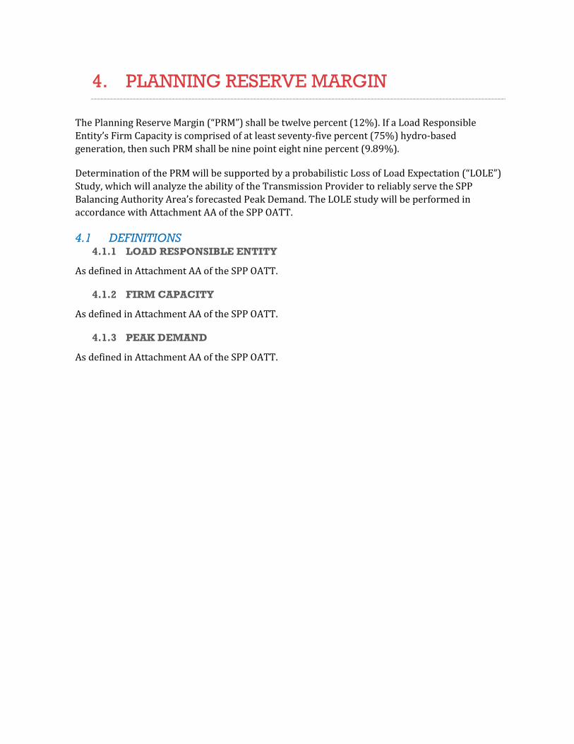
The Planning Reserve Margin (“PRM”) shall be twelve percent (12%). If a Load Responsible Entity’s Firm Capacity is comprised of at least seventy-five percent (75%) hydro-based generation, then such PRM shall be nine point eight nine percent (9.89%).
Determination of the PRM will be supported by a probabilistic Loss of Load Expectation (“LOLE”) Study, which will analyze the ability of the Transmission Provider to reliably serve the SPP Balancing Authority Area’s forecasted Peak Demand. The LOLE study will be performed in accordance with Attachment AA of the SPP OATT.
4.1 DEFINITIONS 4.1.1 LOAD RESPONSIBLE ENTITY
As defined in Attachment AA of the SPP OATT.
4.1.2 FIRM CAPACITY
As defined in Attachment AA of the SPP OATT.
4.1.3 PEAK DEMAND
As defined in Attachment AA of the SPP OATT.

5. REGIONAL TRANSMISSION PLANNING
5.1 CONCEPTS For the purposes of Section 5 of the SPP Criteria the transmission system shall be defined as facilities under the functional control of the SPP Open Access Transmission Tariff (OATT) or the Bulk Electric System (BES). The transmission system shall be capable of performing reliably under a wide variety of expected system conditions while continuing to operate within equipment and electric system thermal, voltage, and stability limits. The transmission system, at a minimum, shall be planned to withstand all single element contingencies and maintenance outages over the load conditions of all applicable seasonal models as required for each planning process. Extreme event contingencies which measure the robustness of the electric systems should be evaluated for risks and consequences. The NERC Reliability Standards define specific requirements where adherence provides a measurable degree of reliability for the BES. SPP provides additional coordinated regional transmission planning requirements to promote reliability through this Criterion and related “Transmission Planning Process” (Attachment O) in the OATT.
5.2 DEFINITIONS All capitalized terms shall have their meaning as contemplated in the SPP OATT or NERC Glossary of Terms used in the NERC Reliability Standards, unless defined below or noted within this document.
Nominal Voltage – The root-mean-square, phase-to-phase voltage by which the system is designated and to which certain operating characteristics of the system are related. Examples of nominal voltages are 500 kV, 345 kV, 230 kV, 161 kV, 138 kV, 115 kV and 69 kV.
The definition of Material Modifications is used for purposes of evaluating changes to existing Bulk Electric System (BES) interconnections of transmission Facilities for NERC Reliability Standard FAC-002-2 compliance. If one or more Material Modifications criterion are met, SPP shall analyze these changes to meet the requirements of NERC FAC-002-2 as the Planning Coordinator. Any change outside of this definition may be submitted to the Planning Coordinator for evaluation.
Material Modifications are permanent changes (that are typically greater than 12 months) to BES transmission Facilities. These permanent changes include:
1) Reduction to a BES transmission Facility’s Normal Rating or Emergency Rating greater than 20% (derate);
2) Proportional changes to the magnitude of the BES transmission Facility’s impedance that is greater than +/- 30% from its original positive sequence impedance value;
3) Changes in operating voltage of a BES transmission Facility;
4) Changes in BES transmission Facility system configuration including the connection or disconnection of new or existing BES transmission Facilities;
5) Changes in BES transmission Facility system protection that would reduce fault-interrupting capability or fault-clearing expediency for events that are included in the SPP Annual data request.
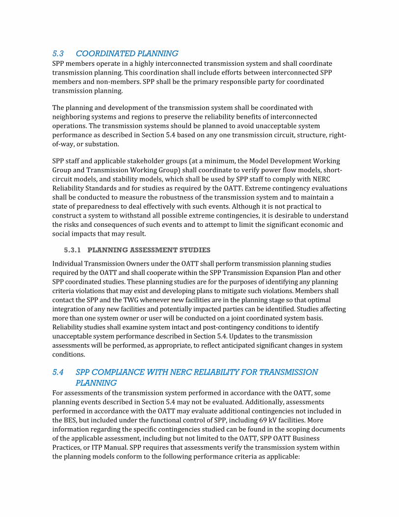
5.3 COORDINATED PLANNING SPP members operate in a highly interconnected transmission system and shall coordinate transmission planning. This coordination shall include efforts between interconnected SPP members and non-members. SPP shall be the primary responsible party for coordinated transmission planning.
The planning and development of the transmission system shall be coordinated with neighboring systems and regions to preserve the reliability benefits of interconnected operations. The transmission systems should be planned to avoid unacceptable system performance as described in Section 5.4 based on any one transmission circuit, structure, right-of-way, or substation.
SPP staff and applicable stakeholder groups (at a minimum, the Model Development Working Group and Transmission Working Group) shall coordinate to verify power flow models, short-circuit models, and stability models, which shall be used by SPP staff to comply with NERC Reliability Standards and for studies as required by the OATT. Extreme contingency evaluations shall be conducted to measure the robustness of the transmission system and to maintain a state of preparedness to deal effectively with such events. Although it is not practical to construct a system to withstand all possible extreme contingencies, it is desirable to understand the risks and consequences of such events and to attempt to limit the significant economic and social impacts that may result.
5.3.1 PLANNING ASSESSMENT STUDIES
Individual Transmission Owners under the OATT shall perform transmission planning studies required by the OATT and shall cooperate within the SPP Transmission Expansion Plan and other SPP coordinated studies. These planning studies are for the purposes of identifying any planning criteria violations that may exist and developing plans to mitigate such violations. Members shall contact the SPP and the TWG whenever new facilities are in the planning stage so that optimal integration of any new facilities and potentially impacted parties can be identified. Studies affecting more than one system owner or user will be conducted on a joint coordinated system basis. Reliability studies shall examine system intact and post-contingency conditions to identify unacceptable system performance described in Section 5.4. Updates to the transmission assessments will be performed, as appropriate, to reflect anticipated significant changes in system conditions.
5.4 SPP COMPLIANCE WITH NERC RELIABILITY FOR TRANSMISSION PLANNING
For assessments of the transmission system performed in accordance with the OATT, some planning events described in Section 5.4 may not be evaluated. Additionally, assessments performed in accordance with the OATT may evaluate additional contingencies not included in the BES, but included under the functional control of SPP, including 69 kV facilities. More information regarding the specific contingencies studied can be found in the scoping documents of the applicable assessment, including but not limited to the OATT, SPP OATT Business Practices, or ITP Manual. SPP requires that assessments verify the transmission system within the planning models conform to the following performance criteria as applicable:
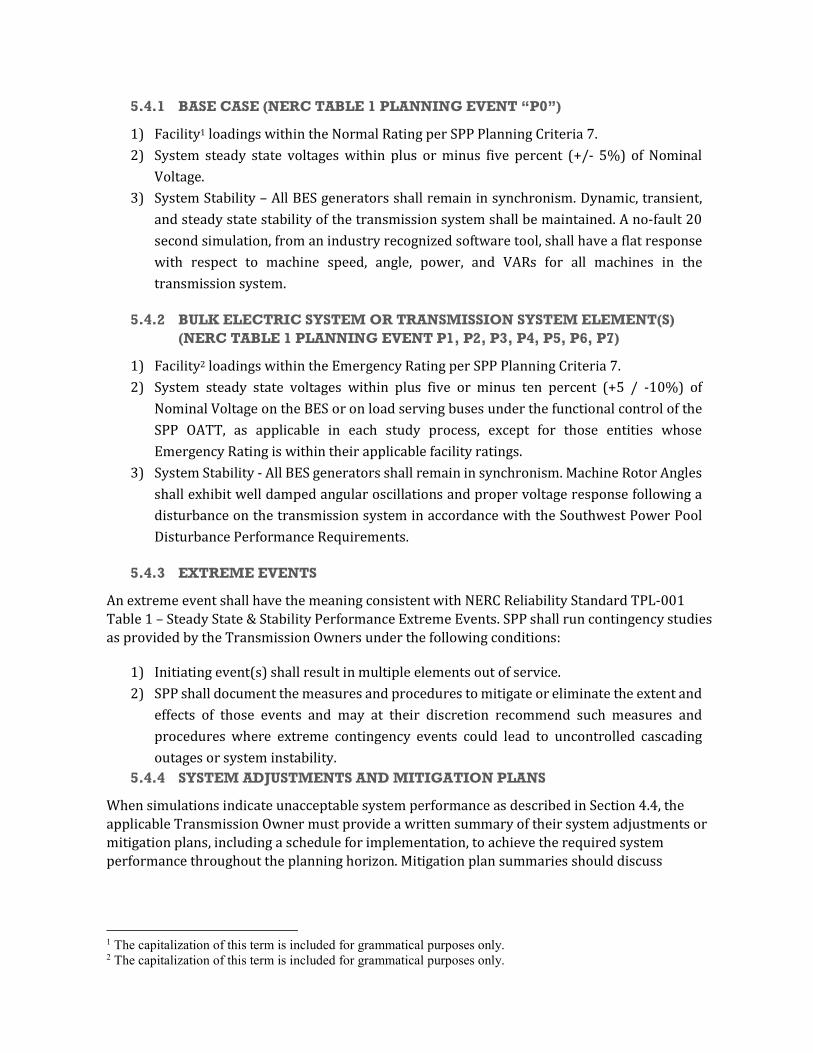
5.4.1 BASE CASE (NERC TABLE 1 PLANNING EVENT “P0”)
1) Facility1 loadings within the Normal Rating per SPP Planning Criteria 7. 2) System steady state voltages within plus or minus five percent (+/- 5%) of Nominal
Voltage. 3) System Stability – All BES generators shall remain in synchronism. Dynamic, transient,
and steady state stability of the transmission system shall be maintained. A no-fault 20 second simulation, from an industry recognized software tool, shall have a flat response with respect to machine speed, angle, power, and VARs for all machines in the transmission system.
5.4.2 BULK ELECTRIC SYSTEM OR TRANSMISSION SYSTEM ELEMENT(S) (NERC TABLE 1 PLANNING EVENT P1, P2, P3, P4, P5, P6, P7)
1) Facility2 loadings within the Emergency Rating per SPP Planning Criteria 7. 2) System steady state voltages within plus five or minus ten percent (+5 / -10%) of
Nominal Voltage on the BES or on load serving buses under the functional control of the SPP OATT, as applicable in each study process, except for those entities whose Emergency Rating is within their applicable facility ratings.
3) System Stability - All BES generators shall remain in synchronism. Machine Rotor Angles shall exhibit well damped angular oscillations and proper voltage response following a disturbance on the transmission system in accordance with the Southwest Power Pool Disturbance Performance Requirements.
5.4.3 EXTREME EVENTS
An extreme event shall have the meaning consistent with NERC Reliability Standard TPL-001 Table 1 – Steady State & Stability Performance Extreme Events. SPP shall run contingency studies as provided by the Transmission Owners under the following conditions:
1) Initiating event(s) shall result in multiple elements out of service. 2) SPP shall document the measures and procedures to mitigate or eliminate the extent and
effects of those events and may at their discretion recommend such measures and procedures where extreme contingency events could lead to uncontrolled cascading outages or system instability.
5.4.4 SYSTEM ADJUSTMENTS AND MITIGATION PLANS
When simulations indicate unacceptable system performance as described in Section 4.4, the applicable Transmission Owner must provide a written summary of their system adjustments or mitigation plans, including a schedule for implementation, to achieve the required system performance throughout the planning horizon. Mitigation plan summaries should discuss
1 The capitalization of this term is included for grammatical purposes only. 2 The capitalization of this term is included for grammatical purposes only.

expected required in-service dates of facilities, should consider lead-times necessary to implement plans, and will be reviewed for continuing need in subsequent annual assessments.
5.4.5 TRANSMISSION OPERATING GUIDES
A transmission operating guide qualifies as a valid mitigation measure when the transmission operating guide is effective as written.
5.5 INTERCONNECTION REVIEW PROCESS Southwest Power Pool Planning Criteria 5.3.1 and the SPP Open Access Transmission Tariff both require members to contact SPP and the Transmission Working Group whenever new transmission facilities that impact the interconnected operation are in the conceptual planning stage so that the optimal integration of any new facilities can be identified. Under this criterion an interconnection involves two or more SPP members or an SPP member and a non-member. A project that creates a non-radial, non-generation interconnection at 69 kV or above or that removes an interconnection at 230 kV or above shall be reviewed for impacts in accordance with Section 14 of this Criteria.

6. REGIONAL CALCULATION OF AVAILABLE TRANSFER CAPABILITY
SPP takes a regional approach in the determination of Available Transfer Capability (ATC). The regional approach calls for SPP to evaluate the inter-area transfer capability of its Transmission Owners. This approach provides a high level of coordination between ATC reported by SPP and Transmission Owners on SPP Open Access Same-time Information Network (OASIS) nodes. Likewise, when Transmission Owners calculate ATC, they are responsible to coordinate the ATC between their areas. If there is a dispute concerning the ATC, the SPP Transmission Working Group (TWG) will act as the technical body to determine the ATC to be reported. This Planning Criteria provides Transmission Owners and the SPP Transmission Provider flexibility to revise the ATC as needed for changes in operating conditions, while providing for unique modeling parameters of the areas. The SPP Transmission Provider calculations do not preclude any studies made by Transmission Owners in accordance with their individual tariffs, which may contain specific methodologies for evaluating transmission service requests.
Transfer capabilities are calculated for two different commercial business applications; a) for use as default values for Transmission Owners to post on their OASIS node for business under their transmission tariffs and b) for use by SPP in administering the SPP Open Access Transmission Tariff (SPP OATT).
The SPP utilizes a “constrained element” approach in determining ATC. This approach is referred to as a Flowgate ATC methodology. Constrained facilities, termed “Flowgates”, used in this approach are identified primarily from a non-simultaneous transfer study using standard incremental transfer capability techniques that recognize thermal, voltage and contractual limitations. Stability limitations are studied as needed. Flowgates serve as proxies for the transmission network and are used to study system response to transfers and contingencies. Using Flowgates with pre-determined ratings, this process is able to evaluate the ATC of specific paths on a constrained element basis (Flowgate basis) while considering the simultaneous impact of existing transactions.
The calculation of ATC is a very complex and dynamic procedure. SPP realizes that there are many technical and policy issues concerning the calculation of ATC that will evolve with industry changes. Therefore, the SPP Operating Reliability Working Group and the SPP Transmission Working Group will have the joint authority to modify the implementation of this Section of the Criteria based on experience and improvements in technology and data coordination. Any changes made by these groups will be subject to formal approval as outlined in the SPP Bylaws at the first practical opportunity, with the exception of response factor thresholds for short-term transmission service which may be approved for immediate implementation by the ORWG subject to subsequent review by the MOPC at the first practical opportunity. The response factor thresholds for short-term and long-term service are included in Section 13.

6.1 DEFINITIONS 6.1.1 BASE LOADING, FIRM AND NON-FIRM (FBL & NFBL)
The determined loading on a Flowgate resulting from the net effect of modeled existing transmission service commitments for the purpose of serving firm network load and impacts from existing OATT OASIS commitments
6.1.2 CAPACITY BENEFIT MARGIN
The amount of Flowgate capacity reserved by load serving entities to ensure access to generation from interconnected systems to meet generation reliability requirements
6.1.3 CONTRACTUAL LIMIT
Contractual arrangements between Transmission Providers that define transfer capability between the two
6.1.4 CRITICAL CONTINGENCY
Any generation or transmission facility that, when outaged, is deemed to have an adverse impact on the reliability of the transmission network
6.1.5 DESIGNATED NETWORK RESOURCES (DNR)
Any designated generation resource that can be called upon at any time for the purpose of serving network load on a non-interruptible basis. The designated generation resource must be owned, purchased or leased by the owner of the network load
6.1.6 EMERGENCY VOLTAGE LIMITS
The operating voltage range on the interconnected system that is acceptable for the time sufficient for system adjustments to be made following a Critical Contingency
6.1.7 FIRM AVAILABLE TRANSFER CAPABILITY (FATC)
The determined transfer capability available for firm Transmission Service as defined by the FERC pro forma OATT or any direction of interest on a transmission network between generation groups and/or system load for which commercial service may be desired.
6.1.8 FIRST CONTINGENCY INCREMENTAL TRANSFER CAPABILITY
NERC Transmission Transfer Capability, reference document (May 1995) defines FCITC as: "The amount of power, incremental and above normal base transfers, that can be transferred over the interconnected transmission systems in a reliable manner based on all of the following conditions:
1) For the existing or planned system configuration, and with normal (pre-contingency) operating procedures in effect, all facility loadings are within normal ratings and all voltages are within normal limits,
2) The electric systems are capable of absorbing the dynamic power swings, and remaining stable, following a disturbance that results in the loss of any single electric system element, such as a transmission circuit, transformer or generating unit, and,

3) After the dynamic power swings subside following a disturbance that results in the loss of any single electric system element as described in 2 above, and after the operation of any automatic operating systems, but before any post-contingency operator-initiated system adjustments are implemented, all transmission facilities loadings are within emergency ratings and all voltages are within emergency limits."
6.1.9 FLOWGATE
A selected transmission element or group of elements acting as proxy for the transmission network representing potential thermal, voltage, stability and contractual system constraints to power transfer. The process of determining the reliability issues for which a Flowgate is representative of and by which a Flowgate is established is outlined in SPP Planning Criteria Section 6.4.
6.1.10 LINE OUTAGE DISTRIBUTION FACTOR
The percent of the power flowing across the contingency facility that transfers over the monitored facility when the contingency facility is switched out of service.
6.1.11 LOCAL AREA PROBLEM
A Transmission Owner may declare a facility under its control a Local Area Problem if it is overloaded in either the base case or contingency case prior to the transfer. If a member declares a facility a Local Area Problem, the member may neither deny transmission service nor request NERC Transmission Loading Relief for that defined condition.
6.1.12 MONITORED FACILITIES
Any transmission facility that is checked for predefined transmission limitations.
6.1.13 NON-FIRM AVAILABLE TRANSFER CAPABILITY
The determined transfer capability available for sale for non-firm Transmission Service as defined by the FERC pro forma OATT for any direction of interest on a transmission network between generation groups and/or system load for which commercial service may be desired.
6.1.14 NORMAL VOLTAGE LIMITS
The operating voltage range on the interconnected system that is acceptable on a sustained basis.
6.1.15 OPEN ACCESS TRANSMISSION TARIFF
FERC approved Pro-Forma Open Access Transmission Tariff.
6.1.16 OPERATING HORIZON
Time frame for which Hourly transmission service is offered. The rolling time frame is twelve to36 hours with a 12 noon threshold. It includes the current day, and after 12 noon, the remainder of the current day and all hours of the following day.

6.1.17 OPERATING PROCEDURE
Any policy, practice or system adjustment that may be automatically implemented, or manually implemented by the system operator within a specified time frame, to maintain the operational integrity of the interconnected electric systems. If an Operating Procedure is submitted to the SPP in writing and states that it is an unconditional action to implement the procedure without regard to economic impacts or existing transfers, then the Operating Procedure will be used to allow transfers to a higher level.
6.1.18 OUTAGE TRANSFER DISTRIBUTION FACTOR
The percentage of a power transfer that flows through the monitored facility for a particular transfer when the contingency facility is switched out of service.
6.1.19 PARTICIPATION FACTOR
The percentage of the total power adjustment that a participation point will contribute when simulating a transfer.
6.1.20 PARTICIPATION POINTS
Specified generators that will have their power output adjusted to simulate a transfer.
6.1.21 PLANNING HORIZON
Time frame beyond which Hourly transmission service is not offered.
6.1.22 POWER TRANSFER DISTRIBUTION FACTOR (PTDF)
The percentage of power transfer flowing through a facility or a set of facilities for a particular transfer when there are no contingencies.
6.1.23 POWER TRANSFER VOLTAGE RESPONSE FACTOR (PTVF)
The per unit amount that a facility’s voltage changes due to a particular transfer level.
6.1.24 SPP OPEN ACCESS TRANSMISSION TARIFF (SPP OATT)
The Southwest Power Pool Regional FERC approved Open Access Transmission Tariff
6.1.25 TRANSFER DISTRIBUTION FACTOR
A general term, which may refer to either PTDF or OTDF – The TDF represents the relationship
between the participation adjustment of two areas and the Flowgates within the system.
6.1.26 TRANSFER TEST LEVEL
The amount of power that will be transferred to determine facility TDFs for use in DC linear analysis.
6.1.27 TRANSMISSION OWNER
An Entity that owns transmission facilities which are operated under a FERC approved OATT

6.1.28 TRANSMISSION PROVIDER
An entity responsible for administering a transmission tariff. In the case of the SPP OATT, SPP is the Transmission Provider. An SPP member may be its own Transmission Provider if the member continues to sell transmission service under the terms of its own tariff.
6.1.29 TRANSMISSION USER
Any entities that are parties to transactions under appropriate tariffs.
6.1.30 TRANSMISSION RELIABILITY MARGIN (TRM)
The amount of Flowgate capacity necessary to ensure that the interconnected transmission network is secure under a reasonable range of uncertainties in system conditions.
6.1.31 TRM MULTIPLIERS (A & B)
1) “a”-multiplier; a factor between 0 and 1 indicating the amount of TRM not available for non-firm use during the Planning Horizon
2) “b”-multiplier; a factor between 0 and 1 indicating the amount of TRM not available for non-firm use during the Operating Horizon
6.2 CONCEPTS 6.2.1 TRANSFER CAPABILITY
Transfer capability is the measure of the ability of the interconnected electric systems to reliably move or transfer power from one area to another over all transmission circuits (or paths) between those areas under specified system conditions. The units of transfer capability are in terms of electric power, generally expressed in megawatts (MW). Transfer capability is also directional in nature. That is, the transfer capability from area A to area B is not generally equal to the transfer capability from area B to area A.
Some major points concerning transfer capability analysis are briefly outlined below:
1) System Conditions - Base system conditions are identified and modeled for the period being analyzed, including projected customer demand, generation dispatch, system configuration and base reserved and scheduled transfers.
2) Critical Contingencies - During transfer capability studies, both generation and transmission system contingencies are evaluated to determine which facility outages are most restrictive to the transfer being analyzed.
3) System Limits - The transfer capability of the transmission network can be limited by thermal, voltage, stability or contractual considerations.
Thermal and voltage transfer limits can be determined by calculating the First Contingency Incremental Transfer Capability. Stability studies may be performed by the Transmission Owners at their discretion. Any known stability limits, which are determined on a simultaneous basis, and all contractual limits will be supplied by each Transmission Owner in writing to the Transmission Provider and the TWG.

6.2.2 AVAILABLE TRANSFER CAPABILITY
NERC Available Transfer Capability Definitions and Determinations, reference document (June 1996) states: “Available Transfer Capability (ATC) is a measure of the transfer capability remaining in the physical transmission network for further commercial activity over and above already committed uses.”
SPP determines ATC as a function of the most limiting Flowgate of the path of interest. How limiting a Flowgate is to a path is based on two aspects: (1) The determined firm or non- firm Available Flowgate Capacity (FAFC or NFAFC) for that Flowgate, and (2) the TDF for which that Flowgate responds to power movement on the path under evaluation.
The common relationship between the identified limiting Flowgate and the path is the Transfer Distribution Factor (TDF). This is mathematically expressed as follows:
1) Firm ATC = the firm Available Flowgate Capacity divided by the Transmission Distribution Factor (FATC = FAFC/TDF) of the associated path.
Likewise,
2) Non-Firm ATC = the non-firm Available Flowgate Capacity divided by the Transmission Distribution Factor (NFATC = NFAFC/TDF) of the associated path.
Path ATC is determined by identifying the most limiting Flowgates to the path in question. Each Flowgate represents a potential limiting element to any path within a system. Therefore, each Flowgate with known Transfer Distribution Factor (TDF) can be translated into path ATC.
However, the Flowgate that produces the most limiting path ATC is the key Flowgate for that path.
The calculation of path ATC using this method is based on the ratio of the TDF into the remaining capacity of a Flowgate, (non-firm Available Flowgate Capacity or firm Available Flowgate Capacity). Once a group of potential limiting elements has been selected, then all values pertaining to ATC can be translated based on the TDF.
6.2.3 RESPONSE FACTORS
Response Factors are numerical relationships between key adjustments in the transmission system and specific transmission components being monitored. They provide a linear means of extrapolation to an anticipated end for which decisions can be made. The thresholds for several of the following response factors are listed in Section 13.
1) Transfer Distribution Factor - The Transfer Distribution Factor (TDF) is a general term referring to either PTDF or OTDF. The relationship between adjustments in participation points associated with a specific path and the identified Flowgate in the system is the TDF. Depending on the Flowgate type, the TDF may specifically represent the response in the system to certain types of pre-identified system limitations as mentioned in SPP Planning Criteria section 6.2.4.

2) Line Outage Distribution Factor - The Line Outage Distribution Factor (LODF) is the percent of the power flowing across the contingency facility that transfers over the monitored facility when the contingency facility is switched out of service.
3) Power Transfer Distribution Factor - The Power Transfer Distribution Factor (PTDF) is the percentage of a power transfer that flows through a facility or a set of facilities for a particular transfer when there are no contingencies. PTDF type Flowgates are used for representing Thermal, Voltage, Stability and Contractual Limitations. To be considered a valid limit to transfers, a PTDF Flowgate must have a PTDF at or above the applicable short-term or long-term threshold.
4) Outage Transfer Distribution Factor - The Outage Transfer Distribution Factor (OTDF) is the percentage of a power transfer that flows through the monitored facility for a particular transfer when the contingency facility is switched out of service. OTDF type Flowgates typically represent contingency based thermal limitations within the system. They can also be used to represent Stability limitations. To be considered a valid limit to transfers, a Monitored Facility must have an OTDF at or above the applicable short-term or long-term threshold.
5) Power Transfer Voltage Factor - The Power Transfer Voltage Factor (PTVF) is the per unit amount that a facility’s voltage changes due to a particular transfer level. To be considered a valid limit to transfers, a Monitored Facility must have a PTVF at or above the applicable short-term or long-term threshold.
6.2.4 TRANSFER CAPABILITY LIMITATIONS
The electrical ability of the interconnected transmission network to reliably transfer electric power may be limited by any one or more of the following:
1) Thermal Limits - Thermal limits establish the maximum amount of electrical current that a transmission circuit or electrical facility can conduct over a specified time period before it sustains permanent damage by overheating or before it violates public safety requirements. Normal and emergency transmission circuit ratings are defined in the SPP Rating of Equipment.
2) Voltage Limits - System voltages must be maintained within the range of acceptable minimum and maximum voltage limits. For example, minimum voltage limits can establish the maximum amount of electric power that can be transferred without causing damage to the electric system or customer facilities. A widespread collapse of system voltage can result in a blackout of portions of or the entire interconnected network. Acceptable minimum and maximum voltages are network and system dependent. The Normal Voltage Limit range is the operating voltage range on the interconnected systems, above or below nominal voltage and generally expressed in kilovolts that is acceptable on a sustained basis. The Emergency Voltage Limit range is the operating voltage range on the interconnected systems, above or below nominal voltage and generally expressed in kilovolts that is acceptable for the time sufficient for system adjustments to be made following a facility outage or system disturbance. Voltage limits will be as specified in the SPP Planning Criteria section 5.
3) Stability Limits - The transmission network must be capable of surviving disturbances through the transient and dynamic time periods following a disturbance. Specific

Stability Limits Criteria is found in the SPP Criteria: Regional Transmission Coordinated Planning.
4) Contractual Requirements - Some Transmission Owners have contractual arrangements that contain mutual agreements regarding the power transfer available between them. These contractual arrangements have been approved by the appropriate regulatory agencies. The NERC Operating Policies inherently recognize contract requirements that may limit the power transfer between Transmission Owners. Some contract requirements are discussed in NERC Operating Policy 3 – Interchange.
The limiting conditions on some portions of the transmission network can shift among thermal, voltage, stability and contractual limits as the network operating conditions change over time.
6.2.5 INVALID LIMITS
The procedures outlined in criteria may lead to identification of certain limiting facilities that are invalid. Reasons may include, but are not limited to:
1) An invalid contingency generated as a generic single outage, which is not valid without the outage of other facilities.
2) Incorrect ratings. Ratings will be corrected and the limiting transfer level recalculated. 3) The rating used may be directional in nature (directional relaying) and may not be
valid for the direction of flow. 4) The limiting facility is the result of over-generation/under-generation at a
participation point. 5) The contingency is considered improper implementation of an operating procedure. 6) The facility represents an equivalent circuit. 7) The limiting facility is declared a Local Area Problem.
Any limiting facility determined to be invalid due to modeling error that could be corrected must be corrected by the next series of seasonal calculations.
6.2.6 FLOWGATES
Flowgates are selected power transmission element groups that act as proxies for the power transmission system capable of representing potential thermal, voltage, stability and contractual system limits to power transfer. There are two types of Flowgates;
(1) OTDF Flowgate - Composed of usually two power transmission elements in which the loss of one (contingency facility) can cause the other power transmission element (monitored facility) to reach its emergency rating.
(2) PTDF Flowgate - Composed of one or more power transmission elements in which the total pre-contingency flow over the flowgate cannot exceed a predetermined limit. Either with the power transmission system intact or with a contingency elsewhere, the Flowgate can be selected to represent a thermal, voltage, stability or contractual limit.
Once a set of limiting elements have been identified, as potential transfer constraints, they can be grouped with their related components and identified as unique Flowgates. The rating of the Flowgate is called the Total Flowgate Capacity (TFC) of the Flowgate and is monitored and used
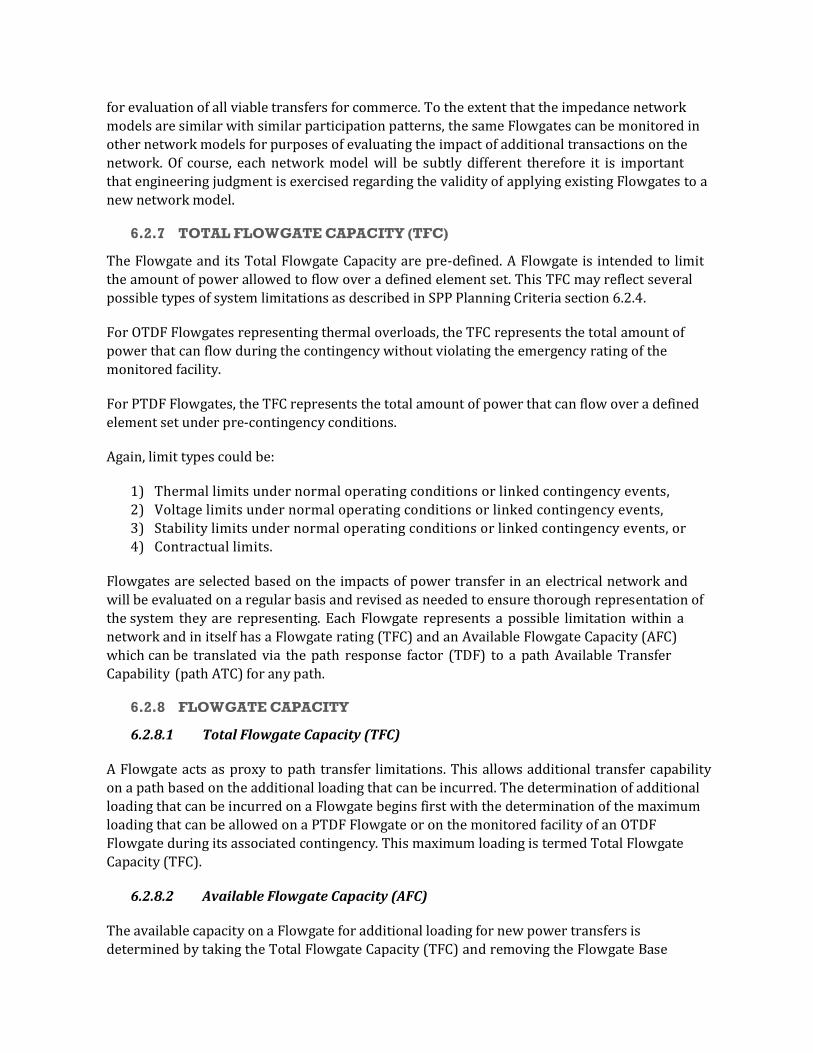
for evaluation of all viable transfers for commerce. To the extent that the impedance network models are similar with similar participation patterns, the same Flowgates can be monitored in other network models for purposes of evaluating the impact of additional transactions on the network. Of course, each network model will be subtly different therefore it is important that engineering judgment is exercised regarding the validity of applying existing Flowgates to a new network model.
6.2.7 TOTAL FLOWGATE CAPACITY (TFC)
The Flowgate and its Total Flowgate Capacity are pre-defined. A Flowgate is intended to limit the amount of power allowed to flow over a defined element set. This TFC may reflect several possible types of system limitations as described in SPP Planning Criteria section 6.2.4.
For OTDF Flowgates representing thermal overloads, the TFC represents the total amount of power that can flow during the contingency without violating the emergency rating of the monitored facility.
For PTDF Flowgates, the TFC represents the total amount of power that can flow over a defined element set under pre-contingency conditions.
Again, limit types could be:
1) Thermal limits under normal operating conditions or linked contingency events, 2) Voltage limits under normal operating conditions or linked contingency events, 3) Stability limits under normal operating conditions or linked contingency events, or 4) Contractual limits.
Flowgates are selected based on the impacts of power transfer in an electrical network and will be evaluated on a regular basis and revised as needed to ensure thorough representation of the system they are representing. Each Flowgate represents a possible limitation within a network and in itself has a Flowgate rating (TFC) and an Available Flowgate Capacity (AFC) which can be translated via the path response factor (TDF) to a path Available Transfer Capability (path ATC) for any path.
6.2.8 FLOWGATE CAPACITY
6.2.8.1 Total Flowgate Capacity (TFC)
A Flowgate acts as proxy to path transfer limitations. This allows additional transfer capability on a path based on the additional loading that can be incurred. The determination of additional loading that can be incurred on a Flowgate begins first with the determination of the maximum loading that can be allowed on a PTDF Flowgate or on the monitored facility of an OTDF Flowgate during its associated contingency. This maximum loading is termed Total Flowgate Capacity (TFC).
6.2.8.2 Available Flowgate Capacity (AFC)
The available capacity on a Flowgate for additional loading for new power transfers is determined by taking the Total Flowgate Capacity (TFC) and removing the Flowgate Base

Loading (FBL) and the Impacts due to existing system commitments and any transmission margins.
AFC = TFC – FBL – Impacts of existing commitments – transmission margins
6.2.8.3 Firm and Non-Firm Available Flowgate Capacity (FAFC and NFAFC)
Path ATC is classified as firm or non-firm. This distinction is made when determining the AFC remaining for path ATC. AFC is classified as firm or on firm depending on the types of existing commitments considered for Impacts. This is realized in the formula for AFC:
AFC = TFC – FBL – Impacts of existing commitments – transmission margins
6.2.9 SYSTEM IMPACTS
6.2.9.1 Impacts of Existing Commitments
In order to simultaneously account for impacts of all commitments to all paths at any given instant in time, it is necessary to devise a system that allows for fluctuation in the number of and the magnitude of system commitments on each path within an acceptable amount of time, for the purpose of providing transmission service in a competitive manner.
Existing transmission commitments beyond those modeled as native load and related generation commitments can be found on the OASIS. However, before impacts of OASIS posted reservations can be calculated, they must first be interpreted – carefully examined for peculiar individual characteristics. Due to the nature of the OASIS and the rules therein, posted reservations sometimes require interpretation as to their actual value to apply toward the transmission network.
The following are examples of evaluations that are performed:
1) Recognize and adjust for duplicate reservations by multiple providers to complete one transaction.
2) Adjust for reservations that may have changed status or have been replaced by another reservation, including renewals and redirects.
3) Check for proper reflection of capacity profiles of reservations. 4) Distinguish status and class of reservations such as Study, Accepted, Confirmed, Firm,
and Non-Firm status to determine their proper impact level.
6.2.9.2 Positive Impacts
The scope of “Impacts of existing commitments” in the formula for AFC incorporates both the calculated positive impacts and counter impacts of non-firm and firm service commitments. A positive impact is determined as having the effect of increasing the loading on a Flowgate in the direction of the Flowgate. Positive impact types are sorted into those resulting from firm and non-firm service commitments. To determine firm or non-firm Available Flowgate Capacity, the appropriate impacts are applied to make up the “Impacts of existing commitments” in the

above formula. Additionally, counter impacts are considered depending on firm or non-firm determinations.
6.2.9.3 Counter Impacts
Counter impacts are those impacts due to transfers that act to relieve loading on limiting elements. Counter impact types are sorted into those resulting from firm and non-firm service commitments. These flows are not traditionally accepted as valid under the pretense that any reservation that may cause such a loading relief is not actually doing so until it has been scheduled. To consider counter-flows in transfer capability studies is to assume a high probability of scheduling.
6.2.10 MONITORED FACILITIES
During the Flowgate determination process those facilities monitored for pre-defined limiting conditions. Mandatory Monitored Facilities, for use in these calculations, are all facilities operated at 100 kV and above and all interconnections between Transmission Providers. Other facilities operated at lower voltage levels may be added to the Monitored Facilities list at the discretion of the Transmission Providers or Transmission Owners. In defining Flowgates, the Monitored Facilities are those components of a Flowgate that remain in service following the defined contingency.
6.2.11 CRITICAL CONTINGENCIES
Those facilities that, when outaged, are deemed to have an adverse impact on the reliability of the transmission network. These facilities may be transmission facilities, including multi-terminal lines, or generating units. All interconnections of an area will be considered Critical Contingencies, regardless of voltage level as will the largest generating unit in the area.
6.3 RELIABILITY MARGINS Transmission margins are very important to the reliability of the interconnected network in an Open Access environment. The NERC "Available Transfer Capability Definitions and Determination Reference Document" defines Transmission Reliability and Capacity Benefit margins (TRM, CBM).
When using Flowgates as a means to represent a system’s constraints, it is necessary to
translate reliability margins, TRM and CBM, to a unique TRM and CBM for each Flowgate. Margins are the required capacities that must be preserved for the purpose of moving power between areas during specific emergency conditions. Since a margin is a preservation of transfer capacity, the margin itself will have an impact on the most limiting element between the two areas for which it is reserved.
All studies for the purpose of assessing TRM and CBM will only include generation units located within the transmission system for which the Transmission Provider is responsible. These generation units may also include those not specifically designated to serve network load connected to transmission systems within the Transmission Provider system. However, the method by which a Transmission Provider is to determine TRM and CBM shall not

vary from that described herein with the exception of assessing facilities located outside of SPP regional structure/bounds.
6.3.1 TRANSMISSION RELIABILITY MARGIN (TRM)
TRM on a Flowgate basis is that amount of reserved Flowgate capacity necessary to ensure that the interconnected transmission network is secure under a reasonable range of uncertainties in system conditions. The following factors shall be considered by SPP in the determination of TRM:
1) Load Forecast: Transmission Providers will forecast hourly load for the next seven days for all applicable control areas. Beyond seven days, Transmission Providers will project a demand based on seasonal peak load models for all applicable Transmission Owners. These load levels will be the projected peaks for the time frame for which the forecast applies.
2) Variations in Generation Dispatch: Variations to generation patterns constitute a viable concern. Generation dispatch in near-term models will be based on real-time snapshots of network system conditions. For the longer-term horizons, whenever possible, generation dispatch information provided by generation owners will be applied to the ATC calculations. However, it is recognized that longer-term dispatch is probably unknown to the generation controlling entities themselves except for base-load and must run type units.
3) Unaccounted Parallel Flows: Parallel flows can be an issue if pertinent data to the ATC calculations are not shared among the transmission providers and those transactions that have multiple wheeling parties are not identified. Provisions in the SPP OATT have reduced the impacts of these transactions within SPP and between SPP and other regions. Transmission Owners of facilities that are impacted by unaccounted parallel flows or variations in dispatch may request additional TRM for their impacted Flowgates from the TWG. Such requests must be in writing, must document the parallel flow impacts or the variance in historical dispatch, and be accompanied by analysis or documentation supporting the additional TRM requirements. The TWG shall have the authority to grant or reject requests for the additional TRM requests.
4) SPP Operating Reserve Sharing: The SPP Operating Reserve Sharing program was instituted to provide both reliability and economic benefits to its members. This program reduces the amount of internal operating reserves each entity is required to maintain while providing an automated way of allocating resources on a region wide level to ensure quick recovery for the loss of any unit. Transmission facilities must be able to support the automatic implementation of the Reserve Sharing program. To that end, TRM on the Flowgates will provide enough capacity to withstand the impact of the most critical generation loss to that facility. All generation contingencies will be simulated by the Operating Reserve Sharing algorithm to determine the highest impact on each Flowgate. This capacity will be included in TRM.
5) Counter Flow Impacts: Another factor to consider in the SPP TRM process is that for the planning horizon, which is primarily next day and beyond, the counter flow impacts of reservations on the Flowgates are removed with the exception of Designated Network Resources. This provides an inherent margin in the calculation

which along with the constant TRM provided by the reserve sharing allocation, is a proxy for the generation variation.
6.3.2 TRM COORDINATION
The TRM specified on a Flowgate represents a transmission margin that the transmission system needs to maintain a secure network under a reasonable range of uncertainties in system conditions. As such it is not necessarily an import or export quantity specifically. The Automatic Operating Reserve Sharing portion is determined by centralized Regional study based on the SPP Operating Reserve Sharing Criteria. Any additional TRM may be requested by the Flowgate owner(s), subject to review by the SPP TWG.
6.3.3 TRM AVAILABILITY FOR NON-FIRM SERVICE
To maximize transmission use to the extent reliably possible, Transmission Providers may sell TRM on a non-firm basis. The ‘a’ and ‘b’ multipliers facilitate this purpose in the calculations. However, a contingency or long-term outage to a high impact unit may result in the curtailment of non-firm schedules and displacement of non-firm reservations sold within the TRM.
6.3.4 TRM CALCULATION FREQUENCY
The Operating Reserve Sharing portion of the TRM will be determined annually for each season (spring, summer, fall, winter). This process is outlined in the SPP Criteria under Operating Reserves and the Operating Reserve Share Program Procedures. Flowgate owner requests for additional TRM may be submitted at any time for consideration at the next TWG meeting. The submittal should include justification and rational in writing for the requested additional TRM. The TWG shall have authority to reject or grant such requests.
6.3.5 CAPACITY BENEFIT MARGIN (CBM)
CBM on a Flowgate basis is the amount of Flowgate capacity reserved by load serving entities to ensure access to generation from interconnected systems to meet generation reliability requirements.
SPP does not utilize CBM for calculations of ATC for some or all of the following reasons:
1) the existing level of internal reserve margin of each member is adequate 2) historical reliability indicators of transmission strength of the SPP area 3) Open Access transmission usage environment allows greater purchasing options
Since SPP does not utilize CBM for any flowgate within the SPP footprint, the CBM value used in any calculations will be zero.
6.4 FLOWGATE AND TFC DETERMINATION The Flowgates used by SPP to administer the Regional Tariff serve as a proxy of the transmission system. It is therefore essential to the reliable operation of the transmission system for the set of Flowgates to adequately represent the transmission system.

6.4.1 FLOWGATE UPDATES
Updating the list of Flowgates is a continual process. Flowgate additions and deletions and changes in TFC are the result of studies, analyses, and operating experience of SPP and its member Transmission Owners. At any time during the year, the owner of transmission facilities may require that a set of facilities be used as a Flowgate to protect equipment or maintain system reliability, regardless of the ownership of that set of facilities. SPP will update the Flowgate list as needed. The responsibility for reviewing and monitoring the list will be shared between the individual Transmission Owners, the TWG, the Operating Reliability Working Group (ORWG) and the SPP staff. Updating the Flowgate list may or may not require running a study. If the Transmission Owner is to perform a study, they are responsible for gathering accurate information from neighboring Transmission Owners. The following requirements apply when adding a Flowgate to the list:
1) Transmission Owners may add OTDF Flowgates, provided that the contingency is valid, the TFC represents the total amount of power that can flow during the contingency without violating the emergency rating of the monitored facility, and no operating procedures apply to that Flowgate.
2) Transmission Owners may add PTDF Flowgates, provided that it is a single facility Flowgate, the TFC is equal to the normal rating of the single facility, and no operating procedures apply to that Flowgate.
3) All other Flowgates proposed by Transmission Owners must have TWG and ORWG approval. The Reliability Authority can provide interim approval until the TWG and ORWG can convene to assess the request. Examples of such Flowgates are PTDF Flowgates with two or more elements, OTDF Flowgates with three or more elements, or Flowgates involving operating procedures.
There may be times when significant topological changes occur during operations that create unexpected loadings on facilities not explicitly modeled as Flowgates. During these conditions, the Reliability Coordinator will work with the Transmission Owner(s) to develop a commercial Flowgate representative of the conditions present. Any such additions will be analyzed at the next Flowgate evaluation to determine if they should remain in the permanent list of Flowgates.
6.4.2 ANNUAL REVIEW
In addition to the continual studies and analyses, the Flowgate list will also be reviewed annually by the TWG using seasonal power flow models. This annual assessment will be performed
following the January SPP Model Development Work Group (MDWG) release of each year ’s load
flow cases. This review is intended to serve as a tool by which the TWG, the Transmission Owners, and the SPP may assess the adequacy of the existing list of Flowgates and thereby recommend necessary additions, deletions, and TFC changes. In order to accomplish this assessment, the process herein described will be used to identify the most limiting elements for a variety of transfer directions. Although transfer values will be involved in this process, this process is not intended to produce any viable ATC values for use commercially or otherwise. Rather, ATC values are determined as described in SPP Planning Criteria section 6.5.
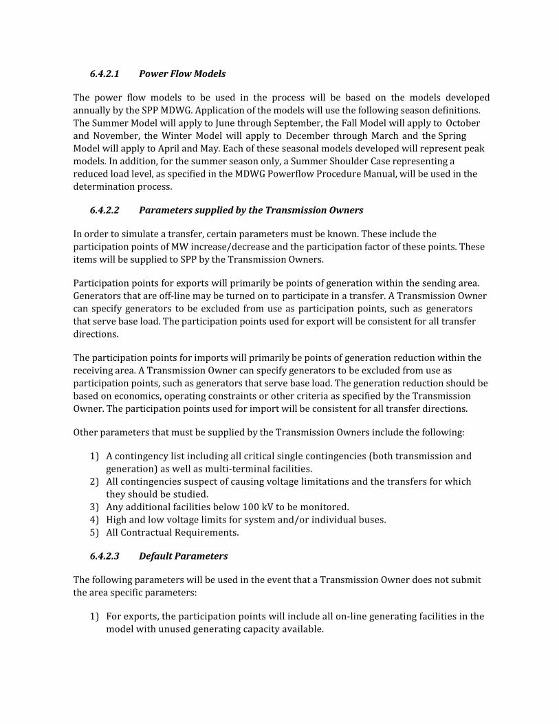
6.4.2.1 Power Flow Models
The power flow models to be used in the process will be based on the models developed annually by the SPP MDWG. Application of the models will use the following season definitions. The Summer Model will apply to June through September, the Fall Model will apply to October and November, the Winter Model will apply to December through March and the Spring Model will apply to April and May. Each of these seasonal models developed will represent peak models. In addition, for the summer season only, a Summer Shoulder Case representing a reduced load level, as specified in the MDWG Powerflow Procedure Manual, will be used in the determination process.
6.4.2.2 Parameters supplied by the Transmission Owners
In order to simulate a transfer, certain parameters must be known. These include the participation points of MW increase/decrease and the participation factor of these points. These items will be supplied to SPP by the Transmission Owners.
Participation points for exports will primarily be points of generation within the sending area. Generators that are off-line may be turned on to participate in a transfer. A Transmission Owner can specify generators to be excluded from use as participation points, such as generators that serve base load. The participation points used for export will be consistent for all transfer directions.
The participation points for imports will primarily be points of generation reduction within the receiving area. A Transmission Owner can specify generators to be excluded from use as participation points, such as generators that serve base load. The generation reduction should be based on economics, operating constraints or other criteria as specified by the Transmission Owner. The participation points used for import will be consistent for all transfer directions.
Other parameters that must be supplied by the Transmission Owners include the following:
1) A contingency list including all critical single contingencies (both transmission and generation) as well as multi-terminal facilities.
2) All contingencies suspect of causing voltage limitations and the transfers for which they should be studied.
3) Any additional facilities below 100 kV to be monitored. 4) High and low voltage limits for system and/or individual buses. 5) All Contractual Requirements.
6.4.2.3 Default Parameters
The following parameters will be used in the event that a Transmission Owner does not submit the area specific parameters:
1) For exports, the participation points will include all on-line generating facilities in the model with unused generating capacity available.

2) The export participation factors will be the amount of unused generating capacity at each point divided by the sum of the unused generating capacity at all export participation points. (i.e., PMAX-PGEN).
3) For imports, all on-line generators will be decreased prorated by their capable generation (i.e., PGEN-PMIN).
4) Transfer directions will be a set of all commercial paths. 5) Exports from merchant power plants will be considered in the determination of
Flowgates. 6) The transfer test levels are specified at the time of the ATC calculations, and are
determined by SPP staff. 7) All facilities 100 kV and above will be included in the contingency list and the
monitored facility list. In addition, the largest unit within the area will be included in the contingency list.
8) Voltage limits will be as specified in SPP Planning Criteria section 5.
6.4.2.4 Voltage Limits
Voltage limits are network and system dependent. Each Transmission Owner will submit an acceptable set of Normal Voltage Limits and Emergency Voltage Limits to be applied for the purpose of Flowgate and TFC determination.
6.4.2.5 Linear Analysis and AC Verification
SPP will perform DC linear analysis studies estimating the import or export ability of the identified commercial paths using a combined linear evaluation of the network models with a follow up AC verification of a minimum of the first three valid operational limitations. Specific AC analysis will also be performed on any specified contingency/transfer combinations noted as voltage limiting contingencies. Monitored Facilities, Contingency Facilities and Participation Points will be implemented as described in SPP Planning Criteria sections 6.4.2.2 and 6.4.2.3 as applicable.
6.4.2.6 Operating Procedures
Operating Procedures are available and may increase the Total Flowgate Capacity of a Flowgate when implemented. Implementation of any available Operating Procedures will be done using a full AC solution to determine the correct limit to be placed on a Flowgate. Any operationally increased Total Flowgate Capacities established will be so noted.
6.4.2.7 Identification of Flowgate Changes
TWG will review the FCITC results of the power flow models and selected paths and identify whether any Flowgates should be added, removed, or changed to better represent the SPP transmission system.
A minimum of the first three valid FCITC limitations to each path will be AC verified. When all paths have been evaluated, the TWG will review the AC verification results and, where needed, the linear results for consideration as potential Flowgates.

Typically, new Flowgates should be either OTDF Flowgates with a TFC representing the total amount of power that can flow during a contingency without violating the emergency rating of the monitored facility or single facility PTDF Flowgates with a TFC equal to the normal rating of the single facility. In situations involving operating procedures the TFC may be higher than the facility ratings.
The TWG will then determine any needed changes to the existing list of Flowgates. The number of times elements appear as one of the most limiting components for transfers, the rank in the list of most limiting elements, and the TDF level will be the primary factors considered in making the determination. Flowgates can also be developed to represent identified Voltage Limitations and Contractual Requirements.
6.4.2.8 Review and Coordination with Transmission Owners
Each SPP Transmission Owner will have the option of naming a representative to review the results of the Flowgate review or deferring to the TWG finalization of the results. Summary sheets of all interfaces or paths calculated will be communicated to the representatives for review. All data will be made available for review upon request. The results will be approved by the TWG before being reported.
The Transmission Owner should review the TWG proposed Flowgate changes and consider their own operating experience and study results. Any modifications to the TWG proposed changes should be returned to the TWG. Further dialog and justification may be required of a
Transmission Owner if the TWG has concerns about their modifications.
TWG will draft a final Flowgate list, incorporating the comments of the Transmission Owners. The Transmission Owners should approve any additions, deletions, or changes to the Flowgate list.
6.4.2.9 Initiating Interim Review of Flowgate List
Operational condition changes, especially status changes of EHV transmission facilities and large generators, may warrant a partial or full evaluation of the list of Flowgates. A review may also be necessary due to multiple schedules being implemented causing parallel flows.
Transmission Owners will have access to copies of the SPP models and all relevant data used for the annual review. Transmission Owners may at any time request a re-run of the Flowgate evaluations. The Transmission Owner requesting the re-run shall provide their reasons for requesting the re-run to the TWG for consideration. Should the TWG deem a re-run necessary, the SPP staff will perform the additional evaluation.
6.4.3 DISPUTE RESOLUTION
If there is a dispute concerning a Flowgate, the questioning party must contact SPP and the Transmission Owner(s) involved to resolve the dispute. Examples of reasons for disputing a Flowgate may include:
1) The contingency used for the Flowgate is not valid.

2) There is an operating procedure that corrects the violation that is not being properly taken into account.
3) An operating procedure is being taken into account in an improper manner yielding an incorrect TFC.
If the parties involved do not reach agreement on the selected Flowgates, the SPP TWG will review all of the arguments. Additional analyses will be performed if necessary. SPP TWG will then make a final determination. If a party still wishes to dispute the Flowgate, the SPP Dispute Resolution policy described in Section 2 of the SPP By-laws may be initiated.
6.4.4 COORDINATION WITH NON-SPP MEMBERS
Flowgates involving transfers on interfaces and paths between SPP Transmission Owners and non-SPP Transmission Owners will be coordinated by the parties involved and the TWG.
6.4.5 FEEDBACK TO SPP MEMBERS
The SPP staff shall maintain a table of all Flowgates on the SPP OASIS. The table shall include all Flowgate data, which are applicable, including the Flowgate name, monitored facility, contingency facility, Flowgate rating, TRM, CBM, a and b multipliers, LODF, the TDF basis for the Flowgate (OTDF or PTDF), and the TDF cutoff threshold. This table shall be updated with any new information on or before the first of each month.
6.5 ATC CALCULATION PROCEDURES The determination of ATC via Flowgates utilizes proxy elements to represent the power transmission network. This process depends on the selected Flowgates to act as predetermined limiting constraints to power transfer. The process by which ATC will be determined when using the Flowgate proxy technique incorporates the Definitions and Concepts within this Criteria.
Determination of ATC via Flowgates adheres to the following approach:
1) establishes a network representation (power flow model) 2) identifies potential limits to transfer (thermal, voltage, stability, contract) 3) determines response factors of identified limits relative to transfer directions (TDF) 4) determines impacts of existing commitments (firm, non-firm) 5) applies margins (TRM, CBM, a & b multipliers) 6) determines maximum transfer capabilities allowed by limits and applied margins (
ATC, FATC, NFATC)
6.5.1 ATC CALCULATION AND POSTING TIMEFRAMES
To assist Transmission Providers with Short Term service obligations under FERC Order 888 and 889, SPP will calculate the monthly path ATC for the upcoming 16-months for all potential commercial paths for Transmission Providers in the SPP Region. This data will be posted for use in evaluating the SPP OATT requests and provided on a monthly basis to the Transmission Providers in adequate time to post the information on OASIS nodes by the 1st of each month.
Hourly, Daily and Weekly ATC shall be calculated on a daily basis and posted at the time of run. SPP will also provide commercial path conversions to any individual providers needing that

information to administer their own tariff. Hourly ATC shall be calculated for 12 to 36 hours ahead depending on time of day. SPP has a firm scheduling deadline at 12:00 noon of the day prior to start. At this point all firm schedules are known and the hourly non-firm request window opens for the next day. At this point SPP will calculate hourly ATC for HE 14 of the current day through HE 24 of the next day. This process continues dropping the current hour each resynchronization until 12:00 noon the next day when the cycle starts again. Again SPP will provide commercial path conversions for any SPP provider that needs them for posting on their own OASIS nodes.
6.5.2 POWER FLOW MODELS
The monthly calculation of Flowgate based ATC will be made using rolling seasonal models that produce an update for the upcoming sixteen month service window (12 month multi-month service + 4 months advance notice). For example, the required data update for January of any year will yield data for January thru December plus the next January, February, March and April of the following year. The necessary seasonal models will be selected from the approved SPP MDWG set to represent this time frame. Any known system changes/corrections to these models will be included. SPP will routinely calculate ATC for the upcoming 16-month service window. Monthly models will be updated/developed from the latest seasonal models to represent individual months for the purpose of capturing operational conditions that may be unique from other monthly models.
6.5.3 BASE LOADING, FIRM AND NON-FIRM (FBL & NFBL)
Model base flows provide the basis for which to begin determination of Available Flowgate Capacity. However, there are many transactions within the monthly models that are duplicated on the OASIS. A record of the network model flows of each Flowgate as found in the solved network models will be used as a beginning point to account for impacts of base case transactions and existing commitments. The impacts on Flowgates due to transactions outside the purpose of representing designated Network Resource exchange will be removed by applying the TDF factors determined to each transaction identified in the base case. In addition to adjusting the model flow in this manner, positive and counter impacts of existing OASIS commitments will be applied according to the type of Base Loading (Firm or Non-Firm) under consideration. In non-firm Base Loading, 50% of Counter Impacts resulting from firm Confirmed reservations will act to reduce the overall Base Loading figure. This process will establish the base loading expected with each control area serving its firm Network Load.
6.5.4 TRANSFER DISTRIBUTION FACTOR DETERMINATIONS (TDF)
For export and import participation points all on-line generators, unless otherwise denoted (e.g., nuclear units), will be scaled prorated by their machine base (MBASE). TDF data will be calculated for all commercial paths using the most current participation data, ATC models and Flowgate list on a monthly basis.
6.5.5 EXISTING COMMITMENTS AND NETTING PRACTICES
Existing commitments resulting from Confirmed, Accepted and Study reservations on the SPP OATT OASIS nodes will be considered and accounted for in the determination of Available Flowgate Capacity. Accounting for the impact of existing commitments is a key part of the
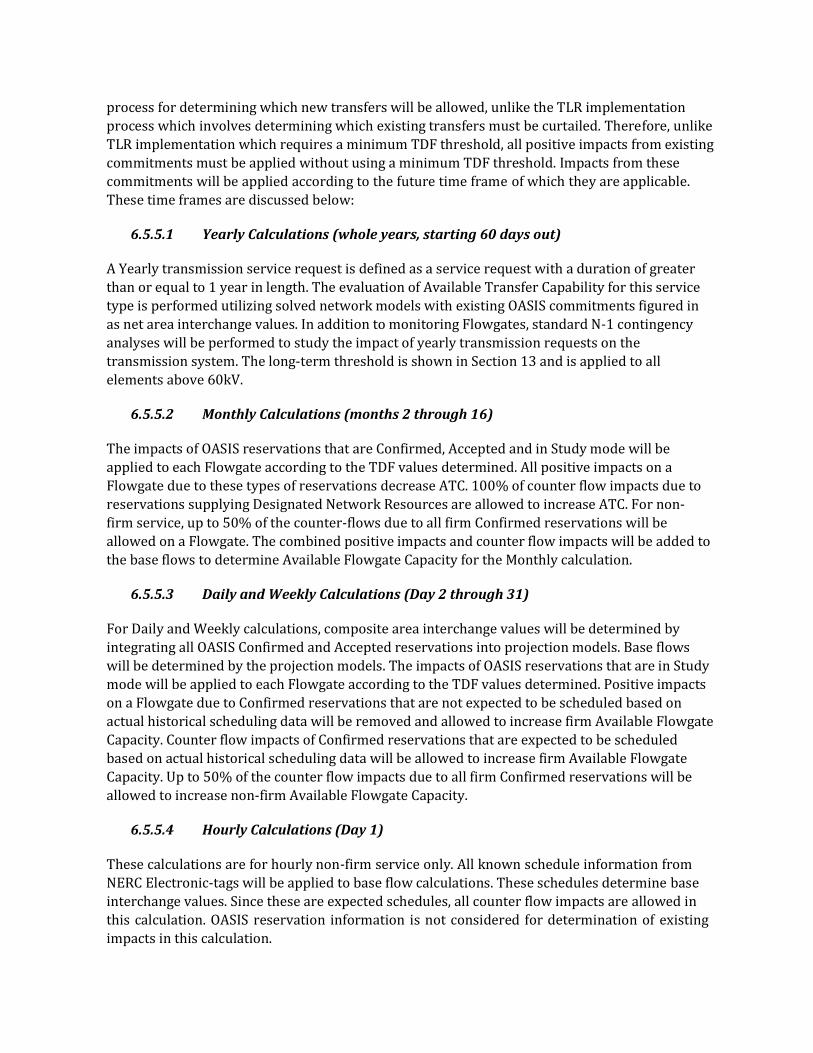
process for determining which new transfers will be allowed, unlike the TLR implementation process which involves determining which existing transfers must be curtailed. Therefore, unlike TLR implementation which requires a minimum TDF threshold, all positive impacts from existing commitments must be applied without using a minimum TDF threshold. Impacts from these commitments will be applied according to the future time frame of which they are applicable. These time frames are discussed below:
6.5.5.1 Yearly Calculations (whole years, starting 60 days out)
A Yearly transmission service request is defined as a service request with a duration of greater than or equal to 1 year in length. The evaluation of Available Transfer Capability for this service type is performed utilizing solved network models with existing OASIS commitments figured in as net area interchange values. In addition to monitoring Flowgates, standard N-1 contingency analyses will be performed to study the impact of yearly transmission requests on the transmission system. The long-term threshold is shown in Section 13 and is applied to all elements above 60kV.
6.5.5.2 Monthly Calculations (months 2 through 16)
The impacts of OASIS reservations that are Confirmed, Accepted and in Study mode will be applied to each Flowgate according to the TDF values determined. All positive impacts on a Flowgate due to these types of reservations decrease ATC. 100% of counter flow impacts due to reservations supplying Designated Network Resources are allowed to increase ATC. For non- firm service, up to 50% of the counter-flows due to all firm Confirmed reservations will be allowed on a Flowgate. The combined positive impacts and counter flow impacts will be added to the base flows to determine Available Flowgate Capacity for the Monthly calculation.
6.5.5.3 Daily and Weekly Calculations (Day 2 through 31)
For Daily and Weekly calculations, composite area interchange values will be determined by integrating all OASIS Confirmed and Accepted reservations into projection models. Base flows will be determined by the projection models. The impacts of OASIS reservations that are in Study mode will be applied to each Flowgate according to the TDF values determined. Positive impacts on a Flowgate due to Confirmed reservations that are not expected to be scheduled based on actual historical scheduling data will be removed and allowed to increase firm Available Flowgate Capacity. Counter flow impacts of Confirmed reservations that are expected to be scheduled based on actual historical scheduling data will be allowed to increase firm Available Flowgate Capacity. Up to 50% of the counter flow impacts due to all firm Confirmed reservations will be allowed to increase non-firm Available Flowgate Capacity.
6.5.5.4 Hourly Calculations (Day 1)
These calculations are for hourly non-firm service only. All known schedule information from NERC Electronic-tags will be applied to base flow calculations. These schedules determine base interchange values. Since these are expected schedules, all counter flow impacts are allowed in this calculation. OASIS reservation information is not considered for determination of existing impacts in this calculation.

6.5.6 PARTIAL PATH RESERVATIONS
Requests made on individual Transmission Provider’s tariffs require two or more reservations to complete a transaction resulting in a partial path reservation. The SPP OATT offers service out of, into and across SPP and between SPP members with a single reservation. For transmission service under the SPP OATT, only reservations with valid sources and sinks are allowed. However, to avoid double accounting of Flowgate and system impacts due to duplicate reservations documented on Transmission Provider OATT OASIS nodes from partial path reservations, necessary means will be incorporated to recognize these related reservations and determine the correct singular impacts.
6.5.7 ATC ADJUSTMENTS BETWEEN CALCULATIONS
ATC will be adjusted following receipt of any valid SPP OASIS node reservation. The requested capacity will be multiplied by the TDF on all affected Flowgates and the resulting amounts will be subtracted from each Flowgates’ ATC and posted to the OASIS.
6.5.8 COORDINATION OF TRANSMISSION COMMITMENTS WITH NEIGHBORING ORGANIZATIONS
Coordination of dispatch information, Confirmed firm and non-firm system commitments from neighboring regions, RTO’s, ISO’s etc. will be conducted as appropriate to each type of ATC being determined to establish the most accurate system representation of base flows and generation profiles. External reservations may be retrieved from other OASIS sites or locations designated by neighboring Transmission Providers.
6.5.9 MARGINS
Identified TRM and CBM will be applied to each Flowgate as described in SPP Planning Criteria section 6.3.
6.5.10 ATC DETERMINATION
The following equations are used in ATC determination:
6.5.10.1 Firm Base Loading (FBL)*, **:
Firm Base Loading = (Flows resultant of DNR) + (Σ Positive Impacts due to Firm OASIS
Commitments, Confirmed, Accepted and Study) – (100% of Σ Counter Impacts due to Confirmed Firm OASIS Commitments for DNR only)
6.5.10.2 Non-Firm Base Loading (NFBL)*, **:
Non-Firm Base Loading = (Flows resultant of DNR) + (Σ Positive Impacts due to Firm and Non-
Firm OASIS Commitments, Confirmed, Accepted and Study) – (up to 50% of Σ Counter Impacts
due to Confirmed Firm OASIS Commitments)

6.5.10.3 Firm Available Flowgate Capacity (FAFC):
Firm Available Flowgate Capacity = (Total Flowgate Capacity) – (TRM) – (CBM) – (Firm Base
Loading)
6.5.10.4 Non-Firm Available Flowgate Capacity (NFAFC, Operating Horizon):
Non-Firm Available Flowgate Capacity, Operating Horizon = (Total Flowgate Capacity) – (b*TRM)
– (CBM) – (Non-Firm Base Loading)
6.5.10.5 Non-Firm Available Flowgate Capacity (NFAFC, Planning Horizon):
Non-Firm Available Flowgate Capacity, Planning Horizon = (Total Flowgate Capacity) – (a*TRM)
– (CBM) – (Non-Firm Base Loading)
6.5.10.6 Firm Available Transfer Capability (FATC):
Firm ATC = Most limiting value from associated Flowgates = Min Firm Available Flowgate Capacity/TDF of appropriate path
6.5.10.7 Non-Firm Path Available Transfer Capability (NATC, Operating Horizon):
Non-Firm ATC, Operating Horizon = Most limiting value from associated Flowgates = Min Non-Firm Available Flowgate Capacity, Operating Horizon/TDF of appropriate path
6.5.10.8 Non-Firm Available Transfer Capability (NFATC, Planning Horizon):
Non-Firm ATC, Planning Horizon = Most limiting value from associated Flowgates = Min Non-Firm Available Flowgate Capacity, Planning Horizon/TDF of appropriate path
*Applicable pre-emption requirements of lower priority service types will be considered when evaluating requests for transmission service.
** Impacts resulting from queued Study reservations will be applied according to priority when evaluating requests for transmission service.
SPP will calculate the ATC for each of its Transmission Providers on their direct interconnections (either physical interconnections or by rights to a line) and any interface or path requested by a Transmission Provider to fulfill its obligations under FERC Order 889. The ATC for requested interfaces or paths will be calculated only if requested by the Transmission Provider obligated to post the interfaces or paths.
6.5.11 ANNUAL REVIEW OF ATC PROCESS
The SPP TWG will conduct an annual review of the Regional ATC determination process including TRM and CBM to assess regional compliance with NERC requirements, regional reliability needs and functionality toward SPP Transmission Owners and Users. This review will

be held at the same time as the Flowgate Evaluation process. The applicable long-term TRM is listed in Section 13.
SPP will conduct a survey of the Transmission Owners and Users and the results will be published on the SPP website. Concerns that are identified from the survey will be forwarded to the appropriate SPP Committee.
6.5.12 DIALOG WITH TRANSMISSION USERS
Transmission Users may contact the TWG with any concerns regarding this criterion, its implementation, or the resulting ATC values. The concerns should be in writing and sent to the chair of the TWG. The chair will then draft a written response to the Transmission User containing either an answer or a schedule for when such an answer can be provided. If the Transmission User is not satisfied, the concerns can be sent to the chair of the Markets and Operations Policy Committee.
7. ELECTRICAL FACILITY RATINGS
7.1 ACCREDITED NET CAPACITY FOR GENERATING UNITS AND DEMAND RESPONSE PROGRAMS
This Section shall be used to determine the annual and seasonal accredited net capacity of generators and Demand Response Programs. Procedures are herein for establishing a system of records so that changes in capacity during the life of the equipment can be recognized. These procedures define the framework under which the net capacity are to be established while recognizing the necessity of exercising judgment in their determination. The terms defined and the net capacity established pursuant to these procedures shall be used for SPP purposes, including determining reserve margins for capacity planning and preparation of reports of other information for industry organizations, news media, and governmental agencies. These net generating capacities are not intended to restrict daily operating practices associated with the Transmission Provider operating reserve sharing, for which more dynamic ratings may be necessary. Each member shall test its equipment in accordance with the procedures contained herein. On the basis of these tests summer and winter net capability ratings for each generating unit, Demand Response Program, and station on the member's electric system shall be established. This net capability or program is the maximum capacity a unit or program can sustain over a specified period modified for seasonal limitations and reduced by the capacity required for station service or auxiliaries. The summer net capability of each unit or program may be used as the winter net capability without further testing, at the option of the member. As a minimum, each member shall conduct tests on all its generators and programs that are designated as a part of the resource for supplying a member’s peak load and minimum reserve margin requirement of this Criteria. The seasonal net capabilities shall be furnished to the Transmission Provider for all existing generating units and programs and upon installation of new generating units and programs and shall be revised at other times when necessary. For newly installed generating units and programs, and units undergoing a physical or operational modification which could impact capability, design output may be used for the first peak operating season to allow sufficient time for Operational and Capability tests to be conducted. For generating units or programs out of service during the preceding peak season or that were de-rated because of forced outage due to equipment failure during the preceding peak season which limited the ability to perform an Operational test during the peak season, an Operational test that is completed after repairs are made may be used to satisfy the Operational test requirement for the upcoming peak operating season. Members shall annually report the seasonal net generating unit capability in conjunction with the Department of Energy 411 Report data gathering effort. For Behind-The-Meter Generation, section 7.1 applies only to Controllable and Dispatchable Behind-The-Meter Generation, as defined in Attachment AA of the SPP Tariff. Non-Controllable and Dispatchable Behind-The-Meter Generation, as defined in Attachment AA, do not require testing.

7.1.1 TESTING REQUIREMENTS FOR GENERATING UNITS
7.1.1.1 Accredited Capability Test
Capability Tests are required to demonstrate the claimed capability of all synchronous generating units, excluding run-of-the-river hydroelectric plants and wind/solar plants. During a Capability Test, a unit shall generate its rated net capability for a minimum of one hour period. Only minor changes in unit controls shall be made during this time as required to bring the unit into normal, steady-state operation.
7.1.1.2 Operational Test
An Operational Test is used to demonstrate the ability of a generating unit to be loaded to its claimed net capability. Operational tests shall be conducted at a minimum of 90% of the claimed net capability for a minimum of 1 hour. Any normal operating hour with the unit at or above 90% of claimed net capability may be deemed an Operational Test.
7.1.1.3 Frequency of Testing
Summer Capability Tests shall be conducted once every 5 years. If the winter capability rating is greater than summer, winter tests shall also be conducted once every 5 years. Operational Tests shall be conducted once every year during the member’s peak season. New units or units undergoing a physical or operational modification which could impact capability shall be given a capability test.
7.1.1.4 Net generating capacity and Testing Conditions
Ambient conditions at the time of running capability tests shall be recorded so that appropriate adjustments can be made when establishing seasonal capabilities. Conditions to be recorded are: dry-bulb temperature, wet-bulb temperature, barometric pressure, and condenser cooling water inlet temperature. Summer Capability Tests are to be conducted at an ambient temperature within 10 degrees Fahrenheit of Rating dry-bulb temperature.
Winter Capability Tests are to be conducted at an ambient temperature equal to or greater than the minimum dry-bulb temperature for winter testing and rating defined in paragraph SPP Planning Criteria 7.1.5.2. (7).
7.1.1.5 External Factor Procedures For Establishing Capability Ratings
1) Units dependent upon common systems which can restrict total output shall be tested simultaneously.
2) When the total output of a member's system is reduced due to restrictions placed upon the output of individual generating units through the operation of the Clean Air Act, or similar legislation, then the total of the individual unit ratings of a member's generating resources shall not exceed the modified system capacity.
3) The fuel used during testing shall be the general type expected to be used during peak load conditions or adjustments made to test data if an alternate fuel is used.

4) Net Capability is the net power output which can be obtained for the period specified on a seasonally adjusted basis with all equipment in service under average conditions of operation and with the equipment in an average state of maintenance. Deductions from net capability shall not be made for equipment temporarily out of service for normal maintenance or repairs.
5) The seasonal net capability shall be determined separately for each generating unit in a power plant where the input to the prime mover of the unit is independent of the others, except that in the event multiple unit plant capability is limited by fuel limitations, transmission limitations or other auxiliary devices or equipment, each unit shall be assigned a net generating capacity by apportioning the combined capability among the units. The seasonal net capability shall be determined as a group for common header sections of steam plants or multiple unit hydro plants, and each unit shall be assigned a net generating capacity by apportioning the combined capability among the units.
7.1.1.6 Seasonality Factors for Establishing Capability Ratings
1) The summer season is defined by the months June, July, August and September. The winter season is defined by the months December, January, February, and March. The adjustments required to develop seasonal net capabilities are intended to include seasonal variations in ambient temperature, condenser cooling water temperature and availability, fuel changes, quality and availability, steam heating loads, reservoir levels, scheduled reservoir discharge, and wind speed.
2) The total seasonal net capability rating shall be that available regularly to satisfy the daily load patterns of the member and shall be available for a minimum of four continuous hours taking into account possible fuel curtailments and thermal limits.
3) The seasonal net capability of each generating unit shall be based upon a set of conditions, referred to as the "Net generating capacity Conditions" for that unit. This set of conditions is determined by the geographical location of the unit, and is composed of three or four factors, depending upon the type of unit. The three factors which can affect most generating units are: Ambient dry-bulb temperature, ambient wet-bulb temperature and Barometric pressure. Condensing steam turbines which obtain condenser cooling water from a lake, river, or comparable source have a fourth factor: Condenser cooling water source temperature.
4) The Rating dry-bulb and wet-bulb temperatures shall be obtained from weather data provided in the most recently published American Society of Heating, Refrigeration, and Air Conditioning Engineers (ASHRAE) Fundamentals Handbook, Chapter 27 Climatic Design Information. The handbook is published every four years; 1997, 2001, etc., and is based on 15 years of historical weather data where available. If the generating station is within 30 miles of the nearest weather station reported in the Handbook, then these temperatures will be those for the nearest station. For all other stations, rating temperatures shall be determined by interpolating between weather stations using plant latitude and longitude. The steps to be used for interpolating weather data and correcting for elevation are presented in SPP Criteria Section 9.
5) If experience for a given unit suggests otherwise, members may optionally use their own site specific temperature data if accurate hourly data is available to allow

calculation of the temperature levels as defined in the Criteria. Site specific data shall contain both dry- bulb and wet-bulb temperatures.
6) Temperatures for summer rating of equipment should be taken from Handbook Table 1B: Cooling and Dehumidification Design Conditions - Cooling DB/MWB for 0.4% DB (dry-bulb) and MWB (mean wet-bulb) (Column 2a and 2b, respectively). According to the 2001 Handbook Page 27.2, "The 0.4% annual value is about the same as the 1.0% summer design temperature in the 1993 ASHRAE Handbook." In older Handbooks, the dry-bulb temperature for summer rating of equipment shall be taken as that which is equaled or exceeded 1% of the total hours during the months of June through September for the plant's geographical location. The wet-bulb temperature for the summer rating shall be the "mean coincident wet-bulb" temperature corresponding to the above dry-bulb temperature.
7) The temperature for winter rating of equipment should be taken from Handbook Table 1A: Heating and Wind Design Conditions-United States - Heating Dry Bulb 99% (Column 2b). According to the 2001 Handbook Page 27.3, "Annual 99.6% and 99.0% design conditions represent a slightly colder condition than the previous cold season design temperatures, although there is considerable variability in this relationship from location to location." In older Handbooks, the minimum dry-bulb temperature for winter testing and net generating capacity shall be taken as that which is equaled or exceeded 99% of the total hours during the months of December through February (per Handbook definition) for the plant's geographical location. The wet-bulb temperature is not significant for the winter rating and can be disregarded.
8) Standard barometric pressure for a plant site shall be determined for each plant elevation from the equation provided in Section 9.
9) For those units using a lake or river as a source of condenser cooling water, the summer standard inlet temperature is the highest water inlet temperature during the month concurrent with the member’s peak load of the year, averaged over the past ten years.
10) Ambient wet-bulb temperature and condenser cooling water temperature are generally not significant factors in adjusting cold weather capability of generating units. Shall special situations arise in which these temperatures are required, reasonable estimates for temperatures occurring coincidentally with the winter rating dry-bulb temperature as defined in the Criteria shall be used.
7.1.2 NET GENERATING CAPACITY AND DEMAND RESPONSEADJUSTMENTS
1) The rated net capability of a unit may be above or below the actual tested net capability as a result of adjustments for Net generating capacity Conditions, with the exception of units with winter season net capacity greater than their summer net capacity. For these units, the winter season rated net capability shall be no greater than the actual tested net capacity. No net generating capacity adjustment for ambient conditions shall be made.
2) Seasonal net capability shall not be reduced to provide regulating margin or spinning reserve. It shall reflect operation at the power factor level at which the generating equipment is normally expected to be operated over the daily peak load period.
3) Extended capability of a unit or plant obtained through bypassing of feed-water heaters, by utilizing other than normal steam conditions, by abnormal operation of

auxiliaries in steam plants, or by abnormal operation of combustion turbines or diesel units may be included in the seasonal net capability if the following conditions are met; a) the extended capability based on such conditions shall be available for a period of not less than four continuous hours when needed and meets the other restrictions, and b) appropriate procedures have been established so that this capability shall be available promptly when requested by the system operator.
4) The seasonal net capability established for nuclear units shall be determined taking into consideration the fuel management program and any restrictions imposed by governmental agencies.
5) The seasonal net capability established for hydroelectric plants, including pumped storage projects, shall be determined taking into consideration the reservoir storage program and any restrictions imposed by governmental agencies and shall be based on median hydro conditions.
6) The seasonal net capability established for run-of-the-river hydroelectric plants shall be determined using historical hydrological data on a monthly basis.
7) The seasonal net capability established for Demand Response Programs shall be adjusted in accordance with the Demand Response Programs Reporting and Documentation Procedures givin in SPP Business Practice.
8) The seasonal net capability established for Behind-The-Meter Generation, which does not have firm delivery beyond a discrete point of delivery, shall be adjusted in accordance with Behind The Meter Generation Reporting and Documentation Procedures given in SPP Business Practice.
9) The recommended methodology to evaluate the net planning capability established for wind or solar facilities shall be determined on a monthly basis, as stated below. If a member’s desire to use a more restrictive methodology to evaluate the net capability of wind or solar they may do so, however net capability determined by the alternative methodology employed cannot credit the wind or solar with a capability greater than determined with the methodology stated below:
10) Assemble all available hourly net power output (MWH) data measured at the system interconnection point.
(a) Select the hourly net power output values occurring during the top 3% of load hours for the SPP Load Serving Entity for each month of each year for the evaluation period.
(b) Select the hourly net power output value that can be expected from the facility 60% of the time or greater. For example, for a 5 year period with the 110 hourly net power output values ranked from highest to lowest, the capacity of the facility will be the MW value in the 65th data point.
(c) A seasonal or annual net capability may be determined by selecting the appropriate monthly MW values corresponding to the Load Serving Entity’s peak load month of the season of interest (e.g., 22 hours for a typical 30 day month and110 hours for a 5 year period).
(d) Facilities in commercial operation 3 years or less:
(i) The data must include the most recent 3 years.

(ii) Values may be calculated from wind or solar data, if measured MW values are not yet available. Wind data correlated with a reference tower beyond fifty miles is subject to Supply Adequacy Working Group approval. Solar data correlated with a reference measuring device beyond two hundred miles is subject to Supply Adequacy Working Group approval. For calculated values, at least one year must be based on site specific data.
(iii) If the Load Serving Entity chooses not to perform the net capability calculations as described above during the first 3 years of commercial operation, the Load Serving Entity may submit 5% for wind facilities and 10% for solar facilities of the site facility’s nameplate rating.
(e) Facilities in commercial operation 4 years and greater
(i) The data must include all available data up to the most recent 10 years of commercial operation.
(ii) Only metered hourly net power output (MWH) data may be used.
(iii) After three years of commercial operations, if the Load Serving Entity does not perform or provide the net capability calculations to The Transmission Provider as described above, then the net capability for the resource will be 0 MW
(f) The net capability calculation shall be updated at least once every three years.
7.1.3 EXEMPTION
Behind-The-Meter Generation, less than 10 MW, are exempted from Capability and Operational performance testing during the 2020 summer season. Behind-The-Meter Generation, less than 10 MW, will be required to follow testing guidelines in accordance with the SPP Plannign Criteria starting with the 2021 summer season in order to be eligible to meet the Resource Adequacy Requirement for 2022 summer season.
7.1.4 TESTING AND CAPABILITY REQUIREMENTS FOR DEMAND RESPONSE PROGRAMS
Demand Response Programs are as defined in Attachment AA
7.1.4.1 Capability Test
Demand Response Programs will be accredited based on a sustainable level of reduction as outlined in the SPP Business Practice. The amount of load reduction shall be 100% of the claimed capability, or the load shall be reduced to an amount that is less than the load forecast of the Demand Response Programs customer by an amount equivalent to 100% of the claimed capability.
If a Demand Response Program is deployed during the summer season, the deployment of that Demand Response Program can suffice in place of the Capability Test.

Demand Response Programs in the first year of operation or expansion of an existing program will be reported at 50% of the expected capability, unless validated by testing the program to 100% of the claimed capability prior to May 15. This test will be similar to a capability test but will be conducted outside of the peak season. Testing outside of the peak season will only be considered a capability test during the first year of operation or existing program expansion. An Operational Test shall be performed during the upcoming summer season and reported to the Transmission Provider in accordance with the SPP Business Practice.
7.1.4.2 Operational Test
An Operational Test is used to demonstrate the ability of a program. Operational test for Demand Response Programs shall be conducted at a minimum of 50% of programs claimed capability for a minimum of 1 hour. If a Demand Response Program is deployed during the summer season, the deployment of that Demand Response Program can suffice in place of the Operational Test.
7.1.4.3 Frequency of Testing
Capability Tests shall be conducted at least once every 5 years. Operational Tests shall be conducted once every year during the member’s peak season. New programs or programs undergoing a physical or operational modification which could impact capability shall be given a capability test.
7.1.4.4 Procedures for Establishing Capability Ratings for Demand Response
1) Test shall be completed during a peak load period in the summer season. 2) The load reduction shall be measured and report in accordance with SPP Business
Practice.
7.1.4.5 Exemption
Demand Response Programs are exempted from Capability and Operational performance testing during the 2020 summer season. Demand Response Programs will be required to follow testing guidelines in accordance with the SPP Planning Criteria starting with the 2021 summer season in order to be eligible to meet the Resource Adequacy Requirement for the 2022 summer season.
7.1.5 FUEL SUPPLY
Assurance of having desired generating capacity depends, in part, on the availability of an adequate and reliable fuel supply. Where contractual or physical arrangements permit curtailment or interruption of the normal fuel supply, sufficient quantities of standby fuel shall be provided. Due to the dependence of hydroelectric plants on seasonal water flows, this factor shall be taken into consideration when calculating capacity for reserve margin requirements.
7.2 RATING OF TRANSMISSION FACILITIES All transmission facilities, referenced in Section 5.1, shall have a Normal Rating and an Emergency Rating. Each SPP member shall provide the Normal Rating, Emergency Rating, and associated time durations to the SPP Planning Coordinator upon request.

SPP members may develop dynamic or seasonal ratings based on windspeed, ambient temperature or other variables if permitted by their individual Facility Rating methodology document.. The following sections provide guidance and recommendations to Transmission Owners (for voluntary use) in developing their respective Facility Ratings methodology document.
7.2.1 POWER TRANSFORMER
Power transformer ratings are discussed in ANSI/IEEE C5791, IEEE Guide for Loading Mineral-Oil-Immersed Power Transformers. Every transformer has a distinct temperature rise capability used in setting its nameplate rating (either 55°C or 65°C). These temperature rise amounts reflect the average winding temperature rise over ambient that a transformer may operate on a continuous basis and still provide normal life expectancy.
7.2.1.1 Normal Rating
The recommended Normal Rating for power transformers is its highest nameplate rating. The nameplate rating include the effects of forced cooling equipment if it is available. For multi-rated transformer (OA/FA, OA/FA/FA, OA/FOA/FOA, OA/FA/FOA) with all or part of forced cooling inoperative, nameplate rating used is based upon the maximum cooling available for operation. Normal life expectancy will occur with a transformer operated at continuous nameplate rating.
7.2.1.2 Emergency Rating
When operated for one or more load cycles above nameplate rating, the transformer insulation deteriorates at a faster rate than normal. The recommended Emergency Rating for power transformers is a minimum of 100% of its highest nameplate rating. Member systems may use a higher Emergency Rating if they are willing to experience more transformer loss-of-life.
7.2.1.3 Loss of Life
In ANSI/IEEE C57.91, a 65°C rise transformer can operate at 120% for an 8 hour peak load cycle and will experience a 0.25% loss of life. If a 65°C rise transformer experiences 4 incidents where it operates at or below 120% for an 8 hour peak load cycle, it will still be within the target of 1% loss of life per year. In ANSI/IEEE C57.91, a 55°C rise transformer can operate at 123% for an 8 hour peak load cycle and will experience a 0.25% loss of life. Likewise, if a 55°C rise transformer experiences 4 incidents where it operates at or below 123% for an 8 hour peak load cycle, it will still be within the target of 1% loss of life per year.
7.2.1.4 Ambient Temperature
Average ambient temperature is an important factor in determining the load capability of a transformer since the temperature rise for any load must be added to the ambient to determine operating temperature. Transformers designed according to ANSI standards use a 30°C average ambient temperature (average temperature for 24 consecutive hours) when setting nameplate rating. Transformer overloads can be increased at lower average ambient temperatures and still experience the same loss of life. This allows seasonal ratings with higher Normal and Emergency Ratings. However, seasonal transformer ratings are optional. In ANSI/IEEE C57.91, transformers

can be loaded above 110% and experience no loss of life when the average ambient temperature is below 78°F. By not having seasonal ratings, the four occurrences that contribute to loss of life are limited to days when the average ambient temperature exceeds 78°F. The Power Transformer Rating Factors include:
1) Nameplate rating, normal loss of life for 55°C and 65°C rise transformers with cooling equipment operating.
2) Average ambient temperature, 30°C. 3) Equivalent load before peak load, 90% of nameplate rating. 4) Hours of peak load, 8 hour load cycle. 5) Acceptable annual loss of life, 1%.
7.2.2 OVERHEAD CONDUCTOR
Overhead conductor ratings are discussed in IEEE Standard 738, IEEE Standard for Calculating the Current-Temperature Relationship of Bare Overhead Conductors. Ampacity values are to be determined using the fundamental heat balance equation outlined in the House and Tuttle method. Because of the amount and complexity of the equations, this method lends itself to computer application. The recommended computer programs to be used for this calculation either include the BASIC program listed in Annex B of IEEE Standard 738 or an equivalent program, such as the DYNMAP program which is part of the EPRI TL Workstation TM software package. While tables and graphs may be convenient to use, they fail to take into account the geographic location of the line and often lack either the desired ambient temperature and/or the desired conductor temperature. The use of tables and graphs is not recommended.
7.2.2.1 Conductor Properties
Some computer programs used to compute ampacity values have a conductor property library whereby a user simply specifies the conductor code name and the program will search the conductor property file and select the proper input properties. Those using the BASIC program from Annex B of IEEE Standard 738 or another computer program that does not have a conductor property library should obtain conductor properties from an appropriate data source (Aluminum Electrical Conductor Handbook, EPRI Transmission Line Reference Book 345 kV and Above, Westinghouse Transmission and Distribution Book, etc.).
7.2.2.2 Line Geographic Location
These factors specify the location of the line, its predominant direction and its predominant inclination. These numbers can either be line specific or they can represent a general line within the area.
7.2.2.3 Radiation Properties
The two radiative properties of conductor material are solar absorptivity and infrared emissivity.
Solar Absorptivity The fraction of incident solar radiant energy that is absorbed by the conductor surface. This value should be between 0 and 1. Recommended values are given in the following tables:

Copper Conductors
Oxidation Level Absorptivity
None 0.23
Light 0.5
Normal 0.7
Heavy 1.0
Aluminum Conductors
Service Years Absorptivity
0<5 .43
Source: Glenn A. Davidson, Thomas E. Donoho, George Hakun III, P. W. Hofmann, T. E Bethke, Pierre R. H. Landrieu and Robert T. McElhaney, "Thermal Ratings for Bare Overhead Conductors",
IEEE Trans., PAS Vol. 88, No.3, pp. 200-05, March 1969.
Infrared Emissivity The ratio of infrared radiant energy emitted by the conductor surface to the infrared radiant energy emitted by a blackbody at the same temperature. This value should be between 0 and 1. Recommended values are given in tables below:
Copper Conductors
Oxidation Level Emissivity
None 0.03
Light 0.3
Normal 0.5
Heavy 0.8
Aluminum Conductors
Service Years Emissivity
0 0.23
5-10 0.82
10-20 088
0.90

Source: W. S. Rigdon, H. E. House, R. J. Grosh and W. B. Cottingham, "Emissivity of Weathered Conductors After Service in Rural and Industrial Environments," AIEE Trans., Vol. 82, pp. 891-
896, Feb. 1963.
7.2.2.4 Weather Conditions
Ambient temperature represents the maximum seasonal temperature the line may experience for summer and winter conditions. Section 10.1 in this SPP Planning Criteria contains a methodology to compute maximum ambient temperature. Wind speed is assumed at 2 ft. /sec (1.4 mph) or higher. Wind direction is assumed perpendicular to the conductor.
7.2.2.5 Maximum Conductor Temperature
The selection of a maximum conductor temperature affects both the operation and design of transmission lines. Existing transmission lines were designed to meet some operating standard that was in effect at the time the line was built. That standard specified the maximum conductor temperature which maintained acceptable ground clearance while allowing for acceptable loss of strength. Over time, the required amount of ground clearance and the maximum conductor temperature needed to maintain acceptable ground clearance have changed. The changes are reflected in the revisions that have been made to the National Electric Safety Code (NESC) over the years. Although this Criteria recommends a maximum conductor temperature that could be met by current line design practices, consideration should be given to existing lines that were built according to an earlier standard. This rating criteria recommends a maximum conductor temperature (for both normal and emergency operating conditions) that should be used if developing seasonal ratings. For those existing lines that were designed to meet an earlier standard, it is the responsibility of the line owner to establish a rating that is consistent with the NESC design standards being practiced at the time the line was built. This Criteria specifies the use of maximum conductor temperatures that either maintain acceptable ground clearance requirements from earlier NESC's or meet the temperature recommendations in SPP Planning Criteria section 7.2.2.6, whichever is lower
7.2.2.6 Determination of Maximum Conductor Temperature
The maximum conductor temperature for Normal Ratings may be limited by conductor clearance concerns. Normal Ratings are at a level where loss of strength is not a concern. The maximum conductor temperature for Emergency Ratings have both conductor clearance and loss of strength concerns. By setting a maximum conductor temperature and the length of time a conductor may operate at this temperature, the maximum allowable loss of strength over the life of the conductor is prescribed. Unless conductor clearance concerns dictate otherwise, at least the following maximum conductor temperatures can be used. This allows for the efficient utilization of the transmission system while accepting minimal risk of loss of conductor strength during emergency operating conditions. These conductor temperatures are a result of the examination of SPP members’ practices

Maximum Conductor Temperature
Normal Rating Emergency Rating
ACSR 85°C 100°C
ACAR 85°C 100°C
Copper 85°C 100°C
Copperweld 85°C 100°C
AAC 85°C 100°C
AAAC 85°C 100°C
SSAC 200°C 200°C
Note: Annealing of copper and aluminum begins near 100°C
7.2.2.7 Hours of Operation at Emergency Rating
The effect of conductor heating due to operating at the maximum temperature during emergency conditions is cumulative. If a conductor is heated under emergency loading for 4 hours 8 times during the year, the total effect is nearly the same as heating the conductor continuously at the temperature for 32 hours. Using a useful conductor life of 30 years, the conductor will have been heated to the maximum temperature for 1000 hours. For an all-aluminum conductor (AAC), this results in a 7% reduction from initial strength. Since the steel core of an ACSR conductor is essentially unaffected by the temperature range considered for emergency loadings, for an ACSR conductor, this results in a 3% reduction from initial strength. Both of these amounts are acceptable loss of strength. The daily load cycle for operating at the Emergency Rating should not exceed 4 hours. This load cycle duration for conductors operating at the Emergency Rating is more restrictive than power transformers because power transformers have a delay in the time required to reach a stable temperature following any change in load (caused by a thermal lag in oil rise) and because seasonal ratings should allow transmission lines to achieve a maximum conductor temperature throughout the year, not just days when the ambient exceeds 78°F.
7.2.3 UNDERGROUND CABLES
Ampacities are calculated by solving the thermal equivalent of Ohm's Law. Conceptually, the solution is simple, however the careful selection of the values of the components of the Facility is necessary to ensure an accurate ampacity calculation. The recognized standard for almost all steady-state ampacity calculations, in the United States, is taken from a publication, "The Calculation of the Temperature Rise and Load Capability of Cable Systems," by J.H. Neher and M.H. McGrath, 1957, hereafter referred to as the Neher-McGrath method. The procedure is relatively simple to follow and has been verified through testing. In recent years, some of the parameters have been updated, but the method is still the basis of all ampacity calculations.

7.2.3.1 Cable Ampacity
Cable ampacity is dependent upon the allowable conductor temperature for the particular insulation being used. Conductor temperature is influenced by the following factors:
1) Peak current and load-cycle shape; 2) Conductor size, material and construction; 3) Dielectric loss in the insulation; 4) Current-dependent losses in conductor, shields, sheath and pipe; 5) Thermal resistances of insulation, sheaths and coverings, filling medium, pipe or duct
and covering, and earth; 6) Thermal capacitances of these components of the thermal Facility; 7) Mutual-heating effects of other cables and other heat sources; and 8) Ambient earth temperatures.
Both steady-state and emergency ampacities depend upon these factors, although Emergency Ratings have a greater dependency upon the thermal capacitances of each of the thermal Facility components.
7.2.3.2 Conductor Temperature
The maximum allowable conductor temperature is 85°C for high-pressure fluid-filled (HPFF), pipe-type cables and 90°C for cross-linked, extruded-dielectric cables.
The table below summarizes allowable conductor temperatures for different insulation materials. Two values are given for each cable insulation. The higher temperature may be used if the thermal environment of the cable is well-known along the entire route, or if controlled backfill is used, or if fluid circulation is present in an HPFF Facility. The maximum conductor temperatures allowed under steady-state conditions are limited by the thermal aging characteristics of the insulation structure of the cable. For emergency-overload operating conditions, maximum conductor temperatures are also limited by the thermal aging characteristics. The temperature is also limited by the melting temperature range of the insulation structure of the cable, its deformation characteristic with temperatures, restraints imposed by the metallic shield, deformation characteristic of the jacket, and the decrease in ac and impulse strengths with increases in temperature.

Insulation Material Maximum Temperature
Normal Emergency
Impregnated paper (AEIC CS2-90 for HPFF and HPGF
(AEIC CS4-79 for SCLF)
85°C
(75°C)
105°C for 100 hr.
100°C for 300 hr.
Laminated paper-polypropylene (AEIC CS2-90) 85°C
(75°C)
105°C for 100 hr.
100°C for 300 hr.
Cross-linked polyethylene (AEIC CS7-87) 90°C
(80°C)
105°C
Cumulative for 1500 hr.
Ethylene-propylene rubber (AEIC CS6-87) 90°C
(80°C)
105°C
Cumulative for 1500 hr.
Electronegative gas/spacer Consult manufacturer for specific designs
*Emergency operation at conductor temperatures up to 130°C may be used if mutually agreed between purchaser and manufacturer and verified by qualification and prequalification tests
7.2.3.3 Ambient Temperature
The ambient temperature is measured at the specified burial depth for buried cables and the ambient air temperature is used for cables installed above ground. IEC Standard 287-1982 (2-5) recommends that in the absence of national or local temperature data the following should be used:
Climate Ambient Air Temperature °C
Ambient Ground Temperature °C
Tropical 55 40 Sub-tropical 40 30 Temperate 25 20
The electrical resistance is composed of conductor dc resistance, ac increments due to skin and proximity effects, losses due to induced currents in the cable shield and sheath and induced magnetic losses in the steel pipe. Heat generated in the cable system will flow to ambient earth and then to the earth surface. This heat passes through the thermal resistances of the cable insulation, cable jacket, duct or pipe space, pipe covering and soil. Adjacent heat sources, such as other cables or steam mains, will provide impedance to the heat flow and thus reduce cable ampacity. Further information concerning the components of the ampacity calculations are summarized in Section 10.2 in this SPP Planning Criteria and fully detailed in the EPRI

Underground Transmission Systems Reference Book. An example calculation, from the EPRI book, is also provided in this SPP Planning Criteria section 10.2.
7.2.4 SWITCHES
Section 10.4 of this SPP Planning Criteria contains a discussion on developing ratings for switches. In general, switches have seasonal ratings that are a function of the maximum ambient temperature. A switch part class designation is used to differentiate loadability curves that give factors which can be multiplied by the rated continuous current of the switch to determine temperature adjusted Normal and 4 hour Emergency Ratings. The summer Normal and Emergency Ratings for switches can be computed by selecting the appropriate loadability factor curve for the switch part class, reading the loadability factors that are appropriate for the summer maximum ambient temperature (40°C or the summer maximum ambient temperature determined in Section 10.1 in this SPP Planning Criteria), and multiplying the continuous current ratings by the loadability factor. The switch winter normal and emergency ratings can be computed by multiplying the continuous current rating by the normal and emergency loadability factors that are appropriate for the winter maximum ambient temperature (0°C or the winter maximum ambient temperature determined in Section 10.1 in this SPP Planning Criteria ). Section 10.4 of this SPP Planning Criteria contains loadability factor curves (both normal and emergency) for various switch part classes. The ANSI/IEEE standard referenced in Section 10.4 of this SPP Planning Criteria allows for Emergency Ratings to be greater than Normal Ratings. The Emergency Rating does not need to be greater than the Normal Rating.
7.2.5 WAVE WRAPS
Section 10.4 of this SPP Planning Criteria contains a discussion on developing ratings for wave traps. The two types of wave traps are the older air-core type and the newer epoxy-encapsulated type. In general, both types have a continuous current rating based on a 40°C maximum ambient temperature. Both types have a loadability factor that can be used to determine seasonal ratings that are a function of the maximum ambient temperature. However, the older air-core type has another loadability factor that can be used to determine a four-hour Emergency Rating that is also a function of the maximum ambient temperature. The newer epoxy encapsulated type does not have an Emergency Rating.
7.2.6 CURRENT TRANSFORMERS
Section 10.5 in this SPP Planning Criteria contains a discussion on developing ratings for current transformers. The two types of current transformers are the separately-mounted type and the bushing type. In general, both types have a continuous current rating based on a 30°C average ambient temperature.
7.2.6.1 Separately Mounted Current Transformers
The separately-mounted type has an ambient-adjusted continuous thermal current rating
factor that can be multiplied by the rated primary current of the current transformer to determine seasonal ratings. Separately-mounted current transformers do not have Emergency Ratings.

7.2.6.2 Bushing Current Transformers
Bushing current transformers are subject to and influenced by the environment of the power apparatus in which they are mounted. Bushing current transformers can be located within circuit breakers and power transformers. Since bushing current transformers are subject to the environment within the power apparatus, they do not have ambient adjusted continuous thermal current rating factors. Rather, if the primary current rating of the ratio being used is less than the continuous current rating of the breaker or the power transformer, this restricts the breaker or power transformer to operate below its rated current which reduces the current transformer temperature. This allows the current transformer to be operated at a continuous thermal rating factor greater than 1.0. Having a bushing current transformer whose primary current rating of the ratio being used is less than the continuous current rating of the breaker or the power transformer is an unusual case. However, the formula to develop the rating factor for this case is located in Section 10.5 in this SPP Planning Criteria. Although bushing current transformers have some short-term emergency overload capability, it must be coordinated with the overall application limitation of the other equipment affected by the current transformer loading. Consequently, this criteria does not recognize an Emergency Rating for bushing current transformers.
7.2.7 CIRCUIT BREAKERS
Section 10.6 in this SPP Planning Criteria contains a discussion on developing ratings for circuit breakers. This discussion centers on the use of specific circuit breaker design information to set seasonal and Emergency Ratings. This design information is not readily available to the owners of such equipment. To use the rating methodology discussed in Section 10.6 in this SPP Planning Criteria would require contacting the manufacturer for detailed design information for each circuit breaker being rated. Rather than doing that, this rating criteria specifies that the nameplate rating should be used for seasonal Normal and Emergency Ratings. The nameplate rating is based on a maximum ambient temperature of 40°C. If a circuit breaker is found to be a limiting element and is experiencing loadings that limit operations, a member system may pursue the methodology outlined in Section 10.6 in this SPP Planning Criteria to determine the circuit breakers seasonal Normal and Emergency Rating.
7.2.8 RATINGS OF SERIES AND REACTIVE ELEMENTS
The series transmission elements rating will be in amps, ohms, and MVA. The series transmission elements current (amps) rating will be taken as the minimum rating of all internal components (e.g., breakers) that are in series with the interconnected transmission Facility. Shunt reactive elements (e.g., capacitors, reactors) MVA ratings will be based on the nominal transmission interconnecting voltage.
7.2.9 RATINGS OF ENERGY STORAGE DEVICES
The available real power rating, reactive power rating, control points, and availability of each electrical energy storage device will be provided to SPP upon request.

7.2.10 FACILITY RATING ISSUES
7.2.10.1 Dynamic (Real Time) Ratings
The calculation of static thermal ratings specified in SPP Planning Criteria section 7.2.2.6 uses worst case thermal and operational factors and therefore apply under all conditions. Often times, these worst case thermal and operational factors do not all occur at the same time. Consequently, a static rating may understate the thermal capacity of theFacility. For operation purposes, some members have elected to monitor the factors that affect Facility Ratings and use this information to set dynamic ratings. A member can develop and use a rating that exceeds the static thermal rating for operating purposes. The ratings developed by using this criteria are not intended to restrict daily operations but set a minimum rating that can be increased when factors for determining the equipment rating have changed. However, if Facility Ratings are changed dynamically, the required clearances should still be met.
7.2.10.2 Non Thermal Limitations
There may be instances when the flow on a transmission is limited by factors other than the thermal capacity of its elements. The limit may be caused by other factors such as dynamics, phase angle difference, relay settings or voltage limited.
7.2.10.3 Tie Lines
When a tie line exists between two member systems, use of this criteria should result in a uniform Facility Rating that is determined on a consistent basis between the two systems. For tie lines between a SPP member and a non-member, the member should follow this criteria to rate the elements owned by them and should coordinate the rating of the tie line with the non- member system such that it utilizes the lowest rating between the two systems.
7.2.10.4 Ratings Inconsistencies
A member may have a contractual interest in a joint ownership transmission line whereby the capacity of the line is allocated among the owners. The allocated capacity may be based upon the thermal capacity of the line or other considerations. Members should use good faith effort to amend their transmission line agreements to reflect the effects of new Facility Ratings. There may exist other transmission agreements or regulatory mandates that use the thermal capacity of transmission Facilities in allocation of cost and determination of network usage formulas (for example, the MW-mile in ERCOT). These agreements and mandates may specify a methodology and/or factors for computing thermal capacity used in the formulas. Since these amounts are only used in assignment of cost or usage responsibility and not in actual operations of the transmission system, there is no conflict with using a different set of ratings for this specific purpose.
7.2.10.5 Damaged Equipment
There may be instances when a de-rating of a transmission line element is required due to damaged equipment. The limit may be caused by such factors as broken strands, damaged connectors, failed cooling fans, or other damage reducing the thermal capability.

7.3 SYSTEM OPERATING LIMITS (SOLS) The value (such as MW, Mvar, amperes, frequency or volts) that satisfies the most limiting of the prescribed operating criteria for a specified system configuration to ensure operation within acceptable reliability criteria. System Operating Limits are based upon certain operating criteria. These include, but are not limited to:
1) Facility Ratings (Applicable pre- and post-Contingency Equipment Ratings or Facility Ratings)
2) Transient stability ratings (applicable pre- and post-Contingency stability limits) 3) Voltage stability ratings (applicable pre- and post-Contingency voltage stability) 4) System voltage limits (applicable pre- and post-Contingency voltage limits)
7.3.1 RESERVED FOR FUTURE USE
7.3.2 METHODOLOGY FOR DETERMINATION OF PLANNING HORIZON SOLS
1) This methodology is applicable for developing SOLs used in the planning horizon. SPP monitors all BES facilities within its footprint in its planning assessments.
2) SOLs shall not exceed applicable Facility Ratings. SOLs equal applicable Facility Ratings unless additional studies have established a lower limit based on other operational issues such as transient, dynamic and voltage stability, etc.
3) Voltage SOLs exceedances are identified as any pre-contingent or post-contingent bus voltages outside the Transmission Owner’s applicable Facility Ratings and applicable voltage limits.
4) Anticipated system topology, generation dispatch, and load levels are based on the modeling data provided in the annual Loadflow Model Development process coordinated by the MDWG. Individual Transmission Owners may request development of additional models for SOL analysis as needed to evaluate regional transfer conditions which are not captured in existing MDWG models.
5) Pre-contingency, first contingency and multiple contingency studies will be conducted to investigate thermal and voltage violations for all those future year loadflow models developed by the MDWG.
6) Voltage and angular stability issues are studied in the annual Dynamic Stability models developed by the MDWG.
7) As deemed necessary by study results, an operating guide to aid operators in mitigating potential SOL violations may be produced. These guides may be temporary or permanent, depending whether the violation is due to a short-term outage, seasonal loading issues, etc. At a minimum, this operating guide will include:
(a) Statement of type(s) of violations revealed by study (voltage/thermal/stability)
(b) Applicable dates
(c) Available/recommended mitigation methods, including generation redispatch (maximum MW and/or minimum Mvar generation), transmission reconfiguration, reclosing reconfiguration, load shedding, and Transmission Loading Relief (TLR).
8) Identified SOLs are screened to compile a list of potential IROLs per the following criteria:
(a) Potential IROLs will be investigated when a contingency analysis highlights a thermal overload in excess of 120% of the SOL of the monitored facility.
(b) Potential IROLs will also be investigated when a contingency analysis highlights an under-voltage condition characterized by bus voltages of less than 90% across three or more BES facilities.
9) The potential IROL condition will be reviewed further by evaluating the system response to the loss of the SOL violated facility. The original potential IROL contingency will be assumed to be a confirmed IROL condition if the evaluation reveals that the ensuing SOL violated facility contingency results in another BES facility being overloaded to greater than 120% of its SOL or three or more additional BES facilities with bus voltages in the area experiencing projected post contingency voltages less than 90%, unless there are studies or system knowledge that the SOL is not an IROL.
10) The IROL TV is 30 minutes. 11) Remedial Action Schemes (RAS’s) are allowed to prevent prolonged undervoltage and
to preserve system voltage and machine stability. The Transmission Owner shall provide the RC with the location and description of each SPS, and shall notify the RC when the schemes are enabled/disabled.
7.3.2.1 SOL Provisions
1) In the pre-contingency state, the BES shall demonstrate transient, dynamic, and voltage stability; all Facilities shall be within their Facility Ratings and within their thermal, voltage, and stability limits. In determining SOLs, the BES condition used shall reflect future system conditions with all facilities operated in their normal operating condition.
2) Following single contingencies as defined in (a) and (b) below, the system shall demonstrate transient, dynamic, and voltage stability; all Facilities shall be operating within their Facility Ratings and within their thermal, voltage, and stability limits; and Cascading Outages or uncontrolled separation shall not occur.
(a) Single-line-to-ground or three-phase fault (whichever is more severe), with normal clearing, on any faulted generator, line, transformer, or shunt device.
(b) Loss of any generator, line, transformer, or shunt device without a Fault.
3) In determining the system’s response to a single Contingency starting with all facilities operated in their normal operating condition, the following shall be acceptable:
(a) Planned or controlled interruption of electric supply to radial customers or some local network customers connected to or supplied by the Faulted Facility or by the affected area. System reconfiguration should be implemented to minimize the interruption of electric supply to the extent possible.
(b) System reconfiguration through manual or automatic control or protection

actions.
(c) Single pole block, with Normal Clearing, in a monopolar or bipolar high voltage direct current system.
4) To prepare for the next Contingency, system adjustments may be made, including changes to generation, uses of the transmission system, and the transmission system topology.
5) Starting with all facilities operated in their normal operating condition and following any of the multiple contingency planning event, excluding extreme events, identified in Reliability standard TPL-001-4 the system shall demonstrate transient, dynamic and voltage stability; all facilities shall be operating within their facility ratings and within their thermal, voltage and stability limits; and cascading or uncontrolled separation shall not occur.
6) In determining the system’s response to any of the multiple contingency planning events, excluding extreme events, identified in Reliability standard TPL-001-4, in addition to the actions identified in (a) and (b) above, the following shall be acceptable:
(a) Planned or controlled interruption of electric supply to customers (load shedding) the planned removal from service of certain generators, and/or curtailment of contracted firm electric power transfers. System reconfiguration should be implemented to minimize the interruption of electric supply to the extent possible.
7.3.2.2 System Modeling and Contingency Definition
1) All planning models are based on the ERAG MMWG model of the Eastern Interconnect power system. The model includes all TOs within the SPP RC footprint. Updates shall be made to reflect the most accurate system configuration, generation, and load representation for each pertinent individual balancing authority area for the study period. The following guidelines for system representation in modeling shall be applied:
(a) Full loop representation is to be used with the entire Eastern Interconnect power system modeled. The model includes all non-radial facilities within the BES. Loads served over radial lines are typically modeled as aggregate at the delivery bus. Many systems are modeled in greater detail down to subtransmission level voltages (<69kV). This is typically true only when the subtransmission system is networked (nonradial). In a few cases distribution level voltages are also modeled. Distribution capacitors can be modeled as aggregate at a load bus.
(b) The study model will assume all facilities in their normal operating condition, with no planned outages, except those facilities normally operated in a de- energized condition.
(c) System transfer levels for major Eastern Interconnect paths should be agreed upon and listed. Additional transfer paths should be included as appropriate.

(d) Voltage profile and equipment loading will be within the ratings of the facilities and will be determined using existing criteria.
(e) The phase shifter methodology to be followed for all applicable phase shifters should be identified.
(f) Generation and load shedding may exceed the minimum requirement to ensure margin for system security.
(g) A MMWG model base case will be selected based on the generation dispatch, load level (peak/off-peak) for seasonal (i.e. winter, spring, summer, and/or fall) system conditions. The generation dispatch may vary due to wind, hydro or other conditions.
(h) Residential, commercial, and industrial load models, with constant power, current and impedance should be included as appropriate. Transient stability models shall represent voltage and frequency characteristics, either actual load models when available, or accepted industry models. Loads shall be modeled as accurately as possible, including the appropriate load power factor. Margins provided to allow for load model uncertainty shall be explicitly stated.
2) At a minimum the contingency list used in the planning horizon should include all non- radial BES transmission lines and transformers > 100kV and all generators rated 300MW and above. Additional contingencies will be included as provided by BA’s and/or TOs within the RC footprint.
3) Special Protection Schemes (SPS) or Remedial Action Schemes (RAS). All SPS required to obtain the Accepted Rating should be described in details and modeled as they will be applied in operation.
7.3.2.3 Methodology Distribution
SPP shall issue this methodology and any changes to the methodology, prior to the changes taking effect, to all the following:
1) Adjacent Planning Coordinator and each Planning Coordinator that has indicated it has a reliability-related need for the methodology
2) Each RC and Transmission Operator that operates any portion of the Planning Coordinator’s Planning Coordinator Area.
3) Each Transmission Planner (TP) that works in the Planning Coordinator’s Planning Coordination Area.

8. SYSTEM PROTECTION REQUIREMENT
Section Owner: System Protection and Controls Working Group (SPCWG)
8.1 UNDER-FREQUENCY LOAD SHEDDING NERC Reliability Standard PRC-006-3 requires each Planning Coordinator (PC) to develop an Under-Frequency Load Shedding (UFLS) program for its area. The SPP UFLS Plan is designed to meet the NERC UFLS requirements for the SPP PC Area. Each UFLS Entity in the SPP PC Area, shall follow the criteria and requirements defined in the SPP UFLS Plan document, which can be found on the SPP website.
8.2 REMEDIAL ACTION SCHEME REVIEW PROCESS Effective January 1, 2021 the SPP RAS Review Process document will serve to facilitate meeting the requirements of NERC Reliability Standard PRC-012-2 to evaluate each RAS within the SPP PC and RC Areas. Applicable entities in the SPP PC and RC Areas shall follow the criteria and requirements defined in the SPP RAS Review Process document, which can be found on the SPP website.
8.3 UNDER VOLTAGE LOAD SHEDDING While there are local undervoltage load shedding (UVLS) schemes implemented by individual UVLS entities, as of the publication date of this criteria, there is no regional UVLS Program implemented within the SPP PC area. SPP, as the PC, annually surveys the members to determine if there are any TP UVLS programs or schemes within its PC footprint. If a Member plans to implement a UVLS scheme within the SPP footprint, it must submit its information to SPP during this annual survey in order for SPP to determine if a region-wide UVLS program needs to be developed.

9. UNIFORM RATING OF GENERATING EQUIPMENT
Given: Plant site is 39°, 15’ latitude; 94°, 58’ longitude.
Elevation is 750 feet.
Find: Generator rating conditions.
1) Determine the three nearest weather stations and temperatures from the ASHRAE Handbook.
Station Latitude Longitude Elevation Td Tw
Kansas City, MO 39°, 07’ 94°, 35’ 791 99 75
Atchison, KS 39°, 34’ 95°, 07’ 945 96 77
Topeka, KS 39°, 04’ 95°, 38’ 877 99 75
2) Correct the temperatures to the plant elevation:
Station Elevation above Plant
Effect on Td
Effect on Tw
Corrected Td
Corrected Tw
Kansas City, MO 41 0.2 0.1 99.2 75.1
Atchison, KS 195 1 0.4 97 77.4
Topeka, KS 127 0.6 0.3 99.6 75.3
3) Using 39°, 00’; 94°, 00’ as the origin determine the relative location of each point A, B, and C from the plant P. To obtain the east-west dimensions, multiply the longitude minutes from 94°, 00’ by the cosine of plant latitude; cos (39.25) = 0.7744. Doing so, the following coordinates are obtained:
North West Point
Plant 15 44.9 P
Kansas City, MO 7 27.1 A
Atchison, KS 34 51.9 B
Topeka, KS 4 75.9 C
4) Calculate the distance between P and points A, B, and C, and then temperatures at P.

𝐷 = ((𝑦 − 𝑦 ) + (𝑥 − 𝑥 ) ) / = 19.5
𝐷 = ((𝑦 − 𝑦 ) + (𝑥 − 𝑥 ) ) / = 20.2
𝐷 ((𝑦 − 𝑦 ) + (𝑥 − 𝑥 ) ) / = 32.9
So,
𝑇𝑖 = ∑
𝑇𝑖𝐷𝑖
∑1
𝐷𝑖
Td = (TdA/DPA + TdB/DPB + TdC/DPC)/(1/DPA + 1/DPB + 1/DPC) = 98.46°F Tw = (TwA/DPA + TwB/DPB + TwC/DPC)/(1/DPA + 1/DPB + 1/DPC) = 76.01°F
5) The standard barometric pressure for the site is:
𝑃 = 29.921 × (1 − 6.8753 × 0.000001 × 𝐸𝑙𝑒𝑣𝑎𝑡𝑖𝑜𝑛) . = 29.12 𝑖𝑛𝑐ℎ𝑒𝑠 𝐻𝑔

10. TRANSMISSION RATING CRITERIA
10.1 AMBIENT TEMPERATURE 10.1.1 PURPOSE
The purpose of this section is to describe the methodology to be used when determining ambient temperature for circuit rating purposes. This methodology allows for the flexibility of computing ambient temperatures that are location specific and allows for the ease of using default values.
10.1.2 TYPES OF AMBIENT TEMPERATURE
Maximum ambient temperatures are used when calculating seasonal ratings for overhead conductors, disconnect switches, circuit breakers and wave traps. Average ambient temperatures are used when calculating seasonal ratings for power transformers and current transformers.
10.1.2.1 Maximum Ambient Temperature
Circuit rating criteria specify the maximum temperature an overhead conductor, switch, circuit breaker, and wave trap may experience. As the ambient temperature increases, the temperature rise that produces the same maximum equipment temperature is reduced.
The reduced temperature rise results in a reduced load carrying capability. Consequently, increases in the maximum ambient temperature does not alter the maximum temperature the equipment was designed to withstand, but it does reduce the current carrying capability for the same maximum equipment temperature.
Selection of the maximum ambient temperature used in rating transmission circuits involves trade- offs. If you select an ambient temperature that is the highest temperature ever recorded for your control area, you may be limiting the use of the transmission system on an ongoing basis for a temperature that has a very small likelihood of occurring. On the other hand, if you select an ambient temperature that is frequently exceeded, you put the transmission system at risk of operating equipment at temperatures in excess of design when it is carrying rated load.
This circuit rating criteria attempts to achieve a balance by specifying a method for determining the maximum ambient temperature that allows for full utilization of the transmission system without experiencing frequent violations of equipment design temperatures. When selecting a maximum ambient temperature for seasonal ratings, a system may choose to either compute a temperature based on local weather station data or may use a default value.
Switches, circuit breakers and wave traps have nameplate ratings based on a 40°C (104°F) maximum ambient temperature (if designed according to ANSI/IEEE standards). The 40°C shall be used as the summer default value for this equipment along with overhead conductors. A system that elects to use the summer default value shall utilize the nameplate rating. Those systems wanting to compute their own maximum ambient temperature shall use the procedure

described in section 10.1.3.1 and must adjust the nameplate rating using the procedure described in the appropriate section for that piece of equipment. The winter default temperature is 10°C (50°F). Whether a system elects to use the winter default value or compute its own, it shall still need to determine winter ratings for overhead conductors, switches, circuit breakers and wave traps using the procedures described in the appropriate section (nameplate ratings apply for summer months only).
The maximum ambient temperature, whether based on a default value or a computed value, represents a ceiling or highest number that can be used for rating circuits. A system may rate their equipment at some lower temperature but cannot exceed the default value or the computed value. This allows systems that have historically computed their circuit ratings using an ambient temperature below the default value or the computed value to continue using this value for rating purposes.
However, for a system that has historically utilized an ambient temperature that exceeds both the default value and the computed value, it must lower the maximum ambient temperature it is using for rating purposes such that it equals either the default value or the computed value, whichever of the two the system elects to use.
10.1.2.2 Average Ambient Temperature
According to ANSI standards, both power transformers and current transformers are rated using average ambient temperature. The average temperature is calculated by averaging 24 consecutive hourly readings. The maximum daily temperature should not be more than 10°C greater than the average temperature. Power transformers and current transformers both have nameplate ratings based on a 30°C (86°F) average ambient temperature. The 30°C shall be used as the summer default value for this equipment. Using the 30°C average ambient temperature allows for a maximum daily temperature of 40°C that is consistent with the summer default value used for other equipment. The winter default value is 0°C (32°F). It allows a maximum daily temperature of 10°C (50°F) for the winter months and is consistent with the winter default value used for other equipment. A system can elect to compute its own average temperature using the procedure described in Section 10.3.1.2. Using a computed average ambient temperature (either summer or winter) for power transformers shall require adjusting its nameplate rating. The default average ambient temperature value of the transformer has been used to determine its emergency rating and an acceptable loss of life. This circuit rating criteria uses the power transformer nameplate rating as a year-round rating (both summer and winter). Consequently, even though an average ambient temperature can be computed, using it to adjust transformer nameplate ratings will affect emergency ratings and is not recommended.
Similar to the maximum ambient temperature the default or computed average ambient temperature represents a ceiling or highest number that can be used for rating power transformers and current transformers. A system can use an average ambient temperature that is less than the default or computed amount but cannot use one that exceeds the default or computed amount.

10.1.3 PROCEDURE FOR COMPUTING AMBIENT TEMPERATURE
Systems have the option of either using default values or computing maximum ambient temperature and average ambient temperature. This section describes the procedure for computing ambient temperatures. In general, it is intended that a system would use this procedure a single time and once they have determined their maximum and average ambient temperature, these amounts would remain constant for all future circuit ratings.
When computing ambient temperature, systems shall use temperature readings from nearest weather stations. Some control areas span a large area that may encompass several weather stations. If a large enough geographic area is involved, it is also possible that the computed ambient temperature could be significantly higher at one or more of the weather stations. For these control areas, they may choose to either divide the control area into sections using the highest ambient temperature readings from weather stations within the section or, to maintain consistent ratings throughout the control area, they may choose to use the highest ambient temperature of all weather stations within the control area.
A system is not required to use the same weather station when computing summer and winter ambient temperature. However, the weather station selected must be within the control area or, if there are no weather stations within the control area, it must be the nearest weather station to the control area. Once a weather station is selected for either summer readings or winter readings, all or the readings for each season must come from the same weather station.
10.1.3.1 Maximum Ambient Temperature
The summer maximum ambient temperature is determined by averaging the top 1% of the hourly temperature readings from the nearest weather station for the summer months (June through September). The summer average shall be computed each year for the past five years and the highest average shall be selected as the summer maximum ambient temperature.
The winter maximum ambient temperature is determined by averaging the top 1% of the hourly temperature readings from the nearest weather station for the winter months (December through February). The winter average shall be computed each year for the past five years and the highest average shall be selected as the winter maximum ambient temperature.
10.1.3.2 Average Ambient Temperature
The summer average ambient temperature is determined by averaging the 24 consecutive hourly temperature readings from the nearest weather station for the summer months (June through September). This summer average shall be computed using an average of the five hottest days during the four months. It shall be computed for each year for the past five years and the highest average shall be selected as the summer average ambient temperature.
The winter average ambient temperature shall be computed in a similar manner but shall use the average of the hottest 24 consecutive hourly temperature readings from the nearest weather station for the winter months (December through February). The winter months are defined as the three consecutive months that overlap the end of the year. The winter average shall be computed similar to the summer average using an average of the five hottest days

during the three months. The winter average shall be computed each year for the past five years and the highest average shall be selected as the winter average ambient temperature.
10.2 UNDERGROUND CABLES The determination of the ampacity of an underground cable is dependent upon the maximum temperature the conductor can withstand without causing significant thermal deterioration. This temperature can refer to steady-state, emergency or short-circuit conditions. It is the specification of this temperature limit that limits the cable's ampacity. The Neher-McGrath procedure is the basis of steady-state ampacity calculations. This current rating can be calculated by solving the thermal equivalent of Ohm's Law and in its basic form is shown by the equation below:
𝐼 =𝑇 − 𝑇 − ∆𝑇
𝑅 × 𝑅× 10 𝐴
where,
Tc = allowable conductor temperature, °C Ta =ambient earth temperature, °C ∆Td =temperature rise due to dielectric loss, °C Rel = electrical resistance, µΩ/ft. Rth = thermal resistance, TOF (thermal ohm-feet)
The basic thermal circuit consists of cable heat (in watts) that corresponds to electrical current (in amperes), thermal resistance (in thermal ohm-feet) that corresponds to electrical resistance (in ohms) and temperature drop (in °C) that corresponds to voltage drop (in volts). The electrical analogy and thermal circuit are shown below.
Simply stated, the ampacity calculation consists of the calculation of losses and the temperature rise due to those losses flowing through the various resistances. The procedure can be summarized as follows:
1) Determine the cable construction and conductor size of the existing cable. 2) Refer to AEIC specifications for the maximum allowable conductor temperature f o r
this cable. Determine the temperature rise over ambient earth temperature that will give this value.
3) Calculate dielectric loss. 4) Calculate the electrical resistances of each current-carrying component of the system
for the expected operating temperature of that component. 5) Calculate the thermal resistance of each component of the system, including the earth. 6) Calculate the temperature rise due to dielectric loss flowing through the thermal
resistances, and subtract that number from the total available temperature rise. 7) Solve the Ohm's law equivalent circuit to determine the ampacity that achieves the
allowable temperature rise.
The total thermal circuit for a self-cooled buried transmission cable is shown as an electrical analog in figure below.

The following equations summarize the calculation of the allowable current:
𝐼 =∆𝑇
∑ 𝑅 × 𝑅, (𝑘𝐴)
Temperature Rise Due to Dielectric Losses
For pipe-type cables:
∆𝑇 = 𝑊1
2𝑅 + 𝑅 + 𝑅 + 𝑅 + 𝑅 , (𝐶°)
For single-conductor cables:
∆𝑇 = 𝑊1
2𝑅 + 𝑅 + 𝑅 + 𝑅 + 𝑅 + 𝑅 + 𝑅 , (𝐶°)
where,
Ri = jacket thermal resistance (TOF), Rsd = thermal resistance between cable surface and surrounding enclosure (TOF), Rpc = pipe-covering thermal resistance (TOF), Rdc = d-c resistance of conductor (TOF), Rdcor = correction factor for controlled backfill or concrete-encased duct (TOF), Rj = thermal resistance of jacket (TOF),
Available Temperature Rise for Current-Dependent Losses
∆𝑇 = 𝑇 − 𝑇 − ∆𝑇 − ∆𝑇 , (C°)
where,
Tc = allowable conductor temperature (C°) Ta = ambient earth temperature (C°) ΔTd = conductor temperature rise due to dielectric and charging-current losses (C°) ΔTint = temperature rise due to extraneous heat source (C°)
Summation of Electrical and Thermal Resistances
For pipe-type cables:
𝑅 𝑅 = 𝑅 𝑅 + 𝑅 𝑅 + 𝑅 𝑅 + 𝑅 𝑅 + 𝑅 𝑅 + 𝑅 𝑅
+ 𝑅 𝑅 , °𝐶
𝑘𝐴
For single-conductor cables:

𝑅 𝑅 = 𝑅 𝑅 + 𝑅 𝑅 + 𝑅 𝑅 + 𝑅 𝑅 + 𝑅 𝑅 + 𝑅 𝑅 + 𝑅 𝑅
+ 𝑅 𝑅 , °𝐶
𝑘𝐴
where,
De = diameter at start of the earth portion of the thermal circuit (in.) Dx = fictitious diameter at which the effect of loss factor commences (in.) Racc = conductor ac resistance (µΩ/ft.) Racp = ac resistance of pipe (µΩ/ft.) Racs = ac resistance of shield (µΩ/ft.) Rccorr = correction factor, current-dependent losses (TOF) Rdx = thermal resistance from De to diameter Dx (TOF) Rearth = thermal resistance from Dx to diameter earth (TOF) Rmut = mutual-heating earth thermal resistance term (TOF)
For further and more detailed information see the EPRI Underground Transmission Systems Reference Book, Chapter 5: Ampacity. The above equations apply to buried cable installations. For above ground installation (e.g. bridge crossings, tunnel installations or riser sections), there are three main differences. First, solar radiation provides heat input. The Neher-McGrath method does not consider this factor. Second, heat transfer by conduction is negligible. And third, heat transfer for cables in air is by free or forced convection and by radiation. Generally, the ampacity of an identical cable circuit installed in the air will be greater than that for a buried cable circuit. The equations will not be presented here and may be found in the EPRI Underground Transmission Systems Reference Book, Chapter 5: Ampacity.
Under emergency conditions it may become necessary to exceed the normal temperature limit of the cable. A new cable rating may be calculated by substituting the new temperature limit into the equations seen above. The key to calculating the emergency rating will be establishing the allowable temperature increase. One must be careful not to overestimate the ability of the cable to withstand higher temperatures as well as not to underestimate the loss of life that will occur with operation above normal temperatures.
10.3 SWITCHES Switch ratings are discussed in ANSI/IEEE C37.37 Loading Guide for AC High-Voltage Air Switches (in excess of 1000 volts) and in ANSI/IEEE C37.37a Loading Guide for AC High-Voltage Air Switch Under Emergency conditions. In general, the allowable continuous current of a switch is based on the allowable maximum temperature of the switch parts and is affected by the ambient temperature. Provisions are made for loading the switches under emergency conditions in the above referenced ANSI/IEEE Standard C37.37a. Therefore both Normal and Four-Hour Emergency circuit ratings will be developed based upon the allowable continuous current capability rating of the switch. These ratings will be treated as the loading limits for normal and emergency conditions.
A switch is made up of a number of different switch parts, which are classified and grouped in accordance with their material and function into switch part classes, each of which is given a

switch part class designation of the form xO#. Examples of the switch part class designations are A01, DO6, JO10, NO1, and WO9. The loadability factors of each switch part class, as a function of ambient temperature, are represented by a curve. Tabular representations of these curves for normal continuous load conditions are contained in Table C-3 for non-enclosed indoor and outdoor switches and in Table C-4 for enclosed indoor and outdoor switches. Tabular representations of these curves for emergency load conditions with a maximum emergency loading duration of four hours are contained in Table C-5 for non-enclosed indoor and outdoor switches and in Table C-6 for enclosed indoor and outdoor switches.
The Allowable Continuous Current Class (ACCC) designation of a switch is a code which identifies a composite loadability curve made up from the limiting switch part classes. In most instances, the ACCC designation will be contained on the switch's nameplate. However, air switches designed in accordance with ANSI C37.30- and earlier may not have an ACCC designation on the nameplate. Such non-enclosed switches having a 30°C limit of observable temperature rise in a maximum ambient of 40°C, indicative of an allowable maximum temperature of 70°C, are assigned an ACCC designation of AO1. In like manner, such enclosed switches having a 30°C limit of observable temperature rise in a maximum ambient of 55°C, indicative of an allowable maximum temperature of 85°C, are assigned an ACCC designation of N01.
ACCC designations were developed such that the first character, x, designates that the specific normal loadability factors for that class are represented by Curve x when the ambient is between 60°C and 25°C.; the second character in the ACCC designation, O, represents the specific normal loadability factor for that class at 25°C. (All curves intersect at O and have a loadability factor of 1.22 at 25°C ambient); and the third character, #, designates that the specific normal loadability factors for that class are represented by Curve# when the ambient is between 25°C and -30°C.
In some instances, a composite curve must be developed due to the fact that the switch is constructed such that some parts of the switch have different switch part class designations than other parts of the switch. In this situation, the switch's ACCC designation will differ from the standard ACCC designations listed in the tables and instead will be a composite of two of the standard ACCC designations. An example of this would be a switch having a designation of D06, signifying that the switch is constructed using some parts having the switch part class designations of D04 and some parts having the switch part class designations of F06.
Based upon the ACCC designation of a switch, a normal loadability factor curve can be developed for the switch in the following manner.
1) Using Table C-2 for non-enclosed indoor and outdoor switches or Table C-3 for enclosed indoor and outdoor switches, the appropriate values for Curve x, Curve 0, and Curve# are determined based upon the switch's ACCC designation. These curves will be joined together to form a composite normal loadability factor curve for the switch for the ambient temperature range from 60°C to -30°C.
2) The normal loadability factor for specific ambient temperatures can be determined from the composite loadability factor curve. If the normal loadability factor for a specific temperature, which is not represented in the composite table, is desired, the

normal loadability factor may be calculated by interpolating between the nearest known values. In no case shall the normal loadability factor exceed 2.00.
3) The Allowable Continuous Current Capability of a switch at a given ambient temperature is equal to the normal loadability factor at that ambient temperature multiplied by rated continuous current of the switch, which is contained on the switch's nameplate.
The Allowable Continuous Current Capability of a switch at a given ambient temperature will treated as the normal ratings of the switch for that ambient temperature.
Example: The following example should serve to clarify this process:
Problem:
1) Develop a loadability factor table for a 1200-amp non-enclosed switch with ACCC designation D06.
2) Using this table, determine the Allowable Continuous Current Capability of this switch at an ambient temperature of 0°C.
Solution:
1) The normal loadability factor table, Table C-1, was created using Table C-3 for a non- enclosed switch with ACCC designation 006. For the temperatures from 25°C to 60°C, the loadability factors from Curve D were used. The standard loadability factor of 1.22 was used for an ambient of 25°C. The loadability factors from Curve 6 were used for the temperatures from 20°C to -30°C.
2) Based upon Table C-1, the Allowable Continuous Current Capability of a 1200-A non- enclosed switch designated DO6 at 0°C would be:
Loadability Factor @ 0°C * Rated Current
or
1.41 * 1200 amps= 1692 amps
For operation at 0°C, the Normal rating of switch would be 1692 amps.

Maximum Ambient Temperature Loadability Factor Curve Used
60°C .84
Curve D 50°C .96
40°C 1.07
30°C 1.18
25°C 1.22 Standard
20°C 1.27
Curve 6
10°C 1.34
0°C 1.41
-10°C 1.47
-20°C 1.54
-30°C 1.60
Table C-1: Normal Loadability Factors for a Type D06 Switch
The Four-Hour Emergency Load Current carrying capability of a switch can be determined based upon the switch's ACCC designation. A four-hour emergency loadability factor curve can be developed for the switch in the following manner.
1) Using Table C-5 for non-enclosed indoor and outdoor switches or Table C-6 for enclosed indoor and outdoor switches, the appropriate emergency loadability factors are determined based upon the switch's ACCC designation. In developing the composite curve, the emergency loadability factor curves of the two standard ACCC designations must be examined and the most limiting loadability factor at each ambient temperature will be used to form a composite emergency loadability factor curve for the switch for the ambient temperature range from 60°C to -30°C.
2) The emergency loadability factor for specific ambient temperatures can be determined from the composite loadability factor curve. If the emergency loadability factor for a specific temperature, which is not represented in the composite table, is desired, the emergency loadability factor may be calculated by interpolating between the nearest known values. In no case shall the emergency loadability factor exceed 2.00.
3) The Four-Hour Emergency Load Current Capability of a switch at a given ambient temperature is equal to the emergency loadability factor at that ambient temperature multiplied by rated continuous current of the switch, which is contained on the switch's nameplate.
The Four-Hour Emergency Load Current Capability of a switch at a given ambient temperature will be treated as the Emergency ratings of the switch for that ambient temperature.
Example: The following example should serve to clarify this process

Problem:
1) Develop an emergency loadability factor table for a 1200-amp non-enclosed switch with ACCC designation D06.
2) Using this table, determine the Four-Hour Emergency Load Current Capability of this switch at an ambient temperature of 0°C.
Solution:
1) The emergency loadability factor table, Table C-2, was created using Table C-5 for a non-enclosed switch with ACCC designation D06. The composite curve was developed by examining the emergency loadability curves for switches having ACCC designations of D04 and F06. At each of the ambient temperatures, the most limiting loadability factor was chosen from the D04 and F06 curves to form the composite curve.
2) Based upon Table C- 3, the Four-Hour Emergency Load Current Capability of a 1200-A non-enclosed switch designated D06 at 0°C would be:
Emergency Loadability Factor@ 0°C * Rated Current
or
1.54 * 1200 amps = 1848 amps
For operation at 0°C, the Four-Hour Emergency ratings of the switch would be 1848 amps.
Maximum Ambient Temperature
Loadability Factor Curve 004
Loadability Factor Curve F06
Composite Curve for a D06 Switch
60°C 1.08 1.11 1.08
50°C 1.18 1.19 1.18
40°C 1.28 1.27 1.27
35°C 1.32 1.30 1.30
30°C 1.36 1.34 1.34
25°C 1.41 1.37 1.37
20°C 1.45 1.41 1.41
10°C 1.53 1.47 1.47
0°C 1.60 1.54 1.54
-10°C 1.67 1.60 1.60
-20°C 1.74 1.65 1.65
-30°C 1.81 1.71 1.71
Table C-2: Four-Hour Emergency Loadability Factors for a Type D06 Switch

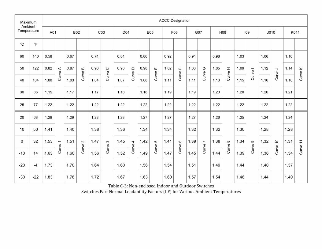
Maximum Ambient
Temperature
ACCC Designation
A01 B02 C03 D04 E05 F06 G07 H08 I09 J010 K011
°C °F
60 140 0.58 C
urv
e A
0.67
Cu
rve
B
0.74
Cu
rve
C
0.84
Cu
rve
D
0.86
Cu
rve
E
0.92
Cu
rve
F
0.94
Cu
rve
G
0.98
Cu
rve
H
1.03
Cu
rve
I
1.06
Cu
rve
J
1.10
Cu
rve
K
50 122 0.82 0.87 0.90 0.96 0.98 1.02 1.03 1.05 1.09 1.12 1.14
40 104 1.00 1.03 1.04 1.07 1.08 1.11 1.11 1.13 1.15 1.16 1.18
30 86 1.15 1.17 1.17 1.18 1.18 1.19 1.19 1.20 1.20 1.20 1.21
25 77 1.22 1.22 1.22 1.22 1.22 1.22 1.22 1.22 1.22 1.22 1.22
20 68 1.29
Cu
rve
1
1.29
Cu
rve
2
1.28
Cu
rve
3
1.28
Cu
rve
4
1.27
Cu
rve
5
1.27
Cu
rve
6
1.27
Cu
rve
7
1.26
Cu
rve
8
1.25
Cu
rve
9
1.24
Cu
rve
10
1.24
Cu
rve
11
10 50 1.41 1.40 1.38 1.36 1.34 1.34 1.32 1.32 1.30 1.28 1.28
0 32 1.53 1.51 1.47 1.45 1.42 1.41 1.39 1.38 1.34 1.32 1.31
-10 14 1.63 1.60 1.56 1.52 1.49 1.47 1.45 1.44 1.39 1.36 1.34
-20 -4 1.73 1.70 1.64 1.60 1.56 1.54 1.51 1.49 1.44 1.40 1.37
-30 -22 1.83 1.78 1.72 1.67 1.63 1.60 1.57 1.54 1.48 1.44 1.40
Table C-3: Non-enclosed Indoor and Outdoor Switches Switches Part Normal Loadability Factors (LF) for Various Ambient Temperatures

Maximum Ambient
Temperature
ACCC Designation
Q033 PO22 NO1 RO4 SO5 TO6 UO7 VO8 WO9 XO10 YO11
°C °F
60 140 0.00 C
urv
e Q
0.45
Cu
rve
P 0.58
Cu
rve
N
0.67
Cu
rve
R
0.74
Cu
rve
S
0.84
Cu
rve
T
0.86
Cu
rve
U
0.92
Cu
rve
V
1.00
Cu
rve
W
1.05
Cu
rve
X
1.09
Cu
rve
Y 50 122 0.71 0.77 0.82 0.87 0.90 0.96 0.98 1.02 1.07 1.10 1.13
40 104 1.00 1.00 1.00 1.00 1.03 1.04 1.08 1.11 1.13 1.15 1.17
30 86 1.22
Cu
rve
3
1.18
Cu
rve
2
1.15 1.16 1.16 1.18 1.18 1.19 0.20 1.20 1.20
25 77 1.32 1.26 1.22 1.22 1.22 1.22 1.22 1.22 1.22 1.22 1.22
20 68 1.41 1.34 1.29
Cu
rve
1
1.29 C
urv
e 4
1.28
Cu
rve
5
1.28
Cu
rve
6
1.26
Cu
rve
7
1.26
Cu
rve
8
1.25
Cu
rve
9
1.25
Cu
rve
10
1.24
Cu
rve
11
10 50 1.58 1.48 1.41 1.40 1.38 1.36 1.35 1.34 1.31 1.29 1.28
0 32 1.73 1.61 1.53 1.51 1.47 1.45 1.42 1.41 1.36 1.34 1.31
-10 14 1.87 1.73 1.63 1.61 1.56 1.53 1.50 1.47 1.41 1.40 1.35
-20 -4 2.00 1.84 1.73 1.70 1.64 1.60 1.56 1.54 1.46 1.42 1.38
-30 -22 2.00 1.95 1.83 1.78 1.72 1.67 1.63 1.60 1.51 1.46 1.41
Table C-4: Enclosed Indoor and Outdoor Switches Switches Part Normal Loadability Factors (LF) for Various Ambient Temperatures

Maximum Ambient Temperature
ACCC Designation
AO1 BO2 CO3 DO4 EO5 FO6 GO7 HO8 IO9 JO10 KO11
°C °F
60 140 1.00 1.03 1.04 1.08 1.08 1.11 1.11 1.13 1.15 1.16 1.18
50 122 1.15 1.17 1.16 1.18 1.18 1.09 1.18 1.20 1.20 1.20 1.21
40 104 1.29 1.29 1.27 1.28 1.26 1.27 1.26 1.26 1.25 1.24 1.24
35 95 1.35 1.35 1.33 1.32 1.30 1.30 1.29 1.29 1.27 1.26 1.26
30 86 1.41 1.40 1.38 1.36 1.34 1.34 1.32 1.32 1.30 1.28 1.28
25 77 1.47 1.46 1.42 1.41 1.38 1.37 1.36 1.35 1.32 1.30 1.29
20 68 1.53 1.51 1.47 1.45 1.42 1.41 1.39 1.38 1.35 1.32 1.31
10 50 1.63 1361 1.56 1.53 1.49 1.47 1.45 1.44 1.39 1.36 1.34
0 32 1.73 1.70 1.64 1.60 1.56 1.54 1.51 1.49 1.44 1.40 1.37
-10 14 1.83 1.78 1.72 1.67 1.63 1.60 1.57 1.54 1.48 1.44 1.40
-20 -4 1.92 1.87 1.80 1.74 1.69 1.65 1.62 1.59 1.52 1.47 1.43
-30 -22 2.00 1.95 1.87 1.80 1.76 1.71 1.68 1.64 1.56 1.51 1.46
Table C-5: Non-enclosed Indoor Outdoor Switches Switch Part Emergency Loadability Factors (ELF) for Various Ambient Temperatures
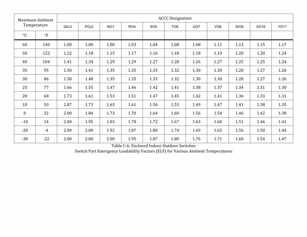
Maximum Ambient Temperature
ACCC Designation
Q033 PO22 NO1 RO4 SO5 TO6 UO7 VO8 WO9 XO10 YO11
°C °F
60 140 1.00 1.00 1.00 1.03 1.04 1.08 1.08 1.11 1.13 1.15 1.17
50 122 1.22 1.18 1.15 1.17 1.16 1.18 1.18 1.19 1.20 1.20 1.24
40 104 1.41 1.34 1.29 1.29 1.27 1.28 1.26 1.27 1.25 1.25 1.24
35 95 1.50 1.41 1.35 1.35 1.33 1.32 1.30 1.30 1.28 1.27 1.26
30 86 1.58 1.48 1.35 1.35 1.33 1.32 1.30 1.30 1.28 1.27 1.26
25 77 1.66 1.55 1.47 1.46 1.42 1.41 1.38 1.37 1.34 1.31 1.30
20 68 1.73 1.61 1.53 1.51 1.47 1.45 1.42 1.41 1.36 1.33 1.31
10 50 1.87 1.73 1.63 1.61 1.56 1.53 1.49 1.47 1.41 1.38 1.35
0 32 2.00 1.84 1.73 1.70 1.64 1.60 1.56 1.54 1.46 1.42 1.38
-10 14 2.00 1.95 1.83 1.78 1.72 1.67 1.63 1.60 1.51 1.46 1.41
-20 -4 2.00 2.00 1.92 1.87 1.80 1.74 1.69 1.65 1.56 1.50 1.44
-30 -22 2.00 2.00 2.00 1.95 1.87 1.80 1.76 1.71 1.60 1.54 1.47
Table C-6: Enclosed Indoor Outdoor Switches Switch Part Emergency Loadability Factors (ELF) for Various Ambient Temperatures

10.4 WAVE TRAPS Wave trap ratings are discussed in several sources. The ratings for the older wave traps in which the main coil is designed as a single-phase, air-cored inductor of the dry type are discussed in ANSI C93.3-1981, Requirements for Power-Line Carrier Line Traps and in Westinghouse Electric's Curve No. 511545. The ratings of the newer type of wave traps consisting of a coil of wire encapsulated in an epoxy resin are not covered in an ANSI/IEEE standard. The ratings for this type of wave trap were developed based upon guidelines supplied by the manufacturer, Trench Electric. In general, the rated continuous current for wave traps is based on the maximum permissible temperature rise limitations of the wave trap when it is carrying rated current at an ambient temperature of 40°C. The total temperature of the wave trap under service conditions depends both on the actual load current and the actual ambient temperature. It is, therefore, possible to operate at a current higher than rated continuous current when ambient temperature is less than 40°C, provided that the allowable total temperature rise limitation is not exceeded.
Ambient-compensated continuous current ratings will be used for the normal seasonal circuit ratings of both types of wave traps. These seasonal ratings will be based on the nameplate rating of the wave trap with an adjustment made for changes in the rated continuous current due to changes in the ambient air temperature. The ambient-compensated normal loadability factors for Dry-Type, Air-Cored Inductor wave traps are given in Table D-1 and were obtained from Westinghouse Electric's Curve No. 511545. The ambient- compensated loadability factors for Epoxy-Encapsulated Inductor wave traps were developed from Trench Electric's loadability curves and are given in Table D-2. To determine the normal seasonal circuit rating, simply multiply the wave trap's nameplate rating by the appropriate normal loadability factor. Interpolation may be used to obtain loadability factors at ambients other than those specified in the tables.
Normal life expectancy will occur with a wave trap operated at or below its ambient-compensated normal current rating. Any value of currents in excess of the ambient-compensated normal current ratings may cause the designed temperature rise to be exceeded and may shorten the life expectancy of the wave trap. For wave traps utilizing an air-cored inductor, an acceptable level of emergency overload current has been determined and is specified in ANSI Standard C93.3-1981, Requirements for Power-Line Carrier Line Traps. Ambient-compensated emergency current ratings will be used for the emergency seasonal circuit ratings of wave traps utilizing an air-cored inductor. These seasonal ratings will be based on the Four-Hour Emergency Overload Current-Carrying capability of the wave trap with an adjustment made for changes in the continuous current due to changes in the ambient air temperature. The wave traps may be loaded to this emergency level for a maximum of four hours per cycle. Before an emergency load cycle, the wave trap loading must be at or below the normal seasonal loading level for at least two hours.
The emergency seasonal circuit rating can be developed by simply multiplying the wave trap's nameplate rating by the appropriate emergency loadability factor. The ambient-compensated emergency loadability factors for Dry-Type, Air-Cored Inductor wave traps are given in Table D-1 and were obtained from ANSI Standard C93.3-1981, Requirements for Power-Line Carrier Line Traps. Interpolation may be used to obtain loadability factors at ambients other than those specified in the tables.

Average Ambient Air Temperature Loadability Factors
Normal 4-Hour Emergency
40°C 1.00 1.10
20°C 1.05 1.15
0°C 1.10 1.20
-20°C 1.10 1.25
Table D-1: Loadability Factors for Dry-Type Air-Cored Inductor Wave Traps
Average Ambient Air Temperature
Loadability Factors
Normal 4-Hour Emergency
40°C 1.00 N/A
20°C 1.13 N/A
0°C 1.25 N/A
-20°C 1.36 N/A
Table D-2: Loadability Factors for Epoxy-Encapsulated Inductor Wave Traps
Trench Electric, the manufacturer of the newer type of wave traps which consist of a coil of wire encapsulated in an epoxy resin, has stated that no overload capability is available on this type of wave trap. For this reason, no separate emergency rating will be assigned to this type of wave trap and the ambient-compensated current rating will be used for both the circuit's normal and emergency ratings.

July 16, 1985
Westinghouse Electric Corporation
Subject: Line Trap Loadings
Attached is one copy of the Appendix to ANSI Standard C93.3-1981 titled "Guide for Emergency Overload Current Capability of Line Traps".
This guide is current and, all Westinghouse traps built since 1970 conforms to the overload capability designated therein.
The Curve No. 511545 supplied applies to Westinghouse Line Traps built prior to 1970. Note that the overload capability of traps 2000 amperes and below on this curve are the same as that specified in the Standard. The larger traps were modified in design in order to conform to the Standard requirement.

July 25, 1985
Trench Electric
Attached are three copies of the overload current U.S. temperature curves. General Electric did not send any such information when we purchased their Line Trap division but the curves should be approximately the same.

10.5 CURRENT TRANSFORMERS Current transformer ratings are discussed in ANSI/IEEE C57.13 IEEE Standard Requirements for Instrument Transformers and in Westinghouse Electric's technical paper titled "Memorandum on Thermal Current Characteristics of Current Transformers Used With Power Circuit Breakers and Power Transformers". In general, the rated continuous current for current transformers is based on the maximum permissible temperature limitations of the various parts of the current transformer when it is carrying rated current at a 24-hour average ambient temperature of 30°C (with. a maximum hourly temperature of 40°C). The total temperature of these parts under service conditions depends both on the actual load current, the actual average ambient temperature, and the service environment of the current transformer. Depending on the environment, it is, therefore, possible to operate at a current higher than rated continuous current when the average ambient temperature is less than 30 °C, provided that the allowable total temperature limit is not exceeded. Similarly, when the average ambient temperature is greater than 30°C, the current must be reduced to less than rated continuous current to keep total temperatures within allowable limits.
The environment in which a current transformer operates has a large effect on the current-carrying capability of the current transformer. Separately mounted current transformers have been assigned rated primary and secondary currents and continuous-thermal-current rating factors by the manufacturer. Separately mounted current transformers are designed to meet these characteristics by the independent control of such parameters as: current density in the primary and secondary windings, geometry, area of radiating surfaces, and heat transfer characteristics. Permissible loading as a function of ambient temperatures and continuous-thermal-current rating factors, and permissible overloading under emergency conditions, is covered in ANSI/IEEE C57.13 IEEE Standard Requirements for Instrument Transformers.
Bushing current transformers mounted in power circuit breakers and power transformers differ from separately mounted current transformers in that the design parameters cannot be independently controlled since they are restricted by the characteristics of the power apparatus in which they are mounted. Bushing current transformers, when attached to various power apparatus, are subjected to wide variations in their environmental ambient temperature. This variation is dependent upon the thermal characteristics of the power apparatus and the relative current loading with respect to the rated current of the power apparatus and its bushing current transformer. For this reason, continuous-thermal-current rating factors are not typically calculated by the manufacturer for bushing current transformers. Instead, the continuous-thermal-current rating factors must be determined for each application. Permissible loading and permissible overloading of bushing current transformers is covered in Westinghouse Electric's technical paper titled "Memorandum on Thermal Current Characteristics of Current Transformers Used With Power Circuit Breakers and Power Transformers".
Rating Separately Mounted Current Transformers: The maximum continuous-thermal-current ratings for separately-mounted current transformers designed for 55°C temperature rise above 30°C average ambient air temperature will vary according to actual ambient cooling air temperature. The adjusted continuous current ratings will be based on three items:
1) The nameplate primary and secondary current ratings at the ratio setting being used. 2) The average cooling air temperature at which the rating is being calculated. Note: The
maximum cooling air temperature must not exceed the average cooling air temperature by more than 10°C.
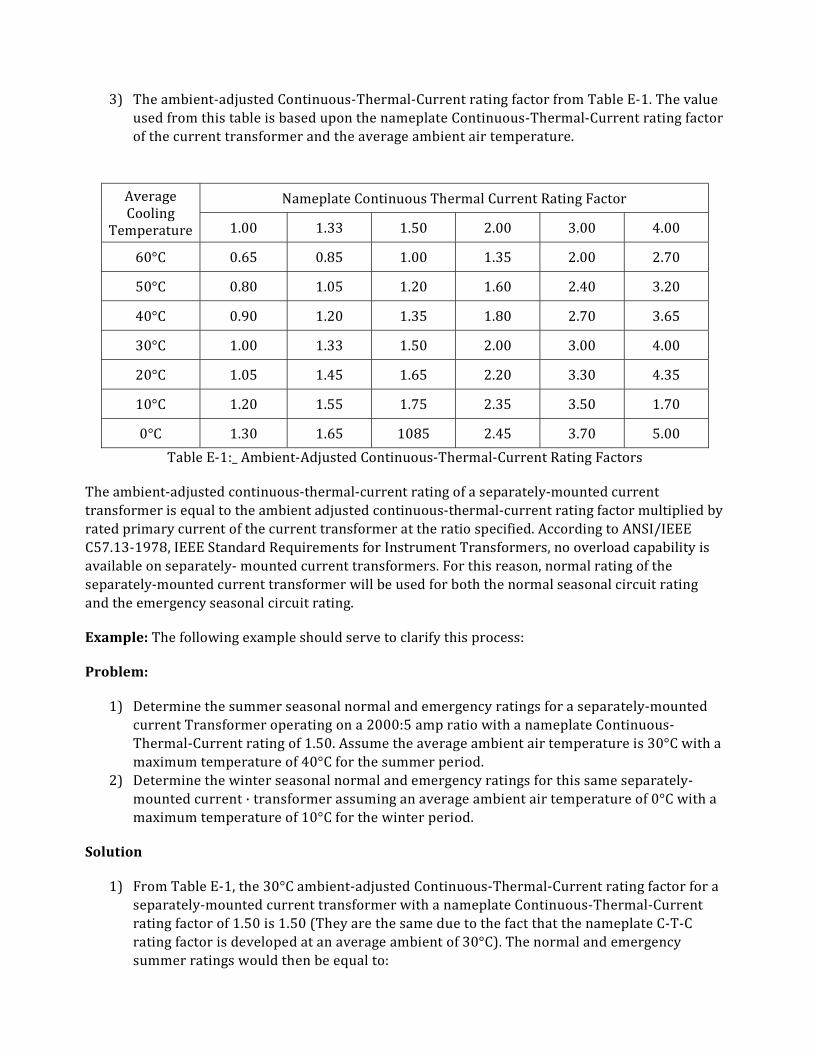
3) The ambient-adjusted Continuous-Thermal-Current rating factor from Table E-1. The value used from this table is based upon the nameplate Continuous-Thermal-Current rating factor of the current transformer and the average ambient air temperature.
Average Cooling
Temperature
Nameplate Continuous Thermal Current Rating Factor
1.00 1.33 1.50 2.00 3.00 4.00
60°C 0.65 0.85 1.00 1.35 2.00 2.70
50°C 0.80 1.05 1.20 1.60 2.40 3.20
40°C 0.90 1.20 1.35 1.80 2.70 3.65
30°C 1.00 1.33 1.50 2.00 3.00 4.00
20°C 1.05 1.45 1.65 2.20 3.30 4.35
10°C 1.20 1.55 1.75 2.35 3.50 1.70
0°C 1.30 1.65 1085 2.45 3.70 5.00
Table E-1:_ Ambient-Adjusted Continuous-Thermal-Current Rating Factors
The ambient-adjusted continuous-thermal-current rating of a separately-mounted current transformer is equal to the ambient adjusted continuous-thermal-current rating factor multiplied by rated primary current of the current transformer at the ratio specified. According to ANSI/IEEE C57.13-1978, IEEE Standard Requirements for Instrument Transformers, no overload capability is available on separately- mounted current transformers. For this reason, normal rating of the separately-mounted current transformer will be used for both the normal seasonal circuit rating and the emergency seasonal circuit rating.
Example: The following example should serve to clarify this process:
Problem:
1) Determine the summer seasonal normal and emergency ratings for a separately-mounted current Transformer operating on a 2000:5 amp ratio with a nameplate Continuous-Thermal-Current rating of 1.50. Assume the average ambient air temperature is 30°C with a maximum temperature of 40°C for the summer period.
2) Determine the winter seasonal normal and emergency ratings for this same separately-mounted current · transformer assuming an average ambient air temperature of 0°C with a maximum temperature of 10°C for the winter period.
Solution
1) From Table E-1, the 30°C ambient-adjusted Continuous-Thermal-Current rating factor for a separately-mounted current transformer with a nameplate Continuous-Thermal-Current rating factor of 1.50 is 1.50 (They are the same due to the fact that the nameplate C-T-C rating factor is developed at an average ambient of 30°C). The normal and emergency summer ratings would then be equal to:

Ambient-Adjusted C-T-C R.F. @ 30°C • Rated Primary Current of CT Ratio or
1.50 • 2000 amps = 3000 amps
For operation at 30°C, both the Summer Normal and Emergency ratings of current transformer would be 3000 amps. Note: When the primary current is 3000 amps, the secondary current would be 7.5 amps due to the 2000:5 ratio used in the current transformer.
2) From Table E-1, the 0°C ambient-adjusted Continuous-Thermal-Current rating factor for a separately-mounted current transformer with a nameplate Continuous-Thermal-Current rating factor of 1.50 is 1.85. The normal and emergency summer ratings would then be equal to:
Ambient-Adjusted C-T-C R.F. @ 0°C *Rated Primary Current of CT Ratio or
1.85 * 2000 amps = 3700 amps
For operation at 0°C, both the Winter Normal and Emergency ratings of current transformer would be 3700 amps. Note: When the primary current is 3700 amps, the secondary current would be 9.25 amps due to the 2000:5 ratio used in the current transformer.
Rating Bushing Current Transformers Mounted in Power Apparatus: The continuous current rating of current transformers mounted in power circuit breakers or power transformers is determined as follows:
1) When the bushing current transformer ratio being used has the same primary current rating as the breaker continuous current rating or the power transformer rated current, the continuous current rating factor of the current transformer is 1.0 (unity).
2) When the primary current rating of the ratio being used on the current transformer is greater than the continuous current rating of the breaker or greater than the power transformer rated current, then the maximum load current is limited by the breaker or power transformer rating, whichever is applicable.
3) When the primary current rating of the ratio being used is less than the continuous current rating of the breaker or the power transformer rated current, then the maximum load current is limited by the continuous thermal current rating of the current transformer when operating on that ratio. Under these conditions, the temperature rises of the current transformer and the power apparatus would be lower, and therefore, the current transformer can be operated at a continuous thermal rating factor greater than 1.0. In this situation, the permissible continuous -thermal-current rating factor is calculated based upon constant maximum power dissipation, using the following equation:
𝑅. 𝐹 = 𝐼
𝐼
where,
R.F. =Continuous-thermal-current rating factor Ipa= Power apparatus continuous current rating (amps)

Ict = Primary current rating of bushing current transformer ratio used (amps)
The results calculated from this equation should be so limited that the maximum rating factor does not exceed 2.0 and that the continuous current rating of the breaker or the rated current of the power transformer is not exceeded. Note: The situation, in which the primary current rating of the current transformer ratio being used is less than the continuous current rating of the breaker or the power transformer rated current, is an unusual case and should be viewed as the exception rather than the rule.
The normal rating of a bushing current transformer is equal to the continuous-thermal-current rating factor multiplied by rated primary current of the current transformer at the ratio specified.
Some short-term emergency overload capability is typically available on bushing current transformers mounted on power circuit breakers and power transformers. However, w he n utilizing this emergency overload capability, care must be taken to coordinate the loading limit of the current transformer with the overall application limitations of the other equipment affected by the current transformer loading. Particular care should be taken to avoid exceeding the maximum metering capability of metering equipment attached to the current transformer secondary.
10.6 CIRCUIT BREAKERS Circuit breaker ratings are discussed in ANSI/IEEE C37.010, IEEE Application Guide for AC High-Voltage Circuit Breakers Rated on a Symmetrical Current Basis and in ANSI/IEEE C37.010b, IEEE Standard for Emergency Load Current-Carrying Capability. These standards discuss the development of ratings for circuit breakers from the standpoint of the manufacturers. From a practical standpoint, the application of the methods discussed in these standards to circuit breakers in operation will be very difficult, due to the fact that this application would require contacting the manufacturer for detailed design information for each circuit breaker being rated. Therefore, it is recommended that for any circuit breakers which do not limit flows on the transmission system, the nameplate rated continuous current be used as the circuit breaker's normal and emergency circuit ratings. For circuit breakers which limit flows on the transmission system, the manufacturer could be consulted and ambient-compensated normal and emergency ratings could be developed for the circuit breaker using the methods described in the ANSI/IEEE Standards. These methods are described in the remainder of this section.
In general, the rated continuous current for circuit breakers is based on the maximum permissible temperature limitations of the various parts of the circuit breaker when it is carrying rated current at an ambient temperature of 40°C. The total temperature of these parts under service conditions depends both on the actual load current and the actual ambient temperature. It is, therefore, possible to operate at a current higher than rated continuous current when ambient temperature is less than 40°C, provided that the allowable total temperature limit is not exceeded. Similarly, when the ambient temperature is greater than 40°C, the current must be reduced to less than rated continuous current to keep total temperatures within allowable limits.
Ambient-compensated continuous current ratings will be used for the normal seasonal circuit ratings of outdoor circuit breakers. These seasonal ratings will be based on the nameplate rating of the circuit breaker with an adjustment made for changes in the rated continuous current due to changes in the ambient air temperature. The seasonal loading limit shall be coordinated with the overall application limitations of the other equipment affected by the loading of the circuit breaker,

such as cables and current transformers. (See other appropriate appendices to determine limitations on the other equipment.) For circuit breakers used in metal-clad switchgear, no seasonal ratings will be calculated. Instead, the loading limit shall be coordinated with the overall application limitations of the switchgear.
The seasonal normal circuit breaker ratings can be determined in the following manner:
1) A circuit breaker's rated continuous current is based on the maximum permissible total temperature limitations, Ømax, and Ør, of the various parts of the circuit breaker when it is carrying rated current at an ambient temperature of 40°C. The constructional features of a circuit breaker dictate the appropriate values of Ømax and Ør, to be used in the calculation of ambient-compensated ratings. The major components of a circuit breaker have several different temperature limitations which are shown in Table F-1. In order that none of these temperature limitations be exceeded when the load current is adjusted to the value permitted by the actual ambient temperature, the values of Ømax and Ør, should be determined as follows:
(a) If the actual temperature is less than 40°C, the applicable component with the highest specified values of allowable temperature limitations should be used for determining Ømax and Ør,
(b) If the actual temperature is greater than 40°C, the applicable component with the lowest specified values of allowable temperature limitations should be used for determining Ømax and Ør,

Component Description Limit of
Temperature Rise, °C Ør
Limit of Total Temperature,
°C Ør
Circuit breaker parts handled by the operator in the normal course of his duties
10 50
Copper contacts, coper-to-copper conducting joints, external surfaces accessible to the operator in the normal course of his duties, external terminal connected to bushing
30 70
Top oil 40 80
Breaker terminal to be connected to 85°C 45 85
Hottest spot temperature of parts where they contact oil; silver (or equal) contacts in oil; silver (or equal) conduction joints in oil
50 90
Silver (or equal) contact in air; silver (or equal) conducting joints in air; hottest spot of bushing conductor or of bushing metal parts in contact with Class A insulation or with oil; hottest spot winding temperature 55°C rise of current transformers
60 105
External surfaces not accessible to an operator in the normal course of his duties
70 110
Hottest spot winding temperature of 80°C dry type current transformers
110 150
Table F-1 Summary of Temperature Limitations for Circuit Breaker Components
2) The continuous current which a circuit breaker can carry at a given ambient temperature without exceeding its total temperature limitations is given by the formula:
𝐼 = 𝐼∅ − ∅
∅
where,
Ia = allowable continuous load current, in amperes, at the actual ambient temperature Θa (Ia is not to exceed two times Ir) Ir = rated continuous current, in amperes Θmax = allowable hottest spot total temperature (Θmax = Θr + 40°C), in degrees Celsius Θa = actual ambient temperature expected (between -30°C and 60°C), in degrees Celsius Θr = allowable hottest spot temperature rise at rated current, in degrees Celsius
3) The ambient-compensated allowable continuous load current, Ia. calculated in Step 2 will be treated as the seasonal normal rating of the circuit breaker.

Normal life expectancy will occur with a circuit breaker operated at continuous nameplate rating. When operated for one or more load cycles above nameplate rating, the material used in manufacturing the circuit breaker deteriorates at a faster rate than normal. The rate of deterioration is commonly expressed as a percentage loss of life. According to ANSI/IEEE C37.010b- IEEE Standard for Emergency Load Current-Carrying Capability, a circuit breaker can experience operation at 10°C above the limits of total temperature for which the circuit breaker was designed for up to two periods of an emergency cycle of eight hours before an unreasonable loss of life occurs and maintenance is required. Inspection and maintenance must be performed in accordance with manufacturer's recommendations before the circuit breaker can be subjected to additional emergency cycles. In addition, following each emergency cycle, the load current shall be limited to 95% of the rated continuous current as modified by ambient compensation for a minimum of two hours.
Ambient-compensated emergency current ratings will be used for the emergency seasonal circuit ratings of outdoor circuit breakers. These seasonal ratings will be based on the Eight-Hour Emergency Load Current-Carrying capability of the circuit breaker with an adjustment made for changes in the continuous current due to changes in the ambient air temperature. The seasonal emergency loading limit shall be coordinated with the overall application limitations of the other equipment affected by the loading of the circuit breaker, such as cables and current transformers.
The seasonal emergency circuit breaker ratings can be determined in the following manner:
1) Emergency load current-carrying capability factors with ambient temperatures at 40°C are listed in Table F-2 for each limiting temperature of various circuit breaker components. The factors have been selected to allow operation at 10°C above the limits of total temperature for an emergency period of eight hours. The factors are expressed as the ratio of emergency load current allowed at an ambient temperature of 40°C, Ie, to the rated continuous current, Ir, and can be applied with the following restrictions:
(a) The circuit breaker component with the highest values of limiting temperature, Θmax, and Θr, shall be used to select the proper emergency load current-carrying capability factor from Table F- 2.
(b) The Eight-Hour factor shall be used for a cycle of operation consisting of separate periods of no longer than eight hours each, with not more than two such occurrences before maintenance.
(c) Each cycle of operation is separate, and no time-current integration is permissible to increase the number of periods within a given maintenance cycle.
Limiting Temperatures of (°C) of Different Breaker Components
Θmax 70 80 85 90 105 110 150
Θr 30 40 45 50 65 70 110
1.17 1.13 1.11 1.10 1.08 1.07 1.05
Table F-2: Emergency Load Current. Carrying Capability Factor (Ie/If)
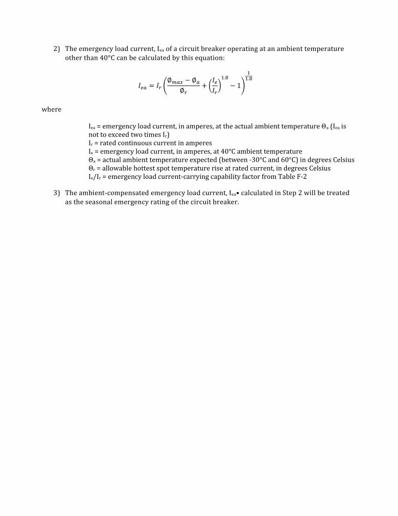
2) The emergency load current, Iea of a circuit breaker operating at an ambient temperature other than 40°C can be calculated by this equation:
𝐼 = 𝐼∅ − ∅
∅+
𝐼
𝐼
.
− 1.
where
Iea = emergency load current, in amperes, at the actual ambient temperature Θa (Iea is not to exceed two times Ir) Ir = rated continuous current in amperes Ie = emergency load current, in amperes, at 40°C ambient temperature Θa = actual ambient temperature expected (between -30°C and 60°C) in degrees Celsius Θr = allowable hottest spot temperature rise at rated current, in degrees Celsius Ie/Ir = emergency load current-carrying capability factor from Table F-2
3) The ambient-compensated emergency load current, Iea• calculated in Step 2 will be treated as the seasonal emergency rating of the circuit breaker.

11. GENERATOR REPORTING FORMS

Southwest Power Pool
Generator Owner/Operator Excitation System Summary Report
Instructions: Generator Owner/Operator shall fill out summary information for all units under your control concerning the number of hours the Excitation System was not operated in Automatic Voltage Control Mode.
Generator Owner/Operator
Month Reporting Data
Contact Name
Contact Phone
Station Unit # # Hours Excitation System not operated in
Automatic Voltage Control Mode
Dev. February, 2001 By SPP GWG

Southwest Power Pool
Generator Unit Excitation System Status Report
Instructions: Generator Owner/Operator shall fill out information concerning the frequency and duration of events of a particular generating unit’s excitation system not being operated in automatic voltage control mode.
Generator Owner/Operator
Generating Unit
Month Reporting Data
Contact Name
Contact Phone
Date (unit not operated in automatic mode)
Unit # Reason unit’s excitation system was operated out of automated voltage control mode
Dev. February, 2001 By SPP GWG

Southwest Power Pool
Generator Owner/Operator Voltage Schedule Requirements
Instructions: Control Area Operator shall specify voltage schedule to be maintained by each Generator Owner/Operator’s units at a specified bus.
Generator Owner/Operator
Control Area
Voltage Schedule Date
Contact Name (Control Area)
Contact Phone (Control Area)
Station Unit # Specified Voltage Specified Bus
Dev. February, 2001 By SPP GWG

Southwest Power Pool
Generator Unit Voltage Schedule Status Report
Instructions: Generator Owner/Operator shall fill out information concerning the frequency and duration of periods in which particular generating units did not adhere to control area’s prescribed voltage schedule. If event was approved by control area operator, please attach written approvals.
Generator Owner/Operator
Generating Unit
Month Reporting Data
Contact Name
Contact Phone
Date Duration
(hr:min) Reason unit did not adhere to voltage schedule
Approved (yes/no)
Dev. February, 2001 By SPP GWG

Southwest Power Pool
Control Area’s List of Exempt Generators
Instructions: Control Area Operator shall list units in their area of responsibility that are exempt from following prescribed Control Area Voltage Schedules.
Control Area Operator
Last Updated
Contact Name
Contact Phone
Generator Owner/Operator Generating Station Unit
Dev. February, 2001 By SPP GWG

Southwest Power Pool
Generator Unit Transformer Tap Setting Report
Instructions: Generator Owner/Operators shall fill out information concerning the tap settings and impedances of all GSU and AUX transformers under their control.
Generator Owner/Operator
Generating Station
Last Updated
Contact Name
Contact Phone
GSU/AUX Transformer I.D.
Current Tap Setting
Tap Setting Range Transformer Impedance (OA Base)
Dev. February, 2001 By SPP GWG

Southwest Power Pool
Transformer Tap Setting Change Request
Instructions: Control Area Operator shall complete information necessary to let affected Generator Owner/Operator know of needed Generator Unit Transformer settings changes.
Generator Owner/Operator
Generating Station
Control Area
Date
Contact Name (Control Area)
Contact Phone (Control Area)
GSU/AUX Transformer I.D.
Current Tap Setting
New Tap Setting Technical Justification for Tap Setting Change
Dev. February, 2001 By SPP GWG

Southwest Power Pool
Generator Units Exempt from Tap Setting Reporting Procedures
Instructions: Generator Owner/Operators shall fill out information for all units under their control that are exempt from Transformer Tap Setting Procedures. The criteria that is met must also be documented
Generator Owner/Operator
Control Area
Date
Contact Name (Control Area)
Contact Phone (Control Area)
Generating Station
Unit # Exemption Criteria Met
Dev. February, 2001 By SPP GWG

Southwest Power Pool
Voltage Regulator Control Setting Status Report
Instructions: Generator Owner/Operators shall fill out information for all units under their control.
Generator Owner/Operator
Generating Unit
Date
Contact Name
Contact Phone
Generating Control
Control Setting Generator Short Term Capability
Protective Relay Setting
Overexcitation Limiter
Underexcitation Limiter
Volts/Hertz Limiter
Dev. February, 2001 By SPP GWG

Southwest Power Pool
Generator Governor Characteristic Reporting
Instructions: Generator Owner/Operators shall fill out information for all units under their control.
Generator Owner/Operator
Generating Unit
Last Updated
Contact Name
Contact Phone
Governor Control Control Setting Speed Regulation
Dev. February, 2001 By SPP GWG

Southwest Power Pool
Non-Functioning Governor Controls
Instructions: Generator Owner/Operators shall fill out information for all units under their control that has a non-functioning or a blocked speed/load governor control.
Generator Owner/Operator
Last Updated
Contact Name
Contact Phone
Generating Station Unit Governor Status
(Blocked/Non-functioning)
Dev. February, 2001 By SPP GWG

12. SPP MISOPERATION REPORT
Reporting Utility: Date:
Contact Person:
Name Phone Fax Email Address
Equipment Category and Operating Voltage: DME (Yes/No) TPS (Yes/No) GCP (Yes/No) SPS (Yes/No) UFLS (Yes/No) UVLS (Yes/No) ARL (Yes/No) Voltage (kV)
Time, Equipment Location & Description: Incident Date: Incident Time Time Zone: Relay MFGR: Relay Type: Relay Flags: Substation Name/Number:
Line/Bus/Auto/Unit Name/No:
Circuit Breaker Numbers:
Description of Misoperation/Failure:
Investigation Results
Corrective Action
Target Date to Complete Recommendations
Recommendations
Person verifying that all Corrective Actions and Recommendations have been completed Name: Title: Date:
Note: Equipment categories include DME – Disturbance Monitoring Equip, TPS – Transmission Protection Systems, GCP – Generator Control & Protection, SPS – Special Protection Systems, UFLS – Under Frequency Load Shedding, UVLS – Under Voltage Load Shedding

13. RESPONSE FACTOR THRESHOLDS
Factor Short-term Long-term * Date Approved Comments
PTDF 3% 3% 4/27/2004
OTDF 3% 3% 4/27/2004
PTVF 0.02 p.u. 0.02 p.u. 12/12/2001
TRM
0% 12/12/2001 See SPP website for short-term TRM
* Long-term factors apply to all elements above 60kV.

14. INTERCONNECTION REVIEW PROCESS DETAILS
This section shall be subject to review and approval of the Transmission Working Group (TWG). Given the limited amount of time during a regular TWG meeting, and given the need for timely responses, the majority of the interconnection review process will take place outside of a regular meeting. A Transmission Assessment Report will be prepared by the parties to the proposed interconnection and presented to the TWG for review. Once received, the TWG will review the information provided in the assessment of impacts on the interconnected system. This section details the technical requirements which shall be the minimum necessary.
14.1 COORDINATION 1) The party proposing the interconnection shall appoint a person who will serve as the primary
contact with the TWG staff secretary. 2) The primary contact shall ensure that all affected parties are identified. This includes but is
not limited to notification through the TWG Exploder and requesting any affected parties identify themselves, shall provide a proposed timeline for the studies, shall ensure that all affected parties are notified of and kept informed of progress, and shall provide the opportunity to review all study results prior to submission to the TWG.
3) The primary contact shall coordinate any joint studies that may be necessary and shall report the results to all affected parties.
4) All affected parties shall cooperate in joint planning efforts. 5) All affected parties will work together to develop an estimated timeline for the completion of
the study. 6) SPP shall coordinate activities that affect other regions pursuant to an applicable seams
agreement.
14.2 PRIOR TO THE REVIEW Affected parties shall jointly develop and evaluate both the proposed interconnection and any mitigation plans. The primary contact shall submit a request for review of the interconnection request to the TWG through the group’s staff secretary. The request for review shall include the following:
1) A list of all affected parties and the contact person at each affected party. The rationale for determining affected parties shall be included.
2) A brief summary of the results of planning studies. Each affected party shall provide a copy of its own planning criteria as documentation of the need of mitigations that exceed regional requirements.
3) A detailed description of the project including: in-service date; design information; ratings of the interconnection; a geographic map of the interconnection area; electrical one-line diagrams of the facilities being connected.
4) A summary of the results of power flow, short-circuit, and dynamic analyses in accordance

with NERC Reliability Standards, SPP Criteria, other regional requirements, and affected party planning criteria.
5) 5Appropriate program files and program automation files to allow SPP staff to reproduce the studies performed.
6) Details of any required mitigation plans including identification of the parties responsible for mitigation. The detailed description of mitigation plans shall include such information as detailed in Item 3 above.
7) Any comments of the affected parties.
14.3 TECHNICAL STUDY REQUIREMENTS Impact analysis shall be performed to assess the system with and without the interconnection to determine if the interconnection causes any adverse effects to the system.
The following are minimum requirements for power flow analysis:
1) A contingency assessment consistent with Integrated Transmission Planning Manual in the entire first-tier area of the combined areas which the proposed interconnection connects. This area maybe expanded or reduced as mutually agreed upon. The rationale for expansion or reduction of the study area shall be documented and agreed upon by all affected areas.
2) A review of impacts shall utilize all applicable Scenario Cases developed by the SPP extending to the planning horizon year.
3) If, at any time, impacts are identified affecting a nuclear power plant, it shall be included separately as an affected party.
4) Affected parties shall report adverse impacts and required mitigations.
The TWG may request additional studies at its discretion. The rationale for requesting additional studies shall be provided to all affected parties. If the proposed interconnection was previously evaluated by SPP and included in the most recent STEP, the power flow analysis described here does not need to be repeated.
The following are minimum requirements for short-circuit analysis:
1) Analysis shall be consistent with the Integrated Transmission Planning Manual. The model(s) assessed shall be determined by the affected parties. The rationale for the model(s) assessed shall be included.
2) Assessment shall consist of 3-phase and phase-to-ground faults applied at the buses of the proposed interconnection plus all first-tier buses to the interconnection.
3) Additional buses may be studied as mutually agreed upon and documentation for including such additional buses shall be included.
4) Assessments shall document the before and after fault currents on all monitored busses. 5) Affected parties shall report adverse impacts and the required mitigation.
The following are minimum requirements for transient stability analysis:
1) Analysis shall be performed using a contingency assessment. The model(s) and contingencies

assessed shall be determined by the affected parties. Consideration shall be applied for evaluating impactful contingent events from neighboring SPP or non-SPP systems. The rationale for the model(s) and contingencies assessed shall be included. If no transient stability analysis is performed the rationale for not performing such studies shall be provided.
2) The assessments performed shall be determined by the affected parties. The rationale for the assessments shall be included.
3) Assessments shall document the before and after post disturbance performance on all monitored buses consistent with Section 5.4 of this Criteria.
4) Affected parties shall report adverse impacts and the required mitigation.
If the interconnection is to be made at 345 kV or higher voltage, affected parties shall determine if additional study work is needed to assess reactive power impacts and management. If the affected parties determine additional study work is required, results of these studies shall be provided for review. Additional study work may include but is not limited to steady state, transient (including electromagnetics transient studies), surge impedance loading for long lines, insulation coordination, or switching studies clearly indicating any required levels of shunt compensation. If no additional study work is performed for 345 kV or higher interconnections, the rationale for not performing such studies shall be provided.
14.4 DISPUTE RESOLUTION All disputes between SPP members shall be resolved using the procedures of Section 3.13 of the SPP Bylaws.
14.5 REVIEW AND BALLOT BY THE TRANSMISSION WORKING GROUP 1) The TWG Secretary shall review the request for interconnection for completeness. 2) Any deficiencies shall be reported to the primary contact. 3) Once a complete request is received, it shall be forwarded to the TWG for a 14 day review and
comment period. 4) The primary contact shall be responsible for coordinating any response necessary to
comments and questions raised by the TWG. 5) The TWG shall schedule a ballot to accept or to reject the interconnection request. 6) Any action taken by the TWG will be included in the minutes.
14.5.1 TRANSMISSION INTERCONNECTION REVIEW DATA CHECKLIST
1) Primary contact and all affected parties’ contact information. 2) Overview of the proposed interconnection and its need. 3) Estimated or proposed in-service date. 4) List of all studies run by season.
(a) Power flow studies minimum requirements met. (b) Short-circuit studies minimum requirements met. (c) Transient studies minimum requirements met.
5) Affected parties planning criteria, if applicable. 6) A detailed description of the proposed interconnection.
(a) In- service date

(b) Design information (c) Ratings of the interconnection (d) A geographic map of the interconnection area (e) Electrical one-line diagrams of the facilities being connected.
7) Appropriate program files and program automation files to allow SPP staff to reproduce the studies performed.
8) Details of any required mitigation plans including identification of the affected parties responsible for mitigation.
(a) In-service date (b) Design information (c) Ratings of the facilities (d) A geographic map of the facility area (e) Electrical one-line diagrams of the facilities being connected.
9) Comments of affected parties covering agreement or points of disagreement of the proposed interconnection, if any.
The TWG shall review and modify this section as needed but not less frequently than once every 3 years.