Crystallisation progress in Si-rich ultra-soft nanocomposite alloy fabricated by melt spinning
Upload
khangminh22Category
view
1download
0
Original article
Modification of the mechanical propertiesof polyamide 6 multifilaments in high-speed melt spinning with nano silicates
Wilhelm Steinmann1, Stephan Walter1, Thomas Gries1,Gunnar Seide1 and Georg Roth2
Abstract
In the last few years research activities have been focused on the modification of fiber properties with nano-scaled
additives. One of the most important fields of research is the alteration of mechanical properties such as the tenacity and
the specific breaking load. In this study, we determined the influence of nano-phyllosilicates on the drawability of
polyamide 6 multifilament yarns. It was first demonstrated that the drawability of the fibers drastically increased in an
industrially relevant high-speed melt spinning process. Structural properties of the material are identified by wide-angle
X-ray diffraction (WAXD) and differential scanning calorimetry (DSC). Changes in the crystalline properties as well as in
the alignment of the silicates are compared with the stress–strain curves of the fibers, and a molecular mechanism for the
drawing process is derived from these experiments. In a first step, a significant phase transition in the crystalline structure
unaffected by the silicates occurs for low draw ratios (DRs). Beyond this point, where unmodified fibers start to break,
a gliding between the silicate layers takes place, which is responsible for an extended drawability of the fibers.
This mechanism leads to new possibilities for fiber processing, which can be used to research ultra-fine filaments in
future studies.
Keywords
melt spinning, multifilament yarn, nanocomposites, polyamide 6, structure analysis
Polyamide 6 (PA6), also called Polycaprolactam orPerlon as a trademark, is a polymer of the group ofpolyamides. It was first synthesized by means of ring-opening polymerization reactions from "-aminocapro-lactam in 1938.1 The ‘6’ in the name denotes thenumber of carbon atoms in the repeating base mol-ecule. The resulting sequence in the polymer chain is�½HN� ðCH2Þ5 � CO�n�.
2
The polymer is a polymorphic, semi-crystallinematerial. Three different thermodynamic, metastablephases can coexist in the glassy or rubbery solidstate.3,4 The so-called g phase is crystalline with amonoclinic unit cell. The lattice parameters areknown as a¼ 9.33 A and c¼ 4.78 A perpendicular tothe polymer chains as well as b¼ 16.88 A in the polymerchain direction from wide-angle X-ray diffraction(WAXD) experiments. The value of the angle �between a and c axis is 121�.5 Since g is around 120�,a pseudohexagonal version of this unit cell can be
calculated and is often used in theory for the structuraldescription.4 The second crystalline phase denoted asthe a phase also has a monoclinic cell with lattice par-ameters a¼ 9.56 A, b¼ 17.24 A, and c¼ 8.01 A with anangle �¼ 67.5�.6 As distinguished from the a and gphase, the � phase as the third stable phaseis characterized by a mesomorphic structure. Theshort-range order exceeds the typical values for anamorphous material. Since no long-range order exists
1Institut fur Textiltechnik der RWTH Aachen University (ITA), Aachen,
Germany2Institut fur Kristallographie der RWTH Aachen University (XTAL),
Aachen, Germany
Corresponding author:
Wilhelm Steinmann, Institut fur Textiltechnik der RWTH Aachen
University (ITA), Otto-Blumenthal-Straße 1, 52074 Aachen, Germany.
Email: [email protected]
Textile Research Journal
82(18) 1846–1858
! The Author(s) 2012
Reprints and permissions:
sagepub.co.uk/journalsPermissions.nav
DOI: 10.1177/0040517512456756
trj.sagepub.com
at PENNSYLVANIA STATE UNIV on September 12, 2016trj.sagepub.comDownloaded from
in this phase, no detailed structure can be obtainedfrom diffraction experiments. However, a molecularmodel, based on a nano-crystalline, hexagonal phasewith a¼ 4.8 A and c¼ 8.6 A was proposed. The sidegroups in this structure model are randomly oriented.7
Characterization and phase transitions
Information on the properties of all phases is predomi-nantly gathered from diffraction experiments. Since allreflections from the lattice planes perpendicular to thepolymer chains appear in the same angular range, peakfitting is carried out for an identification of thephases.3,4 Both g and a form crystals appearingtogether with the � phase if a sample is cooled fromthe melt. The a formation is preferred at low coolingrates.3,4,8 Pure � phase material can be obtained byquenching.3,7
Thermal analysis as well as temperature-dependentdiffraction experiments reveal information about phasetransitions. The g crystallites arise from the � phase attemperatures higher than 130 �C,3 whereas g is trans-formed to a phase crystallites in the temperature regimeof the melting point, which is located at 220 �C.9 Incontrast, examples of unstable g crystals, which trans-form far below the melting point,10–12 have beenreported. Also � phase crystals are able to transformto a phase. Therefore, annealing at 190 �C is neces-sary.13 Since polymer chains are more stretched in theg phase, these chains’ formation is also preferred instrain-induced crystallization under mechanical stresswith the result that this phase is preferred after thedrawing processes.8 The g phase is gradually trans-formed to the a phase during annealing at temperatureshigher than 160 �C.3
Melt spinning
Melt spinning is the classic method of fiber productionof thermoplastic materials.2 PA6 is one of the mostcommon fiber polymers, where the processing of mono-filaments and multifilament yarn has a long tradition.The material can be melt-spun as low oriented yarn(LOY) and partially oriented yarn (POY), whereashigh-spinning speeds can be achieved. The materialcan be converted to fully drawn yarn (FDY) in a sepa-rate process as well as to inline drawn yarns (IDY) inone step by melt spinning.2,14
The fiber formation process of PA6 has been widelyexamined with theoretical calculations and online mea-surements of fiber properties. In this case, the fiberdiameter and velocity, mechanical forces, filament tem-perature, and development of molecular orientation
have been investigated.14–16 Other studies deal withthe structure formation in the melt spinning process.The development of crystal phases was examined within-situ measurements of diffraction patterns, whichshowed the qualitative development of the threephases.17–20
Nanocomposites
Nanocomposites of PA6 were characterized in manystudies. Several types of particles at the nanoscale,including carbon nanotubes, carbon nanofibers, silicondioxide, and many silicate-based particles, were dopedin the polymer matrix.21–49 The composites are eitherproduced by in-situ processing during polymerizationor by compounding a nano-powder in the liquid statewith a twin screw extruder.22–29
Much research has focused on the modification ofpolyamide with layered silicates (or phyllosili-cates).22–49 These sheet-like structures are known forthe improvement of fire retardancy, the modificationof mechanical and electrical properties, and influen-cing the sorption.27,30–34 The influence on the polymerstructure and its physical properties were examined byWAXD, differential scanning calorimetry (DSC),transmission electron microscopy (TEM), nuclearmagnetic resonance (NMR), Fourier-transform infra-red spectroscopy (FTIR), and viscosimetry. In theseexperiments, the silicate concentration, the molecularweight of the polymer, and the silicate type werevaried.4,28,32,34–45 The presence of the silicates seemsto affect the crystallization behavior, the occurringcrystal phases, and the crystallite sizes.28,35–42
Further structural changes occur in the annealing pro-cess.46 In addition, the silicates are supposed to sup-port the formation of a rigid amorphous phase(RAF).47
The use of silicates in fibers was mostly examined inelectrospun nanofibers, where fiber diameter is in thesame range as the silicate dimensions. The alignment ofthe particles was observed with TEM.48–50 Only a lim-ited amount of research projects on the effect of nano-silicates on the properties of filament yarns have beencarried out.8,28,51 One group detected changes in thecrystal geometry.8 Another study deals with the fiberproperties of yarns spun at different take-up velocitieswith different silicate concentrations. The presence ofsilicates leads to an increase in the density and the crys-tallinity, where mechanical properties mostly remainunchanged.51 Another group worked on the structuralchanges in the fibers, where nanocomposites with exfo-liated silicate sheets were obtained by in-situ prepara-tion. The monofilaments were spun at very low take-upvelocities and showed a reduced drawability with higherclay content.27
Steinmann et al. 1847
at PENNSYLVANIA STATE UNIV on September 12, 2016trj.sagepub.comDownloaded from
Aim of this study
Current research activities at the Institut furTextiltechnik (ITA) focus on the processing of newpolymer materials to fibers as well as the modificationof standard polymeric materials with dopants fromorganic and inorganic materials. These activities aimat the functionalization of fibers with new propertiesand the enhancement of fiber properties. In thisstudy, we examined the influence of melt-compoundednano-phyllosilicates (or layered silicates) on themechanical properties and drawability of PA6 multifi-laments in a high-speed melt spinning process withindustrially relevant winding speeds. Various experi-ments have been carried out to determine the influenceof these particles and to understand the changes at amolecular scale. According to the crystallographic andthermal properties, we present a model for the extendeddrawability of the multifilaments.
Experimental details
Material
For the melt spinning of the multifilaments, a standardpolymer B24N03 from BASF AG, Germany was used,which is suitable for high-speed spinning. According tothe datasheet of the material, the melting temperature is220 �C and the density at room temperature is about1.14 g/cm3.52
Silicate-modified compounds of the material areproduced with the help of a twin screw extruder.Two different master batches with a total mass fractionof 2% and 1% of phyllosilicates are created.Commercially available phyllosilicates, Nanofil 5 fromRockwood Clay Products, Inc., USA, are used as nano-clays.53 These silicates are based on a natural bentonitethe most important component of which is montmor-illonite. The surface of the silicate is treated by adimethyl, di(hydrogenated tallow)alkyl ammoniumsalt.53 As a consequence, Na+ ions are exchangedwith an organic component, allowing for a betterembedding in the polymer matrix. The typical distancebetween two layers is about 2.8 nm.53
Melt spinning
Melt spinning is carried out on the spinning plant ITAPlus, which allows a broad variation of many spinningparameters at an industrial scale. The polymer in gran-ule form is being transported into a single-screw extru-der from Oerlikon Barmag GmbH & Co. KG,Germany, where the polymer is compressed andmelted through friction and increasing pressureamong the granules. The melt exits the extruder at
pressure levels around 100 bar and is transportedthrough heated pipes to the spin pump. Up to thespin pump the process and throughput is pressure con-trolled depending on the lead pressure at the extruderhead. From the spin pump is a throughput-controlledprocess, where the mass flow rate Q is adjusted to44.0 g/min. The polymer is pumped into the spinpack, which consists of a spinneret and multiple filtra-tion layers. These can be woven metal structures, cera-mic, or metallic nonwovens, and also stainless steelsand is commonly used in melt spinning. After passingthrough all filtration stages, the melt flows into thecapillaries of the spinneret. For the melt spinning ofPA6, a spinning plate with a number of n¼ 24 capil-laries is chosen. The geometry of the capillaries isdefined by their diameter (D¼ 250 mm) and theirlength (L¼ 500mm). Together with the mass flow rateQ and the density of the polymer �, the geometry alsodefines the extrusion velocity ve, where A is the totalarea of capillaries:
ve ¼Q
� � A¼
Q
� � n � �D
2
� �2ð1Þ
At the end of the capillary, the melt exits and forms afiber. The temperature of the extrusion equipment andthus of the melt is the major process parameter deter-mining the viscosity and shearing of the polymer. Thetemperature in the extruder is chosen as 265�C andslightly increased in the heated pipes for lowering theviscosity. The extrusion temperature is chosen as265�C. Over a length of 1500mm the filaments arecooled by a laminar, conditioned air stream at 20�Cwith a velocity of 0.35m/s perpendicular to the fiberaxis and 75% relative humidity. In this step, the solidi-fication and crystallization of the fibers take place. Theas-spun fibers are drawn down vertically usually by atleast one draw down godet rotating at a surface velocityvG. Thus, the draw down ratio (DDR) is fixed asthe ratio between godet velocity vG and extrusionvelocity ve:
DDR ¼vGve
ð2Þ
Depending on the use of the filaments, a wide varietyof drawing states can be realized inline before windingthe filaments on bobbins. The solid-state drawing of thefibers is conducted between two godets, where the con-secutive godet revolves faster than the first. In thisstudy the spinning is realized with inline drawingusing a variation of the drawing ratio between 1.0185and 1.8, whereas the drawing temperature is fixed. Thefilaments are winded on bobbins with a winder from
1848 Textile Research Journal 82(18)
at PENNSYLVANIA STATE UNIV on September 12, 2016trj.sagepub.comDownloaded from
Oerlikon Barmag GmbH & Co. KG, Germany,whereas the winding speed is fixed at 5000m/min. Theparameters used for melt spinning and inline drawingof the multifilaments are summarized in Table 1.
WAXD
Diffraction experiments are carried out on a single-crys-tal diffractometer STOE & Cie IPDS II equipped withan image plate for digital readout. Two independentgoniometer circles allow the exact positioning of thesample for detecting the reflections of the main latticeplanes from the PA6 crystal structures. A special speci-men holder guarantees the parallel alignment of thefibers and a reproducible measurement of the orienta-tion distribution of crystallites in the fiber.
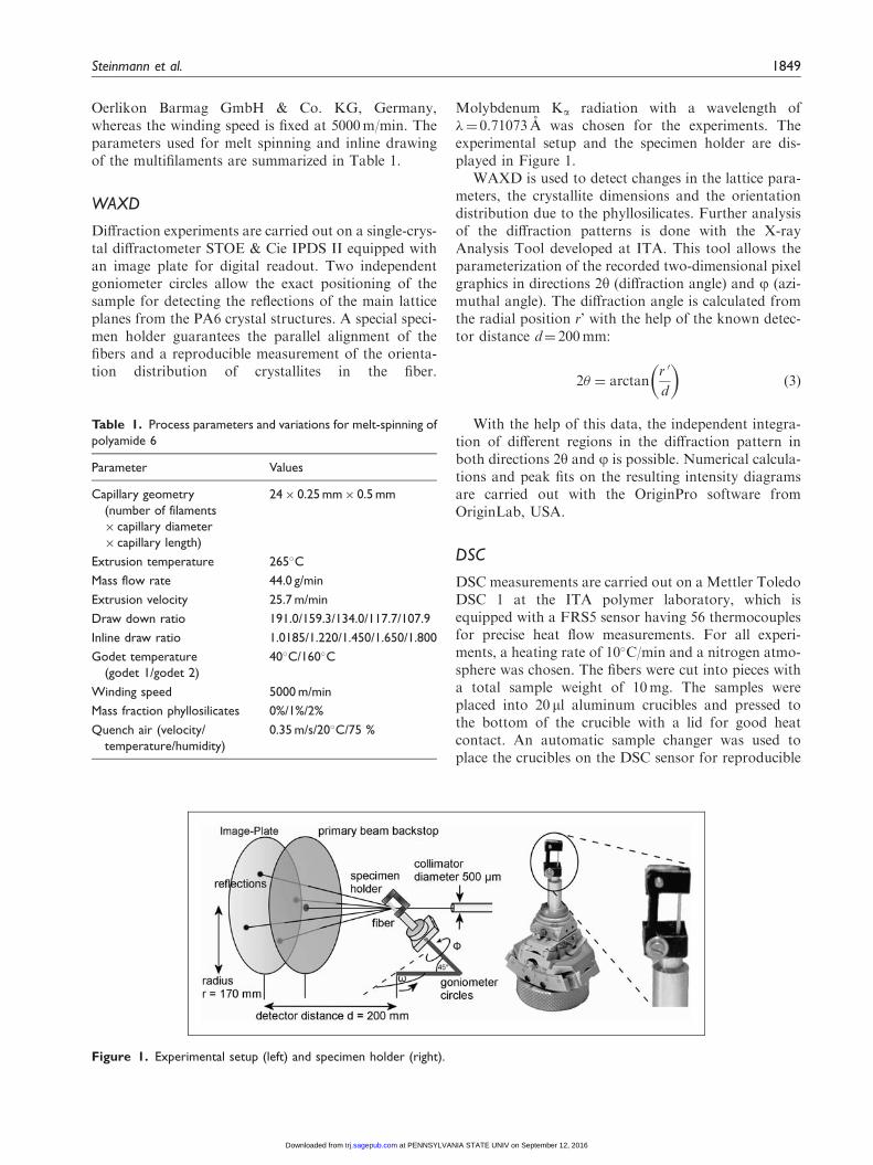
Molybdenum Ka radiation with a wavelength of�¼ 0.71073 A was chosen for the experiments. Theexperimental setup and the specimen holder are dis-played in Figure 1.
WAXD is used to detect changes in the lattice para-meters, the crystallite dimensions and the orientationdistribution due to the phyllosilicates. Further analysisof the diffraction patterns is done with the X-rayAnalysis Tool developed at ITA. This tool allows theparameterization of the recorded two-dimensional pixelgraphics in directions 2y (diffraction angle) and j (azi-muthal angle). The diffraction angle is calculated fromthe radial position r’ with the help of the known detec-tor distance d¼ 200mm:
2� ¼ arctanr 0
d
� �ð3Þ
With the help of this data, the independent integra-tion of different regions in the diffraction pattern inboth directions 2y and j is possible. Numerical calcula-tions and peak fits on the resulting intensity diagramsare carried out with the OriginPro software fromOriginLab, USA.
DSC
DSC measurements are carried out on a Mettler ToledoDSC 1 at the ITA polymer laboratory, which isequipped with a FRS5 sensor having 56 thermocouplesfor precise heat flow measurements. For all experi-ments, a heating rate of 10�C/min and a nitrogen atmo-sphere was chosen. The fibers were cut into pieces witha total sample weight of 10mg. The samples wereplaced into 20 ml aluminum crucibles and pressed tothe bottom of the crucible with a lid for good heatcontact. An automatic sample changer was used toplace the crucibles on the DSC sensor for reproducible
Figure 1. Experimental setup (left) and specimen holder (right).
Table 1. Process parameters and variations for melt-spinning of
polyamide 6
Parameter Values
Capillary geometry
(number of filaments
� capillary diameter
� capillary length)
24� 0.25 mm� 0.5 mm
Extrusion temperature 265�C
Mass flow rate 44.0 g/min
Extrusion velocity 25.7 m/min
Draw down ratio 191.0/159.3/134.0/117.7/107.9
Inline draw ratio 1.0185/1.220/1.450/1.650/1.800
Godet temperature
(godet 1/godet 2)
40�C/160�C
Winding speed 5000 m/min
Mass fraction phyllosilicates 0%/1%/2%
Quench air (velocity/
temperature/humidity)
0.35 m/s/20�C/75 %
Steinmann et al. 1849
at PENNSYLVANIA STATE UNIV on September 12, 2016trj.sagepub.comDownloaded from

measurements. Melting enthalpy is calculated by usingthe received thermograms. The melting temperaturebetween fibers in the first and quiescent crystallizationin the second heating process is also determined.Furthermore, the glass transition and correspondingrelaxation processes are examined. The results areused for the identification of changes in the crystalphases a and g as well as for the determination of thetotal crystallinity.
Mechanical properties
A Statimat 4U from Textechno GmbH, Germany wasused to determine the stress–strain curve of all materialswith a clamping length of 100mm and an extensionvelocity of 100mm/min under the standard condition.These curves are used for the calculation of the tensilestrength and the elongation at break. The mechanicalproperties are compared with the structural data deter-mined by the other experimental techniques. This com-bination reveals specific molecular mechanisms for themodification of the mechanical properties due tophyllosilicates.
Results
Crystalline properties
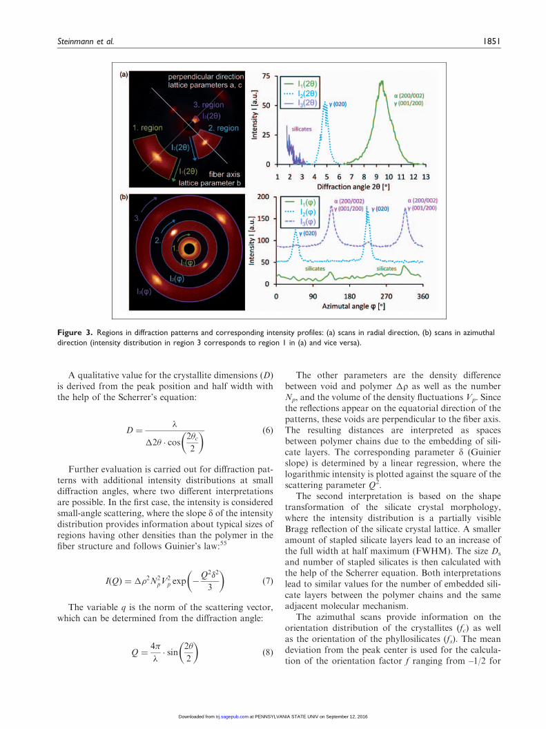
In Figure 2, typical diffraction patterns of the PA6fibers are displayed and are representative for all mea-surements. The small-angle scattering reflections(2y& 2�) appear on the equator of the patterns onlyat high DRs for fibers with phyllosilicates.
For further analysis, intensity profiles are calculatedfor selected regions. Background intensity due to air
scattering and noise from the readout process is sub-tracted. The regions in the diffraction patterns and thecorresponding intensity profiles are displayed in Figure 3.
The 2y profiles can be used for the determination ofthe unit cell and crystallite dimensions meridional andparallel to the fiber axis. Equatorial profiles contain onereflection from the two lattice planes (200) and (001) ofthe g phase (indices for pseudohexagonal description ofthe crystalline form) and (200) as well as (002) of the aphase. The meridional profiles (parallel to the fiber) axiscontain one peak from the (020) lattice plane. For thedescription of the crystalline intensity distributions, aLorentz peak model is chosen, where the center Braggangle 2yc, the half width �2y, and the total intensityI0 are refined:
Ið2�Þ ¼ Io �1
2��
�2�
2� � 2�cð Þ þ�2�
2
� �2ð4Þ
The distance (d) between the crystalline lattice planesis calculated from the center diffraction angle and thewavelength with the help of Bragg’s equation:
d ¼�
2 � sin2�c2
� � ð5Þ
For all fiber samples, the d values for (200), (020),and (001) correspond to well-investigated values of theunit cell of g phase PA6 (4.79 A in the pseudohexagonaldescription)5,54 and do not change with the processparameters. Therefore, they cannot be used to evaluatethe effect of the spinning process.
Figure 2. Typical diffraction patterns of PA6 fibers (left: 0% of phyllosilicates with a DR¼ 1.22, right: 2% of phyllosilicates with a
DR of 1.8).
1850 Textile Research Journal 82(18)
at PENNSYLVANIA STATE UNIV on September 12, 2016trj.sagepub.comDownloaded from
A qualitative value for the crystallite dimensions (D)is derived from the peak position and half width withthe help of the Scherrer’s equation:
D ¼�
�2� � cos2�c2
� � ð6Þ
Further evaluation is carried out for diffraction pat-terns with additional intensity distributions at smalldiffraction angles, where two different interpretationsare possible. In the first case, the intensity is consideredsmall-angle scattering, where the slope d of the intensitydistribution provides information about typical sizes ofregions having other densities than the polymer in thefiber structure and follows Guinier’s law:55
IðQÞ ¼ ��2N2pV
2p exp �
Q2�2
3
� �ð7Þ
The variable q is the norm of the scattering vector,which can be determined from the diffraction angle:
Q ¼4�
�� sin
2�
2
� �ð8Þ
The other parameters are the density differencebetween void and polymer �r as well as the numberNp, and the volume of the density fluctuations Vp. Sincethe reflections appear on the equatorial direction of thepatterns, these voids are perpendicular to the fiber axis.The resulting distances are interpreted as spacesbetween polymer chains due to the embedding of sili-cate layers. The corresponding parameter d (Guinierslope) is determined by a linear regression, where thelogarithmic intensity is plotted against the square of thescattering parameter Q2.
The second interpretation is based on the shapetransformation of the silicate crystal morphology,where the intensity distribution is a partially visibleBragg reflection of the silicate crystal lattice. A smalleramount of stapled silicate layers lead to an increase ofthe full width at half maximum (FWHM). The size Ds
and number of stapled silicates is then calculated withthe help of the Scherrer equation. Both interpretationslead to similar values for the number of embedded sili-cate layers between the polymer chains and the sameadjacent molecular mechanism.
The azimuthal scans provide information on theorientation distribution of the crystallites (fc) as wellas the orientation of the phyllosilicates (fs). The meandeviation from the peak center is used for the calcula-tion of the orientation factor f ranging from –1/2 for
Figure 3. Regions in diffraction patterns and corresponding intensity profiles: (a) scans in radial direction, (b) scans in azimuthal
direction (intensity distribution in region 3 corresponds to region 1 in (a) and vice versa).
Steinmann et al. 1851
at PENNSYLVANIA STATE UNIV on September 12, 2016trj.sagepub.comDownloaded from
samples oriented in the other direction (not possible forfibers) to 0 for unoriented samples up to 1 for perfectorientation:56
f ¼ 1�3
25 sin2ð’Þ4 ð9Þ
In Table 2, an overview of the crystalline propertiesof all samples is given.
Thermal properties
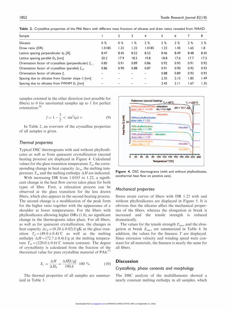
Typical DSC thermograms with and without phyllosili-cates as well as from quiescent crystallization (secondheating process) are displayed in Figure 4. Calculatedvalues for the glass transition temperature Tg, the corre-sponding change in heat capacity �cp, the melting tem-perature Tm and the melting enthalpy �H are indicated.
With increasing DR from 1.0185 to 1.22, a signifi-cant change in the heat flow curves takes place for bothtypes of fiber. First, a relaxation process can beobserved at the glass transition for the less drawnfibers, which also appears in the second heating process.The second change is a modification of the peak formfor the higher ratio together with the appearance of ashoulder at lower temperatures. For the fibers withphyllosilicates allowing higher DRs (1.8), no significantchange in the thermograms takes place. For all fibers,as well as for quiescent crystallization, the changes inheat capacity �cp¼ (0.20� 0.02) J/gK at the glass tran-sition Tg¼ (49.0� 0.4)�C as well as the meltingenthalpy �H¼ (72.7� 0.4) J/g at the melting tempera-ture Tm¼ (220.0� 0.6)�C remain constant. The degreeof crystallinity is calculated from the fraction of thetheoretical value for pure crystalline material of PA6:57
Xc ¼�H
�H0¼
�H J=g½ �
190:6� 100 % ð10Þ
The thermal properties of all samples are summar-ized in Table 3.
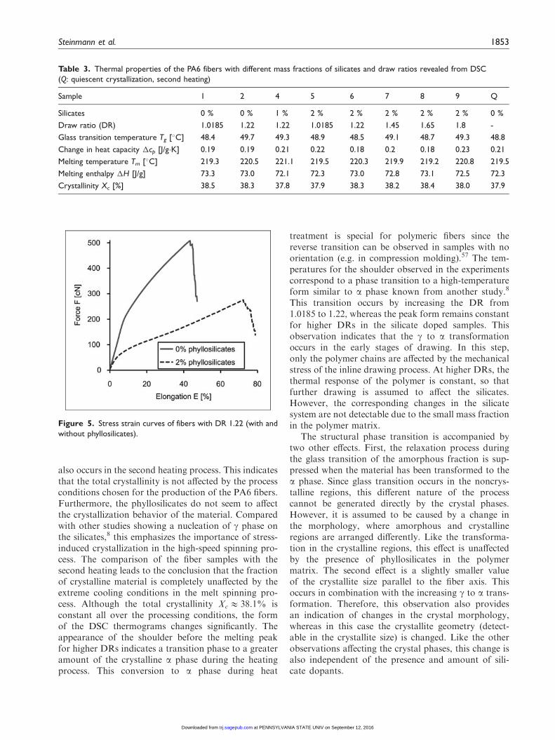
Mechanical properties
Stress strain curves of fibers with DR 1.22 with andwithout phyllosilicates are displayed in Figure 5. It isobvious that the silicates affect the mechanical proper-ties of the fibers, whereas the elongation at break isincreased and the tensile strength is reduceddramatically.
The values for the tensile strength Fmax and the elon-gation at break Emax are summarized in Table 4. Inaddition, the values for the fineness T are displayed.Since extrusion velocity and winding speed were con-stant for all materials, the fineness is nearly the same forall fibers.
Discussion
Crystallinity, phase contents and morphology
The DSC analysis of the multifilaments showed anearly constant melting enthalpy in all samples, which
Table 2. Crystalline properties of the PA6 fibers with different mass fractions of silicates and draw ratios revealed from WAXD
Sample 1 2 3 4 5 6 7 8
Silicates 0 % 0 % 1 % 2 % 2 % 2 % 2 % 2 %
Draw ratio (DR) 1.0185 1.22 1.22 1.0185 1.22 1.45 1.65 1.8
Lattice spacing perpendicular dII [A] 8.47 8.45 8.52 8.52 8.46 8.49 8.48 8.45
Lattice spacing parallel DII [nm] 20.2 17.9 18.5 19.8 18.8 17.6 17.7 17.5
Orientation factor of crystallites (perpendicular) fc,r 0.85 0.91 0.89 0.86 0.92 0.93 0.91 0.92
Orientation factor of crystallites (parallel) fc,II 0.86 0.90 0.88 0.87 0.91 0.90 0.92 0.93
Orientation factor of silicates fs – – – – 0.88 0.89 0.92 0.93
Spacing due to silicates from Guinier slope d [nm] – – – – 2.35 2.15 1.85 1.49
Spacing due to silicates from FWHM Ds [nm] – – – – 2.45 2.11 1.67 1.35
Figure 4. DSC thermograms (with and without phyllosilicates,
exothermal heat flow on positive axis).
1852 Textile Research Journal 82(18)
at PENNSYLVANIA STATE UNIV on September 12, 2016trj.sagepub.comDownloaded from
also occurs in the second heating process. This indicatesthat the total crystallinity is not affected by the processconditions chosen for the production of the PA6 fibers.Furthermore, the phyllosilicates do not seem to affectthe crystallization behavior of the material. Comparedwith other studies showing a nucleation of g phase onthe silicates,8 this emphasizes the importance of stress-induced crystallization in the high-speed spinning pro-cess. The comparison of the fiber samples with thesecond heating leads to the conclusion that the fractionof crystalline material is completely unaffected by theextreme cooling conditions in the melt spinning pro-cess. Although the total crystallinity Xc& 38.1% isconstant all over the processing conditions, the formof the DSC thermograms changes significantly. Theappearance of the shoulder before the melting peakfor higher DRs indicates a transition phase to a greateramount of the crystalline a phase during the heatingprocess. This conversion to a phase during heat
treatment is special for polymeric fibers since thereverse transition can be observed in samples with noorientation (e.g. in compression molding).57 The tem-peratures for the shoulder observed in the experimentscorrespond to a phase transition to a high-temperatureform similar to a phase known from another study.8
This transition occurs by increasing the DR from1.0185 to 1.22, whereas the peak form remains constantfor higher DRs in the silicate doped samples. Thisobservation indicates that the g to a transformationoccurs in the early stages of drawing. In this step,only the polymer chains are affected by the mechanicalstress of the inline drawing process. At higher DRs, thethermal response of the polymer is constant, so thatfurther drawing is assumed to affect the silicates.However, the corresponding changes in the silicatesystem are not detectable due to the small mass fractionin the polymer matrix.
The structural phase transition is accompanied bytwo other effects. First, the relaxation process duringthe glass transition of the amorphous fraction is sup-pressed when the material has been transformed to thea phase. Since glass transition occurs in the noncrys-talline regions, this different nature of the processcannot be generated directly by the crystal phases.However, it is assumed to be caused by a change inthe morphology, where amorphous and crystallineregions are arranged differently. Like the transforma-tion in the crystalline regions, this effect is unaffectedby the presence of phyllosilicates in the polymermatrix. The second effect is a slightly smaller valueof the crystallite size parallel to the fiber axis. Thisoccurs in combination with the increasing g to a trans-formation. Therefore, this observation also providesan indication of changes in the crystal morphology,whereas in this case the crystallite geometry (detect-able in the crystallite size) is changed. Like the otherobservations affecting the crystal phases, this change isalso independent of the presence and amount of sili-cate dopants.
Table 3. Thermal properties of the PA6 fibers with different mass fractions of silicates and draw ratios revealed from DSC
(Q: quiescent crystallization, second heating)
Sample 1 2 4 5 6 7 8 9 Q
Silicates 0 % 0 % 1 % 2 % 2 % 2 % 2 % 2 % 0 %
Draw ratio (DR) 1.0185 1.22 1.22 1.0185 1.22 1.45 1.65 1.8 -
Glass transition temperature Tg [�C] 48.4 49.7 49.3 48.9 48.5 49.1 48.7 49.3 48.8
Change in heat capacity �cp [J/g�K] 0.19 0.19 0.21 0.22 0.18 0.2 0.18 0.23 0.21
Melting temperature Tm [�C] 219.3 220.5 221.1 219.5 220.3 219.9 219.2 220.8 219.5
Melting enthalpy �H [J/g] 73.3 73.0 72.1 72.3 73.0 72.8 73.1 72.5 72.3
Crystallinity Xc [%] 38.5 38.3 37.8 37.9 38.3 38.2 38.4 38.0 37.9
Figure 5. Stress strain curves of fibers with DR 1.22 (with and
without phyllosilicates).
Steinmann et al. 1853
at PENNSYLVANIA STATE UNIV on September 12, 2016trj.sagepub.comDownloaded from

Orientation distribution and dispersion of silicates
Information about the orientation distribution isobtained from the evaluation of the intensity profiles.Since small angle scattering in the patterns due to voidsis assumed to be an effect of the silicates embedded inthe polymer, the corresponding intensity distribution isused for the determination of the placement of silicatesin the fiber. The orientation factor f of the crystallites aswell as the silicates is displayed in Figure 6a. The crys-talline regions are well oriented in all fibers, but thisorientation increases even more together with the g toa transformation. For higher DRs, the factor remainsalmost constant. Since values for f with different massfractions of silicates are very similar, the dopant doesnot seem to affect the reorientation. Instead of that, theeffect is also assumed to take place due to a significantchange in the morphology of the fiber structure, wherethe fibrils of the a phase have a stronger orientationalong the fiber axis.
For the lowest DR, no small-angle scattering signalcan be detected, so that no orientation information canbe obtained. In this case, the silicates are assumed to bemore or less disoriented respective to the fiber axis so
that no orientation occurs by the drawing of the melt.For higher DRs in the solid state, the silicate orienta-tion increases continuously and reaches values as highas the crystalline ones. Since small-angle scattering isobserved in the equatorial plane of the diffraction pat-terns, the normal to the silicate layers defined by dis-tance to the next silicate sheet is perpendicular to thefiber axis.
Further information on the embedding of the silicatelayers in the polyamide matrix can be obtained fromthe slope d determined in the Guinier plot described inthe experimental section, or alternatively from theFWHM of the reflection and the Scherrer formula.Both values represent a medium distance of polymericmaterial, whereas this void is filled with silicates.Consequently, the parameter can be used for the calcu-lation for an average thickness of silicates in the matrix.With the help of the typical distance between two sili-cate layers, the corresponding number of adjacentlayers can be evaluated, which is a benchmark for thedispersion of silicates in polyamide. As seen in Figure6b, the Guinier slope d decreases with increasing DR.The final value for the highest DR 1.8 (1.49 nm) corre-sponds to the dimension of one silicate layer (with
Figure 6. (a) Orientation factors of crystallites and silicates dependent to DR, (b) Guinier slope d as a function of DR.
Table 4. Mechanical properties of the PA6 fibers with different mass fractions of silicates and draw ratios revealed from stress strain
curves (fineness T from reeling)
Sample 1 2 3 4 5 6 7 8
Silicates 0 % 0 % 1 % 2 % 2 % 2 % 2 % 2 %
Draw ratio (DR) 1.0185 1.22 1.22 1.0185 1.22 1.45 1.65 1.8
Tensile strength Fmax [cN/dtex] 5.68 5.75 4.06 3.08 3.19 3.72 4.05 4.31
Elongation at break Emax [%] 49.2 46.6 65.4 76.9 73.6 63.8 55.8 51.8
Fineness T [dtex] 91.4 91.4 91.2 91.2 91.4 91.3 91.5 91.5
1854 Textile Research Journal 82(18)
at PENNSYLVANIA STATE UNIV on September 12, 2016trj.sagepub.comDownloaded from
regard to the organic component, which is compatiblewith the polymer and does not cause voids). Therefore,a defoliation of silicates takes place in the drawing pro-cess and results in single silicate layers dispersed in thepolymer matrix. The same effect of silicate defoliation,remarkable in smaller voids in the polymeric material,was detected by Ibanes et al.8,58 Compared with thisstudy with winding speeds less than 1000m/min, theeffect was demonstrated here for high-speed melt spin-ning (5000m/min). Furthermore, the material wasdrawn at lower temperatures (40�C compared with140�C). Both variations cause a slower phase transfor-mation since kinetics is slower at lower temperaturesand the transition has less time to take place at higherspeeds. Therefore, the effect of a phase formation is lessdetectable here. It is remarkable that a complete defo-liation of the silicates could be achieved in an indust-rially relevant spinning process.
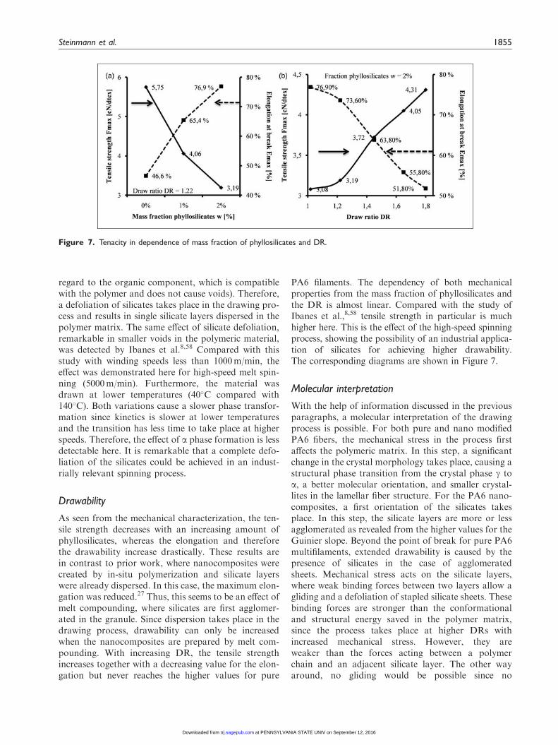
Drawability
As seen from the mechanical characterization, the ten-sile strength decreases with an increasing amount ofphyllosilicates, whereas the elongation and thereforethe drawability increase drastically. These results arein contrast to prior work, where nanocomposites werecreated by in-situ polymerization and silicate layerswere already dispersed. In this case, the maximum elon-gation was reduced.27 Thus, this seems to be an effect ofmelt compounding, where silicates are first agglomer-ated in the granule. Since dispersion takes place in thedrawing process, drawability can only be increasedwhen the nanocomposites are prepared by melt com-pounding. With increasing DR, the tensile strengthincreases together with a decreasing value for the elon-gation but never reaches the higher values for pure
PA6 filaments. The dependency of both mechanicalproperties from the mass fraction of phyllosilicates andthe DR is almost linear. Compared with the study ofIbanes et al.,8,58 tensile strength in particular is muchhigher here. This is the effect of the high-speed spinningprocess, showing the possibility of an industrial applica-tion of silicates for achieving higher drawability.The corresponding diagrams are shown in Figure 7.
Molecular interpretation
With the help of information discussed in the previousparagraphs, a molecular interpretation of the drawingprocess is possible. For both pure and nano modifiedPA6 fibers, the mechanical stress in the process firstaffects the polymeric matrix. In this step, a significantchange in the crystal morphology takes place, causing astructural phase transition from the crystal phase g toa, a better molecular orientation, and smaller crystal-lites in the lamellar fiber structure. For the PA6 nano-composites, a first orientation of the silicates takesplace. In this step, the silicate layers are more or lessagglomerated as revealed from the higher values for theGuinier slope. Beyond the point of break for pure PA6multifilaments, extended drawability is caused by thepresence of silicates in the case of agglomeratedsheets. Mechanical stress acts on the silicate layers,where weak binding forces between two layers allow agliding and a defoliation of stapled silicate sheets. Thesebinding forces are stronger than the conformationaland structural energy saved in the polymer matrix,since the process takes place at higher DRs withincreased mechanical stress. However, they areweaker than the forces acting between a polymerchain and an adjacent silicate layer. The other wayaround, no gliding would be possible since no
Figure 7. Tenacity in dependence of mass fraction of phyllosilicates and DR.
Steinmann et al. 1855
at PENNSYLVANIA STATE UNIV on September 12, 2016trj.sagepub.comDownloaded from

mechanical forces would be transmitted from the poly-mer to the silicate system. Weak binding forces can alsoexplain the decrease of tensile strength. For the highestDR, the defoliation is fulfilled and single-layer silicatesare well dispersed and oriented in the polyamidematrix. Since no further orientation and gliding pro-cesses can take place, the fiber breaks after this point.The complete transformations at the molecular scaleoccurring in the drawing process are exemplifiedin Figure 8.
Conclusion
The presence of phyllosilicates in PA6 multifilamentsleads to an increase of the drawability in the inlinedrawing process. For achieving these properties, thepreparation should be done by melt compoundingsince agglomerated silicate sheets are necessary. Inthis study, it was first demonstrated that this effectcan be used in an industrially relevant high-speed spin-ning process at 5000m/min. For lower DRs, only thePA6 polymer chains are affected by the mechanicalstress. This effect is independent of the silicates andleads to a higher orientation of the polymer chains aswell as a transformation in the crystalline regions. Thistransformation is assumed to be the conversion fromthe g to the a phase. For higher DRs, beyond the elon-gation of break for pure PA6, a defoliation of the sili-cate layers takes place. Drawing of the fibers is possibleuntil single silicate layers are dispersed in the polymermatrix. Compared with other studies with lower wind-ing speeds, the structural phase transition from g to a isless dominant, but the effect of the silicates is larger. Inthis case, the doping of PA6 with nano phyllosilicatescould be used to reduce the fiber fineness and to pro-duce ultrafine filaments. Even though mechanical prop-erties are lower than for unfilled PA6, they are still
good enough for an industrial application of these fila-ments. For this purpose, further experiments with areduced mass flow rate have to be carried out.Furthermore, the reduction of tensile strength has tobe compensated with an appropriate procedure of pro-cessing the fibers.
Funding
Contract grant sponsor: Deutsche Forschungsgemeinschaft(German Research Foundation, DFG); research project‘‘FiberSage’’, contract grant number: GR 1311/34-1.
References
1. Schlack P. Preparation of polyamides. Patent 2241321,
USA, 2002.2. Fourne F. Synthetische fasern, 1st edn. Munchen: Hanser,
1995.3. Ho JC and Wei KH. Induced g! a crystal transformation
in blends of polyamide 6 and liquid crystalline copolyester.
Macromolecules 2000; 33: 5181–5186.
4. Fornes TD and Paul DR. Crystallization behavior of
nylon 6 nanocomposites. Polymer 2003; 44: 3945–3961.
5. Arimoto H, Ishibashi M and Hirai M. Crystal structure of
the g-form of nylon 6. J Polym Sci Pol Phys 1965; 3:
317–326.6. Holmes DR, Bunn CW and Smith DJ. The crystal struc-
ture of polycaproamide: nylon 6. J Polym Sci Pol Chem
1955; XVII: 159–177.7. Ziabicki A. Uber die mesomorphe �-form von polycapro-
namid und ihre umwandlung in die kristalline form a.Kolloid Z 1959; 167(2): 132–141.
8. Ibanes C, de Boissieu M, David L, et al. High temperature
behavior of the crystalline phases in unfilled and clay-filled
nylon 6 fibers. Polymer 2006; 47: 5071–5079.9. Rahbar R and Mojtahedi M. Influence of hot multistage
drawing on structure and mechanical properties of nylon 6
multifilament yarn. J Eng Fibers Fabrics 2011; 6(2): 11.
Figure 8. Overview of all transformations at molecular scale occurring in the drawing process.
1856 Textile Research Journal 82(18)
at PENNSYLVANIA STATE UNIV on September 12, 2016trj.sagepub.comDownloaded from
10. Gianchandani J, Spruiell JE and Clark ES. J Appl Polym
Sci 1982; 27: 3527–3551.
11. Varlot K, Reynaud E, Kloppfer MH and Vigier G.
Clayreinforced polyamide: preferential orientation of
the montmorillonite sheets and the polyamide crystalline
lamellae. J Polym Sci, Part B: Polym Phys 2001; 39:
1360–1370.
12. Xiaohui Liu and Qiuju Wu. Phase transition in nylon 6/
clay nanocomposites on annealing, Polymer
Communication, Polymer 2002; 43: 1933–1936.13. Zhang CF, Liu YH, Liu SX, et al. Crystalline behaviors
and phase transition during the manufacture of fine
denier PA6 fibers. Sci China Press 2002; 52(11):
1835–1842.14. Craubner H. Untersuchungen uber den schmelzspinn-
proze ß und die fadenbildung bei polyamid 6. Angew
Makromol Chem 1974; 40/41: 173–217.
15. Ishibashi T, Aoki K and Ishii T. Studies on melt spinning
of nylon 6. I. Cooling and deformation behavior and
orientation of nylon 6 threadline. J Appl Polym Sci
1970; 14: 1597–1613.16. Ishibashi T and Ishii T. Studies on melt spinning of nylon
6. ii. effect of heating the threadline upon orientation and
crystallization. J Appl Polym Sci 1976; 20: 335–344.
17. Bankar VG, Spruiell JE and White JL. Melt spinning of
nylon 6: structure development and mechanical proper-
ties of as-spun-filaments. J Appl Polym Sci 1977; 21:
2341–2358.18. Hirami M and Tanimura A. Structure development in the
melt spinning of nylon 6. J Macromol Sci Phys 1981;
19(2): 205–210.
19. Haberkorn H, Hahn K, Breuer H, et al. On the neck-like
deformation in high-speed spun polyamides. J Appl
Polym Sci 1993; 47: 1551–1579.20. Samon JM, Schultz JM and Hsiao BS. Structure devel-
opment in the early stages of crystallization during melt
spinning. Polymer 2002; 43: 1873–1875.21. Tjong SC. Structural and mechanical properties of poly-
mer nanocomposites. Mat Sci Eng R 2006; 53: 73–197.22. Ray SS and Okamoto M. Polymer/layered silicate nano-
composites: a review from preparation to processing.
Prog Polym Sci 2003; 28: 1539–1641.23. Carrado KA. Synthetic organo- and polymer-clays: prep-
aration, characterization: materials applications. Appl
Clay Sci 2000; 17: 1–23.
24. LeBaron PC, Wang Z and Pinnavaia TJ. Polymer-layered
silicate nanocomposites: an overview. Appl Clay Sci 1999;
15: 11–29.25. Mahfuz H, Hasan MM, Rangari VK, et al. Investigation
of thermal and mechanical response of nylon-6 filaments
with the infusion of acicular and spherical nanoparticles.
NSTI-Nanotech 2005; 2: 86–89.
26. Cho JW and Paul DR. Nylon 6 nanocomposites by melt
compounding. Polymer 2003; 42: 1083–1094.
27. Kim KJ, Lee JS, Prabu AA, et al. Preparation and char-
acterization of nylon 6/organoclay nanocomposite fila-
ment fibers. Polymer Composite 2009; 42: 1083–1094.28. Ming Z, Xiangqing P and Wang Y. Preparation and
characterization of polyamide6/montmorillonite
nanocomposites by reactive extrusion. Int J Polym Mat2006; 55(2): 147–159.
29. Shah RK and Paul DR. Nylon 6 nanocomposites pre-
pared by a melt mixing masterbatch process. Polymer2004; 45: 2991–3000.
30. Yang X, Li Q, Chen Z, et al. Mechanical properties andflame retardancy research of montmorillonite intercalate
polyamide 66 composites. J Compos Mater 2009; 43(23):2785–2792.
31. Gilman JW, Morgen AB, Harris R, et al. Polymer
layered-silicate nanocomposites: polyamide 6, polypro-pylene and polystyrene: new advances in flame retardanttechnology. In: Proceedings. Fire Retardant Chemicals
Association; 1999 Oct 24-27; Tucson, US. Lancaster:Fire Retardant Chemicals Assoc, 1999, pp.9–22.
32. Reynaud E, Jouen T, Gauthier C, et al. Nanofillers in
polymeric matrix: a study on silica reinforced PA6.Polymer. 2001; 42: 8759–8768.
33. Kristofic M, Dulıkova M, Vassova I, et al. PA6/copolyamide/layered silicate fibers. Fibres Text East
Eur 2007; 15(5–6): 64–65.34. Masenelli-Varlot K, Reynaud E, Vigier G, et al.
Mechanical properties of clay-reinforced polyamide.
J Polym Sci Pol Phys 2002; 40: 272–283.35. Wu TM and Wu JY. Structural analysis of polyamide/
clay nanocomposites. J Macromol Sci Phys 2002; 41(1):
17–31.36. Lee JH, Park MG and Kim SC. Structure and properties
of polyamide-6 & 6/66 clay nanocomposites. J MacromolSci Chem 2009; 46(1): 65–73.
37. Tamura K, Uno H, Yamada H, et al. Layered silicate-polyamide-6 nanocomposites: influence of silicate specieson morphology and properties. J Polym Sci Pol Phys
2009; 47(6): 583–595.38. Hedicke K, Wittich H, Mehler C, et al. Crystallization
behavior of polyamide-6 and polyamide-66 nanocompo-
sites. Compos Sci Technol 2006; 66(3–4): 571–575.39. Dinzhos RV, Privalko EG and Privalko VP. Enthalpy
relaxation in the cooling/heating cycles of polyamide
6/organoclay nanocomposites I. nonisothermal crystal-lization. Macromol Sci Phys 2005; 44(4): 421–430.
40. Mathias LJ, Davis RD and Jarrett W. Observation ofa and g crystal forms and amorphous regions of nylon
6-clay nanocomposites using solid state 15N nuclear mag-netic resonance. Macromolecules 1999; 32: 7958–7960.
41. Na B, Xu W, Lv R, et al. Suppressed molecular orien-
tation in nylon 6/clay nanocomposite at large strain: roleof microvoiding. J Polym Sci Pol Phys 2010; 48(5):514–519.
42. Garofalo E, Russo GM, Scarfato P, et al. Nanostructuralmodifications of polyamide/MMT hybrids under isother-mal and nonisothermal elongational flow. J Polym SciPol Phys 2009; 47(10): 981–993.
43. Baldi F, Fanceschini A, Bignotti F, et al. Rheologicalbehavior of nano-composites based on polyamide6 under shear and elongational flow at high strain rates.
Rheol Acta 2009; 48: 73–88.44. Choi JS, Lim ST, Choi HJ, et al. Viscoelastic properties
of exfoliated polyamide-6/layered silicate nanocompo-
sites. J Mater Sci 2006; 41: 1843–1846.
Steinmann et al. 1857
at PENNSYLVANIA STATE UNIV on September 12, 2016trj.sagepub.comDownloaded from
45. Loo LS and Gleason KK. Investigation of polymerand nanoclay orientation distribution in nylon6/montmorillonite nanocomposites. Polymer 2004; 45:
5933–5939.46. Zhao XY. Thermal history dependence of polymorphic
transformation of polyamide 6/silicate nanocomposites.Polym Int 2009; 58(5): 469–474.
47. Wurm A, Ismail M, Krezschmar B, et al. Retarded crys-tallization in polyamide/layered silicates nanocompositescaused by an immobilized interphase. Macromolecules
2010; 43: 1480–1487.48. Fong H, Liu W, Wang CS, et al. Generation of electro-
spun fibers of nylon 6-montmorillonite nanocomposites.
Polymer 2002; 43: 775–780.49. Li L, Bellan LM, Craighead HG, et al. Formation and
properties of nylon-6 and nylon-6/montmorillonite com-
posite nanofibers. Polymer 2006; 47: 6208–6217.50. Kim GM, Michler GH, Ania F, et al. Temperature
dependence of polymorphism in electrospun nanofibersof PA6 and PA6/clay nanocomposite. Polymer 2007; 48:
4814–4823.51. Giza E, Ito H, Kikutani T, et al. Fiber structure forma-
tion in high-speed melt spinning of polyamide 6/clay
hybrid nanocomposite. J Macromol Sci Phys 2000;39(4): 545–559.
52. BASF. Ultramid B24 N 03 product information.
Ludwigshafen: BASF Plastics. 2007 Mar. Available
from: http: //prospector.ides.com/. Accessed: 14.10.2011.53. Rockwood Clay Additives. Product bulletin/nanofil. che-
shire: rockwood additives limited. Available from: http: //
www.rockwoodadditives.com. Accessed: 14.10.2011.54. Miyasaka K and Makishima K. Transition of nylon 6
g-phase crystals by stretching in the chain direction.
J Polym Sci A 1967; 5: 3017–3027.
55. Richardson R. Scattering and reflection techniques. In:
Cosgrove editor (ed) Colloid Science: Principles, Methods
and Applications. 2nd ed. Chichester: Wiley, 2010,
pp. 273–298.56. Booys J and Hermans P. Zur ableitung eines mittleren
orientierungswinkels aus dem rontgendiagramm. Colloid
Polym Sci 1941; 97: 229–231.57. Kristofic M, Marcincin A and Ujhelyiova A. The DSC
study of PA6, polyamides and copolyamides. J Therm
Anal Calorim 2000; 60: 357–369.
58. Lincoln D, Vaia R, Wang Z, et al. Temperature depend-
ence of polymer crystalline morphology in nylon 6/mont-
morillonite nanocomposites. Polymer 2001; 42:
9975–9985.
1858 Textile Research Journal 82(18)
at PENNSYLVANIA STATE UNIV on September 12, 2016trj.sagepub.comDownloaded from
Copyright © 2022 FDOKUMEN