SPECIFICATIONS - US Embassy and Consulates in Turkey
221
American Embassy Ankara / Turkey SPECIFICATIONS Corrected Final Design Submittal September 2020 A&E SERVICES FOR STRENGTHENING OF DCR RETAINING WALL Ankara / Turkey ORDER NO: 19TU1519Q3008 REQUISITION / REFERENCE NO: PR8244110 DESIGNER Altan Ltd. Co. Design – Consultancy - Services Yalım Sok. No. 5/1 - 4 06660 Kavaklıdere, Ankara / Turkey Phone: +90 312 419 17 07 Fax : +90 312 419 16 69 www.altan-tuncer.com [email protected]
-
Upload
khangminh22 -
Category
Documents
-
view
0 -
download
0
Transcript of SPECIFICATIONS - US Embassy and Consulates in Turkey

American Embassy
Ankara / Turkey
SPECIFICATIONS
Corrected Final Design Submittal September 2020
A&E SERVICES FOR STRENGTHENING
OF DCR RETAINING WALL
Ankara / Turkey
ORDER NO: 19TU1519Q3008
REQUISITION / REFERENCE NO: PR8244110
DESIGNER
Altan Ltd. Co. Design – Consultancy - Services Yalım Sok. No. 5/1 - 4 06660 Kavaklıdere, Ankara / Turkey Phone: +90 312 419 17 07 Fax : +90 312 419 16 69 www.altan-tuncer.com [email protected]

PROJECT TABLE OF CONTENTS
DIVISION 01 - GENERAL REQUIREMENTS
EXISTING CONDITIONS
DEMOLITION AND DECONSTRUCTION SELECT FILL AND TOPSOIL FOR LANDFILL COVER
CONCRETE
03 11 14.00 10 FORMWORK FOR CONCRETE 03 20 01.00 10 CONCRETE REINFORCEMENT 03 20 02 STEEL BARS AND WELDED WIRE FABRIC FOR CONCRETE
REINFORCEMENT FOR CIVIL WORKS 03 31 01.00 10 CAST-IN-PLACE STRUCTURAL CONCRETE FOR CIVIL WORKS
DIVISION 05 - METALS
05 05 23 WELDING, STRUCTURAL 05 05 23.13 10 ULTRASONIC INSPECTION OF WELDMENTS 05 12 00 STRUCTURAL STEEL 05 28 33 METAL SECURITY FENCES 05 83 33 ORNAMENTAL METAL SECURITY FENCES
DIVISION 31 - EARTHWORK
31 00 00 EARTHWORK 31 23 00.00 20 EXCAVATION AND FILL
DIVISION 32 - EXTERIOR IMPROVEMENTS
32 92 19 SEEDING
-- End of Project Table of Contents --
PROJECT TABLE OF CONTENTS Page 1
01 11 00.00 40 SUMMARY OF WORK 01 14 00 WORK RESTRICTIONS 01 32 01.00 10 PROJECT SCHEDULE 01 33 00 SUBMITTAL PROCEDURES 01 35 30 SAFETY, HEALTH, AND EMERGENCY RESPONSE (HTRW/UST) 01 45 00.00 20 CONSTRUCTION QUALITY CONTROL 01 45 04.00 10 CONTRACTOR QUALITY CONTROL 01 50 02.00 10 TEMPORARY CONSTRUCTION FACILITIES 01 57 20.00 10 ENVIRONMENTAL PROTECTION 01 77 00.00 20 CLOSEOUT PROCEDURES 01 78 02.00 10 CLOSEOUT SUBMITTALS
DIVISION
02 41 00
02 -
02 66 00
DIVISION 03 -

Section 01 11 00.00 40 Page 1
SECTION 01 11 00.00 40
SUMMARY OF WORK 06/06
PART 1 GENERAL 1.1 SUMMARY The work to be performed under this project consists of providing the labor, equipment, and materials as shown on the Contract Documents.
The construction works for the strengthening of the existing retaining walls shall be conducted in phases in order to avoid any failure in the site security and to avoid any disruption to the neighboring facilities. In order to avoid any failures in site security, existing fence shall be removed in phases and totally six phases are considered for the completion of fence replacement works. Below listed work items shall be conducted at the removed sections of the existing fence and shall be repeated for each phase of the work. (See Figure 1): 3.2.1 Coordination with the local municipality and neighboring land owners for
the necessary permissions and formalities.
3.2.2 Preparation of the contractor lay-down area.
3.2.3 Excavating pits to determine the exact routes of existing lawn irrigation lines, cables of CCTV cameras and other underground utilities.
3.2.4 Marking of the locations of the new concrete foundations of the fence post back bracings.
3.2.5 Removal of existing bushes that interfere with the locations of the fence back bracings and their foundations.
3.2.6 Installation of the formwork on existing retaining wall for the bases of the posts retaining wall top leveling reinforced concrete member and foundations of the back bracings.
3.2.7 Installation of chemical dowels on existing retaining wall for the bases of the posts and retaining wall top leveling reinforced concrete member.
3.2.8 Application of building chemicals for the bonding of new and existing concrete.
3.2.9 Installation of reinforcement for post bases and leveling concrete member.
3.2.10 Casting of concrete of the post bases, retaining wall top leveling member and foundations of the back bracings.
3.2.11 Installation of the fence posts and related back bracings. 3.2.12 Installation of shop fabricated anti climb fencing panels.
3.2.13 Completion of painting works. 3.2.14 Rough grading and cleaning of the area affected from work.
Leveling of the effected garden area, tree planting and seeding works.
The contract drawings, which accompany this specification, are a part of the Contract Documents.
Section 01 11 00.00 40 Page 2
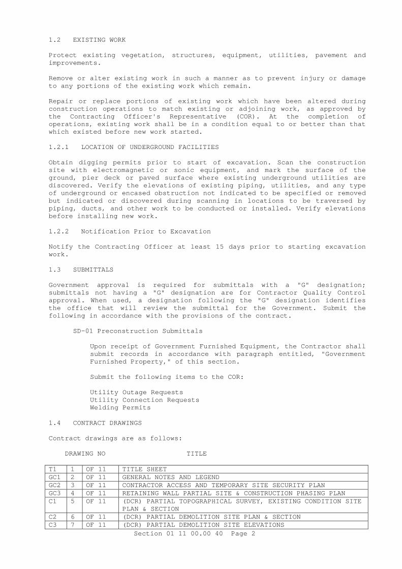
1.2 EXISTING WORK Protect existing vegetation, structures, equipment, utilities, pavement and improvements. Remove or alter existing work in such a manner as to prevent injury or damage to any portions of the existing work which remain. Repair or replace portions of existing work which have been altered during construction operations to match existing or adjoining work, as approved by the Contracting Officer's Representative (COR). At the completion of operations, existing work shall be in a condition equal to or better than that which existed before new work started. 1.2.1 LOCATION OF UNDERGROUND FACILITIES Obtain digging permits prior to start of excavation. Scan the construction site with electromagnetic or sonic equipment, and mark the surface of the ground, pier deck or paved surface where existing underground utilities are discovered. Verify the elevations of existing piping, utilities, and any type of underground or encased obstruction not indicated to be specified or removed but indicated or discovered during scanning in locations to be traversed by piping, ducts, and other work to be conducted or installed. Verify elevations before installing new work. 1.2.2 Notification Prior to Excavation Notify the Contracting Officer at least 15 days prior to starting excavation work. 1.3 SUBMITTALS Government approval is required for submittals with a "G" designation; submittals not having a "G" designation are for Contractor Quality Control approval. When used, a designation following the "G" designation identifies the office that will review the submittal for the Government. Submit the following in accordance with the provisions of the contract.
SD-01 Preconstruction Submittals
Upon receipt of Government Furnished Equipment, the Contractor shall submit records in accordance with paragraph entitled, "Government Furnished Property," of this section.
Submit the following items to the COR: Utility Outage Requests Utility Connection Requests Welding Permits
1.4 CONTRACT DRAWINGS Contract drawings are as follows: DRAWING NO TITLE T1 1 OF 11 TITLE SHEET GC1 2 OF 11 GENERAL NOTES AND LEGEND GC2 3 OF 11 CONTRACTOR ACCESS AND TEMPORARY SITE SECURITY PLAN GC3 4 OF 11 RETAINING WALL PARTIAL SITE & CONSTRUCTION PHASING PLAN C1 5 OF 11 (DCR) PARTIAL TOPOGRAPHICAL SURVEY, EXISTING CONDITION SITE
PLAN & SECTION C2 6 OF 11 (DCR) PARTIAL DEMOLITION SITE PLAN & SECTION C3 7 OF 11 (DCR) PARTIAL DEMOLITION SITE ELEVATIONS

Section 01 11 00.00 40 Page 3
C4 8 OF 11 (DCR) NEW CONDITION SITE PLAN & SECTION C5 9 OF 11 (DCR) NEW CONDITION SITE ELEVATIONS C6 10 OF 11 ANTI-CLIMB FENCE DETAILS-1 C7 11 OF 11 ANTI-CLIMB FENCE DETAILS-2 A CD copy of contract drawings, maps, and specifications will be furnished to the Contractor without charge. Reference publications will not be furnished. Contractor shall immediately check furnished drawings and notify the Government of any discrepancies. 1.5 WORK RESCHEDULING Contractor shall allow for delays where construction activity is prohibitive. Government will provide 24 hour notification each time the restrictions are invoked. Normal duty hours for work shall be from 07:30 a.m. to 16:30 p.m., Monday through Friday. Requests for additional work shall require written approval from the COR 7 days in advance of the proposed work period. 1.5.1 WEATHER DELAYS The performance period listed in the contract does not include expected weather delays. The weather delays will be added when
In order for the contract to be extended for severe weather, the contractor must demonstrate the total actual adverse weather days. 1.5.2 WORK IN RESTRICTED AREAS Contractors performing work in restricted areas will encounter temporary delays and full exclusion days due to mission requirements. The contractor should prepare their proposals and schedules with the expectation that there will be 8.5 work days of delays for every 50 scheduled calendar days during the total contract period. The Contractor may also experience shorter work hours due to functional requirements of the DCR 1.6 OCCUPANCY OF PREMISES Building(s) will be occupied during performance of work under this Contract. Before work is started, the Contractor shall arrange with the COR a sequence of procedure, means of access, space for storage of materials and equipment, and use of approaches, corridors, and stairways. 1.7 GOVERNMENT FURNISHED PROPERTY: NOT USED. 1.8 ON-SITE PERMITS 1.8.1 Utility Outage Requests and Utility Connection Requests Notify the COR at least 48 hours prior to starting excavation work. Contractor is responsible for marking and verifying all utilities not marked. The Contractor shall verify the elevations of existing piping, utilities, and any type of underground obstruction not indicated or specified to be removed. But indicated in locations to be transversed by piping, ducts, and other work to be installed. Verify elevations before installing new work closer than nearest manhole or other structure at which an adjustment in grade can be made. Work shall be scheduled to hold outages to a minimum.

Section 01 11 00.00 40 Page 4
Utility outages and connections required during the prosecution of work that affect existing systems shall be arranged for at the convenience of the Government and shall be scheduled outside the regular working hours or on weekends. [COR may permit utility outages at his discretion.] Contractor shall not be entitled to additional payment for utility outages and connections required to be performed outside the regular work hours. Requests for utility outages and connections shall be made in writing to the COR at least 15 calendar days in advance of the time required. Each request shall state the system involved, area involved, approximate duration of outage, and the nature of work involved. 1.8.2 Borrow, Excavation, Welding, and Burning Permits ACTIVITY SUBMISSION DATE Welding Permits Daily from COR Permits shall be posted at a conspicuous location in the construction area.
Burning of trash or rubbish is not permitted on project site.
1.9 SALVAGE MATERIAL AND EQUIPMENT Items designated by the COR to be salvaged shall remain the property of the Government. The salvaged property shall be segregated, itemized, delivered, and off-loaded at the Government designated storage area. Contractor shall maintain property control records for material or equipment designated as salvage. Contractor's system of property control may be used if approved by the Contracting Officer. Contractor shall be responsible for storage and protection of salvaged materials and equipment until disposition by the Contracting Officer. 1.10 EPA DESIGNATED ITEMS INCORPORATED IN THE WORK Various sections of the specifications contain requirements for materials that have been designated by EPA as being products which are or can be made with recovered or recycled materials. These items, when incorporated into the work under this contract, shall contain at least the specified percentage of recycled or recovered material. A waiver must be completed and submitted by the Contractor, and approved by the Contracting Officer, if EPA designated products within this specification do not meet the required recovered or recycled content percentages. The following EPA designated products are included in this specification:
a. Fly Ash in Concrete b. Blast Furnace Slag in Concrete
PART 2 PRODUCTS Not Used PART 3 EXECUTION Not Used -- End of Section --

Section 01 14 00 Page 1
SECTION 01 14 00
WORK RESTRICTIONS 07/07
PART 1 GENERAL 1.1 SPECIAL SCHEDULING REQUIREMENTS
a. Contractor shall be ready for operation as approved by COR before work is started.
b. Have materials, equipment, and personnel required to perform the
work at the site prior to the commencement of the work.
c. The Contractor shall conduct his operations so as to cause the least possible interference with normal operations of the activity.
d. Permission to interrupt any Activity roads, and/or utility service
shall be requested in writing a minimum of 7 calendar days prior to the desired date of interruption.
1.2 CONTRACTOR ACCESS AND USE OF PREMISES 1.2.1 Activity Regulations 1.2.1.1 Subcontractors and Personnel Contacts Furnish a list of contact personnel of the Contractor and subcontractors including addresses and telephone numbers for use in the event of an emergency. As changes occur and additional information becomes available, correct and change the information contained in previous lists. 1.2.1.2 Identification Badges Identification badges, if required, will be furnished without charge. Application for and use of badges will be as directed. Immediately report instances of lost or stolen badges to the Contracting Officer. 1.2.1.3 Personnel Entry Approval Failure to obtain entry approval will not affect the contract price or time of completion. 1.2.1.4 No Smoking Policy Smoking is prohibited within and outside of all buildings on installations except in designated smoking areas. This applies to existing buildings, buildings under construction and buildings under renovation. Discarding tobacco materials other than into designated tobacco receptacles is considered littering and is subject to fines. The Contracting Officer will identify designated smoking areas. 1.2.2 Shipyard Regulations Not used. 1.2.3 Entry to Radiologically Controlled Areas Not Used

Section 01 14 00 Page 2
1.2.3.1 Radioactive Materials and Equipment: Not Used. 1.2.4 Working Hours Regular working hours shall consist of an 8 1/2 hour period, Monday through Friday, excluding Government holidays. 1.2.5 Work Outside Regular Hours Work outside regular working hours requires COR's approval. Make application 15 calendar days prior to such work to allow arrangements to be made by the Government for inspecting the work in progress. During periods of darkness, the different parts of the work shall be lighted in a manner approved by the COR. 1.2.6 Occupied Building[s] The Contractor shall be working around existing buildings which are occupied. Do not enter the building[s] without prior approval of the Contracting Officer. The existing buildings and their contents shall be kept secure at all times. Provide temporary closures as required to maintain security as directed by the COR.] 1.2.7 Utility Cutovers and Interruptions
a. Make utility cutovers and interruptions after normal working hours or on Saturdays, Sundays, and Government holidays. Conform to procedures required in the paragraph "Work Outside Regular Hours."
b. Ensure that new utility lines are complete, except for the
connection, before interrupting existing service.
c. Interruption to water, sanitary sewer, storm sewer, telephone service, electric service, air conditioning, heating, fire alarm, and compressed air shall be considered utility cutovers pursuant to the paragraph entitled "Work Outside Regular Hours."
d. Operation of Station Utilities: The Contractor shall not operate
nor disturb the setting of control devices in the station utilities system, including water, sewer, electrical, services. The Government will operate the control devices as required for normal conduct of the work. The Contractor shall notify the COR giving reasonable advance notice when such operation is required.
1.2.8 SHIPYARD AREA WORK CLEARANCE REQUEST Not Used. 1.2.8.1 Shipyard Hazardous Areas Not Used. 1.2.9 RESTRICTIONS ON USE OF YELLOW, ORANGE-YELLOW, RED, AND MAGENTA MATERIALS Contractor shall refrain from use of yellow or orange-yellow materials for the following purposes: sheeting, tarpaulins, polyethylene bottles or other containers, tapes, bags, banding of identification marks on tools, boundary markers such as ribbons. Contractor generated yellow waste materials such as torn foul weather gear shall be disposed of by the Contractor off-yard. Shipyard dumpsters and trash cans shall not be used for disposal of Contractor

Section 01 14 00 Page 3
generated yellow waste materials. Yellow colored items such as described above are of specific significance and are subject to strict controls. The use of yellow, yellow-orange, red and magenta materials for the following purposes is prohibited: sheeting, tarpaulins, polyethylene bottles or other containers, tapes, bags, banding of identification marks on tools, and boundary markers such as ribbons. Obtain COR's prior approval for use of such colored materials for other purposes, such as buried vapor barrier membranes. 1.3 SECURITY REQUIREMENTS "Special Working Conditions and Entry to Work Area" shall apply: PART 2 PRODUCTS Not used. PART 3 EXECUTION Not used. -- End of Section --

Section 01 32 01.00 10 Page 1
SECTION 01 32 01.00 10
PROJECT SCHEDULE 07/07
PART 1 GENERAL 1.1 REFERENCES References are made to various publications and standards, as well as the referenced ones, other applicable ASTM, BS, DIN, EN or equal TS-EN publications may also be used for the subject work. Under such circumstances English versions of the publications shall be furnished to the COR for his/her review and approval. 1.2 SUBMITTALS Government approval is required for submittals with a "G" designation; submittals not having a "G" designation are for Contractor Quality Control approval. When used, a designation following the "G" designation identifies the office that will review the submittal for the Government. The following shall be submitted in accordance with the provisions of the contract:
SD-01 Preconstruction Submittals
Project Schedule[; G] 1.3 QUALIFICATIONS Designate an authorized representative to be responsible for the preparation of the schedule and all required updating (activity status) and preparation of reports. The authorized representative shall [be experienced in scheduling projects similar in nature and complexity to this project and shall be experienced in the use of the scheduling software that meets the requirements of this specification. PART 2 PRODUCTS (NOT APPLICABLE) PART 3 EXECUTION 3.1 GENERAL REQUIREMENTS Prepare for approval a Project Schedule, as specified herein, pursuant to the Contract Clause, SCHEDULE FOR CONSTRUCTION CONTRACTS. Show in the schedule the sequence in which the Contractor proposes to perform the work and dates on which the Contractor contemplates starting and completing all schedule activities. The scheduling of the entire project, including the design and construction sequences, is required. The scheduling of construction design and construction is the responsibility of the Contractor. Contractor management personnel shall actively participate in its development. Subcontractors and suppliers Designers, Subcontractors and suppliers working on the project shall also contribute in developing and maintaining an accurate Project Schedule. The schedule must be a forward planning as well as a project monitoring tool. 3.1.1 Approved Poject Schedule Use the approved Project Schedule to measure the progress of the work and to aid in evaluating time extensions. Make the schedule cost loaded and activity coded. The schedule will provide the basis for all progress payments. If the Contractor fails to submit any schedule within the time prescribed, the Contracting Officer may withhold approval of progress payments until the Contractor submits the required schedule.

Section 01 32 01.00 10 Page 2
3.1.2 Schedule Status Reports Provide a Schedule Status Report on at least a monthly basis. If, in the opinion of the Contracting Officer, the Contractor falls behind the approved schedule, the Contractor shall take steps necessary to improve its progress including those that may be required by the Contracting Officer, without additional cost to the Government. In this circumstance, the Contracting Officer may require the Contractor to increase the number of shifts, overtime operations, days of work, and/or the amount of construction plant, and to submit for approval any supplementary schedule or schedules as the Contracting Officer deems necessary to demonstrate how the approved rate of progress will be regained. 3.1.3 Default Terms Failure of the Contractor to comply with the requirements of the Contracting Officer shall be grounds for a determination by the Contracting Officer that the Contractor is not prosecuting the work with sufficient diligence to ensure completion within the time specified in the contract. Upon making this determination, the Contracting Officer may terminate the Contractor's right to proceed with the work, or any separable part of it, in accordance with the default terms of the contract. 3.2 BASIS FOR PAYMENT AND COST LOADING Use the schedule as the basis for determining contract earnings during each update period and therefore the amount of each progress payment. Lack of an approved schedule update or qualified scheduling personnel will result in an inability of the Contracting Officer to evaluate contract earned value for the purposes of payment. Failure of the Contractor to provide all required information will result in the disapproval of the preliminary, initial and subsequent schedule updates. In the event schedule revisions are directed by the Contracting Officer and those revisions have not been included in subsequent revisions or updates, the Contracting Officer may hold retainage up to the maximum allowed by contract, each payment period, until such revisions to the Project Schedule have been made. Activity cost loading shall be reasonable, as determined by the Contracting Officer. The aggregate value of all activities coded to a contract CLIN shall equal the value of the CLIN on the Schedule. 3.3 PROJECT SCHEDULE DETAILED REQUIREMENTS The computer software system utilized to produce and update the Project Schedule shall be capable of meeting all requirements of this specification. Failure of the Contractor to meet the requirements of this specification will result in the disapproval of the schedule. Scheduling software that meets the activity coding structure defined in the Standard Data Exchange Format (SDEF) in ER 1-1-11 are Primavera Project Planner (P3) by Primavera, and Open Plan by Deltek 3.3.1 Critical Path Method Use the Critical Path Method (CPM) of network calculation to generate the Project Schedule. Prepare the Project Schedule using the Precedence Diagram Method (PDM). 3.3.2 Level of Detail Required Develop the Project Schedule to an appropriate level of detail. Failure to develop the Project Schedule to an appropriate level of detail, as determined by the Contracting Officer, will result in its disapproval. The Contracting Officer will consider, but is not limited to, the following characteristics and requirements to determine appropriate level of detail:

Section 01 32 01.00 10 Page 3
3.3.2.1 Activity Durations Reasonable activity durations are those that allow the progress of ongoing activities to be accurately determined between update periods. Less than 2 percent of all non-procurement activities shall have Original Durations (OD) greater than 20 work days or 30 calendar days. Procurement activities are defined herein. 3.3.2.2 Design and Permit Activities Include design and permit activities with the necessary conferences and follow-up actions and design package submission dates. Include the design schedule in the project schedule, showing the sequence of events involved in carrying out the project design tasks within the specific contract period. This shall be at a detailed level of scheduling sufficient to identify all major design tasks, including those that control the flow of work. The schedule shall include review and correction periods associated with each item. 3.3.2.3 Procurement Activities The schedule must include activities associated with the submittal, approval, procurement, fabrication and delivery of long lead materials, equipment, fabricated assemblies and supplies. Long lead procurement activities are those with an anticipated procurement sequence of over 90 calendar days. A typical procurement sequence includes the string of activities: submit, approve, procure, fabricate, and deliver. 3.3.2.4 Mandatory Tasks The following tasks must be included and properly scheduled:
a. Submission, review and acceptance of design packages.
b. Submission of mechanical/electrical/information systems layout drawings.
c. Submission and approval of O & M manuals.
d. Submission and approval of as-built drawings.
e. Other systems testing, if required.
f. Contractor's pre-final inspection.
g. Correction of punchlist from Contractor's pre-final inspection.
h. Government's pre-final inspection.
i. Correction of punch list from Government's pre-final inspection.
j. Final inspection.
3.3.2.5 Government Activities Show Government and other agency activities that could impact progress. These activities include, but are not limited to: approvals,design reviews, environmental permit approvals by State regulators, inspections, utility tie-in, Government Furnished Equipment (GFE) and Notice to Proceed (NTP) for phasing requirements.

Section 01 32 01.00 10 Page 4
3.3.2.6 Activity Responsibility Coding (RESP) Assign responsibility Code for all activities to the Prime Contractor, Subcontractor or Government agency responsible for performing the activity. Activities coded with a Government Responsibility code include, but are not limited to: Government approvals, Government design reviews, environmental permit approvals by State regulators, Government Furnished Equipment (GFE) and Notice to Proceed (NTP) for phasing requirements. Code all activities not coded with a Government Responsibility Code to the Prime Contractor or Subcontractor responsible to perform the work. Activities shall not have more than one Responsibility Code. Examples of acceptable activity code values are: DOR (for the designer of record); ELEC (for the electrical subcontractor); MECH (for the mechanical subcontractor); and GOVT (for OBO). Unacceptable code values are abbreviations of the names of subcontractors. 3.3.2.7 Activity Work Area Coding Assign Work Area code to activities based upon the work area in which the activity occurs. Define work areas based on resource constraints or space constraints that would preclude a resource, such as a particular trade or craft work crew, from working in more than one work area at a time due to restraints on resources or space. Examples of Work Area Coding include different areas within a floor of a building, different floors within a building, and different buildings within a complex of buildings. Activities shall not have more than one Work Area Code. Not all activities are required to be Work Area coded. A lack of Work Area coding will indicate the activity is not resource or space constrained. 3.3.2.8 Contract Changes/Requests for Equitable Adjustment (REA) Coding (MODF) Assign Activity code to any activity or sequence of activities added to the schedule as a result of a Contract Modification, when approved by the Contracting Officer, with a Contract Changes/REA Code. Key all Code values to the Government's modification numbering system. Any activity or sequence of activities added to the schedule as a result of alleged constructive changes made by the Government may be added to a copy of the current schedule, subject to the approval of the Contracting Officer. Assign Activity codes for these activities with a Contract Changes/REA Code. Key the code values to the Contractor's numbering system. Approval to add these activities does not necessarily mean the Government accepts responsibility and therefore liability for such activities and any associated impacts to the schedule, but rather the Government recognizes such activities are appropriately added to the schedule for the purposes of maintaining a realistic and meaningful schedule. Such activities shall not be Responsibility Coded to the Government unless approved. An activity shall not have more than one Contract Changes/REA Code. 3.3.2.9 Contract Line Item (CLIN) Coding (BIDI) Code all activities to the CLIN on the Contract Line Item Schedule to which the activity belongs. An activity shall not contain more than one CLIN Item Code. CLIN Item code all activities, even when an activity is not cost loaded. 3.3.2.10 Phase of Work Coding (PHAS) Assign Phase of Work Code to all activities based upon the phase of work in which the activity occurs. Code activities to either a Design Phase or a Construction Phase. Code fast track design and construction phases proposed by the Contractor to allow filtering and organizing the schedule by fast track design and construction packages. If the contract specifies construction phasing with separately defined performance periods, identify a Construction Phase Code to allow filtering and organizing the schedule accordingly. Each activity shall be identified with a single project phase and have only one Phase of Work code.

Section 01 32 01.00 10 Page 5
3.3.2.11 Category of Work Coding (CATW) Assign Category of Work Code to all Activities based upon the category of work to which the activity belongs. Category of Work Code must include, but is not limited to: design, design submittal, design reviews, review conferences, permits, construction submittal approvals, Acceptance, Procurement, Fabrication, Delivery, Weather Sensitive Installation, Non-Weather Sensitive Installation, Start-Up, Test and Turnover. Assign a Category of Work Code to each activity. Each activity shall have only one Category of Work Code. 3.3.2.12 Definable Features of Work Coding (FOW1, FOW2, FOW3) Assign a Definable Feature of Work Code to appropriate activities based on the definable feature of work to which the activity belongs. Definable Feature of Work is defined in Specification Section 01 45 04.00 10 CONTRACTOR QUALITY CONTROL. An activity shall not have more than one Definable Feature of Work Code. Not all activities are required to be Definable Feature of Work Coded. 3.3.3 Scheduled Project Completion and Activity Calendars The schedule interval shall extend from NTP date to the required contract completion date. The contract completion activity (End Project) shall finish based on the required contract duration in the accepted contract proposal, as adjusted for any approved contract time extensions. The first scheduled work period shall be the day after NTP is acknowledged by the Contractor. Schedule activities on a calendar to which the activity logically belongs. Activities may be assigned to a 7 day calendar when the contract assigns calendar day durations for the activity such as a Government Acceptance activity. If the Contractor intends to perform physical work less than seven days per week, schedule the associated activities on a calendar with non-work periods identified including weekends and holidays. Assign the Category of Work Code - Weather Sensitive Installation to those activities that are weather sensitive. Original durations must account for anticipated normal adverse weather. The Government will interpret all work periods not identified as non-work periods on each calendar as meaning the Contractor intends to perform work during those periods. 3.3.3.1 Project Start Date The schedule shall start no earlier than the date on which the NTP was acknowledged. Include as the first activity in the project schedule an activity called "Start Project"( or NTP). The "Start Project" activity shall have an "ES" constraint date equal to the date that the NTP was acknowledged, and a zero day duration. 3.3.3.2 Schedule Constraints and Open Ended Logic Constrain completion of the last activity in the schedule by the contract completion date. Schedule calculations shall result in a negative float when the calculated early finish date of the last activity is later than the contract completion date. Include as the last activity in the project schedule an activity called "End Project". The "End Project" activity shall have an "LF" constraint date equal to the contract completion date for the project, and with a zero day duration or by using the "project must finish by" date in the scheduling software. The schedule shall have no constrained dates other than those specified in the contract. The use of artificial float constraints such as "zero fee float" or "zero total float" are typically prohibited. There shall only be 2 open ended activities: Start Project (or NTP) with no predecessor logic and End Project with no successor logic.

Section 01 32 01.00 10 Page 6
3.3.3.3 Early Project Completion In the event the Preliminary or Initial project schedule calculates an early completion date of the last activity prior to the contract completion date, the Contractor shall identify those activities that it intends to accelerate and/or those activities that are scheduled in parallel to support the Contractor's "early" completion. The last activity shall have a late finish constraint equal to the contract completion date and the schedule will calculate positive float. The Government will not approve an early completion schedule with zero float on the longest path. The Government is under no obligation to accelerate activities for which it is responsible to support a proposed early contract completion. 3.3.4 Interim Completion Dates Constrain contractually specified interim completion dates to show negative float when the calculated early finish date of the last activity in that phase is later than the specified interim completion date. 3.3.4.1 Start Phase Include as the first activity for a project phase an activity called "Start Phase X" where "X" refers to the phase of work. The "Start Phase X" activity shall have an "ES" constraint date equal to the date on which the NTP was acknowledged, and a zero day duration. 3.3.4.2 End Phase Include as the last activity for a project phase an activity called "End Phase X" where "X" refers to the phase of work. The "End Phase X" activity shall have an "LF" constraint date equal to the specified completion date for that phase and a zero day duration. 3.3.4.3 Phase "X" Hammock Include a hammock type activity for each project phase called "Phase X" where "X" refers to the phase of work. The "Phase X" hammock activity shall be logically tied to the earliest and latest activities in the phase. 3.3.5 Default Progress Data Disallowed Do not automatically update Actual Start and Finish dates with default mechanisms that may be included in the scheduling software. Activity Actual Start (AS) and Actual Finish (AF) dates assigned during the updating process shall match those dates provided from Contractor Quality Control Reports. Failure of the Contractor to document the AS and AF dates on the Daily Quality Control report for every in-progress or completed activity, and failure to ensure that the data contained on the Daily Quality Control reports is the sole basis for schedule updating shall result in the disapproval of the Contractor's updated schedule and the inability of the Contracting Officer to evaluate Contractor progress for payment purposes. Updating of the percent complete and the remaining duration of any activity shall be independent functions. Disable program features which calculate one of these parameters from the other. 3.3.6 Out-of-Sequence Progress Activities that have progressed before all preceding logic has been satisfied (Out-of-Sequence Progress) will be allowed only on a case-by-case basis subject to approval by the Contracting Officer. Propose logic corrections to eliminate all out of sequence progress or justify not changing the sequencing for approval prior to submitting an updated project schedule. Correct out of sequence progress that continues for more than two update cycles by logic revision, as approved by the Contracting Officer.

Section 01 32 01.00 10 Page 7
3.3.7 Negative Lags and Start to Finish Relationships Lag durations contained in the project schedule shall not have a negative value. Do not use Start to Finish (SF) relationships. 3.3.8 Calculation Mode Schedule calculations shall retain the logic between predecessors and successors even when the successor activity starts and the predecessor activity has not finished. Software features that in effect sever the tie between predecessor and successor activities when the successor has started and the predecessor logic is not satisfied ("progress override") will not be allowed. 3.3.9 Milestones The schedule must include milestone activities for each significant project event including but not limited to: milestone activities for each fast track design package released for construction; design complete; foundation / substructure construction complete; superstructure construction complete; building dry-in or enclosure complete to allow the initiation of finish activities; permanent power complete; and building systems commissioning complete. 3.4 PROJECT SCHEDULE SUBMISSIONS Provide the submissions as described below. The data CD, reports, and network diagrams required for each submission are contained in paragraph SUBMISSION REQUIREMENTS. 3.4.1 Preliminary Project Schedule Submission Submit the Preliminary Project Schedule, defining the Contractor's planned operations for the first 90 calendar days for approval within 15 calendar days after the NTP is acknowledged. The approved Preliminary Project Schedule will be used for payment purposes not to exceed 90 calendar days after NTP. Completely cost load the Preliminary Project Schedule to balance the contract award CLINS shown on the Price Schedule. Detail it for the first 90 calendar days. It may be summary in nature for the remaining performance period. It must be early start and late finish constrained and logically tied as previously specified. The Preliminary Project Schedule forms the basis for the Initial Project Schedule specified herein and must include all of the required Plan and Program preparations, submissions and approvals identified in the contract (for example, Quality Control Plan, Safety Plan, and Environmental Protection Plan) as well as design activities, the planned submissions of all early design packages, permitting activities, design review conference activities and other non-construction activities intended to occur within the first 90 calendar days. Schedule any construction activities planned for the first 90 calendar days after NTP. Constrain planned construction activities by Government acceptance of the associated design package(s) and all other specified Program and Plan approvals. Activity code any activities that are summary in nature after the first 90 calendar days with Responsibility Code (RESP) and Feature of Work code (FOW1, FOW2, FOW3). 3.4.2 Initial Project Schedule Submission Submit the Initial Project Schedule for approval within 42 calendar days after NTP. The schedule shall demonstrate a reasonable and realistic sequence of activities which represent all work through the entire contract performance period. The Initial Schedule shall be at a reasonable level of detail as determined by the Contracting Officer. Include in the design-build schedule detailed design and permitting activities, including but not limited to identification of individual design packages, design submission, reviews and conferences; permit submissions and any required Government actions; and long

Section 01 32 01.00 10 Page 8
lead item acquisition prior to design completion. Also cover in the preliminary design-build schedule the entire construction effort with as much detail as is known at the time but, as a minimum, include all construction start and completion milestones, and detailed construction activities through the dry-in milestone, including all activity coding and cost loading. Include the remaining construction, including cost loading, but it may be scheduled summary in nature. As the design proceeds and design packages are developed, fully detail the remaining construction activities concurrent with the monthly schedule updating process. Constrain construction activities by Government acceptance of associated designs. When the design is complete, incorporate into the then approved schedule update all remaining detailed construction activities that are planned to occur after the dry-in milestone. 3.4.3 Design Package Schedule Submission With each design package submitted to the Government, submit a frag-net schedule extracted from the then current Preliminary, Initial or Updated schedule which covers the activities associated with that Design Package including construction, procurement and permitting activities. 3.4.4 Periodic Schedule Updates Based on the result of the meeting, specified in PERIODIC SCHEDULE UPDATE MEETINGS, submit periodic schedule updates. These submissions will enable the Contracting Officer to assess Contractor's progress. If the Contractor fails or refuses to furnish the information and project schedule data, which in the judgment of the Contracting Officer or authorized representative is necessary for verifying the Contractor's progress, the Contractor shall be deemed not to have provided an estimate upon which progress payment may be made. Update the schedule to include detailed, lower WBS level construction activities as the design progresses, but not later than the submission of the final, un-reviewed design submission for each separate design package. The Contracting Officer may require submission of detailed schedule activities for any distinct construction that is started prior to submission of a final design submission, if such activity is authorized. 3.4.5 Standard Activity Coding Dictionary Use the activity coding structure defined in the Standard Data Exchange Format (SDEF) in ER 1-1-11, Appendix A. This exact structure is mandatory, even if some fields are not used. A template SDEF compatible schedule backup file (sdef.prx) is available on the QCS website: www.rmssupport.com. The SDEF format is as follows: Field Activity Code Length Description 1 WRKP 3 Workers per Day 2 RESP 4 Responsible Party (e.g. GC, subcontractor, USACE) 3 AREA 4 Area of Work 4 MODF 6 Modification or REA number 5 BIDI 6 Bid Item (CLIN) 6 PHAS 2 Phase of Work 7 CATW 1 Category of Work 8 FOW1 10 Feature of Work (used up to 10 characters in length) 9 FOW2 10 Feature of Work (used up to 20 characters in length) 10 FOW3 10 Feature of Work (used up to 30 characters in length) 3.5 SUBMISSION REQUIREMENTS Submit the following items for the Preliminary Schedule, Initial Schedule, and every Periodic Schedule Update throughout the life of the project:

Section 01 32 01.00 10 Page 9
3.5.1 Data CD's Provide two sets of data CD's containing the project schedule in the backup format. Each CD shall also contain all previous update backup files. File medium shall be CD. Label each CD indicating the type of schedule (Preliminary, Initial, Update), full contract number, Data Date and file name. Each schedule shall have a unique file name as determined by the Contractor. 3.5.2 Narrative Report Provide a Narrative Report with the Preliminary, Initial, and each Periodic Update of the project schedule, as the basis of the progress payment request. The Narrative Report shall include: a description of activities along the 2 most critical paths where the total float is less than or equal to 20 work days, a description of current and anticipated problem areas or delaying factors and their impact, and an explanation of corrective actions taken or required to be taken. The narrative report is expected to communicate to the Government, the Contractor's thorough analysis of the schedule output and its plans to compensate for any problems, either current or potential, which are revealed through that analysis. Identify and explain why any activities that, based their calculated late dates, should have either started or finished during the update period but did not. 3.5.3 Approved Changes Verification Include only those project schedule changes in the schedule submission that have been previously approved by the Contracting Officer. The Narrative Report shall specifically reference, on an activity by activity basis, all changes made since the previous period and relate each change to documented, approved schedule changes. 3.5.4 Schedule Reports The format, filtering, organizing and sorting for each schedule report shall be as directed by the Contracting Officer. Typically reports shall contain: Activity Numbers, Activity Description, Original Duration, Remaining Duration, Early Start Date, Early Finish Date, Late Start Date, Late Finish Date, Total Float, Actual Start Date, Actual Finish Date, and Percent Complete. The following lists typical reports that will be requested. One or all of these reports may be requested for each schedule submission. 3.5.4.1 Activity Report A list of all activities sorted according to activity number. 3.5.4.2 Logic Report A list of detailed predecessor and successor activities for every activity in ascending order by activity number. 3.5.4.3 Total Float Report A list of all incomplete activities sorted in ascending order of total float. List activities which have the same amount of total float in ascending order of Early Start Dates. Do not show completed activities on this report. 3.5.4.4 Earnings Report by CLIN A compilation of the Contractor's Total Earnings on the project from the NTP to the data date. This report shall reflect the earnings of specific activities based on the agreements made in the schedule update meeting defined herein. Provided that the Contractor has furnished a complete schedule update, this report shall serve as the basis of determining progress payments. Group activities by CLIN item number and sort by activity number. This report shall:

Section 01 32 01.00 10 Page 10
sum all activities coded to a particular CLIN and provide a CLIN item percent earned value; and complete and sum CLIN items to provide a total project percent complete. The printed report shall contain, for each activity: the Activity Number, Activity Description, Original Budgeted Amount, Total Quantity, Quantity to Date, Percent Complete (based on cost), and Earnings to Date. 3.5.5 Network Diagram The network diagram is required for the Preliminary, Initial and Periodic Updates. The network diagram shall depict and display the order and interdependence of activities and the sequence in which the work is to be accomplished. The Contracting Officer will use, but is not limited to, the following conditions to review compliance with this paragraph: 3.5.5.1 Continuous Flow Diagrams shall show a continuous flow from left to right with no arrows from right to left. Show the activity number, description, duration, and estimated earned value on the diagram. 3.5.5.2 Project Milestone Dates Show dates on the diagram for start of project, any contract required interim completion dates, and contract completion dates. 3.5.5.3 Critical Path Clearly show the critical path. 3.5.5.4 Banding Organize activities as directed to assist in the understanding of the activity sequence. Typically, this flow will group activities by category of work, work area and/or responsibility. 3.5.5.5 S-Curves Earnings curves showing projected early and late earnings and earnings to date. 3.6 PERIODIC SCHEDULE UPDATE MEETINGS Conduct periodic schedule update meetings for the purposes of reviewing the Contractor's proposed out of sequence corrections, determining causes for delay, correcting logic, maintaining schedule accuracy and determining earned value. Meetings shall occur at least monthly within five days of the proposed schedule data date and after the Contractor has updated the schedule with Government concurrence respecting actual start dates, actual finish dates, remaining durations and percent complete for each activity it intend to status. Provide a computer with the scheduling software loaded and a projector during the meeting which allows all meeting participants to view the proposed schedule update during the meeting. The meeting and resultant approvable schedule update shall be a condition precedent to a formal submission of the update as described in SUBMISSION REQUIREMENTS and to the submission of an invoice for payment. The meeting will be a working interactive exchange which will allow the Government and the Contractor the opportunity to review the updated schedule on a real time and interactive basis. The Contractor's authorized scheduling representative will organize, sort, filter and schedule the update as requested by the Government. The meeting will last no longer than 8 hours. A rough draft of the proposed activity logic corrections and narrative report shall be provided to the Government 48 hours in advance of the meeting. The Contractor's Project Manager and Authorized Scheduler shall

Section 01 32 01.00 10 Page 11
attend the meeting with the Authorized Representative of the Contracting Officer. 3.6.1 Update Submission Following Progress Meeting Submit a complete update of the project schedule containing all approved progress, revisions, and adjustments, pursuant to paragraph SUBMISSION REQUIREMENTS not later than 4 working days after the periodic schedule update meeting, reflecting only those changes made during the previous update meeting. 3.6.2 Status of Activities Update information, including Actual Start Dates (AS), Actual Finish Dates (AF), Remaining Durations (RD), and Percent Complete shall be subject to the approval of the Government prior to the meeting. As a minimum, address the following items on an activity by activity basis during each progress meeting. 3.6.2.1 Start and Finish Dates Accurately show the status of the AS and/or AF dates for each activity currently in-progress or completed since the last update. The Government may allow an AF date to be assigned with the percent complete less than 100% to account for the value of work remaining but not restraining successor activities. Only assign AS dates when actual progress occurs on an activity. 3.6.2.2 Remaining Duration Update the estimated RD for all incomplete activities independent of Percent Complete. Remaining Durations may exceed the activity OD or may exceed the activity's prior update RD if the Government considers the current OD or RD to be understated based on current progress, insufficient work crews actually manning the job, unrealistic OD or deficiencies that must be corrected that restrain successor activities. 3.6.2.3 Percent Complete Update the percent complete for each activity started, based on the realistic assessment of earned value. Activities which are complete but for remaining minor punch list work and which do not restrain the initiation of successor activities may be declared 100 percent complete. To allow for proper schedule management, cost load the correction of punch list from Government pre-final inspection activity(ies) not less than 1 percent of the total contract value, which activity(ies) may be declared 100 percent complete upon completion and correction of all punch list work identified during Government pre-final inspection(s). 3.6.2.4 Logic Changes Specifically identify and discuss all logic changes pertaining to NTP on change orders, change orders to be incorporated into the schedule, Contractor proposed changes in work sequence, corrections to schedule logic for out-of-sequence progress, and other changes that have been made pursuant to contract provisions. The Government will only approve logic revisions for the purpose of keeping the schedule valid in terms of its usefulness in calculating a realistic completion date, correcting erroneous logic ties, and accurately sequencing the work. 3.6.2.5 Other Changes Other changes required due to delays in completion of any activity or group of activities include: 1) delays beyond the Contractor's control, such as strikes and unusual weather. 2) delays encountered due to submittals, Government Activities, deliveries or work stoppages which make re-planning the work

Section 01 32 01.00 10 Page 12
necessary. 3) Changes required to correct a schedule that does not represent the actual or planned prosecution and progress of the work. 3.7 REQUESTS FOR TIME EXTENSIONS In the event the Contractor believes it is entitled to an extension of the contract performance period, completion date, or any interim milestone date, furnish the following for a determination by the Contracting Officer: justification, project schedule data, and supporting evidence as the Contracting Officer may deem necessary. Submission of proof of excusable delay, based on revised activity logic, duration, and costs (updated to the specific date that the delay occurred) is a condition precedent to any approvals by the Government. In response to each Request For Proposal issued by the Government, the Contractor shall submit a schedule impact analysis demonstrating whether or not the change contemplated by the Government impacts the critical path. 3.7.1 Justification of Delay The project schedule shall clearly display that the Contractor has used, in full, all the float time available for the work involved with this request. The Contracting Officer's determination as to the number of allowable days of contract extension shall be based upon the project schedule updates in effect for the time period in question, and other factual information. Actual delays that are found to be caused by the Contractor's own actions, which result in a calculated schedule delay, will not be a cause for an extension to the performance period, completion date, or any interim milestone date. 3.7.2 Submission Requirements Submit a justification for each request for a change in the contract completion date of less than 2 weeks based upon the most recent schedule update at the time of the NTP or constructive direction issued for the change. Such a request shall be in accordance with the requirements of other appropriate Contract Clauses and shall include, as a minimum:
a. A list of affected activities, with their associated project schedule activity number.
b. A brief explanation of the causes of the change.
c. An analysis of the overall impact of the changes proposed.
d. A sub-network of the affected area.
Identify activities impacted in each justification for change by a unique activity code contained in the required data file. 3.7.3 Additional Submission Requirements The Contracting Officer may request an interim update with revised activities for any requested time extension of over 2 weeks. Provide this disk within 4 days of the Contracting Officer's request. 3.8 DIRECTED CHANGES If the NTP is issued for changes prior to settlement of price and/or time, submit proposed schedule revisions to the Contracting Officer within 2 weeks of the NTP being issued. The Contracting Officer will approve proposed revisions to the schedule prior to inclusion of those changes within the project schedule. If the Contractor fails to submit the proposed revisions, the Contracting Officer may furnish the Contractor with suggested revisions to the project schedule. The Contractor shall include these revisions in the project schedule until revisions are submitted, and final changes and impacts

Section 01 32 01.00 10 Page 13
have been negotiated. If the Contractor has any objections to the revisions furnished by the Contracting Officer, advise the Contracting Officer within 2 weeks of receipt of the revisions. Regardless of the objections, the Contractor shall continue to update the schedule with the Contracting Officer's revisions until a mutual agreement in the revisions is reached. If the Contractor fails to submit alternative revisions within 2 weeks of receipt of the Contracting Officer's proposed revisions, the Contractor will be deemed to have concurred with the Contracting Officer's proposed revisions. The proposed revisions will then be the basis for an equitable adjustment for performance of the work. 3.9 WEEKLY PROGRESS MEETINGS a. The Government and the Contractor shall meet weekly (or as otherwise mutually agreed to) between the meetings described in paragraph PERIODIC SCHEDULE UPDATE MEETINGS for the purpose of jointly reviewing the actual progress of the project as compared to the as planned progress and to review planned activities for the upcoming two weeks. The then current and approved schedule update shall be used for the purposes of this meeting and for the production and review of reports. The Contractor's Project Manager and the Authorized Representative of the Contracting Officer shall attend. The weekly progress meeting will address the status of RFI's, RFP's and Submittals. b. Provide a bar chart produced by the scheduling software, organized by Total Float and Sorted by Early Start Date, and a two week "look-ahead" schedule by filtering all schedule activities to show only current ongoing activities and activities schedule to start during the upcoming two weeks, organized by Work Area Code (AREA) and sorted by Early Start Date. c. The Government and the Contractor shall jointly review the reports. If it appears that activities on the longest path(s) which are currently driving the calculated completion date (driving activities), are not progressing satisfactorily and therefore could jeopardize timely project completion, corrective action must be taken immediately. Corrective action includes but is not limited to: increasing the number of work crews; increasing the number of work shifts; increasing the number of hours worked per shift; and determining if Government responsibility coded activities require Government corrective action. 3.10 OWNERSHIP OF FLOAT Float available in the schedule, at any time, shall not be considered for the exclusive use of either the Government or the Contractor. 3.11 TRANSFER OF SCHEDULE DATA INTO RMS/QCS The Contractor shall download and upload the schedule data into the Resident Management System (RMS) prior to RMS databases being transferred to the Government and is considered to be additional supporting data in a form and detail required by the Contracting Officer. The receipt of a proper payment request is contingent upon the Government receiving both acceptable and approvable hard copies and electronic export from QCS of the application for progress payment. -- End of Section --

Section 01 33 00 Page 1
SECTION 01 33 00
SUBMITTAL PROCEDURES 10/06
PART 1 GENERAL 1.1 DEFINITIONS 1.1.1 Submittal Descriptions (SD) Submittals requirements are specified in the technical sections. Submittals are identified by SD numbers and titles as follows. SD-01 Preconstruction Submittals Certificates of insurance. Surety bonds. List of proposed subcontractors. List of proposed products. Construction Progress Schedule. Submittal register. Schedule of prices. Health and safety plan. Work plan. Quality control plan. Environmental protection plan. SD-02 Shop Drawings Drawings, diagrams and schedules specifically prepared to illustrate some portion of the work. Diagrams and instructions from a manufacturer or fabricator for use in producing the product and as aids to the Contractor for integrating the product or system into the project. Drawings prepared by or for the Contractor to show how multiple systems and interdisciplinary work will be coordinated. SD-03 Product Data Catalog cuts, illustrations, schedules, diagrams, performance charts, instructions and brochures illustrating size, physical appearance and other characteristics of materials, systems or equipment for some portion of the work. Samples of warranty language when the contract requires extended product warranties. SD-05 Design Data Design calculations, mix designs, analyses or other data pertaining to a part of work. SD-06 Test Reports Report signed by authorized official of testing laboratory that a material, product or system identical to the material, product or system to be provided has been tested in accord with specified requirements. (Testing must have been within three years of date of contract award for the project.)

Section 01 33 00 Page 2
Report which includes findings of a test required to be performed by the Contractor on an actual portion of the work or prototype prepared for the project before shipment to job site. Report which includes finding of a test made at the job site or on sample taken from the job site, on portion of work during or after installation. Investigation reports. Daily logs and checklists. Final acceptance test and operational test procedure. SD-07 Certificates Statements printed on the manufacturer's letterhead and signed by responsible officials of manufacturer of product, system or material attesting that product, system or material meets specification requirements. Must be dated after award of project contract and clearly name the project. Document required of Contractor, or of a manufacturer, supplier, installer or subcontractor through Contractor, the purpose of which is to further quality of orderly progression of a portion of the work by documenting procedures, acceptability of methods or personnel qualifications. Confined space entry permits. Text of posted operating instructions. SD-08 Manufacturer's Instructions Preprinted material describing installation of a product, system or material, including special notices and Material Safety Data sheets concerning impedances, hazards and safety precautions. SD-11 Closeout Submittals 1.1.2 Approving Authority Office or designated person authorized to approve submittal. 1.1.3 Work As used in this section, on- and off-site construction required by contract documents, including labor necessary to produce submittals, construction, materials, products, equipment, and systems incorporated or to be incorporated in such construction. 1.2 SUBMITTALS Government approval is required for submittals with a "G" designation; submittals not having a "G" designation are for information only or as otherwise designated. When used, a designation following the "G" designation identifies the office that will review the submittal for the Government. The following shall be submitted in accordance with the provisions of the contract.
SD-01 Preconstruction Submittals
Submittal register; G PART 2 PRODUCTS Not Used

Section 01 33 00 Page 3
PART 3 EXECUTION Not Used -- End of Section --

Section 01 35 30 Page 1
SECTION 01 35 30
SAFETY, HEALTH, AND EMERGENCY RESPONSE (HTRW/UST) 04/06
PART 1 GENERAL 1.1 REFERENCES References are made to various publications and standards, as well as the referenced ones, other applicable ASTM, BS, DIN, EN or equal TS-EN publications may also be used for the subject work. Under such circumstances English versions of the publications shall be furnished to the contracting officer for his/her review and approval. 1.2 DESCRIPTION OF WORK This section requires Contractors to implement practices and procedures for working safely and in compliance with OSHA and OBO regulation while performing cleanup activities on uncontrolled hazardous waste sites. 1.3 SUBMITTALS Government approval is required for submittals with a "G" designation; submittals not having a "G" designation are for Contractor Quality Control approval. When used, a designation following the "G" designation identifies the office that will review the submittal for the Government. The following shall be submitted in accordance with the provisions of the contract:
SD-02 Shop Drawings
Work Zones[; G]
Drawings including initial work zone boundaries: Exclusion Zone (EZ), including restricted and regulated areas; Contamination Reduction Zone (CRZ); and Support Zone (SZ).
SD-03 Product Data
Site Control Log
Record of each entry and exit into the site, as specified.
Employee Certificates
A certificate for each worker performing cleanup operations with potential for contaminant-related occupational exposure signed by the safety and health manager and the occupational physician indicating the workers meet the training and medical surveillance requirements of this contract.
1.4 REGULATORY REQUIREMENTS Work performed under this contract shall comply with EM 385-1-1, OSHA requirements in 29 CFR 1910 and 29 CFR 1926, especially OSHA's Standards 29 CFR 1926.65 and 29 CFR 1910.120 and state specific OSHA requirements where applicable. Matters of interpretation of standards shall be submitted to the Contracting Officer for resolution before starting work. Where the requirements of this specification, applicable laws, criteria, ordinances, regulations, and referenced documents vary, the most stringent requirements shall apply.

Section 01 35 30 Page 2
1.5 PRECONSTRUCTION SAFETY CONFERENCE A preconstruction safety conference shall be conducted prior to the start of site activities and after submission of the Contractor's APP/SSHP. The objective of the meeting will be to discuss health and safety concerns related to the impending work, discuss project health and safety organization and expectations, review and answer comments and concerns regarding the APP/SSHP or other health and safety concerns the Contractor may have. The Contractor shall ensure that those individuals responsible for health and safety at the project level are available and attend this meeting. 1.6 ACCIDENT PREVENTION PLAN/SITE SAFETY AND HEALTH PLAN (APP/SSHP) The Contractor shall develop and implement a Site Safety and Health Plan that shall be attached to the Accident Prevention Plan (APP) as an appendix (APP/SSHP). The APP/SSHP shall address all occupational safety and health hazards (traditional construction as well as contaminant-related hazards) associated with cleanup operations. The APP/SSHP shall cover each SSHP element in section 28.A.01 of EM 385-1-1 and each APP element in Appendix A of EM 385-1-1. There are overlapping elements in Section 28.A.01 and Appendix A of EM 385-1-1. SSHP appendix elements that overlap with APP elements need not be duplicated in the APP/SSHP provided each SOH issue receives adequate attention and is documented in the APP/SSHP. The APP/SSHP is a dynamic document, subject to change as project operations/execution change. The APP/SSHP will require modification to address changing and previously unidentified health and safety conditions. It is the Contractor's responsibility to ensure that the APP/SSHP is updated accordingly. Amendments to the APP/SSHP will be submitted to the COR as the APP/SSHP is updated. For long duration projects the APP/SSHP shall be resubmitted to the COR annually for review. The APP/SSHP will contain all updates. 1.6.1 Acceptance and Modifications Prior to submittal, the APP/SSHP shall be signed and dated by the Safety and Health Manager and the Site Superintendent. The APP/SSHP shall be submitted for review 10 days prior to the Preconstruction Safety Conference. Deficiencies in the APP/SSHP will be discussed at the preconstruction safety conference, and the APP/SSHP shall be revised to correct the deficiencies and resubmitted for acceptance. Onsite work shall not begin until the plan has been accepted. A copy of the written APP/SSHP shall be maintained onsite. Changes and modifications to the accepted APP/SSHP shall be made with the knowledge and concurrence of the Safety and Health Manager, the Site Superintendent, and the Contracting Officer. Should any unforeseen hazard become evident during the performance of the work, the Site Safety and Health Officer (SSHO) shall bring such hazard to the attention of the Safety and Health Manager, the Site Superintendent, and the Contracting Officer for resolution as soon as possible. In the interim, necessary action shall be taken to re-establish and maintain safe working conditions in order to safeguard onsite personnel, visitors, the public, and the environment. Disregard for the provisions of this specification or the accepted APP/SSHP shall be cause for stopping work until the matter has been rectified. 1.6.2 Availability The APP/SSHP shall be made available in accordance with 29 CFR 1910.120, (b)(1)(v) and 29 CFR 1926.65, (b)(1)(v). 1.7 SITE DESCRIPTION AND CONTAMINATION CHARACTERIZATION 1.7.1 Project/Site Conditions The Contractor shall refer to the following reports and information for the site description and contamination characterization.

Section 01 35 30 Page 3
1.7.1.1 CERCLA Documents 1.7.1.2 RCRA Documents 1.7.1.3 UST Documents 1.7.2 Ordnance and Explosives (OE) The Contractor shall stop work and contact the Contracting Officer (CO) if ordnance and expolsives (OE), explosive media or chemical agent contaminated media (CACM) are discovered during hazardous waste site cleanup activities. Work shall proceed after the CO gives permission and, according to ER 385-1-95 requirements. 1.8 TASK SPECIFIC HAZARDS, INITIAL PPE, HAZWOPER MEDICAL SURVEILLANCE AND TRAINING APPLICABILITY Task specific occupational hazards, task specific HAZWOPER medical surveillance and training applicability and task specific initial PPE requirements for the project are listed on the Task Hazard and Control Sheets at the end of this section. It is the Contractor's responsibility to reevaluate occupational safety and health hazards as the work progresses and to adjust the PPE and onsite operations, if necessary, so that the work is performed safely and in compliance with occupational safety and health regulations. 1.9 STAFF ORGANIZATION, QUALIFICATION AND RESPONSIBILITIES 1.9.1 Safety and Health Manager
1). The Safety and Health Manager shall have the following additional qualifications:
a. A minimum of 3 years experience in developing and implementing safety and health programs at hazardous waste sites, in the hazardous waste disposal industry, in the chemical industry, in the petroleum processing industry or at underground storage tank removal projects.
b. Documented experience in supervising professional and technician level personnel.
c. Documented experience in developing worker exposure assessment programs and air monitoring programs and techniques.
d. Documented experience in managing personal protective equipment programs and conducting PPE hazard evaluations for the types of activities and hazards likely to be encountered on the project.
e. Working knowledge of state and Federal occupational safety and health regulations.
2). The Safety and Health Manager shall:
a. Be responsible for the development, implementation, oversight, and enforcement of the APP/SSHP.
b. Sign and date the APP/SSHP prior to submittal.
c. Conduct initial site-specific training.
d. Be present onsite or available for consultation during the first 3 days of remedial activities and at the startup of each new major phase of work.

Section 01 35 30 Page 4
e. Visit the site as needed and at least once per week for the duration of activities, to audit the effectiveness of the APP/SSHP.
f. Be available for emergencies.
g. Provide onsite consultation as needed to ensure the APP/SSHP is fully implemented.
h. Coordinate any modifications to the APP/SSHP with the Site Superintendent, the SSHO, and the Contracting Officer.
i. Provide continued support for upgrading/downgrading of the level of personal protection.
j. Review accident reports and results of daily inspections.
k. Serve as a member of the Contractor's quality control staff.
1.9.2 Additional Certified Health and Safety Support Personnel The Contractor shall retain health physics support from a health physicist to develop radiation protection requirements of the APP/SSHP and, when necessary, visit the site to help implement ionizing radiation protection requirements of the APP/SSHP. Safety support from a safety professional to develop written occupational safety procedures for the APP/SSHP and, when necessary, visit the site to help implement APP/SSHP requirements. Industrial hygiene support from an industrial hygienist to develop occupational health practices for the APP/SSHP and, if necessary, visit the site to help implement APP/SSHP requirements. 1.9.3 Site Safety and Health Officer An individual shall be designated the Site Safety and Health Officer (SSHO). The name, qualifications (education and training summary and documentation), and work experience of the Site Safety and Health Officer shall be included in the APP/SSHP.
1). The SSHO shall have the following qualifications:
a. A minimum of 1 year experience in implementing safety and health programs at hazardous waste sites, in the hazardous waste disposal industry, at underground storage tank removal projects, in the chemical or petroleum processing industry or radioactive waste cleanup projects where Level B or Level C personal protective equipment was required.
b. Documented experience in construction techniques and construction safety procedures.
c. Working knowledge of Federal and state occupational safety and health regulations.
d. Specific training in personal and respiratory protective equipment, confined space entry and in the proper use of air monitoring instruments and air sampling methods including monitoring for ionizing radiation.
2). The Site Safety and Health Officer shall:
a. Assist and represent the Safety and Health Manager in onsite training and the day to day onsite implementation and enforcement of the accepted APP/SSHP.
b. Be assigned to the site on a full time basis for the duration of field activities. The SSHO can have collateral duties in addition to Safety and Health related duties. If operations are performed during

Section 01 35 30 Page 5
more than 1 work shift per day, a site Safety and Health Officer shall be present for each shift and when applicable, act as the radiation safety officer (RSO) as defined in paragraph 06.E.02 of EM 385-1-1 on radioactive waste cleanup projects.
c. Have authority to ensure site compliance with specified safety and health requirements, Federal, state and OSHA regulations and all aspects of the APP/SSHP including, but not limited to, activity hazard analyses, air monitoring, monitoring for ionizing radiation, use of PPE, decontamination, site control, standard operating procedures used to minimize hazards, safe use of engineering controls, the emergency response plan, confined space entry procedures, spill containment program, and preparation of records by performing a daily safety and health inspection and documenting results on the Daily Safety Inspection Log in accordance with 29 CFR 1904.
d. Have authority to stop work if unacceptable health or safety conditions exist, and take necessary action to re-establish and maintain safe working conditions.
e. Consult with and coordinate any modifications to the APP/SSHP with the Safety and Health Manager, the Site Superintendent, and the Contracting Officer.
f. Serve as a member of the Contractor's quality control staff on matters relating to safety and health.
g. Conduct accident investigations and prepare accident reports.
h. Conduct daily safety inspection and document safety and health findings into the Daily Safety Inspection Log. Track noted safety and health deficiencies to ensure that they are corrected.
i. In coordination with site management and the Safety and Health Manager, recommend corrective actions for identified deficiencies and oversee the corrective actions.
1.9.4 Occupational Physician The services of a licensed physician, who is certified in occupational medicine, or who, by necessary training and experience, shall be utilized. The physician shall be familiar with this site's hazards and the scope of this project. The medical consultant's name, qualifications, and knowledge of the site's conditions and proposed activities shall be included in the APP/SSHP. The physician shall be responsible for the determination of medical surveillance protocols and for review of examination/test results performed in compliance with 29 CFR 1910.120, (f) and 29 CFR 1926.65, (f) and paragraph MEDICAL SURVEILLANCE. 1.9.5 Persons Certified in First Aid and CPR At least two persons who are currently certified in first aid and CPR by an approved agency shall be onsite at all times during site operations. They shall be trained in universal precautions and the use of PPE as described in the Blood borne Pathogens Standard of 29 CFR 1910, Section 1030. These persons may perform other duties but shall be immediately available to render first aid when needed. 1.9.6 Safety and Health Technicians For each work crew in the exclusion zone, one person, designated as a Safety and Health technician, shall perform activities such as air monitoring, decontamination, and safety oversight on behalf of the SSHO. They shall have appropriate training equivalent to the SSHO in each specific area for which

Section 01 35 30 Page 6
they have responsibility and shall report to and be under the supervision of the SSHO. 1.10 TRAINING The Contractor's training program for workers performing cleanup operations and who will be exposed to contaminants shall meet the following requirements. 1.10.1 General Hazardous Waste Operations Training All Personnel performing duties with potential for exposure to onsite contaminants shall meet and maintain the following 29 CFR 1910.120/29 CFR 1926.65 (e) training requirements:
a. 40 hours of off site hazardous waste instruction.
b. 3 days actual field experience under the direct supervision of a trained, experienced supervisor.
c. 8 hours refresher training annually.
Onsite supervisors shall have an additional 8 hours management and supervisor training specified in 29 CFR 1910.120/29 CFR 1926.65 (e) (4). 1.10.2 Pre-entry Briefing Prior to commencement of onsite field activities, all site employees, including those assigned only to the Support Zone, shall attend a site-specific safety and health training session. This session shall be conducted by the Safety and Health Manager and the Site Safety and Health Officer to ensure that all personnel are familiar with requirements and responsibilities for maintaining a safe and healthful work environment. Procedures and contents of the accepted APP/SSHP and Sections 01.B.02 and 28.D.03 of EM 385-1-1 shall be thoroughly discussed. Each employee shall sign a training log to acknowledge attendance and understanding of the training. The Contracting Officer shall be notified at least 5 days prior to the initial site-specific training session so government personnel involved in the project may attend. 1.10.3 Periodic Sessions Periodic onsite training shall be conducted by the SSHO at least weekly for personnel assigned to work at the site during the following week. The training shall address safety and health procedures, work practices, any changes in the APP/SSHP, activity hazard analyses, work tasks, or schedule; results of previous week's air monitoring, review of safety discrepancies and accidents. Should an operational change affecting onsite field work be made, a meeting prior to implementation of the change shall be convened to explain safety and health procedures. Site-specific training sessions for new personnel, visitors, and suppliers shall be conducted by the SSHO using the training curriculum outlines developed by the Safety and Health Manager. Each employee shall sign a training log to acknowledge attendance and understanding of the training. 1.10.4 Other Training Special site specific training requirements: Site specific training for sites where radioactive wastes are to be cleaned up include:
a. Site specific procedures for handling and storing radioactive materials;
b. Health and safety hazards associated with exposure to the radioactive material that will be cleaned up or otherwise handled and the purpose

Section 01 35 30 Page 7
and function of protective devices and precautions used to minimize exposures;
c. Elements of the APP/SSHP and company specific procedures intended to provide protection from radiation exposure;
d. Worker responsibility to report any unsafe acts which might result in exposure to ionizing radiation;
e. Appropriate worker response procedures to events that may result in worker exposure to ionizing radiation;
f. Worker rights and responsibilities with respect to ionizing radiation exposure. The Safety and Health Manager shall provide training as specified by 29 CFR 1910 Section .146, for employees who are required to supervise, standby, or enter permit-required confined spaces. Persons involved in any aspect of the transportation of hazardous materials shall be trained in accordance with 49 CFR 172 Subpart H.
1.11 PERSONAL PROTECTIVE EQUIPMENT 1.11.1 Site Specific PPE Program Onsite personnel exposed to contaminants shall be provided with appropriate personal protective equipment. Components of levels of protection (B, C, D and modifications) must be relevant to site-specific conditions, including heat and cold stress potential and safety hazards. Only respirators approved by NIOSH shall be used. Commercially available PPE, used to protect against chemical agent, shall be approved by the director of Army Safety through the Chemical Agent Safety and Health Policy Action Committee (CASHPAC). Protective equipment and clothing shall be kept clean and well maintained. The PPE section of the APP/SSHP shall include site-specific procedures to determine PPE program effectiveness and for onsite fit-testing of respirators, cleaning, maintenance, inspection, and storage of PPE. 1.11.2 Levels of Protection The Safety and Health Manager shall establish and evaluate as the work progresses the levels of protection for each work activity. The Safety and Health Manager shall also establish action levels for upgrade or downgrade in levels of PPE. Protocols and the communication network for changing the level of protection shall be described in the SSHP. The PPE evaluation protocol shall address air monitoring results, potential for exposure, changes in site conditions, work phases, job tasks, weather, temperature extremes, individual medical considerations, etc. 1.11.2.1 Initial PPE Components The following items constitute initial minimum protective clothing and equipment ensembles.
a. Level D
b. Modified Level D
c. Level C
d. Level B 1.11.3 PPE for Government Personnel Three clean sets of personal protective equipment and personal dosimeters for work on radioactive waste cleanup sites and clothing (excluding air-purifying negative-pressure respirators and safety shoes, which will be provided by

Section 01 35 30 Page 8
individual visitors), as required for entry into the Exclusion Zone and/or Contamination Reduction Zone, shall be available for use by the Contracting Officer or official visitors. The items shall be cleaned and maintained by the Contractor and stored in the clean room of the decontamination facility and clearly marked: "FOR USE BY GOVERNMENT ONLY." The Contractor shall provide basic training in the use and limitations of the PPE provided. 1.12 MEDICAL SURVEILLANCE PROGRAM The Contractor's medical surveillance program for workers performing cleanup operations and who will be exposed to contaminants shall meet 29 CFR 1910.120/29 CFR 1926.65 (f) and the following requirements. The Contractor shall assure the Occupational Physician or the physician's designee performs the physical examinations and reviews examination results. Participation in the medical surveillance program shall be without cost to the employee, without loss of pay and at a reasonable time and place. 1.12.1 Frequency of Examinations Medical surveillance program participants shall receive medical examinations and consultations on the following schedule:
a. Every 12 months
b. If and when the participant develops signs and symptoms indicating a possible overexposure due to an uncontrolled release of a hazardous substance on the project.
c. Upon termination or reassignment to a job where medical surveillance program participation is not required, unless his/her previous annual examination/consultation was less than 6 months prior to reassignment or termination.
d. On a schedule specified by the occupational physician.
1.12.2 Content of Examinations The physical examination/consultation shall verify the following information about medical surveillance program participants:
a. Baseline health conditions and exposure history.
b. Allergies/sensitivity/susceptibility to hazardous substances exposure.
c. Ability to wear personal protective equipment inclusive of NIOSH certified respirators under extreme temperature conditions.
d. Fitness to perform assigned duties.
The Contractor shall provide the occupational physician with the following information for each medical surveillance program participant:
a. Information on the employee's anticipated or measured exposure.
b. A description of any PPE used or to be used.
c. A description of the employee's duties as they relate to the employee's exposures (including physical demands on the employee and heat/cold stress).
d. A copy of 29 CFR 1910.120, or 29 CFR 1926.65.

Section 01 35 30 Page 9
e. Information from previous examinations not readily available to the examining physician.
f. A copy of Section 5.0 of NIOSH 85-115.
g. Information required by 29 CFR 1910 Section .134.
1.12.3 Physician's Written Opinion A copy of the physician's written opinion for each employee shall be obtained and furnished to the Safety and Health Manager; and the employee before work begins. The opinion shall address the employee's ability to perform hazardous waste site remediation work and shall contain the following:
a. The physician's verification of the employee's fitness to perform duties as well as recommended limitations upon the employee's assigned work and/or PPE usage.
b. The physician's opinion about increased risk to the employee's health resulting from work; and
c. A statement that the employee has been informed and advised about the results of the examination.
1.12.4 Employee Certificates Documentation that employees have received medical examinations shall be provided on employee certificates. 1.11.5 Site Specific Medical Surveillance Prior to onsite work, medical surveillance program participants shall undergo the specified medical testing. The Contractor shall provide an explanation of the site specific medical surveillance testing in the APP/SSHP. 1.13 EXPOSURE MONITORING/AIR SAMPLING PROGRAM: NOT USED 1.14 HEAT STRESS MONITORING AND MANAGEMENT The Contractor shall document in the APP/SSHP and implement the procedures and practices in section 06.J. in EM 385-1-1 to monitor and manage heat stress. 1.15 SPILL AND DISCHARGE CONTROL Written spill and discharge containment/control procedures shall be developed and implemented. These procedures shall address radioactive wastes, shock sensitive wastes, laboratory waste packs, material handling equipment, as well as drum and container handling, opening, sampling, shipping and transport. These procedures shall describe prevention measures, such as building berms or dikes; spill control measures and material to be used (e.g. booms, vermiculite); location of the spill control material; personal protective equipment required to cleanup spills; disposal of contaminated material; and who is responsible to report the spill. Storage of contaminated material or hazardous materials shall be appropriately bermed, diked and/or contained to prevent any spillage of material on uncontaminated soil. If the spill or discharge is reportable, and/or human health or the environment are threatened, the National Response Center, the state, and the Contracting Officer shall be notified as soon as possible. 1.16 MATERIALS TRANSFER SAFETY Liquids and residues shall be removed from the tanks using explosion-proof or air-driven pumps. Pump motors and suction hoses shall be bonded to the tank and grounded to prevent electrostatic ignition hazards. Use of a hand pump

Section 01 35 30 Page 10
will be permitted to remove the last of the liquid from the bottom of the tanks. If a vacuum truck is used for removal of liquids or residues, the area of operation for the vacuum truck shall be vapor free. The truck shall be located upwind from the tank and outside the path of probable vapor travel. The vacuum pump exhaust gases shall be discharged through a hose of adequate size and length downwind of the truck and tank area. Vacuum truck operating and safety practices shall conform to API RP 2219. Tank residues shall be collected in drums, tanks, or tank trucks labeled according to 49 CFR 171 and 49 CFR 172 and disposed of as specified. After the materials have been transferred and the tanks have been exposed, fittings and lines leading to the tanks shall be disconnected and drained of their contents. The contents of the lines shall not spill to the environment during cutting or disconnecting of tank fittings. Materials drained shall be transferred into DOT-approved drums for storage and/or transportation. Only non-sparking or non-heat producing tools shall be used to disconnect and drain or to cut through tank fittings. Electrical equipment (e.g., pumps, portable hand tools, etc.) used for tank preparation shall be explosion-proof. Following cutting or disconnecting of the fittings, openings leading to the tanks shall be plugged. 1.17 DRUM AND CONTAINER HANDLING Procedures and Precautions (opening, sampling, overpacking). 1.18 CONFINED SPACE ENTRY PROCEDURES:NOT USED. 1.19 HOT WORK: NOT USED 1.20 IGNITION SOURCES : NOT USED 1.21 FIRE PROTECTION AND PREVENTION The contractor shall take all measures and shall follow all applicable regulations and the recommendations of the COR for fire protection and prevention. 1.22 ELECTRICAL SAFETY During the execution of work, the existing generator, pole mounted light fixtures, security cameras and related work shall be temporarily removed and installed at designated locations. Upon the completion of the pile construction works, all removed items shall be installed back at their original locations. During these activities contractor shall take all measures for electrical safety and for avoiding any interruption to the site and facility functions. 1.23 EXCAVATION AND TRENCH SAFETY Local regulations and applicable sections of EM385-1-1 shall apply. 1.24 GUARDING OF MACHINERY AND EQUIPMENT As specified and recommended by the manufacturer of the machinery or equipment. 1.25 LOCKOUT/TAGOUT: NOT USED. 1.26 FALL PROTECTION Local regulations and applicable sections of EM385-1-1 shall apply. 1.27 HAZARD COMMUNICATION: NOT USED.

Section 01 35 30 Page 11
1.28 ILLUMINATION The construction site shall be illuminated as required. 1.29 SANITATION The contractor shall provide temporary toilet facilities and shall be responsible from their cleaning and maintenance. 1.30 ENGINEERING CONTROLS: NOT UWSED. 1.31 PROCESS SAFETY MANAGEMENT: NOT USED. 1.32 SIGNS AND LABELS The Contractor shall provide all necessary signs and labels necessary for the subject work. 1.33 WASTE DISPOSAL All waste resulting from work shall be removed off the site daily and shall be disposed as required by local regulations. 1.34 TANK PURGING FOR PERMIT-REQUIRED CONFINED SPACE ENTRIES: NOT USED. 1.35 TANK INERTING (NO ENTRY): NOT USED. 1.36 TANK ATMOSPHERE TESTING: NOT USED. 1.37 TANK LIFTING: NOT USED. 1.38 TANK DEMOLITION: NOT USED. 1.39 TANK CLEANING: NOT USED. 1.40 SITE CONTROL MEASURES 1.40.1 Work Zones Initial anticipated work zone boundaries (exclusion zone, support zone, all access points and staging areas) are to be clearly delineated on the site drawings. Delineation of work zone boundaries shall be based on the the hazard/risk analysis to be performed as described in paragraph: HAZARD/RISK ANALYSIS. As work progresses and field conditions are monitored, work zone boundaries may be modified (and site drawings modified) with approval of the COR. Work zones shall be clearly identified and marked in the field (using fences, tape, signs, etc.). A site map, showing work zone boundaries and locations of decontamination facilities, shall be posted in the onsite office. Work zones shall consist of the following:
a. Support Zone (SZ): The Support Zone is defined as areas of the site, where workers do not have the potential to be exposed to hazardous substances or dangerous conditions resulting from work. Site offices, parking areas, and other support facilities shall be located in the Support Zone.
1.40.2 Site Control Log A log of personnel visiting, entering, or working on the site shall be maintained. The log shall include the following: date, name, agency or company, time entering and exiting site, time entering and exiting the exclusion zone (if applicable). Before visitors are allowed to enter the Contamination Reduction Zone or Exclusion Zone, they shall show proof of current training, medical surveillance and respirator fit testing (if
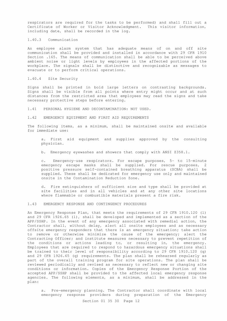
Section 01 35 30 Page 12
respirators are required for the tasks to be performed) and shall fill out a Certificate of Worker or Visitor Acknowledgment. This visitor information, including date, shall be recorded in the log. 1.40.3 Communication An employee alarm system that has adequate means of on and off site communication shall be provided and installed in accordance with 29 CFR 1910 Section .165. The means of communication shall be able to be perceived above ambient noise or light levels by employees in the affected portions of the workplace. The signals shall be distinctive and recognizable as messages to evacuate or to perform critical operations. 1.40.4 Site Security Signs shall be printed in bold large letters on contrasting backgrounds. Signs shall be visible from all points where entry might occur and at such distances from the restricted area that employees may read the signs and take necessary protective steps before entering. 1.41 PERSONAL HYGIENE AND DECONTAMINATION: NOT USED. 1.42 EMERGENCY EQUIPMENT AND FIRST AID REQUIREMENTS The following items, as a minimum, shall be maintained onsite and available for immediate use:
a. First aid equipment and supplies approved by the consulting physician.
b. Emergency eyewashes and showers that comply with ANSI Z358.1.
c. Emergency-use respirators. For escape purposes, 5- to 15-minute emergency escape masks shall be supplied. For rescue purposes, 2 positive pressure self-contained breathing apparatus (SCBA) shall be supplied. These shall be dedicated for emergency use only and maintained onsite in the Contamination Reduction Zone.
d. Fire extinguishers of sufficient size and type shall be provided at site facilities and in all vehicles and at any other site locations where flammable or combustible materials present a fire risk.
1.43 EMERGENCY RESPONSE AND CONTINGENCY PROCEDURES An Emergency Response Plan, that meets the requirements of 29 CFR 1910.120 (l) and 29 CFR 1926.65 (l), shall be developed and implemented as a section of the APP/SSHP. In the event of any emergency associated with remedial action, the Contractor shall, without delay, alert all onsite employees and as necessary offsite emergency responders that there is an emergency situation; take action to remove or otherwise minimize the cause of the emergency; alert the Contracting Officer; and institute measures necessary to prevent repetition of the conditions or actions leading to, or resulting in, the emergency. Employees that are required to respond to hazardous emergency situations shall be trained to their level of responsibility according to 29 CFR 1910.120 (q) and 29 CFR 1926.65 (q) requirements. The plan shall be rehearsed regularly as part of the overall training program for site operations. The plan shall be reviewed periodically and revised as necessary to reflect new or changing site conditions or information. Copies of the Emergency Response Portion of the accepted APP/SSHP shall be provided to the affected local emergency response agencies. The following elements, as a minimum, shall be addressed in the plan:
a. Pre-emergency planning. The Contractor shall coordinate with local emergency response providers during preparation of the Emergency

Section 01 35 30 Page 13
Response Plan. At a minimum, coordinate with local fire, rescue, hazardous materials response teams, police and emergency medical providers to assure all organizations are capable and willing to respond to and provide services for on-site emergencies. The Contractor shall ensure the Emergency Response Plan for the site is compatible and integrated with the local fire, rescue, medical and police security services available from local emergency response planning agencies.
b. Personnel roles, lines of authority, communications for emergencies.
c. Emergency recognition and prevention.
d. Site topography, layout, and prevailing weather conditions.
e. Criteria and procedures for site evacuation (emergency alerting procedures, employee alarm system, emergency PPE and equipment, safe distances, places of refuge, evacuation routes, site security and control).
f. Specific procedures for decontamination and medical treatment of injured personnel.
g. Route maps to nearest pre-notified medical facility. Site-support vehicles shall be equipped with maps. At the beginning of project operations, drivers of the support vehicles shall become familiar with the emergency route and the travel time required.
h. Emergency alerting and response procedures including posted instructions and a list of names and telephone numbers of emergency contacts (physician, nearby medical facility, fire and police departments, ambulance service, Federal, state, and local environmental agencies; as well as Safety and Health Manager, the Site Superintendent, the Contracting Officer and/or their alternates).
i. Criteria for initiating community alert program, contacts, and responsibilities.
j. Procedures for reporting incidents to appropriate government agencies. In the event that an incident such as an explosion or fire, or a spill or release of toxic materials occurs during the course of the project, the appropriate government agencies shall be immediately notified. In addition, the Contracting Officer and the local district safety office shall be verbally notified immediately and receive a written notification within 24 hours. The report shall include the following items:
(1) Name, organization, telephone number, and location of the Contractor.
(2) Name and title of the person(s) reporting.
(3) Date and time of the incident.
(4) Location of the incident, i.e., site location, facility name.
(5) Brief summary of the incident giving pertinent details including type of operation ongoing at the time of the incident.
(6) Cause of the incident, if known.
(7) Casualties (fatalities, disabling injuries).
(8) Details of any existing chemical hazard or contamination.

Section 01 35 30 Page 14
(9) Estimated property damage, if applicable.
(10) Nature of damage, effect on contract schedule.
(11) Action taken to ensure safety and security.
(12) Other damage or injuries sustained, public or private.
k. Procedures for critique of emergency responses and follow-up. 1.44 CERTIFICATE OF WORKER/VISITOR ACKNOWLEDGEMENT A copy of a Contractor-generated certificate of worker/visitor acknowledgement shall be completed and submitted for each visitor allowed to enter contamination reduction or exclusion zones, and for each employee, following the example certificate at the end of this section. 1.45 INSPECTIONS The SSHO's Daily Inspection Logs shall be attached to and submitted with the Daily Quality Control reports. Each entry shall include the following: date, work area checked, employees present in work area, PPE and work equipment being used in each area, special safety and health issues and notes, and signature of preparer. 1.46 SAFETY AND HEALTH PHASE-OUT REPORT A Safety and Health Phase-Out Report shall be submitted in conjunction with the project close out report and will be received prior to final acceptance of the work. The following minimum information shall be included:
a. Summary of the overall performance of safety and health (accidents or incidents including near misses, unusual events, lessons learned, etc.).
b. Final decontamination documentation including procedures and techniques used to decontaminate equipment, vehicles, and on site facilities.
c. Summary of exposure monitoring and air sampling accomplished during the project.
d. Signatures of Safety and Health Manager and SSHO.
Task Hazard and Control Requirements Sheet. Task _________ Initial Anticipated Hazards_________ Initial PPE________ Initial Controls________ Initial Exposure Monitoring _________ HAZWOPER Medical Surveillance Required yes no HAZWOPER Training Required yes no
-- End of Section --

Section 01 45 00.00 20 Page 1
SECTION 01 45 00.00 20
CONSTRUCTION QUALITY CONTROL 01/07
PART 1 GENERAL 1.1 REFERENCES References are made to various publications and standards, as well as the referenced ones,other applicable ASTM, BS, DIN, EN or equal TS-EN publications may also be used for the subject work. Under such circumstances English versions of the publications shall be furnished to the Contracting Officer for his/her review and approval. 1.2 SUBMITTALS The following shall be submitted in accordance with the provisions of the contract.
SD-01 Preconstruction Submittals
Construction Quality Control (QC) Plan; G
Submit a Construction QC Plan prior to start of construction.
Indoor Air Quality (IAQ) Management Plan; G;
Basis of Design and Design Intent
SD-05 Design Data
Design Review
SD-07 Certificates
CA Resume
SD-10 Operation and Maintenance Data
Training Plan
For each training session submit dates, start and finish times, and locations; outline of the information to be presented; names and qualifications of the presenters; and list of texts and other materials required to support training.
SD-11 Closeout Submittals
Training Outline; G
Training Video Recording G
Validation of Training Completion; G
1.3 INFORMATION FOR THE CONTRACTING OFFICER'S REPRESENTATIVE, (COR) All electronic submissions of QC documentation will be through the Web Based Construction Management (WebCM) system. The Contractor shall use the Daily Report forms that are available in WebCM. Prior to commencing work on construction, the Contractor can obtain a single copy set of the current report forms from the COR. The report forms will consist of the Contractor Production Report, Contractor Production Report (Continuation Sheet), Contractor Quality Control (CQC) Report, (CQC) Report (Continuation Sheet),

Section 01 45 00.00 20 Page 2
Preparatory Phase Checklist, Initial Phase Checklist, Rework Items List, and Testing Plan and Log. Deliver the following to the Contracting Officer during Construction:
a. CQC Report: Submit the report electronically by 10:00 AM the next working day after each day that work is performed and for every seven consecutive calendar days of no-work. Mail or hand-carry the original (wet signatures) and one copy by 10:00 AM the next working day after each day that work is performed and for every seven consecutive calendar days of no-work.
b. Contractor Production Report: Submit the report electronically by 10:00 AM the next working day after each day that work is performed and for every seven consecutive calendar days of no-work.Mail or hand-carry the original (wet signatures) and one copy by 10:00 AM the next working day after each day that work is performed and for every seven consecutive calendar days of no-work, attached to the CQC Report.
c. Preparatory Phase Checklist: Submit the report electronically in the same manner as the CQC Report for each Preparatory Phase held. Original attached to the original CQC Report and one copy attached to each QC Report copy.
d. Initial Phase Checklist: Submit the report electronically in the same manner as the CQC Report for each Initial Phase held. Original attached to the original CQC Report and one copy attached to each QC Report copy.
e. QC Specialist Reports: Submit the report electronically by 10:00 AM the next working day after each day that work is performed. Mail or hand-carry the original (wet signatures) and one copy by 10:00 AM the next working day after each day that work is performed.
f. Field Test Reports: Within two working days after the test is performed, submit the report as an electronic attachment to the CQC Report. Mail or hand-carry the original within two working days after the test is performed, attached to the original CQC Report and one copy attached to each QC Report copy.
g. Monthly Summary Report of Tests: Submit the report as an electronic attachment to the CQC Report at the end of each month. Mail or hand-carry the original attached to the last QC Report of the month.
h. Testing Plan and Log: Submit the report as an electronic attachment to the CQC Report, at the end of each month. A copy of the final Testing Plan and Log shall be provided to the OMSI preparer for inclusion into the OMSI documentation. Mail or hand-carry the original attached to the last CQC Report of each month and one copy attached to each CQC Report copy. A copy of the final Testing Plan and Log shall be provided to the OMSI preparer for inclusion into the OMSI documentation.
i. Rework Items List: Submit lists containing new entries daily, in the same manner as the CQC Report. Mail or hand-carry the original attached to the last CQC Report of each month and one copy attached to each CQC Report copy.
j. CQC Meeting Minutes: Within two working days after the meeting is held, submit the report as an electronic attachment to the CQC Report. Mail or hand-carry the original within two working days after the meeting is held, attached to the original CQC Report and one copy attached to each CQC Report copy.
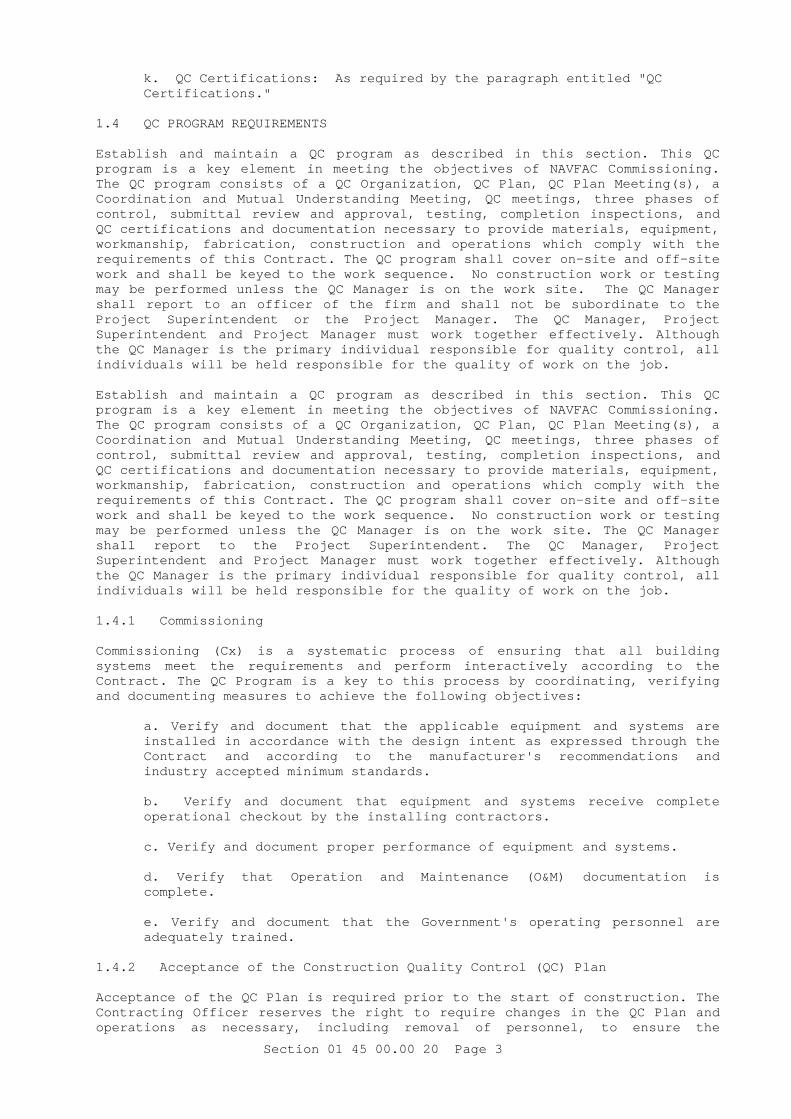
Section 01 45 00.00 20 Page 3
k. QC Certifications: As required by the paragraph entitled "QC Certifications."
1.4 QC PROGRAM REQUIREMENTS Establish and maintain a QC program as described in this section. This QC program is a key element in meeting the objectives of NAVFAC Commissioning. The QC program consists of a QC Organization, QC Plan, QC Plan Meeting(s), a Coordination and Mutual Understanding Meeting, QC meetings, three phases of control, submittal review and approval, testing, completion inspections, and QC certifications and documentation necessary to provide materials, equipment, workmanship, fabrication, construction and operations which comply with the requirements of this Contract. The QC program shall cover on-site and off-site work and shall be keyed to the work sequence. No construction work or testing may be performed unless the QC Manager is on the work site. The QC Manager shall report to an officer of the firm and shall not be subordinate to the Project Superintendent or the Project Manager. The QC Manager, Project Superintendent and Project Manager must work together effectively. Although the QC Manager is the primary individual responsible for quality control, all individuals will be held responsible for the quality of work on the job. Establish and maintain a QC program as described in this section. This QC program is a key element in meeting the objectives of NAVFAC Commissioning. The QC program consists of a QC Organization, QC Plan, QC Plan Meeting(s), a Coordination and Mutual Understanding Meeting, QC meetings, three phases of control, submittal review and approval, testing, completion inspections, and QC certifications and documentation necessary to provide materials, equipment, workmanship, fabrication, construction and operations which comply with the requirements of this Contract. The QC program shall cover on-site and off-site work and shall be keyed to the work sequence. No construction work or testing may be performed unless the QC Manager is on the work site. The QC Manager shall report to the Project Superintendent. The QC Manager, Project Superintendent and Project Manager must work together effectively. Although the QC Manager is the primary individual responsible for quality control, all individuals will be held responsible for the quality of work on the job. 1.4.1 Commissioning Commissioning (Cx) is a systematic process of ensuring that all building systems meet the requirements and perform interactively according to the Contract. The QC Program is a key to this process by coordinating, verifying and documenting measures to achieve the following objectives:
a. Verify and document that the applicable equipment and systems are installed in accordance with the design intent as expressed through the Contract and according to the manufacturer's recommendations and industry accepted minimum standards.
b. Verify and document that equipment and systems receive complete operational checkout by the installing contractors.
c. Verify and document proper performance of equipment and systems.
d. Verify that Operation and Maintenance (O&M) documentation is complete.
e. Verify and document that the Government's operating personnel are adequately trained.
1.4.2 Acceptance of the Construction Quality Control (QC) Plan Acceptance of the QC Plan is required prior to the start of construction. The Contracting Officer reserves the right to require changes in the QC Plan and operations as necessary, including removal of personnel, to ensure the

Section 01 45 00.00 20 Page 4
specified quality of work. The Contracting Officer reserves the right to interview any member of the QC organization at any time in order to verify the submitted qualifications. All QC organization personnel shall be subject to acceptance by the Contracting Officer. The Contracting Officer may require the removal of any individual for non-compliance with quality requirements specified in the Contract. 1.4.3 Preliminary Construction Work Authorized Prior to Acceptance The only construction work that is authorized to proceed prior to the acceptance of the QC Plan is mobilization of storage and office trailers, temporary utilities, and surveying. 1.4.4 Notification of Changes Notify the Contracting Officer, in writing, of any proposed changes in the QC Plan or changes to the QC organization personnel, a minimum of 10 work days prior to a proposed change. Proposed changes shall be subject to acceptance by the Contracting Officer. 1.5 QC ORGANIZATION 1.5.1 QC Manager 1.5.1.1 Duties Provide a QC Manager at the work site to implement and manage the QC program. In addition to implementing and managing the QC program, the QC Manager may perform the duties of Project Superintendent. The only duties and responsibilities of the QC Manager are to manage and implement the QC program on this Contract. The QC Manager shall not be designated as the safety competent person as defined by EM 385-1-1. The QC Manager is required to attend the partnering meetings, QC Plan Meetings, Coordination and Mutual Understanding Meeting, conduct the QC meetings, perform the three phases of control except for those phases of control designated to be performed by QC Specialists, perform submittal review and approval, ensure testing is performed and provide QC certifications and documentation required in this Contract. The QC Manager is responsible for managing and coordinating the three phases of control and documentation performed by the QC Specialists, testing laboratory personnel and any other inspection and testing personnel required by this Contract. The QC Manager is the manager of all QC activities. 1.5.1.2 Qualifications An individual with a minimum of 10 years combined experience in the following positions: Project Superintendent, QC Manager, Project Manager, Project Engineer or Construction Manager on similar size and type construction contracts which included the major trades that are part of this Contract. The individual shall have at least two years experience as a QC Manager. The individual must be familiar with the requirements of EM 385-1-1, and have experience in the areas of hazard identification, safety compliance, and sustainability. A graduate of a four year accredited college or university program in one of the following disciplines: Engineering, Architecture, Construction Management, Engineering Technology, Building Construction, or Building Science, with a minimum of 10 years experience as a Project Superintendent, QC Manager, Project Manager, Project Engineer or Construction Manager on similar size and type construction contracts which included the major trades that are part of this Contract. The individual shall have at least two years experience as a QC Manager. The individual must be familiar with the requirements of EM 385-1-1, and have experience in the areas of hazard identification, safety compliance, and sustainability.
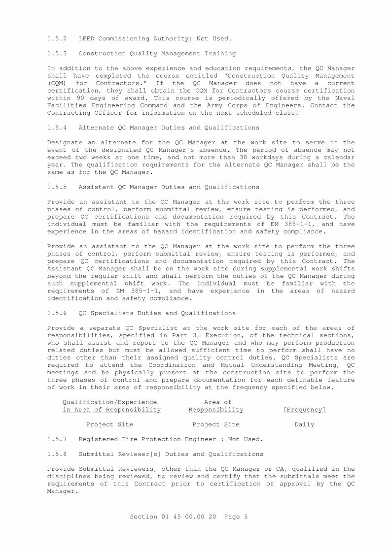
Section 01 45 00.00 20 Page 5
1.5.2 LEED Commissioning Authority: Not Used. 1.5.3 Construction Quality Management Training In addition to the above experience and education requirements, the QC Manager shall have completed the course entitled "Construction Quality Management (CQM) for Contractors." If the QC Manager does not have a current certification, they shall obtain the CQM for Contractors course certification within 90 days of award. This course is periodically offered by the Naval Facilities Engineering Command and the Army Corps of Engineers. Contact the Contracting Officer for information on the next scheduled class. 1.5.4 Alternate QC Manager Duties and Qualifications Designate an alternate for the QC Manager at the work site to serve in the event of the designated QC Manager's absence. The period of absence may not exceed two weeks at one time, and not more than 30 workdays during a calendar year. The qualification requirements for the Alternate QC Manager shall be the same as for the QC Manager. 1.5.5 Assistant QC Manager Duties and Qualifications Provide an assistant to the QC Manager at the work site to perform the three phases of control, perform submittal review, ensure testing is performed, and prepare QC certifications and documentation required by this Contract. The individual must be familiar with the requirements of EM 385-1-1, and have experience in the areas of hazard identification and safety compliance. Provide an assistant to the QC Manager at the work site to perform the three phases of control, perform submittal review, ensure testing is performed, and prepare QC certifications and documentation required by this Contract. The Assistant QC Manager shall be on the work site during supplemental work shifts beyond the regular shift and shall perform the duties of the QC Manager during such supplemental shift work. The individual must be familiar with the requirements of EM 385-1-1, and have experience in the areas of hazard identification and safety compliance. 1.5.6 QC Specialists Duties and Qualifications Provide a separate QC Specialist at the work site for each of the areas of responsibilities, specified in Part 3, Execution, of the technical sections, who shall assist and report to the QC Manager and who may perform production related duties but must be allowed sufficient time to perform shall have no duties other than their assigned quality control duties. QC Specialists are required to attend the Coordination and Mutual Understanding Meeting, QC meetings and be physically present at the construction site to perform the three phases of control and prepare documentation for each definable feature of work in their area of responsibility at the frequency specified below. Qualification/Experience Area of in Area of Responsibility Responsibility [Frequency] Project Site Project Site Daily
1.5.7 Registered Fire Protection Engineer : Not Used. 1.5.8 Submittal Reviewer[s] Duties and Qualifications Provide Submittal Reviewers, other than the QC Manager or CA, qualified in the disciplines being reviewed, to review and certify that the submittals meet the requirements of this Contract prior to certification or approval by the QC Manager.

Section 01 45 00.00 20 Page 6
Each submittal shall be reviewed by an individual with 10 years of construction experience. Each submittal shall be reviewed by a registered architect or professional engineer. Each of the following submittals shall be reviewed by [an] individual[s] meeting the qualifications/experience specified below: Qualification/Experience Submittals to be reviewed: in Submittal Discipline Spec Section No. Submittal All All All
1.5.9 QC Administrative Assistant Provide an Administrative Assistant at the work site until the work has been accepted. The primary duty shall be to assist the QC Manager in processing and maintaining files for submittals, preparing and publishing reports and meeting minutes. After primary duties are accomplished, other duties may be assigned provided the duties do not interfere with primary duties. 1.5.10 Underwater QC Team: Not Used. 1.6 QUALITY CONTROL (QC) PLAN 1.6.1 Construction Quality Control (QC) Plan 1.6.1.1 Requirements Provide, for acceptance by the Contracting Officer, a Construction QC Plan submitted in a three-ring binder that includes a table of contents, with major sections identified with tabs, with pages numbered sequentially, and that documents the proposed methods and responsibilities for accomplishing commissioning activities during the construction of the project:
I. QC ORGANIZATION: A chart showing the QC organizational structure.
II. NAMES AND QUALIFICATIONS: Names and qualifications, in resume format, for each person in the QC organization. Include the CQM for Contractors course certifications for the QC Manager and Alternate QC Manager as required by the paragraphs entitled "Construction Quality Management Training" and "Alternate QC Manager Duties and Qualifications".
III. DUTIES, RESPONSIBILITY AND AUTHORITY OF QC PERSONNEL: Duties, responsibilities, and authorities of each person in the QC organization.
IV. OUTSIDE ORGANIZATIONS: A listing of outside organizations, such as architectural and consulting engineering firms, that will be employed by the Contractor and a description of the services these firms will provide.
V. APPOINTMENT LETTERS: Letters signed by an officer of the firm appointing the QC Manager and Alternate QC Manager and stating that they are responsible for implementing and managing the QC program as described in this Contract. Include in this letter the responsibility of the QC Manager and Alternate QC Manager to implement and manage the three phases of control, and their authority to stop work which is not in compliance with the Contract. The QC Manager shall issue letters of direction to [the Assistant QC Manager and ]all other QC Specialists outlining their duties, authorities, and responsibilities. Copies of the letters shall be included in the QC Plan.

Section 01 45 00.00 20 Page 7
VI. SUBMITTAL PROCEDURES AND INITIAL SUBMITTAL REGISTER: Procedures for reviewing, approving, and managing submittals. Provide the name(s) of the person(s) in the QC organization authorized to review and certify submittals prior to approval. Provide the initial submittal of the Submittal Register.
VII. TESTING LABORATORY INFORMATION: Testing laboratory information required by the paragraphs entitled "Accreditation Requirements", as applicable.
VIII. TESTING PLAN AND LOG: A Testing Plan and Log that includes the tests required, referenced by the specification paragraph number requiring the test, the frequency, and the person responsible for each test. Use Government forms to log and track tests.
IX. PROCEDURES TO COMPLETE REWORK ITEMS: Procedures to identify, record, track, and complete rework items. Use Government [WebCM ]forms to record and track rework items.
X. DOCUMENTATION PROCEDURES: Use Government [WebCM ]form.
XI. LIST OF DEFINABLE FEATURES: A Definable Feature of Work (DFOW) is a task that is separate and distinct from other tasks and has control requirements and work crews unique to that task. A DFOW is identified by different trades or disciplines and is an item or activity on the construction schedule. The list of DFOWs shall include, but not be limited to, all critical path activities on the NAS. Include all activities for which this specification requires QC Specialists or specialty inspection personnel. Each design development stage and submittal package shall have separate DFOWs in the Network Analysis Schedule.
XII. PROCEDURES FOR PERFORMING THE THREE PHASES OF CONTROL: Identify procedures you will use to ensure the three phases of control are used to manage the quality on this project. For each DFOW, a Preparatory and Initial phase checklist will be filled out during the Preparatory and Initial phase meetings. [The checklist(s) will then also be entered in WebCM. ]The Preparatory and Initial Phases and meetings shall be conducted with a view towards obtaining quality construction by planning ahead and identifying potential problems for each DFOW.
XIII. PERSONNEL MATRIX: Not Applicable
XIV. PROCEDURES FOR COMPLETION INSPECTION: Procedures for identifying and documenting the completion inspection process. Include in these procedures the responsible party for punch out inspection, pre-final inspection, and final acceptance inspection.
XV. TRAINING PROCEDURES AND TRAINING LOG: Not Applicable XVI. ORGANIZATION AND PERSONNEL CERTIFICATIONS LOG: Procedures for coordinating, tracking and documenting all certifications on subcontractors, testing laboratories, suppliers, personnel, etc. QC Manager will ensure that certifications are current, appropriate for the work being performed, and will not lapse during any period of the contract that the work is being performed.
1.7 QC PLAN MEETINGS Prior to submission of the QC Plan, the QC Manager will meet with the Contracting Officer to discuss the QC Plan requirements of this Contract. The purpose of this meeting is to develop a mutual understanding of the QC Plan requirements prior to plan development and submission and to agree on the Contractor's list of DFOWs.

Section 01 45 00.00 20 Page 8
1.8 COORDINATION AND MUTUAL UNDERSTANDING MEETING After submission of the QC Plan, and prior to the start of construction, the QC Manager will meet with the Contracting Officer to present the QC program required by this Contract. When a new QC Manager is appointed, the coordination and mutual understanding meeting shall be repeated. 1.8.1 Purpose The purpose of this meeting is to develop a mutual understanding of the QC details, including documentation, administration for on-site and off-site work, design intent, Cx, environmental requirements and procedures, coordination of activities to be performed, and the coordination of the Contractor's management, production, and QC personnel. At the meeting, the Contractor will be required to explain in detail how three phases of control will be implemented for each DFOW, as well as how each DFOW will be affected by each management plan or requirement as listed below:
a. Waste Management Plan.
b. IAQ Management Plan.
c. Procedures for noise and acoustics management.
d. Environmental Protection Plan.
e. Environmental regulatory requirements.
f. Cx Plan. 1.8.2 Coordination of Activities Activities included in various sections shall be coordinated to assure efficient and orderly installation of each component. Coordinate operations included under different sections that are dependent on each other for proper installation and operation. Schedule construction operations with consideration for indoor air quality as specified in the IAQ Management Plan. Coordinate pre-functional tests and startup testing with Cx. 1.8.3 Attendees As a minimum, the Contractor's personnel required to attend shall include an officer of the firm, the Project Manager, Project Superintendent, QC Manager, Alternate QC Manager, Assistant QC Manager, QC Specialists, A/E, CA, Environmental Manager, and subcontractor representatives. Each subcontractor who will be assigned QC responsibilities shall have a principal of the firm at the meeting. Minutes of the meeting will be prepared by the QC Manager and signed by the Contractor, the A/E and the Contracting Officer. The Contractor shall provide a copy of the signed minutes to all attendees and shall be included in the QC Plan. 1.9 QC MEETINGS After the start of construction, the QC Manager shall conduct weekly QC meetings at the work site with the Project Superintendent, QC Specialists, the CA, and the foremen who are performing the work of the DFOWs. The QC Manager shall prepare the minutes of the meeting and provide a copy to the Contracting Officer within two working days after the meeting. The Contracting Officer may attend these meetings. As a minimum, the following shall be accomplished at each meeting:
a. Review the minutes of the previous meeting;
b. Review the schedule and the status of work and rework;

Section 01 45 00.00 20 Page 9
c. Review the status of submittals;
d. Review the work to be accomplished in the next two weeks and documentation required;
e. Resolve QC and production problems (RFI, etc.);
f. Address items that may require revising the QC Plan;
g. Review Accident Prevention Plan (APP);
h. Review environmental requirements and procedures;
i. Review Waste Management Plan;
j. Review IAQ Management Plan;
k. Review Environmental Management Plan;
l. Review the status of training completion; and
m. Review Cx Plan and progress.
1.10 DESIGN REVIEW AND DOCUMENTATION: NOT USED. 1.11 THREE PHASES OF CONTROL The Three Phases of Control shall adequately cover both on-site and off-site work and shall include the following for each DFOW. 1.11.1 Preparatory Phase Notify the COR at least two work days in advance of each preparatory phase meeting. The meeting shall be conducted by the QC Manager and attended by the QC Specialists, the Project Superintendent, the CA, and the foreman responsible for the DFOW. When the DFOW will be accomplished by a subcontractor, that subcontractor's foreman shall attend the preparatory phase meeting. Document the results of the preparatory phase actions in the daily Contractor Quality Control Report and in the Preparatory Phase Checklist. Perform the following prior to beginning work on each DFOW:
a. Review each paragraph of the applicable specification sections;
b. Review the Contract drawings;
c. Verify that field measurements are as indicated on construction and/or shop drawings before confirming product orders, in order to minimize waste due to excessive materials;
d. Verify that appropriate shop drawings and submittals for materials and equipment have been submitted and approved. Verify receipt of approved factory test results, when required;
e. Review the testing plan and ensure that provisions have been made to provide the required QC testing;
f. Examine the work area to ensure that the required preliminary work has been completed;
g. Coordinate the schedule of product delivery to designated prepared areas in order to minimize site storage time and potential damage to stored materials;

Section 01 45 00.00 20 Page 10
h. Arrange for the return of shipping/packaging materials, such as wood pallets, where economically feasible;
i. Examine the required materials, equipment and sample work to ensure that they are on hand and conform to the approved shop drawings and submitted data;
j. Discuss construction methods, construction tolerances, workmanship standards, and the approach that will be used to provide quality construction by planning ahead and identifying potential problems for each DFOW;
k. Review the APP and appropriate Activity Hazard Analysis (AHA) to ensure that applicable safety requirements are met, and that required Material Safety Data Sheets (MSDS) are submitted; and
l. Review the Cx Plan and ensure all preliminary work items have been completed and documented.
1.11.2 Initial Phase Notify the Contracting Officer at least two work days in advance of each initial phase. When construction crews are ready to start work on a DFOW, conduct the initial phase with the QC Specialists, the Project Superintendent, and the foreman responsible for that DFOW. Observe the initial segment of the DFOW to ensure that the work complies with Contract requirements. Document the results of the initial phase in the daily CQC Report and in the Initial Phase Checklist. Repeat the initial phase for each new crew to work on-site, or when acceptable levels of specified quality are not being met. Perform the following for each DFOW:
a. Establish the quality of workmanship required;
b. Resolve conflicts;
c. Ensure that testing is performed by the approved laboratory;
d. Check work procedures for compliance with the APP and the appropriate AHA to ensure that applicable safety requirements are met; and
e. Review the Cx Plan and ensure all preparatory work items have been completed and documented.
1.11.3 Follow-Up Phase Perform the following for on-going work daily, or more frequently as necessary, until the completion of each DFOW and document in the daily CQC Report:
a. Ensure the work is in compliance with Contract requirements;
b. Maintain the quality of workmanship required;
c. Ensure that testing is performed by the approved laboratory;
d. Ensure that rework items are being corrected;
e. Perform safety inspections; and
f. Review the Cx Plan and ensure all work items, testing, and documentation has been completed.

Section 01 45 00.00 20 Page 11
1.11.4 Additional Preparatory and Initial Phases Additional preparatory and initial phases shall be conducted on the same DFOW if the quality of on-going work is unacceptable, if there are changes in the applicable QC organization, if there are changes in the on-site production supervision or work crew, if work on a DFOW is resumed after substantial period of inactivity, or if other problems develop. 1.11.5 Notification of Three Phases of Control for Off-Site Work Notify the Contracting Officer at least two weeks prior to the start of the preparatory and initial phases. 1.12 SUBMITTAL REVIEW AND APPROVAL Procedures for submission, review and approval of submittals shall be in accordance with the provisions of the contract. 1.13 TESTING Except as stated otherwise in the specification sections, perform sampling and testing required under this Contract. All testing shall be performed by the laboratories of Middle East Technical University or other laboratories accrediated by Turkish Standards Institute. 1.13.2 Test Results Cite applicable Contract requirements, tests or analytical procedures used. Provide actual results and include a statement that the item tested or analyzed conforms or fails to conform to specified requirements. If the item fails to conform, notify the Contracting Officer immediately. Conspicuously stamp the cover sheet for each report in large red letters "CONFORMS" or "DOES NOT CONFORM" to the specification requirements, whichever is applicable. Test results shall be signed by a testing laboratory representative authorized to sign certified test reports. Furnish the signed reports, certifications, and other documentation to the Contracting Officer via the QC Manager. Furnish a summary report of field tests at the end of each month, per the paragraph entitled "INFORMATION FOR THE CONTRACTING OFFICER'S REPRESENTATIVE". 1.13.3 Test Reports and Monthly Summary Report of Tests The QC Manager shall furnish the signed reports, certifications, and a summary report of field tests at the end of each month to the Contracting Officer. Attach a copy of the summary report to the last daily Contractor Quality Control Report of each month. A copy of the signed test reports and certifications shall be provided to the OMSI preparer for inclusion into the OMSI documentation. 1.14 QC CERTIFICATIONS 1.14.1 CQC Report Certification Each CQC Report shall contain the following statement: "On behalf of the Contractor, I certify that this report is complete and correct and equipment and material used and work performed during this reporting period is in compliance with the contract drawings and specifications to the best of my knowledge, except as noted in this report." 1.14.2 Invoice Certification Furnish a certificate to the Contracting Officer with each payment request, signed by the QC Manager, attesting that as-built drawings are current, coordinated and attesting that the work for which payment is requested, including stored material, is in compliance with Contract requirements.

Section 01 45 00.00 20 Page 12
1.14.3 Completion Certification Upon completion of work under this Contract, the QC Manager shall furnish a certificate to the Contracting Officer attesting that "the work has been completed, inspected, tested and is in compliance with the Contract." A copy of this final QC Certification for completion shall be provided to the OMSI preparer for inclusion into the OMSI documentation. 1.15 COMPLETION INSPECTIONS 1.15.1 Punch-Out Inspection Near the completion of all work or any increment thereof, established by a completion time stated in the Contract Clause entitled "Commencement, Prosecution, and Completion of Work," or stated elsewhere in the specifications, the QC Manager and the CA shall conduct an inspection of the work and develop a "punch list" of items which do not conform to the approved drawings, specifications and Contract. Include in the punch list any remaining items on the "Rework Items List", which were not corrected prior to the Punch-Out Inspection. The punch list shall include the estimated date by which the deficiencies will be corrected. A copy of the punch list shall be provided to the COR. The QC Manager, or staff, shall make follow-on inspections to ascertain that all deficiencies have been corrected. Once this is accomplished, the Contractor shall notify the Government that the facility is ready for the Government "Pre-Final Inspection". 1.15.2 Pre-Final Inspection The Government will perform this inspection to verify that the facility is complete and ready to be occupied. A Government "Pre-Final Punch List" may be developed as a result of this inspection. The QC Manager shall ensure that all items on this list are corrected prior to notifying the Government that a "Final" inspection with the Client can be scheduled. Any items noted on the "Pre-Final" inspection shall be corrected in a timely manner and shall be accomplished before the contract completion date for the work,or any particular increment thereof, if the project is divided into increments by separate completion dates. 1.15.3 Final Acceptance Inspection The Contractor shall notify the COR at least 14 calendar days prior to the date a final acceptance inspection can be held. The notice shall state that all items previously identified on the pre-final punch list will be corrected and acceptable, along with any other unfinished Contract work, by the date of the final acceptance inspection. The Contractor shall be represented by the QC Manager, the Project Superintendent, the CA, and others deemed necessary. Attendees for the Government will include the COR, other ROICC personnel, and personnel representing the Client. Failure of the Contractor to have all contract work acceptably complete for this inspection will be cause for the COR to bill the Contractor for the Government's additional inspection cost in accordance with the Contract Clause entitled "Inspection of Construction." 1.16 TRAINING: NOT USED. 1.17 DOCUMENTATION Maintain current and complete records of on-site and off-site QC program operations and activities. The Contractor shall submit all documentation in accordance with the provisions of the contract and directions of the COR. 1.17.1 Construction Documentation Reports are required for each day that work is performed and shall be attached to the Contractor Quality Control Report prepared for the same day. Maintain

Section 01 45 00.00 20 Page 13
current and complete records of on-site and off-site QC program operations and activities. The forms identified under the paragraph "INFORMATION FOR THE CONTRACTING OFFICER'S REPRESENTATIVE" shall be used. Reports are required for each day work is performed. Account for each calendar day throughout the life of the Contract. Every space on the forms must be filled in. Use N/A if nothing can be reported in one of the spaces. The Project Superintendent and the QC Manager must prepare and sign the Contractor Production and CQC Reports, respectively. The reporting of work shall be identified by terminology consistent with the construction schedule. In the "remarks" sections of the reports, enter pertinent information including directions received, problems encountered during construction, work progress and delays, conflicts or errors in the drawings or specifications, field changes, safety hazards encountered, instructions given and corrective actions taken, delays encountered and a record of visitors to the work site, quality control problem areas, deviations from the QC Plan, construction deficiencies encountered, meetings held. For each entry in the report(s), identify the Schedule Activity No. that is associated with the entered remark. 1.17.2 Quality Control Validation Establish and maintain the following in a series of three ring binders. Binders shall be divided and tabbed as shown below. These binders shall be readily available to the Contracting Officer during all business hours.
a. All completed Preparatory and Initial Phase Checklists, arranged by specification section.
b. All milestone inspections, arranged by Activity Number.
c. An up-to-date copy of the Testing Plan and Log with supporting field test reports, arranged by specification section.
d. Copies of all contract modifications, arranged in numerical order. Also include documentation that modified work was accomplished.
e. An up-to-date copy of the Rework Items List.
f. Maintain up-to-date copies of all punch lists issued by the QC staff to the Contractor and Sub-Contractors and all punch lists issued by the Government.
g. Commissioning documentation including Cx checklists, schedules, tests, and reports.
1.17.3 Reports from the QC Specialist(s) Reports are required for each day that work is performed in their area of responsibility. QC Specialist reports shall include the same documentation requirements as the CQC Report for their area of responsibility. QC Specialist reports are to be prepared, signed and dated by the QC Specialists and shall be attached to the CQC Report prepared for the same day. 1.17.4 Testing Plan and Log As tests are performed, the CA and the QC Manager shall record on the "Testing Plan and Log" the date the test was performed and the date the test results were forwarded to the Contracting Officer. Attach a copy of the updated "Testing Plan and Log" to the last daily CQC Report of each month, per the paragraph "INFORMATION FOR THE CONTRACTING OFFICER". A copy of the final "Testing Plan and Log" shall be provided to the OMSI preparer for inclusion into the OMSI documentation.

Section 01 45 00.00 20 Page 14
1.17.5 Rework Items List The QC Manager shall maintain a list of work that does not comply with the Contract, identifying what items need to be reworked, the date the item was originally discovered, the date the item will be corrected by, and the date the item was corrected. There is no requirement to report a rework item that is corrected the same day it is discovered. Attach a copy of the "Rework Items List" to the last daily CQC Report of each month. The Contractor shall be responsible for including those items identified by the Contracting Officer. 1.17.6 As-Built Drawings The QC Manager is required to ensure the as-built drawings, required by Section 01 77 00.00 20 CLOSEOUT PROCEDURES are kept current on a daily basis and marked to show deviations which have been made from the Contract drawings. Ensure each deviation has been identified with the appropriate modifying documentation (e.g. PC No., Modification No., Request for Information No., etc.). The QC Manager or QC Specialist assigned to an area of responsibility shall initial each revision. Upon completion of work, the QC Manager shall furnish a certificate attesting to the accuracy of the as-built drawings prior to submission to the Contracting Officer. 1.18 NOTIFICATION ON NON-COMPLIANCE The Contracting Officer will notify the Contractor of any detected non-compliance with the Contract. The Contractor shall take immediate corrective action after receipt of such notice. Such notice, when delivered to the Contractor at the work site, shall be deemed sufficient for the purpose of notification. If the Contractor fails or refuses to comply promptly, the Contracting Officer may issue an order stopping all or part of the work until satisfactory corrective action has been taken. No part of the time lost due to such stop orders shall be made the subject of claim for extension of time for excess costs or damages by the Contractor. 1.19 CONSTRUCTION INDOOR AIR QUALITY (IAQ) MANAGEMENT PLAN: NOT USED. PART 2 PRODUCTS Not used. PART 3 EXECUTION 3.1 PREPARATION Designate receiving/storage areas for incoming material to be delivered according to installation schedule and to be placed convenient to work area in order to minimize waste due to excessive materials handling and misapplication. Store and handle materials in a manner as to prevent loss from weather and other damage. Keep materials, products, and accessories covered and off the ground, and store in a dry, secure area. Prevent contact with material that may cause corrosion, discoloration, or staining. Protect all materials and installations from damage by the activities of other trades. -- End of Section --

Section 01 45 04.00 10 Page 1
SECTION 01 45 04.00 10
CONTRACTOR QUALITY CONTROL 04/06
PART 1 GENERAL 1.1 REFERENCES References are made to various publications and standards, as well as the referenced ones, other applicable ASTM, BS, DIN, EN or equal TS-EN publications may also be used for the subject work. Under such circumstances English versions of the publications shall be furnished to the Contracting Officer for his/her review and approval. 1.2 PAYMENT Separate payment will not be made for providing and maintaining an effective Quality Control program, and all costs associated therewith shall be included in the applicable unit prices or lump-sum prices contained in the Bidding Schedule. PART 2 PRODUCTS (NOT APPLICABLE) PART 3 EXECUTION 3.1 GENERAL REQUIREMENTS The Contractor is responsible for quality control and shall establish and maintain an effective quality control system in compliance with the Contract Clause titled "Inspection of Construction." The quality control system shall consist of plans, procedures, and organization necessary to produce an end product which complies with the contract requirements. The system shall cover all construction design and construction operations, both onsite and offsite, and shall be keyed to the proposed construction design and construction sequence. The site project superintendent will be held responsible for the quality of work on the job and is subject to removal by the Contracting Officer for non-compliance with the quality requirements specified in the contract. The site project superintendent in this context shall be the highest level manager responsible for the overall construction activities at the site, including quality and production. The site project superintendent shall maintain a physical presence at the site at all times, except as otherwise acceptable to the Contracting Officer, and shall be responsible for all construction and construction related activities at the site. 3.2 QUALITY CONTROL PLAN The Contractor shall furnish for review by the Government, not later than 20ays after receipt of notice to proceed, the Contractor Quality Control (CQC) Plan proposed to implement the requirements of the Contract Clause titled "Inspection of Construction." The plan shall identify personnel, procedures, control, instructions, tests, records, and forms to be used. The Government will consider an interim plan for the first three days of operation. Construction Design and construction will be permitted to begin only after acceptance of the CQC Plan or acceptance of an interim plan applicable to the particular feature of work to be started. Work outside of the features of work included in an accepted interim plan will not be permitted to begin until acceptance of a CQC Plan or another interim plan containing the additional features of work to be started. 3.2.1 Content of the CQC Plan The CQC Plan shall include, as a minimum, the following to cover all design and construction operations, both onsite and offsite, including work by

Section 01 45 04.00 10 Page 2
subcontractors, fabricators, suppliers, and purchasing agents subcontractors, designers of record, consultants, architect / engineers (AE), fabricators, suppliers, and purchasing agents:
a. A description of the quality control organization, including a chart showing lines of authority and acknowledgment that the CQC staff shall implement the three phase control system for all aspects of the work specified. The staff shall include a CQC System Manager who shall report to the project superintendent.
b. The name, qualifications (in resume format), duties,
responsibilities, and authorities of each person assigned a CQC function.
c. A copy of the letter to the CQC System Manager signed by an
authorized official of the firm which describes the responsibilities and delegates sufficient authorities to adequately perform the functions of the CQC System Manager, including authority to stop work which is not in compliance with the contract. The CQC System Manager shall issue letters of direction to all other various quality control representatives outlining duties, authorities, and responsibilities. Copies of these letters shall also be furnished to the Government.
d. Procedures for scheduling, reviewing, certifying, and managing
submittals, including those of subcontractors, offsite fabricators, suppliers, and purchasing agents subcontractors, designers of record, consultants, architect engineers (AE), offsite fabricators, suppliers, and purchasing agents. These procedures shall be in accordance with the provisions of the contract.
e. Control, verification, and acceptance testing procedures for each
specific test to include the test name, specification paragraph requiring test, feature of work to be tested, test frequency, and person responsible for each test. (Laboratory facilities approved by the Contracting Officer shall be used.)
f. Procedures for tracking preparatory, initial, and follow-up control
phases and control, verification, and acceptance tests including documentation.
g. Procedures for tracking construction design and construction
deficiencies from identification through acceptable corrective action. These procedures shall establish verification that identified deficiencies have been corrected.
h. Reporting procedures, including proposed reporting formats.
i. A list of the definable features of work. A definable feature of
work is a task which is separate and distinct from other tasks, has separate control requirements, and may be identified by different trades or disciplines, or it may be work by the same trade in a different environment. Although each section of the specifications may generally be considered as a definable feature of work, there are frequently more than one definable features under a particular section. This list will be agreed upon during the coordination meeting.
3.2.2 Additional Requirements for Design Quality Control (DQC) Plan The following additional requirements apply to the Design Quality Control (DQC) plan:

Section 01 45 04.00 10 Page 3
(1) The Contractor's QCP Plan shall provide and maintain a Design Quality Control (DQC) Plan as an effective quality control program which will assure that all services required by this design-build contract are performed and provided in a manner that meets professional architectural and engineering quality standards. As a minimum, all documents shall be technically reviewed by competent, independent reviewers identified in the DQC Plan. The same element that produced the product shall not perform the independent technical review (ITR). The Contractor shall correct errors and deficiencies in the design documents prior to submitting them to the Government.
(2) The Contractor shall include the design schedule in the master project schedule, showing the sequence of events involved in carrying out the project design tasks within the specific contract period. This should be at a detailed level of scheduling sufficient to identify all major design tasks, including those that control the flow of work. The schedule shall include review and correction periods associated with each item. This should be a forward planning as well as a project monitoring tool. The schedule reflects calendar days and not dates for each activity. If the schedule is changed, the Contractor shall submit a revised schedule reflecting the change within 7 calendar days. The Contractor shall include in the DQC Plan the discipline-specific checklists to be used during the design and quality control of each submittal. These completed checklists shall be submitted at each design phase as part of the project documentation. Example checklists can be found in ER 1110-1-12.
(3) The DQC Plan shall be implemented by an Design Quality Control Manager who has the responsibility of being cognizant of and assuring that all documents on the project have been coordinated. This individual shall be a person who has verifiable engineering or architectural design experience and is a registered professional engineer or architect. The Contractor shall notify the Contracting Officer's Representative, in writing, of the name of the individual, and the name of an alternate person assigned to the position.
The Contracting Officer will notify the Contractor in writing of the acceptance of the DQC Plan. After acceptance, any changes proposed by the Contractor are subject to the acceptance of the COR.
3.2.3 Acceptance of Plan Acceptance of the Contractor's plan is required prior to the start of construction design and construction. Acceptance is conditional and will be predicated on satisfactory performance during the construction design and construction. The Government reserves the right to require the Contractor to make changes in his CQC Plan and operations including removal of personnel, as necessary, to obtain the quality specified. 3.2.4 Notification of Changes After acceptance of the CQC Plan, the Contractor shall notify the Contracting Officer in writing of any proposed change. Proposed changes are subject to acceptance by the COR. 3.3 COORDINATION MEETING After the Preconstruction Conference, before start of construction,Postaward Conference, before start of design or construction, and prior to acceptance by the Government of the CQC Plan, the Contractor shall meet with the Contracting Officer or Authorized Representative and discuss the Contractor's quality control system. The CQC Plan shall be submitted for review a minimum of two

Section 01 45 04.00 10 Page 4
calendar days prior to the Coordination Meeting. During the meeting, a mutual understanding of the system details shall be developed, including the forms for recording the CQC operations, design activities, control activities, testing, administration of the system for both onsite and offsite work, and the interrelationship of Contractor's Management and control with the Government's Quality Assurance. Minutes of the meeting shall be prepared by the Government and signed by both the Contractor and the Contracting Officer. The minutes shall become a part of the contract file. There may be occasions when subsequent conferences will be called by either party to reconfirm mutual understandings and/or address deficiencies in the CQC system or procedures which may require corrective action by the Contractor. 3.4 QUALITY CONTROL ORGANIZATION 3.4.1 Personnel Requirements The requirements for the CQC organization are a CQC System Manager CQC System Manager, a Design Quality Manager, and sufficient number of additional qualified personnel to ensure safety and contract compliance. The Safety and Health Manager shall serve as a member of the CQC staff. Personnel identified in the technical provisions as requiring specialized skills to assure the required work is being performed properly will also be included as part of the CQC organization. The Contractor's CQC staff shall maintain a presence at the site at all times during progress of the work and have complete authority and responsibility to take any action necessary to ensure contract compliance. The CQC staff shall be subject to acceptance by the Contracting Officer. The Contractor shall provide adequate office space, filing systems and other resources as necessary to maintain an effective and fully functional CQC organization. Complete records of all letters, material submittals, shop drawing submittals, schedules and all other project documentation shall be promptly furnished to the CQC organization by the Contractor. The CQC organization shall be responsible to maintain these documents and records at the site at all times, except as otherwise acceptable to the Contracting Officer. 3.4.2 CQC System Manager The Contractor shall identify as CQC System Manager an individual within the onsite work organization who shall be responsible for overall management of CQC and have the authority to act in all CQC matters for the Contractor. The CQC System Manager shall be a graduate engineer, graduate architect, or a graduate of construction management, with a minimum of three years construction experience on construction similar to this contract. This CQC System Manager shall be on the site at all times during construction and shall be employed by the prime Contractor. The CQC System Manager shall be assigned as System Manager but may have duties as project superintendent in addition to quality control. An alternate for the CQC System Manager shall be identified in the plan to serve in the event of the System Manager's absence. The requirements for the alternate shall be the same as for the designated CQC System Manager. 3.4.3 CQC Personnel In addition to CQC personnel specified elsewhere in the contract, the Contractor shall provide as part of the CQC organization specialized personnel to assist the CQC System Manager for the following areas: electrical, mechanical, civil, structural, architectural. These individuals shall be directly employed by the prime Contractor and may not be employed by a supplier or sub-Contractor on this project]; be responsible to the CQC System Manager; be physically present at the construction site during work on their areas of responsibility; have the necessary education and/or experience in accordance with the experience matrix listed herein. These individuals may perform other duties but must be allowed sufficient time to perform their assigned quality control duties as described in the Quality Control Plan. A

Section 01 45 04.00 10 Page 5
single person may cover more than one area provided that they are qualified to perform QC activities in each designated and that workload allows.
Experience Matrix Area Qualifications a. Civil Graduate Civil Engineer or Construction Manager with 2 years experience in the type of work being performed on this project or technician with 5yrs related experience b. Electrical Graduate Electrical Engineer or Construction Manager with 2 yrs related experience or person with 5 yrs related experience c. Structural Graduate Structural Engineer or Construction Manager with 2 yrs experience or person with 5yrs related experience d. Architectural Graduate Architect with 2 yrs experience or person with 5 yrs related experience e. Concrete, Pavements and Soils Materials Technician with 2 yrs experience for the appropriate area 3.4.4 Additional Requirement In addition to the above experience and education requirements the CQC System Manager shall have completed the course entitled "Construction Quality Management For Contractors". 3.4.5 Organizational Changes The Contractor shall maintain the CQC staff at full strength at all times. When it is necessary to make changes to the CQC staff, the Contractor shall revise the CQC Plan to reflect the changes and submit the changes to the COR for acceptance. 3.5 SUBMITTALS AND DELIVERABLES Submittals, if needed, shall be made as specified in the provisions of the contract. 3.6 CONTROL Contractor Quality Control is the means by which the Contractor ensures that the construction, to include that of subcontractors and suppliers, complies with the requirements of the contract. At least three phases of control shall be conducted by the CQC System Manager for each definable feature of the construction work as follows:

Section 01 45 04.00 10 Page 6
3.6.1 Preparatory Phase This phase shall be performed prior to beginning work on each definable feature of work, after all required plans/documents/materials are approved/accepted, and after copies are at the work site. This phase shall include:
a. A review of each paragraph of applicable specifications, reference codes, and standards. A copy of those sections of referenced codes and standards applicable to that portion of the work to be accomplished in the field shall be made available by the Contractor at the preparatory inspection. These copies shall be maintained in the field and available for use by Government personnel until final acceptance of the work.
b. A review of the contract drawings.
c. A check to assure that all materials and/or equipment have been
tested, submitted, and approved.
d. Review of provisions that have been made to provide required control inspection and testing.
e. Examination of the work area to assure that all required
preliminary work has been completed and is in compliance with the contract.
f. A physical examination of required materials, equipment, and sample
work to assure that they are on hand, conform to approved shop drawings or submitted data, and are properly stored.
g. A review of the appropriate activity hazard analysis to assure
safety requirements are met.
h. Discussion of procedures for controlling quality of the work including repetitive deficiencies. Document construction tolerances and workmanship standards for that feature of work.
i. A check to ensure that the portion of the plan for the work to be
performed has been accepted by the COR.
j. Discussion of the initial control phase.
k. The Government shall be notified at least 24 hours in advance of beginning the preparatory control phase. This phase shall include a meeting conducted by the CQC System Manager and attended by the superintendent, other CQC personnel (as applicable), and the foreman responsible for the definable feature. The results of the preparatory phase actions shall be documented by separate minutes prepared by the CQC System Manager and attached to the daily CQC report. The Contractor shall instruct applicable workers as to the acceptable level of workmanship required in order to meet contract specifications.
3.6.2 Initial Phase This phase shall be accomplished at the beginning of a definable feature of work. The following shall be accomplished:
a. A check of work to ensure that it is in full compliance with contract requirements. Review minutes of the preparatory meeting.
b. Verify adequacy of controls to ensure full contract compliance.
Verify required control inspection and testing.
Section 01 45 04.00 10 Page 7
c. Establish level of workmanship and verify that it meets minimum
acceptable workmanship standards. Compare with required sample panels as appropriate.
d. Resolve all differences.
e. Check safety to include compliance with and upgrading of the safety
plan and activity hazard analysis. Review the activity analysis with each worker.
f. The Government shall be notified at least 24 hours in advance of
beginning the initial phase. Separate minutes of this phase shall be prepared by the CQC System Manager and attached to the daily CQC report. Exact location of initial phase shall be indicated for future reference and comparison with follow-up phases.
g. The initial phase should be repeated for each new crew to work
onsite, or any time acceptable specified quality standards are not being met.
3.6.3 Follow-up Phase Daily checks shall be performed to assure control activities, including control testing, are providing continued compliance with contract requirements, until completion of the particular feature of work. The checks shall be made a matter of record in the CQC documentation. Final follow-up checks shall be conducted and all deficiencies corrected prior to the start of additional features of work which may be affected by the deficient work. The Contractor shall not build upon nor conceal non-conforming work. 3.6.4 Additional Preparatory and Initial Phases Additional preparatory and initial phases shall be conducted on the same definable features of work if: the quality of on-going work is unacceptable; if there are changes in the applicable CQC staff, onsite production supervision or work crew; if work on a definable feature is resumed after a substantial period of inactivity; or if other problems develop. 3.7 TESTS 3.7.1 Testing Procedure The Contractor shall perform specified or required tests to verify that control measures are adequate to provide a product which conforms to contract requirements. Upon request, the Contractor shall furnish to the Government duplicate samples of test specimens for possible testing by the Government. Testing includes operation and/or acceptance tests when specified. The Contractor shall procure the services of a Corps of Engineers approved testing laboratory or establish an approved testing laboratory at the project site. The Contractor shall perform the following activities and record and provide the following data:
a. Verify that testing procedures comply with contract requirements.
b. Verify that facilities and testing equipment are available and comply with testing standards.
c. Check test instrument calibration data against certified standards.
d. Verify that recording forms and test identification control number
system, including all of the test documentation requirements, have been prepared.

Section 01 45 04.00 10 Page 8
e. Results of all tests taken, both passing and failing tests, shall be recorded on the CQC report for the date taken. Specification paragraph reference, location where tests were taken, and the sequential control number identifying the test shall be given. If approved by the COR, actual test reports may be submitted later with a reference to the test number and date taken. An information copy of tests performed by an offsite or commercial test facility shall be provided directly to the COR. Failure to submit timely test reports as stated may result in nonpayment for related work performed and disapproval of the test facility for this contract.
3.7.2 Testing Laboratories 3.7.2.1 Capability Check The Government reserves the right to check laboratory equipment in the proposed laboratory for compliance with the standards set forth in the contract specifications and to check the laboratory technician's testing procedures and techniques. Laboratories utilized for testing soils, concrete, asphalt, and steel shall meet criteria detailed in ASTM D 3740 and ASTM E 329. 3.7.2.2 Capability Recheck If the selected laboratory fails the capability check, the Contractor will be assessed to reimburse the Government for each succeeding recheck of the laboratory or the checking of a subsequently selected laboratory. Such costs will be deducted from the contract amount due the Contractor. 3.7.3 Onsite Laboratory The Government reserves the right to utilize the Contractor's control testing laboratory and equipment to make assurance tests, and to check the Contractor's testing procedures, techniques, and test results at no additional cost to the Government. 3.7.4 Furnishing or Transportation of Samples for Testing Costs incidental to the transportation of samples or materials shall be borne by the Contractor. Coordination for each specific test, exact delivery location, and dates will be made through the Contracting Office. 3.8 COMPLETION INSPECTION 3.8.1 Punch-Out Inspection Near the end of the work, or any increment of the work established by a time stated in the SPECIAL CONTRACT REQUIREMENTS Clause, "Commencement, Prosecution, and Completion of Work", or by the specifications, the CQC Manager shall conduct an inspection of the work. A punch list of items which do not conform to the approved drawings and specifications shall be prepared and included in the CQC documentation, as required by paragraph DOCUMENTATION. The list of deficiencies shall include the estimated date by which the deficiencies will be corrected. The CQC System Manager or staff shall make a second inspection to ascertain that all deficiencies have been corrected. Once this is accomplished, the Contractor shall notify the Government that the facility is ready for the Government Pre-Final inspection. 3.8.2 Pre-Final Inspection The Government will perform the pre-final inspection to verify that the facility is complete and ready to be occupied. A Government Pre-Final Punch List may be developed as a result of this inspection. The Contractor's CQC
Section 01 45 04.00 10 Page 9
System Manager shall ensure that all items on this list have been corrected before notifying the Government, so that a Final inspection with the customer can be scheduled. Any items noted on the Pre-Final inspection shall be corrected in a timely manner. These inspections and any deficiency corrections required by this paragraph shall be accomplished within the time slated for completion of the entire work or any particular increment of the work if the project is divided into increments by separate completion dates. 3.8.3 Final Acceptance Inspection The Contractor's Quality Control Inspection personnel, plus the superintendent or other primary management person, and the Contracting Officer's Representative shall be in attendance at the final acceptance inspection. Additional Government personnel including, but not limited to, those from Base/Post Civil Facility Engineer user groups, and major commands may also be in attendance. The final acceptance inspection will be formally scheduled by the Contracting Officer based upon results of the Pre-Final inspection. Notice shall be given to the Contracting Officer at least 14 days prior to the final acceptance inspection and shall include the Contractor's assurance that all specific items previously identified to the Contractor as being unacceptable, along with all remaining work performed under the contract, will be complete and acceptable by the date scheduled for the final acceptance inspection. Failure of the Contractor to have all contract work acceptably complete for this inspection will be cause for the Contracting Officer to bill the Contractor for the Government's additional inspection cost in accordance with the contract clause titled "Inspection of Construction". 3.9 DOCUMENTATION The Contractor shall maintain current records providing factual evidence that required quality control activities and/or tests have been performed. These records shall include the work of subcontractors and suppliers and shall be on an acceptable form that includes, as a minimum, the following information:
a. Contractor/subcontractor and their area of responsibility. b. Operating plant/equipment with hours worked, idle, or down for
repair. c. Work performed each day, giving location, description, and by whom.
When Network Analysis (NAS) is used, identify each phase of work performed each day by NAS activity number.
d. Test and/or control activities performed with results and references
to specifications/drawings requirements. The control phase shall be identified (Preparatory, Initial, Follow-up). List of deficiencies noted, along with corrective action.
e. Quantity of materials received at the site with statement as to
acceptability, storage, and reference to specifications/drawings requirements.
f. Submittals and deliverables reviewed, with contract reference, by
whom, and action taken. g. Offsite surveillance activities, including actions taken. h. Job safety evaluations stating what was checked, results, and
instructions or corrective actions. i. Instructions given/received and conflicts in plans and/or
specifications. j. Contractor's verification statement.

Section 01 45 04.00 10 Page 10
These records shall indicate a description of trades working on the project; the number of personnel working; weather conditions encountered; and any delays encountered. These records shall cover both conforming and deficient features and shall include a statement that equipment and materials incorporated in the work and workmanship comply with the contract. The original and one copy of these records in report form shall be furnished to the Government daily within 48 hours after the date covered by the report, except that reports need not be submitted for days on which no work is performed. As a minimum, one report shall be prepared and submitted for every 7 days of no work and on the last day of a no work period. All calendar days shall be accounted for throughout the life of the contract. The first report following a day of no work shall be for that day only. Reports shall be signed and dated by the CQC System Manager. The report from the CQC System Manager shall include copies of test reports and copies of reports prepared by all subordinate quality control personnel. 3.10 SAMPLE FORMS Sample forms enclosed at the end of this section. 3.11 NOTIFICATION OF NONCOMPLIANCE The Contracting Officer will notify the Contractor of any detected noncompliance with the foregoing requirements. The Contractor shall take immediate corrective action after receipt of such notice. Such notice, when delivered to the Contractor at the work site, shall be deemed sufficient for the purpose of notification. If the Contractor fails or refuses to comply promptly, the Contracting Officer may issue an order stopping all or part of the work until satisfactory corrective action has been taken. No part of the time lost due to such stop orders shall be made the subject of claim for extension of time or for excess costs or damages by the Contractor. -- End of Section --

Section 01 50 02.00 10 Page 1
SECTION 01 50 02.00 10
TEMPORARY CONSTRUCTION FACILITIES
03/09 PART 1 GENERAL 1.1 GENERAL Construction sites shall be operated and maintained according to these specifications, and are subject to inspection and enforcement according to all Incirlik Air Base and local codes/regulations. The following individuals are authorized to inspect contractor construction sites, and enforce the standards contained in these specifications: contracting officer, contracting administrator, and construction management inspector. All contractor construction projects with performance periods greater than 60 days are authorized a "staging" area adjacent to their construction sites providing such a space is available at that time. Contractor shall provide his/her own security for the area. The storage area shall be kept in a safe, neat, and orderly manner at all times. 1.1.1 Construction Area Screening All project staging areas, construction sites, and storage areas shall be securely fenced around the entire perimeter of the job site. Fencing (min 2m in height) shall be completely secured at top and bottom to prevent pedestrian access. Fences shall be screened with opaque screening material to prevent visibility of the fenced area - in areas where material storage, contractor work trailers, trash containers, and any debris that may be collected as a result of the construction. Fences and screens shall be adequately staked and/or anchored to prevent blowing over or coming loose during high wind conditions. Contractor shall not start installation of area screening until approved, in writing, by 39 CES/CECEC. Security fences shall be erected and maintained by the contractor at his/her own expense. Upon completion of the contract, security fences shall be removed from the base, by the contractor, prior to final payment. Contractor shall submit photos or samples of the screening material for approval by 39 CES/CECEC prior to installation. The Contractor shall replace or repair in a timely manner, as determined by 39 CES/CECEC, all fences and screening sections that have damage or develop unsightly rips or holes. 1.1.2 Project Signs The contractor shall furnish a project sign on site in accordance with the attached drawing (see Attachment 1). The sign shall be made of a durable material in good condition. Lettering is to be white gloss (RAL 9003), exterior-type enamel. The sign and posts shall be given one prime coat and two finish coats of dark brown gloss (RAL 8028) exterior enamel paint. Sizes shown are nominal. The sign shall be erected at the designated location and shall be maintained in good condition by the contractor until completion of the contract. The sign shall remain the property of the Contractor and shall be removed from the site upon final inspection and acceptance of the facility, equipment, or infrastructure. Contractor identification and logo shall be allowed only on this sign and nowhere else on the exterior of the job site, with the exception of company vehicles. There should be no signs for the purpose of advertising anywhere on the site. Contractors shall submit sign proposal to 39 CES/CECEC for approval.
Note: Attachment 1 is a generic sign. Logos and names can be changed to fit specified contract.

Section 01 50 02.00 10 Page 2
1.2 JOB SITE MOBILIZATION The contractor shall submit a proposal to 39 CES/CECEC diagramming their construction site and all material storage areas in locations separate from a construction site. The Contractor shall submit this plan 14 calendar days prior to the start of construction. Material mobilization and construction execution cannot begin until the plan has been approved by the base. Jobsite utility connections are the responsibility of the contractor and shall be coordinated through 39 CES/CECEC. Temporary overhead utility runs are prohibited. Contractor shall include a plan for supplying required utilities to their site in their proposal. Contractor shall obtain an approved BCE Work Clearance Request (AF Form 103) prior to the start of work. No excavation, digging work shall be allowed until utility check performed by O&M. Contractor shall coordinate utility checks with O&M shops on every Tuesday for the following Friday. 1.2.1 HAZMAT/HAZWASTE HOUSEKEEPING Prior to bringing any hazardous material onto the base, the contractor must contact 39CES/CECEC to coordinate the storage and handling of all hazardous materials. Contractor is responsible for complying with all applicable environmental regulations and laws pertaining to the storage, handling and transportation of hazardous materials and hazardous waste. 1.2.2 PRESERVATION OF EXISTING CONDITIONS The contractor shall preserve and protect all structures, equipment, and vegetation (such as trees, shrubs, and grass) on or adjacent to the construction work site, which are not to be removed and which do not unreasonably interfere with the work required under this contract. Unless designated for removal, the contractor shall take appropriate measures to prevent injury to plants and subsurface irrigation systems on the project site. The contractor shall not remove or prune any plants or trees without approval and authorization by 39 CES/CECV to do so, and shall avoid damaging vegetation that will remain in place. If any limbs or branches of trees are broken during contract performance, or by the careless operation of equipment, or by workmen, the contractor shall trim those limbs or branches with a clean cut and paint the cut with a tree-pruning compound. Plants that are damaged during construction shall be replaced at no expense to the government with a one-year warranty. Damaged shrubs or hedges shall be replaced with plants of equal size, type, and value. Any subsurface irrigation system damaged by the contractor shall be repaired at no expense to the government. The contractor shall return all areas disturbed during construction to their original condition. 1.2.3 ADMINISTRATIVE CONTAINERS The contractor shall request 39 CES/CECEC's approval for sitting and placing an office trailer at the project construction site. Any office trailer shall be no more than 10' x 32' in size, and if it is not obscured and hidden by the opaque fencing material, then it shall be provided in like new condition, with a skirt on all sides, and painted a color which coordinates with the base architectural plan and is approved by 39 CES/ CECEC. Office trailers in need of painting and/or repairs, or that are in an unsightly condition will not be allowed at the project construction site. A nameplate, no greater than 0.5 meters x 0.5 meters in size, shall be displayed on the exterior of all trailers which lists the name of the contractor's company, 24-hours contractor point(s) of contact (POC) and telephone number(s) where he/she can be reached, and the date the trailer was placed at the job site.

Section 01 50 02.00 10 Page 3
1.2.4 MATERIAL STORAGE Storage of materials at the work site is at the contractor's risk. Any fencing or utility hookups required are the sole responsibility of the contractor. Contractor fencing shall be neat, plumb, level, and tightly constructed. Storage containers will be in like new condition, and painted a color which coordinates with the base architectural plan and is approved by 39 CES/CECEC, if it is not hidden by the opaque fencing material. Contractor shall display a nameplate on the exterior of all storage units with the name of the contractor's company, the contractor's point(s) of contact (POC) and telephone number where they can be reached. Contractor shall vacate and restore to original condition storage areas at individual construction sites prior to final acceptance. Availability and size of material staging area shall be restricted as noted on the contract documents or as approved by 39 CES/CECEC. The contractor shall consolidate all bulk and/or large quantities of materials at the construction site in area(s) approved by the 39 CES/CECEC. All such items shall be stored neatly grouped together. Bulky or unsightly construction materials, construction equipment, and tanks shall not be delivered to, or stored on, the construction site for any period longer than seven calendar days prior to installation or use. The contractor shall store all supplies and equipment on the project site so as to preclude theft or damage. Protection and security for materials and equipment on site is the sole responsibility of the contractor. The use of private security guards on a job site shall be coordinated with base Security Forces and approved by the installation commander. The contractor shall not use any area(s) for material or equipment storage that has not been approved by the 39 CES/CECEC. 1.3 PARKING Contractor and contractor's employees, including subcontractors, shall obey all traffic laws on the installation. The contractor shall park all vehicles, including heavy equipment vehicles, only non obstructive locations within the fence line of the construction site or lay down areas. Every effort must be made to avoid parking vehicles or heavy equipment where it can be easily observed by the public. The contractor shall not park outside the construction zone unless approved through 39 CES/CECEC. Contractor shall not park or run vehicles on grass areas; only equipment required in direct performance of the work shall be permitted to enter grass areas. Any damage done to lawns or shrubs shall be repaired or replaced by the contractor at no additional cost to the government. At certain facilities/locations, the contractor may be required to load or off-load material and equipment and park elsewhere. The contractor shall clearly identify their vehicles through the use of company logos or signs on their vehicles. 1.4 HOUSEKEEPING AND SITE CLEANUP The contractor shall perform normal housekeeping functions inside and outside contractor facilities and construction sites. Such functions include grounds maintenance, sweeping, mopping, dusting, disposal of accumulated waste materials and rubbish, and other operations necessary to present a neat appearance at all times. Grass within the construction sites and material storage areas shall never exceed 10 cm in height. All rubbish and waste materials (whether blown in or contractor generated) shall be removed daily, and shall be placed in contractor furnished containers. The contractor shall not dump refuse from any project in government dumpsters. If the contracting officer or construction management inspector discovers contractor refuse in government dumpsters, they may instruct the contractor to immediately remove the refuse, or have government resources remove it at the contractor's expense. As required, contractor generated refuse and waste shall be hauled from the construction site daily, to a disposal area to be selected by the contractor located outside the physical boundaries of the installation. The contractor shall provide a haul route plan for approval by 39 CES/CECEC. During construction, contractor shall maintain all areas in a neat and orderly manner. Contractor shall clean the construction site and/or structure of all
Section 01 50 02.00 10 Page 4
construction trash, trash generated by employees, debris, demolished building materials, combustible waste material, and/or dust daily or more frequently as necessary for safe operations. During the laying of asphalt roads, streets and/or parking surfaces soiled by residual asphalt shall be cleaned daily. The contractor shall treat with lime entrances and exits to asphalt work sites at his/her own expense. Contractor shall ensure all light or moderate weight debris at the construction site is properly secured in waste receptacles so that it does not blow to another area or onto the airfield. Contractor shall remove temporary materials, equipment, services, and construction off the base prior to final payment. Contractor shall clean and repair damage caused by installation or use of temporary facilities, and restore existing facilities used during construction to their original or specified condition. If the contracting officer or construction management inspector deems the project site is unsafe or unsightly, the contractor may be instructed to halt construction and clean up the site 1.5 ACCESS ROUTES The contractor shall provide a haul route plan for approval by 39 CES/CECEC 1.6 TRUCKING AND ROADS Trucks loaded with loose material that can create dust, debris, or falling hazards shall be secured and covered. Fasten suitable cover, such as tarpaulin, over the load before entering surrounding streets. The contractor is solely responsible for spillage from his/her vehicles, and such spillage shall be cleaned up immediately; the contractor shall bear the monetary responsibility to repair all damage associated with falling debris. For the duration of this contract and on a daily basis, the contractor shall remove from all base roads and/or streets asphalt, mud, soil, rocks, trash, and debris that result from his/her construction operation on base. As an additional measure, contractor may construct a water-filled tire cleaner in the construction driveway, where it connects to the base roadway, to prevent from tracking mud onto the base roadways. All roads and/or streets affected shall be cleaned before close of business on the particular day affected. In the case of asphalt, roads shall be cleaned and/or treated with lime immediately. Taxiways, runways, parking aprons, and hard surfaces, used as access to the work or staging areas, shall be kept clean at all times. 1.7 NOISE CONTROL The contractor shall comply with all applicable country, local, and installation laws, ordinances, and regulations relative to noise control, to include applicable quiet hour's exclusive to Incirlik Air Base. Approved weekend work will not start before 0900.The contractor shall comply with all applicable country, local, and installation laws, ordinances, and regulations relative to noise control, to include applicable quiet hour's exclusive to Incirlik Air Base. Approved weekend work will not start before 0900. 1.8 EXCAVATIONS Every trench/excavation shall be returned to its original condition within five days of the original excavation; this may be extend to 30 days if approved by the 39 CES/CECED. Contractor shall phase trenching and excavation operations in order to comply. At minimum, contractor shall restore the site to pre-excavation conditions. All soil stockpiles shall be hidden from view to the maximum extend possible. Prior approval by the 39 CESS/CECEC is required if soil stock-piles are to remain exposed for long periods of time. Dust control measures are the responsibility of the Contractor and shall be implemented as directed by the 39 CES/CECEC. Base policy prohibits trenching through roadways; therefore, utilities crossing roadways shall be achieved using a jack and bore technique. If boring cannot meet the requirements and specifications of the project, the contractor shall submit a Request-For-

Section 01 50 02.00 10 Page 5
Information (RFI) to the contracting officer recommending alternate solutions for consideration and approval. 1.8.1 Communication Trenching -Contractor shall not start any work without the approval of the Contracting Officer or his/her technical representative.
-Contractor shall not start any work until all required utility & communication checks are performed by 39 CES and 39 CS - as required by the Contracting Officer or his/her technical representative. If utility & communication checks need to be phased, the contractor shall provide a phasing schedule that will provide the government 15 days notice prior to the scheduled start date of the first and subsequent phase(s) - so the proper utility & communication checks can be scheduled and conducted.
-When utility and/or communication lines are identified in, or close to, the contractor's work area, the contractor shall hand dig and expose all of the indicated utility and/or communication lines to verify their location and routing. The contractor shall not start any work in these areas until cleared to do so by the Contracting Officer or his/her technical representative. If the contractor cannot find any of the indicated utility and/or communication lines, the contractor shall submit an RFI to the Contracting Officer for further guidance.
-Contractor shall not use any other means of digging, besides "hand digging", unless approved by the Contracting Officer or his/her technical representative.
-If the contractor damages and/or cuts a utility and/or communication line, he shall: 1)immediately stop all digging work in that area, 2)immediately notify the Contracting Officer or his/her technical representative of the damaged/cut line, 3)repair/replace the damaged/cut line within 4 hours - or as indicated by the Contracting Officer or his/her technical representative, 4)before backfilling the trench, notify the Contracting Officer or his/her technical representative when the repair/replacement is completed - so it can be inspected by the Contracting Officer or his/her technical representative, 5)upon the approval of the repair/replacement by the Contracting Officer or his/her technical representative, the contractor can resume work. The repair/replacement of the damaged/cut utility and/or communication line will be done at no additional cost to the government.
-If the contractor cannot repair/replace the damaged/cut utility and/or communication line w/in the timeframe set by the Contracting Officer or his/her technical representative, the government reserves the right to repair/replace the damaged/cut utility and/or communication line and charge the contractor for the costs incurred. 1.9 LAWN MAINTENANCE Grassy areas disturbed by any type of construction work including storage, equipment staging, and material delivery areas shall be sodded or hydroseeded, and covered with one inch of sand to prevent birds from eating where required by the 39 CES/CECED. Contractor shall be responsible for the successful growth and maintenance of all seeded areas for a period of one hundred eighty days or three mowing after final acceptance of the work - whichever is longer. All grass, shrubbery, and ornamental plants fenced by the construction site shall be maintained to base standards by the contractor.

Section 01 50 02.00 10 Page 6
1.10 SAFETY Safety Barriers and Signs: Contractor shall be solely responsible for furnishing, erecting, maintaining, and removing all protective barriers, signs, temporary lighting, etc., required for protection of persons and property. Contractor shall provide barriers as required to prevent public entry into construction areas and to protect existing facilities and adjacent properties from damage from construction operations. Contractor shall provide barricades, traffic control signs, and construction safety signs that meet installation standards and comply with Turkish and US traffic laws. Actual location, size, and final arrangement of these items shall be discussed and approved by the 39 CES/CECEC prior to installation. Such approved items shall be of uniform size, design, and color. All cones, barricades, warning lights, temporary signs, and protective devices shall conform to the current requirements of the Manual of Uniform Traffic Control Devices for Streets and Highways (MUTCD) and the US Army Corps of Engineers Safety and Health Requirements Manual EM 385-1-1. No open flame devices of any type shall be permitted. Attachments 3 and 4 document proper usage of Sawhorse Barriers and Web Fencing to cordon off vehicular / pedestrian traffic and to temporarily restrict access to construction sites, respectively. 1.11 LAWN ESTABLISHMENT Within seven workdays of actual completion of work at contract site, the contractor shall prepare all disturbed areas inside and outside of the fenced site for sodding or hydroseeding, as provided in contract specifications. Contractor shall restore the site to a condition and appearance equal to or better than existing before the work occurred. Such restoration work shall not be considered complete, and the facility not accepted, until approved by the 39 CES/CECEC. Additionally, no seeding shall be authorized for lawn establishment, whether new, or for restoration purposes unless specifically authorized by the 39 CES/CECEC. 1.12 CONSTRUCTION SITE RESTORATION All contractor owned items such as, but not limited to,stakes, traffic/safety cones, barriers, warning tape, and erosion control fences that are erected during construction, shall be removed entirely after completion of project and within five days of government acceptance of the project site. The contractor, at his own expense, shall return to the site to remove any items left at or near the project site after this time period. All trailers, equipment/storage units, and residual construction materials shall be removed, also within five days of government acceptance of the project site. 1.13 EQUIPMENT/MATERIAL WEATHER PROTECTION Contractor shall take all necessary precautions to protect the work and materials, including government-furnished materials and equipment (GFM/GFE) from damage or loss. Contractor shall have on hand at the jobsite all tarpaulins or other necessary equipment prior to commencing any work that would expose the building occupants, materials, and/or equipment to rain, wind, and other elements of nature. Tarpaulins when required will not be light weight plastic sheets, but shall be of a gauge heavy enough to assure that no rain accumulation that would weigh greater than the tarpaulin's ability to deter buckling and allowing water to enter into or onto the protected area. Precautions shall include, but not be limited to, closing all openings, removing all loose materials, removing tools and equipment from exposed locations, removing or securing scaffolding and other temporary work, and covering exposed work and setting a watchman as necessary to remove all accumulated water to keep it from entering the facilities and causing damage. Contractor shall not leave equipment/material on any roof (or tower) unless prior approval has been obtained from the contracting officer. Contractor shall be solely responsible for damage due to negligence as determined by industry standards and the contracting officer.

Section 01 50 02.00 10 Page 7
1.14 EQUIPMENT/MATERIAL SECURITY Store equipment that is removed in performance of work where directed or reuse in work as required by drawings and specifications. Equipment temporarily removed shall be protected, cleaned, and replaced equal to or better than its condition prior to starting work. Security for equipment or material that is to be reused and is removed for temporary storage shall be the sole responsibility of the contractor. 1.15 SANITARY FACILITIES Contractor shall provide adequate and properly enclosed temporary toilet facilities for the use of employees at the construction site. These facilities shall be maintained in a clean and sanitary condition, shall be fly proof, and shall be emptied at least once per week, cleaned with an approved janitorial sanitizing solution after emptying, deodorized after cleaning, and repaired as necessary. Facilities shall be located at least 50 meters from existing buildings unless they can be located over a sanitary sewer manhole. Upon completion of the work, the contractor shall remove the temporary toilet facilities and leave the premises clean and sanitary. All cost incurred in connection with these sanitary facilities shall be included in the contract price. PART 2 PRODUCTS Not used. PART 3 EXECUTION Not used.

Page 8
ATTACHMENT 1
PROJECT SIGN
Space Height Line Description Letter Height
Stroke
A 102 mm (4 in)
1 U.S. AIR FORCE PROJECT 38 mm (1.5 in)
5 mm (0.1875 in)
B 102 mm (4 in)
2 BASE CIVIL ENGINEERING 38 mm (1.5 in)
5 mm (0.1875 in)
C 127 mm (5 in)
3 PROJECT NAME 102 mm (4 in)
13 mm (0.5 in)
D 76 mm (3 in)
4 PROJECT NAME CONT’D (IF REQUIRED) 102 mm (4 in)
13 mm (0.5 in)
E 127 mm (5 in)
5 GENERAL CONTRACTOR/A-E 38 mm (1.5 in)
5 mm (0.1875 in)
F 25 mm (1 in)
6 GENERAL CONTRACTOR/A-E 38 mm (1.5 in)
5 mm (0.1875 in)
G 102 mm (4 in)
7 PLANNED COMPLETION DATE DO NOT PUT DAY (MONTH YEAR)
63 mm (2.5 in)
6 mm (0.25 in)
H 102 mm (4 in)
FIGURE - 1: CONSTRUCTION SIGN
39 CES Construction Site Screening Standard
A
B
C
D
E
F
G
H
2.44 meters(8 feet)
U.S. AIR FORCE PROJECT 1
BASE CIVIL ENGINEERING 2
FIELD MAINTENANCEHANGAR
3
4
GENERAL CONTRACTOR
JAMES SMITH
ARCHITECT-ENGINEER
JOHN DOE
5
6
PLANNED COMPLETION DATE: 7
1.22
met
ers
(4 fe
et)

Page 9
Not able to see through must block 80% or more when viewed from perpendicular angle**
Dark Green in color
alternate colors must be explicitly approved by submitting a material sample at least 2 weeks prior to fence installation
Fabric must be attached securely to prevent coming loose or tearing in wind. Fabric must be pulled taut and attached squarely for neat appearance Fence must be securely braced against wind
**
- Fabric is preferred to run uninterrupted the length of fence, except for authorized gates
- In situations where site access is difficult and individual fence sections are required to be movable, it is acceptable to attach fabric to individual fence sections
- Screen gates except where safety requires otherwise
- Post a single contractor identification sign at construction site gate outside of fabric, no larger than 1 square meter in size
- Fence posts may be driven into ground; site must be returned to original condition at end of project
Fence posts may not be driven into pavement without the prior approval of BCE; if approved, pavement must be returned to original condition at end of project
- Fence must maintained a neat appearance for duration of project; repair damaged fabric immediately, keep fence in straight line with all sections vertically aligned.
Examples of unacceptable fence appearance

Page 10
Screening material can be easily seen through and adds little value.
Note contractor containers do not meet standard color requirements
Poorly attached and frayed material has unprofessional appearance
Fence sections not maintained neatly -- unprofessional appearance

Page 11
39 CES Construction Site Sawhorse Barriers
39 CES Construction Site Web Fence
• Orange Web Fencing may be used to block off construction areas for projects with short performance periods, where the installation of a chain-link fence would not be practical.
• The Web Fence must be securely fastened and drawn tight to maintain a professional appearance.
-- End of Section --
• Sawhorse barriers shall be used for excavated trenches in the loops and unpopulated areas. (Green construction barriers shall be used in all populated areas of the base - included areas being trenched)
• The sawhorses shall be sturdy and in good condition.

Section 01 57 20.00 10 Page 1
SECTION 01 57 20.00 10
ENVIRONMENTAL PROTECTION 04/06
PART 1 GENERAL 1.1 REFERENCES References are made to various publications and standards, as well as the referenced ones, other applicable ASTM, BS, DIN, EN or equal TS-EN publications may also be used for the subject work. Under such circumstances English versions of the publications shall be furnished to the Contracting Officer for his/her review and approval. 1.2 DEFINITIONS 1.2.1 Environmental Pollution and Damage Environmental pollution and damage is the presence of chemical, physical, or biological elements or agents which adversely affect human health or welfare; unfavorably alter ecological balances of importance to human life; affect other species of importance to humankind; or degrade the environment aesthetically, culturally and/or historically. 1.2.2 Environmental Protection Environmental protection is the prevention/control of pollution and habitat disruption that may occur to the environment during construction. The control of environmental pollution and damage requires consideration of land, water, and air; biological and cultural resources; and includes management of visual aesthetics; noise; solid, chemical, gaseous, and liquid waste; radiant energy and radioactive material as well as other pollutants. 1.2.3 Contractor Generated Hazardous Waste Contractor generated hazardous waste means materials that, if abandoned or disposed of, may meet the definition of a hazardous waste. These waste streams would typically consist of material brought on site by the Contractor to execute work, but are not fully consumed during the course of construction. Examples include, but are not limited to, excess paint thinners (i.e. methyl ethyl ketone, toluene etc.), waste thinners, excess paints, excess solvents, waste solvents, and excess pesticides, and contaminated pesticide equipment rinse water. 1.2.4 Installation Pest Management Coordinator: Not Used. 1.2.5 Project Pesticide Coordinator: Not Used. 1.2.6 Land Application for Discharge Water The term "Land Application" for discharge water implies that the Contractor must discharge water at a rate which allows the water to percolate into the soil. No sheeting action, soil erosion, discharge into storm sewers, discharge into defined drainage areas, or discharge into the "waters of the United States" must occur. Land Application must be in compliance with all applicable Federal, State, and local laws and regulations. 1.2.7 Pesticide: Not Used. 1.2.8 Pests: Not Used.

Section 01 57 20.00 10 Page 2
1.2.9 Surface Discharge The term "Surface Discharge" implies that the water is discharged with possible sheeting action and subsequent soil erosion may occur. Waters that are surface discharged may terminate in drainage ditches, storm sewers,creeks, and/or "waters of the United States" and would require a permit to discharge water from the governing agency. 1.2.10 Waters of the United States : Not Used. 1.2.11 Wetlands: Not Used 1.3 GENERAL REQUIREMENTS Minimize environmental pollution and damage that may occur as the result of construction operations. The environmental resources within the project boundaries and those affected outside the limits of permanent work must be protected during the entire duration of this contract. Comply with all applicable environmental Federal, State, and local laws and regulations. Any delays resulting from failure to comply with environmental laws and regulations will be the Contractor's responsibility. 1.4 SUBCONTRACTORS Ensure compliance with this section by subcontractors. 1.5 PAYMENT No separate payment will be made for work covered under this section. Payment of fees associated with environmental permits, application, and/or notices obtained by the Contractor, and payment of all fines/fees for violation or non-compliance with Federal, State, Regional and local laws and regulations are the Contractor's responsibility. All costs associated with this section must be included in the contract price. 1.6 SUBMITTALS Government approval is required for submittals with a "G" designation; submittals not having a "G" designation are for Contractor Quality Control approval. When used, a designation following the "G" designation identifies the office that will review the submittal for the Government. Submit the following in accordance with the provisions of the contract.
SD-01 Preconstruction Submittals
Environmental Protection Plan
The environmental protection plan. 1.7 ENVIRONMENTAL PROTECTION PLAN Prior to commencing construction activities or delivery of materials to the site, submit an Environmental Protection Plan for review and approval by the Contracting Officer. The purpose of the Environmental Protection Plan is to present a comprehensive overview of known or potential environmental issues which the Contractor must address during construction. Issues of concern must be defined within the Environmental Protection Plan as outlined in this section. Address each topic at a level of detail commensurate with the environmental issue and required construction task(s). Topics or issues which are not identified in this section, but are considered necessary, must be identified and discussed after those items formally identified in this section. Prior to submittal of the Environmental Protection Plan, meet with the Contracting Officer for the purpose of discussing the implementation of the initial Environmental Protection Plan; possible subsequent additions and

Section 01 57 20.00 10 Page 3
revisions to the plan including any reporting requirements; and methods for administration of the Contractor's Environmental Plans. The Environmental Protection Plan must be current and maintained onsite by the Contractor. 1.7.1 Compliance No requirement in this Section will relieve the Contractor of any applicable Federal, State, and local environmental protection laws and regulations. During Construction, the Contractor will be responsible for identifying, implementing, and submitting for approval any additional requirements to be included in the Environmental Protection Plan. 1.7.2 Contents Include in the environmental protection plan, but not limit it to, the following:
a. Name(s) of person(s) within the Contractor's organization who is(are) responsible for ensuring adherence to the Environmental Protection Plan.
b. Name(s) and qualifications of person(s) responsible for manifesting hazardous waste to be removed from the site, if applicable.
c. Name(s) and qualifications of person(s) responsible for training the Contractor's environmental protection personnel.
d. Description of the Contractor's environmental protection personnel training program.
e. An erosion and sediment control plan which identifies the type and location of the erosion and sediment controls to be provided. The plan must include monitoring and reporting requirements to assure that the control measures are in compliance with the erosion and sediment control plan, Federal, State, and local laws and regulations. A Storm Water Pollution Prevention Plan (SWPPP) may be substituted for this plan.
f. Drawings showing locations of proposed temporary excavations or embankments for haul roads, material storage areas, structures, sanitary facilities, and stockpiles of excess or spoil materials including methods to control runoff and to contain materials on the site.
g. Traffic control plans including measures to reduce erosion of temporary roadbeds by construction traffic, especially during wet weather. Plan shall include measures to minimize the amount of mud transported onto paved public roads by vehicles or runoff.
h. Work area plan showing the proposed activity in each portion of the area and identifying the areas of limited use or nonuse. Plan should include measures for marking the limits of use areas including methods for protection of features to be preserved within authorized work areas.
i. Drawing showing the location of borrow areas.
j. Include in the Spill Control plan the procedures, instructions, and reports to be used in the event of an unforeseen spill of a substance regulated under State or Local laws and regulations. The Spill Control Plan supplements the requirements of EM 385-1-1. Include in this plan, as a minimum:
1). The name of the individual who will report any spills or hazardous substance releases and who will follow up with complete documentation. This individual shall immediately notify the Contracting Officer and Facility Fire Department, Facility Response

Section 01 57 20.00 10 Page 4
Personnel and Facility Environmental Office in addition to the legally required Environmental and local reporting channels if a reportable quantity is released to the environment. The plan shall contain a list of the required reporting channels and telephone numbers.
2). The name and qualifications of the individual who will be responsible for implementing and supervising the containment and cleanup.
3). Training requirements for Contractor's personnel and methods of accomplishing the training.
4). A list of materials and equipment to be immediately available at the job site, tailored to cleanup work of the potential hazard(s) identified.
5). The names and locations of suppliers of containment materials and locations of additional fuel oil recovery, cleanup, restoration, and material-placement equipment available in case of an unforeseen spill emergency.
6). The methods and procedures to be used for expeditious contaminant cleanup.
k. A non-hazardous solid waste disposal plan identifying methods and locations for solid waste disposal including clearing debris and schedules for disposal.
1). Identify any subcontractors responsible for the transportation and disposal of solid waste. Submit licenses or permits for solid waste disposal sites that are not a commercial operating facility.
2). Evidence of the disposal facility's acceptance of the solid waste must be attached to this plan during the construction. Attach a copy of each of the Non-hazardous Solid Waste Diversion Reports to the disposal plan. Submit the report for the previous quarter on the first working day after the first quarter that non-hazardous solid waste has been disposed and/or diverted (e.g. the first working day of January, April, July, and October).
3). Indicate in the report the total amount of waste generated and total amount of waste diverted in cubic meters or tons along with the percent that was diverted.
4). A recycling and solid waste minimization plan with a list of measures to reduce consumption of energy and natural resources. Detail in the plan the Contractor's actions to comply with and to participate in Federal, State, Regional, and local government sponsored recycling programs to reduce the volume of solid waste at the source.
l. A contaminant prevention plan that: identifies potentially hazardous substances to be used on the job site; identifies the intended actions to prevent introduction of such materials into the air, water, or ground; and details provisions for compliance with Federal, State, and local laws and regulations for storage and handling of these materials. In accordance with EM 385-1-1, a copy of the Material Safety Data Sheets (MSDS) and the maximum quantity of each hazardous material to be onsite at any given time must be included in the contaminant prevention plan. Update the plan as new hazardous materials are brought onsite or removed from the site.

Section 01 57 20.00 10 Page 5
m. A waste water management plan that identifies the methods and procedures for management and/or discharge of waste waters which are directly derived from construction activities, such as concrete curing water, clean-up water, and dewatering of ground water. If a settling/retention pond is required, the plan must include the design of the pond including drawings, removal plan, and testing requirements for possible pollutants. If land application will be the method of disposal for the waste water, the plan must include a sketch showing the location for land application along with a description of the pretreatment methods to be implemented. If surface discharge will be the method of disposal, include a copy of the permit and associated documents as an attachment prior to discharging the waste water. If disposal is to a sanitary sewer, the plan must include documentation that the Waste Water Treatment Plant Operator has approved the flow rate, volume, and type of discharge.
1.7.3 Appendix Attach to the Environmental Protection Plan, as an appendix, copies of all environmental permits, permit application packages, approvals to construct, notifications, certifications, reports, and termination documents. 1.8 PROTECTION FEATURES This paragraph supplements the Contract Clause PROTECTION OF EXISTING VEGETATION, STRUCTURES, EQUIPMENT, UTILITIES, AND IMPROVEMENTS. Prior to start of any onsite construction activities, the Contractor and the Contracting Officer will make a joint condition survey. Immediately following the survey, the Contractor will prepare a brief report including a plan describing the features requiring protection under the provisions of the Contract Clauses, which are not specifically identified on the drawings as environmental features requiring protection along with the condition of trees, shrubs and grassed areas immediately adjacent to the site of work and adjacent to the Contractor's assigned storage area and access route(s), as applicable. This survey report will be signed by both the the Contractor and the Contracting Officer upon mutual agreement as to its accuracy and completeness. The Contractor must protect those environmental features included in the survey report and any indicated on the drawings, regardless of interference which their preservation may cause to the work under the contract. 1.9 SPECIAL ENVIRONMENTAL REQUIREMENTS Comply with the special environmental requirements listed here and attached at the end of this section. 1.10 ENVIRONMENTAL ASSESSMENT OF CONTRACT DEVIATIONS Any deviations from the drawings, plans and specifications, requested by the Contractor and which may have an environmental impact, will be subject to approval by the Contracting Officer and may require an extended review, processing, and approval time. The Contracting Officer reserves the right to disapprove alternate methods, even if they are more cost effective, if the Contracting Officer determines that the proposed alternate method will have an adverse environmental impact. 1.11 NOTIFICATION The Contracting Officer will notify the Contractor in writing of any observed noncompliance with Federal, State or local environmental laws or regulations, permits, and other elements of the Contractor's Environmental Protection plan. After receipt of such notice, the Contractor will inform the Contracting Officer of the proposed corrective action and take such action when approved by the Contracting Officer. The Contracting Officer may issue an order stopping all or part of the work until satisfactory corrective action has been

Section 01 57 20.00 10 Page 6
taken. No time extensions will be granted or equitable adjustments allowed for any such suspensions. This is in addition to any other actions the Contracting Officer may take under the contract, or in accordance with the Federal Acquisition Regulation or Federal Law. 1.12 HTRW PERIMETER AIR MONITORING: NOT USED. PART 2 PRODUCTS (NOT USED) PART 3 EXECUTION 3.1 ENVIRONMENTAL PERMITS AND COMMITMENTS The Contractor shall be responsible for obtaining and complying with all environmental permits and commitments required by Regional and local environmental laws and regulations. 3.2 LAND RESOURCES Confine all activities to areas defined by the drawings and specifications. Identify any land resources to be preserved within the work area prior to the beginning of any construction. Do not remove, cut, deface, injure, or destroy land resources including trees, shrubs, vines, grasses, topsoil, and land forms without approval, except in areas indicated on the drawings or specified to be cleared. Ropes, cables, or guys will not be fastened to or attached to any trees for anchorage unless specifically authorized. Provide effective protection for land and vegetation resources at all times, as defined in the following subparagraphs. Remove stone, soil, or other materials displaced into uncleared areas. 3.2.1 Work Area Limits Mark the areas that need not be disturbed under this contract prior to commencing construction activities. Mark or fence isolated areas within the general work area which are not to be disturbed. Protect monuments and markers before construction operations commence. Where construction operations are to be conducted during darkness, any markers must be visible in the dark. The Contractor's personnel must be knowledgeable of the purpose for marking and/or protecting particular objects. 3.2.2 Landscape Trees, shrubs, vines, grasses, land forms and other landscape features indicated and defined on the drawings to be preserved must be clearly identified by marking, fencing, or wrapping with boards, or any other approved techniques. Restore landscape features damaged or destroyed during construction operations outside the limits of the approved work area. 3.2.3 Erosion and Sediment Controls Providing erosion and sediment control measures in accordance with Federal, State, and local laws and regulations is the Contractor's responsibility. The erosion and sediment controls selected and maintained by the Contractor shall be such that water quality standards are not violated as a result of construction activities. The area of bare soil exposed at any one time by construction operations should be kept to a minimum. Construct or install temporary and permanent erosion and sediment control best management practices (BMPs) as required. BMPs may include, but not be limited to, vegetation cover, slope stabilization, construction of terraces, interceptor channels, sediment traps, inlet and outfall protection, diversion channels, and sedimentation basins. Remove any temporary measures after the area has been stabilized.

Section 01 57 20.00 10 Page 7
3.2.4 Contractor Facilities and Work Areas Place field offices, staging areas, stockpile storage, and temporary buildings in areas designated on the drawings or as directed by the Contracting Officer. Temporary movement or relocation of Contractor facilities will be made only when approved. Erosion and sediment controls must be provided for onsite borrow and spoil areas to prevent sediment from entering nearby waters. Temporary excavation and embankments for plant and/or work areas must be controlled to protect adjacent areas. 3.3 WATER RESOURCES Monitor all water areas affected by construction activities to prevent pollution of surface and ground waters. Do not apply toxic or hazardous chemicals to soil or vegetation unless otherwise indicated. For construction activities immediately adjacent to impaired surface waters, the Contractor must be capable of quantifying sediment or pollutant loading to that surface water when required by State or Federally issued Clean Water Act permits. 3.4 AIR RESOURCES Equipment operation, activities, or processes will be in accordance with all Federal State and local air emission and performance laws and standards. 3.4.1 Particulates Dust particles; aerosols and gaseous by-products from construction activities; and processing and preparation of materials, must be controlled at all times, including weekends, holidays and hours when work is not in progress. Maintain excavations, stockpiles, haul roads, permanent and temporary access roads, plant sites, spoil areas, borrow areas, and other work areas within or outside the project boundaries free from particulates which would cause the Federal, State, and local air pollution standards to be exceeded or which would cause a hazard or a nuisance. Provide sufficient, competent equipment available to accomplish these tasks. Perform particulate control as the work proceeds and whenever a particulate nuisance or hazard occurs. Comply with all State and local visibility regulations. 3.4.2 Odors Odors from construction activities must be controlled at all times. The odors must be in compliance with State regulations and/or local ordinances and may not constitute a health hazard. 3.4.3 Sound Intrusions Keep construction activities under surveillance and control to minimize environment damage by noise. Comply with the provisions of the State of rules. 3.4.4 Burning Burning is prohibited on the Government premises. 3.5 HTRW AIR EMISSION CONTROL: NOT USED. 3.6 CHEMICAL MATERIALS MANAGEMENT AND WASTE DISPOSAL Disposal of wastes will be as directed below, unless otherwise specified in other sections and/or shown on the drawings.

Section 01 57 20.00 10 Page 8
3.6.1 Solid Wastes Place solid wastes (excluding clearing debris) in containers which are emptied on a regular schedule. Handling, storage, and disposal must be conducted to prevent contamination. Employ segregation measures so that no hazardous or toxic waste will become co-mingled with solid waste. [Transport solid waste off Government property and dispose of it in compliance with Federal, State, and local requirements for solid waste disposal. A Subtitle D RCRA permitted landfill will be the minimum acceptable offsite solid waste disposal option. Verify that the selected transporters and disposal facilities have the necessary permits and licenses to operate or Waste materials will be hauled to the Government landfill site shown on the drawings and designated by the Contracting Officer. Comply with site procedures Federal, State, and local laws and regulations pertaining to the use of landfill areas. 3.6.2 Chemicals and Chemical Wastes Dispense chemicals ensuring no spillage to the ground or water. Perform and document periodic inspections of dispensing areas to identify leakage and initiate corrective action. This documentation will be periodically reviewed by the Government. Collect chemical waste in corrosion resistant, compatible containers. Collection drums must be monitored and removed to a staging or storage area when contents are within 150 mm of the top. Wastes will be classified, managed, stored, and disposed of in accordance with Federal, State, and local laws and regulations. 3.6.3 Contractor Generated Hazardous Wastes/Excess Hazardous Materials Hazardous wastes are defined in 40 CFR 261, or are as defined by applicable State and local regulations. Hazardous materials are defined in 49 CFR 171 - 178. At a minimum, manage and store hazardous waste in compliance with 40 CFR 262 in accordance with the hazardous waste management plan. Take sufficient measures to prevent spillage of hazardous and toxic materials during dispensing. Segregate hazardous waste from other materials and wastes, protect it from the weather by placing it in a safe covered location, and take precautionary measures such as berming or other appropriate measures against accidental spillage. Storage, describing, packaging, labeling, marking, and placing of hazardous waste and hazardous material in accordance with 49 CFR 171 - 178, State, and local laws and regulations is the Contractor's responsibility. Transport Contractor generated hazardous waste off Government property within 60 days in accordance with the Environmental Protection Agency and the Department of Transportation laws and regulations. Dispose of hazardous waste in compliance with Federal, State and local laws and regulations. Spills of hazardous or toxic materials must be immediately reported to the COR. Cleanup and cleanup costs due to spills are the Contractor's responsibility. The disposition of Contractor generated hazardous waste and excess hazardous materials are the Contractor's responsibility and coordinate the disposition of hazardous waste with the project office's Hazardous Waste Manager and the Contracting Officer. 3.6.4 Fuel and Lubricants Storage, fueling and lubrication of equipment and motor vehicles must be conducted in a manner that affords the maximum protection against spill and evaporation. Manage and store fuel, lubricants and oil in accordance with all Federal, State, Regional, and local laws and regulations. Used lubricants and used oil to be discarded must be stored in marked corrosion-resistant containers and recycled or disposed in accordance with 40 CFR 279, State, and local laws and regulations. Storage of fuel on the project site is not allowed. Fuel must be brought to the project site each day that work is performed and storage of fuel on the project site will be in accordance with all Federal, State, and local laws and regulations.

Section 01 57 20.00 10 Page 9
3.6.5 Waste Water Disposal of waste water will be as specified below.
a. Waste water from construction activities, such as onsite material processing, concrete curing, foundation and concrete clean-up, water used in concrete trucks, forms, etc. will not be allowed to enter water ways or to be discharged prior to being treated to remove pollutants. Dispose of the construction related waste water off-Government property in accordance with all Federal, State, Regional and Local laws and regulations.
b. For discharge of ground water, the Contractor will obtain a local
permit specific for pumping and discharging ground water prior to surface discharging.
3.7 RECYCLING AND WASTE MINIMIZATION : NOT USED. 3.8 NON-HAZARDOUS SOLID WASTE DIVERSION REPORT Maintain an inventory of non-hazardous solid waste diversion and disposal of construction and demolition debris. Submit a report to through the Contracting Officer on the first working day after each fiscal year quarter, starting the first quarter that non-hazardous solid waste has been generated. 3.9 HISTORICAL, ARCHAEOLOGICAL, AND CULTURAL RESOURCES If during excavation or other construction activities any previously unidentified or unanticipated historical, archaeological, and cultural resources are discovered or found, all activities that may damage or alter such resources shall be temporarily suspended. Resources covered by this paragraph include but are not limited to: any human skeletal remains or burials; artifacts; shell, bone, charcoal, or other deposits; rock or coral alignments, paving wall, or other constructed features; and any indication of agricultural or other human activities. Upon such discovery or find, the Contractor shall immediately notify the COR so that the appropriate authorities may be notified and a determination made as to their significance and what, if any, special disposition of the finds should be made. The Contractor shall cease all activities that may result in impact to or the destruction of these resources. The Contractor shall secure the area and prevent employees or other persons from trespassing on, removing, or otherwise disturbing such resources. 3.10 BIOLOGICAL RESOURCES Minimize interference with, disturbance to, existing plants including their habitat. The protection of threatened and endangered animal and plant species, including their habitat, is the Contractor's responsibility in accordance with Federal, State, Regional, and local laws and regulations. 3.11 INTEGRATED PEST MANAGEMENT : NOT USED. 3.12 PREVIOUSLY USED EQUIPMENT Clean all previously used construction equipment prior to bringing it onto the project site. Ensure that the equipment is free from soil residuals, egg deposits from plant pests, noxious weeds, and plant seeds. Consult with the USDA jurisdictional office for additional cleaning requirements. 3.13 MAINTENANCE OF POLLUTION FACILITIES Maintain permanent and temporary pollution control facilities and devices for the duration of the contract or for that length of time construction activities create the particular pollutant.

Section 01 57 20.00 10 Page 10
3.14 MILITARY MUNITIONS: NOT USED. 3.15 TRAINING OF CONTRACTOR PERSONNEL The Contractor's personnel must be trained in all phases of environmental protection and pollution control. Conduct environmental protection/pollution control meetings for all personnel prior to commencing construction activities. Additional meetings must be conducted for new personnel and when site conditions change. Include in the training and meeting agenda: methods of detecting and avoiding pollution; familiarization with statutory and contractual pollution standards; installation and care of devices, vegetative covers, and instruments required for monitoring purposes to ensure adequate and continuous environmental protection/pollution control; anticipated hazardous or toxic chemicals or wastes, and other regulated contaminants; recognition and protection of archaeological sites, artifacts, wetlands, and endangered species and their habitat that are known to be in the area. 3.16 CONTAMINATED MEDIA MANAGEMENT Manage contaminated environmental media consisting of, but not limited to, ground water, soils, and sediments in accordance project drawings. 3.17 POST CONSTRUCTION CLEANUP The Contractor will clean up all areas used for construction in accordance with Contract Clause: "Cleaning Up". Unless otherwise instructed in writing by the Contracting Officer, obliterate all signs of temporary construction facilities such as haul roads, work area, structures, foundations of temporary structures, stockpiles of excess or waste materials, and other vestiges of construction prior to final acceptance of the work. The disturbed area must be graded, filled and the entire area seeded unless otherwise indicated. -- End of Section --

Section 01 77 00.00 20 Page 1
SECTION 01 77 00.00 20
CLOSEOUT PROCEDURES
07/06 PART 1 GENERAL 1.1 REFERENCES References are made to various publications and standards, as well as the referenced ones, other applicable ASTM, BS, DIN, EN or equal TS-EN publications may also be used for the subject work. Under such circumstances English versions of the publications shall be furnished to the Contracting Officer for his/her review and approval. 1.2 SUBMITTALS Government approval is required for submittals. The following shall be submitted in accordance with the provisions of the contract.
SD-11 Closeout Submittals
As-Built Drawings;
Record Of Materials;
Utility As-Built Drawings;
Hazardous Material Reporting;
Form DD1354;
Checklist for Form DD1354; 1.3 CERTIFICATION OF EPA DESIGNATED ITEMS : NOT USED. 1.4 PROJECT RECORD DOCUMENTS 1.4.1 As-Built Drawings During the execution of work the Contractor shall survey the horizontal and vertical location of all encountered existing underground utilities to within 30 mm relative to the station datum. All pipe utilities shall be surveyed at each fitting and every 10 m of run length. Electrical and communication ductbank, direct buried conduit, and direct buried conductor shall be surveyed every 10 m and at each change of direction. Locations and elevations shall be recorded on the Record Drawings. Submit drawings in CAD format. 1.4.2 Utility As-Built Drawings In addition to record drawings provide for each exterior utility system a set of reproducible utility drawings, stamped and signed by a registered professional civil engineer or professional land surveyor, and two copies. Submit within ten working days after each system is in place, but no later than five working days before final inspection. Indicate exterior utilities from a point five feet from a building to the termination point or point of connection to existing system. Include the following:
a. Horizontal and vertical controls for new utilities and existing utilities exposed during construction. Reference to station's horizontal and vertical control system.

Section 01 77 00.00 20 Page 2
b. Sufficient dimensional control for all important features such as beginning and termination points, points of connection, top of pipe or conduit runs, manholes, handholes, and other significant features.
c. Indicate type and size of all materials used in the construction of
the system.
d. Indicate bearing and distance on tangent lines. On curves, indicate delta and radius of the curve, also provide X, Y, and Z coordinates at all BC and EC angle points. Indicate horizontal and vertical control for all intersecting and tangent points where utility alignment changes. Indicate X, Y, and Z coordinates at building line and point of connection for straight building laterals or services under 12 m.
e. Tolerances: Horizontal and vertical control dimensions, plus or
minus 25 mm. Angular control, plus or minus 0 degrees 01 minute.
1.5 EQUIPMENT/PRODUCT WARRANTIES : NOT USED. 1.6 MECHANICAL TESTING AND BALANCING: NOT USED. 1.7 CLEANUP Leave premises "broom clean," remove temporary labels, stains and foreign substances. Clean debris from the vicinity of work. Sweep paved areas and rake clean landscaped areas. Remove waste and surplus materials, rubbish and construction facilities from the site.
1.8 REAL PROPERTY RECORD : NOT USED. PART 2 PRODUCTS Not used. PART 3 EXECUTION Not used. -- End of Section --

Section 01 78 02.00 10 Page 1
SECTION 01 78 02.00 10
CLOSEOUT SUBMITTALS 04/06
PART 1 GENERAL 1.1 SUBMITTALS Government approval is required for submittals. The following shall be submitted in accordance with Section 01 33 00 SUBMITTAL PROCEDURES:
SD-02 Shop Drawings
As-Built Drawings
Drawings showing final as-built conditions of the project. The final CADD as-built drawings shall consist of one set of electronic CADD drawing files in the specified format and one set of the approved working as-built drawings.
SD-03 Product Data
As-Built Record of Equipment and Materials
Two copies of the record listing the as-built materials and equipment incorporated into the construction of the project.
Warranty Management Plan
One set of the warranty management plan containing information relevant to the warranty of materials and equipment incorporated into the construction project, including the starting date of warranty of construction. The Contractor shall furnish with each warranty the name, address, and telephone number of each of the guarantor's representatives nearest to the project location.
Final Cleaning
Two copies of the listing of completed final clean-up items.
1.2 PROJECT RECORD DOCUMENTS 1.2.1 As-Built Drawings This paragraph covers as-built drawings complete, as a requirement of the contract. The terms "drawings," "contract drawings," "drawing files," "working as-built drawings" and "final as-built drawings" refer to contract drawings which are revised to be used for final as-built drawings. 1.2.1.1 Government Furnished Materials: Not Used. 1.2.1.2 Working As-Built and Final As-Built Drawings The Contractor shall revise 2 sets of paper drawings by red-line process to show the as-built conditions during the prosecution of the project. These working as-built marked drawings shall be kept current on a weekly basis and at least one set shall be available on the jobsite at all times. Changes from the contract plans which are made in the work or additional information which might be uncovered in the course of construction shall be accurately and neatly recorded as they occur by means of details and notes. Final as-built drawings shall be prepared after the completion of each definable feature of work as listed in the Contractor Quality Control Plan (Foundations, Utilities, Structural Steel, etc., as appropriate for the project). The working as-built

Section 01 78 02.00 10 Page 2
marked prints and final as-built drawings will be jointly reviewed for accuracy and completeness by the COR and the Contractor prior to submission of each monthly pay estimate. If the Contractor fails to maintain the working and final as-built drawings as specified herein, the COR will deduct from the monthly progress payment an amount representing the estimated cost of maintaining the as-built drawings. This monthly deduction will continue until an agreement can be reached between the Contracting Officer and the Contractor regarding the accuracy and completeness of updated drawings. The working and final as-built drawings shall show, but shall not be limited to, the following information: a. The actual location, kinds and sizes of all sub-surface utility lines. In order that the location of these lines and appurtenances may be determined in the event the surface openings or indicators become covered over or obscured, the as-built drawings shall show, by offset dimensions to two permanently fixed surface features, the end of each run including each change in direction. Valves, splice boxes and similar appurtenances shall be located by dimensioning along the utility run from a reference point. The average depth below the surface of each run shall also be recorded.
b. The location and dimensions of any changes within the retaining wall structure.
c. Correct grade, elevations, cross section, or alignment of roads, earthwork, structures or utilities if any changes were made from contract plans.
d. Changes in details of design or additional information obtained from working drawings specified to be prepared and/or furnished by the Contractor; including but not limited to fabrication, erection, installation plans and placing details, pipe sizes, insulation material, dimensions of equipment foundations, etc.
e. The topography, invert elevations and grades of drainage affected as part of the project construction.
f. Changes or modifications which result from the final inspection.
g. Where contract drawings or specifications present options, only the option selected for construction shall be shown on the final as-built prints.
h. If borrow material for this project is from sources on Government property, or if Government property is used as a spoil area, the Contractor shall furnish a contour map of the final borrow pit/spoil area elevations.
i. Modifications (change order price shall include the Contractor's cost to change working and final as-built drawings to reflect modifications) and compliance with the following procedures.
(1) Directions in the modification for posting descriptive changes shall be followed.
(2) A Modification Circle shall be placed at the location of each deletion.
(3) For new details or sections which are added to a drawing, a Modification Circle shall be placed by the detail or section title.
(4) For minor changes, a Modification Circle shall be placed by the area changed on the drawing (each location).

Section 01 78 02.00 10 Page 3
(5) For major changes to a drawing, a Modification Circle shall be placed by the title of the affected plan, section, or detail at each location.
(6) For changes to schedules or drawings, a Modification Circle shall be placed either by the schedule heading or by the change in the schedule.
(7) The Modification Circle size shall be 13 mm diameter unless the area where the circle is to be placed is crowded. Smaller size circle shall be used for crowded areas.
1.2.1.3 Drawing Preparation The as-built drawings shall be modified as may be necessary to correctly show the features of the project as it has been constructed by bringing the contract set into agreement with approved working as-built prints, and adding such additional drawings as may be necessary. These working as-built marked prints shall be neat, legible and accurate. These drawings are part of the permanent records of this project and shall be returned to the Contracting Officer after approval by the Government. Any drawings damaged or lost by the Contractor shall be satisfactorily replaced by the Contractor at no expense to the Government. 1.2.1.4 Computer Aided Design and Drafting (CADD) Drawings Only personnel proficient in the preparation of CADD drawings shall be employed to modify the contract drawings or prepare additional new drawings. Additions and corrections to the contract drawings shall be equal in quality and detail to that of the originals. Line colors, line weights, lettering, layering conventions, and symbols shall be the same as the original line colors, line weights, lettering, layering conventions, and symbols. If additional drawings are required, they shall be prepared using the specified electronic file format applying the same graphic standards specified for original drawings. The title block and drawing border to be used for any new final as-built drawings shall be identical to that used on the contract drawings. Additions and corrections to the contract drawings shall be accomplished using CADD files. The Contractor will be furnished "as-designed" drawings in (not older release than) AutoCad Release 2016 format compatible with a Windows operating system. The electronic files will be supplied on CD or DVD read-only memory DVD-ROM. The Contractor shall be responsible for providing all program files and hardware necessary to prepare final as-built drawings. The COR will review final as-built drawings for accuracy and the Contractor shall make required corrections, changes, additions, and deletions. a. CADD colors shall be the "base" colors of red, green, and blue. Color code for changes shall be as follows:
(1) Deletions (red) - Deleted graphic items (lines) shall be colored red with red lettering in notes and leaders.
(2) Additions (Green) - Added items shall be drawn in green with green lettering in notes and leaders.
(3) Special (Blue) - Items requiring special information, coordination, or special detailing or detailing notes shall be in blue.
b. The Contract Drawing files shall be renamed in a manner related to the contract number (i.e., 98-C-10.DGN) as instructed in the Pre-Construction conference. Marked-up changes shall be made only to those renamed files. All changes shall be made on the layer/level as the original item. There shall be no deletions of existing lines; existing lines shall

Section 01 78 02.00 10 Page 4
be over struck in red. Additions shall be in green with line weights the same as the drawing. Special notes shall be in blue on layer #63.
c. When final revisions have been completed, the cover sheet drawing shall show the wording "RECORD DRAWING AS-BUILT" followed by the name of the Contractor in letters at least 5 mm high. All other contract drawings shall be marked either "AS-Built" drawing denoting no revisions on the sheet or "Revised As-Built" denoting one or more revisions. Original contract drawings shall be dated in the revision block.
d. Within 10 days for contracts less than $5 million, 20 days for contracts $5 million and above after Government approval of all of the working as-built drawings for a phase of work, the Contractor shall prepare the final CADD as-built drawings for that phase of work and submit two sets of blue-lined prints of these drawings for Government review and approval. The Government will promptly return one set of prints annotated with any necessary corrections. Within 7 days for contracts less than $5 million, 10 days for contracts $5 million and above, the Contractor shall revise the CADD files accordingly at no additional cost and submit one set of final prints for the completed phase of work to the Government. Within 10 days for contracts less than $5 million, 20 days for contracts $5 million and above of substantial completion of all phases of work, the Contractor shall submit the final as-built drawing package for the entire project. The submittal shall consist of one set of electronic files on compact disc, read-only memory (CD-ROM), two sets of blue-line prints and one set of the approved working as-built drawings. They shall be complete in all details and identical in form and function to the contract drawing files supplied by the Government. Any transactions or adjustments necessary to accomplish this is the responsibility of the Contractor. The Government reserves the right to reject any drawing files it deems incompatible with the customer's CADD system. Paper prints, drawing files and storage media submitted will become the property of the Government upon final approval. Failure to submit final as-built drawing files and marked prints as specified shall be cause for withholding any payment due the Contractor under this contract. Approval and acceptance of final as-built drawings shall be accomplished before final payment is made to the Contractor.
1.2.1.5 Payment No separate payment will be made for as-built drawings required under this contract, and all costs accrued in connection with such drawings shall be considered a subsidiary obligation of the Contractor. 1.2.2 As-Built Record of Equipment and Materials The Contractor shall furnish one copy of preliminary record of equipment and materials used on the project 15 days prior to final inspection. This preliminary submittal will be reviewed and returned 2 days after final inspection with Government comments. Two sets of final record of equipment and materials shall be submitted 10 days after final inspection. The designations shall be keyed to the related area depicted on the contract drawings. The record shall list the following data:
RECORD OF DESIGNATED EQUIPMENT AND MATERIALS DATA Description Specification Manufacturer Composition Where Section and Catalog, and Size Used Model, and Serial Number 1.2.3 Final Approved Shop Drawings The Contractor shall furnish final approved project shop drawings 30 days after transfer of the completed facility.

Section 01 78 02.00 10 Page 5
1.2.4 Construction Contract Specifications The Contractor shall furnish final as-built construction contract specifications, including modifications thereto, 30 days after transfer of the completed facility. 1.3 WARRANTY MANAGEMENT 1.3.1 Warranty Management Plan The Contractor shall develop a warranty management plan which shall contain information relevant to the clause Warranty of Construction. At least 30 days before the planned pre-warranty conference, the Contractor shall submit the warranty management plan for Government approval. The warranty management plan shall include all required actions and documents to assure that the Government receives all warranties to which it is entitled. The plan shall be in narrative form and contain sufficient detail to render it suitable for use by future maintenance and repair personnel, whether tradesmen, or of engineering background, not necessarily familiar with this contract. The term "status" as indicated below shall include due date and whether item has been submitted or was accomplished. Warranty information made available during the construction phase shall be submitted to the Contracting Officer for approval monthly. Approved information shall be assembled in a binder and shall be turned over to the Government upon acceptance of the work. The construction warranty period shall begin on the date of project acceptance and shall continue for the full product warranty period. A joint 4 month and 9 month warranty inspection shall be conducted, measured from time of acceptance, by the Contractor, Contracting Officer and the Customer Representative. Information contained in the warranty management plan shall include, but shall not be limited to, the following: a. Roles and responsibilities of all personnel associated with the warranty process, including points of contact and telephone numbers within the organizations of the Contractors, sub-Contractors, manufacturers or suppliers involved.
b. Listing and status of delivery of all Certificates of Warranty for extended warranty items, to include roofs, HVAC balancing, pumps, motors, transformers, and for all commissioned systems such as fire protection and alarm systems, sprinkler systems, lightning protection systems, etc.
c. A list for each warranted equipment, item, feature of construction or system indicating:
1. Name of item. 2. Location where installed. 3. Name and phone numbers of manufacturers or suppliers. 4. Warranties and terms of warranty. This shall include one-year overall warranty of construction. Items which have extended warranties shall be indicated with separate warranty expiration dates. 5. Cross-reference to warranty certificates as applicable. 6. Starting point and duration of warranty period. 7. Summary of maintenance procedures required to continue the warranty in force. 8. Organization, names and phone numbers of persons to call for warranty service. 9. Typical response time and repair time expected for various warranted equipment.
d. The Contractor's plans for attendance at the 4 and 9 month post-construction warranty inspections conducted by the Government.

Section 01 78 02.00 10 Page 6
1.3.2 Performance Bond The Contractor's Performance Bond shall remain effective throughout the construction period. a. In the event the Contractor fails to commence and diligently pursue any construction warranty work required, the Contracting Officer will have the work performed by others, and after completion of the work, will charge the remaining construction warranty funds of expenses incurred by the Government while performing the work, including, but not limited to administrative expenses.
b. In the event sufficient funds are not available to cover the construction warranty work performed by the Government at the Contractor's expense, the Contracting Officer will have the right to recoup expenses from the bonding company.
c. Following oral or written notification of required construction warranty repair work, the Contractor shall respond in a timely manner. Written verification will follow oral instructions. Failure of the Contractor to respond will be cause for the Contracting Officer to proceed against the Contractor.
1.3.3 Pre-Warranty Conference Prior to contract completion, and at a time designated by the Contracting Officer, the Contractor shall meet with the Contracting Officer to develop a mutual understanding with respect to the requirements of this section. Communication procedures for Contractor notification of construction warranty defects, priorities with respect to the type of defect, reasonable time required for Contractor response, and other details deemed necessary by the Contracting Officer for the execution of the construction warranty shall be established/reviewed at this meeting. In connection with these requirements and at the time of the Contractor's quality control completion inspection, the Contractor shall furnish the name, telephone number and address of a licensed and bonded company which is authorized to initiate and pursue construction warranty work action on behalf of the Contractor. This point of contact will be located within the local service area of the warranted construction, shall be continuously available, and shall be responsive to Government inquiry on warranty work action and status. This requirement does not relieve the Contractor of any of its responsibilities in connection with other portions of this provision. 1.3.4 Contractor's Response to Construction Warranty Service Requirements Following oral or written notification by the Contracting Officer, the Contractor shall respond to construction warranty service requirements in accordance with the "Construction Warranty Service Priority List" and the three categories of priorities listed below. The Contractor shall submit a report on any warranty item that has been repaired during the warranty period. The report shall include the cause of the problem, date reported, corrective action taken, and when the repair was completed. If the Contractor does not perform the construction warranty within the timeframes specified, the Government will perform the work and back-charge the construction warranty payment item established. a. First Priority Code 1. Perform onsite inspection to evaluate situation, and determine course of action within 4 hours, initiate work within 6 hours and work continuously to completion or relief.
b. Second Priority Code 2. Perform onsite inspection to evaluate situation, and determine course of action within 8 hours, initiate work within 24 hours and work continuously to completion or relief.

Section 01 78 02.00 10 Page 7
c. Third Priority Code 3. All other work to be initiated within 3 work days and work continuously to completion or relief.
d. The "Construction Warranty Service Priority List" is as follows:
Code 1-Electrical
(1) Power failure (entire area or any building operational after 1600 hours). (2) Security lights
Code 2-Electrical
(1) Power failure (no power to a part of building). (2) Receptacle and lights (in a part of building).
Code 3-Electrical
Site security lights. Code 3-All other work not listed above.
1.3.5 Warranty Tags: Not Used. 1.4 MECHANICAL TESTING, ADJUSTING, BALANCING, AND COMMISSIONING: NOT USED 1.5 OPERATION AND MAINTENANCE MANUALS: NOT USED. 1.6 FINAL CLEANING The premises shall be left broom clean. Stains, foreign substances, and temporary labels shall be removed from surfaces. Equipment and fixtures shall be cleaned to a sanitary condition. Paved areas shall be swept and landscaped areas shall be raked clean. The site shall have waste, surplus materials, and rubbish removed. The project area shall have temporary structures, barricades, project signs and construction facilities removed. A list of completed clean-up items shall be submitted on the day of final inspection. PART 2 PRODUCTS (NOT USED) PART 3 EXECUTION (NOT USED) -- End of Section --

Section 02 41 00 Page 1
SECTION 02 41 00
DEMOLITION AND DECONSTRUCTION 10/06
PART 1 GENERAL 1.1 REFERENCES References are made to various publications and standards, as well as the referenced ones, other applicable ASTM, BS, DIN, EN or equal TS-EN publications may also be used for the subject work. Under such circumstances English versions of the publications shall be furnished to the Contracting Officer for his/her review and approval. 1.2 GENERAL REQUIREMENTS Do not begin demolition or deconstruction until authorization is received from the COR. Remove rubbish and debris from the project site daily; do not allow accumulations inside or outside the building[s]and on airfield pavements. The work includes demolition/deconstruction, salvage of identified items and materials, and removal of resulting rubbish and debris. Remove rubbish and debris from Government property daily, unless otherwise directed. Store materials that cannot be removed daily in areas specified by the Contracting Officer. In the interest of occupational safety and health, perform the work in accordance with EM 385-1-1, Section 23, Demolition, and other applicable Sections. 1.3 SUBMITTALS Government approval is required for submittals with a "G" designation; submittals not having a "G" designation are for Contractor Quality Control approval. When used, a designation following the "G" designation identifies the office that will review the submittal for the Government. The following shall be submitted in accordance with the provisions of the contract.
SD-01 Preconstruction Submittals
Existing Conditions; G
SD-07 Certificates
Demolition Plan; G Deconstruction Plan; G Notifications; G
Proposed salvage, demolition/deconstruction, and removal procedures for approval before work is started.
SD-11 Closeout Submittals
Receipts
Receipts or bills of lading, as specified.
1.4 REGULATORY AND SAFETY REQUIREMENTS Comply with federal, state, and local hauling and disposal regulations. In addition to the requirements of the "Contract Clauses," conform to the safety requirements contained in ASSE/SAFE A10.6.

Section 02 41 00 Page 2
1.4.1 Notifications 1.4.1.1 General Requirements Furnish timely notification of demolition/deconstruction and renovation projects to Federal, State, regional, and local authorities in accordance with 40 CFR 61, Subpart M. Notify the local air pollution control district/agency and the Contracting Officer in writing 10 working days prior to the commencement of work in accordance with 40 CFR 61, Subpart M. 1.4.2 Receipts Submit a shipping receipt or bill of lading for all containers of ozone depleting substance (ODS) shipped to the Defense Depot, Richmond, Virginia. 1.5 DUST AND DEBRIS CONTROL Prevent the spread of dust and debris to occupied portions of the building or on airfield pavements and avoid the creation of a nuisance or hazard in the surrounding area. Do not use water if it results in hazardous or objectionable conditions such as, but not limited to, ice, flooding, or pollution. Vacuum and dust the work area daily. Sweep pavements as often as necessary to control the spread of debris that may result in foreign object damage potential to aircraft. 1.6 PROTECTION 1.6.1 Traffic Control Signs Where pedestrian and driver safety is endangered in the area of removal work, use traffic barricades with flashing lights. Anchor barricades in a manner to prevent displacement by wind, jet or prop blast. Notify the COR prior to beginning such work. Light construction and installation must comply with FAA AC 70/7460-1. Lights must be operational during periods of reduced visibility, darkness, and as directed by the COR. Maintain the temporary services during the period of construction and remove only after permanent services have been installed and tested and are in operation. 1.6.2 Existing Conditions Documentation Before beginning any demolition or deconstruction work, survey the site and examine the drawings and specifications to determine the extent of the work. Record existing conditions in the presence of the Contracting Officer showing the condition of structures and other facilities adjacent to areas of alteration or removal. Photographs sized 100 mm will be acceptable as a record of existing conditions. Include in the record the elevation of the top of foundation walls, finish ground elevations, possible conflicting electrical conduits, plumbing lines, alarms systems, the location and extent of existing cracks and other damage and description of surface conditions that exist prior to before starting work. It is the Contractor's responsibility to verify and document all required outages which will be required during the course of work, and to note these outages on the record document. 1.6.3 Items to Remain in Place Take necessary precautions to avoid damage to existing items to remain in place, to be reused, or to remain the property of the Government. Repair or replace damaged items as approved by the Contracting Officer. Coordinate the work of this section with all other work indicated. Construct and maintain shoring, bracing, and supports as required. Ensure that structural elements are not overloaded. Increase structural supports or add new supports as may be required as a result of any cutting, removal, deconstruction, or demolition

Section 02 41 00 Page 3
work performed under this contract. Do not overload structural elements and pavements to remain. Provide new supports and reinforcement for existing construction weakened by demolition, deconstruction, or removal work. Repairs, reinforcement, or structural replacement require approval by the Contracting Officer prior to performing such work. 1.6.4 Existing Construction Limits and Protection Do not disturb existing construction beyond the extent indicated or necessary for installation of new construction. Provide temporary shoring and bracing for support of existing shear walls components to prevent fall over, settlement or other movement. Provide protective measures to control accumulation and migration of dust and dirt in all work areas. Remove dust, dirt, and debris from work areas daily. 1.6.5 Weather Protection: Not Used. 1.6.6 Trees Protect trees within the project site which might be damaged during demolition or deconstruction, and which are indicated to be left in place, by a 1.8 m high fence. Erect and secure fence a minimum of 1.5 m from the trunk of individual trees or follow the outer perimeter of branches or clumps of trees. Replace any tree designated to remain that is damaged during the work under this contract with like-kind or as approved by the COR. 1.6.7 Utility Service Maintain existing utilities indicated to stay in service and protect against damage during demolition and deconstruction operations. Prior to start of work, utilities serving each area of alteration or removal will be shut off by the Government and disconnected and sealed by the Contractor. 1.6.8 Facilities Protect electrical and mechanical services and utilities. Where removal of existing utilities and pavement is specified or indicated, provide approved barricades, temporary covering of exposed areas, and temporary services or connections for electrical and mechanical utilities. Floors, roofs, walls, columns, pilasters, and other structural components that are designed and constructed to stand without lateral support or shoring, and are determined to be in stable condition, must remain standing without additional bracing, shoring, or lateral support until demolished or deconstructed, unless directed otherwise by the COR. Ensure that no elements determined to be unstable are left unsupported and place and secure bracing, shoring, or lateral supports as may be required as a result of any cutting, removal, deconstruction, or demolition work performed under this contract. 1.6.9 Protection of Personnel Before, during and after the demolition and deconstruction work the Contractor shall continuously evaluate the condition of the structure being demolished and deconstructed and take immediate action to protect all personnel working in and around the project site. No area, section, or component of retaining walls, fences, or other structural element will be allowed to be left standing without sufficient bracing, shoring, or lateral support to prevent collapse or failure while workmen remove debris or perform other work in the immediate area. 1.7 BURNING The use of burning at the project site for the disposal of refuse and debris will not be permitted.

Section 02 41 00 Page 4
1.8 FOREIGN OBJECT DAMAGE (FOD): NOT USED. 1.9 RELOCATIONS Perform the removal and reinstallation of relocated items as indicated with workmen skilled in the trades involved. Items to be relocated which are damaged by the Contractor shall be repaired or replaced with new undamaged items as approved by the Contracting Officer. 1.10 REQUIRED DATA Prepare a Demolition Plan/Deconstruction Plan. Include in the plan procedures for careful removal and disposition of materials specified to be salvaged, coordination with other work in progress, a disconnection schedule of utility services, and airfield lighting, a detailed description of methods and equipment to be used for each operation and of the sequence of operations. Coordinate with Waste Management Plan. Include statements affirming Contractor inspection of the existing roof deck and its suitability to perform as a safe working platform or if inspection reveals a safety hazard to workers, state provisions for securing the safety of the workers throughout the performance of the work. Provide procedures for safe conduct of the work in accordance with EM 385-1-1. Plan shall be approved by COR prior to work beginning. 1.11 ENVIRONMENTAL PROTECTION Comply with the Environmental Protection Agency requirements specified. 1.12 USE OF EXPLOSIVES Use of explosives will not be permitted. 1.13 AVAILABILITY OF WORK AREAS Areas in which the work is to be accomplished will be available as specified in the contract. PART 2 PRODUCTS 2.1 FILL MATERIAL Comply with excavating, backfilling, and compacting procedures for soils used as backfill material to fill basements, voids, depressions or excavations resulting from demolition or deconstruction of structures. Fill material must conform to the definition of satisfactory soil material as defined in AASHTO M 145, Soil Classification Groups A-1, A-2-4, A-2-5, A-3 and applicable Turkish Standards. In addition, fill material must be free from roots and other organic matter, trash, debris, frozen materials, and stones larger than 50 millimeter in any dimension. Proposed fill material must be sampled and tested by an approved soil testing laboratory, as follows:
Soil classification AASHTO M 145 Moisture-density relations AASHTO T 180, Method B or D]
PART 3 EXECUTION 3.1 EXISTING FACILITIES TO BE REMOVED Inspect and evaluate existing structures on site for reuse. Existing construction scheduled to be removed for reuse shall be disassembled. Dismantled and removed materials are to be separated, set aside, and prepared

Section 02 41 00 Page 5
as specified, and stored or delivered to a collection point for reuse, remanufacture, recycling, or other disposal, as specified. Materials shall be designated for reuse on site whenever possible. 3.1.1 Structures
a. Remove existing structures indicated to be removed to as specified on the contract drawings.
b. Demolish/Deconstruct structures in a systematic manner from the top of the structure to the ground. Complete demolition work above each tier or floor before the supporting members on the lower level are disturbed. Demolish/Deconstruct concrete and masonry walls in small sections. Remove structural framing members and lower to ground by means of derricks, platforms hoists, or other suitable methods as approved by the COR.
c. Locate demolition and deconstruction equipment throughout the structure and remove materials so as to not impose excessive loads to supporting walls, or framing.
3.1.2 Utilities and Related Equipment 3.1.2.1 General Requirements Do not interrupt existing utilities serving occupied or used facilities, except when authorized in writing by the COR. Do not interrupt existing utilities serving facilities occupied and used by the Government except when approved in writing and then only after temporary utility services have been approved and provided. Do not begin demolition or deconstruction work until all utility disconnections have been made. Shut off and cap utilities for future use, as indicated. 3.1.2.2 Disconnecting Existing Utilities Remove existing utilities as indicated, and terminate in a manner conforming to the nationally recognized code covering the specific utility and approved by the COR. When utility lines are encountered that are not indicated on the drawings, the COR shall be notified prior to further work in that area. Remove meters and related equipment and deliver to a location on the station in accordance with instructions of the COR. 3.1.3 Fencing Remove fencing, gates and other related salvaged items scheduled for removal and transport to designated areas. Remove gates as whole units. Cut fence fabric to 7 m lengths and store in rolls off the ground. 3.1.4 Paving and Slabs: Not Used. 3.1.5 Roofing: Not Used. 3.1.5.1 Temporary Roofing: Not Used 3.1.5.2 Reroofing: Not Used 3.1.6 Masonry: Not Used. 3.1.7 Concrete: Not Used 3.1.8 Structural Steel: Not Used 3.1.9 Miscellaneous Metal: Not Used

Section 02 41 00 Page 6
3.1.10 Carpentry: Not Used 3.1.11 Carpet: Not Used 3.1.12 Acoustic Ceiling Tile: Not Used. 3.1.13 Airfield Lighting: Not Used. 3.1.14 Patching Where removals leave holes and damaged surfaces exposed in the finished work, patch and repair these holes and damaged surfaces to match adjacent finished surfaces, using on-site materials when available. Where new work is to be applied to existing surfaces, perform removals and patching in a manner to produce surfaces suitable for receiving new work. Finished surfaces of patched area shall be flush with the adjacent existing surface and shall match the existing adjacent surface as closely as possible as to texture and finish. Patching shall be as specified and indicated, and shall include:
a. Stone Masonry: Completely fill holes and depressions, caused by previous physical damage or left as a result of removals in existing masonry walls to remain, with an approved stone masonry patching material, applied in accordance with the manufacturer's printed instructions.
3.1.15 Air Conditioning Equipment: Not Used. 3.1.16 Cylinders and Canisters: Not Used 3.1.17 Locksets on Swinging Doors: Not Used 3.1.18 Mechanical Equipment and Fixtures: Not Used 3.1.18.1 Preparation for Storage Remove water, dirt, dust, and foreign matter from units; Seal openings with caps, plates, or plugs. Secure motors attached by flexible connections to the unit. Change lubricating systems with the proper oil or grease. 3.1.18.2 Piping: Not Used 3.1.18.3 Ducts: Not Used 3.1.18.4 Fixtures, Motors and Machines: Not Used 3.1.19 Electrical Equipment and Fixtures Salvage motors, motor controllers, and operating and control equipment that are attached to the driven equipment. Salvage wiring systems and components. Box loose items and tag for identification. Disconnect primary, secondary, control, communication, and signal circuits at the point of attachment to their distribution system. 3.1.19.1 Fixtures Remove and salvage electrical fixtures. Salvage unprotected glassware from the fixture and salvage separately. Salvage incandescent, mercury-vapor, and fluorescent lamps and fluorescent ballasts manufactured prior to 1978, boxed and tagged for identification, and protected from breakage. 3.1.19.2 Electrical Devices Remove and salvage switches, conductors including wire and nonmetallic sheathed and flexible armored cable, regulators, meters, instruments, plates,

Section 02 41 00 Page 7
circuit breakers, panelboards, outlet boxes, and similar items. Box and tag these items for identification according to type and size. 3.1.19.3 Wiring Ducts or Troughs: Not Used 3.1.19.4 Conduit and Miscellaneous Items Salvage conduit except where embedded in concrete or masonry. Consider corroded, bent, or damaged conduit as scrap metal. Sort straight and undamaged lengths of conduit according to size and type. Classify supports, knobs, tubes, cleats, and straps as debris to be removed and disposed. 3.1.20 Elevators and Hoists: Not Used. 3.2 CONCURRENT EARTH-MOVING OPERATIONS Do not begin excavation, filling, and other earth-moving operations that are sequential to demolition or deconstruction work in areas occupied by structures to be demolished or deconstructed until all demolition and deconstruction in the area has been completed and debris removed. Fill holes, open basements and other hazardous openings. 3.3 DISPOSITION OF MATERIAL 3.3.1 Title to Materials Except for salvaged items specified in related Sections, and for materials or equipment scheduled for salvage, all materials and equipment removed and not reused or salvaged, shall become the property of the Contractor and shall be removed from Government property. Title to materials resulting from demolition and deconstruction, and materials and equipment to be removed, is vested in the Contractor upon approval by the COR of the Contractor's demolition, deconstruction, and removal procedures, and authorization by the COR to begin demolition and deconstruction. The Government will not be responsible for the condition or loss of, or damage to, such property after contract award. Showing for sale or selling materials and equipment on site is prohibited. 3.3.2 Reuse of Materials and Equipment Remove and store materials and equipment listed to be reused or relocated to prevent damage, and reinstall as the work progresses. 3.3.3 Salvaged Materials and Equipment Remove materials and equipment that are listed and specified to be removed by the Contractor and that are to remain the property of the Government, and deliver to a storage site.
a. Salvage items and material to the maximum extent possible.
b. Store all materials salvaged for the Contractor as approved by the COR and remove from Government property before completion of the contract. Material salvaged for the Contractor shall not be sold on the site.
c. Remove salvaged items to remain the property of the Government in a manner to prevent damage, and packed or crated to protect the items from damage while in storage or during shipment. Items damaged during removal or storage must be repaired or replaced to match existing items. Properly identify the contents of containers. Deliver the items (as indicated in the design) reserved as property of the Government to the areas designated.

Section 02 41 00 Page 8
d. Remove the items (as shown in the design) reserved as property of the using service prior to commencement of work under this contract.
3.4 CLEANUP Remove debris and rubbish from excavations. Remove and transport in a manner that prevents spillage on streets or adjacent areas. Apply local regulations regarding hauling and disposal. 3.5 DISPOSAL OF REMOVED MATERIALS 3.5.1 Regulation of Removed Materials Dispose of debris, rubbish, scrap, and other non-salvageable materials resulting from removal operations with all applicable federal, state and local regulations as contractually specified. Storage of removed materials on the project site is prohibited. 3.5.2 Burning on Government Property Burning of materials removed from demolished and deconstructed structures will not be permitted on Government property. 3.5.3 Removal from Government Property Transport waste materials removed from demolished and deconstructed structures, except waste soil, from Government property for legal disposal. Dispose of waste soil as directed. 3.6 REUSE OF SALVAGED ITEMS Recondition salvaged materials and equipment designated for reuse before installation. Replace items damaged during removal and salvage operations or restore them as necessary to usable condition. -- End of Section --

Section 02 66 00 Page 1
SECTION 02 66 00
SELECT FILL AND TOPSOIL FOR LANDFILL COVER 04/06
PART 1 GENERAL 1.1 REFERENCES References are made to various publications and standards, as well as the referenced ones, other applicable ASTM, BS, DIN, EN or equal TS-EN publications may also be used for the subject work. Under such circumstances English versions of the publications shall be furnished to the Contracting officer for his/her review and approval. 1.2 UNIT PRICES: NOT USED 1.3 SUBMITTALS Government approval is required for submittals with a "G" designation; submittals not having a "G" designation are for Contractor Quality Control approval. When used, a designation following the "G" designation identifies the office that will review the submittal for the Government. The following shall be submitted in accordance with the provisions of the contract:
SD-03 Product Data
Materials Handling Plan
Materials Handling Plan describing placement and compaction procedures. The plan shall also describe equipment to be used (including ground pressures).
SD-04 Samples
Select Fill
A minimum of 23 kg of select fill from each proposed borrow source to the Government's designated laboratory at least 15 days prior to placement.
Topsoil
A minimum of 2 kg of topsoil from each proposed borrow source to the Government's designated laboratory at least 15 days prior to placement.
SD-06 Test Reports
Borrow Source Assessment; G Select Fill and Topsoil Material Tests Moisture Content and Density Tests of In-Place Select Fill
Borrow Source Assessment Report at least 15 days prior to select fill and topsoil placement. No select fill or topsoil shall be placed until the Borrow Source Assessment Report is approved. The report shall include the following: location of each borrow source; estimated quantity of borrow available; logs of subsurface explorations; and laboratory test results.

Section 02 66 00 Page 2
1.4 EQUIPMENT Equipment used to place the select fill and topsoil layers shall be as described in the approved Materials Handling Plan. Equipment shall not accelerate or brake suddenly, turn sharply, or be operated at speeds exceeding 8 km per hour. PART 2 PRODUCTS 2.1 SELECT FILL Select fill shall comply with the criteria listed in Table 1 and shall be free of debris, frozen materials, angular rocks, roots, and organics. 2.2 TOPSOIL Topsoil shall consist of natural, friable soil that is representative of soils in the vicinity which produce heavy growths of crops, grass, or other vegetation and is reasonably free from underlying subsoil, clay lumps, objectionable weeds, litter, brush, matted roots, toxic substances, or any material that might be harmful to plant growth or be a hindrance to grading, planting, or maintenance operations. Topsoil shall also comply with the criteria listed in Table 1.
TABLE 1 REQUIRED PHYSICAL PROPERTIES OF SELECT FILL AND TOPSOIL
Test Test Property Value Method ________ ______ ______ Select Fill Soil classification Lean clay (CL) ASTM D 2487 Clayey sand (SC) Clayey gravel (GC) Max. particle size (mm) 25 ASTM D 422 Topsoil Max. particle size (mm) 25 ASTM D 422 pH 5-7 ASTM D 4972 Organic content (%) 5-20 ASTM D 2974 PART 3 EXECUTION 3.1 BORROW SOURCE ASSESSMENT 3.1.1 Select Fill 3.1.1.1 Classification Testing Borrow source assessment tests shall be performed on each principal type or combination of materials proposed for use in the select fill layer to ensure compliance with specified requirements. At least one set of borrow assessment tests shall be performed on each borrow source proposed for use. A set of borrow source assessment tests shall consist of Atterberg limits (ASTM D 4318), particle size analysis (ASTM D 422), and moisture content (ASTM D 2216). Based on borrow source assessment testing, soils shall be classified in accordance with ASTM D 2487.

Section 02 66 00 Page 3
3.1.1.2 Moisture-Density (Compaction) Testing A representative sample from each principal type or combination of borrow materials shall be tested to establish compaction curves using ASTM D 698. At least one compaction test shall be performed on each borrow source proposed. A minimum of 5 points shall be used to develop each compaction curve. During construction, placement of select fill shall conform to the following requirements:
a. The minimum allowable dry density shall be no less than 90 percent of maximum dry density.
b. The allowable moisture content range shall be +/- 3 percent of
optimum. 3.1.2 Topsoil Testing shall be performed on representative samples of each principal type or combination of topsoil materials. At least one set of tests shall be performed on each borrow source proposed. Testing shall consist of the determination of maximum particle size in accordance with ASTM D 422, pH in accordance with ASTM D 4972, and organic content in accordance with ASTM D 2974. 3.1.3 Chemical Contamination Testing Borrow used for the select fill and topsoil layers shall be free of contamination. 3.2 INSTALLATION 3.2.1 Select Fill Placement No equipment shall be operated directly on the top surface of geosynthetics without permission from the Contracting Officer. Select fill shall be pushed out over geosynthetics in an upward tumbling motion so that wrinkles in geosynthetics do not fold over. Soil shall not be dropped directly onto geosynthetics from a height greater than 915 mm. On slopes, select fill shall be placed from the bottom of the slope upward. 3.2.1.1 Initial Lift of Select Fill Placed Over Geosynthetics The first lift of soil placed over geosynthetics shall be a minimum of 380 mm in loose thickness. Equipment with ground pressures less than 49 kPa shall be used to place and traffic compact the first lift of select fill. Traffic compaction shall consist of a minimum of 2 passes over all areas. 3.2.1.2 Subsequent Lifts of Select Fill The loose lift thickness of each subsequent lift shall be no greater than305 mm. Compaction shall consist of a minimum of 2 passes over all areas. 3.2.2 Topsoil Placement Topsoil shall not be placed when the subgrade is frozen, excessively wet, extremely dry, or in a condition otherwise detrimental to proper grading. Topsoil shall be placed in one lift and shall be evenly spread to a final compacted thickness of 150 mm. Topsoil shall be traffic compacted using approved placement equipment. On slopes, topsoil shall be placed from the bottom of the slope upward. 3.3 CONSTRUCTION TOLERANCES Finished surfaces shall be uniformly graded and shall be free from depressions, mounds, or windrows. The top surface of the select fill layer and

Section 02 66 00 Page 4
topsoil layer shall be no greater than 76 mm above the lines and grades shown on the drawings. No minus tolerance will be permitted. Rigid grade stakes shall not be driven into the select fill layer to control placement. 3.4 CONSTRUCTION TESTS 3.4.1 Select Fill and Topsoil Material Tests During construction of the select fill layer, representative samples shall be taken for testing at the frequencies listed in Table 2 from the borrow source prior to placement. Test results must comply with the requirements listed in Part 2 Products or the material will be rejected for use.
TABLE 2 SELECT FILL AND TOPSOIL MATERIAL TESTING FREQUENCIES
Test Property Frequency Method ________ _________ ______ Select Fill Grain size analysis 1,500 cubic meters ASTM D 422 Atterberg limits 1,500 cubic meters ASTM D 4318 Compaction 4,000 cubic meters ASTM D 698 (Note 1) Topsoil Grain size analysis 1,500 cubic meters ASTM D 422 for maximum particle size pH 1,500 cubic meters ASTM D 4972 Organic content 1,500 cubic meters ASTM D 2974 Note 1: Compaction test results shall be compared with the results obtained during the borrow source assessment. When there are significant differences, adjustments to the acceptable moisture content or density ranges shall be proposed by the Contractor for approval.
3.4.2 Moisture Content and Density Tests of In-Place Select Fill Moisture content and density tests shall be performed in accordance with Table 3. Density requirements will not be enforced for the first lift of the select fill layer.
TABLE 3 MOISTURE CONTENT AND DENSITY TESTS OF IN-PLACE SELECT FILL
Test Property Frequency Method per Lift ________ _________ ______ Nuclear moisture content 925 square meters ASTM D 6938 Standard moisture content 1 for every ASTM D 2216 20 nuclear tests Nuclear density 925 square meters ASTM D 6938 Standard density 1 for every ASTM D 1556 or 20 nuclear tests ASTM D 2167

Section 02 66 00 Page 5
3.4.2.1 Test Frequencies and Locations Each day that select fill is placed, a minimum of one set of standard moisture content and density tests shall be performed. Nuclear density and moisture content tests shall be checked at the frequencies shown in Table 3. Standard tests shall be performed at locations which are as close as possible to the locations of the nuclear tests being checked. 3.4.2.2 Nuclear Density and Moisture Content Tests Nuclear density readings shall be taken in the direct transmission mode. When ASTM D 6938 is used, the calibration curves shall be checked and adjusted using only the sand cone method as described in ASTM D 1556. ASTM D 6938 results in a wet unit weight of soil and when using this method ASTM D 6938 shall be used to determine the moisture content of the soil. The calibration curves furnished with the moisture gauges shall also be checked along with density calibration checks as described in ASTM D 6938; the calibration checks of both the density and moisture gauges shall be made at the beginning of a job on each different type of material encountered and at intervals as directed by the Contracting Officer. 3.4.2.3 Test Results Field moisture content and density test results shall be compared to the compaction curve for the appropriate material type being tested. If test results are not within the acceptable range for moisture content or density, as described in subparagraph Moisture-Density (Compaction) Testing, 3 additional tests shall be performed near the location of the failed parameter. If all retests pass, no additional action shall be taken. If any of the retests fail, the lift of soil shall be repaired out to the limits defined by passing tests for that parameter. The area shall then be retested as directed. 3.5 PROTECTION 3.5.1 Damage Erosion rills or other damage that occurs shall be repaired and grades re-established. Repairs to the select fill layer or topsoil layer shall be documented including location and volume of soil affected, corrective action taken, and results of retests. 3.5.2 Stockpiles Storage or stockpiling of material on the completed surface of the select fill or topsoil layers will not be permitted. -- End of Section --

Section 03 11 14.00 10 Page 1
SECTION 03 11 14.00 10
FORMWORK FOR CONCRETE 04/06
PART 1 GENERAL 1.1 REFERENCES References are made to various publications and standards, as well as the referenced ones, other applicable ASTM, BS, DIN, EN or equal TS-EN publications may also be used for the subject work. Under such circumstances English versions of the publications shall be furnished to the COR for his/her review and approval. 1.2 DESIGN REQUIREMENTS The design, engineering, and construction of the formwork shall be the responsibility of the Contractor. The formwork shall be designed for anticipated live and dead loads and shall comply with the tolerances specified in Section 03 31 01.01 10 CAST-IN-PLACE STRUCTURAL CONCRETE FOR CIVIL WORKS, paragraph CONSTRUCTION TOLERANCES. However, for exposed concrete surfaces the allowable deflection for facing material between studs, for studs between bracing shall be limited to 0.0025 times the span. The formwork shall be designed as a complete system with consideration given to the effects of cementitious materials and mixture additives such as fly ash, cement type, plasticizers, accelerators, retarders, air entrainment, and others. The adequacy of formwork design and construction shall be monitored prior to and during concrete placement as part of the Contractor's approved Quality Control Plan. 1.3 SUBMITTALS Government approval is required for submittals with a "G" designation; submittals not having a "G" designation are for Contractor Quality Control approval. When used, a designation following the "G" designation identifies the office that will review the submittal for the Government. The following shall be submitted in accordance with the provisions of the contract.
SD-02 Shop Drawings
Shop Drawings
Drawings and design computations for all formwork required shall be submitted at least 10 days either before fabrication on site or before delivery of prefabricated forms. If re-shoring is permitted, the method, including location, order, and time of erection and removal shall also be submitted for review.
SD-03 Product Data
Materials
Manufacturer's literature shall be submitted for plywood, concrete form hard board, form accessories, prefabricated forms, form coating, and form-lining materials.
SD-04 Samples
Sample Panels; G
After shop drawings have been reviewed, sample panels for Class A finish with applied architectural treatment shall be built on the project site where directed.

Section 03 11 14.00 10 Page 2
SD-06 Test Reports
Inspection
The Contractor shall submit field inspection reports for concrete forms and embedded items.
Formwork Not Supporting Weight of Concrete; G
If forms are to be removed in less than 24 hours on formwork not supporting the weight of concrete, the evaluation and results of the control cylinder tests shall be submitted to and approved before the forms are removed.
1.4 SHOP DRAWINGS The shop drawings and data submitted shall include the type, size, quantity, and strength of all materials of which the forms are made, the plan for jointing of facing panels, details affecting the appearance, and the assumed design values and loading conditions. 1.5 SAMPLE PANELS Panels shall be of sufficient size to contain joints and shall be not less than 2 meters long and 1.5 meters wide. The panels shall be of typical wall thickness and constructed containing the full allocation of reinforcing steel that will be used in the structure, with the forming system that duplicates in every detail the one that will be used in construction of the structure. The same concrete mixture proportion and materials, the same placement techniques and equipment, and the same finishing techniques and timing shall be used that are planned for the structure. Construction of Class A finish will not be permitted until sample panels have been approved. Sample panels shall be protected from construction operations in a manner to protect approved finish, and are not to be removed until all Class A finish concrete has been accepted. PART 2 PRODUCTS 2.1 MATERIALS 2.1.1 Forms and Form Liners Forms and form liners shall be fabricated with facing materials that will produce a finish meeting the specified irregularities in formed surface requirements as defined in ACI 347. Forms and form liners shall be fabricated with facing materials as specified below. 2.1.1.1 Class "A" Finish: Not Used 2.1.1.2 Class "B" Finish: Not Used 2.1.1.3 Class "C" Finish: Not Used 2.1.1.4 Class "D" Finish The form facing may be of wood or steel. 2.1.2 Form Coating Form coating shall be commercial formulation that will not bond with, stain, cause deterioration, or any other damage to concrete surfaces. The coating shall not impair subsequent treatment of concrete surfaces depending upon bond or adhesion nor impede the wetting of surfaces to be cured with water or curing compounds. If special form liners are to be used, the Contractor shall follow the recommendation of the form coating manufacturer.

Section 03 11 14.00 10 Page 3
2.2 ACCESSORIES Ties and other similar form accessories to be partially or wholly embedded in the concrete shall be of a commercially manufactured type. After the ends or end fasteners have been removed, the embedded portion of metal ties shall terminate not less than 50 mm from any concrete surface either exposed to view or exposed to water. Plastic snap ties may be used in locations where the surface will not be exposed to view. Form ties shall be constructed so that the ends or end fasteners can be removed without spalling the concrete. PART 3 EXECUTION 3.1 INSTALLATION 3.1.1 Form Construction Forms shall be constructed true to the structural design and required alignment. The form surface and joints shall be mortar tight and supported to achieve safe performance during construction, concrete placement, and form removal. The Contractor shall continuously monitor the alignment and stability of the forms during all phases to assure the finished product will meet the required surface class or classes specified in paragraph FORMS AND FORM LINERS and tolerances specified in paragraph DESIGN REQUIREMENTS. Failure of any supporting surface either due to surface texture, deflection or form collapse shall be the responsibility of the Contractor as will the replacement or correction of unsatisfactory surfaces. When forms for continuous surfaces are placed in successive units, care shall be taken to fit the forms over the completed surface to obtain accurate alignment of the surface and to prevent leakage of mortar. Forms shall not be re-used if there is any evidence of defects which would impair the quality of the resulting concrete surface. All surfaces of used forms shall be cleaned of mortar and any other foreign material before reuse. 3.1.2 Chamfering All exposed joints, edges and external corners shall be chamfered by molding placed in the forms unless the drawings specifically state that chamfering is to be omitted or as otherwise specified. Chamfered joints shall not be permitted where earth or rock fill is placed in contact with concrete surfaces. Chamfered joints shall be terminated 300 mm outside the limit of the earth or rock fill so that the end of the chamfers will be clearly visible. 3.1.3 Coating Forms for exposed or painted surfaces shall be coated with form oil or a form-release agent before the form or reinforcement is placed in final position. The coating shall be used as recommended in the manufacturer's instructions. Forms for unexposed surfaces may be wet with water in lieu of coating immediately before placing concrete, except that, in cold weather when freezing temperatures are anticipated, coating shall be mandatory. Surplus coating on form surfaces and coating on reinforcing steel and construction joints shall be removed before placing concrete. 3.2 FORM REMOVAL Forms shall not be removed without approval. The minimal time required for concrete to reach a strength adequate for removal of formwork without risking the safety of workers or the quality of the concrete depends on a number of factors including, but not limited to, ambient temperature, concrete lift heights, type and amount of concrete admixture, and type and amount of cementitious material in the concrete. It is the responsibility of the Contractor to consider all applicable factors and leave the forms in place until it is safe to remove them. In any case forms shall not be removed unless

Section 03 11 14.00 10 Page 4
the minimum time, minimum ambient temperature, and minimum compressive strength requirements below are met, except as otherwise directed or specifically authorized. When conditions are such as to justify the requirement, forms will be required to remain in place for a longer period. All removal shall be accomplished in a manner which will prevent damage to the concrete and ensure the complete safety of the structure. Where forms support more than one element, the forms shall not be removed until the form removal criteria are met by all supported elements. Evidence that concrete has gained sufficient strength to permit removal of forms shall be determined by tests on control cylinders. All control cylinders shall be stored in the structure or as near the structure as possible so they receive the same curing conditions and protection methods as given those portions of the structure they represent. Control cylinders shall be removed from the molds at an age of no more than 24 hours. All control cylinders shall be prepared and tested in accordance with ASTM C 31/C 31M and ASTM C 39/C 39M or applicable Turkish Standards at the expense of the Contractor by an independent approved laboratory and shall be tested within 4 hours after removal from the site. After obtaining approval, the Contractor may use maturity instrumentation instead of control cylinders to determine the compressive strength of the concrete. ASTM C 1074 procedures shall be used for estimating concrete strength by means of the maturity method. All expenses associated with instrumenting the concrete and evaluating the strength using maturity relationships shall be the responsibility of the Contractor. 3.2.1 Formwork Not Supporting Weight of Concrete Formwork for walls, columns, sides of beams, gravity structures, and other vertical type formwork not supporting the weight of concrete shall not be removed in less than 24 hours after concrete placement is completed. Control cylinders shall be prepared for each set of forms to be removed before 24 hours. The stability of the concrete shall be evaluated by a structural engineer prior to removal of the forms. 3.2.2 Formwork Supporting Weight of Concrete Formwork supporting weight of concrete and shoring shall not be removed until structural members have acquired sufficient strength to safely support their own weight and any construction or other superimposed loads to which the supported concrete may be subjected. As a minimum, forms shall be left in place until control concrete test cylinders indicate evidence the concrete has attained at least 80 percent of the compressive strength required for the structure. 3.2.3 Tunnel Forms: Not Used. 3.3 INSPECTION Forms and embedded items shall be inspected in sufficient time prior to each concrete placement by the Contractor in order to certify to the Contracting Officer that they are ready to receive concrete. The results of each inspection shall be reported in writing. -- End of Section --

Section 03 20 01.00 10 Page 1
SECTION 03 20 01.00 10
CONCRETE REINFORCEMENT 10/07
PART 1 GENERAL 1.1 REFERENCES References are made to various publications and standards, as well as the referenced ones, other applicable ASTM, BS, DIN, EN or equal TS-EN publications may also be used for the subject work. Under such circumstances English versions of the publications shall be furnished to the Contracting Officer for his/her review and approval. 1.2 SUBMITTALS Government approval is required for submittals with a "G" designation; submittals not having a "G" designation are for Contractor Quality Control approval. When used, a designation following the "G" designation identifies the office that will review the submittal for the Government. The following shall be submitted in accordance with the provisions of the contract.
SD-02 Shop Drawings
Reinforcement; G
Detail drawings showing reinforcing steel placement, schedules, sizes, grades, and splicing and bending details. Drawings shall show support details including types, sizes and spacing.
SD-03 Product Data
Welding
A list of qualified welders names.
SD-07 Certificates
Reinforcing Steel
Certified copies of mill reports attesting that the reinforcing steel furnished contains no less than 25 percent recycled scrap steel and meets the requirements specified herein, prior to the installation of reinforcing steel.
1.3 WELDING Welders shall be qualified in accordance with AWS D1.4/D1.4M. Qualification test shall be performed at the worksite and the Contractor shall notify the COR 24 hours prior to conducting tests. Special welding procedures and welders qualified by others may be accepted as permitted by AWS D1.4/D1.4M. 1.4 DELIVERY AND STORAGE Reinforcement and accessories shall be stored off the ground on platforms, skids, or other supports.

Section 03 20 01.00 10 Page 2
PART 2 PRODUCTS 2.1 DOWELS Dowels shall conform to ASTM A 675/A 675M, Grade 80. Steel pipe conforming to ASTM A 53/A 53M, Schedule 80, may be used as dowels provided the ends are closed with metal or plastic inserts or with mortar. 2.2 FABRICATED BAR MATS Fabricated bar mats shall conform to ASTM A 184/A 184M. 2.3 REINFORCING STEEL Reinforcing steel shall be deformed bars conforming to ASTM A 615/A 615M or ASTM A 706/A 706M, grades and sizes as indicated. Cold drawn wire used for spiral reinforcement shall conform to ASTM A 82/A 82M. 2.4 WELDED WIRE FABRIC Welded wire fabric shall conform to ASTM A 185/A 185M, ASTM A 496/A 496M, ASTM A 497/A 497M or applicable Turkish Regulations. 2.5 WIRE TIES Wire ties shall be 16 gauge or heavier black annealed steel wire. 2.6 SUPPORTS Bar supports for formed surfaces shall be designed and fabricated in accordance with CRSI 1MSP and shall be steel or precast concrete blocks. Precast concrete blocks shall have wire ties and shall be not less than 100 by 100 mm when supporting reinforcement on ground. Precast concrete block shall have compressive strength equal to that of the surrounding concrete. Where concrete formed surfaces will be exposed to weather or where surfaces are to be painted, steel supports within 13 mm of concrete surface shall be galvanized, plastic protected or of stainless steel. Concrete supports used in concrete exposed to view shall have the same color and texture as the finish surface. For slabs on grade, supports shall be precast concrete blocks, plastic coated steel fabricated with bearing plates, or specifically designed wire-fabric supports fabricated of plastic. 2.7 SYNTHETIC FIBER REINFORCEMENT Synthetic fiber shall be polypropylene with a denier less than 100 and a nominal fiber length of 50 mm. PART 3 EXECUTION 3.1 REINFORCEMENT Reinforcement shall be fabricated to shapes and dimensions shown and shall conform to the requirements of ACI 318M. Reinforcement shall be cold bent unless otherwise authorized. Bending may be accomplished in the field or at the mill. Bars shall not be bent after embedment in concrete. Safety caps shall be placed on all exposed ends of vertical concrete reinforcement bars that pose a danger to life safety. Wire tie ends shall face away from the forms. 3.1.1 Placement Reinforcement shall be free from loose rust and scale, dirt, oil, or other deleterious coating that could reduce bond with the concrete. Reinforcement shall be placed in accordance with ACI 318M at locations shown plus or minus

Section 03 20 01.00 10 Page 3
one bar diameter. Reinforcement shall not be continuous through expansion joints and shall be as indicated through construction or contraction joints. Concrete coverage shall be as indicated or as required by ACI 318M. If bars are moved more than one bar diameter to avoid interference with other reinforcement, conduits or embedded items, the resulting arrangement of bars, including additional bars required to meet structural requirements, shall be approved before concrete is placed. 3.1.2 Splicing Splices of reinforcement shall conform to ACI 318M and shall be made only as required or indicated. Splicing shall be by lapping or by mechanical or welded butt connection; except that lap splices shall not be used for bars larger than No. 11 unless otherwise indicated. Welding shall conform to AWS D1.4/D1.4M. Welded butt splices shall be full penetration butt welds. Lapped bars shall be placed in contact and securely tied or spaced transversely apart to permit the embedment of the entire surface of each bar in concrete. Lapped bars shall not be spaced farther apart than one-fifth the required length of lap or 150 mm. Mechanical butt splices shall be in accordance with the recommendation of the manufacturer of the mechanical splicing device. Butt splices shall develop 125 percent of the specified minimum yield tensile strength of the spliced bars or of the smaller bar in transition splices. Bars shall be flame dried before butt splicing. Adequate jigs and clamps or other devices shall be provided to support, align, and hold the longitudinal centerline of the bars to be butt spliced in a straight line. 3.2 WELDED-WIRE FABRIC PLACEMENT Welded-wire fabric shall be placed in slabs as indicated. Fabric placed in slabs on grade shall be continuous between expansion, construction, and contraction joints. Fabric placement at joints shall be as indicated. Lap splices shall be made in such a way that the overlapped area equals the distance between the outermost cross wires plus 50 mm. Laps shall be staggered to avoid continuous laps in either direction. Fabric shall be wired or clipped together at laps at intervals not to exceed 1.2 m. Fabric shall be positioned by the use of supports. 3.3 DOWEL INSTALLATION Dowels shall be installed in slabs on grade at locations indicated and at right angles to joint being doweled. Dowels shall be accurately positioned and aligned parallel to the finished concrete surface before concrete placement. Dowels shall be rigidly supported during concrete placement. One end of dowels shall be coated with a bond breaker. 3.4 SYNTHETIC FIBER REINFORCED CONCRETE Fiber reinforcement shall be added to the concrete mix in accordance with the applicable sections of ASTM C 1116/C 1116M and the recommendations of the manufacturer, and in an amount of 0.1 percent by volume. 3.5 SPECIAL INSPECTION AND TESTING FOR SEISMIC-RESISTING SYSTEMS Special inspections and testing for seismic-resisting systems and components shall be done in accordance with UFC 3-310-04 SEISMIC DESIGN FOR BUILDINGS and Section 01 45 35 SPECIAL INSPECTION FOR SEISMIC-RESISTING SYSTEMS. -- End of Section --

Section 03 20 02 Page 1
SECTION 03 20 02 STEEL BARS AND WELDED WIRE FABRIC FOR CONCRETE REINFORCEMENT FOR CIVIL WORKS
04/06 PART 1 GENERAL 1.1 REFERENCES References are made to various publications and standards, as well as the referenced ones, other applicable ASTM, BS, DIN, EN or equal TS-EN publications may also be used for the subject work. Under such circumstances English versions of the publications shall be furnished to the Contracting Officer for his/her review and approval. 1.2 UNIT PRICES: NOT USED. 1.3 SUBMITTALS Government approval is required for submittals with a "G" designation; submittals not having a "G" designation are for Contractor Quality Control approval. When used, a designation following the "G" designation identifies the office that will review the submittal for the Government. The following shall be submitted in accordance with the provisions of the contract.
SD-02 Shop Drawings
Fabrication and Placement
The Contractor shall submit shop drawings which include: reinforcement steel placement drawings; reinforcement steel schedules showing quantity, size, shape, dimensions, weight per meter, total weights and bending details; and details of bar supports showing types, sizes, spacing and sequence.
SD-03 Product Data
Butt-Splices
The Contractor shall submit the proposed procedure for butt-splicing steel bars prior to making the test butt-splices for qualification of the procedure. Properties and analyses of steel bars and splicing materials shall be included in the submitted procedure. Physical properties of splicing sleeves shall include length, inside and outside diameters, and inside surface details.
Materials
A system of identification which shows the disposition of specific lots of approved materials in the work shall be established and submitted before completion of the contract.
SD-06 Test Reports
Material Tests, Inspections, and Verifications
Certified tests reports of reinforcement steel showing that the steel complies with the applicable specifications shall be furnished for each steel shipment and identified with specific lots prior to placement. Three copies of the heat analyses shall be provided for each lot of steel furnished and the Contractor shall certify that the steel conforms to the heat analyses.

Section 03 20 02 Page 2
SD-07 Certificates
Qualification of Steel Bar Butt-Splicers
Certificates on the Qualifications of Steel Bar Butt-Splicers shall be submitted prior to commencing butt-splicing.
PART 2 PRODUCTS 2.1 MATERIALS Materials shall conform to the following requirements. 2.1.1 Steel Bars Steel bars shall comply with the requirements of ASTM A 615/A 615M,ASTM A 996/A 996M including Supplementary Requirements, or ASTM A 706/A 706M, deformed, of the grades, sizes and lengths shown. 2.1.2 Steel Welded Wire Fabric Steel welded wire fabric shall comply with the requirements of ASTM A 185/A 185M, ASTM A 497/A 497M wire sizes and spacings as shown. For wire with a specified yield strength (fy) exceeding 400 MPa, fy shall be the stress corresponding to a strain of 0.35 percent. 2.1.3 Accessories 2.1.3.1 Bar Supports Bar supports shall comply with the requirements of ACI SP-66. Supports for bars in concrete with formed surfaces exposed to view or to be painted shall be plastic-coated wire, stainless steel or precast concrete supports. Precast concrete supports shall be wedged-shaped, not larger than 90 by 90 mm, of thickness equal to that indicated for concrete cover and have an embedded hooked tie-wire for anchorage. Bar supports used in precast concrete with formed surfaces exposed to view shall be the same quality, texture and color as the finish surfaces. 2.1.3.2 Wire Ties Wire ties shall be 16 gage or heavier black annealed wire. Ties for epoxy-coated bars shall be vinyl-coated or epoxy-coated. Ties for zinc-coated bars shall be zinc-coated. 2.2 TESTS, INSPECTIONS, AND VERIFICATIONS The Contractor shall have material tests required by applicable standards and specified performed by an approved laboratory and certified to demonstrate that the materials are in conformance with the specifications. Tests, inspections, and verifications shall be performed and certified at the Contractor's expense. 2.2.1 Reinforcement Steel Tests Mechanical testing of steel shall be in accordance with ASTM A 370 except as otherwise specified or required by the material specifications. Tension tests shall be performed on full cross-section specimens using a gage length that spans the extremities of specimens with welds or sleeves included. Chemical analyses of steel heats shall show the percentages of carbon, phosphorous, manganese, sulphur and silicon present in the steel.

Section 03 20 02 Page 3
2.2.2 Qualification of Steel Bar Butt-Splicers Qualification of steel bar butt-splicers shall be certified to have satisfactorily completed a course of instruction in the proposed method of butt-splicing or have satisfactorily performed such work within the preceding year. 2.2.3 Qualification of Butt-Splicing Procedure As a condition of approval of the butt-splicing procedure, the Contractor, in the presence of the Contracting Officer, shall make three test butt-splices of steel bars of each size to be spliced using the proposed butt-splicing method. These test butt-splices and unspliced bars of the same size shall be tension tested to destruction with stress-strain curves plotted for each test. Test results must show that the butt-splices meet the specified strength and deformation requirements in order for the splicing procedure to be approved. 2.2.4 Radiographic Examination of Welds Radiographic examination of welds shall be in accordance with ASTM E 94 and shall be performed and evaluated by an approved testing agency adequately equipped to perform such services. Radiographs of welds and evaluations of the radiographs submitted for approval shall become the property of the Government. PART 3 EXECUTION 3.1 FABRICATION AND PLACEMENT Reinforcement steel and accessories shall be fabricated and placed as specified and shown and approved shop drawings. Fabrication and placement details of steel and accessories not specified or shown shall be in accordance with ACI SP-66 and ACI 318M or as directed. Steel shall be fabricated to shapes and dimensions shown, placed where indicated within specified tolerances and adequately supported during concrete placement. At the time of concrete placement all steel shall be free from loose, flaky rust, scale (except tight mill scale), mud, oil, grease or any other coating that might reduce the bond with the concrete. 3.1.1 Hooks and Bends Steel bars, except for zinc-coated or epoxy-coated, shall be mill or field-bent. Zinc-Coated and epoxy-coated bars shall be mill-bent prior to coating. All steel shall be bent cold unless authorized. No steel bars shall be bent after being partially embedded in concrete unless indicated or authorized. 3.1.2 Welding Welding of steel bars will be permitted only where indicated or authorized. Welding shall be performed in accordance with AWS D1.4/D1.4M except where otherwise specified or indicated. 3.1.3 Placing Tolerances 3.1.3.1 Spacing The spacing between adjacent bars and the distance between layers of bars may not vary from the indicated position by more than one bar diameter nor more than 25 mm. 3.1.3.2 Concrete Cover The minimum concrete cover of main reinforcement steel bars shall be as shown. The allowable variation for minimum cover shall be as follows:

Section 03 20 02 Page 4
MINIMUM COVER VARIATION 150 mm plus 13 mm 100 mm plus 10 mm 75 mm plus 10 mm 50 mm plus 6 mm 38 mm plus 6 mm 25 mm plus 3 mm 19 mm plus 3 mm 3.1.4 Splicing Splices in steel bars shall be made only as required. Bars may be spliced at alternate or additional locations at no additional cost to the Government subject to approval. 3.1.4.1 Lap Splices Lap splices shall be used only for bars smaller than size 45 and welded wire fabric. Lapped bars may be placed in contact and securely tied or spaced transversely apart to permit the embedment of the entire surface of each bar in concrete. Lapped bars shall not be spaced farther apart than 1/5 the required length of lap or 150 mm. 3.1.4.2 Butt-Splices Butt-splices shall be used only for splicing size 45 and 55 bars and for splicing #11 bars to larger bars except where otherwise shown or authorized. Butt-splices shall be made by a method which develops splices suitable for tension, compression and stress reversal applications. Welded butt-splices shall be full penetration butt welds. Butt-splices shall develop 90 percent of the specified minimum ultimate tensile strength of the smallest bar of each splice. Bars shall be cleaned of all oil, grease, dirt, rust, scale and other foreign substances and shall be flame dried before splicing. Adequate jigs and clamps or other devices shall be provided to support, align and hold the longitudinal centerline of the bars to be butt-spliced in a straight line. Butt-splices shall be as follows:
a. Thermit Welded Butt Splices - Bars to be thermit welded shall be restricted to steel shown by heat analysis to have a sulfur content not exceeding 0.05 percent. The ends of bars to be thermit welded shall be cut square and smooth. Flame cutting will be permitted provided grinding is employed to remove the resulting scale and to square and smooth the cut ends to a condition equivalent to a saw cut. No shearing will be permitted. Bars shall be cleaned and flame dried before splicing. The joint shall be properly aligned in the mold with a gap opening in accordance with the manufacturer's recommendations. Charging and firing shall conform to the manufacturer's recommendations. The end of bars and the welded mold shall be preheated before welding to a temperature of not less than 40 degrees C and the mold shall be left in place for at least 15 minutes after ignition. Risers shall be broken or burned off after removing the mold. Tension splices shall be staggered longitudinally a minimum of 1500 mm so that no more than half of the bars are spliced at any one section or as otherwise indicated.
b. Mechanical Butt-Splices - Mechanical butt-splices shall be an approved exothermic, threaded coupling, swaged sleeve or other positive connecting type. Bars to be spliced by a mechanical butt-splicing process may be sawed, sheared or flame cut provided the ends of sheared bars are reshaped after shearing and all slag is removed from the ends of flame cut bars by chipping and wire brushing prior to splicing. Surfaces to be enclosed within a splice sleeve or coupling shall be cleaned by wire brushing or other approved method prior to splicing.

Section 03 20 02 Page 5
Splices shall be made using manufacturer's standard jigs, clamps, ignition devices and other required accessories. In addition to the strength requirements specified paragraph BUTT-SPLICES the additional deformation of number45 and smaller bars due to slippage or other movement within the splice sleeve shall not exceed 0.38 mm (unit strain 0.0015 mm/mm) beyond the elongation of an unspliced bar based upon a 250 mm gage length spanning the extremities of the sleeve at a stress of 200 MPa. The additional deformation of number 55 bars shall not exceed 0.75 mm (unit strain 0.003 mm/mm) beyond the elongation of an unspliced bar based upon a 250 mm gage length spanning the extremities of the sleeve at a stress of 200 MPa. The amount of the additional deformation shall be determined from the stress-strain curves of the unspliced and spliced bars tested as required paragraph QUALIFICATION OF BUTT-SPLICING PROCEDURE for qualification of the butt-splicing procedure. Tension splices of number 45 or smaller bar shall be staggered longitudinally a minimum of 1500 mm or as otherwise indicated so that no more than half of the bars are spliced at any one section. Tension splices of number 55 bars shall be staggered longitudinally a minimum of 1500 mm so that no more than 1/3 of the bars are spliced at any one section.
3.2 FIELD TESTS AND INSPECTIONS 3.2.1 Butt-Splices 3.2.1.1 Identification of Splices The Contractor shall establish and maintain an approved method of identification of all field splices which will indicate the splicer and the number assigned each splice made by the splicer. 3.2.1.2 Examining, Testing, and Correcting The Contractor shall perform the following during the butt-splicing operations as specified and as directed:
a. Visual Examination - All welded splices shall be visually examined for the presence of cracks, undercuts, inadequate size and other visible defects. Respliced connections resulting from correction of visual defects may be radiographically examined at the option of the Contracting Officer as specified in paragraph SUPPLEMENTAL EXAMINATION. Exothermic mechanical butt-splices shall be visually examined to determine if the filler metal is clearly visible at the tap holes and completely fills the sleeves at both ends except for spaces of not more than 10 mm occupied by packing.
b. Tension Tests - Tensions tests to 90 percent of the minimum specified ultimate tensile strength of the spliced bars or to destruction shall be performed on one test specimen made in the field for every 25 splices made. Test specimens shall be made by the splicers engaged in the work, using the approved splicing procedure and the same size bars placed in the same relative position, and under the same conditions as those in the groups represented by the specimens. Stress-strain curves shall be furnished for each butt-splice tested.
c. Radiographic Examination - Not less than one of each 25 welded splices selected at random by the Contracting Officer shall be examined radiographically and evaluated for defects. The greatest dimension of any porosity (gas pocket or similar void) or fusion-type defect (slag inclusion, incomplete fusion or similar generally elongated defect in weld fusion) shall not exceed 6 mm. The minimum clearance between edges of porosity or fusion-type defects shall not be less than 25 mm.
d. Correction of Deficiencies - No splice shall be embedded in concrete until satisfactory results of visual examination and the required tests

Section 03 20 02 Page 6
or examinations have been obtained. All splices having visible defects or represented by test specimens which do not satisfy the tests or examinations shall be removed. If any of the tension test specimens fail to meet the strength requirements or deformation limitations two production splices from the same lot represented by the test specimens which failed shall be cut out and tension tested by the Contractor. If both of the retests pass the strength requirements and deformation limitations all of the splices in the lot will be accepted. If one or both of the retests fail to meet the strength requirements or deformation limitations all of the splices in the lot will be rejected. All costs of removal, testing and resplicing of the additional production splices shall be borne by the Contractor. The bars of rejected splices shall be cut off outside the splice zone of weld metal, filler metal contact, coupling or sleeve. The cut ends shall be finished as specified and the joints shall be respliced and reinspected at no additional cost.
e. Supplemental Examination - The Contracting Officer may require additional or supplemental radiographic examination and/or tension test of any completed splice. For costs of such examinations and tests see paragraph UNIT PRICES.
-- End of Section --

Section 03 31 01.00 10 Page 1
SECTION 03 31 01.00 10
CAST-IN-PLACE STRUCTURAL CONCRETE FOR CIVIL WORKS 04/06
PART 1 GENERAL 1.1 REFERENCES References are made to various publications and standards, as well as the referenced ones, other applicable ASTM, BS, DIN, EN or equal TS-EN publications may also be used for the subject work. Under such circumstances English versions of the publications shall be furnished to the Contracting Officer for his/her review and approval. 1.2 UNIT PRICES: NOT USED. 1.3 SUBMITTALS Government approval is required for submittals with a "G" designation; submittals not having a "G" designation are for Contractor Quality Control approval. When used, a designation following the "G" designation identifies the office that will review the submittal for the Government. The following shall be submitted in accordance with the provisions of the contract.
SD-03 Product Data
Concrete Mixture Proportioning; G
Concrete mixture proportions shall be determined by the Contractor and submitted for review. The concrete mixture quantities of all ingredients per cubic meter and nominal maximum coarse aggregate size that will be used in the manufacture of each quality of concrete shall be stated. Proportions shall indicate the mass of cement, pozzolan and ground granulated blast-furnace (GGBF) slag when used, and water; the mass of aggregates in a saturated surface-dry condition; and the quantities of admixtures. The submission shall be accompanied by test reports from a laboratory complying with ASTM C 1077 which show that proportions thus selected will produce concrete of the qualities indicated. No substitution shall be made in the source or type of materials used in the work without additional tests to show that the quality of the new materials and concrete are satisfactory.
Batch Plant[; G]
The Contractor shall submit batch plant data to the Contracting Officer for review for conformance with applicable specifications.
Concrete Mixers Capacity
The Contractor shall submit concrete mixer data which includes the make, type, and capacity of concrete mixers proposed for mixing concrete.
Conveying Equipment
Data on the conveying equipment and methods for transporting, handling, and depositing the concrete.
Placing Equipment
Data on placing equipment and methods.

Section 03 31 01.00 10 Page 2
Tests and Inspections Testing Technicians Concrete Transportation Construction Inspector (CTCI) Concrete Construction Inspector (CCI)
Statements that the concrete testing technicians and the concrete inspectors meet the specified requirements.
Construction Joint Treatment; G
The method and equipment proposed for joint cleanup and waste disposal shall be submitted for review and approval.
Curing and Protection; G
The curing medium and methods to be used shall be submitted for review and approval.
Cold-Weather Placing; G
If concrete is to be placed under cold-weather conditions, the proposed materials, methods, and protection shall be submitted for approval.
Hot-Weather Placing; G Finishing; G
If concrete is to be placed under hot-weather conditions, the proposed materials and methods shall be submitted for review and approval.
SD-04 Samples
Aggregates; G Cementitious Materials, Admixtures, and Curing Compound; G
Samples of materials for government testing and approval.
SD-06 Test Reports
Quality of Aggregates; G
Aggregate quality tests shall be submitted at least 30 days prior to start of concrete placement.
Mixer Uniformity.
The results of the initial mixer uniformity tests shall be submitted at least 5 days prior to the initiation of placing.
Tests and Inspections
Test results and inspection reports shall be submitted daily and weekly.
SD-07 Certificates
Cementitious Materials; G
Cementitious Materials, including Cement and Pozzolan, [and Ground Granulated Blast-Furnace Slag] will be accepted on the basis of the manufacturer's certification of compliance, accompanied by mill test reports that materials meet the requirements of the specification

Section 03 31 01.00 10 Page 3
under which they are furnished. Certification and mill test reports shall be from samples taken from the particular lot furnished. No cementitious materials shall be used until notice of acceptance has been given by the Contracting Officer. Cementitious materials will be subject to check testing from samples obtained at the source, at transfer points, or at the project site, as scheduled by the Contracting Officer, and such sampling will be by or under the supervision of the Government at its expense. Material not meeting specifications shall be promptly removed from the site of work.
Impervious-Sheet Curing Materials
Impervious-Sheet Curing Materials shall be certified for compliance with all specification requirements.
Air-Entraining Admixture
Air-Entraining Admixture shall be certified for compliance with all specification requirements.
Other Chemical Admixtures
Other Chemical Admixtures shall be certified for compliance with all specification requirements.
Membrane-Forming Curing Compound
Membrane-Forming Curing Compound shall be certified for compliance with all specification requirements.
Epoxy Resin Latex Bonding Compound
Epoxy Resin and Latex Bonding Compound shall be certified for compliance with all specification requirements.
Nonshrink Grout
Descriptive literature of the Nonshrink Grout proposed for use shall be furnished together with a certificate from the manufacturer stating that it is suitable for the application or exposure for which it is being considered.
1.4 GOVERNMENT TESTING AND SAMPLING The Government will sample and test aggregates and concrete to determine compliance with the specifications. The Contractor shall provide facilities and labor as may be necessary for procurement of representative test samples. Samples of aggregates will be obtained at the point of batching in accordance with ASTM D 75. Concrete will be sampled in accordance with ASTM C 172.
1.4.1 Preconstruction Sampling and Testing 1.4.1.1 Aggregates The aggregate sources listed at the end of this section for aggregates have been tested and at the time testing was performed were capable of producing materials of a quality required for this project provided suitable processing is performed. The Contractor may furnish materials from a listed source or from a source not listed. Samples from any source of coarse aggregate and any source of fine aggregate selected by the Contractor, consisting of not less than 70 kg of each size coarse aggregate and 35 kg of fine aggregate taken under the supervision of the COR in accordance with COE CRD-C 100 shall be
Section 03 31 01.00 10 Page 4
delivered within 15 days after notice to proceed. Sampling and shipment of samples shall be at the Contractor's expense. 7 days will be required to complete evaluation of the aggregates. Testing will be performed by and at the expense of the Government in accordance with the applicable ASTM or TS-EN test methods. The cost of testing one source for each size of aggregate will be borne by the Government. If the Contractor selects more than one source for each aggregate size or selects a substitute source for any size aggregate after the original source was tested, the cost of that additional testing will be borne by the Contractor. Tests to which aggregate may be subjected are listed in paragraph QUALITY. The material from the proposed source shall meet the quality requirements of this paragraph. The Government's test data and other information on aggregate quality of those sources listed at the end of this section are included in the Design Memorandum and are available for review in the district office. Testing of aggregates by the Government does not relieve the Contractor of the requirements outlined in paragraph TESTS AND INSPECTIONS. 1.4.1.2 Cementitious Materials, Admixtures, and Curing Compound At least 60 days in advance of concrete placement, the Contractor shall notify the COR of the sources for cementitious materials, admixtures, and curing compound, along with sampling location, brand name, type, and quantity to be used in the manufacture and/or curing of the concrete. 1.4.2 Construction Testing by the Government Sampling and testing will be performed by and at the expense of the Government except as otherwise specified. No material shall be used until notice has been given by the Contracting Officer that test results are satisfactory. The Government will sample and test chemical admixtures, curing compounds, and cementitious materials. 1.4.2.1 Chemical Admixtures Storage Chemical admixtures that have been in storage at the project site for longer than 6 months or that have been subjected to freezing shall be retested at the expense of the Contractor when directed by the Contracting Officer and shall be rejected if test results are not satisfactory. Chemical admixtures will be accepted based on compliance with the requirements of paragraph CHEMICAL ADMIXTURES. 1.4.2.2 Cement and Pozzolan If cement or pozzolan is to be obtained from more than one source, the initial notification shall state the estimated amount to be obtained from each source and the proposed schedule of shipments.
a. Prequalified Cement Sources - Cement shall be delivered and used directly from a mill of a producer designated as a qualified source. Samples of cement for check testing will be taken at the project site or concrete-producing plant by a representative of the Contracting Officer for testing at the expense of the Government. A list of prequalified cement sources is available from Director, U.S. Army Corps of Engineers, Engineer Research and Development Center - Structures Laboratory, 3909 Halls Ferry Road, Vicksburg, MS 39180-6199, ATTN: CEERD-SC.
b. Prequalified Pozzolan Sources - Pozzolan shall be delivered and used directly from a producer designated as a qualified source. Samples of pozzolan for check testing will be taken at the project site by a representative of the Contracting Officer for testing at the expense of the Government. A list of prequalified pozzolan sources is available from the Director, U.S. Army Corps of Engineers, Engineer Research and Development Center - Structures Laboratory, 3909 Halls Ferry Road, Vicksburg, MS 39180-6199, ATTN: CEERD-SC.

Section 03 31 01.00 10 Page 5
c. Non-prequalified Cement Sources - Cement, if not from a prequalified source, will be sampled at the source and stored in sealed bins pending completion of testing. Sampling, testing, and the shipping inspection from the point of sampling, when the point is other than at the site of the work, will be made by or under the supervision of the Government and at its expense. No cement shall be used until notice has been given by the Contracting Officer that test results are satisfactory. In the event of failure, the cement may be re-sampled and tested at the request of the Contractor, at his expense. When the point of sampling is other than at the site of the work, the fill gates of the sampled bin and conveyances used in shipment will be sealed under Government supervision and kept sealed until shipment from the bin has been completed. If tested cement is re-handled at transfer points, the extra cost of inspection shall be at the Contractor's expense. The cost of testing cement excess to project requirements shall also be at the expense of the Contractor. The charges for testing cement at the expense of the Contractor will be deducted from the payments.
d. Non-prequalified Pozzolan Sources - Pozzolan, if not from a prequalified source, will be sampled at the source and stored in sealed bins pending completion of certain tests. Pozzolan will also be sampled at the site when determined necessary. All sampling and testing will be by and at the expense of the Government. Release for shipment and approval for use will be based on compliance with 7-day lime-pozzolan strength requirements and other physical and chemical and uniformity requirements for which tests can be completed by the time the 7-day lime-pozzolan strength test is completed. Release for shipment and approval for use on the above basis will be contingent on continuing compliance with the other requirements of the specifications. If a bin fails, the contents may be re-sampled and tested at the Contractor's expense. In this event the pozzolan may be sampled as it is loaded into cars, trucks, or barges provided they are kept at the source until released for shipment. Unsealing and resealing of bins and sealing of shipping conveyances will be done by or under the supervision of the Government. Shipping conveyances will not be accepted at the site of the work unless received with all seals intact. If pozzolan is damaged in shipment, handling, or storage, it shall be promptly removed from the site of the work. Pozzolan that has not been used within 6 months after testing shall be retested at the expense of the Contractor when directed by the Contracting Officer and shall be rejected if the test results are not satisfactory. If tested pozzolan is re-handled at transfer points, the extra cost of inspection shall be at the Contractor's expense. The cost of testing excess pozzolan shall be at the Contractor's expense. The amount will be deducted from payment to the Contractor.]
1.4.2.3 Concrete Strength Compressive strength test specimens will be made by the Government and cured in accordance with ASTM C 31/C 31M and tested in accordance with ASTM C 39/C 39M. The strength of the concrete will be considered satisfactory so long as the average of all sets of three consecutive test results equals or exceeds the specified compressive strength f'c and no individual test result falls below the specified strength f'c by more than 3.5 MPa. A "test" is defined as the average of two companion cylinders, or if only one cylinder is tested, the results of the single cylinder test. Additional analysis or testing, including nondestructive testing, taking cores and/or load tests may be required at the Contractor's expense when the strength of the concrete in the structure is considered potentially deficient.
a. Investigation of Low-Strength Test Results - When any strength test of standard-cured test cylinders falls below the specified strength requirement by more than 3.5 MPa or if tests of field-cured cylinders indicate deficiencies in protection and curing, steps shall be taken to

Section 03 31 01.00 10 Page 6
assure that the load-carrying capacity of the structure is not jeopardized. Nondestructive testing in accordance with ASTM C 597, ASTM C 803/C 803M, or ASTM C 805 may be permitted by the Contracting Officer to estimate the relative strengths at various locations in the structure as an aid in evaluating concrete strength in place or for selecting areas to be cored. Such tests shall not be used as a basis for acceptance or rejection.
b. Testing of Cores - When the strength of concrete in place is considered potentially deficient, cores shall be obtained and tested in accordance with ASTM C 42/C 42M. At least three representative cores shall be taken from each member or area of concrete in place that is considered potentially deficient. The location of cores will be determined by the Contracting Officer to least impair the performance of the structure. Concrete in the area represented by the core testing will be considered adequate if the average strength of the cores is equal to at least 85 percent of the specified strength requirement and if no single core is less than 75 percent of the specified strength requirement.
c. Load Tests - If the core tests are inconclusive or impractical to obtain or if structural analysis does not confirm the safety of the structure, load tests may be directed by the Contracting Officer in accordance with the requirements of ACI 318M. Concrete work evaluated by structural analysis or by results of a load test shall be corrected in a manner satisfactory to the Contacting Officer. All investigations, testing, load tests, and correction of deficiencies will be performed and approved by the Contracting Officer at the expense of the Contractor, except that if all concrete is in compliance with the plans and specifications, the cost of investigations, testing, and load tests will be at the expense of the Government.
1.5 DESIGN REQUIREMENTS 1.5.1 Concrete Strength Specified compressive strength f'c shall be in accordance with the references. 1.5.2 Maximum Water-Cement (W/C) Ratio Maximum W/C shall be in accordance with the references. W/C's may cause higher strengths than that required by paragraph CONCRETE STRENGTH. 1.6 CONSTRUCTION TOLERANCES Except as specified otherwise, a plus tolerance increases and a minus tolerance decreases the dimension to which it applies. A tolerance without sign means plus or minus. Where only one sign is specified, there is no limit in the other direction. Tolerances are not cumulative. The most restrictive tolerance will control. Tolerances shall not extend the structure beyond legal boundaries.
a. Level and grade tolerance measurements of slabs shall be made as soon as possible after finishing. When forms or shoring are used, the measurements shall be made prior to removal.
b. Construction tolerances shall meet the requirements of ACI 117 and any of the following requirements that are applicable.

Section 03 31 01.00 10 Page 7
1.6.1 Formed Concrete Surfaces For High Velocity flow, Class A-HV-Abrupt variation, a positive offset between concrete surfaces is a raise of elevation in the direction of water flow and a negative offset is a drop of elevation in the direction of the water flow.
Direction of water flow +0 mm -3 mm
Perpendicular to the 3 mm direction of water flow
1.6.2 Appearance Permanently exposed surfaces shall be cleaned, if stained or otherwise discolored, by a method that does not harm the concrete and that is approved by the COR. PART 2 PRODUCTS 2.1 MATERIALS 2.1.1 Cementitious Materials Cementitious materials shall be portland cement, portland-pozzolan cement, portland blast-furnace slag cement, portland cement in combination with pozzolan or GGBF slag or portland cement in combination with silica fume and shall conform to appropriate specifications listed below. Use of cementitious materials in architectural concrete shall be restricted to one color, one source, and one type. 2.1.1.1 Portland Cement ASTM C 150, Type I, except that the maximum amount of C3A in Type I cement shall be 15 percent including the heat of hydration at 7 days orincluding false set requirements or low alkali when used with aggregates listed at the end of this section which require it. In lieu of low-alkali cement, the Contractor may use a combination of portland cement that does not meet the low-alkali requirement with a pozzolan or GGBF slag provided the following requirement is met. The expansion of the proposed combination when tested in accordance with ASTM C 441 shall be equal to or less than the expansion of a low-alkali cement meeting the requirements of ASTM C 150 when tested in general conformance with ASTM C 441. The expansion tests shall be run concurrently at an independent laboratory that is nationally recognized to perform such tests. The Government reserves the right to confirm the test results and to adjust the percentage of pozzolan or slag in the combination to suit other requirements. 2.1.1.2 Pozzolan, Other than Silica Fume Pozzolan shall conform to ASTM C 618, Class C or F, with the optional requirements for multiple factor, drying shrinkage, and uniformity of Table 2A. Table 1A requirement for maximum alkalies shall apply when used with aggregates listed at the end of this section to require low-alkali cement. 2.1.1.3 Ground Granulated Blast-Furnace Slag Ground Granulated Blast-Furnace Slag shall conform to ASTM C 989. 2.1.1.4 Silica Fume Silica fume may be furnished as a dry, densified material or as a slurry. Silica fume, unprocessed, or before processing into a slurry or a densified

Section 03 31 01.00 10 Page 8
material, shall conform to ASTM C 1240 with Table 2 and the Specific Surface Area and Uniformity Requirements in Table 4 invoked. The Contractor shall provide at his expense the services of a manufacturer's technical representative, experienced in mixture proportioning, placement procedures, and curing of concrete containing silica fume. The manufacturer's representative shall be available for consultation by both the Contractor and the Government during mixture proportioning, planning, and production of silica-fume concrete and shall be onsite immediately prior to and during at least the first placement of concrete containing silica fume, and at other times if directed. 2.1.2 Aggregates 2.1.2.1 General Concrete aggregates may be furnished from any source capable of meeting the quality requirements as stated in paragraph QUALITY. The sources listed at the end of this section were evaluated during the design phase of the project and were found at that time capable of meeting the quality requirements when suitably processed. No guarantee is given or implied that any of the listed sources are currently capable of producing aggregates that meet the required quality stated in paragraph QUALITY. A Design Memorandum containing the results of the government investigation and test results is available for review. The test results and conclusions shall be considered valid only for the sample tested and shall not be taken as an indication of the quality of all material from a source nor for the amount of processing required. Fine and coarse aggregates shall conform to the grading requirements of ASTM C 33. The nominal maximum size shall be as listed in paragraph NOMINAL MAXIMUM-SIZE COARSE AGGREGATE. Where the use of highway department gradations are permitted, proposed gradations shall be submitted for approval. 2.1.2.2 Concrete Aggregate Sources a. List of Sources - The concrete aggregates sources may be selected from sources listed at the end of this section. b. Selection of Source - After the award of the contract, the Contractor shall designate in writing only one source or combination of sources from which he proposes to furnish aggregates. If the Contractor proposes to furnish aggregates from a source or from sources not listed at the end of this section, he may designate only a single source or single combination of sources for aggregates. Regardless of the source, selected samples for acceptance testing shall be provided as required by paragraph GOVERNMENT TESTING AND SAMPLING. If a source for coarse or fine aggregates so designated by the Contractor does not meet the quality requirements stated in paragraph QUALITY, the Contractor may not submit for approval other non-listed sources but shall furnish the coarse or fine aggregate, as the case may be, from sources listed at the end of this section at no additional cost to the Government. 2.1.2.3 Quality Fine and coarse aggregates delivered to the mixer shall "be tested and evaluated for alkali-aggregate reactivity in accordance with ASTM C 1260. The fine and coarse aggregates shall be evaluated separately and in combination, which matches the Contractor's proposed mix design proportioning. All results of the separate and combination testing shall have a measured expansion less than 0.10 (0.08) percent at 16 days after casting. Should the test data indicate an expansion of 0.10 (0.08) percent or greater, the aggregate(s) shall be rejected or additional testing using ASTM C 1260 and ASTM C 1567 shall be performed. The additional testing using ASTM C 1260 and ASTM C 1567 shall be performed using the low alkali portland cement in combination with ground granulated blast furnace (GGBF) slag, or Class F fly ash. GGBF slag

Section 03 31 01.00 10 Page 9
shall be used in the range of 40 to 50 percent of the total cementitious material by mass. 2.1.3 Chemical Admixtures Chemical admixtures to be used, when required or permitted, shall conform to the appropriate specification listed. 2.1.3.1 Air-Entraining Admixture The air-entraining admixture shall conform to ASTM C 260 and shall consistently cause the concrete to have an air content in the specified ranges under field conditions. 2.1.3.2 Accelerating Admixture Accelerators shall meet the requirements of ASTM C 494/C 494M, Type C or E, except that calcium chloride or admixtures containing calcium chloride shall not be used. 2.1.3.3 Water-Reducing or Retarding Admixture a. Water-Reducing or Retarding Admixtures: ASTM C 494/C 494M, Type A, B, or D, except that the 6-month and 1-year compressive strength tests are waived. b. High-Range Water Reducing Admixture: ASTM C 494/C 494M, Type F or G except that the 6-month and 1-year strength requirements shall be waived. The admixture may be used only when approved by the Contracting Officer, such approval being contingent upon particular mixture control as described in the Contractor's Quality Control Plan. 2.1.3.4 Other Chemical Admixtures Other chemical admixtures for use in producing flowing concrete shall comply with ASTM C 1017/C 1017M, Type 1 or 2. These admixture shall be used only for concrete listed in paragraph SLUMP. 2.1.4 Curing Materials 2.1.4.1 Impervious-Sheet Curing Materials Impervious-sheet curing materials shall conform to ASTM C 171, type optional, except polyethylene film shall not be used. 2.1.4.2 Membrane-Forming Curing Compound The membrane-forming curing compound shall conform to ASTM C 309, Type 1-D or 2, except a styrene acrylate or chlorinated rubber compound meeting Class B requirements shall be used for surfaces that are to be painted or are to receive bituminous roofing, or waterproofing, or floors that are to receive adhesive applications of resilient flooring. The curing compound selected shall be compatible with any subsequent paint, roofing, coating, or flooring specified. Nonpigmented compound shall contain a fugitive dye and shall have the reflective requirements in ASTM C 309 waived. 2.1.4.3 Burlap Burlap used for curing shall conform to AASHTO M 182 2.1.5 Water Water for mixing and curing shall be fresh, clean, potable, and free of injurious amounts of oil, acid, salt, or alkali, except that nonpotable water may be used if it meets the requirements of COE CRD-C 400.

Section 03 31 01.00 10 Page 10
2.1.6 Nonshrink Grout Nonshrink grout shall conform to ASTM C 1107/C 1107M and shall be a commercial formulation suitable for the application proposed. 2.1.7 Abrasive Aggregates Fifty-five percent, minimum, aluminum oxide or silicon-dioxide abrasive ceramically bonded together to form a homogeneous material sufficiently porous to provide a good bond with portland paste; or factory-graded emery aggregate consisting of not less than 45 percent aluminum oxide and 25 percent ferric oxide. The aggregate shall be well graded from particles retained on the 600-µm (No. 30) sieve to particles passing the 2.36-mm (No. 8) sieve. 2.1.8 Latex Bonding Compound Latex bonding compound agents for bonding fresh to hardened concrete shall conform to ASTM C 1059. 2.1.9 Epoxy Resin Epoxy resin for use in repairs shall conform to ASTM C 881/C 881M, Type III, Grade I or II. 2.2 CONCRETE MIXTURE PROPORTIONING 2.2.1 Quality of Mixture For each portion of the structure, mixture proportions shall be selected so that the strength and W/C requirements listed in paragraph DESIGN REQUIREMENTS are met. 2.2.2 Nominal Maximum-Size Coarse Aggregate Nominal maximum-size coarse aggregate shall be 37.5 mm or 25.0 mm inches except 19.0 mm nominal maximum-size coarse aggregate shall be used when any of the following conditions exist: the narrowest dimension between sides of forms is less than 190 mm, the depth of the slab is less than 100 mm, or the minimum clear spacing between reinforcing is less than 55 mm. 2.2.3 Air Content Air content as delivered to the forms and as determined by ASTM C 231 shall be between 4 and 7 percent except that when the nominal maximum-size coarse aggregate is 19.0 mm, it shall be between 4.5 and 7.5 percent. 2.2.4 Slump The slump shall be determined in accordance with ASTM C 143/C 143M and shall be within the range of 25 to 100 mm. Where placement by pump is approved, the slump shall not exceed 150 mm. Concrete may contain a chemical admixture for use in producing flowing concrete in accordance with ASTM C 1017/C 1017M, and the slump of the concrete shall not exceed 200 mm]. 2.2.5 Concrete Proportioning Trial batches and testing requirements for various qualities of concrete specified shall be the responsibility of the Contractor. Samples of aggregates shall be obtained in accordance with the requirements of ASTM D 75. Samples of materials other than aggregate shall be representative of those proposed for the project and shall be accompanied by the manufacturer's test reports indicating compliance with applicable specified requirements. Trial mixtures having proportions, consistencies, and air content suitable for the work shall be made based on methodology described in ACI 211.1, using at least three

Section 03 31 01.00 10 Page 11
different water-cement ratios, which will produce a range of strength encompassing those required for the work. The maximum water-cement ratios required in paragraph MAXIMUM WATER-CEMENT RATIO will be converted to a weight ratio of water to cement plus pozzolan by mass, silica fume, or GGBF slag by mass equivalency as described in ACI 211.1. In the case where GGBF slag is used, the weight of the slag shall be included in the equations for the term P, which is used to denote the mass of pozzolan. If pozzolan is used in the concrete mixture, the minimum pozzolan content shall be 15 percent of the total cementitious material. Trial mixtures shall be proportioned for maximum permitted slump and air content with due consideration to the approved conveying and placement method. The temperature of concrete in each trial batch shall be reported. For each water-cement ratio, at least three test cylinders for each test age shall be made and cured in accordance with ASTM C 192/C 192M. They shall be tested at 7 days and at the design age specified in paragraph DESIGN REQUIREMENTS in accordance with ASTM C 39/C 39M. From these test results, a curve will be plotted showing the relationship between water-cement ratio and strength. 2.2.6 Required Average Compressive Strength In meeting the strength requirements specified in paragraph CONCRETE STRENGTH, the selected mixture proportion shall produce a required average compressive strength f'cr exceeding the specified strength f'c by the amount indicated below. 2.2.6.1 Average Compressive Strength from Test Records Where a concrete production facility has test records, a standard deviation shall be established in accordance with the applicable provisions of ACI 214R. Test records from which a standard deviation is calculated shall represent materials, quality control procedures, and conditions similar to those expected, shall represent concrete produced to meet a specified strength or strengths (f'c) within 6.89 MPa of that specified for proposed work, and shall consist of at least 30 consecutive tests. A strength test shall be the average of the strengths of two cylinders made from the same sample of concrete and tested at 28 days or at another test age designated for determination of f'c. Required average compressive strength f'cr used as the basis for selection of concrete proportions shall be the larger of the equations that follow using the standard deviation as determined above:
f'cr = f'c + 1.34S f'cr = f'c + 2.33S - 3.45
Where S = standard deviation
Where a concrete production facility does not have test records meeting the requirements above but does have a record based on 15 to 29 consecutive tests, a standard deviation shall be established as the product of the calculated standard deviation and a modification factor from the following table:
MODIFICATION FACTOR FOR STANDARD DEVIATION NUMBER OF TESTS* Use tabulation in paragraph less than 15 DETERMINING REQUIRED AVERAGE STRENGTH 15 1.16 20 1.08 25 1.03 30 or more 1.00 *Interpolate for intermediate numbers of tests.

Section 03 31 01.00 10 Page 12
2.2.6.2 Average Compressive Strength without Previous Test Records When a concrete production facility does not have sufficient field strength test records for calculation of the standard deviation, the required average strength fcr shall be determined as follows: If the specified compressive strength f'c is less than 20.7 MPa,
f'cr = f'c + 6.89
If the specified compressive strength f'c is 20.7 to 34.5 MPa,
f'cr = f'c + 8.27
If the specified compressive strength f'c is over 34.5 MPa,
f'cr = f'c + 9.65.
PART 3 EXECUTION 3.1 EQUIPMENT 3.1.1 Capacity The batching, mixing, conveying, and placing equipment shall have a capacity as indicated on the project documents. 3.1.2 Batch Plant Batch plant shall conform to the requirements of NRMCA CPMB 100and as specified; however, rating plates attached to batch plant equipment are not required. 3.1.2.1 Batching Equipment The batching controls shall be partially automatic, semiautomatic, or automatic. The semiautomatic batching system shall be provided with interlocks such that the discharge device cannot be actuated until the indicated material is within the applicable tolerance. The batching system shall be equipped with an accurate recorder or recorders that meet the requirements of NRMCA CPMB 100. Separate bins or compartments shall be provided for each size group of aggregate and cement, pozzolan, and GGBF slag. Aggregates shall be weighed either in separate weigh batchers with individual scales or cumulatively in one weigh batcher on one scale. Aggregate shall not be weighed in the same batcher with cement, pozzolan, or GGBF slag. If both cement and pozzolan or GGBF slag are used, they may be batched cumulatively provided that the portland cement is batched first. If measured by mass, the mass of the water shall not be weighed cumulatively with another ingredient. Water batcher filling and discharging valves shall be so interlocked that the discharge valve cannot be opened before the filling valve is fully closed. An accurate mechanical device for measuring and dispensing each admixture shall be provided. Each dispenser shall be interlocked with the batching and discharging operation of the water so that each admixture is separately batched and discharged automatically in a manner to obtain uniform distribution throughout the batch in the specified mixing period. Admixtures shall not be combined prior to introduction in water. The plant shall be arranged so as to facilitate the inspection of all operations at all times. Suitable facilities shall be provided for obtaining representative samples of aggregates from each bin or compartment. All filling ports for cementitious materials bins or silos shall be clearly marked with a permanent sign stating the contents.
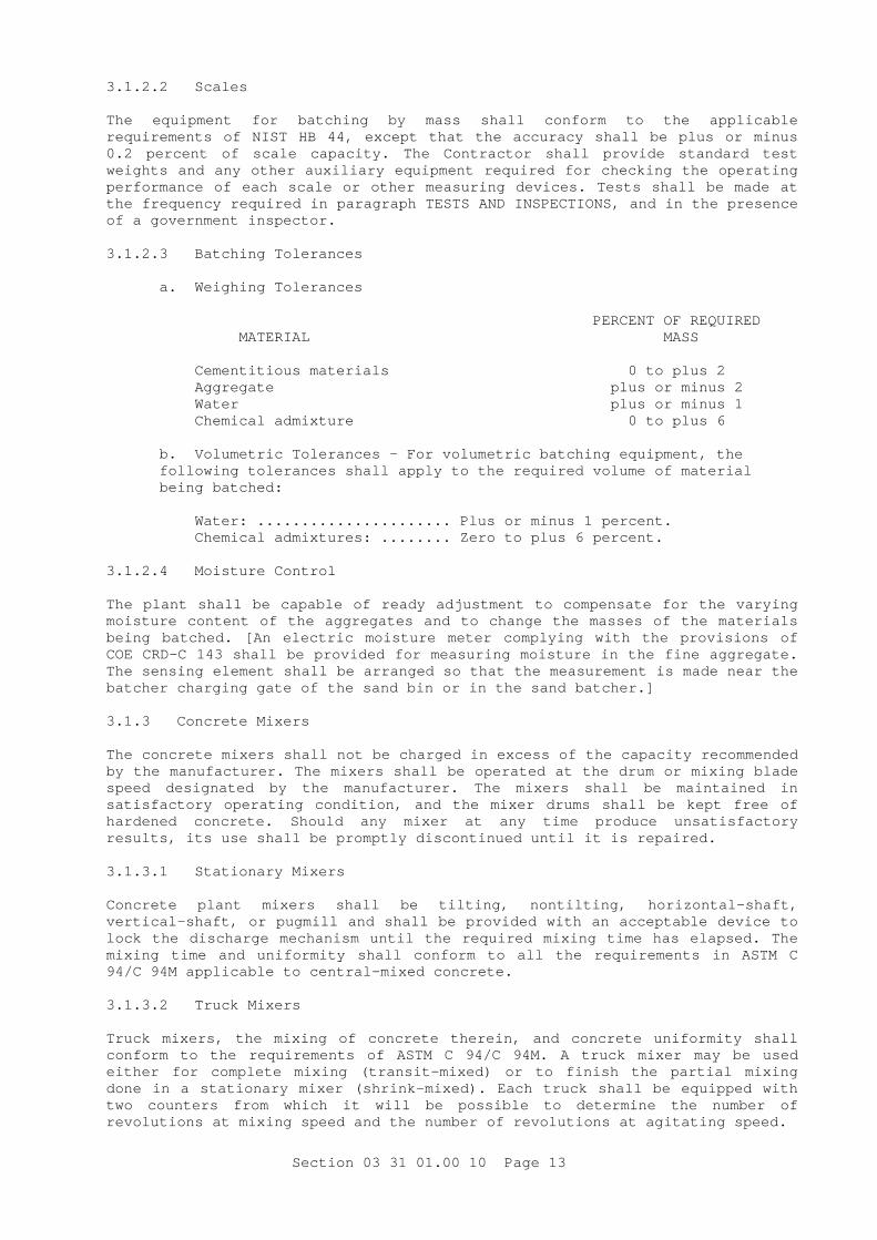
Section 03 31 01.00 10 Page 13
3.1.2.2 Scales The equipment for batching by mass shall conform to the applicable requirements of NIST HB 44, except that the accuracy shall be plus or minus 0.2 percent of scale capacity. The Contractor shall provide standard test weights and any other auxiliary equipment required for checking the operating performance of each scale or other measuring devices. Tests shall be made at the frequency required in paragraph TESTS AND INSPECTIONS, and in the presence of a government inspector. 3.1.2.3 Batching Tolerances
a. Weighing Tolerances PERCENT OF REQUIRED MATERIAL MASS Cementitious materials 0 to plus 2 Aggregate plus or minus 2 Water plus or minus 1 Chemical admixture 0 to plus 6
b. Volumetric Tolerances - For volumetric batching equipment, the following tolerances shall apply to the required volume of material being batched:
Water: ...................... Plus or minus 1 percent. Chemical admixtures: ........ Zero to plus 6 percent. 3.1.2.4 Moisture Control The plant shall be capable of ready adjustment to compensate for the varying moisture content of the aggregates and to change the masses of the materials being batched. [An electric moisture meter complying with the provisions of COE CRD-C 143 shall be provided for measuring moisture in the fine aggregate. The sensing element shall be arranged so that the measurement is made near the batcher charging gate of the sand bin or in the sand batcher.] 3.1.3 Concrete Mixers The concrete mixers shall not be charged in excess of the capacity recommended by the manufacturer. The mixers shall be operated at the drum or mixing blade speed designated by the manufacturer. The mixers shall be maintained in satisfactory operating condition, and the mixer drums shall be kept free of hardened concrete. Should any mixer at any time produce unsatisfactory results, its use shall be promptly discontinued until it is repaired. 3.1.3.1 Stationary Mixers Concrete plant mixers shall be tilting, nontilting, horizontal-shaft, vertical-shaft, or pugmill and shall be provided with an acceptable device to lock the discharge mechanism until the required mixing time has elapsed. The mixing time and uniformity shall conform to all the requirements in ASTM C 94/C 94M applicable to central-mixed concrete. 3.1.3.2 Truck Mixers Truck mixers, the mixing of concrete therein, and concrete uniformity shall conform to the requirements of ASTM C 94/C 94M. A truck mixer may be used either for complete mixing (transit-mixed) or to finish the partial mixing done in a stationary mixer (shrink-mixed). Each truck shall be equipped with two counters from which it will be possible to determine the number of revolutions at mixing speed and the number of revolutions at agitating speed.
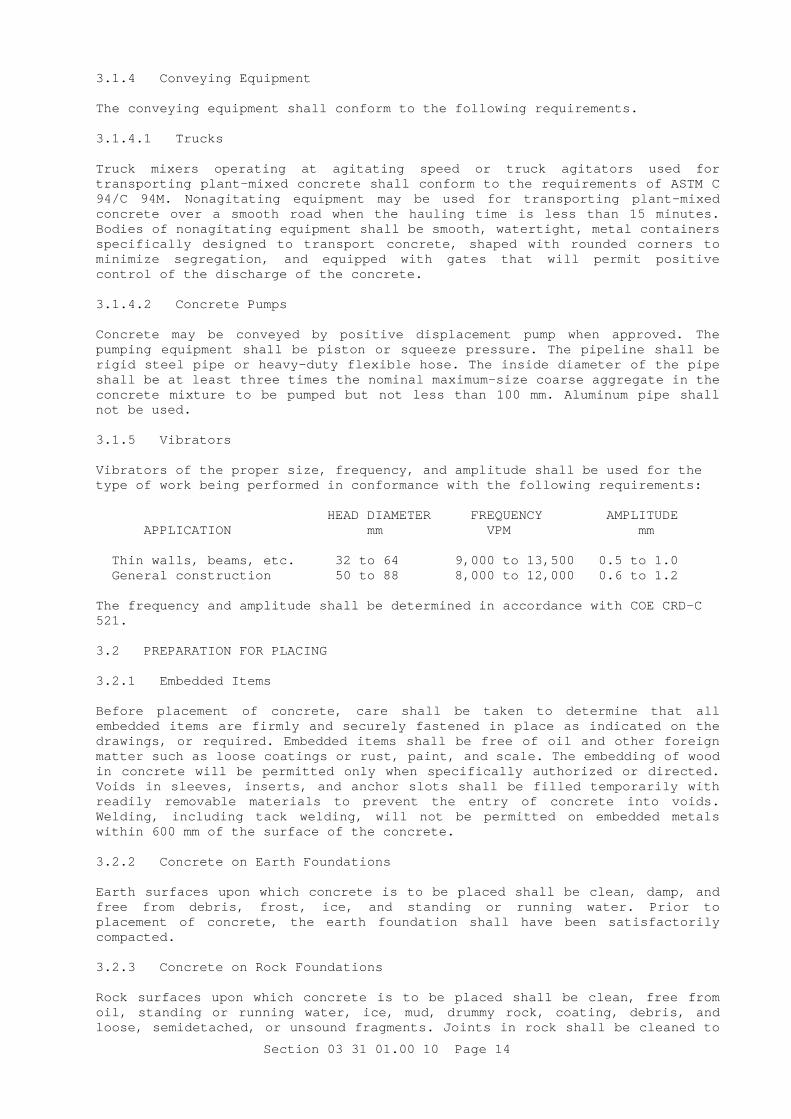
Section 03 31 01.00 10 Page 14
3.1.4 Conveying Equipment The conveying equipment shall conform to the following requirements. 3.1.4.1 Trucks Truck mixers operating at agitating speed or truck agitators used for transporting plant-mixed concrete shall conform to the requirements of ASTM C 94/C 94M. Nonagitating equipment may be used for transporting plant-mixed concrete over a smooth road when the hauling time is less than 15 minutes. Bodies of nonagitating equipment shall be smooth, watertight, metal containers specifically designed to transport concrete, shaped with rounded corners to minimize segregation, and equipped with gates that will permit positive control of the discharge of the concrete. 3.1.4.2 Concrete Pumps Concrete may be conveyed by positive displacement pump when approved. The pumping equipment shall be piston or squeeze pressure. The pipeline shall be rigid steel pipe or heavy-duty flexible hose. The inside diameter of the pipe shall be at least three times the nominal maximum-size coarse aggregate in the concrete mixture to be pumped but not less than 100 mm. Aluminum pipe shall not be used. 3.1.5 Vibrators Vibrators of the proper size, frequency, and amplitude shall be used for the type of work being performed in conformance with the following requirements: HEAD DIAMETER FREQUENCY AMPLITUDE APPLICATION mm VPM mm Thin walls, beams, etc. 32 to 64 9,000 to 13,500 0.5 to 1.0 General construction 50 to 88 8,000 to 12,000 0.6 to 1.2 The frequency and amplitude shall be determined in accordance with COE CRD-C 521. 3.2 PREPARATION FOR PLACING 3.2.1 Embedded Items Before placement of concrete, care shall be taken to determine that all embedded items are firmly and securely fastened in place as indicated on the drawings, or required. Embedded items shall be free of oil and other foreign matter such as loose coatings or rust, paint, and scale. The embedding of wood in concrete will be permitted only when specifically authorized or directed. Voids in sleeves, inserts, and anchor slots shall be filled temporarily with readily removable materials to prevent the entry of concrete into voids. Welding, including tack welding, will not be permitted on embedded metals within 600 mm of the surface of the concrete. 3.2.2 Concrete on Earth Foundations Earth surfaces upon which concrete is to be placed shall be clean, damp, and free from debris, frost, ice, and standing or running water. Prior to placement of concrete, the earth foundation shall have been satisfactorily compacted. 3.2.3 Concrete on Rock Foundations Rock surfaces upon which concrete is to be placed shall be clean, free from oil, standing or running water, ice, mud, drummy rock, coating, debris, and loose, semidetached, or unsound fragments. Joints in rock shall be cleaned to

Section 03 31 01.00 10 Page 15
a satisfactory depth, as determined by the Contracting Officer, and to firm rock on the sides. Immediately before the concrete is placed, all rock surfaces shall be cleaned thoroughly by the use of air-water jets or sandblasting as described in paragraph CONSTRUCTION JOINT TREATMENT. All rock surfaces shall be kept continuously wet for at least 24 hours immediately prior to placing concrete thereon. All approximately horizontal surfaces shall be covered, immediately before the concrete is placed, with a layer of mortar proportioned similar to that in the concrete mixture. The mortar shall be covered with concrete before the time of initial setting of the mortar. 3.2.4 Construction Joint Treatment Construction joint treatment shall conform to the following requirements. 3.2.4.1 Joint Preparation Concrete surfaces to which additional concrete is to be bonded shall be prepared for receiving the next lift or adjacent concrete by cleaning with either air-water cutting, sandblasting, high-pressure water jet, or other approved method. Air-water cutting will not be permitted on formed surfaces or surfaces congested with reinforcing steel. Regardless of the method used, the resulting surfaces shall be free from all laitance and inferior concrete so that clean, well bonded coarse aggregate is exposed uniformly throughout the lift surface. The edges of the coarse aggregate shall not be undercut. The surface shall be washed clean again as the last operation prior to placing the next lift. There shall be no standing water on the surface upon which concrete is placed. 3.2.4.2 Air-Water Cutting Air-water cutting of a construction joint shall be performed at the proper time and only on horizontal construction joints. The air pressure used in the jet shall be 620 to 760 kPa, and the water pressure shall be just sufficient to bring the water into effective influence of the air pressure. When approved by the Contracting Officer, a retarder complying with the requirements of COE CRD-C 94 may be applied to the surface of the lift to prolong the period of time during which air-water cutting is effective. Prior to receiving approval, the Contractor shall furnish samples of the material to be used and shall demonstrate the method to be used in applications. After cutting, the surface shall be washed and rinsed as long as there is any trace of cloudiness of the wash water. Where necessary to remove accumulated laitance, coatings, stains, debris, and other foreign material, high-pressure water jet or sandblasting will be required as the last operation before placing the next lift. 3.2.4.3 High-Pressure Water Jet A stream of water under a pressure of not less than 20.7 MPa may be used for cleaning. Its use shall be delayed until the concrete is sufficiently hard so that only the surface skin or mortar is removed and there is no undercutting of coarse-aggregate particles. If the water jet is incapable of a satisfactory cleaning, the surface shall be cleaned by sandblasting. 3.2.4.4 Wet Sandblasting This method may be used when the concrete has reached sufficient strength to prevent undercutting of the coarse aggregate particles. The surface of the concrete shall then be washed thoroughly to remove all loose materials. 3.2.4.5 Waste Disposal The method used in disposing of waste water employed in cutting, washing, and rinsing of concrete surfaces shall be such that the waste water does not stain, discolor, or affect exposed surfaces of the structures, or damage the

Section 03 31 01.00 10 Page 16
environment of the project area. The method of disposal shall be subject to approval. 3.3 PLACING 3.3.1 Placing Procedures The surfaces of horizontal construction joints shall be kept continuously wet for the first 12 hours during the 24-hour period prior to placing concrete. Surfaces may be dampened immediately before placement if necessary. Concrete placement will not be permitted when, in the opinion of the Contracting Officer, weather conditions prevent proper placement and consolidation. Concrete shall be deposited as close as possible to its final position in the forms and, in so depositing, there shall be no vertical drop greater than 1.5 m except where suitable equipment is provided to prevent segregation and where specifically authorized. Depositing of the concrete shall be so regulated that it may be effectively consolidated in horizontal layers 600 mm or less in thickness with a minimum of lateral movement. The amount deposited in each location shall be that which can be readily and thoroughly consolidated. Sufficient placing capacity shall be provided so that concrete placement can be kept plastic and free of cold joints while concrete is being placed. Concrete shall be placed by methods that will prevent segregation or loss of ingredients. Any concrete transferred from one conveying device to another shall be passed through a hopper that is conical in shape. The concrete shall not be dropped vertically more than 1.5 m, except where a properly designed and sized elephant truck with rigid drop chute bottom section is provided to prevent segregation and where specifically authorized. In no case will concrete be discharged to free-fall through reinforcing bars. 3.3.2 Placement by Pump When concrete is to be placed by pump, the nominal maximum-size coarse aggregate shall not be reduced to accommodate the pumps. The distance to be pumped shall not exceed limits recommended by the pump manufacturer. The concrete shall be supplied to the concrete pump continuously. When pumping is completed, concrete remaining in the pipeline shall be ejected without contamination of concrete in place. After each operation, equipment shall be thoroughly cleaned, and flushing water shall be wasted outside of the forms. Grout used to lubricate the pumping equipment at the beginning of the placement will not be incorporated into the placement. 3.3.3 Time Interval Between Mixing and Placing Concrete shall be placed within 30 minutes after discharge into nonagitating equipment. When concrete is truck-mixed or when a truck mixer or agitator is used for transporting concrete mixed by a concrete plant mixer, the concrete shall be delivered to the site of the work, and discharge shall be completed within 1-1/2 hours after introduction of the cement to the aggregates. When the length of haul makes it impossible to deliver truck-mixed concrete within these time limits, batching of cement and a portion of the mixing water shall be delayed until the truck mixer is at or near the construction site. 3.3.4 Cold-Weather Placing When cold-weather placing of concrete is likely to be subjected to freezing temperatures before the expiration of the curing period, it shall be placed in accordance with procedures previously submitted in accordance with paragraph SUBMITTALS. The ambient temperature of the space adjacent to the concrete placement and surfaces to receive concrete shall be above 0 degrees C. The placing temperature of the concrete having a minimum dimension less than 300 mm shall be between 12 and 24 degrees C when measured in accordance with ASTM C 1064/C 1064M. The placing temperature of the concrete having a minimum dimension greater than 300 mm shall be between 10 and 20 degrees C. Heating of the mixing water or aggregates will be required to regulate the concrete-

Section 03 31 01.00 10 Page 17
placing temperatures. Materials entering the mixer shall be free from ice, snow, or frozen lumps. Salt, chemicals, or other materials shall not be mixed with the concrete to prevent freezing. 3.3.5 Hot-Weather Placing Concrete shall be properly placed and finished with procedures previously submitted in accordance with paragraph SUBMITTALS. The concrete-placing temperature shall be at a degree C when measured in accordance with ASTM C 1064/C 1064M. Cooling of the mixing water and aggregates, or both, may be required to obtain an adequate placing temperature. A retarder meeting the requirements of paragraph WATER-REDUCING OR RETARDING ADMIXTURES may be used to facilitate placing and finishing. Steel forms and reinforcement shall be cooled prior to concrete placement when steel temperatures are greater than 50 degrees C.Conveying and placing equipment shall be cooled if necessary to maintain proper concrete-placing temperature. 3.3.6 Consolidation Immediately after placement, each layer of concrete, including flowing concrete, shall be consolidated by internal vibrating equipment. Vibrators shall not be used to transport concrete within the forms. Hand spading may be required, if necessary, with internal vibrating along formed surfaces permanently exposed to view. Form or surface vibrators shall not be used unless specifically approved. The vibrator shall be inserted vertically at uniform spacing over the entire area of placement. The distance between insertions shall be approximately 1-1/2 times the radius of action of the vibrator. The vibrator shall penetrate rapidly to the bottom of the layer and at least 150 mm into the preceding unhardened layer if such exists. It shall be held stationary until the concrete is consolidated and then withdrawn slowly. 3.4 FINISHING The ambient temperature of spaces adjacent to surfaces being finished shall be not less than 5 degrees C. In hot weather when the rate of evaporation of surface moisture, as determined by use of Figure 2.1.5 of ACI 305R, may reasonably be expected to exceed 1.0 kg/square meter per hour. Provisions for windbreaks, shading, fog spraying, or wet covering with a light-colored material shall be made in advance of placement, and such protective measures shall be taken as quickly as finishing operations will allow. All unformed surfaces that are not to be covered by additional concrete or backfill shall have a float finish. Additional finishing shall be as specified below and shall be true to the elevation shown in the drawings. Surfaces to receive additional concrete or backfill shall be brought to the elevation shown on the drawings and left true and regular. Exterior surfaces shall be sloped for drainage unless otherwise shown in the drawing or as directed. Joints shall be carefully made with a jointing or edging tool. The finished surfaces shall be protected from stains or abrasions. Grate tampers or jitterbugs shall not be used. 3.4.1 Unformed Surfaces 3.4.1.1 Float Finish Surfaces shall be screeded and darbied or bullfloated to bring the surface to the required finish level with no coarse aggregate visible. No water, cement, or mortar shall be added to the surface during the finishing operation. The concrete, while still green but sufficiently hardened to bear a man's weight without deep imprint, shall be floated to a true and even plane. Floating may be performed by use of suitable hand floats or power-driven equipment. Hand floats shall be made of magnesium or aluminum.

Section 03 31 01.00 10 Page 18
3.4.1.2 Trowel Finish Concrete surfaces shall be finished with a float finish, and after surface moisture has disappeared, the surface shall be troweled to a smooth, even, dense finish free from blemishes including trowel marks. 3.4.1.3 Broom Finish The concrete surface shall be finished with a float finish. The floated surface shall be broomed with a fiber-bristle brush in a direction transverse to that of the main traffic. 3.4.2 Formed Surfaces Unless another finish is specified, surfaces shall be left with the texture imparted by the forms except that defective surfaces shall be repaired as described in paragraph FORMED SURFACE REPAIR. Unless painting of surfaces is required, uniform color of the concrete shall be maintained by use of only one mixture without changes in materials or proportions for any structure or portion of structure that is exposed to view or on which a special finish is required. The form panels used to produce the finish shall be orderly in arrangement, with joints between panels planned in approved relation to openings, building corners, and other architectural features. Forms shall not be reused if there is any evidence of surface wear or defects that would impair the quality of the surface. 3.4.2.1 Grout-Cleaned Finish The surfaces shall be given a grout-cleaned finish as described, as approved by the COR and after all required curing, cleaning, and repairs have been completed. Surfaces to be grout-cleaned shall be moist cured for the required period of time before application of the grout-cleaned finish. Grout-cleaning shall be delayed until near the end of construction on all surfaces not to be painted in order to achieve uniformity of appearance and reduce the chance of discoloring caused by subsequent construction operations. The temperature of the air adjacent to the surface shall be not less than 5 degrees C for 24 hours prior to and 72 hours following the application of the finish. The finish for any area shall be completed in the same day, and the limits of a finished area shall be made at natural breaks in the finished surface. The surface to receive grout-cleaned finish shall be thoroughly wetted to prevent absorption of water from the grout but shall have no free water present. The surface shall then be coated with grout. The grout shall be applied as soon as the surface of the concrete approaches surface dryness and shall be vigorously and thoroughly rubbed over the area with clean burlap pads, cork floats or stones, so as to fill all voids. The grout shall be composed of one part portland cement as used on the project, to two parts by volume of well-graded sand passing a 600-µm (No. 30) sieve mixed with water to the consistency of thick paint. White portland cement shall be used for all or part of the cement as approved by the Contracting Officer to give the desired finish color. The applied coating shall be uniform, completely filling all pits, air bubbles, and surface voids. While the grout is still plastic, remove all excess grout by working the surface with a rubber float, burlap pad, or other means. Then, after the surface whitens from drying (about 30 minutes at normal temperature) rub vigorously with clean burlap pads. Immediately after rubbing is completed, the finished surface shall be continuously moist cured for 72 hours. Burlap pads used for this operation shall be burlap stretched tightly around a board to prevent dishing the mortar in the voids. 3.4.3 Formed Surface Repair After removal of forms, all ridges, lips, and bulges on surfaces permanently exposed shall be removed. All repairs shall be completed within 48 hours after form removal.

Section 03 31 01.00 10 Page 19
3.4.3.1 Material and Procedure for Repairs The cement used in the dry-packed mortar or replacement concrete shall be a blend of the cement used for production of project concrete and white portland cement properly proportioned so that the final color of the mortar or concrete will match adjacent concrete. Trial batches shall be used to determine the proportions required to match colors. Dry-packed mortar shall consist of one part cement to two and one-half parts fine aggregate. The fine aggregate shall be that used for production of project concrete. The mortar shall be remixed over a period of at least 30 minutes without addition of water until it obtains the stiffest consistency that will permit placing. Mortar shall be thoroughly compacted into the prepared void by tamping, rodding, ramming, etc. and struck off to match adjacent concrete. Replacement concrete shall be produced using project materials and shall be proportioned by the Contracting Officer. It shall be thoroughly compacted into the prepared void by internal vibration, tamping, rodding, ramming, etc. and shall be struck off and finished to match adjacent concrete. Forms shall be used to confine the concrete. If an expanding agent is used in the repair concrete, the repair shall be thoroughly confined on all sides including the top surface. Metal tools shall not be used to finish permanently exposed surfaces. The repaired areas shall be cured for 7 days. The temperature of the in situ concrete, adjacent air, and replacement mortar or concrete shall be above 5 degrees C during placement, finishing, and curing. Other methods and materials for repair may be used only when approved in writing by the Contracting Officer. Repairs of the so called "plaster-type" will not be permitted. 3.5 CURING AND PROTECTION 3.5.1 Duration The length of the curing period shall be determined by the type of cementitious material, as specified below. Concrete shall be cured by an approved method. Type I portland cement _________________________________ 7 days Type IS or Type IP cement ______________________________ 7 days Portland cement blended with silica fume _______________ 7 days Immediately after placement, concrete shall be protected from premature drying, extremes in temperatures, rapid temperature change, and mechanical damage. All materials and equipment needed for adequate curing and protection shall be available and at the placement site prior to the start of concrete placement. Concrete shall be protected from the damaging effects of rain for 12 hours and from flowing water for 14 days or 7 days with Type III cement. No fire or excessive heat including welding shall be permitted near or in direct contact with concrete or concrete embedments at any time. 3.5.2 Moist Curing Moist-cured concrete shall be maintained continuously, not periodically, wet for the entire curing period. If water or curing materials stain or discolor concrete surfaces that are to be permanently exposed, they shall be cleaned as required in paragraph APPEARANCE. Where wooden form sheathing is left in place during curing, the sheathing shall be kept wet at all times. If steel forms are used in hot weather, nonsupporting vertical forms shall be carefully broken loose from the concrete, soon after the concrete hardens, and curing water continuously applied into the void so as to continuously saturate the entire concrete surface. Horizontal surfaces may be moist cured by ponding, by covering with a minimum uniform thickness of 50 mm of continuously saturated sand, or by covering with saturated nonstaining burlap or cotton mats. Horizontal construction joints may be allowed to dry for 12 hours immediately prior to the placing of the following lift. Silica fume concrete, if used,

Section 03 31 01.00 10 Page 20
shall be moist-cured. Curing of silica fume concrete shall start immediately after placement. 3.5.3 Membrane-Forming Curing Compound Concrete may be cured with an approved membrane-forming curing compound in lieu of moist curing except that membrane curing will not be permitted on any surface to which a grout-cleaned finish is to be applied or other concrete is to be bonded, on any surface containing protruding steel reinforcement, on an abrasive aggregate finish, or any surface maintained at curing temperature by use of free steam. A styrene acrylate or chlorinated rubber compound may be used for surfaces that are to be painted or are to receive bituminous roofing or waterproofing, or for floors that are to receive adhesive applications of resilient flooring. The curing compound selected shall be compatible with any subsequent paint, roofing, waterproofing, or flooring specified. 3.5.3.1 Application The curing compound shall be applied to formed surfaces immediately after the forms are removed and prior to any patching or other surface treatment except the cleaning of loose sand, mortar, and debris from the surface. The surfaces shall be thoroughly moistened with water, and the curing compound applied as soon as free water disappears. The curing compound shall be applied to unformed surfaces as soon as free water has disappeared and bleeding has stopped. The curing compound shall be applied in a two-coat continuous operation by approved motorized power-spraying equipment operating at a minimum pressure of 500 kPa, at a uniform coverage of not more than 10 square meters/L for each coat, and the second coat shall be applied perpendicular to the first coat. Concrete surfaces that have been subjected to rainfall within 3 hours after curing compound has been applied shall be resprayed by the method and at the coverage specified. All concrete surfaces on which the curing compound has been applied shall be adequately protected for the duration of the entire curing period from pedestrian and vehicular traffic and from any other cause that will disrupt the continuity of the curing membrane. 3.5.4 Evaporation Retardant Sheet curing shall not be used on vertical or near-vertical surfaces. All surfaces shall be thoroughly wetted and be completely covered with waterproof paper or polyethylene-coated burlap having the burlap thoroughly water-saturated before placing. Covering shall be laid with light-colored side up. Covering shall be lapped not less than 300 mm and securely weighted down or shall be lapped not less than 100 mm and taped to form a continuous cover with completely closed joints. The sheet shall be weighted to prevent displacement so that it remains in contact with the concrete during the specified length of curing. Coverings shall be folded down over exposed edges of slabs and secured by approved means. Sheets shall be immediately repaired or replaced if tears or holes appear during the curing period. 3.5.5 Cold-Weather Curing and Protection When the daily outdoor low temperature is less than 0 degrees C, the temperature of the concrete shall be maintained above 5 degrees C for the first 7 days after placing. In addition, during the period of protection removal, the air temperature adjacent to the concrete surfaces shall be controlled so that concrete near the surface will not be subjected to a temperature differential of more than 15 degrees C as determined by observation of ambient and concrete temperatures indicated by suitable temperatures measuring devices furnished by the Government as required and installed adjacent to the concrete surface and 50 mm inside the surface of the concrete. The installation of the thermometers shall be made by the Contractor at such locations as may be directed.

Section 03 31 01.00 10 Page 21
3.6 SETTING OF BASE PLATES AND BEARING PLATES 3.6.1 Setting of Plates After being plumbed and properly positioned, column base plates, bearing plates for beams and similar structural members, and machinery and equipment base plates shall be provided with full bearing with nonshrink grout. The space between the top of concrete or masonry-bearing surface and the bottom of the plate shall be approximately 1/24 of the width of the plate, but not less than 13 mm for plates less than 300 mm wide. Concrete surfaces shall be rough, clean, and free of oil, grease, and laitance, and they shall be damp. Metal surfaces shall be clean and free of oil, grease, and rust. 3.6.2 Nonshrink Grout Application Nonshrink grout shall conform to the requirements of paragraph NONSHRINK GROUT. Water content shall be the minimum that will provide a flowable mixture and fill the space to be grouted without segregation, bleeding, or reduction of strength. 3.6.2.1 Mixing and Placing of Nonshrink Grout Mixing and placing shall be in conformance with the material manufacturer's instructions and as specified. Ingredients shall be thoroughly dry-mixed before adding water. After adding water, the batch shall be mixed for 3 minutes. Batches shall be of size to allow continuous placement of freshly mixed grout. Grout not used within 30 minutes after mixing shall be discarded. The space between the top of the concrete or masonry-bearing surface and the plate shall be filled solid with the grout. Forms shall be of wood or other equally suitable material for retaining the grout and shall be removed after the grout has set. If grade "A" grout as specified in ASTM C 1107/C 1107M is used, all surfaces shall be formed to provide restraint. The placed grout shall be worked to eliminate voids; however, overworking and breakdown of the initial set shall be avoided. Grout shall not be retempered or subjected to vibration from any source. Where clearances are unusually small, placement shall be under pressure with a grout pump. Temperature of the grout, and of surfaces receiving the grout, shall be maintained at 20 to 30 degrees C until after setting. 3.6.2.2 Treatment of Exposed Surfaces After the grout has set, those types containing metallic aggregate shall have the exposed surfaces cut back 25 mm and immediately covered with a parge coat of mortar proportioned by mass of one part portland cement, two parts sand, and sufficient water to make the mixture placeable. The parge coat shall have a smooth, dense finish. The exposed surface of other types of nonshrink grout shall have a smooth, dense finish. 3.6.2.3 Curing Grout and parge coats shall be cured in conformance with paragraph CURING AND PROTECTION. 3.7 TESTS AND INSPECTIONS Tests and inspections shall conform to the following requirements. 3.7.1 General The Contractor shall perform the inspections and tests described below, and, based upon the results of these inspections and tests, he shall take the action required and submit reports as required. When, in the opinion of the COR, the concreting operation is out of control, concrete placement shall cease. The laboratory performing the tests shall be on site and shall conform

Section 03 31 01.00 10 Page 22
with ASTM C 1077. The individuals who sample and test concrete or the constituents of concrete as required in this specification shall have demonstrated a knowledge and ability to perform the necessary test procedures equivalent to the ACI minimum guidelines for certification of Concrete Field Testing Technicians, Grade I. The individuals who perform the inspection of concrete construction shall have demonstrated a knowledge and ability equivalent to the ACI minimum guidelines for certification of Concrete Transportation Construction Inspector (CTCI) or Concrete Construction Inspector (CCI). The Government will inspect the laboratory, equipment, and test procedures prior to start of concreting operations and at least once per year thereafter for conformance with ASTM C 1077. 3.7.2 Testing and Inspection Requirements 3.7.2.1 Fine Aggregate
a. Grading - At least once during each shift when the concrete plant is operating, there shall be one sieve analysis and fineness modulus determination in accordance with ASTM C 136 and COE CRD-C 104 for the fine aggregate or for each size range of fine aggregate if it is batched in more than one size or classification. The location at which samples are taken may be selected by the Contractor as the most advantageous for control. However, the Contractor is responsible for delivering fine aggregate to the mixer within specification limits.
b. Corrective Action for Fine Aggregate Grading - When the amount passing on any sieve is outside the specification limits, the fine aggregate shall be immediately resampled and retested. If there is another failure on any sieve, the fact shall immediately be reported to the Contracting Officer.
c. Moisture Content Testing - When in the opinion of the Contracting Officer the electric moisture meter is not operating satisfactorily, there shall be at least four tests for moisture content in accordance with ASTM C 566 during each 8-hour period of mixing plant operation. The times for the tests shall be selected randomly within the 8-hour period. An additional test shall be made whenever the slump is shown to be out of control or excessive variation in workability is reported by the placing foreman. When the electric moisture meter is operating satisfactorily, at least two direct measurements of moisture content shall be made per week to check the calibration of the meter. The results of tests for moisture content shall be used to adjust the added water in the control of the batch plant.
d. Moisture Content Corrective Action - Whenever the moisture content of the fine aggregate changes by 0.5 percent or more, the scale settings for the fine-aggregate batcher and water batcher shall be adjusted (directly or by means of a moisture compensation device) if necessary to maintain the specified slump.
3.7.2.2 Coarse Aggregate
a. Grading - At least once during each shift in which the concrete plant is operating, there shall be a sieve analysis in accordance with ASTM C 136 for each size of coarse aggregate. The location at which samples are taken may be selected by the Contractor as the most advantageous for production control. However, the Contractor shall be responsible for delivering the aggregate to the mixer within specification limits. A test record of samples of aggregate taken at the same locations shall show the results of the current test as well as the average results of the five most recent tests including the current test. The Contractor may adopt limits for control which are coarser than the specification limits for samples taken at locations other than as delivered to the mixer to allow for degradation during handling.

Section 03 31 01.00 10 Page 23
b. Corrective Action for Grading - When the amount passing any sieve is outside the specification limits, the coarse aggregate shall be immediately resampled and retested. If the second sample fails on any sieve, that fact shall be reported to the Contracting Officer. Where two consecutive averages of five tests are outside specification limits, the operation shall be considered out of control and shall be reported to the Contracting Officer. Concreting shall be stopped and immediate steps shall be taken to correct the grading.
c. Coarse Aggregate Moisture Content - A test for moisture content of each size group of coarse aggregate shall be made at least twice per week. When two consecutive readings for smallest size coarse aggregate differ by more than 1.0 percent, frequency of testing shall be increased to that specified above for fine aggregate, until the difference falls below 1.0 percent.
d. Coarse Aggregate Moisture Corrective Action - Whenever the moisture content of any size of coarse aggregate changes by 0.5 percent or more, the scale setting for the coarse aggregate batcher and the water batcher shall be adjusted if necessary to maintain the specified slump.
3.7.2.3 Quality of Aggregates
a. Frequency of Quality Tests - Thirty days prior to the start of concrete placement the Contractor shall perform all tests for aggregate quality listed below. In addition, after the start of concrete placement, the Contractor shall perform tests for aggregate quality in accordance with the frequency schedule shown below. Samples tested after the start of concrete placement shall be taken immediately prior to entering the concrete mixer.
FREQUENCY FINE COARSE PROPERTY AGGREGATE AGGREGATE TEST Specific Gravity Every 3 months Every 3 months ASTM C 127 ASTM C 128 Absorption Every 3 months Every 3 months ASTM C 127 ASTM C 128 Durability Factor Using, COE CRD-C 114 (Procedure A) Every 12 months Every 12 months ASTM C 666/C 666M Clay Lumps and Friable Particles Every 3 months Every 3 months ASTM C 142 Material Finer than the 75-µm (No. 200) Sieve Not applicable Every 3 months ASTM C 117 Impurities Every 3 months Not applicable ASTM C 40 ASTM C 87 A.L. Abrasion Not applicable Every 6 months ASTM C 131 ASTM C 535 Soft and Friable (Scratch Hardness) Not applicable Every 6 months COE CRD-C 130

Section 03 31 01.00 10 Page 24
Petrographic Examination Every 6 months Every 6 months ASTM C 295 Chert, less than 2.40 specific gravity Every 6 months Every 6 months ASTM C 123 Coal and Lignite, less than 2.00 gravity Every 6 months Every 6 months ASTM C 123
b. Corrective Action for Aggregate Quality - If the result of a quality test fails to meet the requirements for quality immediately prior to start of concrete placement, production procedures or materials shall be changed and additional tests shall be performed until the material meets the quality requirements prior to proceeding with either mixture proportioning studies or starting concrete placement. After concrete placement commences, whenever the result of a test for quality fails the requirements, the test shall be rerun immediately. If the second test fails the quality requirement, the fact shall be reported to the Contracting Officer and immediate steps taken to rectify the situation.
3.7.2.4 Scales a. Weighing Accuracy - The accuracy of the scales shall be checked by test weights prior to start of concrete operations and at least once every 3 months for conformance with the applicable requirements of paragraph BATCHING EQUIPMENT. Such tests shall also be made as directed whenever there are variations in properties of the fresh concrete that could result from batching errors. b. Batching and Recording Accuracy - Once a week the accuracy of each batching and recording device shall be checked during a weighing operation by noting and recording the required weight, recorded weight, and the actual weight batched. The Contractor shall confirm that the calibration devices described in paragraph BATCH PLANT for checking the accuracy of dispensed admixtures are operating properly. c. Scales Corrective Action - When either the weighing accuracy or batching accuracy does not comply with specification requirements, the plant shall not be operated until necessary adjustments or repairs have been made. Discrepancies in recording accuracies shall be corrected immediately. 3.7.2.5 Batch-Plant Control The measurement of all constituent materials including cementitious materials, each size of aggregate, water, and admixtures shall be continuously controlled. The aggregate weights and amount of added water shall be adjusted as necessary to compensate for free moisture in the aggregates. The amount of air-entraining agent shall be adjusted to control air content within specified limits. A report shall be prepared indicating type and source of cement used, type and source of pozzolan or slag used, amount and source of admixtures used, aggregate source, the required aggregate and water weights per cubic meter, amount of water as free moisture in each size of aggregate, and the batch aggregate and water weights per cubic meter for each class of concrete batched during plant operation. 3.7.2.6 Concrete Mixture a. Air Content Testing - Air content tests shall be made when test specimens are fabricated. In addition, at least two tests for air content shall be made on randomly selected batches of each separate concrete mixture produced during

Section 03 31 01.00 10 Page 25
each 8-hour period of concrete production. Additional tests shall be made when excessive variation in workability is reported by the placing foreman or Government quality assurance representative. Tests shall be made in accordance with ASTM C 231. Test results shall be plotted on control charts which shall at all times be readily available to the Government. Copies of the current control charts shall be kept in the field by the Contractor's quality control representatives and results plotted as tests are made. When a single test result reaches either the upper or lower action limit a second test shall immediately be made. The results of the two tests shall be averaged and this average used as the air content of the batch to plot on both the control chart for air content and the control chart for range, and for determining the need for any remedial action. The result of each test, or average as noted in the previous sentence, shall be plotted on a separate chart for each mixture on which an "average line" is set at the midpoint of the specified air content range from paragraph AIR CONTENT. An upper warning limit and a lower warning limit line shall be set 1.0 percentage point above and below the average line. An upper action limit and a lower action limit line shall be set 1.5 percentage points above and below the average line, respectively. The range between each two consecutive tests shall be plotted on a control chart for range where an upper warning limit is set at 2.0 percentage points and up upper action limit is set at 3.0 percentage points. Samples for air content may be taken at the mixer, however, the Contractor is responsible for delivering the concrete to the placement site at the stipulated air content. If the Contractor's materials or transportation methods cause air content loss between the mixer and the placement, correlation samples shall be taken at the placement site as required by the Contracting Officer and the air content at the mixer controlled as directed. b. Air Content Corrective Action - Whenever points on the control chart for percent air reach either warning limit, an adjustment shall immediately be made in the amount of air-entraining admixture batched. As soon as is practical after each adjustment, another test shall be made to verify the result of the adjustment. Whenever a point on the control chart range reaches the warning limit, the admixture dispenser shall be recalibrated to ensure that it is operating accurately and with good reproducibility. Whenever a point on either control chart reaches an action limit line, the air content shall be considered out of control and the concreting operation shall immediately be halted until the air content is under control. Additional air content tests shall be made when concreting is restarted. All this shall be at no extra cost to the Government. c. Slump Testing - In addition to slump tests which shall be made when test specimens are fabricated, at least four slump tests shall be made on randomly selected batches in accordance with ASTM C 143/C 143M for each separate concrete mixture produced during each 8-hour or less period of concrete production each day. Also, additional tests shall be made when excessive variation in workability is reported by the placing foreman or Government's quality assurance representative. Test results shall be plotted on control charts which shall at all times be readily available to the Government. Copies of the current control charts shall be kept in the field by the Contractor's quality control representatives and results plotted as tests are made. When a single slump test reaches or goes beyond either the upper or lower action limit, a second test shall immediately be made on the same batch of concrete. The results of the two tests shall be averaged and this average used as the slump of the batch to plot on both the control chart for percent air and the chart for range, and for determining the need for any remedial action. An upper warning limit shall be set at 13 mm below the maximum allowable slump on separate control charts for percent air used for each type of mixture as specified in paragraph SLUMP, and an upper action limit line and lower action limit line shall be set at the maximum and minimum allowable slumps, respectively, as specified in the same paragraph. The range between each consecutive slump test for each type of mixture shall be plotted on a single control chart for range on which an upper action limit is set at 50 mm. Samples for slump shall be taken at the mixer, however, the Contractor is

Section 03 31 01.00 10 Page 26
responsible for delivering the concrete to the placement site at the stipulated slump. If the Contractor's materials or transportation methods cause slump loss between mixer and the placement, correlation samples shall be taken at the placement site as required by the Contracting Officer and the slump at the mixer controlled as directed. d. Slump Corrective Action - Whenever points on the control chart for slump reach the upper warning limit, an adjustment shall be immediately made in the batch weights of water and fine aggregate. The adjustments are to be made so that the total water content does not exceed that amount allowed by the maximum W/C specified, based upon aggregates which are in a saturated surface-dry condition. When a single slump reaches the upper or lower action limit, no further concrete shall be delivered to the placing site until proper adjustments have been made. Immediately after each adjustment, another test shall be made to verify the correctness of the adjustment. Whenever two consecutive slump tests, made during a period when there was no adjustment of batch weights, produce a point on the control chart for range at or above the upper action limit, the concreting operation shall immediately be halted and the Contractor shall take appropriate steps to bring the slump under control. Also, additional slump tests shall be made as directed. All this shall be at no additional cost to the Government. e. Temperature - The temperature of the concrete shall be measured when compressive strength specimens are fabricated. Measurement shall be in accordance with ASTM C 1064/C 1064M. The temperature shall be reported along with the compressive strength data. f. Compressive-Strength Specimens - At least one set of test specimens shall be made each day on each different concrete mixture placed during the day. Additional sets of test cylinders shall be made, as directed by the Contracting Officer, when the mixture proportions are changed or when low strengths have been detected. A random sampling plan shall be developed by the Contractor and approved by the Contracting Officer prior to the start of construction. The plan shall assure that sampling is done in a completely random and unbiased manner. A set of test specimens for concrete with a 28-day specified strength per paragraph DESIGN REQUIREMENTS shall consist of four cylinders, two to be tested at 7 days and two at 28 days. A set of test specimens for concrete with a 90-day strength per specified paragraph DESIGN REQUIREMENTS shall consist of six cylinders, two tested at 7 days, two at 28 days, and two at 90 days. Test specimens shall be molded and cured in accordance with ASTM C 31/C 31M and tested in accordance with ASTM C 39/C 39M. All compressive-strength tests shall be reported immediately to the Contracting Officer. Quality control charts shall be kept for individual strength tests, moving average for strength, and moving average for range for each mixture. The charts shall be similar to those found in ACI 214R. 3.7.2.7 Inspection Before Placing Foundation or construction joints, forms, and embedded items shall be inspected for quality by the Contractor in sufficient time prior to each concrete placement to certify to the Contracting Officer that they are ready to receive concrete. The results of each inspection shall be reported in writing. 3.7.2.8 Placing a. Placing Inspection - The placing foreman shall supervise all placing operations, shall determine that the correct quality of concrete or grout is placed in each location as directed and shall be responsible for measuring and recording concrete temperatures and ambient temperature hourly during placing operations, weather conditions, time of placement, yardage placed, and method of placement.

Section 03 31 01.00 10 Page 27
b. Placing Corrective Action - The placing foreman shall not permit batching and placing to begin until he has verified that an adequate number of vibrators in working order and with competent operators are available. Placing shall not be continued if any pile of concrete is inadequately consolidated. If any batch of concrete fails to meet the temperature requirements, immediate steps shall be taken to improve temperature controls. 3.7.2.9 Vibrators a. Vibrator Testing and Use - The frequency and amplitude of each vibrator shall be determined in accordance with COE CRD-C 521prior to initial use and at least once a month when concrete is being placed. Additional tests shall be made as directed when a vibrator does not appear to be adequately consolidating the concrete. The frequency shall be determined at the same time the vibrator is operating in concrete with the tachometer held against the upper end of the vibrator head while almost submerged and just before the vibrator is withdrawn from the concrete. The amplitude shall be determined with the head vibrating in air. Two measurements shall be taken, one near the tip and another near the upper end of the vibrator head and these results averaged. The make, model, type, and size of the vibrator and frequency and amplitude results shall be reported in writing. b. Vibrator Corrective Action - Any vibrator not meeting the requirements of paragraph VIBRATORS shall be immediately removed from service and repaired or replaced. 3.7.2.10 Curing a. Moist-Curing Inspections - At least once each shift, and once per day on nonwork days an inspection shall be made of all areas subject to moist curing. The surface moisture condition shall be noted and recorded. b. Moist-Curing Corrective Action - When a daily inspection report lists an area of inadequate curing, immediate corrective action shall be taken, and the required curing period for such areas shall be extended by one (1) day. c. Membrane-Curing Inspection - No curing compound shall be applied until the Contractor's authorized representative has verified that the compound is properly mixed and ready for spraying. At the end of each operation, he shall estimate the quantity of compound used by measurement of the container and the area of concrete surface covered and compute the rate of coverage in square meters/L. He shall note whether or not coverage is uniform. d. Membrane-Curing Corrective Action - When the coverage rate of the curing compound is less than that specified or when the coverage is not uniform, the entire surface shall be sprayed again. e. Sheet-Curing Inspection - At least once each shift and once per day on nonwork days, an inspection shall be made of all areas being cured using material sheets. The condition of the covering and the tightness of the laps and tapes shall be noted and recorded. f. Sheet-Curing Corrective Action - When a daily inspection report lists any tears, holes, or laps or joints that are not completely closed, the tears and holes shall promptly be repaired or the sheets replaced, the joints closed, and the required curing period for those areas shall be extended by one (1) day. 3.7.2.11 Cold-Weather Protection and Sealed Insulation Curing At least once each shift and once per day on nonwork days, an inspection shall be made of all areas subject to cold-weather protection. The protection system shall be inspected for holes, tears, unsealed joints, or other deficiencies that could result in damage to the concrete. Special attention shall be taken

Section 03 31 01.00 10 Page 28
at edges, corners, and thin sections. Any deficiencies shall be noted, corrected, and reported. 3.7.2.12 Cold-Weather Protection Corrective Action When a daily inspection report lists any holes, tears, unsealed joints, or other deficiencies, the deficiency shall be corrected immediately and the period of protection extended 1 day. 3.7.2.13 Mixer Uniformity a. Stationary Mixers - Prior to the start of concrete placing and once every 6 months when concrete is being placed, or once for every 57,000 cubic meters of concrete placed, whichever results in the longest time interval, uniformity of concrete mixing shall be determined in accordance with ASTM C 94/C 94M. b. Truck Mixers - Prior to the start of concrete placing and at least once every 6 months when concrete is being placed, uniformity of concrete shall be determined in accordance with ASTM C 94/C 94M. The truck mixers shall be selected randomly for testing. When satisfactory performance is found in one truck mixer, the performance of mixers of substantially the same design and condition of the blades may be regarded as satisfactory. 3.7.2.14 Mixer Uniformity Corrective Action When a mixer fails to meet mixer uniformity requirements, either the mixer shall be removed from service on the work, the mixing time shall be increased, batching sequence changed, batch size reduced, or adjustments shall be made to the mixer until compliance is achieved. 3.7.3 Reports All results of tests or inspections conducted shall be reported informally as they are completed and in writing daily. A weekly report shall be prepared for the updating of control charts covering the entire period from the start of the construction season through the current week. During periods of cold-weather protection, reports of pertinent temperatures shall be made daily. These requirements do not relieve the Contractor of the obligation to report certain failures immediately as required in preceding paragraphs. Such reports of failures and the action taken shall be confirmed in writing in the routine reports. The Contracting Officer has the right to examine all test and inspection records. -- End of Section --
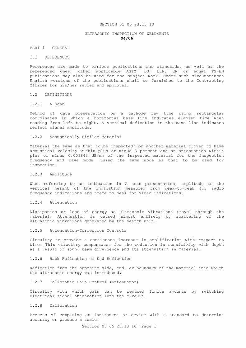
Section 05 05 23.13 10 Page 1
SECTION 05 05 23.13 10
ULTRASONIC INSPECTION OF WELDMENTS 04/06
PART 1 GENERAL 1.1 REFERENCES References are made to various publications and standards, as well as the referenced ones, other applicable ASTM, BS, DIN, EN or equal TS-EN publications may also be used for the subject work. Under such circumstances English versions of the publications shall be furnished to the Contracting Officer for his/her review and approval. 1.2 DEFINITIONS 1.2.1 A Scan Method of data presentation on a cathode ray tube using rectangular coordinates in which a horizontal base line indicates elapsed time when reading from left to right. A vertical deflection in the base line indicates reflect signal amplitude. 1.2.2 Acoustically Similar Material Material the same as that to be inspected; or another material proven to have acoustical velocity within plus or minus 3 percent and an attenuation within plus or minus 0.009843 dB/mm of the inspected material for the inspection frequency and wave mode, using the same mode as that to be used for inspection. 1.2.3 Amplitude When referring to an indication in A scan presentation, amplitude is the vertical height of the indication measured from peak-to-peak for radio frequency indications and trace-to-peak for video indications. 1.2.4 Attenuation Dissipation or loss of energy as ultrasonic vibrations travel through the material. Attenuation is caused almost entirely by scattering of the ultrasonic vibrations generated by the search unit. 1.2.5 Attenuation-Correction Controls Circuitry to provide a continuous increase in amplification with respect to time. This circuitry compensates for the reduction in sensitivity with depth as a result of sound beam divergence and its attenuation in material. 1.2.6 Back Reflection or End Reflection Reflection from the opposite side, end, or boundary of the material into which the ultrasonic energy was introduced. 1.2.7 Calibrated Gain Control (Attenuator) Circuitry with which gain can be reduced finite amounts by switching electrical signal attenuation into the circuit. 1.2.8 Calibration Process of comparing an instrument or device with a standard to determine accuracy or produce a scale.

Section 05 05 23.13 10 Page 2
1.2.9 Cathode Ray Tube (CRT) An electron tube in which a controlled beam of electrons from the cathode is used to produce an image on a fluorescent screen at the end of the tube. 1.2.10 Couplant Any material, usually a liquid or semiliquid, used between the search unit and the inspection surface to exclude air and to convey the ultrasonic vibrations between the search unit and the material being inspected. 1.2.11 Damping Control Control that varies the duration of transducer ringing. 1.2.12 Decibel (dB) Units for the logarithmic expression of the ratio of power levels. Power levels can be functions of voltage, current, or impedance, for example. Decibel units having no values of their own are only significant when a reference is stated, as 10 dB above one reference level or 6 dB below another reference level. 1.2.13 Delay Control Means of delaying the pattern obtained on the CRT. 1.2.14 Discontinuity Anything within a material that will cause a detectable interruption in an ultrasonic beam. 1.2.15 Distance-Amplitude Correction Curve Curve showing the relationship between signal amplitude and equal-sized reflecting surfaces at various distances from the transducer. Reference standards are used to obtain such curves. 1.2.16 Dynamic Range Ratio of maximum to minimum size of reflective areas that can be adequately distinguished on the CRT at a constant gain setting. 1.2.17 Effective Depth of Penetration Maximum depth at which the sensitivity is satisfactory for the quality of test desired. 1.2.18 Examination Within the context of this specification, examination is equivalent to the word "inspection." 1.2.19 Gain Control Circuitry designed into the ultrasonic system to vary reflection amplitude. This control is usually calibrated in decibels. It is also called the sensitivity control.

Section 05 05 23.13 10 Page 3
1.2.20 Gross Background displacement of the trace on the CRT from the established baseline due to the gain setting, the characteristics of the test equipment, or the material under examination. 1.2.21 Hertz One complete set of recurrent values of a periodic quantity comprises a cycle. In other words, any one set of periodic variations starting at one condition and returning once to the same condition is a cycle. 1.2.22 Immersion Techniques Test methods in which the part to be tested and the search units are immersed in water or other suitable liquid couplant. A mechanical device is used to firmly hold and direct the wave angle of the search unit. The search unit does not contact the item being inspected. 1.2.23 Indication Visual presentation on the cathode ray screen resulting from a sound beam reflection from a boundary surface or discontinuity. 1.2.24 Initial Pulse Indication Usually called the "initial pulse". A signal on the CRT screen marking the instant at which a voltage impulse is applied to the transmitting crystal. Its rising edge is frequently invisible due to the time lag in the probe shoe and the consequent necessity to ensure coincidence between the time base zero and the instant at which the transmitter pulse actually enters the material under test. 1.2.25 Linearity Property of an instrument revealed by a linear change in reflected signal or displacement. The vertical linearity is determined by plotting the change in ratios of signal amplitude from two adjacent reflections from an area of known size. The horizontal linearity is determined by plotting the distance the signal is displaced along the sweep against the change in material thickness or by noting the spacing of multiple back reflections. 1.2.26 Longitudinal or Compressional Waves Simple compression-rare-fraction waves in which particle motion within a material is linear and in the direction of wave propagation. Also called straight beams, or compressional or normal waves. 1.227 Longitudinal Wave Inspection Ultrasonic technique, normally using straight beam methods, in which longitudinal waves are the dominant form. 1.2.28 Mid-Screen Reflection Reflection whose amplitude is equal to one-half the useable screen height on the CRT. 1.2.29 Megahertz (MHz) One million hertz per second frequency.

Section 05 05 23.13 10 Page 4
1.2.30 NDT Level I An NDT Level I individual should be qualified to properly perform specific calibrations, specific NDT, and specific evaluations for acceptance or rejection determinations according to written instructions, and to record results. 1.2.31 NDT Level II An NDT Level II individual should be qualified to set up and calibrate equipment and to interpret and evaluate results with respect to applicable codes, standards, and specifications. 1.2.32 NDT Level III An NDT Level III individual should be capable of establishing techniques and procedures; interpreting codes, standards, specifications, and procedures; and designating the particular NDT methods, techniques, and procedures to be used. 1.2.33 Node Distance a shear wave travels in a straight line from the inspection surface before being reflected by the opposite surface. 1.2.34 Pulse Repetition Rate Number of spaced pulses of sound per second sent into the material being inspected. 1.2.35 Range Control Means of expanding the pattern obtained on the CRT so that any portion of the total distance being tested can be presented. 1.2.36 Reference Reflector Standard reflector 1.52 mm diameter reference hole in the IIW reference block. Other approved blocks may have a different diameter reflector. 1.2.37 Reflector Boundary, consisting of an opposite side, crack, or separation, or a distinct change in material such as slag or porosity that reflects the ultrasonic energy the same as a mirror reflects light. 1.2.38 Refracted Waves Waves that have undergone change of velocity and direction by passing from one material to another material with different acoustical properties. Refraction will occur wherever the angle of the incident wave to the interface is other than perpendicular. 1.2.39 Rejectable Discontinuity (Defect) Reflector large enough to produce a signal (decibel rating) that exceeds the reject/repair line. 1.2.40 Resolution Ability to clearly distinguish signals obtained from two reflective surfaces with a minimum separation distance. Near-surface resolution is the ability to clearly distinguish a signal from a reflector at a minimum distance under the contact or near surface without interference from the initial pulse signal. Far-surface resolution is the ability to clearly distinguish signals from
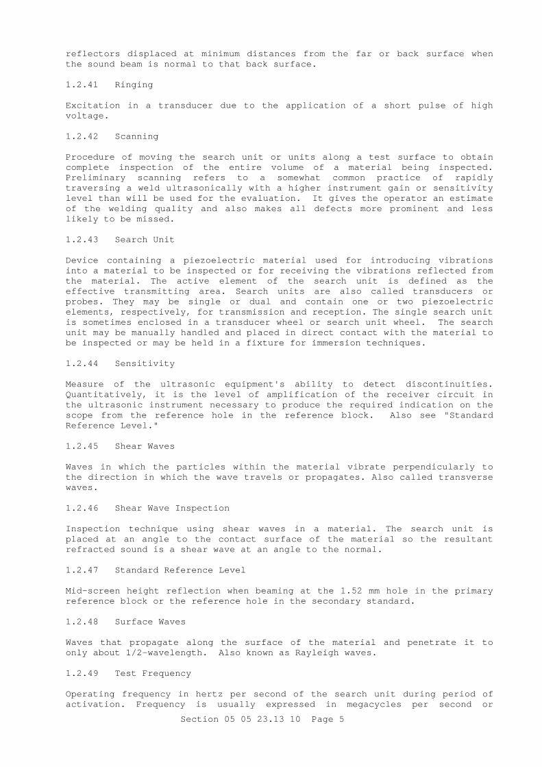
Section 05 05 23.13 10 Page 5
reflectors displaced at minimum distances from the far or back surface when the sound beam is normal to that back surface. 1.2.41 Ringing Excitation in a transducer due to the application of a short pulse of high voltage. 1.2.42 Scanning Procedure of moving the search unit or units along a test surface to obtain complete inspection of the entire volume of a material being inspected. Preliminary scanning refers to a somewhat common practice of rapidly traversing a weld ultrasonically with a higher instrument gain or sensitivity level than will be used for the evaluation. It gives the operator an estimate of the welding quality and also makes all defects more prominent and less likely to be missed. 1.2.43 Search Unit Device containing a piezoelectric material used for introducing vibrations into a material to be inspected or for receiving the vibrations reflected from the material. The active element of the search unit is defined as the effective transmitting area. Search units are also called transducers or probes. They may be single or dual and contain one or two piezoelectric elements, respectively, for transmission and reception. The single search unit is sometimes enclosed in a transducer wheel or search unit wheel. The search unit may be manually handled and placed in direct contact with the material to be inspected or may be held in a fixture for immersion techniques. 1.2.44 Sensitivity Measure of the ultrasonic equipment's ability to detect discontinuities. Quantitatively, it is the level of amplification of the receiver circuit in the ultrasonic instrument necessary to produce the required indication on the scope from the reference hole in the reference block. Also see "Standard Reference Level." 1.2.45 Shear Waves Waves in which the particles within the material vibrate perpendicularly to the direction in which the wave travels or propagates. Also called transverse waves. 1.2.46 Shear Wave Inspection Inspection technique using shear waves in a material. The search unit is placed at an angle to the contact surface of the material so the resultant refracted sound is a shear wave at an angle to the normal. 1.2.47 Standard Reference Level Mid-screen height reflection when beaming at the 1.52 mm hole in the primary reference block or the reference hole in the secondary standard. 1.2.48 Surface Waves Waves that propagate along the surface of the material and penetrate it to only about 1/2-wavelength. Also known as Rayleigh waves. 1.2.49 Test Frequency Operating frequency in hertz per second of the search unit during period of activation. Frequency is usually expressed in megacycles per second or

Section 05 05 23.13 10 Page 6
megahertz. The latter term has been adopted for international use and is preferred. 1.2.50 Video Form Type of signal presentation on a CRT in which only the upper half of the signal appears. 1.3 GENERAL REQUIREMENTS The procedures, methods, standards, and description of equipment specified herein shall be used for inspection of weldments. Ultrasonic inspections shall be made to detect the following defects:
a. Cracks or crack-like faults.
b. Root defects, including lack of penetration and fusion.
c. Lack of fusion between passes on the sidewall.
d. Porosity or inclusions and excessive undercutting. 1.4 SUBMITTALS Government approval is required for submittals with a "G" designation; submittals not having a "G" designation are for Contractor Quality Control approval. When used, a designation following the "G" designation identifies the office that will review the submittal for the Government. The following shall be submitted in accordance with the provisions of the contract.
SD-03 Product Data
Ultrasonic Inspection
Procedures and Methods. The pulse echo contact method with an A scan presentation shall be used for the ultrasonic inspection of welded joints, except that immersion techniques may be used for some applications when approved by the Contracting Officer. The Contractor shall provide a standard reference block and working standards as described in paragraph REFERENCE STANDARDS FOR EQUIPMENT, QUALIFICATIONS, AND CALIBRATION. The procedures to be used for personnel and equipment qualification, equipment calibration, and inspection, shall be submitted to the Contracting Officer at least 30 days prior to their intended use. Approval by the Government will in no way affect the obligation of the Contractor to employ qualified personnel, equipment, and procedures, and to perform the inspection as specified. The procedure description shall include the following:
a. Couplant.
b. Search unit characteristics including angle, size, shape, nominal frequency, type designation.
c. Method and type of wave.
d. Equipment and accessories including manufacturer, model number, date of manufacture, last date of calibration, and the manufacturer's electrical, physical, and performance specifications.
e. Decibel (dB) compensation system for distance-amplitude correction.
Reports containing the following information:

Section 05 05 23.13 10 Page 7
a. Identification and Location of Inspected Item: Name and place of the inspected item, the person performing the inspection, and the date of inspection.
b. Detail of Inspections: Details of methods, types of waves used, search units, frequencies, inspection equipment identification, and calibration data with enough information to permit duplication of the inspection at a later date.
c. Response in Calibration: The response from the DSC or SC block used in calibration and for acceptance/rejection in terms of the response from the 1.524 mm reference hole in the standard IIW block (primary standard).
d. Identification of Unacceptable Areas: Locations, dimensions, types, and area of unacceptable defects and discontinuities giving reflections over 50 percent of the reject/repair line. These may be noted on a sketch or marked-up drawing.
e. Record of Repair Areas: A record of repaired areas shall be furnished as well as test results for the repaired areas.
1.5 WAVE TYPES The types of waves and the conditions under which they shall be used are specified below: 1.5.1 Shear Waves Unless conditions prohibit, shear waves shall be used. A longitudinal wave procedure may be used instead, if approved by the Contracting Officer. Refracted waves between 40 degrees and 70 degrees shall be used except where different angles are indicated in approved procedures, such as for materials less than 13 mm thick, for materials with sound velocities greater than in steel, when the weldments are not readily accessible, or when existing backing rings or backing strips are not removed. For inspection of weldments containing backing rings or backing strips, the instrument shall be adjusted and the refracted angles shall be selected in a way to separate the weldment and the backing ring reflections. The search unit angle and the resulting shear wave angle in the material to be inspected shall be established by the Contractor for each application and this information shall be included in the procedure submitted for approval. 1.5.2 Longitudinal Waves When conditions prohibit the use of shear waves, longitudinal waves may be used. The procedure shall be specially developed to suit the application and shall have the prior approval of the Contracting Officer. 1.6 CHANGES IN PROCEDURE Should application of an approved procedure not provide for good resolution or adequate ultrasonic penetration in the items to be inspected (see paragraph EQUIPMENT QUALIFICATION REQUIREMENTS), changes in procedure or equipment such as frequency, pulse repetition rate, angle of search unit, couplant, or oscilloscope shall be made by the Contractor. Adequacy of the new procedure shall be demonstrated to the Contracting Officer. The Government reserves the right to require a change in test equipment during these tests if any of the following test system characteristics fall below the levels listed in paragraph EQUIPMENT QUALIFICATION REQUIREMENTS: sensitivity, amplitude and distance linearity, signal-to-noise ratio, entry and back surface resolution and penetration.
Section 05 05 23.13 10 Page 8
1.7 ULTRASONIC EQUIPMENT The ultrasonic equipment shall conform to the requirements listed in AWS D1.1/D1.1M Section Inspection, subsection Ultrasonic Equipment, with the following exceptions:
a. The ultrasonic test instruments shall be able to generate, receive, and to present pulses in the frequency range from 1 to 10 megahertz (MHz).
b. The horizontal linearity of the ultrasonic instrument shall be measured in accordance with paragraph EQUIPMENT QUALIFICATION REQUIREMENTS.
c. In addition to the resolution test specified in AWS D1.1/D1.1M, subsection Ultrasonic Equipment, both near- and far-surface resolution tests shall be conducted in accordance with the tests specified for these characteristics in the paragraph EQUIPMENT QUALIFICATION REQUIREMENTS.
1.8 PERSONNEL QUALIFICATION AND REQUIREMENTS 1.8.1 Personnel Qualification The three levels of responsibility associated with ultrasonic inspection are defined in ASNT RP SNT-TC-1A. For qualification to perform ultrasonic inspection, personnel shall be certified under ASNT RP SNT-TC-1A and ASNT Q&A Bk C within a period of 1 year before the date of contract. Other qualification or certification may be accepted at the Contracting Officer's discretion. Personnel with only an operator or inspector trainee certification will not be considered qualified to pass judgement on the acceptability of inspected items, but may work under the direct supervision of a qualified ultrasonic inspector. Qualified ultrasonic inspectors shall be able to judge the acceptability of the item in accordance with paragraph ACCEPTANCE/REJECTION LIMITS. 1.8.2 Examinations If the Contracting Officer doubts an individual's ability as an operator, inspector, or supervisor, the individual shall be recertified in accordance with ASNT RP SNT-TC-1A. At the option of the Government, the Contracting Officer may participate in administering the examination and in evaluating the results. 1.9 REFERENCE STANDARDS FOR EQUIPMENT, QUALIFICATIONS, AND CALIBRATION Reference standards shall be used to calibrate the inspection equipment, test its operating condition, and record the sensitivity or response of the equipment during the inspection in accordance with paragraph EQUIPMENT QUALIFICATION REQUIREMENTS. The standards shall comprise a standard reference block and reference specimens as noted below. 1.9.1 Standard Reference Block The standard reference block or primary standard shall be provided by the Contractor and shall consist of the IIW block in AWS D1.1/D1.1M, Section Inspection, subsection Reference Standards. The standard reference block also shall be used in any reinspection on the same basis as the original inspection, even though the reinspection is to be performed by other ultrasonic instruments and accessories.
Section 05 05 23.13 10 Page 9
1.9.2 Working Standards The Contractor may use other recognized working standards detailed with the IIW block in AWS D1.1/D1.1M such as the Sensitivity Calibration (SC) block. However, such blocks shall be referenced to the IIW block as noted in paragraph SENSITIVITY CALIBRATION OF LONGITUDINAL AND ANGLE WAVE SYSTEMS. Details of their use shall be included in the procedure description submitted to the Contracting Officer. These blocks are the secondary standards. They shall be of acoustically similar material to the welds to be inspected. The secondary standards shall be suited for the applicable tests specified in paragraph EQUIPMENT QUALIFICATION REQUIREMENTS and shall be used as follows, except where the IIW block is specifically required:
a. To assure adequate penetration of the base material.
b. To provide a secondary field standard.
c. To calibrate the equipment and establish the standard reference level.
1.9.3 Resolution Test Block The Contractor shall furnish a resolution test block in accordance with the details shown in AWS D1.1/D1.1M Section Inspection, subsection Ultrasonic Equipment. 1.10 EQUIPMENT QUALIFICATION REQUIREMENTS The ultrasonic instrument and accessories shall be evaluated on their arrival at the jobsite, immediately prior to the start of inspection. They shall be evaluated using the Contractor's furnished primary standard and shall meet or exceed the requirements listed in paragraphs below. Equipment that does not meet these requirements shall not be used in the inspection. 1.10.1 Requalifications The equipment shall be requalified after normal use at intervals not to exceed 40 hours, except as noted. The equipment also shall be requalified immediately after maintenance or repair or when the Contracting Officer considers its operation questionable. 1.10.2 Longitudinal Wave System 1.10.2.1 Vertical Amplitude Linearity Two adjacent reflections of different amplitudes obtained through the thickness of the primary or secondary standard shall vary in the same proportion as the amplitude of the first reflection is increased in discrete 2-dB increments between 20 percent and 80 percent to full screen height. For each gain setting, the amplitude of each reflection shall vary by the same factor, within plus or minus 5 percent. Requalification is required monthly or as otherwise stated. 1.10.2.2 Horizontal Linearity The first three multiple reflections obtained through the thickness of the primary or secondary standard shall be equally spaced, within plus or minus 5 percent, when spread over 90 percent of the sweep length. Requalification is required monthly or as otherwise stated. 1.10.2.3 Near-Surface Resolution Excessive ringing that appears on the CRT to the right of the sound entry point shall not exceed a 13 mm equivalent distance in steel with the search
Section 05 05 23.13 10 Page 10
unit placed on the 100 mm edge of the IIW (primary) block and positioned for maximum amplitude reflection from the 1.524 mm reference hole of the primary standard. The reference reflector shall be set to mid-screen and the gain shall be increased 20 dB. The reference hole located at least 13 mm from one edge of the AW DSC or SC secondary standard shall be used similarly. Acceptability will be on the same basis as in the primary standard. 1.10.2.4 Far-Surface Resolution This property of the equipment shall be verified by the method detailed in AWS D1.1/D1.1M, Section Inspection, subsection Calibration of the Ultrasonic Unit with the IIW or Other Approved Calibration Blocks. In addition, the trailing edge of the third reflection shall return to the sweep line and be clearly discernible. 1.10.3 Angle Wave System 1.10.3.1 Vertical (Amplitude) Linearity Two adjacent multiple reflections from the 1.524 mm reference hole in the primary standard shall vary in the same proportion as the amplitude of the first reflection in discrete 2-dB increments between 20 percent and 80 percent of full screen height. For each gain setting, the amplitude of each adjacent reflection shall vary within plus or minus 5 percent. For testing with the AWS SC or AWS DSC secondary standard, the same criteria shall apply. For the SC block, the transducer shall be placed on the longitudinal surface contiguous with the sound entry point lines, whereas the 100 mm longitudinal surface of the DSC block shall be used for the same purpose. Requalification is required monthly, or as otherwise stated. 1.10.3.2 Horizontal Linearity (Angle Wave} The first three multiple echoes, obtained from the 1.524 mm reference hole of the primary standard or from the reference hole in a secondary standard with the transducer positioned at a minimum of 25 mm sound path distance, shall be equally spaced plus or minus 5 percent when spread over 90 percent of the sweep length. The gain shall be adjusted to give a mid-screen height first reflection. Requalification is required monthly or as otherwise stated. 1.10.3.3 Near-Surface Resolution (Angle Wave) The search unit shall be positioned for maximum amplitude using the primary or secondary standard as in the horizontal linearity test. The gain shall be adjusted to give a mid-screen height first reflection and then shall be increased 20 dB. Excessive ringing that appears on the CRT to the right of the sound entry point shall not exceed 13 mm equivalent distance in steel. 1.10.3.4 Far-Surface Resolution (Angle Wave) The equipment shall delineate the three resolution holes in the resolution block appropriate for the angle of the transducer to be used in the inspection. 1.10.3.5 Signal-to-Noise Ratio With the search unit located as in the horizontal linearity test, the gain shall be set to obtain an 80 percent full screen height first reflection. The reference reflection-to-noise-amplitude ratio shall not be less than 10 to 1. 1.10.3.6 Exit Point The search unit shall be placed on the graduated scale on the 300 mm edge of the primary standard and the ultrasound shall be beamed toward the curved edge of the block. The gain shall be set for a mid-screen first reflection. The

Section 05 05 23.13 10 Page 11
search unit shall be moved back and forth until the first reflection is maximized. The index line on the side of the search unit shall be within 1.6 mm of the mid-point of the graduated scale in either direction. Requalification is required after 40 hours or as otherwise stated. 1.10.3.7 Transducer Angle The established exit point of the probe shall be set over the applicable angle index line scribed on the 200 mm or 300 mm edge, as appropriate, of the primary standard. The gain shall be set to obtain a mid-screen first reflection from the 50 mm plexiglass-lined hole for search units up to 70 percent with the search unit placed on the 200 mm edge. Search units of large angles that have been approved specifically by the Contracting Officer shall be tested from the 300 mm edge using the 1.524 mm reference hole. The search unit shall be moved back and forth to maximize the first reflection. When the material to be inspected is not acoustically similar to the primary standard, the inspection angle shall be within plus or minus 2 degrees of the angle specified in the approved procedure. Requalification is required after 40 hours or as otherwise stated. 1.11 SENSITIVITY CALIBRATION OF LONGITUDINAL AND ANGLE WAVE SYSTEMS Sensitivity calibration shall be done immediately after a change of operators and at least every 30 minutes thereafter as testing proceeds. Recalibration will be required after any power interruption, including a change of source, when the equipment is suspected of being in error, or after relocation of the jobsite. The 30-minute and relocation calibrations may coincide. The instrument shall be allowed to warm up before calibration is attempted. The instrument range and delay controls shall be adjusted to display signals from the reference hole in the primary (IIW block) or secondary standard (DSC or SC block or both) on the viewing screen for the range of distances to be inspected. 1.11.1 Calibration Procedure The test instrument shall be calibrated as described below. 1.11.1.1 Longitudinal Wave In calibrating with the primary standard, the transducer shall be positioned on the 100 mm edge for maximum reflection from the 1.524 mm reference hole. The gain shall be adjusted so that the first reflection is at 50 percent full scale. The top of that indication shall be marked on the CRT with a wax pencil or by other means. This establishes the standard reference level. A point at 80 percent of the standard reference level shall be calculated and marked. This locates the reject/repair line. If a secondary standard is to be used in the inspection, the reject/repair line shall be established similarly. For the DSC block, the transducer shall be positioned on the 100 mm long surface and with the SC degrees sound entry point lines. Adjustment for loss of signal due to distance shall be compensated for as noted above. 1.11.1.2 Angle Wave In calibrating with either the primary or secondary standard, the transducer shall be positioned on the same surfaces as in the case of the longitudinal wave system but over the sound entry point lines appropriate for the angle of the transducer to be used in the inspection. The gain shall be adjusted to give a first reflection that is 50 percent of full-scale response. The top of that indication shall be marked with a wax pencil or by other means. This establishes the standard reference level. A point at 80 percent of the standard reference level shall be calculated and marked. This locates the reject/repair line. Loss of signal shall be compensated as noted.

Section 05 05 23.13 10 Page 12
1.11.2 Calibration of the Secondary Standards After adjusting the first reflection from the reference hole in the secondary standard to 50 percent full-scale response for a sheer or longitudinal wave inspection, a maximized reflection from the 1.524 mm reference hole in the primary standard shall be obtained without changing the gain setting. The gain setting shall be readjusted to obtain a 50 percent full-scale reflection and the readjusted setting shall be recorded as required by paragraph SUBMITTALS, SD-03, to provide a basis for recalibration when the secondary standard is unavailable. 1.11.3 Equipment With a Calibrated Gain Control (Attenuator) When a calibrated gain control attenuator is used, the transducer shall be positioned for a maximum reflection from the reference hole in the secondary standard representing approximately 1/2 the longest inspection distance. This reflection shall be adjusted to mid-scale by varying the gain control accordingly. The difference in decibels between this amplitude and the signal obtained from the first, second, and longest distance reflection obtainable on the secondary standard shall be measured. The differences shall be recorded and plotted on a curve to determine the necessary correction to the amplitude at the various inspection distances. A level of 80 percent of the primary level obtained from the corrected signal heights, is equivalent to the reject/repair line. 1.11.4 Equipment With Electronic Distance Compensation Circuitry If the difference in amplitude between the first reflection and the reflection obtained from the maximum inspection distance is 1 dB or less, the instrument may be used as is. If not, the procedure used for equipment with a calibrated decibel control shall be used to determine the necessary correction to the reflections obtained at the various inspection distances. This characteristic of the equipment shall be re-examined on a monthly basis or as otherwise stated in paragraph EQUIPMENT QUALIFICATION REQUIREMENTS, and correction factors shall be modified accordingly. 1.11.5 Longitudinal Wave Distance-Amplitude Correction Curve A distance-amplitude correction curve may be used instead of the calibrated gain control or the electronic circuitry for either the shear or longitudinal wave system as described below:
a. A shear wave distance-amplitude correction curve shall be constructed and drawn on the face of the cathode ray tube (CRT) for inspection of weldments in excess of 38 mm thick when the design of the test equipment permits. The reference hole in the secondary standard SC or DSC shall be used to construct the distance-amplitude correction curve for a minimum of three node points, 1, 2, and 3. The sensitivity of the instrument shall be adjusted to produce 50 percent full-scale response for the maximized primary reflection and the reject/repair line shall be constructed at 80 percent of the established distance-amplitude curve.
b. A longitudinal wave distance-amplitude correction curve shall be constructed and drawn on the face of the CRT when longitudinal waves are to be used in the inspection for material thicknesses exceeding 25 mm, if design of the test equipment permits. The reference hole in the secondary standard shall be used. Instrument sensitivity shall be adjusted to 50 percent full-scale of the maximized response from the reference hole at 1/2 maximum inspection distance. A reject/repair line shall be constructed at 80 percent of the established distance-amplitude curve. The reflection amplitudes to define this curve shall be taken from the faces of the secondary sensitivity standards which are 25 mm, 50 mm, and 1/2 maximum inspection distance, and the longest distance obtainable from the secondary standard, respectively, from the reference

Section 05 05 23.13 10 Page 13
hole. When a correction curve cannot be drawn on the face of the CRT, one of the distance-amplitude correction methods noted above and submitted under the procedure description shall be applied in accordance with paragraph GENERAL REQUIREMENTS.
1.11.6 Longitudinal Wave Inspections Using Immersion Technique The reference hole in a secondary standard shall be used for each different inspection distance. Repair/reject limits shall be established by immersing both the search unit and secondary standard in the liquid bath in which the inspection is to be conducted. The procedure noted below shall be used:
a. The longitudinal waves from the search unit shall be directed toward the face of the secondary standard closest to the reference hole.
b. The search unit shall be positioned for maximum response. The amplitude of reflection shall be adjusted to 50 percent full-scale. The top of that indication shall be marked on the CRT with a wax pencil or by other means. This establishes the standard reference level. A point at 80 percent of the standard reference level shall be calculated and marked. This locates the reject/repair point. The above shall be repeated for each different surface-to-hole distance to establish the reject/repair line.
c. With the gain at the same setting and the primary standard and search unit in air, a maximized reflection shall be obtained from the 1.524 mm reference hole in the primary standard (IIW). Then, this gain setting shall be readjusted to obtain a 50 percent full-scale reflection. The readjusted setting shall be recorded as required by paragraph SUBMITTALS, SD-18 Records, to provide a basis for recalibration when the secondary standard is unavailable.
PART 2 PRODUCTS (NOT APPLICABLE) PART 3 EXECUTION 3.1 PREPARATION OF MATERIALS FOR INSPECTION Surfaces shall be free from the following: 3.1.1 Weld Spatter Spattering or any roughness that interferes with free movement of the search unit or impairs transmission of the ultrasonic vibrations. 3.1.2 Irregularities Those which could mask or be confused with defect indications. 3.1.3 Weld Backing Strips Strips that are not to remain in place shall be removed and all sharp edges and valleys shall be eliminated by grinding or other mechanical means. 3.1.4 Dirt All loose scale, rust, paint, and dirt shall be removed from the coupling surface. 3.2 INSPECTION PROCEDURE When possible, all welds shall be examined from both sides of the weld and from one surface. If complete inspection cannot be accomplished from one surface, inspection shall be made from another surface that is part of the

Section 05 05 23.13 10 Page 14
same joint. Preliminary scanning techniques using an increased instrument gain shall be used to locate possible defects. When possible, gain shall be increased to a minimum of twice (6 dB) the reference level setting. Final acceptance or rejection shall be evaluated with the equipment properly calibrated and the gain control set at the reference level. The reject/repair line shall be used to evaluate quality of the weld. If a periodic calibration check shows that the equipment is not operating properly or that the system's sensitivity has decreased more than 20 percent (2 dB) from the established sensitivity level, all welds inspected since the prior calibration shall be reexamined. If penetration of the shear waves is questionable, the angle search unit shall be placed in position on one side of the weldment with the waves directed through the weldment. A disconnected angle search unit, plastic or metal wedge or disk, or any good reflector shall be placed in the wave path of the search unit on the far side of the weld to reflect the sound. When good reflections cannot be obtained by either shear or longitudinal waves, the Contractor shall modify the procedures in accordance with paragraph GENERAL REQUIREMENTS. 3.2.1 Test Frequency The test frequency for ferrous materials shall be as specified in AWS D1.1/D1.1M, Section Inspection, subsection Ultrasonic Equipment, except for thicknesses below 13 mm, frequencies between 2.25 and 5 MHz may be used to obtain increased sensitivity. For materials that are difficult to penetrate, any frequency within the operating range of the equipment may be used. The effective depth of penetration and sound beam divergency shall be demonstrated to the Contracting Officer. 3.2.2 Couplants The choice of couplant is optional with the Contractor, except as follows:
a. The couplant shall be the same as that used for equipment qualification and calibration.
b. Couplants that may corrode the reference standards and material being tested or leave objectionable residues shall not be used.
c. Oils shall not be used in systems intended to handle liquid oxygen.
d. Couplants shall be of the proper viscosity to give good coupling for the surface roughness.
3.2.3 Shear Wave Inspection Shear wave inspection shall be performed as follows: The search unit shall be placed on the contact surface at a distance from the weld equal to that used when calibrating the equipment. 3.2.4 Longitudinal Flaws To detect longitudinal flaws, the search unit shall be slowly moved toward and away from the weld far enough to cover its entire cross section, approximately 90 degrees to the weld centerline. The search unit shall be radially oscillated to the left and right, covering an angle of approximately 30 degrees. During the foregoing movement, the search unit shall be continually advanced parallel to the weld centerline. The rate of movement shall depend on the operator's ability to clearly see and identify all reflections. The amount of movement shall be calculated to ensure that the inspection distance will be great enough to traverse the weld. For plate thicknesses 50 mm and greater with an unmachined stainless steel overlay covering the welded joint, the inspection distance shall range from a minimum of one thickness (T) or the first node back from the near fusion line to a distance exceeding T plus 2/3, the maximum width of the weld deposit at the surface. The inspection shall be

Section 05 05 23.13 10 Page 15
repeated from the other side of the weld on the same surface if accessible or if not, from another surface that is part of the same joint as indicated above. The surface of the weld metal in the joint shall be ground smooth and blended with the base metal. 3.2.5 Transverse Flaws To detect transverse flaws when the welded surface is ground flush, the search unit shall be moved along the welded surface in each direction parallel to the centerline of the weld metal with the wave radiating parallel to the weld centerline. To detect transverse flaws when the welded surface is not ground flush, the search unit shall be moved parallel to the weld in each direction, on the adjacent base metal at the top of the weld, with the wave directed at an angle of 30 degrees to the weld centerline. 3.2.6 Longitudinal Wave Inspection This inspection shall be made as follows:
a. The search unit shall be placed on the contact surface with the wave directed in a straight line through any intervening base metal and through the weldment.
b. The search unit shall then be moved slowly in a direction parallel to the weld centerline and zigzagged across an area equivalent to the welded thickness to make sure that waves penetrate the entire welded cross section.
c. The rate of movement shall be dependent on the operator's ability to clearly see and identify all reflections.
3.3 GENERAL ACCEPTANCE/REJECTION REQUIREMENTS Discontinuities shall be evaluated only when the ultrasonic equipment is calibrated properly. If discontinuities are detected, the sound beam shall be directed to maximize the signal amplitude. To determine the length of a discontinuity, the search unit shall be moved parallel to the discontinuity axis in both directions from the position of maximum signal amplitude. One-half the amplitude or a 6-dB increase in sensitivity from a point at which the discontinuity signal drops rapidly to the baseline shall be defined as the extremity of the discontinuity. At this point, the scanning surface shall be marked at the position indicated by the center of the transducer. This shall be repeated to determine the other extremity. The length of the discontinuity shall be defined as the distance between these two marks. For discontinuities with signal amplitudes exceeding full screen height, 50 percent of full screen shall be considered half-peak amplitude. At this point, the scanning surface shall be marked at the position indicated by the center of the transducer. This shall be repeated to determine the other extremity. The length of the discontinuity shall be defined as the distance between these two marks. The maximum signal amplitude, length, depth, and position within the inspection zone shall be determined and reported for discontinuities yielding a signal amplitude equal to or exceeding the reject/repair line. The minimum recordable length of a discontinuity shall be 3 mm. When evaluating welds joining two members with different thicknesses at the weld, the thickness T shall be the lesser of the two thicknesses. The criteria for acceptance or rejection based on ultrasonic inspection will supplement a visual inspection. The sizes and surface conditions of the welds shall conform to the requirements indicated on the applicable plans and drawings and other sections of the specification. When ultrasonic inspection is used along with radiography, the limits specified under paragraph REFERENCE STANDARDS FOR EQUIPMENT, QUALIFICATIONS, AND CALIBRATION shall be the primary standard, supplement the radiographic standards.
Section 05 05 23.13 10 Page 16
3.3.1 Investigation of Questionable Indications An indication considered doubtful shall be brought to the attention of the Contracting Officer and, at the Contractor's option, the weld shall be repaired or investigated further. Indications detected within 10 mm of accessible surfaces shall be investigated further using liquid penetrant in accordance with ASTM E 165 or magnetic particle methods in accordance with ASTM E 709, as applicable, to determine if the surface is penetrated. Failure to locate the flaws by one of these methods shall necessitate further investigation by the other. For nonmagnetic materials, only dye penetrant inspection is required. Other questionable defects shall be further investigated using modifications of the inspection procedure in accordance with paragraph GENERAL REQUIREMENTS. 3.3.2 Inspection of Repairs All repairs shall undergo the same inspection procedure that originally revealed the discontinuities. Before acceptance, the welds shall meet the standards required for the original weld. 3.4 ACCEPTANCE/REJECTION LIMITS Welds shall be accepted or rejected by ultrasonic indication in accordance with the following: 3.4.1 Full Penetration Butt Joints and Corner Joints 3.4.1.1 Class I Welds shall be rejected on the basis of the following:
a. Any evidence of a crack, including any revealed by dye penetrant or magnetic particle in accordance with paragraph GENERAL ACCEPTANCE/ REJECTION REQUIREMENTS.
b. Any indication of a discontinuity such as excessive undercutting, lack of fusion, incomplete penetration, inclusions, or porosity which individually or collectively produce reflections equal to or greater than the established reject/repair line.
c. Any discontinuity with a reflection equal to or exceeding 25 percent of the reject/repair line, up to and including the reject/repair line, shall be rejected where the discontinuity length exceeds 1/2 T or 25 mm.
d. Adjacent discontinuities separated by sound metal with the dimension less than twice the length of the longest discontinuity shall be considered a single discontinuity. The maximum distance between the outer extremities of any two such discontinuities or the sum of their lengths, whichever is greater, shall not exceed the limits specified.
e. If the total cumulative length of the discontinuities in any 300 mm of weld length exceeds T, that weld length shall be rejected.
3.4.1.2 Class II Welds shall be rejected on the basis of the following:
a. Any evidence of a crack, including those revealed by dye penetrant or magnetic particle inspection in accordance with paragraph GENERAL ACCEPTANCE/REJECTION REQUIREMENTS.
b. Any discontinuity with a reflection exceeding the established reject/repair line and with a length exceeding 6 mm. Adjacent discontinuities separated by sound metal with the dimension less than

Section 05 05 23.13 10 Page 17
twice the length of the longest discontinuity shall be considered a single discontinuity.
c. Any discontinuity with a reflection greater than or equal to or 50 percent of the reject/repair line, up to and including the reject/repair line, shall be rejected if the discontinuity length exceeds T. In no case shall any single discontinuity length exceed 38 mm.
d. Adjacent discontinuities separated by sound metal with the dimension less than twice the length of the longest discontinuity shall be considered a single discontinuity. The maximum distance between the outer extremities of any two adjacent discontinuities or the sum of their lengths, whichever is greater, shall not exceed the length as specified above.
e. If the total cumulative length of discontinuities in any 300 mm of weld length exceeds 2 T, that weld length shall be rejected.
3.4.1.3 Class III Welds shall be rejected on the basis of the following:
a. Any discontinuity with a reflection exceeding the established reject/repair line and with a length exceeding 13 mm. Adjacent discontinuities separated by sound metal with a dimension less than twice the length of the longest discontinuity shall be considered a single discontinuity. b. Any discontinuity with a reflection greater than or equal to 50 percent of the reject/repair line, or with the level 8 dB more than the reject/repair line, and with a length (L) exceeding 50 mm or LT, whichever is greater. c. If the total cumulative length of discontinuities in any 300 mm of weld length exceeds 75 mm or 2 T, whichever is greater, that weld length shall be rejected.
3.4.2 Full Penetration Tee Joints Full Penetration Tee Joints (for Incomplete Root Penetration): Any discontinuity with the reflection exceeding the established reject/repair line of the applicable class shall be rejected. Any discontinuity with a reflection exceeding 25 percent of the established reject/repair line, up to and including the reject/repair line, shall be rejected if its length exceeds 1/2 T in a direction transverse to the axis of the weld or LT parallel to the axis for all classes. If the total cumulative length of discontinuities in any 300 mm of weld length exceeds the limits of the applicable class, that weld length shall be rejected. 3.4.3 Partial and Full Penetration Tee Joints Partial and Full Penetration Tee Joint Boundaries: The depth of weld penetration and weld cross section width at the through member surface shall be as indicated by applicable plans or drawings. Limits of discontinuities shall be as specified in preceding paragraphs. 3.4.4 Tee Joint Discontinuities Tee joint discontinuities extending into the through member shall be rejected if reflection exceeds the established reject/repair line, reflection amplitude is in the range of minus 6 dB of the reject/repair line and the discontinuity extends more than 1.6 mm or more into the through plate.] [the total cumulative length of discontinuities in any 300 mm of weld length exceeds 100 mm. -- End of Section --

Section 05 05 23 Page 1
SECTION 05 05 23
WELDING, STRUCTURAL 07/07
PART 1 GENERAL 1.1 REFERENCES References are made to various publications and standards, as well as the referenced ones, other applicable ASTM, BS, DIN, EN or equal TS-EN publications may also be used for the subject work. Under such circumstances English versions of the publications shall be furnished to the COR for his/her review and approval. 1.2 DEFINITIONS Definitions of welding terms are in accordance with AWS A3.0. The following classifications Class 1 (highest class) to Class 6 (lowest class) indicate the project's class(es) of weld joints. 1.2.1 Class 1 Weld Joints This covers complete penetration weld joints only. These weld joints apply where failure would cause a loss of the system and/or be hazardous to personnel. Class 1 weld joints are highly stressed (dynamic and cyclic loading) and characterized as a single point of failure with no redundancy for the redistribution of stress into another member. 1.2.2 Class 2 Weld Joints This covers both complete and partial penetration groove weld joints and fillet weld joints. These weld joints apply where failure would reduce the overall efficiency of a system but loss of the system or a hazard to personnel would not be experienced. 1.2.3 Class 3 Weld Joints This covers both complete and partial penetration groove weld joints and fillet weld joints. These weld joints apply where failure would not affect the efficiency of a system nor create a hazard to personnel. Class 3 weld joints are connections of secondary members not subject to dynamic action and/or low stressed miscellaneous applications. 1.2.4 Class 4 Weld Joints This covers weld joints applicable to welding reinforcing steel to primary structural members. 1.2.5 Class 5 Weld Joints This covers weld joints applicable to welding concrete reinforcing steel splices (prestressing steel excepted), steel connection devices, and inserts and anchors required in concrete construction. 1.2.6 Class 6 Weld Joints This covers plug and slot weld joints as applicable to the requirements of the project's code(s). 1.3 GENERAL REQUIREMENTS Conform the design of welded connections to AISC 360, unless otherwise indicated or specified. Material with welds will not be accepted unless the

Section 05 05 23 Page 2
welding is specified or indicated on the drawings or otherwise approved. Perform welding as specified in this section, except where additional requirements are shown on the drawings or are specified in other sections. Do not commence welding until welding procedures, inspectors, nondestructive testing personnel, welders, welding operators, and tackers have been qualified and the submittals approved by the COR. Perform all testing at or near the work site. Each Contractor performing welding shall maintain records of the test results obtained in welding procedure, welder, welding operator, and tacker performance qualifications. 1.3.1 Pre-erection Conference Hold a pre-erection conference prior to the start of the field welding, to bring all affected parties together and to gain a naturally clear understanding of the project and the Welding Procedure Specifications (WPS) (which the Contractor shall develop and submit for all welding, including welding done using pre-qualified procedures). Mandatory attendance is required by all Contractor's welding production and inspection personnel and appropriate Government personnel. Include as items for discussion: responsibilities of various parties; welding procedures and processes to be followed; welding sequence (both within a joint and joint sequence within the building); inspection requirements and procedures, both visual and ultrasonic; welding schedule; fabrication of mock-up model; and other items deemed necessary by the attendees. 1.3.2 Mock-up Model Perform first the field-welded connection designated as the mock-up model on the drawings. All welders qualified and designated to perform field-welded groove joints must be present during the welding of the mock-up model connections and each one shall perform a part of the welding. Simulate with the mock-up test all physical and environmental conditions that will be encountered during the welding of all groove joints. Execute all inspection procedures required for groove welded joints, including NDE tests, on the mock-up model. All Contractor inspection and testing personnel designated to perform QC of groove welded joints must be present during the welding of the mock-up model and each one shall perform the inspection procedures to be performed on production welding of these joints. This mock-up model connection represents the standard of performance, both for the welding and inspection procedures used and the results to be achieved in the production welding for these groove welded joints. 1.4 SUBMITTALS Government approval is required for submittals with a "G" designation; submittals not having a "G" designation are for Contractor Quality Control approval. When used, a designation following the "G" designation identifies the office that will review the submittal for the Government. Submit the following in accordance with the provisions of the contract:
SD-03 Product Data
Welding Procedure Qualifications[; G] Welder, Welding Operator, and Tacker Qualification Inspector Qualification Previous Qualifications Pre-qualified Procedures
Copies of the welding procedure specifications; the procedure qualification test records; and the welder, welding operator, or tacker qualification test records.

Section 05 05 23 Page 3
SD-06 Test Reports
Quality Control Nondestructive Examination
A quality assurance plan and records of tests and inspections. Submit all records of nondestructive examination in accordance with paragraph "Acceptance Requirements".
SD-07 Certificates
Certified Welding Procedure Specifications (WPS) Certified Brazing Procedure Specifications (BPS) Certified Procedure Qualification Records (PQR) Certified Welder Performance Qualifications (WPQ) Certified Brazer Performance Qualifications (BPQ)
Certificates in accordance with paragraph "Other Applications".
1.5 WELDING PROCEDURE QUALIFICATIONS Except for pre-qualified (per AWS D1.1/D1.1M) and previously qualified procedures, each Contractor performing welding shall record in detail and qualify the welding procedure specification for any welding procedure followed in the fabrication of weldments. Conform qualification of welding procedures to AWS D1.1/D1.1M and to the specifications in this section. Submit for approval copies of the welding procedure specification and the results of the procedure qualification test for each type of welding which requires procedure qualification. Approval of any procedure, however, does not relieve the Contractor of the sole responsibility for producing a finished structure meeting all the specified requirements. Submit this information on the forms in Appendix E of AWS D1.1/D1.1M. Individually identify and clearly reference on the detail drawings and erection drawings all welding procedure specifications, or suitably key them to the contract drawings. In case of conflict between this specification and AWS D1.1/D1.1M, this specification governs. 1.5.1 General Requirements The organization performing this work must be certified in the following: American Institute of Steel Construction (AISC) Quality Certification Program Category, Category I Conventional Steel Structures, or METU Welding and Non-Destructive Testing Personnel Certification Center.
a. For Structural Projects, provide documentation of the following:
1) Component Thickness 3 mm and greater: Qualification documents (WPS, PQR, and WPQ) in accordance with AWS D1.1/D1.1M.
2) Component Thickness Less than 3 mm: Qualification documents (WPS, PQR, and WPQ) in accordance with AWS D1.3.
3) Reinforcing Steel: Qualification documents (WPS, PWR, and WPQ) in accordance with AWS D1.4/D1.4M.
b. For other applications, provide documentation of the following:
1) Submit for approval or/and review to the Contracting Officer three copies of Certified Welding Procedure Specifications (WPS), Certified Brazing Procedure Specifications (BPS) and Certified Procedure Qualification Records (PQR) within fifteen calendar days after receipt of Notice to Proceed.

Section 05 05 23 Page 4
2) Cranes: Qualification documents (WPS, PQR, and WPQ) in accordance with AWS D14.1/D14.1M.
3) Submit for approval to the COR three copies of Certified Welder Performance Qualifications (WPQ)and Certified Brazer Performance Qualifications (BPQ) within fifteen calendar days prior to any employee welding on the project material.
4) Machinery: Qualification documents (WPS, PQR, and WPQ) in accordance with AWS D14.4/D14.4M.
1.5.2 Previous Qualifications Welding procedures previously qualified by test may be accepted for this contract without re-qualification if the following conditions are met:
a. Testing was performed by an approved testing laboratory, technical consultant, or the Contractor's approved quality control organization.
b. The qualified welding procedure conforms to the requirements of this specification and is applicable to welding conditions encountered under this contract.
c. The welder, welding operator, and tacker qualification tests conform to the requirements of this specification and are applicable to welding conditions encountered under this contract.
1.5.3 Pre-qualified Procedures Welding procedures which are considered pre-qualified as specified in AWS D1.1/D1.1M will be accepted without further qualification. The Contractor shall submit for approval a listing or an annotated drawing to indicate the joints not pre-qualified. Procedure qualification is mandatory for these joints. No pre-qualified welding procedures are allowed. Contractor shall qualify the welding procedures and welders by tests prescribed in the applicable code or specification not withstanding the fact the code or specification may allow pre-qualified procedures. 1.5.4 Retests If welding procedure fails to meet the requirements of AWS D1.1/D1.1M, the procedure specification must be revised and re-qualified, or at the Contractor's option, welding procedure may be retested in accordance with AWS D1.1/D1.1M. If the welding procedure is qualified through retesting, all test results, including those of test welds that failed to meet the requirements, must be submitted with the welding procedure. 1.6 WELDER, WELDING OPERATOR, AND TACKER QUALIFICATION Each welder, welding operator, and tacker assigned to work on this contract must be qualified in accordance with the applicable requirements of AWS D1.1/D1.1M and as specified in this section. Welders, welding operators, and tackers who make acceptable procedure qualification test welds will be considered qualified for the welding procedure used. 1.6.1 Previous Personnel Qualifications At the discretion of the Contracting Officer, welders, welding operators, and tackers qualified by test within the previous 6 months may be accepted for this contract without re-qualification if all the following conditions are met:
a. Copies of the welding procedure specifications, the procedure qualification test records, and the welder, welding operator, and tacker
Section 05 05 23 Page 5
qualification test records are submitted and approved in accordance with the specified requirements for detail drawings.
b. Testing was performed by an approved testing laboratory, technical consultant, or the Contractor's approved quality control organization.
c. The previously qualified welding procedure conforms to the requirements of this specification and is applicable to welding conditions encountered under this contract.
d. The welder, welding operator, and tacker qualification tests conform to the requirements of this specification and are applicable to welding conditions encountered under this contract.
1.6.2 Certificates Before assigning any welder, welding operator, or tacker to work under this contract, submit the names of the welders, welding operators, and tackers to be employed, and certification that each individual is qualified as specified. The certification must state the type of welding and positions for which the welder, welding operator, or tacker is qualified, the code and procedure under which the individual is qualified, the date qualified, and the name of the firm and person certifying the qualification tests. Keep the certification current, on file, and furnish 3 copies.
1.6.3 Renewal of Qualification Re-qualification of a welder or welding operator is required under any of the following conditions:
a. It has been more than 6 months since the welder or welding operator has used the specific welding process for which he is qualified.
b. There is specific reason to question the welder or welding operator's ability to make welds that meet the requirements of these specifications.
c. The welder or welding operator was qualified by an employer other than those firms performing work under this contract, and a qualification test has not been taken within the past 12 months. Submit as evidence of conformance all records showing periods of employment, name of employer where welder, or welding operator, was last employed, and the process for which qualified.
d. A tacker who passes the qualification test is considered eligible to perform tack welding indefinitely in the positions and with the processes for which he is qualified, unless there is some specific reason to question the tacker's ability. In such a case, the tacker is required to pass the prescribed tack welding test.
1.7 INSPECTOR QUALIFICATION Inspector qualifications must be in accordance with AWS D1.1/D1.1M. Qualify all nondestructive testing personnel in accordance with the requirements of ASNT RP SNT-TC-1A for Levels I or II in the applicable nondestructive testing method. The inspector may be supported by assistant welding inspectors who are not qualified to ASNT RP SNT-TC-1A, and assistant inspectors may perform specific inspection functions under the supervision of the qualified inspector. 1.8 SYMBOLS Symbols must be in accordance with AWS A2.4, unless otherwise indicated.
Section 05 05 23 Page 6
1.9 SAFETY Safe weldiing practices and safety precautions during welding must conform to AWS Z49.1. PART 2 PRODUCTS 2.1 WELDING EQUIPMENT AND MATERIALS All welding equipment, electrodes, welding wire, and fluxes must be capable of producing satisfactory welds when used by a qualified welder or welding operator performing qualified welding procedures. All welding equipment and materials shall comply with the applicable requirements of AWS D1.1/D1.1M. PART 3 EXECUTION 3.1 WELDING OPERATIONS 3.1.1 Requirements Conform workmanship and techniques for welded construction to the requirements of AWS D1.1/D1.1M and AISC 360. When AWS D1.1/D1.1M and the AISC 360 specification conflict, the requirements of AWS D1.1/D1.1M govern. 3.1.2 Identification Identify all welds in one of the following ways:
a. Submit written records to indicate the location of welds made by each welder, welding operator, or tacker.
b. Identify all work performed by each welder, welding operator, or tacker with an assigned number, letter, or symbol to identify welds made by that individual. The Contracting Officer may require welders, welding operators, and tackers to apply their symbol next to the weld by means of rubber stamp, felt-tipped marker with waterproof ink, or other methods that do not cause an indentation in the metal. Place the identification mark for seam welds adjacent to the weld at 1 meter intervals. Identification with die stamps or electric etchers is not allowed.
3.2 QUALITY CONTROL Perform testing using an approved inspection or testing laboratory or technical consultant; or if approved, the Contractor's inspection and testing personnel may be used instead of the commercial inspection or testing laboratory or technical consultant. Perform visual and radiographic, ultrasonic, magnetic particle, and liquid penetrant dye penetrant inspections to determine conformance with paragraph STANDARDS OF ACCEPTANCE. Conform procedures and techniques for inspection with applicable requirements of AWS D1.1/D1.1M, ASTM E 165, ASTM E 709, except that in radiographic inspection only film types designated as "fine grain," or "extra fine," are acceptable. 3.3 STANDARDS OF ACCEPTANCE Conform dimensional tolerances for welded construction, details of welds, and quality of welds with the applicable requirements of AWS D1.1/D1.1M and the contract drawings. Perform nondestructive testing by visual inspection and radiographic, ultrasonic, magnetic particle, or dye penetrant methods. The minimum extent of nondestructive testing must be random, as indicated on the drawings.

Section 05 05 23 Page 7
3.3.1 Nondestructive Examination The welding is subject to inspection and tests in the mill, shop, and field. Inspection and tests in the mill or shop do not relieve the Contractor of the responsibility to furnish weldments of satisfactory quality. When materials or workmanship do not conform to the specification requirements, the Government reserves the right to reject material or workmanship or both at any time before final acceptance of the structure containing the weldment. 3.3.2 Destructive Tests Make all repairs when metallographic specimens are removed from any part of a structure. Employ only qualified welders or welding operators, and use the proper joints and welding procedures, including peening or heat treatment if required, to develop the full strength of the members and joints cut and to relieve residual stress. 3.4 GOVERNMENT INSPECTION AND TESTING In addition to the inspection and tests performed by the Contractor for quality control, the Government will perform inspection and testing for acceptance to the extent determined by the COR. The costs of such inspection and testing will be borne by the Contractor if unsatisfactory welds are discovered, or by the Government if the welds are satisfactory. The work may be performed by the Government's own forces or under a separate contract for inspection and testing. The Government reserves the right to perform supplemental nondestructive and destructive tests to determine compliance with paragraph STANDARDS OF ACCEPTANCE. 3.5 CORRECTIONS AND REPAIRS If inspection or testing indicates defects in the weld joints, repair defective welds using a qualified welder or welding operator as applicable. Conduct corrections in accordance with the requirements of AWS D1.1/D1.1M and the specifications. Repair all defects in accordance with the approved procedures. Repair defects discovered between passes before additional weld material is deposited. Wherever a defect is removed and repair by welding is not required, blend the affected area into the surrounding surface to eliminate sharp notches, crevices, or corners. After a defect is thought to have been removed, and before re-welding, examine the area by suitable methods to ensure that the defect has been eliminated. Repaired welds shall meet the inspection requirements for the original welds. Any indication of a defect is regarded as a defect, unless re-evaluation by nondestructive methods or by surface conditioning shows that no unacceptable defect is present. -- End of Section --

Section 05 12 00 Page 1
SECTION 05 12 00
STRUCTURAL STEEL 10/07
PART 1 GENERAL 1.1 REFERENCES References are made to various publications and standards, as well as the referenced ones, other applicable ASTM, BS, DIN, EN or equal TS-EN publications may also be used for the subject work. Under such circumstances English versions of the publications shall be furnished to the COR for his/her review and approval. 1.2 SYSTEM DESCRIPTION Provide the structural steel system, including shop primer or galvanizing, complete and ready for use. Structural steel systems including design, materials, installation, workmanship, fabrication, assembly, erection, inspection, quality control, and testing shall be provided in accordance with [AISC 316 and AISC 317 and AISC 325 except as modified in this contract. 1.3 MODIFICATIONS TO REFERENCES Conform to AISC 316, AISC 317, AISC 360, AISC 303, AISC 348, and AISC 325, except as modified in this section. Conform to AISC 325, AISC 350, AISC 303, AISC 34], and AISC 325, except as modified in this section. 1.4 SUBMITTALS Government approval is required for submittals with a "G" designation; submittals not having a "G" designation are for Contractor Quality Control approval. When used, a designation following the "G" designation identifies the office that will review the submittal for the Government. Submit the following in accordance with the provisions of the contract.
SD-02 Shop Drawings
Erection Plan, including description of temporary supports; G
Fabrication drawings including description of connections; G
SD-03 Product Data
Shop primer
Welding electrodes and rods
Non-Shrink Grout
Include test report for Class B primer.
SD-06 Test Reports
Class B coating
Bolts, nuts, and washers
Supply the certified manufacturer's mill reports which clearly show the applicable ASTM or TS-EN mechanical and chemical requirements together with the actual test results for the supplied fasteners.
Section 05 12 00 Page 2
SD-07 Certificates
Steel
Bolts, nuts, and washers
Galvanizing
Pins and rollers
Welding procedures and qualifications 1.5 AISC QUALITY CERTIFICATION : NOT USED 1.6 SEISMIC PROVISIONS: NOT USED. 1.7 QUALITY ASSURANCE 1.7.1 Drawing Requirements Submit fabrication drawings for approval prior to fabrication. Fabrication drawings shall not be reproductions of contract drawings. Sign and seal fabrication drawings by a professional engineer registered in the country where the project is located. Include complete information for the fabrication and erection of the structure's components, including the location, type, and size of bolts, welds, member sizes and lengths, connection details, blocks, copes, and cuts. Use AWS A2.4 standard welding symbols. Shoring and temporary bracing shall be designed and sealed by a registered professional engineer and submitted for record purposes, with calculations, as part of the drawings. Member substitutions of details shown on the contract drawings shall be clearly highlighted on the fabrication drawings. Explain the reasons for any deviations from the contract drawings. 1.7.2 Certifications 1.7.2.1 Erection Plan Submit for record purposes. Indicate the sequence of erection, temporary shoring and bracing, and a detailed sequence of welding, including each welding procedure required. 1.7.2.2 Welding Procedures and Qualifications Prior to welding, submit certification for each welder stating the type of welding and positions qualified for, the code and procedure qualified under, date qualified, and the firm and individual certifying the qualification tests. If the qualification date of the welding operator is more than one-year old, the welding operator's qualification certificate shall be accompanied by a current certificate by the welder attesting to the fact that he has been engaged in welding since the date of certification, with no break in welding service greater than 6 months. Conform to all requirements specified in AWS D1.1/D1.1M. PART 2 PRODUCTS 2.1 STEEL 2.1.1 Structural Steel ASTM A 36/A 36M.

Section 05 12 00 Page 3
2.1.2 Weathering Structural Steel ASTM A 242/A 242M, Type 1; ASTM A 588/A 588M. 2.1.3 Structural Shapes for Use in Building Framing Wide flange shapes, ASTM A 992/A 992M. 2.1.4 Structural Steel Tubing ASTM A 500, ASTM A 501, ASTM A 618 2.1.5 Steel Pipe ASTM A 53/A 53M, Type E or S, Grade B, weight class STD (Standard) as noted on drawings. 2.2 BOLTS, NUTS, AND WASHERS Provide the following unless indicated otherwise. 2.2.1 Structural Steel , Steel Pipe 2.2.1.1 Bolts ASTM A 307, Grade A; ASTM A 325M, Type 1, ASTM A 490M, Type 1. The bolt heads and the nuts of the supplied fasteners must be marked with the manufacturer's identification mark, the strength grade and type specified by ASTM specifications. 2.2.1.2 Nuts ASTM A 563M, Grade A, heavy hex style, except nuts under M36 may be provided in hex style. 2.2.1.3 Washers ASTM F 844 washers for ASTM A 307 bolts, and ASTM F 436M washers for ASTM A 325M and ASTM A 490M bolts. 2.2.2 Foundation Anchorage 2.2.2.1 Anchor Bolts ASTM A 307. Stainless steel Type 304, Type 316 conforming to ASTM A 276. 2.2.2.2 Anchor Nuts ASTM A 563, Grade A, hex style.Stainless steel Type 304, Type 316 conforming to ASTM A 276. 2.2.2.3 Anchor Washers ASTM F 844. Stainless steel Type 304, Type 316 conforming to ASTM A 276. 2.3 STRUCTURAL STEEL ACCESSORIES 2.3.1 Welding Electrodes and Rods AWS D1.1/D1.1M.

Section 05 12 00 Page 4
2.3.2 Non-Shrink Grout ASTM C 1107/C 1107M, with no ASTM C 827 shrinkage. Grout shall be nonmetallic. 2.3.3 Welded Shear Stud Connectors AWS D1.1/D1.1M. 2.3.4 Pins and Rollers ASTM A 668/A 668M, Class C, D, F, or G; ASTM A 108, Grades 1016 to 1030. Provide as specified in AASHTO HB-17, Division II, Sections 10.26 and 10.27, except provide pins in lengths to extend a minimum of 6 mm beyond the outside faces of the connected parts. 2.4 SHOP PRIMER SSPC Paint 25, (alkyd primer) or SSPC PS 13.01 epoxy-polyamide, green primer (Form 150) type 1, except provide a Class B coating in accordance with AISC 316 and AISC 317 for slip critical joints. Primer shall conform to Federal, State, and local VOC regulations. If flash rusting occurs, re-clean the surface prior to application of primer. 2.5 GALVANIZING ASTM A 123/A 123M or ASTM A 153/A 153M, as applicable, unless specified otherwise galvanize after fabrication where practicable. 2.6 OVERHEAD, TOP RUNNING CRANE RAIL: NOT USED. 2.7 FABRICATION 2.7.1 Markings Prior to erection, members shall be identified by a painted erection mark. Connecting parts assembled in the shop for reaming holes in field connections shall be match marked with scratch and notch marks. Do not locate erection markings on areas to be welded or on surfaces of weathering steels that will be exposed in the completed structure. Do not locate match markings in areas that will decrease member strength or cause stress concentrations. Affix embossed tags to hot-dipped galvanized members. 2.7.2 Shop Primer Shop prime structural steel, except as modified herein, in accordance with SSPC PA 1. Do not prime steel surfaces embedded in concrete, galvanized surfaces, surfaces to receive sprayed-on fireproofing, surfaces to receive epoxy coatings, surfaces designed as part of a composite steel concrete section, or surfaces within 13 mm of the toe of the welds prior to welding (except surfaces on which metal decking is to be welded). Slip critical surfaces shall be primed with a Class B coating. Prior to assembly, prime surfaces which will be concealed or inaccessible after assembly. Do not apply primer in foggy or rainy weather; when the ambient temperature is below 7 degrees C or over 35 degrees C; or when the primer may be exposed to temperatures below 4 degrees C within 48 hours after application, unless approved otherwise by the Contracting Officer. 2.7.2.1 Cleaning SSPC SP 6, except steel exposed in spaces above ceilings, attic spaces, furred spaces, and chases that will be hidden to view in finished construction may be cleaned to SSPC SP 3 when recommended by the shop primer manufacturer. Maintain steel surfaces free from rust, dirt, oil, grease, and other contaminants through final assembly.

Section 05 12 00 Page 5
2.7.2.2 Primer Apply primer to a minimum dry film thickness of 0.05 mm except provide the Class B coating for slip critical joints in accordance with the coating manufacturer's recommendations. Repair damaged primed surfaces with an additional coat of primer. 2.8 DRAINAGE HOLES Adequate drainage holes shall be drilled to eliminate water traps. Hole diameter shall be 13 mm and location shall be indicated on the detail drawings. Hole size and location shall not affect the structural integrity. PART 3 EXECUTION 3.1 FABRICATION Fabrication shall be in accordance with the applicable provisions of AISC 316. Fabrication and assembly shall be done in the shop to the greatest extent possible. The fabricating plant shall be certified under the AISC FCD for Supplement structural steelwork.
Compression joints depending on contact bearing shall have a surface roughness not in excess of 13 micrometer as determined by ASME B46.1, and ends shall be square within the tolerances for milled ends specified in ASTM A 6/A 6M.
Structural steelwork, except surfaces of steel to be encased in concrete, surfaces to be field welded, surfaces to be fireproofed, and contact surfaces of friction-type high-strength bolted connections shall be prepared for painting in accordance with endorsement "P" of AISC FCD and primed with the specified paint. Shop splices of members between field splices will be permitted only where indicated on the Contract Drawings. Splices not indicated require the approval of the Contracting Officer. 3.2 INSTALLATION: NOT USED. 3.3 ERECTION
a. Erection of structural steel, except as indicated in item b. below, shall be in accordance with the applicable provisions of AISC 316, AISC 325 and endorsement F of AISC FCD. Erection plan shall be reviewed, stamped and sealed by a licensed structural engineer.
Provide for drainage in structural steel. After final positioning of steel members, provide full bearing under base plates and bearing plates using nonshrink grout. Place nonshrink grout in accordance with the manufacturer's instructions.
3.3.1 Storage Material shall be stored out of contact with the ground in such manner and location as will minimize deterioration. 3.4 CONNECTIONS Except as modified in this section, connections not detailed shall be designed in accordance with AISC 360 or AISC 350. Build connections into existing work. Do not tighten anchor bolts set in concrete with impact torque wrenches. Punch, subpunch and ream, or drill bolt and pin holes perpendicular to the surface of the member. Holes shall not be cut or enlarged by burning. Bolts, nuts, and washers shall be clean of dirt and rust, and lubricated immediately prior to installation.

Section 05 12 00 Page 6
3.4.1 Common Grade Bolts ASTM A 307 bolts shall be tightened to a "snug tight" fit. "Snug tight" is the tightness that exists when plies in a joint are in firm contact. If firm contact of joint plies cannot be obtained with a few impacts of an impact wrench, or the full effort of a man using a spud wrench, contact the Contracting Officer for further instructions. 3.5 GAS CUTTING Use of gas-cutting torch in the field for correcting fabrication errors will not be permitted on any major member in the structural framing. Use of a gas cutting torch will be permitted on minor members not under stress only after approval has been obtained from the Contracting Officers. 3.6 WELDING AWS D1.1/D1.1M, except use only shielded metal arc welding and low hydrogen electrodes for ASTM A 514/A 514M steel. Do not stress relieve ASTM A 514/A 514M steel by heat treatment. Grind exposed welds smooth as indicated. Provide AWS D1.1/D1.1M qualified welders, welding operators, and tackers. The Contractor shall develop and submit the Welding Procedure Specifications (WPS) for all welding, including welding done using prequalified procedures. Prequalified procedures may be submitted for information only; however, procedures that are not prequalified shall be submitted for approval. 3.6.1 Removal of Temporary Welds, Run-Off Plates, and Backing Strips Removal is not required or Remove only from finished areas. 3.7 SHOP PRIMER REPAIR Repair shop primer in accordance with the paint manufacturer's recommendation for surfaces damaged by handling, transporting, cutting, welding, or bolting. 3.7.1 Field Priming Field priming of steel exposed to the weather, or located in building areas without HVAC for control of relative humidity. After erection, the field bolt heads and nuts, field welds, and any abrasions in the shop coat shall be cleaned and primed with paint of the same quality as that used for the shop coat. 3.8 GALVANIZING REPAIR Provide as indicated or specified. Galvanize after fabrication where practicable. Repair damage to galvanized coatings using zinc rich paint for galvanizing damaged by handling, transporting, cutting, welding, or bolting. Do not heat surfaces to which repair paint has been applied. 3.9 FIELD QUALITY CONTROL Perform field tests, and provide labor, equipment, and incidentals required for testing, except that electric power for field tests will be furnished as set forth in Division 1. The Contracting Officer shall be notified in writing of defective welds, bolts, nuts, and washers within 7 working days of the date of weld inspection.

Section 05 12 00 Page 7
3.9.1 Welds 3.9.1.1 Visual Inspection AWS D1.1/D1.1M. Furnish the services of AWS-certified welding inspectors for fabrication and erection inspection and testing and verification inspections. Welding inspectors shall visually inspect and mark welds, including fillet weld end returns. 3.9.1.2 Nondestructive Testing AWS D1.1/D1.1M. Test locations shall selected by the Contracting Officer. If more than 20 percent of welds made by a welder contain defects identified by testing, then all welds made by that welder shall be tested by radiographic or ultrasonic testing, as approved by the Contracting Officer. When all welds made by an individual welder are required to be tested, magnetic particle testing shall be used only in areas inaccessible to either radiographic or ultrasonic testing. Retest defective areas after repair.
a. Testing frequency: Provide the following types and number of tests:
Test Type Radiographic Ultrasonic Magnetic Particle Dye Penetrant 3.10 SPECIAL INSPECTION AND TESTING FOR SEISMIC-RESISTING SYSTEMS: NOT USED -- End of Section --

Section 05 50 04.00 10 Page 1
SECTION 05 28 33
METAL SECURITY FENCES PART 1 GENERAL 1.1 REFERENCES
References are made to various publications and standards, as well as the referenced ones, other applicable ASTM, BS, DIN, EN or equal TS-EN publications may also be used for the subject work. Under such circumstances English versions of the publications shall be furnished to the Contracting Officer for his/her review and approval.
1.2 SUMMARY A. The extent and locations of ornamental metal security fences (OMSF) are shown on the Contract Drawings, and include devices for anchorage of fence units to substrates. B. Related Sections include the following:
1. Section 03 31 01.00 10 Cast in Place Structural Concrete for Civil Works.
1.3 PERFORMANCE REQUIREMENTS A. Detail, fabricate, and install metal fencing as shown, and in a manner that will produce maximum resistance to penetration of the enclosed property by intruders, including resistance to scaling or climbing without the use of ladders. Fabricate for maximum strength against the use of ordinary hand tools to bend pickets in a manner that would enlarge openings sufficiently to allow passage of intruders through the fence.
1.4 SUBMITTALS
Government approval is required for submittals with a "G" designation; submittals not having a "G" designation are for Contractor Quality Control approval. When used, a designation following the "G" designation identifies the office that will review the submittal for the Government. The following shall be submitted in accordance with the provisions of the contract. A. Product data, for each type and grade of metal used in fabricating units, and for bolts and accessory items used in assembly and installation. Include manufacturer's product data for materials to be used in finishing or painting fence units. B. Shop drawings for each type and size of metal fence unit. Show layout at same scale as site plan; typical plan, elevation, and section of units, including bracing, at 1:20 scale; and joint/anchorage details at 1:5 scale. Include details of fence posts, corners, and terminations. Include structural analysis of resistance to wind loading.
1.5 DELIVERY, STORAGE, AND HANDLING A. Deliver prefabricated security fence units and support bracing/anchorage units to project site, completely assembled and prefinished, with finish fully protected during handling, shipping, storage, and delivery / installation.

Section 05 50 04.00 10 Page 2
PART 2 - PRODUCTS
2.1 MANUFACTURERS A. The manufacturer of the anti-climb fences shall be experinced in the construction of similar fences and shall have a documented experience for the completion of similar jobs.
2.2 MATERIALS, GENERAL A. Steel Shapes, Plates, and Bars: ASTM A 36. B. Steel Structural Tubing: ASTM A 618; welded or seamless, high-strength, low-alloy, structural tubing; Grade Ib; shapes/sizes and wall thicknesses as indicated. C. Steel Structural Tubing: ASTM A 501; hot-formed, welded or seamless structural tubing; shapes/sizes and wall thicknesses as indicated. D. Welding Rods and Bare Electrodes: Provide as required by AWS specifications, for the metal and alloy to be welded. E. Bolts and Fasteners: ASTM A 320, AISI Type 300-series, stainless steel bolts and nuts. Where within reach from attack-face of fence, provide non-removable bolt/nut units (not removable by use of commonly available tools). Provide stainless steel washers. F. Concrete Inserts: Furnish anchorage units to be placed in concrete substrate; of hot-dip galvanized cast-iron/malleable-iron body, design as indicated: ASTM A 153 zinc coating, ASTM A 47 castings. G. Setting/Anchoring Cement: Nonshrinking, nonstaining, hydraulic-controlled expansion cementitious compound; factory prepackaged for mixing with water at project site for a pourable and trowellable mix; recommended by manufacturer for exterior exposure without protective coating, sealer, or waterproofing. Provide product equivalent to "Super Por-Rock" by Minwax Const. Products Div. H. Expansion Shims: To allow for thermal expansion of fence units, provide fluorocarbon resin (or similar) plastic washers, pads, and slip sheets in bolted connections between units, and between fence components and anchorages. I. Shop Primer Paint - Normal Exposure: Fabricator's baked-on, lead-free, modified alkyd-base, ferrous-metal primer, which is compatible with finish system specified in "Painting" or "Special Coatings" section of these specifications, and which will provide long-term resistance to corrosion from exterior exposure, and firm undercoat for field-applied topcoats, after prolonged construction-period exposures. Comply with performance requirements of FS TT-P-645, and with paint manufacturer's instruction for baked-on primer coat application. J. Shop Primer Paint - Severe Exposure: Organic zinc-rich coating, with zinc-dust content not less than 80 percent by weight of non-volatile content; with vehicle base selected for compatibility with specified finish coating system. Comply with paint manufacturer's instructions for method of application and surface pretreatment.
2.3 FABRICATION A. General: Cut and form/shape members to sizes and shapes required, for assembly of fence units of sizes indicated. Weld joints of assembly with welds all around, to produce joints of full-member-strength, with no possible moisture penetration. Grind welds reasonably smooth, but not

Section 05 50 04.00 10 Page 3
necessarily flush. Prefabricate units in plant by welding, to the greatest extent possible. Provide bolted connections for bracing elements and similar parts, but only to the extent units must be disassembled for delivery to project and for installation by method indicated. 1. Drill anchor bolt holes accurately spaced as shown, oversized by 6 mm (1/4 inch) above bolt size, for installation tolerance. 2. Provide for thermal movement of units, amounting to plus-or-minus 1 mm in 1 m (1/8 in. in 10 ft. ) of fence length. 3. Close ends of hollow members (pipes/tubes) which are not butt welded tight against another member in the assembly. Close with 6 mm (1/4 inch) thick steel plate, slightly recessed and welded all around for tight seal, except as otherwise shown. 4. Avoid the use of bolts and screws exposed to and accessible from the threat side of fence. Where unavoidable, provide nonremovable type fasteners in the assembly. 5. Ease exposed metal edges of fabricated units, to approximately 0.8 mm (1/32 inch) radius, prior to finishing. B. Shop-applied Finish, General: Comply with applicable provisions/recommendations of NAAMM Metal Finishes Manual, and the following: 1. Prepare ferrous metal surfaces by cleaning in compliance with SSPC-SP6, "Commercial Blast Cleaning." 2. Apply shop primer paint coat in accordance with paint manufacturer's recommendations for application and baking.
PART 3 - EXECUTION
3.1 PREPARATION A. Coordinate fence installation with work of other sections of these specifications. Deliver concrete inserts to Installer of concrete substrates that will support fence units, prior to time scheduled for placement of concrete. Furnish templates and complete instructions for placing inserts. B. Check concrete substrate and anchorage inserts, for compliances and tolerances required to facilitate installation of fence units. Coordinate beginning of installation with curing of concrete substrate, and with other work at project site; for both temporary security utilization of fence enclosure, and for preservation of metal work and finish. 3.2 INSTALLATION A. Install fence units as indicated. Set plumb and level, and true to line-of-slope as indicated; accurately located with respect to adjacent units, property lines, and adjoining work. Comply with Fabricator's instructions on unpacking, handling, preservation/removal of protective covering, and assembly of fabricated elements. Set base/support plates of units in confined bed of setting/anchoring cement, without voids. Trim away excess bedding material, and tool exposed joint faces for neat, water-resistant exposure. B. Anchor fence units to substrate with bolts and expansion shims as indicated; and fasten units together with bolts/screws and expansion shims. Achieve nonremovable status of fasteners, except where otherwise indicated.

Section 05 50 04.00 10 Page 4
C. Avoid unnecessary cutting, drilling, and welding of prefinished fence units. Where necessary to cut, drill, or weld, repair shop coat(s) of finish (primer and finish coat, if any) in manner recommended by paint manufacturer, and in manner which will provide corrosion protection equivalent to shop-applied coat(s) in-so-far as this is possible. D. Complete the installation of corner posts, special bracing, gates, special security features, and other elements of the work indicated as work of this section. E. Clean exposed surfaces of fence work, and touch up abraded finishes to restore appearance and corrosion resistance. -- End of Section --

Section 05 83 33 Page 1
SECTION 05 83 33
ORNAMENTAL METAL SECURITY FENCES PART 1 – GENERAL 1.1 REFERENCES References are made to various publications and standards, as well as the referenced ones, other applicable ASTM, BS, DIN, EN or equal TS-EN publications may also be used for the subject work. Under such circumstances English versions of the publications shall be furnished to the Contracting Officer for his/her review and approval. 1.2 SUMMARY
A. The extent and locations of ornamental metal security fences (OMSF) are shown on the Contract Drawings, and include devices for anchorage of fence units to substrates.
B. Related Sections include the following: 1. Division 3 Section "Concrete." 2. Other Sections for gates and sally port enclosures.
1.3 PERFORMANCE REQUIREMENTS
A. Detail, fabricate, and install metal fencing as shown, and in a manner that will produce maximum resistance to penetration of the enclosed property by intruders, including resistance to scaling or climbing without the use of ladders. Fabricate for maximum strength against the use of ordinary hand tools to bend pickets in a manner that would enlarge openings sufficiently to allow passage of intruders through the fence.
1.4 SUBMITTALS
A. Product data, for each type and grade of metal used in fabricating units, and for bolts and accessory items used in assembly and installation. Include manufacturer's product data for materials to be used in finishing or painting fence units.
B. Shop drawings for each type and size of metal fence unit. Show layout at same scale as site plan; typical plan, elevation, and section of units, including bracing, at 1:20 scale; and joint/anchorage details at 1:5 scale. Include details of fence posts, corners, and terminations. Include structural analysis of resistance to wind loading.
1.5 DELIVERY, STORAGE, AND HANDLING
A. Deliver prefabricated security fence units and support bracing/anchorage units to project site, completely assembled and prefinished, with finish fully protected during handling, shipping, storage, and delivery / installation.
PART 2 – PRODUCTS 2.1 MANUFACTURERS Manufacturer/fabricator of ornamental metal security fence units shall be a reputable local manufacturer who is experienced in work for a period of minimum 10 years and shall be completed similar works for the US Embassy

Section 05 83 33 Page 2
installations in Turkey. The qualifications of the fence manufacturer shall be submitted to the COR for approval. 2.2 MATERIALS, GENERAL
A. Steel Shapes, Plates, and Bars: ASTM A 36.
B. Steel Structural Tubing: ASTM A 618; welded or seamless, high-strength, low-alloy, structural tubing; Grade Ib; shapes / sizes and wall thicknesses as indicated.
C. Steel Structural Tubing: ASTM A 501; hot-formed, welded or seamless structural tubing; shapes/sizes and wall thicknesses as indicated.
D. Welding Rods and Bare Electrodes: Provide as required by AWS specifications, for the metal and alloy to be welded.
E. Bolts and Fasteners: ASTM A 320, AISI Type 300-series, stainless steel bolts and nuts. Where within reach from attack-face of fence, provide non-removable bolt/nut units (not removable by use of commonly available tools). Provide stainless steel washers.
F. Concrete Inserts: Furnish anchorage units to be placed in concrete substrate; of hot-dip galvanized cast-iron/malleable-iron body, design as indicated: ASTM A 153 zinc coating, ASTM A 47 castings.
G. Setting/Anchoring Cement: Nonshrinking, nonstaining, hydraulic-controlled expansion cementitious compound; factory prepackaged for mixing with water at project site for a pourable and trowellable mix; recommended by manufacturer for exterior exposure without protective coating, sealer, or waterproofing. Provide product equivalent to "Super Por-Rock" by Minwax Const. Products Div.
H. Expansion Shims: To allow for thermal expansion of fence units, provide fluorocarbon resin (or similar) plastic washers, pads, and slip sheets in bolted connections between units, and between fence components and anchorages.
I. Shop Primer Paint - Normal Exposure: Fabricator's baked-on, lead-free, modified alkyd-base, ferrous-metal primer, which is compatible with finish system specified in "Painting" or "Special Coatings" section of these specifications, and which will provide long-term resistance to corrosion from exterior exposure, and firm undercoat for field-applied topcoats, after prolonged construction-period exposures. Comply with performance requirements of FS TT-P-645, and with paint manufacturer's instruction for baked-on primer coat application.
J. Shop Primer Paint – Severe Exposure: Organic zinc-rich coating, with zinc-dust content not less than 80 percent by weight of non-volatile content; with vehicle base selected for compatibility with specified finish coating system. Comply with paint manufacturer's instructions for method of application and surface pretreatment.
2.3 FABRICATION
A. General: Cut and form/shape members to sizes and shapes required, for assembly of fence units of sizes indicated. Weld joints of assembly with welds all around, to produce joints of full-member-strength, with no possible moisture penetration. Grind welds reasonably smooth, but not necessarily flush. Prefabricate units in plant by welding, to the greatest extent possible. Provide bolted connections for bracing elements and similar parts, but only to the extent units must be disassembled for delivery to project and for installation by method indicated.

Section 05 83 33 Page 3
1. Drill anchor bolt holes accurately spaced as shown, oversized by 6 mm
(1/4 inch) above bolt size, for installation tolerance.
2. Provide for thermal movement of units, amounting to plus-or-minus 1 mm in 1 m (1/8 in. in 10 ft.) of fence length.
3. Close ends of hollow members (pipes/tubes) which are not butt welded
tight against another member in the assembly. Close with 6 mm (1/4 inch) thick steel plate, slightly recessed and welded all around for tight seal, except as otherwise shown.
4. Avoid the use of bolts and screws exposed to and accessible from the
threat side of fence. Where unavoidable, provide nonremovable type fasteners in the assembly.
5. Ease exposed metal edges of fabricated units, to approximately 0.8 mm
(1/32 inch) radius, prior to finishing.
B. Shop-applied Finish, General: Comply with applicable provisions / recommendations of NAAMM Metal Finishes Manual, and the following: 1. Prepare ferrous metal surfaces by cleaning in compliance with SSPC-
SP6, "Commercial Blast Cleaning."
2. Apply shop primer paint coat in accordance with paint manufacturer's recommendations for application and baking.
3. PVC Special Coating: Provide Fabricator's standard 10 mil (0.254 mm)
dry film thickness, of polyvinyl chloride coating, thermally fused on preheated, prime-coated steel surfaces; of color indicated.
4. Polyurethane Special Coating: Provide Fabricator's standard 2.5- to
3.0-mil (0.0635 to 0.0762 mm) dry film thickness, of powdered polyurethane, applied electrostatically and thermally fused to form smooth coating on prime-coated steel surfaces; of color indicated.
5. Polyester Special Coating: Provide Fabricator's standard 2.0 to 2.5
mil (0.0508 to 0.0635 mm) dry film thickness, of powdered polyester resin, applied electrostatically and thermally fused to form smooth coating on prime-coated steel surfaces; of color indicated.
PART 3 – EXECUTION 3.1 PREPARATION
A. Coordinate fence installation with work of other sections of these specifications. Deliver concrete inserts to Installer of concrete substrates that will support fence units, prior to time scheduled for placement of concrete. Furnish templates and complete instructions for placing inserts.
B. Check concrete substrate and anchorage inserts, for compliances and tolerances required to facilitate installation of fence units. Coordinate beginning of installation with curing of concrete substrate, and with other work at project site; for both temporary security utilization of fence enclosure, and for preservation of metal work and finish.
3.2 INSTALLATION

Section 05 83 33 Page 4
A. Install fence units as indicated. Set plumb and level, and true to line-of-slope as indicated; accurately located with respect to adjacent units, property lines, and adjoining work. Comply with Fabricator's instructions on unpacking, handling, preservation/removal of protective covering, and assembly of fabricated elements. Set base/support plates of units in confined bed of setting/anchoring cement, without voids. Trim away excess bedding material, and tool exposed joint faces for neat, water-resistant exposure.
B. Anchor fence units to substrate with bolts and expansion shims as indicated; and fasten units together with bolts/screws and expansion shims. Achieve nonremovable status of fasteners, except where otherwise indicated.
C. Avoid unnecessary cutting, drilling, and welding of prefinished fence units. Where necessary to cut, drill, or weld, repair shop coat(s) of finish (primer and finish coat, if any) in manner recommended by paint manufacturer, and in manner which will provide corrosion protection equivalent to shop-applied coat(s) in-so-far as this is possible.
D. Complete the installation of corner posts, special bracing, gates, special security features, and other elements of the work indicated as work of this section.
E. Clean exposed surfaces of fence work, and touch up abraded finishes to restore appearance and corrosion resistance.
-- End of Section --

Section 31 00 00 Page 1
SECTION 31 00 00
EARTHWORK 07/06
PART 1 GENERAL 1.1 REFERENCES References are made to various publications and standards, as well as the referenced ones, other applicable ASTM, BS, DIN, EN or equal TS-EN publications may also be used for the subject work. Under such circumstances English versions of the publications shall be furnished to the COR for his/her review and approval. 1.2 DEFINITIONS 1.2.1 Satisfactory Materials Satisfactory materials comprise any materials classified by ASTM D 2487 as GW, GP, GM, GP-GM, GW-GM, GC, GP-GC, GM-GC, SW, SP, SM, SW-SM, SC, SW-SC, SP-SM, SP-SC, CL, ML, CL-ML, CH, MH. Satisfactory materials for grading comprise stones less than 200 mm, except for fill material for pavements and railroads which comprise stones less than 75 mm in any dimension. 1.2.2 Unsatisfactory Materials Materials which do not comply with the requirements for satisfactory materials are unsatisfactory. Unsatisfactory materials also include man-made fills; trash; refuse; backfills from previous construction; and material classified as satisfactory which contains root and other organic matter or frozen material. Notify the Contracting Officer when encountering any contaminated materials. 1.2.3 Cohesionless and Cohesive Materials Cohesionless materials include materials classified in ASTM D 2487 as GW, GP, SW, and SP. Cohesive materials include materials classified as GC, SC, ML, CL, MH, and CH. Materials classified as GM and SM will be identified as cohesionless only when the fines are nonplastic. Perform testing, required for classifying materials, in accordance with ASTM D 4318, ASTM C 136, ASTM D 422, and ASTM D 1140. 1.2.4 Degree of Compaction Degree of compaction required, except as noted in the second sentence, is expressed as a percentage of the maximum density obtained by the test procedure presented in ASTM D 1557 abbreviated as a percent of laboratory maximum density. Since ASTM D 1557 applies only to soils that have 30 percent or less by weight of their particles retained on the 19.0 mm sieve, express the degree of compaction for material having more than 30 percent by weight of their particles retained on the 19.0 mm sieve as a percentage of the maximum density in accordance with AASHTO T 180 and corrected with AASHTO T 224. To maintain the same percentage of coarse material, use the "remove and replace" procedure as described in NOTE 8 of Paragraph 7.2 in AASHTO T 180. 1.2.5 Overhaul Overhaul is the product of the quantity of materials hauled beyond the free-haul limit, and the distance such materials are hauled beyond the free-haul limit, expressed in station meters.

Section 31 00 00 Page 2
1.2.6 Topsoil Material suitable for topsoils obtained from offsite areas, excavations or areas indicated on the drawings is defined as: Natural, friable soil representative of productive, well-drained soils in the area, free of subsoil, stumps, rocks larger than 25 mm diameter, brush, weeds, toxic substances, and other material detrimental to plant growth. Amend topsoil pH range to obtain a pH of 5.5 to 7. 1.2.7 Hard/Unyielding Materials These materials usually require the use of heavy excavation equipment, ripper teeth, or jack hammers for removal. 1.2.8 Rock Solid homogeneous interlocking crystalline material with firmly cemented, laminated, or foliated masses or conglomerate deposits, neither of which can be removed without systematic drilling and blasting, drilling and the use of expansion jacks or feather wedges, or the use of backhoe-mounted pneumatic hole punchers or rock breakers; also large boulders, buried masonry, or concrete other than pavement exceeding 0.375 cubic meter in volume. Removal of hard material will not be considered rock excavation because of intermittent drilling and blasting that is performed merely to increase production. 1.2.9 Unstable Material Unstable material are too wet to properly support the utility pipe, conduit, or appurtenant structure. 1.2.10 Select Granular Material 1.2.10.1 General Requirements Select granular material consist of materials classified as GW, GP, SW, SP, by ASTM D 2487 where indicated. The liquid limit of such material must not exceed 35 percent when tested in accordance with ASTM D 4318. The plasticity index must not be greater than 12 percent when tested in accordance with ASTM D 4318, and not more than 35 percent by weight may be finer than 75 micrometers sieve when tested in accordance with ASTM D 1140. 1.2.10.2 California Bearing Ratio Values Bearing Ratio: At 2.5 mm penetration, provide a bearing ratio at 95 percent ASTM D 1557 maximum density as determined in accordance with ASTM D 1883 for a laboratory soaking period of not less than 4 days. Conform the combined material to the following sieve analysis: Sieve Size Percent Passing by Weight 63 mm 100 4.75 mm 40 - 85 2.00 mm 20 - 80 425 micrometers 10 - 60 75 micrometers 5 - 25 1.2.11 Initial Backfill Material Initial backfill consists of select granular material or satisfactory materials free from rocks of such size as recommended by the pipe manufacturer. When the pipe is coated or wrapped for corrosion protection, free the initial backfill material of stones such as recommended by the pipe manufacturer.

Section 31 00 00 Page 3
1.2.12 Expansive Soils Expansive soils are defined as soils that have a plasticity index as required, when tested in accordance with ASTM D 4318. 1.2.13 Nonfrost Susceptible (NFS) Material Nonfrost susceptible material are a uniformly graded washed sand with a maximum particle size less than 5 percent passing the 0.075 mm size sieve, and with not more than 3 percent by weight finer than 0.02 mm grain size. 1.3 MEASUREMENT 1.3.1 Excavation The unit of measurement for excavation and borrow will be the cubic meter, computed by the average end area method from cross sections taken before and after the excavation and borrow operations, including the excavation for ditches, gutters, and channel changes, when the material is acceptably utilized or disposed of as herein specified. The measurements will include authorized excavation of rock (except for piping trenches that is covered below), authorized excavation of unsatisfactory subgrade soil, and the volume of loose, scattered rocks and boulders collected within the limits of the work; allowance will be made on the same basis for selected backfill ordered as replacement. The measurement will not include the volume of subgrade material or other material that is scarified or plowed and reused in-place, and will not include the volume excavated without authorization or the volume of any material used for purposes other than directed. The volume of overburden stripped from borrow pits and the volume of excavation for ditches to drain borrow pits, unless used as borrow material, will not be measured for payment. The measurement will not include the volume of any excavation performed prior to the taking of elevations and measurements of the undisturbed grade. 1.3.2 Topsoil Requirements Separate excavation, hauling, and spreading or piling of topsoil and related miscellaneous operations will be considered subsidiary obligations of the Contractor, covered under the contract unit price for excavation. 1.3.3 Select Granular Material Measure select granular material in place as the actual cubic meters replacing wet or unstable material in trench bottoms within the limits shown. 1.4 PAYMENT: NOT USED 1.5 SUBMITTALS Government approval is required for submittals with a "G" designation; submittals not having a "G" designation are for Contractor Quality Control approval. When used, a designation following the "G" designation identifies the office that will review the submittal for the Government. Submit the following in accordance with the provisions of the contract.
SD-01 Preconstruction Submittals
Shoring; G
Dewatering Work Plan; G
Submit 15 days prior to starting work.
SD-03 Product Data

Section 31 00 00 Page 4
Utilization of Excavated Materials; G Opening of any Excavation or Borrow Pit
Procedure and location for disposal of unused satisfactory material. Proposed source of borrow material. Notification of encountering rock in the project. Advance notice on the opening of excavation or borrow areas. Advance notice on shoulder construction for rigid pavements.
SD-06 Test Reports
Testing Borrow Site Testing
Within 24 hours of conclusion of physical tests, three copies of test results, including calibration curves and results of calibration tests. Results of testing at the borrow site.
SD-07 Certificates
Testing
Qualifications of the Corps validated commercial testing laboratory or the Contractor's validated testing facilities.
1.6 SUBSURFACE DATA Subsurface soil boring logs are appended to the SPECIAL CONTRACT REQUIREMENTS. These data represent the best subsurface information available; however, variations may exist in the subsurface between boring locations. 1.7 CLASSIFICATION OF EXCAVATION No consideration will be given to the nature of the materials, and all excavation will be designated as unclassified excavation. Finish the specified excavation on a classified basis, in accordance with the following designations and classifications. 1.7.1 Common Excavation Include common excavation with the satisfactory removal and disposal of all materials not classified as rock excavation. 1.8 CRITERIA FOR BIDDING: NOT USED 1.9 DEWATERING WORK PLAN Submit procedures for accomplishing dewatering work. PART 2 PRODUCTS 2.1 REQUIREMENTS FOR OFFSITE SOILS Test offsite soils brought in for use as backfill for Total Petroleum Hydrocarbons (TPH), Benzene, Toluene, Ethyl Benzene, and Xylene (BTEX) and full Toxicity Characteristic Leaching Procedure (TCLP) including ignitability, corrosivity and reactivity. Backfill shall contain a maximum of 100 parts per million (ppm) of total petroleum hydrocarbons (TPH) and a maximum of 10 ppm of the sum of Benzene, Toluene, Ethyl Benzene, and Xylene (BTEX) and shall pass the TCPL test. Determine TPH concentrations by using EPA 600/4-79/020 Method 418.1. Determine BTEX concentrations by using EPA SW-846.3-3 Method 5030/8020. Perform TCLP in accordance with EPA SW-846.3-3 Method 1311. Provide Borrow Site Testing for TPH, BTEX and TCLP from a composite sample of material from
Section 31 00 00 Page 5
the borrow site, with at least one test from each borrow site. Do not bring material onsite until tests have been approved by the Contracting Officer. 2.2 BURIED WARNING AND IDENTIFICATION TAPE Provide polyethylene plastic and metallic core or metallic-faced, acid- and alkali-resistant, polyethylene plastic warning tape manufactured specifically for warning and identification of buried utility lines. Provide tape on rolls, 75 mm minimum width, color coded as specified below for the intended utility with warning and identification imprinted in bold black letters continuously over the entire tape length. Warning and identification to read, "CAUTION, BURIED (intended service) LINE BELOW" or similar wording. Provide permanent color and printing, unaffected by moisture or soil. Warning Tape Color Codes [Red:] [Electric] [Yellow:] [Gas, Oil; Dangerous Materials] [Orange:] [Telephone and Other Communications] [Blue:] [Water Systems] [Green:] [Sewer Systems] [White:] [Steam Systems] [Gray:] [Compressed Air] 2.2.1 Warning Tape for Metallic Piping Provide acid and alkali-resistant polyethylene plastic tape conforming to the width, color, and printing requirements specified above, with a minimum thickness of 0.08 mm and a minimum strength of 10.3 MPa lengthwise, and 8.6 MPa crosswise, with a maximum 350 percent elongation. 2.2.2 Detectable Warning Tape for Non-Metallic Piping Provide polyethylene plastic tape conforming to the width, color, and printing requirements specified above, with a minimum thickness of 0.10 mm, and a minimum strength of 10.3 MPa lengthwise and 8.6 MPa crosswise. Manufacture tape with integral wires, foil backing, or other means of enabling detection by a metal detector when tape is buried up to 920 mm deep. Encase metallic element of the tape in a protective jacket or provide with other means of corrosion protection. 2.3 DETECTION WIRE FOR NON-METALLIC PIPING Insulate a single strand, solid copper detection wire with a minimum of 12 AWG. 2.4 MATERIAL FOR RIP-RAP: NOT USED. 2.5 CAPILLARY WATER BARRIER Provide capillary water barrier of clean, poorly graded crushed rock, crushed gravel, or uncrushed gravel placed beneath a building slab with or without a vapor barrier to cut off the capillary flow of pore water to the area immediately below. Conform to ASTM C 33 for fine aggregate grading with a maximum of 3 percent by weight passing ASTM D 1140, 75 micrometers sieve, or 37.5 mm and no more than 2 percent by weight passing the 4.75 mm size sieve or coarse aggregate Size 57, 67, or 77. 2.6 PIPE CASING: NOT USED

Section 31 00 00 Page 6
PART 3 EXECUTION 3.1 STRIPPING OF TOPSOIL Where indicated or directed, strip topsoil to a depth of 100 mm. Spread topsoil on areas already graded and prepared for topsoil, or transported and deposited in stockpiles convenient to areas that are to receive application of the topsoil later, or at locations indicated or specified. Keep topsoil separate from other excavated materials, brush, litter, objectionable weeds, roots, stones larger than 50 mm in diameter, and other materials that would interfere with planting and maintenance operations. Remove from the site any surplus of topsoil from excavations and gradings. 3.2 GENERAL EXCAVATION Perform excavation of every type of material encountered within the limits of the project to the lines, grades, and elevations indicated and as specified. Perform the grading in accordance with the typical sections shown and the tolerances specified in paragraph FINISHING. Transport satisfactory excavated materials and place in fill or embankment within the limits of the work. Excavate unsatisfactory materials encountered within the limits of the work below grade and replace with satisfactory materials as directed. Include such excavated material and the satisfactory material ordered as replacement in excavation. Dispose surplus satisfactory excavated material not required for fill or embankment in areas approved for surplus material storage or designated waste areas. Dispose unsatisfactory excavated material in designated waste or spoil areas. During construction, perform excavation and fill in a manner and sequence that will provide proper drainage at all times. Excavate material required for fill or embankment in excess of that produced by excavation within the grading limits from the borrow areas indicated or from other approved areas selected by the Contractor as specified. 3.2.1 Drainage Provide for the collection and disposal of surface and subsurface water encountered during construction. Completely drain construction site during periods of construction to keep soil materials sufficiently dry. Construct storm drainage features (ponds/basins) at the earliest stages of site development, and throughout construction grade the construction area to provide positive surface water runoff away from the construction activity and or provide temporary ditches, swales, and other drainage features and equipment as required to maintain dry soils. When unsuitable working platforms for equipment operation and unsuitable soil support for subsequent construction features develop, remove unsuitable material and provide new soil material as specified herein. It is the responsibility of the Contractor to assess the soil and ground water conditions presented by the plans and specifications and to employ necessary measures to permit construction to proceed. 3.2.2 Dewatering Control groundwater flowing toward or into excavations to prevent sloughing of excavation slopes and walls, boils, uplift and heave in the excavation and to eliminate interference with orderly progress of construction. Do not permit French drains, sumps, ditches or trenches within 0.9 m of the foundation of any structure, except with specific written approval, and after specific contractual provisions for restoration of the foundation area have been made. Take control measures by the time the excavation reaches the water level in order to maintain the integrity of the in situ material. While the excavation is open, maintain the water level continuously. [Operate dewatering system continuously until construction work below existing water levels is complete. Submit performance records weekly.] [Measure and record performance of dewatering system at same time each day by use of observation wells or piezometers installed in conjunction with the dewatering system.] [Relieve
Section 31 00 00 Page 7
hydrostatic head in previous zones below subgrade elevation in layered soils to prevent uplift.] 3.2.3 Underground Utilities The Contractor is responsible for movement of construction machinery and equipment over pipes and utilities during construction. Perform work adjacent to non-Government utilities as indicated in accordance with procedures outlined by utility company. Excavation made with power-driven equipment is not permitted within 600 mm of known Government-owned utility or subsurface construction. For work immediately adjacent to or for excavations exposing a utility or other buried obstruction, excavate by hand. Start hand excavation on each side of the indicated obstruction and continue until the obstruction is uncovered or until clearance for the new grade is assured. Support uncovered lines or other existing work affected by the contract excavation until approval for backfill is granted by the COR. Report damage to utility lines or subsurface construction immediately to the Contracting Officer. 3.2.4 Structural Excavation Ensure that footing subgrades have been inspected and approved by the Contracting Officer prior to concrete placement. Excavate to bottom of pile cap prior to placing or driving piles, unless authorized otherwise by the Contracting Officer. Backfill and compact over excavations and changes in grade due to pile driving operations to 95 percent of ASTM D 698 maximum density. 3.3 SELECTION OF BORROW MATERIAL Select borrow material to meet the requirements and conditions of the particular fill or embankment for which it is to be used. Obtain borrow material from the borrow areas from approved private sources. Unless otherwise provided in the contract, the Contractor is responsible for obtaining the right to procure material, pay royalties and other charges involved, and bear the expense of developing the sources, including rights-of-way for hauling from the owners. Borrow material from approved sources on Government-controlled land may be obtained without payment of royalties. Unless specifically provided, do not obtain borrow within the limits of the project site without prior written approval. Consider necessary clearing, grubbing, and satisfactory drainage of borrow pits and the disposal of debris thereon related operations to the borrow excavation. 3.4 OPENING AND DRAINAGE OF EXCAVATION AND BORROW PITS The Contractor is responsible for notifying the Contracting Officer sufficiently in advance of the opening of any excavation or borrow pit to permit elevations and measurements of the undisturbed ground surface to be taken. Except as otherwise permitted, excavate borrow pits and other excavation areas providing adequate drainage. Transport overburden and other spoil material to designated spoil areas or otherwise dispose of as directed. Provide neatly trimmed and drained borrow pits after the excavation is completed. Ensure that excavation of any area, operation of borrow pits, or dumping of spoil material results in minimum detrimental effects on natural environmental conditions. 3.5 SHORING 3.5.1 General Requirements Submit a Shoring and Sheeting plan for approval 15 days prior to starting work. Submit drawings and calculations, certified by a registered professional engineer, describing the methods for shoring and sheeting of excavations. Finish shoring, including sheet piling, and install as necessary to protect workmen, banks, adjacent paving, structures, and utilities. Remove shoring,

Section 31 00 00 Page 8
bracing, and sheeting as excavations are backfilled, in a manner to prevent caving. 3.5.2 Geotechnical Engineer The Contractor is required to hire a Professional Geotechnical Engineer to provide inspection of excavations and soil/groundwater conditions throughout construction. The Geotechnical Engineer is responsible for performing pre-construction and periodic site visits throughout construction to assess site conditions. The Geotechnical Engineer is responsible for updating the excavation, sheeting and dewatering plans as construction progresses to reflect changing conditions and submit an updated plan if necessary. Submit a monthly written report, informing the Contractor and COR of the status of the plan and an accounting of the Contractor's adherence to the plan addressing any present or potential problems. The COR is responsible for arranging meetings with the Geotechnical Engineer at any time throughout the contract duration. 3.6 GRADING AREAS Where indicated, divide work into grading areas within which satisfactory excavated material will be placed in embankments, fills, and required backfills. Do not haul satisfactory material excavated in one grading area to another grading area except when so directed in writing. Place and grade stockpiles of satisfactory, unsatisfactory and wasted materials as specified. Keep stockpiles in a neat and well drained condition, giving due consideration to drainage at all times. Clear, grub, and seal by rubber-tired equipment, the ground surface at stockpile locations; separately stockpile excavated satisfactory and unsatisfactory materials. Protect stockpiles of satisfactory materials from contamination which may destroy the quality and fitness of the stockpiled material. If the Contractor fails to protect the stockpiles, and any material becomes unsatisfactory, remove and replace such material with satisfactory material from approved sources. 3.7 FINAL GRADE OF SURFACES TO SUPPORT CONCRETE Do not excavate to final grade until just before concrete is to be placed. For pile foundations, stop the excavation at an elevation of from 150 to 300 mm above the bottom of the footing before driving piles. After pile driving has been completed, complete the remainder of the excavation to the elevations shown. Only use excavation methods that will leave the foundation rock in a solid and unshattered condition. Roughen the level surfaces, and cut the sloped surfaces, as indicated, into rough steps or benches to provide a satisfactory bond. Protect shales from slaking and all surfaces from erosion resulting from ponding or water flow. 3.8 GROUND SURFACE PREPARATION 3.8.1 General Requirements Remove and replace unsatisfactory material with satisfactory materials, as directed by the Contracting Officer, in surfaces to receive fill or in excavated areas. Scarify the surface to a depth of 150 mm before the fill is started. Plow, step, bench, or break up sloped surfaces steeper than 1 vertical to 4 horizontal so that the fill material will bond with the existing material. When subgrades are less than the specified density, break up the ground surface to a minimum depth of 150 mm, pulverizing, and compacting to the specified density. When the subgrade is part fill and part excavation or natural ground, scarify the excavated or natural ground portion to a depth of 300 mm and compact it as specified for the adjacent fill.
Section 31 00 00 Page 9
3.8.2 Frozen Material Do not place material on surfaces that are muddy, frozen, or contain frost. Finish compaction by sheepsfoot rollers, pneumatic-tired rollers, steel-wheeled rollers, or other approved equipment well suited to the soil being compacted. Moisten material as necessary to provide the moisture content that will readily facilitate obtaining the specified compaction with the equipment used. 3.9 UTILIZATION OF EXCAVATED MATERIALS Dispose unsatisfactory materials removing from excavations into designated waste disposal or spoil areas. Use satisfactory material removed from excavations, insofar as practicable, in the construction of fills, embankments, subgrades, shoulders, bedding (as backfill), and for similar purposes. Do not waste any satisfactory excavated material without specific written authorization. Dispose of satisfactory material, authorized to be wasted, in designated areas approved for surplus material storage or designated waste areas as directed. Clear and grub newly designated waste areas on Government-controlled land before disposal of waste material thereon. Stockpile and use coarse rock from excavations for constructing slopes or embankments adjacent to streams, or sides and bottoms of channels and for protecting against erosion. Do not dispose excavated material to obstruct the flow of any stream, endanger a partly finished structure, impair the efficiency or appearance of any structure, or be detrimental to the completed work in any way. 3.10 BURIED TAPE AND DETECTION WIRE 3.10.1 Buried Warning and Identification Tape Provide buried utility lines with utility identification tape. Bury tape 300 mm below finished grade; under pavements and slabs, bury tape 150 mm below top of subgrade. 3.10.2 Buried Detection Wire Bury detection wire directly above non-metallic piping at a distance not to exceed 300 mm above the top of pipe. Extend the wire continuously and unbroken, from manhole to manhole. Terminate the ends of the wire inside the manholes at each end of the pipe, with a minimum of 0.9 m of wire, coiled, remaining accessible in each manhole. Furnish insulated wire over it's entire length. Install wires at manholes between the top of the corbel and the frame, and extend up through the chimney seal between the frame and the chimney seal. For force mains, terminate the wire in the valve pit at the pump station end of the pipe. 3.11 BACKFILLING AND COMPACTION Place backfill adjacent to any and all types of structures, and compact to at least 90 percent laboratory maximum density for cohesive materials or 95 percent laboratory maximum density for cohesionless materials, to prevent wedging action or eccentric loading upon or against the structure. Prepare ground surface on which backfill is to be placed as indicated on drawings Provide compaction requirements for backfill materials in conformance with the drawings. Finish compaction by rollers, vibratory compactors, or other approved equipment. 3.11.1 Trench Backfill Backfill trenches to the grade shown. Backfill the trench above the top of pipe prior to performing the required pressure tests. Leave the joints and couplings uncovered during the pressure test. Do not backfill the trench until all specified tests are performed.

Section 31 00 00 Page 10
3.11.1.1 Replacement of Unyielding Material Replace unyielding material removed from the bottom of the trench with select granular material or initial backfill material. 3.11.1.2 Replacement of Unstable Material Replace unstable material removed from the bottom of the trench or excavation with select granular material placed in layers not exceeding 150 mm loose thickness. 3.11.1.3 Bedding and Initial Backfill Provide bedding of the type and thickness shown. Place initial backfill material and compact it with approved tampers to a height of at least 300 mm above the utility pipe or conduit. Bring up the backfill evenly on both sides of the pipe for the full length of the pipe. Take care to ensure thorough compaction of the fill under the haunches of the pipe. Except as specified otherwise in the individual piping section, provide bedding for buried piping in accordance with AWWA C600, Type 4, except as specified herein. Compact backfill to top of pipe to 95 percent of ASTM D 698 maximum density. Provide plastic piping with bedding to spring line of pipe. Provide materials as follows:
a. Class I: Angular, 6 to 40 mm, graded stone, including a number of fill materials that have regional significance such as coral, slag, cinders, crushed stone, and crushed shells.
b. Class II: Coarse sands and gravels with maximum particle size of
40 mm, including various graded sands and gravels containing small percentages of fines, generally granular and noncohesive, either wet or dry. Soil Types GW, GP, SW, and SP are included in this class as specified in ASTM D 2487.
c. Clean, coarse-grained sand classified in accordance with Section 31 23 00.00 20 EXCAVATION AND FILL, gradation of the SW or SP by ASTM D 2487 for bedding and backfill as indicated.
d. Clean, coarsely graded natural gravel, crushed stone or a
combination thereof identified in accordance with Section 31 23 00.00 20 EXCAVATION AND FILL, gradation having a classification of GW GP in accordance with ASTM D 2487 for bedding and backfill as indicated. [Do not exceed maximum particle size of 75 mm).
3.11.1.4 Sidewalks
3.11.1.4 Backfilling at Turfed or Seeded Areas and Miscellaneous Areas: Deposit backfill in layers of a maximum of 300 mm loose thickness, and compact it to 85 percent maximum density for cohesive soils and 90 percent maximum density for cohesionless soils. Allow water flooding or jetting methods of compaction for granular noncohesive backfill material. Do not allow water jetting to penetrate the initial backfill. Do not permit compaction by water flooding or jetting. Apply this requirement to all other areas not specifically designated above. 3.11.2 Backfill for Appurtenances After the manhole, catchbasin, inlet, or similar structure has been constructed, place backfill in such a manner that the structure is not be damaged by the shock of falling earth. Deposit the backfill material, compact it as specified for final backfill, and bring up the backfill evenly on all sides of the structure to prevent eccentric loading and excessive stress.

Section 31 00 00 Page 11
3.12 SPECIAL REQUIREMENTS Special requirements for both excavation and backfill relating to the specific utilities are as follows: 3.12.1 Electrical Distribution System Provide a minimum cover of 600 mm from the finished grade to direct burial cable and conduit or duct line, unless otherwise indicated. 3.13 EMBANKMENTS 3.13.1 Earth Embankments Construct earth embankments from satisfactory materials free of organic or frozen material and rocks with any dimension greater than 75 mm. Place the material in successive horizontal layers of loose material not more than 300 mm in depth. Spread each layer uniformly on a soil surface that has been moistened or aerated as necessary, and scarified or otherwise broken up so that the fill will bond with the surface on which it is placed. After spreading, plow, disk, or otherwise brake up each layer; moisten or aerate as necessary; thoroughly mix; and compact to at least 90 percent laboratory maximum density for cohesive materials or 95 percent laboratory maximum density for cohesionless materials. 3.14 SUBGRADE PREPARATION: NOT USED. 3.15 SHOULDER CONSTRUCTION: NOT USED. 3.16 FINISHING Finish the surface of excavations, embankments, and subgrades to a smooth and compact surface in accordance with the lines, grades, and cross sections or elevations shown. Finish the surface of areas to be turfed from settlement or washing to a smoothness suitable for the application of turfing materials. Repair graded, topsoiled, or backfilled areas prior to acceptance of the work, and re-established grades to the required elevations and slopes. 3.16.1 Subgrade and Embankments During construction, keep embankments and excavations shaped and drained. Maintain ditches and drains along subgrade to drain effectively at all times. Do no disturb the finished subgrade by traffic or other operation. The Contractor is responsible for protecting and maintaining the finsihed subgrade in a satisfactory condition until ballast, subbase, base, or pavement is placed. Do not permit the storage or stockpiling of materials on the finished subgrade. 3.16.3 Grading Around Structures Construct areas within 1.5 m outside of each building and structure line true-to-grade, shape to drain, and maintain free of trash and debris until final inspection has been completed and the work has been accepted. 3.17 PLACING TOPSOIL On areas to receive topsoil, prepare the compacted subgrade soil to a 50 mm depth for bonding of topsoil with subsoil. Spread topsoil evenly to a thickness of 100 mm and grade to the elevations and slopes shown. Do not spread topsoil when frozen or excessively wet or dry. Obtain material required for topsoil in excess of that produced by excavation within the grading limits from offsite areas

Section 31 00 00 Page 12
3.18 TESTING Perform testing by a validated commercial testing laboratory or the Contractor's validated testing facility. If the Contractor elects to establish testing facilities, do not permit work requiring testing until the Contractor's facilities have been inspected, validated and approved by the COR. Determine field in-place density in accordance with ASTM D 1556. When test results indicate, as determined by the COR, that compaction is not as specified, remove the material, replace and recompact to meet specification requirements. Perform tests on recompacted areas to determine conformance with specification requirements. Appoint a registered professional civil engineer to certify inspections and test results. These certifications shall state that the tests and observations were performed by or under the direct supervision of the engineer and that the results are representative of the materials or conditions being certified by the tests. The following number of tests, if performed at the appropriate time, will be the minimum acceptable for each type operation. 3.18.1 Fill and Backfill Material Gradation One test per 50 cubic meters stockpiled or in-place source material. Determine gradation of fill and backfill material in accordance with ASTM C 136, ASTM D 422 or ASTM D 1140 . 3.18.2 In-Place Densities
a. One test per 100 square meters, or fraction thereof, of each lift of fill or backfill areas compacted by other than hand-operated machines.
b. One test per 100 square meters, or fraction thereof, of each lift
of fill or backfill areas compacted by hand-operated machines.
c. One test per 10 linear meters, or fraction thereof, of each lift of embankment or backfill.
3.18.3 Check Tests on In-Place Densities If ASTM D 6938 is used, check in-place densities by ASTM D 1556 as follows:
a. One check test per lift for each 100 square meters, or fraction thereof, of each lift of fill or backfill compacted by other than hand-operated machines.
b. One check test per lift for each 100 square meters, of fill or
backfill areas compacted by hand-operated machines.
c. One check test per lift for each 10 linear meters, or fraction thereof, of embankment or backfill.
3.18.4 Moisture Contents In the stockpile, excavation, or borrow areas, perform a minimum of two tests per day per type of material or source of material being placed during stable weather conditions. During unstable weather, perform tests as dictated by local conditions and approved by the Contracting Officer. 3.18.5 Optimum Moisture and Laboratory Maximum Density Perform tests for each type material or source of material including borrow material to determine the optimum moisture and laboratory maximum density values. One representative test per 50 cubic meters of fill and backfill, or when any change in material occurs which may affect the optimum moisture content or laboratory maximum density.

Section 31 00 00 Page 13
3.19 DISPOSITION OF SURPLUS MATERIAL Provide surplus material or other soil material not required or suitable for filling or backfilling, and brush, refuse, stumps, roots, and NED/timber shall be removed from Government property and dumped at a location that is determined by the local authorities. -- End of Section --

Section 31 23 00.00 20 Page 1
SECTION 31 23 00.00 20
EXCAVATION AND FILL 04/06
PART 1 GENERAL 1.1 REFERENCES References are made to various publications and standards, as well as the referenced ones, other applicable ASTM, BS, DIN, EN or equal TS-EN publications may also be used for the subject work. Under such circumstances English versions of the publications shall be furnished to the COR for his/her review and approval. 1.2 DEFINITIONS 1.2.1 Capillary Water Barrier A layer of clean, poorly graded crushed rock, stone, or natural sand or gravel having a high porosity which is placed beneath a building slab with or without a vapor barrier to cut off the capillary flow of pore water to the area immediately below a slab. 1.2.2 Degree of Compaction Degree of compaction is expressed as a percentage of the maximum density obtained by the test procedure presented in ASTM D 698 or ASTM D 1557, for general soil types, abbreviated as percent laboratory maximum density. 1.2.3 Hard Materials Weathered rock, dense consolidated deposits, or conglomerate materials which are not included in the definition of "rock" but which usually require the use of heavy excavation equipment, ripper teeth, or jack hammers for removal. 1.2.4 Rock Solid homogeneous interlocking crystalline material with firmly cemented, laminated, or foliated masses or conglomerate deposits, neither of which can be removed without systematic drilling and blasting, drilling and the use of expansion jacks or feather wedges, or the use of backhoe-mounted pneumatic hole punchers or rock breakers; also large boulders, buried masonry, or concrete other than pavement exceeding 0.375 cubic meter in volume. Removal of hard material will not be considered rock excavation because of intermittent drilling and blasting that is performed merely to increase production. 1.2.5 Pile Supported Structure As used herein, a structure where piles are used as retaining walls. 1.3 SUBMITTALS Government approval is required for submittals with a "G" designation; submittals not having a "G" designation are for Contractor Quality Control approval. When used, a designation following the "G" designation identifies the office that will review the submittal for the Government. The following shall be submitted in accordance with the provisions of the contract.
SD-01 Preconstruction Submittals
Shoring and Sheeting Plan
Dewatering work plan

Section 31 23 00.00 20 Page 2
Submit 15 days prior to starting work.
SD-06 Test Reports
Borrow Site Testing; G
Fill and backfill test
Select material test
Porous fill test for capillary water barrier
Density tests
Moisture Content Tests
Copies of all laboratory and field test reports within 24 hours of the completion of the test. 1.4 DELIVERY, STORAGE, AND HANDLING Perform in a manner to prevent contamination or segregation of materials. 1.5 CRITERIA FOR BIDDING Base bids on the following criteria:
a. Surface elevations are as indicated.
b. Pipes or other artificial obstructions, except those indicated, may be encountered.
c. Borrow material, Suitable backfill and bedding material in the
quantities required is or is not available at the project site or on Government property at the locations
d. Blasting will not be permitted. Remove material in an approved
manner. 1.6 REQUIREMENTS FOR OFF SITE SOIL Soils brought in from off site for use as backfill shall be tested for TPH, BTEX and full TCLP including ignitability, corrosivity and reactivity. Backfill shall contain less than 100 parts per million (ppm) of total petroleum hydrocarbons (TPH) and less than 10 ppm of the sum of Benzene, Toluene, Ethyl Benzene, and Xylene (BTEX) and shall not fail the TCPL test. TPH concentrations shall be determined by using EPA 600/4-79/020 Method 418.1. BTEX concentrations shall be determined by using EPA 530/F-93/004 Method 5030/8020. TCLP shall be performed in accordance with EPA 530/F-93/004 Method 1311. Provide Borrow Site Testing for TPH, BTEX and TCLP from a composite sample of material from the borrow site, with at least one test from each borrow site. Material shall not be brought on site until tests have been approved by the Contracting Officer. 1.7 QUALITY ASSURANCE 1.7.1 Shoring and Sheeting Plan Submit drawings and calculations, certified by a registered professional engineer, describing the methods for shoring and sheeting of excavations. Drawings shall include material sizes and types, arrangement of members, and the sequence and method of installation and removal. Calculations shall include data and references used.

Section 31 23 00.00 20 Page 3
The Contractor is required to hire a Professional Geotechnical Engineer to provide inspection of excavations and soil/groundwater conditions throughout construction. The Geotechnical Engineer shall be responsible for performing pre-construction and periodic site visits throughout construction to assess site conditions. The Geotechnical Engineer shall update the excavation, sheeting and dewatering plans as construction progresses to reflect changing conditions and shall submit an updated plan if necessary. A written report shall be submitted, at least monthly, informing the Contractor and COR of the status of the plan and an accounting of the Contractor's adherence to the plan addressing any present or potential problems. The Geotechnical Engineer shall be available to meet with the COR at any time throughout the contract duration. 1.7.2 Dewatering Work Plan Submit procedures for accomplishing dewatering work. 1.7.3 Utilities Movement of construction machinery and equipment over pipes and utilities during construction shall be at the Contractor's risk. Perform work adjacent to non-Government utilities as indicated in accordance with procedures outlined by utility company or the local authorities. Excavation made with power-driven equipment is not permitted within 600 mm of known Government-owned utility or subsurface construction. For work immediately adjacent to or for excavations exposing a utility or other buried obstruction, excavate by hand. Start hand excavation on each side of the indicated obstruction and continue until the obstruction is uncovered or until clearance for the new grade is assured. Support uncovered lines or other existing work affected by the contract excavation until approval for backfill is granted by the COR. Report damage to utility lines or subsurface construction immediately to the COR. PART 2 PRODUCTS 2.1 SOIL MATERIALS 2.1.1 Satisfactory Materials Any materials classified by ASTM D 2487 as GW, GP, GM, GP-GM, GW-GM, GC, GP-GC, GM-GC, SW, SP, SM, SW-SM, SC, SW-SC, SP-SM, SP-SC, CL, ML, CL-ML, CH, MH free of debris, roots, wood, scrap material, vegetation, refuse, soft unsound particles, and frozen, deleterious, or objectionable materials. Unless specified otherwise, the maximum particle diameter shall be one-half the lift thickness at the intended location. 2.1.2 Unsatisfactory Materials Materials which do not comply with the requirements for satisfactory materials. Unsatisfactory materials also include man-made fills, trash, refuse, or backfills from previous construction. Unsatisfactory material also includes material classified as satisfactory which contains root and other organic matter, frozen material, and stones larger than as indicated. The Contracting Officer shall be notified of any contaminated materials. 2.1.3 Cohesionless and Cohesive Materials Cohesionless materials include materials classified in ASTM D 2487 as GW, GP, SW, and SP. Cohesive materials include materials classified as GC, SC, ML, CL, MH, and CH. Materials classified as GM, GP-GM, GW-GM, SW-SM, SP-SM, and SM shall be identified as cohesionless only when the fines are nonplastic (plasticity index equals zero). Materials classified as GM and SM will be

Section 31 23 00.00 20 Page 4
identified as cohesive only when the fines have a plasticity index greater than zero. 2.1.4 Expansive Soils Soils that have a plasticity index equal to or greater than indicated when tested in accordance with ASTM D 4318. 2.1.5 Nonfrost Susceptible (NFS) Material A uniformly graded washed sand with a maximum particle size as indicated and less than 5 percent passing the 0.075 mm size sieve, and with not more than 3 percent by weight finer than 0.02 mm grain size. 2.1.6 Common Fill Approved, unclassified soil material with the characteristics required to compact to the soil density specified for the intended location. 2.1.7 Backfill and Fill Material ASTM D 2487, classification GW, GP, GM, GC, SW, SP, SM, SC with a maximum ASTM D 4318 liquid limit of 35, maximum ASTM D 4318 plasticity index of 12 , and a maximum of 25 percent by weight passing ASTM D 1140, 75 micrometers sieve. 2.1.8 Select Material Provide materials classified as GW, GP, SW, SP, or by ASTM D 2487 where indicated. The liquid limit of such material shall not exceed 35 percent when tested in accordance with ASTM D 4318. The plasticity index shall not be greater than 12 percent when tested in accordance with ASTM D 4318, and not more than 35 percent by weight shall be finer than 75 micrometers sieve when tested in accordance with ASTM D 1140. Coefficient of permeability shall be a minimum of 0.01 mm per second when tested in accordance with ASTM D 2434. Bearing Ratio: At 2.5 mm penetration, the bearing ratio shall be indicated percent at 95 percent ASTM D 1557 maximum density as determined in accordance with ASTM D 1883 for a laboratory soaking period of not less than 4 days. The combined material shall conform to the following sieve analysis: Sieve Size Percent Passing by Weight 63 mm 100 4.75 mm 40 - 85 2.00 mm 20 - 80 425 micrometers 10 - 60 75 micrometers 5 - 25 2.1.9 Topsoil Provide as specified in Section 32 92 19 SEEDING. Natural, friable soil representative of productive, well-drained soils in the area, free of subsoil, stumps, rocks larger than 25 mm diameter, brush, weeds, toxic substances, and other material detrimental to plant growth. Amend topsoil pH range to obtain a pH of 5.5 to 7. 2.2 POROUS FILL FOR CAPILLARY WATER BARRIER ASTM C 33 fine aggregate grading with a maximum of 3 percent by weight passing ASTM D 1140, 75 micrometers sieve, or 37.5 mm and no more than 2 percent by weight passing the 4.75 mm size sieve] [or coarse aggregate Size 57, 67, or 77 and conforming to the general soil material requirements specified in paragraph entitled "Satisfactory Materials."

Section 31 23 00.00 20 Page 5
2.3 UTILITY BEDDING MATERIAL Except as specified otherwise in the individual piping section, provide bedding for buried piping in accordance with AWWA C600, Type 4, except as specified herein. Backfill to top of pipe shall be compacted to 95 percent of ASTM D 698 maximum density. Plastic piping shall have bedding to spring line of pipe. Provide ASTM D 2321 materials as follows:
a. Class I: Angular, 6 to 40 mm, graded stone, including a number of fill materials that have regional significance such as coral, slag, cinders, crushed stone, and crushed shells.
b. Class II: Coarse sands and gravels with maximum particle size of
40 mm, including various graded sands and gravels containing small percentages of fines, generally granular and noncohesive, either wet or dry. Soil Types GW, GP, SW, and SP are included in this class as specified in ASTM D 2487.
2.3.1 Sand Clean, coarse-grained sand classified as State Standard or SW or SP by ASTM D 2487 for bedding and backfill or as indicated. 2.3.2 Gravel Clean, coarsely graded natural gravel, crushed stone or a combination thereof identified as having a classification of GW or GP in accordance with ASTM D 2487 for bedding and backfill or as indicated. Maximum particle size shall not exceed 75 mm. 2.4 SEWAGE ABSORPTION TRENCHES OR PITS: NOT USED. 2.5 BORROW Obtain borrow materials required in excess of those furnished from excavations from sources outside of Government property. Obtain borrow materials required in excess of those furnished from excavations from sources outside of Government property, except that borrow materials conforming to common fill and fill and backfill material Satisfactory material may be obtained from the Government borrow pit. The Government borrow pit is located as indicated. If the Government borrow pit is used, the Contractor shall perform clearing, grubbing, and stripping required for providing access to suitable borrow material. Dispose of materials from clearing and grubbing operations off Government property or at the Government landfill indicated. Strip top 300 mm of soil material from borrow area and stockpile. After removal of borrow material, regrade borrow pit using stockpiled soil material to contours which will blend in with adjacent topography. Maximum side slopes shall be two horizontal to one vertical. Excavation and backfilling of borrow pit shall ensure proper drainage. 2.6 BACKFILL FOR UNDERDRAINAGE SYSTEMS Clean sand, crushed rock, or gravel meeting the following requirements:
a. Perforated or Slotted-Wall Pipe: Backfill meeting requirements of Type I material as specified in Table 1.
b. Open Joint Pipe: Type III backfill consisting of both Type I and
Type II materials as specified in Table 1.
c. Blind or French Drains: Backfill consisting of Type II, Type III material as specified in Table 1.

Section 31 23 00.00 20 Page 6
d. Any Type Drain Used With Filter Fabric: Clean gravel or crushed
stone or gravel conforming to ASTM C 33 coarse aggregate grading size 57, 67, or 7 or fill consisting of Type I or Type II and Type III material as specified in Table 1.
TABLE 1
Type I Type II Type III Gradation E 11 Gradation 57 ASTM C 33 ASTM C 33 ASTM D 422 Sieve Size Percent Passing Percent Passing Percent Passing 37.5 mm -- 100 25.0 mm -- 90 - 100 9.5 mm 100 25 - 60 4.75 mm 95 - 100 5 - 40 2.36 mm -- 0 - 20 1.18 mm 45 - 80 -- 300 micrometers 10 - 30 -- 150 micrometers 0 - 10 -- 2.7 FILTER FABRIC Provide a pervious sheet of polyester, nylon, glass or polypropylene [, ultraviolet resistant] filaments woven, spun bonded, fused, or otherwise manufactured into a nonraveling fabric with uniform thickness and strength. Fabric shall have the following manufacturer certified minimum average roll properties as determined by ASTM D 4759: Class A Class B a. Grab tensile strength (ASTM D 4632) min. 800] 356 N machine and transversed direction b. Grab elongation (ASTM D 4632) min. 15 15 percent machine and transverse direction c. Puncture resistance (ASTM D 4833) min. 356 111 N d. Mullen burst strength (ASTM D 3786) min. 2,000 896 kPa e. Trapezoidal Tear (ASTM D 4533) min. 222 111 N f. Apparent Opening Size (ASTM D 4751) f. Apparent Opening Size (ASTM D 4751) See Criteria Below (1) Soil with 50 percent or less particles by weight passing 75 micrometers Sieve, AOS less than 0.6 mm (greater than 600 micrometers Sieve)
(2) Soil with more than 50 percent particles by weight passing 75 mircometers Sieve, AOS less than 0.297 mm (greater than 300 micrometers Sieve)
g. Permeability (ASTM D 4491) k fabric greater than k Soil h. Ultraviolet Degradation (ASTM D 4355) 70 percent Strength retained at 150 hours]

Section 31 23 00.00 20 Page 7
2.8 MATERIAL FOR PIPE CASING: NOT USED. 2.9 MATERIAL FOR RIP-RAP: NOT USED. 2.10 BURIED WARNING AND IDENTIFICATION TAPE Polyethylene plastic and metallic core or metallic-faced, acid- and alkali-resistant, polyethylene plastic warning tape manufactured specifically for warning and identification of buried utility lines. Provide tape on rolls, 75 mm minimum width, color coded as specified below for the intended utility with warning and identification imprinted in bold black letters continuously over the entire tape length. Warning and identification to read, "CAUTION, BURIED (intended service) LINE BELOW" or similar wording. Color and printing shall be permanent, unaffected by moisture or soil. Warning Tape Color Codes Yellow: Electric Yellow: Gas, Oil; Dangerous Materials Orange: Telephone and Other Communications Blue: Water Systems Green: Sewer Systems White: Steam Systems Gray: Compressed Air 2.10.1 Warning Tape for Metallic Piping Acid and alkali-resistant polyethylene plastic tape conforming to the width, color, and printing requirements specified above. Minimum thickness of tape shall be 0.08 mm. Tape shall have a minimum strength of 10.3 MPa lengthwise, and 8.6 MPa crosswise, with a maximum 350 percent elongation. 2.10.2 Detectable Warning Tape for Non-Metallic Piping Polyethylene plastic tape conforming to the width, color, and printing requirements specified above. Minimum thickness of the tape shall be 0.10 mm. Tape shall have a minimum strength of 10.3 MPa lengthwise and 8.6 MPa crosswise. Tape shall be manufactured with integral wires, foil backing, or other means of enabling detection by a metal detector when tape is buried up to 920 mm deep. Encase metallic element of the tape in a protective jacket or provide with other means of corrosion protection. 2.11 DETECTION WIRE FOR NON-METALLIC PIPING Detection wire shall be insulated single strand, solid copper with a minimum of 12 AWG. PART 3 EXECUTION 3.1 PROTECTION 3.1.1 Shoring and Sheeting Provide shoring, bracing, cribbing, trench boxes,underpinning and sheeting where indicated. In addition to Section 25 A and B of EM 385-1-1 and other requirements set forth in this contract], include provisions in the shoring and sheeting plan that will accomplish the following:
a. Prevent undermining of pavements, foundations and slabs.
b. Prevent slippage or movement in banks or slopes adjacent to the excavation.
Section 31 23 00.00 20 Page 8
c. Allow for the abandonment of shoring and sheeting materials in place in critical areas as the work is completed. In these areas, backfill the excavation to the elevation indicated within 900 mm of the finished grade and remove the remaining exposed portion of the shoring before completing the backfill.
3.1.2 Drainage and Dewatering Provide for the collection and disposal of surface and subsurface water encountered during construction. 3.1.2.1 Drainage So that construction operations progress successfully, completely drain construction site during periods of construction to keep soil materials sufficiently dry. The Contractor shall establish/construct storm drainage features (ponds/basins) at the earliest stages of site development, and throughout construction grade the construction area to provide positive surface water runoff away from the construction activity and/or provide temporary ditches, dikes, swales, and other drainage features and equipment as required to maintain dry soils[, prevent erosion and undermining of foundations]. When unsuitable working platforms for equipment operation and unsuitable soil support for subsequent construction features develop, remove unsuitable material and provide new soil material as specified herein. It is the responsibility of the Contractor to assess the soil and ground water conditions presented by the plans and specifications and to employ necessary measures to permit construction to proceed. Excavated slopes and backfill surfaces shall be protected to prevent erosion and sloughing. Excavation shall be performed so that the site, the area immediately surrounding the site, and the area affecting operations at the site shall be continually and effectively drained. 3.1.2.2 Dewatering Groundwater flowing toward or into excavations shall be controlled to prevent sloughing of excavation slopes and walls, boils, uplift and heave in the excavation and to eliminate interference with orderly progress of construction. French drains, sumps, ditches or trenches will not be permitted within 0.9 m of the foundation of any structure, except with specific written approval, and after specific contractual provisions for restoration of the foundation area have been made. Control measures shall be taken by the time the excavation reaches the water level in order to maintain the integrity of the in situ material. While the excavation is open, the water level shall be maintained continuously, at least indicated m below the working level. Operate dewatering system continuously until construction work below existing water levels is complete. Submit performance records weekly. Measure and record performance of dewatering system at same time each day by use of observation wells or piezometers installed in conjunction with the dewatering system. Relieve hydrostatic head in previous zones below subgrade elevation in layered soils to prevent uplift. 3.1.3 Underground Utilities Location of the existing utilities indicated is approximate. The Contractor shall physically verify the location and elevation of the existing utilities indicated prior to starting construction. The Contractor shall contact the Government or Public Works Department of the Local Municipality for assistance in locating existing utilities. The Contractor shall scan the construction site with electromagnetic and sonic equipment and mark the surface of the ground where existing underground utilities are discovered.

Section 31 23 00.00 20 Page 9
3.1.4 Machinery and Equipment Movement of construction machinery and equipment over pipes during construction shall be at the Contractor's risk. Repair, or remove and provide new pipe for existing or newly installed pipe that has been displaced or damaged. 3.2 SURFACE PREPARATION 3.2.1 Clearing and Grubbing Unless indicated otherwise, remove trees, stumps, logs, shrubs, brush and vegetation and other items that would interfere with construction operations within the clearing limits within lines 1.5 m outside of each building and structure line. Remove stumps entirely. Grub out matted roots and roots over 50 mm in diameter to at least 460 mm below existing surface. 3.2.2 Stripping Strip suitable soil from the site where excavation or grading is indicated and stockpile separately from other excavated material. Material unsuitable for use as topsoil shall be wasted or shall be stockpiled and used for backfilling. Locate topsoil so that the material can be used readily for the finished grading. Where sufficient existing topsoil conforming to the material requirements is not available on site, provide borrow materials suitable for use as topsoil. Protect topsoil and keep in segregated piles until needed. 3.2.3 Unsuitable Material Remove vegetation, debris, decayed vegetable matter, sod, mulch, and rubbish underneath paved areas or concrete slabs. 3.3 EXCAVATION Excavate to contours, elevation, and dimensions indicated. Reuse excavated materials that meet the specified requirements for the material type required at the intended location. Keep excavations free from water. Excavate soil disturbed or weakened by Contractor's operations, soils softened or made unsuitable for subsequent construction due to exposure to weather. Excavations below indicated depths will not be permitted except to remove unsatisfactory material. Unsatisfactory material encountered below the grades shown shall be removed as directed. Refill with backfill and fill material, satisfactory material, select material, porous fill and compact to 95 percent of ASTM D 698 or ASTM D 1557 maximum density. Unless specified otherwise, refill excavations cut below indicated depth with [backfill and fill material, satisfactory material, select material, porous fill and compact to 95 percent of ASTM D 698 or ASTM D 1557 maximum density. Satisfactory material removed below the depths indicated, without specific direction of the COR, shall be replaced with satisfactory materials to the indicated excavation grade; except as specified for spread footings. Determination of elevations and measurements of approved overdepth excavation of unsatisfactory material below grades indicated shall be done under the direction of the COR. 3.3.1 Pile Cap Excavation and Backfilling Excavate to bottom of pile cap prior to placing or driving piles, unless authorized otherwise by the Contracting Officer. Backfill and compact overexcavations and changes in grade due to pile driving operations to 95 percent of ASTM D 698 maximum density. 3.3.2 Pipe Trenches Excavate to the dimension indicated. Grade bottom of trenches to provide uniform support for each section of pipe after pipe bedding placement. Tamp if

Section 31 23 00.00 20 Page 10
necessary to provide a firm pipe bed. Recesses shall be excavated to accommodate bells and joints so that pipe will be uniformly supported for the entire length. Rock, where encountered, shall be excavated to a depth of at least 150 mm below the bottom of the pipe. 3.3.3 Hard Material and Rock Excavation Remove hard material and rock to elevations indicated in a manner that will leave foundation material in an unshattered and solid condition. Roughen level surfaces and cut sloped surfaces into benches for bond with concrete. Protect shale from conditions causing decomposition along joints or cleavage planes and other types of erosion. Removal of hard material and rock beyond lines and grades indicated will not be grounds for a claim for additional payment unless previously authorized by the Contracting Officer. Excavation of the material claimed as rock shall not be performed until the material has been cross sectioned by the Contractor and approved by the Contracting Officer. Common excavation shall consist of all excavation not classified as rock excavation. 3.3.4 Excavated Materials Satisfactory excavated material required for fill or backfill shall be placed in the proper section of the permanent work required or shall be separately stockpiled if it cannot be readily placed. Satisfactory material in excess of that required for the permanent work and all unsatisfactory material shall be disposed of as specified in Paragraph "DISPOSITION OF SURPLUS MATERIAL." 3.4 SUBGRADE PREPARATION Unsatisfactory material in surfaces to receive fill or in excavated areas shall be removed and replaced with satisfactory materials as directed by the Contracting Officer. The surface shall be scarified to a depth of 150 mm before the fill is started. Sloped surfaces steeper than 1 vertical to 4 horizontal shall be plowed, stepped, benched, or broken up so that the fill material will bond with the existing material. When subgrades are less than the specified density, the ground surface shall be broken up to a minimum depth of 150 mm, pulverized, and compacted to the specified density. When the subgrade is part fill and part excavation or natural ground, the excavated or natural ground portion shall be scarified to a depth of 300 mm and compacted as specified for the adjacent fill. Material shall not be placed on surfaces that are muddy, frozen, or contain frost. Compaction shall be accomplished by sheepsfoot rollers, pneumatic-tired rollers, steel-wheeled rollers, or other approved equipment well suited to the soil being compacted. Material shall be moistened or aerated as necessary to provide the moisture content that will readily facilitate obtaining the specified compaction with the equipment used]. Minimum subgrade density shall be as specified herein. 3.5 SUBGRADE FILTER FABRIC: NOT USED 3.6 FILLING AND BACKFILLING Fill and backfill to contours, elevations, and dimensions indicated. Compact each lift before placing overlaying lift. 3.6.1 Common Fill Placement Provide for general site and under porous fill of pile-supported structures Use satisfactory materials. Place in 150 mm lifts. Compact areas not accessible to rollers or compactors with mechanical hand tampers. Aerate material excessively moistened by rain to a satisfactory moisture content. Finish to a smooth surface by blading, rolling with a smooth roller, or both.

Section 31 23 00.00 20 Page 11
3.6.2 Select Material Placement Provide under [porous fill of] structures. Place in 150 mm lifts. Do not place over wet or frozen areas. Backfill adjacent to structures shall be placed as structural elements are completed and accepted. Backfill against concrete only when approved. Place and compact material to avoid loading upon or against structure. 3.6.3 Backfill and Fill Material Placement Over Pipes and at Walls Backfilling shall not begin until construction below finish grade has been approved, underground utilities systems have been inspected, tested and approved, forms removed, and the excavation cleaned of trash and debris. Backfill shall be brought to indicated finish grade. Where pipe is coated or wrapped for protection against corrosion, the backfill material up to an elevation 600 mm above sewer lines and 300 mm above other utility lines shall be free from stones larger than 25 mm in any dimension. Heavy equipment for spreading and compacting backfill shall not be operated closer to foundation or retaining walls than a distance equal to the height of backfill above the top of footing; the area remaining shall be compacted in layers not more than 100 mm in compacted thickness with power-driven hand tampers suitable for the material being compacted. Backfill shall be placed carefully around pipes or tanks to avoid damage to coatings, wrappings, or tanks. Backfill shall not be placed against foundation walls prior to 7 days after completion of the walls. As far as practicable, backfill shall be brought up evenly on each side of the wall and sloped to drain away from the wall. 3.6.4 Porous Fill Placement Provide under floor and area-way slabs on a compacted subgrade. Place in 100 mm lifts with a minimum of two passes of a hand-operated plate-type vibratory compactor. 3.6.5 Trench Backfilling Backfill as rapidly as construction, testing, and acceptance of work permits. Place and compact backfill under structures and paved areas in 150 mm lifts to top of trench and in 150 mm lifts to 300 mm over pipe outside structures and paved areas. 3.7 BORROW Where satisfactory materials are not available in sufficient quantity from required excavations, approved borrow materials shall be obtained as specified herein. 3.8 BURIED WARNING AND IDENTIFICATION TAPE Provide buried utility lines with utility identification tape. Bury tape 300 mm below finished grade; under pavements and slabs, bury tape 150 mm below top of subgrade. 3.9 BURIED DETECTION WIRE Bury detection wire directly above non-metallic piping at a distance not to exceed 300 mm above the top of pipe. The wire shall extend continuously and unbroken, from manhole to manhole. The ends of the wire shall terminate inside the manholes at each end of the pipe, with a minimum of 0.9 m of wire, coiled, remaining accessible in each manhole. The wire shall remain insulated over it's entire length. The wire shall enter manholes between the top of the corbel and the frame, and extend up through the chimney seal between the frame and the chimney seal. For force mains, the wire shall terminate in the valve pit at the pump station end of the pipe.

Section 31 23 00.00 20 Page 12
3.10 COMPACTION Determine in-place density of existing subgrade; if required density exists, no compaction of existing subgrade will be required. Density requirements specified herein are for cohesionless materials. When cohesive materials are encountered or used, density requirements may be reduced by 5 percent. 3.10.1 General Site Compact underneath areas designated for vegetation and areas outside the 1.5 meter line of the paved area or structure to 95 percent of ASTM D 698 or ASTM D 1557. 3.10.2 Structures: Compact top 300 mm of subgrades to 95 percent of ASTM D 698 or ASTM D 1557. Compact common fill, fill and backfill material or select material to 100 percent of ASTM D 698 or ASTM D 1557. 3.10.3 Adjacent Area Compact areas within 1.5 m of structures to 95 percent of ASTM D 698 or ASTM D 1557. 3.10.4 Paved Areas Compact top 300 mm of subgrades to 95 percent of ASTM D 698 or ASTM D 1557. Compact fill and backfill materials to 100 percent of ASTM D 698 or ASTM D 1557. 3.11 PIPELINE CASING UNDER RAILROAD AND PAVEMENT: NOT USED 3.12 SPECIAL EARTHWORK REQUIREMENTS FOR SUBSURFACE DRAINS Excavate to dimensions indicated. Provide a bedding surface of no more than 25 mm of sand, gravel, Type I subdrain backfill material and place on compacted native soil or impermeable material as indicated. Backfill blind or french drains around and over the pipes after pipe installation has been approved. Place special granular filter material in 150 mm lifts and compact with mechanical, vibrating plate tampers or rammers until no further consolidation can be achieved. Compact backfill overlying the special granular filter material as specified for adjacent or overlying work. 3.12.1 Granular Backfill Without Filter Fabric 3.12.1.1 Perforated or Slotted Wall Pipe Place granular material as pipe is laid and extend fit for a minimum of one pipe diameter on each side of and 450 mm above the top of the pipe. Place a layer of kraft paper on top of granular filter before continuing with the backfill. 3.12.2 Granular Backfill Using Filter Fabric 3.12.2.1 Perforated or Slotted Wall Pipes Wrap one layer of filter fabric around pipe in such a manner that longitudinal overlaps are in unperforated or unslotted quadrants of the pipe. Overlap fabric a minimum of 50 mm. Secure fabric to pipe so that backfill material does not infiltrate through overlaps. Place granular material and extend it for one pipe diameter, minimum of 150 mm on each side of and 450 mm above top of pipe. Place a layer of filter fabric on top of granular filter before continuing with backfill.

Section 31 23 00.00 20 Page 13
3.13 EARTHWORK REQUIREMENTS FOR SEWAGE ABSORPTION TRENCHES OR PITS: NOT USED 3.14 RIP-RAP CONSTRUCTION: NOT USED. 3.15 FINISH OPERATIONS 3.15.1 Grading Finish grades as indicated within 30 mm. Grade areas to drain water away from structures. Maintain areas free of trash and debris. For existing grades that will remain but which were disturbed by Contractor's operations, grade as directed. 3.15.2 Topsoil and Seed Provide as specified in Section 32 92 19 SEEDING. Scarify existing subgrade. Provide 100 mm of topsoil for newly graded finish earth surfaces and areas disturbed by the Contractor. Topsoil shall not be placed when the subgrade is frozen, excessively wet, extremely dry, or in a condition otherwise detrimental to seeding, planting, or proper grading. Additional topsoil will not be required if work is performed in compliance with stripping and stockpiling requirements. If there is insufficient on-site topsoil meeting specified requirements for topsoil, provide topsoil required in excess of that available. Seed shall match existing vegetation. Provide seed at 2.5 kg per 100 square meters. Provide CID A-A-1909, Type I, Class 2, 10-10-10 analysis fertilizer at 12.2 kg per 100 square meters. Provide commercial agricultural limestone of 94-80-14 analysis at 34.2 kg per 100 square meters. Provide mulch and water to establish an acceptable stand of grass. 3.15.3 Protection of Surfaces Protect newly backfilled, graded, and topsoiled areas from traffic, erosion, and settlements that may occur. Repair or reestablish damaged grades, elevations, or slopes. 3.16 DISPOSITION OF SURPLUS MATERIAL Remove from Government property surplus or other soil material not required or suitable for filling or backfilling, and brush, refuse, stumps, roots, and timber. All removed material shall be dumped at a site determined by the local authorities. 3.17 FIELD QUALITY CONTROL 3.17.1 Sampling Take the number and size of samples required to perform the following tests. 3.17.2 Testing Perform one of each of the following tests for each material used. Provide additional tests for each source change. 3.17.2.1 Fill and Backfill Material Testing Test fill and backfill material in accordance with ASTM C 136 for conformance to ASTM D 2487 gradation limits; ASTM D 1140 for material finer than the 75 micrometers sieve; ASTM D 4318 for liquid limit and for plastic limit; ASTM D 698 or ASTM D 1557 for moisture density relations, as applicable.
Section 31 23 00.00 20 Page 14
3.17.2.2 Select Material Testing Test select material in accordance with ASTM C 136 for conformance to ASTM D 2487 gradation limits; ASTM D 1140 for material finer than the 75 micrometers sieve; ASTM D 698 or ASTM D 1557 for moisture density relations, as applicable. 3.17.2.3 Porous Fill Testing Test porous fill in accordance with ASTM C 136 for conformance to gradation specified in ASTM C 33. 3.17.2.4 Density Tests Test density in accordance with ASTM D 1556, or ASTM D 2922 and ASTM D 3017. When ASTM D 2922 and ASTM D 3017 density tests are used, verify density test results by performing an ASTM D 1556 density test at a location already ASTM D 2922 and ASTM D 3017 tested as specified herein. Perform an ASTM D 1556 density test at the start of the job, and for every 10 ASTM D 2922 and ASTM D 3017 density tests thereafter. Test each lift at randomly selected locations every 200 square meters of existing grade in fills for structures and concrete slabs, and every 250 square meters for other fill areas and every 200 square meters of subgrade in cut. Include density test results in daily report.
a. Bedding and backfill in trenches: One test per 15 meters in each lift.
3.17.2.5 Moisture Content Tests In the stockpile, excavation or borrow areas, a minimum of two tests per day per type of material or source of materials being placed is required during stable weather conditions. During unstable weather, tests shall be made as dictated by local conditions and approved moisture content shall be tested in accordance with ASTM D 2216. Include moisture content test results in daily report. -- End of Section --

Section 32 92 19 Page 1
SECTION 32 92 19
SEEDING 10/06
PART 1 GENERAL 1.1 REFERENCES References are made to various publications and standards, as well as the referenced ones, other applicable ASTM, BS, DIN, EN or equal TS-EN publications may also be used for the subject work. Under such circumstances English versions of the publications shall be furnished to the Contracting Officer for his/her review and approval. 1.2 DEFINITIONS 1.2.1 Stand of Turf 95 percent ground cover of the established species. 1.3 RELATED REQUIREMENTS Section 31 00 00 EARTHWORK, applies to this section, with additions and modifications herein. 1.4 SUBMITTALS Government approval is required for submittals with a "G" designation; submittals not having a "G" designation are for Contractor Quality Control approval. When used, a designation following the "G" designation identifies the office that will review the submittal for the Government. The following shall be submitted in accordance with the provisions of the Contract.
SD-03 Product Data
Wood cellulose fiber mulch
Fertilizer
Include physical characteristics, and recommendations.
SD-06 Test Reports
Topsoil composition tests (reports and recommendations).
SD-07 Certificates
State certification and approval for seed
SD-08 Manufacturer's Instructions
Erosion Control Materials 1.5 DELIVERY, STORAGE, AND HANDLING 1.5.1 Delivery 1.5.1.1 Seed Protection Protect from drying out and from contamination during delivery, on-site storage, and handling.

Section 32 92 19 Page 2
1.5.1.2 Fertilizer, Gypsum, Sulfur, Iron and] Lime Delivery Deliver to the site in original, unopened containers bearing manufacturer's chemical analysis, name, trade name, trademark, and indication of conformance to state and federal laws. Instead of containers, fertilizer gypsum, sulphur, iron and lime may be furnished in bulk with certificate indicating the above information. 1.5.2 Storage 1.5.2.1 Seed, Fertilizer, Gypsum, Sulfur, Iron and Lime Storage Store in cool, dry locations away from contaminants. 1.5.2.2 Topsoil Prior to stockpiling topsoil, treat growing vegetation with application of appropriate specified non-selective herbicide. Clear and grub existing vegetation three to four weeks prior to stockpiling topsoil. 1.5.2.3 Handling Do not drop or dump materials from vehicles. 1.6 TIME RESTRICTIONS AND PLANTING CONDITIONS 1.6.1 Restrictions Do not plant when the ground is frozen, snow covered, muddy, or when air temperature exceeds 32 degrees Celsius. 1.7 TIME LIMITATIONS 1.7.1 Seed Apply seed within twenty four hours after seed bed preparation. PART 2 PRODUCTS 2.1 SEED 2.1.1 Classification Provide national-certified, national-approved or Endophyte-enhanced seed of the latest season's crop delivered in original sealed packages, bearing producer's guaranteed analysis for percentages of mixtures, purity, germination, weedseed content, and inert material. Label in conformance with AMS Seed Act and applicable state seed laws. Wet, moldy, or otherwise damaged seed will be rejected. Field mixes will be acceptable when field mix is performed on site in the presence of the Contracting Officer. 2.1.2 Permanent Seed Species and Mixtures Permanent seed species and mixtures shall be proportioned by weight as listed below. %30 Lolium perenne Stravinsky %20 Lolium perenne Numan %10 Festuca rubra rubra Corail %20 Festuca rubra com. Trophy %10 Poa pratensis Evora %10 Poa pratensis Miracle

Section 32 92 19 Page 3
2.1.3 Temporary Seed Species Temporary seed species for surface erosion control or overseeding shall be as indicated. 2.1.4 Quality Weed seed shall be a maximum 1 percent by weight of the total mixture. 2.1.5 Seed Mixing The mixing of seed may be done by the seed supplier prior to delivery, or on site as directed. 2.1.6 Substitutions Substitutions will not be allowed without written request and approval from the Contracting Officer. Add conditioners to topsoil as required to bring into compliance with "composition" standard for topsoil as specified herein. 2.2 TOPSOIL 2.2.1 On-Site Topsoil Surface soil stripped and stockpiled on site and modified as necessary to meet the requirements specified for topsoil in paragraph entitled "Composition." When available topsoil shall be existing surface soil stripped and stockpiled on-site in accordance with Section 31 00 00 EARTHWORK or 31 23 00.00 20 EXCAVATION AND FILL. 2.2.2 Off-Site Topsoil Conform to requirements specified in paragraph entitled "Composition." Additional topsoil shall be furnished by the Contractor. 2.2.3 Composition Containing from 5 to 10 percent organic matter as determined by the topsoil composition tests of the Organic Carbon, 6A, Chemical Analysis Method described in DOA SSIR 42. Maximum particle size, 19 mm, with maximum 3 percent retained on 6 mm screen. The pH shall be tested in accordance with ASTM D 4972. Topsoil shall be free of sticks, stones, roots, and other debris and objectionable materials. Other components shall conform to the following limits:
Silt 25-50 or 7 to 17 percent Clay 10-30 or 4 to 12 percent Sand 20-35 or 70 to 82 percent pH 5.5 to 7.0 Soluble Salts 600 ppm maximum
2.3 SOIL CONDITIONERS Add conditioners to topsoil as required to bring into compliance with "composition" standard for topsoil as specified herein. 2.3.1 Lime Commercial grade hydrate or burnt limestone containing a calcium carbonate equivalent (C.C.E.) as specified in ASTM C 602.

Section 32 92 19 Page 4
2.3.2 Aluminum Sulfate Commercial grade. 2.3.3 Sulfur 100 percent elemental 2.3.4 Iron 100 percent elemental 2.3.5 Peat Natural product of peat moss derived from a freshwater site and conforming to ASTM D 4427. Shred and granulate peat to pass a 12.5 mm mesh screen and condition in storage pile for minimum 6 months after excavation. 2.3.6 Sand Clean and free of materials harmful to plants. 2.3.7 Perlite Horticultural grade. 2.3.8 Composted Derivatives Ground bark, nitrolized sawdust, humus or other green wood waste material free of stones, sticks, and soil stabilized with nitrogen and having the following properties: 2.3.8.1 Particle Size Minimum percent by weight passing:
4.75 mm screen 95 2.36 mm screen 80
2.3.8.2 Nitrogen Content Minimum percent based on dry weight:
Fir Sawdust 0.7 Fir or Pine Bark 1.0
2.3.9 Gypsum Coarsely ground gypsum comprised of calcium sulfate dihydrate 61 percent, calcium 22 percent, sulfur 17 percent; minimum 96 percent passing through 850 micrometers, 100 percent passing thru 970 micrometers screen. 2.3.10 Calcined Clay Calcined clay shall be granular particles produced from montmorillonite clay calcined to a minimum temperature of 650 degrees C. Gradation: A minimum 90 percent shall pass a 2.36 mm sieve; a minimum 99 percent shall be retained on a 0.250 mm sieve; and a maximum 2 percent shall pass a 0.150 mm sieve. Bulk density: A maximum 640 kilogram per cubic meter.

Section 32 92 19 Page 5
2.4 FERTILIZER 2.4.1 Granular Fertilizer 2.4.2 Hydroseeding Fertilizer Controlled release fertilizer, to use with hydroseeding and composed of pills coated with plastic resin to provide a continuous release of nutrients for at least 6 months. 2.5 MULCH Mulch shall be free from noxious weeds, mold, and other deleterious materials. 2.5.1 Straw Stalks from oats, wheat, rye, barley, or rice. Furnish in air-dry condition and of proper consistency for placing with commercial mulch blowing equipment. Straw shall contrain no fertile seed. 2.5.2 Hay Air-dry condition and of proper consistency for placing with commercial mulch blowing equipment. Hay shall be sterile, containing no fertile seed. 2.5.3 Wood Cellulose Fiber Mulch Use recovered materials of either paper-based (100 percent) or wood-based (100 percent) hydraulic mulch. Processed to contain no growth or germination-inhibiting factors and dyed an appropriate color to facilitate visual metering of materials application. Composition on air-dry weight basis: 9 to 15 percent moisture, pH range from 5.5 to 8.2. Use with hydraulic application of grass seed and fertilizer. 2.6 WATER Source of water shall be approved by Contracting Officer and of suitable quality for irrigation, containing no elements toxic to plant life. 2.7 EROSION CONTROL MATERIALS Erosion control material shall conform to the following: 2.7.1 Erosion Control Blanket 100 percent agricultural straw or 70 percent agricultural staw/30 percent coconut fiber matrix stitched with a degradable nettings, designed to degrade within 12 months to 18 months. 2.7.2 Erosion Control Fabric Fabric shall be knitted construction of polypropylene yarn with uniform mesh openings 19 to 25 mm square with strips of biodegradable paper. Filler paper strips shall have a minimum life of 6 months. 2.7.3 Erosion Control Net Net shall be heavy, twisted jute mesh, weighing approximately 605 grams per meter and 1200 mm wide with mesh openings of approximately 25 mm square. 2.7.4 Hydrophilic Colloids Hydrophilic colloids shall be physiologically harmless to plant and animal life without phytotoxic agents. Colloids shall be naturally occurring,

Section 32 92 19 Page 6
silicate powder based, and shall form a water insoluble membrane after curing. Colloids shall resist mold growth. 2.7.5 Erosion Control Material Anchors Erosion control anchors shall be as recommended by the manufacturer. PART 3 EXECUTION 3.1 PREPARATION 3.1.1 Extent Of Work Provide soil preparation (including soil conditioners as required), fertilizing, seeding, and surface topdressing of all newly graded finished earth surfaces, unless indicated otherwise, and at all areas inside or outside the limits of construction that are disturbed by the Contractor's operations. 3.1.1.1 Topsoil Provide 150 mm of off-site topsoil to meet indicated finish grade. After areas have been brought to indicated finish grade, incorporate fertilizer, pH adjusters or soil conditioners into soil a minimum depth of 150 mm by disking, harrowing, tilling or other method approved by the Contracting Officer. Remove debris and stones larger than 19 mm in any dimension remaining on the surface after finish grading. Correct irregularities in finish surfaces to eliminate depressions. Protect finished topsoil areas from damage by vehicular or pedestrian traffic. 3.1.1.2 Soil Conditioner Application Rates Apply soil conditioners at rates as determined by laboratory soil analysis of the soils at the job site. 3.2 SEEDING 3.2.1 Seed Application Seasons and Conditions Immediately before seeding, restore soil to proper grade. Do not seed when ground is muddy frozen, snow covered or in an unsatisfactory condition for seeding. If special conditions exist that may warrant a variance in the above seeding dates or conditions, submit a written request to the Contracting Officer stating the special conditions and proposed variance. Apply seed within twenty four hours after seedbed preparation. Sow seed by approved sowing equipment. Sow one-half the seed in one direction, and sow remainder at right angles to the first sowing. 3.2.2 Seed Application Method Seeding method shall be broadcasted and drop seeding, drill seeding or hydroseeding. 3.2.2.1 Broadcast and Drop Seeding Seed shall be uniformly broadcast at the rate indicated kilograms per hectare. Use broadcast or drop seeders. Sow one-half the seed in one direction, and sow remainder at right angles to the first sowing. Cover seed uniformly to a maximum depth of 6 mm in clay soils and 13 mm in sandy soils by means of spike-tooth harrow, cultipacker, raking or other approved devices. 3.2.2.2 Drill Seeding Seed shall be uniformly drilled to a maximum 13 mm depth and at the rate indicated on the drawings per hectare, using equipment having drills a maximum

Section 32 92 19 Page 7
175 mm distance apart. Row markers shall be used with the drill seeder. Half the total rate of seed application shall be drilled in 1 direction, with the remainder of the seed rate drilled at 90 degrees from the first direction. The drilling equipment shall be maintained with half full seed boxes during the seeding operations 3.2.2.3 Hydroseeding First, mix water and fiber. Wood cellulose fiber, paper fiber, or recycled paper shall be applied as part of the hydroseeding operation. Fiber shall be added at 11.2 kg per 100 square meter. Then add and mix seed and fertilizer to produce a homogeneous slurry. Seed shall be mixed to ensure broadcasting at the rate indicated kilograms per hectare. When hydraulically sprayed on the ground, material shall form a blotter like cover impregnated uniformly with grass seed. Spread with one application with no second application of mulch. 3.2.3 Mulching 3.2.3.1 Hay or Straw Mulch Hay or straw mulch shall be spread uniformly at the rate of 0.75 metric tons per hectare. Mulch shall be spread by hand, blower-type mulch spreader, or other approved method. Mulching shall be started on the windward side of relatively flat areas or on the upper part of steep slopes, and continued uniformly until the area is covered. The mulch shall not be bunched or clumped. Sunlight shall not be completely excluded from penetrating to the ground surface. All areas installed with seed shall be mulched on the same day as the seeding. Mulch shall be anchored immediately following spreading. 3.2.3.2 Mechanical Anchor Mechanical anchor shall be a V-type-wheel land packer; a scalloped-disk land packer designed to force mulch into the soil surface; or other suitable equipment. 3.2.3.3 Asphalt Adhesive Tackifier Asphalt adhesive tackifier shall be sprayed at a rate between 666 to 866 liters per hectare. Sunlight shall not be completely excluded from penetrating to the ground surface. 3.2.3.4 Non-Asphaltic Tackifier Hydrophilic colloid shall be applied at the rate recommended by the manufacturer, using hydraulic equipment suitable for thoroughly mixing with water. A uniform mixture shall be applied over the area. 3.2.3.5 Asphalt Adhesive Coated Mulch Hay or straw mulch may be spread simultaneously with asphalt adhesive applied at a rate between 666 to 866 liters per hectare , using power mulch equipment which shall be equipped with suitable asphalt pump and nozzle. The adhesive-coated mulch shall be applied evenly over the surface. Sunlight shall not be completely excluded from penetrating to the ground surface. 3.2.4 Rolling Immediately after seeding, firm entire area except for slopes in excess of 3 to 1 with a roller not exceeding 134 kg per m for each foot of roller width. If seeding is performed with cultipacker-type seeder or by hydroseeding, rolling may be eliminated.

Section 32 92 19 Page 8
3.2.5 Erosion Control Material Install in accordance with manufacturer's instructions, where indicated or as directed by the Contracting Officer. 3.2.6 Watering Start watering areas seeded as required by temperature and wind conditions. Apply water at a rate sufficient to insure thorough wetting of soil to a depth of 50 mm without run off. During the germination process, seed is to be kept actively growing and not allowed to dry out. 3.3 PROTECTION OF TURF AREAS Immediately after turfing, protect area against traffic and other use. 3.4 RENOVATION OF EXISTING TURF AREA 3.4.1 Aeration Upon completion of weed eradication operations and Contracting Officer's approval to proceed, aerate turf areas indicated , by approved device. Core, by pulling soil plugs. Leave all soil plugs, that are produced, in the turf area. Remove all debris generated during this operation off site. After aeration operations are complete, topdress entire area 6.35 mm to 12.70 mm depth. Blend all parts of topdressing mixture to a uniform consistency throughout.] Keep clean at all times at least one paved pedestrian access route and one paved vehicular access route to each building. Clean all soil plugs off of other paving when work is complete. 3.4.2 Vertical Mowing Upon completion of aerating operation and Contracting Officer's approval to proceed, vertical mow turf areas indicated, by approved device, to a depth of 6 mm to 13 mm above existing soil level, to reduce thatch build-up, grain, and surface compaction. Keep clean at all times at least one paved pedestrian access route and one paved vehicular access route to each building. Clean other paving when work is complete. Remove all debris generated during this operation off site. Below existing soil level, to reduce thatch build-up, grain, and surface compaction. Keep clean at all times at least one paved pedestrian access route and one paved vehicular access route to each building. Clean other paving when work is complete. Remove all debris generated during this operation off site. 3.4.3 Overseeding Apply seed in accordance with applicable portions of paragraph entitled "Seed Application Method" at rates in accordance with paragraph entitled "Seed Composition." 3.5 RESTORATION Restore to original condition existing turf areas which have been damaged during turf installation operations at the Contractor's expense. Keep clean at all times at least one paved pedestrian access route and one paved vehicular access route to each building. Clean other paving when work in adjacent areas is complete. -- End of Section --