Sorry, please disregard the previous attachment (it did not ...
29
From: Steven Lopes To: Xinjian Chen Subject: FW: Manatee County - Rookery at Perico Seagrass Advance Mitigation Date: Monday, September 16, 2013 12:03:24 PM Attachments: image001.png Perico Responses 2.pdf Sorry, please disregard the previous attachment (it did not highlight all applicable responses). The response letter attached to this email contains correct highlights. Steven J. Lopes, P.E. Environmental Resource Permit Bureau Regulation Division Southwest Florida Water Management District (800) 836-0797 or (813) 985-7481 ext. 6506 [email protected] From: Steven Lopes Sent: Monday, September 16, 2013 11:53 AM To: Xinjian Chen Cc: Tasha Bowers Subject: Manatee County - Rookery at Perico Seagrass Advance Mitigation Chen – As discussed attached are responses from consultant (she says she had previously discussed with you). Please confirm that the responses regarding flushing study (highlighted) are ok. Steven J. Lopes, P.E. Environmental Resource Permit Bureau Regulation Division Southwest Florida Water Management District (800) 836-0797 or (813) 985-7481 ext. 6506 [email protected]
-
Upload
khangminh22 -
Category
Documents
-
view
3 -
download
0
Transcript of Sorry, please disregard the previous attachment (it did not ...

From Steven LopesTo Xinjian ChenSubject FW Manatee County - Rookery at Perico Seagrass Advance MitigationDate Monday September 16 2013 120324 PMAttachments image001png
Perico Responses 2pdf
Sorry please disregard the previous attachment (it did not highlight all applicable responses)The response letter attached to this email contains correct highlights Steven J Lopes PEEnvironmental Resource Permit BureauRegulation DivisionSouthwest Florida Water Management District(800) 836-0797 or (813) 985-7481 ext 6506stevenlopeswatermattersorg
From Steven Lopes Sent Monday September 16 2013 1153 AMTo Xinjian ChenCc Tasha BowersSubject Manatee County - Rookery at Perico Seagrass Advance Mitigation Chen ndash As discussed attached are responses from consultant (she says she had previously discussed withyou)Please confirm that the responses regarding flushing study (highlighted) are ok Steven J Lopes PEEnvironmental Resource Permit BureauRegulation DivisionSouthwest Florida Water Management District(800) 836-0797 or (813) 985-7481 ext 6506stevenlopeswatermattersorg

Stantec Consulting Services Inc 6900 Professional Parkway East Sarasota Florida 34240-8414 Tel (941) 907-6900 Fax (941) 907-6910
09042013 ndash RA us1227-f01workgroup2155active215510428env05_rpt-delivdeliverablesswfwmdrai_responsesubmittalltr_swfwmd_lopes_rai_response_2010904_finaldocx
Via E Submittal September 4 2013 File 215510428
Southwest Florida Water Management District 7601 Highway 301 North Tampa Florida 33637-6759 Attention Steven J Lopes PE (Engineering) and Tasha Bowers (Environmental) Reference Response to Request for Additional Information
Manatee County - Rookery at Perico Seagrass Advance Mitigation Application No 678237 County Manatee SecsTwpsRges 26 34 South 16 East 27 34 South 16 East
Dear Mr Lopes and Ms Bowers
On behalf of our Client Manatee County Natural Resources we provide the following responses to your request for additional information dated June 7 2013 The responses and associated information incorporate the results of discussions held between District staff and project representatives during the July 8 2013 meeting at the project site and on July 17 2013 at the Tampa Service Office ENVIRONMENTAL CONSIDERATIONS
1 Please identify how Manatee County complies with the provisions of Section 3734135(1)(b)
FS The application states ldquoMitigation credits will become available for use by other governmental agencieshelliprdquo Please identify what other governmental agencies will be using credits Additionally please identify if Port Manatee is a division of Manatee County or it is a separate entity Please be advised additional information may be required once the Request for Additional Information response has been received [Section 3734135(1)(b) FS] Manatee County no longer desires to permit this project as a designated Regional Offsite Mitigation Area (ROMA) The County desires to permit this project as a habitat creation project that is designed to create seagrass mangrove saltmarsh and other complimentary coastal habitats for the purpose of ecological enhancement However the County requests that the District acknowledge the proposed project may create habitats that could at some point in the future be utilized to provide offsite mitigation for projects proposed by Manatee County or other governmental agencies proposing coastal impacts in Manatee County Manatee County acknowledges the use of the site for offsite mitigation is not guaranteed and will require formal permit modification to determine the quantity of mitigation provided Should the site be considered as offsite mitigation the quantity of mitigation provided will be based on assessments conducted at that time based on comparison to baseline conditions as established by this permit
Response to Request for Additional Information Manatee County - Rookery at Perico Seagrass Advance Mitigation Application No 678237 September 4 2013 Page 2 of 13
09042013 ndash RA us1227-f01workgroup2155active215510428env05_rpt-delivdeliverablesswfwmdrai_responsesubmittalltr_swfwmd_lopes_rai_response_2010904_finaldocx
2 A Memorandum of Agreement is required for Regional Offsite Mitigation Areas that provide mitigation for five or more applicants for permits or for 35 or more acres of adverse impacts Therefore please provide the following information [Section 3734135(6) FS] Applicant no longer desires to permit project as a ROMA therefore Comments 2b through 2g are no longer applicable Comment 2a is applicable only to the Mangrove Mitigation Area proposed for the direct project impacts associated with the establishment of the flushing channels
a A timeline for completion of the proposed mitigation activities The proposed mitigation activities include the construction of a Mangrove Mitigation Area to offset the direct mangrove habitat impacts resulting from the construction of the flushing channels Grading and preparation of the Mangrove Mitigation Area will commence within 30 days of the start of project construction however planting of the Mangrove Mitigation Area will be completed within 60 days of the substantial completion of the flushing channel construction to insure the tidal regime is fully functional
b A cost estimate for establishing a management account which when funded will provide a continual source of interest that can be used for annual maintenance costs Not applicable
c Define the geographic area within which impact permits could use the project as mitigation Please definedescribe the types of communities that could be reasonably offset by the proposed mitigation This is known as the Mitigation Service Area (MSA) Since the proposed mitigation would be appropriate for estuarine habitats a custom service area may be more appropriate than the use of the entire watershed boundary Not applicable
d Provide an estimate of the entire cost of the project including mitigation activities monitoring management in the short and long-term overhead and administration and a per-credit total This cost must be paid for by the impact Permittee Specify to whom or where the payment would be deposited Further within the plan provide the mechanism of tracking this money Generally there are one or more separate accounts for acquisition implementation and long-term management Not applicable
e Provide a DRAFT conservation easement document for review and approval by the Districts Legal Department A conservation easement template document is available at wwwwatermattersorg Not applicable
f Provide a provision for application of all moneys received solely to the project for which they were collected Show that the money received actually goes entirely toward the mitigation project Not applicable
Response to Request for Additional Information Manatee County - Rookery at Perico Seagrass Advance Mitigation Application No 678237 September 4 2013 Page 3 of 13
09042013 ndash RA us1227-f01workgroup2155active215510428env05_rpt-delivdeliverablesswfwmdrai_responsesubmittalltr_swfwmd_lopes_rai_response_2010904_finaldocx
g Provide a provision for termination of the agreement and cessation of use of the project as mitigation if any material contingency of the agreement has failed to occur Not applicable
3 Please provide a statement that the proposed project associated with the Rookery at Perico Seagrass ROMA has not received any funds from the Districts Surface Water Improvement and Management (SWIM) program [Rule 40D-4301(1)(j) FAC] The portion of the project boundary that includes the proposed tidal basin and tidal connections has not received District SWIM funds for restoration or property purchase The entire Perico Preserve property was purchased as part of a settlement agreement and was not purchased for conservation purposes SWIM funds have been secured and utilized to complete restoration activities on the Perico Preserve site outside of the limits of the tidal basin area
4 Please provide details of any proposed barge use within Perico Bayou and if sufficient depths exist to avoid any impacts to the existing seagrass areas [Rule 40D-4301(1)(def) FAC] Note 14 on Sheet 13 of the Construction Plans specifies that all excavation and access shall be from within the project No construction equipment or vehicles barges included will be allowed to access the project area from Perico Bayou
5 The application indicates that public access and passive recreation was a required component associated with the grant stipulations and purchaserestoration of the property Please provide reasonable assurance that there will be no impacts to each of the proposed mitigation assessment areas as a result of canoekayak use wade fishing fishing line debris to wildlife etc [Subsections 327 and 335 of the Basis of Review] While the preserve will be open to public access and passive recreation will not be discouraged Manatee County intends for the property to be conservation focused Boat access will be restricted through the placement of boardwalk pilings with signage affixed if necessary Kayaks will be able to access the basin however the fact that the basin is a ldquodead-endrdquo and will normally be characterized by shallow water kayak use is likely to be minimal Manatee County will not provide a kayak launch into the basin Manatee County will not construct facilities to encourage fishing access from along the banks will be restricted through placement of natural barriers including vegetation The basin is intended to provide fish habitat for juvenile fish and will not likely be targeted by fishermen as a primary fishing location Manatee Countyrsquos plan to construct and manage a bird rookery in the basin increases the Countyrsquos desire to minimize any recreational activities that would be detrimental to the establishment and functioning of the bird rookery
6 Please provide the following information associated with the proposed construction plans [Rule 40D-4101(1)(ce) FAC]
a Please label the proposed top of bank width between 40-feet and 65-feet as stated in the written environmental information on the Sheet 9 Typical Outlet Channel Excavation section The proposed top of bank widths (which range from 40 feet to 68 feet) have been added to the Construction Plans Please reference Sheet 9 Typical Outlet Channel Excavation Section
Response to Request for Additional Information Manatee County - Rookery at Perico Seagrass Advance Mitigation Application No 678237 September 4 2013 Page 4 of 13
09042013 ndash RA us1227-f01workgroup2155active215510428env05_rpt-delivdeliverablesswfwmdrai_responsesubmittalltr_swfwmd_lopes_rai_response_2010904_finaldocx
b Provide the boardwalk shading impact acreages over the proposed seagrass areas and each of the existing created wetland areas The Construction Plans show two areas of potential shading impact associated with the boardwalk crossings of previously created wetland areas The shading impact is 160 square feet for Boardwalk 1 and 440 square feet for Boardwalk 2 as measured from top of bank to top of bank Applicant is not proposing compensatory mitigation for shading impacts because the impacts are minimal and associated with created wetlands There are no boardwalks proposed over the proposed seagrass area
c Show and label the proposed wetland boundary elevation and the proposed uplandbuffer (Planting Zone AB) on the plan view drawing Please reference Typical Planting Details on Sheet 10 of the Construction Plans showing the elevation of mean high water line (MHWL) and the horizontal limits of the proposed planting zones In addition the boundaries of planting zones are shown on the Plan View The specific wetland boundary elevation is not a fixed point and can only be delineated once the system is constructed and is functioning The wetland elevation may vary along the bank as a result of capillary action quantity of groundwater seepage and other local soil characteristics
d The length measurements shown on Table 4 Summary of Structures for the boardwalks do not correlate with the lengths of the boardwalks over the wetlandsurface water areas shown on Sheet 12 of the construction drawings Please reference the lengths shown on the revised ERP Application Table 4 Summary of Structures which identifies the boardwalk length that is within the limits of the top of bank The length dimension shown on the boardwalk details on Sheet 12 of the Construction Plans identifies the length of the upper portion of the boardwalk before the transitioning ramps that slope back down to existing grade on either side
e Show and label the proposed bagged shell and loose shell locations on the construction plans within Channel 1 and Channel 2 Please reference Plan and Section view for Typical Grading Detail on Sheet 11 of Construction Plans showing the location of the bagged and loose shell locations Due to the small scale of the shell placement areas these areas cannot be clearly depicted on the Grading Plan sheets
f Cross sectional drawing J-J shows the connection of the proposed Channels to Perico Bayou is at an elevation above mean low water Therefore flushing would not occur at the mean low tide Please revise the proposed Channel connections to an elevation below mean low tide Applicant acknowledges that Cross Section J-J depicts the flushing channel connection bottom elevation slightly above the -120 mean low water (MLW) elevation for Perico Bayou It is important to note that the bottom elevation shown on the plans is based on contours interpolated from numerous spot elevations surveyed within Perico Bayou The exact elevations across the flushing channel connection vary and the post-construction elevations across the connection may vary above and below the elevation shown as existing grade is matched Additionally flow at mean low water should still occur at the north connection and flushing will not be adversely impacted if flow is reduced at the mean low water elevation
Response to Request for Additional Information Manatee County - Rookery at Perico Seagrass Advance Mitigation Application No 678237 September 4 2013 Page 5 of 13
09042013 ndash RA us1227-f01workgroup2155active215510428env05_rpt-delivdeliverablesswfwmdrai_responsesubmittalltr_swfwmd_lopes_rai_response_2010904_finaldocx
The elevations shown in the plans were utilized in the model and therefore the flushing analysis represents the flow conditions based on the plans The Applicant does not believe that the flushing channel connection will adversely impact the success of the project
7 Detail on the Table 1 WetlandSurface Water summary each of the boardwalk shading impact acreages over the proposed seagrass areas and each of the existing created wetland areas [Rule 40D-4101(1)(b) FAC] Please reference the minimal shading impacts that have been added to the revised ERP Application Table 1
8 Detail on the Table 2 Mitigation summary each of the proposed mitigation assessment areas such as Seagrass Creation area1221 acres Natural Recruitment area127 acres Planting Zone A045acre Planting Zone B137 acres and the Rookery Island Planting area011 acre [Rule 40D-4101(1)(b) FAC] The project will no longer be permitted as a ROMA Therefore the attached ERP Application Table 2 has been updated to include only the Mangrove Mitigation Area providing compensation for direct project impacts
9 Please provide the following information associated with the proposed Mangrove Mitigation Zone
a Show and label the monitoring pointslocations on the plan view construction plans The proposed monitoring plan includes random transect locations as opposed to fixed transects The random transects are preferred for quantitative data collection as they evaluate the mitigation area without concern of transect location bias In addition fixed and marked transects often invite people in a park setting to investigate what the markers identify and potentially cause damage along the transect Please reference the included ldquoSupport Narrative and Documentation for SWFWMD ERP Application (revised August 27 2013)rdquo for additional monitoring plan details
b Please revise the success criteria to include an 85 aerial coverage of the mangrove assessment area instead of 50 aerial coverage The Applicant agrees to success criteria for the Mangrove Mitigation Zone that includes 85 areal coverage within five (5) years
c Please include Spartina alterniflora to be planted within the Mangrove Planting Zone to promote the stability of soils and the planted and recruited propagules of the Red Mangroves The Applicant has revised the planting plan to include Spartina alterniflora as an additional measure to increase the success potential and diversity of the Mangrove Mitigation Area Please reference the revised Seagrass Basin Slope Planting Specifications on Sheet 10 of the Construction Plans
Response to Request for Additional Information Manatee County - Rookery at Perico Seagrass Advance Mitigation Application No 678237 September 4 2013 Page 6 of 13
09042013 ndash RA us1227-f01workgroup2155active215510428env05_rpt-delivdeliverablesswfwmdrai_responsesubmittalltr_swfwmd_lopes_rai_response_2010904_finaldocx
d The Mangrove Mitigation Zone is a separate assessment area from the future mitigation areas to be evaluated Each mitigation assessment area should be clearly defined on the construction drawings The Mangrove Mitigation Zone is specifically labeled on the Mitigation Planting Plan and Details plan view and typical planting detail on Sheet 10 of the Construction Plans
10 Please revise the success criteria for vegetative coverage of the proposed Mangrove Credit Area (not the Mangrove Mitigation Zone) to 85 aerial coverage The District agrees a tree height is not required Provide a proposed ldquotime zerordquo annual report including the activities conducted for each year and the seagrass habitat established each year until the ROMA has reached full success [Subsection 3332 of the Basis of Review] The Applicant is no longer requesting the establishment of a ROMA and therefore this comment is no longer applicable
11 Please provide the following information associated with the proposed Seagrass Creation Area [Subsection 3332 of the Basis of Review]
a Provide a proposed ldquotime zerordquo annual report including the activities conducted for each year and the seagrass habitat established each year until the ROMA has reached full success This comment is no longer applicable
b Include in the annual monitoring events the survival and expansion of the planted seagrass in order to monitor the trend toward success or failure of the mitigation area This comment is no longer applicable
c Show and label the proposed monitoring transects within the seagrass mitigation creation area This comment is no longer applicable
d Once the construction area is completed and plantings are installed annual monitoring will commence until the success criteria have been met This comment is no longer applicable
e The assessment areas for the Continuous and Patchy seagrasses will be discussed in further detail during the field evaluation of the proposed project Please contact District Senior Environmental Scientist Lisa Cartwright to arrange for this activity This comment is no longer applicable
12 Please identify which method of seagrass restoration is being proposed and in which location within the seagrass creation assessment area A seagrass donor site within the project area or off-site will need to be authorized through an Environmental Resource Permit [Subsection 3332 of the Basis of Review]
Response to Request for Additional Information Manatee County - Rookery at Perico Seagrass Advance Mitigation Application No 678237 September 4 2013 Page 7 of 13
09042013 ndash RA us1227-f01workgroup2155active215510428env05_rpt-delivdeliverablesswfwmdrai_responsesubmittalltr_swfwmd_lopes_rai_response_2010904_finaldocx
a Transplanting a sod patch of seagrass is the most successful means of mitigation however the donor site will need to be monitored Please provide a monitoring plan for any proposed donor site Although the Applicant is no longer requesting the establishment of a ROMA the Applicant desires to retain the ability to conduct seagrass transplanting for the purposes of habitat creation Please reference the included ldquoSupport Narrative and Documentation for SWFWMD ERP Application (revised August 27 2013)rdquo for seagrass donor area selection and monitoring details
b Show and label the Seagrass Donor Area as shown in Figure A1 on the construction drawings Show on the plan view drawings the harvested locations and the distance between each harvest area Additionally provide the percentage of seagrass area remaining within the donor site Although the Applicant is no longer requesting the establishment of a ROMA the Applicant desires to retain the ability to conduct seagrass transplanting for the purposes of habitat creation The Applicant requests the flexibility to select the specific seagrass donor area(s) prior to the commencement of transplanting activities The donor areas will be selected based on current seagrass community conditions which may differ from conditions that exist now The Applicant will prepare plan view drawings depicting the proposed seagrass donor locations within the seagrass donor area harvesting details (eg spacing size and quantity) and a description of the seagrass community prepost harvesting Please reference the included ldquoSupport Narrative and Documentation for SWFWMD ERP Application (revised August 27 2013)rdquo for seagrass donor area selection and monitoring details
c Please confirm that the Applicant ownscontrols the seagrass donor site Additionally show and label on the construction drawings the property boundaries adjacent to the Donor site Proof that Manatee County owns the seagrass donor site was provided with the original application submittal and included the property legal description Manatee County Property Appraiser property listing report FDEP SSL determination letter (dated January 18 2013) Deed No 22765 Map Exhibit and a copy of Recorded Deed No 22765 Property boundary and Seagrass Donor Area will be depicted on Construction Plans
d Please include the Donor Site within the project area and provide a revised project acreage if the Donor Site is proposed within this permit authorization Please reference Sheet 2 on the revised Construction Plans The revised project area including the seagrass donor area is 289 plusmn acres
e Seagrass plugs will take a longer amount of time to coalesce at the mitigation site The Applicant will evaluate planting methods and chose a planting method appropriately suited for the planting location the donor site and growing conditions
f Natural recruitment is not a viable option because seagrasses in this area recruit via vegetative growth (rhizome expansion) There is no documentation of sexual reproduction in this area Accordingly please remove natural recruitment as an implementation option Seagrass habitat mitigation credit is no longer a component of this permit application However significant vegetative recruitment of shoalgrass has been observed within the
Response to Request for Additional Information Manatee County - Rookery at Perico Seagrass Advance Mitigation Application No 678237 September 4 2013 Page 8 of 13
09042013 ndash RA us1227-f01workgroup2155active215510428env05_rpt-delivdeliverablesswfwmdrai_responsesubmittalltr_swfwmd_lopes_rai_response_2010904_finaldocx
created interior tidal waters at Robinson Preserve to the north of the project site and vegetative recruitment does frequently occur within the region
13 Please provide reasonable assurance the sediment from the recently created pond will not flush out material into the adjacent existing seagrass areas as occurred at Robinson Park located northeast of Perico Bayou [Rule 40D-4301(1)(def) FAC] The Perico Preserve Habitat Restoration Modeling Study results prepared by Coastal Planning amp Engineering Inc (CPE) show the velocities within the proposed flushing channels to be less than 03 feet per second (fps) The permissible channel velocity for a channel excavated in fine sand is 15 fps (Table 3-1 Erosion and Sedimentation Manual US Department of the Interior Bureau of Reclamation 2006) Therefore the model results show the velocities within the seagrass basin and the flushing channels are well below the permissible velocities which should provide reasonable assurance that sediment from the ldquorecently created pondrdquo should not flush material into the adjacent existing seagrass areas
14 The construction plans show a Rookery Island in the center of the proposed seagrass mitigation area This area will provide a constant nutrient source into the surrounding water column primarily from bird guano Please provide reasonable assurance there is sufficient flushing within the mitigation area in order to avoid excess nutrients causing algal blooms increased shading within the water column and seagrass mortality [Rule 40D-4101(1)(e) FAC] Results of the 3D modeling indicate that flushing of a pollutant from within the seagrass basin is similar to the flushing that currently occurs within Perico Bayou Also the rookery island has been designed such that the area under the proposed bird nesting area will flush with regularly occurring tides to reduce the potential for the accumulation of bird guano and subsequent release of large quantities of guano during high tide events
15 Provide details of any stormwater discharge that the seagrass creation area will receive to flush new nutrients into Perico Bayou and potentially adversely affect the existing adjacent seagrasses [Rule 40D-4101(1)(e) FAC] Review of the Construction Plans shows that there are no stormwater facilities discharging to the seagrass creation area Review of the topography and land use of the site shows the area contributing to the seagrass creation area is mainly the seagrass creation area its side slopes and a very limited portion of the Perico upland restoration area As there are no existingproposed stormwater facilities discharging to the seagrass creation area and the land use from the limited contributing area surrounding the seagrass creation area is an upland restoration area no significant new nutrients are expected to be discharged into the seagrass creation area and flushed into Perico Bayou
16 Please provide reasonable assurance the sediment type within the recently excavated pond is compatible for seagrass growth within the creation area [Section 3332 of the Basis of Review] Seagrass habitat mitigation credit is no longer a component of this permit application However the seagrass species likely to colonize the seagrass basin are known to grow in areas with a wide range of sediment types including silty mud sands pea gravel and even rock with a thin veneer of sediment While sediment type does influence rate of colonization stability of established seagrass beds and the short shoot density sediment type is typically a less critical component than the water environment The fine
Response to Request for Additional Information Manatee County - Rookery at Perico Seagrass Advance Mitigation Application No 678237 September 4 2013 Page 9 of 13
09042013 ndash RA us1227-f01workgroup2155active215510428env05_rpt-delivdeliverablesswfwmdrai_responsesubmittalltr_swfwmd_lopes_rai_response_2010904_finaldocx
sand present within the proposed seagrass basin is suitable sediment for the colonization and growth of seagrasses
17 Please contact Senior Environmental Scientist Lisa Cartwright at the Tampa Service Office to schedule a field review of the proposed UMAM evaluations and assessment areas for each mitigation area Additionally final credit approval pre andor post permitting for each assessment area may also be discussed at that time Additional information may be required based on the final UMAM scores and assessment area determinations [Rule 62-345 FAC] The field review was conducted on July 8 2013 with John Emery Bonnie Irving and Tasha Bowers present The impact and mitigation UMAM assessments were discussed briefly Email correspondence from Tasha Bowers was received by Ryan Horstman on July 23 2013 which included the Districtrsquos comment on the Mangrove Mitigation Zone UMAM and Districtrsquos acceptance of the channel connections Impact UMAM The UMAM for the Mangrove Mitigation Zone has been revised per District comment and is included with this submittal
18 Please provide additional details for the Long-Term maintenance of each mitigation assessment area including maintaining each area per the approved success criteria including an annual monitoring report for each of the assessment areas within the ROMA [Section 334 of the Basis of Review and Section 3734135(6) FS] The Mangrove Mitigation Zone is the only mitigation assessment area currently proposed The Applicant believes the previously proposed long-term maintenance details are sufficient and has included those details in the attached ldquoSupport Narrative and Documentation for SWFWMD ERP Application (revised August 27 2013)rdquo
19 Please address the following regarding the tidal exchange analysis report Please note that the responses to Comment 19a through 19f below have been provided by CPE the Applicantrsquos coastal modeling consultant Dr Samantha Danchuk PE has discussed these comments and responses with Dr Chen
a Please clarify if current data was collected and used for model calibration or clarify how the effects of currents are otherwise reflected in the model Water level data from tide gages deployed during the study was used to calibrate the model Current data was not collected nor used for calibration Currents were simulated and reported for select observation points within the model A discussion of the effects of the simulated currents on flow direction and velocity was presented for each alternative in the report
b It appears that the magnitude of current through the culvert could be over-predicted because the friction of the two vertical side walls of the culvert was not included in the model Discussion of the culvert is not relevant to the proposed design alternative in this application as the mosquito ditch is not proposed to be cut
c In first paragraph of Section 41 ldquoeastern side of the gridrdquo should be ldquowestern side of the gridrdquo Corrected Revised page 17 attached
slopes
Highlight
Response to Request for Additional Information Manatee County - Rookery at Perico Seagrass Advance Mitigation Application No 678237 September 4 2013 Page 10 of 13
09042013 ndash RA us1227-f01workgroup2155active215510428env05_rpt-delivdeliverablesswfwmdrai_responsesubmittalltr_swfwmd_lopes_rai_response_2010904_finaldocx
d Please explain how the upstream or upstream side of the culvert (or Manatee Ave bridge) is decided when flood and ebb currents through the culvert (bridge) were discussed It appears that there is a contradiction when the terms lsquofloodrsquo and lsquoebbrsquo currents were used in Figures 25 38 and 39 As previously stated the culvert is not relevant to the proposed design alternative Within the culvert the flood direction was assumed to be towards the north which is the existing inland direction South is the ebb direction towards Spoonbill Bay
e Please revisit the units of current velocity in Figures 25 ndash 26 and 40 ndash 42 (eets should be feets and feetseconds should be feetsecond) Corrected Revised pages 31 32 54 55 and 56 attached
f The flushing time is an important parameter in describing transport characteristics for estuaries Although there are some variations of definition for flushing time it is generally a bulk parameter that is used to measure the turnover time of fresh water in an estuary Please justify the way that the flushing time was calculated in the modeling study Please contact Xinjian Chen PE at extension 2215 to discuss in detail [Rules 40D-4101(1)(c) and 40ED-4301(1)(d)(e) FAC] A conservative tracer was placed inside the seagrass basin area in order to evaluate the potential for pollutant dispersal and sediment transport As these parcels of tracer moved and spread into the estuary their concentration was diluted Residence time could be approximated as the time it takes to reach 1 concentration when nearly all tracer parcels have exited the study area These results were presented in Tables 8 (page 57) and 9 (page 58) in the report
SITE INFORMATION
20 Please clarify the following regarding the tidal exchange analysis results Please note that the responses to Comment 20a through 20c below have been provided by CPE the Applicantrsquos coastal modeling consultant Dr Samantha Danchuk PE has discussed these comments and responses with Dr Chen
a The conclusion (page 68) indicates ldquounder the existing conditions roughly 6 to 8 days would be required to dilute a pollutant released inside Perico Bayou and Spoonbill Bay to 10 of its original concentration in those two water bodiesrdquo However Table 8 indicates flushing time of 0-days for Alternative 1 at Perico Bayou The Perico Bayou observation station is at the far north end of the study area where the bayou connects to Tampa Bay By the time the tracer reaches this station before the end of the first day the tracerrsquos concentration is less than 1 of its initial concentration As a result the flushing times for Perico Bayou were listed as zero days Table 8 (page 57) has been revised to state the flushing time is less than one day As an additional note Spoonbill Bay is no longer included in the project area
slopes
Highlight
slopes
Highlight
slopes
Highlight
slopes
Highlight
Response to Request for Additional Information Manatee County - Rookery at Perico Seagrass Advance Mitigation Application No 678237 September 4 2013 Page 11 of 13
09042013 ndash RA us1227-f01workgroup2155active215510428env05_rpt-delivdeliverablesswfwmdrai_responsesubmittalltr_swfwmd_lopes_rai_response_2010904_finaldocx
b The conclusion (page 68) indicates ldquounder the with-project conditions roughly to 6 to 9 days would be required to dilute a pollutant released inside Perico Bayou Spoonbill Bay and the projectrsquos main pond to 10 of its original concentration in those areasrdquo However Table 8 indicates flushing time of 0-days for Alternatives 1 3 and 4 at Perico Bayou The Perico Bayou observation station is at the far north end of the study area where the bayou connects to Tampa Bay By the time the tracer reaches this station before the end of the first day the tracerrsquos concentration is less than 1 of its initial concentration As a result the flushing times for Perico Bayou were listed as zero days Table 8 (page 57) has been revised to state the flushing time is less than one day As an additional note Spoonbill Bay is no longer included in the project area
c The conclusion (page 68) indicates ldquounder the with-project conditions roughly to 6 to 9 days would be required to dilute a pollutant released inside Perico Bayou Spoonbill Bay and the projectrsquos main pond to 10 of its original concentration in those areasrdquo However Table 9 indicates flushing time never exceeds 1 or 10 for Alternatives 2 3 and 4 at Perico Bayou Table 9 is correct There are multiple model observation stations within Perico Bayou including ldquoRookery Outsiderdquo and ldquoPerico Bayou Nrdquo from Tables 8 and 9 The flushing time at ldquoPerico Bayou Nrdquo may not exceed 1 however the flushing time at ldquoRookery Outsiderdquo is 8 days The conclusion statement has been revised to a flushing time of 8 days Revised page 68 is attached
d Previous project concepts included creating new connections with the existing mosquito ditches andor modifying the existing mosquito ditches Please verify that construction as currently proposed with this application does not include any new interconnections or modifications to the existing mosquito ditches
The construction as currently proposed does not include any connections to the existing mosquito ditches
e Please provide a detailed narrative describing (based on the tidal exchange modeling results and other pertinent factors) how reasonable assurance is provided that the proposed seagrass will thrive under proposed conditions
Seagrass habitat mitigation credit is no longer a component of this permit application However the project design focused on providing seagrass growing conditions that are similar to immediately adjacent portions of Perico Bayou that contain extensive healthy seagrass beds Establishing a suitable water environment is an important component of seagrass habitat creation The tidal exchange model results were utilized to evaluate the whether the water environment within the seagrass basin would flush pollutant loads in a manner similar to Perico Bayou The results demonstrate the flushing characteristics within the seagrass basin are similar to those in Perico Bayou that contain natural seagrass beds The tidal exchange results also demonstrate tidal fluctuations will occur similar to Perico Bayou and the proposed bottom depth (-20rsquo NAVD) will provide sufficient water depths for the colonization and persistence of seagrass
CONSTRUCTION SCHEDULE AND TECHNIQUES 21 Sarasota Bay Estuarine System is a designated special Outstanding Florida Waters (OFW) For
projects located wholly or partially within 100 feet of an OFW or within 100 feet of any wetland abutting an OFW applicants must provide reasonable assurance that the proposed construction
slopes
Highlight
Response to Request for Additional Information Manatee County - Rookery at Perico Seagrass Advance Mitigation Application No 678237 September 4 2013 Page 12 of 13
09042013 ndash RA us1227-f01workgroup2155active215510428env05_rpt-delivdeliverablesswfwmdrai_responsesubmittalltr_swfwmd_lopes_rai_response_2010904_finaldocx
or alteration of a system will not cause sedimentation in the OFW or adjacent wetlands and that filtration of all runoff will occur prior to discharge into the OFW or adjacent wetlands
a Reasonable assurance is presumed if in addition to implementation of the requirements in Basis of Review Section 28 any one or more of the Basis of Review Subsection 283 measures are implemented Erosion and sediment control measures are shown on the Construction Plans for the project However construction of the project requires the excavation of two tidal channels through wetlands adjacent to Perico Bayou Therefore the presumptive measures per Basis of Review Section 28 are not practical and the applicant is submitting a Construction Turbidity Monitoring Plan with temporary mixing zones provided on Sheet 14 of the revised Construction Plans for review and approval
b If the presumptive measures per Basis of Review Section 28 are not practical the District may consider other site specific proposals that provide required reasonable assurance For example temporary mixing zones (per Basis of Review Subsection 3244) could be requested and a construction turbidity monitoring plan provided [Rules 40D-4101(1)(c) and 40D-4301(1)(d)(e) FAC] As described above the presumptive measures per Basis of Review Section 28 are not practical and Sheet 14 of the Construction Plans has been revised to include a Construction Turbidity Monitoring Plan with temporary mixing zones for review and approval as part of this response
22 If mixing zones (for turbidity) and a construction turbidity monitoring plan will be provided please ensure the following are addressed [Rules 40D-4101(1)(c) and 40D-4301(1)(d)(e) FAC]
a Please specify in the turbidity monitoring plan that OFW rules do not allow any increase in turbidity (zero NTUrsquos above normalbackground) outside the approved temporary mixing zone(s) See paragraph 3 of the Construction Turbidity Monitoring Plan on the enclosed Sheet 14 of the Construction Plans
b Please specify in the turbidity monitoring plan that OFW rules only allow a maximum 41 NTU increase in turbidity (above normalbackground levels) within the approved temporary mixing zone(s) See paragraph 3 of the Construction Turbidity Monitoring Plan on the enclosed Sheet 14 of the Construction Plans
c Please delineate the limits of the requested mixing zone(s) See enclosed Sheet 14 of the Construction Plans
d Please showlabel the proposed turbidity sampling locations (within the mixing zone and just outside the mixing zone) The number of sampling locations should be commensurate with the size of the project area along the OFW See enclosed Sheet 14 of the Construction Plans
Response to Request for Additional Information Manatee County - Rookery at Perico Seagrass Advance Mitigation Application No 678237 September 4 2013 Page 13 of 13
09042013 ndash RA us1227-f01workgroup2155active215510428env05_rpt-delivdeliverablesswfwmdrai_responsesubmittalltr_swfwmd_lopes_rai_response_2010904_finaldocx
e Please showlabel the background sample location The background sample location should be adequately distant from the project area so as not to be affected by any potential turbidity from the project See enclosed Sheet 14 of the Construction Plans
Please contact our office with any questions you may have regarding this submittal Sincerely STANTEC CONSULTING SERVICES INC Michael AG Burton CEP Principal Environmental Management Ph 9419076900 x488 Fx 9419076910 mikeburtonstanteccom Attachments Revised Construction Plans (Sheets 1-14) dated September 4 2013
Revised ERP Application Tables 1-5 Revised Support Narrative and Documentation for SWFWMD ERP Application dated August 27 2013 Revised Perico Preserve Habitat Restoration Modeling Study (Sheets 17 31 32 54-58 and 68) dated December 2012
C Charlie Hunsicker Director - Manatee County Natural Resources Max Dersch Division Manager - Manatee County Natural Resources
FORM 54727ERP (0811)
TABLE ONE PROJECT WETLAND AND OTHER SURFACE WATER SUMMARY
WL amp SW
ID
WL amp SW
TYPE
WL amp SW
SIZE
WL amp SW
NOT IMPACTED
TEMPORARY
WL amp SW IMPACTS
PERMANENT
WL amp SW IMPACTS
MITIGATION
AREA ID
WL amp SW
TYPE
IMPACT
SIZE
IMPACT
TYPE
WL amp SW
TYPE
IMPACT
SIZE
IMPACT
TYPE
PROJECT TOTALS
Comments Note WL=Wetland SW=Other Surface Water ID=Identification number letter etc Wetland Type from an established wetland classification system Impact Type D=dredge F=fill H=change hydrology S=shading C=clearing O=other Multiple entries per cell not allowed except in the Mitigation ID column If more than one impact is proposed in a given area indicate the final impact
Surface Water 2 510 - Ditch 005 000 510 - Ditch 004 D 510 - ditch 001 F NA
Perico Bayou 612 - Mangrove 612 - Mangrove 041 DMangrove Mitigation
Zone
Perico Bayou 540 - Estuary 540 - Estuary 004 D
Perico Bayou612 - Mangrove
(disturbed)612 -Mangrove
(disturbed) 001 F NA
Created Wetland(ERP
40580 000)
641 - Marsh(created) 121 1206
641-Marsh(created)
0004S NA
Created Wetland(ERP
40091 001)
641-Marsh(created) 097 096
641-Marsh(created)
001S NA
Seagrass Basin911 - Seagrass
(created) 164 1632911 - Seagrass
(created)008
S NA
008 acre 052 acre
08272013 - RHus1227-f01workgroup2155active215510428env05_rpt-delivdeliverablesswfwmdrai_responsefrm_erp_revised_tables_20130827pdf
FORM 54727ERP (0811)
TABLE TWO PROJECT ON-SITE MITIGATION SUMMARY
MITIGATION AREA ID
CREATION
RESTORATION
ENHANCEMENT
WETLAND PRESERVE
UPLAND
PRESERVE
OTHER
AREA
TARGET
TYPE
AREA
TARGET
TYPE
AREA
TARGET
TYPE
AREA
TYPE
AREA
TYPE
AREA
TARGET
TYPE
PROJECT TOTALS
COMMENTS NOTE Target Type or Type=target or existing habitat type from an established wetland classification system or land use classification for non-wetland mitigation
Multiple entries per cell not allowed
Mangrove MitigationZone 050 ac
612 -Mangrove
050 ac
08272013 - RHus1227-f01workgroup2155active215510428env05 rpt-delivdeliverablesswfwmdrai responsefrm erp revised tables 20130827pdf
FORM 54727ERP (0811) RULE 40D-4101(1)(b) FAC
TABLE THREE PROJECT OFF-SITE MITIGATION SUMMARY
MITIGATION
AREA ID
CREATION
RESTORATION
ENHANCEMENT
WETLAND PRESERVE
UPLAND
PRESERVE
OTHER
AREA
TARGET
TYPE
AREA
TARGET
TYPE
AREA
TARGET
TYPE
AREA
TYPE
AREA
TYPE
AREA
TARGET
TYPE
PROJECT TOTALS
COMMENTS
Target Type=target or existing habitat type from an established wetland classification system or land use classification for non-wetland mitigation
NOTE Multiple entries per cell not allowed
08272013 - RHus1227-f01workgroup2155active215510428env05 rpt-delivdeliverablesswfwmdrai responsefrm erp revised tables 20130827pdf
FORM 54727ERP (0811) RULE 40D-4101(1)(b) FAC
TABLE FOUR SUMMARY OF STRUCTURES OVER WETLANDS AND OTHER SURFACE WATERS
STRUCTURES
TYPE OF WORK
LENGTH
WIDTH
HEIGHT
TOTAL AREA
PROPOSED
SLIPS
EXISTING
SLIPS
FOR EACH
DOCK OR PIER
PLEASE
COMPLETE
FOR EACH FINGER PIER
PLEASE
COMPLETE
FOR EACH
OTHER WATER
STRUCTURE
PLEASE COMPLETE
TOTAL
Type of Work N=new R=replaced O=other RR=removed A=alteredmodified
Primary use of proposed structures ____________________________________________________________________________________________________ Will the docking facility provide
Live aboard slips If yes provide number ____________________________________________________________________________________________ Fueling facilities If yes provide number ____________________________________________________________________________________________ Sewage pumpout facilities If yes provide number ____________________________________________________________________________________ Other Supplies or Services If yes specify __________________________________________________________________________________________
Type of materials for decking and pilings (eg CCA pressure treated wood plastic concrete) Pilings _______________________________________________________________________________________________________________________ Decking ______________________________________________________________________________________________________________________
Deck plank spacing _________________________________________________________________________________________________________________ Number of boats grouped by length type and draft expected to use the facility ________________________________________________________________
N - Boardwalk 1 20 8 4 160 sq ft 0 0
N - Boardwalk 2 55 8 55 440 sq ft 0 0
N - Boardwalk 3 125 8 7 1000 sq ft 0 0
N - Boardwalk 4 60 8 7 480 sq ft 0 0
N - Boardwalk 5 236 8 7 1888 sq ft 0 0
N - Boardwalk 6 18 24 2 432 sq ft 0 0
4400 sq ft 0 0
pedestrian activities
NA
NA
NA
NA
Pressure treated wood
14 to 12
ZERO - motorized vessels to be prohibited within seagrass basinchannels and from docking at pier
08272013 - RHus1227-f01workgroup2155active215510428env05 rpt-delivdeliverablesswfwmdrai responsefrm erp revised tables 20130827pdf
PVC wrapped (1 above MHW to 1 below sediment) pressure treated wood or CCA
FORM 54727ERP (0811) RULE 40D-4101(1)(b) FAC
TABLE FIVE SUMMARY OF SHORELINE STABILIZATION
STABILIZATION
LINEAR FEET NEW
LINEAR FEET REPLACED
LINEAR FEET REMOVED
SLOPE H V
WIDTH AT THE TOE
VERTICAL SEAWALL
SEAWALL AND RIPRAP
RIPRAP
RIPRAP AND VEGETATION
OTHER TYPE
SIZE OF RIPRAP TYPE OF RIPRAP
1140 4 1 9 inches
3 minimum (washed shell) for stabilization and habitat creation
Large washed shell (loose) and 9-inch diameter mesh bagged large washed shell
08272013 - RHus1227-f01workgroup2155active215510428env05 rpt-delivdeliverablesswfwmdrai responsefrm erp revised tables 20130827pdf
SHELL
PERICO PRESERVE HABITAT RESTORATION MODELING STUDY MANATEE COUNTY FL
Prepared for
Manatee County Florida
Prepared by
Coastal Planning amp Engineering Inc 2481 NW Boca Raton Blvd
Boca Raton FL 33431
December 2012
rhorstman
Text Box
Revised Pages 17 31 32 54 55 56 57 58 and 68 from
17 COASTAL PLANNING amp ENGINEERING INC
Bathymetry over the Calibration Grid and the Local Flow Grid was based on the 2012 surveys by Stantec followed by the July 2012 LIDAR survey the USGS (2004) Digital Elevation Models and the 1953-1954 hydrographic surveys by NOAA (see Table 1) Similar to the Regional Flow Grid the most recent data sources were used first followed by the remaining data sources going back in time Bathymetry and topography over the Local Flow Grid appears in Figure 13 and Figure 14 The bathymetry and topography over the Calibration Grid is similar in appearance 4 MODEL CALIBRATION 41 Model Forcing Initial calibration of the Delft3D-FLOW model was performed using the water level measurements in Figure 4 and the Calibration Grid Water levels at the Perico Bayou tide gage provided the forcing on the northern side of the grid (see thin black line in Figure 4 and pink line in Figure 13) Water levels at the Main Channel tide gage provided the forcing on the western side of the grid (see blue dashed line in Figure 4 and pink line in Figure 13) Output from the model was evaluated at the Foot Bridge (see Figure 3 and orange dashed line in Figure 4) Additional model forcing was provided using wind and rainfall measurements at ANMF1 (USF 2012) (see Figure 15 and Figure 16) Wind speeds ranged from 0 to 29 mph with the highest wind speeds occurring on June 20 Daily rainfall was on the order 1 to 2 inches Rainfall values were comparable to those at the SarasotaBradenton Airport during the end of the calibration period During the beginning of the calibration period ANMF1 reported more rainfall than occurred at the airport It should also be noted that there were a few periods (June 15-18) during which the weather instrumentation at ANMF1 malfunctioned 42 Calibration Parameters Calibration of the model was conducted by varying the value of Manningrsquos n which was used as the bottom friction coefficient in the Delft3D-FLOW model All other model parameters were set to their default values As shown in Figure 7 much of the seafloor surrounding the project area is covered by seagrass Seagrass beds often increase the bottom friction The way to account for this effect is to increase the value of Manningrsquos n by 0010 to 0030 (Lloyd Environmental 2006 Hauck and Brown 1990 Loder 2008) To assess the sensitivity of the water levels to variable friction the schematizations listed in Table 4 were examined
31 COASTAL PLANNING amp ENGINEERING INC
Figure 25 Simulated Currents and Water Levels in the Culvert Interior Final Calibration
32 COASTAL PLANNING amp ENGINEERING INC
Figure 26 Simulated Currents under the Manatee Avenue Bridge Final Calibration
At the Manatee Avenue bridge the predominant direction of the current during the calibration period is from south to north (see Figure 26) This is due to the characteristics of the observed water levels that were used to drive the model It should be noted that the calibration period included the effects of Tropical Storm Debby Over the calibration period the water levels at the Main Channel tide gage were 013 to 036 feet higher than those at the Perico Bayou tide gage (see Figure 4) As a result estimated currents near the Manatee Avenue bridge were from north to south during the majority of the calibration period Given the final calibration results the schematization of the bottom friction and the magnitudes of the currents were acceptable However assessment of the typical flow patterns and flushing times suggested the model would require model inputs that would be more representative of average conditions As a result the production runs were not driven by water levels observed during Tropical Storm Debby but rather water levels that are more representative of average conditions Modeling parameters used in the final calibration and subsequent model simulations appear in Table 6
54 COASTAL PLANNING amp ENGINEERING INC
Figure 40 Simulated Currents in the Culvert Interior under Average Conditions Given Alternatives
1 and 2
Current (feetsecond) Current (feetsecond)
55 COASTAL PLANNING amp ENGINEERING INC
Figure 41 Simulated Currents outside the South End of the Culvert under Average Conditions
Given Alternatives 1 and 2
Current (feetsecond) Current (feetsecond)
56 COASTAL PLANNING amp ENGINEERING INC
Figure 42 Simulated Currents under the Manatee Avenue Bridge under Average Conditions
Given Alternatives 1 and 2
Current (feetsecond) Current (feetsecond)
57 COASTAL PLANNING amp ENGINEERING INC
Table 8 Perico Bayou Tidal Flushing Results Scenario B Tracer in Spoonbill Bay Perico Bayou amp Rookery
Flushing Time (days) to Given of Original Tracer Concentration
Station Name FL-West NAD83 Alternative 1 Alternative 3 Alternative 4 E (feet) N (feet) to 1 to 10 to 1 to 10 to 1 to 10 MAIN POND
ROOKERY W 436730 1151857 142 70 116 64 ROOKERY MIDDLE 437166 1152125 132 63 115 63 ROOKERY NE 437342 1152393 124 62 113 62 ROOKERY SE 437693 1151948 124 62 122 62 MOSQUITO DITCH
MOSQ DITCH E 436575 1151735 152 80 117 64 CULVERT N 435089 1150240 gt 16 76 gt 16 77 gt 16 83 CULVERT INSIDE 435086 1150204 gt 16 74 gt 16 73 gt 16 79 CULVERT S 435070 1150128 gt 16 73 gt 16 73 gt 16 74 SPOONBILL BAY
SPOONBILL BAY N 435080 1149409 gt 16 69 gt 16 70 gt 16 68 SPOONBILL BAY S 435019 1148577 gt 16 63 gt 16 63 gt 16 63 MISC LOCATIONS
FOOTBRIDGE 439199 1150681 122 67 133 72 129 72 MANATEE AV 439307 1150177 123 69 133 73 131 73 MAIN CHANNEL 432081 1145973 58 58 58 PERICO BAYOU N 435137 1156360 10 lt10 10 lt10 10 lt10 ROOKERY OUTSIDE 438323 1152539 111 59 122 69 121 69
NOTE Concentration never exceeds 1 or 10 at these locations
58 COASTAL PLANNING amp ENGINEERING INC
Table 9 Perico Bayou Tidal Flushing Results Scenario A Tracer in Rookery Only Flushing Time (days) to Given of Original Tracer Concentration
Station Name FL-West NAD83 Alternative 2 Alternative 3 Alternative 4 E (feet) N (feet) to 1 to 10 to 1 to 10 to 1 to 10 MAIN POND
ROOKERY W 436730 1151857 75 25 75 25 76 26 ROOKERY MIDDLE 437166 1152125 74 23 74 23 74 23 ROOKERY NE 437342 1152393 73 22 73 22 73 22 ROOKERY SE 437693 1151948 73 22 73 22 73 22 MOSQUITO DITCH
MOSQ DITCH E 436575 1151735 79 32 79 32 77 27 CULVERT N 435089 1150240 56 10 56 10 CULVERT INSIDE 435086 1150204 47 09 47 09 CULVERT S 435070 1150128 37 08 37 08 MISC LOCATIONS
FOOTBRIDGE 439199 1150681 83 83 83 MANATEE AV 439307 1150177 83 83 83 MAIN CHANNEL 432081 1145973 PERICO BAYOU N 435137 1156360 ROOKERY OUTSIDE 438323 1152539 80 80 80
NOTE Concentration never exceeds 1 or 10 at these locations
68 COASTAL PLANNING amp ENGINEERING INC
7 CONCLUSIONS Using the Delft3D-FLOW model tidal flushing was evaluated in Perico Bayou Spoonbill Bay and the main pond to be constructed as part of the Perico Preserve Habitat Restoration Calibration of the model was conducted using water levels collected in June 2012 which were characterized by heavy rains To examine tidal flushing over more typical conditions tidal flushing patterns given the existing conditions the preliminary project design and the most recent project design were evaluated using water levels from an earlier period characterized by average weather conditions Overall the findings of the tidal flushing evaluations were the following
The major effects of the project on flow during average conditions would be limited to the immediate project area Outside the immediate project area project-induced changes in currents would be small (~03 feetsecond) or negligible
Overall the main conduits for the flushing of the Habitat Restorationrsquos main pond will be the two cuts connecting it to Perico Bayou
Given the release of a pollutant inside the projectrsquos main pond only the times required to dilute the pollutant to 10 and 1 of its initial concentration in the immediate project area would be 2 to 3 days and 7 to 8 days respectively Most of the flushing would occur through the two cuts connecting the main pond to Perico Bayou As such a clog in the mosquito ditch that connects the pond to Spoonbill Bay would not have a significant impact on flushing times The amount of time required to flush the pollutant out of Perico Bayou and Palma Sola Bay as a whole would be on the order of 8 to 11 days
Under the existing conditions roughly 6 to 7 days would be required to dilute a pollutant released inside Perico Bayou and Spoonbill Bay to 10 of its original concentration in those two water bodies
Under the with-project conditions roughly 8 days would be required to dilute a pollutant released inside Perico Bayou Spoonbill Bay and the projectrsquos main pond to 10 of its original concentration in those areas A clog in the mosquito ditch connecting the pond to Spoonbill Bay would not have a significant impact on those flushing times
Based on the sediment analysis of local grain size and simulated current speeds the flushing channels will be stable Additionally the current speeds within the remainder of the model are below the threshold for sediment mobility
Stantec Consulting Services Inc 6900 Professional Parkway East Sarasota Florida 34240-8414 Tel (941) 907-6900 Fax (941) 907-6910
09042013 ndash RA us1227-f01workgroup2155active215510428env05_rpt-delivdeliverablesswfwmdrai_responsesubmittalltr_swfwmd_lopes_rai_response_2010904_finaldocx
Via E Submittal September 4 2013 File 215510428
Southwest Florida Water Management District 7601 Highway 301 North Tampa Florida 33637-6759 Attention Steven J Lopes PE (Engineering) and Tasha Bowers (Environmental) Reference Response to Request for Additional Information
Manatee County - Rookery at Perico Seagrass Advance Mitigation Application No 678237 County Manatee SecsTwpsRges 26 34 South 16 East 27 34 South 16 East
Dear Mr Lopes and Ms Bowers
On behalf of our Client Manatee County Natural Resources we provide the following responses to your request for additional information dated June 7 2013 The responses and associated information incorporate the results of discussions held between District staff and project representatives during the July 8 2013 meeting at the project site and on July 17 2013 at the Tampa Service Office ENVIRONMENTAL CONSIDERATIONS
1 Please identify how Manatee County complies with the provisions of Section 3734135(1)(b)
FS The application states ldquoMitigation credits will become available for use by other governmental agencieshelliprdquo Please identify what other governmental agencies will be using credits Additionally please identify if Port Manatee is a division of Manatee County or it is a separate entity Please be advised additional information may be required once the Request for Additional Information response has been received [Section 3734135(1)(b) FS] Manatee County no longer desires to permit this project as a designated Regional Offsite Mitigation Area (ROMA) The County desires to permit this project as a habitat creation project that is designed to create seagrass mangrove saltmarsh and other complimentary coastal habitats for the purpose of ecological enhancement However the County requests that the District acknowledge the proposed project may create habitats that could at some point in the future be utilized to provide offsite mitigation for projects proposed by Manatee County or other governmental agencies proposing coastal impacts in Manatee County Manatee County acknowledges the use of the site for offsite mitigation is not guaranteed and will require formal permit modification to determine the quantity of mitigation provided Should the site be considered as offsite mitigation the quantity of mitigation provided will be based on assessments conducted at that time based on comparison to baseline conditions as established by this permit
Response to Request for Additional Information Manatee County - Rookery at Perico Seagrass Advance Mitigation Application No 678237 September 4 2013 Page 2 of 13
09042013 ndash RA us1227-f01workgroup2155active215510428env05_rpt-delivdeliverablesswfwmdrai_responsesubmittalltr_swfwmd_lopes_rai_response_2010904_finaldocx
2 A Memorandum of Agreement is required for Regional Offsite Mitigation Areas that provide mitigation for five or more applicants for permits or for 35 or more acres of adverse impacts Therefore please provide the following information [Section 3734135(6) FS] Applicant no longer desires to permit project as a ROMA therefore Comments 2b through 2g are no longer applicable Comment 2a is applicable only to the Mangrove Mitigation Area proposed for the direct project impacts associated with the establishment of the flushing channels
a A timeline for completion of the proposed mitigation activities The proposed mitigation activities include the construction of a Mangrove Mitigation Area to offset the direct mangrove habitat impacts resulting from the construction of the flushing channels Grading and preparation of the Mangrove Mitigation Area will commence within 30 days of the start of project construction however planting of the Mangrove Mitigation Area will be completed within 60 days of the substantial completion of the flushing channel construction to insure the tidal regime is fully functional
b A cost estimate for establishing a management account which when funded will provide a continual source of interest that can be used for annual maintenance costs Not applicable
c Define the geographic area within which impact permits could use the project as mitigation Please definedescribe the types of communities that could be reasonably offset by the proposed mitigation This is known as the Mitigation Service Area (MSA) Since the proposed mitigation would be appropriate for estuarine habitats a custom service area may be more appropriate than the use of the entire watershed boundary Not applicable
d Provide an estimate of the entire cost of the project including mitigation activities monitoring management in the short and long-term overhead and administration and a per-credit total This cost must be paid for by the impact Permittee Specify to whom or where the payment would be deposited Further within the plan provide the mechanism of tracking this money Generally there are one or more separate accounts for acquisition implementation and long-term management Not applicable
e Provide a DRAFT conservation easement document for review and approval by the Districts Legal Department A conservation easement template document is available at wwwwatermattersorg Not applicable
f Provide a provision for application of all moneys received solely to the project for which they were collected Show that the money received actually goes entirely toward the mitigation project Not applicable
Response to Request for Additional Information Manatee County - Rookery at Perico Seagrass Advance Mitigation Application No 678237 September 4 2013 Page 3 of 13
09042013 ndash RA us1227-f01workgroup2155active215510428env05_rpt-delivdeliverablesswfwmdrai_responsesubmittalltr_swfwmd_lopes_rai_response_2010904_finaldocx
g Provide a provision for termination of the agreement and cessation of use of the project as mitigation if any material contingency of the agreement has failed to occur Not applicable
3 Please provide a statement that the proposed project associated with the Rookery at Perico Seagrass ROMA has not received any funds from the Districts Surface Water Improvement and Management (SWIM) program [Rule 40D-4301(1)(j) FAC] The portion of the project boundary that includes the proposed tidal basin and tidal connections has not received District SWIM funds for restoration or property purchase The entire Perico Preserve property was purchased as part of a settlement agreement and was not purchased for conservation purposes SWIM funds have been secured and utilized to complete restoration activities on the Perico Preserve site outside of the limits of the tidal basin area
4 Please provide details of any proposed barge use within Perico Bayou and if sufficient depths exist to avoid any impacts to the existing seagrass areas [Rule 40D-4301(1)(def) FAC] Note 14 on Sheet 13 of the Construction Plans specifies that all excavation and access shall be from within the project No construction equipment or vehicles barges included will be allowed to access the project area from Perico Bayou
5 The application indicates that public access and passive recreation was a required component associated with the grant stipulations and purchaserestoration of the property Please provide reasonable assurance that there will be no impacts to each of the proposed mitigation assessment areas as a result of canoekayak use wade fishing fishing line debris to wildlife etc [Subsections 327 and 335 of the Basis of Review] While the preserve will be open to public access and passive recreation will not be discouraged Manatee County intends for the property to be conservation focused Boat access will be restricted through the placement of boardwalk pilings with signage affixed if necessary Kayaks will be able to access the basin however the fact that the basin is a ldquodead-endrdquo and will normally be characterized by shallow water kayak use is likely to be minimal Manatee County will not provide a kayak launch into the basin Manatee County will not construct facilities to encourage fishing access from along the banks will be restricted through placement of natural barriers including vegetation The basin is intended to provide fish habitat for juvenile fish and will not likely be targeted by fishermen as a primary fishing location Manatee Countyrsquos plan to construct and manage a bird rookery in the basin increases the Countyrsquos desire to minimize any recreational activities that would be detrimental to the establishment and functioning of the bird rookery
6 Please provide the following information associated with the proposed construction plans [Rule 40D-4101(1)(ce) FAC]
a Please label the proposed top of bank width between 40-feet and 65-feet as stated in the written environmental information on the Sheet 9 Typical Outlet Channel Excavation section The proposed top of bank widths (which range from 40 feet to 68 feet) have been added to the Construction Plans Please reference Sheet 9 Typical Outlet Channel Excavation Section
Response to Request for Additional Information Manatee County - Rookery at Perico Seagrass Advance Mitigation Application No 678237 September 4 2013 Page 4 of 13
09042013 ndash RA us1227-f01workgroup2155active215510428env05_rpt-delivdeliverablesswfwmdrai_responsesubmittalltr_swfwmd_lopes_rai_response_2010904_finaldocx
b Provide the boardwalk shading impact acreages over the proposed seagrass areas and each of the existing created wetland areas The Construction Plans show two areas of potential shading impact associated with the boardwalk crossings of previously created wetland areas The shading impact is 160 square feet for Boardwalk 1 and 440 square feet for Boardwalk 2 as measured from top of bank to top of bank Applicant is not proposing compensatory mitigation for shading impacts because the impacts are minimal and associated with created wetlands There are no boardwalks proposed over the proposed seagrass area
c Show and label the proposed wetland boundary elevation and the proposed uplandbuffer (Planting Zone AB) on the plan view drawing Please reference Typical Planting Details on Sheet 10 of the Construction Plans showing the elevation of mean high water line (MHWL) and the horizontal limits of the proposed planting zones In addition the boundaries of planting zones are shown on the Plan View The specific wetland boundary elevation is not a fixed point and can only be delineated once the system is constructed and is functioning The wetland elevation may vary along the bank as a result of capillary action quantity of groundwater seepage and other local soil characteristics
d The length measurements shown on Table 4 Summary of Structures for the boardwalks do not correlate with the lengths of the boardwalks over the wetlandsurface water areas shown on Sheet 12 of the construction drawings Please reference the lengths shown on the revised ERP Application Table 4 Summary of Structures which identifies the boardwalk length that is within the limits of the top of bank The length dimension shown on the boardwalk details on Sheet 12 of the Construction Plans identifies the length of the upper portion of the boardwalk before the transitioning ramps that slope back down to existing grade on either side
e Show and label the proposed bagged shell and loose shell locations on the construction plans within Channel 1 and Channel 2 Please reference Plan and Section view for Typical Grading Detail on Sheet 11 of Construction Plans showing the location of the bagged and loose shell locations Due to the small scale of the shell placement areas these areas cannot be clearly depicted on the Grading Plan sheets
f Cross sectional drawing J-J shows the connection of the proposed Channels to Perico Bayou is at an elevation above mean low water Therefore flushing would not occur at the mean low tide Please revise the proposed Channel connections to an elevation below mean low tide Applicant acknowledges that Cross Section J-J depicts the flushing channel connection bottom elevation slightly above the -120 mean low water (MLW) elevation for Perico Bayou It is important to note that the bottom elevation shown on the plans is based on contours interpolated from numerous spot elevations surveyed within Perico Bayou The exact elevations across the flushing channel connection vary and the post-construction elevations across the connection may vary above and below the elevation shown as existing grade is matched Additionally flow at mean low water should still occur at the north connection and flushing will not be adversely impacted if flow is reduced at the mean low water elevation
Response to Request for Additional Information Manatee County - Rookery at Perico Seagrass Advance Mitigation Application No 678237 September 4 2013 Page 5 of 13
09042013 ndash RA us1227-f01workgroup2155active215510428env05_rpt-delivdeliverablesswfwmdrai_responsesubmittalltr_swfwmd_lopes_rai_response_2010904_finaldocx
The elevations shown in the plans were utilized in the model and therefore the flushing analysis represents the flow conditions based on the plans The Applicant does not believe that the flushing channel connection will adversely impact the success of the project
7 Detail on the Table 1 WetlandSurface Water summary each of the boardwalk shading impact acreages over the proposed seagrass areas and each of the existing created wetland areas [Rule 40D-4101(1)(b) FAC] Please reference the minimal shading impacts that have been added to the revised ERP Application Table 1
8 Detail on the Table 2 Mitigation summary each of the proposed mitigation assessment areas such as Seagrass Creation area1221 acres Natural Recruitment area127 acres Planting Zone A045acre Planting Zone B137 acres and the Rookery Island Planting area011 acre [Rule 40D-4101(1)(b) FAC] The project will no longer be permitted as a ROMA Therefore the attached ERP Application Table 2 has been updated to include only the Mangrove Mitigation Area providing compensation for direct project impacts
9 Please provide the following information associated with the proposed Mangrove Mitigation Zone
a Show and label the monitoring pointslocations on the plan view construction plans The proposed monitoring plan includes random transect locations as opposed to fixed transects The random transects are preferred for quantitative data collection as they evaluate the mitigation area without concern of transect location bias In addition fixed and marked transects often invite people in a park setting to investigate what the markers identify and potentially cause damage along the transect Please reference the included ldquoSupport Narrative and Documentation for SWFWMD ERP Application (revised August 27 2013)rdquo for additional monitoring plan details
b Please revise the success criteria to include an 85 aerial coverage of the mangrove assessment area instead of 50 aerial coverage The Applicant agrees to success criteria for the Mangrove Mitigation Zone that includes 85 areal coverage within five (5) years
c Please include Spartina alterniflora to be planted within the Mangrove Planting Zone to promote the stability of soils and the planted and recruited propagules of the Red Mangroves The Applicant has revised the planting plan to include Spartina alterniflora as an additional measure to increase the success potential and diversity of the Mangrove Mitigation Area Please reference the revised Seagrass Basin Slope Planting Specifications on Sheet 10 of the Construction Plans
Response to Request for Additional Information Manatee County - Rookery at Perico Seagrass Advance Mitigation Application No 678237 September 4 2013 Page 6 of 13
09042013 ndash RA us1227-f01workgroup2155active215510428env05_rpt-delivdeliverablesswfwmdrai_responsesubmittalltr_swfwmd_lopes_rai_response_2010904_finaldocx
d The Mangrove Mitigation Zone is a separate assessment area from the future mitigation areas to be evaluated Each mitigation assessment area should be clearly defined on the construction drawings The Mangrove Mitigation Zone is specifically labeled on the Mitigation Planting Plan and Details plan view and typical planting detail on Sheet 10 of the Construction Plans
10 Please revise the success criteria for vegetative coverage of the proposed Mangrove Credit Area (not the Mangrove Mitigation Zone) to 85 aerial coverage The District agrees a tree height is not required Provide a proposed ldquotime zerordquo annual report including the activities conducted for each year and the seagrass habitat established each year until the ROMA has reached full success [Subsection 3332 of the Basis of Review] The Applicant is no longer requesting the establishment of a ROMA and therefore this comment is no longer applicable
11 Please provide the following information associated with the proposed Seagrass Creation Area [Subsection 3332 of the Basis of Review]
a Provide a proposed ldquotime zerordquo annual report including the activities conducted for each year and the seagrass habitat established each year until the ROMA has reached full success This comment is no longer applicable
b Include in the annual monitoring events the survival and expansion of the planted seagrass in order to monitor the trend toward success or failure of the mitigation area This comment is no longer applicable
c Show and label the proposed monitoring transects within the seagrass mitigation creation area This comment is no longer applicable
d Once the construction area is completed and plantings are installed annual monitoring will commence until the success criteria have been met This comment is no longer applicable
e The assessment areas for the Continuous and Patchy seagrasses will be discussed in further detail during the field evaluation of the proposed project Please contact District Senior Environmental Scientist Lisa Cartwright to arrange for this activity This comment is no longer applicable
12 Please identify which method of seagrass restoration is being proposed and in which location within the seagrass creation assessment area A seagrass donor site within the project area or off-site will need to be authorized through an Environmental Resource Permit [Subsection 3332 of the Basis of Review]
Response to Request for Additional Information Manatee County - Rookery at Perico Seagrass Advance Mitigation Application No 678237 September 4 2013 Page 7 of 13
09042013 ndash RA us1227-f01workgroup2155active215510428env05_rpt-delivdeliverablesswfwmdrai_responsesubmittalltr_swfwmd_lopes_rai_response_2010904_finaldocx
a Transplanting a sod patch of seagrass is the most successful means of mitigation however the donor site will need to be monitored Please provide a monitoring plan for any proposed donor site Although the Applicant is no longer requesting the establishment of a ROMA the Applicant desires to retain the ability to conduct seagrass transplanting for the purposes of habitat creation Please reference the included ldquoSupport Narrative and Documentation for SWFWMD ERP Application (revised August 27 2013)rdquo for seagrass donor area selection and monitoring details
b Show and label the Seagrass Donor Area as shown in Figure A1 on the construction drawings Show on the plan view drawings the harvested locations and the distance between each harvest area Additionally provide the percentage of seagrass area remaining within the donor site Although the Applicant is no longer requesting the establishment of a ROMA the Applicant desires to retain the ability to conduct seagrass transplanting for the purposes of habitat creation The Applicant requests the flexibility to select the specific seagrass donor area(s) prior to the commencement of transplanting activities The donor areas will be selected based on current seagrass community conditions which may differ from conditions that exist now The Applicant will prepare plan view drawings depicting the proposed seagrass donor locations within the seagrass donor area harvesting details (eg spacing size and quantity) and a description of the seagrass community prepost harvesting Please reference the included ldquoSupport Narrative and Documentation for SWFWMD ERP Application (revised August 27 2013)rdquo for seagrass donor area selection and monitoring details
c Please confirm that the Applicant ownscontrols the seagrass donor site Additionally show and label on the construction drawings the property boundaries adjacent to the Donor site Proof that Manatee County owns the seagrass donor site was provided with the original application submittal and included the property legal description Manatee County Property Appraiser property listing report FDEP SSL determination letter (dated January 18 2013) Deed No 22765 Map Exhibit and a copy of Recorded Deed No 22765 Property boundary and Seagrass Donor Area will be depicted on Construction Plans
d Please include the Donor Site within the project area and provide a revised project acreage if the Donor Site is proposed within this permit authorization Please reference Sheet 2 on the revised Construction Plans The revised project area including the seagrass donor area is 289 plusmn acres
e Seagrass plugs will take a longer amount of time to coalesce at the mitigation site The Applicant will evaluate planting methods and chose a planting method appropriately suited for the planting location the donor site and growing conditions
f Natural recruitment is not a viable option because seagrasses in this area recruit via vegetative growth (rhizome expansion) There is no documentation of sexual reproduction in this area Accordingly please remove natural recruitment as an implementation option Seagrass habitat mitigation credit is no longer a component of this permit application However significant vegetative recruitment of shoalgrass has been observed within the
Response to Request for Additional Information Manatee County - Rookery at Perico Seagrass Advance Mitigation Application No 678237 September 4 2013 Page 8 of 13
09042013 ndash RA us1227-f01workgroup2155active215510428env05_rpt-delivdeliverablesswfwmdrai_responsesubmittalltr_swfwmd_lopes_rai_response_2010904_finaldocx
created interior tidal waters at Robinson Preserve to the north of the project site and vegetative recruitment does frequently occur within the region
13 Please provide reasonable assurance the sediment from the recently created pond will not flush out material into the adjacent existing seagrass areas as occurred at Robinson Park located northeast of Perico Bayou [Rule 40D-4301(1)(def) FAC] The Perico Preserve Habitat Restoration Modeling Study results prepared by Coastal Planning amp Engineering Inc (CPE) show the velocities within the proposed flushing channels to be less than 03 feet per second (fps) The permissible channel velocity for a channel excavated in fine sand is 15 fps (Table 3-1 Erosion and Sedimentation Manual US Department of the Interior Bureau of Reclamation 2006) Therefore the model results show the velocities within the seagrass basin and the flushing channels are well below the permissible velocities which should provide reasonable assurance that sediment from the ldquorecently created pondrdquo should not flush material into the adjacent existing seagrass areas
14 The construction plans show a Rookery Island in the center of the proposed seagrass mitigation area This area will provide a constant nutrient source into the surrounding water column primarily from bird guano Please provide reasonable assurance there is sufficient flushing within the mitigation area in order to avoid excess nutrients causing algal blooms increased shading within the water column and seagrass mortality [Rule 40D-4101(1)(e) FAC] Results of the 3D modeling indicate that flushing of a pollutant from within the seagrass basin is similar to the flushing that currently occurs within Perico Bayou Also the rookery island has been designed such that the area under the proposed bird nesting area will flush with regularly occurring tides to reduce the potential for the accumulation of bird guano and subsequent release of large quantities of guano during high tide events
15 Provide details of any stormwater discharge that the seagrass creation area will receive to flush new nutrients into Perico Bayou and potentially adversely affect the existing adjacent seagrasses [Rule 40D-4101(1)(e) FAC] Review of the Construction Plans shows that there are no stormwater facilities discharging to the seagrass creation area Review of the topography and land use of the site shows the area contributing to the seagrass creation area is mainly the seagrass creation area its side slopes and a very limited portion of the Perico upland restoration area As there are no existingproposed stormwater facilities discharging to the seagrass creation area and the land use from the limited contributing area surrounding the seagrass creation area is an upland restoration area no significant new nutrients are expected to be discharged into the seagrass creation area and flushed into Perico Bayou
16 Please provide reasonable assurance the sediment type within the recently excavated pond is compatible for seagrass growth within the creation area [Section 3332 of the Basis of Review] Seagrass habitat mitigation credit is no longer a component of this permit application However the seagrass species likely to colonize the seagrass basin are known to grow in areas with a wide range of sediment types including silty mud sands pea gravel and even rock with a thin veneer of sediment While sediment type does influence rate of colonization stability of established seagrass beds and the short shoot density sediment type is typically a less critical component than the water environment The fine
Response to Request for Additional Information Manatee County - Rookery at Perico Seagrass Advance Mitigation Application No 678237 September 4 2013 Page 9 of 13
09042013 ndash RA us1227-f01workgroup2155active215510428env05_rpt-delivdeliverablesswfwmdrai_responsesubmittalltr_swfwmd_lopes_rai_response_2010904_finaldocx
sand present within the proposed seagrass basin is suitable sediment for the colonization and growth of seagrasses
17 Please contact Senior Environmental Scientist Lisa Cartwright at the Tampa Service Office to schedule a field review of the proposed UMAM evaluations and assessment areas for each mitigation area Additionally final credit approval pre andor post permitting for each assessment area may also be discussed at that time Additional information may be required based on the final UMAM scores and assessment area determinations [Rule 62-345 FAC] The field review was conducted on July 8 2013 with John Emery Bonnie Irving and Tasha Bowers present The impact and mitigation UMAM assessments were discussed briefly Email correspondence from Tasha Bowers was received by Ryan Horstman on July 23 2013 which included the Districtrsquos comment on the Mangrove Mitigation Zone UMAM and Districtrsquos acceptance of the channel connections Impact UMAM The UMAM for the Mangrove Mitigation Zone has been revised per District comment and is included with this submittal
18 Please provide additional details for the Long-Term maintenance of each mitigation assessment area including maintaining each area per the approved success criteria including an annual monitoring report for each of the assessment areas within the ROMA [Section 334 of the Basis of Review and Section 3734135(6) FS] The Mangrove Mitigation Zone is the only mitigation assessment area currently proposed The Applicant believes the previously proposed long-term maintenance details are sufficient and has included those details in the attached ldquoSupport Narrative and Documentation for SWFWMD ERP Application (revised August 27 2013)rdquo
19 Please address the following regarding the tidal exchange analysis report Please note that the responses to Comment 19a through 19f below have been provided by CPE the Applicantrsquos coastal modeling consultant Dr Samantha Danchuk PE has discussed these comments and responses with Dr Chen
a Please clarify if current data was collected and used for model calibration or clarify how the effects of currents are otherwise reflected in the model Water level data from tide gages deployed during the study was used to calibrate the model Current data was not collected nor used for calibration Currents were simulated and reported for select observation points within the model A discussion of the effects of the simulated currents on flow direction and velocity was presented for each alternative in the report
b It appears that the magnitude of current through the culvert could be over-predicted because the friction of the two vertical side walls of the culvert was not included in the model Discussion of the culvert is not relevant to the proposed design alternative in this application as the mosquito ditch is not proposed to be cut
c In first paragraph of Section 41 ldquoeastern side of the gridrdquo should be ldquowestern side of the gridrdquo Corrected Revised page 17 attached
slopes
Highlight
Response to Request for Additional Information Manatee County - Rookery at Perico Seagrass Advance Mitigation Application No 678237 September 4 2013 Page 10 of 13
09042013 ndash RA us1227-f01workgroup2155active215510428env05_rpt-delivdeliverablesswfwmdrai_responsesubmittalltr_swfwmd_lopes_rai_response_2010904_finaldocx
d Please explain how the upstream or upstream side of the culvert (or Manatee Ave bridge) is decided when flood and ebb currents through the culvert (bridge) were discussed It appears that there is a contradiction when the terms lsquofloodrsquo and lsquoebbrsquo currents were used in Figures 25 38 and 39 As previously stated the culvert is not relevant to the proposed design alternative Within the culvert the flood direction was assumed to be towards the north which is the existing inland direction South is the ebb direction towards Spoonbill Bay
e Please revisit the units of current velocity in Figures 25 ndash 26 and 40 ndash 42 (eets should be feets and feetseconds should be feetsecond) Corrected Revised pages 31 32 54 55 and 56 attached
f The flushing time is an important parameter in describing transport characteristics for estuaries Although there are some variations of definition for flushing time it is generally a bulk parameter that is used to measure the turnover time of fresh water in an estuary Please justify the way that the flushing time was calculated in the modeling study Please contact Xinjian Chen PE at extension 2215 to discuss in detail [Rules 40D-4101(1)(c) and 40ED-4301(1)(d)(e) FAC] A conservative tracer was placed inside the seagrass basin area in order to evaluate the potential for pollutant dispersal and sediment transport As these parcels of tracer moved and spread into the estuary their concentration was diluted Residence time could be approximated as the time it takes to reach 1 concentration when nearly all tracer parcels have exited the study area These results were presented in Tables 8 (page 57) and 9 (page 58) in the report
SITE INFORMATION
20 Please clarify the following regarding the tidal exchange analysis results Please note that the responses to Comment 20a through 20c below have been provided by CPE the Applicantrsquos coastal modeling consultant Dr Samantha Danchuk PE has discussed these comments and responses with Dr Chen
a The conclusion (page 68) indicates ldquounder the existing conditions roughly 6 to 8 days would be required to dilute a pollutant released inside Perico Bayou and Spoonbill Bay to 10 of its original concentration in those two water bodiesrdquo However Table 8 indicates flushing time of 0-days for Alternative 1 at Perico Bayou The Perico Bayou observation station is at the far north end of the study area where the bayou connects to Tampa Bay By the time the tracer reaches this station before the end of the first day the tracerrsquos concentration is less than 1 of its initial concentration As a result the flushing times for Perico Bayou were listed as zero days Table 8 (page 57) has been revised to state the flushing time is less than one day As an additional note Spoonbill Bay is no longer included in the project area
slopes
Highlight
slopes
Highlight
slopes
Highlight
slopes
Highlight
Response to Request for Additional Information Manatee County - Rookery at Perico Seagrass Advance Mitigation Application No 678237 September 4 2013 Page 11 of 13
09042013 ndash RA us1227-f01workgroup2155active215510428env05_rpt-delivdeliverablesswfwmdrai_responsesubmittalltr_swfwmd_lopes_rai_response_2010904_finaldocx
b The conclusion (page 68) indicates ldquounder the with-project conditions roughly to 6 to 9 days would be required to dilute a pollutant released inside Perico Bayou Spoonbill Bay and the projectrsquos main pond to 10 of its original concentration in those areasrdquo However Table 8 indicates flushing time of 0-days for Alternatives 1 3 and 4 at Perico Bayou The Perico Bayou observation station is at the far north end of the study area where the bayou connects to Tampa Bay By the time the tracer reaches this station before the end of the first day the tracerrsquos concentration is less than 1 of its initial concentration As a result the flushing times for Perico Bayou were listed as zero days Table 8 (page 57) has been revised to state the flushing time is less than one day As an additional note Spoonbill Bay is no longer included in the project area
c The conclusion (page 68) indicates ldquounder the with-project conditions roughly to 6 to 9 days would be required to dilute a pollutant released inside Perico Bayou Spoonbill Bay and the projectrsquos main pond to 10 of its original concentration in those areasrdquo However Table 9 indicates flushing time never exceeds 1 or 10 for Alternatives 2 3 and 4 at Perico Bayou Table 9 is correct There are multiple model observation stations within Perico Bayou including ldquoRookery Outsiderdquo and ldquoPerico Bayou Nrdquo from Tables 8 and 9 The flushing time at ldquoPerico Bayou Nrdquo may not exceed 1 however the flushing time at ldquoRookery Outsiderdquo is 8 days The conclusion statement has been revised to a flushing time of 8 days Revised page 68 is attached
d Previous project concepts included creating new connections with the existing mosquito ditches andor modifying the existing mosquito ditches Please verify that construction as currently proposed with this application does not include any new interconnections or modifications to the existing mosquito ditches
The construction as currently proposed does not include any connections to the existing mosquito ditches
e Please provide a detailed narrative describing (based on the tidal exchange modeling results and other pertinent factors) how reasonable assurance is provided that the proposed seagrass will thrive under proposed conditions
Seagrass habitat mitigation credit is no longer a component of this permit application However the project design focused on providing seagrass growing conditions that are similar to immediately adjacent portions of Perico Bayou that contain extensive healthy seagrass beds Establishing a suitable water environment is an important component of seagrass habitat creation The tidal exchange model results were utilized to evaluate the whether the water environment within the seagrass basin would flush pollutant loads in a manner similar to Perico Bayou The results demonstrate the flushing characteristics within the seagrass basin are similar to those in Perico Bayou that contain natural seagrass beds The tidal exchange results also demonstrate tidal fluctuations will occur similar to Perico Bayou and the proposed bottom depth (-20rsquo NAVD) will provide sufficient water depths for the colonization and persistence of seagrass
CONSTRUCTION SCHEDULE AND TECHNIQUES 21 Sarasota Bay Estuarine System is a designated special Outstanding Florida Waters (OFW) For
projects located wholly or partially within 100 feet of an OFW or within 100 feet of any wetland abutting an OFW applicants must provide reasonable assurance that the proposed construction
slopes
Highlight
Response to Request for Additional Information Manatee County - Rookery at Perico Seagrass Advance Mitigation Application No 678237 September 4 2013 Page 12 of 13
09042013 ndash RA us1227-f01workgroup2155active215510428env05_rpt-delivdeliverablesswfwmdrai_responsesubmittalltr_swfwmd_lopes_rai_response_2010904_finaldocx
or alteration of a system will not cause sedimentation in the OFW or adjacent wetlands and that filtration of all runoff will occur prior to discharge into the OFW or adjacent wetlands
a Reasonable assurance is presumed if in addition to implementation of the requirements in Basis of Review Section 28 any one or more of the Basis of Review Subsection 283 measures are implemented Erosion and sediment control measures are shown on the Construction Plans for the project However construction of the project requires the excavation of two tidal channels through wetlands adjacent to Perico Bayou Therefore the presumptive measures per Basis of Review Section 28 are not practical and the applicant is submitting a Construction Turbidity Monitoring Plan with temporary mixing zones provided on Sheet 14 of the revised Construction Plans for review and approval
b If the presumptive measures per Basis of Review Section 28 are not practical the District may consider other site specific proposals that provide required reasonable assurance For example temporary mixing zones (per Basis of Review Subsection 3244) could be requested and a construction turbidity monitoring plan provided [Rules 40D-4101(1)(c) and 40D-4301(1)(d)(e) FAC] As described above the presumptive measures per Basis of Review Section 28 are not practical and Sheet 14 of the Construction Plans has been revised to include a Construction Turbidity Monitoring Plan with temporary mixing zones for review and approval as part of this response
22 If mixing zones (for turbidity) and a construction turbidity monitoring plan will be provided please ensure the following are addressed [Rules 40D-4101(1)(c) and 40D-4301(1)(d)(e) FAC]
a Please specify in the turbidity monitoring plan that OFW rules do not allow any increase in turbidity (zero NTUrsquos above normalbackground) outside the approved temporary mixing zone(s) See paragraph 3 of the Construction Turbidity Monitoring Plan on the enclosed Sheet 14 of the Construction Plans
b Please specify in the turbidity monitoring plan that OFW rules only allow a maximum 41 NTU increase in turbidity (above normalbackground levels) within the approved temporary mixing zone(s) See paragraph 3 of the Construction Turbidity Monitoring Plan on the enclosed Sheet 14 of the Construction Plans
c Please delineate the limits of the requested mixing zone(s) See enclosed Sheet 14 of the Construction Plans
d Please showlabel the proposed turbidity sampling locations (within the mixing zone and just outside the mixing zone) The number of sampling locations should be commensurate with the size of the project area along the OFW See enclosed Sheet 14 of the Construction Plans
Response to Request for Additional Information Manatee County - Rookery at Perico Seagrass Advance Mitigation Application No 678237 September 4 2013 Page 13 of 13
09042013 ndash RA us1227-f01workgroup2155active215510428env05_rpt-delivdeliverablesswfwmdrai_responsesubmittalltr_swfwmd_lopes_rai_response_2010904_finaldocx
e Please showlabel the background sample location The background sample location should be adequately distant from the project area so as not to be affected by any potential turbidity from the project See enclosed Sheet 14 of the Construction Plans
Please contact our office with any questions you may have regarding this submittal Sincerely STANTEC CONSULTING SERVICES INC Michael AG Burton CEP Principal Environmental Management Ph 9419076900 x488 Fx 9419076910 mikeburtonstanteccom Attachments Revised Construction Plans (Sheets 1-14) dated September 4 2013
Revised ERP Application Tables 1-5 Revised Support Narrative and Documentation for SWFWMD ERP Application dated August 27 2013 Revised Perico Preserve Habitat Restoration Modeling Study (Sheets 17 31 32 54-58 and 68) dated December 2012
C Charlie Hunsicker Director - Manatee County Natural Resources Max Dersch Division Manager - Manatee County Natural Resources
FORM 54727ERP (0811)
TABLE ONE PROJECT WETLAND AND OTHER SURFACE WATER SUMMARY
WL amp SW
ID
WL amp SW
TYPE
WL amp SW
SIZE
WL amp SW
NOT IMPACTED
TEMPORARY
WL amp SW IMPACTS
PERMANENT
WL amp SW IMPACTS
MITIGATION
AREA ID
WL amp SW
TYPE
IMPACT
SIZE
IMPACT
TYPE
WL amp SW
TYPE
IMPACT
SIZE
IMPACT
TYPE
PROJECT TOTALS
Comments Note WL=Wetland SW=Other Surface Water ID=Identification number letter etc Wetland Type from an established wetland classification system Impact Type D=dredge F=fill H=change hydrology S=shading C=clearing O=other Multiple entries per cell not allowed except in the Mitigation ID column If more than one impact is proposed in a given area indicate the final impact
Surface Water 2 510 - Ditch 005 000 510 - Ditch 004 D 510 - ditch 001 F NA
Perico Bayou 612 - Mangrove 612 - Mangrove 041 DMangrove Mitigation
Zone
Perico Bayou 540 - Estuary 540 - Estuary 004 D
Perico Bayou612 - Mangrove
(disturbed)612 -Mangrove
(disturbed) 001 F NA
Created Wetland(ERP
40580 000)
641 - Marsh(created) 121 1206
641-Marsh(created)
0004S NA
Created Wetland(ERP
40091 001)
641-Marsh(created) 097 096
641-Marsh(created)
001S NA
Seagrass Basin911 - Seagrass
(created) 164 1632911 - Seagrass
(created)008
S NA
008 acre 052 acre
08272013 - RHus1227-f01workgroup2155active215510428env05_rpt-delivdeliverablesswfwmdrai_responsefrm_erp_revised_tables_20130827pdf
FORM 54727ERP (0811)
TABLE TWO PROJECT ON-SITE MITIGATION SUMMARY
MITIGATION AREA ID
CREATION
RESTORATION
ENHANCEMENT
WETLAND PRESERVE
UPLAND
PRESERVE
OTHER
AREA
TARGET
TYPE
AREA
TARGET
TYPE
AREA
TARGET
TYPE
AREA
TYPE
AREA
TYPE
AREA
TARGET
TYPE
PROJECT TOTALS
COMMENTS NOTE Target Type or Type=target or existing habitat type from an established wetland classification system or land use classification for non-wetland mitigation
Multiple entries per cell not allowed
Mangrove MitigationZone 050 ac
612 -Mangrove
050 ac
08272013 - RHus1227-f01workgroup2155active215510428env05 rpt-delivdeliverablesswfwmdrai responsefrm erp revised tables 20130827pdf
FORM 54727ERP (0811) RULE 40D-4101(1)(b) FAC
TABLE THREE PROJECT OFF-SITE MITIGATION SUMMARY
MITIGATION
AREA ID
CREATION
RESTORATION
ENHANCEMENT
WETLAND PRESERVE
UPLAND
PRESERVE
OTHER
AREA
TARGET
TYPE
AREA
TARGET
TYPE
AREA
TARGET
TYPE
AREA
TYPE
AREA
TYPE
AREA
TARGET
TYPE
PROJECT TOTALS
COMMENTS
Target Type=target or existing habitat type from an established wetland classification system or land use classification for non-wetland mitigation
NOTE Multiple entries per cell not allowed
08272013 - RHus1227-f01workgroup2155active215510428env05 rpt-delivdeliverablesswfwmdrai responsefrm erp revised tables 20130827pdf
FORM 54727ERP (0811) RULE 40D-4101(1)(b) FAC
TABLE FOUR SUMMARY OF STRUCTURES OVER WETLANDS AND OTHER SURFACE WATERS
STRUCTURES
TYPE OF WORK
LENGTH
WIDTH
HEIGHT
TOTAL AREA
PROPOSED
SLIPS
EXISTING
SLIPS
FOR EACH
DOCK OR PIER
PLEASE
COMPLETE
FOR EACH FINGER PIER
PLEASE
COMPLETE
FOR EACH
OTHER WATER
STRUCTURE
PLEASE COMPLETE
TOTAL
Type of Work N=new R=replaced O=other RR=removed A=alteredmodified
Primary use of proposed structures ____________________________________________________________________________________________________ Will the docking facility provide
Live aboard slips If yes provide number ____________________________________________________________________________________________ Fueling facilities If yes provide number ____________________________________________________________________________________________ Sewage pumpout facilities If yes provide number ____________________________________________________________________________________ Other Supplies or Services If yes specify __________________________________________________________________________________________
Type of materials for decking and pilings (eg CCA pressure treated wood plastic concrete) Pilings _______________________________________________________________________________________________________________________ Decking ______________________________________________________________________________________________________________________
Deck plank spacing _________________________________________________________________________________________________________________ Number of boats grouped by length type and draft expected to use the facility ________________________________________________________________
N - Boardwalk 1 20 8 4 160 sq ft 0 0
N - Boardwalk 2 55 8 55 440 sq ft 0 0
N - Boardwalk 3 125 8 7 1000 sq ft 0 0
N - Boardwalk 4 60 8 7 480 sq ft 0 0
N - Boardwalk 5 236 8 7 1888 sq ft 0 0
N - Boardwalk 6 18 24 2 432 sq ft 0 0
4400 sq ft 0 0
pedestrian activities
NA
NA
NA
NA
Pressure treated wood
14 to 12
ZERO - motorized vessels to be prohibited within seagrass basinchannels and from docking at pier
08272013 - RHus1227-f01workgroup2155active215510428env05 rpt-delivdeliverablesswfwmdrai responsefrm erp revised tables 20130827pdf
PVC wrapped (1 above MHW to 1 below sediment) pressure treated wood or CCA
FORM 54727ERP (0811) RULE 40D-4101(1)(b) FAC
TABLE FIVE SUMMARY OF SHORELINE STABILIZATION
STABILIZATION
LINEAR FEET NEW
LINEAR FEET REPLACED
LINEAR FEET REMOVED
SLOPE H V
WIDTH AT THE TOE
VERTICAL SEAWALL
SEAWALL AND RIPRAP
RIPRAP
RIPRAP AND VEGETATION
OTHER TYPE
SIZE OF RIPRAP TYPE OF RIPRAP
1140 4 1 9 inches
3 minimum (washed shell) for stabilization and habitat creation
Large washed shell (loose) and 9-inch diameter mesh bagged large washed shell
08272013 - RHus1227-f01workgroup2155active215510428env05 rpt-delivdeliverablesswfwmdrai responsefrm erp revised tables 20130827pdf
SHELL
PERICO PRESERVE HABITAT RESTORATION MODELING STUDY MANATEE COUNTY FL
Prepared for
Manatee County Florida
Prepared by
Coastal Planning amp Engineering Inc 2481 NW Boca Raton Blvd
Boca Raton FL 33431
December 2012
rhorstman
Text Box
Revised Pages 17 31 32 54 55 56 57 58 and 68 from
17 COASTAL PLANNING amp ENGINEERING INC
Bathymetry over the Calibration Grid and the Local Flow Grid was based on the 2012 surveys by Stantec followed by the July 2012 LIDAR survey the USGS (2004) Digital Elevation Models and the 1953-1954 hydrographic surveys by NOAA (see Table 1) Similar to the Regional Flow Grid the most recent data sources were used first followed by the remaining data sources going back in time Bathymetry and topography over the Local Flow Grid appears in Figure 13 and Figure 14 The bathymetry and topography over the Calibration Grid is similar in appearance 4 MODEL CALIBRATION 41 Model Forcing Initial calibration of the Delft3D-FLOW model was performed using the water level measurements in Figure 4 and the Calibration Grid Water levels at the Perico Bayou tide gage provided the forcing on the northern side of the grid (see thin black line in Figure 4 and pink line in Figure 13) Water levels at the Main Channel tide gage provided the forcing on the western side of the grid (see blue dashed line in Figure 4 and pink line in Figure 13) Output from the model was evaluated at the Foot Bridge (see Figure 3 and orange dashed line in Figure 4) Additional model forcing was provided using wind and rainfall measurements at ANMF1 (USF 2012) (see Figure 15 and Figure 16) Wind speeds ranged from 0 to 29 mph with the highest wind speeds occurring on June 20 Daily rainfall was on the order 1 to 2 inches Rainfall values were comparable to those at the SarasotaBradenton Airport during the end of the calibration period During the beginning of the calibration period ANMF1 reported more rainfall than occurred at the airport It should also be noted that there were a few periods (June 15-18) during which the weather instrumentation at ANMF1 malfunctioned 42 Calibration Parameters Calibration of the model was conducted by varying the value of Manningrsquos n which was used as the bottom friction coefficient in the Delft3D-FLOW model All other model parameters were set to their default values As shown in Figure 7 much of the seafloor surrounding the project area is covered by seagrass Seagrass beds often increase the bottom friction The way to account for this effect is to increase the value of Manningrsquos n by 0010 to 0030 (Lloyd Environmental 2006 Hauck and Brown 1990 Loder 2008) To assess the sensitivity of the water levels to variable friction the schematizations listed in Table 4 were examined
31 COASTAL PLANNING amp ENGINEERING INC
Figure 25 Simulated Currents and Water Levels in the Culvert Interior Final Calibration
32 COASTAL PLANNING amp ENGINEERING INC
Figure 26 Simulated Currents under the Manatee Avenue Bridge Final Calibration
At the Manatee Avenue bridge the predominant direction of the current during the calibration period is from south to north (see Figure 26) This is due to the characteristics of the observed water levels that were used to drive the model It should be noted that the calibration period included the effects of Tropical Storm Debby Over the calibration period the water levels at the Main Channel tide gage were 013 to 036 feet higher than those at the Perico Bayou tide gage (see Figure 4) As a result estimated currents near the Manatee Avenue bridge were from north to south during the majority of the calibration period Given the final calibration results the schematization of the bottom friction and the magnitudes of the currents were acceptable However assessment of the typical flow patterns and flushing times suggested the model would require model inputs that would be more representative of average conditions As a result the production runs were not driven by water levels observed during Tropical Storm Debby but rather water levels that are more representative of average conditions Modeling parameters used in the final calibration and subsequent model simulations appear in Table 6
54 COASTAL PLANNING amp ENGINEERING INC
Figure 40 Simulated Currents in the Culvert Interior under Average Conditions Given Alternatives
1 and 2
Current (feetsecond) Current (feetsecond)
55 COASTAL PLANNING amp ENGINEERING INC
Figure 41 Simulated Currents outside the South End of the Culvert under Average Conditions
Given Alternatives 1 and 2
Current (feetsecond) Current (feetsecond)
56 COASTAL PLANNING amp ENGINEERING INC
Figure 42 Simulated Currents under the Manatee Avenue Bridge under Average Conditions
Given Alternatives 1 and 2
Current (feetsecond) Current (feetsecond)
57 COASTAL PLANNING amp ENGINEERING INC
Table 8 Perico Bayou Tidal Flushing Results Scenario B Tracer in Spoonbill Bay Perico Bayou amp Rookery
Flushing Time (days) to Given of Original Tracer Concentration
Station Name FL-West NAD83 Alternative 1 Alternative 3 Alternative 4 E (feet) N (feet) to 1 to 10 to 1 to 10 to 1 to 10 MAIN POND
ROOKERY W 436730 1151857 142 70 116 64 ROOKERY MIDDLE 437166 1152125 132 63 115 63 ROOKERY NE 437342 1152393 124 62 113 62 ROOKERY SE 437693 1151948 124 62 122 62 MOSQUITO DITCH
MOSQ DITCH E 436575 1151735 152 80 117 64 CULVERT N 435089 1150240 gt 16 76 gt 16 77 gt 16 83 CULVERT INSIDE 435086 1150204 gt 16 74 gt 16 73 gt 16 79 CULVERT S 435070 1150128 gt 16 73 gt 16 73 gt 16 74 SPOONBILL BAY
SPOONBILL BAY N 435080 1149409 gt 16 69 gt 16 70 gt 16 68 SPOONBILL BAY S 435019 1148577 gt 16 63 gt 16 63 gt 16 63 MISC LOCATIONS
FOOTBRIDGE 439199 1150681 122 67 133 72 129 72 MANATEE AV 439307 1150177 123 69 133 73 131 73 MAIN CHANNEL 432081 1145973 58 58 58 PERICO BAYOU N 435137 1156360 10 lt10 10 lt10 10 lt10 ROOKERY OUTSIDE 438323 1152539 111 59 122 69 121 69
NOTE Concentration never exceeds 1 or 10 at these locations
58 COASTAL PLANNING amp ENGINEERING INC
Table 9 Perico Bayou Tidal Flushing Results Scenario A Tracer in Rookery Only Flushing Time (days) to Given of Original Tracer Concentration
Station Name FL-West NAD83 Alternative 2 Alternative 3 Alternative 4 E (feet) N (feet) to 1 to 10 to 1 to 10 to 1 to 10 MAIN POND
ROOKERY W 436730 1151857 75 25 75 25 76 26 ROOKERY MIDDLE 437166 1152125 74 23 74 23 74 23 ROOKERY NE 437342 1152393 73 22 73 22 73 22 ROOKERY SE 437693 1151948 73 22 73 22 73 22 MOSQUITO DITCH
MOSQ DITCH E 436575 1151735 79 32 79 32 77 27 CULVERT N 435089 1150240 56 10 56 10 CULVERT INSIDE 435086 1150204 47 09 47 09 CULVERT S 435070 1150128 37 08 37 08 MISC LOCATIONS
FOOTBRIDGE 439199 1150681 83 83 83 MANATEE AV 439307 1150177 83 83 83 MAIN CHANNEL 432081 1145973 PERICO BAYOU N 435137 1156360 ROOKERY OUTSIDE 438323 1152539 80 80 80
NOTE Concentration never exceeds 1 or 10 at these locations
68 COASTAL PLANNING amp ENGINEERING INC
7 CONCLUSIONS Using the Delft3D-FLOW model tidal flushing was evaluated in Perico Bayou Spoonbill Bay and the main pond to be constructed as part of the Perico Preserve Habitat Restoration Calibration of the model was conducted using water levels collected in June 2012 which were characterized by heavy rains To examine tidal flushing over more typical conditions tidal flushing patterns given the existing conditions the preliminary project design and the most recent project design were evaluated using water levels from an earlier period characterized by average weather conditions Overall the findings of the tidal flushing evaluations were the following
The major effects of the project on flow during average conditions would be limited to the immediate project area Outside the immediate project area project-induced changes in currents would be small (~03 feetsecond) or negligible
Overall the main conduits for the flushing of the Habitat Restorationrsquos main pond will be the two cuts connecting it to Perico Bayou
Given the release of a pollutant inside the projectrsquos main pond only the times required to dilute the pollutant to 10 and 1 of its initial concentration in the immediate project area would be 2 to 3 days and 7 to 8 days respectively Most of the flushing would occur through the two cuts connecting the main pond to Perico Bayou As such a clog in the mosquito ditch that connects the pond to Spoonbill Bay would not have a significant impact on flushing times The amount of time required to flush the pollutant out of Perico Bayou and Palma Sola Bay as a whole would be on the order of 8 to 11 days
Under the existing conditions roughly 6 to 7 days would be required to dilute a pollutant released inside Perico Bayou and Spoonbill Bay to 10 of its original concentration in those two water bodies
Under the with-project conditions roughly 8 days would be required to dilute a pollutant released inside Perico Bayou Spoonbill Bay and the projectrsquos main pond to 10 of its original concentration in those areas A clog in the mosquito ditch connecting the pond to Spoonbill Bay would not have a significant impact on those flushing times
Based on the sediment analysis of local grain size and simulated current speeds the flushing channels will be stable Additionally the current speeds within the remainder of the model are below the threshold for sediment mobility
Stantec Consulting Services Inc 6900 Professional Parkway East Sarasota Florida 34240-8414 Tel (941) 907-6900 Fax (941) 907-6910
09042013 ndash RA us1227-f01workgroup2155active215510428env05_rpt-delivdeliverablesswfwmdrai_responsesubmittalltr_swfwmd_lopes_rai_response_2010904_finaldocx
Via E Submittal September 4 2013 File 215510428
Southwest Florida Water Management District 7601 Highway 301 North Tampa Florida 33637-6759 Attention Steven J Lopes PE (Engineering) and Tasha Bowers (Environmental) Reference Response to Request for Additional Information
Manatee County - Rookery at Perico Seagrass Advance Mitigation Application No 678237 County Manatee SecsTwpsRges 26 34 South 16 East 27 34 South 16 East
Dear Mr Lopes and Ms Bowers
On behalf of our Client Manatee County Natural Resources we provide the following responses to your request for additional information dated June 7 2013 The responses and associated information incorporate the results of discussions held between District staff and project representatives during the July 8 2013 meeting at the project site and on July 17 2013 at the Tampa Service Office ENVIRONMENTAL CONSIDERATIONS
1 Please identify how Manatee County complies with the provisions of Section 3734135(1)(b)
FS The application states ldquoMitigation credits will become available for use by other governmental agencieshelliprdquo Please identify what other governmental agencies will be using credits Additionally please identify if Port Manatee is a division of Manatee County or it is a separate entity Please be advised additional information may be required once the Request for Additional Information response has been received [Section 3734135(1)(b) FS] Manatee County no longer desires to permit this project as a designated Regional Offsite Mitigation Area (ROMA) The County desires to permit this project as a habitat creation project that is designed to create seagrass mangrove saltmarsh and other complimentary coastal habitats for the purpose of ecological enhancement However the County requests that the District acknowledge the proposed project may create habitats that could at some point in the future be utilized to provide offsite mitigation for projects proposed by Manatee County or other governmental agencies proposing coastal impacts in Manatee County Manatee County acknowledges the use of the site for offsite mitigation is not guaranteed and will require formal permit modification to determine the quantity of mitigation provided Should the site be considered as offsite mitigation the quantity of mitigation provided will be based on assessments conducted at that time based on comparison to baseline conditions as established by this permit
Response to Request for Additional Information Manatee County - Rookery at Perico Seagrass Advance Mitigation Application No 678237 September 4 2013 Page 2 of 13
09042013 ndash RA us1227-f01workgroup2155active215510428env05_rpt-delivdeliverablesswfwmdrai_responsesubmittalltr_swfwmd_lopes_rai_response_2010904_finaldocx
2 A Memorandum of Agreement is required for Regional Offsite Mitigation Areas that provide mitigation for five or more applicants for permits or for 35 or more acres of adverse impacts Therefore please provide the following information [Section 3734135(6) FS] Applicant no longer desires to permit project as a ROMA therefore Comments 2b through 2g are no longer applicable Comment 2a is applicable only to the Mangrove Mitigation Area proposed for the direct project impacts associated with the establishment of the flushing channels
a A timeline for completion of the proposed mitigation activities The proposed mitigation activities include the construction of a Mangrove Mitigation Area to offset the direct mangrove habitat impacts resulting from the construction of the flushing channels Grading and preparation of the Mangrove Mitigation Area will commence within 30 days of the start of project construction however planting of the Mangrove Mitigation Area will be completed within 60 days of the substantial completion of the flushing channel construction to insure the tidal regime is fully functional
b A cost estimate for establishing a management account which when funded will provide a continual source of interest that can be used for annual maintenance costs Not applicable
c Define the geographic area within which impact permits could use the project as mitigation Please definedescribe the types of communities that could be reasonably offset by the proposed mitigation This is known as the Mitigation Service Area (MSA) Since the proposed mitigation would be appropriate for estuarine habitats a custom service area may be more appropriate than the use of the entire watershed boundary Not applicable
d Provide an estimate of the entire cost of the project including mitigation activities monitoring management in the short and long-term overhead and administration and a per-credit total This cost must be paid for by the impact Permittee Specify to whom or where the payment would be deposited Further within the plan provide the mechanism of tracking this money Generally there are one or more separate accounts for acquisition implementation and long-term management Not applicable
e Provide a DRAFT conservation easement document for review and approval by the Districts Legal Department A conservation easement template document is available at wwwwatermattersorg Not applicable
f Provide a provision for application of all moneys received solely to the project for which they were collected Show that the money received actually goes entirely toward the mitigation project Not applicable
Response to Request for Additional Information Manatee County - Rookery at Perico Seagrass Advance Mitigation Application No 678237 September 4 2013 Page 3 of 13
09042013 ndash RA us1227-f01workgroup2155active215510428env05_rpt-delivdeliverablesswfwmdrai_responsesubmittalltr_swfwmd_lopes_rai_response_2010904_finaldocx
g Provide a provision for termination of the agreement and cessation of use of the project as mitigation if any material contingency of the agreement has failed to occur Not applicable
3 Please provide a statement that the proposed project associated with the Rookery at Perico Seagrass ROMA has not received any funds from the Districts Surface Water Improvement and Management (SWIM) program [Rule 40D-4301(1)(j) FAC] The portion of the project boundary that includes the proposed tidal basin and tidal connections has not received District SWIM funds for restoration or property purchase The entire Perico Preserve property was purchased as part of a settlement agreement and was not purchased for conservation purposes SWIM funds have been secured and utilized to complete restoration activities on the Perico Preserve site outside of the limits of the tidal basin area
4 Please provide details of any proposed barge use within Perico Bayou and if sufficient depths exist to avoid any impacts to the existing seagrass areas [Rule 40D-4301(1)(def) FAC] Note 14 on Sheet 13 of the Construction Plans specifies that all excavation and access shall be from within the project No construction equipment or vehicles barges included will be allowed to access the project area from Perico Bayou
5 The application indicates that public access and passive recreation was a required component associated with the grant stipulations and purchaserestoration of the property Please provide reasonable assurance that there will be no impacts to each of the proposed mitigation assessment areas as a result of canoekayak use wade fishing fishing line debris to wildlife etc [Subsections 327 and 335 of the Basis of Review] While the preserve will be open to public access and passive recreation will not be discouraged Manatee County intends for the property to be conservation focused Boat access will be restricted through the placement of boardwalk pilings with signage affixed if necessary Kayaks will be able to access the basin however the fact that the basin is a ldquodead-endrdquo and will normally be characterized by shallow water kayak use is likely to be minimal Manatee County will not provide a kayak launch into the basin Manatee County will not construct facilities to encourage fishing access from along the banks will be restricted through placement of natural barriers including vegetation The basin is intended to provide fish habitat for juvenile fish and will not likely be targeted by fishermen as a primary fishing location Manatee Countyrsquos plan to construct and manage a bird rookery in the basin increases the Countyrsquos desire to minimize any recreational activities that would be detrimental to the establishment and functioning of the bird rookery
6 Please provide the following information associated with the proposed construction plans [Rule 40D-4101(1)(ce) FAC]
a Please label the proposed top of bank width between 40-feet and 65-feet as stated in the written environmental information on the Sheet 9 Typical Outlet Channel Excavation section The proposed top of bank widths (which range from 40 feet to 68 feet) have been added to the Construction Plans Please reference Sheet 9 Typical Outlet Channel Excavation Section
Response to Request for Additional Information Manatee County - Rookery at Perico Seagrass Advance Mitigation Application No 678237 September 4 2013 Page 4 of 13
09042013 ndash RA us1227-f01workgroup2155active215510428env05_rpt-delivdeliverablesswfwmdrai_responsesubmittalltr_swfwmd_lopes_rai_response_2010904_finaldocx
b Provide the boardwalk shading impact acreages over the proposed seagrass areas and each of the existing created wetland areas The Construction Plans show two areas of potential shading impact associated with the boardwalk crossings of previously created wetland areas The shading impact is 160 square feet for Boardwalk 1 and 440 square feet for Boardwalk 2 as measured from top of bank to top of bank Applicant is not proposing compensatory mitigation for shading impacts because the impacts are minimal and associated with created wetlands There are no boardwalks proposed over the proposed seagrass area
c Show and label the proposed wetland boundary elevation and the proposed uplandbuffer (Planting Zone AB) on the plan view drawing Please reference Typical Planting Details on Sheet 10 of the Construction Plans showing the elevation of mean high water line (MHWL) and the horizontal limits of the proposed planting zones In addition the boundaries of planting zones are shown on the Plan View The specific wetland boundary elevation is not a fixed point and can only be delineated once the system is constructed and is functioning The wetland elevation may vary along the bank as a result of capillary action quantity of groundwater seepage and other local soil characteristics
d The length measurements shown on Table 4 Summary of Structures for the boardwalks do not correlate with the lengths of the boardwalks over the wetlandsurface water areas shown on Sheet 12 of the construction drawings Please reference the lengths shown on the revised ERP Application Table 4 Summary of Structures which identifies the boardwalk length that is within the limits of the top of bank The length dimension shown on the boardwalk details on Sheet 12 of the Construction Plans identifies the length of the upper portion of the boardwalk before the transitioning ramps that slope back down to existing grade on either side
e Show and label the proposed bagged shell and loose shell locations on the construction plans within Channel 1 and Channel 2 Please reference Plan and Section view for Typical Grading Detail on Sheet 11 of Construction Plans showing the location of the bagged and loose shell locations Due to the small scale of the shell placement areas these areas cannot be clearly depicted on the Grading Plan sheets
f Cross sectional drawing J-J shows the connection of the proposed Channels to Perico Bayou is at an elevation above mean low water Therefore flushing would not occur at the mean low tide Please revise the proposed Channel connections to an elevation below mean low tide Applicant acknowledges that Cross Section J-J depicts the flushing channel connection bottom elevation slightly above the -120 mean low water (MLW) elevation for Perico Bayou It is important to note that the bottom elevation shown on the plans is based on contours interpolated from numerous spot elevations surveyed within Perico Bayou The exact elevations across the flushing channel connection vary and the post-construction elevations across the connection may vary above and below the elevation shown as existing grade is matched Additionally flow at mean low water should still occur at the north connection and flushing will not be adversely impacted if flow is reduced at the mean low water elevation
Response to Request for Additional Information Manatee County - Rookery at Perico Seagrass Advance Mitigation Application No 678237 September 4 2013 Page 5 of 13
09042013 ndash RA us1227-f01workgroup2155active215510428env05_rpt-delivdeliverablesswfwmdrai_responsesubmittalltr_swfwmd_lopes_rai_response_2010904_finaldocx
The elevations shown in the plans were utilized in the model and therefore the flushing analysis represents the flow conditions based on the plans The Applicant does not believe that the flushing channel connection will adversely impact the success of the project
7 Detail on the Table 1 WetlandSurface Water summary each of the boardwalk shading impact acreages over the proposed seagrass areas and each of the existing created wetland areas [Rule 40D-4101(1)(b) FAC] Please reference the minimal shading impacts that have been added to the revised ERP Application Table 1
8 Detail on the Table 2 Mitigation summary each of the proposed mitigation assessment areas such as Seagrass Creation area1221 acres Natural Recruitment area127 acres Planting Zone A045acre Planting Zone B137 acres and the Rookery Island Planting area011 acre [Rule 40D-4101(1)(b) FAC] The project will no longer be permitted as a ROMA Therefore the attached ERP Application Table 2 has been updated to include only the Mangrove Mitigation Area providing compensation for direct project impacts
9 Please provide the following information associated with the proposed Mangrove Mitigation Zone
a Show and label the monitoring pointslocations on the plan view construction plans The proposed monitoring plan includes random transect locations as opposed to fixed transects The random transects are preferred for quantitative data collection as they evaluate the mitigation area without concern of transect location bias In addition fixed and marked transects often invite people in a park setting to investigate what the markers identify and potentially cause damage along the transect Please reference the included ldquoSupport Narrative and Documentation for SWFWMD ERP Application (revised August 27 2013)rdquo for additional monitoring plan details
b Please revise the success criteria to include an 85 aerial coverage of the mangrove assessment area instead of 50 aerial coverage The Applicant agrees to success criteria for the Mangrove Mitigation Zone that includes 85 areal coverage within five (5) years
c Please include Spartina alterniflora to be planted within the Mangrove Planting Zone to promote the stability of soils and the planted and recruited propagules of the Red Mangroves The Applicant has revised the planting plan to include Spartina alterniflora as an additional measure to increase the success potential and diversity of the Mangrove Mitigation Area Please reference the revised Seagrass Basin Slope Planting Specifications on Sheet 10 of the Construction Plans
Response to Request for Additional Information Manatee County - Rookery at Perico Seagrass Advance Mitigation Application No 678237 September 4 2013 Page 6 of 13
09042013 ndash RA us1227-f01workgroup2155active215510428env05_rpt-delivdeliverablesswfwmdrai_responsesubmittalltr_swfwmd_lopes_rai_response_2010904_finaldocx
d The Mangrove Mitigation Zone is a separate assessment area from the future mitigation areas to be evaluated Each mitigation assessment area should be clearly defined on the construction drawings The Mangrove Mitigation Zone is specifically labeled on the Mitigation Planting Plan and Details plan view and typical planting detail on Sheet 10 of the Construction Plans
10 Please revise the success criteria for vegetative coverage of the proposed Mangrove Credit Area (not the Mangrove Mitigation Zone) to 85 aerial coverage The District agrees a tree height is not required Provide a proposed ldquotime zerordquo annual report including the activities conducted for each year and the seagrass habitat established each year until the ROMA has reached full success [Subsection 3332 of the Basis of Review] The Applicant is no longer requesting the establishment of a ROMA and therefore this comment is no longer applicable
11 Please provide the following information associated with the proposed Seagrass Creation Area [Subsection 3332 of the Basis of Review]
a Provide a proposed ldquotime zerordquo annual report including the activities conducted for each year and the seagrass habitat established each year until the ROMA has reached full success This comment is no longer applicable
b Include in the annual monitoring events the survival and expansion of the planted seagrass in order to monitor the trend toward success or failure of the mitigation area This comment is no longer applicable
c Show and label the proposed monitoring transects within the seagrass mitigation creation area This comment is no longer applicable
d Once the construction area is completed and plantings are installed annual monitoring will commence until the success criteria have been met This comment is no longer applicable
e The assessment areas for the Continuous and Patchy seagrasses will be discussed in further detail during the field evaluation of the proposed project Please contact District Senior Environmental Scientist Lisa Cartwright to arrange for this activity This comment is no longer applicable
12 Please identify which method of seagrass restoration is being proposed and in which location within the seagrass creation assessment area A seagrass donor site within the project area or off-site will need to be authorized through an Environmental Resource Permit [Subsection 3332 of the Basis of Review]
Response to Request for Additional Information Manatee County - Rookery at Perico Seagrass Advance Mitigation Application No 678237 September 4 2013 Page 7 of 13
09042013 ndash RA us1227-f01workgroup2155active215510428env05_rpt-delivdeliverablesswfwmdrai_responsesubmittalltr_swfwmd_lopes_rai_response_2010904_finaldocx
a Transplanting a sod patch of seagrass is the most successful means of mitigation however the donor site will need to be monitored Please provide a monitoring plan for any proposed donor site Although the Applicant is no longer requesting the establishment of a ROMA the Applicant desires to retain the ability to conduct seagrass transplanting for the purposes of habitat creation Please reference the included ldquoSupport Narrative and Documentation for SWFWMD ERP Application (revised August 27 2013)rdquo for seagrass donor area selection and monitoring details
b Show and label the Seagrass Donor Area as shown in Figure A1 on the construction drawings Show on the plan view drawings the harvested locations and the distance between each harvest area Additionally provide the percentage of seagrass area remaining within the donor site Although the Applicant is no longer requesting the establishment of a ROMA the Applicant desires to retain the ability to conduct seagrass transplanting for the purposes of habitat creation The Applicant requests the flexibility to select the specific seagrass donor area(s) prior to the commencement of transplanting activities The donor areas will be selected based on current seagrass community conditions which may differ from conditions that exist now The Applicant will prepare plan view drawings depicting the proposed seagrass donor locations within the seagrass donor area harvesting details (eg spacing size and quantity) and a description of the seagrass community prepost harvesting Please reference the included ldquoSupport Narrative and Documentation for SWFWMD ERP Application (revised August 27 2013)rdquo for seagrass donor area selection and monitoring details
c Please confirm that the Applicant ownscontrols the seagrass donor site Additionally show and label on the construction drawings the property boundaries adjacent to the Donor site Proof that Manatee County owns the seagrass donor site was provided with the original application submittal and included the property legal description Manatee County Property Appraiser property listing report FDEP SSL determination letter (dated January 18 2013) Deed No 22765 Map Exhibit and a copy of Recorded Deed No 22765 Property boundary and Seagrass Donor Area will be depicted on Construction Plans
d Please include the Donor Site within the project area and provide a revised project acreage if the Donor Site is proposed within this permit authorization Please reference Sheet 2 on the revised Construction Plans The revised project area including the seagrass donor area is 289 plusmn acres
e Seagrass plugs will take a longer amount of time to coalesce at the mitigation site The Applicant will evaluate planting methods and chose a planting method appropriately suited for the planting location the donor site and growing conditions
f Natural recruitment is not a viable option because seagrasses in this area recruit via vegetative growth (rhizome expansion) There is no documentation of sexual reproduction in this area Accordingly please remove natural recruitment as an implementation option Seagrass habitat mitigation credit is no longer a component of this permit application However significant vegetative recruitment of shoalgrass has been observed within the
Response to Request for Additional Information Manatee County - Rookery at Perico Seagrass Advance Mitigation Application No 678237 September 4 2013 Page 8 of 13
09042013 ndash RA us1227-f01workgroup2155active215510428env05_rpt-delivdeliverablesswfwmdrai_responsesubmittalltr_swfwmd_lopes_rai_response_2010904_finaldocx
created interior tidal waters at Robinson Preserve to the north of the project site and vegetative recruitment does frequently occur within the region
13 Please provide reasonable assurance the sediment from the recently created pond will not flush out material into the adjacent existing seagrass areas as occurred at Robinson Park located northeast of Perico Bayou [Rule 40D-4301(1)(def) FAC] The Perico Preserve Habitat Restoration Modeling Study results prepared by Coastal Planning amp Engineering Inc (CPE) show the velocities within the proposed flushing channels to be less than 03 feet per second (fps) The permissible channel velocity for a channel excavated in fine sand is 15 fps (Table 3-1 Erosion and Sedimentation Manual US Department of the Interior Bureau of Reclamation 2006) Therefore the model results show the velocities within the seagrass basin and the flushing channels are well below the permissible velocities which should provide reasonable assurance that sediment from the ldquorecently created pondrdquo should not flush material into the adjacent existing seagrass areas
14 The construction plans show a Rookery Island in the center of the proposed seagrass mitigation area This area will provide a constant nutrient source into the surrounding water column primarily from bird guano Please provide reasonable assurance there is sufficient flushing within the mitigation area in order to avoid excess nutrients causing algal blooms increased shading within the water column and seagrass mortality [Rule 40D-4101(1)(e) FAC] Results of the 3D modeling indicate that flushing of a pollutant from within the seagrass basin is similar to the flushing that currently occurs within Perico Bayou Also the rookery island has been designed such that the area under the proposed bird nesting area will flush with regularly occurring tides to reduce the potential for the accumulation of bird guano and subsequent release of large quantities of guano during high tide events
15 Provide details of any stormwater discharge that the seagrass creation area will receive to flush new nutrients into Perico Bayou and potentially adversely affect the existing adjacent seagrasses [Rule 40D-4101(1)(e) FAC] Review of the Construction Plans shows that there are no stormwater facilities discharging to the seagrass creation area Review of the topography and land use of the site shows the area contributing to the seagrass creation area is mainly the seagrass creation area its side slopes and a very limited portion of the Perico upland restoration area As there are no existingproposed stormwater facilities discharging to the seagrass creation area and the land use from the limited contributing area surrounding the seagrass creation area is an upland restoration area no significant new nutrients are expected to be discharged into the seagrass creation area and flushed into Perico Bayou
16 Please provide reasonable assurance the sediment type within the recently excavated pond is compatible for seagrass growth within the creation area [Section 3332 of the Basis of Review] Seagrass habitat mitigation credit is no longer a component of this permit application However the seagrass species likely to colonize the seagrass basin are known to grow in areas with a wide range of sediment types including silty mud sands pea gravel and even rock with a thin veneer of sediment While sediment type does influence rate of colonization stability of established seagrass beds and the short shoot density sediment type is typically a less critical component than the water environment The fine
Response to Request for Additional Information Manatee County - Rookery at Perico Seagrass Advance Mitigation Application No 678237 September 4 2013 Page 9 of 13
09042013 ndash RA us1227-f01workgroup2155active215510428env05_rpt-delivdeliverablesswfwmdrai_responsesubmittalltr_swfwmd_lopes_rai_response_2010904_finaldocx
sand present within the proposed seagrass basin is suitable sediment for the colonization and growth of seagrasses
17 Please contact Senior Environmental Scientist Lisa Cartwright at the Tampa Service Office to schedule a field review of the proposed UMAM evaluations and assessment areas for each mitigation area Additionally final credit approval pre andor post permitting for each assessment area may also be discussed at that time Additional information may be required based on the final UMAM scores and assessment area determinations [Rule 62-345 FAC] The field review was conducted on July 8 2013 with John Emery Bonnie Irving and Tasha Bowers present The impact and mitigation UMAM assessments were discussed briefly Email correspondence from Tasha Bowers was received by Ryan Horstman on July 23 2013 which included the Districtrsquos comment on the Mangrove Mitigation Zone UMAM and Districtrsquos acceptance of the channel connections Impact UMAM The UMAM for the Mangrove Mitigation Zone has been revised per District comment and is included with this submittal
18 Please provide additional details for the Long-Term maintenance of each mitigation assessment area including maintaining each area per the approved success criteria including an annual monitoring report for each of the assessment areas within the ROMA [Section 334 of the Basis of Review and Section 3734135(6) FS] The Mangrove Mitigation Zone is the only mitigation assessment area currently proposed The Applicant believes the previously proposed long-term maintenance details are sufficient and has included those details in the attached ldquoSupport Narrative and Documentation for SWFWMD ERP Application (revised August 27 2013)rdquo
19 Please address the following regarding the tidal exchange analysis report Please note that the responses to Comment 19a through 19f below have been provided by CPE the Applicantrsquos coastal modeling consultant Dr Samantha Danchuk PE has discussed these comments and responses with Dr Chen
a Please clarify if current data was collected and used for model calibration or clarify how the effects of currents are otherwise reflected in the model Water level data from tide gages deployed during the study was used to calibrate the model Current data was not collected nor used for calibration Currents were simulated and reported for select observation points within the model A discussion of the effects of the simulated currents on flow direction and velocity was presented for each alternative in the report
b It appears that the magnitude of current through the culvert could be over-predicted because the friction of the two vertical side walls of the culvert was not included in the model Discussion of the culvert is not relevant to the proposed design alternative in this application as the mosquito ditch is not proposed to be cut
c In first paragraph of Section 41 ldquoeastern side of the gridrdquo should be ldquowestern side of the gridrdquo Corrected Revised page 17 attached
slopes
Highlight
Response to Request for Additional Information Manatee County - Rookery at Perico Seagrass Advance Mitigation Application No 678237 September 4 2013 Page 10 of 13
09042013 ndash RA us1227-f01workgroup2155active215510428env05_rpt-delivdeliverablesswfwmdrai_responsesubmittalltr_swfwmd_lopes_rai_response_2010904_finaldocx
d Please explain how the upstream or upstream side of the culvert (or Manatee Ave bridge) is decided when flood and ebb currents through the culvert (bridge) were discussed It appears that there is a contradiction when the terms lsquofloodrsquo and lsquoebbrsquo currents were used in Figures 25 38 and 39 As previously stated the culvert is not relevant to the proposed design alternative Within the culvert the flood direction was assumed to be towards the north which is the existing inland direction South is the ebb direction towards Spoonbill Bay
e Please revisit the units of current velocity in Figures 25 ndash 26 and 40 ndash 42 (eets should be feets and feetseconds should be feetsecond) Corrected Revised pages 31 32 54 55 and 56 attached
f The flushing time is an important parameter in describing transport characteristics for estuaries Although there are some variations of definition for flushing time it is generally a bulk parameter that is used to measure the turnover time of fresh water in an estuary Please justify the way that the flushing time was calculated in the modeling study Please contact Xinjian Chen PE at extension 2215 to discuss in detail [Rules 40D-4101(1)(c) and 40ED-4301(1)(d)(e) FAC] A conservative tracer was placed inside the seagrass basin area in order to evaluate the potential for pollutant dispersal and sediment transport As these parcels of tracer moved and spread into the estuary their concentration was diluted Residence time could be approximated as the time it takes to reach 1 concentration when nearly all tracer parcels have exited the study area These results were presented in Tables 8 (page 57) and 9 (page 58) in the report
SITE INFORMATION
20 Please clarify the following regarding the tidal exchange analysis results Please note that the responses to Comment 20a through 20c below have been provided by CPE the Applicantrsquos coastal modeling consultant Dr Samantha Danchuk PE has discussed these comments and responses with Dr Chen
a The conclusion (page 68) indicates ldquounder the existing conditions roughly 6 to 8 days would be required to dilute a pollutant released inside Perico Bayou and Spoonbill Bay to 10 of its original concentration in those two water bodiesrdquo However Table 8 indicates flushing time of 0-days for Alternative 1 at Perico Bayou The Perico Bayou observation station is at the far north end of the study area where the bayou connects to Tampa Bay By the time the tracer reaches this station before the end of the first day the tracerrsquos concentration is less than 1 of its initial concentration As a result the flushing times for Perico Bayou were listed as zero days Table 8 (page 57) has been revised to state the flushing time is less than one day As an additional note Spoonbill Bay is no longer included in the project area
slopes
Highlight
slopes
Highlight
slopes
Highlight
slopes
Highlight
Response to Request for Additional Information Manatee County - Rookery at Perico Seagrass Advance Mitigation Application No 678237 September 4 2013 Page 11 of 13
09042013 ndash RA us1227-f01workgroup2155active215510428env05_rpt-delivdeliverablesswfwmdrai_responsesubmittalltr_swfwmd_lopes_rai_response_2010904_finaldocx
b The conclusion (page 68) indicates ldquounder the with-project conditions roughly to 6 to 9 days would be required to dilute a pollutant released inside Perico Bayou Spoonbill Bay and the projectrsquos main pond to 10 of its original concentration in those areasrdquo However Table 8 indicates flushing time of 0-days for Alternatives 1 3 and 4 at Perico Bayou The Perico Bayou observation station is at the far north end of the study area where the bayou connects to Tampa Bay By the time the tracer reaches this station before the end of the first day the tracerrsquos concentration is less than 1 of its initial concentration As a result the flushing times for Perico Bayou were listed as zero days Table 8 (page 57) has been revised to state the flushing time is less than one day As an additional note Spoonbill Bay is no longer included in the project area
c The conclusion (page 68) indicates ldquounder the with-project conditions roughly to 6 to 9 days would be required to dilute a pollutant released inside Perico Bayou Spoonbill Bay and the projectrsquos main pond to 10 of its original concentration in those areasrdquo However Table 9 indicates flushing time never exceeds 1 or 10 for Alternatives 2 3 and 4 at Perico Bayou Table 9 is correct There are multiple model observation stations within Perico Bayou including ldquoRookery Outsiderdquo and ldquoPerico Bayou Nrdquo from Tables 8 and 9 The flushing time at ldquoPerico Bayou Nrdquo may not exceed 1 however the flushing time at ldquoRookery Outsiderdquo is 8 days The conclusion statement has been revised to a flushing time of 8 days Revised page 68 is attached
d Previous project concepts included creating new connections with the existing mosquito ditches andor modifying the existing mosquito ditches Please verify that construction as currently proposed with this application does not include any new interconnections or modifications to the existing mosquito ditches
The construction as currently proposed does not include any connections to the existing mosquito ditches
e Please provide a detailed narrative describing (based on the tidal exchange modeling results and other pertinent factors) how reasonable assurance is provided that the proposed seagrass will thrive under proposed conditions
Seagrass habitat mitigation credit is no longer a component of this permit application However the project design focused on providing seagrass growing conditions that are similar to immediately adjacent portions of Perico Bayou that contain extensive healthy seagrass beds Establishing a suitable water environment is an important component of seagrass habitat creation The tidal exchange model results were utilized to evaluate the whether the water environment within the seagrass basin would flush pollutant loads in a manner similar to Perico Bayou The results demonstrate the flushing characteristics within the seagrass basin are similar to those in Perico Bayou that contain natural seagrass beds The tidal exchange results also demonstrate tidal fluctuations will occur similar to Perico Bayou and the proposed bottom depth (-20rsquo NAVD) will provide sufficient water depths for the colonization and persistence of seagrass
CONSTRUCTION SCHEDULE AND TECHNIQUES 21 Sarasota Bay Estuarine System is a designated special Outstanding Florida Waters (OFW) For
projects located wholly or partially within 100 feet of an OFW or within 100 feet of any wetland abutting an OFW applicants must provide reasonable assurance that the proposed construction
slopes
Highlight
Response to Request for Additional Information Manatee County - Rookery at Perico Seagrass Advance Mitigation Application No 678237 September 4 2013 Page 12 of 13
09042013 ndash RA us1227-f01workgroup2155active215510428env05_rpt-delivdeliverablesswfwmdrai_responsesubmittalltr_swfwmd_lopes_rai_response_2010904_finaldocx
or alteration of a system will not cause sedimentation in the OFW or adjacent wetlands and that filtration of all runoff will occur prior to discharge into the OFW or adjacent wetlands
a Reasonable assurance is presumed if in addition to implementation of the requirements in Basis of Review Section 28 any one or more of the Basis of Review Subsection 283 measures are implemented Erosion and sediment control measures are shown on the Construction Plans for the project However construction of the project requires the excavation of two tidal channels through wetlands adjacent to Perico Bayou Therefore the presumptive measures per Basis of Review Section 28 are not practical and the applicant is submitting a Construction Turbidity Monitoring Plan with temporary mixing zones provided on Sheet 14 of the revised Construction Plans for review and approval
b If the presumptive measures per Basis of Review Section 28 are not practical the District may consider other site specific proposals that provide required reasonable assurance For example temporary mixing zones (per Basis of Review Subsection 3244) could be requested and a construction turbidity monitoring plan provided [Rules 40D-4101(1)(c) and 40D-4301(1)(d)(e) FAC] As described above the presumptive measures per Basis of Review Section 28 are not practical and Sheet 14 of the Construction Plans has been revised to include a Construction Turbidity Monitoring Plan with temporary mixing zones for review and approval as part of this response
22 If mixing zones (for turbidity) and a construction turbidity monitoring plan will be provided please ensure the following are addressed [Rules 40D-4101(1)(c) and 40D-4301(1)(d)(e) FAC]
a Please specify in the turbidity monitoring plan that OFW rules do not allow any increase in turbidity (zero NTUrsquos above normalbackground) outside the approved temporary mixing zone(s) See paragraph 3 of the Construction Turbidity Monitoring Plan on the enclosed Sheet 14 of the Construction Plans
b Please specify in the turbidity monitoring plan that OFW rules only allow a maximum 41 NTU increase in turbidity (above normalbackground levels) within the approved temporary mixing zone(s) See paragraph 3 of the Construction Turbidity Monitoring Plan on the enclosed Sheet 14 of the Construction Plans
c Please delineate the limits of the requested mixing zone(s) See enclosed Sheet 14 of the Construction Plans
d Please showlabel the proposed turbidity sampling locations (within the mixing zone and just outside the mixing zone) The number of sampling locations should be commensurate with the size of the project area along the OFW See enclosed Sheet 14 of the Construction Plans
Response to Request for Additional Information Manatee County - Rookery at Perico Seagrass Advance Mitigation Application No 678237 September 4 2013 Page 13 of 13
09042013 ndash RA us1227-f01workgroup2155active215510428env05_rpt-delivdeliverablesswfwmdrai_responsesubmittalltr_swfwmd_lopes_rai_response_2010904_finaldocx
e Please showlabel the background sample location The background sample location should be adequately distant from the project area so as not to be affected by any potential turbidity from the project See enclosed Sheet 14 of the Construction Plans
Please contact our office with any questions you may have regarding this submittal Sincerely STANTEC CONSULTING SERVICES INC Michael AG Burton CEP Principal Environmental Management Ph 9419076900 x488 Fx 9419076910 mikeburtonstanteccom Attachments Revised Construction Plans (Sheets 1-14) dated September 4 2013
Revised ERP Application Tables 1-5 Revised Support Narrative and Documentation for SWFWMD ERP Application dated August 27 2013 Revised Perico Preserve Habitat Restoration Modeling Study (Sheets 17 31 32 54-58 and 68) dated December 2012
C Charlie Hunsicker Director - Manatee County Natural Resources Max Dersch Division Manager - Manatee County Natural Resources
FORM 54727ERP (0811)
TABLE ONE PROJECT WETLAND AND OTHER SURFACE WATER SUMMARY
WL amp SW
ID
WL amp SW
TYPE
WL amp SW
SIZE
WL amp SW
NOT IMPACTED
TEMPORARY
WL amp SW IMPACTS
PERMANENT
WL amp SW IMPACTS
MITIGATION
AREA ID
WL amp SW
TYPE
IMPACT
SIZE
IMPACT
TYPE
WL amp SW
TYPE
IMPACT
SIZE
IMPACT
TYPE
PROJECT TOTALS
Comments Note WL=Wetland SW=Other Surface Water ID=Identification number letter etc Wetland Type from an established wetland classification system Impact Type D=dredge F=fill H=change hydrology S=shading C=clearing O=other Multiple entries per cell not allowed except in the Mitigation ID column If more than one impact is proposed in a given area indicate the final impact
Surface Water 2 510 - Ditch 005 000 510 - Ditch 004 D 510 - ditch 001 F NA
Perico Bayou 612 - Mangrove 612 - Mangrove 041 DMangrove Mitigation
Zone
Perico Bayou 540 - Estuary 540 - Estuary 004 D
Perico Bayou612 - Mangrove
(disturbed)612 -Mangrove
(disturbed) 001 F NA
Created Wetland(ERP
40580 000)
641 - Marsh(created) 121 1206
641-Marsh(created)
0004S NA
Created Wetland(ERP
40091 001)
641-Marsh(created) 097 096
641-Marsh(created)
001S NA
Seagrass Basin911 - Seagrass
(created) 164 1632911 - Seagrass
(created)008
S NA
008 acre 052 acre
08272013 - RHus1227-f01workgroup2155active215510428env05_rpt-delivdeliverablesswfwmdrai_responsefrm_erp_revised_tables_20130827pdf
FORM 54727ERP (0811)
TABLE TWO PROJECT ON-SITE MITIGATION SUMMARY
MITIGATION AREA ID
CREATION
RESTORATION
ENHANCEMENT
WETLAND PRESERVE
UPLAND
PRESERVE
OTHER
AREA
TARGET
TYPE
AREA
TARGET
TYPE
AREA
TARGET
TYPE
AREA
TYPE
AREA
TYPE
AREA
TARGET
TYPE
PROJECT TOTALS
COMMENTS NOTE Target Type or Type=target or existing habitat type from an established wetland classification system or land use classification for non-wetland mitigation
Multiple entries per cell not allowed
Mangrove MitigationZone 050 ac
612 -Mangrove
050 ac
08272013 - RHus1227-f01workgroup2155active215510428env05 rpt-delivdeliverablesswfwmdrai responsefrm erp revised tables 20130827pdf
FORM 54727ERP (0811) RULE 40D-4101(1)(b) FAC
TABLE THREE PROJECT OFF-SITE MITIGATION SUMMARY
MITIGATION
AREA ID
CREATION
RESTORATION
ENHANCEMENT
WETLAND PRESERVE
UPLAND
PRESERVE
OTHER
AREA
TARGET
TYPE
AREA
TARGET
TYPE
AREA
TARGET
TYPE
AREA
TYPE
AREA
TYPE
AREA
TARGET
TYPE
PROJECT TOTALS
COMMENTS
Target Type=target or existing habitat type from an established wetland classification system or land use classification for non-wetland mitigation
NOTE Multiple entries per cell not allowed
08272013 - RHus1227-f01workgroup2155active215510428env05 rpt-delivdeliverablesswfwmdrai responsefrm erp revised tables 20130827pdf
FORM 54727ERP (0811) RULE 40D-4101(1)(b) FAC
TABLE FOUR SUMMARY OF STRUCTURES OVER WETLANDS AND OTHER SURFACE WATERS
STRUCTURES
TYPE OF WORK
LENGTH
WIDTH
HEIGHT
TOTAL AREA
PROPOSED
SLIPS
EXISTING
SLIPS
FOR EACH
DOCK OR PIER
PLEASE
COMPLETE
FOR EACH FINGER PIER
PLEASE
COMPLETE
FOR EACH
OTHER WATER
STRUCTURE
PLEASE COMPLETE
TOTAL
Type of Work N=new R=replaced O=other RR=removed A=alteredmodified
Primary use of proposed structures ____________________________________________________________________________________________________ Will the docking facility provide
Live aboard slips If yes provide number ____________________________________________________________________________________________ Fueling facilities If yes provide number ____________________________________________________________________________________________ Sewage pumpout facilities If yes provide number ____________________________________________________________________________________ Other Supplies or Services If yes specify __________________________________________________________________________________________
Type of materials for decking and pilings (eg CCA pressure treated wood plastic concrete) Pilings _______________________________________________________________________________________________________________________ Decking ______________________________________________________________________________________________________________________
Deck plank spacing _________________________________________________________________________________________________________________ Number of boats grouped by length type and draft expected to use the facility ________________________________________________________________
N - Boardwalk 1 20 8 4 160 sq ft 0 0
N - Boardwalk 2 55 8 55 440 sq ft 0 0
N - Boardwalk 3 125 8 7 1000 sq ft 0 0
N - Boardwalk 4 60 8 7 480 sq ft 0 0
N - Boardwalk 5 236 8 7 1888 sq ft 0 0
N - Boardwalk 6 18 24 2 432 sq ft 0 0
4400 sq ft 0 0
pedestrian activities
NA
NA
NA
NA
Pressure treated wood
14 to 12
ZERO - motorized vessels to be prohibited within seagrass basinchannels and from docking at pier
08272013 - RHus1227-f01workgroup2155active215510428env05 rpt-delivdeliverablesswfwmdrai responsefrm erp revised tables 20130827pdf
PVC wrapped (1 above MHW to 1 below sediment) pressure treated wood or CCA
FORM 54727ERP (0811) RULE 40D-4101(1)(b) FAC
TABLE FIVE SUMMARY OF SHORELINE STABILIZATION
STABILIZATION
LINEAR FEET NEW
LINEAR FEET REPLACED
LINEAR FEET REMOVED
SLOPE H V
WIDTH AT THE TOE
VERTICAL SEAWALL
SEAWALL AND RIPRAP
RIPRAP
RIPRAP AND VEGETATION
OTHER TYPE
SIZE OF RIPRAP TYPE OF RIPRAP
1140 4 1 9 inches
3 minimum (washed shell) for stabilization and habitat creation
Large washed shell (loose) and 9-inch diameter mesh bagged large washed shell
08272013 - RHus1227-f01workgroup2155active215510428env05 rpt-delivdeliverablesswfwmdrai responsefrm erp revised tables 20130827pdf
SHELL
PERICO PRESERVE HABITAT RESTORATION MODELING STUDY MANATEE COUNTY FL
Prepared for
Manatee County Florida
Prepared by
Coastal Planning amp Engineering Inc 2481 NW Boca Raton Blvd
Boca Raton FL 33431
December 2012
rhorstman
Text Box
Revised Pages 17 31 32 54 55 56 57 58 and 68 from
17 COASTAL PLANNING amp ENGINEERING INC
Bathymetry over the Calibration Grid and the Local Flow Grid was based on the 2012 surveys by Stantec followed by the July 2012 LIDAR survey the USGS (2004) Digital Elevation Models and the 1953-1954 hydrographic surveys by NOAA (see Table 1) Similar to the Regional Flow Grid the most recent data sources were used first followed by the remaining data sources going back in time Bathymetry and topography over the Local Flow Grid appears in Figure 13 and Figure 14 The bathymetry and topography over the Calibration Grid is similar in appearance 4 MODEL CALIBRATION 41 Model Forcing Initial calibration of the Delft3D-FLOW model was performed using the water level measurements in Figure 4 and the Calibration Grid Water levels at the Perico Bayou tide gage provided the forcing on the northern side of the grid (see thin black line in Figure 4 and pink line in Figure 13) Water levels at the Main Channel tide gage provided the forcing on the western side of the grid (see blue dashed line in Figure 4 and pink line in Figure 13) Output from the model was evaluated at the Foot Bridge (see Figure 3 and orange dashed line in Figure 4) Additional model forcing was provided using wind and rainfall measurements at ANMF1 (USF 2012) (see Figure 15 and Figure 16) Wind speeds ranged from 0 to 29 mph with the highest wind speeds occurring on June 20 Daily rainfall was on the order 1 to 2 inches Rainfall values were comparable to those at the SarasotaBradenton Airport during the end of the calibration period During the beginning of the calibration period ANMF1 reported more rainfall than occurred at the airport It should also be noted that there were a few periods (June 15-18) during which the weather instrumentation at ANMF1 malfunctioned 42 Calibration Parameters Calibration of the model was conducted by varying the value of Manningrsquos n which was used as the bottom friction coefficient in the Delft3D-FLOW model All other model parameters were set to their default values As shown in Figure 7 much of the seafloor surrounding the project area is covered by seagrass Seagrass beds often increase the bottom friction The way to account for this effect is to increase the value of Manningrsquos n by 0010 to 0030 (Lloyd Environmental 2006 Hauck and Brown 1990 Loder 2008) To assess the sensitivity of the water levels to variable friction the schematizations listed in Table 4 were examined
31 COASTAL PLANNING amp ENGINEERING INC
Figure 25 Simulated Currents and Water Levels in the Culvert Interior Final Calibration
32 COASTAL PLANNING amp ENGINEERING INC
Figure 26 Simulated Currents under the Manatee Avenue Bridge Final Calibration
At the Manatee Avenue bridge the predominant direction of the current during the calibration period is from south to north (see Figure 26) This is due to the characteristics of the observed water levels that were used to drive the model It should be noted that the calibration period included the effects of Tropical Storm Debby Over the calibration period the water levels at the Main Channel tide gage were 013 to 036 feet higher than those at the Perico Bayou tide gage (see Figure 4) As a result estimated currents near the Manatee Avenue bridge were from north to south during the majority of the calibration period Given the final calibration results the schematization of the bottom friction and the magnitudes of the currents were acceptable However assessment of the typical flow patterns and flushing times suggested the model would require model inputs that would be more representative of average conditions As a result the production runs were not driven by water levels observed during Tropical Storm Debby but rather water levels that are more representative of average conditions Modeling parameters used in the final calibration and subsequent model simulations appear in Table 6
54 COASTAL PLANNING amp ENGINEERING INC
Figure 40 Simulated Currents in the Culvert Interior under Average Conditions Given Alternatives
1 and 2
Current (feetsecond) Current (feetsecond)
55 COASTAL PLANNING amp ENGINEERING INC
Figure 41 Simulated Currents outside the South End of the Culvert under Average Conditions
Given Alternatives 1 and 2
Current (feetsecond) Current (feetsecond)
56 COASTAL PLANNING amp ENGINEERING INC
Figure 42 Simulated Currents under the Manatee Avenue Bridge under Average Conditions
Given Alternatives 1 and 2
Current (feetsecond) Current (feetsecond)
57 COASTAL PLANNING amp ENGINEERING INC
Table 8 Perico Bayou Tidal Flushing Results Scenario B Tracer in Spoonbill Bay Perico Bayou amp Rookery
Flushing Time (days) to Given of Original Tracer Concentration
Station Name FL-West NAD83 Alternative 1 Alternative 3 Alternative 4 E (feet) N (feet) to 1 to 10 to 1 to 10 to 1 to 10 MAIN POND
ROOKERY W 436730 1151857 142 70 116 64 ROOKERY MIDDLE 437166 1152125 132 63 115 63 ROOKERY NE 437342 1152393 124 62 113 62 ROOKERY SE 437693 1151948 124 62 122 62 MOSQUITO DITCH
MOSQ DITCH E 436575 1151735 152 80 117 64 CULVERT N 435089 1150240 gt 16 76 gt 16 77 gt 16 83 CULVERT INSIDE 435086 1150204 gt 16 74 gt 16 73 gt 16 79 CULVERT S 435070 1150128 gt 16 73 gt 16 73 gt 16 74 SPOONBILL BAY
SPOONBILL BAY N 435080 1149409 gt 16 69 gt 16 70 gt 16 68 SPOONBILL BAY S 435019 1148577 gt 16 63 gt 16 63 gt 16 63 MISC LOCATIONS
FOOTBRIDGE 439199 1150681 122 67 133 72 129 72 MANATEE AV 439307 1150177 123 69 133 73 131 73 MAIN CHANNEL 432081 1145973 58 58 58 PERICO BAYOU N 435137 1156360 10 lt10 10 lt10 10 lt10 ROOKERY OUTSIDE 438323 1152539 111 59 122 69 121 69
NOTE Concentration never exceeds 1 or 10 at these locations
58 COASTAL PLANNING amp ENGINEERING INC
Table 9 Perico Bayou Tidal Flushing Results Scenario A Tracer in Rookery Only Flushing Time (days) to Given of Original Tracer Concentration
Station Name FL-West NAD83 Alternative 2 Alternative 3 Alternative 4 E (feet) N (feet) to 1 to 10 to 1 to 10 to 1 to 10 MAIN POND
ROOKERY W 436730 1151857 75 25 75 25 76 26 ROOKERY MIDDLE 437166 1152125 74 23 74 23 74 23 ROOKERY NE 437342 1152393 73 22 73 22 73 22 ROOKERY SE 437693 1151948 73 22 73 22 73 22 MOSQUITO DITCH
MOSQ DITCH E 436575 1151735 79 32 79 32 77 27 CULVERT N 435089 1150240 56 10 56 10 CULVERT INSIDE 435086 1150204 47 09 47 09 CULVERT S 435070 1150128 37 08 37 08 MISC LOCATIONS
FOOTBRIDGE 439199 1150681 83 83 83 MANATEE AV 439307 1150177 83 83 83 MAIN CHANNEL 432081 1145973 PERICO BAYOU N 435137 1156360 ROOKERY OUTSIDE 438323 1152539 80 80 80
NOTE Concentration never exceeds 1 or 10 at these locations
68 COASTAL PLANNING amp ENGINEERING INC
7 CONCLUSIONS Using the Delft3D-FLOW model tidal flushing was evaluated in Perico Bayou Spoonbill Bay and the main pond to be constructed as part of the Perico Preserve Habitat Restoration Calibration of the model was conducted using water levels collected in June 2012 which were characterized by heavy rains To examine tidal flushing over more typical conditions tidal flushing patterns given the existing conditions the preliminary project design and the most recent project design were evaluated using water levels from an earlier period characterized by average weather conditions Overall the findings of the tidal flushing evaluations were the following
The major effects of the project on flow during average conditions would be limited to the immediate project area Outside the immediate project area project-induced changes in currents would be small (~03 feetsecond) or negligible
Overall the main conduits for the flushing of the Habitat Restorationrsquos main pond will be the two cuts connecting it to Perico Bayou
Given the release of a pollutant inside the projectrsquos main pond only the times required to dilute the pollutant to 10 and 1 of its initial concentration in the immediate project area would be 2 to 3 days and 7 to 8 days respectively Most of the flushing would occur through the two cuts connecting the main pond to Perico Bayou As such a clog in the mosquito ditch that connects the pond to Spoonbill Bay would not have a significant impact on flushing times The amount of time required to flush the pollutant out of Perico Bayou and Palma Sola Bay as a whole would be on the order of 8 to 11 days
Under the existing conditions roughly 6 to 7 days would be required to dilute a pollutant released inside Perico Bayou and Spoonbill Bay to 10 of its original concentration in those two water bodies
Under the with-project conditions roughly 8 days would be required to dilute a pollutant released inside Perico Bayou Spoonbill Bay and the projectrsquos main pond to 10 of its original concentration in those areas A clog in the mosquito ditch connecting the pond to Spoonbill Bay would not have a significant impact on those flushing times
Based on the sediment analysis of local grain size and simulated current speeds the flushing channels will be stable Additionally the current speeds within the remainder of the model are below the threshold for sediment mobility
Stantec Consulting Services Inc 6900 Professional Parkway East Sarasota Florida 34240-8414 Tel (941) 907-6900 Fax (941) 907-6910
09042013 ndash RA us1227-f01workgroup2155active215510428env05_rpt-delivdeliverablesswfwmdrai_responsesubmittalltr_swfwmd_lopes_rai_response_2010904_finaldocx
Via E Submittal September 4 2013 File 215510428
Southwest Florida Water Management District 7601 Highway 301 North Tampa Florida 33637-6759 Attention Steven J Lopes PE (Engineering) and Tasha Bowers (Environmental) Reference Response to Request for Additional Information
Manatee County - Rookery at Perico Seagrass Advance Mitigation Application No 678237 County Manatee SecsTwpsRges 26 34 South 16 East 27 34 South 16 East
Dear Mr Lopes and Ms Bowers
On behalf of our Client Manatee County Natural Resources we provide the following responses to your request for additional information dated June 7 2013 The responses and associated information incorporate the results of discussions held between District staff and project representatives during the July 8 2013 meeting at the project site and on July 17 2013 at the Tampa Service Office ENVIRONMENTAL CONSIDERATIONS
1 Please identify how Manatee County complies with the provisions of Section 3734135(1)(b)
FS The application states ldquoMitigation credits will become available for use by other governmental agencieshelliprdquo Please identify what other governmental agencies will be using credits Additionally please identify if Port Manatee is a division of Manatee County or it is a separate entity Please be advised additional information may be required once the Request for Additional Information response has been received [Section 3734135(1)(b) FS] Manatee County no longer desires to permit this project as a designated Regional Offsite Mitigation Area (ROMA) The County desires to permit this project as a habitat creation project that is designed to create seagrass mangrove saltmarsh and other complimentary coastal habitats for the purpose of ecological enhancement However the County requests that the District acknowledge the proposed project may create habitats that could at some point in the future be utilized to provide offsite mitigation for projects proposed by Manatee County or other governmental agencies proposing coastal impacts in Manatee County Manatee County acknowledges the use of the site for offsite mitigation is not guaranteed and will require formal permit modification to determine the quantity of mitigation provided Should the site be considered as offsite mitigation the quantity of mitigation provided will be based on assessments conducted at that time based on comparison to baseline conditions as established by this permit
Response to Request for Additional Information Manatee County - Rookery at Perico Seagrass Advance Mitigation Application No 678237 September 4 2013 Page 2 of 13
09042013 ndash RA us1227-f01workgroup2155active215510428env05_rpt-delivdeliverablesswfwmdrai_responsesubmittalltr_swfwmd_lopes_rai_response_2010904_finaldocx
2 A Memorandum of Agreement is required for Regional Offsite Mitigation Areas that provide mitigation for five or more applicants for permits or for 35 or more acres of adverse impacts Therefore please provide the following information [Section 3734135(6) FS] Applicant no longer desires to permit project as a ROMA therefore Comments 2b through 2g are no longer applicable Comment 2a is applicable only to the Mangrove Mitigation Area proposed for the direct project impacts associated with the establishment of the flushing channels
a A timeline for completion of the proposed mitigation activities The proposed mitigation activities include the construction of a Mangrove Mitigation Area to offset the direct mangrove habitat impacts resulting from the construction of the flushing channels Grading and preparation of the Mangrove Mitigation Area will commence within 30 days of the start of project construction however planting of the Mangrove Mitigation Area will be completed within 60 days of the substantial completion of the flushing channel construction to insure the tidal regime is fully functional
b A cost estimate for establishing a management account which when funded will provide a continual source of interest that can be used for annual maintenance costs Not applicable
c Define the geographic area within which impact permits could use the project as mitigation Please definedescribe the types of communities that could be reasonably offset by the proposed mitigation This is known as the Mitigation Service Area (MSA) Since the proposed mitigation would be appropriate for estuarine habitats a custom service area may be more appropriate than the use of the entire watershed boundary Not applicable
d Provide an estimate of the entire cost of the project including mitigation activities monitoring management in the short and long-term overhead and administration and a per-credit total This cost must be paid for by the impact Permittee Specify to whom or where the payment would be deposited Further within the plan provide the mechanism of tracking this money Generally there are one or more separate accounts for acquisition implementation and long-term management Not applicable
e Provide a DRAFT conservation easement document for review and approval by the Districts Legal Department A conservation easement template document is available at wwwwatermattersorg Not applicable
f Provide a provision for application of all moneys received solely to the project for which they were collected Show that the money received actually goes entirely toward the mitigation project Not applicable
Response to Request for Additional Information Manatee County - Rookery at Perico Seagrass Advance Mitigation Application No 678237 September 4 2013 Page 3 of 13
09042013 ndash RA us1227-f01workgroup2155active215510428env05_rpt-delivdeliverablesswfwmdrai_responsesubmittalltr_swfwmd_lopes_rai_response_2010904_finaldocx
g Provide a provision for termination of the agreement and cessation of use of the project as mitigation if any material contingency of the agreement has failed to occur Not applicable
3 Please provide a statement that the proposed project associated with the Rookery at Perico Seagrass ROMA has not received any funds from the Districts Surface Water Improvement and Management (SWIM) program [Rule 40D-4301(1)(j) FAC] The portion of the project boundary that includes the proposed tidal basin and tidal connections has not received District SWIM funds for restoration or property purchase The entire Perico Preserve property was purchased as part of a settlement agreement and was not purchased for conservation purposes SWIM funds have been secured and utilized to complete restoration activities on the Perico Preserve site outside of the limits of the tidal basin area
4 Please provide details of any proposed barge use within Perico Bayou and if sufficient depths exist to avoid any impacts to the existing seagrass areas [Rule 40D-4301(1)(def) FAC] Note 14 on Sheet 13 of the Construction Plans specifies that all excavation and access shall be from within the project No construction equipment or vehicles barges included will be allowed to access the project area from Perico Bayou
5 The application indicates that public access and passive recreation was a required component associated with the grant stipulations and purchaserestoration of the property Please provide reasonable assurance that there will be no impacts to each of the proposed mitigation assessment areas as a result of canoekayak use wade fishing fishing line debris to wildlife etc [Subsections 327 and 335 of the Basis of Review] While the preserve will be open to public access and passive recreation will not be discouraged Manatee County intends for the property to be conservation focused Boat access will be restricted through the placement of boardwalk pilings with signage affixed if necessary Kayaks will be able to access the basin however the fact that the basin is a ldquodead-endrdquo and will normally be characterized by shallow water kayak use is likely to be minimal Manatee County will not provide a kayak launch into the basin Manatee County will not construct facilities to encourage fishing access from along the banks will be restricted through placement of natural barriers including vegetation The basin is intended to provide fish habitat for juvenile fish and will not likely be targeted by fishermen as a primary fishing location Manatee Countyrsquos plan to construct and manage a bird rookery in the basin increases the Countyrsquos desire to minimize any recreational activities that would be detrimental to the establishment and functioning of the bird rookery
6 Please provide the following information associated with the proposed construction plans [Rule 40D-4101(1)(ce) FAC]
a Please label the proposed top of bank width between 40-feet and 65-feet as stated in the written environmental information on the Sheet 9 Typical Outlet Channel Excavation section The proposed top of bank widths (which range from 40 feet to 68 feet) have been added to the Construction Plans Please reference Sheet 9 Typical Outlet Channel Excavation Section
Response to Request for Additional Information Manatee County - Rookery at Perico Seagrass Advance Mitigation Application No 678237 September 4 2013 Page 4 of 13
09042013 ndash RA us1227-f01workgroup2155active215510428env05_rpt-delivdeliverablesswfwmdrai_responsesubmittalltr_swfwmd_lopes_rai_response_2010904_finaldocx
b Provide the boardwalk shading impact acreages over the proposed seagrass areas and each of the existing created wetland areas The Construction Plans show two areas of potential shading impact associated with the boardwalk crossings of previously created wetland areas The shading impact is 160 square feet for Boardwalk 1 and 440 square feet for Boardwalk 2 as measured from top of bank to top of bank Applicant is not proposing compensatory mitigation for shading impacts because the impacts are minimal and associated with created wetlands There are no boardwalks proposed over the proposed seagrass area
c Show and label the proposed wetland boundary elevation and the proposed uplandbuffer (Planting Zone AB) on the plan view drawing Please reference Typical Planting Details on Sheet 10 of the Construction Plans showing the elevation of mean high water line (MHWL) and the horizontal limits of the proposed planting zones In addition the boundaries of planting zones are shown on the Plan View The specific wetland boundary elevation is not a fixed point and can only be delineated once the system is constructed and is functioning The wetland elevation may vary along the bank as a result of capillary action quantity of groundwater seepage and other local soil characteristics
d The length measurements shown on Table 4 Summary of Structures for the boardwalks do not correlate with the lengths of the boardwalks over the wetlandsurface water areas shown on Sheet 12 of the construction drawings Please reference the lengths shown on the revised ERP Application Table 4 Summary of Structures which identifies the boardwalk length that is within the limits of the top of bank The length dimension shown on the boardwalk details on Sheet 12 of the Construction Plans identifies the length of the upper portion of the boardwalk before the transitioning ramps that slope back down to existing grade on either side
e Show and label the proposed bagged shell and loose shell locations on the construction plans within Channel 1 and Channel 2 Please reference Plan and Section view for Typical Grading Detail on Sheet 11 of Construction Plans showing the location of the bagged and loose shell locations Due to the small scale of the shell placement areas these areas cannot be clearly depicted on the Grading Plan sheets
f Cross sectional drawing J-J shows the connection of the proposed Channels to Perico Bayou is at an elevation above mean low water Therefore flushing would not occur at the mean low tide Please revise the proposed Channel connections to an elevation below mean low tide Applicant acknowledges that Cross Section J-J depicts the flushing channel connection bottom elevation slightly above the -120 mean low water (MLW) elevation for Perico Bayou It is important to note that the bottom elevation shown on the plans is based on contours interpolated from numerous spot elevations surveyed within Perico Bayou The exact elevations across the flushing channel connection vary and the post-construction elevations across the connection may vary above and below the elevation shown as existing grade is matched Additionally flow at mean low water should still occur at the north connection and flushing will not be adversely impacted if flow is reduced at the mean low water elevation
Response to Request for Additional Information Manatee County - Rookery at Perico Seagrass Advance Mitigation Application No 678237 September 4 2013 Page 5 of 13
09042013 ndash RA us1227-f01workgroup2155active215510428env05_rpt-delivdeliverablesswfwmdrai_responsesubmittalltr_swfwmd_lopes_rai_response_2010904_finaldocx
The elevations shown in the plans were utilized in the model and therefore the flushing analysis represents the flow conditions based on the plans The Applicant does not believe that the flushing channel connection will adversely impact the success of the project
7 Detail on the Table 1 WetlandSurface Water summary each of the boardwalk shading impact acreages over the proposed seagrass areas and each of the existing created wetland areas [Rule 40D-4101(1)(b) FAC] Please reference the minimal shading impacts that have been added to the revised ERP Application Table 1
8 Detail on the Table 2 Mitigation summary each of the proposed mitigation assessment areas such as Seagrass Creation area1221 acres Natural Recruitment area127 acres Planting Zone A045acre Planting Zone B137 acres and the Rookery Island Planting area011 acre [Rule 40D-4101(1)(b) FAC] The project will no longer be permitted as a ROMA Therefore the attached ERP Application Table 2 has been updated to include only the Mangrove Mitigation Area providing compensation for direct project impacts
9 Please provide the following information associated with the proposed Mangrove Mitigation Zone
a Show and label the monitoring pointslocations on the plan view construction plans The proposed monitoring plan includes random transect locations as opposed to fixed transects The random transects are preferred for quantitative data collection as they evaluate the mitigation area without concern of transect location bias In addition fixed and marked transects often invite people in a park setting to investigate what the markers identify and potentially cause damage along the transect Please reference the included ldquoSupport Narrative and Documentation for SWFWMD ERP Application (revised August 27 2013)rdquo for additional monitoring plan details
b Please revise the success criteria to include an 85 aerial coverage of the mangrove assessment area instead of 50 aerial coverage The Applicant agrees to success criteria for the Mangrove Mitigation Zone that includes 85 areal coverage within five (5) years
c Please include Spartina alterniflora to be planted within the Mangrove Planting Zone to promote the stability of soils and the planted and recruited propagules of the Red Mangroves The Applicant has revised the planting plan to include Spartina alterniflora as an additional measure to increase the success potential and diversity of the Mangrove Mitigation Area Please reference the revised Seagrass Basin Slope Planting Specifications on Sheet 10 of the Construction Plans
Response to Request for Additional Information Manatee County - Rookery at Perico Seagrass Advance Mitigation Application No 678237 September 4 2013 Page 6 of 13
09042013 ndash RA us1227-f01workgroup2155active215510428env05_rpt-delivdeliverablesswfwmdrai_responsesubmittalltr_swfwmd_lopes_rai_response_2010904_finaldocx
d The Mangrove Mitigation Zone is a separate assessment area from the future mitigation areas to be evaluated Each mitigation assessment area should be clearly defined on the construction drawings The Mangrove Mitigation Zone is specifically labeled on the Mitigation Planting Plan and Details plan view and typical planting detail on Sheet 10 of the Construction Plans
10 Please revise the success criteria for vegetative coverage of the proposed Mangrove Credit Area (not the Mangrove Mitigation Zone) to 85 aerial coverage The District agrees a tree height is not required Provide a proposed ldquotime zerordquo annual report including the activities conducted for each year and the seagrass habitat established each year until the ROMA has reached full success [Subsection 3332 of the Basis of Review] The Applicant is no longer requesting the establishment of a ROMA and therefore this comment is no longer applicable
11 Please provide the following information associated with the proposed Seagrass Creation Area [Subsection 3332 of the Basis of Review]
a Provide a proposed ldquotime zerordquo annual report including the activities conducted for each year and the seagrass habitat established each year until the ROMA has reached full success This comment is no longer applicable
b Include in the annual monitoring events the survival and expansion of the planted seagrass in order to monitor the trend toward success or failure of the mitigation area This comment is no longer applicable
c Show and label the proposed monitoring transects within the seagrass mitigation creation area This comment is no longer applicable
d Once the construction area is completed and plantings are installed annual monitoring will commence until the success criteria have been met This comment is no longer applicable
e The assessment areas for the Continuous and Patchy seagrasses will be discussed in further detail during the field evaluation of the proposed project Please contact District Senior Environmental Scientist Lisa Cartwright to arrange for this activity This comment is no longer applicable
12 Please identify which method of seagrass restoration is being proposed and in which location within the seagrass creation assessment area A seagrass donor site within the project area or off-site will need to be authorized through an Environmental Resource Permit [Subsection 3332 of the Basis of Review]
Response to Request for Additional Information Manatee County - Rookery at Perico Seagrass Advance Mitigation Application No 678237 September 4 2013 Page 7 of 13
09042013 ndash RA us1227-f01workgroup2155active215510428env05_rpt-delivdeliverablesswfwmdrai_responsesubmittalltr_swfwmd_lopes_rai_response_2010904_finaldocx
a Transplanting a sod patch of seagrass is the most successful means of mitigation however the donor site will need to be monitored Please provide a monitoring plan for any proposed donor site Although the Applicant is no longer requesting the establishment of a ROMA the Applicant desires to retain the ability to conduct seagrass transplanting for the purposes of habitat creation Please reference the included ldquoSupport Narrative and Documentation for SWFWMD ERP Application (revised August 27 2013)rdquo for seagrass donor area selection and monitoring details
b Show and label the Seagrass Donor Area as shown in Figure A1 on the construction drawings Show on the plan view drawings the harvested locations and the distance between each harvest area Additionally provide the percentage of seagrass area remaining within the donor site Although the Applicant is no longer requesting the establishment of a ROMA the Applicant desires to retain the ability to conduct seagrass transplanting for the purposes of habitat creation The Applicant requests the flexibility to select the specific seagrass donor area(s) prior to the commencement of transplanting activities The donor areas will be selected based on current seagrass community conditions which may differ from conditions that exist now The Applicant will prepare plan view drawings depicting the proposed seagrass donor locations within the seagrass donor area harvesting details (eg spacing size and quantity) and a description of the seagrass community prepost harvesting Please reference the included ldquoSupport Narrative and Documentation for SWFWMD ERP Application (revised August 27 2013)rdquo for seagrass donor area selection and monitoring details
c Please confirm that the Applicant ownscontrols the seagrass donor site Additionally show and label on the construction drawings the property boundaries adjacent to the Donor site Proof that Manatee County owns the seagrass donor site was provided with the original application submittal and included the property legal description Manatee County Property Appraiser property listing report FDEP SSL determination letter (dated January 18 2013) Deed No 22765 Map Exhibit and a copy of Recorded Deed No 22765 Property boundary and Seagrass Donor Area will be depicted on Construction Plans
d Please include the Donor Site within the project area and provide a revised project acreage if the Donor Site is proposed within this permit authorization Please reference Sheet 2 on the revised Construction Plans The revised project area including the seagrass donor area is 289 plusmn acres
e Seagrass plugs will take a longer amount of time to coalesce at the mitigation site The Applicant will evaluate planting methods and chose a planting method appropriately suited for the planting location the donor site and growing conditions
f Natural recruitment is not a viable option because seagrasses in this area recruit via vegetative growth (rhizome expansion) There is no documentation of sexual reproduction in this area Accordingly please remove natural recruitment as an implementation option Seagrass habitat mitigation credit is no longer a component of this permit application However significant vegetative recruitment of shoalgrass has been observed within the
Response to Request for Additional Information Manatee County - Rookery at Perico Seagrass Advance Mitigation Application No 678237 September 4 2013 Page 8 of 13
09042013 ndash RA us1227-f01workgroup2155active215510428env05_rpt-delivdeliverablesswfwmdrai_responsesubmittalltr_swfwmd_lopes_rai_response_2010904_finaldocx
created interior tidal waters at Robinson Preserve to the north of the project site and vegetative recruitment does frequently occur within the region
13 Please provide reasonable assurance the sediment from the recently created pond will not flush out material into the adjacent existing seagrass areas as occurred at Robinson Park located northeast of Perico Bayou [Rule 40D-4301(1)(def) FAC] The Perico Preserve Habitat Restoration Modeling Study results prepared by Coastal Planning amp Engineering Inc (CPE) show the velocities within the proposed flushing channels to be less than 03 feet per second (fps) The permissible channel velocity for a channel excavated in fine sand is 15 fps (Table 3-1 Erosion and Sedimentation Manual US Department of the Interior Bureau of Reclamation 2006) Therefore the model results show the velocities within the seagrass basin and the flushing channels are well below the permissible velocities which should provide reasonable assurance that sediment from the ldquorecently created pondrdquo should not flush material into the adjacent existing seagrass areas
14 The construction plans show a Rookery Island in the center of the proposed seagrass mitigation area This area will provide a constant nutrient source into the surrounding water column primarily from bird guano Please provide reasonable assurance there is sufficient flushing within the mitigation area in order to avoid excess nutrients causing algal blooms increased shading within the water column and seagrass mortality [Rule 40D-4101(1)(e) FAC] Results of the 3D modeling indicate that flushing of a pollutant from within the seagrass basin is similar to the flushing that currently occurs within Perico Bayou Also the rookery island has been designed such that the area under the proposed bird nesting area will flush with regularly occurring tides to reduce the potential for the accumulation of bird guano and subsequent release of large quantities of guano during high tide events
15 Provide details of any stormwater discharge that the seagrass creation area will receive to flush new nutrients into Perico Bayou and potentially adversely affect the existing adjacent seagrasses [Rule 40D-4101(1)(e) FAC] Review of the Construction Plans shows that there are no stormwater facilities discharging to the seagrass creation area Review of the topography and land use of the site shows the area contributing to the seagrass creation area is mainly the seagrass creation area its side slopes and a very limited portion of the Perico upland restoration area As there are no existingproposed stormwater facilities discharging to the seagrass creation area and the land use from the limited contributing area surrounding the seagrass creation area is an upland restoration area no significant new nutrients are expected to be discharged into the seagrass creation area and flushed into Perico Bayou
16 Please provide reasonable assurance the sediment type within the recently excavated pond is compatible for seagrass growth within the creation area [Section 3332 of the Basis of Review] Seagrass habitat mitigation credit is no longer a component of this permit application However the seagrass species likely to colonize the seagrass basin are known to grow in areas with a wide range of sediment types including silty mud sands pea gravel and even rock with a thin veneer of sediment While sediment type does influence rate of colonization stability of established seagrass beds and the short shoot density sediment type is typically a less critical component than the water environment The fine
Response to Request for Additional Information Manatee County - Rookery at Perico Seagrass Advance Mitigation Application No 678237 September 4 2013 Page 9 of 13
09042013 ndash RA us1227-f01workgroup2155active215510428env05_rpt-delivdeliverablesswfwmdrai_responsesubmittalltr_swfwmd_lopes_rai_response_2010904_finaldocx
sand present within the proposed seagrass basin is suitable sediment for the colonization and growth of seagrasses
17 Please contact Senior Environmental Scientist Lisa Cartwright at the Tampa Service Office to schedule a field review of the proposed UMAM evaluations and assessment areas for each mitigation area Additionally final credit approval pre andor post permitting for each assessment area may also be discussed at that time Additional information may be required based on the final UMAM scores and assessment area determinations [Rule 62-345 FAC] The field review was conducted on July 8 2013 with John Emery Bonnie Irving and Tasha Bowers present The impact and mitigation UMAM assessments were discussed briefly Email correspondence from Tasha Bowers was received by Ryan Horstman on July 23 2013 which included the Districtrsquos comment on the Mangrove Mitigation Zone UMAM and Districtrsquos acceptance of the channel connections Impact UMAM The UMAM for the Mangrove Mitigation Zone has been revised per District comment and is included with this submittal
18 Please provide additional details for the Long-Term maintenance of each mitigation assessment area including maintaining each area per the approved success criteria including an annual monitoring report for each of the assessment areas within the ROMA [Section 334 of the Basis of Review and Section 3734135(6) FS] The Mangrove Mitigation Zone is the only mitigation assessment area currently proposed The Applicant believes the previously proposed long-term maintenance details are sufficient and has included those details in the attached ldquoSupport Narrative and Documentation for SWFWMD ERP Application (revised August 27 2013)rdquo
19 Please address the following regarding the tidal exchange analysis report Please note that the responses to Comment 19a through 19f below have been provided by CPE the Applicantrsquos coastal modeling consultant Dr Samantha Danchuk PE has discussed these comments and responses with Dr Chen
a Please clarify if current data was collected and used for model calibration or clarify how the effects of currents are otherwise reflected in the model Water level data from tide gages deployed during the study was used to calibrate the model Current data was not collected nor used for calibration Currents were simulated and reported for select observation points within the model A discussion of the effects of the simulated currents on flow direction and velocity was presented for each alternative in the report
b It appears that the magnitude of current through the culvert could be over-predicted because the friction of the two vertical side walls of the culvert was not included in the model Discussion of the culvert is not relevant to the proposed design alternative in this application as the mosquito ditch is not proposed to be cut
c In first paragraph of Section 41 ldquoeastern side of the gridrdquo should be ldquowestern side of the gridrdquo Corrected Revised page 17 attached
slopes
Highlight
Response to Request for Additional Information Manatee County - Rookery at Perico Seagrass Advance Mitigation Application No 678237 September 4 2013 Page 10 of 13
09042013 ndash RA us1227-f01workgroup2155active215510428env05_rpt-delivdeliverablesswfwmdrai_responsesubmittalltr_swfwmd_lopes_rai_response_2010904_finaldocx
d Please explain how the upstream or upstream side of the culvert (or Manatee Ave bridge) is decided when flood and ebb currents through the culvert (bridge) were discussed It appears that there is a contradiction when the terms lsquofloodrsquo and lsquoebbrsquo currents were used in Figures 25 38 and 39 As previously stated the culvert is not relevant to the proposed design alternative Within the culvert the flood direction was assumed to be towards the north which is the existing inland direction South is the ebb direction towards Spoonbill Bay
e Please revisit the units of current velocity in Figures 25 ndash 26 and 40 ndash 42 (eets should be feets and feetseconds should be feetsecond) Corrected Revised pages 31 32 54 55 and 56 attached
f The flushing time is an important parameter in describing transport characteristics for estuaries Although there are some variations of definition for flushing time it is generally a bulk parameter that is used to measure the turnover time of fresh water in an estuary Please justify the way that the flushing time was calculated in the modeling study Please contact Xinjian Chen PE at extension 2215 to discuss in detail [Rules 40D-4101(1)(c) and 40ED-4301(1)(d)(e) FAC] A conservative tracer was placed inside the seagrass basin area in order to evaluate the potential for pollutant dispersal and sediment transport As these parcels of tracer moved and spread into the estuary their concentration was diluted Residence time could be approximated as the time it takes to reach 1 concentration when nearly all tracer parcels have exited the study area These results were presented in Tables 8 (page 57) and 9 (page 58) in the report
SITE INFORMATION
20 Please clarify the following regarding the tidal exchange analysis results Please note that the responses to Comment 20a through 20c below have been provided by CPE the Applicantrsquos coastal modeling consultant Dr Samantha Danchuk PE has discussed these comments and responses with Dr Chen
a The conclusion (page 68) indicates ldquounder the existing conditions roughly 6 to 8 days would be required to dilute a pollutant released inside Perico Bayou and Spoonbill Bay to 10 of its original concentration in those two water bodiesrdquo However Table 8 indicates flushing time of 0-days for Alternative 1 at Perico Bayou The Perico Bayou observation station is at the far north end of the study area where the bayou connects to Tampa Bay By the time the tracer reaches this station before the end of the first day the tracerrsquos concentration is less than 1 of its initial concentration As a result the flushing times for Perico Bayou were listed as zero days Table 8 (page 57) has been revised to state the flushing time is less than one day As an additional note Spoonbill Bay is no longer included in the project area
slopes
Highlight
slopes
Highlight
slopes
Highlight
slopes
Highlight
Response to Request for Additional Information Manatee County - Rookery at Perico Seagrass Advance Mitigation Application No 678237 September 4 2013 Page 11 of 13
09042013 ndash RA us1227-f01workgroup2155active215510428env05_rpt-delivdeliverablesswfwmdrai_responsesubmittalltr_swfwmd_lopes_rai_response_2010904_finaldocx
b The conclusion (page 68) indicates ldquounder the with-project conditions roughly to 6 to 9 days would be required to dilute a pollutant released inside Perico Bayou Spoonbill Bay and the projectrsquos main pond to 10 of its original concentration in those areasrdquo However Table 8 indicates flushing time of 0-days for Alternatives 1 3 and 4 at Perico Bayou The Perico Bayou observation station is at the far north end of the study area where the bayou connects to Tampa Bay By the time the tracer reaches this station before the end of the first day the tracerrsquos concentration is less than 1 of its initial concentration As a result the flushing times for Perico Bayou were listed as zero days Table 8 (page 57) has been revised to state the flushing time is less than one day As an additional note Spoonbill Bay is no longer included in the project area
c The conclusion (page 68) indicates ldquounder the with-project conditions roughly to 6 to 9 days would be required to dilute a pollutant released inside Perico Bayou Spoonbill Bay and the projectrsquos main pond to 10 of its original concentration in those areasrdquo However Table 9 indicates flushing time never exceeds 1 or 10 for Alternatives 2 3 and 4 at Perico Bayou Table 9 is correct There are multiple model observation stations within Perico Bayou including ldquoRookery Outsiderdquo and ldquoPerico Bayou Nrdquo from Tables 8 and 9 The flushing time at ldquoPerico Bayou Nrdquo may not exceed 1 however the flushing time at ldquoRookery Outsiderdquo is 8 days The conclusion statement has been revised to a flushing time of 8 days Revised page 68 is attached
d Previous project concepts included creating new connections with the existing mosquito ditches andor modifying the existing mosquito ditches Please verify that construction as currently proposed with this application does not include any new interconnections or modifications to the existing mosquito ditches
The construction as currently proposed does not include any connections to the existing mosquito ditches
e Please provide a detailed narrative describing (based on the tidal exchange modeling results and other pertinent factors) how reasonable assurance is provided that the proposed seagrass will thrive under proposed conditions
Seagrass habitat mitigation credit is no longer a component of this permit application However the project design focused on providing seagrass growing conditions that are similar to immediately adjacent portions of Perico Bayou that contain extensive healthy seagrass beds Establishing a suitable water environment is an important component of seagrass habitat creation The tidal exchange model results were utilized to evaluate the whether the water environment within the seagrass basin would flush pollutant loads in a manner similar to Perico Bayou The results demonstrate the flushing characteristics within the seagrass basin are similar to those in Perico Bayou that contain natural seagrass beds The tidal exchange results also demonstrate tidal fluctuations will occur similar to Perico Bayou and the proposed bottom depth (-20rsquo NAVD) will provide sufficient water depths for the colonization and persistence of seagrass
CONSTRUCTION SCHEDULE AND TECHNIQUES 21 Sarasota Bay Estuarine System is a designated special Outstanding Florida Waters (OFW) For
projects located wholly or partially within 100 feet of an OFW or within 100 feet of any wetland abutting an OFW applicants must provide reasonable assurance that the proposed construction
slopes
Highlight
Response to Request for Additional Information Manatee County - Rookery at Perico Seagrass Advance Mitigation Application No 678237 September 4 2013 Page 12 of 13
09042013 ndash RA us1227-f01workgroup2155active215510428env05_rpt-delivdeliverablesswfwmdrai_responsesubmittalltr_swfwmd_lopes_rai_response_2010904_finaldocx
or alteration of a system will not cause sedimentation in the OFW or adjacent wetlands and that filtration of all runoff will occur prior to discharge into the OFW or adjacent wetlands
a Reasonable assurance is presumed if in addition to implementation of the requirements in Basis of Review Section 28 any one or more of the Basis of Review Subsection 283 measures are implemented Erosion and sediment control measures are shown on the Construction Plans for the project However construction of the project requires the excavation of two tidal channels through wetlands adjacent to Perico Bayou Therefore the presumptive measures per Basis of Review Section 28 are not practical and the applicant is submitting a Construction Turbidity Monitoring Plan with temporary mixing zones provided on Sheet 14 of the revised Construction Plans for review and approval
b If the presumptive measures per Basis of Review Section 28 are not practical the District may consider other site specific proposals that provide required reasonable assurance For example temporary mixing zones (per Basis of Review Subsection 3244) could be requested and a construction turbidity monitoring plan provided [Rules 40D-4101(1)(c) and 40D-4301(1)(d)(e) FAC] As described above the presumptive measures per Basis of Review Section 28 are not practical and Sheet 14 of the Construction Plans has been revised to include a Construction Turbidity Monitoring Plan with temporary mixing zones for review and approval as part of this response
22 If mixing zones (for turbidity) and a construction turbidity monitoring plan will be provided please ensure the following are addressed [Rules 40D-4101(1)(c) and 40D-4301(1)(d)(e) FAC]
a Please specify in the turbidity monitoring plan that OFW rules do not allow any increase in turbidity (zero NTUrsquos above normalbackground) outside the approved temporary mixing zone(s) See paragraph 3 of the Construction Turbidity Monitoring Plan on the enclosed Sheet 14 of the Construction Plans
b Please specify in the turbidity monitoring plan that OFW rules only allow a maximum 41 NTU increase in turbidity (above normalbackground levels) within the approved temporary mixing zone(s) See paragraph 3 of the Construction Turbidity Monitoring Plan on the enclosed Sheet 14 of the Construction Plans
c Please delineate the limits of the requested mixing zone(s) See enclosed Sheet 14 of the Construction Plans
d Please showlabel the proposed turbidity sampling locations (within the mixing zone and just outside the mixing zone) The number of sampling locations should be commensurate with the size of the project area along the OFW See enclosed Sheet 14 of the Construction Plans
Response to Request for Additional Information Manatee County - Rookery at Perico Seagrass Advance Mitigation Application No 678237 September 4 2013 Page 13 of 13
09042013 ndash RA us1227-f01workgroup2155active215510428env05_rpt-delivdeliverablesswfwmdrai_responsesubmittalltr_swfwmd_lopes_rai_response_2010904_finaldocx
e Please showlabel the background sample location The background sample location should be adequately distant from the project area so as not to be affected by any potential turbidity from the project See enclosed Sheet 14 of the Construction Plans
Please contact our office with any questions you may have regarding this submittal Sincerely STANTEC CONSULTING SERVICES INC Michael AG Burton CEP Principal Environmental Management Ph 9419076900 x488 Fx 9419076910 mikeburtonstanteccom Attachments Revised Construction Plans (Sheets 1-14) dated September 4 2013
Revised ERP Application Tables 1-5 Revised Support Narrative and Documentation for SWFWMD ERP Application dated August 27 2013 Revised Perico Preserve Habitat Restoration Modeling Study (Sheets 17 31 32 54-58 and 68) dated December 2012
C Charlie Hunsicker Director - Manatee County Natural Resources Max Dersch Division Manager - Manatee County Natural Resources
FORM 54727ERP (0811)
TABLE ONE PROJECT WETLAND AND OTHER SURFACE WATER SUMMARY
WL amp SW
ID
WL amp SW
TYPE
WL amp SW
SIZE
WL amp SW
NOT IMPACTED
TEMPORARY
WL amp SW IMPACTS
PERMANENT
WL amp SW IMPACTS
MITIGATION
AREA ID
WL amp SW
TYPE
IMPACT
SIZE
IMPACT
TYPE
WL amp SW
TYPE
IMPACT
SIZE
IMPACT
TYPE
PROJECT TOTALS
Comments Note WL=Wetland SW=Other Surface Water ID=Identification number letter etc Wetland Type from an established wetland classification system Impact Type D=dredge F=fill H=change hydrology S=shading C=clearing O=other Multiple entries per cell not allowed except in the Mitigation ID column If more than one impact is proposed in a given area indicate the final impact
Surface Water 2 510 - Ditch 005 000 510 - Ditch 004 D 510 - ditch 001 F NA
Perico Bayou 612 - Mangrove 612 - Mangrove 041 DMangrove Mitigation
Zone
Perico Bayou 540 - Estuary 540 - Estuary 004 D
Perico Bayou612 - Mangrove
(disturbed)612 -Mangrove
(disturbed) 001 F NA
Created Wetland(ERP
40580 000)
641 - Marsh(created) 121 1206
641-Marsh(created)
0004S NA
Created Wetland(ERP
40091 001)
641-Marsh(created) 097 096
641-Marsh(created)
001S NA
Seagrass Basin911 - Seagrass
(created) 164 1632911 - Seagrass
(created)008
S NA
008 acre 052 acre
08272013 - RHus1227-f01workgroup2155active215510428env05_rpt-delivdeliverablesswfwmdrai_responsefrm_erp_revised_tables_20130827pdf
FORM 54727ERP (0811)
TABLE TWO PROJECT ON-SITE MITIGATION SUMMARY
MITIGATION AREA ID
CREATION
RESTORATION
ENHANCEMENT
WETLAND PRESERVE
UPLAND
PRESERVE
OTHER
AREA
TARGET
TYPE
AREA
TARGET
TYPE
AREA
TARGET
TYPE
AREA
TYPE
AREA
TYPE
AREA
TARGET
TYPE
PROJECT TOTALS
COMMENTS NOTE Target Type or Type=target or existing habitat type from an established wetland classification system or land use classification for non-wetland mitigation
Multiple entries per cell not allowed
Mangrove MitigationZone 050 ac
612 -Mangrove
050 ac
08272013 - RHus1227-f01workgroup2155active215510428env05 rpt-delivdeliverablesswfwmdrai responsefrm erp revised tables 20130827pdf
FORM 54727ERP (0811) RULE 40D-4101(1)(b) FAC
TABLE THREE PROJECT OFF-SITE MITIGATION SUMMARY
MITIGATION
AREA ID
CREATION
RESTORATION
ENHANCEMENT
WETLAND PRESERVE
UPLAND
PRESERVE
OTHER
AREA
TARGET
TYPE
AREA
TARGET
TYPE
AREA
TARGET
TYPE
AREA
TYPE
AREA
TYPE
AREA
TARGET
TYPE
PROJECT TOTALS
COMMENTS
Target Type=target or existing habitat type from an established wetland classification system or land use classification for non-wetland mitigation
NOTE Multiple entries per cell not allowed
08272013 - RHus1227-f01workgroup2155active215510428env05 rpt-delivdeliverablesswfwmdrai responsefrm erp revised tables 20130827pdf
FORM 54727ERP (0811) RULE 40D-4101(1)(b) FAC
TABLE FOUR SUMMARY OF STRUCTURES OVER WETLANDS AND OTHER SURFACE WATERS
STRUCTURES
TYPE OF WORK
LENGTH
WIDTH
HEIGHT
TOTAL AREA
PROPOSED
SLIPS
EXISTING
SLIPS
FOR EACH
DOCK OR PIER
PLEASE
COMPLETE
FOR EACH FINGER PIER
PLEASE
COMPLETE
FOR EACH
OTHER WATER
STRUCTURE
PLEASE COMPLETE
TOTAL
Type of Work N=new R=replaced O=other RR=removed A=alteredmodified
Primary use of proposed structures ____________________________________________________________________________________________________ Will the docking facility provide
Live aboard slips If yes provide number ____________________________________________________________________________________________ Fueling facilities If yes provide number ____________________________________________________________________________________________ Sewage pumpout facilities If yes provide number ____________________________________________________________________________________ Other Supplies or Services If yes specify __________________________________________________________________________________________
Type of materials for decking and pilings (eg CCA pressure treated wood plastic concrete) Pilings _______________________________________________________________________________________________________________________ Decking ______________________________________________________________________________________________________________________
Deck plank spacing _________________________________________________________________________________________________________________ Number of boats grouped by length type and draft expected to use the facility ________________________________________________________________
N - Boardwalk 1 20 8 4 160 sq ft 0 0
N - Boardwalk 2 55 8 55 440 sq ft 0 0
N - Boardwalk 3 125 8 7 1000 sq ft 0 0
N - Boardwalk 4 60 8 7 480 sq ft 0 0
N - Boardwalk 5 236 8 7 1888 sq ft 0 0
N - Boardwalk 6 18 24 2 432 sq ft 0 0
4400 sq ft 0 0
pedestrian activities
NA
NA
NA
NA
Pressure treated wood
14 to 12
ZERO - motorized vessels to be prohibited within seagrass basinchannels and from docking at pier
08272013 - RHus1227-f01workgroup2155active215510428env05 rpt-delivdeliverablesswfwmdrai responsefrm erp revised tables 20130827pdf
PVC wrapped (1 above MHW to 1 below sediment) pressure treated wood or CCA
FORM 54727ERP (0811) RULE 40D-4101(1)(b) FAC
TABLE FIVE SUMMARY OF SHORELINE STABILIZATION
STABILIZATION
LINEAR FEET NEW
LINEAR FEET REPLACED
LINEAR FEET REMOVED
SLOPE H V
WIDTH AT THE TOE
VERTICAL SEAWALL
SEAWALL AND RIPRAP
RIPRAP
RIPRAP AND VEGETATION
OTHER TYPE
SIZE OF RIPRAP TYPE OF RIPRAP
1140 4 1 9 inches
3 minimum (washed shell) for stabilization and habitat creation
Large washed shell (loose) and 9-inch diameter mesh bagged large washed shell
08272013 - RHus1227-f01workgroup2155active215510428env05 rpt-delivdeliverablesswfwmdrai responsefrm erp revised tables 20130827pdf
SHELL
PERICO PRESERVE HABITAT RESTORATION MODELING STUDY MANATEE COUNTY FL
Prepared for
Manatee County Florida
Prepared by
Coastal Planning amp Engineering Inc 2481 NW Boca Raton Blvd
Boca Raton FL 33431
December 2012
rhorstman
Text Box
Revised Pages 17 31 32 54 55 56 57 58 and 68 from
17 COASTAL PLANNING amp ENGINEERING INC
Bathymetry over the Calibration Grid and the Local Flow Grid was based on the 2012 surveys by Stantec followed by the July 2012 LIDAR survey the USGS (2004) Digital Elevation Models and the 1953-1954 hydrographic surveys by NOAA (see Table 1) Similar to the Regional Flow Grid the most recent data sources were used first followed by the remaining data sources going back in time Bathymetry and topography over the Local Flow Grid appears in Figure 13 and Figure 14 The bathymetry and topography over the Calibration Grid is similar in appearance 4 MODEL CALIBRATION 41 Model Forcing Initial calibration of the Delft3D-FLOW model was performed using the water level measurements in Figure 4 and the Calibration Grid Water levels at the Perico Bayou tide gage provided the forcing on the northern side of the grid (see thin black line in Figure 4 and pink line in Figure 13) Water levels at the Main Channel tide gage provided the forcing on the western side of the grid (see blue dashed line in Figure 4 and pink line in Figure 13) Output from the model was evaluated at the Foot Bridge (see Figure 3 and orange dashed line in Figure 4) Additional model forcing was provided using wind and rainfall measurements at ANMF1 (USF 2012) (see Figure 15 and Figure 16) Wind speeds ranged from 0 to 29 mph with the highest wind speeds occurring on June 20 Daily rainfall was on the order 1 to 2 inches Rainfall values were comparable to those at the SarasotaBradenton Airport during the end of the calibration period During the beginning of the calibration period ANMF1 reported more rainfall than occurred at the airport It should also be noted that there were a few periods (June 15-18) during which the weather instrumentation at ANMF1 malfunctioned 42 Calibration Parameters Calibration of the model was conducted by varying the value of Manningrsquos n which was used as the bottom friction coefficient in the Delft3D-FLOW model All other model parameters were set to their default values As shown in Figure 7 much of the seafloor surrounding the project area is covered by seagrass Seagrass beds often increase the bottom friction The way to account for this effect is to increase the value of Manningrsquos n by 0010 to 0030 (Lloyd Environmental 2006 Hauck and Brown 1990 Loder 2008) To assess the sensitivity of the water levels to variable friction the schematizations listed in Table 4 were examined
31 COASTAL PLANNING amp ENGINEERING INC
Figure 25 Simulated Currents and Water Levels in the Culvert Interior Final Calibration
32 COASTAL PLANNING amp ENGINEERING INC
Figure 26 Simulated Currents under the Manatee Avenue Bridge Final Calibration
At the Manatee Avenue bridge the predominant direction of the current during the calibration period is from south to north (see Figure 26) This is due to the characteristics of the observed water levels that were used to drive the model It should be noted that the calibration period included the effects of Tropical Storm Debby Over the calibration period the water levels at the Main Channel tide gage were 013 to 036 feet higher than those at the Perico Bayou tide gage (see Figure 4) As a result estimated currents near the Manatee Avenue bridge were from north to south during the majority of the calibration period Given the final calibration results the schematization of the bottom friction and the magnitudes of the currents were acceptable However assessment of the typical flow patterns and flushing times suggested the model would require model inputs that would be more representative of average conditions As a result the production runs were not driven by water levels observed during Tropical Storm Debby but rather water levels that are more representative of average conditions Modeling parameters used in the final calibration and subsequent model simulations appear in Table 6
54 COASTAL PLANNING amp ENGINEERING INC
Figure 40 Simulated Currents in the Culvert Interior under Average Conditions Given Alternatives
1 and 2
Current (feetsecond) Current (feetsecond)
55 COASTAL PLANNING amp ENGINEERING INC
Figure 41 Simulated Currents outside the South End of the Culvert under Average Conditions
Given Alternatives 1 and 2
Current (feetsecond) Current (feetsecond)
56 COASTAL PLANNING amp ENGINEERING INC
Figure 42 Simulated Currents under the Manatee Avenue Bridge under Average Conditions
Given Alternatives 1 and 2
Current (feetsecond) Current (feetsecond)
57 COASTAL PLANNING amp ENGINEERING INC
Table 8 Perico Bayou Tidal Flushing Results Scenario B Tracer in Spoonbill Bay Perico Bayou amp Rookery
Flushing Time (days) to Given of Original Tracer Concentration
Station Name FL-West NAD83 Alternative 1 Alternative 3 Alternative 4 E (feet) N (feet) to 1 to 10 to 1 to 10 to 1 to 10 MAIN POND
ROOKERY W 436730 1151857 142 70 116 64 ROOKERY MIDDLE 437166 1152125 132 63 115 63 ROOKERY NE 437342 1152393 124 62 113 62 ROOKERY SE 437693 1151948 124 62 122 62 MOSQUITO DITCH
MOSQ DITCH E 436575 1151735 152 80 117 64 CULVERT N 435089 1150240 gt 16 76 gt 16 77 gt 16 83 CULVERT INSIDE 435086 1150204 gt 16 74 gt 16 73 gt 16 79 CULVERT S 435070 1150128 gt 16 73 gt 16 73 gt 16 74 SPOONBILL BAY
SPOONBILL BAY N 435080 1149409 gt 16 69 gt 16 70 gt 16 68 SPOONBILL BAY S 435019 1148577 gt 16 63 gt 16 63 gt 16 63 MISC LOCATIONS
FOOTBRIDGE 439199 1150681 122 67 133 72 129 72 MANATEE AV 439307 1150177 123 69 133 73 131 73 MAIN CHANNEL 432081 1145973 58 58 58 PERICO BAYOU N 435137 1156360 10 lt10 10 lt10 10 lt10 ROOKERY OUTSIDE 438323 1152539 111 59 122 69 121 69
NOTE Concentration never exceeds 1 or 10 at these locations
58 COASTAL PLANNING amp ENGINEERING INC
Table 9 Perico Bayou Tidal Flushing Results Scenario A Tracer in Rookery Only Flushing Time (days) to Given of Original Tracer Concentration
Station Name FL-West NAD83 Alternative 2 Alternative 3 Alternative 4 E (feet) N (feet) to 1 to 10 to 1 to 10 to 1 to 10 MAIN POND
ROOKERY W 436730 1151857 75 25 75 25 76 26 ROOKERY MIDDLE 437166 1152125 74 23 74 23 74 23 ROOKERY NE 437342 1152393 73 22 73 22 73 22 ROOKERY SE 437693 1151948 73 22 73 22 73 22 MOSQUITO DITCH
MOSQ DITCH E 436575 1151735 79 32 79 32 77 27 CULVERT N 435089 1150240 56 10 56 10 CULVERT INSIDE 435086 1150204 47 09 47 09 CULVERT S 435070 1150128 37 08 37 08 MISC LOCATIONS
FOOTBRIDGE 439199 1150681 83 83 83 MANATEE AV 439307 1150177 83 83 83 MAIN CHANNEL 432081 1145973 PERICO BAYOU N 435137 1156360 ROOKERY OUTSIDE 438323 1152539 80 80 80
NOTE Concentration never exceeds 1 or 10 at these locations
68 COASTAL PLANNING amp ENGINEERING INC
7 CONCLUSIONS Using the Delft3D-FLOW model tidal flushing was evaluated in Perico Bayou Spoonbill Bay and the main pond to be constructed as part of the Perico Preserve Habitat Restoration Calibration of the model was conducted using water levels collected in June 2012 which were characterized by heavy rains To examine tidal flushing over more typical conditions tidal flushing patterns given the existing conditions the preliminary project design and the most recent project design were evaluated using water levels from an earlier period characterized by average weather conditions Overall the findings of the tidal flushing evaluations were the following
The major effects of the project on flow during average conditions would be limited to the immediate project area Outside the immediate project area project-induced changes in currents would be small (~03 feetsecond) or negligible
Overall the main conduits for the flushing of the Habitat Restorationrsquos main pond will be the two cuts connecting it to Perico Bayou
Given the release of a pollutant inside the projectrsquos main pond only the times required to dilute the pollutant to 10 and 1 of its initial concentration in the immediate project area would be 2 to 3 days and 7 to 8 days respectively Most of the flushing would occur through the two cuts connecting the main pond to Perico Bayou As such a clog in the mosquito ditch that connects the pond to Spoonbill Bay would not have a significant impact on flushing times The amount of time required to flush the pollutant out of Perico Bayou and Palma Sola Bay as a whole would be on the order of 8 to 11 days
Under the existing conditions roughly 6 to 7 days would be required to dilute a pollutant released inside Perico Bayou and Spoonbill Bay to 10 of its original concentration in those two water bodies
Under the with-project conditions roughly 8 days would be required to dilute a pollutant released inside Perico Bayou Spoonbill Bay and the projectrsquos main pond to 10 of its original concentration in those areas A clog in the mosquito ditch connecting the pond to Spoonbill Bay would not have a significant impact on those flushing times
Based on the sediment analysis of local grain size and simulated current speeds the flushing channels will be stable Additionally the current speeds within the remainder of the model are below the threshold for sediment mobility
Stantec Consulting Services Inc 6900 Professional Parkway East Sarasota Florida 34240-8414 Tel (941) 907-6900 Fax (941) 907-6910
09042013 ndash RA us1227-f01workgroup2155active215510428env05_rpt-delivdeliverablesswfwmdrai_responsesubmittalltr_swfwmd_lopes_rai_response_2010904_finaldocx
Via E Submittal September 4 2013 File 215510428
Southwest Florida Water Management District 7601 Highway 301 North Tampa Florida 33637-6759 Attention Steven J Lopes PE (Engineering) and Tasha Bowers (Environmental) Reference Response to Request for Additional Information
Manatee County - Rookery at Perico Seagrass Advance Mitigation Application No 678237 County Manatee SecsTwpsRges 26 34 South 16 East 27 34 South 16 East
Dear Mr Lopes and Ms Bowers
On behalf of our Client Manatee County Natural Resources we provide the following responses to your request for additional information dated June 7 2013 The responses and associated information incorporate the results of discussions held between District staff and project representatives during the July 8 2013 meeting at the project site and on July 17 2013 at the Tampa Service Office ENVIRONMENTAL CONSIDERATIONS
1 Please identify how Manatee County complies with the provisions of Section 3734135(1)(b)
FS The application states ldquoMitigation credits will become available for use by other governmental agencieshelliprdquo Please identify what other governmental agencies will be using credits Additionally please identify if Port Manatee is a division of Manatee County or it is a separate entity Please be advised additional information may be required once the Request for Additional Information response has been received [Section 3734135(1)(b) FS] Manatee County no longer desires to permit this project as a designated Regional Offsite Mitigation Area (ROMA) The County desires to permit this project as a habitat creation project that is designed to create seagrass mangrove saltmarsh and other complimentary coastal habitats for the purpose of ecological enhancement However the County requests that the District acknowledge the proposed project may create habitats that could at some point in the future be utilized to provide offsite mitigation for projects proposed by Manatee County or other governmental agencies proposing coastal impacts in Manatee County Manatee County acknowledges the use of the site for offsite mitigation is not guaranteed and will require formal permit modification to determine the quantity of mitigation provided Should the site be considered as offsite mitigation the quantity of mitigation provided will be based on assessments conducted at that time based on comparison to baseline conditions as established by this permit
Response to Request for Additional Information Manatee County - Rookery at Perico Seagrass Advance Mitigation Application No 678237 September 4 2013 Page 2 of 13
09042013 ndash RA us1227-f01workgroup2155active215510428env05_rpt-delivdeliverablesswfwmdrai_responsesubmittalltr_swfwmd_lopes_rai_response_2010904_finaldocx
2 A Memorandum of Agreement is required for Regional Offsite Mitigation Areas that provide mitigation for five or more applicants for permits or for 35 or more acres of adverse impacts Therefore please provide the following information [Section 3734135(6) FS] Applicant no longer desires to permit project as a ROMA therefore Comments 2b through 2g are no longer applicable Comment 2a is applicable only to the Mangrove Mitigation Area proposed for the direct project impacts associated with the establishment of the flushing channels
a A timeline for completion of the proposed mitigation activities The proposed mitigation activities include the construction of a Mangrove Mitigation Area to offset the direct mangrove habitat impacts resulting from the construction of the flushing channels Grading and preparation of the Mangrove Mitigation Area will commence within 30 days of the start of project construction however planting of the Mangrove Mitigation Area will be completed within 60 days of the substantial completion of the flushing channel construction to insure the tidal regime is fully functional
b A cost estimate for establishing a management account which when funded will provide a continual source of interest that can be used for annual maintenance costs Not applicable
c Define the geographic area within which impact permits could use the project as mitigation Please definedescribe the types of communities that could be reasonably offset by the proposed mitigation This is known as the Mitigation Service Area (MSA) Since the proposed mitigation would be appropriate for estuarine habitats a custom service area may be more appropriate than the use of the entire watershed boundary Not applicable
d Provide an estimate of the entire cost of the project including mitigation activities monitoring management in the short and long-term overhead and administration and a per-credit total This cost must be paid for by the impact Permittee Specify to whom or where the payment would be deposited Further within the plan provide the mechanism of tracking this money Generally there are one or more separate accounts for acquisition implementation and long-term management Not applicable
e Provide a DRAFT conservation easement document for review and approval by the Districts Legal Department A conservation easement template document is available at wwwwatermattersorg Not applicable
f Provide a provision for application of all moneys received solely to the project for which they were collected Show that the money received actually goes entirely toward the mitigation project Not applicable
Response to Request for Additional Information Manatee County - Rookery at Perico Seagrass Advance Mitigation Application No 678237 September 4 2013 Page 3 of 13
09042013 ndash RA us1227-f01workgroup2155active215510428env05_rpt-delivdeliverablesswfwmdrai_responsesubmittalltr_swfwmd_lopes_rai_response_2010904_finaldocx
g Provide a provision for termination of the agreement and cessation of use of the project as mitigation if any material contingency of the agreement has failed to occur Not applicable
3 Please provide a statement that the proposed project associated with the Rookery at Perico Seagrass ROMA has not received any funds from the Districts Surface Water Improvement and Management (SWIM) program [Rule 40D-4301(1)(j) FAC] The portion of the project boundary that includes the proposed tidal basin and tidal connections has not received District SWIM funds for restoration or property purchase The entire Perico Preserve property was purchased as part of a settlement agreement and was not purchased for conservation purposes SWIM funds have been secured and utilized to complete restoration activities on the Perico Preserve site outside of the limits of the tidal basin area
4 Please provide details of any proposed barge use within Perico Bayou and if sufficient depths exist to avoid any impacts to the existing seagrass areas [Rule 40D-4301(1)(def) FAC] Note 14 on Sheet 13 of the Construction Plans specifies that all excavation and access shall be from within the project No construction equipment or vehicles barges included will be allowed to access the project area from Perico Bayou
5 The application indicates that public access and passive recreation was a required component associated with the grant stipulations and purchaserestoration of the property Please provide reasonable assurance that there will be no impacts to each of the proposed mitigation assessment areas as a result of canoekayak use wade fishing fishing line debris to wildlife etc [Subsections 327 and 335 of the Basis of Review] While the preserve will be open to public access and passive recreation will not be discouraged Manatee County intends for the property to be conservation focused Boat access will be restricted through the placement of boardwalk pilings with signage affixed if necessary Kayaks will be able to access the basin however the fact that the basin is a ldquodead-endrdquo and will normally be characterized by shallow water kayak use is likely to be minimal Manatee County will not provide a kayak launch into the basin Manatee County will not construct facilities to encourage fishing access from along the banks will be restricted through placement of natural barriers including vegetation The basin is intended to provide fish habitat for juvenile fish and will not likely be targeted by fishermen as a primary fishing location Manatee Countyrsquos plan to construct and manage a bird rookery in the basin increases the Countyrsquos desire to minimize any recreational activities that would be detrimental to the establishment and functioning of the bird rookery
6 Please provide the following information associated with the proposed construction plans [Rule 40D-4101(1)(ce) FAC]
a Please label the proposed top of bank width between 40-feet and 65-feet as stated in the written environmental information on the Sheet 9 Typical Outlet Channel Excavation section The proposed top of bank widths (which range from 40 feet to 68 feet) have been added to the Construction Plans Please reference Sheet 9 Typical Outlet Channel Excavation Section
Response to Request for Additional Information Manatee County - Rookery at Perico Seagrass Advance Mitigation Application No 678237 September 4 2013 Page 4 of 13
09042013 ndash RA us1227-f01workgroup2155active215510428env05_rpt-delivdeliverablesswfwmdrai_responsesubmittalltr_swfwmd_lopes_rai_response_2010904_finaldocx
b Provide the boardwalk shading impact acreages over the proposed seagrass areas and each of the existing created wetland areas The Construction Plans show two areas of potential shading impact associated with the boardwalk crossings of previously created wetland areas The shading impact is 160 square feet for Boardwalk 1 and 440 square feet for Boardwalk 2 as measured from top of bank to top of bank Applicant is not proposing compensatory mitigation for shading impacts because the impacts are minimal and associated with created wetlands There are no boardwalks proposed over the proposed seagrass area
c Show and label the proposed wetland boundary elevation and the proposed uplandbuffer (Planting Zone AB) on the plan view drawing Please reference Typical Planting Details on Sheet 10 of the Construction Plans showing the elevation of mean high water line (MHWL) and the horizontal limits of the proposed planting zones In addition the boundaries of planting zones are shown on the Plan View The specific wetland boundary elevation is not a fixed point and can only be delineated once the system is constructed and is functioning The wetland elevation may vary along the bank as a result of capillary action quantity of groundwater seepage and other local soil characteristics
d The length measurements shown on Table 4 Summary of Structures for the boardwalks do not correlate with the lengths of the boardwalks over the wetlandsurface water areas shown on Sheet 12 of the construction drawings Please reference the lengths shown on the revised ERP Application Table 4 Summary of Structures which identifies the boardwalk length that is within the limits of the top of bank The length dimension shown on the boardwalk details on Sheet 12 of the Construction Plans identifies the length of the upper portion of the boardwalk before the transitioning ramps that slope back down to existing grade on either side
e Show and label the proposed bagged shell and loose shell locations on the construction plans within Channel 1 and Channel 2 Please reference Plan and Section view for Typical Grading Detail on Sheet 11 of Construction Plans showing the location of the bagged and loose shell locations Due to the small scale of the shell placement areas these areas cannot be clearly depicted on the Grading Plan sheets
f Cross sectional drawing J-J shows the connection of the proposed Channels to Perico Bayou is at an elevation above mean low water Therefore flushing would not occur at the mean low tide Please revise the proposed Channel connections to an elevation below mean low tide Applicant acknowledges that Cross Section J-J depicts the flushing channel connection bottom elevation slightly above the -120 mean low water (MLW) elevation for Perico Bayou It is important to note that the bottom elevation shown on the plans is based on contours interpolated from numerous spot elevations surveyed within Perico Bayou The exact elevations across the flushing channel connection vary and the post-construction elevations across the connection may vary above and below the elevation shown as existing grade is matched Additionally flow at mean low water should still occur at the north connection and flushing will not be adversely impacted if flow is reduced at the mean low water elevation
Response to Request for Additional Information Manatee County - Rookery at Perico Seagrass Advance Mitigation Application No 678237 September 4 2013 Page 5 of 13
09042013 ndash RA us1227-f01workgroup2155active215510428env05_rpt-delivdeliverablesswfwmdrai_responsesubmittalltr_swfwmd_lopes_rai_response_2010904_finaldocx
The elevations shown in the plans were utilized in the model and therefore the flushing analysis represents the flow conditions based on the plans The Applicant does not believe that the flushing channel connection will adversely impact the success of the project
7 Detail on the Table 1 WetlandSurface Water summary each of the boardwalk shading impact acreages over the proposed seagrass areas and each of the existing created wetland areas [Rule 40D-4101(1)(b) FAC] Please reference the minimal shading impacts that have been added to the revised ERP Application Table 1
8 Detail on the Table 2 Mitigation summary each of the proposed mitigation assessment areas such as Seagrass Creation area1221 acres Natural Recruitment area127 acres Planting Zone A045acre Planting Zone B137 acres and the Rookery Island Planting area011 acre [Rule 40D-4101(1)(b) FAC] The project will no longer be permitted as a ROMA Therefore the attached ERP Application Table 2 has been updated to include only the Mangrove Mitigation Area providing compensation for direct project impacts
9 Please provide the following information associated with the proposed Mangrove Mitigation Zone
a Show and label the monitoring pointslocations on the plan view construction plans The proposed monitoring plan includes random transect locations as opposed to fixed transects The random transects are preferred for quantitative data collection as they evaluate the mitigation area without concern of transect location bias In addition fixed and marked transects often invite people in a park setting to investigate what the markers identify and potentially cause damage along the transect Please reference the included ldquoSupport Narrative and Documentation for SWFWMD ERP Application (revised August 27 2013)rdquo for additional monitoring plan details
b Please revise the success criteria to include an 85 aerial coverage of the mangrove assessment area instead of 50 aerial coverage The Applicant agrees to success criteria for the Mangrove Mitigation Zone that includes 85 areal coverage within five (5) years
c Please include Spartina alterniflora to be planted within the Mangrove Planting Zone to promote the stability of soils and the planted and recruited propagules of the Red Mangroves The Applicant has revised the planting plan to include Spartina alterniflora as an additional measure to increase the success potential and diversity of the Mangrove Mitigation Area Please reference the revised Seagrass Basin Slope Planting Specifications on Sheet 10 of the Construction Plans
Response to Request for Additional Information Manatee County - Rookery at Perico Seagrass Advance Mitigation Application No 678237 September 4 2013 Page 6 of 13
09042013 ndash RA us1227-f01workgroup2155active215510428env05_rpt-delivdeliverablesswfwmdrai_responsesubmittalltr_swfwmd_lopes_rai_response_2010904_finaldocx
d The Mangrove Mitigation Zone is a separate assessment area from the future mitigation areas to be evaluated Each mitigation assessment area should be clearly defined on the construction drawings The Mangrove Mitigation Zone is specifically labeled on the Mitigation Planting Plan and Details plan view and typical planting detail on Sheet 10 of the Construction Plans
10 Please revise the success criteria for vegetative coverage of the proposed Mangrove Credit Area (not the Mangrove Mitigation Zone) to 85 aerial coverage The District agrees a tree height is not required Provide a proposed ldquotime zerordquo annual report including the activities conducted for each year and the seagrass habitat established each year until the ROMA has reached full success [Subsection 3332 of the Basis of Review] The Applicant is no longer requesting the establishment of a ROMA and therefore this comment is no longer applicable
11 Please provide the following information associated with the proposed Seagrass Creation Area [Subsection 3332 of the Basis of Review]
a Provide a proposed ldquotime zerordquo annual report including the activities conducted for each year and the seagrass habitat established each year until the ROMA has reached full success This comment is no longer applicable
b Include in the annual monitoring events the survival and expansion of the planted seagrass in order to monitor the trend toward success or failure of the mitigation area This comment is no longer applicable
c Show and label the proposed monitoring transects within the seagrass mitigation creation area This comment is no longer applicable
d Once the construction area is completed and plantings are installed annual monitoring will commence until the success criteria have been met This comment is no longer applicable
e The assessment areas for the Continuous and Patchy seagrasses will be discussed in further detail during the field evaluation of the proposed project Please contact District Senior Environmental Scientist Lisa Cartwright to arrange for this activity This comment is no longer applicable
12 Please identify which method of seagrass restoration is being proposed and in which location within the seagrass creation assessment area A seagrass donor site within the project area or off-site will need to be authorized through an Environmental Resource Permit [Subsection 3332 of the Basis of Review]
Response to Request for Additional Information Manatee County - Rookery at Perico Seagrass Advance Mitigation Application No 678237 September 4 2013 Page 7 of 13
09042013 ndash RA us1227-f01workgroup2155active215510428env05_rpt-delivdeliverablesswfwmdrai_responsesubmittalltr_swfwmd_lopes_rai_response_2010904_finaldocx
a Transplanting a sod patch of seagrass is the most successful means of mitigation however the donor site will need to be monitored Please provide a monitoring plan for any proposed donor site Although the Applicant is no longer requesting the establishment of a ROMA the Applicant desires to retain the ability to conduct seagrass transplanting for the purposes of habitat creation Please reference the included ldquoSupport Narrative and Documentation for SWFWMD ERP Application (revised August 27 2013)rdquo for seagrass donor area selection and monitoring details
b Show and label the Seagrass Donor Area as shown in Figure A1 on the construction drawings Show on the plan view drawings the harvested locations and the distance between each harvest area Additionally provide the percentage of seagrass area remaining within the donor site Although the Applicant is no longer requesting the establishment of a ROMA the Applicant desires to retain the ability to conduct seagrass transplanting for the purposes of habitat creation The Applicant requests the flexibility to select the specific seagrass donor area(s) prior to the commencement of transplanting activities The donor areas will be selected based on current seagrass community conditions which may differ from conditions that exist now The Applicant will prepare plan view drawings depicting the proposed seagrass donor locations within the seagrass donor area harvesting details (eg spacing size and quantity) and a description of the seagrass community prepost harvesting Please reference the included ldquoSupport Narrative and Documentation for SWFWMD ERP Application (revised August 27 2013)rdquo for seagrass donor area selection and monitoring details
c Please confirm that the Applicant ownscontrols the seagrass donor site Additionally show and label on the construction drawings the property boundaries adjacent to the Donor site Proof that Manatee County owns the seagrass donor site was provided with the original application submittal and included the property legal description Manatee County Property Appraiser property listing report FDEP SSL determination letter (dated January 18 2013) Deed No 22765 Map Exhibit and a copy of Recorded Deed No 22765 Property boundary and Seagrass Donor Area will be depicted on Construction Plans
d Please include the Donor Site within the project area and provide a revised project acreage if the Donor Site is proposed within this permit authorization Please reference Sheet 2 on the revised Construction Plans The revised project area including the seagrass donor area is 289 plusmn acres
e Seagrass plugs will take a longer amount of time to coalesce at the mitigation site The Applicant will evaluate planting methods and chose a planting method appropriately suited for the planting location the donor site and growing conditions
f Natural recruitment is not a viable option because seagrasses in this area recruit via vegetative growth (rhizome expansion) There is no documentation of sexual reproduction in this area Accordingly please remove natural recruitment as an implementation option Seagrass habitat mitigation credit is no longer a component of this permit application However significant vegetative recruitment of shoalgrass has been observed within the
Response to Request for Additional Information Manatee County - Rookery at Perico Seagrass Advance Mitigation Application No 678237 September 4 2013 Page 8 of 13
09042013 ndash RA us1227-f01workgroup2155active215510428env05_rpt-delivdeliverablesswfwmdrai_responsesubmittalltr_swfwmd_lopes_rai_response_2010904_finaldocx
created interior tidal waters at Robinson Preserve to the north of the project site and vegetative recruitment does frequently occur within the region
13 Please provide reasonable assurance the sediment from the recently created pond will not flush out material into the adjacent existing seagrass areas as occurred at Robinson Park located northeast of Perico Bayou [Rule 40D-4301(1)(def) FAC] The Perico Preserve Habitat Restoration Modeling Study results prepared by Coastal Planning amp Engineering Inc (CPE) show the velocities within the proposed flushing channels to be less than 03 feet per second (fps) The permissible channel velocity for a channel excavated in fine sand is 15 fps (Table 3-1 Erosion and Sedimentation Manual US Department of the Interior Bureau of Reclamation 2006) Therefore the model results show the velocities within the seagrass basin and the flushing channels are well below the permissible velocities which should provide reasonable assurance that sediment from the ldquorecently created pondrdquo should not flush material into the adjacent existing seagrass areas
14 The construction plans show a Rookery Island in the center of the proposed seagrass mitigation area This area will provide a constant nutrient source into the surrounding water column primarily from bird guano Please provide reasonable assurance there is sufficient flushing within the mitigation area in order to avoid excess nutrients causing algal blooms increased shading within the water column and seagrass mortality [Rule 40D-4101(1)(e) FAC] Results of the 3D modeling indicate that flushing of a pollutant from within the seagrass basin is similar to the flushing that currently occurs within Perico Bayou Also the rookery island has been designed such that the area under the proposed bird nesting area will flush with regularly occurring tides to reduce the potential for the accumulation of bird guano and subsequent release of large quantities of guano during high tide events
15 Provide details of any stormwater discharge that the seagrass creation area will receive to flush new nutrients into Perico Bayou and potentially adversely affect the existing adjacent seagrasses [Rule 40D-4101(1)(e) FAC] Review of the Construction Plans shows that there are no stormwater facilities discharging to the seagrass creation area Review of the topography and land use of the site shows the area contributing to the seagrass creation area is mainly the seagrass creation area its side slopes and a very limited portion of the Perico upland restoration area As there are no existingproposed stormwater facilities discharging to the seagrass creation area and the land use from the limited contributing area surrounding the seagrass creation area is an upland restoration area no significant new nutrients are expected to be discharged into the seagrass creation area and flushed into Perico Bayou
16 Please provide reasonable assurance the sediment type within the recently excavated pond is compatible for seagrass growth within the creation area [Section 3332 of the Basis of Review] Seagrass habitat mitigation credit is no longer a component of this permit application However the seagrass species likely to colonize the seagrass basin are known to grow in areas with a wide range of sediment types including silty mud sands pea gravel and even rock with a thin veneer of sediment While sediment type does influence rate of colonization stability of established seagrass beds and the short shoot density sediment type is typically a less critical component than the water environment The fine
Response to Request for Additional Information Manatee County - Rookery at Perico Seagrass Advance Mitigation Application No 678237 September 4 2013 Page 9 of 13
09042013 ndash RA us1227-f01workgroup2155active215510428env05_rpt-delivdeliverablesswfwmdrai_responsesubmittalltr_swfwmd_lopes_rai_response_2010904_finaldocx
sand present within the proposed seagrass basin is suitable sediment for the colonization and growth of seagrasses
17 Please contact Senior Environmental Scientist Lisa Cartwright at the Tampa Service Office to schedule a field review of the proposed UMAM evaluations and assessment areas for each mitigation area Additionally final credit approval pre andor post permitting for each assessment area may also be discussed at that time Additional information may be required based on the final UMAM scores and assessment area determinations [Rule 62-345 FAC] The field review was conducted on July 8 2013 with John Emery Bonnie Irving and Tasha Bowers present The impact and mitigation UMAM assessments were discussed briefly Email correspondence from Tasha Bowers was received by Ryan Horstman on July 23 2013 which included the Districtrsquos comment on the Mangrove Mitigation Zone UMAM and Districtrsquos acceptance of the channel connections Impact UMAM The UMAM for the Mangrove Mitigation Zone has been revised per District comment and is included with this submittal
18 Please provide additional details for the Long-Term maintenance of each mitigation assessment area including maintaining each area per the approved success criteria including an annual monitoring report for each of the assessment areas within the ROMA [Section 334 of the Basis of Review and Section 3734135(6) FS] The Mangrove Mitigation Zone is the only mitigation assessment area currently proposed The Applicant believes the previously proposed long-term maintenance details are sufficient and has included those details in the attached ldquoSupport Narrative and Documentation for SWFWMD ERP Application (revised August 27 2013)rdquo
19 Please address the following regarding the tidal exchange analysis report Please note that the responses to Comment 19a through 19f below have been provided by CPE the Applicantrsquos coastal modeling consultant Dr Samantha Danchuk PE has discussed these comments and responses with Dr Chen
a Please clarify if current data was collected and used for model calibration or clarify how the effects of currents are otherwise reflected in the model Water level data from tide gages deployed during the study was used to calibrate the model Current data was not collected nor used for calibration Currents were simulated and reported for select observation points within the model A discussion of the effects of the simulated currents on flow direction and velocity was presented for each alternative in the report
b It appears that the magnitude of current through the culvert could be over-predicted because the friction of the two vertical side walls of the culvert was not included in the model Discussion of the culvert is not relevant to the proposed design alternative in this application as the mosquito ditch is not proposed to be cut
c In first paragraph of Section 41 ldquoeastern side of the gridrdquo should be ldquowestern side of the gridrdquo Corrected Revised page 17 attached
slopes
Highlight
Response to Request for Additional Information Manatee County - Rookery at Perico Seagrass Advance Mitigation Application No 678237 September 4 2013 Page 10 of 13
09042013 ndash RA us1227-f01workgroup2155active215510428env05_rpt-delivdeliverablesswfwmdrai_responsesubmittalltr_swfwmd_lopes_rai_response_2010904_finaldocx
d Please explain how the upstream or upstream side of the culvert (or Manatee Ave bridge) is decided when flood and ebb currents through the culvert (bridge) were discussed It appears that there is a contradiction when the terms lsquofloodrsquo and lsquoebbrsquo currents were used in Figures 25 38 and 39 As previously stated the culvert is not relevant to the proposed design alternative Within the culvert the flood direction was assumed to be towards the north which is the existing inland direction South is the ebb direction towards Spoonbill Bay
e Please revisit the units of current velocity in Figures 25 ndash 26 and 40 ndash 42 (eets should be feets and feetseconds should be feetsecond) Corrected Revised pages 31 32 54 55 and 56 attached
f The flushing time is an important parameter in describing transport characteristics for estuaries Although there are some variations of definition for flushing time it is generally a bulk parameter that is used to measure the turnover time of fresh water in an estuary Please justify the way that the flushing time was calculated in the modeling study Please contact Xinjian Chen PE at extension 2215 to discuss in detail [Rules 40D-4101(1)(c) and 40ED-4301(1)(d)(e) FAC] A conservative tracer was placed inside the seagrass basin area in order to evaluate the potential for pollutant dispersal and sediment transport As these parcels of tracer moved and spread into the estuary their concentration was diluted Residence time could be approximated as the time it takes to reach 1 concentration when nearly all tracer parcels have exited the study area These results were presented in Tables 8 (page 57) and 9 (page 58) in the report
SITE INFORMATION
20 Please clarify the following regarding the tidal exchange analysis results Please note that the responses to Comment 20a through 20c below have been provided by CPE the Applicantrsquos coastal modeling consultant Dr Samantha Danchuk PE has discussed these comments and responses with Dr Chen
a The conclusion (page 68) indicates ldquounder the existing conditions roughly 6 to 8 days would be required to dilute a pollutant released inside Perico Bayou and Spoonbill Bay to 10 of its original concentration in those two water bodiesrdquo However Table 8 indicates flushing time of 0-days for Alternative 1 at Perico Bayou The Perico Bayou observation station is at the far north end of the study area where the bayou connects to Tampa Bay By the time the tracer reaches this station before the end of the first day the tracerrsquos concentration is less than 1 of its initial concentration As a result the flushing times for Perico Bayou were listed as zero days Table 8 (page 57) has been revised to state the flushing time is less than one day As an additional note Spoonbill Bay is no longer included in the project area
slopes
Highlight
slopes
Highlight
slopes
Highlight
slopes
Highlight
Response to Request for Additional Information Manatee County - Rookery at Perico Seagrass Advance Mitigation Application No 678237 September 4 2013 Page 11 of 13
09042013 ndash RA us1227-f01workgroup2155active215510428env05_rpt-delivdeliverablesswfwmdrai_responsesubmittalltr_swfwmd_lopes_rai_response_2010904_finaldocx
b The conclusion (page 68) indicates ldquounder the with-project conditions roughly to 6 to 9 days would be required to dilute a pollutant released inside Perico Bayou Spoonbill Bay and the projectrsquos main pond to 10 of its original concentration in those areasrdquo However Table 8 indicates flushing time of 0-days for Alternatives 1 3 and 4 at Perico Bayou The Perico Bayou observation station is at the far north end of the study area where the bayou connects to Tampa Bay By the time the tracer reaches this station before the end of the first day the tracerrsquos concentration is less than 1 of its initial concentration As a result the flushing times for Perico Bayou were listed as zero days Table 8 (page 57) has been revised to state the flushing time is less than one day As an additional note Spoonbill Bay is no longer included in the project area
c The conclusion (page 68) indicates ldquounder the with-project conditions roughly to 6 to 9 days would be required to dilute a pollutant released inside Perico Bayou Spoonbill Bay and the projectrsquos main pond to 10 of its original concentration in those areasrdquo However Table 9 indicates flushing time never exceeds 1 or 10 for Alternatives 2 3 and 4 at Perico Bayou Table 9 is correct There are multiple model observation stations within Perico Bayou including ldquoRookery Outsiderdquo and ldquoPerico Bayou Nrdquo from Tables 8 and 9 The flushing time at ldquoPerico Bayou Nrdquo may not exceed 1 however the flushing time at ldquoRookery Outsiderdquo is 8 days The conclusion statement has been revised to a flushing time of 8 days Revised page 68 is attached
d Previous project concepts included creating new connections with the existing mosquito ditches andor modifying the existing mosquito ditches Please verify that construction as currently proposed with this application does not include any new interconnections or modifications to the existing mosquito ditches
The construction as currently proposed does not include any connections to the existing mosquito ditches
e Please provide a detailed narrative describing (based on the tidal exchange modeling results and other pertinent factors) how reasonable assurance is provided that the proposed seagrass will thrive under proposed conditions
Seagrass habitat mitigation credit is no longer a component of this permit application However the project design focused on providing seagrass growing conditions that are similar to immediately adjacent portions of Perico Bayou that contain extensive healthy seagrass beds Establishing a suitable water environment is an important component of seagrass habitat creation The tidal exchange model results were utilized to evaluate the whether the water environment within the seagrass basin would flush pollutant loads in a manner similar to Perico Bayou The results demonstrate the flushing characteristics within the seagrass basin are similar to those in Perico Bayou that contain natural seagrass beds The tidal exchange results also demonstrate tidal fluctuations will occur similar to Perico Bayou and the proposed bottom depth (-20rsquo NAVD) will provide sufficient water depths for the colonization and persistence of seagrass
CONSTRUCTION SCHEDULE AND TECHNIQUES 21 Sarasota Bay Estuarine System is a designated special Outstanding Florida Waters (OFW) For
projects located wholly or partially within 100 feet of an OFW or within 100 feet of any wetland abutting an OFW applicants must provide reasonable assurance that the proposed construction
slopes
Highlight
Response to Request for Additional Information Manatee County - Rookery at Perico Seagrass Advance Mitigation Application No 678237 September 4 2013 Page 12 of 13
09042013 ndash RA us1227-f01workgroup2155active215510428env05_rpt-delivdeliverablesswfwmdrai_responsesubmittalltr_swfwmd_lopes_rai_response_2010904_finaldocx
or alteration of a system will not cause sedimentation in the OFW or adjacent wetlands and that filtration of all runoff will occur prior to discharge into the OFW or adjacent wetlands
a Reasonable assurance is presumed if in addition to implementation of the requirements in Basis of Review Section 28 any one or more of the Basis of Review Subsection 283 measures are implemented Erosion and sediment control measures are shown on the Construction Plans for the project However construction of the project requires the excavation of two tidal channels through wetlands adjacent to Perico Bayou Therefore the presumptive measures per Basis of Review Section 28 are not practical and the applicant is submitting a Construction Turbidity Monitoring Plan with temporary mixing zones provided on Sheet 14 of the revised Construction Plans for review and approval
b If the presumptive measures per Basis of Review Section 28 are not practical the District may consider other site specific proposals that provide required reasonable assurance For example temporary mixing zones (per Basis of Review Subsection 3244) could be requested and a construction turbidity monitoring plan provided [Rules 40D-4101(1)(c) and 40D-4301(1)(d)(e) FAC] As described above the presumptive measures per Basis of Review Section 28 are not practical and Sheet 14 of the Construction Plans has been revised to include a Construction Turbidity Monitoring Plan with temporary mixing zones for review and approval as part of this response
22 If mixing zones (for turbidity) and a construction turbidity monitoring plan will be provided please ensure the following are addressed [Rules 40D-4101(1)(c) and 40D-4301(1)(d)(e) FAC]
a Please specify in the turbidity monitoring plan that OFW rules do not allow any increase in turbidity (zero NTUrsquos above normalbackground) outside the approved temporary mixing zone(s) See paragraph 3 of the Construction Turbidity Monitoring Plan on the enclosed Sheet 14 of the Construction Plans
b Please specify in the turbidity monitoring plan that OFW rules only allow a maximum 41 NTU increase in turbidity (above normalbackground levels) within the approved temporary mixing zone(s) See paragraph 3 of the Construction Turbidity Monitoring Plan on the enclosed Sheet 14 of the Construction Plans
c Please delineate the limits of the requested mixing zone(s) See enclosed Sheet 14 of the Construction Plans
d Please showlabel the proposed turbidity sampling locations (within the mixing zone and just outside the mixing zone) The number of sampling locations should be commensurate with the size of the project area along the OFW See enclosed Sheet 14 of the Construction Plans
Response to Request for Additional Information Manatee County - Rookery at Perico Seagrass Advance Mitigation Application No 678237 September 4 2013 Page 13 of 13
09042013 ndash RA us1227-f01workgroup2155active215510428env05_rpt-delivdeliverablesswfwmdrai_responsesubmittalltr_swfwmd_lopes_rai_response_2010904_finaldocx
e Please showlabel the background sample location The background sample location should be adequately distant from the project area so as not to be affected by any potential turbidity from the project See enclosed Sheet 14 of the Construction Plans
Please contact our office with any questions you may have regarding this submittal Sincerely STANTEC CONSULTING SERVICES INC Michael AG Burton CEP Principal Environmental Management Ph 9419076900 x488 Fx 9419076910 mikeburtonstanteccom Attachments Revised Construction Plans (Sheets 1-14) dated September 4 2013
Revised ERP Application Tables 1-5 Revised Support Narrative and Documentation for SWFWMD ERP Application dated August 27 2013 Revised Perico Preserve Habitat Restoration Modeling Study (Sheets 17 31 32 54-58 and 68) dated December 2012
C Charlie Hunsicker Director - Manatee County Natural Resources Max Dersch Division Manager - Manatee County Natural Resources
FORM 54727ERP (0811)
TABLE ONE PROJECT WETLAND AND OTHER SURFACE WATER SUMMARY
WL amp SW
ID
WL amp SW
TYPE
WL amp SW
SIZE
WL amp SW
NOT IMPACTED
TEMPORARY
WL amp SW IMPACTS
PERMANENT
WL amp SW IMPACTS
MITIGATION
AREA ID
WL amp SW
TYPE
IMPACT
SIZE
IMPACT
TYPE
WL amp SW
TYPE
IMPACT
SIZE
IMPACT
TYPE
PROJECT TOTALS
Comments Note WL=Wetland SW=Other Surface Water ID=Identification number letter etc Wetland Type from an established wetland classification system Impact Type D=dredge F=fill H=change hydrology S=shading C=clearing O=other Multiple entries per cell not allowed except in the Mitigation ID column If more than one impact is proposed in a given area indicate the final impact
Surface Water 2 510 - Ditch 005 000 510 - Ditch 004 D 510 - ditch 001 F NA
Perico Bayou 612 - Mangrove 612 - Mangrove 041 DMangrove Mitigation
Zone
Perico Bayou 540 - Estuary 540 - Estuary 004 D
Perico Bayou612 - Mangrove
(disturbed)612 -Mangrove
(disturbed) 001 F NA
Created Wetland(ERP
40580 000)
641 - Marsh(created) 121 1206
641-Marsh(created)
0004S NA
Created Wetland(ERP
40091 001)
641-Marsh(created) 097 096
641-Marsh(created)
001S NA
Seagrass Basin911 - Seagrass
(created) 164 1632911 - Seagrass
(created)008
S NA
008 acre 052 acre
08272013 - RHus1227-f01workgroup2155active215510428env05_rpt-delivdeliverablesswfwmdrai_responsefrm_erp_revised_tables_20130827pdf
FORM 54727ERP (0811)
TABLE TWO PROJECT ON-SITE MITIGATION SUMMARY
MITIGATION AREA ID
CREATION
RESTORATION
ENHANCEMENT
WETLAND PRESERVE
UPLAND
PRESERVE
OTHER
AREA
TARGET
TYPE
AREA
TARGET
TYPE
AREA
TARGET
TYPE
AREA
TYPE
AREA
TYPE
AREA
TARGET
TYPE
PROJECT TOTALS
COMMENTS NOTE Target Type or Type=target or existing habitat type from an established wetland classification system or land use classification for non-wetland mitigation
Multiple entries per cell not allowed
Mangrove MitigationZone 050 ac
612 -Mangrove
050 ac
08272013 - RHus1227-f01workgroup2155active215510428env05 rpt-delivdeliverablesswfwmdrai responsefrm erp revised tables 20130827pdf
FORM 54727ERP (0811) RULE 40D-4101(1)(b) FAC
TABLE THREE PROJECT OFF-SITE MITIGATION SUMMARY
MITIGATION
AREA ID
CREATION
RESTORATION
ENHANCEMENT
WETLAND PRESERVE
UPLAND
PRESERVE
OTHER
AREA
TARGET
TYPE
AREA
TARGET
TYPE
AREA
TARGET
TYPE
AREA
TYPE
AREA
TYPE
AREA
TARGET
TYPE
PROJECT TOTALS
COMMENTS
Target Type=target or existing habitat type from an established wetland classification system or land use classification for non-wetland mitigation
NOTE Multiple entries per cell not allowed
08272013 - RHus1227-f01workgroup2155active215510428env05 rpt-delivdeliverablesswfwmdrai responsefrm erp revised tables 20130827pdf
FORM 54727ERP (0811) RULE 40D-4101(1)(b) FAC
TABLE FOUR SUMMARY OF STRUCTURES OVER WETLANDS AND OTHER SURFACE WATERS
STRUCTURES
TYPE OF WORK
LENGTH
WIDTH
HEIGHT
TOTAL AREA
PROPOSED
SLIPS
EXISTING
SLIPS
FOR EACH
DOCK OR PIER
PLEASE
COMPLETE
FOR EACH FINGER PIER
PLEASE
COMPLETE
FOR EACH
OTHER WATER
STRUCTURE
PLEASE COMPLETE
TOTAL
Type of Work N=new R=replaced O=other RR=removed A=alteredmodified
Primary use of proposed structures ____________________________________________________________________________________________________ Will the docking facility provide
Live aboard slips If yes provide number ____________________________________________________________________________________________ Fueling facilities If yes provide number ____________________________________________________________________________________________ Sewage pumpout facilities If yes provide number ____________________________________________________________________________________ Other Supplies or Services If yes specify __________________________________________________________________________________________
Type of materials for decking and pilings (eg CCA pressure treated wood plastic concrete) Pilings _______________________________________________________________________________________________________________________ Decking ______________________________________________________________________________________________________________________
Deck plank spacing _________________________________________________________________________________________________________________ Number of boats grouped by length type and draft expected to use the facility ________________________________________________________________
N - Boardwalk 1 20 8 4 160 sq ft 0 0
N - Boardwalk 2 55 8 55 440 sq ft 0 0
N - Boardwalk 3 125 8 7 1000 sq ft 0 0
N - Boardwalk 4 60 8 7 480 sq ft 0 0
N - Boardwalk 5 236 8 7 1888 sq ft 0 0
N - Boardwalk 6 18 24 2 432 sq ft 0 0
4400 sq ft 0 0
pedestrian activities
NA
NA
NA
NA
Pressure treated wood
14 to 12
ZERO - motorized vessels to be prohibited within seagrass basinchannels and from docking at pier
08272013 - RHus1227-f01workgroup2155active215510428env05 rpt-delivdeliverablesswfwmdrai responsefrm erp revised tables 20130827pdf
PVC wrapped (1 above MHW to 1 below sediment) pressure treated wood or CCA
FORM 54727ERP (0811) RULE 40D-4101(1)(b) FAC
TABLE FIVE SUMMARY OF SHORELINE STABILIZATION
STABILIZATION
LINEAR FEET NEW
LINEAR FEET REPLACED
LINEAR FEET REMOVED
SLOPE H V
WIDTH AT THE TOE
VERTICAL SEAWALL
SEAWALL AND RIPRAP
RIPRAP
RIPRAP AND VEGETATION
OTHER TYPE
SIZE OF RIPRAP TYPE OF RIPRAP
1140 4 1 9 inches
3 minimum (washed shell) for stabilization and habitat creation
Large washed shell (loose) and 9-inch diameter mesh bagged large washed shell
08272013 - RHus1227-f01workgroup2155active215510428env05 rpt-delivdeliverablesswfwmdrai responsefrm erp revised tables 20130827pdf
SHELL
PERICO PRESERVE HABITAT RESTORATION MODELING STUDY MANATEE COUNTY FL
Prepared for
Manatee County Florida
Prepared by
Coastal Planning amp Engineering Inc 2481 NW Boca Raton Blvd
Boca Raton FL 33431
December 2012
rhorstman
Text Box
Revised Pages 17 31 32 54 55 56 57 58 and 68 from
17 COASTAL PLANNING amp ENGINEERING INC
Bathymetry over the Calibration Grid and the Local Flow Grid was based on the 2012 surveys by Stantec followed by the July 2012 LIDAR survey the USGS (2004) Digital Elevation Models and the 1953-1954 hydrographic surveys by NOAA (see Table 1) Similar to the Regional Flow Grid the most recent data sources were used first followed by the remaining data sources going back in time Bathymetry and topography over the Local Flow Grid appears in Figure 13 and Figure 14 The bathymetry and topography over the Calibration Grid is similar in appearance 4 MODEL CALIBRATION 41 Model Forcing Initial calibration of the Delft3D-FLOW model was performed using the water level measurements in Figure 4 and the Calibration Grid Water levels at the Perico Bayou tide gage provided the forcing on the northern side of the grid (see thin black line in Figure 4 and pink line in Figure 13) Water levels at the Main Channel tide gage provided the forcing on the western side of the grid (see blue dashed line in Figure 4 and pink line in Figure 13) Output from the model was evaluated at the Foot Bridge (see Figure 3 and orange dashed line in Figure 4) Additional model forcing was provided using wind and rainfall measurements at ANMF1 (USF 2012) (see Figure 15 and Figure 16) Wind speeds ranged from 0 to 29 mph with the highest wind speeds occurring on June 20 Daily rainfall was on the order 1 to 2 inches Rainfall values were comparable to those at the SarasotaBradenton Airport during the end of the calibration period During the beginning of the calibration period ANMF1 reported more rainfall than occurred at the airport It should also be noted that there were a few periods (June 15-18) during which the weather instrumentation at ANMF1 malfunctioned 42 Calibration Parameters Calibration of the model was conducted by varying the value of Manningrsquos n which was used as the bottom friction coefficient in the Delft3D-FLOW model All other model parameters were set to their default values As shown in Figure 7 much of the seafloor surrounding the project area is covered by seagrass Seagrass beds often increase the bottom friction The way to account for this effect is to increase the value of Manningrsquos n by 0010 to 0030 (Lloyd Environmental 2006 Hauck and Brown 1990 Loder 2008) To assess the sensitivity of the water levels to variable friction the schematizations listed in Table 4 were examined
31 COASTAL PLANNING amp ENGINEERING INC
Figure 25 Simulated Currents and Water Levels in the Culvert Interior Final Calibration
32 COASTAL PLANNING amp ENGINEERING INC
Figure 26 Simulated Currents under the Manatee Avenue Bridge Final Calibration
At the Manatee Avenue bridge the predominant direction of the current during the calibration period is from south to north (see Figure 26) This is due to the characteristics of the observed water levels that were used to drive the model It should be noted that the calibration period included the effects of Tropical Storm Debby Over the calibration period the water levels at the Main Channel tide gage were 013 to 036 feet higher than those at the Perico Bayou tide gage (see Figure 4) As a result estimated currents near the Manatee Avenue bridge were from north to south during the majority of the calibration period Given the final calibration results the schematization of the bottom friction and the magnitudes of the currents were acceptable However assessment of the typical flow patterns and flushing times suggested the model would require model inputs that would be more representative of average conditions As a result the production runs were not driven by water levels observed during Tropical Storm Debby but rather water levels that are more representative of average conditions Modeling parameters used in the final calibration and subsequent model simulations appear in Table 6
54 COASTAL PLANNING amp ENGINEERING INC
Figure 40 Simulated Currents in the Culvert Interior under Average Conditions Given Alternatives
1 and 2
Current (feetsecond) Current (feetsecond)
55 COASTAL PLANNING amp ENGINEERING INC
Figure 41 Simulated Currents outside the South End of the Culvert under Average Conditions
Given Alternatives 1 and 2
Current (feetsecond) Current (feetsecond)
56 COASTAL PLANNING amp ENGINEERING INC
Figure 42 Simulated Currents under the Manatee Avenue Bridge under Average Conditions
Given Alternatives 1 and 2
Current (feetsecond) Current (feetsecond)
57 COASTAL PLANNING amp ENGINEERING INC
Table 8 Perico Bayou Tidal Flushing Results Scenario B Tracer in Spoonbill Bay Perico Bayou amp Rookery
Flushing Time (days) to Given of Original Tracer Concentration
Station Name FL-West NAD83 Alternative 1 Alternative 3 Alternative 4 E (feet) N (feet) to 1 to 10 to 1 to 10 to 1 to 10 MAIN POND
ROOKERY W 436730 1151857 142 70 116 64 ROOKERY MIDDLE 437166 1152125 132 63 115 63 ROOKERY NE 437342 1152393 124 62 113 62 ROOKERY SE 437693 1151948 124 62 122 62 MOSQUITO DITCH
MOSQ DITCH E 436575 1151735 152 80 117 64 CULVERT N 435089 1150240 gt 16 76 gt 16 77 gt 16 83 CULVERT INSIDE 435086 1150204 gt 16 74 gt 16 73 gt 16 79 CULVERT S 435070 1150128 gt 16 73 gt 16 73 gt 16 74 SPOONBILL BAY
SPOONBILL BAY N 435080 1149409 gt 16 69 gt 16 70 gt 16 68 SPOONBILL BAY S 435019 1148577 gt 16 63 gt 16 63 gt 16 63 MISC LOCATIONS
FOOTBRIDGE 439199 1150681 122 67 133 72 129 72 MANATEE AV 439307 1150177 123 69 133 73 131 73 MAIN CHANNEL 432081 1145973 58 58 58 PERICO BAYOU N 435137 1156360 10 lt10 10 lt10 10 lt10 ROOKERY OUTSIDE 438323 1152539 111 59 122 69 121 69
NOTE Concentration never exceeds 1 or 10 at these locations
58 COASTAL PLANNING amp ENGINEERING INC
Table 9 Perico Bayou Tidal Flushing Results Scenario A Tracer in Rookery Only Flushing Time (days) to Given of Original Tracer Concentration
Station Name FL-West NAD83 Alternative 2 Alternative 3 Alternative 4 E (feet) N (feet) to 1 to 10 to 1 to 10 to 1 to 10 MAIN POND
ROOKERY W 436730 1151857 75 25 75 25 76 26 ROOKERY MIDDLE 437166 1152125 74 23 74 23 74 23 ROOKERY NE 437342 1152393 73 22 73 22 73 22 ROOKERY SE 437693 1151948 73 22 73 22 73 22 MOSQUITO DITCH
MOSQ DITCH E 436575 1151735 79 32 79 32 77 27 CULVERT N 435089 1150240 56 10 56 10 CULVERT INSIDE 435086 1150204 47 09 47 09 CULVERT S 435070 1150128 37 08 37 08 MISC LOCATIONS
FOOTBRIDGE 439199 1150681 83 83 83 MANATEE AV 439307 1150177 83 83 83 MAIN CHANNEL 432081 1145973 PERICO BAYOU N 435137 1156360 ROOKERY OUTSIDE 438323 1152539 80 80 80
NOTE Concentration never exceeds 1 or 10 at these locations
68 COASTAL PLANNING amp ENGINEERING INC
7 CONCLUSIONS Using the Delft3D-FLOW model tidal flushing was evaluated in Perico Bayou Spoonbill Bay and the main pond to be constructed as part of the Perico Preserve Habitat Restoration Calibration of the model was conducted using water levels collected in June 2012 which were characterized by heavy rains To examine tidal flushing over more typical conditions tidal flushing patterns given the existing conditions the preliminary project design and the most recent project design were evaluated using water levels from an earlier period characterized by average weather conditions Overall the findings of the tidal flushing evaluations were the following
The major effects of the project on flow during average conditions would be limited to the immediate project area Outside the immediate project area project-induced changes in currents would be small (~03 feetsecond) or negligible
Overall the main conduits for the flushing of the Habitat Restorationrsquos main pond will be the two cuts connecting it to Perico Bayou
Given the release of a pollutant inside the projectrsquos main pond only the times required to dilute the pollutant to 10 and 1 of its initial concentration in the immediate project area would be 2 to 3 days and 7 to 8 days respectively Most of the flushing would occur through the two cuts connecting the main pond to Perico Bayou As such a clog in the mosquito ditch that connects the pond to Spoonbill Bay would not have a significant impact on flushing times The amount of time required to flush the pollutant out of Perico Bayou and Palma Sola Bay as a whole would be on the order of 8 to 11 days
Under the existing conditions roughly 6 to 7 days would be required to dilute a pollutant released inside Perico Bayou and Spoonbill Bay to 10 of its original concentration in those two water bodies
Under the with-project conditions roughly 8 days would be required to dilute a pollutant released inside Perico Bayou Spoonbill Bay and the projectrsquos main pond to 10 of its original concentration in those areas A clog in the mosquito ditch connecting the pond to Spoonbill Bay would not have a significant impact on those flushing times
Based on the sediment analysis of local grain size and simulated current speeds the flushing channels will be stable Additionally the current speeds within the remainder of the model are below the threshold for sediment mobility
Stantec Consulting Services Inc 6900 Professional Parkway East Sarasota Florida 34240-8414 Tel (941) 907-6900 Fax (941) 907-6910
09042013 ndash RA us1227-f01workgroup2155active215510428env05_rpt-delivdeliverablesswfwmdrai_responsesubmittalltr_swfwmd_lopes_rai_response_2010904_finaldocx
Via E Submittal September 4 2013 File 215510428
Southwest Florida Water Management District 7601 Highway 301 North Tampa Florida 33637-6759 Attention Steven J Lopes PE (Engineering) and Tasha Bowers (Environmental) Reference Response to Request for Additional Information
Manatee County - Rookery at Perico Seagrass Advance Mitigation Application No 678237 County Manatee SecsTwpsRges 26 34 South 16 East 27 34 South 16 East
Dear Mr Lopes and Ms Bowers
On behalf of our Client Manatee County Natural Resources we provide the following responses to your request for additional information dated June 7 2013 The responses and associated information incorporate the results of discussions held between District staff and project representatives during the July 8 2013 meeting at the project site and on July 17 2013 at the Tampa Service Office ENVIRONMENTAL CONSIDERATIONS
1 Please identify how Manatee County complies with the provisions of Section 3734135(1)(b)
FS The application states ldquoMitigation credits will become available for use by other governmental agencieshelliprdquo Please identify what other governmental agencies will be using credits Additionally please identify if Port Manatee is a division of Manatee County or it is a separate entity Please be advised additional information may be required once the Request for Additional Information response has been received [Section 3734135(1)(b) FS] Manatee County no longer desires to permit this project as a designated Regional Offsite Mitigation Area (ROMA) The County desires to permit this project as a habitat creation project that is designed to create seagrass mangrove saltmarsh and other complimentary coastal habitats for the purpose of ecological enhancement However the County requests that the District acknowledge the proposed project may create habitats that could at some point in the future be utilized to provide offsite mitigation for projects proposed by Manatee County or other governmental agencies proposing coastal impacts in Manatee County Manatee County acknowledges the use of the site for offsite mitigation is not guaranteed and will require formal permit modification to determine the quantity of mitigation provided Should the site be considered as offsite mitigation the quantity of mitigation provided will be based on assessments conducted at that time based on comparison to baseline conditions as established by this permit
Response to Request for Additional Information Manatee County - Rookery at Perico Seagrass Advance Mitigation Application No 678237 September 4 2013 Page 2 of 13
09042013 ndash RA us1227-f01workgroup2155active215510428env05_rpt-delivdeliverablesswfwmdrai_responsesubmittalltr_swfwmd_lopes_rai_response_2010904_finaldocx
2 A Memorandum of Agreement is required for Regional Offsite Mitigation Areas that provide mitigation for five or more applicants for permits or for 35 or more acres of adverse impacts Therefore please provide the following information [Section 3734135(6) FS] Applicant no longer desires to permit project as a ROMA therefore Comments 2b through 2g are no longer applicable Comment 2a is applicable only to the Mangrove Mitigation Area proposed for the direct project impacts associated with the establishment of the flushing channels
a A timeline for completion of the proposed mitigation activities The proposed mitigation activities include the construction of a Mangrove Mitigation Area to offset the direct mangrove habitat impacts resulting from the construction of the flushing channels Grading and preparation of the Mangrove Mitigation Area will commence within 30 days of the start of project construction however planting of the Mangrove Mitigation Area will be completed within 60 days of the substantial completion of the flushing channel construction to insure the tidal regime is fully functional
b A cost estimate for establishing a management account which when funded will provide a continual source of interest that can be used for annual maintenance costs Not applicable
c Define the geographic area within which impact permits could use the project as mitigation Please definedescribe the types of communities that could be reasonably offset by the proposed mitigation This is known as the Mitigation Service Area (MSA) Since the proposed mitigation would be appropriate for estuarine habitats a custom service area may be more appropriate than the use of the entire watershed boundary Not applicable
d Provide an estimate of the entire cost of the project including mitigation activities monitoring management in the short and long-term overhead and administration and a per-credit total This cost must be paid for by the impact Permittee Specify to whom or where the payment would be deposited Further within the plan provide the mechanism of tracking this money Generally there are one or more separate accounts for acquisition implementation and long-term management Not applicable
e Provide a DRAFT conservation easement document for review and approval by the Districts Legal Department A conservation easement template document is available at wwwwatermattersorg Not applicable
f Provide a provision for application of all moneys received solely to the project for which they were collected Show that the money received actually goes entirely toward the mitigation project Not applicable
Response to Request for Additional Information Manatee County - Rookery at Perico Seagrass Advance Mitigation Application No 678237 September 4 2013 Page 3 of 13
09042013 ndash RA us1227-f01workgroup2155active215510428env05_rpt-delivdeliverablesswfwmdrai_responsesubmittalltr_swfwmd_lopes_rai_response_2010904_finaldocx
g Provide a provision for termination of the agreement and cessation of use of the project as mitigation if any material contingency of the agreement has failed to occur Not applicable
3 Please provide a statement that the proposed project associated with the Rookery at Perico Seagrass ROMA has not received any funds from the Districts Surface Water Improvement and Management (SWIM) program [Rule 40D-4301(1)(j) FAC] The portion of the project boundary that includes the proposed tidal basin and tidal connections has not received District SWIM funds for restoration or property purchase The entire Perico Preserve property was purchased as part of a settlement agreement and was not purchased for conservation purposes SWIM funds have been secured and utilized to complete restoration activities on the Perico Preserve site outside of the limits of the tidal basin area
4 Please provide details of any proposed barge use within Perico Bayou and if sufficient depths exist to avoid any impacts to the existing seagrass areas [Rule 40D-4301(1)(def) FAC] Note 14 on Sheet 13 of the Construction Plans specifies that all excavation and access shall be from within the project No construction equipment or vehicles barges included will be allowed to access the project area from Perico Bayou
5 The application indicates that public access and passive recreation was a required component associated with the grant stipulations and purchaserestoration of the property Please provide reasonable assurance that there will be no impacts to each of the proposed mitigation assessment areas as a result of canoekayak use wade fishing fishing line debris to wildlife etc [Subsections 327 and 335 of the Basis of Review] While the preserve will be open to public access and passive recreation will not be discouraged Manatee County intends for the property to be conservation focused Boat access will be restricted through the placement of boardwalk pilings with signage affixed if necessary Kayaks will be able to access the basin however the fact that the basin is a ldquodead-endrdquo and will normally be characterized by shallow water kayak use is likely to be minimal Manatee County will not provide a kayak launch into the basin Manatee County will not construct facilities to encourage fishing access from along the banks will be restricted through placement of natural barriers including vegetation The basin is intended to provide fish habitat for juvenile fish and will not likely be targeted by fishermen as a primary fishing location Manatee Countyrsquos plan to construct and manage a bird rookery in the basin increases the Countyrsquos desire to minimize any recreational activities that would be detrimental to the establishment and functioning of the bird rookery
6 Please provide the following information associated with the proposed construction plans [Rule 40D-4101(1)(ce) FAC]
a Please label the proposed top of bank width between 40-feet and 65-feet as stated in the written environmental information on the Sheet 9 Typical Outlet Channel Excavation section The proposed top of bank widths (which range from 40 feet to 68 feet) have been added to the Construction Plans Please reference Sheet 9 Typical Outlet Channel Excavation Section
Response to Request for Additional Information Manatee County - Rookery at Perico Seagrass Advance Mitigation Application No 678237 September 4 2013 Page 4 of 13
09042013 ndash RA us1227-f01workgroup2155active215510428env05_rpt-delivdeliverablesswfwmdrai_responsesubmittalltr_swfwmd_lopes_rai_response_2010904_finaldocx
b Provide the boardwalk shading impact acreages over the proposed seagrass areas and each of the existing created wetland areas The Construction Plans show two areas of potential shading impact associated with the boardwalk crossings of previously created wetland areas The shading impact is 160 square feet for Boardwalk 1 and 440 square feet for Boardwalk 2 as measured from top of bank to top of bank Applicant is not proposing compensatory mitigation for shading impacts because the impacts are minimal and associated with created wetlands There are no boardwalks proposed over the proposed seagrass area
c Show and label the proposed wetland boundary elevation and the proposed uplandbuffer (Planting Zone AB) on the plan view drawing Please reference Typical Planting Details on Sheet 10 of the Construction Plans showing the elevation of mean high water line (MHWL) and the horizontal limits of the proposed planting zones In addition the boundaries of planting zones are shown on the Plan View The specific wetland boundary elevation is not a fixed point and can only be delineated once the system is constructed and is functioning The wetland elevation may vary along the bank as a result of capillary action quantity of groundwater seepage and other local soil characteristics
d The length measurements shown on Table 4 Summary of Structures for the boardwalks do not correlate with the lengths of the boardwalks over the wetlandsurface water areas shown on Sheet 12 of the construction drawings Please reference the lengths shown on the revised ERP Application Table 4 Summary of Structures which identifies the boardwalk length that is within the limits of the top of bank The length dimension shown on the boardwalk details on Sheet 12 of the Construction Plans identifies the length of the upper portion of the boardwalk before the transitioning ramps that slope back down to existing grade on either side
e Show and label the proposed bagged shell and loose shell locations on the construction plans within Channel 1 and Channel 2 Please reference Plan and Section view for Typical Grading Detail on Sheet 11 of Construction Plans showing the location of the bagged and loose shell locations Due to the small scale of the shell placement areas these areas cannot be clearly depicted on the Grading Plan sheets
f Cross sectional drawing J-J shows the connection of the proposed Channels to Perico Bayou is at an elevation above mean low water Therefore flushing would not occur at the mean low tide Please revise the proposed Channel connections to an elevation below mean low tide Applicant acknowledges that Cross Section J-J depicts the flushing channel connection bottom elevation slightly above the -120 mean low water (MLW) elevation for Perico Bayou It is important to note that the bottom elevation shown on the plans is based on contours interpolated from numerous spot elevations surveyed within Perico Bayou The exact elevations across the flushing channel connection vary and the post-construction elevations across the connection may vary above and below the elevation shown as existing grade is matched Additionally flow at mean low water should still occur at the north connection and flushing will not be adversely impacted if flow is reduced at the mean low water elevation
Response to Request for Additional Information Manatee County - Rookery at Perico Seagrass Advance Mitigation Application No 678237 September 4 2013 Page 5 of 13
09042013 ndash RA us1227-f01workgroup2155active215510428env05_rpt-delivdeliverablesswfwmdrai_responsesubmittalltr_swfwmd_lopes_rai_response_2010904_finaldocx
The elevations shown in the plans were utilized in the model and therefore the flushing analysis represents the flow conditions based on the plans The Applicant does not believe that the flushing channel connection will adversely impact the success of the project
7 Detail on the Table 1 WetlandSurface Water summary each of the boardwalk shading impact acreages over the proposed seagrass areas and each of the existing created wetland areas [Rule 40D-4101(1)(b) FAC] Please reference the minimal shading impacts that have been added to the revised ERP Application Table 1
8 Detail on the Table 2 Mitigation summary each of the proposed mitigation assessment areas such as Seagrass Creation area1221 acres Natural Recruitment area127 acres Planting Zone A045acre Planting Zone B137 acres and the Rookery Island Planting area011 acre [Rule 40D-4101(1)(b) FAC] The project will no longer be permitted as a ROMA Therefore the attached ERP Application Table 2 has been updated to include only the Mangrove Mitigation Area providing compensation for direct project impacts
9 Please provide the following information associated with the proposed Mangrove Mitigation Zone
a Show and label the monitoring pointslocations on the plan view construction plans The proposed monitoring plan includes random transect locations as opposed to fixed transects The random transects are preferred for quantitative data collection as they evaluate the mitigation area without concern of transect location bias In addition fixed and marked transects often invite people in a park setting to investigate what the markers identify and potentially cause damage along the transect Please reference the included ldquoSupport Narrative and Documentation for SWFWMD ERP Application (revised August 27 2013)rdquo for additional monitoring plan details
b Please revise the success criteria to include an 85 aerial coverage of the mangrove assessment area instead of 50 aerial coverage The Applicant agrees to success criteria for the Mangrove Mitigation Zone that includes 85 areal coverage within five (5) years
c Please include Spartina alterniflora to be planted within the Mangrove Planting Zone to promote the stability of soils and the planted and recruited propagules of the Red Mangroves The Applicant has revised the planting plan to include Spartina alterniflora as an additional measure to increase the success potential and diversity of the Mangrove Mitigation Area Please reference the revised Seagrass Basin Slope Planting Specifications on Sheet 10 of the Construction Plans
Response to Request for Additional Information Manatee County - Rookery at Perico Seagrass Advance Mitigation Application No 678237 September 4 2013 Page 6 of 13
09042013 ndash RA us1227-f01workgroup2155active215510428env05_rpt-delivdeliverablesswfwmdrai_responsesubmittalltr_swfwmd_lopes_rai_response_2010904_finaldocx
d The Mangrove Mitigation Zone is a separate assessment area from the future mitigation areas to be evaluated Each mitigation assessment area should be clearly defined on the construction drawings The Mangrove Mitigation Zone is specifically labeled on the Mitigation Planting Plan and Details plan view and typical planting detail on Sheet 10 of the Construction Plans
10 Please revise the success criteria for vegetative coverage of the proposed Mangrove Credit Area (not the Mangrove Mitigation Zone) to 85 aerial coverage The District agrees a tree height is not required Provide a proposed ldquotime zerordquo annual report including the activities conducted for each year and the seagrass habitat established each year until the ROMA has reached full success [Subsection 3332 of the Basis of Review] The Applicant is no longer requesting the establishment of a ROMA and therefore this comment is no longer applicable
11 Please provide the following information associated with the proposed Seagrass Creation Area [Subsection 3332 of the Basis of Review]
a Provide a proposed ldquotime zerordquo annual report including the activities conducted for each year and the seagrass habitat established each year until the ROMA has reached full success This comment is no longer applicable
b Include in the annual monitoring events the survival and expansion of the planted seagrass in order to monitor the trend toward success or failure of the mitigation area This comment is no longer applicable
c Show and label the proposed monitoring transects within the seagrass mitigation creation area This comment is no longer applicable
d Once the construction area is completed and plantings are installed annual monitoring will commence until the success criteria have been met This comment is no longer applicable
e The assessment areas for the Continuous and Patchy seagrasses will be discussed in further detail during the field evaluation of the proposed project Please contact District Senior Environmental Scientist Lisa Cartwright to arrange for this activity This comment is no longer applicable
12 Please identify which method of seagrass restoration is being proposed and in which location within the seagrass creation assessment area A seagrass donor site within the project area or off-site will need to be authorized through an Environmental Resource Permit [Subsection 3332 of the Basis of Review]
Response to Request for Additional Information Manatee County - Rookery at Perico Seagrass Advance Mitigation Application No 678237 September 4 2013 Page 7 of 13
09042013 ndash RA us1227-f01workgroup2155active215510428env05_rpt-delivdeliverablesswfwmdrai_responsesubmittalltr_swfwmd_lopes_rai_response_2010904_finaldocx
a Transplanting a sod patch of seagrass is the most successful means of mitigation however the donor site will need to be monitored Please provide a monitoring plan for any proposed donor site Although the Applicant is no longer requesting the establishment of a ROMA the Applicant desires to retain the ability to conduct seagrass transplanting for the purposes of habitat creation Please reference the included ldquoSupport Narrative and Documentation for SWFWMD ERP Application (revised August 27 2013)rdquo for seagrass donor area selection and monitoring details
b Show and label the Seagrass Donor Area as shown in Figure A1 on the construction drawings Show on the plan view drawings the harvested locations and the distance between each harvest area Additionally provide the percentage of seagrass area remaining within the donor site Although the Applicant is no longer requesting the establishment of a ROMA the Applicant desires to retain the ability to conduct seagrass transplanting for the purposes of habitat creation The Applicant requests the flexibility to select the specific seagrass donor area(s) prior to the commencement of transplanting activities The donor areas will be selected based on current seagrass community conditions which may differ from conditions that exist now The Applicant will prepare plan view drawings depicting the proposed seagrass donor locations within the seagrass donor area harvesting details (eg spacing size and quantity) and a description of the seagrass community prepost harvesting Please reference the included ldquoSupport Narrative and Documentation for SWFWMD ERP Application (revised August 27 2013)rdquo for seagrass donor area selection and monitoring details
c Please confirm that the Applicant ownscontrols the seagrass donor site Additionally show and label on the construction drawings the property boundaries adjacent to the Donor site Proof that Manatee County owns the seagrass donor site was provided with the original application submittal and included the property legal description Manatee County Property Appraiser property listing report FDEP SSL determination letter (dated January 18 2013) Deed No 22765 Map Exhibit and a copy of Recorded Deed No 22765 Property boundary and Seagrass Donor Area will be depicted on Construction Plans
d Please include the Donor Site within the project area and provide a revised project acreage if the Donor Site is proposed within this permit authorization Please reference Sheet 2 on the revised Construction Plans The revised project area including the seagrass donor area is 289 plusmn acres
e Seagrass plugs will take a longer amount of time to coalesce at the mitigation site The Applicant will evaluate planting methods and chose a planting method appropriately suited for the planting location the donor site and growing conditions
f Natural recruitment is not a viable option because seagrasses in this area recruit via vegetative growth (rhizome expansion) There is no documentation of sexual reproduction in this area Accordingly please remove natural recruitment as an implementation option Seagrass habitat mitigation credit is no longer a component of this permit application However significant vegetative recruitment of shoalgrass has been observed within the
Response to Request for Additional Information Manatee County - Rookery at Perico Seagrass Advance Mitigation Application No 678237 September 4 2013 Page 8 of 13
09042013 ndash RA us1227-f01workgroup2155active215510428env05_rpt-delivdeliverablesswfwmdrai_responsesubmittalltr_swfwmd_lopes_rai_response_2010904_finaldocx
created interior tidal waters at Robinson Preserve to the north of the project site and vegetative recruitment does frequently occur within the region
13 Please provide reasonable assurance the sediment from the recently created pond will not flush out material into the adjacent existing seagrass areas as occurred at Robinson Park located northeast of Perico Bayou [Rule 40D-4301(1)(def) FAC] The Perico Preserve Habitat Restoration Modeling Study results prepared by Coastal Planning amp Engineering Inc (CPE) show the velocities within the proposed flushing channels to be less than 03 feet per second (fps) The permissible channel velocity for a channel excavated in fine sand is 15 fps (Table 3-1 Erosion and Sedimentation Manual US Department of the Interior Bureau of Reclamation 2006) Therefore the model results show the velocities within the seagrass basin and the flushing channels are well below the permissible velocities which should provide reasonable assurance that sediment from the ldquorecently created pondrdquo should not flush material into the adjacent existing seagrass areas
14 The construction plans show a Rookery Island in the center of the proposed seagrass mitigation area This area will provide a constant nutrient source into the surrounding water column primarily from bird guano Please provide reasonable assurance there is sufficient flushing within the mitigation area in order to avoid excess nutrients causing algal blooms increased shading within the water column and seagrass mortality [Rule 40D-4101(1)(e) FAC] Results of the 3D modeling indicate that flushing of a pollutant from within the seagrass basin is similar to the flushing that currently occurs within Perico Bayou Also the rookery island has been designed such that the area under the proposed bird nesting area will flush with regularly occurring tides to reduce the potential for the accumulation of bird guano and subsequent release of large quantities of guano during high tide events
15 Provide details of any stormwater discharge that the seagrass creation area will receive to flush new nutrients into Perico Bayou and potentially adversely affect the existing adjacent seagrasses [Rule 40D-4101(1)(e) FAC] Review of the Construction Plans shows that there are no stormwater facilities discharging to the seagrass creation area Review of the topography and land use of the site shows the area contributing to the seagrass creation area is mainly the seagrass creation area its side slopes and a very limited portion of the Perico upland restoration area As there are no existingproposed stormwater facilities discharging to the seagrass creation area and the land use from the limited contributing area surrounding the seagrass creation area is an upland restoration area no significant new nutrients are expected to be discharged into the seagrass creation area and flushed into Perico Bayou
16 Please provide reasonable assurance the sediment type within the recently excavated pond is compatible for seagrass growth within the creation area [Section 3332 of the Basis of Review] Seagrass habitat mitigation credit is no longer a component of this permit application However the seagrass species likely to colonize the seagrass basin are known to grow in areas with a wide range of sediment types including silty mud sands pea gravel and even rock with a thin veneer of sediment While sediment type does influence rate of colonization stability of established seagrass beds and the short shoot density sediment type is typically a less critical component than the water environment The fine
Response to Request for Additional Information Manatee County - Rookery at Perico Seagrass Advance Mitigation Application No 678237 September 4 2013 Page 9 of 13
09042013 ndash RA us1227-f01workgroup2155active215510428env05_rpt-delivdeliverablesswfwmdrai_responsesubmittalltr_swfwmd_lopes_rai_response_2010904_finaldocx
sand present within the proposed seagrass basin is suitable sediment for the colonization and growth of seagrasses
17 Please contact Senior Environmental Scientist Lisa Cartwright at the Tampa Service Office to schedule a field review of the proposed UMAM evaluations and assessment areas for each mitigation area Additionally final credit approval pre andor post permitting for each assessment area may also be discussed at that time Additional information may be required based on the final UMAM scores and assessment area determinations [Rule 62-345 FAC] The field review was conducted on July 8 2013 with John Emery Bonnie Irving and Tasha Bowers present The impact and mitigation UMAM assessments were discussed briefly Email correspondence from Tasha Bowers was received by Ryan Horstman on July 23 2013 which included the Districtrsquos comment on the Mangrove Mitigation Zone UMAM and Districtrsquos acceptance of the channel connections Impact UMAM The UMAM for the Mangrove Mitigation Zone has been revised per District comment and is included with this submittal
18 Please provide additional details for the Long-Term maintenance of each mitigation assessment area including maintaining each area per the approved success criteria including an annual monitoring report for each of the assessment areas within the ROMA [Section 334 of the Basis of Review and Section 3734135(6) FS] The Mangrove Mitigation Zone is the only mitigation assessment area currently proposed The Applicant believes the previously proposed long-term maintenance details are sufficient and has included those details in the attached ldquoSupport Narrative and Documentation for SWFWMD ERP Application (revised August 27 2013)rdquo
19 Please address the following regarding the tidal exchange analysis report Please note that the responses to Comment 19a through 19f below have been provided by CPE the Applicantrsquos coastal modeling consultant Dr Samantha Danchuk PE has discussed these comments and responses with Dr Chen
a Please clarify if current data was collected and used for model calibration or clarify how the effects of currents are otherwise reflected in the model Water level data from tide gages deployed during the study was used to calibrate the model Current data was not collected nor used for calibration Currents were simulated and reported for select observation points within the model A discussion of the effects of the simulated currents on flow direction and velocity was presented for each alternative in the report
b It appears that the magnitude of current through the culvert could be over-predicted because the friction of the two vertical side walls of the culvert was not included in the model Discussion of the culvert is not relevant to the proposed design alternative in this application as the mosquito ditch is not proposed to be cut
c In first paragraph of Section 41 ldquoeastern side of the gridrdquo should be ldquowestern side of the gridrdquo Corrected Revised page 17 attached
slopes
Highlight
Response to Request for Additional Information Manatee County - Rookery at Perico Seagrass Advance Mitigation Application No 678237 September 4 2013 Page 10 of 13
09042013 ndash RA us1227-f01workgroup2155active215510428env05_rpt-delivdeliverablesswfwmdrai_responsesubmittalltr_swfwmd_lopes_rai_response_2010904_finaldocx
d Please explain how the upstream or upstream side of the culvert (or Manatee Ave bridge) is decided when flood and ebb currents through the culvert (bridge) were discussed It appears that there is a contradiction when the terms lsquofloodrsquo and lsquoebbrsquo currents were used in Figures 25 38 and 39 As previously stated the culvert is not relevant to the proposed design alternative Within the culvert the flood direction was assumed to be towards the north which is the existing inland direction South is the ebb direction towards Spoonbill Bay
e Please revisit the units of current velocity in Figures 25 ndash 26 and 40 ndash 42 (eets should be feets and feetseconds should be feetsecond) Corrected Revised pages 31 32 54 55 and 56 attached
f The flushing time is an important parameter in describing transport characteristics for estuaries Although there are some variations of definition for flushing time it is generally a bulk parameter that is used to measure the turnover time of fresh water in an estuary Please justify the way that the flushing time was calculated in the modeling study Please contact Xinjian Chen PE at extension 2215 to discuss in detail [Rules 40D-4101(1)(c) and 40ED-4301(1)(d)(e) FAC] A conservative tracer was placed inside the seagrass basin area in order to evaluate the potential for pollutant dispersal and sediment transport As these parcels of tracer moved and spread into the estuary their concentration was diluted Residence time could be approximated as the time it takes to reach 1 concentration when nearly all tracer parcels have exited the study area These results were presented in Tables 8 (page 57) and 9 (page 58) in the report
SITE INFORMATION
20 Please clarify the following regarding the tidal exchange analysis results Please note that the responses to Comment 20a through 20c below have been provided by CPE the Applicantrsquos coastal modeling consultant Dr Samantha Danchuk PE has discussed these comments and responses with Dr Chen
a The conclusion (page 68) indicates ldquounder the existing conditions roughly 6 to 8 days would be required to dilute a pollutant released inside Perico Bayou and Spoonbill Bay to 10 of its original concentration in those two water bodiesrdquo However Table 8 indicates flushing time of 0-days for Alternative 1 at Perico Bayou The Perico Bayou observation station is at the far north end of the study area where the bayou connects to Tampa Bay By the time the tracer reaches this station before the end of the first day the tracerrsquos concentration is less than 1 of its initial concentration As a result the flushing times for Perico Bayou were listed as zero days Table 8 (page 57) has been revised to state the flushing time is less than one day As an additional note Spoonbill Bay is no longer included in the project area
slopes
Highlight
slopes
Highlight
slopes
Highlight
slopes
Highlight
Response to Request for Additional Information Manatee County - Rookery at Perico Seagrass Advance Mitigation Application No 678237 September 4 2013 Page 11 of 13
09042013 ndash RA us1227-f01workgroup2155active215510428env05_rpt-delivdeliverablesswfwmdrai_responsesubmittalltr_swfwmd_lopes_rai_response_2010904_finaldocx
b The conclusion (page 68) indicates ldquounder the with-project conditions roughly to 6 to 9 days would be required to dilute a pollutant released inside Perico Bayou Spoonbill Bay and the projectrsquos main pond to 10 of its original concentration in those areasrdquo However Table 8 indicates flushing time of 0-days for Alternatives 1 3 and 4 at Perico Bayou The Perico Bayou observation station is at the far north end of the study area where the bayou connects to Tampa Bay By the time the tracer reaches this station before the end of the first day the tracerrsquos concentration is less than 1 of its initial concentration As a result the flushing times for Perico Bayou were listed as zero days Table 8 (page 57) has been revised to state the flushing time is less than one day As an additional note Spoonbill Bay is no longer included in the project area
c The conclusion (page 68) indicates ldquounder the with-project conditions roughly to 6 to 9 days would be required to dilute a pollutant released inside Perico Bayou Spoonbill Bay and the projectrsquos main pond to 10 of its original concentration in those areasrdquo However Table 9 indicates flushing time never exceeds 1 or 10 for Alternatives 2 3 and 4 at Perico Bayou Table 9 is correct There are multiple model observation stations within Perico Bayou including ldquoRookery Outsiderdquo and ldquoPerico Bayou Nrdquo from Tables 8 and 9 The flushing time at ldquoPerico Bayou Nrdquo may not exceed 1 however the flushing time at ldquoRookery Outsiderdquo is 8 days The conclusion statement has been revised to a flushing time of 8 days Revised page 68 is attached
d Previous project concepts included creating new connections with the existing mosquito ditches andor modifying the existing mosquito ditches Please verify that construction as currently proposed with this application does not include any new interconnections or modifications to the existing mosquito ditches
The construction as currently proposed does not include any connections to the existing mosquito ditches
e Please provide a detailed narrative describing (based on the tidal exchange modeling results and other pertinent factors) how reasonable assurance is provided that the proposed seagrass will thrive under proposed conditions
Seagrass habitat mitigation credit is no longer a component of this permit application However the project design focused on providing seagrass growing conditions that are similar to immediately adjacent portions of Perico Bayou that contain extensive healthy seagrass beds Establishing a suitable water environment is an important component of seagrass habitat creation The tidal exchange model results were utilized to evaluate the whether the water environment within the seagrass basin would flush pollutant loads in a manner similar to Perico Bayou The results demonstrate the flushing characteristics within the seagrass basin are similar to those in Perico Bayou that contain natural seagrass beds The tidal exchange results also demonstrate tidal fluctuations will occur similar to Perico Bayou and the proposed bottom depth (-20rsquo NAVD) will provide sufficient water depths for the colonization and persistence of seagrass
CONSTRUCTION SCHEDULE AND TECHNIQUES 21 Sarasota Bay Estuarine System is a designated special Outstanding Florida Waters (OFW) For
projects located wholly or partially within 100 feet of an OFW or within 100 feet of any wetland abutting an OFW applicants must provide reasonable assurance that the proposed construction
slopes
Highlight
Response to Request for Additional Information Manatee County - Rookery at Perico Seagrass Advance Mitigation Application No 678237 September 4 2013 Page 12 of 13
09042013 ndash RA us1227-f01workgroup2155active215510428env05_rpt-delivdeliverablesswfwmdrai_responsesubmittalltr_swfwmd_lopes_rai_response_2010904_finaldocx
or alteration of a system will not cause sedimentation in the OFW or adjacent wetlands and that filtration of all runoff will occur prior to discharge into the OFW or adjacent wetlands
a Reasonable assurance is presumed if in addition to implementation of the requirements in Basis of Review Section 28 any one or more of the Basis of Review Subsection 283 measures are implemented Erosion and sediment control measures are shown on the Construction Plans for the project However construction of the project requires the excavation of two tidal channels through wetlands adjacent to Perico Bayou Therefore the presumptive measures per Basis of Review Section 28 are not practical and the applicant is submitting a Construction Turbidity Monitoring Plan with temporary mixing zones provided on Sheet 14 of the revised Construction Plans for review and approval
b If the presumptive measures per Basis of Review Section 28 are not practical the District may consider other site specific proposals that provide required reasonable assurance For example temporary mixing zones (per Basis of Review Subsection 3244) could be requested and a construction turbidity monitoring plan provided [Rules 40D-4101(1)(c) and 40D-4301(1)(d)(e) FAC] As described above the presumptive measures per Basis of Review Section 28 are not practical and Sheet 14 of the Construction Plans has been revised to include a Construction Turbidity Monitoring Plan with temporary mixing zones for review and approval as part of this response
22 If mixing zones (for turbidity) and a construction turbidity monitoring plan will be provided please ensure the following are addressed [Rules 40D-4101(1)(c) and 40D-4301(1)(d)(e) FAC]
a Please specify in the turbidity monitoring plan that OFW rules do not allow any increase in turbidity (zero NTUrsquos above normalbackground) outside the approved temporary mixing zone(s) See paragraph 3 of the Construction Turbidity Monitoring Plan on the enclosed Sheet 14 of the Construction Plans
b Please specify in the turbidity monitoring plan that OFW rules only allow a maximum 41 NTU increase in turbidity (above normalbackground levels) within the approved temporary mixing zone(s) See paragraph 3 of the Construction Turbidity Monitoring Plan on the enclosed Sheet 14 of the Construction Plans
c Please delineate the limits of the requested mixing zone(s) See enclosed Sheet 14 of the Construction Plans
d Please showlabel the proposed turbidity sampling locations (within the mixing zone and just outside the mixing zone) The number of sampling locations should be commensurate with the size of the project area along the OFW See enclosed Sheet 14 of the Construction Plans
Response to Request for Additional Information Manatee County - Rookery at Perico Seagrass Advance Mitigation Application No 678237 September 4 2013 Page 13 of 13
09042013 ndash RA us1227-f01workgroup2155active215510428env05_rpt-delivdeliverablesswfwmdrai_responsesubmittalltr_swfwmd_lopes_rai_response_2010904_finaldocx
e Please showlabel the background sample location The background sample location should be adequately distant from the project area so as not to be affected by any potential turbidity from the project See enclosed Sheet 14 of the Construction Plans
Please contact our office with any questions you may have regarding this submittal Sincerely STANTEC CONSULTING SERVICES INC Michael AG Burton CEP Principal Environmental Management Ph 9419076900 x488 Fx 9419076910 mikeburtonstanteccom Attachments Revised Construction Plans (Sheets 1-14) dated September 4 2013
Revised ERP Application Tables 1-5 Revised Support Narrative and Documentation for SWFWMD ERP Application dated August 27 2013 Revised Perico Preserve Habitat Restoration Modeling Study (Sheets 17 31 32 54-58 and 68) dated December 2012
C Charlie Hunsicker Director - Manatee County Natural Resources Max Dersch Division Manager - Manatee County Natural Resources
FORM 54727ERP (0811)
TABLE ONE PROJECT WETLAND AND OTHER SURFACE WATER SUMMARY
WL amp SW
ID
WL amp SW
TYPE
WL amp SW
SIZE
WL amp SW
NOT IMPACTED
TEMPORARY
WL amp SW IMPACTS
PERMANENT
WL amp SW IMPACTS
MITIGATION
AREA ID
WL amp SW
TYPE
IMPACT
SIZE
IMPACT
TYPE
WL amp SW
TYPE
IMPACT
SIZE
IMPACT
TYPE
PROJECT TOTALS
Comments Note WL=Wetland SW=Other Surface Water ID=Identification number letter etc Wetland Type from an established wetland classification system Impact Type D=dredge F=fill H=change hydrology S=shading C=clearing O=other Multiple entries per cell not allowed except in the Mitigation ID column If more than one impact is proposed in a given area indicate the final impact
Surface Water 2 510 - Ditch 005 000 510 - Ditch 004 D 510 - ditch 001 F NA
Perico Bayou 612 - Mangrove 612 - Mangrove 041 DMangrove Mitigation
Zone
Perico Bayou 540 - Estuary 540 - Estuary 004 D
Perico Bayou612 - Mangrove
(disturbed)612 -Mangrove
(disturbed) 001 F NA
Created Wetland(ERP
40580 000)
641 - Marsh(created) 121 1206
641-Marsh(created)
0004S NA
Created Wetland(ERP
40091 001)
641-Marsh(created) 097 096
641-Marsh(created)
001S NA
Seagrass Basin911 - Seagrass
(created) 164 1632911 - Seagrass
(created)008
S NA
008 acre 052 acre
08272013 - RHus1227-f01workgroup2155active215510428env05_rpt-delivdeliverablesswfwmdrai_responsefrm_erp_revised_tables_20130827pdf
FORM 54727ERP (0811)
TABLE TWO PROJECT ON-SITE MITIGATION SUMMARY
MITIGATION AREA ID
CREATION
RESTORATION
ENHANCEMENT
WETLAND PRESERVE
UPLAND
PRESERVE
OTHER
AREA
TARGET
TYPE
AREA
TARGET
TYPE
AREA
TARGET
TYPE
AREA
TYPE
AREA
TYPE
AREA
TARGET
TYPE
PROJECT TOTALS
COMMENTS NOTE Target Type or Type=target or existing habitat type from an established wetland classification system or land use classification for non-wetland mitigation
Multiple entries per cell not allowed
Mangrove MitigationZone 050 ac
612 -Mangrove
050 ac
08272013 - RHus1227-f01workgroup2155active215510428env05 rpt-delivdeliverablesswfwmdrai responsefrm erp revised tables 20130827pdf
FORM 54727ERP (0811) RULE 40D-4101(1)(b) FAC
TABLE THREE PROJECT OFF-SITE MITIGATION SUMMARY
MITIGATION
AREA ID
CREATION
RESTORATION
ENHANCEMENT
WETLAND PRESERVE
UPLAND
PRESERVE
OTHER
AREA
TARGET
TYPE
AREA
TARGET
TYPE
AREA
TARGET
TYPE
AREA
TYPE
AREA
TYPE
AREA
TARGET
TYPE
PROJECT TOTALS
COMMENTS
Target Type=target or existing habitat type from an established wetland classification system or land use classification for non-wetland mitigation
NOTE Multiple entries per cell not allowed
08272013 - RHus1227-f01workgroup2155active215510428env05 rpt-delivdeliverablesswfwmdrai responsefrm erp revised tables 20130827pdf
FORM 54727ERP (0811) RULE 40D-4101(1)(b) FAC
TABLE FOUR SUMMARY OF STRUCTURES OVER WETLANDS AND OTHER SURFACE WATERS
STRUCTURES
TYPE OF WORK
LENGTH
WIDTH
HEIGHT
TOTAL AREA
PROPOSED
SLIPS
EXISTING
SLIPS
FOR EACH
DOCK OR PIER
PLEASE
COMPLETE
FOR EACH FINGER PIER
PLEASE
COMPLETE
FOR EACH
OTHER WATER
STRUCTURE
PLEASE COMPLETE
TOTAL
Type of Work N=new R=replaced O=other RR=removed A=alteredmodified
Primary use of proposed structures ____________________________________________________________________________________________________ Will the docking facility provide
Live aboard slips If yes provide number ____________________________________________________________________________________________ Fueling facilities If yes provide number ____________________________________________________________________________________________ Sewage pumpout facilities If yes provide number ____________________________________________________________________________________ Other Supplies or Services If yes specify __________________________________________________________________________________________
Type of materials for decking and pilings (eg CCA pressure treated wood plastic concrete) Pilings _______________________________________________________________________________________________________________________ Decking ______________________________________________________________________________________________________________________
Deck plank spacing _________________________________________________________________________________________________________________ Number of boats grouped by length type and draft expected to use the facility ________________________________________________________________
N - Boardwalk 1 20 8 4 160 sq ft 0 0
N - Boardwalk 2 55 8 55 440 sq ft 0 0
N - Boardwalk 3 125 8 7 1000 sq ft 0 0
N - Boardwalk 4 60 8 7 480 sq ft 0 0
N - Boardwalk 5 236 8 7 1888 sq ft 0 0
N - Boardwalk 6 18 24 2 432 sq ft 0 0
4400 sq ft 0 0
pedestrian activities
NA
NA
NA
NA
Pressure treated wood
14 to 12
ZERO - motorized vessels to be prohibited within seagrass basinchannels and from docking at pier
08272013 - RHus1227-f01workgroup2155active215510428env05 rpt-delivdeliverablesswfwmdrai responsefrm erp revised tables 20130827pdf
PVC wrapped (1 above MHW to 1 below sediment) pressure treated wood or CCA
FORM 54727ERP (0811) RULE 40D-4101(1)(b) FAC
TABLE FIVE SUMMARY OF SHORELINE STABILIZATION
STABILIZATION
LINEAR FEET NEW
LINEAR FEET REPLACED
LINEAR FEET REMOVED
SLOPE H V
WIDTH AT THE TOE
VERTICAL SEAWALL
SEAWALL AND RIPRAP
RIPRAP
RIPRAP AND VEGETATION
OTHER TYPE
SIZE OF RIPRAP TYPE OF RIPRAP
1140 4 1 9 inches
3 minimum (washed shell) for stabilization and habitat creation
Large washed shell (loose) and 9-inch diameter mesh bagged large washed shell
08272013 - RHus1227-f01workgroup2155active215510428env05 rpt-delivdeliverablesswfwmdrai responsefrm erp revised tables 20130827pdf
SHELL
PERICO PRESERVE HABITAT RESTORATION MODELING STUDY MANATEE COUNTY FL
Prepared for
Manatee County Florida
Prepared by
Coastal Planning amp Engineering Inc 2481 NW Boca Raton Blvd
Boca Raton FL 33431
December 2012
rhorstman
Text Box
Revised Pages 17 31 32 54 55 56 57 58 and 68 from
17 COASTAL PLANNING amp ENGINEERING INC
Bathymetry over the Calibration Grid and the Local Flow Grid was based on the 2012 surveys by Stantec followed by the July 2012 LIDAR survey the USGS (2004) Digital Elevation Models and the 1953-1954 hydrographic surveys by NOAA (see Table 1) Similar to the Regional Flow Grid the most recent data sources were used first followed by the remaining data sources going back in time Bathymetry and topography over the Local Flow Grid appears in Figure 13 and Figure 14 The bathymetry and topography over the Calibration Grid is similar in appearance 4 MODEL CALIBRATION 41 Model Forcing Initial calibration of the Delft3D-FLOW model was performed using the water level measurements in Figure 4 and the Calibration Grid Water levels at the Perico Bayou tide gage provided the forcing on the northern side of the grid (see thin black line in Figure 4 and pink line in Figure 13) Water levels at the Main Channel tide gage provided the forcing on the western side of the grid (see blue dashed line in Figure 4 and pink line in Figure 13) Output from the model was evaluated at the Foot Bridge (see Figure 3 and orange dashed line in Figure 4) Additional model forcing was provided using wind and rainfall measurements at ANMF1 (USF 2012) (see Figure 15 and Figure 16) Wind speeds ranged from 0 to 29 mph with the highest wind speeds occurring on June 20 Daily rainfall was on the order 1 to 2 inches Rainfall values were comparable to those at the SarasotaBradenton Airport during the end of the calibration period During the beginning of the calibration period ANMF1 reported more rainfall than occurred at the airport It should also be noted that there were a few periods (June 15-18) during which the weather instrumentation at ANMF1 malfunctioned 42 Calibration Parameters Calibration of the model was conducted by varying the value of Manningrsquos n which was used as the bottom friction coefficient in the Delft3D-FLOW model All other model parameters were set to their default values As shown in Figure 7 much of the seafloor surrounding the project area is covered by seagrass Seagrass beds often increase the bottom friction The way to account for this effect is to increase the value of Manningrsquos n by 0010 to 0030 (Lloyd Environmental 2006 Hauck and Brown 1990 Loder 2008) To assess the sensitivity of the water levels to variable friction the schematizations listed in Table 4 were examined
31 COASTAL PLANNING amp ENGINEERING INC
Figure 25 Simulated Currents and Water Levels in the Culvert Interior Final Calibration
32 COASTAL PLANNING amp ENGINEERING INC
Figure 26 Simulated Currents under the Manatee Avenue Bridge Final Calibration
At the Manatee Avenue bridge the predominant direction of the current during the calibration period is from south to north (see Figure 26) This is due to the characteristics of the observed water levels that were used to drive the model It should be noted that the calibration period included the effects of Tropical Storm Debby Over the calibration period the water levels at the Main Channel tide gage were 013 to 036 feet higher than those at the Perico Bayou tide gage (see Figure 4) As a result estimated currents near the Manatee Avenue bridge were from north to south during the majority of the calibration period Given the final calibration results the schematization of the bottom friction and the magnitudes of the currents were acceptable However assessment of the typical flow patterns and flushing times suggested the model would require model inputs that would be more representative of average conditions As a result the production runs were not driven by water levels observed during Tropical Storm Debby but rather water levels that are more representative of average conditions Modeling parameters used in the final calibration and subsequent model simulations appear in Table 6
54 COASTAL PLANNING amp ENGINEERING INC
Figure 40 Simulated Currents in the Culvert Interior under Average Conditions Given Alternatives
1 and 2
Current (feetsecond) Current (feetsecond)
55 COASTAL PLANNING amp ENGINEERING INC
Figure 41 Simulated Currents outside the South End of the Culvert under Average Conditions
Given Alternatives 1 and 2
Current (feetsecond) Current (feetsecond)
56 COASTAL PLANNING amp ENGINEERING INC
Figure 42 Simulated Currents under the Manatee Avenue Bridge under Average Conditions
Given Alternatives 1 and 2
Current (feetsecond) Current (feetsecond)
57 COASTAL PLANNING amp ENGINEERING INC
Table 8 Perico Bayou Tidal Flushing Results Scenario B Tracer in Spoonbill Bay Perico Bayou amp Rookery
Flushing Time (days) to Given of Original Tracer Concentration
Station Name FL-West NAD83 Alternative 1 Alternative 3 Alternative 4 E (feet) N (feet) to 1 to 10 to 1 to 10 to 1 to 10 MAIN POND
ROOKERY W 436730 1151857 142 70 116 64 ROOKERY MIDDLE 437166 1152125 132 63 115 63 ROOKERY NE 437342 1152393 124 62 113 62 ROOKERY SE 437693 1151948 124 62 122 62 MOSQUITO DITCH
MOSQ DITCH E 436575 1151735 152 80 117 64 CULVERT N 435089 1150240 gt 16 76 gt 16 77 gt 16 83 CULVERT INSIDE 435086 1150204 gt 16 74 gt 16 73 gt 16 79 CULVERT S 435070 1150128 gt 16 73 gt 16 73 gt 16 74 SPOONBILL BAY
SPOONBILL BAY N 435080 1149409 gt 16 69 gt 16 70 gt 16 68 SPOONBILL BAY S 435019 1148577 gt 16 63 gt 16 63 gt 16 63 MISC LOCATIONS
FOOTBRIDGE 439199 1150681 122 67 133 72 129 72 MANATEE AV 439307 1150177 123 69 133 73 131 73 MAIN CHANNEL 432081 1145973 58 58 58 PERICO BAYOU N 435137 1156360 10 lt10 10 lt10 10 lt10 ROOKERY OUTSIDE 438323 1152539 111 59 122 69 121 69
NOTE Concentration never exceeds 1 or 10 at these locations
58 COASTAL PLANNING amp ENGINEERING INC
Table 9 Perico Bayou Tidal Flushing Results Scenario A Tracer in Rookery Only Flushing Time (days) to Given of Original Tracer Concentration
Station Name FL-West NAD83 Alternative 2 Alternative 3 Alternative 4 E (feet) N (feet) to 1 to 10 to 1 to 10 to 1 to 10 MAIN POND
ROOKERY W 436730 1151857 75 25 75 25 76 26 ROOKERY MIDDLE 437166 1152125 74 23 74 23 74 23 ROOKERY NE 437342 1152393 73 22 73 22 73 22 ROOKERY SE 437693 1151948 73 22 73 22 73 22 MOSQUITO DITCH
MOSQ DITCH E 436575 1151735 79 32 79 32 77 27 CULVERT N 435089 1150240 56 10 56 10 CULVERT INSIDE 435086 1150204 47 09 47 09 CULVERT S 435070 1150128 37 08 37 08 MISC LOCATIONS
FOOTBRIDGE 439199 1150681 83 83 83 MANATEE AV 439307 1150177 83 83 83 MAIN CHANNEL 432081 1145973 PERICO BAYOU N 435137 1156360 ROOKERY OUTSIDE 438323 1152539 80 80 80
NOTE Concentration never exceeds 1 or 10 at these locations
68 COASTAL PLANNING amp ENGINEERING INC
7 CONCLUSIONS Using the Delft3D-FLOW model tidal flushing was evaluated in Perico Bayou Spoonbill Bay and the main pond to be constructed as part of the Perico Preserve Habitat Restoration Calibration of the model was conducted using water levels collected in June 2012 which were characterized by heavy rains To examine tidal flushing over more typical conditions tidal flushing patterns given the existing conditions the preliminary project design and the most recent project design were evaluated using water levels from an earlier period characterized by average weather conditions Overall the findings of the tidal flushing evaluations were the following
The major effects of the project on flow during average conditions would be limited to the immediate project area Outside the immediate project area project-induced changes in currents would be small (~03 feetsecond) or negligible
Overall the main conduits for the flushing of the Habitat Restorationrsquos main pond will be the two cuts connecting it to Perico Bayou
Given the release of a pollutant inside the projectrsquos main pond only the times required to dilute the pollutant to 10 and 1 of its initial concentration in the immediate project area would be 2 to 3 days and 7 to 8 days respectively Most of the flushing would occur through the two cuts connecting the main pond to Perico Bayou As such a clog in the mosquito ditch that connects the pond to Spoonbill Bay would not have a significant impact on flushing times The amount of time required to flush the pollutant out of Perico Bayou and Palma Sola Bay as a whole would be on the order of 8 to 11 days
Under the existing conditions roughly 6 to 7 days would be required to dilute a pollutant released inside Perico Bayou and Spoonbill Bay to 10 of its original concentration in those two water bodies
Under the with-project conditions roughly 8 days would be required to dilute a pollutant released inside Perico Bayou Spoonbill Bay and the projectrsquos main pond to 10 of its original concentration in those areas A clog in the mosquito ditch connecting the pond to Spoonbill Bay would not have a significant impact on those flushing times
Based on the sediment analysis of local grain size and simulated current speeds the flushing channels will be stable Additionally the current speeds within the remainder of the model are below the threshold for sediment mobility
Stantec Consulting Services Inc 6900 Professional Parkway East Sarasota Florida 34240-8414 Tel (941) 907-6900 Fax (941) 907-6910
09042013 ndash RA us1227-f01workgroup2155active215510428env05_rpt-delivdeliverablesswfwmdrai_responsesubmittalltr_swfwmd_lopes_rai_response_2010904_finaldocx
Via E Submittal September 4 2013 File 215510428
Southwest Florida Water Management District 7601 Highway 301 North Tampa Florida 33637-6759 Attention Steven J Lopes PE (Engineering) and Tasha Bowers (Environmental) Reference Response to Request for Additional Information
Manatee County - Rookery at Perico Seagrass Advance Mitigation Application No 678237 County Manatee SecsTwpsRges 26 34 South 16 East 27 34 South 16 East
Dear Mr Lopes and Ms Bowers
On behalf of our Client Manatee County Natural Resources we provide the following responses to your request for additional information dated June 7 2013 The responses and associated information incorporate the results of discussions held between District staff and project representatives during the July 8 2013 meeting at the project site and on July 17 2013 at the Tampa Service Office ENVIRONMENTAL CONSIDERATIONS
1 Please identify how Manatee County complies with the provisions of Section 3734135(1)(b)
FS The application states ldquoMitigation credits will become available for use by other governmental agencieshelliprdquo Please identify what other governmental agencies will be using credits Additionally please identify if Port Manatee is a division of Manatee County or it is a separate entity Please be advised additional information may be required once the Request for Additional Information response has been received [Section 3734135(1)(b) FS] Manatee County no longer desires to permit this project as a designated Regional Offsite Mitigation Area (ROMA) The County desires to permit this project as a habitat creation project that is designed to create seagrass mangrove saltmarsh and other complimentary coastal habitats for the purpose of ecological enhancement However the County requests that the District acknowledge the proposed project may create habitats that could at some point in the future be utilized to provide offsite mitigation for projects proposed by Manatee County or other governmental agencies proposing coastal impacts in Manatee County Manatee County acknowledges the use of the site for offsite mitigation is not guaranteed and will require formal permit modification to determine the quantity of mitigation provided Should the site be considered as offsite mitigation the quantity of mitigation provided will be based on assessments conducted at that time based on comparison to baseline conditions as established by this permit
Response to Request for Additional Information Manatee County - Rookery at Perico Seagrass Advance Mitigation Application No 678237 September 4 2013 Page 2 of 13
09042013 ndash RA us1227-f01workgroup2155active215510428env05_rpt-delivdeliverablesswfwmdrai_responsesubmittalltr_swfwmd_lopes_rai_response_2010904_finaldocx
2 A Memorandum of Agreement is required for Regional Offsite Mitigation Areas that provide mitigation for five or more applicants for permits or for 35 or more acres of adverse impacts Therefore please provide the following information [Section 3734135(6) FS] Applicant no longer desires to permit project as a ROMA therefore Comments 2b through 2g are no longer applicable Comment 2a is applicable only to the Mangrove Mitigation Area proposed for the direct project impacts associated with the establishment of the flushing channels
a A timeline for completion of the proposed mitigation activities The proposed mitigation activities include the construction of a Mangrove Mitigation Area to offset the direct mangrove habitat impacts resulting from the construction of the flushing channels Grading and preparation of the Mangrove Mitigation Area will commence within 30 days of the start of project construction however planting of the Mangrove Mitigation Area will be completed within 60 days of the substantial completion of the flushing channel construction to insure the tidal regime is fully functional
b A cost estimate for establishing a management account which when funded will provide a continual source of interest that can be used for annual maintenance costs Not applicable
c Define the geographic area within which impact permits could use the project as mitigation Please definedescribe the types of communities that could be reasonably offset by the proposed mitigation This is known as the Mitigation Service Area (MSA) Since the proposed mitigation would be appropriate for estuarine habitats a custom service area may be more appropriate than the use of the entire watershed boundary Not applicable
d Provide an estimate of the entire cost of the project including mitigation activities monitoring management in the short and long-term overhead and administration and a per-credit total This cost must be paid for by the impact Permittee Specify to whom or where the payment would be deposited Further within the plan provide the mechanism of tracking this money Generally there are one or more separate accounts for acquisition implementation and long-term management Not applicable
e Provide a DRAFT conservation easement document for review and approval by the Districts Legal Department A conservation easement template document is available at wwwwatermattersorg Not applicable
f Provide a provision for application of all moneys received solely to the project for which they were collected Show that the money received actually goes entirely toward the mitigation project Not applicable
Response to Request for Additional Information Manatee County - Rookery at Perico Seagrass Advance Mitigation Application No 678237 September 4 2013 Page 3 of 13
09042013 ndash RA us1227-f01workgroup2155active215510428env05_rpt-delivdeliverablesswfwmdrai_responsesubmittalltr_swfwmd_lopes_rai_response_2010904_finaldocx
g Provide a provision for termination of the agreement and cessation of use of the project as mitigation if any material contingency of the agreement has failed to occur Not applicable
3 Please provide a statement that the proposed project associated with the Rookery at Perico Seagrass ROMA has not received any funds from the Districts Surface Water Improvement and Management (SWIM) program [Rule 40D-4301(1)(j) FAC] The portion of the project boundary that includes the proposed tidal basin and tidal connections has not received District SWIM funds for restoration or property purchase The entire Perico Preserve property was purchased as part of a settlement agreement and was not purchased for conservation purposes SWIM funds have been secured and utilized to complete restoration activities on the Perico Preserve site outside of the limits of the tidal basin area
4 Please provide details of any proposed barge use within Perico Bayou and if sufficient depths exist to avoid any impacts to the existing seagrass areas [Rule 40D-4301(1)(def) FAC] Note 14 on Sheet 13 of the Construction Plans specifies that all excavation and access shall be from within the project No construction equipment or vehicles barges included will be allowed to access the project area from Perico Bayou
5 The application indicates that public access and passive recreation was a required component associated with the grant stipulations and purchaserestoration of the property Please provide reasonable assurance that there will be no impacts to each of the proposed mitigation assessment areas as a result of canoekayak use wade fishing fishing line debris to wildlife etc [Subsections 327 and 335 of the Basis of Review] While the preserve will be open to public access and passive recreation will not be discouraged Manatee County intends for the property to be conservation focused Boat access will be restricted through the placement of boardwalk pilings with signage affixed if necessary Kayaks will be able to access the basin however the fact that the basin is a ldquodead-endrdquo and will normally be characterized by shallow water kayak use is likely to be minimal Manatee County will not provide a kayak launch into the basin Manatee County will not construct facilities to encourage fishing access from along the banks will be restricted through placement of natural barriers including vegetation The basin is intended to provide fish habitat for juvenile fish and will not likely be targeted by fishermen as a primary fishing location Manatee Countyrsquos plan to construct and manage a bird rookery in the basin increases the Countyrsquos desire to minimize any recreational activities that would be detrimental to the establishment and functioning of the bird rookery
6 Please provide the following information associated with the proposed construction plans [Rule 40D-4101(1)(ce) FAC]
a Please label the proposed top of bank width between 40-feet and 65-feet as stated in the written environmental information on the Sheet 9 Typical Outlet Channel Excavation section The proposed top of bank widths (which range from 40 feet to 68 feet) have been added to the Construction Plans Please reference Sheet 9 Typical Outlet Channel Excavation Section
Response to Request for Additional Information Manatee County - Rookery at Perico Seagrass Advance Mitigation Application No 678237 September 4 2013 Page 4 of 13
09042013 ndash RA us1227-f01workgroup2155active215510428env05_rpt-delivdeliverablesswfwmdrai_responsesubmittalltr_swfwmd_lopes_rai_response_2010904_finaldocx
b Provide the boardwalk shading impact acreages over the proposed seagrass areas and each of the existing created wetland areas The Construction Plans show two areas of potential shading impact associated with the boardwalk crossings of previously created wetland areas The shading impact is 160 square feet for Boardwalk 1 and 440 square feet for Boardwalk 2 as measured from top of bank to top of bank Applicant is not proposing compensatory mitigation for shading impacts because the impacts are minimal and associated with created wetlands There are no boardwalks proposed over the proposed seagrass area
c Show and label the proposed wetland boundary elevation and the proposed uplandbuffer (Planting Zone AB) on the plan view drawing Please reference Typical Planting Details on Sheet 10 of the Construction Plans showing the elevation of mean high water line (MHWL) and the horizontal limits of the proposed planting zones In addition the boundaries of planting zones are shown on the Plan View The specific wetland boundary elevation is not a fixed point and can only be delineated once the system is constructed and is functioning The wetland elevation may vary along the bank as a result of capillary action quantity of groundwater seepage and other local soil characteristics
d The length measurements shown on Table 4 Summary of Structures for the boardwalks do not correlate with the lengths of the boardwalks over the wetlandsurface water areas shown on Sheet 12 of the construction drawings Please reference the lengths shown on the revised ERP Application Table 4 Summary of Structures which identifies the boardwalk length that is within the limits of the top of bank The length dimension shown on the boardwalk details on Sheet 12 of the Construction Plans identifies the length of the upper portion of the boardwalk before the transitioning ramps that slope back down to existing grade on either side
e Show and label the proposed bagged shell and loose shell locations on the construction plans within Channel 1 and Channel 2 Please reference Plan and Section view for Typical Grading Detail on Sheet 11 of Construction Plans showing the location of the bagged and loose shell locations Due to the small scale of the shell placement areas these areas cannot be clearly depicted on the Grading Plan sheets
f Cross sectional drawing J-J shows the connection of the proposed Channels to Perico Bayou is at an elevation above mean low water Therefore flushing would not occur at the mean low tide Please revise the proposed Channel connections to an elevation below mean low tide Applicant acknowledges that Cross Section J-J depicts the flushing channel connection bottom elevation slightly above the -120 mean low water (MLW) elevation for Perico Bayou It is important to note that the bottom elevation shown on the plans is based on contours interpolated from numerous spot elevations surveyed within Perico Bayou The exact elevations across the flushing channel connection vary and the post-construction elevations across the connection may vary above and below the elevation shown as existing grade is matched Additionally flow at mean low water should still occur at the north connection and flushing will not be adversely impacted if flow is reduced at the mean low water elevation
Response to Request for Additional Information Manatee County - Rookery at Perico Seagrass Advance Mitigation Application No 678237 September 4 2013 Page 5 of 13
09042013 ndash RA us1227-f01workgroup2155active215510428env05_rpt-delivdeliverablesswfwmdrai_responsesubmittalltr_swfwmd_lopes_rai_response_2010904_finaldocx
The elevations shown in the plans were utilized in the model and therefore the flushing analysis represents the flow conditions based on the plans The Applicant does not believe that the flushing channel connection will adversely impact the success of the project
7 Detail on the Table 1 WetlandSurface Water summary each of the boardwalk shading impact acreages over the proposed seagrass areas and each of the existing created wetland areas [Rule 40D-4101(1)(b) FAC] Please reference the minimal shading impacts that have been added to the revised ERP Application Table 1
8 Detail on the Table 2 Mitigation summary each of the proposed mitigation assessment areas such as Seagrass Creation area1221 acres Natural Recruitment area127 acres Planting Zone A045acre Planting Zone B137 acres and the Rookery Island Planting area011 acre [Rule 40D-4101(1)(b) FAC] The project will no longer be permitted as a ROMA Therefore the attached ERP Application Table 2 has been updated to include only the Mangrove Mitigation Area providing compensation for direct project impacts
9 Please provide the following information associated with the proposed Mangrove Mitigation Zone
a Show and label the monitoring pointslocations on the plan view construction plans The proposed monitoring plan includes random transect locations as opposed to fixed transects The random transects are preferred for quantitative data collection as they evaluate the mitigation area without concern of transect location bias In addition fixed and marked transects often invite people in a park setting to investigate what the markers identify and potentially cause damage along the transect Please reference the included ldquoSupport Narrative and Documentation for SWFWMD ERP Application (revised August 27 2013)rdquo for additional monitoring plan details
b Please revise the success criteria to include an 85 aerial coverage of the mangrove assessment area instead of 50 aerial coverage The Applicant agrees to success criteria for the Mangrove Mitigation Zone that includes 85 areal coverage within five (5) years
c Please include Spartina alterniflora to be planted within the Mangrove Planting Zone to promote the stability of soils and the planted and recruited propagules of the Red Mangroves The Applicant has revised the planting plan to include Spartina alterniflora as an additional measure to increase the success potential and diversity of the Mangrove Mitigation Area Please reference the revised Seagrass Basin Slope Planting Specifications on Sheet 10 of the Construction Plans
Response to Request for Additional Information Manatee County - Rookery at Perico Seagrass Advance Mitigation Application No 678237 September 4 2013 Page 6 of 13
09042013 ndash RA us1227-f01workgroup2155active215510428env05_rpt-delivdeliverablesswfwmdrai_responsesubmittalltr_swfwmd_lopes_rai_response_2010904_finaldocx
d The Mangrove Mitigation Zone is a separate assessment area from the future mitigation areas to be evaluated Each mitigation assessment area should be clearly defined on the construction drawings The Mangrove Mitigation Zone is specifically labeled on the Mitigation Planting Plan and Details plan view and typical planting detail on Sheet 10 of the Construction Plans
10 Please revise the success criteria for vegetative coverage of the proposed Mangrove Credit Area (not the Mangrove Mitigation Zone) to 85 aerial coverage The District agrees a tree height is not required Provide a proposed ldquotime zerordquo annual report including the activities conducted for each year and the seagrass habitat established each year until the ROMA has reached full success [Subsection 3332 of the Basis of Review] The Applicant is no longer requesting the establishment of a ROMA and therefore this comment is no longer applicable
11 Please provide the following information associated with the proposed Seagrass Creation Area [Subsection 3332 of the Basis of Review]
a Provide a proposed ldquotime zerordquo annual report including the activities conducted for each year and the seagrass habitat established each year until the ROMA has reached full success This comment is no longer applicable
b Include in the annual monitoring events the survival and expansion of the planted seagrass in order to monitor the trend toward success or failure of the mitigation area This comment is no longer applicable
c Show and label the proposed monitoring transects within the seagrass mitigation creation area This comment is no longer applicable
d Once the construction area is completed and plantings are installed annual monitoring will commence until the success criteria have been met This comment is no longer applicable
e The assessment areas for the Continuous and Patchy seagrasses will be discussed in further detail during the field evaluation of the proposed project Please contact District Senior Environmental Scientist Lisa Cartwright to arrange for this activity This comment is no longer applicable
12 Please identify which method of seagrass restoration is being proposed and in which location within the seagrass creation assessment area A seagrass donor site within the project area or off-site will need to be authorized through an Environmental Resource Permit [Subsection 3332 of the Basis of Review]
Response to Request for Additional Information Manatee County - Rookery at Perico Seagrass Advance Mitigation Application No 678237 September 4 2013 Page 7 of 13
09042013 ndash RA us1227-f01workgroup2155active215510428env05_rpt-delivdeliverablesswfwmdrai_responsesubmittalltr_swfwmd_lopes_rai_response_2010904_finaldocx
a Transplanting a sod patch of seagrass is the most successful means of mitigation however the donor site will need to be monitored Please provide a monitoring plan for any proposed donor site Although the Applicant is no longer requesting the establishment of a ROMA the Applicant desires to retain the ability to conduct seagrass transplanting for the purposes of habitat creation Please reference the included ldquoSupport Narrative and Documentation for SWFWMD ERP Application (revised August 27 2013)rdquo for seagrass donor area selection and monitoring details
b Show and label the Seagrass Donor Area as shown in Figure A1 on the construction drawings Show on the plan view drawings the harvested locations and the distance between each harvest area Additionally provide the percentage of seagrass area remaining within the donor site Although the Applicant is no longer requesting the establishment of a ROMA the Applicant desires to retain the ability to conduct seagrass transplanting for the purposes of habitat creation The Applicant requests the flexibility to select the specific seagrass donor area(s) prior to the commencement of transplanting activities The donor areas will be selected based on current seagrass community conditions which may differ from conditions that exist now The Applicant will prepare plan view drawings depicting the proposed seagrass donor locations within the seagrass donor area harvesting details (eg spacing size and quantity) and a description of the seagrass community prepost harvesting Please reference the included ldquoSupport Narrative and Documentation for SWFWMD ERP Application (revised August 27 2013)rdquo for seagrass donor area selection and monitoring details
c Please confirm that the Applicant ownscontrols the seagrass donor site Additionally show and label on the construction drawings the property boundaries adjacent to the Donor site Proof that Manatee County owns the seagrass donor site was provided with the original application submittal and included the property legal description Manatee County Property Appraiser property listing report FDEP SSL determination letter (dated January 18 2013) Deed No 22765 Map Exhibit and a copy of Recorded Deed No 22765 Property boundary and Seagrass Donor Area will be depicted on Construction Plans
d Please include the Donor Site within the project area and provide a revised project acreage if the Donor Site is proposed within this permit authorization Please reference Sheet 2 on the revised Construction Plans The revised project area including the seagrass donor area is 289 plusmn acres
e Seagrass plugs will take a longer amount of time to coalesce at the mitigation site The Applicant will evaluate planting methods and chose a planting method appropriately suited for the planting location the donor site and growing conditions
f Natural recruitment is not a viable option because seagrasses in this area recruit via vegetative growth (rhizome expansion) There is no documentation of sexual reproduction in this area Accordingly please remove natural recruitment as an implementation option Seagrass habitat mitigation credit is no longer a component of this permit application However significant vegetative recruitment of shoalgrass has been observed within the
Response to Request for Additional Information Manatee County - Rookery at Perico Seagrass Advance Mitigation Application No 678237 September 4 2013 Page 8 of 13
09042013 ndash RA us1227-f01workgroup2155active215510428env05_rpt-delivdeliverablesswfwmdrai_responsesubmittalltr_swfwmd_lopes_rai_response_2010904_finaldocx
created interior tidal waters at Robinson Preserve to the north of the project site and vegetative recruitment does frequently occur within the region
13 Please provide reasonable assurance the sediment from the recently created pond will not flush out material into the adjacent existing seagrass areas as occurred at Robinson Park located northeast of Perico Bayou [Rule 40D-4301(1)(def) FAC] The Perico Preserve Habitat Restoration Modeling Study results prepared by Coastal Planning amp Engineering Inc (CPE) show the velocities within the proposed flushing channels to be less than 03 feet per second (fps) The permissible channel velocity for a channel excavated in fine sand is 15 fps (Table 3-1 Erosion and Sedimentation Manual US Department of the Interior Bureau of Reclamation 2006) Therefore the model results show the velocities within the seagrass basin and the flushing channels are well below the permissible velocities which should provide reasonable assurance that sediment from the ldquorecently created pondrdquo should not flush material into the adjacent existing seagrass areas
14 The construction plans show a Rookery Island in the center of the proposed seagrass mitigation area This area will provide a constant nutrient source into the surrounding water column primarily from bird guano Please provide reasonable assurance there is sufficient flushing within the mitigation area in order to avoid excess nutrients causing algal blooms increased shading within the water column and seagrass mortality [Rule 40D-4101(1)(e) FAC] Results of the 3D modeling indicate that flushing of a pollutant from within the seagrass basin is similar to the flushing that currently occurs within Perico Bayou Also the rookery island has been designed such that the area under the proposed bird nesting area will flush with regularly occurring tides to reduce the potential for the accumulation of bird guano and subsequent release of large quantities of guano during high tide events
15 Provide details of any stormwater discharge that the seagrass creation area will receive to flush new nutrients into Perico Bayou and potentially adversely affect the existing adjacent seagrasses [Rule 40D-4101(1)(e) FAC] Review of the Construction Plans shows that there are no stormwater facilities discharging to the seagrass creation area Review of the topography and land use of the site shows the area contributing to the seagrass creation area is mainly the seagrass creation area its side slopes and a very limited portion of the Perico upland restoration area As there are no existingproposed stormwater facilities discharging to the seagrass creation area and the land use from the limited contributing area surrounding the seagrass creation area is an upland restoration area no significant new nutrients are expected to be discharged into the seagrass creation area and flushed into Perico Bayou
16 Please provide reasonable assurance the sediment type within the recently excavated pond is compatible for seagrass growth within the creation area [Section 3332 of the Basis of Review] Seagrass habitat mitigation credit is no longer a component of this permit application However the seagrass species likely to colonize the seagrass basin are known to grow in areas with a wide range of sediment types including silty mud sands pea gravel and even rock with a thin veneer of sediment While sediment type does influence rate of colonization stability of established seagrass beds and the short shoot density sediment type is typically a less critical component than the water environment The fine
Response to Request for Additional Information Manatee County - Rookery at Perico Seagrass Advance Mitigation Application No 678237 September 4 2013 Page 9 of 13
09042013 ndash RA us1227-f01workgroup2155active215510428env05_rpt-delivdeliverablesswfwmdrai_responsesubmittalltr_swfwmd_lopes_rai_response_2010904_finaldocx
sand present within the proposed seagrass basin is suitable sediment for the colonization and growth of seagrasses
17 Please contact Senior Environmental Scientist Lisa Cartwright at the Tampa Service Office to schedule a field review of the proposed UMAM evaluations and assessment areas for each mitigation area Additionally final credit approval pre andor post permitting for each assessment area may also be discussed at that time Additional information may be required based on the final UMAM scores and assessment area determinations [Rule 62-345 FAC] The field review was conducted on July 8 2013 with John Emery Bonnie Irving and Tasha Bowers present The impact and mitigation UMAM assessments were discussed briefly Email correspondence from Tasha Bowers was received by Ryan Horstman on July 23 2013 which included the Districtrsquos comment on the Mangrove Mitigation Zone UMAM and Districtrsquos acceptance of the channel connections Impact UMAM The UMAM for the Mangrove Mitigation Zone has been revised per District comment and is included with this submittal
18 Please provide additional details for the Long-Term maintenance of each mitigation assessment area including maintaining each area per the approved success criteria including an annual monitoring report for each of the assessment areas within the ROMA [Section 334 of the Basis of Review and Section 3734135(6) FS] The Mangrove Mitigation Zone is the only mitigation assessment area currently proposed The Applicant believes the previously proposed long-term maintenance details are sufficient and has included those details in the attached ldquoSupport Narrative and Documentation for SWFWMD ERP Application (revised August 27 2013)rdquo
19 Please address the following regarding the tidal exchange analysis report Please note that the responses to Comment 19a through 19f below have been provided by CPE the Applicantrsquos coastal modeling consultant Dr Samantha Danchuk PE has discussed these comments and responses with Dr Chen
a Please clarify if current data was collected and used for model calibration or clarify how the effects of currents are otherwise reflected in the model Water level data from tide gages deployed during the study was used to calibrate the model Current data was not collected nor used for calibration Currents were simulated and reported for select observation points within the model A discussion of the effects of the simulated currents on flow direction and velocity was presented for each alternative in the report
b It appears that the magnitude of current through the culvert could be over-predicted because the friction of the two vertical side walls of the culvert was not included in the model Discussion of the culvert is not relevant to the proposed design alternative in this application as the mosquito ditch is not proposed to be cut
c In first paragraph of Section 41 ldquoeastern side of the gridrdquo should be ldquowestern side of the gridrdquo Corrected Revised page 17 attached
slopes
Highlight
Response to Request for Additional Information Manatee County - Rookery at Perico Seagrass Advance Mitigation Application No 678237 September 4 2013 Page 10 of 13
09042013 ndash RA us1227-f01workgroup2155active215510428env05_rpt-delivdeliverablesswfwmdrai_responsesubmittalltr_swfwmd_lopes_rai_response_2010904_finaldocx
d Please explain how the upstream or upstream side of the culvert (or Manatee Ave bridge) is decided when flood and ebb currents through the culvert (bridge) were discussed It appears that there is a contradiction when the terms lsquofloodrsquo and lsquoebbrsquo currents were used in Figures 25 38 and 39 As previously stated the culvert is not relevant to the proposed design alternative Within the culvert the flood direction was assumed to be towards the north which is the existing inland direction South is the ebb direction towards Spoonbill Bay
e Please revisit the units of current velocity in Figures 25 ndash 26 and 40 ndash 42 (eets should be feets and feetseconds should be feetsecond) Corrected Revised pages 31 32 54 55 and 56 attached
f The flushing time is an important parameter in describing transport characteristics for estuaries Although there are some variations of definition for flushing time it is generally a bulk parameter that is used to measure the turnover time of fresh water in an estuary Please justify the way that the flushing time was calculated in the modeling study Please contact Xinjian Chen PE at extension 2215 to discuss in detail [Rules 40D-4101(1)(c) and 40ED-4301(1)(d)(e) FAC] A conservative tracer was placed inside the seagrass basin area in order to evaluate the potential for pollutant dispersal and sediment transport As these parcels of tracer moved and spread into the estuary their concentration was diluted Residence time could be approximated as the time it takes to reach 1 concentration when nearly all tracer parcels have exited the study area These results were presented in Tables 8 (page 57) and 9 (page 58) in the report
SITE INFORMATION
20 Please clarify the following regarding the tidal exchange analysis results Please note that the responses to Comment 20a through 20c below have been provided by CPE the Applicantrsquos coastal modeling consultant Dr Samantha Danchuk PE has discussed these comments and responses with Dr Chen
a The conclusion (page 68) indicates ldquounder the existing conditions roughly 6 to 8 days would be required to dilute a pollutant released inside Perico Bayou and Spoonbill Bay to 10 of its original concentration in those two water bodiesrdquo However Table 8 indicates flushing time of 0-days for Alternative 1 at Perico Bayou The Perico Bayou observation station is at the far north end of the study area where the bayou connects to Tampa Bay By the time the tracer reaches this station before the end of the first day the tracerrsquos concentration is less than 1 of its initial concentration As a result the flushing times for Perico Bayou were listed as zero days Table 8 (page 57) has been revised to state the flushing time is less than one day As an additional note Spoonbill Bay is no longer included in the project area
slopes
Highlight
slopes
Highlight
slopes
Highlight
slopes
Highlight
Response to Request for Additional Information Manatee County - Rookery at Perico Seagrass Advance Mitigation Application No 678237 September 4 2013 Page 11 of 13
09042013 ndash RA us1227-f01workgroup2155active215510428env05_rpt-delivdeliverablesswfwmdrai_responsesubmittalltr_swfwmd_lopes_rai_response_2010904_finaldocx
b The conclusion (page 68) indicates ldquounder the with-project conditions roughly to 6 to 9 days would be required to dilute a pollutant released inside Perico Bayou Spoonbill Bay and the projectrsquos main pond to 10 of its original concentration in those areasrdquo However Table 8 indicates flushing time of 0-days for Alternatives 1 3 and 4 at Perico Bayou The Perico Bayou observation station is at the far north end of the study area where the bayou connects to Tampa Bay By the time the tracer reaches this station before the end of the first day the tracerrsquos concentration is less than 1 of its initial concentration As a result the flushing times for Perico Bayou were listed as zero days Table 8 (page 57) has been revised to state the flushing time is less than one day As an additional note Spoonbill Bay is no longer included in the project area
c The conclusion (page 68) indicates ldquounder the with-project conditions roughly to 6 to 9 days would be required to dilute a pollutant released inside Perico Bayou Spoonbill Bay and the projectrsquos main pond to 10 of its original concentration in those areasrdquo However Table 9 indicates flushing time never exceeds 1 or 10 for Alternatives 2 3 and 4 at Perico Bayou Table 9 is correct There are multiple model observation stations within Perico Bayou including ldquoRookery Outsiderdquo and ldquoPerico Bayou Nrdquo from Tables 8 and 9 The flushing time at ldquoPerico Bayou Nrdquo may not exceed 1 however the flushing time at ldquoRookery Outsiderdquo is 8 days The conclusion statement has been revised to a flushing time of 8 days Revised page 68 is attached
d Previous project concepts included creating new connections with the existing mosquito ditches andor modifying the existing mosquito ditches Please verify that construction as currently proposed with this application does not include any new interconnections or modifications to the existing mosquito ditches
The construction as currently proposed does not include any connections to the existing mosquito ditches
e Please provide a detailed narrative describing (based on the tidal exchange modeling results and other pertinent factors) how reasonable assurance is provided that the proposed seagrass will thrive under proposed conditions
Seagrass habitat mitigation credit is no longer a component of this permit application However the project design focused on providing seagrass growing conditions that are similar to immediately adjacent portions of Perico Bayou that contain extensive healthy seagrass beds Establishing a suitable water environment is an important component of seagrass habitat creation The tidal exchange model results were utilized to evaluate the whether the water environment within the seagrass basin would flush pollutant loads in a manner similar to Perico Bayou The results demonstrate the flushing characteristics within the seagrass basin are similar to those in Perico Bayou that contain natural seagrass beds The tidal exchange results also demonstrate tidal fluctuations will occur similar to Perico Bayou and the proposed bottom depth (-20rsquo NAVD) will provide sufficient water depths for the colonization and persistence of seagrass
CONSTRUCTION SCHEDULE AND TECHNIQUES 21 Sarasota Bay Estuarine System is a designated special Outstanding Florida Waters (OFW) For
projects located wholly or partially within 100 feet of an OFW or within 100 feet of any wetland abutting an OFW applicants must provide reasonable assurance that the proposed construction
slopes
Highlight
Response to Request for Additional Information Manatee County - Rookery at Perico Seagrass Advance Mitigation Application No 678237 September 4 2013 Page 12 of 13
09042013 ndash RA us1227-f01workgroup2155active215510428env05_rpt-delivdeliverablesswfwmdrai_responsesubmittalltr_swfwmd_lopes_rai_response_2010904_finaldocx
or alteration of a system will not cause sedimentation in the OFW or adjacent wetlands and that filtration of all runoff will occur prior to discharge into the OFW or adjacent wetlands
a Reasonable assurance is presumed if in addition to implementation of the requirements in Basis of Review Section 28 any one or more of the Basis of Review Subsection 283 measures are implemented Erosion and sediment control measures are shown on the Construction Plans for the project However construction of the project requires the excavation of two tidal channels through wetlands adjacent to Perico Bayou Therefore the presumptive measures per Basis of Review Section 28 are not practical and the applicant is submitting a Construction Turbidity Monitoring Plan with temporary mixing zones provided on Sheet 14 of the revised Construction Plans for review and approval
b If the presumptive measures per Basis of Review Section 28 are not practical the District may consider other site specific proposals that provide required reasonable assurance For example temporary mixing zones (per Basis of Review Subsection 3244) could be requested and a construction turbidity monitoring plan provided [Rules 40D-4101(1)(c) and 40D-4301(1)(d)(e) FAC] As described above the presumptive measures per Basis of Review Section 28 are not practical and Sheet 14 of the Construction Plans has been revised to include a Construction Turbidity Monitoring Plan with temporary mixing zones for review and approval as part of this response
22 If mixing zones (for turbidity) and a construction turbidity monitoring plan will be provided please ensure the following are addressed [Rules 40D-4101(1)(c) and 40D-4301(1)(d)(e) FAC]
a Please specify in the turbidity monitoring plan that OFW rules do not allow any increase in turbidity (zero NTUrsquos above normalbackground) outside the approved temporary mixing zone(s) See paragraph 3 of the Construction Turbidity Monitoring Plan on the enclosed Sheet 14 of the Construction Plans
b Please specify in the turbidity monitoring plan that OFW rules only allow a maximum 41 NTU increase in turbidity (above normalbackground levels) within the approved temporary mixing zone(s) See paragraph 3 of the Construction Turbidity Monitoring Plan on the enclosed Sheet 14 of the Construction Plans
c Please delineate the limits of the requested mixing zone(s) See enclosed Sheet 14 of the Construction Plans
d Please showlabel the proposed turbidity sampling locations (within the mixing zone and just outside the mixing zone) The number of sampling locations should be commensurate with the size of the project area along the OFW See enclosed Sheet 14 of the Construction Plans
Response to Request for Additional Information Manatee County - Rookery at Perico Seagrass Advance Mitigation Application No 678237 September 4 2013 Page 13 of 13
09042013 ndash RA us1227-f01workgroup2155active215510428env05_rpt-delivdeliverablesswfwmdrai_responsesubmittalltr_swfwmd_lopes_rai_response_2010904_finaldocx
e Please showlabel the background sample location The background sample location should be adequately distant from the project area so as not to be affected by any potential turbidity from the project See enclosed Sheet 14 of the Construction Plans
Please contact our office with any questions you may have regarding this submittal Sincerely STANTEC CONSULTING SERVICES INC Michael AG Burton CEP Principal Environmental Management Ph 9419076900 x488 Fx 9419076910 mikeburtonstanteccom Attachments Revised Construction Plans (Sheets 1-14) dated September 4 2013
Revised ERP Application Tables 1-5 Revised Support Narrative and Documentation for SWFWMD ERP Application dated August 27 2013 Revised Perico Preserve Habitat Restoration Modeling Study (Sheets 17 31 32 54-58 and 68) dated December 2012
C Charlie Hunsicker Director - Manatee County Natural Resources Max Dersch Division Manager - Manatee County Natural Resources
FORM 54727ERP (0811)
TABLE ONE PROJECT WETLAND AND OTHER SURFACE WATER SUMMARY
WL amp SW
ID
WL amp SW
TYPE
WL amp SW
SIZE
WL amp SW
NOT IMPACTED
TEMPORARY
WL amp SW IMPACTS
PERMANENT
WL amp SW IMPACTS
MITIGATION
AREA ID
WL amp SW
TYPE
IMPACT
SIZE
IMPACT
TYPE
WL amp SW
TYPE
IMPACT
SIZE
IMPACT
TYPE
PROJECT TOTALS
Comments Note WL=Wetland SW=Other Surface Water ID=Identification number letter etc Wetland Type from an established wetland classification system Impact Type D=dredge F=fill H=change hydrology S=shading C=clearing O=other Multiple entries per cell not allowed except in the Mitigation ID column If more than one impact is proposed in a given area indicate the final impact
Surface Water 2 510 - Ditch 005 000 510 - Ditch 004 D 510 - ditch 001 F NA
Perico Bayou 612 - Mangrove 612 - Mangrove 041 DMangrove Mitigation
Zone
Perico Bayou 540 - Estuary 540 - Estuary 004 D
Perico Bayou612 - Mangrove
(disturbed)612 -Mangrove
(disturbed) 001 F NA
Created Wetland(ERP
40580 000)
641 - Marsh(created) 121 1206
641-Marsh(created)
0004S NA
Created Wetland(ERP
40091 001)
641-Marsh(created) 097 096
641-Marsh(created)
001S NA
Seagrass Basin911 - Seagrass
(created) 164 1632911 - Seagrass
(created)008
S NA
008 acre 052 acre
08272013 - RHus1227-f01workgroup2155active215510428env05_rpt-delivdeliverablesswfwmdrai_responsefrm_erp_revised_tables_20130827pdf
FORM 54727ERP (0811)
TABLE TWO PROJECT ON-SITE MITIGATION SUMMARY
MITIGATION AREA ID
CREATION
RESTORATION
ENHANCEMENT
WETLAND PRESERVE
UPLAND
PRESERVE
OTHER
AREA
TARGET
TYPE
AREA
TARGET
TYPE
AREA
TARGET
TYPE
AREA
TYPE
AREA
TYPE
AREA
TARGET
TYPE
PROJECT TOTALS
COMMENTS NOTE Target Type or Type=target or existing habitat type from an established wetland classification system or land use classification for non-wetland mitigation
Multiple entries per cell not allowed
Mangrove MitigationZone 050 ac
612 -Mangrove
050 ac
08272013 - RHus1227-f01workgroup2155active215510428env05 rpt-delivdeliverablesswfwmdrai responsefrm erp revised tables 20130827pdf
FORM 54727ERP (0811) RULE 40D-4101(1)(b) FAC
TABLE THREE PROJECT OFF-SITE MITIGATION SUMMARY
MITIGATION
AREA ID
CREATION
RESTORATION
ENHANCEMENT
WETLAND PRESERVE
UPLAND
PRESERVE
OTHER
AREA
TARGET
TYPE
AREA
TARGET
TYPE
AREA
TARGET
TYPE
AREA
TYPE
AREA
TYPE
AREA
TARGET
TYPE
PROJECT TOTALS
COMMENTS
Target Type=target or existing habitat type from an established wetland classification system or land use classification for non-wetland mitigation
NOTE Multiple entries per cell not allowed
08272013 - RHus1227-f01workgroup2155active215510428env05 rpt-delivdeliverablesswfwmdrai responsefrm erp revised tables 20130827pdf
FORM 54727ERP (0811) RULE 40D-4101(1)(b) FAC
TABLE FOUR SUMMARY OF STRUCTURES OVER WETLANDS AND OTHER SURFACE WATERS
STRUCTURES
TYPE OF WORK
LENGTH
WIDTH
HEIGHT
TOTAL AREA
PROPOSED
SLIPS
EXISTING
SLIPS
FOR EACH
DOCK OR PIER
PLEASE
COMPLETE
FOR EACH FINGER PIER
PLEASE
COMPLETE
FOR EACH
OTHER WATER
STRUCTURE
PLEASE COMPLETE
TOTAL
Type of Work N=new R=replaced O=other RR=removed A=alteredmodified
Primary use of proposed structures ____________________________________________________________________________________________________ Will the docking facility provide
Live aboard slips If yes provide number ____________________________________________________________________________________________ Fueling facilities If yes provide number ____________________________________________________________________________________________ Sewage pumpout facilities If yes provide number ____________________________________________________________________________________ Other Supplies or Services If yes specify __________________________________________________________________________________________
Type of materials for decking and pilings (eg CCA pressure treated wood plastic concrete) Pilings _______________________________________________________________________________________________________________________ Decking ______________________________________________________________________________________________________________________
Deck plank spacing _________________________________________________________________________________________________________________ Number of boats grouped by length type and draft expected to use the facility ________________________________________________________________
N - Boardwalk 1 20 8 4 160 sq ft 0 0
N - Boardwalk 2 55 8 55 440 sq ft 0 0
N - Boardwalk 3 125 8 7 1000 sq ft 0 0
N - Boardwalk 4 60 8 7 480 sq ft 0 0
N - Boardwalk 5 236 8 7 1888 sq ft 0 0
N - Boardwalk 6 18 24 2 432 sq ft 0 0
4400 sq ft 0 0
pedestrian activities
NA
NA
NA
NA
Pressure treated wood
14 to 12
ZERO - motorized vessels to be prohibited within seagrass basinchannels and from docking at pier
08272013 - RHus1227-f01workgroup2155active215510428env05 rpt-delivdeliverablesswfwmdrai responsefrm erp revised tables 20130827pdf
PVC wrapped (1 above MHW to 1 below sediment) pressure treated wood or CCA
FORM 54727ERP (0811) RULE 40D-4101(1)(b) FAC
TABLE FIVE SUMMARY OF SHORELINE STABILIZATION
STABILIZATION
LINEAR FEET NEW
LINEAR FEET REPLACED
LINEAR FEET REMOVED
SLOPE H V
WIDTH AT THE TOE
VERTICAL SEAWALL
SEAWALL AND RIPRAP
RIPRAP
RIPRAP AND VEGETATION
OTHER TYPE
SIZE OF RIPRAP TYPE OF RIPRAP
1140 4 1 9 inches
3 minimum (washed shell) for stabilization and habitat creation
Large washed shell (loose) and 9-inch diameter mesh bagged large washed shell
08272013 - RHus1227-f01workgroup2155active215510428env05 rpt-delivdeliverablesswfwmdrai responsefrm erp revised tables 20130827pdf
SHELL
PERICO PRESERVE HABITAT RESTORATION MODELING STUDY MANATEE COUNTY FL
Prepared for
Manatee County Florida
Prepared by
Coastal Planning amp Engineering Inc 2481 NW Boca Raton Blvd
Boca Raton FL 33431
December 2012
rhorstman
Text Box
Revised Pages 17 31 32 54 55 56 57 58 and 68 from
17 COASTAL PLANNING amp ENGINEERING INC
Bathymetry over the Calibration Grid and the Local Flow Grid was based on the 2012 surveys by Stantec followed by the July 2012 LIDAR survey the USGS (2004) Digital Elevation Models and the 1953-1954 hydrographic surveys by NOAA (see Table 1) Similar to the Regional Flow Grid the most recent data sources were used first followed by the remaining data sources going back in time Bathymetry and topography over the Local Flow Grid appears in Figure 13 and Figure 14 The bathymetry and topography over the Calibration Grid is similar in appearance 4 MODEL CALIBRATION 41 Model Forcing Initial calibration of the Delft3D-FLOW model was performed using the water level measurements in Figure 4 and the Calibration Grid Water levels at the Perico Bayou tide gage provided the forcing on the northern side of the grid (see thin black line in Figure 4 and pink line in Figure 13) Water levels at the Main Channel tide gage provided the forcing on the western side of the grid (see blue dashed line in Figure 4 and pink line in Figure 13) Output from the model was evaluated at the Foot Bridge (see Figure 3 and orange dashed line in Figure 4) Additional model forcing was provided using wind and rainfall measurements at ANMF1 (USF 2012) (see Figure 15 and Figure 16) Wind speeds ranged from 0 to 29 mph with the highest wind speeds occurring on June 20 Daily rainfall was on the order 1 to 2 inches Rainfall values were comparable to those at the SarasotaBradenton Airport during the end of the calibration period During the beginning of the calibration period ANMF1 reported more rainfall than occurred at the airport It should also be noted that there were a few periods (June 15-18) during which the weather instrumentation at ANMF1 malfunctioned 42 Calibration Parameters Calibration of the model was conducted by varying the value of Manningrsquos n which was used as the bottom friction coefficient in the Delft3D-FLOW model All other model parameters were set to their default values As shown in Figure 7 much of the seafloor surrounding the project area is covered by seagrass Seagrass beds often increase the bottom friction The way to account for this effect is to increase the value of Manningrsquos n by 0010 to 0030 (Lloyd Environmental 2006 Hauck and Brown 1990 Loder 2008) To assess the sensitivity of the water levels to variable friction the schematizations listed in Table 4 were examined
31 COASTAL PLANNING amp ENGINEERING INC
Figure 25 Simulated Currents and Water Levels in the Culvert Interior Final Calibration
32 COASTAL PLANNING amp ENGINEERING INC
Figure 26 Simulated Currents under the Manatee Avenue Bridge Final Calibration
At the Manatee Avenue bridge the predominant direction of the current during the calibration period is from south to north (see Figure 26) This is due to the characteristics of the observed water levels that were used to drive the model It should be noted that the calibration period included the effects of Tropical Storm Debby Over the calibration period the water levels at the Main Channel tide gage were 013 to 036 feet higher than those at the Perico Bayou tide gage (see Figure 4) As a result estimated currents near the Manatee Avenue bridge were from north to south during the majority of the calibration period Given the final calibration results the schematization of the bottom friction and the magnitudes of the currents were acceptable However assessment of the typical flow patterns and flushing times suggested the model would require model inputs that would be more representative of average conditions As a result the production runs were not driven by water levels observed during Tropical Storm Debby but rather water levels that are more representative of average conditions Modeling parameters used in the final calibration and subsequent model simulations appear in Table 6
54 COASTAL PLANNING amp ENGINEERING INC
Figure 40 Simulated Currents in the Culvert Interior under Average Conditions Given Alternatives
1 and 2
Current (feetsecond) Current (feetsecond)
55 COASTAL PLANNING amp ENGINEERING INC
Figure 41 Simulated Currents outside the South End of the Culvert under Average Conditions
Given Alternatives 1 and 2
Current (feetsecond) Current (feetsecond)
56 COASTAL PLANNING amp ENGINEERING INC
Figure 42 Simulated Currents under the Manatee Avenue Bridge under Average Conditions
Given Alternatives 1 and 2
Current (feetsecond) Current (feetsecond)
57 COASTAL PLANNING amp ENGINEERING INC
Table 8 Perico Bayou Tidal Flushing Results Scenario B Tracer in Spoonbill Bay Perico Bayou amp Rookery
Flushing Time (days) to Given of Original Tracer Concentration
Station Name FL-West NAD83 Alternative 1 Alternative 3 Alternative 4 E (feet) N (feet) to 1 to 10 to 1 to 10 to 1 to 10 MAIN POND
ROOKERY W 436730 1151857 142 70 116 64 ROOKERY MIDDLE 437166 1152125 132 63 115 63 ROOKERY NE 437342 1152393 124 62 113 62 ROOKERY SE 437693 1151948 124 62 122 62 MOSQUITO DITCH
MOSQ DITCH E 436575 1151735 152 80 117 64 CULVERT N 435089 1150240 gt 16 76 gt 16 77 gt 16 83 CULVERT INSIDE 435086 1150204 gt 16 74 gt 16 73 gt 16 79 CULVERT S 435070 1150128 gt 16 73 gt 16 73 gt 16 74 SPOONBILL BAY
SPOONBILL BAY N 435080 1149409 gt 16 69 gt 16 70 gt 16 68 SPOONBILL BAY S 435019 1148577 gt 16 63 gt 16 63 gt 16 63 MISC LOCATIONS
FOOTBRIDGE 439199 1150681 122 67 133 72 129 72 MANATEE AV 439307 1150177 123 69 133 73 131 73 MAIN CHANNEL 432081 1145973 58 58 58 PERICO BAYOU N 435137 1156360 10 lt10 10 lt10 10 lt10 ROOKERY OUTSIDE 438323 1152539 111 59 122 69 121 69
NOTE Concentration never exceeds 1 or 10 at these locations
58 COASTAL PLANNING amp ENGINEERING INC
Table 9 Perico Bayou Tidal Flushing Results Scenario A Tracer in Rookery Only Flushing Time (days) to Given of Original Tracer Concentration
Station Name FL-West NAD83 Alternative 2 Alternative 3 Alternative 4 E (feet) N (feet) to 1 to 10 to 1 to 10 to 1 to 10 MAIN POND
ROOKERY W 436730 1151857 75 25 75 25 76 26 ROOKERY MIDDLE 437166 1152125 74 23 74 23 74 23 ROOKERY NE 437342 1152393 73 22 73 22 73 22 ROOKERY SE 437693 1151948 73 22 73 22 73 22 MOSQUITO DITCH
MOSQ DITCH E 436575 1151735 79 32 79 32 77 27 CULVERT N 435089 1150240 56 10 56 10 CULVERT INSIDE 435086 1150204 47 09 47 09 CULVERT S 435070 1150128 37 08 37 08 MISC LOCATIONS
FOOTBRIDGE 439199 1150681 83 83 83 MANATEE AV 439307 1150177 83 83 83 MAIN CHANNEL 432081 1145973 PERICO BAYOU N 435137 1156360 ROOKERY OUTSIDE 438323 1152539 80 80 80
NOTE Concentration never exceeds 1 or 10 at these locations
68 COASTAL PLANNING amp ENGINEERING INC
7 CONCLUSIONS Using the Delft3D-FLOW model tidal flushing was evaluated in Perico Bayou Spoonbill Bay and the main pond to be constructed as part of the Perico Preserve Habitat Restoration Calibration of the model was conducted using water levels collected in June 2012 which were characterized by heavy rains To examine tidal flushing over more typical conditions tidal flushing patterns given the existing conditions the preliminary project design and the most recent project design were evaluated using water levels from an earlier period characterized by average weather conditions Overall the findings of the tidal flushing evaluations were the following
The major effects of the project on flow during average conditions would be limited to the immediate project area Outside the immediate project area project-induced changes in currents would be small (~03 feetsecond) or negligible
Overall the main conduits for the flushing of the Habitat Restorationrsquos main pond will be the two cuts connecting it to Perico Bayou
Given the release of a pollutant inside the projectrsquos main pond only the times required to dilute the pollutant to 10 and 1 of its initial concentration in the immediate project area would be 2 to 3 days and 7 to 8 days respectively Most of the flushing would occur through the two cuts connecting the main pond to Perico Bayou As such a clog in the mosquito ditch that connects the pond to Spoonbill Bay would not have a significant impact on flushing times The amount of time required to flush the pollutant out of Perico Bayou and Palma Sola Bay as a whole would be on the order of 8 to 11 days
Under the existing conditions roughly 6 to 7 days would be required to dilute a pollutant released inside Perico Bayou and Spoonbill Bay to 10 of its original concentration in those two water bodies
Under the with-project conditions roughly 8 days would be required to dilute a pollutant released inside Perico Bayou Spoonbill Bay and the projectrsquos main pond to 10 of its original concentration in those areas A clog in the mosquito ditch connecting the pond to Spoonbill Bay would not have a significant impact on those flushing times
Based on the sediment analysis of local grain size and simulated current speeds the flushing channels will be stable Additionally the current speeds within the remainder of the model are below the threshold for sediment mobility
Stantec Consulting Services Inc 6900 Professional Parkway East Sarasota Florida 34240-8414 Tel (941) 907-6900 Fax (941) 907-6910
09042013 ndash RA us1227-f01workgroup2155active215510428env05_rpt-delivdeliverablesswfwmdrai_responsesubmittalltr_swfwmd_lopes_rai_response_2010904_finaldocx
Via E Submittal September 4 2013 File 215510428
Southwest Florida Water Management District 7601 Highway 301 North Tampa Florida 33637-6759 Attention Steven J Lopes PE (Engineering) and Tasha Bowers (Environmental) Reference Response to Request for Additional Information
Manatee County - Rookery at Perico Seagrass Advance Mitigation Application No 678237 County Manatee SecsTwpsRges 26 34 South 16 East 27 34 South 16 East
Dear Mr Lopes and Ms Bowers
On behalf of our Client Manatee County Natural Resources we provide the following responses to your request for additional information dated June 7 2013 The responses and associated information incorporate the results of discussions held between District staff and project representatives during the July 8 2013 meeting at the project site and on July 17 2013 at the Tampa Service Office ENVIRONMENTAL CONSIDERATIONS
1 Please identify how Manatee County complies with the provisions of Section 3734135(1)(b)
FS The application states ldquoMitigation credits will become available for use by other governmental agencieshelliprdquo Please identify what other governmental agencies will be using credits Additionally please identify if Port Manatee is a division of Manatee County or it is a separate entity Please be advised additional information may be required once the Request for Additional Information response has been received [Section 3734135(1)(b) FS] Manatee County no longer desires to permit this project as a designated Regional Offsite Mitigation Area (ROMA) The County desires to permit this project as a habitat creation project that is designed to create seagrass mangrove saltmarsh and other complimentary coastal habitats for the purpose of ecological enhancement However the County requests that the District acknowledge the proposed project may create habitats that could at some point in the future be utilized to provide offsite mitigation for projects proposed by Manatee County or other governmental agencies proposing coastal impacts in Manatee County Manatee County acknowledges the use of the site for offsite mitigation is not guaranteed and will require formal permit modification to determine the quantity of mitigation provided Should the site be considered as offsite mitigation the quantity of mitigation provided will be based on assessments conducted at that time based on comparison to baseline conditions as established by this permit
Response to Request for Additional Information Manatee County - Rookery at Perico Seagrass Advance Mitigation Application No 678237 September 4 2013 Page 2 of 13
09042013 ndash RA us1227-f01workgroup2155active215510428env05_rpt-delivdeliverablesswfwmdrai_responsesubmittalltr_swfwmd_lopes_rai_response_2010904_finaldocx
2 A Memorandum of Agreement is required for Regional Offsite Mitigation Areas that provide mitigation for five or more applicants for permits or for 35 or more acres of adverse impacts Therefore please provide the following information [Section 3734135(6) FS] Applicant no longer desires to permit project as a ROMA therefore Comments 2b through 2g are no longer applicable Comment 2a is applicable only to the Mangrove Mitigation Area proposed for the direct project impacts associated with the establishment of the flushing channels
a A timeline for completion of the proposed mitigation activities The proposed mitigation activities include the construction of a Mangrove Mitigation Area to offset the direct mangrove habitat impacts resulting from the construction of the flushing channels Grading and preparation of the Mangrove Mitigation Area will commence within 30 days of the start of project construction however planting of the Mangrove Mitigation Area will be completed within 60 days of the substantial completion of the flushing channel construction to insure the tidal regime is fully functional
b A cost estimate for establishing a management account which when funded will provide a continual source of interest that can be used for annual maintenance costs Not applicable
c Define the geographic area within which impact permits could use the project as mitigation Please definedescribe the types of communities that could be reasonably offset by the proposed mitigation This is known as the Mitigation Service Area (MSA) Since the proposed mitigation would be appropriate for estuarine habitats a custom service area may be more appropriate than the use of the entire watershed boundary Not applicable
d Provide an estimate of the entire cost of the project including mitigation activities monitoring management in the short and long-term overhead and administration and a per-credit total This cost must be paid for by the impact Permittee Specify to whom or where the payment would be deposited Further within the plan provide the mechanism of tracking this money Generally there are one or more separate accounts for acquisition implementation and long-term management Not applicable
e Provide a DRAFT conservation easement document for review and approval by the Districts Legal Department A conservation easement template document is available at wwwwatermattersorg Not applicable
f Provide a provision for application of all moneys received solely to the project for which they were collected Show that the money received actually goes entirely toward the mitigation project Not applicable
Response to Request for Additional Information Manatee County - Rookery at Perico Seagrass Advance Mitigation Application No 678237 September 4 2013 Page 3 of 13
09042013 ndash RA us1227-f01workgroup2155active215510428env05_rpt-delivdeliverablesswfwmdrai_responsesubmittalltr_swfwmd_lopes_rai_response_2010904_finaldocx
g Provide a provision for termination of the agreement and cessation of use of the project as mitigation if any material contingency of the agreement has failed to occur Not applicable
3 Please provide a statement that the proposed project associated with the Rookery at Perico Seagrass ROMA has not received any funds from the Districts Surface Water Improvement and Management (SWIM) program [Rule 40D-4301(1)(j) FAC] The portion of the project boundary that includes the proposed tidal basin and tidal connections has not received District SWIM funds for restoration or property purchase The entire Perico Preserve property was purchased as part of a settlement agreement and was not purchased for conservation purposes SWIM funds have been secured and utilized to complete restoration activities on the Perico Preserve site outside of the limits of the tidal basin area
4 Please provide details of any proposed barge use within Perico Bayou and if sufficient depths exist to avoid any impacts to the existing seagrass areas [Rule 40D-4301(1)(def) FAC] Note 14 on Sheet 13 of the Construction Plans specifies that all excavation and access shall be from within the project No construction equipment or vehicles barges included will be allowed to access the project area from Perico Bayou
5 The application indicates that public access and passive recreation was a required component associated with the grant stipulations and purchaserestoration of the property Please provide reasonable assurance that there will be no impacts to each of the proposed mitigation assessment areas as a result of canoekayak use wade fishing fishing line debris to wildlife etc [Subsections 327 and 335 of the Basis of Review] While the preserve will be open to public access and passive recreation will not be discouraged Manatee County intends for the property to be conservation focused Boat access will be restricted through the placement of boardwalk pilings with signage affixed if necessary Kayaks will be able to access the basin however the fact that the basin is a ldquodead-endrdquo and will normally be characterized by shallow water kayak use is likely to be minimal Manatee County will not provide a kayak launch into the basin Manatee County will not construct facilities to encourage fishing access from along the banks will be restricted through placement of natural barriers including vegetation The basin is intended to provide fish habitat for juvenile fish and will not likely be targeted by fishermen as a primary fishing location Manatee Countyrsquos plan to construct and manage a bird rookery in the basin increases the Countyrsquos desire to minimize any recreational activities that would be detrimental to the establishment and functioning of the bird rookery
6 Please provide the following information associated with the proposed construction plans [Rule 40D-4101(1)(ce) FAC]
a Please label the proposed top of bank width between 40-feet and 65-feet as stated in the written environmental information on the Sheet 9 Typical Outlet Channel Excavation section The proposed top of bank widths (which range from 40 feet to 68 feet) have been added to the Construction Plans Please reference Sheet 9 Typical Outlet Channel Excavation Section
Response to Request for Additional Information Manatee County - Rookery at Perico Seagrass Advance Mitigation Application No 678237 September 4 2013 Page 4 of 13
09042013 ndash RA us1227-f01workgroup2155active215510428env05_rpt-delivdeliverablesswfwmdrai_responsesubmittalltr_swfwmd_lopes_rai_response_2010904_finaldocx
b Provide the boardwalk shading impact acreages over the proposed seagrass areas and each of the existing created wetland areas The Construction Plans show two areas of potential shading impact associated with the boardwalk crossings of previously created wetland areas The shading impact is 160 square feet for Boardwalk 1 and 440 square feet for Boardwalk 2 as measured from top of bank to top of bank Applicant is not proposing compensatory mitigation for shading impacts because the impacts are minimal and associated with created wetlands There are no boardwalks proposed over the proposed seagrass area
c Show and label the proposed wetland boundary elevation and the proposed uplandbuffer (Planting Zone AB) on the plan view drawing Please reference Typical Planting Details on Sheet 10 of the Construction Plans showing the elevation of mean high water line (MHWL) and the horizontal limits of the proposed planting zones In addition the boundaries of planting zones are shown on the Plan View The specific wetland boundary elevation is not a fixed point and can only be delineated once the system is constructed and is functioning The wetland elevation may vary along the bank as a result of capillary action quantity of groundwater seepage and other local soil characteristics
d The length measurements shown on Table 4 Summary of Structures for the boardwalks do not correlate with the lengths of the boardwalks over the wetlandsurface water areas shown on Sheet 12 of the construction drawings Please reference the lengths shown on the revised ERP Application Table 4 Summary of Structures which identifies the boardwalk length that is within the limits of the top of bank The length dimension shown on the boardwalk details on Sheet 12 of the Construction Plans identifies the length of the upper portion of the boardwalk before the transitioning ramps that slope back down to existing grade on either side
e Show and label the proposed bagged shell and loose shell locations on the construction plans within Channel 1 and Channel 2 Please reference Plan and Section view for Typical Grading Detail on Sheet 11 of Construction Plans showing the location of the bagged and loose shell locations Due to the small scale of the shell placement areas these areas cannot be clearly depicted on the Grading Plan sheets
f Cross sectional drawing J-J shows the connection of the proposed Channels to Perico Bayou is at an elevation above mean low water Therefore flushing would not occur at the mean low tide Please revise the proposed Channel connections to an elevation below mean low tide Applicant acknowledges that Cross Section J-J depicts the flushing channel connection bottom elevation slightly above the -120 mean low water (MLW) elevation for Perico Bayou It is important to note that the bottom elevation shown on the plans is based on contours interpolated from numerous spot elevations surveyed within Perico Bayou The exact elevations across the flushing channel connection vary and the post-construction elevations across the connection may vary above and below the elevation shown as existing grade is matched Additionally flow at mean low water should still occur at the north connection and flushing will not be adversely impacted if flow is reduced at the mean low water elevation
Response to Request for Additional Information Manatee County - Rookery at Perico Seagrass Advance Mitigation Application No 678237 September 4 2013 Page 5 of 13
09042013 ndash RA us1227-f01workgroup2155active215510428env05_rpt-delivdeliverablesswfwmdrai_responsesubmittalltr_swfwmd_lopes_rai_response_2010904_finaldocx
The elevations shown in the plans were utilized in the model and therefore the flushing analysis represents the flow conditions based on the plans The Applicant does not believe that the flushing channel connection will adversely impact the success of the project
7 Detail on the Table 1 WetlandSurface Water summary each of the boardwalk shading impact acreages over the proposed seagrass areas and each of the existing created wetland areas [Rule 40D-4101(1)(b) FAC] Please reference the minimal shading impacts that have been added to the revised ERP Application Table 1
8 Detail on the Table 2 Mitigation summary each of the proposed mitigation assessment areas such as Seagrass Creation area1221 acres Natural Recruitment area127 acres Planting Zone A045acre Planting Zone B137 acres and the Rookery Island Planting area011 acre [Rule 40D-4101(1)(b) FAC] The project will no longer be permitted as a ROMA Therefore the attached ERP Application Table 2 has been updated to include only the Mangrove Mitigation Area providing compensation for direct project impacts
9 Please provide the following information associated with the proposed Mangrove Mitigation Zone
a Show and label the monitoring pointslocations on the plan view construction plans The proposed monitoring plan includes random transect locations as opposed to fixed transects The random transects are preferred for quantitative data collection as they evaluate the mitigation area without concern of transect location bias In addition fixed and marked transects often invite people in a park setting to investigate what the markers identify and potentially cause damage along the transect Please reference the included ldquoSupport Narrative and Documentation for SWFWMD ERP Application (revised August 27 2013)rdquo for additional monitoring plan details
b Please revise the success criteria to include an 85 aerial coverage of the mangrove assessment area instead of 50 aerial coverage The Applicant agrees to success criteria for the Mangrove Mitigation Zone that includes 85 areal coverage within five (5) years
c Please include Spartina alterniflora to be planted within the Mangrove Planting Zone to promote the stability of soils and the planted and recruited propagules of the Red Mangroves The Applicant has revised the planting plan to include Spartina alterniflora as an additional measure to increase the success potential and diversity of the Mangrove Mitigation Area Please reference the revised Seagrass Basin Slope Planting Specifications on Sheet 10 of the Construction Plans
Response to Request for Additional Information Manatee County - Rookery at Perico Seagrass Advance Mitigation Application No 678237 September 4 2013 Page 6 of 13
09042013 ndash RA us1227-f01workgroup2155active215510428env05_rpt-delivdeliverablesswfwmdrai_responsesubmittalltr_swfwmd_lopes_rai_response_2010904_finaldocx
d The Mangrove Mitigation Zone is a separate assessment area from the future mitigation areas to be evaluated Each mitigation assessment area should be clearly defined on the construction drawings The Mangrove Mitigation Zone is specifically labeled on the Mitigation Planting Plan and Details plan view and typical planting detail on Sheet 10 of the Construction Plans
10 Please revise the success criteria for vegetative coverage of the proposed Mangrove Credit Area (not the Mangrove Mitigation Zone) to 85 aerial coverage The District agrees a tree height is not required Provide a proposed ldquotime zerordquo annual report including the activities conducted for each year and the seagrass habitat established each year until the ROMA has reached full success [Subsection 3332 of the Basis of Review] The Applicant is no longer requesting the establishment of a ROMA and therefore this comment is no longer applicable
11 Please provide the following information associated with the proposed Seagrass Creation Area [Subsection 3332 of the Basis of Review]
a Provide a proposed ldquotime zerordquo annual report including the activities conducted for each year and the seagrass habitat established each year until the ROMA has reached full success This comment is no longer applicable
b Include in the annual monitoring events the survival and expansion of the planted seagrass in order to monitor the trend toward success or failure of the mitigation area This comment is no longer applicable
c Show and label the proposed monitoring transects within the seagrass mitigation creation area This comment is no longer applicable
d Once the construction area is completed and plantings are installed annual monitoring will commence until the success criteria have been met This comment is no longer applicable
e The assessment areas for the Continuous and Patchy seagrasses will be discussed in further detail during the field evaluation of the proposed project Please contact District Senior Environmental Scientist Lisa Cartwright to arrange for this activity This comment is no longer applicable
12 Please identify which method of seagrass restoration is being proposed and in which location within the seagrass creation assessment area A seagrass donor site within the project area or off-site will need to be authorized through an Environmental Resource Permit [Subsection 3332 of the Basis of Review]
Response to Request for Additional Information Manatee County - Rookery at Perico Seagrass Advance Mitigation Application No 678237 September 4 2013 Page 7 of 13
09042013 ndash RA us1227-f01workgroup2155active215510428env05_rpt-delivdeliverablesswfwmdrai_responsesubmittalltr_swfwmd_lopes_rai_response_2010904_finaldocx
a Transplanting a sod patch of seagrass is the most successful means of mitigation however the donor site will need to be monitored Please provide a monitoring plan for any proposed donor site Although the Applicant is no longer requesting the establishment of a ROMA the Applicant desires to retain the ability to conduct seagrass transplanting for the purposes of habitat creation Please reference the included ldquoSupport Narrative and Documentation for SWFWMD ERP Application (revised August 27 2013)rdquo for seagrass donor area selection and monitoring details
b Show and label the Seagrass Donor Area as shown in Figure A1 on the construction drawings Show on the plan view drawings the harvested locations and the distance between each harvest area Additionally provide the percentage of seagrass area remaining within the donor site Although the Applicant is no longer requesting the establishment of a ROMA the Applicant desires to retain the ability to conduct seagrass transplanting for the purposes of habitat creation The Applicant requests the flexibility to select the specific seagrass donor area(s) prior to the commencement of transplanting activities The donor areas will be selected based on current seagrass community conditions which may differ from conditions that exist now The Applicant will prepare plan view drawings depicting the proposed seagrass donor locations within the seagrass donor area harvesting details (eg spacing size and quantity) and a description of the seagrass community prepost harvesting Please reference the included ldquoSupport Narrative and Documentation for SWFWMD ERP Application (revised August 27 2013)rdquo for seagrass donor area selection and monitoring details
c Please confirm that the Applicant ownscontrols the seagrass donor site Additionally show and label on the construction drawings the property boundaries adjacent to the Donor site Proof that Manatee County owns the seagrass donor site was provided with the original application submittal and included the property legal description Manatee County Property Appraiser property listing report FDEP SSL determination letter (dated January 18 2013) Deed No 22765 Map Exhibit and a copy of Recorded Deed No 22765 Property boundary and Seagrass Donor Area will be depicted on Construction Plans
d Please include the Donor Site within the project area and provide a revised project acreage if the Donor Site is proposed within this permit authorization Please reference Sheet 2 on the revised Construction Plans The revised project area including the seagrass donor area is 289 plusmn acres
e Seagrass plugs will take a longer amount of time to coalesce at the mitigation site The Applicant will evaluate planting methods and chose a planting method appropriately suited for the planting location the donor site and growing conditions
f Natural recruitment is not a viable option because seagrasses in this area recruit via vegetative growth (rhizome expansion) There is no documentation of sexual reproduction in this area Accordingly please remove natural recruitment as an implementation option Seagrass habitat mitigation credit is no longer a component of this permit application However significant vegetative recruitment of shoalgrass has been observed within the
Response to Request for Additional Information Manatee County - Rookery at Perico Seagrass Advance Mitigation Application No 678237 September 4 2013 Page 8 of 13
09042013 ndash RA us1227-f01workgroup2155active215510428env05_rpt-delivdeliverablesswfwmdrai_responsesubmittalltr_swfwmd_lopes_rai_response_2010904_finaldocx
created interior tidal waters at Robinson Preserve to the north of the project site and vegetative recruitment does frequently occur within the region
13 Please provide reasonable assurance the sediment from the recently created pond will not flush out material into the adjacent existing seagrass areas as occurred at Robinson Park located northeast of Perico Bayou [Rule 40D-4301(1)(def) FAC] The Perico Preserve Habitat Restoration Modeling Study results prepared by Coastal Planning amp Engineering Inc (CPE) show the velocities within the proposed flushing channels to be less than 03 feet per second (fps) The permissible channel velocity for a channel excavated in fine sand is 15 fps (Table 3-1 Erosion and Sedimentation Manual US Department of the Interior Bureau of Reclamation 2006) Therefore the model results show the velocities within the seagrass basin and the flushing channels are well below the permissible velocities which should provide reasonable assurance that sediment from the ldquorecently created pondrdquo should not flush material into the adjacent existing seagrass areas
14 The construction plans show a Rookery Island in the center of the proposed seagrass mitigation area This area will provide a constant nutrient source into the surrounding water column primarily from bird guano Please provide reasonable assurance there is sufficient flushing within the mitigation area in order to avoid excess nutrients causing algal blooms increased shading within the water column and seagrass mortality [Rule 40D-4101(1)(e) FAC] Results of the 3D modeling indicate that flushing of a pollutant from within the seagrass basin is similar to the flushing that currently occurs within Perico Bayou Also the rookery island has been designed such that the area under the proposed bird nesting area will flush with regularly occurring tides to reduce the potential for the accumulation of bird guano and subsequent release of large quantities of guano during high tide events
15 Provide details of any stormwater discharge that the seagrass creation area will receive to flush new nutrients into Perico Bayou and potentially adversely affect the existing adjacent seagrasses [Rule 40D-4101(1)(e) FAC] Review of the Construction Plans shows that there are no stormwater facilities discharging to the seagrass creation area Review of the topography and land use of the site shows the area contributing to the seagrass creation area is mainly the seagrass creation area its side slopes and a very limited portion of the Perico upland restoration area As there are no existingproposed stormwater facilities discharging to the seagrass creation area and the land use from the limited contributing area surrounding the seagrass creation area is an upland restoration area no significant new nutrients are expected to be discharged into the seagrass creation area and flushed into Perico Bayou
16 Please provide reasonable assurance the sediment type within the recently excavated pond is compatible for seagrass growth within the creation area [Section 3332 of the Basis of Review] Seagrass habitat mitigation credit is no longer a component of this permit application However the seagrass species likely to colonize the seagrass basin are known to grow in areas with a wide range of sediment types including silty mud sands pea gravel and even rock with a thin veneer of sediment While sediment type does influence rate of colonization stability of established seagrass beds and the short shoot density sediment type is typically a less critical component than the water environment The fine
Response to Request for Additional Information Manatee County - Rookery at Perico Seagrass Advance Mitigation Application No 678237 September 4 2013 Page 9 of 13
09042013 ndash RA us1227-f01workgroup2155active215510428env05_rpt-delivdeliverablesswfwmdrai_responsesubmittalltr_swfwmd_lopes_rai_response_2010904_finaldocx
sand present within the proposed seagrass basin is suitable sediment for the colonization and growth of seagrasses
17 Please contact Senior Environmental Scientist Lisa Cartwright at the Tampa Service Office to schedule a field review of the proposed UMAM evaluations and assessment areas for each mitigation area Additionally final credit approval pre andor post permitting for each assessment area may also be discussed at that time Additional information may be required based on the final UMAM scores and assessment area determinations [Rule 62-345 FAC] The field review was conducted on July 8 2013 with John Emery Bonnie Irving and Tasha Bowers present The impact and mitigation UMAM assessments were discussed briefly Email correspondence from Tasha Bowers was received by Ryan Horstman on July 23 2013 which included the Districtrsquos comment on the Mangrove Mitigation Zone UMAM and Districtrsquos acceptance of the channel connections Impact UMAM The UMAM for the Mangrove Mitigation Zone has been revised per District comment and is included with this submittal
18 Please provide additional details for the Long-Term maintenance of each mitigation assessment area including maintaining each area per the approved success criteria including an annual monitoring report for each of the assessment areas within the ROMA [Section 334 of the Basis of Review and Section 3734135(6) FS] The Mangrove Mitigation Zone is the only mitigation assessment area currently proposed The Applicant believes the previously proposed long-term maintenance details are sufficient and has included those details in the attached ldquoSupport Narrative and Documentation for SWFWMD ERP Application (revised August 27 2013)rdquo
19 Please address the following regarding the tidal exchange analysis report Please note that the responses to Comment 19a through 19f below have been provided by CPE the Applicantrsquos coastal modeling consultant Dr Samantha Danchuk PE has discussed these comments and responses with Dr Chen
a Please clarify if current data was collected and used for model calibration or clarify how the effects of currents are otherwise reflected in the model Water level data from tide gages deployed during the study was used to calibrate the model Current data was not collected nor used for calibration Currents were simulated and reported for select observation points within the model A discussion of the effects of the simulated currents on flow direction and velocity was presented for each alternative in the report
b It appears that the magnitude of current through the culvert could be over-predicted because the friction of the two vertical side walls of the culvert was not included in the model Discussion of the culvert is not relevant to the proposed design alternative in this application as the mosquito ditch is not proposed to be cut
c In first paragraph of Section 41 ldquoeastern side of the gridrdquo should be ldquowestern side of the gridrdquo Corrected Revised page 17 attached
slopes
Highlight
Response to Request for Additional Information Manatee County - Rookery at Perico Seagrass Advance Mitigation Application No 678237 September 4 2013 Page 10 of 13
09042013 ndash RA us1227-f01workgroup2155active215510428env05_rpt-delivdeliverablesswfwmdrai_responsesubmittalltr_swfwmd_lopes_rai_response_2010904_finaldocx
d Please explain how the upstream or upstream side of the culvert (or Manatee Ave bridge) is decided when flood and ebb currents through the culvert (bridge) were discussed It appears that there is a contradiction when the terms lsquofloodrsquo and lsquoebbrsquo currents were used in Figures 25 38 and 39 As previously stated the culvert is not relevant to the proposed design alternative Within the culvert the flood direction was assumed to be towards the north which is the existing inland direction South is the ebb direction towards Spoonbill Bay
e Please revisit the units of current velocity in Figures 25 ndash 26 and 40 ndash 42 (eets should be feets and feetseconds should be feetsecond) Corrected Revised pages 31 32 54 55 and 56 attached
f The flushing time is an important parameter in describing transport characteristics for estuaries Although there are some variations of definition for flushing time it is generally a bulk parameter that is used to measure the turnover time of fresh water in an estuary Please justify the way that the flushing time was calculated in the modeling study Please contact Xinjian Chen PE at extension 2215 to discuss in detail [Rules 40D-4101(1)(c) and 40ED-4301(1)(d)(e) FAC] A conservative tracer was placed inside the seagrass basin area in order to evaluate the potential for pollutant dispersal and sediment transport As these parcels of tracer moved and spread into the estuary their concentration was diluted Residence time could be approximated as the time it takes to reach 1 concentration when nearly all tracer parcels have exited the study area These results were presented in Tables 8 (page 57) and 9 (page 58) in the report
SITE INFORMATION
20 Please clarify the following regarding the tidal exchange analysis results Please note that the responses to Comment 20a through 20c below have been provided by CPE the Applicantrsquos coastal modeling consultant Dr Samantha Danchuk PE has discussed these comments and responses with Dr Chen
a The conclusion (page 68) indicates ldquounder the existing conditions roughly 6 to 8 days would be required to dilute a pollutant released inside Perico Bayou and Spoonbill Bay to 10 of its original concentration in those two water bodiesrdquo However Table 8 indicates flushing time of 0-days for Alternative 1 at Perico Bayou The Perico Bayou observation station is at the far north end of the study area where the bayou connects to Tampa Bay By the time the tracer reaches this station before the end of the first day the tracerrsquos concentration is less than 1 of its initial concentration As a result the flushing times for Perico Bayou were listed as zero days Table 8 (page 57) has been revised to state the flushing time is less than one day As an additional note Spoonbill Bay is no longer included in the project area
slopes
Highlight
slopes
Highlight
slopes
Highlight
slopes
Highlight
Response to Request for Additional Information Manatee County - Rookery at Perico Seagrass Advance Mitigation Application No 678237 September 4 2013 Page 11 of 13
09042013 ndash RA us1227-f01workgroup2155active215510428env05_rpt-delivdeliverablesswfwmdrai_responsesubmittalltr_swfwmd_lopes_rai_response_2010904_finaldocx
b The conclusion (page 68) indicates ldquounder the with-project conditions roughly to 6 to 9 days would be required to dilute a pollutant released inside Perico Bayou Spoonbill Bay and the projectrsquos main pond to 10 of its original concentration in those areasrdquo However Table 8 indicates flushing time of 0-days for Alternatives 1 3 and 4 at Perico Bayou The Perico Bayou observation station is at the far north end of the study area where the bayou connects to Tampa Bay By the time the tracer reaches this station before the end of the first day the tracerrsquos concentration is less than 1 of its initial concentration As a result the flushing times for Perico Bayou were listed as zero days Table 8 (page 57) has been revised to state the flushing time is less than one day As an additional note Spoonbill Bay is no longer included in the project area
c The conclusion (page 68) indicates ldquounder the with-project conditions roughly to 6 to 9 days would be required to dilute a pollutant released inside Perico Bayou Spoonbill Bay and the projectrsquos main pond to 10 of its original concentration in those areasrdquo However Table 9 indicates flushing time never exceeds 1 or 10 for Alternatives 2 3 and 4 at Perico Bayou Table 9 is correct There are multiple model observation stations within Perico Bayou including ldquoRookery Outsiderdquo and ldquoPerico Bayou Nrdquo from Tables 8 and 9 The flushing time at ldquoPerico Bayou Nrdquo may not exceed 1 however the flushing time at ldquoRookery Outsiderdquo is 8 days The conclusion statement has been revised to a flushing time of 8 days Revised page 68 is attached
d Previous project concepts included creating new connections with the existing mosquito ditches andor modifying the existing mosquito ditches Please verify that construction as currently proposed with this application does not include any new interconnections or modifications to the existing mosquito ditches
The construction as currently proposed does not include any connections to the existing mosquito ditches
e Please provide a detailed narrative describing (based on the tidal exchange modeling results and other pertinent factors) how reasonable assurance is provided that the proposed seagrass will thrive under proposed conditions
Seagrass habitat mitigation credit is no longer a component of this permit application However the project design focused on providing seagrass growing conditions that are similar to immediately adjacent portions of Perico Bayou that contain extensive healthy seagrass beds Establishing a suitable water environment is an important component of seagrass habitat creation The tidal exchange model results were utilized to evaluate the whether the water environment within the seagrass basin would flush pollutant loads in a manner similar to Perico Bayou The results demonstrate the flushing characteristics within the seagrass basin are similar to those in Perico Bayou that contain natural seagrass beds The tidal exchange results also demonstrate tidal fluctuations will occur similar to Perico Bayou and the proposed bottom depth (-20rsquo NAVD) will provide sufficient water depths for the colonization and persistence of seagrass
CONSTRUCTION SCHEDULE AND TECHNIQUES 21 Sarasota Bay Estuarine System is a designated special Outstanding Florida Waters (OFW) For
projects located wholly or partially within 100 feet of an OFW or within 100 feet of any wetland abutting an OFW applicants must provide reasonable assurance that the proposed construction
slopes
Highlight
Response to Request for Additional Information Manatee County - Rookery at Perico Seagrass Advance Mitigation Application No 678237 September 4 2013 Page 12 of 13
09042013 ndash RA us1227-f01workgroup2155active215510428env05_rpt-delivdeliverablesswfwmdrai_responsesubmittalltr_swfwmd_lopes_rai_response_2010904_finaldocx
or alteration of a system will not cause sedimentation in the OFW or adjacent wetlands and that filtration of all runoff will occur prior to discharge into the OFW or adjacent wetlands
a Reasonable assurance is presumed if in addition to implementation of the requirements in Basis of Review Section 28 any one or more of the Basis of Review Subsection 283 measures are implemented Erosion and sediment control measures are shown on the Construction Plans for the project However construction of the project requires the excavation of two tidal channels through wetlands adjacent to Perico Bayou Therefore the presumptive measures per Basis of Review Section 28 are not practical and the applicant is submitting a Construction Turbidity Monitoring Plan with temporary mixing zones provided on Sheet 14 of the revised Construction Plans for review and approval
b If the presumptive measures per Basis of Review Section 28 are not practical the District may consider other site specific proposals that provide required reasonable assurance For example temporary mixing zones (per Basis of Review Subsection 3244) could be requested and a construction turbidity monitoring plan provided [Rules 40D-4101(1)(c) and 40D-4301(1)(d)(e) FAC] As described above the presumptive measures per Basis of Review Section 28 are not practical and Sheet 14 of the Construction Plans has been revised to include a Construction Turbidity Monitoring Plan with temporary mixing zones for review and approval as part of this response
22 If mixing zones (for turbidity) and a construction turbidity monitoring plan will be provided please ensure the following are addressed [Rules 40D-4101(1)(c) and 40D-4301(1)(d)(e) FAC]
a Please specify in the turbidity monitoring plan that OFW rules do not allow any increase in turbidity (zero NTUrsquos above normalbackground) outside the approved temporary mixing zone(s) See paragraph 3 of the Construction Turbidity Monitoring Plan on the enclosed Sheet 14 of the Construction Plans
b Please specify in the turbidity monitoring plan that OFW rules only allow a maximum 41 NTU increase in turbidity (above normalbackground levels) within the approved temporary mixing zone(s) See paragraph 3 of the Construction Turbidity Monitoring Plan on the enclosed Sheet 14 of the Construction Plans
c Please delineate the limits of the requested mixing zone(s) See enclosed Sheet 14 of the Construction Plans
d Please showlabel the proposed turbidity sampling locations (within the mixing zone and just outside the mixing zone) The number of sampling locations should be commensurate with the size of the project area along the OFW See enclosed Sheet 14 of the Construction Plans
Response to Request for Additional Information Manatee County - Rookery at Perico Seagrass Advance Mitigation Application No 678237 September 4 2013 Page 13 of 13
09042013 ndash RA us1227-f01workgroup2155active215510428env05_rpt-delivdeliverablesswfwmdrai_responsesubmittalltr_swfwmd_lopes_rai_response_2010904_finaldocx
e Please showlabel the background sample location The background sample location should be adequately distant from the project area so as not to be affected by any potential turbidity from the project See enclosed Sheet 14 of the Construction Plans
Please contact our office with any questions you may have regarding this submittal Sincerely STANTEC CONSULTING SERVICES INC Michael AG Burton CEP Principal Environmental Management Ph 9419076900 x488 Fx 9419076910 mikeburtonstanteccom Attachments Revised Construction Plans (Sheets 1-14) dated September 4 2013
Revised ERP Application Tables 1-5 Revised Support Narrative and Documentation for SWFWMD ERP Application dated August 27 2013 Revised Perico Preserve Habitat Restoration Modeling Study (Sheets 17 31 32 54-58 and 68) dated December 2012
C Charlie Hunsicker Director - Manatee County Natural Resources Max Dersch Division Manager - Manatee County Natural Resources
FORM 54727ERP (0811)
TABLE ONE PROJECT WETLAND AND OTHER SURFACE WATER SUMMARY
WL amp SW
ID
WL amp SW
TYPE
WL amp SW
SIZE
WL amp SW
NOT IMPACTED
TEMPORARY
WL amp SW IMPACTS
PERMANENT
WL amp SW IMPACTS
MITIGATION
AREA ID
WL amp SW
TYPE
IMPACT
SIZE
IMPACT
TYPE
WL amp SW
TYPE
IMPACT
SIZE
IMPACT
TYPE
PROJECT TOTALS
Comments Note WL=Wetland SW=Other Surface Water ID=Identification number letter etc Wetland Type from an established wetland classification system Impact Type D=dredge F=fill H=change hydrology S=shading C=clearing O=other Multiple entries per cell not allowed except in the Mitigation ID column If more than one impact is proposed in a given area indicate the final impact
Surface Water 2 510 - Ditch 005 000 510 - Ditch 004 D 510 - ditch 001 F NA
Perico Bayou 612 - Mangrove 612 - Mangrove 041 DMangrove Mitigation
Zone
Perico Bayou 540 - Estuary 540 - Estuary 004 D
Perico Bayou612 - Mangrove
(disturbed)612 -Mangrove
(disturbed) 001 F NA
Created Wetland(ERP
40580 000)
641 - Marsh(created) 121 1206
641-Marsh(created)
0004S NA
Created Wetland(ERP
40091 001)
641-Marsh(created) 097 096
641-Marsh(created)
001S NA
Seagrass Basin911 - Seagrass
(created) 164 1632911 - Seagrass
(created)008
S NA
008 acre 052 acre
08272013 - RHus1227-f01workgroup2155active215510428env05_rpt-delivdeliverablesswfwmdrai_responsefrm_erp_revised_tables_20130827pdf
FORM 54727ERP (0811)
TABLE TWO PROJECT ON-SITE MITIGATION SUMMARY
MITIGATION AREA ID
CREATION
RESTORATION
ENHANCEMENT
WETLAND PRESERVE
UPLAND
PRESERVE
OTHER
AREA
TARGET
TYPE
AREA
TARGET
TYPE
AREA
TARGET
TYPE
AREA
TYPE
AREA
TYPE
AREA
TARGET
TYPE
PROJECT TOTALS
COMMENTS NOTE Target Type or Type=target or existing habitat type from an established wetland classification system or land use classification for non-wetland mitigation
Multiple entries per cell not allowed
Mangrove MitigationZone 050 ac
612 -Mangrove
050 ac
08272013 - RHus1227-f01workgroup2155active215510428env05 rpt-delivdeliverablesswfwmdrai responsefrm erp revised tables 20130827pdf
FORM 54727ERP (0811) RULE 40D-4101(1)(b) FAC
TABLE THREE PROJECT OFF-SITE MITIGATION SUMMARY
MITIGATION
AREA ID
CREATION
RESTORATION
ENHANCEMENT
WETLAND PRESERVE
UPLAND
PRESERVE
OTHER
AREA
TARGET
TYPE
AREA
TARGET
TYPE
AREA
TARGET
TYPE
AREA
TYPE
AREA
TYPE
AREA
TARGET
TYPE
PROJECT TOTALS
COMMENTS
Target Type=target or existing habitat type from an established wetland classification system or land use classification for non-wetland mitigation
NOTE Multiple entries per cell not allowed
08272013 - RHus1227-f01workgroup2155active215510428env05 rpt-delivdeliverablesswfwmdrai responsefrm erp revised tables 20130827pdf
FORM 54727ERP (0811) RULE 40D-4101(1)(b) FAC
TABLE FOUR SUMMARY OF STRUCTURES OVER WETLANDS AND OTHER SURFACE WATERS
STRUCTURES
TYPE OF WORK
LENGTH
WIDTH
HEIGHT
TOTAL AREA
PROPOSED
SLIPS
EXISTING
SLIPS
FOR EACH
DOCK OR PIER
PLEASE
COMPLETE
FOR EACH FINGER PIER
PLEASE
COMPLETE
FOR EACH
OTHER WATER
STRUCTURE
PLEASE COMPLETE
TOTAL
Type of Work N=new R=replaced O=other RR=removed A=alteredmodified
Primary use of proposed structures ____________________________________________________________________________________________________ Will the docking facility provide
Live aboard slips If yes provide number ____________________________________________________________________________________________ Fueling facilities If yes provide number ____________________________________________________________________________________________ Sewage pumpout facilities If yes provide number ____________________________________________________________________________________ Other Supplies or Services If yes specify __________________________________________________________________________________________
Type of materials for decking and pilings (eg CCA pressure treated wood plastic concrete) Pilings _______________________________________________________________________________________________________________________ Decking ______________________________________________________________________________________________________________________
Deck plank spacing _________________________________________________________________________________________________________________ Number of boats grouped by length type and draft expected to use the facility ________________________________________________________________
N - Boardwalk 1 20 8 4 160 sq ft 0 0
N - Boardwalk 2 55 8 55 440 sq ft 0 0
N - Boardwalk 3 125 8 7 1000 sq ft 0 0
N - Boardwalk 4 60 8 7 480 sq ft 0 0
N - Boardwalk 5 236 8 7 1888 sq ft 0 0
N - Boardwalk 6 18 24 2 432 sq ft 0 0
4400 sq ft 0 0
pedestrian activities
NA
NA
NA
NA
Pressure treated wood
14 to 12
ZERO - motorized vessels to be prohibited within seagrass basinchannels and from docking at pier
08272013 - RHus1227-f01workgroup2155active215510428env05 rpt-delivdeliverablesswfwmdrai responsefrm erp revised tables 20130827pdf
PVC wrapped (1 above MHW to 1 below sediment) pressure treated wood or CCA
FORM 54727ERP (0811) RULE 40D-4101(1)(b) FAC
TABLE FIVE SUMMARY OF SHORELINE STABILIZATION
STABILIZATION
LINEAR FEET NEW
LINEAR FEET REPLACED
LINEAR FEET REMOVED
SLOPE H V
WIDTH AT THE TOE
VERTICAL SEAWALL
SEAWALL AND RIPRAP
RIPRAP
RIPRAP AND VEGETATION
OTHER TYPE
SIZE OF RIPRAP TYPE OF RIPRAP
1140 4 1 9 inches
3 minimum (washed shell) for stabilization and habitat creation
Large washed shell (loose) and 9-inch diameter mesh bagged large washed shell
08272013 - RHus1227-f01workgroup2155active215510428env05 rpt-delivdeliverablesswfwmdrai responsefrm erp revised tables 20130827pdf
SHELL
PERICO PRESERVE HABITAT RESTORATION MODELING STUDY MANATEE COUNTY FL
Prepared for
Manatee County Florida
Prepared by
Coastal Planning amp Engineering Inc 2481 NW Boca Raton Blvd
Boca Raton FL 33431
December 2012
rhorstman
Text Box
Revised Pages 17 31 32 54 55 56 57 58 and 68 from
17 COASTAL PLANNING amp ENGINEERING INC
Bathymetry over the Calibration Grid and the Local Flow Grid was based on the 2012 surveys by Stantec followed by the July 2012 LIDAR survey the USGS (2004) Digital Elevation Models and the 1953-1954 hydrographic surveys by NOAA (see Table 1) Similar to the Regional Flow Grid the most recent data sources were used first followed by the remaining data sources going back in time Bathymetry and topography over the Local Flow Grid appears in Figure 13 and Figure 14 The bathymetry and topography over the Calibration Grid is similar in appearance 4 MODEL CALIBRATION 41 Model Forcing Initial calibration of the Delft3D-FLOW model was performed using the water level measurements in Figure 4 and the Calibration Grid Water levels at the Perico Bayou tide gage provided the forcing on the northern side of the grid (see thin black line in Figure 4 and pink line in Figure 13) Water levels at the Main Channel tide gage provided the forcing on the western side of the grid (see blue dashed line in Figure 4 and pink line in Figure 13) Output from the model was evaluated at the Foot Bridge (see Figure 3 and orange dashed line in Figure 4) Additional model forcing was provided using wind and rainfall measurements at ANMF1 (USF 2012) (see Figure 15 and Figure 16) Wind speeds ranged from 0 to 29 mph with the highest wind speeds occurring on June 20 Daily rainfall was on the order 1 to 2 inches Rainfall values were comparable to those at the SarasotaBradenton Airport during the end of the calibration period During the beginning of the calibration period ANMF1 reported more rainfall than occurred at the airport It should also be noted that there were a few periods (June 15-18) during which the weather instrumentation at ANMF1 malfunctioned 42 Calibration Parameters Calibration of the model was conducted by varying the value of Manningrsquos n which was used as the bottom friction coefficient in the Delft3D-FLOW model All other model parameters were set to their default values As shown in Figure 7 much of the seafloor surrounding the project area is covered by seagrass Seagrass beds often increase the bottom friction The way to account for this effect is to increase the value of Manningrsquos n by 0010 to 0030 (Lloyd Environmental 2006 Hauck and Brown 1990 Loder 2008) To assess the sensitivity of the water levels to variable friction the schematizations listed in Table 4 were examined
31 COASTAL PLANNING amp ENGINEERING INC
Figure 25 Simulated Currents and Water Levels in the Culvert Interior Final Calibration
32 COASTAL PLANNING amp ENGINEERING INC
Figure 26 Simulated Currents under the Manatee Avenue Bridge Final Calibration
At the Manatee Avenue bridge the predominant direction of the current during the calibration period is from south to north (see Figure 26) This is due to the characteristics of the observed water levels that were used to drive the model It should be noted that the calibration period included the effects of Tropical Storm Debby Over the calibration period the water levels at the Main Channel tide gage were 013 to 036 feet higher than those at the Perico Bayou tide gage (see Figure 4) As a result estimated currents near the Manatee Avenue bridge were from north to south during the majority of the calibration period Given the final calibration results the schematization of the bottom friction and the magnitudes of the currents were acceptable However assessment of the typical flow patterns and flushing times suggested the model would require model inputs that would be more representative of average conditions As a result the production runs were not driven by water levels observed during Tropical Storm Debby but rather water levels that are more representative of average conditions Modeling parameters used in the final calibration and subsequent model simulations appear in Table 6
54 COASTAL PLANNING amp ENGINEERING INC
Figure 40 Simulated Currents in the Culvert Interior under Average Conditions Given Alternatives
1 and 2
Current (feetsecond) Current (feetsecond)
55 COASTAL PLANNING amp ENGINEERING INC
Figure 41 Simulated Currents outside the South End of the Culvert under Average Conditions
Given Alternatives 1 and 2
Current (feetsecond) Current (feetsecond)
56 COASTAL PLANNING amp ENGINEERING INC
Figure 42 Simulated Currents under the Manatee Avenue Bridge under Average Conditions
Given Alternatives 1 and 2
Current (feetsecond) Current (feetsecond)
57 COASTAL PLANNING amp ENGINEERING INC
Table 8 Perico Bayou Tidal Flushing Results Scenario B Tracer in Spoonbill Bay Perico Bayou amp Rookery
Flushing Time (days) to Given of Original Tracer Concentration
Station Name FL-West NAD83 Alternative 1 Alternative 3 Alternative 4 E (feet) N (feet) to 1 to 10 to 1 to 10 to 1 to 10 MAIN POND
ROOKERY W 436730 1151857 142 70 116 64 ROOKERY MIDDLE 437166 1152125 132 63 115 63 ROOKERY NE 437342 1152393 124 62 113 62 ROOKERY SE 437693 1151948 124 62 122 62 MOSQUITO DITCH
MOSQ DITCH E 436575 1151735 152 80 117 64 CULVERT N 435089 1150240 gt 16 76 gt 16 77 gt 16 83 CULVERT INSIDE 435086 1150204 gt 16 74 gt 16 73 gt 16 79 CULVERT S 435070 1150128 gt 16 73 gt 16 73 gt 16 74 SPOONBILL BAY
SPOONBILL BAY N 435080 1149409 gt 16 69 gt 16 70 gt 16 68 SPOONBILL BAY S 435019 1148577 gt 16 63 gt 16 63 gt 16 63 MISC LOCATIONS
FOOTBRIDGE 439199 1150681 122 67 133 72 129 72 MANATEE AV 439307 1150177 123 69 133 73 131 73 MAIN CHANNEL 432081 1145973 58 58 58 PERICO BAYOU N 435137 1156360 10 lt10 10 lt10 10 lt10 ROOKERY OUTSIDE 438323 1152539 111 59 122 69 121 69
NOTE Concentration never exceeds 1 or 10 at these locations
58 COASTAL PLANNING amp ENGINEERING INC
Table 9 Perico Bayou Tidal Flushing Results Scenario A Tracer in Rookery Only Flushing Time (days) to Given of Original Tracer Concentration
Station Name FL-West NAD83 Alternative 2 Alternative 3 Alternative 4 E (feet) N (feet) to 1 to 10 to 1 to 10 to 1 to 10 MAIN POND
ROOKERY W 436730 1151857 75 25 75 25 76 26 ROOKERY MIDDLE 437166 1152125 74 23 74 23 74 23 ROOKERY NE 437342 1152393 73 22 73 22 73 22 ROOKERY SE 437693 1151948 73 22 73 22 73 22 MOSQUITO DITCH
MOSQ DITCH E 436575 1151735 79 32 79 32 77 27 CULVERT N 435089 1150240 56 10 56 10 CULVERT INSIDE 435086 1150204 47 09 47 09 CULVERT S 435070 1150128 37 08 37 08 MISC LOCATIONS
FOOTBRIDGE 439199 1150681 83 83 83 MANATEE AV 439307 1150177 83 83 83 MAIN CHANNEL 432081 1145973 PERICO BAYOU N 435137 1156360 ROOKERY OUTSIDE 438323 1152539 80 80 80
NOTE Concentration never exceeds 1 or 10 at these locations
68 COASTAL PLANNING amp ENGINEERING INC
7 CONCLUSIONS Using the Delft3D-FLOW model tidal flushing was evaluated in Perico Bayou Spoonbill Bay and the main pond to be constructed as part of the Perico Preserve Habitat Restoration Calibration of the model was conducted using water levels collected in June 2012 which were characterized by heavy rains To examine tidal flushing over more typical conditions tidal flushing patterns given the existing conditions the preliminary project design and the most recent project design were evaluated using water levels from an earlier period characterized by average weather conditions Overall the findings of the tidal flushing evaluations were the following
The major effects of the project on flow during average conditions would be limited to the immediate project area Outside the immediate project area project-induced changes in currents would be small (~03 feetsecond) or negligible
Overall the main conduits for the flushing of the Habitat Restorationrsquos main pond will be the two cuts connecting it to Perico Bayou
Given the release of a pollutant inside the projectrsquos main pond only the times required to dilute the pollutant to 10 and 1 of its initial concentration in the immediate project area would be 2 to 3 days and 7 to 8 days respectively Most of the flushing would occur through the two cuts connecting the main pond to Perico Bayou As such a clog in the mosquito ditch that connects the pond to Spoonbill Bay would not have a significant impact on flushing times The amount of time required to flush the pollutant out of Perico Bayou and Palma Sola Bay as a whole would be on the order of 8 to 11 days
Under the existing conditions roughly 6 to 7 days would be required to dilute a pollutant released inside Perico Bayou and Spoonbill Bay to 10 of its original concentration in those two water bodies
Under the with-project conditions roughly 8 days would be required to dilute a pollutant released inside Perico Bayou Spoonbill Bay and the projectrsquos main pond to 10 of its original concentration in those areas A clog in the mosquito ditch connecting the pond to Spoonbill Bay would not have a significant impact on those flushing times
Based on the sediment analysis of local grain size and simulated current speeds the flushing channels will be stable Additionally the current speeds within the remainder of the model are below the threshold for sediment mobility
Stantec Consulting Services Inc 6900 Professional Parkway East Sarasota Florida 34240-8414 Tel (941) 907-6900 Fax (941) 907-6910
09042013 ndash RA us1227-f01workgroup2155active215510428env05_rpt-delivdeliverablesswfwmdrai_responsesubmittalltr_swfwmd_lopes_rai_response_2010904_finaldocx
Via E Submittal September 4 2013 File 215510428
Southwest Florida Water Management District 7601 Highway 301 North Tampa Florida 33637-6759 Attention Steven J Lopes PE (Engineering) and Tasha Bowers (Environmental) Reference Response to Request for Additional Information
Manatee County - Rookery at Perico Seagrass Advance Mitigation Application No 678237 County Manatee SecsTwpsRges 26 34 South 16 East 27 34 South 16 East
Dear Mr Lopes and Ms Bowers
On behalf of our Client Manatee County Natural Resources we provide the following responses to your request for additional information dated June 7 2013 The responses and associated information incorporate the results of discussions held between District staff and project representatives during the July 8 2013 meeting at the project site and on July 17 2013 at the Tampa Service Office ENVIRONMENTAL CONSIDERATIONS
1 Please identify how Manatee County complies with the provisions of Section 3734135(1)(b)
FS The application states ldquoMitigation credits will become available for use by other governmental agencieshelliprdquo Please identify what other governmental agencies will be using credits Additionally please identify if Port Manatee is a division of Manatee County or it is a separate entity Please be advised additional information may be required once the Request for Additional Information response has been received [Section 3734135(1)(b) FS] Manatee County no longer desires to permit this project as a designated Regional Offsite Mitigation Area (ROMA) The County desires to permit this project as a habitat creation project that is designed to create seagrass mangrove saltmarsh and other complimentary coastal habitats for the purpose of ecological enhancement However the County requests that the District acknowledge the proposed project may create habitats that could at some point in the future be utilized to provide offsite mitigation for projects proposed by Manatee County or other governmental agencies proposing coastal impacts in Manatee County Manatee County acknowledges the use of the site for offsite mitigation is not guaranteed and will require formal permit modification to determine the quantity of mitigation provided Should the site be considered as offsite mitigation the quantity of mitigation provided will be based on assessments conducted at that time based on comparison to baseline conditions as established by this permit
Response to Request for Additional Information Manatee County - Rookery at Perico Seagrass Advance Mitigation Application No 678237 September 4 2013 Page 2 of 13
09042013 ndash RA us1227-f01workgroup2155active215510428env05_rpt-delivdeliverablesswfwmdrai_responsesubmittalltr_swfwmd_lopes_rai_response_2010904_finaldocx
2 A Memorandum of Agreement is required for Regional Offsite Mitigation Areas that provide mitigation for five or more applicants for permits or for 35 or more acres of adverse impacts Therefore please provide the following information [Section 3734135(6) FS] Applicant no longer desires to permit project as a ROMA therefore Comments 2b through 2g are no longer applicable Comment 2a is applicable only to the Mangrove Mitigation Area proposed for the direct project impacts associated with the establishment of the flushing channels
a A timeline for completion of the proposed mitigation activities The proposed mitigation activities include the construction of a Mangrove Mitigation Area to offset the direct mangrove habitat impacts resulting from the construction of the flushing channels Grading and preparation of the Mangrove Mitigation Area will commence within 30 days of the start of project construction however planting of the Mangrove Mitigation Area will be completed within 60 days of the substantial completion of the flushing channel construction to insure the tidal regime is fully functional
b A cost estimate for establishing a management account which when funded will provide a continual source of interest that can be used for annual maintenance costs Not applicable
c Define the geographic area within which impact permits could use the project as mitigation Please definedescribe the types of communities that could be reasonably offset by the proposed mitigation This is known as the Mitigation Service Area (MSA) Since the proposed mitigation would be appropriate for estuarine habitats a custom service area may be more appropriate than the use of the entire watershed boundary Not applicable
d Provide an estimate of the entire cost of the project including mitigation activities monitoring management in the short and long-term overhead and administration and a per-credit total This cost must be paid for by the impact Permittee Specify to whom or where the payment would be deposited Further within the plan provide the mechanism of tracking this money Generally there are one or more separate accounts for acquisition implementation and long-term management Not applicable
e Provide a DRAFT conservation easement document for review and approval by the Districts Legal Department A conservation easement template document is available at wwwwatermattersorg Not applicable
f Provide a provision for application of all moneys received solely to the project for which they were collected Show that the money received actually goes entirely toward the mitigation project Not applicable
Response to Request for Additional Information Manatee County - Rookery at Perico Seagrass Advance Mitigation Application No 678237 September 4 2013 Page 3 of 13
09042013 ndash RA us1227-f01workgroup2155active215510428env05_rpt-delivdeliverablesswfwmdrai_responsesubmittalltr_swfwmd_lopes_rai_response_2010904_finaldocx
g Provide a provision for termination of the agreement and cessation of use of the project as mitigation if any material contingency of the agreement has failed to occur Not applicable
3 Please provide a statement that the proposed project associated with the Rookery at Perico Seagrass ROMA has not received any funds from the Districts Surface Water Improvement and Management (SWIM) program [Rule 40D-4301(1)(j) FAC] The portion of the project boundary that includes the proposed tidal basin and tidal connections has not received District SWIM funds for restoration or property purchase The entire Perico Preserve property was purchased as part of a settlement agreement and was not purchased for conservation purposes SWIM funds have been secured and utilized to complete restoration activities on the Perico Preserve site outside of the limits of the tidal basin area
4 Please provide details of any proposed barge use within Perico Bayou and if sufficient depths exist to avoid any impacts to the existing seagrass areas [Rule 40D-4301(1)(def) FAC] Note 14 on Sheet 13 of the Construction Plans specifies that all excavation and access shall be from within the project No construction equipment or vehicles barges included will be allowed to access the project area from Perico Bayou
5 The application indicates that public access and passive recreation was a required component associated with the grant stipulations and purchaserestoration of the property Please provide reasonable assurance that there will be no impacts to each of the proposed mitigation assessment areas as a result of canoekayak use wade fishing fishing line debris to wildlife etc [Subsections 327 and 335 of the Basis of Review] While the preserve will be open to public access and passive recreation will not be discouraged Manatee County intends for the property to be conservation focused Boat access will be restricted through the placement of boardwalk pilings with signage affixed if necessary Kayaks will be able to access the basin however the fact that the basin is a ldquodead-endrdquo and will normally be characterized by shallow water kayak use is likely to be minimal Manatee County will not provide a kayak launch into the basin Manatee County will not construct facilities to encourage fishing access from along the banks will be restricted through placement of natural barriers including vegetation The basin is intended to provide fish habitat for juvenile fish and will not likely be targeted by fishermen as a primary fishing location Manatee Countyrsquos plan to construct and manage a bird rookery in the basin increases the Countyrsquos desire to minimize any recreational activities that would be detrimental to the establishment and functioning of the bird rookery
6 Please provide the following information associated with the proposed construction plans [Rule 40D-4101(1)(ce) FAC]
a Please label the proposed top of bank width between 40-feet and 65-feet as stated in the written environmental information on the Sheet 9 Typical Outlet Channel Excavation section The proposed top of bank widths (which range from 40 feet to 68 feet) have been added to the Construction Plans Please reference Sheet 9 Typical Outlet Channel Excavation Section
Response to Request for Additional Information Manatee County - Rookery at Perico Seagrass Advance Mitigation Application No 678237 September 4 2013 Page 4 of 13
09042013 ndash RA us1227-f01workgroup2155active215510428env05_rpt-delivdeliverablesswfwmdrai_responsesubmittalltr_swfwmd_lopes_rai_response_2010904_finaldocx
b Provide the boardwalk shading impact acreages over the proposed seagrass areas and each of the existing created wetland areas The Construction Plans show two areas of potential shading impact associated with the boardwalk crossings of previously created wetland areas The shading impact is 160 square feet for Boardwalk 1 and 440 square feet for Boardwalk 2 as measured from top of bank to top of bank Applicant is not proposing compensatory mitigation for shading impacts because the impacts are minimal and associated with created wetlands There are no boardwalks proposed over the proposed seagrass area
c Show and label the proposed wetland boundary elevation and the proposed uplandbuffer (Planting Zone AB) on the plan view drawing Please reference Typical Planting Details on Sheet 10 of the Construction Plans showing the elevation of mean high water line (MHWL) and the horizontal limits of the proposed planting zones In addition the boundaries of planting zones are shown on the Plan View The specific wetland boundary elevation is not a fixed point and can only be delineated once the system is constructed and is functioning The wetland elevation may vary along the bank as a result of capillary action quantity of groundwater seepage and other local soil characteristics
d The length measurements shown on Table 4 Summary of Structures for the boardwalks do not correlate with the lengths of the boardwalks over the wetlandsurface water areas shown on Sheet 12 of the construction drawings Please reference the lengths shown on the revised ERP Application Table 4 Summary of Structures which identifies the boardwalk length that is within the limits of the top of bank The length dimension shown on the boardwalk details on Sheet 12 of the Construction Plans identifies the length of the upper portion of the boardwalk before the transitioning ramps that slope back down to existing grade on either side
e Show and label the proposed bagged shell and loose shell locations on the construction plans within Channel 1 and Channel 2 Please reference Plan and Section view for Typical Grading Detail on Sheet 11 of Construction Plans showing the location of the bagged and loose shell locations Due to the small scale of the shell placement areas these areas cannot be clearly depicted on the Grading Plan sheets
f Cross sectional drawing J-J shows the connection of the proposed Channels to Perico Bayou is at an elevation above mean low water Therefore flushing would not occur at the mean low tide Please revise the proposed Channel connections to an elevation below mean low tide Applicant acknowledges that Cross Section J-J depicts the flushing channel connection bottom elevation slightly above the -120 mean low water (MLW) elevation for Perico Bayou It is important to note that the bottom elevation shown on the plans is based on contours interpolated from numerous spot elevations surveyed within Perico Bayou The exact elevations across the flushing channel connection vary and the post-construction elevations across the connection may vary above and below the elevation shown as existing grade is matched Additionally flow at mean low water should still occur at the north connection and flushing will not be adversely impacted if flow is reduced at the mean low water elevation
Response to Request for Additional Information Manatee County - Rookery at Perico Seagrass Advance Mitigation Application No 678237 September 4 2013 Page 5 of 13
09042013 ndash RA us1227-f01workgroup2155active215510428env05_rpt-delivdeliverablesswfwmdrai_responsesubmittalltr_swfwmd_lopes_rai_response_2010904_finaldocx
The elevations shown in the plans were utilized in the model and therefore the flushing analysis represents the flow conditions based on the plans The Applicant does not believe that the flushing channel connection will adversely impact the success of the project
7 Detail on the Table 1 WetlandSurface Water summary each of the boardwalk shading impact acreages over the proposed seagrass areas and each of the existing created wetland areas [Rule 40D-4101(1)(b) FAC] Please reference the minimal shading impacts that have been added to the revised ERP Application Table 1
8 Detail on the Table 2 Mitigation summary each of the proposed mitigation assessment areas such as Seagrass Creation area1221 acres Natural Recruitment area127 acres Planting Zone A045acre Planting Zone B137 acres and the Rookery Island Planting area011 acre [Rule 40D-4101(1)(b) FAC] The project will no longer be permitted as a ROMA Therefore the attached ERP Application Table 2 has been updated to include only the Mangrove Mitigation Area providing compensation for direct project impacts
9 Please provide the following information associated with the proposed Mangrove Mitigation Zone
a Show and label the monitoring pointslocations on the plan view construction plans The proposed monitoring plan includes random transect locations as opposed to fixed transects The random transects are preferred for quantitative data collection as they evaluate the mitigation area without concern of transect location bias In addition fixed and marked transects often invite people in a park setting to investigate what the markers identify and potentially cause damage along the transect Please reference the included ldquoSupport Narrative and Documentation for SWFWMD ERP Application (revised August 27 2013)rdquo for additional monitoring plan details
b Please revise the success criteria to include an 85 aerial coverage of the mangrove assessment area instead of 50 aerial coverage The Applicant agrees to success criteria for the Mangrove Mitigation Zone that includes 85 areal coverage within five (5) years
c Please include Spartina alterniflora to be planted within the Mangrove Planting Zone to promote the stability of soils and the planted and recruited propagules of the Red Mangroves The Applicant has revised the planting plan to include Spartina alterniflora as an additional measure to increase the success potential and diversity of the Mangrove Mitigation Area Please reference the revised Seagrass Basin Slope Planting Specifications on Sheet 10 of the Construction Plans
Response to Request for Additional Information Manatee County - Rookery at Perico Seagrass Advance Mitigation Application No 678237 September 4 2013 Page 6 of 13
09042013 ndash RA us1227-f01workgroup2155active215510428env05_rpt-delivdeliverablesswfwmdrai_responsesubmittalltr_swfwmd_lopes_rai_response_2010904_finaldocx
d The Mangrove Mitigation Zone is a separate assessment area from the future mitigation areas to be evaluated Each mitigation assessment area should be clearly defined on the construction drawings The Mangrove Mitigation Zone is specifically labeled on the Mitigation Planting Plan and Details plan view and typical planting detail on Sheet 10 of the Construction Plans
10 Please revise the success criteria for vegetative coverage of the proposed Mangrove Credit Area (not the Mangrove Mitigation Zone) to 85 aerial coverage The District agrees a tree height is not required Provide a proposed ldquotime zerordquo annual report including the activities conducted for each year and the seagrass habitat established each year until the ROMA has reached full success [Subsection 3332 of the Basis of Review] The Applicant is no longer requesting the establishment of a ROMA and therefore this comment is no longer applicable
11 Please provide the following information associated with the proposed Seagrass Creation Area [Subsection 3332 of the Basis of Review]
a Provide a proposed ldquotime zerordquo annual report including the activities conducted for each year and the seagrass habitat established each year until the ROMA has reached full success This comment is no longer applicable
b Include in the annual monitoring events the survival and expansion of the planted seagrass in order to monitor the trend toward success or failure of the mitigation area This comment is no longer applicable
c Show and label the proposed monitoring transects within the seagrass mitigation creation area This comment is no longer applicable
d Once the construction area is completed and plantings are installed annual monitoring will commence until the success criteria have been met This comment is no longer applicable
e The assessment areas for the Continuous and Patchy seagrasses will be discussed in further detail during the field evaluation of the proposed project Please contact District Senior Environmental Scientist Lisa Cartwright to arrange for this activity This comment is no longer applicable
12 Please identify which method of seagrass restoration is being proposed and in which location within the seagrass creation assessment area A seagrass donor site within the project area or off-site will need to be authorized through an Environmental Resource Permit [Subsection 3332 of the Basis of Review]
Response to Request for Additional Information Manatee County - Rookery at Perico Seagrass Advance Mitigation Application No 678237 September 4 2013 Page 7 of 13
09042013 ndash RA us1227-f01workgroup2155active215510428env05_rpt-delivdeliverablesswfwmdrai_responsesubmittalltr_swfwmd_lopes_rai_response_2010904_finaldocx
a Transplanting a sod patch of seagrass is the most successful means of mitigation however the donor site will need to be monitored Please provide a monitoring plan for any proposed donor site Although the Applicant is no longer requesting the establishment of a ROMA the Applicant desires to retain the ability to conduct seagrass transplanting for the purposes of habitat creation Please reference the included ldquoSupport Narrative and Documentation for SWFWMD ERP Application (revised August 27 2013)rdquo for seagrass donor area selection and monitoring details
b Show and label the Seagrass Donor Area as shown in Figure A1 on the construction drawings Show on the plan view drawings the harvested locations and the distance between each harvest area Additionally provide the percentage of seagrass area remaining within the donor site Although the Applicant is no longer requesting the establishment of a ROMA the Applicant desires to retain the ability to conduct seagrass transplanting for the purposes of habitat creation The Applicant requests the flexibility to select the specific seagrass donor area(s) prior to the commencement of transplanting activities The donor areas will be selected based on current seagrass community conditions which may differ from conditions that exist now The Applicant will prepare plan view drawings depicting the proposed seagrass donor locations within the seagrass donor area harvesting details (eg spacing size and quantity) and a description of the seagrass community prepost harvesting Please reference the included ldquoSupport Narrative and Documentation for SWFWMD ERP Application (revised August 27 2013)rdquo for seagrass donor area selection and monitoring details
c Please confirm that the Applicant ownscontrols the seagrass donor site Additionally show and label on the construction drawings the property boundaries adjacent to the Donor site Proof that Manatee County owns the seagrass donor site was provided with the original application submittal and included the property legal description Manatee County Property Appraiser property listing report FDEP SSL determination letter (dated January 18 2013) Deed No 22765 Map Exhibit and a copy of Recorded Deed No 22765 Property boundary and Seagrass Donor Area will be depicted on Construction Plans
d Please include the Donor Site within the project area and provide a revised project acreage if the Donor Site is proposed within this permit authorization Please reference Sheet 2 on the revised Construction Plans The revised project area including the seagrass donor area is 289 plusmn acres
e Seagrass plugs will take a longer amount of time to coalesce at the mitigation site The Applicant will evaluate planting methods and chose a planting method appropriately suited for the planting location the donor site and growing conditions
f Natural recruitment is not a viable option because seagrasses in this area recruit via vegetative growth (rhizome expansion) There is no documentation of sexual reproduction in this area Accordingly please remove natural recruitment as an implementation option Seagrass habitat mitigation credit is no longer a component of this permit application However significant vegetative recruitment of shoalgrass has been observed within the
Response to Request for Additional Information Manatee County - Rookery at Perico Seagrass Advance Mitigation Application No 678237 September 4 2013 Page 8 of 13
09042013 ndash RA us1227-f01workgroup2155active215510428env05_rpt-delivdeliverablesswfwmdrai_responsesubmittalltr_swfwmd_lopes_rai_response_2010904_finaldocx
created interior tidal waters at Robinson Preserve to the north of the project site and vegetative recruitment does frequently occur within the region
13 Please provide reasonable assurance the sediment from the recently created pond will not flush out material into the adjacent existing seagrass areas as occurred at Robinson Park located northeast of Perico Bayou [Rule 40D-4301(1)(def) FAC] The Perico Preserve Habitat Restoration Modeling Study results prepared by Coastal Planning amp Engineering Inc (CPE) show the velocities within the proposed flushing channels to be less than 03 feet per second (fps) The permissible channel velocity for a channel excavated in fine sand is 15 fps (Table 3-1 Erosion and Sedimentation Manual US Department of the Interior Bureau of Reclamation 2006) Therefore the model results show the velocities within the seagrass basin and the flushing channels are well below the permissible velocities which should provide reasonable assurance that sediment from the ldquorecently created pondrdquo should not flush material into the adjacent existing seagrass areas
14 The construction plans show a Rookery Island in the center of the proposed seagrass mitigation area This area will provide a constant nutrient source into the surrounding water column primarily from bird guano Please provide reasonable assurance there is sufficient flushing within the mitigation area in order to avoid excess nutrients causing algal blooms increased shading within the water column and seagrass mortality [Rule 40D-4101(1)(e) FAC] Results of the 3D modeling indicate that flushing of a pollutant from within the seagrass basin is similar to the flushing that currently occurs within Perico Bayou Also the rookery island has been designed such that the area under the proposed bird nesting area will flush with regularly occurring tides to reduce the potential for the accumulation of bird guano and subsequent release of large quantities of guano during high tide events
15 Provide details of any stormwater discharge that the seagrass creation area will receive to flush new nutrients into Perico Bayou and potentially adversely affect the existing adjacent seagrasses [Rule 40D-4101(1)(e) FAC] Review of the Construction Plans shows that there are no stormwater facilities discharging to the seagrass creation area Review of the topography and land use of the site shows the area contributing to the seagrass creation area is mainly the seagrass creation area its side slopes and a very limited portion of the Perico upland restoration area As there are no existingproposed stormwater facilities discharging to the seagrass creation area and the land use from the limited contributing area surrounding the seagrass creation area is an upland restoration area no significant new nutrients are expected to be discharged into the seagrass creation area and flushed into Perico Bayou
16 Please provide reasonable assurance the sediment type within the recently excavated pond is compatible for seagrass growth within the creation area [Section 3332 of the Basis of Review] Seagrass habitat mitigation credit is no longer a component of this permit application However the seagrass species likely to colonize the seagrass basin are known to grow in areas with a wide range of sediment types including silty mud sands pea gravel and even rock with a thin veneer of sediment While sediment type does influence rate of colonization stability of established seagrass beds and the short shoot density sediment type is typically a less critical component than the water environment The fine
Response to Request for Additional Information Manatee County - Rookery at Perico Seagrass Advance Mitigation Application No 678237 September 4 2013 Page 9 of 13
09042013 ndash RA us1227-f01workgroup2155active215510428env05_rpt-delivdeliverablesswfwmdrai_responsesubmittalltr_swfwmd_lopes_rai_response_2010904_finaldocx
sand present within the proposed seagrass basin is suitable sediment for the colonization and growth of seagrasses
17 Please contact Senior Environmental Scientist Lisa Cartwright at the Tampa Service Office to schedule a field review of the proposed UMAM evaluations and assessment areas for each mitigation area Additionally final credit approval pre andor post permitting for each assessment area may also be discussed at that time Additional information may be required based on the final UMAM scores and assessment area determinations [Rule 62-345 FAC] The field review was conducted on July 8 2013 with John Emery Bonnie Irving and Tasha Bowers present The impact and mitigation UMAM assessments were discussed briefly Email correspondence from Tasha Bowers was received by Ryan Horstman on July 23 2013 which included the Districtrsquos comment on the Mangrove Mitigation Zone UMAM and Districtrsquos acceptance of the channel connections Impact UMAM The UMAM for the Mangrove Mitigation Zone has been revised per District comment and is included with this submittal
18 Please provide additional details for the Long-Term maintenance of each mitigation assessment area including maintaining each area per the approved success criteria including an annual monitoring report for each of the assessment areas within the ROMA [Section 334 of the Basis of Review and Section 3734135(6) FS] The Mangrove Mitigation Zone is the only mitigation assessment area currently proposed The Applicant believes the previously proposed long-term maintenance details are sufficient and has included those details in the attached ldquoSupport Narrative and Documentation for SWFWMD ERP Application (revised August 27 2013)rdquo
19 Please address the following regarding the tidal exchange analysis report Please note that the responses to Comment 19a through 19f below have been provided by CPE the Applicantrsquos coastal modeling consultant Dr Samantha Danchuk PE has discussed these comments and responses with Dr Chen
a Please clarify if current data was collected and used for model calibration or clarify how the effects of currents are otherwise reflected in the model Water level data from tide gages deployed during the study was used to calibrate the model Current data was not collected nor used for calibration Currents were simulated and reported for select observation points within the model A discussion of the effects of the simulated currents on flow direction and velocity was presented for each alternative in the report
b It appears that the magnitude of current through the culvert could be over-predicted because the friction of the two vertical side walls of the culvert was not included in the model Discussion of the culvert is not relevant to the proposed design alternative in this application as the mosquito ditch is not proposed to be cut
c In first paragraph of Section 41 ldquoeastern side of the gridrdquo should be ldquowestern side of the gridrdquo Corrected Revised page 17 attached
slopes
Highlight
Response to Request for Additional Information Manatee County - Rookery at Perico Seagrass Advance Mitigation Application No 678237 September 4 2013 Page 10 of 13
09042013 ndash RA us1227-f01workgroup2155active215510428env05_rpt-delivdeliverablesswfwmdrai_responsesubmittalltr_swfwmd_lopes_rai_response_2010904_finaldocx
d Please explain how the upstream or upstream side of the culvert (or Manatee Ave bridge) is decided when flood and ebb currents through the culvert (bridge) were discussed It appears that there is a contradiction when the terms lsquofloodrsquo and lsquoebbrsquo currents were used in Figures 25 38 and 39 As previously stated the culvert is not relevant to the proposed design alternative Within the culvert the flood direction was assumed to be towards the north which is the existing inland direction South is the ebb direction towards Spoonbill Bay
e Please revisit the units of current velocity in Figures 25 ndash 26 and 40 ndash 42 (eets should be feets and feetseconds should be feetsecond) Corrected Revised pages 31 32 54 55 and 56 attached
f The flushing time is an important parameter in describing transport characteristics for estuaries Although there are some variations of definition for flushing time it is generally a bulk parameter that is used to measure the turnover time of fresh water in an estuary Please justify the way that the flushing time was calculated in the modeling study Please contact Xinjian Chen PE at extension 2215 to discuss in detail [Rules 40D-4101(1)(c) and 40ED-4301(1)(d)(e) FAC] A conservative tracer was placed inside the seagrass basin area in order to evaluate the potential for pollutant dispersal and sediment transport As these parcels of tracer moved and spread into the estuary their concentration was diluted Residence time could be approximated as the time it takes to reach 1 concentration when nearly all tracer parcels have exited the study area These results were presented in Tables 8 (page 57) and 9 (page 58) in the report
SITE INFORMATION
20 Please clarify the following regarding the tidal exchange analysis results Please note that the responses to Comment 20a through 20c below have been provided by CPE the Applicantrsquos coastal modeling consultant Dr Samantha Danchuk PE has discussed these comments and responses with Dr Chen
a The conclusion (page 68) indicates ldquounder the existing conditions roughly 6 to 8 days would be required to dilute a pollutant released inside Perico Bayou and Spoonbill Bay to 10 of its original concentration in those two water bodiesrdquo However Table 8 indicates flushing time of 0-days for Alternative 1 at Perico Bayou The Perico Bayou observation station is at the far north end of the study area where the bayou connects to Tampa Bay By the time the tracer reaches this station before the end of the first day the tracerrsquos concentration is less than 1 of its initial concentration As a result the flushing times for Perico Bayou were listed as zero days Table 8 (page 57) has been revised to state the flushing time is less than one day As an additional note Spoonbill Bay is no longer included in the project area
slopes
Highlight
slopes
Highlight
slopes
Highlight
slopes
Highlight
Response to Request for Additional Information Manatee County - Rookery at Perico Seagrass Advance Mitigation Application No 678237 September 4 2013 Page 11 of 13
09042013 ndash RA us1227-f01workgroup2155active215510428env05_rpt-delivdeliverablesswfwmdrai_responsesubmittalltr_swfwmd_lopes_rai_response_2010904_finaldocx
b The conclusion (page 68) indicates ldquounder the with-project conditions roughly to 6 to 9 days would be required to dilute a pollutant released inside Perico Bayou Spoonbill Bay and the projectrsquos main pond to 10 of its original concentration in those areasrdquo However Table 8 indicates flushing time of 0-days for Alternatives 1 3 and 4 at Perico Bayou The Perico Bayou observation station is at the far north end of the study area where the bayou connects to Tampa Bay By the time the tracer reaches this station before the end of the first day the tracerrsquos concentration is less than 1 of its initial concentration As a result the flushing times for Perico Bayou were listed as zero days Table 8 (page 57) has been revised to state the flushing time is less than one day As an additional note Spoonbill Bay is no longer included in the project area
c The conclusion (page 68) indicates ldquounder the with-project conditions roughly to 6 to 9 days would be required to dilute a pollutant released inside Perico Bayou Spoonbill Bay and the projectrsquos main pond to 10 of its original concentration in those areasrdquo However Table 9 indicates flushing time never exceeds 1 or 10 for Alternatives 2 3 and 4 at Perico Bayou Table 9 is correct There are multiple model observation stations within Perico Bayou including ldquoRookery Outsiderdquo and ldquoPerico Bayou Nrdquo from Tables 8 and 9 The flushing time at ldquoPerico Bayou Nrdquo may not exceed 1 however the flushing time at ldquoRookery Outsiderdquo is 8 days The conclusion statement has been revised to a flushing time of 8 days Revised page 68 is attached
d Previous project concepts included creating new connections with the existing mosquito ditches andor modifying the existing mosquito ditches Please verify that construction as currently proposed with this application does not include any new interconnections or modifications to the existing mosquito ditches
The construction as currently proposed does not include any connections to the existing mosquito ditches
e Please provide a detailed narrative describing (based on the tidal exchange modeling results and other pertinent factors) how reasonable assurance is provided that the proposed seagrass will thrive under proposed conditions
Seagrass habitat mitigation credit is no longer a component of this permit application However the project design focused on providing seagrass growing conditions that are similar to immediately adjacent portions of Perico Bayou that contain extensive healthy seagrass beds Establishing a suitable water environment is an important component of seagrass habitat creation The tidal exchange model results were utilized to evaluate the whether the water environment within the seagrass basin would flush pollutant loads in a manner similar to Perico Bayou The results demonstrate the flushing characteristics within the seagrass basin are similar to those in Perico Bayou that contain natural seagrass beds The tidal exchange results also demonstrate tidal fluctuations will occur similar to Perico Bayou and the proposed bottom depth (-20rsquo NAVD) will provide sufficient water depths for the colonization and persistence of seagrass
CONSTRUCTION SCHEDULE AND TECHNIQUES 21 Sarasota Bay Estuarine System is a designated special Outstanding Florida Waters (OFW) For
projects located wholly or partially within 100 feet of an OFW or within 100 feet of any wetland abutting an OFW applicants must provide reasonable assurance that the proposed construction
slopes
Highlight
Response to Request for Additional Information Manatee County - Rookery at Perico Seagrass Advance Mitigation Application No 678237 September 4 2013 Page 12 of 13
09042013 ndash RA us1227-f01workgroup2155active215510428env05_rpt-delivdeliverablesswfwmdrai_responsesubmittalltr_swfwmd_lopes_rai_response_2010904_finaldocx
or alteration of a system will not cause sedimentation in the OFW or adjacent wetlands and that filtration of all runoff will occur prior to discharge into the OFW or adjacent wetlands
a Reasonable assurance is presumed if in addition to implementation of the requirements in Basis of Review Section 28 any one or more of the Basis of Review Subsection 283 measures are implemented Erosion and sediment control measures are shown on the Construction Plans for the project However construction of the project requires the excavation of two tidal channels through wetlands adjacent to Perico Bayou Therefore the presumptive measures per Basis of Review Section 28 are not practical and the applicant is submitting a Construction Turbidity Monitoring Plan with temporary mixing zones provided on Sheet 14 of the revised Construction Plans for review and approval
b If the presumptive measures per Basis of Review Section 28 are not practical the District may consider other site specific proposals that provide required reasonable assurance For example temporary mixing zones (per Basis of Review Subsection 3244) could be requested and a construction turbidity monitoring plan provided [Rules 40D-4101(1)(c) and 40D-4301(1)(d)(e) FAC] As described above the presumptive measures per Basis of Review Section 28 are not practical and Sheet 14 of the Construction Plans has been revised to include a Construction Turbidity Monitoring Plan with temporary mixing zones for review and approval as part of this response
22 If mixing zones (for turbidity) and a construction turbidity monitoring plan will be provided please ensure the following are addressed [Rules 40D-4101(1)(c) and 40D-4301(1)(d)(e) FAC]
a Please specify in the turbidity monitoring plan that OFW rules do not allow any increase in turbidity (zero NTUrsquos above normalbackground) outside the approved temporary mixing zone(s) See paragraph 3 of the Construction Turbidity Monitoring Plan on the enclosed Sheet 14 of the Construction Plans
b Please specify in the turbidity monitoring plan that OFW rules only allow a maximum 41 NTU increase in turbidity (above normalbackground levels) within the approved temporary mixing zone(s) See paragraph 3 of the Construction Turbidity Monitoring Plan on the enclosed Sheet 14 of the Construction Plans
c Please delineate the limits of the requested mixing zone(s) See enclosed Sheet 14 of the Construction Plans
d Please showlabel the proposed turbidity sampling locations (within the mixing zone and just outside the mixing zone) The number of sampling locations should be commensurate with the size of the project area along the OFW See enclosed Sheet 14 of the Construction Plans
Response to Request for Additional Information Manatee County - Rookery at Perico Seagrass Advance Mitigation Application No 678237 September 4 2013 Page 13 of 13
09042013 ndash RA us1227-f01workgroup2155active215510428env05_rpt-delivdeliverablesswfwmdrai_responsesubmittalltr_swfwmd_lopes_rai_response_2010904_finaldocx
e Please showlabel the background sample location The background sample location should be adequately distant from the project area so as not to be affected by any potential turbidity from the project See enclosed Sheet 14 of the Construction Plans
Please contact our office with any questions you may have regarding this submittal Sincerely STANTEC CONSULTING SERVICES INC Michael AG Burton CEP Principal Environmental Management Ph 9419076900 x488 Fx 9419076910 mikeburtonstanteccom Attachments Revised Construction Plans (Sheets 1-14) dated September 4 2013
Revised ERP Application Tables 1-5 Revised Support Narrative and Documentation for SWFWMD ERP Application dated August 27 2013 Revised Perico Preserve Habitat Restoration Modeling Study (Sheets 17 31 32 54-58 and 68) dated December 2012
C Charlie Hunsicker Director - Manatee County Natural Resources Max Dersch Division Manager - Manatee County Natural Resources
FORM 54727ERP (0811)
TABLE ONE PROJECT WETLAND AND OTHER SURFACE WATER SUMMARY
WL amp SW
ID
WL amp SW
TYPE
WL amp SW
SIZE
WL amp SW
NOT IMPACTED
TEMPORARY
WL amp SW IMPACTS
PERMANENT
WL amp SW IMPACTS
MITIGATION
AREA ID
WL amp SW
TYPE
IMPACT
SIZE
IMPACT
TYPE
WL amp SW
TYPE
IMPACT
SIZE
IMPACT
TYPE
PROJECT TOTALS
Comments Note WL=Wetland SW=Other Surface Water ID=Identification number letter etc Wetland Type from an established wetland classification system Impact Type D=dredge F=fill H=change hydrology S=shading C=clearing O=other Multiple entries per cell not allowed except in the Mitigation ID column If more than one impact is proposed in a given area indicate the final impact
Surface Water 2 510 - Ditch 005 000 510 - Ditch 004 D 510 - ditch 001 F NA
Perico Bayou 612 - Mangrove 612 - Mangrove 041 DMangrove Mitigation
Zone
Perico Bayou 540 - Estuary 540 - Estuary 004 D
Perico Bayou612 - Mangrove
(disturbed)612 -Mangrove
(disturbed) 001 F NA
Created Wetland(ERP
40580 000)
641 - Marsh(created) 121 1206
641-Marsh(created)
0004S NA
Created Wetland(ERP
40091 001)
641-Marsh(created) 097 096
641-Marsh(created)
001S NA
Seagrass Basin911 - Seagrass
(created) 164 1632911 - Seagrass
(created)008
S NA
008 acre 052 acre
08272013 - RHus1227-f01workgroup2155active215510428env05_rpt-delivdeliverablesswfwmdrai_responsefrm_erp_revised_tables_20130827pdf
FORM 54727ERP (0811)
TABLE TWO PROJECT ON-SITE MITIGATION SUMMARY
MITIGATION AREA ID
CREATION
RESTORATION
ENHANCEMENT
WETLAND PRESERVE
UPLAND
PRESERVE
OTHER
AREA
TARGET
TYPE
AREA
TARGET
TYPE
AREA
TARGET
TYPE
AREA
TYPE
AREA
TYPE
AREA
TARGET
TYPE
PROJECT TOTALS
COMMENTS NOTE Target Type or Type=target or existing habitat type from an established wetland classification system or land use classification for non-wetland mitigation
Multiple entries per cell not allowed
Mangrove MitigationZone 050 ac
612 -Mangrove
050 ac
08272013 - RHus1227-f01workgroup2155active215510428env05 rpt-delivdeliverablesswfwmdrai responsefrm erp revised tables 20130827pdf
FORM 54727ERP (0811) RULE 40D-4101(1)(b) FAC
TABLE THREE PROJECT OFF-SITE MITIGATION SUMMARY
MITIGATION
AREA ID
CREATION
RESTORATION
ENHANCEMENT
WETLAND PRESERVE
UPLAND
PRESERVE
OTHER
AREA
TARGET
TYPE
AREA
TARGET
TYPE
AREA
TARGET
TYPE
AREA
TYPE
AREA
TYPE
AREA
TARGET
TYPE
PROJECT TOTALS
COMMENTS
Target Type=target or existing habitat type from an established wetland classification system or land use classification for non-wetland mitigation
NOTE Multiple entries per cell not allowed
08272013 - RHus1227-f01workgroup2155active215510428env05 rpt-delivdeliverablesswfwmdrai responsefrm erp revised tables 20130827pdf
FORM 54727ERP (0811) RULE 40D-4101(1)(b) FAC
TABLE FOUR SUMMARY OF STRUCTURES OVER WETLANDS AND OTHER SURFACE WATERS
STRUCTURES
TYPE OF WORK
LENGTH
WIDTH
HEIGHT
TOTAL AREA
PROPOSED
SLIPS
EXISTING
SLIPS
FOR EACH
DOCK OR PIER
PLEASE
COMPLETE
FOR EACH FINGER PIER
PLEASE
COMPLETE
FOR EACH
OTHER WATER
STRUCTURE
PLEASE COMPLETE
TOTAL
Type of Work N=new R=replaced O=other RR=removed A=alteredmodified
Primary use of proposed structures ____________________________________________________________________________________________________ Will the docking facility provide
Live aboard slips If yes provide number ____________________________________________________________________________________________ Fueling facilities If yes provide number ____________________________________________________________________________________________ Sewage pumpout facilities If yes provide number ____________________________________________________________________________________ Other Supplies or Services If yes specify __________________________________________________________________________________________
Type of materials for decking and pilings (eg CCA pressure treated wood plastic concrete) Pilings _______________________________________________________________________________________________________________________ Decking ______________________________________________________________________________________________________________________
Deck plank spacing _________________________________________________________________________________________________________________ Number of boats grouped by length type and draft expected to use the facility ________________________________________________________________
N - Boardwalk 1 20 8 4 160 sq ft 0 0
N - Boardwalk 2 55 8 55 440 sq ft 0 0
N - Boardwalk 3 125 8 7 1000 sq ft 0 0
N - Boardwalk 4 60 8 7 480 sq ft 0 0
N - Boardwalk 5 236 8 7 1888 sq ft 0 0
N - Boardwalk 6 18 24 2 432 sq ft 0 0
4400 sq ft 0 0
pedestrian activities
NA
NA
NA
NA
Pressure treated wood
14 to 12
ZERO - motorized vessels to be prohibited within seagrass basinchannels and from docking at pier
08272013 - RHus1227-f01workgroup2155active215510428env05 rpt-delivdeliverablesswfwmdrai responsefrm erp revised tables 20130827pdf
PVC wrapped (1 above MHW to 1 below sediment) pressure treated wood or CCA
FORM 54727ERP (0811) RULE 40D-4101(1)(b) FAC
TABLE FIVE SUMMARY OF SHORELINE STABILIZATION
STABILIZATION
LINEAR FEET NEW
LINEAR FEET REPLACED
LINEAR FEET REMOVED
SLOPE H V
WIDTH AT THE TOE
VERTICAL SEAWALL
SEAWALL AND RIPRAP
RIPRAP
RIPRAP AND VEGETATION
OTHER TYPE
SIZE OF RIPRAP TYPE OF RIPRAP
1140 4 1 9 inches
3 minimum (washed shell) for stabilization and habitat creation
Large washed shell (loose) and 9-inch diameter mesh bagged large washed shell
08272013 - RHus1227-f01workgroup2155active215510428env05 rpt-delivdeliverablesswfwmdrai responsefrm erp revised tables 20130827pdf
SHELL
PERICO PRESERVE HABITAT RESTORATION MODELING STUDY MANATEE COUNTY FL
Prepared for
Manatee County Florida
Prepared by
Coastal Planning amp Engineering Inc 2481 NW Boca Raton Blvd
Boca Raton FL 33431
December 2012
rhorstman
Text Box
Revised Pages 17 31 32 54 55 56 57 58 and 68 from
17 COASTAL PLANNING amp ENGINEERING INC
Bathymetry over the Calibration Grid and the Local Flow Grid was based on the 2012 surveys by Stantec followed by the July 2012 LIDAR survey the USGS (2004) Digital Elevation Models and the 1953-1954 hydrographic surveys by NOAA (see Table 1) Similar to the Regional Flow Grid the most recent data sources were used first followed by the remaining data sources going back in time Bathymetry and topography over the Local Flow Grid appears in Figure 13 and Figure 14 The bathymetry and topography over the Calibration Grid is similar in appearance 4 MODEL CALIBRATION 41 Model Forcing Initial calibration of the Delft3D-FLOW model was performed using the water level measurements in Figure 4 and the Calibration Grid Water levels at the Perico Bayou tide gage provided the forcing on the northern side of the grid (see thin black line in Figure 4 and pink line in Figure 13) Water levels at the Main Channel tide gage provided the forcing on the western side of the grid (see blue dashed line in Figure 4 and pink line in Figure 13) Output from the model was evaluated at the Foot Bridge (see Figure 3 and orange dashed line in Figure 4) Additional model forcing was provided using wind and rainfall measurements at ANMF1 (USF 2012) (see Figure 15 and Figure 16) Wind speeds ranged from 0 to 29 mph with the highest wind speeds occurring on June 20 Daily rainfall was on the order 1 to 2 inches Rainfall values were comparable to those at the SarasotaBradenton Airport during the end of the calibration period During the beginning of the calibration period ANMF1 reported more rainfall than occurred at the airport It should also be noted that there were a few periods (June 15-18) during which the weather instrumentation at ANMF1 malfunctioned 42 Calibration Parameters Calibration of the model was conducted by varying the value of Manningrsquos n which was used as the bottom friction coefficient in the Delft3D-FLOW model All other model parameters were set to their default values As shown in Figure 7 much of the seafloor surrounding the project area is covered by seagrass Seagrass beds often increase the bottom friction The way to account for this effect is to increase the value of Manningrsquos n by 0010 to 0030 (Lloyd Environmental 2006 Hauck and Brown 1990 Loder 2008) To assess the sensitivity of the water levels to variable friction the schematizations listed in Table 4 were examined
31 COASTAL PLANNING amp ENGINEERING INC
Figure 25 Simulated Currents and Water Levels in the Culvert Interior Final Calibration
32 COASTAL PLANNING amp ENGINEERING INC
Figure 26 Simulated Currents under the Manatee Avenue Bridge Final Calibration
At the Manatee Avenue bridge the predominant direction of the current during the calibration period is from south to north (see Figure 26) This is due to the characteristics of the observed water levels that were used to drive the model It should be noted that the calibration period included the effects of Tropical Storm Debby Over the calibration period the water levels at the Main Channel tide gage were 013 to 036 feet higher than those at the Perico Bayou tide gage (see Figure 4) As a result estimated currents near the Manatee Avenue bridge were from north to south during the majority of the calibration period Given the final calibration results the schematization of the bottom friction and the magnitudes of the currents were acceptable However assessment of the typical flow patterns and flushing times suggested the model would require model inputs that would be more representative of average conditions As a result the production runs were not driven by water levels observed during Tropical Storm Debby but rather water levels that are more representative of average conditions Modeling parameters used in the final calibration and subsequent model simulations appear in Table 6
54 COASTAL PLANNING amp ENGINEERING INC
Figure 40 Simulated Currents in the Culvert Interior under Average Conditions Given Alternatives
1 and 2
Current (feetsecond) Current (feetsecond)
55 COASTAL PLANNING amp ENGINEERING INC
Figure 41 Simulated Currents outside the South End of the Culvert under Average Conditions
Given Alternatives 1 and 2
Current (feetsecond) Current (feetsecond)
56 COASTAL PLANNING amp ENGINEERING INC
Figure 42 Simulated Currents under the Manatee Avenue Bridge under Average Conditions
Given Alternatives 1 and 2
Current (feetsecond) Current (feetsecond)
57 COASTAL PLANNING amp ENGINEERING INC
Table 8 Perico Bayou Tidal Flushing Results Scenario B Tracer in Spoonbill Bay Perico Bayou amp Rookery
Flushing Time (days) to Given of Original Tracer Concentration
Station Name FL-West NAD83 Alternative 1 Alternative 3 Alternative 4 E (feet) N (feet) to 1 to 10 to 1 to 10 to 1 to 10 MAIN POND
ROOKERY W 436730 1151857 142 70 116 64 ROOKERY MIDDLE 437166 1152125 132 63 115 63 ROOKERY NE 437342 1152393 124 62 113 62 ROOKERY SE 437693 1151948 124 62 122 62 MOSQUITO DITCH
MOSQ DITCH E 436575 1151735 152 80 117 64 CULVERT N 435089 1150240 gt 16 76 gt 16 77 gt 16 83 CULVERT INSIDE 435086 1150204 gt 16 74 gt 16 73 gt 16 79 CULVERT S 435070 1150128 gt 16 73 gt 16 73 gt 16 74 SPOONBILL BAY
SPOONBILL BAY N 435080 1149409 gt 16 69 gt 16 70 gt 16 68 SPOONBILL BAY S 435019 1148577 gt 16 63 gt 16 63 gt 16 63 MISC LOCATIONS
FOOTBRIDGE 439199 1150681 122 67 133 72 129 72 MANATEE AV 439307 1150177 123 69 133 73 131 73 MAIN CHANNEL 432081 1145973 58 58 58 PERICO BAYOU N 435137 1156360 10 lt10 10 lt10 10 lt10 ROOKERY OUTSIDE 438323 1152539 111 59 122 69 121 69
NOTE Concentration never exceeds 1 or 10 at these locations
58 COASTAL PLANNING amp ENGINEERING INC
Table 9 Perico Bayou Tidal Flushing Results Scenario A Tracer in Rookery Only Flushing Time (days) to Given of Original Tracer Concentration
Station Name FL-West NAD83 Alternative 2 Alternative 3 Alternative 4 E (feet) N (feet) to 1 to 10 to 1 to 10 to 1 to 10 MAIN POND
ROOKERY W 436730 1151857 75 25 75 25 76 26 ROOKERY MIDDLE 437166 1152125 74 23 74 23 74 23 ROOKERY NE 437342 1152393 73 22 73 22 73 22 ROOKERY SE 437693 1151948 73 22 73 22 73 22 MOSQUITO DITCH
MOSQ DITCH E 436575 1151735 79 32 79 32 77 27 CULVERT N 435089 1150240 56 10 56 10 CULVERT INSIDE 435086 1150204 47 09 47 09 CULVERT S 435070 1150128 37 08 37 08 MISC LOCATIONS
FOOTBRIDGE 439199 1150681 83 83 83 MANATEE AV 439307 1150177 83 83 83 MAIN CHANNEL 432081 1145973 PERICO BAYOU N 435137 1156360 ROOKERY OUTSIDE 438323 1152539 80 80 80
NOTE Concentration never exceeds 1 or 10 at these locations
68 COASTAL PLANNING amp ENGINEERING INC
7 CONCLUSIONS Using the Delft3D-FLOW model tidal flushing was evaluated in Perico Bayou Spoonbill Bay and the main pond to be constructed as part of the Perico Preserve Habitat Restoration Calibration of the model was conducted using water levels collected in June 2012 which were characterized by heavy rains To examine tidal flushing over more typical conditions tidal flushing patterns given the existing conditions the preliminary project design and the most recent project design were evaluated using water levels from an earlier period characterized by average weather conditions Overall the findings of the tidal flushing evaluations were the following
The major effects of the project on flow during average conditions would be limited to the immediate project area Outside the immediate project area project-induced changes in currents would be small (~03 feetsecond) or negligible
Overall the main conduits for the flushing of the Habitat Restorationrsquos main pond will be the two cuts connecting it to Perico Bayou
Given the release of a pollutant inside the projectrsquos main pond only the times required to dilute the pollutant to 10 and 1 of its initial concentration in the immediate project area would be 2 to 3 days and 7 to 8 days respectively Most of the flushing would occur through the two cuts connecting the main pond to Perico Bayou As such a clog in the mosquito ditch that connects the pond to Spoonbill Bay would not have a significant impact on flushing times The amount of time required to flush the pollutant out of Perico Bayou and Palma Sola Bay as a whole would be on the order of 8 to 11 days
Under the existing conditions roughly 6 to 7 days would be required to dilute a pollutant released inside Perico Bayou and Spoonbill Bay to 10 of its original concentration in those two water bodies
Under the with-project conditions roughly 8 days would be required to dilute a pollutant released inside Perico Bayou Spoonbill Bay and the projectrsquos main pond to 10 of its original concentration in those areas A clog in the mosquito ditch connecting the pond to Spoonbill Bay would not have a significant impact on those flushing times
Based on the sediment analysis of local grain size and simulated current speeds the flushing channels will be stable Additionally the current speeds within the remainder of the model are below the threshold for sediment mobility
Stantec Consulting Services Inc 6900 Professional Parkway East Sarasota Florida 34240-8414 Tel (941) 907-6900 Fax (941) 907-6910
09042013 ndash RA us1227-f01workgroup2155active215510428env05_rpt-delivdeliverablesswfwmdrai_responsesubmittalltr_swfwmd_lopes_rai_response_2010904_finaldocx
Via E Submittal September 4 2013 File 215510428
Southwest Florida Water Management District 7601 Highway 301 North Tampa Florida 33637-6759 Attention Steven J Lopes PE (Engineering) and Tasha Bowers (Environmental) Reference Response to Request for Additional Information
Manatee County - Rookery at Perico Seagrass Advance Mitigation Application No 678237 County Manatee SecsTwpsRges 26 34 South 16 East 27 34 South 16 East
Dear Mr Lopes and Ms Bowers
On behalf of our Client Manatee County Natural Resources we provide the following responses to your request for additional information dated June 7 2013 The responses and associated information incorporate the results of discussions held between District staff and project representatives during the July 8 2013 meeting at the project site and on July 17 2013 at the Tampa Service Office ENVIRONMENTAL CONSIDERATIONS
1 Please identify how Manatee County complies with the provisions of Section 3734135(1)(b)
FS The application states ldquoMitigation credits will become available for use by other governmental agencieshelliprdquo Please identify what other governmental agencies will be using credits Additionally please identify if Port Manatee is a division of Manatee County or it is a separate entity Please be advised additional information may be required once the Request for Additional Information response has been received [Section 3734135(1)(b) FS] Manatee County no longer desires to permit this project as a designated Regional Offsite Mitigation Area (ROMA) The County desires to permit this project as a habitat creation project that is designed to create seagrass mangrove saltmarsh and other complimentary coastal habitats for the purpose of ecological enhancement However the County requests that the District acknowledge the proposed project may create habitats that could at some point in the future be utilized to provide offsite mitigation for projects proposed by Manatee County or other governmental agencies proposing coastal impacts in Manatee County Manatee County acknowledges the use of the site for offsite mitigation is not guaranteed and will require formal permit modification to determine the quantity of mitigation provided Should the site be considered as offsite mitigation the quantity of mitigation provided will be based on assessments conducted at that time based on comparison to baseline conditions as established by this permit
Response to Request for Additional Information Manatee County - Rookery at Perico Seagrass Advance Mitigation Application No 678237 September 4 2013 Page 2 of 13
09042013 ndash RA us1227-f01workgroup2155active215510428env05_rpt-delivdeliverablesswfwmdrai_responsesubmittalltr_swfwmd_lopes_rai_response_2010904_finaldocx
2 A Memorandum of Agreement is required for Regional Offsite Mitigation Areas that provide mitigation for five or more applicants for permits or for 35 or more acres of adverse impacts Therefore please provide the following information [Section 3734135(6) FS] Applicant no longer desires to permit project as a ROMA therefore Comments 2b through 2g are no longer applicable Comment 2a is applicable only to the Mangrove Mitigation Area proposed for the direct project impacts associated with the establishment of the flushing channels
a A timeline for completion of the proposed mitigation activities The proposed mitigation activities include the construction of a Mangrove Mitigation Area to offset the direct mangrove habitat impacts resulting from the construction of the flushing channels Grading and preparation of the Mangrove Mitigation Area will commence within 30 days of the start of project construction however planting of the Mangrove Mitigation Area will be completed within 60 days of the substantial completion of the flushing channel construction to insure the tidal regime is fully functional
b A cost estimate for establishing a management account which when funded will provide a continual source of interest that can be used for annual maintenance costs Not applicable
c Define the geographic area within which impact permits could use the project as mitigation Please definedescribe the types of communities that could be reasonably offset by the proposed mitigation This is known as the Mitigation Service Area (MSA) Since the proposed mitigation would be appropriate for estuarine habitats a custom service area may be more appropriate than the use of the entire watershed boundary Not applicable
d Provide an estimate of the entire cost of the project including mitigation activities monitoring management in the short and long-term overhead and administration and a per-credit total This cost must be paid for by the impact Permittee Specify to whom or where the payment would be deposited Further within the plan provide the mechanism of tracking this money Generally there are one or more separate accounts for acquisition implementation and long-term management Not applicable
e Provide a DRAFT conservation easement document for review and approval by the Districts Legal Department A conservation easement template document is available at wwwwatermattersorg Not applicable
f Provide a provision for application of all moneys received solely to the project for which they were collected Show that the money received actually goes entirely toward the mitigation project Not applicable
Response to Request for Additional Information Manatee County - Rookery at Perico Seagrass Advance Mitigation Application No 678237 September 4 2013 Page 3 of 13
09042013 ndash RA us1227-f01workgroup2155active215510428env05_rpt-delivdeliverablesswfwmdrai_responsesubmittalltr_swfwmd_lopes_rai_response_2010904_finaldocx
g Provide a provision for termination of the agreement and cessation of use of the project as mitigation if any material contingency of the agreement has failed to occur Not applicable
3 Please provide a statement that the proposed project associated with the Rookery at Perico Seagrass ROMA has not received any funds from the Districts Surface Water Improvement and Management (SWIM) program [Rule 40D-4301(1)(j) FAC] The portion of the project boundary that includes the proposed tidal basin and tidal connections has not received District SWIM funds for restoration or property purchase The entire Perico Preserve property was purchased as part of a settlement agreement and was not purchased for conservation purposes SWIM funds have been secured and utilized to complete restoration activities on the Perico Preserve site outside of the limits of the tidal basin area
4 Please provide details of any proposed barge use within Perico Bayou and if sufficient depths exist to avoid any impacts to the existing seagrass areas [Rule 40D-4301(1)(def) FAC] Note 14 on Sheet 13 of the Construction Plans specifies that all excavation and access shall be from within the project No construction equipment or vehicles barges included will be allowed to access the project area from Perico Bayou
5 The application indicates that public access and passive recreation was a required component associated with the grant stipulations and purchaserestoration of the property Please provide reasonable assurance that there will be no impacts to each of the proposed mitigation assessment areas as a result of canoekayak use wade fishing fishing line debris to wildlife etc [Subsections 327 and 335 of the Basis of Review] While the preserve will be open to public access and passive recreation will not be discouraged Manatee County intends for the property to be conservation focused Boat access will be restricted through the placement of boardwalk pilings with signage affixed if necessary Kayaks will be able to access the basin however the fact that the basin is a ldquodead-endrdquo and will normally be characterized by shallow water kayak use is likely to be minimal Manatee County will not provide a kayak launch into the basin Manatee County will not construct facilities to encourage fishing access from along the banks will be restricted through placement of natural barriers including vegetation The basin is intended to provide fish habitat for juvenile fish and will not likely be targeted by fishermen as a primary fishing location Manatee Countyrsquos plan to construct and manage a bird rookery in the basin increases the Countyrsquos desire to minimize any recreational activities that would be detrimental to the establishment and functioning of the bird rookery
6 Please provide the following information associated with the proposed construction plans [Rule 40D-4101(1)(ce) FAC]
a Please label the proposed top of bank width between 40-feet and 65-feet as stated in the written environmental information on the Sheet 9 Typical Outlet Channel Excavation section The proposed top of bank widths (which range from 40 feet to 68 feet) have been added to the Construction Plans Please reference Sheet 9 Typical Outlet Channel Excavation Section
Response to Request for Additional Information Manatee County - Rookery at Perico Seagrass Advance Mitigation Application No 678237 September 4 2013 Page 4 of 13
09042013 ndash RA us1227-f01workgroup2155active215510428env05_rpt-delivdeliverablesswfwmdrai_responsesubmittalltr_swfwmd_lopes_rai_response_2010904_finaldocx
b Provide the boardwalk shading impact acreages over the proposed seagrass areas and each of the existing created wetland areas The Construction Plans show two areas of potential shading impact associated with the boardwalk crossings of previously created wetland areas The shading impact is 160 square feet for Boardwalk 1 and 440 square feet for Boardwalk 2 as measured from top of bank to top of bank Applicant is not proposing compensatory mitigation for shading impacts because the impacts are minimal and associated with created wetlands There are no boardwalks proposed over the proposed seagrass area
c Show and label the proposed wetland boundary elevation and the proposed uplandbuffer (Planting Zone AB) on the plan view drawing Please reference Typical Planting Details on Sheet 10 of the Construction Plans showing the elevation of mean high water line (MHWL) and the horizontal limits of the proposed planting zones In addition the boundaries of planting zones are shown on the Plan View The specific wetland boundary elevation is not a fixed point and can only be delineated once the system is constructed and is functioning The wetland elevation may vary along the bank as a result of capillary action quantity of groundwater seepage and other local soil characteristics
d The length measurements shown on Table 4 Summary of Structures for the boardwalks do not correlate with the lengths of the boardwalks over the wetlandsurface water areas shown on Sheet 12 of the construction drawings Please reference the lengths shown on the revised ERP Application Table 4 Summary of Structures which identifies the boardwalk length that is within the limits of the top of bank The length dimension shown on the boardwalk details on Sheet 12 of the Construction Plans identifies the length of the upper portion of the boardwalk before the transitioning ramps that slope back down to existing grade on either side
e Show and label the proposed bagged shell and loose shell locations on the construction plans within Channel 1 and Channel 2 Please reference Plan and Section view for Typical Grading Detail on Sheet 11 of Construction Plans showing the location of the bagged and loose shell locations Due to the small scale of the shell placement areas these areas cannot be clearly depicted on the Grading Plan sheets
f Cross sectional drawing J-J shows the connection of the proposed Channels to Perico Bayou is at an elevation above mean low water Therefore flushing would not occur at the mean low tide Please revise the proposed Channel connections to an elevation below mean low tide Applicant acknowledges that Cross Section J-J depicts the flushing channel connection bottom elevation slightly above the -120 mean low water (MLW) elevation for Perico Bayou It is important to note that the bottom elevation shown on the plans is based on contours interpolated from numerous spot elevations surveyed within Perico Bayou The exact elevations across the flushing channel connection vary and the post-construction elevations across the connection may vary above and below the elevation shown as existing grade is matched Additionally flow at mean low water should still occur at the north connection and flushing will not be adversely impacted if flow is reduced at the mean low water elevation
Response to Request for Additional Information Manatee County - Rookery at Perico Seagrass Advance Mitigation Application No 678237 September 4 2013 Page 5 of 13
09042013 ndash RA us1227-f01workgroup2155active215510428env05_rpt-delivdeliverablesswfwmdrai_responsesubmittalltr_swfwmd_lopes_rai_response_2010904_finaldocx
The elevations shown in the plans were utilized in the model and therefore the flushing analysis represents the flow conditions based on the plans The Applicant does not believe that the flushing channel connection will adversely impact the success of the project
7 Detail on the Table 1 WetlandSurface Water summary each of the boardwalk shading impact acreages over the proposed seagrass areas and each of the existing created wetland areas [Rule 40D-4101(1)(b) FAC] Please reference the minimal shading impacts that have been added to the revised ERP Application Table 1
8 Detail on the Table 2 Mitigation summary each of the proposed mitigation assessment areas such as Seagrass Creation area1221 acres Natural Recruitment area127 acres Planting Zone A045acre Planting Zone B137 acres and the Rookery Island Planting area011 acre [Rule 40D-4101(1)(b) FAC] The project will no longer be permitted as a ROMA Therefore the attached ERP Application Table 2 has been updated to include only the Mangrove Mitigation Area providing compensation for direct project impacts
9 Please provide the following information associated with the proposed Mangrove Mitigation Zone
a Show and label the monitoring pointslocations on the plan view construction plans The proposed monitoring plan includes random transect locations as opposed to fixed transects The random transects are preferred for quantitative data collection as they evaluate the mitigation area without concern of transect location bias In addition fixed and marked transects often invite people in a park setting to investigate what the markers identify and potentially cause damage along the transect Please reference the included ldquoSupport Narrative and Documentation for SWFWMD ERP Application (revised August 27 2013)rdquo for additional monitoring plan details
b Please revise the success criteria to include an 85 aerial coverage of the mangrove assessment area instead of 50 aerial coverage The Applicant agrees to success criteria for the Mangrove Mitigation Zone that includes 85 areal coverage within five (5) years
c Please include Spartina alterniflora to be planted within the Mangrove Planting Zone to promote the stability of soils and the planted and recruited propagules of the Red Mangroves The Applicant has revised the planting plan to include Spartina alterniflora as an additional measure to increase the success potential and diversity of the Mangrove Mitigation Area Please reference the revised Seagrass Basin Slope Planting Specifications on Sheet 10 of the Construction Plans
Response to Request for Additional Information Manatee County - Rookery at Perico Seagrass Advance Mitigation Application No 678237 September 4 2013 Page 6 of 13
09042013 ndash RA us1227-f01workgroup2155active215510428env05_rpt-delivdeliverablesswfwmdrai_responsesubmittalltr_swfwmd_lopes_rai_response_2010904_finaldocx
d The Mangrove Mitigation Zone is a separate assessment area from the future mitigation areas to be evaluated Each mitigation assessment area should be clearly defined on the construction drawings The Mangrove Mitigation Zone is specifically labeled on the Mitigation Planting Plan and Details plan view and typical planting detail on Sheet 10 of the Construction Plans
10 Please revise the success criteria for vegetative coverage of the proposed Mangrove Credit Area (not the Mangrove Mitigation Zone) to 85 aerial coverage The District agrees a tree height is not required Provide a proposed ldquotime zerordquo annual report including the activities conducted for each year and the seagrass habitat established each year until the ROMA has reached full success [Subsection 3332 of the Basis of Review] The Applicant is no longer requesting the establishment of a ROMA and therefore this comment is no longer applicable
11 Please provide the following information associated with the proposed Seagrass Creation Area [Subsection 3332 of the Basis of Review]
a Provide a proposed ldquotime zerordquo annual report including the activities conducted for each year and the seagrass habitat established each year until the ROMA has reached full success This comment is no longer applicable
b Include in the annual monitoring events the survival and expansion of the planted seagrass in order to monitor the trend toward success or failure of the mitigation area This comment is no longer applicable
c Show and label the proposed monitoring transects within the seagrass mitigation creation area This comment is no longer applicable
d Once the construction area is completed and plantings are installed annual monitoring will commence until the success criteria have been met This comment is no longer applicable
e The assessment areas for the Continuous and Patchy seagrasses will be discussed in further detail during the field evaluation of the proposed project Please contact District Senior Environmental Scientist Lisa Cartwright to arrange for this activity This comment is no longer applicable
12 Please identify which method of seagrass restoration is being proposed and in which location within the seagrass creation assessment area A seagrass donor site within the project area or off-site will need to be authorized through an Environmental Resource Permit [Subsection 3332 of the Basis of Review]
Response to Request for Additional Information Manatee County - Rookery at Perico Seagrass Advance Mitigation Application No 678237 September 4 2013 Page 7 of 13
09042013 ndash RA us1227-f01workgroup2155active215510428env05_rpt-delivdeliverablesswfwmdrai_responsesubmittalltr_swfwmd_lopes_rai_response_2010904_finaldocx
a Transplanting a sod patch of seagrass is the most successful means of mitigation however the donor site will need to be monitored Please provide a monitoring plan for any proposed donor site Although the Applicant is no longer requesting the establishment of a ROMA the Applicant desires to retain the ability to conduct seagrass transplanting for the purposes of habitat creation Please reference the included ldquoSupport Narrative and Documentation for SWFWMD ERP Application (revised August 27 2013)rdquo for seagrass donor area selection and monitoring details
b Show and label the Seagrass Donor Area as shown in Figure A1 on the construction drawings Show on the plan view drawings the harvested locations and the distance between each harvest area Additionally provide the percentage of seagrass area remaining within the donor site Although the Applicant is no longer requesting the establishment of a ROMA the Applicant desires to retain the ability to conduct seagrass transplanting for the purposes of habitat creation The Applicant requests the flexibility to select the specific seagrass donor area(s) prior to the commencement of transplanting activities The donor areas will be selected based on current seagrass community conditions which may differ from conditions that exist now The Applicant will prepare plan view drawings depicting the proposed seagrass donor locations within the seagrass donor area harvesting details (eg spacing size and quantity) and a description of the seagrass community prepost harvesting Please reference the included ldquoSupport Narrative and Documentation for SWFWMD ERP Application (revised August 27 2013)rdquo for seagrass donor area selection and monitoring details
c Please confirm that the Applicant ownscontrols the seagrass donor site Additionally show and label on the construction drawings the property boundaries adjacent to the Donor site Proof that Manatee County owns the seagrass donor site was provided with the original application submittal and included the property legal description Manatee County Property Appraiser property listing report FDEP SSL determination letter (dated January 18 2013) Deed No 22765 Map Exhibit and a copy of Recorded Deed No 22765 Property boundary and Seagrass Donor Area will be depicted on Construction Plans
d Please include the Donor Site within the project area and provide a revised project acreage if the Donor Site is proposed within this permit authorization Please reference Sheet 2 on the revised Construction Plans The revised project area including the seagrass donor area is 289 plusmn acres
e Seagrass plugs will take a longer amount of time to coalesce at the mitigation site The Applicant will evaluate planting methods and chose a planting method appropriately suited for the planting location the donor site and growing conditions
f Natural recruitment is not a viable option because seagrasses in this area recruit via vegetative growth (rhizome expansion) There is no documentation of sexual reproduction in this area Accordingly please remove natural recruitment as an implementation option Seagrass habitat mitigation credit is no longer a component of this permit application However significant vegetative recruitment of shoalgrass has been observed within the
Response to Request for Additional Information Manatee County - Rookery at Perico Seagrass Advance Mitigation Application No 678237 September 4 2013 Page 8 of 13
09042013 ndash RA us1227-f01workgroup2155active215510428env05_rpt-delivdeliverablesswfwmdrai_responsesubmittalltr_swfwmd_lopes_rai_response_2010904_finaldocx
created interior tidal waters at Robinson Preserve to the north of the project site and vegetative recruitment does frequently occur within the region
13 Please provide reasonable assurance the sediment from the recently created pond will not flush out material into the adjacent existing seagrass areas as occurred at Robinson Park located northeast of Perico Bayou [Rule 40D-4301(1)(def) FAC] The Perico Preserve Habitat Restoration Modeling Study results prepared by Coastal Planning amp Engineering Inc (CPE) show the velocities within the proposed flushing channels to be less than 03 feet per second (fps) The permissible channel velocity for a channel excavated in fine sand is 15 fps (Table 3-1 Erosion and Sedimentation Manual US Department of the Interior Bureau of Reclamation 2006) Therefore the model results show the velocities within the seagrass basin and the flushing channels are well below the permissible velocities which should provide reasonable assurance that sediment from the ldquorecently created pondrdquo should not flush material into the adjacent existing seagrass areas
14 The construction plans show a Rookery Island in the center of the proposed seagrass mitigation area This area will provide a constant nutrient source into the surrounding water column primarily from bird guano Please provide reasonable assurance there is sufficient flushing within the mitigation area in order to avoid excess nutrients causing algal blooms increased shading within the water column and seagrass mortality [Rule 40D-4101(1)(e) FAC] Results of the 3D modeling indicate that flushing of a pollutant from within the seagrass basin is similar to the flushing that currently occurs within Perico Bayou Also the rookery island has been designed such that the area under the proposed bird nesting area will flush with regularly occurring tides to reduce the potential for the accumulation of bird guano and subsequent release of large quantities of guano during high tide events
15 Provide details of any stormwater discharge that the seagrass creation area will receive to flush new nutrients into Perico Bayou and potentially adversely affect the existing adjacent seagrasses [Rule 40D-4101(1)(e) FAC] Review of the Construction Plans shows that there are no stormwater facilities discharging to the seagrass creation area Review of the topography and land use of the site shows the area contributing to the seagrass creation area is mainly the seagrass creation area its side slopes and a very limited portion of the Perico upland restoration area As there are no existingproposed stormwater facilities discharging to the seagrass creation area and the land use from the limited contributing area surrounding the seagrass creation area is an upland restoration area no significant new nutrients are expected to be discharged into the seagrass creation area and flushed into Perico Bayou
16 Please provide reasonable assurance the sediment type within the recently excavated pond is compatible for seagrass growth within the creation area [Section 3332 of the Basis of Review] Seagrass habitat mitigation credit is no longer a component of this permit application However the seagrass species likely to colonize the seagrass basin are known to grow in areas with a wide range of sediment types including silty mud sands pea gravel and even rock with a thin veneer of sediment While sediment type does influence rate of colonization stability of established seagrass beds and the short shoot density sediment type is typically a less critical component than the water environment The fine
Response to Request for Additional Information Manatee County - Rookery at Perico Seagrass Advance Mitigation Application No 678237 September 4 2013 Page 9 of 13
09042013 ndash RA us1227-f01workgroup2155active215510428env05_rpt-delivdeliverablesswfwmdrai_responsesubmittalltr_swfwmd_lopes_rai_response_2010904_finaldocx
sand present within the proposed seagrass basin is suitable sediment for the colonization and growth of seagrasses
17 Please contact Senior Environmental Scientist Lisa Cartwright at the Tampa Service Office to schedule a field review of the proposed UMAM evaluations and assessment areas for each mitigation area Additionally final credit approval pre andor post permitting for each assessment area may also be discussed at that time Additional information may be required based on the final UMAM scores and assessment area determinations [Rule 62-345 FAC] The field review was conducted on July 8 2013 with John Emery Bonnie Irving and Tasha Bowers present The impact and mitigation UMAM assessments were discussed briefly Email correspondence from Tasha Bowers was received by Ryan Horstman on July 23 2013 which included the Districtrsquos comment on the Mangrove Mitigation Zone UMAM and Districtrsquos acceptance of the channel connections Impact UMAM The UMAM for the Mangrove Mitigation Zone has been revised per District comment and is included with this submittal
18 Please provide additional details for the Long-Term maintenance of each mitigation assessment area including maintaining each area per the approved success criteria including an annual monitoring report for each of the assessment areas within the ROMA [Section 334 of the Basis of Review and Section 3734135(6) FS] The Mangrove Mitigation Zone is the only mitigation assessment area currently proposed The Applicant believes the previously proposed long-term maintenance details are sufficient and has included those details in the attached ldquoSupport Narrative and Documentation for SWFWMD ERP Application (revised August 27 2013)rdquo
19 Please address the following regarding the tidal exchange analysis report Please note that the responses to Comment 19a through 19f below have been provided by CPE the Applicantrsquos coastal modeling consultant Dr Samantha Danchuk PE has discussed these comments and responses with Dr Chen
a Please clarify if current data was collected and used for model calibration or clarify how the effects of currents are otherwise reflected in the model Water level data from tide gages deployed during the study was used to calibrate the model Current data was not collected nor used for calibration Currents were simulated and reported for select observation points within the model A discussion of the effects of the simulated currents on flow direction and velocity was presented for each alternative in the report
b It appears that the magnitude of current through the culvert could be over-predicted because the friction of the two vertical side walls of the culvert was not included in the model Discussion of the culvert is not relevant to the proposed design alternative in this application as the mosquito ditch is not proposed to be cut
c In first paragraph of Section 41 ldquoeastern side of the gridrdquo should be ldquowestern side of the gridrdquo Corrected Revised page 17 attached
slopes
Highlight
Response to Request for Additional Information Manatee County - Rookery at Perico Seagrass Advance Mitigation Application No 678237 September 4 2013 Page 10 of 13
09042013 ndash RA us1227-f01workgroup2155active215510428env05_rpt-delivdeliverablesswfwmdrai_responsesubmittalltr_swfwmd_lopes_rai_response_2010904_finaldocx
d Please explain how the upstream or upstream side of the culvert (or Manatee Ave bridge) is decided when flood and ebb currents through the culvert (bridge) were discussed It appears that there is a contradiction when the terms lsquofloodrsquo and lsquoebbrsquo currents were used in Figures 25 38 and 39 As previously stated the culvert is not relevant to the proposed design alternative Within the culvert the flood direction was assumed to be towards the north which is the existing inland direction South is the ebb direction towards Spoonbill Bay
e Please revisit the units of current velocity in Figures 25 ndash 26 and 40 ndash 42 (eets should be feets and feetseconds should be feetsecond) Corrected Revised pages 31 32 54 55 and 56 attached
f The flushing time is an important parameter in describing transport characteristics for estuaries Although there are some variations of definition for flushing time it is generally a bulk parameter that is used to measure the turnover time of fresh water in an estuary Please justify the way that the flushing time was calculated in the modeling study Please contact Xinjian Chen PE at extension 2215 to discuss in detail [Rules 40D-4101(1)(c) and 40ED-4301(1)(d)(e) FAC] A conservative tracer was placed inside the seagrass basin area in order to evaluate the potential for pollutant dispersal and sediment transport As these parcels of tracer moved and spread into the estuary their concentration was diluted Residence time could be approximated as the time it takes to reach 1 concentration when nearly all tracer parcels have exited the study area These results were presented in Tables 8 (page 57) and 9 (page 58) in the report
SITE INFORMATION
20 Please clarify the following regarding the tidal exchange analysis results Please note that the responses to Comment 20a through 20c below have been provided by CPE the Applicantrsquos coastal modeling consultant Dr Samantha Danchuk PE has discussed these comments and responses with Dr Chen
a The conclusion (page 68) indicates ldquounder the existing conditions roughly 6 to 8 days would be required to dilute a pollutant released inside Perico Bayou and Spoonbill Bay to 10 of its original concentration in those two water bodiesrdquo However Table 8 indicates flushing time of 0-days for Alternative 1 at Perico Bayou The Perico Bayou observation station is at the far north end of the study area where the bayou connects to Tampa Bay By the time the tracer reaches this station before the end of the first day the tracerrsquos concentration is less than 1 of its initial concentration As a result the flushing times for Perico Bayou were listed as zero days Table 8 (page 57) has been revised to state the flushing time is less than one day As an additional note Spoonbill Bay is no longer included in the project area
slopes
Highlight
slopes
Highlight
slopes
Highlight
slopes
Highlight
Response to Request for Additional Information Manatee County - Rookery at Perico Seagrass Advance Mitigation Application No 678237 September 4 2013 Page 11 of 13
09042013 ndash RA us1227-f01workgroup2155active215510428env05_rpt-delivdeliverablesswfwmdrai_responsesubmittalltr_swfwmd_lopes_rai_response_2010904_finaldocx
b The conclusion (page 68) indicates ldquounder the with-project conditions roughly to 6 to 9 days would be required to dilute a pollutant released inside Perico Bayou Spoonbill Bay and the projectrsquos main pond to 10 of its original concentration in those areasrdquo However Table 8 indicates flushing time of 0-days for Alternatives 1 3 and 4 at Perico Bayou The Perico Bayou observation station is at the far north end of the study area where the bayou connects to Tampa Bay By the time the tracer reaches this station before the end of the first day the tracerrsquos concentration is less than 1 of its initial concentration As a result the flushing times for Perico Bayou were listed as zero days Table 8 (page 57) has been revised to state the flushing time is less than one day As an additional note Spoonbill Bay is no longer included in the project area
c The conclusion (page 68) indicates ldquounder the with-project conditions roughly to 6 to 9 days would be required to dilute a pollutant released inside Perico Bayou Spoonbill Bay and the projectrsquos main pond to 10 of its original concentration in those areasrdquo However Table 9 indicates flushing time never exceeds 1 or 10 for Alternatives 2 3 and 4 at Perico Bayou Table 9 is correct There are multiple model observation stations within Perico Bayou including ldquoRookery Outsiderdquo and ldquoPerico Bayou Nrdquo from Tables 8 and 9 The flushing time at ldquoPerico Bayou Nrdquo may not exceed 1 however the flushing time at ldquoRookery Outsiderdquo is 8 days The conclusion statement has been revised to a flushing time of 8 days Revised page 68 is attached
d Previous project concepts included creating new connections with the existing mosquito ditches andor modifying the existing mosquito ditches Please verify that construction as currently proposed with this application does not include any new interconnections or modifications to the existing mosquito ditches
The construction as currently proposed does not include any connections to the existing mosquito ditches
e Please provide a detailed narrative describing (based on the tidal exchange modeling results and other pertinent factors) how reasonable assurance is provided that the proposed seagrass will thrive under proposed conditions
Seagrass habitat mitigation credit is no longer a component of this permit application However the project design focused on providing seagrass growing conditions that are similar to immediately adjacent portions of Perico Bayou that contain extensive healthy seagrass beds Establishing a suitable water environment is an important component of seagrass habitat creation The tidal exchange model results were utilized to evaluate the whether the water environment within the seagrass basin would flush pollutant loads in a manner similar to Perico Bayou The results demonstrate the flushing characteristics within the seagrass basin are similar to those in Perico Bayou that contain natural seagrass beds The tidal exchange results also demonstrate tidal fluctuations will occur similar to Perico Bayou and the proposed bottom depth (-20rsquo NAVD) will provide sufficient water depths for the colonization and persistence of seagrass
CONSTRUCTION SCHEDULE AND TECHNIQUES 21 Sarasota Bay Estuarine System is a designated special Outstanding Florida Waters (OFW) For
projects located wholly or partially within 100 feet of an OFW or within 100 feet of any wetland abutting an OFW applicants must provide reasonable assurance that the proposed construction
slopes
Highlight
Response to Request for Additional Information Manatee County - Rookery at Perico Seagrass Advance Mitigation Application No 678237 September 4 2013 Page 12 of 13
09042013 ndash RA us1227-f01workgroup2155active215510428env05_rpt-delivdeliverablesswfwmdrai_responsesubmittalltr_swfwmd_lopes_rai_response_2010904_finaldocx
or alteration of a system will not cause sedimentation in the OFW or adjacent wetlands and that filtration of all runoff will occur prior to discharge into the OFW or adjacent wetlands
a Reasonable assurance is presumed if in addition to implementation of the requirements in Basis of Review Section 28 any one or more of the Basis of Review Subsection 283 measures are implemented Erosion and sediment control measures are shown on the Construction Plans for the project However construction of the project requires the excavation of two tidal channels through wetlands adjacent to Perico Bayou Therefore the presumptive measures per Basis of Review Section 28 are not practical and the applicant is submitting a Construction Turbidity Monitoring Plan with temporary mixing zones provided on Sheet 14 of the revised Construction Plans for review and approval
b If the presumptive measures per Basis of Review Section 28 are not practical the District may consider other site specific proposals that provide required reasonable assurance For example temporary mixing zones (per Basis of Review Subsection 3244) could be requested and a construction turbidity monitoring plan provided [Rules 40D-4101(1)(c) and 40D-4301(1)(d)(e) FAC] As described above the presumptive measures per Basis of Review Section 28 are not practical and Sheet 14 of the Construction Plans has been revised to include a Construction Turbidity Monitoring Plan with temporary mixing zones for review and approval as part of this response
22 If mixing zones (for turbidity) and a construction turbidity monitoring plan will be provided please ensure the following are addressed [Rules 40D-4101(1)(c) and 40D-4301(1)(d)(e) FAC]
a Please specify in the turbidity monitoring plan that OFW rules do not allow any increase in turbidity (zero NTUrsquos above normalbackground) outside the approved temporary mixing zone(s) See paragraph 3 of the Construction Turbidity Monitoring Plan on the enclosed Sheet 14 of the Construction Plans
b Please specify in the turbidity monitoring plan that OFW rules only allow a maximum 41 NTU increase in turbidity (above normalbackground levels) within the approved temporary mixing zone(s) See paragraph 3 of the Construction Turbidity Monitoring Plan on the enclosed Sheet 14 of the Construction Plans
c Please delineate the limits of the requested mixing zone(s) See enclosed Sheet 14 of the Construction Plans
d Please showlabel the proposed turbidity sampling locations (within the mixing zone and just outside the mixing zone) The number of sampling locations should be commensurate with the size of the project area along the OFW See enclosed Sheet 14 of the Construction Plans
Response to Request for Additional Information Manatee County - Rookery at Perico Seagrass Advance Mitigation Application No 678237 September 4 2013 Page 13 of 13
09042013 ndash RA us1227-f01workgroup2155active215510428env05_rpt-delivdeliverablesswfwmdrai_responsesubmittalltr_swfwmd_lopes_rai_response_2010904_finaldocx
e Please showlabel the background sample location The background sample location should be adequately distant from the project area so as not to be affected by any potential turbidity from the project See enclosed Sheet 14 of the Construction Plans
Please contact our office with any questions you may have regarding this submittal Sincerely STANTEC CONSULTING SERVICES INC Michael AG Burton CEP Principal Environmental Management Ph 9419076900 x488 Fx 9419076910 mikeburtonstanteccom Attachments Revised Construction Plans (Sheets 1-14) dated September 4 2013
Revised ERP Application Tables 1-5 Revised Support Narrative and Documentation for SWFWMD ERP Application dated August 27 2013 Revised Perico Preserve Habitat Restoration Modeling Study (Sheets 17 31 32 54-58 and 68) dated December 2012
C Charlie Hunsicker Director - Manatee County Natural Resources Max Dersch Division Manager - Manatee County Natural Resources
FORM 54727ERP (0811)
TABLE ONE PROJECT WETLAND AND OTHER SURFACE WATER SUMMARY
WL amp SW
ID
WL amp SW
TYPE
WL amp SW
SIZE
WL amp SW
NOT IMPACTED
TEMPORARY
WL amp SW IMPACTS
PERMANENT
WL amp SW IMPACTS
MITIGATION
AREA ID
WL amp SW
TYPE
IMPACT
SIZE
IMPACT
TYPE
WL amp SW
TYPE
IMPACT
SIZE
IMPACT
TYPE
PROJECT TOTALS
Comments Note WL=Wetland SW=Other Surface Water ID=Identification number letter etc Wetland Type from an established wetland classification system Impact Type D=dredge F=fill H=change hydrology S=shading C=clearing O=other Multiple entries per cell not allowed except in the Mitigation ID column If more than one impact is proposed in a given area indicate the final impact
Surface Water 2 510 - Ditch 005 000 510 - Ditch 004 D 510 - ditch 001 F NA
Perico Bayou 612 - Mangrove 612 - Mangrove 041 DMangrove Mitigation
Zone
Perico Bayou 540 - Estuary 540 - Estuary 004 D
Perico Bayou612 - Mangrove
(disturbed)612 -Mangrove
(disturbed) 001 F NA
Created Wetland(ERP
40580 000)
641 - Marsh(created) 121 1206
641-Marsh(created)
0004S NA
Created Wetland(ERP
40091 001)
641-Marsh(created) 097 096
641-Marsh(created)
001S NA
Seagrass Basin911 - Seagrass
(created) 164 1632911 - Seagrass
(created)008
S NA
008 acre 052 acre
08272013 - RHus1227-f01workgroup2155active215510428env05_rpt-delivdeliverablesswfwmdrai_responsefrm_erp_revised_tables_20130827pdf
FORM 54727ERP (0811)
TABLE TWO PROJECT ON-SITE MITIGATION SUMMARY
MITIGATION AREA ID
CREATION
RESTORATION
ENHANCEMENT
WETLAND PRESERVE
UPLAND
PRESERVE
OTHER
AREA
TARGET
TYPE
AREA
TARGET
TYPE
AREA
TARGET
TYPE
AREA
TYPE
AREA
TYPE
AREA
TARGET
TYPE
PROJECT TOTALS
COMMENTS NOTE Target Type or Type=target or existing habitat type from an established wetland classification system or land use classification for non-wetland mitigation
Multiple entries per cell not allowed
Mangrove MitigationZone 050 ac
612 -Mangrove
050 ac
08272013 - RHus1227-f01workgroup2155active215510428env05 rpt-delivdeliverablesswfwmdrai responsefrm erp revised tables 20130827pdf
FORM 54727ERP (0811) RULE 40D-4101(1)(b) FAC
TABLE THREE PROJECT OFF-SITE MITIGATION SUMMARY
MITIGATION
AREA ID
CREATION
RESTORATION
ENHANCEMENT
WETLAND PRESERVE
UPLAND
PRESERVE
OTHER
AREA
TARGET
TYPE
AREA
TARGET
TYPE
AREA
TARGET
TYPE
AREA
TYPE
AREA
TYPE
AREA
TARGET
TYPE
PROJECT TOTALS
COMMENTS
Target Type=target or existing habitat type from an established wetland classification system or land use classification for non-wetland mitigation
NOTE Multiple entries per cell not allowed
08272013 - RHus1227-f01workgroup2155active215510428env05 rpt-delivdeliverablesswfwmdrai responsefrm erp revised tables 20130827pdf
FORM 54727ERP (0811) RULE 40D-4101(1)(b) FAC
TABLE FOUR SUMMARY OF STRUCTURES OVER WETLANDS AND OTHER SURFACE WATERS
STRUCTURES
TYPE OF WORK
LENGTH
WIDTH
HEIGHT
TOTAL AREA
PROPOSED
SLIPS
EXISTING
SLIPS
FOR EACH
DOCK OR PIER
PLEASE
COMPLETE
FOR EACH FINGER PIER
PLEASE
COMPLETE
FOR EACH
OTHER WATER
STRUCTURE
PLEASE COMPLETE
TOTAL
Type of Work N=new R=replaced O=other RR=removed A=alteredmodified
Primary use of proposed structures ____________________________________________________________________________________________________ Will the docking facility provide
Live aboard slips If yes provide number ____________________________________________________________________________________________ Fueling facilities If yes provide number ____________________________________________________________________________________________ Sewage pumpout facilities If yes provide number ____________________________________________________________________________________ Other Supplies or Services If yes specify __________________________________________________________________________________________
Type of materials for decking and pilings (eg CCA pressure treated wood plastic concrete) Pilings _______________________________________________________________________________________________________________________ Decking ______________________________________________________________________________________________________________________
Deck plank spacing _________________________________________________________________________________________________________________ Number of boats grouped by length type and draft expected to use the facility ________________________________________________________________
N - Boardwalk 1 20 8 4 160 sq ft 0 0
N - Boardwalk 2 55 8 55 440 sq ft 0 0
N - Boardwalk 3 125 8 7 1000 sq ft 0 0
N - Boardwalk 4 60 8 7 480 sq ft 0 0
N - Boardwalk 5 236 8 7 1888 sq ft 0 0
N - Boardwalk 6 18 24 2 432 sq ft 0 0
4400 sq ft 0 0
pedestrian activities
NA
NA
NA
NA
Pressure treated wood
14 to 12
ZERO - motorized vessels to be prohibited within seagrass basinchannels and from docking at pier
08272013 - RHus1227-f01workgroup2155active215510428env05 rpt-delivdeliverablesswfwmdrai responsefrm erp revised tables 20130827pdf
PVC wrapped (1 above MHW to 1 below sediment) pressure treated wood or CCA
FORM 54727ERP (0811) RULE 40D-4101(1)(b) FAC
TABLE FIVE SUMMARY OF SHORELINE STABILIZATION
STABILIZATION
LINEAR FEET NEW
LINEAR FEET REPLACED
LINEAR FEET REMOVED
SLOPE H V
WIDTH AT THE TOE
VERTICAL SEAWALL
SEAWALL AND RIPRAP
RIPRAP
RIPRAP AND VEGETATION
OTHER TYPE
SIZE OF RIPRAP TYPE OF RIPRAP
1140 4 1 9 inches
3 minimum (washed shell) for stabilization and habitat creation
Large washed shell (loose) and 9-inch diameter mesh bagged large washed shell
08272013 - RHus1227-f01workgroup2155active215510428env05 rpt-delivdeliverablesswfwmdrai responsefrm erp revised tables 20130827pdf
SHELL
PERICO PRESERVE HABITAT RESTORATION MODELING STUDY MANATEE COUNTY FL
Prepared for
Manatee County Florida
Prepared by
Coastal Planning amp Engineering Inc 2481 NW Boca Raton Blvd
Boca Raton FL 33431
December 2012
rhorstman
Text Box
Revised Pages 17 31 32 54 55 56 57 58 and 68 from
17 COASTAL PLANNING amp ENGINEERING INC
Bathymetry over the Calibration Grid and the Local Flow Grid was based on the 2012 surveys by Stantec followed by the July 2012 LIDAR survey the USGS (2004) Digital Elevation Models and the 1953-1954 hydrographic surveys by NOAA (see Table 1) Similar to the Regional Flow Grid the most recent data sources were used first followed by the remaining data sources going back in time Bathymetry and topography over the Local Flow Grid appears in Figure 13 and Figure 14 The bathymetry and topography over the Calibration Grid is similar in appearance 4 MODEL CALIBRATION 41 Model Forcing Initial calibration of the Delft3D-FLOW model was performed using the water level measurements in Figure 4 and the Calibration Grid Water levels at the Perico Bayou tide gage provided the forcing on the northern side of the grid (see thin black line in Figure 4 and pink line in Figure 13) Water levels at the Main Channel tide gage provided the forcing on the western side of the grid (see blue dashed line in Figure 4 and pink line in Figure 13) Output from the model was evaluated at the Foot Bridge (see Figure 3 and orange dashed line in Figure 4) Additional model forcing was provided using wind and rainfall measurements at ANMF1 (USF 2012) (see Figure 15 and Figure 16) Wind speeds ranged from 0 to 29 mph with the highest wind speeds occurring on June 20 Daily rainfall was on the order 1 to 2 inches Rainfall values were comparable to those at the SarasotaBradenton Airport during the end of the calibration period During the beginning of the calibration period ANMF1 reported more rainfall than occurred at the airport It should also be noted that there were a few periods (June 15-18) during which the weather instrumentation at ANMF1 malfunctioned 42 Calibration Parameters Calibration of the model was conducted by varying the value of Manningrsquos n which was used as the bottom friction coefficient in the Delft3D-FLOW model All other model parameters were set to their default values As shown in Figure 7 much of the seafloor surrounding the project area is covered by seagrass Seagrass beds often increase the bottom friction The way to account for this effect is to increase the value of Manningrsquos n by 0010 to 0030 (Lloyd Environmental 2006 Hauck and Brown 1990 Loder 2008) To assess the sensitivity of the water levels to variable friction the schematizations listed in Table 4 were examined
31 COASTAL PLANNING amp ENGINEERING INC
Figure 25 Simulated Currents and Water Levels in the Culvert Interior Final Calibration
32 COASTAL PLANNING amp ENGINEERING INC
Figure 26 Simulated Currents under the Manatee Avenue Bridge Final Calibration
At the Manatee Avenue bridge the predominant direction of the current during the calibration period is from south to north (see Figure 26) This is due to the characteristics of the observed water levels that were used to drive the model It should be noted that the calibration period included the effects of Tropical Storm Debby Over the calibration period the water levels at the Main Channel tide gage were 013 to 036 feet higher than those at the Perico Bayou tide gage (see Figure 4) As a result estimated currents near the Manatee Avenue bridge were from north to south during the majority of the calibration period Given the final calibration results the schematization of the bottom friction and the magnitudes of the currents were acceptable However assessment of the typical flow patterns and flushing times suggested the model would require model inputs that would be more representative of average conditions As a result the production runs were not driven by water levels observed during Tropical Storm Debby but rather water levels that are more representative of average conditions Modeling parameters used in the final calibration and subsequent model simulations appear in Table 6
54 COASTAL PLANNING amp ENGINEERING INC
Figure 40 Simulated Currents in the Culvert Interior under Average Conditions Given Alternatives
1 and 2
Current (feetsecond) Current (feetsecond)
55 COASTAL PLANNING amp ENGINEERING INC
Figure 41 Simulated Currents outside the South End of the Culvert under Average Conditions
Given Alternatives 1 and 2
Current (feetsecond) Current (feetsecond)
56 COASTAL PLANNING amp ENGINEERING INC
Figure 42 Simulated Currents under the Manatee Avenue Bridge under Average Conditions
Given Alternatives 1 and 2
Current (feetsecond) Current (feetsecond)
57 COASTAL PLANNING amp ENGINEERING INC
Table 8 Perico Bayou Tidal Flushing Results Scenario B Tracer in Spoonbill Bay Perico Bayou amp Rookery
Flushing Time (days) to Given of Original Tracer Concentration
Station Name FL-West NAD83 Alternative 1 Alternative 3 Alternative 4 E (feet) N (feet) to 1 to 10 to 1 to 10 to 1 to 10 MAIN POND
ROOKERY W 436730 1151857 142 70 116 64 ROOKERY MIDDLE 437166 1152125 132 63 115 63 ROOKERY NE 437342 1152393 124 62 113 62 ROOKERY SE 437693 1151948 124 62 122 62 MOSQUITO DITCH
MOSQ DITCH E 436575 1151735 152 80 117 64 CULVERT N 435089 1150240 gt 16 76 gt 16 77 gt 16 83 CULVERT INSIDE 435086 1150204 gt 16 74 gt 16 73 gt 16 79 CULVERT S 435070 1150128 gt 16 73 gt 16 73 gt 16 74 SPOONBILL BAY
SPOONBILL BAY N 435080 1149409 gt 16 69 gt 16 70 gt 16 68 SPOONBILL BAY S 435019 1148577 gt 16 63 gt 16 63 gt 16 63 MISC LOCATIONS
FOOTBRIDGE 439199 1150681 122 67 133 72 129 72 MANATEE AV 439307 1150177 123 69 133 73 131 73 MAIN CHANNEL 432081 1145973 58 58 58 PERICO BAYOU N 435137 1156360 10 lt10 10 lt10 10 lt10 ROOKERY OUTSIDE 438323 1152539 111 59 122 69 121 69
NOTE Concentration never exceeds 1 or 10 at these locations
58 COASTAL PLANNING amp ENGINEERING INC
Table 9 Perico Bayou Tidal Flushing Results Scenario A Tracer in Rookery Only Flushing Time (days) to Given of Original Tracer Concentration
Station Name FL-West NAD83 Alternative 2 Alternative 3 Alternative 4 E (feet) N (feet) to 1 to 10 to 1 to 10 to 1 to 10 MAIN POND
ROOKERY W 436730 1151857 75 25 75 25 76 26 ROOKERY MIDDLE 437166 1152125 74 23 74 23 74 23 ROOKERY NE 437342 1152393 73 22 73 22 73 22 ROOKERY SE 437693 1151948 73 22 73 22 73 22 MOSQUITO DITCH
MOSQ DITCH E 436575 1151735 79 32 79 32 77 27 CULVERT N 435089 1150240 56 10 56 10 CULVERT INSIDE 435086 1150204 47 09 47 09 CULVERT S 435070 1150128 37 08 37 08 MISC LOCATIONS
FOOTBRIDGE 439199 1150681 83 83 83 MANATEE AV 439307 1150177 83 83 83 MAIN CHANNEL 432081 1145973 PERICO BAYOU N 435137 1156360 ROOKERY OUTSIDE 438323 1152539 80 80 80
NOTE Concentration never exceeds 1 or 10 at these locations
68 COASTAL PLANNING amp ENGINEERING INC
7 CONCLUSIONS Using the Delft3D-FLOW model tidal flushing was evaluated in Perico Bayou Spoonbill Bay and the main pond to be constructed as part of the Perico Preserve Habitat Restoration Calibration of the model was conducted using water levels collected in June 2012 which were characterized by heavy rains To examine tidal flushing over more typical conditions tidal flushing patterns given the existing conditions the preliminary project design and the most recent project design were evaluated using water levels from an earlier period characterized by average weather conditions Overall the findings of the tidal flushing evaluations were the following
The major effects of the project on flow during average conditions would be limited to the immediate project area Outside the immediate project area project-induced changes in currents would be small (~03 feetsecond) or negligible
Overall the main conduits for the flushing of the Habitat Restorationrsquos main pond will be the two cuts connecting it to Perico Bayou
Given the release of a pollutant inside the projectrsquos main pond only the times required to dilute the pollutant to 10 and 1 of its initial concentration in the immediate project area would be 2 to 3 days and 7 to 8 days respectively Most of the flushing would occur through the two cuts connecting the main pond to Perico Bayou As such a clog in the mosquito ditch that connects the pond to Spoonbill Bay would not have a significant impact on flushing times The amount of time required to flush the pollutant out of Perico Bayou and Palma Sola Bay as a whole would be on the order of 8 to 11 days
Under the existing conditions roughly 6 to 7 days would be required to dilute a pollutant released inside Perico Bayou and Spoonbill Bay to 10 of its original concentration in those two water bodies
Under the with-project conditions roughly 8 days would be required to dilute a pollutant released inside Perico Bayou Spoonbill Bay and the projectrsquos main pond to 10 of its original concentration in those areas A clog in the mosquito ditch connecting the pond to Spoonbill Bay would not have a significant impact on those flushing times
Based on the sediment analysis of local grain size and simulated current speeds the flushing channels will be stable Additionally the current speeds within the remainder of the model are below the threshold for sediment mobility
Stantec Consulting Services Inc 6900 Professional Parkway East Sarasota Florida 34240-8414 Tel (941) 907-6900 Fax (941) 907-6910
09042013 ndash RA us1227-f01workgroup2155active215510428env05_rpt-delivdeliverablesswfwmdrai_responsesubmittalltr_swfwmd_lopes_rai_response_2010904_finaldocx
Via E Submittal September 4 2013 File 215510428
Southwest Florida Water Management District 7601 Highway 301 North Tampa Florida 33637-6759 Attention Steven J Lopes PE (Engineering) and Tasha Bowers (Environmental) Reference Response to Request for Additional Information
Manatee County - Rookery at Perico Seagrass Advance Mitigation Application No 678237 County Manatee SecsTwpsRges 26 34 South 16 East 27 34 South 16 East
Dear Mr Lopes and Ms Bowers
On behalf of our Client Manatee County Natural Resources we provide the following responses to your request for additional information dated June 7 2013 The responses and associated information incorporate the results of discussions held between District staff and project representatives during the July 8 2013 meeting at the project site and on July 17 2013 at the Tampa Service Office ENVIRONMENTAL CONSIDERATIONS
1 Please identify how Manatee County complies with the provisions of Section 3734135(1)(b)
FS The application states ldquoMitigation credits will become available for use by other governmental agencieshelliprdquo Please identify what other governmental agencies will be using credits Additionally please identify if Port Manatee is a division of Manatee County or it is a separate entity Please be advised additional information may be required once the Request for Additional Information response has been received [Section 3734135(1)(b) FS] Manatee County no longer desires to permit this project as a designated Regional Offsite Mitigation Area (ROMA) The County desires to permit this project as a habitat creation project that is designed to create seagrass mangrove saltmarsh and other complimentary coastal habitats for the purpose of ecological enhancement However the County requests that the District acknowledge the proposed project may create habitats that could at some point in the future be utilized to provide offsite mitigation for projects proposed by Manatee County or other governmental agencies proposing coastal impacts in Manatee County Manatee County acknowledges the use of the site for offsite mitigation is not guaranteed and will require formal permit modification to determine the quantity of mitigation provided Should the site be considered as offsite mitigation the quantity of mitigation provided will be based on assessments conducted at that time based on comparison to baseline conditions as established by this permit
Response to Request for Additional Information Manatee County - Rookery at Perico Seagrass Advance Mitigation Application No 678237 September 4 2013 Page 2 of 13
09042013 ndash RA us1227-f01workgroup2155active215510428env05_rpt-delivdeliverablesswfwmdrai_responsesubmittalltr_swfwmd_lopes_rai_response_2010904_finaldocx
2 A Memorandum of Agreement is required for Regional Offsite Mitigation Areas that provide mitigation for five or more applicants for permits or for 35 or more acres of adverse impacts Therefore please provide the following information [Section 3734135(6) FS] Applicant no longer desires to permit project as a ROMA therefore Comments 2b through 2g are no longer applicable Comment 2a is applicable only to the Mangrove Mitigation Area proposed for the direct project impacts associated with the establishment of the flushing channels
a A timeline for completion of the proposed mitigation activities The proposed mitigation activities include the construction of a Mangrove Mitigation Area to offset the direct mangrove habitat impacts resulting from the construction of the flushing channels Grading and preparation of the Mangrove Mitigation Area will commence within 30 days of the start of project construction however planting of the Mangrove Mitigation Area will be completed within 60 days of the substantial completion of the flushing channel construction to insure the tidal regime is fully functional
b A cost estimate for establishing a management account which when funded will provide a continual source of interest that can be used for annual maintenance costs Not applicable
c Define the geographic area within which impact permits could use the project as mitigation Please definedescribe the types of communities that could be reasonably offset by the proposed mitigation This is known as the Mitigation Service Area (MSA) Since the proposed mitigation would be appropriate for estuarine habitats a custom service area may be more appropriate than the use of the entire watershed boundary Not applicable
d Provide an estimate of the entire cost of the project including mitigation activities monitoring management in the short and long-term overhead and administration and a per-credit total This cost must be paid for by the impact Permittee Specify to whom or where the payment would be deposited Further within the plan provide the mechanism of tracking this money Generally there are one or more separate accounts for acquisition implementation and long-term management Not applicable
e Provide a DRAFT conservation easement document for review and approval by the Districts Legal Department A conservation easement template document is available at wwwwatermattersorg Not applicable
f Provide a provision for application of all moneys received solely to the project for which they were collected Show that the money received actually goes entirely toward the mitigation project Not applicable
Response to Request for Additional Information Manatee County - Rookery at Perico Seagrass Advance Mitigation Application No 678237 September 4 2013 Page 3 of 13
09042013 ndash RA us1227-f01workgroup2155active215510428env05_rpt-delivdeliverablesswfwmdrai_responsesubmittalltr_swfwmd_lopes_rai_response_2010904_finaldocx
g Provide a provision for termination of the agreement and cessation of use of the project as mitigation if any material contingency of the agreement has failed to occur Not applicable
3 Please provide a statement that the proposed project associated with the Rookery at Perico Seagrass ROMA has not received any funds from the Districts Surface Water Improvement and Management (SWIM) program [Rule 40D-4301(1)(j) FAC] The portion of the project boundary that includes the proposed tidal basin and tidal connections has not received District SWIM funds for restoration or property purchase The entire Perico Preserve property was purchased as part of a settlement agreement and was not purchased for conservation purposes SWIM funds have been secured and utilized to complete restoration activities on the Perico Preserve site outside of the limits of the tidal basin area
4 Please provide details of any proposed barge use within Perico Bayou and if sufficient depths exist to avoid any impacts to the existing seagrass areas [Rule 40D-4301(1)(def) FAC] Note 14 on Sheet 13 of the Construction Plans specifies that all excavation and access shall be from within the project No construction equipment or vehicles barges included will be allowed to access the project area from Perico Bayou
5 The application indicates that public access and passive recreation was a required component associated with the grant stipulations and purchaserestoration of the property Please provide reasonable assurance that there will be no impacts to each of the proposed mitigation assessment areas as a result of canoekayak use wade fishing fishing line debris to wildlife etc [Subsections 327 and 335 of the Basis of Review] While the preserve will be open to public access and passive recreation will not be discouraged Manatee County intends for the property to be conservation focused Boat access will be restricted through the placement of boardwalk pilings with signage affixed if necessary Kayaks will be able to access the basin however the fact that the basin is a ldquodead-endrdquo and will normally be characterized by shallow water kayak use is likely to be minimal Manatee County will not provide a kayak launch into the basin Manatee County will not construct facilities to encourage fishing access from along the banks will be restricted through placement of natural barriers including vegetation The basin is intended to provide fish habitat for juvenile fish and will not likely be targeted by fishermen as a primary fishing location Manatee Countyrsquos plan to construct and manage a bird rookery in the basin increases the Countyrsquos desire to minimize any recreational activities that would be detrimental to the establishment and functioning of the bird rookery
6 Please provide the following information associated with the proposed construction plans [Rule 40D-4101(1)(ce) FAC]
a Please label the proposed top of bank width between 40-feet and 65-feet as stated in the written environmental information on the Sheet 9 Typical Outlet Channel Excavation section The proposed top of bank widths (which range from 40 feet to 68 feet) have been added to the Construction Plans Please reference Sheet 9 Typical Outlet Channel Excavation Section
Response to Request for Additional Information Manatee County - Rookery at Perico Seagrass Advance Mitigation Application No 678237 September 4 2013 Page 4 of 13
09042013 ndash RA us1227-f01workgroup2155active215510428env05_rpt-delivdeliverablesswfwmdrai_responsesubmittalltr_swfwmd_lopes_rai_response_2010904_finaldocx
b Provide the boardwalk shading impact acreages over the proposed seagrass areas and each of the existing created wetland areas The Construction Plans show two areas of potential shading impact associated with the boardwalk crossings of previously created wetland areas The shading impact is 160 square feet for Boardwalk 1 and 440 square feet for Boardwalk 2 as measured from top of bank to top of bank Applicant is not proposing compensatory mitigation for shading impacts because the impacts are minimal and associated with created wetlands There are no boardwalks proposed over the proposed seagrass area
c Show and label the proposed wetland boundary elevation and the proposed uplandbuffer (Planting Zone AB) on the plan view drawing Please reference Typical Planting Details on Sheet 10 of the Construction Plans showing the elevation of mean high water line (MHWL) and the horizontal limits of the proposed planting zones In addition the boundaries of planting zones are shown on the Plan View The specific wetland boundary elevation is not a fixed point and can only be delineated once the system is constructed and is functioning The wetland elevation may vary along the bank as a result of capillary action quantity of groundwater seepage and other local soil characteristics
d The length measurements shown on Table 4 Summary of Structures for the boardwalks do not correlate with the lengths of the boardwalks over the wetlandsurface water areas shown on Sheet 12 of the construction drawings Please reference the lengths shown on the revised ERP Application Table 4 Summary of Structures which identifies the boardwalk length that is within the limits of the top of bank The length dimension shown on the boardwalk details on Sheet 12 of the Construction Plans identifies the length of the upper portion of the boardwalk before the transitioning ramps that slope back down to existing grade on either side
e Show and label the proposed bagged shell and loose shell locations on the construction plans within Channel 1 and Channel 2 Please reference Plan and Section view for Typical Grading Detail on Sheet 11 of Construction Plans showing the location of the bagged and loose shell locations Due to the small scale of the shell placement areas these areas cannot be clearly depicted on the Grading Plan sheets
f Cross sectional drawing J-J shows the connection of the proposed Channels to Perico Bayou is at an elevation above mean low water Therefore flushing would not occur at the mean low tide Please revise the proposed Channel connections to an elevation below mean low tide Applicant acknowledges that Cross Section J-J depicts the flushing channel connection bottom elevation slightly above the -120 mean low water (MLW) elevation for Perico Bayou It is important to note that the bottom elevation shown on the plans is based on contours interpolated from numerous spot elevations surveyed within Perico Bayou The exact elevations across the flushing channel connection vary and the post-construction elevations across the connection may vary above and below the elevation shown as existing grade is matched Additionally flow at mean low water should still occur at the north connection and flushing will not be adversely impacted if flow is reduced at the mean low water elevation
Response to Request for Additional Information Manatee County - Rookery at Perico Seagrass Advance Mitigation Application No 678237 September 4 2013 Page 5 of 13
09042013 ndash RA us1227-f01workgroup2155active215510428env05_rpt-delivdeliverablesswfwmdrai_responsesubmittalltr_swfwmd_lopes_rai_response_2010904_finaldocx
The elevations shown in the plans were utilized in the model and therefore the flushing analysis represents the flow conditions based on the plans The Applicant does not believe that the flushing channel connection will adversely impact the success of the project
7 Detail on the Table 1 WetlandSurface Water summary each of the boardwalk shading impact acreages over the proposed seagrass areas and each of the existing created wetland areas [Rule 40D-4101(1)(b) FAC] Please reference the minimal shading impacts that have been added to the revised ERP Application Table 1
8 Detail on the Table 2 Mitigation summary each of the proposed mitigation assessment areas such as Seagrass Creation area1221 acres Natural Recruitment area127 acres Planting Zone A045acre Planting Zone B137 acres and the Rookery Island Planting area011 acre [Rule 40D-4101(1)(b) FAC] The project will no longer be permitted as a ROMA Therefore the attached ERP Application Table 2 has been updated to include only the Mangrove Mitigation Area providing compensation for direct project impacts
9 Please provide the following information associated with the proposed Mangrove Mitigation Zone
a Show and label the monitoring pointslocations on the plan view construction plans The proposed monitoring plan includes random transect locations as opposed to fixed transects The random transects are preferred for quantitative data collection as they evaluate the mitigation area without concern of transect location bias In addition fixed and marked transects often invite people in a park setting to investigate what the markers identify and potentially cause damage along the transect Please reference the included ldquoSupport Narrative and Documentation for SWFWMD ERP Application (revised August 27 2013)rdquo for additional monitoring plan details
b Please revise the success criteria to include an 85 aerial coverage of the mangrove assessment area instead of 50 aerial coverage The Applicant agrees to success criteria for the Mangrove Mitigation Zone that includes 85 areal coverage within five (5) years
c Please include Spartina alterniflora to be planted within the Mangrove Planting Zone to promote the stability of soils and the planted and recruited propagules of the Red Mangroves The Applicant has revised the planting plan to include Spartina alterniflora as an additional measure to increase the success potential and diversity of the Mangrove Mitigation Area Please reference the revised Seagrass Basin Slope Planting Specifications on Sheet 10 of the Construction Plans
Response to Request for Additional Information Manatee County - Rookery at Perico Seagrass Advance Mitigation Application No 678237 September 4 2013 Page 6 of 13
09042013 ndash RA us1227-f01workgroup2155active215510428env05_rpt-delivdeliverablesswfwmdrai_responsesubmittalltr_swfwmd_lopes_rai_response_2010904_finaldocx
d The Mangrove Mitigation Zone is a separate assessment area from the future mitigation areas to be evaluated Each mitigation assessment area should be clearly defined on the construction drawings The Mangrove Mitigation Zone is specifically labeled on the Mitigation Planting Plan and Details plan view and typical planting detail on Sheet 10 of the Construction Plans
10 Please revise the success criteria for vegetative coverage of the proposed Mangrove Credit Area (not the Mangrove Mitigation Zone) to 85 aerial coverage The District agrees a tree height is not required Provide a proposed ldquotime zerordquo annual report including the activities conducted for each year and the seagrass habitat established each year until the ROMA has reached full success [Subsection 3332 of the Basis of Review] The Applicant is no longer requesting the establishment of a ROMA and therefore this comment is no longer applicable
11 Please provide the following information associated with the proposed Seagrass Creation Area [Subsection 3332 of the Basis of Review]
a Provide a proposed ldquotime zerordquo annual report including the activities conducted for each year and the seagrass habitat established each year until the ROMA has reached full success This comment is no longer applicable
b Include in the annual monitoring events the survival and expansion of the planted seagrass in order to monitor the trend toward success or failure of the mitigation area This comment is no longer applicable
c Show and label the proposed monitoring transects within the seagrass mitigation creation area This comment is no longer applicable
d Once the construction area is completed and plantings are installed annual monitoring will commence until the success criteria have been met This comment is no longer applicable
e The assessment areas for the Continuous and Patchy seagrasses will be discussed in further detail during the field evaluation of the proposed project Please contact District Senior Environmental Scientist Lisa Cartwright to arrange for this activity This comment is no longer applicable
12 Please identify which method of seagrass restoration is being proposed and in which location within the seagrass creation assessment area A seagrass donor site within the project area or off-site will need to be authorized through an Environmental Resource Permit [Subsection 3332 of the Basis of Review]
Response to Request for Additional Information Manatee County - Rookery at Perico Seagrass Advance Mitigation Application No 678237 September 4 2013 Page 7 of 13
09042013 ndash RA us1227-f01workgroup2155active215510428env05_rpt-delivdeliverablesswfwmdrai_responsesubmittalltr_swfwmd_lopes_rai_response_2010904_finaldocx
a Transplanting a sod patch of seagrass is the most successful means of mitigation however the donor site will need to be monitored Please provide a monitoring plan for any proposed donor site Although the Applicant is no longer requesting the establishment of a ROMA the Applicant desires to retain the ability to conduct seagrass transplanting for the purposes of habitat creation Please reference the included ldquoSupport Narrative and Documentation for SWFWMD ERP Application (revised August 27 2013)rdquo for seagrass donor area selection and monitoring details
b Show and label the Seagrass Donor Area as shown in Figure A1 on the construction drawings Show on the plan view drawings the harvested locations and the distance between each harvest area Additionally provide the percentage of seagrass area remaining within the donor site Although the Applicant is no longer requesting the establishment of a ROMA the Applicant desires to retain the ability to conduct seagrass transplanting for the purposes of habitat creation The Applicant requests the flexibility to select the specific seagrass donor area(s) prior to the commencement of transplanting activities The donor areas will be selected based on current seagrass community conditions which may differ from conditions that exist now The Applicant will prepare plan view drawings depicting the proposed seagrass donor locations within the seagrass donor area harvesting details (eg spacing size and quantity) and a description of the seagrass community prepost harvesting Please reference the included ldquoSupport Narrative and Documentation for SWFWMD ERP Application (revised August 27 2013)rdquo for seagrass donor area selection and monitoring details
c Please confirm that the Applicant ownscontrols the seagrass donor site Additionally show and label on the construction drawings the property boundaries adjacent to the Donor site Proof that Manatee County owns the seagrass donor site was provided with the original application submittal and included the property legal description Manatee County Property Appraiser property listing report FDEP SSL determination letter (dated January 18 2013) Deed No 22765 Map Exhibit and a copy of Recorded Deed No 22765 Property boundary and Seagrass Donor Area will be depicted on Construction Plans
d Please include the Donor Site within the project area and provide a revised project acreage if the Donor Site is proposed within this permit authorization Please reference Sheet 2 on the revised Construction Plans The revised project area including the seagrass donor area is 289 plusmn acres
e Seagrass plugs will take a longer amount of time to coalesce at the mitigation site The Applicant will evaluate planting methods and chose a planting method appropriately suited for the planting location the donor site and growing conditions
f Natural recruitment is not a viable option because seagrasses in this area recruit via vegetative growth (rhizome expansion) There is no documentation of sexual reproduction in this area Accordingly please remove natural recruitment as an implementation option Seagrass habitat mitigation credit is no longer a component of this permit application However significant vegetative recruitment of shoalgrass has been observed within the
Response to Request for Additional Information Manatee County - Rookery at Perico Seagrass Advance Mitigation Application No 678237 September 4 2013 Page 8 of 13
09042013 ndash RA us1227-f01workgroup2155active215510428env05_rpt-delivdeliverablesswfwmdrai_responsesubmittalltr_swfwmd_lopes_rai_response_2010904_finaldocx
created interior tidal waters at Robinson Preserve to the north of the project site and vegetative recruitment does frequently occur within the region
13 Please provide reasonable assurance the sediment from the recently created pond will not flush out material into the adjacent existing seagrass areas as occurred at Robinson Park located northeast of Perico Bayou [Rule 40D-4301(1)(def) FAC] The Perico Preserve Habitat Restoration Modeling Study results prepared by Coastal Planning amp Engineering Inc (CPE) show the velocities within the proposed flushing channels to be less than 03 feet per second (fps) The permissible channel velocity for a channel excavated in fine sand is 15 fps (Table 3-1 Erosion and Sedimentation Manual US Department of the Interior Bureau of Reclamation 2006) Therefore the model results show the velocities within the seagrass basin and the flushing channels are well below the permissible velocities which should provide reasonable assurance that sediment from the ldquorecently created pondrdquo should not flush material into the adjacent existing seagrass areas
14 The construction plans show a Rookery Island in the center of the proposed seagrass mitigation area This area will provide a constant nutrient source into the surrounding water column primarily from bird guano Please provide reasonable assurance there is sufficient flushing within the mitigation area in order to avoid excess nutrients causing algal blooms increased shading within the water column and seagrass mortality [Rule 40D-4101(1)(e) FAC] Results of the 3D modeling indicate that flushing of a pollutant from within the seagrass basin is similar to the flushing that currently occurs within Perico Bayou Also the rookery island has been designed such that the area under the proposed bird nesting area will flush with regularly occurring tides to reduce the potential for the accumulation of bird guano and subsequent release of large quantities of guano during high tide events
15 Provide details of any stormwater discharge that the seagrass creation area will receive to flush new nutrients into Perico Bayou and potentially adversely affect the existing adjacent seagrasses [Rule 40D-4101(1)(e) FAC] Review of the Construction Plans shows that there are no stormwater facilities discharging to the seagrass creation area Review of the topography and land use of the site shows the area contributing to the seagrass creation area is mainly the seagrass creation area its side slopes and a very limited portion of the Perico upland restoration area As there are no existingproposed stormwater facilities discharging to the seagrass creation area and the land use from the limited contributing area surrounding the seagrass creation area is an upland restoration area no significant new nutrients are expected to be discharged into the seagrass creation area and flushed into Perico Bayou
16 Please provide reasonable assurance the sediment type within the recently excavated pond is compatible for seagrass growth within the creation area [Section 3332 of the Basis of Review] Seagrass habitat mitigation credit is no longer a component of this permit application However the seagrass species likely to colonize the seagrass basin are known to grow in areas with a wide range of sediment types including silty mud sands pea gravel and even rock with a thin veneer of sediment While sediment type does influence rate of colonization stability of established seagrass beds and the short shoot density sediment type is typically a less critical component than the water environment The fine
Response to Request for Additional Information Manatee County - Rookery at Perico Seagrass Advance Mitigation Application No 678237 September 4 2013 Page 9 of 13
09042013 ndash RA us1227-f01workgroup2155active215510428env05_rpt-delivdeliverablesswfwmdrai_responsesubmittalltr_swfwmd_lopes_rai_response_2010904_finaldocx
sand present within the proposed seagrass basin is suitable sediment for the colonization and growth of seagrasses
17 Please contact Senior Environmental Scientist Lisa Cartwright at the Tampa Service Office to schedule a field review of the proposed UMAM evaluations and assessment areas for each mitigation area Additionally final credit approval pre andor post permitting for each assessment area may also be discussed at that time Additional information may be required based on the final UMAM scores and assessment area determinations [Rule 62-345 FAC] The field review was conducted on July 8 2013 with John Emery Bonnie Irving and Tasha Bowers present The impact and mitigation UMAM assessments were discussed briefly Email correspondence from Tasha Bowers was received by Ryan Horstman on July 23 2013 which included the Districtrsquos comment on the Mangrove Mitigation Zone UMAM and Districtrsquos acceptance of the channel connections Impact UMAM The UMAM for the Mangrove Mitigation Zone has been revised per District comment and is included with this submittal
18 Please provide additional details for the Long-Term maintenance of each mitigation assessment area including maintaining each area per the approved success criteria including an annual monitoring report for each of the assessment areas within the ROMA [Section 334 of the Basis of Review and Section 3734135(6) FS] The Mangrove Mitigation Zone is the only mitigation assessment area currently proposed The Applicant believes the previously proposed long-term maintenance details are sufficient and has included those details in the attached ldquoSupport Narrative and Documentation for SWFWMD ERP Application (revised August 27 2013)rdquo
19 Please address the following regarding the tidal exchange analysis report Please note that the responses to Comment 19a through 19f below have been provided by CPE the Applicantrsquos coastal modeling consultant Dr Samantha Danchuk PE has discussed these comments and responses with Dr Chen
a Please clarify if current data was collected and used for model calibration or clarify how the effects of currents are otherwise reflected in the model Water level data from tide gages deployed during the study was used to calibrate the model Current data was not collected nor used for calibration Currents were simulated and reported for select observation points within the model A discussion of the effects of the simulated currents on flow direction and velocity was presented for each alternative in the report
b It appears that the magnitude of current through the culvert could be over-predicted because the friction of the two vertical side walls of the culvert was not included in the model Discussion of the culvert is not relevant to the proposed design alternative in this application as the mosquito ditch is not proposed to be cut
c In first paragraph of Section 41 ldquoeastern side of the gridrdquo should be ldquowestern side of the gridrdquo Corrected Revised page 17 attached
slopes
Highlight
Response to Request for Additional Information Manatee County - Rookery at Perico Seagrass Advance Mitigation Application No 678237 September 4 2013 Page 10 of 13
09042013 ndash RA us1227-f01workgroup2155active215510428env05_rpt-delivdeliverablesswfwmdrai_responsesubmittalltr_swfwmd_lopes_rai_response_2010904_finaldocx
d Please explain how the upstream or upstream side of the culvert (or Manatee Ave bridge) is decided when flood and ebb currents through the culvert (bridge) were discussed It appears that there is a contradiction when the terms lsquofloodrsquo and lsquoebbrsquo currents were used in Figures 25 38 and 39 As previously stated the culvert is not relevant to the proposed design alternative Within the culvert the flood direction was assumed to be towards the north which is the existing inland direction South is the ebb direction towards Spoonbill Bay
e Please revisit the units of current velocity in Figures 25 ndash 26 and 40 ndash 42 (eets should be feets and feetseconds should be feetsecond) Corrected Revised pages 31 32 54 55 and 56 attached
f The flushing time is an important parameter in describing transport characteristics for estuaries Although there are some variations of definition for flushing time it is generally a bulk parameter that is used to measure the turnover time of fresh water in an estuary Please justify the way that the flushing time was calculated in the modeling study Please contact Xinjian Chen PE at extension 2215 to discuss in detail [Rules 40D-4101(1)(c) and 40ED-4301(1)(d)(e) FAC] A conservative tracer was placed inside the seagrass basin area in order to evaluate the potential for pollutant dispersal and sediment transport As these parcels of tracer moved and spread into the estuary their concentration was diluted Residence time could be approximated as the time it takes to reach 1 concentration when nearly all tracer parcels have exited the study area These results were presented in Tables 8 (page 57) and 9 (page 58) in the report
SITE INFORMATION
20 Please clarify the following regarding the tidal exchange analysis results Please note that the responses to Comment 20a through 20c below have been provided by CPE the Applicantrsquos coastal modeling consultant Dr Samantha Danchuk PE has discussed these comments and responses with Dr Chen
a The conclusion (page 68) indicates ldquounder the existing conditions roughly 6 to 8 days would be required to dilute a pollutant released inside Perico Bayou and Spoonbill Bay to 10 of its original concentration in those two water bodiesrdquo However Table 8 indicates flushing time of 0-days for Alternative 1 at Perico Bayou The Perico Bayou observation station is at the far north end of the study area where the bayou connects to Tampa Bay By the time the tracer reaches this station before the end of the first day the tracerrsquos concentration is less than 1 of its initial concentration As a result the flushing times for Perico Bayou were listed as zero days Table 8 (page 57) has been revised to state the flushing time is less than one day As an additional note Spoonbill Bay is no longer included in the project area
slopes
Highlight
slopes
Highlight
slopes
Highlight
slopes
Highlight
Response to Request for Additional Information Manatee County - Rookery at Perico Seagrass Advance Mitigation Application No 678237 September 4 2013 Page 11 of 13
09042013 ndash RA us1227-f01workgroup2155active215510428env05_rpt-delivdeliverablesswfwmdrai_responsesubmittalltr_swfwmd_lopes_rai_response_2010904_finaldocx
b The conclusion (page 68) indicates ldquounder the with-project conditions roughly to 6 to 9 days would be required to dilute a pollutant released inside Perico Bayou Spoonbill Bay and the projectrsquos main pond to 10 of its original concentration in those areasrdquo However Table 8 indicates flushing time of 0-days for Alternatives 1 3 and 4 at Perico Bayou The Perico Bayou observation station is at the far north end of the study area where the bayou connects to Tampa Bay By the time the tracer reaches this station before the end of the first day the tracerrsquos concentration is less than 1 of its initial concentration As a result the flushing times for Perico Bayou were listed as zero days Table 8 (page 57) has been revised to state the flushing time is less than one day As an additional note Spoonbill Bay is no longer included in the project area
c The conclusion (page 68) indicates ldquounder the with-project conditions roughly to 6 to 9 days would be required to dilute a pollutant released inside Perico Bayou Spoonbill Bay and the projectrsquos main pond to 10 of its original concentration in those areasrdquo However Table 9 indicates flushing time never exceeds 1 or 10 for Alternatives 2 3 and 4 at Perico Bayou Table 9 is correct There are multiple model observation stations within Perico Bayou including ldquoRookery Outsiderdquo and ldquoPerico Bayou Nrdquo from Tables 8 and 9 The flushing time at ldquoPerico Bayou Nrdquo may not exceed 1 however the flushing time at ldquoRookery Outsiderdquo is 8 days The conclusion statement has been revised to a flushing time of 8 days Revised page 68 is attached
d Previous project concepts included creating new connections with the existing mosquito ditches andor modifying the existing mosquito ditches Please verify that construction as currently proposed with this application does not include any new interconnections or modifications to the existing mosquito ditches
The construction as currently proposed does not include any connections to the existing mosquito ditches
e Please provide a detailed narrative describing (based on the tidal exchange modeling results and other pertinent factors) how reasonable assurance is provided that the proposed seagrass will thrive under proposed conditions
Seagrass habitat mitigation credit is no longer a component of this permit application However the project design focused on providing seagrass growing conditions that are similar to immediately adjacent portions of Perico Bayou that contain extensive healthy seagrass beds Establishing a suitable water environment is an important component of seagrass habitat creation The tidal exchange model results were utilized to evaluate the whether the water environment within the seagrass basin would flush pollutant loads in a manner similar to Perico Bayou The results demonstrate the flushing characteristics within the seagrass basin are similar to those in Perico Bayou that contain natural seagrass beds The tidal exchange results also demonstrate tidal fluctuations will occur similar to Perico Bayou and the proposed bottom depth (-20rsquo NAVD) will provide sufficient water depths for the colonization and persistence of seagrass
CONSTRUCTION SCHEDULE AND TECHNIQUES 21 Sarasota Bay Estuarine System is a designated special Outstanding Florida Waters (OFW) For
projects located wholly or partially within 100 feet of an OFW or within 100 feet of any wetland abutting an OFW applicants must provide reasonable assurance that the proposed construction
slopes
Highlight
Response to Request for Additional Information Manatee County - Rookery at Perico Seagrass Advance Mitigation Application No 678237 September 4 2013 Page 12 of 13
09042013 ndash RA us1227-f01workgroup2155active215510428env05_rpt-delivdeliverablesswfwmdrai_responsesubmittalltr_swfwmd_lopes_rai_response_2010904_finaldocx
or alteration of a system will not cause sedimentation in the OFW or adjacent wetlands and that filtration of all runoff will occur prior to discharge into the OFW or adjacent wetlands
a Reasonable assurance is presumed if in addition to implementation of the requirements in Basis of Review Section 28 any one or more of the Basis of Review Subsection 283 measures are implemented Erosion and sediment control measures are shown on the Construction Plans for the project However construction of the project requires the excavation of two tidal channels through wetlands adjacent to Perico Bayou Therefore the presumptive measures per Basis of Review Section 28 are not practical and the applicant is submitting a Construction Turbidity Monitoring Plan with temporary mixing zones provided on Sheet 14 of the revised Construction Plans for review and approval
b If the presumptive measures per Basis of Review Section 28 are not practical the District may consider other site specific proposals that provide required reasonable assurance For example temporary mixing zones (per Basis of Review Subsection 3244) could be requested and a construction turbidity monitoring plan provided [Rules 40D-4101(1)(c) and 40D-4301(1)(d)(e) FAC] As described above the presumptive measures per Basis of Review Section 28 are not practical and Sheet 14 of the Construction Plans has been revised to include a Construction Turbidity Monitoring Plan with temporary mixing zones for review and approval as part of this response
22 If mixing zones (for turbidity) and a construction turbidity monitoring plan will be provided please ensure the following are addressed [Rules 40D-4101(1)(c) and 40D-4301(1)(d)(e) FAC]
a Please specify in the turbidity monitoring plan that OFW rules do not allow any increase in turbidity (zero NTUrsquos above normalbackground) outside the approved temporary mixing zone(s) See paragraph 3 of the Construction Turbidity Monitoring Plan on the enclosed Sheet 14 of the Construction Plans
b Please specify in the turbidity monitoring plan that OFW rules only allow a maximum 41 NTU increase in turbidity (above normalbackground levels) within the approved temporary mixing zone(s) See paragraph 3 of the Construction Turbidity Monitoring Plan on the enclosed Sheet 14 of the Construction Plans
c Please delineate the limits of the requested mixing zone(s) See enclosed Sheet 14 of the Construction Plans
d Please showlabel the proposed turbidity sampling locations (within the mixing zone and just outside the mixing zone) The number of sampling locations should be commensurate with the size of the project area along the OFW See enclosed Sheet 14 of the Construction Plans
Response to Request for Additional Information Manatee County - Rookery at Perico Seagrass Advance Mitigation Application No 678237 September 4 2013 Page 13 of 13
09042013 ndash RA us1227-f01workgroup2155active215510428env05_rpt-delivdeliverablesswfwmdrai_responsesubmittalltr_swfwmd_lopes_rai_response_2010904_finaldocx
e Please showlabel the background sample location The background sample location should be adequately distant from the project area so as not to be affected by any potential turbidity from the project See enclosed Sheet 14 of the Construction Plans
Please contact our office with any questions you may have regarding this submittal Sincerely STANTEC CONSULTING SERVICES INC Michael AG Burton CEP Principal Environmental Management Ph 9419076900 x488 Fx 9419076910 mikeburtonstanteccom Attachments Revised Construction Plans (Sheets 1-14) dated September 4 2013
Revised ERP Application Tables 1-5 Revised Support Narrative and Documentation for SWFWMD ERP Application dated August 27 2013 Revised Perico Preserve Habitat Restoration Modeling Study (Sheets 17 31 32 54-58 and 68) dated December 2012
C Charlie Hunsicker Director - Manatee County Natural Resources Max Dersch Division Manager - Manatee County Natural Resources
FORM 54727ERP (0811)
TABLE ONE PROJECT WETLAND AND OTHER SURFACE WATER SUMMARY
WL amp SW
ID
WL amp SW
TYPE
WL amp SW
SIZE
WL amp SW
NOT IMPACTED
TEMPORARY
WL amp SW IMPACTS
PERMANENT
WL amp SW IMPACTS
MITIGATION
AREA ID
WL amp SW
TYPE
IMPACT
SIZE
IMPACT
TYPE
WL amp SW
TYPE
IMPACT
SIZE
IMPACT
TYPE
PROJECT TOTALS
Comments Note WL=Wetland SW=Other Surface Water ID=Identification number letter etc Wetland Type from an established wetland classification system Impact Type D=dredge F=fill H=change hydrology S=shading C=clearing O=other Multiple entries per cell not allowed except in the Mitigation ID column If more than one impact is proposed in a given area indicate the final impact
Surface Water 2 510 - Ditch 005 000 510 - Ditch 004 D 510 - ditch 001 F NA
Perico Bayou 612 - Mangrove 612 - Mangrove 041 DMangrove Mitigation
Zone
Perico Bayou 540 - Estuary 540 - Estuary 004 D
Perico Bayou612 - Mangrove
(disturbed)612 -Mangrove
(disturbed) 001 F NA
Created Wetland(ERP
40580 000)
641 - Marsh(created) 121 1206
641-Marsh(created)
0004S NA
Created Wetland(ERP
40091 001)
641-Marsh(created) 097 096
641-Marsh(created)
001S NA
Seagrass Basin911 - Seagrass
(created) 164 1632911 - Seagrass
(created)008
S NA
008 acre 052 acre
08272013 - RHus1227-f01workgroup2155active215510428env05_rpt-delivdeliverablesswfwmdrai_responsefrm_erp_revised_tables_20130827pdf
FORM 54727ERP (0811)
TABLE TWO PROJECT ON-SITE MITIGATION SUMMARY
MITIGATION AREA ID
CREATION
RESTORATION
ENHANCEMENT
WETLAND PRESERVE
UPLAND
PRESERVE
OTHER
AREA
TARGET
TYPE
AREA
TARGET
TYPE
AREA
TARGET
TYPE
AREA
TYPE
AREA
TYPE
AREA
TARGET
TYPE
PROJECT TOTALS
COMMENTS NOTE Target Type or Type=target or existing habitat type from an established wetland classification system or land use classification for non-wetland mitigation
Multiple entries per cell not allowed
Mangrove MitigationZone 050 ac
612 -Mangrove
050 ac
08272013 - RHus1227-f01workgroup2155active215510428env05 rpt-delivdeliverablesswfwmdrai responsefrm erp revised tables 20130827pdf
FORM 54727ERP (0811) RULE 40D-4101(1)(b) FAC
TABLE THREE PROJECT OFF-SITE MITIGATION SUMMARY
MITIGATION
AREA ID
CREATION
RESTORATION
ENHANCEMENT
WETLAND PRESERVE
UPLAND
PRESERVE
OTHER
AREA
TARGET
TYPE
AREA
TARGET
TYPE
AREA
TARGET
TYPE
AREA
TYPE
AREA
TYPE
AREA
TARGET
TYPE
PROJECT TOTALS
COMMENTS
Target Type=target or existing habitat type from an established wetland classification system or land use classification for non-wetland mitigation
NOTE Multiple entries per cell not allowed
08272013 - RHus1227-f01workgroup2155active215510428env05 rpt-delivdeliverablesswfwmdrai responsefrm erp revised tables 20130827pdf
FORM 54727ERP (0811) RULE 40D-4101(1)(b) FAC
TABLE FOUR SUMMARY OF STRUCTURES OVER WETLANDS AND OTHER SURFACE WATERS
STRUCTURES
TYPE OF WORK
LENGTH
WIDTH
HEIGHT
TOTAL AREA
PROPOSED
SLIPS
EXISTING
SLIPS
FOR EACH
DOCK OR PIER
PLEASE
COMPLETE
FOR EACH FINGER PIER
PLEASE
COMPLETE
FOR EACH
OTHER WATER
STRUCTURE
PLEASE COMPLETE
TOTAL
Type of Work N=new R=replaced O=other RR=removed A=alteredmodified
Primary use of proposed structures ____________________________________________________________________________________________________ Will the docking facility provide
Live aboard slips If yes provide number ____________________________________________________________________________________________ Fueling facilities If yes provide number ____________________________________________________________________________________________ Sewage pumpout facilities If yes provide number ____________________________________________________________________________________ Other Supplies or Services If yes specify __________________________________________________________________________________________
Type of materials for decking and pilings (eg CCA pressure treated wood plastic concrete) Pilings _______________________________________________________________________________________________________________________ Decking ______________________________________________________________________________________________________________________
Deck plank spacing _________________________________________________________________________________________________________________ Number of boats grouped by length type and draft expected to use the facility ________________________________________________________________
N - Boardwalk 1 20 8 4 160 sq ft 0 0
N - Boardwalk 2 55 8 55 440 sq ft 0 0
N - Boardwalk 3 125 8 7 1000 sq ft 0 0
N - Boardwalk 4 60 8 7 480 sq ft 0 0
N - Boardwalk 5 236 8 7 1888 sq ft 0 0
N - Boardwalk 6 18 24 2 432 sq ft 0 0
4400 sq ft 0 0
pedestrian activities
NA
NA
NA
NA
Pressure treated wood
14 to 12
ZERO - motorized vessels to be prohibited within seagrass basinchannels and from docking at pier
08272013 - RHus1227-f01workgroup2155active215510428env05 rpt-delivdeliverablesswfwmdrai responsefrm erp revised tables 20130827pdf
PVC wrapped (1 above MHW to 1 below sediment) pressure treated wood or CCA
FORM 54727ERP (0811) RULE 40D-4101(1)(b) FAC
TABLE FIVE SUMMARY OF SHORELINE STABILIZATION
STABILIZATION
LINEAR FEET NEW
LINEAR FEET REPLACED
LINEAR FEET REMOVED
SLOPE H V
WIDTH AT THE TOE
VERTICAL SEAWALL
SEAWALL AND RIPRAP
RIPRAP
RIPRAP AND VEGETATION
OTHER TYPE
SIZE OF RIPRAP TYPE OF RIPRAP
1140 4 1 9 inches
3 minimum (washed shell) for stabilization and habitat creation
Large washed shell (loose) and 9-inch diameter mesh bagged large washed shell
08272013 - RHus1227-f01workgroup2155active215510428env05 rpt-delivdeliverablesswfwmdrai responsefrm erp revised tables 20130827pdf
SHELL
PERICO PRESERVE HABITAT RESTORATION MODELING STUDY MANATEE COUNTY FL
Prepared for
Manatee County Florida
Prepared by
Coastal Planning amp Engineering Inc 2481 NW Boca Raton Blvd
Boca Raton FL 33431
December 2012
rhorstman
Text Box
Revised Pages 17 31 32 54 55 56 57 58 and 68 from
17 COASTAL PLANNING amp ENGINEERING INC
Bathymetry over the Calibration Grid and the Local Flow Grid was based on the 2012 surveys by Stantec followed by the July 2012 LIDAR survey the USGS (2004) Digital Elevation Models and the 1953-1954 hydrographic surveys by NOAA (see Table 1) Similar to the Regional Flow Grid the most recent data sources were used first followed by the remaining data sources going back in time Bathymetry and topography over the Local Flow Grid appears in Figure 13 and Figure 14 The bathymetry and topography over the Calibration Grid is similar in appearance 4 MODEL CALIBRATION 41 Model Forcing Initial calibration of the Delft3D-FLOW model was performed using the water level measurements in Figure 4 and the Calibration Grid Water levels at the Perico Bayou tide gage provided the forcing on the northern side of the grid (see thin black line in Figure 4 and pink line in Figure 13) Water levels at the Main Channel tide gage provided the forcing on the western side of the grid (see blue dashed line in Figure 4 and pink line in Figure 13) Output from the model was evaluated at the Foot Bridge (see Figure 3 and orange dashed line in Figure 4) Additional model forcing was provided using wind and rainfall measurements at ANMF1 (USF 2012) (see Figure 15 and Figure 16) Wind speeds ranged from 0 to 29 mph with the highest wind speeds occurring on June 20 Daily rainfall was on the order 1 to 2 inches Rainfall values were comparable to those at the SarasotaBradenton Airport during the end of the calibration period During the beginning of the calibration period ANMF1 reported more rainfall than occurred at the airport It should also be noted that there were a few periods (June 15-18) during which the weather instrumentation at ANMF1 malfunctioned 42 Calibration Parameters Calibration of the model was conducted by varying the value of Manningrsquos n which was used as the bottom friction coefficient in the Delft3D-FLOW model All other model parameters were set to their default values As shown in Figure 7 much of the seafloor surrounding the project area is covered by seagrass Seagrass beds often increase the bottom friction The way to account for this effect is to increase the value of Manningrsquos n by 0010 to 0030 (Lloyd Environmental 2006 Hauck and Brown 1990 Loder 2008) To assess the sensitivity of the water levels to variable friction the schematizations listed in Table 4 were examined
31 COASTAL PLANNING amp ENGINEERING INC
Figure 25 Simulated Currents and Water Levels in the Culvert Interior Final Calibration
32 COASTAL PLANNING amp ENGINEERING INC
Figure 26 Simulated Currents under the Manatee Avenue Bridge Final Calibration
At the Manatee Avenue bridge the predominant direction of the current during the calibration period is from south to north (see Figure 26) This is due to the characteristics of the observed water levels that were used to drive the model It should be noted that the calibration period included the effects of Tropical Storm Debby Over the calibration period the water levels at the Main Channel tide gage were 013 to 036 feet higher than those at the Perico Bayou tide gage (see Figure 4) As a result estimated currents near the Manatee Avenue bridge were from north to south during the majority of the calibration period Given the final calibration results the schematization of the bottom friction and the magnitudes of the currents were acceptable However assessment of the typical flow patterns and flushing times suggested the model would require model inputs that would be more representative of average conditions As a result the production runs were not driven by water levels observed during Tropical Storm Debby but rather water levels that are more representative of average conditions Modeling parameters used in the final calibration and subsequent model simulations appear in Table 6
54 COASTAL PLANNING amp ENGINEERING INC
Figure 40 Simulated Currents in the Culvert Interior under Average Conditions Given Alternatives
1 and 2
Current (feetsecond) Current (feetsecond)
55 COASTAL PLANNING amp ENGINEERING INC
Figure 41 Simulated Currents outside the South End of the Culvert under Average Conditions
Given Alternatives 1 and 2
Current (feetsecond) Current (feetsecond)
56 COASTAL PLANNING amp ENGINEERING INC
Figure 42 Simulated Currents under the Manatee Avenue Bridge under Average Conditions
Given Alternatives 1 and 2
Current (feetsecond) Current (feetsecond)
57 COASTAL PLANNING amp ENGINEERING INC
Table 8 Perico Bayou Tidal Flushing Results Scenario B Tracer in Spoonbill Bay Perico Bayou amp Rookery
Flushing Time (days) to Given of Original Tracer Concentration
Station Name FL-West NAD83 Alternative 1 Alternative 3 Alternative 4 E (feet) N (feet) to 1 to 10 to 1 to 10 to 1 to 10 MAIN POND
ROOKERY W 436730 1151857 142 70 116 64 ROOKERY MIDDLE 437166 1152125 132 63 115 63 ROOKERY NE 437342 1152393 124 62 113 62 ROOKERY SE 437693 1151948 124 62 122 62 MOSQUITO DITCH
MOSQ DITCH E 436575 1151735 152 80 117 64 CULVERT N 435089 1150240 gt 16 76 gt 16 77 gt 16 83 CULVERT INSIDE 435086 1150204 gt 16 74 gt 16 73 gt 16 79 CULVERT S 435070 1150128 gt 16 73 gt 16 73 gt 16 74 SPOONBILL BAY
SPOONBILL BAY N 435080 1149409 gt 16 69 gt 16 70 gt 16 68 SPOONBILL BAY S 435019 1148577 gt 16 63 gt 16 63 gt 16 63 MISC LOCATIONS
FOOTBRIDGE 439199 1150681 122 67 133 72 129 72 MANATEE AV 439307 1150177 123 69 133 73 131 73 MAIN CHANNEL 432081 1145973 58 58 58 PERICO BAYOU N 435137 1156360 10 lt10 10 lt10 10 lt10 ROOKERY OUTSIDE 438323 1152539 111 59 122 69 121 69
NOTE Concentration never exceeds 1 or 10 at these locations
58 COASTAL PLANNING amp ENGINEERING INC
Table 9 Perico Bayou Tidal Flushing Results Scenario A Tracer in Rookery Only Flushing Time (days) to Given of Original Tracer Concentration
Station Name FL-West NAD83 Alternative 2 Alternative 3 Alternative 4 E (feet) N (feet) to 1 to 10 to 1 to 10 to 1 to 10 MAIN POND
ROOKERY W 436730 1151857 75 25 75 25 76 26 ROOKERY MIDDLE 437166 1152125 74 23 74 23 74 23 ROOKERY NE 437342 1152393 73 22 73 22 73 22 ROOKERY SE 437693 1151948 73 22 73 22 73 22 MOSQUITO DITCH
MOSQ DITCH E 436575 1151735 79 32 79 32 77 27 CULVERT N 435089 1150240 56 10 56 10 CULVERT INSIDE 435086 1150204 47 09 47 09 CULVERT S 435070 1150128 37 08 37 08 MISC LOCATIONS
FOOTBRIDGE 439199 1150681 83 83 83 MANATEE AV 439307 1150177 83 83 83 MAIN CHANNEL 432081 1145973 PERICO BAYOU N 435137 1156360 ROOKERY OUTSIDE 438323 1152539 80 80 80
NOTE Concentration never exceeds 1 or 10 at these locations
68 COASTAL PLANNING amp ENGINEERING INC
7 CONCLUSIONS Using the Delft3D-FLOW model tidal flushing was evaluated in Perico Bayou Spoonbill Bay and the main pond to be constructed as part of the Perico Preserve Habitat Restoration Calibration of the model was conducted using water levels collected in June 2012 which were characterized by heavy rains To examine tidal flushing over more typical conditions tidal flushing patterns given the existing conditions the preliminary project design and the most recent project design were evaluated using water levels from an earlier period characterized by average weather conditions Overall the findings of the tidal flushing evaluations were the following
The major effects of the project on flow during average conditions would be limited to the immediate project area Outside the immediate project area project-induced changes in currents would be small (~03 feetsecond) or negligible
Overall the main conduits for the flushing of the Habitat Restorationrsquos main pond will be the two cuts connecting it to Perico Bayou
Given the release of a pollutant inside the projectrsquos main pond only the times required to dilute the pollutant to 10 and 1 of its initial concentration in the immediate project area would be 2 to 3 days and 7 to 8 days respectively Most of the flushing would occur through the two cuts connecting the main pond to Perico Bayou As such a clog in the mosquito ditch that connects the pond to Spoonbill Bay would not have a significant impact on flushing times The amount of time required to flush the pollutant out of Perico Bayou and Palma Sola Bay as a whole would be on the order of 8 to 11 days
Under the existing conditions roughly 6 to 7 days would be required to dilute a pollutant released inside Perico Bayou and Spoonbill Bay to 10 of its original concentration in those two water bodies
Under the with-project conditions roughly 8 days would be required to dilute a pollutant released inside Perico Bayou Spoonbill Bay and the projectrsquos main pond to 10 of its original concentration in those areas A clog in the mosquito ditch connecting the pond to Spoonbill Bay would not have a significant impact on those flushing times
Based on the sediment analysis of local grain size and simulated current speeds the flushing channels will be stable Additionally the current speeds within the remainder of the model are below the threshold for sediment mobility
Stantec Consulting Services Inc 6900 Professional Parkway East Sarasota Florida 34240-8414 Tel (941) 907-6900 Fax (941) 907-6910
09042013 ndash RA us1227-f01workgroup2155active215510428env05_rpt-delivdeliverablesswfwmdrai_responsesubmittalltr_swfwmd_lopes_rai_response_2010904_finaldocx
Via E Submittal September 4 2013 File 215510428
Southwest Florida Water Management District 7601 Highway 301 North Tampa Florida 33637-6759 Attention Steven J Lopes PE (Engineering) and Tasha Bowers (Environmental) Reference Response to Request for Additional Information
Manatee County - Rookery at Perico Seagrass Advance Mitigation Application No 678237 County Manatee SecsTwpsRges 26 34 South 16 East 27 34 South 16 East
Dear Mr Lopes and Ms Bowers
On behalf of our Client Manatee County Natural Resources we provide the following responses to your request for additional information dated June 7 2013 The responses and associated information incorporate the results of discussions held between District staff and project representatives during the July 8 2013 meeting at the project site and on July 17 2013 at the Tampa Service Office ENVIRONMENTAL CONSIDERATIONS
1 Please identify how Manatee County complies with the provisions of Section 3734135(1)(b)
FS The application states ldquoMitigation credits will become available for use by other governmental agencieshelliprdquo Please identify what other governmental agencies will be using credits Additionally please identify if Port Manatee is a division of Manatee County or it is a separate entity Please be advised additional information may be required once the Request for Additional Information response has been received [Section 3734135(1)(b) FS] Manatee County no longer desires to permit this project as a designated Regional Offsite Mitigation Area (ROMA) The County desires to permit this project as a habitat creation project that is designed to create seagrass mangrove saltmarsh and other complimentary coastal habitats for the purpose of ecological enhancement However the County requests that the District acknowledge the proposed project may create habitats that could at some point in the future be utilized to provide offsite mitigation for projects proposed by Manatee County or other governmental agencies proposing coastal impacts in Manatee County Manatee County acknowledges the use of the site for offsite mitigation is not guaranteed and will require formal permit modification to determine the quantity of mitigation provided Should the site be considered as offsite mitigation the quantity of mitigation provided will be based on assessments conducted at that time based on comparison to baseline conditions as established by this permit
Response to Request for Additional Information Manatee County - Rookery at Perico Seagrass Advance Mitigation Application No 678237 September 4 2013 Page 2 of 13
09042013 ndash RA us1227-f01workgroup2155active215510428env05_rpt-delivdeliverablesswfwmdrai_responsesubmittalltr_swfwmd_lopes_rai_response_2010904_finaldocx
2 A Memorandum of Agreement is required for Regional Offsite Mitigation Areas that provide mitigation for five or more applicants for permits or for 35 or more acres of adverse impacts Therefore please provide the following information [Section 3734135(6) FS] Applicant no longer desires to permit project as a ROMA therefore Comments 2b through 2g are no longer applicable Comment 2a is applicable only to the Mangrove Mitigation Area proposed for the direct project impacts associated with the establishment of the flushing channels
a A timeline for completion of the proposed mitigation activities The proposed mitigation activities include the construction of a Mangrove Mitigation Area to offset the direct mangrove habitat impacts resulting from the construction of the flushing channels Grading and preparation of the Mangrove Mitigation Area will commence within 30 days of the start of project construction however planting of the Mangrove Mitigation Area will be completed within 60 days of the substantial completion of the flushing channel construction to insure the tidal regime is fully functional
b A cost estimate for establishing a management account which when funded will provide a continual source of interest that can be used for annual maintenance costs Not applicable
c Define the geographic area within which impact permits could use the project as mitigation Please definedescribe the types of communities that could be reasonably offset by the proposed mitigation This is known as the Mitigation Service Area (MSA) Since the proposed mitigation would be appropriate for estuarine habitats a custom service area may be more appropriate than the use of the entire watershed boundary Not applicable
d Provide an estimate of the entire cost of the project including mitigation activities monitoring management in the short and long-term overhead and administration and a per-credit total This cost must be paid for by the impact Permittee Specify to whom or where the payment would be deposited Further within the plan provide the mechanism of tracking this money Generally there are one or more separate accounts for acquisition implementation and long-term management Not applicable
e Provide a DRAFT conservation easement document for review and approval by the Districts Legal Department A conservation easement template document is available at wwwwatermattersorg Not applicable
f Provide a provision for application of all moneys received solely to the project for which they were collected Show that the money received actually goes entirely toward the mitigation project Not applicable
Response to Request for Additional Information Manatee County - Rookery at Perico Seagrass Advance Mitigation Application No 678237 September 4 2013 Page 3 of 13
09042013 ndash RA us1227-f01workgroup2155active215510428env05_rpt-delivdeliverablesswfwmdrai_responsesubmittalltr_swfwmd_lopes_rai_response_2010904_finaldocx
g Provide a provision for termination of the agreement and cessation of use of the project as mitigation if any material contingency of the agreement has failed to occur Not applicable
3 Please provide a statement that the proposed project associated with the Rookery at Perico Seagrass ROMA has not received any funds from the Districts Surface Water Improvement and Management (SWIM) program [Rule 40D-4301(1)(j) FAC] The portion of the project boundary that includes the proposed tidal basin and tidal connections has not received District SWIM funds for restoration or property purchase The entire Perico Preserve property was purchased as part of a settlement agreement and was not purchased for conservation purposes SWIM funds have been secured and utilized to complete restoration activities on the Perico Preserve site outside of the limits of the tidal basin area
4 Please provide details of any proposed barge use within Perico Bayou and if sufficient depths exist to avoid any impacts to the existing seagrass areas [Rule 40D-4301(1)(def) FAC] Note 14 on Sheet 13 of the Construction Plans specifies that all excavation and access shall be from within the project No construction equipment or vehicles barges included will be allowed to access the project area from Perico Bayou
5 The application indicates that public access and passive recreation was a required component associated with the grant stipulations and purchaserestoration of the property Please provide reasonable assurance that there will be no impacts to each of the proposed mitigation assessment areas as a result of canoekayak use wade fishing fishing line debris to wildlife etc [Subsections 327 and 335 of the Basis of Review] While the preserve will be open to public access and passive recreation will not be discouraged Manatee County intends for the property to be conservation focused Boat access will be restricted through the placement of boardwalk pilings with signage affixed if necessary Kayaks will be able to access the basin however the fact that the basin is a ldquodead-endrdquo and will normally be characterized by shallow water kayak use is likely to be minimal Manatee County will not provide a kayak launch into the basin Manatee County will not construct facilities to encourage fishing access from along the banks will be restricted through placement of natural barriers including vegetation The basin is intended to provide fish habitat for juvenile fish and will not likely be targeted by fishermen as a primary fishing location Manatee Countyrsquos plan to construct and manage a bird rookery in the basin increases the Countyrsquos desire to minimize any recreational activities that would be detrimental to the establishment and functioning of the bird rookery
6 Please provide the following information associated with the proposed construction plans [Rule 40D-4101(1)(ce) FAC]
a Please label the proposed top of bank width between 40-feet and 65-feet as stated in the written environmental information on the Sheet 9 Typical Outlet Channel Excavation section The proposed top of bank widths (which range from 40 feet to 68 feet) have been added to the Construction Plans Please reference Sheet 9 Typical Outlet Channel Excavation Section
Response to Request for Additional Information Manatee County - Rookery at Perico Seagrass Advance Mitigation Application No 678237 September 4 2013 Page 4 of 13
09042013 ndash RA us1227-f01workgroup2155active215510428env05_rpt-delivdeliverablesswfwmdrai_responsesubmittalltr_swfwmd_lopes_rai_response_2010904_finaldocx
b Provide the boardwalk shading impact acreages over the proposed seagrass areas and each of the existing created wetland areas The Construction Plans show two areas of potential shading impact associated with the boardwalk crossings of previously created wetland areas The shading impact is 160 square feet for Boardwalk 1 and 440 square feet for Boardwalk 2 as measured from top of bank to top of bank Applicant is not proposing compensatory mitigation for shading impacts because the impacts are minimal and associated with created wetlands There are no boardwalks proposed over the proposed seagrass area
c Show and label the proposed wetland boundary elevation and the proposed uplandbuffer (Planting Zone AB) on the plan view drawing Please reference Typical Planting Details on Sheet 10 of the Construction Plans showing the elevation of mean high water line (MHWL) and the horizontal limits of the proposed planting zones In addition the boundaries of planting zones are shown on the Plan View The specific wetland boundary elevation is not a fixed point and can only be delineated once the system is constructed and is functioning The wetland elevation may vary along the bank as a result of capillary action quantity of groundwater seepage and other local soil characteristics
d The length measurements shown on Table 4 Summary of Structures for the boardwalks do not correlate with the lengths of the boardwalks over the wetlandsurface water areas shown on Sheet 12 of the construction drawings Please reference the lengths shown on the revised ERP Application Table 4 Summary of Structures which identifies the boardwalk length that is within the limits of the top of bank The length dimension shown on the boardwalk details on Sheet 12 of the Construction Plans identifies the length of the upper portion of the boardwalk before the transitioning ramps that slope back down to existing grade on either side
e Show and label the proposed bagged shell and loose shell locations on the construction plans within Channel 1 and Channel 2 Please reference Plan and Section view for Typical Grading Detail on Sheet 11 of Construction Plans showing the location of the bagged and loose shell locations Due to the small scale of the shell placement areas these areas cannot be clearly depicted on the Grading Plan sheets
f Cross sectional drawing J-J shows the connection of the proposed Channels to Perico Bayou is at an elevation above mean low water Therefore flushing would not occur at the mean low tide Please revise the proposed Channel connections to an elevation below mean low tide Applicant acknowledges that Cross Section J-J depicts the flushing channel connection bottom elevation slightly above the -120 mean low water (MLW) elevation for Perico Bayou It is important to note that the bottom elevation shown on the plans is based on contours interpolated from numerous spot elevations surveyed within Perico Bayou The exact elevations across the flushing channel connection vary and the post-construction elevations across the connection may vary above and below the elevation shown as existing grade is matched Additionally flow at mean low water should still occur at the north connection and flushing will not be adversely impacted if flow is reduced at the mean low water elevation
Response to Request for Additional Information Manatee County - Rookery at Perico Seagrass Advance Mitigation Application No 678237 September 4 2013 Page 5 of 13
09042013 ndash RA us1227-f01workgroup2155active215510428env05_rpt-delivdeliverablesswfwmdrai_responsesubmittalltr_swfwmd_lopes_rai_response_2010904_finaldocx
The elevations shown in the plans were utilized in the model and therefore the flushing analysis represents the flow conditions based on the plans The Applicant does not believe that the flushing channel connection will adversely impact the success of the project
7 Detail on the Table 1 WetlandSurface Water summary each of the boardwalk shading impact acreages over the proposed seagrass areas and each of the existing created wetland areas [Rule 40D-4101(1)(b) FAC] Please reference the minimal shading impacts that have been added to the revised ERP Application Table 1
8 Detail on the Table 2 Mitigation summary each of the proposed mitigation assessment areas such as Seagrass Creation area1221 acres Natural Recruitment area127 acres Planting Zone A045acre Planting Zone B137 acres and the Rookery Island Planting area011 acre [Rule 40D-4101(1)(b) FAC] The project will no longer be permitted as a ROMA Therefore the attached ERP Application Table 2 has been updated to include only the Mangrove Mitigation Area providing compensation for direct project impacts
9 Please provide the following information associated with the proposed Mangrove Mitigation Zone
a Show and label the monitoring pointslocations on the plan view construction plans The proposed monitoring plan includes random transect locations as opposed to fixed transects The random transects are preferred for quantitative data collection as they evaluate the mitigation area without concern of transect location bias In addition fixed and marked transects often invite people in a park setting to investigate what the markers identify and potentially cause damage along the transect Please reference the included ldquoSupport Narrative and Documentation for SWFWMD ERP Application (revised August 27 2013)rdquo for additional monitoring plan details
b Please revise the success criteria to include an 85 aerial coverage of the mangrove assessment area instead of 50 aerial coverage The Applicant agrees to success criteria for the Mangrove Mitigation Zone that includes 85 areal coverage within five (5) years
c Please include Spartina alterniflora to be planted within the Mangrove Planting Zone to promote the stability of soils and the planted and recruited propagules of the Red Mangroves The Applicant has revised the planting plan to include Spartina alterniflora as an additional measure to increase the success potential and diversity of the Mangrove Mitigation Area Please reference the revised Seagrass Basin Slope Planting Specifications on Sheet 10 of the Construction Plans
Response to Request for Additional Information Manatee County - Rookery at Perico Seagrass Advance Mitigation Application No 678237 September 4 2013 Page 6 of 13
09042013 ndash RA us1227-f01workgroup2155active215510428env05_rpt-delivdeliverablesswfwmdrai_responsesubmittalltr_swfwmd_lopes_rai_response_2010904_finaldocx
d The Mangrove Mitigation Zone is a separate assessment area from the future mitigation areas to be evaluated Each mitigation assessment area should be clearly defined on the construction drawings The Mangrove Mitigation Zone is specifically labeled on the Mitigation Planting Plan and Details plan view and typical planting detail on Sheet 10 of the Construction Plans
10 Please revise the success criteria for vegetative coverage of the proposed Mangrove Credit Area (not the Mangrove Mitigation Zone) to 85 aerial coverage The District agrees a tree height is not required Provide a proposed ldquotime zerordquo annual report including the activities conducted for each year and the seagrass habitat established each year until the ROMA has reached full success [Subsection 3332 of the Basis of Review] The Applicant is no longer requesting the establishment of a ROMA and therefore this comment is no longer applicable
11 Please provide the following information associated with the proposed Seagrass Creation Area [Subsection 3332 of the Basis of Review]
a Provide a proposed ldquotime zerordquo annual report including the activities conducted for each year and the seagrass habitat established each year until the ROMA has reached full success This comment is no longer applicable
b Include in the annual monitoring events the survival and expansion of the planted seagrass in order to monitor the trend toward success or failure of the mitigation area This comment is no longer applicable
c Show and label the proposed monitoring transects within the seagrass mitigation creation area This comment is no longer applicable
d Once the construction area is completed and plantings are installed annual monitoring will commence until the success criteria have been met This comment is no longer applicable
e The assessment areas for the Continuous and Patchy seagrasses will be discussed in further detail during the field evaluation of the proposed project Please contact District Senior Environmental Scientist Lisa Cartwright to arrange for this activity This comment is no longer applicable
12 Please identify which method of seagrass restoration is being proposed and in which location within the seagrass creation assessment area A seagrass donor site within the project area or off-site will need to be authorized through an Environmental Resource Permit [Subsection 3332 of the Basis of Review]
Response to Request for Additional Information Manatee County - Rookery at Perico Seagrass Advance Mitigation Application No 678237 September 4 2013 Page 7 of 13
09042013 ndash RA us1227-f01workgroup2155active215510428env05_rpt-delivdeliverablesswfwmdrai_responsesubmittalltr_swfwmd_lopes_rai_response_2010904_finaldocx
a Transplanting a sod patch of seagrass is the most successful means of mitigation however the donor site will need to be monitored Please provide a monitoring plan for any proposed donor site Although the Applicant is no longer requesting the establishment of a ROMA the Applicant desires to retain the ability to conduct seagrass transplanting for the purposes of habitat creation Please reference the included ldquoSupport Narrative and Documentation for SWFWMD ERP Application (revised August 27 2013)rdquo for seagrass donor area selection and monitoring details
b Show and label the Seagrass Donor Area as shown in Figure A1 on the construction drawings Show on the plan view drawings the harvested locations and the distance between each harvest area Additionally provide the percentage of seagrass area remaining within the donor site Although the Applicant is no longer requesting the establishment of a ROMA the Applicant desires to retain the ability to conduct seagrass transplanting for the purposes of habitat creation The Applicant requests the flexibility to select the specific seagrass donor area(s) prior to the commencement of transplanting activities The donor areas will be selected based on current seagrass community conditions which may differ from conditions that exist now The Applicant will prepare plan view drawings depicting the proposed seagrass donor locations within the seagrass donor area harvesting details (eg spacing size and quantity) and a description of the seagrass community prepost harvesting Please reference the included ldquoSupport Narrative and Documentation for SWFWMD ERP Application (revised August 27 2013)rdquo for seagrass donor area selection and monitoring details
c Please confirm that the Applicant ownscontrols the seagrass donor site Additionally show and label on the construction drawings the property boundaries adjacent to the Donor site Proof that Manatee County owns the seagrass donor site was provided with the original application submittal and included the property legal description Manatee County Property Appraiser property listing report FDEP SSL determination letter (dated January 18 2013) Deed No 22765 Map Exhibit and a copy of Recorded Deed No 22765 Property boundary and Seagrass Donor Area will be depicted on Construction Plans
d Please include the Donor Site within the project area and provide a revised project acreage if the Donor Site is proposed within this permit authorization Please reference Sheet 2 on the revised Construction Plans The revised project area including the seagrass donor area is 289 plusmn acres
e Seagrass plugs will take a longer amount of time to coalesce at the mitigation site The Applicant will evaluate planting methods and chose a planting method appropriately suited for the planting location the donor site and growing conditions
f Natural recruitment is not a viable option because seagrasses in this area recruit via vegetative growth (rhizome expansion) There is no documentation of sexual reproduction in this area Accordingly please remove natural recruitment as an implementation option Seagrass habitat mitigation credit is no longer a component of this permit application However significant vegetative recruitment of shoalgrass has been observed within the
Response to Request for Additional Information Manatee County - Rookery at Perico Seagrass Advance Mitigation Application No 678237 September 4 2013 Page 8 of 13
09042013 ndash RA us1227-f01workgroup2155active215510428env05_rpt-delivdeliverablesswfwmdrai_responsesubmittalltr_swfwmd_lopes_rai_response_2010904_finaldocx
created interior tidal waters at Robinson Preserve to the north of the project site and vegetative recruitment does frequently occur within the region
13 Please provide reasonable assurance the sediment from the recently created pond will not flush out material into the adjacent existing seagrass areas as occurred at Robinson Park located northeast of Perico Bayou [Rule 40D-4301(1)(def) FAC] The Perico Preserve Habitat Restoration Modeling Study results prepared by Coastal Planning amp Engineering Inc (CPE) show the velocities within the proposed flushing channels to be less than 03 feet per second (fps) The permissible channel velocity for a channel excavated in fine sand is 15 fps (Table 3-1 Erosion and Sedimentation Manual US Department of the Interior Bureau of Reclamation 2006) Therefore the model results show the velocities within the seagrass basin and the flushing channels are well below the permissible velocities which should provide reasonable assurance that sediment from the ldquorecently created pondrdquo should not flush material into the adjacent existing seagrass areas
14 The construction plans show a Rookery Island in the center of the proposed seagrass mitigation area This area will provide a constant nutrient source into the surrounding water column primarily from bird guano Please provide reasonable assurance there is sufficient flushing within the mitigation area in order to avoid excess nutrients causing algal blooms increased shading within the water column and seagrass mortality [Rule 40D-4101(1)(e) FAC] Results of the 3D modeling indicate that flushing of a pollutant from within the seagrass basin is similar to the flushing that currently occurs within Perico Bayou Also the rookery island has been designed such that the area under the proposed bird nesting area will flush with regularly occurring tides to reduce the potential for the accumulation of bird guano and subsequent release of large quantities of guano during high tide events
15 Provide details of any stormwater discharge that the seagrass creation area will receive to flush new nutrients into Perico Bayou and potentially adversely affect the existing adjacent seagrasses [Rule 40D-4101(1)(e) FAC] Review of the Construction Plans shows that there are no stormwater facilities discharging to the seagrass creation area Review of the topography and land use of the site shows the area contributing to the seagrass creation area is mainly the seagrass creation area its side slopes and a very limited portion of the Perico upland restoration area As there are no existingproposed stormwater facilities discharging to the seagrass creation area and the land use from the limited contributing area surrounding the seagrass creation area is an upland restoration area no significant new nutrients are expected to be discharged into the seagrass creation area and flushed into Perico Bayou
16 Please provide reasonable assurance the sediment type within the recently excavated pond is compatible for seagrass growth within the creation area [Section 3332 of the Basis of Review] Seagrass habitat mitigation credit is no longer a component of this permit application However the seagrass species likely to colonize the seagrass basin are known to grow in areas with a wide range of sediment types including silty mud sands pea gravel and even rock with a thin veneer of sediment While sediment type does influence rate of colonization stability of established seagrass beds and the short shoot density sediment type is typically a less critical component than the water environment The fine
Response to Request for Additional Information Manatee County - Rookery at Perico Seagrass Advance Mitigation Application No 678237 September 4 2013 Page 9 of 13
09042013 ndash RA us1227-f01workgroup2155active215510428env05_rpt-delivdeliverablesswfwmdrai_responsesubmittalltr_swfwmd_lopes_rai_response_2010904_finaldocx
sand present within the proposed seagrass basin is suitable sediment for the colonization and growth of seagrasses
17 Please contact Senior Environmental Scientist Lisa Cartwright at the Tampa Service Office to schedule a field review of the proposed UMAM evaluations and assessment areas for each mitigation area Additionally final credit approval pre andor post permitting for each assessment area may also be discussed at that time Additional information may be required based on the final UMAM scores and assessment area determinations [Rule 62-345 FAC] The field review was conducted on July 8 2013 with John Emery Bonnie Irving and Tasha Bowers present The impact and mitigation UMAM assessments were discussed briefly Email correspondence from Tasha Bowers was received by Ryan Horstman on July 23 2013 which included the Districtrsquos comment on the Mangrove Mitigation Zone UMAM and Districtrsquos acceptance of the channel connections Impact UMAM The UMAM for the Mangrove Mitigation Zone has been revised per District comment and is included with this submittal
18 Please provide additional details for the Long-Term maintenance of each mitigation assessment area including maintaining each area per the approved success criteria including an annual monitoring report for each of the assessment areas within the ROMA [Section 334 of the Basis of Review and Section 3734135(6) FS] The Mangrove Mitigation Zone is the only mitigation assessment area currently proposed The Applicant believes the previously proposed long-term maintenance details are sufficient and has included those details in the attached ldquoSupport Narrative and Documentation for SWFWMD ERP Application (revised August 27 2013)rdquo
19 Please address the following regarding the tidal exchange analysis report Please note that the responses to Comment 19a through 19f below have been provided by CPE the Applicantrsquos coastal modeling consultant Dr Samantha Danchuk PE has discussed these comments and responses with Dr Chen
a Please clarify if current data was collected and used for model calibration or clarify how the effects of currents are otherwise reflected in the model Water level data from tide gages deployed during the study was used to calibrate the model Current data was not collected nor used for calibration Currents were simulated and reported for select observation points within the model A discussion of the effects of the simulated currents on flow direction and velocity was presented for each alternative in the report
b It appears that the magnitude of current through the culvert could be over-predicted because the friction of the two vertical side walls of the culvert was not included in the model Discussion of the culvert is not relevant to the proposed design alternative in this application as the mosquito ditch is not proposed to be cut
c In first paragraph of Section 41 ldquoeastern side of the gridrdquo should be ldquowestern side of the gridrdquo Corrected Revised page 17 attached
slopes
Highlight
Response to Request for Additional Information Manatee County - Rookery at Perico Seagrass Advance Mitigation Application No 678237 September 4 2013 Page 10 of 13
09042013 ndash RA us1227-f01workgroup2155active215510428env05_rpt-delivdeliverablesswfwmdrai_responsesubmittalltr_swfwmd_lopes_rai_response_2010904_finaldocx
d Please explain how the upstream or upstream side of the culvert (or Manatee Ave bridge) is decided when flood and ebb currents through the culvert (bridge) were discussed It appears that there is a contradiction when the terms lsquofloodrsquo and lsquoebbrsquo currents were used in Figures 25 38 and 39 As previously stated the culvert is not relevant to the proposed design alternative Within the culvert the flood direction was assumed to be towards the north which is the existing inland direction South is the ebb direction towards Spoonbill Bay
e Please revisit the units of current velocity in Figures 25 ndash 26 and 40 ndash 42 (eets should be feets and feetseconds should be feetsecond) Corrected Revised pages 31 32 54 55 and 56 attached
f The flushing time is an important parameter in describing transport characteristics for estuaries Although there are some variations of definition for flushing time it is generally a bulk parameter that is used to measure the turnover time of fresh water in an estuary Please justify the way that the flushing time was calculated in the modeling study Please contact Xinjian Chen PE at extension 2215 to discuss in detail [Rules 40D-4101(1)(c) and 40ED-4301(1)(d)(e) FAC] A conservative tracer was placed inside the seagrass basin area in order to evaluate the potential for pollutant dispersal and sediment transport As these parcels of tracer moved and spread into the estuary their concentration was diluted Residence time could be approximated as the time it takes to reach 1 concentration when nearly all tracer parcels have exited the study area These results were presented in Tables 8 (page 57) and 9 (page 58) in the report
SITE INFORMATION
20 Please clarify the following regarding the tidal exchange analysis results Please note that the responses to Comment 20a through 20c below have been provided by CPE the Applicantrsquos coastal modeling consultant Dr Samantha Danchuk PE has discussed these comments and responses with Dr Chen
a The conclusion (page 68) indicates ldquounder the existing conditions roughly 6 to 8 days would be required to dilute a pollutant released inside Perico Bayou and Spoonbill Bay to 10 of its original concentration in those two water bodiesrdquo However Table 8 indicates flushing time of 0-days for Alternative 1 at Perico Bayou The Perico Bayou observation station is at the far north end of the study area where the bayou connects to Tampa Bay By the time the tracer reaches this station before the end of the first day the tracerrsquos concentration is less than 1 of its initial concentration As a result the flushing times for Perico Bayou were listed as zero days Table 8 (page 57) has been revised to state the flushing time is less than one day As an additional note Spoonbill Bay is no longer included in the project area
slopes
Highlight
slopes
Highlight
slopes
Highlight
slopes
Highlight
Response to Request for Additional Information Manatee County - Rookery at Perico Seagrass Advance Mitigation Application No 678237 September 4 2013 Page 11 of 13
09042013 ndash RA us1227-f01workgroup2155active215510428env05_rpt-delivdeliverablesswfwmdrai_responsesubmittalltr_swfwmd_lopes_rai_response_2010904_finaldocx
b The conclusion (page 68) indicates ldquounder the with-project conditions roughly to 6 to 9 days would be required to dilute a pollutant released inside Perico Bayou Spoonbill Bay and the projectrsquos main pond to 10 of its original concentration in those areasrdquo However Table 8 indicates flushing time of 0-days for Alternatives 1 3 and 4 at Perico Bayou The Perico Bayou observation station is at the far north end of the study area where the bayou connects to Tampa Bay By the time the tracer reaches this station before the end of the first day the tracerrsquos concentration is less than 1 of its initial concentration As a result the flushing times for Perico Bayou were listed as zero days Table 8 (page 57) has been revised to state the flushing time is less than one day As an additional note Spoonbill Bay is no longer included in the project area
c The conclusion (page 68) indicates ldquounder the with-project conditions roughly to 6 to 9 days would be required to dilute a pollutant released inside Perico Bayou Spoonbill Bay and the projectrsquos main pond to 10 of its original concentration in those areasrdquo However Table 9 indicates flushing time never exceeds 1 or 10 for Alternatives 2 3 and 4 at Perico Bayou Table 9 is correct There are multiple model observation stations within Perico Bayou including ldquoRookery Outsiderdquo and ldquoPerico Bayou Nrdquo from Tables 8 and 9 The flushing time at ldquoPerico Bayou Nrdquo may not exceed 1 however the flushing time at ldquoRookery Outsiderdquo is 8 days The conclusion statement has been revised to a flushing time of 8 days Revised page 68 is attached
d Previous project concepts included creating new connections with the existing mosquito ditches andor modifying the existing mosquito ditches Please verify that construction as currently proposed with this application does not include any new interconnections or modifications to the existing mosquito ditches
The construction as currently proposed does not include any connections to the existing mosquito ditches
e Please provide a detailed narrative describing (based on the tidal exchange modeling results and other pertinent factors) how reasonable assurance is provided that the proposed seagrass will thrive under proposed conditions
Seagrass habitat mitigation credit is no longer a component of this permit application However the project design focused on providing seagrass growing conditions that are similar to immediately adjacent portions of Perico Bayou that contain extensive healthy seagrass beds Establishing a suitable water environment is an important component of seagrass habitat creation The tidal exchange model results were utilized to evaluate the whether the water environment within the seagrass basin would flush pollutant loads in a manner similar to Perico Bayou The results demonstrate the flushing characteristics within the seagrass basin are similar to those in Perico Bayou that contain natural seagrass beds The tidal exchange results also demonstrate tidal fluctuations will occur similar to Perico Bayou and the proposed bottom depth (-20rsquo NAVD) will provide sufficient water depths for the colonization and persistence of seagrass
CONSTRUCTION SCHEDULE AND TECHNIQUES 21 Sarasota Bay Estuarine System is a designated special Outstanding Florida Waters (OFW) For
projects located wholly or partially within 100 feet of an OFW or within 100 feet of any wetland abutting an OFW applicants must provide reasonable assurance that the proposed construction
slopes
Highlight
Response to Request for Additional Information Manatee County - Rookery at Perico Seagrass Advance Mitigation Application No 678237 September 4 2013 Page 12 of 13
09042013 ndash RA us1227-f01workgroup2155active215510428env05_rpt-delivdeliverablesswfwmdrai_responsesubmittalltr_swfwmd_lopes_rai_response_2010904_finaldocx
or alteration of a system will not cause sedimentation in the OFW or adjacent wetlands and that filtration of all runoff will occur prior to discharge into the OFW or adjacent wetlands
a Reasonable assurance is presumed if in addition to implementation of the requirements in Basis of Review Section 28 any one or more of the Basis of Review Subsection 283 measures are implemented Erosion and sediment control measures are shown on the Construction Plans for the project However construction of the project requires the excavation of two tidal channels through wetlands adjacent to Perico Bayou Therefore the presumptive measures per Basis of Review Section 28 are not practical and the applicant is submitting a Construction Turbidity Monitoring Plan with temporary mixing zones provided on Sheet 14 of the revised Construction Plans for review and approval
b If the presumptive measures per Basis of Review Section 28 are not practical the District may consider other site specific proposals that provide required reasonable assurance For example temporary mixing zones (per Basis of Review Subsection 3244) could be requested and a construction turbidity monitoring plan provided [Rules 40D-4101(1)(c) and 40D-4301(1)(d)(e) FAC] As described above the presumptive measures per Basis of Review Section 28 are not practical and Sheet 14 of the Construction Plans has been revised to include a Construction Turbidity Monitoring Plan with temporary mixing zones for review and approval as part of this response
22 If mixing zones (for turbidity) and a construction turbidity monitoring plan will be provided please ensure the following are addressed [Rules 40D-4101(1)(c) and 40D-4301(1)(d)(e) FAC]
a Please specify in the turbidity monitoring plan that OFW rules do not allow any increase in turbidity (zero NTUrsquos above normalbackground) outside the approved temporary mixing zone(s) See paragraph 3 of the Construction Turbidity Monitoring Plan on the enclosed Sheet 14 of the Construction Plans
b Please specify in the turbidity monitoring plan that OFW rules only allow a maximum 41 NTU increase in turbidity (above normalbackground levels) within the approved temporary mixing zone(s) See paragraph 3 of the Construction Turbidity Monitoring Plan on the enclosed Sheet 14 of the Construction Plans
c Please delineate the limits of the requested mixing zone(s) See enclosed Sheet 14 of the Construction Plans
d Please showlabel the proposed turbidity sampling locations (within the mixing zone and just outside the mixing zone) The number of sampling locations should be commensurate with the size of the project area along the OFW See enclosed Sheet 14 of the Construction Plans
Response to Request for Additional Information Manatee County - Rookery at Perico Seagrass Advance Mitigation Application No 678237 September 4 2013 Page 13 of 13
09042013 ndash RA us1227-f01workgroup2155active215510428env05_rpt-delivdeliverablesswfwmdrai_responsesubmittalltr_swfwmd_lopes_rai_response_2010904_finaldocx
e Please showlabel the background sample location The background sample location should be adequately distant from the project area so as not to be affected by any potential turbidity from the project See enclosed Sheet 14 of the Construction Plans
Please contact our office with any questions you may have regarding this submittal Sincerely STANTEC CONSULTING SERVICES INC Michael AG Burton CEP Principal Environmental Management Ph 9419076900 x488 Fx 9419076910 mikeburtonstanteccom Attachments Revised Construction Plans (Sheets 1-14) dated September 4 2013
Revised ERP Application Tables 1-5 Revised Support Narrative and Documentation for SWFWMD ERP Application dated August 27 2013 Revised Perico Preserve Habitat Restoration Modeling Study (Sheets 17 31 32 54-58 and 68) dated December 2012
C Charlie Hunsicker Director - Manatee County Natural Resources Max Dersch Division Manager - Manatee County Natural Resources
FORM 54727ERP (0811)
TABLE ONE PROJECT WETLAND AND OTHER SURFACE WATER SUMMARY
WL amp SW
ID
WL amp SW
TYPE
WL amp SW
SIZE
WL amp SW
NOT IMPACTED
TEMPORARY
WL amp SW IMPACTS
PERMANENT
WL amp SW IMPACTS
MITIGATION
AREA ID
WL amp SW
TYPE
IMPACT
SIZE
IMPACT
TYPE
WL amp SW
TYPE
IMPACT
SIZE
IMPACT
TYPE
PROJECT TOTALS
Comments Note WL=Wetland SW=Other Surface Water ID=Identification number letter etc Wetland Type from an established wetland classification system Impact Type D=dredge F=fill H=change hydrology S=shading C=clearing O=other Multiple entries per cell not allowed except in the Mitigation ID column If more than one impact is proposed in a given area indicate the final impact
Surface Water 2 510 - Ditch 005 000 510 - Ditch 004 D 510 - ditch 001 F NA
Perico Bayou 612 - Mangrove 612 - Mangrove 041 DMangrove Mitigation
Zone
Perico Bayou 540 - Estuary 540 - Estuary 004 D
Perico Bayou612 - Mangrove
(disturbed)612 -Mangrove
(disturbed) 001 F NA
Created Wetland(ERP
40580 000)
641 - Marsh(created) 121 1206
641-Marsh(created)
0004S NA
Created Wetland(ERP
40091 001)
641-Marsh(created) 097 096
641-Marsh(created)
001S NA
Seagrass Basin911 - Seagrass
(created) 164 1632911 - Seagrass
(created)008
S NA
008 acre 052 acre
08272013 - RHus1227-f01workgroup2155active215510428env05_rpt-delivdeliverablesswfwmdrai_responsefrm_erp_revised_tables_20130827pdf
FORM 54727ERP (0811)
TABLE TWO PROJECT ON-SITE MITIGATION SUMMARY
MITIGATION AREA ID
CREATION
RESTORATION
ENHANCEMENT
WETLAND PRESERVE
UPLAND
PRESERVE
OTHER
AREA
TARGET
TYPE
AREA
TARGET
TYPE
AREA
TARGET
TYPE
AREA
TYPE
AREA
TYPE
AREA
TARGET
TYPE
PROJECT TOTALS
COMMENTS NOTE Target Type or Type=target or existing habitat type from an established wetland classification system or land use classification for non-wetland mitigation
Multiple entries per cell not allowed
Mangrove MitigationZone 050 ac
612 -Mangrove
050 ac
08272013 - RHus1227-f01workgroup2155active215510428env05 rpt-delivdeliverablesswfwmdrai responsefrm erp revised tables 20130827pdf
FORM 54727ERP (0811) RULE 40D-4101(1)(b) FAC
TABLE THREE PROJECT OFF-SITE MITIGATION SUMMARY
MITIGATION
AREA ID
CREATION
RESTORATION
ENHANCEMENT
WETLAND PRESERVE
UPLAND
PRESERVE
OTHER
AREA
TARGET
TYPE
AREA
TARGET
TYPE
AREA
TARGET
TYPE
AREA
TYPE
AREA
TYPE
AREA
TARGET
TYPE
PROJECT TOTALS
COMMENTS
Target Type=target or existing habitat type from an established wetland classification system or land use classification for non-wetland mitigation
NOTE Multiple entries per cell not allowed
08272013 - RHus1227-f01workgroup2155active215510428env05 rpt-delivdeliverablesswfwmdrai responsefrm erp revised tables 20130827pdf
FORM 54727ERP (0811) RULE 40D-4101(1)(b) FAC
TABLE FOUR SUMMARY OF STRUCTURES OVER WETLANDS AND OTHER SURFACE WATERS
STRUCTURES
TYPE OF WORK
LENGTH
WIDTH
HEIGHT
TOTAL AREA
PROPOSED
SLIPS
EXISTING
SLIPS
FOR EACH
DOCK OR PIER
PLEASE
COMPLETE
FOR EACH FINGER PIER
PLEASE
COMPLETE
FOR EACH
OTHER WATER
STRUCTURE
PLEASE COMPLETE
TOTAL
Type of Work N=new R=replaced O=other RR=removed A=alteredmodified
Primary use of proposed structures ____________________________________________________________________________________________________ Will the docking facility provide
Live aboard slips If yes provide number ____________________________________________________________________________________________ Fueling facilities If yes provide number ____________________________________________________________________________________________ Sewage pumpout facilities If yes provide number ____________________________________________________________________________________ Other Supplies or Services If yes specify __________________________________________________________________________________________
Type of materials for decking and pilings (eg CCA pressure treated wood plastic concrete) Pilings _______________________________________________________________________________________________________________________ Decking ______________________________________________________________________________________________________________________
Deck plank spacing _________________________________________________________________________________________________________________ Number of boats grouped by length type and draft expected to use the facility ________________________________________________________________
N - Boardwalk 1 20 8 4 160 sq ft 0 0
N - Boardwalk 2 55 8 55 440 sq ft 0 0
N - Boardwalk 3 125 8 7 1000 sq ft 0 0
N - Boardwalk 4 60 8 7 480 sq ft 0 0
N - Boardwalk 5 236 8 7 1888 sq ft 0 0
N - Boardwalk 6 18 24 2 432 sq ft 0 0
4400 sq ft 0 0
pedestrian activities
NA
NA
NA
NA
Pressure treated wood
14 to 12
ZERO - motorized vessels to be prohibited within seagrass basinchannels and from docking at pier
08272013 - RHus1227-f01workgroup2155active215510428env05 rpt-delivdeliverablesswfwmdrai responsefrm erp revised tables 20130827pdf
PVC wrapped (1 above MHW to 1 below sediment) pressure treated wood or CCA
FORM 54727ERP (0811) RULE 40D-4101(1)(b) FAC
TABLE FIVE SUMMARY OF SHORELINE STABILIZATION
STABILIZATION
LINEAR FEET NEW
LINEAR FEET REPLACED
LINEAR FEET REMOVED
SLOPE H V
WIDTH AT THE TOE
VERTICAL SEAWALL
SEAWALL AND RIPRAP
RIPRAP
RIPRAP AND VEGETATION
OTHER TYPE
SIZE OF RIPRAP TYPE OF RIPRAP
1140 4 1 9 inches
3 minimum (washed shell) for stabilization and habitat creation
Large washed shell (loose) and 9-inch diameter mesh bagged large washed shell
08272013 - RHus1227-f01workgroup2155active215510428env05 rpt-delivdeliverablesswfwmdrai responsefrm erp revised tables 20130827pdf
SHELL
PERICO PRESERVE HABITAT RESTORATION MODELING STUDY MANATEE COUNTY FL
Prepared for
Manatee County Florida
Prepared by
Coastal Planning amp Engineering Inc 2481 NW Boca Raton Blvd
Boca Raton FL 33431
December 2012
rhorstman
Text Box
Revised Pages 17 31 32 54 55 56 57 58 and 68 from
17 COASTAL PLANNING amp ENGINEERING INC
Bathymetry over the Calibration Grid and the Local Flow Grid was based on the 2012 surveys by Stantec followed by the July 2012 LIDAR survey the USGS (2004) Digital Elevation Models and the 1953-1954 hydrographic surveys by NOAA (see Table 1) Similar to the Regional Flow Grid the most recent data sources were used first followed by the remaining data sources going back in time Bathymetry and topography over the Local Flow Grid appears in Figure 13 and Figure 14 The bathymetry and topography over the Calibration Grid is similar in appearance 4 MODEL CALIBRATION 41 Model Forcing Initial calibration of the Delft3D-FLOW model was performed using the water level measurements in Figure 4 and the Calibration Grid Water levels at the Perico Bayou tide gage provided the forcing on the northern side of the grid (see thin black line in Figure 4 and pink line in Figure 13) Water levels at the Main Channel tide gage provided the forcing on the western side of the grid (see blue dashed line in Figure 4 and pink line in Figure 13) Output from the model was evaluated at the Foot Bridge (see Figure 3 and orange dashed line in Figure 4) Additional model forcing was provided using wind and rainfall measurements at ANMF1 (USF 2012) (see Figure 15 and Figure 16) Wind speeds ranged from 0 to 29 mph with the highest wind speeds occurring on June 20 Daily rainfall was on the order 1 to 2 inches Rainfall values were comparable to those at the SarasotaBradenton Airport during the end of the calibration period During the beginning of the calibration period ANMF1 reported more rainfall than occurred at the airport It should also be noted that there were a few periods (June 15-18) during which the weather instrumentation at ANMF1 malfunctioned 42 Calibration Parameters Calibration of the model was conducted by varying the value of Manningrsquos n which was used as the bottom friction coefficient in the Delft3D-FLOW model All other model parameters were set to their default values As shown in Figure 7 much of the seafloor surrounding the project area is covered by seagrass Seagrass beds often increase the bottom friction The way to account for this effect is to increase the value of Manningrsquos n by 0010 to 0030 (Lloyd Environmental 2006 Hauck and Brown 1990 Loder 2008) To assess the sensitivity of the water levels to variable friction the schematizations listed in Table 4 were examined
31 COASTAL PLANNING amp ENGINEERING INC
Figure 25 Simulated Currents and Water Levels in the Culvert Interior Final Calibration
32 COASTAL PLANNING amp ENGINEERING INC
Figure 26 Simulated Currents under the Manatee Avenue Bridge Final Calibration
At the Manatee Avenue bridge the predominant direction of the current during the calibration period is from south to north (see Figure 26) This is due to the characteristics of the observed water levels that were used to drive the model It should be noted that the calibration period included the effects of Tropical Storm Debby Over the calibration period the water levels at the Main Channel tide gage were 013 to 036 feet higher than those at the Perico Bayou tide gage (see Figure 4) As a result estimated currents near the Manatee Avenue bridge were from north to south during the majority of the calibration period Given the final calibration results the schematization of the bottom friction and the magnitudes of the currents were acceptable However assessment of the typical flow patterns and flushing times suggested the model would require model inputs that would be more representative of average conditions As a result the production runs were not driven by water levels observed during Tropical Storm Debby but rather water levels that are more representative of average conditions Modeling parameters used in the final calibration and subsequent model simulations appear in Table 6
54 COASTAL PLANNING amp ENGINEERING INC
Figure 40 Simulated Currents in the Culvert Interior under Average Conditions Given Alternatives
1 and 2
Current (feetsecond) Current (feetsecond)
55 COASTAL PLANNING amp ENGINEERING INC
Figure 41 Simulated Currents outside the South End of the Culvert under Average Conditions
Given Alternatives 1 and 2
Current (feetsecond) Current (feetsecond)
56 COASTAL PLANNING amp ENGINEERING INC
Figure 42 Simulated Currents under the Manatee Avenue Bridge under Average Conditions
Given Alternatives 1 and 2
Current (feetsecond) Current (feetsecond)
57 COASTAL PLANNING amp ENGINEERING INC
Table 8 Perico Bayou Tidal Flushing Results Scenario B Tracer in Spoonbill Bay Perico Bayou amp Rookery
Flushing Time (days) to Given of Original Tracer Concentration
Station Name FL-West NAD83 Alternative 1 Alternative 3 Alternative 4 E (feet) N (feet) to 1 to 10 to 1 to 10 to 1 to 10 MAIN POND
ROOKERY W 436730 1151857 142 70 116 64 ROOKERY MIDDLE 437166 1152125 132 63 115 63 ROOKERY NE 437342 1152393 124 62 113 62 ROOKERY SE 437693 1151948 124 62 122 62 MOSQUITO DITCH
MOSQ DITCH E 436575 1151735 152 80 117 64 CULVERT N 435089 1150240 gt 16 76 gt 16 77 gt 16 83 CULVERT INSIDE 435086 1150204 gt 16 74 gt 16 73 gt 16 79 CULVERT S 435070 1150128 gt 16 73 gt 16 73 gt 16 74 SPOONBILL BAY
SPOONBILL BAY N 435080 1149409 gt 16 69 gt 16 70 gt 16 68 SPOONBILL BAY S 435019 1148577 gt 16 63 gt 16 63 gt 16 63 MISC LOCATIONS
FOOTBRIDGE 439199 1150681 122 67 133 72 129 72 MANATEE AV 439307 1150177 123 69 133 73 131 73 MAIN CHANNEL 432081 1145973 58 58 58 PERICO BAYOU N 435137 1156360 10 lt10 10 lt10 10 lt10 ROOKERY OUTSIDE 438323 1152539 111 59 122 69 121 69
NOTE Concentration never exceeds 1 or 10 at these locations
58 COASTAL PLANNING amp ENGINEERING INC
Table 9 Perico Bayou Tidal Flushing Results Scenario A Tracer in Rookery Only Flushing Time (days) to Given of Original Tracer Concentration
Station Name FL-West NAD83 Alternative 2 Alternative 3 Alternative 4 E (feet) N (feet) to 1 to 10 to 1 to 10 to 1 to 10 MAIN POND
ROOKERY W 436730 1151857 75 25 75 25 76 26 ROOKERY MIDDLE 437166 1152125 74 23 74 23 74 23 ROOKERY NE 437342 1152393 73 22 73 22 73 22 ROOKERY SE 437693 1151948 73 22 73 22 73 22 MOSQUITO DITCH
MOSQ DITCH E 436575 1151735 79 32 79 32 77 27 CULVERT N 435089 1150240 56 10 56 10 CULVERT INSIDE 435086 1150204 47 09 47 09 CULVERT S 435070 1150128 37 08 37 08 MISC LOCATIONS
FOOTBRIDGE 439199 1150681 83 83 83 MANATEE AV 439307 1150177 83 83 83 MAIN CHANNEL 432081 1145973 PERICO BAYOU N 435137 1156360 ROOKERY OUTSIDE 438323 1152539 80 80 80
NOTE Concentration never exceeds 1 or 10 at these locations
68 COASTAL PLANNING amp ENGINEERING INC
7 CONCLUSIONS Using the Delft3D-FLOW model tidal flushing was evaluated in Perico Bayou Spoonbill Bay and the main pond to be constructed as part of the Perico Preserve Habitat Restoration Calibration of the model was conducted using water levels collected in June 2012 which were characterized by heavy rains To examine tidal flushing over more typical conditions tidal flushing patterns given the existing conditions the preliminary project design and the most recent project design were evaluated using water levels from an earlier period characterized by average weather conditions Overall the findings of the tidal flushing evaluations were the following
The major effects of the project on flow during average conditions would be limited to the immediate project area Outside the immediate project area project-induced changes in currents would be small (~03 feetsecond) or negligible
Overall the main conduits for the flushing of the Habitat Restorationrsquos main pond will be the two cuts connecting it to Perico Bayou
Given the release of a pollutant inside the projectrsquos main pond only the times required to dilute the pollutant to 10 and 1 of its initial concentration in the immediate project area would be 2 to 3 days and 7 to 8 days respectively Most of the flushing would occur through the two cuts connecting the main pond to Perico Bayou As such a clog in the mosquito ditch that connects the pond to Spoonbill Bay would not have a significant impact on flushing times The amount of time required to flush the pollutant out of Perico Bayou and Palma Sola Bay as a whole would be on the order of 8 to 11 days
Under the existing conditions roughly 6 to 7 days would be required to dilute a pollutant released inside Perico Bayou and Spoonbill Bay to 10 of its original concentration in those two water bodies
Under the with-project conditions roughly 8 days would be required to dilute a pollutant released inside Perico Bayou Spoonbill Bay and the projectrsquos main pond to 10 of its original concentration in those areas A clog in the mosquito ditch connecting the pond to Spoonbill Bay would not have a significant impact on those flushing times
Based on the sediment analysis of local grain size and simulated current speeds the flushing channels will be stable Additionally the current speeds within the remainder of the model are below the threshold for sediment mobility
Stantec Consulting Services Inc 6900 Professional Parkway East Sarasota Florida 34240-8414 Tel (941) 907-6900 Fax (941) 907-6910
09042013 ndash RA us1227-f01workgroup2155active215510428env05_rpt-delivdeliverablesswfwmdrai_responsesubmittalltr_swfwmd_lopes_rai_response_2010904_finaldocx
Via E Submittal September 4 2013 File 215510428
Southwest Florida Water Management District 7601 Highway 301 North Tampa Florida 33637-6759 Attention Steven J Lopes PE (Engineering) and Tasha Bowers (Environmental) Reference Response to Request for Additional Information
Manatee County - Rookery at Perico Seagrass Advance Mitigation Application No 678237 County Manatee SecsTwpsRges 26 34 South 16 East 27 34 South 16 East
Dear Mr Lopes and Ms Bowers
On behalf of our Client Manatee County Natural Resources we provide the following responses to your request for additional information dated June 7 2013 The responses and associated information incorporate the results of discussions held between District staff and project representatives during the July 8 2013 meeting at the project site and on July 17 2013 at the Tampa Service Office ENVIRONMENTAL CONSIDERATIONS
1 Please identify how Manatee County complies with the provisions of Section 3734135(1)(b)
FS The application states ldquoMitigation credits will become available for use by other governmental agencieshelliprdquo Please identify what other governmental agencies will be using credits Additionally please identify if Port Manatee is a division of Manatee County or it is a separate entity Please be advised additional information may be required once the Request for Additional Information response has been received [Section 3734135(1)(b) FS] Manatee County no longer desires to permit this project as a designated Regional Offsite Mitigation Area (ROMA) The County desires to permit this project as a habitat creation project that is designed to create seagrass mangrove saltmarsh and other complimentary coastal habitats for the purpose of ecological enhancement However the County requests that the District acknowledge the proposed project may create habitats that could at some point in the future be utilized to provide offsite mitigation for projects proposed by Manatee County or other governmental agencies proposing coastal impacts in Manatee County Manatee County acknowledges the use of the site for offsite mitigation is not guaranteed and will require formal permit modification to determine the quantity of mitigation provided Should the site be considered as offsite mitigation the quantity of mitigation provided will be based on assessments conducted at that time based on comparison to baseline conditions as established by this permit
Response to Request for Additional Information Manatee County - Rookery at Perico Seagrass Advance Mitigation Application No 678237 September 4 2013 Page 2 of 13
09042013 ndash RA us1227-f01workgroup2155active215510428env05_rpt-delivdeliverablesswfwmdrai_responsesubmittalltr_swfwmd_lopes_rai_response_2010904_finaldocx
2 A Memorandum of Agreement is required for Regional Offsite Mitigation Areas that provide mitigation for five or more applicants for permits or for 35 or more acres of adverse impacts Therefore please provide the following information [Section 3734135(6) FS] Applicant no longer desires to permit project as a ROMA therefore Comments 2b through 2g are no longer applicable Comment 2a is applicable only to the Mangrove Mitigation Area proposed for the direct project impacts associated with the establishment of the flushing channels
a A timeline for completion of the proposed mitigation activities The proposed mitigation activities include the construction of a Mangrove Mitigation Area to offset the direct mangrove habitat impacts resulting from the construction of the flushing channels Grading and preparation of the Mangrove Mitigation Area will commence within 30 days of the start of project construction however planting of the Mangrove Mitigation Area will be completed within 60 days of the substantial completion of the flushing channel construction to insure the tidal regime is fully functional
b A cost estimate for establishing a management account which when funded will provide a continual source of interest that can be used for annual maintenance costs Not applicable
c Define the geographic area within which impact permits could use the project as mitigation Please definedescribe the types of communities that could be reasonably offset by the proposed mitigation This is known as the Mitigation Service Area (MSA) Since the proposed mitigation would be appropriate for estuarine habitats a custom service area may be more appropriate than the use of the entire watershed boundary Not applicable
d Provide an estimate of the entire cost of the project including mitigation activities monitoring management in the short and long-term overhead and administration and a per-credit total This cost must be paid for by the impact Permittee Specify to whom or where the payment would be deposited Further within the plan provide the mechanism of tracking this money Generally there are one or more separate accounts for acquisition implementation and long-term management Not applicable
e Provide a DRAFT conservation easement document for review and approval by the Districts Legal Department A conservation easement template document is available at wwwwatermattersorg Not applicable
f Provide a provision for application of all moneys received solely to the project for which they were collected Show that the money received actually goes entirely toward the mitigation project Not applicable
Response to Request for Additional Information Manatee County - Rookery at Perico Seagrass Advance Mitigation Application No 678237 September 4 2013 Page 3 of 13
09042013 ndash RA us1227-f01workgroup2155active215510428env05_rpt-delivdeliverablesswfwmdrai_responsesubmittalltr_swfwmd_lopes_rai_response_2010904_finaldocx
g Provide a provision for termination of the agreement and cessation of use of the project as mitigation if any material contingency of the agreement has failed to occur Not applicable
3 Please provide a statement that the proposed project associated with the Rookery at Perico Seagrass ROMA has not received any funds from the Districts Surface Water Improvement and Management (SWIM) program [Rule 40D-4301(1)(j) FAC] The portion of the project boundary that includes the proposed tidal basin and tidal connections has not received District SWIM funds for restoration or property purchase The entire Perico Preserve property was purchased as part of a settlement agreement and was not purchased for conservation purposes SWIM funds have been secured and utilized to complete restoration activities on the Perico Preserve site outside of the limits of the tidal basin area
4 Please provide details of any proposed barge use within Perico Bayou and if sufficient depths exist to avoid any impacts to the existing seagrass areas [Rule 40D-4301(1)(def) FAC] Note 14 on Sheet 13 of the Construction Plans specifies that all excavation and access shall be from within the project No construction equipment or vehicles barges included will be allowed to access the project area from Perico Bayou
5 The application indicates that public access and passive recreation was a required component associated with the grant stipulations and purchaserestoration of the property Please provide reasonable assurance that there will be no impacts to each of the proposed mitigation assessment areas as a result of canoekayak use wade fishing fishing line debris to wildlife etc [Subsections 327 and 335 of the Basis of Review] While the preserve will be open to public access and passive recreation will not be discouraged Manatee County intends for the property to be conservation focused Boat access will be restricted through the placement of boardwalk pilings with signage affixed if necessary Kayaks will be able to access the basin however the fact that the basin is a ldquodead-endrdquo and will normally be characterized by shallow water kayak use is likely to be minimal Manatee County will not provide a kayak launch into the basin Manatee County will not construct facilities to encourage fishing access from along the banks will be restricted through placement of natural barriers including vegetation The basin is intended to provide fish habitat for juvenile fish and will not likely be targeted by fishermen as a primary fishing location Manatee Countyrsquos plan to construct and manage a bird rookery in the basin increases the Countyrsquos desire to minimize any recreational activities that would be detrimental to the establishment and functioning of the bird rookery
6 Please provide the following information associated with the proposed construction plans [Rule 40D-4101(1)(ce) FAC]
a Please label the proposed top of bank width between 40-feet and 65-feet as stated in the written environmental information on the Sheet 9 Typical Outlet Channel Excavation section The proposed top of bank widths (which range from 40 feet to 68 feet) have been added to the Construction Plans Please reference Sheet 9 Typical Outlet Channel Excavation Section
Response to Request for Additional Information Manatee County - Rookery at Perico Seagrass Advance Mitigation Application No 678237 September 4 2013 Page 4 of 13
09042013 ndash RA us1227-f01workgroup2155active215510428env05_rpt-delivdeliverablesswfwmdrai_responsesubmittalltr_swfwmd_lopes_rai_response_2010904_finaldocx
b Provide the boardwalk shading impact acreages over the proposed seagrass areas and each of the existing created wetland areas The Construction Plans show two areas of potential shading impact associated with the boardwalk crossings of previously created wetland areas The shading impact is 160 square feet for Boardwalk 1 and 440 square feet for Boardwalk 2 as measured from top of bank to top of bank Applicant is not proposing compensatory mitigation for shading impacts because the impacts are minimal and associated with created wetlands There are no boardwalks proposed over the proposed seagrass area
c Show and label the proposed wetland boundary elevation and the proposed uplandbuffer (Planting Zone AB) on the plan view drawing Please reference Typical Planting Details on Sheet 10 of the Construction Plans showing the elevation of mean high water line (MHWL) and the horizontal limits of the proposed planting zones In addition the boundaries of planting zones are shown on the Plan View The specific wetland boundary elevation is not a fixed point and can only be delineated once the system is constructed and is functioning The wetland elevation may vary along the bank as a result of capillary action quantity of groundwater seepage and other local soil characteristics
d The length measurements shown on Table 4 Summary of Structures for the boardwalks do not correlate with the lengths of the boardwalks over the wetlandsurface water areas shown on Sheet 12 of the construction drawings Please reference the lengths shown on the revised ERP Application Table 4 Summary of Structures which identifies the boardwalk length that is within the limits of the top of bank The length dimension shown on the boardwalk details on Sheet 12 of the Construction Plans identifies the length of the upper portion of the boardwalk before the transitioning ramps that slope back down to existing grade on either side
e Show and label the proposed bagged shell and loose shell locations on the construction plans within Channel 1 and Channel 2 Please reference Plan and Section view for Typical Grading Detail on Sheet 11 of Construction Plans showing the location of the bagged and loose shell locations Due to the small scale of the shell placement areas these areas cannot be clearly depicted on the Grading Plan sheets
f Cross sectional drawing J-J shows the connection of the proposed Channels to Perico Bayou is at an elevation above mean low water Therefore flushing would not occur at the mean low tide Please revise the proposed Channel connections to an elevation below mean low tide Applicant acknowledges that Cross Section J-J depicts the flushing channel connection bottom elevation slightly above the -120 mean low water (MLW) elevation for Perico Bayou It is important to note that the bottom elevation shown on the plans is based on contours interpolated from numerous spot elevations surveyed within Perico Bayou The exact elevations across the flushing channel connection vary and the post-construction elevations across the connection may vary above and below the elevation shown as existing grade is matched Additionally flow at mean low water should still occur at the north connection and flushing will not be adversely impacted if flow is reduced at the mean low water elevation
Response to Request for Additional Information Manatee County - Rookery at Perico Seagrass Advance Mitigation Application No 678237 September 4 2013 Page 5 of 13
09042013 ndash RA us1227-f01workgroup2155active215510428env05_rpt-delivdeliverablesswfwmdrai_responsesubmittalltr_swfwmd_lopes_rai_response_2010904_finaldocx
The elevations shown in the plans were utilized in the model and therefore the flushing analysis represents the flow conditions based on the plans The Applicant does not believe that the flushing channel connection will adversely impact the success of the project
7 Detail on the Table 1 WetlandSurface Water summary each of the boardwalk shading impact acreages over the proposed seagrass areas and each of the existing created wetland areas [Rule 40D-4101(1)(b) FAC] Please reference the minimal shading impacts that have been added to the revised ERP Application Table 1
8 Detail on the Table 2 Mitigation summary each of the proposed mitigation assessment areas such as Seagrass Creation area1221 acres Natural Recruitment area127 acres Planting Zone A045acre Planting Zone B137 acres and the Rookery Island Planting area011 acre [Rule 40D-4101(1)(b) FAC] The project will no longer be permitted as a ROMA Therefore the attached ERP Application Table 2 has been updated to include only the Mangrove Mitigation Area providing compensation for direct project impacts
9 Please provide the following information associated with the proposed Mangrove Mitigation Zone
a Show and label the monitoring pointslocations on the plan view construction plans The proposed monitoring plan includes random transect locations as opposed to fixed transects The random transects are preferred for quantitative data collection as they evaluate the mitigation area without concern of transect location bias In addition fixed and marked transects often invite people in a park setting to investigate what the markers identify and potentially cause damage along the transect Please reference the included ldquoSupport Narrative and Documentation for SWFWMD ERP Application (revised August 27 2013)rdquo for additional monitoring plan details
b Please revise the success criteria to include an 85 aerial coverage of the mangrove assessment area instead of 50 aerial coverage The Applicant agrees to success criteria for the Mangrove Mitigation Zone that includes 85 areal coverage within five (5) years
c Please include Spartina alterniflora to be planted within the Mangrove Planting Zone to promote the stability of soils and the planted and recruited propagules of the Red Mangroves The Applicant has revised the planting plan to include Spartina alterniflora as an additional measure to increase the success potential and diversity of the Mangrove Mitigation Area Please reference the revised Seagrass Basin Slope Planting Specifications on Sheet 10 of the Construction Plans
Response to Request for Additional Information Manatee County - Rookery at Perico Seagrass Advance Mitigation Application No 678237 September 4 2013 Page 6 of 13
09042013 ndash RA us1227-f01workgroup2155active215510428env05_rpt-delivdeliverablesswfwmdrai_responsesubmittalltr_swfwmd_lopes_rai_response_2010904_finaldocx
d The Mangrove Mitigation Zone is a separate assessment area from the future mitigation areas to be evaluated Each mitigation assessment area should be clearly defined on the construction drawings The Mangrove Mitigation Zone is specifically labeled on the Mitigation Planting Plan and Details plan view and typical planting detail on Sheet 10 of the Construction Plans
10 Please revise the success criteria for vegetative coverage of the proposed Mangrove Credit Area (not the Mangrove Mitigation Zone) to 85 aerial coverage The District agrees a tree height is not required Provide a proposed ldquotime zerordquo annual report including the activities conducted for each year and the seagrass habitat established each year until the ROMA has reached full success [Subsection 3332 of the Basis of Review] The Applicant is no longer requesting the establishment of a ROMA and therefore this comment is no longer applicable
11 Please provide the following information associated with the proposed Seagrass Creation Area [Subsection 3332 of the Basis of Review]
a Provide a proposed ldquotime zerordquo annual report including the activities conducted for each year and the seagrass habitat established each year until the ROMA has reached full success This comment is no longer applicable
b Include in the annual monitoring events the survival and expansion of the planted seagrass in order to monitor the trend toward success or failure of the mitigation area This comment is no longer applicable
c Show and label the proposed monitoring transects within the seagrass mitigation creation area This comment is no longer applicable
d Once the construction area is completed and plantings are installed annual monitoring will commence until the success criteria have been met This comment is no longer applicable
e The assessment areas for the Continuous and Patchy seagrasses will be discussed in further detail during the field evaluation of the proposed project Please contact District Senior Environmental Scientist Lisa Cartwright to arrange for this activity This comment is no longer applicable
12 Please identify which method of seagrass restoration is being proposed and in which location within the seagrass creation assessment area A seagrass donor site within the project area or off-site will need to be authorized through an Environmental Resource Permit [Subsection 3332 of the Basis of Review]
Response to Request for Additional Information Manatee County - Rookery at Perico Seagrass Advance Mitigation Application No 678237 September 4 2013 Page 7 of 13
09042013 ndash RA us1227-f01workgroup2155active215510428env05_rpt-delivdeliverablesswfwmdrai_responsesubmittalltr_swfwmd_lopes_rai_response_2010904_finaldocx
a Transplanting a sod patch of seagrass is the most successful means of mitigation however the donor site will need to be monitored Please provide a monitoring plan for any proposed donor site Although the Applicant is no longer requesting the establishment of a ROMA the Applicant desires to retain the ability to conduct seagrass transplanting for the purposes of habitat creation Please reference the included ldquoSupport Narrative and Documentation for SWFWMD ERP Application (revised August 27 2013)rdquo for seagrass donor area selection and monitoring details
b Show and label the Seagrass Donor Area as shown in Figure A1 on the construction drawings Show on the plan view drawings the harvested locations and the distance between each harvest area Additionally provide the percentage of seagrass area remaining within the donor site Although the Applicant is no longer requesting the establishment of a ROMA the Applicant desires to retain the ability to conduct seagrass transplanting for the purposes of habitat creation The Applicant requests the flexibility to select the specific seagrass donor area(s) prior to the commencement of transplanting activities The donor areas will be selected based on current seagrass community conditions which may differ from conditions that exist now The Applicant will prepare plan view drawings depicting the proposed seagrass donor locations within the seagrass donor area harvesting details (eg spacing size and quantity) and a description of the seagrass community prepost harvesting Please reference the included ldquoSupport Narrative and Documentation for SWFWMD ERP Application (revised August 27 2013)rdquo for seagrass donor area selection and monitoring details
c Please confirm that the Applicant ownscontrols the seagrass donor site Additionally show and label on the construction drawings the property boundaries adjacent to the Donor site Proof that Manatee County owns the seagrass donor site was provided with the original application submittal and included the property legal description Manatee County Property Appraiser property listing report FDEP SSL determination letter (dated January 18 2013) Deed No 22765 Map Exhibit and a copy of Recorded Deed No 22765 Property boundary and Seagrass Donor Area will be depicted on Construction Plans
d Please include the Donor Site within the project area and provide a revised project acreage if the Donor Site is proposed within this permit authorization Please reference Sheet 2 on the revised Construction Plans The revised project area including the seagrass donor area is 289 plusmn acres
e Seagrass plugs will take a longer amount of time to coalesce at the mitigation site The Applicant will evaluate planting methods and chose a planting method appropriately suited for the planting location the donor site and growing conditions
f Natural recruitment is not a viable option because seagrasses in this area recruit via vegetative growth (rhizome expansion) There is no documentation of sexual reproduction in this area Accordingly please remove natural recruitment as an implementation option Seagrass habitat mitigation credit is no longer a component of this permit application However significant vegetative recruitment of shoalgrass has been observed within the
Response to Request for Additional Information Manatee County - Rookery at Perico Seagrass Advance Mitigation Application No 678237 September 4 2013 Page 8 of 13
09042013 ndash RA us1227-f01workgroup2155active215510428env05_rpt-delivdeliverablesswfwmdrai_responsesubmittalltr_swfwmd_lopes_rai_response_2010904_finaldocx
created interior tidal waters at Robinson Preserve to the north of the project site and vegetative recruitment does frequently occur within the region
13 Please provide reasonable assurance the sediment from the recently created pond will not flush out material into the adjacent existing seagrass areas as occurred at Robinson Park located northeast of Perico Bayou [Rule 40D-4301(1)(def) FAC] The Perico Preserve Habitat Restoration Modeling Study results prepared by Coastal Planning amp Engineering Inc (CPE) show the velocities within the proposed flushing channels to be less than 03 feet per second (fps) The permissible channel velocity for a channel excavated in fine sand is 15 fps (Table 3-1 Erosion and Sedimentation Manual US Department of the Interior Bureau of Reclamation 2006) Therefore the model results show the velocities within the seagrass basin and the flushing channels are well below the permissible velocities which should provide reasonable assurance that sediment from the ldquorecently created pondrdquo should not flush material into the adjacent existing seagrass areas
14 The construction plans show a Rookery Island in the center of the proposed seagrass mitigation area This area will provide a constant nutrient source into the surrounding water column primarily from bird guano Please provide reasonable assurance there is sufficient flushing within the mitigation area in order to avoid excess nutrients causing algal blooms increased shading within the water column and seagrass mortality [Rule 40D-4101(1)(e) FAC] Results of the 3D modeling indicate that flushing of a pollutant from within the seagrass basin is similar to the flushing that currently occurs within Perico Bayou Also the rookery island has been designed such that the area under the proposed bird nesting area will flush with regularly occurring tides to reduce the potential for the accumulation of bird guano and subsequent release of large quantities of guano during high tide events
15 Provide details of any stormwater discharge that the seagrass creation area will receive to flush new nutrients into Perico Bayou and potentially adversely affect the existing adjacent seagrasses [Rule 40D-4101(1)(e) FAC] Review of the Construction Plans shows that there are no stormwater facilities discharging to the seagrass creation area Review of the topography and land use of the site shows the area contributing to the seagrass creation area is mainly the seagrass creation area its side slopes and a very limited portion of the Perico upland restoration area As there are no existingproposed stormwater facilities discharging to the seagrass creation area and the land use from the limited contributing area surrounding the seagrass creation area is an upland restoration area no significant new nutrients are expected to be discharged into the seagrass creation area and flushed into Perico Bayou
16 Please provide reasonable assurance the sediment type within the recently excavated pond is compatible for seagrass growth within the creation area [Section 3332 of the Basis of Review] Seagrass habitat mitigation credit is no longer a component of this permit application However the seagrass species likely to colonize the seagrass basin are known to grow in areas with a wide range of sediment types including silty mud sands pea gravel and even rock with a thin veneer of sediment While sediment type does influence rate of colonization stability of established seagrass beds and the short shoot density sediment type is typically a less critical component than the water environment The fine
Response to Request for Additional Information Manatee County - Rookery at Perico Seagrass Advance Mitigation Application No 678237 September 4 2013 Page 9 of 13
09042013 ndash RA us1227-f01workgroup2155active215510428env05_rpt-delivdeliverablesswfwmdrai_responsesubmittalltr_swfwmd_lopes_rai_response_2010904_finaldocx
sand present within the proposed seagrass basin is suitable sediment for the colonization and growth of seagrasses
17 Please contact Senior Environmental Scientist Lisa Cartwright at the Tampa Service Office to schedule a field review of the proposed UMAM evaluations and assessment areas for each mitigation area Additionally final credit approval pre andor post permitting for each assessment area may also be discussed at that time Additional information may be required based on the final UMAM scores and assessment area determinations [Rule 62-345 FAC] The field review was conducted on July 8 2013 with John Emery Bonnie Irving and Tasha Bowers present The impact and mitigation UMAM assessments were discussed briefly Email correspondence from Tasha Bowers was received by Ryan Horstman on July 23 2013 which included the Districtrsquos comment on the Mangrove Mitigation Zone UMAM and Districtrsquos acceptance of the channel connections Impact UMAM The UMAM for the Mangrove Mitigation Zone has been revised per District comment and is included with this submittal
18 Please provide additional details for the Long-Term maintenance of each mitigation assessment area including maintaining each area per the approved success criteria including an annual monitoring report for each of the assessment areas within the ROMA [Section 334 of the Basis of Review and Section 3734135(6) FS] The Mangrove Mitigation Zone is the only mitigation assessment area currently proposed The Applicant believes the previously proposed long-term maintenance details are sufficient and has included those details in the attached ldquoSupport Narrative and Documentation for SWFWMD ERP Application (revised August 27 2013)rdquo
19 Please address the following regarding the tidal exchange analysis report Please note that the responses to Comment 19a through 19f below have been provided by CPE the Applicantrsquos coastal modeling consultant Dr Samantha Danchuk PE has discussed these comments and responses with Dr Chen
a Please clarify if current data was collected and used for model calibration or clarify how the effects of currents are otherwise reflected in the model Water level data from tide gages deployed during the study was used to calibrate the model Current data was not collected nor used for calibration Currents were simulated and reported for select observation points within the model A discussion of the effects of the simulated currents on flow direction and velocity was presented for each alternative in the report
b It appears that the magnitude of current through the culvert could be over-predicted because the friction of the two vertical side walls of the culvert was not included in the model Discussion of the culvert is not relevant to the proposed design alternative in this application as the mosquito ditch is not proposed to be cut
c In first paragraph of Section 41 ldquoeastern side of the gridrdquo should be ldquowestern side of the gridrdquo Corrected Revised page 17 attached
slopes
Highlight
Response to Request for Additional Information Manatee County - Rookery at Perico Seagrass Advance Mitigation Application No 678237 September 4 2013 Page 10 of 13
09042013 ndash RA us1227-f01workgroup2155active215510428env05_rpt-delivdeliverablesswfwmdrai_responsesubmittalltr_swfwmd_lopes_rai_response_2010904_finaldocx
d Please explain how the upstream or upstream side of the culvert (or Manatee Ave bridge) is decided when flood and ebb currents through the culvert (bridge) were discussed It appears that there is a contradiction when the terms lsquofloodrsquo and lsquoebbrsquo currents were used in Figures 25 38 and 39 As previously stated the culvert is not relevant to the proposed design alternative Within the culvert the flood direction was assumed to be towards the north which is the existing inland direction South is the ebb direction towards Spoonbill Bay
e Please revisit the units of current velocity in Figures 25 ndash 26 and 40 ndash 42 (eets should be feets and feetseconds should be feetsecond) Corrected Revised pages 31 32 54 55 and 56 attached
f The flushing time is an important parameter in describing transport characteristics for estuaries Although there are some variations of definition for flushing time it is generally a bulk parameter that is used to measure the turnover time of fresh water in an estuary Please justify the way that the flushing time was calculated in the modeling study Please contact Xinjian Chen PE at extension 2215 to discuss in detail [Rules 40D-4101(1)(c) and 40ED-4301(1)(d)(e) FAC] A conservative tracer was placed inside the seagrass basin area in order to evaluate the potential for pollutant dispersal and sediment transport As these parcels of tracer moved and spread into the estuary their concentration was diluted Residence time could be approximated as the time it takes to reach 1 concentration when nearly all tracer parcels have exited the study area These results were presented in Tables 8 (page 57) and 9 (page 58) in the report
SITE INFORMATION
20 Please clarify the following regarding the tidal exchange analysis results Please note that the responses to Comment 20a through 20c below have been provided by CPE the Applicantrsquos coastal modeling consultant Dr Samantha Danchuk PE has discussed these comments and responses with Dr Chen
a The conclusion (page 68) indicates ldquounder the existing conditions roughly 6 to 8 days would be required to dilute a pollutant released inside Perico Bayou and Spoonbill Bay to 10 of its original concentration in those two water bodiesrdquo However Table 8 indicates flushing time of 0-days for Alternative 1 at Perico Bayou The Perico Bayou observation station is at the far north end of the study area where the bayou connects to Tampa Bay By the time the tracer reaches this station before the end of the first day the tracerrsquos concentration is less than 1 of its initial concentration As a result the flushing times for Perico Bayou were listed as zero days Table 8 (page 57) has been revised to state the flushing time is less than one day As an additional note Spoonbill Bay is no longer included in the project area
slopes
Highlight
slopes
Highlight
slopes
Highlight
slopes
Highlight
Response to Request for Additional Information Manatee County - Rookery at Perico Seagrass Advance Mitigation Application No 678237 September 4 2013 Page 11 of 13
09042013 ndash RA us1227-f01workgroup2155active215510428env05_rpt-delivdeliverablesswfwmdrai_responsesubmittalltr_swfwmd_lopes_rai_response_2010904_finaldocx
b The conclusion (page 68) indicates ldquounder the with-project conditions roughly to 6 to 9 days would be required to dilute a pollutant released inside Perico Bayou Spoonbill Bay and the projectrsquos main pond to 10 of its original concentration in those areasrdquo However Table 8 indicates flushing time of 0-days for Alternatives 1 3 and 4 at Perico Bayou The Perico Bayou observation station is at the far north end of the study area where the bayou connects to Tampa Bay By the time the tracer reaches this station before the end of the first day the tracerrsquos concentration is less than 1 of its initial concentration As a result the flushing times for Perico Bayou were listed as zero days Table 8 (page 57) has been revised to state the flushing time is less than one day As an additional note Spoonbill Bay is no longer included in the project area
c The conclusion (page 68) indicates ldquounder the with-project conditions roughly to 6 to 9 days would be required to dilute a pollutant released inside Perico Bayou Spoonbill Bay and the projectrsquos main pond to 10 of its original concentration in those areasrdquo However Table 9 indicates flushing time never exceeds 1 or 10 for Alternatives 2 3 and 4 at Perico Bayou Table 9 is correct There are multiple model observation stations within Perico Bayou including ldquoRookery Outsiderdquo and ldquoPerico Bayou Nrdquo from Tables 8 and 9 The flushing time at ldquoPerico Bayou Nrdquo may not exceed 1 however the flushing time at ldquoRookery Outsiderdquo is 8 days The conclusion statement has been revised to a flushing time of 8 days Revised page 68 is attached
d Previous project concepts included creating new connections with the existing mosquito ditches andor modifying the existing mosquito ditches Please verify that construction as currently proposed with this application does not include any new interconnections or modifications to the existing mosquito ditches
The construction as currently proposed does not include any connections to the existing mosquito ditches
e Please provide a detailed narrative describing (based on the tidal exchange modeling results and other pertinent factors) how reasonable assurance is provided that the proposed seagrass will thrive under proposed conditions
Seagrass habitat mitigation credit is no longer a component of this permit application However the project design focused on providing seagrass growing conditions that are similar to immediately adjacent portions of Perico Bayou that contain extensive healthy seagrass beds Establishing a suitable water environment is an important component of seagrass habitat creation The tidal exchange model results were utilized to evaluate the whether the water environment within the seagrass basin would flush pollutant loads in a manner similar to Perico Bayou The results demonstrate the flushing characteristics within the seagrass basin are similar to those in Perico Bayou that contain natural seagrass beds The tidal exchange results also demonstrate tidal fluctuations will occur similar to Perico Bayou and the proposed bottom depth (-20rsquo NAVD) will provide sufficient water depths for the colonization and persistence of seagrass
CONSTRUCTION SCHEDULE AND TECHNIQUES 21 Sarasota Bay Estuarine System is a designated special Outstanding Florida Waters (OFW) For
projects located wholly or partially within 100 feet of an OFW or within 100 feet of any wetland abutting an OFW applicants must provide reasonable assurance that the proposed construction
slopes
Highlight
Response to Request for Additional Information Manatee County - Rookery at Perico Seagrass Advance Mitigation Application No 678237 September 4 2013 Page 12 of 13
09042013 ndash RA us1227-f01workgroup2155active215510428env05_rpt-delivdeliverablesswfwmdrai_responsesubmittalltr_swfwmd_lopes_rai_response_2010904_finaldocx
or alteration of a system will not cause sedimentation in the OFW or adjacent wetlands and that filtration of all runoff will occur prior to discharge into the OFW or adjacent wetlands
a Reasonable assurance is presumed if in addition to implementation of the requirements in Basis of Review Section 28 any one or more of the Basis of Review Subsection 283 measures are implemented Erosion and sediment control measures are shown on the Construction Plans for the project However construction of the project requires the excavation of two tidal channels through wetlands adjacent to Perico Bayou Therefore the presumptive measures per Basis of Review Section 28 are not practical and the applicant is submitting a Construction Turbidity Monitoring Plan with temporary mixing zones provided on Sheet 14 of the revised Construction Plans for review and approval
b If the presumptive measures per Basis of Review Section 28 are not practical the District may consider other site specific proposals that provide required reasonable assurance For example temporary mixing zones (per Basis of Review Subsection 3244) could be requested and a construction turbidity monitoring plan provided [Rules 40D-4101(1)(c) and 40D-4301(1)(d)(e) FAC] As described above the presumptive measures per Basis of Review Section 28 are not practical and Sheet 14 of the Construction Plans has been revised to include a Construction Turbidity Monitoring Plan with temporary mixing zones for review and approval as part of this response
22 If mixing zones (for turbidity) and a construction turbidity monitoring plan will be provided please ensure the following are addressed [Rules 40D-4101(1)(c) and 40D-4301(1)(d)(e) FAC]
a Please specify in the turbidity monitoring plan that OFW rules do not allow any increase in turbidity (zero NTUrsquos above normalbackground) outside the approved temporary mixing zone(s) See paragraph 3 of the Construction Turbidity Monitoring Plan on the enclosed Sheet 14 of the Construction Plans
b Please specify in the turbidity monitoring plan that OFW rules only allow a maximum 41 NTU increase in turbidity (above normalbackground levels) within the approved temporary mixing zone(s) See paragraph 3 of the Construction Turbidity Monitoring Plan on the enclosed Sheet 14 of the Construction Plans
c Please delineate the limits of the requested mixing zone(s) See enclosed Sheet 14 of the Construction Plans
d Please showlabel the proposed turbidity sampling locations (within the mixing zone and just outside the mixing zone) The number of sampling locations should be commensurate with the size of the project area along the OFW See enclosed Sheet 14 of the Construction Plans
Response to Request for Additional Information Manatee County - Rookery at Perico Seagrass Advance Mitigation Application No 678237 September 4 2013 Page 13 of 13
09042013 ndash RA us1227-f01workgroup2155active215510428env05_rpt-delivdeliverablesswfwmdrai_responsesubmittalltr_swfwmd_lopes_rai_response_2010904_finaldocx
e Please showlabel the background sample location The background sample location should be adequately distant from the project area so as not to be affected by any potential turbidity from the project See enclosed Sheet 14 of the Construction Plans
Please contact our office with any questions you may have regarding this submittal Sincerely STANTEC CONSULTING SERVICES INC Michael AG Burton CEP Principal Environmental Management Ph 9419076900 x488 Fx 9419076910 mikeburtonstanteccom Attachments Revised Construction Plans (Sheets 1-14) dated September 4 2013
Revised ERP Application Tables 1-5 Revised Support Narrative and Documentation for SWFWMD ERP Application dated August 27 2013 Revised Perico Preserve Habitat Restoration Modeling Study (Sheets 17 31 32 54-58 and 68) dated December 2012
C Charlie Hunsicker Director - Manatee County Natural Resources Max Dersch Division Manager - Manatee County Natural Resources
FORM 54727ERP (0811)
TABLE ONE PROJECT WETLAND AND OTHER SURFACE WATER SUMMARY
WL amp SW
ID
WL amp SW
TYPE
WL amp SW
SIZE
WL amp SW
NOT IMPACTED
TEMPORARY
WL amp SW IMPACTS
PERMANENT
WL amp SW IMPACTS
MITIGATION
AREA ID
WL amp SW
TYPE
IMPACT
SIZE
IMPACT
TYPE
WL amp SW
TYPE
IMPACT
SIZE
IMPACT
TYPE
PROJECT TOTALS
Comments Note WL=Wetland SW=Other Surface Water ID=Identification number letter etc Wetland Type from an established wetland classification system Impact Type D=dredge F=fill H=change hydrology S=shading C=clearing O=other Multiple entries per cell not allowed except in the Mitigation ID column If more than one impact is proposed in a given area indicate the final impact
Surface Water 2 510 - Ditch 005 000 510 - Ditch 004 D 510 - ditch 001 F NA
Perico Bayou 612 - Mangrove 612 - Mangrove 041 DMangrove Mitigation
Zone
Perico Bayou 540 - Estuary 540 - Estuary 004 D
Perico Bayou612 - Mangrove
(disturbed)612 -Mangrove
(disturbed) 001 F NA
Created Wetland(ERP
40580 000)
641 - Marsh(created) 121 1206
641-Marsh(created)
0004S NA
Created Wetland(ERP
40091 001)
641-Marsh(created) 097 096
641-Marsh(created)
001S NA
Seagrass Basin911 - Seagrass
(created) 164 1632911 - Seagrass
(created)008
S NA
008 acre 052 acre
08272013 - RHus1227-f01workgroup2155active215510428env05_rpt-delivdeliverablesswfwmdrai_responsefrm_erp_revised_tables_20130827pdf
FORM 54727ERP (0811)
TABLE TWO PROJECT ON-SITE MITIGATION SUMMARY
MITIGATION AREA ID
CREATION
RESTORATION
ENHANCEMENT
WETLAND PRESERVE
UPLAND
PRESERVE
OTHER
AREA
TARGET
TYPE
AREA
TARGET
TYPE
AREA
TARGET
TYPE
AREA
TYPE
AREA
TYPE
AREA
TARGET
TYPE
PROJECT TOTALS
COMMENTS NOTE Target Type or Type=target or existing habitat type from an established wetland classification system or land use classification for non-wetland mitigation
Multiple entries per cell not allowed
Mangrove MitigationZone 050 ac
612 -Mangrove
050 ac
08272013 - RHus1227-f01workgroup2155active215510428env05 rpt-delivdeliverablesswfwmdrai responsefrm erp revised tables 20130827pdf
FORM 54727ERP (0811) RULE 40D-4101(1)(b) FAC
TABLE THREE PROJECT OFF-SITE MITIGATION SUMMARY
MITIGATION
AREA ID
CREATION
RESTORATION
ENHANCEMENT
WETLAND PRESERVE
UPLAND
PRESERVE
OTHER
AREA
TARGET
TYPE
AREA
TARGET
TYPE
AREA
TARGET
TYPE
AREA
TYPE
AREA
TYPE
AREA
TARGET
TYPE
PROJECT TOTALS
COMMENTS
Target Type=target or existing habitat type from an established wetland classification system or land use classification for non-wetland mitigation
NOTE Multiple entries per cell not allowed
08272013 - RHus1227-f01workgroup2155active215510428env05 rpt-delivdeliverablesswfwmdrai responsefrm erp revised tables 20130827pdf
FORM 54727ERP (0811) RULE 40D-4101(1)(b) FAC
TABLE FOUR SUMMARY OF STRUCTURES OVER WETLANDS AND OTHER SURFACE WATERS
STRUCTURES
TYPE OF WORK
LENGTH
WIDTH
HEIGHT
TOTAL AREA
PROPOSED
SLIPS
EXISTING
SLIPS
FOR EACH
DOCK OR PIER
PLEASE
COMPLETE
FOR EACH FINGER PIER
PLEASE
COMPLETE
FOR EACH
OTHER WATER
STRUCTURE
PLEASE COMPLETE
TOTAL
Type of Work N=new R=replaced O=other RR=removed A=alteredmodified
Primary use of proposed structures ____________________________________________________________________________________________________ Will the docking facility provide
Live aboard slips If yes provide number ____________________________________________________________________________________________ Fueling facilities If yes provide number ____________________________________________________________________________________________ Sewage pumpout facilities If yes provide number ____________________________________________________________________________________ Other Supplies or Services If yes specify __________________________________________________________________________________________
Type of materials for decking and pilings (eg CCA pressure treated wood plastic concrete) Pilings _______________________________________________________________________________________________________________________ Decking ______________________________________________________________________________________________________________________
Deck plank spacing _________________________________________________________________________________________________________________ Number of boats grouped by length type and draft expected to use the facility ________________________________________________________________
N - Boardwalk 1 20 8 4 160 sq ft 0 0
N - Boardwalk 2 55 8 55 440 sq ft 0 0
N - Boardwalk 3 125 8 7 1000 sq ft 0 0
N - Boardwalk 4 60 8 7 480 sq ft 0 0
N - Boardwalk 5 236 8 7 1888 sq ft 0 0
N - Boardwalk 6 18 24 2 432 sq ft 0 0
4400 sq ft 0 0
pedestrian activities
NA
NA
NA
NA
Pressure treated wood
14 to 12
ZERO - motorized vessels to be prohibited within seagrass basinchannels and from docking at pier
08272013 - RHus1227-f01workgroup2155active215510428env05 rpt-delivdeliverablesswfwmdrai responsefrm erp revised tables 20130827pdf
PVC wrapped (1 above MHW to 1 below sediment) pressure treated wood or CCA
FORM 54727ERP (0811) RULE 40D-4101(1)(b) FAC
TABLE FIVE SUMMARY OF SHORELINE STABILIZATION
STABILIZATION
LINEAR FEET NEW
LINEAR FEET REPLACED
LINEAR FEET REMOVED
SLOPE H V
WIDTH AT THE TOE
VERTICAL SEAWALL
SEAWALL AND RIPRAP
RIPRAP
RIPRAP AND VEGETATION
OTHER TYPE
SIZE OF RIPRAP TYPE OF RIPRAP
1140 4 1 9 inches
3 minimum (washed shell) for stabilization and habitat creation
Large washed shell (loose) and 9-inch diameter mesh bagged large washed shell
08272013 - RHus1227-f01workgroup2155active215510428env05 rpt-delivdeliverablesswfwmdrai responsefrm erp revised tables 20130827pdf
SHELL
PERICO PRESERVE HABITAT RESTORATION MODELING STUDY MANATEE COUNTY FL
Prepared for
Manatee County Florida
Prepared by
Coastal Planning amp Engineering Inc 2481 NW Boca Raton Blvd
Boca Raton FL 33431
December 2012
rhorstman
Text Box
Revised Pages 17 31 32 54 55 56 57 58 and 68 from
17 COASTAL PLANNING amp ENGINEERING INC
Bathymetry over the Calibration Grid and the Local Flow Grid was based on the 2012 surveys by Stantec followed by the July 2012 LIDAR survey the USGS (2004) Digital Elevation Models and the 1953-1954 hydrographic surveys by NOAA (see Table 1) Similar to the Regional Flow Grid the most recent data sources were used first followed by the remaining data sources going back in time Bathymetry and topography over the Local Flow Grid appears in Figure 13 and Figure 14 The bathymetry and topography over the Calibration Grid is similar in appearance 4 MODEL CALIBRATION 41 Model Forcing Initial calibration of the Delft3D-FLOW model was performed using the water level measurements in Figure 4 and the Calibration Grid Water levels at the Perico Bayou tide gage provided the forcing on the northern side of the grid (see thin black line in Figure 4 and pink line in Figure 13) Water levels at the Main Channel tide gage provided the forcing on the western side of the grid (see blue dashed line in Figure 4 and pink line in Figure 13) Output from the model was evaluated at the Foot Bridge (see Figure 3 and orange dashed line in Figure 4) Additional model forcing was provided using wind and rainfall measurements at ANMF1 (USF 2012) (see Figure 15 and Figure 16) Wind speeds ranged from 0 to 29 mph with the highest wind speeds occurring on June 20 Daily rainfall was on the order 1 to 2 inches Rainfall values were comparable to those at the SarasotaBradenton Airport during the end of the calibration period During the beginning of the calibration period ANMF1 reported more rainfall than occurred at the airport It should also be noted that there were a few periods (June 15-18) during which the weather instrumentation at ANMF1 malfunctioned 42 Calibration Parameters Calibration of the model was conducted by varying the value of Manningrsquos n which was used as the bottom friction coefficient in the Delft3D-FLOW model All other model parameters were set to their default values As shown in Figure 7 much of the seafloor surrounding the project area is covered by seagrass Seagrass beds often increase the bottom friction The way to account for this effect is to increase the value of Manningrsquos n by 0010 to 0030 (Lloyd Environmental 2006 Hauck and Brown 1990 Loder 2008) To assess the sensitivity of the water levels to variable friction the schematizations listed in Table 4 were examined
31 COASTAL PLANNING amp ENGINEERING INC
Figure 25 Simulated Currents and Water Levels in the Culvert Interior Final Calibration
32 COASTAL PLANNING amp ENGINEERING INC
Figure 26 Simulated Currents under the Manatee Avenue Bridge Final Calibration
At the Manatee Avenue bridge the predominant direction of the current during the calibration period is from south to north (see Figure 26) This is due to the characteristics of the observed water levels that were used to drive the model It should be noted that the calibration period included the effects of Tropical Storm Debby Over the calibration period the water levels at the Main Channel tide gage were 013 to 036 feet higher than those at the Perico Bayou tide gage (see Figure 4) As a result estimated currents near the Manatee Avenue bridge were from north to south during the majority of the calibration period Given the final calibration results the schematization of the bottom friction and the magnitudes of the currents were acceptable However assessment of the typical flow patterns and flushing times suggested the model would require model inputs that would be more representative of average conditions As a result the production runs were not driven by water levels observed during Tropical Storm Debby but rather water levels that are more representative of average conditions Modeling parameters used in the final calibration and subsequent model simulations appear in Table 6
54 COASTAL PLANNING amp ENGINEERING INC
Figure 40 Simulated Currents in the Culvert Interior under Average Conditions Given Alternatives
1 and 2
Current (feetsecond) Current (feetsecond)
55 COASTAL PLANNING amp ENGINEERING INC
Figure 41 Simulated Currents outside the South End of the Culvert under Average Conditions
Given Alternatives 1 and 2
Current (feetsecond) Current (feetsecond)
56 COASTAL PLANNING amp ENGINEERING INC
Figure 42 Simulated Currents under the Manatee Avenue Bridge under Average Conditions
Given Alternatives 1 and 2
Current (feetsecond) Current (feetsecond)
57 COASTAL PLANNING amp ENGINEERING INC
Table 8 Perico Bayou Tidal Flushing Results Scenario B Tracer in Spoonbill Bay Perico Bayou amp Rookery
Flushing Time (days) to Given of Original Tracer Concentration
Station Name FL-West NAD83 Alternative 1 Alternative 3 Alternative 4 E (feet) N (feet) to 1 to 10 to 1 to 10 to 1 to 10 MAIN POND
ROOKERY W 436730 1151857 142 70 116 64 ROOKERY MIDDLE 437166 1152125 132 63 115 63 ROOKERY NE 437342 1152393 124 62 113 62 ROOKERY SE 437693 1151948 124 62 122 62 MOSQUITO DITCH
MOSQ DITCH E 436575 1151735 152 80 117 64 CULVERT N 435089 1150240 gt 16 76 gt 16 77 gt 16 83 CULVERT INSIDE 435086 1150204 gt 16 74 gt 16 73 gt 16 79 CULVERT S 435070 1150128 gt 16 73 gt 16 73 gt 16 74 SPOONBILL BAY
SPOONBILL BAY N 435080 1149409 gt 16 69 gt 16 70 gt 16 68 SPOONBILL BAY S 435019 1148577 gt 16 63 gt 16 63 gt 16 63 MISC LOCATIONS
FOOTBRIDGE 439199 1150681 122 67 133 72 129 72 MANATEE AV 439307 1150177 123 69 133 73 131 73 MAIN CHANNEL 432081 1145973 58 58 58 PERICO BAYOU N 435137 1156360 10 lt10 10 lt10 10 lt10 ROOKERY OUTSIDE 438323 1152539 111 59 122 69 121 69
NOTE Concentration never exceeds 1 or 10 at these locations
58 COASTAL PLANNING amp ENGINEERING INC
Table 9 Perico Bayou Tidal Flushing Results Scenario A Tracer in Rookery Only Flushing Time (days) to Given of Original Tracer Concentration
Station Name FL-West NAD83 Alternative 2 Alternative 3 Alternative 4 E (feet) N (feet) to 1 to 10 to 1 to 10 to 1 to 10 MAIN POND
ROOKERY W 436730 1151857 75 25 75 25 76 26 ROOKERY MIDDLE 437166 1152125 74 23 74 23 74 23 ROOKERY NE 437342 1152393 73 22 73 22 73 22 ROOKERY SE 437693 1151948 73 22 73 22 73 22 MOSQUITO DITCH
MOSQ DITCH E 436575 1151735 79 32 79 32 77 27 CULVERT N 435089 1150240 56 10 56 10 CULVERT INSIDE 435086 1150204 47 09 47 09 CULVERT S 435070 1150128 37 08 37 08 MISC LOCATIONS
FOOTBRIDGE 439199 1150681 83 83 83 MANATEE AV 439307 1150177 83 83 83 MAIN CHANNEL 432081 1145973 PERICO BAYOU N 435137 1156360 ROOKERY OUTSIDE 438323 1152539 80 80 80
NOTE Concentration never exceeds 1 or 10 at these locations
68 COASTAL PLANNING amp ENGINEERING INC
7 CONCLUSIONS Using the Delft3D-FLOW model tidal flushing was evaluated in Perico Bayou Spoonbill Bay and the main pond to be constructed as part of the Perico Preserve Habitat Restoration Calibration of the model was conducted using water levels collected in June 2012 which were characterized by heavy rains To examine tidal flushing over more typical conditions tidal flushing patterns given the existing conditions the preliminary project design and the most recent project design were evaluated using water levels from an earlier period characterized by average weather conditions Overall the findings of the tidal flushing evaluations were the following
The major effects of the project on flow during average conditions would be limited to the immediate project area Outside the immediate project area project-induced changes in currents would be small (~03 feetsecond) or negligible
Overall the main conduits for the flushing of the Habitat Restorationrsquos main pond will be the two cuts connecting it to Perico Bayou
Given the release of a pollutant inside the projectrsquos main pond only the times required to dilute the pollutant to 10 and 1 of its initial concentration in the immediate project area would be 2 to 3 days and 7 to 8 days respectively Most of the flushing would occur through the two cuts connecting the main pond to Perico Bayou As such a clog in the mosquito ditch that connects the pond to Spoonbill Bay would not have a significant impact on flushing times The amount of time required to flush the pollutant out of Perico Bayou and Palma Sola Bay as a whole would be on the order of 8 to 11 days
Under the existing conditions roughly 6 to 7 days would be required to dilute a pollutant released inside Perico Bayou and Spoonbill Bay to 10 of its original concentration in those two water bodies
Under the with-project conditions roughly 8 days would be required to dilute a pollutant released inside Perico Bayou Spoonbill Bay and the projectrsquos main pond to 10 of its original concentration in those areas A clog in the mosquito ditch connecting the pond to Spoonbill Bay would not have a significant impact on those flushing times
Based on the sediment analysis of local grain size and simulated current speeds the flushing channels will be stable Additionally the current speeds within the remainder of the model are below the threshold for sediment mobility

FORM 54727ERP (0811)
TABLE ONE PROJECT WETLAND AND OTHER SURFACE WATER SUMMARY
WL amp SW
ID
WL amp SW
TYPE
WL amp SW
SIZE
WL amp SW
NOT IMPACTED
TEMPORARY
WL amp SW IMPACTS
PERMANENT
WL amp SW IMPACTS
MITIGATION
AREA ID
WL amp SW
TYPE
IMPACT
SIZE
IMPACT
TYPE
WL amp SW
TYPE
IMPACT
SIZE
IMPACT
TYPE
PROJECT TOTALS
Comments Note WL=Wetland SW=Other Surface Water ID=Identification number letter etc Wetland Type from an established wetland classification system Impact Type D=dredge F=fill H=change hydrology S=shading C=clearing O=other Multiple entries per cell not allowed except in the Mitigation ID column If more than one impact is proposed in a given area indicate the final impact
Surface Water 2 510 - Ditch 005 000 510 - Ditch 004 D 510 - ditch 001 F NA
Perico Bayou 612 - Mangrove 612 - Mangrove 041 DMangrove Mitigation
Zone
Perico Bayou 540 - Estuary 540 - Estuary 004 D
Perico Bayou612 - Mangrove
(disturbed)612 -Mangrove
(disturbed) 001 F NA
Created Wetland(ERP
40580 000)
641 - Marsh(created) 121 1206
641-Marsh(created)
0004S NA
Created Wetland(ERP
40091 001)
641-Marsh(created) 097 096
641-Marsh(created)
001S NA
Seagrass Basin911 - Seagrass
(created) 164 1632911 - Seagrass
(created)008
S NA
008 acre 052 acre
08272013 - RHus1227-f01workgroup2155active215510428env05_rpt-delivdeliverablesswfwmdrai_responsefrm_erp_revised_tables_20130827pdf
FORM 54727ERP (0811)
TABLE TWO PROJECT ON-SITE MITIGATION SUMMARY
MITIGATION AREA ID
CREATION
RESTORATION
ENHANCEMENT
WETLAND PRESERVE
UPLAND
PRESERVE
OTHER
AREA
TARGET
TYPE
AREA
TARGET
TYPE
AREA
TARGET
TYPE
AREA
TYPE
AREA
TYPE
AREA
TARGET
TYPE
PROJECT TOTALS
COMMENTS NOTE Target Type or Type=target or existing habitat type from an established wetland classification system or land use classification for non-wetland mitigation
Multiple entries per cell not allowed
Mangrove MitigationZone 050 ac
612 -Mangrove
050 ac
08272013 - RHus1227-f01workgroup2155active215510428env05 rpt-delivdeliverablesswfwmdrai responsefrm erp revised tables 20130827pdf
FORM 54727ERP (0811) RULE 40D-4101(1)(b) FAC
TABLE THREE PROJECT OFF-SITE MITIGATION SUMMARY
MITIGATION
AREA ID
CREATION
RESTORATION
ENHANCEMENT
WETLAND PRESERVE
UPLAND
PRESERVE
OTHER
AREA
TARGET
TYPE
AREA
TARGET
TYPE
AREA
TARGET
TYPE
AREA
TYPE
AREA
TYPE
AREA
TARGET
TYPE
PROJECT TOTALS
COMMENTS
Target Type=target or existing habitat type from an established wetland classification system or land use classification for non-wetland mitigation
NOTE Multiple entries per cell not allowed
08272013 - RHus1227-f01workgroup2155active215510428env05 rpt-delivdeliverablesswfwmdrai responsefrm erp revised tables 20130827pdf
FORM 54727ERP (0811) RULE 40D-4101(1)(b) FAC
TABLE FOUR SUMMARY OF STRUCTURES OVER WETLANDS AND OTHER SURFACE WATERS
STRUCTURES
TYPE OF WORK
LENGTH
WIDTH
HEIGHT
TOTAL AREA
PROPOSED
SLIPS
EXISTING
SLIPS
FOR EACH
DOCK OR PIER
PLEASE
COMPLETE
FOR EACH FINGER PIER
PLEASE
COMPLETE
FOR EACH
OTHER WATER
STRUCTURE
PLEASE COMPLETE
TOTAL
Type of Work N=new R=replaced O=other RR=removed A=alteredmodified
Primary use of proposed structures ____________________________________________________________________________________________________ Will the docking facility provide
Live aboard slips If yes provide number ____________________________________________________________________________________________ Fueling facilities If yes provide number ____________________________________________________________________________________________ Sewage pumpout facilities If yes provide number ____________________________________________________________________________________ Other Supplies or Services If yes specify __________________________________________________________________________________________
Type of materials for decking and pilings (eg CCA pressure treated wood plastic concrete) Pilings _______________________________________________________________________________________________________________________ Decking ______________________________________________________________________________________________________________________
Deck plank spacing _________________________________________________________________________________________________________________ Number of boats grouped by length type and draft expected to use the facility ________________________________________________________________
N - Boardwalk 1 20 8 4 160 sq ft 0 0
N - Boardwalk 2 55 8 55 440 sq ft 0 0
N - Boardwalk 3 125 8 7 1000 sq ft 0 0
N - Boardwalk 4 60 8 7 480 sq ft 0 0
N - Boardwalk 5 236 8 7 1888 sq ft 0 0
N - Boardwalk 6 18 24 2 432 sq ft 0 0
4400 sq ft 0 0
pedestrian activities
NA
NA
NA
NA
Pressure treated wood
14 to 12
ZERO - motorized vessels to be prohibited within seagrass basinchannels and from docking at pier
08272013 - RHus1227-f01workgroup2155active215510428env05 rpt-delivdeliverablesswfwmdrai responsefrm erp revised tables 20130827pdf
PVC wrapped (1 above MHW to 1 below sediment) pressure treated wood or CCA
FORM 54727ERP (0811) RULE 40D-4101(1)(b) FAC
TABLE FIVE SUMMARY OF SHORELINE STABILIZATION
STABILIZATION
LINEAR FEET NEW
LINEAR FEET REPLACED
LINEAR FEET REMOVED
SLOPE H V
WIDTH AT THE TOE
VERTICAL SEAWALL
SEAWALL AND RIPRAP
RIPRAP
RIPRAP AND VEGETATION
OTHER TYPE
SIZE OF RIPRAP TYPE OF RIPRAP
1140 4 1 9 inches
3 minimum (washed shell) for stabilization and habitat creation
Large washed shell (loose) and 9-inch diameter mesh bagged large washed shell
08272013 - RHus1227-f01workgroup2155active215510428env05 rpt-delivdeliverablesswfwmdrai responsefrm erp revised tables 20130827pdf
SHELL
PERICO PRESERVE HABITAT RESTORATION MODELING STUDY MANATEE COUNTY FL
Prepared for
Manatee County Florida
Prepared by
Coastal Planning amp Engineering Inc 2481 NW Boca Raton Blvd
Boca Raton FL 33431
December 2012
rhorstman
Text Box
Revised Pages 17 31 32 54 55 56 57 58 and 68 from
17 COASTAL PLANNING amp ENGINEERING INC
Bathymetry over the Calibration Grid and the Local Flow Grid was based on the 2012 surveys by Stantec followed by the July 2012 LIDAR survey the USGS (2004) Digital Elevation Models and the 1953-1954 hydrographic surveys by NOAA (see Table 1) Similar to the Regional Flow Grid the most recent data sources were used first followed by the remaining data sources going back in time Bathymetry and topography over the Local Flow Grid appears in Figure 13 and Figure 14 The bathymetry and topography over the Calibration Grid is similar in appearance 4 MODEL CALIBRATION 41 Model Forcing Initial calibration of the Delft3D-FLOW model was performed using the water level measurements in Figure 4 and the Calibration Grid Water levels at the Perico Bayou tide gage provided the forcing on the northern side of the grid (see thin black line in Figure 4 and pink line in Figure 13) Water levels at the Main Channel tide gage provided the forcing on the western side of the grid (see blue dashed line in Figure 4 and pink line in Figure 13) Output from the model was evaluated at the Foot Bridge (see Figure 3 and orange dashed line in Figure 4) Additional model forcing was provided using wind and rainfall measurements at ANMF1 (USF 2012) (see Figure 15 and Figure 16) Wind speeds ranged from 0 to 29 mph with the highest wind speeds occurring on June 20 Daily rainfall was on the order 1 to 2 inches Rainfall values were comparable to those at the SarasotaBradenton Airport during the end of the calibration period During the beginning of the calibration period ANMF1 reported more rainfall than occurred at the airport It should also be noted that there were a few periods (June 15-18) during which the weather instrumentation at ANMF1 malfunctioned 42 Calibration Parameters Calibration of the model was conducted by varying the value of Manningrsquos n which was used as the bottom friction coefficient in the Delft3D-FLOW model All other model parameters were set to their default values As shown in Figure 7 much of the seafloor surrounding the project area is covered by seagrass Seagrass beds often increase the bottom friction The way to account for this effect is to increase the value of Manningrsquos n by 0010 to 0030 (Lloyd Environmental 2006 Hauck and Brown 1990 Loder 2008) To assess the sensitivity of the water levels to variable friction the schematizations listed in Table 4 were examined
31 COASTAL PLANNING amp ENGINEERING INC
Figure 25 Simulated Currents and Water Levels in the Culvert Interior Final Calibration
32 COASTAL PLANNING amp ENGINEERING INC
Figure 26 Simulated Currents under the Manatee Avenue Bridge Final Calibration
At the Manatee Avenue bridge the predominant direction of the current during the calibration period is from south to north (see Figure 26) This is due to the characteristics of the observed water levels that were used to drive the model It should be noted that the calibration period included the effects of Tropical Storm Debby Over the calibration period the water levels at the Main Channel tide gage were 013 to 036 feet higher than those at the Perico Bayou tide gage (see Figure 4) As a result estimated currents near the Manatee Avenue bridge were from north to south during the majority of the calibration period Given the final calibration results the schematization of the bottom friction and the magnitudes of the currents were acceptable However assessment of the typical flow patterns and flushing times suggested the model would require model inputs that would be more representative of average conditions As a result the production runs were not driven by water levels observed during Tropical Storm Debby but rather water levels that are more representative of average conditions Modeling parameters used in the final calibration and subsequent model simulations appear in Table 6
54 COASTAL PLANNING amp ENGINEERING INC
Figure 40 Simulated Currents in the Culvert Interior under Average Conditions Given Alternatives
1 and 2
Current (feetsecond) Current (feetsecond)
55 COASTAL PLANNING amp ENGINEERING INC
Figure 41 Simulated Currents outside the South End of the Culvert under Average Conditions
Given Alternatives 1 and 2
Current (feetsecond) Current (feetsecond)
56 COASTAL PLANNING amp ENGINEERING INC
Figure 42 Simulated Currents under the Manatee Avenue Bridge under Average Conditions
Given Alternatives 1 and 2
Current (feetsecond) Current (feetsecond)
57 COASTAL PLANNING amp ENGINEERING INC
Table 8 Perico Bayou Tidal Flushing Results Scenario B Tracer in Spoonbill Bay Perico Bayou amp Rookery
Flushing Time (days) to Given of Original Tracer Concentration
Station Name FL-West NAD83 Alternative 1 Alternative 3 Alternative 4 E (feet) N (feet) to 1 to 10 to 1 to 10 to 1 to 10 MAIN POND
ROOKERY W 436730 1151857 142 70 116 64 ROOKERY MIDDLE 437166 1152125 132 63 115 63 ROOKERY NE 437342 1152393 124 62 113 62 ROOKERY SE 437693 1151948 124 62 122 62 MOSQUITO DITCH
MOSQ DITCH E 436575 1151735 152 80 117 64 CULVERT N 435089 1150240 gt 16 76 gt 16 77 gt 16 83 CULVERT INSIDE 435086 1150204 gt 16 74 gt 16 73 gt 16 79 CULVERT S 435070 1150128 gt 16 73 gt 16 73 gt 16 74 SPOONBILL BAY
SPOONBILL BAY N 435080 1149409 gt 16 69 gt 16 70 gt 16 68 SPOONBILL BAY S 435019 1148577 gt 16 63 gt 16 63 gt 16 63 MISC LOCATIONS
FOOTBRIDGE 439199 1150681 122 67 133 72 129 72 MANATEE AV 439307 1150177 123 69 133 73 131 73 MAIN CHANNEL 432081 1145973 58 58 58 PERICO BAYOU N 435137 1156360 10 lt10 10 lt10 10 lt10 ROOKERY OUTSIDE 438323 1152539 111 59 122 69 121 69
NOTE Concentration never exceeds 1 or 10 at these locations
58 COASTAL PLANNING amp ENGINEERING INC
Table 9 Perico Bayou Tidal Flushing Results Scenario A Tracer in Rookery Only Flushing Time (days) to Given of Original Tracer Concentration
Station Name FL-West NAD83 Alternative 2 Alternative 3 Alternative 4 E (feet) N (feet) to 1 to 10 to 1 to 10 to 1 to 10 MAIN POND
ROOKERY W 436730 1151857 75 25 75 25 76 26 ROOKERY MIDDLE 437166 1152125 74 23 74 23 74 23 ROOKERY NE 437342 1152393 73 22 73 22 73 22 ROOKERY SE 437693 1151948 73 22 73 22 73 22 MOSQUITO DITCH
MOSQ DITCH E 436575 1151735 79 32 79 32 77 27 CULVERT N 435089 1150240 56 10 56 10 CULVERT INSIDE 435086 1150204 47 09 47 09 CULVERT S 435070 1150128 37 08 37 08 MISC LOCATIONS
FOOTBRIDGE 439199 1150681 83 83 83 MANATEE AV 439307 1150177 83 83 83 MAIN CHANNEL 432081 1145973 PERICO BAYOU N 435137 1156360 ROOKERY OUTSIDE 438323 1152539 80 80 80
NOTE Concentration never exceeds 1 or 10 at these locations
68 COASTAL PLANNING amp ENGINEERING INC
7 CONCLUSIONS Using the Delft3D-FLOW model tidal flushing was evaluated in Perico Bayou Spoonbill Bay and the main pond to be constructed as part of the Perico Preserve Habitat Restoration Calibration of the model was conducted using water levels collected in June 2012 which were characterized by heavy rains To examine tidal flushing over more typical conditions tidal flushing patterns given the existing conditions the preliminary project design and the most recent project design were evaluated using water levels from an earlier period characterized by average weather conditions Overall the findings of the tidal flushing evaluations were the following
The major effects of the project on flow during average conditions would be limited to the immediate project area Outside the immediate project area project-induced changes in currents would be small (~03 feetsecond) or negligible
Overall the main conduits for the flushing of the Habitat Restorationrsquos main pond will be the two cuts connecting it to Perico Bayou
Given the release of a pollutant inside the projectrsquos main pond only the times required to dilute the pollutant to 10 and 1 of its initial concentration in the immediate project area would be 2 to 3 days and 7 to 8 days respectively Most of the flushing would occur through the two cuts connecting the main pond to Perico Bayou As such a clog in the mosquito ditch that connects the pond to Spoonbill Bay would not have a significant impact on flushing times The amount of time required to flush the pollutant out of Perico Bayou and Palma Sola Bay as a whole would be on the order of 8 to 11 days
Under the existing conditions roughly 6 to 7 days would be required to dilute a pollutant released inside Perico Bayou and Spoonbill Bay to 10 of its original concentration in those two water bodies
Under the with-project conditions roughly 8 days would be required to dilute a pollutant released inside Perico Bayou Spoonbill Bay and the projectrsquos main pond to 10 of its original concentration in those areas A clog in the mosquito ditch connecting the pond to Spoonbill Bay would not have a significant impact on those flushing times
Based on the sediment analysis of local grain size and simulated current speeds the flushing channels will be stable Additionally the current speeds within the remainder of the model are below the threshold for sediment mobility
Stantec Consulting Services Inc 6900 Professional Parkway East Sarasota Florida 34240-8414 Tel (941) 907-6900 Fax (941) 907-6910
09042013 ndash RA us1227-f01workgroup2155active215510428env05_rpt-delivdeliverablesswfwmdrai_responsesubmittalltr_swfwmd_lopes_rai_response_2010904_finaldocx
Via E Submittal September 4 2013 File 215510428
Southwest Florida Water Management District 7601 Highway 301 North Tampa Florida 33637-6759 Attention Steven J Lopes PE (Engineering) and Tasha Bowers (Environmental) Reference Response to Request for Additional Information
Manatee County - Rookery at Perico Seagrass Advance Mitigation Application No 678237 County Manatee SecsTwpsRges 26 34 South 16 East 27 34 South 16 East
Dear Mr Lopes and Ms Bowers
On behalf of our Client Manatee County Natural Resources we provide the following responses to your request for additional information dated June 7 2013 The responses and associated information incorporate the results of discussions held between District staff and project representatives during the July 8 2013 meeting at the project site and on July 17 2013 at the Tampa Service Office ENVIRONMENTAL CONSIDERATIONS
1 Please identify how Manatee County complies with the provisions of Section 3734135(1)(b)
FS The application states ldquoMitigation credits will become available for use by other governmental agencieshelliprdquo Please identify what other governmental agencies will be using credits Additionally please identify if Port Manatee is a division of Manatee County or it is a separate entity Please be advised additional information may be required once the Request for Additional Information response has been received [Section 3734135(1)(b) FS] Manatee County no longer desires to permit this project as a designated Regional Offsite Mitigation Area (ROMA) The County desires to permit this project as a habitat creation project that is designed to create seagrass mangrove saltmarsh and other complimentary coastal habitats for the purpose of ecological enhancement However the County requests that the District acknowledge the proposed project may create habitats that could at some point in the future be utilized to provide offsite mitigation for projects proposed by Manatee County or other governmental agencies proposing coastal impacts in Manatee County Manatee County acknowledges the use of the site for offsite mitigation is not guaranteed and will require formal permit modification to determine the quantity of mitigation provided Should the site be considered as offsite mitigation the quantity of mitigation provided will be based on assessments conducted at that time based on comparison to baseline conditions as established by this permit
Response to Request for Additional Information Manatee County - Rookery at Perico Seagrass Advance Mitigation Application No 678237 September 4 2013 Page 2 of 13
09042013 ndash RA us1227-f01workgroup2155active215510428env05_rpt-delivdeliverablesswfwmdrai_responsesubmittalltr_swfwmd_lopes_rai_response_2010904_finaldocx
2 A Memorandum of Agreement is required for Regional Offsite Mitigation Areas that provide mitigation for five or more applicants for permits or for 35 or more acres of adverse impacts Therefore please provide the following information [Section 3734135(6) FS] Applicant no longer desires to permit project as a ROMA therefore Comments 2b through 2g are no longer applicable Comment 2a is applicable only to the Mangrove Mitigation Area proposed for the direct project impacts associated with the establishment of the flushing channels
a A timeline for completion of the proposed mitigation activities The proposed mitigation activities include the construction of a Mangrove Mitigation Area to offset the direct mangrove habitat impacts resulting from the construction of the flushing channels Grading and preparation of the Mangrove Mitigation Area will commence within 30 days of the start of project construction however planting of the Mangrove Mitigation Area will be completed within 60 days of the substantial completion of the flushing channel construction to insure the tidal regime is fully functional
b A cost estimate for establishing a management account which when funded will provide a continual source of interest that can be used for annual maintenance costs Not applicable
c Define the geographic area within which impact permits could use the project as mitigation Please definedescribe the types of communities that could be reasonably offset by the proposed mitigation This is known as the Mitigation Service Area (MSA) Since the proposed mitigation would be appropriate for estuarine habitats a custom service area may be more appropriate than the use of the entire watershed boundary Not applicable
d Provide an estimate of the entire cost of the project including mitigation activities monitoring management in the short and long-term overhead and administration and a per-credit total This cost must be paid for by the impact Permittee Specify to whom or where the payment would be deposited Further within the plan provide the mechanism of tracking this money Generally there are one or more separate accounts for acquisition implementation and long-term management Not applicable
e Provide a DRAFT conservation easement document for review and approval by the Districts Legal Department A conservation easement template document is available at wwwwatermattersorg Not applicable
f Provide a provision for application of all moneys received solely to the project for which they were collected Show that the money received actually goes entirely toward the mitigation project Not applicable
Response to Request for Additional Information Manatee County - Rookery at Perico Seagrass Advance Mitigation Application No 678237 September 4 2013 Page 3 of 13
09042013 ndash RA us1227-f01workgroup2155active215510428env05_rpt-delivdeliverablesswfwmdrai_responsesubmittalltr_swfwmd_lopes_rai_response_2010904_finaldocx
g Provide a provision for termination of the agreement and cessation of use of the project as mitigation if any material contingency of the agreement has failed to occur Not applicable
3 Please provide a statement that the proposed project associated with the Rookery at Perico Seagrass ROMA has not received any funds from the Districts Surface Water Improvement and Management (SWIM) program [Rule 40D-4301(1)(j) FAC] The portion of the project boundary that includes the proposed tidal basin and tidal connections has not received District SWIM funds for restoration or property purchase The entire Perico Preserve property was purchased as part of a settlement agreement and was not purchased for conservation purposes SWIM funds have been secured and utilized to complete restoration activities on the Perico Preserve site outside of the limits of the tidal basin area
4 Please provide details of any proposed barge use within Perico Bayou and if sufficient depths exist to avoid any impacts to the existing seagrass areas [Rule 40D-4301(1)(def) FAC] Note 14 on Sheet 13 of the Construction Plans specifies that all excavation and access shall be from within the project No construction equipment or vehicles barges included will be allowed to access the project area from Perico Bayou
5 The application indicates that public access and passive recreation was a required component associated with the grant stipulations and purchaserestoration of the property Please provide reasonable assurance that there will be no impacts to each of the proposed mitigation assessment areas as a result of canoekayak use wade fishing fishing line debris to wildlife etc [Subsections 327 and 335 of the Basis of Review] While the preserve will be open to public access and passive recreation will not be discouraged Manatee County intends for the property to be conservation focused Boat access will be restricted through the placement of boardwalk pilings with signage affixed if necessary Kayaks will be able to access the basin however the fact that the basin is a ldquodead-endrdquo and will normally be characterized by shallow water kayak use is likely to be minimal Manatee County will not provide a kayak launch into the basin Manatee County will not construct facilities to encourage fishing access from along the banks will be restricted through placement of natural barriers including vegetation The basin is intended to provide fish habitat for juvenile fish and will not likely be targeted by fishermen as a primary fishing location Manatee Countyrsquos plan to construct and manage a bird rookery in the basin increases the Countyrsquos desire to minimize any recreational activities that would be detrimental to the establishment and functioning of the bird rookery
6 Please provide the following information associated with the proposed construction plans [Rule 40D-4101(1)(ce) FAC]
a Please label the proposed top of bank width between 40-feet and 65-feet as stated in the written environmental information on the Sheet 9 Typical Outlet Channel Excavation section The proposed top of bank widths (which range from 40 feet to 68 feet) have been added to the Construction Plans Please reference Sheet 9 Typical Outlet Channel Excavation Section
Response to Request for Additional Information Manatee County - Rookery at Perico Seagrass Advance Mitigation Application No 678237 September 4 2013 Page 4 of 13
09042013 ndash RA us1227-f01workgroup2155active215510428env05_rpt-delivdeliverablesswfwmdrai_responsesubmittalltr_swfwmd_lopes_rai_response_2010904_finaldocx
b Provide the boardwalk shading impact acreages over the proposed seagrass areas and each of the existing created wetland areas The Construction Plans show two areas of potential shading impact associated with the boardwalk crossings of previously created wetland areas The shading impact is 160 square feet for Boardwalk 1 and 440 square feet for Boardwalk 2 as measured from top of bank to top of bank Applicant is not proposing compensatory mitigation for shading impacts because the impacts are minimal and associated with created wetlands There are no boardwalks proposed over the proposed seagrass area
c Show and label the proposed wetland boundary elevation and the proposed uplandbuffer (Planting Zone AB) on the plan view drawing Please reference Typical Planting Details on Sheet 10 of the Construction Plans showing the elevation of mean high water line (MHWL) and the horizontal limits of the proposed planting zones In addition the boundaries of planting zones are shown on the Plan View The specific wetland boundary elevation is not a fixed point and can only be delineated once the system is constructed and is functioning The wetland elevation may vary along the bank as a result of capillary action quantity of groundwater seepage and other local soil characteristics
d The length measurements shown on Table 4 Summary of Structures for the boardwalks do not correlate with the lengths of the boardwalks over the wetlandsurface water areas shown on Sheet 12 of the construction drawings Please reference the lengths shown on the revised ERP Application Table 4 Summary of Structures which identifies the boardwalk length that is within the limits of the top of bank The length dimension shown on the boardwalk details on Sheet 12 of the Construction Plans identifies the length of the upper portion of the boardwalk before the transitioning ramps that slope back down to existing grade on either side
e Show and label the proposed bagged shell and loose shell locations on the construction plans within Channel 1 and Channel 2 Please reference Plan and Section view for Typical Grading Detail on Sheet 11 of Construction Plans showing the location of the bagged and loose shell locations Due to the small scale of the shell placement areas these areas cannot be clearly depicted on the Grading Plan sheets
f Cross sectional drawing J-J shows the connection of the proposed Channels to Perico Bayou is at an elevation above mean low water Therefore flushing would not occur at the mean low tide Please revise the proposed Channel connections to an elevation below mean low tide Applicant acknowledges that Cross Section J-J depicts the flushing channel connection bottom elevation slightly above the -120 mean low water (MLW) elevation for Perico Bayou It is important to note that the bottom elevation shown on the plans is based on contours interpolated from numerous spot elevations surveyed within Perico Bayou The exact elevations across the flushing channel connection vary and the post-construction elevations across the connection may vary above and below the elevation shown as existing grade is matched Additionally flow at mean low water should still occur at the north connection and flushing will not be adversely impacted if flow is reduced at the mean low water elevation
Response to Request for Additional Information Manatee County - Rookery at Perico Seagrass Advance Mitigation Application No 678237 September 4 2013 Page 5 of 13
09042013 ndash RA us1227-f01workgroup2155active215510428env05_rpt-delivdeliverablesswfwmdrai_responsesubmittalltr_swfwmd_lopes_rai_response_2010904_finaldocx
The elevations shown in the plans were utilized in the model and therefore the flushing analysis represents the flow conditions based on the plans The Applicant does not believe that the flushing channel connection will adversely impact the success of the project
7 Detail on the Table 1 WetlandSurface Water summary each of the boardwalk shading impact acreages over the proposed seagrass areas and each of the existing created wetland areas [Rule 40D-4101(1)(b) FAC] Please reference the minimal shading impacts that have been added to the revised ERP Application Table 1
8 Detail on the Table 2 Mitigation summary each of the proposed mitigation assessment areas such as Seagrass Creation area1221 acres Natural Recruitment area127 acres Planting Zone A045acre Planting Zone B137 acres and the Rookery Island Planting area011 acre [Rule 40D-4101(1)(b) FAC] The project will no longer be permitted as a ROMA Therefore the attached ERP Application Table 2 has been updated to include only the Mangrove Mitigation Area providing compensation for direct project impacts
9 Please provide the following information associated with the proposed Mangrove Mitigation Zone
a Show and label the monitoring pointslocations on the plan view construction plans The proposed monitoring plan includes random transect locations as opposed to fixed transects The random transects are preferred for quantitative data collection as they evaluate the mitigation area without concern of transect location bias In addition fixed and marked transects often invite people in a park setting to investigate what the markers identify and potentially cause damage along the transect Please reference the included ldquoSupport Narrative and Documentation for SWFWMD ERP Application (revised August 27 2013)rdquo for additional monitoring plan details
b Please revise the success criteria to include an 85 aerial coverage of the mangrove assessment area instead of 50 aerial coverage The Applicant agrees to success criteria for the Mangrove Mitigation Zone that includes 85 areal coverage within five (5) years
c Please include Spartina alterniflora to be planted within the Mangrove Planting Zone to promote the stability of soils and the planted and recruited propagules of the Red Mangroves The Applicant has revised the planting plan to include Spartina alterniflora as an additional measure to increase the success potential and diversity of the Mangrove Mitigation Area Please reference the revised Seagrass Basin Slope Planting Specifications on Sheet 10 of the Construction Plans
Response to Request for Additional Information Manatee County - Rookery at Perico Seagrass Advance Mitigation Application No 678237 September 4 2013 Page 6 of 13
09042013 ndash RA us1227-f01workgroup2155active215510428env05_rpt-delivdeliverablesswfwmdrai_responsesubmittalltr_swfwmd_lopes_rai_response_2010904_finaldocx
d The Mangrove Mitigation Zone is a separate assessment area from the future mitigation areas to be evaluated Each mitigation assessment area should be clearly defined on the construction drawings The Mangrove Mitigation Zone is specifically labeled on the Mitigation Planting Plan and Details plan view and typical planting detail on Sheet 10 of the Construction Plans
10 Please revise the success criteria for vegetative coverage of the proposed Mangrove Credit Area (not the Mangrove Mitigation Zone) to 85 aerial coverage The District agrees a tree height is not required Provide a proposed ldquotime zerordquo annual report including the activities conducted for each year and the seagrass habitat established each year until the ROMA has reached full success [Subsection 3332 of the Basis of Review] The Applicant is no longer requesting the establishment of a ROMA and therefore this comment is no longer applicable
11 Please provide the following information associated with the proposed Seagrass Creation Area [Subsection 3332 of the Basis of Review]
a Provide a proposed ldquotime zerordquo annual report including the activities conducted for each year and the seagrass habitat established each year until the ROMA has reached full success This comment is no longer applicable
b Include in the annual monitoring events the survival and expansion of the planted seagrass in order to monitor the trend toward success or failure of the mitigation area This comment is no longer applicable
c Show and label the proposed monitoring transects within the seagrass mitigation creation area This comment is no longer applicable
d Once the construction area is completed and plantings are installed annual monitoring will commence until the success criteria have been met This comment is no longer applicable
e The assessment areas for the Continuous and Patchy seagrasses will be discussed in further detail during the field evaluation of the proposed project Please contact District Senior Environmental Scientist Lisa Cartwright to arrange for this activity This comment is no longer applicable
12 Please identify which method of seagrass restoration is being proposed and in which location within the seagrass creation assessment area A seagrass donor site within the project area or off-site will need to be authorized through an Environmental Resource Permit [Subsection 3332 of the Basis of Review]
Response to Request for Additional Information Manatee County - Rookery at Perico Seagrass Advance Mitigation Application No 678237 September 4 2013 Page 7 of 13
09042013 ndash RA us1227-f01workgroup2155active215510428env05_rpt-delivdeliverablesswfwmdrai_responsesubmittalltr_swfwmd_lopes_rai_response_2010904_finaldocx
a Transplanting a sod patch of seagrass is the most successful means of mitigation however the donor site will need to be monitored Please provide a monitoring plan for any proposed donor site Although the Applicant is no longer requesting the establishment of a ROMA the Applicant desires to retain the ability to conduct seagrass transplanting for the purposes of habitat creation Please reference the included ldquoSupport Narrative and Documentation for SWFWMD ERP Application (revised August 27 2013)rdquo for seagrass donor area selection and monitoring details
b Show and label the Seagrass Donor Area as shown in Figure A1 on the construction drawings Show on the plan view drawings the harvested locations and the distance between each harvest area Additionally provide the percentage of seagrass area remaining within the donor site Although the Applicant is no longer requesting the establishment of a ROMA the Applicant desires to retain the ability to conduct seagrass transplanting for the purposes of habitat creation The Applicant requests the flexibility to select the specific seagrass donor area(s) prior to the commencement of transplanting activities The donor areas will be selected based on current seagrass community conditions which may differ from conditions that exist now The Applicant will prepare plan view drawings depicting the proposed seagrass donor locations within the seagrass donor area harvesting details (eg spacing size and quantity) and a description of the seagrass community prepost harvesting Please reference the included ldquoSupport Narrative and Documentation for SWFWMD ERP Application (revised August 27 2013)rdquo for seagrass donor area selection and monitoring details
c Please confirm that the Applicant ownscontrols the seagrass donor site Additionally show and label on the construction drawings the property boundaries adjacent to the Donor site Proof that Manatee County owns the seagrass donor site was provided with the original application submittal and included the property legal description Manatee County Property Appraiser property listing report FDEP SSL determination letter (dated January 18 2013) Deed No 22765 Map Exhibit and a copy of Recorded Deed No 22765 Property boundary and Seagrass Donor Area will be depicted on Construction Plans
d Please include the Donor Site within the project area and provide a revised project acreage if the Donor Site is proposed within this permit authorization Please reference Sheet 2 on the revised Construction Plans The revised project area including the seagrass donor area is 289 plusmn acres
e Seagrass plugs will take a longer amount of time to coalesce at the mitigation site The Applicant will evaluate planting methods and chose a planting method appropriately suited for the planting location the donor site and growing conditions
f Natural recruitment is not a viable option because seagrasses in this area recruit via vegetative growth (rhizome expansion) There is no documentation of sexual reproduction in this area Accordingly please remove natural recruitment as an implementation option Seagrass habitat mitigation credit is no longer a component of this permit application However significant vegetative recruitment of shoalgrass has been observed within the
Response to Request for Additional Information Manatee County - Rookery at Perico Seagrass Advance Mitigation Application No 678237 September 4 2013 Page 8 of 13
09042013 ndash RA us1227-f01workgroup2155active215510428env05_rpt-delivdeliverablesswfwmdrai_responsesubmittalltr_swfwmd_lopes_rai_response_2010904_finaldocx
created interior tidal waters at Robinson Preserve to the north of the project site and vegetative recruitment does frequently occur within the region
13 Please provide reasonable assurance the sediment from the recently created pond will not flush out material into the adjacent existing seagrass areas as occurred at Robinson Park located northeast of Perico Bayou [Rule 40D-4301(1)(def) FAC] The Perico Preserve Habitat Restoration Modeling Study results prepared by Coastal Planning amp Engineering Inc (CPE) show the velocities within the proposed flushing channels to be less than 03 feet per second (fps) The permissible channel velocity for a channel excavated in fine sand is 15 fps (Table 3-1 Erosion and Sedimentation Manual US Department of the Interior Bureau of Reclamation 2006) Therefore the model results show the velocities within the seagrass basin and the flushing channels are well below the permissible velocities which should provide reasonable assurance that sediment from the ldquorecently created pondrdquo should not flush material into the adjacent existing seagrass areas
14 The construction plans show a Rookery Island in the center of the proposed seagrass mitigation area This area will provide a constant nutrient source into the surrounding water column primarily from bird guano Please provide reasonable assurance there is sufficient flushing within the mitigation area in order to avoid excess nutrients causing algal blooms increased shading within the water column and seagrass mortality [Rule 40D-4101(1)(e) FAC] Results of the 3D modeling indicate that flushing of a pollutant from within the seagrass basin is similar to the flushing that currently occurs within Perico Bayou Also the rookery island has been designed such that the area under the proposed bird nesting area will flush with regularly occurring tides to reduce the potential for the accumulation of bird guano and subsequent release of large quantities of guano during high tide events
15 Provide details of any stormwater discharge that the seagrass creation area will receive to flush new nutrients into Perico Bayou and potentially adversely affect the existing adjacent seagrasses [Rule 40D-4101(1)(e) FAC] Review of the Construction Plans shows that there are no stormwater facilities discharging to the seagrass creation area Review of the topography and land use of the site shows the area contributing to the seagrass creation area is mainly the seagrass creation area its side slopes and a very limited portion of the Perico upland restoration area As there are no existingproposed stormwater facilities discharging to the seagrass creation area and the land use from the limited contributing area surrounding the seagrass creation area is an upland restoration area no significant new nutrients are expected to be discharged into the seagrass creation area and flushed into Perico Bayou
16 Please provide reasonable assurance the sediment type within the recently excavated pond is compatible for seagrass growth within the creation area [Section 3332 of the Basis of Review] Seagrass habitat mitigation credit is no longer a component of this permit application However the seagrass species likely to colonize the seagrass basin are known to grow in areas with a wide range of sediment types including silty mud sands pea gravel and even rock with a thin veneer of sediment While sediment type does influence rate of colonization stability of established seagrass beds and the short shoot density sediment type is typically a less critical component than the water environment The fine
Response to Request for Additional Information Manatee County - Rookery at Perico Seagrass Advance Mitigation Application No 678237 September 4 2013 Page 9 of 13
09042013 ndash RA us1227-f01workgroup2155active215510428env05_rpt-delivdeliverablesswfwmdrai_responsesubmittalltr_swfwmd_lopes_rai_response_2010904_finaldocx
sand present within the proposed seagrass basin is suitable sediment for the colonization and growth of seagrasses
17 Please contact Senior Environmental Scientist Lisa Cartwright at the Tampa Service Office to schedule a field review of the proposed UMAM evaluations and assessment areas for each mitigation area Additionally final credit approval pre andor post permitting for each assessment area may also be discussed at that time Additional information may be required based on the final UMAM scores and assessment area determinations [Rule 62-345 FAC] The field review was conducted on July 8 2013 with John Emery Bonnie Irving and Tasha Bowers present The impact and mitigation UMAM assessments were discussed briefly Email correspondence from Tasha Bowers was received by Ryan Horstman on July 23 2013 which included the Districtrsquos comment on the Mangrove Mitigation Zone UMAM and Districtrsquos acceptance of the channel connections Impact UMAM The UMAM for the Mangrove Mitigation Zone has been revised per District comment and is included with this submittal
18 Please provide additional details for the Long-Term maintenance of each mitigation assessment area including maintaining each area per the approved success criteria including an annual monitoring report for each of the assessment areas within the ROMA [Section 334 of the Basis of Review and Section 3734135(6) FS] The Mangrove Mitigation Zone is the only mitigation assessment area currently proposed The Applicant believes the previously proposed long-term maintenance details are sufficient and has included those details in the attached ldquoSupport Narrative and Documentation for SWFWMD ERP Application (revised August 27 2013)rdquo
19 Please address the following regarding the tidal exchange analysis report Please note that the responses to Comment 19a through 19f below have been provided by CPE the Applicantrsquos coastal modeling consultant Dr Samantha Danchuk PE has discussed these comments and responses with Dr Chen
a Please clarify if current data was collected and used for model calibration or clarify how the effects of currents are otherwise reflected in the model Water level data from tide gages deployed during the study was used to calibrate the model Current data was not collected nor used for calibration Currents were simulated and reported for select observation points within the model A discussion of the effects of the simulated currents on flow direction and velocity was presented for each alternative in the report
b It appears that the magnitude of current through the culvert could be over-predicted because the friction of the two vertical side walls of the culvert was not included in the model Discussion of the culvert is not relevant to the proposed design alternative in this application as the mosquito ditch is not proposed to be cut
c In first paragraph of Section 41 ldquoeastern side of the gridrdquo should be ldquowestern side of the gridrdquo Corrected Revised page 17 attached
slopes
Highlight
Response to Request for Additional Information Manatee County - Rookery at Perico Seagrass Advance Mitigation Application No 678237 September 4 2013 Page 10 of 13
09042013 ndash RA us1227-f01workgroup2155active215510428env05_rpt-delivdeliverablesswfwmdrai_responsesubmittalltr_swfwmd_lopes_rai_response_2010904_finaldocx
d Please explain how the upstream or upstream side of the culvert (or Manatee Ave bridge) is decided when flood and ebb currents through the culvert (bridge) were discussed It appears that there is a contradiction when the terms lsquofloodrsquo and lsquoebbrsquo currents were used in Figures 25 38 and 39 As previously stated the culvert is not relevant to the proposed design alternative Within the culvert the flood direction was assumed to be towards the north which is the existing inland direction South is the ebb direction towards Spoonbill Bay
e Please revisit the units of current velocity in Figures 25 ndash 26 and 40 ndash 42 (eets should be feets and feetseconds should be feetsecond) Corrected Revised pages 31 32 54 55 and 56 attached
f The flushing time is an important parameter in describing transport characteristics for estuaries Although there are some variations of definition for flushing time it is generally a bulk parameter that is used to measure the turnover time of fresh water in an estuary Please justify the way that the flushing time was calculated in the modeling study Please contact Xinjian Chen PE at extension 2215 to discuss in detail [Rules 40D-4101(1)(c) and 40ED-4301(1)(d)(e) FAC] A conservative tracer was placed inside the seagrass basin area in order to evaluate the potential for pollutant dispersal and sediment transport As these parcels of tracer moved and spread into the estuary their concentration was diluted Residence time could be approximated as the time it takes to reach 1 concentration when nearly all tracer parcels have exited the study area These results were presented in Tables 8 (page 57) and 9 (page 58) in the report
SITE INFORMATION
20 Please clarify the following regarding the tidal exchange analysis results Please note that the responses to Comment 20a through 20c below have been provided by CPE the Applicantrsquos coastal modeling consultant Dr Samantha Danchuk PE has discussed these comments and responses with Dr Chen
a The conclusion (page 68) indicates ldquounder the existing conditions roughly 6 to 8 days would be required to dilute a pollutant released inside Perico Bayou and Spoonbill Bay to 10 of its original concentration in those two water bodiesrdquo However Table 8 indicates flushing time of 0-days for Alternative 1 at Perico Bayou The Perico Bayou observation station is at the far north end of the study area where the bayou connects to Tampa Bay By the time the tracer reaches this station before the end of the first day the tracerrsquos concentration is less than 1 of its initial concentration As a result the flushing times for Perico Bayou were listed as zero days Table 8 (page 57) has been revised to state the flushing time is less than one day As an additional note Spoonbill Bay is no longer included in the project area
slopes
Highlight
slopes
Highlight
slopes
Highlight
slopes
Highlight
Response to Request for Additional Information Manatee County - Rookery at Perico Seagrass Advance Mitigation Application No 678237 September 4 2013 Page 11 of 13
09042013 ndash RA us1227-f01workgroup2155active215510428env05_rpt-delivdeliverablesswfwmdrai_responsesubmittalltr_swfwmd_lopes_rai_response_2010904_finaldocx
b The conclusion (page 68) indicates ldquounder the with-project conditions roughly to 6 to 9 days would be required to dilute a pollutant released inside Perico Bayou Spoonbill Bay and the projectrsquos main pond to 10 of its original concentration in those areasrdquo However Table 8 indicates flushing time of 0-days for Alternatives 1 3 and 4 at Perico Bayou The Perico Bayou observation station is at the far north end of the study area where the bayou connects to Tampa Bay By the time the tracer reaches this station before the end of the first day the tracerrsquos concentration is less than 1 of its initial concentration As a result the flushing times for Perico Bayou were listed as zero days Table 8 (page 57) has been revised to state the flushing time is less than one day As an additional note Spoonbill Bay is no longer included in the project area
c The conclusion (page 68) indicates ldquounder the with-project conditions roughly to 6 to 9 days would be required to dilute a pollutant released inside Perico Bayou Spoonbill Bay and the projectrsquos main pond to 10 of its original concentration in those areasrdquo However Table 9 indicates flushing time never exceeds 1 or 10 for Alternatives 2 3 and 4 at Perico Bayou Table 9 is correct There are multiple model observation stations within Perico Bayou including ldquoRookery Outsiderdquo and ldquoPerico Bayou Nrdquo from Tables 8 and 9 The flushing time at ldquoPerico Bayou Nrdquo may not exceed 1 however the flushing time at ldquoRookery Outsiderdquo is 8 days The conclusion statement has been revised to a flushing time of 8 days Revised page 68 is attached
d Previous project concepts included creating new connections with the existing mosquito ditches andor modifying the existing mosquito ditches Please verify that construction as currently proposed with this application does not include any new interconnections or modifications to the existing mosquito ditches
The construction as currently proposed does not include any connections to the existing mosquito ditches
e Please provide a detailed narrative describing (based on the tidal exchange modeling results and other pertinent factors) how reasonable assurance is provided that the proposed seagrass will thrive under proposed conditions
Seagrass habitat mitigation credit is no longer a component of this permit application However the project design focused on providing seagrass growing conditions that are similar to immediately adjacent portions of Perico Bayou that contain extensive healthy seagrass beds Establishing a suitable water environment is an important component of seagrass habitat creation The tidal exchange model results were utilized to evaluate the whether the water environment within the seagrass basin would flush pollutant loads in a manner similar to Perico Bayou The results demonstrate the flushing characteristics within the seagrass basin are similar to those in Perico Bayou that contain natural seagrass beds The tidal exchange results also demonstrate tidal fluctuations will occur similar to Perico Bayou and the proposed bottom depth (-20rsquo NAVD) will provide sufficient water depths for the colonization and persistence of seagrass
CONSTRUCTION SCHEDULE AND TECHNIQUES 21 Sarasota Bay Estuarine System is a designated special Outstanding Florida Waters (OFW) For
projects located wholly or partially within 100 feet of an OFW or within 100 feet of any wetland abutting an OFW applicants must provide reasonable assurance that the proposed construction
slopes
Highlight
Response to Request for Additional Information Manatee County - Rookery at Perico Seagrass Advance Mitigation Application No 678237 September 4 2013 Page 12 of 13
09042013 ndash RA us1227-f01workgroup2155active215510428env05_rpt-delivdeliverablesswfwmdrai_responsesubmittalltr_swfwmd_lopes_rai_response_2010904_finaldocx
or alteration of a system will not cause sedimentation in the OFW or adjacent wetlands and that filtration of all runoff will occur prior to discharge into the OFW or adjacent wetlands
a Reasonable assurance is presumed if in addition to implementation of the requirements in Basis of Review Section 28 any one or more of the Basis of Review Subsection 283 measures are implemented Erosion and sediment control measures are shown on the Construction Plans for the project However construction of the project requires the excavation of two tidal channels through wetlands adjacent to Perico Bayou Therefore the presumptive measures per Basis of Review Section 28 are not practical and the applicant is submitting a Construction Turbidity Monitoring Plan with temporary mixing zones provided on Sheet 14 of the revised Construction Plans for review and approval
b If the presumptive measures per Basis of Review Section 28 are not practical the District may consider other site specific proposals that provide required reasonable assurance For example temporary mixing zones (per Basis of Review Subsection 3244) could be requested and a construction turbidity monitoring plan provided [Rules 40D-4101(1)(c) and 40D-4301(1)(d)(e) FAC] As described above the presumptive measures per Basis of Review Section 28 are not practical and Sheet 14 of the Construction Plans has been revised to include a Construction Turbidity Monitoring Plan with temporary mixing zones for review and approval as part of this response
22 If mixing zones (for turbidity) and a construction turbidity monitoring plan will be provided please ensure the following are addressed [Rules 40D-4101(1)(c) and 40D-4301(1)(d)(e) FAC]
a Please specify in the turbidity monitoring plan that OFW rules do not allow any increase in turbidity (zero NTUrsquos above normalbackground) outside the approved temporary mixing zone(s) See paragraph 3 of the Construction Turbidity Monitoring Plan on the enclosed Sheet 14 of the Construction Plans
b Please specify in the turbidity monitoring plan that OFW rules only allow a maximum 41 NTU increase in turbidity (above normalbackground levels) within the approved temporary mixing zone(s) See paragraph 3 of the Construction Turbidity Monitoring Plan on the enclosed Sheet 14 of the Construction Plans
c Please delineate the limits of the requested mixing zone(s) See enclosed Sheet 14 of the Construction Plans
d Please showlabel the proposed turbidity sampling locations (within the mixing zone and just outside the mixing zone) The number of sampling locations should be commensurate with the size of the project area along the OFW See enclosed Sheet 14 of the Construction Plans
Response to Request for Additional Information Manatee County - Rookery at Perico Seagrass Advance Mitigation Application No 678237 September 4 2013 Page 13 of 13
09042013 ndash RA us1227-f01workgroup2155active215510428env05_rpt-delivdeliverablesswfwmdrai_responsesubmittalltr_swfwmd_lopes_rai_response_2010904_finaldocx
e Please showlabel the background sample location The background sample location should be adequately distant from the project area so as not to be affected by any potential turbidity from the project See enclosed Sheet 14 of the Construction Plans
Please contact our office with any questions you may have regarding this submittal Sincerely STANTEC CONSULTING SERVICES INC Michael AG Burton CEP Principal Environmental Management Ph 9419076900 x488 Fx 9419076910 mikeburtonstanteccom Attachments Revised Construction Plans (Sheets 1-14) dated September 4 2013
Revised ERP Application Tables 1-5 Revised Support Narrative and Documentation for SWFWMD ERP Application dated August 27 2013 Revised Perico Preserve Habitat Restoration Modeling Study (Sheets 17 31 32 54-58 and 68) dated December 2012
C Charlie Hunsicker Director - Manatee County Natural Resources Max Dersch Division Manager - Manatee County Natural Resources
FORM 54727ERP (0811)
TABLE ONE PROJECT WETLAND AND OTHER SURFACE WATER SUMMARY
WL amp SW
ID
WL amp SW
TYPE
WL amp SW
SIZE
WL amp SW
NOT IMPACTED
TEMPORARY
WL amp SW IMPACTS
PERMANENT
WL amp SW IMPACTS
MITIGATION
AREA ID
WL amp SW
TYPE
IMPACT
SIZE
IMPACT
TYPE
WL amp SW
TYPE
IMPACT
SIZE
IMPACT
TYPE
PROJECT TOTALS
Comments Note WL=Wetland SW=Other Surface Water ID=Identification number letter etc Wetland Type from an established wetland classification system Impact Type D=dredge F=fill H=change hydrology S=shading C=clearing O=other Multiple entries per cell not allowed except in the Mitigation ID column If more than one impact is proposed in a given area indicate the final impact
Surface Water 2 510 - Ditch 005 000 510 - Ditch 004 D 510 - ditch 001 F NA
Perico Bayou 612 - Mangrove 612 - Mangrove 041 DMangrove Mitigation
Zone
Perico Bayou 540 - Estuary 540 - Estuary 004 D
Perico Bayou612 - Mangrove
(disturbed)612 -Mangrove
(disturbed) 001 F NA
Created Wetland(ERP
40580 000)
641 - Marsh(created) 121 1206
641-Marsh(created)
0004S NA
Created Wetland(ERP
40091 001)
641-Marsh(created) 097 096
641-Marsh(created)
001S NA
Seagrass Basin911 - Seagrass
(created) 164 1632911 - Seagrass
(created)008
S NA
008 acre 052 acre
08272013 - RHus1227-f01workgroup2155active215510428env05_rpt-delivdeliverablesswfwmdrai_responsefrm_erp_revised_tables_20130827pdf
FORM 54727ERP (0811)
TABLE TWO PROJECT ON-SITE MITIGATION SUMMARY
MITIGATION AREA ID
CREATION
RESTORATION
ENHANCEMENT
WETLAND PRESERVE
UPLAND
PRESERVE
OTHER
AREA
TARGET
TYPE
AREA
TARGET
TYPE
AREA
TARGET
TYPE
AREA
TYPE
AREA
TYPE
AREA
TARGET
TYPE
PROJECT TOTALS
COMMENTS NOTE Target Type or Type=target or existing habitat type from an established wetland classification system or land use classification for non-wetland mitigation
Multiple entries per cell not allowed
Mangrove MitigationZone 050 ac
612 -Mangrove
050 ac
08272013 - RHus1227-f01workgroup2155active215510428env05 rpt-delivdeliverablesswfwmdrai responsefrm erp revised tables 20130827pdf
FORM 54727ERP (0811) RULE 40D-4101(1)(b) FAC
TABLE THREE PROJECT OFF-SITE MITIGATION SUMMARY
MITIGATION
AREA ID
CREATION
RESTORATION
ENHANCEMENT
WETLAND PRESERVE
UPLAND
PRESERVE
OTHER
AREA
TARGET
TYPE
AREA
TARGET
TYPE
AREA
TARGET
TYPE
AREA
TYPE
AREA
TYPE
AREA
TARGET
TYPE
PROJECT TOTALS
COMMENTS
Target Type=target or existing habitat type from an established wetland classification system or land use classification for non-wetland mitigation
NOTE Multiple entries per cell not allowed
08272013 - RHus1227-f01workgroup2155active215510428env05 rpt-delivdeliverablesswfwmdrai responsefrm erp revised tables 20130827pdf
FORM 54727ERP (0811) RULE 40D-4101(1)(b) FAC
TABLE FOUR SUMMARY OF STRUCTURES OVER WETLANDS AND OTHER SURFACE WATERS
STRUCTURES
TYPE OF WORK
LENGTH
WIDTH
HEIGHT
TOTAL AREA
PROPOSED
SLIPS
EXISTING
SLIPS
FOR EACH
DOCK OR PIER
PLEASE
COMPLETE
FOR EACH FINGER PIER
PLEASE
COMPLETE
FOR EACH
OTHER WATER
STRUCTURE
PLEASE COMPLETE
TOTAL
Type of Work N=new R=replaced O=other RR=removed A=alteredmodified
Primary use of proposed structures ____________________________________________________________________________________________________ Will the docking facility provide
Live aboard slips If yes provide number ____________________________________________________________________________________________ Fueling facilities If yes provide number ____________________________________________________________________________________________ Sewage pumpout facilities If yes provide number ____________________________________________________________________________________ Other Supplies or Services If yes specify __________________________________________________________________________________________
Type of materials for decking and pilings (eg CCA pressure treated wood plastic concrete) Pilings _______________________________________________________________________________________________________________________ Decking ______________________________________________________________________________________________________________________
Deck plank spacing _________________________________________________________________________________________________________________ Number of boats grouped by length type and draft expected to use the facility ________________________________________________________________
N - Boardwalk 1 20 8 4 160 sq ft 0 0
N - Boardwalk 2 55 8 55 440 sq ft 0 0
N - Boardwalk 3 125 8 7 1000 sq ft 0 0
N - Boardwalk 4 60 8 7 480 sq ft 0 0
N - Boardwalk 5 236 8 7 1888 sq ft 0 0
N - Boardwalk 6 18 24 2 432 sq ft 0 0
4400 sq ft 0 0
pedestrian activities
NA
NA
NA
NA
Pressure treated wood
14 to 12
ZERO - motorized vessels to be prohibited within seagrass basinchannels and from docking at pier
08272013 - RHus1227-f01workgroup2155active215510428env05 rpt-delivdeliverablesswfwmdrai responsefrm erp revised tables 20130827pdf
PVC wrapped (1 above MHW to 1 below sediment) pressure treated wood or CCA
FORM 54727ERP (0811) RULE 40D-4101(1)(b) FAC
TABLE FIVE SUMMARY OF SHORELINE STABILIZATION
STABILIZATION
LINEAR FEET NEW
LINEAR FEET REPLACED
LINEAR FEET REMOVED
SLOPE H V
WIDTH AT THE TOE
VERTICAL SEAWALL
SEAWALL AND RIPRAP
RIPRAP
RIPRAP AND VEGETATION
OTHER TYPE
SIZE OF RIPRAP TYPE OF RIPRAP
1140 4 1 9 inches
3 minimum (washed shell) for stabilization and habitat creation
Large washed shell (loose) and 9-inch diameter mesh bagged large washed shell
08272013 - RHus1227-f01workgroup2155active215510428env05 rpt-delivdeliverablesswfwmdrai responsefrm erp revised tables 20130827pdf
SHELL
PERICO PRESERVE HABITAT RESTORATION MODELING STUDY MANATEE COUNTY FL
Prepared for
Manatee County Florida
Prepared by
Coastal Planning amp Engineering Inc 2481 NW Boca Raton Blvd
Boca Raton FL 33431
December 2012
rhorstman
Text Box
Revised Pages 17 31 32 54 55 56 57 58 and 68 from
17 COASTAL PLANNING amp ENGINEERING INC
Bathymetry over the Calibration Grid and the Local Flow Grid was based on the 2012 surveys by Stantec followed by the July 2012 LIDAR survey the USGS (2004) Digital Elevation Models and the 1953-1954 hydrographic surveys by NOAA (see Table 1) Similar to the Regional Flow Grid the most recent data sources were used first followed by the remaining data sources going back in time Bathymetry and topography over the Local Flow Grid appears in Figure 13 and Figure 14 The bathymetry and topography over the Calibration Grid is similar in appearance 4 MODEL CALIBRATION 41 Model Forcing Initial calibration of the Delft3D-FLOW model was performed using the water level measurements in Figure 4 and the Calibration Grid Water levels at the Perico Bayou tide gage provided the forcing on the northern side of the grid (see thin black line in Figure 4 and pink line in Figure 13) Water levels at the Main Channel tide gage provided the forcing on the western side of the grid (see blue dashed line in Figure 4 and pink line in Figure 13) Output from the model was evaluated at the Foot Bridge (see Figure 3 and orange dashed line in Figure 4) Additional model forcing was provided using wind and rainfall measurements at ANMF1 (USF 2012) (see Figure 15 and Figure 16) Wind speeds ranged from 0 to 29 mph with the highest wind speeds occurring on June 20 Daily rainfall was on the order 1 to 2 inches Rainfall values were comparable to those at the SarasotaBradenton Airport during the end of the calibration period During the beginning of the calibration period ANMF1 reported more rainfall than occurred at the airport It should also be noted that there were a few periods (June 15-18) during which the weather instrumentation at ANMF1 malfunctioned 42 Calibration Parameters Calibration of the model was conducted by varying the value of Manningrsquos n which was used as the bottom friction coefficient in the Delft3D-FLOW model All other model parameters were set to their default values As shown in Figure 7 much of the seafloor surrounding the project area is covered by seagrass Seagrass beds often increase the bottom friction The way to account for this effect is to increase the value of Manningrsquos n by 0010 to 0030 (Lloyd Environmental 2006 Hauck and Brown 1990 Loder 2008) To assess the sensitivity of the water levels to variable friction the schematizations listed in Table 4 were examined
31 COASTAL PLANNING amp ENGINEERING INC
Figure 25 Simulated Currents and Water Levels in the Culvert Interior Final Calibration
32 COASTAL PLANNING amp ENGINEERING INC
Figure 26 Simulated Currents under the Manatee Avenue Bridge Final Calibration
At the Manatee Avenue bridge the predominant direction of the current during the calibration period is from south to north (see Figure 26) This is due to the characteristics of the observed water levels that were used to drive the model It should be noted that the calibration period included the effects of Tropical Storm Debby Over the calibration period the water levels at the Main Channel tide gage were 013 to 036 feet higher than those at the Perico Bayou tide gage (see Figure 4) As a result estimated currents near the Manatee Avenue bridge were from north to south during the majority of the calibration period Given the final calibration results the schematization of the bottom friction and the magnitudes of the currents were acceptable However assessment of the typical flow patterns and flushing times suggested the model would require model inputs that would be more representative of average conditions As a result the production runs were not driven by water levels observed during Tropical Storm Debby but rather water levels that are more representative of average conditions Modeling parameters used in the final calibration and subsequent model simulations appear in Table 6
54 COASTAL PLANNING amp ENGINEERING INC
Figure 40 Simulated Currents in the Culvert Interior under Average Conditions Given Alternatives
1 and 2
Current (feetsecond) Current (feetsecond)
55 COASTAL PLANNING amp ENGINEERING INC
Figure 41 Simulated Currents outside the South End of the Culvert under Average Conditions
Given Alternatives 1 and 2
Current (feetsecond) Current (feetsecond)
56 COASTAL PLANNING amp ENGINEERING INC
Figure 42 Simulated Currents under the Manatee Avenue Bridge under Average Conditions
Given Alternatives 1 and 2
Current (feetsecond) Current (feetsecond)
57 COASTAL PLANNING amp ENGINEERING INC
Table 8 Perico Bayou Tidal Flushing Results Scenario B Tracer in Spoonbill Bay Perico Bayou amp Rookery
Flushing Time (days) to Given of Original Tracer Concentration
Station Name FL-West NAD83 Alternative 1 Alternative 3 Alternative 4 E (feet) N (feet) to 1 to 10 to 1 to 10 to 1 to 10 MAIN POND
ROOKERY W 436730 1151857 142 70 116 64 ROOKERY MIDDLE 437166 1152125 132 63 115 63 ROOKERY NE 437342 1152393 124 62 113 62 ROOKERY SE 437693 1151948 124 62 122 62 MOSQUITO DITCH
MOSQ DITCH E 436575 1151735 152 80 117 64 CULVERT N 435089 1150240 gt 16 76 gt 16 77 gt 16 83 CULVERT INSIDE 435086 1150204 gt 16 74 gt 16 73 gt 16 79 CULVERT S 435070 1150128 gt 16 73 gt 16 73 gt 16 74 SPOONBILL BAY
SPOONBILL BAY N 435080 1149409 gt 16 69 gt 16 70 gt 16 68 SPOONBILL BAY S 435019 1148577 gt 16 63 gt 16 63 gt 16 63 MISC LOCATIONS
FOOTBRIDGE 439199 1150681 122 67 133 72 129 72 MANATEE AV 439307 1150177 123 69 133 73 131 73 MAIN CHANNEL 432081 1145973 58 58 58 PERICO BAYOU N 435137 1156360 10 lt10 10 lt10 10 lt10 ROOKERY OUTSIDE 438323 1152539 111 59 122 69 121 69
NOTE Concentration never exceeds 1 or 10 at these locations
58 COASTAL PLANNING amp ENGINEERING INC
Table 9 Perico Bayou Tidal Flushing Results Scenario A Tracer in Rookery Only Flushing Time (days) to Given of Original Tracer Concentration
Station Name FL-West NAD83 Alternative 2 Alternative 3 Alternative 4 E (feet) N (feet) to 1 to 10 to 1 to 10 to 1 to 10 MAIN POND
ROOKERY W 436730 1151857 75 25 75 25 76 26 ROOKERY MIDDLE 437166 1152125 74 23 74 23 74 23 ROOKERY NE 437342 1152393 73 22 73 22 73 22 ROOKERY SE 437693 1151948 73 22 73 22 73 22 MOSQUITO DITCH
MOSQ DITCH E 436575 1151735 79 32 79 32 77 27 CULVERT N 435089 1150240 56 10 56 10 CULVERT INSIDE 435086 1150204 47 09 47 09 CULVERT S 435070 1150128 37 08 37 08 MISC LOCATIONS
FOOTBRIDGE 439199 1150681 83 83 83 MANATEE AV 439307 1150177 83 83 83 MAIN CHANNEL 432081 1145973 PERICO BAYOU N 435137 1156360 ROOKERY OUTSIDE 438323 1152539 80 80 80
NOTE Concentration never exceeds 1 or 10 at these locations
68 COASTAL PLANNING amp ENGINEERING INC
7 CONCLUSIONS Using the Delft3D-FLOW model tidal flushing was evaluated in Perico Bayou Spoonbill Bay and the main pond to be constructed as part of the Perico Preserve Habitat Restoration Calibration of the model was conducted using water levels collected in June 2012 which were characterized by heavy rains To examine tidal flushing over more typical conditions tidal flushing patterns given the existing conditions the preliminary project design and the most recent project design were evaluated using water levels from an earlier period characterized by average weather conditions Overall the findings of the tidal flushing evaluations were the following
The major effects of the project on flow during average conditions would be limited to the immediate project area Outside the immediate project area project-induced changes in currents would be small (~03 feetsecond) or negligible
Overall the main conduits for the flushing of the Habitat Restorationrsquos main pond will be the two cuts connecting it to Perico Bayou
Given the release of a pollutant inside the projectrsquos main pond only the times required to dilute the pollutant to 10 and 1 of its initial concentration in the immediate project area would be 2 to 3 days and 7 to 8 days respectively Most of the flushing would occur through the two cuts connecting the main pond to Perico Bayou As such a clog in the mosquito ditch that connects the pond to Spoonbill Bay would not have a significant impact on flushing times The amount of time required to flush the pollutant out of Perico Bayou and Palma Sola Bay as a whole would be on the order of 8 to 11 days
Under the existing conditions roughly 6 to 7 days would be required to dilute a pollutant released inside Perico Bayou and Spoonbill Bay to 10 of its original concentration in those two water bodies
Under the with-project conditions roughly 8 days would be required to dilute a pollutant released inside Perico Bayou Spoonbill Bay and the projectrsquos main pond to 10 of its original concentration in those areas A clog in the mosquito ditch connecting the pond to Spoonbill Bay would not have a significant impact on those flushing times
Based on the sediment analysis of local grain size and simulated current speeds the flushing channels will be stable Additionally the current speeds within the remainder of the model are below the threshold for sediment mobility

FORM 54727ERP (0811)
TABLE TWO PROJECT ON-SITE MITIGATION SUMMARY
MITIGATION AREA ID
CREATION
RESTORATION
ENHANCEMENT
WETLAND PRESERVE
UPLAND
PRESERVE
OTHER
AREA
TARGET
TYPE
AREA
TARGET
TYPE
AREA
TARGET
TYPE
AREA
TYPE
AREA
TYPE
AREA
TARGET
TYPE
PROJECT TOTALS
COMMENTS NOTE Target Type or Type=target or existing habitat type from an established wetland classification system or land use classification for non-wetland mitigation
Multiple entries per cell not allowed
Mangrove MitigationZone 050 ac
612 -Mangrove
050 ac
08272013 - RHus1227-f01workgroup2155active215510428env05 rpt-delivdeliverablesswfwmdrai responsefrm erp revised tables 20130827pdf
FORM 54727ERP (0811) RULE 40D-4101(1)(b) FAC
TABLE THREE PROJECT OFF-SITE MITIGATION SUMMARY
MITIGATION
AREA ID
CREATION
RESTORATION
ENHANCEMENT
WETLAND PRESERVE
UPLAND
PRESERVE
OTHER
AREA
TARGET
TYPE
AREA
TARGET
TYPE
AREA
TARGET
TYPE
AREA
TYPE
AREA
TYPE
AREA
TARGET
TYPE
PROJECT TOTALS
COMMENTS
Target Type=target or existing habitat type from an established wetland classification system or land use classification for non-wetland mitigation
NOTE Multiple entries per cell not allowed
08272013 - RHus1227-f01workgroup2155active215510428env05 rpt-delivdeliverablesswfwmdrai responsefrm erp revised tables 20130827pdf
FORM 54727ERP (0811) RULE 40D-4101(1)(b) FAC
TABLE FOUR SUMMARY OF STRUCTURES OVER WETLANDS AND OTHER SURFACE WATERS
STRUCTURES
TYPE OF WORK
LENGTH
WIDTH
HEIGHT
TOTAL AREA
PROPOSED
SLIPS
EXISTING
SLIPS
FOR EACH
DOCK OR PIER
PLEASE
COMPLETE
FOR EACH FINGER PIER
PLEASE
COMPLETE
FOR EACH
OTHER WATER
STRUCTURE
PLEASE COMPLETE
TOTAL
Type of Work N=new R=replaced O=other RR=removed A=alteredmodified
Primary use of proposed structures ____________________________________________________________________________________________________ Will the docking facility provide
Live aboard slips If yes provide number ____________________________________________________________________________________________ Fueling facilities If yes provide number ____________________________________________________________________________________________ Sewage pumpout facilities If yes provide number ____________________________________________________________________________________ Other Supplies or Services If yes specify __________________________________________________________________________________________
Type of materials for decking and pilings (eg CCA pressure treated wood plastic concrete) Pilings _______________________________________________________________________________________________________________________ Decking ______________________________________________________________________________________________________________________
Deck plank spacing _________________________________________________________________________________________________________________ Number of boats grouped by length type and draft expected to use the facility ________________________________________________________________
N - Boardwalk 1 20 8 4 160 sq ft 0 0
N - Boardwalk 2 55 8 55 440 sq ft 0 0
N - Boardwalk 3 125 8 7 1000 sq ft 0 0
N - Boardwalk 4 60 8 7 480 sq ft 0 0
N - Boardwalk 5 236 8 7 1888 sq ft 0 0
N - Boardwalk 6 18 24 2 432 sq ft 0 0
4400 sq ft 0 0
pedestrian activities
NA
NA
NA
NA
Pressure treated wood
14 to 12
ZERO - motorized vessels to be prohibited within seagrass basinchannels and from docking at pier
08272013 - RHus1227-f01workgroup2155active215510428env05 rpt-delivdeliverablesswfwmdrai responsefrm erp revised tables 20130827pdf
PVC wrapped (1 above MHW to 1 below sediment) pressure treated wood or CCA
FORM 54727ERP (0811) RULE 40D-4101(1)(b) FAC
TABLE FIVE SUMMARY OF SHORELINE STABILIZATION
STABILIZATION
LINEAR FEET NEW
LINEAR FEET REPLACED
LINEAR FEET REMOVED
SLOPE H V
WIDTH AT THE TOE
VERTICAL SEAWALL
SEAWALL AND RIPRAP
RIPRAP
RIPRAP AND VEGETATION
OTHER TYPE
SIZE OF RIPRAP TYPE OF RIPRAP
1140 4 1 9 inches
3 minimum (washed shell) for stabilization and habitat creation
Large washed shell (loose) and 9-inch diameter mesh bagged large washed shell
08272013 - RHus1227-f01workgroup2155active215510428env05 rpt-delivdeliverablesswfwmdrai responsefrm erp revised tables 20130827pdf
SHELL
PERICO PRESERVE HABITAT RESTORATION MODELING STUDY MANATEE COUNTY FL
Prepared for
Manatee County Florida
Prepared by
Coastal Planning amp Engineering Inc 2481 NW Boca Raton Blvd
Boca Raton FL 33431
December 2012
rhorstman
Text Box
Revised Pages 17 31 32 54 55 56 57 58 and 68 from
17 COASTAL PLANNING amp ENGINEERING INC
Bathymetry over the Calibration Grid and the Local Flow Grid was based on the 2012 surveys by Stantec followed by the July 2012 LIDAR survey the USGS (2004) Digital Elevation Models and the 1953-1954 hydrographic surveys by NOAA (see Table 1) Similar to the Regional Flow Grid the most recent data sources were used first followed by the remaining data sources going back in time Bathymetry and topography over the Local Flow Grid appears in Figure 13 and Figure 14 The bathymetry and topography over the Calibration Grid is similar in appearance 4 MODEL CALIBRATION 41 Model Forcing Initial calibration of the Delft3D-FLOW model was performed using the water level measurements in Figure 4 and the Calibration Grid Water levels at the Perico Bayou tide gage provided the forcing on the northern side of the grid (see thin black line in Figure 4 and pink line in Figure 13) Water levels at the Main Channel tide gage provided the forcing on the western side of the grid (see blue dashed line in Figure 4 and pink line in Figure 13) Output from the model was evaluated at the Foot Bridge (see Figure 3 and orange dashed line in Figure 4) Additional model forcing was provided using wind and rainfall measurements at ANMF1 (USF 2012) (see Figure 15 and Figure 16) Wind speeds ranged from 0 to 29 mph with the highest wind speeds occurring on June 20 Daily rainfall was on the order 1 to 2 inches Rainfall values were comparable to those at the SarasotaBradenton Airport during the end of the calibration period During the beginning of the calibration period ANMF1 reported more rainfall than occurred at the airport It should also be noted that there were a few periods (June 15-18) during which the weather instrumentation at ANMF1 malfunctioned 42 Calibration Parameters Calibration of the model was conducted by varying the value of Manningrsquos n which was used as the bottom friction coefficient in the Delft3D-FLOW model All other model parameters were set to their default values As shown in Figure 7 much of the seafloor surrounding the project area is covered by seagrass Seagrass beds often increase the bottom friction The way to account for this effect is to increase the value of Manningrsquos n by 0010 to 0030 (Lloyd Environmental 2006 Hauck and Brown 1990 Loder 2008) To assess the sensitivity of the water levels to variable friction the schematizations listed in Table 4 were examined
31 COASTAL PLANNING amp ENGINEERING INC
Figure 25 Simulated Currents and Water Levels in the Culvert Interior Final Calibration
32 COASTAL PLANNING amp ENGINEERING INC
Figure 26 Simulated Currents under the Manatee Avenue Bridge Final Calibration
At the Manatee Avenue bridge the predominant direction of the current during the calibration period is from south to north (see Figure 26) This is due to the characteristics of the observed water levels that were used to drive the model It should be noted that the calibration period included the effects of Tropical Storm Debby Over the calibration period the water levels at the Main Channel tide gage were 013 to 036 feet higher than those at the Perico Bayou tide gage (see Figure 4) As a result estimated currents near the Manatee Avenue bridge were from north to south during the majority of the calibration period Given the final calibration results the schematization of the bottom friction and the magnitudes of the currents were acceptable However assessment of the typical flow patterns and flushing times suggested the model would require model inputs that would be more representative of average conditions As a result the production runs were not driven by water levels observed during Tropical Storm Debby but rather water levels that are more representative of average conditions Modeling parameters used in the final calibration and subsequent model simulations appear in Table 6
54 COASTAL PLANNING amp ENGINEERING INC
Figure 40 Simulated Currents in the Culvert Interior under Average Conditions Given Alternatives
1 and 2
Current (feetsecond) Current (feetsecond)
55 COASTAL PLANNING amp ENGINEERING INC
Figure 41 Simulated Currents outside the South End of the Culvert under Average Conditions
Given Alternatives 1 and 2
Current (feetsecond) Current (feetsecond)
56 COASTAL PLANNING amp ENGINEERING INC
Figure 42 Simulated Currents under the Manatee Avenue Bridge under Average Conditions
Given Alternatives 1 and 2
Current (feetsecond) Current (feetsecond)
57 COASTAL PLANNING amp ENGINEERING INC
Table 8 Perico Bayou Tidal Flushing Results Scenario B Tracer in Spoonbill Bay Perico Bayou amp Rookery
Flushing Time (days) to Given of Original Tracer Concentration
Station Name FL-West NAD83 Alternative 1 Alternative 3 Alternative 4 E (feet) N (feet) to 1 to 10 to 1 to 10 to 1 to 10 MAIN POND
ROOKERY W 436730 1151857 142 70 116 64 ROOKERY MIDDLE 437166 1152125 132 63 115 63 ROOKERY NE 437342 1152393 124 62 113 62 ROOKERY SE 437693 1151948 124 62 122 62 MOSQUITO DITCH
MOSQ DITCH E 436575 1151735 152 80 117 64 CULVERT N 435089 1150240 gt 16 76 gt 16 77 gt 16 83 CULVERT INSIDE 435086 1150204 gt 16 74 gt 16 73 gt 16 79 CULVERT S 435070 1150128 gt 16 73 gt 16 73 gt 16 74 SPOONBILL BAY
SPOONBILL BAY N 435080 1149409 gt 16 69 gt 16 70 gt 16 68 SPOONBILL BAY S 435019 1148577 gt 16 63 gt 16 63 gt 16 63 MISC LOCATIONS
FOOTBRIDGE 439199 1150681 122 67 133 72 129 72 MANATEE AV 439307 1150177 123 69 133 73 131 73 MAIN CHANNEL 432081 1145973 58 58 58 PERICO BAYOU N 435137 1156360 10 lt10 10 lt10 10 lt10 ROOKERY OUTSIDE 438323 1152539 111 59 122 69 121 69
NOTE Concentration never exceeds 1 or 10 at these locations
58 COASTAL PLANNING amp ENGINEERING INC
Table 9 Perico Bayou Tidal Flushing Results Scenario A Tracer in Rookery Only Flushing Time (days) to Given of Original Tracer Concentration
Station Name FL-West NAD83 Alternative 2 Alternative 3 Alternative 4 E (feet) N (feet) to 1 to 10 to 1 to 10 to 1 to 10 MAIN POND
ROOKERY W 436730 1151857 75 25 75 25 76 26 ROOKERY MIDDLE 437166 1152125 74 23 74 23 74 23 ROOKERY NE 437342 1152393 73 22 73 22 73 22 ROOKERY SE 437693 1151948 73 22 73 22 73 22 MOSQUITO DITCH
MOSQ DITCH E 436575 1151735 79 32 79 32 77 27 CULVERT N 435089 1150240 56 10 56 10 CULVERT INSIDE 435086 1150204 47 09 47 09 CULVERT S 435070 1150128 37 08 37 08 MISC LOCATIONS
FOOTBRIDGE 439199 1150681 83 83 83 MANATEE AV 439307 1150177 83 83 83 MAIN CHANNEL 432081 1145973 PERICO BAYOU N 435137 1156360 ROOKERY OUTSIDE 438323 1152539 80 80 80
NOTE Concentration never exceeds 1 or 10 at these locations
68 COASTAL PLANNING amp ENGINEERING INC
7 CONCLUSIONS Using the Delft3D-FLOW model tidal flushing was evaluated in Perico Bayou Spoonbill Bay and the main pond to be constructed as part of the Perico Preserve Habitat Restoration Calibration of the model was conducted using water levels collected in June 2012 which were characterized by heavy rains To examine tidal flushing over more typical conditions tidal flushing patterns given the existing conditions the preliminary project design and the most recent project design were evaluated using water levels from an earlier period characterized by average weather conditions Overall the findings of the tidal flushing evaluations were the following
The major effects of the project on flow during average conditions would be limited to the immediate project area Outside the immediate project area project-induced changes in currents would be small (~03 feetsecond) or negligible
Overall the main conduits for the flushing of the Habitat Restorationrsquos main pond will be the two cuts connecting it to Perico Bayou
Given the release of a pollutant inside the projectrsquos main pond only the times required to dilute the pollutant to 10 and 1 of its initial concentration in the immediate project area would be 2 to 3 days and 7 to 8 days respectively Most of the flushing would occur through the two cuts connecting the main pond to Perico Bayou As such a clog in the mosquito ditch that connects the pond to Spoonbill Bay would not have a significant impact on flushing times The amount of time required to flush the pollutant out of Perico Bayou and Palma Sola Bay as a whole would be on the order of 8 to 11 days
Under the existing conditions roughly 6 to 7 days would be required to dilute a pollutant released inside Perico Bayou and Spoonbill Bay to 10 of its original concentration in those two water bodies
Under the with-project conditions roughly 8 days would be required to dilute a pollutant released inside Perico Bayou Spoonbill Bay and the projectrsquos main pond to 10 of its original concentration in those areas A clog in the mosquito ditch connecting the pond to Spoonbill Bay would not have a significant impact on those flushing times
Based on the sediment analysis of local grain size and simulated current speeds the flushing channels will be stable Additionally the current speeds within the remainder of the model are below the threshold for sediment mobility
Stantec Consulting Services Inc 6900 Professional Parkway East Sarasota Florida 34240-8414 Tel (941) 907-6900 Fax (941) 907-6910
09042013 ndash RA us1227-f01workgroup2155active215510428env05_rpt-delivdeliverablesswfwmdrai_responsesubmittalltr_swfwmd_lopes_rai_response_2010904_finaldocx
Via E Submittal September 4 2013 File 215510428
Southwest Florida Water Management District 7601 Highway 301 North Tampa Florida 33637-6759 Attention Steven J Lopes PE (Engineering) and Tasha Bowers (Environmental) Reference Response to Request for Additional Information
Manatee County - Rookery at Perico Seagrass Advance Mitigation Application No 678237 County Manatee SecsTwpsRges 26 34 South 16 East 27 34 South 16 East
Dear Mr Lopes and Ms Bowers
On behalf of our Client Manatee County Natural Resources we provide the following responses to your request for additional information dated June 7 2013 The responses and associated information incorporate the results of discussions held between District staff and project representatives during the July 8 2013 meeting at the project site and on July 17 2013 at the Tampa Service Office ENVIRONMENTAL CONSIDERATIONS
1 Please identify how Manatee County complies with the provisions of Section 3734135(1)(b)
FS The application states ldquoMitigation credits will become available for use by other governmental agencieshelliprdquo Please identify what other governmental agencies will be using credits Additionally please identify if Port Manatee is a division of Manatee County or it is a separate entity Please be advised additional information may be required once the Request for Additional Information response has been received [Section 3734135(1)(b) FS] Manatee County no longer desires to permit this project as a designated Regional Offsite Mitigation Area (ROMA) The County desires to permit this project as a habitat creation project that is designed to create seagrass mangrove saltmarsh and other complimentary coastal habitats for the purpose of ecological enhancement However the County requests that the District acknowledge the proposed project may create habitats that could at some point in the future be utilized to provide offsite mitigation for projects proposed by Manatee County or other governmental agencies proposing coastal impacts in Manatee County Manatee County acknowledges the use of the site for offsite mitigation is not guaranteed and will require formal permit modification to determine the quantity of mitigation provided Should the site be considered as offsite mitigation the quantity of mitigation provided will be based on assessments conducted at that time based on comparison to baseline conditions as established by this permit
Response to Request for Additional Information Manatee County - Rookery at Perico Seagrass Advance Mitigation Application No 678237 September 4 2013 Page 2 of 13
09042013 ndash RA us1227-f01workgroup2155active215510428env05_rpt-delivdeliverablesswfwmdrai_responsesubmittalltr_swfwmd_lopes_rai_response_2010904_finaldocx
2 A Memorandum of Agreement is required for Regional Offsite Mitigation Areas that provide mitigation for five or more applicants for permits or for 35 or more acres of adverse impacts Therefore please provide the following information [Section 3734135(6) FS] Applicant no longer desires to permit project as a ROMA therefore Comments 2b through 2g are no longer applicable Comment 2a is applicable only to the Mangrove Mitigation Area proposed for the direct project impacts associated with the establishment of the flushing channels
a A timeline for completion of the proposed mitigation activities The proposed mitigation activities include the construction of a Mangrove Mitigation Area to offset the direct mangrove habitat impacts resulting from the construction of the flushing channels Grading and preparation of the Mangrove Mitigation Area will commence within 30 days of the start of project construction however planting of the Mangrove Mitigation Area will be completed within 60 days of the substantial completion of the flushing channel construction to insure the tidal regime is fully functional
b A cost estimate for establishing a management account which when funded will provide a continual source of interest that can be used for annual maintenance costs Not applicable
c Define the geographic area within which impact permits could use the project as mitigation Please definedescribe the types of communities that could be reasonably offset by the proposed mitigation This is known as the Mitigation Service Area (MSA) Since the proposed mitigation would be appropriate for estuarine habitats a custom service area may be more appropriate than the use of the entire watershed boundary Not applicable
d Provide an estimate of the entire cost of the project including mitigation activities monitoring management in the short and long-term overhead and administration and a per-credit total This cost must be paid for by the impact Permittee Specify to whom or where the payment would be deposited Further within the plan provide the mechanism of tracking this money Generally there are one or more separate accounts for acquisition implementation and long-term management Not applicable
e Provide a DRAFT conservation easement document for review and approval by the Districts Legal Department A conservation easement template document is available at wwwwatermattersorg Not applicable
f Provide a provision for application of all moneys received solely to the project for which they were collected Show that the money received actually goes entirely toward the mitigation project Not applicable
Response to Request for Additional Information Manatee County - Rookery at Perico Seagrass Advance Mitigation Application No 678237 September 4 2013 Page 3 of 13
09042013 ndash RA us1227-f01workgroup2155active215510428env05_rpt-delivdeliverablesswfwmdrai_responsesubmittalltr_swfwmd_lopes_rai_response_2010904_finaldocx
g Provide a provision for termination of the agreement and cessation of use of the project as mitigation if any material contingency of the agreement has failed to occur Not applicable
3 Please provide a statement that the proposed project associated with the Rookery at Perico Seagrass ROMA has not received any funds from the Districts Surface Water Improvement and Management (SWIM) program [Rule 40D-4301(1)(j) FAC] The portion of the project boundary that includes the proposed tidal basin and tidal connections has not received District SWIM funds for restoration or property purchase The entire Perico Preserve property was purchased as part of a settlement agreement and was not purchased for conservation purposes SWIM funds have been secured and utilized to complete restoration activities on the Perico Preserve site outside of the limits of the tidal basin area
4 Please provide details of any proposed barge use within Perico Bayou and if sufficient depths exist to avoid any impacts to the existing seagrass areas [Rule 40D-4301(1)(def) FAC] Note 14 on Sheet 13 of the Construction Plans specifies that all excavation and access shall be from within the project No construction equipment or vehicles barges included will be allowed to access the project area from Perico Bayou
5 The application indicates that public access and passive recreation was a required component associated with the grant stipulations and purchaserestoration of the property Please provide reasonable assurance that there will be no impacts to each of the proposed mitigation assessment areas as a result of canoekayak use wade fishing fishing line debris to wildlife etc [Subsections 327 and 335 of the Basis of Review] While the preserve will be open to public access and passive recreation will not be discouraged Manatee County intends for the property to be conservation focused Boat access will be restricted through the placement of boardwalk pilings with signage affixed if necessary Kayaks will be able to access the basin however the fact that the basin is a ldquodead-endrdquo and will normally be characterized by shallow water kayak use is likely to be minimal Manatee County will not provide a kayak launch into the basin Manatee County will not construct facilities to encourage fishing access from along the banks will be restricted through placement of natural barriers including vegetation The basin is intended to provide fish habitat for juvenile fish and will not likely be targeted by fishermen as a primary fishing location Manatee Countyrsquos plan to construct and manage a bird rookery in the basin increases the Countyrsquos desire to minimize any recreational activities that would be detrimental to the establishment and functioning of the bird rookery
6 Please provide the following information associated with the proposed construction plans [Rule 40D-4101(1)(ce) FAC]
a Please label the proposed top of bank width between 40-feet and 65-feet as stated in the written environmental information on the Sheet 9 Typical Outlet Channel Excavation section The proposed top of bank widths (which range from 40 feet to 68 feet) have been added to the Construction Plans Please reference Sheet 9 Typical Outlet Channel Excavation Section
Response to Request for Additional Information Manatee County - Rookery at Perico Seagrass Advance Mitigation Application No 678237 September 4 2013 Page 4 of 13
09042013 ndash RA us1227-f01workgroup2155active215510428env05_rpt-delivdeliverablesswfwmdrai_responsesubmittalltr_swfwmd_lopes_rai_response_2010904_finaldocx
b Provide the boardwalk shading impact acreages over the proposed seagrass areas and each of the existing created wetland areas The Construction Plans show two areas of potential shading impact associated with the boardwalk crossings of previously created wetland areas The shading impact is 160 square feet for Boardwalk 1 and 440 square feet for Boardwalk 2 as measured from top of bank to top of bank Applicant is not proposing compensatory mitigation for shading impacts because the impacts are minimal and associated with created wetlands There are no boardwalks proposed over the proposed seagrass area
c Show and label the proposed wetland boundary elevation and the proposed uplandbuffer (Planting Zone AB) on the plan view drawing Please reference Typical Planting Details on Sheet 10 of the Construction Plans showing the elevation of mean high water line (MHWL) and the horizontal limits of the proposed planting zones In addition the boundaries of planting zones are shown on the Plan View The specific wetland boundary elevation is not a fixed point and can only be delineated once the system is constructed and is functioning The wetland elevation may vary along the bank as a result of capillary action quantity of groundwater seepage and other local soil characteristics
d The length measurements shown on Table 4 Summary of Structures for the boardwalks do not correlate with the lengths of the boardwalks over the wetlandsurface water areas shown on Sheet 12 of the construction drawings Please reference the lengths shown on the revised ERP Application Table 4 Summary of Structures which identifies the boardwalk length that is within the limits of the top of bank The length dimension shown on the boardwalk details on Sheet 12 of the Construction Plans identifies the length of the upper portion of the boardwalk before the transitioning ramps that slope back down to existing grade on either side
e Show and label the proposed bagged shell and loose shell locations on the construction plans within Channel 1 and Channel 2 Please reference Plan and Section view for Typical Grading Detail on Sheet 11 of Construction Plans showing the location of the bagged and loose shell locations Due to the small scale of the shell placement areas these areas cannot be clearly depicted on the Grading Plan sheets
f Cross sectional drawing J-J shows the connection of the proposed Channels to Perico Bayou is at an elevation above mean low water Therefore flushing would not occur at the mean low tide Please revise the proposed Channel connections to an elevation below mean low tide Applicant acknowledges that Cross Section J-J depicts the flushing channel connection bottom elevation slightly above the -120 mean low water (MLW) elevation for Perico Bayou It is important to note that the bottom elevation shown on the plans is based on contours interpolated from numerous spot elevations surveyed within Perico Bayou The exact elevations across the flushing channel connection vary and the post-construction elevations across the connection may vary above and below the elevation shown as existing grade is matched Additionally flow at mean low water should still occur at the north connection and flushing will not be adversely impacted if flow is reduced at the mean low water elevation
Response to Request for Additional Information Manatee County - Rookery at Perico Seagrass Advance Mitigation Application No 678237 September 4 2013 Page 5 of 13
09042013 ndash RA us1227-f01workgroup2155active215510428env05_rpt-delivdeliverablesswfwmdrai_responsesubmittalltr_swfwmd_lopes_rai_response_2010904_finaldocx
The elevations shown in the plans were utilized in the model and therefore the flushing analysis represents the flow conditions based on the plans The Applicant does not believe that the flushing channel connection will adversely impact the success of the project
7 Detail on the Table 1 WetlandSurface Water summary each of the boardwalk shading impact acreages over the proposed seagrass areas and each of the existing created wetland areas [Rule 40D-4101(1)(b) FAC] Please reference the minimal shading impacts that have been added to the revised ERP Application Table 1
8 Detail on the Table 2 Mitigation summary each of the proposed mitigation assessment areas such as Seagrass Creation area1221 acres Natural Recruitment area127 acres Planting Zone A045acre Planting Zone B137 acres and the Rookery Island Planting area011 acre [Rule 40D-4101(1)(b) FAC] The project will no longer be permitted as a ROMA Therefore the attached ERP Application Table 2 has been updated to include only the Mangrove Mitigation Area providing compensation for direct project impacts
9 Please provide the following information associated with the proposed Mangrove Mitigation Zone
a Show and label the monitoring pointslocations on the plan view construction plans The proposed monitoring plan includes random transect locations as opposed to fixed transects The random transects are preferred for quantitative data collection as they evaluate the mitigation area without concern of transect location bias In addition fixed and marked transects often invite people in a park setting to investigate what the markers identify and potentially cause damage along the transect Please reference the included ldquoSupport Narrative and Documentation for SWFWMD ERP Application (revised August 27 2013)rdquo for additional monitoring plan details
b Please revise the success criteria to include an 85 aerial coverage of the mangrove assessment area instead of 50 aerial coverage The Applicant agrees to success criteria for the Mangrove Mitigation Zone that includes 85 areal coverage within five (5) years
c Please include Spartina alterniflora to be planted within the Mangrove Planting Zone to promote the stability of soils and the planted and recruited propagules of the Red Mangroves The Applicant has revised the planting plan to include Spartina alterniflora as an additional measure to increase the success potential and diversity of the Mangrove Mitigation Area Please reference the revised Seagrass Basin Slope Planting Specifications on Sheet 10 of the Construction Plans
Response to Request for Additional Information Manatee County - Rookery at Perico Seagrass Advance Mitigation Application No 678237 September 4 2013 Page 6 of 13
09042013 ndash RA us1227-f01workgroup2155active215510428env05_rpt-delivdeliverablesswfwmdrai_responsesubmittalltr_swfwmd_lopes_rai_response_2010904_finaldocx
d The Mangrove Mitigation Zone is a separate assessment area from the future mitigation areas to be evaluated Each mitigation assessment area should be clearly defined on the construction drawings The Mangrove Mitigation Zone is specifically labeled on the Mitigation Planting Plan and Details plan view and typical planting detail on Sheet 10 of the Construction Plans
10 Please revise the success criteria for vegetative coverage of the proposed Mangrove Credit Area (not the Mangrove Mitigation Zone) to 85 aerial coverage The District agrees a tree height is not required Provide a proposed ldquotime zerordquo annual report including the activities conducted for each year and the seagrass habitat established each year until the ROMA has reached full success [Subsection 3332 of the Basis of Review] The Applicant is no longer requesting the establishment of a ROMA and therefore this comment is no longer applicable
11 Please provide the following information associated with the proposed Seagrass Creation Area [Subsection 3332 of the Basis of Review]
a Provide a proposed ldquotime zerordquo annual report including the activities conducted for each year and the seagrass habitat established each year until the ROMA has reached full success This comment is no longer applicable
b Include in the annual monitoring events the survival and expansion of the planted seagrass in order to monitor the trend toward success or failure of the mitigation area This comment is no longer applicable
c Show and label the proposed monitoring transects within the seagrass mitigation creation area This comment is no longer applicable
d Once the construction area is completed and plantings are installed annual monitoring will commence until the success criteria have been met This comment is no longer applicable
e The assessment areas for the Continuous and Patchy seagrasses will be discussed in further detail during the field evaluation of the proposed project Please contact District Senior Environmental Scientist Lisa Cartwright to arrange for this activity This comment is no longer applicable
12 Please identify which method of seagrass restoration is being proposed and in which location within the seagrass creation assessment area A seagrass donor site within the project area or off-site will need to be authorized through an Environmental Resource Permit [Subsection 3332 of the Basis of Review]
Response to Request for Additional Information Manatee County - Rookery at Perico Seagrass Advance Mitigation Application No 678237 September 4 2013 Page 7 of 13
09042013 ndash RA us1227-f01workgroup2155active215510428env05_rpt-delivdeliverablesswfwmdrai_responsesubmittalltr_swfwmd_lopes_rai_response_2010904_finaldocx
a Transplanting a sod patch of seagrass is the most successful means of mitigation however the donor site will need to be monitored Please provide a monitoring plan for any proposed donor site Although the Applicant is no longer requesting the establishment of a ROMA the Applicant desires to retain the ability to conduct seagrass transplanting for the purposes of habitat creation Please reference the included ldquoSupport Narrative and Documentation for SWFWMD ERP Application (revised August 27 2013)rdquo for seagrass donor area selection and monitoring details
b Show and label the Seagrass Donor Area as shown in Figure A1 on the construction drawings Show on the plan view drawings the harvested locations and the distance between each harvest area Additionally provide the percentage of seagrass area remaining within the donor site Although the Applicant is no longer requesting the establishment of a ROMA the Applicant desires to retain the ability to conduct seagrass transplanting for the purposes of habitat creation The Applicant requests the flexibility to select the specific seagrass donor area(s) prior to the commencement of transplanting activities The donor areas will be selected based on current seagrass community conditions which may differ from conditions that exist now The Applicant will prepare plan view drawings depicting the proposed seagrass donor locations within the seagrass donor area harvesting details (eg spacing size and quantity) and a description of the seagrass community prepost harvesting Please reference the included ldquoSupport Narrative and Documentation for SWFWMD ERP Application (revised August 27 2013)rdquo for seagrass donor area selection and monitoring details
c Please confirm that the Applicant ownscontrols the seagrass donor site Additionally show and label on the construction drawings the property boundaries adjacent to the Donor site Proof that Manatee County owns the seagrass donor site was provided with the original application submittal and included the property legal description Manatee County Property Appraiser property listing report FDEP SSL determination letter (dated January 18 2013) Deed No 22765 Map Exhibit and a copy of Recorded Deed No 22765 Property boundary and Seagrass Donor Area will be depicted on Construction Plans
d Please include the Donor Site within the project area and provide a revised project acreage if the Donor Site is proposed within this permit authorization Please reference Sheet 2 on the revised Construction Plans The revised project area including the seagrass donor area is 289 plusmn acres
e Seagrass plugs will take a longer amount of time to coalesce at the mitigation site The Applicant will evaluate planting methods and chose a planting method appropriately suited for the planting location the donor site and growing conditions
f Natural recruitment is not a viable option because seagrasses in this area recruit via vegetative growth (rhizome expansion) There is no documentation of sexual reproduction in this area Accordingly please remove natural recruitment as an implementation option Seagrass habitat mitigation credit is no longer a component of this permit application However significant vegetative recruitment of shoalgrass has been observed within the
Response to Request for Additional Information Manatee County - Rookery at Perico Seagrass Advance Mitigation Application No 678237 September 4 2013 Page 8 of 13
09042013 ndash RA us1227-f01workgroup2155active215510428env05_rpt-delivdeliverablesswfwmdrai_responsesubmittalltr_swfwmd_lopes_rai_response_2010904_finaldocx
created interior tidal waters at Robinson Preserve to the north of the project site and vegetative recruitment does frequently occur within the region
13 Please provide reasonable assurance the sediment from the recently created pond will not flush out material into the adjacent existing seagrass areas as occurred at Robinson Park located northeast of Perico Bayou [Rule 40D-4301(1)(def) FAC] The Perico Preserve Habitat Restoration Modeling Study results prepared by Coastal Planning amp Engineering Inc (CPE) show the velocities within the proposed flushing channels to be less than 03 feet per second (fps) The permissible channel velocity for a channel excavated in fine sand is 15 fps (Table 3-1 Erosion and Sedimentation Manual US Department of the Interior Bureau of Reclamation 2006) Therefore the model results show the velocities within the seagrass basin and the flushing channels are well below the permissible velocities which should provide reasonable assurance that sediment from the ldquorecently created pondrdquo should not flush material into the adjacent existing seagrass areas
14 The construction plans show a Rookery Island in the center of the proposed seagrass mitigation area This area will provide a constant nutrient source into the surrounding water column primarily from bird guano Please provide reasonable assurance there is sufficient flushing within the mitigation area in order to avoid excess nutrients causing algal blooms increased shading within the water column and seagrass mortality [Rule 40D-4101(1)(e) FAC] Results of the 3D modeling indicate that flushing of a pollutant from within the seagrass basin is similar to the flushing that currently occurs within Perico Bayou Also the rookery island has been designed such that the area under the proposed bird nesting area will flush with regularly occurring tides to reduce the potential for the accumulation of bird guano and subsequent release of large quantities of guano during high tide events
15 Provide details of any stormwater discharge that the seagrass creation area will receive to flush new nutrients into Perico Bayou and potentially adversely affect the existing adjacent seagrasses [Rule 40D-4101(1)(e) FAC] Review of the Construction Plans shows that there are no stormwater facilities discharging to the seagrass creation area Review of the topography and land use of the site shows the area contributing to the seagrass creation area is mainly the seagrass creation area its side slopes and a very limited portion of the Perico upland restoration area As there are no existingproposed stormwater facilities discharging to the seagrass creation area and the land use from the limited contributing area surrounding the seagrass creation area is an upland restoration area no significant new nutrients are expected to be discharged into the seagrass creation area and flushed into Perico Bayou
16 Please provide reasonable assurance the sediment type within the recently excavated pond is compatible for seagrass growth within the creation area [Section 3332 of the Basis of Review] Seagrass habitat mitigation credit is no longer a component of this permit application However the seagrass species likely to colonize the seagrass basin are known to grow in areas with a wide range of sediment types including silty mud sands pea gravel and even rock with a thin veneer of sediment While sediment type does influence rate of colonization stability of established seagrass beds and the short shoot density sediment type is typically a less critical component than the water environment The fine
Response to Request for Additional Information Manatee County - Rookery at Perico Seagrass Advance Mitigation Application No 678237 September 4 2013 Page 9 of 13
09042013 ndash RA us1227-f01workgroup2155active215510428env05_rpt-delivdeliverablesswfwmdrai_responsesubmittalltr_swfwmd_lopes_rai_response_2010904_finaldocx
sand present within the proposed seagrass basin is suitable sediment for the colonization and growth of seagrasses
17 Please contact Senior Environmental Scientist Lisa Cartwright at the Tampa Service Office to schedule a field review of the proposed UMAM evaluations and assessment areas for each mitigation area Additionally final credit approval pre andor post permitting for each assessment area may also be discussed at that time Additional information may be required based on the final UMAM scores and assessment area determinations [Rule 62-345 FAC] The field review was conducted on July 8 2013 with John Emery Bonnie Irving and Tasha Bowers present The impact and mitigation UMAM assessments were discussed briefly Email correspondence from Tasha Bowers was received by Ryan Horstman on July 23 2013 which included the Districtrsquos comment on the Mangrove Mitigation Zone UMAM and Districtrsquos acceptance of the channel connections Impact UMAM The UMAM for the Mangrove Mitigation Zone has been revised per District comment and is included with this submittal
18 Please provide additional details for the Long-Term maintenance of each mitigation assessment area including maintaining each area per the approved success criteria including an annual monitoring report for each of the assessment areas within the ROMA [Section 334 of the Basis of Review and Section 3734135(6) FS] The Mangrove Mitigation Zone is the only mitigation assessment area currently proposed The Applicant believes the previously proposed long-term maintenance details are sufficient and has included those details in the attached ldquoSupport Narrative and Documentation for SWFWMD ERP Application (revised August 27 2013)rdquo
19 Please address the following regarding the tidal exchange analysis report Please note that the responses to Comment 19a through 19f below have been provided by CPE the Applicantrsquos coastal modeling consultant Dr Samantha Danchuk PE has discussed these comments and responses with Dr Chen
a Please clarify if current data was collected and used for model calibration or clarify how the effects of currents are otherwise reflected in the model Water level data from tide gages deployed during the study was used to calibrate the model Current data was not collected nor used for calibration Currents were simulated and reported for select observation points within the model A discussion of the effects of the simulated currents on flow direction and velocity was presented for each alternative in the report
b It appears that the magnitude of current through the culvert could be over-predicted because the friction of the two vertical side walls of the culvert was not included in the model Discussion of the culvert is not relevant to the proposed design alternative in this application as the mosquito ditch is not proposed to be cut
c In first paragraph of Section 41 ldquoeastern side of the gridrdquo should be ldquowestern side of the gridrdquo Corrected Revised page 17 attached
slopes
Highlight
Response to Request for Additional Information Manatee County - Rookery at Perico Seagrass Advance Mitigation Application No 678237 September 4 2013 Page 10 of 13
09042013 ndash RA us1227-f01workgroup2155active215510428env05_rpt-delivdeliverablesswfwmdrai_responsesubmittalltr_swfwmd_lopes_rai_response_2010904_finaldocx
d Please explain how the upstream or upstream side of the culvert (or Manatee Ave bridge) is decided when flood and ebb currents through the culvert (bridge) were discussed It appears that there is a contradiction when the terms lsquofloodrsquo and lsquoebbrsquo currents were used in Figures 25 38 and 39 As previously stated the culvert is not relevant to the proposed design alternative Within the culvert the flood direction was assumed to be towards the north which is the existing inland direction South is the ebb direction towards Spoonbill Bay
e Please revisit the units of current velocity in Figures 25 ndash 26 and 40 ndash 42 (eets should be feets and feetseconds should be feetsecond) Corrected Revised pages 31 32 54 55 and 56 attached
f The flushing time is an important parameter in describing transport characteristics for estuaries Although there are some variations of definition for flushing time it is generally a bulk parameter that is used to measure the turnover time of fresh water in an estuary Please justify the way that the flushing time was calculated in the modeling study Please contact Xinjian Chen PE at extension 2215 to discuss in detail [Rules 40D-4101(1)(c) and 40ED-4301(1)(d)(e) FAC] A conservative tracer was placed inside the seagrass basin area in order to evaluate the potential for pollutant dispersal and sediment transport As these parcels of tracer moved and spread into the estuary their concentration was diluted Residence time could be approximated as the time it takes to reach 1 concentration when nearly all tracer parcels have exited the study area These results were presented in Tables 8 (page 57) and 9 (page 58) in the report
SITE INFORMATION
20 Please clarify the following regarding the tidal exchange analysis results Please note that the responses to Comment 20a through 20c below have been provided by CPE the Applicantrsquos coastal modeling consultant Dr Samantha Danchuk PE has discussed these comments and responses with Dr Chen
a The conclusion (page 68) indicates ldquounder the existing conditions roughly 6 to 8 days would be required to dilute a pollutant released inside Perico Bayou and Spoonbill Bay to 10 of its original concentration in those two water bodiesrdquo However Table 8 indicates flushing time of 0-days for Alternative 1 at Perico Bayou The Perico Bayou observation station is at the far north end of the study area where the bayou connects to Tampa Bay By the time the tracer reaches this station before the end of the first day the tracerrsquos concentration is less than 1 of its initial concentration As a result the flushing times for Perico Bayou were listed as zero days Table 8 (page 57) has been revised to state the flushing time is less than one day As an additional note Spoonbill Bay is no longer included in the project area
slopes
Highlight
slopes
Highlight
slopes
Highlight
slopes
Highlight
Response to Request for Additional Information Manatee County - Rookery at Perico Seagrass Advance Mitigation Application No 678237 September 4 2013 Page 11 of 13
09042013 ndash RA us1227-f01workgroup2155active215510428env05_rpt-delivdeliverablesswfwmdrai_responsesubmittalltr_swfwmd_lopes_rai_response_2010904_finaldocx
b The conclusion (page 68) indicates ldquounder the with-project conditions roughly to 6 to 9 days would be required to dilute a pollutant released inside Perico Bayou Spoonbill Bay and the projectrsquos main pond to 10 of its original concentration in those areasrdquo However Table 8 indicates flushing time of 0-days for Alternatives 1 3 and 4 at Perico Bayou The Perico Bayou observation station is at the far north end of the study area where the bayou connects to Tampa Bay By the time the tracer reaches this station before the end of the first day the tracerrsquos concentration is less than 1 of its initial concentration As a result the flushing times for Perico Bayou were listed as zero days Table 8 (page 57) has been revised to state the flushing time is less than one day As an additional note Spoonbill Bay is no longer included in the project area
c The conclusion (page 68) indicates ldquounder the with-project conditions roughly to 6 to 9 days would be required to dilute a pollutant released inside Perico Bayou Spoonbill Bay and the projectrsquos main pond to 10 of its original concentration in those areasrdquo However Table 9 indicates flushing time never exceeds 1 or 10 for Alternatives 2 3 and 4 at Perico Bayou Table 9 is correct There are multiple model observation stations within Perico Bayou including ldquoRookery Outsiderdquo and ldquoPerico Bayou Nrdquo from Tables 8 and 9 The flushing time at ldquoPerico Bayou Nrdquo may not exceed 1 however the flushing time at ldquoRookery Outsiderdquo is 8 days The conclusion statement has been revised to a flushing time of 8 days Revised page 68 is attached
d Previous project concepts included creating new connections with the existing mosquito ditches andor modifying the existing mosquito ditches Please verify that construction as currently proposed with this application does not include any new interconnections or modifications to the existing mosquito ditches
The construction as currently proposed does not include any connections to the existing mosquito ditches
e Please provide a detailed narrative describing (based on the tidal exchange modeling results and other pertinent factors) how reasonable assurance is provided that the proposed seagrass will thrive under proposed conditions
Seagrass habitat mitigation credit is no longer a component of this permit application However the project design focused on providing seagrass growing conditions that are similar to immediately adjacent portions of Perico Bayou that contain extensive healthy seagrass beds Establishing a suitable water environment is an important component of seagrass habitat creation The tidal exchange model results were utilized to evaluate the whether the water environment within the seagrass basin would flush pollutant loads in a manner similar to Perico Bayou The results demonstrate the flushing characteristics within the seagrass basin are similar to those in Perico Bayou that contain natural seagrass beds The tidal exchange results also demonstrate tidal fluctuations will occur similar to Perico Bayou and the proposed bottom depth (-20rsquo NAVD) will provide sufficient water depths for the colonization and persistence of seagrass
CONSTRUCTION SCHEDULE AND TECHNIQUES 21 Sarasota Bay Estuarine System is a designated special Outstanding Florida Waters (OFW) For
projects located wholly or partially within 100 feet of an OFW or within 100 feet of any wetland abutting an OFW applicants must provide reasonable assurance that the proposed construction
slopes
Highlight
Response to Request for Additional Information Manatee County - Rookery at Perico Seagrass Advance Mitigation Application No 678237 September 4 2013 Page 12 of 13
09042013 ndash RA us1227-f01workgroup2155active215510428env05_rpt-delivdeliverablesswfwmdrai_responsesubmittalltr_swfwmd_lopes_rai_response_2010904_finaldocx
or alteration of a system will not cause sedimentation in the OFW or adjacent wetlands and that filtration of all runoff will occur prior to discharge into the OFW or adjacent wetlands
a Reasonable assurance is presumed if in addition to implementation of the requirements in Basis of Review Section 28 any one or more of the Basis of Review Subsection 283 measures are implemented Erosion and sediment control measures are shown on the Construction Plans for the project However construction of the project requires the excavation of two tidal channels through wetlands adjacent to Perico Bayou Therefore the presumptive measures per Basis of Review Section 28 are not practical and the applicant is submitting a Construction Turbidity Monitoring Plan with temporary mixing zones provided on Sheet 14 of the revised Construction Plans for review and approval
b If the presumptive measures per Basis of Review Section 28 are not practical the District may consider other site specific proposals that provide required reasonable assurance For example temporary mixing zones (per Basis of Review Subsection 3244) could be requested and a construction turbidity monitoring plan provided [Rules 40D-4101(1)(c) and 40D-4301(1)(d)(e) FAC] As described above the presumptive measures per Basis of Review Section 28 are not practical and Sheet 14 of the Construction Plans has been revised to include a Construction Turbidity Monitoring Plan with temporary mixing zones for review and approval as part of this response
22 If mixing zones (for turbidity) and a construction turbidity monitoring plan will be provided please ensure the following are addressed [Rules 40D-4101(1)(c) and 40D-4301(1)(d)(e) FAC]
a Please specify in the turbidity monitoring plan that OFW rules do not allow any increase in turbidity (zero NTUrsquos above normalbackground) outside the approved temporary mixing zone(s) See paragraph 3 of the Construction Turbidity Monitoring Plan on the enclosed Sheet 14 of the Construction Plans
b Please specify in the turbidity monitoring plan that OFW rules only allow a maximum 41 NTU increase in turbidity (above normalbackground levels) within the approved temporary mixing zone(s) See paragraph 3 of the Construction Turbidity Monitoring Plan on the enclosed Sheet 14 of the Construction Plans
c Please delineate the limits of the requested mixing zone(s) See enclosed Sheet 14 of the Construction Plans
d Please showlabel the proposed turbidity sampling locations (within the mixing zone and just outside the mixing zone) The number of sampling locations should be commensurate with the size of the project area along the OFW See enclosed Sheet 14 of the Construction Plans
Response to Request for Additional Information Manatee County - Rookery at Perico Seagrass Advance Mitigation Application No 678237 September 4 2013 Page 13 of 13
09042013 ndash RA us1227-f01workgroup2155active215510428env05_rpt-delivdeliverablesswfwmdrai_responsesubmittalltr_swfwmd_lopes_rai_response_2010904_finaldocx
e Please showlabel the background sample location The background sample location should be adequately distant from the project area so as not to be affected by any potential turbidity from the project See enclosed Sheet 14 of the Construction Plans
Please contact our office with any questions you may have regarding this submittal Sincerely STANTEC CONSULTING SERVICES INC Michael AG Burton CEP Principal Environmental Management Ph 9419076900 x488 Fx 9419076910 mikeburtonstanteccom Attachments Revised Construction Plans (Sheets 1-14) dated September 4 2013
Revised ERP Application Tables 1-5 Revised Support Narrative and Documentation for SWFWMD ERP Application dated August 27 2013 Revised Perico Preserve Habitat Restoration Modeling Study (Sheets 17 31 32 54-58 and 68) dated December 2012
C Charlie Hunsicker Director - Manatee County Natural Resources Max Dersch Division Manager - Manatee County Natural Resources
FORM 54727ERP (0811)
TABLE ONE PROJECT WETLAND AND OTHER SURFACE WATER SUMMARY
WL amp SW
ID
WL amp SW
TYPE
WL amp SW
SIZE
WL amp SW
NOT IMPACTED
TEMPORARY
WL amp SW IMPACTS
PERMANENT
WL amp SW IMPACTS
MITIGATION
AREA ID
WL amp SW
TYPE
IMPACT
SIZE
IMPACT
TYPE
WL amp SW
TYPE
IMPACT
SIZE
IMPACT
TYPE
PROJECT TOTALS
Comments Note WL=Wetland SW=Other Surface Water ID=Identification number letter etc Wetland Type from an established wetland classification system Impact Type D=dredge F=fill H=change hydrology S=shading C=clearing O=other Multiple entries per cell not allowed except in the Mitigation ID column If more than one impact is proposed in a given area indicate the final impact
Surface Water 2 510 - Ditch 005 000 510 - Ditch 004 D 510 - ditch 001 F NA
Perico Bayou 612 - Mangrove 612 - Mangrove 041 DMangrove Mitigation
Zone
Perico Bayou 540 - Estuary 540 - Estuary 004 D
Perico Bayou612 - Mangrove
(disturbed)612 -Mangrove
(disturbed) 001 F NA
Created Wetland(ERP
40580 000)
641 - Marsh(created) 121 1206
641-Marsh(created)
0004S NA
Created Wetland(ERP
40091 001)
641-Marsh(created) 097 096
641-Marsh(created)
001S NA
Seagrass Basin911 - Seagrass
(created) 164 1632911 - Seagrass
(created)008
S NA
008 acre 052 acre
08272013 - RHus1227-f01workgroup2155active215510428env05_rpt-delivdeliverablesswfwmdrai_responsefrm_erp_revised_tables_20130827pdf
FORM 54727ERP (0811)
TABLE TWO PROJECT ON-SITE MITIGATION SUMMARY
MITIGATION AREA ID
CREATION
RESTORATION
ENHANCEMENT
WETLAND PRESERVE
UPLAND
PRESERVE
OTHER
AREA
TARGET
TYPE
AREA
TARGET
TYPE
AREA
TARGET
TYPE
AREA
TYPE
AREA
TYPE
AREA
TARGET
TYPE
PROJECT TOTALS
COMMENTS NOTE Target Type or Type=target or existing habitat type from an established wetland classification system or land use classification for non-wetland mitigation
Multiple entries per cell not allowed
Mangrove MitigationZone 050 ac
612 -Mangrove
050 ac
08272013 - RHus1227-f01workgroup2155active215510428env05 rpt-delivdeliverablesswfwmdrai responsefrm erp revised tables 20130827pdf
FORM 54727ERP (0811) RULE 40D-4101(1)(b) FAC
TABLE THREE PROJECT OFF-SITE MITIGATION SUMMARY
MITIGATION
AREA ID
CREATION
RESTORATION
ENHANCEMENT
WETLAND PRESERVE
UPLAND
PRESERVE
OTHER
AREA
TARGET
TYPE
AREA
TARGET
TYPE
AREA
TARGET
TYPE
AREA
TYPE
AREA
TYPE
AREA
TARGET
TYPE
PROJECT TOTALS
COMMENTS
Target Type=target or existing habitat type from an established wetland classification system or land use classification for non-wetland mitigation
NOTE Multiple entries per cell not allowed
08272013 - RHus1227-f01workgroup2155active215510428env05 rpt-delivdeliverablesswfwmdrai responsefrm erp revised tables 20130827pdf
FORM 54727ERP (0811) RULE 40D-4101(1)(b) FAC
TABLE FOUR SUMMARY OF STRUCTURES OVER WETLANDS AND OTHER SURFACE WATERS
STRUCTURES
TYPE OF WORK
LENGTH
WIDTH
HEIGHT
TOTAL AREA
PROPOSED
SLIPS
EXISTING
SLIPS
FOR EACH
DOCK OR PIER
PLEASE
COMPLETE
FOR EACH FINGER PIER
PLEASE
COMPLETE
FOR EACH
OTHER WATER
STRUCTURE
PLEASE COMPLETE
TOTAL
Type of Work N=new R=replaced O=other RR=removed A=alteredmodified
Primary use of proposed structures ____________________________________________________________________________________________________ Will the docking facility provide
Live aboard slips If yes provide number ____________________________________________________________________________________________ Fueling facilities If yes provide number ____________________________________________________________________________________________ Sewage pumpout facilities If yes provide number ____________________________________________________________________________________ Other Supplies or Services If yes specify __________________________________________________________________________________________
Type of materials for decking and pilings (eg CCA pressure treated wood plastic concrete) Pilings _______________________________________________________________________________________________________________________ Decking ______________________________________________________________________________________________________________________
Deck plank spacing _________________________________________________________________________________________________________________ Number of boats grouped by length type and draft expected to use the facility ________________________________________________________________
N - Boardwalk 1 20 8 4 160 sq ft 0 0
N - Boardwalk 2 55 8 55 440 sq ft 0 0
N - Boardwalk 3 125 8 7 1000 sq ft 0 0
N - Boardwalk 4 60 8 7 480 sq ft 0 0
N - Boardwalk 5 236 8 7 1888 sq ft 0 0
N - Boardwalk 6 18 24 2 432 sq ft 0 0
4400 sq ft 0 0
pedestrian activities
NA
NA
NA
NA
Pressure treated wood
14 to 12
ZERO - motorized vessels to be prohibited within seagrass basinchannels and from docking at pier
08272013 - RHus1227-f01workgroup2155active215510428env05 rpt-delivdeliverablesswfwmdrai responsefrm erp revised tables 20130827pdf
PVC wrapped (1 above MHW to 1 below sediment) pressure treated wood or CCA
FORM 54727ERP (0811) RULE 40D-4101(1)(b) FAC
TABLE FIVE SUMMARY OF SHORELINE STABILIZATION
STABILIZATION
LINEAR FEET NEW
LINEAR FEET REPLACED
LINEAR FEET REMOVED
SLOPE H V
WIDTH AT THE TOE
VERTICAL SEAWALL
SEAWALL AND RIPRAP
RIPRAP
RIPRAP AND VEGETATION
OTHER TYPE
SIZE OF RIPRAP TYPE OF RIPRAP
1140 4 1 9 inches
3 minimum (washed shell) for stabilization and habitat creation
Large washed shell (loose) and 9-inch diameter mesh bagged large washed shell
08272013 - RHus1227-f01workgroup2155active215510428env05 rpt-delivdeliverablesswfwmdrai responsefrm erp revised tables 20130827pdf
SHELL
PERICO PRESERVE HABITAT RESTORATION MODELING STUDY MANATEE COUNTY FL
Prepared for
Manatee County Florida
Prepared by
Coastal Planning amp Engineering Inc 2481 NW Boca Raton Blvd
Boca Raton FL 33431
December 2012
rhorstman
Text Box
Revised Pages 17 31 32 54 55 56 57 58 and 68 from
17 COASTAL PLANNING amp ENGINEERING INC
Bathymetry over the Calibration Grid and the Local Flow Grid was based on the 2012 surveys by Stantec followed by the July 2012 LIDAR survey the USGS (2004) Digital Elevation Models and the 1953-1954 hydrographic surveys by NOAA (see Table 1) Similar to the Regional Flow Grid the most recent data sources were used first followed by the remaining data sources going back in time Bathymetry and topography over the Local Flow Grid appears in Figure 13 and Figure 14 The bathymetry and topography over the Calibration Grid is similar in appearance 4 MODEL CALIBRATION 41 Model Forcing Initial calibration of the Delft3D-FLOW model was performed using the water level measurements in Figure 4 and the Calibration Grid Water levels at the Perico Bayou tide gage provided the forcing on the northern side of the grid (see thin black line in Figure 4 and pink line in Figure 13) Water levels at the Main Channel tide gage provided the forcing on the western side of the grid (see blue dashed line in Figure 4 and pink line in Figure 13) Output from the model was evaluated at the Foot Bridge (see Figure 3 and orange dashed line in Figure 4) Additional model forcing was provided using wind and rainfall measurements at ANMF1 (USF 2012) (see Figure 15 and Figure 16) Wind speeds ranged from 0 to 29 mph with the highest wind speeds occurring on June 20 Daily rainfall was on the order 1 to 2 inches Rainfall values were comparable to those at the SarasotaBradenton Airport during the end of the calibration period During the beginning of the calibration period ANMF1 reported more rainfall than occurred at the airport It should also be noted that there were a few periods (June 15-18) during which the weather instrumentation at ANMF1 malfunctioned 42 Calibration Parameters Calibration of the model was conducted by varying the value of Manningrsquos n which was used as the bottom friction coefficient in the Delft3D-FLOW model All other model parameters were set to their default values As shown in Figure 7 much of the seafloor surrounding the project area is covered by seagrass Seagrass beds often increase the bottom friction The way to account for this effect is to increase the value of Manningrsquos n by 0010 to 0030 (Lloyd Environmental 2006 Hauck and Brown 1990 Loder 2008) To assess the sensitivity of the water levels to variable friction the schematizations listed in Table 4 were examined
31 COASTAL PLANNING amp ENGINEERING INC
Figure 25 Simulated Currents and Water Levels in the Culvert Interior Final Calibration
32 COASTAL PLANNING amp ENGINEERING INC
Figure 26 Simulated Currents under the Manatee Avenue Bridge Final Calibration
At the Manatee Avenue bridge the predominant direction of the current during the calibration period is from south to north (see Figure 26) This is due to the characteristics of the observed water levels that were used to drive the model It should be noted that the calibration period included the effects of Tropical Storm Debby Over the calibration period the water levels at the Main Channel tide gage were 013 to 036 feet higher than those at the Perico Bayou tide gage (see Figure 4) As a result estimated currents near the Manatee Avenue bridge were from north to south during the majority of the calibration period Given the final calibration results the schematization of the bottom friction and the magnitudes of the currents were acceptable However assessment of the typical flow patterns and flushing times suggested the model would require model inputs that would be more representative of average conditions As a result the production runs were not driven by water levels observed during Tropical Storm Debby but rather water levels that are more representative of average conditions Modeling parameters used in the final calibration and subsequent model simulations appear in Table 6
54 COASTAL PLANNING amp ENGINEERING INC
Figure 40 Simulated Currents in the Culvert Interior under Average Conditions Given Alternatives
1 and 2
Current (feetsecond) Current (feetsecond)
55 COASTAL PLANNING amp ENGINEERING INC
Figure 41 Simulated Currents outside the South End of the Culvert under Average Conditions
Given Alternatives 1 and 2
Current (feetsecond) Current (feetsecond)
56 COASTAL PLANNING amp ENGINEERING INC
Figure 42 Simulated Currents under the Manatee Avenue Bridge under Average Conditions
Given Alternatives 1 and 2
Current (feetsecond) Current (feetsecond)
57 COASTAL PLANNING amp ENGINEERING INC
Table 8 Perico Bayou Tidal Flushing Results Scenario B Tracer in Spoonbill Bay Perico Bayou amp Rookery
Flushing Time (days) to Given of Original Tracer Concentration
Station Name FL-West NAD83 Alternative 1 Alternative 3 Alternative 4 E (feet) N (feet) to 1 to 10 to 1 to 10 to 1 to 10 MAIN POND
ROOKERY W 436730 1151857 142 70 116 64 ROOKERY MIDDLE 437166 1152125 132 63 115 63 ROOKERY NE 437342 1152393 124 62 113 62 ROOKERY SE 437693 1151948 124 62 122 62 MOSQUITO DITCH
MOSQ DITCH E 436575 1151735 152 80 117 64 CULVERT N 435089 1150240 gt 16 76 gt 16 77 gt 16 83 CULVERT INSIDE 435086 1150204 gt 16 74 gt 16 73 gt 16 79 CULVERT S 435070 1150128 gt 16 73 gt 16 73 gt 16 74 SPOONBILL BAY
SPOONBILL BAY N 435080 1149409 gt 16 69 gt 16 70 gt 16 68 SPOONBILL BAY S 435019 1148577 gt 16 63 gt 16 63 gt 16 63 MISC LOCATIONS
FOOTBRIDGE 439199 1150681 122 67 133 72 129 72 MANATEE AV 439307 1150177 123 69 133 73 131 73 MAIN CHANNEL 432081 1145973 58 58 58 PERICO BAYOU N 435137 1156360 10 lt10 10 lt10 10 lt10 ROOKERY OUTSIDE 438323 1152539 111 59 122 69 121 69
NOTE Concentration never exceeds 1 or 10 at these locations
58 COASTAL PLANNING amp ENGINEERING INC
Table 9 Perico Bayou Tidal Flushing Results Scenario A Tracer in Rookery Only Flushing Time (days) to Given of Original Tracer Concentration
Station Name FL-West NAD83 Alternative 2 Alternative 3 Alternative 4 E (feet) N (feet) to 1 to 10 to 1 to 10 to 1 to 10 MAIN POND
ROOKERY W 436730 1151857 75 25 75 25 76 26 ROOKERY MIDDLE 437166 1152125 74 23 74 23 74 23 ROOKERY NE 437342 1152393 73 22 73 22 73 22 ROOKERY SE 437693 1151948 73 22 73 22 73 22 MOSQUITO DITCH
MOSQ DITCH E 436575 1151735 79 32 79 32 77 27 CULVERT N 435089 1150240 56 10 56 10 CULVERT INSIDE 435086 1150204 47 09 47 09 CULVERT S 435070 1150128 37 08 37 08 MISC LOCATIONS
FOOTBRIDGE 439199 1150681 83 83 83 MANATEE AV 439307 1150177 83 83 83 MAIN CHANNEL 432081 1145973 PERICO BAYOU N 435137 1156360 ROOKERY OUTSIDE 438323 1152539 80 80 80
NOTE Concentration never exceeds 1 or 10 at these locations
68 COASTAL PLANNING amp ENGINEERING INC
7 CONCLUSIONS Using the Delft3D-FLOW model tidal flushing was evaluated in Perico Bayou Spoonbill Bay and the main pond to be constructed as part of the Perico Preserve Habitat Restoration Calibration of the model was conducted using water levels collected in June 2012 which were characterized by heavy rains To examine tidal flushing over more typical conditions tidal flushing patterns given the existing conditions the preliminary project design and the most recent project design were evaluated using water levels from an earlier period characterized by average weather conditions Overall the findings of the tidal flushing evaluations were the following
The major effects of the project on flow during average conditions would be limited to the immediate project area Outside the immediate project area project-induced changes in currents would be small (~03 feetsecond) or negligible
Overall the main conduits for the flushing of the Habitat Restorationrsquos main pond will be the two cuts connecting it to Perico Bayou
Given the release of a pollutant inside the projectrsquos main pond only the times required to dilute the pollutant to 10 and 1 of its initial concentration in the immediate project area would be 2 to 3 days and 7 to 8 days respectively Most of the flushing would occur through the two cuts connecting the main pond to Perico Bayou As such a clog in the mosquito ditch that connects the pond to Spoonbill Bay would not have a significant impact on flushing times The amount of time required to flush the pollutant out of Perico Bayou and Palma Sola Bay as a whole would be on the order of 8 to 11 days
Under the existing conditions roughly 6 to 7 days would be required to dilute a pollutant released inside Perico Bayou and Spoonbill Bay to 10 of its original concentration in those two water bodies
Under the with-project conditions roughly 8 days would be required to dilute a pollutant released inside Perico Bayou Spoonbill Bay and the projectrsquos main pond to 10 of its original concentration in those areas A clog in the mosquito ditch connecting the pond to Spoonbill Bay would not have a significant impact on those flushing times
Based on the sediment analysis of local grain size and simulated current speeds the flushing channels will be stable Additionally the current speeds within the remainder of the model are below the threshold for sediment mobility

FORM 54727ERP (0811) RULE 40D-4101(1)(b) FAC
TABLE THREE PROJECT OFF-SITE MITIGATION SUMMARY
MITIGATION
AREA ID
CREATION
RESTORATION
ENHANCEMENT
WETLAND PRESERVE
UPLAND
PRESERVE
OTHER
AREA
TARGET
TYPE
AREA
TARGET
TYPE
AREA
TARGET
TYPE
AREA
TYPE
AREA
TYPE
AREA
TARGET
TYPE
PROJECT TOTALS
COMMENTS
Target Type=target or existing habitat type from an established wetland classification system or land use classification for non-wetland mitigation
NOTE Multiple entries per cell not allowed
08272013 - RHus1227-f01workgroup2155active215510428env05 rpt-delivdeliverablesswfwmdrai responsefrm erp revised tables 20130827pdf
FORM 54727ERP (0811) RULE 40D-4101(1)(b) FAC
TABLE FOUR SUMMARY OF STRUCTURES OVER WETLANDS AND OTHER SURFACE WATERS
STRUCTURES
TYPE OF WORK
LENGTH
WIDTH
HEIGHT
TOTAL AREA
PROPOSED
SLIPS
EXISTING
SLIPS
FOR EACH
DOCK OR PIER
PLEASE
COMPLETE
FOR EACH FINGER PIER
PLEASE
COMPLETE
FOR EACH
OTHER WATER
STRUCTURE
PLEASE COMPLETE
TOTAL
Type of Work N=new R=replaced O=other RR=removed A=alteredmodified
Primary use of proposed structures ____________________________________________________________________________________________________ Will the docking facility provide
Live aboard slips If yes provide number ____________________________________________________________________________________________ Fueling facilities If yes provide number ____________________________________________________________________________________________ Sewage pumpout facilities If yes provide number ____________________________________________________________________________________ Other Supplies or Services If yes specify __________________________________________________________________________________________
Type of materials for decking and pilings (eg CCA pressure treated wood plastic concrete) Pilings _______________________________________________________________________________________________________________________ Decking ______________________________________________________________________________________________________________________
Deck plank spacing _________________________________________________________________________________________________________________ Number of boats grouped by length type and draft expected to use the facility ________________________________________________________________
N - Boardwalk 1 20 8 4 160 sq ft 0 0
N - Boardwalk 2 55 8 55 440 sq ft 0 0
N - Boardwalk 3 125 8 7 1000 sq ft 0 0
N - Boardwalk 4 60 8 7 480 sq ft 0 0
N - Boardwalk 5 236 8 7 1888 sq ft 0 0
N - Boardwalk 6 18 24 2 432 sq ft 0 0
4400 sq ft 0 0
pedestrian activities
NA
NA
NA
NA
Pressure treated wood
14 to 12
ZERO - motorized vessels to be prohibited within seagrass basinchannels and from docking at pier
08272013 - RHus1227-f01workgroup2155active215510428env05 rpt-delivdeliverablesswfwmdrai responsefrm erp revised tables 20130827pdf
PVC wrapped (1 above MHW to 1 below sediment) pressure treated wood or CCA
FORM 54727ERP (0811) RULE 40D-4101(1)(b) FAC
TABLE FIVE SUMMARY OF SHORELINE STABILIZATION
STABILIZATION
LINEAR FEET NEW
LINEAR FEET REPLACED
LINEAR FEET REMOVED
SLOPE H V
WIDTH AT THE TOE
VERTICAL SEAWALL
SEAWALL AND RIPRAP
RIPRAP
RIPRAP AND VEGETATION
OTHER TYPE
SIZE OF RIPRAP TYPE OF RIPRAP
1140 4 1 9 inches
3 minimum (washed shell) for stabilization and habitat creation
Large washed shell (loose) and 9-inch diameter mesh bagged large washed shell
08272013 - RHus1227-f01workgroup2155active215510428env05 rpt-delivdeliverablesswfwmdrai responsefrm erp revised tables 20130827pdf
SHELL
PERICO PRESERVE HABITAT RESTORATION MODELING STUDY MANATEE COUNTY FL
Prepared for
Manatee County Florida
Prepared by
Coastal Planning amp Engineering Inc 2481 NW Boca Raton Blvd
Boca Raton FL 33431
December 2012
rhorstman
Text Box
Revised Pages 17 31 32 54 55 56 57 58 and 68 from
17 COASTAL PLANNING amp ENGINEERING INC
Bathymetry over the Calibration Grid and the Local Flow Grid was based on the 2012 surveys by Stantec followed by the July 2012 LIDAR survey the USGS (2004) Digital Elevation Models and the 1953-1954 hydrographic surveys by NOAA (see Table 1) Similar to the Regional Flow Grid the most recent data sources were used first followed by the remaining data sources going back in time Bathymetry and topography over the Local Flow Grid appears in Figure 13 and Figure 14 The bathymetry and topography over the Calibration Grid is similar in appearance 4 MODEL CALIBRATION 41 Model Forcing Initial calibration of the Delft3D-FLOW model was performed using the water level measurements in Figure 4 and the Calibration Grid Water levels at the Perico Bayou tide gage provided the forcing on the northern side of the grid (see thin black line in Figure 4 and pink line in Figure 13) Water levels at the Main Channel tide gage provided the forcing on the western side of the grid (see blue dashed line in Figure 4 and pink line in Figure 13) Output from the model was evaluated at the Foot Bridge (see Figure 3 and orange dashed line in Figure 4) Additional model forcing was provided using wind and rainfall measurements at ANMF1 (USF 2012) (see Figure 15 and Figure 16) Wind speeds ranged from 0 to 29 mph with the highest wind speeds occurring on June 20 Daily rainfall was on the order 1 to 2 inches Rainfall values were comparable to those at the SarasotaBradenton Airport during the end of the calibration period During the beginning of the calibration period ANMF1 reported more rainfall than occurred at the airport It should also be noted that there were a few periods (June 15-18) during which the weather instrumentation at ANMF1 malfunctioned 42 Calibration Parameters Calibration of the model was conducted by varying the value of Manningrsquos n which was used as the bottom friction coefficient in the Delft3D-FLOW model All other model parameters were set to their default values As shown in Figure 7 much of the seafloor surrounding the project area is covered by seagrass Seagrass beds often increase the bottom friction The way to account for this effect is to increase the value of Manningrsquos n by 0010 to 0030 (Lloyd Environmental 2006 Hauck and Brown 1990 Loder 2008) To assess the sensitivity of the water levels to variable friction the schematizations listed in Table 4 were examined
31 COASTAL PLANNING amp ENGINEERING INC
Figure 25 Simulated Currents and Water Levels in the Culvert Interior Final Calibration
32 COASTAL PLANNING amp ENGINEERING INC
Figure 26 Simulated Currents under the Manatee Avenue Bridge Final Calibration
At the Manatee Avenue bridge the predominant direction of the current during the calibration period is from south to north (see Figure 26) This is due to the characteristics of the observed water levels that were used to drive the model It should be noted that the calibration period included the effects of Tropical Storm Debby Over the calibration period the water levels at the Main Channel tide gage were 013 to 036 feet higher than those at the Perico Bayou tide gage (see Figure 4) As a result estimated currents near the Manatee Avenue bridge were from north to south during the majority of the calibration period Given the final calibration results the schematization of the bottom friction and the magnitudes of the currents were acceptable However assessment of the typical flow patterns and flushing times suggested the model would require model inputs that would be more representative of average conditions As a result the production runs were not driven by water levels observed during Tropical Storm Debby but rather water levels that are more representative of average conditions Modeling parameters used in the final calibration and subsequent model simulations appear in Table 6
54 COASTAL PLANNING amp ENGINEERING INC
Figure 40 Simulated Currents in the Culvert Interior under Average Conditions Given Alternatives
1 and 2
Current (feetsecond) Current (feetsecond)
55 COASTAL PLANNING amp ENGINEERING INC
Figure 41 Simulated Currents outside the South End of the Culvert under Average Conditions
Given Alternatives 1 and 2
Current (feetsecond) Current (feetsecond)
56 COASTAL PLANNING amp ENGINEERING INC
Figure 42 Simulated Currents under the Manatee Avenue Bridge under Average Conditions
Given Alternatives 1 and 2
Current (feetsecond) Current (feetsecond)
57 COASTAL PLANNING amp ENGINEERING INC
Table 8 Perico Bayou Tidal Flushing Results Scenario B Tracer in Spoonbill Bay Perico Bayou amp Rookery
Flushing Time (days) to Given of Original Tracer Concentration
Station Name FL-West NAD83 Alternative 1 Alternative 3 Alternative 4 E (feet) N (feet) to 1 to 10 to 1 to 10 to 1 to 10 MAIN POND
ROOKERY W 436730 1151857 142 70 116 64 ROOKERY MIDDLE 437166 1152125 132 63 115 63 ROOKERY NE 437342 1152393 124 62 113 62 ROOKERY SE 437693 1151948 124 62 122 62 MOSQUITO DITCH
MOSQ DITCH E 436575 1151735 152 80 117 64 CULVERT N 435089 1150240 gt 16 76 gt 16 77 gt 16 83 CULVERT INSIDE 435086 1150204 gt 16 74 gt 16 73 gt 16 79 CULVERT S 435070 1150128 gt 16 73 gt 16 73 gt 16 74 SPOONBILL BAY
SPOONBILL BAY N 435080 1149409 gt 16 69 gt 16 70 gt 16 68 SPOONBILL BAY S 435019 1148577 gt 16 63 gt 16 63 gt 16 63 MISC LOCATIONS
FOOTBRIDGE 439199 1150681 122 67 133 72 129 72 MANATEE AV 439307 1150177 123 69 133 73 131 73 MAIN CHANNEL 432081 1145973 58 58 58 PERICO BAYOU N 435137 1156360 10 lt10 10 lt10 10 lt10 ROOKERY OUTSIDE 438323 1152539 111 59 122 69 121 69
NOTE Concentration never exceeds 1 or 10 at these locations
58 COASTAL PLANNING amp ENGINEERING INC
Table 9 Perico Bayou Tidal Flushing Results Scenario A Tracer in Rookery Only Flushing Time (days) to Given of Original Tracer Concentration
Station Name FL-West NAD83 Alternative 2 Alternative 3 Alternative 4 E (feet) N (feet) to 1 to 10 to 1 to 10 to 1 to 10 MAIN POND
ROOKERY W 436730 1151857 75 25 75 25 76 26 ROOKERY MIDDLE 437166 1152125 74 23 74 23 74 23 ROOKERY NE 437342 1152393 73 22 73 22 73 22 ROOKERY SE 437693 1151948 73 22 73 22 73 22 MOSQUITO DITCH
MOSQ DITCH E 436575 1151735 79 32 79 32 77 27 CULVERT N 435089 1150240 56 10 56 10 CULVERT INSIDE 435086 1150204 47 09 47 09 CULVERT S 435070 1150128 37 08 37 08 MISC LOCATIONS
FOOTBRIDGE 439199 1150681 83 83 83 MANATEE AV 439307 1150177 83 83 83 MAIN CHANNEL 432081 1145973 PERICO BAYOU N 435137 1156360 ROOKERY OUTSIDE 438323 1152539 80 80 80
NOTE Concentration never exceeds 1 or 10 at these locations
68 COASTAL PLANNING amp ENGINEERING INC
7 CONCLUSIONS Using the Delft3D-FLOW model tidal flushing was evaluated in Perico Bayou Spoonbill Bay and the main pond to be constructed as part of the Perico Preserve Habitat Restoration Calibration of the model was conducted using water levels collected in June 2012 which were characterized by heavy rains To examine tidal flushing over more typical conditions tidal flushing patterns given the existing conditions the preliminary project design and the most recent project design were evaluated using water levels from an earlier period characterized by average weather conditions Overall the findings of the tidal flushing evaluations were the following
The major effects of the project on flow during average conditions would be limited to the immediate project area Outside the immediate project area project-induced changes in currents would be small (~03 feetsecond) or negligible
Overall the main conduits for the flushing of the Habitat Restorationrsquos main pond will be the two cuts connecting it to Perico Bayou
Given the release of a pollutant inside the projectrsquos main pond only the times required to dilute the pollutant to 10 and 1 of its initial concentration in the immediate project area would be 2 to 3 days and 7 to 8 days respectively Most of the flushing would occur through the two cuts connecting the main pond to Perico Bayou As such a clog in the mosquito ditch that connects the pond to Spoonbill Bay would not have a significant impact on flushing times The amount of time required to flush the pollutant out of Perico Bayou and Palma Sola Bay as a whole would be on the order of 8 to 11 days
Under the existing conditions roughly 6 to 7 days would be required to dilute a pollutant released inside Perico Bayou and Spoonbill Bay to 10 of its original concentration in those two water bodies
Under the with-project conditions roughly 8 days would be required to dilute a pollutant released inside Perico Bayou Spoonbill Bay and the projectrsquos main pond to 10 of its original concentration in those areas A clog in the mosquito ditch connecting the pond to Spoonbill Bay would not have a significant impact on those flushing times
Based on the sediment analysis of local grain size and simulated current speeds the flushing channels will be stable Additionally the current speeds within the remainder of the model are below the threshold for sediment mobility
Stantec Consulting Services Inc 6900 Professional Parkway East Sarasota Florida 34240-8414 Tel (941) 907-6900 Fax (941) 907-6910
09042013 ndash RA us1227-f01workgroup2155active215510428env05_rpt-delivdeliverablesswfwmdrai_responsesubmittalltr_swfwmd_lopes_rai_response_2010904_finaldocx
Via E Submittal September 4 2013 File 215510428
Southwest Florida Water Management District 7601 Highway 301 North Tampa Florida 33637-6759 Attention Steven J Lopes PE (Engineering) and Tasha Bowers (Environmental) Reference Response to Request for Additional Information
Manatee County - Rookery at Perico Seagrass Advance Mitigation Application No 678237 County Manatee SecsTwpsRges 26 34 South 16 East 27 34 South 16 East
Dear Mr Lopes and Ms Bowers
On behalf of our Client Manatee County Natural Resources we provide the following responses to your request for additional information dated June 7 2013 The responses and associated information incorporate the results of discussions held between District staff and project representatives during the July 8 2013 meeting at the project site and on July 17 2013 at the Tampa Service Office ENVIRONMENTAL CONSIDERATIONS
1 Please identify how Manatee County complies with the provisions of Section 3734135(1)(b)
FS The application states ldquoMitigation credits will become available for use by other governmental agencieshelliprdquo Please identify what other governmental agencies will be using credits Additionally please identify if Port Manatee is a division of Manatee County or it is a separate entity Please be advised additional information may be required once the Request for Additional Information response has been received [Section 3734135(1)(b) FS] Manatee County no longer desires to permit this project as a designated Regional Offsite Mitigation Area (ROMA) The County desires to permit this project as a habitat creation project that is designed to create seagrass mangrove saltmarsh and other complimentary coastal habitats for the purpose of ecological enhancement However the County requests that the District acknowledge the proposed project may create habitats that could at some point in the future be utilized to provide offsite mitigation for projects proposed by Manatee County or other governmental agencies proposing coastal impacts in Manatee County Manatee County acknowledges the use of the site for offsite mitigation is not guaranteed and will require formal permit modification to determine the quantity of mitigation provided Should the site be considered as offsite mitigation the quantity of mitigation provided will be based on assessments conducted at that time based on comparison to baseline conditions as established by this permit
Response to Request for Additional Information Manatee County - Rookery at Perico Seagrass Advance Mitigation Application No 678237 September 4 2013 Page 2 of 13
09042013 ndash RA us1227-f01workgroup2155active215510428env05_rpt-delivdeliverablesswfwmdrai_responsesubmittalltr_swfwmd_lopes_rai_response_2010904_finaldocx
2 A Memorandum of Agreement is required for Regional Offsite Mitigation Areas that provide mitigation for five or more applicants for permits or for 35 or more acres of adverse impacts Therefore please provide the following information [Section 3734135(6) FS] Applicant no longer desires to permit project as a ROMA therefore Comments 2b through 2g are no longer applicable Comment 2a is applicable only to the Mangrove Mitigation Area proposed for the direct project impacts associated with the establishment of the flushing channels
a A timeline for completion of the proposed mitigation activities The proposed mitigation activities include the construction of a Mangrove Mitigation Area to offset the direct mangrove habitat impacts resulting from the construction of the flushing channels Grading and preparation of the Mangrove Mitigation Area will commence within 30 days of the start of project construction however planting of the Mangrove Mitigation Area will be completed within 60 days of the substantial completion of the flushing channel construction to insure the tidal regime is fully functional
b A cost estimate for establishing a management account which when funded will provide a continual source of interest that can be used for annual maintenance costs Not applicable
c Define the geographic area within which impact permits could use the project as mitigation Please definedescribe the types of communities that could be reasonably offset by the proposed mitigation This is known as the Mitigation Service Area (MSA) Since the proposed mitigation would be appropriate for estuarine habitats a custom service area may be more appropriate than the use of the entire watershed boundary Not applicable
d Provide an estimate of the entire cost of the project including mitigation activities monitoring management in the short and long-term overhead and administration and a per-credit total This cost must be paid for by the impact Permittee Specify to whom or where the payment would be deposited Further within the plan provide the mechanism of tracking this money Generally there are one or more separate accounts for acquisition implementation and long-term management Not applicable
e Provide a DRAFT conservation easement document for review and approval by the Districts Legal Department A conservation easement template document is available at wwwwatermattersorg Not applicable
f Provide a provision for application of all moneys received solely to the project for which they were collected Show that the money received actually goes entirely toward the mitigation project Not applicable
Response to Request for Additional Information Manatee County - Rookery at Perico Seagrass Advance Mitigation Application No 678237 September 4 2013 Page 3 of 13
09042013 ndash RA us1227-f01workgroup2155active215510428env05_rpt-delivdeliverablesswfwmdrai_responsesubmittalltr_swfwmd_lopes_rai_response_2010904_finaldocx
g Provide a provision for termination of the agreement and cessation of use of the project as mitigation if any material contingency of the agreement has failed to occur Not applicable
3 Please provide a statement that the proposed project associated with the Rookery at Perico Seagrass ROMA has not received any funds from the Districts Surface Water Improvement and Management (SWIM) program [Rule 40D-4301(1)(j) FAC] The portion of the project boundary that includes the proposed tidal basin and tidal connections has not received District SWIM funds for restoration or property purchase The entire Perico Preserve property was purchased as part of a settlement agreement and was not purchased for conservation purposes SWIM funds have been secured and utilized to complete restoration activities on the Perico Preserve site outside of the limits of the tidal basin area
4 Please provide details of any proposed barge use within Perico Bayou and if sufficient depths exist to avoid any impacts to the existing seagrass areas [Rule 40D-4301(1)(def) FAC] Note 14 on Sheet 13 of the Construction Plans specifies that all excavation and access shall be from within the project No construction equipment or vehicles barges included will be allowed to access the project area from Perico Bayou
5 The application indicates that public access and passive recreation was a required component associated with the grant stipulations and purchaserestoration of the property Please provide reasonable assurance that there will be no impacts to each of the proposed mitigation assessment areas as a result of canoekayak use wade fishing fishing line debris to wildlife etc [Subsections 327 and 335 of the Basis of Review] While the preserve will be open to public access and passive recreation will not be discouraged Manatee County intends for the property to be conservation focused Boat access will be restricted through the placement of boardwalk pilings with signage affixed if necessary Kayaks will be able to access the basin however the fact that the basin is a ldquodead-endrdquo and will normally be characterized by shallow water kayak use is likely to be minimal Manatee County will not provide a kayak launch into the basin Manatee County will not construct facilities to encourage fishing access from along the banks will be restricted through placement of natural barriers including vegetation The basin is intended to provide fish habitat for juvenile fish and will not likely be targeted by fishermen as a primary fishing location Manatee Countyrsquos plan to construct and manage a bird rookery in the basin increases the Countyrsquos desire to minimize any recreational activities that would be detrimental to the establishment and functioning of the bird rookery
6 Please provide the following information associated with the proposed construction plans [Rule 40D-4101(1)(ce) FAC]
a Please label the proposed top of bank width between 40-feet and 65-feet as stated in the written environmental information on the Sheet 9 Typical Outlet Channel Excavation section The proposed top of bank widths (which range from 40 feet to 68 feet) have been added to the Construction Plans Please reference Sheet 9 Typical Outlet Channel Excavation Section
Response to Request for Additional Information Manatee County - Rookery at Perico Seagrass Advance Mitigation Application No 678237 September 4 2013 Page 4 of 13
09042013 ndash RA us1227-f01workgroup2155active215510428env05_rpt-delivdeliverablesswfwmdrai_responsesubmittalltr_swfwmd_lopes_rai_response_2010904_finaldocx
b Provide the boardwalk shading impact acreages over the proposed seagrass areas and each of the existing created wetland areas The Construction Plans show two areas of potential shading impact associated with the boardwalk crossings of previously created wetland areas The shading impact is 160 square feet for Boardwalk 1 and 440 square feet for Boardwalk 2 as measured from top of bank to top of bank Applicant is not proposing compensatory mitigation for shading impacts because the impacts are minimal and associated with created wetlands There are no boardwalks proposed over the proposed seagrass area
c Show and label the proposed wetland boundary elevation and the proposed uplandbuffer (Planting Zone AB) on the plan view drawing Please reference Typical Planting Details on Sheet 10 of the Construction Plans showing the elevation of mean high water line (MHWL) and the horizontal limits of the proposed planting zones In addition the boundaries of planting zones are shown on the Plan View The specific wetland boundary elevation is not a fixed point and can only be delineated once the system is constructed and is functioning The wetland elevation may vary along the bank as a result of capillary action quantity of groundwater seepage and other local soil characteristics
d The length measurements shown on Table 4 Summary of Structures for the boardwalks do not correlate with the lengths of the boardwalks over the wetlandsurface water areas shown on Sheet 12 of the construction drawings Please reference the lengths shown on the revised ERP Application Table 4 Summary of Structures which identifies the boardwalk length that is within the limits of the top of bank The length dimension shown on the boardwalk details on Sheet 12 of the Construction Plans identifies the length of the upper portion of the boardwalk before the transitioning ramps that slope back down to existing grade on either side
e Show and label the proposed bagged shell and loose shell locations on the construction plans within Channel 1 and Channel 2 Please reference Plan and Section view for Typical Grading Detail on Sheet 11 of Construction Plans showing the location of the bagged and loose shell locations Due to the small scale of the shell placement areas these areas cannot be clearly depicted on the Grading Plan sheets
f Cross sectional drawing J-J shows the connection of the proposed Channels to Perico Bayou is at an elevation above mean low water Therefore flushing would not occur at the mean low tide Please revise the proposed Channel connections to an elevation below mean low tide Applicant acknowledges that Cross Section J-J depicts the flushing channel connection bottom elevation slightly above the -120 mean low water (MLW) elevation for Perico Bayou It is important to note that the bottom elevation shown on the plans is based on contours interpolated from numerous spot elevations surveyed within Perico Bayou The exact elevations across the flushing channel connection vary and the post-construction elevations across the connection may vary above and below the elevation shown as existing grade is matched Additionally flow at mean low water should still occur at the north connection and flushing will not be adversely impacted if flow is reduced at the mean low water elevation
Response to Request for Additional Information Manatee County - Rookery at Perico Seagrass Advance Mitigation Application No 678237 September 4 2013 Page 5 of 13
09042013 ndash RA us1227-f01workgroup2155active215510428env05_rpt-delivdeliverablesswfwmdrai_responsesubmittalltr_swfwmd_lopes_rai_response_2010904_finaldocx
The elevations shown in the plans were utilized in the model and therefore the flushing analysis represents the flow conditions based on the plans The Applicant does not believe that the flushing channel connection will adversely impact the success of the project
7 Detail on the Table 1 WetlandSurface Water summary each of the boardwalk shading impact acreages over the proposed seagrass areas and each of the existing created wetland areas [Rule 40D-4101(1)(b) FAC] Please reference the minimal shading impacts that have been added to the revised ERP Application Table 1
8 Detail on the Table 2 Mitigation summary each of the proposed mitigation assessment areas such as Seagrass Creation area1221 acres Natural Recruitment area127 acres Planting Zone A045acre Planting Zone B137 acres and the Rookery Island Planting area011 acre [Rule 40D-4101(1)(b) FAC] The project will no longer be permitted as a ROMA Therefore the attached ERP Application Table 2 has been updated to include only the Mangrove Mitigation Area providing compensation for direct project impacts
9 Please provide the following information associated with the proposed Mangrove Mitigation Zone
a Show and label the monitoring pointslocations on the plan view construction plans The proposed monitoring plan includes random transect locations as opposed to fixed transects The random transects are preferred for quantitative data collection as they evaluate the mitigation area without concern of transect location bias In addition fixed and marked transects often invite people in a park setting to investigate what the markers identify and potentially cause damage along the transect Please reference the included ldquoSupport Narrative and Documentation for SWFWMD ERP Application (revised August 27 2013)rdquo for additional monitoring plan details
b Please revise the success criteria to include an 85 aerial coverage of the mangrove assessment area instead of 50 aerial coverage The Applicant agrees to success criteria for the Mangrove Mitigation Zone that includes 85 areal coverage within five (5) years
c Please include Spartina alterniflora to be planted within the Mangrove Planting Zone to promote the stability of soils and the planted and recruited propagules of the Red Mangroves The Applicant has revised the planting plan to include Spartina alterniflora as an additional measure to increase the success potential and diversity of the Mangrove Mitigation Area Please reference the revised Seagrass Basin Slope Planting Specifications on Sheet 10 of the Construction Plans
Response to Request for Additional Information Manatee County - Rookery at Perico Seagrass Advance Mitigation Application No 678237 September 4 2013 Page 6 of 13
09042013 ndash RA us1227-f01workgroup2155active215510428env05_rpt-delivdeliverablesswfwmdrai_responsesubmittalltr_swfwmd_lopes_rai_response_2010904_finaldocx
d The Mangrove Mitigation Zone is a separate assessment area from the future mitigation areas to be evaluated Each mitigation assessment area should be clearly defined on the construction drawings The Mangrove Mitigation Zone is specifically labeled on the Mitigation Planting Plan and Details plan view and typical planting detail on Sheet 10 of the Construction Plans
10 Please revise the success criteria for vegetative coverage of the proposed Mangrove Credit Area (not the Mangrove Mitigation Zone) to 85 aerial coverage The District agrees a tree height is not required Provide a proposed ldquotime zerordquo annual report including the activities conducted for each year and the seagrass habitat established each year until the ROMA has reached full success [Subsection 3332 of the Basis of Review] The Applicant is no longer requesting the establishment of a ROMA and therefore this comment is no longer applicable
11 Please provide the following information associated with the proposed Seagrass Creation Area [Subsection 3332 of the Basis of Review]
a Provide a proposed ldquotime zerordquo annual report including the activities conducted for each year and the seagrass habitat established each year until the ROMA has reached full success This comment is no longer applicable
b Include in the annual monitoring events the survival and expansion of the planted seagrass in order to monitor the trend toward success or failure of the mitigation area This comment is no longer applicable
c Show and label the proposed monitoring transects within the seagrass mitigation creation area This comment is no longer applicable
d Once the construction area is completed and plantings are installed annual monitoring will commence until the success criteria have been met This comment is no longer applicable
e The assessment areas for the Continuous and Patchy seagrasses will be discussed in further detail during the field evaluation of the proposed project Please contact District Senior Environmental Scientist Lisa Cartwright to arrange for this activity This comment is no longer applicable
12 Please identify which method of seagrass restoration is being proposed and in which location within the seagrass creation assessment area A seagrass donor site within the project area or off-site will need to be authorized through an Environmental Resource Permit [Subsection 3332 of the Basis of Review]
Response to Request for Additional Information Manatee County - Rookery at Perico Seagrass Advance Mitigation Application No 678237 September 4 2013 Page 7 of 13
09042013 ndash RA us1227-f01workgroup2155active215510428env05_rpt-delivdeliverablesswfwmdrai_responsesubmittalltr_swfwmd_lopes_rai_response_2010904_finaldocx
a Transplanting a sod patch of seagrass is the most successful means of mitigation however the donor site will need to be monitored Please provide a monitoring plan for any proposed donor site Although the Applicant is no longer requesting the establishment of a ROMA the Applicant desires to retain the ability to conduct seagrass transplanting for the purposes of habitat creation Please reference the included ldquoSupport Narrative and Documentation for SWFWMD ERP Application (revised August 27 2013)rdquo for seagrass donor area selection and monitoring details
b Show and label the Seagrass Donor Area as shown in Figure A1 on the construction drawings Show on the plan view drawings the harvested locations and the distance between each harvest area Additionally provide the percentage of seagrass area remaining within the donor site Although the Applicant is no longer requesting the establishment of a ROMA the Applicant desires to retain the ability to conduct seagrass transplanting for the purposes of habitat creation The Applicant requests the flexibility to select the specific seagrass donor area(s) prior to the commencement of transplanting activities The donor areas will be selected based on current seagrass community conditions which may differ from conditions that exist now The Applicant will prepare plan view drawings depicting the proposed seagrass donor locations within the seagrass donor area harvesting details (eg spacing size and quantity) and a description of the seagrass community prepost harvesting Please reference the included ldquoSupport Narrative and Documentation for SWFWMD ERP Application (revised August 27 2013)rdquo for seagrass donor area selection and monitoring details
c Please confirm that the Applicant ownscontrols the seagrass donor site Additionally show and label on the construction drawings the property boundaries adjacent to the Donor site Proof that Manatee County owns the seagrass donor site was provided with the original application submittal and included the property legal description Manatee County Property Appraiser property listing report FDEP SSL determination letter (dated January 18 2013) Deed No 22765 Map Exhibit and a copy of Recorded Deed No 22765 Property boundary and Seagrass Donor Area will be depicted on Construction Plans
d Please include the Donor Site within the project area and provide a revised project acreage if the Donor Site is proposed within this permit authorization Please reference Sheet 2 on the revised Construction Plans The revised project area including the seagrass donor area is 289 plusmn acres
e Seagrass plugs will take a longer amount of time to coalesce at the mitigation site The Applicant will evaluate planting methods and chose a planting method appropriately suited for the planting location the donor site and growing conditions
f Natural recruitment is not a viable option because seagrasses in this area recruit via vegetative growth (rhizome expansion) There is no documentation of sexual reproduction in this area Accordingly please remove natural recruitment as an implementation option Seagrass habitat mitigation credit is no longer a component of this permit application However significant vegetative recruitment of shoalgrass has been observed within the
Response to Request for Additional Information Manatee County - Rookery at Perico Seagrass Advance Mitigation Application No 678237 September 4 2013 Page 8 of 13
09042013 ndash RA us1227-f01workgroup2155active215510428env05_rpt-delivdeliverablesswfwmdrai_responsesubmittalltr_swfwmd_lopes_rai_response_2010904_finaldocx
created interior tidal waters at Robinson Preserve to the north of the project site and vegetative recruitment does frequently occur within the region
13 Please provide reasonable assurance the sediment from the recently created pond will not flush out material into the adjacent existing seagrass areas as occurred at Robinson Park located northeast of Perico Bayou [Rule 40D-4301(1)(def) FAC] The Perico Preserve Habitat Restoration Modeling Study results prepared by Coastal Planning amp Engineering Inc (CPE) show the velocities within the proposed flushing channels to be less than 03 feet per second (fps) The permissible channel velocity for a channel excavated in fine sand is 15 fps (Table 3-1 Erosion and Sedimentation Manual US Department of the Interior Bureau of Reclamation 2006) Therefore the model results show the velocities within the seagrass basin and the flushing channels are well below the permissible velocities which should provide reasonable assurance that sediment from the ldquorecently created pondrdquo should not flush material into the adjacent existing seagrass areas
14 The construction plans show a Rookery Island in the center of the proposed seagrass mitigation area This area will provide a constant nutrient source into the surrounding water column primarily from bird guano Please provide reasonable assurance there is sufficient flushing within the mitigation area in order to avoid excess nutrients causing algal blooms increased shading within the water column and seagrass mortality [Rule 40D-4101(1)(e) FAC] Results of the 3D modeling indicate that flushing of a pollutant from within the seagrass basin is similar to the flushing that currently occurs within Perico Bayou Also the rookery island has been designed such that the area under the proposed bird nesting area will flush with regularly occurring tides to reduce the potential for the accumulation of bird guano and subsequent release of large quantities of guano during high tide events
15 Provide details of any stormwater discharge that the seagrass creation area will receive to flush new nutrients into Perico Bayou and potentially adversely affect the existing adjacent seagrasses [Rule 40D-4101(1)(e) FAC] Review of the Construction Plans shows that there are no stormwater facilities discharging to the seagrass creation area Review of the topography and land use of the site shows the area contributing to the seagrass creation area is mainly the seagrass creation area its side slopes and a very limited portion of the Perico upland restoration area As there are no existingproposed stormwater facilities discharging to the seagrass creation area and the land use from the limited contributing area surrounding the seagrass creation area is an upland restoration area no significant new nutrients are expected to be discharged into the seagrass creation area and flushed into Perico Bayou
16 Please provide reasonable assurance the sediment type within the recently excavated pond is compatible for seagrass growth within the creation area [Section 3332 of the Basis of Review] Seagrass habitat mitigation credit is no longer a component of this permit application However the seagrass species likely to colonize the seagrass basin are known to grow in areas with a wide range of sediment types including silty mud sands pea gravel and even rock with a thin veneer of sediment While sediment type does influence rate of colonization stability of established seagrass beds and the short shoot density sediment type is typically a less critical component than the water environment The fine
Response to Request for Additional Information Manatee County - Rookery at Perico Seagrass Advance Mitigation Application No 678237 September 4 2013 Page 9 of 13
09042013 ndash RA us1227-f01workgroup2155active215510428env05_rpt-delivdeliverablesswfwmdrai_responsesubmittalltr_swfwmd_lopes_rai_response_2010904_finaldocx
sand present within the proposed seagrass basin is suitable sediment for the colonization and growth of seagrasses
17 Please contact Senior Environmental Scientist Lisa Cartwright at the Tampa Service Office to schedule a field review of the proposed UMAM evaluations and assessment areas for each mitigation area Additionally final credit approval pre andor post permitting for each assessment area may also be discussed at that time Additional information may be required based on the final UMAM scores and assessment area determinations [Rule 62-345 FAC] The field review was conducted on July 8 2013 with John Emery Bonnie Irving and Tasha Bowers present The impact and mitigation UMAM assessments were discussed briefly Email correspondence from Tasha Bowers was received by Ryan Horstman on July 23 2013 which included the Districtrsquos comment on the Mangrove Mitigation Zone UMAM and Districtrsquos acceptance of the channel connections Impact UMAM The UMAM for the Mangrove Mitigation Zone has been revised per District comment and is included with this submittal
18 Please provide additional details for the Long-Term maintenance of each mitigation assessment area including maintaining each area per the approved success criteria including an annual monitoring report for each of the assessment areas within the ROMA [Section 334 of the Basis of Review and Section 3734135(6) FS] The Mangrove Mitigation Zone is the only mitigation assessment area currently proposed The Applicant believes the previously proposed long-term maintenance details are sufficient and has included those details in the attached ldquoSupport Narrative and Documentation for SWFWMD ERP Application (revised August 27 2013)rdquo
19 Please address the following regarding the tidal exchange analysis report Please note that the responses to Comment 19a through 19f below have been provided by CPE the Applicantrsquos coastal modeling consultant Dr Samantha Danchuk PE has discussed these comments and responses with Dr Chen
a Please clarify if current data was collected and used for model calibration or clarify how the effects of currents are otherwise reflected in the model Water level data from tide gages deployed during the study was used to calibrate the model Current data was not collected nor used for calibration Currents were simulated and reported for select observation points within the model A discussion of the effects of the simulated currents on flow direction and velocity was presented for each alternative in the report
b It appears that the magnitude of current through the culvert could be over-predicted because the friction of the two vertical side walls of the culvert was not included in the model Discussion of the culvert is not relevant to the proposed design alternative in this application as the mosquito ditch is not proposed to be cut
c In first paragraph of Section 41 ldquoeastern side of the gridrdquo should be ldquowestern side of the gridrdquo Corrected Revised page 17 attached
slopes
Highlight
Response to Request for Additional Information Manatee County - Rookery at Perico Seagrass Advance Mitigation Application No 678237 September 4 2013 Page 10 of 13
09042013 ndash RA us1227-f01workgroup2155active215510428env05_rpt-delivdeliverablesswfwmdrai_responsesubmittalltr_swfwmd_lopes_rai_response_2010904_finaldocx
d Please explain how the upstream or upstream side of the culvert (or Manatee Ave bridge) is decided when flood and ebb currents through the culvert (bridge) were discussed It appears that there is a contradiction when the terms lsquofloodrsquo and lsquoebbrsquo currents were used in Figures 25 38 and 39 As previously stated the culvert is not relevant to the proposed design alternative Within the culvert the flood direction was assumed to be towards the north which is the existing inland direction South is the ebb direction towards Spoonbill Bay
e Please revisit the units of current velocity in Figures 25 ndash 26 and 40 ndash 42 (eets should be feets and feetseconds should be feetsecond) Corrected Revised pages 31 32 54 55 and 56 attached
f The flushing time is an important parameter in describing transport characteristics for estuaries Although there are some variations of definition for flushing time it is generally a bulk parameter that is used to measure the turnover time of fresh water in an estuary Please justify the way that the flushing time was calculated in the modeling study Please contact Xinjian Chen PE at extension 2215 to discuss in detail [Rules 40D-4101(1)(c) and 40ED-4301(1)(d)(e) FAC] A conservative tracer was placed inside the seagrass basin area in order to evaluate the potential for pollutant dispersal and sediment transport As these parcels of tracer moved and spread into the estuary their concentration was diluted Residence time could be approximated as the time it takes to reach 1 concentration when nearly all tracer parcels have exited the study area These results were presented in Tables 8 (page 57) and 9 (page 58) in the report
SITE INFORMATION
20 Please clarify the following regarding the tidal exchange analysis results Please note that the responses to Comment 20a through 20c below have been provided by CPE the Applicantrsquos coastal modeling consultant Dr Samantha Danchuk PE has discussed these comments and responses with Dr Chen
a The conclusion (page 68) indicates ldquounder the existing conditions roughly 6 to 8 days would be required to dilute a pollutant released inside Perico Bayou and Spoonbill Bay to 10 of its original concentration in those two water bodiesrdquo However Table 8 indicates flushing time of 0-days for Alternative 1 at Perico Bayou The Perico Bayou observation station is at the far north end of the study area where the bayou connects to Tampa Bay By the time the tracer reaches this station before the end of the first day the tracerrsquos concentration is less than 1 of its initial concentration As a result the flushing times for Perico Bayou were listed as zero days Table 8 (page 57) has been revised to state the flushing time is less than one day As an additional note Spoonbill Bay is no longer included in the project area
slopes
Highlight
slopes
Highlight
slopes
Highlight
slopes
Highlight
Response to Request for Additional Information Manatee County - Rookery at Perico Seagrass Advance Mitigation Application No 678237 September 4 2013 Page 11 of 13
09042013 ndash RA us1227-f01workgroup2155active215510428env05_rpt-delivdeliverablesswfwmdrai_responsesubmittalltr_swfwmd_lopes_rai_response_2010904_finaldocx
b The conclusion (page 68) indicates ldquounder the with-project conditions roughly to 6 to 9 days would be required to dilute a pollutant released inside Perico Bayou Spoonbill Bay and the projectrsquos main pond to 10 of its original concentration in those areasrdquo However Table 8 indicates flushing time of 0-days for Alternatives 1 3 and 4 at Perico Bayou The Perico Bayou observation station is at the far north end of the study area where the bayou connects to Tampa Bay By the time the tracer reaches this station before the end of the first day the tracerrsquos concentration is less than 1 of its initial concentration As a result the flushing times for Perico Bayou were listed as zero days Table 8 (page 57) has been revised to state the flushing time is less than one day As an additional note Spoonbill Bay is no longer included in the project area
c The conclusion (page 68) indicates ldquounder the with-project conditions roughly to 6 to 9 days would be required to dilute a pollutant released inside Perico Bayou Spoonbill Bay and the projectrsquos main pond to 10 of its original concentration in those areasrdquo However Table 9 indicates flushing time never exceeds 1 or 10 for Alternatives 2 3 and 4 at Perico Bayou Table 9 is correct There are multiple model observation stations within Perico Bayou including ldquoRookery Outsiderdquo and ldquoPerico Bayou Nrdquo from Tables 8 and 9 The flushing time at ldquoPerico Bayou Nrdquo may not exceed 1 however the flushing time at ldquoRookery Outsiderdquo is 8 days The conclusion statement has been revised to a flushing time of 8 days Revised page 68 is attached
d Previous project concepts included creating new connections with the existing mosquito ditches andor modifying the existing mosquito ditches Please verify that construction as currently proposed with this application does not include any new interconnections or modifications to the existing mosquito ditches
The construction as currently proposed does not include any connections to the existing mosquito ditches
e Please provide a detailed narrative describing (based on the tidal exchange modeling results and other pertinent factors) how reasonable assurance is provided that the proposed seagrass will thrive under proposed conditions
Seagrass habitat mitigation credit is no longer a component of this permit application However the project design focused on providing seagrass growing conditions that are similar to immediately adjacent portions of Perico Bayou that contain extensive healthy seagrass beds Establishing a suitable water environment is an important component of seagrass habitat creation The tidal exchange model results were utilized to evaluate the whether the water environment within the seagrass basin would flush pollutant loads in a manner similar to Perico Bayou The results demonstrate the flushing characteristics within the seagrass basin are similar to those in Perico Bayou that contain natural seagrass beds The tidal exchange results also demonstrate tidal fluctuations will occur similar to Perico Bayou and the proposed bottom depth (-20rsquo NAVD) will provide sufficient water depths for the colonization and persistence of seagrass
CONSTRUCTION SCHEDULE AND TECHNIQUES 21 Sarasota Bay Estuarine System is a designated special Outstanding Florida Waters (OFW) For
projects located wholly or partially within 100 feet of an OFW or within 100 feet of any wetland abutting an OFW applicants must provide reasonable assurance that the proposed construction
slopes
Highlight
Response to Request for Additional Information Manatee County - Rookery at Perico Seagrass Advance Mitigation Application No 678237 September 4 2013 Page 12 of 13
09042013 ndash RA us1227-f01workgroup2155active215510428env05_rpt-delivdeliverablesswfwmdrai_responsesubmittalltr_swfwmd_lopes_rai_response_2010904_finaldocx
or alteration of a system will not cause sedimentation in the OFW or adjacent wetlands and that filtration of all runoff will occur prior to discharge into the OFW or adjacent wetlands
a Reasonable assurance is presumed if in addition to implementation of the requirements in Basis of Review Section 28 any one or more of the Basis of Review Subsection 283 measures are implemented Erosion and sediment control measures are shown on the Construction Plans for the project However construction of the project requires the excavation of two tidal channels through wetlands adjacent to Perico Bayou Therefore the presumptive measures per Basis of Review Section 28 are not practical and the applicant is submitting a Construction Turbidity Monitoring Plan with temporary mixing zones provided on Sheet 14 of the revised Construction Plans for review and approval
b If the presumptive measures per Basis of Review Section 28 are not practical the District may consider other site specific proposals that provide required reasonable assurance For example temporary mixing zones (per Basis of Review Subsection 3244) could be requested and a construction turbidity monitoring plan provided [Rules 40D-4101(1)(c) and 40D-4301(1)(d)(e) FAC] As described above the presumptive measures per Basis of Review Section 28 are not practical and Sheet 14 of the Construction Plans has been revised to include a Construction Turbidity Monitoring Plan with temporary mixing zones for review and approval as part of this response
22 If mixing zones (for turbidity) and a construction turbidity monitoring plan will be provided please ensure the following are addressed [Rules 40D-4101(1)(c) and 40D-4301(1)(d)(e) FAC]
a Please specify in the turbidity monitoring plan that OFW rules do not allow any increase in turbidity (zero NTUrsquos above normalbackground) outside the approved temporary mixing zone(s) See paragraph 3 of the Construction Turbidity Monitoring Plan on the enclosed Sheet 14 of the Construction Plans
b Please specify in the turbidity monitoring plan that OFW rules only allow a maximum 41 NTU increase in turbidity (above normalbackground levels) within the approved temporary mixing zone(s) See paragraph 3 of the Construction Turbidity Monitoring Plan on the enclosed Sheet 14 of the Construction Plans
c Please delineate the limits of the requested mixing zone(s) See enclosed Sheet 14 of the Construction Plans
d Please showlabel the proposed turbidity sampling locations (within the mixing zone and just outside the mixing zone) The number of sampling locations should be commensurate with the size of the project area along the OFW See enclosed Sheet 14 of the Construction Plans
Response to Request for Additional Information Manatee County - Rookery at Perico Seagrass Advance Mitigation Application No 678237 September 4 2013 Page 13 of 13
09042013 ndash RA us1227-f01workgroup2155active215510428env05_rpt-delivdeliverablesswfwmdrai_responsesubmittalltr_swfwmd_lopes_rai_response_2010904_finaldocx
e Please showlabel the background sample location The background sample location should be adequately distant from the project area so as not to be affected by any potential turbidity from the project See enclosed Sheet 14 of the Construction Plans
Please contact our office with any questions you may have regarding this submittal Sincerely STANTEC CONSULTING SERVICES INC Michael AG Burton CEP Principal Environmental Management Ph 9419076900 x488 Fx 9419076910 mikeburtonstanteccom Attachments Revised Construction Plans (Sheets 1-14) dated September 4 2013
Revised ERP Application Tables 1-5 Revised Support Narrative and Documentation for SWFWMD ERP Application dated August 27 2013 Revised Perico Preserve Habitat Restoration Modeling Study (Sheets 17 31 32 54-58 and 68) dated December 2012
C Charlie Hunsicker Director - Manatee County Natural Resources Max Dersch Division Manager - Manatee County Natural Resources
FORM 54727ERP (0811)
TABLE ONE PROJECT WETLAND AND OTHER SURFACE WATER SUMMARY
WL amp SW
ID
WL amp SW
TYPE
WL amp SW
SIZE
WL amp SW
NOT IMPACTED
TEMPORARY
WL amp SW IMPACTS
PERMANENT
WL amp SW IMPACTS
MITIGATION
AREA ID
WL amp SW
TYPE
IMPACT
SIZE
IMPACT
TYPE
WL amp SW
TYPE
IMPACT
SIZE
IMPACT
TYPE
PROJECT TOTALS
Comments Note WL=Wetland SW=Other Surface Water ID=Identification number letter etc Wetland Type from an established wetland classification system Impact Type D=dredge F=fill H=change hydrology S=shading C=clearing O=other Multiple entries per cell not allowed except in the Mitigation ID column If more than one impact is proposed in a given area indicate the final impact
Surface Water 2 510 - Ditch 005 000 510 - Ditch 004 D 510 - ditch 001 F NA
Perico Bayou 612 - Mangrove 612 - Mangrove 041 DMangrove Mitigation
Zone
Perico Bayou 540 - Estuary 540 - Estuary 004 D
Perico Bayou612 - Mangrove
(disturbed)612 -Mangrove
(disturbed) 001 F NA
Created Wetland(ERP
40580 000)
641 - Marsh(created) 121 1206
641-Marsh(created)
0004S NA
Created Wetland(ERP
40091 001)
641-Marsh(created) 097 096
641-Marsh(created)
001S NA
Seagrass Basin911 - Seagrass
(created) 164 1632911 - Seagrass
(created)008
S NA
008 acre 052 acre
08272013 - RHus1227-f01workgroup2155active215510428env05_rpt-delivdeliverablesswfwmdrai_responsefrm_erp_revised_tables_20130827pdf
FORM 54727ERP (0811)
TABLE TWO PROJECT ON-SITE MITIGATION SUMMARY
MITIGATION AREA ID
CREATION
RESTORATION
ENHANCEMENT
WETLAND PRESERVE
UPLAND
PRESERVE
OTHER
AREA
TARGET
TYPE
AREA
TARGET
TYPE
AREA
TARGET
TYPE
AREA
TYPE
AREA
TYPE
AREA
TARGET
TYPE
PROJECT TOTALS
COMMENTS NOTE Target Type or Type=target or existing habitat type from an established wetland classification system or land use classification for non-wetland mitigation
Multiple entries per cell not allowed
Mangrove MitigationZone 050 ac
612 -Mangrove
050 ac
08272013 - RHus1227-f01workgroup2155active215510428env05 rpt-delivdeliverablesswfwmdrai responsefrm erp revised tables 20130827pdf
FORM 54727ERP (0811) RULE 40D-4101(1)(b) FAC
TABLE THREE PROJECT OFF-SITE MITIGATION SUMMARY
MITIGATION
AREA ID
CREATION
RESTORATION
ENHANCEMENT
WETLAND PRESERVE
UPLAND
PRESERVE
OTHER
AREA
TARGET
TYPE
AREA
TARGET
TYPE
AREA
TARGET
TYPE
AREA
TYPE
AREA
TYPE
AREA
TARGET
TYPE
PROJECT TOTALS
COMMENTS
Target Type=target or existing habitat type from an established wetland classification system or land use classification for non-wetland mitigation
NOTE Multiple entries per cell not allowed
08272013 - RHus1227-f01workgroup2155active215510428env05 rpt-delivdeliverablesswfwmdrai responsefrm erp revised tables 20130827pdf
FORM 54727ERP (0811) RULE 40D-4101(1)(b) FAC
TABLE FOUR SUMMARY OF STRUCTURES OVER WETLANDS AND OTHER SURFACE WATERS
STRUCTURES
TYPE OF WORK
LENGTH
WIDTH
HEIGHT
TOTAL AREA
PROPOSED
SLIPS
EXISTING
SLIPS
FOR EACH
DOCK OR PIER
PLEASE
COMPLETE
FOR EACH FINGER PIER
PLEASE
COMPLETE
FOR EACH
OTHER WATER
STRUCTURE
PLEASE COMPLETE
TOTAL
Type of Work N=new R=replaced O=other RR=removed A=alteredmodified
Primary use of proposed structures ____________________________________________________________________________________________________ Will the docking facility provide
Live aboard slips If yes provide number ____________________________________________________________________________________________ Fueling facilities If yes provide number ____________________________________________________________________________________________ Sewage pumpout facilities If yes provide number ____________________________________________________________________________________ Other Supplies or Services If yes specify __________________________________________________________________________________________
Type of materials for decking and pilings (eg CCA pressure treated wood plastic concrete) Pilings _______________________________________________________________________________________________________________________ Decking ______________________________________________________________________________________________________________________
Deck plank spacing _________________________________________________________________________________________________________________ Number of boats grouped by length type and draft expected to use the facility ________________________________________________________________
N - Boardwalk 1 20 8 4 160 sq ft 0 0
N - Boardwalk 2 55 8 55 440 sq ft 0 0
N - Boardwalk 3 125 8 7 1000 sq ft 0 0
N - Boardwalk 4 60 8 7 480 sq ft 0 0
N - Boardwalk 5 236 8 7 1888 sq ft 0 0
N - Boardwalk 6 18 24 2 432 sq ft 0 0
4400 sq ft 0 0
pedestrian activities
NA
NA
NA
NA
Pressure treated wood
14 to 12
ZERO - motorized vessels to be prohibited within seagrass basinchannels and from docking at pier
08272013 - RHus1227-f01workgroup2155active215510428env05 rpt-delivdeliverablesswfwmdrai responsefrm erp revised tables 20130827pdf
PVC wrapped (1 above MHW to 1 below sediment) pressure treated wood or CCA
FORM 54727ERP (0811) RULE 40D-4101(1)(b) FAC
TABLE FIVE SUMMARY OF SHORELINE STABILIZATION
STABILIZATION
LINEAR FEET NEW
LINEAR FEET REPLACED
LINEAR FEET REMOVED
SLOPE H V
WIDTH AT THE TOE
VERTICAL SEAWALL
SEAWALL AND RIPRAP
RIPRAP
RIPRAP AND VEGETATION
OTHER TYPE
SIZE OF RIPRAP TYPE OF RIPRAP
1140 4 1 9 inches
3 minimum (washed shell) for stabilization and habitat creation
Large washed shell (loose) and 9-inch diameter mesh bagged large washed shell
08272013 - RHus1227-f01workgroup2155active215510428env05 rpt-delivdeliverablesswfwmdrai responsefrm erp revised tables 20130827pdf
SHELL
PERICO PRESERVE HABITAT RESTORATION MODELING STUDY MANATEE COUNTY FL
Prepared for
Manatee County Florida
Prepared by
Coastal Planning amp Engineering Inc 2481 NW Boca Raton Blvd
Boca Raton FL 33431
December 2012
rhorstman
Text Box
Revised Pages 17 31 32 54 55 56 57 58 and 68 from
17 COASTAL PLANNING amp ENGINEERING INC
Bathymetry over the Calibration Grid and the Local Flow Grid was based on the 2012 surveys by Stantec followed by the July 2012 LIDAR survey the USGS (2004) Digital Elevation Models and the 1953-1954 hydrographic surveys by NOAA (see Table 1) Similar to the Regional Flow Grid the most recent data sources were used first followed by the remaining data sources going back in time Bathymetry and topography over the Local Flow Grid appears in Figure 13 and Figure 14 The bathymetry and topography over the Calibration Grid is similar in appearance 4 MODEL CALIBRATION 41 Model Forcing Initial calibration of the Delft3D-FLOW model was performed using the water level measurements in Figure 4 and the Calibration Grid Water levels at the Perico Bayou tide gage provided the forcing on the northern side of the grid (see thin black line in Figure 4 and pink line in Figure 13) Water levels at the Main Channel tide gage provided the forcing on the western side of the grid (see blue dashed line in Figure 4 and pink line in Figure 13) Output from the model was evaluated at the Foot Bridge (see Figure 3 and orange dashed line in Figure 4) Additional model forcing was provided using wind and rainfall measurements at ANMF1 (USF 2012) (see Figure 15 and Figure 16) Wind speeds ranged from 0 to 29 mph with the highest wind speeds occurring on June 20 Daily rainfall was on the order 1 to 2 inches Rainfall values were comparable to those at the SarasotaBradenton Airport during the end of the calibration period During the beginning of the calibration period ANMF1 reported more rainfall than occurred at the airport It should also be noted that there were a few periods (June 15-18) during which the weather instrumentation at ANMF1 malfunctioned 42 Calibration Parameters Calibration of the model was conducted by varying the value of Manningrsquos n which was used as the bottom friction coefficient in the Delft3D-FLOW model All other model parameters were set to their default values As shown in Figure 7 much of the seafloor surrounding the project area is covered by seagrass Seagrass beds often increase the bottom friction The way to account for this effect is to increase the value of Manningrsquos n by 0010 to 0030 (Lloyd Environmental 2006 Hauck and Brown 1990 Loder 2008) To assess the sensitivity of the water levels to variable friction the schematizations listed in Table 4 were examined
31 COASTAL PLANNING amp ENGINEERING INC
Figure 25 Simulated Currents and Water Levels in the Culvert Interior Final Calibration
32 COASTAL PLANNING amp ENGINEERING INC
Figure 26 Simulated Currents under the Manatee Avenue Bridge Final Calibration
At the Manatee Avenue bridge the predominant direction of the current during the calibration period is from south to north (see Figure 26) This is due to the characteristics of the observed water levels that were used to drive the model It should be noted that the calibration period included the effects of Tropical Storm Debby Over the calibration period the water levels at the Main Channel tide gage were 013 to 036 feet higher than those at the Perico Bayou tide gage (see Figure 4) As a result estimated currents near the Manatee Avenue bridge were from north to south during the majority of the calibration period Given the final calibration results the schematization of the bottom friction and the magnitudes of the currents were acceptable However assessment of the typical flow patterns and flushing times suggested the model would require model inputs that would be more representative of average conditions As a result the production runs were not driven by water levels observed during Tropical Storm Debby but rather water levels that are more representative of average conditions Modeling parameters used in the final calibration and subsequent model simulations appear in Table 6
54 COASTAL PLANNING amp ENGINEERING INC
Figure 40 Simulated Currents in the Culvert Interior under Average Conditions Given Alternatives
1 and 2
Current (feetsecond) Current (feetsecond)
55 COASTAL PLANNING amp ENGINEERING INC
Figure 41 Simulated Currents outside the South End of the Culvert under Average Conditions
Given Alternatives 1 and 2
Current (feetsecond) Current (feetsecond)
56 COASTAL PLANNING amp ENGINEERING INC
Figure 42 Simulated Currents under the Manatee Avenue Bridge under Average Conditions
Given Alternatives 1 and 2
Current (feetsecond) Current (feetsecond)
57 COASTAL PLANNING amp ENGINEERING INC
Table 8 Perico Bayou Tidal Flushing Results Scenario B Tracer in Spoonbill Bay Perico Bayou amp Rookery
Flushing Time (days) to Given of Original Tracer Concentration
Station Name FL-West NAD83 Alternative 1 Alternative 3 Alternative 4 E (feet) N (feet) to 1 to 10 to 1 to 10 to 1 to 10 MAIN POND
ROOKERY W 436730 1151857 142 70 116 64 ROOKERY MIDDLE 437166 1152125 132 63 115 63 ROOKERY NE 437342 1152393 124 62 113 62 ROOKERY SE 437693 1151948 124 62 122 62 MOSQUITO DITCH
MOSQ DITCH E 436575 1151735 152 80 117 64 CULVERT N 435089 1150240 gt 16 76 gt 16 77 gt 16 83 CULVERT INSIDE 435086 1150204 gt 16 74 gt 16 73 gt 16 79 CULVERT S 435070 1150128 gt 16 73 gt 16 73 gt 16 74 SPOONBILL BAY
SPOONBILL BAY N 435080 1149409 gt 16 69 gt 16 70 gt 16 68 SPOONBILL BAY S 435019 1148577 gt 16 63 gt 16 63 gt 16 63 MISC LOCATIONS
FOOTBRIDGE 439199 1150681 122 67 133 72 129 72 MANATEE AV 439307 1150177 123 69 133 73 131 73 MAIN CHANNEL 432081 1145973 58 58 58 PERICO BAYOU N 435137 1156360 10 lt10 10 lt10 10 lt10 ROOKERY OUTSIDE 438323 1152539 111 59 122 69 121 69
NOTE Concentration never exceeds 1 or 10 at these locations
58 COASTAL PLANNING amp ENGINEERING INC
Table 9 Perico Bayou Tidal Flushing Results Scenario A Tracer in Rookery Only Flushing Time (days) to Given of Original Tracer Concentration
Station Name FL-West NAD83 Alternative 2 Alternative 3 Alternative 4 E (feet) N (feet) to 1 to 10 to 1 to 10 to 1 to 10 MAIN POND
ROOKERY W 436730 1151857 75 25 75 25 76 26 ROOKERY MIDDLE 437166 1152125 74 23 74 23 74 23 ROOKERY NE 437342 1152393 73 22 73 22 73 22 ROOKERY SE 437693 1151948 73 22 73 22 73 22 MOSQUITO DITCH
MOSQ DITCH E 436575 1151735 79 32 79 32 77 27 CULVERT N 435089 1150240 56 10 56 10 CULVERT INSIDE 435086 1150204 47 09 47 09 CULVERT S 435070 1150128 37 08 37 08 MISC LOCATIONS
FOOTBRIDGE 439199 1150681 83 83 83 MANATEE AV 439307 1150177 83 83 83 MAIN CHANNEL 432081 1145973 PERICO BAYOU N 435137 1156360 ROOKERY OUTSIDE 438323 1152539 80 80 80
NOTE Concentration never exceeds 1 or 10 at these locations
68 COASTAL PLANNING amp ENGINEERING INC
7 CONCLUSIONS Using the Delft3D-FLOW model tidal flushing was evaluated in Perico Bayou Spoonbill Bay and the main pond to be constructed as part of the Perico Preserve Habitat Restoration Calibration of the model was conducted using water levels collected in June 2012 which were characterized by heavy rains To examine tidal flushing over more typical conditions tidal flushing patterns given the existing conditions the preliminary project design and the most recent project design were evaluated using water levels from an earlier period characterized by average weather conditions Overall the findings of the tidal flushing evaluations were the following
The major effects of the project on flow during average conditions would be limited to the immediate project area Outside the immediate project area project-induced changes in currents would be small (~03 feetsecond) or negligible
Overall the main conduits for the flushing of the Habitat Restorationrsquos main pond will be the two cuts connecting it to Perico Bayou
Given the release of a pollutant inside the projectrsquos main pond only the times required to dilute the pollutant to 10 and 1 of its initial concentration in the immediate project area would be 2 to 3 days and 7 to 8 days respectively Most of the flushing would occur through the two cuts connecting the main pond to Perico Bayou As such a clog in the mosquito ditch that connects the pond to Spoonbill Bay would not have a significant impact on flushing times The amount of time required to flush the pollutant out of Perico Bayou and Palma Sola Bay as a whole would be on the order of 8 to 11 days
Under the existing conditions roughly 6 to 7 days would be required to dilute a pollutant released inside Perico Bayou and Spoonbill Bay to 10 of its original concentration in those two water bodies
Under the with-project conditions roughly 8 days would be required to dilute a pollutant released inside Perico Bayou Spoonbill Bay and the projectrsquos main pond to 10 of its original concentration in those areas A clog in the mosquito ditch connecting the pond to Spoonbill Bay would not have a significant impact on those flushing times
Based on the sediment analysis of local grain size and simulated current speeds the flushing channels will be stable Additionally the current speeds within the remainder of the model are below the threshold for sediment mobility

FORM 54727ERP (0811) RULE 40D-4101(1)(b) FAC
TABLE FOUR SUMMARY OF STRUCTURES OVER WETLANDS AND OTHER SURFACE WATERS
STRUCTURES
TYPE OF WORK
LENGTH
WIDTH
HEIGHT
TOTAL AREA
PROPOSED
SLIPS
EXISTING
SLIPS
FOR EACH
DOCK OR PIER
PLEASE
COMPLETE
FOR EACH FINGER PIER
PLEASE
COMPLETE
FOR EACH
OTHER WATER
STRUCTURE
PLEASE COMPLETE
TOTAL
Type of Work N=new R=replaced O=other RR=removed A=alteredmodified
Primary use of proposed structures ____________________________________________________________________________________________________ Will the docking facility provide
Live aboard slips If yes provide number ____________________________________________________________________________________________ Fueling facilities If yes provide number ____________________________________________________________________________________________ Sewage pumpout facilities If yes provide number ____________________________________________________________________________________ Other Supplies or Services If yes specify __________________________________________________________________________________________
Type of materials for decking and pilings (eg CCA pressure treated wood plastic concrete) Pilings _______________________________________________________________________________________________________________________ Decking ______________________________________________________________________________________________________________________
Deck plank spacing _________________________________________________________________________________________________________________ Number of boats grouped by length type and draft expected to use the facility ________________________________________________________________
N - Boardwalk 1 20 8 4 160 sq ft 0 0
N - Boardwalk 2 55 8 55 440 sq ft 0 0
N - Boardwalk 3 125 8 7 1000 sq ft 0 0
N - Boardwalk 4 60 8 7 480 sq ft 0 0
N - Boardwalk 5 236 8 7 1888 sq ft 0 0
N - Boardwalk 6 18 24 2 432 sq ft 0 0
4400 sq ft 0 0
pedestrian activities
NA
NA
NA
NA
Pressure treated wood
14 to 12
ZERO - motorized vessels to be prohibited within seagrass basinchannels and from docking at pier
08272013 - RHus1227-f01workgroup2155active215510428env05 rpt-delivdeliverablesswfwmdrai responsefrm erp revised tables 20130827pdf
PVC wrapped (1 above MHW to 1 below sediment) pressure treated wood or CCA
FORM 54727ERP (0811) RULE 40D-4101(1)(b) FAC
TABLE FIVE SUMMARY OF SHORELINE STABILIZATION
STABILIZATION
LINEAR FEET NEW
LINEAR FEET REPLACED
LINEAR FEET REMOVED
SLOPE H V
WIDTH AT THE TOE
VERTICAL SEAWALL
SEAWALL AND RIPRAP
RIPRAP
RIPRAP AND VEGETATION
OTHER TYPE
SIZE OF RIPRAP TYPE OF RIPRAP
1140 4 1 9 inches
3 minimum (washed shell) for stabilization and habitat creation
Large washed shell (loose) and 9-inch diameter mesh bagged large washed shell
08272013 - RHus1227-f01workgroup2155active215510428env05 rpt-delivdeliverablesswfwmdrai responsefrm erp revised tables 20130827pdf
SHELL
PERICO PRESERVE HABITAT RESTORATION MODELING STUDY MANATEE COUNTY FL
Prepared for
Manatee County Florida
Prepared by
Coastal Planning amp Engineering Inc 2481 NW Boca Raton Blvd
Boca Raton FL 33431
December 2012
rhorstman
Text Box
Revised Pages 17 31 32 54 55 56 57 58 and 68 from
17 COASTAL PLANNING amp ENGINEERING INC
Bathymetry over the Calibration Grid and the Local Flow Grid was based on the 2012 surveys by Stantec followed by the July 2012 LIDAR survey the USGS (2004) Digital Elevation Models and the 1953-1954 hydrographic surveys by NOAA (see Table 1) Similar to the Regional Flow Grid the most recent data sources were used first followed by the remaining data sources going back in time Bathymetry and topography over the Local Flow Grid appears in Figure 13 and Figure 14 The bathymetry and topography over the Calibration Grid is similar in appearance 4 MODEL CALIBRATION 41 Model Forcing Initial calibration of the Delft3D-FLOW model was performed using the water level measurements in Figure 4 and the Calibration Grid Water levels at the Perico Bayou tide gage provided the forcing on the northern side of the grid (see thin black line in Figure 4 and pink line in Figure 13) Water levels at the Main Channel tide gage provided the forcing on the western side of the grid (see blue dashed line in Figure 4 and pink line in Figure 13) Output from the model was evaluated at the Foot Bridge (see Figure 3 and orange dashed line in Figure 4) Additional model forcing was provided using wind and rainfall measurements at ANMF1 (USF 2012) (see Figure 15 and Figure 16) Wind speeds ranged from 0 to 29 mph with the highest wind speeds occurring on June 20 Daily rainfall was on the order 1 to 2 inches Rainfall values were comparable to those at the SarasotaBradenton Airport during the end of the calibration period During the beginning of the calibration period ANMF1 reported more rainfall than occurred at the airport It should also be noted that there were a few periods (June 15-18) during which the weather instrumentation at ANMF1 malfunctioned 42 Calibration Parameters Calibration of the model was conducted by varying the value of Manningrsquos n which was used as the bottom friction coefficient in the Delft3D-FLOW model All other model parameters were set to their default values As shown in Figure 7 much of the seafloor surrounding the project area is covered by seagrass Seagrass beds often increase the bottom friction The way to account for this effect is to increase the value of Manningrsquos n by 0010 to 0030 (Lloyd Environmental 2006 Hauck and Brown 1990 Loder 2008) To assess the sensitivity of the water levels to variable friction the schematizations listed in Table 4 were examined
31 COASTAL PLANNING amp ENGINEERING INC
Figure 25 Simulated Currents and Water Levels in the Culvert Interior Final Calibration
32 COASTAL PLANNING amp ENGINEERING INC
Figure 26 Simulated Currents under the Manatee Avenue Bridge Final Calibration
At the Manatee Avenue bridge the predominant direction of the current during the calibration period is from south to north (see Figure 26) This is due to the characteristics of the observed water levels that were used to drive the model It should be noted that the calibration period included the effects of Tropical Storm Debby Over the calibration period the water levels at the Main Channel tide gage were 013 to 036 feet higher than those at the Perico Bayou tide gage (see Figure 4) As a result estimated currents near the Manatee Avenue bridge were from north to south during the majority of the calibration period Given the final calibration results the schematization of the bottom friction and the magnitudes of the currents were acceptable However assessment of the typical flow patterns and flushing times suggested the model would require model inputs that would be more representative of average conditions As a result the production runs were not driven by water levels observed during Tropical Storm Debby but rather water levels that are more representative of average conditions Modeling parameters used in the final calibration and subsequent model simulations appear in Table 6
54 COASTAL PLANNING amp ENGINEERING INC
Figure 40 Simulated Currents in the Culvert Interior under Average Conditions Given Alternatives
1 and 2
Current (feetsecond) Current (feetsecond)
55 COASTAL PLANNING amp ENGINEERING INC
Figure 41 Simulated Currents outside the South End of the Culvert under Average Conditions
Given Alternatives 1 and 2
Current (feetsecond) Current (feetsecond)
56 COASTAL PLANNING amp ENGINEERING INC
Figure 42 Simulated Currents under the Manatee Avenue Bridge under Average Conditions
Given Alternatives 1 and 2
Current (feetsecond) Current (feetsecond)
57 COASTAL PLANNING amp ENGINEERING INC
Table 8 Perico Bayou Tidal Flushing Results Scenario B Tracer in Spoonbill Bay Perico Bayou amp Rookery
Flushing Time (days) to Given of Original Tracer Concentration
Station Name FL-West NAD83 Alternative 1 Alternative 3 Alternative 4 E (feet) N (feet) to 1 to 10 to 1 to 10 to 1 to 10 MAIN POND
ROOKERY W 436730 1151857 142 70 116 64 ROOKERY MIDDLE 437166 1152125 132 63 115 63 ROOKERY NE 437342 1152393 124 62 113 62 ROOKERY SE 437693 1151948 124 62 122 62 MOSQUITO DITCH
MOSQ DITCH E 436575 1151735 152 80 117 64 CULVERT N 435089 1150240 gt 16 76 gt 16 77 gt 16 83 CULVERT INSIDE 435086 1150204 gt 16 74 gt 16 73 gt 16 79 CULVERT S 435070 1150128 gt 16 73 gt 16 73 gt 16 74 SPOONBILL BAY
SPOONBILL BAY N 435080 1149409 gt 16 69 gt 16 70 gt 16 68 SPOONBILL BAY S 435019 1148577 gt 16 63 gt 16 63 gt 16 63 MISC LOCATIONS
FOOTBRIDGE 439199 1150681 122 67 133 72 129 72 MANATEE AV 439307 1150177 123 69 133 73 131 73 MAIN CHANNEL 432081 1145973 58 58 58 PERICO BAYOU N 435137 1156360 10 lt10 10 lt10 10 lt10 ROOKERY OUTSIDE 438323 1152539 111 59 122 69 121 69
NOTE Concentration never exceeds 1 or 10 at these locations
58 COASTAL PLANNING amp ENGINEERING INC
Table 9 Perico Bayou Tidal Flushing Results Scenario A Tracer in Rookery Only Flushing Time (days) to Given of Original Tracer Concentration
Station Name FL-West NAD83 Alternative 2 Alternative 3 Alternative 4 E (feet) N (feet) to 1 to 10 to 1 to 10 to 1 to 10 MAIN POND
ROOKERY W 436730 1151857 75 25 75 25 76 26 ROOKERY MIDDLE 437166 1152125 74 23 74 23 74 23 ROOKERY NE 437342 1152393 73 22 73 22 73 22 ROOKERY SE 437693 1151948 73 22 73 22 73 22 MOSQUITO DITCH
MOSQ DITCH E 436575 1151735 79 32 79 32 77 27 CULVERT N 435089 1150240 56 10 56 10 CULVERT INSIDE 435086 1150204 47 09 47 09 CULVERT S 435070 1150128 37 08 37 08 MISC LOCATIONS
FOOTBRIDGE 439199 1150681 83 83 83 MANATEE AV 439307 1150177 83 83 83 MAIN CHANNEL 432081 1145973 PERICO BAYOU N 435137 1156360 ROOKERY OUTSIDE 438323 1152539 80 80 80
NOTE Concentration never exceeds 1 or 10 at these locations
68 COASTAL PLANNING amp ENGINEERING INC
7 CONCLUSIONS Using the Delft3D-FLOW model tidal flushing was evaluated in Perico Bayou Spoonbill Bay and the main pond to be constructed as part of the Perico Preserve Habitat Restoration Calibration of the model was conducted using water levels collected in June 2012 which were characterized by heavy rains To examine tidal flushing over more typical conditions tidal flushing patterns given the existing conditions the preliminary project design and the most recent project design were evaluated using water levels from an earlier period characterized by average weather conditions Overall the findings of the tidal flushing evaluations were the following
The major effects of the project on flow during average conditions would be limited to the immediate project area Outside the immediate project area project-induced changes in currents would be small (~03 feetsecond) or negligible
Overall the main conduits for the flushing of the Habitat Restorationrsquos main pond will be the two cuts connecting it to Perico Bayou
Given the release of a pollutant inside the projectrsquos main pond only the times required to dilute the pollutant to 10 and 1 of its initial concentration in the immediate project area would be 2 to 3 days and 7 to 8 days respectively Most of the flushing would occur through the two cuts connecting the main pond to Perico Bayou As such a clog in the mosquito ditch that connects the pond to Spoonbill Bay would not have a significant impact on flushing times The amount of time required to flush the pollutant out of Perico Bayou and Palma Sola Bay as a whole would be on the order of 8 to 11 days
Under the existing conditions roughly 6 to 7 days would be required to dilute a pollutant released inside Perico Bayou and Spoonbill Bay to 10 of its original concentration in those two water bodies
Under the with-project conditions roughly 8 days would be required to dilute a pollutant released inside Perico Bayou Spoonbill Bay and the projectrsquos main pond to 10 of its original concentration in those areas A clog in the mosquito ditch connecting the pond to Spoonbill Bay would not have a significant impact on those flushing times
Based on the sediment analysis of local grain size and simulated current speeds the flushing channels will be stable Additionally the current speeds within the remainder of the model are below the threshold for sediment mobility
Stantec Consulting Services Inc 6900 Professional Parkway East Sarasota Florida 34240-8414 Tel (941) 907-6900 Fax (941) 907-6910
09042013 ndash RA us1227-f01workgroup2155active215510428env05_rpt-delivdeliverablesswfwmdrai_responsesubmittalltr_swfwmd_lopes_rai_response_2010904_finaldocx
Via E Submittal September 4 2013 File 215510428
Southwest Florida Water Management District 7601 Highway 301 North Tampa Florida 33637-6759 Attention Steven J Lopes PE (Engineering) and Tasha Bowers (Environmental) Reference Response to Request for Additional Information
Manatee County - Rookery at Perico Seagrass Advance Mitigation Application No 678237 County Manatee SecsTwpsRges 26 34 South 16 East 27 34 South 16 East
Dear Mr Lopes and Ms Bowers
On behalf of our Client Manatee County Natural Resources we provide the following responses to your request for additional information dated June 7 2013 The responses and associated information incorporate the results of discussions held between District staff and project representatives during the July 8 2013 meeting at the project site and on July 17 2013 at the Tampa Service Office ENVIRONMENTAL CONSIDERATIONS
1 Please identify how Manatee County complies with the provisions of Section 3734135(1)(b)
FS The application states ldquoMitigation credits will become available for use by other governmental agencieshelliprdquo Please identify what other governmental agencies will be using credits Additionally please identify if Port Manatee is a division of Manatee County or it is a separate entity Please be advised additional information may be required once the Request for Additional Information response has been received [Section 3734135(1)(b) FS] Manatee County no longer desires to permit this project as a designated Regional Offsite Mitigation Area (ROMA) The County desires to permit this project as a habitat creation project that is designed to create seagrass mangrove saltmarsh and other complimentary coastal habitats for the purpose of ecological enhancement However the County requests that the District acknowledge the proposed project may create habitats that could at some point in the future be utilized to provide offsite mitigation for projects proposed by Manatee County or other governmental agencies proposing coastal impacts in Manatee County Manatee County acknowledges the use of the site for offsite mitigation is not guaranteed and will require formal permit modification to determine the quantity of mitigation provided Should the site be considered as offsite mitigation the quantity of mitigation provided will be based on assessments conducted at that time based on comparison to baseline conditions as established by this permit
Response to Request for Additional Information Manatee County - Rookery at Perico Seagrass Advance Mitigation Application No 678237 September 4 2013 Page 2 of 13
09042013 ndash RA us1227-f01workgroup2155active215510428env05_rpt-delivdeliverablesswfwmdrai_responsesubmittalltr_swfwmd_lopes_rai_response_2010904_finaldocx
2 A Memorandum of Agreement is required for Regional Offsite Mitigation Areas that provide mitigation for five or more applicants for permits or for 35 or more acres of adverse impacts Therefore please provide the following information [Section 3734135(6) FS] Applicant no longer desires to permit project as a ROMA therefore Comments 2b through 2g are no longer applicable Comment 2a is applicable only to the Mangrove Mitigation Area proposed for the direct project impacts associated with the establishment of the flushing channels
a A timeline for completion of the proposed mitigation activities The proposed mitigation activities include the construction of a Mangrove Mitigation Area to offset the direct mangrove habitat impacts resulting from the construction of the flushing channels Grading and preparation of the Mangrove Mitigation Area will commence within 30 days of the start of project construction however planting of the Mangrove Mitigation Area will be completed within 60 days of the substantial completion of the flushing channel construction to insure the tidal regime is fully functional
b A cost estimate for establishing a management account which when funded will provide a continual source of interest that can be used for annual maintenance costs Not applicable
c Define the geographic area within which impact permits could use the project as mitigation Please definedescribe the types of communities that could be reasonably offset by the proposed mitigation This is known as the Mitigation Service Area (MSA) Since the proposed mitigation would be appropriate for estuarine habitats a custom service area may be more appropriate than the use of the entire watershed boundary Not applicable
d Provide an estimate of the entire cost of the project including mitigation activities monitoring management in the short and long-term overhead and administration and a per-credit total This cost must be paid for by the impact Permittee Specify to whom or where the payment would be deposited Further within the plan provide the mechanism of tracking this money Generally there are one or more separate accounts for acquisition implementation and long-term management Not applicable
e Provide a DRAFT conservation easement document for review and approval by the Districts Legal Department A conservation easement template document is available at wwwwatermattersorg Not applicable
f Provide a provision for application of all moneys received solely to the project for which they were collected Show that the money received actually goes entirely toward the mitigation project Not applicable
Response to Request for Additional Information Manatee County - Rookery at Perico Seagrass Advance Mitigation Application No 678237 September 4 2013 Page 3 of 13
09042013 ndash RA us1227-f01workgroup2155active215510428env05_rpt-delivdeliverablesswfwmdrai_responsesubmittalltr_swfwmd_lopes_rai_response_2010904_finaldocx
g Provide a provision for termination of the agreement and cessation of use of the project as mitigation if any material contingency of the agreement has failed to occur Not applicable
3 Please provide a statement that the proposed project associated with the Rookery at Perico Seagrass ROMA has not received any funds from the Districts Surface Water Improvement and Management (SWIM) program [Rule 40D-4301(1)(j) FAC] The portion of the project boundary that includes the proposed tidal basin and tidal connections has not received District SWIM funds for restoration or property purchase The entire Perico Preserve property was purchased as part of a settlement agreement and was not purchased for conservation purposes SWIM funds have been secured and utilized to complete restoration activities on the Perico Preserve site outside of the limits of the tidal basin area
4 Please provide details of any proposed barge use within Perico Bayou and if sufficient depths exist to avoid any impacts to the existing seagrass areas [Rule 40D-4301(1)(def) FAC] Note 14 on Sheet 13 of the Construction Plans specifies that all excavation and access shall be from within the project No construction equipment or vehicles barges included will be allowed to access the project area from Perico Bayou
5 The application indicates that public access and passive recreation was a required component associated with the grant stipulations and purchaserestoration of the property Please provide reasonable assurance that there will be no impacts to each of the proposed mitigation assessment areas as a result of canoekayak use wade fishing fishing line debris to wildlife etc [Subsections 327 and 335 of the Basis of Review] While the preserve will be open to public access and passive recreation will not be discouraged Manatee County intends for the property to be conservation focused Boat access will be restricted through the placement of boardwalk pilings with signage affixed if necessary Kayaks will be able to access the basin however the fact that the basin is a ldquodead-endrdquo and will normally be characterized by shallow water kayak use is likely to be minimal Manatee County will not provide a kayak launch into the basin Manatee County will not construct facilities to encourage fishing access from along the banks will be restricted through placement of natural barriers including vegetation The basin is intended to provide fish habitat for juvenile fish and will not likely be targeted by fishermen as a primary fishing location Manatee Countyrsquos plan to construct and manage a bird rookery in the basin increases the Countyrsquos desire to minimize any recreational activities that would be detrimental to the establishment and functioning of the bird rookery
6 Please provide the following information associated with the proposed construction plans [Rule 40D-4101(1)(ce) FAC]
a Please label the proposed top of bank width between 40-feet and 65-feet as stated in the written environmental information on the Sheet 9 Typical Outlet Channel Excavation section The proposed top of bank widths (which range from 40 feet to 68 feet) have been added to the Construction Plans Please reference Sheet 9 Typical Outlet Channel Excavation Section
Response to Request for Additional Information Manatee County - Rookery at Perico Seagrass Advance Mitigation Application No 678237 September 4 2013 Page 4 of 13
09042013 ndash RA us1227-f01workgroup2155active215510428env05_rpt-delivdeliverablesswfwmdrai_responsesubmittalltr_swfwmd_lopes_rai_response_2010904_finaldocx
b Provide the boardwalk shading impact acreages over the proposed seagrass areas and each of the existing created wetland areas The Construction Plans show two areas of potential shading impact associated with the boardwalk crossings of previously created wetland areas The shading impact is 160 square feet for Boardwalk 1 and 440 square feet for Boardwalk 2 as measured from top of bank to top of bank Applicant is not proposing compensatory mitigation for shading impacts because the impacts are minimal and associated with created wetlands There are no boardwalks proposed over the proposed seagrass area
c Show and label the proposed wetland boundary elevation and the proposed uplandbuffer (Planting Zone AB) on the plan view drawing Please reference Typical Planting Details on Sheet 10 of the Construction Plans showing the elevation of mean high water line (MHWL) and the horizontal limits of the proposed planting zones In addition the boundaries of planting zones are shown on the Plan View The specific wetland boundary elevation is not a fixed point and can only be delineated once the system is constructed and is functioning The wetland elevation may vary along the bank as a result of capillary action quantity of groundwater seepage and other local soil characteristics
d The length measurements shown on Table 4 Summary of Structures for the boardwalks do not correlate with the lengths of the boardwalks over the wetlandsurface water areas shown on Sheet 12 of the construction drawings Please reference the lengths shown on the revised ERP Application Table 4 Summary of Structures which identifies the boardwalk length that is within the limits of the top of bank The length dimension shown on the boardwalk details on Sheet 12 of the Construction Plans identifies the length of the upper portion of the boardwalk before the transitioning ramps that slope back down to existing grade on either side
e Show and label the proposed bagged shell and loose shell locations on the construction plans within Channel 1 and Channel 2 Please reference Plan and Section view for Typical Grading Detail on Sheet 11 of Construction Plans showing the location of the bagged and loose shell locations Due to the small scale of the shell placement areas these areas cannot be clearly depicted on the Grading Plan sheets
f Cross sectional drawing J-J shows the connection of the proposed Channels to Perico Bayou is at an elevation above mean low water Therefore flushing would not occur at the mean low tide Please revise the proposed Channel connections to an elevation below mean low tide Applicant acknowledges that Cross Section J-J depicts the flushing channel connection bottom elevation slightly above the -120 mean low water (MLW) elevation for Perico Bayou It is important to note that the bottom elevation shown on the plans is based on contours interpolated from numerous spot elevations surveyed within Perico Bayou The exact elevations across the flushing channel connection vary and the post-construction elevations across the connection may vary above and below the elevation shown as existing grade is matched Additionally flow at mean low water should still occur at the north connection and flushing will not be adversely impacted if flow is reduced at the mean low water elevation
Response to Request for Additional Information Manatee County - Rookery at Perico Seagrass Advance Mitigation Application No 678237 September 4 2013 Page 5 of 13
09042013 ndash RA us1227-f01workgroup2155active215510428env05_rpt-delivdeliverablesswfwmdrai_responsesubmittalltr_swfwmd_lopes_rai_response_2010904_finaldocx
The elevations shown in the plans were utilized in the model and therefore the flushing analysis represents the flow conditions based on the plans The Applicant does not believe that the flushing channel connection will adversely impact the success of the project
7 Detail on the Table 1 WetlandSurface Water summary each of the boardwalk shading impact acreages over the proposed seagrass areas and each of the existing created wetland areas [Rule 40D-4101(1)(b) FAC] Please reference the minimal shading impacts that have been added to the revised ERP Application Table 1
8 Detail on the Table 2 Mitigation summary each of the proposed mitigation assessment areas such as Seagrass Creation area1221 acres Natural Recruitment area127 acres Planting Zone A045acre Planting Zone B137 acres and the Rookery Island Planting area011 acre [Rule 40D-4101(1)(b) FAC] The project will no longer be permitted as a ROMA Therefore the attached ERP Application Table 2 has been updated to include only the Mangrove Mitigation Area providing compensation for direct project impacts
9 Please provide the following information associated with the proposed Mangrove Mitigation Zone
a Show and label the monitoring pointslocations on the plan view construction plans The proposed monitoring plan includes random transect locations as opposed to fixed transects The random transects are preferred for quantitative data collection as they evaluate the mitigation area without concern of transect location bias In addition fixed and marked transects often invite people in a park setting to investigate what the markers identify and potentially cause damage along the transect Please reference the included ldquoSupport Narrative and Documentation for SWFWMD ERP Application (revised August 27 2013)rdquo for additional monitoring plan details
b Please revise the success criteria to include an 85 aerial coverage of the mangrove assessment area instead of 50 aerial coverage The Applicant agrees to success criteria for the Mangrove Mitigation Zone that includes 85 areal coverage within five (5) years
c Please include Spartina alterniflora to be planted within the Mangrove Planting Zone to promote the stability of soils and the planted and recruited propagules of the Red Mangroves The Applicant has revised the planting plan to include Spartina alterniflora as an additional measure to increase the success potential and diversity of the Mangrove Mitigation Area Please reference the revised Seagrass Basin Slope Planting Specifications on Sheet 10 of the Construction Plans
Response to Request for Additional Information Manatee County - Rookery at Perico Seagrass Advance Mitigation Application No 678237 September 4 2013 Page 6 of 13
09042013 ndash RA us1227-f01workgroup2155active215510428env05_rpt-delivdeliverablesswfwmdrai_responsesubmittalltr_swfwmd_lopes_rai_response_2010904_finaldocx
d The Mangrove Mitigation Zone is a separate assessment area from the future mitigation areas to be evaluated Each mitigation assessment area should be clearly defined on the construction drawings The Mangrove Mitigation Zone is specifically labeled on the Mitigation Planting Plan and Details plan view and typical planting detail on Sheet 10 of the Construction Plans
10 Please revise the success criteria for vegetative coverage of the proposed Mangrove Credit Area (not the Mangrove Mitigation Zone) to 85 aerial coverage The District agrees a tree height is not required Provide a proposed ldquotime zerordquo annual report including the activities conducted for each year and the seagrass habitat established each year until the ROMA has reached full success [Subsection 3332 of the Basis of Review] The Applicant is no longer requesting the establishment of a ROMA and therefore this comment is no longer applicable
11 Please provide the following information associated with the proposed Seagrass Creation Area [Subsection 3332 of the Basis of Review]
a Provide a proposed ldquotime zerordquo annual report including the activities conducted for each year and the seagrass habitat established each year until the ROMA has reached full success This comment is no longer applicable
b Include in the annual monitoring events the survival and expansion of the planted seagrass in order to monitor the trend toward success or failure of the mitigation area This comment is no longer applicable
c Show and label the proposed monitoring transects within the seagrass mitigation creation area This comment is no longer applicable
d Once the construction area is completed and plantings are installed annual monitoring will commence until the success criteria have been met This comment is no longer applicable
e The assessment areas for the Continuous and Patchy seagrasses will be discussed in further detail during the field evaluation of the proposed project Please contact District Senior Environmental Scientist Lisa Cartwright to arrange for this activity This comment is no longer applicable
12 Please identify which method of seagrass restoration is being proposed and in which location within the seagrass creation assessment area A seagrass donor site within the project area or off-site will need to be authorized through an Environmental Resource Permit [Subsection 3332 of the Basis of Review]
Response to Request for Additional Information Manatee County - Rookery at Perico Seagrass Advance Mitigation Application No 678237 September 4 2013 Page 7 of 13
09042013 ndash RA us1227-f01workgroup2155active215510428env05_rpt-delivdeliverablesswfwmdrai_responsesubmittalltr_swfwmd_lopes_rai_response_2010904_finaldocx
a Transplanting a sod patch of seagrass is the most successful means of mitigation however the donor site will need to be monitored Please provide a monitoring plan for any proposed donor site Although the Applicant is no longer requesting the establishment of a ROMA the Applicant desires to retain the ability to conduct seagrass transplanting for the purposes of habitat creation Please reference the included ldquoSupport Narrative and Documentation for SWFWMD ERP Application (revised August 27 2013)rdquo for seagrass donor area selection and monitoring details
b Show and label the Seagrass Donor Area as shown in Figure A1 on the construction drawings Show on the plan view drawings the harvested locations and the distance between each harvest area Additionally provide the percentage of seagrass area remaining within the donor site Although the Applicant is no longer requesting the establishment of a ROMA the Applicant desires to retain the ability to conduct seagrass transplanting for the purposes of habitat creation The Applicant requests the flexibility to select the specific seagrass donor area(s) prior to the commencement of transplanting activities The donor areas will be selected based on current seagrass community conditions which may differ from conditions that exist now The Applicant will prepare plan view drawings depicting the proposed seagrass donor locations within the seagrass donor area harvesting details (eg spacing size and quantity) and a description of the seagrass community prepost harvesting Please reference the included ldquoSupport Narrative and Documentation for SWFWMD ERP Application (revised August 27 2013)rdquo for seagrass donor area selection and monitoring details
c Please confirm that the Applicant ownscontrols the seagrass donor site Additionally show and label on the construction drawings the property boundaries adjacent to the Donor site Proof that Manatee County owns the seagrass donor site was provided with the original application submittal and included the property legal description Manatee County Property Appraiser property listing report FDEP SSL determination letter (dated January 18 2013) Deed No 22765 Map Exhibit and a copy of Recorded Deed No 22765 Property boundary and Seagrass Donor Area will be depicted on Construction Plans
d Please include the Donor Site within the project area and provide a revised project acreage if the Donor Site is proposed within this permit authorization Please reference Sheet 2 on the revised Construction Plans The revised project area including the seagrass donor area is 289 plusmn acres
e Seagrass plugs will take a longer amount of time to coalesce at the mitigation site The Applicant will evaluate planting methods and chose a planting method appropriately suited for the planting location the donor site and growing conditions
f Natural recruitment is not a viable option because seagrasses in this area recruit via vegetative growth (rhizome expansion) There is no documentation of sexual reproduction in this area Accordingly please remove natural recruitment as an implementation option Seagrass habitat mitigation credit is no longer a component of this permit application However significant vegetative recruitment of shoalgrass has been observed within the
Response to Request for Additional Information Manatee County - Rookery at Perico Seagrass Advance Mitigation Application No 678237 September 4 2013 Page 8 of 13
09042013 ndash RA us1227-f01workgroup2155active215510428env05_rpt-delivdeliverablesswfwmdrai_responsesubmittalltr_swfwmd_lopes_rai_response_2010904_finaldocx
created interior tidal waters at Robinson Preserve to the north of the project site and vegetative recruitment does frequently occur within the region
13 Please provide reasonable assurance the sediment from the recently created pond will not flush out material into the adjacent existing seagrass areas as occurred at Robinson Park located northeast of Perico Bayou [Rule 40D-4301(1)(def) FAC] The Perico Preserve Habitat Restoration Modeling Study results prepared by Coastal Planning amp Engineering Inc (CPE) show the velocities within the proposed flushing channels to be less than 03 feet per second (fps) The permissible channel velocity for a channel excavated in fine sand is 15 fps (Table 3-1 Erosion and Sedimentation Manual US Department of the Interior Bureau of Reclamation 2006) Therefore the model results show the velocities within the seagrass basin and the flushing channels are well below the permissible velocities which should provide reasonable assurance that sediment from the ldquorecently created pondrdquo should not flush material into the adjacent existing seagrass areas
14 The construction plans show a Rookery Island in the center of the proposed seagrass mitigation area This area will provide a constant nutrient source into the surrounding water column primarily from bird guano Please provide reasonable assurance there is sufficient flushing within the mitigation area in order to avoid excess nutrients causing algal blooms increased shading within the water column and seagrass mortality [Rule 40D-4101(1)(e) FAC] Results of the 3D modeling indicate that flushing of a pollutant from within the seagrass basin is similar to the flushing that currently occurs within Perico Bayou Also the rookery island has been designed such that the area under the proposed bird nesting area will flush with regularly occurring tides to reduce the potential for the accumulation of bird guano and subsequent release of large quantities of guano during high tide events
15 Provide details of any stormwater discharge that the seagrass creation area will receive to flush new nutrients into Perico Bayou and potentially adversely affect the existing adjacent seagrasses [Rule 40D-4101(1)(e) FAC] Review of the Construction Plans shows that there are no stormwater facilities discharging to the seagrass creation area Review of the topography and land use of the site shows the area contributing to the seagrass creation area is mainly the seagrass creation area its side slopes and a very limited portion of the Perico upland restoration area As there are no existingproposed stormwater facilities discharging to the seagrass creation area and the land use from the limited contributing area surrounding the seagrass creation area is an upland restoration area no significant new nutrients are expected to be discharged into the seagrass creation area and flushed into Perico Bayou
16 Please provide reasonable assurance the sediment type within the recently excavated pond is compatible for seagrass growth within the creation area [Section 3332 of the Basis of Review] Seagrass habitat mitigation credit is no longer a component of this permit application However the seagrass species likely to colonize the seagrass basin are known to grow in areas with a wide range of sediment types including silty mud sands pea gravel and even rock with a thin veneer of sediment While sediment type does influence rate of colonization stability of established seagrass beds and the short shoot density sediment type is typically a less critical component than the water environment The fine
Response to Request for Additional Information Manatee County - Rookery at Perico Seagrass Advance Mitigation Application No 678237 September 4 2013 Page 9 of 13
09042013 ndash RA us1227-f01workgroup2155active215510428env05_rpt-delivdeliverablesswfwmdrai_responsesubmittalltr_swfwmd_lopes_rai_response_2010904_finaldocx
sand present within the proposed seagrass basin is suitable sediment for the colonization and growth of seagrasses
17 Please contact Senior Environmental Scientist Lisa Cartwright at the Tampa Service Office to schedule a field review of the proposed UMAM evaluations and assessment areas for each mitigation area Additionally final credit approval pre andor post permitting for each assessment area may also be discussed at that time Additional information may be required based on the final UMAM scores and assessment area determinations [Rule 62-345 FAC] The field review was conducted on July 8 2013 with John Emery Bonnie Irving and Tasha Bowers present The impact and mitigation UMAM assessments were discussed briefly Email correspondence from Tasha Bowers was received by Ryan Horstman on July 23 2013 which included the Districtrsquos comment on the Mangrove Mitigation Zone UMAM and Districtrsquos acceptance of the channel connections Impact UMAM The UMAM for the Mangrove Mitigation Zone has been revised per District comment and is included with this submittal
18 Please provide additional details for the Long-Term maintenance of each mitigation assessment area including maintaining each area per the approved success criteria including an annual monitoring report for each of the assessment areas within the ROMA [Section 334 of the Basis of Review and Section 3734135(6) FS] The Mangrove Mitigation Zone is the only mitigation assessment area currently proposed The Applicant believes the previously proposed long-term maintenance details are sufficient and has included those details in the attached ldquoSupport Narrative and Documentation for SWFWMD ERP Application (revised August 27 2013)rdquo
19 Please address the following regarding the tidal exchange analysis report Please note that the responses to Comment 19a through 19f below have been provided by CPE the Applicantrsquos coastal modeling consultant Dr Samantha Danchuk PE has discussed these comments and responses with Dr Chen
a Please clarify if current data was collected and used for model calibration or clarify how the effects of currents are otherwise reflected in the model Water level data from tide gages deployed during the study was used to calibrate the model Current data was not collected nor used for calibration Currents were simulated and reported for select observation points within the model A discussion of the effects of the simulated currents on flow direction and velocity was presented for each alternative in the report
b It appears that the magnitude of current through the culvert could be over-predicted because the friction of the two vertical side walls of the culvert was not included in the model Discussion of the culvert is not relevant to the proposed design alternative in this application as the mosquito ditch is not proposed to be cut
c In first paragraph of Section 41 ldquoeastern side of the gridrdquo should be ldquowestern side of the gridrdquo Corrected Revised page 17 attached
slopes
Highlight
Response to Request for Additional Information Manatee County - Rookery at Perico Seagrass Advance Mitigation Application No 678237 September 4 2013 Page 10 of 13
09042013 ndash RA us1227-f01workgroup2155active215510428env05_rpt-delivdeliverablesswfwmdrai_responsesubmittalltr_swfwmd_lopes_rai_response_2010904_finaldocx
d Please explain how the upstream or upstream side of the culvert (or Manatee Ave bridge) is decided when flood and ebb currents through the culvert (bridge) were discussed It appears that there is a contradiction when the terms lsquofloodrsquo and lsquoebbrsquo currents were used in Figures 25 38 and 39 As previously stated the culvert is not relevant to the proposed design alternative Within the culvert the flood direction was assumed to be towards the north which is the existing inland direction South is the ebb direction towards Spoonbill Bay
e Please revisit the units of current velocity in Figures 25 ndash 26 and 40 ndash 42 (eets should be feets and feetseconds should be feetsecond) Corrected Revised pages 31 32 54 55 and 56 attached
f The flushing time is an important parameter in describing transport characteristics for estuaries Although there are some variations of definition for flushing time it is generally a bulk parameter that is used to measure the turnover time of fresh water in an estuary Please justify the way that the flushing time was calculated in the modeling study Please contact Xinjian Chen PE at extension 2215 to discuss in detail [Rules 40D-4101(1)(c) and 40ED-4301(1)(d)(e) FAC] A conservative tracer was placed inside the seagrass basin area in order to evaluate the potential for pollutant dispersal and sediment transport As these parcels of tracer moved and spread into the estuary their concentration was diluted Residence time could be approximated as the time it takes to reach 1 concentration when nearly all tracer parcels have exited the study area These results were presented in Tables 8 (page 57) and 9 (page 58) in the report
SITE INFORMATION
20 Please clarify the following regarding the tidal exchange analysis results Please note that the responses to Comment 20a through 20c below have been provided by CPE the Applicantrsquos coastal modeling consultant Dr Samantha Danchuk PE has discussed these comments and responses with Dr Chen
a The conclusion (page 68) indicates ldquounder the existing conditions roughly 6 to 8 days would be required to dilute a pollutant released inside Perico Bayou and Spoonbill Bay to 10 of its original concentration in those two water bodiesrdquo However Table 8 indicates flushing time of 0-days for Alternative 1 at Perico Bayou The Perico Bayou observation station is at the far north end of the study area where the bayou connects to Tampa Bay By the time the tracer reaches this station before the end of the first day the tracerrsquos concentration is less than 1 of its initial concentration As a result the flushing times for Perico Bayou were listed as zero days Table 8 (page 57) has been revised to state the flushing time is less than one day As an additional note Spoonbill Bay is no longer included in the project area
slopes
Highlight
slopes
Highlight
slopes
Highlight
slopes
Highlight
Response to Request for Additional Information Manatee County - Rookery at Perico Seagrass Advance Mitigation Application No 678237 September 4 2013 Page 11 of 13
09042013 ndash RA us1227-f01workgroup2155active215510428env05_rpt-delivdeliverablesswfwmdrai_responsesubmittalltr_swfwmd_lopes_rai_response_2010904_finaldocx
b The conclusion (page 68) indicates ldquounder the with-project conditions roughly to 6 to 9 days would be required to dilute a pollutant released inside Perico Bayou Spoonbill Bay and the projectrsquos main pond to 10 of its original concentration in those areasrdquo However Table 8 indicates flushing time of 0-days for Alternatives 1 3 and 4 at Perico Bayou The Perico Bayou observation station is at the far north end of the study area where the bayou connects to Tampa Bay By the time the tracer reaches this station before the end of the first day the tracerrsquos concentration is less than 1 of its initial concentration As a result the flushing times for Perico Bayou were listed as zero days Table 8 (page 57) has been revised to state the flushing time is less than one day As an additional note Spoonbill Bay is no longer included in the project area
c The conclusion (page 68) indicates ldquounder the with-project conditions roughly to 6 to 9 days would be required to dilute a pollutant released inside Perico Bayou Spoonbill Bay and the projectrsquos main pond to 10 of its original concentration in those areasrdquo However Table 9 indicates flushing time never exceeds 1 or 10 for Alternatives 2 3 and 4 at Perico Bayou Table 9 is correct There are multiple model observation stations within Perico Bayou including ldquoRookery Outsiderdquo and ldquoPerico Bayou Nrdquo from Tables 8 and 9 The flushing time at ldquoPerico Bayou Nrdquo may not exceed 1 however the flushing time at ldquoRookery Outsiderdquo is 8 days The conclusion statement has been revised to a flushing time of 8 days Revised page 68 is attached
d Previous project concepts included creating new connections with the existing mosquito ditches andor modifying the existing mosquito ditches Please verify that construction as currently proposed with this application does not include any new interconnections or modifications to the existing mosquito ditches
The construction as currently proposed does not include any connections to the existing mosquito ditches
e Please provide a detailed narrative describing (based on the tidal exchange modeling results and other pertinent factors) how reasonable assurance is provided that the proposed seagrass will thrive under proposed conditions
Seagrass habitat mitigation credit is no longer a component of this permit application However the project design focused on providing seagrass growing conditions that are similar to immediately adjacent portions of Perico Bayou that contain extensive healthy seagrass beds Establishing a suitable water environment is an important component of seagrass habitat creation The tidal exchange model results were utilized to evaluate the whether the water environment within the seagrass basin would flush pollutant loads in a manner similar to Perico Bayou The results demonstrate the flushing characteristics within the seagrass basin are similar to those in Perico Bayou that contain natural seagrass beds The tidal exchange results also demonstrate tidal fluctuations will occur similar to Perico Bayou and the proposed bottom depth (-20rsquo NAVD) will provide sufficient water depths for the colonization and persistence of seagrass
CONSTRUCTION SCHEDULE AND TECHNIQUES 21 Sarasota Bay Estuarine System is a designated special Outstanding Florida Waters (OFW) For
projects located wholly or partially within 100 feet of an OFW or within 100 feet of any wetland abutting an OFW applicants must provide reasonable assurance that the proposed construction
slopes
Highlight
Response to Request for Additional Information Manatee County - Rookery at Perico Seagrass Advance Mitigation Application No 678237 September 4 2013 Page 12 of 13
09042013 ndash RA us1227-f01workgroup2155active215510428env05_rpt-delivdeliverablesswfwmdrai_responsesubmittalltr_swfwmd_lopes_rai_response_2010904_finaldocx
or alteration of a system will not cause sedimentation in the OFW or adjacent wetlands and that filtration of all runoff will occur prior to discharge into the OFW or adjacent wetlands
a Reasonable assurance is presumed if in addition to implementation of the requirements in Basis of Review Section 28 any one or more of the Basis of Review Subsection 283 measures are implemented Erosion and sediment control measures are shown on the Construction Plans for the project However construction of the project requires the excavation of two tidal channels through wetlands adjacent to Perico Bayou Therefore the presumptive measures per Basis of Review Section 28 are not practical and the applicant is submitting a Construction Turbidity Monitoring Plan with temporary mixing zones provided on Sheet 14 of the revised Construction Plans for review and approval
b If the presumptive measures per Basis of Review Section 28 are not practical the District may consider other site specific proposals that provide required reasonable assurance For example temporary mixing zones (per Basis of Review Subsection 3244) could be requested and a construction turbidity monitoring plan provided [Rules 40D-4101(1)(c) and 40D-4301(1)(d)(e) FAC] As described above the presumptive measures per Basis of Review Section 28 are not practical and Sheet 14 of the Construction Plans has been revised to include a Construction Turbidity Monitoring Plan with temporary mixing zones for review and approval as part of this response
22 If mixing zones (for turbidity) and a construction turbidity monitoring plan will be provided please ensure the following are addressed [Rules 40D-4101(1)(c) and 40D-4301(1)(d)(e) FAC]
a Please specify in the turbidity monitoring plan that OFW rules do not allow any increase in turbidity (zero NTUrsquos above normalbackground) outside the approved temporary mixing zone(s) See paragraph 3 of the Construction Turbidity Monitoring Plan on the enclosed Sheet 14 of the Construction Plans
b Please specify in the turbidity monitoring plan that OFW rules only allow a maximum 41 NTU increase in turbidity (above normalbackground levels) within the approved temporary mixing zone(s) See paragraph 3 of the Construction Turbidity Monitoring Plan on the enclosed Sheet 14 of the Construction Plans
c Please delineate the limits of the requested mixing zone(s) See enclosed Sheet 14 of the Construction Plans
d Please showlabel the proposed turbidity sampling locations (within the mixing zone and just outside the mixing zone) The number of sampling locations should be commensurate with the size of the project area along the OFW See enclosed Sheet 14 of the Construction Plans
Response to Request for Additional Information Manatee County - Rookery at Perico Seagrass Advance Mitigation Application No 678237 September 4 2013 Page 13 of 13
09042013 ndash RA us1227-f01workgroup2155active215510428env05_rpt-delivdeliverablesswfwmdrai_responsesubmittalltr_swfwmd_lopes_rai_response_2010904_finaldocx
e Please showlabel the background sample location The background sample location should be adequately distant from the project area so as not to be affected by any potential turbidity from the project See enclosed Sheet 14 of the Construction Plans
Please contact our office with any questions you may have regarding this submittal Sincerely STANTEC CONSULTING SERVICES INC Michael AG Burton CEP Principal Environmental Management Ph 9419076900 x488 Fx 9419076910 mikeburtonstanteccom Attachments Revised Construction Plans (Sheets 1-14) dated September 4 2013
Revised ERP Application Tables 1-5 Revised Support Narrative and Documentation for SWFWMD ERP Application dated August 27 2013 Revised Perico Preserve Habitat Restoration Modeling Study (Sheets 17 31 32 54-58 and 68) dated December 2012
C Charlie Hunsicker Director - Manatee County Natural Resources Max Dersch Division Manager - Manatee County Natural Resources
FORM 54727ERP (0811)
TABLE ONE PROJECT WETLAND AND OTHER SURFACE WATER SUMMARY
WL amp SW
ID
WL amp SW
TYPE
WL amp SW
SIZE
WL amp SW
NOT IMPACTED
TEMPORARY
WL amp SW IMPACTS
PERMANENT
WL amp SW IMPACTS
MITIGATION
AREA ID
WL amp SW
TYPE
IMPACT
SIZE
IMPACT
TYPE
WL amp SW
TYPE
IMPACT
SIZE
IMPACT
TYPE
PROJECT TOTALS
Comments Note WL=Wetland SW=Other Surface Water ID=Identification number letter etc Wetland Type from an established wetland classification system Impact Type D=dredge F=fill H=change hydrology S=shading C=clearing O=other Multiple entries per cell not allowed except in the Mitigation ID column If more than one impact is proposed in a given area indicate the final impact
Surface Water 2 510 - Ditch 005 000 510 - Ditch 004 D 510 - ditch 001 F NA
Perico Bayou 612 - Mangrove 612 - Mangrove 041 DMangrove Mitigation
Zone
Perico Bayou 540 - Estuary 540 - Estuary 004 D
Perico Bayou612 - Mangrove
(disturbed)612 -Mangrove
(disturbed) 001 F NA
Created Wetland(ERP
40580 000)
641 - Marsh(created) 121 1206
641-Marsh(created)
0004S NA
Created Wetland(ERP
40091 001)
641-Marsh(created) 097 096
641-Marsh(created)
001S NA
Seagrass Basin911 - Seagrass
(created) 164 1632911 - Seagrass
(created)008
S NA
008 acre 052 acre
08272013 - RHus1227-f01workgroup2155active215510428env05_rpt-delivdeliverablesswfwmdrai_responsefrm_erp_revised_tables_20130827pdf
FORM 54727ERP (0811)
TABLE TWO PROJECT ON-SITE MITIGATION SUMMARY
MITIGATION AREA ID
CREATION
RESTORATION
ENHANCEMENT
WETLAND PRESERVE
UPLAND
PRESERVE
OTHER
AREA
TARGET
TYPE
AREA
TARGET
TYPE
AREA
TARGET
TYPE
AREA
TYPE
AREA
TYPE
AREA
TARGET
TYPE
PROJECT TOTALS
COMMENTS NOTE Target Type or Type=target or existing habitat type from an established wetland classification system or land use classification for non-wetland mitigation
Multiple entries per cell not allowed
Mangrove MitigationZone 050 ac
612 -Mangrove
050 ac
08272013 - RHus1227-f01workgroup2155active215510428env05 rpt-delivdeliverablesswfwmdrai responsefrm erp revised tables 20130827pdf
FORM 54727ERP (0811) RULE 40D-4101(1)(b) FAC
TABLE THREE PROJECT OFF-SITE MITIGATION SUMMARY
MITIGATION
AREA ID
CREATION
RESTORATION
ENHANCEMENT
WETLAND PRESERVE
UPLAND
PRESERVE
OTHER
AREA
TARGET
TYPE
AREA
TARGET
TYPE
AREA
TARGET
TYPE
AREA
TYPE
AREA
TYPE
AREA
TARGET
TYPE
PROJECT TOTALS
COMMENTS
Target Type=target or existing habitat type from an established wetland classification system or land use classification for non-wetland mitigation
NOTE Multiple entries per cell not allowed
08272013 - RHus1227-f01workgroup2155active215510428env05 rpt-delivdeliverablesswfwmdrai responsefrm erp revised tables 20130827pdf
FORM 54727ERP (0811) RULE 40D-4101(1)(b) FAC
TABLE FOUR SUMMARY OF STRUCTURES OVER WETLANDS AND OTHER SURFACE WATERS
STRUCTURES
TYPE OF WORK
LENGTH
WIDTH
HEIGHT
TOTAL AREA
PROPOSED
SLIPS
EXISTING
SLIPS
FOR EACH
DOCK OR PIER
PLEASE
COMPLETE
FOR EACH FINGER PIER
PLEASE
COMPLETE
FOR EACH
OTHER WATER
STRUCTURE
PLEASE COMPLETE
TOTAL
Type of Work N=new R=replaced O=other RR=removed A=alteredmodified
Primary use of proposed structures ____________________________________________________________________________________________________ Will the docking facility provide
Live aboard slips If yes provide number ____________________________________________________________________________________________ Fueling facilities If yes provide number ____________________________________________________________________________________________ Sewage pumpout facilities If yes provide number ____________________________________________________________________________________ Other Supplies or Services If yes specify __________________________________________________________________________________________
Type of materials for decking and pilings (eg CCA pressure treated wood plastic concrete) Pilings _______________________________________________________________________________________________________________________ Decking ______________________________________________________________________________________________________________________
Deck plank spacing _________________________________________________________________________________________________________________ Number of boats grouped by length type and draft expected to use the facility ________________________________________________________________
N - Boardwalk 1 20 8 4 160 sq ft 0 0
N - Boardwalk 2 55 8 55 440 sq ft 0 0
N - Boardwalk 3 125 8 7 1000 sq ft 0 0
N - Boardwalk 4 60 8 7 480 sq ft 0 0
N - Boardwalk 5 236 8 7 1888 sq ft 0 0
N - Boardwalk 6 18 24 2 432 sq ft 0 0
4400 sq ft 0 0
pedestrian activities
NA
NA
NA
NA
Pressure treated wood
14 to 12
ZERO - motorized vessels to be prohibited within seagrass basinchannels and from docking at pier
08272013 - RHus1227-f01workgroup2155active215510428env05 rpt-delivdeliverablesswfwmdrai responsefrm erp revised tables 20130827pdf
PVC wrapped (1 above MHW to 1 below sediment) pressure treated wood or CCA
FORM 54727ERP (0811) RULE 40D-4101(1)(b) FAC
TABLE FIVE SUMMARY OF SHORELINE STABILIZATION
STABILIZATION
LINEAR FEET NEW
LINEAR FEET REPLACED
LINEAR FEET REMOVED
SLOPE H V
WIDTH AT THE TOE
VERTICAL SEAWALL
SEAWALL AND RIPRAP
RIPRAP
RIPRAP AND VEGETATION
OTHER TYPE
SIZE OF RIPRAP TYPE OF RIPRAP
1140 4 1 9 inches
3 minimum (washed shell) for stabilization and habitat creation
Large washed shell (loose) and 9-inch diameter mesh bagged large washed shell
08272013 - RHus1227-f01workgroup2155active215510428env05 rpt-delivdeliverablesswfwmdrai responsefrm erp revised tables 20130827pdf
SHELL
PERICO PRESERVE HABITAT RESTORATION MODELING STUDY MANATEE COUNTY FL
Prepared for
Manatee County Florida
Prepared by
Coastal Planning amp Engineering Inc 2481 NW Boca Raton Blvd
Boca Raton FL 33431
December 2012
rhorstman
Text Box
Revised Pages 17 31 32 54 55 56 57 58 and 68 from
17 COASTAL PLANNING amp ENGINEERING INC
Bathymetry over the Calibration Grid and the Local Flow Grid was based on the 2012 surveys by Stantec followed by the July 2012 LIDAR survey the USGS (2004) Digital Elevation Models and the 1953-1954 hydrographic surveys by NOAA (see Table 1) Similar to the Regional Flow Grid the most recent data sources were used first followed by the remaining data sources going back in time Bathymetry and topography over the Local Flow Grid appears in Figure 13 and Figure 14 The bathymetry and topography over the Calibration Grid is similar in appearance 4 MODEL CALIBRATION 41 Model Forcing Initial calibration of the Delft3D-FLOW model was performed using the water level measurements in Figure 4 and the Calibration Grid Water levels at the Perico Bayou tide gage provided the forcing on the northern side of the grid (see thin black line in Figure 4 and pink line in Figure 13) Water levels at the Main Channel tide gage provided the forcing on the western side of the grid (see blue dashed line in Figure 4 and pink line in Figure 13) Output from the model was evaluated at the Foot Bridge (see Figure 3 and orange dashed line in Figure 4) Additional model forcing was provided using wind and rainfall measurements at ANMF1 (USF 2012) (see Figure 15 and Figure 16) Wind speeds ranged from 0 to 29 mph with the highest wind speeds occurring on June 20 Daily rainfall was on the order 1 to 2 inches Rainfall values were comparable to those at the SarasotaBradenton Airport during the end of the calibration period During the beginning of the calibration period ANMF1 reported more rainfall than occurred at the airport It should also be noted that there were a few periods (June 15-18) during which the weather instrumentation at ANMF1 malfunctioned 42 Calibration Parameters Calibration of the model was conducted by varying the value of Manningrsquos n which was used as the bottom friction coefficient in the Delft3D-FLOW model All other model parameters were set to their default values As shown in Figure 7 much of the seafloor surrounding the project area is covered by seagrass Seagrass beds often increase the bottom friction The way to account for this effect is to increase the value of Manningrsquos n by 0010 to 0030 (Lloyd Environmental 2006 Hauck and Brown 1990 Loder 2008) To assess the sensitivity of the water levels to variable friction the schematizations listed in Table 4 were examined
31 COASTAL PLANNING amp ENGINEERING INC
Figure 25 Simulated Currents and Water Levels in the Culvert Interior Final Calibration
32 COASTAL PLANNING amp ENGINEERING INC
Figure 26 Simulated Currents under the Manatee Avenue Bridge Final Calibration
At the Manatee Avenue bridge the predominant direction of the current during the calibration period is from south to north (see Figure 26) This is due to the characteristics of the observed water levels that were used to drive the model It should be noted that the calibration period included the effects of Tropical Storm Debby Over the calibration period the water levels at the Main Channel tide gage were 013 to 036 feet higher than those at the Perico Bayou tide gage (see Figure 4) As a result estimated currents near the Manatee Avenue bridge were from north to south during the majority of the calibration period Given the final calibration results the schematization of the bottom friction and the magnitudes of the currents were acceptable However assessment of the typical flow patterns and flushing times suggested the model would require model inputs that would be more representative of average conditions As a result the production runs were not driven by water levels observed during Tropical Storm Debby but rather water levels that are more representative of average conditions Modeling parameters used in the final calibration and subsequent model simulations appear in Table 6
54 COASTAL PLANNING amp ENGINEERING INC
Figure 40 Simulated Currents in the Culvert Interior under Average Conditions Given Alternatives
1 and 2
Current (feetsecond) Current (feetsecond)
55 COASTAL PLANNING amp ENGINEERING INC
Figure 41 Simulated Currents outside the South End of the Culvert under Average Conditions
Given Alternatives 1 and 2
Current (feetsecond) Current (feetsecond)
56 COASTAL PLANNING amp ENGINEERING INC
Figure 42 Simulated Currents under the Manatee Avenue Bridge under Average Conditions
Given Alternatives 1 and 2
Current (feetsecond) Current (feetsecond)
57 COASTAL PLANNING amp ENGINEERING INC
Table 8 Perico Bayou Tidal Flushing Results Scenario B Tracer in Spoonbill Bay Perico Bayou amp Rookery
Flushing Time (days) to Given of Original Tracer Concentration
Station Name FL-West NAD83 Alternative 1 Alternative 3 Alternative 4 E (feet) N (feet) to 1 to 10 to 1 to 10 to 1 to 10 MAIN POND
ROOKERY W 436730 1151857 142 70 116 64 ROOKERY MIDDLE 437166 1152125 132 63 115 63 ROOKERY NE 437342 1152393 124 62 113 62 ROOKERY SE 437693 1151948 124 62 122 62 MOSQUITO DITCH
MOSQ DITCH E 436575 1151735 152 80 117 64 CULVERT N 435089 1150240 gt 16 76 gt 16 77 gt 16 83 CULVERT INSIDE 435086 1150204 gt 16 74 gt 16 73 gt 16 79 CULVERT S 435070 1150128 gt 16 73 gt 16 73 gt 16 74 SPOONBILL BAY
SPOONBILL BAY N 435080 1149409 gt 16 69 gt 16 70 gt 16 68 SPOONBILL BAY S 435019 1148577 gt 16 63 gt 16 63 gt 16 63 MISC LOCATIONS
FOOTBRIDGE 439199 1150681 122 67 133 72 129 72 MANATEE AV 439307 1150177 123 69 133 73 131 73 MAIN CHANNEL 432081 1145973 58 58 58 PERICO BAYOU N 435137 1156360 10 lt10 10 lt10 10 lt10 ROOKERY OUTSIDE 438323 1152539 111 59 122 69 121 69
NOTE Concentration never exceeds 1 or 10 at these locations
58 COASTAL PLANNING amp ENGINEERING INC
Table 9 Perico Bayou Tidal Flushing Results Scenario A Tracer in Rookery Only Flushing Time (days) to Given of Original Tracer Concentration
Station Name FL-West NAD83 Alternative 2 Alternative 3 Alternative 4 E (feet) N (feet) to 1 to 10 to 1 to 10 to 1 to 10 MAIN POND
ROOKERY W 436730 1151857 75 25 75 25 76 26 ROOKERY MIDDLE 437166 1152125 74 23 74 23 74 23 ROOKERY NE 437342 1152393 73 22 73 22 73 22 ROOKERY SE 437693 1151948 73 22 73 22 73 22 MOSQUITO DITCH
MOSQ DITCH E 436575 1151735 79 32 79 32 77 27 CULVERT N 435089 1150240 56 10 56 10 CULVERT INSIDE 435086 1150204 47 09 47 09 CULVERT S 435070 1150128 37 08 37 08 MISC LOCATIONS
FOOTBRIDGE 439199 1150681 83 83 83 MANATEE AV 439307 1150177 83 83 83 MAIN CHANNEL 432081 1145973 PERICO BAYOU N 435137 1156360 ROOKERY OUTSIDE 438323 1152539 80 80 80
NOTE Concentration never exceeds 1 or 10 at these locations
68 COASTAL PLANNING amp ENGINEERING INC
7 CONCLUSIONS Using the Delft3D-FLOW model tidal flushing was evaluated in Perico Bayou Spoonbill Bay and the main pond to be constructed as part of the Perico Preserve Habitat Restoration Calibration of the model was conducted using water levels collected in June 2012 which were characterized by heavy rains To examine tidal flushing over more typical conditions tidal flushing patterns given the existing conditions the preliminary project design and the most recent project design were evaluated using water levels from an earlier period characterized by average weather conditions Overall the findings of the tidal flushing evaluations were the following
The major effects of the project on flow during average conditions would be limited to the immediate project area Outside the immediate project area project-induced changes in currents would be small (~03 feetsecond) or negligible
Overall the main conduits for the flushing of the Habitat Restorationrsquos main pond will be the two cuts connecting it to Perico Bayou
Given the release of a pollutant inside the projectrsquos main pond only the times required to dilute the pollutant to 10 and 1 of its initial concentration in the immediate project area would be 2 to 3 days and 7 to 8 days respectively Most of the flushing would occur through the two cuts connecting the main pond to Perico Bayou As such a clog in the mosquito ditch that connects the pond to Spoonbill Bay would not have a significant impact on flushing times The amount of time required to flush the pollutant out of Perico Bayou and Palma Sola Bay as a whole would be on the order of 8 to 11 days
Under the existing conditions roughly 6 to 7 days would be required to dilute a pollutant released inside Perico Bayou and Spoonbill Bay to 10 of its original concentration in those two water bodies
Under the with-project conditions roughly 8 days would be required to dilute a pollutant released inside Perico Bayou Spoonbill Bay and the projectrsquos main pond to 10 of its original concentration in those areas A clog in the mosquito ditch connecting the pond to Spoonbill Bay would not have a significant impact on those flushing times
Based on the sediment analysis of local grain size and simulated current speeds the flushing channels will be stable Additionally the current speeds within the remainder of the model are below the threshold for sediment mobility

FORM 54727ERP (0811) RULE 40D-4101(1)(b) FAC
TABLE FIVE SUMMARY OF SHORELINE STABILIZATION
STABILIZATION
LINEAR FEET NEW
LINEAR FEET REPLACED
LINEAR FEET REMOVED
SLOPE H V
WIDTH AT THE TOE
VERTICAL SEAWALL
SEAWALL AND RIPRAP
RIPRAP
RIPRAP AND VEGETATION
OTHER TYPE
SIZE OF RIPRAP TYPE OF RIPRAP
1140 4 1 9 inches
3 minimum (washed shell) for stabilization and habitat creation
Large washed shell (loose) and 9-inch diameter mesh bagged large washed shell
08272013 - RHus1227-f01workgroup2155active215510428env05 rpt-delivdeliverablesswfwmdrai responsefrm erp revised tables 20130827pdf
SHELL
PERICO PRESERVE HABITAT RESTORATION MODELING STUDY MANATEE COUNTY FL
Prepared for
Manatee County Florida
Prepared by
Coastal Planning amp Engineering Inc 2481 NW Boca Raton Blvd
Boca Raton FL 33431
December 2012
rhorstman
Text Box
Revised Pages 17 31 32 54 55 56 57 58 and 68 from
17 COASTAL PLANNING amp ENGINEERING INC
Bathymetry over the Calibration Grid and the Local Flow Grid was based on the 2012 surveys by Stantec followed by the July 2012 LIDAR survey the USGS (2004) Digital Elevation Models and the 1953-1954 hydrographic surveys by NOAA (see Table 1) Similar to the Regional Flow Grid the most recent data sources were used first followed by the remaining data sources going back in time Bathymetry and topography over the Local Flow Grid appears in Figure 13 and Figure 14 The bathymetry and topography over the Calibration Grid is similar in appearance 4 MODEL CALIBRATION 41 Model Forcing Initial calibration of the Delft3D-FLOW model was performed using the water level measurements in Figure 4 and the Calibration Grid Water levels at the Perico Bayou tide gage provided the forcing on the northern side of the grid (see thin black line in Figure 4 and pink line in Figure 13) Water levels at the Main Channel tide gage provided the forcing on the western side of the grid (see blue dashed line in Figure 4 and pink line in Figure 13) Output from the model was evaluated at the Foot Bridge (see Figure 3 and orange dashed line in Figure 4) Additional model forcing was provided using wind and rainfall measurements at ANMF1 (USF 2012) (see Figure 15 and Figure 16) Wind speeds ranged from 0 to 29 mph with the highest wind speeds occurring on June 20 Daily rainfall was on the order 1 to 2 inches Rainfall values were comparable to those at the SarasotaBradenton Airport during the end of the calibration period During the beginning of the calibration period ANMF1 reported more rainfall than occurred at the airport It should also be noted that there were a few periods (June 15-18) during which the weather instrumentation at ANMF1 malfunctioned 42 Calibration Parameters Calibration of the model was conducted by varying the value of Manningrsquos n which was used as the bottom friction coefficient in the Delft3D-FLOW model All other model parameters were set to their default values As shown in Figure 7 much of the seafloor surrounding the project area is covered by seagrass Seagrass beds often increase the bottom friction The way to account for this effect is to increase the value of Manningrsquos n by 0010 to 0030 (Lloyd Environmental 2006 Hauck and Brown 1990 Loder 2008) To assess the sensitivity of the water levels to variable friction the schematizations listed in Table 4 were examined
31 COASTAL PLANNING amp ENGINEERING INC
Figure 25 Simulated Currents and Water Levels in the Culvert Interior Final Calibration
32 COASTAL PLANNING amp ENGINEERING INC
Figure 26 Simulated Currents under the Manatee Avenue Bridge Final Calibration
At the Manatee Avenue bridge the predominant direction of the current during the calibration period is from south to north (see Figure 26) This is due to the characteristics of the observed water levels that were used to drive the model It should be noted that the calibration period included the effects of Tropical Storm Debby Over the calibration period the water levels at the Main Channel tide gage were 013 to 036 feet higher than those at the Perico Bayou tide gage (see Figure 4) As a result estimated currents near the Manatee Avenue bridge were from north to south during the majority of the calibration period Given the final calibration results the schematization of the bottom friction and the magnitudes of the currents were acceptable However assessment of the typical flow patterns and flushing times suggested the model would require model inputs that would be more representative of average conditions As a result the production runs were not driven by water levels observed during Tropical Storm Debby but rather water levels that are more representative of average conditions Modeling parameters used in the final calibration and subsequent model simulations appear in Table 6
54 COASTAL PLANNING amp ENGINEERING INC
Figure 40 Simulated Currents in the Culvert Interior under Average Conditions Given Alternatives
1 and 2
Current (feetsecond) Current (feetsecond)
55 COASTAL PLANNING amp ENGINEERING INC
Figure 41 Simulated Currents outside the South End of the Culvert under Average Conditions
Given Alternatives 1 and 2
Current (feetsecond) Current (feetsecond)
56 COASTAL PLANNING amp ENGINEERING INC
Figure 42 Simulated Currents under the Manatee Avenue Bridge under Average Conditions
Given Alternatives 1 and 2
Current (feetsecond) Current (feetsecond)
57 COASTAL PLANNING amp ENGINEERING INC
Table 8 Perico Bayou Tidal Flushing Results Scenario B Tracer in Spoonbill Bay Perico Bayou amp Rookery
Flushing Time (days) to Given of Original Tracer Concentration
Station Name FL-West NAD83 Alternative 1 Alternative 3 Alternative 4 E (feet) N (feet) to 1 to 10 to 1 to 10 to 1 to 10 MAIN POND
ROOKERY W 436730 1151857 142 70 116 64 ROOKERY MIDDLE 437166 1152125 132 63 115 63 ROOKERY NE 437342 1152393 124 62 113 62 ROOKERY SE 437693 1151948 124 62 122 62 MOSQUITO DITCH
MOSQ DITCH E 436575 1151735 152 80 117 64 CULVERT N 435089 1150240 gt 16 76 gt 16 77 gt 16 83 CULVERT INSIDE 435086 1150204 gt 16 74 gt 16 73 gt 16 79 CULVERT S 435070 1150128 gt 16 73 gt 16 73 gt 16 74 SPOONBILL BAY
SPOONBILL BAY N 435080 1149409 gt 16 69 gt 16 70 gt 16 68 SPOONBILL BAY S 435019 1148577 gt 16 63 gt 16 63 gt 16 63 MISC LOCATIONS
FOOTBRIDGE 439199 1150681 122 67 133 72 129 72 MANATEE AV 439307 1150177 123 69 133 73 131 73 MAIN CHANNEL 432081 1145973 58 58 58 PERICO BAYOU N 435137 1156360 10 lt10 10 lt10 10 lt10 ROOKERY OUTSIDE 438323 1152539 111 59 122 69 121 69
NOTE Concentration never exceeds 1 or 10 at these locations
58 COASTAL PLANNING amp ENGINEERING INC
Table 9 Perico Bayou Tidal Flushing Results Scenario A Tracer in Rookery Only Flushing Time (days) to Given of Original Tracer Concentration
Station Name FL-West NAD83 Alternative 2 Alternative 3 Alternative 4 E (feet) N (feet) to 1 to 10 to 1 to 10 to 1 to 10 MAIN POND
ROOKERY W 436730 1151857 75 25 75 25 76 26 ROOKERY MIDDLE 437166 1152125 74 23 74 23 74 23 ROOKERY NE 437342 1152393 73 22 73 22 73 22 ROOKERY SE 437693 1151948 73 22 73 22 73 22 MOSQUITO DITCH
MOSQ DITCH E 436575 1151735 79 32 79 32 77 27 CULVERT N 435089 1150240 56 10 56 10 CULVERT INSIDE 435086 1150204 47 09 47 09 CULVERT S 435070 1150128 37 08 37 08 MISC LOCATIONS
FOOTBRIDGE 439199 1150681 83 83 83 MANATEE AV 439307 1150177 83 83 83 MAIN CHANNEL 432081 1145973 PERICO BAYOU N 435137 1156360 ROOKERY OUTSIDE 438323 1152539 80 80 80
NOTE Concentration never exceeds 1 or 10 at these locations
68 COASTAL PLANNING amp ENGINEERING INC
7 CONCLUSIONS Using the Delft3D-FLOW model tidal flushing was evaluated in Perico Bayou Spoonbill Bay and the main pond to be constructed as part of the Perico Preserve Habitat Restoration Calibration of the model was conducted using water levels collected in June 2012 which were characterized by heavy rains To examine tidal flushing over more typical conditions tidal flushing patterns given the existing conditions the preliminary project design and the most recent project design were evaluated using water levels from an earlier period characterized by average weather conditions Overall the findings of the tidal flushing evaluations were the following
The major effects of the project on flow during average conditions would be limited to the immediate project area Outside the immediate project area project-induced changes in currents would be small (~03 feetsecond) or negligible
Overall the main conduits for the flushing of the Habitat Restorationrsquos main pond will be the two cuts connecting it to Perico Bayou
Given the release of a pollutant inside the projectrsquos main pond only the times required to dilute the pollutant to 10 and 1 of its initial concentration in the immediate project area would be 2 to 3 days and 7 to 8 days respectively Most of the flushing would occur through the two cuts connecting the main pond to Perico Bayou As such a clog in the mosquito ditch that connects the pond to Spoonbill Bay would not have a significant impact on flushing times The amount of time required to flush the pollutant out of Perico Bayou and Palma Sola Bay as a whole would be on the order of 8 to 11 days
Under the existing conditions roughly 6 to 7 days would be required to dilute a pollutant released inside Perico Bayou and Spoonbill Bay to 10 of its original concentration in those two water bodies
Under the with-project conditions roughly 8 days would be required to dilute a pollutant released inside Perico Bayou Spoonbill Bay and the projectrsquos main pond to 10 of its original concentration in those areas A clog in the mosquito ditch connecting the pond to Spoonbill Bay would not have a significant impact on those flushing times
Based on the sediment analysis of local grain size and simulated current speeds the flushing channels will be stable Additionally the current speeds within the remainder of the model are below the threshold for sediment mobility
Stantec Consulting Services Inc 6900 Professional Parkway East Sarasota Florida 34240-8414 Tel (941) 907-6900 Fax (941) 907-6910
09042013 ndash RA us1227-f01workgroup2155active215510428env05_rpt-delivdeliverablesswfwmdrai_responsesubmittalltr_swfwmd_lopes_rai_response_2010904_finaldocx
Via E Submittal September 4 2013 File 215510428
Southwest Florida Water Management District 7601 Highway 301 North Tampa Florida 33637-6759 Attention Steven J Lopes PE (Engineering) and Tasha Bowers (Environmental) Reference Response to Request for Additional Information
Manatee County - Rookery at Perico Seagrass Advance Mitigation Application No 678237 County Manatee SecsTwpsRges 26 34 South 16 East 27 34 South 16 East
Dear Mr Lopes and Ms Bowers
On behalf of our Client Manatee County Natural Resources we provide the following responses to your request for additional information dated June 7 2013 The responses and associated information incorporate the results of discussions held between District staff and project representatives during the July 8 2013 meeting at the project site and on July 17 2013 at the Tampa Service Office ENVIRONMENTAL CONSIDERATIONS
1 Please identify how Manatee County complies with the provisions of Section 3734135(1)(b)
FS The application states ldquoMitigation credits will become available for use by other governmental agencieshelliprdquo Please identify what other governmental agencies will be using credits Additionally please identify if Port Manatee is a division of Manatee County or it is a separate entity Please be advised additional information may be required once the Request for Additional Information response has been received [Section 3734135(1)(b) FS] Manatee County no longer desires to permit this project as a designated Regional Offsite Mitigation Area (ROMA) The County desires to permit this project as a habitat creation project that is designed to create seagrass mangrove saltmarsh and other complimentary coastal habitats for the purpose of ecological enhancement However the County requests that the District acknowledge the proposed project may create habitats that could at some point in the future be utilized to provide offsite mitigation for projects proposed by Manatee County or other governmental agencies proposing coastal impacts in Manatee County Manatee County acknowledges the use of the site for offsite mitigation is not guaranteed and will require formal permit modification to determine the quantity of mitigation provided Should the site be considered as offsite mitigation the quantity of mitigation provided will be based on assessments conducted at that time based on comparison to baseline conditions as established by this permit
Response to Request for Additional Information Manatee County - Rookery at Perico Seagrass Advance Mitigation Application No 678237 September 4 2013 Page 2 of 13
09042013 ndash RA us1227-f01workgroup2155active215510428env05_rpt-delivdeliverablesswfwmdrai_responsesubmittalltr_swfwmd_lopes_rai_response_2010904_finaldocx
2 A Memorandum of Agreement is required for Regional Offsite Mitigation Areas that provide mitigation for five or more applicants for permits or for 35 or more acres of adverse impacts Therefore please provide the following information [Section 3734135(6) FS] Applicant no longer desires to permit project as a ROMA therefore Comments 2b through 2g are no longer applicable Comment 2a is applicable only to the Mangrove Mitigation Area proposed for the direct project impacts associated with the establishment of the flushing channels
a A timeline for completion of the proposed mitigation activities The proposed mitigation activities include the construction of a Mangrove Mitigation Area to offset the direct mangrove habitat impacts resulting from the construction of the flushing channels Grading and preparation of the Mangrove Mitigation Area will commence within 30 days of the start of project construction however planting of the Mangrove Mitigation Area will be completed within 60 days of the substantial completion of the flushing channel construction to insure the tidal regime is fully functional
b A cost estimate for establishing a management account which when funded will provide a continual source of interest that can be used for annual maintenance costs Not applicable
c Define the geographic area within which impact permits could use the project as mitigation Please definedescribe the types of communities that could be reasonably offset by the proposed mitigation This is known as the Mitigation Service Area (MSA) Since the proposed mitigation would be appropriate for estuarine habitats a custom service area may be more appropriate than the use of the entire watershed boundary Not applicable
d Provide an estimate of the entire cost of the project including mitigation activities monitoring management in the short and long-term overhead and administration and a per-credit total This cost must be paid for by the impact Permittee Specify to whom or where the payment would be deposited Further within the plan provide the mechanism of tracking this money Generally there are one or more separate accounts for acquisition implementation and long-term management Not applicable
e Provide a DRAFT conservation easement document for review and approval by the Districts Legal Department A conservation easement template document is available at wwwwatermattersorg Not applicable
f Provide a provision for application of all moneys received solely to the project for which they were collected Show that the money received actually goes entirely toward the mitigation project Not applicable
Response to Request for Additional Information Manatee County - Rookery at Perico Seagrass Advance Mitigation Application No 678237 September 4 2013 Page 3 of 13
09042013 ndash RA us1227-f01workgroup2155active215510428env05_rpt-delivdeliverablesswfwmdrai_responsesubmittalltr_swfwmd_lopes_rai_response_2010904_finaldocx
g Provide a provision for termination of the agreement and cessation of use of the project as mitigation if any material contingency of the agreement has failed to occur Not applicable
3 Please provide a statement that the proposed project associated with the Rookery at Perico Seagrass ROMA has not received any funds from the Districts Surface Water Improvement and Management (SWIM) program [Rule 40D-4301(1)(j) FAC] The portion of the project boundary that includes the proposed tidal basin and tidal connections has not received District SWIM funds for restoration or property purchase The entire Perico Preserve property was purchased as part of a settlement agreement and was not purchased for conservation purposes SWIM funds have been secured and utilized to complete restoration activities on the Perico Preserve site outside of the limits of the tidal basin area
4 Please provide details of any proposed barge use within Perico Bayou and if sufficient depths exist to avoid any impacts to the existing seagrass areas [Rule 40D-4301(1)(def) FAC] Note 14 on Sheet 13 of the Construction Plans specifies that all excavation and access shall be from within the project No construction equipment or vehicles barges included will be allowed to access the project area from Perico Bayou
5 The application indicates that public access and passive recreation was a required component associated with the grant stipulations and purchaserestoration of the property Please provide reasonable assurance that there will be no impacts to each of the proposed mitigation assessment areas as a result of canoekayak use wade fishing fishing line debris to wildlife etc [Subsections 327 and 335 of the Basis of Review] While the preserve will be open to public access and passive recreation will not be discouraged Manatee County intends for the property to be conservation focused Boat access will be restricted through the placement of boardwalk pilings with signage affixed if necessary Kayaks will be able to access the basin however the fact that the basin is a ldquodead-endrdquo and will normally be characterized by shallow water kayak use is likely to be minimal Manatee County will not provide a kayak launch into the basin Manatee County will not construct facilities to encourage fishing access from along the banks will be restricted through placement of natural barriers including vegetation The basin is intended to provide fish habitat for juvenile fish and will not likely be targeted by fishermen as a primary fishing location Manatee Countyrsquos plan to construct and manage a bird rookery in the basin increases the Countyrsquos desire to minimize any recreational activities that would be detrimental to the establishment and functioning of the bird rookery
6 Please provide the following information associated with the proposed construction plans [Rule 40D-4101(1)(ce) FAC]
a Please label the proposed top of bank width between 40-feet and 65-feet as stated in the written environmental information on the Sheet 9 Typical Outlet Channel Excavation section The proposed top of bank widths (which range from 40 feet to 68 feet) have been added to the Construction Plans Please reference Sheet 9 Typical Outlet Channel Excavation Section
Response to Request for Additional Information Manatee County - Rookery at Perico Seagrass Advance Mitigation Application No 678237 September 4 2013 Page 4 of 13
09042013 ndash RA us1227-f01workgroup2155active215510428env05_rpt-delivdeliverablesswfwmdrai_responsesubmittalltr_swfwmd_lopes_rai_response_2010904_finaldocx
b Provide the boardwalk shading impact acreages over the proposed seagrass areas and each of the existing created wetland areas The Construction Plans show two areas of potential shading impact associated with the boardwalk crossings of previously created wetland areas The shading impact is 160 square feet for Boardwalk 1 and 440 square feet for Boardwalk 2 as measured from top of bank to top of bank Applicant is not proposing compensatory mitigation for shading impacts because the impacts are minimal and associated with created wetlands There are no boardwalks proposed over the proposed seagrass area
c Show and label the proposed wetland boundary elevation and the proposed uplandbuffer (Planting Zone AB) on the plan view drawing Please reference Typical Planting Details on Sheet 10 of the Construction Plans showing the elevation of mean high water line (MHWL) and the horizontal limits of the proposed planting zones In addition the boundaries of planting zones are shown on the Plan View The specific wetland boundary elevation is not a fixed point and can only be delineated once the system is constructed and is functioning The wetland elevation may vary along the bank as a result of capillary action quantity of groundwater seepage and other local soil characteristics
d The length measurements shown on Table 4 Summary of Structures for the boardwalks do not correlate with the lengths of the boardwalks over the wetlandsurface water areas shown on Sheet 12 of the construction drawings Please reference the lengths shown on the revised ERP Application Table 4 Summary of Structures which identifies the boardwalk length that is within the limits of the top of bank The length dimension shown on the boardwalk details on Sheet 12 of the Construction Plans identifies the length of the upper portion of the boardwalk before the transitioning ramps that slope back down to existing grade on either side
e Show and label the proposed bagged shell and loose shell locations on the construction plans within Channel 1 and Channel 2 Please reference Plan and Section view for Typical Grading Detail on Sheet 11 of Construction Plans showing the location of the bagged and loose shell locations Due to the small scale of the shell placement areas these areas cannot be clearly depicted on the Grading Plan sheets
f Cross sectional drawing J-J shows the connection of the proposed Channels to Perico Bayou is at an elevation above mean low water Therefore flushing would not occur at the mean low tide Please revise the proposed Channel connections to an elevation below mean low tide Applicant acknowledges that Cross Section J-J depicts the flushing channel connection bottom elevation slightly above the -120 mean low water (MLW) elevation for Perico Bayou It is important to note that the bottom elevation shown on the plans is based on contours interpolated from numerous spot elevations surveyed within Perico Bayou The exact elevations across the flushing channel connection vary and the post-construction elevations across the connection may vary above and below the elevation shown as existing grade is matched Additionally flow at mean low water should still occur at the north connection and flushing will not be adversely impacted if flow is reduced at the mean low water elevation
Response to Request for Additional Information Manatee County - Rookery at Perico Seagrass Advance Mitigation Application No 678237 September 4 2013 Page 5 of 13
09042013 ndash RA us1227-f01workgroup2155active215510428env05_rpt-delivdeliverablesswfwmdrai_responsesubmittalltr_swfwmd_lopes_rai_response_2010904_finaldocx
The elevations shown in the plans were utilized in the model and therefore the flushing analysis represents the flow conditions based on the plans The Applicant does not believe that the flushing channel connection will adversely impact the success of the project
7 Detail on the Table 1 WetlandSurface Water summary each of the boardwalk shading impact acreages over the proposed seagrass areas and each of the existing created wetland areas [Rule 40D-4101(1)(b) FAC] Please reference the minimal shading impacts that have been added to the revised ERP Application Table 1
8 Detail on the Table 2 Mitigation summary each of the proposed mitigation assessment areas such as Seagrass Creation area1221 acres Natural Recruitment area127 acres Planting Zone A045acre Planting Zone B137 acres and the Rookery Island Planting area011 acre [Rule 40D-4101(1)(b) FAC] The project will no longer be permitted as a ROMA Therefore the attached ERP Application Table 2 has been updated to include only the Mangrove Mitigation Area providing compensation for direct project impacts
9 Please provide the following information associated with the proposed Mangrove Mitigation Zone
a Show and label the monitoring pointslocations on the plan view construction plans The proposed monitoring plan includes random transect locations as opposed to fixed transects The random transects are preferred for quantitative data collection as they evaluate the mitigation area without concern of transect location bias In addition fixed and marked transects often invite people in a park setting to investigate what the markers identify and potentially cause damage along the transect Please reference the included ldquoSupport Narrative and Documentation for SWFWMD ERP Application (revised August 27 2013)rdquo for additional monitoring plan details
b Please revise the success criteria to include an 85 aerial coverage of the mangrove assessment area instead of 50 aerial coverage The Applicant agrees to success criteria for the Mangrove Mitigation Zone that includes 85 areal coverage within five (5) years
c Please include Spartina alterniflora to be planted within the Mangrove Planting Zone to promote the stability of soils and the planted and recruited propagules of the Red Mangroves The Applicant has revised the planting plan to include Spartina alterniflora as an additional measure to increase the success potential and diversity of the Mangrove Mitigation Area Please reference the revised Seagrass Basin Slope Planting Specifications on Sheet 10 of the Construction Plans
Response to Request for Additional Information Manatee County - Rookery at Perico Seagrass Advance Mitigation Application No 678237 September 4 2013 Page 6 of 13
09042013 ndash RA us1227-f01workgroup2155active215510428env05_rpt-delivdeliverablesswfwmdrai_responsesubmittalltr_swfwmd_lopes_rai_response_2010904_finaldocx
d The Mangrove Mitigation Zone is a separate assessment area from the future mitigation areas to be evaluated Each mitigation assessment area should be clearly defined on the construction drawings The Mangrove Mitigation Zone is specifically labeled on the Mitigation Planting Plan and Details plan view and typical planting detail on Sheet 10 of the Construction Plans
10 Please revise the success criteria for vegetative coverage of the proposed Mangrove Credit Area (not the Mangrove Mitigation Zone) to 85 aerial coverage The District agrees a tree height is not required Provide a proposed ldquotime zerordquo annual report including the activities conducted for each year and the seagrass habitat established each year until the ROMA has reached full success [Subsection 3332 of the Basis of Review] The Applicant is no longer requesting the establishment of a ROMA and therefore this comment is no longer applicable
11 Please provide the following information associated with the proposed Seagrass Creation Area [Subsection 3332 of the Basis of Review]
a Provide a proposed ldquotime zerordquo annual report including the activities conducted for each year and the seagrass habitat established each year until the ROMA has reached full success This comment is no longer applicable
b Include in the annual monitoring events the survival and expansion of the planted seagrass in order to monitor the trend toward success or failure of the mitigation area This comment is no longer applicable
c Show and label the proposed monitoring transects within the seagrass mitigation creation area This comment is no longer applicable
d Once the construction area is completed and plantings are installed annual monitoring will commence until the success criteria have been met This comment is no longer applicable
e The assessment areas for the Continuous and Patchy seagrasses will be discussed in further detail during the field evaluation of the proposed project Please contact District Senior Environmental Scientist Lisa Cartwright to arrange for this activity This comment is no longer applicable
12 Please identify which method of seagrass restoration is being proposed and in which location within the seagrass creation assessment area A seagrass donor site within the project area or off-site will need to be authorized through an Environmental Resource Permit [Subsection 3332 of the Basis of Review]
Response to Request for Additional Information Manatee County - Rookery at Perico Seagrass Advance Mitigation Application No 678237 September 4 2013 Page 7 of 13
09042013 ndash RA us1227-f01workgroup2155active215510428env05_rpt-delivdeliverablesswfwmdrai_responsesubmittalltr_swfwmd_lopes_rai_response_2010904_finaldocx
a Transplanting a sod patch of seagrass is the most successful means of mitigation however the donor site will need to be monitored Please provide a monitoring plan for any proposed donor site Although the Applicant is no longer requesting the establishment of a ROMA the Applicant desires to retain the ability to conduct seagrass transplanting for the purposes of habitat creation Please reference the included ldquoSupport Narrative and Documentation for SWFWMD ERP Application (revised August 27 2013)rdquo for seagrass donor area selection and monitoring details
b Show and label the Seagrass Donor Area as shown in Figure A1 on the construction drawings Show on the plan view drawings the harvested locations and the distance between each harvest area Additionally provide the percentage of seagrass area remaining within the donor site Although the Applicant is no longer requesting the establishment of a ROMA the Applicant desires to retain the ability to conduct seagrass transplanting for the purposes of habitat creation The Applicant requests the flexibility to select the specific seagrass donor area(s) prior to the commencement of transplanting activities The donor areas will be selected based on current seagrass community conditions which may differ from conditions that exist now The Applicant will prepare plan view drawings depicting the proposed seagrass donor locations within the seagrass donor area harvesting details (eg spacing size and quantity) and a description of the seagrass community prepost harvesting Please reference the included ldquoSupport Narrative and Documentation for SWFWMD ERP Application (revised August 27 2013)rdquo for seagrass donor area selection and monitoring details
c Please confirm that the Applicant ownscontrols the seagrass donor site Additionally show and label on the construction drawings the property boundaries adjacent to the Donor site Proof that Manatee County owns the seagrass donor site was provided with the original application submittal and included the property legal description Manatee County Property Appraiser property listing report FDEP SSL determination letter (dated January 18 2013) Deed No 22765 Map Exhibit and a copy of Recorded Deed No 22765 Property boundary and Seagrass Donor Area will be depicted on Construction Plans
d Please include the Donor Site within the project area and provide a revised project acreage if the Donor Site is proposed within this permit authorization Please reference Sheet 2 on the revised Construction Plans The revised project area including the seagrass donor area is 289 plusmn acres
e Seagrass plugs will take a longer amount of time to coalesce at the mitigation site The Applicant will evaluate planting methods and chose a planting method appropriately suited for the planting location the donor site and growing conditions
f Natural recruitment is not a viable option because seagrasses in this area recruit via vegetative growth (rhizome expansion) There is no documentation of sexual reproduction in this area Accordingly please remove natural recruitment as an implementation option Seagrass habitat mitigation credit is no longer a component of this permit application However significant vegetative recruitment of shoalgrass has been observed within the
Response to Request for Additional Information Manatee County - Rookery at Perico Seagrass Advance Mitigation Application No 678237 September 4 2013 Page 8 of 13
09042013 ndash RA us1227-f01workgroup2155active215510428env05_rpt-delivdeliverablesswfwmdrai_responsesubmittalltr_swfwmd_lopes_rai_response_2010904_finaldocx
created interior tidal waters at Robinson Preserve to the north of the project site and vegetative recruitment does frequently occur within the region
13 Please provide reasonable assurance the sediment from the recently created pond will not flush out material into the adjacent existing seagrass areas as occurred at Robinson Park located northeast of Perico Bayou [Rule 40D-4301(1)(def) FAC] The Perico Preserve Habitat Restoration Modeling Study results prepared by Coastal Planning amp Engineering Inc (CPE) show the velocities within the proposed flushing channels to be less than 03 feet per second (fps) The permissible channel velocity for a channel excavated in fine sand is 15 fps (Table 3-1 Erosion and Sedimentation Manual US Department of the Interior Bureau of Reclamation 2006) Therefore the model results show the velocities within the seagrass basin and the flushing channels are well below the permissible velocities which should provide reasonable assurance that sediment from the ldquorecently created pondrdquo should not flush material into the adjacent existing seagrass areas
14 The construction plans show a Rookery Island in the center of the proposed seagrass mitigation area This area will provide a constant nutrient source into the surrounding water column primarily from bird guano Please provide reasonable assurance there is sufficient flushing within the mitigation area in order to avoid excess nutrients causing algal blooms increased shading within the water column and seagrass mortality [Rule 40D-4101(1)(e) FAC] Results of the 3D modeling indicate that flushing of a pollutant from within the seagrass basin is similar to the flushing that currently occurs within Perico Bayou Also the rookery island has been designed such that the area under the proposed bird nesting area will flush with regularly occurring tides to reduce the potential for the accumulation of bird guano and subsequent release of large quantities of guano during high tide events
15 Provide details of any stormwater discharge that the seagrass creation area will receive to flush new nutrients into Perico Bayou and potentially adversely affect the existing adjacent seagrasses [Rule 40D-4101(1)(e) FAC] Review of the Construction Plans shows that there are no stormwater facilities discharging to the seagrass creation area Review of the topography and land use of the site shows the area contributing to the seagrass creation area is mainly the seagrass creation area its side slopes and a very limited portion of the Perico upland restoration area As there are no existingproposed stormwater facilities discharging to the seagrass creation area and the land use from the limited contributing area surrounding the seagrass creation area is an upland restoration area no significant new nutrients are expected to be discharged into the seagrass creation area and flushed into Perico Bayou
16 Please provide reasonable assurance the sediment type within the recently excavated pond is compatible for seagrass growth within the creation area [Section 3332 of the Basis of Review] Seagrass habitat mitigation credit is no longer a component of this permit application However the seagrass species likely to colonize the seagrass basin are known to grow in areas with a wide range of sediment types including silty mud sands pea gravel and even rock with a thin veneer of sediment While sediment type does influence rate of colonization stability of established seagrass beds and the short shoot density sediment type is typically a less critical component than the water environment The fine
Response to Request for Additional Information Manatee County - Rookery at Perico Seagrass Advance Mitigation Application No 678237 September 4 2013 Page 9 of 13
09042013 ndash RA us1227-f01workgroup2155active215510428env05_rpt-delivdeliverablesswfwmdrai_responsesubmittalltr_swfwmd_lopes_rai_response_2010904_finaldocx
sand present within the proposed seagrass basin is suitable sediment for the colonization and growth of seagrasses
17 Please contact Senior Environmental Scientist Lisa Cartwright at the Tampa Service Office to schedule a field review of the proposed UMAM evaluations and assessment areas for each mitigation area Additionally final credit approval pre andor post permitting for each assessment area may also be discussed at that time Additional information may be required based on the final UMAM scores and assessment area determinations [Rule 62-345 FAC] The field review was conducted on July 8 2013 with John Emery Bonnie Irving and Tasha Bowers present The impact and mitigation UMAM assessments were discussed briefly Email correspondence from Tasha Bowers was received by Ryan Horstman on July 23 2013 which included the Districtrsquos comment on the Mangrove Mitigation Zone UMAM and Districtrsquos acceptance of the channel connections Impact UMAM The UMAM for the Mangrove Mitigation Zone has been revised per District comment and is included with this submittal
18 Please provide additional details for the Long-Term maintenance of each mitigation assessment area including maintaining each area per the approved success criteria including an annual monitoring report for each of the assessment areas within the ROMA [Section 334 of the Basis of Review and Section 3734135(6) FS] The Mangrove Mitigation Zone is the only mitigation assessment area currently proposed The Applicant believes the previously proposed long-term maintenance details are sufficient and has included those details in the attached ldquoSupport Narrative and Documentation for SWFWMD ERP Application (revised August 27 2013)rdquo
19 Please address the following regarding the tidal exchange analysis report Please note that the responses to Comment 19a through 19f below have been provided by CPE the Applicantrsquos coastal modeling consultant Dr Samantha Danchuk PE has discussed these comments and responses with Dr Chen
a Please clarify if current data was collected and used for model calibration or clarify how the effects of currents are otherwise reflected in the model Water level data from tide gages deployed during the study was used to calibrate the model Current data was not collected nor used for calibration Currents were simulated and reported for select observation points within the model A discussion of the effects of the simulated currents on flow direction and velocity was presented for each alternative in the report
b It appears that the magnitude of current through the culvert could be over-predicted because the friction of the two vertical side walls of the culvert was not included in the model Discussion of the culvert is not relevant to the proposed design alternative in this application as the mosquito ditch is not proposed to be cut
c In first paragraph of Section 41 ldquoeastern side of the gridrdquo should be ldquowestern side of the gridrdquo Corrected Revised page 17 attached
slopes
Highlight
Response to Request for Additional Information Manatee County - Rookery at Perico Seagrass Advance Mitigation Application No 678237 September 4 2013 Page 10 of 13
09042013 ndash RA us1227-f01workgroup2155active215510428env05_rpt-delivdeliverablesswfwmdrai_responsesubmittalltr_swfwmd_lopes_rai_response_2010904_finaldocx
d Please explain how the upstream or upstream side of the culvert (or Manatee Ave bridge) is decided when flood and ebb currents through the culvert (bridge) were discussed It appears that there is a contradiction when the terms lsquofloodrsquo and lsquoebbrsquo currents were used in Figures 25 38 and 39 As previously stated the culvert is not relevant to the proposed design alternative Within the culvert the flood direction was assumed to be towards the north which is the existing inland direction South is the ebb direction towards Spoonbill Bay
e Please revisit the units of current velocity in Figures 25 ndash 26 and 40 ndash 42 (eets should be feets and feetseconds should be feetsecond) Corrected Revised pages 31 32 54 55 and 56 attached
f The flushing time is an important parameter in describing transport characteristics for estuaries Although there are some variations of definition for flushing time it is generally a bulk parameter that is used to measure the turnover time of fresh water in an estuary Please justify the way that the flushing time was calculated in the modeling study Please contact Xinjian Chen PE at extension 2215 to discuss in detail [Rules 40D-4101(1)(c) and 40ED-4301(1)(d)(e) FAC] A conservative tracer was placed inside the seagrass basin area in order to evaluate the potential for pollutant dispersal and sediment transport As these parcels of tracer moved and spread into the estuary their concentration was diluted Residence time could be approximated as the time it takes to reach 1 concentration when nearly all tracer parcels have exited the study area These results were presented in Tables 8 (page 57) and 9 (page 58) in the report
SITE INFORMATION
20 Please clarify the following regarding the tidal exchange analysis results Please note that the responses to Comment 20a through 20c below have been provided by CPE the Applicantrsquos coastal modeling consultant Dr Samantha Danchuk PE has discussed these comments and responses with Dr Chen
a The conclusion (page 68) indicates ldquounder the existing conditions roughly 6 to 8 days would be required to dilute a pollutant released inside Perico Bayou and Spoonbill Bay to 10 of its original concentration in those two water bodiesrdquo However Table 8 indicates flushing time of 0-days for Alternative 1 at Perico Bayou The Perico Bayou observation station is at the far north end of the study area where the bayou connects to Tampa Bay By the time the tracer reaches this station before the end of the first day the tracerrsquos concentration is less than 1 of its initial concentration As a result the flushing times for Perico Bayou were listed as zero days Table 8 (page 57) has been revised to state the flushing time is less than one day As an additional note Spoonbill Bay is no longer included in the project area
slopes
Highlight
slopes
Highlight
slopes
Highlight
slopes
Highlight
Response to Request for Additional Information Manatee County - Rookery at Perico Seagrass Advance Mitigation Application No 678237 September 4 2013 Page 11 of 13
09042013 ndash RA us1227-f01workgroup2155active215510428env05_rpt-delivdeliverablesswfwmdrai_responsesubmittalltr_swfwmd_lopes_rai_response_2010904_finaldocx
b The conclusion (page 68) indicates ldquounder the with-project conditions roughly to 6 to 9 days would be required to dilute a pollutant released inside Perico Bayou Spoonbill Bay and the projectrsquos main pond to 10 of its original concentration in those areasrdquo However Table 8 indicates flushing time of 0-days for Alternatives 1 3 and 4 at Perico Bayou The Perico Bayou observation station is at the far north end of the study area where the bayou connects to Tampa Bay By the time the tracer reaches this station before the end of the first day the tracerrsquos concentration is less than 1 of its initial concentration As a result the flushing times for Perico Bayou were listed as zero days Table 8 (page 57) has been revised to state the flushing time is less than one day As an additional note Spoonbill Bay is no longer included in the project area
c The conclusion (page 68) indicates ldquounder the with-project conditions roughly to 6 to 9 days would be required to dilute a pollutant released inside Perico Bayou Spoonbill Bay and the projectrsquos main pond to 10 of its original concentration in those areasrdquo However Table 9 indicates flushing time never exceeds 1 or 10 for Alternatives 2 3 and 4 at Perico Bayou Table 9 is correct There are multiple model observation stations within Perico Bayou including ldquoRookery Outsiderdquo and ldquoPerico Bayou Nrdquo from Tables 8 and 9 The flushing time at ldquoPerico Bayou Nrdquo may not exceed 1 however the flushing time at ldquoRookery Outsiderdquo is 8 days The conclusion statement has been revised to a flushing time of 8 days Revised page 68 is attached
d Previous project concepts included creating new connections with the existing mosquito ditches andor modifying the existing mosquito ditches Please verify that construction as currently proposed with this application does not include any new interconnections or modifications to the existing mosquito ditches
The construction as currently proposed does not include any connections to the existing mosquito ditches
e Please provide a detailed narrative describing (based on the tidal exchange modeling results and other pertinent factors) how reasonable assurance is provided that the proposed seagrass will thrive under proposed conditions
Seagrass habitat mitigation credit is no longer a component of this permit application However the project design focused on providing seagrass growing conditions that are similar to immediately adjacent portions of Perico Bayou that contain extensive healthy seagrass beds Establishing a suitable water environment is an important component of seagrass habitat creation The tidal exchange model results were utilized to evaluate the whether the water environment within the seagrass basin would flush pollutant loads in a manner similar to Perico Bayou The results demonstrate the flushing characteristics within the seagrass basin are similar to those in Perico Bayou that contain natural seagrass beds The tidal exchange results also demonstrate tidal fluctuations will occur similar to Perico Bayou and the proposed bottom depth (-20rsquo NAVD) will provide sufficient water depths for the colonization and persistence of seagrass
CONSTRUCTION SCHEDULE AND TECHNIQUES 21 Sarasota Bay Estuarine System is a designated special Outstanding Florida Waters (OFW) For
projects located wholly or partially within 100 feet of an OFW or within 100 feet of any wetland abutting an OFW applicants must provide reasonable assurance that the proposed construction
slopes
Highlight
Response to Request for Additional Information Manatee County - Rookery at Perico Seagrass Advance Mitigation Application No 678237 September 4 2013 Page 12 of 13
09042013 ndash RA us1227-f01workgroup2155active215510428env05_rpt-delivdeliverablesswfwmdrai_responsesubmittalltr_swfwmd_lopes_rai_response_2010904_finaldocx
or alteration of a system will not cause sedimentation in the OFW or adjacent wetlands and that filtration of all runoff will occur prior to discharge into the OFW or adjacent wetlands
a Reasonable assurance is presumed if in addition to implementation of the requirements in Basis of Review Section 28 any one or more of the Basis of Review Subsection 283 measures are implemented Erosion and sediment control measures are shown on the Construction Plans for the project However construction of the project requires the excavation of two tidal channels through wetlands adjacent to Perico Bayou Therefore the presumptive measures per Basis of Review Section 28 are not practical and the applicant is submitting a Construction Turbidity Monitoring Plan with temporary mixing zones provided on Sheet 14 of the revised Construction Plans for review and approval
b If the presumptive measures per Basis of Review Section 28 are not practical the District may consider other site specific proposals that provide required reasonable assurance For example temporary mixing zones (per Basis of Review Subsection 3244) could be requested and a construction turbidity monitoring plan provided [Rules 40D-4101(1)(c) and 40D-4301(1)(d)(e) FAC] As described above the presumptive measures per Basis of Review Section 28 are not practical and Sheet 14 of the Construction Plans has been revised to include a Construction Turbidity Monitoring Plan with temporary mixing zones for review and approval as part of this response
22 If mixing zones (for turbidity) and a construction turbidity monitoring plan will be provided please ensure the following are addressed [Rules 40D-4101(1)(c) and 40D-4301(1)(d)(e) FAC]
a Please specify in the turbidity monitoring plan that OFW rules do not allow any increase in turbidity (zero NTUrsquos above normalbackground) outside the approved temporary mixing zone(s) See paragraph 3 of the Construction Turbidity Monitoring Plan on the enclosed Sheet 14 of the Construction Plans
b Please specify in the turbidity monitoring plan that OFW rules only allow a maximum 41 NTU increase in turbidity (above normalbackground levels) within the approved temporary mixing zone(s) See paragraph 3 of the Construction Turbidity Monitoring Plan on the enclosed Sheet 14 of the Construction Plans
c Please delineate the limits of the requested mixing zone(s) See enclosed Sheet 14 of the Construction Plans
d Please showlabel the proposed turbidity sampling locations (within the mixing zone and just outside the mixing zone) The number of sampling locations should be commensurate with the size of the project area along the OFW See enclosed Sheet 14 of the Construction Plans
Response to Request for Additional Information Manatee County - Rookery at Perico Seagrass Advance Mitigation Application No 678237 September 4 2013 Page 13 of 13
09042013 ndash RA us1227-f01workgroup2155active215510428env05_rpt-delivdeliverablesswfwmdrai_responsesubmittalltr_swfwmd_lopes_rai_response_2010904_finaldocx
e Please showlabel the background sample location The background sample location should be adequately distant from the project area so as not to be affected by any potential turbidity from the project See enclosed Sheet 14 of the Construction Plans
Please contact our office with any questions you may have regarding this submittal Sincerely STANTEC CONSULTING SERVICES INC Michael AG Burton CEP Principal Environmental Management Ph 9419076900 x488 Fx 9419076910 mikeburtonstanteccom Attachments Revised Construction Plans (Sheets 1-14) dated September 4 2013
Revised ERP Application Tables 1-5 Revised Support Narrative and Documentation for SWFWMD ERP Application dated August 27 2013 Revised Perico Preserve Habitat Restoration Modeling Study (Sheets 17 31 32 54-58 and 68) dated December 2012
C Charlie Hunsicker Director - Manatee County Natural Resources Max Dersch Division Manager - Manatee County Natural Resources
FORM 54727ERP (0811)
TABLE ONE PROJECT WETLAND AND OTHER SURFACE WATER SUMMARY
WL amp SW
ID
WL amp SW
TYPE
WL amp SW
SIZE
WL amp SW
NOT IMPACTED
TEMPORARY
WL amp SW IMPACTS
PERMANENT
WL amp SW IMPACTS
MITIGATION
AREA ID
WL amp SW
TYPE
IMPACT
SIZE
IMPACT
TYPE
WL amp SW
TYPE
IMPACT
SIZE
IMPACT
TYPE
PROJECT TOTALS
Comments Note WL=Wetland SW=Other Surface Water ID=Identification number letter etc Wetland Type from an established wetland classification system Impact Type D=dredge F=fill H=change hydrology S=shading C=clearing O=other Multiple entries per cell not allowed except in the Mitigation ID column If more than one impact is proposed in a given area indicate the final impact
Surface Water 2 510 - Ditch 005 000 510 - Ditch 004 D 510 - ditch 001 F NA
Perico Bayou 612 - Mangrove 612 - Mangrove 041 DMangrove Mitigation
Zone
Perico Bayou 540 - Estuary 540 - Estuary 004 D
Perico Bayou612 - Mangrove
(disturbed)612 -Mangrove
(disturbed) 001 F NA
Created Wetland(ERP
40580 000)
641 - Marsh(created) 121 1206
641-Marsh(created)
0004S NA
Created Wetland(ERP
40091 001)
641-Marsh(created) 097 096
641-Marsh(created)
001S NA
Seagrass Basin911 - Seagrass
(created) 164 1632911 - Seagrass
(created)008
S NA
008 acre 052 acre
08272013 - RHus1227-f01workgroup2155active215510428env05_rpt-delivdeliverablesswfwmdrai_responsefrm_erp_revised_tables_20130827pdf
FORM 54727ERP (0811)
TABLE TWO PROJECT ON-SITE MITIGATION SUMMARY
MITIGATION AREA ID
CREATION
RESTORATION
ENHANCEMENT
WETLAND PRESERVE
UPLAND
PRESERVE
OTHER
AREA
TARGET
TYPE
AREA
TARGET
TYPE
AREA
TARGET
TYPE
AREA
TYPE
AREA
TYPE
AREA
TARGET
TYPE
PROJECT TOTALS
COMMENTS NOTE Target Type or Type=target or existing habitat type from an established wetland classification system or land use classification for non-wetland mitigation
Multiple entries per cell not allowed
Mangrove MitigationZone 050 ac
612 -Mangrove
050 ac
08272013 - RHus1227-f01workgroup2155active215510428env05 rpt-delivdeliverablesswfwmdrai responsefrm erp revised tables 20130827pdf
FORM 54727ERP (0811) RULE 40D-4101(1)(b) FAC
TABLE THREE PROJECT OFF-SITE MITIGATION SUMMARY
MITIGATION
AREA ID
CREATION
RESTORATION
ENHANCEMENT
WETLAND PRESERVE
UPLAND
PRESERVE
OTHER
AREA
TARGET
TYPE
AREA
TARGET
TYPE
AREA
TARGET
TYPE
AREA
TYPE
AREA
TYPE
AREA
TARGET
TYPE
PROJECT TOTALS
COMMENTS
Target Type=target or existing habitat type from an established wetland classification system or land use classification for non-wetland mitigation
NOTE Multiple entries per cell not allowed
08272013 - RHus1227-f01workgroup2155active215510428env05 rpt-delivdeliverablesswfwmdrai responsefrm erp revised tables 20130827pdf
FORM 54727ERP (0811) RULE 40D-4101(1)(b) FAC
TABLE FOUR SUMMARY OF STRUCTURES OVER WETLANDS AND OTHER SURFACE WATERS
STRUCTURES
TYPE OF WORK
LENGTH
WIDTH
HEIGHT
TOTAL AREA
PROPOSED
SLIPS
EXISTING
SLIPS
FOR EACH
DOCK OR PIER
PLEASE
COMPLETE
FOR EACH FINGER PIER
PLEASE
COMPLETE
FOR EACH
OTHER WATER
STRUCTURE
PLEASE COMPLETE
TOTAL
Type of Work N=new R=replaced O=other RR=removed A=alteredmodified
Primary use of proposed structures ____________________________________________________________________________________________________ Will the docking facility provide
Live aboard slips If yes provide number ____________________________________________________________________________________________ Fueling facilities If yes provide number ____________________________________________________________________________________________ Sewage pumpout facilities If yes provide number ____________________________________________________________________________________ Other Supplies or Services If yes specify __________________________________________________________________________________________
Type of materials for decking and pilings (eg CCA pressure treated wood plastic concrete) Pilings _______________________________________________________________________________________________________________________ Decking ______________________________________________________________________________________________________________________
Deck plank spacing _________________________________________________________________________________________________________________ Number of boats grouped by length type and draft expected to use the facility ________________________________________________________________
N - Boardwalk 1 20 8 4 160 sq ft 0 0
N - Boardwalk 2 55 8 55 440 sq ft 0 0
N - Boardwalk 3 125 8 7 1000 sq ft 0 0
N - Boardwalk 4 60 8 7 480 sq ft 0 0
N - Boardwalk 5 236 8 7 1888 sq ft 0 0
N - Boardwalk 6 18 24 2 432 sq ft 0 0
4400 sq ft 0 0
pedestrian activities
NA
NA
NA
NA
Pressure treated wood
14 to 12
ZERO - motorized vessels to be prohibited within seagrass basinchannels and from docking at pier
08272013 - RHus1227-f01workgroup2155active215510428env05 rpt-delivdeliverablesswfwmdrai responsefrm erp revised tables 20130827pdf
PVC wrapped (1 above MHW to 1 below sediment) pressure treated wood or CCA
FORM 54727ERP (0811) RULE 40D-4101(1)(b) FAC
TABLE FIVE SUMMARY OF SHORELINE STABILIZATION
STABILIZATION
LINEAR FEET NEW
LINEAR FEET REPLACED
LINEAR FEET REMOVED
SLOPE H V
WIDTH AT THE TOE
VERTICAL SEAWALL
SEAWALL AND RIPRAP
RIPRAP
RIPRAP AND VEGETATION
OTHER TYPE
SIZE OF RIPRAP TYPE OF RIPRAP
1140 4 1 9 inches
3 minimum (washed shell) for stabilization and habitat creation
Large washed shell (loose) and 9-inch diameter mesh bagged large washed shell
08272013 - RHus1227-f01workgroup2155active215510428env05 rpt-delivdeliverablesswfwmdrai responsefrm erp revised tables 20130827pdf
SHELL
PERICO PRESERVE HABITAT RESTORATION MODELING STUDY MANATEE COUNTY FL
Prepared for
Manatee County Florida
Prepared by
Coastal Planning amp Engineering Inc 2481 NW Boca Raton Blvd
Boca Raton FL 33431
December 2012
rhorstman
Text Box
Revised Pages 17 31 32 54 55 56 57 58 and 68 from
17 COASTAL PLANNING amp ENGINEERING INC
Bathymetry over the Calibration Grid and the Local Flow Grid was based on the 2012 surveys by Stantec followed by the July 2012 LIDAR survey the USGS (2004) Digital Elevation Models and the 1953-1954 hydrographic surveys by NOAA (see Table 1) Similar to the Regional Flow Grid the most recent data sources were used first followed by the remaining data sources going back in time Bathymetry and topography over the Local Flow Grid appears in Figure 13 and Figure 14 The bathymetry and topography over the Calibration Grid is similar in appearance 4 MODEL CALIBRATION 41 Model Forcing Initial calibration of the Delft3D-FLOW model was performed using the water level measurements in Figure 4 and the Calibration Grid Water levels at the Perico Bayou tide gage provided the forcing on the northern side of the grid (see thin black line in Figure 4 and pink line in Figure 13) Water levels at the Main Channel tide gage provided the forcing on the western side of the grid (see blue dashed line in Figure 4 and pink line in Figure 13) Output from the model was evaluated at the Foot Bridge (see Figure 3 and orange dashed line in Figure 4) Additional model forcing was provided using wind and rainfall measurements at ANMF1 (USF 2012) (see Figure 15 and Figure 16) Wind speeds ranged from 0 to 29 mph with the highest wind speeds occurring on June 20 Daily rainfall was on the order 1 to 2 inches Rainfall values were comparable to those at the SarasotaBradenton Airport during the end of the calibration period During the beginning of the calibration period ANMF1 reported more rainfall than occurred at the airport It should also be noted that there were a few periods (June 15-18) during which the weather instrumentation at ANMF1 malfunctioned 42 Calibration Parameters Calibration of the model was conducted by varying the value of Manningrsquos n which was used as the bottom friction coefficient in the Delft3D-FLOW model All other model parameters were set to their default values As shown in Figure 7 much of the seafloor surrounding the project area is covered by seagrass Seagrass beds often increase the bottom friction The way to account for this effect is to increase the value of Manningrsquos n by 0010 to 0030 (Lloyd Environmental 2006 Hauck and Brown 1990 Loder 2008) To assess the sensitivity of the water levels to variable friction the schematizations listed in Table 4 were examined
31 COASTAL PLANNING amp ENGINEERING INC
Figure 25 Simulated Currents and Water Levels in the Culvert Interior Final Calibration
32 COASTAL PLANNING amp ENGINEERING INC
Figure 26 Simulated Currents under the Manatee Avenue Bridge Final Calibration
At the Manatee Avenue bridge the predominant direction of the current during the calibration period is from south to north (see Figure 26) This is due to the characteristics of the observed water levels that were used to drive the model It should be noted that the calibration period included the effects of Tropical Storm Debby Over the calibration period the water levels at the Main Channel tide gage were 013 to 036 feet higher than those at the Perico Bayou tide gage (see Figure 4) As a result estimated currents near the Manatee Avenue bridge were from north to south during the majority of the calibration period Given the final calibration results the schematization of the bottom friction and the magnitudes of the currents were acceptable However assessment of the typical flow patterns and flushing times suggested the model would require model inputs that would be more representative of average conditions As a result the production runs were not driven by water levels observed during Tropical Storm Debby but rather water levels that are more representative of average conditions Modeling parameters used in the final calibration and subsequent model simulations appear in Table 6
54 COASTAL PLANNING amp ENGINEERING INC
Figure 40 Simulated Currents in the Culvert Interior under Average Conditions Given Alternatives
1 and 2
Current (feetsecond) Current (feetsecond)
55 COASTAL PLANNING amp ENGINEERING INC
Figure 41 Simulated Currents outside the South End of the Culvert under Average Conditions
Given Alternatives 1 and 2
Current (feetsecond) Current (feetsecond)
56 COASTAL PLANNING amp ENGINEERING INC
Figure 42 Simulated Currents under the Manatee Avenue Bridge under Average Conditions
Given Alternatives 1 and 2
Current (feetsecond) Current (feetsecond)
57 COASTAL PLANNING amp ENGINEERING INC
Table 8 Perico Bayou Tidal Flushing Results Scenario B Tracer in Spoonbill Bay Perico Bayou amp Rookery
Flushing Time (days) to Given of Original Tracer Concentration
Station Name FL-West NAD83 Alternative 1 Alternative 3 Alternative 4 E (feet) N (feet) to 1 to 10 to 1 to 10 to 1 to 10 MAIN POND
ROOKERY W 436730 1151857 142 70 116 64 ROOKERY MIDDLE 437166 1152125 132 63 115 63 ROOKERY NE 437342 1152393 124 62 113 62 ROOKERY SE 437693 1151948 124 62 122 62 MOSQUITO DITCH
MOSQ DITCH E 436575 1151735 152 80 117 64 CULVERT N 435089 1150240 gt 16 76 gt 16 77 gt 16 83 CULVERT INSIDE 435086 1150204 gt 16 74 gt 16 73 gt 16 79 CULVERT S 435070 1150128 gt 16 73 gt 16 73 gt 16 74 SPOONBILL BAY
SPOONBILL BAY N 435080 1149409 gt 16 69 gt 16 70 gt 16 68 SPOONBILL BAY S 435019 1148577 gt 16 63 gt 16 63 gt 16 63 MISC LOCATIONS
FOOTBRIDGE 439199 1150681 122 67 133 72 129 72 MANATEE AV 439307 1150177 123 69 133 73 131 73 MAIN CHANNEL 432081 1145973 58 58 58 PERICO BAYOU N 435137 1156360 10 lt10 10 lt10 10 lt10 ROOKERY OUTSIDE 438323 1152539 111 59 122 69 121 69
NOTE Concentration never exceeds 1 or 10 at these locations
58 COASTAL PLANNING amp ENGINEERING INC
Table 9 Perico Bayou Tidal Flushing Results Scenario A Tracer in Rookery Only Flushing Time (days) to Given of Original Tracer Concentration
Station Name FL-West NAD83 Alternative 2 Alternative 3 Alternative 4 E (feet) N (feet) to 1 to 10 to 1 to 10 to 1 to 10 MAIN POND
ROOKERY W 436730 1151857 75 25 75 25 76 26 ROOKERY MIDDLE 437166 1152125 74 23 74 23 74 23 ROOKERY NE 437342 1152393 73 22 73 22 73 22 ROOKERY SE 437693 1151948 73 22 73 22 73 22 MOSQUITO DITCH
MOSQ DITCH E 436575 1151735 79 32 79 32 77 27 CULVERT N 435089 1150240 56 10 56 10 CULVERT INSIDE 435086 1150204 47 09 47 09 CULVERT S 435070 1150128 37 08 37 08 MISC LOCATIONS
FOOTBRIDGE 439199 1150681 83 83 83 MANATEE AV 439307 1150177 83 83 83 MAIN CHANNEL 432081 1145973 PERICO BAYOU N 435137 1156360 ROOKERY OUTSIDE 438323 1152539 80 80 80
NOTE Concentration never exceeds 1 or 10 at these locations
68 COASTAL PLANNING amp ENGINEERING INC
7 CONCLUSIONS Using the Delft3D-FLOW model tidal flushing was evaluated in Perico Bayou Spoonbill Bay and the main pond to be constructed as part of the Perico Preserve Habitat Restoration Calibration of the model was conducted using water levels collected in June 2012 which were characterized by heavy rains To examine tidal flushing over more typical conditions tidal flushing patterns given the existing conditions the preliminary project design and the most recent project design were evaluated using water levels from an earlier period characterized by average weather conditions Overall the findings of the tidal flushing evaluations were the following
The major effects of the project on flow during average conditions would be limited to the immediate project area Outside the immediate project area project-induced changes in currents would be small (~03 feetsecond) or negligible
Overall the main conduits for the flushing of the Habitat Restorationrsquos main pond will be the two cuts connecting it to Perico Bayou
Given the release of a pollutant inside the projectrsquos main pond only the times required to dilute the pollutant to 10 and 1 of its initial concentration in the immediate project area would be 2 to 3 days and 7 to 8 days respectively Most of the flushing would occur through the two cuts connecting the main pond to Perico Bayou As such a clog in the mosquito ditch that connects the pond to Spoonbill Bay would not have a significant impact on flushing times The amount of time required to flush the pollutant out of Perico Bayou and Palma Sola Bay as a whole would be on the order of 8 to 11 days
Under the existing conditions roughly 6 to 7 days would be required to dilute a pollutant released inside Perico Bayou and Spoonbill Bay to 10 of its original concentration in those two water bodies
Under the with-project conditions roughly 8 days would be required to dilute a pollutant released inside Perico Bayou Spoonbill Bay and the projectrsquos main pond to 10 of its original concentration in those areas A clog in the mosquito ditch connecting the pond to Spoonbill Bay would not have a significant impact on those flushing times
Based on the sediment analysis of local grain size and simulated current speeds the flushing channels will be stable Additionally the current speeds within the remainder of the model are below the threshold for sediment mobility
Stantec Consulting Services Inc 6900 Professional Parkway East Sarasota Florida 34240-8414 Tel (941) 907-6900 Fax (941) 907-6910
09042013 ndash RA us1227-f01workgroup2155active215510428env05_rpt-delivdeliverablesswfwmdrai_responsesubmittalltr_swfwmd_lopes_rai_response_2010904_finaldocx
Via E Submittal September 4 2013 File 215510428
Southwest Florida Water Management District 7601 Highway 301 North Tampa Florida 33637-6759 Attention Steven J Lopes PE (Engineering) and Tasha Bowers (Environmental) Reference Response to Request for Additional Information
Manatee County - Rookery at Perico Seagrass Advance Mitigation Application No 678237 County Manatee SecsTwpsRges 26 34 South 16 East 27 34 South 16 East
Dear Mr Lopes and Ms Bowers
On behalf of our Client Manatee County Natural Resources we provide the following responses to your request for additional information dated June 7 2013 The responses and associated information incorporate the results of discussions held between District staff and project representatives during the July 8 2013 meeting at the project site and on July 17 2013 at the Tampa Service Office ENVIRONMENTAL CONSIDERATIONS
1 Please identify how Manatee County complies with the provisions of Section 3734135(1)(b)
FS The application states ldquoMitigation credits will become available for use by other governmental agencieshelliprdquo Please identify what other governmental agencies will be using credits Additionally please identify if Port Manatee is a division of Manatee County or it is a separate entity Please be advised additional information may be required once the Request for Additional Information response has been received [Section 3734135(1)(b) FS] Manatee County no longer desires to permit this project as a designated Regional Offsite Mitigation Area (ROMA) The County desires to permit this project as a habitat creation project that is designed to create seagrass mangrove saltmarsh and other complimentary coastal habitats for the purpose of ecological enhancement However the County requests that the District acknowledge the proposed project may create habitats that could at some point in the future be utilized to provide offsite mitigation for projects proposed by Manatee County or other governmental agencies proposing coastal impacts in Manatee County Manatee County acknowledges the use of the site for offsite mitigation is not guaranteed and will require formal permit modification to determine the quantity of mitigation provided Should the site be considered as offsite mitigation the quantity of mitigation provided will be based on assessments conducted at that time based on comparison to baseline conditions as established by this permit
Response to Request for Additional Information Manatee County - Rookery at Perico Seagrass Advance Mitigation Application No 678237 September 4 2013 Page 2 of 13
09042013 ndash RA us1227-f01workgroup2155active215510428env05_rpt-delivdeliverablesswfwmdrai_responsesubmittalltr_swfwmd_lopes_rai_response_2010904_finaldocx
2 A Memorandum of Agreement is required for Regional Offsite Mitigation Areas that provide mitigation for five or more applicants for permits or for 35 or more acres of adverse impacts Therefore please provide the following information [Section 3734135(6) FS] Applicant no longer desires to permit project as a ROMA therefore Comments 2b through 2g are no longer applicable Comment 2a is applicable only to the Mangrove Mitigation Area proposed for the direct project impacts associated with the establishment of the flushing channels
a A timeline for completion of the proposed mitigation activities The proposed mitigation activities include the construction of a Mangrove Mitigation Area to offset the direct mangrove habitat impacts resulting from the construction of the flushing channels Grading and preparation of the Mangrove Mitigation Area will commence within 30 days of the start of project construction however planting of the Mangrove Mitigation Area will be completed within 60 days of the substantial completion of the flushing channel construction to insure the tidal regime is fully functional
b A cost estimate for establishing a management account which when funded will provide a continual source of interest that can be used for annual maintenance costs Not applicable
c Define the geographic area within which impact permits could use the project as mitigation Please definedescribe the types of communities that could be reasonably offset by the proposed mitigation This is known as the Mitigation Service Area (MSA) Since the proposed mitigation would be appropriate for estuarine habitats a custom service area may be more appropriate than the use of the entire watershed boundary Not applicable
d Provide an estimate of the entire cost of the project including mitigation activities monitoring management in the short and long-term overhead and administration and a per-credit total This cost must be paid for by the impact Permittee Specify to whom or where the payment would be deposited Further within the plan provide the mechanism of tracking this money Generally there are one or more separate accounts for acquisition implementation and long-term management Not applicable
e Provide a DRAFT conservation easement document for review and approval by the Districts Legal Department A conservation easement template document is available at wwwwatermattersorg Not applicable
f Provide a provision for application of all moneys received solely to the project for which they were collected Show that the money received actually goes entirely toward the mitigation project Not applicable
Response to Request for Additional Information Manatee County - Rookery at Perico Seagrass Advance Mitigation Application No 678237 September 4 2013 Page 3 of 13
09042013 ndash RA us1227-f01workgroup2155active215510428env05_rpt-delivdeliverablesswfwmdrai_responsesubmittalltr_swfwmd_lopes_rai_response_2010904_finaldocx
g Provide a provision for termination of the agreement and cessation of use of the project as mitigation if any material contingency of the agreement has failed to occur Not applicable
3 Please provide a statement that the proposed project associated with the Rookery at Perico Seagrass ROMA has not received any funds from the Districts Surface Water Improvement and Management (SWIM) program [Rule 40D-4301(1)(j) FAC] The portion of the project boundary that includes the proposed tidal basin and tidal connections has not received District SWIM funds for restoration or property purchase The entire Perico Preserve property was purchased as part of a settlement agreement and was not purchased for conservation purposes SWIM funds have been secured and utilized to complete restoration activities on the Perico Preserve site outside of the limits of the tidal basin area
4 Please provide details of any proposed barge use within Perico Bayou and if sufficient depths exist to avoid any impacts to the existing seagrass areas [Rule 40D-4301(1)(def) FAC] Note 14 on Sheet 13 of the Construction Plans specifies that all excavation and access shall be from within the project No construction equipment or vehicles barges included will be allowed to access the project area from Perico Bayou
5 The application indicates that public access and passive recreation was a required component associated with the grant stipulations and purchaserestoration of the property Please provide reasonable assurance that there will be no impacts to each of the proposed mitigation assessment areas as a result of canoekayak use wade fishing fishing line debris to wildlife etc [Subsections 327 and 335 of the Basis of Review] While the preserve will be open to public access and passive recreation will not be discouraged Manatee County intends for the property to be conservation focused Boat access will be restricted through the placement of boardwalk pilings with signage affixed if necessary Kayaks will be able to access the basin however the fact that the basin is a ldquodead-endrdquo and will normally be characterized by shallow water kayak use is likely to be minimal Manatee County will not provide a kayak launch into the basin Manatee County will not construct facilities to encourage fishing access from along the banks will be restricted through placement of natural barriers including vegetation The basin is intended to provide fish habitat for juvenile fish and will not likely be targeted by fishermen as a primary fishing location Manatee Countyrsquos plan to construct and manage a bird rookery in the basin increases the Countyrsquos desire to minimize any recreational activities that would be detrimental to the establishment and functioning of the bird rookery
6 Please provide the following information associated with the proposed construction plans [Rule 40D-4101(1)(ce) FAC]
a Please label the proposed top of bank width between 40-feet and 65-feet as stated in the written environmental information on the Sheet 9 Typical Outlet Channel Excavation section The proposed top of bank widths (which range from 40 feet to 68 feet) have been added to the Construction Plans Please reference Sheet 9 Typical Outlet Channel Excavation Section
Response to Request for Additional Information Manatee County - Rookery at Perico Seagrass Advance Mitigation Application No 678237 September 4 2013 Page 4 of 13
09042013 ndash RA us1227-f01workgroup2155active215510428env05_rpt-delivdeliverablesswfwmdrai_responsesubmittalltr_swfwmd_lopes_rai_response_2010904_finaldocx
b Provide the boardwalk shading impact acreages over the proposed seagrass areas and each of the existing created wetland areas The Construction Plans show two areas of potential shading impact associated with the boardwalk crossings of previously created wetland areas The shading impact is 160 square feet for Boardwalk 1 and 440 square feet for Boardwalk 2 as measured from top of bank to top of bank Applicant is not proposing compensatory mitigation for shading impacts because the impacts are minimal and associated with created wetlands There are no boardwalks proposed over the proposed seagrass area
c Show and label the proposed wetland boundary elevation and the proposed uplandbuffer (Planting Zone AB) on the plan view drawing Please reference Typical Planting Details on Sheet 10 of the Construction Plans showing the elevation of mean high water line (MHWL) and the horizontal limits of the proposed planting zones In addition the boundaries of planting zones are shown on the Plan View The specific wetland boundary elevation is not a fixed point and can only be delineated once the system is constructed and is functioning The wetland elevation may vary along the bank as a result of capillary action quantity of groundwater seepage and other local soil characteristics
d The length measurements shown on Table 4 Summary of Structures for the boardwalks do not correlate with the lengths of the boardwalks over the wetlandsurface water areas shown on Sheet 12 of the construction drawings Please reference the lengths shown on the revised ERP Application Table 4 Summary of Structures which identifies the boardwalk length that is within the limits of the top of bank The length dimension shown on the boardwalk details on Sheet 12 of the Construction Plans identifies the length of the upper portion of the boardwalk before the transitioning ramps that slope back down to existing grade on either side
e Show and label the proposed bagged shell and loose shell locations on the construction plans within Channel 1 and Channel 2 Please reference Plan and Section view for Typical Grading Detail on Sheet 11 of Construction Plans showing the location of the bagged and loose shell locations Due to the small scale of the shell placement areas these areas cannot be clearly depicted on the Grading Plan sheets
f Cross sectional drawing J-J shows the connection of the proposed Channels to Perico Bayou is at an elevation above mean low water Therefore flushing would not occur at the mean low tide Please revise the proposed Channel connections to an elevation below mean low tide Applicant acknowledges that Cross Section J-J depicts the flushing channel connection bottom elevation slightly above the -120 mean low water (MLW) elevation for Perico Bayou It is important to note that the bottom elevation shown on the plans is based on contours interpolated from numerous spot elevations surveyed within Perico Bayou The exact elevations across the flushing channel connection vary and the post-construction elevations across the connection may vary above and below the elevation shown as existing grade is matched Additionally flow at mean low water should still occur at the north connection and flushing will not be adversely impacted if flow is reduced at the mean low water elevation
Response to Request for Additional Information Manatee County - Rookery at Perico Seagrass Advance Mitigation Application No 678237 September 4 2013 Page 5 of 13
09042013 ndash RA us1227-f01workgroup2155active215510428env05_rpt-delivdeliverablesswfwmdrai_responsesubmittalltr_swfwmd_lopes_rai_response_2010904_finaldocx
The elevations shown in the plans were utilized in the model and therefore the flushing analysis represents the flow conditions based on the plans The Applicant does not believe that the flushing channel connection will adversely impact the success of the project
7 Detail on the Table 1 WetlandSurface Water summary each of the boardwalk shading impact acreages over the proposed seagrass areas and each of the existing created wetland areas [Rule 40D-4101(1)(b) FAC] Please reference the minimal shading impacts that have been added to the revised ERP Application Table 1
8 Detail on the Table 2 Mitigation summary each of the proposed mitigation assessment areas such as Seagrass Creation area1221 acres Natural Recruitment area127 acres Planting Zone A045acre Planting Zone B137 acres and the Rookery Island Planting area011 acre [Rule 40D-4101(1)(b) FAC] The project will no longer be permitted as a ROMA Therefore the attached ERP Application Table 2 has been updated to include only the Mangrove Mitigation Area providing compensation for direct project impacts
9 Please provide the following information associated with the proposed Mangrove Mitigation Zone
a Show and label the monitoring pointslocations on the plan view construction plans The proposed monitoring plan includes random transect locations as opposed to fixed transects The random transects are preferred for quantitative data collection as they evaluate the mitigation area without concern of transect location bias In addition fixed and marked transects often invite people in a park setting to investigate what the markers identify and potentially cause damage along the transect Please reference the included ldquoSupport Narrative and Documentation for SWFWMD ERP Application (revised August 27 2013)rdquo for additional monitoring plan details
b Please revise the success criteria to include an 85 aerial coverage of the mangrove assessment area instead of 50 aerial coverage The Applicant agrees to success criteria for the Mangrove Mitigation Zone that includes 85 areal coverage within five (5) years
c Please include Spartina alterniflora to be planted within the Mangrove Planting Zone to promote the stability of soils and the planted and recruited propagules of the Red Mangroves The Applicant has revised the planting plan to include Spartina alterniflora as an additional measure to increase the success potential and diversity of the Mangrove Mitigation Area Please reference the revised Seagrass Basin Slope Planting Specifications on Sheet 10 of the Construction Plans
Response to Request for Additional Information Manatee County - Rookery at Perico Seagrass Advance Mitigation Application No 678237 September 4 2013 Page 6 of 13
09042013 ndash RA us1227-f01workgroup2155active215510428env05_rpt-delivdeliverablesswfwmdrai_responsesubmittalltr_swfwmd_lopes_rai_response_2010904_finaldocx
d The Mangrove Mitigation Zone is a separate assessment area from the future mitigation areas to be evaluated Each mitigation assessment area should be clearly defined on the construction drawings The Mangrove Mitigation Zone is specifically labeled on the Mitigation Planting Plan and Details plan view and typical planting detail on Sheet 10 of the Construction Plans
10 Please revise the success criteria for vegetative coverage of the proposed Mangrove Credit Area (not the Mangrove Mitigation Zone) to 85 aerial coverage The District agrees a tree height is not required Provide a proposed ldquotime zerordquo annual report including the activities conducted for each year and the seagrass habitat established each year until the ROMA has reached full success [Subsection 3332 of the Basis of Review] The Applicant is no longer requesting the establishment of a ROMA and therefore this comment is no longer applicable
11 Please provide the following information associated with the proposed Seagrass Creation Area [Subsection 3332 of the Basis of Review]
a Provide a proposed ldquotime zerordquo annual report including the activities conducted for each year and the seagrass habitat established each year until the ROMA has reached full success This comment is no longer applicable
b Include in the annual monitoring events the survival and expansion of the planted seagrass in order to monitor the trend toward success or failure of the mitigation area This comment is no longer applicable
c Show and label the proposed monitoring transects within the seagrass mitigation creation area This comment is no longer applicable
d Once the construction area is completed and plantings are installed annual monitoring will commence until the success criteria have been met This comment is no longer applicable
e The assessment areas for the Continuous and Patchy seagrasses will be discussed in further detail during the field evaluation of the proposed project Please contact District Senior Environmental Scientist Lisa Cartwright to arrange for this activity This comment is no longer applicable
12 Please identify which method of seagrass restoration is being proposed and in which location within the seagrass creation assessment area A seagrass donor site within the project area or off-site will need to be authorized through an Environmental Resource Permit [Subsection 3332 of the Basis of Review]
Response to Request for Additional Information Manatee County - Rookery at Perico Seagrass Advance Mitigation Application No 678237 September 4 2013 Page 7 of 13
09042013 ndash RA us1227-f01workgroup2155active215510428env05_rpt-delivdeliverablesswfwmdrai_responsesubmittalltr_swfwmd_lopes_rai_response_2010904_finaldocx
a Transplanting a sod patch of seagrass is the most successful means of mitigation however the donor site will need to be monitored Please provide a monitoring plan for any proposed donor site Although the Applicant is no longer requesting the establishment of a ROMA the Applicant desires to retain the ability to conduct seagrass transplanting for the purposes of habitat creation Please reference the included ldquoSupport Narrative and Documentation for SWFWMD ERP Application (revised August 27 2013)rdquo for seagrass donor area selection and monitoring details
b Show and label the Seagrass Donor Area as shown in Figure A1 on the construction drawings Show on the plan view drawings the harvested locations and the distance between each harvest area Additionally provide the percentage of seagrass area remaining within the donor site Although the Applicant is no longer requesting the establishment of a ROMA the Applicant desires to retain the ability to conduct seagrass transplanting for the purposes of habitat creation The Applicant requests the flexibility to select the specific seagrass donor area(s) prior to the commencement of transplanting activities The donor areas will be selected based on current seagrass community conditions which may differ from conditions that exist now The Applicant will prepare plan view drawings depicting the proposed seagrass donor locations within the seagrass donor area harvesting details (eg spacing size and quantity) and a description of the seagrass community prepost harvesting Please reference the included ldquoSupport Narrative and Documentation for SWFWMD ERP Application (revised August 27 2013)rdquo for seagrass donor area selection and monitoring details
c Please confirm that the Applicant ownscontrols the seagrass donor site Additionally show and label on the construction drawings the property boundaries adjacent to the Donor site Proof that Manatee County owns the seagrass donor site was provided with the original application submittal and included the property legal description Manatee County Property Appraiser property listing report FDEP SSL determination letter (dated January 18 2013) Deed No 22765 Map Exhibit and a copy of Recorded Deed No 22765 Property boundary and Seagrass Donor Area will be depicted on Construction Plans
d Please include the Donor Site within the project area and provide a revised project acreage if the Donor Site is proposed within this permit authorization Please reference Sheet 2 on the revised Construction Plans The revised project area including the seagrass donor area is 289 plusmn acres
e Seagrass plugs will take a longer amount of time to coalesce at the mitigation site The Applicant will evaluate planting methods and chose a planting method appropriately suited for the planting location the donor site and growing conditions
f Natural recruitment is not a viable option because seagrasses in this area recruit via vegetative growth (rhizome expansion) There is no documentation of sexual reproduction in this area Accordingly please remove natural recruitment as an implementation option Seagrass habitat mitigation credit is no longer a component of this permit application However significant vegetative recruitment of shoalgrass has been observed within the
Response to Request for Additional Information Manatee County - Rookery at Perico Seagrass Advance Mitigation Application No 678237 September 4 2013 Page 8 of 13
09042013 ndash RA us1227-f01workgroup2155active215510428env05_rpt-delivdeliverablesswfwmdrai_responsesubmittalltr_swfwmd_lopes_rai_response_2010904_finaldocx
created interior tidal waters at Robinson Preserve to the north of the project site and vegetative recruitment does frequently occur within the region
13 Please provide reasonable assurance the sediment from the recently created pond will not flush out material into the adjacent existing seagrass areas as occurred at Robinson Park located northeast of Perico Bayou [Rule 40D-4301(1)(def) FAC] The Perico Preserve Habitat Restoration Modeling Study results prepared by Coastal Planning amp Engineering Inc (CPE) show the velocities within the proposed flushing channels to be less than 03 feet per second (fps) The permissible channel velocity for a channel excavated in fine sand is 15 fps (Table 3-1 Erosion and Sedimentation Manual US Department of the Interior Bureau of Reclamation 2006) Therefore the model results show the velocities within the seagrass basin and the flushing channels are well below the permissible velocities which should provide reasonable assurance that sediment from the ldquorecently created pondrdquo should not flush material into the adjacent existing seagrass areas
14 The construction plans show a Rookery Island in the center of the proposed seagrass mitigation area This area will provide a constant nutrient source into the surrounding water column primarily from bird guano Please provide reasonable assurance there is sufficient flushing within the mitigation area in order to avoid excess nutrients causing algal blooms increased shading within the water column and seagrass mortality [Rule 40D-4101(1)(e) FAC] Results of the 3D modeling indicate that flushing of a pollutant from within the seagrass basin is similar to the flushing that currently occurs within Perico Bayou Also the rookery island has been designed such that the area under the proposed bird nesting area will flush with regularly occurring tides to reduce the potential for the accumulation of bird guano and subsequent release of large quantities of guano during high tide events
15 Provide details of any stormwater discharge that the seagrass creation area will receive to flush new nutrients into Perico Bayou and potentially adversely affect the existing adjacent seagrasses [Rule 40D-4101(1)(e) FAC] Review of the Construction Plans shows that there are no stormwater facilities discharging to the seagrass creation area Review of the topography and land use of the site shows the area contributing to the seagrass creation area is mainly the seagrass creation area its side slopes and a very limited portion of the Perico upland restoration area As there are no existingproposed stormwater facilities discharging to the seagrass creation area and the land use from the limited contributing area surrounding the seagrass creation area is an upland restoration area no significant new nutrients are expected to be discharged into the seagrass creation area and flushed into Perico Bayou
16 Please provide reasonable assurance the sediment type within the recently excavated pond is compatible for seagrass growth within the creation area [Section 3332 of the Basis of Review] Seagrass habitat mitigation credit is no longer a component of this permit application However the seagrass species likely to colonize the seagrass basin are known to grow in areas with a wide range of sediment types including silty mud sands pea gravel and even rock with a thin veneer of sediment While sediment type does influence rate of colonization stability of established seagrass beds and the short shoot density sediment type is typically a less critical component than the water environment The fine
Response to Request for Additional Information Manatee County - Rookery at Perico Seagrass Advance Mitigation Application No 678237 September 4 2013 Page 9 of 13
09042013 ndash RA us1227-f01workgroup2155active215510428env05_rpt-delivdeliverablesswfwmdrai_responsesubmittalltr_swfwmd_lopes_rai_response_2010904_finaldocx
sand present within the proposed seagrass basin is suitable sediment for the colonization and growth of seagrasses
17 Please contact Senior Environmental Scientist Lisa Cartwright at the Tampa Service Office to schedule a field review of the proposed UMAM evaluations and assessment areas for each mitigation area Additionally final credit approval pre andor post permitting for each assessment area may also be discussed at that time Additional information may be required based on the final UMAM scores and assessment area determinations [Rule 62-345 FAC] The field review was conducted on July 8 2013 with John Emery Bonnie Irving and Tasha Bowers present The impact and mitigation UMAM assessments were discussed briefly Email correspondence from Tasha Bowers was received by Ryan Horstman on July 23 2013 which included the Districtrsquos comment on the Mangrove Mitigation Zone UMAM and Districtrsquos acceptance of the channel connections Impact UMAM The UMAM for the Mangrove Mitigation Zone has been revised per District comment and is included with this submittal
18 Please provide additional details for the Long-Term maintenance of each mitigation assessment area including maintaining each area per the approved success criteria including an annual monitoring report for each of the assessment areas within the ROMA [Section 334 of the Basis of Review and Section 3734135(6) FS] The Mangrove Mitigation Zone is the only mitigation assessment area currently proposed The Applicant believes the previously proposed long-term maintenance details are sufficient and has included those details in the attached ldquoSupport Narrative and Documentation for SWFWMD ERP Application (revised August 27 2013)rdquo
19 Please address the following regarding the tidal exchange analysis report Please note that the responses to Comment 19a through 19f below have been provided by CPE the Applicantrsquos coastal modeling consultant Dr Samantha Danchuk PE has discussed these comments and responses with Dr Chen
a Please clarify if current data was collected and used for model calibration or clarify how the effects of currents are otherwise reflected in the model Water level data from tide gages deployed during the study was used to calibrate the model Current data was not collected nor used for calibration Currents were simulated and reported for select observation points within the model A discussion of the effects of the simulated currents on flow direction and velocity was presented for each alternative in the report
b It appears that the magnitude of current through the culvert could be over-predicted because the friction of the two vertical side walls of the culvert was not included in the model Discussion of the culvert is not relevant to the proposed design alternative in this application as the mosquito ditch is not proposed to be cut
c In first paragraph of Section 41 ldquoeastern side of the gridrdquo should be ldquowestern side of the gridrdquo Corrected Revised page 17 attached
slopes
Highlight
Response to Request for Additional Information Manatee County - Rookery at Perico Seagrass Advance Mitigation Application No 678237 September 4 2013 Page 10 of 13
09042013 ndash RA us1227-f01workgroup2155active215510428env05_rpt-delivdeliverablesswfwmdrai_responsesubmittalltr_swfwmd_lopes_rai_response_2010904_finaldocx
d Please explain how the upstream or upstream side of the culvert (or Manatee Ave bridge) is decided when flood and ebb currents through the culvert (bridge) were discussed It appears that there is a contradiction when the terms lsquofloodrsquo and lsquoebbrsquo currents were used in Figures 25 38 and 39 As previously stated the culvert is not relevant to the proposed design alternative Within the culvert the flood direction was assumed to be towards the north which is the existing inland direction South is the ebb direction towards Spoonbill Bay
e Please revisit the units of current velocity in Figures 25 ndash 26 and 40 ndash 42 (eets should be feets and feetseconds should be feetsecond) Corrected Revised pages 31 32 54 55 and 56 attached
f The flushing time is an important parameter in describing transport characteristics for estuaries Although there are some variations of definition for flushing time it is generally a bulk parameter that is used to measure the turnover time of fresh water in an estuary Please justify the way that the flushing time was calculated in the modeling study Please contact Xinjian Chen PE at extension 2215 to discuss in detail [Rules 40D-4101(1)(c) and 40ED-4301(1)(d)(e) FAC] A conservative tracer was placed inside the seagrass basin area in order to evaluate the potential for pollutant dispersal and sediment transport As these parcels of tracer moved and spread into the estuary their concentration was diluted Residence time could be approximated as the time it takes to reach 1 concentration when nearly all tracer parcels have exited the study area These results were presented in Tables 8 (page 57) and 9 (page 58) in the report
SITE INFORMATION
20 Please clarify the following regarding the tidal exchange analysis results Please note that the responses to Comment 20a through 20c below have been provided by CPE the Applicantrsquos coastal modeling consultant Dr Samantha Danchuk PE has discussed these comments and responses with Dr Chen
a The conclusion (page 68) indicates ldquounder the existing conditions roughly 6 to 8 days would be required to dilute a pollutant released inside Perico Bayou and Spoonbill Bay to 10 of its original concentration in those two water bodiesrdquo However Table 8 indicates flushing time of 0-days for Alternative 1 at Perico Bayou The Perico Bayou observation station is at the far north end of the study area where the bayou connects to Tampa Bay By the time the tracer reaches this station before the end of the first day the tracerrsquos concentration is less than 1 of its initial concentration As a result the flushing times for Perico Bayou were listed as zero days Table 8 (page 57) has been revised to state the flushing time is less than one day As an additional note Spoonbill Bay is no longer included in the project area
slopes
Highlight
slopes
Highlight
slopes
Highlight
slopes
Highlight
Response to Request for Additional Information Manatee County - Rookery at Perico Seagrass Advance Mitigation Application No 678237 September 4 2013 Page 11 of 13
09042013 ndash RA us1227-f01workgroup2155active215510428env05_rpt-delivdeliverablesswfwmdrai_responsesubmittalltr_swfwmd_lopes_rai_response_2010904_finaldocx
b The conclusion (page 68) indicates ldquounder the with-project conditions roughly to 6 to 9 days would be required to dilute a pollutant released inside Perico Bayou Spoonbill Bay and the projectrsquos main pond to 10 of its original concentration in those areasrdquo However Table 8 indicates flushing time of 0-days for Alternatives 1 3 and 4 at Perico Bayou The Perico Bayou observation station is at the far north end of the study area where the bayou connects to Tampa Bay By the time the tracer reaches this station before the end of the first day the tracerrsquos concentration is less than 1 of its initial concentration As a result the flushing times for Perico Bayou were listed as zero days Table 8 (page 57) has been revised to state the flushing time is less than one day As an additional note Spoonbill Bay is no longer included in the project area
c The conclusion (page 68) indicates ldquounder the with-project conditions roughly to 6 to 9 days would be required to dilute a pollutant released inside Perico Bayou Spoonbill Bay and the projectrsquos main pond to 10 of its original concentration in those areasrdquo However Table 9 indicates flushing time never exceeds 1 or 10 for Alternatives 2 3 and 4 at Perico Bayou Table 9 is correct There are multiple model observation stations within Perico Bayou including ldquoRookery Outsiderdquo and ldquoPerico Bayou Nrdquo from Tables 8 and 9 The flushing time at ldquoPerico Bayou Nrdquo may not exceed 1 however the flushing time at ldquoRookery Outsiderdquo is 8 days The conclusion statement has been revised to a flushing time of 8 days Revised page 68 is attached
d Previous project concepts included creating new connections with the existing mosquito ditches andor modifying the existing mosquito ditches Please verify that construction as currently proposed with this application does not include any new interconnections or modifications to the existing mosquito ditches
The construction as currently proposed does not include any connections to the existing mosquito ditches
e Please provide a detailed narrative describing (based on the tidal exchange modeling results and other pertinent factors) how reasonable assurance is provided that the proposed seagrass will thrive under proposed conditions
Seagrass habitat mitigation credit is no longer a component of this permit application However the project design focused on providing seagrass growing conditions that are similar to immediately adjacent portions of Perico Bayou that contain extensive healthy seagrass beds Establishing a suitable water environment is an important component of seagrass habitat creation The tidal exchange model results were utilized to evaluate the whether the water environment within the seagrass basin would flush pollutant loads in a manner similar to Perico Bayou The results demonstrate the flushing characteristics within the seagrass basin are similar to those in Perico Bayou that contain natural seagrass beds The tidal exchange results also demonstrate tidal fluctuations will occur similar to Perico Bayou and the proposed bottom depth (-20rsquo NAVD) will provide sufficient water depths for the colonization and persistence of seagrass
CONSTRUCTION SCHEDULE AND TECHNIQUES 21 Sarasota Bay Estuarine System is a designated special Outstanding Florida Waters (OFW) For
projects located wholly or partially within 100 feet of an OFW or within 100 feet of any wetland abutting an OFW applicants must provide reasonable assurance that the proposed construction
slopes
Highlight
Response to Request for Additional Information Manatee County - Rookery at Perico Seagrass Advance Mitigation Application No 678237 September 4 2013 Page 12 of 13
09042013 ndash RA us1227-f01workgroup2155active215510428env05_rpt-delivdeliverablesswfwmdrai_responsesubmittalltr_swfwmd_lopes_rai_response_2010904_finaldocx
or alteration of a system will not cause sedimentation in the OFW or adjacent wetlands and that filtration of all runoff will occur prior to discharge into the OFW or adjacent wetlands
a Reasonable assurance is presumed if in addition to implementation of the requirements in Basis of Review Section 28 any one or more of the Basis of Review Subsection 283 measures are implemented Erosion and sediment control measures are shown on the Construction Plans for the project However construction of the project requires the excavation of two tidal channels through wetlands adjacent to Perico Bayou Therefore the presumptive measures per Basis of Review Section 28 are not practical and the applicant is submitting a Construction Turbidity Monitoring Plan with temporary mixing zones provided on Sheet 14 of the revised Construction Plans for review and approval
b If the presumptive measures per Basis of Review Section 28 are not practical the District may consider other site specific proposals that provide required reasonable assurance For example temporary mixing zones (per Basis of Review Subsection 3244) could be requested and a construction turbidity monitoring plan provided [Rules 40D-4101(1)(c) and 40D-4301(1)(d)(e) FAC] As described above the presumptive measures per Basis of Review Section 28 are not practical and Sheet 14 of the Construction Plans has been revised to include a Construction Turbidity Monitoring Plan with temporary mixing zones for review and approval as part of this response
22 If mixing zones (for turbidity) and a construction turbidity monitoring plan will be provided please ensure the following are addressed [Rules 40D-4101(1)(c) and 40D-4301(1)(d)(e) FAC]
a Please specify in the turbidity monitoring plan that OFW rules do not allow any increase in turbidity (zero NTUrsquos above normalbackground) outside the approved temporary mixing zone(s) See paragraph 3 of the Construction Turbidity Monitoring Plan on the enclosed Sheet 14 of the Construction Plans
b Please specify in the turbidity monitoring plan that OFW rules only allow a maximum 41 NTU increase in turbidity (above normalbackground levels) within the approved temporary mixing zone(s) See paragraph 3 of the Construction Turbidity Monitoring Plan on the enclosed Sheet 14 of the Construction Plans
c Please delineate the limits of the requested mixing zone(s) See enclosed Sheet 14 of the Construction Plans
d Please showlabel the proposed turbidity sampling locations (within the mixing zone and just outside the mixing zone) The number of sampling locations should be commensurate with the size of the project area along the OFW See enclosed Sheet 14 of the Construction Plans
Response to Request for Additional Information Manatee County - Rookery at Perico Seagrass Advance Mitigation Application No 678237 September 4 2013 Page 13 of 13
09042013 ndash RA us1227-f01workgroup2155active215510428env05_rpt-delivdeliverablesswfwmdrai_responsesubmittalltr_swfwmd_lopes_rai_response_2010904_finaldocx
e Please showlabel the background sample location The background sample location should be adequately distant from the project area so as not to be affected by any potential turbidity from the project See enclosed Sheet 14 of the Construction Plans
Please contact our office with any questions you may have regarding this submittal Sincerely STANTEC CONSULTING SERVICES INC Michael AG Burton CEP Principal Environmental Management Ph 9419076900 x488 Fx 9419076910 mikeburtonstanteccom Attachments Revised Construction Plans (Sheets 1-14) dated September 4 2013
Revised ERP Application Tables 1-5 Revised Support Narrative and Documentation for SWFWMD ERP Application dated August 27 2013 Revised Perico Preserve Habitat Restoration Modeling Study (Sheets 17 31 32 54-58 and 68) dated December 2012
C Charlie Hunsicker Director - Manatee County Natural Resources Max Dersch Division Manager - Manatee County Natural Resources
FORM 54727ERP (0811)
TABLE ONE PROJECT WETLAND AND OTHER SURFACE WATER SUMMARY
WL amp SW
ID
WL amp SW
TYPE
WL amp SW
SIZE
WL amp SW
NOT IMPACTED
TEMPORARY
WL amp SW IMPACTS
PERMANENT
WL amp SW IMPACTS
MITIGATION
AREA ID
WL amp SW
TYPE
IMPACT
SIZE
IMPACT
TYPE
WL amp SW
TYPE
IMPACT
SIZE
IMPACT
TYPE
PROJECT TOTALS
Comments Note WL=Wetland SW=Other Surface Water ID=Identification number letter etc Wetland Type from an established wetland classification system Impact Type D=dredge F=fill H=change hydrology S=shading C=clearing O=other Multiple entries per cell not allowed except in the Mitigation ID column If more than one impact is proposed in a given area indicate the final impact
Surface Water 2 510 - Ditch 005 000 510 - Ditch 004 D 510 - ditch 001 F NA
Perico Bayou 612 - Mangrove 612 - Mangrove 041 DMangrove Mitigation
Zone
Perico Bayou 540 - Estuary 540 - Estuary 004 D
Perico Bayou612 - Mangrove
(disturbed)612 -Mangrove
(disturbed) 001 F NA
Created Wetland(ERP
40580 000)
641 - Marsh(created) 121 1206
641-Marsh(created)
0004S NA
Created Wetland(ERP
40091 001)
641-Marsh(created) 097 096
641-Marsh(created)
001S NA
Seagrass Basin911 - Seagrass
(created) 164 1632911 - Seagrass
(created)008
S NA
008 acre 052 acre
08272013 - RHus1227-f01workgroup2155active215510428env05_rpt-delivdeliverablesswfwmdrai_responsefrm_erp_revised_tables_20130827pdf
FORM 54727ERP (0811)
TABLE TWO PROJECT ON-SITE MITIGATION SUMMARY
MITIGATION AREA ID
CREATION
RESTORATION
ENHANCEMENT
WETLAND PRESERVE
UPLAND
PRESERVE
OTHER
AREA
TARGET
TYPE
AREA
TARGET
TYPE
AREA
TARGET
TYPE
AREA
TYPE
AREA
TYPE
AREA
TARGET
TYPE
PROJECT TOTALS
COMMENTS NOTE Target Type or Type=target or existing habitat type from an established wetland classification system or land use classification for non-wetland mitigation
Multiple entries per cell not allowed
Mangrove MitigationZone 050 ac
612 -Mangrove
050 ac
08272013 - RHus1227-f01workgroup2155active215510428env05 rpt-delivdeliverablesswfwmdrai responsefrm erp revised tables 20130827pdf
FORM 54727ERP (0811) RULE 40D-4101(1)(b) FAC
TABLE THREE PROJECT OFF-SITE MITIGATION SUMMARY
MITIGATION
AREA ID
CREATION
RESTORATION
ENHANCEMENT
WETLAND PRESERVE
UPLAND
PRESERVE
OTHER
AREA
TARGET
TYPE
AREA
TARGET
TYPE
AREA
TARGET
TYPE
AREA
TYPE
AREA
TYPE
AREA
TARGET
TYPE
PROJECT TOTALS
COMMENTS
Target Type=target or existing habitat type from an established wetland classification system or land use classification for non-wetland mitigation
NOTE Multiple entries per cell not allowed
08272013 - RHus1227-f01workgroup2155active215510428env05 rpt-delivdeliverablesswfwmdrai responsefrm erp revised tables 20130827pdf
FORM 54727ERP (0811) RULE 40D-4101(1)(b) FAC
TABLE FOUR SUMMARY OF STRUCTURES OVER WETLANDS AND OTHER SURFACE WATERS
STRUCTURES
TYPE OF WORK
LENGTH
WIDTH
HEIGHT
TOTAL AREA
PROPOSED
SLIPS
EXISTING
SLIPS
FOR EACH
DOCK OR PIER
PLEASE
COMPLETE
FOR EACH FINGER PIER
PLEASE
COMPLETE
FOR EACH
OTHER WATER
STRUCTURE
PLEASE COMPLETE
TOTAL
Type of Work N=new R=replaced O=other RR=removed A=alteredmodified
Primary use of proposed structures ____________________________________________________________________________________________________ Will the docking facility provide
Live aboard slips If yes provide number ____________________________________________________________________________________________ Fueling facilities If yes provide number ____________________________________________________________________________________________ Sewage pumpout facilities If yes provide number ____________________________________________________________________________________ Other Supplies or Services If yes specify __________________________________________________________________________________________
Type of materials for decking and pilings (eg CCA pressure treated wood plastic concrete) Pilings _______________________________________________________________________________________________________________________ Decking ______________________________________________________________________________________________________________________
Deck plank spacing _________________________________________________________________________________________________________________ Number of boats grouped by length type and draft expected to use the facility ________________________________________________________________
N - Boardwalk 1 20 8 4 160 sq ft 0 0
N - Boardwalk 2 55 8 55 440 sq ft 0 0
N - Boardwalk 3 125 8 7 1000 sq ft 0 0
N - Boardwalk 4 60 8 7 480 sq ft 0 0
N - Boardwalk 5 236 8 7 1888 sq ft 0 0
N - Boardwalk 6 18 24 2 432 sq ft 0 0
4400 sq ft 0 0
pedestrian activities
NA
NA
NA
NA
Pressure treated wood
14 to 12
ZERO - motorized vessels to be prohibited within seagrass basinchannels and from docking at pier
08272013 - RHus1227-f01workgroup2155active215510428env05 rpt-delivdeliverablesswfwmdrai responsefrm erp revised tables 20130827pdf
PVC wrapped (1 above MHW to 1 below sediment) pressure treated wood or CCA
FORM 54727ERP (0811) RULE 40D-4101(1)(b) FAC
TABLE FIVE SUMMARY OF SHORELINE STABILIZATION
STABILIZATION
LINEAR FEET NEW
LINEAR FEET REPLACED
LINEAR FEET REMOVED
SLOPE H V
WIDTH AT THE TOE
VERTICAL SEAWALL
SEAWALL AND RIPRAP
RIPRAP
RIPRAP AND VEGETATION
OTHER TYPE
SIZE OF RIPRAP TYPE OF RIPRAP
1140 4 1 9 inches
3 minimum (washed shell) for stabilization and habitat creation
Large washed shell (loose) and 9-inch diameter mesh bagged large washed shell
08272013 - RHus1227-f01workgroup2155active215510428env05 rpt-delivdeliverablesswfwmdrai responsefrm erp revised tables 20130827pdf
SHELL
PERICO PRESERVE HABITAT RESTORATION MODELING STUDY MANATEE COUNTY FL
Prepared for
Manatee County Florida
Prepared by
Coastal Planning amp Engineering Inc 2481 NW Boca Raton Blvd
Boca Raton FL 33431
December 2012
rhorstman
Text Box
Revised Pages 17 31 32 54 55 56 57 58 and 68 from
17 COASTAL PLANNING amp ENGINEERING INC
Bathymetry over the Calibration Grid and the Local Flow Grid was based on the 2012 surveys by Stantec followed by the July 2012 LIDAR survey the USGS (2004) Digital Elevation Models and the 1953-1954 hydrographic surveys by NOAA (see Table 1) Similar to the Regional Flow Grid the most recent data sources were used first followed by the remaining data sources going back in time Bathymetry and topography over the Local Flow Grid appears in Figure 13 and Figure 14 The bathymetry and topography over the Calibration Grid is similar in appearance 4 MODEL CALIBRATION 41 Model Forcing Initial calibration of the Delft3D-FLOW model was performed using the water level measurements in Figure 4 and the Calibration Grid Water levels at the Perico Bayou tide gage provided the forcing on the northern side of the grid (see thin black line in Figure 4 and pink line in Figure 13) Water levels at the Main Channel tide gage provided the forcing on the western side of the grid (see blue dashed line in Figure 4 and pink line in Figure 13) Output from the model was evaluated at the Foot Bridge (see Figure 3 and orange dashed line in Figure 4) Additional model forcing was provided using wind and rainfall measurements at ANMF1 (USF 2012) (see Figure 15 and Figure 16) Wind speeds ranged from 0 to 29 mph with the highest wind speeds occurring on June 20 Daily rainfall was on the order 1 to 2 inches Rainfall values were comparable to those at the SarasotaBradenton Airport during the end of the calibration period During the beginning of the calibration period ANMF1 reported more rainfall than occurred at the airport It should also be noted that there were a few periods (June 15-18) during which the weather instrumentation at ANMF1 malfunctioned 42 Calibration Parameters Calibration of the model was conducted by varying the value of Manningrsquos n which was used as the bottom friction coefficient in the Delft3D-FLOW model All other model parameters were set to their default values As shown in Figure 7 much of the seafloor surrounding the project area is covered by seagrass Seagrass beds often increase the bottom friction The way to account for this effect is to increase the value of Manningrsquos n by 0010 to 0030 (Lloyd Environmental 2006 Hauck and Brown 1990 Loder 2008) To assess the sensitivity of the water levels to variable friction the schematizations listed in Table 4 were examined
31 COASTAL PLANNING amp ENGINEERING INC
Figure 25 Simulated Currents and Water Levels in the Culvert Interior Final Calibration
32 COASTAL PLANNING amp ENGINEERING INC
Figure 26 Simulated Currents under the Manatee Avenue Bridge Final Calibration
At the Manatee Avenue bridge the predominant direction of the current during the calibration period is from south to north (see Figure 26) This is due to the characteristics of the observed water levels that were used to drive the model It should be noted that the calibration period included the effects of Tropical Storm Debby Over the calibration period the water levels at the Main Channel tide gage were 013 to 036 feet higher than those at the Perico Bayou tide gage (see Figure 4) As a result estimated currents near the Manatee Avenue bridge were from north to south during the majority of the calibration period Given the final calibration results the schematization of the bottom friction and the magnitudes of the currents were acceptable However assessment of the typical flow patterns and flushing times suggested the model would require model inputs that would be more representative of average conditions As a result the production runs were not driven by water levels observed during Tropical Storm Debby but rather water levels that are more representative of average conditions Modeling parameters used in the final calibration and subsequent model simulations appear in Table 6
54 COASTAL PLANNING amp ENGINEERING INC
Figure 40 Simulated Currents in the Culvert Interior under Average Conditions Given Alternatives
1 and 2
Current (feetsecond) Current (feetsecond)
55 COASTAL PLANNING amp ENGINEERING INC
Figure 41 Simulated Currents outside the South End of the Culvert under Average Conditions
Given Alternatives 1 and 2
Current (feetsecond) Current (feetsecond)
56 COASTAL PLANNING amp ENGINEERING INC
Figure 42 Simulated Currents under the Manatee Avenue Bridge under Average Conditions
Given Alternatives 1 and 2
Current (feetsecond) Current (feetsecond)
57 COASTAL PLANNING amp ENGINEERING INC
Table 8 Perico Bayou Tidal Flushing Results Scenario B Tracer in Spoonbill Bay Perico Bayou amp Rookery
Flushing Time (days) to Given of Original Tracer Concentration
Station Name FL-West NAD83 Alternative 1 Alternative 3 Alternative 4 E (feet) N (feet) to 1 to 10 to 1 to 10 to 1 to 10 MAIN POND
ROOKERY W 436730 1151857 142 70 116 64 ROOKERY MIDDLE 437166 1152125 132 63 115 63 ROOKERY NE 437342 1152393 124 62 113 62 ROOKERY SE 437693 1151948 124 62 122 62 MOSQUITO DITCH
MOSQ DITCH E 436575 1151735 152 80 117 64 CULVERT N 435089 1150240 gt 16 76 gt 16 77 gt 16 83 CULVERT INSIDE 435086 1150204 gt 16 74 gt 16 73 gt 16 79 CULVERT S 435070 1150128 gt 16 73 gt 16 73 gt 16 74 SPOONBILL BAY
SPOONBILL BAY N 435080 1149409 gt 16 69 gt 16 70 gt 16 68 SPOONBILL BAY S 435019 1148577 gt 16 63 gt 16 63 gt 16 63 MISC LOCATIONS
FOOTBRIDGE 439199 1150681 122 67 133 72 129 72 MANATEE AV 439307 1150177 123 69 133 73 131 73 MAIN CHANNEL 432081 1145973 58 58 58 PERICO BAYOU N 435137 1156360 10 lt10 10 lt10 10 lt10 ROOKERY OUTSIDE 438323 1152539 111 59 122 69 121 69
NOTE Concentration never exceeds 1 or 10 at these locations
58 COASTAL PLANNING amp ENGINEERING INC
Table 9 Perico Bayou Tidal Flushing Results Scenario A Tracer in Rookery Only Flushing Time (days) to Given of Original Tracer Concentration
Station Name FL-West NAD83 Alternative 2 Alternative 3 Alternative 4 E (feet) N (feet) to 1 to 10 to 1 to 10 to 1 to 10 MAIN POND
ROOKERY W 436730 1151857 75 25 75 25 76 26 ROOKERY MIDDLE 437166 1152125 74 23 74 23 74 23 ROOKERY NE 437342 1152393 73 22 73 22 73 22 ROOKERY SE 437693 1151948 73 22 73 22 73 22 MOSQUITO DITCH
MOSQ DITCH E 436575 1151735 79 32 79 32 77 27 CULVERT N 435089 1150240 56 10 56 10 CULVERT INSIDE 435086 1150204 47 09 47 09 CULVERT S 435070 1150128 37 08 37 08 MISC LOCATIONS
FOOTBRIDGE 439199 1150681 83 83 83 MANATEE AV 439307 1150177 83 83 83 MAIN CHANNEL 432081 1145973 PERICO BAYOU N 435137 1156360 ROOKERY OUTSIDE 438323 1152539 80 80 80
NOTE Concentration never exceeds 1 or 10 at these locations
68 COASTAL PLANNING amp ENGINEERING INC
7 CONCLUSIONS Using the Delft3D-FLOW model tidal flushing was evaluated in Perico Bayou Spoonbill Bay and the main pond to be constructed as part of the Perico Preserve Habitat Restoration Calibration of the model was conducted using water levels collected in June 2012 which were characterized by heavy rains To examine tidal flushing over more typical conditions tidal flushing patterns given the existing conditions the preliminary project design and the most recent project design were evaluated using water levels from an earlier period characterized by average weather conditions Overall the findings of the tidal flushing evaluations were the following
The major effects of the project on flow during average conditions would be limited to the immediate project area Outside the immediate project area project-induced changes in currents would be small (~03 feetsecond) or negligible
Overall the main conduits for the flushing of the Habitat Restorationrsquos main pond will be the two cuts connecting it to Perico Bayou
Given the release of a pollutant inside the projectrsquos main pond only the times required to dilute the pollutant to 10 and 1 of its initial concentration in the immediate project area would be 2 to 3 days and 7 to 8 days respectively Most of the flushing would occur through the two cuts connecting the main pond to Perico Bayou As such a clog in the mosquito ditch that connects the pond to Spoonbill Bay would not have a significant impact on flushing times The amount of time required to flush the pollutant out of Perico Bayou and Palma Sola Bay as a whole would be on the order of 8 to 11 days
Under the existing conditions roughly 6 to 7 days would be required to dilute a pollutant released inside Perico Bayou and Spoonbill Bay to 10 of its original concentration in those two water bodies
Under the with-project conditions roughly 8 days would be required to dilute a pollutant released inside Perico Bayou Spoonbill Bay and the projectrsquos main pond to 10 of its original concentration in those areas A clog in the mosquito ditch connecting the pond to Spoonbill Bay would not have a significant impact on those flushing times
Based on the sediment analysis of local grain size and simulated current speeds the flushing channels will be stable Additionally the current speeds within the remainder of the model are below the threshold for sediment mobility
Stantec Consulting Services Inc 6900 Professional Parkway East Sarasota Florida 34240-8414 Tel (941) 907-6900 Fax (941) 907-6910
09042013 ndash RA us1227-f01workgroup2155active215510428env05_rpt-delivdeliverablesswfwmdrai_responsesubmittalltr_swfwmd_lopes_rai_response_2010904_finaldocx
Via E Submittal September 4 2013 File 215510428
Southwest Florida Water Management District 7601 Highway 301 North Tampa Florida 33637-6759 Attention Steven J Lopes PE (Engineering) and Tasha Bowers (Environmental) Reference Response to Request for Additional Information
Manatee County - Rookery at Perico Seagrass Advance Mitigation Application No 678237 County Manatee SecsTwpsRges 26 34 South 16 East 27 34 South 16 East
Dear Mr Lopes and Ms Bowers
On behalf of our Client Manatee County Natural Resources we provide the following responses to your request for additional information dated June 7 2013 The responses and associated information incorporate the results of discussions held between District staff and project representatives during the July 8 2013 meeting at the project site and on July 17 2013 at the Tampa Service Office ENVIRONMENTAL CONSIDERATIONS
1 Please identify how Manatee County complies with the provisions of Section 3734135(1)(b)
FS The application states ldquoMitigation credits will become available for use by other governmental agencieshelliprdquo Please identify what other governmental agencies will be using credits Additionally please identify if Port Manatee is a division of Manatee County or it is a separate entity Please be advised additional information may be required once the Request for Additional Information response has been received [Section 3734135(1)(b) FS] Manatee County no longer desires to permit this project as a designated Regional Offsite Mitigation Area (ROMA) The County desires to permit this project as a habitat creation project that is designed to create seagrass mangrove saltmarsh and other complimentary coastal habitats for the purpose of ecological enhancement However the County requests that the District acknowledge the proposed project may create habitats that could at some point in the future be utilized to provide offsite mitigation for projects proposed by Manatee County or other governmental agencies proposing coastal impacts in Manatee County Manatee County acknowledges the use of the site for offsite mitigation is not guaranteed and will require formal permit modification to determine the quantity of mitigation provided Should the site be considered as offsite mitigation the quantity of mitigation provided will be based on assessments conducted at that time based on comparison to baseline conditions as established by this permit
Response to Request for Additional Information Manatee County - Rookery at Perico Seagrass Advance Mitigation Application No 678237 September 4 2013 Page 2 of 13
09042013 ndash RA us1227-f01workgroup2155active215510428env05_rpt-delivdeliverablesswfwmdrai_responsesubmittalltr_swfwmd_lopes_rai_response_2010904_finaldocx
2 A Memorandum of Agreement is required for Regional Offsite Mitigation Areas that provide mitigation for five or more applicants for permits or for 35 or more acres of adverse impacts Therefore please provide the following information [Section 3734135(6) FS] Applicant no longer desires to permit project as a ROMA therefore Comments 2b through 2g are no longer applicable Comment 2a is applicable only to the Mangrove Mitigation Area proposed for the direct project impacts associated with the establishment of the flushing channels
a A timeline for completion of the proposed mitigation activities The proposed mitigation activities include the construction of a Mangrove Mitigation Area to offset the direct mangrove habitat impacts resulting from the construction of the flushing channels Grading and preparation of the Mangrove Mitigation Area will commence within 30 days of the start of project construction however planting of the Mangrove Mitigation Area will be completed within 60 days of the substantial completion of the flushing channel construction to insure the tidal regime is fully functional
b A cost estimate for establishing a management account which when funded will provide a continual source of interest that can be used for annual maintenance costs Not applicable
c Define the geographic area within which impact permits could use the project as mitigation Please definedescribe the types of communities that could be reasonably offset by the proposed mitigation This is known as the Mitigation Service Area (MSA) Since the proposed mitigation would be appropriate for estuarine habitats a custom service area may be more appropriate than the use of the entire watershed boundary Not applicable
d Provide an estimate of the entire cost of the project including mitigation activities monitoring management in the short and long-term overhead and administration and a per-credit total This cost must be paid for by the impact Permittee Specify to whom or where the payment would be deposited Further within the plan provide the mechanism of tracking this money Generally there are one or more separate accounts for acquisition implementation and long-term management Not applicable
e Provide a DRAFT conservation easement document for review and approval by the Districts Legal Department A conservation easement template document is available at wwwwatermattersorg Not applicable
f Provide a provision for application of all moneys received solely to the project for which they were collected Show that the money received actually goes entirely toward the mitigation project Not applicable
Response to Request for Additional Information Manatee County - Rookery at Perico Seagrass Advance Mitigation Application No 678237 September 4 2013 Page 3 of 13
09042013 ndash RA us1227-f01workgroup2155active215510428env05_rpt-delivdeliverablesswfwmdrai_responsesubmittalltr_swfwmd_lopes_rai_response_2010904_finaldocx
g Provide a provision for termination of the agreement and cessation of use of the project as mitigation if any material contingency of the agreement has failed to occur Not applicable
3 Please provide a statement that the proposed project associated with the Rookery at Perico Seagrass ROMA has not received any funds from the Districts Surface Water Improvement and Management (SWIM) program [Rule 40D-4301(1)(j) FAC] The portion of the project boundary that includes the proposed tidal basin and tidal connections has not received District SWIM funds for restoration or property purchase The entire Perico Preserve property was purchased as part of a settlement agreement and was not purchased for conservation purposes SWIM funds have been secured and utilized to complete restoration activities on the Perico Preserve site outside of the limits of the tidal basin area
4 Please provide details of any proposed barge use within Perico Bayou and if sufficient depths exist to avoid any impacts to the existing seagrass areas [Rule 40D-4301(1)(def) FAC] Note 14 on Sheet 13 of the Construction Plans specifies that all excavation and access shall be from within the project No construction equipment or vehicles barges included will be allowed to access the project area from Perico Bayou
5 The application indicates that public access and passive recreation was a required component associated with the grant stipulations and purchaserestoration of the property Please provide reasonable assurance that there will be no impacts to each of the proposed mitigation assessment areas as a result of canoekayak use wade fishing fishing line debris to wildlife etc [Subsections 327 and 335 of the Basis of Review] While the preserve will be open to public access and passive recreation will not be discouraged Manatee County intends for the property to be conservation focused Boat access will be restricted through the placement of boardwalk pilings with signage affixed if necessary Kayaks will be able to access the basin however the fact that the basin is a ldquodead-endrdquo and will normally be characterized by shallow water kayak use is likely to be minimal Manatee County will not provide a kayak launch into the basin Manatee County will not construct facilities to encourage fishing access from along the banks will be restricted through placement of natural barriers including vegetation The basin is intended to provide fish habitat for juvenile fish and will not likely be targeted by fishermen as a primary fishing location Manatee Countyrsquos plan to construct and manage a bird rookery in the basin increases the Countyrsquos desire to minimize any recreational activities that would be detrimental to the establishment and functioning of the bird rookery
6 Please provide the following information associated with the proposed construction plans [Rule 40D-4101(1)(ce) FAC]
a Please label the proposed top of bank width between 40-feet and 65-feet as stated in the written environmental information on the Sheet 9 Typical Outlet Channel Excavation section The proposed top of bank widths (which range from 40 feet to 68 feet) have been added to the Construction Plans Please reference Sheet 9 Typical Outlet Channel Excavation Section
Response to Request for Additional Information Manatee County - Rookery at Perico Seagrass Advance Mitigation Application No 678237 September 4 2013 Page 4 of 13
09042013 ndash RA us1227-f01workgroup2155active215510428env05_rpt-delivdeliverablesswfwmdrai_responsesubmittalltr_swfwmd_lopes_rai_response_2010904_finaldocx
b Provide the boardwalk shading impact acreages over the proposed seagrass areas and each of the existing created wetland areas The Construction Plans show two areas of potential shading impact associated with the boardwalk crossings of previously created wetland areas The shading impact is 160 square feet for Boardwalk 1 and 440 square feet for Boardwalk 2 as measured from top of bank to top of bank Applicant is not proposing compensatory mitigation for shading impacts because the impacts are minimal and associated with created wetlands There are no boardwalks proposed over the proposed seagrass area
c Show and label the proposed wetland boundary elevation and the proposed uplandbuffer (Planting Zone AB) on the plan view drawing Please reference Typical Planting Details on Sheet 10 of the Construction Plans showing the elevation of mean high water line (MHWL) and the horizontal limits of the proposed planting zones In addition the boundaries of planting zones are shown on the Plan View The specific wetland boundary elevation is not a fixed point and can only be delineated once the system is constructed and is functioning The wetland elevation may vary along the bank as a result of capillary action quantity of groundwater seepage and other local soil characteristics
d The length measurements shown on Table 4 Summary of Structures for the boardwalks do not correlate with the lengths of the boardwalks over the wetlandsurface water areas shown on Sheet 12 of the construction drawings Please reference the lengths shown on the revised ERP Application Table 4 Summary of Structures which identifies the boardwalk length that is within the limits of the top of bank The length dimension shown on the boardwalk details on Sheet 12 of the Construction Plans identifies the length of the upper portion of the boardwalk before the transitioning ramps that slope back down to existing grade on either side
e Show and label the proposed bagged shell and loose shell locations on the construction plans within Channel 1 and Channel 2 Please reference Plan and Section view for Typical Grading Detail on Sheet 11 of Construction Plans showing the location of the bagged and loose shell locations Due to the small scale of the shell placement areas these areas cannot be clearly depicted on the Grading Plan sheets
f Cross sectional drawing J-J shows the connection of the proposed Channels to Perico Bayou is at an elevation above mean low water Therefore flushing would not occur at the mean low tide Please revise the proposed Channel connections to an elevation below mean low tide Applicant acknowledges that Cross Section J-J depicts the flushing channel connection bottom elevation slightly above the -120 mean low water (MLW) elevation for Perico Bayou It is important to note that the bottom elevation shown on the plans is based on contours interpolated from numerous spot elevations surveyed within Perico Bayou The exact elevations across the flushing channel connection vary and the post-construction elevations across the connection may vary above and below the elevation shown as existing grade is matched Additionally flow at mean low water should still occur at the north connection and flushing will not be adversely impacted if flow is reduced at the mean low water elevation
Response to Request for Additional Information Manatee County - Rookery at Perico Seagrass Advance Mitigation Application No 678237 September 4 2013 Page 5 of 13
09042013 ndash RA us1227-f01workgroup2155active215510428env05_rpt-delivdeliverablesswfwmdrai_responsesubmittalltr_swfwmd_lopes_rai_response_2010904_finaldocx
The elevations shown in the plans were utilized in the model and therefore the flushing analysis represents the flow conditions based on the plans The Applicant does not believe that the flushing channel connection will adversely impact the success of the project
7 Detail on the Table 1 WetlandSurface Water summary each of the boardwalk shading impact acreages over the proposed seagrass areas and each of the existing created wetland areas [Rule 40D-4101(1)(b) FAC] Please reference the minimal shading impacts that have been added to the revised ERP Application Table 1
8 Detail on the Table 2 Mitigation summary each of the proposed mitigation assessment areas such as Seagrass Creation area1221 acres Natural Recruitment area127 acres Planting Zone A045acre Planting Zone B137 acres and the Rookery Island Planting area011 acre [Rule 40D-4101(1)(b) FAC] The project will no longer be permitted as a ROMA Therefore the attached ERP Application Table 2 has been updated to include only the Mangrove Mitigation Area providing compensation for direct project impacts
9 Please provide the following information associated with the proposed Mangrove Mitigation Zone
a Show and label the monitoring pointslocations on the plan view construction plans The proposed monitoring plan includes random transect locations as opposed to fixed transects The random transects are preferred for quantitative data collection as they evaluate the mitigation area without concern of transect location bias In addition fixed and marked transects often invite people in a park setting to investigate what the markers identify and potentially cause damage along the transect Please reference the included ldquoSupport Narrative and Documentation for SWFWMD ERP Application (revised August 27 2013)rdquo for additional monitoring plan details
b Please revise the success criteria to include an 85 aerial coverage of the mangrove assessment area instead of 50 aerial coverage The Applicant agrees to success criteria for the Mangrove Mitigation Zone that includes 85 areal coverage within five (5) years
c Please include Spartina alterniflora to be planted within the Mangrove Planting Zone to promote the stability of soils and the planted and recruited propagules of the Red Mangroves The Applicant has revised the planting plan to include Spartina alterniflora as an additional measure to increase the success potential and diversity of the Mangrove Mitigation Area Please reference the revised Seagrass Basin Slope Planting Specifications on Sheet 10 of the Construction Plans
Response to Request for Additional Information Manatee County - Rookery at Perico Seagrass Advance Mitigation Application No 678237 September 4 2013 Page 6 of 13
09042013 ndash RA us1227-f01workgroup2155active215510428env05_rpt-delivdeliverablesswfwmdrai_responsesubmittalltr_swfwmd_lopes_rai_response_2010904_finaldocx
d The Mangrove Mitigation Zone is a separate assessment area from the future mitigation areas to be evaluated Each mitigation assessment area should be clearly defined on the construction drawings The Mangrove Mitigation Zone is specifically labeled on the Mitigation Planting Plan and Details plan view and typical planting detail on Sheet 10 of the Construction Plans
10 Please revise the success criteria for vegetative coverage of the proposed Mangrove Credit Area (not the Mangrove Mitigation Zone) to 85 aerial coverage The District agrees a tree height is not required Provide a proposed ldquotime zerordquo annual report including the activities conducted for each year and the seagrass habitat established each year until the ROMA has reached full success [Subsection 3332 of the Basis of Review] The Applicant is no longer requesting the establishment of a ROMA and therefore this comment is no longer applicable
11 Please provide the following information associated with the proposed Seagrass Creation Area [Subsection 3332 of the Basis of Review]
a Provide a proposed ldquotime zerordquo annual report including the activities conducted for each year and the seagrass habitat established each year until the ROMA has reached full success This comment is no longer applicable
b Include in the annual monitoring events the survival and expansion of the planted seagrass in order to monitor the trend toward success or failure of the mitigation area This comment is no longer applicable
c Show and label the proposed monitoring transects within the seagrass mitigation creation area This comment is no longer applicable
d Once the construction area is completed and plantings are installed annual monitoring will commence until the success criteria have been met This comment is no longer applicable
e The assessment areas for the Continuous and Patchy seagrasses will be discussed in further detail during the field evaluation of the proposed project Please contact District Senior Environmental Scientist Lisa Cartwright to arrange for this activity This comment is no longer applicable
12 Please identify which method of seagrass restoration is being proposed and in which location within the seagrass creation assessment area A seagrass donor site within the project area or off-site will need to be authorized through an Environmental Resource Permit [Subsection 3332 of the Basis of Review]
Response to Request for Additional Information Manatee County - Rookery at Perico Seagrass Advance Mitigation Application No 678237 September 4 2013 Page 7 of 13
09042013 ndash RA us1227-f01workgroup2155active215510428env05_rpt-delivdeliverablesswfwmdrai_responsesubmittalltr_swfwmd_lopes_rai_response_2010904_finaldocx
a Transplanting a sod patch of seagrass is the most successful means of mitigation however the donor site will need to be monitored Please provide a monitoring plan for any proposed donor site Although the Applicant is no longer requesting the establishment of a ROMA the Applicant desires to retain the ability to conduct seagrass transplanting for the purposes of habitat creation Please reference the included ldquoSupport Narrative and Documentation for SWFWMD ERP Application (revised August 27 2013)rdquo for seagrass donor area selection and monitoring details
b Show and label the Seagrass Donor Area as shown in Figure A1 on the construction drawings Show on the plan view drawings the harvested locations and the distance between each harvest area Additionally provide the percentage of seagrass area remaining within the donor site Although the Applicant is no longer requesting the establishment of a ROMA the Applicant desires to retain the ability to conduct seagrass transplanting for the purposes of habitat creation The Applicant requests the flexibility to select the specific seagrass donor area(s) prior to the commencement of transplanting activities The donor areas will be selected based on current seagrass community conditions which may differ from conditions that exist now The Applicant will prepare plan view drawings depicting the proposed seagrass donor locations within the seagrass donor area harvesting details (eg spacing size and quantity) and a description of the seagrass community prepost harvesting Please reference the included ldquoSupport Narrative and Documentation for SWFWMD ERP Application (revised August 27 2013)rdquo for seagrass donor area selection and monitoring details
c Please confirm that the Applicant ownscontrols the seagrass donor site Additionally show and label on the construction drawings the property boundaries adjacent to the Donor site Proof that Manatee County owns the seagrass donor site was provided with the original application submittal and included the property legal description Manatee County Property Appraiser property listing report FDEP SSL determination letter (dated January 18 2013) Deed No 22765 Map Exhibit and a copy of Recorded Deed No 22765 Property boundary and Seagrass Donor Area will be depicted on Construction Plans
d Please include the Donor Site within the project area and provide a revised project acreage if the Donor Site is proposed within this permit authorization Please reference Sheet 2 on the revised Construction Plans The revised project area including the seagrass donor area is 289 plusmn acres
e Seagrass plugs will take a longer amount of time to coalesce at the mitigation site The Applicant will evaluate planting methods and chose a planting method appropriately suited for the planting location the donor site and growing conditions
f Natural recruitment is not a viable option because seagrasses in this area recruit via vegetative growth (rhizome expansion) There is no documentation of sexual reproduction in this area Accordingly please remove natural recruitment as an implementation option Seagrass habitat mitigation credit is no longer a component of this permit application However significant vegetative recruitment of shoalgrass has been observed within the
Response to Request for Additional Information Manatee County - Rookery at Perico Seagrass Advance Mitigation Application No 678237 September 4 2013 Page 8 of 13
09042013 ndash RA us1227-f01workgroup2155active215510428env05_rpt-delivdeliverablesswfwmdrai_responsesubmittalltr_swfwmd_lopes_rai_response_2010904_finaldocx
created interior tidal waters at Robinson Preserve to the north of the project site and vegetative recruitment does frequently occur within the region
13 Please provide reasonable assurance the sediment from the recently created pond will not flush out material into the adjacent existing seagrass areas as occurred at Robinson Park located northeast of Perico Bayou [Rule 40D-4301(1)(def) FAC] The Perico Preserve Habitat Restoration Modeling Study results prepared by Coastal Planning amp Engineering Inc (CPE) show the velocities within the proposed flushing channels to be less than 03 feet per second (fps) The permissible channel velocity for a channel excavated in fine sand is 15 fps (Table 3-1 Erosion and Sedimentation Manual US Department of the Interior Bureau of Reclamation 2006) Therefore the model results show the velocities within the seagrass basin and the flushing channels are well below the permissible velocities which should provide reasonable assurance that sediment from the ldquorecently created pondrdquo should not flush material into the adjacent existing seagrass areas
14 The construction plans show a Rookery Island in the center of the proposed seagrass mitigation area This area will provide a constant nutrient source into the surrounding water column primarily from bird guano Please provide reasonable assurance there is sufficient flushing within the mitigation area in order to avoid excess nutrients causing algal blooms increased shading within the water column and seagrass mortality [Rule 40D-4101(1)(e) FAC] Results of the 3D modeling indicate that flushing of a pollutant from within the seagrass basin is similar to the flushing that currently occurs within Perico Bayou Also the rookery island has been designed such that the area under the proposed bird nesting area will flush with regularly occurring tides to reduce the potential for the accumulation of bird guano and subsequent release of large quantities of guano during high tide events
15 Provide details of any stormwater discharge that the seagrass creation area will receive to flush new nutrients into Perico Bayou and potentially adversely affect the existing adjacent seagrasses [Rule 40D-4101(1)(e) FAC] Review of the Construction Plans shows that there are no stormwater facilities discharging to the seagrass creation area Review of the topography and land use of the site shows the area contributing to the seagrass creation area is mainly the seagrass creation area its side slopes and a very limited portion of the Perico upland restoration area As there are no existingproposed stormwater facilities discharging to the seagrass creation area and the land use from the limited contributing area surrounding the seagrass creation area is an upland restoration area no significant new nutrients are expected to be discharged into the seagrass creation area and flushed into Perico Bayou
16 Please provide reasonable assurance the sediment type within the recently excavated pond is compatible for seagrass growth within the creation area [Section 3332 of the Basis of Review] Seagrass habitat mitigation credit is no longer a component of this permit application However the seagrass species likely to colonize the seagrass basin are known to grow in areas with a wide range of sediment types including silty mud sands pea gravel and even rock with a thin veneer of sediment While sediment type does influence rate of colonization stability of established seagrass beds and the short shoot density sediment type is typically a less critical component than the water environment The fine
Response to Request for Additional Information Manatee County - Rookery at Perico Seagrass Advance Mitigation Application No 678237 September 4 2013 Page 9 of 13
09042013 ndash RA us1227-f01workgroup2155active215510428env05_rpt-delivdeliverablesswfwmdrai_responsesubmittalltr_swfwmd_lopes_rai_response_2010904_finaldocx
sand present within the proposed seagrass basin is suitable sediment for the colonization and growth of seagrasses
17 Please contact Senior Environmental Scientist Lisa Cartwright at the Tampa Service Office to schedule a field review of the proposed UMAM evaluations and assessment areas for each mitigation area Additionally final credit approval pre andor post permitting for each assessment area may also be discussed at that time Additional information may be required based on the final UMAM scores and assessment area determinations [Rule 62-345 FAC] The field review was conducted on July 8 2013 with John Emery Bonnie Irving and Tasha Bowers present The impact and mitigation UMAM assessments were discussed briefly Email correspondence from Tasha Bowers was received by Ryan Horstman on July 23 2013 which included the Districtrsquos comment on the Mangrove Mitigation Zone UMAM and Districtrsquos acceptance of the channel connections Impact UMAM The UMAM for the Mangrove Mitigation Zone has been revised per District comment and is included with this submittal
18 Please provide additional details for the Long-Term maintenance of each mitigation assessment area including maintaining each area per the approved success criteria including an annual monitoring report for each of the assessment areas within the ROMA [Section 334 of the Basis of Review and Section 3734135(6) FS] The Mangrove Mitigation Zone is the only mitigation assessment area currently proposed The Applicant believes the previously proposed long-term maintenance details are sufficient and has included those details in the attached ldquoSupport Narrative and Documentation for SWFWMD ERP Application (revised August 27 2013)rdquo
19 Please address the following regarding the tidal exchange analysis report Please note that the responses to Comment 19a through 19f below have been provided by CPE the Applicantrsquos coastal modeling consultant Dr Samantha Danchuk PE has discussed these comments and responses with Dr Chen
a Please clarify if current data was collected and used for model calibration or clarify how the effects of currents are otherwise reflected in the model Water level data from tide gages deployed during the study was used to calibrate the model Current data was not collected nor used for calibration Currents were simulated and reported for select observation points within the model A discussion of the effects of the simulated currents on flow direction and velocity was presented for each alternative in the report
b It appears that the magnitude of current through the culvert could be over-predicted because the friction of the two vertical side walls of the culvert was not included in the model Discussion of the culvert is not relevant to the proposed design alternative in this application as the mosquito ditch is not proposed to be cut
c In first paragraph of Section 41 ldquoeastern side of the gridrdquo should be ldquowestern side of the gridrdquo Corrected Revised page 17 attached
slopes
Highlight
Response to Request for Additional Information Manatee County - Rookery at Perico Seagrass Advance Mitigation Application No 678237 September 4 2013 Page 10 of 13
09042013 ndash RA us1227-f01workgroup2155active215510428env05_rpt-delivdeliverablesswfwmdrai_responsesubmittalltr_swfwmd_lopes_rai_response_2010904_finaldocx
d Please explain how the upstream or upstream side of the culvert (or Manatee Ave bridge) is decided when flood and ebb currents through the culvert (bridge) were discussed It appears that there is a contradiction when the terms lsquofloodrsquo and lsquoebbrsquo currents were used in Figures 25 38 and 39 As previously stated the culvert is not relevant to the proposed design alternative Within the culvert the flood direction was assumed to be towards the north which is the existing inland direction South is the ebb direction towards Spoonbill Bay
e Please revisit the units of current velocity in Figures 25 ndash 26 and 40 ndash 42 (eets should be feets and feetseconds should be feetsecond) Corrected Revised pages 31 32 54 55 and 56 attached
f The flushing time is an important parameter in describing transport characteristics for estuaries Although there are some variations of definition for flushing time it is generally a bulk parameter that is used to measure the turnover time of fresh water in an estuary Please justify the way that the flushing time was calculated in the modeling study Please contact Xinjian Chen PE at extension 2215 to discuss in detail [Rules 40D-4101(1)(c) and 40ED-4301(1)(d)(e) FAC] A conservative tracer was placed inside the seagrass basin area in order to evaluate the potential for pollutant dispersal and sediment transport As these parcels of tracer moved and spread into the estuary their concentration was diluted Residence time could be approximated as the time it takes to reach 1 concentration when nearly all tracer parcels have exited the study area These results were presented in Tables 8 (page 57) and 9 (page 58) in the report
SITE INFORMATION
20 Please clarify the following regarding the tidal exchange analysis results Please note that the responses to Comment 20a through 20c below have been provided by CPE the Applicantrsquos coastal modeling consultant Dr Samantha Danchuk PE has discussed these comments and responses with Dr Chen
a The conclusion (page 68) indicates ldquounder the existing conditions roughly 6 to 8 days would be required to dilute a pollutant released inside Perico Bayou and Spoonbill Bay to 10 of its original concentration in those two water bodiesrdquo However Table 8 indicates flushing time of 0-days for Alternative 1 at Perico Bayou The Perico Bayou observation station is at the far north end of the study area where the bayou connects to Tampa Bay By the time the tracer reaches this station before the end of the first day the tracerrsquos concentration is less than 1 of its initial concentration As a result the flushing times for Perico Bayou were listed as zero days Table 8 (page 57) has been revised to state the flushing time is less than one day As an additional note Spoonbill Bay is no longer included in the project area
slopes
Highlight
slopes
Highlight
slopes
Highlight
slopes
Highlight
Response to Request for Additional Information Manatee County - Rookery at Perico Seagrass Advance Mitigation Application No 678237 September 4 2013 Page 11 of 13
09042013 ndash RA us1227-f01workgroup2155active215510428env05_rpt-delivdeliverablesswfwmdrai_responsesubmittalltr_swfwmd_lopes_rai_response_2010904_finaldocx
b The conclusion (page 68) indicates ldquounder the with-project conditions roughly to 6 to 9 days would be required to dilute a pollutant released inside Perico Bayou Spoonbill Bay and the projectrsquos main pond to 10 of its original concentration in those areasrdquo However Table 8 indicates flushing time of 0-days for Alternatives 1 3 and 4 at Perico Bayou The Perico Bayou observation station is at the far north end of the study area where the bayou connects to Tampa Bay By the time the tracer reaches this station before the end of the first day the tracerrsquos concentration is less than 1 of its initial concentration As a result the flushing times for Perico Bayou were listed as zero days Table 8 (page 57) has been revised to state the flushing time is less than one day As an additional note Spoonbill Bay is no longer included in the project area
c The conclusion (page 68) indicates ldquounder the with-project conditions roughly to 6 to 9 days would be required to dilute a pollutant released inside Perico Bayou Spoonbill Bay and the projectrsquos main pond to 10 of its original concentration in those areasrdquo However Table 9 indicates flushing time never exceeds 1 or 10 for Alternatives 2 3 and 4 at Perico Bayou Table 9 is correct There are multiple model observation stations within Perico Bayou including ldquoRookery Outsiderdquo and ldquoPerico Bayou Nrdquo from Tables 8 and 9 The flushing time at ldquoPerico Bayou Nrdquo may not exceed 1 however the flushing time at ldquoRookery Outsiderdquo is 8 days The conclusion statement has been revised to a flushing time of 8 days Revised page 68 is attached
d Previous project concepts included creating new connections with the existing mosquito ditches andor modifying the existing mosquito ditches Please verify that construction as currently proposed with this application does not include any new interconnections or modifications to the existing mosquito ditches
The construction as currently proposed does not include any connections to the existing mosquito ditches
e Please provide a detailed narrative describing (based on the tidal exchange modeling results and other pertinent factors) how reasonable assurance is provided that the proposed seagrass will thrive under proposed conditions
Seagrass habitat mitigation credit is no longer a component of this permit application However the project design focused on providing seagrass growing conditions that are similar to immediately adjacent portions of Perico Bayou that contain extensive healthy seagrass beds Establishing a suitable water environment is an important component of seagrass habitat creation The tidal exchange model results were utilized to evaluate the whether the water environment within the seagrass basin would flush pollutant loads in a manner similar to Perico Bayou The results demonstrate the flushing characteristics within the seagrass basin are similar to those in Perico Bayou that contain natural seagrass beds The tidal exchange results also demonstrate tidal fluctuations will occur similar to Perico Bayou and the proposed bottom depth (-20rsquo NAVD) will provide sufficient water depths for the colonization and persistence of seagrass
CONSTRUCTION SCHEDULE AND TECHNIQUES 21 Sarasota Bay Estuarine System is a designated special Outstanding Florida Waters (OFW) For
projects located wholly or partially within 100 feet of an OFW or within 100 feet of any wetland abutting an OFW applicants must provide reasonable assurance that the proposed construction
slopes
Highlight
Response to Request for Additional Information Manatee County - Rookery at Perico Seagrass Advance Mitigation Application No 678237 September 4 2013 Page 12 of 13
09042013 ndash RA us1227-f01workgroup2155active215510428env05_rpt-delivdeliverablesswfwmdrai_responsesubmittalltr_swfwmd_lopes_rai_response_2010904_finaldocx
or alteration of a system will not cause sedimentation in the OFW or adjacent wetlands and that filtration of all runoff will occur prior to discharge into the OFW or adjacent wetlands
a Reasonable assurance is presumed if in addition to implementation of the requirements in Basis of Review Section 28 any one or more of the Basis of Review Subsection 283 measures are implemented Erosion and sediment control measures are shown on the Construction Plans for the project However construction of the project requires the excavation of two tidal channels through wetlands adjacent to Perico Bayou Therefore the presumptive measures per Basis of Review Section 28 are not practical and the applicant is submitting a Construction Turbidity Monitoring Plan with temporary mixing zones provided on Sheet 14 of the revised Construction Plans for review and approval
b If the presumptive measures per Basis of Review Section 28 are not practical the District may consider other site specific proposals that provide required reasonable assurance For example temporary mixing zones (per Basis of Review Subsection 3244) could be requested and a construction turbidity monitoring plan provided [Rules 40D-4101(1)(c) and 40D-4301(1)(d)(e) FAC] As described above the presumptive measures per Basis of Review Section 28 are not practical and Sheet 14 of the Construction Plans has been revised to include a Construction Turbidity Monitoring Plan with temporary mixing zones for review and approval as part of this response
22 If mixing zones (for turbidity) and a construction turbidity monitoring plan will be provided please ensure the following are addressed [Rules 40D-4101(1)(c) and 40D-4301(1)(d)(e) FAC]
a Please specify in the turbidity monitoring plan that OFW rules do not allow any increase in turbidity (zero NTUrsquos above normalbackground) outside the approved temporary mixing zone(s) See paragraph 3 of the Construction Turbidity Monitoring Plan on the enclosed Sheet 14 of the Construction Plans
b Please specify in the turbidity monitoring plan that OFW rules only allow a maximum 41 NTU increase in turbidity (above normalbackground levels) within the approved temporary mixing zone(s) See paragraph 3 of the Construction Turbidity Monitoring Plan on the enclosed Sheet 14 of the Construction Plans
c Please delineate the limits of the requested mixing zone(s) See enclosed Sheet 14 of the Construction Plans
d Please showlabel the proposed turbidity sampling locations (within the mixing zone and just outside the mixing zone) The number of sampling locations should be commensurate with the size of the project area along the OFW See enclosed Sheet 14 of the Construction Plans
Response to Request for Additional Information Manatee County - Rookery at Perico Seagrass Advance Mitigation Application No 678237 September 4 2013 Page 13 of 13
09042013 ndash RA us1227-f01workgroup2155active215510428env05_rpt-delivdeliverablesswfwmdrai_responsesubmittalltr_swfwmd_lopes_rai_response_2010904_finaldocx
e Please showlabel the background sample location The background sample location should be adequately distant from the project area so as not to be affected by any potential turbidity from the project See enclosed Sheet 14 of the Construction Plans
Please contact our office with any questions you may have regarding this submittal Sincerely STANTEC CONSULTING SERVICES INC Michael AG Burton CEP Principal Environmental Management Ph 9419076900 x488 Fx 9419076910 mikeburtonstanteccom Attachments Revised Construction Plans (Sheets 1-14) dated September 4 2013
Revised ERP Application Tables 1-5 Revised Support Narrative and Documentation for SWFWMD ERP Application dated August 27 2013 Revised Perico Preserve Habitat Restoration Modeling Study (Sheets 17 31 32 54-58 and 68) dated December 2012
C Charlie Hunsicker Director - Manatee County Natural Resources Max Dersch Division Manager - Manatee County Natural Resources
FORM 54727ERP (0811)
TABLE ONE PROJECT WETLAND AND OTHER SURFACE WATER SUMMARY
WL amp SW
ID
WL amp SW
TYPE
WL amp SW
SIZE
WL amp SW
NOT IMPACTED
TEMPORARY
WL amp SW IMPACTS
PERMANENT
WL amp SW IMPACTS
MITIGATION
AREA ID
WL amp SW
TYPE
IMPACT
SIZE
IMPACT
TYPE
WL amp SW
TYPE
IMPACT
SIZE
IMPACT
TYPE
PROJECT TOTALS
Comments Note WL=Wetland SW=Other Surface Water ID=Identification number letter etc Wetland Type from an established wetland classification system Impact Type D=dredge F=fill H=change hydrology S=shading C=clearing O=other Multiple entries per cell not allowed except in the Mitigation ID column If more than one impact is proposed in a given area indicate the final impact
Surface Water 2 510 - Ditch 005 000 510 - Ditch 004 D 510 - ditch 001 F NA
Perico Bayou 612 - Mangrove 612 - Mangrove 041 DMangrove Mitigation
Zone
Perico Bayou 540 - Estuary 540 - Estuary 004 D
Perico Bayou612 - Mangrove
(disturbed)612 -Mangrove
(disturbed) 001 F NA
Created Wetland(ERP
40580 000)
641 - Marsh(created) 121 1206
641-Marsh(created)
0004S NA
Created Wetland(ERP
40091 001)
641-Marsh(created) 097 096
641-Marsh(created)
001S NA
Seagrass Basin911 - Seagrass
(created) 164 1632911 - Seagrass
(created)008
S NA
008 acre 052 acre
08272013 - RHus1227-f01workgroup2155active215510428env05_rpt-delivdeliverablesswfwmdrai_responsefrm_erp_revised_tables_20130827pdf
FORM 54727ERP (0811)
TABLE TWO PROJECT ON-SITE MITIGATION SUMMARY
MITIGATION AREA ID
CREATION
RESTORATION
ENHANCEMENT
WETLAND PRESERVE
UPLAND
PRESERVE
OTHER
AREA
TARGET
TYPE
AREA
TARGET
TYPE
AREA
TARGET
TYPE
AREA
TYPE
AREA
TYPE
AREA
TARGET
TYPE
PROJECT TOTALS
COMMENTS NOTE Target Type or Type=target or existing habitat type from an established wetland classification system or land use classification for non-wetland mitigation
Multiple entries per cell not allowed
Mangrove MitigationZone 050 ac
612 -Mangrove
050 ac
08272013 - RHus1227-f01workgroup2155active215510428env05 rpt-delivdeliverablesswfwmdrai responsefrm erp revised tables 20130827pdf
FORM 54727ERP (0811) RULE 40D-4101(1)(b) FAC
TABLE THREE PROJECT OFF-SITE MITIGATION SUMMARY
MITIGATION
AREA ID
CREATION
RESTORATION
ENHANCEMENT
WETLAND PRESERVE
UPLAND
PRESERVE
OTHER
AREA
TARGET
TYPE
AREA
TARGET
TYPE
AREA
TARGET
TYPE
AREA
TYPE
AREA
TYPE
AREA
TARGET
TYPE
PROJECT TOTALS
COMMENTS
Target Type=target or existing habitat type from an established wetland classification system or land use classification for non-wetland mitigation
NOTE Multiple entries per cell not allowed
08272013 - RHus1227-f01workgroup2155active215510428env05 rpt-delivdeliverablesswfwmdrai responsefrm erp revised tables 20130827pdf
FORM 54727ERP (0811) RULE 40D-4101(1)(b) FAC
TABLE FOUR SUMMARY OF STRUCTURES OVER WETLANDS AND OTHER SURFACE WATERS
STRUCTURES
TYPE OF WORK
LENGTH
WIDTH
HEIGHT
TOTAL AREA
PROPOSED
SLIPS
EXISTING
SLIPS
FOR EACH
DOCK OR PIER
PLEASE
COMPLETE
FOR EACH FINGER PIER
PLEASE
COMPLETE
FOR EACH
OTHER WATER
STRUCTURE
PLEASE COMPLETE
TOTAL
Type of Work N=new R=replaced O=other RR=removed A=alteredmodified
Primary use of proposed structures ____________________________________________________________________________________________________ Will the docking facility provide
Live aboard slips If yes provide number ____________________________________________________________________________________________ Fueling facilities If yes provide number ____________________________________________________________________________________________ Sewage pumpout facilities If yes provide number ____________________________________________________________________________________ Other Supplies or Services If yes specify __________________________________________________________________________________________
Type of materials for decking and pilings (eg CCA pressure treated wood plastic concrete) Pilings _______________________________________________________________________________________________________________________ Decking ______________________________________________________________________________________________________________________
Deck plank spacing _________________________________________________________________________________________________________________ Number of boats grouped by length type and draft expected to use the facility ________________________________________________________________
N - Boardwalk 1 20 8 4 160 sq ft 0 0
N - Boardwalk 2 55 8 55 440 sq ft 0 0
N - Boardwalk 3 125 8 7 1000 sq ft 0 0
N - Boardwalk 4 60 8 7 480 sq ft 0 0
N - Boardwalk 5 236 8 7 1888 sq ft 0 0
N - Boardwalk 6 18 24 2 432 sq ft 0 0
4400 sq ft 0 0
pedestrian activities
NA
NA
NA
NA
Pressure treated wood
14 to 12
ZERO - motorized vessels to be prohibited within seagrass basinchannels and from docking at pier
08272013 - RHus1227-f01workgroup2155active215510428env05 rpt-delivdeliverablesswfwmdrai responsefrm erp revised tables 20130827pdf
PVC wrapped (1 above MHW to 1 below sediment) pressure treated wood or CCA
FORM 54727ERP (0811) RULE 40D-4101(1)(b) FAC
TABLE FIVE SUMMARY OF SHORELINE STABILIZATION
STABILIZATION
LINEAR FEET NEW
LINEAR FEET REPLACED
LINEAR FEET REMOVED
SLOPE H V
WIDTH AT THE TOE
VERTICAL SEAWALL
SEAWALL AND RIPRAP
RIPRAP
RIPRAP AND VEGETATION
OTHER TYPE
SIZE OF RIPRAP TYPE OF RIPRAP
1140 4 1 9 inches
3 minimum (washed shell) for stabilization and habitat creation
Large washed shell (loose) and 9-inch diameter mesh bagged large washed shell
08272013 - RHus1227-f01workgroup2155active215510428env05 rpt-delivdeliverablesswfwmdrai responsefrm erp revised tables 20130827pdf
SHELL
PERICO PRESERVE HABITAT RESTORATION MODELING STUDY MANATEE COUNTY FL
Prepared for
Manatee County Florida
Prepared by
Coastal Planning amp Engineering Inc 2481 NW Boca Raton Blvd
Boca Raton FL 33431
December 2012
rhorstman
Text Box
Revised Pages 17 31 32 54 55 56 57 58 and 68 from
17 COASTAL PLANNING amp ENGINEERING INC
Bathymetry over the Calibration Grid and the Local Flow Grid was based on the 2012 surveys by Stantec followed by the July 2012 LIDAR survey the USGS (2004) Digital Elevation Models and the 1953-1954 hydrographic surveys by NOAA (see Table 1) Similar to the Regional Flow Grid the most recent data sources were used first followed by the remaining data sources going back in time Bathymetry and topography over the Local Flow Grid appears in Figure 13 and Figure 14 The bathymetry and topography over the Calibration Grid is similar in appearance 4 MODEL CALIBRATION 41 Model Forcing Initial calibration of the Delft3D-FLOW model was performed using the water level measurements in Figure 4 and the Calibration Grid Water levels at the Perico Bayou tide gage provided the forcing on the northern side of the grid (see thin black line in Figure 4 and pink line in Figure 13) Water levels at the Main Channel tide gage provided the forcing on the western side of the grid (see blue dashed line in Figure 4 and pink line in Figure 13) Output from the model was evaluated at the Foot Bridge (see Figure 3 and orange dashed line in Figure 4) Additional model forcing was provided using wind and rainfall measurements at ANMF1 (USF 2012) (see Figure 15 and Figure 16) Wind speeds ranged from 0 to 29 mph with the highest wind speeds occurring on June 20 Daily rainfall was on the order 1 to 2 inches Rainfall values were comparable to those at the SarasotaBradenton Airport during the end of the calibration period During the beginning of the calibration period ANMF1 reported more rainfall than occurred at the airport It should also be noted that there were a few periods (June 15-18) during which the weather instrumentation at ANMF1 malfunctioned 42 Calibration Parameters Calibration of the model was conducted by varying the value of Manningrsquos n which was used as the bottom friction coefficient in the Delft3D-FLOW model All other model parameters were set to their default values As shown in Figure 7 much of the seafloor surrounding the project area is covered by seagrass Seagrass beds often increase the bottom friction The way to account for this effect is to increase the value of Manningrsquos n by 0010 to 0030 (Lloyd Environmental 2006 Hauck and Brown 1990 Loder 2008) To assess the sensitivity of the water levels to variable friction the schematizations listed in Table 4 were examined
31 COASTAL PLANNING amp ENGINEERING INC
Figure 25 Simulated Currents and Water Levels in the Culvert Interior Final Calibration
32 COASTAL PLANNING amp ENGINEERING INC
Figure 26 Simulated Currents under the Manatee Avenue Bridge Final Calibration
At the Manatee Avenue bridge the predominant direction of the current during the calibration period is from south to north (see Figure 26) This is due to the characteristics of the observed water levels that were used to drive the model It should be noted that the calibration period included the effects of Tropical Storm Debby Over the calibration period the water levels at the Main Channel tide gage were 013 to 036 feet higher than those at the Perico Bayou tide gage (see Figure 4) As a result estimated currents near the Manatee Avenue bridge were from north to south during the majority of the calibration period Given the final calibration results the schematization of the bottom friction and the magnitudes of the currents were acceptable However assessment of the typical flow patterns and flushing times suggested the model would require model inputs that would be more representative of average conditions As a result the production runs were not driven by water levels observed during Tropical Storm Debby but rather water levels that are more representative of average conditions Modeling parameters used in the final calibration and subsequent model simulations appear in Table 6
54 COASTAL PLANNING amp ENGINEERING INC
Figure 40 Simulated Currents in the Culvert Interior under Average Conditions Given Alternatives
1 and 2
Current (feetsecond) Current (feetsecond)
55 COASTAL PLANNING amp ENGINEERING INC
Figure 41 Simulated Currents outside the South End of the Culvert under Average Conditions
Given Alternatives 1 and 2
Current (feetsecond) Current (feetsecond)
56 COASTAL PLANNING amp ENGINEERING INC
Figure 42 Simulated Currents under the Manatee Avenue Bridge under Average Conditions
Given Alternatives 1 and 2
Current (feetsecond) Current (feetsecond)
57 COASTAL PLANNING amp ENGINEERING INC
Table 8 Perico Bayou Tidal Flushing Results Scenario B Tracer in Spoonbill Bay Perico Bayou amp Rookery
Flushing Time (days) to Given of Original Tracer Concentration
Station Name FL-West NAD83 Alternative 1 Alternative 3 Alternative 4 E (feet) N (feet) to 1 to 10 to 1 to 10 to 1 to 10 MAIN POND
ROOKERY W 436730 1151857 142 70 116 64 ROOKERY MIDDLE 437166 1152125 132 63 115 63 ROOKERY NE 437342 1152393 124 62 113 62 ROOKERY SE 437693 1151948 124 62 122 62 MOSQUITO DITCH
MOSQ DITCH E 436575 1151735 152 80 117 64 CULVERT N 435089 1150240 gt 16 76 gt 16 77 gt 16 83 CULVERT INSIDE 435086 1150204 gt 16 74 gt 16 73 gt 16 79 CULVERT S 435070 1150128 gt 16 73 gt 16 73 gt 16 74 SPOONBILL BAY
SPOONBILL BAY N 435080 1149409 gt 16 69 gt 16 70 gt 16 68 SPOONBILL BAY S 435019 1148577 gt 16 63 gt 16 63 gt 16 63 MISC LOCATIONS
FOOTBRIDGE 439199 1150681 122 67 133 72 129 72 MANATEE AV 439307 1150177 123 69 133 73 131 73 MAIN CHANNEL 432081 1145973 58 58 58 PERICO BAYOU N 435137 1156360 10 lt10 10 lt10 10 lt10 ROOKERY OUTSIDE 438323 1152539 111 59 122 69 121 69
NOTE Concentration never exceeds 1 or 10 at these locations
58 COASTAL PLANNING amp ENGINEERING INC
Table 9 Perico Bayou Tidal Flushing Results Scenario A Tracer in Rookery Only Flushing Time (days) to Given of Original Tracer Concentration
Station Name FL-West NAD83 Alternative 2 Alternative 3 Alternative 4 E (feet) N (feet) to 1 to 10 to 1 to 10 to 1 to 10 MAIN POND
ROOKERY W 436730 1151857 75 25 75 25 76 26 ROOKERY MIDDLE 437166 1152125 74 23 74 23 74 23 ROOKERY NE 437342 1152393 73 22 73 22 73 22 ROOKERY SE 437693 1151948 73 22 73 22 73 22 MOSQUITO DITCH
MOSQ DITCH E 436575 1151735 79 32 79 32 77 27 CULVERT N 435089 1150240 56 10 56 10 CULVERT INSIDE 435086 1150204 47 09 47 09 CULVERT S 435070 1150128 37 08 37 08 MISC LOCATIONS
FOOTBRIDGE 439199 1150681 83 83 83 MANATEE AV 439307 1150177 83 83 83 MAIN CHANNEL 432081 1145973 PERICO BAYOU N 435137 1156360 ROOKERY OUTSIDE 438323 1152539 80 80 80
NOTE Concentration never exceeds 1 or 10 at these locations
68 COASTAL PLANNING amp ENGINEERING INC
7 CONCLUSIONS Using the Delft3D-FLOW model tidal flushing was evaluated in Perico Bayou Spoonbill Bay and the main pond to be constructed as part of the Perico Preserve Habitat Restoration Calibration of the model was conducted using water levels collected in June 2012 which were characterized by heavy rains To examine tidal flushing over more typical conditions tidal flushing patterns given the existing conditions the preliminary project design and the most recent project design were evaluated using water levels from an earlier period characterized by average weather conditions Overall the findings of the tidal flushing evaluations were the following
The major effects of the project on flow during average conditions would be limited to the immediate project area Outside the immediate project area project-induced changes in currents would be small (~03 feetsecond) or negligible
Overall the main conduits for the flushing of the Habitat Restorationrsquos main pond will be the two cuts connecting it to Perico Bayou
Given the release of a pollutant inside the projectrsquos main pond only the times required to dilute the pollutant to 10 and 1 of its initial concentration in the immediate project area would be 2 to 3 days and 7 to 8 days respectively Most of the flushing would occur through the two cuts connecting the main pond to Perico Bayou As such a clog in the mosquito ditch that connects the pond to Spoonbill Bay would not have a significant impact on flushing times The amount of time required to flush the pollutant out of Perico Bayou and Palma Sola Bay as a whole would be on the order of 8 to 11 days
Under the existing conditions roughly 6 to 7 days would be required to dilute a pollutant released inside Perico Bayou and Spoonbill Bay to 10 of its original concentration in those two water bodies
Under the with-project conditions roughly 8 days would be required to dilute a pollutant released inside Perico Bayou Spoonbill Bay and the projectrsquos main pond to 10 of its original concentration in those areas A clog in the mosquito ditch connecting the pond to Spoonbill Bay would not have a significant impact on those flushing times
Based on the sediment analysis of local grain size and simulated current speeds the flushing channels will be stable Additionally the current speeds within the remainder of the model are below the threshold for sediment mobility
Stantec Consulting Services Inc 6900 Professional Parkway East Sarasota Florida 34240-8414 Tel (941) 907-6900 Fax (941) 907-6910
09042013 ndash RA us1227-f01workgroup2155active215510428env05_rpt-delivdeliverablesswfwmdrai_responsesubmittalltr_swfwmd_lopes_rai_response_2010904_finaldocx
Via E Submittal September 4 2013 File 215510428
Southwest Florida Water Management District 7601 Highway 301 North Tampa Florida 33637-6759 Attention Steven J Lopes PE (Engineering) and Tasha Bowers (Environmental) Reference Response to Request for Additional Information
Manatee County - Rookery at Perico Seagrass Advance Mitigation Application No 678237 County Manatee SecsTwpsRges 26 34 South 16 East 27 34 South 16 East
Dear Mr Lopes and Ms Bowers
On behalf of our Client Manatee County Natural Resources we provide the following responses to your request for additional information dated June 7 2013 The responses and associated information incorporate the results of discussions held between District staff and project representatives during the July 8 2013 meeting at the project site and on July 17 2013 at the Tampa Service Office ENVIRONMENTAL CONSIDERATIONS
1 Please identify how Manatee County complies with the provisions of Section 3734135(1)(b)
FS The application states ldquoMitigation credits will become available for use by other governmental agencieshelliprdquo Please identify what other governmental agencies will be using credits Additionally please identify if Port Manatee is a division of Manatee County or it is a separate entity Please be advised additional information may be required once the Request for Additional Information response has been received [Section 3734135(1)(b) FS] Manatee County no longer desires to permit this project as a designated Regional Offsite Mitigation Area (ROMA) The County desires to permit this project as a habitat creation project that is designed to create seagrass mangrove saltmarsh and other complimentary coastal habitats for the purpose of ecological enhancement However the County requests that the District acknowledge the proposed project may create habitats that could at some point in the future be utilized to provide offsite mitigation for projects proposed by Manatee County or other governmental agencies proposing coastal impacts in Manatee County Manatee County acknowledges the use of the site for offsite mitigation is not guaranteed and will require formal permit modification to determine the quantity of mitigation provided Should the site be considered as offsite mitigation the quantity of mitigation provided will be based on assessments conducted at that time based on comparison to baseline conditions as established by this permit
Response to Request for Additional Information Manatee County - Rookery at Perico Seagrass Advance Mitigation Application No 678237 September 4 2013 Page 2 of 13
09042013 ndash RA us1227-f01workgroup2155active215510428env05_rpt-delivdeliverablesswfwmdrai_responsesubmittalltr_swfwmd_lopes_rai_response_2010904_finaldocx
2 A Memorandum of Agreement is required for Regional Offsite Mitigation Areas that provide mitigation for five or more applicants for permits or for 35 or more acres of adverse impacts Therefore please provide the following information [Section 3734135(6) FS] Applicant no longer desires to permit project as a ROMA therefore Comments 2b through 2g are no longer applicable Comment 2a is applicable only to the Mangrove Mitigation Area proposed for the direct project impacts associated with the establishment of the flushing channels
a A timeline for completion of the proposed mitigation activities The proposed mitigation activities include the construction of a Mangrove Mitigation Area to offset the direct mangrove habitat impacts resulting from the construction of the flushing channels Grading and preparation of the Mangrove Mitigation Area will commence within 30 days of the start of project construction however planting of the Mangrove Mitigation Area will be completed within 60 days of the substantial completion of the flushing channel construction to insure the tidal regime is fully functional
b A cost estimate for establishing a management account which when funded will provide a continual source of interest that can be used for annual maintenance costs Not applicable
c Define the geographic area within which impact permits could use the project as mitigation Please definedescribe the types of communities that could be reasonably offset by the proposed mitigation This is known as the Mitigation Service Area (MSA) Since the proposed mitigation would be appropriate for estuarine habitats a custom service area may be more appropriate than the use of the entire watershed boundary Not applicable
d Provide an estimate of the entire cost of the project including mitigation activities monitoring management in the short and long-term overhead and administration and a per-credit total This cost must be paid for by the impact Permittee Specify to whom or where the payment would be deposited Further within the plan provide the mechanism of tracking this money Generally there are one or more separate accounts for acquisition implementation and long-term management Not applicable
e Provide a DRAFT conservation easement document for review and approval by the Districts Legal Department A conservation easement template document is available at wwwwatermattersorg Not applicable
f Provide a provision for application of all moneys received solely to the project for which they were collected Show that the money received actually goes entirely toward the mitigation project Not applicable
Response to Request for Additional Information Manatee County - Rookery at Perico Seagrass Advance Mitigation Application No 678237 September 4 2013 Page 3 of 13
09042013 ndash RA us1227-f01workgroup2155active215510428env05_rpt-delivdeliverablesswfwmdrai_responsesubmittalltr_swfwmd_lopes_rai_response_2010904_finaldocx
g Provide a provision for termination of the agreement and cessation of use of the project as mitigation if any material contingency of the agreement has failed to occur Not applicable
3 Please provide a statement that the proposed project associated with the Rookery at Perico Seagrass ROMA has not received any funds from the Districts Surface Water Improvement and Management (SWIM) program [Rule 40D-4301(1)(j) FAC] The portion of the project boundary that includes the proposed tidal basin and tidal connections has not received District SWIM funds for restoration or property purchase The entire Perico Preserve property was purchased as part of a settlement agreement and was not purchased for conservation purposes SWIM funds have been secured and utilized to complete restoration activities on the Perico Preserve site outside of the limits of the tidal basin area
4 Please provide details of any proposed barge use within Perico Bayou and if sufficient depths exist to avoid any impacts to the existing seagrass areas [Rule 40D-4301(1)(def) FAC] Note 14 on Sheet 13 of the Construction Plans specifies that all excavation and access shall be from within the project No construction equipment or vehicles barges included will be allowed to access the project area from Perico Bayou
5 The application indicates that public access and passive recreation was a required component associated with the grant stipulations and purchaserestoration of the property Please provide reasonable assurance that there will be no impacts to each of the proposed mitigation assessment areas as a result of canoekayak use wade fishing fishing line debris to wildlife etc [Subsections 327 and 335 of the Basis of Review] While the preserve will be open to public access and passive recreation will not be discouraged Manatee County intends for the property to be conservation focused Boat access will be restricted through the placement of boardwalk pilings with signage affixed if necessary Kayaks will be able to access the basin however the fact that the basin is a ldquodead-endrdquo and will normally be characterized by shallow water kayak use is likely to be minimal Manatee County will not provide a kayak launch into the basin Manatee County will not construct facilities to encourage fishing access from along the banks will be restricted through placement of natural barriers including vegetation The basin is intended to provide fish habitat for juvenile fish and will not likely be targeted by fishermen as a primary fishing location Manatee Countyrsquos plan to construct and manage a bird rookery in the basin increases the Countyrsquos desire to minimize any recreational activities that would be detrimental to the establishment and functioning of the bird rookery
6 Please provide the following information associated with the proposed construction plans [Rule 40D-4101(1)(ce) FAC]
a Please label the proposed top of bank width between 40-feet and 65-feet as stated in the written environmental information on the Sheet 9 Typical Outlet Channel Excavation section The proposed top of bank widths (which range from 40 feet to 68 feet) have been added to the Construction Plans Please reference Sheet 9 Typical Outlet Channel Excavation Section
Response to Request for Additional Information Manatee County - Rookery at Perico Seagrass Advance Mitigation Application No 678237 September 4 2013 Page 4 of 13
09042013 ndash RA us1227-f01workgroup2155active215510428env05_rpt-delivdeliverablesswfwmdrai_responsesubmittalltr_swfwmd_lopes_rai_response_2010904_finaldocx
b Provide the boardwalk shading impact acreages over the proposed seagrass areas and each of the existing created wetland areas The Construction Plans show two areas of potential shading impact associated with the boardwalk crossings of previously created wetland areas The shading impact is 160 square feet for Boardwalk 1 and 440 square feet for Boardwalk 2 as measured from top of bank to top of bank Applicant is not proposing compensatory mitigation for shading impacts because the impacts are minimal and associated with created wetlands There are no boardwalks proposed over the proposed seagrass area
c Show and label the proposed wetland boundary elevation and the proposed uplandbuffer (Planting Zone AB) on the plan view drawing Please reference Typical Planting Details on Sheet 10 of the Construction Plans showing the elevation of mean high water line (MHWL) and the horizontal limits of the proposed planting zones In addition the boundaries of planting zones are shown on the Plan View The specific wetland boundary elevation is not a fixed point and can only be delineated once the system is constructed and is functioning The wetland elevation may vary along the bank as a result of capillary action quantity of groundwater seepage and other local soil characteristics
d The length measurements shown on Table 4 Summary of Structures for the boardwalks do not correlate with the lengths of the boardwalks over the wetlandsurface water areas shown on Sheet 12 of the construction drawings Please reference the lengths shown on the revised ERP Application Table 4 Summary of Structures which identifies the boardwalk length that is within the limits of the top of bank The length dimension shown on the boardwalk details on Sheet 12 of the Construction Plans identifies the length of the upper portion of the boardwalk before the transitioning ramps that slope back down to existing grade on either side
e Show and label the proposed bagged shell and loose shell locations on the construction plans within Channel 1 and Channel 2 Please reference Plan and Section view for Typical Grading Detail on Sheet 11 of Construction Plans showing the location of the bagged and loose shell locations Due to the small scale of the shell placement areas these areas cannot be clearly depicted on the Grading Plan sheets
f Cross sectional drawing J-J shows the connection of the proposed Channels to Perico Bayou is at an elevation above mean low water Therefore flushing would not occur at the mean low tide Please revise the proposed Channel connections to an elevation below mean low tide Applicant acknowledges that Cross Section J-J depicts the flushing channel connection bottom elevation slightly above the -120 mean low water (MLW) elevation for Perico Bayou It is important to note that the bottom elevation shown on the plans is based on contours interpolated from numerous spot elevations surveyed within Perico Bayou The exact elevations across the flushing channel connection vary and the post-construction elevations across the connection may vary above and below the elevation shown as existing grade is matched Additionally flow at mean low water should still occur at the north connection and flushing will not be adversely impacted if flow is reduced at the mean low water elevation
Response to Request for Additional Information Manatee County - Rookery at Perico Seagrass Advance Mitigation Application No 678237 September 4 2013 Page 5 of 13
09042013 ndash RA us1227-f01workgroup2155active215510428env05_rpt-delivdeliverablesswfwmdrai_responsesubmittalltr_swfwmd_lopes_rai_response_2010904_finaldocx
The elevations shown in the plans were utilized in the model and therefore the flushing analysis represents the flow conditions based on the plans The Applicant does not believe that the flushing channel connection will adversely impact the success of the project
7 Detail on the Table 1 WetlandSurface Water summary each of the boardwalk shading impact acreages over the proposed seagrass areas and each of the existing created wetland areas [Rule 40D-4101(1)(b) FAC] Please reference the minimal shading impacts that have been added to the revised ERP Application Table 1
8 Detail on the Table 2 Mitigation summary each of the proposed mitigation assessment areas such as Seagrass Creation area1221 acres Natural Recruitment area127 acres Planting Zone A045acre Planting Zone B137 acres and the Rookery Island Planting area011 acre [Rule 40D-4101(1)(b) FAC] The project will no longer be permitted as a ROMA Therefore the attached ERP Application Table 2 has been updated to include only the Mangrove Mitigation Area providing compensation for direct project impacts
9 Please provide the following information associated with the proposed Mangrove Mitigation Zone
a Show and label the monitoring pointslocations on the plan view construction plans The proposed monitoring plan includes random transect locations as opposed to fixed transects The random transects are preferred for quantitative data collection as they evaluate the mitigation area without concern of transect location bias In addition fixed and marked transects often invite people in a park setting to investigate what the markers identify and potentially cause damage along the transect Please reference the included ldquoSupport Narrative and Documentation for SWFWMD ERP Application (revised August 27 2013)rdquo for additional monitoring plan details
b Please revise the success criteria to include an 85 aerial coverage of the mangrove assessment area instead of 50 aerial coverage The Applicant agrees to success criteria for the Mangrove Mitigation Zone that includes 85 areal coverage within five (5) years
c Please include Spartina alterniflora to be planted within the Mangrove Planting Zone to promote the stability of soils and the planted and recruited propagules of the Red Mangroves The Applicant has revised the planting plan to include Spartina alterniflora as an additional measure to increase the success potential and diversity of the Mangrove Mitigation Area Please reference the revised Seagrass Basin Slope Planting Specifications on Sheet 10 of the Construction Plans
Response to Request for Additional Information Manatee County - Rookery at Perico Seagrass Advance Mitigation Application No 678237 September 4 2013 Page 6 of 13
09042013 ndash RA us1227-f01workgroup2155active215510428env05_rpt-delivdeliverablesswfwmdrai_responsesubmittalltr_swfwmd_lopes_rai_response_2010904_finaldocx
d The Mangrove Mitigation Zone is a separate assessment area from the future mitigation areas to be evaluated Each mitigation assessment area should be clearly defined on the construction drawings The Mangrove Mitigation Zone is specifically labeled on the Mitigation Planting Plan and Details plan view and typical planting detail on Sheet 10 of the Construction Plans
10 Please revise the success criteria for vegetative coverage of the proposed Mangrove Credit Area (not the Mangrove Mitigation Zone) to 85 aerial coverage The District agrees a tree height is not required Provide a proposed ldquotime zerordquo annual report including the activities conducted for each year and the seagrass habitat established each year until the ROMA has reached full success [Subsection 3332 of the Basis of Review] The Applicant is no longer requesting the establishment of a ROMA and therefore this comment is no longer applicable
11 Please provide the following information associated with the proposed Seagrass Creation Area [Subsection 3332 of the Basis of Review]
a Provide a proposed ldquotime zerordquo annual report including the activities conducted for each year and the seagrass habitat established each year until the ROMA has reached full success This comment is no longer applicable
b Include in the annual monitoring events the survival and expansion of the planted seagrass in order to monitor the trend toward success or failure of the mitigation area This comment is no longer applicable
c Show and label the proposed monitoring transects within the seagrass mitigation creation area This comment is no longer applicable
d Once the construction area is completed and plantings are installed annual monitoring will commence until the success criteria have been met This comment is no longer applicable
e The assessment areas for the Continuous and Patchy seagrasses will be discussed in further detail during the field evaluation of the proposed project Please contact District Senior Environmental Scientist Lisa Cartwright to arrange for this activity This comment is no longer applicable
12 Please identify which method of seagrass restoration is being proposed and in which location within the seagrass creation assessment area A seagrass donor site within the project area or off-site will need to be authorized through an Environmental Resource Permit [Subsection 3332 of the Basis of Review]
Response to Request for Additional Information Manatee County - Rookery at Perico Seagrass Advance Mitigation Application No 678237 September 4 2013 Page 7 of 13
09042013 ndash RA us1227-f01workgroup2155active215510428env05_rpt-delivdeliverablesswfwmdrai_responsesubmittalltr_swfwmd_lopes_rai_response_2010904_finaldocx
a Transplanting a sod patch of seagrass is the most successful means of mitigation however the donor site will need to be monitored Please provide a monitoring plan for any proposed donor site Although the Applicant is no longer requesting the establishment of a ROMA the Applicant desires to retain the ability to conduct seagrass transplanting for the purposes of habitat creation Please reference the included ldquoSupport Narrative and Documentation for SWFWMD ERP Application (revised August 27 2013)rdquo for seagrass donor area selection and monitoring details
b Show and label the Seagrass Donor Area as shown in Figure A1 on the construction drawings Show on the plan view drawings the harvested locations and the distance between each harvest area Additionally provide the percentage of seagrass area remaining within the donor site Although the Applicant is no longer requesting the establishment of a ROMA the Applicant desires to retain the ability to conduct seagrass transplanting for the purposes of habitat creation The Applicant requests the flexibility to select the specific seagrass donor area(s) prior to the commencement of transplanting activities The donor areas will be selected based on current seagrass community conditions which may differ from conditions that exist now The Applicant will prepare plan view drawings depicting the proposed seagrass donor locations within the seagrass donor area harvesting details (eg spacing size and quantity) and a description of the seagrass community prepost harvesting Please reference the included ldquoSupport Narrative and Documentation for SWFWMD ERP Application (revised August 27 2013)rdquo for seagrass donor area selection and monitoring details
c Please confirm that the Applicant ownscontrols the seagrass donor site Additionally show and label on the construction drawings the property boundaries adjacent to the Donor site Proof that Manatee County owns the seagrass donor site was provided with the original application submittal and included the property legal description Manatee County Property Appraiser property listing report FDEP SSL determination letter (dated January 18 2013) Deed No 22765 Map Exhibit and a copy of Recorded Deed No 22765 Property boundary and Seagrass Donor Area will be depicted on Construction Plans
d Please include the Donor Site within the project area and provide a revised project acreage if the Donor Site is proposed within this permit authorization Please reference Sheet 2 on the revised Construction Plans The revised project area including the seagrass donor area is 289 plusmn acres
e Seagrass plugs will take a longer amount of time to coalesce at the mitigation site The Applicant will evaluate planting methods and chose a planting method appropriately suited for the planting location the donor site and growing conditions
f Natural recruitment is not a viable option because seagrasses in this area recruit via vegetative growth (rhizome expansion) There is no documentation of sexual reproduction in this area Accordingly please remove natural recruitment as an implementation option Seagrass habitat mitigation credit is no longer a component of this permit application However significant vegetative recruitment of shoalgrass has been observed within the
Response to Request for Additional Information Manatee County - Rookery at Perico Seagrass Advance Mitigation Application No 678237 September 4 2013 Page 8 of 13
09042013 ndash RA us1227-f01workgroup2155active215510428env05_rpt-delivdeliverablesswfwmdrai_responsesubmittalltr_swfwmd_lopes_rai_response_2010904_finaldocx
created interior tidal waters at Robinson Preserve to the north of the project site and vegetative recruitment does frequently occur within the region
13 Please provide reasonable assurance the sediment from the recently created pond will not flush out material into the adjacent existing seagrass areas as occurred at Robinson Park located northeast of Perico Bayou [Rule 40D-4301(1)(def) FAC] The Perico Preserve Habitat Restoration Modeling Study results prepared by Coastal Planning amp Engineering Inc (CPE) show the velocities within the proposed flushing channels to be less than 03 feet per second (fps) The permissible channel velocity for a channel excavated in fine sand is 15 fps (Table 3-1 Erosion and Sedimentation Manual US Department of the Interior Bureau of Reclamation 2006) Therefore the model results show the velocities within the seagrass basin and the flushing channels are well below the permissible velocities which should provide reasonable assurance that sediment from the ldquorecently created pondrdquo should not flush material into the adjacent existing seagrass areas
14 The construction plans show a Rookery Island in the center of the proposed seagrass mitigation area This area will provide a constant nutrient source into the surrounding water column primarily from bird guano Please provide reasonable assurance there is sufficient flushing within the mitigation area in order to avoid excess nutrients causing algal blooms increased shading within the water column and seagrass mortality [Rule 40D-4101(1)(e) FAC] Results of the 3D modeling indicate that flushing of a pollutant from within the seagrass basin is similar to the flushing that currently occurs within Perico Bayou Also the rookery island has been designed such that the area under the proposed bird nesting area will flush with regularly occurring tides to reduce the potential for the accumulation of bird guano and subsequent release of large quantities of guano during high tide events
15 Provide details of any stormwater discharge that the seagrass creation area will receive to flush new nutrients into Perico Bayou and potentially adversely affect the existing adjacent seagrasses [Rule 40D-4101(1)(e) FAC] Review of the Construction Plans shows that there are no stormwater facilities discharging to the seagrass creation area Review of the topography and land use of the site shows the area contributing to the seagrass creation area is mainly the seagrass creation area its side slopes and a very limited portion of the Perico upland restoration area As there are no existingproposed stormwater facilities discharging to the seagrass creation area and the land use from the limited contributing area surrounding the seagrass creation area is an upland restoration area no significant new nutrients are expected to be discharged into the seagrass creation area and flushed into Perico Bayou
16 Please provide reasonable assurance the sediment type within the recently excavated pond is compatible for seagrass growth within the creation area [Section 3332 of the Basis of Review] Seagrass habitat mitigation credit is no longer a component of this permit application However the seagrass species likely to colonize the seagrass basin are known to grow in areas with a wide range of sediment types including silty mud sands pea gravel and even rock with a thin veneer of sediment While sediment type does influence rate of colonization stability of established seagrass beds and the short shoot density sediment type is typically a less critical component than the water environment The fine
Response to Request for Additional Information Manatee County - Rookery at Perico Seagrass Advance Mitigation Application No 678237 September 4 2013 Page 9 of 13
09042013 ndash RA us1227-f01workgroup2155active215510428env05_rpt-delivdeliverablesswfwmdrai_responsesubmittalltr_swfwmd_lopes_rai_response_2010904_finaldocx
sand present within the proposed seagrass basin is suitable sediment for the colonization and growth of seagrasses
17 Please contact Senior Environmental Scientist Lisa Cartwright at the Tampa Service Office to schedule a field review of the proposed UMAM evaluations and assessment areas for each mitigation area Additionally final credit approval pre andor post permitting for each assessment area may also be discussed at that time Additional information may be required based on the final UMAM scores and assessment area determinations [Rule 62-345 FAC] The field review was conducted on July 8 2013 with John Emery Bonnie Irving and Tasha Bowers present The impact and mitigation UMAM assessments were discussed briefly Email correspondence from Tasha Bowers was received by Ryan Horstman on July 23 2013 which included the Districtrsquos comment on the Mangrove Mitigation Zone UMAM and Districtrsquos acceptance of the channel connections Impact UMAM The UMAM for the Mangrove Mitigation Zone has been revised per District comment and is included with this submittal
18 Please provide additional details for the Long-Term maintenance of each mitigation assessment area including maintaining each area per the approved success criteria including an annual monitoring report for each of the assessment areas within the ROMA [Section 334 of the Basis of Review and Section 3734135(6) FS] The Mangrove Mitigation Zone is the only mitigation assessment area currently proposed The Applicant believes the previously proposed long-term maintenance details are sufficient and has included those details in the attached ldquoSupport Narrative and Documentation for SWFWMD ERP Application (revised August 27 2013)rdquo
19 Please address the following regarding the tidal exchange analysis report Please note that the responses to Comment 19a through 19f below have been provided by CPE the Applicantrsquos coastal modeling consultant Dr Samantha Danchuk PE has discussed these comments and responses with Dr Chen
a Please clarify if current data was collected and used for model calibration or clarify how the effects of currents are otherwise reflected in the model Water level data from tide gages deployed during the study was used to calibrate the model Current data was not collected nor used for calibration Currents were simulated and reported for select observation points within the model A discussion of the effects of the simulated currents on flow direction and velocity was presented for each alternative in the report
b It appears that the magnitude of current through the culvert could be over-predicted because the friction of the two vertical side walls of the culvert was not included in the model Discussion of the culvert is not relevant to the proposed design alternative in this application as the mosquito ditch is not proposed to be cut
c In first paragraph of Section 41 ldquoeastern side of the gridrdquo should be ldquowestern side of the gridrdquo Corrected Revised page 17 attached
slopes
Highlight
Response to Request for Additional Information Manatee County - Rookery at Perico Seagrass Advance Mitigation Application No 678237 September 4 2013 Page 10 of 13
09042013 ndash RA us1227-f01workgroup2155active215510428env05_rpt-delivdeliverablesswfwmdrai_responsesubmittalltr_swfwmd_lopes_rai_response_2010904_finaldocx
d Please explain how the upstream or upstream side of the culvert (or Manatee Ave bridge) is decided when flood and ebb currents through the culvert (bridge) were discussed It appears that there is a contradiction when the terms lsquofloodrsquo and lsquoebbrsquo currents were used in Figures 25 38 and 39 As previously stated the culvert is not relevant to the proposed design alternative Within the culvert the flood direction was assumed to be towards the north which is the existing inland direction South is the ebb direction towards Spoonbill Bay
e Please revisit the units of current velocity in Figures 25 ndash 26 and 40 ndash 42 (eets should be feets and feetseconds should be feetsecond) Corrected Revised pages 31 32 54 55 and 56 attached
f The flushing time is an important parameter in describing transport characteristics for estuaries Although there are some variations of definition for flushing time it is generally a bulk parameter that is used to measure the turnover time of fresh water in an estuary Please justify the way that the flushing time was calculated in the modeling study Please contact Xinjian Chen PE at extension 2215 to discuss in detail [Rules 40D-4101(1)(c) and 40ED-4301(1)(d)(e) FAC] A conservative tracer was placed inside the seagrass basin area in order to evaluate the potential for pollutant dispersal and sediment transport As these parcels of tracer moved and spread into the estuary their concentration was diluted Residence time could be approximated as the time it takes to reach 1 concentration when nearly all tracer parcels have exited the study area These results were presented in Tables 8 (page 57) and 9 (page 58) in the report
SITE INFORMATION
20 Please clarify the following regarding the tidal exchange analysis results Please note that the responses to Comment 20a through 20c below have been provided by CPE the Applicantrsquos coastal modeling consultant Dr Samantha Danchuk PE has discussed these comments and responses with Dr Chen
a The conclusion (page 68) indicates ldquounder the existing conditions roughly 6 to 8 days would be required to dilute a pollutant released inside Perico Bayou and Spoonbill Bay to 10 of its original concentration in those two water bodiesrdquo However Table 8 indicates flushing time of 0-days for Alternative 1 at Perico Bayou The Perico Bayou observation station is at the far north end of the study area where the bayou connects to Tampa Bay By the time the tracer reaches this station before the end of the first day the tracerrsquos concentration is less than 1 of its initial concentration As a result the flushing times for Perico Bayou were listed as zero days Table 8 (page 57) has been revised to state the flushing time is less than one day As an additional note Spoonbill Bay is no longer included in the project area
slopes
Highlight
slopes
Highlight
slopes
Highlight
slopes
Highlight
Response to Request for Additional Information Manatee County - Rookery at Perico Seagrass Advance Mitigation Application No 678237 September 4 2013 Page 11 of 13
09042013 ndash RA us1227-f01workgroup2155active215510428env05_rpt-delivdeliverablesswfwmdrai_responsesubmittalltr_swfwmd_lopes_rai_response_2010904_finaldocx
b The conclusion (page 68) indicates ldquounder the with-project conditions roughly to 6 to 9 days would be required to dilute a pollutant released inside Perico Bayou Spoonbill Bay and the projectrsquos main pond to 10 of its original concentration in those areasrdquo However Table 8 indicates flushing time of 0-days for Alternatives 1 3 and 4 at Perico Bayou The Perico Bayou observation station is at the far north end of the study area where the bayou connects to Tampa Bay By the time the tracer reaches this station before the end of the first day the tracerrsquos concentration is less than 1 of its initial concentration As a result the flushing times for Perico Bayou were listed as zero days Table 8 (page 57) has been revised to state the flushing time is less than one day As an additional note Spoonbill Bay is no longer included in the project area
c The conclusion (page 68) indicates ldquounder the with-project conditions roughly to 6 to 9 days would be required to dilute a pollutant released inside Perico Bayou Spoonbill Bay and the projectrsquos main pond to 10 of its original concentration in those areasrdquo However Table 9 indicates flushing time never exceeds 1 or 10 for Alternatives 2 3 and 4 at Perico Bayou Table 9 is correct There are multiple model observation stations within Perico Bayou including ldquoRookery Outsiderdquo and ldquoPerico Bayou Nrdquo from Tables 8 and 9 The flushing time at ldquoPerico Bayou Nrdquo may not exceed 1 however the flushing time at ldquoRookery Outsiderdquo is 8 days The conclusion statement has been revised to a flushing time of 8 days Revised page 68 is attached
d Previous project concepts included creating new connections with the existing mosquito ditches andor modifying the existing mosquito ditches Please verify that construction as currently proposed with this application does not include any new interconnections or modifications to the existing mosquito ditches
The construction as currently proposed does not include any connections to the existing mosquito ditches
e Please provide a detailed narrative describing (based on the tidal exchange modeling results and other pertinent factors) how reasonable assurance is provided that the proposed seagrass will thrive under proposed conditions
Seagrass habitat mitigation credit is no longer a component of this permit application However the project design focused on providing seagrass growing conditions that are similar to immediately adjacent portions of Perico Bayou that contain extensive healthy seagrass beds Establishing a suitable water environment is an important component of seagrass habitat creation The tidal exchange model results were utilized to evaluate the whether the water environment within the seagrass basin would flush pollutant loads in a manner similar to Perico Bayou The results demonstrate the flushing characteristics within the seagrass basin are similar to those in Perico Bayou that contain natural seagrass beds The tidal exchange results also demonstrate tidal fluctuations will occur similar to Perico Bayou and the proposed bottom depth (-20rsquo NAVD) will provide sufficient water depths for the colonization and persistence of seagrass
CONSTRUCTION SCHEDULE AND TECHNIQUES 21 Sarasota Bay Estuarine System is a designated special Outstanding Florida Waters (OFW) For
projects located wholly or partially within 100 feet of an OFW or within 100 feet of any wetland abutting an OFW applicants must provide reasonable assurance that the proposed construction
slopes
Highlight
Response to Request for Additional Information Manatee County - Rookery at Perico Seagrass Advance Mitigation Application No 678237 September 4 2013 Page 12 of 13
09042013 ndash RA us1227-f01workgroup2155active215510428env05_rpt-delivdeliverablesswfwmdrai_responsesubmittalltr_swfwmd_lopes_rai_response_2010904_finaldocx
or alteration of a system will not cause sedimentation in the OFW or adjacent wetlands and that filtration of all runoff will occur prior to discharge into the OFW or adjacent wetlands
a Reasonable assurance is presumed if in addition to implementation of the requirements in Basis of Review Section 28 any one or more of the Basis of Review Subsection 283 measures are implemented Erosion and sediment control measures are shown on the Construction Plans for the project However construction of the project requires the excavation of two tidal channels through wetlands adjacent to Perico Bayou Therefore the presumptive measures per Basis of Review Section 28 are not practical and the applicant is submitting a Construction Turbidity Monitoring Plan with temporary mixing zones provided on Sheet 14 of the revised Construction Plans for review and approval
b If the presumptive measures per Basis of Review Section 28 are not practical the District may consider other site specific proposals that provide required reasonable assurance For example temporary mixing zones (per Basis of Review Subsection 3244) could be requested and a construction turbidity monitoring plan provided [Rules 40D-4101(1)(c) and 40D-4301(1)(d)(e) FAC] As described above the presumptive measures per Basis of Review Section 28 are not practical and Sheet 14 of the Construction Plans has been revised to include a Construction Turbidity Monitoring Plan with temporary mixing zones for review and approval as part of this response
22 If mixing zones (for turbidity) and a construction turbidity monitoring plan will be provided please ensure the following are addressed [Rules 40D-4101(1)(c) and 40D-4301(1)(d)(e) FAC]
a Please specify in the turbidity monitoring plan that OFW rules do not allow any increase in turbidity (zero NTUrsquos above normalbackground) outside the approved temporary mixing zone(s) See paragraph 3 of the Construction Turbidity Monitoring Plan on the enclosed Sheet 14 of the Construction Plans
b Please specify in the turbidity monitoring plan that OFW rules only allow a maximum 41 NTU increase in turbidity (above normalbackground levels) within the approved temporary mixing zone(s) See paragraph 3 of the Construction Turbidity Monitoring Plan on the enclosed Sheet 14 of the Construction Plans
c Please delineate the limits of the requested mixing zone(s) See enclosed Sheet 14 of the Construction Plans
d Please showlabel the proposed turbidity sampling locations (within the mixing zone and just outside the mixing zone) The number of sampling locations should be commensurate with the size of the project area along the OFW See enclosed Sheet 14 of the Construction Plans
Response to Request for Additional Information Manatee County - Rookery at Perico Seagrass Advance Mitigation Application No 678237 September 4 2013 Page 13 of 13
09042013 ndash RA us1227-f01workgroup2155active215510428env05_rpt-delivdeliverablesswfwmdrai_responsesubmittalltr_swfwmd_lopes_rai_response_2010904_finaldocx
e Please showlabel the background sample location The background sample location should be adequately distant from the project area so as not to be affected by any potential turbidity from the project See enclosed Sheet 14 of the Construction Plans
Please contact our office with any questions you may have regarding this submittal Sincerely STANTEC CONSULTING SERVICES INC Michael AG Burton CEP Principal Environmental Management Ph 9419076900 x488 Fx 9419076910 mikeburtonstanteccom Attachments Revised Construction Plans (Sheets 1-14) dated September 4 2013
Revised ERP Application Tables 1-5 Revised Support Narrative and Documentation for SWFWMD ERP Application dated August 27 2013 Revised Perico Preserve Habitat Restoration Modeling Study (Sheets 17 31 32 54-58 and 68) dated December 2012
C Charlie Hunsicker Director - Manatee County Natural Resources Max Dersch Division Manager - Manatee County Natural Resources
FORM 54727ERP (0811)
TABLE ONE PROJECT WETLAND AND OTHER SURFACE WATER SUMMARY
WL amp SW
ID
WL amp SW
TYPE
WL amp SW
SIZE
WL amp SW
NOT IMPACTED
TEMPORARY
WL amp SW IMPACTS
PERMANENT
WL amp SW IMPACTS
MITIGATION
AREA ID
WL amp SW
TYPE
IMPACT
SIZE
IMPACT
TYPE
WL amp SW
TYPE
IMPACT
SIZE
IMPACT
TYPE
PROJECT TOTALS
Comments Note WL=Wetland SW=Other Surface Water ID=Identification number letter etc Wetland Type from an established wetland classification system Impact Type D=dredge F=fill H=change hydrology S=shading C=clearing O=other Multiple entries per cell not allowed except in the Mitigation ID column If more than one impact is proposed in a given area indicate the final impact
Surface Water 2 510 - Ditch 005 000 510 - Ditch 004 D 510 - ditch 001 F NA
Perico Bayou 612 - Mangrove 612 - Mangrove 041 DMangrove Mitigation
Zone
Perico Bayou 540 - Estuary 540 - Estuary 004 D
Perico Bayou612 - Mangrove
(disturbed)612 -Mangrove
(disturbed) 001 F NA
Created Wetland(ERP
40580 000)
641 - Marsh(created) 121 1206
641-Marsh(created)
0004S NA
Created Wetland(ERP
40091 001)
641-Marsh(created) 097 096
641-Marsh(created)
001S NA
Seagrass Basin911 - Seagrass
(created) 164 1632911 - Seagrass
(created)008
S NA
008 acre 052 acre
08272013 - RHus1227-f01workgroup2155active215510428env05_rpt-delivdeliverablesswfwmdrai_responsefrm_erp_revised_tables_20130827pdf
FORM 54727ERP (0811)
TABLE TWO PROJECT ON-SITE MITIGATION SUMMARY
MITIGATION AREA ID
CREATION
RESTORATION
ENHANCEMENT
WETLAND PRESERVE
UPLAND
PRESERVE
OTHER
AREA
TARGET
TYPE
AREA
TARGET
TYPE
AREA
TARGET
TYPE
AREA
TYPE
AREA
TYPE
AREA
TARGET
TYPE
PROJECT TOTALS
COMMENTS NOTE Target Type or Type=target or existing habitat type from an established wetland classification system or land use classification for non-wetland mitigation
Multiple entries per cell not allowed
Mangrove MitigationZone 050 ac
612 -Mangrove
050 ac
08272013 - RHus1227-f01workgroup2155active215510428env05 rpt-delivdeliverablesswfwmdrai responsefrm erp revised tables 20130827pdf
FORM 54727ERP (0811) RULE 40D-4101(1)(b) FAC
TABLE THREE PROJECT OFF-SITE MITIGATION SUMMARY
MITIGATION
AREA ID
CREATION
RESTORATION
ENHANCEMENT
WETLAND PRESERVE
UPLAND
PRESERVE
OTHER
AREA
TARGET
TYPE
AREA
TARGET
TYPE
AREA
TARGET
TYPE
AREA
TYPE
AREA
TYPE
AREA
TARGET
TYPE
PROJECT TOTALS
COMMENTS
Target Type=target or existing habitat type from an established wetland classification system or land use classification for non-wetland mitigation
NOTE Multiple entries per cell not allowed
08272013 - RHus1227-f01workgroup2155active215510428env05 rpt-delivdeliverablesswfwmdrai responsefrm erp revised tables 20130827pdf
FORM 54727ERP (0811) RULE 40D-4101(1)(b) FAC
TABLE FOUR SUMMARY OF STRUCTURES OVER WETLANDS AND OTHER SURFACE WATERS
STRUCTURES
TYPE OF WORK
LENGTH
WIDTH
HEIGHT
TOTAL AREA
PROPOSED
SLIPS
EXISTING
SLIPS
FOR EACH
DOCK OR PIER
PLEASE
COMPLETE
FOR EACH FINGER PIER
PLEASE
COMPLETE
FOR EACH
OTHER WATER
STRUCTURE
PLEASE COMPLETE
TOTAL
Type of Work N=new R=replaced O=other RR=removed A=alteredmodified
Primary use of proposed structures ____________________________________________________________________________________________________ Will the docking facility provide
Live aboard slips If yes provide number ____________________________________________________________________________________________ Fueling facilities If yes provide number ____________________________________________________________________________________________ Sewage pumpout facilities If yes provide number ____________________________________________________________________________________ Other Supplies or Services If yes specify __________________________________________________________________________________________
Type of materials for decking and pilings (eg CCA pressure treated wood plastic concrete) Pilings _______________________________________________________________________________________________________________________ Decking ______________________________________________________________________________________________________________________
Deck plank spacing _________________________________________________________________________________________________________________ Number of boats grouped by length type and draft expected to use the facility ________________________________________________________________
N - Boardwalk 1 20 8 4 160 sq ft 0 0
N - Boardwalk 2 55 8 55 440 sq ft 0 0
N - Boardwalk 3 125 8 7 1000 sq ft 0 0
N - Boardwalk 4 60 8 7 480 sq ft 0 0
N - Boardwalk 5 236 8 7 1888 sq ft 0 0
N - Boardwalk 6 18 24 2 432 sq ft 0 0
4400 sq ft 0 0
pedestrian activities
NA
NA
NA
NA
Pressure treated wood
14 to 12
ZERO - motorized vessels to be prohibited within seagrass basinchannels and from docking at pier
08272013 - RHus1227-f01workgroup2155active215510428env05 rpt-delivdeliverablesswfwmdrai responsefrm erp revised tables 20130827pdf
PVC wrapped (1 above MHW to 1 below sediment) pressure treated wood or CCA
FORM 54727ERP (0811) RULE 40D-4101(1)(b) FAC
TABLE FIVE SUMMARY OF SHORELINE STABILIZATION
STABILIZATION
LINEAR FEET NEW
LINEAR FEET REPLACED
LINEAR FEET REMOVED
SLOPE H V
WIDTH AT THE TOE
VERTICAL SEAWALL
SEAWALL AND RIPRAP
RIPRAP
RIPRAP AND VEGETATION
OTHER TYPE
SIZE OF RIPRAP TYPE OF RIPRAP
1140 4 1 9 inches
3 minimum (washed shell) for stabilization and habitat creation
Large washed shell (loose) and 9-inch diameter mesh bagged large washed shell
08272013 - RHus1227-f01workgroup2155active215510428env05 rpt-delivdeliverablesswfwmdrai responsefrm erp revised tables 20130827pdf
SHELL
PERICO PRESERVE HABITAT RESTORATION MODELING STUDY MANATEE COUNTY FL
Prepared for
Manatee County Florida
Prepared by
Coastal Planning amp Engineering Inc 2481 NW Boca Raton Blvd
Boca Raton FL 33431
December 2012
rhorstman
Text Box
Revised Pages 17 31 32 54 55 56 57 58 and 68 from
17 COASTAL PLANNING amp ENGINEERING INC
Bathymetry over the Calibration Grid and the Local Flow Grid was based on the 2012 surveys by Stantec followed by the July 2012 LIDAR survey the USGS (2004) Digital Elevation Models and the 1953-1954 hydrographic surveys by NOAA (see Table 1) Similar to the Regional Flow Grid the most recent data sources were used first followed by the remaining data sources going back in time Bathymetry and topography over the Local Flow Grid appears in Figure 13 and Figure 14 The bathymetry and topography over the Calibration Grid is similar in appearance 4 MODEL CALIBRATION 41 Model Forcing Initial calibration of the Delft3D-FLOW model was performed using the water level measurements in Figure 4 and the Calibration Grid Water levels at the Perico Bayou tide gage provided the forcing on the northern side of the grid (see thin black line in Figure 4 and pink line in Figure 13) Water levels at the Main Channel tide gage provided the forcing on the western side of the grid (see blue dashed line in Figure 4 and pink line in Figure 13) Output from the model was evaluated at the Foot Bridge (see Figure 3 and orange dashed line in Figure 4) Additional model forcing was provided using wind and rainfall measurements at ANMF1 (USF 2012) (see Figure 15 and Figure 16) Wind speeds ranged from 0 to 29 mph with the highest wind speeds occurring on June 20 Daily rainfall was on the order 1 to 2 inches Rainfall values were comparable to those at the SarasotaBradenton Airport during the end of the calibration period During the beginning of the calibration period ANMF1 reported more rainfall than occurred at the airport It should also be noted that there were a few periods (June 15-18) during which the weather instrumentation at ANMF1 malfunctioned 42 Calibration Parameters Calibration of the model was conducted by varying the value of Manningrsquos n which was used as the bottom friction coefficient in the Delft3D-FLOW model All other model parameters were set to their default values As shown in Figure 7 much of the seafloor surrounding the project area is covered by seagrass Seagrass beds often increase the bottom friction The way to account for this effect is to increase the value of Manningrsquos n by 0010 to 0030 (Lloyd Environmental 2006 Hauck and Brown 1990 Loder 2008) To assess the sensitivity of the water levels to variable friction the schematizations listed in Table 4 were examined
31 COASTAL PLANNING amp ENGINEERING INC
Figure 25 Simulated Currents and Water Levels in the Culvert Interior Final Calibration
32 COASTAL PLANNING amp ENGINEERING INC
Figure 26 Simulated Currents under the Manatee Avenue Bridge Final Calibration
At the Manatee Avenue bridge the predominant direction of the current during the calibration period is from south to north (see Figure 26) This is due to the characteristics of the observed water levels that were used to drive the model It should be noted that the calibration period included the effects of Tropical Storm Debby Over the calibration period the water levels at the Main Channel tide gage were 013 to 036 feet higher than those at the Perico Bayou tide gage (see Figure 4) As a result estimated currents near the Manatee Avenue bridge were from north to south during the majority of the calibration period Given the final calibration results the schematization of the bottom friction and the magnitudes of the currents were acceptable However assessment of the typical flow patterns and flushing times suggested the model would require model inputs that would be more representative of average conditions As a result the production runs were not driven by water levels observed during Tropical Storm Debby but rather water levels that are more representative of average conditions Modeling parameters used in the final calibration and subsequent model simulations appear in Table 6
54 COASTAL PLANNING amp ENGINEERING INC
Figure 40 Simulated Currents in the Culvert Interior under Average Conditions Given Alternatives
1 and 2
Current (feetsecond) Current (feetsecond)
55 COASTAL PLANNING amp ENGINEERING INC
Figure 41 Simulated Currents outside the South End of the Culvert under Average Conditions
Given Alternatives 1 and 2
Current (feetsecond) Current (feetsecond)
56 COASTAL PLANNING amp ENGINEERING INC
Figure 42 Simulated Currents under the Manatee Avenue Bridge under Average Conditions
Given Alternatives 1 and 2
Current (feetsecond) Current (feetsecond)
57 COASTAL PLANNING amp ENGINEERING INC
Table 8 Perico Bayou Tidal Flushing Results Scenario B Tracer in Spoonbill Bay Perico Bayou amp Rookery
Flushing Time (days) to Given of Original Tracer Concentration
Station Name FL-West NAD83 Alternative 1 Alternative 3 Alternative 4 E (feet) N (feet) to 1 to 10 to 1 to 10 to 1 to 10 MAIN POND
ROOKERY W 436730 1151857 142 70 116 64 ROOKERY MIDDLE 437166 1152125 132 63 115 63 ROOKERY NE 437342 1152393 124 62 113 62 ROOKERY SE 437693 1151948 124 62 122 62 MOSQUITO DITCH
MOSQ DITCH E 436575 1151735 152 80 117 64 CULVERT N 435089 1150240 gt 16 76 gt 16 77 gt 16 83 CULVERT INSIDE 435086 1150204 gt 16 74 gt 16 73 gt 16 79 CULVERT S 435070 1150128 gt 16 73 gt 16 73 gt 16 74 SPOONBILL BAY
SPOONBILL BAY N 435080 1149409 gt 16 69 gt 16 70 gt 16 68 SPOONBILL BAY S 435019 1148577 gt 16 63 gt 16 63 gt 16 63 MISC LOCATIONS
FOOTBRIDGE 439199 1150681 122 67 133 72 129 72 MANATEE AV 439307 1150177 123 69 133 73 131 73 MAIN CHANNEL 432081 1145973 58 58 58 PERICO BAYOU N 435137 1156360 10 lt10 10 lt10 10 lt10 ROOKERY OUTSIDE 438323 1152539 111 59 122 69 121 69
NOTE Concentration never exceeds 1 or 10 at these locations
58 COASTAL PLANNING amp ENGINEERING INC
Table 9 Perico Bayou Tidal Flushing Results Scenario A Tracer in Rookery Only Flushing Time (days) to Given of Original Tracer Concentration
Station Name FL-West NAD83 Alternative 2 Alternative 3 Alternative 4 E (feet) N (feet) to 1 to 10 to 1 to 10 to 1 to 10 MAIN POND
ROOKERY W 436730 1151857 75 25 75 25 76 26 ROOKERY MIDDLE 437166 1152125 74 23 74 23 74 23 ROOKERY NE 437342 1152393 73 22 73 22 73 22 ROOKERY SE 437693 1151948 73 22 73 22 73 22 MOSQUITO DITCH
MOSQ DITCH E 436575 1151735 79 32 79 32 77 27 CULVERT N 435089 1150240 56 10 56 10 CULVERT INSIDE 435086 1150204 47 09 47 09 CULVERT S 435070 1150128 37 08 37 08 MISC LOCATIONS
FOOTBRIDGE 439199 1150681 83 83 83 MANATEE AV 439307 1150177 83 83 83 MAIN CHANNEL 432081 1145973 PERICO BAYOU N 435137 1156360 ROOKERY OUTSIDE 438323 1152539 80 80 80
NOTE Concentration never exceeds 1 or 10 at these locations
68 COASTAL PLANNING amp ENGINEERING INC
7 CONCLUSIONS Using the Delft3D-FLOW model tidal flushing was evaluated in Perico Bayou Spoonbill Bay and the main pond to be constructed as part of the Perico Preserve Habitat Restoration Calibration of the model was conducted using water levels collected in June 2012 which were characterized by heavy rains To examine tidal flushing over more typical conditions tidal flushing patterns given the existing conditions the preliminary project design and the most recent project design were evaluated using water levels from an earlier period characterized by average weather conditions Overall the findings of the tidal flushing evaluations were the following
The major effects of the project on flow during average conditions would be limited to the immediate project area Outside the immediate project area project-induced changes in currents would be small (~03 feetsecond) or negligible
Overall the main conduits for the flushing of the Habitat Restorationrsquos main pond will be the two cuts connecting it to Perico Bayou
Given the release of a pollutant inside the projectrsquos main pond only the times required to dilute the pollutant to 10 and 1 of its initial concentration in the immediate project area would be 2 to 3 days and 7 to 8 days respectively Most of the flushing would occur through the two cuts connecting the main pond to Perico Bayou As such a clog in the mosquito ditch that connects the pond to Spoonbill Bay would not have a significant impact on flushing times The amount of time required to flush the pollutant out of Perico Bayou and Palma Sola Bay as a whole would be on the order of 8 to 11 days
Under the existing conditions roughly 6 to 7 days would be required to dilute a pollutant released inside Perico Bayou and Spoonbill Bay to 10 of its original concentration in those two water bodies
Under the with-project conditions roughly 8 days would be required to dilute a pollutant released inside Perico Bayou Spoonbill Bay and the projectrsquos main pond to 10 of its original concentration in those areas A clog in the mosquito ditch connecting the pond to Spoonbill Bay would not have a significant impact on those flushing times
Based on the sediment analysis of local grain size and simulated current speeds the flushing channels will be stable Additionally the current speeds within the remainder of the model are below the threshold for sediment mobility
Stantec Consulting Services Inc 6900 Professional Parkway East Sarasota Florida 34240-8414 Tel (941) 907-6900 Fax (941) 907-6910
09042013 ndash RA us1227-f01workgroup2155active215510428env05_rpt-delivdeliverablesswfwmdrai_responsesubmittalltr_swfwmd_lopes_rai_response_2010904_finaldocx
Via E Submittal September 4 2013 File 215510428
Southwest Florida Water Management District 7601 Highway 301 North Tampa Florida 33637-6759 Attention Steven J Lopes PE (Engineering) and Tasha Bowers (Environmental) Reference Response to Request for Additional Information
Manatee County - Rookery at Perico Seagrass Advance Mitigation Application No 678237 County Manatee SecsTwpsRges 26 34 South 16 East 27 34 South 16 East
Dear Mr Lopes and Ms Bowers
On behalf of our Client Manatee County Natural Resources we provide the following responses to your request for additional information dated June 7 2013 The responses and associated information incorporate the results of discussions held between District staff and project representatives during the July 8 2013 meeting at the project site and on July 17 2013 at the Tampa Service Office ENVIRONMENTAL CONSIDERATIONS
1 Please identify how Manatee County complies with the provisions of Section 3734135(1)(b)
FS The application states ldquoMitigation credits will become available for use by other governmental agencieshelliprdquo Please identify what other governmental agencies will be using credits Additionally please identify if Port Manatee is a division of Manatee County or it is a separate entity Please be advised additional information may be required once the Request for Additional Information response has been received [Section 3734135(1)(b) FS] Manatee County no longer desires to permit this project as a designated Regional Offsite Mitigation Area (ROMA) The County desires to permit this project as a habitat creation project that is designed to create seagrass mangrove saltmarsh and other complimentary coastal habitats for the purpose of ecological enhancement However the County requests that the District acknowledge the proposed project may create habitats that could at some point in the future be utilized to provide offsite mitigation for projects proposed by Manatee County or other governmental agencies proposing coastal impacts in Manatee County Manatee County acknowledges the use of the site for offsite mitigation is not guaranteed and will require formal permit modification to determine the quantity of mitigation provided Should the site be considered as offsite mitigation the quantity of mitigation provided will be based on assessments conducted at that time based on comparison to baseline conditions as established by this permit
Response to Request for Additional Information Manatee County - Rookery at Perico Seagrass Advance Mitigation Application No 678237 September 4 2013 Page 2 of 13
09042013 ndash RA us1227-f01workgroup2155active215510428env05_rpt-delivdeliverablesswfwmdrai_responsesubmittalltr_swfwmd_lopes_rai_response_2010904_finaldocx
2 A Memorandum of Agreement is required for Regional Offsite Mitigation Areas that provide mitigation for five or more applicants for permits or for 35 or more acres of adverse impacts Therefore please provide the following information [Section 3734135(6) FS] Applicant no longer desires to permit project as a ROMA therefore Comments 2b through 2g are no longer applicable Comment 2a is applicable only to the Mangrove Mitigation Area proposed for the direct project impacts associated with the establishment of the flushing channels
a A timeline for completion of the proposed mitigation activities The proposed mitigation activities include the construction of a Mangrove Mitigation Area to offset the direct mangrove habitat impacts resulting from the construction of the flushing channels Grading and preparation of the Mangrove Mitigation Area will commence within 30 days of the start of project construction however planting of the Mangrove Mitigation Area will be completed within 60 days of the substantial completion of the flushing channel construction to insure the tidal regime is fully functional
b A cost estimate for establishing a management account which when funded will provide a continual source of interest that can be used for annual maintenance costs Not applicable
c Define the geographic area within which impact permits could use the project as mitigation Please definedescribe the types of communities that could be reasonably offset by the proposed mitigation This is known as the Mitigation Service Area (MSA) Since the proposed mitigation would be appropriate for estuarine habitats a custom service area may be more appropriate than the use of the entire watershed boundary Not applicable
d Provide an estimate of the entire cost of the project including mitigation activities monitoring management in the short and long-term overhead and administration and a per-credit total This cost must be paid for by the impact Permittee Specify to whom or where the payment would be deposited Further within the plan provide the mechanism of tracking this money Generally there are one or more separate accounts for acquisition implementation and long-term management Not applicable
e Provide a DRAFT conservation easement document for review and approval by the Districts Legal Department A conservation easement template document is available at wwwwatermattersorg Not applicable
f Provide a provision for application of all moneys received solely to the project for which they were collected Show that the money received actually goes entirely toward the mitigation project Not applicable
Response to Request for Additional Information Manatee County - Rookery at Perico Seagrass Advance Mitigation Application No 678237 September 4 2013 Page 3 of 13
09042013 ndash RA us1227-f01workgroup2155active215510428env05_rpt-delivdeliverablesswfwmdrai_responsesubmittalltr_swfwmd_lopes_rai_response_2010904_finaldocx
g Provide a provision for termination of the agreement and cessation of use of the project as mitigation if any material contingency of the agreement has failed to occur Not applicable
3 Please provide a statement that the proposed project associated with the Rookery at Perico Seagrass ROMA has not received any funds from the Districts Surface Water Improvement and Management (SWIM) program [Rule 40D-4301(1)(j) FAC] The portion of the project boundary that includes the proposed tidal basin and tidal connections has not received District SWIM funds for restoration or property purchase The entire Perico Preserve property was purchased as part of a settlement agreement and was not purchased for conservation purposes SWIM funds have been secured and utilized to complete restoration activities on the Perico Preserve site outside of the limits of the tidal basin area
4 Please provide details of any proposed barge use within Perico Bayou and if sufficient depths exist to avoid any impacts to the existing seagrass areas [Rule 40D-4301(1)(def) FAC] Note 14 on Sheet 13 of the Construction Plans specifies that all excavation and access shall be from within the project No construction equipment or vehicles barges included will be allowed to access the project area from Perico Bayou
5 The application indicates that public access and passive recreation was a required component associated with the grant stipulations and purchaserestoration of the property Please provide reasonable assurance that there will be no impacts to each of the proposed mitigation assessment areas as a result of canoekayak use wade fishing fishing line debris to wildlife etc [Subsections 327 and 335 of the Basis of Review] While the preserve will be open to public access and passive recreation will not be discouraged Manatee County intends for the property to be conservation focused Boat access will be restricted through the placement of boardwalk pilings with signage affixed if necessary Kayaks will be able to access the basin however the fact that the basin is a ldquodead-endrdquo and will normally be characterized by shallow water kayak use is likely to be minimal Manatee County will not provide a kayak launch into the basin Manatee County will not construct facilities to encourage fishing access from along the banks will be restricted through placement of natural barriers including vegetation The basin is intended to provide fish habitat for juvenile fish and will not likely be targeted by fishermen as a primary fishing location Manatee Countyrsquos plan to construct and manage a bird rookery in the basin increases the Countyrsquos desire to minimize any recreational activities that would be detrimental to the establishment and functioning of the bird rookery
6 Please provide the following information associated with the proposed construction plans [Rule 40D-4101(1)(ce) FAC]
a Please label the proposed top of bank width between 40-feet and 65-feet as stated in the written environmental information on the Sheet 9 Typical Outlet Channel Excavation section The proposed top of bank widths (which range from 40 feet to 68 feet) have been added to the Construction Plans Please reference Sheet 9 Typical Outlet Channel Excavation Section
Response to Request for Additional Information Manatee County - Rookery at Perico Seagrass Advance Mitigation Application No 678237 September 4 2013 Page 4 of 13
09042013 ndash RA us1227-f01workgroup2155active215510428env05_rpt-delivdeliverablesswfwmdrai_responsesubmittalltr_swfwmd_lopes_rai_response_2010904_finaldocx
b Provide the boardwalk shading impact acreages over the proposed seagrass areas and each of the existing created wetland areas The Construction Plans show two areas of potential shading impact associated with the boardwalk crossings of previously created wetland areas The shading impact is 160 square feet for Boardwalk 1 and 440 square feet for Boardwalk 2 as measured from top of bank to top of bank Applicant is not proposing compensatory mitigation for shading impacts because the impacts are minimal and associated with created wetlands There are no boardwalks proposed over the proposed seagrass area
c Show and label the proposed wetland boundary elevation and the proposed uplandbuffer (Planting Zone AB) on the plan view drawing Please reference Typical Planting Details on Sheet 10 of the Construction Plans showing the elevation of mean high water line (MHWL) and the horizontal limits of the proposed planting zones In addition the boundaries of planting zones are shown on the Plan View The specific wetland boundary elevation is not a fixed point and can only be delineated once the system is constructed and is functioning The wetland elevation may vary along the bank as a result of capillary action quantity of groundwater seepage and other local soil characteristics
d The length measurements shown on Table 4 Summary of Structures for the boardwalks do not correlate with the lengths of the boardwalks over the wetlandsurface water areas shown on Sheet 12 of the construction drawings Please reference the lengths shown on the revised ERP Application Table 4 Summary of Structures which identifies the boardwalk length that is within the limits of the top of bank The length dimension shown on the boardwalk details on Sheet 12 of the Construction Plans identifies the length of the upper portion of the boardwalk before the transitioning ramps that slope back down to existing grade on either side
e Show and label the proposed bagged shell and loose shell locations on the construction plans within Channel 1 and Channel 2 Please reference Plan and Section view for Typical Grading Detail on Sheet 11 of Construction Plans showing the location of the bagged and loose shell locations Due to the small scale of the shell placement areas these areas cannot be clearly depicted on the Grading Plan sheets
f Cross sectional drawing J-J shows the connection of the proposed Channels to Perico Bayou is at an elevation above mean low water Therefore flushing would not occur at the mean low tide Please revise the proposed Channel connections to an elevation below mean low tide Applicant acknowledges that Cross Section J-J depicts the flushing channel connection bottom elevation slightly above the -120 mean low water (MLW) elevation for Perico Bayou It is important to note that the bottom elevation shown on the plans is based on contours interpolated from numerous spot elevations surveyed within Perico Bayou The exact elevations across the flushing channel connection vary and the post-construction elevations across the connection may vary above and below the elevation shown as existing grade is matched Additionally flow at mean low water should still occur at the north connection and flushing will not be adversely impacted if flow is reduced at the mean low water elevation
Response to Request for Additional Information Manatee County - Rookery at Perico Seagrass Advance Mitigation Application No 678237 September 4 2013 Page 5 of 13
09042013 ndash RA us1227-f01workgroup2155active215510428env05_rpt-delivdeliverablesswfwmdrai_responsesubmittalltr_swfwmd_lopes_rai_response_2010904_finaldocx
The elevations shown in the plans were utilized in the model and therefore the flushing analysis represents the flow conditions based on the plans The Applicant does not believe that the flushing channel connection will adversely impact the success of the project
7 Detail on the Table 1 WetlandSurface Water summary each of the boardwalk shading impact acreages over the proposed seagrass areas and each of the existing created wetland areas [Rule 40D-4101(1)(b) FAC] Please reference the minimal shading impacts that have been added to the revised ERP Application Table 1
8 Detail on the Table 2 Mitigation summary each of the proposed mitigation assessment areas such as Seagrass Creation area1221 acres Natural Recruitment area127 acres Planting Zone A045acre Planting Zone B137 acres and the Rookery Island Planting area011 acre [Rule 40D-4101(1)(b) FAC] The project will no longer be permitted as a ROMA Therefore the attached ERP Application Table 2 has been updated to include only the Mangrove Mitigation Area providing compensation for direct project impacts
9 Please provide the following information associated with the proposed Mangrove Mitigation Zone
a Show and label the monitoring pointslocations on the plan view construction plans The proposed monitoring plan includes random transect locations as opposed to fixed transects The random transects are preferred for quantitative data collection as they evaluate the mitigation area without concern of transect location bias In addition fixed and marked transects often invite people in a park setting to investigate what the markers identify and potentially cause damage along the transect Please reference the included ldquoSupport Narrative and Documentation for SWFWMD ERP Application (revised August 27 2013)rdquo for additional monitoring plan details
b Please revise the success criteria to include an 85 aerial coverage of the mangrove assessment area instead of 50 aerial coverage The Applicant agrees to success criteria for the Mangrove Mitigation Zone that includes 85 areal coverage within five (5) years
c Please include Spartina alterniflora to be planted within the Mangrove Planting Zone to promote the stability of soils and the planted and recruited propagules of the Red Mangroves The Applicant has revised the planting plan to include Spartina alterniflora as an additional measure to increase the success potential and diversity of the Mangrove Mitigation Area Please reference the revised Seagrass Basin Slope Planting Specifications on Sheet 10 of the Construction Plans
Response to Request for Additional Information Manatee County - Rookery at Perico Seagrass Advance Mitigation Application No 678237 September 4 2013 Page 6 of 13
09042013 ndash RA us1227-f01workgroup2155active215510428env05_rpt-delivdeliverablesswfwmdrai_responsesubmittalltr_swfwmd_lopes_rai_response_2010904_finaldocx
d The Mangrove Mitigation Zone is a separate assessment area from the future mitigation areas to be evaluated Each mitigation assessment area should be clearly defined on the construction drawings The Mangrove Mitigation Zone is specifically labeled on the Mitigation Planting Plan and Details plan view and typical planting detail on Sheet 10 of the Construction Plans
10 Please revise the success criteria for vegetative coverage of the proposed Mangrove Credit Area (not the Mangrove Mitigation Zone) to 85 aerial coverage The District agrees a tree height is not required Provide a proposed ldquotime zerordquo annual report including the activities conducted for each year and the seagrass habitat established each year until the ROMA has reached full success [Subsection 3332 of the Basis of Review] The Applicant is no longer requesting the establishment of a ROMA and therefore this comment is no longer applicable
11 Please provide the following information associated with the proposed Seagrass Creation Area [Subsection 3332 of the Basis of Review]
a Provide a proposed ldquotime zerordquo annual report including the activities conducted for each year and the seagrass habitat established each year until the ROMA has reached full success This comment is no longer applicable
b Include in the annual monitoring events the survival and expansion of the planted seagrass in order to monitor the trend toward success or failure of the mitigation area This comment is no longer applicable
c Show and label the proposed monitoring transects within the seagrass mitigation creation area This comment is no longer applicable
d Once the construction area is completed and plantings are installed annual monitoring will commence until the success criteria have been met This comment is no longer applicable
e The assessment areas for the Continuous and Patchy seagrasses will be discussed in further detail during the field evaluation of the proposed project Please contact District Senior Environmental Scientist Lisa Cartwright to arrange for this activity This comment is no longer applicable
12 Please identify which method of seagrass restoration is being proposed and in which location within the seagrass creation assessment area A seagrass donor site within the project area or off-site will need to be authorized through an Environmental Resource Permit [Subsection 3332 of the Basis of Review]
Response to Request for Additional Information Manatee County - Rookery at Perico Seagrass Advance Mitigation Application No 678237 September 4 2013 Page 7 of 13
09042013 ndash RA us1227-f01workgroup2155active215510428env05_rpt-delivdeliverablesswfwmdrai_responsesubmittalltr_swfwmd_lopes_rai_response_2010904_finaldocx
a Transplanting a sod patch of seagrass is the most successful means of mitigation however the donor site will need to be monitored Please provide a monitoring plan for any proposed donor site Although the Applicant is no longer requesting the establishment of a ROMA the Applicant desires to retain the ability to conduct seagrass transplanting for the purposes of habitat creation Please reference the included ldquoSupport Narrative and Documentation for SWFWMD ERP Application (revised August 27 2013)rdquo for seagrass donor area selection and monitoring details
b Show and label the Seagrass Donor Area as shown in Figure A1 on the construction drawings Show on the plan view drawings the harvested locations and the distance between each harvest area Additionally provide the percentage of seagrass area remaining within the donor site Although the Applicant is no longer requesting the establishment of a ROMA the Applicant desires to retain the ability to conduct seagrass transplanting for the purposes of habitat creation The Applicant requests the flexibility to select the specific seagrass donor area(s) prior to the commencement of transplanting activities The donor areas will be selected based on current seagrass community conditions which may differ from conditions that exist now The Applicant will prepare plan view drawings depicting the proposed seagrass donor locations within the seagrass donor area harvesting details (eg spacing size and quantity) and a description of the seagrass community prepost harvesting Please reference the included ldquoSupport Narrative and Documentation for SWFWMD ERP Application (revised August 27 2013)rdquo for seagrass donor area selection and monitoring details
c Please confirm that the Applicant ownscontrols the seagrass donor site Additionally show and label on the construction drawings the property boundaries adjacent to the Donor site Proof that Manatee County owns the seagrass donor site was provided with the original application submittal and included the property legal description Manatee County Property Appraiser property listing report FDEP SSL determination letter (dated January 18 2013) Deed No 22765 Map Exhibit and a copy of Recorded Deed No 22765 Property boundary and Seagrass Donor Area will be depicted on Construction Plans
d Please include the Donor Site within the project area and provide a revised project acreage if the Donor Site is proposed within this permit authorization Please reference Sheet 2 on the revised Construction Plans The revised project area including the seagrass donor area is 289 plusmn acres
e Seagrass plugs will take a longer amount of time to coalesce at the mitigation site The Applicant will evaluate planting methods and chose a planting method appropriately suited for the planting location the donor site and growing conditions
f Natural recruitment is not a viable option because seagrasses in this area recruit via vegetative growth (rhizome expansion) There is no documentation of sexual reproduction in this area Accordingly please remove natural recruitment as an implementation option Seagrass habitat mitigation credit is no longer a component of this permit application However significant vegetative recruitment of shoalgrass has been observed within the
Response to Request for Additional Information Manatee County - Rookery at Perico Seagrass Advance Mitigation Application No 678237 September 4 2013 Page 8 of 13
09042013 ndash RA us1227-f01workgroup2155active215510428env05_rpt-delivdeliverablesswfwmdrai_responsesubmittalltr_swfwmd_lopes_rai_response_2010904_finaldocx
created interior tidal waters at Robinson Preserve to the north of the project site and vegetative recruitment does frequently occur within the region
13 Please provide reasonable assurance the sediment from the recently created pond will not flush out material into the adjacent existing seagrass areas as occurred at Robinson Park located northeast of Perico Bayou [Rule 40D-4301(1)(def) FAC] The Perico Preserve Habitat Restoration Modeling Study results prepared by Coastal Planning amp Engineering Inc (CPE) show the velocities within the proposed flushing channels to be less than 03 feet per second (fps) The permissible channel velocity for a channel excavated in fine sand is 15 fps (Table 3-1 Erosion and Sedimentation Manual US Department of the Interior Bureau of Reclamation 2006) Therefore the model results show the velocities within the seagrass basin and the flushing channels are well below the permissible velocities which should provide reasonable assurance that sediment from the ldquorecently created pondrdquo should not flush material into the adjacent existing seagrass areas
14 The construction plans show a Rookery Island in the center of the proposed seagrass mitigation area This area will provide a constant nutrient source into the surrounding water column primarily from bird guano Please provide reasonable assurance there is sufficient flushing within the mitigation area in order to avoid excess nutrients causing algal blooms increased shading within the water column and seagrass mortality [Rule 40D-4101(1)(e) FAC] Results of the 3D modeling indicate that flushing of a pollutant from within the seagrass basin is similar to the flushing that currently occurs within Perico Bayou Also the rookery island has been designed such that the area under the proposed bird nesting area will flush with regularly occurring tides to reduce the potential for the accumulation of bird guano and subsequent release of large quantities of guano during high tide events
15 Provide details of any stormwater discharge that the seagrass creation area will receive to flush new nutrients into Perico Bayou and potentially adversely affect the existing adjacent seagrasses [Rule 40D-4101(1)(e) FAC] Review of the Construction Plans shows that there are no stormwater facilities discharging to the seagrass creation area Review of the topography and land use of the site shows the area contributing to the seagrass creation area is mainly the seagrass creation area its side slopes and a very limited portion of the Perico upland restoration area As there are no existingproposed stormwater facilities discharging to the seagrass creation area and the land use from the limited contributing area surrounding the seagrass creation area is an upland restoration area no significant new nutrients are expected to be discharged into the seagrass creation area and flushed into Perico Bayou
16 Please provide reasonable assurance the sediment type within the recently excavated pond is compatible for seagrass growth within the creation area [Section 3332 of the Basis of Review] Seagrass habitat mitigation credit is no longer a component of this permit application However the seagrass species likely to colonize the seagrass basin are known to grow in areas with a wide range of sediment types including silty mud sands pea gravel and even rock with a thin veneer of sediment While sediment type does influence rate of colonization stability of established seagrass beds and the short shoot density sediment type is typically a less critical component than the water environment The fine
Response to Request for Additional Information Manatee County - Rookery at Perico Seagrass Advance Mitigation Application No 678237 September 4 2013 Page 9 of 13
09042013 ndash RA us1227-f01workgroup2155active215510428env05_rpt-delivdeliverablesswfwmdrai_responsesubmittalltr_swfwmd_lopes_rai_response_2010904_finaldocx
sand present within the proposed seagrass basin is suitable sediment for the colonization and growth of seagrasses
17 Please contact Senior Environmental Scientist Lisa Cartwright at the Tampa Service Office to schedule a field review of the proposed UMAM evaluations and assessment areas for each mitigation area Additionally final credit approval pre andor post permitting for each assessment area may also be discussed at that time Additional information may be required based on the final UMAM scores and assessment area determinations [Rule 62-345 FAC] The field review was conducted on July 8 2013 with John Emery Bonnie Irving and Tasha Bowers present The impact and mitigation UMAM assessments were discussed briefly Email correspondence from Tasha Bowers was received by Ryan Horstman on July 23 2013 which included the Districtrsquos comment on the Mangrove Mitigation Zone UMAM and Districtrsquos acceptance of the channel connections Impact UMAM The UMAM for the Mangrove Mitigation Zone has been revised per District comment and is included with this submittal
18 Please provide additional details for the Long-Term maintenance of each mitigation assessment area including maintaining each area per the approved success criteria including an annual monitoring report for each of the assessment areas within the ROMA [Section 334 of the Basis of Review and Section 3734135(6) FS] The Mangrove Mitigation Zone is the only mitigation assessment area currently proposed The Applicant believes the previously proposed long-term maintenance details are sufficient and has included those details in the attached ldquoSupport Narrative and Documentation for SWFWMD ERP Application (revised August 27 2013)rdquo
19 Please address the following regarding the tidal exchange analysis report Please note that the responses to Comment 19a through 19f below have been provided by CPE the Applicantrsquos coastal modeling consultant Dr Samantha Danchuk PE has discussed these comments and responses with Dr Chen
a Please clarify if current data was collected and used for model calibration or clarify how the effects of currents are otherwise reflected in the model Water level data from tide gages deployed during the study was used to calibrate the model Current data was not collected nor used for calibration Currents were simulated and reported for select observation points within the model A discussion of the effects of the simulated currents on flow direction and velocity was presented for each alternative in the report
b It appears that the magnitude of current through the culvert could be over-predicted because the friction of the two vertical side walls of the culvert was not included in the model Discussion of the culvert is not relevant to the proposed design alternative in this application as the mosquito ditch is not proposed to be cut
c In first paragraph of Section 41 ldquoeastern side of the gridrdquo should be ldquowestern side of the gridrdquo Corrected Revised page 17 attached
slopes
Highlight
Response to Request for Additional Information Manatee County - Rookery at Perico Seagrass Advance Mitigation Application No 678237 September 4 2013 Page 10 of 13
09042013 ndash RA us1227-f01workgroup2155active215510428env05_rpt-delivdeliverablesswfwmdrai_responsesubmittalltr_swfwmd_lopes_rai_response_2010904_finaldocx
d Please explain how the upstream or upstream side of the culvert (or Manatee Ave bridge) is decided when flood and ebb currents through the culvert (bridge) were discussed It appears that there is a contradiction when the terms lsquofloodrsquo and lsquoebbrsquo currents were used in Figures 25 38 and 39 As previously stated the culvert is not relevant to the proposed design alternative Within the culvert the flood direction was assumed to be towards the north which is the existing inland direction South is the ebb direction towards Spoonbill Bay
e Please revisit the units of current velocity in Figures 25 ndash 26 and 40 ndash 42 (eets should be feets and feetseconds should be feetsecond) Corrected Revised pages 31 32 54 55 and 56 attached
f The flushing time is an important parameter in describing transport characteristics for estuaries Although there are some variations of definition for flushing time it is generally a bulk parameter that is used to measure the turnover time of fresh water in an estuary Please justify the way that the flushing time was calculated in the modeling study Please contact Xinjian Chen PE at extension 2215 to discuss in detail [Rules 40D-4101(1)(c) and 40ED-4301(1)(d)(e) FAC] A conservative tracer was placed inside the seagrass basin area in order to evaluate the potential for pollutant dispersal and sediment transport As these parcels of tracer moved and spread into the estuary their concentration was diluted Residence time could be approximated as the time it takes to reach 1 concentration when nearly all tracer parcels have exited the study area These results were presented in Tables 8 (page 57) and 9 (page 58) in the report
SITE INFORMATION
20 Please clarify the following regarding the tidal exchange analysis results Please note that the responses to Comment 20a through 20c below have been provided by CPE the Applicantrsquos coastal modeling consultant Dr Samantha Danchuk PE has discussed these comments and responses with Dr Chen
a The conclusion (page 68) indicates ldquounder the existing conditions roughly 6 to 8 days would be required to dilute a pollutant released inside Perico Bayou and Spoonbill Bay to 10 of its original concentration in those two water bodiesrdquo However Table 8 indicates flushing time of 0-days for Alternative 1 at Perico Bayou The Perico Bayou observation station is at the far north end of the study area where the bayou connects to Tampa Bay By the time the tracer reaches this station before the end of the first day the tracerrsquos concentration is less than 1 of its initial concentration As a result the flushing times for Perico Bayou were listed as zero days Table 8 (page 57) has been revised to state the flushing time is less than one day As an additional note Spoonbill Bay is no longer included in the project area
slopes
Highlight
slopes
Highlight
slopes
Highlight
slopes
Highlight
Response to Request for Additional Information Manatee County - Rookery at Perico Seagrass Advance Mitigation Application No 678237 September 4 2013 Page 11 of 13
09042013 ndash RA us1227-f01workgroup2155active215510428env05_rpt-delivdeliverablesswfwmdrai_responsesubmittalltr_swfwmd_lopes_rai_response_2010904_finaldocx
b The conclusion (page 68) indicates ldquounder the with-project conditions roughly to 6 to 9 days would be required to dilute a pollutant released inside Perico Bayou Spoonbill Bay and the projectrsquos main pond to 10 of its original concentration in those areasrdquo However Table 8 indicates flushing time of 0-days for Alternatives 1 3 and 4 at Perico Bayou The Perico Bayou observation station is at the far north end of the study area where the bayou connects to Tampa Bay By the time the tracer reaches this station before the end of the first day the tracerrsquos concentration is less than 1 of its initial concentration As a result the flushing times for Perico Bayou were listed as zero days Table 8 (page 57) has been revised to state the flushing time is less than one day As an additional note Spoonbill Bay is no longer included in the project area
c The conclusion (page 68) indicates ldquounder the with-project conditions roughly to 6 to 9 days would be required to dilute a pollutant released inside Perico Bayou Spoonbill Bay and the projectrsquos main pond to 10 of its original concentration in those areasrdquo However Table 9 indicates flushing time never exceeds 1 or 10 for Alternatives 2 3 and 4 at Perico Bayou Table 9 is correct There are multiple model observation stations within Perico Bayou including ldquoRookery Outsiderdquo and ldquoPerico Bayou Nrdquo from Tables 8 and 9 The flushing time at ldquoPerico Bayou Nrdquo may not exceed 1 however the flushing time at ldquoRookery Outsiderdquo is 8 days The conclusion statement has been revised to a flushing time of 8 days Revised page 68 is attached
d Previous project concepts included creating new connections with the existing mosquito ditches andor modifying the existing mosquito ditches Please verify that construction as currently proposed with this application does not include any new interconnections or modifications to the existing mosquito ditches
The construction as currently proposed does not include any connections to the existing mosquito ditches
e Please provide a detailed narrative describing (based on the tidal exchange modeling results and other pertinent factors) how reasonable assurance is provided that the proposed seagrass will thrive under proposed conditions
Seagrass habitat mitigation credit is no longer a component of this permit application However the project design focused on providing seagrass growing conditions that are similar to immediately adjacent portions of Perico Bayou that contain extensive healthy seagrass beds Establishing a suitable water environment is an important component of seagrass habitat creation The tidal exchange model results were utilized to evaluate the whether the water environment within the seagrass basin would flush pollutant loads in a manner similar to Perico Bayou The results demonstrate the flushing characteristics within the seagrass basin are similar to those in Perico Bayou that contain natural seagrass beds The tidal exchange results also demonstrate tidal fluctuations will occur similar to Perico Bayou and the proposed bottom depth (-20rsquo NAVD) will provide sufficient water depths for the colonization and persistence of seagrass
CONSTRUCTION SCHEDULE AND TECHNIQUES 21 Sarasota Bay Estuarine System is a designated special Outstanding Florida Waters (OFW) For
projects located wholly or partially within 100 feet of an OFW or within 100 feet of any wetland abutting an OFW applicants must provide reasonable assurance that the proposed construction
slopes
Highlight
Response to Request for Additional Information Manatee County - Rookery at Perico Seagrass Advance Mitigation Application No 678237 September 4 2013 Page 12 of 13
09042013 ndash RA us1227-f01workgroup2155active215510428env05_rpt-delivdeliverablesswfwmdrai_responsesubmittalltr_swfwmd_lopes_rai_response_2010904_finaldocx
or alteration of a system will not cause sedimentation in the OFW or adjacent wetlands and that filtration of all runoff will occur prior to discharge into the OFW or adjacent wetlands
a Reasonable assurance is presumed if in addition to implementation of the requirements in Basis of Review Section 28 any one or more of the Basis of Review Subsection 283 measures are implemented Erosion and sediment control measures are shown on the Construction Plans for the project However construction of the project requires the excavation of two tidal channels through wetlands adjacent to Perico Bayou Therefore the presumptive measures per Basis of Review Section 28 are not practical and the applicant is submitting a Construction Turbidity Monitoring Plan with temporary mixing zones provided on Sheet 14 of the revised Construction Plans for review and approval
b If the presumptive measures per Basis of Review Section 28 are not practical the District may consider other site specific proposals that provide required reasonable assurance For example temporary mixing zones (per Basis of Review Subsection 3244) could be requested and a construction turbidity monitoring plan provided [Rules 40D-4101(1)(c) and 40D-4301(1)(d)(e) FAC] As described above the presumptive measures per Basis of Review Section 28 are not practical and Sheet 14 of the Construction Plans has been revised to include a Construction Turbidity Monitoring Plan with temporary mixing zones for review and approval as part of this response
22 If mixing zones (for turbidity) and a construction turbidity monitoring plan will be provided please ensure the following are addressed [Rules 40D-4101(1)(c) and 40D-4301(1)(d)(e) FAC]
a Please specify in the turbidity monitoring plan that OFW rules do not allow any increase in turbidity (zero NTUrsquos above normalbackground) outside the approved temporary mixing zone(s) See paragraph 3 of the Construction Turbidity Monitoring Plan on the enclosed Sheet 14 of the Construction Plans
b Please specify in the turbidity monitoring plan that OFW rules only allow a maximum 41 NTU increase in turbidity (above normalbackground levels) within the approved temporary mixing zone(s) See paragraph 3 of the Construction Turbidity Monitoring Plan on the enclosed Sheet 14 of the Construction Plans
c Please delineate the limits of the requested mixing zone(s) See enclosed Sheet 14 of the Construction Plans
d Please showlabel the proposed turbidity sampling locations (within the mixing zone and just outside the mixing zone) The number of sampling locations should be commensurate with the size of the project area along the OFW See enclosed Sheet 14 of the Construction Plans
Response to Request for Additional Information Manatee County - Rookery at Perico Seagrass Advance Mitigation Application No 678237 September 4 2013 Page 13 of 13
09042013 ndash RA us1227-f01workgroup2155active215510428env05_rpt-delivdeliverablesswfwmdrai_responsesubmittalltr_swfwmd_lopes_rai_response_2010904_finaldocx
e Please showlabel the background sample location The background sample location should be adequately distant from the project area so as not to be affected by any potential turbidity from the project See enclosed Sheet 14 of the Construction Plans
Please contact our office with any questions you may have regarding this submittal Sincerely STANTEC CONSULTING SERVICES INC Michael AG Burton CEP Principal Environmental Management Ph 9419076900 x488 Fx 9419076910 mikeburtonstanteccom Attachments Revised Construction Plans (Sheets 1-14) dated September 4 2013
Revised ERP Application Tables 1-5 Revised Support Narrative and Documentation for SWFWMD ERP Application dated August 27 2013 Revised Perico Preserve Habitat Restoration Modeling Study (Sheets 17 31 32 54-58 and 68) dated December 2012
C Charlie Hunsicker Director - Manatee County Natural Resources Max Dersch Division Manager - Manatee County Natural Resources
FORM 54727ERP (0811)
TABLE ONE PROJECT WETLAND AND OTHER SURFACE WATER SUMMARY
WL amp SW
ID
WL amp SW
TYPE
WL amp SW
SIZE
WL amp SW
NOT IMPACTED
TEMPORARY
WL amp SW IMPACTS
PERMANENT
WL amp SW IMPACTS
MITIGATION
AREA ID
WL amp SW
TYPE
IMPACT
SIZE
IMPACT
TYPE
WL amp SW
TYPE
IMPACT
SIZE
IMPACT
TYPE
PROJECT TOTALS
Comments Note WL=Wetland SW=Other Surface Water ID=Identification number letter etc Wetland Type from an established wetland classification system Impact Type D=dredge F=fill H=change hydrology S=shading C=clearing O=other Multiple entries per cell not allowed except in the Mitigation ID column If more than one impact is proposed in a given area indicate the final impact
Surface Water 2 510 - Ditch 005 000 510 - Ditch 004 D 510 - ditch 001 F NA
Perico Bayou 612 - Mangrove 612 - Mangrove 041 DMangrove Mitigation
Zone
Perico Bayou 540 - Estuary 540 - Estuary 004 D
Perico Bayou612 - Mangrove
(disturbed)612 -Mangrove
(disturbed) 001 F NA
Created Wetland(ERP
40580 000)
641 - Marsh(created) 121 1206
641-Marsh(created)
0004S NA
Created Wetland(ERP
40091 001)
641-Marsh(created) 097 096
641-Marsh(created)
001S NA
Seagrass Basin911 - Seagrass
(created) 164 1632911 - Seagrass
(created)008
S NA
008 acre 052 acre
08272013 - RHus1227-f01workgroup2155active215510428env05_rpt-delivdeliverablesswfwmdrai_responsefrm_erp_revised_tables_20130827pdf
FORM 54727ERP (0811)
TABLE TWO PROJECT ON-SITE MITIGATION SUMMARY
MITIGATION AREA ID
CREATION
RESTORATION
ENHANCEMENT
WETLAND PRESERVE
UPLAND
PRESERVE
OTHER
AREA
TARGET
TYPE
AREA
TARGET
TYPE
AREA
TARGET
TYPE
AREA
TYPE
AREA
TYPE
AREA
TARGET
TYPE
PROJECT TOTALS
COMMENTS NOTE Target Type or Type=target or existing habitat type from an established wetland classification system or land use classification for non-wetland mitigation
Multiple entries per cell not allowed
Mangrove MitigationZone 050 ac
612 -Mangrove
050 ac
08272013 - RHus1227-f01workgroup2155active215510428env05 rpt-delivdeliverablesswfwmdrai responsefrm erp revised tables 20130827pdf
FORM 54727ERP (0811) RULE 40D-4101(1)(b) FAC
TABLE THREE PROJECT OFF-SITE MITIGATION SUMMARY
MITIGATION
AREA ID
CREATION
RESTORATION
ENHANCEMENT
WETLAND PRESERVE
UPLAND
PRESERVE
OTHER
AREA
TARGET
TYPE
AREA
TARGET
TYPE
AREA
TARGET
TYPE
AREA
TYPE
AREA
TYPE
AREA
TARGET
TYPE
PROJECT TOTALS
COMMENTS
Target Type=target or existing habitat type from an established wetland classification system or land use classification for non-wetland mitigation
NOTE Multiple entries per cell not allowed
08272013 - RHus1227-f01workgroup2155active215510428env05 rpt-delivdeliverablesswfwmdrai responsefrm erp revised tables 20130827pdf
FORM 54727ERP (0811) RULE 40D-4101(1)(b) FAC
TABLE FOUR SUMMARY OF STRUCTURES OVER WETLANDS AND OTHER SURFACE WATERS
STRUCTURES
TYPE OF WORK
LENGTH
WIDTH
HEIGHT
TOTAL AREA
PROPOSED
SLIPS
EXISTING
SLIPS
FOR EACH
DOCK OR PIER
PLEASE
COMPLETE
FOR EACH FINGER PIER
PLEASE
COMPLETE
FOR EACH
OTHER WATER
STRUCTURE
PLEASE COMPLETE
TOTAL
Type of Work N=new R=replaced O=other RR=removed A=alteredmodified
Primary use of proposed structures ____________________________________________________________________________________________________ Will the docking facility provide
Live aboard slips If yes provide number ____________________________________________________________________________________________ Fueling facilities If yes provide number ____________________________________________________________________________________________ Sewage pumpout facilities If yes provide number ____________________________________________________________________________________ Other Supplies or Services If yes specify __________________________________________________________________________________________
Type of materials for decking and pilings (eg CCA pressure treated wood plastic concrete) Pilings _______________________________________________________________________________________________________________________ Decking ______________________________________________________________________________________________________________________
Deck plank spacing _________________________________________________________________________________________________________________ Number of boats grouped by length type and draft expected to use the facility ________________________________________________________________
N - Boardwalk 1 20 8 4 160 sq ft 0 0
N - Boardwalk 2 55 8 55 440 sq ft 0 0
N - Boardwalk 3 125 8 7 1000 sq ft 0 0
N - Boardwalk 4 60 8 7 480 sq ft 0 0
N - Boardwalk 5 236 8 7 1888 sq ft 0 0
N - Boardwalk 6 18 24 2 432 sq ft 0 0
4400 sq ft 0 0
pedestrian activities
NA
NA
NA
NA
Pressure treated wood
14 to 12
ZERO - motorized vessels to be prohibited within seagrass basinchannels and from docking at pier
08272013 - RHus1227-f01workgroup2155active215510428env05 rpt-delivdeliverablesswfwmdrai responsefrm erp revised tables 20130827pdf
PVC wrapped (1 above MHW to 1 below sediment) pressure treated wood or CCA
FORM 54727ERP (0811) RULE 40D-4101(1)(b) FAC
TABLE FIVE SUMMARY OF SHORELINE STABILIZATION
STABILIZATION
LINEAR FEET NEW
LINEAR FEET REPLACED
LINEAR FEET REMOVED
SLOPE H V
WIDTH AT THE TOE
VERTICAL SEAWALL
SEAWALL AND RIPRAP
RIPRAP
RIPRAP AND VEGETATION
OTHER TYPE
SIZE OF RIPRAP TYPE OF RIPRAP
1140 4 1 9 inches
3 minimum (washed shell) for stabilization and habitat creation
Large washed shell (loose) and 9-inch diameter mesh bagged large washed shell
08272013 - RHus1227-f01workgroup2155active215510428env05 rpt-delivdeliverablesswfwmdrai responsefrm erp revised tables 20130827pdf
SHELL
PERICO PRESERVE HABITAT RESTORATION MODELING STUDY MANATEE COUNTY FL
Prepared for
Manatee County Florida
Prepared by
Coastal Planning amp Engineering Inc 2481 NW Boca Raton Blvd
Boca Raton FL 33431
December 2012
rhorstman
Text Box
Revised Pages 17 31 32 54 55 56 57 58 and 68 from
17 COASTAL PLANNING amp ENGINEERING INC
Bathymetry over the Calibration Grid and the Local Flow Grid was based on the 2012 surveys by Stantec followed by the July 2012 LIDAR survey the USGS (2004) Digital Elevation Models and the 1953-1954 hydrographic surveys by NOAA (see Table 1) Similar to the Regional Flow Grid the most recent data sources were used first followed by the remaining data sources going back in time Bathymetry and topography over the Local Flow Grid appears in Figure 13 and Figure 14 The bathymetry and topography over the Calibration Grid is similar in appearance 4 MODEL CALIBRATION 41 Model Forcing Initial calibration of the Delft3D-FLOW model was performed using the water level measurements in Figure 4 and the Calibration Grid Water levels at the Perico Bayou tide gage provided the forcing on the northern side of the grid (see thin black line in Figure 4 and pink line in Figure 13) Water levels at the Main Channel tide gage provided the forcing on the western side of the grid (see blue dashed line in Figure 4 and pink line in Figure 13) Output from the model was evaluated at the Foot Bridge (see Figure 3 and orange dashed line in Figure 4) Additional model forcing was provided using wind and rainfall measurements at ANMF1 (USF 2012) (see Figure 15 and Figure 16) Wind speeds ranged from 0 to 29 mph with the highest wind speeds occurring on June 20 Daily rainfall was on the order 1 to 2 inches Rainfall values were comparable to those at the SarasotaBradenton Airport during the end of the calibration period During the beginning of the calibration period ANMF1 reported more rainfall than occurred at the airport It should also be noted that there were a few periods (June 15-18) during which the weather instrumentation at ANMF1 malfunctioned 42 Calibration Parameters Calibration of the model was conducted by varying the value of Manningrsquos n which was used as the bottom friction coefficient in the Delft3D-FLOW model All other model parameters were set to their default values As shown in Figure 7 much of the seafloor surrounding the project area is covered by seagrass Seagrass beds often increase the bottom friction The way to account for this effect is to increase the value of Manningrsquos n by 0010 to 0030 (Lloyd Environmental 2006 Hauck and Brown 1990 Loder 2008) To assess the sensitivity of the water levels to variable friction the schematizations listed in Table 4 were examined
31 COASTAL PLANNING amp ENGINEERING INC
Figure 25 Simulated Currents and Water Levels in the Culvert Interior Final Calibration
32 COASTAL PLANNING amp ENGINEERING INC
Figure 26 Simulated Currents under the Manatee Avenue Bridge Final Calibration
At the Manatee Avenue bridge the predominant direction of the current during the calibration period is from south to north (see Figure 26) This is due to the characteristics of the observed water levels that were used to drive the model It should be noted that the calibration period included the effects of Tropical Storm Debby Over the calibration period the water levels at the Main Channel tide gage were 013 to 036 feet higher than those at the Perico Bayou tide gage (see Figure 4) As a result estimated currents near the Manatee Avenue bridge were from north to south during the majority of the calibration period Given the final calibration results the schematization of the bottom friction and the magnitudes of the currents were acceptable However assessment of the typical flow patterns and flushing times suggested the model would require model inputs that would be more representative of average conditions As a result the production runs were not driven by water levels observed during Tropical Storm Debby but rather water levels that are more representative of average conditions Modeling parameters used in the final calibration and subsequent model simulations appear in Table 6
54 COASTAL PLANNING amp ENGINEERING INC
Figure 40 Simulated Currents in the Culvert Interior under Average Conditions Given Alternatives
1 and 2
Current (feetsecond) Current (feetsecond)
55 COASTAL PLANNING amp ENGINEERING INC
Figure 41 Simulated Currents outside the South End of the Culvert under Average Conditions
Given Alternatives 1 and 2
Current (feetsecond) Current (feetsecond)
56 COASTAL PLANNING amp ENGINEERING INC
Figure 42 Simulated Currents under the Manatee Avenue Bridge under Average Conditions
Given Alternatives 1 and 2
Current (feetsecond) Current (feetsecond)
57 COASTAL PLANNING amp ENGINEERING INC
Table 8 Perico Bayou Tidal Flushing Results Scenario B Tracer in Spoonbill Bay Perico Bayou amp Rookery
Flushing Time (days) to Given of Original Tracer Concentration
Station Name FL-West NAD83 Alternative 1 Alternative 3 Alternative 4 E (feet) N (feet) to 1 to 10 to 1 to 10 to 1 to 10 MAIN POND
ROOKERY W 436730 1151857 142 70 116 64 ROOKERY MIDDLE 437166 1152125 132 63 115 63 ROOKERY NE 437342 1152393 124 62 113 62 ROOKERY SE 437693 1151948 124 62 122 62 MOSQUITO DITCH
MOSQ DITCH E 436575 1151735 152 80 117 64 CULVERT N 435089 1150240 gt 16 76 gt 16 77 gt 16 83 CULVERT INSIDE 435086 1150204 gt 16 74 gt 16 73 gt 16 79 CULVERT S 435070 1150128 gt 16 73 gt 16 73 gt 16 74 SPOONBILL BAY
SPOONBILL BAY N 435080 1149409 gt 16 69 gt 16 70 gt 16 68 SPOONBILL BAY S 435019 1148577 gt 16 63 gt 16 63 gt 16 63 MISC LOCATIONS
FOOTBRIDGE 439199 1150681 122 67 133 72 129 72 MANATEE AV 439307 1150177 123 69 133 73 131 73 MAIN CHANNEL 432081 1145973 58 58 58 PERICO BAYOU N 435137 1156360 10 lt10 10 lt10 10 lt10 ROOKERY OUTSIDE 438323 1152539 111 59 122 69 121 69
NOTE Concentration never exceeds 1 or 10 at these locations
58 COASTAL PLANNING amp ENGINEERING INC
Table 9 Perico Bayou Tidal Flushing Results Scenario A Tracer in Rookery Only Flushing Time (days) to Given of Original Tracer Concentration
Station Name FL-West NAD83 Alternative 2 Alternative 3 Alternative 4 E (feet) N (feet) to 1 to 10 to 1 to 10 to 1 to 10 MAIN POND
ROOKERY W 436730 1151857 75 25 75 25 76 26 ROOKERY MIDDLE 437166 1152125 74 23 74 23 74 23 ROOKERY NE 437342 1152393 73 22 73 22 73 22 ROOKERY SE 437693 1151948 73 22 73 22 73 22 MOSQUITO DITCH
MOSQ DITCH E 436575 1151735 79 32 79 32 77 27 CULVERT N 435089 1150240 56 10 56 10 CULVERT INSIDE 435086 1150204 47 09 47 09 CULVERT S 435070 1150128 37 08 37 08 MISC LOCATIONS
FOOTBRIDGE 439199 1150681 83 83 83 MANATEE AV 439307 1150177 83 83 83 MAIN CHANNEL 432081 1145973 PERICO BAYOU N 435137 1156360 ROOKERY OUTSIDE 438323 1152539 80 80 80
NOTE Concentration never exceeds 1 or 10 at these locations
68 COASTAL PLANNING amp ENGINEERING INC
7 CONCLUSIONS Using the Delft3D-FLOW model tidal flushing was evaluated in Perico Bayou Spoonbill Bay and the main pond to be constructed as part of the Perico Preserve Habitat Restoration Calibration of the model was conducted using water levels collected in June 2012 which were characterized by heavy rains To examine tidal flushing over more typical conditions tidal flushing patterns given the existing conditions the preliminary project design and the most recent project design were evaluated using water levels from an earlier period characterized by average weather conditions Overall the findings of the tidal flushing evaluations were the following
The major effects of the project on flow during average conditions would be limited to the immediate project area Outside the immediate project area project-induced changes in currents would be small (~03 feetsecond) or negligible
Overall the main conduits for the flushing of the Habitat Restorationrsquos main pond will be the two cuts connecting it to Perico Bayou
Given the release of a pollutant inside the projectrsquos main pond only the times required to dilute the pollutant to 10 and 1 of its initial concentration in the immediate project area would be 2 to 3 days and 7 to 8 days respectively Most of the flushing would occur through the two cuts connecting the main pond to Perico Bayou As such a clog in the mosquito ditch that connects the pond to Spoonbill Bay would not have a significant impact on flushing times The amount of time required to flush the pollutant out of Perico Bayou and Palma Sola Bay as a whole would be on the order of 8 to 11 days
Under the existing conditions roughly 6 to 7 days would be required to dilute a pollutant released inside Perico Bayou and Spoonbill Bay to 10 of its original concentration in those two water bodies
Under the with-project conditions roughly 8 days would be required to dilute a pollutant released inside Perico Bayou Spoonbill Bay and the projectrsquos main pond to 10 of its original concentration in those areas A clog in the mosquito ditch connecting the pond to Spoonbill Bay would not have a significant impact on those flushing times
Based on the sediment analysis of local grain size and simulated current speeds the flushing channels will be stable Additionally the current speeds within the remainder of the model are below the threshold for sediment mobility
Stantec Consulting Services Inc 6900 Professional Parkway East Sarasota Florida 34240-8414 Tel (941) 907-6900 Fax (941) 907-6910
09042013 ndash RA us1227-f01workgroup2155active215510428env05_rpt-delivdeliverablesswfwmdrai_responsesubmittalltr_swfwmd_lopes_rai_response_2010904_finaldocx
Via E Submittal September 4 2013 File 215510428
Southwest Florida Water Management District 7601 Highway 301 North Tampa Florida 33637-6759 Attention Steven J Lopes PE (Engineering) and Tasha Bowers (Environmental) Reference Response to Request for Additional Information
Manatee County - Rookery at Perico Seagrass Advance Mitigation Application No 678237 County Manatee SecsTwpsRges 26 34 South 16 East 27 34 South 16 East
Dear Mr Lopes and Ms Bowers
On behalf of our Client Manatee County Natural Resources we provide the following responses to your request for additional information dated June 7 2013 The responses and associated information incorporate the results of discussions held between District staff and project representatives during the July 8 2013 meeting at the project site and on July 17 2013 at the Tampa Service Office ENVIRONMENTAL CONSIDERATIONS
1 Please identify how Manatee County complies with the provisions of Section 3734135(1)(b)
FS The application states ldquoMitigation credits will become available for use by other governmental agencieshelliprdquo Please identify what other governmental agencies will be using credits Additionally please identify if Port Manatee is a division of Manatee County or it is a separate entity Please be advised additional information may be required once the Request for Additional Information response has been received [Section 3734135(1)(b) FS] Manatee County no longer desires to permit this project as a designated Regional Offsite Mitigation Area (ROMA) The County desires to permit this project as a habitat creation project that is designed to create seagrass mangrove saltmarsh and other complimentary coastal habitats for the purpose of ecological enhancement However the County requests that the District acknowledge the proposed project may create habitats that could at some point in the future be utilized to provide offsite mitigation for projects proposed by Manatee County or other governmental agencies proposing coastal impacts in Manatee County Manatee County acknowledges the use of the site for offsite mitigation is not guaranteed and will require formal permit modification to determine the quantity of mitigation provided Should the site be considered as offsite mitigation the quantity of mitigation provided will be based on assessments conducted at that time based on comparison to baseline conditions as established by this permit
Response to Request for Additional Information Manatee County - Rookery at Perico Seagrass Advance Mitigation Application No 678237 September 4 2013 Page 2 of 13
09042013 ndash RA us1227-f01workgroup2155active215510428env05_rpt-delivdeliverablesswfwmdrai_responsesubmittalltr_swfwmd_lopes_rai_response_2010904_finaldocx
2 A Memorandum of Agreement is required for Regional Offsite Mitigation Areas that provide mitigation for five or more applicants for permits or for 35 or more acres of adverse impacts Therefore please provide the following information [Section 3734135(6) FS] Applicant no longer desires to permit project as a ROMA therefore Comments 2b through 2g are no longer applicable Comment 2a is applicable only to the Mangrove Mitigation Area proposed for the direct project impacts associated with the establishment of the flushing channels
a A timeline for completion of the proposed mitigation activities The proposed mitigation activities include the construction of a Mangrove Mitigation Area to offset the direct mangrove habitat impacts resulting from the construction of the flushing channels Grading and preparation of the Mangrove Mitigation Area will commence within 30 days of the start of project construction however planting of the Mangrove Mitigation Area will be completed within 60 days of the substantial completion of the flushing channel construction to insure the tidal regime is fully functional
b A cost estimate for establishing a management account which when funded will provide a continual source of interest that can be used for annual maintenance costs Not applicable
c Define the geographic area within which impact permits could use the project as mitigation Please definedescribe the types of communities that could be reasonably offset by the proposed mitigation This is known as the Mitigation Service Area (MSA) Since the proposed mitigation would be appropriate for estuarine habitats a custom service area may be more appropriate than the use of the entire watershed boundary Not applicable
d Provide an estimate of the entire cost of the project including mitigation activities monitoring management in the short and long-term overhead and administration and a per-credit total This cost must be paid for by the impact Permittee Specify to whom or where the payment would be deposited Further within the plan provide the mechanism of tracking this money Generally there are one or more separate accounts for acquisition implementation and long-term management Not applicable
e Provide a DRAFT conservation easement document for review and approval by the Districts Legal Department A conservation easement template document is available at wwwwatermattersorg Not applicable
f Provide a provision for application of all moneys received solely to the project for which they were collected Show that the money received actually goes entirely toward the mitigation project Not applicable
Response to Request for Additional Information Manatee County - Rookery at Perico Seagrass Advance Mitigation Application No 678237 September 4 2013 Page 3 of 13
09042013 ndash RA us1227-f01workgroup2155active215510428env05_rpt-delivdeliverablesswfwmdrai_responsesubmittalltr_swfwmd_lopes_rai_response_2010904_finaldocx
g Provide a provision for termination of the agreement and cessation of use of the project as mitigation if any material contingency of the agreement has failed to occur Not applicable
3 Please provide a statement that the proposed project associated with the Rookery at Perico Seagrass ROMA has not received any funds from the Districts Surface Water Improvement and Management (SWIM) program [Rule 40D-4301(1)(j) FAC] The portion of the project boundary that includes the proposed tidal basin and tidal connections has not received District SWIM funds for restoration or property purchase The entire Perico Preserve property was purchased as part of a settlement agreement and was not purchased for conservation purposes SWIM funds have been secured and utilized to complete restoration activities on the Perico Preserve site outside of the limits of the tidal basin area
4 Please provide details of any proposed barge use within Perico Bayou and if sufficient depths exist to avoid any impacts to the existing seagrass areas [Rule 40D-4301(1)(def) FAC] Note 14 on Sheet 13 of the Construction Plans specifies that all excavation and access shall be from within the project No construction equipment or vehicles barges included will be allowed to access the project area from Perico Bayou
5 The application indicates that public access and passive recreation was a required component associated with the grant stipulations and purchaserestoration of the property Please provide reasonable assurance that there will be no impacts to each of the proposed mitigation assessment areas as a result of canoekayak use wade fishing fishing line debris to wildlife etc [Subsections 327 and 335 of the Basis of Review] While the preserve will be open to public access and passive recreation will not be discouraged Manatee County intends for the property to be conservation focused Boat access will be restricted through the placement of boardwalk pilings with signage affixed if necessary Kayaks will be able to access the basin however the fact that the basin is a ldquodead-endrdquo and will normally be characterized by shallow water kayak use is likely to be minimal Manatee County will not provide a kayak launch into the basin Manatee County will not construct facilities to encourage fishing access from along the banks will be restricted through placement of natural barriers including vegetation The basin is intended to provide fish habitat for juvenile fish and will not likely be targeted by fishermen as a primary fishing location Manatee Countyrsquos plan to construct and manage a bird rookery in the basin increases the Countyrsquos desire to minimize any recreational activities that would be detrimental to the establishment and functioning of the bird rookery
6 Please provide the following information associated with the proposed construction plans [Rule 40D-4101(1)(ce) FAC]
a Please label the proposed top of bank width between 40-feet and 65-feet as stated in the written environmental information on the Sheet 9 Typical Outlet Channel Excavation section The proposed top of bank widths (which range from 40 feet to 68 feet) have been added to the Construction Plans Please reference Sheet 9 Typical Outlet Channel Excavation Section
Response to Request for Additional Information Manatee County - Rookery at Perico Seagrass Advance Mitigation Application No 678237 September 4 2013 Page 4 of 13
09042013 ndash RA us1227-f01workgroup2155active215510428env05_rpt-delivdeliverablesswfwmdrai_responsesubmittalltr_swfwmd_lopes_rai_response_2010904_finaldocx
b Provide the boardwalk shading impact acreages over the proposed seagrass areas and each of the existing created wetland areas The Construction Plans show two areas of potential shading impact associated with the boardwalk crossings of previously created wetland areas The shading impact is 160 square feet for Boardwalk 1 and 440 square feet for Boardwalk 2 as measured from top of bank to top of bank Applicant is not proposing compensatory mitigation for shading impacts because the impacts are minimal and associated with created wetlands There are no boardwalks proposed over the proposed seagrass area
c Show and label the proposed wetland boundary elevation and the proposed uplandbuffer (Planting Zone AB) on the plan view drawing Please reference Typical Planting Details on Sheet 10 of the Construction Plans showing the elevation of mean high water line (MHWL) and the horizontal limits of the proposed planting zones In addition the boundaries of planting zones are shown on the Plan View The specific wetland boundary elevation is not a fixed point and can only be delineated once the system is constructed and is functioning The wetland elevation may vary along the bank as a result of capillary action quantity of groundwater seepage and other local soil characteristics
d The length measurements shown on Table 4 Summary of Structures for the boardwalks do not correlate with the lengths of the boardwalks over the wetlandsurface water areas shown on Sheet 12 of the construction drawings Please reference the lengths shown on the revised ERP Application Table 4 Summary of Structures which identifies the boardwalk length that is within the limits of the top of bank The length dimension shown on the boardwalk details on Sheet 12 of the Construction Plans identifies the length of the upper portion of the boardwalk before the transitioning ramps that slope back down to existing grade on either side
e Show and label the proposed bagged shell and loose shell locations on the construction plans within Channel 1 and Channel 2 Please reference Plan and Section view for Typical Grading Detail on Sheet 11 of Construction Plans showing the location of the bagged and loose shell locations Due to the small scale of the shell placement areas these areas cannot be clearly depicted on the Grading Plan sheets
f Cross sectional drawing J-J shows the connection of the proposed Channels to Perico Bayou is at an elevation above mean low water Therefore flushing would not occur at the mean low tide Please revise the proposed Channel connections to an elevation below mean low tide Applicant acknowledges that Cross Section J-J depicts the flushing channel connection bottom elevation slightly above the -120 mean low water (MLW) elevation for Perico Bayou It is important to note that the bottom elevation shown on the plans is based on contours interpolated from numerous spot elevations surveyed within Perico Bayou The exact elevations across the flushing channel connection vary and the post-construction elevations across the connection may vary above and below the elevation shown as existing grade is matched Additionally flow at mean low water should still occur at the north connection and flushing will not be adversely impacted if flow is reduced at the mean low water elevation
Response to Request for Additional Information Manatee County - Rookery at Perico Seagrass Advance Mitigation Application No 678237 September 4 2013 Page 5 of 13
09042013 ndash RA us1227-f01workgroup2155active215510428env05_rpt-delivdeliverablesswfwmdrai_responsesubmittalltr_swfwmd_lopes_rai_response_2010904_finaldocx
The elevations shown in the plans were utilized in the model and therefore the flushing analysis represents the flow conditions based on the plans The Applicant does not believe that the flushing channel connection will adversely impact the success of the project
7 Detail on the Table 1 WetlandSurface Water summary each of the boardwalk shading impact acreages over the proposed seagrass areas and each of the existing created wetland areas [Rule 40D-4101(1)(b) FAC] Please reference the minimal shading impacts that have been added to the revised ERP Application Table 1
8 Detail on the Table 2 Mitigation summary each of the proposed mitigation assessment areas such as Seagrass Creation area1221 acres Natural Recruitment area127 acres Planting Zone A045acre Planting Zone B137 acres and the Rookery Island Planting area011 acre [Rule 40D-4101(1)(b) FAC] The project will no longer be permitted as a ROMA Therefore the attached ERP Application Table 2 has been updated to include only the Mangrove Mitigation Area providing compensation for direct project impacts
9 Please provide the following information associated with the proposed Mangrove Mitigation Zone
a Show and label the monitoring pointslocations on the plan view construction plans The proposed monitoring plan includes random transect locations as opposed to fixed transects The random transects are preferred for quantitative data collection as they evaluate the mitigation area without concern of transect location bias In addition fixed and marked transects often invite people in a park setting to investigate what the markers identify and potentially cause damage along the transect Please reference the included ldquoSupport Narrative and Documentation for SWFWMD ERP Application (revised August 27 2013)rdquo for additional monitoring plan details
b Please revise the success criteria to include an 85 aerial coverage of the mangrove assessment area instead of 50 aerial coverage The Applicant agrees to success criteria for the Mangrove Mitigation Zone that includes 85 areal coverage within five (5) years
c Please include Spartina alterniflora to be planted within the Mangrove Planting Zone to promote the stability of soils and the planted and recruited propagules of the Red Mangroves The Applicant has revised the planting plan to include Spartina alterniflora as an additional measure to increase the success potential and diversity of the Mangrove Mitigation Area Please reference the revised Seagrass Basin Slope Planting Specifications on Sheet 10 of the Construction Plans
Response to Request for Additional Information Manatee County - Rookery at Perico Seagrass Advance Mitigation Application No 678237 September 4 2013 Page 6 of 13
09042013 ndash RA us1227-f01workgroup2155active215510428env05_rpt-delivdeliverablesswfwmdrai_responsesubmittalltr_swfwmd_lopes_rai_response_2010904_finaldocx
d The Mangrove Mitigation Zone is a separate assessment area from the future mitigation areas to be evaluated Each mitigation assessment area should be clearly defined on the construction drawings The Mangrove Mitigation Zone is specifically labeled on the Mitigation Planting Plan and Details plan view and typical planting detail on Sheet 10 of the Construction Plans
10 Please revise the success criteria for vegetative coverage of the proposed Mangrove Credit Area (not the Mangrove Mitigation Zone) to 85 aerial coverage The District agrees a tree height is not required Provide a proposed ldquotime zerordquo annual report including the activities conducted for each year and the seagrass habitat established each year until the ROMA has reached full success [Subsection 3332 of the Basis of Review] The Applicant is no longer requesting the establishment of a ROMA and therefore this comment is no longer applicable
11 Please provide the following information associated with the proposed Seagrass Creation Area [Subsection 3332 of the Basis of Review]
a Provide a proposed ldquotime zerordquo annual report including the activities conducted for each year and the seagrass habitat established each year until the ROMA has reached full success This comment is no longer applicable
b Include in the annual monitoring events the survival and expansion of the planted seagrass in order to monitor the trend toward success or failure of the mitigation area This comment is no longer applicable
c Show and label the proposed monitoring transects within the seagrass mitigation creation area This comment is no longer applicable
d Once the construction area is completed and plantings are installed annual monitoring will commence until the success criteria have been met This comment is no longer applicable
e The assessment areas for the Continuous and Patchy seagrasses will be discussed in further detail during the field evaluation of the proposed project Please contact District Senior Environmental Scientist Lisa Cartwright to arrange for this activity This comment is no longer applicable
12 Please identify which method of seagrass restoration is being proposed and in which location within the seagrass creation assessment area A seagrass donor site within the project area or off-site will need to be authorized through an Environmental Resource Permit [Subsection 3332 of the Basis of Review]
Response to Request for Additional Information Manatee County - Rookery at Perico Seagrass Advance Mitigation Application No 678237 September 4 2013 Page 7 of 13
09042013 ndash RA us1227-f01workgroup2155active215510428env05_rpt-delivdeliverablesswfwmdrai_responsesubmittalltr_swfwmd_lopes_rai_response_2010904_finaldocx
a Transplanting a sod patch of seagrass is the most successful means of mitigation however the donor site will need to be monitored Please provide a monitoring plan for any proposed donor site Although the Applicant is no longer requesting the establishment of a ROMA the Applicant desires to retain the ability to conduct seagrass transplanting for the purposes of habitat creation Please reference the included ldquoSupport Narrative and Documentation for SWFWMD ERP Application (revised August 27 2013)rdquo for seagrass donor area selection and monitoring details
b Show and label the Seagrass Donor Area as shown in Figure A1 on the construction drawings Show on the plan view drawings the harvested locations and the distance between each harvest area Additionally provide the percentage of seagrass area remaining within the donor site Although the Applicant is no longer requesting the establishment of a ROMA the Applicant desires to retain the ability to conduct seagrass transplanting for the purposes of habitat creation The Applicant requests the flexibility to select the specific seagrass donor area(s) prior to the commencement of transplanting activities The donor areas will be selected based on current seagrass community conditions which may differ from conditions that exist now The Applicant will prepare plan view drawings depicting the proposed seagrass donor locations within the seagrass donor area harvesting details (eg spacing size and quantity) and a description of the seagrass community prepost harvesting Please reference the included ldquoSupport Narrative and Documentation for SWFWMD ERP Application (revised August 27 2013)rdquo for seagrass donor area selection and monitoring details
c Please confirm that the Applicant ownscontrols the seagrass donor site Additionally show and label on the construction drawings the property boundaries adjacent to the Donor site Proof that Manatee County owns the seagrass donor site was provided with the original application submittal and included the property legal description Manatee County Property Appraiser property listing report FDEP SSL determination letter (dated January 18 2013) Deed No 22765 Map Exhibit and a copy of Recorded Deed No 22765 Property boundary and Seagrass Donor Area will be depicted on Construction Plans
d Please include the Donor Site within the project area and provide a revised project acreage if the Donor Site is proposed within this permit authorization Please reference Sheet 2 on the revised Construction Plans The revised project area including the seagrass donor area is 289 plusmn acres
e Seagrass plugs will take a longer amount of time to coalesce at the mitigation site The Applicant will evaluate planting methods and chose a planting method appropriately suited for the planting location the donor site and growing conditions
f Natural recruitment is not a viable option because seagrasses in this area recruit via vegetative growth (rhizome expansion) There is no documentation of sexual reproduction in this area Accordingly please remove natural recruitment as an implementation option Seagrass habitat mitigation credit is no longer a component of this permit application However significant vegetative recruitment of shoalgrass has been observed within the
Response to Request for Additional Information Manatee County - Rookery at Perico Seagrass Advance Mitigation Application No 678237 September 4 2013 Page 8 of 13
09042013 ndash RA us1227-f01workgroup2155active215510428env05_rpt-delivdeliverablesswfwmdrai_responsesubmittalltr_swfwmd_lopes_rai_response_2010904_finaldocx
created interior tidal waters at Robinson Preserve to the north of the project site and vegetative recruitment does frequently occur within the region
13 Please provide reasonable assurance the sediment from the recently created pond will not flush out material into the adjacent existing seagrass areas as occurred at Robinson Park located northeast of Perico Bayou [Rule 40D-4301(1)(def) FAC] The Perico Preserve Habitat Restoration Modeling Study results prepared by Coastal Planning amp Engineering Inc (CPE) show the velocities within the proposed flushing channels to be less than 03 feet per second (fps) The permissible channel velocity for a channel excavated in fine sand is 15 fps (Table 3-1 Erosion and Sedimentation Manual US Department of the Interior Bureau of Reclamation 2006) Therefore the model results show the velocities within the seagrass basin and the flushing channels are well below the permissible velocities which should provide reasonable assurance that sediment from the ldquorecently created pondrdquo should not flush material into the adjacent existing seagrass areas
14 The construction plans show a Rookery Island in the center of the proposed seagrass mitigation area This area will provide a constant nutrient source into the surrounding water column primarily from bird guano Please provide reasonable assurance there is sufficient flushing within the mitigation area in order to avoid excess nutrients causing algal blooms increased shading within the water column and seagrass mortality [Rule 40D-4101(1)(e) FAC] Results of the 3D modeling indicate that flushing of a pollutant from within the seagrass basin is similar to the flushing that currently occurs within Perico Bayou Also the rookery island has been designed such that the area under the proposed bird nesting area will flush with regularly occurring tides to reduce the potential for the accumulation of bird guano and subsequent release of large quantities of guano during high tide events
15 Provide details of any stormwater discharge that the seagrass creation area will receive to flush new nutrients into Perico Bayou and potentially adversely affect the existing adjacent seagrasses [Rule 40D-4101(1)(e) FAC] Review of the Construction Plans shows that there are no stormwater facilities discharging to the seagrass creation area Review of the topography and land use of the site shows the area contributing to the seagrass creation area is mainly the seagrass creation area its side slopes and a very limited portion of the Perico upland restoration area As there are no existingproposed stormwater facilities discharging to the seagrass creation area and the land use from the limited contributing area surrounding the seagrass creation area is an upland restoration area no significant new nutrients are expected to be discharged into the seagrass creation area and flushed into Perico Bayou
16 Please provide reasonable assurance the sediment type within the recently excavated pond is compatible for seagrass growth within the creation area [Section 3332 of the Basis of Review] Seagrass habitat mitigation credit is no longer a component of this permit application However the seagrass species likely to colonize the seagrass basin are known to grow in areas with a wide range of sediment types including silty mud sands pea gravel and even rock with a thin veneer of sediment While sediment type does influence rate of colonization stability of established seagrass beds and the short shoot density sediment type is typically a less critical component than the water environment The fine
Response to Request for Additional Information Manatee County - Rookery at Perico Seagrass Advance Mitigation Application No 678237 September 4 2013 Page 9 of 13
09042013 ndash RA us1227-f01workgroup2155active215510428env05_rpt-delivdeliverablesswfwmdrai_responsesubmittalltr_swfwmd_lopes_rai_response_2010904_finaldocx
sand present within the proposed seagrass basin is suitable sediment for the colonization and growth of seagrasses
17 Please contact Senior Environmental Scientist Lisa Cartwright at the Tampa Service Office to schedule a field review of the proposed UMAM evaluations and assessment areas for each mitigation area Additionally final credit approval pre andor post permitting for each assessment area may also be discussed at that time Additional information may be required based on the final UMAM scores and assessment area determinations [Rule 62-345 FAC] The field review was conducted on July 8 2013 with John Emery Bonnie Irving and Tasha Bowers present The impact and mitigation UMAM assessments were discussed briefly Email correspondence from Tasha Bowers was received by Ryan Horstman on July 23 2013 which included the Districtrsquos comment on the Mangrove Mitigation Zone UMAM and Districtrsquos acceptance of the channel connections Impact UMAM The UMAM for the Mangrove Mitigation Zone has been revised per District comment and is included with this submittal
18 Please provide additional details for the Long-Term maintenance of each mitigation assessment area including maintaining each area per the approved success criteria including an annual monitoring report for each of the assessment areas within the ROMA [Section 334 of the Basis of Review and Section 3734135(6) FS] The Mangrove Mitigation Zone is the only mitigation assessment area currently proposed The Applicant believes the previously proposed long-term maintenance details are sufficient and has included those details in the attached ldquoSupport Narrative and Documentation for SWFWMD ERP Application (revised August 27 2013)rdquo
19 Please address the following regarding the tidal exchange analysis report Please note that the responses to Comment 19a through 19f below have been provided by CPE the Applicantrsquos coastal modeling consultant Dr Samantha Danchuk PE has discussed these comments and responses with Dr Chen
a Please clarify if current data was collected and used for model calibration or clarify how the effects of currents are otherwise reflected in the model Water level data from tide gages deployed during the study was used to calibrate the model Current data was not collected nor used for calibration Currents were simulated and reported for select observation points within the model A discussion of the effects of the simulated currents on flow direction and velocity was presented for each alternative in the report
b It appears that the magnitude of current through the culvert could be over-predicted because the friction of the two vertical side walls of the culvert was not included in the model Discussion of the culvert is not relevant to the proposed design alternative in this application as the mosquito ditch is not proposed to be cut
c In first paragraph of Section 41 ldquoeastern side of the gridrdquo should be ldquowestern side of the gridrdquo Corrected Revised page 17 attached
slopes
Highlight
Response to Request for Additional Information Manatee County - Rookery at Perico Seagrass Advance Mitigation Application No 678237 September 4 2013 Page 10 of 13
09042013 ndash RA us1227-f01workgroup2155active215510428env05_rpt-delivdeliverablesswfwmdrai_responsesubmittalltr_swfwmd_lopes_rai_response_2010904_finaldocx
d Please explain how the upstream or upstream side of the culvert (or Manatee Ave bridge) is decided when flood and ebb currents through the culvert (bridge) were discussed It appears that there is a contradiction when the terms lsquofloodrsquo and lsquoebbrsquo currents were used in Figures 25 38 and 39 As previously stated the culvert is not relevant to the proposed design alternative Within the culvert the flood direction was assumed to be towards the north which is the existing inland direction South is the ebb direction towards Spoonbill Bay
e Please revisit the units of current velocity in Figures 25 ndash 26 and 40 ndash 42 (eets should be feets and feetseconds should be feetsecond) Corrected Revised pages 31 32 54 55 and 56 attached
f The flushing time is an important parameter in describing transport characteristics for estuaries Although there are some variations of definition for flushing time it is generally a bulk parameter that is used to measure the turnover time of fresh water in an estuary Please justify the way that the flushing time was calculated in the modeling study Please contact Xinjian Chen PE at extension 2215 to discuss in detail [Rules 40D-4101(1)(c) and 40ED-4301(1)(d)(e) FAC] A conservative tracer was placed inside the seagrass basin area in order to evaluate the potential for pollutant dispersal and sediment transport As these parcels of tracer moved and spread into the estuary their concentration was diluted Residence time could be approximated as the time it takes to reach 1 concentration when nearly all tracer parcels have exited the study area These results were presented in Tables 8 (page 57) and 9 (page 58) in the report
SITE INFORMATION
20 Please clarify the following regarding the tidal exchange analysis results Please note that the responses to Comment 20a through 20c below have been provided by CPE the Applicantrsquos coastal modeling consultant Dr Samantha Danchuk PE has discussed these comments and responses with Dr Chen
a The conclusion (page 68) indicates ldquounder the existing conditions roughly 6 to 8 days would be required to dilute a pollutant released inside Perico Bayou and Spoonbill Bay to 10 of its original concentration in those two water bodiesrdquo However Table 8 indicates flushing time of 0-days for Alternative 1 at Perico Bayou The Perico Bayou observation station is at the far north end of the study area where the bayou connects to Tampa Bay By the time the tracer reaches this station before the end of the first day the tracerrsquos concentration is less than 1 of its initial concentration As a result the flushing times for Perico Bayou were listed as zero days Table 8 (page 57) has been revised to state the flushing time is less than one day As an additional note Spoonbill Bay is no longer included in the project area
slopes
Highlight
slopes
Highlight
slopes
Highlight
slopes
Highlight
Response to Request for Additional Information Manatee County - Rookery at Perico Seagrass Advance Mitigation Application No 678237 September 4 2013 Page 11 of 13
09042013 ndash RA us1227-f01workgroup2155active215510428env05_rpt-delivdeliverablesswfwmdrai_responsesubmittalltr_swfwmd_lopes_rai_response_2010904_finaldocx
b The conclusion (page 68) indicates ldquounder the with-project conditions roughly to 6 to 9 days would be required to dilute a pollutant released inside Perico Bayou Spoonbill Bay and the projectrsquos main pond to 10 of its original concentration in those areasrdquo However Table 8 indicates flushing time of 0-days for Alternatives 1 3 and 4 at Perico Bayou The Perico Bayou observation station is at the far north end of the study area where the bayou connects to Tampa Bay By the time the tracer reaches this station before the end of the first day the tracerrsquos concentration is less than 1 of its initial concentration As a result the flushing times for Perico Bayou were listed as zero days Table 8 (page 57) has been revised to state the flushing time is less than one day As an additional note Spoonbill Bay is no longer included in the project area
c The conclusion (page 68) indicates ldquounder the with-project conditions roughly to 6 to 9 days would be required to dilute a pollutant released inside Perico Bayou Spoonbill Bay and the projectrsquos main pond to 10 of its original concentration in those areasrdquo However Table 9 indicates flushing time never exceeds 1 or 10 for Alternatives 2 3 and 4 at Perico Bayou Table 9 is correct There are multiple model observation stations within Perico Bayou including ldquoRookery Outsiderdquo and ldquoPerico Bayou Nrdquo from Tables 8 and 9 The flushing time at ldquoPerico Bayou Nrdquo may not exceed 1 however the flushing time at ldquoRookery Outsiderdquo is 8 days The conclusion statement has been revised to a flushing time of 8 days Revised page 68 is attached
d Previous project concepts included creating new connections with the existing mosquito ditches andor modifying the existing mosquito ditches Please verify that construction as currently proposed with this application does not include any new interconnections or modifications to the existing mosquito ditches
The construction as currently proposed does not include any connections to the existing mosquito ditches
e Please provide a detailed narrative describing (based on the tidal exchange modeling results and other pertinent factors) how reasonable assurance is provided that the proposed seagrass will thrive under proposed conditions
Seagrass habitat mitigation credit is no longer a component of this permit application However the project design focused on providing seagrass growing conditions that are similar to immediately adjacent portions of Perico Bayou that contain extensive healthy seagrass beds Establishing a suitable water environment is an important component of seagrass habitat creation The tidal exchange model results were utilized to evaluate the whether the water environment within the seagrass basin would flush pollutant loads in a manner similar to Perico Bayou The results demonstrate the flushing characteristics within the seagrass basin are similar to those in Perico Bayou that contain natural seagrass beds The tidal exchange results also demonstrate tidal fluctuations will occur similar to Perico Bayou and the proposed bottom depth (-20rsquo NAVD) will provide sufficient water depths for the colonization and persistence of seagrass
CONSTRUCTION SCHEDULE AND TECHNIQUES 21 Sarasota Bay Estuarine System is a designated special Outstanding Florida Waters (OFW) For
projects located wholly or partially within 100 feet of an OFW or within 100 feet of any wetland abutting an OFW applicants must provide reasonable assurance that the proposed construction
slopes
Highlight
Response to Request for Additional Information Manatee County - Rookery at Perico Seagrass Advance Mitigation Application No 678237 September 4 2013 Page 12 of 13
09042013 ndash RA us1227-f01workgroup2155active215510428env05_rpt-delivdeliverablesswfwmdrai_responsesubmittalltr_swfwmd_lopes_rai_response_2010904_finaldocx
or alteration of a system will not cause sedimentation in the OFW or adjacent wetlands and that filtration of all runoff will occur prior to discharge into the OFW or adjacent wetlands
a Reasonable assurance is presumed if in addition to implementation of the requirements in Basis of Review Section 28 any one or more of the Basis of Review Subsection 283 measures are implemented Erosion and sediment control measures are shown on the Construction Plans for the project However construction of the project requires the excavation of two tidal channels through wetlands adjacent to Perico Bayou Therefore the presumptive measures per Basis of Review Section 28 are not practical and the applicant is submitting a Construction Turbidity Monitoring Plan with temporary mixing zones provided on Sheet 14 of the revised Construction Plans for review and approval
b If the presumptive measures per Basis of Review Section 28 are not practical the District may consider other site specific proposals that provide required reasonable assurance For example temporary mixing zones (per Basis of Review Subsection 3244) could be requested and a construction turbidity monitoring plan provided [Rules 40D-4101(1)(c) and 40D-4301(1)(d)(e) FAC] As described above the presumptive measures per Basis of Review Section 28 are not practical and Sheet 14 of the Construction Plans has been revised to include a Construction Turbidity Monitoring Plan with temporary mixing zones for review and approval as part of this response
22 If mixing zones (for turbidity) and a construction turbidity monitoring plan will be provided please ensure the following are addressed [Rules 40D-4101(1)(c) and 40D-4301(1)(d)(e) FAC]
a Please specify in the turbidity monitoring plan that OFW rules do not allow any increase in turbidity (zero NTUrsquos above normalbackground) outside the approved temporary mixing zone(s) See paragraph 3 of the Construction Turbidity Monitoring Plan on the enclosed Sheet 14 of the Construction Plans
b Please specify in the turbidity monitoring plan that OFW rules only allow a maximum 41 NTU increase in turbidity (above normalbackground levels) within the approved temporary mixing zone(s) See paragraph 3 of the Construction Turbidity Monitoring Plan on the enclosed Sheet 14 of the Construction Plans
c Please delineate the limits of the requested mixing zone(s) See enclosed Sheet 14 of the Construction Plans
d Please showlabel the proposed turbidity sampling locations (within the mixing zone and just outside the mixing zone) The number of sampling locations should be commensurate with the size of the project area along the OFW See enclosed Sheet 14 of the Construction Plans
Response to Request for Additional Information Manatee County - Rookery at Perico Seagrass Advance Mitigation Application No 678237 September 4 2013 Page 13 of 13
09042013 ndash RA us1227-f01workgroup2155active215510428env05_rpt-delivdeliverablesswfwmdrai_responsesubmittalltr_swfwmd_lopes_rai_response_2010904_finaldocx
e Please showlabel the background sample location The background sample location should be adequately distant from the project area so as not to be affected by any potential turbidity from the project See enclosed Sheet 14 of the Construction Plans
Please contact our office with any questions you may have regarding this submittal Sincerely STANTEC CONSULTING SERVICES INC Michael AG Burton CEP Principal Environmental Management Ph 9419076900 x488 Fx 9419076910 mikeburtonstanteccom Attachments Revised Construction Plans (Sheets 1-14) dated September 4 2013
Revised ERP Application Tables 1-5 Revised Support Narrative and Documentation for SWFWMD ERP Application dated August 27 2013 Revised Perico Preserve Habitat Restoration Modeling Study (Sheets 17 31 32 54-58 and 68) dated December 2012
C Charlie Hunsicker Director - Manatee County Natural Resources Max Dersch Division Manager - Manatee County Natural Resources
FORM 54727ERP (0811)
TABLE ONE PROJECT WETLAND AND OTHER SURFACE WATER SUMMARY
WL amp SW
ID
WL amp SW
TYPE
WL amp SW
SIZE
WL amp SW
NOT IMPACTED
TEMPORARY
WL amp SW IMPACTS
PERMANENT
WL amp SW IMPACTS
MITIGATION
AREA ID
WL amp SW
TYPE
IMPACT
SIZE
IMPACT
TYPE
WL amp SW
TYPE
IMPACT
SIZE
IMPACT
TYPE
PROJECT TOTALS
Comments Note WL=Wetland SW=Other Surface Water ID=Identification number letter etc Wetland Type from an established wetland classification system Impact Type D=dredge F=fill H=change hydrology S=shading C=clearing O=other Multiple entries per cell not allowed except in the Mitigation ID column If more than one impact is proposed in a given area indicate the final impact
Surface Water 2 510 - Ditch 005 000 510 - Ditch 004 D 510 - ditch 001 F NA
Perico Bayou 612 - Mangrove 612 - Mangrove 041 DMangrove Mitigation
Zone
Perico Bayou 540 - Estuary 540 - Estuary 004 D
Perico Bayou612 - Mangrove
(disturbed)612 -Mangrove
(disturbed) 001 F NA
Created Wetland(ERP
40580 000)
641 - Marsh(created) 121 1206
641-Marsh(created)
0004S NA
Created Wetland(ERP
40091 001)
641-Marsh(created) 097 096
641-Marsh(created)
001S NA
Seagrass Basin911 - Seagrass
(created) 164 1632911 - Seagrass
(created)008
S NA
008 acre 052 acre
08272013 - RHus1227-f01workgroup2155active215510428env05_rpt-delivdeliverablesswfwmdrai_responsefrm_erp_revised_tables_20130827pdf
FORM 54727ERP (0811)
TABLE TWO PROJECT ON-SITE MITIGATION SUMMARY
MITIGATION AREA ID
CREATION
RESTORATION
ENHANCEMENT
WETLAND PRESERVE
UPLAND
PRESERVE
OTHER
AREA
TARGET
TYPE
AREA
TARGET
TYPE
AREA
TARGET
TYPE
AREA
TYPE
AREA
TYPE
AREA
TARGET
TYPE
PROJECT TOTALS
COMMENTS NOTE Target Type or Type=target or existing habitat type from an established wetland classification system or land use classification for non-wetland mitigation
Multiple entries per cell not allowed
Mangrove MitigationZone 050 ac
612 -Mangrove
050 ac
08272013 - RHus1227-f01workgroup2155active215510428env05 rpt-delivdeliverablesswfwmdrai responsefrm erp revised tables 20130827pdf
FORM 54727ERP (0811) RULE 40D-4101(1)(b) FAC
TABLE THREE PROJECT OFF-SITE MITIGATION SUMMARY
MITIGATION
AREA ID
CREATION
RESTORATION
ENHANCEMENT
WETLAND PRESERVE
UPLAND
PRESERVE
OTHER
AREA
TARGET
TYPE
AREA
TARGET
TYPE
AREA
TARGET
TYPE
AREA
TYPE
AREA
TYPE
AREA
TARGET
TYPE
PROJECT TOTALS
COMMENTS
Target Type=target or existing habitat type from an established wetland classification system or land use classification for non-wetland mitigation
NOTE Multiple entries per cell not allowed
08272013 - RHus1227-f01workgroup2155active215510428env05 rpt-delivdeliverablesswfwmdrai responsefrm erp revised tables 20130827pdf
FORM 54727ERP (0811) RULE 40D-4101(1)(b) FAC
TABLE FOUR SUMMARY OF STRUCTURES OVER WETLANDS AND OTHER SURFACE WATERS
STRUCTURES
TYPE OF WORK
LENGTH
WIDTH
HEIGHT
TOTAL AREA
PROPOSED
SLIPS
EXISTING
SLIPS
FOR EACH
DOCK OR PIER
PLEASE
COMPLETE
FOR EACH FINGER PIER
PLEASE
COMPLETE
FOR EACH
OTHER WATER
STRUCTURE
PLEASE COMPLETE
TOTAL
Type of Work N=new R=replaced O=other RR=removed A=alteredmodified
Primary use of proposed structures ____________________________________________________________________________________________________ Will the docking facility provide
Live aboard slips If yes provide number ____________________________________________________________________________________________ Fueling facilities If yes provide number ____________________________________________________________________________________________ Sewage pumpout facilities If yes provide number ____________________________________________________________________________________ Other Supplies or Services If yes specify __________________________________________________________________________________________
Type of materials for decking and pilings (eg CCA pressure treated wood plastic concrete) Pilings _______________________________________________________________________________________________________________________ Decking ______________________________________________________________________________________________________________________
Deck plank spacing _________________________________________________________________________________________________________________ Number of boats grouped by length type and draft expected to use the facility ________________________________________________________________
N - Boardwalk 1 20 8 4 160 sq ft 0 0
N - Boardwalk 2 55 8 55 440 sq ft 0 0
N - Boardwalk 3 125 8 7 1000 sq ft 0 0
N - Boardwalk 4 60 8 7 480 sq ft 0 0
N - Boardwalk 5 236 8 7 1888 sq ft 0 0
N - Boardwalk 6 18 24 2 432 sq ft 0 0
4400 sq ft 0 0
pedestrian activities
NA
NA
NA
NA
Pressure treated wood
14 to 12
ZERO - motorized vessels to be prohibited within seagrass basinchannels and from docking at pier
08272013 - RHus1227-f01workgroup2155active215510428env05 rpt-delivdeliverablesswfwmdrai responsefrm erp revised tables 20130827pdf
PVC wrapped (1 above MHW to 1 below sediment) pressure treated wood or CCA
FORM 54727ERP (0811) RULE 40D-4101(1)(b) FAC
TABLE FIVE SUMMARY OF SHORELINE STABILIZATION
STABILIZATION
LINEAR FEET NEW
LINEAR FEET REPLACED
LINEAR FEET REMOVED
SLOPE H V
WIDTH AT THE TOE
VERTICAL SEAWALL
SEAWALL AND RIPRAP
RIPRAP
RIPRAP AND VEGETATION
OTHER TYPE
SIZE OF RIPRAP TYPE OF RIPRAP
1140 4 1 9 inches
3 minimum (washed shell) for stabilization and habitat creation
Large washed shell (loose) and 9-inch diameter mesh bagged large washed shell
08272013 - RHus1227-f01workgroup2155active215510428env05 rpt-delivdeliverablesswfwmdrai responsefrm erp revised tables 20130827pdf
SHELL
PERICO PRESERVE HABITAT RESTORATION MODELING STUDY MANATEE COUNTY FL
Prepared for
Manatee County Florida
Prepared by
Coastal Planning amp Engineering Inc 2481 NW Boca Raton Blvd
Boca Raton FL 33431
December 2012
rhorstman
Text Box
Revised Pages 17 31 32 54 55 56 57 58 and 68 from
17 COASTAL PLANNING amp ENGINEERING INC
Bathymetry over the Calibration Grid and the Local Flow Grid was based on the 2012 surveys by Stantec followed by the July 2012 LIDAR survey the USGS (2004) Digital Elevation Models and the 1953-1954 hydrographic surveys by NOAA (see Table 1) Similar to the Regional Flow Grid the most recent data sources were used first followed by the remaining data sources going back in time Bathymetry and topography over the Local Flow Grid appears in Figure 13 and Figure 14 The bathymetry and topography over the Calibration Grid is similar in appearance 4 MODEL CALIBRATION 41 Model Forcing Initial calibration of the Delft3D-FLOW model was performed using the water level measurements in Figure 4 and the Calibration Grid Water levels at the Perico Bayou tide gage provided the forcing on the northern side of the grid (see thin black line in Figure 4 and pink line in Figure 13) Water levels at the Main Channel tide gage provided the forcing on the western side of the grid (see blue dashed line in Figure 4 and pink line in Figure 13) Output from the model was evaluated at the Foot Bridge (see Figure 3 and orange dashed line in Figure 4) Additional model forcing was provided using wind and rainfall measurements at ANMF1 (USF 2012) (see Figure 15 and Figure 16) Wind speeds ranged from 0 to 29 mph with the highest wind speeds occurring on June 20 Daily rainfall was on the order 1 to 2 inches Rainfall values were comparable to those at the SarasotaBradenton Airport during the end of the calibration period During the beginning of the calibration period ANMF1 reported more rainfall than occurred at the airport It should also be noted that there were a few periods (June 15-18) during which the weather instrumentation at ANMF1 malfunctioned 42 Calibration Parameters Calibration of the model was conducted by varying the value of Manningrsquos n which was used as the bottom friction coefficient in the Delft3D-FLOW model All other model parameters were set to their default values As shown in Figure 7 much of the seafloor surrounding the project area is covered by seagrass Seagrass beds often increase the bottom friction The way to account for this effect is to increase the value of Manningrsquos n by 0010 to 0030 (Lloyd Environmental 2006 Hauck and Brown 1990 Loder 2008) To assess the sensitivity of the water levels to variable friction the schematizations listed in Table 4 were examined
31 COASTAL PLANNING amp ENGINEERING INC
Figure 25 Simulated Currents and Water Levels in the Culvert Interior Final Calibration
32 COASTAL PLANNING amp ENGINEERING INC
Figure 26 Simulated Currents under the Manatee Avenue Bridge Final Calibration
At the Manatee Avenue bridge the predominant direction of the current during the calibration period is from south to north (see Figure 26) This is due to the characteristics of the observed water levels that were used to drive the model It should be noted that the calibration period included the effects of Tropical Storm Debby Over the calibration period the water levels at the Main Channel tide gage were 013 to 036 feet higher than those at the Perico Bayou tide gage (see Figure 4) As a result estimated currents near the Manatee Avenue bridge were from north to south during the majority of the calibration period Given the final calibration results the schematization of the bottom friction and the magnitudes of the currents were acceptable However assessment of the typical flow patterns and flushing times suggested the model would require model inputs that would be more representative of average conditions As a result the production runs were not driven by water levels observed during Tropical Storm Debby but rather water levels that are more representative of average conditions Modeling parameters used in the final calibration and subsequent model simulations appear in Table 6
54 COASTAL PLANNING amp ENGINEERING INC
Figure 40 Simulated Currents in the Culvert Interior under Average Conditions Given Alternatives
1 and 2
Current (feetsecond) Current (feetsecond)
55 COASTAL PLANNING amp ENGINEERING INC
Figure 41 Simulated Currents outside the South End of the Culvert under Average Conditions
Given Alternatives 1 and 2
Current (feetsecond) Current (feetsecond)
56 COASTAL PLANNING amp ENGINEERING INC
Figure 42 Simulated Currents under the Manatee Avenue Bridge under Average Conditions
Given Alternatives 1 and 2
Current (feetsecond) Current (feetsecond)
57 COASTAL PLANNING amp ENGINEERING INC
Table 8 Perico Bayou Tidal Flushing Results Scenario B Tracer in Spoonbill Bay Perico Bayou amp Rookery
Flushing Time (days) to Given of Original Tracer Concentration
Station Name FL-West NAD83 Alternative 1 Alternative 3 Alternative 4 E (feet) N (feet) to 1 to 10 to 1 to 10 to 1 to 10 MAIN POND
ROOKERY W 436730 1151857 142 70 116 64 ROOKERY MIDDLE 437166 1152125 132 63 115 63 ROOKERY NE 437342 1152393 124 62 113 62 ROOKERY SE 437693 1151948 124 62 122 62 MOSQUITO DITCH
MOSQ DITCH E 436575 1151735 152 80 117 64 CULVERT N 435089 1150240 gt 16 76 gt 16 77 gt 16 83 CULVERT INSIDE 435086 1150204 gt 16 74 gt 16 73 gt 16 79 CULVERT S 435070 1150128 gt 16 73 gt 16 73 gt 16 74 SPOONBILL BAY
SPOONBILL BAY N 435080 1149409 gt 16 69 gt 16 70 gt 16 68 SPOONBILL BAY S 435019 1148577 gt 16 63 gt 16 63 gt 16 63 MISC LOCATIONS
FOOTBRIDGE 439199 1150681 122 67 133 72 129 72 MANATEE AV 439307 1150177 123 69 133 73 131 73 MAIN CHANNEL 432081 1145973 58 58 58 PERICO BAYOU N 435137 1156360 10 lt10 10 lt10 10 lt10 ROOKERY OUTSIDE 438323 1152539 111 59 122 69 121 69
NOTE Concentration never exceeds 1 or 10 at these locations
58 COASTAL PLANNING amp ENGINEERING INC
Table 9 Perico Bayou Tidal Flushing Results Scenario A Tracer in Rookery Only Flushing Time (days) to Given of Original Tracer Concentration
Station Name FL-West NAD83 Alternative 2 Alternative 3 Alternative 4 E (feet) N (feet) to 1 to 10 to 1 to 10 to 1 to 10 MAIN POND
ROOKERY W 436730 1151857 75 25 75 25 76 26 ROOKERY MIDDLE 437166 1152125 74 23 74 23 74 23 ROOKERY NE 437342 1152393 73 22 73 22 73 22 ROOKERY SE 437693 1151948 73 22 73 22 73 22 MOSQUITO DITCH
MOSQ DITCH E 436575 1151735 79 32 79 32 77 27 CULVERT N 435089 1150240 56 10 56 10 CULVERT INSIDE 435086 1150204 47 09 47 09 CULVERT S 435070 1150128 37 08 37 08 MISC LOCATIONS
FOOTBRIDGE 439199 1150681 83 83 83 MANATEE AV 439307 1150177 83 83 83 MAIN CHANNEL 432081 1145973 PERICO BAYOU N 435137 1156360 ROOKERY OUTSIDE 438323 1152539 80 80 80
NOTE Concentration never exceeds 1 or 10 at these locations
68 COASTAL PLANNING amp ENGINEERING INC
7 CONCLUSIONS Using the Delft3D-FLOW model tidal flushing was evaluated in Perico Bayou Spoonbill Bay and the main pond to be constructed as part of the Perico Preserve Habitat Restoration Calibration of the model was conducted using water levels collected in June 2012 which were characterized by heavy rains To examine tidal flushing over more typical conditions tidal flushing patterns given the existing conditions the preliminary project design and the most recent project design were evaluated using water levels from an earlier period characterized by average weather conditions Overall the findings of the tidal flushing evaluations were the following
The major effects of the project on flow during average conditions would be limited to the immediate project area Outside the immediate project area project-induced changes in currents would be small (~03 feetsecond) or negligible
Overall the main conduits for the flushing of the Habitat Restorationrsquos main pond will be the two cuts connecting it to Perico Bayou
Given the release of a pollutant inside the projectrsquos main pond only the times required to dilute the pollutant to 10 and 1 of its initial concentration in the immediate project area would be 2 to 3 days and 7 to 8 days respectively Most of the flushing would occur through the two cuts connecting the main pond to Perico Bayou As such a clog in the mosquito ditch that connects the pond to Spoonbill Bay would not have a significant impact on flushing times The amount of time required to flush the pollutant out of Perico Bayou and Palma Sola Bay as a whole would be on the order of 8 to 11 days
Under the existing conditions roughly 6 to 7 days would be required to dilute a pollutant released inside Perico Bayou and Spoonbill Bay to 10 of its original concentration in those two water bodies
Under the with-project conditions roughly 8 days would be required to dilute a pollutant released inside Perico Bayou Spoonbill Bay and the projectrsquos main pond to 10 of its original concentration in those areas A clog in the mosquito ditch connecting the pond to Spoonbill Bay would not have a significant impact on those flushing times
Based on the sediment analysis of local grain size and simulated current speeds the flushing channels will be stable Additionally the current speeds within the remainder of the model are below the threshold for sediment mobility
Stantec Consulting Services Inc 6900 Professional Parkway East Sarasota Florida 34240-8414 Tel (941) 907-6900 Fax (941) 907-6910
09042013 ndash RA us1227-f01workgroup2155active215510428env05_rpt-delivdeliverablesswfwmdrai_responsesubmittalltr_swfwmd_lopes_rai_response_2010904_finaldocx
Via E Submittal September 4 2013 File 215510428
Southwest Florida Water Management District 7601 Highway 301 North Tampa Florida 33637-6759 Attention Steven J Lopes PE (Engineering) and Tasha Bowers (Environmental) Reference Response to Request for Additional Information
Manatee County - Rookery at Perico Seagrass Advance Mitigation Application No 678237 County Manatee SecsTwpsRges 26 34 South 16 East 27 34 South 16 East
Dear Mr Lopes and Ms Bowers
On behalf of our Client Manatee County Natural Resources we provide the following responses to your request for additional information dated June 7 2013 The responses and associated information incorporate the results of discussions held between District staff and project representatives during the July 8 2013 meeting at the project site and on July 17 2013 at the Tampa Service Office ENVIRONMENTAL CONSIDERATIONS
1 Please identify how Manatee County complies with the provisions of Section 3734135(1)(b)
FS The application states ldquoMitigation credits will become available for use by other governmental agencieshelliprdquo Please identify what other governmental agencies will be using credits Additionally please identify if Port Manatee is a division of Manatee County or it is a separate entity Please be advised additional information may be required once the Request for Additional Information response has been received [Section 3734135(1)(b) FS] Manatee County no longer desires to permit this project as a designated Regional Offsite Mitigation Area (ROMA) The County desires to permit this project as a habitat creation project that is designed to create seagrass mangrove saltmarsh and other complimentary coastal habitats for the purpose of ecological enhancement However the County requests that the District acknowledge the proposed project may create habitats that could at some point in the future be utilized to provide offsite mitigation for projects proposed by Manatee County or other governmental agencies proposing coastal impacts in Manatee County Manatee County acknowledges the use of the site for offsite mitigation is not guaranteed and will require formal permit modification to determine the quantity of mitigation provided Should the site be considered as offsite mitigation the quantity of mitigation provided will be based on assessments conducted at that time based on comparison to baseline conditions as established by this permit
Response to Request for Additional Information Manatee County - Rookery at Perico Seagrass Advance Mitigation Application No 678237 September 4 2013 Page 2 of 13
09042013 ndash RA us1227-f01workgroup2155active215510428env05_rpt-delivdeliverablesswfwmdrai_responsesubmittalltr_swfwmd_lopes_rai_response_2010904_finaldocx
2 A Memorandum of Agreement is required for Regional Offsite Mitigation Areas that provide mitigation for five or more applicants for permits or for 35 or more acres of adverse impacts Therefore please provide the following information [Section 3734135(6) FS] Applicant no longer desires to permit project as a ROMA therefore Comments 2b through 2g are no longer applicable Comment 2a is applicable only to the Mangrove Mitigation Area proposed for the direct project impacts associated with the establishment of the flushing channels
a A timeline for completion of the proposed mitigation activities The proposed mitigation activities include the construction of a Mangrove Mitigation Area to offset the direct mangrove habitat impacts resulting from the construction of the flushing channels Grading and preparation of the Mangrove Mitigation Area will commence within 30 days of the start of project construction however planting of the Mangrove Mitigation Area will be completed within 60 days of the substantial completion of the flushing channel construction to insure the tidal regime is fully functional
b A cost estimate for establishing a management account which when funded will provide a continual source of interest that can be used for annual maintenance costs Not applicable
c Define the geographic area within which impact permits could use the project as mitigation Please definedescribe the types of communities that could be reasonably offset by the proposed mitigation This is known as the Mitigation Service Area (MSA) Since the proposed mitigation would be appropriate for estuarine habitats a custom service area may be more appropriate than the use of the entire watershed boundary Not applicable
d Provide an estimate of the entire cost of the project including mitigation activities monitoring management in the short and long-term overhead and administration and a per-credit total This cost must be paid for by the impact Permittee Specify to whom or where the payment would be deposited Further within the plan provide the mechanism of tracking this money Generally there are one or more separate accounts for acquisition implementation and long-term management Not applicable
e Provide a DRAFT conservation easement document for review and approval by the Districts Legal Department A conservation easement template document is available at wwwwatermattersorg Not applicable
f Provide a provision for application of all moneys received solely to the project for which they were collected Show that the money received actually goes entirely toward the mitigation project Not applicable
Response to Request for Additional Information Manatee County - Rookery at Perico Seagrass Advance Mitigation Application No 678237 September 4 2013 Page 3 of 13
09042013 ndash RA us1227-f01workgroup2155active215510428env05_rpt-delivdeliverablesswfwmdrai_responsesubmittalltr_swfwmd_lopes_rai_response_2010904_finaldocx
g Provide a provision for termination of the agreement and cessation of use of the project as mitigation if any material contingency of the agreement has failed to occur Not applicable
3 Please provide a statement that the proposed project associated with the Rookery at Perico Seagrass ROMA has not received any funds from the Districts Surface Water Improvement and Management (SWIM) program [Rule 40D-4301(1)(j) FAC] The portion of the project boundary that includes the proposed tidal basin and tidal connections has not received District SWIM funds for restoration or property purchase The entire Perico Preserve property was purchased as part of a settlement agreement and was not purchased for conservation purposes SWIM funds have been secured and utilized to complete restoration activities on the Perico Preserve site outside of the limits of the tidal basin area
4 Please provide details of any proposed barge use within Perico Bayou and if sufficient depths exist to avoid any impacts to the existing seagrass areas [Rule 40D-4301(1)(def) FAC] Note 14 on Sheet 13 of the Construction Plans specifies that all excavation and access shall be from within the project No construction equipment or vehicles barges included will be allowed to access the project area from Perico Bayou
5 The application indicates that public access and passive recreation was a required component associated with the grant stipulations and purchaserestoration of the property Please provide reasonable assurance that there will be no impacts to each of the proposed mitigation assessment areas as a result of canoekayak use wade fishing fishing line debris to wildlife etc [Subsections 327 and 335 of the Basis of Review] While the preserve will be open to public access and passive recreation will not be discouraged Manatee County intends for the property to be conservation focused Boat access will be restricted through the placement of boardwalk pilings with signage affixed if necessary Kayaks will be able to access the basin however the fact that the basin is a ldquodead-endrdquo and will normally be characterized by shallow water kayak use is likely to be minimal Manatee County will not provide a kayak launch into the basin Manatee County will not construct facilities to encourage fishing access from along the banks will be restricted through placement of natural barriers including vegetation The basin is intended to provide fish habitat for juvenile fish and will not likely be targeted by fishermen as a primary fishing location Manatee Countyrsquos plan to construct and manage a bird rookery in the basin increases the Countyrsquos desire to minimize any recreational activities that would be detrimental to the establishment and functioning of the bird rookery
6 Please provide the following information associated with the proposed construction plans [Rule 40D-4101(1)(ce) FAC]
a Please label the proposed top of bank width between 40-feet and 65-feet as stated in the written environmental information on the Sheet 9 Typical Outlet Channel Excavation section The proposed top of bank widths (which range from 40 feet to 68 feet) have been added to the Construction Plans Please reference Sheet 9 Typical Outlet Channel Excavation Section
Response to Request for Additional Information Manatee County - Rookery at Perico Seagrass Advance Mitigation Application No 678237 September 4 2013 Page 4 of 13
09042013 ndash RA us1227-f01workgroup2155active215510428env05_rpt-delivdeliverablesswfwmdrai_responsesubmittalltr_swfwmd_lopes_rai_response_2010904_finaldocx
b Provide the boardwalk shading impact acreages over the proposed seagrass areas and each of the existing created wetland areas The Construction Plans show two areas of potential shading impact associated with the boardwalk crossings of previously created wetland areas The shading impact is 160 square feet for Boardwalk 1 and 440 square feet for Boardwalk 2 as measured from top of bank to top of bank Applicant is not proposing compensatory mitigation for shading impacts because the impacts are minimal and associated with created wetlands There are no boardwalks proposed over the proposed seagrass area
c Show and label the proposed wetland boundary elevation and the proposed uplandbuffer (Planting Zone AB) on the plan view drawing Please reference Typical Planting Details on Sheet 10 of the Construction Plans showing the elevation of mean high water line (MHWL) and the horizontal limits of the proposed planting zones In addition the boundaries of planting zones are shown on the Plan View The specific wetland boundary elevation is not a fixed point and can only be delineated once the system is constructed and is functioning The wetland elevation may vary along the bank as a result of capillary action quantity of groundwater seepage and other local soil characteristics
d The length measurements shown on Table 4 Summary of Structures for the boardwalks do not correlate with the lengths of the boardwalks over the wetlandsurface water areas shown on Sheet 12 of the construction drawings Please reference the lengths shown on the revised ERP Application Table 4 Summary of Structures which identifies the boardwalk length that is within the limits of the top of bank The length dimension shown on the boardwalk details on Sheet 12 of the Construction Plans identifies the length of the upper portion of the boardwalk before the transitioning ramps that slope back down to existing grade on either side
e Show and label the proposed bagged shell and loose shell locations on the construction plans within Channel 1 and Channel 2 Please reference Plan and Section view for Typical Grading Detail on Sheet 11 of Construction Plans showing the location of the bagged and loose shell locations Due to the small scale of the shell placement areas these areas cannot be clearly depicted on the Grading Plan sheets
f Cross sectional drawing J-J shows the connection of the proposed Channels to Perico Bayou is at an elevation above mean low water Therefore flushing would not occur at the mean low tide Please revise the proposed Channel connections to an elevation below mean low tide Applicant acknowledges that Cross Section J-J depicts the flushing channel connection bottom elevation slightly above the -120 mean low water (MLW) elevation for Perico Bayou It is important to note that the bottom elevation shown on the plans is based on contours interpolated from numerous spot elevations surveyed within Perico Bayou The exact elevations across the flushing channel connection vary and the post-construction elevations across the connection may vary above and below the elevation shown as existing grade is matched Additionally flow at mean low water should still occur at the north connection and flushing will not be adversely impacted if flow is reduced at the mean low water elevation
Response to Request for Additional Information Manatee County - Rookery at Perico Seagrass Advance Mitigation Application No 678237 September 4 2013 Page 5 of 13
09042013 ndash RA us1227-f01workgroup2155active215510428env05_rpt-delivdeliverablesswfwmdrai_responsesubmittalltr_swfwmd_lopes_rai_response_2010904_finaldocx
The elevations shown in the plans were utilized in the model and therefore the flushing analysis represents the flow conditions based on the plans The Applicant does not believe that the flushing channel connection will adversely impact the success of the project
7 Detail on the Table 1 WetlandSurface Water summary each of the boardwalk shading impact acreages over the proposed seagrass areas and each of the existing created wetland areas [Rule 40D-4101(1)(b) FAC] Please reference the minimal shading impacts that have been added to the revised ERP Application Table 1
8 Detail on the Table 2 Mitigation summary each of the proposed mitigation assessment areas such as Seagrass Creation area1221 acres Natural Recruitment area127 acres Planting Zone A045acre Planting Zone B137 acres and the Rookery Island Planting area011 acre [Rule 40D-4101(1)(b) FAC] The project will no longer be permitted as a ROMA Therefore the attached ERP Application Table 2 has been updated to include only the Mangrove Mitigation Area providing compensation for direct project impacts
9 Please provide the following information associated with the proposed Mangrove Mitigation Zone
a Show and label the monitoring pointslocations on the plan view construction plans The proposed monitoring plan includes random transect locations as opposed to fixed transects The random transects are preferred for quantitative data collection as they evaluate the mitigation area without concern of transect location bias In addition fixed and marked transects often invite people in a park setting to investigate what the markers identify and potentially cause damage along the transect Please reference the included ldquoSupport Narrative and Documentation for SWFWMD ERP Application (revised August 27 2013)rdquo for additional monitoring plan details
b Please revise the success criteria to include an 85 aerial coverage of the mangrove assessment area instead of 50 aerial coverage The Applicant agrees to success criteria for the Mangrove Mitigation Zone that includes 85 areal coverage within five (5) years
c Please include Spartina alterniflora to be planted within the Mangrove Planting Zone to promote the stability of soils and the planted and recruited propagules of the Red Mangroves The Applicant has revised the planting plan to include Spartina alterniflora as an additional measure to increase the success potential and diversity of the Mangrove Mitigation Area Please reference the revised Seagrass Basin Slope Planting Specifications on Sheet 10 of the Construction Plans
Response to Request for Additional Information Manatee County - Rookery at Perico Seagrass Advance Mitigation Application No 678237 September 4 2013 Page 6 of 13
09042013 ndash RA us1227-f01workgroup2155active215510428env05_rpt-delivdeliverablesswfwmdrai_responsesubmittalltr_swfwmd_lopes_rai_response_2010904_finaldocx
d The Mangrove Mitigation Zone is a separate assessment area from the future mitigation areas to be evaluated Each mitigation assessment area should be clearly defined on the construction drawings The Mangrove Mitigation Zone is specifically labeled on the Mitigation Planting Plan and Details plan view and typical planting detail on Sheet 10 of the Construction Plans
10 Please revise the success criteria for vegetative coverage of the proposed Mangrove Credit Area (not the Mangrove Mitigation Zone) to 85 aerial coverage The District agrees a tree height is not required Provide a proposed ldquotime zerordquo annual report including the activities conducted for each year and the seagrass habitat established each year until the ROMA has reached full success [Subsection 3332 of the Basis of Review] The Applicant is no longer requesting the establishment of a ROMA and therefore this comment is no longer applicable
11 Please provide the following information associated with the proposed Seagrass Creation Area [Subsection 3332 of the Basis of Review]
a Provide a proposed ldquotime zerordquo annual report including the activities conducted for each year and the seagrass habitat established each year until the ROMA has reached full success This comment is no longer applicable
b Include in the annual monitoring events the survival and expansion of the planted seagrass in order to monitor the trend toward success or failure of the mitigation area This comment is no longer applicable
c Show and label the proposed monitoring transects within the seagrass mitigation creation area This comment is no longer applicable
d Once the construction area is completed and plantings are installed annual monitoring will commence until the success criteria have been met This comment is no longer applicable
e The assessment areas for the Continuous and Patchy seagrasses will be discussed in further detail during the field evaluation of the proposed project Please contact District Senior Environmental Scientist Lisa Cartwright to arrange for this activity This comment is no longer applicable
12 Please identify which method of seagrass restoration is being proposed and in which location within the seagrass creation assessment area A seagrass donor site within the project area or off-site will need to be authorized through an Environmental Resource Permit [Subsection 3332 of the Basis of Review]
Response to Request for Additional Information Manatee County - Rookery at Perico Seagrass Advance Mitigation Application No 678237 September 4 2013 Page 7 of 13
09042013 ndash RA us1227-f01workgroup2155active215510428env05_rpt-delivdeliverablesswfwmdrai_responsesubmittalltr_swfwmd_lopes_rai_response_2010904_finaldocx
a Transplanting a sod patch of seagrass is the most successful means of mitigation however the donor site will need to be monitored Please provide a monitoring plan for any proposed donor site Although the Applicant is no longer requesting the establishment of a ROMA the Applicant desires to retain the ability to conduct seagrass transplanting for the purposes of habitat creation Please reference the included ldquoSupport Narrative and Documentation for SWFWMD ERP Application (revised August 27 2013)rdquo for seagrass donor area selection and monitoring details
b Show and label the Seagrass Donor Area as shown in Figure A1 on the construction drawings Show on the plan view drawings the harvested locations and the distance between each harvest area Additionally provide the percentage of seagrass area remaining within the donor site Although the Applicant is no longer requesting the establishment of a ROMA the Applicant desires to retain the ability to conduct seagrass transplanting for the purposes of habitat creation The Applicant requests the flexibility to select the specific seagrass donor area(s) prior to the commencement of transplanting activities The donor areas will be selected based on current seagrass community conditions which may differ from conditions that exist now The Applicant will prepare plan view drawings depicting the proposed seagrass donor locations within the seagrass donor area harvesting details (eg spacing size and quantity) and a description of the seagrass community prepost harvesting Please reference the included ldquoSupport Narrative and Documentation for SWFWMD ERP Application (revised August 27 2013)rdquo for seagrass donor area selection and monitoring details
c Please confirm that the Applicant ownscontrols the seagrass donor site Additionally show and label on the construction drawings the property boundaries adjacent to the Donor site Proof that Manatee County owns the seagrass donor site was provided with the original application submittal and included the property legal description Manatee County Property Appraiser property listing report FDEP SSL determination letter (dated January 18 2013) Deed No 22765 Map Exhibit and a copy of Recorded Deed No 22765 Property boundary and Seagrass Donor Area will be depicted on Construction Plans
d Please include the Donor Site within the project area and provide a revised project acreage if the Donor Site is proposed within this permit authorization Please reference Sheet 2 on the revised Construction Plans The revised project area including the seagrass donor area is 289 plusmn acres
e Seagrass plugs will take a longer amount of time to coalesce at the mitigation site The Applicant will evaluate planting methods and chose a planting method appropriately suited for the planting location the donor site and growing conditions
f Natural recruitment is not a viable option because seagrasses in this area recruit via vegetative growth (rhizome expansion) There is no documentation of sexual reproduction in this area Accordingly please remove natural recruitment as an implementation option Seagrass habitat mitigation credit is no longer a component of this permit application However significant vegetative recruitment of shoalgrass has been observed within the
Response to Request for Additional Information Manatee County - Rookery at Perico Seagrass Advance Mitigation Application No 678237 September 4 2013 Page 8 of 13
09042013 ndash RA us1227-f01workgroup2155active215510428env05_rpt-delivdeliverablesswfwmdrai_responsesubmittalltr_swfwmd_lopes_rai_response_2010904_finaldocx
created interior tidal waters at Robinson Preserve to the north of the project site and vegetative recruitment does frequently occur within the region
13 Please provide reasonable assurance the sediment from the recently created pond will not flush out material into the adjacent existing seagrass areas as occurred at Robinson Park located northeast of Perico Bayou [Rule 40D-4301(1)(def) FAC] The Perico Preserve Habitat Restoration Modeling Study results prepared by Coastal Planning amp Engineering Inc (CPE) show the velocities within the proposed flushing channels to be less than 03 feet per second (fps) The permissible channel velocity for a channel excavated in fine sand is 15 fps (Table 3-1 Erosion and Sedimentation Manual US Department of the Interior Bureau of Reclamation 2006) Therefore the model results show the velocities within the seagrass basin and the flushing channels are well below the permissible velocities which should provide reasonable assurance that sediment from the ldquorecently created pondrdquo should not flush material into the adjacent existing seagrass areas
14 The construction plans show a Rookery Island in the center of the proposed seagrass mitigation area This area will provide a constant nutrient source into the surrounding water column primarily from bird guano Please provide reasonable assurance there is sufficient flushing within the mitigation area in order to avoid excess nutrients causing algal blooms increased shading within the water column and seagrass mortality [Rule 40D-4101(1)(e) FAC] Results of the 3D modeling indicate that flushing of a pollutant from within the seagrass basin is similar to the flushing that currently occurs within Perico Bayou Also the rookery island has been designed such that the area under the proposed bird nesting area will flush with regularly occurring tides to reduce the potential for the accumulation of bird guano and subsequent release of large quantities of guano during high tide events
15 Provide details of any stormwater discharge that the seagrass creation area will receive to flush new nutrients into Perico Bayou and potentially adversely affect the existing adjacent seagrasses [Rule 40D-4101(1)(e) FAC] Review of the Construction Plans shows that there are no stormwater facilities discharging to the seagrass creation area Review of the topography and land use of the site shows the area contributing to the seagrass creation area is mainly the seagrass creation area its side slopes and a very limited portion of the Perico upland restoration area As there are no existingproposed stormwater facilities discharging to the seagrass creation area and the land use from the limited contributing area surrounding the seagrass creation area is an upland restoration area no significant new nutrients are expected to be discharged into the seagrass creation area and flushed into Perico Bayou
16 Please provide reasonable assurance the sediment type within the recently excavated pond is compatible for seagrass growth within the creation area [Section 3332 of the Basis of Review] Seagrass habitat mitigation credit is no longer a component of this permit application However the seagrass species likely to colonize the seagrass basin are known to grow in areas with a wide range of sediment types including silty mud sands pea gravel and even rock with a thin veneer of sediment While sediment type does influence rate of colonization stability of established seagrass beds and the short shoot density sediment type is typically a less critical component than the water environment The fine
Response to Request for Additional Information Manatee County - Rookery at Perico Seagrass Advance Mitigation Application No 678237 September 4 2013 Page 9 of 13
09042013 ndash RA us1227-f01workgroup2155active215510428env05_rpt-delivdeliverablesswfwmdrai_responsesubmittalltr_swfwmd_lopes_rai_response_2010904_finaldocx
sand present within the proposed seagrass basin is suitable sediment for the colonization and growth of seagrasses
17 Please contact Senior Environmental Scientist Lisa Cartwright at the Tampa Service Office to schedule a field review of the proposed UMAM evaluations and assessment areas for each mitigation area Additionally final credit approval pre andor post permitting for each assessment area may also be discussed at that time Additional information may be required based on the final UMAM scores and assessment area determinations [Rule 62-345 FAC] The field review was conducted on July 8 2013 with John Emery Bonnie Irving and Tasha Bowers present The impact and mitigation UMAM assessments were discussed briefly Email correspondence from Tasha Bowers was received by Ryan Horstman on July 23 2013 which included the Districtrsquos comment on the Mangrove Mitigation Zone UMAM and Districtrsquos acceptance of the channel connections Impact UMAM The UMAM for the Mangrove Mitigation Zone has been revised per District comment and is included with this submittal
18 Please provide additional details for the Long-Term maintenance of each mitigation assessment area including maintaining each area per the approved success criteria including an annual monitoring report for each of the assessment areas within the ROMA [Section 334 of the Basis of Review and Section 3734135(6) FS] The Mangrove Mitigation Zone is the only mitigation assessment area currently proposed The Applicant believes the previously proposed long-term maintenance details are sufficient and has included those details in the attached ldquoSupport Narrative and Documentation for SWFWMD ERP Application (revised August 27 2013)rdquo
19 Please address the following regarding the tidal exchange analysis report Please note that the responses to Comment 19a through 19f below have been provided by CPE the Applicantrsquos coastal modeling consultant Dr Samantha Danchuk PE has discussed these comments and responses with Dr Chen
a Please clarify if current data was collected and used for model calibration or clarify how the effects of currents are otherwise reflected in the model Water level data from tide gages deployed during the study was used to calibrate the model Current data was not collected nor used for calibration Currents were simulated and reported for select observation points within the model A discussion of the effects of the simulated currents on flow direction and velocity was presented for each alternative in the report
b It appears that the magnitude of current through the culvert could be over-predicted because the friction of the two vertical side walls of the culvert was not included in the model Discussion of the culvert is not relevant to the proposed design alternative in this application as the mosquito ditch is not proposed to be cut
c In first paragraph of Section 41 ldquoeastern side of the gridrdquo should be ldquowestern side of the gridrdquo Corrected Revised page 17 attached
slopes
Highlight
Response to Request for Additional Information Manatee County - Rookery at Perico Seagrass Advance Mitigation Application No 678237 September 4 2013 Page 10 of 13
09042013 ndash RA us1227-f01workgroup2155active215510428env05_rpt-delivdeliverablesswfwmdrai_responsesubmittalltr_swfwmd_lopes_rai_response_2010904_finaldocx
d Please explain how the upstream or upstream side of the culvert (or Manatee Ave bridge) is decided when flood and ebb currents through the culvert (bridge) were discussed It appears that there is a contradiction when the terms lsquofloodrsquo and lsquoebbrsquo currents were used in Figures 25 38 and 39 As previously stated the culvert is not relevant to the proposed design alternative Within the culvert the flood direction was assumed to be towards the north which is the existing inland direction South is the ebb direction towards Spoonbill Bay
e Please revisit the units of current velocity in Figures 25 ndash 26 and 40 ndash 42 (eets should be feets and feetseconds should be feetsecond) Corrected Revised pages 31 32 54 55 and 56 attached
f The flushing time is an important parameter in describing transport characteristics for estuaries Although there are some variations of definition for flushing time it is generally a bulk parameter that is used to measure the turnover time of fresh water in an estuary Please justify the way that the flushing time was calculated in the modeling study Please contact Xinjian Chen PE at extension 2215 to discuss in detail [Rules 40D-4101(1)(c) and 40ED-4301(1)(d)(e) FAC] A conservative tracer was placed inside the seagrass basin area in order to evaluate the potential for pollutant dispersal and sediment transport As these parcels of tracer moved and spread into the estuary their concentration was diluted Residence time could be approximated as the time it takes to reach 1 concentration when nearly all tracer parcels have exited the study area These results were presented in Tables 8 (page 57) and 9 (page 58) in the report
SITE INFORMATION
20 Please clarify the following regarding the tidal exchange analysis results Please note that the responses to Comment 20a through 20c below have been provided by CPE the Applicantrsquos coastal modeling consultant Dr Samantha Danchuk PE has discussed these comments and responses with Dr Chen
a The conclusion (page 68) indicates ldquounder the existing conditions roughly 6 to 8 days would be required to dilute a pollutant released inside Perico Bayou and Spoonbill Bay to 10 of its original concentration in those two water bodiesrdquo However Table 8 indicates flushing time of 0-days for Alternative 1 at Perico Bayou The Perico Bayou observation station is at the far north end of the study area where the bayou connects to Tampa Bay By the time the tracer reaches this station before the end of the first day the tracerrsquos concentration is less than 1 of its initial concentration As a result the flushing times for Perico Bayou were listed as zero days Table 8 (page 57) has been revised to state the flushing time is less than one day As an additional note Spoonbill Bay is no longer included in the project area
slopes
Highlight
slopes
Highlight
slopes
Highlight
slopes
Highlight
Response to Request for Additional Information Manatee County - Rookery at Perico Seagrass Advance Mitigation Application No 678237 September 4 2013 Page 11 of 13
09042013 ndash RA us1227-f01workgroup2155active215510428env05_rpt-delivdeliverablesswfwmdrai_responsesubmittalltr_swfwmd_lopes_rai_response_2010904_finaldocx
b The conclusion (page 68) indicates ldquounder the with-project conditions roughly to 6 to 9 days would be required to dilute a pollutant released inside Perico Bayou Spoonbill Bay and the projectrsquos main pond to 10 of its original concentration in those areasrdquo However Table 8 indicates flushing time of 0-days for Alternatives 1 3 and 4 at Perico Bayou The Perico Bayou observation station is at the far north end of the study area where the bayou connects to Tampa Bay By the time the tracer reaches this station before the end of the first day the tracerrsquos concentration is less than 1 of its initial concentration As a result the flushing times for Perico Bayou were listed as zero days Table 8 (page 57) has been revised to state the flushing time is less than one day As an additional note Spoonbill Bay is no longer included in the project area
c The conclusion (page 68) indicates ldquounder the with-project conditions roughly to 6 to 9 days would be required to dilute a pollutant released inside Perico Bayou Spoonbill Bay and the projectrsquos main pond to 10 of its original concentration in those areasrdquo However Table 9 indicates flushing time never exceeds 1 or 10 for Alternatives 2 3 and 4 at Perico Bayou Table 9 is correct There are multiple model observation stations within Perico Bayou including ldquoRookery Outsiderdquo and ldquoPerico Bayou Nrdquo from Tables 8 and 9 The flushing time at ldquoPerico Bayou Nrdquo may not exceed 1 however the flushing time at ldquoRookery Outsiderdquo is 8 days The conclusion statement has been revised to a flushing time of 8 days Revised page 68 is attached
d Previous project concepts included creating new connections with the existing mosquito ditches andor modifying the existing mosquito ditches Please verify that construction as currently proposed with this application does not include any new interconnections or modifications to the existing mosquito ditches
The construction as currently proposed does not include any connections to the existing mosquito ditches
e Please provide a detailed narrative describing (based on the tidal exchange modeling results and other pertinent factors) how reasonable assurance is provided that the proposed seagrass will thrive under proposed conditions
Seagrass habitat mitigation credit is no longer a component of this permit application However the project design focused on providing seagrass growing conditions that are similar to immediately adjacent portions of Perico Bayou that contain extensive healthy seagrass beds Establishing a suitable water environment is an important component of seagrass habitat creation The tidal exchange model results were utilized to evaluate the whether the water environment within the seagrass basin would flush pollutant loads in a manner similar to Perico Bayou The results demonstrate the flushing characteristics within the seagrass basin are similar to those in Perico Bayou that contain natural seagrass beds The tidal exchange results also demonstrate tidal fluctuations will occur similar to Perico Bayou and the proposed bottom depth (-20rsquo NAVD) will provide sufficient water depths for the colonization and persistence of seagrass
CONSTRUCTION SCHEDULE AND TECHNIQUES 21 Sarasota Bay Estuarine System is a designated special Outstanding Florida Waters (OFW) For
projects located wholly or partially within 100 feet of an OFW or within 100 feet of any wetland abutting an OFW applicants must provide reasonable assurance that the proposed construction
slopes
Highlight
Response to Request for Additional Information Manatee County - Rookery at Perico Seagrass Advance Mitigation Application No 678237 September 4 2013 Page 12 of 13
09042013 ndash RA us1227-f01workgroup2155active215510428env05_rpt-delivdeliverablesswfwmdrai_responsesubmittalltr_swfwmd_lopes_rai_response_2010904_finaldocx
or alteration of a system will not cause sedimentation in the OFW or adjacent wetlands and that filtration of all runoff will occur prior to discharge into the OFW or adjacent wetlands
a Reasonable assurance is presumed if in addition to implementation of the requirements in Basis of Review Section 28 any one or more of the Basis of Review Subsection 283 measures are implemented Erosion and sediment control measures are shown on the Construction Plans for the project However construction of the project requires the excavation of two tidal channels through wetlands adjacent to Perico Bayou Therefore the presumptive measures per Basis of Review Section 28 are not practical and the applicant is submitting a Construction Turbidity Monitoring Plan with temporary mixing zones provided on Sheet 14 of the revised Construction Plans for review and approval
b If the presumptive measures per Basis of Review Section 28 are not practical the District may consider other site specific proposals that provide required reasonable assurance For example temporary mixing zones (per Basis of Review Subsection 3244) could be requested and a construction turbidity monitoring plan provided [Rules 40D-4101(1)(c) and 40D-4301(1)(d)(e) FAC] As described above the presumptive measures per Basis of Review Section 28 are not practical and Sheet 14 of the Construction Plans has been revised to include a Construction Turbidity Monitoring Plan with temporary mixing zones for review and approval as part of this response
22 If mixing zones (for turbidity) and a construction turbidity monitoring plan will be provided please ensure the following are addressed [Rules 40D-4101(1)(c) and 40D-4301(1)(d)(e) FAC]
a Please specify in the turbidity monitoring plan that OFW rules do not allow any increase in turbidity (zero NTUrsquos above normalbackground) outside the approved temporary mixing zone(s) See paragraph 3 of the Construction Turbidity Monitoring Plan on the enclosed Sheet 14 of the Construction Plans
b Please specify in the turbidity monitoring plan that OFW rules only allow a maximum 41 NTU increase in turbidity (above normalbackground levels) within the approved temporary mixing zone(s) See paragraph 3 of the Construction Turbidity Monitoring Plan on the enclosed Sheet 14 of the Construction Plans
c Please delineate the limits of the requested mixing zone(s) See enclosed Sheet 14 of the Construction Plans
d Please showlabel the proposed turbidity sampling locations (within the mixing zone and just outside the mixing zone) The number of sampling locations should be commensurate with the size of the project area along the OFW See enclosed Sheet 14 of the Construction Plans
Response to Request for Additional Information Manatee County - Rookery at Perico Seagrass Advance Mitigation Application No 678237 September 4 2013 Page 13 of 13
09042013 ndash RA us1227-f01workgroup2155active215510428env05_rpt-delivdeliverablesswfwmdrai_responsesubmittalltr_swfwmd_lopes_rai_response_2010904_finaldocx
e Please showlabel the background sample location The background sample location should be adequately distant from the project area so as not to be affected by any potential turbidity from the project See enclosed Sheet 14 of the Construction Plans
Please contact our office with any questions you may have regarding this submittal Sincerely STANTEC CONSULTING SERVICES INC Michael AG Burton CEP Principal Environmental Management Ph 9419076900 x488 Fx 9419076910 mikeburtonstanteccom Attachments Revised Construction Plans (Sheets 1-14) dated September 4 2013
Revised ERP Application Tables 1-5 Revised Support Narrative and Documentation for SWFWMD ERP Application dated August 27 2013 Revised Perico Preserve Habitat Restoration Modeling Study (Sheets 17 31 32 54-58 and 68) dated December 2012
C Charlie Hunsicker Director - Manatee County Natural Resources Max Dersch Division Manager - Manatee County Natural Resources
FORM 54727ERP (0811)
TABLE ONE PROJECT WETLAND AND OTHER SURFACE WATER SUMMARY
WL amp SW
ID
WL amp SW
TYPE
WL amp SW
SIZE
WL amp SW
NOT IMPACTED
TEMPORARY
WL amp SW IMPACTS
PERMANENT
WL amp SW IMPACTS
MITIGATION
AREA ID
WL amp SW
TYPE
IMPACT
SIZE
IMPACT
TYPE
WL amp SW
TYPE
IMPACT
SIZE
IMPACT
TYPE
PROJECT TOTALS
Comments Note WL=Wetland SW=Other Surface Water ID=Identification number letter etc Wetland Type from an established wetland classification system Impact Type D=dredge F=fill H=change hydrology S=shading C=clearing O=other Multiple entries per cell not allowed except in the Mitigation ID column If more than one impact is proposed in a given area indicate the final impact
Surface Water 2 510 - Ditch 005 000 510 - Ditch 004 D 510 - ditch 001 F NA
Perico Bayou 612 - Mangrove 612 - Mangrove 041 DMangrove Mitigation
Zone
Perico Bayou 540 - Estuary 540 - Estuary 004 D
Perico Bayou612 - Mangrove
(disturbed)612 -Mangrove
(disturbed) 001 F NA
Created Wetland(ERP
40580 000)
641 - Marsh(created) 121 1206
641-Marsh(created)
0004S NA
Created Wetland(ERP
40091 001)
641-Marsh(created) 097 096
641-Marsh(created)
001S NA
Seagrass Basin911 - Seagrass
(created) 164 1632911 - Seagrass
(created)008
S NA
008 acre 052 acre
08272013 - RHus1227-f01workgroup2155active215510428env05_rpt-delivdeliverablesswfwmdrai_responsefrm_erp_revised_tables_20130827pdf
FORM 54727ERP (0811)
TABLE TWO PROJECT ON-SITE MITIGATION SUMMARY
MITIGATION AREA ID
CREATION
RESTORATION
ENHANCEMENT
WETLAND PRESERVE
UPLAND
PRESERVE
OTHER
AREA
TARGET
TYPE
AREA
TARGET
TYPE
AREA
TARGET
TYPE
AREA
TYPE
AREA
TYPE
AREA
TARGET
TYPE
PROJECT TOTALS
COMMENTS NOTE Target Type or Type=target or existing habitat type from an established wetland classification system or land use classification for non-wetland mitigation
Multiple entries per cell not allowed
Mangrove MitigationZone 050 ac
612 -Mangrove
050 ac
08272013 - RHus1227-f01workgroup2155active215510428env05 rpt-delivdeliverablesswfwmdrai responsefrm erp revised tables 20130827pdf
FORM 54727ERP (0811) RULE 40D-4101(1)(b) FAC
TABLE THREE PROJECT OFF-SITE MITIGATION SUMMARY
MITIGATION
AREA ID
CREATION
RESTORATION
ENHANCEMENT
WETLAND PRESERVE
UPLAND
PRESERVE
OTHER
AREA
TARGET
TYPE
AREA
TARGET
TYPE
AREA
TARGET
TYPE
AREA
TYPE
AREA
TYPE
AREA
TARGET
TYPE
PROJECT TOTALS
COMMENTS
Target Type=target or existing habitat type from an established wetland classification system or land use classification for non-wetland mitigation
NOTE Multiple entries per cell not allowed
08272013 - RHus1227-f01workgroup2155active215510428env05 rpt-delivdeliverablesswfwmdrai responsefrm erp revised tables 20130827pdf
FORM 54727ERP (0811) RULE 40D-4101(1)(b) FAC
TABLE FOUR SUMMARY OF STRUCTURES OVER WETLANDS AND OTHER SURFACE WATERS
STRUCTURES
TYPE OF WORK
LENGTH
WIDTH
HEIGHT
TOTAL AREA
PROPOSED
SLIPS
EXISTING
SLIPS
FOR EACH
DOCK OR PIER
PLEASE
COMPLETE
FOR EACH FINGER PIER
PLEASE
COMPLETE
FOR EACH
OTHER WATER
STRUCTURE
PLEASE COMPLETE
TOTAL
Type of Work N=new R=replaced O=other RR=removed A=alteredmodified
Primary use of proposed structures ____________________________________________________________________________________________________ Will the docking facility provide
Live aboard slips If yes provide number ____________________________________________________________________________________________ Fueling facilities If yes provide number ____________________________________________________________________________________________ Sewage pumpout facilities If yes provide number ____________________________________________________________________________________ Other Supplies or Services If yes specify __________________________________________________________________________________________
Type of materials for decking and pilings (eg CCA pressure treated wood plastic concrete) Pilings _______________________________________________________________________________________________________________________ Decking ______________________________________________________________________________________________________________________
Deck plank spacing _________________________________________________________________________________________________________________ Number of boats grouped by length type and draft expected to use the facility ________________________________________________________________
N - Boardwalk 1 20 8 4 160 sq ft 0 0
N - Boardwalk 2 55 8 55 440 sq ft 0 0
N - Boardwalk 3 125 8 7 1000 sq ft 0 0
N - Boardwalk 4 60 8 7 480 sq ft 0 0
N - Boardwalk 5 236 8 7 1888 sq ft 0 0
N - Boardwalk 6 18 24 2 432 sq ft 0 0
4400 sq ft 0 0
pedestrian activities
NA
NA
NA
NA
Pressure treated wood
14 to 12
ZERO - motorized vessels to be prohibited within seagrass basinchannels and from docking at pier
08272013 - RHus1227-f01workgroup2155active215510428env05 rpt-delivdeliverablesswfwmdrai responsefrm erp revised tables 20130827pdf
PVC wrapped (1 above MHW to 1 below sediment) pressure treated wood or CCA
FORM 54727ERP (0811) RULE 40D-4101(1)(b) FAC
TABLE FIVE SUMMARY OF SHORELINE STABILIZATION
STABILIZATION
LINEAR FEET NEW
LINEAR FEET REPLACED
LINEAR FEET REMOVED
SLOPE H V
WIDTH AT THE TOE
VERTICAL SEAWALL
SEAWALL AND RIPRAP
RIPRAP
RIPRAP AND VEGETATION
OTHER TYPE
SIZE OF RIPRAP TYPE OF RIPRAP
1140 4 1 9 inches
3 minimum (washed shell) for stabilization and habitat creation
Large washed shell (loose) and 9-inch diameter mesh bagged large washed shell
08272013 - RHus1227-f01workgroup2155active215510428env05 rpt-delivdeliverablesswfwmdrai responsefrm erp revised tables 20130827pdf
SHELL
PERICO PRESERVE HABITAT RESTORATION MODELING STUDY MANATEE COUNTY FL
Prepared for
Manatee County Florida
Prepared by
Coastal Planning amp Engineering Inc 2481 NW Boca Raton Blvd
Boca Raton FL 33431
December 2012
rhorstman
Text Box
Revised Pages 17 31 32 54 55 56 57 58 and 68 from
17 COASTAL PLANNING amp ENGINEERING INC
Bathymetry over the Calibration Grid and the Local Flow Grid was based on the 2012 surveys by Stantec followed by the July 2012 LIDAR survey the USGS (2004) Digital Elevation Models and the 1953-1954 hydrographic surveys by NOAA (see Table 1) Similar to the Regional Flow Grid the most recent data sources were used first followed by the remaining data sources going back in time Bathymetry and topography over the Local Flow Grid appears in Figure 13 and Figure 14 The bathymetry and topography over the Calibration Grid is similar in appearance 4 MODEL CALIBRATION 41 Model Forcing Initial calibration of the Delft3D-FLOW model was performed using the water level measurements in Figure 4 and the Calibration Grid Water levels at the Perico Bayou tide gage provided the forcing on the northern side of the grid (see thin black line in Figure 4 and pink line in Figure 13) Water levels at the Main Channel tide gage provided the forcing on the western side of the grid (see blue dashed line in Figure 4 and pink line in Figure 13) Output from the model was evaluated at the Foot Bridge (see Figure 3 and orange dashed line in Figure 4) Additional model forcing was provided using wind and rainfall measurements at ANMF1 (USF 2012) (see Figure 15 and Figure 16) Wind speeds ranged from 0 to 29 mph with the highest wind speeds occurring on June 20 Daily rainfall was on the order 1 to 2 inches Rainfall values were comparable to those at the SarasotaBradenton Airport during the end of the calibration period During the beginning of the calibration period ANMF1 reported more rainfall than occurred at the airport It should also be noted that there were a few periods (June 15-18) during which the weather instrumentation at ANMF1 malfunctioned 42 Calibration Parameters Calibration of the model was conducted by varying the value of Manningrsquos n which was used as the bottom friction coefficient in the Delft3D-FLOW model All other model parameters were set to their default values As shown in Figure 7 much of the seafloor surrounding the project area is covered by seagrass Seagrass beds often increase the bottom friction The way to account for this effect is to increase the value of Manningrsquos n by 0010 to 0030 (Lloyd Environmental 2006 Hauck and Brown 1990 Loder 2008) To assess the sensitivity of the water levels to variable friction the schematizations listed in Table 4 were examined
31 COASTAL PLANNING amp ENGINEERING INC
Figure 25 Simulated Currents and Water Levels in the Culvert Interior Final Calibration
32 COASTAL PLANNING amp ENGINEERING INC
Figure 26 Simulated Currents under the Manatee Avenue Bridge Final Calibration
At the Manatee Avenue bridge the predominant direction of the current during the calibration period is from south to north (see Figure 26) This is due to the characteristics of the observed water levels that were used to drive the model It should be noted that the calibration period included the effects of Tropical Storm Debby Over the calibration period the water levels at the Main Channel tide gage were 013 to 036 feet higher than those at the Perico Bayou tide gage (see Figure 4) As a result estimated currents near the Manatee Avenue bridge were from north to south during the majority of the calibration period Given the final calibration results the schematization of the bottom friction and the magnitudes of the currents were acceptable However assessment of the typical flow patterns and flushing times suggested the model would require model inputs that would be more representative of average conditions As a result the production runs were not driven by water levels observed during Tropical Storm Debby but rather water levels that are more representative of average conditions Modeling parameters used in the final calibration and subsequent model simulations appear in Table 6
54 COASTAL PLANNING amp ENGINEERING INC
Figure 40 Simulated Currents in the Culvert Interior under Average Conditions Given Alternatives
1 and 2
Current (feetsecond) Current (feetsecond)
55 COASTAL PLANNING amp ENGINEERING INC
Figure 41 Simulated Currents outside the South End of the Culvert under Average Conditions
Given Alternatives 1 and 2
Current (feetsecond) Current (feetsecond)
56 COASTAL PLANNING amp ENGINEERING INC
Figure 42 Simulated Currents under the Manatee Avenue Bridge under Average Conditions
Given Alternatives 1 and 2
Current (feetsecond) Current (feetsecond)
57 COASTAL PLANNING amp ENGINEERING INC
Table 8 Perico Bayou Tidal Flushing Results Scenario B Tracer in Spoonbill Bay Perico Bayou amp Rookery
Flushing Time (days) to Given of Original Tracer Concentration
Station Name FL-West NAD83 Alternative 1 Alternative 3 Alternative 4 E (feet) N (feet) to 1 to 10 to 1 to 10 to 1 to 10 MAIN POND
ROOKERY W 436730 1151857 142 70 116 64 ROOKERY MIDDLE 437166 1152125 132 63 115 63 ROOKERY NE 437342 1152393 124 62 113 62 ROOKERY SE 437693 1151948 124 62 122 62 MOSQUITO DITCH
MOSQ DITCH E 436575 1151735 152 80 117 64 CULVERT N 435089 1150240 gt 16 76 gt 16 77 gt 16 83 CULVERT INSIDE 435086 1150204 gt 16 74 gt 16 73 gt 16 79 CULVERT S 435070 1150128 gt 16 73 gt 16 73 gt 16 74 SPOONBILL BAY
SPOONBILL BAY N 435080 1149409 gt 16 69 gt 16 70 gt 16 68 SPOONBILL BAY S 435019 1148577 gt 16 63 gt 16 63 gt 16 63 MISC LOCATIONS
FOOTBRIDGE 439199 1150681 122 67 133 72 129 72 MANATEE AV 439307 1150177 123 69 133 73 131 73 MAIN CHANNEL 432081 1145973 58 58 58 PERICO BAYOU N 435137 1156360 10 lt10 10 lt10 10 lt10 ROOKERY OUTSIDE 438323 1152539 111 59 122 69 121 69
NOTE Concentration never exceeds 1 or 10 at these locations
58 COASTAL PLANNING amp ENGINEERING INC
Table 9 Perico Bayou Tidal Flushing Results Scenario A Tracer in Rookery Only Flushing Time (days) to Given of Original Tracer Concentration
Station Name FL-West NAD83 Alternative 2 Alternative 3 Alternative 4 E (feet) N (feet) to 1 to 10 to 1 to 10 to 1 to 10 MAIN POND
ROOKERY W 436730 1151857 75 25 75 25 76 26 ROOKERY MIDDLE 437166 1152125 74 23 74 23 74 23 ROOKERY NE 437342 1152393 73 22 73 22 73 22 ROOKERY SE 437693 1151948 73 22 73 22 73 22 MOSQUITO DITCH
MOSQ DITCH E 436575 1151735 79 32 79 32 77 27 CULVERT N 435089 1150240 56 10 56 10 CULVERT INSIDE 435086 1150204 47 09 47 09 CULVERT S 435070 1150128 37 08 37 08 MISC LOCATIONS
FOOTBRIDGE 439199 1150681 83 83 83 MANATEE AV 439307 1150177 83 83 83 MAIN CHANNEL 432081 1145973 PERICO BAYOU N 435137 1156360 ROOKERY OUTSIDE 438323 1152539 80 80 80
NOTE Concentration never exceeds 1 or 10 at these locations
68 COASTAL PLANNING amp ENGINEERING INC
7 CONCLUSIONS Using the Delft3D-FLOW model tidal flushing was evaluated in Perico Bayou Spoonbill Bay and the main pond to be constructed as part of the Perico Preserve Habitat Restoration Calibration of the model was conducted using water levels collected in June 2012 which were characterized by heavy rains To examine tidal flushing over more typical conditions tidal flushing patterns given the existing conditions the preliminary project design and the most recent project design were evaluated using water levels from an earlier period characterized by average weather conditions Overall the findings of the tidal flushing evaluations were the following
The major effects of the project on flow during average conditions would be limited to the immediate project area Outside the immediate project area project-induced changes in currents would be small (~03 feetsecond) or negligible
Overall the main conduits for the flushing of the Habitat Restorationrsquos main pond will be the two cuts connecting it to Perico Bayou
Given the release of a pollutant inside the projectrsquos main pond only the times required to dilute the pollutant to 10 and 1 of its initial concentration in the immediate project area would be 2 to 3 days and 7 to 8 days respectively Most of the flushing would occur through the two cuts connecting the main pond to Perico Bayou As such a clog in the mosquito ditch that connects the pond to Spoonbill Bay would not have a significant impact on flushing times The amount of time required to flush the pollutant out of Perico Bayou and Palma Sola Bay as a whole would be on the order of 8 to 11 days
Under the existing conditions roughly 6 to 7 days would be required to dilute a pollutant released inside Perico Bayou and Spoonbill Bay to 10 of its original concentration in those two water bodies
Under the with-project conditions roughly 8 days would be required to dilute a pollutant released inside Perico Bayou Spoonbill Bay and the projectrsquos main pond to 10 of its original concentration in those areas A clog in the mosquito ditch connecting the pond to Spoonbill Bay would not have a significant impact on those flushing times
Based on the sediment analysis of local grain size and simulated current speeds the flushing channels will be stable Additionally the current speeds within the remainder of the model are below the threshold for sediment mobility
Stantec Consulting Services Inc 6900 Professional Parkway East Sarasota Florida 34240-8414 Tel (941) 907-6900 Fax (941) 907-6910
09042013 ndash RA us1227-f01workgroup2155active215510428env05_rpt-delivdeliverablesswfwmdrai_responsesubmittalltr_swfwmd_lopes_rai_response_2010904_finaldocx
Via E Submittal September 4 2013 File 215510428
Southwest Florida Water Management District 7601 Highway 301 North Tampa Florida 33637-6759 Attention Steven J Lopes PE (Engineering) and Tasha Bowers (Environmental) Reference Response to Request for Additional Information
Manatee County - Rookery at Perico Seagrass Advance Mitigation Application No 678237 County Manatee SecsTwpsRges 26 34 South 16 East 27 34 South 16 East
Dear Mr Lopes and Ms Bowers
On behalf of our Client Manatee County Natural Resources we provide the following responses to your request for additional information dated June 7 2013 The responses and associated information incorporate the results of discussions held between District staff and project representatives during the July 8 2013 meeting at the project site and on July 17 2013 at the Tampa Service Office ENVIRONMENTAL CONSIDERATIONS
1 Please identify how Manatee County complies with the provisions of Section 3734135(1)(b)
FS The application states ldquoMitigation credits will become available for use by other governmental agencieshelliprdquo Please identify what other governmental agencies will be using credits Additionally please identify if Port Manatee is a division of Manatee County or it is a separate entity Please be advised additional information may be required once the Request for Additional Information response has been received [Section 3734135(1)(b) FS] Manatee County no longer desires to permit this project as a designated Regional Offsite Mitigation Area (ROMA) The County desires to permit this project as a habitat creation project that is designed to create seagrass mangrove saltmarsh and other complimentary coastal habitats for the purpose of ecological enhancement However the County requests that the District acknowledge the proposed project may create habitats that could at some point in the future be utilized to provide offsite mitigation for projects proposed by Manatee County or other governmental agencies proposing coastal impacts in Manatee County Manatee County acknowledges the use of the site for offsite mitigation is not guaranteed and will require formal permit modification to determine the quantity of mitigation provided Should the site be considered as offsite mitigation the quantity of mitigation provided will be based on assessments conducted at that time based on comparison to baseline conditions as established by this permit
Response to Request for Additional Information Manatee County - Rookery at Perico Seagrass Advance Mitigation Application No 678237 September 4 2013 Page 2 of 13
09042013 ndash RA us1227-f01workgroup2155active215510428env05_rpt-delivdeliverablesswfwmdrai_responsesubmittalltr_swfwmd_lopes_rai_response_2010904_finaldocx
2 A Memorandum of Agreement is required for Regional Offsite Mitigation Areas that provide mitigation for five or more applicants for permits or for 35 or more acres of adverse impacts Therefore please provide the following information [Section 3734135(6) FS] Applicant no longer desires to permit project as a ROMA therefore Comments 2b through 2g are no longer applicable Comment 2a is applicable only to the Mangrove Mitigation Area proposed for the direct project impacts associated with the establishment of the flushing channels
a A timeline for completion of the proposed mitigation activities The proposed mitigation activities include the construction of a Mangrove Mitigation Area to offset the direct mangrove habitat impacts resulting from the construction of the flushing channels Grading and preparation of the Mangrove Mitigation Area will commence within 30 days of the start of project construction however planting of the Mangrove Mitigation Area will be completed within 60 days of the substantial completion of the flushing channel construction to insure the tidal regime is fully functional
b A cost estimate for establishing a management account which when funded will provide a continual source of interest that can be used for annual maintenance costs Not applicable
c Define the geographic area within which impact permits could use the project as mitigation Please definedescribe the types of communities that could be reasonably offset by the proposed mitigation This is known as the Mitigation Service Area (MSA) Since the proposed mitigation would be appropriate for estuarine habitats a custom service area may be more appropriate than the use of the entire watershed boundary Not applicable
d Provide an estimate of the entire cost of the project including mitigation activities monitoring management in the short and long-term overhead and administration and a per-credit total This cost must be paid for by the impact Permittee Specify to whom or where the payment would be deposited Further within the plan provide the mechanism of tracking this money Generally there are one or more separate accounts for acquisition implementation and long-term management Not applicable
e Provide a DRAFT conservation easement document for review and approval by the Districts Legal Department A conservation easement template document is available at wwwwatermattersorg Not applicable
f Provide a provision for application of all moneys received solely to the project for which they were collected Show that the money received actually goes entirely toward the mitigation project Not applicable
Response to Request for Additional Information Manatee County - Rookery at Perico Seagrass Advance Mitigation Application No 678237 September 4 2013 Page 3 of 13
09042013 ndash RA us1227-f01workgroup2155active215510428env05_rpt-delivdeliverablesswfwmdrai_responsesubmittalltr_swfwmd_lopes_rai_response_2010904_finaldocx
g Provide a provision for termination of the agreement and cessation of use of the project as mitigation if any material contingency of the agreement has failed to occur Not applicable
3 Please provide a statement that the proposed project associated with the Rookery at Perico Seagrass ROMA has not received any funds from the Districts Surface Water Improvement and Management (SWIM) program [Rule 40D-4301(1)(j) FAC] The portion of the project boundary that includes the proposed tidal basin and tidal connections has not received District SWIM funds for restoration or property purchase The entire Perico Preserve property was purchased as part of a settlement agreement and was not purchased for conservation purposes SWIM funds have been secured and utilized to complete restoration activities on the Perico Preserve site outside of the limits of the tidal basin area
4 Please provide details of any proposed barge use within Perico Bayou and if sufficient depths exist to avoid any impacts to the existing seagrass areas [Rule 40D-4301(1)(def) FAC] Note 14 on Sheet 13 of the Construction Plans specifies that all excavation and access shall be from within the project No construction equipment or vehicles barges included will be allowed to access the project area from Perico Bayou
5 The application indicates that public access and passive recreation was a required component associated with the grant stipulations and purchaserestoration of the property Please provide reasonable assurance that there will be no impacts to each of the proposed mitigation assessment areas as a result of canoekayak use wade fishing fishing line debris to wildlife etc [Subsections 327 and 335 of the Basis of Review] While the preserve will be open to public access and passive recreation will not be discouraged Manatee County intends for the property to be conservation focused Boat access will be restricted through the placement of boardwalk pilings with signage affixed if necessary Kayaks will be able to access the basin however the fact that the basin is a ldquodead-endrdquo and will normally be characterized by shallow water kayak use is likely to be minimal Manatee County will not provide a kayak launch into the basin Manatee County will not construct facilities to encourage fishing access from along the banks will be restricted through placement of natural barriers including vegetation The basin is intended to provide fish habitat for juvenile fish and will not likely be targeted by fishermen as a primary fishing location Manatee Countyrsquos plan to construct and manage a bird rookery in the basin increases the Countyrsquos desire to minimize any recreational activities that would be detrimental to the establishment and functioning of the bird rookery
6 Please provide the following information associated with the proposed construction plans [Rule 40D-4101(1)(ce) FAC]
a Please label the proposed top of bank width between 40-feet and 65-feet as stated in the written environmental information on the Sheet 9 Typical Outlet Channel Excavation section The proposed top of bank widths (which range from 40 feet to 68 feet) have been added to the Construction Plans Please reference Sheet 9 Typical Outlet Channel Excavation Section
Response to Request for Additional Information Manatee County - Rookery at Perico Seagrass Advance Mitigation Application No 678237 September 4 2013 Page 4 of 13
09042013 ndash RA us1227-f01workgroup2155active215510428env05_rpt-delivdeliverablesswfwmdrai_responsesubmittalltr_swfwmd_lopes_rai_response_2010904_finaldocx
b Provide the boardwalk shading impact acreages over the proposed seagrass areas and each of the existing created wetland areas The Construction Plans show two areas of potential shading impact associated with the boardwalk crossings of previously created wetland areas The shading impact is 160 square feet for Boardwalk 1 and 440 square feet for Boardwalk 2 as measured from top of bank to top of bank Applicant is not proposing compensatory mitigation for shading impacts because the impacts are minimal and associated with created wetlands There are no boardwalks proposed over the proposed seagrass area
c Show and label the proposed wetland boundary elevation and the proposed uplandbuffer (Planting Zone AB) on the plan view drawing Please reference Typical Planting Details on Sheet 10 of the Construction Plans showing the elevation of mean high water line (MHWL) and the horizontal limits of the proposed planting zones In addition the boundaries of planting zones are shown on the Plan View The specific wetland boundary elevation is not a fixed point and can only be delineated once the system is constructed and is functioning The wetland elevation may vary along the bank as a result of capillary action quantity of groundwater seepage and other local soil characteristics
d The length measurements shown on Table 4 Summary of Structures for the boardwalks do not correlate with the lengths of the boardwalks over the wetlandsurface water areas shown on Sheet 12 of the construction drawings Please reference the lengths shown on the revised ERP Application Table 4 Summary of Structures which identifies the boardwalk length that is within the limits of the top of bank The length dimension shown on the boardwalk details on Sheet 12 of the Construction Plans identifies the length of the upper portion of the boardwalk before the transitioning ramps that slope back down to existing grade on either side
e Show and label the proposed bagged shell and loose shell locations on the construction plans within Channel 1 and Channel 2 Please reference Plan and Section view for Typical Grading Detail on Sheet 11 of Construction Plans showing the location of the bagged and loose shell locations Due to the small scale of the shell placement areas these areas cannot be clearly depicted on the Grading Plan sheets
f Cross sectional drawing J-J shows the connection of the proposed Channels to Perico Bayou is at an elevation above mean low water Therefore flushing would not occur at the mean low tide Please revise the proposed Channel connections to an elevation below mean low tide Applicant acknowledges that Cross Section J-J depicts the flushing channel connection bottom elevation slightly above the -120 mean low water (MLW) elevation for Perico Bayou It is important to note that the bottom elevation shown on the plans is based on contours interpolated from numerous spot elevations surveyed within Perico Bayou The exact elevations across the flushing channel connection vary and the post-construction elevations across the connection may vary above and below the elevation shown as existing grade is matched Additionally flow at mean low water should still occur at the north connection and flushing will not be adversely impacted if flow is reduced at the mean low water elevation
Response to Request for Additional Information Manatee County - Rookery at Perico Seagrass Advance Mitigation Application No 678237 September 4 2013 Page 5 of 13
09042013 ndash RA us1227-f01workgroup2155active215510428env05_rpt-delivdeliverablesswfwmdrai_responsesubmittalltr_swfwmd_lopes_rai_response_2010904_finaldocx
The elevations shown in the plans were utilized in the model and therefore the flushing analysis represents the flow conditions based on the plans The Applicant does not believe that the flushing channel connection will adversely impact the success of the project
7 Detail on the Table 1 WetlandSurface Water summary each of the boardwalk shading impact acreages over the proposed seagrass areas and each of the existing created wetland areas [Rule 40D-4101(1)(b) FAC] Please reference the minimal shading impacts that have been added to the revised ERP Application Table 1
8 Detail on the Table 2 Mitigation summary each of the proposed mitigation assessment areas such as Seagrass Creation area1221 acres Natural Recruitment area127 acres Planting Zone A045acre Planting Zone B137 acres and the Rookery Island Planting area011 acre [Rule 40D-4101(1)(b) FAC] The project will no longer be permitted as a ROMA Therefore the attached ERP Application Table 2 has been updated to include only the Mangrove Mitigation Area providing compensation for direct project impacts
9 Please provide the following information associated with the proposed Mangrove Mitigation Zone
a Show and label the monitoring pointslocations on the plan view construction plans The proposed monitoring plan includes random transect locations as opposed to fixed transects The random transects are preferred for quantitative data collection as they evaluate the mitigation area without concern of transect location bias In addition fixed and marked transects often invite people in a park setting to investigate what the markers identify and potentially cause damage along the transect Please reference the included ldquoSupport Narrative and Documentation for SWFWMD ERP Application (revised August 27 2013)rdquo for additional monitoring plan details
b Please revise the success criteria to include an 85 aerial coverage of the mangrove assessment area instead of 50 aerial coverage The Applicant agrees to success criteria for the Mangrove Mitigation Zone that includes 85 areal coverage within five (5) years
c Please include Spartina alterniflora to be planted within the Mangrove Planting Zone to promote the stability of soils and the planted and recruited propagules of the Red Mangroves The Applicant has revised the planting plan to include Spartina alterniflora as an additional measure to increase the success potential and diversity of the Mangrove Mitigation Area Please reference the revised Seagrass Basin Slope Planting Specifications on Sheet 10 of the Construction Plans
Response to Request for Additional Information Manatee County - Rookery at Perico Seagrass Advance Mitigation Application No 678237 September 4 2013 Page 6 of 13
09042013 ndash RA us1227-f01workgroup2155active215510428env05_rpt-delivdeliverablesswfwmdrai_responsesubmittalltr_swfwmd_lopes_rai_response_2010904_finaldocx
d The Mangrove Mitigation Zone is a separate assessment area from the future mitigation areas to be evaluated Each mitigation assessment area should be clearly defined on the construction drawings The Mangrove Mitigation Zone is specifically labeled on the Mitigation Planting Plan and Details plan view and typical planting detail on Sheet 10 of the Construction Plans
10 Please revise the success criteria for vegetative coverage of the proposed Mangrove Credit Area (not the Mangrove Mitigation Zone) to 85 aerial coverage The District agrees a tree height is not required Provide a proposed ldquotime zerordquo annual report including the activities conducted for each year and the seagrass habitat established each year until the ROMA has reached full success [Subsection 3332 of the Basis of Review] The Applicant is no longer requesting the establishment of a ROMA and therefore this comment is no longer applicable
11 Please provide the following information associated with the proposed Seagrass Creation Area [Subsection 3332 of the Basis of Review]
a Provide a proposed ldquotime zerordquo annual report including the activities conducted for each year and the seagrass habitat established each year until the ROMA has reached full success This comment is no longer applicable
b Include in the annual monitoring events the survival and expansion of the planted seagrass in order to monitor the trend toward success or failure of the mitigation area This comment is no longer applicable
c Show and label the proposed monitoring transects within the seagrass mitigation creation area This comment is no longer applicable
d Once the construction area is completed and plantings are installed annual monitoring will commence until the success criteria have been met This comment is no longer applicable
e The assessment areas for the Continuous and Patchy seagrasses will be discussed in further detail during the field evaluation of the proposed project Please contact District Senior Environmental Scientist Lisa Cartwright to arrange for this activity This comment is no longer applicable
12 Please identify which method of seagrass restoration is being proposed and in which location within the seagrass creation assessment area A seagrass donor site within the project area or off-site will need to be authorized through an Environmental Resource Permit [Subsection 3332 of the Basis of Review]
Response to Request for Additional Information Manatee County - Rookery at Perico Seagrass Advance Mitigation Application No 678237 September 4 2013 Page 7 of 13
09042013 ndash RA us1227-f01workgroup2155active215510428env05_rpt-delivdeliverablesswfwmdrai_responsesubmittalltr_swfwmd_lopes_rai_response_2010904_finaldocx
a Transplanting a sod patch of seagrass is the most successful means of mitigation however the donor site will need to be monitored Please provide a monitoring plan for any proposed donor site Although the Applicant is no longer requesting the establishment of a ROMA the Applicant desires to retain the ability to conduct seagrass transplanting for the purposes of habitat creation Please reference the included ldquoSupport Narrative and Documentation for SWFWMD ERP Application (revised August 27 2013)rdquo for seagrass donor area selection and monitoring details
b Show and label the Seagrass Donor Area as shown in Figure A1 on the construction drawings Show on the plan view drawings the harvested locations and the distance between each harvest area Additionally provide the percentage of seagrass area remaining within the donor site Although the Applicant is no longer requesting the establishment of a ROMA the Applicant desires to retain the ability to conduct seagrass transplanting for the purposes of habitat creation The Applicant requests the flexibility to select the specific seagrass donor area(s) prior to the commencement of transplanting activities The donor areas will be selected based on current seagrass community conditions which may differ from conditions that exist now The Applicant will prepare plan view drawings depicting the proposed seagrass donor locations within the seagrass donor area harvesting details (eg spacing size and quantity) and a description of the seagrass community prepost harvesting Please reference the included ldquoSupport Narrative and Documentation for SWFWMD ERP Application (revised August 27 2013)rdquo for seagrass donor area selection and monitoring details
c Please confirm that the Applicant ownscontrols the seagrass donor site Additionally show and label on the construction drawings the property boundaries adjacent to the Donor site Proof that Manatee County owns the seagrass donor site was provided with the original application submittal and included the property legal description Manatee County Property Appraiser property listing report FDEP SSL determination letter (dated January 18 2013) Deed No 22765 Map Exhibit and a copy of Recorded Deed No 22765 Property boundary and Seagrass Donor Area will be depicted on Construction Plans
d Please include the Donor Site within the project area and provide a revised project acreage if the Donor Site is proposed within this permit authorization Please reference Sheet 2 on the revised Construction Plans The revised project area including the seagrass donor area is 289 plusmn acres
e Seagrass plugs will take a longer amount of time to coalesce at the mitigation site The Applicant will evaluate planting methods and chose a planting method appropriately suited for the planting location the donor site and growing conditions
f Natural recruitment is not a viable option because seagrasses in this area recruit via vegetative growth (rhizome expansion) There is no documentation of sexual reproduction in this area Accordingly please remove natural recruitment as an implementation option Seagrass habitat mitigation credit is no longer a component of this permit application However significant vegetative recruitment of shoalgrass has been observed within the
Response to Request for Additional Information Manatee County - Rookery at Perico Seagrass Advance Mitigation Application No 678237 September 4 2013 Page 8 of 13
09042013 ndash RA us1227-f01workgroup2155active215510428env05_rpt-delivdeliverablesswfwmdrai_responsesubmittalltr_swfwmd_lopes_rai_response_2010904_finaldocx
created interior tidal waters at Robinson Preserve to the north of the project site and vegetative recruitment does frequently occur within the region
13 Please provide reasonable assurance the sediment from the recently created pond will not flush out material into the adjacent existing seagrass areas as occurred at Robinson Park located northeast of Perico Bayou [Rule 40D-4301(1)(def) FAC] The Perico Preserve Habitat Restoration Modeling Study results prepared by Coastal Planning amp Engineering Inc (CPE) show the velocities within the proposed flushing channels to be less than 03 feet per second (fps) The permissible channel velocity for a channel excavated in fine sand is 15 fps (Table 3-1 Erosion and Sedimentation Manual US Department of the Interior Bureau of Reclamation 2006) Therefore the model results show the velocities within the seagrass basin and the flushing channels are well below the permissible velocities which should provide reasonable assurance that sediment from the ldquorecently created pondrdquo should not flush material into the adjacent existing seagrass areas
14 The construction plans show a Rookery Island in the center of the proposed seagrass mitigation area This area will provide a constant nutrient source into the surrounding water column primarily from bird guano Please provide reasonable assurance there is sufficient flushing within the mitigation area in order to avoid excess nutrients causing algal blooms increased shading within the water column and seagrass mortality [Rule 40D-4101(1)(e) FAC] Results of the 3D modeling indicate that flushing of a pollutant from within the seagrass basin is similar to the flushing that currently occurs within Perico Bayou Also the rookery island has been designed such that the area under the proposed bird nesting area will flush with regularly occurring tides to reduce the potential for the accumulation of bird guano and subsequent release of large quantities of guano during high tide events
15 Provide details of any stormwater discharge that the seagrass creation area will receive to flush new nutrients into Perico Bayou and potentially adversely affect the existing adjacent seagrasses [Rule 40D-4101(1)(e) FAC] Review of the Construction Plans shows that there are no stormwater facilities discharging to the seagrass creation area Review of the topography and land use of the site shows the area contributing to the seagrass creation area is mainly the seagrass creation area its side slopes and a very limited portion of the Perico upland restoration area As there are no existingproposed stormwater facilities discharging to the seagrass creation area and the land use from the limited contributing area surrounding the seagrass creation area is an upland restoration area no significant new nutrients are expected to be discharged into the seagrass creation area and flushed into Perico Bayou
16 Please provide reasonable assurance the sediment type within the recently excavated pond is compatible for seagrass growth within the creation area [Section 3332 of the Basis of Review] Seagrass habitat mitigation credit is no longer a component of this permit application However the seagrass species likely to colonize the seagrass basin are known to grow in areas with a wide range of sediment types including silty mud sands pea gravel and even rock with a thin veneer of sediment While sediment type does influence rate of colonization stability of established seagrass beds and the short shoot density sediment type is typically a less critical component than the water environment The fine
Response to Request for Additional Information Manatee County - Rookery at Perico Seagrass Advance Mitigation Application No 678237 September 4 2013 Page 9 of 13
09042013 ndash RA us1227-f01workgroup2155active215510428env05_rpt-delivdeliverablesswfwmdrai_responsesubmittalltr_swfwmd_lopes_rai_response_2010904_finaldocx
sand present within the proposed seagrass basin is suitable sediment for the colonization and growth of seagrasses
17 Please contact Senior Environmental Scientist Lisa Cartwright at the Tampa Service Office to schedule a field review of the proposed UMAM evaluations and assessment areas for each mitigation area Additionally final credit approval pre andor post permitting for each assessment area may also be discussed at that time Additional information may be required based on the final UMAM scores and assessment area determinations [Rule 62-345 FAC] The field review was conducted on July 8 2013 with John Emery Bonnie Irving and Tasha Bowers present The impact and mitigation UMAM assessments were discussed briefly Email correspondence from Tasha Bowers was received by Ryan Horstman on July 23 2013 which included the Districtrsquos comment on the Mangrove Mitigation Zone UMAM and Districtrsquos acceptance of the channel connections Impact UMAM The UMAM for the Mangrove Mitigation Zone has been revised per District comment and is included with this submittal
18 Please provide additional details for the Long-Term maintenance of each mitigation assessment area including maintaining each area per the approved success criteria including an annual monitoring report for each of the assessment areas within the ROMA [Section 334 of the Basis of Review and Section 3734135(6) FS] The Mangrove Mitigation Zone is the only mitigation assessment area currently proposed The Applicant believes the previously proposed long-term maintenance details are sufficient and has included those details in the attached ldquoSupport Narrative and Documentation for SWFWMD ERP Application (revised August 27 2013)rdquo
19 Please address the following regarding the tidal exchange analysis report Please note that the responses to Comment 19a through 19f below have been provided by CPE the Applicantrsquos coastal modeling consultant Dr Samantha Danchuk PE has discussed these comments and responses with Dr Chen
a Please clarify if current data was collected and used for model calibration or clarify how the effects of currents are otherwise reflected in the model Water level data from tide gages deployed during the study was used to calibrate the model Current data was not collected nor used for calibration Currents were simulated and reported for select observation points within the model A discussion of the effects of the simulated currents on flow direction and velocity was presented for each alternative in the report
b It appears that the magnitude of current through the culvert could be over-predicted because the friction of the two vertical side walls of the culvert was not included in the model Discussion of the culvert is not relevant to the proposed design alternative in this application as the mosquito ditch is not proposed to be cut
c In first paragraph of Section 41 ldquoeastern side of the gridrdquo should be ldquowestern side of the gridrdquo Corrected Revised page 17 attached
slopes
Highlight
Response to Request for Additional Information Manatee County - Rookery at Perico Seagrass Advance Mitigation Application No 678237 September 4 2013 Page 10 of 13
09042013 ndash RA us1227-f01workgroup2155active215510428env05_rpt-delivdeliverablesswfwmdrai_responsesubmittalltr_swfwmd_lopes_rai_response_2010904_finaldocx
d Please explain how the upstream or upstream side of the culvert (or Manatee Ave bridge) is decided when flood and ebb currents through the culvert (bridge) were discussed It appears that there is a contradiction when the terms lsquofloodrsquo and lsquoebbrsquo currents were used in Figures 25 38 and 39 As previously stated the culvert is not relevant to the proposed design alternative Within the culvert the flood direction was assumed to be towards the north which is the existing inland direction South is the ebb direction towards Spoonbill Bay
e Please revisit the units of current velocity in Figures 25 ndash 26 and 40 ndash 42 (eets should be feets and feetseconds should be feetsecond) Corrected Revised pages 31 32 54 55 and 56 attached
f The flushing time is an important parameter in describing transport characteristics for estuaries Although there are some variations of definition for flushing time it is generally a bulk parameter that is used to measure the turnover time of fresh water in an estuary Please justify the way that the flushing time was calculated in the modeling study Please contact Xinjian Chen PE at extension 2215 to discuss in detail [Rules 40D-4101(1)(c) and 40ED-4301(1)(d)(e) FAC] A conservative tracer was placed inside the seagrass basin area in order to evaluate the potential for pollutant dispersal and sediment transport As these parcels of tracer moved and spread into the estuary their concentration was diluted Residence time could be approximated as the time it takes to reach 1 concentration when nearly all tracer parcels have exited the study area These results were presented in Tables 8 (page 57) and 9 (page 58) in the report
SITE INFORMATION
20 Please clarify the following regarding the tidal exchange analysis results Please note that the responses to Comment 20a through 20c below have been provided by CPE the Applicantrsquos coastal modeling consultant Dr Samantha Danchuk PE has discussed these comments and responses with Dr Chen
a The conclusion (page 68) indicates ldquounder the existing conditions roughly 6 to 8 days would be required to dilute a pollutant released inside Perico Bayou and Spoonbill Bay to 10 of its original concentration in those two water bodiesrdquo However Table 8 indicates flushing time of 0-days for Alternative 1 at Perico Bayou The Perico Bayou observation station is at the far north end of the study area where the bayou connects to Tampa Bay By the time the tracer reaches this station before the end of the first day the tracerrsquos concentration is less than 1 of its initial concentration As a result the flushing times for Perico Bayou were listed as zero days Table 8 (page 57) has been revised to state the flushing time is less than one day As an additional note Spoonbill Bay is no longer included in the project area
slopes
Highlight
slopes
Highlight
slopes
Highlight
slopes
Highlight
Response to Request for Additional Information Manatee County - Rookery at Perico Seagrass Advance Mitigation Application No 678237 September 4 2013 Page 11 of 13
09042013 ndash RA us1227-f01workgroup2155active215510428env05_rpt-delivdeliverablesswfwmdrai_responsesubmittalltr_swfwmd_lopes_rai_response_2010904_finaldocx
b The conclusion (page 68) indicates ldquounder the with-project conditions roughly to 6 to 9 days would be required to dilute a pollutant released inside Perico Bayou Spoonbill Bay and the projectrsquos main pond to 10 of its original concentration in those areasrdquo However Table 8 indicates flushing time of 0-days for Alternatives 1 3 and 4 at Perico Bayou The Perico Bayou observation station is at the far north end of the study area where the bayou connects to Tampa Bay By the time the tracer reaches this station before the end of the first day the tracerrsquos concentration is less than 1 of its initial concentration As a result the flushing times for Perico Bayou were listed as zero days Table 8 (page 57) has been revised to state the flushing time is less than one day As an additional note Spoonbill Bay is no longer included in the project area
c The conclusion (page 68) indicates ldquounder the with-project conditions roughly to 6 to 9 days would be required to dilute a pollutant released inside Perico Bayou Spoonbill Bay and the projectrsquos main pond to 10 of its original concentration in those areasrdquo However Table 9 indicates flushing time never exceeds 1 or 10 for Alternatives 2 3 and 4 at Perico Bayou Table 9 is correct There are multiple model observation stations within Perico Bayou including ldquoRookery Outsiderdquo and ldquoPerico Bayou Nrdquo from Tables 8 and 9 The flushing time at ldquoPerico Bayou Nrdquo may not exceed 1 however the flushing time at ldquoRookery Outsiderdquo is 8 days The conclusion statement has been revised to a flushing time of 8 days Revised page 68 is attached
d Previous project concepts included creating new connections with the existing mosquito ditches andor modifying the existing mosquito ditches Please verify that construction as currently proposed with this application does not include any new interconnections or modifications to the existing mosquito ditches
The construction as currently proposed does not include any connections to the existing mosquito ditches
e Please provide a detailed narrative describing (based on the tidal exchange modeling results and other pertinent factors) how reasonable assurance is provided that the proposed seagrass will thrive under proposed conditions
Seagrass habitat mitigation credit is no longer a component of this permit application However the project design focused on providing seagrass growing conditions that are similar to immediately adjacent portions of Perico Bayou that contain extensive healthy seagrass beds Establishing a suitable water environment is an important component of seagrass habitat creation The tidal exchange model results were utilized to evaluate the whether the water environment within the seagrass basin would flush pollutant loads in a manner similar to Perico Bayou The results demonstrate the flushing characteristics within the seagrass basin are similar to those in Perico Bayou that contain natural seagrass beds The tidal exchange results also demonstrate tidal fluctuations will occur similar to Perico Bayou and the proposed bottom depth (-20rsquo NAVD) will provide sufficient water depths for the colonization and persistence of seagrass
CONSTRUCTION SCHEDULE AND TECHNIQUES 21 Sarasota Bay Estuarine System is a designated special Outstanding Florida Waters (OFW) For
projects located wholly or partially within 100 feet of an OFW or within 100 feet of any wetland abutting an OFW applicants must provide reasonable assurance that the proposed construction
slopes
Highlight
Response to Request for Additional Information Manatee County - Rookery at Perico Seagrass Advance Mitigation Application No 678237 September 4 2013 Page 12 of 13
09042013 ndash RA us1227-f01workgroup2155active215510428env05_rpt-delivdeliverablesswfwmdrai_responsesubmittalltr_swfwmd_lopes_rai_response_2010904_finaldocx
or alteration of a system will not cause sedimentation in the OFW or adjacent wetlands and that filtration of all runoff will occur prior to discharge into the OFW or adjacent wetlands
a Reasonable assurance is presumed if in addition to implementation of the requirements in Basis of Review Section 28 any one or more of the Basis of Review Subsection 283 measures are implemented Erosion and sediment control measures are shown on the Construction Plans for the project However construction of the project requires the excavation of two tidal channels through wetlands adjacent to Perico Bayou Therefore the presumptive measures per Basis of Review Section 28 are not practical and the applicant is submitting a Construction Turbidity Monitoring Plan with temporary mixing zones provided on Sheet 14 of the revised Construction Plans for review and approval
b If the presumptive measures per Basis of Review Section 28 are not practical the District may consider other site specific proposals that provide required reasonable assurance For example temporary mixing zones (per Basis of Review Subsection 3244) could be requested and a construction turbidity monitoring plan provided [Rules 40D-4101(1)(c) and 40D-4301(1)(d)(e) FAC] As described above the presumptive measures per Basis of Review Section 28 are not practical and Sheet 14 of the Construction Plans has been revised to include a Construction Turbidity Monitoring Plan with temporary mixing zones for review and approval as part of this response
22 If mixing zones (for turbidity) and a construction turbidity monitoring plan will be provided please ensure the following are addressed [Rules 40D-4101(1)(c) and 40D-4301(1)(d)(e) FAC]
a Please specify in the turbidity monitoring plan that OFW rules do not allow any increase in turbidity (zero NTUrsquos above normalbackground) outside the approved temporary mixing zone(s) See paragraph 3 of the Construction Turbidity Monitoring Plan on the enclosed Sheet 14 of the Construction Plans
b Please specify in the turbidity monitoring plan that OFW rules only allow a maximum 41 NTU increase in turbidity (above normalbackground levels) within the approved temporary mixing zone(s) See paragraph 3 of the Construction Turbidity Monitoring Plan on the enclosed Sheet 14 of the Construction Plans
c Please delineate the limits of the requested mixing zone(s) See enclosed Sheet 14 of the Construction Plans
d Please showlabel the proposed turbidity sampling locations (within the mixing zone and just outside the mixing zone) The number of sampling locations should be commensurate with the size of the project area along the OFW See enclosed Sheet 14 of the Construction Plans
Response to Request for Additional Information Manatee County - Rookery at Perico Seagrass Advance Mitigation Application No 678237 September 4 2013 Page 13 of 13
09042013 ndash RA us1227-f01workgroup2155active215510428env05_rpt-delivdeliverablesswfwmdrai_responsesubmittalltr_swfwmd_lopes_rai_response_2010904_finaldocx
e Please showlabel the background sample location The background sample location should be adequately distant from the project area so as not to be affected by any potential turbidity from the project See enclosed Sheet 14 of the Construction Plans
Please contact our office with any questions you may have regarding this submittal Sincerely STANTEC CONSULTING SERVICES INC Michael AG Burton CEP Principal Environmental Management Ph 9419076900 x488 Fx 9419076910 mikeburtonstanteccom Attachments Revised Construction Plans (Sheets 1-14) dated September 4 2013
Revised ERP Application Tables 1-5 Revised Support Narrative and Documentation for SWFWMD ERP Application dated August 27 2013 Revised Perico Preserve Habitat Restoration Modeling Study (Sheets 17 31 32 54-58 and 68) dated December 2012
C Charlie Hunsicker Director - Manatee County Natural Resources Max Dersch Division Manager - Manatee County Natural Resources
FORM 54727ERP (0811)
TABLE ONE PROJECT WETLAND AND OTHER SURFACE WATER SUMMARY
WL amp SW
ID
WL amp SW
TYPE
WL amp SW
SIZE
WL amp SW
NOT IMPACTED
TEMPORARY
WL amp SW IMPACTS
PERMANENT
WL amp SW IMPACTS
MITIGATION
AREA ID
WL amp SW
TYPE
IMPACT
SIZE
IMPACT
TYPE
WL amp SW
TYPE
IMPACT
SIZE
IMPACT
TYPE
PROJECT TOTALS
Comments Note WL=Wetland SW=Other Surface Water ID=Identification number letter etc Wetland Type from an established wetland classification system Impact Type D=dredge F=fill H=change hydrology S=shading C=clearing O=other Multiple entries per cell not allowed except in the Mitigation ID column If more than one impact is proposed in a given area indicate the final impact
Surface Water 2 510 - Ditch 005 000 510 - Ditch 004 D 510 - ditch 001 F NA
Perico Bayou 612 - Mangrove 612 - Mangrove 041 DMangrove Mitigation
Zone
Perico Bayou 540 - Estuary 540 - Estuary 004 D
Perico Bayou612 - Mangrove
(disturbed)612 -Mangrove
(disturbed) 001 F NA
Created Wetland(ERP
40580 000)
641 - Marsh(created) 121 1206
641-Marsh(created)
0004S NA
Created Wetland(ERP
40091 001)
641-Marsh(created) 097 096
641-Marsh(created)
001S NA
Seagrass Basin911 - Seagrass
(created) 164 1632911 - Seagrass
(created)008
S NA
008 acre 052 acre
08272013 - RHus1227-f01workgroup2155active215510428env05_rpt-delivdeliverablesswfwmdrai_responsefrm_erp_revised_tables_20130827pdf
FORM 54727ERP (0811)
TABLE TWO PROJECT ON-SITE MITIGATION SUMMARY
MITIGATION AREA ID
CREATION
RESTORATION
ENHANCEMENT
WETLAND PRESERVE
UPLAND
PRESERVE
OTHER
AREA
TARGET
TYPE
AREA
TARGET
TYPE
AREA
TARGET
TYPE
AREA
TYPE
AREA
TYPE
AREA
TARGET
TYPE
PROJECT TOTALS
COMMENTS NOTE Target Type or Type=target or existing habitat type from an established wetland classification system or land use classification for non-wetland mitigation
Multiple entries per cell not allowed
Mangrove MitigationZone 050 ac
612 -Mangrove
050 ac
08272013 - RHus1227-f01workgroup2155active215510428env05 rpt-delivdeliverablesswfwmdrai responsefrm erp revised tables 20130827pdf
FORM 54727ERP (0811) RULE 40D-4101(1)(b) FAC
TABLE THREE PROJECT OFF-SITE MITIGATION SUMMARY
MITIGATION
AREA ID
CREATION
RESTORATION
ENHANCEMENT
WETLAND PRESERVE
UPLAND
PRESERVE
OTHER
AREA
TARGET
TYPE
AREA
TARGET
TYPE
AREA
TARGET
TYPE
AREA
TYPE
AREA
TYPE
AREA
TARGET
TYPE
PROJECT TOTALS
COMMENTS
Target Type=target or existing habitat type from an established wetland classification system or land use classification for non-wetland mitigation
NOTE Multiple entries per cell not allowed
08272013 - RHus1227-f01workgroup2155active215510428env05 rpt-delivdeliverablesswfwmdrai responsefrm erp revised tables 20130827pdf
FORM 54727ERP (0811) RULE 40D-4101(1)(b) FAC
TABLE FOUR SUMMARY OF STRUCTURES OVER WETLANDS AND OTHER SURFACE WATERS
STRUCTURES
TYPE OF WORK
LENGTH
WIDTH
HEIGHT
TOTAL AREA
PROPOSED
SLIPS
EXISTING
SLIPS
FOR EACH
DOCK OR PIER
PLEASE
COMPLETE
FOR EACH FINGER PIER
PLEASE
COMPLETE
FOR EACH
OTHER WATER
STRUCTURE
PLEASE COMPLETE
TOTAL
Type of Work N=new R=replaced O=other RR=removed A=alteredmodified
Primary use of proposed structures ____________________________________________________________________________________________________ Will the docking facility provide
Live aboard slips If yes provide number ____________________________________________________________________________________________ Fueling facilities If yes provide number ____________________________________________________________________________________________ Sewage pumpout facilities If yes provide number ____________________________________________________________________________________ Other Supplies or Services If yes specify __________________________________________________________________________________________
Type of materials for decking and pilings (eg CCA pressure treated wood plastic concrete) Pilings _______________________________________________________________________________________________________________________ Decking ______________________________________________________________________________________________________________________
Deck plank spacing _________________________________________________________________________________________________________________ Number of boats grouped by length type and draft expected to use the facility ________________________________________________________________
N - Boardwalk 1 20 8 4 160 sq ft 0 0
N - Boardwalk 2 55 8 55 440 sq ft 0 0
N - Boardwalk 3 125 8 7 1000 sq ft 0 0
N - Boardwalk 4 60 8 7 480 sq ft 0 0
N - Boardwalk 5 236 8 7 1888 sq ft 0 0
N - Boardwalk 6 18 24 2 432 sq ft 0 0
4400 sq ft 0 0
pedestrian activities
NA
NA
NA
NA
Pressure treated wood
14 to 12
ZERO - motorized vessels to be prohibited within seagrass basinchannels and from docking at pier
08272013 - RHus1227-f01workgroup2155active215510428env05 rpt-delivdeliverablesswfwmdrai responsefrm erp revised tables 20130827pdf
PVC wrapped (1 above MHW to 1 below sediment) pressure treated wood or CCA
FORM 54727ERP (0811) RULE 40D-4101(1)(b) FAC
TABLE FIVE SUMMARY OF SHORELINE STABILIZATION
STABILIZATION
LINEAR FEET NEW
LINEAR FEET REPLACED
LINEAR FEET REMOVED
SLOPE H V
WIDTH AT THE TOE
VERTICAL SEAWALL
SEAWALL AND RIPRAP
RIPRAP
RIPRAP AND VEGETATION
OTHER TYPE
SIZE OF RIPRAP TYPE OF RIPRAP
1140 4 1 9 inches
3 minimum (washed shell) for stabilization and habitat creation
Large washed shell (loose) and 9-inch diameter mesh bagged large washed shell
08272013 - RHus1227-f01workgroup2155active215510428env05 rpt-delivdeliverablesswfwmdrai responsefrm erp revised tables 20130827pdf
SHELL
PERICO PRESERVE HABITAT RESTORATION MODELING STUDY MANATEE COUNTY FL
Prepared for
Manatee County Florida
Prepared by
Coastal Planning amp Engineering Inc 2481 NW Boca Raton Blvd
Boca Raton FL 33431
December 2012
rhorstman
Text Box
Revised Pages 17 31 32 54 55 56 57 58 and 68 from
17 COASTAL PLANNING amp ENGINEERING INC
Bathymetry over the Calibration Grid and the Local Flow Grid was based on the 2012 surveys by Stantec followed by the July 2012 LIDAR survey the USGS (2004) Digital Elevation Models and the 1953-1954 hydrographic surveys by NOAA (see Table 1) Similar to the Regional Flow Grid the most recent data sources were used first followed by the remaining data sources going back in time Bathymetry and topography over the Local Flow Grid appears in Figure 13 and Figure 14 The bathymetry and topography over the Calibration Grid is similar in appearance 4 MODEL CALIBRATION 41 Model Forcing Initial calibration of the Delft3D-FLOW model was performed using the water level measurements in Figure 4 and the Calibration Grid Water levels at the Perico Bayou tide gage provided the forcing on the northern side of the grid (see thin black line in Figure 4 and pink line in Figure 13) Water levels at the Main Channel tide gage provided the forcing on the western side of the grid (see blue dashed line in Figure 4 and pink line in Figure 13) Output from the model was evaluated at the Foot Bridge (see Figure 3 and orange dashed line in Figure 4) Additional model forcing was provided using wind and rainfall measurements at ANMF1 (USF 2012) (see Figure 15 and Figure 16) Wind speeds ranged from 0 to 29 mph with the highest wind speeds occurring on June 20 Daily rainfall was on the order 1 to 2 inches Rainfall values were comparable to those at the SarasotaBradenton Airport during the end of the calibration period During the beginning of the calibration period ANMF1 reported more rainfall than occurred at the airport It should also be noted that there were a few periods (June 15-18) during which the weather instrumentation at ANMF1 malfunctioned 42 Calibration Parameters Calibration of the model was conducted by varying the value of Manningrsquos n which was used as the bottom friction coefficient in the Delft3D-FLOW model All other model parameters were set to their default values As shown in Figure 7 much of the seafloor surrounding the project area is covered by seagrass Seagrass beds often increase the bottom friction The way to account for this effect is to increase the value of Manningrsquos n by 0010 to 0030 (Lloyd Environmental 2006 Hauck and Brown 1990 Loder 2008) To assess the sensitivity of the water levels to variable friction the schematizations listed in Table 4 were examined
31 COASTAL PLANNING amp ENGINEERING INC
Figure 25 Simulated Currents and Water Levels in the Culvert Interior Final Calibration
32 COASTAL PLANNING amp ENGINEERING INC
Figure 26 Simulated Currents under the Manatee Avenue Bridge Final Calibration
At the Manatee Avenue bridge the predominant direction of the current during the calibration period is from south to north (see Figure 26) This is due to the characteristics of the observed water levels that were used to drive the model It should be noted that the calibration period included the effects of Tropical Storm Debby Over the calibration period the water levels at the Main Channel tide gage were 013 to 036 feet higher than those at the Perico Bayou tide gage (see Figure 4) As a result estimated currents near the Manatee Avenue bridge were from north to south during the majority of the calibration period Given the final calibration results the schematization of the bottom friction and the magnitudes of the currents were acceptable However assessment of the typical flow patterns and flushing times suggested the model would require model inputs that would be more representative of average conditions As a result the production runs were not driven by water levels observed during Tropical Storm Debby but rather water levels that are more representative of average conditions Modeling parameters used in the final calibration and subsequent model simulations appear in Table 6
54 COASTAL PLANNING amp ENGINEERING INC
Figure 40 Simulated Currents in the Culvert Interior under Average Conditions Given Alternatives
1 and 2
Current (feetsecond) Current (feetsecond)
55 COASTAL PLANNING amp ENGINEERING INC
Figure 41 Simulated Currents outside the South End of the Culvert under Average Conditions
Given Alternatives 1 and 2
Current (feetsecond) Current (feetsecond)
56 COASTAL PLANNING amp ENGINEERING INC
Figure 42 Simulated Currents under the Manatee Avenue Bridge under Average Conditions
Given Alternatives 1 and 2
Current (feetsecond) Current (feetsecond)
57 COASTAL PLANNING amp ENGINEERING INC
Table 8 Perico Bayou Tidal Flushing Results Scenario B Tracer in Spoonbill Bay Perico Bayou amp Rookery
Flushing Time (days) to Given of Original Tracer Concentration
Station Name FL-West NAD83 Alternative 1 Alternative 3 Alternative 4 E (feet) N (feet) to 1 to 10 to 1 to 10 to 1 to 10 MAIN POND
ROOKERY W 436730 1151857 142 70 116 64 ROOKERY MIDDLE 437166 1152125 132 63 115 63 ROOKERY NE 437342 1152393 124 62 113 62 ROOKERY SE 437693 1151948 124 62 122 62 MOSQUITO DITCH
MOSQ DITCH E 436575 1151735 152 80 117 64 CULVERT N 435089 1150240 gt 16 76 gt 16 77 gt 16 83 CULVERT INSIDE 435086 1150204 gt 16 74 gt 16 73 gt 16 79 CULVERT S 435070 1150128 gt 16 73 gt 16 73 gt 16 74 SPOONBILL BAY
SPOONBILL BAY N 435080 1149409 gt 16 69 gt 16 70 gt 16 68 SPOONBILL BAY S 435019 1148577 gt 16 63 gt 16 63 gt 16 63 MISC LOCATIONS
FOOTBRIDGE 439199 1150681 122 67 133 72 129 72 MANATEE AV 439307 1150177 123 69 133 73 131 73 MAIN CHANNEL 432081 1145973 58 58 58 PERICO BAYOU N 435137 1156360 10 lt10 10 lt10 10 lt10 ROOKERY OUTSIDE 438323 1152539 111 59 122 69 121 69
NOTE Concentration never exceeds 1 or 10 at these locations
58 COASTAL PLANNING amp ENGINEERING INC
Table 9 Perico Bayou Tidal Flushing Results Scenario A Tracer in Rookery Only Flushing Time (days) to Given of Original Tracer Concentration
Station Name FL-West NAD83 Alternative 2 Alternative 3 Alternative 4 E (feet) N (feet) to 1 to 10 to 1 to 10 to 1 to 10 MAIN POND
ROOKERY W 436730 1151857 75 25 75 25 76 26 ROOKERY MIDDLE 437166 1152125 74 23 74 23 74 23 ROOKERY NE 437342 1152393 73 22 73 22 73 22 ROOKERY SE 437693 1151948 73 22 73 22 73 22 MOSQUITO DITCH
MOSQ DITCH E 436575 1151735 79 32 79 32 77 27 CULVERT N 435089 1150240 56 10 56 10 CULVERT INSIDE 435086 1150204 47 09 47 09 CULVERT S 435070 1150128 37 08 37 08 MISC LOCATIONS
FOOTBRIDGE 439199 1150681 83 83 83 MANATEE AV 439307 1150177 83 83 83 MAIN CHANNEL 432081 1145973 PERICO BAYOU N 435137 1156360 ROOKERY OUTSIDE 438323 1152539 80 80 80
NOTE Concentration never exceeds 1 or 10 at these locations
68 COASTAL PLANNING amp ENGINEERING INC
7 CONCLUSIONS Using the Delft3D-FLOW model tidal flushing was evaluated in Perico Bayou Spoonbill Bay and the main pond to be constructed as part of the Perico Preserve Habitat Restoration Calibration of the model was conducted using water levels collected in June 2012 which were characterized by heavy rains To examine tidal flushing over more typical conditions tidal flushing patterns given the existing conditions the preliminary project design and the most recent project design were evaluated using water levels from an earlier period characterized by average weather conditions Overall the findings of the tidal flushing evaluations were the following
The major effects of the project on flow during average conditions would be limited to the immediate project area Outside the immediate project area project-induced changes in currents would be small (~03 feetsecond) or negligible
Overall the main conduits for the flushing of the Habitat Restorationrsquos main pond will be the two cuts connecting it to Perico Bayou
Given the release of a pollutant inside the projectrsquos main pond only the times required to dilute the pollutant to 10 and 1 of its initial concentration in the immediate project area would be 2 to 3 days and 7 to 8 days respectively Most of the flushing would occur through the two cuts connecting the main pond to Perico Bayou As such a clog in the mosquito ditch that connects the pond to Spoonbill Bay would not have a significant impact on flushing times The amount of time required to flush the pollutant out of Perico Bayou and Palma Sola Bay as a whole would be on the order of 8 to 11 days
Under the existing conditions roughly 6 to 7 days would be required to dilute a pollutant released inside Perico Bayou and Spoonbill Bay to 10 of its original concentration in those two water bodies
Under the with-project conditions roughly 8 days would be required to dilute a pollutant released inside Perico Bayou Spoonbill Bay and the projectrsquos main pond to 10 of its original concentration in those areas A clog in the mosquito ditch connecting the pond to Spoonbill Bay would not have a significant impact on those flushing times
Based on the sediment analysis of local grain size and simulated current speeds the flushing channels will be stable Additionally the current speeds within the remainder of the model are below the threshold for sediment mobility
Stantec Consulting Services Inc 6900 Professional Parkway East Sarasota Florida 34240-8414 Tel (941) 907-6900 Fax (941) 907-6910
09042013 ndash RA us1227-f01workgroup2155active215510428env05_rpt-delivdeliverablesswfwmdrai_responsesubmittalltr_swfwmd_lopes_rai_response_2010904_finaldocx
Via E Submittal September 4 2013 File 215510428
Southwest Florida Water Management District 7601 Highway 301 North Tampa Florida 33637-6759 Attention Steven J Lopes PE (Engineering) and Tasha Bowers (Environmental) Reference Response to Request for Additional Information
Manatee County - Rookery at Perico Seagrass Advance Mitigation Application No 678237 County Manatee SecsTwpsRges 26 34 South 16 East 27 34 South 16 East
Dear Mr Lopes and Ms Bowers
On behalf of our Client Manatee County Natural Resources we provide the following responses to your request for additional information dated June 7 2013 The responses and associated information incorporate the results of discussions held between District staff and project representatives during the July 8 2013 meeting at the project site and on July 17 2013 at the Tampa Service Office ENVIRONMENTAL CONSIDERATIONS
1 Please identify how Manatee County complies with the provisions of Section 3734135(1)(b)
FS The application states ldquoMitigation credits will become available for use by other governmental agencieshelliprdquo Please identify what other governmental agencies will be using credits Additionally please identify if Port Manatee is a division of Manatee County or it is a separate entity Please be advised additional information may be required once the Request for Additional Information response has been received [Section 3734135(1)(b) FS] Manatee County no longer desires to permit this project as a designated Regional Offsite Mitigation Area (ROMA) The County desires to permit this project as a habitat creation project that is designed to create seagrass mangrove saltmarsh and other complimentary coastal habitats for the purpose of ecological enhancement However the County requests that the District acknowledge the proposed project may create habitats that could at some point in the future be utilized to provide offsite mitigation for projects proposed by Manatee County or other governmental agencies proposing coastal impacts in Manatee County Manatee County acknowledges the use of the site for offsite mitigation is not guaranteed and will require formal permit modification to determine the quantity of mitigation provided Should the site be considered as offsite mitigation the quantity of mitigation provided will be based on assessments conducted at that time based on comparison to baseline conditions as established by this permit
Response to Request for Additional Information Manatee County - Rookery at Perico Seagrass Advance Mitigation Application No 678237 September 4 2013 Page 2 of 13
09042013 ndash RA us1227-f01workgroup2155active215510428env05_rpt-delivdeliverablesswfwmdrai_responsesubmittalltr_swfwmd_lopes_rai_response_2010904_finaldocx
2 A Memorandum of Agreement is required for Regional Offsite Mitigation Areas that provide mitigation for five or more applicants for permits or for 35 or more acres of adverse impacts Therefore please provide the following information [Section 3734135(6) FS] Applicant no longer desires to permit project as a ROMA therefore Comments 2b through 2g are no longer applicable Comment 2a is applicable only to the Mangrove Mitigation Area proposed for the direct project impacts associated with the establishment of the flushing channels
a A timeline for completion of the proposed mitigation activities The proposed mitigation activities include the construction of a Mangrove Mitigation Area to offset the direct mangrove habitat impacts resulting from the construction of the flushing channels Grading and preparation of the Mangrove Mitigation Area will commence within 30 days of the start of project construction however planting of the Mangrove Mitigation Area will be completed within 60 days of the substantial completion of the flushing channel construction to insure the tidal regime is fully functional
b A cost estimate for establishing a management account which when funded will provide a continual source of interest that can be used for annual maintenance costs Not applicable
c Define the geographic area within which impact permits could use the project as mitigation Please definedescribe the types of communities that could be reasonably offset by the proposed mitigation This is known as the Mitigation Service Area (MSA) Since the proposed mitigation would be appropriate for estuarine habitats a custom service area may be more appropriate than the use of the entire watershed boundary Not applicable
d Provide an estimate of the entire cost of the project including mitigation activities monitoring management in the short and long-term overhead and administration and a per-credit total This cost must be paid for by the impact Permittee Specify to whom or where the payment would be deposited Further within the plan provide the mechanism of tracking this money Generally there are one or more separate accounts for acquisition implementation and long-term management Not applicable
e Provide a DRAFT conservation easement document for review and approval by the Districts Legal Department A conservation easement template document is available at wwwwatermattersorg Not applicable
f Provide a provision for application of all moneys received solely to the project for which they were collected Show that the money received actually goes entirely toward the mitigation project Not applicable
Response to Request for Additional Information Manatee County - Rookery at Perico Seagrass Advance Mitigation Application No 678237 September 4 2013 Page 3 of 13
09042013 ndash RA us1227-f01workgroup2155active215510428env05_rpt-delivdeliverablesswfwmdrai_responsesubmittalltr_swfwmd_lopes_rai_response_2010904_finaldocx
g Provide a provision for termination of the agreement and cessation of use of the project as mitigation if any material contingency of the agreement has failed to occur Not applicable
3 Please provide a statement that the proposed project associated with the Rookery at Perico Seagrass ROMA has not received any funds from the Districts Surface Water Improvement and Management (SWIM) program [Rule 40D-4301(1)(j) FAC] The portion of the project boundary that includes the proposed tidal basin and tidal connections has not received District SWIM funds for restoration or property purchase The entire Perico Preserve property was purchased as part of a settlement agreement and was not purchased for conservation purposes SWIM funds have been secured and utilized to complete restoration activities on the Perico Preserve site outside of the limits of the tidal basin area
4 Please provide details of any proposed barge use within Perico Bayou and if sufficient depths exist to avoid any impacts to the existing seagrass areas [Rule 40D-4301(1)(def) FAC] Note 14 on Sheet 13 of the Construction Plans specifies that all excavation and access shall be from within the project No construction equipment or vehicles barges included will be allowed to access the project area from Perico Bayou
5 The application indicates that public access and passive recreation was a required component associated with the grant stipulations and purchaserestoration of the property Please provide reasonable assurance that there will be no impacts to each of the proposed mitigation assessment areas as a result of canoekayak use wade fishing fishing line debris to wildlife etc [Subsections 327 and 335 of the Basis of Review] While the preserve will be open to public access and passive recreation will not be discouraged Manatee County intends for the property to be conservation focused Boat access will be restricted through the placement of boardwalk pilings with signage affixed if necessary Kayaks will be able to access the basin however the fact that the basin is a ldquodead-endrdquo and will normally be characterized by shallow water kayak use is likely to be minimal Manatee County will not provide a kayak launch into the basin Manatee County will not construct facilities to encourage fishing access from along the banks will be restricted through placement of natural barriers including vegetation The basin is intended to provide fish habitat for juvenile fish and will not likely be targeted by fishermen as a primary fishing location Manatee Countyrsquos plan to construct and manage a bird rookery in the basin increases the Countyrsquos desire to minimize any recreational activities that would be detrimental to the establishment and functioning of the bird rookery
6 Please provide the following information associated with the proposed construction plans [Rule 40D-4101(1)(ce) FAC]
a Please label the proposed top of bank width between 40-feet and 65-feet as stated in the written environmental information on the Sheet 9 Typical Outlet Channel Excavation section The proposed top of bank widths (which range from 40 feet to 68 feet) have been added to the Construction Plans Please reference Sheet 9 Typical Outlet Channel Excavation Section
Response to Request for Additional Information Manatee County - Rookery at Perico Seagrass Advance Mitigation Application No 678237 September 4 2013 Page 4 of 13
09042013 ndash RA us1227-f01workgroup2155active215510428env05_rpt-delivdeliverablesswfwmdrai_responsesubmittalltr_swfwmd_lopes_rai_response_2010904_finaldocx
b Provide the boardwalk shading impact acreages over the proposed seagrass areas and each of the existing created wetland areas The Construction Plans show two areas of potential shading impact associated with the boardwalk crossings of previously created wetland areas The shading impact is 160 square feet for Boardwalk 1 and 440 square feet for Boardwalk 2 as measured from top of bank to top of bank Applicant is not proposing compensatory mitigation for shading impacts because the impacts are minimal and associated with created wetlands There are no boardwalks proposed over the proposed seagrass area
c Show and label the proposed wetland boundary elevation and the proposed uplandbuffer (Planting Zone AB) on the plan view drawing Please reference Typical Planting Details on Sheet 10 of the Construction Plans showing the elevation of mean high water line (MHWL) and the horizontal limits of the proposed planting zones In addition the boundaries of planting zones are shown on the Plan View The specific wetland boundary elevation is not a fixed point and can only be delineated once the system is constructed and is functioning The wetland elevation may vary along the bank as a result of capillary action quantity of groundwater seepage and other local soil characteristics
d The length measurements shown on Table 4 Summary of Structures for the boardwalks do not correlate with the lengths of the boardwalks over the wetlandsurface water areas shown on Sheet 12 of the construction drawings Please reference the lengths shown on the revised ERP Application Table 4 Summary of Structures which identifies the boardwalk length that is within the limits of the top of bank The length dimension shown on the boardwalk details on Sheet 12 of the Construction Plans identifies the length of the upper portion of the boardwalk before the transitioning ramps that slope back down to existing grade on either side
e Show and label the proposed bagged shell and loose shell locations on the construction plans within Channel 1 and Channel 2 Please reference Plan and Section view for Typical Grading Detail on Sheet 11 of Construction Plans showing the location of the bagged and loose shell locations Due to the small scale of the shell placement areas these areas cannot be clearly depicted on the Grading Plan sheets
f Cross sectional drawing J-J shows the connection of the proposed Channels to Perico Bayou is at an elevation above mean low water Therefore flushing would not occur at the mean low tide Please revise the proposed Channel connections to an elevation below mean low tide Applicant acknowledges that Cross Section J-J depicts the flushing channel connection bottom elevation slightly above the -120 mean low water (MLW) elevation for Perico Bayou It is important to note that the bottom elevation shown on the plans is based on contours interpolated from numerous spot elevations surveyed within Perico Bayou The exact elevations across the flushing channel connection vary and the post-construction elevations across the connection may vary above and below the elevation shown as existing grade is matched Additionally flow at mean low water should still occur at the north connection and flushing will not be adversely impacted if flow is reduced at the mean low water elevation
Response to Request for Additional Information Manatee County - Rookery at Perico Seagrass Advance Mitigation Application No 678237 September 4 2013 Page 5 of 13
09042013 ndash RA us1227-f01workgroup2155active215510428env05_rpt-delivdeliverablesswfwmdrai_responsesubmittalltr_swfwmd_lopes_rai_response_2010904_finaldocx
The elevations shown in the plans were utilized in the model and therefore the flushing analysis represents the flow conditions based on the plans The Applicant does not believe that the flushing channel connection will adversely impact the success of the project
7 Detail on the Table 1 WetlandSurface Water summary each of the boardwalk shading impact acreages over the proposed seagrass areas and each of the existing created wetland areas [Rule 40D-4101(1)(b) FAC] Please reference the minimal shading impacts that have been added to the revised ERP Application Table 1
8 Detail on the Table 2 Mitigation summary each of the proposed mitigation assessment areas such as Seagrass Creation area1221 acres Natural Recruitment area127 acres Planting Zone A045acre Planting Zone B137 acres and the Rookery Island Planting area011 acre [Rule 40D-4101(1)(b) FAC] The project will no longer be permitted as a ROMA Therefore the attached ERP Application Table 2 has been updated to include only the Mangrove Mitigation Area providing compensation for direct project impacts
9 Please provide the following information associated with the proposed Mangrove Mitigation Zone
a Show and label the monitoring pointslocations on the plan view construction plans The proposed monitoring plan includes random transect locations as opposed to fixed transects The random transects are preferred for quantitative data collection as they evaluate the mitigation area without concern of transect location bias In addition fixed and marked transects often invite people in a park setting to investigate what the markers identify and potentially cause damage along the transect Please reference the included ldquoSupport Narrative and Documentation for SWFWMD ERP Application (revised August 27 2013)rdquo for additional monitoring plan details
b Please revise the success criteria to include an 85 aerial coverage of the mangrove assessment area instead of 50 aerial coverage The Applicant agrees to success criteria for the Mangrove Mitigation Zone that includes 85 areal coverage within five (5) years
c Please include Spartina alterniflora to be planted within the Mangrove Planting Zone to promote the stability of soils and the planted and recruited propagules of the Red Mangroves The Applicant has revised the planting plan to include Spartina alterniflora as an additional measure to increase the success potential and diversity of the Mangrove Mitigation Area Please reference the revised Seagrass Basin Slope Planting Specifications on Sheet 10 of the Construction Plans
Response to Request for Additional Information Manatee County - Rookery at Perico Seagrass Advance Mitigation Application No 678237 September 4 2013 Page 6 of 13
09042013 ndash RA us1227-f01workgroup2155active215510428env05_rpt-delivdeliverablesswfwmdrai_responsesubmittalltr_swfwmd_lopes_rai_response_2010904_finaldocx
d The Mangrove Mitigation Zone is a separate assessment area from the future mitigation areas to be evaluated Each mitigation assessment area should be clearly defined on the construction drawings The Mangrove Mitigation Zone is specifically labeled on the Mitigation Planting Plan and Details plan view and typical planting detail on Sheet 10 of the Construction Plans
10 Please revise the success criteria for vegetative coverage of the proposed Mangrove Credit Area (not the Mangrove Mitigation Zone) to 85 aerial coverage The District agrees a tree height is not required Provide a proposed ldquotime zerordquo annual report including the activities conducted for each year and the seagrass habitat established each year until the ROMA has reached full success [Subsection 3332 of the Basis of Review] The Applicant is no longer requesting the establishment of a ROMA and therefore this comment is no longer applicable
11 Please provide the following information associated with the proposed Seagrass Creation Area [Subsection 3332 of the Basis of Review]
a Provide a proposed ldquotime zerordquo annual report including the activities conducted for each year and the seagrass habitat established each year until the ROMA has reached full success This comment is no longer applicable
b Include in the annual monitoring events the survival and expansion of the planted seagrass in order to monitor the trend toward success or failure of the mitigation area This comment is no longer applicable
c Show and label the proposed monitoring transects within the seagrass mitigation creation area This comment is no longer applicable
d Once the construction area is completed and plantings are installed annual monitoring will commence until the success criteria have been met This comment is no longer applicable
e The assessment areas for the Continuous and Patchy seagrasses will be discussed in further detail during the field evaluation of the proposed project Please contact District Senior Environmental Scientist Lisa Cartwright to arrange for this activity This comment is no longer applicable
12 Please identify which method of seagrass restoration is being proposed and in which location within the seagrass creation assessment area A seagrass donor site within the project area or off-site will need to be authorized through an Environmental Resource Permit [Subsection 3332 of the Basis of Review]
Response to Request for Additional Information Manatee County - Rookery at Perico Seagrass Advance Mitigation Application No 678237 September 4 2013 Page 7 of 13
09042013 ndash RA us1227-f01workgroup2155active215510428env05_rpt-delivdeliverablesswfwmdrai_responsesubmittalltr_swfwmd_lopes_rai_response_2010904_finaldocx
a Transplanting a sod patch of seagrass is the most successful means of mitigation however the donor site will need to be monitored Please provide a monitoring plan for any proposed donor site Although the Applicant is no longer requesting the establishment of a ROMA the Applicant desires to retain the ability to conduct seagrass transplanting for the purposes of habitat creation Please reference the included ldquoSupport Narrative and Documentation for SWFWMD ERP Application (revised August 27 2013)rdquo for seagrass donor area selection and monitoring details
b Show and label the Seagrass Donor Area as shown in Figure A1 on the construction drawings Show on the plan view drawings the harvested locations and the distance between each harvest area Additionally provide the percentage of seagrass area remaining within the donor site Although the Applicant is no longer requesting the establishment of a ROMA the Applicant desires to retain the ability to conduct seagrass transplanting for the purposes of habitat creation The Applicant requests the flexibility to select the specific seagrass donor area(s) prior to the commencement of transplanting activities The donor areas will be selected based on current seagrass community conditions which may differ from conditions that exist now The Applicant will prepare plan view drawings depicting the proposed seagrass donor locations within the seagrass donor area harvesting details (eg spacing size and quantity) and a description of the seagrass community prepost harvesting Please reference the included ldquoSupport Narrative and Documentation for SWFWMD ERP Application (revised August 27 2013)rdquo for seagrass donor area selection and monitoring details
c Please confirm that the Applicant ownscontrols the seagrass donor site Additionally show and label on the construction drawings the property boundaries adjacent to the Donor site Proof that Manatee County owns the seagrass donor site was provided with the original application submittal and included the property legal description Manatee County Property Appraiser property listing report FDEP SSL determination letter (dated January 18 2013) Deed No 22765 Map Exhibit and a copy of Recorded Deed No 22765 Property boundary and Seagrass Donor Area will be depicted on Construction Plans
d Please include the Donor Site within the project area and provide a revised project acreage if the Donor Site is proposed within this permit authorization Please reference Sheet 2 on the revised Construction Plans The revised project area including the seagrass donor area is 289 plusmn acres
e Seagrass plugs will take a longer amount of time to coalesce at the mitigation site The Applicant will evaluate planting methods and chose a planting method appropriately suited for the planting location the donor site and growing conditions
f Natural recruitment is not a viable option because seagrasses in this area recruit via vegetative growth (rhizome expansion) There is no documentation of sexual reproduction in this area Accordingly please remove natural recruitment as an implementation option Seagrass habitat mitigation credit is no longer a component of this permit application However significant vegetative recruitment of shoalgrass has been observed within the
Response to Request for Additional Information Manatee County - Rookery at Perico Seagrass Advance Mitigation Application No 678237 September 4 2013 Page 8 of 13
09042013 ndash RA us1227-f01workgroup2155active215510428env05_rpt-delivdeliverablesswfwmdrai_responsesubmittalltr_swfwmd_lopes_rai_response_2010904_finaldocx
created interior tidal waters at Robinson Preserve to the north of the project site and vegetative recruitment does frequently occur within the region
13 Please provide reasonable assurance the sediment from the recently created pond will not flush out material into the adjacent existing seagrass areas as occurred at Robinson Park located northeast of Perico Bayou [Rule 40D-4301(1)(def) FAC] The Perico Preserve Habitat Restoration Modeling Study results prepared by Coastal Planning amp Engineering Inc (CPE) show the velocities within the proposed flushing channels to be less than 03 feet per second (fps) The permissible channel velocity for a channel excavated in fine sand is 15 fps (Table 3-1 Erosion and Sedimentation Manual US Department of the Interior Bureau of Reclamation 2006) Therefore the model results show the velocities within the seagrass basin and the flushing channels are well below the permissible velocities which should provide reasonable assurance that sediment from the ldquorecently created pondrdquo should not flush material into the adjacent existing seagrass areas
14 The construction plans show a Rookery Island in the center of the proposed seagrass mitigation area This area will provide a constant nutrient source into the surrounding water column primarily from bird guano Please provide reasonable assurance there is sufficient flushing within the mitigation area in order to avoid excess nutrients causing algal blooms increased shading within the water column and seagrass mortality [Rule 40D-4101(1)(e) FAC] Results of the 3D modeling indicate that flushing of a pollutant from within the seagrass basin is similar to the flushing that currently occurs within Perico Bayou Also the rookery island has been designed such that the area under the proposed bird nesting area will flush with regularly occurring tides to reduce the potential for the accumulation of bird guano and subsequent release of large quantities of guano during high tide events
15 Provide details of any stormwater discharge that the seagrass creation area will receive to flush new nutrients into Perico Bayou and potentially adversely affect the existing adjacent seagrasses [Rule 40D-4101(1)(e) FAC] Review of the Construction Plans shows that there are no stormwater facilities discharging to the seagrass creation area Review of the topography and land use of the site shows the area contributing to the seagrass creation area is mainly the seagrass creation area its side slopes and a very limited portion of the Perico upland restoration area As there are no existingproposed stormwater facilities discharging to the seagrass creation area and the land use from the limited contributing area surrounding the seagrass creation area is an upland restoration area no significant new nutrients are expected to be discharged into the seagrass creation area and flushed into Perico Bayou
16 Please provide reasonable assurance the sediment type within the recently excavated pond is compatible for seagrass growth within the creation area [Section 3332 of the Basis of Review] Seagrass habitat mitigation credit is no longer a component of this permit application However the seagrass species likely to colonize the seagrass basin are known to grow in areas with a wide range of sediment types including silty mud sands pea gravel and even rock with a thin veneer of sediment While sediment type does influence rate of colonization stability of established seagrass beds and the short shoot density sediment type is typically a less critical component than the water environment The fine
Response to Request for Additional Information Manatee County - Rookery at Perico Seagrass Advance Mitigation Application No 678237 September 4 2013 Page 9 of 13
09042013 ndash RA us1227-f01workgroup2155active215510428env05_rpt-delivdeliverablesswfwmdrai_responsesubmittalltr_swfwmd_lopes_rai_response_2010904_finaldocx
sand present within the proposed seagrass basin is suitable sediment for the colonization and growth of seagrasses
17 Please contact Senior Environmental Scientist Lisa Cartwright at the Tampa Service Office to schedule a field review of the proposed UMAM evaluations and assessment areas for each mitigation area Additionally final credit approval pre andor post permitting for each assessment area may also be discussed at that time Additional information may be required based on the final UMAM scores and assessment area determinations [Rule 62-345 FAC] The field review was conducted on July 8 2013 with John Emery Bonnie Irving and Tasha Bowers present The impact and mitigation UMAM assessments were discussed briefly Email correspondence from Tasha Bowers was received by Ryan Horstman on July 23 2013 which included the Districtrsquos comment on the Mangrove Mitigation Zone UMAM and Districtrsquos acceptance of the channel connections Impact UMAM The UMAM for the Mangrove Mitigation Zone has been revised per District comment and is included with this submittal
18 Please provide additional details for the Long-Term maintenance of each mitigation assessment area including maintaining each area per the approved success criteria including an annual monitoring report for each of the assessment areas within the ROMA [Section 334 of the Basis of Review and Section 3734135(6) FS] The Mangrove Mitigation Zone is the only mitigation assessment area currently proposed The Applicant believes the previously proposed long-term maintenance details are sufficient and has included those details in the attached ldquoSupport Narrative and Documentation for SWFWMD ERP Application (revised August 27 2013)rdquo
19 Please address the following regarding the tidal exchange analysis report Please note that the responses to Comment 19a through 19f below have been provided by CPE the Applicantrsquos coastal modeling consultant Dr Samantha Danchuk PE has discussed these comments and responses with Dr Chen
a Please clarify if current data was collected and used for model calibration or clarify how the effects of currents are otherwise reflected in the model Water level data from tide gages deployed during the study was used to calibrate the model Current data was not collected nor used for calibration Currents were simulated and reported for select observation points within the model A discussion of the effects of the simulated currents on flow direction and velocity was presented for each alternative in the report
b It appears that the magnitude of current through the culvert could be over-predicted because the friction of the two vertical side walls of the culvert was not included in the model Discussion of the culvert is not relevant to the proposed design alternative in this application as the mosquito ditch is not proposed to be cut
c In first paragraph of Section 41 ldquoeastern side of the gridrdquo should be ldquowestern side of the gridrdquo Corrected Revised page 17 attached
slopes
Highlight
Response to Request for Additional Information Manatee County - Rookery at Perico Seagrass Advance Mitigation Application No 678237 September 4 2013 Page 10 of 13
09042013 ndash RA us1227-f01workgroup2155active215510428env05_rpt-delivdeliverablesswfwmdrai_responsesubmittalltr_swfwmd_lopes_rai_response_2010904_finaldocx
d Please explain how the upstream or upstream side of the culvert (or Manatee Ave bridge) is decided when flood and ebb currents through the culvert (bridge) were discussed It appears that there is a contradiction when the terms lsquofloodrsquo and lsquoebbrsquo currents were used in Figures 25 38 and 39 As previously stated the culvert is not relevant to the proposed design alternative Within the culvert the flood direction was assumed to be towards the north which is the existing inland direction South is the ebb direction towards Spoonbill Bay
e Please revisit the units of current velocity in Figures 25 ndash 26 and 40 ndash 42 (eets should be feets and feetseconds should be feetsecond) Corrected Revised pages 31 32 54 55 and 56 attached
f The flushing time is an important parameter in describing transport characteristics for estuaries Although there are some variations of definition for flushing time it is generally a bulk parameter that is used to measure the turnover time of fresh water in an estuary Please justify the way that the flushing time was calculated in the modeling study Please contact Xinjian Chen PE at extension 2215 to discuss in detail [Rules 40D-4101(1)(c) and 40ED-4301(1)(d)(e) FAC] A conservative tracer was placed inside the seagrass basin area in order to evaluate the potential for pollutant dispersal and sediment transport As these parcels of tracer moved and spread into the estuary their concentration was diluted Residence time could be approximated as the time it takes to reach 1 concentration when nearly all tracer parcels have exited the study area These results were presented in Tables 8 (page 57) and 9 (page 58) in the report
SITE INFORMATION
20 Please clarify the following regarding the tidal exchange analysis results Please note that the responses to Comment 20a through 20c below have been provided by CPE the Applicantrsquos coastal modeling consultant Dr Samantha Danchuk PE has discussed these comments and responses with Dr Chen
a The conclusion (page 68) indicates ldquounder the existing conditions roughly 6 to 8 days would be required to dilute a pollutant released inside Perico Bayou and Spoonbill Bay to 10 of its original concentration in those two water bodiesrdquo However Table 8 indicates flushing time of 0-days for Alternative 1 at Perico Bayou The Perico Bayou observation station is at the far north end of the study area where the bayou connects to Tampa Bay By the time the tracer reaches this station before the end of the first day the tracerrsquos concentration is less than 1 of its initial concentration As a result the flushing times for Perico Bayou were listed as zero days Table 8 (page 57) has been revised to state the flushing time is less than one day As an additional note Spoonbill Bay is no longer included in the project area
slopes
Highlight
slopes
Highlight
slopes
Highlight
slopes
Highlight
Response to Request for Additional Information Manatee County - Rookery at Perico Seagrass Advance Mitigation Application No 678237 September 4 2013 Page 11 of 13
09042013 ndash RA us1227-f01workgroup2155active215510428env05_rpt-delivdeliverablesswfwmdrai_responsesubmittalltr_swfwmd_lopes_rai_response_2010904_finaldocx
b The conclusion (page 68) indicates ldquounder the with-project conditions roughly to 6 to 9 days would be required to dilute a pollutant released inside Perico Bayou Spoonbill Bay and the projectrsquos main pond to 10 of its original concentration in those areasrdquo However Table 8 indicates flushing time of 0-days for Alternatives 1 3 and 4 at Perico Bayou The Perico Bayou observation station is at the far north end of the study area where the bayou connects to Tampa Bay By the time the tracer reaches this station before the end of the first day the tracerrsquos concentration is less than 1 of its initial concentration As a result the flushing times for Perico Bayou were listed as zero days Table 8 (page 57) has been revised to state the flushing time is less than one day As an additional note Spoonbill Bay is no longer included in the project area
c The conclusion (page 68) indicates ldquounder the with-project conditions roughly to 6 to 9 days would be required to dilute a pollutant released inside Perico Bayou Spoonbill Bay and the projectrsquos main pond to 10 of its original concentration in those areasrdquo However Table 9 indicates flushing time never exceeds 1 or 10 for Alternatives 2 3 and 4 at Perico Bayou Table 9 is correct There are multiple model observation stations within Perico Bayou including ldquoRookery Outsiderdquo and ldquoPerico Bayou Nrdquo from Tables 8 and 9 The flushing time at ldquoPerico Bayou Nrdquo may not exceed 1 however the flushing time at ldquoRookery Outsiderdquo is 8 days The conclusion statement has been revised to a flushing time of 8 days Revised page 68 is attached
d Previous project concepts included creating new connections with the existing mosquito ditches andor modifying the existing mosquito ditches Please verify that construction as currently proposed with this application does not include any new interconnections or modifications to the existing mosquito ditches
The construction as currently proposed does not include any connections to the existing mosquito ditches
e Please provide a detailed narrative describing (based on the tidal exchange modeling results and other pertinent factors) how reasonable assurance is provided that the proposed seagrass will thrive under proposed conditions
Seagrass habitat mitigation credit is no longer a component of this permit application However the project design focused on providing seagrass growing conditions that are similar to immediately adjacent portions of Perico Bayou that contain extensive healthy seagrass beds Establishing a suitable water environment is an important component of seagrass habitat creation The tidal exchange model results were utilized to evaluate the whether the water environment within the seagrass basin would flush pollutant loads in a manner similar to Perico Bayou The results demonstrate the flushing characteristics within the seagrass basin are similar to those in Perico Bayou that contain natural seagrass beds The tidal exchange results also demonstrate tidal fluctuations will occur similar to Perico Bayou and the proposed bottom depth (-20rsquo NAVD) will provide sufficient water depths for the colonization and persistence of seagrass
CONSTRUCTION SCHEDULE AND TECHNIQUES 21 Sarasota Bay Estuarine System is a designated special Outstanding Florida Waters (OFW) For
projects located wholly or partially within 100 feet of an OFW or within 100 feet of any wetland abutting an OFW applicants must provide reasonable assurance that the proposed construction
slopes
Highlight
Response to Request for Additional Information Manatee County - Rookery at Perico Seagrass Advance Mitigation Application No 678237 September 4 2013 Page 12 of 13
09042013 ndash RA us1227-f01workgroup2155active215510428env05_rpt-delivdeliverablesswfwmdrai_responsesubmittalltr_swfwmd_lopes_rai_response_2010904_finaldocx
or alteration of a system will not cause sedimentation in the OFW or adjacent wetlands and that filtration of all runoff will occur prior to discharge into the OFW or adjacent wetlands
a Reasonable assurance is presumed if in addition to implementation of the requirements in Basis of Review Section 28 any one or more of the Basis of Review Subsection 283 measures are implemented Erosion and sediment control measures are shown on the Construction Plans for the project However construction of the project requires the excavation of two tidal channels through wetlands adjacent to Perico Bayou Therefore the presumptive measures per Basis of Review Section 28 are not practical and the applicant is submitting a Construction Turbidity Monitoring Plan with temporary mixing zones provided on Sheet 14 of the revised Construction Plans for review and approval
b If the presumptive measures per Basis of Review Section 28 are not practical the District may consider other site specific proposals that provide required reasonable assurance For example temporary mixing zones (per Basis of Review Subsection 3244) could be requested and a construction turbidity monitoring plan provided [Rules 40D-4101(1)(c) and 40D-4301(1)(d)(e) FAC] As described above the presumptive measures per Basis of Review Section 28 are not practical and Sheet 14 of the Construction Plans has been revised to include a Construction Turbidity Monitoring Plan with temporary mixing zones for review and approval as part of this response
22 If mixing zones (for turbidity) and a construction turbidity monitoring plan will be provided please ensure the following are addressed [Rules 40D-4101(1)(c) and 40D-4301(1)(d)(e) FAC]
a Please specify in the turbidity monitoring plan that OFW rules do not allow any increase in turbidity (zero NTUrsquos above normalbackground) outside the approved temporary mixing zone(s) See paragraph 3 of the Construction Turbidity Monitoring Plan on the enclosed Sheet 14 of the Construction Plans
b Please specify in the turbidity monitoring plan that OFW rules only allow a maximum 41 NTU increase in turbidity (above normalbackground levels) within the approved temporary mixing zone(s) See paragraph 3 of the Construction Turbidity Monitoring Plan on the enclosed Sheet 14 of the Construction Plans
c Please delineate the limits of the requested mixing zone(s) See enclosed Sheet 14 of the Construction Plans
d Please showlabel the proposed turbidity sampling locations (within the mixing zone and just outside the mixing zone) The number of sampling locations should be commensurate with the size of the project area along the OFW See enclosed Sheet 14 of the Construction Plans
Response to Request for Additional Information Manatee County - Rookery at Perico Seagrass Advance Mitigation Application No 678237 September 4 2013 Page 13 of 13
09042013 ndash RA us1227-f01workgroup2155active215510428env05_rpt-delivdeliverablesswfwmdrai_responsesubmittalltr_swfwmd_lopes_rai_response_2010904_finaldocx
e Please showlabel the background sample location The background sample location should be adequately distant from the project area so as not to be affected by any potential turbidity from the project See enclosed Sheet 14 of the Construction Plans
Please contact our office with any questions you may have regarding this submittal Sincerely STANTEC CONSULTING SERVICES INC Michael AG Burton CEP Principal Environmental Management Ph 9419076900 x488 Fx 9419076910 mikeburtonstanteccom Attachments Revised Construction Plans (Sheets 1-14) dated September 4 2013
Revised ERP Application Tables 1-5 Revised Support Narrative and Documentation for SWFWMD ERP Application dated August 27 2013 Revised Perico Preserve Habitat Restoration Modeling Study (Sheets 17 31 32 54-58 and 68) dated December 2012
C Charlie Hunsicker Director - Manatee County Natural Resources Max Dersch Division Manager - Manatee County Natural Resources
FORM 54727ERP (0811)
TABLE ONE PROJECT WETLAND AND OTHER SURFACE WATER SUMMARY
WL amp SW
ID
WL amp SW
TYPE
WL amp SW
SIZE
WL amp SW
NOT IMPACTED
TEMPORARY
WL amp SW IMPACTS
PERMANENT
WL amp SW IMPACTS
MITIGATION
AREA ID
WL amp SW
TYPE
IMPACT
SIZE
IMPACT
TYPE
WL amp SW
TYPE
IMPACT
SIZE
IMPACT
TYPE
PROJECT TOTALS
Comments Note WL=Wetland SW=Other Surface Water ID=Identification number letter etc Wetland Type from an established wetland classification system Impact Type D=dredge F=fill H=change hydrology S=shading C=clearing O=other Multiple entries per cell not allowed except in the Mitigation ID column If more than one impact is proposed in a given area indicate the final impact
Surface Water 2 510 - Ditch 005 000 510 - Ditch 004 D 510 - ditch 001 F NA
Perico Bayou 612 - Mangrove 612 - Mangrove 041 DMangrove Mitigation
Zone
Perico Bayou 540 - Estuary 540 - Estuary 004 D
Perico Bayou612 - Mangrove
(disturbed)612 -Mangrove
(disturbed) 001 F NA
Created Wetland(ERP
40580 000)
641 - Marsh(created) 121 1206
641-Marsh(created)
0004S NA
Created Wetland(ERP
40091 001)
641-Marsh(created) 097 096
641-Marsh(created)
001S NA
Seagrass Basin911 - Seagrass
(created) 164 1632911 - Seagrass
(created)008
S NA
008 acre 052 acre
08272013 - RHus1227-f01workgroup2155active215510428env05_rpt-delivdeliverablesswfwmdrai_responsefrm_erp_revised_tables_20130827pdf
FORM 54727ERP (0811)
TABLE TWO PROJECT ON-SITE MITIGATION SUMMARY
MITIGATION AREA ID
CREATION
RESTORATION
ENHANCEMENT
WETLAND PRESERVE
UPLAND
PRESERVE
OTHER
AREA
TARGET
TYPE
AREA
TARGET
TYPE
AREA
TARGET
TYPE
AREA
TYPE
AREA
TYPE
AREA
TARGET
TYPE
PROJECT TOTALS
COMMENTS NOTE Target Type or Type=target or existing habitat type from an established wetland classification system or land use classification for non-wetland mitigation
Multiple entries per cell not allowed
Mangrove MitigationZone 050 ac
612 -Mangrove
050 ac
08272013 - RHus1227-f01workgroup2155active215510428env05 rpt-delivdeliverablesswfwmdrai responsefrm erp revised tables 20130827pdf
FORM 54727ERP (0811) RULE 40D-4101(1)(b) FAC
TABLE THREE PROJECT OFF-SITE MITIGATION SUMMARY
MITIGATION
AREA ID
CREATION
RESTORATION
ENHANCEMENT
WETLAND PRESERVE
UPLAND
PRESERVE
OTHER
AREA
TARGET
TYPE
AREA
TARGET
TYPE
AREA
TARGET
TYPE
AREA
TYPE
AREA
TYPE
AREA
TARGET
TYPE
PROJECT TOTALS
COMMENTS
Target Type=target or existing habitat type from an established wetland classification system or land use classification for non-wetland mitigation
NOTE Multiple entries per cell not allowed
08272013 - RHus1227-f01workgroup2155active215510428env05 rpt-delivdeliverablesswfwmdrai responsefrm erp revised tables 20130827pdf
FORM 54727ERP (0811) RULE 40D-4101(1)(b) FAC
TABLE FOUR SUMMARY OF STRUCTURES OVER WETLANDS AND OTHER SURFACE WATERS
STRUCTURES
TYPE OF WORK
LENGTH
WIDTH
HEIGHT
TOTAL AREA
PROPOSED
SLIPS
EXISTING
SLIPS
FOR EACH
DOCK OR PIER
PLEASE
COMPLETE
FOR EACH FINGER PIER
PLEASE
COMPLETE
FOR EACH
OTHER WATER
STRUCTURE
PLEASE COMPLETE
TOTAL
Type of Work N=new R=replaced O=other RR=removed A=alteredmodified
Primary use of proposed structures ____________________________________________________________________________________________________ Will the docking facility provide
Live aboard slips If yes provide number ____________________________________________________________________________________________ Fueling facilities If yes provide number ____________________________________________________________________________________________ Sewage pumpout facilities If yes provide number ____________________________________________________________________________________ Other Supplies or Services If yes specify __________________________________________________________________________________________
Type of materials for decking and pilings (eg CCA pressure treated wood plastic concrete) Pilings _______________________________________________________________________________________________________________________ Decking ______________________________________________________________________________________________________________________
Deck plank spacing _________________________________________________________________________________________________________________ Number of boats grouped by length type and draft expected to use the facility ________________________________________________________________
N - Boardwalk 1 20 8 4 160 sq ft 0 0
N - Boardwalk 2 55 8 55 440 sq ft 0 0
N - Boardwalk 3 125 8 7 1000 sq ft 0 0
N - Boardwalk 4 60 8 7 480 sq ft 0 0
N - Boardwalk 5 236 8 7 1888 sq ft 0 0
N - Boardwalk 6 18 24 2 432 sq ft 0 0
4400 sq ft 0 0
pedestrian activities
NA
NA
NA
NA
Pressure treated wood
14 to 12
ZERO - motorized vessels to be prohibited within seagrass basinchannels and from docking at pier
08272013 - RHus1227-f01workgroup2155active215510428env05 rpt-delivdeliverablesswfwmdrai responsefrm erp revised tables 20130827pdf
PVC wrapped (1 above MHW to 1 below sediment) pressure treated wood or CCA
FORM 54727ERP (0811) RULE 40D-4101(1)(b) FAC
TABLE FIVE SUMMARY OF SHORELINE STABILIZATION
STABILIZATION
LINEAR FEET NEW
LINEAR FEET REPLACED
LINEAR FEET REMOVED
SLOPE H V
WIDTH AT THE TOE
VERTICAL SEAWALL
SEAWALL AND RIPRAP
RIPRAP
RIPRAP AND VEGETATION
OTHER TYPE
SIZE OF RIPRAP TYPE OF RIPRAP
1140 4 1 9 inches
3 minimum (washed shell) for stabilization and habitat creation
Large washed shell (loose) and 9-inch diameter mesh bagged large washed shell
08272013 - RHus1227-f01workgroup2155active215510428env05 rpt-delivdeliverablesswfwmdrai responsefrm erp revised tables 20130827pdf
SHELL
PERICO PRESERVE HABITAT RESTORATION MODELING STUDY MANATEE COUNTY FL
Prepared for
Manatee County Florida
Prepared by
Coastal Planning amp Engineering Inc 2481 NW Boca Raton Blvd
Boca Raton FL 33431
December 2012
rhorstman
Text Box
Revised Pages 17 31 32 54 55 56 57 58 and 68 from
17 COASTAL PLANNING amp ENGINEERING INC
Bathymetry over the Calibration Grid and the Local Flow Grid was based on the 2012 surveys by Stantec followed by the July 2012 LIDAR survey the USGS (2004) Digital Elevation Models and the 1953-1954 hydrographic surveys by NOAA (see Table 1) Similar to the Regional Flow Grid the most recent data sources were used first followed by the remaining data sources going back in time Bathymetry and topography over the Local Flow Grid appears in Figure 13 and Figure 14 The bathymetry and topography over the Calibration Grid is similar in appearance 4 MODEL CALIBRATION 41 Model Forcing Initial calibration of the Delft3D-FLOW model was performed using the water level measurements in Figure 4 and the Calibration Grid Water levels at the Perico Bayou tide gage provided the forcing on the northern side of the grid (see thin black line in Figure 4 and pink line in Figure 13) Water levels at the Main Channel tide gage provided the forcing on the western side of the grid (see blue dashed line in Figure 4 and pink line in Figure 13) Output from the model was evaluated at the Foot Bridge (see Figure 3 and orange dashed line in Figure 4) Additional model forcing was provided using wind and rainfall measurements at ANMF1 (USF 2012) (see Figure 15 and Figure 16) Wind speeds ranged from 0 to 29 mph with the highest wind speeds occurring on June 20 Daily rainfall was on the order 1 to 2 inches Rainfall values were comparable to those at the SarasotaBradenton Airport during the end of the calibration period During the beginning of the calibration period ANMF1 reported more rainfall than occurred at the airport It should also be noted that there were a few periods (June 15-18) during which the weather instrumentation at ANMF1 malfunctioned 42 Calibration Parameters Calibration of the model was conducted by varying the value of Manningrsquos n which was used as the bottom friction coefficient in the Delft3D-FLOW model All other model parameters were set to their default values As shown in Figure 7 much of the seafloor surrounding the project area is covered by seagrass Seagrass beds often increase the bottom friction The way to account for this effect is to increase the value of Manningrsquos n by 0010 to 0030 (Lloyd Environmental 2006 Hauck and Brown 1990 Loder 2008) To assess the sensitivity of the water levels to variable friction the schematizations listed in Table 4 were examined
31 COASTAL PLANNING amp ENGINEERING INC
Figure 25 Simulated Currents and Water Levels in the Culvert Interior Final Calibration
32 COASTAL PLANNING amp ENGINEERING INC
Figure 26 Simulated Currents under the Manatee Avenue Bridge Final Calibration
At the Manatee Avenue bridge the predominant direction of the current during the calibration period is from south to north (see Figure 26) This is due to the characteristics of the observed water levels that were used to drive the model It should be noted that the calibration period included the effects of Tropical Storm Debby Over the calibration period the water levels at the Main Channel tide gage were 013 to 036 feet higher than those at the Perico Bayou tide gage (see Figure 4) As a result estimated currents near the Manatee Avenue bridge were from north to south during the majority of the calibration period Given the final calibration results the schematization of the bottom friction and the magnitudes of the currents were acceptable However assessment of the typical flow patterns and flushing times suggested the model would require model inputs that would be more representative of average conditions As a result the production runs were not driven by water levels observed during Tropical Storm Debby but rather water levels that are more representative of average conditions Modeling parameters used in the final calibration and subsequent model simulations appear in Table 6
54 COASTAL PLANNING amp ENGINEERING INC
Figure 40 Simulated Currents in the Culvert Interior under Average Conditions Given Alternatives
1 and 2
Current (feetsecond) Current (feetsecond)
55 COASTAL PLANNING amp ENGINEERING INC
Figure 41 Simulated Currents outside the South End of the Culvert under Average Conditions
Given Alternatives 1 and 2
Current (feetsecond) Current (feetsecond)
56 COASTAL PLANNING amp ENGINEERING INC
Figure 42 Simulated Currents under the Manatee Avenue Bridge under Average Conditions
Given Alternatives 1 and 2
Current (feetsecond) Current (feetsecond)
57 COASTAL PLANNING amp ENGINEERING INC
Table 8 Perico Bayou Tidal Flushing Results Scenario B Tracer in Spoonbill Bay Perico Bayou amp Rookery
Flushing Time (days) to Given of Original Tracer Concentration
Station Name FL-West NAD83 Alternative 1 Alternative 3 Alternative 4 E (feet) N (feet) to 1 to 10 to 1 to 10 to 1 to 10 MAIN POND
ROOKERY W 436730 1151857 142 70 116 64 ROOKERY MIDDLE 437166 1152125 132 63 115 63 ROOKERY NE 437342 1152393 124 62 113 62 ROOKERY SE 437693 1151948 124 62 122 62 MOSQUITO DITCH
MOSQ DITCH E 436575 1151735 152 80 117 64 CULVERT N 435089 1150240 gt 16 76 gt 16 77 gt 16 83 CULVERT INSIDE 435086 1150204 gt 16 74 gt 16 73 gt 16 79 CULVERT S 435070 1150128 gt 16 73 gt 16 73 gt 16 74 SPOONBILL BAY
SPOONBILL BAY N 435080 1149409 gt 16 69 gt 16 70 gt 16 68 SPOONBILL BAY S 435019 1148577 gt 16 63 gt 16 63 gt 16 63 MISC LOCATIONS
FOOTBRIDGE 439199 1150681 122 67 133 72 129 72 MANATEE AV 439307 1150177 123 69 133 73 131 73 MAIN CHANNEL 432081 1145973 58 58 58 PERICO BAYOU N 435137 1156360 10 lt10 10 lt10 10 lt10 ROOKERY OUTSIDE 438323 1152539 111 59 122 69 121 69
NOTE Concentration never exceeds 1 or 10 at these locations
58 COASTAL PLANNING amp ENGINEERING INC
Table 9 Perico Bayou Tidal Flushing Results Scenario A Tracer in Rookery Only Flushing Time (days) to Given of Original Tracer Concentration
Station Name FL-West NAD83 Alternative 2 Alternative 3 Alternative 4 E (feet) N (feet) to 1 to 10 to 1 to 10 to 1 to 10 MAIN POND
ROOKERY W 436730 1151857 75 25 75 25 76 26 ROOKERY MIDDLE 437166 1152125 74 23 74 23 74 23 ROOKERY NE 437342 1152393 73 22 73 22 73 22 ROOKERY SE 437693 1151948 73 22 73 22 73 22 MOSQUITO DITCH
MOSQ DITCH E 436575 1151735 79 32 79 32 77 27 CULVERT N 435089 1150240 56 10 56 10 CULVERT INSIDE 435086 1150204 47 09 47 09 CULVERT S 435070 1150128 37 08 37 08 MISC LOCATIONS
FOOTBRIDGE 439199 1150681 83 83 83 MANATEE AV 439307 1150177 83 83 83 MAIN CHANNEL 432081 1145973 PERICO BAYOU N 435137 1156360 ROOKERY OUTSIDE 438323 1152539 80 80 80
NOTE Concentration never exceeds 1 or 10 at these locations
68 COASTAL PLANNING amp ENGINEERING INC
7 CONCLUSIONS Using the Delft3D-FLOW model tidal flushing was evaluated in Perico Bayou Spoonbill Bay and the main pond to be constructed as part of the Perico Preserve Habitat Restoration Calibration of the model was conducted using water levels collected in June 2012 which were characterized by heavy rains To examine tidal flushing over more typical conditions tidal flushing patterns given the existing conditions the preliminary project design and the most recent project design were evaluated using water levels from an earlier period characterized by average weather conditions Overall the findings of the tidal flushing evaluations were the following
The major effects of the project on flow during average conditions would be limited to the immediate project area Outside the immediate project area project-induced changes in currents would be small (~03 feetsecond) or negligible
Overall the main conduits for the flushing of the Habitat Restorationrsquos main pond will be the two cuts connecting it to Perico Bayou
Given the release of a pollutant inside the projectrsquos main pond only the times required to dilute the pollutant to 10 and 1 of its initial concentration in the immediate project area would be 2 to 3 days and 7 to 8 days respectively Most of the flushing would occur through the two cuts connecting the main pond to Perico Bayou As such a clog in the mosquito ditch that connects the pond to Spoonbill Bay would not have a significant impact on flushing times The amount of time required to flush the pollutant out of Perico Bayou and Palma Sola Bay as a whole would be on the order of 8 to 11 days
Under the existing conditions roughly 6 to 7 days would be required to dilute a pollutant released inside Perico Bayou and Spoonbill Bay to 10 of its original concentration in those two water bodies
Under the with-project conditions roughly 8 days would be required to dilute a pollutant released inside Perico Bayou Spoonbill Bay and the projectrsquos main pond to 10 of its original concentration in those areas A clog in the mosquito ditch connecting the pond to Spoonbill Bay would not have a significant impact on those flushing times
Based on the sediment analysis of local grain size and simulated current speeds the flushing channels will be stable Additionally the current speeds within the remainder of the model are below the threshold for sediment mobility
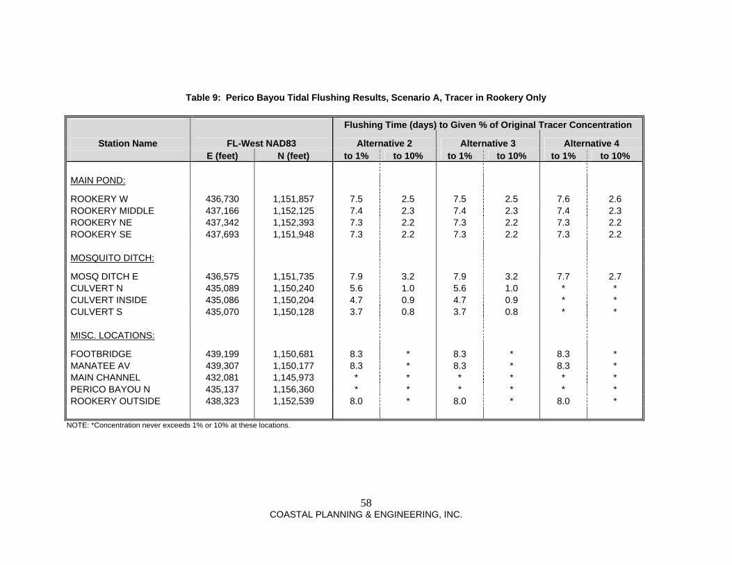
Stantec Consulting Services Inc 6900 Professional Parkway East Sarasota Florida 34240-8414 Tel (941) 907-6900 Fax (941) 907-6910
09042013 ndash RA us1227-f01workgroup2155active215510428env05_rpt-delivdeliverablesswfwmdrai_responsesubmittalltr_swfwmd_lopes_rai_response_2010904_finaldocx
Via E Submittal September 4 2013 File 215510428
Southwest Florida Water Management District 7601 Highway 301 North Tampa Florida 33637-6759 Attention Steven J Lopes PE (Engineering) and Tasha Bowers (Environmental) Reference Response to Request for Additional Information
Manatee County - Rookery at Perico Seagrass Advance Mitigation Application No 678237 County Manatee SecsTwpsRges 26 34 South 16 East 27 34 South 16 East
Dear Mr Lopes and Ms Bowers
On behalf of our Client Manatee County Natural Resources we provide the following responses to your request for additional information dated June 7 2013 The responses and associated information incorporate the results of discussions held between District staff and project representatives during the July 8 2013 meeting at the project site and on July 17 2013 at the Tampa Service Office ENVIRONMENTAL CONSIDERATIONS
1 Please identify how Manatee County complies with the provisions of Section 3734135(1)(b)
FS The application states ldquoMitigation credits will become available for use by other governmental agencieshelliprdquo Please identify what other governmental agencies will be using credits Additionally please identify if Port Manatee is a division of Manatee County or it is a separate entity Please be advised additional information may be required once the Request for Additional Information response has been received [Section 3734135(1)(b) FS] Manatee County no longer desires to permit this project as a designated Regional Offsite Mitigation Area (ROMA) The County desires to permit this project as a habitat creation project that is designed to create seagrass mangrove saltmarsh and other complimentary coastal habitats for the purpose of ecological enhancement However the County requests that the District acknowledge the proposed project may create habitats that could at some point in the future be utilized to provide offsite mitigation for projects proposed by Manatee County or other governmental agencies proposing coastal impacts in Manatee County Manatee County acknowledges the use of the site for offsite mitigation is not guaranteed and will require formal permit modification to determine the quantity of mitigation provided Should the site be considered as offsite mitigation the quantity of mitigation provided will be based on assessments conducted at that time based on comparison to baseline conditions as established by this permit
Response to Request for Additional Information Manatee County - Rookery at Perico Seagrass Advance Mitigation Application No 678237 September 4 2013 Page 2 of 13
09042013 ndash RA us1227-f01workgroup2155active215510428env05_rpt-delivdeliverablesswfwmdrai_responsesubmittalltr_swfwmd_lopes_rai_response_2010904_finaldocx
2 A Memorandum of Agreement is required for Regional Offsite Mitigation Areas that provide mitigation for five or more applicants for permits or for 35 or more acres of adverse impacts Therefore please provide the following information [Section 3734135(6) FS] Applicant no longer desires to permit project as a ROMA therefore Comments 2b through 2g are no longer applicable Comment 2a is applicable only to the Mangrove Mitigation Area proposed for the direct project impacts associated with the establishment of the flushing channels
a A timeline for completion of the proposed mitigation activities The proposed mitigation activities include the construction of a Mangrove Mitigation Area to offset the direct mangrove habitat impacts resulting from the construction of the flushing channels Grading and preparation of the Mangrove Mitigation Area will commence within 30 days of the start of project construction however planting of the Mangrove Mitigation Area will be completed within 60 days of the substantial completion of the flushing channel construction to insure the tidal regime is fully functional
b A cost estimate for establishing a management account which when funded will provide a continual source of interest that can be used for annual maintenance costs Not applicable
c Define the geographic area within which impact permits could use the project as mitigation Please definedescribe the types of communities that could be reasonably offset by the proposed mitigation This is known as the Mitigation Service Area (MSA) Since the proposed mitigation would be appropriate for estuarine habitats a custom service area may be more appropriate than the use of the entire watershed boundary Not applicable
d Provide an estimate of the entire cost of the project including mitigation activities monitoring management in the short and long-term overhead and administration and a per-credit total This cost must be paid for by the impact Permittee Specify to whom or where the payment would be deposited Further within the plan provide the mechanism of tracking this money Generally there are one or more separate accounts for acquisition implementation and long-term management Not applicable
e Provide a DRAFT conservation easement document for review and approval by the Districts Legal Department A conservation easement template document is available at wwwwatermattersorg Not applicable
f Provide a provision for application of all moneys received solely to the project for which they were collected Show that the money received actually goes entirely toward the mitigation project Not applicable
Response to Request for Additional Information Manatee County - Rookery at Perico Seagrass Advance Mitigation Application No 678237 September 4 2013 Page 3 of 13
09042013 ndash RA us1227-f01workgroup2155active215510428env05_rpt-delivdeliverablesswfwmdrai_responsesubmittalltr_swfwmd_lopes_rai_response_2010904_finaldocx
g Provide a provision for termination of the agreement and cessation of use of the project as mitigation if any material contingency of the agreement has failed to occur Not applicable
3 Please provide a statement that the proposed project associated with the Rookery at Perico Seagrass ROMA has not received any funds from the Districts Surface Water Improvement and Management (SWIM) program [Rule 40D-4301(1)(j) FAC] The portion of the project boundary that includes the proposed tidal basin and tidal connections has not received District SWIM funds for restoration or property purchase The entire Perico Preserve property was purchased as part of a settlement agreement and was not purchased for conservation purposes SWIM funds have been secured and utilized to complete restoration activities on the Perico Preserve site outside of the limits of the tidal basin area
4 Please provide details of any proposed barge use within Perico Bayou and if sufficient depths exist to avoid any impacts to the existing seagrass areas [Rule 40D-4301(1)(def) FAC] Note 14 on Sheet 13 of the Construction Plans specifies that all excavation and access shall be from within the project No construction equipment or vehicles barges included will be allowed to access the project area from Perico Bayou
5 The application indicates that public access and passive recreation was a required component associated with the grant stipulations and purchaserestoration of the property Please provide reasonable assurance that there will be no impacts to each of the proposed mitigation assessment areas as a result of canoekayak use wade fishing fishing line debris to wildlife etc [Subsections 327 and 335 of the Basis of Review] While the preserve will be open to public access and passive recreation will not be discouraged Manatee County intends for the property to be conservation focused Boat access will be restricted through the placement of boardwalk pilings with signage affixed if necessary Kayaks will be able to access the basin however the fact that the basin is a ldquodead-endrdquo and will normally be characterized by shallow water kayak use is likely to be minimal Manatee County will not provide a kayak launch into the basin Manatee County will not construct facilities to encourage fishing access from along the banks will be restricted through placement of natural barriers including vegetation The basin is intended to provide fish habitat for juvenile fish and will not likely be targeted by fishermen as a primary fishing location Manatee Countyrsquos plan to construct and manage a bird rookery in the basin increases the Countyrsquos desire to minimize any recreational activities that would be detrimental to the establishment and functioning of the bird rookery
6 Please provide the following information associated with the proposed construction plans [Rule 40D-4101(1)(ce) FAC]
a Please label the proposed top of bank width between 40-feet and 65-feet as stated in the written environmental information on the Sheet 9 Typical Outlet Channel Excavation section The proposed top of bank widths (which range from 40 feet to 68 feet) have been added to the Construction Plans Please reference Sheet 9 Typical Outlet Channel Excavation Section
Response to Request for Additional Information Manatee County - Rookery at Perico Seagrass Advance Mitigation Application No 678237 September 4 2013 Page 4 of 13
09042013 ndash RA us1227-f01workgroup2155active215510428env05_rpt-delivdeliverablesswfwmdrai_responsesubmittalltr_swfwmd_lopes_rai_response_2010904_finaldocx
b Provide the boardwalk shading impact acreages over the proposed seagrass areas and each of the existing created wetland areas The Construction Plans show two areas of potential shading impact associated with the boardwalk crossings of previously created wetland areas The shading impact is 160 square feet for Boardwalk 1 and 440 square feet for Boardwalk 2 as measured from top of bank to top of bank Applicant is not proposing compensatory mitigation for shading impacts because the impacts are minimal and associated with created wetlands There are no boardwalks proposed over the proposed seagrass area
c Show and label the proposed wetland boundary elevation and the proposed uplandbuffer (Planting Zone AB) on the plan view drawing Please reference Typical Planting Details on Sheet 10 of the Construction Plans showing the elevation of mean high water line (MHWL) and the horizontal limits of the proposed planting zones In addition the boundaries of planting zones are shown on the Plan View The specific wetland boundary elevation is not a fixed point and can only be delineated once the system is constructed and is functioning The wetland elevation may vary along the bank as a result of capillary action quantity of groundwater seepage and other local soil characteristics
d The length measurements shown on Table 4 Summary of Structures for the boardwalks do not correlate with the lengths of the boardwalks over the wetlandsurface water areas shown on Sheet 12 of the construction drawings Please reference the lengths shown on the revised ERP Application Table 4 Summary of Structures which identifies the boardwalk length that is within the limits of the top of bank The length dimension shown on the boardwalk details on Sheet 12 of the Construction Plans identifies the length of the upper portion of the boardwalk before the transitioning ramps that slope back down to existing grade on either side
e Show and label the proposed bagged shell and loose shell locations on the construction plans within Channel 1 and Channel 2 Please reference Plan and Section view for Typical Grading Detail on Sheet 11 of Construction Plans showing the location of the bagged and loose shell locations Due to the small scale of the shell placement areas these areas cannot be clearly depicted on the Grading Plan sheets
f Cross sectional drawing J-J shows the connection of the proposed Channels to Perico Bayou is at an elevation above mean low water Therefore flushing would not occur at the mean low tide Please revise the proposed Channel connections to an elevation below mean low tide Applicant acknowledges that Cross Section J-J depicts the flushing channel connection bottom elevation slightly above the -120 mean low water (MLW) elevation for Perico Bayou It is important to note that the bottom elevation shown on the plans is based on contours interpolated from numerous spot elevations surveyed within Perico Bayou The exact elevations across the flushing channel connection vary and the post-construction elevations across the connection may vary above and below the elevation shown as existing grade is matched Additionally flow at mean low water should still occur at the north connection and flushing will not be adversely impacted if flow is reduced at the mean low water elevation
Response to Request for Additional Information Manatee County - Rookery at Perico Seagrass Advance Mitigation Application No 678237 September 4 2013 Page 5 of 13
09042013 ndash RA us1227-f01workgroup2155active215510428env05_rpt-delivdeliverablesswfwmdrai_responsesubmittalltr_swfwmd_lopes_rai_response_2010904_finaldocx
The elevations shown in the plans were utilized in the model and therefore the flushing analysis represents the flow conditions based on the plans The Applicant does not believe that the flushing channel connection will adversely impact the success of the project
7 Detail on the Table 1 WetlandSurface Water summary each of the boardwalk shading impact acreages over the proposed seagrass areas and each of the existing created wetland areas [Rule 40D-4101(1)(b) FAC] Please reference the minimal shading impacts that have been added to the revised ERP Application Table 1
8 Detail on the Table 2 Mitigation summary each of the proposed mitigation assessment areas such as Seagrass Creation area1221 acres Natural Recruitment area127 acres Planting Zone A045acre Planting Zone B137 acres and the Rookery Island Planting area011 acre [Rule 40D-4101(1)(b) FAC] The project will no longer be permitted as a ROMA Therefore the attached ERP Application Table 2 has been updated to include only the Mangrove Mitigation Area providing compensation for direct project impacts
9 Please provide the following information associated with the proposed Mangrove Mitigation Zone
a Show and label the monitoring pointslocations on the plan view construction plans The proposed monitoring plan includes random transect locations as opposed to fixed transects The random transects are preferred for quantitative data collection as they evaluate the mitigation area without concern of transect location bias In addition fixed and marked transects often invite people in a park setting to investigate what the markers identify and potentially cause damage along the transect Please reference the included ldquoSupport Narrative and Documentation for SWFWMD ERP Application (revised August 27 2013)rdquo for additional monitoring plan details
b Please revise the success criteria to include an 85 aerial coverage of the mangrove assessment area instead of 50 aerial coverage The Applicant agrees to success criteria for the Mangrove Mitigation Zone that includes 85 areal coverage within five (5) years
c Please include Spartina alterniflora to be planted within the Mangrove Planting Zone to promote the stability of soils and the planted and recruited propagules of the Red Mangroves The Applicant has revised the planting plan to include Spartina alterniflora as an additional measure to increase the success potential and diversity of the Mangrove Mitigation Area Please reference the revised Seagrass Basin Slope Planting Specifications on Sheet 10 of the Construction Plans
Response to Request for Additional Information Manatee County - Rookery at Perico Seagrass Advance Mitigation Application No 678237 September 4 2013 Page 6 of 13
09042013 ndash RA us1227-f01workgroup2155active215510428env05_rpt-delivdeliverablesswfwmdrai_responsesubmittalltr_swfwmd_lopes_rai_response_2010904_finaldocx
d The Mangrove Mitigation Zone is a separate assessment area from the future mitigation areas to be evaluated Each mitigation assessment area should be clearly defined on the construction drawings The Mangrove Mitigation Zone is specifically labeled on the Mitigation Planting Plan and Details plan view and typical planting detail on Sheet 10 of the Construction Plans
10 Please revise the success criteria for vegetative coverage of the proposed Mangrove Credit Area (not the Mangrove Mitigation Zone) to 85 aerial coverage The District agrees a tree height is not required Provide a proposed ldquotime zerordquo annual report including the activities conducted for each year and the seagrass habitat established each year until the ROMA has reached full success [Subsection 3332 of the Basis of Review] The Applicant is no longer requesting the establishment of a ROMA and therefore this comment is no longer applicable
11 Please provide the following information associated with the proposed Seagrass Creation Area [Subsection 3332 of the Basis of Review]
a Provide a proposed ldquotime zerordquo annual report including the activities conducted for each year and the seagrass habitat established each year until the ROMA has reached full success This comment is no longer applicable
b Include in the annual monitoring events the survival and expansion of the planted seagrass in order to monitor the trend toward success or failure of the mitigation area This comment is no longer applicable
c Show and label the proposed monitoring transects within the seagrass mitigation creation area This comment is no longer applicable
d Once the construction area is completed and plantings are installed annual monitoring will commence until the success criteria have been met This comment is no longer applicable
e The assessment areas for the Continuous and Patchy seagrasses will be discussed in further detail during the field evaluation of the proposed project Please contact District Senior Environmental Scientist Lisa Cartwright to arrange for this activity This comment is no longer applicable
12 Please identify which method of seagrass restoration is being proposed and in which location within the seagrass creation assessment area A seagrass donor site within the project area or off-site will need to be authorized through an Environmental Resource Permit [Subsection 3332 of the Basis of Review]
Response to Request for Additional Information Manatee County - Rookery at Perico Seagrass Advance Mitigation Application No 678237 September 4 2013 Page 7 of 13
09042013 ndash RA us1227-f01workgroup2155active215510428env05_rpt-delivdeliverablesswfwmdrai_responsesubmittalltr_swfwmd_lopes_rai_response_2010904_finaldocx
a Transplanting a sod patch of seagrass is the most successful means of mitigation however the donor site will need to be monitored Please provide a monitoring plan for any proposed donor site Although the Applicant is no longer requesting the establishment of a ROMA the Applicant desires to retain the ability to conduct seagrass transplanting for the purposes of habitat creation Please reference the included ldquoSupport Narrative and Documentation for SWFWMD ERP Application (revised August 27 2013)rdquo for seagrass donor area selection and monitoring details
b Show and label the Seagrass Donor Area as shown in Figure A1 on the construction drawings Show on the plan view drawings the harvested locations and the distance between each harvest area Additionally provide the percentage of seagrass area remaining within the donor site Although the Applicant is no longer requesting the establishment of a ROMA the Applicant desires to retain the ability to conduct seagrass transplanting for the purposes of habitat creation The Applicant requests the flexibility to select the specific seagrass donor area(s) prior to the commencement of transplanting activities The donor areas will be selected based on current seagrass community conditions which may differ from conditions that exist now The Applicant will prepare plan view drawings depicting the proposed seagrass donor locations within the seagrass donor area harvesting details (eg spacing size and quantity) and a description of the seagrass community prepost harvesting Please reference the included ldquoSupport Narrative and Documentation for SWFWMD ERP Application (revised August 27 2013)rdquo for seagrass donor area selection and monitoring details
c Please confirm that the Applicant ownscontrols the seagrass donor site Additionally show and label on the construction drawings the property boundaries adjacent to the Donor site Proof that Manatee County owns the seagrass donor site was provided with the original application submittal and included the property legal description Manatee County Property Appraiser property listing report FDEP SSL determination letter (dated January 18 2013) Deed No 22765 Map Exhibit and a copy of Recorded Deed No 22765 Property boundary and Seagrass Donor Area will be depicted on Construction Plans
d Please include the Donor Site within the project area and provide a revised project acreage if the Donor Site is proposed within this permit authorization Please reference Sheet 2 on the revised Construction Plans The revised project area including the seagrass donor area is 289 plusmn acres
e Seagrass plugs will take a longer amount of time to coalesce at the mitigation site The Applicant will evaluate planting methods and chose a planting method appropriately suited for the planting location the donor site and growing conditions
f Natural recruitment is not a viable option because seagrasses in this area recruit via vegetative growth (rhizome expansion) There is no documentation of sexual reproduction in this area Accordingly please remove natural recruitment as an implementation option Seagrass habitat mitigation credit is no longer a component of this permit application However significant vegetative recruitment of shoalgrass has been observed within the
Response to Request for Additional Information Manatee County - Rookery at Perico Seagrass Advance Mitigation Application No 678237 September 4 2013 Page 8 of 13
09042013 ndash RA us1227-f01workgroup2155active215510428env05_rpt-delivdeliverablesswfwmdrai_responsesubmittalltr_swfwmd_lopes_rai_response_2010904_finaldocx
created interior tidal waters at Robinson Preserve to the north of the project site and vegetative recruitment does frequently occur within the region
13 Please provide reasonable assurance the sediment from the recently created pond will not flush out material into the adjacent existing seagrass areas as occurred at Robinson Park located northeast of Perico Bayou [Rule 40D-4301(1)(def) FAC] The Perico Preserve Habitat Restoration Modeling Study results prepared by Coastal Planning amp Engineering Inc (CPE) show the velocities within the proposed flushing channels to be less than 03 feet per second (fps) The permissible channel velocity for a channel excavated in fine sand is 15 fps (Table 3-1 Erosion and Sedimentation Manual US Department of the Interior Bureau of Reclamation 2006) Therefore the model results show the velocities within the seagrass basin and the flushing channels are well below the permissible velocities which should provide reasonable assurance that sediment from the ldquorecently created pondrdquo should not flush material into the adjacent existing seagrass areas
14 The construction plans show a Rookery Island in the center of the proposed seagrass mitigation area This area will provide a constant nutrient source into the surrounding water column primarily from bird guano Please provide reasonable assurance there is sufficient flushing within the mitigation area in order to avoid excess nutrients causing algal blooms increased shading within the water column and seagrass mortality [Rule 40D-4101(1)(e) FAC] Results of the 3D modeling indicate that flushing of a pollutant from within the seagrass basin is similar to the flushing that currently occurs within Perico Bayou Also the rookery island has been designed such that the area under the proposed bird nesting area will flush with regularly occurring tides to reduce the potential for the accumulation of bird guano and subsequent release of large quantities of guano during high tide events
15 Provide details of any stormwater discharge that the seagrass creation area will receive to flush new nutrients into Perico Bayou and potentially adversely affect the existing adjacent seagrasses [Rule 40D-4101(1)(e) FAC] Review of the Construction Plans shows that there are no stormwater facilities discharging to the seagrass creation area Review of the topography and land use of the site shows the area contributing to the seagrass creation area is mainly the seagrass creation area its side slopes and a very limited portion of the Perico upland restoration area As there are no existingproposed stormwater facilities discharging to the seagrass creation area and the land use from the limited contributing area surrounding the seagrass creation area is an upland restoration area no significant new nutrients are expected to be discharged into the seagrass creation area and flushed into Perico Bayou
16 Please provide reasonable assurance the sediment type within the recently excavated pond is compatible for seagrass growth within the creation area [Section 3332 of the Basis of Review] Seagrass habitat mitigation credit is no longer a component of this permit application However the seagrass species likely to colonize the seagrass basin are known to grow in areas with a wide range of sediment types including silty mud sands pea gravel and even rock with a thin veneer of sediment While sediment type does influence rate of colonization stability of established seagrass beds and the short shoot density sediment type is typically a less critical component than the water environment The fine
Response to Request for Additional Information Manatee County - Rookery at Perico Seagrass Advance Mitigation Application No 678237 September 4 2013 Page 9 of 13
09042013 ndash RA us1227-f01workgroup2155active215510428env05_rpt-delivdeliverablesswfwmdrai_responsesubmittalltr_swfwmd_lopes_rai_response_2010904_finaldocx
sand present within the proposed seagrass basin is suitable sediment for the colonization and growth of seagrasses
17 Please contact Senior Environmental Scientist Lisa Cartwright at the Tampa Service Office to schedule a field review of the proposed UMAM evaluations and assessment areas for each mitigation area Additionally final credit approval pre andor post permitting for each assessment area may also be discussed at that time Additional information may be required based on the final UMAM scores and assessment area determinations [Rule 62-345 FAC] The field review was conducted on July 8 2013 with John Emery Bonnie Irving and Tasha Bowers present The impact and mitigation UMAM assessments were discussed briefly Email correspondence from Tasha Bowers was received by Ryan Horstman on July 23 2013 which included the Districtrsquos comment on the Mangrove Mitigation Zone UMAM and Districtrsquos acceptance of the channel connections Impact UMAM The UMAM for the Mangrove Mitigation Zone has been revised per District comment and is included with this submittal
18 Please provide additional details for the Long-Term maintenance of each mitigation assessment area including maintaining each area per the approved success criteria including an annual monitoring report for each of the assessment areas within the ROMA [Section 334 of the Basis of Review and Section 3734135(6) FS] The Mangrove Mitigation Zone is the only mitigation assessment area currently proposed The Applicant believes the previously proposed long-term maintenance details are sufficient and has included those details in the attached ldquoSupport Narrative and Documentation for SWFWMD ERP Application (revised August 27 2013)rdquo
19 Please address the following regarding the tidal exchange analysis report Please note that the responses to Comment 19a through 19f below have been provided by CPE the Applicantrsquos coastal modeling consultant Dr Samantha Danchuk PE has discussed these comments and responses with Dr Chen
a Please clarify if current data was collected and used for model calibration or clarify how the effects of currents are otherwise reflected in the model Water level data from tide gages deployed during the study was used to calibrate the model Current data was not collected nor used for calibration Currents were simulated and reported for select observation points within the model A discussion of the effects of the simulated currents on flow direction and velocity was presented for each alternative in the report
b It appears that the magnitude of current through the culvert could be over-predicted because the friction of the two vertical side walls of the culvert was not included in the model Discussion of the culvert is not relevant to the proposed design alternative in this application as the mosquito ditch is not proposed to be cut
c In first paragraph of Section 41 ldquoeastern side of the gridrdquo should be ldquowestern side of the gridrdquo Corrected Revised page 17 attached
slopes
Highlight
Response to Request for Additional Information Manatee County - Rookery at Perico Seagrass Advance Mitigation Application No 678237 September 4 2013 Page 10 of 13
09042013 ndash RA us1227-f01workgroup2155active215510428env05_rpt-delivdeliverablesswfwmdrai_responsesubmittalltr_swfwmd_lopes_rai_response_2010904_finaldocx
d Please explain how the upstream or upstream side of the culvert (or Manatee Ave bridge) is decided when flood and ebb currents through the culvert (bridge) were discussed It appears that there is a contradiction when the terms lsquofloodrsquo and lsquoebbrsquo currents were used in Figures 25 38 and 39 As previously stated the culvert is not relevant to the proposed design alternative Within the culvert the flood direction was assumed to be towards the north which is the existing inland direction South is the ebb direction towards Spoonbill Bay
e Please revisit the units of current velocity in Figures 25 ndash 26 and 40 ndash 42 (eets should be feets and feetseconds should be feetsecond) Corrected Revised pages 31 32 54 55 and 56 attached
f The flushing time is an important parameter in describing transport characteristics for estuaries Although there are some variations of definition for flushing time it is generally a bulk parameter that is used to measure the turnover time of fresh water in an estuary Please justify the way that the flushing time was calculated in the modeling study Please contact Xinjian Chen PE at extension 2215 to discuss in detail [Rules 40D-4101(1)(c) and 40ED-4301(1)(d)(e) FAC] A conservative tracer was placed inside the seagrass basin area in order to evaluate the potential for pollutant dispersal and sediment transport As these parcels of tracer moved and spread into the estuary their concentration was diluted Residence time could be approximated as the time it takes to reach 1 concentration when nearly all tracer parcels have exited the study area These results were presented in Tables 8 (page 57) and 9 (page 58) in the report
SITE INFORMATION
20 Please clarify the following regarding the tidal exchange analysis results Please note that the responses to Comment 20a through 20c below have been provided by CPE the Applicantrsquos coastal modeling consultant Dr Samantha Danchuk PE has discussed these comments and responses with Dr Chen
a The conclusion (page 68) indicates ldquounder the existing conditions roughly 6 to 8 days would be required to dilute a pollutant released inside Perico Bayou and Spoonbill Bay to 10 of its original concentration in those two water bodiesrdquo However Table 8 indicates flushing time of 0-days for Alternative 1 at Perico Bayou The Perico Bayou observation station is at the far north end of the study area where the bayou connects to Tampa Bay By the time the tracer reaches this station before the end of the first day the tracerrsquos concentration is less than 1 of its initial concentration As a result the flushing times for Perico Bayou were listed as zero days Table 8 (page 57) has been revised to state the flushing time is less than one day As an additional note Spoonbill Bay is no longer included in the project area
slopes
Highlight
slopes
Highlight
slopes
Highlight
slopes
Highlight
Response to Request for Additional Information Manatee County - Rookery at Perico Seagrass Advance Mitigation Application No 678237 September 4 2013 Page 11 of 13
09042013 ndash RA us1227-f01workgroup2155active215510428env05_rpt-delivdeliverablesswfwmdrai_responsesubmittalltr_swfwmd_lopes_rai_response_2010904_finaldocx
b The conclusion (page 68) indicates ldquounder the with-project conditions roughly to 6 to 9 days would be required to dilute a pollutant released inside Perico Bayou Spoonbill Bay and the projectrsquos main pond to 10 of its original concentration in those areasrdquo However Table 8 indicates flushing time of 0-days for Alternatives 1 3 and 4 at Perico Bayou The Perico Bayou observation station is at the far north end of the study area where the bayou connects to Tampa Bay By the time the tracer reaches this station before the end of the first day the tracerrsquos concentration is less than 1 of its initial concentration As a result the flushing times for Perico Bayou were listed as zero days Table 8 (page 57) has been revised to state the flushing time is less than one day As an additional note Spoonbill Bay is no longer included in the project area
c The conclusion (page 68) indicates ldquounder the with-project conditions roughly to 6 to 9 days would be required to dilute a pollutant released inside Perico Bayou Spoonbill Bay and the projectrsquos main pond to 10 of its original concentration in those areasrdquo However Table 9 indicates flushing time never exceeds 1 or 10 for Alternatives 2 3 and 4 at Perico Bayou Table 9 is correct There are multiple model observation stations within Perico Bayou including ldquoRookery Outsiderdquo and ldquoPerico Bayou Nrdquo from Tables 8 and 9 The flushing time at ldquoPerico Bayou Nrdquo may not exceed 1 however the flushing time at ldquoRookery Outsiderdquo is 8 days The conclusion statement has been revised to a flushing time of 8 days Revised page 68 is attached
d Previous project concepts included creating new connections with the existing mosquito ditches andor modifying the existing mosquito ditches Please verify that construction as currently proposed with this application does not include any new interconnections or modifications to the existing mosquito ditches
The construction as currently proposed does not include any connections to the existing mosquito ditches
e Please provide a detailed narrative describing (based on the tidal exchange modeling results and other pertinent factors) how reasonable assurance is provided that the proposed seagrass will thrive under proposed conditions
Seagrass habitat mitigation credit is no longer a component of this permit application However the project design focused on providing seagrass growing conditions that are similar to immediately adjacent portions of Perico Bayou that contain extensive healthy seagrass beds Establishing a suitable water environment is an important component of seagrass habitat creation The tidal exchange model results were utilized to evaluate the whether the water environment within the seagrass basin would flush pollutant loads in a manner similar to Perico Bayou The results demonstrate the flushing characteristics within the seagrass basin are similar to those in Perico Bayou that contain natural seagrass beds The tidal exchange results also demonstrate tidal fluctuations will occur similar to Perico Bayou and the proposed bottom depth (-20rsquo NAVD) will provide sufficient water depths for the colonization and persistence of seagrass
CONSTRUCTION SCHEDULE AND TECHNIQUES 21 Sarasota Bay Estuarine System is a designated special Outstanding Florida Waters (OFW) For
projects located wholly or partially within 100 feet of an OFW or within 100 feet of any wetland abutting an OFW applicants must provide reasonable assurance that the proposed construction
slopes
Highlight
Response to Request for Additional Information Manatee County - Rookery at Perico Seagrass Advance Mitigation Application No 678237 September 4 2013 Page 12 of 13
09042013 ndash RA us1227-f01workgroup2155active215510428env05_rpt-delivdeliverablesswfwmdrai_responsesubmittalltr_swfwmd_lopes_rai_response_2010904_finaldocx
or alteration of a system will not cause sedimentation in the OFW or adjacent wetlands and that filtration of all runoff will occur prior to discharge into the OFW or adjacent wetlands
a Reasonable assurance is presumed if in addition to implementation of the requirements in Basis of Review Section 28 any one or more of the Basis of Review Subsection 283 measures are implemented Erosion and sediment control measures are shown on the Construction Plans for the project However construction of the project requires the excavation of two tidal channels through wetlands adjacent to Perico Bayou Therefore the presumptive measures per Basis of Review Section 28 are not practical and the applicant is submitting a Construction Turbidity Monitoring Plan with temporary mixing zones provided on Sheet 14 of the revised Construction Plans for review and approval
b If the presumptive measures per Basis of Review Section 28 are not practical the District may consider other site specific proposals that provide required reasonable assurance For example temporary mixing zones (per Basis of Review Subsection 3244) could be requested and a construction turbidity monitoring plan provided [Rules 40D-4101(1)(c) and 40D-4301(1)(d)(e) FAC] As described above the presumptive measures per Basis of Review Section 28 are not practical and Sheet 14 of the Construction Plans has been revised to include a Construction Turbidity Monitoring Plan with temporary mixing zones for review and approval as part of this response
22 If mixing zones (for turbidity) and a construction turbidity monitoring plan will be provided please ensure the following are addressed [Rules 40D-4101(1)(c) and 40D-4301(1)(d)(e) FAC]
a Please specify in the turbidity monitoring plan that OFW rules do not allow any increase in turbidity (zero NTUrsquos above normalbackground) outside the approved temporary mixing zone(s) See paragraph 3 of the Construction Turbidity Monitoring Plan on the enclosed Sheet 14 of the Construction Plans
b Please specify in the turbidity monitoring plan that OFW rules only allow a maximum 41 NTU increase in turbidity (above normalbackground levels) within the approved temporary mixing zone(s) See paragraph 3 of the Construction Turbidity Monitoring Plan on the enclosed Sheet 14 of the Construction Plans
c Please delineate the limits of the requested mixing zone(s) See enclosed Sheet 14 of the Construction Plans
d Please showlabel the proposed turbidity sampling locations (within the mixing zone and just outside the mixing zone) The number of sampling locations should be commensurate with the size of the project area along the OFW See enclosed Sheet 14 of the Construction Plans
Response to Request for Additional Information Manatee County - Rookery at Perico Seagrass Advance Mitigation Application No 678237 September 4 2013 Page 13 of 13
09042013 ndash RA us1227-f01workgroup2155active215510428env05_rpt-delivdeliverablesswfwmdrai_responsesubmittalltr_swfwmd_lopes_rai_response_2010904_finaldocx
e Please showlabel the background sample location The background sample location should be adequately distant from the project area so as not to be affected by any potential turbidity from the project See enclosed Sheet 14 of the Construction Plans
Please contact our office with any questions you may have regarding this submittal Sincerely STANTEC CONSULTING SERVICES INC Michael AG Burton CEP Principal Environmental Management Ph 9419076900 x488 Fx 9419076910 mikeburtonstanteccom Attachments Revised Construction Plans (Sheets 1-14) dated September 4 2013
Revised ERP Application Tables 1-5 Revised Support Narrative and Documentation for SWFWMD ERP Application dated August 27 2013 Revised Perico Preserve Habitat Restoration Modeling Study (Sheets 17 31 32 54-58 and 68) dated December 2012
C Charlie Hunsicker Director - Manatee County Natural Resources Max Dersch Division Manager - Manatee County Natural Resources
FORM 54727ERP (0811)
TABLE ONE PROJECT WETLAND AND OTHER SURFACE WATER SUMMARY
WL amp SW
ID
WL amp SW
TYPE
WL amp SW
SIZE
WL amp SW
NOT IMPACTED
TEMPORARY
WL amp SW IMPACTS
PERMANENT
WL amp SW IMPACTS
MITIGATION
AREA ID
WL amp SW
TYPE
IMPACT
SIZE
IMPACT
TYPE
WL amp SW
TYPE
IMPACT
SIZE
IMPACT
TYPE
PROJECT TOTALS
Comments Note WL=Wetland SW=Other Surface Water ID=Identification number letter etc Wetland Type from an established wetland classification system Impact Type D=dredge F=fill H=change hydrology S=shading C=clearing O=other Multiple entries per cell not allowed except in the Mitigation ID column If more than one impact is proposed in a given area indicate the final impact
Surface Water 2 510 - Ditch 005 000 510 - Ditch 004 D 510 - ditch 001 F NA
Perico Bayou 612 - Mangrove 612 - Mangrove 041 DMangrove Mitigation
Zone
Perico Bayou 540 - Estuary 540 - Estuary 004 D
Perico Bayou612 - Mangrove
(disturbed)612 -Mangrove
(disturbed) 001 F NA
Created Wetland(ERP
40580 000)
641 - Marsh(created) 121 1206
641-Marsh(created)
0004S NA
Created Wetland(ERP
40091 001)
641-Marsh(created) 097 096
641-Marsh(created)
001S NA
Seagrass Basin911 - Seagrass
(created) 164 1632911 - Seagrass
(created)008
S NA
008 acre 052 acre
08272013 - RHus1227-f01workgroup2155active215510428env05_rpt-delivdeliverablesswfwmdrai_responsefrm_erp_revised_tables_20130827pdf
FORM 54727ERP (0811)
TABLE TWO PROJECT ON-SITE MITIGATION SUMMARY
MITIGATION AREA ID
CREATION
RESTORATION
ENHANCEMENT
WETLAND PRESERVE
UPLAND
PRESERVE
OTHER
AREA
TARGET
TYPE
AREA
TARGET
TYPE
AREA
TARGET
TYPE
AREA
TYPE
AREA
TYPE
AREA
TARGET
TYPE
PROJECT TOTALS
COMMENTS NOTE Target Type or Type=target or existing habitat type from an established wetland classification system or land use classification for non-wetland mitigation
Multiple entries per cell not allowed
Mangrove MitigationZone 050 ac
612 -Mangrove
050 ac
08272013 - RHus1227-f01workgroup2155active215510428env05 rpt-delivdeliverablesswfwmdrai responsefrm erp revised tables 20130827pdf
FORM 54727ERP (0811) RULE 40D-4101(1)(b) FAC
TABLE THREE PROJECT OFF-SITE MITIGATION SUMMARY
MITIGATION
AREA ID
CREATION
RESTORATION
ENHANCEMENT
WETLAND PRESERVE
UPLAND
PRESERVE
OTHER
AREA
TARGET
TYPE
AREA
TARGET
TYPE
AREA
TARGET
TYPE
AREA
TYPE
AREA
TYPE
AREA
TARGET
TYPE
PROJECT TOTALS
COMMENTS
Target Type=target or existing habitat type from an established wetland classification system or land use classification for non-wetland mitigation
NOTE Multiple entries per cell not allowed
08272013 - RHus1227-f01workgroup2155active215510428env05 rpt-delivdeliverablesswfwmdrai responsefrm erp revised tables 20130827pdf
FORM 54727ERP (0811) RULE 40D-4101(1)(b) FAC
TABLE FOUR SUMMARY OF STRUCTURES OVER WETLANDS AND OTHER SURFACE WATERS
STRUCTURES
TYPE OF WORK
LENGTH
WIDTH
HEIGHT
TOTAL AREA
PROPOSED
SLIPS
EXISTING
SLIPS
FOR EACH
DOCK OR PIER
PLEASE
COMPLETE
FOR EACH FINGER PIER
PLEASE
COMPLETE
FOR EACH
OTHER WATER
STRUCTURE
PLEASE COMPLETE
TOTAL
Type of Work N=new R=replaced O=other RR=removed A=alteredmodified
Primary use of proposed structures ____________________________________________________________________________________________________ Will the docking facility provide
Live aboard slips If yes provide number ____________________________________________________________________________________________ Fueling facilities If yes provide number ____________________________________________________________________________________________ Sewage pumpout facilities If yes provide number ____________________________________________________________________________________ Other Supplies or Services If yes specify __________________________________________________________________________________________
Type of materials for decking and pilings (eg CCA pressure treated wood plastic concrete) Pilings _______________________________________________________________________________________________________________________ Decking ______________________________________________________________________________________________________________________
Deck plank spacing _________________________________________________________________________________________________________________ Number of boats grouped by length type and draft expected to use the facility ________________________________________________________________
N - Boardwalk 1 20 8 4 160 sq ft 0 0
N - Boardwalk 2 55 8 55 440 sq ft 0 0
N - Boardwalk 3 125 8 7 1000 sq ft 0 0
N - Boardwalk 4 60 8 7 480 sq ft 0 0
N - Boardwalk 5 236 8 7 1888 sq ft 0 0
N - Boardwalk 6 18 24 2 432 sq ft 0 0
4400 sq ft 0 0
pedestrian activities
NA
NA
NA
NA
Pressure treated wood
14 to 12
ZERO - motorized vessels to be prohibited within seagrass basinchannels and from docking at pier
08272013 - RHus1227-f01workgroup2155active215510428env05 rpt-delivdeliverablesswfwmdrai responsefrm erp revised tables 20130827pdf
PVC wrapped (1 above MHW to 1 below sediment) pressure treated wood or CCA
FORM 54727ERP (0811) RULE 40D-4101(1)(b) FAC
TABLE FIVE SUMMARY OF SHORELINE STABILIZATION
STABILIZATION
LINEAR FEET NEW
LINEAR FEET REPLACED
LINEAR FEET REMOVED
SLOPE H V
WIDTH AT THE TOE
VERTICAL SEAWALL
SEAWALL AND RIPRAP
RIPRAP
RIPRAP AND VEGETATION
OTHER TYPE
SIZE OF RIPRAP TYPE OF RIPRAP
1140 4 1 9 inches
3 minimum (washed shell) for stabilization and habitat creation
Large washed shell (loose) and 9-inch diameter mesh bagged large washed shell
08272013 - RHus1227-f01workgroup2155active215510428env05 rpt-delivdeliverablesswfwmdrai responsefrm erp revised tables 20130827pdf
SHELL
PERICO PRESERVE HABITAT RESTORATION MODELING STUDY MANATEE COUNTY FL
Prepared for
Manatee County Florida
Prepared by
Coastal Planning amp Engineering Inc 2481 NW Boca Raton Blvd
Boca Raton FL 33431
December 2012
rhorstman
Text Box
Revised Pages 17 31 32 54 55 56 57 58 and 68 from
17 COASTAL PLANNING amp ENGINEERING INC
Bathymetry over the Calibration Grid and the Local Flow Grid was based on the 2012 surveys by Stantec followed by the July 2012 LIDAR survey the USGS (2004) Digital Elevation Models and the 1953-1954 hydrographic surveys by NOAA (see Table 1) Similar to the Regional Flow Grid the most recent data sources were used first followed by the remaining data sources going back in time Bathymetry and topography over the Local Flow Grid appears in Figure 13 and Figure 14 The bathymetry and topography over the Calibration Grid is similar in appearance 4 MODEL CALIBRATION 41 Model Forcing Initial calibration of the Delft3D-FLOW model was performed using the water level measurements in Figure 4 and the Calibration Grid Water levels at the Perico Bayou tide gage provided the forcing on the northern side of the grid (see thin black line in Figure 4 and pink line in Figure 13) Water levels at the Main Channel tide gage provided the forcing on the western side of the grid (see blue dashed line in Figure 4 and pink line in Figure 13) Output from the model was evaluated at the Foot Bridge (see Figure 3 and orange dashed line in Figure 4) Additional model forcing was provided using wind and rainfall measurements at ANMF1 (USF 2012) (see Figure 15 and Figure 16) Wind speeds ranged from 0 to 29 mph with the highest wind speeds occurring on June 20 Daily rainfall was on the order 1 to 2 inches Rainfall values were comparable to those at the SarasotaBradenton Airport during the end of the calibration period During the beginning of the calibration period ANMF1 reported more rainfall than occurred at the airport It should also be noted that there were a few periods (June 15-18) during which the weather instrumentation at ANMF1 malfunctioned 42 Calibration Parameters Calibration of the model was conducted by varying the value of Manningrsquos n which was used as the bottom friction coefficient in the Delft3D-FLOW model All other model parameters were set to their default values As shown in Figure 7 much of the seafloor surrounding the project area is covered by seagrass Seagrass beds often increase the bottom friction The way to account for this effect is to increase the value of Manningrsquos n by 0010 to 0030 (Lloyd Environmental 2006 Hauck and Brown 1990 Loder 2008) To assess the sensitivity of the water levels to variable friction the schematizations listed in Table 4 were examined
31 COASTAL PLANNING amp ENGINEERING INC
Figure 25 Simulated Currents and Water Levels in the Culvert Interior Final Calibration
32 COASTAL PLANNING amp ENGINEERING INC
Figure 26 Simulated Currents under the Manatee Avenue Bridge Final Calibration
At the Manatee Avenue bridge the predominant direction of the current during the calibration period is from south to north (see Figure 26) This is due to the characteristics of the observed water levels that were used to drive the model It should be noted that the calibration period included the effects of Tropical Storm Debby Over the calibration period the water levels at the Main Channel tide gage were 013 to 036 feet higher than those at the Perico Bayou tide gage (see Figure 4) As a result estimated currents near the Manatee Avenue bridge were from north to south during the majority of the calibration period Given the final calibration results the schematization of the bottom friction and the magnitudes of the currents were acceptable However assessment of the typical flow patterns and flushing times suggested the model would require model inputs that would be more representative of average conditions As a result the production runs were not driven by water levels observed during Tropical Storm Debby but rather water levels that are more representative of average conditions Modeling parameters used in the final calibration and subsequent model simulations appear in Table 6
54 COASTAL PLANNING amp ENGINEERING INC
Figure 40 Simulated Currents in the Culvert Interior under Average Conditions Given Alternatives
1 and 2
Current (feetsecond) Current (feetsecond)
55 COASTAL PLANNING amp ENGINEERING INC
Figure 41 Simulated Currents outside the South End of the Culvert under Average Conditions
Given Alternatives 1 and 2
Current (feetsecond) Current (feetsecond)
56 COASTAL PLANNING amp ENGINEERING INC
Figure 42 Simulated Currents under the Manatee Avenue Bridge under Average Conditions
Given Alternatives 1 and 2
Current (feetsecond) Current (feetsecond)
57 COASTAL PLANNING amp ENGINEERING INC
Table 8 Perico Bayou Tidal Flushing Results Scenario B Tracer in Spoonbill Bay Perico Bayou amp Rookery
Flushing Time (days) to Given of Original Tracer Concentration
Station Name FL-West NAD83 Alternative 1 Alternative 3 Alternative 4 E (feet) N (feet) to 1 to 10 to 1 to 10 to 1 to 10 MAIN POND
ROOKERY W 436730 1151857 142 70 116 64 ROOKERY MIDDLE 437166 1152125 132 63 115 63 ROOKERY NE 437342 1152393 124 62 113 62 ROOKERY SE 437693 1151948 124 62 122 62 MOSQUITO DITCH
MOSQ DITCH E 436575 1151735 152 80 117 64 CULVERT N 435089 1150240 gt 16 76 gt 16 77 gt 16 83 CULVERT INSIDE 435086 1150204 gt 16 74 gt 16 73 gt 16 79 CULVERT S 435070 1150128 gt 16 73 gt 16 73 gt 16 74 SPOONBILL BAY
SPOONBILL BAY N 435080 1149409 gt 16 69 gt 16 70 gt 16 68 SPOONBILL BAY S 435019 1148577 gt 16 63 gt 16 63 gt 16 63 MISC LOCATIONS
FOOTBRIDGE 439199 1150681 122 67 133 72 129 72 MANATEE AV 439307 1150177 123 69 133 73 131 73 MAIN CHANNEL 432081 1145973 58 58 58 PERICO BAYOU N 435137 1156360 10 lt10 10 lt10 10 lt10 ROOKERY OUTSIDE 438323 1152539 111 59 122 69 121 69
NOTE Concentration never exceeds 1 or 10 at these locations
58 COASTAL PLANNING amp ENGINEERING INC
Table 9 Perico Bayou Tidal Flushing Results Scenario A Tracer in Rookery Only Flushing Time (days) to Given of Original Tracer Concentration
Station Name FL-West NAD83 Alternative 2 Alternative 3 Alternative 4 E (feet) N (feet) to 1 to 10 to 1 to 10 to 1 to 10 MAIN POND
ROOKERY W 436730 1151857 75 25 75 25 76 26 ROOKERY MIDDLE 437166 1152125 74 23 74 23 74 23 ROOKERY NE 437342 1152393 73 22 73 22 73 22 ROOKERY SE 437693 1151948 73 22 73 22 73 22 MOSQUITO DITCH
MOSQ DITCH E 436575 1151735 79 32 79 32 77 27 CULVERT N 435089 1150240 56 10 56 10 CULVERT INSIDE 435086 1150204 47 09 47 09 CULVERT S 435070 1150128 37 08 37 08 MISC LOCATIONS
FOOTBRIDGE 439199 1150681 83 83 83 MANATEE AV 439307 1150177 83 83 83 MAIN CHANNEL 432081 1145973 PERICO BAYOU N 435137 1156360 ROOKERY OUTSIDE 438323 1152539 80 80 80
NOTE Concentration never exceeds 1 or 10 at these locations
68 COASTAL PLANNING amp ENGINEERING INC
7 CONCLUSIONS Using the Delft3D-FLOW model tidal flushing was evaluated in Perico Bayou Spoonbill Bay and the main pond to be constructed as part of the Perico Preserve Habitat Restoration Calibration of the model was conducted using water levels collected in June 2012 which were characterized by heavy rains To examine tidal flushing over more typical conditions tidal flushing patterns given the existing conditions the preliminary project design and the most recent project design were evaluated using water levels from an earlier period characterized by average weather conditions Overall the findings of the tidal flushing evaluations were the following
The major effects of the project on flow during average conditions would be limited to the immediate project area Outside the immediate project area project-induced changes in currents would be small (~03 feetsecond) or negligible
Overall the main conduits for the flushing of the Habitat Restorationrsquos main pond will be the two cuts connecting it to Perico Bayou
Given the release of a pollutant inside the projectrsquos main pond only the times required to dilute the pollutant to 10 and 1 of its initial concentration in the immediate project area would be 2 to 3 days and 7 to 8 days respectively Most of the flushing would occur through the two cuts connecting the main pond to Perico Bayou As such a clog in the mosquito ditch that connects the pond to Spoonbill Bay would not have a significant impact on flushing times The amount of time required to flush the pollutant out of Perico Bayou and Palma Sola Bay as a whole would be on the order of 8 to 11 days
Under the existing conditions roughly 6 to 7 days would be required to dilute a pollutant released inside Perico Bayou and Spoonbill Bay to 10 of its original concentration in those two water bodies
Under the with-project conditions roughly 8 days would be required to dilute a pollutant released inside Perico Bayou Spoonbill Bay and the projectrsquos main pond to 10 of its original concentration in those areas A clog in the mosquito ditch connecting the pond to Spoonbill Bay would not have a significant impact on those flushing times
Based on the sediment analysis of local grain size and simulated current speeds the flushing channels will be stable Additionally the current speeds within the remainder of the model are below the threshold for sediment mobility
Stantec Consulting Services Inc 6900 Professional Parkway East Sarasota Florida 34240-8414 Tel (941) 907-6900 Fax (941) 907-6910
09042013 ndash RA us1227-f01workgroup2155active215510428env05_rpt-delivdeliverablesswfwmdrai_responsesubmittalltr_swfwmd_lopes_rai_response_2010904_finaldocx
Via E Submittal September 4 2013 File 215510428
Southwest Florida Water Management District 7601 Highway 301 North Tampa Florida 33637-6759 Attention Steven J Lopes PE (Engineering) and Tasha Bowers (Environmental) Reference Response to Request for Additional Information
Manatee County - Rookery at Perico Seagrass Advance Mitigation Application No 678237 County Manatee SecsTwpsRges 26 34 South 16 East 27 34 South 16 East
Dear Mr Lopes and Ms Bowers
On behalf of our Client Manatee County Natural Resources we provide the following responses to your request for additional information dated June 7 2013 The responses and associated information incorporate the results of discussions held between District staff and project representatives during the July 8 2013 meeting at the project site and on July 17 2013 at the Tampa Service Office ENVIRONMENTAL CONSIDERATIONS
1 Please identify how Manatee County complies with the provisions of Section 3734135(1)(b)
FS The application states ldquoMitigation credits will become available for use by other governmental agencieshelliprdquo Please identify what other governmental agencies will be using credits Additionally please identify if Port Manatee is a division of Manatee County or it is a separate entity Please be advised additional information may be required once the Request for Additional Information response has been received [Section 3734135(1)(b) FS] Manatee County no longer desires to permit this project as a designated Regional Offsite Mitigation Area (ROMA) The County desires to permit this project as a habitat creation project that is designed to create seagrass mangrove saltmarsh and other complimentary coastal habitats for the purpose of ecological enhancement However the County requests that the District acknowledge the proposed project may create habitats that could at some point in the future be utilized to provide offsite mitigation for projects proposed by Manatee County or other governmental agencies proposing coastal impacts in Manatee County Manatee County acknowledges the use of the site for offsite mitigation is not guaranteed and will require formal permit modification to determine the quantity of mitigation provided Should the site be considered as offsite mitigation the quantity of mitigation provided will be based on assessments conducted at that time based on comparison to baseline conditions as established by this permit
Response to Request for Additional Information Manatee County - Rookery at Perico Seagrass Advance Mitigation Application No 678237 September 4 2013 Page 2 of 13
09042013 ndash RA us1227-f01workgroup2155active215510428env05_rpt-delivdeliverablesswfwmdrai_responsesubmittalltr_swfwmd_lopes_rai_response_2010904_finaldocx
2 A Memorandum of Agreement is required for Regional Offsite Mitigation Areas that provide mitigation for five or more applicants for permits or for 35 or more acres of adverse impacts Therefore please provide the following information [Section 3734135(6) FS] Applicant no longer desires to permit project as a ROMA therefore Comments 2b through 2g are no longer applicable Comment 2a is applicable only to the Mangrove Mitigation Area proposed for the direct project impacts associated with the establishment of the flushing channels
a A timeline for completion of the proposed mitigation activities The proposed mitigation activities include the construction of a Mangrove Mitigation Area to offset the direct mangrove habitat impacts resulting from the construction of the flushing channels Grading and preparation of the Mangrove Mitigation Area will commence within 30 days of the start of project construction however planting of the Mangrove Mitigation Area will be completed within 60 days of the substantial completion of the flushing channel construction to insure the tidal regime is fully functional
b A cost estimate for establishing a management account which when funded will provide a continual source of interest that can be used for annual maintenance costs Not applicable
c Define the geographic area within which impact permits could use the project as mitigation Please definedescribe the types of communities that could be reasonably offset by the proposed mitigation This is known as the Mitigation Service Area (MSA) Since the proposed mitigation would be appropriate for estuarine habitats a custom service area may be more appropriate than the use of the entire watershed boundary Not applicable
d Provide an estimate of the entire cost of the project including mitigation activities monitoring management in the short and long-term overhead and administration and a per-credit total This cost must be paid for by the impact Permittee Specify to whom or where the payment would be deposited Further within the plan provide the mechanism of tracking this money Generally there are one or more separate accounts for acquisition implementation and long-term management Not applicable
e Provide a DRAFT conservation easement document for review and approval by the Districts Legal Department A conservation easement template document is available at wwwwatermattersorg Not applicable
f Provide a provision for application of all moneys received solely to the project for which they were collected Show that the money received actually goes entirely toward the mitigation project Not applicable
Response to Request for Additional Information Manatee County - Rookery at Perico Seagrass Advance Mitigation Application No 678237 September 4 2013 Page 3 of 13
09042013 ndash RA us1227-f01workgroup2155active215510428env05_rpt-delivdeliverablesswfwmdrai_responsesubmittalltr_swfwmd_lopes_rai_response_2010904_finaldocx
g Provide a provision for termination of the agreement and cessation of use of the project as mitigation if any material contingency of the agreement has failed to occur Not applicable
3 Please provide a statement that the proposed project associated with the Rookery at Perico Seagrass ROMA has not received any funds from the Districts Surface Water Improvement and Management (SWIM) program [Rule 40D-4301(1)(j) FAC] The portion of the project boundary that includes the proposed tidal basin and tidal connections has not received District SWIM funds for restoration or property purchase The entire Perico Preserve property was purchased as part of a settlement agreement and was not purchased for conservation purposes SWIM funds have been secured and utilized to complete restoration activities on the Perico Preserve site outside of the limits of the tidal basin area
4 Please provide details of any proposed barge use within Perico Bayou and if sufficient depths exist to avoid any impacts to the existing seagrass areas [Rule 40D-4301(1)(def) FAC] Note 14 on Sheet 13 of the Construction Plans specifies that all excavation and access shall be from within the project No construction equipment or vehicles barges included will be allowed to access the project area from Perico Bayou
5 The application indicates that public access and passive recreation was a required component associated with the grant stipulations and purchaserestoration of the property Please provide reasonable assurance that there will be no impacts to each of the proposed mitigation assessment areas as a result of canoekayak use wade fishing fishing line debris to wildlife etc [Subsections 327 and 335 of the Basis of Review] While the preserve will be open to public access and passive recreation will not be discouraged Manatee County intends for the property to be conservation focused Boat access will be restricted through the placement of boardwalk pilings with signage affixed if necessary Kayaks will be able to access the basin however the fact that the basin is a ldquodead-endrdquo and will normally be characterized by shallow water kayak use is likely to be minimal Manatee County will not provide a kayak launch into the basin Manatee County will not construct facilities to encourage fishing access from along the banks will be restricted through placement of natural barriers including vegetation The basin is intended to provide fish habitat for juvenile fish and will not likely be targeted by fishermen as a primary fishing location Manatee Countyrsquos plan to construct and manage a bird rookery in the basin increases the Countyrsquos desire to minimize any recreational activities that would be detrimental to the establishment and functioning of the bird rookery
6 Please provide the following information associated with the proposed construction plans [Rule 40D-4101(1)(ce) FAC]
a Please label the proposed top of bank width between 40-feet and 65-feet as stated in the written environmental information on the Sheet 9 Typical Outlet Channel Excavation section The proposed top of bank widths (which range from 40 feet to 68 feet) have been added to the Construction Plans Please reference Sheet 9 Typical Outlet Channel Excavation Section
Response to Request for Additional Information Manatee County - Rookery at Perico Seagrass Advance Mitigation Application No 678237 September 4 2013 Page 4 of 13
09042013 ndash RA us1227-f01workgroup2155active215510428env05_rpt-delivdeliverablesswfwmdrai_responsesubmittalltr_swfwmd_lopes_rai_response_2010904_finaldocx
b Provide the boardwalk shading impact acreages over the proposed seagrass areas and each of the existing created wetland areas The Construction Plans show two areas of potential shading impact associated with the boardwalk crossings of previously created wetland areas The shading impact is 160 square feet for Boardwalk 1 and 440 square feet for Boardwalk 2 as measured from top of bank to top of bank Applicant is not proposing compensatory mitigation for shading impacts because the impacts are minimal and associated with created wetlands There are no boardwalks proposed over the proposed seagrass area
c Show and label the proposed wetland boundary elevation and the proposed uplandbuffer (Planting Zone AB) on the plan view drawing Please reference Typical Planting Details on Sheet 10 of the Construction Plans showing the elevation of mean high water line (MHWL) and the horizontal limits of the proposed planting zones In addition the boundaries of planting zones are shown on the Plan View The specific wetland boundary elevation is not a fixed point and can only be delineated once the system is constructed and is functioning The wetland elevation may vary along the bank as a result of capillary action quantity of groundwater seepage and other local soil characteristics
d The length measurements shown on Table 4 Summary of Structures for the boardwalks do not correlate with the lengths of the boardwalks over the wetlandsurface water areas shown on Sheet 12 of the construction drawings Please reference the lengths shown on the revised ERP Application Table 4 Summary of Structures which identifies the boardwalk length that is within the limits of the top of bank The length dimension shown on the boardwalk details on Sheet 12 of the Construction Plans identifies the length of the upper portion of the boardwalk before the transitioning ramps that slope back down to existing grade on either side
e Show and label the proposed bagged shell and loose shell locations on the construction plans within Channel 1 and Channel 2 Please reference Plan and Section view for Typical Grading Detail on Sheet 11 of Construction Plans showing the location of the bagged and loose shell locations Due to the small scale of the shell placement areas these areas cannot be clearly depicted on the Grading Plan sheets
f Cross sectional drawing J-J shows the connection of the proposed Channels to Perico Bayou is at an elevation above mean low water Therefore flushing would not occur at the mean low tide Please revise the proposed Channel connections to an elevation below mean low tide Applicant acknowledges that Cross Section J-J depicts the flushing channel connection bottom elevation slightly above the -120 mean low water (MLW) elevation for Perico Bayou It is important to note that the bottom elevation shown on the plans is based on contours interpolated from numerous spot elevations surveyed within Perico Bayou The exact elevations across the flushing channel connection vary and the post-construction elevations across the connection may vary above and below the elevation shown as existing grade is matched Additionally flow at mean low water should still occur at the north connection and flushing will not be adversely impacted if flow is reduced at the mean low water elevation
Response to Request for Additional Information Manatee County - Rookery at Perico Seagrass Advance Mitigation Application No 678237 September 4 2013 Page 5 of 13
09042013 ndash RA us1227-f01workgroup2155active215510428env05_rpt-delivdeliverablesswfwmdrai_responsesubmittalltr_swfwmd_lopes_rai_response_2010904_finaldocx
The elevations shown in the plans were utilized in the model and therefore the flushing analysis represents the flow conditions based on the plans The Applicant does not believe that the flushing channel connection will adversely impact the success of the project
7 Detail on the Table 1 WetlandSurface Water summary each of the boardwalk shading impact acreages over the proposed seagrass areas and each of the existing created wetland areas [Rule 40D-4101(1)(b) FAC] Please reference the minimal shading impacts that have been added to the revised ERP Application Table 1
8 Detail on the Table 2 Mitigation summary each of the proposed mitigation assessment areas such as Seagrass Creation area1221 acres Natural Recruitment area127 acres Planting Zone A045acre Planting Zone B137 acres and the Rookery Island Planting area011 acre [Rule 40D-4101(1)(b) FAC] The project will no longer be permitted as a ROMA Therefore the attached ERP Application Table 2 has been updated to include only the Mangrove Mitigation Area providing compensation for direct project impacts
9 Please provide the following information associated with the proposed Mangrove Mitigation Zone
a Show and label the monitoring pointslocations on the plan view construction plans The proposed monitoring plan includes random transect locations as opposed to fixed transects The random transects are preferred for quantitative data collection as they evaluate the mitigation area without concern of transect location bias In addition fixed and marked transects often invite people in a park setting to investigate what the markers identify and potentially cause damage along the transect Please reference the included ldquoSupport Narrative and Documentation for SWFWMD ERP Application (revised August 27 2013)rdquo for additional monitoring plan details
b Please revise the success criteria to include an 85 aerial coverage of the mangrove assessment area instead of 50 aerial coverage The Applicant agrees to success criteria for the Mangrove Mitigation Zone that includes 85 areal coverage within five (5) years
c Please include Spartina alterniflora to be planted within the Mangrove Planting Zone to promote the stability of soils and the planted and recruited propagules of the Red Mangroves The Applicant has revised the planting plan to include Spartina alterniflora as an additional measure to increase the success potential and diversity of the Mangrove Mitigation Area Please reference the revised Seagrass Basin Slope Planting Specifications on Sheet 10 of the Construction Plans
Response to Request for Additional Information Manatee County - Rookery at Perico Seagrass Advance Mitigation Application No 678237 September 4 2013 Page 6 of 13
09042013 ndash RA us1227-f01workgroup2155active215510428env05_rpt-delivdeliverablesswfwmdrai_responsesubmittalltr_swfwmd_lopes_rai_response_2010904_finaldocx
d The Mangrove Mitigation Zone is a separate assessment area from the future mitigation areas to be evaluated Each mitigation assessment area should be clearly defined on the construction drawings The Mangrove Mitigation Zone is specifically labeled on the Mitigation Planting Plan and Details plan view and typical planting detail on Sheet 10 of the Construction Plans
10 Please revise the success criteria for vegetative coverage of the proposed Mangrove Credit Area (not the Mangrove Mitigation Zone) to 85 aerial coverage The District agrees a tree height is not required Provide a proposed ldquotime zerordquo annual report including the activities conducted for each year and the seagrass habitat established each year until the ROMA has reached full success [Subsection 3332 of the Basis of Review] The Applicant is no longer requesting the establishment of a ROMA and therefore this comment is no longer applicable
11 Please provide the following information associated with the proposed Seagrass Creation Area [Subsection 3332 of the Basis of Review]
a Provide a proposed ldquotime zerordquo annual report including the activities conducted for each year and the seagrass habitat established each year until the ROMA has reached full success This comment is no longer applicable
b Include in the annual monitoring events the survival and expansion of the planted seagrass in order to monitor the trend toward success or failure of the mitigation area This comment is no longer applicable
c Show and label the proposed monitoring transects within the seagrass mitigation creation area This comment is no longer applicable
d Once the construction area is completed and plantings are installed annual monitoring will commence until the success criteria have been met This comment is no longer applicable
e The assessment areas for the Continuous and Patchy seagrasses will be discussed in further detail during the field evaluation of the proposed project Please contact District Senior Environmental Scientist Lisa Cartwright to arrange for this activity This comment is no longer applicable
12 Please identify which method of seagrass restoration is being proposed and in which location within the seagrass creation assessment area A seagrass donor site within the project area or off-site will need to be authorized through an Environmental Resource Permit [Subsection 3332 of the Basis of Review]
Response to Request for Additional Information Manatee County - Rookery at Perico Seagrass Advance Mitigation Application No 678237 September 4 2013 Page 7 of 13
09042013 ndash RA us1227-f01workgroup2155active215510428env05_rpt-delivdeliverablesswfwmdrai_responsesubmittalltr_swfwmd_lopes_rai_response_2010904_finaldocx
a Transplanting a sod patch of seagrass is the most successful means of mitigation however the donor site will need to be monitored Please provide a monitoring plan for any proposed donor site Although the Applicant is no longer requesting the establishment of a ROMA the Applicant desires to retain the ability to conduct seagrass transplanting for the purposes of habitat creation Please reference the included ldquoSupport Narrative and Documentation for SWFWMD ERP Application (revised August 27 2013)rdquo for seagrass donor area selection and monitoring details
b Show and label the Seagrass Donor Area as shown in Figure A1 on the construction drawings Show on the plan view drawings the harvested locations and the distance between each harvest area Additionally provide the percentage of seagrass area remaining within the donor site Although the Applicant is no longer requesting the establishment of a ROMA the Applicant desires to retain the ability to conduct seagrass transplanting for the purposes of habitat creation The Applicant requests the flexibility to select the specific seagrass donor area(s) prior to the commencement of transplanting activities The donor areas will be selected based on current seagrass community conditions which may differ from conditions that exist now The Applicant will prepare plan view drawings depicting the proposed seagrass donor locations within the seagrass donor area harvesting details (eg spacing size and quantity) and a description of the seagrass community prepost harvesting Please reference the included ldquoSupport Narrative and Documentation for SWFWMD ERP Application (revised August 27 2013)rdquo for seagrass donor area selection and monitoring details
c Please confirm that the Applicant ownscontrols the seagrass donor site Additionally show and label on the construction drawings the property boundaries adjacent to the Donor site Proof that Manatee County owns the seagrass donor site was provided with the original application submittal and included the property legal description Manatee County Property Appraiser property listing report FDEP SSL determination letter (dated January 18 2013) Deed No 22765 Map Exhibit and a copy of Recorded Deed No 22765 Property boundary and Seagrass Donor Area will be depicted on Construction Plans
d Please include the Donor Site within the project area and provide a revised project acreage if the Donor Site is proposed within this permit authorization Please reference Sheet 2 on the revised Construction Plans The revised project area including the seagrass donor area is 289 plusmn acres
e Seagrass plugs will take a longer amount of time to coalesce at the mitigation site The Applicant will evaluate planting methods and chose a planting method appropriately suited for the planting location the donor site and growing conditions
f Natural recruitment is not a viable option because seagrasses in this area recruit via vegetative growth (rhizome expansion) There is no documentation of sexual reproduction in this area Accordingly please remove natural recruitment as an implementation option Seagrass habitat mitigation credit is no longer a component of this permit application However significant vegetative recruitment of shoalgrass has been observed within the
Response to Request for Additional Information Manatee County - Rookery at Perico Seagrass Advance Mitigation Application No 678237 September 4 2013 Page 8 of 13
09042013 ndash RA us1227-f01workgroup2155active215510428env05_rpt-delivdeliverablesswfwmdrai_responsesubmittalltr_swfwmd_lopes_rai_response_2010904_finaldocx
created interior tidal waters at Robinson Preserve to the north of the project site and vegetative recruitment does frequently occur within the region
13 Please provide reasonable assurance the sediment from the recently created pond will not flush out material into the adjacent existing seagrass areas as occurred at Robinson Park located northeast of Perico Bayou [Rule 40D-4301(1)(def) FAC] The Perico Preserve Habitat Restoration Modeling Study results prepared by Coastal Planning amp Engineering Inc (CPE) show the velocities within the proposed flushing channels to be less than 03 feet per second (fps) The permissible channel velocity for a channel excavated in fine sand is 15 fps (Table 3-1 Erosion and Sedimentation Manual US Department of the Interior Bureau of Reclamation 2006) Therefore the model results show the velocities within the seagrass basin and the flushing channels are well below the permissible velocities which should provide reasonable assurance that sediment from the ldquorecently created pondrdquo should not flush material into the adjacent existing seagrass areas
14 The construction plans show a Rookery Island in the center of the proposed seagrass mitigation area This area will provide a constant nutrient source into the surrounding water column primarily from bird guano Please provide reasonable assurance there is sufficient flushing within the mitigation area in order to avoid excess nutrients causing algal blooms increased shading within the water column and seagrass mortality [Rule 40D-4101(1)(e) FAC] Results of the 3D modeling indicate that flushing of a pollutant from within the seagrass basin is similar to the flushing that currently occurs within Perico Bayou Also the rookery island has been designed such that the area under the proposed bird nesting area will flush with regularly occurring tides to reduce the potential for the accumulation of bird guano and subsequent release of large quantities of guano during high tide events
15 Provide details of any stormwater discharge that the seagrass creation area will receive to flush new nutrients into Perico Bayou and potentially adversely affect the existing adjacent seagrasses [Rule 40D-4101(1)(e) FAC] Review of the Construction Plans shows that there are no stormwater facilities discharging to the seagrass creation area Review of the topography and land use of the site shows the area contributing to the seagrass creation area is mainly the seagrass creation area its side slopes and a very limited portion of the Perico upland restoration area As there are no existingproposed stormwater facilities discharging to the seagrass creation area and the land use from the limited contributing area surrounding the seagrass creation area is an upland restoration area no significant new nutrients are expected to be discharged into the seagrass creation area and flushed into Perico Bayou
16 Please provide reasonable assurance the sediment type within the recently excavated pond is compatible for seagrass growth within the creation area [Section 3332 of the Basis of Review] Seagrass habitat mitigation credit is no longer a component of this permit application However the seagrass species likely to colonize the seagrass basin are known to grow in areas with a wide range of sediment types including silty mud sands pea gravel and even rock with a thin veneer of sediment While sediment type does influence rate of colonization stability of established seagrass beds and the short shoot density sediment type is typically a less critical component than the water environment The fine
Response to Request for Additional Information Manatee County - Rookery at Perico Seagrass Advance Mitigation Application No 678237 September 4 2013 Page 9 of 13
09042013 ndash RA us1227-f01workgroup2155active215510428env05_rpt-delivdeliverablesswfwmdrai_responsesubmittalltr_swfwmd_lopes_rai_response_2010904_finaldocx
sand present within the proposed seagrass basin is suitable sediment for the colonization and growth of seagrasses
17 Please contact Senior Environmental Scientist Lisa Cartwright at the Tampa Service Office to schedule a field review of the proposed UMAM evaluations and assessment areas for each mitigation area Additionally final credit approval pre andor post permitting for each assessment area may also be discussed at that time Additional information may be required based on the final UMAM scores and assessment area determinations [Rule 62-345 FAC] The field review was conducted on July 8 2013 with John Emery Bonnie Irving and Tasha Bowers present The impact and mitigation UMAM assessments were discussed briefly Email correspondence from Tasha Bowers was received by Ryan Horstman on July 23 2013 which included the Districtrsquos comment on the Mangrove Mitigation Zone UMAM and Districtrsquos acceptance of the channel connections Impact UMAM The UMAM for the Mangrove Mitigation Zone has been revised per District comment and is included with this submittal
18 Please provide additional details for the Long-Term maintenance of each mitigation assessment area including maintaining each area per the approved success criteria including an annual monitoring report for each of the assessment areas within the ROMA [Section 334 of the Basis of Review and Section 3734135(6) FS] The Mangrove Mitigation Zone is the only mitigation assessment area currently proposed The Applicant believes the previously proposed long-term maintenance details are sufficient and has included those details in the attached ldquoSupport Narrative and Documentation for SWFWMD ERP Application (revised August 27 2013)rdquo
19 Please address the following regarding the tidal exchange analysis report Please note that the responses to Comment 19a through 19f below have been provided by CPE the Applicantrsquos coastal modeling consultant Dr Samantha Danchuk PE has discussed these comments and responses with Dr Chen
a Please clarify if current data was collected and used for model calibration or clarify how the effects of currents are otherwise reflected in the model Water level data from tide gages deployed during the study was used to calibrate the model Current data was not collected nor used for calibration Currents were simulated and reported for select observation points within the model A discussion of the effects of the simulated currents on flow direction and velocity was presented for each alternative in the report
b It appears that the magnitude of current through the culvert could be over-predicted because the friction of the two vertical side walls of the culvert was not included in the model Discussion of the culvert is not relevant to the proposed design alternative in this application as the mosquito ditch is not proposed to be cut
c In first paragraph of Section 41 ldquoeastern side of the gridrdquo should be ldquowestern side of the gridrdquo Corrected Revised page 17 attached
slopes
Highlight
Response to Request for Additional Information Manatee County - Rookery at Perico Seagrass Advance Mitigation Application No 678237 September 4 2013 Page 10 of 13
09042013 ndash RA us1227-f01workgroup2155active215510428env05_rpt-delivdeliverablesswfwmdrai_responsesubmittalltr_swfwmd_lopes_rai_response_2010904_finaldocx
d Please explain how the upstream or upstream side of the culvert (or Manatee Ave bridge) is decided when flood and ebb currents through the culvert (bridge) were discussed It appears that there is a contradiction when the terms lsquofloodrsquo and lsquoebbrsquo currents were used in Figures 25 38 and 39 As previously stated the culvert is not relevant to the proposed design alternative Within the culvert the flood direction was assumed to be towards the north which is the existing inland direction South is the ebb direction towards Spoonbill Bay
e Please revisit the units of current velocity in Figures 25 ndash 26 and 40 ndash 42 (eets should be feets and feetseconds should be feetsecond) Corrected Revised pages 31 32 54 55 and 56 attached
f The flushing time is an important parameter in describing transport characteristics for estuaries Although there are some variations of definition for flushing time it is generally a bulk parameter that is used to measure the turnover time of fresh water in an estuary Please justify the way that the flushing time was calculated in the modeling study Please contact Xinjian Chen PE at extension 2215 to discuss in detail [Rules 40D-4101(1)(c) and 40ED-4301(1)(d)(e) FAC] A conservative tracer was placed inside the seagrass basin area in order to evaluate the potential for pollutant dispersal and sediment transport As these parcels of tracer moved and spread into the estuary their concentration was diluted Residence time could be approximated as the time it takes to reach 1 concentration when nearly all tracer parcels have exited the study area These results were presented in Tables 8 (page 57) and 9 (page 58) in the report
SITE INFORMATION
20 Please clarify the following regarding the tidal exchange analysis results Please note that the responses to Comment 20a through 20c below have been provided by CPE the Applicantrsquos coastal modeling consultant Dr Samantha Danchuk PE has discussed these comments and responses with Dr Chen
a The conclusion (page 68) indicates ldquounder the existing conditions roughly 6 to 8 days would be required to dilute a pollutant released inside Perico Bayou and Spoonbill Bay to 10 of its original concentration in those two water bodiesrdquo However Table 8 indicates flushing time of 0-days for Alternative 1 at Perico Bayou The Perico Bayou observation station is at the far north end of the study area where the bayou connects to Tampa Bay By the time the tracer reaches this station before the end of the first day the tracerrsquos concentration is less than 1 of its initial concentration As a result the flushing times for Perico Bayou were listed as zero days Table 8 (page 57) has been revised to state the flushing time is less than one day As an additional note Spoonbill Bay is no longer included in the project area
slopes
Highlight
slopes
Highlight
slopes
Highlight
slopes
Highlight
Response to Request for Additional Information Manatee County - Rookery at Perico Seagrass Advance Mitigation Application No 678237 September 4 2013 Page 11 of 13
09042013 ndash RA us1227-f01workgroup2155active215510428env05_rpt-delivdeliverablesswfwmdrai_responsesubmittalltr_swfwmd_lopes_rai_response_2010904_finaldocx
b The conclusion (page 68) indicates ldquounder the with-project conditions roughly to 6 to 9 days would be required to dilute a pollutant released inside Perico Bayou Spoonbill Bay and the projectrsquos main pond to 10 of its original concentration in those areasrdquo However Table 8 indicates flushing time of 0-days for Alternatives 1 3 and 4 at Perico Bayou The Perico Bayou observation station is at the far north end of the study area where the bayou connects to Tampa Bay By the time the tracer reaches this station before the end of the first day the tracerrsquos concentration is less than 1 of its initial concentration As a result the flushing times for Perico Bayou were listed as zero days Table 8 (page 57) has been revised to state the flushing time is less than one day As an additional note Spoonbill Bay is no longer included in the project area
c The conclusion (page 68) indicates ldquounder the with-project conditions roughly to 6 to 9 days would be required to dilute a pollutant released inside Perico Bayou Spoonbill Bay and the projectrsquos main pond to 10 of its original concentration in those areasrdquo However Table 9 indicates flushing time never exceeds 1 or 10 for Alternatives 2 3 and 4 at Perico Bayou Table 9 is correct There are multiple model observation stations within Perico Bayou including ldquoRookery Outsiderdquo and ldquoPerico Bayou Nrdquo from Tables 8 and 9 The flushing time at ldquoPerico Bayou Nrdquo may not exceed 1 however the flushing time at ldquoRookery Outsiderdquo is 8 days The conclusion statement has been revised to a flushing time of 8 days Revised page 68 is attached
d Previous project concepts included creating new connections with the existing mosquito ditches andor modifying the existing mosquito ditches Please verify that construction as currently proposed with this application does not include any new interconnections or modifications to the existing mosquito ditches
The construction as currently proposed does not include any connections to the existing mosquito ditches
e Please provide a detailed narrative describing (based on the tidal exchange modeling results and other pertinent factors) how reasonable assurance is provided that the proposed seagrass will thrive under proposed conditions
Seagrass habitat mitigation credit is no longer a component of this permit application However the project design focused on providing seagrass growing conditions that are similar to immediately adjacent portions of Perico Bayou that contain extensive healthy seagrass beds Establishing a suitable water environment is an important component of seagrass habitat creation The tidal exchange model results were utilized to evaluate the whether the water environment within the seagrass basin would flush pollutant loads in a manner similar to Perico Bayou The results demonstrate the flushing characteristics within the seagrass basin are similar to those in Perico Bayou that contain natural seagrass beds The tidal exchange results also demonstrate tidal fluctuations will occur similar to Perico Bayou and the proposed bottom depth (-20rsquo NAVD) will provide sufficient water depths for the colonization and persistence of seagrass
CONSTRUCTION SCHEDULE AND TECHNIQUES 21 Sarasota Bay Estuarine System is a designated special Outstanding Florida Waters (OFW) For
projects located wholly or partially within 100 feet of an OFW or within 100 feet of any wetland abutting an OFW applicants must provide reasonable assurance that the proposed construction
slopes
Highlight
Response to Request for Additional Information Manatee County - Rookery at Perico Seagrass Advance Mitigation Application No 678237 September 4 2013 Page 12 of 13
09042013 ndash RA us1227-f01workgroup2155active215510428env05_rpt-delivdeliverablesswfwmdrai_responsesubmittalltr_swfwmd_lopes_rai_response_2010904_finaldocx
or alteration of a system will not cause sedimentation in the OFW or adjacent wetlands and that filtration of all runoff will occur prior to discharge into the OFW or adjacent wetlands
a Reasonable assurance is presumed if in addition to implementation of the requirements in Basis of Review Section 28 any one or more of the Basis of Review Subsection 283 measures are implemented Erosion and sediment control measures are shown on the Construction Plans for the project However construction of the project requires the excavation of two tidal channels through wetlands adjacent to Perico Bayou Therefore the presumptive measures per Basis of Review Section 28 are not practical and the applicant is submitting a Construction Turbidity Monitoring Plan with temporary mixing zones provided on Sheet 14 of the revised Construction Plans for review and approval
b If the presumptive measures per Basis of Review Section 28 are not practical the District may consider other site specific proposals that provide required reasonable assurance For example temporary mixing zones (per Basis of Review Subsection 3244) could be requested and a construction turbidity monitoring plan provided [Rules 40D-4101(1)(c) and 40D-4301(1)(d)(e) FAC] As described above the presumptive measures per Basis of Review Section 28 are not practical and Sheet 14 of the Construction Plans has been revised to include a Construction Turbidity Monitoring Plan with temporary mixing zones for review and approval as part of this response
22 If mixing zones (for turbidity) and a construction turbidity monitoring plan will be provided please ensure the following are addressed [Rules 40D-4101(1)(c) and 40D-4301(1)(d)(e) FAC]
a Please specify in the turbidity monitoring plan that OFW rules do not allow any increase in turbidity (zero NTUrsquos above normalbackground) outside the approved temporary mixing zone(s) See paragraph 3 of the Construction Turbidity Monitoring Plan on the enclosed Sheet 14 of the Construction Plans
b Please specify in the turbidity monitoring plan that OFW rules only allow a maximum 41 NTU increase in turbidity (above normalbackground levels) within the approved temporary mixing zone(s) See paragraph 3 of the Construction Turbidity Monitoring Plan on the enclosed Sheet 14 of the Construction Plans
c Please delineate the limits of the requested mixing zone(s) See enclosed Sheet 14 of the Construction Plans
d Please showlabel the proposed turbidity sampling locations (within the mixing zone and just outside the mixing zone) The number of sampling locations should be commensurate with the size of the project area along the OFW See enclosed Sheet 14 of the Construction Plans
Response to Request for Additional Information Manatee County - Rookery at Perico Seagrass Advance Mitigation Application No 678237 September 4 2013 Page 13 of 13
09042013 ndash RA us1227-f01workgroup2155active215510428env05_rpt-delivdeliverablesswfwmdrai_responsesubmittalltr_swfwmd_lopes_rai_response_2010904_finaldocx
e Please showlabel the background sample location The background sample location should be adequately distant from the project area so as not to be affected by any potential turbidity from the project See enclosed Sheet 14 of the Construction Plans
Please contact our office with any questions you may have regarding this submittal Sincerely STANTEC CONSULTING SERVICES INC Michael AG Burton CEP Principal Environmental Management Ph 9419076900 x488 Fx 9419076910 mikeburtonstanteccom Attachments Revised Construction Plans (Sheets 1-14) dated September 4 2013
Revised ERP Application Tables 1-5 Revised Support Narrative and Documentation for SWFWMD ERP Application dated August 27 2013 Revised Perico Preserve Habitat Restoration Modeling Study (Sheets 17 31 32 54-58 and 68) dated December 2012
C Charlie Hunsicker Director - Manatee County Natural Resources Max Dersch Division Manager - Manatee County Natural Resources
FORM 54727ERP (0811)
TABLE ONE PROJECT WETLAND AND OTHER SURFACE WATER SUMMARY
WL amp SW
ID
WL amp SW
TYPE
WL amp SW
SIZE
WL amp SW
NOT IMPACTED
TEMPORARY
WL amp SW IMPACTS
PERMANENT
WL amp SW IMPACTS
MITIGATION
AREA ID
WL amp SW
TYPE
IMPACT
SIZE
IMPACT
TYPE
WL amp SW
TYPE
IMPACT
SIZE
IMPACT
TYPE
PROJECT TOTALS
Comments Note WL=Wetland SW=Other Surface Water ID=Identification number letter etc Wetland Type from an established wetland classification system Impact Type D=dredge F=fill H=change hydrology S=shading C=clearing O=other Multiple entries per cell not allowed except in the Mitigation ID column If more than one impact is proposed in a given area indicate the final impact
Surface Water 2 510 - Ditch 005 000 510 - Ditch 004 D 510 - ditch 001 F NA
Perico Bayou 612 - Mangrove 612 - Mangrove 041 DMangrove Mitigation
Zone
Perico Bayou 540 - Estuary 540 - Estuary 004 D
Perico Bayou612 - Mangrove
(disturbed)612 -Mangrove
(disturbed) 001 F NA
Created Wetland(ERP
40580 000)
641 - Marsh(created) 121 1206
641-Marsh(created)
0004S NA
Created Wetland(ERP
40091 001)
641-Marsh(created) 097 096
641-Marsh(created)
001S NA
Seagrass Basin911 - Seagrass
(created) 164 1632911 - Seagrass
(created)008
S NA
008 acre 052 acre
08272013 - RHus1227-f01workgroup2155active215510428env05_rpt-delivdeliverablesswfwmdrai_responsefrm_erp_revised_tables_20130827pdf
FORM 54727ERP (0811)
TABLE TWO PROJECT ON-SITE MITIGATION SUMMARY
MITIGATION AREA ID
CREATION
RESTORATION
ENHANCEMENT
WETLAND PRESERVE
UPLAND
PRESERVE
OTHER
AREA
TARGET
TYPE
AREA
TARGET
TYPE
AREA
TARGET
TYPE
AREA
TYPE
AREA
TYPE
AREA
TARGET
TYPE
PROJECT TOTALS
COMMENTS NOTE Target Type or Type=target or existing habitat type from an established wetland classification system or land use classification for non-wetland mitigation
Multiple entries per cell not allowed
Mangrove MitigationZone 050 ac
612 -Mangrove
050 ac
08272013 - RHus1227-f01workgroup2155active215510428env05 rpt-delivdeliverablesswfwmdrai responsefrm erp revised tables 20130827pdf
FORM 54727ERP (0811) RULE 40D-4101(1)(b) FAC
TABLE THREE PROJECT OFF-SITE MITIGATION SUMMARY
MITIGATION
AREA ID
CREATION
RESTORATION
ENHANCEMENT
WETLAND PRESERVE
UPLAND
PRESERVE
OTHER
AREA
TARGET
TYPE
AREA
TARGET
TYPE
AREA
TARGET
TYPE
AREA
TYPE
AREA
TYPE
AREA
TARGET
TYPE
PROJECT TOTALS
COMMENTS
Target Type=target or existing habitat type from an established wetland classification system or land use classification for non-wetland mitigation
NOTE Multiple entries per cell not allowed
08272013 - RHus1227-f01workgroup2155active215510428env05 rpt-delivdeliverablesswfwmdrai responsefrm erp revised tables 20130827pdf
FORM 54727ERP (0811) RULE 40D-4101(1)(b) FAC
TABLE FOUR SUMMARY OF STRUCTURES OVER WETLANDS AND OTHER SURFACE WATERS
STRUCTURES
TYPE OF WORK
LENGTH
WIDTH
HEIGHT
TOTAL AREA
PROPOSED
SLIPS
EXISTING
SLIPS
FOR EACH
DOCK OR PIER
PLEASE
COMPLETE
FOR EACH FINGER PIER
PLEASE
COMPLETE
FOR EACH
OTHER WATER
STRUCTURE
PLEASE COMPLETE
TOTAL
Type of Work N=new R=replaced O=other RR=removed A=alteredmodified
Primary use of proposed structures ____________________________________________________________________________________________________ Will the docking facility provide
Live aboard slips If yes provide number ____________________________________________________________________________________________ Fueling facilities If yes provide number ____________________________________________________________________________________________ Sewage pumpout facilities If yes provide number ____________________________________________________________________________________ Other Supplies or Services If yes specify __________________________________________________________________________________________
Type of materials for decking and pilings (eg CCA pressure treated wood plastic concrete) Pilings _______________________________________________________________________________________________________________________ Decking ______________________________________________________________________________________________________________________
Deck plank spacing _________________________________________________________________________________________________________________ Number of boats grouped by length type and draft expected to use the facility ________________________________________________________________
N - Boardwalk 1 20 8 4 160 sq ft 0 0
N - Boardwalk 2 55 8 55 440 sq ft 0 0
N - Boardwalk 3 125 8 7 1000 sq ft 0 0
N - Boardwalk 4 60 8 7 480 sq ft 0 0
N - Boardwalk 5 236 8 7 1888 sq ft 0 0
N - Boardwalk 6 18 24 2 432 sq ft 0 0
4400 sq ft 0 0
pedestrian activities
NA
NA
NA
NA
Pressure treated wood
14 to 12
ZERO - motorized vessels to be prohibited within seagrass basinchannels and from docking at pier
08272013 - RHus1227-f01workgroup2155active215510428env05 rpt-delivdeliverablesswfwmdrai responsefrm erp revised tables 20130827pdf
PVC wrapped (1 above MHW to 1 below sediment) pressure treated wood or CCA
FORM 54727ERP (0811) RULE 40D-4101(1)(b) FAC
TABLE FIVE SUMMARY OF SHORELINE STABILIZATION
STABILIZATION
LINEAR FEET NEW
LINEAR FEET REPLACED
LINEAR FEET REMOVED
SLOPE H V
WIDTH AT THE TOE
VERTICAL SEAWALL
SEAWALL AND RIPRAP
RIPRAP
RIPRAP AND VEGETATION
OTHER TYPE
SIZE OF RIPRAP TYPE OF RIPRAP
1140 4 1 9 inches
3 minimum (washed shell) for stabilization and habitat creation
Large washed shell (loose) and 9-inch diameter mesh bagged large washed shell
08272013 - RHus1227-f01workgroup2155active215510428env05 rpt-delivdeliverablesswfwmdrai responsefrm erp revised tables 20130827pdf
SHELL
PERICO PRESERVE HABITAT RESTORATION MODELING STUDY MANATEE COUNTY FL
Prepared for
Manatee County Florida
Prepared by
Coastal Planning amp Engineering Inc 2481 NW Boca Raton Blvd
Boca Raton FL 33431
December 2012
rhorstman
Text Box
Revised Pages 17 31 32 54 55 56 57 58 and 68 from
17 COASTAL PLANNING amp ENGINEERING INC
Bathymetry over the Calibration Grid and the Local Flow Grid was based on the 2012 surveys by Stantec followed by the July 2012 LIDAR survey the USGS (2004) Digital Elevation Models and the 1953-1954 hydrographic surveys by NOAA (see Table 1) Similar to the Regional Flow Grid the most recent data sources were used first followed by the remaining data sources going back in time Bathymetry and topography over the Local Flow Grid appears in Figure 13 and Figure 14 The bathymetry and topography over the Calibration Grid is similar in appearance 4 MODEL CALIBRATION 41 Model Forcing Initial calibration of the Delft3D-FLOW model was performed using the water level measurements in Figure 4 and the Calibration Grid Water levels at the Perico Bayou tide gage provided the forcing on the northern side of the grid (see thin black line in Figure 4 and pink line in Figure 13) Water levels at the Main Channel tide gage provided the forcing on the western side of the grid (see blue dashed line in Figure 4 and pink line in Figure 13) Output from the model was evaluated at the Foot Bridge (see Figure 3 and orange dashed line in Figure 4) Additional model forcing was provided using wind and rainfall measurements at ANMF1 (USF 2012) (see Figure 15 and Figure 16) Wind speeds ranged from 0 to 29 mph with the highest wind speeds occurring on June 20 Daily rainfall was on the order 1 to 2 inches Rainfall values were comparable to those at the SarasotaBradenton Airport during the end of the calibration period During the beginning of the calibration period ANMF1 reported more rainfall than occurred at the airport It should also be noted that there were a few periods (June 15-18) during which the weather instrumentation at ANMF1 malfunctioned 42 Calibration Parameters Calibration of the model was conducted by varying the value of Manningrsquos n which was used as the bottom friction coefficient in the Delft3D-FLOW model All other model parameters were set to their default values As shown in Figure 7 much of the seafloor surrounding the project area is covered by seagrass Seagrass beds often increase the bottom friction The way to account for this effect is to increase the value of Manningrsquos n by 0010 to 0030 (Lloyd Environmental 2006 Hauck and Brown 1990 Loder 2008) To assess the sensitivity of the water levels to variable friction the schematizations listed in Table 4 were examined
31 COASTAL PLANNING amp ENGINEERING INC
Figure 25 Simulated Currents and Water Levels in the Culvert Interior Final Calibration
32 COASTAL PLANNING amp ENGINEERING INC
Figure 26 Simulated Currents under the Manatee Avenue Bridge Final Calibration
At the Manatee Avenue bridge the predominant direction of the current during the calibration period is from south to north (see Figure 26) This is due to the characteristics of the observed water levels that were used to drive the model It should be noted that the calibration period included the effects of Tropical Storm Debby Over the calibration period the water levels at the Main Channel tide gage were 013 to 036 feet higher than those at the Perico Bayou tide gage (see Figure 4) As a result estimated currents near the Manatee Avenue bridge were from north to south during the majority of the calibration period Given the final calibration results the schematization of the bottom friction and the magnitudes of the currents were acceptable However assessment of the typical flow patterns and flushing times suggested the model would require model inputs that would be more representative of average conditions As a result the production runs were not driven by water levels observed during Tropical Storm Debby but rather water levels that are more representative of average conditions Modeling parameters used in the final calibration and subsequent model simulations appear in Table 6
54 COASTAL PLANNING amp ENGINEERING INC
Figure 40 Simulated Currents in the Culvert Interior under Average Conditions Given Alternatives
1 and 2
Current (feetsecond) Current (feetsecond)
55 COASTAL PLANNING amp ENGINEERING INC
Figure 41 Simulated Currents outside the South End of the Culvert under Average Conditions
Given Alternatives 1 and 2
Current (feetsecond) Current (feetsecond)
56 COASTAL PLANNING amp ENGINEERING INC
Figure 42 Simulated Currents under the Manatee Avenue Bridge under Average Conditions
Given Alternatives 1 and 2
Current (feetsecond) Current (feetsecond)
57 COASTAL PLANNING amp ENGINEERING INC
Table 8 Perico Bayou Tidal Flushing Results Scenario B Tracer in Spoonbill Bay Perico Bayou amp Rookery
Flushing Time (days) to Given of Original Tracer Concentration
Station Name FL-West NAD83 Alternative 1 Alternative 3 Alternative 4 E (feet) N (feet) to 1 to 10 to 1 to 10 to 1 to 10 MAIN POND
ROOKERY W 436730 1151857 142 70 116 64 ROOKERY MIDDLE 437166 1152125 132 63 115 63 ROOKERY NE 437342 1152393 124 62 113 62 ROOKERY SE 437693 1151948 124 62 122 62 MOSQUITO DITCH
MOSQ DITCH E 436575 1151735 152 80 117 64 CULVERT N 435089 1150240 gt 16 76 gt 16 77 gt 16 83 CULVERT INSIDE 435086 1150204 gt 16 74 gt 16 73 gt 16 79 CULVERT S 435070 1150128 gt 16 73 gt 16 73 gt 16 74 SPOONBILL BAY
SPOONBILL BAY N 435080 1149409 gt 16 69 gt 16 70 gt 16 68 SPOONBILL BAY S 435019 1148577 gt 16 63 gt 16 63 gt 16 63 MISC LOCATIONS
FOOTBRIDGE 439199 1150681 122 67 133 72 129 72 MANATEE AV 439307 1150177 123 69 133 73 131 73 MAIN CHANNEL 432081 1145973 58 58 58 PERICO BAYOU N 435137 1156360 10 lt10 10 lt10 10 lt10 ROOKERY OUTSIDE 438323 1152539 111 59 122 69 121 69
NOTE Concentration never exceeds 1 or 10 at these locations
58 COASTAL PLANNING amp ENGINEERING INC
Table 9 Perico Bayou Tidal Flushing Results Scenario A Tracer in Rookery Only Flushing Time (days) to Given of Original Tracer Concentration
Station Name FL-West NAD83 Alternative 2 Alternative 3 Alternative 4 E (feet) N (feet) to 1 to 10 to 1 to 10 to 1 to 10 MAIN POND
ROOKERY W 436730 1151857 75 25 75 25 76 26 ROOKERY MIDDLE 437166 1152125 74 23 74 23 74 23 ROOKERY NE 437342 1152393 73 22 73 22 73 22 ROOKERY SE 437693 1151948 73 22 73 22 73 22 MOSQUITO DITCH
MOSQ DITCH E 436575 1151735 79 32 79 32 77 27 CULVERT N 435089 1150240 56 10 56 10 CULVERT INSIDE 435086 1150204 47 09 47 09 CULVERT S 435070 1150128 37 08 37 08 MISC LOCATIONS
FOOTBRIDGE 439199 1150681 83 83 83 MANATEE AV 439307 1150177 83 83 83 MAIN CHANNEL 432081 1145973 PERICO BAYOU N 435137 1156360 ROOKERY OUTSIDE 438323 1152539 80 80 80
NOTE Concentration never exceeds 1 or 10 at these locations
68 COASTAL PLANNING amp ENGINEERING INC
7 CONCLUSIONS Using the Delft3D-FLOW model tidal flushing was evaluated in Perico Bayou Spoonbill Bay and the main pond to be constructed as part of the Perico Preserve Habitat Restoration Calibration of the model was conducted using water levels collected in June 2012 which were characterized by heavy rains To examine tidal flushing over more typical conditions tidal flushing patterns given the existing conditions the preliminary project design and the most recent project design were evaluated using water levels from an earlier period characterized by average weather conditions Overall the findings of the tidal flushing evaluations were the following
The major effects of the project on flow during average conditions would be limited to the immediate project area Outside the immediate project area project-induced changes in currents would be small (~03 feetsecond) or negligible
Overall the main conduits for the flushing of the Habitat Restorationrsquos main pond will be the two cuts connecting it to Perico Bayou
Given the release of a pollutant inside the projectrsquos main pond only the times required to dilute the pollutant to 10 and 1 of its initial concentration in the immediate project area would be 2 to 3 days and 7 to 8 days respectively Most of the flushing would occur through the two cuts connecting the main pond to Perico Bayou As such a clog in the mosquito ditch that connects the pond to Spoonbill Bay would not have a significant impact on flushing times The amount of time required to flush the pollutant out of Perico Bayou and Palma Sola Bay as a whole would be on the order of 8 to 11 days
Under the existing conditions roughly 6 to 7 days would be required to dilute a pollutant released inside Perico Bayou and Spoonbill Bay to 10 of its original concentration in those two water bodies
Under the with-project conditions roughly 8 days would be required to dilute a pollutant released inside Perico Bayou Spoonbill Bay and the projectrsquos main pond to 10 of its original concentration in those areas A clog in the mosquito ditch connecting the pond to Spoonbill Bay would not have a significant impact on those flushing times
Based on the sediment analysis of local grain size and simulated current speeds the flushing channels will be stable Additionally the current speeds within the remainder of the model are below the threshold for sediment mobility

FORM 54727ERP (0811)
TABLE TWO PROJECT ON-SITE MITIGATION SUMMARY
MITIGATION AREA ID
CREATION
RESTORATION
ENHANCEMENT
WETLAND PRESERVE
UPLAND
PRESERVE
OTHER
AREA
TARGET
TYPE
AREA
TARGET
TYPE
AREA
TARGET
TYPE
AREA
TYPE
AREA
TYPE
AREA
TARGET
TYPE
PROJECT TOTALS
COMMENTS NOTE Target Type or Type=target or existing habitat type from an established wetland classification system or land use classification for non-wetland mitigation
Multiple entries per cell not allowed
Mangrove MitigationZone 050 ac
612 -Mangrove
050 ac
08272013 - RHus1227-f01workgroup2155active215510428env05 rpt-delivdeliverablesswfwmdrai responsefrm erp revised tables 20130827pdf
FORM 54727ERP (0811) RULE 40D-4101(1)(b) FAC
TABLE THREE PROJECT OFF-SITE MITIGATION SUMMARY
MITIGATION
AREA ID
CREATION
RESTORATION
ENHANCEMENT
WETLAND PRESERVE
UPLAND
PRESERVE
OTHER
AREA
TARGET
TYPE
AREA
TARGET
TYPE
AREA
TARGET
TYPE
AREA
TYPE
AREA
TYPE
AREA
TARGET
TYPE
PROJECT TOTALS
COMMENTS
Target Type=target or existing habitat type from an established wetland classification system or land use classification for non-wetland mitigation
NOTE Multiple entries per cell not allowed
08272013 - RHus1227-f01workgroup2155active215510428env05 rpt-delivdeliverablesswfwmdrai responsefrm erp revised tables 20130827pdf
FORM 54727ERP (0811) RULE 40D-4101(1)(b) FAC
TABLE FOUR SUMMARY OF STRUCTURES OVER WETLANDS AND OTHER SURFACE WATERS
STRUCTURES
TYPE OF WORK
LENGTH
WIDTH
HEIGHT
TOTAL AREA
PROPOSED
SLIPS
EXISTING
SLIPS
FOR EACH
DOCK OR PIER
PLEASE
COMPLETE
FOR EACH FINGER PIER
PLEASE
COMPLETE
FOR EACH
OTHER WATER
STRUCTURE
PLEASE COMPLETE
TOTAL
Type of Work N=new R=replaced O=other RR=removed A=alteredmodified
Primary use of proposed structures ____________________________________________________________________________________________________ Will the docking facility provide
Live aboard slips If yes provide number ____________________________________________________________________________________________ Fueling facilities If yes provide number ____________________________________________________________________________________________ Sewage pumpout facilities If yes provide number ____________________________________________________________________________________ Other Supplies or Services If yes specify __________________________________________________________________________________________
Type of materials for decking and pilings (eg CCA pressure treated wood plastic concrete) Pilings _______________________________________________________________________________________________________________________ Decking ______________________________________________________________________________________________________________________
Deck plank spacing _________________________________________________________________________________________________________________ Number of boats grouped by length type and draft expected to use the facility ________________________________________________________________
N - Boardwalk 1 20 8 4 160 sq ft 0 0
N - Boardwalk 2 55 8 55 440 sq ft 0 0
N - Boardwalk 3 125 8 7 1000 sq ft 0 0
N - Boardwalk 4 60 8 7 480 sq ft 0 0
N - Boardwalk 5 236 8 7 1888 sq ft 0 0
N - Boardwalk 6 18 24 2 432 sq ft 0 0
4400 sq ft 0 0
pedestrian activities
NA
NA
NA
NA
Pressure treated wood
14 to 12
ZERO - motorized vessels to be prohibited within seagrass basinchannels and from docking at pier
08272013 - RHus1227-f01workgroup2155active215510428env05 rpt-delivdeliverablesswfwmdrai responsefrm erp revised tables 20130827pdf
PVC wrapped (1 above MHW to 1 below sediment) pressure treated wood or CCA
FORM 54727ERP (0811) RULE 40D-4101(1)(b) FAC
TABLE FIVE SUMMARY OF SHORELINE STABILIZATION
STABILIZATION
LINEAR FEET NEW
LINEAR FEET REPLACED
LINEAR FEET REMOVED
SLOPE H V
WIDTH AT THE TOE
VERTICAL SEAWALL
SEAWALL AND RIPRAP
RIPRAP
RIPRAP AND VEGETATION
OTHER TYPE
SIZE OF RIPRAP TYPE OF RIPRAP
1140 4 1 9 inches
3 minimum (washed shell) for stabilization and habitat creation
Large washed shell (loose) and 9-inch diameter mesh bagged large washed shell
08272013 - RHus1227-f01workgroup2155active215510428env05 rpt-delivdeliverablesswfwmdrai responsefrm erp revised tables 20130827pdf
SHELL
PERICO PRESERVE HABITAT RESTORATION MODELING STUDY MANATEE COUNTY FL
Prepared for
Manatee County Florida
Prepared by
Coastal Planning amp Engineering Inc 2481 NW Boca Raton Blvd
Boca Raton FL 33431
December 2012
rhorstman
Text Box
Revised Pages 17 31 32 54 55 56 57 58 and 68 from
17 COASTAL PLANNING amp ENGINEERING INC
Bathymetry over the Calibration Grid and the Local Flow Grid was based on the 2012 surveys by Stantec followed by the July 2012 LIDAR survey the USGS (2004) Digital Elevation Models and the 1953-1954 hydrographic surveys by NOAA (see Table 1) Similar to the Regional Flow Grid the most recent data sources were used first followed by the remaining data sources going back in time Bathymetry and topography over the Local Flow Grid appears in Figure 13 and Figure 14 The bathymetry and topography over the Calibration Grid is similar in appearance 4 MODEL CALIBRATION 41 Model Forcing Initial calibration of the Delft3D-FLOW model was performed using the water level measurements in Figure 4 and the Calibration Grid Water levels at the Perico Bayou tide gage provided the forcing on the northern side of the grid (see thin black line in Figure 4 and pink line in Figure 13) Water levels at the Main Channel tide gage provided the forcing on the western side of the grid (see blue dashed line in Figure 4 and pink line in Figure 13) Output from the model was evaluated at the Foot Bridge (see Figure 3 and orange dashed line in Figure 4) Additional model forcing was provided using wind and rainfall measurements at ANMF1 (USF 2012) (see Figure 15 and Figure 16) Wind speeds ranged from 0 to 29 mph with the highest wind speeds occurring on June 20 Daily rainfall was on the order 1 to 2 inches Rainfall values were comparable to those at the SarasotaBradenton Airport during the end of the calibration period During the beginning of the calibration period ANMF1 reported more rainfall than occurred at the airport It should also be noted that there were a few periods (June 15-18) during which the weather instrumentation at ANMF1 malfunctioned 42 Calibration Parameters Calibration of the model was conducted by varying the value of Manningrsquos n which was used as the bottom friction coefficient in the Delft3D-FLOW model All other model parameters were set to their default values As shown in Figure 7 much of the seafloor surrounding the project area is covered by seagrass Seagrass beds often increase the bottom friction The way to account for this effect is to increase the value of Manningrsquos n by 0010 to 0030 (Lloyd Environmental 2006 Hauck and Brown 1990 Loder 2008) To assess the sensitivity of the water levels to variable friction the schematizations listed in Table 4 were examined
31 COASTAL PLANNING amp ENGINEERING INC
Figure 25 Simulated Currents and Water Levels in the Culvert Interior Final Calibration
32 COASTAL PLANNING amp ENGINEERING INC
Figure 26 Simulated Currents under the Manatee Avenue Bridge Final Calibration
At the Manatee Avenue bridge the predominant direction of the current during the calibration period is from south to north (see Figure 26) This is due to the characteristics of the observed water levels that were used to drive the model It should be noted that the calibration period included the effects of Tropical Storm Debby Over the calibration period the water levels at the Main Channel tide gage were 013 to 036 feet higher than those at the Perico Bayou tide gage (see Figure 4) As a result estimated currents near the Manatee Avenue bridge were from north to south during the majority of the calibration period Given the final calibration results the schematization of the bottom friction and the magnitudes of the currents were acceptable However assessment of the typical flow patterns and flushing times suggested the model would require model inputs that would be more representative of average conditions As a result the production runs were not driven by water levels observed during Tropical Storm Debby but rather water levels that are more representative of average conditions Modeling parameters used in the final calibration and subsequent model simulations appear in Table 6
54 COASTAL PLANNING amp ENGINEERING INC
Figure 40 Simulated Currents in the Culvert Interior under Average Conditions Given Alternatives
1 and 2
Current (feetsecond) Current (feetsecond)
55 COASTAL PLANNING amp ENGINEERING INC
Figure 41 Simulated Currents outside the South End of the Culvert under Average Conditions
Given Alternatives 1 and 2
Current (feetsecond) Current (feetsecond)
56 COASTAL PLANNING amp ENGINEERING INC
Figure 42 Simulated Currents under the Manatee Avenue Bridge under Average Conditions
Given Alternatives 1 and 2
Current (feetsecond) Current (feetsecond)
57 COASTAL PLANNING amp ENGINEERING INC
Table 8 Perico Bayou Tidal Flushing Results Scenario B Tracer in Spoonbill Bay Perico Bayou amp Rookery
Flushing Time (days) to Given of Original Tracer Concentration
Station Name FL-West NAD83 Alternative 1 Alternative 3 Alternative 4 E (feet) N (feet) to 1 to 10 to 1 to 10 to 1 to 10 MAIN POND
ROOKERY W 436730 1151857 142 70 116 64 ROOKERY MIDDLE 437166 1152125 132 63 115 63 ROOKERY NE 437342 1152393 124 62 113 62 ROOKERY SE 437693 1151948 124 62 122 62 MOSQUITO DITCH
MOSQ DITCH E 436575 1151735 152 80 117 64 CULVERT N 435089 1150240 gt 16 76 gt 16 77 gt 16 83 CULVERT INSIDE 435086 1150204 gt 16 74 gt 16 73 gt 16 79 CULVERT S 435070 1150128 gt 16 73 gt 16 73 gt 16 74 SPOONBILL BAY
SPOONBILL BAY N 435080 1149409 gt 16 69 gt 16 70 gt 16 68 SPOONBILL BAY S 435019 1148577 gt 16 63 gt 16 63 gt 16 63 MISC LOCATIONS
FOOTBRIDGE 439199 1150681 122 67 133 72 129 72 MANATEE AV 439307 1150177 123 69 133 73 131 73 MAIN CHANNEL 432081 1145973 58 58 58 PERICO BAYOU N 435137 1156360 10 lt10 10 lt10 10 lt10 ROOKERY OUTSIDE 438323 1152539 111 59 122 69 121 69
NOTE Concentration never exceeds 1 or 10 at these locations
58 COASTAL PLANNING amp ENGINEERING INC
Table 9 Perico Bayou Tidal Flushing Results Scenario A Tracer in Rookery Only Flushing Time (days) to Given of Original Tracer Concentration
Station Name FL-West NAD83 Alternative 2 Alternative 3 Alternative 4 E (feet) N (feet) to 1 to 10 to 1 to 10 to 1 to 10 MAIN POND
ROOKERY W 436730 1151857 75 25 75 25 76 26 ROOKERY MIDDLE 437166 1152125 74 23 74 23 74 23 ROOKERY NE 437342 1152393 73 22 73 22 73 22 ROOKERY SE 437693 1151948 73 22 73 22 73 22 MOSQUITO DITCH
MOSQ DITCH E 436575 1151735 79 32 79 32 77 27 CULVERT N 435089 1150240 56 10 56 10 CULVERT INSIDE 435086 1150204 47 09 47 09 CULVERT S 435070 1150128 37 08 37 08 MISC LOCATIONS
FOOTBRIDGE 439199 1150681 83 83 83 MANATEE AV 439307 1150177 83 83 83 MAIN CHANNEL 432081 1145973 PERICO BAYOU N 435137 1156360 ROOKERY OUTSIDE 438323 1152539 80 80 80
NOTE Concentration never exceeds 1 or 10 at these locations
68 COASTAL PLANNING amp ENGINEERING INC
7 CONCLUSIONS Using the Delft3D-FLOW model tidal flushing was evaluated in Perico Bayou Spoonbill Bay and the main pond to be constructed as part of the Perico Preserve Habitat Restoration Calibration of the model was conducted using water levels collected in June 2012 which were characterized by heavy rains To examine tidal flushing over more typical conditions tidal flushing patterns given the existing conditions the preliminary project design and the most recent project design were evaluated using water levels from an earlier period characterized by average weather conditions Overall the findings of the tidal flushing evaluations were the following
The major effects of the project on flow during average conditions would be limited to the immediate project area Outside the immediate project area project-induced changes in currents would be small (~03 feetsecond) or negligible
Overall the main conduits for the flushing of the Habitat Restorationrsquos main pond will be the two cuts connecting it to Perico Bayou
Given the release of a pollutant inside the projectrsquos main pond only the times required to dilute the pollutant to 10 and 1 of its initial concentration in the immediate project area would be 2 to 3 days and 7 to 8 days respectively Most of the flushing would occur through the two cuts connecting the main pond to Perico Bayou As such a clog in the mosquito ditch that connects the pond to Spoonbill Bay would not have a significant impact on flushing times The amount of time required to flush the pollutant out of Perico Bayou and Palma Sola Bay as a whole would be on the order of 8 to 11 days
Under the existing conditions roughly 6 to 7 days would be required to dilute a pollutant released inside Perico Bayou and Spoonbill Bay to 10 of its original concentration in those two water bodies
Under the with-project conditions roughly 8 days would be required to dilute a pollutant released inside Perico Bayou Spoonbill Bay and the projectrsquos main pond to 10 of its original concentration in those areas A clog in the mosquito ditch connecting the pond to Spoonbill Bay would not have a significant impact on those flushing times
Based on the sediment analysis of local grain size and simulated current speeds the flushing channels will be stable Additionally the current speeds within the remainder of the model are below the threshold for sediment mobility

FORM 54727ERP (0811) RULE 40D-4101(1)(b) FAC
TABLE FIVE SUMMARY OF SHORELINE STABILIZATION
STABILIZATION
LINEAR FEET NEW
LINEAR FEET REPLACED
LINEAR FEET REMOVED
SLOPE H V
WIDTH AT THE TOE
VERTICAL SEAWALL
SEAWALL AND RIPRAP
RIPRAP
RIPRAP AND VEGETATION
OTHER TYPE
SIZE OF RIPRAP TYPE OF RIPRAP
1140 4 1 9 inches
3 minimum (washed shell) for stabilization and habitat creation
Large washed shell (loose) and 9-inch diameter mesh bagged large washed shell
08272013 - RHus1227-f01workgroup2155active215510428env05 rpt-delivdeliverablesswfwmdrai responsefrm erp revised tables 20130827pdf
SHELL
PERICO PRESERVE HABITAT RESTORATION MODELING STUDY MANATEE COUNTY FL
Prepared for
Manatee County Florida
Prepared by
Coastal Planning amp Engineering Inc 2481 NW Boca Raton Blvd
Boca Raton FL 33431
December 2012
rhorstman
Text Box
Revised Pages 17 31 32 54 55 56 57 58 and 68 from
17 COASTAL PLANNING amp ENGINEERING INC
Bathymetry over the Calibration Grid and the Local Flow Grid was based on the 2012 surveys by Stantec followed by the July 2012 LIDAR survey the USGS (2004) Digital Elevation Models and the 1953-1954 hydrographic surveys by NOAA (see Table 1) Similar to the Regional Flow Grid the most recent data sources were used first followed by the remaining data sources going back in time Bathymetry and topography over the Local Flow Grid appears in Figure 13 and Figure 14 The bathymetry and topography over the Calibration Grid is similar in appearance 4 MODEL CALIBRATION 41 Model Forcing Initial calibration of the Delft3D-FLOW model was performed using the water level measurements in Figure 4 and the Calibration Grid Water levels at the Perico Bayou tide gage provided the forcing on the northern side of the grid (see thin black line in Figure 4 and pink line in Figure 13) Water levels at the Main Channel tide gage provided the forcing on the western side of the grid (see blue dashed line in Figure 4 and pink line in Figure 13) Output from the model was evaluated at the Foot Bridge (see Figure 3 and orange dashed line in Figure 4) Additional model forcing was provided using wind and rainfall measurements at ANMF1 (USF 2012) (see Figure 15 and Figure 16) Wind speeds ranged from 0 to 29 mph with the highest wind speeds occurring on June 20 Daily rainfall was on the order 1 to 2 inches Rainfall values were comparable to those at the SarasotaBradenton Airport during the end of the calibration period During the beginning of the calibration period ANMF1 reported more rainfall than occurred at the airport It should also be noted that there were a few periods (June 15-18) during which the weather instrumentation at ANMF1 malfunctioned 42 Calibration Parameters Calibration of the model was conducted by varying the value of Manningrsquos n which was used as the bottom friction coefficient in the Delft3D-FLOW model All other model parameters were set to their default values As shown in Figure 7 much of the seafloor surrounding the project area is covered by seagrass Seagrass beds often increase the bottom friction The way to account for this effect is to increase the value of Manningrsquos n by 0010 to 0030 (Lloyd Environmental 2006 Hauck and Brown 1990 Loder 2008) To assess the sensitivity of the water levels to variable friction the schematizations listed in Table 4 were examined
31 COASTAL PLANNING amp ENGINEERING INC
Figure 25 Simulated Currents and Water Levels in the Culvert Interior Final Calibration
32 COASTAL PLANNING amp ENGINEERING INC
Figure 26 Simulated Currents under the Manatee Avenue Bridge Final Calibration
At the Manatee Avenue bridge the predominant direction of the current during the calibration period is from south to north (see Figure 26) This is due to the characteristics of the observed water levels that were used to drive the model It should be noted that the calibration period included the effects of Tropical Storm Debby Over the calibration period the water levels at the Main Channel tide gage were 013 to 036 feet higher than those at the Perico Bayou tide gage (see Figure 4) As a result estimated currents near the Manatee Avenue bridge were from north to south during the majority of the calibration period Given the final calibration results the schematization of the bottom friction and the magnitudes of the currents were acceptable However assessment of the typical flow patterns and flushing times suggested the model would require model inputs that would be more representative of average conditions As a result the production runs were not driven by water levels observed during Tropical Storm Debby but rather water levels that are more representative of average conditions Modeling parameters used in the final calibration and subsequent model simulations appear in Table 6
54 COASTAL PLANNING amp ENGINEERING INC
Figure 40 Simulated Currents in the Culvert Interior under Average Conditions Given Alternatives
1 and 2
Current (feetsecond) Current (feetsecond)
55 COASTAL PLANNING amp ENGINEERING INC
Figure 41 Simulated Currents outside the South End of the Culvert under Average Conditions
Given Alternatives 1 and 2
Current (feetsecond) Current (feetsecond)
56 COASTAL PLANNING amp ENGINEERING INC
Figure 42 Simulated Currents under the Manatee Avenue Bridge under Average Conditions
Given Alternatives 1 and 2
Current (feetsecond) Current (feetsecond)
57 COASTAL PLANNING amp ENGINEERING INC
Table 8 Perico Bayou Tidal Flushing Results Scenario B Tracer in Spoonbill Bay Perico Bayou amp Rookery
Flushing Time (days) to Given of Original Tracer Concentration
Station Name FL-West NAD83 Alternative 1 Alternative 3 Alternative 4 E (feet) N (feet) to 1 to 10 to 1 to 10 to 1 to 10 MAIN POND
ROOKERY W 436730 1151857 142 70 116 64 ROOKERY MIDDLE 437166 1152125 132 63 115 63 ROOKERY NE 437342 1152393 124 62 113 62 ROOKERY SE 437693 1151948 124 62 122 62 MOSQUITO DITCH
MOSQ DITCH E 436575 1151735 152 80 117 64 CULVERT N 435089 1150240 gt 16 76 gt 16 77 gt 16 83 CULVERT INSIDE 435086 1150204 gt 16 74 gt 16 73 gt 16 79 CULVERT S 435070 1150128 gt 16 73 gt 16 73 gt 16 74 SPOONBILL BAY
SPOONBILL BAY N 435080 1149409 gt 16 69 gt 16 70 gt 16 68 SPOONBILL BAY S 435019 1148577 gt 16 63 gt 16 63 gt 16 63 MISC LOCATIONS
FOOTBRIDGE 439199 1150681 122 67 133 72 129 72 MANATEE AV 439307 1150177 123 69 133 73 131 73 MAIN CHANNEL 432081 1145973 58 58 58 PERICO BAYOU N 435137 1156360 10 lt10 10 lt10 10 lt10 ROOKERY OUTSIDE 438323 1152539 111 59 122 69 121 69
NOTE Concentration never exceeds 1 or 10 at these locations
58 COASTAL PLANNING amp ENGINEERING INC
Table 9 Perico Bayou Tidal Flushing Results Scenario A Tracer in Rookery Only Flushing Time (days) to Given of Original Tracer Concentration
Station Name FL-West NAD83 Alternative 2 Alternative 3 Alternative 4 E (feet) N (feet) to 1 to 10 to 1 to 10 to 1 to 10 MAIN POND
ROOKERY W 436730 1151857 75 25 75 25 76 26 ROOKERY MIDDLE 437166 1152125 74 23 74 23 74 23 ROOKERY NE 437342 1152393 73 22 73 22 73 22 ROOKERY SE 437693 1151948 73 22 73 22 73 22 MOSQUITO DITCH
MOSQ DITCH E 436575 1151735 79 32 79 32 77 27 CULVERT N 435089 1150240 56 10 56 10 CULVERT INSIDE 435086 1150204 47 09 47 09 CULVERT S 435070 1150128 37 08 37 08 MISC LOCATIONS
FOOTBRIDGE 439199 1150681 83 83 83 MANATEE AV 439307 1150177 83 83 83 MAIN CHANNEL 432081 1145973 PERICO BAYOU N 435137 1156360 ROOKERY OUTSIDE 438323 1152539 80 80 80
NOTE Concentration never exceeds 1 or 10 at these locations
68 COASTAL PLANNING amp ENGINEERING INC
7 CONCLUSIONS Using the Delft3D-FLOW model tidal flushing was evaluated in Perico Bayou Spoonbill Bay and the main pond to be constructed as part of the Perico Preserve Habitat Restoration Calibration of the model was conducted using water levels collected in June 2012 which were characterized by heavy rains To examine tidal flushing over more typical conditions tidal flushing patterns given the existing conditions the preliminary project design and the most recent project design were evaluated using water levels from an earlier period characterized by average weather conditions Overall the findings of the tidal flushing evaluations were the following
The major effects of the project on flow during average conditions would be limited to the immediate project area Outside the immediate project area project-induced changes in currents would be small (~03 feetsecond) or negligible
Overall the main conduits for the flushing of the Habitat Restorationrsquos main pond will be the two cuts connecting it to Perico Bayou
Given the release of a pollutant inside the projectrsquos main pond only the times required to dilute the pollutant to 10 and 1 of its initial concentration in the immediate project area would be 2 to 3 days and 7 to 8 days respectively Most of the flushing would occur through the two cuts connecting the main pond to Perico Bayou As such a clog in the mosquito ditch that connects the pond to Spoonbill Bay would not have a significant impact on flushing times The amount of time required to flush the pollutant out of Perico Bayou and Palma Sola Bay as a whole would be on the order of 8 to 11 days
Under the existing conditions roughly 6 to 7 days would be required to dilute a pollutant released inside Perico Bayou and Spoonbill Bay to 10 of its original concentration in those two water bodies
Under the with-project conditions roughly 8 days would be required to dilute a pollutant released inside Perico Bayou Spoonbill Bay and the projectrsquos main pond to 10 of its original concentration in those areas A clog in the mosquito ditch connecting the pond to Spoonbill Bay would not have a significant impact on those flushing times
Based on the sediment analysis of local grain size and simulated current speeds the flushing channels will be stable Additionally the current speeds within the remainder of the model are below the threshold for sediment mobility