Progress report on the Federal building and fire safety investigation ...
Upload
khangminh22Category
view
3download
0
Project Manual For
CITY OF Somerville
Somerville Public Safety Building
Somerville, Massachusetts
100% SD Set
Date of Issue:
13 August 2021
BY
68 Harrison Ave. 5th Floor
Boston, MA 02111
Project #2006.00
THIS PAGE IS INTENTIONALLY LEFT BLANK

68 HARRISON AVENUE BOSTON, MA 02111 TEL 617 423 1400 WEB CONTEXTARC.COM
SOMERVILLE PUBLIC SAFETY BUILDING
PROJECT MANUAL Table of Contents
08.13.2021
TABLE OF CONTENTS: VOLUME 1 PAGE
A. CITY OF SOMERVILLECONTRACT REQUIREMENTS XX A.1 CM AT RISK
B. CITY OF SOMERVILLE – OWNER'S PROJECT REQUIREMENTS (OPR) XX
C. PROJECT DIRECTORY XX
D. SPECIFICATIONS, NARRATIVES AND REPORTS XX
D1. Civil XX 1. Narrative2. Specifications3. Reports
D.2 Landscape XX 1. Narrative2. Specifications3. Reports
D.3 Architectural XX 1. Narrative2. Specifications3. Reports
D.4 Structural XX 1. Narrative2. Specifications3. Reports
D.5 Mechanical XX 1. Narrative2. Specifications3. Reports: Engineering Economic Analysis/Cost Benefit
D.6 Electrical XX 1. Narrative2. Specifications3. Reports
D.7 Plumbing XX 1. Narrative
2. Specifications3. Reports
D.8 Fire Protection XX 1. Narrative2. Specifications3. Reports
D.9 Geothermal XX 1. Narrative2. Specifications3. Reports
D.10 Radio Communications XX 1. Narrative2. Specifications3. Reports
D.11 Envelope Design XX 1. Narrative2. Specifications3. Reports
D.12 Net Zero Design XX 1. Narrative2. Specifications3. Reports
D.13 LEED Requirements XX 1. Narrative and Scorecard2. Specifications3. Reports: LEED Workplan
D.14 Geotechnical/Foundation Engineering XX 1. Narrative2. Specifications3. Reports
D.15 Geoenvironmental XX 1. Narrative2. Specifications3. Reports
TABLE OF CONTENTS: VOLUME 2 PAGE E. APPENDIX REPORTS AND ADDITIONAL INFORMATION XX F. LIST OF DRAWINGS INCLUDED IN CONTRACT DRAWING SETS XX

SOMERVILLE PUBLIC SAFETY BUILDING Somerville, Massachusetts 02143
Project No. 2006.00
NARRATIVE 8/13/2021
OWNER’S PROJECT REQUIREMENTS

City of Somerville Public Safety Building Owners Project Requirements
1
City of Somerville Public Safety Building
Owners Project Requirements Prepared By: City of Somerville
City of Somerville Public Safety Building Owners Project Requirements
2
Contents Overview and Introduction ...................................................................................................................... 4 Basis of Design (BOD) .............................................................................................................................. 5 Applicable Codes and Standards .............................................................................................................. 5 Project Objectives ................................................................................................................................... 6
Mission Critical Requirements ............................................................................................................. 7 Highly Desirable Requirements (in ranked order) ................................................................................ 7
Sustainability and Energy Efficiency ......................................................................................................... 8 Resiliency ................................................................................................................................................ 9 Equipment and system expectations, including limitations of operating and maintenance personnel .... 10 Functional Uses ..................................................................................................................................... 11
Occupancy requirements and schedules ............................................................................................ 11 Adaptability for future facility changes and expansion ....................................................................... 11 Systems integration requirements, especially across disciplines ........................................................ 12
Occupancy and Use ............................................................................................................................... 13 Indoor environmental requirements ...................................................................................................... 13
Indoor Lighting and Lighting Controls ................................................................................................ 13 Thermal Comfort ............................................................................................................................... 14 Ventilation and Filtration................................................................................................................... 14 Noise from HVAC............................................................................................................................... 14 During Construction .......................................................................................................................... 14
Building Site Requirements .................................................................................................................... 15 Transportation and Parking Requirements............................................................................................. 15 Building Envelope Requirements ........................................................................................................... 16 Emergency and Backup Power ............................................................................................................... 16 Telecommunication Systems and Audio/Visual Systems ........................................................................ 16 Security and Access Controls ................................................................................................................. 16 Commissioning ...................................................................................................................................... 17
Design Phase ..................................................................................................................................... 17 General ............................................................................................................................................. 17 Mechanical Design Phase Commissioning .......................................................................................... 17 Electrical Design Phase Commissioning.............................................................................................. 17 Plumbing Design Phase Commissioning ............................................................................................. 17 Construction Phase Commissioning ................................................................................................... 18 Commissioning Scope ........................................................................................................................ 18
City of Somerville Public Safety Building Owners Project Requirements
3
Warranty Phase Commissioning ........................................................................................................ 18 Budget Considerations and Limitations .................................................................................................. 18 Construction Completion and Turnover ................................................................................................. 19 Operation and Maintenance .................................................................................................................. 19 Owner Training ...................................................................................................................................... 20 Post Occupancy and Warranty ............................................................................................................... 21 Performance Criteria ............................................................................................................................. 22
General ............................................................................................................................................. 22 Quality requirements for materials and construction ..................................................................... 22 System integration requirements, especially across disciplines ...................................................... 22 Acoustical requirements ................................................................................................................ 22 Vibration requirements.................................................................................................................. 22 Seismic requirements .................................................................................................................... 23 Accessibility requirements ............................................................................................................. 23 Security requirements ................................................................................................................... 23 Aesthetics requirements ................................................................................................................ 23 Constructability requirements ....................................................................................................... 23 Communication requirements ....................................................................................................... 23
User Requirements............................................................................................................................ 24 Operations ........................................................................................................................................ 25
Training requirements for Owner’s personnel ................................................................................ 25 Warranty requirements ..................................................................................................................... 25 Equipment and system maintainability expectations, including limitations of operating and maintenance personnel; .................................................................................................................... 25 Allowable tolerance in facility system operation; ............................................................................... 26 Systems ............................................................................................................................................. 26
Quality requirements for materials and construction ..................................................................... 26
City of Somerville Public Safety Building Owners Project Requirements
4
Overview and Introduction The purpose of this document is to provide clear and concise documentation of the Owner’s goals, expectations and requirements for commissioned systems, and shall be utilized throughout the project delivery and commissioning process to provide an informed baseline and focus for design development and for validating systems’ energy and environmental performance. The Owner’s Project Requirements (OPR) document is defined in ASHRAE Guideline 0-2005, The Commissioning Process, as a written document that details the functional requirements of a project and the expectations of how it will be used and operated. These include project goals, measurable performance criteria, cost considerations, benchmarks, success criteria, and supporting information. The purpose of this document is to clarify the Owner’s expectations for the project by detailing specific functional requirements for commissioned systems such as:
• Project schedule and budget • Project documentation requirements • Owner, User, and O&M requirements • Environmental and sustainability goals • Indoor Environmental Quality requirements • Energy Efficiency requirements • Systems requirements
The OPR is developed to provide direction to the design and construction teams from programming through construction. The intent of the OPR is to detail the project’ sustainability goals, functional requirements of the project and the expectations of the building’s use and operation as it relates to commissioned systems. The OPR Document is a required document for commissioning of the building energy systems. It shall be completed by the Owner based on requirements set forth with the design team and input from OPM.
The OPR is considered a “living” document during the design phase of the project, and as such is subject to change as the design progresses, although every effort possible has been put into the completion of this document in order to minimize future changes. the OPR becomes a record by which the City of Somerville, and other parties involved in the project, can judge the degree of success in meeting the owner’s defined objectives and criteria. In part, the success of the project will be tracked by the minimization of the need to change core tenets of this document.
Updates to the Owner’s Project Requirements Document throughout the course of project delivery shall be made by the Owner based on decisions and agreements coordinated with and agreed to by the design team.
The OPR serves three broad vital purposes:
1. Provides the design team with information necessary to develop the Basis of Design (BOD) during program verification and/or schematic design, which serves as a “road map” for development of the design and construction documents. Additionally, the OPR provides a mechanism by which designers can respond to and describe how they are meeting City of Somerville’s requirements. As the design progresses additional information will be added to the OPR as needed until the development of the Basis of Design (BOD) and subsequent establishment of the project scope and final approved construction cost.
City of Somerville Public Safety Building Owners Project Requirements
5
2. Provides the commissioning (Cx) team with tangible benchmarks to measure success & quality and confirm that the building and systems constructed align with the Owner’s expectations and requirements.
3. Serves, along with the BOD and contractor deliverables such as “as-built” documents, as the foundation for the Systems Manual outlined below.
As decisions are made during the life of the project, this document shall be updated to reflect the current requirements of Somerville Public Safety Project. The Owner is the City of Somerville. Primary users and stakeholders include the Police, Fire and 311 – Constituent Services Departments. The entity responsible for project management and delivery is Colliers International. The organization responsible for operation and maintenance is the City of Somerville Department of Public Works.
The Somerville Public Safety Building project includes approximately 80,000 (TBD) gross sq. ft. building area, parking, site amenities and landscaping.
Basis of Design (BOD) A document that records the concepts, calculations, decisions, and product selections used to meet the Owner’s Project Requirements and to satisfy applicable regulatory requirements, standards, and guidelines. The document includes both narrative descriptions and specific assumptions made by the designers during design development phase. The BOD document is updated throughout the design and construction process by the Design Team, as is the OPR document, as design changes and change directives during construction may alter the means by which the OPR requirements are met.
The Basis of Design documents the assumptions made by the design team and the reasoning behind these assumptions for the design to meet the OPR. For any criterion that could not be met, documentation detailing what was done, its impact on the Owner’s Project Requirements, and how the Owner’s Project Requirements was modified shall be included. The BOD includes, but is not limited to, the following:
● Specific codes, standards, and guidelines considered during design of the facility and designer interpretations of such requirements.
● Information regarding ambient conditions (climatic, geologic, structural, existing construction) used during design
● International Association of Police Chiefs (IACP) – Police Facility Planning Guidelines
● National Fire Protection Association (NFPA)
Applicable Codes and Standards The facility shall meet or exceed the following standards, guidelines and codes. In some cases, exceeding these standards will be defined elsewhere in this OPR.
● ANSI/ASHRAE/IES Standard 90.1-2016 ● ANSI/ASHRAE 55-2017 ● ANSI/ASHRAE 62.1-2016 ● ASHRAE Standard 189.1-2017
City of Somerville Public Safety Building Owners Project Requirements
6
● ASHRAE Guideline 0-2013 ● ASHRAE Guideline 1-2017 ● Applicable Local, State, and National Building Codes ● ASHRAE Thermal Guidelines for Data Processing Environments ● ASHRAE Advanced Energy Design Guide for Zero Energy Office Buildings ● State and Federal Police Facility Guidelines ● State and Federal Fire Department Standards ● ANSI/IEE Standard C37.2 for electrical power systems
Meets all applicable ANSI standards for all products, services, processes and personnel including but not limited to electrical, mechanical, civil and ASTM.
Project Objectives The City of Somerville desires to make a statement with this new construction project by exceeding the provisions of ASHRAE‘s energy and indoor air quality standards. The City of Somerville wants a building that will be restorative, livable, and resilient.
Features like water efficient plumbing and landscape, energy efficient HVAC and lighting systems, as well as the ability to harness on site energy production and be a “net zero ready building” are defined herein as project requirements.
The City of Somerville’s objective is to develop a high-quality Public Safety (Fire and Police) building by applying sustainable development principles in a practical, well planned and cost-effective manner that will meet:
● The occupant’s needs to fulfill their daily mission.
● Operation and maintenance needs, featuring an easily maintainable and secure facility that has low operations and maintenance costs.
● Excellent indoor environmental quality requirements that facilitate occupants’ productivity by providing a comfortable environment, good HVAC system performance, good space utilization, good acoustical qualities, unified interior style and high durability of finishes.
● A building which creates a work environment that enhances the general health, safety, fitness, and wellbeing of the workforce. Some of its requirements are addressed in the building design, most are achieved in the policy and programs offered to the staff.
● A building that is both resistant to disruptions from weather, utility outages and other causes as well as a building that can “bounce” back and be resilient. The level of service during extreme events should be defined ranging from no disruption of operations to the ability for the organization to function at some level during longer interruptions. These features will be integrated into the building envelope, HVAC systems, and through storage and renewable systems.
The Objectives for the project are provided in two categories; mission critical and highly desirable. All mission critical goals are required for the project to be successful and are not listed in the order of priority. The highly desirable goals are listed in order of their priority with the direction that the design and construction teams utilize their collective ingenuity through the design process to meet

City of Somerville Public Safety Building Owners Project Requirements
7
as many of the highly desirable requirements as are feasible within the limits of the budget.
Mission Critical Requirements
1. Safety during construction and building operation
2. A building which creates a work environment that enhances the general health, safety, fitness, and wellbeing of the workforce. Some of its requirements are addressed in the building design, most are achieved in the policy and programs offered to the staff.
3. A highly functional Public Safety Building that allows the occupants to complete their working objectives.
4. It is required that the project be designed and built to exhibit the best possible sustainable features affordable and appropriate to the budget and program. The Design and Construction team shall study and advise the City of Somerville throughout the Design Process on the best possible benchmarking of the design against available popular certification programs and provide recommendations on the program(s) recommended for implementation, including impact on professional fees, project and construction cost, schedule and value.
5. Exceed the requirements of ASHRAE Standards 90.1-2016, 62.1-2016, 55-2017
6. All-electric building with the exception of backup generators which can be fossil fueled. Highly Desirable Requirements (in ranked order)
1. Must adhere to City of Somerville zoning ordinance which require buildings over 50,000sqft to be LEED Platinum Certified.
2. Exceed the requirements of ASHRAE Standard 189.1-2017
3. A maximum or better energy consumption of building (excluding renewables) of 63.5 kBtu/SF/yr. Work with owner to limit maximum daytime plug load to 0.5 W/SF, excluding IT rooms and other mission critical spaces eg. Apparatus Bays.
4. Deliver Outside Air at a value of at least 1.3 times the requirements of Std. 62.1 OA to regularly occupied areas and use Demand Controlled Ventilation (DCV) for high occupancy spaces, such as conference and meeting rooms and training center, set at carbon dioxide limit of 400 ppm over ambient, providing a reduction in outside air delivery to these spaces during low or non-occupancy
5. Achieve Spatial Daylighting Autonomy (SDA) which assures the vast majority of occupants have a generous level of daylighting in their work space 55% of the time, This shall be done while maintaining glare to not be objectionable to occupants to the point of distraction.
6. Achieve Resilience at a level established by ASHRAE.
7. Design the project to achieve a Plug Load < 0.4 w/sf
8. Design and construct the building to achieve a demand side EUI < 15 kBtu/SF/yr
9. Flexibility - The building should accommodate future needs as planned by the City of Somerville such as 311 call-in, Parking or other administrative use.
City of Somerville Public Safety Building Owners Project Requirements
8
10. Quality and Context - The building should be designed to last 100 years
11. Redundancy - Redundant utilities shall be designed to be brought into the building for communications, power, water, waste and fuel. The building itself shall be designed to incorporate redundancy wherever feasible in the distribution of network access and critical communications systems.
Sustainability and Energy Efficiency The maximum demand side site EUI for the building shall be 63.5 kBtu/SF/yr consistent with the energy targets in in the Advanced Energy Design Guide for Zero Energy Office Buildings and equal to or better the national average for public safety buildings per CBECS. A secondary (or stretch) goal for the project shall achieve an EUI of less than 50.0 kBtu/SF/yr, not including site PV. Once the primary goal is met, this stretch goal shall be considered and included in the energy model for verification of its achievability.
The design team shall investigate opportunities for electrical utility partnering to improve operation of renewable energy systems to be more integrated with the utility daily and annual carbon emissions profile
As part of an overall commitment to sustainability, it’s important that this facility also promote environmental quality and resource conservation through sustainable design and construction. As part of that commitment and to demonstrate that the facility was designed and constructed to be energy-efficient and environmentally sustainable this project must be designed, constructed, and commissioned to achieve at minimum LEED certification as issued by the U.S. Green Building Council (USGBC) through its Leadership in Energy and Environmental Design (LEED) process.
Plumbing fixtures shall be selected for Best Available water efficiency. The Design team shall investigate opportunities for recovering water effluent from building systems for potential re-use for building non-potable end-uses. Effluent assets to be investigated, include HVAC condensate, stormwater run-off from the roof and wash-water. Non-potable end uses include cooling tower make-up, if applicable, toilet flushing and irrigation.
Specific, high-priority sustainability goals for this project include:
• Net Zero, carbon neutrality as defined in Somerville Climate Forward and in this document • All-electric facility, maximizing solar power and/or geothermal as well as any possible REC
credits to offset. • 30% above ASHRAE
The Basis of Design (BOD) shall establish specific plans and strategies for achieving these goals. The construction documents shall include requirements for submittals and sustainable construction practices and techniques. This should include:
● Narratives of mechanical, electrical, and plumbing systems. ● Design outdoor temperature conditions for Saratoga, California. ● Design indoor temperature conditions.
City of Somerville Public Safety Building Owners Project Requirements
9
● Design Noise Criteria (NC) levels for individual zones. ● Ventilation and filtration. ● Energy efficiency strategies to be implemented. ● Low water use strategies to be implemented. ● Energy efficient strategies for plumbing equipment. ● Overview of the indoor and outdoor lighting and lighting controls. ● Overview of the HVAC control system and integration with existing campus infrastructure. ● Electric, gas, and water use metering. ● Procurement and use of low-VOC, regional-available, and high recycled content. ● Daylight modelling, shading strategies
The LEED matrix provides the City Of Somerville’s estimate of the probability of securing each credit – high, medium, or low. The project team will review and update this spreadsheet in order to firmly establish sustainability goals for the project. The matrix will be continuously maintained by the LEED consultant throughout design and construction as a guideline for achieving LEED certification and tracking progress and action items.
Resiliency A resilient building is one that is both resistant to disruptions from weather, utility outages and other causes as well as having the ability to recover quickly and return to full operation after such disruptions. The Design Team shall facilitate a resiliency workshop with the client to establish goals for the resiliency of the building and its operations. The level of service during extreme events should be defined ranging from no disruption of operations to the ability for the organization to function at some level during longer interruptions. These features will be evaluated for integration into the building envelope, HVAC systems, and through storage and renewable systems. While a generator may be used for life-safety, it is not considered part of the resistance and resilience.
Building Resiliency Design Objectives to be examined for feasibility shall include the following:
● Design team shall research and determine the effects of severe storms, potential flooding, wildfires and other impacts resulting from a warming climate. If impacts are significant, the building design shall include building elements to address these issues.
● Critical building systems shall be located to withstand flooding and extreme weather events.
● Climatic design conditions shall be based on future conditions (20 years) rather than utilizing past climatic design data.
● Building shall be capable of sustaining occupiable conditions in the event of an extended loss of power. (Acceptable low and high drift temperatures 45 - 90 ˚F (7 - 32 ˚C) Define number of hours and/or number of days
● Utilize durable building materials, windows capable of withstanding storm event winds predicted based on future conditions (20 years) and interior finish materials that can dry out in the event they become wet.
● Optimize use of on-site renewable energy systems. ● Recover and reuse water to the extent possible. Rainwater harvesting and condensate
collection systems shall be considered. (Gravity fed if feasible. Optimize use of existing
City of Somerville Public Safety Building Owners Project Requirements
10
stormwater pond. Consider lake on generator powered pump.) ● Consider redundant water supplies or on-site water storage for use during
emergencies. (Potable water: 3 liters per person per day, Non-potable water: 20 liters per person per day.)
● Reuse existing building materials to the extent possible. ● Utilize locally available building materials. ● Utilize building products and materials that do not off-gas or leach hazardous
substances in the event of flooding or fire damage. ● Consider redundant electrical service. ● Design should provide for 3 liters of potable water per day and 20 liters of non-
potable water per day. ● Automatic Transfer Switches - storm switch in case main generator fails
The Design and Construction team shall study and advise City of Somerville throughout the Design Process on the best possible benchmarking of the design against available popular resiliency certification programs and provide recommendations on the program(s) recommended for implementation, including impact on professional fees, project and construction cost, schedule and value.
Equipment and system expectations, including limitations of operating and maintenance personnel
Design and construction of the building should be done to minimize maintenance requirements. HVAC systems shall be designed to contribute to overall building energy goals as defined in this document. The HVAC systems shall have low life cycle cost and be capable of providing excellent indoor environmental quality to facilitate occupant’s productivity while minimizing maintenance requirements. The HVAC system will allow the reconfiguration of office spaces to meet changing needs of the organization without the need for extensive HVAC modification and maintain comfort associated with indoor environmental quality. The City of Somerville recommends consideration of the following:
● HVAC systems shall be designed to provide required cooling and heating load meeting the varying load requirements while maximizing energy efficiency and IEQ and meeting or exceeding the code and standards requirements defined herein.
● HVAC systems shall be zoned to maximize comfort, economical after hours use and minimize cost of construction.
● Provide for humidity control 24/7 such that space relative humidity does not exceed 65% at any time.
● Ventilation to be a minimum level of 30% greater than ASHRAE Standard 62.1- 2016.
● Provide intelligent controls that provide continual performance monitoring. Occupant controls shall be simple and intuitive and operable directly by the occupants in the zone.
● All controls to be native BACnet. ● Individual occupant temperature control by the maximum number of zones
which are economically feasible within the confines of the project budget. Favor system selection that maximizes thermal comfort and zoning.

City of Somerville Public Safety Building Owners Project Requirements
11
● Implement best practices for server room HVAC, including waste heat recovery and expanded temperature ranges as identified in ASHRAE Thermal Guidelines for Data Processing Environments.
● Building occupancy schedule for HVAC systems will be easily modified by zone. ● The building should be equipped to provide real-time data to building operators
and/or occupants. In addition to requirements above, HVAC systems will also be designed to provide energy, demand, and environmental data from the building through web interface accessible to building operations staff.
● Use of VFD drives on all circulator pumps on HVAC units. ● Potable Hot Water Circulation
Functional Uses Occupancy requirements and schedules Mechanical systems shall function seamlessly to deliver the performance levels needed to maintain space comfort in excess of the requirements set forth in ASHRAE Standard 55-2017. A goal is to have the HVAC system deliver Outside Air at a value of at least 1.3 times the requirements of Std. 62.1 OA to regularly occupied areas and use Demand Controlled Ventilation (DCV) for high occupancy spaces, such as conference and meeting rooms and training center, set at carbon dioxide limit of 400 ppm over ambient, providing a reduction in outside air delivery to these spaces during low or non-occupancy periods. Humidity levels in the space must always be maintained less than 60% relative humidity during occupied hours and should never be allowed to reach a level over 65% RH or at a level that would allow condensate to form on HVAC equipment or other building elements.
Lighting controls shall be simple and intuitive. All areas should use vacancy sensors which require staff to engage with the lighting system to turn-on lights. Staff can also turn off lights or lights will turn off automatically when spaces are not occupied. HVAC occupancy can be triggered by occupancy or “time-of-day” controls with temporary user overrides. Occupants should be able to adjust temperatures within the comfort range.
HVAC, domestic hot water circulation pumps, and lighting shall only operate during occupied hours in civilian offices unless manually overridden by building maintenance and Green Building management staff. The majority of the spaces will be 24/7. Override switches must be provided at entrances to override the interior lighting and provide “ON” status when janitorial staff come in to clean the building during unoccupied hours. Override switches should only be enabled to override the lights “ON” during unoccupied hours. During occupied hours the switches shall not be able to override the lights” OFF”. Override switches should be set to override the lights ON for 2 hours after initiation.
The building security system shall be seamless with occupants requiring only a single access card to enter all gates and doors through which they have permission to travel. The use of BACnet native BAS system shall provide a turnkey solution to machine-to-machine communications and shall be capable of remote access/alarm notification. Adaptability for future facility changes and expansion The project is purpose built as a municipal facility housing the Somerville Police Department as well as a Fire Station. The space shall include function specific spaces such as holding cells, processing rooms, sleeping quarters, office space and support space.

City of Somerville Public Safety Building Owners Project Requirements
12
Due to the nature of Police and Fire service, the facility will need to be able to facilitate vehicle parking, specialized occupant loading/unloading, vehicle maintenance and vehicle storage.
The facility will be designed with provisions to accommodate additional staff members as directed by the owner and documented in the final Program. Interior spaces should be designed to facilitate reconfiguration of office spaces to meet changing needs of the organization without further renovation work. Interior areas must have the required mechanical and electrical infrastructure to support expansion of business activities.
Future expansion will be based on use of modular design work stations. Electrical and mechanical infrastructure shall accommodate future reconfiguration without major changes. Systems integration requirements, especially across disciplines
The overall facility shall be served by an electrical infrastructure (telephone/data electricity, intercom, etc.) that can meet the current and future requirements for common areas, conference rooms and office areas. For example, conference rooms used for A/V presentations shall include the ability to dim/turn off the lighting for presentations and a lighting mode to satisfy general occupancy requirements.
All integrated systems should be BACnet communications protocol for building automation and control networks and be able to communicate seamlessly with existing building in the City of Somerville’s portfolio.
The electrical and mechanical systems shall be flexible and functional enough to accommodate the facility’s future expansion growth and needs; the facility’s mechanical and electrical systems shall be designed to permit the easy rearrangement of office space (including cubicles, partition walls, desks, etc.) without adding or tearing down existing systems to accommodate the occupant’s needs.
The design of the electrical system for the building shall divide into separate panels lighting, plug, HVAC, and process and provide sub-metering of utilities serving mechanical equipment, plug loads and the lighting system by functional area and floor. Monitoring shall also be compatible with the building automation system (BAS) to allow remote monitoring and data storage. This integration shall allow use of a web monitoring service to monitor key building systems, energy usage, preventative maintenance, schedule, and distribute necessary aspects of this information to staff, outside service providers, and (technical committee) TC members.
Metering shall be provided as follows at a minimum of a 1-minute interval:
Mandatory a. HVAC energy b. Lighting energy c. Plug Loads energy d. Whole Building energy e. Photovoltaics energy f. Domestic Hot Water
Energy Desirable g. Domestic Water usage h. Cooling Tower water usage i. Irrigation Water usage j. Domestic Hot Water usage
City of Somerville Public Safety Building Owners Project Requirements
13
Note: If an integrated space heating and domestic hot water system is used, these loads do not need to be disaggregated into separate heating and DHW end use categories.
• Energy use and electric power demand of the whole facility including major systems, subsystems, and individual system components/equipment segregated by energy type.
• Conditions such as on/off status, operation mode, temperature, humidity, pressure, and flow
rate at numerous points in various systems and equipment.
• Indoor environmental conditions such as air temperature, humidity, CO2 concentration, concentration of other air pollutants, air flow rates, lighting levels, and daylight availability.
• Water consumption by the whole building and targeted end uses such as cooling tower water
make-up and irrigation water.
• Outdoor conditions including weather, total and diffuse solar radiation, and air quality.
• Occupant satisfaction information and feedback on features will be established in a post occupancy survey to aid in the fine-tuning process.
• Some of the data will require monitoring in near real time and at relatively short time intervals (approximately 1 minute in some cases). The data acquisition system will have the capability to effectively manage the data collected from the building with minimum active human involvement (labor).
Occupancy and Use The building will be operated 24 hour day/7 day a week as a primary public safety facility. Civilian offices will also be in the building.
The building will be occupied by approximately 200 staff during the main working hours between 8-4pm. Overnight it is anticipated 25-30 staff will occupy the building. The public will use the building throughout the day and night to conduct business as well as attend trainings and public meetings. 50-60 people may occupy the building for these trainings/meetings.
The project will need to accommodate parking for the staff, public parking needs will be satisfied by public street parking. It is anticipated the building will require approximately 200 staff parking spaces which may need to be housed in a parking structure, significant surface parking is discouraged. 25 Parking spaces to accommodate shift change is required.
Dedicated area for well-organized trash and recycle storage and pickup area. Miscellaneous storage for building operations including related supplies/equipment/snow removal equipment.
Indoor environmental requirements Indoor Lighting and Lighting Controls
● All lighting fixtures should be DLC qualified. ● The lighting control system must be designed to operate as simple as possible while still meet
minimum energy code requirements. Complex and lengthy lighting control sequences that go

City of Somerville Public Safety Building Owners Project Requirements
14
above and beyond code minimum requirements are not allowed unless otherwise approved by the District.
● Lighting fixtures provided in day lighting zones shall have dimmable ballasts. ● Fixture selection shall take in mind that the building does not have excessive storage for
numerous bulbs of different wattage and size. Selected fixtures shall be equipped with bulbs that are readily available.
● Interior lighting must utilize the use of occupancy sensors, vacancy sensors, and daylighting controls where appropriate as well as meet requirements as stated by Title 24. Owner training of the lighting control system must sufficiently detailed in the project specifications. The specifications are to require an “as-programmed” sequence of operations as part of the closeout documents.
● Occupancy sensors are not allowed inside IDF rooms or where server racks are placed. The lights in these rooms must be provided with manual on/off switch.
● All interior photocells must be field adjustable and calibrated after the furniture is installed by the Contractor.
● Site pole lighting shall be designed to be controlled by the Roam Lighting Control System the campus is currently using.
● Interior and Exterior lighting controls should be segregated for easy operations. ● Building mounted exterior light fixtures should be controlled by an astronomical time clock or
via the network lighting control system. Thermal Comfort
● The building mechanical design must be able to maintain the building temperature set points of 68 degrees F winter, and 76 degrees F summer within ASHRAE winter and summer outdoor temperature design conditions for Somerville, MA
Ventilation and Filtration ● The building shall be ventilated as required to meet ASHRAE Standard 62.1-2010. ● If energy recover ventilators are included as part of the design, the selected filters must
withstand their structural integrity when the filters get damp due to moisture content that is prevalent in the coastal in our area. Consider use of a filter similar to the structural integrity of the Aerostar Nexfil high efficiency mini-pleat air filter.
● The filter differential pressure transducer alarm set point must be field calibrated by the Contractor prior to Owner training. This should be included in the specifications.
● Maintenance access to equipment and associated filters must be provided and exclusively called out for in the design documents.
● Filtration to MERV 13 levels ● Direct capture of exhaust fumes upon startup of fire apparatus/police vehicles in garage bays ● CO monitoring in garage bays. ● Make up air for any cooking/kitchen hood venting equipment. ● All ventilation systems must be updated COVID guidelines as they become available through
design and construction. Noise from HVAC
● Noise from the HVAC should not exceed 45 dB. During Construction – is this required for OPR?
● Whenever possible, non-toxic caulks, paints, adhesives, sealants and cleaning products shall be used. Ideally, materials with no VOCs will be used. Exceptions
City of Somerville Public Safety Building Owners Project Requirements
15
must be preapproved and shall not compromise chosen certification paths. Design teams are encouraged to find solutions that would not be classified as exceptions.
● Smoking, vaping, or the use of smokeless tobacco will be prohibited on the property including during construction.
● Procedures during construction shall be implemented by the contractors to minimize construction-related contaminants in the building. These procedures include activities such as control of moisture, regular space-cleaning activities, and protection of delivered equipment and materials before and after material/equipment installation, start-up of HVAC systems.
● Building materials should be stored in a weather-tight, clean area prior to unpacking for installation.
● Accumulation of water during construction should be avoided and any porous construction materials such as insulation should be protected from moisture.
● Dust in the construction area shall be suppressed with wetting agents or sweeping compounds. Dust shall be cleaned regularly using a damp rag, wet mop, or vacuum equipped with a high efficiency filter or wet scrubber
● The facility shall be positively pressurized. Outside air intakes shall not be accessible from grade.
● Outside Air Intakes shall be located at a minimum as defined in ASHRAE Std. 62.1 and with sufficient separation so that recirculation of pollutants emitted from toilet exhausts, kitchen hoods, flue gas, and any other harmful or noxious emission are not mixed with outside air entering the HVAC system.
Building Site Requirements ● The project shall follow the NPDES Standards and EPA Construction General Permit Criteria. ● 0-lot line All paving material including vehicular hardscape to have a solar reflectance value of
at least 0.28 after 3 years. ● The roofing material shall have a solar reflectance value of at least 82. ● All vegetation on site shall be native and adaptive. ● The project shall follow the criteria of Light Pollution Reduction and where possible,
specification of BUG compliant fixtures. ● Stormwater needs to be considered as part of adjacent development ● Avoid materials specified on “Red List”
Transportation and Parking Requirements Transportation to 90 Washington Street can be achieved via automobile, bus, bicycle, or pedestrian paths. Bicycle parking will be provided outside the building.
All onsite parking spots must be EV ready at a minimum.

City of Somerville Public Safety Building Owners Project Requirements
16
Building Envelope Requirements The facility shall be designed to serve and endure for at least 100 years; thus, selection of materials should be based on the ability to provide years of service with minimum maintenance and withstand weather conditions typical in this region.
● The building envelope will be tightened to conform with minimum requirements allowed by ASHRAE Standard 90.1-2016.
● The fenestration and solar transmission shall be controlled and designed in accordance with ASHRAE Standard 90.1-2016 through glazing selection and external shading.
● Designers should consider the utilization of high-performance glazing to minimizes solar heat gain and maximizes visible light transmittance for day lighting.
● The roofing structure shall minimize the heat island effect (thermal gradient differences between developed and undeveloped areas); roofing structure shall be bridged to support the installment of photovoltaic (PV) array.
● Interior finish shall be highly durable low volatile organic compound emitting materials and require no more than 3 replacements over 75 years. Heavy traffic areas will be designed to have resilient carpet tiles. Easily maintained and low maintenance materials with 25 years life cycle cost will be used for wall and floor coverings.
● The Design Team should address moisture intrusion and impacts of typical snow/ice and freeze/thaw conditions that occur in this region.
● Prevention of moisture intrusion is a high-priority goal applicable to all project team disciplines. Solar transmission shall be controlled and designed in accordance with ASHRAE Standard 90.1-2010 through high-performance, low-e glazing, overhangs and external shading, and other techniques to minimize solar heat gain and maximize light transmittance for day lighting where functionally practical.
Emergency and Backup Power The building must have an uninterruptable power supply (UPS) to keep emergency fire alarm, security system, emergency lights, and receptacles (to be determined by engineer and Owner) operating upon power failure.
Generator should be tied into BMS system to have monitoring of activations/durations/alarms etc. Generator may need to be sited on roof if exhaust/noise has negative impacts The building must be outfitted with an emergency generator sized to handle the entire load of the building including HVAC systems. The fuel supply for the emergency generator will be Diesel. The fuel supply shall be capable of continuously running the facility for (48/72) hours.
Telecommunication Systems and Audio/Visual Systems The City of Somerville IT Department will conduct a performance review of the telecommunication and A/V systems. Any construction related installation, programming, or communication issues must be resolved prior to the end of the equipment and Contractor’s warranty period.
Wireless access shall be provided throughout the building.
Security and Access Controls Access controls are to be provided on all entrances to the building.
City of Somerville Public Safety Building Owners Project Requirements
17
24/7 building security monitoring including digital security cameras.
Commissioning Commissioning shall be performed and completed in accordance with ASHRAE Guideline 0 - 2013 The Commissioning Process and Guideline 1.1-2007 HVAC & R Technical Requirements for the Commissioning Process by an Independent Commissioning Authority hired on behalf of The City of Somerville directly by the PM. Design Phase Design phase commissioning will review the mechanical and electrical system designs for compliance with the OPR. The commissioning authority will provide:
● Design phase commissioning report ● Commissioning plan ● Commissioning specifications to the designers incorporating commissioning
and operator training requirements into the project ● Specific design and construction checklists to be used by the design
and construction team during the delivery of the project ● Specific functional testing procedures for testing commissioned systems to
verify system performance and functionality in accordance with contract documents.
General Review of the drawings and specifications will concentrate on verifying that the designers have met the owner’s project requirements as defined in this document.
Mechanical Design Phase Commissioning The review of the mechanical drawings and specifications will concentrate on design, efficiency, humidity and odor control, safety, and the ability to provide occupant comfort. The commissioning team will assess the ability of the HVAC system to control airflow (and thus pollutants) throughout the building. Evaluations shall be made on equipment sizing and selection, placement of fresh air inlets, filtration, adequacy of the make-up air system to pressurize the building envelopes and their interstitial spaces, balance between make-up air and building exhaust—both internally and externally, environmental and energy management controls, equipment layout, and start-up procedures. Electrical Design Phase Commissioning The review of electrical drawings and specifications will concentrate on adequacy and distribution of electrical power, lighting efficiency, illumination levels, and compliance with life safety requirements. The commissioning team will review panel schedules and single-line drawings, interior and exterior lighting layouts, and electrical life safety drawings.
Plumbing Design Phase Commissioning The review of plumbing system drawings and specifications will concentrate on the design of potable water systems, along with any systems for harvesting non-potable water effluents for re-use. The commissioning team will review fixture selection, pumps and boiler/heater sizing.
City of Somerville Public Safety Building Owners Project Requirements
18
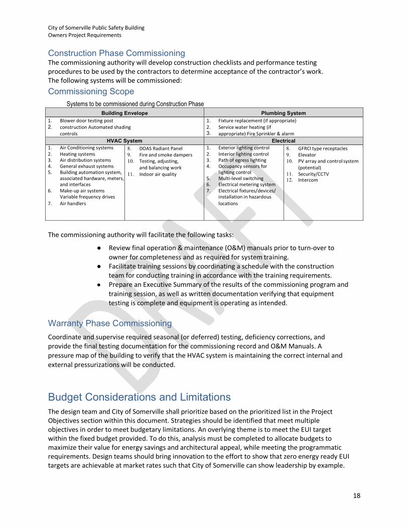
Construction Phase Commissioning The commissioning authority will develop construction checklists and performance testing procedures to be used by the contractors to determine acceptance of the contractor’s work. The following systems will be commissioned: Commissioning Scope
Systems to be commissioned during Construction Phase Building Envelope Plumbing System
1. 2.
Blower door testing post construction Automated shading controls
1. 2. 3.
Fixture replacement (if appropriate) Service water heating (if appropriate) Fire Sprinkler & alarm
HVAC System Electrical 1. Air Conditioning systems 8. DOAS Radiant Panel
9. Fire and smoke dampers 10. Testing, adjusting,
and balancing work 11. Indoor air quality
1. Exterior lighting control 8. GFRCI type receptacles 9. Elevator 10. PV array and control system
(potential) 11. Security/CCTV 12. Intercom
2. Heating systems 2. Interior lighting control 3. Air distribution systems 3. Path of egress lighting 4. General exhaust systems 4. Occupancy sensors for 5. Building automation system, lighting control
associated hardware, meters, 5. Multi-level switching and interfaces 6. Electrical metering system
6. Make-up air systems 7. Electrical fixtures/devices/ Variable frequency drives installation in hazardous
7. Air handlers locations
The commissioning authority will facilitate the following tasks:
● Review final operation & maintenance (O&M) manuals prior to turn-over to owner for completeness and as required for system training.
● Facilitate training sessions by coordinating a schedule with the construction team for conducting training in accordance with the training requirements.
● Prepare an Executive Summary of the results of the commissioning program and training session, as well as written documentation verifying that equipment testing is complete and equipment is operating as intended.
Warranty Phase Commissioning Coordinate and supervise required seasonal (or deferred) testing, deficiency corrections, and provide the final testing documentation for the commissioning record and O&M Manuals. A pressure map of the building to verify that the HVAC system is maintaining the correct internal and external pressurizations will be conducted.
Budget Considerations and Limitations The design team and City of Somerville shall prioritize based on the prioritized list in the Project Objectives section within this document. Strategies should be identified that meet multiple objectives in order to meet budgetary limitations. An overlying theme is to meet the EUI target within the fixed budget provided. To do this, analysis must be completed to allocate budgets to maximize their value for energy savings and architectural appeal, while meeting the programmatic requirements. Design teams should bring innovation to the effort to show that zero energy ready EUI targets are achievable at market rates such that City of Somerville can show leadership by example.

City of Somerville Public Safety Building Owners Project Requirements
19
The renewable energy aspects of the building may be financed through third parties, base renovation budget, or other innovative financing strategies. The cost of renewable energy has made it economically feasible with a wide-range of strategies. Note that additional renewable energy is not an alternative trade-off to increased EUIs. The design team shall investigate any utility incentive programs that might subsidize acquisition of more energy efficiency or equipment that might reduce the facility peak electrical demand.
Construction Completion and Turnover Inspection, testing, and commissioning culminates in a declaration of Substantial Completion by the Architect. This date establishes the beginning of the warranty period.
Move-in of occupants and their personal belongings will not take place until all Substantial Completion “punchlist” items are completed.
Operation and maintenance of equipment and systems is the responsibility of the Contractor until the date of Final Completion.
Commissioning of the building systems will be ongoing once the building is loaded with staff. The Contractor must accommodate the CxA requests for trend data of the HVAC systems during this post-occupancy period.
Operation and Maintenance The requirements below should be included in the project specifications.
Prior to Owner training the Contractor shall deliver Operations and Maintenance manuals which should be a single source of information and instructions for proper operation and maintenance of the building architectural, mechanical, electrical, plumbing, low voltage, and landscaping systems. The O&M’s should be specified to be delivered in a format to easily access narrative and technically detailed reference material, descriptions, diagrams, schedules, and other information on stand-alone and, particularly, integrated systems. Digital and hard copies of the report and manual shall be provided to the in a standardized format.
Sequences of operations for packaged and custom programmable systems must be provided in a written “as programmed” or “as implemented” format. Copy/paste from the project specifications or a reference to a manufacturers O&M manual is not acceptable. This should be clearly stated in the project specifications.
Like the OPR and BOD, the Systems Manual should be a living document. Unlike the OPR and BOD, though, the Systems Manual should evolve throughout the life of the building – complied by the CxA from documentation developed by the owner, design team, contractors, and the Cx process itself, then turned over for perpetual use and upkeep by building operators and future consultants and contractors throughout the building's life.
City of Somerville Public Safety Building Owners Project Requirements
20
Owner Training The following entities within the City of Somerville require training: Building occupants, Dept. of Public Works staff, Capital projects staff, Energy Manager, HVAC and Controls Vendors under City supervision, other staff as directed.
Operator training and users’ project documents are required for O&M staff to properly maintain the facility. These documents include: The O&M manual, as-built drawings, and a Systems Manual. Documentation will be tailored to the specific components that are installed. The requirements for City of Somerville Public Safety Building documentation are as follows:
1. The O&M manual should provide the information needed to understand, operate, and maintain the system and/or assemblies and to inform those not involved in the design and construction process about the systems and assemblies. This information shall be included in printed documents as well as embedded in the final 3D CAD drawings for ease of access by operations and other personnel.
2. Record drawings should provide accurate information in an understandable drawing technique which future contractors can easily read and understand to perform construction tasks. Maintain and submit one set of Contract Drawings and as-built drawings. If modifications are made, mark the as-built drawings to show the actual installation when installation varies from that shown on the Contract Drawings. Include a cross reference on the Contract Drawings to identify that a modification has occurred. Identify and date each record drawing. Record and check markups before enclosing concealed installations. Contractor shall maintain a continuously updated set of as-built drawings on site for review by CxA during construction. The Contractor will mark-up record set and scan approved marked-up drawings in PDF format.
3. The Systems Manual will be the repository of information on updates and corrections to systems and assemblies as they occur during the Occupancy and Operations Phases. The Systems Manual expands the scope of the traditional operating and maintenance documentation to include the additional information gathered during the Commissioning Process and to provide a systems-based organization of information.
4. Outside service providers will provide preventative maintenance and necessary repairs. Maintenance supervision will be performed by City of Somerville staff and will require select staff to receive detailed training on the building HVAC systems. The Training provided will educate staff on identified systems and assemblies to be installed in the facility. Training will include the education of multiple members of staff in the proper use of the monitoring system. One member of City of Somerville staff will be responsible for maintaining and updating the building documentation package for easy online reference.
5. Training shall include an overview of system components and descriptions, equipment locations and functions, safety provisions and concerns, normal operating and energy conservation techniques, BAS, etc. Training shall also include a review of the written O&M instructions, discussion of relevant health and safety issues or concerns, discussion of warranties and guarantees, discussion of common troubleshooting problems and solutions, etc. Training shall normally start with orienting facility operations and information technology staff with the facilities infrastructure including location of data ports in the ceilings, valves, and equipment during construction. Classroom sessions for operators followed by hands-on training for each piece of equipment will occur immediately after
City of Somerville Public Safety Building Owners Project Requirements
21
start-up of the specific equipment. Classroom sessions may include the use of overhead projection, slides, and training videos from equipment manufacturers as might be appropriate. Hands-on training shall include start-up, operation in all possible modes, (including manual, shut-down and any emergency procedures) and preventative maintenance for all pieces of equipment. Training is a progressive on-going process which will occur during construction, after substantial completion, and prior to final completion. A final training exercise will be conducted on-site after occupancy phase.
The intent of training is to clearly and completely instruct the Owner’s Personnel on all capabilities of the control systems, electrical systems, and mechanical systems. It is not typically expected that the trainees will have memorized everything from the training session but that they know where the information is, can find it, and understand sufficiently how to walk through the key steps to troubleshoot a problem and resolve it. Training will be witnessed and documented by the commissioning authority; the contractors will develop and execute the training program. All persons performing tasks related to building operations and maintenance shall receive at least 40 hours of training related to building systems. Training shall be completed prior to Substantial Completion, and all sessions shall be videotaped and converted to DVD format for City of Somerville use.
Building systems that the maintenance entity shall be trained on include but is not limited to:
● Mechanical systems and components including HVAC, electrical and plumbing ● BAS/controls ● Lighting and lighting controls ● Domestic hot water systems ● Security and access control systems ● Fire alarm ● Vertical conveyance systems ● Vehicle Bay Apparatus including rolling doors etc. ● Uninterruptable power supply system ● Emergency Generator ● Automatic Transfer Switches ● Irrigation control system ● Electric, gas and water metering including data collection systems and software.
Building systems that the occupants/users shall be trained on include:
● Lighting controls ● Audio/Visual (A/V) systems
Post Occupancy and Warranty The requirements below should be included in the specifications:
The CxA, GC and all subcontractors whose systems were commissioned shall support the commissioning process 12 months into the post-occupancy period. This includes conducting seasonal testing of HVAC systems when necessary to verify performance and under load as well as provide tuning of the

City of Somerville Public Safety Building Owners Project Requirements
22
commissioned systems and/or components to ensure they operate as intended once the building is occupied.
All issues observed during the commissioning process must be resolved prior to expiration of equipment and the Contractors general warranty.
General equipment and assembly warranty periods provided by manufacturers for building materials and systems are for a period of one year after substantial completion. However, some specific systems have longer warranty periods. Substantial completion is defined according to Section 9.8 of AIA document A201-1997. A representative list of assembly and equipment typically featuring a longer than one-year manufacturer’s warranty is listed below:
● Roofing: 20 years for Leakage and Weather ● Windows: 10 years for trim and glass ● Sealants: 2 years ● HVAC Compressors: 5 years parts and labor ● Water Heaters: 5 years ● Elevator: 5 years
Performance Criteria General Quality requirements for materials and construction In order to achieve the objectives for low maintenance and operating costs, ASHRAE has determined that the building exterior should minimize and resist long term degradation from nature. Construction materials selected for the project should be based on long term serviceability, environmental and sustainability goals System integration requirements, especially across disciplines The design and construction teams are encouraged to function through the Integrated Design Process. The outcome can be increased in value through optimization, something the traditional project delivery approach cannot provide. Integrative design is distinguished from conventional design by establishing a highly collaborative multidisciplinary team at the project’s inception and empowering this team to understand and develop all aspects of the building towards accomplishing the common project goals Acoustical requirements Soundproofing and acoustical treatment should be implemented in the design and construction of all private offices to prevent sound transmission to adjacent corridors, offices, and other space. Spaces shall be planned, configured and designed for compliance with the requirements of GSA- P100, as detailed in the document GSA Sound Matters (Dec. 2011). Vibration requirements Prevent occupants adjacent to HVAC equipment and corridors from sensing vibrations from structural deflection as a result of occupant traffic, and equipment operation. Vibration isolation for all rotating equipment shall be selected for 95% vibration elimination.
City of Somerville Public Safety Building Owners Project Requirements
23
Seismic requirements Comply with local code requirements. Accessibility requirements The building shall be evaluated as to the implications of meeting all Federal, State and Local ADA requirements. An ADA Assessment Report by Nova, Dated October 31, 2018 on the existing building is available for information. The design team shall review the report and provides recommendations on items to be upgraded as appropriate to the budget and needs of the client. Systems requiring routine maintenance, such as HVAC, shall be designed to provide adequate access and clearance for all maintenance tasks (i.e.: AHU filter access, sufficient space to pull coils, light bulbs, etc.) Security requirements Security system shall be capable of being tailored to allow individual users unique access profiles. Security and surveillance provisions at all building entrances and exits will allow approved visitors and employees access to building 24/7. CCTV monitoring system will be provided at the main entrance into the main lobby, at the east entrance to the training center andaround the building’s exterior. The security system shall keep an access log which records profiles of people entering the building, the time of entrance and exit. Aesthetics requirements Private and open offices shall maintain the same interior design attributes as the rest of the building. A goal has been established of maintaining a uniform look throughout the interior of the building. Façade lighting shall follow How-To tips contained in Sections EL-18 to EL-24 in the Energy Advanced Energy Design Guide for Zero Energy Offices. Constructability requirements The Construction Manager shall conduct a constructability review of the design at the completion of Design Development and 90% completion point of the Construction Documents to assure the design can be constructed for the owner’s budget and within the required timeframe. Participants at these reviews should include the design team and project manager. Communication requirements The building shall be served by a modern phone system and computer network, which could be VOIP. This system is part of the plug loads of the building and must be accounted for in the energy model. All offices, workstations, and conference rooms shall have the capability for a least two (2) telecommunications ports (network and telephone). Conference rooms, corridors, and public spaces shall be configured to accommodate the installation of wireless access points to support both staff and volunteers access to the network and the Internet. Access to a wireless network shall be possible within all spaces in the building excluding areas known to be problematic to RF communications. Wireless networks shall be maintained to allow secure network access separate from public internet access. The Learning Center occupants shall have wireless network access separate from the network used by ASHRAE staff. Additional information is required from ASHRAE and will be added upon receipt of input. The building shall be equipped with a public address (PA) system.

City of Somerville Public Safety Building Owners Project Requirements
24
The use of BACnet native BAS system shall provide a turnkey solution to machine-to- machine communications and shall be capable of remote access/alarm notification. Note that all these items should be configured to have low-power modes or off modes when the building is not occupied. User Requirements The general requirements for the City of Somerville Public Safety Building include: Lighting and Daylighting: Daylighting shall be provided via the existing or replaced window system, a case for revised window to wall ratios or reconfigured fenestration can be pursued to improve daylighting. Efficient electric lighting shall be designed to provide the required level of lighting for occupants’ use on cloudy days, night time, or when natural lighting is not sufficient. Designers should follow, as a minimum, the lighting and daylighting recommendations from the Advanced Energy Design Guide for Zero Energy Offices (90% draft or later). Lighting should be based on the tasks that will be performed in each space of the facility. Task based design for meeting/conference rooms would include modes to support the room’s use for A/V presentations including the ability to dim/turn off the lighting around a projector screen for presentations; a lighting mode to satisfy general occupancy requirements; a lighting mode to provide adequate lighting for classroom type tasks, and a lighting mode providing minimum illumination for egress purposes. In the event of a power failure, this lighting system shall provide required illumination for egress purposes. Electrical infrastructure shall be capable of meeting requirements necessary for business activities. The electrical system for the building shall allow separately sub-metering of utilities serving mechanical equipment, lighting systems, and plug loads. The electrical branch circuits in panelboards serving each load category noted above shall be grouped so that the monitoring of the energy usage for these loads can be accomplished. In addition, photovoltaic power generation and use (both on site and sent to the utility grid) shall be monitored. Monitoring shall also be compatible with the BAS to allow remote monitoring. Dedicated shipping and receiving areas will be of sufficient size such that goods awaiting shipment can be stored therein, without overflow into corridors serving the receiving area. The staging area within shipping and receiving shall accommodate 18 large crates of materials allowing compiling, checking for readiness, easy conveyance to vehicles, and unloading upon return. Storage areas shall be designed with sufficient space so that materials stored therein, including files, forms and other such items, may be easily accessed and organized at a central location within the room. Storage rooms should be adequately provided to accommodate departments’ uses. The total area to be provided for file and other storage shall be determined and verified via the programming exercise with the owner.
City of Somerville Public Safety Building Owners Project Requirements
25
Operations Training requirements for Owner’s personnel Provide to Owner after all equipment is in operation and at an agreeable time, instructions for the purpose of training Owner's personnel in all phases of operation and maintenance of equipment and systems. Training sessions when given to the owner’s personnel shall be videotaped for future owner reference. Turn one copy over to the owner upon completion. Warranty requirements General equipment and assembly warranty periods provided by manufacturers for building materials and systems are for a period of one year after substantial completion. However, some specific systems have longer warranty periods. Substantial completion is defined according to Section 9.8 of AIA document A201-1997. A representative list of assembly and equipment typically featuring a longer than one-year manufacturer’s warranty is listed below: Roofing: 20 years for Leakage and Weather Windows: 10 years for trim and glass Sealants: 2 years HVAC Compressors: 5 years parts and labor Water Heaters: 5 years Elevator: 5 years Operations and Maintenance requirements will be established by the current City of Somerville staff that will monitor the building systems and determine what corrective action is required. The current staff will monitor the preventative maintenance and repairs will be performed by outside contractors. To ensure that maintenance can be easily performed, and the facility’s business will not be compromised because of deconstruction due to maintenance, the maintenance criteria shall be adhered as follows:
• Designers are to ensure sufficient access and clearances are provided by the design to perform routine maintenance tasks.
• Contractors shall coordinate the installation of building materials and components so as to allow sufficient space for maintenance and service without limited range of motion in the space which would require deconstruction to provide required service space.
• System manual shall include any changes made to components and systems after substantial completion and shall include the final set points established through the commissioning process.
• Outside maintenance contractors will have between 10 and 25 years of experience and it is assumed they are conversant in basic maintenance techniques and are computer proficient.
It is City of Somerville’s preference that the Mechanical Contractor selected for construction will also provide maintenance & service for the first three years after occupancy.
Equipment and system maintainability expectations, including limitations of operating and maintenance personnel; Maintenance and replacement costs must be considered over the life of the facility and selection of materials will be based on minimizing life cycle costs. Design of mechanical, electrical, and plumbing systems shall allow required maintenance and replacements of key system components to be performed without deconstruction. All systems and their components shall be easily accessible for
City of Somerville Public Safety Building Owners Project Requirements
26
adjustments to the respective system components. Access to the building exterior shall be provided that allows easy maintenance, repair, and replacement of the building exterior including windows, gutters, and sealants. Allowable tolerance in facility system operation; Occupancy sensors shall be installed in office areas, conference rooms, and other public areas to efficiently control lighting usage in accordance with demand. The City of Somerville Public Safety Building will be designed, constructed and operated in an energy efficient and environmentally sustainable manner that will provide both valuable information to the building operators as well as an example for others to follow. The renovated facility shall be designed and constructed to achieve:
• Deliver Outside Air at a value of at least 1.3 times the requirements of Std. 62.1 OA to regularly occupied areas and use Demand Controlled Ventilation (DCV) for high occupancy spaces, such as conference and meeting rooms and training center, set at carbon dioxide limit of 400 ppm over ambient, providing a reduction in outside air delivery to these spaces during low or non-occupancy
• Provide capability for Indoor Environmental Quality (IEQ) monitoring that includes air temperature, humidity, CO2 concentration, air pollutants concentration (VOC), air-flow rates, ambient noise level, lighting levels, and daylighting availability in sufficient granularity to represent the general office & conference space on the first and second floors.
Systems Building systems and equipment requirements are left to the design team in order that they may provide the most efficient building possible in order to meet the energy and other goals defined herein. Quality requirements for materials and construction
• The renovated facility shall be designed to serve and endure for at least 100 years; thus, selection of materials should be based on the ability to provide years of service with minimum maintenance and withstand weather conditions typical in this region.
• The building envelope will be tightened to conform with minimum requirements allowed by ASHRAE Standard 90.1-2016, Section 5.4.3 Air Leakage
• The fenestration and solar transmission shall be controlled and designed in accordance with ASHRAE Standard 90.1-2016 through glazing selection and external shading.
• Interior finish shall be highly durable low volatile organic compound emitting materials and require no more than 3 replacements over 75 years. Heavy traffic areas will be designed to have resilient carpet tiles. Easily maintained and low maintenance materials with 25 years life cycle cost will be used for wall and floor coverings.
• The Design Team should address moisture intrusion and impacts of occasional snow/ice and freeze/thaw conditions that have occurred in this region.
• Mechanical systems shall be designed with required serviceable life as specified in the most current ASHRAE Handbook HVAC Applications, (Chapter 37 – Owning and Operating Costs, Chapter 36 Energy Use and Management and Chapter 41 Building Energy Monitoring).
• HVAC components such as coils and compressors shall be designed to have 20 years serviceable life. The piping and plumbing infrastructure shall be designed to have a serviceable life of 35 years. Lighting systems shall be designed to have 20 years serviceable life. Electrical systems shall be designed to be designed with a serviceable life of between 35 to 50 years. Electrical

City of Somerville Public Safety Building Owners Project Requirements
27
systems will allow the replacement of electrical switch and panel boards, conductors and other electrical products as advancements in technology become available.

SOMERVILLE PUBLIC SAFETY BUILDING Somerville, Massachusetts 02143
Project No. 2006.00
NARRATIVE 8/13/2021
PROJECT DIRECTORY

PROJECT DIRECTORY
1 Colliers Project Leaders | City of Somerville: Public Safety Building
City of Somerville Public Safety Facility COMPANY / ADDRESS CONTACT NAME TITLE EMAIL PHONE EXT. CELL PHONE
Colliers Project Leaders (CPL) Owner’s Project Manager / Representative
135 New Road Ken Guyette Director [email protected] 860 395-0055
Madison, CT 06443 Anthony Diluzio Senior Project Manager [email protected]
(860) 395-0055 George Barnes Project Manager [email protected] 860 395-0055 192
Thao Nguyen Project Accountant [email protected] 860 395-0055
www.cplusa.com
Owner / Client Name Owner
City of Somerville Melissa Woods Senior Planner [email protected] 617 625 6600
50 Evergreen Avenue Angela Allen Director Purchasing [email protected] 617 625 6600 3400 857 523 8647
Somerville, MA, 02145
Rebecca Cooper Strategic Planning/Community Develop.
[email protected] 617 625 6600
Cortni Desir Planner [email protected] 617 625 6600 2116
Thomas Galligani Director of Economic Devel. [email protected] 617 625 6600
Sarah Lewis Director of Planning [email protected] 617 625 6600 2522
Fred Massaro Director of Capital Projects [email protected] 617 625 6600 5123 781 325 6355
Richard Raiche Director of Infrastructure [email protected] 617 625 6600 5410
Robert Ross Energy Manager [email protected] 617 625 6600 2424 781 468 6417
Kristin Stelljies Community Preservation Act Manager
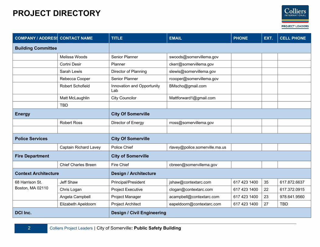
PROJECT DIRECTORY
2 Colliers Project Leaders | City of Somerville: Public Safety Building
COMPANY / ADDRESS CONTACT NAME TITLE EMAIL PHONE EXT. CELL PHONE
Building Committee
Melissa Woods Senior Planner [email protected]
Cortni Desir Planner [email protected]
Sarah Lewis Director of Planning [email protected]
Rebecca Cooper Senior Planner [email protected]
Robert Schofield Innovation and Opportunity Lab
Matt McLaughlin City Councilor [email protected]
TBD
Energy City Of Somerville
Robert Ross Director of Energy [email protected]
Police Services City Of Somerville
Captain Richard Lavey Police Chief [email protected]
Fire Department City of Somerville
Chief Charles Breen Fire Chief [email protected]
Context Architecture Design / Architecture
68 Harrison St. Boston, MA 02110
Jeff Shaw Principal/President [email protected] 617 423 1400 35 617.872.6637
Chris Logan Project Executive [email protected] 617 423 1400 22 617.372.0915
Angela Campbell Project Manager [email protected] 617 423 1400 23 978.641.9560
Elizabeth Apeldoorn Project Architect [email protected] 617 423 1400 27 TBD
DCI Inc. Design / Civil Engineering
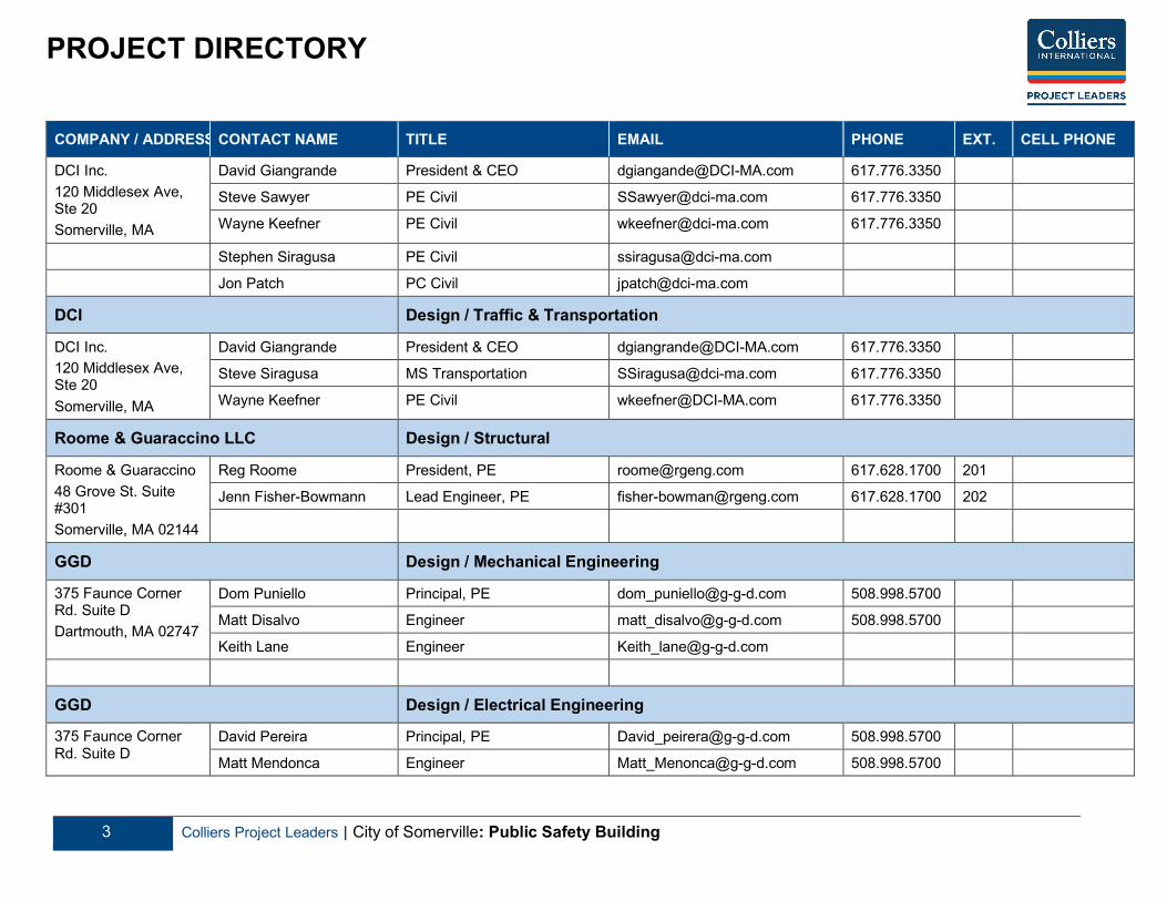
PROJECT DIRECTORY
3 Colliers Project Leaders | City of Somerville: Public Safety Building
COMPANY / ADDRESS CONTACT NAME TITLE EMAIL PHONE EXT. CELL PHONE
DCI Inc. 120 Middlesex Ave, Ste 20 Somerville, MA
David Giangrande President & CEO [email protected] 617.776.3350
Steve Sawyer PE Civil [email protected] 617.776.3350
Wayne Keefner PE Civil [email protected] 617.776.3350
Stephen Siragusa PE Civil [email protected]
Jon Patch PC Civil [email protected]
DCI Design / Traffic & Transportation
DCI Inc. 120 Middlesex Ave, Ste 20 Somerville, MA
David Giangrande President & CEO [email protected] 617.776.3350
Steve Siragusa MS Transportation [email protected] 617.776.3350
Wayne Keefner PE Civil [email protected] 617.776.3350
Roome & Guaraccino LLC Design / Structural
Roome & Guaraccino 48 Grove St. Suite #301 Somerville, MA 02144
Reg Roome President, PE [email protected] 617.628.1700 201
Jenn Fisher-Bowmann Lead Engineer, PE [email protected] 617.628.1700 202
GGD Design / Mechanical Engineering
375 Faunce Corner Rd. Suite D Dartmouth, MA 02747
Dom Puniello Principal, PE [email protected] 508.998.5700
Matt Disalvo Engineer [email protected] 508.998.5700
Keith Lane Engineer [email protected]
GGD Design / Electrical Engineering
375 Faunce Corner Rd. Suite D
David Pereira Principal, PE [email protected] 508.998.5700
Matt Mendonca Engineer [email protected] 508.998.5700

PROJECT DIRECTORY
4 Colliers Project Leaders | City of Somerville: Public Safety Building
COMPANY / ADDRESS CONTACT NAME TITLE EMAIL PHONE EXT. CELL PHONE Dartmouth, MA 02747 Kam Wai Nam Engineer ???
GGD Design /Plumbing Engineering
375 Faunce Corner Rd. Suite D Dartmouth, MA 02747
Chris Garcia Principal, PE [email protected] 508.998.5700
Eric Laforge Engineer [email protected] 508.998.5700
Robert Nesselle Engineer (Fire Safety) [email protected] 508.998.5700
CBA Landscape Architects Design / Landscape Architecture
CBA Landscape Architect 24 Thorndike St. Cambridge, MA 02141 CBALand.com
DJ Chagnon Registered Landscape Architect
[email protected] 617.945.9760
Megan Tomkins Registered Landscape Architect
[email protected] 617.945.9760
RW Sullivan Design / Code Consultant
The Schraffts Center 529 Main St. Suite 203 Boston MA 02129
Don Contois P.E [email protected] 817 523 8016
3 IVE LLC Design / Envelope Design
334 Washington St. Somerville MA 02143
David DeSola Principal [email protected] 617.625.3483
Soden Sustainability Design / LEED Sustainability
19 Richardson Street Colleen Soden Principal [email protected] 617.372.7857

PROJECT DIRECTORY
5 Colliers Project Leaders | City of Somerville: Public Safety Building
COMPANY / ADDRESS CONTACT NAME TITLE EMAIL PHONE EXT. CELL PHONE Winchester, MA 01890
AKF Group Design / Net Zero Design
One Liberty Plaza 165 Broadway 22nd Flr New York, NY 10006 AKFgroup.com
Jeff Rios Partner [email protected] 212.354.5668
Shannon Kaplan PE [email protected] 212.354.5668
Langone & Associates Engineer / Radio & Communication
Langone & Associates 87 Emerald Court Tewksbury, MA 01867
Anthony (Chick) Langone Principal [email protected] 508.633.2470
McPhail Associates Geothermal / Geotechnical / LSP
McPhail Associates 352 Turnpike Road Ste320 Southborough, MA 01772
Chris Erickson Principal [email protected] 860.726.7889
Eric Hinds Project Manager [email protected]
Jonathan Patch Project Manager [email protected]
AM Fogarty Cost Estimating
AM Fogarty 175 Derby St. Hingham MA 02043
Pete Timothy Principal [email protected] 781.740.2652

PROJECT DIRECTORY
6 Colliers Project Leaders | City of Somerville: Public Safety Building
COMPANY / ADDRESS CONTACT NAME TITLE EMAIL PHONE EXT. CELL PHONE

SOMERVILLE PUBLIC SAFETY BUILDING Somerville, Massachusetts 02143
Project No. 2006.00
NARRATIVE 8/13/2021
NARRATIVE-CIVIL
The SD Civil set locates the new building on Parcel B and shows Parcels A and C. The approximate ROW for the re-aligned New Washington Street is shown. The street lane configuration is shown based on the sketch provided by the City. Approximate locations for the transformer, gas meter bank, underground electric, gas, fire protection line, domestic water line, sanitary sewer and storm drain connections are shown. Approximate location for subsurface infiltration system is shown. Approximate finished floor elevations are shown. During DD, the location of the utilities will be coordinated with the team. The finished floor will be confirmed. Grading of the lot will be completed. The subsurface infiltration system will be sized and designed and coordinated with McPhail. The plaza areas will be coordinated with the Landscape Architect. Turning movement analysis will be performed for apparatus and other vehicles. Integration of the early site work into the package will be completed.

SOMERVILLE PUBLIC SAFETY BUILDING Somerville, Massachusetts 02143
Project No. 2006.00
NARRATIVE 8/13/2021
NARRATIVE-TRAFFIC
As part of the next phase of the project, traffic analysis will be completed in coordination with the City’s Mobility Division. Existing traffic data will be collected along Washington Street, both mainline traffic and turning movement data at the intersections of New Washington Street, Franklin Street, and Inner Belt Road. This data will include all modes of transportation, including vehicles, bicycles, and pedestrians.
Comprehensive reports, including a Transportation Impact Study, Mobility Management Plan, and Transportation Access Plan, will be produced, and will include analyses of the intersections, as well as the multimodal transportation options in the area. The reports will also include measures the City will implement to reduce the number of vehicle-trips to and from the site, and include plans detailing multimodal options the project will be providing. These reports will help to determine the effects, if any, the new Somerville Public Safety Building will have on traffic and safety in the area

SOMERVILLE PUBLIC SAFETY BUILDING Somerville, Massachusetts 02143
Project No. 2006.00
NARRATIVE 8/13/2021
D.1 CIVIL-SPECIFICATION
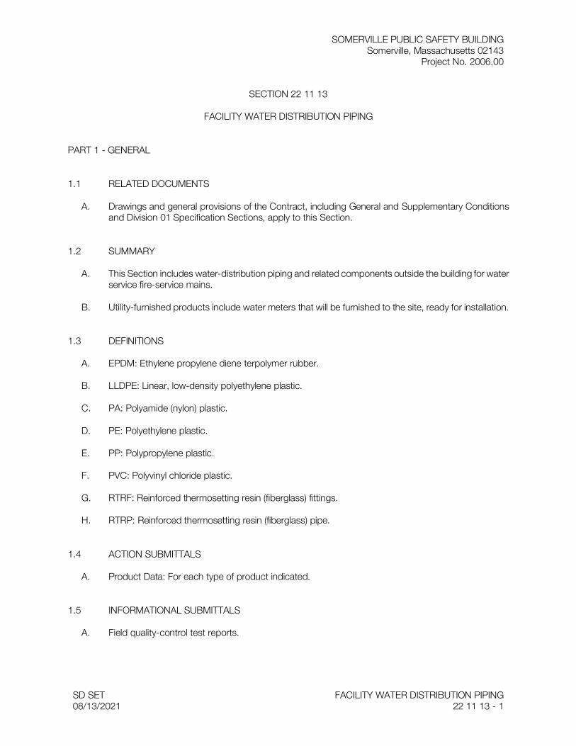
SOMERVILLE PUBLIC SAFETY BUILDING Somerville, Massachusetts 02143
Project No. 2006.00
SD SET 08/13/2021
FACILITY WATER DISTRIBUTION PIPING 22 11 13 - 1
SECTION 22 11 13
FACILITY WATER DISTRIBUTION PIPING
PART 1 - GENERAL
1.1 RELATED DOCUMENTS
A. Drawings and general provisions of the Contract, including General and Supplementary Conditions and Division 01 Specification Sections, apply to this Section.
1.2 SUMMARY
A. This Section includes water-distribution piping and related components outside the building for water service fire-service mains.
B. Utility-furnished products include water meters that will be furnished to the site, ready for installation.
1.3 DEFINITIONS
A. EPDM: Ethylene propylene diene terpolymer rubber.
B. LLDPE: Linear, low-density polyethylene plastic.
C. PA: Polyamide (nylon) plastic.
D. PE: Polyethylene plastic.
E. PP: Polypropylene plastic.
F. PVC: Polyvinyl chloride plastic.
G. RTRF: Reinforced thermosetting resin (fiberglass) fittings.
H. RTRP: Reinforced thermosetting resin (fiberglass) pipe.
1.4 ACTION SUBMITTALS
A. Product Data: For each type of product indicated.
1.5 INFORMATIONAL SUBMITTALS
A. Field quality-control test reports.
SOMERVILLE PUBLIC SAFETY BUILDING Somerville, Massachusetts 02143
Project No. 2006.00
SD SET 08/13/2021
FACILITY WATER DISTRIBUTION PIPING 22 11 13 - 2
1.6 CLOSEOUT SUBMITTALS
1.7 QUALITY ASSURANCE
A. Regulatory Requirements:
1. Comply with requirements of utility company supplying water. Include tapping of water mains and backflow prevention.
2. Comply with standards of authorities having jurisdiction for potable-water-service piping, including materials, installation, testing, and disinfection.
3. Comply with standards of authorities having jurisdiction for fire-suppression water-service piping, including materials, hose threads, installation, and testing.
B. Piping materials shall bear label, stamp, or other markings of specified testing agency.
C. Electrical Components, Devices, and Accessories: Listed and labeled as defined in NFPA 70, Article 100, by a testing agency acceptable to authorities having jurisdiction, and marked for intended use.
D. Comply with ASTM F 645 for selection, design, and installation of thermoplastic water piping.
E. Comply with FMG's "Approval Guide" or UL's "Fire Protection Equipment Directory" for fire-service-main products.
F. NFPA Compliance: Comply with NFPA 24 for materials, installations, tests, flushing, and valve and hydrant supervision for fire-service-main piping for fire suppression.
1. Potable-water piping and components shall comply with NSF 14, NSF 61, and NSF 372.
1.8 DELIVERY, STORAGE, AND HANDLING
A. Preparation for Transport: Prepare valves, including fire hydrants, according to the following:
1. Ensure that valves are dry and internally protected against rust and corrosion. 2. Protect valves against damage to threaded ends and flange faces. 3. Set valves in best position for handling. Set valves closed to prevent rattling.
B. During Storage: Use precautions for valves, including fire hydrants, according to the following:
1. Do not remove end protectors unless necessary for inspection; then reinstall for storage. 2. Protect from weather. Store indoors and maintain temperature higher than ambient dew-point
temperature. Support off the ground or pavement in watertight enclosures when outdoor storage is necessary.
C. Handling: Use sling to handle valves and fire hydrants if size requires handling by crane or lift. Rig valves to avoid damage to exposed parts. Do not use handwheels or stems as lifting or rigging points.
D. Deliver piping with factory-applied end caps. Maintain end caps through shipping, storage, and handling to prevent pipe-end damage and to prevent entrance of dirt, debris, and moisture.
SOMERVILLE PUBLIC SAFETY BUILDING Somerville, Massachusetts 02143
Project No. 2006.00
SD SET 08/13/2021
FACILITY WATER DISTRIBUTION PIPING 22 11 13 - 3
E. Protect stored piping from moisture and dirt. Elevate above grade. Do not exceed structural capacity of floor when storing inside.
F. Protect flanges, fittings, and specialties from moisture and dirt.
G. Store plastic piping protected from direct sunlight. Support to prevent sagging and bending.
1.9 PROJECT CONDITIONS
1.10 COORDINATION
A. Coordinate connection to water main with utility company.
PART 2 - PRODUCTS
2.1 PIPING MATERIALS
A. Comply with requirements in "Piping Application" Article for applications of pipe, tube, fitting materials, and joining methods for specific services, service locations, and pipe sizes.
B. Potable-water piping and components shall comply with NSF 14, NSF 61, and NSF 372.
2.2 DUCTILE-IRON PIPE AND FITTINGS
A. Mechanical-Joint, Ductile-Iron Pipe: AWWA C151, with mechanical-joint bell and plain spigot end unless grooved or flanged ends are indicated.
1. Mechanical-Joint, Ductile-Iron Fittings: AWWA C110, ductile- or gray-iron standard pattern or AWWA C153, ductile-iron compact pattern.
2. Glands, Gaskets, and Bolts: AWWA C111, ductile- or gray-iron glands, rubber gaskets, and steel bolts.
B. Push-on-Joint, Ductile-Iron Pipe: AWWA C151, with push-on-joint bell and plain spigot end unless grooved or flanged ends are indicated.
1. Push-on-Joint, Ductile-Iron Fittings: AWWA C110, ductile- or gray-iron standard pattern or AWWA C153, ductile-iron compact pattern.
2. Gaskets: AWWA C111, rubber. a.
C. Flanges: ASME 16.1, Class 125, cast iron.
2.3 JOINING MATERIALS
A. Refer to Section 33 05 00 "Common Work Results for Utilities" for commonly used joining materials.
B. Brazing Filler Metals: AWS A5.8, BCuP Series.

SOMERVILLE PUBLIC SAFETY BUILDING Somerville, Massachusetts 02143
Project No. 2006.00
SD SET 08/13/2021
FACILITY WATER DISTRIBUTION PIPING 22 11 13 - 4
C. Bonding Adhesive for Fiberglass Piping: As recommended by fiberglass piping manufacturer.
D. Plastic Pipe-Flange Gasket, Bolts, and Nuts: Type and material recommended by piping system manufacturer, unless otherwise indicated.
2.4 GATE VALVES
A. AWWA, Cast-Iron Gate Valves:
1. Manufacturers: Subject to compliance with requirements, undefined: a. Kennedy Valve Company; a division of McWane, Inc. b. M & H Valve Company; a division of McWane, Inc. c. Mueller Co. d. NIBCO INC.
2. Nonrising-Stem, Resilient-Seated Gate Valves: a. Description: Gray- or ductile-iron body and bonnet; with bronze or gray- or ductile-iron
gate, resilient seats, bronze stem, and stem nut. 1) Standard: AWWA C509. 2) Minimum Pressure Rating: 200 psig . 3) End Connections: Mechanical joint. 4) Interior Coating: Complying with AWWA C550.
2.5 CORPORATION VALVES AND CURB VALVES
A. Manufacturers:
1. Manufacturers: Subject to compliance with requirements, undefined: a. Mueller Co. b. Red Hed Manufacturing Company; a division of Everett J. Prescott, Inc.
B. Service-Saddle Assemblies: Comply with AWWA C800. Include saddle and valve compatible with tapping machine.
1. Service Saddle: Copper alloy with seal and AWWA C800, threaded outlet for corporation valve.
2. Corporation Valve: Bronze body and ground-key plug, with AWWA C800, threaded inlet and outlet matching service piping material.
3. Manifold: Copper fitting with two to four inlets as required, with ends matching corporation valves and outlet matching service piping material.
C. Curb Valves: Comply with AWWA C800. Include bronze body, ground-key plug or ball, and wide tee head, with inlet and outlet matching service piping material.
D. Service Boxes for Curb Valves: Similar to AWWA M44 requirements for cast-iron valve boxes. Include cast-iron telescoping top section of length required for depth of burial of valve, plug with lettering "WATER," and bottom section with base that fits over curb valve and with a barrel approximately 3 inches in diameter.
1. Shutoff Rods: Steel, tee-handle with one pointed end, stem of length to operate deepest buried valve, and slotted end matching curb valve.

SOMERVILLE PUBLIC SAFETY BUILDING Somerville, Massachusetts 02143
Project No. 2006.00
SD SET 08/13/2021
FACILITY WATER DISTRIBUTION PIPING 22 11 13 - 5
2.6 FIRE HYDRANTS
A. Dry-Barrel Fire Hydrants:
1. Manufacturers: Subject to compliance with requirements, undefined: a. Kennedy Valve Company; a division of McWane, Inc. b. M & H Valve Company; a division of McWane, Inc. c. Mueller Co.
2. Description: Freestanding, with one NPS 4-1/2 and two NPS 2-1/2 outlets, 5-1/4-inch main valve, drain valve, and NPS 6 mechanical-joint inlet. Include interior coating according to AWWA C550. Hydrant shall have cast-iron body, compression-type valve opening against pressure and closing with pressure. a. Standard: AWWA C502. b. Pressure Rating: 150 psig minimum .
2.7 FIRE DEPARTMENT CONNECTIONS
A. Fire Department Connections:
1. Manufacturers: Subject to compliance with requirements, undefined: a. Guardian Fire Equipment, Inc. b. Kidde; Carrier Global Corporation. c. Potter Roemer LLC; a Division of Morris Group International.
2. Description: Freestanding, with cast-bronze body, thread inlets according to NFPA 1963 and matching local fire department hose threads, and threaded bottom outlet. Include lugged caps, gaskets, and chains; lugged swivel connection and drop clapper for each hose-connection inlet; 18-inch- high brass sleeve; and round escutcheon plate. a. Standard: UL 405. b. Connections: Two NPS 2-1/2 inlets and one NPS 4 outlet. c. Connections: Three NPS 2-1/2 inlets and one NPS 6 outlet. d. Connections: Six NPS 2-1/2 inlets and one NPS 6 outlet. e. Inlet Alignment: Inline, horizontal . f. Finish Including Sleeve: Polished chrome-plated . g. Escutcheon Plate Marking: " AUTO SPKR ."
PART 3 - EXECUTION
3.1 EARTHWORK
A. Refer to Section 31 20 00 "Earth Moving" for excavating, trenching, and backfilling.
3.2 PIPING APPLICATIONS
A. General: Use pipe, fittings, and joining methods for piping systems according to the following applications.
B. Transition couplings and special fittings with pressure ratings at least equal to piping pressure rating may be used, unless otherwise indicated.

SOMERVILLE PUBLIC SAFETY BUILDING Somerville, Massachusetts 02143
Project No. 2006.00
SD SET 08/13/2021
FACILITY WATER DISTRIBUTION PIPING 22 11 13 - 6
C. Do not use flanges or unions for underground piping.
D. Flanges, unions, grooved-end-pipe couplings, and special fittings may be used, instead of joints indicated, on aboveground piping and piping in vaults.
E. Underground water-service piping NPS 4 to NPS 8 shall be the following:
1. Ductile-iron, push-on-joint pipe; ductile-iron, push-on-joint fittings; and gasketed mechanical-joint pipe; ductile-iron, mechanical-joint fittings; and mechanical joints.
2. PVC, Schedule socket fittings; and solvent-cemented joints. 3. NPS 4 and NPS 6 : NPS 6 PVC, AWWA Class 150 pipe; PVC, AWWA Class 150 fittings; and
gasketed joints. 4. NPS 8 : PVC, AWWA Class 200 pipe; fittings; and gasketed joints. 5. Fiberglass, AWWA RTRP, Class ; RTRF; and bonded joints.
3.3 VALVE APPLICATIONS
A. General Application: Use mechanical-joint-end valves for NPS 3 and larger underground installation. Use threaded- or flanged-end valves for installation in vaults. Use UL/FMG, nonrising-stem gate valves for installation with indicator posts. Use corporation valves and curb valves with ends compatible with piping, for NPS 2 and smaller installation.
B. Drawings indicate valve types to be used. Where specific valve types are not indicated, the following requirements apply:
1. Underground Valves, NPS 3 and Larger: AWWA, cast-iron, nonrising-stem, resilient -seated gate valves with valve box.
2. Underground Valves, NPS 4 and Larger, for Indicator Posts: UL/FMG, cast-iron, nonrising-stem gate valves with indicator post.
3.4 PIPING SYSTEMS - COMMON REQUIREMENTS
A. See Section 33 05 00 "Common Work Results for Utilities" for piping-system common requirements.
3.5 PIPING INSTALLATION
A. Water-Main Connection: Tap water main according to requirements of water utility company and of size and in location indicated.
B. Make connections larger than NPS 2 with tapping machine according to the following:
1. Install tapping sleeve and tapping valve according to MSS SP-60. 2. Install tapping sleeve on pipe to be tapped. Position flanged outlet for gate valve. 3. Use tapping machine compatible with valve and tapping sleeve; cut hole in main. Remove
tapping machine and connect water-service piping. 4. Install gate valve onto tapping sleeve. Comply with MSS SP-60. Install valve with stem
pointing up and with valve box.
C. Comply with NFPA 24 for fire-service-main piping materials and installation.
SOMERVILLE PUBLIC SAFETY BUILDING Somerville, Massachusetts 02143
Project No. 2006.00
SD SET 08/13/2021
FACILITY WATER DISTRIBUTION PIPING 22 11 13 - 7
1. Install PE corrosion-protection encasement according to ASTM A 674 or AWWA C105. 2. Install copper tube and fittings according to CDA's "Copper Tube Handbook."
D. Install ductile-iron, water-service piping according to AWWA C600 and AWWA M41.
1. Install PE corrosion-protection encasement according to ASTM A 674 or AWWA C105.
E. Bury piping with depth of cover over top at least 60 inches , with top at least 12 inches below level of maximum frost penetration, and according to the following:
1. Under Driveways: With at least 60 inches cover over top.
F. Install piping by tunneling or jacking, or combination of both, under streets and other obstructions that cannot be disturbed.
G. Extend water-service piping and connect to water-supply source and building-water-piping systems at outside face of building wall in locations and pipe sizes indicated.
1. Terminate water-service piping at building wall until building-water-piping systems are installed. Terminate piping with caps, plugs, or flanges as required for piping material. Make connections to building-water-piping systems when those systems are installed.
H. Sleeves are specified in Section 22 05 17 "Sleeves and Sleeve Seals for Plumbing Piping."
I. Mechanical sleeve seals are specified in Section 22 05 17 "Sleeves and Sleeve Seals for Plumbing Piping."
J. Install underground piping with restrained joints at horizontal and vertical changes in direction. Use restrained-joint piping, thrust blocks, anchors, tie-rods and clamps, and other supports.
K. See Section 21 12 00 "Fire-Suppression Standpipes," Section 21 13 13 "Wet-Pipe Sprinkler Systems," and Section 21 13 16 "Dry-Pipe Sprinkler Systems" for fire-suppression-water piping inside the building.
L. See Section 22 11 16 "Domestic Water Piping" for potable-water piping inside the building.
3.6 INSTALLATION OF HANGERS AND SUPPORTS
A. Comply with requirements for seismic-restraint devices specified in Section 23 05 48 "Vibration and Seismic Controls for HVAC."
B. Comply with requirements for hangers, supports, and anchor devices specified in Section 23 05 29 "Hangers and Supports for HVAC Piping and Equipment."
C. Install the following pipe attachments:
1. Adjustable steel clevis hangers for individual horizontal piping less than 20 feet long. 2. Adjustable roller hangers and spring hangers for individual horizontal piping 20 feet or longer. 3. Pipe Roller: MSS SP-58, Type 44 for multiple horizontal piping 20 feet or longer, supported
on a trapeze. 4. Spring hangers to support vertical runs.

SOMERVILLE PUBLIC SAFETY BUILDING Somerville, Massachusetts 02143
Project No. 2006.00
SD SET 08/13/2021
FACILITY WATER DISTRIBUTION PIPING 22 11 13 - 8
5. Provide copper-clad hangers and supports for hangers and supports in direct contact with copper pipe.
6. On PVC piping, install pads or cushions on bearing surfaces to prevent hanger from scratching pipe.
D. Install hangers for copper tubing with maximum spacing and minimum rod diameters to comply with MSS-58, locally enforced codes, and authorities having jurisdiction requirements, whichever are most stringent.
E. Install hangers for PVC piping with maximum horizontal spacing and minimum rod diameters to comply with manufacturer's written instructions, locally enforced codes, and authorities having jurisdiction requirements, whichever are most stringent.
F. Install hangers for fiberglass piping with maximum horizontal spacing and minimum rod diameters to comply with manufacturer's written instructions, locally enforced codes, and authorities having jurisdiction requirements, whichever are most stringent.
G. Support horizontal piping within 12 inches of each fitting and coupling.
H. Support vertical runs of copper tubing to comply with MSS-58, locally enforced codes, and authorities having jurisdiction requirements, whichever are most stringent.
I. Support vertical runs of PVC piping to comply with manufacturer's written instructions, locally enforced codes, and authorities having jurisdiction requirements, whichever are most stringent.
3.7 JOINT CONSTRUCTION
A. See Section 33 05 00 "Common Work Results for Utilities" for basic piping joint construction.
B. Make pipe joints according to the following:
1. Copper-Tubing, Pressure-Sealed Joints: Join copper tube and pressure-seal fittings with tools and procedures recommended by pressure-seal-fitting manufacturer. Leave insertion marks on pipe after assembly.
2. Ductile-Iron Piping, Gasketed Joints for Water-Service Piping: AWWA C600 and AWWA M41. 3. Ductile-Iron Piping, Gasketed Joints for Fire-Service-Main Piping: UL 194. 4. Ductile-Iron Piping, Grooved Joints: Cut-groove pipe. Assemble joints with grooved-end,
ductile-iron-piping couplings, gaskets, lubricant, and bolts according to coupling manufacturer's written instructions.
5. PE Piping Insert-Fitting Joints: Use plastic insert fittings and fasteners according to fitting manufacturer's written instructions.
6. PVC Piping Gasketed Joints: Use joining materials according to AWWA C900. Construct joints with elastomeric seals and lubricant according to ASTM D 2774 or ASTM D 3139 and pipe manufacturer's written instructions.
7. Fiberglass Piping Bonded Joints: Use adhesive and procedure recommended by piping manufacturer.
8. Install dielectric fittings in piping at connections of dissimilar metal piping and tubing. a. Dielectric Fittings for NPS 2 and Smaller: Use dielectric unions. b. Dielectric Fittings for NPS 2-1/2 to NPS 4 : Use dielectric flanges . c. Dielectric Fittings for NPS 5 and Larger: Use dielectric flange kits.
SOMERVILLE PUBLIC SAFETY BUILDING Somerville, Massachusetts 02143
Project No. 2006.00
SD SET 08/13/2021
FACILITY WATER DISTRIBUTION PIPING 22 11 13 - 9
3.8 ANCHORAGE INSTALLATION
A. Anchorage, General: Install water-distribution piping with restrained joints. Anchorages and restrained-joint types that may be used include the following:
1. Concrete thrust blocks. 2. Locking mechanical joints. 3. Set-screw mechanical retainer glands. 4. Bolted flanged joints. 5. Heat-fused joints. 6. Pipe clamps and tie rods.
B. Install anchorages for tees, plugs and caps, bends, crosses, valves, and hydrant branches. Include anchorages for the following piping systems:
1. Gasketed-Joint, Ductile-Iron, Water-Service Piping: According to AWWA C600. 2. Gasketed-Joint, PVC Water-Service Piping: According to AWWA M23. 3. Bonded-Joint Fiberglass, Water-Service Piping: According to AWWA M45. 4. Fire-Service-Main Piping: According to NFPA 24.
C. Apply full coat of asphalt or other acceptable corrosion-resistant material to surfaces of installed ferrous anchorage devices.
3.9 VALVE INSTALLATION
A. AWWA Gate Valves: Comply with AWWA C600 and AWWA M44. Install each underground valve with stem pointing up and with valve box.
B. AWWA Valves Other Than Gate Valves: Comply with AWWA C600 and AWWA M44.
C. UL/FMG, Gate Valves: Comply with NFPA 24. Install each underground valve and valves in vaults with stem pointing up and with vertical cast-iron indicator post.
D. UL/FMG, Valves Other Than Gate Valves: Comply with NFPA 24.
E. MSS Valves: Install as component of connected piping system.
F. Corporation Valves and Curb Valves: Install each underground curb valve with head pointed up and with service box.
3.10 FIRE HYDRANT INSTALLATION
A. General: Install each fire hydrant with separate gate valve in supply pipe, anchor with restrained joints or thrust blocks, and support in upright position.
B. Wet-Barrel Fire Hydrants: Install with valve below frost line. Provide for drainage.
C. AWWA Fire Hydrants: Comply with AWWA M17.
D. UL/FMG Fire Hydrants: Comply with NFPA 24.
SOMERVILLE PUBLIC SAFETY BUILDING Somerville, Massachusetts 02143
Project No. 2006.00
SD SET 08/13/2021
FACILITY WATER DISTRIBUTION PIPING 22 11 13 - 10
3.11 FIRE DEPARTMENT CONNECTION INSTALLATION
A. Install ball drip valves at each check valve for fire department connection to mains.
B. Install protective pipe bollards on two sides of <Describe arrangement> each fire department connection. Pipe bollards are specified in Section 05 50 00 "Metal Fabrications."
3.12 CONNECTIONS
A. See Section 33 05 00 "Common Work Results for Utilities" for piping connections to valves and equipment.
B. Connect water-distribution piping to existing water main. Use service clamp and corporation valve.
C. Connect water-distribution piping to interior domestic water and fire-suppression piping.
D. Connect waste piping from concrete vault drains to sanitary sewerage system. See Section 22 13 13 "Facility Sanitary Sewers" for connection to sanitary-sewer piping.
E. Ground equipment according to Section 26 05 26 "Grounding and Bonding for Electrical Systems."
F. Connect wiring according to Section 26 05 19 "Low-Voltage Electrical Power Conductors and Cables."
3.13 FIELD QUALITY CONTROL
A. Piping Tests: Conduct piping tests before joints are covered and after concrete thrust blocks have hardened sufficiently. Fill pipeline 24 hours before testing and apply test pressure to stabilize system. Use only potable water.
B. Hydrostatic Tests: Test at not less than one-and-one-half times working pressure for two hours.
1. Increase pressure in 50-psig increments and inspect each joint between increments. Hold at test pressure for 1 hour; decrease to 0 psig . Slowly increase again to test pressure and hold for 1 more hour. Maximum allowable leakage is 2 quarts per hour per 100 joints. Remake leaking joints with new materials and repeat test until leakage is within allowed limits.
C. Prepare reports of testing activities.
3.14 IDENTIFICATION
A. Install continuous underground detectable warning tape during backfilling of trench for underground water-distribution piping. Locate below finished grade, directly over piping. Underground warning tapes are specified in Section 31 20 00 "Earth Moving."
B. Permanently attach equipment nameplate or marker indicating plastic water-service piping, on main electrical meter panel. See Section 33 05 00 "Common Work Results for Utilities" for identifying devices.

SOMERVILLE PUBLIC SAFETY BUILDING Somerville, Massachusetts 02143
Project No. 2006.00
SD SET 08/13/2021
FACILITY WATER DISTRIBUTION PIPING 22 11 13 - 11
3.15 CLEANING
A. Clean and disinfect water-distribution piping as follows:
1. Purge new water-distribution piping systems and parts of existing systems that have been altered, extended, or repaired before use.
2. Use purging and disinfecting procedure prescribed by authorities having jurisdiction or, if method is not prescribed by authorities having jurisdiction, use procedure described in AWWA C651 or do as follows: a. Fill system or part of system with water/chlorine solution containing at least 50 ppm of
chlorine; isolate and allow to stand for 24 hours. b. Drain system or part of system of previous solution and refill with water/chlorine solution
containing at least 200 ppm of chlorine; isolate and allow to stand for 3 hours. c. After standing time, flush system with clean, potable water until no chlorine remains in
water coming from system. d. Submit water samples in sterile bottles to authorities having jurisdiction. Repeat
procedure if biological examination shows evidence of contamination.
B. Prepare reports of purging and disinfecting activities.
END OF SECTION

SOMERVILLE PUBLIC SAFETY BUILDING Somerville, Massachusetts 02143
Project No. 2006.00
SD SET 08/13/2021
FACILITY SANITARY SEWERS 22 13 13 - 1
SECTION 22 13 13
FACILITY SANITARY SEWERS
PART 1 - GENERAL
1.1 RELATED DOCUMENTS
A. Drawings and general provisions of the Contract, including General and Supplementary Conditions and Division 01 Specification Sections, apply to this Section.
1.2 SUMMARY
A. Section Includes:
1. PVC pipe and fittings. 2. Nonpressure-type transition couplings. 3. Manholes. 4. Concrete.
1.3 DEFINITIONS
A. FRP: Fiberglass-reinforced plastic.
1.4 ACTION SUBMITTALS
A. Product Data: For the following:
1. Pipe and fittings. 2. Non-pressure and pressure couplings
B. Shop Drawings: For manholes. Include plans, elevations, sections, details, and frames and covers.
1.5 INFORMATIONAL SUBMITTALS
A. Field quality-control reports.
1.6 DELIVERY, STORAGE, AND HANDLING
A. Do not store plastic manholes, pipe, and fittings in direct sunlight.
B. Protect pipe, pipe fittings, and seals from dirt and damage.
C. Handle manholes according to manufacturer's written rigging instructions.
SOMERVILLE PUBLIC SAFETY BUILDING Somerville, Massachusetts 02143
Project No. 2006.00
SD SET 08/13/2021
FACILITY SANITARY SEWERS 22 13 13 - 2
1.7 FIELD CONDITIONS
PART 2 - PRODUCTS
2.1 PVC PIPE AND FITTINGS
A. PVC Profile Sewer Piping:
1. Pipe: ASTM F 794, PVC profile, gravity sewer pipe with bell-and-spigot ends for gasketed joints.
2. Fittings: ASTM D 3034, PVC with bell ends. 3. Gaskets: ASTM F 477, elastomeric seals.
2.2 NONPRESSURE-TYPE TRANSITION COUPLINGS
A. Comply with ASTM C 1173, elastomeric, sleeve-type, reducing or transition coupling; for joining underground nonpressure piping. Include ends of same sizes as piping to be joined and include corrosion-resistant-metal tension band and tightening mechanism on each end.
B. Sleeve Materials:
1. For Cast-Iron Soil Pipes: ASTM C 564, rubber. 2. For Concrete Pipes: ASTM C 443, rubber. 3. For Fiberglass Pipes: ASTM F 477, elastomeric seal or ASTM D 5926, PVC. 4. For Plastic Pipes: ASTM F 477, elastomeric seal or ASTM D 5926, PVC. 5. For Dissimilar Pipes: ASTM D 5926, PVC or other material compatible with pipe materials
being joined.
C. Ring-Type, Flexible Couplings:
1. Description: Elastomeric compression seal with dimensions to fit inside bell of larger pipe and for spigot of smaller pipe to fit inside ring.
2. Manufacturers: Subject to compliance with requirements, provide products by one of the following: a. Fernco Inc. b. Logan Clay Pipe. c. Mission Rubber Company, LLC; a division of MCP Industries.
2.3 MANHOLES
A. Standard Precast Concrete Manholes:
1. Description: ASTM C 478, precast, reinforced concrete, of depth indicated, with provision for sealant joints.
2. Diameter: 48 inches minimum unless otherwise indicated. 3. Ballast: Increase thickness of precast concrete sections or add concrete to base section, as
required to prevent flotation. 4. Base Section: 6-inch minimum thickness for floor slab and 4-inch minimum thickness for walls
and base riser section; with separate base slab or base section with integral floor.
SOMERVILLE PUBLIC SAFETY BUILDING Somerville, Massachusetts 02143
Project No. 2006.00
SD SET 08/13/2021
FACILITY SANITARY SEWERS 22 13 13 - 3
5. Riser Sections: 4-inch minimum thickness, of length to provide depth indicated. 6. Top Section: Eccentric-cone type unless concentric-cone or flat-slab-top type is indicated;
with top of cone of size that matches grade rings. 7. Joint Sealant: ASTM C 990, bitumen or butyl rubber. 8. Resilient Pipe Connectors: ASTM C 923, cast or fitted into manhole walls, for each pipe
connection. 9. Steps: Individual FRP steps or FRP ladder Individual FRP steps, FRP ladder, or
ASTM A 615/A 615M, deformed, 1/2-inch steel reinforcing rods encased in ASTM D 4101, PP; wide enough to allow worker to place both feet on one step and designed to prevent lateral slippage off step. Cast or anchor steps into sidewalls at 12- to 16-inch intervals. Omit steps if total depth from floor of manhole to finished grade is less than 60 inches .
10. Adjusting Rings: Interlocking HDPE rings, with level or sloped edge in thickness and diameter matching manhole frame and cover, and with height as required to adjust manhole frame and cover to indicated elevation and slope. Include sealant recommended by ring manufacturer.
11. Grade Rings: Reinforced-concrete rings, 6- to 9-inch total thickness, with diameter matching manhole frame and cover, and with height as required to adjust manhole frame and cover to indicated elevation and slope.
B. Manhole Frames and Covers:
1. Description: Ferrous; 24-inch ID by 7- to 9-inch riser, with 4-inch- minimum-width flange and 26-inch- diameter cover. Include indented top design with lettering cast into cover, using wording equivalent to "SANITARY SEWER."
2. Material: ASTM A 536, Grade 60-40-18 ductile iron unless otherwise indicated.
2.4 CONCRETE
A. General: Cast-in-place concrete complying with ACI 318, ACI 350, and the following:
1. Cement: ASTM C 150/C 150M, Type II. 2. Fine Aggregate: ASTM C 33/C 33M, sand. 3. Coarse Aggregate: ASTM C 33/C 33M, crushed gravel. 4. Water: Potable.
B. Portland Cement Design Mix: 4000 psi minimum, with 0.45 maximum water/cementitious materials ratio.
1. Reinforcing Fabric: ASTM A 1064/A 1064M, steel, welded wire fabric, plain. 2. Reinforcing Bars: ASTM A 615/A 615M, Grade 60 deformed steel.
C. Manhole Channels and Benches: Factory or field formed from concrete. Portland cement design mix, 4000 psi minimum, with 0.45 maximum water/cementitious materials ratio. Include channels and benches in manholes.
1. Channels: Concrete invert, formed to same width as connected piping, with height of vertical sides to three-fourths of pipe diameter. Form curved channels with smooth, uniform radius and slope. a. Invert Slope: 1 percent through manhole.
2. Benches: Concrete, sloped to drain into channel. a. Slope: 4 percent.
SOMERVILLE PUBLIC SAFETY BUILDING Somerville, Massachusetts 02143
Project No. 2006.00
SD SET 08/13/2021
FACILITY SANITARY SEWERS 22 13 13 - 4
D. Ballast and Pipe Supports: Portland cement design mix, 3000 psi minimum, with 0.58 maximum water/cementitious materials ratio.
1. Reinforcing Fabric: ASTM A1064/A 1064M, steel, welded wire fabric, plain. 2. Reinforcing Bars: ASTM A 615/A 615M, Grade 60 deformed steel.
PART 3 - EXECUTION
3.1 EARTHWORK
A. Excavating, trenching, and backfilling are specified in Section 31 20 00 "Earth Moving."
3.2 PIPING INSTALLATION
A. General Locations and Arrangements: Drawing plans and details to indicate general location and arrangement of underground sanitary sewer piping. Location and arrangement of piping layout take into account design considerations. Install piping as indicated, to extent practical. Where specific installation is not indicated, follow piping manufacturer's written instructions.
B. Install piping beginning at low point, true to grades and alignment indicated with unbroken continuity of invert. Place bell ends of piping facing upstream. Install gaskets, seals, sleeves, and couplings according to manufacturer's written instructions for using lubricants, cements, and other installation requirements.
C. Install manholes for changes in direction unless fittings are indicated. Use fittings for branch connections unless direct tap into existing sewer is indicated.
D. Install proper size increasers, reducers, and couplings where different sizes or materials of pipes and fittings are connected. Reducing size of piping in direction of flow is prohibited.
E. When installing pipe under streets or other obstructions that cannot be disturbed, use pipe-jacking process of microtunneling.
F. Install gravity-flow, nonpressure, drainage piping according to the following:
1. Install piping pitched down in direction of flow, at minimum slope of 1 percent unless otherwise indicated.
2. Install piping NPS 6 and larger with restrained joints at tee fittings and at changes in direction. Use corrosion-resistant rods, pipe or fitting manufacturer's proprietary restraint system, or cast-in-place-concrete supports or anchors.
3. Install piping with 36-inch minimum cover. 4. Install PVC profile sewer piping according to ASTM D 2321 and ASTM F 1668.
G. Clear interior of piping and manholes of dirt and superfluous material as work progresses. Maintain swab or drag in piping, and pull past each joint as it is completed. Place plug in end of incomplete piping at end of day and when work stops.
SOMERVILLE PUBLIC SAFETY BUILDING Somerville, Massachusetts 02143
Project No. 2006.00
SD SET 08/13/2021
FACILITY SANITARY SEWERS 22 13 13 - 5
3.3 PIPE JOINT CONSTRUCTION
A. Join gravity-flow, nonpressure, drainage piping according to the following:
1. Join PVC profile sewer piping according to ASTM D 2321 for elastomeric-seal joints or ASTM F 794 for gasketed joints.
2. Join dissimilar pipe materials with nonpressure-type, flexible couplings.
B. Pipe couplings, expansion joints, and deflection fittings with pressure ratings at least equal to piping rating may be used in applications below unless otherwise indicated.
1. Use nonpressure flexible couplings where required to join gravity-flow, nonpressure sewer piping unless otherwise indicated. a. flexiblecouplings for pipes of same or slightly different OD. b. Ring-type flexible couplings for piping of different sizes where annular space between
smaller piping's OD and larger piping's ID permits installation. 2. Use pressure pipe couplings for force-main joints.
3.4 MANHOLE INSTALLATION
A. General: Install manholes complete with appurtenances and accessories indicated.
B. Install precast concrete manhole sections with sealants according to ASTM C 891.
C. Install FRP manholes according to manufacturer's written instructions.
D. Form continuous concrete channels and benches between inlets and outlet.
E. Set tops of frames and covers flush with finished surface of manholes that occur in pavements. Set tops 3 inches above finished surface elsewhere unless otherwise indicated.
F. Install manhole-cover inserts in frame and immediately below cover.
3.5 CONCRETE PLACEMENT
A. Place cast-in-place concrete according to ACI 318.
3.6 CLEANOUT INSTALLATION
A. Install cleanouts and riser extensions from sewer pipes to cleanouts at grade. Use cast-iron soil pipe fittings in sewer pipes at branches for cleanouts, and use cast-iron soil pipe for riser extensions to cleanouts. Install piping so cleanouts open in direction of flow in sewer pipe.
1. Use Light-Duty, top-loading classification cleanouts in earth or unpaved foot-traffic areas. 2. Use Medium-Duty, top-loading classification cleanouts in paved foot-traffic areas. 3. Use Heavy-Duty, top-loading classification cleanouts in vehicle-traffic service areas. 4. Use Extra-Heavy-Duty, top-loading classification cleanouts in roads.
B. Set cleanout frames and covers in earth in cast-in-place-concrete block, 18 by 18 by 12 inches deep. Set with tops 1 inch above surrounding grade.
SOMERVILLE PUBLIC SAFETY BUILDING Somerville, Massachusetts 02143
Project No. 2006.00
SD SET 08/13/2021
FACILITY SANITARY SEWERS 22 13 13 - 6
C. Set cleanout frames and covers in concrete pavement and roads with tops flush with pavement surface.
3.7 CONNECTIONS
A. Connect nonpressure, gravity-flow drainage piping to building's sanitary building drains specified in Section 22 13 16 "Sanitary Waste and Vent Piping."
B. Connect force-main piping to building's sanitary force mains specified in Section 22 13 16 "Sanitary Waste and Vent Piping." Terminate piping where indicated.
C. Make connections to existing piping and underground manholes.
1. Use commercially manufactured wye fittings for piping branch connections. Remove section of existing pipe, install wye fitting into existing piping, and encase entire wye fitting plus 6-inch overlap with not less than 6 inches of concrete with 28-day compressive strength of 3000 psi.
2. Make branch connections from side into existing piping, NPS 4 to NPS 20. Remove section of existing pipe, install wye fitting into existing piping, and encase entire wye with not less than 6 inches of concrete with 28-day compressive strength of 3000 psi.
3. Make branch connections from side into existing piping, NPS 21 or larger, or to underground manholes by cutting opening into existing unit large enough to allow 3 inches of concrete to be packed around entering connection. Cut end of connection pipe passing through pipe or structure wall to conform to shape of, and be flush with, inside wall unless otherwise indicated. On outside of pipe or manhole wall, encase entering connection in 6 inches of concrete for minimum length of 12 inches to provide additional support of collar from connection to undisturbed ground. a. Use concrete that will attain a minimum 28-day compressive strength of 3000 psi
unless otherwise indicated. b. Use epoxy-bonding compound as interface between new and existing concrete and
piping materials. 4. Protect existing piping and manholes to prevent concrete or debris from entering while making
tap connections. Remove debris or other extraneous material that may accumulate.
D. Connect to grease oil and sand interceptors specified in Section 22 13 23 "Sanitary Waste Interceptors."
3.8 IDENTIFICATION
A. Comply with requirements in Section 31 20 00 "Earth Moving" for underground utility identification devices. Arrange for installation of green warning tapes directly over piping and at outside edges of underground manholes.
1. Use detectable warning tape over ferrous piping. 2. Use detectable warning tape over nonferrous piping and over edges of underground
manholes.

SOMERVILLE PUBLIC SAFETY BUILDING Somerville, Massachusetts 02143
Project No. 2006.00
SD SET 08/13/2021
FACILITY SANITARY SEWERS 22 13 13 - 7
3.9 FIELD QUALITY CONTROL
A. Inspect interior of piping to determine whether line displacement or other damage has occurred. Inspect after approximately 24 inches of backfill is in place, and again at completion of Project.
1. Submit separate report for each system inspection. 2. Defects requiring correction include the following:
a. Alignment: Less than full diameter of inside of pipe is visible between structures. b. Deflection: Flexible piping with deflection that prevents passage of ball or cylinder of
size not less than 92.5 percent of piping diameter. c. Damage: Crushed, broken, cracked, or otherwise damaged piping. d. Infiltration: Water leakage into piping. e. Exfiltration: Water leakage from or around piping.
3. Replace defective piping using new materials, and repeat inspections until defects are within allowances specified.
4. Reinspect and repeat procedure until results are satisfactory.
B. Test new piping systems, and parts of existing systems that have been altered, extended, or repaired, for leaks and defects.
1. Do not enclose, cover, or put into service before inspection and approval. 2. Test completed piping systems according to requirements of authorities having jurisdiction. 3. Schedule tests and inspections by authorities having jurisdiction with at least 24 hours'
advance notice. 4. Submit separate report for each test. 5. Hydrostatic Tests: Test sanitary sewerage according to requirements of authorities having
jurisdiction and the following: a. Fill sewer piping with water. Test with pressure of at least 10-foot head of water, and
maintain such pressure without leakage for at least 15 minutes. b. Close openings in system and fill with water. c. Purge air and refill with water. d. Disconnect water supply. e. Test and inspect joints for leaks.
6. Force Main: Perform hydrostatic test after thrust blocks, supports, and anchors have hardened. Test at pressure not less than 1-1/2 times the maximum system operating pressure, but not less than 150 psig . a. Ductile-Iron Piping: Test according to AWWA C600, "Hydraulic Testing" Section. b. PVC Piping: Test according to AWWA M23, "Testing and Maintenance" Chapter.
7. Manholes: Perform hydraulic test according to ASTM C 969.
C. Leaks and loss in test pressure constitute defects that must be repaired.
D. Replace leaking piping using new materials, and repeat testing until leakage is within allowances specified.
3.10 CLEANING
A. Clean dirt and superfluous material from interior of piping. Flush with potable water.
END OF SECTION

SOMERVILLE PUBLIC SAFETY BUILDING Somerville, Massachusetts 02143
Project No. 2006.00
SD SET 08/13/2021
FACILITY STORM DRAINAGE PIPING 22 14 13 - 1
SECTION 22 14 13
FACILITY STORM DRAINAGE PIPING
PART 1 - GENERAL
1.1 RELATED DOCUMENTS
A. Drawings and general provisions of the Contract, including General and Supplementary Conditions and Division 01 Specification Sections, apply to this Section.
1.2 SUMMARY
A. Section Includes:
1. Hub-and-spigot, cast-iron soil pipe and fittings. 2. Hubless, cast-iron soil pipe and fittings. 3. Galvanized-steel pipe and fittings. 4. Ductile-iron pipe and fittings. 5. Copper tube and fittings. 6. ABS pipe and fittings. 7. PVC pipe and fittings.
B. Related Requirements:
1. Section 22 14 29 "Sump Pumps" for storm drainage pumps. 2. Section 33 44 00 "Stormwater Utility Equipment" for storm drainage piping outside the
building.
1.3 ACTION SUBMITTALS
A. Product Data: For each type of product.
B. Shop Drawings: For roof drainage system. Include calculations, plans, and details.
1.4 INFORMATIONAL SUBMITTALS
1.5 QUALITY ASSURANCE
A. Piping materials shall bear label, stamp, or other markings of specified testing agency.

SOMERVILLE PUBLIC SAFETY BUILDING Somerville, Massachusetts 02143
Project No. 2006.00
SD SET 08/13/2021
FACILITY STORM DRAINAGE PIPING 22 14 13 - 2
1.6 FIELD CONDITIONS
PART 2 - PRODUCTS
2.1 PERFORMANCE REQUIREMENTS
A. Components and installation shall be capable of withstanding the following minimum working pressure unless otherwise indicated:
1. Storm Drainage Piping: 10-foot head of water .
2.2 HUB-AND-SPIGOT, CAST-IRON SOIL PIPE AND FITTINGS
A. Manufacturers: Subject to compliance with requirements, provide products by one of the following:
1. AB & I Foundry; a part of the McWane family of companies. 2. Charlotte Pipe and Foundry Company. 3. Tyler Pipe; a part of McWane family of companies.
B. Pipe and Fittings:
1. Marked with CISPI collective trademark and NSF certification mark. 2. Class: ASTM A 74, Service class(es).
C. Gaskets: ASTM C 564, rubber.
D. Caulking Materials: ASTM B 29, pure lead and oakum or hemp fiber.
2.3 HUBLESS, CAST-IRON SOIL PIPE AND FITTINGS
A. Manufacturers: Subject to compliance with requirements, provide products by one of the following:
1. AB & I Foundry; a part of the McWane family of companies. 2. Charlotte Pipe and Foundry Company. 3. Tyler Pipe; a part of McWane family of companies.
B. Pipe and Fittings:
1. Marked with CISPI collective trademark and NSF certification mark. 2. Standard: ASTM A 888 or CISPI 301.
C. CISPI, Hubless-Piping Couplings:
1. Manufacturers: Subject to compliance with requirements, provide products by one of the following: a. ANACO-Husky. b. Fernco Inc. c. Ideal Clamp Products, Inc.
2. Couplings shall bear CISPI collective trademark.

SOMERVILLE PUBLIC SAFETY BUILDING Somerville, Massachusetts 02143
Project No. 2006.00
SD SET 08/13/2021
FACILITY STORM DRAINAGE PIPING 22 14 13 - 3
3. Standards: ASTM C 1277 and CISPI 310. . 4. Description: Stainless-steel corrugated shield with stainless-steel bands and tightening
devices; and ASTM C 564, rubber sleeve with integral, center pipe stop.
D. Heavy-Duty, Hubless-Piping Couplings:
1. Manufacturers: Subject to compliance with requirements, provide products by one of the following: a. ANACO-Husky. b. Ideal Clamp Products, Inc.
2. Standard: ASTM C 1540. 3. Description: Stainless-steel shield with stainless-steel bands and tightening devices; and
ASTM C 564, rubber sleeve with integral, center pipe stop.
E. Cast-Iron, Hubless-Piping Couplings:
1. Manufacturers: Subject to compliance with requirements, provide products by one of the following: a. Charlotte Pipe and Foundry Company. b. MG Piping Products Company.
2. Standard: ASTM C 1277. . 3. Description: Two-piece ASTM A 48/A 48M, cast-iron housing; stainless-steel bolts and nuts;
and ASTM C 564, rubber sleeve with integral, center pipe stop.
2.4 GALVANIZED-STEEL PIPE AND FITTINGS
A. Manufacturers: Subject to compliance with requirements, provide products by one of the following:
1. Tubular USA. 2. U.S. Steel. 3. Wheatland Tube; Zekelman Industries.
B. Pipe: ASTM A 53/A 53M, Type E, Standard Weight class. Include square-cut-grooved or threaded ends matching joining method.
C. Galvanized-Cast-Iron Drainage Fittings: ASME B16.12, threaded.
2.5 DUCTILE-IRON PIPE AND FITTINGS
A. Manufacturers: Subject to compliance with requirements, provide products by one of the following:
1. American Ductile Iron Pipe. 2. McWane Ductile. 3. U.S. Pipe and Foundry Company.
B. Ductile-Iron, Mechanical-Joint Piping:
1. Ductile-Iron Pipe: AWWA C151/A21.51, with mechanical-joint bell and plain spigot end unless grooved or flanged ends are indicated.
2. Ductile-Iron Fittings: AWWA C110/A21.10, mechanical-joint ductile- or gray-iron standard pattern or AWWA C153/A21.53, ductile-iron compact pattern.
SOMERVILLE PUBLIC SAFETY BUILDING Somerville, Massachusetts 02143
Project No. 2006.00
SD SET 08/13/2021
FACILITY STORM DRAINAGE PIPING 22 14 13 - 4
3. Glands, Gaskets, and Bolts: AWWA C111/A21.11, ductile- or gray-iron glands, rubber gaskets, and steel bolts.
C. Ductile-Iron, Push-on-Joint Piping:
1. Ductile-Iron Pipe: AWWA C151/A21.51, with push-on-joint bell and plain spigot end unless grooved or flanged ends are indicated.
2. Ductile-Iron Fittings: AWWA C110/A21.10, push-on-joint ductile- or gray-iron standard pattern or AWWA C153/A21.53, ductile-iron compact pattern.
3. Gaskets: AWWA C111/A21.11, rubber.
D. Ductile-Iron, Grooved-Joint Piping:
1. Ductile-Iron Pipe: AWWA C151/A21.51, with round-cut-grooved ends according to AWWA C606.
2. Ductile-Iron, Grooved-End Pipe Appurtenances: a. Manufacturers: Subject to compliance with requirements, provide products by one of
the following: 1) Anvil International/Smith-Cooper International; Tailwind Capital, LLC. 2) Smith-Cooper International. 3) Star Pipe Products.
b. Grooved-End, Ductile-Iron Fittings: ASTM A 536, ductile-iron castings with dimensions matching AWWA C110/A21.10, ductile-iron pipe or AWWA C153/A21.53, ductile-iron fittings; complying with AWWA C606 for grooved ends.
c. Grooved Mechanical Couplings for Ductile-Iron Pipe: ASTM F 1476, Type I. Include ferrous housing sections with continuous curved keys; EPDM-rubber center-leg gasket suitable for hot and cold water; and bolts and nuts.
2.6 COPPER TUBE AND FITTINGS
A. Manufacturers: Subject to compliance with requirements, provide products by one of the following:
1. Mueller Industries, Inc. 2. Wieland Copper Products, LLC.
B. Copper Type DWV Tube: ASTM B 306, drainage tube, drawn temper.
C. Copper Drainage Fittings: ASME B16.23, cast-copper fittings or ASME B16.29, wrought-copper, solder-joint fittings.
D. Hard Copper Tube: ASTM B 88, Type L, water tube, drawn temper.
E. Soft Copper Tube: ASTM B 88, Type L, water tube, annealed temper.
F. Solder: ASTM B 32, lead free with ASTM B 813, water-flushable flux.
2.7 ABS PIPE AND FITTINGS
A. Manufacturers: Subject to compliance with requirements, provide products by the following:
1. Mueller Industries, Inc.

SOMERVILLE PUBLIC SAFETY BUILDING Somerville, Massachusetts 02143
Project No. 2006.00
SD SET 08/13/2021
FACILITY STORM DRAINAGE PIPING 22 14 13 - 5
B. NSF Marking: Comply with NSF 14, "Plastics Piping System Components and Related Materials," for plastic piping components. Include marking with "NSF-drain" for plastic storm drain and "NSF-sewer" for plastic storm sewer piping.
C. Solid-Wall ABS Pipe: ASTM D 2661, Schedule 40.
D. Cellular-Core ABS Pipe: ASTM F 628, Schedule 40.
E. ABS Socket Fittings: ASTM D 2661, made to ASTM D 3311, drain, waste, and vent patterns.
F. Solvent Cement: ASTM D 2235.
2.8 PVC PIPE AND FITTINGS
A. Manufacturers: Subject to compliance with requirements, provide products by one of the following:
1. Mueller Industries, Inc. 2. National Pipe and Plastic, Inc.
B. NSF Marking: Comply with NSF 14, "Plastics Piping Systems Components and Related Materials," for plastic piping components. Include marking with "NSF-drain" for plastic storm drain and "NSF-sewer" for plastic storm sewer piping.
C. Solid-Wall PVC Pipe: ASTM D 2665; drain, waste, and vent.
D. Cellular-Core PVC Pipe: ASTM F 891, Schedule 40.
E. PVC Socket Fittings: ASTM D 2665, made to ASTM D 3311, drain, waste, and vent patterns and to fit Schedule 40 pipe.
F. Adhesive Primer: ASTM F 656.
G. Solvent Cement: ASTM D 2564.
PART 3 - EXECUTION
3.1 EARTH MOVING
A. Comply with requirements for excavating, trenching, and backfilling specified in Section 31 20 00 "Earth Moving."
3.2 PIPING INSTALLATION
A. Drawing plans, schematics, and diagrams indicate general location and arrangement of piping systems.
1. Indicated locations and arrangements were used to size pipe and calculate friction loss, expansion, pump sizing, and other design considerations.
SOMERVILLE PUBLIC SAFETY BUILDING Somerville, Massachusetts 02143
Project No. 2006.00
SD SET 08/13/2021
FACILITY STORM DRAINAGE PIPING 22 14 13 - 6
2. Install piping as indicated unless deviations from layout are approved on coordination drawings.
B. Install piping in concealed locations unless otherwise indicated and except in equipment rooms and service areas.
C. Install piping indicated to be exposed and piping in equipment rooms and service areas at right angles or parallel to building walls. Diagonal runs are prohibited unless specifically indicated otherwise.
D. Install piping above accessible ceilings to allow sufficient space for ceiling panel removal.
E. Install piping to permit valve servicing.
F. Install piping at indicated slopes.
G. Install piping free of sags and bends.
H. Install fittings for changes in direction and branch connections.
I. Install piping to allow application of insulation.
J. Make changes in direction for piping using appropriate branches, bends, and long-sweep bends.
1. Do not change direction of flow more than 90 degrees. 2. Use proper size of standard increasers and reducers if pipes of different sizes are connected.
a. Reducing size of drainage piping in direction of flow is prohibited.
K. Lay buried building piping beginning at low point of each system.
1. Install true to grades and alignment indicated, with unbroken continuity of invert. Place hub ends of piping upstream.
2. Install required gaskets according to manufacturer's written instructions for use of lubricants, cements, and other installation requirements.
3. Maintain swab in piping and pull past each joint as completed.
L. Install piping at the following minimum slopes unless otherwise indicated:
1. Building Storm Drain: 2 percent downward in direction of flow for piping NPS 3 and smaller; 1 percent downward in direction of flow for piping NPS 4 and larger.
2. Horizontal Storm Drainage Piping: 2 percent downward in direction of flow.
M. Install cast-iron soil piping according to CISPI's "Cast Iron Soil Pipe and Fittings Handbook," Chapter IV, "Installation of Cast Iron Soil Pipe and Fittings."
1. Install encasement on underground piping according to ASTM A 674 or AWWA C105/A 21.5.
N. Install steel piping according to applicable plumbing code.
O. Install aboveground copper tubing according to CDA's "Copper Tube Handbook."
P. Install aboveground ABS piping according to ASTM D 2661.
SOMERVILLE PUBLIC SAFETY BUILDING Somerville, Massachusetts 02143
Project No. 2006.00
SD SET 08/13/2021
FACILITY STORM DRAINAGE PIPING 22 14 13 - 7
Q. Install aboveground PVC piping according to ASTM D 2665.
R. Install underground ABS and PVC piping according to ASTM D 2321.
S. Install engineered controlled-flow drain specialties and storm drainage piping in locations indicated.
T. Install underground, ductile-iron, force-main piping according to AWWA C600.
1. Install buried piping inside building between wall and floor penetrations and connection to storm sewer piping outside building with restrained joints.
2. Anchor pipe to wall or floor. Install thrust-block supports at vertical and horizontal offsets. 3. Install encasement on piping according to ASTM A 674 or AWWA C105/A 21.5.
U. Install underground, copper, force-main tubing according to CDA's "Copper Tube Handbook."
1. Install encasement on piping according to ASTM A 674 or AWWA C105/A 21.5.
V. Install force mains at elevations indicated.
W. Plumbing Specialties:
1. Install backwater valves in storm drainage gravity-flow piping. a. Comply with requirements for backwater valves specified in Section 22 14 23 "Storm
Drainage Piping Specialties." 2. Install cleanouts at grade and extend to where building storm drains connect to building storm
sewers in storm drainage gravity-flow piping. a. Install cleanout fitting with closure plug inside the building in storm drainage force-main
piping. b. Comply with requirements for cleanouts specified in Section 22 14 23 "Storm Drainage
Piping Specialties." 3. Install drains in storm drainage gravity-flow piping.
a. Comply with requirements for drains specified in Section 22 14 23 "Storm Drainage Piping Specialties."
X. Do not enclose, cover, or put piping into operation until it is inspected and approved by authorities having jurisdiction.
Y. Install sleeves for piping penetrations of walls, ceilings, and floors.
1. Comply with requirements for sleeves specified in Section 22 05 17 "Sleeves and Sleeve Seals for Plumbing Piping."
Z. Install sleeve seals for piping penetrations of concrete walls and slabs.
1. Comply with requirements for sleeve seals specified in Section 22 05 17 "Sleeves and Sleeve Seals for Plumbing Piping."
AA. Install escutcheons for piping penetrations of walls, ceilings, and floors.
1. Comply with requirements for escutcheons specified in Section 22 05 18 "Escutcheons for Plumbing Piping."
SOMERVILLE PUBLIC SAFETY BUILDING Somerville, Massachusetts 02143
Project No. 2006.00
SD SET 08/13/2021
FACILITY STORM DRAINAGE PIPING 22 14 13 - 8
3.3 JOINT CONSTRUCTION
A. Hub-and-Spigot, Cast-Iron Soil Piping Gasketed Joints: Join according to CISPI's "Cast Iron Soil Pipe and Fittings Handbook" for compression joints.
B. Hub-and-Spigot, Cast-Iron Soil Piping Caulked Joints: Join according to CISPI's "Cast Iron Soil Pipe and Fittings Handbook" for lead-and-oakum caulked joints.
C. Hubless, Cast-Iron Soil Piping Coupled Joints:
1. Join according to CISPI 310 and CISPI's "Cast Iron Soil Pipe and Fittings Handbook" for hubless-piping coupling joints.
D. Threaded Joints: Thread pipe with tapered pipe threads according to ASME B1.20.1.
1. Cut threads full and clean using sharp dies. 2. Ream threaded pipe ends to remove burrs and restore full ID. Join pipe fittings and valves as
follows: a. Apply appropriate tape or thread compound to external pipe threads unless dry seal
threading is specified. b. Damaged Threads: Do not use pipe or pipe fittings with threads that are corroded or
damaged. c. Do not use pipe sections that have cracked or open welds.
E. Join copper tube and fittings with soldered joints according to ASTM B 828 procedure. Use ASTM B 813, water-flushable, lead-free flux and ASTM B 32, lead-free-alloy solder.
F. Grooved Joints: Cut groove ends of pipe according to AWWA C606. Lubricate and install gasket over ends of pipes or pipe and fittings. Install coupling housing sections, over gasket, with keys seated in piping grooves. Install and tighten housing bolts.
G. Flanged Joints: Align bolt holes. Select appropriate gasket material, size, type, and thickness. Install gasket concentrically positioned. Use suitable lubricants on bolt threads. Torque bolts in cross pattern.
H. Plastic, Nonpressure-Piping, Solvent-Cemented Joints: Clean and dry joining surfaces. Join pipe and fittings according to the following:
1. Comply with ASTM F 402 for safe-handling practice of cleaners, primers, and solvent cements.
2. ABS Piping: Join according to ASTM D 2235 and ASTM D 2661 appendices. 3. PVC Piping: Join according to ASTM D 2855 and ASTM D 2665 appendices.
I. Joint Restraints and Sway Bracing:
1. Provide joint restraints and sway bracing for storm drainage piping joints to comply with the following conditions: a. Provide axial restraint for pipe and fittings 5 inches and larger, upstream and
downstream of all changes in direction, branches, and changes in diameter greater than two pipe sizes.
b. Provide rigid sway bracing for pipe and fittings 4 inches and larger, upstream and downstream of all changes in direction 45 degrees and greater.

SOMERVILLE PUBLIC SAFETY BUILDING Somerville, Massachusetts 02143
Project No. 2006.00
SD SET 08/13/2021
FACILITY STORM DRAINAGE PIPING 22 14 13 - 9
c. Provide rigid sway bracing for pipe and fittings 5 inches and larger, upstream and downstream of all changes in direction and branch openings.
3.4 VALVE INSTALLATION
A. General valve installation requirements for general-duty valve installations are specified in the following Sections:
1. Section 22 05 23.12 "Ball Valves for Plumbing Piping." 2. Section 22 05 23.13 "Butterfly Valves for Plumbing Piping." 3. Section 22 05 23.14 "Check Valves for Plumbing Piping." 4. Section 22 05 23.15 "Gate Valves for Plumbing Piping."
3.5 INSTALLATION OF HANGERS AND SUPPORTS
A. Comply with requirements for hangers, supports, and anchor devices specified in Section 22 05 29 "Hangers and Supports for Plumbing Piping and Equipment."
1. Install carbon-steel pipe hangers for horizontal piping in noncorrosive environments. 2. Install stainless-steel pipe hangers for horizontal piping in corrosive environments. 3. Install carbon-steel pipe support clamps for vertical piping in noncorrosive environments. 4. Install stainless-steel pipe support clamps for vertical piping in corrosive environments. 5. Vertical Piping: MSS Type 8 or Type 42, clamps. 6. Install individual, straight, horizontal piping runs:
a. 100 Feet and Less: MSS Type 1, adjustable, steel clevis hangers. b. Longer Than 100 Feet: MSS Type 43, adjustable roller hangers. c. Longer Than 100 Feet if Indicated: MSS Type 49, spring cushion rolls.
7. Multiple, Straight, Horizontal Piping Runs 100 Feet or Longer: MSS Type 44, pipe rolls. Support pipe rolls on trapeze.
8. Base of Vertical Piping: MSS Type 52, spring hangers.
B. Install hangers for cast-iron soil piping, with maximum horizontal spacing and minimum rod diameters, to comply with MSS-58, locally enforced codes, and authorities having jurisdiction requirements, whichever are most stringent.
C. Install hangers for ABS piping, with maximum horizontal spacing and minimum rod diameters, to comply with manufacturer's written instructions, locally enforced codes, and authorities having jurisdiction requirements, whichever are most stringent.
D. Support horizontal piping and tubing within 12 inches of each fitting and coupling.
E. Support vertical cast-iron to comply with MSS-58, locally enforced codes, and authorities having jurisdiction requirements, whichever are most stringent, but as a minimum at base and at each floor.
F. Support vertical ABS piping with manufacturer's written instructions, locally enforced codes, and authorities having jurisdiction requirements, whichever are most stringent.
3.6 CONNECTIONS
A. Drawings indicate general arrangement of piping, fittings, and specialties.
SOMERVILLE PUBLIC SAFETY BUILDING Somerville, Massachusetts 02143
Project No. 2006.00
SD SET 08/13/2021
FACILITY STORM DRAINAGE PIPING 22 14 13 - 10
B. Where installing piping adjacent to equipment, allow space for service and maintenance.
C. Make connections according to the following unless otherwise indicated:
1. Install unions, in piping NPS 2 and smaller, adjacent to each valve and at final connection to each piece of equipment.
2. Install flanges, in piping NPS 2-1/2 and larger, adjacent to flanged valves and at final connection to each piece of equipment.
3.7 IDENTIFICATION
A. Identify exposed storm drainage piping.
B. Comply with requirements for identification specified in Section 22 05 53 "Identification for Plumbing Piping and Equipment."
3.8 FIELD QUALITY CONTROL
A. During installation, notify authorities having jurisdiction at least 24 hours before inspection must be made. Perform tests specified below in presence of authorities having jurisdiction.
1. Roughing-in Inspection: Arrange for inspection of piping before concealing or closing-in after roughing-in.
2. Final Inspection: Arrange for final inspection by authorities having jurisdiction to observe tests specified below and to ensure compliance with requirements.
B. Test storm drainage piping according to procedures of authorities having jurisdiction or, in absence of published procedures, as follows:
1. Test for leaks and defects in new piping and parts of existing piping that have been altered, extended, or repaired. a. If testing is performed in segments, submit separate report for each test, complete with
diagram of portion of piping tested. 2. Leave uncovered and unconcealed new, altered, extended, or replaced storm drainage piping
until it has been tested and approved. a. Expose work that was covered or concealed before it was tested.
3. Test Procedure: a. Test storm drainage piping, except outside leaders, on completion of roughing-in. b. Close openings in piping system and fill with water to point of overflow, but not less
than 10-foot head of water. From 15 minutes before inspection starts until completion of inspection, water level must not drop. Inspect joints for leaks.
4. Repair leaks and defects with new materials and retest piping, or portion thereof, until satisfactory results are obtained.
5. Prepare reports for tests and required corrective action.
C. Test force-main piping according to procedures of authorities having jurisdiction or, in absence of published procedures, as follows:
1. Leave uncovered and unconcealed new, altered, extended, or replaced force-main piping until it has been tested and approved. a. Expose work that was covered or concealed before it was tested.

SOMERVILLE PUBLIC SAFETY BUILDING Somerville, Massachusetts 02143
Project No. 2006.00
SD SET 08/13/2021
FACILITY STORM DRAINAGE PIPING 22 14 13 - 11
2. Cap and subject piping to static-water pressure of 50 psig above operating pressure, without exceeding pressure rating of piping system materials. a. Isolate test source and allow to stand for four hours. Leaks and loss in test pressure
constitute defects that must be repaired. 3. Repair leaks and defects with new materials and retest piping, or portion thereof, until
satisfactory results are obtained. 4. Prepare reports for tests and required corrective action.
D. Piping will be considered defective if it does not pass tests and inspections.
E. Prepare test and inspection reports.
3.9 CLEANING AND PROTECTION
A. Clean interior of piping. Remove dirt and debris as work progresses.
B. Protect drains during remainder of construction period to avoid clogging with dirt and debris and to prevent damage from traffic and construction work.
C. Place plugs in ends of uncompleted piping at end of day and when work stops.
3.10 PIPING SCHEDULE
A. Flanges and unions may be used on aboveground pressure piping unless otherwise indicated.
B. Underground, storm drainage piping NPS 8 and larger shall be the following:
1. class, cast-iron soil pipe and fittings; gaskets; and gasketed joints. 2. Hubless, cast-iron soil pipe and fittings; hubless-piping couplings; and coupled joints. 3. Solid-wall PVC pipe, PVC socket fittings, and solvent-cemented joints. 4. Dissimilar Pipe-Material Couplings, nonpressure transition couplings.
END OF SECTION
SOMERVILLE PUBLIC SAFETY BUILDING Somerville, Massachusetts 02143
Project No. 2006.00
SD SET 08/13/2021
STORM DRAINAGE PIPING SPECIALTIES 22 14 23 - 1
SECTION 22 14 23
STORM DRAINAGE PIPING SPECIALTIES
PART 1 - GENERAL
1.1 RELATED DOCUMENTS
A. Drawings and general provisions of the Contract, including General and Supplementary Conditions and Division 01 Specification Sections, apply to this Section.
1.2 SUMMARY
A. Section Includes:
1. Trench drains.
B. Related Requirements:
1. Section 07 62 00 "Sheet Metal Flashing and Trim" for penetrations of roofs. 2. Section 07 84 13 "Penetration Firestopping" for firestopping roof penetrations.
1.3 ACTION SUBMITTALS
A. Product Data: For each type of product.
1.4 QUALITY ASSURANCE
A. Drainage piping specialties shall bear label, stamp, or other markings of specified testing agency.
PART 2 - PRODUCTS
2.1 TRENCH DRAINS
A. Trench Drains:
1. Manufacturers: Subject to compliance with requirements, provide products by one of the following: a. Jay R. Smith Mfg Co; a division of Morris Group International. b. Neenah Foundry Company. c. Tyler Pipe; a subsidiary of McWane Inc.
2. Standard: ASME A112.6.3. 3. Body Material: Cast iron . 4. Flange: Anchor. 5. Clamping Device: Not required.
SOMERVILLE PUBLIC SAFETY BUILDING Somerville, Massachusetts 02143
Project No. 2006.00
SD SET 08/13/2021
STORM DRAINAGE PIPING SPECIALTIES 22 14 23 - 2
6. Outlet: End. 7. Outlet Type: Inside caulk. 8. Grate Material: Ductile iron . 9. Grate Finish: Painted. 10. Dimensions of Frame and Grate. 11. Top-Loading Classification: Extra-Heavy Duty.
PART 3 - EXECUTION
3.1 INSTALLATION
A. Install cleanouts in aboveground piping and building drain piping in accordance with the following instructions unless otherwise indicated:
1. Use cleanouts the same size as drainage piping up to NPS 4. Use NPS 4 for larger drainage piping unless larger cleanout is indicated.
2. Locate cleanouts at each change in direction of piping greater than 45 degrees. 3. Locate cleanouts at minimum intervals of 50 feet for piping NPS 4 and smaller and 100 feet
for larger piping. 4. Locate cleanouts at base of each vertical storm piping conductor.
B. Install trench drains at low points of surface areas to be drained. Set grates of drains flush with finished surface unless otherwise indicated.
C. Install through-penetration firestop assemblies for penetrations of fire- and smoke-rated assemblies.
1. Comply with requirements in Section 07 84 13 "Penetration Firestopping."
3.2 CONNECTIONS
A. Comply with requirements for piping specified in Section 22 14 13 "Facility Storm Drainage Piping." Drawings indicate general arrangement of piping, fittings, and specialties.
3.3 INSTALLATION OF FLASHING
A. Fabricate flashing from single piece of metal unless large pans, sumps, or other drainage shapes are required.
B. Install sheet flashing on pipes, sleeves, and specialties passing through or embedded in floors and roofs with waterproof membrane.
C. Set flashing on floors and roofs in solid coating of bituminous cement.
D. Secure flashing into sleeve and specialty clamping ring or device.
SOMERVILLE PUBLIC SAFETY BUILDING Somerville, Massachusetts 02143
Project No. 2006.00
SD SET 08/13/2021
STORM DRAINAGE PIPING SPECIALTIES 22 14 23 - 3
3.4 PROTECTION
A. Protect drains during remainder of construction period to avoid clogging with dirt or debris and to prevent damage from traffic or construction work.
B. Place plugs in ends of uncompleted piping at end of each day or when work stops.
END OF SECTION
SOMERVILLE PUBLIC SAFETY BUILDING Somerville, Massachusetts 02143
Project No. 2006.00
SD SET 08/13/2021
SITE CLEARING 31 10 00 - 1
SECTION 31 10 00
SITE CLEARING
PART 1 - GENERAL
1.1 SUMMARY
A. Section Includes:
1. Clearing and grubbing. 2. Stripping and stockpiling topsoil. 3. Removing above- and below-grade site improvements. 4. Disconnecting, capping or sealing, and removing site utilities. 5. Temporary erosion and sedimentation control.
B. Related Requirements:
1. Section 01 50 00 "Temporary Facilities and Controls" for temporary erosion- and sedimentation-control measures.
C. Related Requirements:
1. Section 01 50 00 "Temporary Facilities and Controls" for temporary erosion- and sedimentation-control measures.
1.2 DEFINITIONS
A. Subsoil: Soil beneath the level of subgrade; soil beneath the topsoil layers of a naturally occurring soil profile, typified by less than 1 percent organic matter and few soil organisms.
B. Surface Soil: Soil that is present at the top layer of the existing soil profile. In undisturbed areas, surface soil is typically called "topsoil," but in disturbed areas such as urban environments, the surface soil can be subsoil.
C. Topsoil: Top layer of the soil profile consisting of existing native surface topsoil or existing in-place surface soil; the zone where plant roots grow.
D. Topsoil: Top layer of the soil profile consisting of existing native surface topsoil or existing in-place surface soil; the zone where plant roots grow. Its appearance is generally friable, pervious, and black or a darker shade of brown, gray, or red than underlying subsoil; reasonably free of subsoil, clay lumps, gravel, and other objects larger than 2 inches in diameter; and free of weeds, roots, toxic materials, or other nonsoil materials.
E. Vegetation: Trees, shrubs, groundcovers, grass, and other plants.
SOMERVILLE PUBLIC SAFETY BUILDING Somerville, Massachusetts 02143
Project No. 2006.00
SD SET 08/13/2021
SITE CLEARING 31 10 00 - 2
1.3 PREINSTALLATION MEETINGS
A. Preinstallation Conference: Conduct conference at Project site.
1.4 MATERIAL OWNERSHIP
A. Except for materials indicated to be stockpiled or otherwise remain Owner's property, cleared materials shall become Contractor's property and shall be removed from Project site.
1.5 INFORMATIONAL SUBMITTALS
A. Topsoil stripping and stockpiling program.
B. Burning: Documentation of compliance with burning requirements and permitting of authorities having jurisdiction. Identify location(s) and conditions under which burning will be performed.
1.6 QUALITY ASSURANCE
A. Topsoil Stripping and Stockpiling Program: Prepare a written program to systematically demonstrate the ability of personnel to properly follow procedures and handle materials and equipment during the Work. Include dimensioned diagrams for placement and protection of stockpiles.
1.7 FIELD CONDITIONS
A. Traffic: Minimize interference with adjoining roads, streets, walks, and other adjacent occupied or used facilities during site-clearing operations.
1. Do not close or obstruct streets, walks, or other adjacent occupied or used facilities without permission from Owner and authorities having jurisdiction.
2. Provide alternate routes around closed or obstructed trafficways if required by Owner or authorities having jurisdiction.
B. Utility Locator Service: Notify Dig Safe System for area where Project is located before site clearing.
C. Do not commence site clearing operations until temporary erosion- and sedimentation-control measures are in place.
D. Soil Stripping, Handling, and Stockpiling: Perform only when the soil is dry or slightly moist.
SOMERVILLE PUBLIC SAFETY BUILDING Somerville, Massachusetts 02143
Project No. 2006.00
SD SET 08/13/2021
SITE CLEARING 31 10 00 - 3
PART 2 - PRODUCTS
2.1 MATERIALS
PART 3 - EXECUTION
3.1 PREPARATION
A. Protect and maintain benchmarks and survey control points from disturbance during construction.
B. Protect existing site improvements to remain from damage during construction.
1. Restore damaged improvements to their original condition, as acceptable to Owner.
3.2 TEMPORARY EROSION AND SEDIMENTATION CONTROL
A. Provide temporary erosion- and sedimentation-control measures to prevent soil erosion and discharge of soil-bearing water runoff or airborne dust to adjacent properties and walkways, according to erosion- and sedimentation-control Drawings and requirements of authorities having jurisdiction.
B. Inspect, maintain, and repair erosion- and sedimentation-control measures during construction until permanent vegetation has been established.
C. Remove erosion and sedimentation controls, and restore and stabilize areas disturbed during removal.
3.3 EXISTING UTILITIES
A. Locate, identify, disconnect, and seal or cap utilities indicated to be removed.
1. Owner will arrange to shut off indicated utilities when requested by Contractor.
B. Interrupting Existing Utilities: Do not interrupt utilities serving facilities occupied by Owner or others, unless permitted under the following conditions and then only after arranging to provide temporary utility services according to requirements indicated:
1. Notify Architect not less than two days in advance of proposed utility interruptions. 2. Do not proceed with utility interruptions without Architect's written permission.
C. Excavate for and remove underground utilities indicated to be removed.
3.4 CLEARING AND GRUBBING
A. Remove obstructions, trees, shrubs, and other vegetation to permit installation of new construction.
1. Do not remove trees, shrubs, and other vegetation indicated to remain or to be relocated.
SOMERVILLE PUBLIC SAFETY BUILDING Somerville, Massachusetts 02143
Project No. 2006.00
SD SET 08/13/2021
SITE CLEARING 31 10 00 - 4
2. Grind down stumps and remove roots larger than 2 inches in diameter, obstructions, and debris to a depth of 18 inches below exposed subgrade.
3. Chip removed tree branches and dispose of off-site .
B. Fill depressions caused by clearing and grubbing operations with satisfactory soil material unless further excavation or earthwork is indicated.
1. Place fill material in horizontal layers not exceeding a loose depth of 8 inches, and compact each layer to a density equal to adjacent original ground.
3.5 TOPSOIL STRIPPING
A. Remove sod and grass before stripping topsoil.
B. Strip topsoil to depth of 6 inches in a manner to prevent intermingling with underlying subsoil or other waste materials.
1. Remove subsoil and nonsoil materials from topsoil, including clay lumps, gravel, and other objects larger than 2 inches in diameter; trash, debris, weeds, roots, and other waste materials.
C. Stockpile topsoil away from edge of excavations without intermixing with subsoil or other materials. Grade and shape stockpiles to drain surface water. Cover to prevent windblown dust and erosion by water.
1. Limit height of topsoil stockpiles to 72 inches . 2. Dispose of surplus topsoil. Surplus topsoil is that which exceeds quantity indicated to be
stockpiled or reused.
3.6 SITE IMPROVEMENTS
A. Remove existing above- and below-grade improvements as indicated and necessary to facilitate new construction.
B. Remove slabs, paving, curbs, gutters, and aggregate base as indicated.
1. Unless existing full-depth joints coincide with line of demolition, neatly saw-cut along line of existing pavement to remain before removing adjacent existing pavement. Saw-cut faces vertically.
3.7 DISPOSAL OF SURPLUS AND WASTE MATERIALS
A. Remove surplus soil material, unsuitable topsoil, obstructions, demolished materials, and waste materials including trash and debris, and legally dispose of them off Owner's property.
B. Separate recyclable materials produced during site clearing from other nonrecyclable materials. Store or stockpile without intermixing with other materials, and transport them to recycling facilities. Do not interfere with other Project work.
SOMERVILLE PUBLIC SAFETY BUILDING Somerville, Massachusetts 02143
Project No. 2006.00
SD SET 08/13/2021
SITE CLEARING 31 10 00 - 5
END OF SECTION

SOMERVILLE PUBLIC SAFETY BUILDING Somerville, Massachusetts 02143
Project No. 2006.00
SD SET 08/13/2021
EARTH MOVING 31 20 00 - 1
SECTION 31 20 00
EARTH MOVING
PART 1 - GENERAL
1.1 RELATED DOCUMENTS
A. Drawings and general provisions of the Contract, including General and Supplementary Conditions and Division 01 Specification Sections, apply to this Section.
1.2 SUMMARY
A. Section Includes:
1. Excavating and filling for rough grading the Site. 2. Preparing subgrades for slabs-on-grade walks pavements turf and grasses and plants. 3. Excavating and backfilling for buildings and structures. 4. Drainage course for concrete slabs-on-grade. 5. Subbase course for concrete walks pavements. 6. Subbase course and base course for asphalt paving. 7. Subsurface drainage backfill for walls and trenches. 8. Excavating and backfilling trenches for utilities and pits for buried utility structures.
B. Related Requirements:
1. for recording preexcavation and earth-moving progress. 2. Section 31 10 00 "Site Clearing" for site stripping, grubbing, stripping and stockpiling topsoil,
and removal of above- and below-grade improvements and utilities. 3. Section 31 50 00 "Excavation Support and Protection" for shoring, bracing, and sheet piling
of excavations. 4. Section 31 63 29 "Drilled Concrete Piers and Shafts" for excavation of shafts and disposal of
surplus excavated material. 5. Section 32 92 00 "Turf and Grasses" for finish grading in turf and grass areas, including
preparing and placing planting soil for turf areas. 6. Section 32 93 00 "Plants" for finish grading in planting areas and tree and shrub pit excavation
and planting.
1.3 DEFINITIONS
A. Backfill: Soil material or controlled low-strength material used to fill an excavation.
1. Initial Backfill: Backfill placed beside and over pipe in a trench, including haunches to support sides of pipe.
2. Final Backfill: Backfill placed over initial backfill to fill a trench.
B. Base Course: Aggregate layer placed between the subbase course and hot-mix asphalt paving.
SOMERVILLE PUBLIC SAFETY BUILDING Somerville, Massachusetts 02143
Project No. 2006.00
SD SET 08/13/2021
EARTH MOVING 31 20 00 - 2
C. Bedding Course: Aggregate layer placed over the excavated subgrade in a trench before laying pipe.
D. Borrow Soil: Satisfactory soil imported from off-site for use as fill or backfill.
E. Drainage Course: Aggregate layer supporting the slab-on-grade that also minimizes upward capillary flow of pore water.
F. Excavation: Removal of material encountered above subgrade elevations and to lines and dimensions indicated.
1. Authorized Additional Excavation: Excavation below subgrade elevations or beyond indicated lines and dimensions as directed by Architect. Authorized additional excavation and replacement material will be paid for according to Contract provisions for changes in the Work.
2. Bulk Excavation: Excavation more than 10 feet in width and more than 30 feet in length. 3. Unauthorized Excavation: Excavation below subgrade elevations or beyond indicated lines
and dimensions without direction by Architect. Unauthorized excavation, as well as remedial work directed by Architect, shall be without additional compensation.
G. Fill: Soil materials used to raise existing grades.
H. Rock: Rock material in beds, ledges, unstratified masses, conglomerate deposits, and boulders of rock material 3/4 cu. yd. or more in volume that exceed a standard penetration resistance of 100 blows/2 inches when tested by a geotechnical testing agency, according to ASTM D1586.
I. Structures: Buildings, footings, foundations, retaining walls, slabs, tanks, curbs, mechanical and electrical appurtenances, or other man-made stationary features constructed above or below the ground surface.
J. Subbase Course: Aggregate layer placed between the subgrade and base course for hot-mix asphalt pavement, or aggregate layer placed between the subgrade and a cement concrete pavement or a cement concrete or hot-mix asphalt walk.
K. Subgrade: Uppermost surface of an excavation or the top surface of a fill or backfill immediately below subbase, drainage fill, drainage course, or topsoil materials.
L. Utilities: On-site underground pipes, conduits, ducts, and cables as well as underground services within buildings.
1.4 PREINSTALLATION MEETINGS
A. Preinstallation Conference: Conduct preexcavation conference at Project site.
1. Review methods and procedures related to earthmoving, including, but not limited to, the following: a. Personnel and equipment needed to make progress and avoid delays. b. Coordination of Work with utility locator service. c. Coordination of Work and equipment movement with the locations of tree- and plant-
protection zones. d. Extent of trenching by hand or with air spade. e. Field quality control.
SOMERVILLE PUBLIC SAFETY BUILDING Somerville, Massachusetts 02143
Project No. 2006.00
SD SET 08/13/2021
EARTH MOVING 31 20 00 - 3
1.5 ACTION SUBMITTALS
A. Product Data: For each type of the following manufactured products required:
1. Controlled low-strength material, including design mixture. 2. Warning tapes.
1.6 INFORMATIONAL SUBMITTALS
A. Qualification Data: For qualified testing agency.
B. Material Test Reports: For each on-site and borrow soil material proposed for fill and backfill as follows:
1. Classification according to ASTM D2487. 2. Laboratory compaction curve according to ASTM D698.
1.7 QUALITY ASSURANCE
1.8 FIELD CONDITIONS
A. Traffic: Minimize interference with adjoining roads, streets, walks, and other adjacent occupied or used facilities during earth-moving operations.
1. Do not close or obstruct streets, walks, or other adjacent occupied or used facilities without permission from Owner and authorities having jurisdiction.
2. Provide alternate routes around closed or obstructed traffic ways if required by Owner or authorities having jurisdiction.
B. Improvements on Adjoining Property: Authority for performing earth moving indicated on property adjoining Owner's property will be obtained by Owner before award of Contract.
1. Do not proceed with work on adjoining property until directed by Architect.
C. Utility Locator Service: Notify "Dig Safe System" for area where Project is located before beginning earth-moving operations.
D. Do not commence earth-moving operations until temporary site fencing and erosion- and sedimentation-control measures specified in Section 01 50 00 "Temporary Facilities and Controls" and Section 31 10 00 "Site Clearing" are in place.
E. Do not commence earth-moving operations until plant-protection measures specified in Section 01 56 39 "Temporary Tree and Plant Protection" are in place.
F. The following practices are prohibited within protection zones:
1. Storage of construction materials, debris, or excavated material. 2. Parking vehicles or equipment. 3. Foot traffic. 4. Erection of sheds or structures.

SOMERVILLE PUBLIC SAFETY BUILDING Somerville, Massachusetts 02143
Project No. 2006.00
SD SET 08/13/2021
EARTH MOVING 31 20 00 - 4
5. Impoundment of water. 6. Excavation or other digging unless otherwise indicated. 7. Attachment of signs to or wrapping materials around trees or plants unless otherwise
indicated.
G. Do not direct vehicle or equipment exhaust towards protection zones.
H. Prohibit heat sources, flames, ignition sources, and smoking within or near protection zones.
PART 2 - PRODUCTS
2.1 SOIL MATERIALS
A. General: Provide borrow soil materials when sufficient satisfactory soil materials are not available from excavations.
B. Satisfactory Soils: Soil Classification Groups GW, GP, GM, SW, SP, and SM according to ASTM D2487, or a combination of these groups; free of rock or gravel larger than 3 inches in any dimension, debris, waste, frozen materials, vegetation, and other deleterious matter.
C. Unsatisfactory Soils: Soil Classification Groups GC, SC, CL, ML, OL, CH, MH, OH, and PT according to ASTM D2487, or a combination of these groups.
1. Unsatisfactory soils also include satisfactory soils not maintained within 2 percent of optimum moisture content at time of compaction.
D. Subbase Material: Naturally or artificially graded mixture of natural or crushed gravel, crushed stone, and natural or crushed sand; ASTM D2940/D2940M; with at least 90 percent passing a 1-1/2-inch sieve and not more than 12 percent passing a No. 200 sieve.
E. Base Course: Naturally or artificially graded mixture of natural or crushed gravel, crushed stone, and natural or crushed sand; ASTM D2940/D2940M; with at least 95 percent passing a 1-1/2-inch sieve and not more than 8 percent passing a No. 200 sieve.
F. Engineered Fill: Naturally or artificially graded mixture of natural or crushed gravel, crushed stone, and natural or crushed sand; ASTM D2940/D2940M; with at least 90 percent passing a 1-1/2-inch sieve and not more than 12 percent passing a No. 200 sieve.
G. Bedding Course: Naturally or artificially graded mixture of natural or crushed gravel, crushed stone, and natural or crushed sand; ASTM D2940/D2940M; except with 100 percent passing a 1-inch sieve and not more than 8 percent passing a No. 200 sieve.
H. Drainage Course: Narrowly graded mixture of washed crushed stone, or crushed or uncrushed gravel; ASTM D448; coarse-aggregate grading Size 57; with 100 percent passing a 1-1/2-inch sieve and zero to 5 percent passing a No. 8 sieve.
I. Filter Material: Narrowly graded mixture of natural or crushed gravel, or crushed stone and natural sand; ASTM D448; coarse-aggregate grading Size 67; with 100 percent passing a 1-inch sieve and zero to 5 percent passing a No. 4 sieve.
J. Sand: ASTM C33/C33M; fine aggregate.
SOMERVILLE PUBLIC SAFETY BUILDING Somerville, Massachusetts 02143
Project No. 2006.00
SD SET 08/13/2021
EARTH MOVING 31 20 00 - 5
K. Impervious Fill: Clayey gravel and sand mixture capable of compacting to a dense state.
2.2 CONTROLLED LOW-STRENGTH MATERIAL
A. Controlled Low-Strength Material: Self-compacting, low-density, flowable concrete material produced from the following:
1. Portland Cement: ASTM C150/C150M, Type I. 2. Fly Ash: ASTM C618, Class C or F. 3. Normal-Weight Aggregate: ASTM C33/C33M, 3/4-inch nominal maximum aggregate size. 4. Foaming Agent: ASTM C869/C869M. 5. Water: ASTM C94/C94M. 6. Air-Entraining Admixture: ASTM C260/C260M.
B. Produce low-density, controlled low-strength material with the following physical properties:
1. As-Cast Unit Weight: 30 to 36 lb/cu. ft. at point of placement, when tested according to ASTM C138/C138M.
2. Compressive Strength: 80 psi, when tested according to ASTM C495/C495M.
C. Produce conventional-weight, controlled low-strength material with 80-psi compressive strength when tested according to ASTM C495/C495M.
2.3 ACCESSORIES
A. Detectable Warning Tape: Acid- and alkali-resistant, polyethylene film warning tape manufactured for marking and identifying underground utilities, a minimum of 6 inches wide and 4 mils thick, continuously inscribed with a description of the utility, with metallic core encased in a protective jacket for corrosion protection, detectable by metal detector when tape is buried up to 30 inches deep; colored as follows:
1. Red: Electric. 2. Yellow: Gas, oil, steam, and dangerous materials. 3. Orange: Telephone and other communications. 4. Blue: Water systems. 5. Green: Sewer systems.
PART 3 - EXECUTION
3.1 PREPARATION
A. Protect structures, utilities, sidewalks, pavements, and other facilities from damage caused by settlement, lateral movement, undermining, washout, and other hazards created by earth-moving operations.
B. Protect and maintain erosion and sedimentation controls during earth-moving operations.
C. Protect subgrades and foundation soils from freezing temperatures and frost. Remove temporary protection before placing subsequent materials.
SOMERVILLE PUBLIC SAFETY BUILDING Somerville, Massachusetts 02143
Project No. 2006.00
SD SET 08/13/2021
EARTH MOVING 31 20 00 - 6
3.2 DEWATERING
A. Provide dewatering system of sufficient scope, size, and capacity to control hydrostatic pressures and to lower, control, remove, and dispose of ground water and permit excavation and construction to proceed on dry, stable subgrades.
B. Prevent surface water and ground water from entering excavations, from ponding on prepared subgrades, and from flooding Project site and surrounding area.
C. Protect subgrades from softening, undermining, washout, and damage by rain or water accumulation.
1. Reroute surface water runoff away from excavated areas. Do not allow water to accumulate in excavations. Do not use excavated trenches as temporary drainage ditches.
D. Dispose of water removed by dewatering in a manner that avoids endangering public health, property, and portions of work under construction or completed. Dispose of water and sediment in a manner that avoids inconvenience to others.
3.3 EXPLOSIVES
A. Explosives: Do not use explosives.
3.4 EXCAVATION, GENERAL
A. Unclassified Excavation: Excavate to subgrade elevations regardless of the character of surface and subsurface conditions encountered. Unclassified excavated materials may include rock, soil materials, and obstructions. No changes in the Contract Sum or the Contract Time will be authorized for rock excavation or removal of obstructions.
1. If excavated materials intended for fill and backfill include unsatisfactory soil materials and rock, replace with satisfactory soil materials.
2. Remove rock to lines and grades indicated to permit installation of permanent construction without exceeding the following dimensions: a. 24 inches outside of concrete forms other than at footings. b. 12 inches outside of concrete forms at footings. c. 6 inches outside of minimum required dimensions of concrete cast against grade. d. Outside dimensions of concrete walls indicated to be cast against rock without forms
or exterior waterproofing treatments. e. 6 inches beneath bottom of concrete slabs-on-grade. f. 6 inches beneath pipe in trenches and the greater of 24 inches wider than pipe or 42
inches wide.
B. Classified Excavation: Excavate to subgrade elevations. Material to be excavated will be classified as earth and rock. Do not excavate rock until it has been classified and cross sectioned by Architect. The Contract Sum will be adjusted for rock excavation according to unit prices included in the Contract Documents. Changes in the Contract Time may be authorized for rock excavation.
1. Earth excavation includes excavating pavements and obstructions visible on surface; underground structures, utilities, and other items indicated to be removed; and soil, boulders, and other materials not classified as rock or unauthorized excavation.

SOMERVILLE PUBLIC SAFETY BUILDING Somerville, Massachusetts 02143
Project No. 2006.00
SD SET 08/13/2021
EARTH MOVING 31 20 00 - 7
a. Intermittent drilling; blasting, if permitted; ram hammering; or ripping of material not classified as rock excavation is earth excavation.
2. Rock excavation includes removal and disposal of rock. Remove rock to lines and subgrade elevations indicated to permit installation of permanent construction without exceeding the following dimensions: a. 24 inches outside of concrete forms other than at footings. b. 12 inches outside of concrete forms at footings. c. 6 inches outside of minimum required dimensions of concrete cast against grade. d. Outside dimensions of concrete walls indicated to be cast against rock without forms
or exterior waterproofing treatments. e. 6 inches beneath bottom of concrete slabs-on-grade. f. 6 inches beneath pipe in trenches and the greater of 24 inches wider than pipe or 42
inches wide.
3.5 EXCAVATION FOR STRUCTURES
A. Excavate to indicated elevations and dimensions within a tolerance of plus or minus 1 inch. If applicable, extend excavations a sufficient distance from structures for placing and removing concrete formwork, for installing services and other construction, and for inspections.
1. Excavations for Footings and Foundations: Do not disturb bottom of excavation. Excavate by hand to final grade just before placing concrete reinforcement. Trim bottoms to required lines and grades to leave solid base to receive other work.
2. Pile Foundations: Stop excavations 6 to 12 inches above bottom of pile cap before piles are placed. After piles have been driven, remove loose and displaced material. Excavate to final grade, leaving solid base to receive concrete pile caps.
3. Excavation for Underground Tanks, Basins, and Mechanical or Electrical Utility Structures: Excavate to elevations and dimensions indicated within a tolerance of plus or minus 1 inch. Do not disturb bottom of excavations intended as bearing surfaces.
B. Excavations at Edges of Tree- and Plant-Protection Zones:
1. Excavate by hand or with an air spade to indicated lines, cross sections, elevations, and subgrades. If excavating by hand, use narrow-tine spading forks to comb soil and expose roots. Do not break, tear, or chop exposed roots. Do not use mechanical equipment that rips, tears, or pulls roots.
2. Cut and protect roots according to requirements in Section 01 56 39 "Temporary Tree and Plant Protection."
3.6 EXCAVATION FOR WALKS AND PAVEMENTS
A. Excavate surfaces under walks and pavements to indicated lines, cross sections, elevations, and subgrades.
3.7 EXCAVATION FOR UTILITY TRENCHES
A. Excavate trenches to indicated gradients, lines, depths, and elevations.
1. Beyond building perimeter, excavate trenches to allow installation of top of pipe below frost line.

SOMERVILLE PUBLIC SAFETY BUILDING Somerville, Massachusetts 02143
Project No. 2006.00
SD SET 08/13/2021
EARTH MOVING 31 20 00 - 8
B. Excavate trenches to uniform widths to provide the following clearance on each side of pipe or conduit. Excavate trench walls vertically from trench bottom to 12 inches higher than top of pipe or conduit unless otherwise indicated.
1. Clearance: 12 inches each side of pipe or conduit.
C. Trench Bottoms: Excavate and shape trench bottoms to provide uniform bearing and support of pipes and conduit. Shape subgrade to provide continuous support for bells, joints, and barrels of pipes and for joints, fittings, and bodies of conduits. Remove projecting stones and sharp objects along trench subgrade.
1. For pipes and conduit less than 6 inches in nominal diameter, hand-excavate trench bottoms and support pipe and conduit on an undisturbed subgrade.
2. For pipes and conduit 6 inches or larger in nominal diameter, shape bottom of trench to support bottom 90 degrees of pipe or conduit circumference. Fill depressions with tamped sand backfill.
3. For flat-bottomed, multiple-duct conduit units, hand-excavate trench bottoms and support conduit on an undisturbed subgrade.
4. Excavate trenches 6 inches deeper than elevation required in rock or other unyielding bearing material to allow for bedding course.
D. Trenches in Tree- and Plant-Protection Zones:
1. Hand-excavate to indicated lines, cross sections, elevations, and subgrades. Use narrow-tine spading forks to comb soil and expose roots. Do not break, tear, or chop exposed roots. Do not use mechanical equipment that rips, tears, or pulls roots.
2. Do not cut main lateral roots or taproots; cut only smaller roots that interfere with installation of utilities.
3. Cut and protect roots according to requirements in Section 01 56 39 "Temporary Tree and Plant Protection."
3.8 EXCAVATION FOR ELEVATOR CYLINDER
A. Drill well hole plumb in elevator pit to accommodate installation of elevator-cylinder assembly. Coordinate with applicable requirements for diameter and tolerances in Section 14 24 00 "Hydraulic Elevators."
B. Provide well casing as necessary to retain walls of well hole.
3.9 SUBGRADE INSPECTION
A. Notify Architect when excavations have reached required subgrade.
B. If Architect determines that unsatisfactory soil is present, continue excavation and replace with compacted backfill or fill material as directed.
C. Proof-roll subgrade below the building slabs and pavements with a pneumatic-tired and loaded 10-wheel, tandem-axle dump truck weighing not less than 15 tons to identify soft pockets and areas of excess yielding. Do not proof-roll wet or saturated subgrades.
SOMERVILLE PUBLIC SAFETY BUILDING Somerville, Massachusetts 02143
Project No. 2006.00
SD SET 08/13/2021
EARTH MOVING 31 20 00 - 9
1. Completely proof-roll subgrade in one direction, repeating proof-rolling in direction perpendicular to first direction. Limit vehicle speed to 3 mph.
2. Excavate soft spots, unsatisfactory soils, and areas of excessive pumping or rutting, as determined by Architect, and replace with compacted backfill or fill as directed.
D. Authorized additional excavation and replacement material will be paid for according to Contract provisions for changes in the Work.
E. Reconstruct subgrades damaged by freezing temperatures, frost, rain, accumulated water, or construction activities, as directed by Architect, without additional compensation.
3.10 UNAUTHORIZED EXCAVATION
A. Fill unauthorized excavation under foundations or wall footings by extending bottom elevation of concrete foundation or footing to excavation bottom, without altering top elevation. Lean concrete fill, with 28-day compressive strength of 2500 psi, may be used when approved by Architect.
1. Fill unauthorized excavations under other construction, pipe, or conduit as directed by Architect.
3.11 STORAGE OF SOIL MATERIALS
A. Stockpile borrow soil materials and excavated satisfactory soil materials without intermixing. Place, grade, and shape stockpiles to drain surface water. Cover to prevent windblown dust.
1. Stockpile soil materials away from edge of excavations. Do not store within drip line of remaining trees.
3.12 BACKFILL
A. Place and compact backfill in excavations promptly, but not before completing the following:
1. Construction below finish grade including, where applicable, subdrainage, dampproofing, waterproofing, and perimeter insulation.
2. Surveying locations of underground utilities for Record Documents. 3. Testing and inspecting underground utilities. 4. Removing concrete formwork. 5. Removing trash and debris. 6. Removing temporary shoring, bracing, and sheeting. 7. Installing permanent or temporary horizontal bracing on horizontally supported walls.
B. Place backfill on subgrades free of mud, frost, snow, or ice.
3.13 UTILITY TRENCH BACKFILL
A. Place backfill on subgrades free of mud, frost, snow, or ice.
SOMERVILLE PUBLIC SAFETY BUILDING Somerville, Massachusetts 02143
Project No. 2006.00
SD SET 08/13/2021
EARTH MOVING 31 20 00 - 10
B. Place and compact bedding course on trench bottoms and where indicated. Shape bedding course to provide continuous support for bells, joints, and barrels of pipes and for joints, fittings, and bodies of conduits.
C. Trenches under Roadways: Provide 4-inch- thick, concrete-base slab support for piping or conduit less than 30 inches below surface of roadways. After installing and testing, completely encase piping or conduit in a minimum of 4 inches of concrete before backfilling or placing roadway subbase course. Concrete is specified in Section 03 30 00 "Cast-in-Place Concrete."
D. Backfill voids with satisfactory soil while removing shoring and bracing.
E. Initial Backfill:
1. Soil Backfill: Place and compact initial backfill of satisfactory soil, free of particles larger than 1 inch in any dimension, to a height of 12 inches over the pipe or conduit. a. Carefully compact initial backfill under pipe haunches and compact evenly up on both
sides and along the full length of piping or conduit to avoid damage or displacement of piping or conduit. Coordinate backfilling with utilities testing.
F. Final Backfill:
1. Soil Backfill: Place and compact final backfill of satisfactory soil to final subgrade elevation.
G. Warning Tape: Install warning tape directly above utilities, 12 inches below finished grade, except 6 inches below subgrade under pavements and slabs.
3.14 SOIL FILL
A. Plow, scarify, bench, or break up sloped surfaces steeper than 1 vertical to 4 horizontal so fill material will bond with existing material.
B. Place and compact fill material in layers to required elevations as follows:
1. Under grass and planted areas, use satisfactory soil material. 2. Under walks and pavements, use satisfactory soil material. 3. Under steps and ramps, use engineered fill. 4. Under building slabs, use engineered fill. 5. Under footings and foundations, use engineered fill.
C. Place soil fill on subgrades free of mud, frost, snow, or ice.
3.15 SOIL MOISTURE CONTROL
A. Uniformly moisten or aerate subgrade and each subsequent fill or backfill soil layer before compaction to within 2 percent of optimum moisture content.
1. Do not place backfill or fill soil material on surfaces that are muddy, frozen, or contain frost or ice.
2. Remove and replace, or scarify and air dry, otherwise satisfactory soil material that exceeds optimum moisture content by 2 percent and is too wet to compact to specified dry unit weight.
SOMERVILLE PUBLIC SAFETY BUILDING Somerville, Massachusetts 02143
Project No. 2006.00
SD SET 08/13/2021
EARTH MOVING 31 20 00 - 11
3.16 COMPACTION OF SOIL BACKFILLS AND FILLS
A. Place backfill and fill soil materials in layers not more than 8 inches in loose depth for material compacted by heavy compaction equipment and not more than 4 inches in loose depth for material compacted by hand-operated tampers.
B. Place backfill and fill soil materials evenly on all sides of structures to required elevations and uniformly along the full length of each structure.
C. Compact soil materials to not less than the following percentages of maximum dry unit weight according to ASTM D698:
1. Under structures, building slabs, steps, and pavements, scarify and recompact top 12 inches of existing subgrade and each layer of backfill or fill soil material at 95 percent.
2. Under walkways, scarify and recompact top 6 inches below subgrade and compact each layer of backfill or fill soil material at 92 percent.
3. Under turf or unpaved areas, scarify and recompact top 6 inches below subgrade and compact each layer of backfill or fill soil material at 85 percent.
4. For utility trenches, compact each layer of initial and final backfill soil material at 85 percent.
3.17 GRADING
A. General: Uniformly grade areas to a smooth surface, free of irregular surface changes. Comply with compaction requirements and grade to cross sections, lines, and elevations indicated.
1. Provide a smooth transition between adjacent existing grades and new grades. 2. Cut out soft spots, fill low spots, and trim high spots to comply with required surface
tolerances.
B. Site Rough Grading: Slope grades to direct water away from buildings and to prevent ponding. Finish subgrades to elevations required to achieve indicated finish elevations, within the following subgrade tolerances:
1. Turf or Unpaved Areas: Plus or minus 1 inch. 2. Walks: Plus or minus 1 inch . 3. Pavements: Plus or minus 1/2 inch.
C. Grading inside Building Lines: Finish subgrade to a tolerance of 1/2 inch when tested with a 10-foot straightedge.
3.18 SUBSURFACE DRAINAGE
A. Subsurface Drain: Place subsurface drainage geotextile around perimeter of subdrainage trench. Place a 6-inch course of filter material on subsurface drainage geotextile to support subdrainage pipe. Encase subdrainage pipe in a minimum of 12 inches of filter material, placed in compacted layers 6 inches thick, and wrap in subsurface drainage geotextile, overlapping sides and ends at least 6 inches.
1. Compact each filter material layer to 85 percent of maximum dry unit weight according to ASTM D698.
SOMERVILLE PUBLIC SAFETY BUILDING Somerville, Massachusetts 02143
Project No. 2006.00
SD SET 08/13/2021
EARTH MOVING 31 20 00 - 12
B. Drainage Backfill: Place and compact filter material over subsurface drain, in width indicated, to within 12 inches of final subgrade, in compacted layers 6 inches thick. Overlay drainage backfill with one layer of subsurface drainage geotextile, overlapping sides and ends at least 6 inches.
1. Compact each filter material layer to 85 percent of maximum dry unit weight according to ASTM D698.
2. Place and compact impervious fill over drainage backfill in 6-inch- thick compacted layers to final subgrade.
3.19 SUBBASE AND BASE COURSES UNDER PAVEMENTS AND WALKS
A. Place subbase course and base course on subgrades free of mud, frost, snow, or ice.
B. On prepared subgrade, place subbase course and base course under pavements and walks as follows:
1. Install separation geotextile on prepared subgrade according to manufacturer's written instructions, overlapping sides and ends.
2. Place base course material over subbase course under hot-mix asphalt pavement. 3. Shape subbase course and base course to required crown elevations and cross-slope
grades. 4. Place subbase course and base course 6 inches or less in compacted thickness in a single
layer. 5. Place subbase course and base course that exceeds 6 inches in compacted thickness in
layers of equal thickness, with no compacted layer more than 6 inches thick or less than 3 inches thick.
6. Compact subbase course and base course at optimum moisture content to required grades, lines, cross sections, and thickness to not less than 95 percent of maximum dry unit weight according to ASTM D698 .
C. Pavement Shoulders: Place shoulders along edges of subbase course and base course to prevent lateral movement. Construct shoulders, at least 12 inches wide, of satisfactory soil materials and compact simultaneously with each subbase and base layer to not less than 95 percent of maximum dry unit weight according to ASTM D698.
3.20 DRAINAGE COURSE UNDER CONCRETE SLABS-ON-GRADE
A. Place drainage course on subgrades free of mud, frost, snow, or ice.
B. On prepared subgrade, place and compact drainage course under cast-in-place concrete slabs-on-grade as follows:
1. Install subdrainage geotextile on prepared subgrade according to manufacturer's written instructions, overlapping sides and ends.
2. Place drainage course 6 inches or less in compacted thickness in a single layer. 3. Place drainage course that exceeds 6 inches in compacted thickness in layers of equal
thickness, with no compacted layer more than 6 inches thick or less than 3 inches thick. 4. Compact each layer of drainage course to required cross sections and thicknesses to not
less than 95 percent of maximum dry unit weight according to ASTM D698.
SOMERVILLE PUBLIC SAFETY BUILDING Somerville, Massachusetts 02143
Project No. 2006.00
SD SET 08/13/2021
EARTH MOVING 31 20 00 - 13
3.21 FIELD QUALITY CONTROL
A. Testing Agency: Owner will engage a qualified geotechnical engineering testing agency to perform tests and inspections.
B. Allow testing agency to inspect and test subgrades and each fill or backfill layer. Proceed with subsequent earth moving only after test results for previously completed work comply with requirements.
C. Footing Subgrade: At footing subgrades, at least one test of each soil stratum will be performed to verify design bearing capacities. Subsequent verification and approval of other footing subgrades may be based on a visual comparison of subgrade with tested subgrade when approved by Architect.
D. Testing agency will test compaction of soils in place according to ASTM D1556, ASTM D2167, ASTM D2937, and ASTM D6938, as applicable. Tests will be performed at the following locations and frequencies:
1. Paved and Building Slab Areas: At subgrade and at each compacted fill and backfill layer, at least one test for every 2000 sq. ft. or less of paved area or building slab but in no case fewer than three tests.
2. Foundation Wall Backfill: At each compacted backfill layer, at least one test for every 100 feet or less of wall length but no fewer than two tests.
3. Trench Backfill: At each compacted initial and final backfill layer, at least one test for every 150 feet or less of trench length but no fewer than two tests.
E. When testing agency reports that subgrades, fills, or backfills have not achieved degree of compaction specified, scarify and moisten or aerate, or remove and replace soil materials to depth required; recompact and retest until specified compaction is obtained.
3.22 PROTECTION
A. Protecting Graded Areas: Protect newly graded areas from traffic, freezing, and erosion. Keep free of trash and debris.
B. Repair and reestablish grades to specified tolerances where completed or partially completed surfaces become eroded, rutted, settled, or where they lose compaction due to subsequent construction operations or weather conditions.
1. Scarify or remove and replace soil material to depth as directed by Architect; reshape and recompact.
C. Where settling occurs before Project correction period elapses, remove finished surfacing, backfill with additional soil material, compact, and reconstruct surfacing.
1. Restore appearance, quality, and condition of finished surfacing to match adjacent work, and eliminate evidence of restoration to greatest extent possible.
END OF SECTION

SOMERVILLE PUBLIC SAFETY BUILDING Somerville, Massachusetts 02143
Project No. 2006.00
SD SET 08/13/2021
EXCAVATION SUPPORT AND PROTECTION 31 50 00 - 1
SECTION 31 50 00
EXCAVATION SUPPORT AND PROTECTION
PART 1 - GENERAL
1.1 RELATED DOCUMENTS
A. Drawings and general provisions of the Contract, including General and Supplementary Conditions and Division 01 Specification Sections, apply to this Section.
1.2 SUMMARY
A. Section includes temporary excavation support and protection systems.
B. Related Requirements:
1. Section 01 32 33 "Photographic Documentation" for recording preexisting conditions and excavation support and protection system progress.
2. Section 31 20 00 "Earth Moving" for excavating and backfilling, for controlling surface-water runoff and ponding, and for dewatering excavations.
1.3 PREINSTALLATION MEETINGS
A. Preinstallation Conference: Conduct conference at Project site.
1. Review geotechnical report. 2. Review existing utilities and subsurface conditions. 3. Review coordination for interruption, shutoff, capping, and continuation of utility services. 4. Review proposed excavations. 5. Review proposed equipment. 6. Review monitoring of excavation support and protection system. 7. Review coordination with waterproofing. 8. Review abandonment or removal of excavation support and protection system.
1.4 ACTION SUBMITTALS
A. Delegated-Design Submittal: For excavation support and protection systems, including analysis data signed and sealed by the qualified professional engineer responsible for their preparation.
1.5 INFORMATIONAL SUBMITTALS
A. Qualification Data: For the following:
1. Land surveyor.
SOMERVILLE PUBLIC SAFETY BUILDING Somerville, Massachusetts 02143
Project No. 2006.00
SD SET 08/13/2021
EXCAVATION SUPPORT AND PROTECTION 31 50 00 - 2
2. Professional Engineer: Experience with providing delegated-design engineering services of the type indicated, including documentation that engineer is licensed in the state in which Project is located.
B. Contractor Calculations: For excavation support and protection system. Include analysis data signed and sealed by the qualified professional engineer responsible for their preparation.
C. Existing Conditions: Using, show existing conditions of adjacent construction and site improvements that might be misconstrued as damage caused by inadequate performance of excavation support and protection systems. Submit before Work begins.
1.6 CLOSEOUT SUBMITTALS
1.7 FIELD CONDITIONS
A. Survey Work: Engage a qualified land surveyor or professional engineer to survey adjacent existing buildings, structures, and site improvements; establish exact elevations at fixed points to act as benchmarks. Clearly identify benchmarks, and record existing elevations.
PART 2 - PRODUCTS
2.1 PERFORMANCE REQUIREMENTS
A. Delegated Design: Engage a qualified professional engineer, as defined in Section 01 40 00 "Quality Requirements," to design excavation support and protection systems to resist all lateral loading and surcharge, including but not limited to, retained soil, groundwater pressure, adjacent building loads, adjacent traffic loads, construction traffic loads, material stockpile loads, and seismic loads, based on the following:
1. Compliance with OSHA Standards and interpretations, 29 CFR 1926, Subpart P. 2. Compliance with AASHTO Standard Specification for Highway Bridges or AASHTO LRFD
Bridge Design Specification, Customary U.S. Units. 3. Compliance with requirements of authorities having jurisdiction. 4. Compliance with utility company requirements. 5. Compliance with railroad requirements.
PART 3 - EXECUTION
3.1 PREPARATION
A. Protect structures, utilities, sidewalks, pavements, and other facilities from damage caused by settlement, lateral movement, undermining, washout, and other hazards that could develop during excavation support and protection system operations.
1. Shore, support, and protect utilities encountered.
SOMERVILLE PUBLIC SAFETY BUILDING Somerville, Massachusetts 02143
Project No. 2006.00
SD SET 08/13/2021
EXCAVATION SUPPORT AND PROTECTION 31 50 00 - 3
3.2 INSTALLATION - GENERAL
A. Locate excavation support and protection systems clear of permanent construction, so that construction and finishing of other work is not impeded.
B. Install excavation support and protection systems to ensure minimum interference with roads, streets, walks, and other adjacent occupied and used facilities.
1. Do not close or obstruct streets, walks, or other adjacent occupied or used facilities without permission from Owner and authorities having jurisdiction.
2. Provide alternate routes around closed or obstructed traffic ways if required by authorities having jurisdiction.
C. Install excavation support and protection systems without damaging existing buildings, structures, and site improvements adjacent to excavation.
3.3 SOLDIER PILES AND LAGGING
A. Install steel soldier piles before starting excavation.
1. Extend soldier piles below excavation grade level to depths adequate to prevent lateral movement.
2. Space soldier piles at regular intervals not to exceed allowable flexural strength of wood lagging.
3. Accurately align exposed faces of flanges to vary not more than 2 inches from a horizontal line and not more than 1:120 out of vertical alignment .
B. Install wood lagging within flanges of soldier piles as excavation proceeds.
1. Trim excavation as required to install lagging. 2. Fill voids behind lagging with soil, and compact.
C. Install wales horizontally at locations indicated on Drawings and secure to soldier piles.
3.4 MAINTENANCE
A. Monitor and maintain excavation support and protection system.
B. Prevent surface water from entering excavations by grading, dikes, or other means.
C. Continuously monitor vibrations, settlements, and movements to ensure stability of excavations and constructed slopes and to ensure that damage to permanent structures is prevented.
3.5 FIELD QUALITY CONTROL
A. Survey-Work Benchmarks: Resurvey benchmarks weekly during installation of excavation support and protection systems, excavation progress, and for as long as excavation remains open.
1. Maintain an accurate log of surveyed elevations and positions for comparison with original elevations and positions.

SOMERVILLE PUBLIC SAFETY BUILDING Somerville, Massachusetts 02143
Project No. 2006.00
SD SET 08/13/2021
EXCAVATION SUPPORT AND PROTECTION 31 50 00 - 4
2. Promptly notify Architect if changes in elevations or positions occur or if cracks, sags, or other damage is evident in adjacent construction.
B. Promptly correct detected bulges, breakage, or other evidence of movement to ensure that excavation support and protection system remains stable.
C. Promptly repair damages to adjacent facilities caused by installation or faulty performance of excavation support and protection systems.
3.6 REMOVAL AND REPAIRS
A. Remove excavation support and protection systems when construction has progressed sufficiently to support excavation and earth and hydrostatic pressures.
1. Remove in stages to avoid disturbing underlying soils and rock or damaging structures, pavements, facilities, and utilities.
2. Remove excavation support and protection systems to a minimum depth of 48 inches below overlying construction, and abandon remainder.
3. Fill voids immediately with approved backfill compacted to density specified in Section 31 20 00 "Earth Moving."
4. Repair or replace, as approved by Architect, adjacent work damaged or displaced by removing excavation support and protection systems.
END OF SECTION

SOMERVILLE PUBLIC SAFETY BUILDING Somerville, Massachusetts 02143
Project No. 2006.00
SD SET 08/13/2021
ASPHALT PAVING 32 12 16 - 1
SECTION 32 12 16
ASPHALT PAVING
PART 1 - GENERAL
1.1 RELATED DOCUMENTS
A. Drawings and general provisions of the Contract, including General and Supplementary Conditions and Division 01 Specification Sections, apply to this Section.
1.2 SUMMARY
A. Section Includes:
1. Hot-mix asphalt paving.
B. Related Requirements:
1. for demolition and removal of existing asphalt pavement. 2. Section 31 20 00 "Earth Moving" for subgrade preparation, fill material, separation geotextiles,
unbound-aggregate subbase and base courses, and aggregate pavement shoulders. 3. Section 32 13 13 "Concrete Paving" for concrete pavement and for separate concrete curbs,
gutters, and driveway aprons. 4. Section 32 13 73 "Concrete Paving Joint Sealants" for joint sealants and fillers at pavement
terminations. 5. Section 32 14 00 "Unit Paving" for bituminous setting bed for pavers and for stone and
precast concrete curbs.
1.3 PREINSTALLATION MEETINGS
A. Preinstallation Conference: Conduct conference at Project site.
1. Review methods and procedures related to hot-mix asphalt paving including, but not limited to, the following: a. Review proposed sources of paving materials, including capabilities and location of
plant that will manufacture hot-mix asphalt. b. Review requirements for protecting paving work, including restriction of traffic during
installation period and for remainder of construction period.
1.4 ACTION SUBMITTALS
A. Product Data: Include technical data and tested physical and performance properties.
B. Hot-Mix Asphalt Designs:
SOMERVILLE PUBLIC SAFETY BUILDING Somerville, Massachusetts 02143
Project No. 2006.00
SD SET 08/13/2021
ASPHALT PAVING 32 12 16 - 2
1. Certification, by authorities having jurisdiction, of approval of each hot-mix asphalt design proposed for the Work.
2. For each hot-mix asphalt design proposed for the Work.
1.5 INFORMATIONAL SUBMITTALS
A. Qualification Data: For paving-mix manufacturer.
B. Material Certificates: Include statement that mixes containing recycled materials will perform equal to mixes produced from all new materials.
1. Aggregates. 2. Asphalt binder. 3. Asphalt cement. 4. Cutback prime coat. 5. Emulsified asphalt prime coat. 6. Tack coat. 7. Undersealing asphalt.
1.6 QUALITY ASSURANCE
A. Manufacturer Qualifications: A paving-mix manufacturer registered with and approved by authorities having jurisdiction or the DOT of state in which Project is located.
1.7 FIELD CONDITIONS
A. Environmental Limitations: Do not apply asphalt materials if subgrade is wet or excessively damp, if rain is imminent or expected before time required for adequate cure, or if the following conditions are not met:
1. Prime Coat: Minimum surface temperature of 60 deg F. 2. Tack Coat: Minimum surface temperature of 60 deg F. 3. Asphalt Base Course and Binder Course: Minimum surface temperature of 40 deg F and
rising at time of placement. 4. Asphalt Surface Course: Minimum surface temperature of 60 deg F at time of placement.
PART 2 - PRODUCTS
2.1 AGGREGATES
A. General: Use materials and gradations that have performed satisfactorily in previous installations.
B. Coarse Aggregate: ASTM D692/D692M, sound; angular crushed stone, crushed gravel, or cured, crushed blast-furnace slag.
C. Fine Aggregate: ASTM D1073, sharp-edged natural sand or sand prepared from stone, gravel, cured blast-furnace slag, or combinations thereof.
SOMERVILLE PUBLIC SAFETY BUILDING Somerville, Massachusetts 02143
Project No. 2006.00
SD SET 08/13/2021
ASPHALT PAVING 32 12 16 - 3
1. For hot-mix asphalt, limit natural sand to a maximum of 20 percent by weight of the total aggregate mass.
D. Mineral Filler: ASTM D242/D242M, rock or slag dust, hydraulic cement, or other inert material.
2.2 ASPHALT MATERIALS
A. Asphalt Binder: ASTM D6373 binder designation PG 58-28.
B. Water: Potable.
2.3 AUXILIARY MATERIALS
A. Recycled Materials for Hot-Mix Asphalt Mixes: Reclaimed asphalt pavement; reclaimed, unbound-aggregate base material; and recycled asphalt shingles from sources and gradations that have performed satisfactorily in previous installations, equal to performance of required hot-mix asphalt paving produced from all new materials.
B. Sand: ASTM D1073, Grade No. 2 or No. 3.
2.4 MIXES
A. Recycled Content of Hot-Mix Asphalt: Postconsumer recycled content plus one-half of preconsumer recycled content not less than 10 Insert value> percent or more than 15 percent by weight.
1. Surface Course Limit: Recycled content no more than 10 percent by weight.
B. Hot-Mix Asphalt: Dense-graded, hot-laid, hot-mix asphalt plant mixes; designed in accordance with procedures in AI MS-2, "Asphalt Mix Design Methods"; and complying with the following requirements:
1. Provide mixes with a history of satisfactory performance in geographical area where Project is located.
C. Emulsified-Asphalt Slurry: ASTM D3910, Type 1.
PART 3 - EXECUTION
3.1 EXAMINATION
A. Verify that subgrade is dry and in suitable condition to begin paving.
B. Proceed with paving only after unsatisfactory conditions have been corrected.
SOMERVILLE PUBLIC SAFETY BUILDING Somerville, Massachusetts 02143
Project No. 2006.00
SD SET 08/13/2021
ASPHALT PAVING 32 12 16 - 4
3.2 PREPARATION
A. Protection: Provide protective materials, procedures, and worker training to prevent asphalt materials from spilling, coating, or building up on curbs, driveway aprons, manholes, and other surfaces adjacent to the Work.
B. Proof-roll subgrade below pavements with heavy pneumatic-tired equipment to identify soft pockets and areas of excess yielding. Do not proof-roll wet or saturated subgrades.
1. Completely proof-roll subgrade in one direction, repeating proof-rolling in direction perpendicular to first direction. Limit vehicle speed to 3 mph.
2. Proof-roll with a loaded 10-wheel, tandem-axle dump truck weighing not less than 15 tons. 3. Excavate soft spots, unsatisfactory soils, and areas of excessive pumping or rutting, as
determined by Architect, and replace with compacted backfill or fill as directed.
3.3 SURFACE PREPARATION
A. Ensure that prepared subgrade has been proof-rolled and is ready to receive paving. Immediately before placing asphalt materials, remove loose and deleterious material from substrate surfaces.
B. Herbicide Treatment: Apply herbicide in accordance with manufacturer's recommended rates and written application instructions. Apply to dry, prepared subgrade or surface of compacted-aggregate base before applying paving materials.
1. Mix herbicide with prime coat if formulated by manufacturer for that purpose.
C. Cutback Prime Coat: Apply uniformly over surface of compacted unbound-aggregate base course at a rate of 0.15 to 0.50 gal./sq. yd.. Apply enough material to penetrate and seal, but not flood, surface. Allow prime coat to cure.
1. If prime coat is not entirely absorbed within 24 hours after application, spread sand over surface to blot excess asphalt. Use enough sand to prevent pickup under traffic. Remove loose sand by sweeping before pavement is placed and after volatiles have evaporated.
2. Protect primed substrate from damage until ready to receive paving.
D. Emulsified Asphalt Prime Coat: Apply uniformly over surface of compacted unbound-aggregate base course at a rate of 0.10 to 0.30 gal./sq. yd. per inch depth. Apply enough material to penetrate and seal, but not flood, surface. Allow prime coat to cure.
1. If prime coat is not entirely absorbed within 24 hours after application, spread sand over surface to blot excess asphalt. Use enough sand to prevent pickup under traffic. Remove loose sand by sweeping before pavement is placed and after volatiles have evaporated.
2. Protect primed substrate from damage until ready to receive paving.
E. Tack Coat: Apply uniformly to surfaces of existing pavement at a rate of 0.05 to 0.15 gal./sq. yd.
1. Allow tack coat to cure undisturbed before applying hot-mix asphalt paving. 2. Avoid smearing or staining adjoining surfaces, appurtenances, and surroundings. Remove
spillages and clean affected surfaces.

SOMERVILLE PUBLIC SAFETY BUILDING Somerville, Massachusetts 02143
Project No. 2006.00
SD SET 08/13/2021
ASPHALT PAVING 32 12 16 - 5
3.4 INSTALLATION OF PAVING GEOTEXTILE
A. Apply tack coat uniformly to existing pavement surfaces at a rate of 0.20 to 0.30 gal./sq. yd.
B. Place paving geotextile promptly in accordance with manufacturer's written instructions. Broom or roll geotextile smooth and free of wrinkles and folds. Overlap longitudinal joints 4 inches and transverse joints 6 inches.
C. Protect paving geotextile from traffic and other damage, and place hot-mix asphalt overlay the same day.
3.5 HOT-MIX ASPHALT PLACEMENT
A. Machine place hot-mix asphalt on prepared surface, spread uniformly, and strike off. Place asphalt mix by hand in areas inaccessible to equipment in a manner that prevents segregation of mix. Place each course to required grade, cross section, and thickness when compacted.
1. Place hot-mix asphalt base course and binder course in number of lifts and thicknesses indicated.
2. Place hot-mix asphalt surface course in single lift. 3. Spread mix at a minimum temperature of 250 deg F. 4. Begin applying mix along centerline of crown for crowned sections and on high side of one-
way slopes unless otherwise indicated. 5. Regulate paver machine speed to obtain smooth, continuous surface free of pulls and tears
in asphalt-paving mat.
B. Place paving in consecutive strips not less than 10 feet wide unless infill edge strips of a lesser width are required.
1. After first strip has been placed and rolled, place succeeding strips and extend rolling to overlap previous strips. Overlap mix placement about 1 to 1-1/2 inches from strip to strip to ensure proper compaction of mix along longitudinal joints.
2. Complete a section of asphalt base course and binder course before placing asphalt surface course.
C. Promptly correct surface irregularities in paving course behind paver. Use suitable hand tools to remove excess material forming high spots. Fill depressions with hot-mix asphalt to prevent segregation of mix; use suitable hand tools to smooth surface.
3.6 JOINTS
A. Construct joints to ensure a continuous bond between adjoining paving sections. Construct joints free of depressions, with same texture and smoothness as other sections of hot-mix asphalt course.
1. Clean contact surfaces and apply tack coat to joints. 2. Offset longitudinal joints, in successive courses, a minimum of 6 inches. 3. Offset transverse joints, in successive courses, a minimum of 24 inches. 4. Construct transverse joints at each point where paver ends a day's work and resumes work
at a subsequent time. Construct these joints using either "bulkhead" or "papered" method in accordance with AI MS-22, for both "Ending a Lane" and "Resumption of Paving Operations."

SOMERVILLE PUBLIC SAFETY BUILDING Somerville, Massachusetts 02143
Project No. 2006.00
SD SET 08/13/2021
ASPHALT PAVING 32 12 16 - 6
5. Compact joints as soon as hot-mix asphalt will bear roller weight without excessive displacement.
6. Compact asphalt at joints to a density within 2 percent of specified course density.
3.7 COMPACTION
A. General: Begin compaction as soon as placed hot-mix paving will bear roller weight without excessive displacement. Compact hot-mix paving with hot hand tampers or with vibratory-plate compactors in areas inaccessible to rollers.
1. Complete compaction before mix temperature cools to 185 deg F.
B. Breakdown Rolling: Complete breakdown or initial rolling immediately after rolling joints and outside edge. Examine surface immediately after breakdown rolling for indicated crown, grade, and smoothness. Correct laydown and rolling operations to comply with requirements.
C. Intermediate Rolling: Begin intermediate rolling immediately after breakdown rolling while hot-mix asphalt is still hot enough to achieve specified density. Continue rolling until hot-mix asphalt course has been uniformly compacted to the following density:
1. Average Density, Marshall Test Method: 96 percent of reference laboratory density in accordance with ASTM D6927, but not less than 94 percent or greater than 100 percent.
2. Average Density, Rice Test Method: 92 percent of reference maximum theoretical density in accordance with ASTM D2041/D2041M, but not less than 90 percent or greater than 96 percent.
D. Finish Rolling: Finish roll paved surfaces to remove roller marks while hot-mix asphalt is still warm.
E. Edge Shaping: While surface is being compacted and finished, trim edges of pavement to proper alignment. Bevel edges while asphalt is still hot; compact thoroughly.
F. Repairs: Remove paved areas that are defective or contaminated with foreign materials and replace with fresh, hot-mix asphalt. Compact by rolling to specified density and surface smoothness.
G. Protection: After final rolling, do not permit vehicular traffic on pavement until it has cooled and hardened.
H. Erect barricades to protect paving from traffic until mixture has cooled enough not to become marked.
3.8 INSTALLATION TOLERANCES
A. Pavement Thickness: Compact each course to produce thickness indicated within the following tolerances:
1. Base Course and Binder Course: Plus or minus 1/2 inch. 2. Surface Course: Plus 1/4 inch, no minus.
B. Pavement Surface Smoothness: Compact each course to produce surface smoothness within the following tolerances as determined by using a 10-foot straightedge applied transversely or longitudinally to paved areas:
SOMERVILLE PUBLIC SAFETY BUILDING Somerville, Massachusetts 02143
Project No. 2006.00
SD SET 08/13/2021
ASPHALT PAVING 32 12 16 - 7
1. Base Course and Binder Course : 1/4 inch. 2. Surface Course: 1/8 inch.
3.9 FIELD QUALITY CONTROL
A. Testing Agency: Owner will engage a qualified testing agency to perform tests and inspections.
B. Thickness: In-place compacted thickness of hot-mix asphalt courses will be determined in accordance with ASTM D3549/D3549M.
C. Surface Smoothness: Finished surface of each hot-mix asphalt course will be tested for compliance with smoothness tolerances.
D. In-Place Density: Testing agency will take samples of uncompacted paving mixtures and compacted pavement in accordance with ASTM D979/D979M.
1. Reference maximum theoretical density will be determined by averaging results from four samples of hot-mix asphalt-paving mixture delivered daily to site, prepared in accordance with ASTM D2041/D2041M, and compacted in accordance with job-mix specifications.
2. In-place density of compacted pavement will be determined by testing core samples in accordance with ASTM D1188 or ASTM D2726/D2726M. a. One core sample will be taken for every 1000 sq. yd. or less of installed pavement,
with no fewer than three cores taken. b. Field density of in-place compacted pavement may also be determined by nuclear
method in accordance with ASTM D2950/D2950M and coordinated with ASTM D1188 or ASTM D2726/D2726M.
E. Replace and compact hot-mix asphalt where core tests were taken.
F. Remove and replace or install additional hot-mix asphalt where test results or measurements indicate that it does not comply with specified requirements.
END OF SECTION

SOMERVILLE PUBLIC SAFETY BUILDING Somerville, Massachusetts 02143
Project No. 2006.00
SD SET 08/13/2021
CONCRETE PAVING 32 13 13 - 1
SECTION 32 13 13
CONCRETE PAVING
PART 1 - GENERAL
1.1 RELATED DOCUMENTS
A. Drawings and general provisions of the Contract, including General and Supplementary Conditions and Division 01 Specification Sections, apply to this Section.
1.2 SUMMARY
A. Section Includes Concrete Paving.
1. Driveways. 2. Walks.
B. Related Requirements:
1. Section 03 30 53 "Miscellaneous Cast-in-Place Concrete" for general building applications of concrete.
2. Section 32 13 16 "Decorative Concrete Paving" for stamped concrete other than stamped detectable warnings.
3. Section 32 13 73 "Concrete Paving Joint Sealants" for joint sealants in expansion and contraction joints within concrete paving and in joints between concrete paving and asphalt paving or adjacent construction.
4. Section 32 17 13 "Parking Bumpers." 5. Section 32 17 23 "Pavement Markings." 6. Section 32 17 26 "Tactile Warning Surfacing" for detectable warning mats. 7. Section 32 17 29 "Manufactured Traffic-Calming Devices."
1.3 DEFINITIONS
A. Cementitious Materials: Portland cement alone or in combination with one or more of blended hydraulic cement, fly ash, slag cement, and other pozzolans.
B. W/C Ratio: The ratio by weight of water to cementitious materials.
1.4 PREINSTALLATION MEETINGS
A. Preinstallation Conference: Conduct conference at Project site.
1. Review methods and procedures related to concrete paving, including but not limited to, the following: a. Concrete mixture design. b. Quality control of concrete materials and concrete paving construction practices.
SOMERVILLE PUBLIC SAFETY BUILDING Somerville, Massachusetts 02143
Project No. 2006.00
SD SET 08/13/2021
CONCRETE PAVING 32 13 13 - 2
c. . 2. Require representatives of each entity directly concerned with concrete paving to attend,
including the following: a. Contractor's superintendent. b. Independent testing agency responsible for concrete design mixtures. c. Ready-mix concrete manufacturer. d. Concrete paving Subcontractor. e. Manufacturer's representative of stamped concrete paving system used for stamped
detectable warnings.
1.5 ACTION SUBMITTALS
A. Product Data: For each type of product.
B. Design Mixtures: For each concrete paving mixture. Include alternate design mixtures when characteristics of materials, Project conditions, weather, test results, or other circumstances warrant adjustments.
1.6 INFORMATIONAL SUBMITTALS
A. Qualification Data: For qualified ready-mix concrete manufacturer.
B. Material Test Reports: For each of the following:
1. Aggregates: Include service-record data indicating absence of deleterious expansion of concrete due to alkali-aggregate reactivity.
1.7 QUALITY ASSURANCE
A. Ready-Mix-Concrete Manufacturer Qualifications: A firm experienced in manufacturing ready-mixed concrete products and that complies with ASTM C94/C94M requirements for production facilities and equipment.
1. Manufacturer certified according to NRMCA's "Certification of Ready Mixed Concrete Production Facilities" (Quality Control Manual - Section 3, "Plant Certification Checklist").
1.8 FIELD CONDITIONS
A. Traffic Control: Maintain access for vehicular and pedestrian traffic as required for other construction activities.
B. Cold-Weather Concrete Placement: Protect concrete work from physical damage or reduced strength that could be caused by frost, freezing, or low temperatures. Comply with ACI 306.1 and the following:
1. When air temperature has fallen to or is expected to fall below 40 deg F, uniformly heat water and aggregates before mixing to obtain a concrete mixture temperature of not less than 50 deg F and not more than 80 deg F at point of placement.
2. Do not use frozen materials or materials containing ice or snow.

SOMERVILLE PUBLIC SAFETY BUILDING Somerville, Massachusetts 02143
Project No. 2006.00
SD SET 08/13/2021
CONCRETE PAVING 32 13 13 - 3
3. Do not use calcium chloride, salt, or other materials containing antifreeze agents or chemical accelerators unless otherwise specified and approved in design mixtures.
C. Hot-Weather Concrete Placement: Comply with ACI 301 and as follows when hot-weather conditions exist:
1. Cool ingredients before mixing to maintain concrete temperature below 90 deg F at time of placement. Chilled mixing water or chopped ice may be used to control temperature, provided water equivalent of ice is calculated in total amount of mixing water. Using liquid nitrogen to cool concrete is Contractor's option.
2. Cover steel reinforcement with water-soaked burlap, so steel temperature will not exceed ambient air temperature immediately before embedding in concrete.
3. Fog-spray forms, steel reinforcement, and subgrade just before placing concrete. Keep subgrade moisture uniform without standing water, soft spots, or dry areas.
PART 2 - PRODUCTS
2.1 CONCRETE, GENERAL
A. ACI Publications: Comply with ACI 301 unless otherwise indicated.
2.2 FORMS
A. Form Materials: Plywood, metal, metal-framed plywood, or other approved panel-type materials to provide full-depth, continuous, straight, and smooth exposed surfaces.
1. Use flexible or uniformly curved forms for curves with a radius of 100 feet or less. Do not use notched and bent forms.
B. Form-Release Agent: Commercially formulated form-release agent that will not bond with, stain, or adversely affect concrete surfaces and that will not impair subsequent treatments of concrete surfaces.
2.3 STEEL REINFORCEMENT
A. Plain-Steel Wire: ASTM A1064/A1064M, galvanized.
B. Epoxy-Coated-Steel Wire: ASTM A884/A884M, Class A; coated, .
C. Epoxy Repair Coating: Liquid, two-part, epoxy repair coating, compatible with epoxy coating on reinforcement.
D. Zinc Repair Material: ASTM A780/A780M.
2.4 CONCRETE MATERIALS
A. Cementitious Materials: Use the following cementitious materials, of same type, brand, and source throughout Project:

SOMERVILLE PUBLIC SAFETY BUILDING Somerville, Massachusetts 02143
Project No. 2006.00
SD SET 08/13/2021
CONCRETE PAVING 32 13 13 - 4
1. Portland Cement: ASTM C150/C150M, gray portland cement Type I/II. 2. Fly Ash: ASTM C618, Class C or Class F.
B. Normal-Weight Aggregates: ASTM C33/C33M, Class 4S, uniformly graded. Provide aggregates from a single source with documented service-record data of at least 10 years' satisfactory service in similar paving applications and service conditions using similar aggregates and cementitious materials.
1. Maximum Coarse-Aggregate Size: 1 inch nominal. 2. Fine Aggregate: Free of materials with deleterious reactivity to alkali in cement.
C. Water: Potable and complying with ASTM C94/C94M.
2.5 CURING MATERIALS
A. Absorptive Cover: AASHTO M 182, Class 3, burlap cloth made from jute or kenaf, weighing approximately 9 oz./sq. yd. dry or cotton mats.
B. Moisture-Retaining Cover: ASTM C171, polyethylene film or white burlap-polyethylene sheet.
C. Water: Potable.
D. Evaporation Retarder: Waterborne, monomolecular, film forming, manufactured for application to fresh concrete.
1. Manufacturers: Subject to compliance with requirements, provide products by one of the following: a. Sika Corporation. b. W.R. Meadows, Inc.
2.6 CONCRETE MIXTURES
A. Prepare design mixtures, proportioned according to ACI 301, for each type and strength of normal-weight concrete, and as determined by either laboratory trial mixtures or field experience.
1. Use a qualified independent testing agency for preparing and reporting proposed concrete design mixtures for the trial batch method.
2. When automatic machine placement is used, determine design mixtures and obtain laboratory test results that comply with or exceed requirements.
B. Cementitious Materials: Use fly ash, pozzolan, slag cement, and silica fume as needed to reduce the total amount of portland cement, which would otherwise be used, by not less than 40 percent.
1. Fly Ash or Pozzolan: 25 percent. 2. Combined Fly Ash or Pozzolan, and Slag Cement: 50 percent, with fly ash or pozzolan not
exceeding 25 percent.
C. Add air-entraining admixture at manufacturer's prescribed rate to result in normal-weight concrete at point of placement having an air content as follows:

SOMERVILLE PUBLIC SAFETY BUILDING Somerville, Massachusetts 02143
Project No. 2006.00
SD SET 08/13/2021
CONCRETE PAVING 32 13 13 - 5
1. Air Content, 1-1/2-inch Nominal Maximum Aggregate Size: 5-1/2 percent plus or minus 1-1/2 percent.
2. Air Content, 1-inchNominal Maximum Aggregate Size: 6 percent plus or minus 1-1/2 percent. 3. Air Content, 3/4-inchNominal Maximum Aggregate Size: 6 percent plus or minus 1-1/2
percent.
D. Limit water-soluble, chloride-ion content in hardened concrete to 0.15 percent by weight of cement.
E. Concrete Mixtures: Normal-weight concrete.
1. Compressive Strength (28 Days): 3000 psi. 2. Maximum W/C Ratio at Point of Placement: 0.45. 3. Slump Limit: 4 inches, plus or minus 1 inch.
2.7 CONCRETE MIXING
A. Ready-Mixed Concrete: Measure, batch, and mix concrete materials and concrete according to ASTM C94/C94M and ASTM C1116/C1116M. Furnish batch certificates for each batch discharged and used in the Work.
1. When air temperature is between 85 and 90 deg F, reduce mixing and delivery time from 1-1/2 hours to 75 minutes; when air temperature is above 90 deg F, reduce mixing and delivery time to 60 minutes.
PART 3 - EXECUTION
3.1 EXAMINATION
A. Examine exposed subgrades and subbase surfaces for compliance with requirements for dimensional, grading, and elevation tolerances.
B. Proof-roll prepared subbase surface below concrete paving to identify soft pockets and areas of excess yielding.
1. Completely proof-roll subbase in one direction and repeat in perpendicular direction. Limit vehicle speed to 3 mph.
2. Proof-roll with a pneumatic-tired and loaded, 10-wheel, tandem-axle dump truck weighing not less than 15 tons.
3. Correct subbase with soft spots and areas of pumping or rutting exceeding depth of 1/2 inch according to requirements in Section 31 20 00 "Earth Moving."
C. Proceed with installation only after unsatisfactory conditions have been corrected.
3.2 PREPARATION
A. Remove loose material from compacted subbase surface immediately before placing concrete.
SOMERVILLE PUBLIC SAFETY BUILDING Somerville, Massachusetts 02143
Project No. 2006.00
SD SET 08/13/2021
CONCRETE PAVING 32 13 13 - 6
3.3 EDGE FORMS AND SCREED CONSTRUCTION
A. Set, brace, and secure edge forms, bulkheads, and intermediate screed guides to required lines, grades, and elevations. Install forms to allow continuous progress of work and so forms can remain in place at least 24 hours after concrete placement.
B. Clean forms after each use and coat with form-release agent to ensure separation from concrete without damage.
3.4 INSTALLATION OF STEEL REINFORCEMENT
A. General: Comply with CRSI's "Manual of Standard Practice" for fabricating, placing, and supporting reinforcement.
B. Clean reinforcement of loose rust and mill scale, earth, ice, or other bond-reducing materials.
C. Arrange, space, and securely tie bars and bar supports to hold reinforcement in position during concrete placement. Maintain minimum cover to reinforcement.
D. Install welded-wire reinforcement in lengths as long as practicable. Lap adjoining pieces at least one full mesh, and lace splices with wire. Offset laps of adjoining widths to prevent continuous laps in either direction.
E. Zinc-Coated Reinforcement: Use galvanized-steel wire ties to fasten zinc-coated reinforcement. Repair cut and damaged zinc coatings with zinc repair material.
F. Epoxy-Coated Reinforcement: Use epoxy-coated steel wire ties to fasten epoxy-coated reinforcement. Repair cut and damaged epoxy coatings with epoxy repair coating according to ASTM D3963/D3963M.
G. Install fabricated bar mats in lengths as long as practicable. Handle units to keep them flat and free of distortions. Straighten bends, kinks, and other irregularities, or replace units as required before placement. Set mats for a minimum 2-inch overlap of adjacent mats.
3.5 JOINTS
A. General: Form construction, isolation, and contraction joints and tool edges true to line, with faces perpendicular to surface plane of concrete. Construct transverse joints at right angles to centerline unless otherwise indicated.
1. When joining existing paving, place transverse joints to align with previously placed joints unless otherwise indicated.
B. Construction Joints: Set construction joints at side and end terminations of paving and at locations where paving operations are stopped for more than one-half hour unless paving terminates at isolation joints.
1. Continue steel reinforcement across construction joints unless otherwise indicated. Do not continue reinforcement through sides of paving strips unless otherwise indicated.
2. Provide tie bars at sides of paving strips where indicated.
SOMERVILLE PUBLIC SAFETY BUILDING Somerville, Massachusetts 02143
Project No. 2006.00
SD SET 08/13/2021
CONCRETE PAVING 32 13 13 - 7
C. Isolation Joints: Form isolation joints of preformed joint-filler strips abutting concrete curbs, catch basins, manholes, inlets, structures, other fixed objects, and where indicated.
1. Locate expansion joints at intervals of 50 feet unless otherwise indicated. 2. Extend joint fillers full width and depth of joint. 3. Terminate joint filler not less than 1/2 inch or more than 1 inch below finished surface if joint
sealant is indicated. 4. Place top of joint filler flush with finished concrete surface if joint sealant is not indicated. 5. Furnish joint fillers in one-piece lengths. Where more than one length is required, lace or clip
joint-filler sections together. 6. During concrete placement, protect top edge of joint filler with metal, plastic, or other
temporary preformed cap. Remove protective cap after concrete has been placed on both sides of joint.
D. Contraction Joints: Form weakened-plane contraction joints, sectioning concrete into areas as indicated. Construct contraction joints for a depth equal to at least one-fourth of the concrete thickness, as follows, to match jointing of existing adjacent concrete paving:
1. Grooved Joints: Form contraction joints after initial floating by grooving and finishing each edge of joint with grooving tool to a 1/4-inch radius. Repeat grooving of contraction joints after applying surface finishes. a. Tolerance: Ensure that grooved joints are within 3 inches either way from centers of
dowels.
3.6 CONCRETE PLACEMENT
A. Before placing concrete, inspect and complete formwork installation, steel reinforcement, and items to be embedded or cast-in.
B. Remove snow, ice, or frost from subbase surface and steel reinforcement before placing concrete. Do not place concrete on frozen surfaces.
C. Moisten subbase to provide a uniform dampened condition at time concrete is placed. Do not place concrete around manholes or other structures until they are at required finish elevation and alignment.
D. Comply with ACI 301 requirements for measuring, mixing, transporting, and placing concrete.
E. Do not add water to concrete during delivery or at Project site. Do not add water to fresh concrete after testing.
F. Deposit and spread concrete in a continuous operation between transverse joints. Do not push or drag concrete into place or use vibrators to move concrete into place.
G. Consolidate concrete according to ACI 301 by mechanical vibrating equipment supplemented by hand spading, rodding, or tamping.
1. Consolidate concrete along face of forms and adjacent to transverse joints with an internal vibrator. Keep vibrator away from joint assemblies, reinforcement, or side forms. Use only square-faced shovels for hand spreading and consolidation. Consolidate with care to prevent dislocating reinforcement dowels and joint devices.
SOMERVILLE PUBLIC SAFETY BUILDING Somerville, Massachusetts 02143
Project No. 2006.00
SD SET 08/13/2021
CONCRETE PAVING 32 13 13 - 8
H. Screed paving surface with a straightedge and strike off.
I. Commence initial floating using bull floats or darbies to impart an open-textured and uniform surface plane before excess moisture or bleedwater appears on the surface. Do not further disturb concrete surfaces before beginning finishing operations or spreading surface treatments.
J. Curbs and Gutters: Use design mixture for automatic machine placement. Produce curbs and gutters to required cross section, lines, grades, finish, and jointing.
K. Slip-Form Paving: Use design mixture for automatic machine placement. Produce paving to required thickness, lines, grades, finish, and jointing.
1. Compact subbase and prepare subgrade of sufficient width to prevent displacement of slip-form paving machine during operations.
3.7 FLOAT FINISHING
A. General: Do not add water to concrete surfaces during finishing operations.
B. Float Finish: Begin the second floating operation when bleedwater sheen has disappeared and concrete surface has stiffened sufficiently to permit operations. Float surface with power-driven floats or by hand floating if area is small or inaccessible to power units. Finish surfaces to true planes. Cut down high spots and fill low spots. Refloat surface immediately to uniform granular texture.
1. Medium-to-Fine-Textured Broom Finish: Draw a soft-bristle broom across float-finished concrete surface, perpendicular to line of traffic, to provide a uniform, fine-line texture.
3.8 SPECIAL FINISHES
A. Seeded Exposed-Aggregate Finish: Immediately after initial floating, spread a single layer of aggregate uniformly on paving surface. Tamp aggregate into plastic concrete and float finish to entirely embed aggregate with mortar cover of 1/16 inch.
1. Spray-apply chemical surface retarder to paving according to manufacturer's written instructions.
2. Cover paving surface with plastic sheeting, sealing laps with tape, and remove sheeting when ready to continue finishing operations.
3. Without dislodging aggregate, remove mortar concealing the aggregate by lightly brushing surface with a stiff, nylon-bristle broom. Do not expose more than one-third of the average diameter of the aggregate and not more than one-half of the diameter of the smallest aggregate.
4. Fine-spray surface with water and brush. Repeat cycle of water flushing and brushing until cement film is removed from aggregate surfaces to depth required.
B. Slip-Resistive Aggregate Finish: Before final floating, spread slip-resistive aggregate finish on paving surface according to manufacturer's written instructions and as follows:
1. Uniformly spread 25 lb/100 sq. ft. of dampened, slip-resistive aggregate over paving surface in two applications. Tamp aggregate flush with surface using a steel trowel, but do not force below surface.
SOMERVILLE PUBLIC SAFETY BUILDING Somerville, Massachusetts 02143
Project No. 2006.00
SD SET 08/13/2021
CONCRETE PAVING 32 13 13 - 9
2. Uniformly distribute approximately two-thirds of slip-resistive aggregate over paving surface with mechanical spreader, allow to absorb moisture, and embed by power floating. Follow power floating with a second slip-resistive aggregate application, uniformly distributing remainder of material at right angles to first application to ensure uniform coverage, and embed by power floating.
3. Cure concrete with curing compound recommended by slip-resistive aggregate manufacturer. Apply curing compound immediately after final finishing.
4. After curing, lightly work surface with a steel-wire brush or abrasive stone and water to expose nonslip aggregate.
C. Rock-Salt Finish: After initial floating, uniformly spread rock salt over paving surface at the rate of 5 lb/100 sq. ft.
1. Embed rock salt into plastic concrete with roller. 2. Cover paving surface with 1-mil- thick polyethylene sheet and remove sheet when concrete
has hardened and seven-day curing period has elapsed. 3. After seven-day curing period, saturate concrete with water and broom-sweep surface to
dissolve remaining rock salt, thereby leaving pits and holes.
D. Pigmented Mineral Dry-Shake Hardener Finish: After initial floating, apply dry-shake materials to paving surface according to manufacturer's written instructions and as follows:
1. Uniformly spread dry-shake hardener at a rate of 100 lb/100 sq. ft. unless greater amount is recommended by manufacturer to match paving color required.
2. Uniformly distribute approximately two-thirds of dry-shake hardener over the concrete surface with mechanical spreader; allow hardener to absorb moisture and embed it by power floating. Follow power floating with a second application of pigmented mineral dry-shake hardener, uniformly distributing remainder of material at right angles to first application to ensure uniform color, and embed hardener by final power floating.
3. After final power floating, apply a hand-troweled finish followed by a broom finish. 4. Cure concrete with curing compound recommended by dry-shake hardener manufacturer.
Apply curing compound immediately after final finishing.
3.9 CONCRETE PROTECTION AND CURING
A. General: Protect freshly placed concrete from premature drying and excessive cold or hot temperatures.
B. Comply with ACI 306.1 for cold-weather protection.
C. Evaporation Retarder: Apply evaporation retarder to concrete surfaces if hot, dry, or windy conditions cause moisture loss approaching 0.2 lb/sq. ft. x h before and during finishing operations. Apply according to manufacturer's written instructions after placing, screeding, and bull floating or darbying concrete but before float finishing.
D. Begin curing after finishing concrete but not before free water has disappeared from concrete surface.
E. Curing Methods: Cure concrete by moisture curing moisture-retaining-cover curing curing compound or a combination of these as follows:
SOMERVILLE PUBLIC SAFETY BUILDING Somerville, Massachusetts 02143
Project No. 2006.00
SD SET 08/13/2021
CONCRETE PAVING 32 13 13 - 10
1. Moisture Curing: Keep surfaces continuously moist for not less than seven days with the following materials: a. Water. b. Continuous water-fog spray. c. Absorptive cover, water saturated and kept continuously wet. Cover concrete surfaces
and edges with 12-inch lap over adjacent absorptive covers. 2. Moisture-Retaining-Cover Curing: Cover concrete surfaces with moisture-retaining cover,
placed in widest practicable width, with sides and ends lapped at least 12 inches, and sealed by waterproof tape or adhesive. Immediately repair any holes or tears occurring during installation or curing period, using cover material and waterproof tape.
3. Curing Compound: Apply uniformly in continuous operation by power spray or roller according to manufacturer's written instructions. Recoat areas subjected to heavy rainfall within three hours after initial application. Maintain continuity of coating, and repair damage during curing period.
3.10 PAVING TOLERANCES
A. Comply with tolerances in ACI 117 and as follows:
1. Elevation: 3/4 inch. 2. Thickness: Plus 3/8 inch, minus 1/4 inch. 3. Surface: Gap below 10-feet- long; unleveled straightedge not to exceed 1/2 inch. 4. Alignment of Tie-Bar End Relative to Line Perpendicular to Paving Edge: 1/2 inch per 12
inches of tie bar. 5. Lateral Alignment and Spacing of Dowels: 1 inch. 6. Vertical Alignment of Dowels: 1/4 inch. 7. Alignment of Dowel-Bar End Relative to Line Perpendicular to Paving Edge: 1/4 inch per 12
inches of dowel. 8. Joint Spacing: 3 inches. 9. Contraction Joint Depth: Plus 1/4 inch, no minus. 10. Joint Width: Plus 1/8 inch, no minus.
3.11 FIELD QUALITY CONTROL
A. Testing Agency: Owner will engage a qualified testing agency to perform tests and inspections.
B. Testing Services: Testing and inspecting of composite samples of fresh concrete obtained according to ASTM C172/C172M shall be performed according to the following requirements:
1. Testing Frequency: Obtain at least one composite sample for each 100 cu. yd. or fraction thereof of each concrete mixture placed each day. a. When frequency of testing will provide fewer than five compressive-strength tests for
each concrete mixture, testing shall be conducted from at least five randomly selected batches or from each batch if fewer than five are used.
2. Slump: ASTM C143/C143M; one test at point of placement for each composite sample, but not less than one test for each day's pour of each concrete mixture. Perform additional tests when concrete consistency appears to change.
3. Air Content: ASTM C231/C231M, pressure method; one test for each composite sample, but not less than one test for each day's pour of each concrete mixture.
4. Concrete Temperature: ASTM C1064/C1064M; one test hourly when air temperature is 40 deg F and below and when it is 80 deg F and above, and one test for each composite sample.
SOMERVILLE PUBLIC SAFETY BUILDING Somerville, Massachusetts 02143
Project No. 2006.00
SD SET 08/13/2021
CONCRETE PAVING 32 13 13 - 11
5. Compression Test Specimens: ASTM C31/C31M; cast and laboratory cure one set of three standard cylinder specimens for each composite sample.
6. Compressive-Strength Tests: ASTM C39/C39M; test one specimen at seven days and two specimens at 28 days. a. A compressive-strength test shall be the average compressive strength from two
specimens obtained from same composite sample and tested at 28 days.
C. Strength of each concrete mixture will be satisfactory if average of any three consecutive compressive-strength tests equals or exceeds specified compressive strength and no compressive-strength test value falls below specified compressive strength by more than 500 psi.
D. Test results shall be reported in writing to Architect, concrete manufacturer, and Contractor within 48 hours of testing. Reports of compressive-strength tests shall contain Project identification name and number, date of concrete placement, name of concrete testing and inspecting agency, location of concrete batch in Work, design compressive strength at 28 days, concrete mixture proportions and materials, compressive breaking strength, and type of break for both 7- and 28-day tests.
E. Nondestructive Testing: Impact hammer, sonoscope, or other nondestructive device may be permitted by Architect but will not be used as sole basis for approval or rejection of concrete.
F. Additional Tests: Testing and inspecting agency shall make additional tests of concrete when test results indicate that slump, air entrainment, compressive strengths, or other requirements have not been met, as directed by Architect.
G. Concrete paving will be considered defective if it does not pass tests and inspections.
H. Additional testing and inspecting, at Contractor's expense, will be performed to determine compliance of replaced or additional work with specified requirements.
I. Prepare test and inspection reports.
3.12 REPAIR AND PROTECTION
A. Remove and replace concrete paving that is broken, damaged, or defective or that does not comply with requirements in this Section. Remove work in complete sections from joint to joint unless otherwise approved by Architect.
B. Drill test cores, where directed by Architect, when necessary to determine magnitude of cracks or defective areas. Fill drilled core holes in satisfactory paving areas with portland cement concrete bonded to paving with epoxy adhesive.
C. Protect concrete paving from damage. Exclude traffic from paving for at least 14 days after placement. When construction traffic is permitted, maintain paving as clean as possible by removing surface stains and spillage of materials as they occur.
D. Maintain concrete paving free of stains, discoloration, dirt, and other foreign material. Sweep paving not more than two days before date scheduled for Substantial Completion inspections.
END OF SECTION

SOMERVILLE PUBLIC SAFETY BUILDING Somerville, Massachusetts 02143
Project No. 2006.00
SD SET 08/13/2021
PAVEMENT MARKINGS 32 17 23 - 1
SECTION 32 17 23
PAVEMENT MARKINGS
PART 1 - GENERAL
1.1 RELATED DOCUMENTS
A. Drawings and general provisions of the Contract, including General and Supplementary Conditions and Division 01 Specification Sections, apply to this Section.
1.2 SUMMARY
A. Section Includes:
1. Painted markings applied to asphalt paving.
B. Related Requirements:
1. Section 07 18 00 "Traffic Coatings" for painting whole areas of building floors and pavements with coatings having an integral wearing surface.
2. Section 09 91 13 "Exterior Painting" for painting exterior concrete surfaces other than pavement markings.
3. Section 09 91 23 "Interior Painting" for painting interior concrete surfaces other than pavement markings.
1.3 PREINSTALLATION MEETINGS
A. Preinstallation Conference: Conduct conference at Project site.
1. Review methods and procedures related to marking asphalt paving or concrete surfaces including, but not limited to, the following: a. Asphalt-paving or concrete-surface aging period before application of pavement
markings. b. Review requirements for protecting pavement markings, including restriction of traffic
during installation period.
1.4 ACTION SUBMITTALS
A. Product Data: Include technical data and tested physical and performance properties.
1. Pavement-marking paint, latex.
SOMERVILLE PUBLIC SAFETY BUILDING Somerville, Massachusetts 02143
Project No. 2006.00
SD SET 08/13/2021
PAVEMENT MARKINGS 32 17 23 - 2
1.5 FIELD CONDITIONS
A. Environmental Limitations: Proceed with pavement marking only on clean, dry surfaces and at a minimum ambient or surface temperature of 55 deg F for water-based materials, and not exceeding 95 deg F.
PART 2 - PRODUCTS
2.1 MANUFACTURERS
A. Manufacturers: Subject to compliance with requirements, provide products by one of the following:
1. Dow Chemical Company (The). 2. Ennis-Flint. 3. General Paint. 4. PPG Paints. 5. Transpo Industries, Inc.
B. Source Limitations: Obtain pavement-marking paints from single source from single manufacturer.
2.2 PERFORMANCE REQUIREMENTS
A. Accessibility Standard: Comply with applicable provisions in the USDOJ's "2010 ADA Standards for Accessible Design" and ICC A117.1.
2.3 PAVEMENT-MARKING PAINT
A. Pavement-Marking Paint, Latex: MPI #97, latex traffic-marking paint.
1. Color: White Yellow Blue.
PART 3 - EXECUTION
3.1 EXAMINATION
A. Verify that pavement-marking substrate is dry and in suitable condition to begin pavement marking in accordance with manufacturer's written instructions.
B. Proceed with pavement marking only after unsatisfactory conditions have been corrected.
3.2 PAVEMENT MARKING
A. Do not apply pavement-marking paint until layout, colors, and placement have been verified with Architect.
SOMERVILLE PUBLIC SAFETY BUILDING Somerville, Massachusetts 02143
Project No. 2006.00
SD SET 08/13/2021
PAVEMENT MARKINGS 32 17 23 - 3
B. Allow asphalt paving or concrete surfaces to age for a minimum of 30 days before starting pavement marking.
C. Sweep and clean surface to eliminate loose material and dust.
D. Apply paint with mechanical equipment to produce pavement markings, of dimensions indicated, with uniform, straight edges. Apply at manufacturer's recommended rates to provide a minimum wet film thickness of 15 mils.
1. Apply graphic symbols and lettering with paint-resistant, die-cut stencils, firmly secured to asphalt paving or concrete surface. Mask an extended area beyond edges of each stencil to prevent paint application beyond stencil. Apply paint so that it cannot run beneath stencil.
3.3 PROTECTING AND CLEANING
A. Protect pavement markings from damage and wear during remainder of construction period.
B. Clean spillage and soiling from adjacent construction using cleaning agents and procedures recommended by manufacturer of affected construction.
END OF SECTION

SOMERVILLE PUBLIC SAFETY BUILDING Somerville, Massachusetts 02143
Project No. 2006.00
SD SET 08/13/2021
TACTILE WARNING SURFACING 32 17 26 - 1
SECTION 32 17 26
TACTILE WARNING SURFACING
PART 1 - GENERAL
1.1 RELATED DOCUMENTS
A. Drawings and general provisions of the Contract, including General and Supplementary Conditions and Division 01 Specification Sections, apply to this Section.
1.2 SUMMARY
A. Section Includes:
1. Detectable warning mats.
B. Related Requirements:
1. Section 32 13 13 "Concrete Paving" for concrete walkways serving as substrates for tactile warning surfacing.
2. Section 32 14 00 "Unit Paving" for unit paving installations incorporating detectable warning unit pavers specified in this Section.
1.3 ACTION SUBMITTALS
A. Product Data: For each type of product.
1.4 CLOSEOUT SUBMITTALS
1.5 QUALITY ASSURANCE
1.6 PREINSTALLATION MEETINGS
A. Preinstallation Conference: Conduct conference at Project site.
1.7 PROJECT CONDITIONS
A. Cold-Weather Protection: Do not use frozen materials or materials mixed or coated with ice or frost. Do not build on frozen subgrade or setting beds. Remove and replace unit paver work damaged by frost or freezing.

SOMERVILLE PUBLIC SAFETY BUILDING Somerville, Massachusetts 02143
Project No. 2006.00
SD SET 08/13/2021
TACTILE WARNING SURFACING 32 17 26 - 2
1.8 WARRANTY
A. Special Warranty: Manufacturer agrees to repair or replace components of tactile warning surfaces that fail in materials or workmanship within specified warranty period.
1. Failures include, but are not limited to, the following: a. Deterioration of finishes beyond normal weathering and wear. b. Separation or delamination of materials and components.
2. Warranty Period: Five years from date of Substantial Completion.
PART 2 - PRODUCTS
2.1 TACTILE WARNING SURFACING, GENERAL
A. Accessibility Requirements: Comply with applicable provisions in the U.S. Architectural & Transportation Barriers Compliance Board's ADA-ABA Accessibility Guidelines for Buildings and Facilities and ICC A117.1 for tactile warning surfaces.
1. For tactile warning surfaces composed of multiple units, provide units that when installed provide consistent side-to-side and end-to-end dome spacing that complies with requirements.
B. Source Limitations: Obtain each type of tactile warning surfacing, joint material , setting material , anchor , and fastener from single source with resources to provide materials and products of consistent quality in appearance and physical properties.
2.2 DETECTABLE WARNING MATS
A. Surface-Applied Detectable Warning Mats: Accessible truncated-dome detectable warning resilient mats, UV resistant, manufactured for adhering to existing concrete walkway surfaces, with slip-resistant surface treatment on domes, field of mat, and beveled outside edges.
1. Manufacturers: Subject to compliance with requirements, provide products by the following: a. AlertTile; a division of Cape Fear Systems, II, LLC.
2. Material: Modified rubber compound, UV resistant. 3. Color: As selected by Architect from manufacturer's full range . 4. Shapes and Sizes:
a. Rectangular panel, 24 by 60 inches. 5. Dome Spacing and Configuration: Manufacturer's standard compliant spacing, in square
pattern. 6. Mounting: Adhered to pavement surface with adhesive and fastened with fasteners.
2.3 ACCESSORIES
A. Fasteners and Anchors: Manufacturer's standard as required for secure anchorage of tactile warning surfaces, noncorrosive and compatible with each material joined, and complying with the following:
1. Furnish Type 304 stainless-steel fasteners for exterior use.
SOMERVILLE PUBLIC SAFETY BUILDING Somerville, Massachusetts 02143
Project No. 2006.00
SD SET 08/13/2021
TACTILE WARNING SURFACING 32 17 26 - 3
2. Fastener Heads: For nonstructural connections, use flathead or oval countersunk screws and bolts with tamper-resistant heads, colored to match tile.
PART 3 - EXECUTION
3.1 EXAMINATION
A. Verify that pavement is in suitable condition to begin installation according to manufacturer's written instructions. Verify that installation of tactile warning surfacing will comply with accessibility requirements upon completion.
B. Proceed with installation only after unsatisfactory conditions have been corrected.
3.2 INSTALLATION OF TACTILE WARNING SURFACING
A. General: Prepare substrate and install tactile warning surfacing according to manufacturer's written instructions unless otherwise indicated.
B. Place tactile warning surfacing units in dimensions and orientation indicated. Comply with location requirements of AASHTO MP 12.
3.3 INSTALLATION OF DETECTABLE WARNING MATS
A. Lay out detectable warning mats as indicated and mark concrete pavement at edges of mats.
B. Prepare existing paving surface by grinding and cleaning as recommended by manufacturer.
C. Apply adhesive to back of mat in amounts and pattern recommended by manufacturer, and set mat in place. Firmly seat mat in adhesive bed, eliminating air pockets and establishing full adhesion to pavement. If necessary, temporarily apply weight to mat to ensure full contact with adhesive.
D. Install anchor devices through face of mat and into pavement using anchors located as recommended by manufacturer. Set heads of anchors flush with mat surface.
E. Mask mat perimeter and adjacent concrete, and apply sealant in continuous bead around perimeter of mat.
F. Remove masking, adhesive, excess sealant, and soil from exposed surfaces of detectable warning mat and surrounding concrete pavement using cleaning agents recommended in writing by manufacturer.
G. Protect installed mat from traffic until adhesive has set.
3.4 CLEANING AND PROTECTION
A. Remove and replace tactile warning surfacing that is broken or damaged or does not comply with requirements in this Section. Remove in complete sections from joint to joint unless otherwise
SOMERVILLE PUBLIC SAFETY BUILDING Somerville, Massachusetts 02143
Project No. 2006.00
SD SET 08/13/2021
TACTILE WARNING SURFACING 32 17 26 - 4
approved by Architect. Replace using tactile warning surfacing installation methods acceptable to Architect.
B. Protect tactile warning surfacing from damage and maintain free of stains, discoloration, dirt, and other foreign material.
END OF SECTION
SOMERVILLE PUBLIC SAFETY BUILDING Somerville, Massachusetts 02143
Project No. 2006.00
SD SET 08/13/2021
COMMON WORK RESULTS FOR UTILITIES 33 05 00 - 1
SECTION 33 05 00
COMMON WORK RESULTS FOR UTILITIES
PART 1 - GENERAL
1.1 RELATED DOCUMENTS
A. Drawings and general provisions of the Contract, including General and Supplementary Conditions and Division 01 Specification Sections, apply to this Section.
1.2 SUMMARY
A. This Section includes the following:
1. Piping joining materials. 2. Transition fittings. 3. Sleeves. 4. Piping system common requirements.
1.3 DEFINITIONS
A. Exposed Installations: Exposed to view outdoors or subject to outdoor ambient temperatures and weather conditions.
B. Concealed Installations: Concealed from view and protected from weather conditions and physical contact by building occupants but subject to outdoor ambient temperatures. Examples include installations within unheated shelters.
C. ABS: Acrylonitrile-butadiene-styrene plastic.
D. CPVC: Chlorinated polyvinyl chloride plastic.
E. PE: Polyethylene plastic.
F. PVC: Polyvinyl chloride plastic.
1.4 ACTION SUBMITTALS
1.5 INFORMATIONAL SUBMITTALS
1.6 QUALITY ASSURANCE
A. Comply with ASME A13.1 for lettering size, length of color field, colors, and viewing angles of identification devices.

SOMERVILLE PUBLIC SAFETY BUILDING Somerville, Massachusetts 02143
Project No. 2006.00
SD SET 08/13/2021
COMMON WORK RESULTS FOR UTILITIES 33 05 00 - 2
1.7 DELIVERY, STORAGE, AND HANDLING
A. Deliver pipes and tubes with factory-applied end caps. Maintain end caps through shipping, storage, and handling to prevent pipe end damage and to prevent entrance of dirt, debris, and moisture.
B. Store plastic pipes protected from direct sunlight. Support to prevent sagging and bending.
1.8 COORDINATION
A. Coordinate installation of required supporting devices and set sleeves in poured-in-place concrete and other structural components as they are constructed.
B. Coordinate installation of identifying devices after completing covering and painting if devices are applied to surfaces.
C. Coordinate size and location of concrete bases. Formwork, reinforcement, and concrete requirements are specified in Section 03 30 00 "Cast-in-Place Concrete."
PART 2 - PRODUCTS
2.1 PIPING JOINING MATERIALS
A. Pipe-Flange Gasket Materials: Suitable for chemical and thermal conditions of piping system contents.
1. ASME B16.21, nonmetallic, flat, asbestos free, 1/8-inch maximum thickness, unless otherwise indicated. a. Full-Face Type: For flat-face, Class 125, cast-iron and cast-bronze flanges. b. Narrow-Face Type: For raised-face, Class 250, cast-iron and steel flanges.
2. AWWA C110, rubber, flat face, 1/8 inch thick, unless otherwise indicated; and full-face or ring type, unless otherwise indicated.
B. Flange Bolts and Nuts: ASME B18.2.1, carbon steel, unless otherwise indicated.
C. Plastic, Pipe-Flange Gasket, Bolts, and Nuts: Type and material recommended by piping system manufacturer, unless otherwise indicated.
D. Solder Filler Metals: ASTM B32, lead-free alloys. Include water-flushable flux according to ASTM B813.
E. Brazing Filler Metals: AWS A5.8, BCuP Series, copper-phosphorus alloys for general-duty brazing, unless otherwise indicated; and AWS A5.8, BAg1, silver alloy for refrigerant piping, unless otherwise indicated.
F. Welding Filler Metals: Comply with AWS D10.12/D10.12M for welding materials appropriate for wall thickness and chemical analysis of steel pipe being welded.
G. Solvent Cements for Joining Plastic Piping:
1. PVC Piping: ASTM D2564. Include primer according to ASTM F656.
SOMERVILLE PUBLIC SAFETY BUILDING Somerville, Massachusetts 02143
Project No. 2006.00
SD SET 08/13/2021
COMMON WORK RESULTS FOR UTILITIES 33 05 00 - 3
H. Fiberglass Pipe Adhesive: As furnished or recommended by pipe manufacturer.
2.2 TRANSITION FITTINGS
A. Transition Fittings, General: Same size as, and with pressure rating at least equal to and with ends compatible with, piping to be joined.
B. AWWA Transition Couplings NPS 2 and Larger:
1. Manufacturers: Subject to compliance with requirements, provide products by one of the following: a. Dresser, Inc. b. Smith-Blair, Inc. c. Viking Johnson.
2. Description: AWWA C219, metal sleeve-type coupling for underground pressure piping.
C. Flexible Transition Couplings for Underground Nonpressure Drainage Piping:
1. Manufacturers: Subject to compliance with requirements, provide products by the following: a. Fernco Inc.
2. Description: ASTM C1173 with elastomeric sleeve, ends same size as piping to be joined, and corrosion-resistant metal band on each end.
2.3 SLEEVES
A. Mechanical sleeve seals for pipe penetrations are specified in Section 22 05 17 "Sleeves and Sleeve Seals for Plumbing Piping."
B. PVC Pipe Sleeves: ASTM D1785, Schedule 40.
PART 3 - EXECUTION
3.1 PIPING INSTALLATION
A. Install piping according to the following requirements and utilities Sections specifying piping systems.
B. Drawing plans, schematics, and diagrams indicate general location and arrangement of piping systems. Indicated locations and arrangements were used to size pipe and calculate friction loss, expansion, pump sizing, and other design considerations. Install piping as indicated unless deviations to layout are approved on the Coordination Drawings.
C. Install piping indicated to be exposed and piping in equipment rooms and service areas at right angles or parallel to building walls. Diagonal runs are prohibited unless specifically indicated otherwise.
D. Install piping to permit valve servicing.
E. Install piping at indicated slopes.

SOMERVILLE PUBLIC SAFETY BUILDING Somerville, Massachusetts 02143
Project No. 2006.00
SD SET 08/13/2021
COMMON WORK RESULTS FOR UTILITIES 33 05 00 - 4
F. Install piping free of sags and bends.
G. Install fittings for changes in direction and branch connections.
H. Select system components with pressure rating equal to or greater than system operating pressure.
I. Permanent sleeves are not required for holes formed by removable PE sleeves.
J. Install sleeves for pipes passing through concrete and masonry walls and concrete floor and roof slabs.
1. Cut sleeves to length for mounting flush with both surfaces. a. Exception: Extend sleeves installed in floors of equipment areas or other wet areas 2
inches above finished floor level. 2. Install sleeves in new walls and slabs as new walls and slabs are constructed.
a. PVC Pipe Sleeves: For pipes smaller than NPS 6. b. Steel Sheet Sleeves: For pipes NPS 6 and larger, penetrating gypsum-board partitions.
K. Verify final equipment locations for roughing-in.
L. Refer to equipment specifications in other Sections for roughing-in requirements.
3.2 PIPING JOINT CONSTRUCTION
A. Join pipe and fittings according to the following requirements and utilities Sections specifying piping systems.
B. Ream ends of pipes and tubes and remove burrs. Bevel plain ends of steel pipe.
C. Remove scale, slag, dirt, and debris from inside and outside of pipe and fittings before assembly.
D. Flanged Joints: Select appropriate gasket material, size, type, and thickness for service application. Install gasket concentrically positioned. Use suitable lubricants on bolt threads.
E. Plastic Pressure Piping Gasketed Joints: Join according to ASTM D3139.
F. Plastic Nonpressure Piping Gasketed Joints: Join according to ASTM D3212.
3.3 PIPING CONNECTIONS
A. Make connections according to the following, unless otherwise indicated:
1. Install unions, in piping NPS 2 and smaller, adjacent to each valve and at final connection to each piece of equipment.
2. Install flanges, in piping NPS 2-1/2 and larger, adjacent to flanged valves and at final connection to each piece of equipment.
3. Install dielectric fittings at connections of dissimilar metal pipes.
END OF SECTION
SOMERVILLE PUBLIC SAFETY BUILDING Somerville, Massachusetts 02143
Project No. 2006.00
SD SET 08/13/2021
SUBDRAINAGE 33 46 00 - 1
SECTION 33 46 00
SUBDRAINAGE
PART 1 - GENERAL
1.1 RELATED DOCUMENTS
A. Drawings and general provisions of the Contract, including General and Supplementary Conditions and Division 01 Specification Sections, apply to this Section.
1.2 SUMMARY
A. Section Includes:
1. Perforated-wall pipe and fittings. 2. Drainage panels. 3. Geotextile filter fabrics.
1.3 ACTION SUBMITTALS
A. Product Data:
1. Drainage conduits, including rated capacities. 2. Drainage panels, including rated capacities. 3. Geotextile filter fabrics.
PART 2 - PRODUCTS
2.1 PERFORATED-WALL PIPES AND FITTINGS
A. Perforated PE Pipe and Fittings:
1. NPS 6 and Smaller: ASTM F405 or AASHTO M 252, Type CP; corrugated, for coupled joints. 2. Couplings: Manufacturer's standard, band type.
B. Perforated PVC Sewer Pipe and Fittings: ASTM D2729, bell-and-spigot ends, for loose joints.
2.2 DRAINAGE PANELS
A. Molded-Sheet Drainage Panels: Prefabricated geocomposite, 36 to 60 inches wide with drainage core faced with geotextile filter fabric.
1. Manufacturers: Subject to compliance with requirements, provide products by one of the following:

SOMERVILLE PUBLIC SAFETY BUILDING Somerville, Massachusetts 02143
Project No. 2006.00
SD SET 08/13/2021
SUBDRAINAGE 33 46 00 - 2
a. American Wick Drain. b. Eljen Corporation. c. Sika Greenstreak.
2. Drainage Core: Three-dimensional, nonbiodegradable, molded PP. a. Minimum Compressive Strength: 10,000 lbf/sq. ft. when tested according to
ASTM D1621. b. Minimum In-Plane Flow Rate: 2.8 gpm/ft. of unit width at hydraulic gradient of 1.0 and
compressive stress of 25 psig when tested according to ASTM D4716. 3. Filter Fabric: Nonwoven needle-punched geotextile, manufactured for subsurface drainage,
made from polyolefins or polyesters; with elongation greater than 50 percent; complying with the following properties determined according to AASHTO M 288: a. Survivability: Class 1. b. Apparent Opening Size: No. 40 sieve, maximum. c. Permittivity: 0.5 per second, minimum.
4. Filter Fabric: Woven geotextile fabric, manufactured for subsurface drainage, made from polyolefins or polyesters; with elongation less than 50 percent; complying with the following properties determined according to AASHTO M 288: a. Survivability: Class 1. b. Apparent Opening Size: No. 40 sieve, maximum. c. Permittivity: 0.5 per second, minimum.
5. Film Backing: Polymeric film bonded to drainage core surface.
2.3 SOIL MATERIALS
A. Soil materials are specified in Section 31 20 00 "Earth Moving."
2.4 GEOTEXTILE FILTER FABRICS
A. Description: Fabric of PP or polyester fibers or combination of both, with flow rate range from 110 to 330 gpm/sq. ft. when tested according to ASTM D4491.
B. Structure Type: Nonwoven, needle-punched continuous filament.
1. Survivability: AASHTO M 288 Class 2. 2. Styles: Flat and sock.
PART 3 - EXECUTION
3.1 EXAMINATION
A. Examine surfaces and areas for suitable conditions where subdrainage systems are to be installed.
B. If subdrainage is required for landscaping, locate and mark existing utilities, underground structures, and aboveground obstructions before beginning installation and avoid disruption and damage of services.
C. Proceed with installation only after unsatisfactory conditions have been corrected.
SOMERVILLE PUBLIC SAFETY BUILDING Somerville, Massachusetts 02143
Project No. 2006.00
SD SET 08/13/2021
SUBDRAINAGE 33 46 00 - 3
3.2 EARTHWORK
A. Excavating, trenching, and backfilling are specified in Section 31 20 00 "Earth Moving."
3.3 FOUNDATION DRAINAGE INSTALLATION
A. Place impervious fill material on subgrade adjacent to bottom of footing after concrete footing forms have been removed. Place and compact impervious fill to dimensions indicated, but not less than 6 inches deep and 12 inches wide.
B. Lay flat-style geotextile filter fabric in trench and overlap trench sides.
C. Place supporting layer of drainage course over compacted subgrade and geotextile filter fabric, to compacted depth of not less than 4 inches.
D. Encase pipe with sock-style geotextile filter fabric before installing pipe. Connect sock sections with adhesive or tape.
E. Install drainage piping as indicated in Part 3 "Piping Installation" Article for foundation subdrainage.
F. Add drainage course to width of at least 6 inches on side away from wall and to top of pipe to perform tests.
G. After satisfactory testing, cover drainage piping to width of at least 6 inches on side away from footing and above top of pipe to within 12 inches of finish grade.
H. Install drainage course and wrap top of drainage course with flat-style geotextile filter fabric.
I. Place layer of flat-style geotextile filter fabric over top of drainage course, overlapping edges at least 4 inches.
J. Install drainage panels on foundation walls as follows:
1. Coordinate placement with other drainage materials. 2. Lay perforated drainage pipe at base of footing. Install as indicated in Part 3 "Piping
Installation" Article. 3. Separate 4 inches of fabric at beginning of roll and cut away 4 inches of core. Wrap fabric
around end of remaining core. 4. Attach panels to wall beginning at subdrainage pipe. Place and secure molded-sheet
drainage panels, with geotextile facing away from wall.
K. Place backfill material over compacted drainage course. Place material in loose-depth layers not exceeding 6 inches. Thoroughly compact each layer. Final backfill to finish elevations and slope away from building.
3.4 UNDERSLAB DRAINAGE INSTALLATION
A. Excavate for underslab drainage system after subgrade material has been compacted but before drainage course has been placed. Include horizontal distance of at least 6 inches between drainage pipe and trench walls. Grade bottom of trench excavations to required slope, and compact to firm, solid bed for drainage system.
SOMERVILLE PUBLIC SAFETY BUILDING Somerville, Massachusetts 02143
Project No. 2006.00
SD SET 08/13/2021
SUBDRAINAGE 33 46 00 - 4
B. Lay flat-style geotextile filter fabric in trench and overlap trench sides.
C. Place supporting layer of drainage course over compacted subgrade and geotextile filter fabric, to compacted depth of not less than 4 inches.
D. Encase pipe with sock-style geotextile filter fabric before installing pipe. Connect sock sections with adhesive or tape.
E. Install drainage piping as indicated in Part 3 "Piping Installation" Article for underslab subdrainage.
F. Add drainage course to width of at least 6 inches on side away from wall and to top of pipe to perform tests.
G. After satisfactory testing, cover drainage piping with drainage course to elevation of bottom of slab, and compact and wrap top of drainage course with flat-style geotextile filter fabric.
H. Install horizontal drainage panels as follows:
1. Coordinate placement with other drainage materials. 2. Lay perforated drainage pipe at inside edge of footing. 3. Place drainage panel over drainage pipe with core side up. Peel back fabric and wrap fabric
around pipe. Locate top of core at bottom elevation of floor slab. 4. Butt additional panels against other installed panels. If panels have plastic flanges, overlap
installed panel with flange.
3.5 PIPING INSTALLATION
A. Install piping beginning at low points of system, true to grades and alignment indicated, with unbroken continuity of invert. Bed piping with full bearing in filtering material. Install gaskets, seals, sleeves, and couplings according to manufacturer's written instructions and other requirements indicated.
1. Foundation Subdrainage: Install piping level and with a minimum cover of 36 inches unless otherwise indicated.
2. Underslab Subdrainage: Install piping level. 3. Lay perforated pipe with perforations down. 4. Excavate recesses in trench bottom for bell ends of pipe. Lay pipe with bells facing upslope
and with spigot end entered fully into adjacent bell.
B. Use increasers, reducers, and couplings made for different sizes or materials of pipes and fittings being connected. Reduction of pipe size in direction of flow is prohibited.
C. Install thermoplastic piping according to ASTM D2321.
3.6 PIPE JOINT CONSTRUCTION
A. Join perforated PE pipe and fittings with couplings according to ASTM D3212 with loose banded, coupled, or push-on joints.
B. Join perforated PVC sewer pipe and fittings according to ASTM D3212 with loose bell-and-spigot, push-on joints.
SOMERVILLE PUBLIC SAFETY BUILDING Somerville, Massachusetts 02143
Project No. 2006.00
SD SET 08/13/2021
SUBDRAINAGE 33 46 00 - 5
C. Special Pipe Couplings: Join piping made of different materials and dimensions with special couplings made for this application. Use couplings that are compatible with and fit materials and dimensions of both pipes.
3.7 CLEANOUT INSTALLATION
A. Comply with requirements for cleanouts specified in Section 33 41 00 "Storm Utility Drainage Piping."
B. Cleanouts for Foundation and Subdrainage:
1. Install cleanouts from piping to grade. Locate cleanouts at beginning of piping run and at changes in direction. Install fittings so cleanouts open in direction of flow in piping.
2. In vehicular-traffic areas, use NPS 4 cast-iron soil pipe and fittings for piping branch fittings and riser extensions to cleanout. Set cleanout frames and covers in a cast-in-place concrete anchor, 18 by 18 by 12 inches deep. Set top of cleanout flush with grade.
3. In nonvehicular-traffic areas, use NPS 4 PVC pipe and fittings for piping branch fittings and riser extensions to cleanout. Set cleanout frames and covers in a cast-in-place concrete anchor, 12 by 12 by 4 inches deep. Set top of cleanout 1 inch above grade.
4. Comply with requirements for concrete specified in Section 03 30 00 "Cast-in-Place Concrete."
C. Cleanouts for Underslab Subdrainage:
1. Install cleanouts and riser extensions from piping to top of slab. Locate cleanouts at beginning of piping run and at changes in direction. Install fittings so cleanouts open in direction of flow in piping.
2. Use NPS 4 cast-iron soil pipe and fittings for piping branch fittings and riser extensions to cleanout flush with top of slab.
3.8 CONNECTIONS
A. Comply with requirements for piping specified in Section 33 41 00 "Storm Utility Drainage Piping." Drawings indicate general arrangement of piping, fittings, and specialties.
B. Connect low elevations of subdrainage system to building's solid-wall-piping storm drainage system.
C. Where required, connect low elevations of foundation underslab subdrainage to stormwater sump pumps. Comply with requirements for sump pumps specified in Section 22 14 29 "Sump Pumps."
3.9 IDENTIFICATION
A. Arrange for installation of green warning tapes directly over piping. Comply with requirements for underground warning tapes specified in specified in Section 31 20 00 "Earth Moving."
1. Install PE warning tape or detectable warning tape over ferrous piping. 2. Install detectable warning tape over nonferrous piping and over edges of underground
structures.
SOMERVILLE PUBLIC SAFETY BUILDING Somerville, Massachusetts 02143
Project No. 2006.00
SD SET 08/13/2021
SUBDRAINAGE 33 46 00 - 6
3.10 CLEANING
A. Clear interior of installed piping and structures of dirt and other superfluous material as work progresses. Maintain swab or drag in piping and pull past each joint as it is completed. Place plugs in ends of uncompleted pipe at end of each day or when work stops.
END OF SECTION

SOMERVILLE PUBLIC SAFETY BUILDING Somerville, Massachusetts 02143
Project No. 2006.00
NARRATIVE 8/13/2021
D.2 LANDSCAPE-SPECIFICATION
SOMERVILLE PUBLIC SAFETY BUILDING Somerville, Massachusetts 02143
Project No. 2006.00
SCHEMATIC OUTLINE SPECIFICATION TEMPORARY TREE AND PLANT PROTECTION 8/13/2021 01 56 39 - 1
Section 01 56 39
TEMPORARY TREE AND PLANT PROTECTION
PART 1 – GENERAL
PART 2 – PRODUCTS
A. Tree or Plant Protection Fencing as indicated on the Drawings
PART 3 – EXECUTION
SOMERVILLE PUBLIC SAFETY BUILDING Somerville, Massachusetts 02143
Project No. 2006.00
SCHEMATIC OUTLINE SPECIFICATION PLAYGROUND EQUIPMENT 8/13/2021 11 68 16 - 1
Section 11 68 16
PLAYGROUND EQUIPMENT
PART 1 – GENERAL
PART 2 – PRODUCTS
A. Cast-in-Place Concrete Footings
B. Ages 2-5 Composite Play Structure
C. Ages 5-12 Composite Play Structure
D. Timber Steppers
E. Timber Play Stack
PART 3 – EXECUTION
SOMERVILLE PUBLIC SAFETY BUILDING Somerville, Massachusetts 02143
Project No. 2006.00
SCHEMATIC OUTLINE SPECIFICATION SITE LIGHTING 8/13/2021 26 56 00 - 1
Section 26 56 00
SITE LIGHTING
PART 1 – GENERAL
PART 2 – PRODUCTS
A. Concrete Footings
B. Bollard Light Fixture
C. Pedestrian Light Fixture
PART 3 – EXECUTION

SOMERVILLE PUBLIC SAFETY BUILDING Somerville, Massachusetts 02143
Project No. 2006.00
SCHEMATIC OUTLINE SPECIFICATION TREE PRUNING, REMOVALS, AND TRANSPLANTING 8/13/2021 31 13 00 - 1
Section 31 13 00
TREE PRUNING, REMOVALS, AND TRANSPLANTING
PART 1 – GENERAL
PART 2 – PRODUCTS
A. Equipment and Materials
B. Personnel
C. Pruning Procedures and Quality Control
PART 3 – EXECUTION

SOMERVILLE PUBLIC SAFETY BUILDING Somerville, Massachusetts 02143
Project No. 2006.00
SCHEMATIC OUTLINE SPECIFICATION LANDSCAPE CONCRETE PAVEMENT 8/13/2021 32 13 13 - 1
Section 32 13 13
LANDSCAPE CONCRETE PAVEMENT
PART 1 – GENERAL
PART 2 – PRODUCTS
A. Cast-in-Place Concrete Paving, Pads, and Mow Strips
B. Decorative Finishes and Integral Colorant for Pedestrian Concrete
C. Detectable Warning Pads at Crosswalks
PART 3 – EXECUTION
SOMERVILLE PUBLIC SAFETY BUILDING Somerville, Massachusetts 02143
Project No. 2006.00
SCHEMATIC OUTLINE SPECIFICATION UNIT PAVING 8/13/2021 32 14 00 - 1
Section 32 14 00
UNIT PAVING
PART 1 – GENERAL
PART 2 – PRODUCTS
A. Precast Concrete Unit Pavers
PART 3 – EXECUTION

SOMERVILLE PUBLIC SAFETY BUILDING Somerville, Massachusetts 02143
Project No. 2006.00
SCHEMATIC OUTLINE SPECIFICATION PLAYGROUND PROTECTIVE SURFACING 8/13/2021 32 18 16 - 1
Section 32 18 16
PLAYGROUND PROTECTIVE SURFACING
PART 1 – GENERAL
PART 2 – PRODUCTS
A. Poured in Place Rubber Safety Surfacing
PART 3 – EXECUTION

SOMERVILLE PUBLIC SAFETY BUILDING Somerville, Massachusetts 02143
Project No. 2006.00
SCHEMATIC OUTLINE SPECIFICATION SITE WALLS 8/13/2021 32 32 00 - 1
Section 32 32 00
SITE WALLS
PART 1 – GENERAL
PART 2 – PRODUCTS
A. Concrete Planter Walls and Seat Walls
PART 3 – EXECUTION
SOMERVILLE PUBLIC SAFETY BUILDING Somerville, Massachusetts 02143
Project No. 2006.00
SCHEMATIC OUTLINE SPECIFICATION SITE FURNISHINGS 8/13/2021 32 33 00 - 1
Section 32 33 00
SITE FURNISHINGS
PART 1 – GENERAL
PART 2 – PRODUCTS
A. 6’ Metal Bench with Back
B. 6’ Metal Bench without Back
C. Wall-Mounted Benches
D. Anchored Tables and Chairs
E. Movable Chairs
F. Movable Tables
G. Bicycle Rack
H. Bicycle Repair Station
I. Artist Installation, By Others
J. Bollard
K. Flagpole
L. Trellis
M. Metal Trash Receptacles and Recycling Receptacles
N. Tree Grates and Frames
PART 3 – EXECUTION
SOMERVILLE PUBLIC SAFETY BUILDING Somerville, Massachusetts 02143
Project No. 2006.00
SCHEMATIC OUTLINE SPECIFICATION IRRIGATION 8/13/2021 32 80 00 - 1
Section 32 80 00
IRRIGATION
PART 1 – GENERAL
PART 2 – PRODUCTS
A. General
B. Point of Connection
C. PVC Irrigation Pipe
D. Brass Pipe and Fittings
E. PVC Pipe Sleeves
F. Wire Conduit
G. PVC Irrigation Fittings
H. Polyethylene Irrigation Pipe
I. Polyethylene Irrigation Fittings
J. Spray Sprinklers
K. Electric Control Valves
L. Valve Boxes
M. Automatic Controller
N. Quick Coupling Valves
O. Wire
P. Swing Joints
Q. Automatic Rain Sensor
R. Controller Enclosure
S. Controller Grounding
T. Spare Parts
PART 3 – EXECUTION
SOMERVILLE PUBLIC SAFETY BUILDING Somerville, Massachusetts 02143
Project No. 2006.00
SCHEMATIC OUTLINE SPECIFICATION PLANTING AND LAWNS 8/13/2021 32 90 00 - 1
Section 32 90 00
PLANTING AND LAWNS
PART 1 – GENERAL
PART 2 – PRODUCTS
A. Topsoil (Loam Borrow), Fine Grading, and Loaming
B. Soil Additives
C. Grass Seed
D. Hydroseeding
E. Plant Materials
F. Bark Mulch
G. Watering Bags for Tree Plantings
H. Maintenance and Protection of New Plantings and Lawns, Until Final Acceptance
PART 3 – EXECUTION

SOMERVILLE PUBLIC SAFETY BUILDING Somerville, Massachusetts 02143
Project No. 2006.00
NARRATIVE 8/13/2021
D.3 ARCHITECTURAL-NARRATIVES
SOMERVILLE PUBLIC SAFETY BUILDING Somerville, Massachusetts 02143 Project No. 2006.00
SYNTHETIC ATHLETIC FLOORING CONFORMED PERMIT SET 09 65 66 - 2 3/25/2019
The Somerville Public Safety Building is proposed for the 90 Washington Street parcel at the former location of a retail mall. The site is being divided into three parcels A, B and C with a planned realignment of New Washington Street which will bisect the property into Parcel A, B and Parcel C. Parcels A and C will be developed as separate projects. Parcel B will become the site for the new Public Safety Building.
The new Somerville Public Safety Building will be designed to accommodate Engine 3 Fire Apparatus, Fire Administration Offices, Police Administration Offices and Police Patrol and will include a Community Room among other City offices. The building is a 4-story, Category IV commercial building, approximately 74,000 SF. The proposed building will also include a 3-story, attached open-air parking garage, approximately 57,000 SF which will house police vehicles.
Soil remediation will occur as part of an earlier phase of the project and preliminary preparations for utility trenching and roadway preparation will also occur as part of the Early Site package.
The tail end parcel of Parcel B will be designed to include a below-grade geothermal well field and a public park at grade.

SOMERVILLE PUBLIC SAFETY BUILDING Somerville, Massachusetts 02143
Project No. 2006.00
NARRATIVE 8/13/2021
D.3 ARCHITECTURAL-SPECIFICATION

SOMERVILLE PUBLIC SAFETY BUILDING Somerville, Massachusetts 02143
Project No. 2006.00
SCHEMATIC OUTLINE SPECIFICATION TABLE OF CONTENTS 8/13/2021 00 01 10 - 1
Section 00 01 10
TABLE OF CONTENTS
DIVISION 00 – PROCUREMENT AND CONTRACTING REQUIREMENTS By City of Somerville DIVISION 01 – GENERAL REQUIREMENTS 01 10 00 Summary 01 43 39 Mock Up 01 80 80 General Commissioning Requirements 01 91 15 Facility Exterior Enclosure Commissioning DIVISION 03 – CONCRETE 03 30 00 Cast-in-Place Concrete (R&G, Structural Narrative) DIVISION 04 – MASONRY 04 00 01 Masonry FSB 04 23 00 Reinforced Masonry 04 43 00 Stone Masonry DIVISION 05 – METALS 05 10 00 Structural Steel (R&G, Structural Narrative) 05 30 00 Steel Decking (R&G, Structural Narrative) 05 41 00 Exterior Metal Framing & Sheathing 05 50 00 Miscellaneous Metals 05 58 13 Column Covers DIVISION 06 – WOOD, PLASTICS AND COMPOSITES 06 10 00 Rough Carpentry 06 20 00 Finish Carpentry 06 61 16 Solid Surfacing Fabrications DIVISION 07 – THERMAL AND MOISTURE PROTECTION 07 00 01 Waterproofing Dampproofing and Sealant FSB 07 00 02 Roofing and Flashing FSB 07 14 00 Fluid Applied Waterproofing 07 16 00 Dampproofing 07 21 00 Exterior Thermal Insulation 07 22 00 Acoustic Insulation 07 27 00 Air & Water Resistive Barriers 07 42 00 Wall & Soffit Panels 07 54 23 Thermoplastic (or PVC) Membrane Roofing 07 62 00 Sheet Metal Flashing and Trim 07 76 00 Roof Pavers 07 84 00 Firestopping 07 92 00 Sealants DIVISION 08 – OPENINGS 08 00 08 Glass & Glazing FSB

SOMERVILLE PUBLIC SAFETY BUILDING Somerville, Massachusetts 02143 Project No. 2006.00
TABLE OF CONTETNTS SCHEMATIC OUTLINE SPECIFICATION 00 01 10 - 2 8/13/2021
08 00 09 Alum Storefront Window FSB 08 11 13 Hollow Metal Doors & Frames 08 14 16 Flush Wood Doors 08 31 00 Access Doors & Panels 08 33 00 Column Doors & Grilles 08 34 63 Detention Doors & Frame Assemblies 08 36 13 Sectional Overhead Doors 08 41 13 Aluminum Storefront & Framing 08 44 13 Aluminum Curtain Wall & Aluminum Framing 08 51 00 Metal Windows 08 56 19 Bullet Resistant Pass Through Window 08 71 00 Door Hardware 08 80 00 Glass and Glazing 08 90 00 Architectural Louvers and Vents DIVISION 09 – FINISHES 09 00 03 Tiling, Ceramic & Stone Flooring FSB 09 00 06 Resilient Flooring FSB 09 00 09 Painting FSB 09 22 16 Non-Structural Metal Framing 09 29 00 Gypsum Board 09 30 00 Tiling Ceramic Stone Quarry 09 51 00 Acoustical Ceiling Systems 09 65 13 Rubber Base 09 65 17 Linoleum Flooring 09 65 18 Rubber Flooring and Stair Covering 09 65 66 Synthetic Athletic Flooring 09 67 23 Seamless Epoxy Flooring 09 68 10 Carpet Tile 09 69 00 Access Floor 09 70 00 Wall Finishes 09 81 00 Acoustical Insulation 09 84 00 Acoustical Wall Panels 09 91 00 Painting 09 91 13 Exterior Painting Schedule 09 91 23 Interior Painting Schedule 09 96 99 Water Vapor Emission Control DIVISION 10 – SPECIALTIES 10 00 00 Miscellaneous Specialties 10 11 00 Visual Display Surfaces 10 14 00 Signage 10 22 19 Partitions 10 21 13 Metal Toilet Compartments 10 28 00 Toilet Accessories 10 44 00 Fire Protection Specialties 10 50 00 Storage Specialties 10 75 16 Flagpoles 10 82 13 Roof Screens DIVISION 11 – EQUIPMENT 11 12 00 Parking Control Equipment 11 19 20 Security Hardware
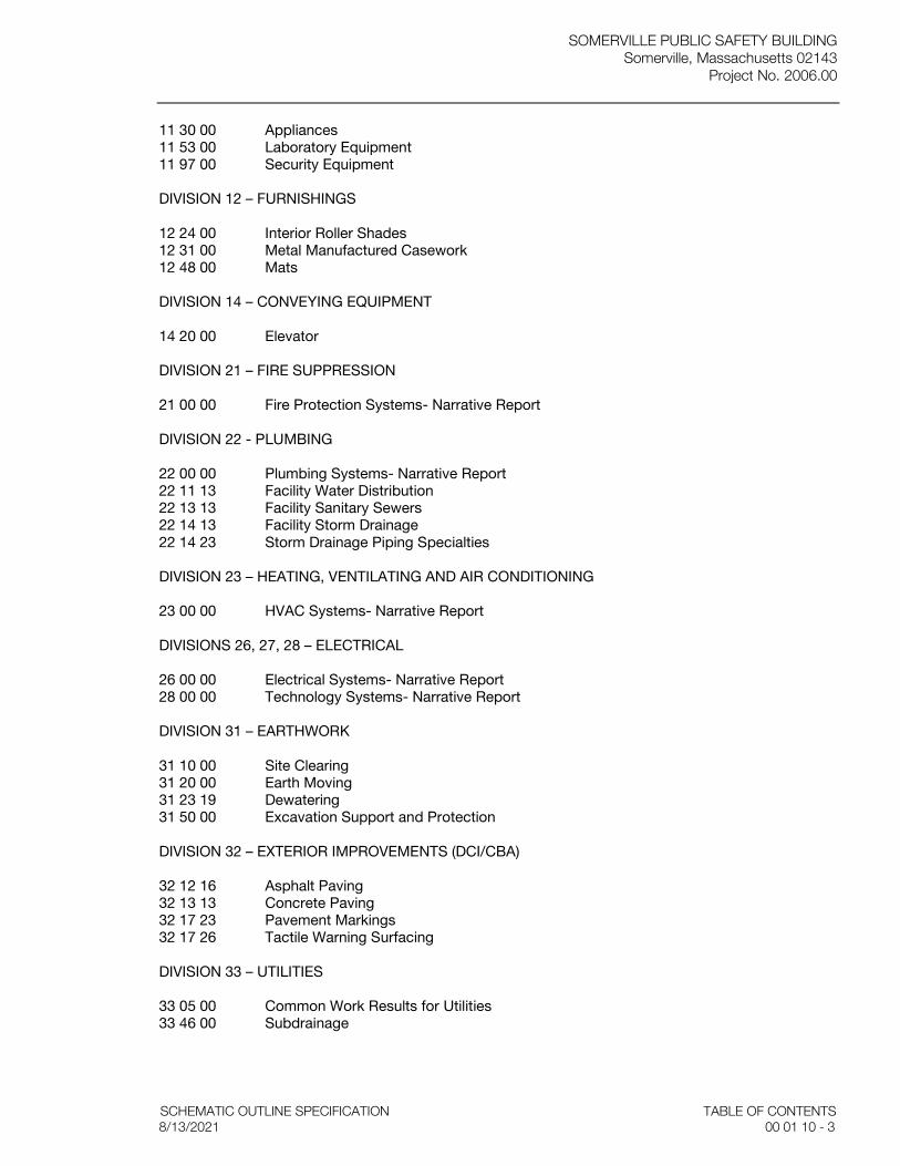
SOMERVILLE PUBLIC SAFETY BUILDING Somerville, Massachusetts 02143
Project No. 2006.00
SCHEMATIC OUTLINE SPECIFICATION TABLE OF CONTENTS 8/13/2021 00 01 10 - 3
11 30 00 Appliances 11 53 00 Laboratory Equipment 11 97 00 Security Equipment DIVISION 12 – FURNISHINGS 12 24 00 Interior Roller Shades 12 31 00 Metal Manufactured Casework 12 48 00 Mats DIVISION 14 – CONVEYING EQUIPMENT 14 20 00 Elevator DIVISION 21 – FIRE SUPPRESSION 21 00 00 Fire Protection Systems- Narrative Report DIVISION 22 - PLUMBING 22 00 00 Plumbing Systems- Narrative Report 22 11 13 Facility Water Distribution 22 13 13 Facility Sanitary Sewers 22 14 13 Facility Storm Drainage 22 14 23 Storm Drainage Piping Specialties DIVISION 23 – HEATING, VENTILATING AND AIR CONDITIONING 23 00 00 HVAC Systems- Narrative Report DIVISIONS 26, 27, 28 – ELECTRICAL 26 00 00 Electrical Systems- Narrative Report 28 00 00 Technology Systems- Narrative Report DIVISION 31 – EARTHWORK 31 10 00 Site Clearing 31 20 00 Earth Moving 31 23 19 Dewatering 31 50 00 Excavation Support and Protection DIVISION 32 – EXTERIOR IMPROVEMENTS (DCI/CBA) 32 12 16 Asphalt Paving 32 13 13 Concrete Paving 32 17 23 Pavement Markings 32 17 26 Tactile Warning Surfacing DIVISION 33 – UTILITIES 33 05 00 Common Work Results for Utilities 33 46 00 Subdrainage

SOMERVILLE PUBLIC SAFETY BUILDING Somerville, Massachusetts 02143 Project No. 2006.00
TABLE OF CONTETNTS SCHEMATIC OUTLINE SPECIFICATION 00 01 10 - 4 8/13/2021
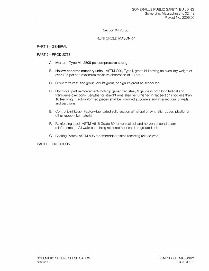
SOMERVILLE PUBLIC SAFETY BUILDING Somerville, Massachusetts 02143
Project No. 2006.00
SCHEMATIC OUTLINE SPECIFICATION REINFORCED MASONRY 8/13/2021 04 23 00 - 1
Section 04 23 00
REINFORCED MASONRY
PART 1 – GENERAL
PART 2 – PRODUCTS
A. Mortar – Type M, 2500 psi compressive strength
B. Hollow concrete masonry units - ASTM C90, Type I, grade N-I having an oven-dry weight of over 125 pcf and maximum moisture absorption of 13 pcf.
C. Grout mixtures: fine grout, low-lift grout, or high-lift grout as scheduled
D. Horizontal joint reinforcement- hot-dip galvanized steel, 9 gauge in both longitudinal and transverse directions; Lengths for straight runs shall be furnished in flat sections not less than 10 feet long. Factory-formed pieces shall be provided at corners and intersections of walls and partitions.
E. Control joint keys- Factory-fabricated solid section of natural or synthetic rubber, plastic, or other rubber-like material
F. Reinforcing steel- ASTM A615 Grade 60 for vertical cell and horizontal bond beam reinforcement. All walls containing reinforcement shall be grouted solid.
G. Bearing Plates- ASTM A36 for embedded plates receiving related work.
PART 3 – EXECUTION
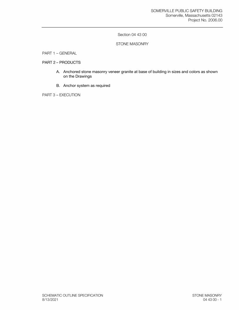
SOMERVILLE PUBLIC SAFETY BUILDING Somerville, Massachusetts 02143
Project No. 2006.00
SCHEMATIC OUTLINE SPECIFICATION STONE MASONRY 8/13/2021 04 43 00 - 1
Section 04 43 00
STONE MASONRY
PART 1 – GENERAL
PART 2 – PRODUCTS
A. Anchored stone masonry veneer granite at base of building in sizes and colors as shown on the Drawings
B. Anchor system as required
PART 3 – EXECUTION
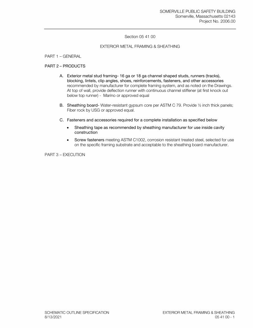
SOMERVILLE PUBLIC SAFETY BUILDING Somerville, Massachusetts 02143
Project No. 2006.00
SCHEMATIC OUTLINE SPECIFICATION EXTERIOR METAL FRAMING & SHEATHING 8/13/2021 05 41 00 - 1
Section 05 41 00
EXTERIOR METAL FRAMING & SHEATHING
PART 1 – GENERAL
PART 2 – PRODUCTS
A. Exterior metal stud framing- 16 ga or 18 ga channel shaped studs, runners (tracks), blocking, lintels, clip angles, shoes, reinforcements, fasteners, and other accessories recommended by manufacturer for complete framing system, and as noted on the Drawings. At top of wall, provide deflection runner with continuous channel stiffener (at first knock out below top runner) - Marino or approved equal
B. Sheathing board- Water-resistant gypsum core per ASTM C 79. Provide ½ inch thick panels; Fiber rock by USG or approved equal.
C. Fasteners and accessories required for a complete installation as specified below
• Sheathing tape as recommended by sheathing manufacturer for use inside cavity construction
• Screw fasteners meeting ASTM C1002, corrosion resistant treated steel, selected for use on the specific framing substrate and acceptable to the sheathing board manufacturer.
PART 3 – EXECUTION
SOMERVILLE PUBLIC SAFETY BUILDING Somerville, Massachusetts 02143 Project No. 2006.00
SCHEMATIC OUTLINE SPECIFICATION MISCELLANEOUS METALS
8/13/2021 05-50-00 - 1
Section 05 50 00
MISCELLANEOUS METALS
PART 1 - GENERAL
PART 2 - PRODUCTS
A. Steel stair structure complete with all supporting members, railing and guard rails
B. Stainless steel railings and brackets
C. Stainless steel splash guards (Jan Clo/ Decon Lockers & Stationware Wash/ SFD WasherDryer)
D. Stainless steel countertop (Evidence Process/ Booking/ Firearms cleaning/ Decon)
E. Metal Shelving (Evidence Weapons Sto/ Narcotics Sto/ SPD Assault Sto/ SPD Training Aids Sto/ Firearms cleaning/ SPD Quartermaster sto/ SPD Motorcycle & bike supplies/ SPD Found Property Sto/ SPD Marine Sto/ Fire training aids/Traffic Equip Sto/ Shared Jan Clo/ SFD Bike Sto/ SFD Quartermaster Sto/ SFD Auxiliary Sto)
F. Heavy-duty galvanized shelving (Hose & Foam)
G. Stainless steel shelving (Decon, EMS supplies, SFD WasherDryer )
H. Stainless detention bench (SPD Booking/Detention cells/ Temporary Holding)
I. Welded steel plate ceiling (Detention cells)
J. Fire pole & cage
K. Guard rail support system for exterior glazed terrace rail
PART 3 - EXECUTION
END OF SECTION
SOMERVILLE PUBLIC SAFETY BUILDING Somerville, Massachusetts 02143
Project No. 2006.00
SCHEMATIC OUTLINE SPECIFICATION STONE MASONRY 8/13/2021 04 43 00 - 1
Section 05 58 13
COLUMN COVERS
PART 1 – GENERAL
PART 2 – PRODUCTS
A. Pre-engineered architectural metal column system including facing material, mounting channel, blocking, trims and reveals. System comes “ready to install” with materials required for a complete assembly. Internal fasteners to be concealed type. – LEVELc Column System by Forms & Surfaces or approved equal (Main entry & Shared Lobby where shown on Drawings)
B. Material to be satin stainless steel in sizes as shown on the Drawings.
PART 3 – EXECUTION

SOMERVILLE PUBLIC SAFETY BUILDING Somerville, Massachusetts 02143
Project No. 2006.00
SCHEMATIC OUTLINE SPECIFICATION ROUGH CARPENTRY 8/13/2021 06 10 00 - 1
Section 06 10 00
ROUGH CARPENTRY
PART 1 – GENERAL
PART 2 – PRODUCTS
A. Plywood backboard (NOC/Radio room; Demarc; Elev machine room; Elec rm; Elec clo; IDF clo)
B. Plywood security liner at GWB (Evidence Technician Office; Evidence Pioneering; Evidence Lab; Evidence, General Storage; Evidence, Assault Sto)
C. Photo backboard (Booking)
PART 3 – EXECUTION

SOMERVILLE PUBLIC SAFETY BUILDING Somerville, Massachusetts 02143
Project No. 2006.00
SCHEMATIC OUTLINE SPECIFICATION FINISH CARPENTRY 8/13/2021 06 20 00 - 1
Section 06 20 00
FINISH CARPENTRY
PART 1 – GENERAL
PART 2 – PRODUCTS
A. Lobby display cases (Shared Lobby; Fire Visitor Lobby)
B. Lobby pamphlet racks
C. Chair rails
D. Coat rods & shelves
E. Millwork (upper and base cabinets at Community room/ Shared Dispatch/ mail alcove- Police/ Digital Forensics/ Firearms cleaning/SFD WasherDryer/ SFD Auxiliary Day_Kitchenette/ Pkg Roll Call)
F. Wood workbench (SFD Repair shop)
G. Wall shelving (Dispatch; Fire Admin Sto; SFD Repair shop; Pkg Sign Shop)
H. Wood wainscot (Pkg Public Waiting)
I. Transaction counter (Pkg Public Waiting)
J. Full height premium wood paneling (Shared Public Lobby)
K. Exterior wood trellis (Roof Garden)
PART 3 – EXECUTION
SOMERVILLE PUBLIC SAFETY BUILDING Somerville, Massachusetts 02143
Project No. 2006.00
SCHEMATIC OUTLINE SPECIFICATION SOLID SURFACING FABRICATIONS 8/13/2021 06 61 16 - 1
Section 06 61 16
SOLID SURFACING FABRICATIONS
PART 1 – GENERAL
PART 2 – PRODUCTS
A. 0.50 inch (13 mm) by Wilsonart Gibralter Solid Surface or approved equal
1. Vanities – countertops with integral bowl (Toilet rooms/mothers’ room/ Locker-Shower rooms)
2. Shower room shelving
3. Countertops- (Shared Training Kitchenette/Dispatch break room/ Shared break room/ Shared IT workshop/ Admin conf rm/ Police transaction/ Records office/Traffic conference/ Roll call/ Patrol evidence prep/ Major Case/ Fire Visitor lobby/ SFD WasherDryer/ SFD Auxiliary Sto/ Pkg Admin Conf rm/ Pkg Roll Call/ Pkg Break Room/ Pkg Work rm/ )
PART 3 – EXECUTION
SOMERVILLE PUBLIC SAFETY BUILDING Somerville, Massachusetts 02143
Project No. 2006.00
SCHEMATIC OUTLINE SPECIFICATION EXTERIOR INSULATION 8/13/2021 07 21 00 - 1
Section 07 21 00
EXTERIOR INSULATION
PART 1 – GENERAL
PART 2 – PRODUCTS
A. Below grade foundation wall & under slab insulation: Extruded polystyrene board by Dow Chemical or approved equal
B. Perimeter foundation wall insulation: Extruded polystyrene board by Dow Chemical or approved equal
C. Cavity wall insulation: mineral wool fiber insulation, made from basalt rock and slag by Rockwool Cavityrock or approved equal.
D. Low pressure polyurethane foamed-in-place insulation/air barrier sealant by Dow or approved equal.
PART 3 – EXECUTION

SOMERVILLE PUBLIC SAFETY BUILDING Somerville, Massachusetts 02143
Project No. 2006.00
SCHEMATIC OUTLINE SPECIFICATION ACOUSTIC INSULATION 8/13/2021 07 22 00 - 1
Section 07 22 00
ACOUSTIC INSULATION
PART 1 – GENERAL
PART 2 – PRODUCTS
A. Unfaced thermal batt/blanket glass fiber insulation by Owens Corning Fiberglas Corp or approved equal
B. Stapes, tape, adhesives, fasteners as required.
PART 3 – EXECUTION

SOMERVILLE PUBLIC SAFETY BUILDING Somerville, Massachusetts 02143
Project No. 2006.00
SCHEMATIC OUTLINE SPECIFICATION AIR & WATER RESISTIVE BARRIERS 8/13/2021 07 27 00 - 1
Section 07 27 00
AIR & WATER RESISTIVE BARRIERS
PART 1 – GENERAL
PART 2 – PRODUCTS
A. Fully-adhered vapor permeable and non-permeable air and water resistive barriers in exterior wall assemblies including flashing, sealants, and related accessories to provide a continuous assembly and transition to adjacent materials and assemblies. Product to be nominal 40 mil thickness consisting of an aluminum-faced cross-laminated high density polyethylene sheet laminated with a styrene-butadiene modified asphalt adhesive, such as CCW 705 FR-A by Carlisle Coatings & Waterproofing
B. Auxiliary Materials:
a. Liquid waterborne or solvent-borne primer recommended for substrate by manufacturer of air barrier material.
b. Counterflashing strip: modified bituminous 40 mil, self-adhering sheet consisting of 32 mils of rubberized asphalt laminated to an 8-mil-thick, crosslaminated polyethylene film with release liner backing.
c. Butyl Strip at Termination with EPDM or TPO Roofing Membrane: Vapor-retarding, 30- to 40- mil-thick, self-adhering; polyethylene-film-reinforced top surface laminated to layer of butyl adhesive, with release liner backing.
d. Modified Bituminous Strip To Cover Cracks and Joints and Terminate Air Barrier to Compatible Roofing Membrane: Vapor-retarding, 40-mil-thick, smooth-surfaced, self-adhering; consisting of 36 mils of rubberized asphalt laminated to a 4-mil- polyethylene film with release liner backing.
e. Termination Mastic: Cold fluid-applied elastomeric liquid; trowel grade. Substrate Patching Membrane: Manufacturer's standard trowel-grade substrate filler.
f. Adhesive and Tape: Air barrier manufacturer's standard adhesive and pressure-sensitive adhesive tape.
g. Stainless-Steel Sheet: ASTM A 240/A 240M, Type 304, 0.0187 inch thick, and Series 300 stainless-steel fasteners.
h. Sprayed Polyurethane Foam Sealant to Fill Gaps at Penetrations and Openings: one- or two- component, foamed-in-place, polyurethane foam sealant, 1.5 to 2.0 lb/cu. ft. density; flame spread index of 25 or less according to ASTM E 162; with primer and noncorrosive substrate cleaner recommended by foam sealant manufacturer.
i. Preformed Silicone-Sealant Extrusion to Seal Air Barrier Terminations with Glazing Systems: Pre-cured silicone extrusion consisting of cured low-modulus silicone extrusion, sized to fit opening widths, with manufacturer’s recommended sealant for bonding extrusions to substrates.
j. Joint Sealant: ASTM C920, single-component, neutral-curing silicone, Class 100/150 (low-imodulus), Grade NS, Use NT related to exposure, and, as applicable to joint substrates indicated, Use O. Comply with Division 07 Section for Joint Sealants.
PART 3 – EXECUTION
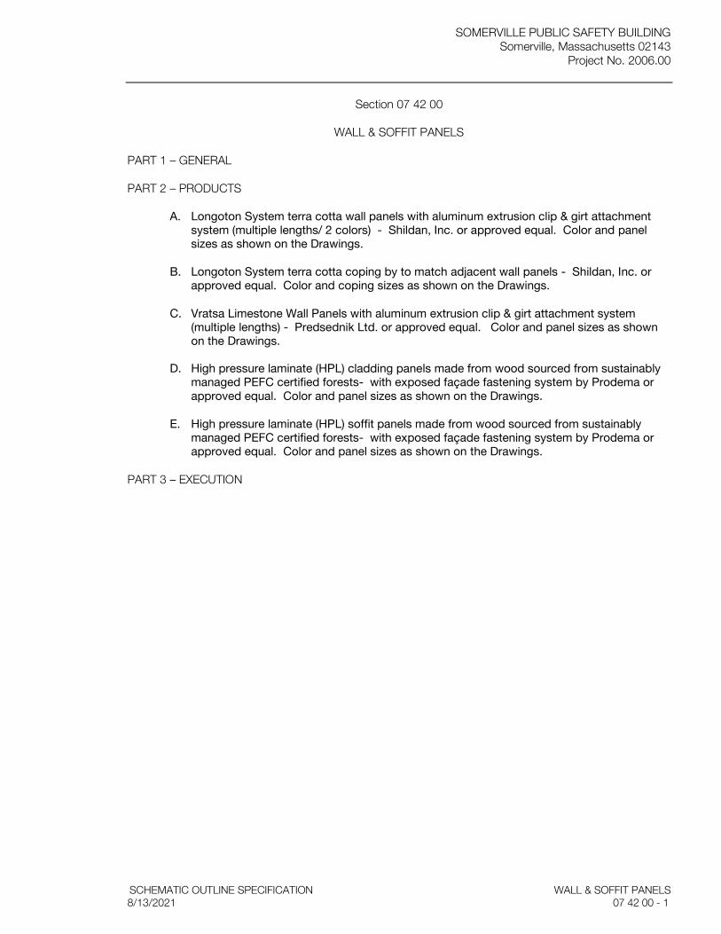
SOMERVILLE PUBLIC SAFETY BUILDING Somerville, Massachusetts 02143
Project No. 2006.00
SCHEMATIC OUTLINE SPECIFICATION WALL & SOFFIT PANELS 8/13/2021 07 42 00 - 1
Section 07 42 00
WALL & SOFFIT PANELS
PART 1 – GENERAL
PART 2 – PRODUCTS
A. Longoton System terra cotta wall panels with aluminum extrusion clip & girt attachment system (multiple lengths/ 2 colors) - Shildan, Inc. or approved equal. Color and panel sizes as shown on the Drawings.
B. Longoton System terra cotta coping by to match adjacent wall panels - Shildan, Inc. or approved equal. Color and coping sizes as shown on the Drawings.
C. Vratsa Limestone Wall Panels with aluminum extrusion clip & girt attachment system (multiple lengths) - Predsednik Ltd. or approved equal. Color and panel sizes as shown on the Drawings.
D. High pressure laminate (HPL) cladding panels made from wood sourced from sustainably managed PEFC certified forests- with exposed façade fastening system by Prodema or approved equal. Color and panel sizes as shown on the Drawings.
E. High pressure laminate (HPL) soffit panels made from wood sourced from sustainably managed PEFC certified forests- with exposed façade fastening system by Prodema or approved equal. Color and panel sizes as shown on the Drawings.
PART 3 – EXECUTION
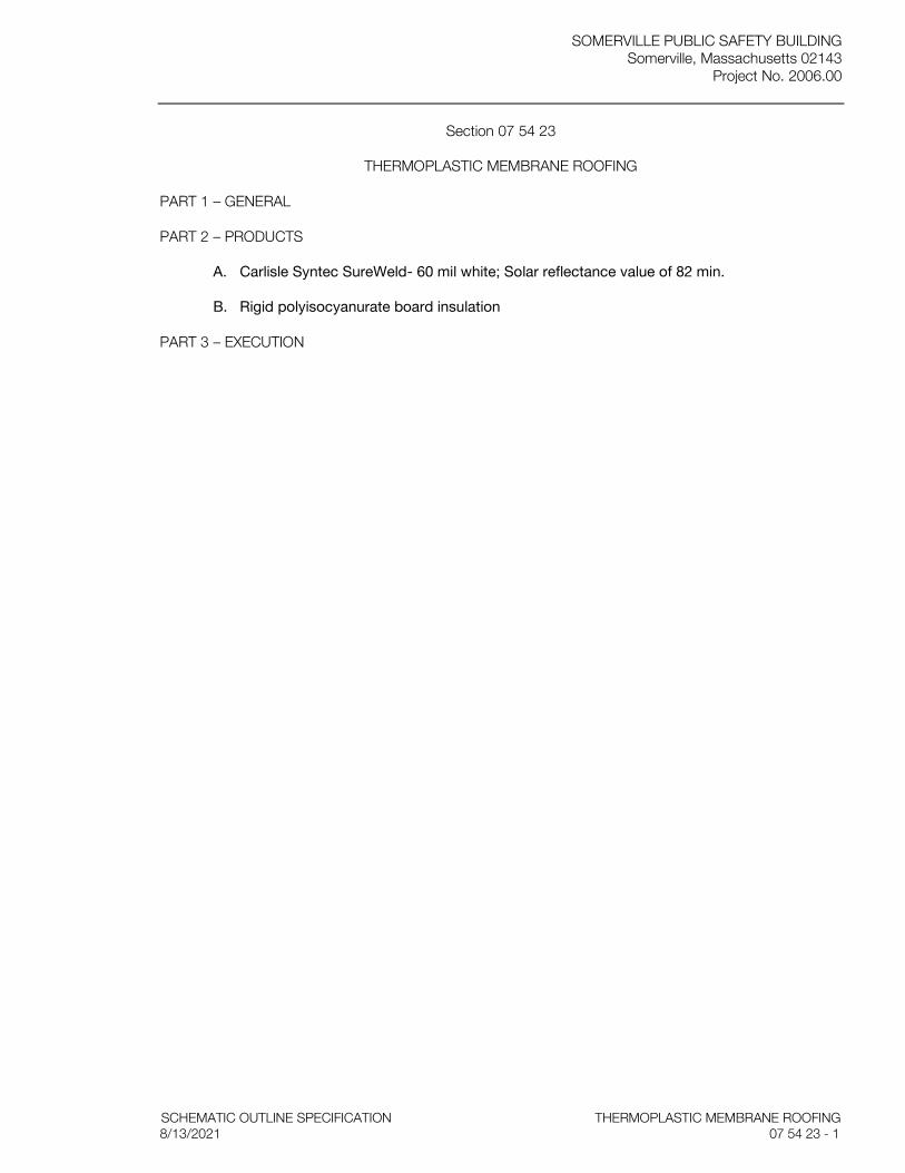
SOMERVILLE PUBLIC SAFETY BUILDING Somerville, Massachusetts 02143
Project No. 2006.00
SCHEMATIC OUTLINE SPECIFICATION THERMOPLASTIC MEMBRANE ROOFING 8/13/2021 07 54 23 - 1
Section 07 54 23
THERMOPLASTIC MEMBRANE ROOFING
PART 1 – GENERAL
PART 2 – PRODUCTS
A. Carlisle Syntec SureWeld- 60 mil white; Solar reflectance value of 82 min.
B. Rigid polyisocyanurate board insulation
PART 3 – EXECUTION
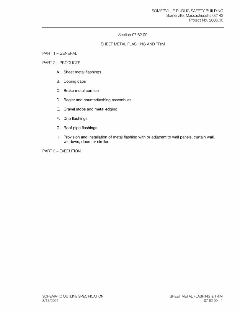
SOMERVILLE PUBLIC SAFETY BUILDING Somerville, Massachusetts 02143
Project No. 2006.00
SCHEMATIC OUTLINE SPECIFICATION SHEET METAL FLASHING & TRIM 8/13/2021 07 62 00 - 1
Section 07 62 00
SHEET METAL FLASHING AND TRIM
PART 1 – GENERAL
PART 2 – PRODUCTS
A. Sheet metal flashings
B. Coping caps
C. Brake metal cornice
D. Reglet and counterflashing assemblies
E. Gravel stops and metal edging
F. Drip flashings
G. Roof pipe flashings
H. Provision and installation of metal flashing with or adjacent to wall panels, curtain wall, windows, doors or similar.
PART 3 – EXECUTION
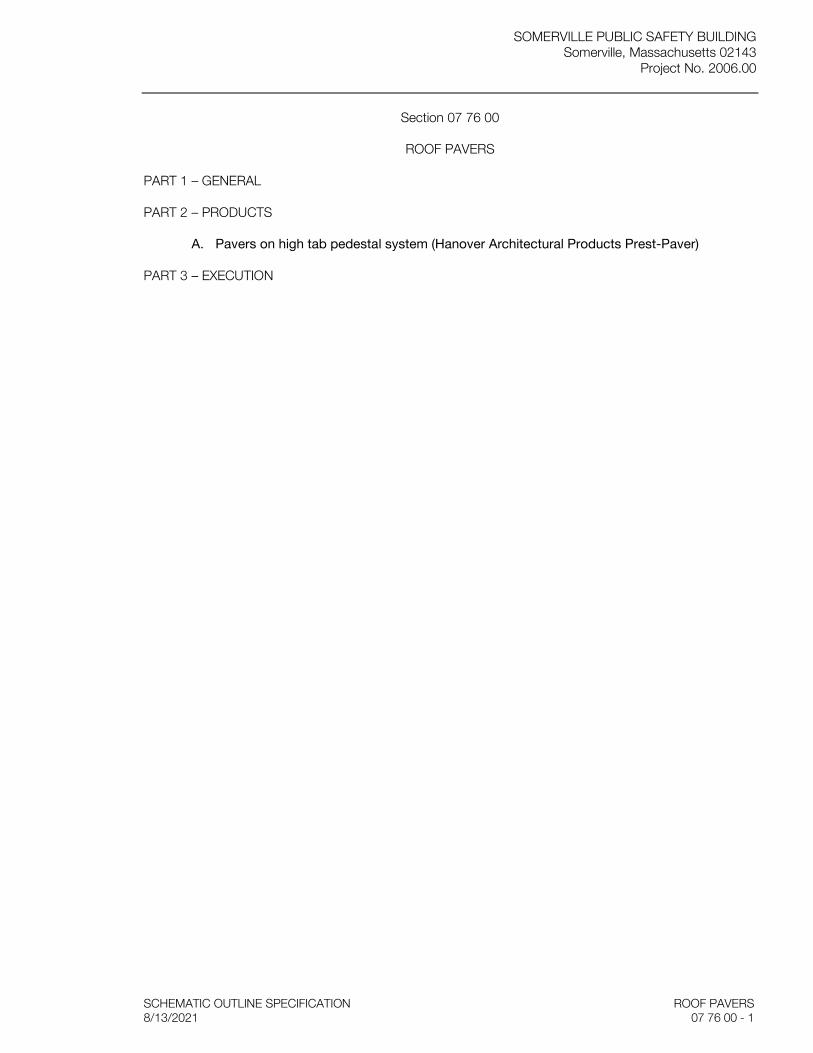
SOMERVILLE PUBLIC SAFETY BUILDING Somerville, Massachusetts 02143
Project No. 2006.00
SCHEMATIC OUTLINE SPECIFICATION ROOF PAVERS 8/13/2021 07 76 00 - 1
Section 07 76 00
ROOF PAVERS
PART 1 – GENERAL
PART 2 – PRODUCTS
A. Pavers on high tab pedestal system (Hanover Architectural Products Prest-Paver)
PART 3 – EXECUTION

SOMERVILLE PUBLIC SAFETY BUILDING Somerville, Massachusetts 02143
Project No. 2006.00
SCHEMATIC OUTLINE SPECIFICATION FIRESTOPPING 8/13/2021 07 84 00 - 1
Section 07 84 00
FIRESTOPPING
PART 1 – GENERAL
PART 2 – PRODUCTS
A. Firestop mortar: asbestos free, cementitious mortar, such as Tremstop M by Tremco Inc.
B. Silicone firestop sealant: single component, non-combustible silicone elastomer firestop sealant, such as Tremsil by Tremco Inc.
C. Intumescent firestop sealant and caulks: acrylic based, water resistant sealant, which will not re-emulsity after drying, such as Tremstop 1A by Tremco Inc.
D. Firestop putty: stick or pads, such as Fire Barrier Modable Putty by 3M Company
E. Firestop collars: premanufactured fire protective pipe sleeve, such as Fireshield Firestop Sleeve by 3M Company
F. Firestop pillows, such as Tremstop P.S. by Tremco Inc.
G. Wrap strips, such as Tremco W.S. by Tremco Inc.
H. Mineral wool fiber/ceramic wool non-combustible insulation (fire safing), Fibrex FBX by Fibrex Insulations Inc.
I. Elastomeric firestopping: Non halogenated latex based elastromeric coating applied by airless spray, such as Spec Seal Elastomeric Firestop Spray by Specified Technologies, Inc.
J. Accessories
1. Foaming & damming materials: mineral fiberboard or other type as recommended by firestopping manufacturer.
2. Primer, sealant and solvents as recommended by firestopping manufacturer.
3. Woven wire mesh: galvanized 20 ga. woven wire mesh “chicken wire”, 1 inch spacing
PART 3 – EXECUTION
SOMERVILLE PUBLIC SAFETY BUILDING Somerville, Massachusetts 02143
Project No. 2006.00
SCHEMATIC OUTLINE SPECIFICATION SEALANTS 8/13/2021 07 92 00 - 1
Section 07 92 00
SEALANTS
PART 1 – GENERAL
PART 2 – PRODUCTS
A. General: Sealants and primers must comply wit the following limits for VOC content:
1. Architectural Sealants: 250 g/L.
2. Roofing Sealants: 450 g/L.
3. Sealant primer: 250 g/L.
B. Joint Sealer Type AP (Acrylic painters caulk): One component acrylic latex caulking compound (Interior – plaster to trim)
C. Joint Sealer Type BP2 (Bitumen modified polyurethane, Multi-component): Pouring grade self-leveling bitumen modified two component urethane sealant (concrete to concrete)
D. Joint Sealer Type P1 (Polyurethane 1-component): Low modulus single component gungrade polyurethane sealant, non-sagging (Exterior – wood to wood & wood to masonry)
E. Joint Sealer Type SC (Silicone, general construction): One-part medium modulus, natural cure, synthetic sealant
F. Joint Sealer Type SS (security sealant)- Two-part epoxy security sealant. (Interior- for use in all Detention areas)
G. Joint Sealer Type MRS (Mildew resistant, damp or wet locations): Standard mildew resistant (Interior – solid surfacing to GWB/ bath mirror)
PART 3 – EXECUTION
SOMERVILLE PUBLIC SAFETY BUILDING Somerville, Massachusetts 02143
Project No. 2006.00
SCHEMATIC OUTLINE SPECIFICATION HOLLOW METAL DOORS & FRAMES 8/13/2021 08 11 13 - 1
Section 08 11 13
HOLLOW METAL DOORS & FRAMES
PART 1 – GENERAL
PART 2 – PRODUCTS
A. Standard hollow metal frames: pressed sheet steel, 2” wide unless noted otherwise; Drywall type with return flange at drywall installations (knock-down type), Steelcraft DW series or equal. Standard type elsewhere, Steelcraft F series or equal. 16 ga at fire rated and exterior construction; 18 ga. typical at interior construction
B. Standard hollow metal doors: flush-type, roller leveled facing sheets, fully-welded construction, full flush or seamless type. Typical interior doors: heavy duty, 18 ga. face sheets; polyethylene core construction at exterior reinforced doors insulated with R value of 3.4 min.
C. Typical frame and door face sheet material: commercial-quality carbon steel, cold-rolled for exposed door faces and either hot or cold-rolled for frames.
D. Hollow metal door manufacturer to provide a cut out for an electronic power transfer (EPT) unit in all frames, with a filler plate for doors not scheduled to receive an EPT unit.
PART 3 – EXECUTION

SOMERVILLE PUBLIC SAFETY BUILDING Somerville, Massachusetts 02143
Project No. 2006.00
SCHEMATIC OUTLINE SPECIFICATION FLUSH WOOD DOORS 8/13/2021 08 14 16 - 1
Section 08 14 16
FLUSH WOOD DOORS
PART 1 – GENERAL
PART 2 – PRODUCTS
A. Solid-core doors: solid particleboard or wood stave cores, of 5- or 7-ply construction; with minimum 1/16” thick cross-banding, hardwood edge stiles and rails
B. Fire doors: same as typical solid-core door, except with solid mineral core
C. Bullet resistant door between Station officer and Lobby
D. Door veneer to match wood species specified in FINISH CARPENTRY, slip-matched, for natural wood finish.
E. Wood to be FSC-certified
PART 3 – EXECUTION

SOMERVILLE PUBLIC SAFETY BUILDING Somerville, Massachusetts 02143
Project No. 2006.00
SCHEMATIC OUTLINE SPECIFICATION COILING DOORS AND GRILLES 8/13/2021 08 33 00 - 1
Section 08 33 00
COILING DOORS AND GRILLES
PART 1 – GENERAL
PART 2 – PRODUCTS
A. Solid uninsulated rolling door, with 16 ga. galvanized steel curtain, Overhead Door model 610 or approved equal (Parking Garage)
B. Controls and photo eye sensors
PART 3 – EXECUTION
SOMERVILLE PUBLIC SAFETY BUILDING Somerville, Massachusetts 02143
Project No. 2006.00
SCHEMATIC OUTLINE SPECIFICATION DETENTION DOORS & FRAME ASSEMBLIES 8/13/2021 08 34 63 - 1
Section 08 34 63
DETENTION DOORS & FRAME ASSEMBLIES.
PART 1 – GENERAL
PART 2 – PRODUCTS
A. Door and frame units: Bullet-resisting steel with door face sheets not less than 1/8”. Doors to be fully welded construction, 1 ¾” thickness. Model #DT by Chicago Bullet Proof Equipment or approved equal
B. Frames to be mitered and welded. Swinging detention doors to be pre-hung and pre-fit within door & frame assembly.
C. Glazing to be laminated polycarbonate: Lexgard MPC 500 or equal, transparent armor for door vision panels (I/2” nom.)
PART 3 – EXECUTION
SOMERVILLE PUBLIC SAFETY BUILDING Somerville, Massachusetts 02143
Project No. 2006.00
SCHEMATIC OUTLINE SPECIFICATION SECTIONAL OVERHEAD DOORS 8/13/2021 08 36 13 - 1
Section 08 36 13
SECTIONAL OVERHEAD DOORS
PART 1 – GENERAL
PART 2 – PRODUCTS
A. Glazed sectional aluminum panel overhead doors, and insulated aluminum panel sectional overhead doors – Clopay or approved equal (Fire Investigative Bay; SFD Apparatus Bay)
B. Solid insulated aluminum panel sectional overhead door – Clopay or approved equal (SALLYPORT)
C. Controls and photo eye sensors
PART 3 – EXECUTION
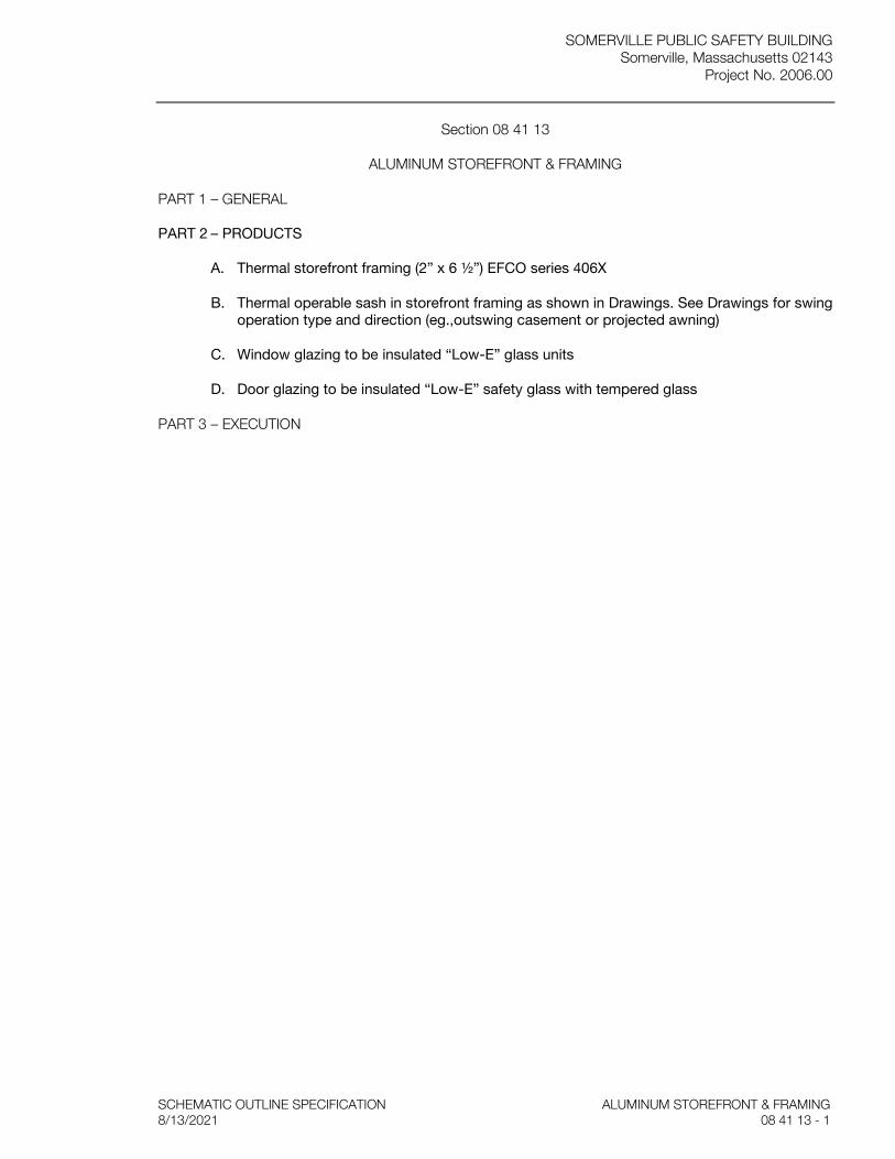
SOMERVILLE PUBLIC SAFETY BUILDING Somerville, Massachusetts 02143
Project No. 2006.00
SCHEMATIC OUTLINE SPECIFICATION ALUMINUM STOREFRONT & FRAMING 8/13/2021 08 41 13 - 1
Section 08 41 13
ALUMINUM STOREFRONT & FRAMING
PART 1 – GENERAL
PART 2 – PRODUCTS
A. Thermal storefront framing (2” x 6 ½”) EFCO series 406X
B. Thermal operable sash in storefront framing as shown in Drawings. See Drawings for swing operation type and direction (eg.,outswing casement or projected awning)
C. Window glazing to be insulated “Low-E” glass units
D. Door glazing to be insulated “Low-E” safety glass with tempered glass
PART 3 – EXECUTION
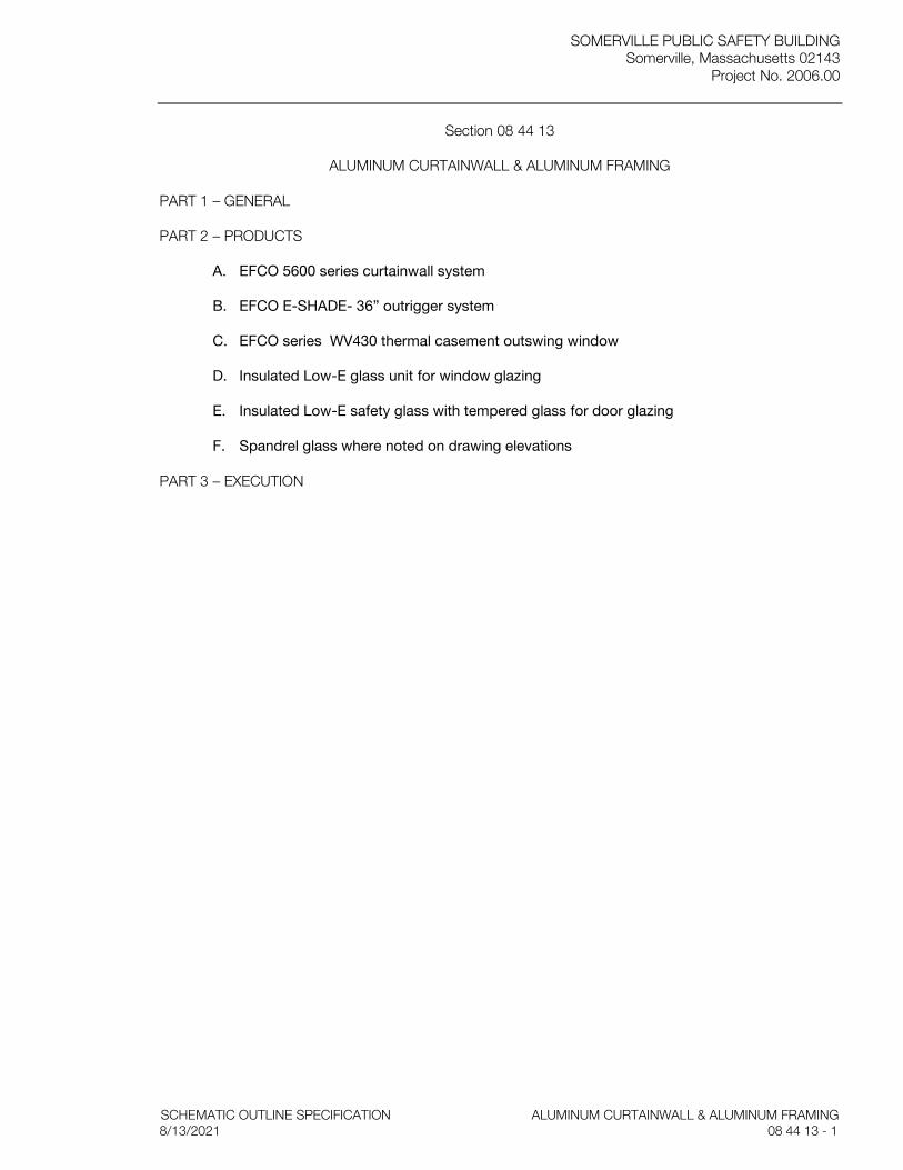
SOMERVILLE PUBLIC SAFETY BUILDING Somerville, Massachusetts 02143
Project No. 2006.00
SCHEMATIC OUTLINE SPECIFICATION ALUMINUM CURTAINWALL & ALUMINUM FRAMING 8/13/2021 08 44 13 - 1
Section 08 44 13
ALUMINUM CURTAINWALL & ALUMINUM FRAMING
PART 1 – GENERAL
PART 2 – PRODUCTS
A. EFCO 5600 series curtainwall system
B. EFCO E-SHADE- 36” outrigger system
C. EFCO series WV430 thermal casement outswing window
D. Insulated Low-E glass unit for window glazing
E. Insulated Low-E safety glass with tempered glass for door glazing
F. Spandrel glass where noted on drawing elevations
PART 3 – EXECUTION
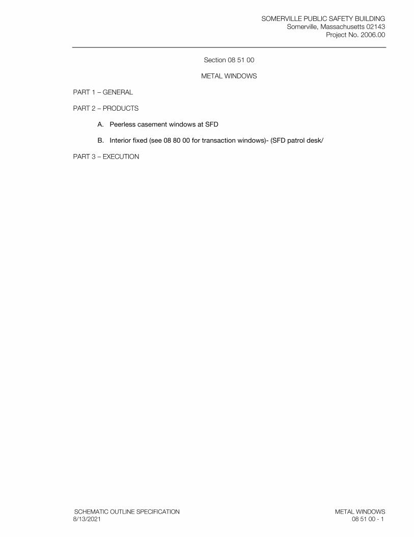
SOMERVILLE PUBLIC SAFETY BUILDING Somerville, Massachusetts 02143
Project No. 2006.00
SCHEMATIC OUTLINE SPECIFICATION METAL WINDOWS 8/13/2021 08 51 00 - 1
Section 08 51 00
METAL WINDOWS
PART 1 – GENERAL
PART 2 – PRODUCTS
A. Peerless casement windows at SFD
B. Interior fixed (see 08 80 00 for transaction windows)- (SFD patrol desk/
PART 3 – EXECUTION
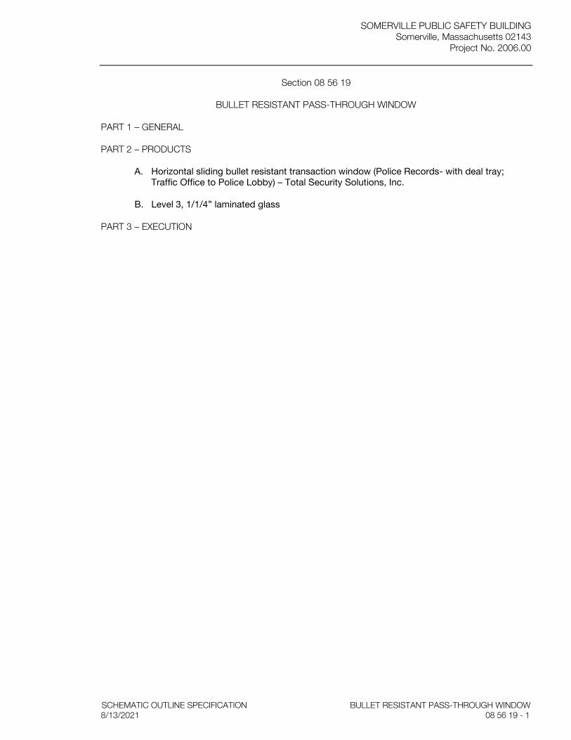
SOMERVILLE PUBLIC SAFETY BUILDING Somerville, Massachusetts 02143
Project No. 2006.00
SCHEMATIC OUTLINE SPECIFICATION BULLET RESISTANT PASS-THROUGH WINDOW 8/13/2021 08 56 19 - 1
Section 08 56 19
BULLET RESISTANT PASS-THROUGH WINDOW
PART 1 – GENERAL
PART 2 – PRODUCTS
A. Horizontal sliding bullet resistant transaction window (Police Records- with deal tray; Traffic Office to Police Lobby) – Total Security Solutions, Inc.
B. Level 3, 1/1/4” laminated glass
PART 3 – EXECUTION
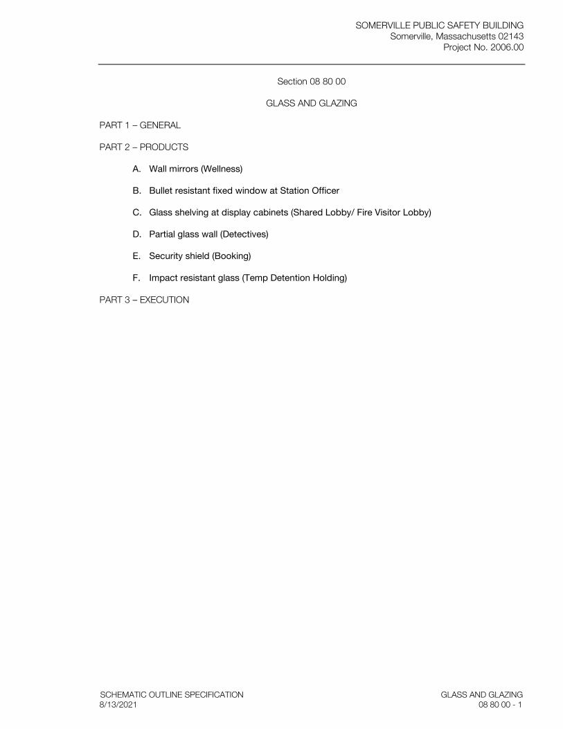
SOMERVILLE PUBLIC SAFETY BUILDING Somerville, Massachusetts 02143
Project No. 2006.00
SCHEMATIC OUTLINE SPECIFICATION GLASS AND GLAZING 8/13/2021 08 80 00 - 1
Section 08 80 00
GLASS AND GLAZING
PART 1 – GENERAL
PART 2 – PRODUCTS
A. Wall mirrors (Wellness)
B. Bullet resistant fixed window at Station Officer
C. Glass shelving at display cabinets (Shared Lobby/ Fire Visitor Lobby)
D. Partial glass wall (Detectives)
E. Security shield (Booking)
F. Impact resistant glass (Temp Detention Holding)
PART 3 – EXECUTION

SOMERVILLE PUBLIC SAFETY BUILDING Somerville, Massachusetts 02143
Project No. 2006.00
SCHEMATIC OUTLINE SPECIFICATION NON-STRUCTURAL METAL FRAMING 8/13/2021 09 22 16 - 1
Section 09 22 16
NON-STRUCTURAL METAL FRAMING
PART 1 – GENERAL
PART 2 – PRODUCTS
A. Metal furring and framing, including cross bracing and knee bracing, by Clark/Dietrich Building Systems or approved equal
1. “Hat shaped” Furring channels: 7/8 x 2-3/4 inch, roll-formed, hat-shaped, furring channel 25 gage hot-dip galvanized steel galvanized steel
2. Resilient furring channels: Roll-formed, hat-shaped, 1/2 x 2-5/8 inch, 26 gage hot-dip galvanized steel
3. Furring channels: ‘Z-shaped’ 1-1/2 inch depth, roll-formed, 25 gage, hot-dip galvanized steel.
4. Studs: ‘C-shaped’ screw studs, hot-dip galvanized steel, 20 gage, of widths indicated on the Drawings.
5. Runners for metal studs: ‘U-shaped’ hemmed, hot-dip galvanized steel track, having 1-1/4 inch leg, provided at tops and bottoms of all studs and at heads of all openings in stud partitions.
6. Internal reinforcement for various stud conditions, and bracing as required: 10 gage, minimum, galvanized steel.
7. Furnish cross bracing and knee bracing, as required to assure a completely rigid assembly on metal stud partitions and furred areas.
B. Metal ceiling and soffit framing
1. Carrying channels, 2 inches deep, 16 gage cold-rolled channels, galvanized.
2. Support channels: 3/4 inches deep, 16 gage cold-rolled channels, galvanized.
3. Furring Channels: 7/8 x 2-3/4 inch, roll-formed, hat-shaped, furring channel 25 gage hot- dip galvanized steel galvanized steel conforming to ASTM C 645.
4. Metal Studs used in soffit and ceiling framing: ‘C-shaped’ screw studs, hot-dip galvanized steel, 25 gage, of widths indicated on the Drawings, or other gages as required under the specified standards to meet fire resistance ratings.
C. Deflection track assemblies at tops of metal stud partitions
1. Metal sheet plate blocking and bracing, where indicated: 20 ga. galvanized sheet
PART 3 – EXECUTION

SOMERVILLE PUBLIC SAFETY BUILDING Somerville, Massachusetts 02143
Project No. 2006.00
SCHEMATIC OUTLINE SPECIFICATION GYPSUM BOARD 8/13/2021 09 29 00 - 1
Section 09 29 00
GYPSUM BOARD
PART 1 – GENERAL
PART 2 – PRODUCTS
A. Gypsum panel products, taped & sanded with acoustical joint sealant and backing at perimeter of partitions; 5/8 thick, by USG or approved equal- Fire rated where noted on the drawings
B. Moisture resistant substrate for wall tile, joint accessories, fasteners
C. Exterior gypsum ceiling and soffit board (5/8” thick)
D. Bullet resistant (Shared Public lobby/ SPD lobby)
E. FRP panels (Trash rm) by Glasliner FRP or approved equal
F. Abuse resistant (Tactical training)
PART 3 – EXECUTION
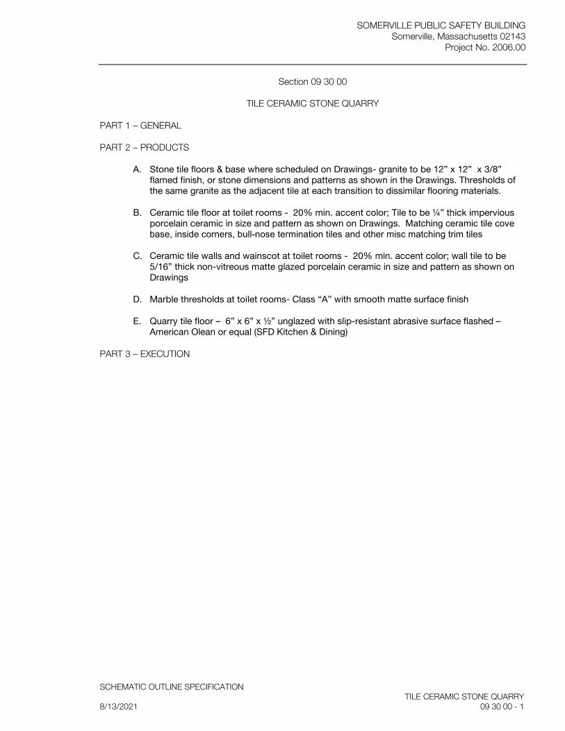
SOMERVILLE PUBLIC SAFETY BUILDING Somerville, Massachusetts 02143
Project No. 2006.00
SCHEMATIC OUTLINE SPECIFICATION TILE CERAMIC STONE QUARRY 8/13/2021 09 30 00 - 1
Section 09 30 00
TILE CERAMIC STONE QUARRY
PART 1 – GENERAL
PART 2 – PRODUCTS
A. Stone tile floors & base where scheduled on Drawings- granite to be 12” x 12” x 3/8” flamed finish, or stone dimensions and patterns as shown in the Drawings. Thresholds of the same granite as the adjacent tile at each transition to dissimilar flooring materials.
B. Ceramic tile floor at toilet rooms - 20% min. accent color; Tile to be ¼” thick impervious porcelain ceramic in size and pattern as shown on Drawings. Matching ceramic tile cove base, inside corners, bull-nose termination tiles and other misc matching trim tiles
C. Ceramic tile walls and wainscot at toilet rooms - 20% min. accent color; wall tile to be 5/16” thick non-vitreous matte glazed porcelain ceramic in size and pattern as shown on Drawings
D. Marble thresholds at toilet rooms- Class “A” with smooth matte surface finish
E. Quarry tile floor – 6” x 6” x ½” unglazed with slip-resistant abrasive surface flashed – American Olean or equal (SFD Kitchen & Dining)
PART 3 – EXECUTION
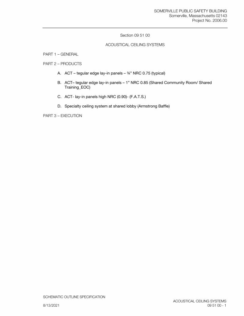
SOMERVILLE PUBLIC SAFETY BUILDING Somerville, Massachusetts 02143
Project No. 2006.00
SCHEMATIC OUTLINE SPECIFICATION ACOUSTICAL CEILING SYSTEMS 8/13/2021 09 51 00 - 1
Section 09 51 00
ACOUSTICAL CEILING SYSTEMS
PART 1 – GENERAL
PART 2 – PRODUCTS
A. ACT – tegular edge lay-in panels – ¾” NRC 0.75 (typical)
B. ACT– tegular edge lay-in panels – 1” NRC 0.85 (Shared Community Room/ Shared Training_EOC)
C. ACT- lay-in panels high NRC (0.90)- (F.A.T.S.)
D. Specialty ceiling system at shared lobby (Armstrong Baffle)
PART 3 – EXECUTION
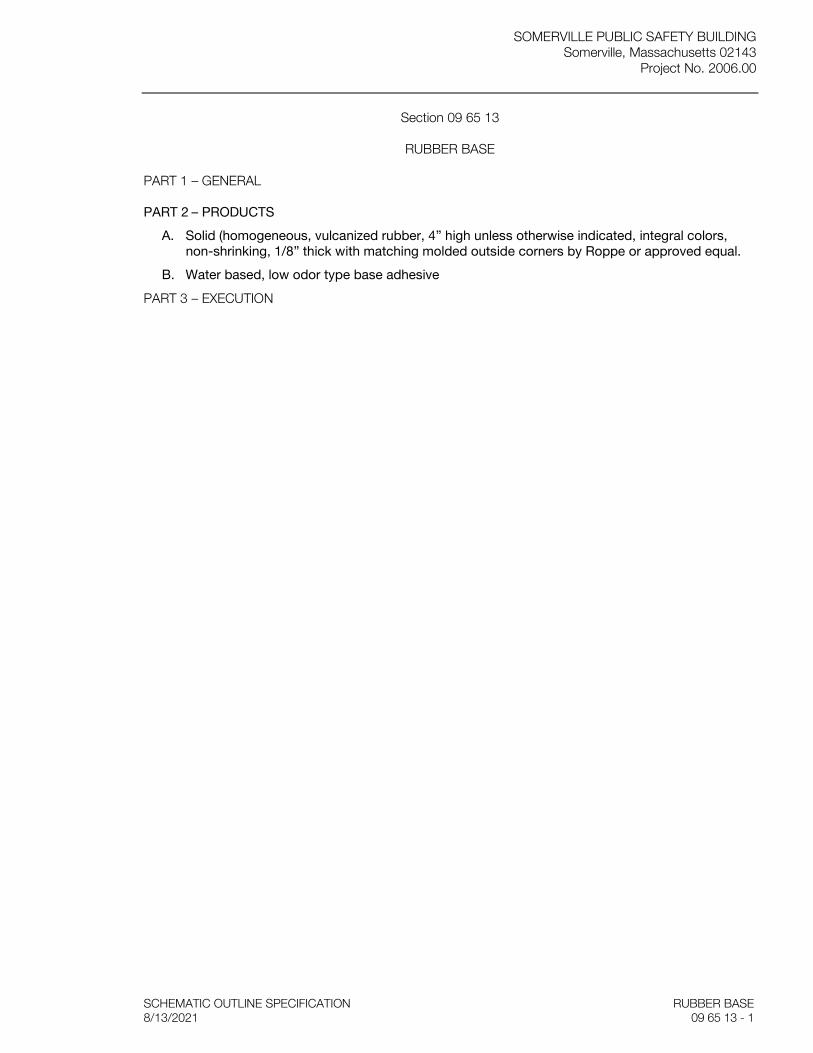
SOMERVILLE PUBLIC SAFETY BUILDING Somerville, Massachusetts 02143
Project No. 2006.00
SCHEMATIC OUTLINE SPECIFICATION RUBBER BASE 8/13/2021 09 65 13 - 1
Section 09 65 13
RUBBER BASE
PART 1 – GENERAL
PART 2 – PRODUCTS
A. Solid (homogeneous, vulcanized rubber, 4” high unless otherwise indicated, integral colors, non-shrinking, 1/8” thick with matching molded outside corners by Roppe or approved equal.
B. Water based, low odor type base adhesive
PART 3 – EXECUTION

SOMERVILLE PUBLIC SAFETY BUILDING Somerville, Massachusetts 02143
Project No. 2006.00
SCHEMATIC OUTLINE SPECIFICATION LINOLEUM FLOORING 8/13/2021 09 65 17 - 1
Section 09 65 17
LINOLEUM FLOORING
PART 1 – GENERAL
PART 2 – PRODUCTS
A. Linoleum tile resilient floor covering (Marmoleum Modular by Forbo Industries or approved equal) where scheduled on the Drawings. Provide minimum of three colors: with 60% field color and two additional accent colors.
PART 3 – EXECUTION

SOMERVILLE PUBLIC SAFETY BUILDING Somerville, Massachusetts 02143
Project No. 2006.00
SCHEMATIC OUTLINE SPECIFICATION RUBBER FLOORING AND STAIR COVERING 8/13/2021 09 65 18 - 1
Section 09 65 18
RUBBER FLOORING AND STAIR COVERING
PART 1 – GENERAL
PART 2 – PRODUCTS
A. 1/8” thick homogeneous rubber tile, through mottled pattern (Shared Community room storage/ Shared kitchenette/ Shared Workroom)
B. Stair Covering- extruded rubber treads with 2” wide min. flush integral contrasting color abrasive strips for installation on stairs on configuration indicated; Risers & Skirting- 1/8” thick rubber with exposed edges factory radius molded
C. Tactile rubber flooring- ½” thick max. 100% synthetic rubber studded tile flooring
PART 3 – EXECUTION
SOMERVILLE PUBLIC SAFETY BUILDING Somerville, Massachusetts 02143
Project No. 2006.00
SCHEMATIC OUTLINE SPECIFICATION RUBBER FLOORING AND STAIR COVERING 8/13/2021 09 65 18 - 1
Section 09 65 18
RUBBER FLOORING AND STAIR COVERING
PART 1 – GENERAL
PART 2 – PRODUCTS
A. Rubber tile flooring: 1/8” thick, homogeneous, through mottled pattern by Nora Rubber Flooring or approved equal
B. Stair riser and treads system: extruded rubber with 2” wide minimum flush integral contrasting color abrasive strips & 1/8” thick rubber or vinyl risers and skirting by Nora Rubber Flooring or approved equal
C. Vinyl transition strips wherever edges of flooring materials abut dissimilar flooring, where no thresholds occur by Nora Rubber Flooring or approved equal
D. Tactile rubber flooring: 100% synthetic rubber studded tile flooring, less than ½” thick by Nora Rubber Flooring or approved equal
E. Crack Filler and Leveling Compound: cementitious type
F. Concrete Primer
G. Water based, low odor type adhesive for use with rubber tile
H. Polymer type floor finish for rubber flooring
PART 3 – EXECUTION
SOMERVILLE PUBLIC SAFETY BUILDING Somerville, Massachusetts 02143
Project No. 2006.00
SCHEMATIC OUTLINE SPECIFICATION SYNTHETIC ATHLETIC FLOORING 8/13/2021 09 65 66 - 1
Section 09 65 66
SYNTHETIC ATHLETIC FLOORING
PART 1 – GENERAL
PART 2 – PRODUCTS
A. 9 mm (3/8”) thick recycled rubber flooring with colored granules; 48” wide rolled sheets by Encore Commercial Flooring or approved equal (Fitness, F.A.T.S.)
PART 3 – EXECUTION
SOMERVILLE PUBLIC SAFETY BUILDING Somerville, Massachusetts 02143
Project No. 2006.00
SCHEMATIC OUTLINE SPECIFICATION SEAMLESS EPOXY FLOORING 8/13/2021 09 67 23 - 1
Section 09 67 23
SEAMLESS EPOXY FLOORING
PART 1 – GENERAL
PART 2 – PRODUCTS
A. Detention floors with integral base (SPD: Cells, Sto, Booking, Holding, Interview; Evidence Lab) – 1/8” system of epoxy-based multi roller applied flooring system with moisture reduction primer, colored quartz aggregate, and urethane topcoat
PART 3 – EXECUTION
SOMERVILLE PUBLIC SAFETY BUILDING Somerville, Massachusetts 02143
Project No. 2006.00
SCHEMATIC OUTLINE SPECIFICATION CARPET TILE 8/13/2021 09 68 10 - 1
Section 09 68 10
CARPET TILE
PART 1 – GENERAL
PART 2 – PRODUCTS
A. CT-1: 24” modular carpet tile (100% of reclaimed carpet tile can be recycled into carpet tile with recycled content) – Captivate Tile by Shaw or approved equal
B. CT-2: 24” modular anti-static carpet tile- StaticSmart Mission Control tiles, Discovery Eco Series by Jolie Industries or approved equal (Shared Dispatch)
PART 3 – EXECUTION
SOMERVILLE PUBLIC SAFETY BUILDING Somerville, Massachusetts 02143
Project No. 2006.00
SCHEMATIC OUTLINE SPECIFICATION ACCESS FLOOR 8/13/2021 09 69 00 - 1
Section 09 69 00
ACCESS FLOOR
PART 1 – GENERAL
PART 2 – PRODUCTS
A. Removable modular floor panels, supported on adjustable pedestals and panel corner locking system; Panel construction to be all steel welded pan with cementitious core – ConCore 1250 Panel-24 by Tate Access Floors, inc. or approved equal (Dispatch; NOC)
B. PosiLock understructure system by ASM Modular System “FS200” or approved equal (Dispatch; NOC)
PART 3 – EXECUTION
SOMERVILLE PUBLIC SAFETY BUILDING Somerville, Massachusetts 02143
Project No. 2006.00
SCHEMATIC OUTLINE SPECIFICATION WALL FINISHES 8/13/2021 09 70 00 - 1
Section 09 70 00
WALL FINISHES
PART 1 – GENERAL
PART 2 – PRODUCTS
A. Pre-engineered architectural wall cladding including wall panels, mounting extrusions, bases, corners, reveal fins, and perimeter fins. System comes “ready to install” with materials required for a complete assembly.– LEVELr Wall Cladding System by Forms & Surfaces or approved equal (Elevator lobbies where shown on Drawings)
B. Material to be satin stainless steel in sizes as shown on the Drawings.
PART 3 – EXECUTION

SOMERVILLE PUBLIC SAFETY BUILDING Somerville, Massachusetts 02143
Project No. 2006.00
SCHEMATIC OUTLINE SPECIFICATION ACOUSTICAL WALL PANELS 8/13/2021 09 84 00 - 1
Section 09 84 00
ACOUSTICAL WALL PANELS
PART 1 – GENERAL
PART 2 – PRODUCTS
A. Acoustic wall panels, 48” wide and length as shown and located on Drawings, mounted at solid walls. Panels to be ¾” thick, 24 pcf mineral core.
B. Manufacturers standard panel construction, fully wrapped edges, with panel manufacturers standard full line of fabric. Facing material to be Guilford of Maine FR 701, 100% polyester, or approved equal.
C. NRC to be 0.50
PART 3 – EXECUTION

SOMERVILLE PUBLIC SAFETY BUILDING Somerville, Massachusetts 02143
Project No. 2006.00
SCHEMATIC OUTLINE SPECIFICATION WATER VAPOR EMISSION CONTROL 8/13/2021 09 96 99 - 1
Section 09 96 99
WATER VAPOR EMISSION CONTROL
PART 1 – GENERAL
PART 2 – PRODUCTS
A. Water vapor reduction system, product of a single manufacturer, such as KOSTER VAP I 2000 System by KOSTER American Corporation or approved equal.
1. KOSTER VAP I 2000 epoxy coating (100% solid epoxy)
2. KOSTER VAP I 06 Primer (non-porous substrate primer)
PART 3 – EXECUTION
SOMERVILLE PUBLIC SAFETY BUILDING Somerville, Massachusetts 02143
Project No. 2006.00
SCHEMATIC OUTLINE SPECIFICATION VISUAL DISPLAY SURFACES 8/13/2021 10 11 00 - 1
Section 10 11 00
VISUAL DISPLAY SURFACES
PART 1 – GENERAL
PART 2 – PRODUCTS
A. Markerboards- LCS white porcelain enamel wiring surface (Claridge) with wood bottom trays for markers where shown on Drawings
B. Frameless tackboards (to receive custom trim) with ¼” pigmented mounted cork
PART 3 – EXECUTION
SOMERVILLE PUBLIC SAFETY BUILDING Somerville, Massachusetts 02143
Project No. 2006.00
SCHEMATIC OUTLINE SPECIFICATION SIGNAGE 8/13/2021 10 14 00 - 1
Section 10 14 00
SIGNAGE
PART 1 – GENERAL
PART 2 – PRODUCTS
A. Plaques – etched stainless steel 1/4” thick; dedication plaque to include city seal
B. Room signage- photopolymer tactile graphic signs to be mounted adjacent to doors, with room names plus Braille, as scheduled on the Drawings.
C. Dimensional letter signage at main lobby – satin stainless steel on mounting studs
D. Dimensional letter signage at building exterior: Factory finished powder coated aluminum channel letters with integral back-lit LED lighting
E. Exterior parking and traffic signs as shown on plans
PART 3 – EXECUTION

SOMERVILLE PUBLIC SAFETY BUILDING Somerville, Massachusetts 02143
Project No. 2006.00
SCHEMATIC OUTLINE SPECIFICATION METAL TOILET COMPARTMENTS 8/13/2021 10 21 13 - 1
Section 10 21 13
METAL TOILET COMPARTMENTS
PART 1 – GENERAL
PART 2 – PRODUCTS
A. Stainless steel toilet partitions, urinal screens and accessories, flush type, floor and ceiling anchored
B. Panel construction to be 22 ga facing plates; doors, partitions, and screens to be 1” thick, 1 ¼” at pilasters and stiles
C. Exposed hardware to be tamper-proof stainless steel.
PART 3 – EXECUTION
SOMERVILLE PUBLIC SAFETY BUILDING Somerville, Massachusetts 02143
Project No. 2006.00
SCHEMATIC OUTLINE SPECIFICATION PARTITIONS 8/13/2021 10 22 19 - 1
Section 10 22 19
PARTITIONS
PART 1 – GENERAL
PART 2 – PRODUCTS
A. Demountable wall partitions (SPD Detectives office)
PART 3 – EXECUTION
SOMERVILLE PUBLIC SAFETY BUILDING Somerville, Massachusetts 02143
Project No. 2006.00
SCHEMATIC OUTLINE SPECIFICATION TOILET ACCESSORIES 8/13/2021 10 28 00 - 1
Section 10 28 00
TOILET ACCESSORIES
PART 1 – GENERAL
PART 2 – PRODUCTS
A. Paper towel dispenser
B. Waste bin
C. Accessible changing table
D. Tilt mirrors
E. Soap dispensers
F. Toilet paper dispensers
G. Grab bars
H. Shower rods
I. Mop/broom holder
J. Detention cell toilet paper holder
PART 3 – EXECUTION

SOMERVILLE PUBLIC SAFETY BUILDING Somerville, Massachusetts 02143
Project No. 2006.00
SCHEMATIC OUTLINE SPECIFICATION STORAGE SPECIALTIES 8/13/2021 10 50 00 - 1
Section 10 50 00
STORAGE SPECIALTIES
PART 1 – GENERAL
PART 2 – PRODUCTS
A. Storage lockers & benches (Dispatch)
B. High density file storage w/recessed tracks (Active Files/ CID Secure Files)
C. Metal shelving (Traffic equip sto)
D. Evidence storage lockers with power (SPD Evidence Locker)
E. Evidence processing pass-through lockers
F. Gun lockers (Sallyport)
G. Property lockers (Booking)
H. Police lockers (Men/Women)
I. Turn out gear cubicles (Fire TO Gear/ Auxiliary TO Gear)
J. 18 x 24 lockable storage units with power, USB, and benches (SFD Locker rm)
K. Gun lockers (Sallyport)
PART 3 – EXECUTION
SOMERVILLE PUBLIC SAFETY BUILDING Somerville, Massachusetts 02143
Project No. 2006.00
SCHEMATIC OUTLINE SPECIFICATION FLAGPOLES 8/13/2021 10 75 16 - 1
Section 10 75 16
FLAGPOLES
PART 1 – GENERAL
PART 2 – PRODUCTS
A. Flagpoles and fittings- 24’ high cone tapered fabricated from extruded aluminum tubing; external halyard with locking cleat and halyard cover; finial ball
B. Mounting/foundation assemblies – flash collar; anchor bolt mounting
C. Solar powered light – battery operated LED light with 100 lux illumination, such as Residential Solar Powered Light #96569 by American Flagpole or approved equal.
PART 3 – EXECUTION

SOMERVILLE PUBLIC SAFETY BUILDING Somerville, Massachusetts 02143
Project No. 2006.00
SCHEMATIC OUTLINE SPECIFICATION ROOF SCREENS 8/13/2021 10 82 13 - 1
Section 10 82 13
ROOF SCREENS
PART 1 – GENERAL
PART 2 – PRODUCTS
A. 24 ga. min. corrugated acoustical metal screen panels fastened to galvanized steel support system by RoofScreen Inc.
B. Height as shown on drawings.
PART 3 – EXECUTION

SOMERVILLE PUBLIC SAFETY BUILDING Somerville, Massachusetts 02143
Project No. 2006.00
SCHEMATIC OUTLINE SPECIFICATION PARKING CONTROL EQUIPMENT 8/13/2021 11 12 00 - 1
Section 11 12 00
PARKING CONTROL EQUIPMENT
PART 1 – GENERAL
PART 2 – PRODUCTS
A. Parking Key and Card Contol units
B. Parking Gates
PART 3 – EXECUTION
SOMERVILLE PUBLIC SAFETY BUILDING Somerville, Massachusetts 02143
Project No. 2006.00
SCHEMATIC OUTLINE SPECIFICATION SECURITY EQUIPMENT 8/13/2021 11 97 00 - 1
Section 11 19 20
SECURITY HARDWARE
PART 1 – GENERAL
PART 2 – PRODUCTS
A. Mechanical security hardware for swing doors, medium security, such as Southern Steel 1010A by Southern Folger Detention Equipment or approved equal
B. Mechanical operation food pass, medium security, such as Southern Steel 1017A by Southern Folger Detention Equipment or approved equal
C. Mortise lock, minimum and medium, such as Southern Steel 10500 by Southern Folger Detention Equipment or approved equal
D. Electric security locks for swinging doors:
1. Medium/Maximum, such as Southern Steel 10120 by Southern Folger Detention Equipment or approved equal
2. Minimum/Medium, such as Southern Steel 10600 by Southern Folger Detention Equipment or approved equal
E. Door Position Switch, such as Southern Steel 200MRS TB by Southern Folger Detention Equipment or approved equal
F. Hinges, such as Southern Steel 204MMSS TB by Southern Folger Detention Equipment or approved equal
G. Miscellaneous: raised pull, recessed pull, detention door stop
H. Security Door Closer/DPS, such as LCN Closer Series 2210DPS or approved equal
I. Cylinders, Keys, and Keying
J. Key Cabinet
PART 3 – EXECUTION

SOMERVILLE PUBLIC SAFETY BUILDING Somerville, Massachusetts 02143
Project No. 2006.00
SCHEMATIC OUTLINE SPECIFICATION APPLIANCES 8/13/2021 11 30 00 - 1
Section 11 30 00
APPLIANCES
PART 1 – GENERAL
PART 2 – PRODUCTS
A. Microwave (Dispatch break room)
B. 30” w. refrig. (Shared Training rm Kitchenette/ Dispatch break room/ Mothers room)
C. 4 Burner range with oven & exhaust hood (Dispatch break room)
D. Washer & dryer (Decon; SFD WasherDryer)
E. 6 Burner range with oven, exhaust hood, commercial uc dishwasher, 36” refrig/freezer, microwave/convection oven (SFD Kitchen)
F. 4 Burner range with oven, exhaust hood, 36” refrig (SFD Auxiliary Day_Kitchenette)
PART 3 – EXECUTION

SOMERVILLE PUBLIC SAFETY BUILDING Somerville, Massachusetts 02143
Project No. 2006.00
SCHEMATIC OUTLINE SPECIFICATION LABORATORY EQUIPMENT 8/13/2021 11 53 00 - 1
Section 11 53 00
LABORATORY EQUIPMENT
PART 1 – GENERAL
PART 2 – PRODUCTS
A. Fume Hood, ducted, dual wall construction, with fully adjustable sliding sash and equipped with explosion-proof light by HEMCO or approved equal (SPD Evidence / Firearms Cleaning)
B. Police Evidence Dusting Station
PART 3 – EXECUTION
SOMERVILLE PUBLIC SAFETY BUILDING Somerville, Massachusetts 02143
Project No. 2006.00
SCHEMATIC OUTLINE SPECIFICATION SECURITY EQUIPMENT 8/13/2021 11 97 00 - 1
Section 11 97 00
SECURITY EQUIPMENT
PART 1 – GENERAL
PART 2 – PRODUCTS
A. Weapons clearing device, with wall or desk mounting brackets as required for location, by APC-200LE by Concept Development Corporation or approved equal
PART 3 – EXECUTION
SOMERVILLE PUBLIC SAFETY BUILDING Somerville, Massachusetts 02143
Project No. 2006.00
SCHEMATIC OUTLINE SPECIFICATION INTERIOR ROLLER SHADES 8/13/2021 12 24 00 - 1
Section 12 24 00
INTERIOR ROLLER SHADES
PART 1 – GENERAL
PART 2 – PRODUCTS
A. Manually Operated Shades, recess mounted with ceiling pocket- double solar and blackout shade-cloth – Mechoshade or approved equal (Training; Conference rms)
B. Manually Operated Shades, recess mounted with ceiling pocket- single solar shade-cloth – Mechoshade or approved equal (SFD Dorms)
PART 3 – EXECUTION
SOMERVILLE PUBLIC SAFETY BUILDING Somerville, Massachusetts 02143
Project No. 2006.00
SCHEMATIC OUTLINE SPECIFICATION METAL MANUFACTURED CASEWORK 8/13/2021 12 31 00 - 1
Section 12 31 00
METAL MANUFACTURED CASEWORK
PART 1 – GENERAL
PART 2 – PRODUCTS
A. Casework to be constructed of sheet steel (stainless steel), except where reinforcing is required. Manufacturer to be Steel Kitchen Corp, or equal. (SFD Kitchen)
B. 20 ga min. drawer fronts, back, bodies, closure plates or scribe; 18 ga. min. base pedestals, doors, and interior panels; 16 ga. min. aprons, gussets, legs
PART 3 – EXECUTION
SOMERVILLE PUBLIC SAFETY BUILDING Somerville, Massachusetts 02143
Project No. 2006.00
SCHEMATIC OUTLINE SPECIFICATION MATS 8/13/2021 12 48 00 - 1
Section 12 48 00
MATS
PART 1 – GENERAL
PART 2 – PRODUCTS
A. Entrance mats at all passage door entry/exit points of PSB except Booking
B. At floor surfaces scheduled to be tile, mats to be installed within an aluminum angle frame that is recessed into the tile or in wall-to-wall applications that do not require a frame. All other locations to be surface roll up mats.
C. Mat in main entry vestibule to be installed within a tapered aluminum angle frame, recessed and matching height of the stone tile border.
D. Recessed and wall-to-wall mats to be GeoTile 100% solution-dyed low static polypropelene with SBR rubber backing by Mat Inc.
E. Roll up mats to be heavy duty, vinyl backed, berber pattern polypropylene fiber with vinyl reducer edges (Mats Inc.)
PART 3 – EXECUTION
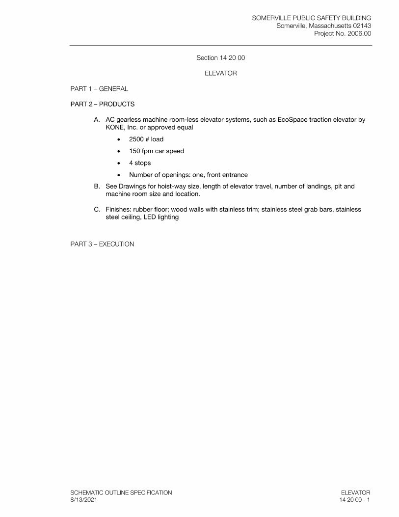
SOMERVILLE PUBLIC SAFETY BUILDING Somerville, Massachusetts 02143
Project No. 2006.00
SCHEMATIC OUTLINE SPECIFICATION ELEVATOR 8/13/2021 14 20 00 - 1
Section 14 20 00
ELEVATOR
PART 1 – GENERAL
PART 2 – PRODUCTS
A. AC gearless machine room-less elevator systems, such as EcoSpace traction elevator by KONE, Inc. or approved equal
• 2500 # load
• 150 fpm car speed
• 4 stops
• Number of openings: one, front entrance
B. See Drawings for hoist-way size, length of elevator travel, number of landings, pit and machine room size and location.
C. Finishes: rubber floor; wood walls with stainless trim; stainless steel grab bars, stainless steel ceiling, LED lighting
PART 3 – EXECUTION

SOMERVILLE PUBLIC SAFETY BUILDING Somerville, Massachusetts 02143
Project No. 2006.00
NARRATIVE 8/13/2021
D.4 STRUCTURAL-NARRATIVE

ROOME & GUARRACINO, LLC Consulting Structural Engineers 48 Grove Street Somerville, MA 02144 Tel: 617.628.1700 Fax: 617.628.1711
Somerville Public Safety Building-Somerville, MA
Structural
This project consists of the design and construction of a new four-story Public Safety Building with adjacent two-story open parking garage, for the City of Somerville. The new building will be irregularly shaped structure of approximately 74,000 sq. ft., that will house both police and fire departments. The adjacent garage will be approximately 9,000 sq. ft., and be separated from the main building with an expansion joint. The buildings will be a Risk Category IV –Essential Facility structures. The first floor will have spaces for the fire departments apparatus bays and offices; police department offices, cells, and for public assembly spaces. The second, third and fourth floors will have offices, areas for fitness and locker rooms, living quarters for the fire department, as well as spaces for mechanicals and training. The first floor will be a slab-on-grade (on improved soils). The second, third, and fourth floors will be composite slab on steel deck with structural steel beams and girders. The roof (steel roof deck supported on structural steel beams and girders) will be flat with mechanical units. Lateral loads will be resisted by structural steel braced frames and moment frames in each direction.
The parking garage will be a two level open garage with a slab-on-grade first floor (on improved soils), and the upper level will be composite slab on steel deck with structural steel beams and girders. Lateral loads will be resisted by structural steel braced frames and moment frames in each direction.
Main Building
2nd, 3rd, and 4th Floor Framing
The slab will be welded wire fabric (6x6-W2.9xW2.9 WWF) reinforced lightweight concrete with a 28 day compressive strength, f’c=3,000psi. The slab will be 3-1/4 inches thick above 2.0 inch deep, 20 ga. composite steel deck (total =5-1/4 inches deep). Beams and girders will be structural steel rolled shapes made composite with the slabs via 3/4in. dia. by 3.5 in. long welded shear studs. Columns will be ASTM A992 (fy=50ksi) steel, or tube steel sections.
Roof Framing
Framing will be 3” – 20 ga. galvanized steel roof deck supported on structural steel beams and girders pitched a ¼”/ft. for drainage.
Facade System
The façade system for the building will consists of masonry and terracotta veneer with 6” light-gage steel stud backup.
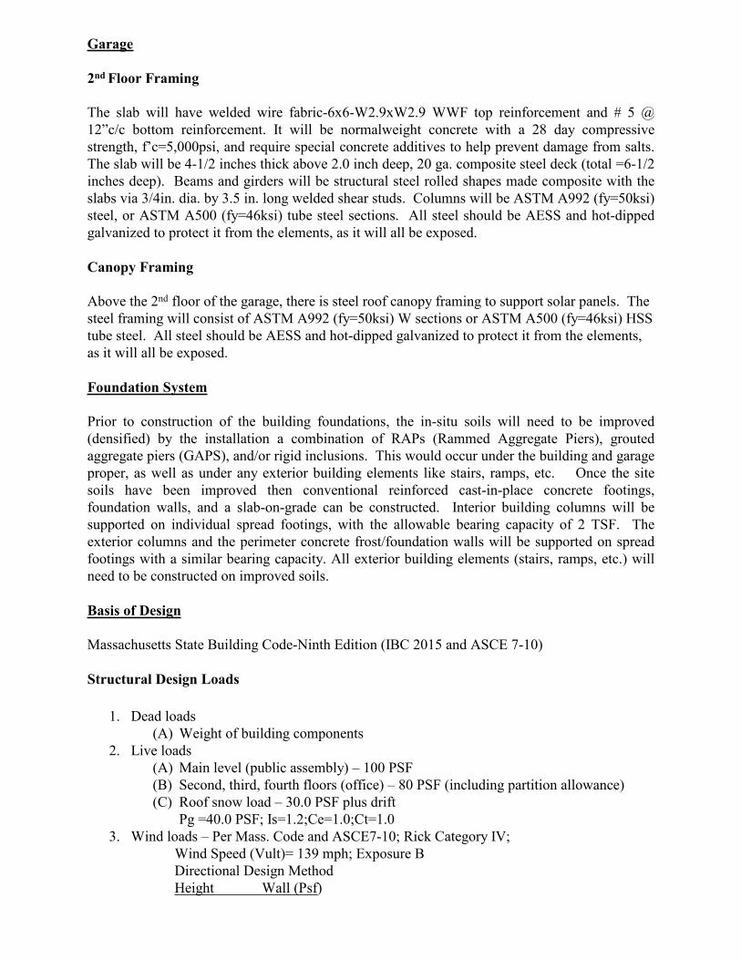
Garage
2nd Floor Framing
The slab will have welded wire fabric-6x6-W2.9xW2.9 WWF top reinforcement and # 5 @ 12”c/c bottom reinforcement. It will be normalweight concrete with a 28 day compressive strength, f’c=5,000psi, and require special concrete additives to help prevent damage from salts. The slab will be 4-1/2 inches thick above 2.0 inch deep, 20 ga. composite steel deck (total =6-1/2 inches deep). Beams and girders will be structural steel rolled shapes made composite with the slabs via 3/4in. dia. by 3.5 in. long welded shear studs. Columns will be ASTM A992 (fy=50ksi) steel, or ASTM A500 (fy=46ksi) tube steel sections. All steel should be AESS and hot-dipped galvanized to protect it from the elements, as it will all be exposed.
Canopy Framing
Above the 2nd floor of the garage, there is steel roof canopy framing to support solar panels. The steel framing will consist of ASTM A992 (fy=50ksi) W sections or ASTM A500 (fy=46ksi) HSS tube steel. All steel should be AESS and hot-dipped galvanized to protect it from the elements, as it will all be exposed.
Foundation System
Prior to construction of the building foundations, the in-situ soils will need to be improved (densified) by the installation a combination of RAPs (Rammed Aggregate Piers), grouted aggregate piers (GAPS), and/or rigid inclusions. This would occur under the building and garage proper, as well as under any exterior building elements like stairs, ramps, etc. Once the site soils have been improved then conventional reinforced cast-in-place concrete footings, foundation walls, and a slab-on-grade can be constructed. Interior building columns will be supported on individual spread footings, with the allowable bearing capacity of 2 TSF. The exterior columns and the perimeter concrete frost/foundation walls will be supported on spread footings with a similar bearing capacity. All exterior building elements (stairs, ramps, etc.) will need to be constructed on improved soils.
Basis of Design
Massachusetts State Building Code-Ninth Edition (IBC 2015 and ASCE 7-10)
Structural Design Loads
1. Dead loads(A) Weight of building components
2. Live loads(A) Main level (public assembly) – 100 PSF (B) Second, third, fourth floors (office) – 80 PSF (including partition allowance) (C) Roof snow load – 30.0 PSF plus drift
Pg =40.0 PSF; Is=1.2;Ce=1.0;Ct=1.03. Wind loads – Per Mass. Code and ASCE7-10; Rick Category IV;
Wind Speed (Vult)= 139 mph; Exposure B Directional Design MethodHeight Wall (Psf)

0’-15’ 24.3 PSF 15’-30’ 29.8 PSF30’-45’ 33.5 PSF
4. Earthquake loads- Per Mass. Code and ASCE7-10; Risk Category “IV”Importance Factor I=1.5; Site Class “D”; Seismic Performance Category ‘C’Equivalent Lateral Force Procedure R=3.0; Cd=3.0 (Steel Systems Not Specially Detailed for Seismic Resistance) Ss= .218; Fa=1.6; SDS=.228g S1=.070; Fv=2.4; SD1= .111g Cs=0.114 V=CsxW; W= Building Wt. + Partition Allowance
Materials
Structural Steel ASTM A36 and ASTM A992 Fy=50ksiASTM A500 Fy=46ksi
Steel Deck ASTM A611 or ASTM A653 Grade 33Steel Reinforcement ASTM A615-Grade 60Welded Wire Fabric ASTM A1064Foundations/SOG Normalweight Concrete - f’c= 4,000 psiSlabs on steel deck-Building Lightweight Concrete - f’c= 3,000 psiSlabs on steel deck-Garage Normalweigth Concrete - f’c= 5,000 psi
For estimating purposed assume 15 PSF for structural steel.
GENERAL
1. Structural work shall conform to the requirements of “The Massachusetts State Building Code”-9th Edition; “The International Building Code”-IBC 2015; and ASCE 7-10.
2. Examine architectural, mechanical, plumbing and electrical drawings for verification of location and dimensions of chases, inserts, openings, sleeves, washes, drips, reveals, depressions and other project requirements not shown on structural drawings.
3. Verify and coordinate dimensions related to this project.4. Provide and install necessary material to connect elevator support beams. Location and
size of beams and any inserts required shall be determined by the elevator manufacturer.5. Openings in slabs and walls less than 12” maximum dimension are generally not shown
on structural drawings shall not be revised without prior written approval of the architect. 6. Typical details and notes shown on structural drawings shall be applicable to all parts of
the structural work except where specifically required otherwise by contract documents.7. Details not specifically shown shall be similar to those shown for the most nearly similar
condition as determined by the architect.8. The contractor shall submit complete shop drawings for all parts of the work, including
description of construction methods and sequencing where applicable. No performance of the work including, but not limited to, construction methods and sequencing, and fabrication or erection of new structural elements, shall commence without review of the shop drawings by the architect.
FOUNDATIONS
1. Foundations for this project consist of spread footings, foundation walls, and slabs-on-grade. The allowable bearing pressure is 2.0 tons per square foot, based on the geotechnical report dated May 24, 2021 and prepared by McPhail Associates. Prior to
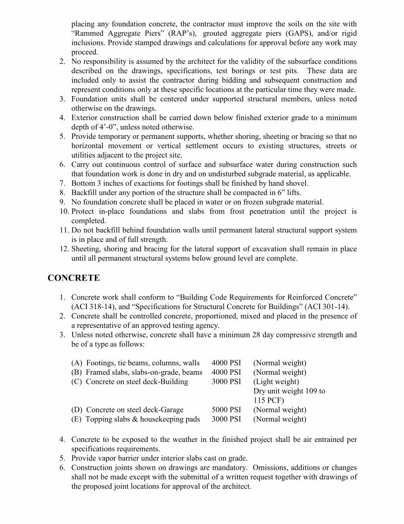
placing any foundation concrete, the contractor must improve the soils on the site with “Rammed Aggregate Piers” (RAP’s), grouted aggregate piers (GAPS), and/or rigid inclusions. Provide stamped drawings and calculations for approval before any work may proceed.
2. No responsibility is assumed by the architect for the validity of the subsurface conditions described on the drawings, specifications, test borings or test pits. These data are included only to assist the contractor during bidding and subsequent construction and represent conditions only at these specific locations at the particular time they were made.
3. Foundation units shall be centered under supported structural members, unless noted otherwise on the drawings.
4. Exterior construction shall be carried down below finished exterior grade to a minimum depth of 4’-0”, unless noted otherwise.
5. Provide temporary or permanent supports, whether shoring, sheeting or bracing so that no horizontal movement or vertical settlement occurs to existing structures, streets or utilities adjacent to the project site.
6. Carry out continuous control of surface and subsurface water during construction such that foundation work is done in dry and on undisturbed subgrade material, as applicable.
7. Bottom 3 inches of exactions for footings shall be finished by hand shovel.8. Backfill under any portion of the structure shall be compacted in 6” lifts.9. No foundation concrete shall be placed in water or on frozen subgrade material.10. Protect in-place foundations and slabs from frost penetration until the project is
completed. 11. Do not backfill behind foundation walls until permanent lateral structural support system
is in place and of full strength.12. Sheeting, shoring and bracing for the lateral support of excavation shall remain in place
until all permanent structural systems below ground level are complete.
CONCRETE
1. Concrete work shall conform to “Building Code Requirements for Reinforced Concrete” (ACI 318-14), and “Specifications for Structural Concrete for Buildings” (ACI 301-14).
2. Concrete shall be controlled concrete, proportioned, mixed and placed in the presence of a representative of an approved testing agency.
3. Unless noted otherwise, concrete shall have a minimum 28 day compressive strength and be of a type as follows:
(A) Footings, tie beams, columns, walls 4000 PSI (Normal weight)(B) Framed slabs, slabs-on-grade, beams 4000 PSI (Normal weight)(C) Concrete on steel deck-Building 3000 PSI (Light weight)
Dry unit weight 109 to 115 PCF)
(D) Concrete on steel deck-Garage 5000 PSI (Normal weight)(E) Topping slabs & housekeeping pads 3000 PSI (Normal weight)
4. Concrete to be exposed to the weather in the finished project shall be air entrained per specifications requirements.
5. Provide vapor barrier under interior slabs cast on grade.6. Construction joints shown on drawings are mandatory. Omissions, additions or changes
shall not be made except with the submittal of a written request together with drawings of the proposed joint locations for approval of the architect.
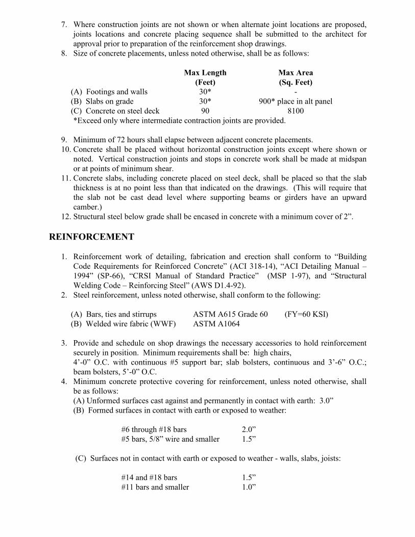
7. Where construction joints are not shown or when alternate joint locations are proposed, joints locations and concrete placing sequence shall be submitted to the architect for approval prior to preparation of the reinforcement shop drawings.
8. Size of concrete placements, unless noted otherwise, shall be as follows:
Max Length(Feet)
Max Area(Sq. Feet)
(A) Footings and walls 30* -(B) Slabs on grade 30* 900* place in alt panel(C) Concrete on steel deck 90 8100*Exceed only where intermediate contraction joints are provided.
9. Minimum of 72 hours shall elapse between adjacent concrete placements.10. Concrete shall be placed without horizontal construction joints except where shown or
noted. Vertical construction joints and stops in concrete work shall be made at midspan or at points of minimum shear.
11. Concrete slabs, including concrete placed on steel deck, shall be placed so that the slab thickness is at no point less than that indicated on the drawings. (This will require that the slab not be cast dead level where supporting beams or girders have an upward camber.)
12. Structural steel below grade shall be encased in concrete with a minimum cover of 2”.
REINFORCEMENT
1. Reinforcement work of detailing, fabrication and erection shall conform to “Building Code Requirements for Reinforced Concrete” (ACI 318-14), “ACI Detailing Manual – 1994” (SP-66), “CRSI Manual of Standard Practice” (MSP 1-97), and “Structural Welding Code – Reinforcing Steel” (AWS D1.4-92).
2. Steel reinforcement, unless noted otherwise, shall conform to the following:
(A) Bars, ties and stirrups ASTM A615 Grade 60 (FY=60 KSI)(B) Welded wire fabric (WWF) ASTM A1064
3. Provide and schedule on shop drawings the necessary accessories to hold reinforcement securely in position. Minimum requirements shall be: high chairs, 4’-0” O.C. with continuous #5 support bar; slab bolsters, continuous and 3’-6” O.C.; beam bolsters, 5’-0” O.C.
4. Minimum concrete protective covering for reinforcement, unless noted otherwise, shall be as follows:(A) Unformed surfaces cast against and permanently in contact with earth: 3.0”(B) Formed surfaces in contact with earth or exposed to weather:
#6 through #18 bars 2.0”#5 bars, 5/8” wire and smaller 1.5”
(C) Surfaces not in contact with earth or exposed to weather - walls, slabs, joists:
#14 and #18 bars 1.5”#11 bars and smaller 1.0”

Beams, girders and columns – principal reinforcement, ties, stirrups or spirals: 1.5”
5. Where continuous reinforcement is called for, it shall be extended continuously around corners and lapped at necessary splices or hooked at discontinuous ends. Laps shall be Class B tension lap splices, unless noted otherwise.
6. Where reinforcement is not shown on drawings, provide reinforcement in accordance with applicable details as determined by the architect. In no case shall reinforcement be less than the minimum reinforcement permitted by the applicable codes.
7. Where reinforcement is required in section, reinforcement is considered typical wherever the section applies.
8. Where there is a conflict between locations of column vertical bars and beam horizontal bars, the column bars shall remain in their designated positions and beam bar locations shall be adjusted.
9. Reinforcement shall be continuous through construction joints.10. Dowels shall match bar size and number, unless noted otherwise.11. Welded wire fabric shall lap 8” or 1-1/2” spaces, whichever is larger and shall be wired
together.12. Reinforcement shall not be tack-welded.13. Installation of reinforcement shall be completed at least 24 hours prior to the scheduled
concrete placement. Notify architect of completion at least 24 hours prior to the scheduled completion of the installation of reinforcement.
STRUCTURAL STEEL
1. Structural steel work shall conform to “Specification for Structural Steel Buildings” (AISC 2011); “Code of Standard Practice for Steel Buildings & Bridges” (AISC 2011); “Seismic Provisions for Structural Steel Buildings” (AISC, 2011); “Specification for Structural Steel Joints Using ASTM A325 and A490 bolts” (AISC 2011), “Structural Welding Code – Steel” (AWS D1.1-96).
2. Structural steel shall be detailed in accordance with “Detailing for Steel Construction (AISC)” and where required, designed in accordance with cited references”.
3. Structural steel details, not specifically shown, shall be taken as being similar to those shown for the most nearly similar condition as determined by the architect.
4. Structural steel shall be new steel conforming to the following:
(A) Unless noted otherwise ASTM A992 Grade 50 (Fy = 50 KSI)(B) Angles, channels, T’s, plates, etc. ASTM A36 (Fy = 36 KSI)(C) Tubes ASTM A500 Grade B (Fy = 46 KSI)(D) Pipes ASTM AS01
or ASTM A53 Type E or S, Grade B
(E) Anchor bolts ASTM A307 or F1554 gr. 105
(F) High strength bolts ASTM A325
5. Anchor bolts, leveling plates or bearing plates shall be located and built into connecting work, preset by templates or similar methods. Plates shall be set in full beds of non-shrink grout.
6. Bolted connections should be as follows:(A) Minimum bolt diameter – ¾”, two bolts minimum.(B) Standard, oversized or horizontal shorts slotted holes in webs of beams.

(C) Shear connections for moment connected members – friction type high strength bolts in single shear.
(D) Shear connections for other members – simple shear connections with either friction type high strength bolts in single shear or bearing type high strength bolts (threads included in shear plane) in single or double shear.
(E) Simple shear connections shall be capable of end rotation per AISC requirements for “Unrestrained Members”.
7. Welded connections shall be made by approved certified welders using filler metal conforming to E70XX or F7X-EXXX with low hydrogen.
8. Welds shall develop the full strength of the materials being welded, unless noted otherwise, except that fillet welds shall be a minimum of ¼”.
9. Beam connections, unless noted otherwise, shall provide connection capacity as follows, or as shown on the plans, whichever is larger:
(A) Non-composite beams: Non-composite beams: support a reaction “R” equal to ½ the total uniform load capacity of beam for a given shape, span and grade of steel per “Maximum Total Uniform Load” Table 3-6 to 3-9, AISC Manual of Steel Construction, 14th Edition.
(B) Composite beams: support a reaction “Rc” = Multiplier x “R” (as defined above):
Rc = 1.50 x R (for beam depth greater than 21”)Rc = 2.00 x R (for beam depth greater than 14”
but less than or equal to 21”)Rc = 2.25 x R (for beam depth great than 8” but
less than or equal to 14”)
(C) Add to “R” or “Rc” the loads or reactions of members supported by the beam near supports and/or the vertical components of force in diagonal bracing members framing into the beam.
10. Ends of columns at splices and at other bearing connections shall be “finished to bear” to complete the true bearing.
11. Provide stiffeners “finished to bear” under all load concentrations on supporting members, over columns, and where shown on drawings.
12. Provide temporary erection bracing and supports to hold structural steel framing securely in position. Such temporary bracing and supports shall not be removed until permanent bracing has been installed and concrete for floor slabs has attained 75% of specified concrete strength.
13. Structural steel framing shall be true and plumb before connections are finally bolted or welded.
14. Field cutting of structural steel or any field modifications of structural steel shall not be made without prior written approval by architect for each specific case.
15. Structural steel encased in masonry shall be covered with mastic coating per specifications.
16. Structural steel members shall be fireproofed per specifications.17. Structural steel members and connections exposed to the weather shall be galvanized.18. Camber shall be by cold-formed process in conformance with AISC specification and
tolerance.
STEEL DECK AND SHEAR CONNECTOR
1. Steel deck and shear connector work shall conform to the “Specification for Design of Light Gage and Cold-Formed Steel Structural Members” (AISC 1989); “Structural Welding Code – Steel” (AWS D1.1-94); and “Structural Welding Code – Sheet Steel” (AWS D1.3-89).
2. Steel deck cross sections are only represented diagrammatically on the drawings.3. Steel deck panels shall be formed from steel sheets conforming to ASTM A653, Grade
33, with a minimum yield point of 33,000 PSI, ASTM A570 (UNGALV), Grade 33 or ASTM A611 (UNGALV), Grade C with a minimum yield point of 33,000 PSI and a thickness not thinner than 20 gage.
4. Floor construction in general consists of concrete fill cast on steel deck and composite in action with the structural steel beams by means of welded shear connectors.
5. Shear connectors shall conform to ASTM A108, Grades 1010, 1015, 1017 or 1020. Typically, shear connectors shall be ¾” diameter x 3 ½” long headed studs, unless noted otherwise, but in no case shall shear connectors extend less than 1-1/2” above steel deck.
6. The number of shear connectors required per beam is indicated by “(32)”, etc. on the drawings. (see beam explanation diagram) Where no shear connectors are indicated for a beam which supports a concrete slab, provide shear connectors at 24” O.C.
7. Shear connectors shall be equally spaced over the length of the beam. Where the number of steel deck corrugations available is less than the number of shear connectors, use pairs of shear connectors starting from each end of beam and continuing toward the center, until it is possible to return to a single shear connector in each corrugation. Shear connectors shall be spaced not closer than 3” transversely and 4 1-2” longitudinally.
8. Horizontal clearance shall be a minimum of 1” from the edge of any shear connector to the faced of concrete, steel deck rib, or similar adjacency.
9. Edge distance from the center of a shear connector to the edge of a structural steel beam shall preferably be 2”, but in no case less than 1 ¼”.
MASONRY CONSTRUCTION
1. Clay (brick) and concrete masonry unit (CMU) construction shall conform to “Building Code Requirements for Masonry Structures” (ACI 530-13/ASCE 5-13/TMS402-13), and to “Specifications for Masonry Structures” (ACI 530.1-13/ASCE 6-13/TMS 602-13).
2. Materials strings shall be as follows:(A) Face brick shall conform to ASTM C-215 Grade SW with compressive strength
of 5000 PSI.(B) Common brick shall conform to ASTM C-62 Grade SW with compressive
strength of 5000 PSI.(C) Concrete masonry units shall conform to ASTM C-90 or C-145 Grade N-1.(D) Mortar shall conform to ASTM C-270, Type M or S.(E) Grout shall conform to ASTM C-476 fine or coarse.
3. Masonry shall have f’m = 1500 PSI. f’m is the compressive strength of the masonry at 28 days as determined by prism tests. (see specs)
4. Prior to grouting cells, bars and cells must be inspected by the testing agency.5. The base of each cell in which a bar is placed must have a cleanout hole. 6. The design of reinforced masonry construction is based on allowable stresses predicated
on “with inspection” provisions, requiring that qualified masonry inspection take place on a continuous basis whenever masonry is being placed.
7. Reinforced masonry walls shall have bond beams at each floor level. Bond beam reinforcing shall be extended into and be continuous with all intersecting bond beams.
8. Anchors to masonry walls shall be 3/4” diameter expansion bolts or anchor bolts. Bolts shall be 2” shorter than wall thickness.
9. Bonding methods, ties, lintels and accessories shall be approved by the architect.10. Submit shop drawings, with ample time for architect’s review and approval, for structural
elements including structural steel.11. Masonry openings more than 16” wide require approved lintels.12. Masonry openings for utilities are to be closed up with new brick work around the utility.13. Provide and install lintels for openings in accordance with the schedule and details on
S0.2. Where lintel abuts columns or walls, provide connections to such. (Submit shop drawing of connection detail for approval.)
14. Provide 1-#5 vertical reinforcing at 24” OC. This reinforcing shall be continuous full height.
15. Masonry block cells containing vertical reinforcing shall be grouted solid. Filling cells with mortar is unacceptable. The compressive strength of grout at the end of 28 days shall be 3000 PSI minimum.
16. Reinforced masonry walls shall have a #9 GA. Wire ladders (ladder or truss type) at 16” OC horizontal reinforcement.
17. Provide 2-#5 continuous horizontal bars in the top course (bond beam) of walls below the each floor and at the roof and fill continuously with grout.
18. Provide 1-#5 additional vertical reinforcing bar at each corner, door or window jamb, and at any discontinuity in the wall.
STRUCTURAL LIGHT GAGE METAL FRAMING:
1. All steel studs, joist, headers, tracks, and accessories shall be formed steel from steel conforming with ASTM A446 and be hot-dipped galvanized in accordance with ASTM A653/A63M-G60.
2. All framing, including but not limited to studs, floor and ceiling joists, headers, sills, tracks, accessories and connections, shall be designed by the supplying subcontractor in accordance with the latest edition of AISI’S “Specification For The Design of Cold-Formed Steel Structural Members.” All design shall be performed and be submitted to the Architect/Engineer for dimensional review only. The governing building code shall be referred to for determining dead and live load requirements. The contract documents shall be referred to for additional loading conditions (if any). Member sizes and connections shown in the contract documents are to be considered schematic only, unless noted otherwise.
3. Submit shop drawings, which shall include dimensioned erection plans, member loadings and sizes, layout of walls, ceilings, floors and openings, connections and temporary and permanent bracing requirements, all of which shall be stamped and signed by a professional engineer registered in the state in which the project is located.
4. Studs exposed to wind pressure or suction forces (i.e. exterior walls, ceilings, soffits and roofs) shall be 18 gauge minimum and spaced at 16” maximum.
5. All members shall be proportioned with the following deflection limits:(A) L/600; Masonry back-up for wind loads.(B) L/360; Non-masonry back-up for wind loads.(C) L/360; Floor live loads.(D) L/360; Snow live loads.(E) L/240; Total dead and live loads.
6. A deflection track shall be provided at all stud wall framing coming up under beams, girders, decking and the like that are subject to live load deflection. The deflection track

shall allow for a deflection of ¾” or the maximum deflection as defined herein, whichever is greater.

SOMERVILLE PUBLIC SAFETY BUILDING Somerville, Massachusetts 02143
Project No. 2006.00
NARRATIVE 8/13/2021
D.5 MECHANICAL-NARRATIVE
GARCIA • GALUSKA • DESOUSA Consulting Engineers Inc.
Somerville Public Safety Building Somerville, MA J#640 061 00.00 L#76873/Page 1/July 14, 2021
TEL 508-998-5700 FAX 508-998-0883 email: [email protected]
HVAC SYSTEMS NARRATIVE
SCHEMATIC DESIGN DRAFT REPORT
The following is the HVAC Systems narrative, which defines the proposed scope of work and capacities of the HVAC Systems, as well as the Basis of Design.
1. CODES
All work installed under Section 230000 shall comply with the Massachusetts State Building Code and all state, county, and federal codes, laws, statutes, and authorities having jurisdiction.
2. DESIGN INTENT
All work is new and consists of furnishing all materials, equipment, labor, transportation, facilities, and all operations and adjustments required for the complete and operating installation of the Mechanical work and all items incidental thereto, including commissioning and testing.
3. MECHANICAL SYSTEM LIFE CYCLE ANALYSIS
As part of the schematic design phase, a building energy model and life cycle cost analysis shall be performed to determine the most cost effective HVAC system for the building in terms of overall life cycle cost of a study period of 30 years. The following options will be studied in comparison to a Baseline HVAC system.
4. BASELINE (FOSSIL FUEL FREE – ELECTRIC HEATING) HVAC SYSTEM: The following HVAC system represents the ASHRAE 90.1-2019 Electric Heating Baseline System consisting of the following features.
A. Air Handling Systems: Multiple air handling units shall be provided to serve the different building zones as described below. AHUs shall be a combination of roof mounted packed direct expansion (DX) electric cooling and heat pump units or indoor units equipped with split air-cooled heat pump condensing units located on the roof. All air handling units shall be equipped with supply air fans with VFDs, supplemental electric heating, DX heat pump cooling/heating sections, and MERV-13 filters. Energy recovery ventilation shall be provided for AHUs with large outdoor air requirements in which energy recovery is code required. AHUs shall be capable of variable air volume operation and shall deliver heated air conditioned supply air (with percentage of outdoor ventilation air meeting the minimum ventilation code requirements) to the building areas via an insulated overhead galvanized sheetmetal ductwork distribution system equipped with terminal VAV (variable air volume) boxes with electric heating coils. A combination of electric resistance type radiation, radiant panels, convectors and unit heaters shall be provided for heating only areas. It is estimated that HVAC air handling equipment with the following capacities shall be required:
1) The Police Department Areas shall be served by a central ventilation air handling unit (AHU-1) that shall have a capacity of approximately 15,800 CFM (53 Ton cooling coil capacity & 610 MBH heating capacity).
GARCIA • GALUSKA • DESOUSA Consulting Engineers Inc.
Somerville Public Safety Building Somerville, MA J#640 061 00.00 L#76873/Page 2/July 14, 2021
2) The Police Department Holding / Prisoner Processing Area central ventilation system will include an air handling unit (AHU-5) of the re-circulation design with 100% outdoor air economizer and energy recovery ventilation capability. It is estimated the AHU shall have a capacity of 2,400 CFM (10 Ton cooling capacity & 200 MBH heating capacity).
3) The Locker Room area shall be served by an air handling unit (AHU-4) of the re-circulation design with 100% outdoor air economizer and energy recovery ventilation capability. It is estimated the AHU shall have a capacity of 4,800 CFM (18 Ton cooling capacity & 260 MBH heating capacity).
4) The Public Lobby and Corridor areas, Shared Office Spaces, COHR, Traffic, Community and Wellness areas shall be served by an AHU (AHU-3) with a capacity of 19,800 CFM (67 Ton cooling capacity & 760 MBH heating capacity).
5) The Fire Department Administration, Living Area and Dormitory areas shall be served by an AHU (AHU-2) with a capacity of 10,200 CFM (38 Ton cooling capacity & 400 MBH heating capacity).
6) The Fire Department Apparatus Bay and Support areas shall be provided with an energy recovery make-up ventilation air unit (AHU-6). The AHU shall have a capacity of 9,000 CFM (400 MBH heating capacity).
7) The air handling units (AHUs) will be provided with MERV 13 filters, DX cooling coils (except for Apparatus Bay which shall not be air conditioned), supply and exhaust fans with variable frequency drives, supplemental electric heating, and energy recovery wheels (where code required). The units will provide conditioned supply air to each space through a fiberglass-insulated galvanized sheet-metal distribution system. Return air from each space will be returned through a separate galvanized sheet-metal return air system back to the air handling units where it will be filtered, heated or air conditioned and re-circulated to the supply air-stream.
8) The AHUs’ supply air distribution system will consist of overhead insulated galvanized sheetmetal distribution system equipped with variable air volume terminal boxes with electric reheat coils and sound attenuators. The VAV boxes will vary the supply airflow based on the zones’ temperature and ventilation requirements. CO2 demand ventilation controls shall be provided for AHU systems where code required (such as large meeting rooms with high anticipated occupant densities).
B. Apparatus Bay and Sally Port Areas:
1) The Apparatus Bay and Sally Ports areas of the building shall be provided with electric unit heaters. The Fire Department Apparatus Bay and Apron shall also be provided with an electric radiant floor slab heating system. The Apparatus Bay shall be provided with a vehicle source-capture exhaust system and general exhaust air systems with gas monitoring controls. The Sallyport shall be provided with an exhaust air system with gas monitoring controls.
GARCIA • GALUSKA • DESOUSA Consulting Engineers Inc.
Somerville Public Safety Building Somerville, MA J#640 061 00.00 L#76873/Page 3/July 14, 2021
C. Supplemental Air Conditioning Systems:
1) The Buildings IT Head End Server Rooms shall be equipped with dedicated split heat pump AC systems which will provide the cooling needs for the space. Ventilation will be provided from the air handling unit serving that area. It is estimated that two (2) 5 ton computer room AC units shall be required to serve each of the IT Head End Room.
2) It is estimated that the Communication Dispatch Center be served by redundant (2) 7.5 ton dedicated split air cooled heat-pump systems.
3) IDF Rooms shall be served by ductless split AC units (estimated 2.5 ton capacity).
4) Elevator machine room shall be served by a 1.5 ton ductless split AC unit. D. Exhaust Systems: Building general, custodial closets, utility room and specialty exhaust
air systems (including Armory gun cleaning hood exhaust, fingerprint fume hood exhaust and drug storage room exhaust air fan systems) shall be provided. A commercial kitchen exhaust air fan system shall be provided for the Fire Department Kitchen.
E. Automatic Temperature Controls (DDC): Automatic Temperature Controls will be of the low-voltage direct digital control (DDC) design for the operation of all HVAC equipment, input sensors, and valve/damper actuators. A central communication network will be provided for the monitoring of all space temperatures, system set points, and overall control for the entire HVAC system. A central front-end workstation PC will also be provided as a user interface for access to the entire automatic temperature control (ATC) system. The ATC control system shall be web accessible and shall be capable of being integrated into a City Wide building energy management system.
5. HVAC SYSTEM OPTION 1 – HIGH EFFICENCY VAV SYSTEM (ELECTRIC HEATING)
A. Summary: This option shall be similar to the Baseline system with the following differences:
1) Energy recovery ventilation shall be provided for all air handling units, including AHU-1,2,3 which would not require energy recovery under the Code Baseline Option.
2) CO2 demand ventilation controls shall be provided for all air handling systems and VAV zones.
3) All air handling unit’s heat pump sections and ductless AC condensing units shall be current industry standard high efficiency option compared to the Code Baseline Option equipment efficiencies.

GARCIA • GALUSKA • DESOUSA Consulting Engineers Inc.
Somerville Public Safety Building Somerville, MA J#640 061 00.00 L#76873/Page 4/July 14, 2021 6. HVAC SYSTEM OPTION 2 – AIR SOURCE VRF SYSTEM
A. Summary:
1) Under this option, a high-efficiency Air Source Variable Refrigerant Flow (VRF) heat recovery system shall provide simultaneous heating and cooling capabilities to all regularly-occupied spaces via a combination of fan coil, ductless wall and/or ductless ceiling cassette type VRF terminal air handling units. Air conditioning will be generated by outdoor roof or grade mounted heat recovery type air source heat pump condensing units that shall be connected to indoor air handling units and terminal heating and cooling units. The HVAC system including air handling unit heating/cooling and terminal heating/cooling systems (excluding supplemental AC systems) shall have a total estimated cooling and heating capacity of 200 tons. The outdoor VRF heat pump condensing units will be sized and located according to AHU and terminal equipment zones capacity requirements and VRF system piping length limitations. Therefore, multiple VRF outdoor heat pump condensing units shall be required.
2) It is estimated that a combined total capacity for the outdoor air cooled heat recovery heat pump condensing units is 75 tons to serve the indoor VRF units.
3) Ventilation shall be provided to building areas via dedicated outdoor air systems (DOAS) air handling units as described below. Indoor air handling units shall be provided with split cooling/heating coils connected to remote heat pump units and outdoor air handling units shall be packaged heat pump units. Both remote condenser and packaged type units’ heat pump sections will include inverter based compressor technology similar to the VRF system for improved energy efficiency.
4) Heating for Entryways, Storage Rooms, Apparatus Bay and Sally Port areas will be generated by a combination of electric resistance type unit heaters, convectors, radiant panels and fin tube radiation.
B. Ventilation System: The ventilation system shall include a combination of indoor and rooftop air handling units of the 100% outside air dedicated outdoor air system (DOAS) design. The DOAS units shall be provided with MERV 13 filters, heat pump cooling/heating coil section (air source integral heat pump condensers for outdoor units and split air source heat pump condensers for indoor units), supply and exhaust fans with variable frequency drives or EC motors, supplemental electric heating coils, total energy recovery wheel, and a sensible reheat wheel or hot gas re-heat coil for dehumidification. The DOAS units shall provide ventilation air to each occupied building area through a fiberglass insulated galvanized sheet-metal distribution system. Airflow from each space will be returned through a separate galvanized sheet-metal return air system back to the air handling units where it will pass through an energy recovery wheel which will transfer heat from the exhaust air stream to the outside air intake stream for preheating or vice-versa for pre-cooling. The DOAS system distribution shall include variable air volume terminal boxes equipped with CO2 demand ventilation controls that will control the amount of ventilation airflow to each space. The units will operate at reduced capacity during the unoccupied periods if unoccupied space set points are not maintained. It is estimated that units with the following capacities shall be required:
GARCIA • GALUSKA • DESOUSA Consulting Engineers Inc.
Somerville Public Safety Building Somerville, MA J#640 061 00.00 L#76873/Page 5/July 14, 2021
1) The Police Department Areas shall be served by a central ventilation air handling unit (AHU-1) that shall have a capacity of approximately 7,700 CFM (32 Ton cooling capacity & 340 MBH heating capacity).
2) The Police Department Holding / Prisoner Processing Area central ventilation system will include an air handling unit (AHU-5) shall have a capacity of 2,400 CFM (10 Ton cooling capacity & 200 MBH heating capacity).
3) The Locker Room area shall be served by an air handling unit (AHU-4) that shall have a capacity of 4,800 CFM (18 Ton cooling capacity & 260 MBH heating capacity).
4) The Public Lobby and Corridor areas, Shared Office Spaces, COHR, Traffic, Community and Wellness areas shall be served by an AHU (AHU-3) with a capacity of 9,800 CFM (40 Ton cooling capacity & 440 MBH heating capacity).
5) The Fire Department Administration, Living Area and Dormitory areas shall be served by an AHU (AHU-2) with a capacity of 4,800 CFM (22 Ton cooling capacity & 230 MBH heating capacity).
6) The Fire Department Apparatus Bay and Support areas shall be provided with an energy recovery make-up ventilation air unit (AHU-6). The unit shall have a capacity of 9,000 CFM (400 MBH heating capacity).
7) The air handling units (AHUs) will be provided with MERV 13 filters, cooling and heating sections, supply and exhaust fans with variable frequency drives, supplemental electric heating coils, and energy recovery wheels. The units will provide conditioned supply air to each space through a fiberglass-insulated galvanized sheet-metal distribution system. Return air from each space will be returned through a separate galvanized sheet-metal return air system back to the air handling units where it will be filtered, heated or air conditioned and re-circulated to the supply air-stream.
8) The AHUs’ supply air distribution system will consist of overhead insulated galvanized sheetmetal distribution system equipped with variable air volume terminal boxes with sound attenuators. The VAV boxes will vary the supply airflow based on the zones’ ventilation requirements utilizing CO2 demand ventilation controls.
C. Police Department Office, Fire Department office and Dormitory, COHR, Wellness, Shared Office, and Public Areas - Space Heating and Air Conditioning:
1) Heating and air-conditioning of the individual heated and air-conditioned occupied
areas will be through the combination of supply air distributed to terminal variable air volume (VAV) boxes and space VRF terminal air handling units. The VAV boxes will modulate the airflow to each zone as required to maintain proper code-required ventilation. A CO2 demand ventilation control system shall also be provided for areas with dense occupancies as required by code. The VRF air handling units shall operate as required to maintain space temperature setpoint control.
GARCIA • GALUSKA • DESOUSA Consulting Engineers Inc.
Somerville Public Safety Building Somerville, MA J#640 061 00.00 L#76873/Page 6/July 14, 2021
2) Ceiling mounted return air registers will be installed in each occupied room which will return air back to the ventilation system air handling unit where it will pass through a unit mounted energy recovery wheel or re-circulate to the supply air-stream.
3) The IT Server Head End Room shall be equipped with dedicated split system AC units which will provide the cooling needs for the space. Ventilation will be provided from the air handling unit serving that area. It is estimated that two (2) 5 ton computer room AC units shall be required to serve the IT Server Head End Room.
4) The Dispatch Centers will each be served by 7.5 ton dedicated split heat-pump systems and associated air cooled condensing units. Ventilation air shall be provided from the zone air handling unit.
5) The Elevator machine room shall be air conditioned by a ductless split system with associated air cooled heat pump condensing unit. Estimated capacity is 1.5 tons.
6) Perimeter ceiling-mounted electric radiant heating panels shall be provided where required for supplemental and/or backup heating.
D. Police Department Detention and Prisoner Processing Areas:
1) The Detention, Prisoner processing and adjacent areas will be provided with a dedicated energy recovery ventilation air handling unit as noted above. Ventilation air will be provided from the DOAS air handling unit. Heating and cooling along with the AHU ventilation air will be provided through VAV boxes and ceiling-mounted overhead diffusers. Cell areas will be served by overhead security type grilles.
E. Locker, Toilet, Shower Rooms:
1) Heating, cooling and ventilation air will be provided through ceiling-mounted overhead diffusers that are served by VAV terminal boxes. Supplemental heating/cooling requirements above what the ventilation system can provide shall be provided by VRF indoor air handling units.
2) Toilet areas and shower areas will be provided with exhaust ductwork for removal of moisture-laden air & odors from these spaces. Aluminum exhaust ductwork and grilles will be provided for shower areas.
3) Perimeter ceiling-mounted electric radiant panels will provide supplemental heating.
F. Exhaust Systems: Exhaust air fans systems shall be provided for custodial closets, utility room and specialty exhaust air systems (including Armory gun cleaning hood exhaust, fingerprint fume hood exhaust and drug storage room exhaust air fan systems). A commercial kitchen exhaust air fan system shall be provided for the Fire Department Kitchen.

GARCIA • GALUSKA • DESOUSA Consulting Engineers Inc.
Somerville Public Safety Building Somerville, MA J#640 061 00.00 L#76873/Page 7/July 14, 2021
G. Sallyport:
1) Ceiling suspended horizontal electric unit heaters located in front of each overhead door will be provided with a dedicated wall mounted thermostat, these units will be utilized as the primary source of heating.
2) The area will also be provided with a carbon monoxide/carbon dioxide monitoring and control system which will automatically energize an exhaust air fan system as levels rise throughout the space.
H. Apparatus Bay:
1) The Apparatus bay shall be served by a vehicle source-capture exhaust air system.
2) The Apparatus bays shall also be served by a general exhaust air ventilation and make-up air system served by an energy recovery ventilation air handling unit as described above. Gas monitoring (CO/NO2 sensors) system shall be provided to modulate the general exhaust fan and associated make-up air system.
3) Apparatus Bay Heating Plant: An electric boiler plant shall be provided to supply hot water heating for the Apparatus Bay and Apron floor slab heating system. It is estimated that boiler size shall be 160 kw. The hot water system will be provided with a mixture of propylene glycol and water to prevent freezing at a concentration of approximately 30% by weight. Heating hot water will be distributed from the boiler to the radiant heating system manifolds through a fiberglass insulated copper distribution system. The boiler plant will include a primary and standby in-line circulator equipped with EC motors. The floor slab radiant heating system shall consist of underslab PEX piping, manifolds, control valves and sensors.
4) The Apparatus Bay shall also be heated by ceiling suspended hot water unit heaters to provide supplemental heating when the Apparatus bay doors are open during the winter heating season.
I. Automatic Temperature Controls (DDC): Automatic Temperature Controls will be of the low-voltage direct digital control (DDC) design for the operation of all HVAC equipment, input sensors, and valve/damper actuators. A central communication network will be provided for the monitoring of all space temperatures, system set points, and overall control for the entire HVAC system. A central front-end workstation PC will also be provided as a user interface for access to the entire automatic temperature control (ATC) system. The ATC control system shall be web accessible and shall be capable of being integrated into a City Wide building energy management system.
GARCIA • GALUSKA • DESOUSA Consulting Engineers Inc.
Somerville Public Safety Building Somerville, MA J#640 061 00.00 L#76873/Page 8/July 14, 2021 7. PROPOSED HVAC SYSTEM - OPTION 3 – CHILLED BEAM SYSTEM (ELECTRIC HEATING)
A. Summary: Under this option, a ceiling mounted air induction system utilizing a 4 pipe to 2 pipe fiberglass insulated copper hot water and chilled water distribution system is proposed for this option. Hot and chilled water supply and return mains shall be provided, and branch dual temperature piping equipped with a pair of 3-way (or single 6-way valve) shall be provided to connect to the induction units. The 3-way (or 6-way) valves will allow for simultaneous heating or cooling operation whenever the building boiler and chiller plants are operational. Primary air will be generated by central indoor air handling units and roof-mounted air handling units that shall be ducted to each induction unit through a central distribution system with 100% outside air. Heating hot water and Chilled water for cooling will be generated by a roof mounted high-efficiency air cooled heat recovery heat pump chiller equipped with a supplemental electric boiler plant. Hot water and chilled water shall be distributed by end suction chilled water pumps equipped with VFD drives. Automatic temperature controls will be of the direct digital low-voltage type communicating with all HVAC equipment.
B. Heating and Cooling Plants:
1) The primary equipment located in the Mechanical Room will include a 250 ton modular heat pump chiller (consisting of five (5) 50 ton modules; one module shall be redundant). The hot and chilled water systems will be provided with a mixture of propylene glycol and water to prevent freezing at a concentration of approximately 30% by weight. A supplemental electric boiler plant with an approximate capacity of 400KW, consisting of (2) 200KW electric boilers manifolded together, shall be provided to inject hot water into the heat pump condenser water side when outdoor air temperatures are below 30 deg F (adj).
2) Heating hot water will be distributed throughout the building through a fiberglass-insulated steel/copper distribution system which will include primary and standby pad-mounted pumps equipped with variable frequency drives.
3) Chilled water will be distributed throughout the building to the various air-handling units at 43°F (adj.) through a fiberglass insulated copper distribution system which will include a primary and standby pad-mounted circulator pump, each at approximately 500 GPM. A compensated chilled water loop shall be provided to distribute chilled water throughout the building to the various induction units at 55°F through a fiberglass insulated copper distribution system. The compensated chilled water loop shall include primary and standby pad-mounted circulator pumps equipped with variable frequency drives.
GARCIA • GALUSKA • DESOUSA Consulting Engineers Inc.
Somerville Public Safety Building Somerville, MA J#640 061 00.00 L#76873/Page 9/July 14, 2021
C. Ventilation System:
1) The central ventilation system will include air handling units of the 100% outside air design. The air handling units will be provided with MERV 13 filters, chilled water cooling coil discharging (55°F to 60°F adj.) air, supply and exhaust fan with variable frequency drives, hot water coil with modulating control valve, total energy recovery wheel, and a hot water re-heat coil for reheat purposes. The units will provide ventilation air to each induction unit through a fiberglass insulated galvanized sheet-metal distribution system. 100% of the supply air to each space will be returned through a separate galvanized sheet-metal return air system back to the air handling units where it will pass through an energy recovery wheel which will transfer heat from the exhaust air stream to the outside air intake stream for pre-heating and vice-versa for pre-cooling. It is estimated that units with the following capacities shall be required: a. The Police Department Areas shall be served by a central ventilation air
handling unit (AHU-1) that shall have a capacity of approximately 7,700 CFM (32 Ton cooling capacity & 340 MBH heating capacity).
b. The Police Department Holding / Prisoner Processing Area central ventilation system will include an air handling unit (AHU-5) that shall have a capacity of 2,400 CFM (10 Ton cooling capacity & 200 MBH heating capacity).
c. The Locker Room area shall be served by an air handling unit (AHU-4) that shall have a capacity of 4,800 CFM (18 Ton cooling capacity & 260 MBH heating capacity).
d. The Public Lobby and Corridor areas, Shared Office Spaces, COHR, Traffic, Community and Wellness areas shall be served by an AHU (AHU-3) with a capacity of 9,800 CFM (40 Ton cooling capacity & 440 MBH heating capacity).
e. The Fire Department Administration, Living Area and Dormitory areas shall be served by an AHU (AHU-2) with a capacity of 4,800 CFM (22 Ton cooling capacity & 220 MBH heating capacity).
f. The Fire Department Apparatus Bay and Support areas shall be provided with an energy recovery make-up ventilation air unit (AHU-6). The unit shall have a capacity of 9,000 CFM (400 MBH heating capacity).
g. The air handling units (AHUs) will be provided with MERV 13 filters, cooling and heating sections, supply and exhaust fans with variable frequency drives, supplemental electric heating coils, and energy recovery wheels. The units will provide conditioned supply air to each space through a fiberglass-insulated galvanized sheet-metal distribution system. Return air from each space will be returned through a separate galvanized sheet-metal return air system back to the air handling units where it will be filtered, heated or air conditioned, and re-circulated to the supply air-stream.

GARCIA • GALUSKA • DESOUSA Consulting Engineers Inc.
Somerville Public Safety Building Somerville, MA J#640 061 00.00 L#76873/Page 10/July 14, 2021
h. The AHUs’ supply air distribution system will consist of overhead insulated galvanized sheetmetal distribution system equipped with variable air volume terminal boxes with sound attenuators. The VAV boxes will vary the supply airflow based on the zones’ ventilation requirements. CO2 demand ventilation controls shall be provided for AHU systems where code required (such as large meeting rooms with high anticipated occupant densities).
D. Police Department Office, Fire Department office and Dormitory, COHR, Wellness, Shared Office, and Public Areas - Space Heating and Air Conditioning:
1) Heating and air-conditioning of the individual heated and air-conditioned occupied areas will be through the combination of supply air distributed to terminal variable air volume (VAV) boxes and space VRF terminal air handling units. The VAV boxes will modulate the airflow each zone as required to maintain proper code-required ventilation. A CO2 demand ventilation control system shall also be provided for areas with large occupancies as required by code. The VRF air handling units shall operate as required to maintain space temperature setpoint control.
2) Ceiling mounted return air registers will be installed in each occupied room which will return air back to the ventilation system air handling unit where it will pass through a unit mounted energy recovery wheel or re-circulate to the supply air-stream.
3) The IT Server Head End Room shall be equipped with dedicated split system AC units which will provide the cooling needs for the space. Ventilation will be provided from the air handling unit serving that area. It is estimated that two (2) 5 ton computer room AC units shall be required to serve the IT Server Head End Room. IDF rooms shall typically be served with 2.5 ton ductless AC systems.
4) The Dispatch Center will be served by redundant (2) 7.5 ton dedicated split heat-pump systems and associated air cooled condensing unit. Ventilation air shall be provided from the zone air handling unit.
5) The Elevator machine room shall be air conditioned by a ductless split system with associated air cooled heat pump condensing unit. Estimated capacity is 1.5 tons.
6) Perimeter ceiling-mounted electric radiant heating panels shall be provided where required for supplemental and/or backup heating.
E. Police Department Detention and Prisoner Processing Areas:
1) The Detention, Prisoner processing and adjacent areas will be provided with a dedicated energy recovery ventilation air handling unit as noted above. Ventilation air will be provided from the DOAS air handling unit. Heating and cooling along with the AHU ventilation air will be provided through VAV boxes with hot water reheat coils and ceiling-mounted overhead diffusers. Cell areas will be served by overhead security type grilles.
GARCIA • GALUSKA • DESOUSA Consulting Engineers Inc.
Somerville Public Safety Building Somerville, MA J#640 061 00.00 L#76873/Page 11/July 14, 2021
F. Locker Rooms:
1) Heating, cooling and ventilation air will be provided through ceiling-mounted overhead diffusers that are served by VAV terminal boxes. Supplemental heating/cooling requirements above what the ventilation system can provide shall be provided by VRF indoor air handling units.
2) Toilet areas and shower areas will be provided with exhaust ductwork for removal of moisture-laden air & odors from these spaces. Aluminum exhaust ductwork and grilles will be provided for shower areas.
3) Perimeter ceiling-mounted electric radiant panels will provide supplemental heating.
G. Exhaust Systems: Exhaust air fans systems shall be provided for custodial closets, utility room and specialty exhaust air systems (including Armory gun cleaning hood exhaust, fingerprint fume hood exhaust and drug storage room exhaust air fan systems). A commercial kitchen exhaust air fan system shall be provided for the Fire Department Kitchen.
H. Sallyport:
1) Ceiling suspended horizontal electric unit heaters located in front of each overhead door will be provided with a dedicated wall mounted thermostat, these units will be utilized as the primary source of heating.
2) The area will also be provided with a carbon monoxide/carbon dioxide monitoring and control system which will automatically energize an exhaust air fan system as levels rise throughout the space.
I. Apparatus Bay:
1) The Apparatus bay shall be served by a vehicle source-capture exhaust air system.
2) The Apparatus bays shall also be served by a general exhaust air ventilation and make-up air system served by an energy recovery ventilation air handling unit as described above. Gas monitoring (CO/NO2 sensors) system shall be provided to modulate the general exhaust fan and associated make-up air system.
3) Apparatus Bay Radiant Floor: Hot water from the heat recovery chiller plant shall be provided to supply hot water heating for the Apparatus Bay and Apron floor slab heating system. Heating hot water will be distributed from the heat recovery chiller to the radiant heating system manifolds through a fiberglass insulated copper distribution system. Radiant floor system will include an in-line circulator equipped with EC motor. The floor slab radiant heating system shall consist of underslab PEX piping, manifolds, control valves and sensors.
4) The Apparatus Bay shall also be heated by ceiling suspended hot water unit heaters to provide supplemental heating when the Apparatus bay doors are open during the winter heating season.
GARCIA • GALUSKA • DESOUSA Consulting Engineers Inc.
Somerville Public Safety Building Somerville, MA J#640 061 00.00 L#76873/Page 12/July 14, 2021
J. Automatic Temperature Controls (DDC): Automatic Temperature Controls will be of the low-voltage direct digital control (DDC) design for the operation of all HVAC equipment, input sensors, and valve/damper actuators. A central communication network will be provided for the monitoring of all space temperatures, system set points, and overall control for the entire HVAC system. A central front-end workstation PC will also be provided as a user interface for access to the entire automatic temperature control (ATC) system. The ATC control system shall be web accessible and shall be capable of being integrated into a City Wide building energy management system.
8. HVAC SYSTEM - OPTION 4 – GROUND SOURCE VRF SYSTEM
A. Summary: The building HVAC distribution system for this option shall be similar to Option 2 VRF system, with the following differences:
B. Heating and Cooling Plant: Option 2 high efficiency air source outdoor heat pump condenser units and the electric boiler plant shall be replaced with ground source water cooled heat recovery heat pump equipment.
C. Air handling units shall be equipped with hot water heating and chilled water cooling supplied from a ground water source heat recovery heat/pump chiller plant.
1) The ground source heat recovery heat pump chiller plant shall consist of five (5) 30 ton modular heat recovery heat pump chillers. Each module shall contain a minimum of 2 compressors and refrigeration circuits. The heat recovery heat pump chiller shall be capable of producing chilled water and hot water simultaneously while being able to supply hot water for reheat purposes when a module(s) is in cooling mode. One (1) 30-ton module shall be redundant.
D. Indoor VRF units shall be served by ground source water to refrigerant VRF heat recovery units. Ground source water shall be distributed between the wellfield and water source VRF heat pump units, and refrigerant piping shall be distributed between the water source VRF heat pumps and the indoor VRF air handling equipment. It is estimated that the following ground water source VRF heat pump equipment is required:
1) Five ground water to refrigerant VRF heat pump units with average capacity of 20 tons each. One module shall be redundant.
E. Ground source water shall be provided for the both the AHU system heat pump chiller/heater and water to refrigerant VRF heat pump equipment from a closed loop geothermal well field. Ground source water shall be distributed to the equipment via a primary secondary condenser water pump system including (2) primary and standby primary loop condenser water pumps, (2) heat pump chiller/heater condenser secondary loop pumps and (2) water to refringent VRF condenser water secondary loop pumps. All pumps shall be equipped with variable speed drives or EC motors. Ground water source side hydronic accessories including expansion tank, filter and an air separator shall be provided. The AHU heat pump chiller/heater equipment shall be located in the lower level mechanical room in the Police Station and the Water to refrigerant VRF heat pump units shall be located within mechanical closets adjacent to the VRF indoor air handling units.

GARCIA • GALUSKA • DESOUSA Consulting Engineers Inc.
Somerville Public Safety Building Somerville, MA J#640 061 00.00 L#76873/Page 13/July 14, 2021
F. The ground source well field shall consist of approximately twenty (20) 900 ft deep vertical close loop wells constructed of HDPX piping (similar to Rygan). Lateral piping shall be constructed of HDPE piping. Each well shall require a capacity of approximately 10 tons each (based on 200 tons total heating/cooling capacity). Well field quantity and depths are estimates only. Actual well field quantity, depth and capacity of wells shall be determined by Ground Source Wellfield Consultant.
9. HVAC SYSTEM - OPTION 5 – GROUND SOURCE CHILLED BEAM (INDUCTION) SYSTEM
A. Summary: The building HVAC distribution system for this option shall be similar to Option 3 chilled beam (induction) system, with the following exceptions:
B. Heating and Cooling Plant: Option 3 high efficiency air cooled heat pump chiller and supplemental electric boiler plants shall be replaced with a high efficiency ground source water cooled heat recovery heat pump chiller/heater plant that shall be capable of producing hot water heating and chilled water cooling for the building HVAC air handling and terminal heating/cooling equipment.
C. The ground source heat recovery heat pump chiller plant shall consist of five (5) 50 ton modular heat recovery heat pump chillers. Each module shall contain a minimum of 2 compressors and refrigeration circuits. The heat recovery heat pump chiller shall be capable of producing chilled water and hot water simultaneously while being able to supply hot water for reheat purposes when a module(s) is in cooling mode. One module shall be redundant.
D. Ground source water from a closed loop geothermal well field shall be distributed to and from the heat pump chiller/heater plant via a primary and standby condenser water pump set equipped with variable speed drives. Ground water source side hydronic accessories including expansion tank, filter and an air separator shall be provided. The heat pump chiller/heater equipment shall be located in the lower level mechanical room in the Police Station.
E. The ground source well field shall consist of approximately twenty (20) 900 ft deep vertical close loop wells constructed of HDPX piping (similar to Rygan). Lateral piping shall be constructed of HDPE piping. Each well shall require a capacity of approximately 10 tons each (based on 200 tons total heating/cooling capacity). Well field quantity and depths are estimates only. Actual well field quantity, depth and capacity of wells shall be determined by Ground Source Wellfield Consultant.

GARCIA • GALUSKA • DESOUSA Consulting Engineers Inc.
Somerville Public Safety Building Somerville, MA J#640 061 00.00 L#76873/Page 14/July 14, 2021 10. BASELINE (GAS HEATING) HVAC SYSTEM: The following HVAC system represents the
ASHRAE 90.1-2019 Gas Heating Baseline System consisting of the following features.
A. Air Handling Systems: Multiple air handling units shall serve the different zones of the building as described below. AHUs shall be a combination of roof mounted hot water heating, direct expansion electric cooling units and indoor hot water heating units equipped with direct expansion cooling coils (DX) connected to split air cooled condenser units located on the roof or grade. All air handling units shall be equipped with supply air fans with VFDs, hot water heating, DX cooling sections, and MERV-13 filters. Energy recovery ventilation shall be provided for AHUs with large outdoor air requirements in which energy recovery is code required. AHUs shall be capable of variable air volume operation and shall deliver air conditioned supply air (with percentage of outdoor ventilation air meeting the minimum ventilation code requirements) to the building areas via an insulated overhead galvanized sheetmetal ductwork distribution system equipped with terminal VAV (variable air volume) boxes with hot water heating coils. A combination of hot water fin tube radiation, convectors and unit heaters shall be provided for heating only areas. It is estimated that HVAC equipment with the following capacities shall be required:
1) The Police Department Areas shall be served by a central ventilation air handling unit (AHU-1) that shall have a capacity of approximately 16,000 CFM (54 Ton cooling coil capacity & 620 MBH heating capacity).
2) The Police Department Holding / Prisoner Processing Area central ventilation system will include an air handling unit (AHU-5) of the re-circulation design with 100% outdoor air economizer and energy recovery ventilation capability. It is estimated the AHU shall have a capacity of 2,000 CFM (10 Ton cooling capacity & 200 MBH heating capacity).
3) The Locker Room area shall be served by an air handling unit (AHU-4) of the re-circulation design with 100% outdoor air economizer and energy recovery ventilation capability. It is estimated the AHU shall have a capacity of 4,800 CFM (18 Ton cooling capacity & 260 MBH heating capacity).
4) The Public Lobby and Corridor areas, Shared Office Spaces, COHR, Traffic, Community and Wellness areas shall be served by an AHU (AHU-3) with a capacity of 19,800 CFM (67 Ton cooling capacity & 760 MBH heating capacity).
5) The Fire Department Administration, Living Area and Dormitory areas shall be served by an AHU (AHU-2) with a capacity of 10,200 CFM (38 Ton cooling capacity & 400 MBH heating capacity).
6) The Fire Department Apparatus Bay and Support areas shall be provided with an energy recovery make-up ventilation air unit (AHU-6). The AHU shall have a capacity of 9,000 CFM (400 MBH heating capacity).
GARCIA • GALUSKA • DESOUSA Consulting Engineers Inc.
Somerville Public Safety Building Somerville, MA J#640 061 00.00 L#76873/Page 15/July 14, 2021
7) The air handling units (AHUs) will be provided with MERV 13 filters, DX cooling coils (except for Apparatus Bay which shall not be air conditioned), supply and exhaust fans with variable frequency drives, gas fired heating, and energy recovery wheels. The units will provide conditioned supply air to each space through a fiberglass-insulated galvanized sheet-metal distribution system. Return air from each space will be returned through a separate galvanized sheet-metal return air system back to the air handling units where it will be filtered, heated or air conditioned and re-circulated to the supply air-stream.
8) The AHUs’ supply air distribution system will consist of overhead insulated galvanized sheetmetal distribution system equipped with variable air volume terminal boxes with hot water heating coils and sound attenuators. The VAV boxes will vary the supply airflow based on the zones’ temperature and ventilation requirements. CO2 demand ventilation controls shall be provided for AHU systems where code required (such as large meeting rooms with increased occupant densities).
B. Hot Water Heating Plant:
1) A code compliant 80% efficiency gas fired hot water heating plant shall be provided to distribute hot water to the building air handling units, VAV hot water heating coils and hot water heating equipment.
2) The boiler plant shall consist of two (2) 2400 MBH input, 1920 MBH output gas fired boilers.
3) A set of two (2) base mounted end suction hot water pumps shall distribute hot water through an insulated steel/copper hot water piping distribution system.
C. Apparatus Bay and Sally Port Areas:
1) The Apparatus Bay and Sally Ports areas of the building shall be provided with hot water unit heaters. The Fire Department Apparatus Bay and Apron shall also be provided with a hot water radiant floor slab heating system. The Apparatus Bay shall be provided with a vehicle source capture exhaust system and general exhaust air systems with gas monitoring controls. The Sallyport shall be provided with hot water unit heaters and an exhaust air system with gas monitoring controls.
D. Supplemental Air Conditioning Systems:
1) The IT Server Areas and Head End Server Room shall be equipped with dedicated split heat pump AC systems which will provide the cooling needs for the space. Ventilation will be provided from the air handling unit serving that area. It is estimated that two (2) 5 ton computer room AC units shall be required to serve each of the IT Head End Room.
2) It is estimated that the Dispatch Center be served by redundant (2) 7.5 ton dedicated split air cooled heat-pump systems.
3) IDF Rooms shall be served by ductless split AC units (estimated 2.5 ton capacity).

GARCIA • GALUSKA • DESOUSA Consulting Engineers Inc.
Somerville Public Safety Building Somerville, MA J#640 061 00.00 L#76873/Page 16/July 14, 2021
4) Elevator machine room shall be served by a1.5 ton ductless split AC unit.
E. Exhaust Systems: Building general, custodial closets, utility room and specialty exhaust air systems (including Armory gun cleaning hood exhaust, fingerprint fume hood exhaust and drug storage room exhaust air fan systems) shall be provided. A commercial kitchen exhaust air fan system shall be provided for the Fire Department Kitchen.
F. Automatic Temperature Controls (DDC): Automatic Temperature Controls will be of the low-voltage direct digital control (DDC) design for the operation of all HVAC equipment, input sensors, and valve/damper actuators. A central communication network will be provided for the monitoring of all space temperatures, system set points, and overall control for the entire HVAC system. A central front-end workstation PC will also be provided as a user interface for access to the entire automatic temperature control (ATC) system. The ATC control system shall be web accessible and shall be capable of being integrated into a City Wide building energy management system.
11. TESTING, ADJUSTMENT, AND BALANCING REQUIREMENTS:
A. The mechanical contractor shall provide testing of the following systems with the owner and owner’s representative present:
1) Geothermal plant system
2) VRF heat pump condensing unit plant system
3) Hot water booster heat exchanger system
4) VRF terminal evaporator units
5) Indoor Air Handling Units
6) Terminal heating and cooling devices
7) Automatic temperature control and building energy management system
B. Testing reports shall be submitted to the engineer for review and approval before providing to the owner.
12. OPERATION MANUALS AND MAINTENANCE MANUALS: When the project is completed, the mechanical contractor shall provide operation and maintenance manuals to the owner.
13. RECORD DRAWINGS AND CONTROL DOCUMENTS: When the project is completed, an as-built set of drawings, showing all mechanical system requirements from the contract and addendum items will be provided to the owner.
14. COMMISSIONING: The project shall be commissioned per the project Commissioning Agent’s (CxA) specifications.
SOMERVILLE PUBLIC SAFETY BUILDING Somerville, Massachusetts 02143
Project No. 2006.00
NARRATIVE 8/13/2021
D.5 REPORTS: ENGINEERING ECONOMIC ANALYSIS
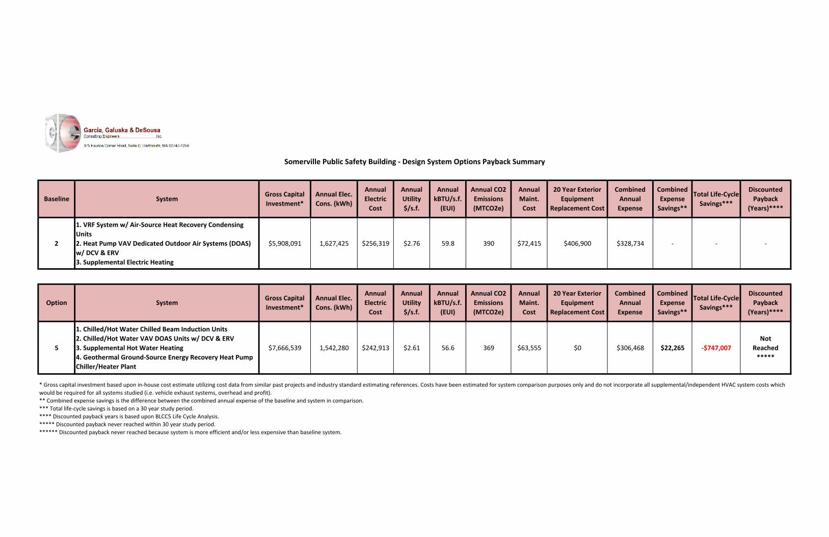
2
1. VRF System w/ Air‐Source Heat Recovery Condensing Units 2. Heat Pump VAV Dedicated Outdoor Air Systems (DOAS) w/ DCV & ERV 3. Supplemental Electric Heating
$5,908,091 1,627,425 $256,319 $2.76 59.8 390 $72,415 $406,900 $328,734 ‐ ‐ ‐
5
1. Chilled/Hot Water Chilled Beam Induction Units 2. Chilled/Hot Water VAV DOAS Units w/ DCV & ERV 3. Supplemental Hot Water Heating 4. Geothermal Ground‐Source Energy Recovery Heat Pump Chiller/Heater Plant
$7,666,539 1,542,280 $242,913 $2.61 56.6 369 $63,555 $0 $306,468 $22,265 ‐$747,007Not
Reached *****
** Combined expense savings is the difference between the combined annual expense of the baseline and system in comparison.*** Total life‐cycle savings is based on a 30 year study period.**** Discounted payback years is based upon BLCC5 Life Cycle Analysis. ***** Discounted payback never reached within 30 year study period.****** Discounted payback never reached because system is more efficient and/or less expensive than baseline system.
Annual Utility $/s.f.
Annual CO2 Emissions (MTCO2e)
Annual CO2 Emissions (MTCO2e)
Somerville Public Safety Building ‐ Design System Options Payback Summary
Baseline SystemGross Capital Investment*
Annual Elec. Cons. (kWh)
Annual Electric Cost
Combined Expense Savings**
Total Life‐Cycle Savings***
Discounted Payback
(Years)****
Option SystemGross Capital Investment*
Annual Elec. Cons. (kWh)
Annual Electric Cost
Annual kBTU/s.f. (EUI)
Annual Utility $/s.f.
Annual kBTU/s.f. (EUI)
Annual Maint. Cost
Combined Annual Expense
Annual Maint. Cost
20 Year Exterior Equipment
Replacement Cost
Discounted Payback
(Years)****
* Gross capital investment based upon in‐house cost estimate utilizing cost data from similar past projects and industry standard estimating references. Costs have been estimated for system comparison purposes only and do not incorporate all supplemental/independent HVAC system costs which would be required for all systems studied (i.e. vehicle exhaust systems, overhead and profit).
20 Year Exterior Equipment
Replacement Cost
Combined Annual Expense
Combined Expense Savings**
Total Life‐Cycle Savings***

������������ ������������������������� !"!#$ #�%"#&�'$($)*+�,"-$��./+$���!#�0$#&�(�+�1.�" �203��")/4+*)�56783*!$��*!$9�2:#"� �;�6�<='�>.!#$?5+#$) *#"@$9�2:#"� �A�6�B$�#&$)?*+�C (4/#"� �D "#�>.!#$?B$ $)*+�C -�)?*#"� '"+$�E*?$9 FGHIJKLJHMKNOPQRSTKUVVWXYZ[H\[FF�]U_aHbLcdKeOJHfcgKLhNRRK�ijkRNe�fSlKOm�\jNRnNToUpgRq*#$��-�>#4(.9 rPj�Yjo�s�atGsGut�vWr�asw)�x$/#�E*?$9 fcgKLhNRRK�ijkRNe�fSlKOm�\jNRnNTow)�x$/#�,�/*#"� 9 XSJJSePjJKOOJ5 *+.!"!�y.:$9 zX\�YTSRmJNJ{�|cT_vTKLom�iLcdKeO5 *+.!"!�w4):�!$9 ijkRNe�ZThKJOgKTO�cL�}KojRSOcLm�YTSRmJNJ5 *+.!#9 ~KNOP�[STK3*!$�q*#$9 fKbOKgkKL�s{�a`>$)@"/$�q*#$9 fKbOKgkKL�s{�a`>#4(.�w$)"�(9 a�mKSLJ�a�gcTOPJ�fKbOKgkKL�s{�a �OPLcjoP�YjojJO�s{�a]�q"!/�4 #�=*#$9 U]�q"!/�4 #" 1��� @$ #"� 9 vTn_cl_�KSL���������������������������������w<�,"-$6�./+$���!# 3*!$��*!$ 5+#$) *#"@$>*@" 1!�-)�?�5+#$) *#"@$C "#"*+�C @$!#?$ #���!#!9����*:"#*+�=$�4")$?$ #!�*!��-�3*!$�q*#$ �]{�a�{a�s �t{���{]� _�s{t]�{uu�'4#4)$���!#!9���� $)1.��� !4?:#"� ���!#! �t{]�]{tss �t{s��{�� ��]{������ $)1.�q$?* (��&*)1$! �a �a �a���� $)1.�D#"+"#.�=$�*#$! �a �a �a����*#$)���!#! �a �a �a���=$/4))" 1�* (�E� 6=$/4))" 1�20�=���!#! �{�u{�� �s{t��{a� ��s]{�ss����*:"#*+�=$:+*/$?$ #! �a �a �a���=$!"(4*+�<*+4$�*#�� (��-�>#4(.�w$)"�( �a �a �a____________ ____________ ____________���>4�#�#*+��-�)�'4#4)$���!#�C#$?!� ��{�]a{ua] ��{��{��u �s{ass{uus____________ ____________ ____________y�#*+�w<�,"-$6�./+$���!# �s]{�]�{u���s�{�a]{]a _�tut{aatE$#�>*@" 1!�-)�?�5+#$) *#"@$���?:*)$(�%"#&�3*!$��*!$w<��-�E� 6C @$!#?$ #�>*@" 1!�s{ass{uus

������������ ������� ��� ������������������������ ������� ���������������� ������ ��� ��� ������� ����!�"����������#��� $���%&'(�)��*�� ��� ���� �������� ��� ��++�� ���&,*- ���� �������� ���+��� -��,����!�"./0,��������#��� $���1�-�����-� ��� �(�)��*�� ��� ���� �������� ��� ��++�� ���&2�13��4�2����5 ��� ��6���� ��2�13��4��+����3����������+���������2���� ���)���2�13��4�����������$��-����� -1�)����&7���-� ��2�13��4�����������$��-����� -1�)����&89:;<=�>?@A9<B�>CDD?;=5����1���������-����1����� � ��-�� 5����1 �����,������ ,��-�� E��-�) �������� F�+��E1����1)� G���E�� ,� ���� ��� ������ ������5��� ���� 1��.H���H�"��IJK����H�H��"��IJK ������"��IJKH�����H//"��IJK5����1���������-����1�����LG - 5����1 �����,������ ,��-�� E��-�) �������� F�+��E1����1)� G���E�� ,� ���� ��� ������ ������5��� ���� 1 ����/"��MNOP��H.H"��MNOP HQ�"��MNOP�����"��MNOP8DABBAR9B�S:TCUVAR9�>CDD?;=5����1 �����,������ ,��-�� 5���������� F�+��E1����1)� G���E�� ,� ���� ��� ��-� ��� ��-� ���5��� ���� 1EWX ���./�Q�."�/�IY������H�/"���IY ���..H"/��IY��..Q��Q/"QH�IY�WX ��/.�"Q��IY �����"���IY H��"���IY �����"�/�IY�WZ �����"�Q�IY �����"�H�IY �/"���IY H��QH"�H�IY�� ��[EWX ���./�Q�."�/�IY������H�/"���IY ���..H"/��IY��..Q��Q/"QH�IY�WX ��/.�"Q��IY �����"���IY H��"���IY �����"�/�IY

��� �������� ��������� ������ ��������
SOMERVILLE PUBLIC SAFETY BUILDING Somerville, Massachusetts 02143
Project No. 2006.00
NARRATIVE 8/13/2021
D.7 ELECTRICAL-NARRATIVE
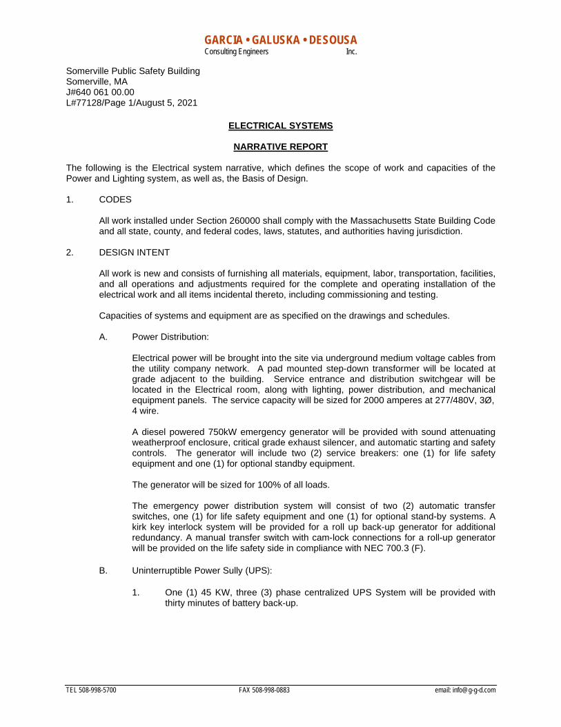
GARCIA • GALUSKA • DESOUSA Consulting Engineers Inc.
Somerville Public Safety Building Somerville, MA J#640 061 00.00 L#77128/Page 1/August 5, 2021
TEL 508-998-5700 FAX 508-998-0883 email: [email protected]
ELECTRICAL SYSTEMS
NARRATIVE REPORT
The following is the Electrical system narrative, which defines the scope of work and capacities of the Power and Lighting system, as well as, the Basis of Design. 1. CODES
All work installed under Section 260000 shall comply with the Massachusetts State Building Code and all state, county, and federal codes, laws, statutes, and authorities having jurisdiction.
2. DESIGN INTENT
All work is new and consists of furnishing all materials, equipment, labor, transportation, facilities, and all operations and adjustments required for the complete and operating installation of the electrical work and all items incidental thereto, including commissioning and testing.
Capacities of systems and equipment are as specified on the drawings and schedules.
A. Power Distribution:
Electrical power will be brought into the site via underground medium voltage cables from the utility company network. A pad mounted step-down transformer will be located at grade adjacent to the building. Service entrance and distribution switchgear will be located in the Electrical room, along with lighting, power distribution, and mechanical equipment panels. The service capacity will be sized for 2000 amperes at 277/480V, 3Ø, 4 wire. A diesel powered 750kW emergency generator will be provided with sound attenuating weatherproof enclosure, critical grade exhaust silencer, and automatic starting and safety controls. The generator will include two (2) service breakers: one (1) for life safety equipment and one (1) for optional standby equipment. The generator will be sized for 100% of all loads. The emergency power distribution system will consist of two (2) automatic transfer switches, one (1) for life safety equipment and one (1) for optional stand-by systems. A kirk key interlock system will be provided for a roll up back-up generator for additional redundancy. A manual transfer switch with cam-lock connections for a roll-up generator will be provided on the life safety side in compliance with NEC 700.3 (F).
B. Uninterruptible Power Sully (UPS):
1. One (1) 45 KW, three (3) phase centralized UPS System will be provided with thirty minutes of battery back-up.
GARCIA • GALUSKA • DESOUSA Consulting Engineers Inc.
Somerville Public Safety Building Somerville, MA J#640 061 00.00 L#77128/Page 2/August 5, 2021
2. The system will provide conditioned power to sensitive electronic loads, telecommunication systems, bridge over power interruptions of short duration and allow an orderly shutdown of servers and communication systems during a prolonged power outage.
3. The UPS system will also be connected to the stand-by generator.
C. Interior Lighting System:
1. General Offices and Meeting Room lighting fixtures will consist of recessed 2’x4’ LED luminaries with dimming drivers. The fixtures will be wired for automatic dimming where natural day light is available and also for multi-level switching.
2. Corridors and other functional lighting fixtures will consist of acrylic recessed
direct fixtures with LEDs and dimmable drivers. 3. Lighting in Cells will be vandal proof fixtures corner mounted LED. Each Cell will
be separately switched. Selected fixtures in Cell areas will have integral emergency ballasts for instant lighting upon power failure.
4. Lighting in the Communications Dispatch Center will be indirect dimmable LED
with consideration of LED dimmable down lights over each position. 5. The Apparatus Bay will be provided with high output LED pendant luminaires
with dimming drivers. Fixtures will be located between the vehicles for access. Fixtures will be designed for rough service.
6. Lighting in the Watch Room will be direct dimmable LED source fixtures.
7. Dorm Rooms will be provided with dual level lighting with low level lighting to be automatically activated by the building’s alerting system.
8. Storage, Mechanical, Sallyport, etc. will be provided with LED industrial wraparound fixtures with acrylic lens.
9. Lighting in the Parking Garage will be low profile LED luminaires specifically
designed for parking garages with integral occupancy sensors.
10. Exit signs will be of the energy efficient, long life LED type. 11. All fixtures will be dimmable LED type. 12. Each area will be locally switched and designed for multi-level controls. Each
Office space and Toilet Room will have an occupancy sensor to turn lights off when unoccupied.
13. The entire facility will be controlled with an addressable automatic lighting control
system for programming lights on and off.
GARCIA • GALUSKA • DESOUSA Consulting Engineers Inc.
Somerville Public Safety Building Somerville, MA J#640 061 00.00 L#77128/Page 3/August 5, 2021
14. Selected area lighting, including corridors, stairwells, and apparatus bay will also be automatically active by the building’s alerting system.
D. Site Lighting System:
1. Fixtures for area lighting will be pole mounted LED luminaries in the Parking area
and Roadways. The exterior lighting will be controlled by photocell ‘on’ and schedule ‘off’ operation, via wireless communication to the buildings automated lighting control system.
2. Building perimeter fixtures will be wall mounted LED luminaries over exterior
doors.
3. All fixtures will be of the dark sky compliant cut-off type.
E. Wiring Devices:
1. Offices will generally have one (1) duplex outlet per wall. At each workstation, a double duplex receptacle will be provided.
2. Corridors will have a cleaning receptacle at approximately 25-foot intervals.
3. Exterior weatherproof receptacles will be installed at exterior doors.
4. A system of computer grade panelboards with double neutrals and transient
voltage surge suppressors will be provided for receptacle circuits.
5. Receptacles in Garage, Apparatus Bay and Sallyport spaces will be GFI type weatherproof covers mounted at 48 inches above floor.
F. Fire Alarm System:
1. A fire alarm and detection system will be provided with battery back-up. The
system will be of the addressable type where each device will be identified at the control panel and remote annunciator by device type and location to facilitate search for origin of alarms.
2. Smoke detectors will be provided in open areas, corridors, stairwells outside of
cells and other egress ways. Elevator recall will be provided.
3. The sprinkler system will alarm on water flow and provide supervisory on valves.
4. Speaker/strobes will be provided in egress ways, assembly spaces, open areas and other large spaces. Strobe only units will be provided in single toilets and conference rooms.
5. Manual pull stations will be provided within 5 feet of all Exit doors.

GARCIA • GALUSKA • DESOUSA Consulting Engineers Inc.
Somerville Public Safety Building Somerville, MA J#640 061 00.00 L#77128/Page 4/August 5, 2021
G. Security System:
1. An addressable security system will be provided. The system will be integrated with the card access and closed-circuit TV (CCTV) system.
2. Position switches will be provided at all exterior doors.
3. A UL Listed Closed Circuit TV system will be provided. The system consists of
computer servers with image software, computer monitors, and IP based closed circuit TV cameras. The head end server shall be located in the Server room and will be rack mounted. The system can be accessed from any PC within the facility or externally via an IP address. Each camera can be viewed independently. The Stored Appliance Network (SAN) will store this information for 45 days at 30 images per second.
4. The location of the cameras is generally in corridors, secure areas, and exterior
building perimeter. The exterior cameras are multi-sensor 360, 270, or 180-degree cameras. The site shall be 100% covered.
5. The system shall fully integrate with the Access Control System to allow viewing
of events from a single alarm viewer. Camera images and recorded video shall be linked to the access system to allow retrieval of video that is associated with the event.
6. The system includes a card access controller, door controllers, and proximity
readers/keypads. The electrical hardware for each door is provided by the Hardware Contractor. Proximity readers will be located at various locations as shown on the security drawings. Motorized gates and overhead doors into garages and restricted parking areas will be provided with LPR technology and proximity readers for access. The purpose is to only allow access to authorized personnel at all times. Each proximity reader will have a distinctive code to identify the user and a log will be kept in memory. The log within the panel can be accessed through a computer.
7. The alarm condition shall also initiate real time recording on the integral CCTV
system that is included as part of this submission. The system is programmed with graphic maps allowing the end-user to quickly identify alarm conditions and lock/unlock doors.
8. The system shall be tested, and complete documentation shall be provided to the
Owner on the operational and programming functions available. The system may be easily expanded to accommodate any additional devices that may be added in the future.
9. A graphic cell door release control panel will be located at Prisoner Processing
allowing the Officer in Charge to release each cell individually as needed.
10. The System will be included with a site license to accommodate future expansion to include the entire district. This will allow the Quincy Public Safety Building to have a centralized solution that may be managed at a central location and expanded to other Town Buildings.
GARCIA • GALUSKA • DESOUSA Consulting Engineers Inc.
Somerville Public Safety Building Somerville, MA J#640 061 00.00 L#77128/Page 5/August 5, 2021
H. Renewable Energy System Provisions:
1. The base project will include:
a. Electrical provisions will be made for a roof mounted and a canopy mounted (over parking garage) Renewable Energy System for a grid connected Photovoltaic (PV) System intended to reduce the facilities demand for power.
I. Level 2 AC Dual Electric Vehicle Charging Equipment (EVSE):
1. Provide nineteen (19) EVSE stations fed with 40 ampere feeders back to the building for charging electric vehicles. Two protective bollards will be installed at each charging station.
J. Lightning Protection System:
1. A system of lightning protection will be provided. The system will be installed in
compliance with the provisions of the latest “Code for Protection Against Lightning” for buildings as adopted by the National Fire Protection Association and the Underwriters’ Laboratories, Inc. for UL Master Label System.
2. The lightning protection equipment will include air terminals, conductors,
conduits, fasteners, connectors, ground rods, etc.
3. The lightning protection system will be installed for the new police facility.
3. TESTING REQUIREMENTS
A. The Electrical Contractor shall provide testing of the following systems with the Owner and Owner’s Representative present:
1. Lighting and power panels for correct phase balance. 2. Emergency generator. 3. Lighting control system (interior and exterior). 4. Fire alarm system. 5. Security systems.
B. Testing reports shall be submitted to the Engineer for review and approval before
providing to the Owner.
4. OPERATION MANUALS AND MAINTENANCE MANUALS:
A. When the project is completed, the Electrical Contractor shall provide operation and maintenance manuals to the Owner.
5. RECORD DRAWINGS AND CONTROL DOCUMENTS:
A. When the project is completed, an as-built set of drawings, showing all lighting and power requirements from contract and addendum items will be provided to the Owner.

SOMERVILLE PUBLIC SAFETY BUILDING Somerville, Massachusetts 02143
Project No. 2006.00
NARRATIVE 8/13/2021
D.7 PLUMBING-NARRATIVE
GARCIA • GALUSKA • DESOUSA Consulting Engineers Inc.
Somerville Public Safety Building Somerville, MA J#640 061 00.00 L#77128/Page 1/August 5, 2021
TEL 508-998-5700 FAX 508-998-0883 email: [email protected]
PLUMBING SYSTEMS
NARRATIVE REPORT
The following is the Plumbing system narrative, which defines the scope of work and capacities of the Plumbing system as well as the Basis of Design. The Plumbing Systems shall be designed and constructed for LEED v4 where indicated on this narrative.
1. CODES
A. All work installed under Section 220000 shall comply with the MA Building Code, MA Plumbing Code and all state, county, and federal codes, laws, statutes, and authorities having jurisdiction.
2. DESIGN INTENT
A. All work is new and consists of furnishing all materials, equipment, labor, transportation, facilities, and all operations and adjustments required for the complete and operating installation of the Plumbing work and all items incidental thereto, including commissioning and testing.
3. GENERAL
A. The Plumbing Systems that will serve the project are cold water, hot water, tempered water, sanitary waste and vent system, garage waste system and storm drain system.
B. The Building will be serviced by Municipal water and Municipal sewer system.
C. All Plumbing in the building will conform to Accessibility Codes and to Water Conserving sections of the Plumbing Code.
4. DRAINAGE SYSTEM
A. Soil, Waste, and Vent piping system is provided to connect to all fixtures and equipment. System runs from 10 feet outside building and terminates with stack vents through the roof.
B. A separate Garage Waste System starting with connection to an exterior concrete oil/water separator running thru the Apparatus and Garage floor drains, and terminating with a vent terminal through the roof. A separate garage waste system with exterior concrete oil/water separator will be provided for the Parking Garage upper deck for Storm.
C. Storm Drainage system is provided to drain all roofs with roof drains piped through the building to a point 10 feet outside the building.
D. Drainage system piping will be service weight cast iron piping; hub and spigot with gaskets for below grade; no hub with gaskets, bands and clamps for above grade 2 in. and larger. Waste and vent piping 1-1/2 in. and smaller will be type ‘L’ copper.
GARCIA • GALUSKA • DESOUSA Consulting Engineers Inc.
Somerville Public Safety Building Somerville, MA J#640 061 00.00 L#77128/Page 2/August 5, 2021 5. WATER SYSTEM
A. New 4 inch domestic water service from the municipal water system will be provided. A meter and backflow preventer, if required, will be provided.
B. Cold water distribution main is provided. Non-freeze wall hydrants with integral back flow preventers are provided along the exterior of the building.
C. Domestic hot water will be provided with electric, point-of-use, instantaneous water heaters.
D. Water piping will be type ‘L’ copper with wrot copper sweat fittings, silver solder or press-fit system. All piping will be insulated with 1 in. thick high density fiberglass.
E. Tepid (70 deg. F – 90 deg. F) water will be provided to the emergency shower/eyewash fixtures in Science Classrooms as required by code.
6. FIXTURES LEED v4
A. Furnish and install all fixtures, including supports, connections, fittings, and any incidentals to make a complete installation.
B. Fixtures shall be the manufacturer’s guaranteed label trademark indicating first quality. All acid resisting enameled ware shall bear the manufacturer’s symbol signifying acid resisting material.
C. Vitreous china and acid resisting enameled fixtures, including stops, supplies and traps shall be of one manufacturer by Kohler, American Standard, or Eljer, or equal. Supports shall be Zurn, Smith, Josam, or equal. All fixtures shall be white. Faucets shall be Speakman, Chicago, or equal.
D. Fixtures shall be as scheduled on drawings.
1. Water Closet: High efficiency toilet, 1.28 gallon per flush, wall hung, vitreous china, siphon jet. Manually operated 1.28 gallon per flush-flush valve.
2. Penal Combi Toilet: Acorn Model 1418-FA-AL/AR-2-BP-4-1.6GPF-M-PBH-SPS-SW, suicide skirt, 18" wide lav/toilet, penal fixture combination, fabricated of type 304, #14 gage Stainless steel, seamless welded construction. Fixture is supplied with domestic hot and cold water.
3. Penal Combi ADA Toilet: Acorn Model No. 1432-ADA-AL/AR-2-DMS-4-1.6GPF-PBH-SPS-SW with rear spud, floor mounted wall outlet blowout jet stainless steel institutional water closet less grab bar, elongated bowl, integral stainless steel seat, suicide skirt, seamless construction, complete with vandal proof mounting hardware. Fixture is supplied with domestic hot and cold water.
4. Urinal: High efficiency 0.13 gallon per flush urinal, wall hung, vitreous china. Manually
operated 0.13 gallon per flush-flush valve.
5. Lavatory: Wall hung/countertop ADA lavatory with 0.5 GPM metering mixing faucet.

GARCIA • GALUSKA • DESOUSA Consulting Engineers Inc.
Somerville Public Safety Building Somerville, MA J#640 061 00.00 L#77128/Page 3/August 5, 2021
6. Sink: MAAB/ADA stainless steel countertop sink with gooseneck faucet and 0.5 GPM aerator.
7. Drinking Fountain: Barrier free hi-low wall mounted electric water cooler, stainless
steel basin with bottle filling stations.
8. Janitor Sink: 24 x 24 x 10 Terrazo mop receptor Stern-Williams or equal.
9. Shower: Aquatic Bath Model 48-ACS acrylic shower stall or Aquatic Bath 6036-BSFCMA barrier free acrylic shower stall with integral soap shelf and seat. Center drain location and slip resistant, textured bottom. Symmons Safetymix shower trim, concealed pressure balanced shower valve with lever handle, integral checkstops, factory pre-set temperature limit stops, 2.5 GPM flow restrictor.
10. Detention Area Hose Bibb: Acorn Series 8109 hot and cold water hose bibb, cast
bronze valve body, vacuum breaker, screw driver stops, recessed stainless steel mounting box with locking door.
7. DRAINS
A. Drains are cast iron, caulked outlets, nickaloy strainers, and in waterproofed areas and roofs shall have galvanized iron clamping rings with 6 lb. lead flashings to bond 9 in. in all directions. Drains shall be Smith, Zurn, Josam, or equal.
8. VALVES
A. Locate all valves so as to isolate all parts of the system. Shutoff valves 3 in. and smaller shall be ball valves, solder end or screwed, Apollo, or equal.
9. INSULATION
A. All water piping shall be insulated with snap-on fiberglass insulation Type ASJ-SSL, equal to Johns Manville Micro-Lok HP.
10. CLEANOUTS
A. Cleanouts shall be full size up to 4 in. threaded bronze plugs located as indicated on the drawings and/or where required in soil and waste pipes.
11. ACCESS DOORS
A. Furnish access doors for access to all concealed parts of the plumbing system that require accessibility. Coordinate types and locations with the Architect.

SOMERVILLE PUBLIC SAFETY BUILDING Somerville, Massachusetts 02143
Project No. 2006.00
NARRATIVE 8/13/2021
D.7 FIRE PROTECTION-NARRATIVE

GARCIA • GALUSKA • DESOUSA Consulting Engineers Inc.
Somerville Public Safety Building Somerville, MA J#640 061 00.00 L#77127/Page 1/August 5, 2021
TEL 508-998-5700 FAX 508-998-0883 email: [email protected]
FIRE PROTECTION SYSTEMS
NARRATIVE REPORT The following is the Fire Protection system narrative, which defines the scope of work and capacities of the Fire Protection system, as well as, the Basis of Design.
1. CODES
A. All work installed under Section 210000 shall comply with the MA Building Code and all state, county, and federal codes, laws, statutes, and authorities having jurisdiction.
2. DESIGN INTENT
A. All work is new and consists of furnishing all materials, equipment, labor, transportation, facilities, and all operations and adjustments required for the complete and operating installation of the Fire Protection work and all items incidental thereto, including commissioning and testing.
3. GENERAL
A. In accordance with the provisions of the Massachusetts Building Code and MA General Law, the building must be protected with an automatic sprinkler system.
4. DESCRIPTION
A. The new building will be served by a new 6-inch fire service, double check valve assembly, wet alarm valve complete with electric bell, and fire department connection meeting local thread standards.
B. System will be a combined standpipe/sprinkler system with control valve assemblies to limit the sprinkler area controlled to less than 52,000 s.f. as required by NFPA 13-2013. There shall be a total of four (4) wet type sprinklers zones. One zone for each and one for detention cell area.
C. Control valve assemblies shall consist of a supervised shutoff valve, check valve, flow switch and test connection with drain. Standpipes meeting the requirements of NFPA 14-2013 shall be provided in the egress stairwells.
D. All areas of the building, including all finished and unfinished spaces, combustible concealed spaces, all electrical rooms and closets will be sprinklered.
E. All sprinkler heads will be quick response, pendent in hung ceiling areas and upright in unfinished areas.
F. Open parking garage will be equipment with a manual dry standpipe.
5. BASIS OF DESIGN
A. The mechanical rooms, kitchen, and storage rooms are considered Ordinary Hazard Group 1; Vehicle storage areas including Sallyport are considered Ordinary Hazard Group 2. All other areas are considered light hazard.
GARCIA • GALUSKA • DESOUSA Consulting Engineers Inc.
Somerville Public Safety Building Somerville, MA J#640 061 00.00 L#77127/Page 2/August 5, 2021
B. Required Design Densities:
Light Hazard Areas 0.10 GPM over 1,500 s.f. Ordinary Hazard Group 1 0.15 GPM over 1,500 s.f. Ordinary Hazard Group 2 0.20 GPM over 1,500 s.f.
C. Sprinkler spacing (max.):
Light Hazard Areas: 225 s.f. Ordinary Hazard Areas: 130 s.f.
D. A hydrant flow test will need to be performed. This will determine if a fire pump will be required.
6. DOUBLE CHECK VALVE ASSEMBLY
A. Double check valve assembly shall be MA State approved, U.L./F.M. approved, with iron body bronze mounted construction complete with supervised OS & Y gate valves and test cocks. Furnish two spare sets of gaskets and repair kits.
B. Double check valve detector assembly shall be of one of the following:
1. Watts Series 757-OSY 2. Wilkins 350A-OSY 3. Conbraco Series 4S-100 4. Or equal
7. PIPING
A. Sprinkler piping 1-1/2 in. and smaller shall be ASTM A-53, Schedule 40 black steel pipe. Sprinkler/standpipe piping 2 in. and larger shall be ASTM A-135, Schedule 10 black steel pipe.
8. FITTINGS
A. Fittings on fire service piping, 2 in. and larger, shall be Victaulic Fire Lock Ductile Iron Fittings conforming to ASTM A-536 with integral grooved shoulder and back stop lugs and grooved ends for use with Style 009-EZ or Style 005 couplings. Branch line fittings shall be welded or shall be Victaulic 920/920N Mechanical Tees. Schedule 10 pipe shall be roll grooved. Schedule 40 pipe, where used with mechanical couplings, shall be roll grooved and shall be threaded where used with screwed fittings. Fittings for threaded piping shall be malleable iron screwed sprinkler fittings.
9. JOINTS
A. Threaded pipe joints shall have an approved thread compound applied on male threads only. Teflon tape shall be used for threads on sprinkler heads. Joints on piping, 2 in. and larger, shall be made up with Victaulic, or equal, Fire Lock Style 005, rigid coupling of ductile iron and pressure responsive gasket system for wet sprinkler system as recommended by manufacturer.

GARCIA • GALUSKA • DESOUSA Consulting Engineers Inc.
Somerville Public Safety Building Somerville, MA J#640 061 00.00 L#77127/Page 3/August 5, 2021 10. SPRINKLERS
A. All sprinklers to be used on this project shall be Quick Response type.
B. Furnish spare heads of each type installed located in a cabinet along with special sprinkler wrenches. The number of spares and location of cabinet shall be in complete accord with NFPA 13-2013.
C. Sprinklers shall be manufactured by Tyco, Victaulic, Viking, or equal.
D. Upright sprinkler heads in areas with no ceilings shall be Tyco Model "TY-FRB" Quick Response, upright natural brass finish heads. Include heavy duty sprinkler guards in all mechanical rooms and storage rooms.
E. Sidewall heads shall be Tyco Model "TY-FRB" Quick Response with white polyester head and escutcheon.
F. Pendent wet sprinkler heads shall be Tyco Model "TY-FRB" Quick Response recessed adjustable escutcheon, white polyester finish.
G. Concealed heads shall be Tyco Model "RFII" Quick Response concealed type, 1-1/2 inch adjustment white cover plate. In special areas, as may be noted on the Drawings, provide alternate cover plate finishes.
H. Sprinkler heads located in the detention portion of the project shall be Tyco Model "Raven" Quick Response Institutional Automatic Sprinkler Heads furnished in bright chrome plated finish, tamper proof mounting, and anti-suicide heat sensors.
I. Use of flexible stainless steel hose with fittings for fire protection service that connect sprinklers to branch lines in suspended ceilings is acceptable. Flexible hoses shall be UL/FM approved and shall comply with NFPA 13 standards. Hose assemblies shall be type 304 stainless steel with minimum 1-inch true-bore internal hose diameter. Ceiling bracket shall be galvanized steel and include multi-port style self-securing integrated snap-on clip ends that attach directly to the ceiling with tamper resistant screws.

SOMERVILLE PUBLIC SAFETY BUILDING Somerville, Massachusetts 02143
Project No. 2006.00
NARRATIVE 8/13/2021
D.9 GEOTHERMAL-NARRATIVE
Memorandum
GEOTECHNICAL AND GEOENVIRONMENTAL ENGINEERS 2269 Massachusetts Avenue Cambridge, Massachusetts 02140 (617) 868-1420
Page 1 of 8
Date:
August 6, 2021
Recipient: Context Architecture
Mr. Jeff Shaw, AIA
Sender:
Jonathan W. Patch, P.E.
Project:
Somerville Public Safety Building; Somerville, Massachusetts
Project No: 7088.2.TA
Subject:
Preliminary Evaluation/Feasibility Study of Geothermal Well System
This memorandum summarizes our preliminary evaluation/feasibility study of using a geothermal well system to heat and cool the proposed building. Refer to the Project Location Plan, Figure 1, for the general site location. This memorandum was prepared in accordance with our proposal dated January 4, 2021 and the subsequent authorization of Context Architecture. Existing Conditions The proposed building site is located immediately east of the intersection of Washington Street and New Washington Street in East Somerville. The project site is bounded by Washington Street to the north, New Washington Street to the west and south, and a multi-family residential property to the east. Currently, the central portion of the site is occupied by the remains (at-grade concrete slab and foundations) of a recently demolished 12,550-square-foot, L-shaped one-story brick strip mall building with at-grade paved parking lots located to the west and access lanes located to the south and east. The areas to the south and east of the former building beyond the access lanes are occupied by landscaped margins, including an approximate 8-foot-high elevated landscaped feature or “mound” along the site’s eastern boundary. Existing grades across the site are relatively level, varying from about Elevation +16 to Elevation +17, with the exception of the above-described landscaped mound and a second mound near the site’s southern boundary where the site grades rise to about Elevation +24 to Elevation +25. Proposed Development The proposed site development is in the preliminary stage and is currently understood to consist of the construction of a 2 to 4-story public safety building with no occupied below-grade space that will include approximately 77,000 gross square feet of occupied space. A network of vertical geothermal wells servicing ground source heat pumps may be installed as part of the project to either partially or fully heat and cool the proposed building. Currently, an approximate 32,500 square-foot irregularly-shaped area at the southeastern portion of the project site that borders New Washington Street is being considered as the location for a potential geothermal well field. The potential well field site currently consists
Memorandum
GEOTECHNICAL AND GEOENVIRONMENTAL ENGINEERS 2269 Massachusetts Avenue Cambridge, Massachusetts 02140 (617) 868-1420
Page 2 of 8
of a raised grassed area with several mature trees. The proposed landscape site plan indicates the area would consist of a park with walkways and numerous trees. Additional discussion regarding existing and proposed trees in relation to the well field is included below. The proposed location of the geothermal well field is indicated on the attached Figure 2. Geothermal Overview Geothermal systems take advantage of the ground’s relatively stable temperature to provide heating/cooling. For heating, geothermal systems extract heat from the ground and utilize heat pumps to boost the temperature then release it inside the space to be heated. For cooling, heat pumps absorb heat from the space to be cooled and release it deep underground. Thus, heat is drawn from the ground during the winter and deposited into the ground during the summer. Typically, geothermal systems work best when there is an annual balance between heating and cooling needs. Buildings that are not air-conditioned, or that have an extreme imbalance of loads are usually not good candidates for geothermal systems. But it is common for buildings with moderate load imbalances to utilize a supplemental boiler or cooling device to handle peak or seasonal imbalances, and most of the heating and cooling is handled by the geothermal system. The following are several potential advantages of geothermal systems:
Environmentally friendly o Uses electricity rather than fossil fuel, compatible with potential other
renewable energy systems such as solar and/or wind. o Do not create significant amounts of pollution. o Sustainable. Utilize a renewable energy source. o Lower carbon footprint than conventional systems.
Contribute to energy efficiency LEED credits. Significantly more efficient than conventional air-source or variable refrigerant flow
systems. Less fluctuation in annual operating costs. No exposed outdoor equipment.
o Minimize or eliminate the need for cooling towers and condensing units, since most of the heat rejection to the environment occurs in the well field.
This may have the added benefit of increasing the available roof area for solar arrays.
o Can eliminate the need for flue stacks and ventilation (required for fuel burning equipment).
o No noise associated with outdoor equipment. o Equipment resistant to extreme weather conditions, more reliable HVAC
system. Lower maintenance than conventional systems
o Closed-loop systems require minimal maintenance. Systems that use antifreeze require loop fluid testing. If antifreeze or corrosion inhibitors are used, yearly testing is recommended to verify that the fluid is not
Memorandum
GEOTECHNICAL AND GEOENVIRONMENTAL ENGINEERS 2269 Massachusetts Avenue Cambridge, Massachusetts 02140 (617) 868-1420
Page 3 of 8
experiencing degradation, which is uncommon, but may occur if systems are operating for long periods of time outside the design temperature ranges.
Longevity: o The materials associated with closed-loop systems, namely HDPE and HPGX
(Rygan) piping, come with a 50-year manufacturer’s warranty. It is expected that the piping will outlive the warranty with no capacity degradation overtime.
o Conversely, the outdoor cooling equipment typically has a 15-year expected useful life. Therefore, three (3) replacements will be required before the loop warranty expires.
Access: Permanent access is not required for either the vertical well heads or the horizontal circuit piping that runs from well to well and to the manifold in the mechanical room. This makes installation of a closed-loop within the building footprint feasible, if required.
The following are several potential disadvantages:
Higher first cost compared to a conventional boiler/chiller system. Need a large area to construct the well field. Schedule
o Installation of the geothermal wells and ground loop piping could add months to the construction duration depending how construction logistics are managed.
Installation impacts o Noise and vibrations from well drilling could be disruptive to abutters.
Geologic Conditions A detailed description of subsurface conditions encountered within geotechnical borings is contained in the Foundation Engineering Report dated May 24, 2021, prepared for this project by McPhail. In general, the surface treatments are underlain by successive soil deposits of fill, organics, marine sand, marine clay, glaciomarine and glacial till that overly bedrock. Groundwater was observed at depths varying from about 6 to 16 feet below ground surface. Bedrock was not encountered in the geotechnical explorations but is anticipated to be present at a depth of approximately 60 feet below the existing ground surface based on a review of information from nearby sites. Based on the United States Geologic Survey (USGS) Bedrock Geology Map of New England and our review of boring logs from nearby sites, bedrock is anticipated to consist of Cambridge Argillite, which is a type of siltstone. Published values of the thermal conductivity of siltstone by ASHRAE range from 1.2 to 2.0 Btu/hr-ft.-F. In addition, the formation thermal conductivity of test wells located in the vicinity of the project site in argillite range from about 1.7 to 2.0 Btu/hr-ft.-F.

Memorandum
GEOTECHNICAL AND GEOENVIRONMENTAL ENGINEERS 2269 Massachusetts Avenue Cambridge, Massachusetts 02140 (617) 868-1420
Page 4 of 8
Note that thermal conductivity values do not directly translate into the number of feet per ton (i.e., the number of tons expected per well or the total number of wells which will be required for the project). The number of wells required is determined based on the results of a well field analysis using ground energy transfer software programs which include the hourly or monthly heating and cooling loads provided by the project mechanical engineer or energy modeling consultant. Closed-Loop Geothermal Systems In general, there are two main types of geothermal systems: closed-loop and open-loop. In consideration of the operations and maintenance which would be required for an open-loop system, along with the potential risks associated with permitting and water quality, an open-loop system is not recommended for the project. Closed-loop wells circulate a water or water-antifreeze solution in a continuous closed piping loop through the heat pumps and mechanical equipment and return the water or a water-antifreeze solution to the well field. Closed-loop systems are often more reliable, require less maintenance in the long term, and have negligible potential environmental impacts versus an open-loop system which directly pumps groundwater. However, closed-loop systems generally have a higher upfront installation cost versus open-loop systems, which results in a longer delay for return on the initial investment. Permanent access to the well heads or piping for a closed-loop system do not need to be maintained. Conventional closed-loop geothermal wells with U-bends are typically installed to depths of about 400 to 600 feet below ground surface and spaced a minimum of 20 feet on-center. Quad-loop wells (double U-bend) and High-Performance GeoXchange (HPGX) (aka proprietary Rygan) wells are typically installed to depths of 600 to 900 feet below ground surface and spaced at a minimum of 25 feet on-center. Deeper Rygan wells on the order of 1,200 to 1,500 linear feet are also technically feasible, but these require a greater minimum spacing between wells (50 feet compared to 25 feet), are expensive to drill due to the need of an additional booster to be able to clear the hole of drill cuttings and may have issues with maintaining vertical tolerance which could result in the bottom portion of the wells being drilled beyond the property line. Permitting Requirements and Other Considerations The Massachusetts Department of Environmental Protection (MassDEP) categorizes closed-loop geothermal wells as Class V closed-loop wells but no longer requires the filing of an Underground Injection Control (UIC) Registration application with MassDEP provided that the well is installed and operated in accordance with MassDEP’s Guidelines for Ground Source Heat Pumps Wells.

Memorandum
GEOTECHNICAL AND GEOENVIRONMENTAL ENGINEERS 2269 Massachusetts Avenue Cambridge, Massachusetts 02140 (617) 868-1420
Page 5 of 8
Using the Massachusetts online mapping tool, the site is understood to not be located within a Zone I area of a public water supply well (MassDEP Wellhead Protection Area) which is required by MassDEP for geothermal wells. Furthermore, the site is not located within a Zone II area either. Other key permitting requirements outlined in the MassDEP UIC “Guidelines for Ground Source Heat Pump Wells” dated December 2013 include the following:
Wells are required to be located at least 25 feet from “existing and potential sources of contamination including, but not limited to septic tanks/fields, lagoons, livestock pens, and oil or hazardous materials storage tanks.”
Various design and setback requirements must be followed. Setback requirements include minimum distances as follow:
o 10 feet from potable water and sewer lines o 50 feet from private potable water supply wells o 10 feet from surface water bodies o 10-foot setback from property lines without the expressed written permission
of the abutter The anticipated well field location is not in a wetland buffer zone and therefore is not
anticipated to be subject to the Wetlands Protection Act regulations which would be governed by the local Conservation Commission.
Per MassDEP guidelines, closed-loop wells are required to be fully grouted and have a permanent steel casing installed a minimum of 15 feet into competent, unweathered bedrock.
A Well Construction Permit is anticipated to be required from the Somerville Board of Health based on a review of the Somerville Private Water Supply Regulations. In addition, the Somerville regulations require “the well casing should be sealed with a watertight grouting extending from the surface of the ground to a depth of ten (10) feet.” The Somerville regulations also contain setback requirements from potential sources of contamination. At present, it is not known if the setback requirements apply to geothermal wells and are only applicable to private water wells. Regardless, these setback requirements include minimum distances as follow:
o 5 feet from property lines [MassDEP requirement of 10 feet is more stringent] o 25 feet from roadways o 100 feet from leaching facilities [Not anticipated to be applicable] o 50 feet from septic or pump tanks [Not anticipated to be applicable] o 100 feet from underground storage tanks [Not anticipated to be applicable] o 50 feet from building or public sewers [more stringent than MassDEP
requirement of 10 feet] o 25 feet from subsurface drains

Memorandum
GEOTECHNICAL AND GEOENVIRONMENTAL ENGINEERS 2269 Massachusetts Avenue Cambridge, Massachusetts 02140 (617) 868-1420 Page 6 of 8
As indicated in our January 8, 2021 memorandum entitled “Preliminary Geotechnical and Geoenvironmental Engineering Evaluation”, the site is a MassDEP listed release site under Release Tracking Number (RTN) 3-31102. The contaminants of concern (COCs) in soil include PCBs, Extractable Petroleum Hydrocarbons (EPH), and the polynuclear aromatic hydrocarbon (PAH) target compounds acenaphthylene, 2-methylnaphthalene, naphthalene, and as well as the volatile organic compounds (VOCs) chlorobenzene and 1,4-dichlorobenzene and semi volatile organic compounds (SVOCs) 2,4-dinitrotoluene and 1,4 dichlorobenzene. Theses COCs have not been detected in groundwater at concentrations that required notification of the MassDEP. Hence, the release condition is limited to soil. In addition, the proposed well field location is understood to be outside the area of RTN-23246, which consists of a release of chlorinated volatile organic compounds (CVOCs) to deep groundwater in bedrock.
Lastly, as indicated above, the proposed well field location is to be located within an existing area that contains several mature trees and will be a future park which is currently planned to contain numerous trees. The location and future size of the existing and proposed trees will need to be coordinated with the well field design. In general, large trees should be avoided near the well field as the roots could potentially damage the horizontal circuit piping. Ornamental trees and bushes near the well field would be acceptable. It is possible that several of the existing trees may need to be removed to install the well field.
Preliminary Loading Information
The project MEP engineer, Garcia Galuska DeSousa (GGD), provided the preliminary estimated peak load in heating and cooling for the proposed building which is 200 tons. Hourly or monthly heating and cooling loads have not been developed and will not be available until the design development (DD) phase. Based on a cursory review of the “HVAC System Option Energy Modeling Report” dated August 4, 2021 prepared by AKF, the total annual heating and cooling loads appear to be relatively balanced. As indicated above, geothermal systems work best when there is an annual balance between heating and cooling needs and buildings that have an extreme imbalance of loads are usually not good candidates for geothermal systems. If the building did have a moderate load imbalance, a supplemental boiler or cooling device could be used to handle peak or seasonal imbalances to allow the load on the geothermal system to be more balanced and hence, more efficient.
Preliminary Well Field Sizing Analysis
Since an hourly or monthly heating and cooling load profile was unavailable, accurate modeling using ground energy transfer software programs was not able to be performed. As such, rules of thumb were used to develop preliminary geothermal well system alternates, including estimated number and length of wells, based on the provided peak load.
We determined that for the 20 and 25-foot well spacings, approximately 74 and 47 wells, respectively, could potentially fit within the limits of the proposed park while keeping 10 feet from the property line. However, this does not consider potential conflicts with large trees, underground utilities or other items which are anticipated to reduce the availability of space
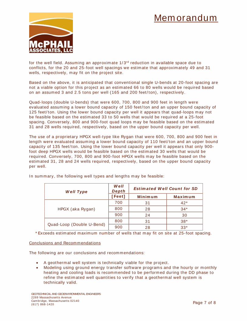
Memorandum
GEOTECHNICAL AND GEOENVIRONMENTAL ENGINEERS 2269 Massachusetts Avenue Cambridge, Massachusetts 02140 (617) 868-1420
Page 7 of 8
for the well field. Assuming an approximate 1/3rd reduction in available space due to conflicts, for the 20 and 25-foot well spacings we estimate that approximately 49 and 31 wells, respectively, may fit on the project site. Based on the above, it is anticipated that conventional single U-bends at 20-foot spacing are not a viable option for this project as an estimated 66 to 80 wells would be required based on an assumed 3 and 2.5 tons per well (165 and 200 feet/ton), respectively. Quad-loops (double U-bends) that were 600, 700, 800 and 900 feet in length were evaluated assuming a lower bound capacity of 150 feet/ton and an upper bound capacity of 125 feet/ton. Using the lower bound capacity per well it appears that quad-loops may not be feasible based on the estimated 33 to 50 wells that would be required at a 25-foot spacing. Conversely, 800 and 900-foot quad loops may be feasible based on the estimated 31 and 28 wells required, respectively, based on the upper bound capacity per well. The use of a proprietary HPGX well-type like Rygan that were 600, 700, 800 and 900 feet in length were evaluated assuming a lower bound capacity of 110 feet/ton and an upper bound capacity of 135 feet/ton. Using the lower bound capacity per well it appears that only 900-foot deep HPGX wells would be feasible based on the estimated 30 wells that would be required. Conversely, 700, 800 and 900-foot HPGX wells may be feasible based on the estimated 31, 28 and 24 wells required, respectively, based on the upper bound capacity per well. In summary, the following well types and lengths may be feasible:
Well Type Well
Depth Estimated Well Count for SD
[Feet] Minimum Maximum
HPGX (aka Rygan) 700 31 42* 800 28 34* 900 24 30
Quad-Loop (Double U-Bend) 800 31 38* 900 28 33*
*Exceeds estimated maximum number of wells that may fit on site at 25-foot spacing. Conclusions and Recommendations The following are our conclusions and recommendations:
A geothermal well system is technically viable for the project. Modeling using ground energy transfer software programs and the hourly or monthly
heating and cooling loads is recommended to be performed during the DD phase to refine the estimated well quantities to verify that a geothermal well system is technically valid.
Memorandum
GEOTECHNICAL AND GEOENVIRONMENTAL ENGINEERS 2269 Massachusetts Avenue Cambridge, Massachusetts 02140 (617) 868-1420
Page 8 of 8
Additional coordination to understand the relationship between existing and proposed trees and the proposed well field will be required to determine how many wells could be installed and where.
To better inform the well field pricing and feasibility, it is recommended that an up to 900-foot-deep test hole be drilled to determine the depth to bedrock, the quality of bedrock, rock fractures, groundwater production and borehole stability. If a high quantity of water is encountered which inhibits the drilling production and requires the use of a booster, then the test hole may be terminated at a shallower depth.
Based on the test hole information and modeling results, the test hole could be completed by installing a quad-loop or HPGX piping and grouting, and performance of a 48-hour duration thermal conductivity test on the completed well. The average formation thermal conductivity, the formation thermal diffusivity, and an estimate of the undisturbed soil temperature will be obtained from the test results. This information will be utilized during the design phase to determine the size of the permanent well field.
M.G.L. c. 149 and 149a requires that material specifications for public bid construction projects be written to provide for full competition for each item of material required for construction. However, if there are “sound reasons in the public interest” to restrict competition to one product, manufacturer or producer, the request to carry a proprietary item must be reasonably investigated and approved by the Awarding Authority. As indicated above, the Rygan HPGX is a proprietary product. If the project proceeds with the Rygan HPGX, to comply with the requirements of M.G.L. c. 149 and 149a, the Project Team would need to request approval for its use.
Closing We trust that the above is sufficient for your present requirements. Should you have any questions, please do not hesitate to call us. Attachments:
Figure 1 Figure 2
\\McPhail-fs2\McPhail\Working Documents\Reports\7088-SomervillePSB_SDGeothermalFeasibilityMemo-080621.docx JWP/jgl
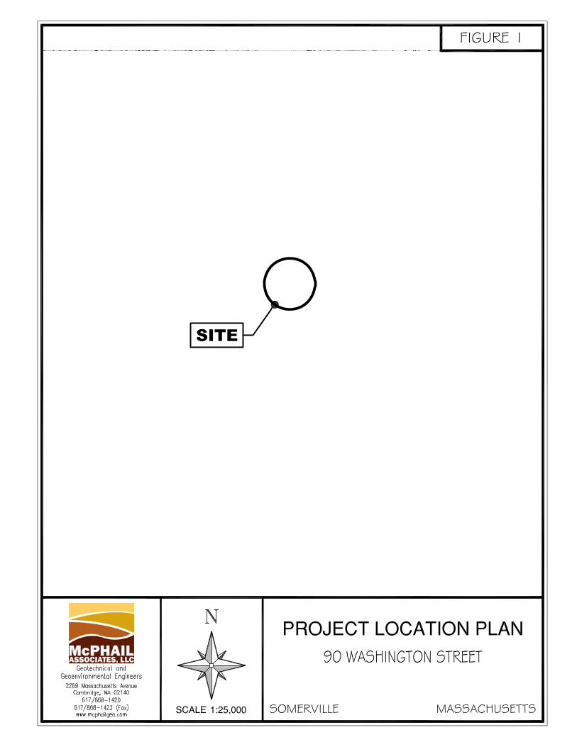
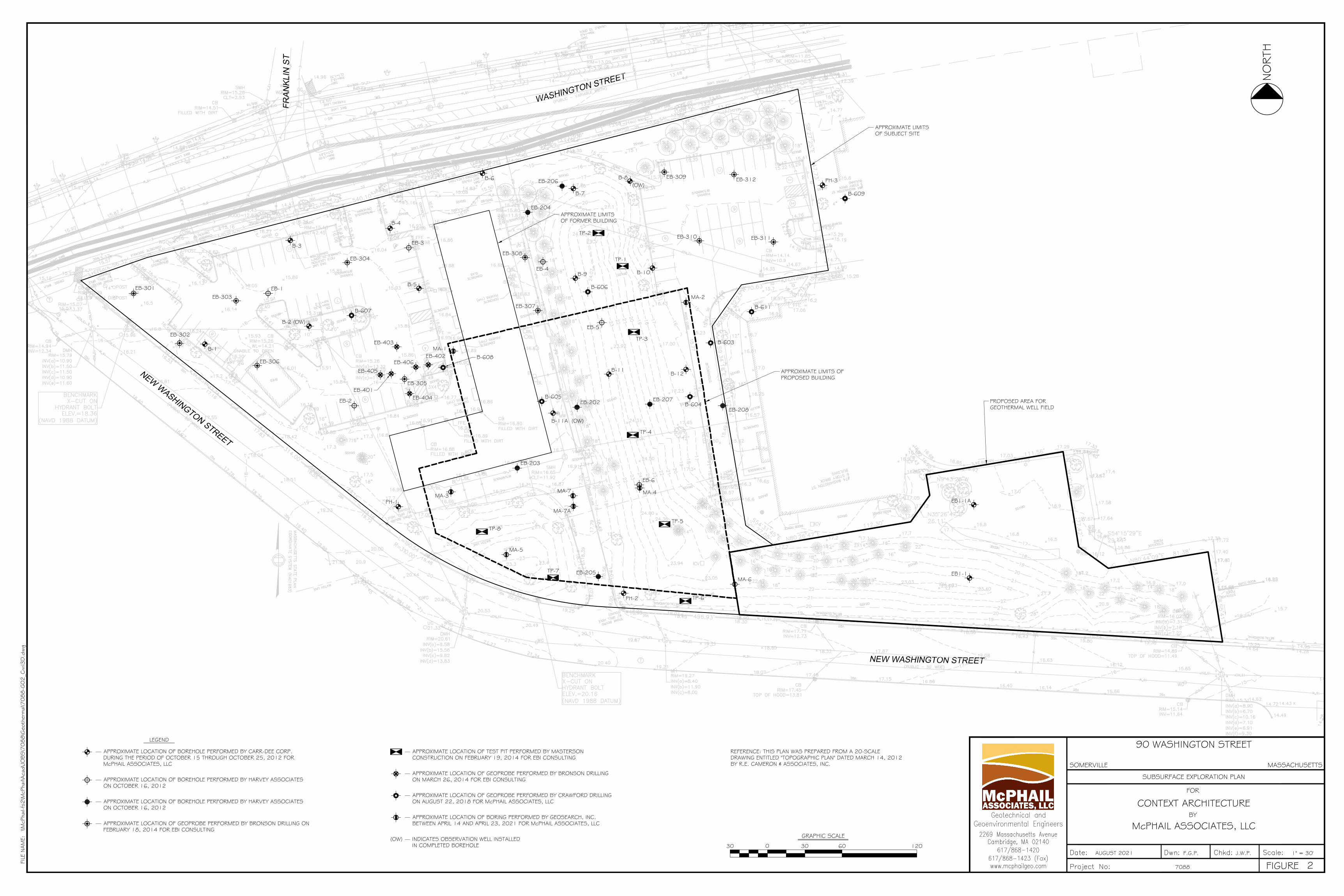
W
A
S
H
IN
G
T
O
N
S
T
R
E
E
T
NEW WASHINGTON STREET
N
E
W
W
A
S
H
I
N
G
T
O
N
S
T
R
E
E
T
FR
AN
KLIN
S
T
FR
AN
KLIN
A
VE
B-1
B-2 (OW)
B-3
B-4
B-5
B-6
B-7
B-8(OW)
B-9 B-10
B-11 B-12
EB1-1A
EB1-1
PH-2
PH-1
PH-3
EB-301
EB-304
EB-303
EB-302
EB-306
EB-305
EB-308
EB-307
EB-311
TP-3
TP-1
TP-2
EB-312EB-309
EB-310
TP-4
TP-5
TP-6
TP-7
TP-8
EB-1
EB-2
EB-3
EB-4
EB-6
EB-202
EB-203
EB-204
EB-205
EB-206
EB-207EB-208
EB-401
EB-402
EB-403
EB-404
EB-405EB-406
B-607
B-608
B-606
B-605B-604
B-603
B-611
B-609
EB-5
APPROXIMATE LIMITSOF SUBJECT SITE
MA-1
MA-2
MA-3 MA-4
MA-6
MA-7
MA-7A
MA-5
B-11A (OW)
APPROXIMATE LIMITS OFPROPOSED BUILDING
APPROXIMATE LIMITSOF FORMER BUILDING
PROPOSED AREA FORGEOTHERMAL WELL FIELD
McPHAIL ASSOCIATES, LLC
FOR
BY
FILE
NAM
E:
FIGURE
\\McP
hail-
fs2\M
cPha
il\Aca
d\JO
BS\7
088\G
eoth
erm
al\7
088-G
02_C
ivil3
D.d
wg
7088
1" = 30'J.W.P.F.G.P.AUGUST 2021
CONTEXT ARCHITECTURE
SUBSURFACE EXPLORATION PLAN
MASSACHUSETTSSOMERVILLE
90 WASHINGTON STREET
2
0
GRAPHIC SCALE
30 30 60 120
REFERENCE: THIS PLAN WAS PREPARED FROM A 20-SCALEDRAWING ENTITLED "TOPOGRAPHIC PLAN" DATED MARCH 14, 2012BY R.E. CAMERON & ASSOCIATES, INC.
APPROXIMATE LOCATION OF BOREHOLE PERFORMED BY CARR-DEE CORP.DURING THE PERIOD OF OCTOBER 15 THROUGH OCTOBER 25, 2012 FORMcPHAIL ASSOCIATES, LLC
LEGEND
INDICATES OBSERVATION WELL INSTALLEDIN COMPLETED BOREHOLE
(OW)
APPROXIMATE LOCATION OF GEOPROBE PERFORMED BY BRONSON DRILLING ONFEBRUARY 18, 2014 FOR EBI CONSULTING
APPROXIMATE LOCATION OF TEST PIT PERFORMED BY MASTERSONCONSTRUCTION ON FEBRUARY 19, 2014 FOR EBI CONSULTING
APPROXIMATE LOCATION OF BOREHOLE PERFORMED BY HARVEY ASSOCIATESON OCTOBER 16, 2012
APPROXIMATE LOCATION OF BOREHOLE PERFORMED BY HARVEY ASSOCIATESON OCTOBER 16, 2012
APPROXIMATE LOCATION OF GEOPROBE PERFORMED BY BRONSON DRILLINGON MARCH 26, 2014 FOR EBI CONSULTING
APPROXIMATE LOCATION OF GEOPROBE PERFORMED BY CRAWFORD DRILLINGON AUGUST 22, 2018 FOR McPHAIL ASSOCIATES, LLC
APPROXIMATE LOCATION OF BORING PERFORMED BY GEOSEARCH, INC.BETWEEN APRIL 14 AND APRIL 23, 2021 FOR McPHAIL ASSOCIATES, LLC
NO
RTH
SOMERVILLE PUBLIC SAFETY BUILDING Somerville, Massachusetts 02143
Project No. 2006.00
NARRATIVE 8/13/2021
D.10 RADIO COMMUNICATIONS-NARRATIVE
CITY OF SOMERVILLE PUBLIC SAFETY BUILDING
RADIO AND RELATED SYSTEMS SCHEMATIC DESIGN INFORMATION
1 DRAFT
FOR DISCUSSION ONLY – THIS REPORT IS PROVIDED TO GENERATE COMMENTS AND IS NOT INTENDED FOR GENERAL DISTRIBUTION. Langone & Associates – Subconsultant to Context Architecture – 8/9/21
1. Introduction Langone & Associates as a subconsultant to Context Architecture will be assisting the City with planning for the new Somerville PSB. The primary systems identified in this document include communications center specialized dispatch furniture, radio equipment at the PSB to connect to the remote radio site infrastructure, antenna systems and municipal fire alarm systems. Other facility related systems (Network, data systems, cameras, intercom, access control, monitors sallyport doors etc.) that may interact with the primary systems for space, monitoring and electrical interface will be identified. Otherwise, those system requirements will be identified by other project team members. The new PSB will be the primary PSAP for the City and will receive all calls for service and dispatch all calls for fire, medical and police response. The current FD communications center at FD HQ will be moved to the new PSB. Somerville’s alternate PSAP is the City of Chelsea Police. Somerville is exploring if a backup PSAP will be needed in the City and its location. The City’s project team shall review the information in this document and make any necessary changes which may impact the construction issues such as power, empty conduit locations and size etc. 2. Current Radio System Background Information The City operates the following citywide radio systems:
• Fire 1 – HUB equipment and Communications Center at FD HQ
• Fire 2 – HUB equipment and Communications Center at FD HQ
• Police 1 – HUB equipment and Communications Center at PD HQ
• Police 2 – HUB equipment and Communications Center at PD HQ
• DPW Main – HUB equipment at FD HQ
• DPW Admin – HUB equipment at FD HQ
• Traffic & Parking – HUB equipment at FD HQ
These systems include radio equipment that is at End of Life (EOL) with parts increasingly difficult to obtain. In addition to FD HQ and PD HQ, the systems include transmit and receive equipment at the following radio infrastructure locations throughout the City:
• 125 Lowell St - Private
• 252 Medford St – SHA (Somerville Housing Authority)
• 15 Weston Ave - SHA
• 114 Highland Ave - SHA
• 13 Warren Ave - SHA
• Davis Square MBTA Station Underground
CITY OF SOMERVILLE PUBLIC SAFETY BUILDING
RADIO AND RELATED SYSTEMS SCHEMATIC DESIGN INFORMATION
2 DRAFT
FOR DISCUSSION ONLY – THIS REPORT IS PROVIDED TO GENERATE COMMENTS AND IS NOT INTENDED FOR GENERAL DISTRIBUTION. Langone & Associates – Subconsultant to Context Architecture – 8/9/21
These radio systems are in the process of being connected to their respective HUB and Communications Centers by COMCAST Metro Ethernet. The Ethernet connection replaces the unreliable Verizon leased copper lines. The City has undertaken a plan to replace the current radio system infrastructure. The new radio system infrastructure will be installed at the existing FD HQ and PD HQ communications centers and radio sites before the PSB is completed. This will require a transition plan to identify the equipment required to move to the PSB and whether some equipment will be located at a backup communications center such as FD HQ. The City will need to identify the level of public safety communications redundancy required. The City has been working with Motorola to develop new radio systems to replace those identified above. The intent of this document is to identify the requirements for the PSB to accept the radio system components since the new radio system will be operating before the PSB is completed. The current plan is to consolidate the Fire and Police communications centers into one communications center at the PSB. The following sections will identify those construction items that provide the necessary power, low voltage and associated conduits and pathways for the technology radio and related system’s cabling. 3. PSB Radio and Related System Requirements This section will outline the requirements for the radio system components in the PSB. The new radio system will include new equipment located at multiple locations throughout the City to improve radio coverage and redundancy. However, our focus will be only on the PSB equipment.
A. Communications Center The Communications Center will require:
• Specialized Furniture that provides space for all the technology required to be at the Fire, Police and Supervisor operating positions
• Wall Monitors (# TBD) for displaying information for:
o Weather
o Local TV Broadcast
o National Broadcast
o Building and Cell Cameras
o School Cameras
o City Road Intersection Cameras
o Other TBD

CITY OF SOMERVILLE PUBLIC SAFETY BUILDING
RADIO AND RELATED SYSTEMS SCHEMATIC DESIGN INFORMATION
3 DRAFT
FOR DISCUSSION ONLY – THIS REPORT IS PROVIDED TO GENERATE COMMENTS AND IS NOT INTENDED FOR GENERAL DISTRIBUTION. Langone & Associates – Subconsultant to Context Architecture – 8/9/21
This furniture must provide the staff with an ergonomically designed work environment. All primary system displays must be in easy reach of the operator. Cabling access to the furniture will be through the floor in the communications center room. Primary computer screens and equipment panels must be located within arm’s reach of the operator. Workstations will be located under the work surface.
The City shall develop layouts and specifications for the operating positions and seek drawings and quotes from manufacturers such as Eaton/WrightLine, Watson, Evans, Xybix etc. See attached fire and police position templates in the Appendix.
It is assumed that the communications center will include the following operator/dispatch positions:
• Two (2) Fire positions
• Four (4) Police positions
• Supervisor position
• Telephone answering positions (# TBD) for the City’s 10-digit non-emergency numbers
The furniture and equipment layout shall provide flexibility in assigning call takers, fire dispatchers and police dispatchers by shift.
The communications center furniture for each position shall include:
• Curved furniture with an ~8-ft x ~8-ft footprint
• Sit to Stand motorized work surface with control
• Motorized keyboard surface with control
• 4 over 4 Monitor (24”) Tree with Focal Adjust
1. 911 Monitor 1 – subject to State 911 guidelines for number TBD of positions
2. 911 Monitor 2 – subject to State 911 guidelines for number of positions
3. QED monitor 1 with CJIS access – police position only
4. QED monitor 2
5. Radio monitor – see below for details
6. TRX 50 monitor – fire position only
7. Admin workstation monitor
8. Spare
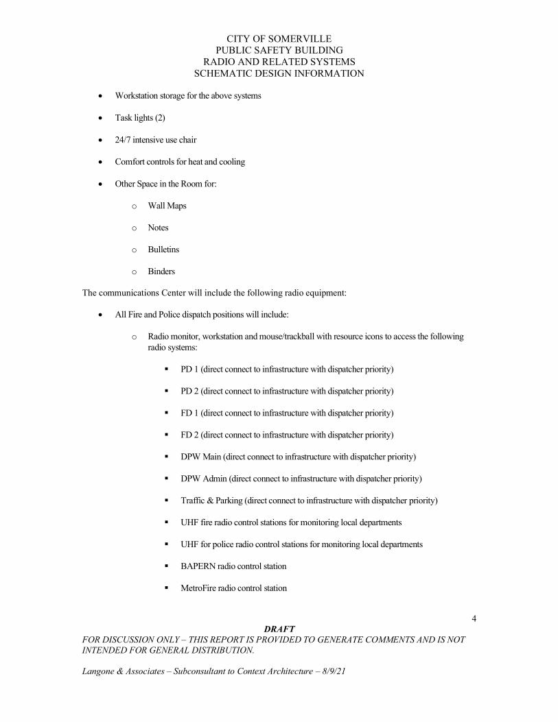
CITY OF SOMERVILLE PUBLIC SAFETY BUILDING
RADIO AND RELATED SYSTEMS SCHEMATIC DESIGN INFORMATION
4 DRAFT
FOR DISCUSSION ONLY – THIS REPORT IS PROVIDED TO GENERATE COMMENTS AND IS NOT INTENDED FOR GENERAL DISTRIBUTION. Langone & Associates – Subconsultant to Context Architecture – 8/9/21
• Workstation storage for the above systems
• Task lights (2)
• 24/7 intensive use chair
• Comfort controls for heat and cooling
• Other Space in the Room for:
o Wall Maps
o Notes
o Bulletins
o Binders
The communications Center will include the following radio equipment:
• All Fire and Police dispatch positions will include:
o Radio monitor, workstation and mouse/trackball with resource icons to access the following radio systems:
PD 1 (direct connect to infrastructure with dispatcher priority)
PD 2 (direct connect to infrastructure with dispatcher priority)
FD 1 (direct connect to infrastructure with dispatcher priority)
FD 2 (direct connect to infrastructure with dispatcher priority)
DPW Main (direct connect to infrastructure with dispatcher priority)
DPW Admin (direct connect to infrastructure with dispatcher priority)
Traffic & Parking (direct connect to infrastructure with dispatcher priority)
UHF fire radio control stations for monitoring local departments
UHF for police radio control stations for monitoring local departments
BAPERN radio control station
MetroFire radio control station

CITY OF SOMERVILLE PUBLIC SAFETY BUILDING
RADIO AND RELATED SYSTEMS SCHEMATIC DESIGN INFORMATION
5 DRAFT
FOR DISCUSSION ONLY – THIS REPORT IS PROVIDED TO GENERATE COMMENTS AND IS NOT INTENDED FOR GENERAL DISTRIBUTION. Langone & Associates – Subconsultant to Context Architecture – 8/9/21
Cataldo Ambulance radio control station
UASI radio control station
State 800 Network radio control station
Controls on the radio console for low voltage external devices such as:
• Traffic light
• Elevator access for visitors
• Selected doors within the building (momentary or latching) requires interface with access control system; access control wiring demarc to be provided adjacent to console back-room equipment rack (LIST DOOR #S)
• Sallyport doors (up-down-stop) requires interface with overhead door electronics; demarc to be provided adjacent to the console back-room equipment rack; requires camera surveillance of doors (LIST DOOR #S)
• Co-located fire station overhead doors; requires camera surveillance of doors (LIST DOOR #S)
• Remote fire station overhead doors; requires camera surveillance of doors (LIST DOOR #S)
o Radio desk set connected to 7 independent control stations for backup to the radio console; desk set to be located at each operator position
o The police radio position is currently connected to the State Core in Boston that allows the police position to access many other radio resources. The City shall investigate the option of remaining connected to the Core or having individual control stations at the PSB
B. Municipal Fire Alarm System
A meeting is scheduled with LW Bills on 8/24/21 to discuss the plan to move or create a second location for the monitoring of the municipal fire alarm systems (100ma & RF boxes)
This system consists of the 100MA circuits and Radio Fire Alarm Boxes at commercial and City buildings. Currently, all the equipment to support this system is located at FD HQ and includes:
• Form 4 Digitize circuits and control panel
• Batteries
• TRX 50 monitor, workstations and servers
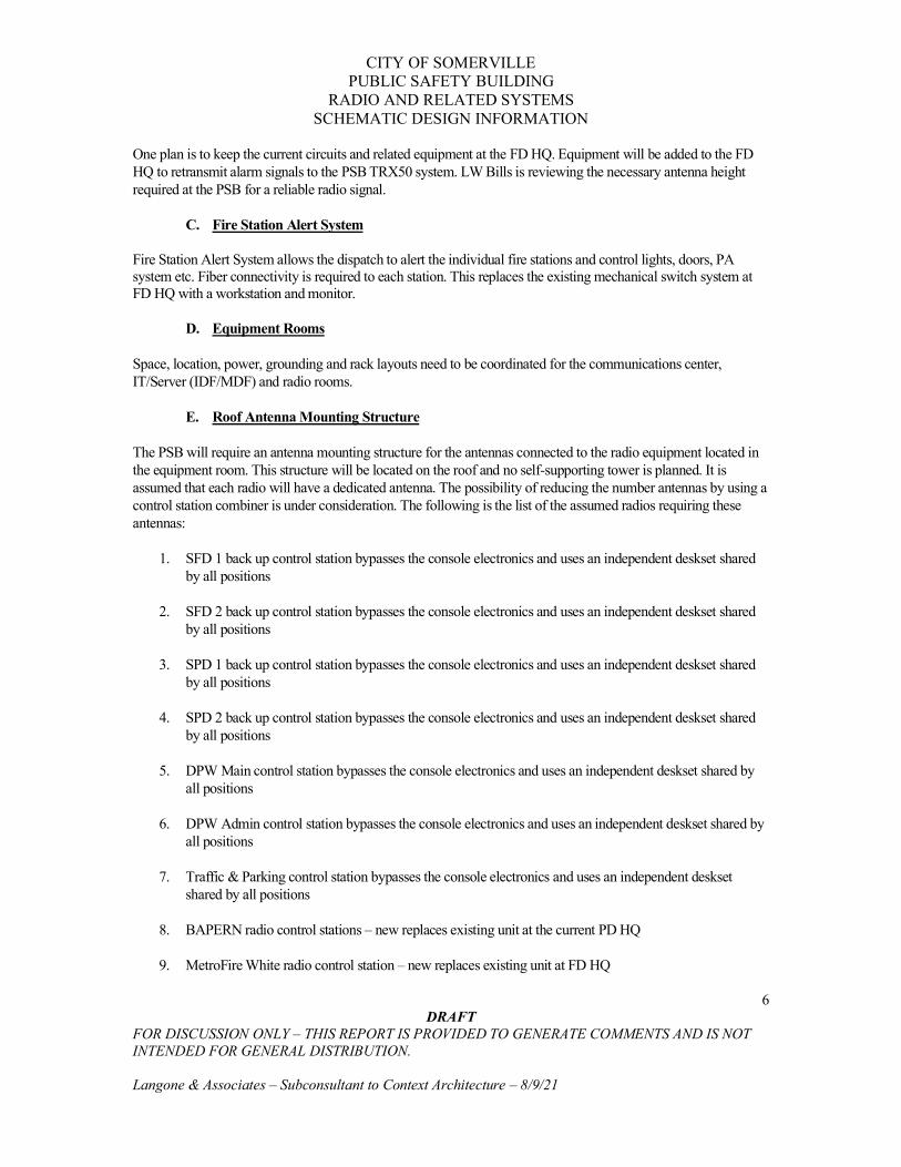
CITY OF SOMERVILLE PUBLIC SAFETY BUILDING
RADIO AND RELATED SYSTEMS SCHEMATIC DESIGN INFORMATION
6 DRAFT
FOR DISCUSSION ONLY – THIS REPORT IS PROVIDED TO GENERATE COMMENTS AND IS NOT INTENDED FOR GENERAL DISTRIBUTION. Langone & Associates – Subconsultant to Context Architecture – 8/9/21
One plan is to keep the current circuits and related equipment at the FD HQ. Equipment will be added to the FD HQ to retransmit alarm signals to the PSB TRX50 system. LW Bills is reviewing the necessary antenna height required at the PSB for a reliable radio signal.
C. Fire Station Alert System
Fire Station Alert System allows the dispatch to alert the individual fire stations and control lights, doors, PA system etc. Fiber connectivity is required to each station. This replaces the existing mechanical switch system at FD HQ with a workstation and monitor.
D. Equipment Rooms
Space, location, power, grounding and rack layouts need to be coordinated for the communications center, IT/Server (IDF/MDF) and radio rooms.
E. Roof Antenna Mounting Structure
The PSB will require an antenna mounting structure for the antennas connected to the radio equipment located in the equipment room. This structure will be located on the roof and no self-supporting tower is planned. It is assumed that each radio will have a dedicated antenna. The possibility of reducing the number antennas by using a control station combiner is under consideration. The following is the list of the assumed radios requiring these antennas:
1. SFD 1 back up control station bypasses the console electronics and uses an independent deskset shared by all positions
2. SFD 2 back up control station bypasses the console electronics and uses an independent deskset shared by all positions
3. SPD 1 back up control station bypasses the console electronics and uses an independent deskset shared by all positions
4. SPD 2 back up control station bypasses the console electronics and uses an independent deskset shared by all positions
5. DPW Main control station bypasses the console electronics and uses an independent deskset shared by all positions
6. DPW Admin control station bypasses the console electronics and uses an independent deskset shared by all positions
7. Traffic & Parking control station bypasses the console electronics and uses an independent deskset shared by all positions
8. BAPERN radio control stations – new replaces existing unit at the current PD HQ
9. MetroFire White radio control station – new replaces existing unit at FD HQ

CITY OF SOMERVILLE PUBLIC SAFETY BUILDING
RADIO AND RELATED SYSTEMS SCHEMATIC DESIGN INFORMATION
7 DRAFT
FOR DISCUSSION ONLY – THIS REPORT IS PROVIDED TO GENERATE COMMENTS AND IS NOT INTENDED FOR GENERAL DISTRIBUTION. Langone & Associates – Subconsultant to Context Architecture – 8/9/21
10. MetroFire xxxx radio control station – new replaces existing unit at FD HQ
11. UASI radio control station – new replaces existing unit at FD HQ
12. State 800 network radio control station - new
13. Fire Mutual Aid control station
14. Police Mutual Aid control station
15. Radio fire alarm receiver 1 - new replaces existing unit at FD HQ
16. Radio fire alarm receiver 2 - new replaces existing unit at FD HQ
17. Cataldo Ambulance radio control station – new replaces existing unit at FD HQ
18. Fire and Police BDA - new
19. Multi-cell carrier BDA – new
20. PSNet Microwave 1 new; non-obstructed microwave path must be field verified
21. PSNet Microwave 2 new; non-obstructed microwave path must be field verified
See information on the roof mounted antenna structure in the Appendix.
F. Generator and Master UPS
It is assumed that the complete building will be on generator with a remote status display in the communications center.
It is assumed that all critical equipment will be connected to a master UPS with a remote status display in the communications center.
G. Co-located Fire Station
What radio communications and fire station alert systems will be required?
H. Remote Fire Stations
Need to determine if any existing radio communications and fire station alert systems will be upgraded.
I. EOC
Need to determine if any radio communications will be required.
J. Mobile and Portable Radios
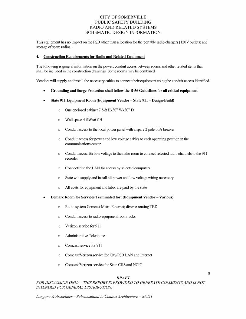
CITY OF SOMERVILLE PUBLIC SAFETY BUILDING
RADIO AND RELATED SYSTEMS SCHEMATIC DESIGN INFORMATION
8 DRAFT
FOR DISCUSSION ONLY – THIS REPORT IS PROVIDED TO GENERATE COMMENTS AND IS NOT INTENDED FOR GENERAL DISTRIBUTION. Langone & Associates – Subconsultant to Context Architecture – 8/9/21
This equipment has no impact on the PSB other than a location for the portable radio chargers (120V outlets) and storage of spare radios.
4. Construction Requirements for Radio and Related Equipment
The following is general information on the power, conduit access between rooms and other related items that shall be included in the construction drawings. Some rooms may be combined.
Vendors will supply and install the necessary cables to connect their equipment using the conduit access identified.
• Grounding and Surge Protection shall follow the R-56 Guidelines for all critical equipment
• State 911 Equipment Room (Equipment Vendor – State 911 – Design-Build)
o One enclosed cabinet 7.5-ft Hx30” Wx30” D
o Wall space 4-ftWx6-ftH
o Conduit access to the local power panel with a spare 2 pole 30A breaker
o Conduit access for power and low voltage cables to each operating position in the communications center
o Conduit access for low voltage to the radio room to connect selected radio channels to the 911 recorder
o Connected to the LAN for access by selected computers
o State will supply and install all power and low voltage wiring necessary
o All costs for equipment and labor are paid by the state
• Demarc Room for Services Terminated for: (Equipment Vendor – Various)
o Radio system Comcast Metro Ethernet; diverse routing TBD
o Conduit access to radio equipment room racks
o Verizon service for 911
o Administrative Telephone
o Comcast service for 911
o Comcast/Verizon service for City/PSB LAN and Internet
o Comcast/Verizon service for State CJIS and NCIC

CITY OF SOMERVILLE PUBLIC SAFETY BUILDING
RADIO AND RELATED SYSTEMS SCHEMATIC DESIGN INFORMATION
9 DRAFT
FOR DISCUSSION ONLY – THIS REPORT IS PROVIDED TO GENERATE COMMENTS AND IS NOT INTENDED FOR GENERAL DISTRIBUTION. Langone & Associates – Subconsultant to Context Architecture – 8/9/21
• Radio and Fire Alarm Equipment Room (Equipment Vendor – Radio Motorola – Design-Build & Municipal Fire Alarm LW Bills – Design-Build)
o Ceiling mounted (96” AFF) cable tray 24” W
o Plywood ¾” on all walls and painted fire-retardant gray
o Radio – 5 ea 7.5-ft H x 2-ft W x 2-ft D open rack with dedicated power (TBD load) for each rack
o Fire alarm – 2 ea cabinets with dedicated power (TBD load) for each rack
o Demarc for selected inside, outside and overhead doors for connection to the radio console relays to allow door controls on the radio console display; cabling and termination provided by door vendors
o Surge protection devices (Polyphasers) grounded to terminate the antenna cables
o Master ground bar
• Communications Center (Equipment Vendor – Radio Motorola – Design-Build & Console Furniture TBD)
o Each dispatch/operating position requires 3 ea 120V/20A dedicated quad outlets which will be field mounted in the furniture; each operating position shall have 8 ea 4-inch access holes field installed in the floor after the furniture is installed; this is only for the radio dispatch console equipment
o Conduit access for low voltage cable routing for the operating positions shall be through the floor for radio equipment, fire alarm equipment, network room and the other systems
o Ground bar for each console position connected to a second ground bar and connected to a master ground bar
• Roof Mounted Antenna Structure (Equipment Vendor – Structure – GC & Antennas/Cables – Motorola/LW Bills)
o Antenna structure mounted on the roof and connected to support flanges from building steel
o Weatherproof housing to protect conduits and cables for access to the radio room
o 19 whip antennas (each with a ½” LDF cable and 2 microwave antennas (each with a 7/8” LDF cable) have been identified for mounting to the roof structure
o Refer to the Appendix for additional information
• EOC - TBD

CITY OF SOMERVILLE PUBLIC SAFETY BUILDING
RADIO AND RELATED SYSTEMS SCHEMATIC DESIGN INFORMATION
10 DRAFT
FOR DISCUSSION ONLY – THIS REPORT IS PROVIDED TO GENERATE COMMENTS AND IS NOT INTENDED FOR GENERAL DISTRIBUTION. Langone & Associates – Subconsultant to Context Architecture – 8/9/21
• Collocated Fire Station – TBD
• Existing Remote Fire Stations - TBD
APPENDICES
1. Fire and Police Operating Position Template – 2 Pages
2. Roof Mount Antenna Structures and QwikPort Picture – 1 Page
3. Roof Mount Antenna Structure and QwikPort – 2 Pages
4. QwikPort Specifications and Installation – 2 Pages
5. Equipment Room Antenna Cable Terminations, Ground Bar and Polyphasers Picture – 1 Page

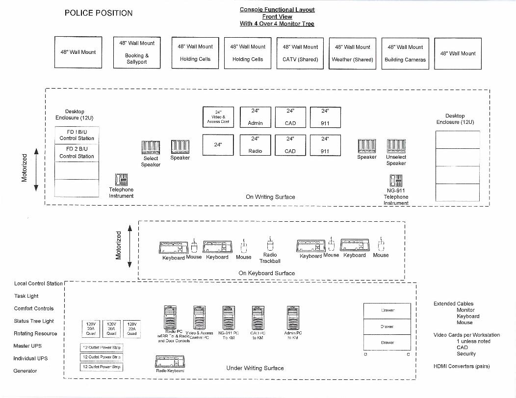

Structure is 10'x10' and mounted on 4 footings that are connected to building steel
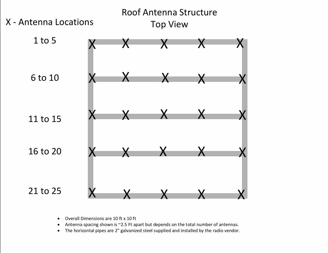
X X X X X
X X X X X
X X X X X
X X X X X
X X X X X
X - Antenna Locations
1 to 5
6 to 10
11 to 15
16 to 20
21 to 25
Roof Antenna StructureTop View
• Overall Dimensions are 10 ft x 10 ft• Antenna spacing shown is ~2.5 Ft apart but depends on the total number of antennas. • The horizontal pipes are 2" galvanized steel supplied and installed by the radio vendor.
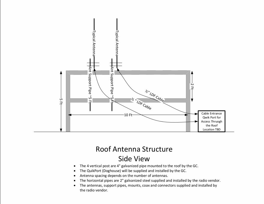
Roof Antenna StructureSide View
10 Ft
5 Ft
2 Ft
Cable Entrance Qwik Port for
Access Thruogh the Roof
Location TBD
An
t Sup
po
rt Pip
e ~5 Ft
An
t Sup
po
rt Pip
e ~
5 Ft
Typ
ical An
tenn
a
Typ
ical An
ten
na
• The 4 vertical post are 4" galvanized pipe mounted to the roof by the GC.• The QuikPort (Doghouse) will be supplied and installed by the GC.• Antenna spacing depends on the number of antennas.• The horizontal pipes are 2" galvanized steel supplied and installed by the radio vendor.• The antennas, support pipes, mounts, coax and connectors supplied and installed by
the radio vendor.
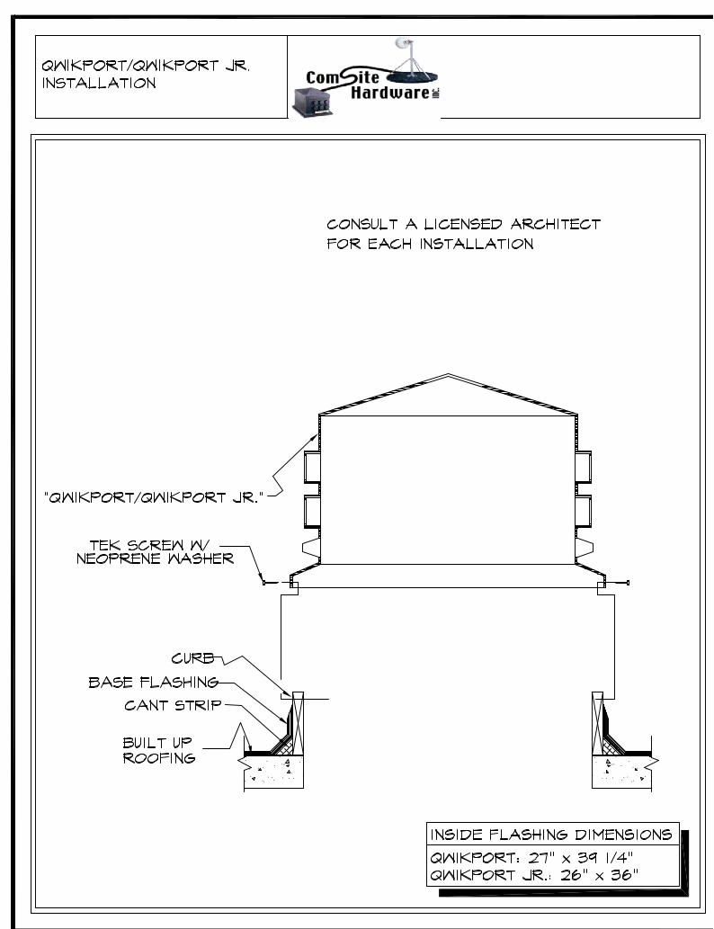
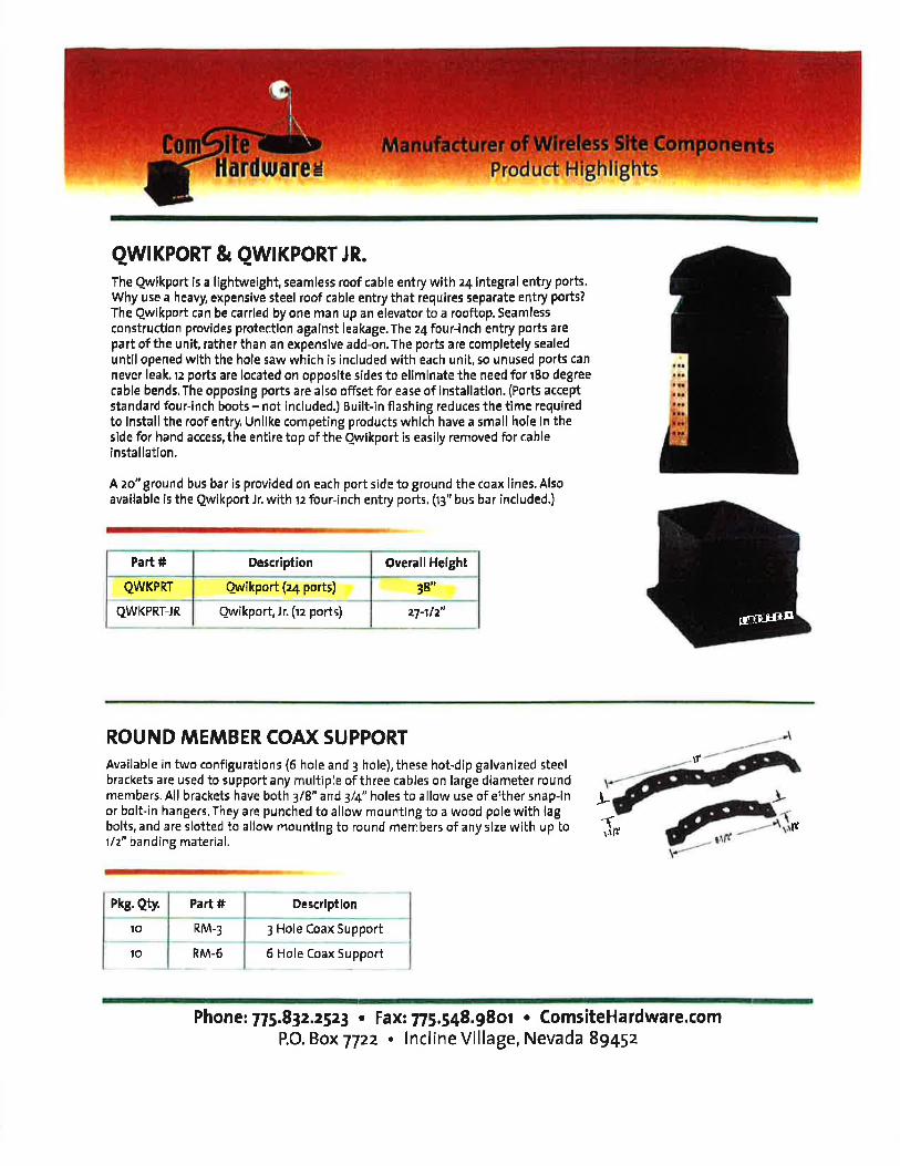
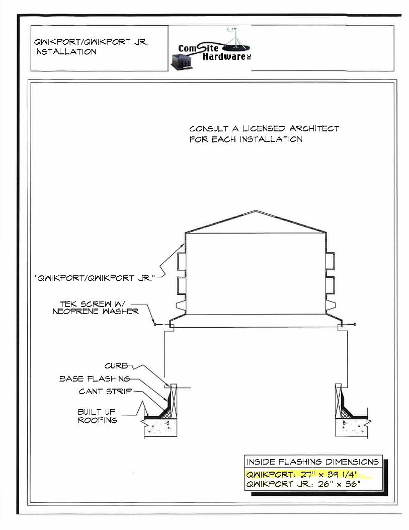
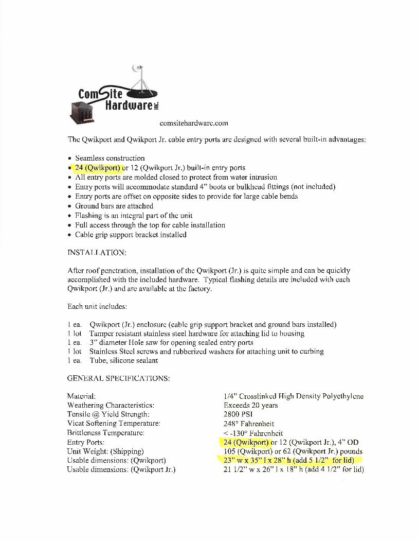


SOMERVILLE PUBLIC SAFETY BUILDING Somerville, Massachusetts 02143
Project No. 2006.00
NARRATIVE 8/13/2021
D.11 ENVELOPE DESIGN-NARRATIVE

EXTERIOR ENCLOSURE NARRATIVE SOMERVILLE PSB
90 WASHINGTON STREET
SOMERVILLE, MA
CLIENT: Context Architecture
68 Harrison Avenue
Boston, MA 02111
DATE: 9 August 2021
3iVE LLC
334 Washington Street
Somerville, MA 02143
www.3iVE.com
Somerville PSB Exterior Enclosure Narrative
- 2 -
Table of Contents
I. INTRODUCTION
II. DESIGN GOALS AND PROCESS
Develop a Robust Enclosure Design Meeting Owner’s Project Requirements
Durable Materials and Assemblies
Maintaining Thermal Consistency/Eliminating Thermal Break
Continuity In Envelope Air And Vapor Barrier, Minimizing Air Leakage
Establishing Performance Plane At Openings, Breaks, Etc.
Effective Rain Screen and Wall Drainage
Insulation Values As It Relates To EUI And Energy Performance
Establishing Envelope Commissioning Baseline Metrics
Ongoing Review Of Details As They Are Developed In DD
Commissioning Process
III. SUMMARY NOTES
Somerville PSB Exterior Enclosure Narrative
- 3 -
I. INTRODUCTION
3iVE LLC (3iVE) was contracted by Context Architecture to serve as the Exterior Enclosure
Consultant for the Somerville Public Safety Building project. On 9 August 2021, we completed a
summary review of three schematic options dated 3 August 2021 for the proposed four-story
structure developed by Context. We found each of the options workable in terms of the Owner’s
Project Requirements as we understand them at this point in the process. Each of the proposed
options is based upon a rain screen cladding system featuring a mix of fenestration types
including masonry, metal panel, and panelized stone. The three options are each capable of
meeting the OPR requirements with a similar degree of difficulty; no options stands out as
significantly more complex in terms of assembly. The following narrative describes the project
goals as well as our intended process moving forward.
II. DESIGN GOALS AND PROCESS
a. Develop a Robust Enclosure Design Meeting Owner’s Project Requirements
3iVE will continue to participate in project meetings with the Architect and Owner to learn
and help codify the Owner’s Project Requirements. 3iVE will work with Context by reviewing
drawings, narratives, details, and specifications, and we will meet with Context at targeted
times during the design process to provide detailed ideas and feedback to help ensure that
the Design Intent expressed in the drawings is aligned with the OPR.
b. Durable Materials and Assemblies
3iVE will assist Context in its selection of materials and its configuration of assemblies to
help ensure that the PSB has materials and details that will endure for the intended lifetime
of the building, or which can be regularly maintained to achieve durability requirements.
c. Maintaining Thermal Consistency/Eliminating Thermal Break
3iVE will review and provide feedback for represenative and unique details for thermal
consistency and minimal thermal breaks in the PSB’s enclosure.
d. Continuity In Envelope Air And Vapor Barrier, Minimizing Air Leakage
3iVE will review and provide feedback for represenative and unique details to ensure a
continuos air and vapor building are represented in way that is both appropriate and
achievable. 3iVE will also assist Context by providing mockup and testing specifications that
will serve to monitor the effectiveness of the air and vapor barrier for ground, wall, and roof
conditions.
e. Establishing Performance Plane At Openings, Breaks, Etc.
3iVE will review large scale details provided by Context to help ensure a sensible and
consistent performance barrier is present around the building.
f. Effective Rain Screen and Wall Drainage
3iVE will review large scale rainscreen and flashing details provided by Context to ensure
the drainage and pressure-equalized rainscreen details achieve moisture management
goals.

Somerville PSB Exterior Enclosure Narrative
- 4 -
g. Insulation Values As It Relates To EUI And Energy Performance
3iVE will review the projects insulationand thermal isolation strategy against the building’s
thermal goals. This will include fenestration, cladding, roofing, and girt and tie systems.
h. Establishing Envelope Commissioning Baseline Metrics
3iVE will provide testing protocols and metric goals consistent with the PSB’s OPR to ensure
the project has appropriate target goals as well as a means to measure and confirm them.
i. Ongoing Review Of Details As They Are Developed In DD
3iVE will maintain a presence througout design, construction, and occupancy to help ensure
that the OPR is achieved in terms of both Design Intent as well as constructed results. Eive
will also assist in developing target goals as well as a means to measure and confirm them.
j. Commissioning Process
3iVE will advise Context and the Owner on an exterior commissioning process that will
provide further assurance that the project’s OPR and the Architect’s Basis of Design are
being achieved as the project progresses. We will be available to review proposals from
qualified vendors.
III. SUMMARY NOTES
Each of the options Context Architecture is exploring stand to meet the Owner’s Project
Requirements. 3iVE will work throughout the design and construction process to offer
commentary, expertise, and advice to help the design team produce a clear and constructible
set of Construction Documents that will meet or exceed the agreed upon requirements and
goals for the project’s exterior enclosure.
Sincerely,
David de Sola, AIA LEED AP BD+C
3iVE LLC

SOMERVILLE PUBLIC SAFETY BUILDING Somerville, Massachusetts 02143
Project No. 2006.00
NARRATIVE 8/13/2021
D.12 NET ZERO DESIGN-NARRATIVE
HVAC System Option Energy Modeling Report
Somerville Public Safety Building Somerville, MA
August 4, 2021
AKF Project No. 201522

TABLE OF CONTENTS
1. EXECUTIVE SUMMARY
2. ENERGY MODEL RESULTS
3. ENERGY MODEL INPUTS

Somerville Public Safety Building
HVAC System Option Energy Model Report Page 3
1. EXECUTIVE SUMMARY
The Somerville Public Safety Building is a proposed new construction building located in Somerville, Massachusetts. The building is approximately 77,000 square feet and features a variety of program areas including a Police Station, Fire station & quarters, dispatch center, and community center. There is an additional parking structure of 15,000 square feet.
The purpose of this energy report is to compare different mechanical design options. Each design option was modeled based on the HVAC Systems Narrative provided by GGD Consulting Engineers. The following HVAC Designs were modeled.
▪ Baseline (Fossil Fuel Free – Electric Heating)
▪ Option 1 – High Efficiency VAV System (Electric Heating)
▪ Option 2 – Air Source VRF System
▪ Option 3 – Chilled Beam System (Electric Heating)
▪ Option 4 – Ground Source VRF System
▪ Option 5 – Ground Source Chilled Beam (Induction) System
The following tables provides the modeled results including the total annual energy cost, consumption, and carbon equivalent for each energy model.
EUI (kBTU/sf)
Annual Energy Cost ($)
Total Energy Consumption
(kWh)
Total Energy Consumption
(MMBtu)
Energy Savings (%)
CO2e Emissions (MTCO2e)
Baseline 98.1 $420,869 2,672,195 9,120 - 640
Option 1 High Eff. VAV Sys 71.1 $304,940 1,936,156 6,608 27.54 463
Option 2 A.S. VRF 59.7 $256,319 1,627,425 5,554 39.10 390
Option 3 A.S. CHW Beam 58.9 $252,862 1,605,411 5,479 39.92 384
Option 4 G.S. VRF 58.7 $251,798 1,598,652 5,456 40.17 383
Option 5 G.S. CHW Beam 56.6 $242,913 1,542,280 5,264 42.28 369
Notes: - All design options are electric only buildings. - CO2e Emissions determined based on ENERGY STAR Portfolio Manager GHG Emission Factors for electricity in the U.S.
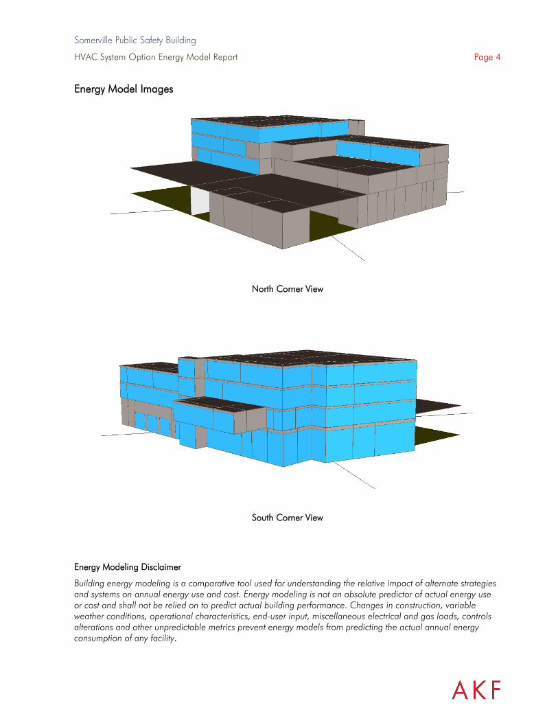
Somerville Public Safety Building
HVAC System Option Energy Model Report Page 4
Energy Model Images
North Corner View
South Corner View
Energy Modeling Disclaimer
Building energy modeling is a comparative tool used for understanding the relative impact of alternate strategies and systems on annual energy use and cost. Energy modeling is not an absolute predictor of actual energy use or cost and shall not be relied on to predict actual building performance. Changes in construction, variable weather conditions, operational characteristics, end-user input, miscellaneous electrical and gas loads, controls alterations and other unpredictable metrics prevent energy models from predicting the actual annual energy consumption of any facility.

Somerville Public Safety Building
HVAC System Option Energy Model Report Page 5
2. ENERGY MODEL RESULTS
General
The below charts show annual energy end-use breakdown for the modeled design options.
-
500
1,000
1,500
2,000
2,500
3,000
3,500
4,000
Ener
gy C
on
sum
pti
on
(M
MB
tu)
Annual Energy Consumption by End-Use (MMBtu)
Baseline Option 1 High Eff. VAV Sys Option 2 A.S. VRF Option 3 A.S. CHW Beam Option 4 G.S. VRF Option 5 G.S. CHW Beam
$- $20,000 $40,000 $60,000 $80,000
$100,000 $120,000 $140,000 $160,000 $180,000 $200,000
Co
st (
$)
Annual Energy Consumption by Cost ($)
Baseline Option 1 High Eff. VAV Sys Option 2 A.S. VRF
Option 3 A.S. CHW Beam Option 4 G.S. VRF Option 5 G.S. CHW Beam
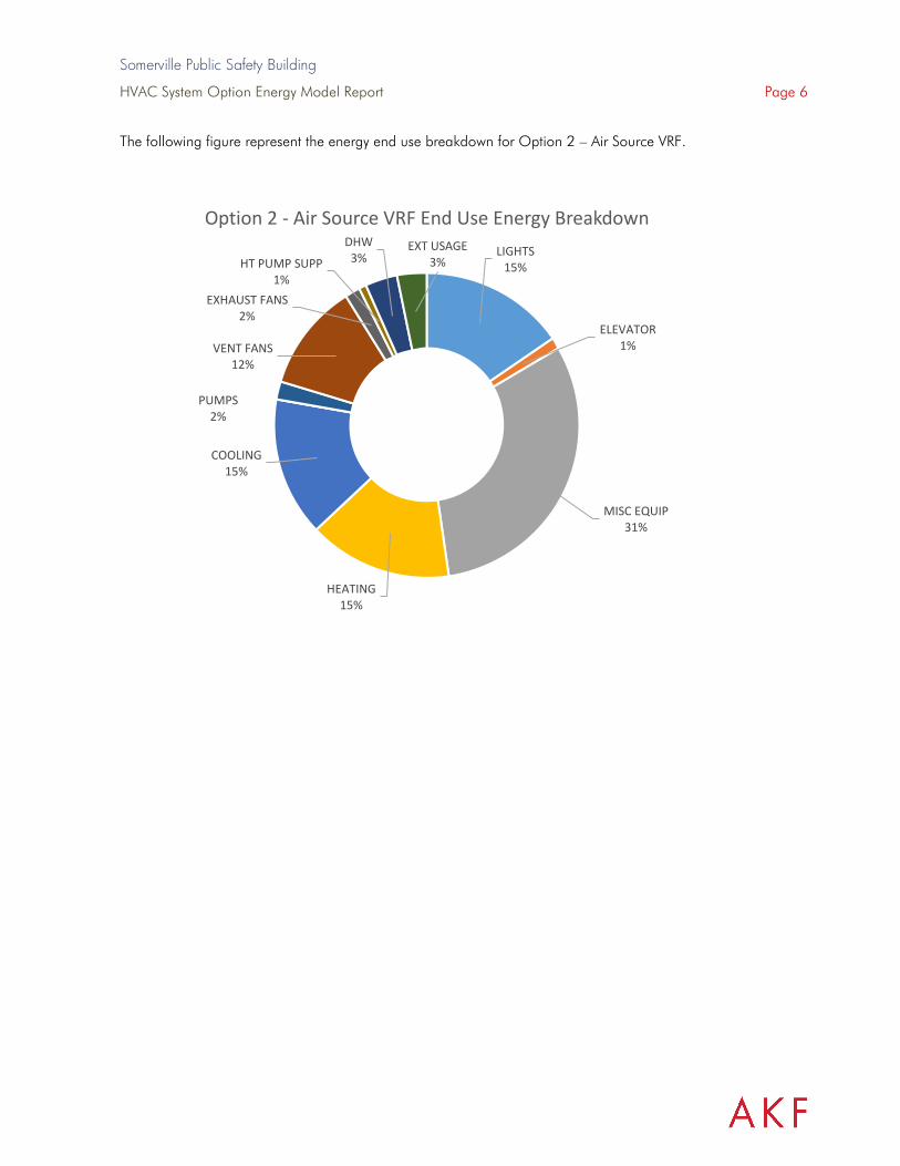
Somerville Public Safety Building
HVAC System Option Energy Model Report Page 6
The following figure represent the energy end use breakdown for Option 2 – Air Source VRF.
LIGHTS15%
ELEVATOR1%
MISC EQUIP31%
HEATING15%
COOLING15%
PUMPS2%
VENT FANS12%
EXHAUST FANS2%
HT PUMP SUPP1%
DHW3%
EXT USAGE3%
Option 2 - Air Source VRF End Use Energy Breakdown
Somerville Public Safety Building
HVAC System Option Energy Model Report Page 7
ENERGY MODEL INPUTS
Project and Site Information
Weather TMY3\MA_Boston_Logan_Intl_Arp.bin
Orientation Plan North = North
ASHRAE Climate Zone
5A
Utility Rate Structure
Electricity EIA Default – Massachusetts Commercial
• $0.1575/kWh
Natural Gas EIA Default – Massachusetts Commercial
• $1.03/Therm
Geometry and Architecture
Zoning Based on Energy Model Plans dated 07/09/2021
Gross Area
Building Area: 77,302 sf
Parking Area: 15,607 sf
Building Area by Space Type:
▪ Police Station: 22,833 sf ▪ Back-of-House: 9,726 sf ▪ Fire Apparatus: 9,560 sf ▪ Locker Rooms: 7,154 sf ▪ Fire Quarters: 5,313 sf ▪ Office: 4,723 sf ▪ Wellness: 2,639 sf ▪ Prison: 2,526 sf ▪ Corridor: 2,413 sf ▪ Dispatch: 2,358 sf ▪ Family: 2,114 sf ▪ Storage: 2,098 sf ▪ Lobby: 2,071 sf ▪ Community: 1,293 sf ▪ Misc. Space: 474 sf

Somerville Public Safety Building
HVAC System Option Energy Model Report Page 8
Floor to Floor Heights
Floor-to-Floor Height:
▪ First: 24’ ▪ Second – Fourth: 14’
Occupants
Occupant quantities are equal in both models and based on ASHRAE 90.1 User’s Manual and ASHRAE 62.1-2010 default occupant density
Space Type Proposed and Baseline (sf/person)
Police Station 275
Parking Garage No Regular Occupancy
Back-of-House 750
Fire Apparatus 500
Locker Rooms 300
Fire Quarters 250
Office 275
Wellness 300
Cell 300
Corridor No Regular Occupancy
Dispatch 275
Family 300
Storage 750
Lobby 250
Community 50
Misc. Space No Regular Occupancy

Somerville Public Safety Building
HVAC System Option Energy Model Report Page 9
Building Envelope Performance
Proposed Design – Per information provided by Context Architecture
Window-to-Wall Ratio 48%
Glazing Performance (assembly values)
U-Value: 0.25
SHGC: 0.33
Skylight Performance None
Above Grade Walls U-Value: 0.0470 R-21.25 continuous (5” X 4.25 R-value) insulation
Sub-grade Walls N/A
Slab-on-Grade N/A
Roof – Insulation entirely above deck
U-Value: 0.02
R-48 continuous insulation
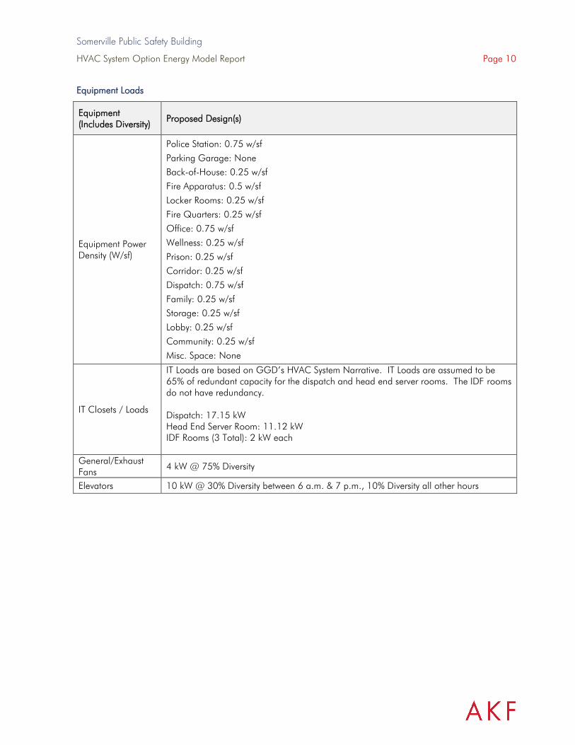
Somerville Public Safety Building
HVAC System Option Energy Model Report Page 10
Equipment Loads
Equipment (Includes Diversity)
Proposed Design(s)
Equipment Power Density (W/sf)
Police Station: 0.75 w/sf
Parking Garage: None
Back-of-House: 0.25 w/sf
Fire Apparatus: 0.5 w/sf
Locker Rooms: 0.25 w/sf
Fire Quarters: 0.25 w/sf
Office: 0.75 w/sf
Wellness: 0.25 w/sf
Prison: 0.25 w/sf
Corridor: 0.25 w/sf
Dispatch: 0.75 w/sf
Family: 0.25 w/sf
Storage: 0.25 w/sf
Lobby: 0.25 w/sf
Community: 0.25 w/sf
Misc. Space: None
IT Closets / Loads
IT Loads are based on GGD’s HVAC System Narrative. IT Loads are assumed to be 65% of redundant capacity for the dispatch and head end server rooms. The IDF rooms do not have redundancy. Dispatch: 17.15 kW Head End Server Room: 11.12 kW IDF Rooms (3 Total): 2 kW each
General/Exhaust Fans
4 kW @ 75% Diversity
Elevators 10 kW @ 30% Diversity between 6 a.m. & 7 p.m., 10% Diversity all other hours

Somerville Public Safety Building
HVAC System Option Energy Model Report Page 11
Internal Electrical Loads
Proposed Design(s)
Lighting (Space-by-Space Method)
Lighting power densities based on IECC 2018.
Police Station: 0.64 w/sf
Parking Garage: 0.15 w/sf
Back-of-House: 0.51 w/sf
Fire Apparatus: 0.56 w/sf
Locker Rooms: 0.52 w/sf
Fire Quarters: 0.41 w/sf
Office: 0.64 w/sf
Wellness: 0.97 w/sf
Prison: 0.66 w/sf
Corridor: 0.41 w/sf
Dispatch: 0.66 w/sf
Family: 0.97 w/sf
Storage: 0.51 w/sf
Lobby: 0.84 w/sf
Community: 0.97 w/sf
Misc. Space: None
Exterior Lighting 10 kW peak (estimated), 0% from 8am-6pm, 100% otherwise
Daylighting
Automatic Daylighting Controls for Primary Side lighted Areas per ASHRAE 90.1-2016.
Lighting Controls Occupancy Sensors in all areas required by code.

Somerville Public Safety Building
HVAC System Option Energy Model Report Page 12
General HVAC
Proposed Design
ASHRAE Climate Zone
Climate Zone 5A
Thermostat Setpoints
74oF / 70oF occupied, 65oF heating setback & 80 oF cooling setback
HVAC Design Options
All Design options were modeled based on GGD HVAC Systems Narrative
Airside HVAC Summary
Proposed Design
System(s)
▪ System Fan Power Based on IECC 2018 requirements ▪ 65% Supply Fan Power / 35% Return Fan Power where
applicable ▪ Efficiency values based on IECC 2018 requirements ▪ Fans assumed to operate 24 / 7. Local VRF & CHB Cycle to
maintain setpoint
DCV DCV modeled based on occupancy schedules. Minimum outdoor air turndown set to 40% of design flow. See figure below.
Energy Recovery Energy Recovery 55% Sensible / 55% Latent effectiveness

Somerville Public Safety Building
HVAC System Option Energy Model Report Page 13
Domestic Hot Water
Proposed Design
General Usage Electric Resistance Domestic hot water heaters
1.92 Peak GPM
Efficiency – 100%
Recirculating System Yes
Schedule and Occupancy
The schedules of use are defined based on ASHRAE 90.1 User’s Manual typical schedules. Adjustments were made to the schedules to capture expected occupancy per each space type. These schedules will be further refined. The building occupancy schedules are shown below.

Somerville Public Safety Building
HVAC System Option Energy Model Report Page 14
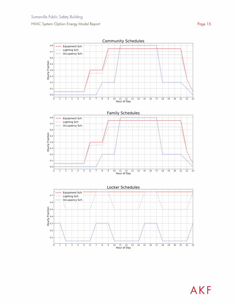
Somerville Public Safety Building
HVAC System Option Energy Model Report Page 15
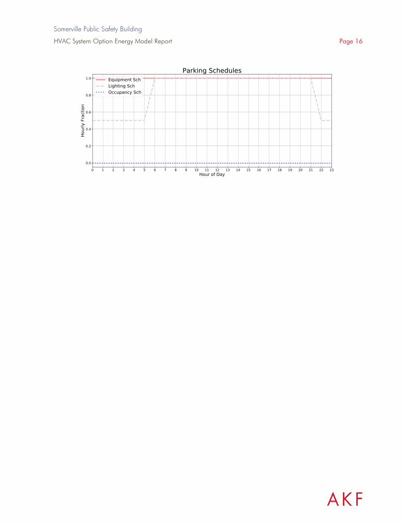
Somerville Public Safety Building
HVAC System Option Energy Model Report Page 16

| One Liberty Plaza, 165 Broadway, 22nd Floor, New York, NY 10006 | T: 212.354.5656 | akfgroup.com |
PV Systems Report
Somerville Public Safety Building Somerville, MA
August 10, 2021
AKF Project No. 201522

Somerville Public Safety Building August 10, 2021
Somerville, MA Page 2 AKF Project Number: 201522
| One Liberty Plaza, 165 Broadway, 22nd Floor, New York, NY 10006 | T: 212.354.5656 | akfgroup.com |
SCHEMATIC DESIGN SYSTEM SUMMARY:
Analysis was completed during the schematic design phase for the Somerville Public Safety Building to determine a maximum potential energy generation using a photovoltaic (PV) system. The design was based on a 405W PV panel from LG Solar. The flat roof racking was based on spacing from Unirac’s Roofmount line of ballasted flat roof systems. Those roof surfaces that receive more east or west shading from other parts of the building were laid out facing due south at a 5 degree tilt and use the spacing from the RM5 racking system with the wider row to row spacing. The wider spacing was selected since Somerville, MA is at 42 deg. North latitude and has lower sun angles. The roof surfaces with no anticipated east or west shading were laid out using the RMDT system with PV panels mounted facing east and west at an 8 degree tilt. This system layout allows for additional PV panels to be mounted on the roof surface. Overall it was assumed that the PV could be mounted with in 4 feet of the roof each as allowed by NFPA. In order for the building to comply with OSHA regulations clip in points for a safety harness will need to be provided on the roof. Additional circulation pathways were also included to comply with NFPA requirements. Roof areas that were determined to receive significant shading from other parts of the building were not covered with PV panels and are available for mechanical systems equipment and building vent piping. An additional PV array was laid out over the roof of the parking garage. These panels would need to be mounted on a canopy system and be mounted over parking and drive aisle. Due to the amount of western shading from the adjacent building in the afternoon, the PV was laid out facing due south at the same 5 degree tilt as the panels on the roof. The panels were also not located in the zone adjacent to the 4 story portion of the building as the shading from the building will be significant. Based on the layout provided in sketch SKE-PV the current design can support 575 PV panels or 233kW of PV on the roof and an additional 604 PV panels or 244 kW of PV over the parking garage roof. This will generate and estimated 579,000 kWh annually. Given the current projected energy usage the building is not currently projecting to achieve net zero energy. The current baseline case estimates 2,762,195 kWh in annual energy usage so the PV only offsets 21% of the estimated energy used. The current lowest estimated annual energy case uses the geothermal wells with chilled beam. This low energy case uses an estimated 1,542,280 kWh annually so our PV array would only offsets 37.5% of the estimated annual energy used. If there is a desire to improve the energy generation potential of the project, in future evolutions of the design attention should be given to ways to minimize self-shading in the building form.
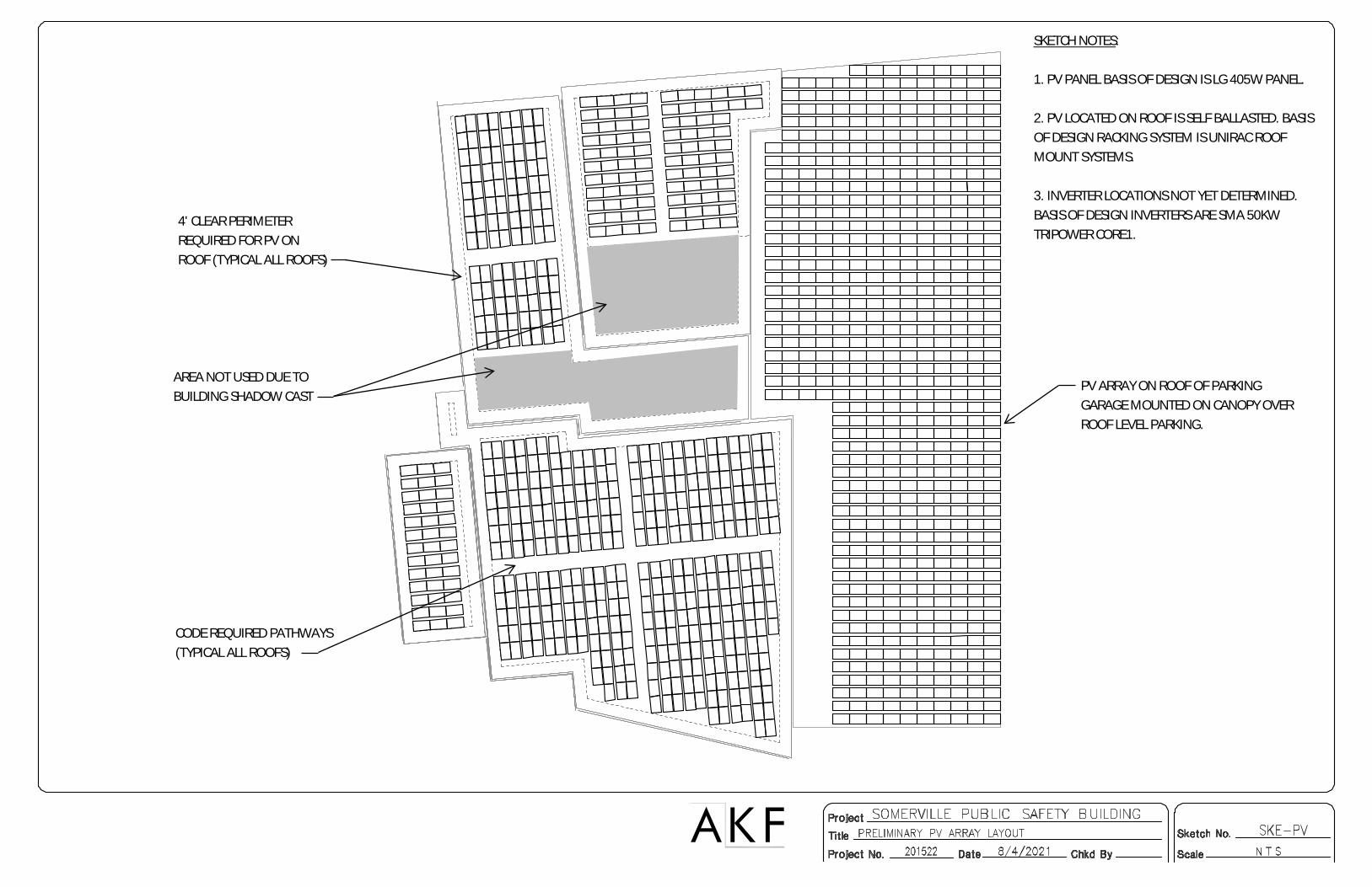
AKF
4' CLEAR PERIMETERREQUIRED FOR PV ONROOF (TYPICAL ALL ROOFS)
AREA NOT USED DUE TOBUILDING SHADOW CAST
CODE REQUIRED PATHWAYS(TYPICAL ALL ROOFS)
PV ARRAY ON ROOF OF PARKINGGARAGE MOUNTED ON CANOPY OVERROOF LEVEL PARKING.
SKETCH NOTES:
1. PV PANEL BASIS OF DESIGN IS LG 405W PANEL.
2. PV LOCATED ON ROOF IS SELF BALLASTED. BASISOF DESIGN RACKING SYSTEM IS UNIRAC ROOFMOUNT SYSTEMS.
3. INVERTER LOCATIONS NOT YET DETERMINED.BASIS OF DESIGN INVERTERS ARE SMA 50KWTRIPOWER CORE1.

SOMERVILLE PUBLIC SAFETY BUILDING Somerville, Massachusetts 02143
Project No. 2006.00
NARRATIVE 8/13/2021
D.13 LEED-NARRATIVE AND SCORECARD
Somerville Public Safety Building
Sustainability NarrativeAugust 6, 2021
Prepared by:Soden Sustainability
Sustainability Narrative Somerville Public Safety Building
90 Washington Street Somerville, MA
Sustainability/Green Building Design Approach
The Project will demonstrate compliance with the LEED Requirements for LEED v4 Building Design and Construction Criteria. Further study over the coming weeks and months will determine and confirm final credit achievement. At this stage in the Project, we are tracking 70 YES credits and 21 Maybe credits.
Sustainability informs every design decision. Enduring and efficient buildings conserve embodied energy and preserve natural resources. The Project embraces the opportunity to positively influence the urban environment. Its urban location takes advantage of existing infrastructure while access to public transit will reduce dependence on single-occupancy vehicle trips and minimize transportation impacts.
The LEED v4 for Building Design and Construction (BD&C) rating system tracks the sustainable features of a Project by achieving points in following categories: Integrative Process; Location & Transportation; Sustainable Sites; Water Efficiency; Energy and Atmosphere; Materials and Resources; Indoor Environmental Quality; and Innovation and Design Process.
Location and Transportation
The Location and Transportation credit category encourages development on previously developed land, minimizing a building’s impact on ecosystems and waterways, regionally appropriate landscaping, and smart transportation choice.
The Project site has been previously developed, meeting the criteria for the sensitive land protection credit. The site also has a history of use that assumes some level of soul contamination is likely and will need to be remediated.
The Project achieves a Walk Score of 86, and is achieving all 5 points of the Surrounding Density and Diverse Uses credit. The Project is earning 5 Quality Transit points as it inly has access to the numerous busses and the new green line extension.
The Project earns the Reduced Parking Footprint credit with over a 50% reduction. The City of Somerville is evaluating the requirements for number of vehicles charging spaces and bike racks which will likely exceed the numbers for LEED compliance therefore both of these credits will be achieved.
Sustainable Sites
The development of sustainable sites is at the core of sustainable design. Sustainable Site design provides quality open space with active landscape elements that can both mitigate stormwater and provide shade and thermal comfort for the building occupants.
The Project will incorporate green infrastructure approaches into the design such as rain gardens, permeable pavers, and increased landscaping. Subsurface infiltration systems will be used to further promote stormwater infiltration. The Project will infiltrate runoff in a volume equivalent to 1.5 inches times the impervious area within the Project Site.
The building roof and all hardscape material will comply with the SRI standards set forth by LEED and achieve both Heat Island credits. All exterior lighting fixtures will comply with the Light Pollution Reduction credit.
As required by LEED, the Project will create and implement an erosion and sedimentation control plan for all construction activities associated with the Project. The plan will conform to the erosion and sedimentation requirements of the 2012 U.S. Environmental Protection Agency (EPA) Construction General Permit (CGP) or local equivalent, whichever is more stringent.

The Project is developing the site assessment credit that will demonstrate the relationships between the Project site features and topics, Topography, Hydrology, Climate, Vegetation, Soils, Human use.
Water Efficiency
Buildings are major users of our potable water supply and conservation of water preserves a natural re-source while reducing the amount of energy and chemicals used for sewage treatment. The goal of the Water Efficiency credit category is to encourage smarter use of water, both inside and outside.
Water reduction is typically achieved through more efficient appliances, fixtures and fittings inside and water-wise landscaping outside. To satisfy the requirements of the Indoor Water Use Reduction Prerequisite and credit, the Project will incorporate water conservation strategies that include low-flow plumbing fixtures for water closets and faucets. To satisfy the requirements of the Outdoor Water Use Reduction Prerequisite and credit, the landscape will be designed to eliminate potable water use and the design will only have plant material that is native and adaptive.
The Project is targeting significant indoor water use reduction from the baseline. All newly installed toilets, lavatory faucets, kitchen sinks and showerheads that are eligible for labeling will be low-flow and have the Water Sense label. The Project is currently tracking over 35% reduction in potable water use for plumbing fixtures.
The Project will install permanent water meters that measure the total potable water use for the building and associated grounds in addition to water meters for two or more of the following water sub-systems, as applicable to the Project: irrigation, indoor plumbing fixtures and fittings, domestic hot water and the boiler for additional metering.
Metering data will be compiled into monthly and annual summaries, and the resulting whole-project water usage data will be shared with USGBC.
Energy & Atmosphere
According to the U.S. Department of Energy, buildings use 39 percent of the energy and 74 percent of the electricity produced each year in the United States. The Energy and Atmosphere credit category encourages a wide variety of energy strategies: commissioning; energy use monitoring; efficient design and construction; efficient appliances, systems and lighting; the use of renewable and clean sources of energy, generated on-site or off-site; and other innovative practices.
Fundamental Commissioning and Enhanced Commissioning will be pursued for the Project. Envelope Commissioning and Monitoring Based Commissioning will also be evaluated.
A whole-building energy simulation was be performed for the Project for the various options. We will provide an update once the HVAC design is selected. Currently we are tracking a 32% energy cost reduction. (13 points)
The Project will evaluate installing building-level energy meters, or submeters that can be aggregated to provide building-level data representing total building energy consumption (electricity, natural gas, chilled water, steam, fuel oil, propane, biomass, etc.).
The Project is also evaluating solar with an update provided by AKF.
As required by LEED, the Project will not use chlorofluorocarbon (CFC)-based refrigerants in new heating, ventilating, air-conditioning, and refrigeration (HVAC&R) systems. The Project will target the use of refrigerants used in heating, ventilating, air-conditioning, and refrigeration (HVAC&R) equipment that minimize or eliminate the emission of compounds that contribute to ozone depletion and climate change. The Enhanced Refrigerant calculation will be completed for the permit submission.
The Proponent is evaluating engaging in a contract for 100% of the Project’s energy from green power, carbon offsets, or renewable energy certificates (RECs).
Materials & Resources
During both construction and operations, buildings generate tremendous waste and use many materials and resources. The Materials & Resources credit category encourages the selection of sustainable materials, including those that are harvested and manufactured locally, contain high-recycled content, and are rapidly renewable. It also promotes the reduction of waste through building and material reuse, construction waste management, and ongoing recycling programs.
As required by LEED, the Project will provide dedicated areas accessible to waste haulers and building occupants for the collection and storage of recyclable materials for the entire building. Collection and storage areas may be separate locations. Recyclable materials will include mixed paper, corrugated cardboard, glass, plastics, and metals. The Project will also take appropriate measures for the safe collection, storage, and disposal of two of the following: batteries, mercury-containing lamps, and electronic waste.
To comply with both the prerequisite and credit requirements related to construction waste management, the Project will develop and implement a construction and demolition waste management plan that will identifying at least five materials (both structural and nonstructural) targeted for diversion and approximate a percentage of the overall Project waste that these materials represent. The Project will divert a minimum of 75 percent of the total construction and demolition material; diverted materials will include at least four material streams.
Careful material selection will be performed for the Project. The Project will evaluate products that have Environmental Product Declarations (EPDs), Sourcing of Raw Materials and Material Ingredients disclosures to meet the LEED Criteria.
Indoor Environmental Quality
The U.S. Environmental Protection Agency estimates that Americans spend about 90 percent of their day in-doors, where the air quality can be significantly worse than outside. The Indoor Environmental Quality credit category promotes strategies that can improve indoor air through low emitting materials selection and increased ventilation. It also promotes access to natural daylight and views.
As required by LEED, the Project will meet the minimum requirements of ASHRAE Standard 62.1–2010, Sections 4–7, Ventilation for Acceptable Indoor Air Quality (with errata), or a local equivalent, whichever is more stringent. Also, during building operations the Proponent will institute a No Smoking Policy to prohibit the use of all tobacco products inside the building and within 25 feet of the building entrance, air intakes, and operable windows.
The Project will develop and implement an indoor air quality (IAQ) management plan for the construction and preoccupancy phases of the building, meeting or exceeding all applicable recommended control measures of the Sheet Metal and Air Conditioning National Contractors Association (SMACNA) IAQ Guidelines for Occupied Buildings under Construction, 2nd edition, 2007, ANSI/SMACNA 008–2008, Chapter 3. The Project will follow strict IAQ guidelines and protect absorptive materials stored on-site from moisture damage. The Project will also consider performing a flush out.
The Project will meet the thermal comfort criteria both for controllability and the ASHRAE 55 standards along with the interior lighting criteria. Additionally, the Quality Views credit and Daylight are being evaluated for benefits for the occupants.
Along with the walk off matts at the entries, MERV 13 filtration, and chemical exhaust, the project is targeting the Low Emitting Materials credit to further increase occupant health.
Innovation and Design Process
The Innovation in Design and Innovation in Operations credit categories provide additional points for projects that use new and innovative technologies, achieve performance well beyond what is required by LEED credits, or utilize green building strategies that are not specifically addressed elsewhere in LEED. This credit category also rewards projects for including a LEED Accredited Professional on the team to ensure a holistic, integrated approach to design, construction, operations and maintenance. The following credits are being pursued and/or evaluated for the Project:

Innovation in Design- Low Mercury/Sustainable Purchasing Lights
Innovation in Design: Exemplary Performance- Heat Island
Innovation in Design: Green Housekeeping & Integrated Pest Management
Innovation in Design: Safety First: Cleaning and Disinfecting Your Space
Innovation in Design: Education/ Tenant Manual
Innovation in Design: LEED Accredited Professional
Regional Priority
The Project is eligible for the following regional priority credits.
Regional Priority: Optimize Energy Performance (yes)
Regional Priority: Rainwater Management (yes)
Regional Priority: High Priority Site (yes)
Regional Priority: Renewable Energy Production (yes)
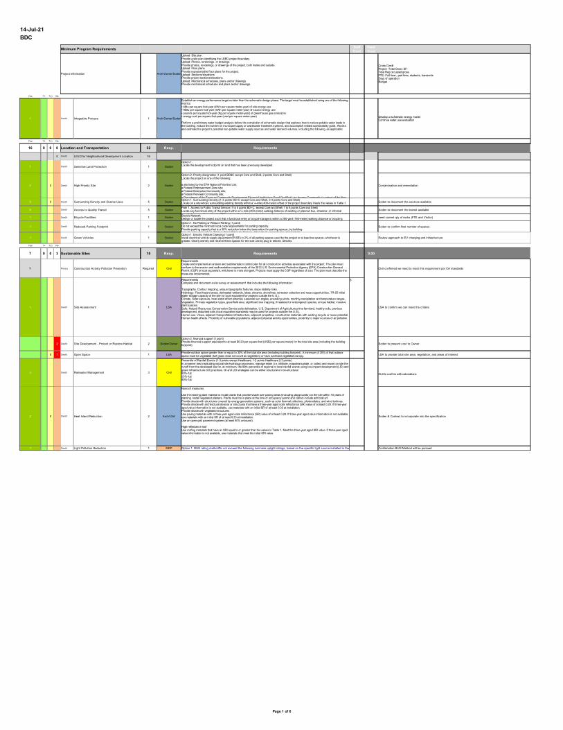
Page 1 of 6
14-Jul-21
BDC
Minimum Program Requirements
Project Information Arch/Owner/Soden
Yes ?+ ?(-) No
1 Credit Integrative Process 1 Arch/Owner/Soden
Yes ?+ ?(-) No
16 0 0 0 Location and Transportation 32 Resp. Requirements
0 Credit LEED for Neighborhood Development Location 16
1 Credit Sensitive Land Protection 1 Soden
2 0 Credit High Priority Site 2 Soden Contamination and remediation
5 0 Credit Surrounding Density and Diverse Uses 5 Soden Soden to document the services available
5 Credit Access to Quality Transit 5 Soden Soden to document the transit available
1 Credit Bicycle Facilities 1 Soden need current qty of racks (FTE and Visitor)
1 Credit Reduced Parking Footprint 1 Soden Soden to confirm final number of spaces
1 Credit Green Vehicles 1 Soden Review approach to EV charging and infrastructure
Yes ?+ ?(-) No
7 0 0 3 Sustainable Sites 10 Resp. Requirements 0.00
Y Prereq Construction Activity Pollution Prevention Required Civil Civil confirmed we need to meet this requirement per CA standards
1 Credit Site Assessment 1 LSA
$
LSA to confirm we can meet the criteria
2 Credit Site Development - Protect or Restore Habitat 2 Soden/Owner Soden to present cost to Owner
0 1 Credit Open Space 1 LSA LSA to provide total site area, vegetation, and areas of interest
3 Credit Rainwater Management 3 Civil $
2 0 Credit Heat Island Reduction 2 Arch/LSA Soden & Context to incorporate into the specification
1 Credit Light Pollution Reduction 1 MEP Confirmation BUG Method will be pursued
Soft Cost
Hard Cost
Upload: Site planProvide a site plan identifying the LEED project boundary.Upload: Photos, renderings, or drawingsProvide photos, renderings, or drawings of the project, both inside and outside.Upload: Floor plansProvide representative floor plans for the project.Upload: Sections/elevationsProvide project sections/elevations.Upload: Mechanical schedules, plans and/or drawingsProvide mechanical schedules and plans and/or drawings.
Cross CreditProject -Total Gross SF- Total Reg occupied gross FTE- Full time , part time, students, transientsDays of operationBudget
Establish an energy performance target no later than the schematic design phase. The target must be established using one of the following metrics:• kBtu per square foot-year (kWh per square meter-year) of site energy use• KBtu per square foot-year (kWh per square meter-year) of source energy use• pounds per square foot-year (Kg per square meter-year) of greenhouse gas emissions• energy cost per square foot-year (cost per square meter-year)
Perform a preliminary water budget analysis before the completion of schematic design that explores how to reduce potable water loads in the building, reduce the burden on municipal supply or wastewater treatment systems, and accomplish related sustainability goals. Assess and estimate the project’s potential non-potable water supply sources and water demand volumes, including the following, as applicable:
Develop a schematic energy modelContinue water use evaluation
Option 1.Locate the development footprint on land that has been previously developed.
Option 2. Priority designation (1 point BD&C except Core and Shell, 2 points Core and Shell)Locate the project on one of the following:
a site listed by the EPA National Priorities List;a Federal Empowerment Zone site;a Federal Enterprise Community site;a Federal Renewal Community site;a Department of the Treasury Community Development Financial Institutions Fund Qualified Low-Income Community (a subset of the New Option 1. Surrounding Density (2–3 points BD+C except Core and Shell, 2-4 points Core and Shell)Locate on a site whose surrounding existing density within a ¼-mile (400-meter) offset of the project boundary meets the values in Table 1. Use either the “separate residential and nonresidential densities” or the “combined density” valuesPath 1. Access to Public Transit Service (1 to 5 points BD+C, except Core and Shell; 1 to 6 points Core and Shell)Locate any functional entry of the project within a ¼-mile (400-meter) walking distance of existing or planned bus, streetcar, or informal transit stops, or within a ½-mile (800-meter) walking distance of existing or planned bus rapid transit stops, passenger rail stations (i.e. light, Bicycle NetworkDesign or locate the project such that a functional entry or bicycle storage is within a 200-yard (180-meter) walking distance or bicycling distance from a bicycle network that connects to at least one of the following:Option 1. No Parking or Reduce Parking (1 point)Do not exceed the minimum local code requirements for parking capacity.Provide parking capacity that is a 30% reduction below the base ratios for parking spaces, by building type, found in Appendix 4. Table 1. Base Ratios for Parking. Alternatively, projects may demonstrate Option 1. Electric Vehicle Charging (1 point)Install electrical vehicle supply equipment (EVSE) in 2% of all parking spaces used by the project or at least two spaces, whichever is greater. Clearly identify and reserve these spaces for the sole use by plug-in electric vehicles.
RequirementsCreate and implement an erosion and sedimentation control plan for all construction activities associated with the project. The plan must conform to the erosion and sedimentation requirements of the 2012 U.S. Environmental Protection Agency (EPA) Construction General Permit (CGP) or local equivalent, whichever is more stringent. Projects must apply the CGP regardless of size. The plan must describe the measures implemented.
RequirementsComplete and document a site survey or assessment1 that includes the following information:
Topography. Contour mapping, unique topographic features, slope stability risks.Hydrology. Flood hazard areas, delineated wetlands, lakes, streams, shorelines, rainwater collection and reuse opportunities, TR-55 initial water storage capacity of the site (or local equivalent for projects outside the U.S.).Climate. Solar exposure, heat island effect potential, seasonal sun angles, prevailing winds, monthly precipitation and temperature ranges.Vegetation. Primary vegetation types, greenfield area, significant tree mapping, threatened or endangered species, unique habitat, invasive plant species.Soils. Natural Resources Conservation Service soils delineation, U.S. Department of Agriculture prime farmland, healthy soils, previous development, disturbed soils (local equivalent standards may be used for projects outside the U.S.).Human use. Views, adjacent transportation infrastructure, adjacent properties, construction materials with existing recycle or reuse potential.Human health effects. Proximity of vulnerable populations, adjacent physical activity opportunities, proximity to major sources of air pollution.
Option 2. financial support (1 point)Provide financial support equivalent to at least $0.20 per square foot (US$2 per square meter) for the total site area (including the building footprint).
Provide outdoor space greater than or equal to 30% of the total site area (including building footprint). A minimum of 25% of that outdoor space must be vegetated (turf grass does not count as vegetation) or have overhead vegetated canopy.
Percentile of Rainfall Events (1-3 points except Healthcare, 1-2 points Healthcare 2-3 points)In a manner best replicating natural site hydrology processes, manage retain (i.e. infiltrate, evapotranspirate, or collect and reuse) on site the runoff from the developed site for, at minimum, the 80th percentile of regional or local rainfall events using low-impact development (LID) and green infrastructure (GI) practices. GI and LID strategies can be either structural or non-structural. 80%-1pt55%-1pt90%-1pt
Civil to confirm with calculations
Nonroof measures
Use the existing plant material or install plants that provide shade over paving areas (including playgrounds) on the site within 10 years of planting. Install vegetated planters. Plants must be in place at the time of occupancy permit and cannot include artificial turf.Provide shade with structures covered by energy generation systems, such as solar thermal collectors, photovoltaics, and wind turbines.Provide shade with architectural devices or structures that have a three-year aged solar reflectance (SR) value of at least 0.28. If three-year aged value information is not available, use materials with an initial SR of at least 0.33 at installation.Provide shade with vegetated structures.Use paving materials with a three-year aged solar reflectance (SR) value of at least 0.28. If three-year aged value information is not available, use materials with an initial SR of at least 0.33 at installation.Use an open-grid pavement system (at least 50% unbound).
High-reflectance roofUse roofing materials that have an SRI equal to or greater than the values in Table 1. Meet the three-year aged SRI value. If three-year aged value information is not available, use materials that meet the initial SRI value.
Option 1. BUG rating methodDo not exceed the following luminaire uplight ratings, based on the specific light source installed in the luminaire, as defined in IES TM-15-11, Addendum A.
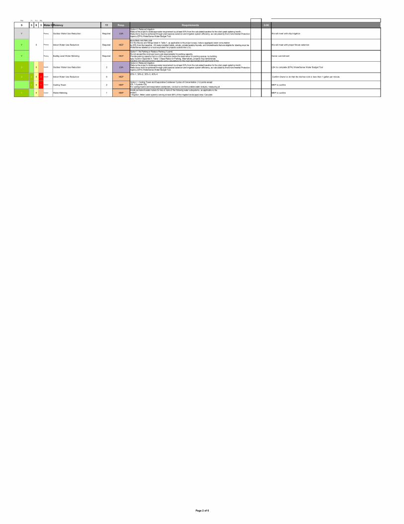
Page 2 of 6
Yes ?+ ?(-) No
5 3 0 3 Water Efficiency 11 Resp. Requirements 0.00
Y Prereq Outdoor Water Use Reduction Required LSA We will meet with drip irrigation
Y 0 Prereq Indoor Water Use Reduction Required MEP We will meet with proper fixture selection
Y Prereq Buildig Level Water Metering Required MEP Owner commitment
2 0 Credit Outdoor Water Use Reduction 2 LSA LSA to complete (EPA) WaterSense Water Budget Tool
2 2 0 2 Credit Indoor Water Use Reduction 6 MEP25%-1, 30%-2, 35%-3, 40%-4
Confirm Owner is ok that the kitchen sink is less than 1 gallon per minute.
1 0 1 Credit Cooling Tower 2 MEP MEP to confirm
1 0 Credit Water Metering 1 MEP MEP to confirm
Option 2. Reduced irrigationReduce the project’s landscape water requirement by at least 30% from the calculated baseline for the site’s peak watering month. Reductions must be achieved through plant species selection and irrigation system efficiency, as calculated by the Environmental Protection Agency (EPA) WaterSense Water Budget Tool.
BUILDING WATER USEFor the fixtures and fittings listed in Table 1, as applicable to the project scope, reduce aggregate water consumptionby 20% from the baseline. All newly installed toilets, urinals, private lavatory faucets, and showerheads that are eligible for labeling must be WaterSense labeled (or a local equivalent for projects outside the U.S.).
Option 1. No Parking or Reduce Parking (1 point)Do not exceed the minimum local code requirements for parking capacity.Provide parking capacity that is a 30% reduction below the base ratios for parking spaces, by building type, found in Appendix 4. Table 1. Base Ratios for Parking. Alternatively, projects may demonstrate baseline and reduced parking capacity using calculations for the most appropriate land use found in the Option 2. Reduced irrigationReduce the project’s landscape water requirement by at least 30% from the calculated baseline for the site’s peak watering month. Reductions must be achieved through plant species selection and irrigation system efficiency, as calculated by the Environmental Protection Agency (EPA) WaterSense Water Budget Tool.
Option 1. Cooling Tower and Evaporative Condenser Cycles of Concentration (1-2 points except CS, 1-3 points CS)For cooling towers and evaporative condensers, conduct a one-time potable water analysis, measuring at least the five control parameters listed in Table 1.Install permanent water meters for two or more of the following water subsystems, as applicable to the project:• Irrigation. Meter water systems serving at least 80% of the irrigated landscaped area. Calculate the percentage of irrigated landscape area served as the total metered irrigated landscape area

Page 3 of 6
Yes ?+ ?(-) No
22 11 0 0 Energy and Atmosphere 33 Resp. Requirements 0.00
Y Prereq Fundamental Commissioning and Verification Required Owner Discuss Cx Scope with Owner
Y Prereq Minimum Energy Performance Required MEP / Arch
Y Prereq Fundamental Refrigerant Management Required MEP Confirmed by the MEP
3 3 Credit Enhanced Commissioning 6 Owner
$
Discuss Cx Scope with Owner- no added for Enhanced Cx, MBcx is nominal, Envelope needs a proposal
13 5 Credit Optimize Energy Performance 18 MEP
$
1 Credit Advanced Energy Metering 1 MEP
$
MEP to confirm
2 Credit Demand Response 2 MEP
$
MEP to assist in plan development
3 Credit Renewable Energy Production 3 MEP
$
Owner and team to evaluate on-site solar options
1 Credit Enhanced Refrigerant Management 1 MEP MEP to run preliminary calculations once systems are selected
2 Credit Green Power and Carbon Offsets 2 Owner / SSC
$
Soden to obtain quotes once a preliminary energy model is complete
Develop the OPR.Develop a BODThe commissioning authority (CxA) must do the following:Review the OPR, BOD, and project design.Develop and implement a Cx plan.Confirm incorporation of Cx requirements into the construction documents.Develop construction checklists.Develop a system test procedure.Verify system test execution.Maintain an issues and benefits log throughout the Cx process.Prepare a final Cx process report.Document all findings and recommendations and report directly to the owner throughout the process.The review of the exterior enclosure design may be performed by a qualified member of the design or construction team (or an employee of that firm) who is not directly responsible for design of the building envelope
RequirementsOption 1. Whole-building energy simulationDemonstrate an improvement of 5% for new construction, 3% for major renovations, or 2% for core and shell projects in the proposed building performance rating compared with the baseline building performance rating. Calculate the baseline building performance according to ANSI/ASHRAE/IESNA Standard 90.1–2010, Appendix G, with errata (or a USGBC-approved equivalent standard for projects outside the U.S.), using a simulation model.
Develop a preliminary energy model before the end of Schematic DesignTeam to evaluate all Energy Conservation measured considered for the project.Team to evaluate the plugs that can be shutdown
Do not use chlorofluorocarbon (CFC)-based refrigerants in new heating, ventilating, air-conditioning, and refrigeration (HVAC&R) systems. When reusing existing HVAC&R equipment, complete a comprehensive CFC phase-out conversion before project completion. Phase-out plans extending beyond the project completion date will be considered on their merits.
Option 1. Enhanced systems commissioning (3-4 points)Path 1: Enhanced commissioning (3 points)Complete the following commissioning process (CxP) activities for mechanical, electrical, plumbing, and renewable energy systems and assemblies in accordance with ASHRAE Guideline 0–2005 and ASHRAE Guideline 1.1–2007 for HVAC&R systems, as they relate to energy, water, indoor environmental quality, and durability.
The commissioning authority must do the following:
Review contractor submittals.Verify inclusion of systems manual requirements in construction documents.Verify inclusion of operator and occupant training requirements in construction documents.Verify systems manual updates and delivery.Verify operator and occupant training delivery and effectiveness.Verify seasonal testing.Review building operations 10 months after substantial completion.Develop an on-going commissioning plan.Include all enhanced commissioning tasks in the OPR and BOD.
OR
Path 2: Enhanced and monitoring-based commissioning (4 points)Achieve Path 1.
AND
Develop monitoring-based procedures and identify points to be measured and evaluated to assess performance of energy- and water-consuming systems.
Include the procedures and measurement points in the commissioning plan. Address the following:
roles and responsibilities;measurement requirements (meters, points, metering systems, data access);the points to be tracked, with frequency and duration for trend monitoring;the limits of acceptable values for tracked points and metered values (where appropriate, predictive algorithms may be used to compare ideal
Option 1. Whole-building energy simulation (1–18 points except Schools and Healthcare, 1–16 points Schools, 1–20 points Healthcare)Analyze efficiency measures during the design process and account for the results in design decision making. Use energy simulation of efficiency opportunities, past energy simulation analyses for similar buildings, or published data (e.g., Advanced Energy Design Guides) from analyses for similar buildings.
Analyze efficiency measures, focusing on load reduction and HVAC-related strategies (passive measures are acceptable) appropriate for the facility. Project potential energy savings and holistic project cost implications related to all affected systems.
Project teams pursuing the Integrative Process credit must complete the basic energy analysis for that credit before conducting the energy simulation.
Follow the criteria in EA Prerequisite Minimum Energy Performance to demonstrate a percentage improvement in the proposed building performance rating compared with the baseline. Points are awarded according to Table 1.
Develop a preliminary energy model before the end of schematic design..Team to evaluate all Energy Conservation measures considered for the project.
Install advanced energy metering for the following:all energy sources used in the tenant space; andany individual energy end uses that represent 10% or more of the total annual consumption of the tenant space.The advanced energy metering must have the following characteristics.Meters must be permanently installed, record at intervals of one hour or less, and transmit data to a remote location.Electricity meters must record both consumption and demand. Whole-building electricity meters should record the power factor, if appropriate.The data collection system must use a local area network, building automation system, wireless network, or comparable communication infrastructure.The system must be capable of storing all meter data for at least 18 months.The data must be remotely accessible.All meters in the system must be capable of reporting hourly, daily, monthly, and annual energy use
Case 1. Demand response program available (2 points)Participate in an existing demand response (DR) program and complete the following activities.
Design a system with the capability for real-time, fully-automated DR based on external initiation by a DR Program Provider. Semi-automated DR may be utilized in practice.Enroll in a minimum one-year DR participation amount contractual commitment with a qualified DR program provider, with the intention of multiyear renewal, for at least 10% of the estimated peak electricity demand. Peak demand is determined under EA Prerequisite Minimum Energy Performance.Develop a comprehensive plan for meeting the contractual commitment during a Demand Response event.Include the DR processes in the scope of work for the commissioning authority, including participation in at least one full test of the DR plan.
Use tenant renewable energy systems to offset the project’s energy cost. Calculate the project’s percentage ofrenewable energy by the following equation:% renewable energy =Equivalent cost of usable energy produced by renewable energy systemTotal building annual energy costUse the project’s annual energy cost, calculated in EA Prerequisite Minimum Energy Performance, if Option 1was pursued; otherwise use the U.S. Department of Energy’s Commercial Buildings Energy Consumption Survey(CBECS) datContextse to estimate energy use and cost.The use of solar gardens or community renewable energy systems is allowed if both of the followingrequirements are met.·· The project owns the system or has signed a lease agreement for a period of at least 10 years.·· The system is located with the same utility service area as the facility claiming the use.
OPTION 2. CALCULATION OF REFRIGERANT IMPACT (1 POINT)Select refrigerants that are used in heating, ventilating, air-conditioning, and refrigeration (HVAC&R) equipmentto minimize or eliminate the emission of compounds that contribute to ozone depletion and climate change.
Percentage of total energy addressed by green power, RECs and/or offsets Points 50% 1100% 2Use the project’s annual energy consumption, calculated in EA Prerequisite Minimum Energy Performance, if Option 1 was pursued; otherwise use the U.S. Department of Energy’s Commercial Buildings Energy Consumption Survey (CBECS) datContextse to estimate energy use. SSC to solicit contract once final energy model is complete
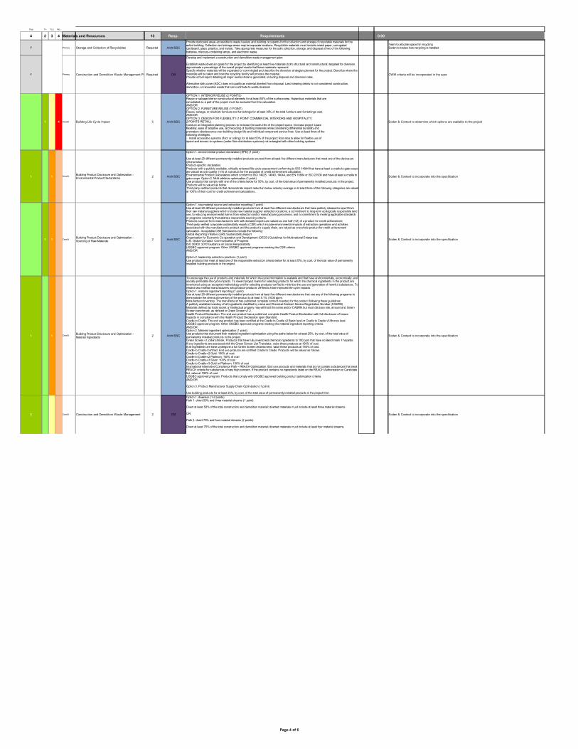
Page 4 of 6
Yes ?+ ?(-) No
4 2 3 4 Materials and Resources 13 Resp. Requirements 0.00
Y Prereq Storage and Collection of Recyclables Required Arch/SSC
Y Prereq Construction and Demolition Waste Management PlanningRequired CM CWM criteria will be incorporated in the spec
1 4 Credit Building Life Cycle Impact 5 Arch/SSC Soden & Context to determine which options are available to the project
1 1 Credit 2 Arch/SSC Soden & Context to incorporate into the specification
1 1 Credit 2 Arch/SSC Soden & Context to incorporate into the specification
1 1 Credit 2 Arch/SSC Soden & Context to incorporate into the specification
2 Credit Construction and Demolition Waste Management 2 CM Soden & Context to incorporate into the specification
Provide dedicated areas accessible to waste haulers and building occupants for the collection and storage of recyclable materials for the entire building. Collection and storage areas may be separate locations. Recyclable materials must include mixed paper, corrugated cardboard, glass, plastics, and metals. Take appropriate measures for the safe collection, storage, and disposal of two of the following: batteries, mercury-containing lamps, and electronic waste.
Team to allocate space for recyclingSoden to review how recycling is handled
Develop and implement a construction and demolition waste management plan:
Establish waste diversion goals for the project by identifying at least five materials (both structural and nonstructural) targeted for diversion. approximate a percentage of the overall project waste that these materials represent.Specify whether materials will be separated or commingled and describe the diversion strategies planned for the project. Describe where the materials will be taken and how the recycling facility will process the material.Provide a final report detailing all major waste streams generated, including disposal and diversion rates.
Alternative daily cover (ADC) does not qualify as material diverted from disposal. Land-clearing debris is not considered construction, demolition, or renovation waste that can contribute to waste diversion
OPTION 1. INTERIOR REUSE (2 POINTS)Reuse or salvage interior nonstructural elements for at least 50% of the surface area. Hazardous materials that areremediated as a part of the project must be excluded from the calculation.AND/OROPTION 2. FURNITURE REUSE (1 POINT)Reuse, salvage, or refurbish furniture and furnishings for at least 30% of the total furniture and furnishings cost.AND/OROPTION 3. DESIGN FOR FLEXIBILITY (1 POINT COMMERCIAL INTERIORS AND HOSPITALITY,2 POINTS RETAIL)Conduct an integrative planning process to increase the useful life of the project space. Increase project spaceflexibility, ease of adaptive use, and recycling of building materials while considering differential durability andpremature obsolescence over building design life and individual component service lives. Use at least three of thefollowing strategies.·· Install accessible systems (floor or ceiling) for at least 50% of the project floor area to allow for flexible use ofspace and access to systems (under floor distribution systems) not entangled with other building systems.
Building Product Disclosure and Optimization - Environmental Product Declarations
Option 1. environmental product declaration (EPD) (1 point)
Use at least 20 different permanently installed products sourced from at least five different manufacturers that meet one of the disclosure criteria below.Product-specific declaration.Products with a publicly available, critically reviewed life-cycle assessment conforming to ISO 14044 that have at least a cradle to gate scope are valued as one quarter (1/4) of a product for the purposes of credit achievement calculation.Environmental Product Declarations which conform to ISO 14025, 14040, 14044, and EN 15804 or ISO 21930 and have at least a cradle to gate scope Option 2. Multi-attribute optimization (1 point)Use products that comply with one of the criteria below for 50%, by cost, of the total value of permanently installed products in the project. Products will be valued as below.Third party certified products that demonstrate impact reduction below industry average in at least three of the following categories are valued at 100% of their cost for credit achievement calculations..
Building Product Disclosure and Optimization - Sourcing of Raw Materials
Option 1. raw material source and extraction reporting (1 point)Use at least 20 different permanently installed products from at least five different manufacturers that have publicly released a report from their raw material suppliers which include raw material supplier extraction locations, a commitment to long-term ecologically responsible land use, to reducing environmental harms from extraction and/or manufacturing processes, and a commitment to meeting applicable standards or programs voluntarily that address responsible sourcing criteria.Products sourced from manufacturers with self-declared reports are valued as one half (1/2) of a product for credit achievement.Third-party verified corporate sustainability reports (CSR) which include environmental impacts of extraction operations and activities associated with the manufacturer’s product and the product’s supply chain, are valued as one whole product for credit achievement calculation. Acceptable CSR frameworks include the following:Global Reporting Initiative (GRI) Sustainability ReportOrganization for Economic Co-operation and Development (OECD) Guidelines for Multinational EnterprisesU.N. Global Compact: Communication of ProgressISO 26000: 2010 Guidance on Social ResponsibilityUSGBC approved program: Other USGBC approved programs meeting the CSR criteria.AND/OR
Option 2. leadership extraction practices (1 point)Use products that meet at least one of the responsible extraction criteria below for at least 25%, by cost, of the total value of permanently installed building products in the project.
Building Product Disclosure and Optimization - Material Ingredients
To encourage the use of products and materials for which life-cycle information is available and that have environmentally, economically, and socially preferable life-cycle impacts. To reward project teams for selecting products for which the chemical ingredients in the product are inventoried using an accepted methodology and for selecting products verified to minimize the use and generation of harmful substances. To reward raw material manufacturers who produce products verified to have improved life-cycle impacts.Option 1. material ingredient reporting (1 point)Use at least 20 different permanently installed products from at least five different manufacturers that use any of the following programs to demonstrate the chemical inventory of the product to at least 0.1% (1000 ppm).Manufacturer Inventory. The manufacturer has published complete content inventory for the product following these guidelines:A publicly available inventory of all ingredients identified by name and Chemical Abstract Service Registration Number (CASRN)Materials defined as trade secret or intellectual property may withhold the name and/or CASRN but must disclose role, amount and Green Screen benchmark, as defined in Green Screen v1.2.Health Product Declaration. The end use product has a published, complete Health Product Declaration with full disclosure of known hazards in compliance with the Health Product Declaration open Standard.Cradle to Cradle. The end use product has been certified at the Cradle to Cradle v2 Basic level or Cradle to Cradle v3 Bronze level.USGBC approved program. Other USGBC approved programs meeting the material ingredient reporting criteria.AND/OROption 2. Material ingredient optimization (1 point)Use products that document their material ingredient optimization using the paths below for at least 25%, by cost, of the total value of permanently installed products in the project.Green Screen v1.2 Benchmark. Products that have fully inventoried chemical ingredients to 100 ppm that have no Benchmark 1 hazards:If any ingredients are assessed with the Green Screen List Translator, value these products at 100% of cost.If all ingredients are have undergone a full Green Screen Assessment, value these products at 150% of cost.Cradle to Cradle Certified. End use products are certified Cradle to Cradle. Products will be valued as follows:Cradle to Cradle v2 Gold: 100% of costCradle to Cradle v2 Platinum: 150% of costCradle to Cradle v3 Silver: 100% of costCradle to Cradle v3 Gold or Platinum: 150% of costInternational Alternative Compliance Path – REACH Optimization. End use products and materials that do not contain substances that meet REACH criteria for substances of very high concern. If the product contains no ingredients listed on the REACH Authorization or Candidate list, value at 100% of cost.USGBC approved program. Products that comply with USGBC approved building product optimization criteria.AND/OR
Option 3. Product Manufacturer Supply Chain Optimization (1 point)
Use building products for at least 25%, by cost, of the total value of permanently installed products in the project that:
Option 1. diversion (1-2 points)Path 1. divert 50% and three material streams (1 point)
Divert at least 50% of the total construction and demolition material; diverted materials must include at least three material streams.
OR
Path 2. divert 75% and four material streams (2 points)
Divert at least 75% of the total construction and demolition material; diverted materials must include at least four material streams.

Page 5 of 6
Yes ?+ ?(-) No
5 7 2 2 Indoor Environmental Quality 16 Resp. Requirements
Y Prereq Minimum Indoor Air Quality Performance Required MEP Will be meeting ASHRAE 62.1-2013
Y Prereq Environmental Tobacco Smoke Control Required Owner/Arch
Context & Soden to review signage requirements
2 Credit Enhanced Indoor Air Quality Strategies 2 MEP
1 1 1 Credit Low-Emitting Materials 3 Arch/SSC Soden & Context to incorporate into the specification
1 Credit Construction Indoor Air Quality Management Plan 1 CM Soden & Context to incorporate into the specification
2 Credit Indoor Air Quality Assessment 2 Owner/CM/SSC
$
MEP to run calculations for a pre and post occupancy flushout
1 Credit Thermal Comfort 1 MEP
1 1 Credit Interior Lighting 2 MEP/Arch
1 1 1 Credit Daylight 3 Arch
1 Credit Quality Views 1 Arch Context and Soden to review areas that will not have views and % of compliant areas
Option 1. ASHRAE Standard 62.1–2010
Determine the minimum outdoor air intake flow for mechanical ventilation systems using the ventilation rate procedure from ASHRAE 62.1–2010 or a local equivalent, whichever is more stringent and meet the minimum requirements of ASHRAE Standard 62.1–2010, Sections 4–7, Ventilation for Acceptable Indoor Air Quality (with errata), or a local equivalent, whichever is more stringent.
Locate the project in a building that prohibits smoking by all occupants and users both inside the building and outside the building except in designated smoking areas located at least 25 feet (7.5 meters) from all entries, outdoor air intakes, and operable windows. Also prohibit smoking outside the property line in spaces used for business purposes.
If the requirement to prohibit smoking within 25 feet (7.5 meters) cannot be implemented because of code, provide documentation of these regulations.
Signage must be posted within 10 feet (3 meters) of all building entrances indicating the no-smoking policy.
Option 1. Enhanced IAQ strategies (1 point)
Comply with the following requirements, as applicable.Mechanically ventilated spaces:A. entryway systems;B. interior cross-contamination prevention; andC. filtration. Option 2. Additional enhanced IAQ strategies (1 point)
Comply with the following requirements, as applicable.
Mechanically ventilated spaces (select one):A. exterior contamination prevention;B. increased ventilation;C. carbon dioxide monitoring; orD. additional source control and monitoring.
Comply with the following requirements, as applicable.Mechanically ventilated spaces:
A. entryway systems;B. interior cross-contamination prevention; and
C. filtration. Option 2. Additional enhanced IAQ strategies (1 point)
Comply with the following requirements, as applicable.
Mechanically ventilated spaces (select one):A. exterior contamination prevention;
B. increased ventilation;C. carbon dioxide monitoring; or
D. additional source control and monitoring.
Context & Soden to review copiers and chemical storage spacesMEP to determine if increased ventilation is an optionMEP, Context, Soden to review all locations requiring CO2 sensors
Category Threshold Emissions and content requirementsInterior paints and coatings applied on site At least 90%, by volume, for emissions; 100% for VOC content General Emissions Evaluation for paints and coatings applied to walls, floors, and ceilingsVOC content requirements for wet applied products
Interior adhesives and sealants applied on site (including flooring adhesive) At least 90%, by volume, for emissions; 100% for VOC content General Emissions EvaluationVOC content requirements for wet applied products
Flooring 100% General Emissions Evaluation
Composite wood 100% not covered by other categories Composite Wood Evaluation
Ceilings, walls, thermal, and acoustic insulation 100% General Emissions Evaluation
Furniture At least 90%, by cost Furniture Evaluation
Develop and implement an indoor air quality (IAQ) management plan for the construction and preoccupancy phases of the building. The plan must address all of the following. During construction, meet or exceed all applicable recommended control measures of the Sheet Metal and Air Conditioning National Contractors Association (SMACNA) IAQ Guidelines for Occupied Buildings under Construction, 2nd edition, 2007, ANSI/SMACNA 008–2008, Chapter 3. Protect absorptive materials stored on-site and installed from moisture damage.
Option 1. Flush-out (1 point)
Path 1. Before occupancyInstall new filtration media and perform a building flush-out by supplying a total air volume of 14,000 cubic feet of outdoor air per square foot (4 267 140 liters of outdoor air per square meter) of gross floor area while maintaining an internal temperature of at least 60°F (15°C) and no higher than 80°F (27°C) and relative humidity no higher than 60%.
Path 2. During occupancyIf occupancy is desired before the flush-out is completed, the space may be occupied only after delivery of a minimum of 3,500 cubic feet of outdoor air per square foot (1 066 260 liters of outdoor air per square meter) of gross floor area while maintaining an internal temperature of at least 60°F (15°C) and no higher than 80°F (27°C) and relative humidity no higher than 60%.
Once the space is occupied, it must be ventilated at a minimum rate of 0.30 cubic foot per minute (cfm) per square foot of outdoor air (1.5 liters per second per square meter of outdoor air) or the design minimum outdoor air rate determined in EQ Prerequisite Minimum Indoor Air Quality Performance, whichever is greater. During each day of the flush-out period, ventilation must begin at least three hours before occupancy and continue during occupancy. These conditions must be maintained until a total of 14,000 cubic feet per square foot of outdoor air (4 270 liters of outdoor air per square meter) has been delivered to the space. Option 2. Air testing (2 points)
After construction ends and before occupancy, but under ventilation conditions typical for occupancy, conduct baseline IAQ testing using protocols consistent with the methods listed in Table 1 for all occupied spaces. Use current versions of ASTM standard methods, EPA compendium methods, or ISO methods, as indicated. Laboratories that conduct the tests for chemical analysis of formaldehyde and volatile organic compounds must be accredited under ISO/IEC 17025 for the test methods they use. Flush out 1- AQ testing 2WELL- testing required
OPTION 1. ASHRAE STANDARD 55-2010Design heating, ventilating, and air-conditioning (HVAC) systems and the building envelope to meet therequirements of ASHRAE Standard 55–2010, Thermal Comfort Conditions for Human Occupancy, with errataor a local equivalent.For natatoriums, demonstrate compliance with ASHRAE HVAC Applications Handbook, 2011 edition, Chapter 5,Places of Assembly, Typical Natatorium Design Conditions, with errata.
Thermal Comfort ControlProvide individual thermal comfort controls for at least 50% of individual occupant spaces. Provide group thermalcomfort controls for all shared multioccupant spaces.
Evaluate raised flooring system throughoutSoden & Context to lay out plans for regularly occupied spaces along with multi/single occupant spaces
RequirementsSelect one or both of the following two options.Option 1. Lighting control (1 point)For at least 90% of individual occupant spaces, provide individual lighting controls that enable occupants to adjust the lighting to suit their individual tasks and preferences, with at least three lighting levels or scenes (on, off, midlevel). Midlevel is 30% to 70% of the maximum illumination level (not including daylight contributions).For all shared multi-occupant spaces, meet all of the following requirements.
Have in place multizone control systems that enable occupants to adjust the lighting to meet group needs and preferences, with at least three lighting levels or scenes (on, off, midlevel).Lighting for any presentation or projection wall must be separately controlled.Switches or manual controls must be located in the same space as the controlled luminaires. A person operating the controls must have a direct line of sight to the controlled luminaires.AND/OR
Option 2. Lighting quality (1 point)- Choose four of the following strategies.For all regularly occupied spaces, use light fixtures with a luminance of less than 2,500 cd/m2 between 45 and 90 degrees from nadir.Exceptions include wallwash fixtures properly aimed at walls, as specified by manufacturer’s data, indirect up lighting fixtures, provided there is no view down into these uplights from a regularly occupied space above, and any other specific applications (i.e. adjustable fixtures).For the entire project, use light sources with a CRI of 80 or higher. Exceptions include lamps or fixtures specifically designed to provide colored lighting for effect, site lighting, or other special use.For 75% of the total connected lighting load, use light sources that have a rated life (or L70 for LED sources) of at least 24,000 hours (at 3-hour per start, if applicable).Use direct-only overhead lighting for 25% or less of the total connected lighting load for all regularly occupied spaces.For 90% of the regularly occupied floor area, meet the following thresholds for area-weighted average surface reflectance: 85% for ceilings, 60% for walls, and 25% for floors.If furniture is included in the scope of work, select furniture finishes to meet the following thresholds for area-weighted average surface reflectance: 45% for work surfaces, and 50% for movable partitions.For 75% of the regularly occupied floor area, meet ratio of average wall surface illuminance (excluding fenestration) to average work plane (or surface, if defined) illuminance that does not exceed 1:10. Must also meet strategy E, strategy F, or demonstrate area-weighted surface reflectance of 60% for walls.For 75% of the regularly occupied floor area, meet ratio of average ceiling illuminance (excluding fenestration) to work surface illuminance that does not exceed 1:10. Must also meet strategy E, strategy F, or demonstrate area-weighted surface reflectance of 85% for ceilings.
Soden & Context to lay out plans for regularly occupied spaces along with multi/single occupant spacesMEP, OMM, Context to determine the light quality options
Table 1. Points for daylit floor area: Spatial daylight autonomy
CI, CI Retail, CI HospitalitysDA (for regularly occupied floor area) Points55% 275% 3AND
Demonstrate through annual computer simulations that annual sunlight exposure1000,250 (ASE1000,250) of no more than 10% is achieved. Use the regularly occupied floor area that is daylit per the sDA300/50% simulations.
Context to advise on scope for daylight modelingGlazing – floor to ceiling – meet comfort conditions – make sure we don’t have too much glare coming in (photochromatic glass, electrochromic glass, shading devices, etc.)
Achieve a direct line of sight to the outdoors via vision glazing for 75% of all regularly occupied floor area.View glazing in the contributing area must provide a clear image of the exterior, not obstructed by frits, fibers, patterned glazing, or added tints that distort color balance.
Additionally, 75% of all regularly occupied floor area must have at least two of the following four kinds of views:
multiple lines of sight to vision glazing in different directions at least 90 degrees apart;views that include at least two of the following: (1) flora, fauna, or sky; (2) movement; and (3) objects at least 25 feet from the exterior of the glazing;unobstructed views located within the distance of three times the head height of the vision glazing; andviews with a view factor of 3 or greater, as defined in “Windows and Offices; A Study of Office Worker Performance and the Indoor Environment.

Page 6 of 6
1 Credit 1 Acoustical
$
Acoustical to weigh in on credit viability.
Yes ?+ ?(-) No
6 0 0 0 Innovation 6 Resp. Requirements
1 Credit 1.1 Low Mercury Lighting 1 MEP
1 Credit 1.2 Education 1 Arch/SSC/Owner
1 Credit 1.3 Biophilia 1 Arch/SSC/Owner
1 Credit 1.4 TBD 1 Arch/SSC/Owner
1 Credit 1.5 TBD 1 Arch/SSC/Owner
1 Credit LEED Accredited Professional 1 SSC
Yes ?+ ?(-) No
4 0 0 0 Regional Priority 4
1 0 Credit Regional Priority: Optimize Energy (8pts) 1 SSC
1 0 Credit Regional Priority: Renewable (2pts) 1 SSC
1 Credit Regional Priority: Rainwater (2pts) 1 SSC
1 Credit Regional Priority: High Prioirty Site (2pts) 1 SSC
70 23 5 12 TOTALS 126
Acoustic Comfort
HVAC Background Noise
Achieve maximum background noise levels from heating, ventilating, and air conditioning (HVAC) systems per 2011 ASHRAE Handbook, HVAC Applications, Chapter 48, Table 1; AHRI Standard 885-2008, Table 15; or a local equivalent. Calculate or measure sound levels.
For measurements, use a sound level meter that conforms to ANSI S1.4 for type 1 (precision) or type 2 (general purpose) sound measurement instrumentation, or a local equivalent.
Comply with design criteria for HVAC noise levels resulting from the sound transmission paths listed in ASHRAE 2011 Applications Handbook, Table 6; or a local equivalent.
Sound Isolation
Meet the composite sound transmission class (STCC) ratings listed in Table 1, or local building code, whichever is more stringent.
Table 1. Minimum composite sound transmission class ratings for adjacent spaces
Adjacency combinations STCCResidence (within a multifamily residence), hotel or motel room Residence, hotel or motel room 55Residence, hotel or motel room Common hallway, stairway 50Residence, hotel or motel room Retail 60Retail 50Standard office Standard office 45Executive office Executive office 50Conference room Conference room 50Office, conference room Hallway, stairway 50Mechanical equipment room Occupied area 60Reverberation Time- goes further in having several optimization and preconditions, check the noise criteria- open office=40NC, enclosed office 35 NC, teleconference 20NC-

LEED v4 for BD+C: New Construction and Major RenovationProject Checklist Somerville Public Safety Building
8/8/2021Y ? N1 Credit 1
16 0 16 16 4 4 5 1316 Credit 16 Y Prereq Required
1 Credit 1 Y Prereq Required2 Credit 2 1 4 Credit 5
5 Credit 5 1 1 Credit 2
5 Credit 5 1 1 Credit 21 Credit 1 1 1 Credit Building Product Disclosure and Optimization - Material Ingredients 21 Credit 1 2 Credit 21 Credit Green Vehicles 1
5 10 1 Indoor Environmental Quality 167 0 3 10 Y Prereq Required
Y Prereq Required Y Prereq Required
1 Credit 1 2 Credit 22 Credit 2 1 2 Credit 31 Credit 1 1 Credit Construction Indoor Air Quality Management Plan 1
3 Credit 3 2 Credit 22 Credit 2 1 Credit 11 Credit 1 1 1 Credit 2
2 1 Credit 35 3 3 11 1 Credit 1Y Prereq Required 1 Credit 1Y Prereq RequiredY Prereq Building-Level Water Metering Required 6 0 0 Innovation 62 Credit 2 5 Credit 53 1 2 Credit 6 1 Credit 1
1 1 Credit 21 Credit Water Metering 1 4 0 0 Regional Priority 4
1 Credit Regional Priority: Optimize Energy (8) 122 11 0 33 1 Credit Regional Priority: Renewable 1Y Prereq Required 1 Credit Regional Priority: Indoor Water 4, Rainwater 2, High Priority Site 2 1Y Prereq Required 1 Credit Regional Priority: High Priority Site 1Y Prereq RequiredY Prereq Required 70 28 28 TOTALS Possible Points: 1103 3 Credit 613 5 Credit 181 Credit 1
2 Credit 23 Credit 3
1 Credit 12 Credit 2
Acoustic PerformanceQuality Views
Enhanced Indoor Air Quality StrategiesLow-Emitting Materials
Indoor Air Quality AssessmentThermal Comfort
Certified: 40 to 49 points, Silver: 50 to 59 points, Gold: 60 to 79 points, Platinum: 80 to 110
Access to Quality Transit
Reduced Parking Footprint
Open Space
Site Assessment
Interior LightingDaylight
LEED Accredited ProfessionalInnovation
Rainwater Management
Light Pollution Reduction
Environmental Tobacco Smoke Control
Energy and Atmosphere
Minimum Energy Performance
Fundamental Refrigerant Management
Cooling Tower Water Use
Green Power and Carbon Offsets
Heat Island Reduction
Outdoor Water Use ReductionIndoor Water Use Reduction
Outdoor Water Use ReductionIndoor Water Use Reduction
Enhanced Commissioning
Building-Level Energy Metering
Water Efficiency
Fundamental Commissioning and Verification
Demand ResponseRenewable Energy ProductionEnhanced Refrigerant Management
Optimize Energy PerformanceAdvanced Energy Metering
Construction Activity Pollution Prevention
High Priority Site
Surrounding Density and Diverse Uses
Sustainable Sites
Building Life-Cycle Impact Reduction
Site Development - Protect or Restore Habitat
Building Product Disclosure and Optimization - Sourcing of Raw Materials
Project Name:Date:
Location and Transportation
Sensitive Land ProtectionLEED for Neighborhood Development Location
Bicycle Facilities
Construction and Demolition Waste Management Planning
Materials and ResourcesStorage and Collection of Recyclables
Construction and Demolition Waste Management
Minimum Indoor Air Quality Performance
Building Product Disclosure and Optimization - Environmental Product Declarations
Integrative Process

SOMERVILLE PUBLIC SAFETY BUILDING Somerville, Massachusetts 02143
Project No. 2006.00
NARRATIVE 8/13/2021
D.14 GEOTECHNICAL-REPORTS

FOUNDATION ENGINEERING REPORT
SOMERVILLE PUBLIC SAFETY
BUILDING
SOMERVILLE, MASSACHUSETTS
MAY 24, 2021
Prepared For:
CONTEXT ARCHITECTURE 68 Harrison Avenue
Boston, MA 02111
PROJECT NO. 7088.2.00
2269 Massachusetts Avenue
Cambridge, MA 02140
www.mcphailgeo.com
(617) 868-1420

May 24, 2021
GEOTECHNICAL AND GEOENVIRONMENTAL ENGINEERS
2269 Massachusetts Avenue
Cambridge, Massachusetts 02140
(617) 868-1420
Context Architecture
68 Harrison Avenue
Boston, MA 02111
Attention: Mr. Jeff Shaw, AIA
Reference: Somerville Public Safety Building; Somerville, Massachusetts
Foundation Engineering Report
Ladies and Gentlemen:
This report documents the results of our subsurface exploration program and foundation
design study for the proposed Somerville Public Safety Building to be located in Somerville,
Massachusetts. Refer to the Project Location Plan, Figure 1, for the general site locus.
This report was prepared in accordance with our revised proposal dated March 24, 2021 and
the subsequent authorization of Context Architecture. These services are subject to the
limitations contained in Appendix A.
Purpose and Scope
The purposes of our subsurface exploration program and geotechnical design study are to
define the subsurface soil and groundwater conditions at the site as they pertain to
foundation design and, based on these conditions, to provide engineering recommendations
for safe and economical foundation design for the proposed building. Foundation
construction considerations are also addressed herein.
Our foundation design recommendations include foundation support for the proposed
building and the lowest level slab, treatment of the lowest level slab in consideration of
groundwater, and seismic design considerations in accordance with the provisions of the
Massachusetts State Building Code (Code).
Available Information
Information provided to McPhail Associates, LLC (McPhail) by Context Architecture included
an undated, uncredited drawing entitled “Test Fit B3 Parking Option,” showing a conceptual
building footprint overlaid on satellite imagery of the site. Additionally, McPhail utilized
information from our records of previous projects at the site location, including the
following:
• An existing conditions survey drawing entitled “Topographic Plan,” dated March 14,
2012 and prepared by R.E. Cameron and Associates, Inc.; and
• A report entitled “Revised Foundation Engineering Report: Proposed Redevelopment
of Cobble Hill Center,” dated February 28, 2014 and prepared by McPhail.
Context Architecture
May 24, 2021
Page 2
Elevations presented herein are in feet and are referenced to the City of Somerville Vertical
Datum, which is approximately 6.2 feet below the North American Vertical Datum of 1988
(NAVD 88).
Existing Conditions and Proposed Development
The proposed building site is located immediately east of the intersection of Washington
Street and New Washington Street in East Somerville. Currently, the central portion of the
site is occupied by the remains (at-grade concrete slab and foundations) of a recently
demolished 12,550-square-foot, L-shaped one-story brick strip mall building with at-grade
paved parking lots located to the west and access lanes located to the south and east. The
areas to the south and east of the former building beyond the access lanes are occupied by
landscaped margins, including an approximate 8-foot-high elevated landscaped feature or
“mound” along the site’s eastern boundary. The project site is bounded by Washington
Street to the north, New Washington Street to the west and south, and a multi-family
residential property to the east. Existing grades across the site are relatively level, varying
from about Elevation +16 to Elevation +17, with the exception of the above-described
landscaped mound and a second mound near the site’s southern boundary where the site
grades rise to about Elevation +24 to Elevation +25.
The proposed site development is in the preliminary stage and is currently understood to
consist of the construction of a 3- to 4-story public safety building with no occupied below-
grade space. The lowest level will include apparatus bays for the fire department and an
approximately 10,000-square-foot parking area. It is assumed that the two “mounds” will
both be removed so that the majority of the site will be at approximately Elevation +17 and
the building’s lowest level slab will be approximately level with the final surrounding grades
which will not be raised as part of the proposed construction. The approximate location and
limits of the proposed building footprint is indicated on the enclosed Subsurface Exploration
Plan, Figure 2.
Previous Subsurface Explorations
Previously completed subsurface explorations were conducted at the project site during the
period of 2012 through 2014. The procedures and logs of these explorations are
documented in the February 2014 report indicated in the “Available Information” section of
this report. Explorations particularly relevant to geotechnical design of this project include
geoprobe EBI-307 and borings B-9 through B-12 and PH-2. Boring B-11A(OW) was
completed as a groundwater observation well. The logs of previous explorations are
contained in Appendix C and the approximate locations of previous explorations are
indicated on the enclosed Subsurface Exploration Plan, Figure 2.
Recent Subsurface Explorations
A recent subsurface exploration program, consisting of seven (7) borings designated as
MA-1 through MA-7A, was performed at the project site during the period of April 14
through April 23, 2021 by Geosearch, Inc. of Sterling, Massachusetts under contract to
Context Architecture
May 24, 2021
Page 3
McPhail. The approximate locations of the borings are indicated on the enclosed Figure 2.
Boring logs prepared by McPhail are contained in Appendix B.
The borings were performed using truck- and ATV-mounted drill rigs and were advanced
utilizing either wet rotary drilling techniques in conjunction with NW and HW casing or
2-1/4-inch ID hollow-stem augers. Standard 1-3/8-inch I.D. split-spoon samples and
standard penetration tests were generally obtained at 5-foot intervals in accordance with
the standard procedures described in ASTM D1586. The borings were terminated at depths
of 18 to 54.5 feet below the existing ground surface.
The subsurface explorations were monitored by a representative of McPhail who performed
field layout, prepared field logs, obtained and visually classified soil samples, monitored
groundwater conditions in the completed explorations, made minor adjustments to the
exploration locations, and determined the required exploration depths based upon the
actual subsurface conditions encountered.
Field locations of the subsurface explorations were determined by taping from existing site
features and the existing ground surface elevation at each boring location was determined
by a level survey performed by McPhail utilizing vertical control indicated on the existing
conditions survey drawing.
Additionally, a subsurface exploration program consisting of geoprobes was performed at
the project site during the same period for geoenvironmental purposes. The recent
geoenvironmental explorations were terminated at a maximum depth of 12 feet and did not
penetrate the fill layer. Logs of the recent geoprobes will be included in a separate Soil
Management Plan.
Subsurface Conditions
A detailed description of the subsurface conditions encountered within the explorations is
documented on the logs contained in Appendix B and Appendix C. The following is a
discussion of the generalized subsurface conditions across the site which are inferred
primarily from the recent explorations, previously completed borings PH-2 and B-9 through
B-12, and previously completed geoprobe EBI-307, but also from the remainder of the
previous explorations conducted within the subject property, our knowledge of local site
geology, and our foundation design and construction experience in the site area. A contour
plan of the surface elevation of the natural marine sand deposit is presented on Figure 3.
The contours were created by linear interpolation of the elevation of the top of the marine
sand deposit observed in the recent and selected previous explorations.

Context Architecture
May 24, 2021
Page 4
Stratum Thickness1
(feet)
Elevation of
Surface1 (feet)
Explorations Where Stratum Was
Encountered
Asphalt/Concrete 0.3 to 0.5 +15.8 to +18.3 MA-1, MA-2, MA-3, MA-7A,
B-11A(OW), EBI-307
Topsoil 0.2 to 0.5 +16.8 to +25.3 MA-4 to MA-6, B-9, B-10, B-12, PH-2
Fill 5.8 to 17.5 +15.5 to +24.8 MA-1 to MA-7A, B-9 to B-12,
EBI-307, PH-2
Organic Deposit 0.1 to 4 +4.9 to +12.2 MA-1, MA-5, MA-7A, B-9, B-10, B-12
Marine Sand 3.5 to 24 +4.0 to +6.8 MA-1 to MA-3, MA-5 to MA-7A, B-9
to B-12, EBI-307, PH-2
Marine Clay 7 to 19 -16.5 to +3.6 MA-1 to MA-3, MA-5 to MA-7A, B-9,
B-10, B-12
Glaciomarine
Deposit 6 -18.3 MA-3
Glacial Till NP2 -26.5 to -22.2 MA-3, MA-6, B-10, B-12
Groundwater N/A +6.3 to +12.3 MA-1, MA-3, MA-5, MA-7A, B-9 to
B-12, EBI-307, PH-2
Notes: 1Where encountered and penetrated. 2“NP” indicates stratum not penetrated.
The following are generalized descriptions of the subsurface strata that were encountered:
• Fill – Loose to very dense, gray to brown to black sand and gravel with some silt,
varying to a well-graded mixture of silt, sand, and gravel. The fill was also observed
to contain varying amounts of brick, wood, glass, metal, concrete rubble, and ash
and cinders. A reinforced concrete slab was encountered within the fill in boring MA-
7A between 7.5 and 8 feet below the existing grade. Concrete was also encountered
within the fill in boring B-7 between 5.7 and 8 feet below the existing grade
Additional unknown obstructions, identified through sampler and/or auger refusal,
were encountered within the fill in borings B-11, EBI-1, and PH-1 and in geoprobes
EB-2 and EB-401 at depths ranging from 3.5 to 13 feet below ground surface.
Additionally, test pits TP-3 through TP-8 encountered practical refusal on various
rubble within the fill, including sections of concrete slabs, at depths ranging from 5 to
9 feet below ground surface. Grain size distributions of samples of the fill are
presented on the enclosed Figure 4.
• Organic Deposit – Very soft to firm, black organic silt with varying amounts of sand
and peat fibers.
• Marine Sand – Compact to very dense, light gray to brown sand with trace to some
silt and gravel. Grain size distributions of samples of the marine sand are presented
on the enclosed Figure 5.
• Marine Clay – Very soft to very stiff, blue to gray clay with some silt varying to silty
clay.
• Glaciomarine Deposit – Compact, blue to gray well-graded mixture of silt, sand,
and gravel with some clay.
Context Architecture
May 24, 2021
Page 5
• Glacial Till – Dense to very dense, gray, silty sand and gravel, varying to sand with
some silt and gravel, varying to gravel with some sand and trace silt. The glacial till
deposit was also observed to contained cobbles.
Groundwater encountered in the recently completed boreholes was typically observed at
depths ranging from 6 to 16 feet below the existing ground surface, corresponding to
Elevation +6.3 to +12.3. The depth to groundwater within the three (3) observation wells
installed during the previous subsurface exploration program (B-2(OW), B-8(OW), and
B-11A(OW)) were measured to range from about to 6.8 to 11.5 feet below the existing
ground surface, corresponding to Elevation +5.9 to +9.3. Groundwater monitoring reports
for the observation wells are contained in Appendix D. It is anticipated that future
groundwater levels across the site may vary from those reported herein due to factors such
as normal seasonal changes, periods of heavy precipitation, and alterations of existing
drainage patterns or may become perched on the relatively impervious organic deposit.
Foundation Design Recommendations
Based upon the results of subsurface explorations, the project site is underlain by fill and an
intermittent organic deposit which extend to depths ranging from approximately 10 to 18
feet below the existing ground surface and is underlain by a natural, compact to very dense
marine sand deposit. The marine sand deposit was not encountered in some of the previous
explorations located outside of the building footprint but was encountered in each of the
recent explorations that penetrated the fill, previously completed borings PH-2 and B-9
through B-12, and previously completed geoprobe EBI-307. Therefore, the marine sand
deposit is anticipated to be continuously present within the building footprint.
Based on our experience with similar scope projects and soil conditions, the use of ground
improvement techniques in conjunction with a conventional spread footing foundation
system and a soil-supported slab-on-grade is recommended for support of the proposed
building.
In general, ground improvement methods would consist of the installation of a combination
of rammed aggregate piers (RAPs), grouted aggregate piers (GAPs), and/or rigid inclusions
(RIs, a.k.a. GeoConcrete Columns, or GCCs). These three types of ground improvement
element consist of “columns” of compacted aggregate (with or without grout) or concrete,
typically about 15 to 30 inches in diameter, which extend through unsuitable soils into the
natural bearing surface (marine sand deposit). The installation process utilized to
install/create of the elements increases the lateral stress in the soil matrix beneath the
proposed building. Thus, the potential for large settlements is reduced by improving the
unsuitable soils to a stiffer composite soil matrix. Based on the results of the explorations,
the ground improvement elements would extend into the top of the marine sand deposit
and would likely range up to about 15 to 20 feet in length.
Since ground improvement techniques are provided by a design-build consultant, detailed
design calculations should be submitted to the Architect for review prior to the beginning of
construction. The design-build consultant should specify which ground improvement types
will be used in specific areas of the site. A detailed explanation of the design parameters for
capacity and settlement calculations should be included in the design submittal. The design

Context Architecture
May 24, 2021
Page 6
submittal should also include a testing program to demonstrate that the design capacity of
each type of ground improvement element utilized in the design is being achieved. All
calculations and drawings should be prepared and sealed by a Professional Engineer
licensed in the Commonwealth of Massachusetts and retained by the Contractor who is to
perform the work.
The following general criteria should be utilized in the design of ground improvement
elements:
1. Elements should extend into the surface of the marine sand deposit;
2. The maximum allowable bearing pressure supported on a reinforced ground surface
which extends into the marine sand deposit should be equal to or less than 4 kips
per square-foot (ksf);
3. Estimated long-term settlement for footings should be less than 1-inch;
4. Estimated long-term differential settlement of adjacent footings should be less than
1/2-inch; and
5. A modulus load test should be performed on at least one element of each utilized
type to 150 percent of the maximum design stress.
The maximum thickness of the marine clay deposit observed in the recent and selected
previous explorations was 20 feet. While the marine clay was generally firm to very stiff and
is considered to be overconsolidated, it should be noted that at one isolated location (boring
MA-3) the lower 12-foot zone of the marine clay deposit was documented to be very soft to
soft.
The lowest level slab should be designed as an economical slab-on-grade supported on the
existing site soils after ground improvement elements are installed in a grid pattern below
the slab. The slab should be underlain by a polyethylene vapor barrier placed over a
minimum 12-inch layer of an off-site gravel borrow. In areas where a flexible asphalt
parking surface will be installed instead of a concrete slab, ground improvement may not be
required.
Perimeter and interior foundations located adjacent to non-heated areas should be provided
with a minimum 4-foot thickness of soil cover as frost protection. Interior foundations within
heated areas should be located such that the top of the foundation concrete is a minimum
of 6 inches below the underside of the lowest level slab. All foundations should be located
such that they are below a theoretical line drawn upward and outward at 2 to 1 (horizontal
to vertical) from the bottom exterior edge of all adjacent footings, structures, and utilities.
Since it is assumed that the proposed development does not include any occupied
below-grade space, underslab and/or perimeter foundation drainage is not anticipated to be
necessary. If the proposed lowest level slabs will be located below-grade, the proposed
grading plan should be provided to McPhail for review to determine if foundation drainage is
required. All localized depressions in the lowest level slab should be provided with properly
tied continuous waterstops in all construction joints and cementitious waterproofing installed
on properly prepared interior surfaces for protection against groundwater intrusion.
Gravel borrow should consist of an off-site, well-graded, natural sand and gravel containing
less than eight (8) percent passing the No. 200 sieve. Reuse of the on-site soil as ordinary
Context Architecture
May 24, 2021
Page 7
fill and structural fill is discussed in more detail in the “Geotechnical Construction
Considerations” section of this report.
Lateral forces can be considered to be transmitted from the structure to the soil by passive
pressure against the foundation walls utilizing an equivalent fluid density of 120 pounds per
cubic-foot providing that the walls are designed to resist these pressures. Lateral force can
also be considered to be transmitted from the structure to the soil by friction on the base of
footings using a coefficient of 0.4, to which a safety factor of 1.5 should be applied.
Seismic Design Considerations
For the purposes of determining parameters for structural seismic design, this site is
considered to be a Site Class D as defined in Chapter 20 of American Society of Civil
Engineers (ASCE) Standard 7-10 “Minimum Design Loads for Buildings and Other
Structures”. The bearing strata on the proposed site are not considered to be subject to
liquefaction during an earthquake based on these criteria.
Foundation Construction Considerations
Foundation construction considerations include removal of existing below grade utilities and
structures, monitoring ground vibrations, reuse of existing on-site fill material, preparation
of the foundation bearing surfaces, construction dewatering, and off-site disposal of excess
excavated material.
It is anticipated that removal of obstructions consisting of former structures and below
grade utilities will be required prior to and during the installation of the aggregate piers.
Excavations to remove former foundations and former and existing below grade utilities and
structures where they interfere with the installation of the ground improvement elements
and new foundations should be backfilled with ordinary fill. The ordinary fill should be
replaced in maximum 2-foot lifts and tamped with the excavator bucket to facilitate future
ground improvement installation. Excavated on-site fill material is considered suitable for
use as ordinary fill.
The installation of the ground improvement elements will likely result in some ground
vibrations and noise which may be disruptive to occupants of the nearby Cobble Hill
Apartments and could potentially cause cosmetic damage to nearby existing structures,
including the Cobble Hill Apartments and the restaurant building across New Washington
Street from the site. Therefore, it is recommended that ground vibration monitoring be
performed with the use of seismographs during the installation of the ground improvement
elements. Additionally, a pre-construction condition survey should be performed of the
nearby structures.
Portions of the existing on-site fill material were observed to contain a relatively high silt
content. Hence, it is emphasized that this soil can become unsuitable for reuse as fill if it
becomes too wet. Therefore, it is recommended that stockpiles of excavated material
intended for reuse be protected against increases in moisture content by securely covering

Context Architecture
May 24, 2021
Page 8
the stockpiles prior to and during precipitation events. The placement and compaction of the
on-site fill should be completed during relatively dry and non-freezing conditions.
The on-site fill is considered suitable for use as ordinary fill for backfilling up to within about
12 inches of the finish ground surface along the exterior side of the new foundations in
landscaped areas and up to within about 6 inches in areas where the finished exterior
surface consists of asphalt or concrete.
Portions of the existing on-site fill material containing less than 30 percent passing the No.
200 sieve may be suitable for use as structural fill along the interior side of new foundations
up to the subgrade of the 12-inch layer of off-site gravel borrow, provided it is excavated
during non-freezing and relatively dry conditions, is maintained in a dry condition, and can
be properly compacted. Protection of all materials from increases in moisture content is
considered to be the responsibility of the Contractor. Prior to re-using the fill material
on-site as structural fill, it will be necessary to cull out all material in excess of 4 inches in
largest dimension.
All structural fill and gravel borrow placed within the footprint of the proposed building for
support of the footings and slabs-on-grade should be placed in lifts having a compacted
thickness of 6 inches and be compacted to a minimum of 95 percent of the material’s
maximum modified Proctor dry density. The placement and compaction of structural fill and
gravel borrow should be monitored by a registered professional engineer or his designated
representative in accordance with the provisions of the Code.
Excavation to the proposed bottom of footing elevations should be performed utilizing a
smooth-edged or "toothless" excavator bucket to avoid disturbance of the composite
bearing surface. Immediately following excavation to the final footing subgrade, a minimum
4-inch thickness of compacted 3/4-inch crushed stone should be placed over the footing
subgrade to protect the bearing surface from disturbance during forming activities and to
facilitate dewatering if required.
In consideration that groundwater was encountered in the borings during the subsurface
exploration program at depths of 6 feet or more below the existing ground surface, it is not
anticipated that groundwater will impact the proposed construction. However, following
periods of heavy precipitation, surface water may accumulate within the building excavation
and may necessitate localized sumping. It is anticipated that dewatering by conventional
sumping should suffice for surface water control and that pumped surface water can be
recharged on the site.
Based on the current understanding of proposed site regrading, excess excavated fill
material will be generated and will be required to be removed from the site. McPhail has
been retained to perform pre-characterization chemical analysis of the excess soil in order
to conform with the regulations and policies of Massachusetts Department of Environmental
Protection (MA DEP). The results of the chemical analyses will be included in a separate Soil
Management Plan.
Context Architecture
May 24, 2021
Page 9
Final Comments
We trust that the above is sufficient for your present requirements. Should you have any
questions concerning the recommendations presented herein, please do not hesitate to call
us.
Very truly yours,
McPHAIL ASSOCIATES, LLC
Eric S. Hinds
Chris M. Erikson, P.E.
N:\Working Documents\Reports\7088_SomervillePSB_FER_052421.docx ESH/cme

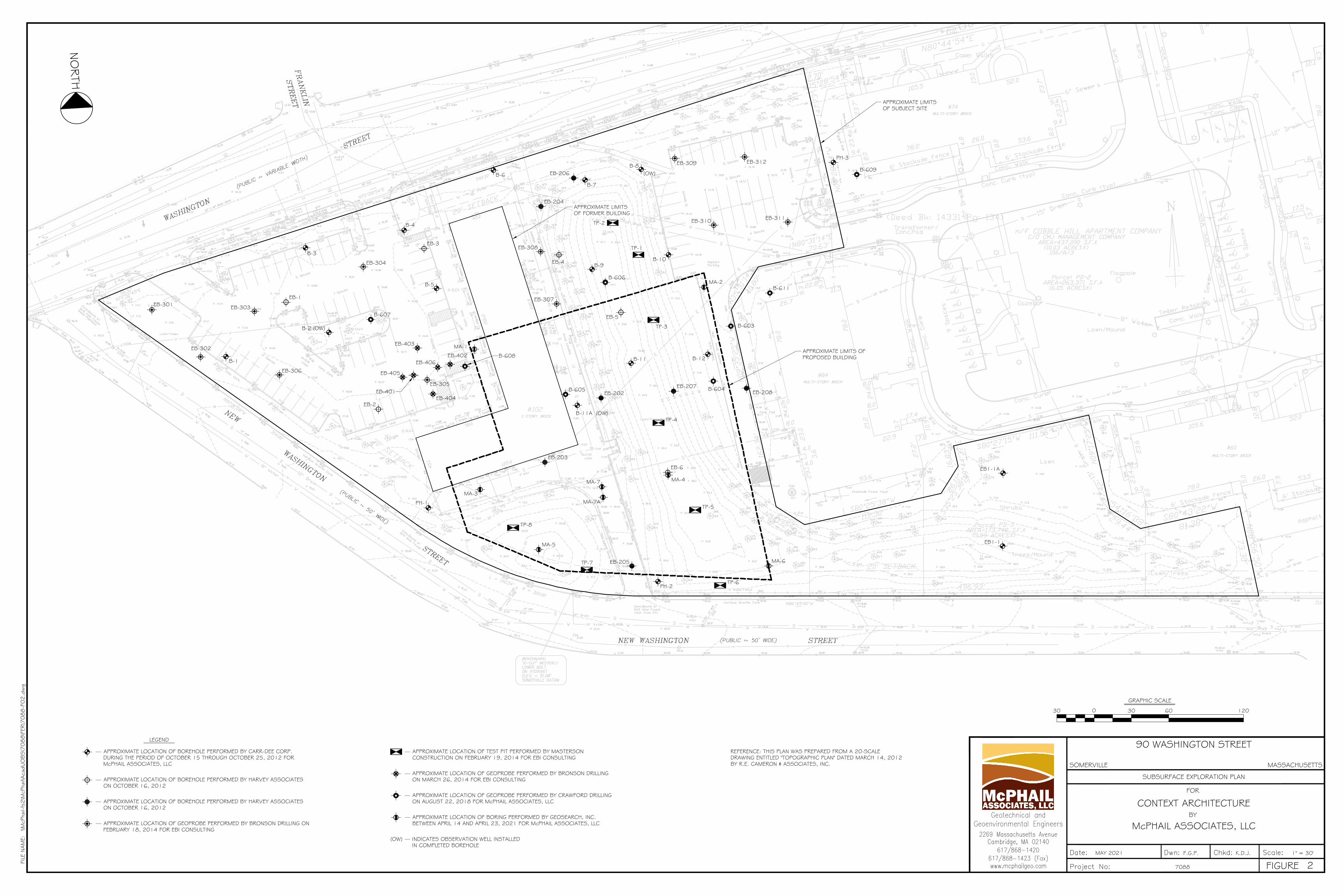
B-1
B-2 (OW)
B-3
B-4
B-5
B-6
B-7
B-8(OW)
B-9B-10
B-11 B-12
EB1-1A
EB1-1
PH-2
PH-1
PH-3
EB-301
EB-304
EB-303
EB-302
EB-306
EB-305
EB-308
EB-307
EB-311
TP-3
TP-1
TP-2
EB-312EB-309
EB-310
TP-4
TP-5
TP-6
TP-7
TP-8
EB-1
EB-2
EB-3
EB-4
EB-6
EB-202
EB-203
EB-204
EB-205
EB-206
EB-207EB-208EB-401
EB-402
EB-403
EB-404
EB-405
EB-406
B-607
B-608
B-606
B-605 B-604
B-603
B-611
B-609
EB-5
APPROXIMATE LIMITSOF SUBJECT SITE
MA-1
MA-2
MA-3
MA-4
MA-6
MA-7
MA-7A
MA-5
B-11A (OW)
APPROXIMATE LIMITS OFPROPOSED BUILDING
APPROXIMATE LIMITSOF FORMER BUILDING
McPHAIL ASSOCIATES, LLC
FOR
BY
FILE
NAM
E:
FIGURE
\\McP
hail-
fs2\M
cPha
il\Aca
d\JO
BS\7
088\F
ER\7
088-F
02.d
wg
7088
1" = 30'K.D.J.F.G.P.MAY 2021
CONTEXT ARCHITECTURE
SUBSURFACE EXPLORATION PLAN
MASSACHUSETTSSOMERVILLE
90 WASHINGTON STREET
2
NO
RTH
0
GRAPHIC SCALE
30 30 60 120
REFERENCE: THIS PLAN WAS PREPARED FROM A 20-SCALEDRAWING ENTITLED "TOPOGRAPHIC PLAN" DATED MARCH 14, 2012BY R.E. CAMERON & ASSOCIATES, INC.
APPROXIMATE LOCATION OF BOREHOLE PERFORMED BY CARR-DEE CORP.DURING THE PERIOD OF OCTOBER 15 THROUGH OCTOBER 25, 2012 FORMcPHAIL ASSOCIATES, LLC
LEGEND
INDICATES OBSERVATION WELL INSTALLEDIN COMPLETED BOREHOLE
(OW)
APPROXIMATE LOCATION OF GEOPROBE PERFORMED BY BRONSON DRILLING ONFEBRUARY 18, 2014 FOR EBI CONSULTING
APPROXIMATE LOCATION OF TEST PIT PERFORMED BY MASTERSONCONSTRUCTION ON FEBRUARY 19, 2014 FOR EBI CONSULTING
APPROXIMATE LOCATION OF BOREHOLE PERFORMED BY HARVEY ASSOCIATESON OCTOBER 16, 2012
APPROXIMATE LOCATION OF BOREHOLE PERFORMED BY HARVEY ASSOCIATESON OCTOBER 16, 2012
APPROXIMATE LOCATION OF GEOPROBE PERFORMED BY BRONSON DRILLINGON MARCH 26, 2014 FOR EBI CONSULTING
APPROXIMATE LOCATION OF GEOPROBE PERFORMED BY CRAWFORD DRILLINGON AUGUST 22, 2018 FOR McPHAIL ASSOCIATES, LLC
APPROXIMATE LOCATION OF BORING PERFORMED BY GEOSEARCH, INC.BETWEEN APRIL 14 AND APRIL 23, 2021 FOR McPHAIL ASSOCIATES, LLC
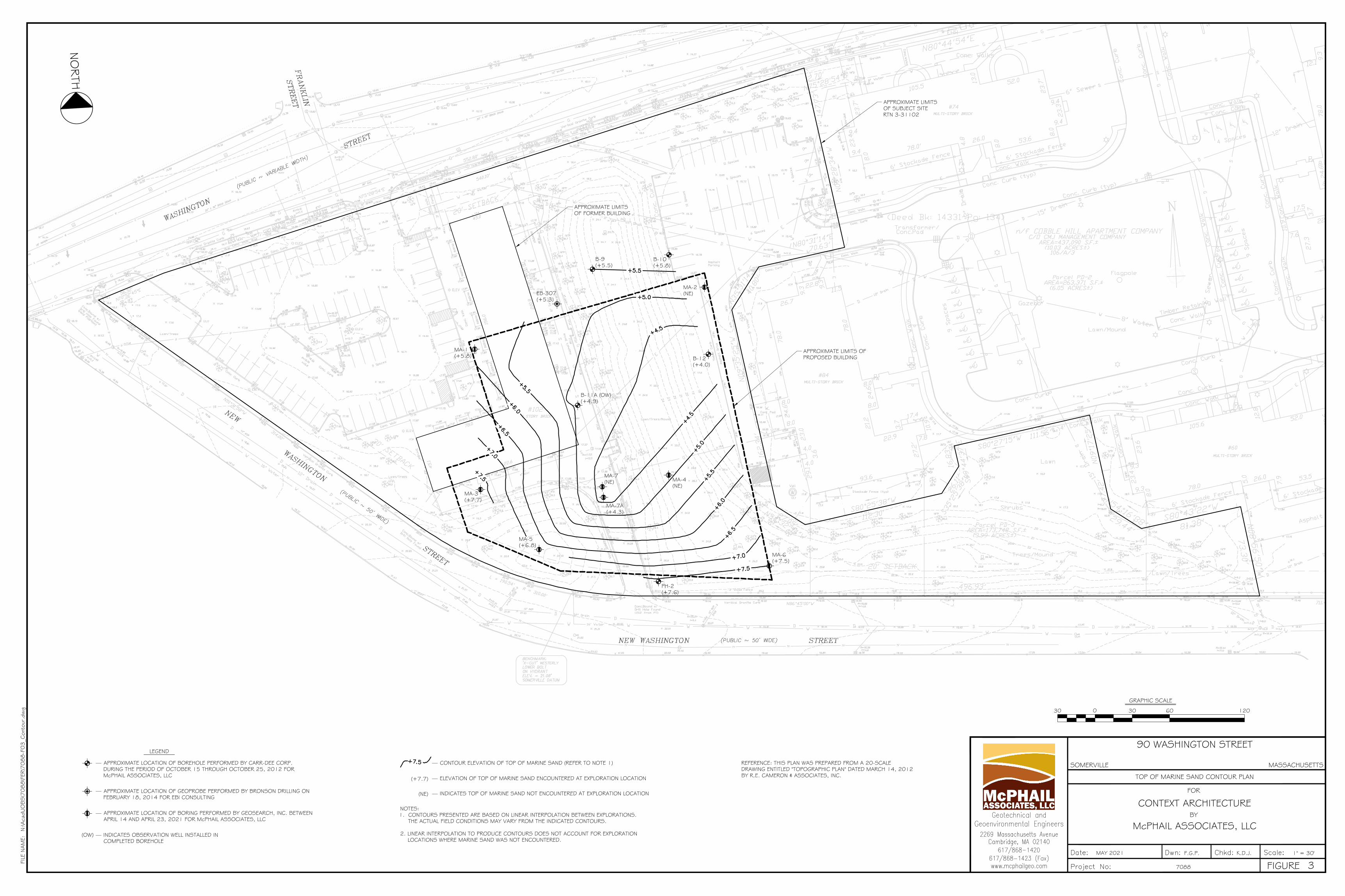
B-9(+5.5)
B-10(+5.8)
B-12(+4.0)
PH-2(+7.6)
EB-307(+5.3)
APPROXIMATE LIMITSOF SUBJECT SITERTN 3-31102
MA-1(+5.8)
MA-2(NE)
MA-3(+7.7)
MA-4(NE)
MA-6(+7.5)
MA-7(NE)
MA-7A(+4.3)
MA-5(+6.8)
B-11A (OW)(+4.9)
APPROXIMATE LIMITS OFPROPOSED BUILDING
APPROXIMATE LIMITSOF FORMER BUILDING
McPHAIL ASSOCIATES, LLC
FOR
BY
FILE
NAM
E:
FIGURE
N:\A
cad\
JOBS\7
088\F
ER\7
088-F
03_C
onto
ur.d
wg
7088
1" = 30'K.D.J.F.G.P.MAY 2021
CONTEXT ARCHITECTURE
TOP OF MARINE SAND CONTOUR PLAN
MASSACHUSETTSSOMERVILLE
90 WASHINGTON STREET
3
NO
RTH
0
GRAPHIC SCALE
30 30 60 120
REFERENCE: THIS PLAN WAS PREPARED FROM A 20-SCALEDRAWING ENTITLED "TOPOGRAPHIC PLAN" DATED MARCH 14, 2012BY R.E. CAMERON & ASSOCIATES, INC.
APPROXIMATE LOCATION OF BOREHOLE PERFORMED BY CARR-DEE CORP.DURING THE PERIOD OF OCTOBER 15 THROUGH OCTOBER 25, 2012 FORMcPHAIL ASSOCIATES, LLC
LEGEND
INDICATES OBSERVATION WELL INSTALLED INCOMPLETED BOREHOLE
(OW)
APPROXIMATE LOCATION OF GEOPROBE PERFORMED BY BRONSON DRILLING ONFEBRUARY 18, 2014 FOR EBI CONSULTING
APPROXIMATE LOCATION OF BORING PERFORMED BY GEOSEARCH, INC. BETWEENAPRIL 14 AND APRIL 23, 2021 FOR McPHAIL ASSOCIATES, LLC
NOTES:1. CONTOURS PRESENTED ARE BASED ON LINEAR INTERPOLATION BETWEEN EXPLORATIONS.
THE ACTUAL FIELD CONDITIONS MAY VARY FROM THE INDICATED CONTOURS.
2. LINEAR INTERPOLATION TO PRODUCE CONTOURS DOES NOT ACCOUNT FOR EXPLORATIONLOCATIONS WHERE MARINE SAND WAS NOT ENCOUNTERED.
ELEVATION OF TOP OF MARINE SAND ENCOUNTERED AT EXPLORATION LOCATION(+7.7)
CONTOUR ELEVATION OF TOP OF MARINE SAND (REFER TO NOTE 1)
INDICATES TOP OF MARINE SAND NOT ENCOUNTERED AT EXPLORATION LOCATION(NE)
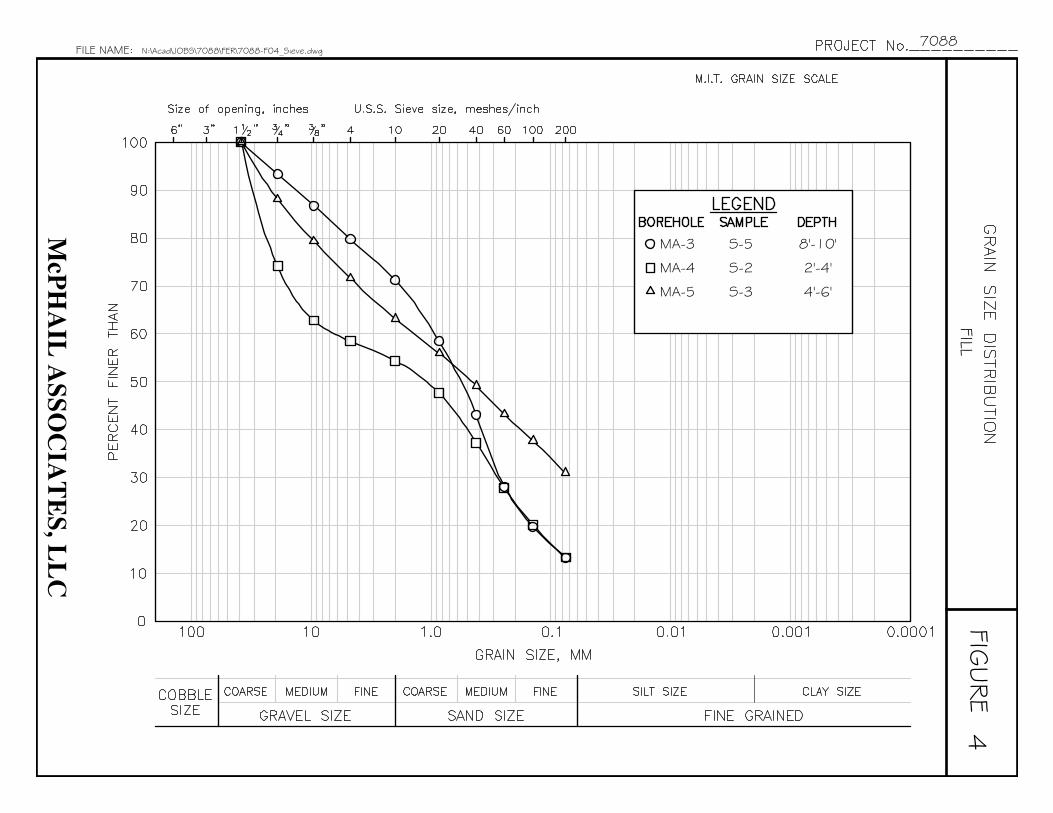
McP
HA
IL A
SSOC
IAT
ES, L
LC
FIGURE
FILE NAME: N:\Acad\JOBS\7088\FER\7088-F04_Sieve.dwg7088
FILL4
MA-4 S-2 2'-4'
MA-5 S-3 4'-6'
MA-3 S-5 8'-10'
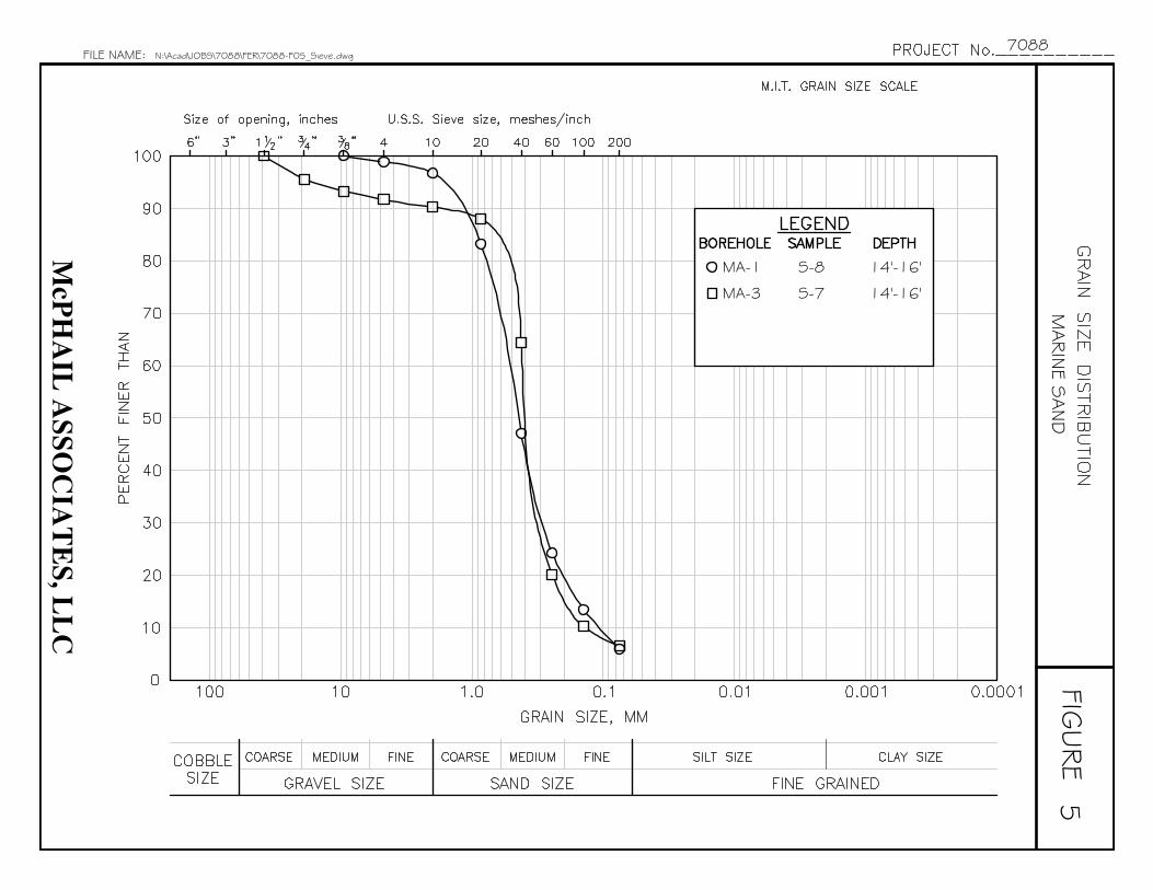
McP
HA
IL A
SSOC
IAT
ES, L
LC
FIGURE
FILE NAME: N:\Acad\JOBS\7088\FER\7088-F05_Sieve.dwg7088
MARIN
E SAND
5
MA-3 S-7 14'-16'
MA-1 S-8 14'-16'
APPENDIX A:
LIMITATIONS

LIMITATIONS
This report has been prepared on behalf of and for the exclusive use of Context
Architecture for specific application to the proposed Somerville Public Safety Building
development to be located in Somerville, Massachusetts in accordance with generally
accepted soil and geotechnical engineering practices. No other warranty, expressed or
implied, is made.
In the event that any changes in nature or design of the proposed construction are
planned, the conclusions and recommendations contained in this report should not be
considered valid unless the changes are reviewed and conclusions of this report modified
or verified in writing by McPhail Associates, LLC.
The analyses and recommendations presented in this report are based upon the data
obtained from the subsurface explorations performed at the approximate locations
indicated on the enclosed plan. If variations in the nature and extent of subsurface
conditions between the widely spaced explorations become evident during the course of
construction, it will be necessary for a re-evaluation of the recommendations of this
report to be made after performing on-site observations during the construction period
and noting the characteristics of any variations.

APPENDIX B:
BORING LOGS MA-1 THROUGH MA-7A PREPARED BY MCPHAIL
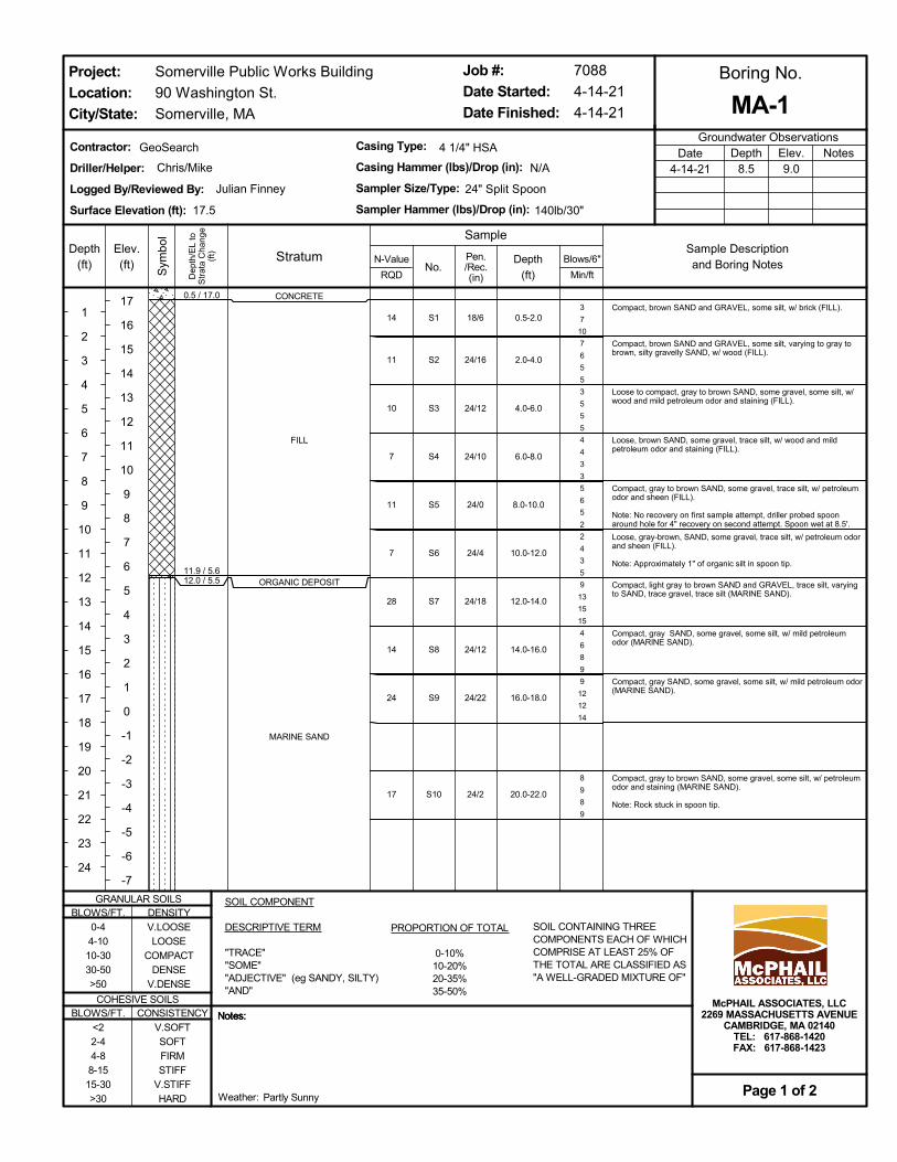
CONCRETE
FILL
ORGANIC DEPOSIT
MARINE SAND
0.5 / 17.0
11.9 / 5.612.0 / 5.5
S1
S2
S3
S4
S5
S6
S7
S8
S9
S10
3
7
10
7
6
5
5
3
5
5
5
4
4
3
3
5
6
5
2
2
4
3
5
9
13
15
15
4
6
8
9
9
12
12
14
8
9
8
9
Compact, brown SAND and GRAVEL, some silt, w/ brick (FILL).
Compact, brown SAND and GRAVEL, some silt, varying to gray tobrown, silty gravelly SAND, w/ wood (FILL).
Loose to compact, gray to brown SAND, some gravel, some silt, w/wood and mild petroleum odor and staining (FILL).
Loose, brown SAND, some gravel, trace silt, w/ wood and mildpetroleum odor and staining (FILL).
Compact, gray to brown SAND, some gravel, trace silt, w/ petroleumodor and sheen (FILL).
Note: No recovery on first sample attempt, driller probed spoonaround hole for 4" recovery on second attempt. Spoon wet at 8.5'.
Loose, gray-brown, SAND, some gravel, trace silt, w/ petroleum odorand sheen (FILL).
Note: Approximately 1" of organic silt in spoon tip.
Compact, light gray to brown SAND and GRAVEL, trace silt, varyingto SAND, trace gravel, trace silt (MARINE SAND).
Compact, gray SAND, some gravel, some silt, w/ mild petroleumodor (MARINE SAND).
Compact, gray SAND, some gravel, some silt, w/ mild petroleum odor(MARINE SAND).
Compact, gray to brown SAND, some gravel, some silt, w/ petroleumodor and staining (MARINE SAND).
Note: Rock stuck in spoon tip.
0.5-2.0
2.0-4.0
4.0-6.0
6.0-8.0
8.0-10.0
10.0-12.0
12.0-14.0
14.0-16.0
16.0-18.0
20.0-22.0
14
11
10
7
11
7
28
14
24
17
18/6
24/16
24/12
24/10
24/0
24/4
24/18
24/12
24/22
24/2
Somerville Public Works Building
90 Washington St.
Somerville, MA
Boring No.
Groundwater Observations
Stratum
Dep
th/E
L to
Str
ata
Cha
nge
(ft)
Sym
bol
No.
Elev.(ft)
17
16
15
14
13
12
11
10
9
8
7
6
5
4
3
2
1
0
-1
-2
-3
-4
-5
-6
-7
Blows/6"
Min/ft
Sample Descriptionand Boring Notes
Contractor:
Driller/Helper:
Logged By/Reviewed By:
Surface Elevation (ft):
SOIL CONTAINING THREECOMPONENTS EACH OF WHICHCOMPRISE AT LEAST 25% OFTHE TOTAL ARE CLASSIFIED AS"A WELL-GRADED MIXTURE OF"
NotesDepth8.5
Elev.9.0
Date4-14-21
Job #:
Date Started:
Date Finished:
PROPORTION OF TOTAL
0-10%10-20%20-35%35-50%
Notes:Notes:
Project:
Location:
City/State:
BLOWS/FT.0-44-1010-3030-50>50
BLOWS/FT.<22-44-88-1515-30>30
Page 1 of 2
DENSITYV.LOOSELOOSE
COMPACTDENSE
V.DENSE
24" Split Spoon
17.5
McPHAIL ASSOCIATES, LLC2269 MASSACHUSETTS AVENUE
CAMBRIDGE, MA 02140TEL: 617-868-1420FAX: 617-868-1423
N/A
140lb/30"
MA-1
Weather:
GRANULAR SOILS
COHESIVE SOILS
Chris/Mike
Notes:
SampleDepth
(ft)
1
2
3
4
5
6
7
8
9
10
11
12
13
14
15
16
17
18
19
20
21
22
23
24
Depth
(ft)
Julian Finney
GeoSearch 4 1/4" HSA
N-Value
RQD
Pen./Rec.(in)
SOIL COMPONENT
DESCRIPTIVE TERM
"TRACE""SOME""ADJECTIVE" (eg SANDY, SILTY)"AND"
CONSISTENCYV.SOFTSOFTFIRMSTIFF
V.STIFFHARD Partly Sunny
7088
4-14-21
4-14-21
Casing Type:
Casing Hammer (lbs)/Drop (in):
Sampler Size/Type:
Sampler Hammer (lbs)/Drop (in):

MARINE SAND
MARINE CLAY
Bottom of borehole 29 feet belowground surface.
27.0 / -9.5
29.0 / -11.5
S11
S12
5
6
11
9
3
2
3
4
Compact, gray SAND, some gravel, some silt, w/ petroleum odor(MARINE SAND).
Firm, gray to blue CLAY, some silt (MARINE CLAY).
25.0-27.0
27.0-29.0
17
5
24/12
24/14
Somerville Public Works Building
90 Washington St.
Somerville, MA
Boring No.
Groundwater Observations
Stratum
Dep
th/E
L to
Str
ata
Cha
nge
(ft)
Sym
bol
No.
Elev.(ft)
-8
-9
-10
-11
-12
-13
-14
-15
-16
-17
-18
-19
-20
-21
-22
-23
-24
-25
-26
-27
-28
-29
-30
-31
-32
Blows/6"
Min/ft
Sample Descriptionand Boring Notes
Contractor:
Driller/Helper:
Logged By/Reviewed By:
Surface Elevation (ft):
SOIL CONTAINING THREECOMPONENTS EACH OF WHICHCOMPRISE AT LEAST 25% OFTHE TOTAL ARE CLASSIFIED AS"A WELL-GRADED MIXTURE OF"
NotesDepth8.5
Elev.9.0
Date4-14-21
Job #:
Date Started:
Date Finished:
PROPORTION OF TOTAL
0-10%10-20%20-35%35-50%
Notes:Notes:
Project:
Location:
City/State:
BLOWS/FT.0-44-1010-3030-50>50
BLOWS/FT.<22-44-88-1515-30>30
Page 2 of 2
DENSITYV.LOOSELOOSE
COMPACTDENSE
V.DENSE
24" Split Spoon
17.5
McPHAIL ASSOCIATES, LLC2269 MASSACHUSETTS AVENUE
CAMBRIDGE, MA 02140TEL: 617-868-1420FAX: 617-868-1423
N/A
140lb/30"
MA-1
Weather:
GRANULAR SOILS
COHESIVE SOILS
Chris/Mike
Notes:
SampleDepth
(ft)
26
27
28
29
30
31
32
33
34
35
36
37
38
39
40
41
42
43
44
45
46
47
48
49
Depth
(ft)
Julian Finney
GeoSearch 4 1/4" HSA
N-Value
RQD
Pen./Rec.(in)
SOIL COMPONENT
DESCRIPTIVE TERM
"TRACE""SOME""ADJECTIVE" (eg SANDY, SILTY)"AND"
CONSISTENCYV.SOFTSOFTFIRMSTIFF
V.STIFFHARD Partly Sunny
7088
4-14-21
4-14-21
Casing Type:
Casing Hammer (lbs)/Drop (in):
Sampler Size/Type:
Sampler Hammer (lbs)/Drop (in):
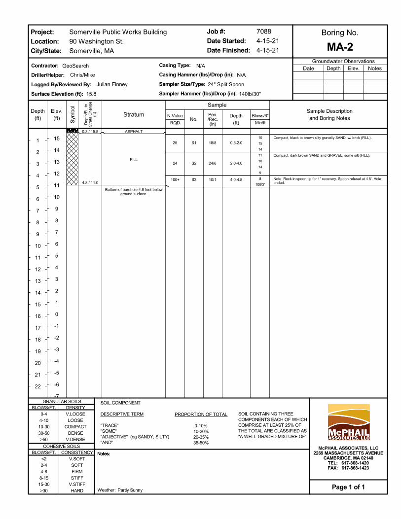
ASPHALT
FILL
Bottom of borehole 4.8 feet belowground surface.
0.3 / 15.5
4.8 / 11.0
S1
S2
S3
10
15
14
11
10
14
9
8
100/3"
Compact, black to brown silty gravelly SAND, w/ brick (FILL).
Compact, dark brown SAND and GRAVEL, some silt (FILL).
Note: Rock in spoon tip for 1" recovery. Spoon refusal at 4.8'. Holeended.
0.5-2.0
2.0-4.0
4.0-4.8
25
24
100+
18/8
24/6
10/1
Somerville Public Works Building
90 Washington St.
Somerville, MA
Boring No.
Groundwater Observations
Stratum
Dep
th/E
L to
Str
ata
Cha
nge
(ft)
Sym
bol
No.
Elev.(ft)
15
14
13
12
11
10
9
8
7
6
5
4
3
2
1
0
-1
-2
-3
-4
-5
-6
-7
Blows/6"
Min/ft
Sample Descriptionand Boring Notes
Contractor:
Driller/Helper:
Logged By/Reviewed By:
Surface Elevation (ft):
SOIL CONTAINING THREECOMPONENTS EACH OF WHICHCOMPRISE AT LEAST 25% OFTHE TOTAL ARE CLASSIFIED AS"A WELL-GRADED MIXTURE OF"
NotesDepth Elev.Date
Job #:
Date Started:
Date Finished:
PROPORTION OF TOTAL
0-10%10-20%20-35%35-50%
Notes:Notes:
Project:
Location:
City/State:
BLOWS/FT.0-44-1010-3030-50>50
BLOWS/FT.<22-44-88-1515-30>30
Page 1 of 1
DENSITYV.LOOSELOOSE
COMPACTDENSE
V.DENSE
24" Split Spoon
15.8
McPHAIL ASSOCIATES, LLC2269 MASSACHUSETTS AVENUE
CAMBRIDGE, MA 02140TEL: 617-868-1420FAX: 617-868-1423
N/A
140lb/30"
MA-2
Weather:
GRANULAR SOILS
COHESIVE SOILS
Chris/Mike
Notes:
SampleDepth
(ft)
1
2
3
4
5
6
7
8
9
10
11
12
13
14
15
16
17
18
19
20
21
22
Depth
(ft)
Julian Finney
GeoSearch N/A
N-Value
RQD
Pen./Rec.(in)
SOIL COMPONENT
DESCRIPTIVE TERM
"TRACE""SOME""ADJECTIVE" (eg SANDY, SILTY)"AND"
CONSISTENCYV.SOFTSOFTFIRMSTIFF
V.STIFFHARD Partly Sunny
7088
4-15-21
4-15-21
Casing Type:
Casing Hammer (lbs)/Drop (in):
Sampler Size/Type:
Sampler Hammer (lbs)/Drop (in):

ASPHALT
FILL
MARINE SAND
MARINE CLAY
0.3 / 17.4
10.0 / 7.7
17.0 / 0.7
S1
S2
S3
S4
S5
S6
S7
S8
2
5
14
11
6
7
6
5
6
5
9
13
8
6
5
7
6
6
7
8
5
9
15
10
11
13
18
2
4
6
6
Compact, dark brown, silty gravelly SAND, w/ brick, glass, and ashand cinders (FILL).
Compact gravelly SAND, some silt (FILL).
Compact, brown gravelly SAND, trace silt (FILL).
Compact, brown gravelly SAND, trace silt (FILL).
Note: Spoon wet at 6'.
Compact, brown SAND, some gravel, trace silt (MARINE SAND).
Compact, gray to brown gravelly SAND, trace silt (MARINE SAND).
Compact, gray SAND, trace gravel, trace silt (MARINE SAND).
Very stiff, blue to gray CLAY, some silt (MARINE CLAY).
0.5-2.5
2.5-4.0
4.0-6.0
6.0-8.0
8.0-10.0
10.0-12.0
14.0-16.0
19.0-21.0
19
14
11
14
12
14
24
10
24/8
18/6
24/10
24/10
24/6
24/4
24/12
24/22
Somerville Public Works Building
90 Washington St.
Somerville, MA
Boring No.
Groundwater Observations
Stratum
Dep
th/E
L to
Str
ata
Cha
nge
(ft)
Sym
bol
No.
Elev.(ft)
17
16
15
14
13
12
11
10
9
8
7
6
5
4
3
2
1
0
-1
-2
-3
-4
-5
-6
Blows/6"
Min/ft
Sample Descriptionand Boring Notes
Contractor:
Driller/Helper:
Logged By/Reviewed By:
Surface Elevation (ft):
SOIL CONTAINING THREECOMPONENTS EACH OF WHICHCOMPRISE AT LEAST 25% OFTHE TOTAL ARE CLASSIFIED AS"A WELL-GRADED MIXTURE OF"
NotesDepth6
Elev.11.7
Date4-14-21
Job #:
Date Started:
Date Finished:
PROPORTION OF TOTAL
0-10%10-20%20-35%35-50%
Notes:Notes:
Project:
Location:
City/State:
BLOWS/FT.0-44-1010-3030-50>50
BLOWS/FT.<22-44-88-1515-30>30
Page 1 of 2
DENSITYV.LOOSELOOSE
COMPACTDENSE
V.DENSE
24" Split Spoon
17.7
McPHAIL ASSOCIATES, LLC2269 MASSACHUSETTS AVENUE
CAMBRIDGE, MA 02140TEL: 617-868-1420FAX: 617-868-1423
300lb/24"
140lb/30"
MA-3
Weather:
GRANULAR SOILS
COHESIVE SOILS
Chris/Mike
Notes:
SampleDepth
(ft)
1
2
3
4
5
6
7
8
9
10
11
12
13
14
15
16
17
18
19
20
21
22
23
Depth
(ft)
Julian Finney
GeoSearch 4" Casing
N-Value
RQD
Pen./Rec.(in)
SOIL COMPONENT
DESCRIPTIVE TERM
"TRACE""SOME""ADJECTIVE" (eg SANDY, SILTY)"AND"
CONSISTENCYV.SOFTSOFTFIRMSTIFF
V.STIFFHARD Partly Sunny
7088
4-14-21
4-14-21
Casing Type:
Casing Hammer (lbs)/Drop (in):
Sampler Size/Type:
Sampler Hammer (lbs)/Drop (in):

MARINE CLAY
GLACIOMARINE
GLACIAL TILL
Bottom of borehole 46 feet belowground surface.
36.0 / -18.3
42.0 / -24.3
46.0 / -28.3
S9
S10
S11
S12
S13
S14
WOH
1
2
2
WOH
WOH
2
3
WOH
WOH
WOH
WOH
23
3
8
6
6
9
12
8
14
15
23
29
Soft, blue to gray CLAY, some silt (MARINE CLAY).
Very soft to soft, blue to gray CLAY, some silt (MARINE CLAY).
Very soft, blue to gray CLAY, some silt (MARINE CLAY).
Compact, blue to gray, well-graded mixture of SILT, SAND, andGRAVEL, some clay (GLACIOMARINE DEPOSIT).
Compact, gray, well-graded mixture of SILT, SAND, and GRAVEL,trace clay (GLACIOMARINE DEPOSIT).
Dense, gray silty SAND and GRAVEL, w/ cobbles (GLACIAL TILL).
24.0-26.0
29.0-31.0
34.0-36.0
36.0-38.0
38.0-40.0
44.0-46.0
3
2
0
11
21
38
24/24
24/10
24/14
24/12
24/1
24/8
Somerville Public Works Building
90 Washington St.
Somerville, MA
Boring No.
Groundwater Observations
Stratum
Dep
th/E
L to
Str
ata
Cha
nge
(ft)
Sym
bol
No.
Elev.(ft)
-7
-8
-9
-10
-11
-12
-13
-14
-15
-16
-17
-18
-19
-20
-21
-22
-23
-24
-25
-26
-27
-28
-29
-30
Blows/6"
Min/ft
Sample Descriptionand Boring Notes
Contractor:
Driller/Helper:
Logged By/Reviewed By:
Surface Elevation (ft):
SOIL CONTAINING THREECOMPONENTS EACH OF WHICHCOMPRISE AT LEAST 25% OFTHE TOTAL ARE CLASSIFIED AS"A WELL-GRADED MIXTURE OF"
NotesDepth6
Elev.11.7
Date4-14-21
Job #:
Date Started:
Date Finished:
PROPORTION OF TOTAL
0-10%10-20%20-35%35-50%
Notes:Notes:
Project:
Location:
City/State:
BLOWS/FT.0-44-1010-3030-50>50
BLOWS/FT.<22-44-88-1515-30>30
Page 2 of 2
DENSITYV.LOOSELOOSE
COMPACTDENSE
V.DENSE
24" Split Spoon
17.7
McPHAIL ASSOCIATES, LLC2269 MASSACHUSETTS AVENUE
CAMBRIDGE, MA 02140TEL: 617-868-1420FAX: 617-868-1423
300lb/24"
140lb/30"
MA-3
Weather:
GRANULAR SOILS
COHESIVE SOILS
Chris/Mike
Notes:
SampleDepth
(ft)
25
26
27
28
29
30
31
32
33
34
35
36
37
38
39
40
41
42
43
44
45
46
47
Depth
(ft)
Julian Finney
GeoSearch 4" Casing
N-Value
RQD
Pen./Rec.(in)
SOIL COMPONENT
DESCRIPTIVE TERM
"TRACE""SOME""ADJECTIVE" (eg SANDY, SILTY)"AND"
CONSISTENCYV.SOFTSOFTFIRMSTIFF
V.STIFFHARD Partly Sunny
7088
4-14-21
4-14-21
Casing Type:
Casing Hammer (lbs)/Drop (in):
Sampler Size/Type:
Sampler Hammer (lbs)/Drop (in):
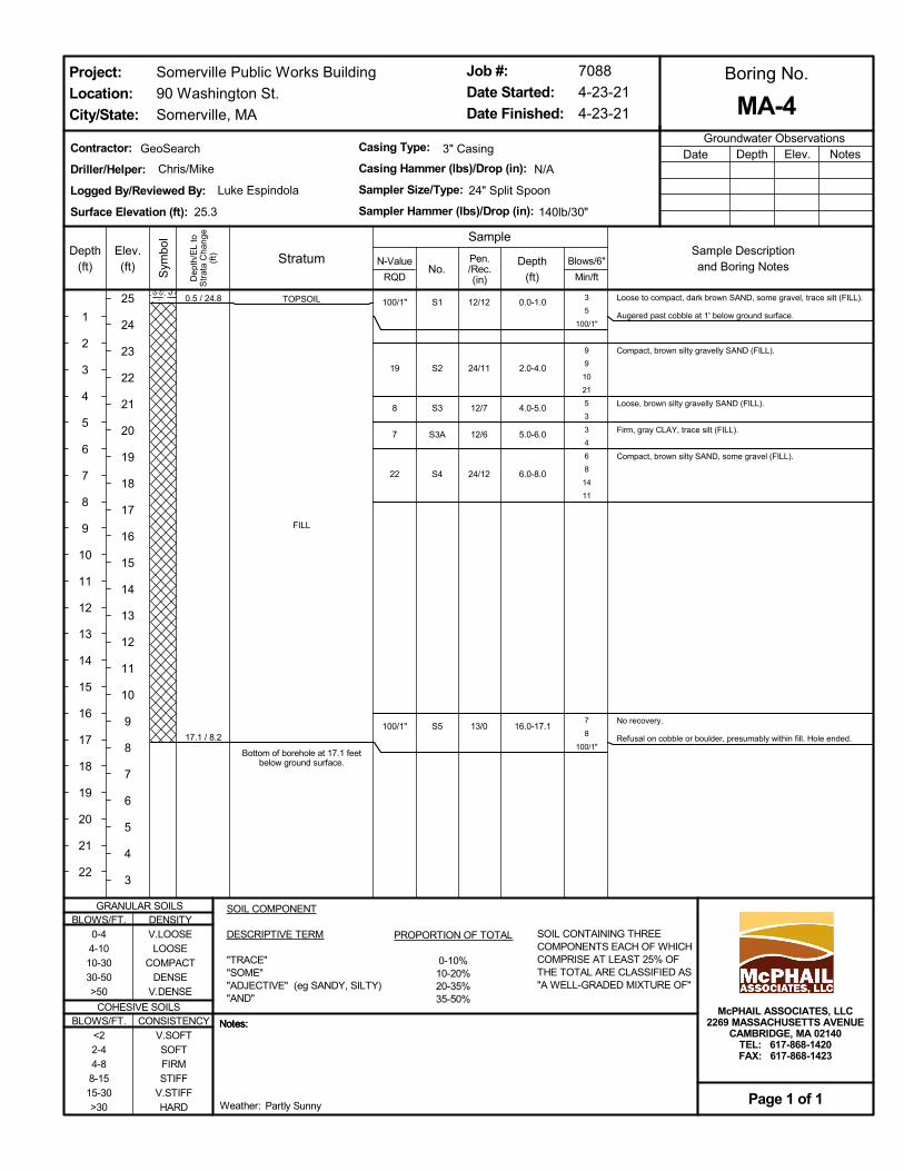
TOPSOIL
FILL
Bottom of borehole at 17.1 feetbelow ground surface.
0.5 / 24.8
17.1 / 8.2
S1
S2
S3
S3A
S4
S5
3
5
100/1"
9
9
10
21
5
3
3
4
6
8
14
11
7
8
100/1"
Loose to compact, dark brown SAND, some gravel, trace silt (FILL).
Augered past cobble at 1' below ground surface.
Compact, brown silty gravelly SAND (FILL).
Loose, brown silty gravelly SAND (FILL).
Firm, gray CLAY, trace silt (FILL).
Compact, brown silty SAND, some gravel (FILL).
No recovery.
Refusal on cobble or boulder, presumably within fill. Hole ended.
0.0-1.0
2.0-4.0
4.0-5.0
5.0-6.0
6.0-8.0
16.0-17.1
100/1"
19
8
7
22
100/1"
12/12
24/11
12/7
12/6
24/12
13/0
Somerville Public Works Building
90 Washington St.
Somerville, MA
Boring No.
Groundwater Observations
Stratum
Dep
th/E
L to
Str
ata
Cha
nge
(ft)
Sym
bol
No.
Elev.(ft)
25
24
23
22
21
20
19
18
17
16
15
14
13
12
11
10
9
8
7
6
5
4
3
Blows/6"
Min/ft
Sample Descriptionand Boring Notes
Contractor:
Driller/Helper:
Logged By/Reviewed By:
Surface Elevation (ft):
SOIL CONTAINING THREECOMPONENTS EACH OF WHICHCOMPRISE AT LEAST 25% OFTHE TOTAL ARE CLASSIFIED AS"A WELL-GRADED MIXTURE OF"
NotesDepth Elev.Date
Job #:
Date Started:
Date Finished:
PROPORTION OF TOTAL
0-10%10-20%20-35%35-50%
Notes:Notes:
Project:
Location:
City/State:
BLOWS/FT.0-44-1010-3030-50>50
BLOWS/FT.<22-44-88-1515-30>30
Page 1 of 1
DENSITYV.LOOSELOOSE
COMPACTDENSE
V.DENSE
24" Split Spoon
25.3
McPHAIL ASSOCIATES, LLC2269 MASSACHUSETTS AVENUE
CAMBRIDGE, MA 02140TEL: 617-868-1420FAX: 617-868-1423
N/A
140lb/30"
MA-4
Weather:
GRANULAR SOILS
COHESIVE SOILS
Chris/Mike
Notes:
SampleDepth
(ft)
1
2
3
4
5
6
7
8
9
10
11
12
13
14
15
16
17
18
19
20
21
22
Depth
(ft)
Luke Espindola
GeoSearch 3" Casing
N-Value
RQD
Pen./Rec.(in)
SOIL COMPONENT
DESCRIPTIVE TERM
"TRACE""SOME""ADJECTIVE" (eg SANDY, SILTY)"AND"
CONSISTENCYV.SOFTSOFTFIRMSTIFF
V.STIFFHARD Partly Sunny
7088
4-23-21
4-23-21
Casing Type:
Casing Hammer (lbs)/Drop (in):
Sampler Size/Type:
Sampler Hammer (lbs)/Drop (in):
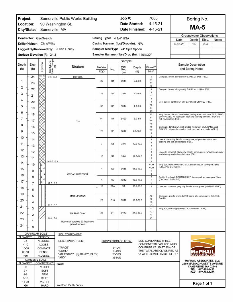
TOPSOIL
FILL
ORGANIC DEPOSIT
MARINE SAND
MARINE CLAY
Bottom of borehole 23 feet belowground surface.
0.5 / 23.8
14.0 / 10.3
17.5 / 6.8
21.0 / 3.3
23.0 / 1.3
S1
S2
S3
S4
S5
S6
S7
S8
S9
S9A
S10
S11
6
11
11
10
9
8
11
9
8
18
34
25
72
81
60
40
16
17
9
9
3
4
3
5
3
5
5
5
WOH
WOH
1
3
2
2
2
5
12
10
15
15
12
12
13
21
Compact, brown silty gravelly SAND, w/ brick (FILL).
Compact, brown silty gravelly SAND, w/ cobbles (FILL).
Very dense, light brown silty SAND and GRAVEL (FILL).
Very dense, black to dark brown, well-graded mixture of SILT, SAND,and GRAVEL, w/ petroleum odor and staining, cobbles, brick andash and cinders (FILL).
Compact, dark brown, well-graded mixture of SILT, SAND, andGRAVEL, w/ petroleum odor, brick, and ash and cinders (FILL).
Loose, black silty SAND, some gravel, w/ petroleum odor andstaining and ash and cinders (FILL).
Loose to compact, black silty SAND, some gravel, w/ petroleum odorand staining and ash and cinders (FILL).
Very soft, black ORGANIC SILT, trace sand, w/ trace peat fibers(ORGANIC DEPOSIT).
Soft to firm, black ORGANIC SILT, trace sand, w/ trace peat fibers(ORGANIC DEPOSIT).
Loose to compact, gray silty SAND, some gravel (MARINE SAND).
Compact, gray to brown SAND, some silt, some gravel (MARINESAND).
Very stiff, blue to gray silty CLAY (MARINE CLAY).
0.0-2.0
2.0-4.0
4.0-6.0
6.0-8.0
8.0-10.0
10.0-12.0
12.0-14.0
14.0-16.0
16.0-17.5
17.5-18.0
19.0-21.0
21.0-23.0
22
19
52
141
26
7
10
1
4
10
25
25
24/14
24/6
24/14
24/20
24/12
24/6
24/4
24/18
18/12
6/4
24/12
24/12
Somerville Public Works Building
90 Washington St.
Somerville, MA
Boring No.
Groundwater Observations
Stratum
Dep
th/E
L to
Str
ata
Cha
nge
(ft)
Sym
bol
No.
Elev.(ft)
24
23
22
21
20
19
18
17
16
15
14
13
12
11
10
9
8
7
6
5
4
3
2
1
0
Blows/6"
Min/ft
Sample Descriptionand Boring Notes
Contractor:
Driller/Helper:
Logged By/Reviewed By:
Surface Elevation (ft):
SOIL CONTAINING THREECOMPONENTS EACH OF WHICHCOMPRISE AT LEAST 25% OFTHE TOTAL ARE CLASSIFIED AS"A WELL-GRADED MIXTURE OF"
NotesDepth16
Elev.8.3
Date4-15-21
Job #:
Date Started:
Date Finished:
PROPORTION OF TOTAL
0-10%10-20%20-35%35-50%
Notes:Notes:
Project:
Location:
City/State:
BLOWS/FT.0-44-1010-3030-50>50
BLOWS/FT.<22-44-88-1515-30>30
Page 1 of 1
DENSITYV.LOOSELOOSE
COMPACTDENSE
V.DENSE
24" Split Spoon
24.3
McPHAIL ASSOCIATES, LLC2269 MASSACHUSETTS AVENUE
CAMBRIDGE, MA 02140TEL: 617-868-1420FAX: 617-868-1423
N/A
140lb/30"
MA-5
Weather:
GRANULAR SOILS
COHESIVE SOILS
Chris/Mike
Notes:
SampleDepth
(ft)
1
2
3
4
5
6
7
8
9
10
11
12
13
14
15
16
17
18
19
20
21
22
23
24
Depth
(ft)
Julian Finney
GeoSearch 4 1/4" HSA
N-Value
RQD
Pen./Rec.(in)
SOIL COMPONENT
DESCRIPTIVE TERM
"TRACE""SOME""ADJECTIVE" (eg SANDY, SILTY)"AND"
CONSISTENCYV.SOFTSOFTFIRMSTIFF
V.STIFFHARD Partly Sunny
7088
4-15-21
4-15-21
Casing Type:
Casing Hammer (lbs)/Drop (in):
Sampler Size/Type:
Sampler Hammer (lbs)/Drop (in):

TOPSOIL
FILL
MARINE SAND
0.5 / 23.0
16.0 / 7.5
S1
S2
S3
S4
S5
S6
S7
S8
S9
S10
3
9
10
6
16
9
8
5
7
7
13
11
3
8
12
6
3
4
5
3
5
5
24
15
10
6
5
6
5
2
1
1
3
4
3
8
12
15
16
16
Compact, brown to dark brown silty SAND, some gravel (FILL).
Compact, dark brown silty SAND, some gravel (FILL).
Compact, dark brown silty SAND, some gravel (FILL).
Compact, dark brown silty SAND, some gravel, w/ brick (FILL).
Stiff, dark brown to light brown sandy SILT, some gravel (FILL).
Very stiff, dark brown sandy SILT, some gravel (FILL).
Compact, dark brown gravelly SAND (FILL).
Very loose, brown GRAVEL, some sand (FILL).
Loose, gray SAND, trace silt (MARINE SAND).
Dense, gray SAND, trace silt (MARINE SAND).
0.0-2.0
2.0-4.0
4.0-6.0
6.0-8.0
8.0-10.0
10.0-12.0
12.0-14.0
14.0-16.0
16.0-18.0
19.0-21.0
19
17
20
20
9
29
11
3
7
31
24/11
24/16
24/19
24/20
24/2
24/12
24/12
24/8
24/9
24/14
Somerville Public Works Building
90 Washington St.
Somerville, MA
Boring No.
Groundwater Observations
Stratum
Dep
th/E
L to
Str
ata
Cha
nge
(ft)
Sym
bol
No.
Elev.(ft)
23
22
21
20
19
18
17
16
15
14
13
12
11
10
9
8
7
6
5
4
3
2
1
Blows/6"
Min/ft
Sample Descriptionand Boring Notes
Contractor:
Driller/Helper:
Logged By/Reviewed By:
Surface Elevation (ft):
SOIL CONTAINING THREECOMPONENTS EACH OF WHICHCOMPRISE AT LEAST 25% OFTHE TOTAL ARE CLASSIFIED AS"A WELL-GRADED MIXTURE OF"
NotesDepth Elev.Date
Job #:
Date Started:
Date Finished:
PROPORTION OF TOTAL
0-10%10-20%20-35%35-50%
Notes:Notes:
Project:
Location:
City/State:
BLOWS/FT.0-44-1010-3030-50>50
BLOWS/FT.<22-44-88-1515-30>30
Page 1 of 3
DENSITYV.LOOSELOOSE
COMPACTDENSE
V.DENSE
24" Split Spoon
23.5
McPHAIL ASSOCIATES, LLC2269 MASSACHUSETTS AVENUE
CAMBRIDGE, MA 02140TEL: 617-868-1420FAX: 617-868-1423
N/A
140lb/30"
MA-6
Weather:
GRANULAR SOILS
COHESIVE SOILS
Chris/Mike
Notes:
SampleDepth
(ft)
1
2
3
4
5
6
7
8
9
10
11
12
13
14
15
16
17
18
19
20
21
22
Depth
(ft)
Luke Espindola
GeoSearch 3" Casing
N-Value
RQD
Pen./Rec.(in)
SOIL COMPONENT
DESCRIPTIVE TERM
"TRACE""SOME""ADJECTIVE" (eg SANDY, SILTY)"AND"
CONSISTENCYV.SOFTSOFTFIRMSTIFF
V.STIFFHARD Partly Sunny
7088
4-23-21
4-23-21
Casing Type:
Casing Hammer (lbs)/Drop (in):
Sampler Size/Type:
Sampler Hammer (lbs)/Drop (in):

MARINE SAND
MARINE CLAY
40.0 / -16.5
S11
S12
S13
S14
S15
S16
2
5
5
6
3
5
6
8
4
7
6
9
3
5
9
5
2
6
7
23
Loose to compact, gray SAND, trace silt (MARINE SAND).
Compact, gray SAND, trace silt, trace clay (MARINE SAND).
Compact, brown SAND, trace silt (MARINE SAND).
Loose, gray SAND, trace silt (MARINE SAND).
Stiff, gray silty CLAY, trace sand (MARINE CLAY).
Stiff. gray silty CLAY (MARINE CLAY).
24.0-26.0
29.0-31.0
34.0-36.0
39.0-40.0
40.0-41.0
44.0-46.0
10
11
13
8
14
13
24/12
24/14.5
24/15
12/6
12/7
24/14
Somerville Public Works Building
90 Washington St.
Somerville, MA
Boring No.
Groundwater Observations
Stratum
Dep
th/E
L to
Str
ata
Cha
nge
(ft)
Sym
bol
No.
Elev.(ft)
0
-1
-2
-3
-4
-5
-6
-7
-8
-9
-10
-11
-12
-13
-14
-15
-16
-17
-18
-19
-20
-21
-22
Blows/6"
Min/ft
Sample Descriptionand Boring Notes
Contractor:
Driller/Helper:
Logged By/Reviewed By:
Surface Elevation (ft):
SOIL CONTAINING THREECOMPONENTS EACH OF WHICHCOMPRISE AT LEAST 25% OFTHE TOTAL ARE CLASSIFIED AS"A WELL-GRADED MIXTURE OF"
NotesDepth Elev.Date
Job #:
Date Started:
Date Finished:
PROPORTION OF TOTAL
0-10%10-20%20-35%35-50%
Notes:Notes:
Project:
Location:
City/State:
BLOWS/FT.0-44-1010-3030-50>50
BLOWS/FT.<22-44-88-1515-30>30
Page 2 of 3
DENSITYV.LOOSELOOSE
COMPACTDENSE
V.DENSE
24" Split Spoon
23.5
McPHAIL ASSOCIATES, LLC2269 MASSACHUSETTS AVENUE
CAMBRIDGE, MA 02140TEL: 617-868-1420FAX: 617-868-1423
N/A
140lb/30"
MA-6
Weather:
GRANULAR SOILS
COHESIVE SOILS
Chris/Mike
Notes:
SampleDepth
(ft)
24
25
26
27
28
29
30
31
32
33
34
35
36
37
38
39
40
41
42
43
44
45
Depth
(ft)
Luke Espindola
GeoSearch 3" Casing
N-Value
RQD
Pen./Rec.(in)
SOIL COMPONENT
DESCRIPTIVE TERM
"TRACE""SOME""ADJECTIVE" (eg SANDY, SILTY)"AND"
CONSISTENCYV.SOFTSOFTFIRMSTIFF
V.STIFFHARD Partly Sunny
7088
4-23-21
4-23-21
Casing Type:
Casing Hammer (lbs)/Drop (in):
Sampler Size/Type:
Sampler Hammer (lbs)/Drop (in):
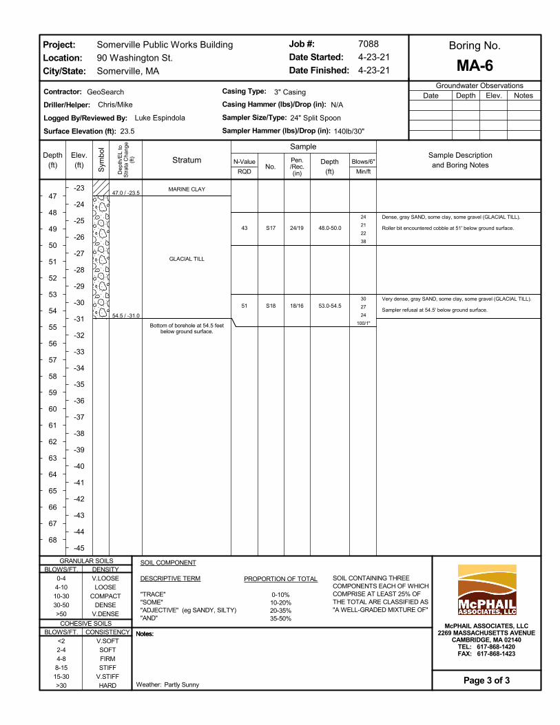
MARINE CLAY
GLACIAL TILL
Bottom of borehole at 54.5 feetbelow ground surface.
47.0 / -23.5
54.5 / -31.0
S17
S18
24
21
22
38
30
27
24
100/1"
Dense, gray SAND, some clay, some gravel (GLACIAL TILL).
Roller bit encountered cobble at 51' below ground surface.
Very dense, gray SAND, some clay, some gravel (GLACIAL TILL).
Sampler refusal at 54.5' below ground surface.
48.0-50.0
53.0-54.5
43
51
24/19
18/16
Somerville Public Works Building
90 Washington St.
Somerville, MA
Boring No.
Groundwater Observations
Stratum
Dep
th/E
L to
Str
ata
Cha
nge
(ft)
Sym
bol
No.
Elev.(ft)
-23
-24
-25
-26
-27
-28
-29
-30
-31
-32
-33
-34
-35
-36
-37
-38
-39
-40
-41
-42
-43
-44
-45
Blows/6"
Min/ft
Sample Descriptionand Boring Notes
Contractor:
Driller/Helper:
Logged By/Reviewed By:
Surface Elevation (ft):
SOIL CONTAINING THREECOMPONENTS EACH OF WHICHCOMPRISE AT LEAST 25% OFTHE TOTAL ARE CLASSIFIED AS"A WELL-GRADED MIXTURE OF"
NotesDepth Elev.Date
Job #:
Date Started:
Date Finished:
PROPORTION OF TOTAL
0-10%10-20%20-35%35-50%
Notes:Notes:
Project:
Location:
City/State:
BLOWS/FT.0-44-1010-3030-50>50
BLOWS/FT.<22-44-88-1515-30>30
Page 3 of 3
DENSITYV.LOOSELOOSE
COMPACTDENSE
V.DENSE
24" Split Spoon
23.5
McPHAIL ASSOCIATES, LLC2269 MASSACHUSETTS AVENUE
CAMBRIDGE, MA 02140TEL: 617-868-1420FAX: 617-868-1423
N/A
140lb/30"
MA-6
Weather:
GRANULAR SOILS
COHESIVE SOILS
Chris/Mike
Notes:
SampleDepth
(ft)
47
48
49
50
51
52
53
54
55
56
57
58
59
60
61
62
63
64
65
66
67
68
Depth
(ft)
Luke Espindola
GeoSearch 3" Casing
N-Value
RQD
Pen./Rec.(in)
SOIL COMPONENT
DESCRIPTIVE TERM
"TRACE""SOME""ADJECTIVE" (eg SANDY, SILTY)"AND"
CONSISTENCYV.SOFTSOFTFIRMSTIFF
V.STIFFHARD Partly Sunny
7088
4-23-21
4-23-21
Casing Type:
Casing Hammer (lbs)/Drop (in):
Sampler Size/Type:
Sampler Hammer (lbs)/Drop (in):

ASPHALT
FILL
REINFORCED CONCRETE
Bottom of borehole 6.1 feet belowground surface.
0.3 / 18.0
6.0 / 12.36.1 / 12.2
S1
S2
S3
S4
7
12
16
11
11
8
5
WOH
1
1
9
100/1"
Compact, light brown gravelly SAND, trace silt, varying to black togray silty SAND, some gravel (FILL).
Compact, black to gray silty SAND, some gravel, w/ brick, ash andcinders, and glass (FILL).
Very loose, gray to blue to black SILT and SAND, some gravel, w/petroleum odor and staining from 5' to 6' (FILL).
Very dense, gray to brown SILT and SAND, some gravel, w/ concretein the spoon tip (FILL).
Note: Auger refusal at 7' below ground surface due to reinforcedconcrete layer.
0.5-2.0
2.0-4.0
4.0-6.0
6.0-6.1
28
19
2
n/a
18/10
24/16
24/12
1/1
Somerville Public Works Building
90 Washington St.
Somerville, MA
Boring No.
Groundwater Observations
Stratum
Dep
th/E
L to
Str
ata
Cha
nge
(ft)
Sym
bol
No.
Elev.(ft)
18
17
16
15
14
13
12
11
10
9
8
7
6
5
4
3
2
1
0
-1
-2
-3
-4
Blows/6"
Min/ft
Sample Descriptionand Boring Notes
Contractor:
Driller/Helper:
Logged By/Reviewed By:
Surface Elevation (ft):
SOIL CONTAINING THREECOMPONENTS EACH OF WHICHCOMPRISE AT LEAST 25% OFTHE TOTAL ARE CLASSIFIED AS"A WELL-GRADED MIXTURE OF"
NotesDepth6
Elev.12.3
Date4-15-21
Job #:
Date Started:
Date Finished:
PROPORTION OF TOTAL
0-10%10-20%20-35%35-50%
Notes:Notes:
Project:
Location:
City/State:
BLOWS/FT.0-44-1010-3030-50>50
BLOWS/FT.<22-44-88-1515-30>30
Page 1 of 1
DENSITYV.LOOSELOOSE
COMPACTDENSE
V.DENSE
24" Split Spoon
18.3
McPHAIL ASSOCIATES, LLC2269 MASSACHUSETTS AVENUE
CAMBRIDGE, MA 02140TEL: 617-868-1420FAX: 617-868-1423
N/A
140lb/30"
MA-7
Weather:
GRANULAR SOILS
COHESIVE SOILS
Chris/Mike
Notes:
SampleDepth
(ft)
1
2
3
4
5
6
7
8
9
10
11
12
13
14
15
16
17
18
19
20
21
22
Depth
(ft)
Julian Finney
GeoSearch 4 1/4" HSA
N-Value
RQD
Pen./Rec.(in)
SOIL COMPONENT
DESCRIPTIVE TERM
"TRACE""SOME""ADJECTIVE" (eg SANDY, SILTY)"AND"
CONSISTENCYV.SOFTSOFTFIRMSTIFF
V.STIFFHARD Partly Sunny
7088
4-15-21
4-15-21
Casing Type:
Casing Hammer (lbs)/Drop (in):
Sampler Size/Type:
Sampler Hammer (lbs)/Drop (in):
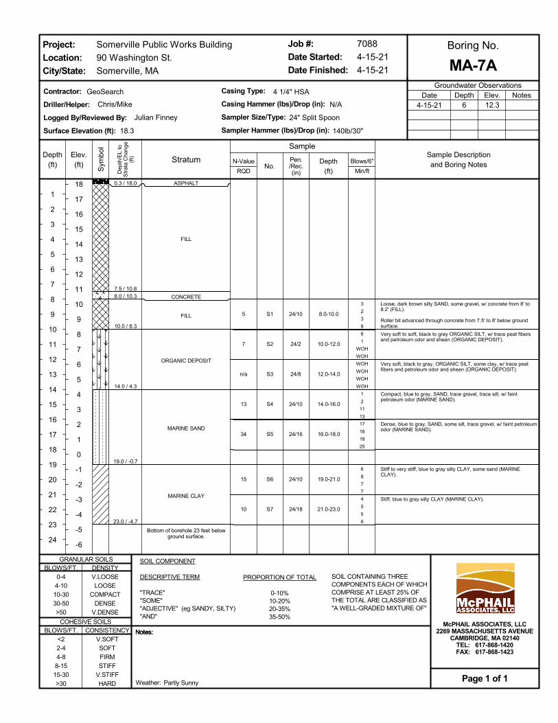
ASPHALT
FILL
CONCRETE
FILL
ORGANIC DEPOSIT
MARINE SAND
MARINE CLAY
Bottom of borehole 23 feet belowground surface.
0.3 / 18.0
7.5 / 10.88.0 / 10.3
10.0 / 8.3
14.0 / 4.3
19.0 / -0.7
23.0 / -4.7
S1
S2
S3
S4
S5
S6
S7
3
2
3
8
6
1
WOH
WOH
WOH
WOH
WOH
WOH
1
2
11
13
17
16
18
25
6
8
7
7
4
5
5
6
Loose, dark brown silty SAND, some gravel, w/ concrete from 8' to8.2' (FILL).
Roller bit advanced through concrete from 7.5' to 8' below groundsurface.
Very soft to soft, black to gray ORGANIC SILT, w/ trace peat fibersand petroleum odor and sheen (ORGANIC DEPOSIT).
Very soft, black to gray, ORGANIC SILT, some clay, w/ trace peatfibers and petroleum odor and sheen (ORGANIC DEPOSIT).
Compact, blue to gray, SAND, trace gravel, trace silt, w/ faintpetroleum odor (MARINE SAND).
Dense, blue to gray, SAND, some silt, trace gravel, w/ faint petroleumodor (MARINE SAND).
Stiff to very stiff, blue to gray silty CLAY, some sand (MARINECLAY).
Stiff, blue to gray silty CLAY (MARINE CLAY).
8.0-10.0
10.0-12.0
12.0-14.0
14.0-16.0
16.0-18.0
19.0-21.0
21.0-23.0
5
7
n/a
13
34
15
10
24/10
24/2
24/8
24/10
24/16
24/10
24/18
Somerville Public Works Building
90 Washington St.
Somerville, MA
Boring No.
Groundwater Observations
Stratum
Dep
th/E
L to
Str
ata
Cha
nge
(ft)
Sym
bol
No.
Elev.(ft)
18
17
16
15
14
13
12
11
10
9
8
7
6
5
4
3
2
1
0
-1
-2
-3
-4
-5
-6
Blows/6"
Min/ft
Sample Descriptionand Boring Notes
Contractor:
Driller/Helper:
Logged By/Reviewed By:
Surface Elevation (ft):
SOIL CONTAINING THREECOMPONENTS EACH OF WHICHCOMPRISE AT LEAST 25% OFTHE TOTAL ARE CLASSIFIED AS"A WELL-GRADED MIXTURE OF"
NotesDepth6
Elev.12.3
Date4-15-21
Job #:
Date Started:
Date Finished:
PROPORTION OF TOTAL
0-10%10-20%20-35%35-50%
Notes:Notes:
Project:
Location:
City/State:
BLOWS/FT.0-44-1010-3030-50>50
BLOWS/FT.<22-44-88-1515-30>30
Page 1 of 1
DENSITYV.LOOSELOOSE
COMPACTDENSE
V.DENSE
24" Split Spoon
18.3
McPHAIL ASSOCIATES, LLC2269 MASSACHUSETTS AVENUE
CAMBRIDGE, MA 02140TEL: 617-868-1420FAX: 617-868-1423
N/A
140lb/30"
MA-7A
Weather:
GRANULAR SOILS
COHESIVE SOILS
Chris/Mike
Notes:
SampleDepth
(ft)
1
2
3
4
5
6
7
8
9
10
11
12
13
14
15
16
17
18
19
20
21
22
23
24
Depth
(ft)
Julian Finney
GeoSearch 4 1/4" HSA
N-Value
RQD
Pen./Rec.(in)
SOIL COMPONENT
DESCRIPTIVE TERM
"TRACE""SOME""ADJECTIVE" (eg SANDY, SILTY)"AND"
CONSISTENCYV.SOFTSOFTFIRMSTIFF
V.STIFFHARD Partly Sunny
7088
4-15-21
4-15-21
Casing Type:
Casing Hammer (lbs)/Drop (in):
Sampler Size/Type:
Sampler Hammer (lbs)/Drop (in):
APPENDIX C:
PREVIOUS EXPLORATION LOGS
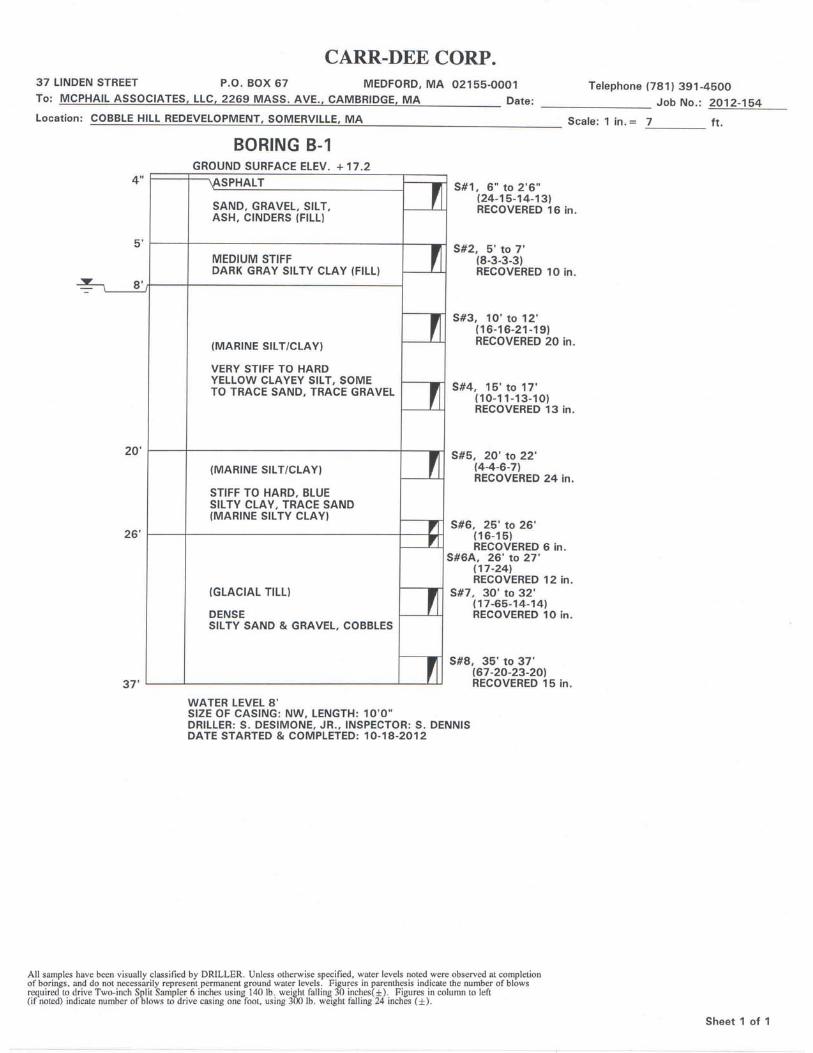


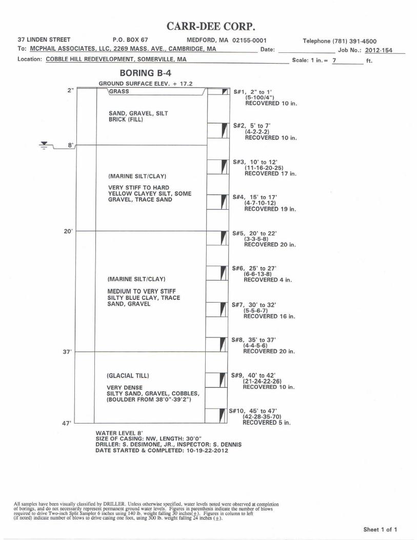
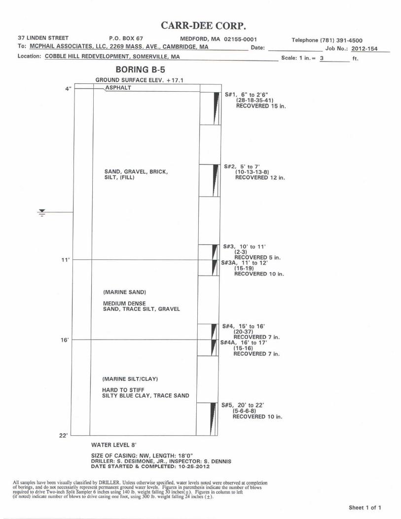
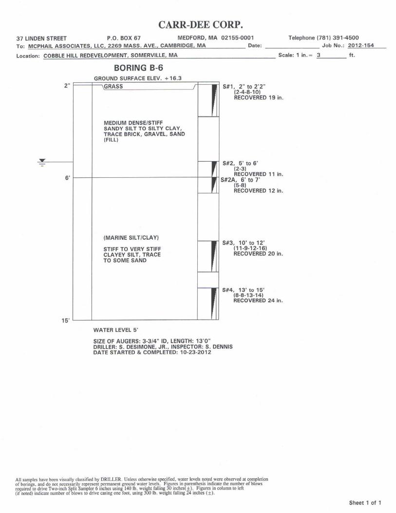

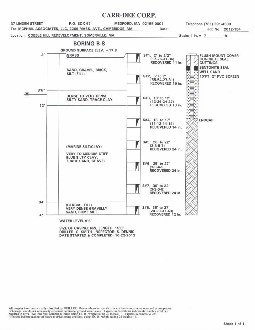
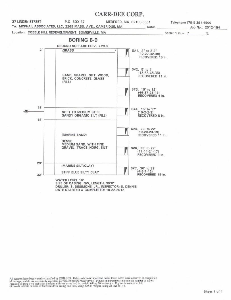
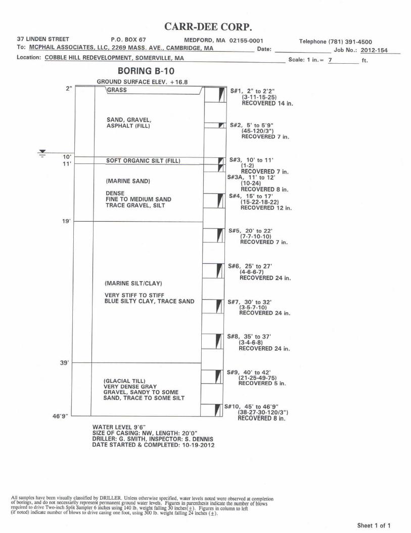
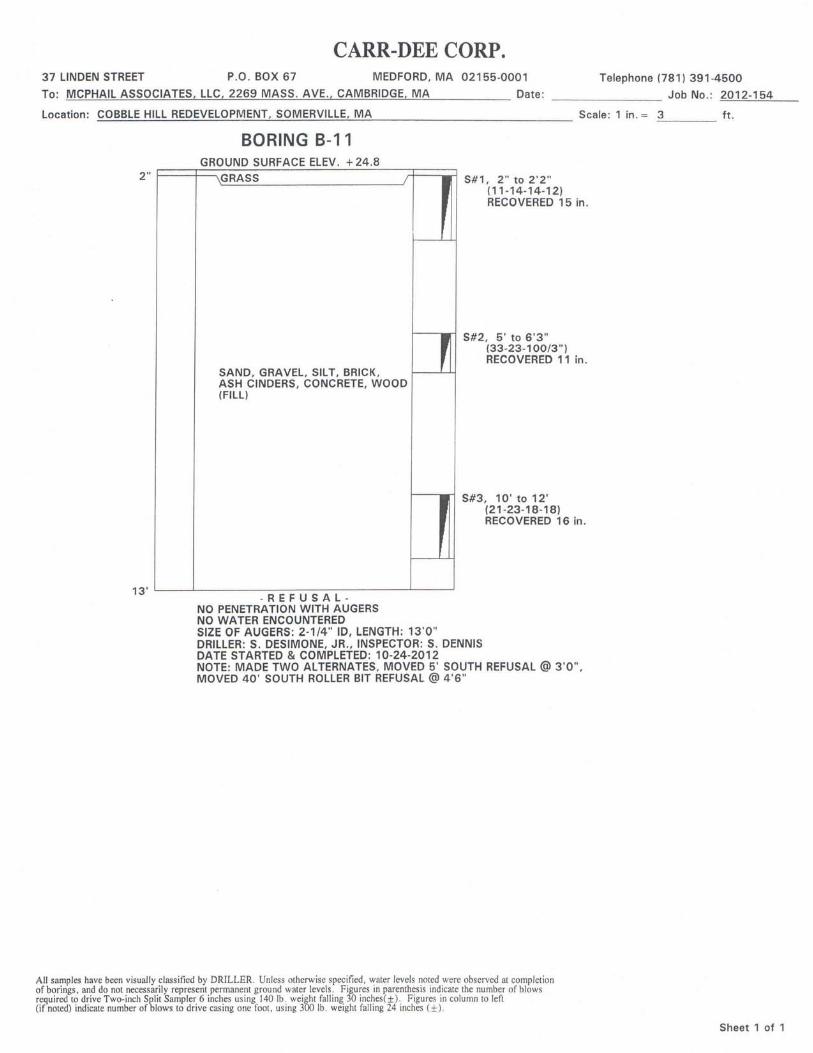
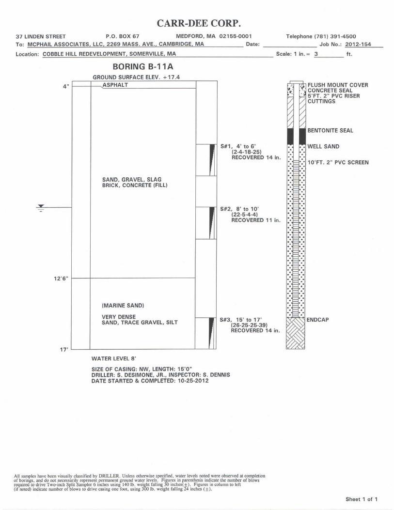
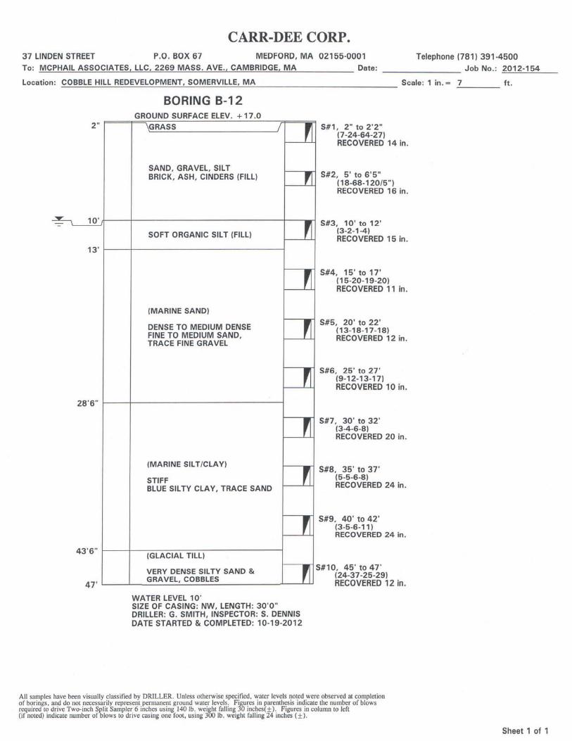
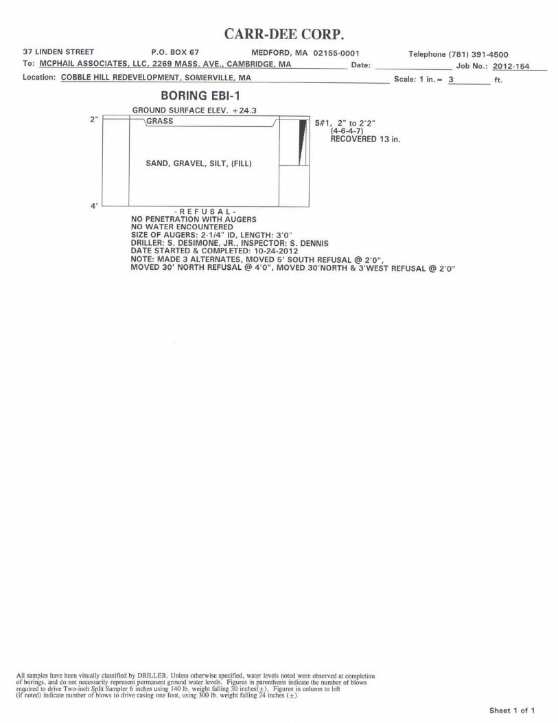

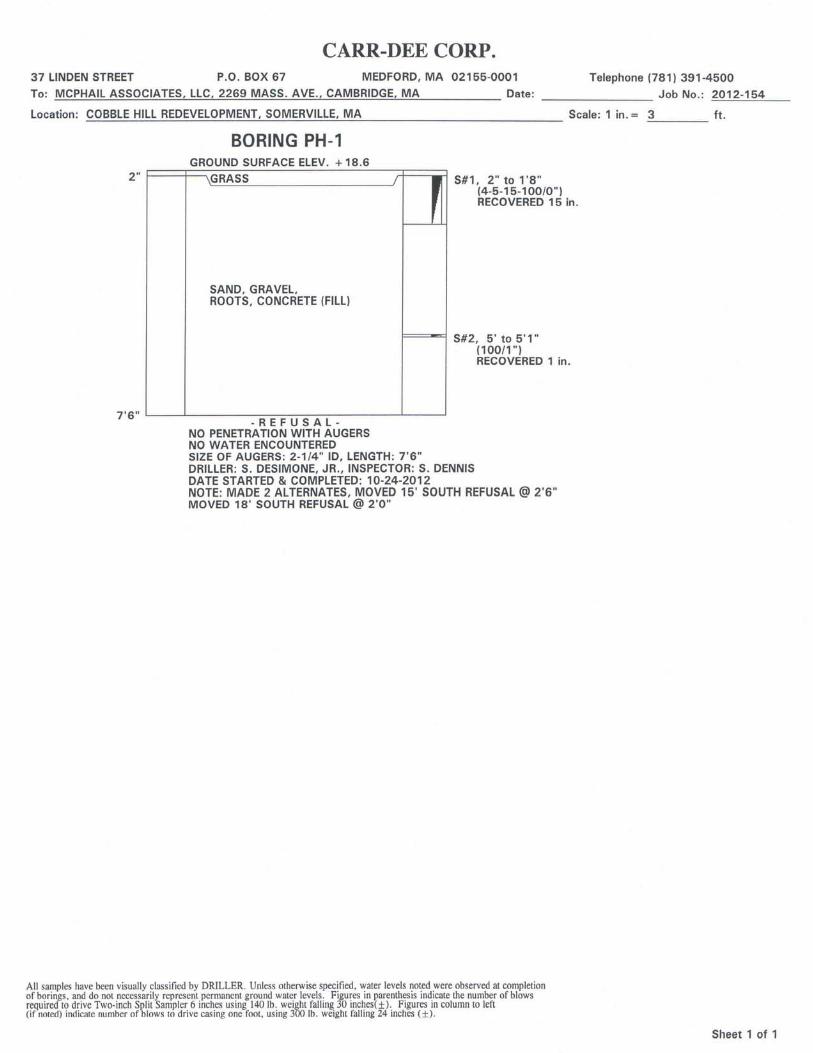
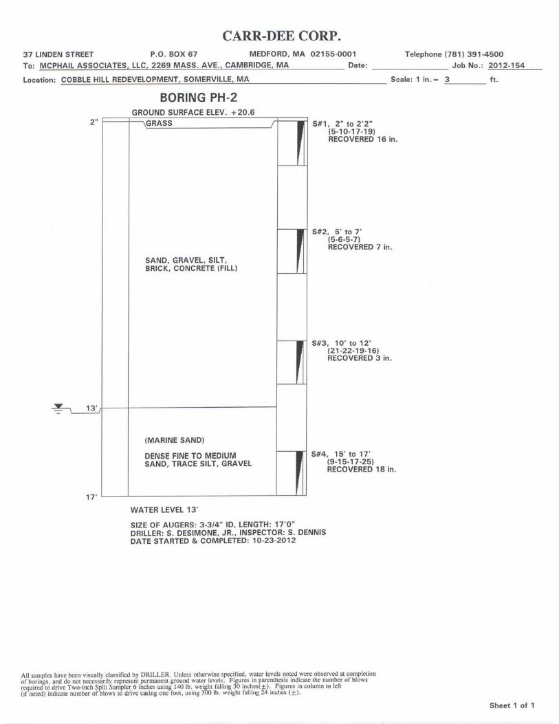
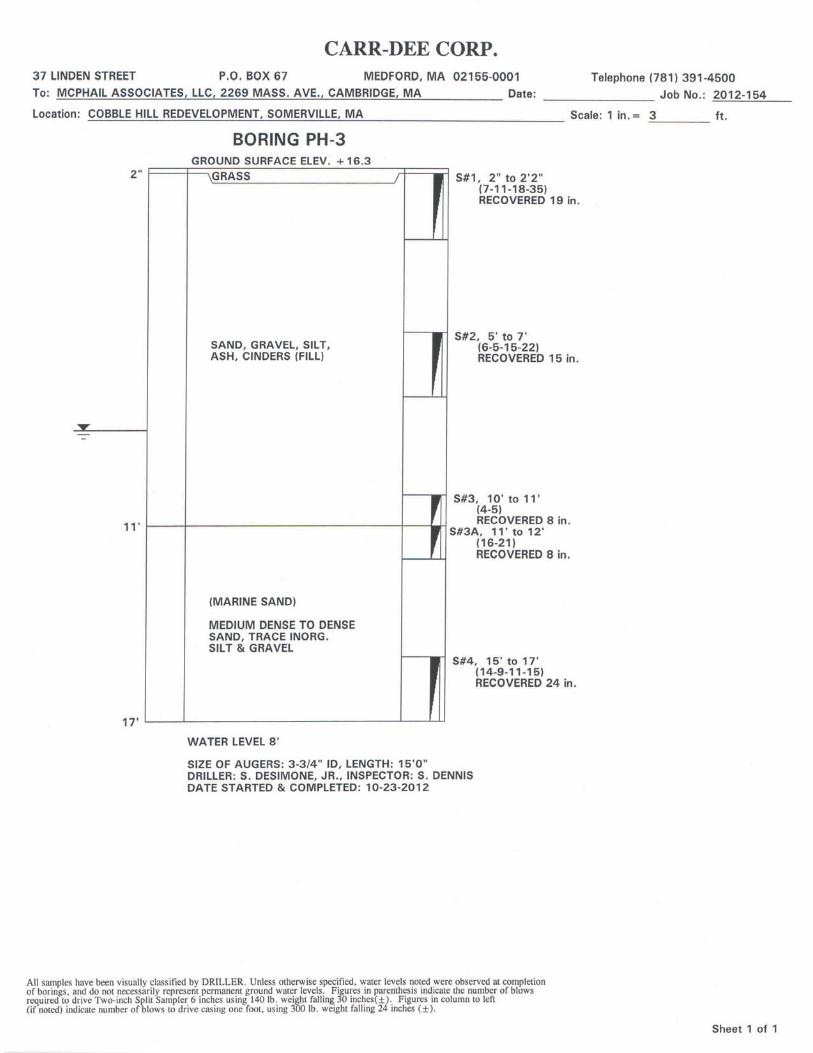
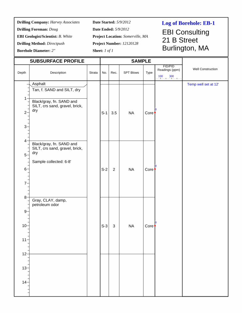
Log of Borehole:Drilling Company:
Drilling Foreman:
EBI Geologist/Scientist:
Drilling Method:
Borehole Diameter:
Date Started:
Date Ended:
Project Location:
Project Number:
Sheet: 1 of 1
EBI Consulting21 B StreetBurlington, MA
SUBSURFACE PROFILE SAMPLE
Depth
1
2
3
4
5
6
7
8
9
10
11
12
13
14
Description Strata No. Rec. SPT Blows Type
FID/PIDReadings (ppm) Well Construction
EB-1Harvey Associates
Doug
B. White
Directpush
2"
5/9/2012
5/9/2012
Somerville, MA
12120128
AsphaltTan, f. SAND and SILT, dry
Black/gray, fn. SAND and SILT, crs sand, gravel, brick, dry
Black/gray, fn. SAND and SILT, crs sand, gravel, brick, dry
Sample collected: 6-8'
Gray, CLAY, damp, petroleum odor
S-1
S-2
S-3
3.5
2
3
NA
NA
NA
Core
Core
Core
100 300
0
0
0
Temp well set at 12'
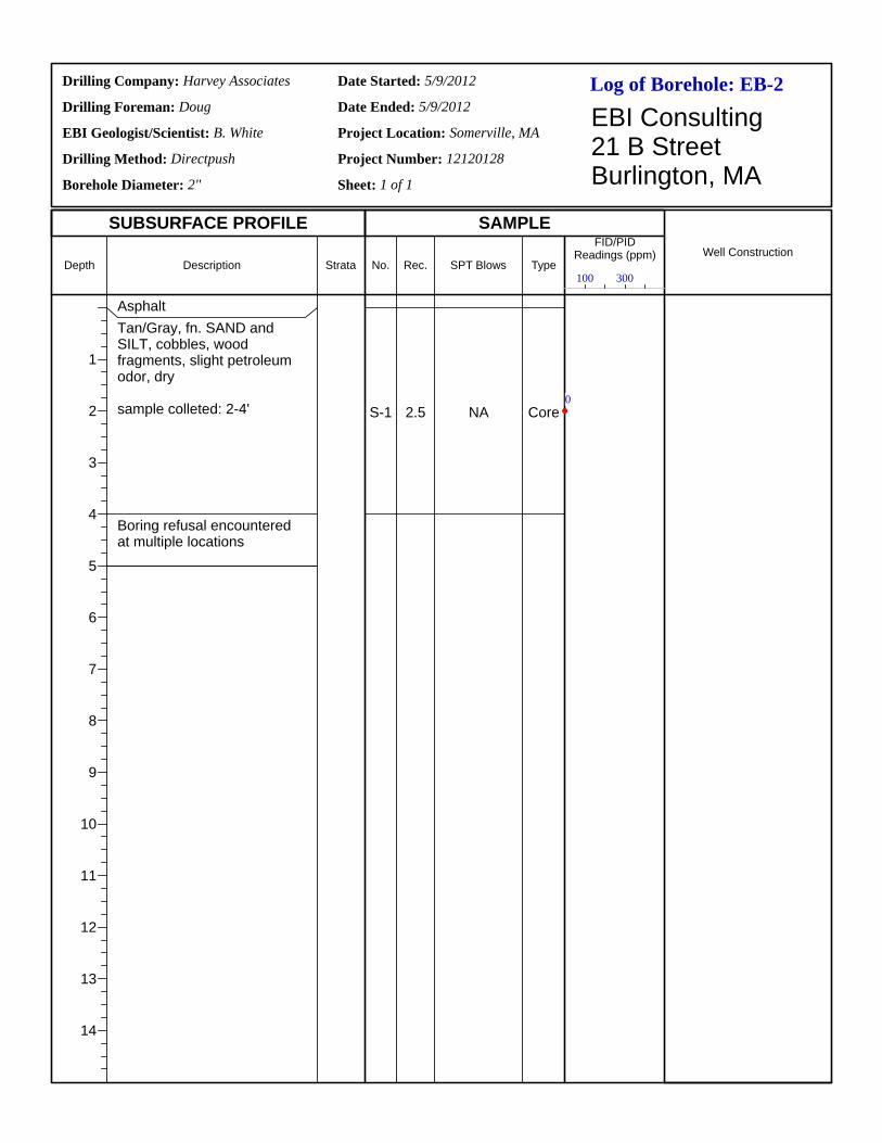
Log of Borehole:Drilling Company:
Drilling Foreman:
EBI Geologist/Scientist:
Drilling Method:
Borehole Diameter:
Date Started:
Date Ended:
Project Location:
Project Number:
Sheet: 1 of 1
EBI Consulting21 B StreetBurlington, MA
SUBSURFACE PROFILE SAMPLE
Depth
1
2
3
4
5
6
7
8
9
10
11
12
13
14
Description Strata No. Rec. SPT Blows Type
FID/PIDReadings (ppm) Well Construction
EB-2Harvey Associates
Doug
B. White
Directpush
2"
5/9/2012
5/9/2012
Somerville, MA
12120128
AsphaltTan/Gray, fn. SAND and SILT, cobbles, wood fragments, slight petroleum odor, dry
sample colleted: 2-4'
Boring refusal encountered at multiple locations
S-1 2.5 NA Core
100 300
0
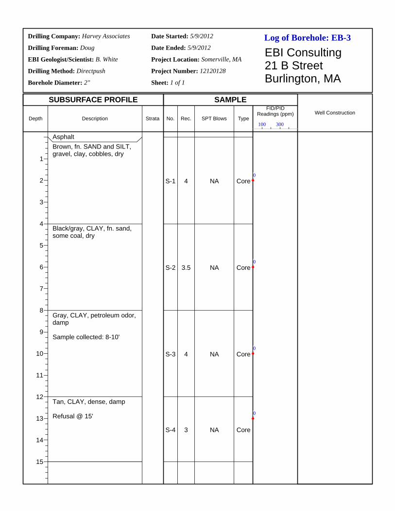
Log of Borehole:Drilling Company:
Drilling Foreman:
EBI Geologist/Scientist:
Drilling Method:
Borehole Diameter:
Date Started:
Date Ended:
Project Location:
Project Number:
Sheet: 1 of 1
EBI Consulting21 B StreetBurlington, MA
SUBSURFACE PROFILE SAMPLE
Depth
1
2
3
4
5
6
7
8
9
10
11
12
13
14
15
Description Strata No. Rec. SPT Blows Type
FID/PIDReadings (ppm) Well Construction
EB-3Harvey Associates
Doug
B. White
Directpush
2"
5/9/2012
5/9/2012
Somerville, MA
12120128
AsphaltBrown, fn. SAND and SILT, gravel, clay, cobbles, dry
Black/gray, CLAY, fn. sand, some coal, dry
Gray, CLAY, petroleum odor, damp
Sample collected: 8-10'
Tan, CLAY, dense, damp
Refusal @ 15'
S-1
S-2
S-3
S-4
4
3.5
4
3
NA
NA
NA
NA
Core
Core
Core
Core
100 300
0
0
0
0
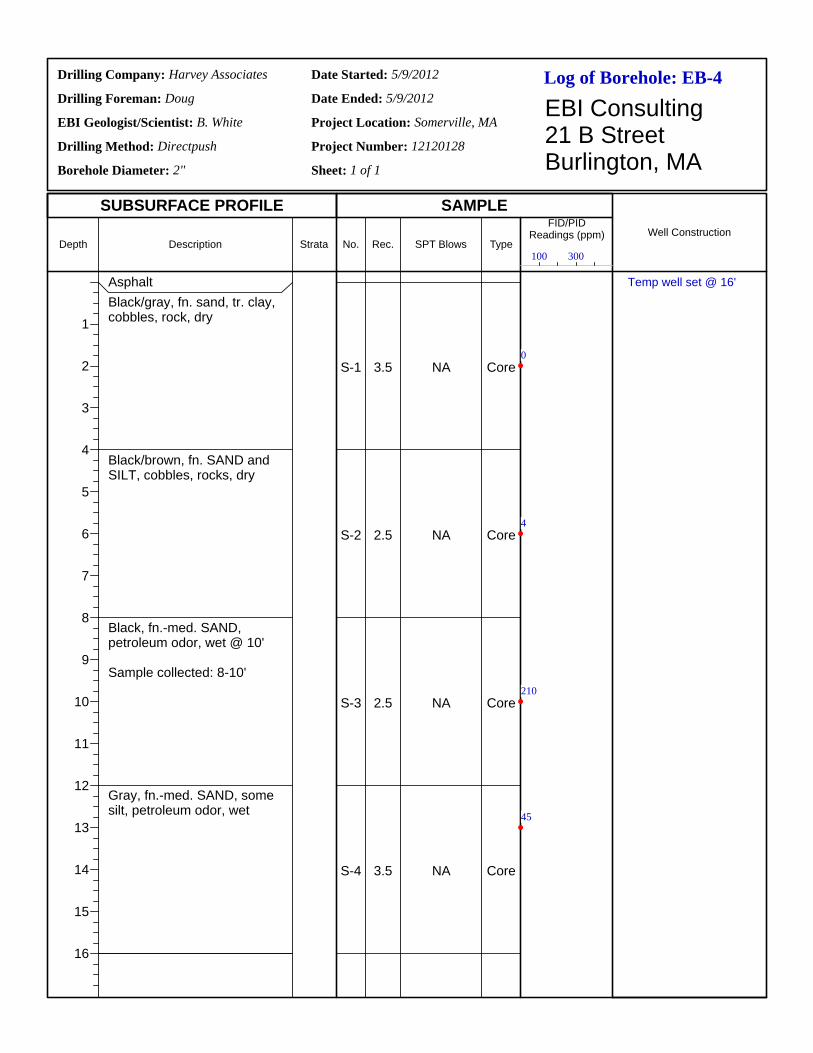
Log of Borehole:Drilling Company:
Drilling Foreman:
EBI Geologist/Scientist:
Drilling Method:
Borehole Diameter:
Date Started:
Date Ended:
Project Location:
Project Number:
Sheet: 1 of 1
EBI Consulting21 B StreetBurlington, MA
SUBSURFACE PROFILE SAMPLE
Depth
1
2
3
4
5
6
7
8
9
10
11
12
13
14
15
16
Description Strata No. Rec. SPT Blows Type
FID/PIDReadings (ppm) Well Construction
EB-4Harvey Associates
Doug
B. White
Directpush
2"
5/9/2012
5/9/2012
Somerville, MA
12120128
AsphaltBlack/gray, fn. sand, tr. clay, cobbles, rock, dry
Black/brown, fn. SAND and SILT, cobbles, rocks, dry
Black, fn.-med. SAND, petroleum odor, wet @ 10'
Sample collected: 8-10'
Gray, fn.-med. SAND, some silt, petroleum odor, wet
S-1
S-2
S-3
S-4
3.5
2.5
2.5
3.5
NA
NA
NA
NA
Core
Core
Core
Core
100 300
0
4
210
45
Temp well set @ 16'
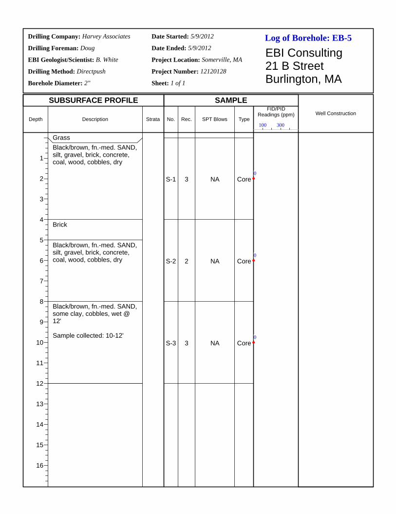
Log of Borehole:Drilling Company:
Drilling Foreman:
EBI Geologist/Scientist:
Drilling Method:
Borehole Diameter:
Date Started:
Date Ended:
Project Location:
Project Number:
Sheet: 1 of 1
EBI Consulting21 B StreetBurlington, MA
SUBSURFACE PROFILE SAMPLE
Depth
1
2
3
4
5
6
7
8
9
10
11
12
13
14
15
16
Description Strata No. Rec. SPT Blows Type
FID/PIDReadings (ppm) Well Construction
EB-5Harvey Associates
Doug
B. White
Directpush
2"
5/9/2012
5/9/2012
Somerville, MA
12120128
GrassBlack/brown, fn.-med. SAND, silt, gravel, brick, concrete, coal, wood, cobbles, dry
Brick
Black/brown, fn.-med. SAND, silt, gravel, brick, concrete, coal, wood, cobbles, dry
Black/brown, fn.-med. SAND, some clay, cobbles, wet @ 12'
Sample collected: 10-12'
S-1
S-2
S-3
3
2
3
NA
NA
NA
Core
Core
Core
100 300
0
0
0
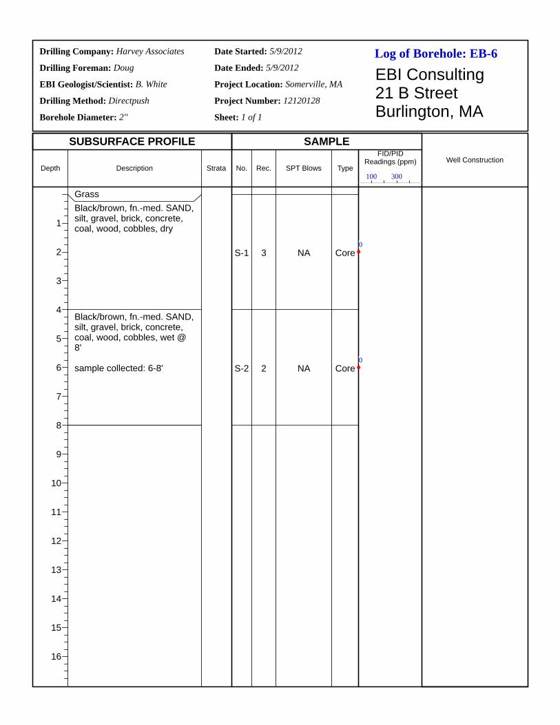
Log of Borehole:Drilling Company:
Drilling Foreman:
EBI Geologist/Scientist:
Drilling Method:
Borehole Diameter:
Date Started:
Date Ended:
Project Location:
Project Number:
Sheet: 1 of 1
EBI Consulting21 B StreetBurlington, MA
SUBSURFACE PROFILE SAMPLE
Depth
1
2
3
4
5
6
7
8
9
10
11
12
13
14
15
16
Description Strata No. Rec. SPT Blows Type
FID/PIDReadings (ppm) Well Construction
EB-6Harvey Associates
Doug
B. White
Directpush
2"
5/9/2012
5/9/2012
Somerville, MA
12120128
GrassBlack/brown, fn.-med. SAND, silt, gravel, brick, concrete, coal, wood, cobbles, dry
Black/brown, fn.-med. SAND, silt, gravel, brick, concrete, coal, wood, cobbles, wet @ 8'
sample collected: 6-8'
S-1
S-2
3
2
NA
NA
Core
Core
100 300
0
0
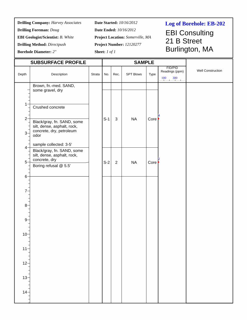
Log of Borehole:Drilling Company:
Drilling Foreman:
EBI Geologist/Scientist:
Drilling Method:
Borehole Diameter:
Date Started:
Date Ended:
Project Location:
Project Number:
Sheet: 1 of 1
EBI Consulting21 B StreetBurlington, MA
SUBSURFACE PROFILE SAMPLE
Depth
1
2
3
4
5
6
7
8
9
10
11
12
13
14
Description Strata No. Rec. SPT Blows Type
FID/PIDReadings (ppm) Well Construction
EB-202Harvey Associates
Doug
B. White
Directpush
2"
10/16/2012
10/16/2012
Somerville, MA
12120277
Brown, fn.-med. SAND, some gravel, dry
Crushed concrete
Black/gray, fn. SAND, some silt, dense, asphalt, rock, concrete, dry, petroleum odor
sample collected: 3-5'Black/gray, fn. SAND, some silt, dense, asphalt, rock, concrete, dryBoring refusal @ 5.5'
S-1
S-2
3
2
NA
NA
Core
Core
100 300
4
2
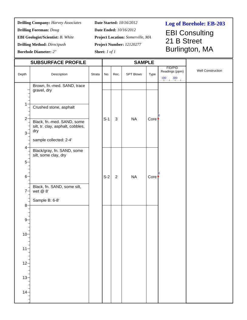
Log of Borehole:Drilling Company:
Drilling Foreman:
EBI Geologist/Scientist:
Drilling Method:
Borehole Diameter:
Date Started:
Date Ended:
Project Location:
Project Number:
Sheet: 1 of 1
EBI Consulting21 B StreetBurlington, MA
SUBSURFACE PROFILE SAMPLE
Depth
1
2
3
4
5
6
7
8
9
10
11
12
13
14
Description Strata No. Rec. SPT Blows Type
FID/PIDReadings (ppm) Well Construction
EB-203Harvey Associates
Doug
B. White
Directpush
2"
10/16/2012
10/16/2012
Somerville, MA
12120277
Brown, fn.-med. SAND, trace gravel, dry
Crushed stone, asphalt
Black, fn.-med. SAND, some silt, tr. clay, asphalt, cobbles, dry
sample collected: 2-4'
Black/gray, fn. SAND, some silt, some clay, dry
Black, fn. SAND, some silt, wet @ 8'
Sample B: 6-8'
S-1
S-2
3
2
NA
NA
Core
Core
100 300
0
0

Log of Borehole:Drilling Company:
Drilling Foreman:
EBI Geologist/Scientist:
Drilling Method:
Borehole Diameter:
Date Started:
Date Ended:
Project Location:
Project Number:
Sheet: 1 of 1
EBI Consulting21 B StreetBurlington, MA
SUBSURFACE PROFILE SAMPLE
Depth
1
2
3
4
5
6
7
8
9
10
11
12
13
14
Description Strata No. Rec. SPT Blows Type
FID/PIDReadings (ppm) Well Construction
EB-204Harvey Associates
Doug
B. White
Directpush
2"
10/16/2012
10/16/2012
Somerville, MA
12120277
Brown, fn.-med. SAND, trace silt, dry
Gray/black, fn. SAND, some silt, tr. gravel, slight petro odor
sample: 2-4'
Brown, fn. SAND, some silt, damp @ 7'
S-1
S-2
2
2
NA
NA
Core
Core
100 300
0
0

Log of Borehole:Drilling Company:
Drilling Foreman:
EBI Geologist/Scientist:
Drilling Method:
Borehole Diameter:
Date Started:
Date Ended:
Project Location:
Project Number:
Sheet: 1 of 1
EBI Consulting21 B StreetBurlington, MA
SUBSURFACE PROFILE SAMPLE
Depth
1
2
3
4
5
6
7
8
9
10
11
12
13
14
Description Strata No. Rec. SPT Blows Type
FID/PIDReadings (ppm) Well Construction
EB-205Harvey Associates
Doug
B. White
Directpush
2"
10/16/2012
10/16/2012
Somerville, MA
12120277
Asphalt
Brown, fn. SAND, tr. gravel, dry
Crushed stone, brick
Gray, fn. SAND, some silt, tr. clay, asphalt, brick, dry
Gray, fn. SAND, some silt, tr. clay, asphalt, brick, damp @ 6'
sample collected: 4-6'
S-1
S-2
3
2
NA
NA
Core
Core
100 300
0
0
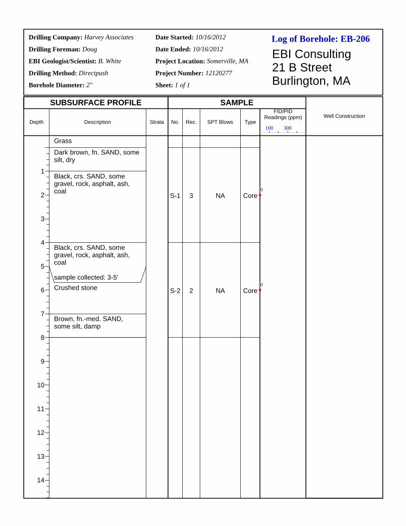
Log of Borehole:Drilling Company:
Drilling Foreman:
EBI Geologist/Scientist:
Drilling Method:
Borehole Diameter:
Date Started:
Date Ended:
Project Location:
Project Number:
Sheet: 1 of 1
EBI Consulting21 B StreetBurlington, MA
SUBSURFACE PROFILE SAMPLE
Depth
1
2
3
4
5
6
7
8
9
10
11
12
13
14
Description Strata No. Rec. SPT Blows Type
FID/PIDReadings (ppm) Well Construction
EB-206Harvey Associates
Doug
B. White
Directpush
2"
10/16/2012
10/16/2012
Somerville, MA
12120277
Grass
Dark brown, fn. SAND, some silt, dry
Black, crs. SAND, some gravel, rock, asphalt, ash, coal
Black, crs. SAND, some gravel, rock, asphalt, ash, coal
sample collected: 3-5'Crushed stone
Brown, fn.-med. SAND, some silt, damp
S-1
S-2
3
2
NA
NA
Core
Core
100 300
0
0
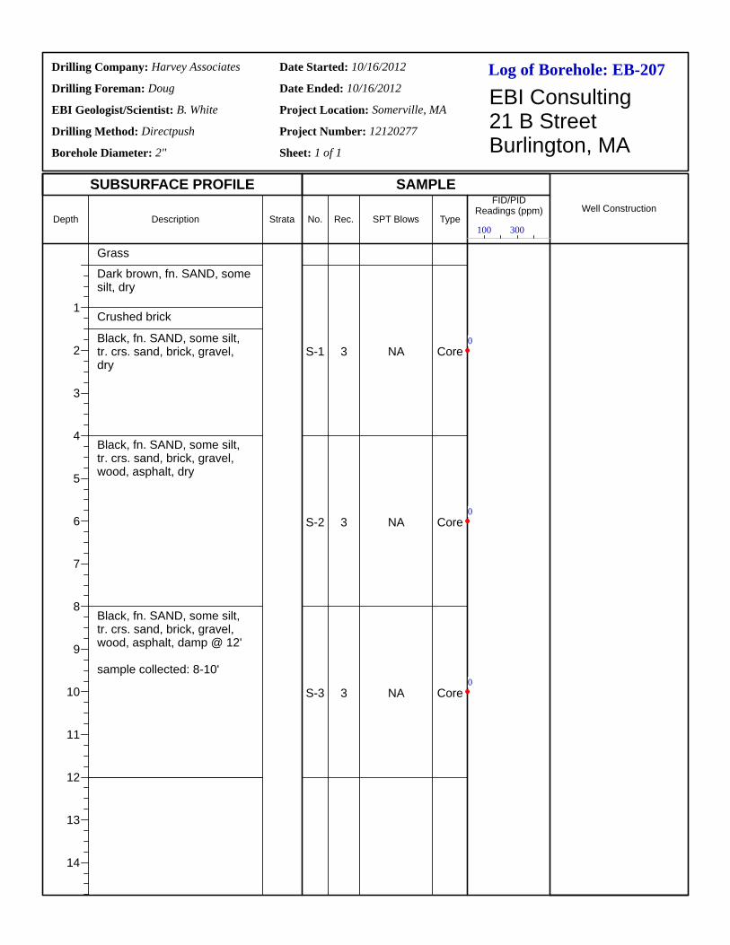
Log of Borehole:Drilling Company:
Drilling Foreman:
EBI Geologist/Scientist:
Drilling Method:
Borehole Diameter:
Date Started:
Date Ended:
Project Location:
Project Number:
Sheet: 1 of 1
EBI Consulting21 B StreetBurlington, MA
SUBSURFACE PROFILE SAMPLE
Depth
1
2
3
4
5
6
7
8
9
10
11
12
13
14
Description Strata No. Rec. SPT Blows Type
FID/PIDReadings (ppm) Well Construction
EB-207Harvey Associates
Doug
B. White
Directpush
2"
10/16/2012
10/16/2012
Somerville, MA
12120277
Grass
Dark brown, fn. SAND, some silt, dry
Crushed brick
Black, fn. SAND, some silt, tr. crs. sand, brick, gravel, dry
Black, fn. SAND, some silt, tr. crs. sand, brick, gravel, wood, asphalt, dry
Black, fn. SAND, some silt, tr. crs. sand, brick, gravel, wood, asphalt, damp @ 12'
sample collected: 8-10'
S-1
S-2
S-3
3
3
3
NA
NA
NA
Core
Core
Core
100 300
0
0
0
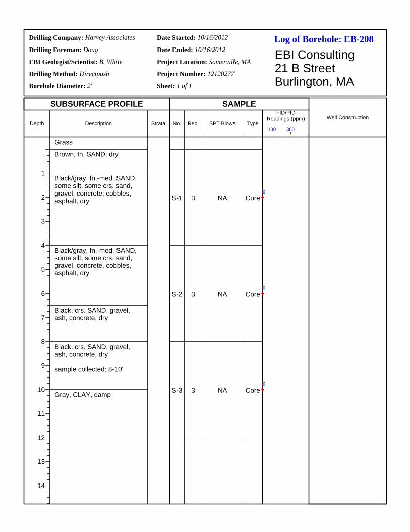
Log of Borehole:Drilling Company:
Drilling Foreman:
EBI Geologist/Scientist:
Drilling Method:
Borehole Diameter:
Date Started:
Date Ended:
Project Location:
Project Number:
Sheet: 1 of 1
EBI Consulting21 B StreetBurlington, MA
SUBSURFACE PROFILE SAMPLE
Depth
1
2
3
4
5
6
7
8
9
10
11
12
13
14
Description Strata No. Rec. SPT Blows Type
FID/PIDReadings (ppm) Well Construction
EB-208Harvey Associates
Doug
B. White
Directpush
2"
10/16/2012
10/16/2012
Somerville, MA
12120277
Grass
Brown, fn. SAND, dry
Black/gray, fn.-med. SAND, some silt, some crs. sand, gravel, concrete, cobbles, asphalt, dry
Black/gray, fn.-med. SAND, some silt, some crs. sand, gravel, concrete, cobbles, asphalt, dry
Black, crs. SAND, gravel, ash, concrete, dry
Black, crs. SAND, gravel, ash, concrete, dry
sample collected: 8-10'
Gray, CLAY, damp
S-1
S-2
S-3
3
3
3
NA
NA
NA
Core
Core
Core
100 300
0
0
0
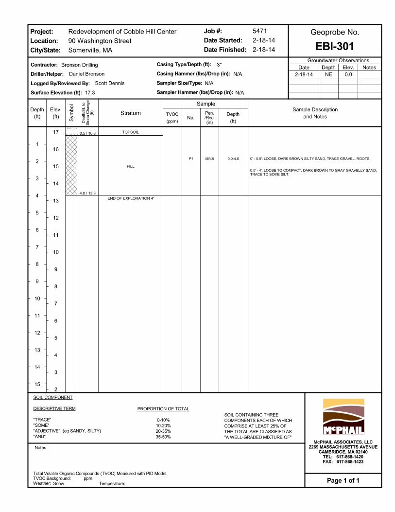
0.5 / 16.8
4.0 / 13.3
P1 0.0-4.048/48
TOPSOIL
FILL
END OF EXPLORATION 4'
0' - 0.5': LOOSE, DARK BROWN SILTY SAND, TRACE GRAVEL, ROOTS.
0.5' - 4': LOOSE TO COMPACT, DARK BROWN TO GRAY GRAVELLY SAND,TRACE TO SOME SILT.
Total Volatile Organic Compounds (TVOC) Measured with PID Model:TVOC Background:Weather: Temperature:
ppm
SOIL COMPONENT
DESCRIPTIVE TERM
"TRACE""SOME""ADJECTIVE" (eg SANDY, SILTY)"AND"
PROPORTION OF TOTAL
0-10%10-20%20-35%35-50%
SOIL CONTAINING THREECOMPONENTS EACH OF WHICHCOMPRISE AT LEAST 25% OFTHE TOTAL ARE CLASSIFIED AS"A WELL-GRADED MIXTURE OF"
Dep
th/E
L to
Str
ata
Cha
nge
(ft)Depth
(ft)
1
2
3
4
5
6
7
8
9
10
11
12
13
14
15
Sym
bol
Elev.(ft)
17
16
15
14
13
12
11
10
9
8
7
6
5
4
3
2
TVOC
(ppm)
Contractor:
Driller/Helper:
Logged By/Reviewed By:
Surface Elevation (ft):
No.
Casing Type/Depth (ft):
Casing Hammer (lbs)/Drop (in):
Sampler Size/Type:
Sampler Hammer (lbs)/Drop (in):
3"
5471
2-18-14
2-18-14
Redevelopment of Cobble Hill Center
90 Washington Street
Somerville, MA
Groundwater ObservationsNotesDepth
NEElev.0.0
Date2-18-14
Job #:
Date Started:
Date Finished:
Notes:
EBI-301
Sample
Geoprobe No.
Snow
Project:
Location:
City/State:
Page 1 of 1
Scott Dennis
Bronson Drilling
17.3
N/A
Depth
(ft)
Pen./Rec.(in)
McPHAIL ASSOCIATES, LLC2269 MASSACHUSETTS AVENUE
CAMBRIDGE, MA 02140TEL: 617-868-1420FAX: 617-868-1423
N/A
N/A
Daniel Bronson
StratumSample Description
and Notes

4.0 / 14.2
P1 0.0-4.048/38FILL
END OF EXPLORATION 4'
LOOSE TO COMPACT, BROWN TO GRAY SILTY SAND, SOME GRAVEL.
Total Volatile Organic Compounds (TVOC) Measured with PID Model:TVOC Background:Weather: Temperature:
ppm
SOIL COMPONENT
DESCRIPTIVE TERM
"TRACE""SOME""ADJECTIVE" (eg SANDY, SILTY)"AND"
PROPORTION OF TOTAL
0-10%10-20%20-35%35-50%
SOIL CONTAINING THREECOMPONENTS EACH OF WHICHCOMPRISE AT LEAST 25% OFTHE TOTAL ARE CLASSIFIED AS"A WELL-GRADED MIXTURE OF"
Dep
th/E
L to
Str
ata
Cha
nge
(ft)Depth
(ft)
1
2
3
4
5
6
7
8
9
10
11
12
13
14
15
Sym
bol
Elev.(ft)
18
17
16
15
14
13
12
11
10
9
8
7
6
5
4
3
TVOC
(ppm)
Contractor:
Driller/Helper:
Logged By/Reviewed By:
Surface Elevation (ft):
No.
Casing Type/Depth (ft):
Casing Hammer (lbs)/Drop (in):
Sampler Size/Type:
Sampler Hammer (lbs)/Drop (in):
3"
5471
2-18-14
2-18-14
Redevelopment of Cobble Hill Center
90 Washington Street
Somerville, MA
Groundwater ObservationsNotesDepth
NEElev.0.0
Date2-18-14
Job #:
Date Started:
Date Finished:
Notes:
EBI-302
Sample
Geoprobe No.
Snow
Project:
Location:
City/State:
Page 1 of 1
Scott Dennis
Bronson Drilling
18.2
N/A
Depth
(ft)
Pen./Rec.(in)
McPHAIL ASSOCIATES, LLC2269 MASSACHUSETTS AVENUE
CAMBRIDGE, MA 02140TEL: 617-868-1420FAX: 617-868-1423
N/A
N/A
Daniel Bronson
StratumSample Description
and Notes
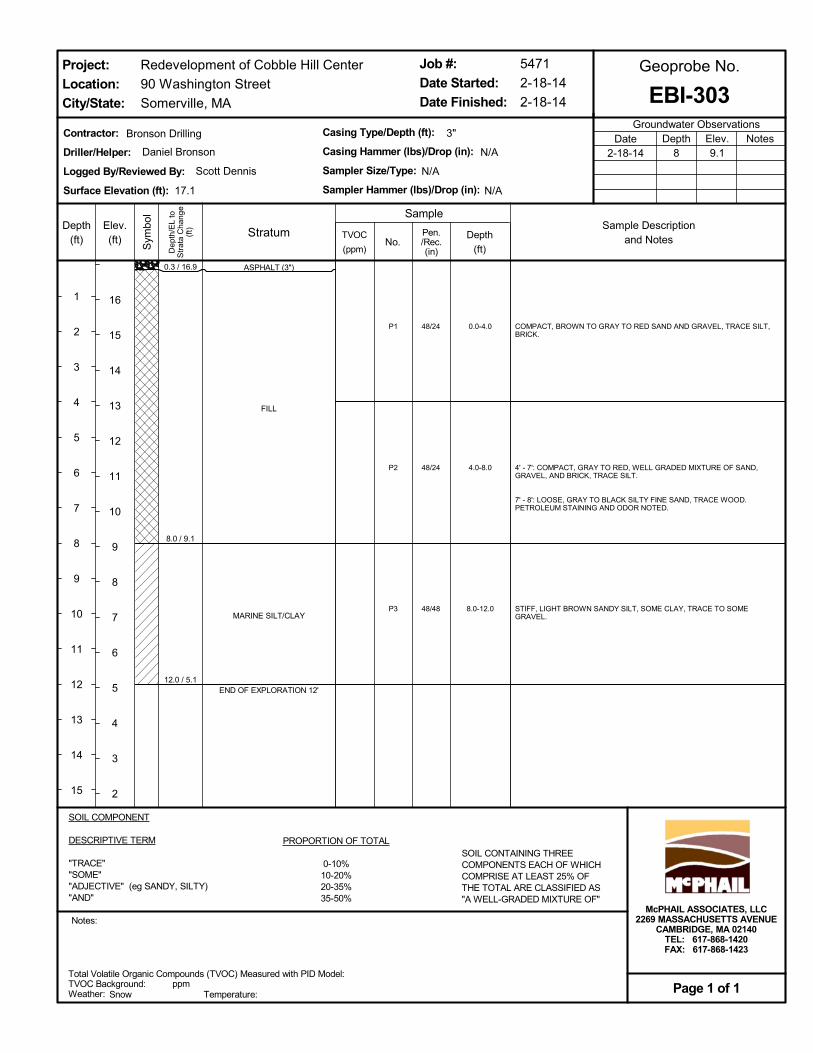
0.3 / 16.9
8.0 / 9.1
12.0 / 5.1
P1
P2
P3
0.0-4.0
4.0-8.0
8.0-12.0
48/24
48/24
48/48
ASPHALT (3")
FILL
MARINE SILT/CLAY
END OF EXPLORATION 12'
COMPACT, BROWN TO GRAY TO RED SAND AND GRAVEL, TRACE SILT,BRICK.
4' - 7': COMPACT, GRAY TO RED, WELL GRADED MIXTURE OF SAND,GRAVEL, AND BRICK, TRACE SILT.
7' - 8': LOOSE, GRAY TO BLACK SILTY FINE SAND, TRACE WOOD.PETROLEUM STAINING AND ODOR NOTED.
STIFF, LIGHT BROWN SANDY SILT, SOME CLAY, TRACE TO SOMEGRAVEL.
Total Volatile Organic Compounds (TVOC) Measured with PID Model:TVOC Background:Weather: Temperature:
ppm
SOIL COMPONENT
DESCRIPTIVE TERM
"TRACE""SOME""ADJECTIVE" (eg SANDY, SILTY)"AND"
PROPORTION OF TOTAL
0-10%10-20%20-35%35-50%
SOIL CONTAINING THREECOMPONENTS EACH OF WHICHCOMPRISE AT LEAST 25% OFTHE TOTAL ARE CLASSIFIED AS"A WELL-GRADED MIXTURE OF"
Dep
th/E
L to
Str
ata
Cha
nge
(ft)Depth
(ft)
1
2
3
4
5
6
7
8
9
10
11
12
13
14
15
Sym
bol
Elev.(ft)
16
15
14
13
12
11
10
9
8
7
6
5
4
3
2
TVOC
(ppm)
Contractor:
Driller/Helper:
Logged By/Reviewed By:
Surface Elevation (ft):
No.
Casing Type/Depth (ft):
Casing Hammer (lbs)/Drop (in):
Sampler Size/Type:
Sampler Hammer (lbs)/Drop (in):
3"
5471
2-18-14
2-18-14
Redevelopment of Cobble Hill Center
90 Washington Street
Somerville, MA
Groundwater ObservationsNotesDepth
8Elev.9.1
Date2-18-14
Job #:
Date Started:
Date Finished:
Notes:
EBI-303
Sample
Geoprobe No.
Snow
Project:
Location:
City/State:
Page 1 of 1
Scott Dennis
Bronson Drilling
17.1
N/A
Depth
(ft)
Pen./Rec.(in)
McPHAIL ASSOCIATES, LLC2269 MASSACHUSETTS AVENUE
CAMBRIDGE, MA 02140TEL: 617-868-1420FAX: 617-868-1423
N/A
N/A
Daniel Bronson
StratumSample Description
and Notes
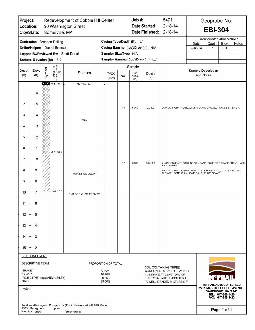
0.3 / 16.8
6.5 / 10.5
10.0 / 7.0
P1
P2
0.0-5.0
5.0-10.0
60/60
60/60
ASPHALT (3")
FILL
MARINE SILT/CLAY
END OF EXPLORATION 10'
COMPACT, GRAY TO BLACK, SAND AND GRAVEL, TRACE SILT, BRICK.
5' - 6.5': COMPACT, DARK BROWN SAND, SOME SILT, TRACE GRAVEL, ASHAND CINDERS.
6.5' - 10': FIRM TO STIFF, GRAY TO 9', BROWN 9' - 10', CLAYEY SILT TOSILT WITH SOME CLAY, SOME SAND, TRACE GRAVEL.
Total Volatile Organic Compounds (TVOC) Measured with PID Model:TVOC Background:Weather: Temperature:
ppm
SOIL COMPONENT
DESCRIPTIVE TERM
"TRACE""SOME""ADJECTIVE" (eg SANDY, SILTY)"AND"
PROPORTION OF TOTAL
0-10%10-20%20-35%35-50%
SOIL CONTAINING THREECOMPONENTS EACH OF WHICHCOMPRISE AT LEAST 25% OFTHE TOTAL ARE CLASSIFIED AS"A WELL-GRADED MIXTURE OF"
Dep
th/E
L to
Str
ata
Cha
nge
(ft)Depth
(ft)
1
2
3
4
5
6
7
8
9
10
11
12
13
14
15
Sym
bol
Elev.(ft)
16
15
14
13
12
11
10
9
8
7
6
5
4
3
2
TVOC
(ppm)
Contractor:
Driller/Helper:
Logged By/Reviewed By:
Surface Elevation (ft):
No.
Casing Type/Depth (ft):
Casing Hammer (lbs)/Drop (in):
Sampler Size/Type:
Sampler Hammer (lbs)/Drop (in):
3"
5471
2-18-14
2-18-14
Redevelopment of Cobble Hill Center
90 Washington Street
Somerville, MA
Groundwater ObservationsNotesDepth
7Elev.10.0
Date2-18-14
Job #:
Date Started:
Date Finished:
Notes:
EBI-304
Sample
Geoprobe No.
Snow
Project:
Location:
City/State:
Page 1 of 1
Scott Dennis
Bronson Drilling
17.0
N/A
Depth
(ft)
Pen./Rec.(in)
McPHAIL ASSOCIATES, LLC2269 MASSACHUSETTS AVENUE
CAMBRIDGE, MA 02140TEL: 617-868-1420FAX: 617-868-1423
N/A
N/A
Daniel Bronson
StratumSample Description
and Notes

0.3 / 16.9
4.0 / 13.1
P1 0.0-4.048/45
ASPHALT (3")
FILL
END OF EXPLORATION 4'
COMPACT, BROWN TO BLACK SAND AND GRAVEL, TRACE TO SOME SILT,TRACE BRICK.
Total Volatile Organic Compounds (TVOC) Measured with PID Model:TVOC Background:Weather: Temperature:
ppm
SOIL COMPONENT
DESCRIPTIVE TERM
"TRACE""SOME""ADJECTIVE" (eg SANDY, SILTY)"AND"
PROPORTION OF TOTAL
0-10%10-20%20-35%35-50%
SOIL CONTAINING THREECOMPONENTS EACH OF WHICHCOMPRISE AT LEAST 25% OFTHE TOTAL ARE CLASSIFIED AS"A WELL-GRADED MIXTURE OF"
Dep
th/E
L to
Str
ata
Cha
nge
(ft)Depth
(ft)
1
2
3
4
5
6
7
8
9
10
11
12
13
14
15
Sym
bol
Elev.(ft)
16
15
14
13
12
11
10
9
8
7
6
5
4
3
2
TVOC
(ppm)
Contractor:
Driller/Helper:
Logged By/Reviewed By:
Surface Elevation (ft):
No.
Casing Type/Depth (ft):
Casing Hammer (lbs)/Drop (in):
Sampler Size/Type:
Sampler Hammer (lbs)/Drop (in):
3"
5471
2-18-14
2-18-14
Redevelopment of Cobble Hill Center
90 Washington Street
Somerville, MA
Groundwater ObservationsNotesDepth
NEElev.0.0
Date2-18-14
Job #:
Date Started:
Date Finished:
Notes:
EBI-305
Sample
Geoprobe No.
Snow
Project:
Location:
City/State:
Page 1 of 1
Scott Dennis
Bronson Drilling
17.1
N/A
Depth
(ft)
Pen./Rec.(in)
McPHAIL ASSOCIATES, LLC2269 MASSACHUSETTS AVENUE
CAMBRIDGE, MA 02140TEL: 617-868-1420FAX: 617-868-1423
N/A
N/A
Daniel Bronson
StratumSample Description
and Notes
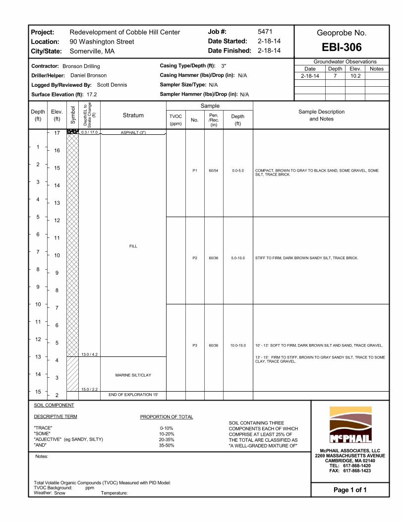
0.3 / 17.0
13.0 / 4.2
15.0 / 2.2
P1
P2
P3
0.0-5.0
5.0-10.0
10.0-15.0
60/54
60/36
60/36
ASPHALT (3")
FILL
MARINE SILT/CLAY
END OF EXPLORATION 15'
COMPACT, BROWN TO GRAY TO BLACK SAND, SOME GRAVEL, SOMESILT, TRACE BRICK.
STIFF TO FIRM, DARK BROWN SANDY SILT, TRACE BRICK.
10' - 13': SOFT TO FIRM, DARK BROWN SILT AND SAND, TRACE GRAVEL.
13' - 15': FIRM TO STIFF, BROWN TO GRAY SANDY SILT, TRACE TO SOMECLAY, TRACE GRAVEL.
Total Volatile Organic Compounds (TVOC) Measured with PID Model:TVOC Background:Weather: Temperature:
ppm
SOIL COMPONENT
DESCRIPTIVE TERM
"TRACE""SOME""ADJECTIVE" (eg SANDY, SILTY)"AND"
PROPORTION OF TOTAL
0-10%10-20%20-35%35-50%
SOIL CONTAINING THREECOMPONENTS EACH OF WHICHCOMPRISE AT LEAST 25% OFTHE TOTAL ARE CLASSIFIED AS"A WELL-GRADED MIXTURE OF"
Dep
th/E
L to
Str
ata
Cha
nge
(ft)Depth
(ft)
1
2
3
4
5
6
7
8
9
10
11
12
13
14
15
Sym
bol
Elev.(ft)
17
16
15
14
13
12
11
10
9
8
7
6
5
4
3
2
TVOC
(ppm)
Contractor:
Driller/Helper:
Logged By/Reviewed By:
Surface Elevation (ft):
No.
Casing Type/Depth (ft):
Casing Hammer (lbs)/Drop (in):
Sampler Size/Type:
Sampler Hammer (lbs)/Drop (in):
3"
5471
2-18-14
2-18-14
Redevelopment of Cobble Hill Center
90 Washington Street
Somerville, MA
Groundwater ObservationsNotesDepth
7Elev.10.2
Date2-18-14
Job #:
Date Started:
Date Finished:
Notes:
EBI-306
Sample
Geoprobe No.
Snow
Project:
Location:
City/State:
Page 1 of 1
Scott Dennis
Bronson Drilling
17.2
N/A
Depth
(ft)
Pen./Rec.(in)
McPHAIL ASSOCIATES, LLC2269 MASSACHUSETTS AVENUE
CAMBRIDGE, MA 02140TEL: 617-868-1420FAX: 617-868-1423
N/A
N/A
Daniel Bronson
StratumSample Description
and Notes
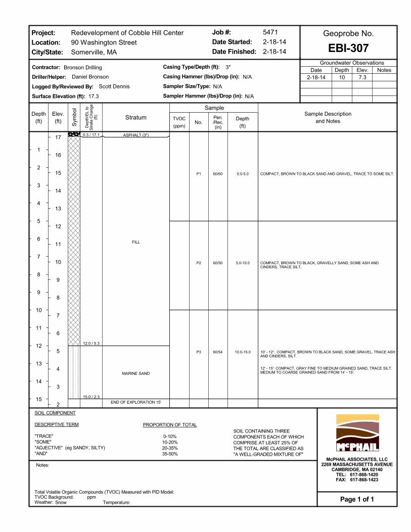
0.3 / 17.1
12.0 / 5.3
15.0 / 2.3
P1
P2
P3
0.0-5.0
5.0-10.0
10.0-15.0
60/60
60/50
60/54
ASPHALT (3")
FILL
MARINE SAND
END OF EXPLORATION 15'
COMPACT, BROWN TO BLACK SAND AND GRAVEL, TRACE TO SOME SILT.
COMPACT, BROWN TO BLACK, GRAVELLY SAND, SOME ASH ANDCINDERS, TRACE SILT.
10' - 12': COMPACT, BROWN TO BLACK SAND, SOME GRAVEL, TRACE ASHAND CINDERS, SILT.
12' - 15': COMPACT, GRAY FINE TO MEDIUM GRAINED SAND, TRACE SILT.MEDIUM TO COARSE GRAINED SAND FROM 14' - 15'.
Total Volatile Organic Compounds (TVOC) Measured with PID Model:TVOC Background:Weather: Temperature:
ppm
SOIL COMPONENT
DESCRIPTIVE TERM
"TRACE""SOME""ADJECTIVE" (eg SANDY, SILTY)"AND"
PROPORTION OF TOTAL
0-10%10-20%20-35%35-50%
SOIL CONTAINING THREECOMPONENTS EACH OF WHICHCOMPRISE AT LEAST 25% OFTHE TOTAL ARE CLASSIFIED AS"A WELL-GRADED MIXTURE OF"
Dep
th/E
L to
Str
ata
Cha
nge
(ft)Depth
(ft)
1
2
3
4
5
6
7
8
9
10
11
12
13
14
15
Sym
bol
Elev.(ft)
17
16
15
14
13
12
11
10
9
8
7
6
5
4
3
2
TVOC
(ppm)
Contractor:
Driller/Helper:
Logged By/Reviewed By:
Surface Elevation (ft):
No.
Casing Type/Depth (ft):
Casing Hammer (lbs)/Drop (in):
Sampler Size/Type:
Sampler Hammer (lbs)/Drop (in):
3"
5471
2-18-14
2-18-14
Redevelopment of Cobble Hill Center
90 Washington Street
Somerville, MA
Groundwater ObservationsNotesDepth
10Elev.7.3
Date2-18-14
Job #:
Date Started:
Date Finished:
Notes:
EBI-307
Sample
Geoprobe No.
Snow
Project:
Location:
City/State:
Page 1 of 1
Scott Dennis
Bronson Drilling
17.3
N/A
Depth
(ft)
Pen./Rec.(in)
McPHAIL ASSOCIATES, LLC2269 MASSACHUSETTS AVENUE
CAMBRIDGE, MA 02140TEL: 617-868-1420FAX: 617-868-1423
N/A
N/A
Daniel Bronson
StratumSample Description
and Notes

0.3 / 17.0
10.5 / 6.7
12.0 / 5.2
P1
P2
P3
0.0-5.0
5.0-8.0
8.0-12.0
60/60
36/36
48/40
ASPHALT (3")
FILL
MARINE SAND
END OF EXPLORATION 12'
COMPACT, BROWN TO GRAY SAND AND GRAVEL, TRACE SILT, ASH ANDCINDERS.
COMPACT, BROWN TO DARK BROWN SAND, SOME SILT, GRAVEL.
8' - 10.5': SOFT, DARK BROWN SILT, SOME SAND, TRACE CLAY.
10.5' - 12': COMPACT, BROWNISH GRAY FINE TO MEDIUM GRAINED SAND,TRACE SILT.
Total Volatile Organic Compounds (TVOC) Measured with PID Model:TVOC Background:Weather: Temperature:
ppm
SOIL COMPONENT
DESCRIPTIVE TERM
"TRACE""SOME""ADJECTIVE" (eg SANDY, SILTY)"AND"
PROPORTION OF TOTAL
0-10%10-20%20-35%35-50%
SOIL CONTAINING THREECOMPONENTS EACH OF WHICHCOMPRISE AT LEAST 25% OFTHE TOTAL ARE CLASSIFIED AS"A WELL-GRADED MIXTURE OF"
Dep
th/E
L to
Str
ata
Cha
nge
(ft)Depth
(ft)
1
2
3
4
5
6
7
8
9
10
11
12
13
14
15
Sym
bol
Elev.(ft)
17
16
15
14
13
12
11
10
9
8
7
6
5
4
3
2
TVOC
(ppm)
Contractor:
Driller/Helper:
Logged By/Reviewed By:
Surface Elevation (ft):
No.
Casing Type/Depth (ft):
Casing Hammer (lbs)/Drop (in):
Sampler Size/Type:
Sampler Hammer (lbs)/Drop (in):
3"
5471
2-18-14
2-18-14
Redevelopment of Cobble Hill Center
90 Washington Street
Somerville, MA
Groundwater ObservationsNotesDepth
10Elev.7.2
Date2-18-14
Job #:
Date Started:
Date Finished:
Notes:
EBI-308
Sample
Geoprobe No.
Snow
Project:
Location:
City/State:
Page 1 of 1
Scott Dennis
Bronson Drilling
17.2
N/A
Depth
(ft)
Pen./Rec.(in)
McPHAIL ASSOCIATES, LLC2269 MASSACHUSETTS AVENUE
CAMBRIDGE, MA 02140TEL: 617-868-1420FAX: 617-868-1423
N/A
N/A
Daniel Bronson
StratumSample Description
and Notes
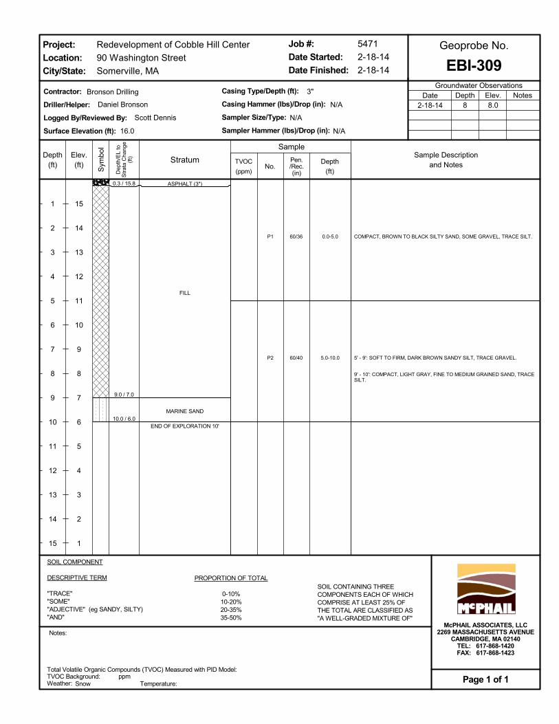
0.3 / 15.8
9.0 / 7.0
10.0 / 6.0
P1
P2
0.0-5.0
5.0-10.0
60/36
60/40
ASPHALT (3")
FILL
MARINE SAND
END OF EXPLORATION 10'
COMPACT, BROWN TO BLACK SILTY SAND, SOME GRAVEL, TRACE SILT.
5' - 9': SOFT TO FIRM, DARK BROWN SANDY SILT, TRACE GRAVEL.
9' - 10': COMPACT, LIGHT GRAY, FINE TO MEDIUM GRAINED SAND, TRACESILT.
Total Volatile Organic Compounds (TVOC) Measured with PID Model:TVOC Background:Weather: Temperature:
ppm
SOIL COMPONENT
DESCRIPTIVE TERM
"TRACE""SOME""ADJECTIVE" (eg SANDY, SILTY)"AND"
PROPORTION OF TOTAL
0-10%10-20%20-35%35-50%
SOIL CONTAINING THREECOMPONENTS EACH OF WHICHCOMPRISE AT LEAST 25% OFTHE TOTAL ARE CLASSIFIED AS"A WELL-GRADED MIXTURE OF"
Dep
th/E
L to
Str
ata
Cha
nge
(ft)Depth
(ft)
1
2
3
4
5
6
7
8
9
10
11
12
13
14
15
Sym
bol
Elev.(ft)
15
14
13
12
11
10
9
8
7
6
5
4
3
2
1
TVOC
(ppm)
Contractor:
Driller/Helper:
Logged By/Reviewed By:
Surface Elevation (ft):
No.
Casing Type/Depth (ft):
Casing Hammer (lbs)/Drop (in):
Sampler Size/Type:
Sampler Hammer (lbs)/Drop (in):
3"
5471
2-18-14
2-18-14
Redevelopment of Cobble Hill Center
90 Washington Street
Somerville, MA
Groundwater ObservationsNotesDepth
8Elev.8.0
Date2-18-14
Job #:
Date Started:
Date Finished:
Notes:
EBI-309
Sample
Geoprobe No.
Snow
Project:
Location:
City/State:
Page 1 of 1
Scott Dennis
Bronson Drilling
16.0
N/A
Depth
(ft)
Pen./Rec.(in)
McPHAIL ASSOCIATES, LLC2269 MASSACHUSETTS AVENUE
CAMBRIDGE, MA 02140TEL: 617-868-1420FAX: 617-868-1423
N/A
N/A
Daniel Bronson
StratumSample Description
and Notes
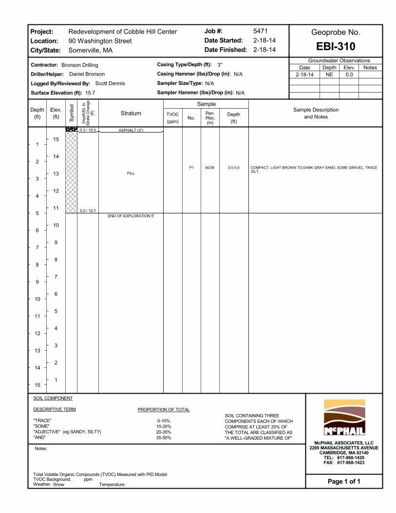
0.3 / 15.5
5.0 / 10.7
P1 0.0-5.060/36
ASPHALT (3")
FILL
END OF EXPLORATION 5'
COMPACT, LIGHT BROWN TO DARK GRAY SAND, SOME GRAVEL, TRACESILT.
Total Volatile Organic Compounds (TVOC) Measured with PID Model:TVOC Background:Weather: Temperature:
ppm
SOIL COMPONENT
DESCRIPTIVE TERM
"TRACE""SOME""ADJECTIVE" (eg SANDY, SILTY)"AND"
PROPORTION OF TOTAL
0-10%10-20%20-35%35-50%
SOIL CONTAINING THREECOMPONENTS EACH OF WHICHCOMPRISE AT LEAST 25% OFTHE TOTAL ARE CLASSIFIED AS"A WELL-GRADED MIXTURE OF"
Dep
th/E
L to
Str
ata
Cha
nge
(ft)Depth
(ft)
1
2
3
4
5
6
7
8
9
10
11
12
13
14
15
Sym
bol
Elev.(ft)
15
14
13
12
11
10
9
8
7
6
5
4
3
2
1
TVOC
(ppm)
Contractor:
Driller/Helper:
Logged By/Reviewed By:
Surface Elevation (ft):
No.
Casing Type/Depth (ft):
Casing Hammer (lbs)/Drop (in):
Sampler Size/Type:
Sampler Hammer (lbs)/Drop (in):
3"
5471
2-18-14
2-18-14
Redevelopment of Cobble Hill Center
90 Washington Street
Somerville, MA
Groundwater ObservationsNotesDepth
NEElev.0.0
Date2-18-14
Job #:
Date Started:
Date Finished:
Notes:
EBI-310
Sample
Geoprobe No.
Snow
Project:
Location:
City/State:
Page 1 of 1
Scott Dennis
Bronson Drilling
15.7
N/A
Depth
(ft)
Pen./Rec.(in)
McPHAIL ASSOCIATES, LLC2269 MASSACHUSETTS AVENUE
CAMBRIDGE, MA 02140TEL: 617-868-1420FAX: 617-868-1423
N/A
N/A
Daniel Bronson
StratumSample Description
and Notes

0.3 / 15.4
5.0 / 10.6
P1 0.0-5.060/36
ASPHALT (3")
FILL
END OF EXPLORATION 5'
COMPACT, LIGHT BROWN TO BLACK SAND, SOME GRAVEL, TRACE SILT.
Total Volatile Organic Compounds (TVOC) Measured with PID Model:TVOC Background:Weather: Temperature:
ppm
SOIL COMPONENT
DESCRIPTIVE TERM
"TRACE""SOME""ADJECTIVE" (eg SANDY, SILTY)"AND"
PROPORTION OF TOTAL
0-10%10-20%20-35%35-50%
SOIL CONTAINING THREECOMPONENTS EACH OF WHICHCOMPRISE AT LEAST 25% OFTHE TOTAL ARE CLASSIFIED AS"A WELL-GRADED MIXTURE OF"
Dep
th/E
L to
Str
ata
Cha
nge
(ft)Depth
(ft)
1
2
3
4
5
6
7
8
9
10
11
12
13
14
15
Sym
bol
Elev.(ft)
15
14
13
12
11
10
9
8
7
6
5
4
3
2
1
TVOC
(ppm)
Contractor:
Driller/Helper:
Logged By/Reviewed By:
Surface Elevation (ft):
No.
Casing Type/Depth (ft):
Casing Hammer (lbs)/Drop (in):
Sampler Size/Type:
Sampler Hammer (lbs)/Drop (in):
3"
5471
2-18-14
2-18-14
Redevelopment of Cobble Hill Center
90 Washington Street
Somerville, MA
Groundwater ObservationsNotesDepth
NEElev.0.0
Date2-18-14
Job #:
Date Started:
Date Finished:
Notes:
EBI-311
Sample
Geoprobe No.
Snow
Project:
Location:
City/State:
Page 1 of 1
Scott Dennis
Bronson Drilling
15.6
N/A
Depth
(ft)
Pen./Rec.(in)
McPHAIL ASSOCIATES, LLC2269 MASSACHUSETTS AVENUE
CAMBRIDGE, MA 02140TEL: 617-868-1420FAX: 617-868-1423
N/A
N/A
Daniel Bronson
StratumSample Description
and Notes
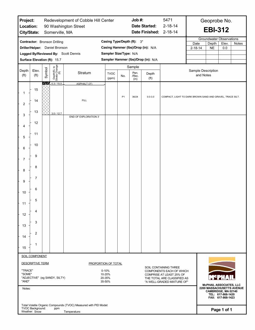
0.3 / 15.5
3.0 / 12.7
P1 0.0-3.036/24
ASPHALT (3")
FILL
END OF EXPLORATION 3'
COMPACT, LIGHT TO DARK BROWN SAND AND GRAVEL, TRACE SILT.
Total Volatile Organic Compounds (TVOC) Measured with PID Model:TVOC Background:Weather: Temperature:
ppm
SOIL COMPONENT
DESCRIPTIVE TERM
"TRACE""SOME""ADJECTIVE" (eg SANDY, SILTY)"AND"
PROPORTION OF TOTAL
0-10%10-20%20-35%35-50%
SOIL CONTAINING THREECOMPONENTS EACH OF WHICHCOMPRISE AT LEAST 25% OFTHE TOTAL ARE CLASSIFIED AS"A WELL-GRADED MIXTURE OF"
Dep
th/E
L to
Str
ata
Cha
nge
(ft)Depth
(ft)
1
2
3
4
5
6
7
8
9
10
11
12
13
14
15
Sym
bol
Elev.(ft)
15
14
13
12
11
10
9
8
7
6
5
4
3
2
1
TVOC
(ppm)
Contractor:
Driller/Helper:
Logged By/Reviewed By:
Surface Elevation (ft):
No.
Casing Type/Depth (ft):
Casing Hammer (lbs)/Drop (in):
Sampler Size/Type:
Sampler Hammer (lbs)/Drop (in):
3"
5471
2-18-14
2-18-14
Redevelopment of Cobble Hill Center
90 Washington Street
Somerville, MA
Groundwater ObservationsNotesDepth
NEElev.0.0
Date2-18-14
Job #:
Date Started:
Date Finished:
Notes:
EBI-312
Sample
Geoprobe No.
Snow
Project:
Location:
City/State:
Page 1 of 1
Scott Dennis
Bronson Drilling
15.7
N/A
Depth
(ft)
Pen./Rec.(in)
McPHAIL ASSOCIATES, LLC2269 MASSACHUSETTS AVENUE
CAMBRIDGE, MA 02140TEL: 617-868-1420FAX: 617-868-1423
N/A
N/A
Daniel Bronson
StratumSample Description
and Notes
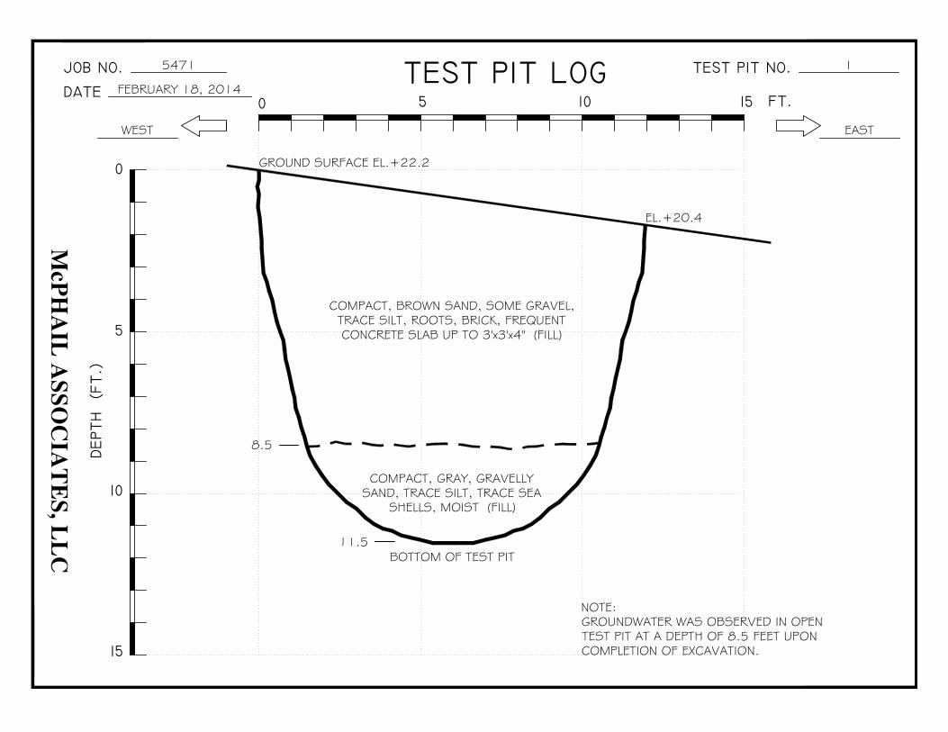
5471
FEBRUARY 18, 2014
WEST
GROUND SURFACE EL.+22.2
1
EAST
EL.+20.4
8.5
11.5BOTTOM OF TEST PIT
COMPACT, BROWN SAND, SOME GRAVEL,TRACE SILT, ROOTS, BRICK, FREQUENTCONCRETE SLAB UP TO 3'x3'x4" (FILL)
COMPACT, GRAY, GRAVELLYSAND, TRACE SILT, TRACE SEA
SHELLS, MOIST (FILL)
NOTE:GROUNDWATER WAS OBSERVED IN OPENTEST PIT AT A DEPTH OF 8.5 FEET UPONCOMPLETION OF EXCAVATION.
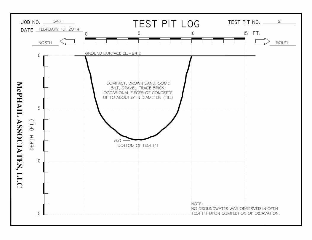
5471
FEBRUARY 19, 2014
NORTH
GROUND SURFACE EL.+24.9
2
SOUTH
8.0BOTTOM OF TEST PIT
COMPACT, BROWN SAND, SOMESILT, GRAVEL, TRACE BRICK,
OCCASIONAL PIECES OF CONCRETEUP TO ABOUT 8" IN DIAMETER (FILL)
NOTE:NO GROUNDWATER WAS OBSERVED IN OPENTEST PIT UPON COMPLETION OF EXCAVATION.
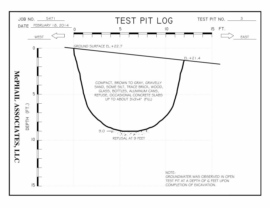
5471
FEBRUARY 18, 2014
WEST
GROUND SURFACE EL.+22.7
3
EAST
EL.+21.4
9.0
REFUSAL AT 9 FEET
COMPACT, BROWN TO GRAY, GRAVELLYSAND, SOME SILT, TRACE BRICK, WOOD,
GLASS, BOTTLES, ALUMINUM CANS,REFUSE, OCCASIONAL CONCRETE SLABS
UP TO ABOUT 3'x3'x4" (FILL)
NOTE:GROUNDWATER WAS OBSERVED IN OPENTEST PIT AT A DEPTH OF 6 FEET UPONCOMPLETION OF EXCAVATION.

21 B Street, Burlington, MA 01803Sheet 4 of 8
Project Number: 12140021 Excavating Co: J. Masterson
Project Location: Cobble Hill Equipment: Cat 370D 84 & 90 Washington Street Somerville MassachusettsDate: 02/19/2014
EBI Scientist: Daniel Bellucci
Minor components include potential coal/wood ash, wood/organic matter, metal wires and Fill material- Major components include SAND (Fine to coarse), large gravel; large concrete
0 to 7
TP-04Scale in Feet Description
*Note- Excavation terminated at 7 feet bgs- Large concrete pieces
bgs- below ground surface
coal slag 0 to 7
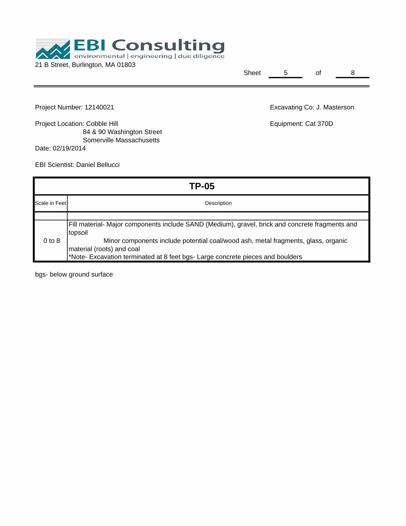
21 B Street, Burlington, MA 01803Sheet 5 of 8
Project Number: 12140021 Excavating Co: J. Masterson
Project Location: Cobble Hill Equipment: Cat 370D 84 & 90 Washington Street Somerville MassachusettsDate: 02/19/2014
EBI Scientist: Daniel Bellucci
*Note- Excavation terminated at 8 feet bgs- Large concrete pieces and boulders
bgs- below ground surface
0 to 8
Fill material- Major components include SAND (Medium), gravel, brick and concrete fragments and topsoil Minor components include potential coal/wood ash, metal fragments, glass, organic material (roots) and coal
TP-05Scale in Feet Description

21 B Street, Burlington, MA 01803Sheet 6 of 8
Project Number: 12140021 Excavating Co: J. Masterson
Project Location: Cobble Hill Equipment: Cat 370D 84 & 90 Washington Street Somerville MassachusettsDate: 02/19/2014
EBI Scientist: Daniel Bellucci
Fill material- Major components include mostly brick with medium SAND, large gravel and concrete fragments Minor components include potential coal/wood ash, organic material (roots), plastic conduit and B l i Bl k0 t 7 5
TP-06Scale in Feet Description
**Note- Excavation terminated at 7.5 feet bgs- Dense material, cannot excavate further
bgs- below ground surface
Belgian Block pavers*Note- Strong petroleum odor (No. 2 Fuel Oil) first 4 feet of excavation: PID= 22.7 ppm (0-4 feet bgs)
0 to 7.5

21 B Street, Burlington, MA 01803Sheet 7 of 8
Project Number: 12140021 Excavating Co: J. Masterson
Project Location: Cobble Hill Equipment: Cat 370D 84 & 90 Washington Street Somerville MassachusettsDate: 02/19/2014
EBI Scientist: Daniel Bellucci
**Note- Excavation terminated at 7 feet bgs- Dense material, cannot excavate further
bgs- below ground surface
Minor components include potential coal/wood ash, wood/organic matter, glass, coal fragments and Belgian Block pavers*Note- Slight petroleum odor (No. 2 Fuel Oil) throughout: PID= 1.0 ppm (6-7 feet bgs)
0 to 7
TP-07Scale in Feet Description
Fill material- Major components include SAND (medium to coarse), large gravel, concrete and brick
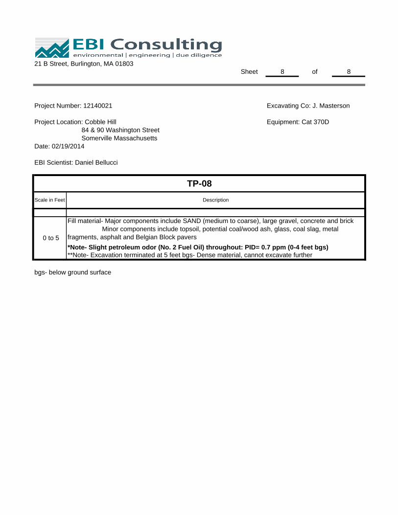
21 B Street, Burlington, MA 01803Sheet 8 of 8
Project Number: 12140021 Excavating Co: J. Masterson
Project Location: Cobble Hill Equipment: Cat 370D 84 & 90 Washington Street Somerville MassachusettsDate: 02/19/2014
EBI Scientist: Daniel Bellucci
TP-08Scale in Feet Description
**Note- Excavation terminated at 5 feet bgs- Dense material, cannot excavate further
bgs- below ground surface
Fill material- Major components include SAND (medium to coarse), large gravel, concrete and brick Minor components include topsoil, potential coal/wood ash, glass, coal slag, metal fragments, asphalt and Belgian Block pavers*Note- Slight petroleum odor (No. 2 Fuel Oil) throughout: PID= 0.7 ppm (0-4 feet bgs)
0 to 5
g g

Log of Borehole:Drilling Company:
Drilling Foreman:
EBI Geologist/Scientist:
Drilling Method:
Borehole Diameter:
Date Started:
Date Ended:
Project Location:
Project Number:
Sheet: 1 of 1
EBI Consulting21 B StreetBurlington, MA
SUBSURFACE PROFILE SAMPLE
Depth
1
2
3
4
Description Strata No. Rec. SPT Blows Type
FID/PIDReadings (ppm) Well Construction
EB-401Bronson Drilling
Dan Bronson
Daniel Bellucci
Direct Push
2.25-inch
02/18/2014
03/25/2014
Somerville, MA
12140021
1 of 1
Asphalt
Fill material comprised of fine to coarse SAND with some CLAY, gravel, concrete and brick; grey; dry
Equipment refusal (Concrete) encountered at 3.5 feet bgs
S-1 3/3.5 NA Core
100 300
18
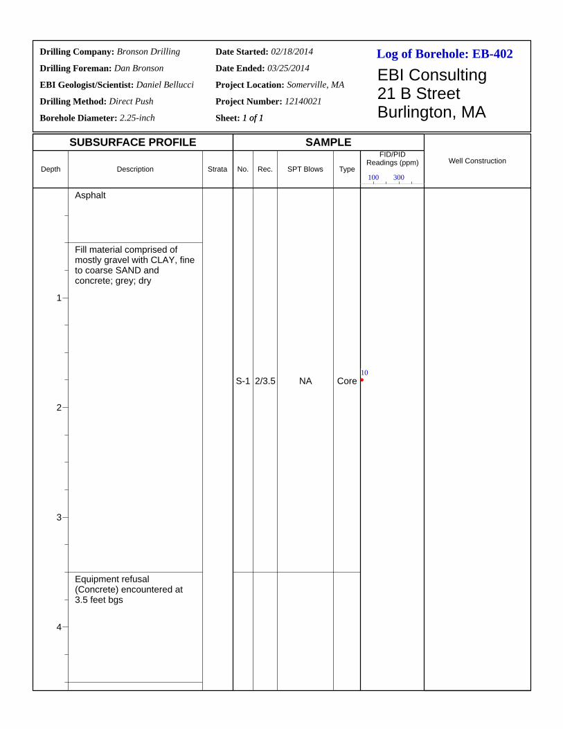
Log of Borehole:Drilling Company:
Drilling Foreman:
EBI Geologist/Scientist:
Drilling Method:
Borehole Diameter:
Date Started:
Date Ended:
Project Location:
Project Number:
Sheet: 1 of 1
EBI Consulting21 B StreetBurlington, MA
SUBSURFACE PROFILE SAMPLE
Depth
1
2
3
4
Description Strata No. Rec. SPT Blows Type
FID/PIDReadings (ppm) Well Construction
EB-402Bronson Drilling
Dan Bronson
Daniel Bellucci
Direct Push
2.25-inch
02/18/2014
03/25/2014
Somerville, MA
12140021
1 of 1
Asphalt
Fill material comprised of mostly gravel with CLAY, fine to coarse SAND and concrete; grey; dry
Equipment refusal (Concrete) encountered at 3.5 feet bgs
S-1 2/3.5 NA Core
100 300
10
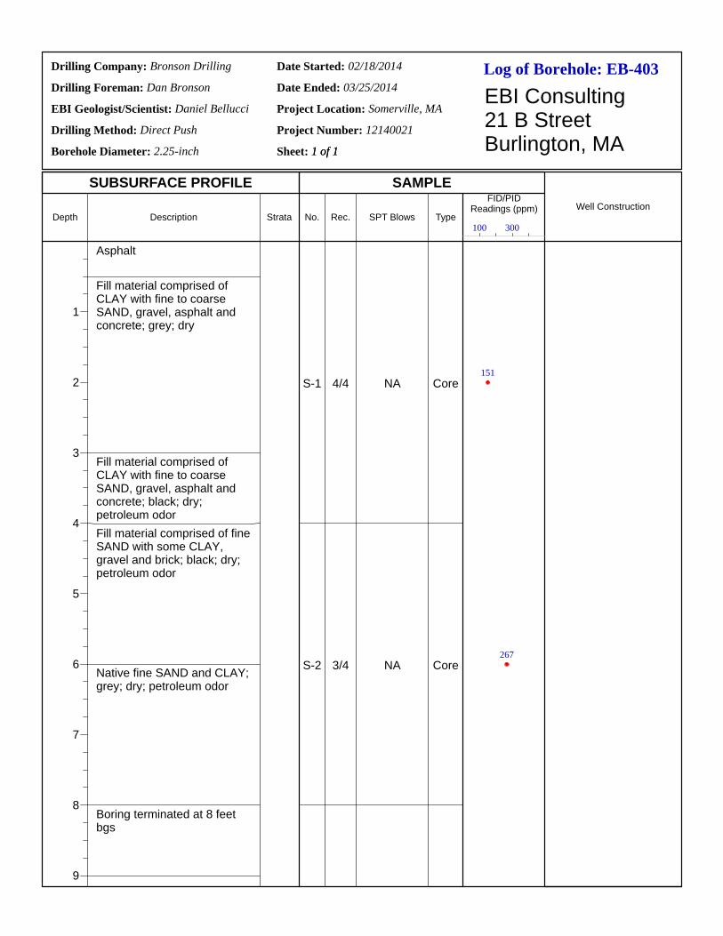
Log of Borehole:Drilling Company:
Drilling Foreman:
EBI Geologist/Scientist:
Drilling Method:
Borehole Diameter:
Date Started:
Date Ended:
Project Location:
Project Number:
Sheet: 1 of 1
EBI Consulting21 B StreetBurlington, MA
SUBSURFACE PROFILE SAMPLE
Depth
1
2
3
4
5
6
7
8
9
Description Strata No. Rec. SPT Blows Type
FID/PIDReadings (ppm) Well Construction
EB-403Bronson Drilling
Dan Bronson
Daniel Bellucci
Direct Push
2.25-inch
02/18/2014
03/25/2014
Somerville, MA
12140021
1 of 1
Asphalt
Fill material comprised of CLAY with fine to coarse SAND, gravel, asphalt and concrete; grey; dry
Fill material comprised of CLAY with fine to coarse SAND, gravel, asphalt and concrete; black; dry; petroleum odorFill material comprised of fine SAND with some CLAY, gravel and brick; black; dry; petroleum odor
Native fine SAND and CLAY; grey; dry; petroleum odor
Boring terminated at 8 feet bgs
S-1
S-2
4/4
3/4
NA
NA
Core
Core
100 300
151
267
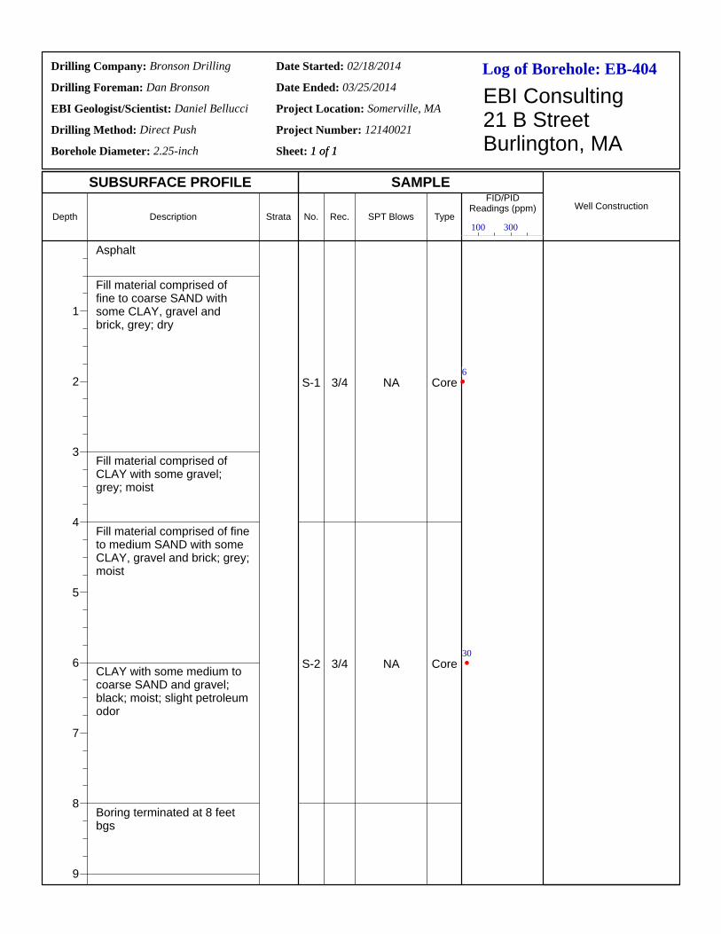
Log of Borehole:Drilling Company:
Drilling Foreman:
EBI Geologist/Scientist:
Drilling Method:
Borehole Diameter:
Date Started:
Date Ended:
Project Location:
Project Number:
Sheet: 1 of 1
EBI Consulting21 B StreetBurlington, MA
SUBSURFACE PROFILE SAMPLE
Depth
1
2
3
4
5
6
7
8
9
Description Strata No. Rec. SPT Blows Type
FID/PIDReadings (ppm) Well Construction
EB-404Bronson Drilling
Dan Bronson
Daniel Bellucci
Direct Push
2.25-inch
02/18/2014
03/25/2014
Somerville, MA
12140021
1 of 1
Asphalt
Fill material comprised of fine to coarse SAND with some CLAY, gravel and brick, grey; dry
Fill material comprised of CLAY with some gravel; grey; moist
Fill material comprised of fine to medium SAND with some CLAY, gravel and brick; grey; moist
CLAY with some medium to coarse SAND and gravel; black; moist; slight petroleum odor
Boring terminated at 8 feet bgs
S-1
S-2
3/4
3/4
NA
NA
Core
Core
100 300
6
30

Log of Borehole:Drilling Company:
Drilling Foreman:
EBI Geologist/Scientist:
Drilling Method:
Borehole Diameter:
Date Started:
Date Ended:
Project Location:
Project Number:
Sheet: 1 of 1
EBI Consulting21 B StreetBurlington, MA
SUBSURFACE PROFILE SAMPLE
Depth
1
2
3
4
5
6
7
Description Strata No. Rec. SPT Blows Type
FID/PIDReadings (ppm) Well Construction
EB-405Bronson Drilling
Dan Bronson
Daniel Bellucci
Direct Push
2.25-inch
02/18/2014
03/25/2014
Somerville, MA
12140021
1 of 1
Asphalt
Fill material comprised of CLAY with some fine to coarse SAND, gravel, brick and concrete; grey; dry
Fill material comprised of CLAY with some fine to coarse SAND, gravel, brick and concrete; grey; dry; slight petroleum odor
Equipment refusal encountered at 6 feet bgs
S-1
S-2
3/4
1/2
NA
NA
Core
Core
100 300
5
23

Log of Borehole:Drilling Company:
Drilling Foreman:
EBI Geologist/Scientist:
Drilling Method:
Borehole Diameter:
Date Started:
Date Ended:
Project Location:
Project Number:
Sheet: 1 of 1
EBI Consulting21 B StreetBurlington, MA
SUBSURFACE PROFILE SAMPLE
Depth
1
2
3
4
Description Strata No. Rec. SPT Blows Type
FID/PIDReadings (ppm) Well Construction
EB-406Bronson Drilling
Dan Bronson
Daniel Bellucci
Direct Push
2.25-inch
02/18/2014
03/25/2014
Somerville, MA
12140021
1 of 1
Asphalt
Fill material comprised of fine to coarse SAND with some CLAY and gravel; grey; moist; slight petroleum odor
Fill material comprised of fine to coarse SAND with some CLAY and gravel; grey; dry; slight petroleum odor
Equipment refusal (Concrete) encountered at 3.5 feet bgs
S-1 3/3.5 NA Core
100 300
6

ASPHALT
GRANULAR FILL
COHESIVE FILL
Bottom of borehole 10 feet belowground surface.
Brown/black, fine to medium SAND, some asphalt (Granular Fill).
Black, SILT, some sand, with asphalt (Granular Fill).
Black/dark brown, SILT, with wood/peat fibers, trace ash&cinders (Cohesive Fill).
Black, SILT, with ash&cinders (Cohesive Fill).
0.3-2.6
2.5-5.0
5.0-7.5
7.5-10.0
27/20
30/20
30/25
30/25
0.5 / 15.8
5.0 / 11.3
10.0 / 6.3
7.9
5.5
2.0
0.8
S1
S2
S3
S4
N/A
N/A
Ryan
StratumSample Description
and Notes
Date
90 Washington St
Somerville, MA
Groundwater ObservationsNotesDepth Elev.
Job #:
Date Started:
Date Finished:
Notes:
B-603
Sample
Geoprobe No.
Clear
Project:
Location:
City/State:
Page 1 of 1
KEH 5' Plastic Sleeve
Depth
(ft)
Pen./Rec.(in)
McPHAIL ASSOCIATES, LLC2269 MASSACHUSETTS AVENUE
CAMBRIDGE, MA 02140TEL: 617-868-1420FAX: 617-868-1423
Weather:
Crawford
16.3
Temperature: 25
SOIL COMPONENT
DESCRIPTIVE TERM
"TRACE""SOME""ADJECTIVE" (eg SANDY, SILTY)"AND"
PROPORTION OF TOTAL
0-10%10-20%20-35%35-50%
SOIL CONTAINING THREECOMPONENTS EACH OF WHICHCOMPRISE AT LEAST 25% OFTHE TOTAL ARE CLASSIFIED AS"A WELL-GRADED MIXTURE OF"
Dep
th/E
L to
Str
ata
Cha
nge
(ft)Depth
(ft)
1
2
3
4
5
6
7
8
9
10
11
12
13
14
15
16
17
18
19
20
21
22
Sym
bol
Elev.(ft)
16
15
14
13
12
11
10
9
8
7
6
5
4
3
2
1
0
-1
-2
-3
-4
-5
-6
TVOC
(ppm)
Contractor:
Driller/Helper:
Logged By/Reviewed By:
Surface Elevation (ft):
No.
Casing Type/Depth (ft):
Casing Hammer (lbs)/Drop (in):
Sampler Size/Type:
Sampler Hammer (lbs)/Drop (in):
N/A
5471
8-22-18
8-22-18

TOPSOIL
GRANULAR FILL
Bottom of borehole 10 feet belowground surface.
Brown/black, SILTY SAND, with brick and ash&cinders (Granular Fill).
Black/gray, SILTY SAND, some clay, with ash&cinders (Granular Fill).
Brown/black, SILTY SAND, with asphalt (Granular Fill).
Black, SILTY SAND, with asphalt, appeared to have a sheen to it (Granular Fill).
0.5-3.0
2.5-5.0
5.0-7.5
7.5-10.0
30/25
30/25
30/20
30/20
0.5 / 16.8
10.0 / 7.3
3.0
10.3
5.3
2.9
S1
S2
S3
S4
N/A
N/A
Ryan
StratumSample Description
and Notes
Date
90 Washington St
Somerville, MA
Groundwater ObservationsNotesDepth Elev.
Job #:
Date Started:
Date Finished:
Notes:
B-604
Sample
Geoprobe No.
Clear
Project:
Location:
City/State:
Page 1 of 1
KEH 5' Plastic Sleeve
Depth
(ft)
Pen./Rec.(in)
McPHAIL ASSOCIATES, LLC2269 MASSACHUSETTS AVENUE
CAMBRIDGE, MA 02140TEL: 617-868-1420FAX: 617-868-1423
Weather:
Crawford
17.3
Temperature: 25
SOIL COMPONENT
DESCRIPTIVE TERM
"TRACE""SOME""ADJECTIVE" (eg SANDY, SILTY)"AND"
PROPORTION OF TOTAL
0-10%10-20%20-35%35-50%
SOIL CONTAINING THREECOMPONENTS EACH OF WHICHCOMPRISE AT LEAST 25% OFTHE TOTAL ARE CLASSIFIED AS"A WELL-GRADED MIXTURE OF"
Dep
th/E
L to
Str
ata
Cha
nge
(ft)Depth
(ft)
1
2
3
4
5
6
7
8
9
10
11
12
13
14
15
16
17
18
19
20
21
22
Sym
bol
Elev.(ft)
17
16
15
14
13
12
11
10
9
8
7
6
5
4
3
2
1
0
-1
-2
-3
-4
-5
TVOC
(ppm)
Contractor:
Driller/Helper:
Logged By/Reviewed By:
Surface Elevation (ft):
No.
Casing Type/Depth (ft):
Casing Hammer (lbs)/Drop (in):
Sampler Size/Type:
Sampler Hammer (lbs)/Drop (in):
N/A
5471
8-22-18
8-22-18

ASPHALT
GRANULAR FILL
Bottom of borehole 10 feet belowground surface.
Brown, SILTY SAND (Granular Fill).
Brown, fine to coarse SAND, trace silt (Granular Fill).
Brown, fine to coarse SAND, trace silt, with dark brown cobbles (Granular Fill).
Brown, fine to coarse SAND, trace silt, petroleum odor (Granular Fill).
0.3-2.6
2.5-5.0
5.0-7.5
7.5-10.0
27/15
30/15
30/15
30/15
0.3 / 17.6
10.0 / 7.9
1.5
123.1
2.5
17.5
S1
S2
S3
S4
N/A
N/A
Ryan
StratumSample Description
and Notes
Date
90 Washington St
Somerville, MA
Groundwater ObservationsNotesDepth Elev.
Job #:
Date Started:
Date Finished:
Notes:
B-605
Sample
Geoprobe No.
Rain
Project:
Location:
City/State:
Page 1 of 1
KEH 5' Plastic Sleeve
Depth
(ft)
Pen./Rec.(in)
McPHAIL ASSOCIATES, LLC2269 MASSACHUSETTS AVENUE
CAMBRIDGE, MA 02140TEL: 617-868-1420FAX: 617-868-1423
Weather:
Crawford
17.9
Temperature: 25
SOIL COMPONENT
DESCRIPTIVE TERM
"TRACE""SOME""ADJECTIVE" (eg SANDY, SILTY)"AND"
PROPORTION OF TOTAL
0-10%10-20%20-35%35-50%
SOIL CONTAINING THREECOMPONENTS EACH OF WHICHCOMPRISE AT LEAST 25% OFTHE TOTAL ARE CLASSIFIED AS"A WELL-GRADED MIXTURE OF"
Dep
th/E
L to
Str
ata
Cha
nge
(ft)Depth
(ft)
1
2
3
4
5
6
7
8
9
10
11
12
13
14
15
16
17
18
19
20
21
22
Sym
bol
Elev.(ft)
17
16
15
14
13
12
11
10
9
8
7
6
5
4
3
2
1
0
-1
-2
-3
-4
TVOC
(ppm)
Contractor:
Driller/Helper:
Logged By/Reviewed By:
Surface Elevation (ft):
No.
Casing Type/Depth (ft):
Casing Hammer (lbs)/Drop (in):
Sampler Size/Type:
Sampler Hammer (lbs)/Drop (in):
N/A
5471
8-22-18
8-22-18
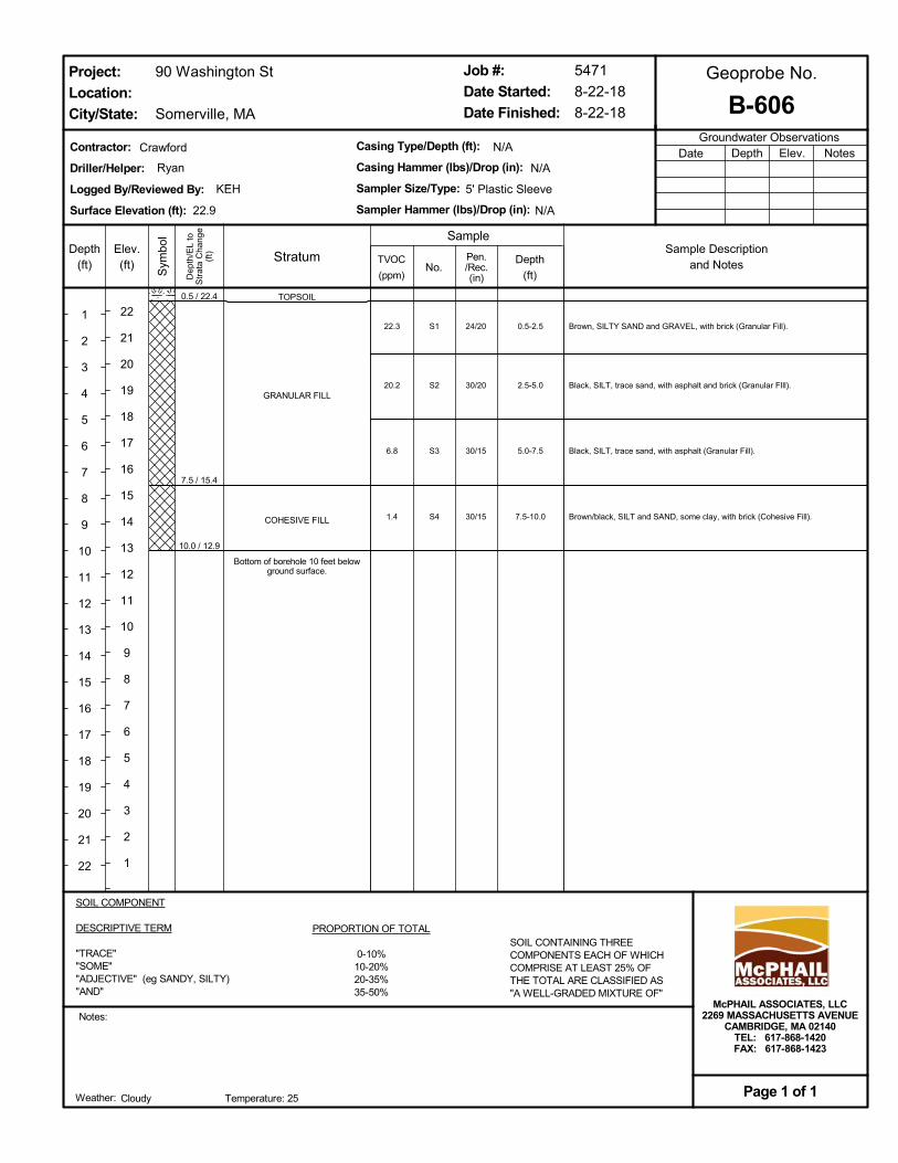
TOPSOIL
GRANULAR FILL
COHESIVE FILL
Bottom of borehole 10 feet belowground surface.
Brown, SILTY SAND and GRAVEL, with brick (Granular Fill).
Black, SILT, trace sand, with asphalt and brick (Granular FIll).
Black, SILT, trace sand, with asphalt (Granular Fill).
Brown/black, SILT and SAND, some clay, with brick (Cohesive Fill).
0.5-2.5
2.5-5.0
5.0-7.5
7.5-10.0
24/20
30/20
30/15
30/15
0.5 / 22.4
7.5 / 15.4
10.0 / 12.9
22.3
20.2
6.8
1.4
S1
S2
S3
S4
N/A
N/A
Ryan
StratumSample Description
and Notes
Date
90 Washington St
Somerville, MA
Groundwater ObservationsNotesDepth Elev.
Job #:
Date Started:
Date Finished:
Notes:
B-606
Sample
Geoprobe No.
Cloudy
Project:
Location:
City/State:
Page 1 of 1
KEH 5' Plastic Sleeve
Depth
(ft)
Pen./Rec.(in)
McPHAIL ASSOCIATES, LLC2269 MASSACHUSETTS AVENUE
CAMBRIDGE, MA 02140TEL: 617-868-1420FAX: 617-868-1423
Weather:
Crawford
22.9
Temperature: 25
SOIL COMPONENT
DESCRIPTIVE TERM
"TRACE""SOME""ADJECTIVE" (eg SANDY, SILTY)"AND"
PROPORTION OF TOTAL
0-10%10-20%20-35%35-50%
SOIL CONTAINING THREECOMPONENTS EACH OF WHICHCOMPRISE AT LEAST 25% OFTHE TOTAL ARE CLASSIFIED AS"A WELL-GRADED MIXTURE OF"
Dep
th/E
L to
Str
ata
Cha
nge
(ft)Depth
(ft)
1
2
3
4
5
6
7
8
9
10
11
12
13
14
15
16
17
18
19
20
21
22
Sym
bol
Elev.(ft)
22
21
20
19
18
17
16
15
14
13
12
11
10
9
8
7
6
5
4
3
2
1
TVOC
(ppm)
Contractor:
Driller/Helper:
Logged By/Reviewed By:
Surface Elevation (ft):
No.
Casing Type/Depth (ft):
Casing Hammer (lbs)/Drop (in):
Sampler Size/Type:
Sampler Hammer (lbs)/Drop (in):
N/A
5471
8-22-18
8-22-18
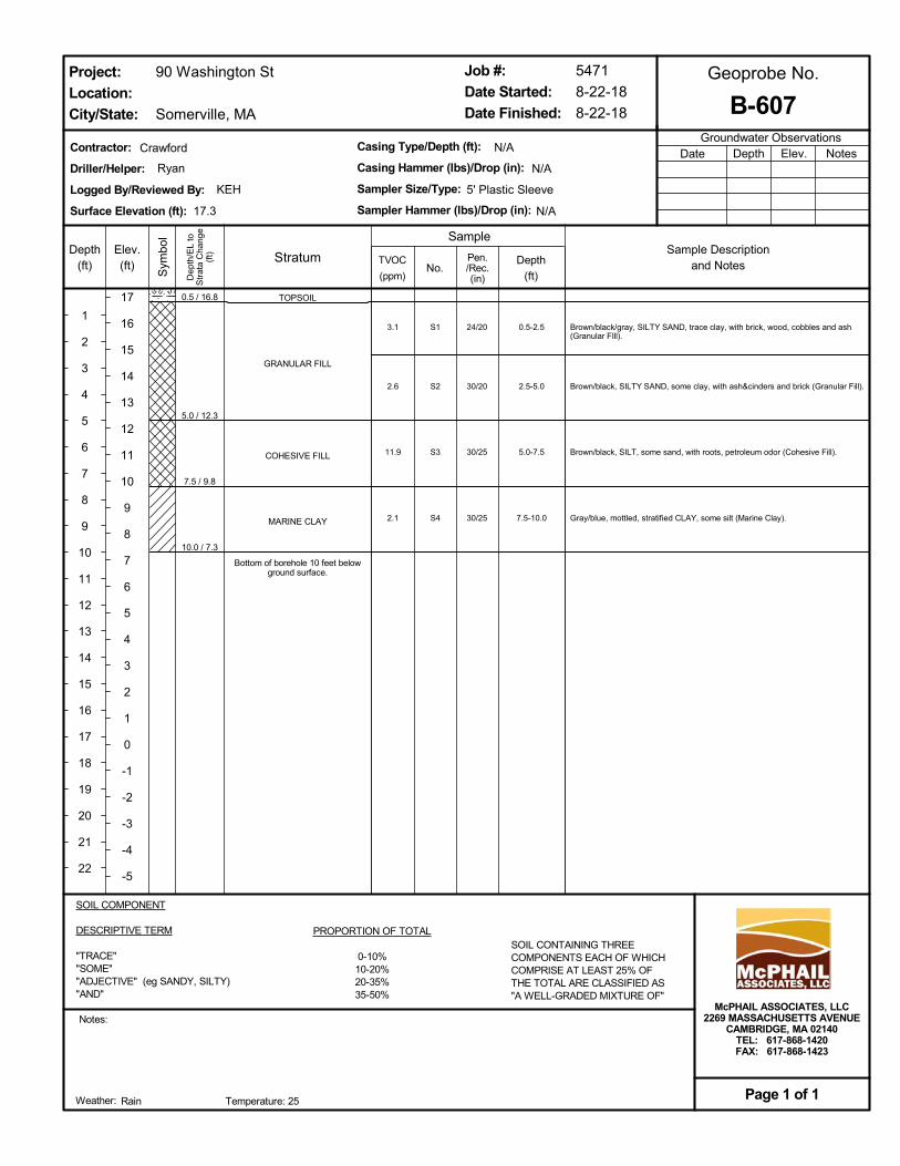
TOPSOIL
GRANULAR FILL
COHESIVE FILL
MARINE CLAY
Bottom of borehole 10 feet belowground surface.
Brown/black/gray, SILTY SAND, trace clay, with brick, wood, cobbles and ash(Granular FIll).
Brown/black, SILTY SAND, some clay, with ash&cinders and brick (Granular Fill).
Brown/black, SILT, some sand, with roots, petroleum odor (Cohesive Fill).
Gray/blue, mottled, stratified CLAY, some silt (Marine Clay).
0.5-2.5
2.5-5.0
5.0-7.5
7.5-10.0
24/20
30/20
30/25
30/25
0.5 / 16.8
5.0 / 12.3
7.5 / 9.8
10.0 / 7.3
3.1
2.6
11.9
2.1
S1
S2
S3
S4
N/A
N/A
Ryan
StratumSample Description
and Notes
Date
90 Washington St
Somerville, MA
Groundwater ObservationsNotesDepth Elev.
Job #:
Date Started:
Date Finished:
Notes:
B-607
Sample
Geoprobe No.
Rain
Project:
Location:
City/State:
Page 1 of 1
KEH 5' Plastic Sleeve
Depth
(ft)
Pen./Rec.(in)
McPHAIL ASSOCIATES, LLC2269 MASSACHUSETTS AVENUE
CAMBRIDGE, MA 02140TEL: 617-868-1420FAX: 617-868-1423
Weather:
Crawford
17.3
Temperature: 25
SOIL COMPONENT
DESCRIPTIVE TERM
"TRACE""SOME""ADJECTIVE" (eg SANDY, SILTY)"AND"
PROPORTION OF TOTAL
0-10%10-20%20-35%35-50%
SOIL CONTAINING THREECOMPONENTS EACH OF WHICHCOMPRISE AT LEAST 25% OFTHE TOTAL ARE CLASSIFIED AS"A WELL-GRADED MIXTURE OF"
Dep
th/E
L to
Str
ata
Cha
nge
(ft)Depth
(ft)
1
2
3
4
5
6
7
8
9
10
11
12
13
14
15
16
17
18
19
20
21
22
Sym
bol
Elev.(ft)
17
16
15
14
13
12
11
10
9
8
7
6
5
4
3
2
1
0
-1
-2
-3
-4
-5
TVOC
(ppm)
Contractor:
Driller/Helper:
Logged By/Reviewed By:
Surface Elevation (ft):
No.
Casing Type/Depth (ft):
Casing Hammer (lbs)/Drop (in):
Sampler Size/Type:
Sampler Hammer (lbs)/Drop (in):
N/A
5471
8-22-18
8-22-18
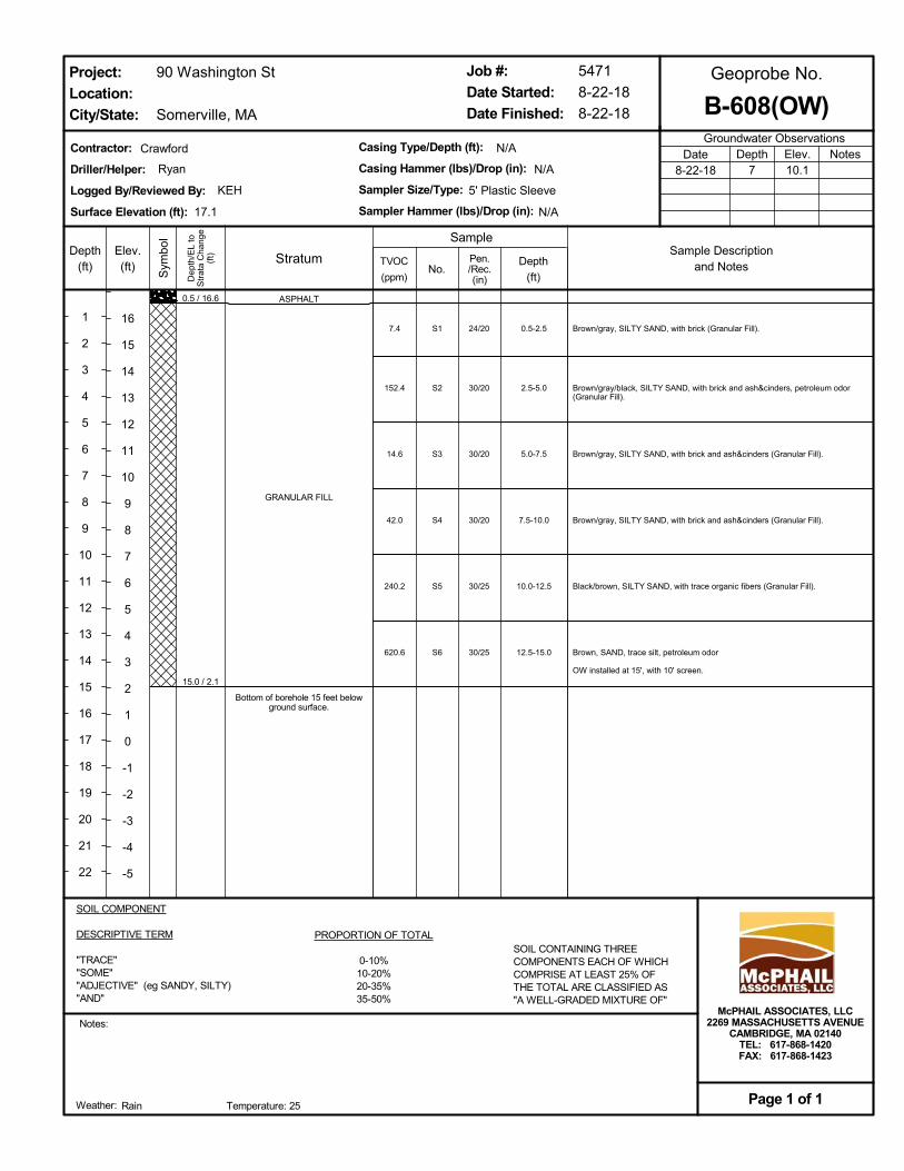
ASPHALT
GRANULAR FILL
Bottom of borehole 15 feet belowground surface.
Brown/gray, SILTY SAND, with brick (Granular Fill).
Brown/gray/black, SILTY SAND, with brick and ash&cinders, petroleum odor(Granular Fill).
Brown/gray, SILTY SAND, with brick and ash&cinders (Granular Fill).
Brown/gray, SILTY SAND, with brick and ash&cinders (Granular Fill).
Black/brown, SILTY SAND, with trace organic fibers (Granular Fill).
Brown, SAND, trace silt, petroleum odor
OW installed at 15', with 10' screen.
0.5-2.5
2.5-5.0
5.0-7.5
7.5-10.0
10.0-12.5
12.5-15.0
24/20
30/20
30/20
30/20
30/25
30/25
0.5 / 16.6
15.0 / 2.1
7.4
152.4
14.6
42.0
240.2
620.6
S1
S2
S3
S4
S5
S6
N/A
N/A
Ryan
StratumSample Description
and Notes
Date8-22-18
90 Washington St
Somerville, MA
Groundwater ObservationsNotesDepth
7Elev.10.1
Job #:
Date Started:
Date Finished:
Notes:
B-608(OW)
Sample
Geoprobe No.
Rain
Project:
Location:
City/State:
Page 1 of 1
KEH 5' Plastic Sleeve
Depth
(ft)
Pen./Rec.(in)
McPHAIL ASSOCIATES, LLC2269 MASSACHUSETTS AVENUE
CAMBRIDGE, MA 02140TEL: 617-868-1420FAX: 617-868-1423
Weather:
Crawford
17.1
Temperature: 25
SOIL COMPONENT
DESCRIPTIVE TERM
"TRACE""SOME""ADJECTIVE" (eg SANDY, SILTY)"AND"
PROPORTION OF TOTAL
0-10%10-20%20-35%35-50%
SOIL CONTAINING THREECOMPONENTS EACH OF WHICHCOMPRISE AT LEAST 25% OFTHE TOTAL ARE CLASSIFIED AS"A WELL-GRADED MIXTURE OF"
Dep
th/E
L to
Str
ata
Cha
nge
(ft)Depth
(ft)
1
2
3
4
5
6
7
8
9
10
11
12
13
14
15
16
17
18
19
20
21
22
Sym
bol
Elev.(ft)
16
15
14
13
12
11
10
9
8
7
6
5
4
3
2
1
0
-1
-2
-3
-4
-5
TVOC
(ppm)
Contractor:
Driller/Helper:
Logged By/Reviewed By:
Surface Elevation (ft):
No.
Casing Type/Depth (ft):
Casing Hammer (lbs)/Drop (in):
Sampler Size/Type:
Sampler Hammer (lbs)/Drop (in):
N/A
5471
8-22-18
8-22-18
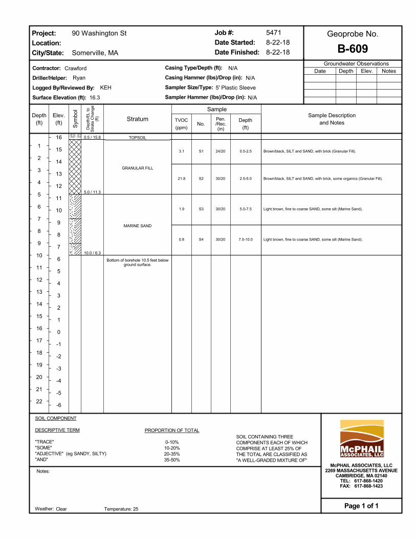
TOPSOIL
GRANULAR FILL
MARINE SAND
Bottom of borehole 10.5 feet belowground surface.
Brown/black, SILT and SAND, with brick (Granular Fill).
Brown/black, SILT and SAND, with brick, some organics (Granular Fill).
Light brown, fine to coarse SAND, some silt (Marine Sand).
Light brown, fine to coarse SAND, some silt (Marine Sand).
0.5-2.5
2.5-5.0
5.0-7.5
7.5-10.0
24/20
30/20
30/20
30/20
0.5 / 15.8
5.0 / 11.3
10.0 / 6.3
3.1
21.8
1.9
0.8
S1
S2
S3
S4
N/A
N/A
Ryan
StratumSample Description
and Notes
Date
90 Washington St
Somerville, MA
Groundwater ObservationsNotesDepth Elev.
Job #:
Date Started:
Date Finished:
Notes:
B-609
Sample
Geoprobe No.
Clear
Project:
Location:
City/State:
Page 1 of 1
KEH 5' Plastic Sleeve
Depth
(ft)
Pen./Rec.(in)
McPHAIL ASSOCIATES, LLC2269 MASSACHUSETTS AVENUE
CAMBRIDGE, MA 02140TEL: 617-868-1420FAX: 617-868-1423
Weather:
Crawford
16.3
Temperature: 25
SOIL COMPONENT
DESCRIPTIVE TERM
"TRACE""SOME""ADJECTIVE" (eg SANDY, SILTY)"AND"
PROPORTION OF TOTAL
0-10%10-20%20-35%35-50%
SOIL CONTAINING THREECOMPONENTS EACH OF WHICHCOMPRISE AT LEAST 25% OFTHE TOTAL ARE CLASSIFIED AS"A WELL-GRADED MIXTURE OF"
Dep
th/E
L to
Str
ata
Cha
nge
(ft)Depth
(ft)
1
2
3
4
5
6
7
8
9
10
11
12
13
14
15
16
17
18
19
20
21
22
Sym
bol
Elev.(ft)
16
15
14
13
12
11
10
9
8
7
6
5
4
3
2
1
0
-1
-2
-3
-4
-5
-6
TVOC
(ppm)
Contractor:
Driller/Helper:
Logged By/Reviewed By:
Surface Elevation (ft):
No.
Casing Type/Depth (ft):
Casing Hammer (lbs)/Drop (in):
Sampler Size/Type:
Sampler Hammer (lbs)/Drop (in):
N/A
5471
8-22-18
8-22-18
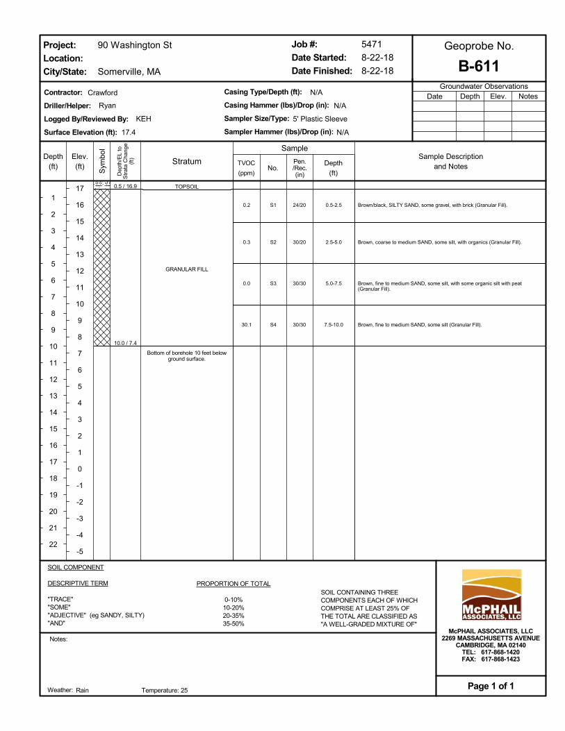
TOPSOIL
GRANULAR FILL
Bottom of borehole 10 feet belowground surface.
Brown/black, SILTY SAND, some gravel, with brick (Granular Fill).
Brown, coarse to medium SAND, some silt, with organics (Granular Fill).
Brown, fine to medium SAND, some silt, with some organic silt with peat(Granular Fill).
Brown, fine to medium SAND, some silt (Granular Fill).
0.5-2.5
2.5-5.0
5.0-7.5
7.5-10.0
24/20
30/20
30/30
30/30
0.5 / 16.9
10.0 / 7.4
0.2
0.3
0.0
30.1
S1
S2
S3
S4
N/A
N/A
Ryan
StratumSample Description
and Notes
Date
90 Washington St
Somerville, MA
Groundwater ObservationsNotesDepth Elev.
Job #:
Date Started:
Date Finished:
Notes:
B-611
Sample
Geoprobe No.
Rain
Project:
Location:
City/State:
Page 1 of 1
KEH 5' Plastic Sleeve
Depth
(ft)
Pen./Rec.(in)
McPHAIL ASSOCIATES, LLC2269 MASSACHUSETTS AVENUE
CAMBRIDGE, MA 02140TEL: 617-868-1420FAX: 617-868-1423
Weather:
Crawford
17.4
Temperature: 25
SOIL COMPONENT
DESCRIPTIVE TERM
"TRACE""SOME""ADJECTIVE" (eg SANDY, SILTY)"AND"
PROPORTION OF TOTAL
0-10%10-20%20-35%35-50%
SOIL CONTAINING THREECOMPONENTS EACH OF WHICHCOMPRISE AT LEAST 25% OFTHE TOTAL ARE CLASSIFIED AS"A WELL-GRADED MIXTURE OF"
Dep
th/E
L to
Str
ata
Cha
nge
(ft)Depth
(ft)
1
2
3
4
5
6
7
8
9
10
11
12
13
14
15
16
17
18
19
20
21
22
Sym
bol
Elev.(ft)
17
16
15
14
13
12
11
10
9
8
7
6
5
4
3
2
1
0
-1
-2
-3
-4
-5
TVOC
(ppm)
Contractor:
Driller/Helper:
Logged By/Reviewed By:
Surface Elevation (ft):
No.
Casing Type/Depth (ft):
Casing Hammer (lbs)/Drop (in):
Sampler Size/Type:
Sampler Hammer (lbs)/Drop (in):
N/A
5471
8-22-18
8-22-18
APPENDIX D:
GROUNDWATER MONITORING REPORTS

Well I.D.: B-2 (OW) Road Box Elev.: +17.1
Project: Somerville PSB Top of PVC Elev.: +17.1
Location: Somerville, MA Top of Well Screen Elev.: +7.1
Project No.: 7088 Bot. of Well Screen Elev.: -2.9
Elev. Datum: City of Somerville Vert. Datum Well Diameter: 2.0 in.
Date Time
Elapsed
Time
Depth from
Road Box
(feet)
Groundwater
Elev. (feet) McPhail Representative Comments
10/24/12 7:00 AM Initial 9.7 +7.4 SSD Initial Reading
10/25/12 9:00 AM 1 Day(s) 8.1 +9.0 SSD
10/29/12 7:00 AM 5 Day(s) 7.9 +9.2 SSD
10/31/12 3:00 PM 7 Day(s) 7.8 +9.3 SSD
01/25/21 2:00 PM 3,015 Day(s) 6.8 +10.3 G. Anderson
Groundwater Monitoring Report
Page 1 of 1 McPhail Associates, LLC
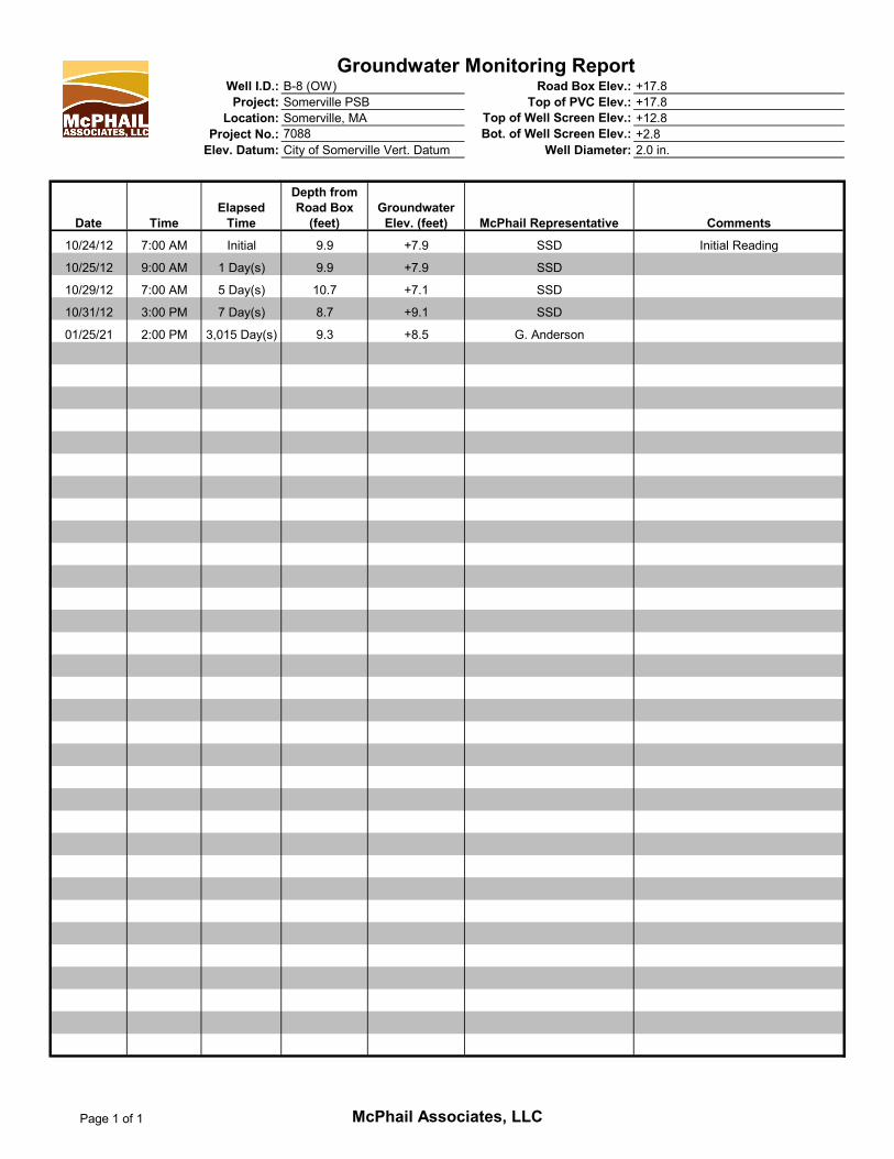
Well I.D.: B-8 (OW) Road Box Elev.: +17.8
Project: Somerville PSB Top of PVC Elev.: +17.8
Location: Somerville, MA Top of Well Screen Elev.: +12.8
Project No.: 7088 Bot. of Well Screen Elev.: +2.8
Elev. Datum: City of Somerville Vert. Datum Well Diameter: 2.0 in.
Date Time
Elapsed
Time
Depth from
Road Box
(feet)
Groundwater
Elev. (feet) McPhail Representative Comments
10/24/12 7:00 AM Initial 9.9 +7.9 SSD Initial Reading
10/25/12 9:00 AM 1 Day(s) 9.9 +7.9 SSD
10/29/12 7:00 AM 5 Day(s) 10.7 +7.1 SSD
10/31/12 3:00 PM 7 Day(s) 8.7 +9.1 SSD
01/25/21 2:00 PM 3,015 Day(s) 9.3 +8.5 G. Anderson
Groundwater Monitoring Report
Page 1 of 1 McPhail Associates, LLC

Well I.D.: B-11A (OW) Road Box Elev.: +17.4
Project: Somerville PSB Top of PVC Elev.: +17.4
Location: Somerville, MA Top of Well Screen Elev.: +12.4
Project No.: 7088 Bot. of Well Screen Elev.: +2.4
Elev. Datum: City of Somerville Vert. Datum Well Diameter: 2.0 in.
Date Time
Elapsed
Time
Depth from
Road Box
(feet)
Groundwater
Elev. (feet) McPhail Representative Comments
10/29/12 7:00 AM Initial 11.5 +5.9 SSD Initial Reading
10/31/12 3:00 PM 2 Day(s) 11.2 +6.2 SSD
01/25/21 2:00 PM 3,010 Day(s) N/A N/A G. Anderson Well Not Accessible
Groundwater Monitoring Report
Page 1 of 1 McPhail Associates, LLC

SOMERVILLE PUBLIC SAFETY BUILDING Somerville, Massachusetts 02143
Project No. 2006.00
NARRATIVE 8/13/2021
D.15 GEOENVIRONMENTAL-REPORTS
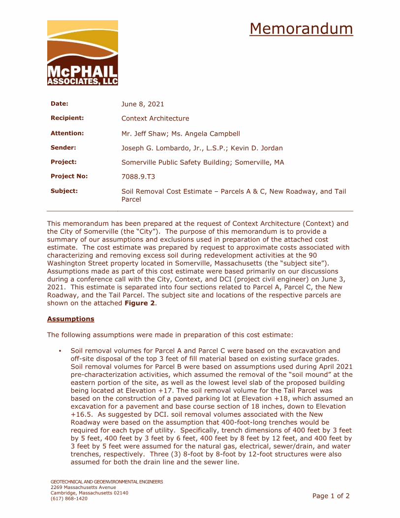
Memorandum
GEOTECHNICAL AND GEOENVIRONMENTAL ENGINEERS
2269 Massachusetts Avenue
Cambridge, Massachusetts 02140
(617) 868-1420
Page 1 of 2
Date:
June 8, 2021
Recipient: Context Architecture
Attention:
Mr. Jeff Shaw; Ms. Angela Campbell
Sender:
Joseph G. Lombardo, Jr., L.S.P.; Kevin D. Jordan
Project:
Somerville Public Safety Building; Somerville, MA
Project No: 7088.9.T3
Subject:
Soil Removal Cost Estimate – Parcels A & C, New Roadway, and Tail
Parcel
This memorandum has been prepared at the request of Context Architecture (Context) and
the City of Somerville (the “City”). The purpose of this memorandum is to provide a
summary of our assumptions and exclusions used in preparation of the attached cost
estimate. The cost estimate was prepared by request to approximate costs associated with
characterizing and removing excess soil during redevelopment activities at the 90
Washington Street property located in Somerville, Massachusetts (the “subject site”).
Assumptions made as part of this cost estimate were based primarily on our discussions
during a conference call with the City, Context, and DCI (project civil engineer) on June 3,
2021. This estimate is separated into four sections related to Parcel A, Parcel C, the New
Roadway, and the Tail Parcel. The subject site and locations of the respective parcels are
shown on the attached Figure 2.
Assumptions
The following assumptions were made in preparation of this cost estimate:
• Soil removal volumes for Parcel A and Parcel C were based on the excavation and
off-site disposal of the top 3 feet of fill material based on existing surface grades.
Soil removal volumes for Parcel B were based on assumptions used during April 2021
pre-characterization activities, which assumed the removal of the “soil mound” at the
eastern portion of the site, as well as the lowest level slab of the proposed building
being located at Elevation +17. The soil removal volume for the Tail Parcel was
based on the construction of a paved parking lot at Elevation +18, which assumed an
excavation for a pavement and base course section of 18 inches, down to Elevation
+16.5. As suggested by DCI. soil removal volumes associated with the New
Roadway were based on the assumption that 400-foot-long trenches would be
required for each type of utility. Specifically, trench dimensions of 400 feet by 3 feet
by 5 feet, 400 feet by 3 feet by 6 feet, 400 feet by 8 feet by 12 feet, and 400 feet by
3 feet by 5 feet were assumed for the natural gas, electrical, sewer/drain, and water
trenches, respectively. Three (3) 8-foot by 8-foot by 12-foot structures were also
assumed for both the drain line and the sewer line.

Memorandum
GEOTECHNICAL AND GEOENVIRONMENTAL ENGINEERS
2269 Massachusetts Avenue
Cambridge, Massachusetts 02140
(617) 868-1420
Page 2 of 2
• Estimated percentages regarding soil characterization classifications (i.e. Unlined
Landfill, Lined Landfill, Asphalt Batch Plant, Out-of-State Non-Hazardous) were based
on an average of existing soil data located at the subject site.
• “Low end” and “high end” unit prices for soil transportation and disposal were utilized
based on recent costs for similar McPhail projects. Soil tonnage was calculated using
a 1.65 ton per cubic yard multiplier.
• The number of assumed soil pre-characterization samples needed was based on
obtaining data at a frequency of one sample per 500 cubic yards of soil, plus
additional samples relative to the amount of Out-of-State Non-Hazardous soil
assumed, which requires a frequency of one sample per 125 cubic yards.
• Backfilling of each excavation area with “clean” imported ordinary fill material was
included as part of this estimate. It is possible that less imported fill would be
needed based currently unknown details regarding future redevelopment activities
and the possibility of reusing existing fill on-site.
• It was assumed that groundwater treatment and off-site discharge would not be
necessary.
Exclusions
This estimate excludes costs for the following:
• Consulting fees and mark-ups on McPhail subcontractors;
• Dewatering, groundwater treatment, sampling, and off-site discharge;
• Removal and disposal of asphalt and solid waste;
• Earth support, including temporary earth support associated with soil excavation;
• Contractor fees not specified herein;
• Additional soil pre-characterization sampling beyond the assumed sampling
frequency;
• Soil marker barriers which may be placed between existing fill material and “clean”
imported fill; and
• Any other costs not specifically state as being included in this cost estimate.
We trust that the above is sufficient for your present requirements. If you have any
questions concerning the information herein, please do not hesitate to contact us.
KDJ/jgl

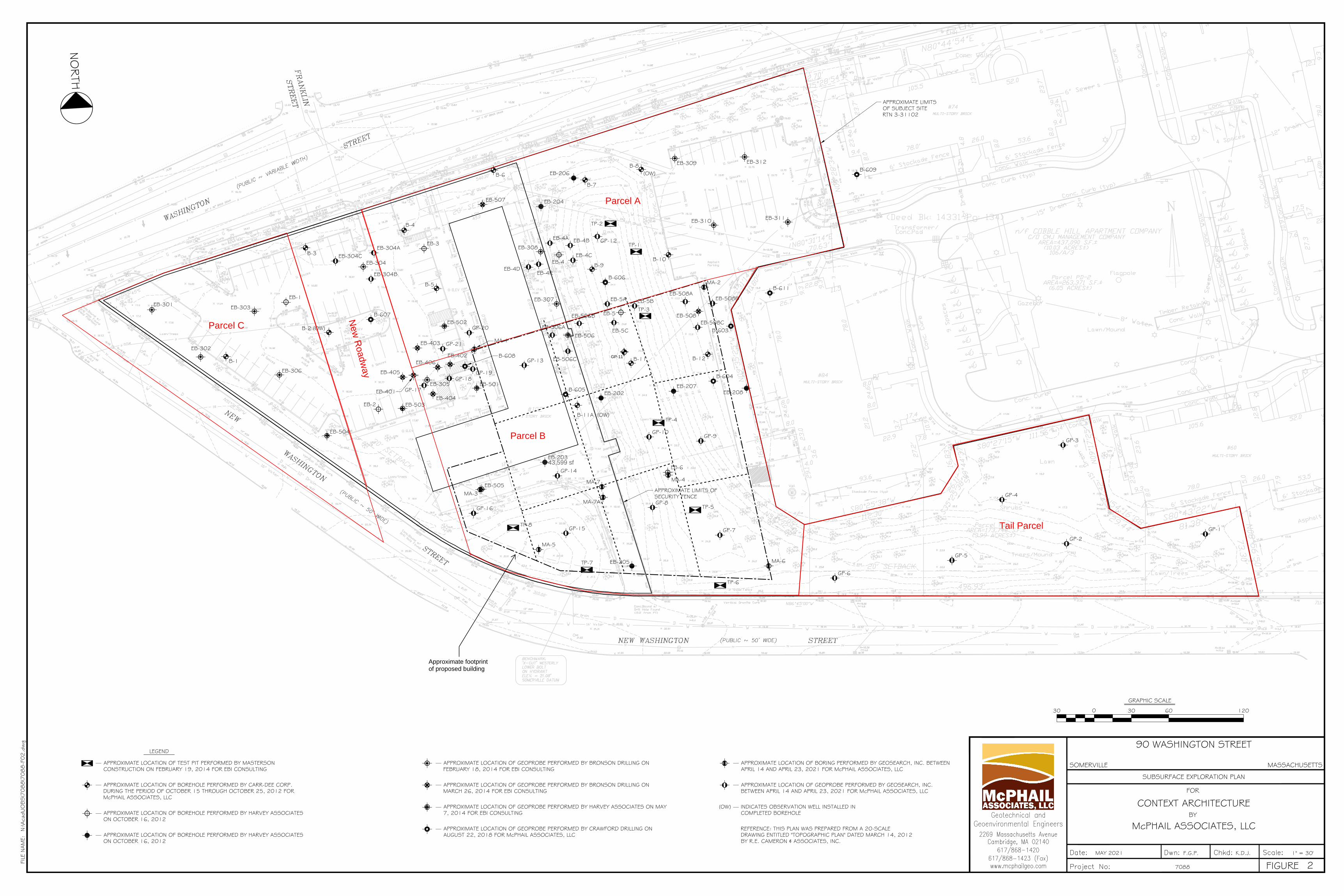
B-1
B-2 (OW)
B-3
B-4
B-5
B-6
B-7
B-8(OW)
B-9B-10
B-11 B-12
B-11A (OW)
EB-301
EB-304
EB-303
EB-302
EB-306
EB-305
EB-308
EB-307
EB-311
TP-3
TP-1
TP-2
EB-312EB-309
EB-310
TP-4
TP-5
TP-6
TP-7
TP-8
EB-1
EB-2
EB-3
EB-4
EB-6
EB-202
EB-203
EB-204
EB-205
EB-206
EB-207EB-208EB-401
EB-402
EB-403
EB-404
EB-405
EB-406
EB-501
EB-502
EB-503
EB-504
EB-505
EB-506
EB-507
EB-508B-607
B-608
B-606
B-605
B-604
B-603
B-611
B-609
EB-5
APPROXIMATE LIMITS OFSECURITY FENCE
APPROXIMATE LIMITSOF SUBJECT SITERTN 3-31102
MA-1
MA-2
MA-3
MA-4
MA-6
MA-7
MA-7A
EB-304CEB-304A
EB-304B
GP-17
GP-21
GP-20
GP-19GP-18
GP-13 EB-506C
EB-506A
GP-12
GP-9GP-10
GP-8
GP-7
GP-16
GP-15
GP-14
MA-5
EB-4DEB-4R
EB-4A EB-4B
EB-4C
EB-5A EB-5B
EB-5C
EB-508AEB-508B
EB-508CEB-506B
GP-6
GP-5
GP-4
GP-2
GP-3
GP-1
McPHAIL ASSOCIATES, LLC
FOR
BY
FILE
NAM
E:
FIGURE
N:\A
cad\
JOBS\7
088\7
088-F
02.d
wg
7088
1" = 30'K.D.J.F.G.P.MAY 2021
CONTEXT ARCHITECTURE
SUBSURFACE EXPLORATION PLAN
MASSACHUSETTSSOMERVILLE
90 WASHINGTON STREET
2
NO
RTH
0
GRAPHIC SCALE
30 30 60 120
REFERENCE: THIS PLAN WAS PREPARED FROM A 20-SCALEDRAWING ENTITLED "TOPOGRAPHIC PLAN" DATED MARCH 14, 2012BY R.E. CAMERON & ASSOCIATES, INC.
APPROXIMATE LOCATION OF BOREHOLE PERFORMED BY CARR-DEE CORP.DURING THE PERIOD OF OCTOBER 15 THROUGH OCTOBER 25, 2012 FORMcPHAIL ASSOCIATES, LLC
LEGEND
INDICATES OBSERVATION WELL INSTALLED INCOMPLETED BOREHOLE
(OW)
APPROXIMATE LOCATION OF GEOPROBE PERFORMED BY BRONSON DRILLING ONFEBRUARY 18, 2014 FOR EBI CONSULTING
APPROXIMATE LOCATION OF TEST PIT PERFORMED BY MASTERSONCONSTRUCTION ON FEBRUARY 19, 2014 FOR EBI CONSULTING
APPROXIMATE LOCATION OF BOREHOLE PERFORMED BY HARVEY ASSOCIATESON OCTOBER 16, 2012
APPROXIMATE LOCATION OF BOREHOLE PERFORMED BY HARVEY ASSOCIATESON OCTOBER 16, 2012
APPROXIMATE LOCATION OF GEOPROBE PERFORMED BY BRONSON DRILLING ONMARCH 26, 2014 FOR EBI CONSULTING
APPROXIMATE LOCATION OF GEOPROBE PERFORMED BY HARVEY ASSOCIATES ON MAY7, 2014 FOR EBI CONSULTING
APPROXIMATE LOCATION OF GEOPROBE PERFORMED BY CRAWFORD DRILLING ONAUGUST 22, 2018 FOR McPHAIL ASSOCIATES, LLC
APPROXIMATE LOCATION OF BORING PERFORMED BY GEOSEARCH, INC. BETWEENAPRIL 14 AND APRIL 23, 2021 FOR McPHAIL ASSOCIATES, LLC
APPROXIMATE LOCATION OF GEOPROBE PERFORMED BY GEOSEARCH, INC.BETWEEN APRIL 14 AND APRIL 23, 2021 FOR McPHAIL ASSOCIATES, LLC
GP-11
43,599 sf
Approximate footprintof proposed building
New
Roadw
ay
Parcel A
Parcel C
Tail Parcel
Parcel B

Table 1 - Soil Disposal Cost Estimate - June 8, 2021 (Rev. 1)
90 Washington Street; Somerville, MA
McPhail Job No. 7088
Estimated Soil Excess Volume (CY) 6,600
Soil Type: Urban FillFill Qty
(CY)
Fill Qty
(Tons)
Cost
(low end)
Cost
(high end)
Depth (ft): 3Unregulated 0% 0 0 $3.50 $0.00 $0.00<RCS-1 0% 0 0 $19.00 $25.00 $0.00 $0.00<RCS-2 0% 0 0 $22.00 $28.00 $0.00 $0.00Unlined Landfill 20% 1,320 2,178 $45.00 $52.00 $98,010 $113,256Lined Landfill 10% 660 1,089 $47.00 $55.00 $51,183.00 $59,895.00Asphalt Batch Plant 40% 2,640 4,356 $55.00 $75.00 $239,580 $326,700Regulated Non-Hazard 30% 1,980 3,267 $75.00 $90.00 $245,025 $294,030
Hardous Soil for TCLP lead treatment 0% 0 0 $16.00 $20.00 $0.00 $0.00
Sub Totals 100% 6,600 10,890 $633,798 $793,881
Estimated Soil Excess Volume (CY) 10,400
Soil Type: Urban FillFill Qty
(CY)
Fill Qty
(Tons)
Cost
(low end)
Cost
(high end)
Depth (ft): 3Unregulated 0% 0 0 $3.50 $0.00 $0.00<RCS-1 0% 0 0 $19.00 $25.00 $0.00 $0.00<RCS-2 0% 0 0 $22.00 $28.00 $0.00 $0.00Unlined Landfill 20% 2,080 3,432 $45.00 $52.00 $154,440 $178,464Lined Landfill 10% 1,040 1,716 $47.00 $55.00 $80,652.00 $94,380.00Asphalt Batch Plant 40% 4,160 6,864 $55.00 $75.00 $377,520 $514,800Regulated Non-Hazard 30% 3,120 5,148 $75.00 $90.00 $386,100 $463,320
Hardous Soil for TCLP lead treatment - 500 825 $16.00 $20.00 $13,200.00 $16,500.00
Sub Totals 100% 10,400 17,160 $998,712 $1,250,964
Estimated Soil Excess Volume (CY) 3,300
Soil Type: Urban FillFill Qty
(CY)
Fill Qty
(Tons)
Cost
(low end)
Cost
(high end)
Depth (ft): 3Unregulated 0% 0 0 $3.50 $0.00 $0.00<RCS-1 0% 0 0 $19.00 $25.00 $0.00 $0.00<RCS-2 0% 0 0 $22.00 $28.00 $0.00 $0.00Unlined Landfill 20% 660 1,089 $45.00 $52.00 $49,005 $56,628Lined Landfill 10% 330 545 $47.00 $55.00 $25,591.50 $29,947.50Asphalt Batch Plant 40% 1,320 2,178 $55.00 $75.00 $119,790 $163,350Regulated Non-Hazard 30% 990 1,634 $75.00 $90.00 $122,513 $147,015Hardous Soil for TCLP lead treatment 0% 0 0 $16.00 $20.00 $0.00 $0.00
Sub Totals 100% 3,300 5,445 $316,899 $396,941
Estimated Soil Excess Volume (CY) 4,300
Soil Type: Urban FillFill Qty
(CY)
Fill Qty
(Tons)
Cost
(low end)
Cost
(high end)
Average Depth (ft): 3.18Unregulated 0% 0 0 $3.50 $0.00 $0.00<RCS-1 0% 0 0 $19.00 $25.00 $0.00 $0.00<RCS-2 0% 0 0 $22.00 $28.00 $0.00 $0.00Unlined Landfill 20% 860 1,419 $45.00 $52.00 $63,855 $73,788Lined Landfill 10% 430 710 $47.00 $55.00 $33,346.50 $39,022.50Asphalt Batch Plant 40% 1,720 2,838 $55.00 $75.00 $156,090 $212,850Regulated Non-Hazard 30% 1,290 2,129 $75.00 $90.00 $159,638 $191,565
Hazardous Soil for TCLP lead treatment 100 165 $16.00 $20.00 $2,640.00 $3,300.00
Sub Totals 100% $412,929 $517,226
Estimated Soil Excess Volume (CY) 2,700
Soil Type: Urban FillFill Qty
(CY)
Fill Qty
(Tons)
Cost
(low end)
Cost
(high end)
Depth (ft): N/A (Various utility trenches)Unregulated 0% 0 0 $3.50 $0.00 $0.00<RCS-1 0% 0 0 $19.00 $25.00 $0.00 $0.00<RCS-2 0% 0 0 $22.00 $28.00 $0.00 $0.00Unlined Landfill 20% 540 891 $45.00 $52.00 $40,095 $46,332Lined Landfill 10% 270 446 $47.00 $55.00 $20,938.50 $24,502.50Asphalt Batch Plant 40% 1,080 1,782 $55.00 $75.00 $98,010 $133,650Regulated Non-Hazard 30% 810 1,337 $75.00 $90.00 $100,238 $120,285Hardous Soil for TCLP lead treatment 0% 0 $16.00 $20.00 $0.00 $0.00
Sub Totals 100% 2,700 4,455 $259,281 $324,770
Estimated Soil Removal Total 12,600 20,790 1,622,907$ 2,032,817$
Soil Quantity & Cost based on Percentage Breakdown of Facility Types
(See memorandum dated June 8, 2021 for assumptions and exclusions)
Unit Price
Range ($/ton)
Unit Price
Range ($/ton)
Unit Price
Range ($/ton)
Unit Price
Range ($/ton)
Pa
rce
l A
Pa
rce
l C
Ta
il P
arc
el
Ro
ad
wa
yP
arc
el
B
Unit Price
Range ($/ton)
McPhail Associates, LLC
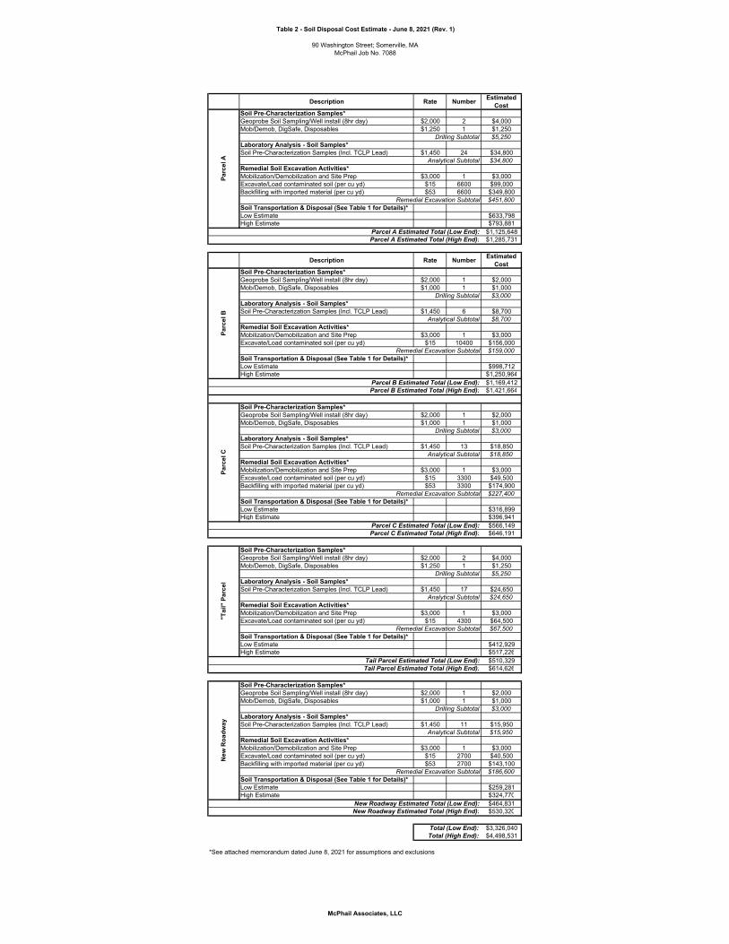
Table 2 - Soil Disposal Cost Estimate - June 8, 2021 (Rev. 1)
90 Washington Street; Somerville, MA
McPhail Job No. 7088
Description Rate NumberEstimated
CostSoil Pre-Characterization Samples*
Geoprobe Soil Sampling/Well install (8hr day) $2,000 2 $4,000
Mob/Demob, DigSafe, Disposables $1,250 1 $1,250
Drilling Subtotal $5,250
Laboratory Analysis - Soil Samples*
Soil Pre-Characterization Samples (Incl. TCLP Lead) $1,450 24 $34,800
Analytical Subtotal $34,800
Remedial Soil Excavation Activities*
Mobilization/Demobilization and Site Prep $3,000 1 $3,000
Excavate/Load contaminated soil (per cu yd) $15 6600 $99,000
Backfilling with imported material (per cu yd) $53 6600 $349,800
Remedial Excavation Subtotal $451,800
Soil Transportation & Disposal (See Table 1 for Details)*
Low Estimate $633,798High Estimate $793,881
Parcel A Estimated Total (Low End): $1,125,648Parcel A Estimated Total (High End): $1,285,731
Description Rate NumberEstimated
CostSoil Pre-Characterization Samples*
Geoprobe Soil Sampling/Well install (8hr day) $2,000 1 $2,000
Mob/Demob, DigSafe, Disposables $1,000 1 $1,000
Drilling Subtotal $3,000
Laboratory Analysis - Soil Samples*
Soil Pre-Characterization Samples (Incl. TCLP Lead) $1,450 6 $8,700
Analytical Subtotal $8,700
Remedial Soil Excavation Activities*
Mobilization/Demobilization and Site Prep $3,000 1 $3,000
Excavate/Load contaminated soil (per cu yd) $15 10400 $156,000
Remedial Excavation Subtotal $159,000
Soil Transportation & Disposal (See Table 1 for Details)*
Low Estimate $998,712High Estimate $1,250,964
Parcel B Estimated Total (Low End): $1,169,412Parcel B Estimated Total (High End): $1,421,664
Soil Pre-Characterization Samples*
Geoprobe Soil Sampling/Well install (8hr day) $2,000 1 $2,000
Mob/Demob, DigSafe, Disposables $1,000 1 $1,000
Drilling Subtotal $3,000
Laboratory Analysis - Soil Samples*
Soil Pre-Characterization Samples (Incl. TCLP Lead) $1,450 13 $18,850
Analytical Subtotal $18,850
Remedial Soil Excavation Activities*
Mobilization/Demobilization and Site Prep $3,000 1 $3,000
Excavate/Load contaminated soil (per cu yd) $15 3300 $49,500
Backfilling with imported material (per cu yd) $53 3300 $174,900
Remedial Excavation Subtotal $227,400
Soil Transportation & Disposal (See Table 1 for Details)*
Low Estimate $316,899High Estimate $396,941
Parcel C Estimated Total (Low End): $566,149Parcel C Estimated Total (High End): $646,191
Soil Pre-Characterization Samples*
Geoprobe Soil Sampling/Well install (8hr day) $2,000 2 $4,000
Mob/Demob, DigSafe, Disposables $1,250 1 $1,250
Drilling Subtotal $5,250
Laboratory Analysis - Soil Samples*
Soil Pre-Characterization Samples (Incl. TCLP Lead) $1,450 17 $24,650
Analytical Subtotal $24,650
Remedial Soil Excavation Activities*
Mobilization/Demobilization and Site Prep $3,000 1 $3,000
Excavate/Load contaminated soil (per cu yd) $15 4300 $64,500
Remedial Excavation Subtotal $67,500
Soil Transportation & Disposal (See Table 1 for Details)*
Low Estimate $412,929High Estimate $517,226
Tail Parcel Estimated Total (Low End): $510,329Tail Parcel Estimated Total (High End): $614,626
Soil Pre-Characterization Samples*
Geoprobe Soil Sampling/Well install (8hr day) $2,000 1 $2,000
Mob/Demob, DigSafe, Disposables $1,000 1 $1,000
Drilling Subtotal $3,000
Laboratory Analysis - Soil Samples*
Soil Pre-Characterization Samples (Incl. TCLP Lead) $1,450 11 $15,950
Analytical Subtotal $15,950
Remedial Soil Excavation Activities*
Mobilization/Demobilization and Site Prep $3,000 1 $3,000
Excavate/Load contaminated soil (per cu yd) $15 2700 $40,500
Backfilling with imported material (per cu yd) $53 2700 $143,100
Remedial Excavation Subtotal $186,600
Soil Transportation & Disposal (See Table 1 for Details)*
Low Estimate $259,281High Estimate $324,770
New Roadway Estimated Total (Low End): $464,831New Roadway Estimated Total (High End): $530,320
Total (Low End): $3,326,040Total (High End): $4,498,531
*See attached memorandum dated June 8, 2021 for assumptions and exclusions
Pa
rce
l C
"Ta
il"
Pa
rce
lN
ew
Ro
ad
wa
yP
arc
el A
Pa
rce
l B
McPhail Associates, LLC

SOMERVILLE PUBLIC SAFETY BUILDING Somerville, Massachusetts 02143
Project No. 2006.00
NARRATIVE 8/13/2021
E. SPACE NEEDS REPORT
PUBLIC SAFETY COMPLEX
SPACE NEEDS STUDY
FIFTH DRAFT JULY 21, 2021
68 H A R R I S O N AV E N U E B O S TO N , M A 02111
TEL 617 423 1400 WEB C O N T E X TA R C .C O M
SOMERVILLE, MASSACHUSETTS

2 Context Architecture
Context Architecture 3
Contents
01. Staffing 4 POLICE DEPARTMENT 4
F IRE DEPARTMENT 6
02. ParkingNeedsSummary 7
03. SpaceNeedsSummary 9 04. SharedProgramSpaceNeeds 15
05. PoliceDepartmentSpaceNeeds 53
06. FireDepartmentSpaceNeeds 147
07. EmergencyManagementSpaceNeeds 189
08. Appendix 193

4 Context Architecture
Public Safety Complex, Space Needs StudySomerville, Massachusetts
STAFFING PROJECTIONS
Police CurrentTotal Shifts: 8 - 4 4-12 12-8 Total
CommandChief 1 1 1Deputy Chief 2 2 2Professional Standards Lieutenant 1 1 1Professional Standards Sergeant 1 1 1Chief's Administrative Sergeant 1 1 1
6 6 6Administration Division
Captain Administration 1 1 1Special Operations Lieutenant 1 1 1Special Operations Sergeant 1 1 1Homeland Security Sergeant 1 1 1K-9 Officer 1 1 1Training Lieutenant 1 1 1Financial Services Analyst 1 1 1Financial Services Clerk 1 1 1Administrative Assistant 1 1 1Detail Office Manager 1 1 1Detail Administrator 1 1 1Records Clerks 1.5 5 5Public Information Lieutenant 1 0 0IT Specialists 2 2 2Animal Control Officers 2 2 2Community Outreach Director 2 2 2Jail Diversion Coordinator 1 1 1CIT Project Assistant 1 1 1Law Enforcement Partnership Coordinator 1 1 1COHR Staff 6 11 11
40.5 48 48Criminal Investigation Division
Captain Detectives / Commander 1 1 1Lieutenant Detectives 0 1 1Sergeant Detectives 2 1 1Detectives 6 5 1 6Detective Clerk 1 1 1Crime Scene Detective 1 1 1FBI Liason Detective - Off Site 1 1 1School Resources Detective 1 1 1Juvenile Detective 1 1 1Family Services Sergeant Detective 1 1 1Family Services Detectives 2 2 2Victim/Witness Advocate 1 1 1Drug Unit Sergeant Detective 1 1 1Drug Unit Detectives 5 3 3DEA Liason Detective - Off Site 1 1 1Licensing Sergeant - Off Site 1 1 1Mayor's Officer 1 1 1
Future to 2050
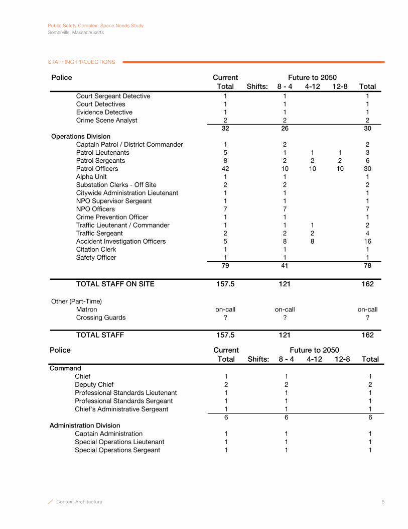
Context Architecture 5
PublicSafetyComplex,SpaceNeedsStudySomerville,Massachusetts
STAFFING PROJECTIONS
Police CurrentTotal Shifts: 8 - 4 4-12 12-8 Total
Future to 2050
Court Sergeant Detective 1 1 1Court Detectives 1 1 1Evidence Detective 1 1 1Crime Scene Analyst 2 2 2
32 26 30Operations Division
Captain Patrol / District Commander 1 2 2Patrol Lieutenants 5 1 1 1 3Patrol Sergeants 8 2 2 2 6Patrol Officers 42 10 10 10 30Alpha Unit 1 1 1Substation Clerks - Off Site 2 2 2Citywide Administration Lieutenant 1 1 1NPO Supervisor Sergeant 1 1 1NPO Officers 7 7 7Crime Prevention Officer 1 1 1Traffic Lieutenant / Commander 1 1 1 2Traffic Sergeant 2 2 2 4Accident Investigation Officers 5 8 8 16Citation Clerk 1 1 1Safety Officer 1 1 1
79 41 78
TOTAL STAFF ON SITE 157.5 121 162
Other (Part-Time)Matron on-call on-call on-callCrossing Guards ? ? ?
TOTAL STAFF 157.5 121 162

6 Context Architecture
Public Safety Complex, Space Needs StudySomerville, Massachusetts
STAFFING PROJECTIONS
Fire CurrentSingle Shift Single Shift Total All Shifts
Headqarters StaffChief 1 1 1Assistant Chief 1 1 1Administrative Lieutenant 1 1 1Fire Analyst 1 1 1Administrative Assistant (civ) 1 1 1Senior Clerk (civ) 1 1 1Training Deputy Chief 1 1 1Homeland Security Lieutentant 1 1 1Homeland Security Coordinator 1 1 1Fire IT 0 1 1
Fire InvestigationFire Investigator 1 1 1Staff (3)* 0* 0** Firefighters with dual role, not incl. in totals
Engine #3Officer 1 2 8Firefighters / EMTs 3 6 24
TOTAL STAFF 14 19 43
Other (Part-Time)Auxilliary 20 20 20
TOTAL STAFF 34 39 63
Future to 2050

Context Architecture 7
PublicSafetyComplex,SpaceNeedsStudySomerville,Massachusetts
PARKING NEEDS SUMMARY
DepartmentSurface Garaged Surface Garaged Off-Site
Police Department
Assigned Department Vehicles 33 0 19 14 0
Unassigned Department Vehicles 13 0 3 10 0
Patrol Cuisers (unassigned) 16 0 0 16 0
Motorcycles (Sp Ops & Traffic) 0 7 0 7 0
Boat on 40' Trailer (stored off site) 0 0 0 0 1
NEMLEC, SWAT & SRT 0 3 0 3 0
Incident Command Van 0 1 0 1 0
Animal Control Van 0 1 0 1 0
Crime Scene Van 0 1 0 1 0
Gator 0 2 0 2 0
Impounded Vehicles 0 0 0 2 0
Sub-total 62 15 22 57 1
Fire Department
Marked Vehicles 3 0 3 12 0
Administration 3 0 3 0 0
Front Line Apparatus 0 5 0 3 0
Reserve Apparatus 0 7 0 3 0
Investigation 0 2 0 2 0
Auxilliary 0 2 0 0 0
Sub-total 6 16 6 20 0
Total 68 31 28 77 1
Shared Site Features Training Features
Future (day shift)
vehicle crash / bomb protectionTrench Prop (Extraction)
Emergency Generator FlagpoleDumpster / Trash EnclosureBack-up Generator
Secure hardening of front entry from
Present (day shift)
Hydrant TrainingStair TowerWall / Ladder TrainingConfined Space Training

8 Context Architecture
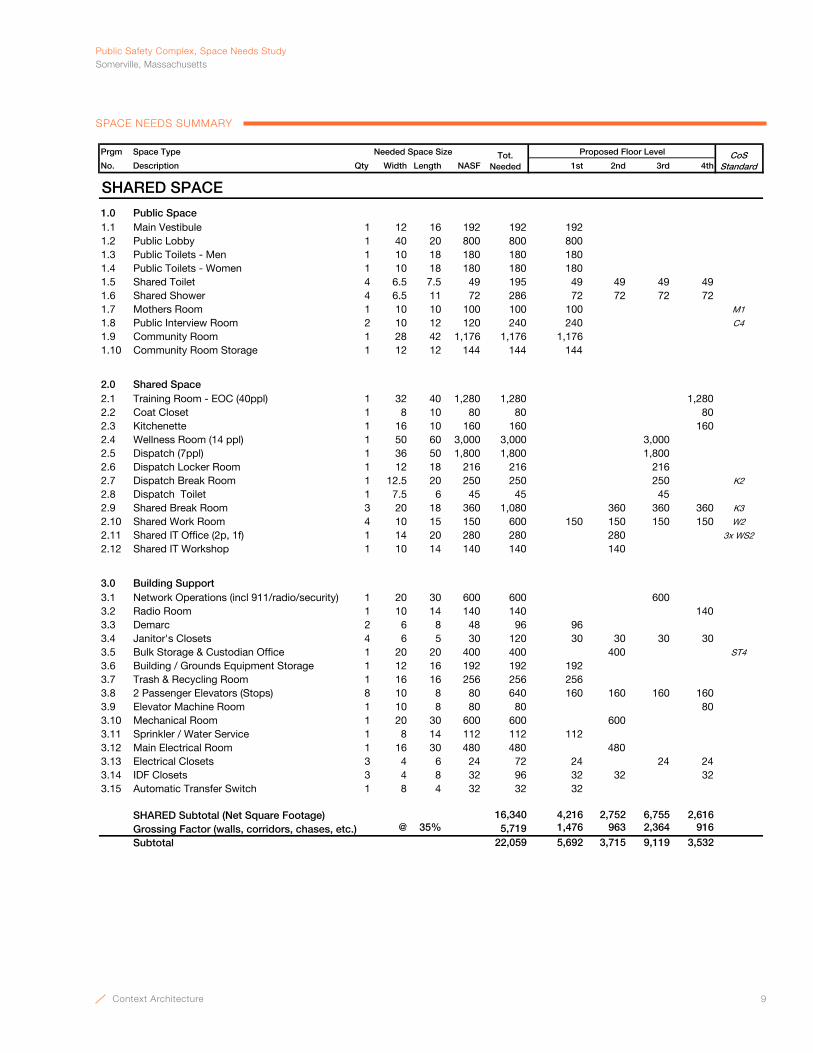
PublicSafetyComplex,SpaceNeedsStudySomerville,Massachusetts
Context Architecture 9
SPACE NEEDS SUMMARY
Prgm Space Type Needed Space Size
No. Description Qty Width Length NASF 1st 2nd 3rd 4th
SHARED SPACE
1.0 Public Space1.1 Main Vestibule 1 12 16 192 192 192 1.2 Public Lobby 1 40 20 800 800 800 1.3 Public Toilets - Men 1 10 18 180 180 180 1.4 Public Toilets - Women 1 10 18 180 180 180 1.5 Shared Toilet 4 6.5 7.5 49 195 49 49 49 49 1.6 Shared Shower 4 6.5 11 72 286 72 72 72 72 1.7 Mothers Room 1 10 10 100 100 100 M1
1.8 Public Interview Room 2 10 12 120 240 240 C4
1.9 Community Room 1 28 42 1,176 1,176 1,176 1.10 Community Room Storage 1 12 12 144 144 144
2.0 Shared Space2.1 Training Room - EOC (40ppl) 1 32 40 1,280 1,280 1,280 2.2 Coat Closet 1 8 10 80 80 80 2.3 Kitchenette 1 16 10 160 160 160 2.4 Wellness Room (14 ppl) 1 50 60 3,000 3,000 3,000 2.5 Dispatch (7ppl) 1 36 50 1,800 1,800 1,800 2.6 Dispatch Locker Room 1 12 18 216 216 216 2.7 Dispatch Break Room 1 12.5 20 250 250 250 K2
2.8 Dispatch Toilet 1 7.5 6 45 45 45 2.9 Shared Break Room 3 20 18 360 1,080 360 360 360 K3
2.10 Shared Work Room 4 10 15 150 600 150 150 150 150 W2
2.11 Shared IT Office (2p, 1f) 1 14 20 280 280 280 3x WS2
2.12 Shared IT Workshop 1 10 14 140 140 140
3.0 Building Support3.1 Network Operations (incl 911/radio/security) 1 20 30 600 600 600 3.2 Radio Room 1 10 14 140 140 140 3.3 Demarc 2 6 8 48 96 96 3.4 Janitor's Closets 4 6 5 30 120 30 30 30 30 3.5 Bulk Storage & Custodian Office 1 20 20 400 400 400 ST4
3.6 Building / Grounds Equipment Storage 1 12 16 192 192 192 3.7 Trash & Recycling Room 1 16 16 256 256 256 3.8 2 Passenger Elevators (Stops) 8 10 8 80 640 160 160 160 160 3.9 Elevator Machine Room 1 10 8 80 80 80 3.10 Mechanical Room 1 20 30 600 600 600 3.11 Sprinkler / Water Service 1 8 14 112 112 112 3.12 Main Electrical Room 1 16 30 480 480 480 3.13 Electrical Closets 3 4 6 24 72 24 24 24 3.14 IDF Closets 3 4 8 32 96 32 32 32 3.15 Automatic Transfer Switch 1 8 4 32 32 32
SHARED Subtotal (Net Square Footage) 16,340 4,216 2,752 6,755 2,616 Grossing Factor (walls, corridors, chases, etc.) @ 35% 5,719 1,476 963 2,364 916
Subtotal 22,059 5,692 3,715 9,119 3,532
Tot. Needed
CoS Standard
Proposed Floor Level
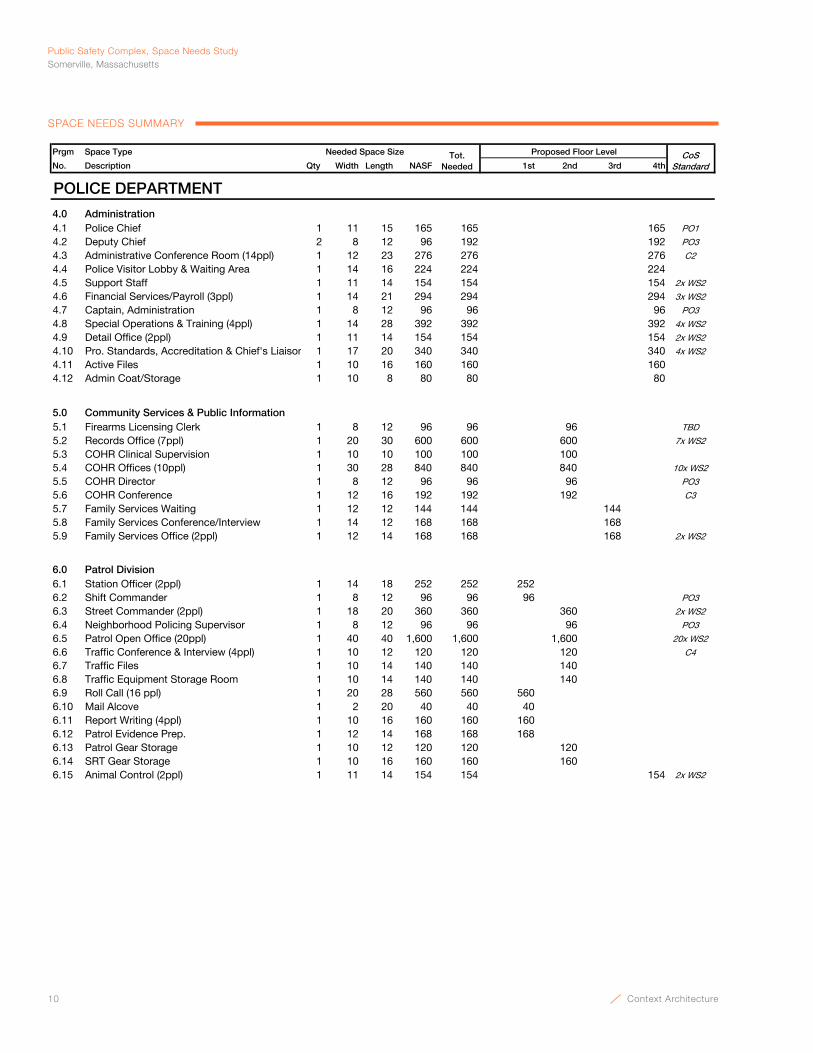
10 Context Architecture
Public Safety Complex, Space Needs StudySomerville, Massachusetts
SPACE NEEDS SUMMARY
Prgm Space Type Needed Space Size
No. Description Qty Width Length NASF 1st 2nd 3rd 4thTot.
NeededCoS
Standard
Proposed Floor Level
POLICE DEPARTMENT
4.0 Administration4.1 Police Chief 1 11 15 165 165 165 PO1
4.2 Deputy Chief 2 8 12 96 192 192 PO3
4.3 Administrative Conference Room (14ppl) 1 12 23 276 276 276 C2
4.4 Police Visitor Lobby & Waiting Area 1 14 16 224 224 224 4.5 Support Staff 1 11 14 154 154 154 2x WS2
4.6 Financial Services/Payroll (3ppl) 1 14 21 294 294 294 3x WS2
4.7 Captain, Administration 1 8 12 96 96 96 PO3
4.8 Special Operations & Training (4ppl) 1 14 28 392 392 392 4x WS2
4.9 Detail Office (2ppl) 1 11 14 154 154 154 2x WS2
4.10 Pro. Standards, Accreditation & Chief's Liaison 1 17 20 340 340 340 4x WS2
4.11 Active Files 1 10 16 160 160 160 4.12 Admin Coat/Storage 1 10 8 80 80 80
5.0 Community Services & Public Information5.1 Firearms Licensing Clerk 1 8 12 96 96 96 TBD
5.2 Records Office (7ppl) 1 20 30 600 600 600 7x WS2
5.3 COHR Clinical Supervision 1 10 10 100 100 100 5.4 COHR Offices (10ppl) 1 30 28 840 840 840 10x WS2
5.5 COHR Director 1 8 12 96 96 96 PO3
5.6 COHR Conference 1 12 16 192 192 192 C3
5.7 Family Services Waiting 1 12 12 144 144 144 5.8 Family Services Conference/Interview 1 14 12 168 168 168 5.9 Family Services Office (2ppl) 1 12 14 168 168 168 2x WS2
6.0 Patrol Division6.1 Station Officer (2ppl) 1 14 18 252 252 252 6.2 Shift Commander 1 8 12 96 96 96 PO3
6.3 Street Commander (2ppl) 1 18 20 360 360 360 2x WS2
6.4 Neighborhood Policing Supervisor 1 8 12 96 96 96 PO3
6.5 Patrol Open Office (20ppl) 1 40 40 1,600 1,600 1,600 20x WS2
6.6 Traffic Conference & Interview (4ppl) 1 10 12 120 120 120 C4
6.7 Traffic Files 1 10 14 140 140 140 6.8 Traffic Equipment Storage Room 1 10 14 140 140 140 6.9 Roll Call (16 ppl) 1 20 28 560 560 560 6.10 Mail Alcove 1 2 20 40 40 40 6.11 Report Writing (4ppl) 1 10 16 160 160 160 6.12 Patrol Evidence Prep. 1 12 14 168 168 168 6.13 Patrol Gear Storage 1 10 12 120 120 120 6.14 SRT Gear Storage 1 10 16 160 160 160 6.15 Animal Control (2ppl) 1 11 14 154 154 154 2x WS2
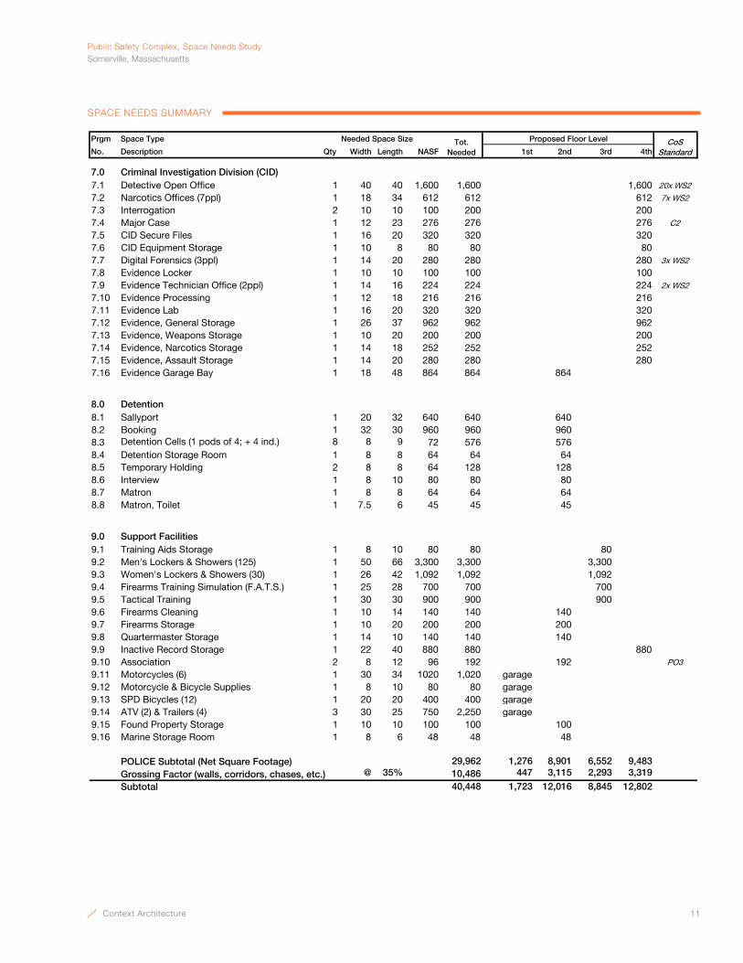
Context Architecture 11
PublicSafetyComplex,SpaceNeedsStudySomerville,Massachusetts
SPACE NEEDS SUMMARY
Prgm Space Type Needed Space Size
No. Description Qty Width Length NASF 1st 2nd 3rd 4thTot.
NeededCoS
Standard
Proposed Floor Level
7.0 Criminal Investigation Division (CID)7.1 Detective Open Office 1 40 40 1,600 1,600 1,600 20x WS2
7.2 Narcotics Offices (7ppl) 1 18 34 612 612 612 7x WS2
7.3 Interrogation 2 10 10 100 200 200 7.4 Major Case 1 12 23 276 276 276 C2
7.5 CID Secure Files 1 16 20 320 320 320 7.6 CID Equipment Storage 1 10 8 80 80 80 7.7 Digital Forensics (3ppl) 1 14 20 280 280 280 3x WS2
7.8 Evidence Locker 1 10 10 100 100 100 7.9 Evidence Technician Office (2ppl) 1 14 16 224 224 224 2x WS2
7.10 Evidence Processing 1 12 18 216 216 216 7.11 Evidence Lab 1 16 20 320 320 320 7.12 Evidence, General Storage 1 26 37 962 962 962 7.13 Evidence, Weapons Storage 1 10 20 200 200 200 7.14 Evidence, Narcotics Storage 1 14 18 252 252 252 7.15 Evidence, Assault Storage 1 14 20 280 280 280 7.16 Evidence Garage Bay 1 18 48 864 864 864
8.0 Detention8.1 Sallyport 1 20 32 640 640 640 8.2 Booking 1 32 30 960 960 960 8.3 Detention Cells (1 pods of 4; + 4 ind.) 8 8 9 72 576 576 8.4 Detention Storage Room 1 8 8 64 64 64 8.5 Temporary Holding 2 8 8 64 128 128 8.6 Interview 1 8 10 80 80 80 8.7 Matron 1 8 8 64 64 64 8.8 Matron, Toilet 1 7.5 6 45 45 45
9.0 Support Facilities9.1 Training Aids Storage 1 8 10 80 80 80 9.2 Men's Lockers & Showers (125) 1 50 66 3,300 3,300 3,300 9.3 Women's Lockers & Showers (30) 1 26 42 1,092 1,092 1,092 9.4 Firearms Training Simulation (F.A.T.S.) 1 25 28 700 700 700 9.5 Tactical Training 1 30 30 900 900 900 9.6 Firearms Cleaning 1 10 14 140 140 140 9.7 Firearms Storage 1 10 20 200 200 200 9.8 Quartermaster Storage 1 14 10 140 140 140 9.9 Inactive Record Storage 1 22 40 880 880 880 9.10 Association 2 8 12 96 192 192 PO3
9.11 Motorcycles (6) 1 30 34 1020 1,020 garage9.12 Motorcycle & Bicycle Supplies 1 8 10 80 80 garage9.13 SPD Bicycles (12) 1 20 20 400 400 garage9.14 ATV (2) & Trailers (4) 3 30 25 750 2,250 garage9.15 Found Property Storage 1 10 10 100 100 100 9.16 Marine Storage Room 1 8 6 48 48 48
POLICE Subtotal (Net Square Footage) 29,962 1,276 8,901 6,552 9,483 Grossing Factor (walls, corridors, chases, etc.) @ 35% 10,486 447 3,115 2,293 3,319
Subtotal 40,448 1,723 12,016 8,845 12,802
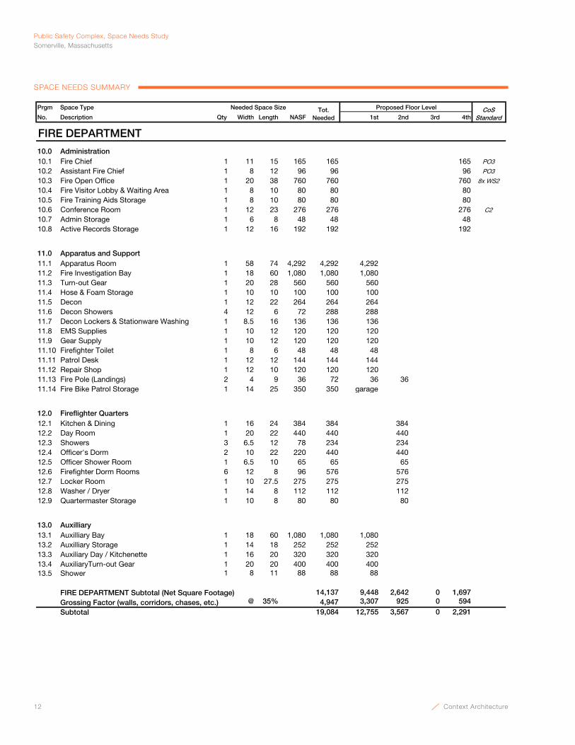
12 Context Architecture
Public Safety Complex, Space Needs StudySomerville, Massachusetts
SPACE NEEDS SUMMARY
Prgm Space Type Needed Space Size
No. Description Qty Width Length NASF 1st 2nd 3rd 4thTot.
NeededCoS
Standard
Proposed Floor Level
FIRE DEPARTMENT
10.0 Administration10.1 Fire Chief 1 11 15 165 165 165 PO3
10.2 Assistant Fire Chief 1 8 12 96 96 96 PO3
10.3 Fire Open Office 1 20 38 760 760 760 8x WS2
10.4 Fire Visitor Lobby & Waiting Area 1 8 10 80 80 80 10.5 Fire Training Aids Storage 1 8 10 80 80 80 10.6 Conference Room 1 12 23 276 276 276 C2
10.7 Admin Storage 1 6 8 48 48 48 10.8 Active Records Storage 1 12 16 192 192 192
11.0 Apparatus and Support11.1 Apparatus Room 1 58 74 4,292 4,292 4,292 11.2 Fire Investigation Bay 1 18 60 1,080 1,080 1,080 11.3 Turn-out Gear 1 20 28 560 560 560 11.4 Hose & Foam Storage 1 10 10 100 100 100 11.5 Decon 1 12 22 264 264 264 11.6 Decon Showers 4 12 6 72 288 288 11.7 Decon Lockers & Stationware Washing 1 8.5 16 136 136 136 11.8 EMS Supplies 1 10 12 120 120 120 11.9 Gear Supply 1 10 12 120 120 120 11.10 Firefighter Toilet 1 8 6 48 48 48 11.11 Patrol Desk 1 12 12 144 144 144 11.12 Repair Shop 1 12 10 120 120 120 11.13 Fire Pole (Landings) 2 4 9 36 72 36 36 11.14 Fire Bike Patrol Storage 1 14 25 350 350 garage
12.0 Fireflighter Quarters12.1 Kitchen & Dining 1 16 24 384 384 384 12.2 Day Room 1 20 22 440 440 440 12.3 Showers 3 6.5 12 78 234 234 12.4 Officer's Dorm 2 10 22 220 440 440 12.5 Officer Shower Room 1 6.5 10 65 65 65 12.6 Firefighter Dorm Rooms 6 12 8 96 576 576 12.7 Locker Room 1 10 27.5 275 275 275 12.8 Washer / Dryer 1 14 8 112 112 112 12.9 Quartermaster Storage 1 10 8 80 80 80
13.0 Auxilliary13.1 Auxilliary Bay 1 18 60 1,080 1,080 1,080 13.2 Auxilliary Storage 1 14 18 252 252 252 13.3 Auxiliary Day / Kitchenette 1 16 20 320 320 320 13.4 AuxiliaryTurn-out Gear 1 20 20 400 400 400 13.5 Shower 1 8 11 88 88 88
FIRE DEPARTMENT Subtotal (Net Square Footage) 14,137 9,448 2,642 0 1,697 Grossing Factor (walls, corridors, chases, etc.) @ 35% 4,947 3,307 925 0 594
Subtotal 19,084 12,755 3,567 0 2,291
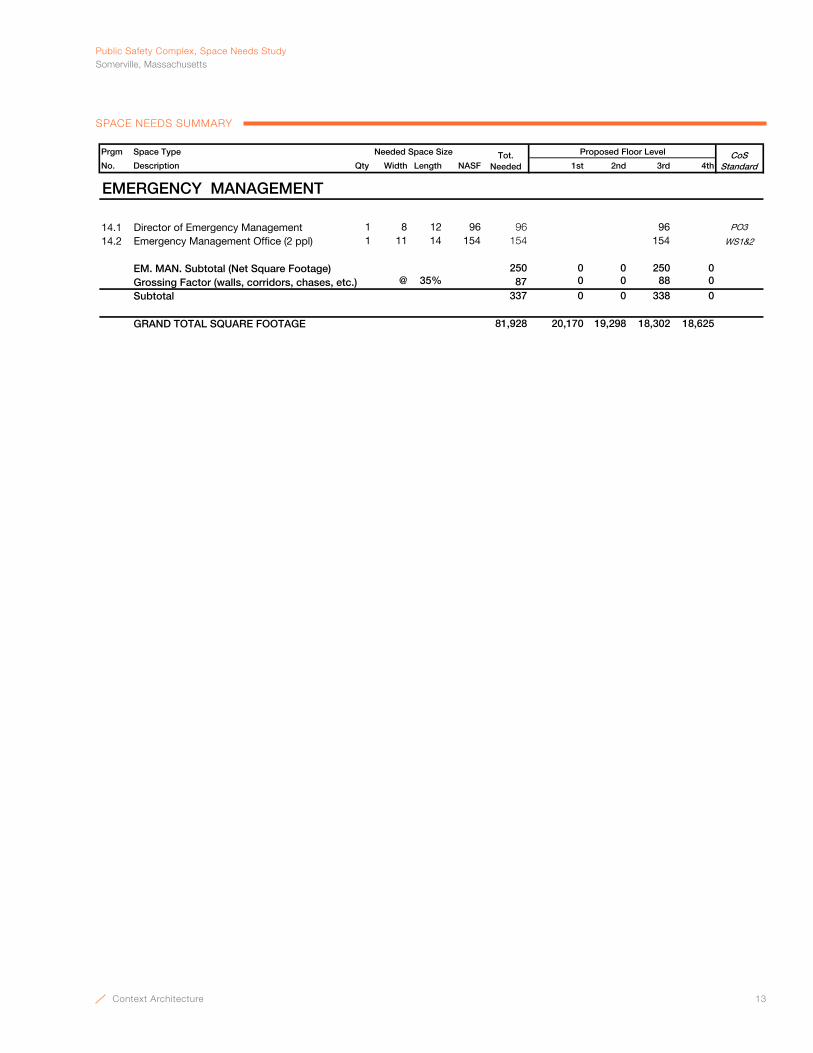
Context Architecture 13
PublicSafetyComplex,SpaceNeedsStudySomerville,Massachusetts
SPACE NEEDS SUMMARY
Prgm Space Type Needed Space Size
No. Description Qty Width Length NASF 1st 2nd 3rd 4thTot.
NeededCoS
Standard
Proposed Floor Level
EMERGENCY MANAGEMENT
14.1 Director of Emergency Management 1 8 12 96 96 96 PO3
14.2 Emergency Management Office (2 ppl) 1 11 14 154 154 154 WS1&2
EM. MAN. Subtotal (Net Square Footage) 250 0 0 250 0 Grossing Factor (walls, corridors, chases, etc.) @ 35% 87 0 0 88 0
Subtotal 337 0 0 338 0
GRAND TOTAL SQUARE FOOTAGE 81,928 20,170 19,298 18,302 18,625

14 Context Architecture

Context Architecture 15
Shared Space Needs
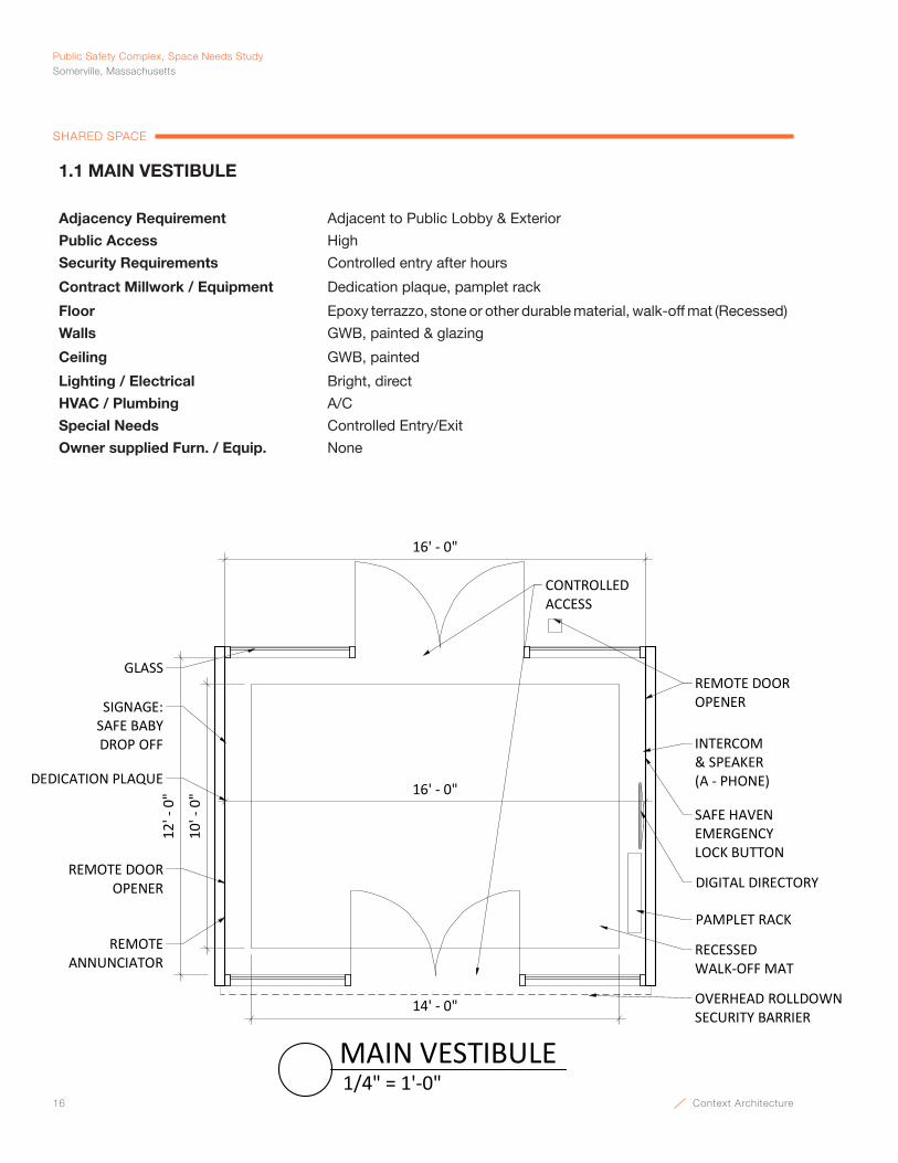
16 Context Architecture
Public Safety Complex, Space Needs StudySomerville, Massachusetts
SHARED SPACE
1.1 MAIN VESTIBULE
Adjacency Requirement Adjacent to Public Lobby & Exterior
Public Access High
Security Requirements Controlled entry after hours
Contract Millwork / Equipment Dedication plaque, pamplet rack
Floor Epoxy terrazzo, stone or other durable material, walk-off mat (Recessed)
Walls GWB, painted & glazing
Ceiling GWB, painted
Lighting / Electrical Bright, direct
HVAC / Plumbing A/C
Special Needs Controlled Entry/Exit
Owner supplied Furn. / Equip. None
16' - 0"
12' -
0"
10' -
0"
14' - 0"
RECESSEDWALK-OFF MAT
GLASS
INTERCOM & SPEAKER(A - PHONE)
REMOTE ANNUNCIATOR
CONTROLLEDACCESS
DEDICATION PLAQUE
REMOTE DOOR OPENER
REMOTE DOOR OPENER
DIGITAL DIRECTORY
PAMPLET RACK
16' - 0"
OVERHEAD ROLLDOWNSECURITY BARRIER
SAFE HAVENEMERGENCY LOCK BUTTON
SIGNAGE:SAFE BABYDROP OFF
1/4" = 1'-0"MAIN VESTIBULE
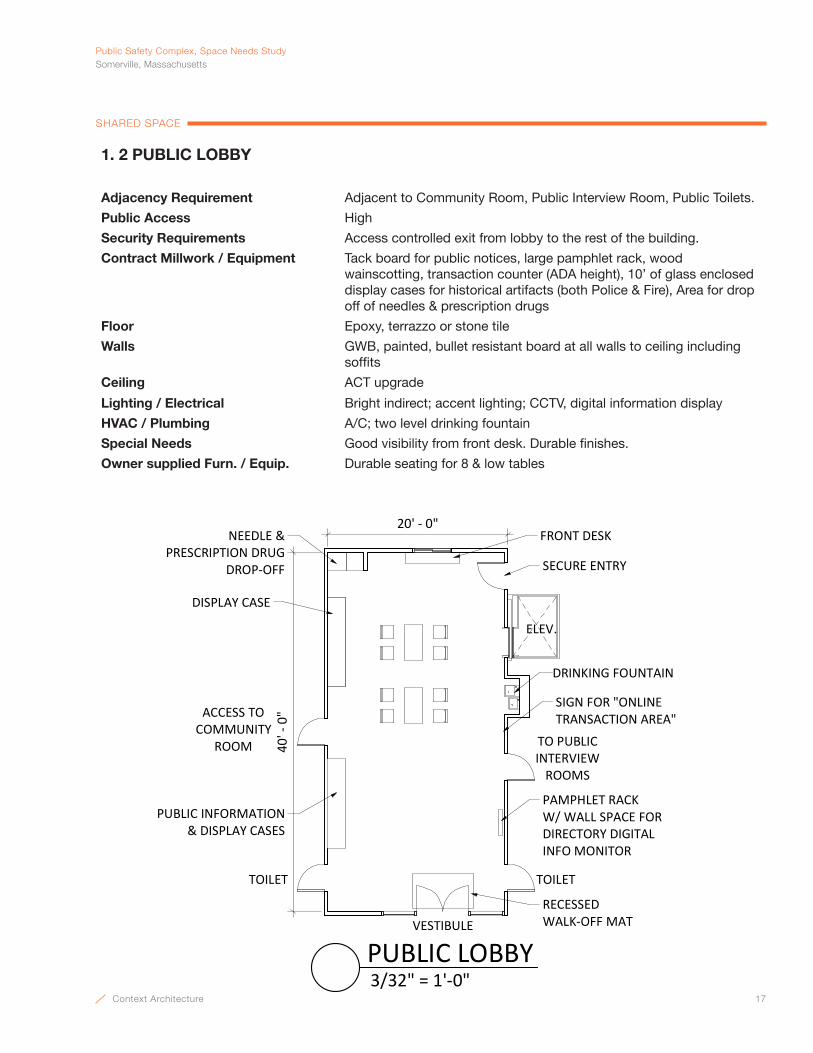
Context Architecture 17
PublicSafetyComplex,SpaceNeedsStudySomerville,Massachusetts
SHARED SPACE
20' - 0"
TOILET
ACCESS TO COMMUNITY
ROOM
VESTIBULE
ELEV.
TOILET
TO PUBLIC INTERVIEW
ROOMS
DISPLAY CASE
DRINKING FOUNTAIN
NEEDLE & PRESCRIPTION DRUG
DROP-OFF SECURE ENTRY
FRONT DESK
PAMPHLET RACK W/ WALL SPACE FOR DIRECTORY DIGITALINFO MONITOR
PUBLIC INFORMATION& DISPLAY CASES
RECESSED WALK-OFF MAT
SIGN FOR "ONLINE TRANSACTION AREA"
40' -
0"
3/32" = 1'-0"PUBLIC LOBBY
1. 2 PUBLIC LOBBY
Adjacency Requirement Adjacent to Community Room, Public Interview Room, Public Toilets.
Public Access High
Security Requirements Access controlled exit from lobby to the rest of the building.
Contract Millwork / Equipment Tack board for public notices, large pamphlet rack, wood wainscotting, transaction counter (ADA height), 10’ of glass enclosed display cases for historical artifacts (both Police & Fire), Area for drop off of needles & prescription drugs
Floor Epoxy, terrazzo or stone tile
Walls GWB, painted, bullet resistant board at all walls to ceiling including soffits
Ceiling ACT upgrade
Lighting / Electrical Bright indirect; accent lighting; CCTV, digital information display
HVAC / Plumbing A/C; two level drinking fountain
Special Needs Good visibility from front desk. Durable finishes.
Owner supplied Furn. / Equip. Durable seating for 8 & low tables
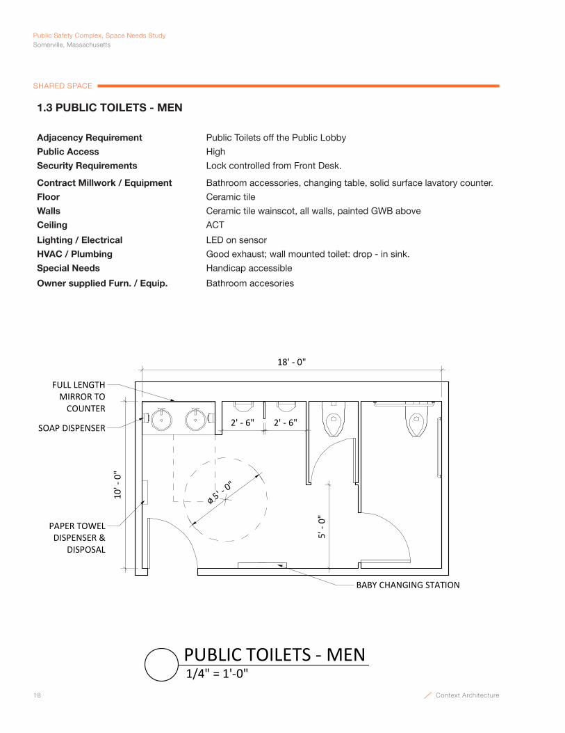
18 Context Architecture
Public Safety Complex, Space Needs StudySomerville, Massachusetts
SHARED SPACE
1.3 PUBLIC TOILETS - MEN
Adjacency Requirement Public Toilets off the Public Lobby
Public Access High
Security Requirements Lock controlled from Front Desk.
Contract Millwork / Equipment Bathroom accessories, changing table, solid surface lavatory counter.
Floor Ceramic tile
Walls Ceramic tile wainscot, all walls, painted GWB above
Ceiling ACT
Lighting / Electrical LED on sensor
HVAC / Plumbing Good exhaust; wall mounted toilet: drop - in sink.
Special Needs Handicap accessible
Owner supplied Furn. / Equip. Bathroom accesories
18' - 0"
10' -
0"
ø 5' - 0"
BABY CHANGING STATION
5' -
0"PAPER TOWELDISPENSER &
DISPOSAL
FULL LENGTHMIRROR TO
COUNTER
SOAP DISPENSER 2' - 6"2' - 6"
1/4" = 1'-0"PUBLIC TOILETS - MEN
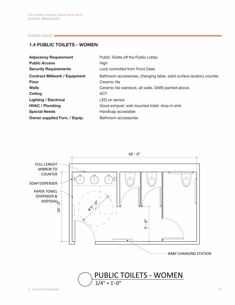
Context Architecture 19
PublicSafetyComplex,SpaceNeedsStudySomerville,Massachusetts
SHARED SPACE
1.4 PUBLIC TOILETS - WOMEN
Adjacency Requirement Public Toilets off the Public Lobby
Public Access High
Security Requirements Lock controlled from Front Desk.
Contract Millwork / Equipment Bathroom accessories, changing table, solid surface lavatory counter.
Floor Ceramic tile
Walls Ceramic tile wainscot, all walls, GWB painted above.
Ceiling ACT
Lighting / Electrical LED on sensor
HVAC / Plumbing Good exhaust; wall mounted toilet: drop-in sink.
Special Needs Handicap accessible
Owner supplied Furn. / Equip. Bathroom accessories
18' - 0"
10' -
0"
FULL LENGHTMIRROR TO
COUNTER
PAPER TOWEL DISPENSER &
DISPOSAL
BABY CHANGING STATION
ø 5' - 0"
5' -
0"
SOAP DISPENSER
1/4" = 1'-0"PUBLIC TOILETS - WOMEN
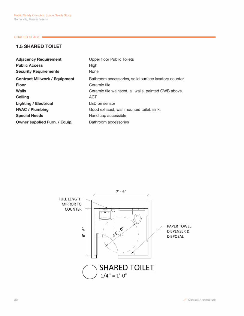
20 Context Architecture
Public Safety Complex, Space Needs StudySomerville, Massachusetts
SHARED SPACE
1.5 SHARED TOILET
Adjacency Requirement Upper floor Public Toilets
Public Access High
Security Requirements None
Contract Millwork / Equipment Bathroom accessories, solid surface lavatory counter.
Floor Ceramic tile
Walls Ceramic tile wainscot, all walls, painted GWB above.
Ceiling ACT
Lighting / Electrical LED on sensor
HVAC / Plumbing Good exhaust; wall mounted toilet: sink.
Special Needs Handicap accessible
Owner supplied Furn. / Equip. Bathroom accessories
7' - 6"
6' -
6"
ø 5' - 0"
FULL LENGTHMIRROR TO
COUNTER
PAPER TOWELDISPENSER & DISPOSAL
1/4" = 1'-0"SHARED TOILET
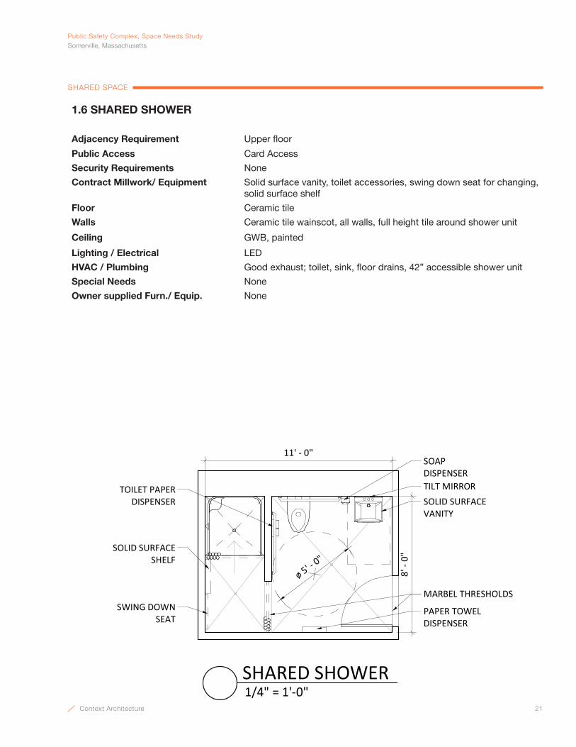
Context Architecture 21
PublicSafetyComplex,SpaceNeedsStudySomerville,Massachusetts
SHARED SPACE
1.6 SHARED SHOWER
Adjacency Requirement Upper floor
Public Access Card Access
Security Requirements None
Contract Millwork/ Equipment Solid surface vanity, toilet accessories, swing down seat for changing, solid surface shelf
Floor Ceramic tile
Walls Ceramic tile wainscot, all walls, full height tile around shower unit
Ceiling GWB, painted
Lighting / Electrical LED
HVAC / Plumbing Good exhaust; toilet, sink, floor drains, 42” accessible shower unit
Special Needs None
Owner supplied Furn./ Equip. None
SOLID SURFACE VANITY
ø 5' - 0"
TILT MIRROR
SOAP DISPENSER
TOILET PAPERDISPENSER
PAPER TOWELDISPENSER
SWING DOWNSEAT
SOLID SURFACE SHELF
11' - 0"
8' -
0"
MARBEL THRESHOLDS
1/4" = 1'-0"SHARED SHOWER
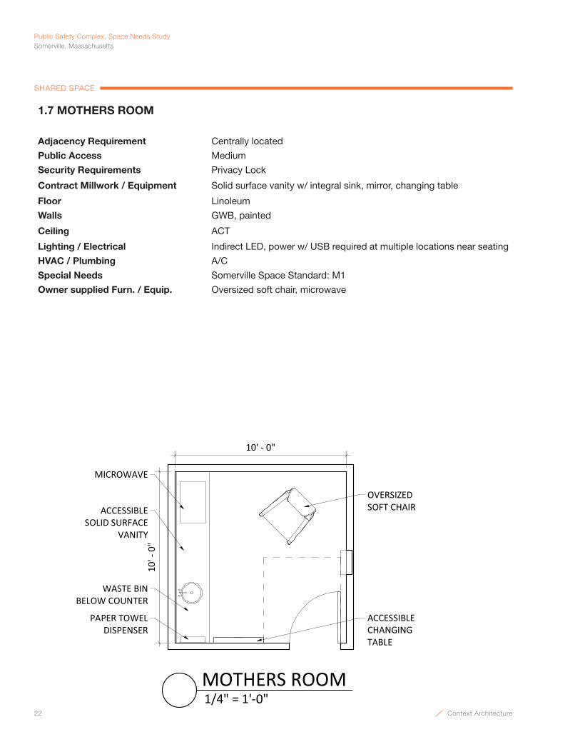
22 Context Architecture
Public Safety Complex, Space Needs StudySomerville, Massachusetts
SHARED SPACE
1.7 MOTHERS ROOM
Adjacency Requirement Centrally located
Public Access Medium
Security Requirements Privacy Lock
Contract Millwork / Equipment Solid surface vanity w/ integral sink, mirror, changing table
Floor Linoleum
Walls GWB, painted
Ceiling ACT
Lighting / Electrical Indirect LED, power w/ USB required at multiple locations near seating
HVAC / Plumbing A/C
Special Needs Somerville Space Standard: M1
Owner supplied Furn. / Equip. Oversized soft chair, microwave
10' -
0"
10' - 0"
ACCESSIBLECHANGING TABLE
OVERSIZEDSOFT CHAIRACCESSIBLE
SOLID SURFACE VANITY
PAPER TOWELDISPENSER
WASTE BINBELOW COUNTER
MICROWAVE
1/4" = 1'-0"MOTHERS ROOM

Context Architecture 23
PublicSafetyComplex,SpaceNeedsStudySomerville,Massachusetts
SHARED SPACE
1.8 PUBLIC INTERVIEW ROOM
Adjacency Requirement Access from Lobby
Public Access High
Security Requirements Access controlled from Front Desk
Contract Millwork / Equipment Chair rail
Floor Linoleum
Walls GWB, painted
Ceiling ACT
Lighting / Electrical Indirect LED; pleasant, not glaring, intercom to Dispatch; CCTV
HVAC / Plumbing A/C
Special Needs Somerville Space Standard: C4
Owner supplied Furn. / Equip. 4’ table, (4) chairs
WALL PHONE &INTERCOM
CCTV. DATA & POWER7'-0" AFF
12' - 0"
10' -
0"
1/4" = 1'-0"PUBLIC INTERVIEW ROOM
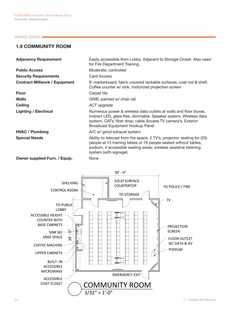
24 Context Architecture
Public Safety Complex, Space Needs StudySomerville, Massachusetts
SHARED SPACE
1.9 COMMUNITY ROOM
Adjacency Requirement Easily accessible from Lobby. Adjacent to Storage Closet. Also used for Fire Department Training.
Public Access Moderate; controlled
Security Requirements Card Access
Contract Millwork / Equipment 8’ markerboard, fabric covered tackable surfaces; coat rod & shelf. Coffee counter w/ sink, motorized projection screen
Floor Carpet tile
Walls GWB, painted w/ chair rail
Ceiling ACT upgrade
Lighting / Electrical Numerous power & wireless data outlets at walls and floor boxes. Indirect LED, glare free, dimmable. Speaker system, Wireless data system, CATV, fiber drop; cable Access TV camera’s, Exterior Broadcast Equipment Hookup Panel
HVAC / Plumbing A/C w/ good exhaust system
Special Needs Ability to telecast from the space, 2 TV’s, projector, seating for (25) people at 13 training tables or 76 people seated without tables, podium, 4 accessible seating areas; wireless assistive listening system (with signage)
Owner supplied Furn. / Equip. None
ACCESSIBLECOAT CLOSET
TO STORAGE
TO POLICE / FIRE
28' -
0"
30' - 0"
TO PUBLICLOBBY
BUILT- INACCESSIBLE
MICROWAVE
COFFEE MACHINE
UPPER CABINETS
ACCESSIBLE HEIGHTCOUNTER WITHBASE CABINETS PROJECTION
SCREEN
PODIUM
TV
FLOOR OUTLET W/ DATA & AV
CONTROL ROOM
SINK W/ KNEE SPACE
SOLID SURFACE COUNTERTOP
SHELVING
EMERGENCY EXIT
3/32" = 1'-0"COMMUNITY ROOM

Context Architecture 25
PublicSafetyComplex,SpaceNeedsStudySomerville,Massachusetts
SHARED SPACE
1.10 COMMUNITY ROOM STORAGE
Adjacency Requirement Off Community Room
Public Access None
Security Requirements None
Contract Millwork / Equipment None
Floor Rubber
Walls GWB, painted
Ceiling ACT
Lighting / Electrical LED
HVAC / Plumbing No A/C
Special Needs Storage for 100% of chairs and tables (stacked on carts), podium, voting and misc public information supplies
Owner supplied Furn. / Equip. None
12' - 0"
12' -
0"
1/4" = 1'-0"COMMUNITY ROOM STORAGE

26 Context Architecture
Public Safety Complex, Space Needs StudySomerville, Massachusetts
SHARED SPACE
2.1 TRAINING ROOM / EOC
Adjacency Requirement Accessible from Fire & Police Department secure spaces, adjacent to training aid storage rooms
Public Access None
Security Requirements Card Access
Contract Millwork / Equipment 8’ markerboard, fabric covered tackboard, whiteboard, counter w/ base cabinets.
Floor Carpet tile
Walls GWB, painted w/ chair rail
Ceiling ACT upgrade
Lighting / Electrical Numerous power & data outlets, indirect LED, glare free, dimmable, speaker system, wireless assistive listening system, CATV
HVAC / Plumbing A/C w/ good exhaust system
Special Needs Ability to telecast from the space. Space to be adaptable for use as the Emergency Operation Center (EOC). EOC Closet (for phones), 4 accesible seating areas.
Owner supplied Furn. / Equip. Seating for (44) people at training tables, podium, motorized projection screen, projector & 2 TV’s
EOC CLOSET
TRAINING AIDSTORAGE
32' -
0"
34' - 0"
PROJECTION SCREEN
WHITEBOARD
TV
TV
PODIUM
ACCESS TO COAT CLOSET
6' - 0"
2' -
0"
POWER & DATAAT EXT. WALLS
& IN FLOOR BOXES
ACCESS TO KITCHENETTE
RECESSED A/V RACK
1/8" = 1'-0"TRAINING ROOM/EOC

Context Architecture 27
PublicSafetyComplex,SpaceNeedsStudySomerville,Massachusetts
SHARED SPACE
2.2 COAT CLOSET
Adjacency Requirement Access from Training Room
Public Access None
Security Requirements None
Contract Millwork / Equipment Coat rods & shelf
Floor Carpet tile
Walls GWB, painted
Ceiling ACT
Lighting / Electrical Direct LED
HVAC / Plumbing None
Special Needs None
Owner supplied Furn. / Equip. None
8' -
0"
8' - 0"
ACCESSIBLE HEIGHTCOAT ROD / SHELF
1/4" = 1'-0"COAT CLOSET

28 Context Architecture
Public Safety Complex, Space Needs StudySomerville, Massachusetts
SHARED SPACE
2.3 KITCHENETTE
Adjacency Requirement Access from Training Room
Public Access None
Security Requirements None
Millwork Solid surface countertop with base and upper cabinets, tackboard, 30” deep refrigerator
Floor Rubber
Walls GWB, painted
Ceiling ACT
Lighting / Electrical LED & under counter lighting
HVAC / Plumbing A/C w/ good exhaust system, sink, bottle fill
Special Needs Handicap accessible
Furniture / Equipment Microwave, (2) coffee machines, recycle and trash bins
10' - 0"
16' -
0"
OPEN TOTRAINING ROOM
UPPER CABINETS
BUILT- INACCESSIBLE
MICROWAVE
ACCESSIBLE HEIGHTSOLID SURFACECOUNTER WITHBASE CABINETS
ACCESSIBLEREF.
COFFEE MACHINE
BOTTLE FILLTACKBOARD
SINK W/ KNEE SPACE
RECYCLE ANDTRASH BINS
ø 5' - 0"
1/4" = 1'-0"KITCHENETTE
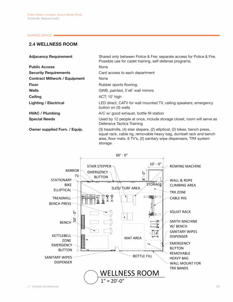
Context Architecture 29
PublicSafetyComplex,SpaceNeedsStudySomerville,Massachusetts
SHARED SPACE
2.4 WELLNESS ROOM
Adjacency Requirement Shared only between Police & Fire; separate access for Police & Fire. Possible use for cadet training, self defense programs.
Public Access None
Security Requirements Card access to each department
Contract Millwork / Equipment None
Floor Rubber sports flooring.
Walls GWB, painted, 5’x6’ wall mirrors
Ceiling ACT; 10’ high
Lighting / Electrical LED direct, CATV for wall mounted TV, ceiling speakers; emergency button on (3) walls
HVAC / Plumbing A/C w/ good exhaust, bottle fill station
Special Needs Used by 12 people at once, include storage closet, room will serve as Defensive Tactics Training
Owner supplied Furn. / Equip. (3) treadmills, (4) stair stepers, (2) elliptical, (2) bikes, bench press, squat rack, cable rig, removable heavy bag, dumbell rack and bench area, floor mats, 6 TV’s, (2) sanitary wipe dispensers, TRX system storage.
MAT AREA
SANITARY WIPES DISPENSER
STATIONARY BIKE
ELLIPTICAL
CABLE RIGTREADMILL
REMOVABLEHEAVY BAG
TV
10' - 0"
8' -
0"
SQUAT RACK
SMITH MACHINEW/ BENCH
BENCH PRESS
STORAGE
STAIR STEPPER
BENCH
EMERGENCY BUTTON
EMERGENCYBUTTON
SANITARY WIPESDISPENSER
BOTTLE FILL
EMERGENCYBUTTON
SLED/ TURF AREA
MIRROR
WALL & ROPECLIMBING AREA
60' - 0"
50' -
0"
TRX ZONE
WALL MOUNT FORTRX BANDS
KETTLEBELLZONE
ROWING MACHINE
1" = 20'-0"WELLNESS ROOM
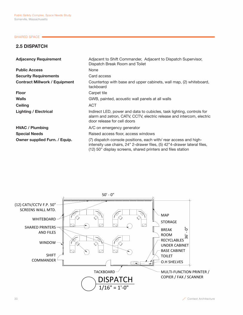
30 Context Architecture
Public Safety Complex, Space Needs StudySomerville, Massachusetts
SHARED SPACE
2.5 DISPATCH
Adjacency Requirement Adjacent to Shift Commander, Adjacent to Dispatch Supervisor, Dispatch Break Room and Toilet
Public Access None
Security Requirements Card access
Contract Millwork / Equipment Countertop with base and upper cabinets, wall map, (2) whiteboard, tackboard
Floor Carpet tile
Walls GWB, painted, acoustic wall panels at all walls
Ceiling ACT
Lighting / Electrical Indirect LED, power and data to cubicles, task lighting, controls for alarm and zetron, CATV, CCTV, electric release and intercom, electric door release for cell doors
HVAC / Plumbing A/C on emergency generator
Special Needs Raised access floor, access windows
Owner supplied Furn. / Equip. (7) dispatch console positions, each with/ rear access and high-intensity use chairs, 24” 2-drawer files, (5) 42”4-drawer lateral files, (12) 50” display screens, shared printers and files station
(12) CATV/CCTV F.P. 50" SCREENS WALL MTD.
50' - 0"
36' -
0"BREAK
ROOM
WINDOW
TACKBOARD
MAPWHITEBOARD
SHIFT COMMANDER
SHARED PRINTERS AND FILES
MULTI-FUNCTION PRINTER /COPIER / FAX / SCANNER
O.H SHELVES
RECYCLABLESUNDER CABINETBASE CABINETTOILET
STORAGE
1/16" = 1'-0"DISPATCH

Context Architecture 31
PublicSafetyComplex,SpaceNeedsStudySomerville,Massachusetts
SHARED SPACE
12' -
0"
18' - 0"
18"x24" STORAGELOCKERS
FILLER @ EACH END
BENCH
3/16" = 1'-0"LOCKER ROOM
2.6 DISPATCH LOCKER ROOM
Adjacency Requirement Access from Dispatch
Public Access None
Security Requirements None
Contract Millwork / Equipment (24) 18”x24”x72” Lockable storage units
Floor Rubber
Walls GWB, painted
Ceiling ACT
Lighting / Electrical LED
HVAC / Plumbing Good ventilation
Special Needs None
Owner supplied Furn. / Equip. Bench

32 Context Architecture
Public Safety Complex, Space Needs StudySomerville, Massachusetts
SHARED SPACE
20' - 0"
12' -
6"
COFFEE MAKER
UPPER CABINETS
ACCESSIBLE HEIGHTSOLID SURFACECOUNTERTOP WITHBASE CABINETS
BUILT-INACCESSIBLE MICROWAVE
KNEE SPACEBELOW SINK& COOKTOP
REF.
RECYCLE ANDTRASH BINS
BOTTLE FILL
TACKBOARD
COOKTOP W/ HOODOVER
3/16" = 1'-0"DISPATCH BREAK ROOM
2.7 DISPATCH BREAK ROOM
Adjacency Requirement Access from Dispatch
Public Access None
Security Requirements None
Contract Millwork / Equipment Solid surface countertop with base & upper cabinets, 30” wide refrigerator, 4 burner range w/ oven, exhaust hood, tackboard, built-in microwave
Floor Rubber
Walls GWB, painted
Ceiling ACT
Lighting / Electrical LED, under cabinet lighting
HVAC / Plumbing A/C w/ good exhaust system, sink, bottle fill, hood
Special Needs Handicap accessible, Somerville Space Standard: K12
Owner supplied Furn. / Equip. Coffee maker, recycle and trash bins, (1) tables, (6) chairs
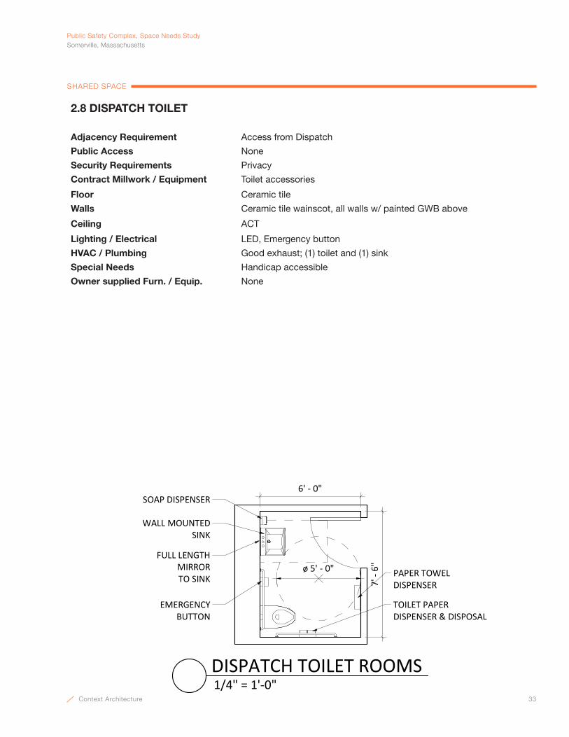
Context Architecture 33
PublicSafetyComplex,SpaceNeedsStudySomerville,Massachusetts
SHARED SPACE
7' -
6"
6' - 0"
ø 5' - 0" PAPER TOWELDISPENSER
TOILET PAPERDISPENSER & DISPOSAL
WALL MOUNTEDSINK
SOAP DISPENSER
FULL LENGTH MIRROR TO SINK
EMERGENCY BUTTON
1/4" = 1'-0"DISPATCH TOILET ROOMS
2.8 DISPATCH TOILET
Adjacency Requirement Access from Dispatch
Public Access None
Security Requirements Privacy
Contract Millwork / Equipment Toilet accessories
Floor Ceramic tile
Walls Ceramic tile wainscot, all walls w/ painted GWB above
Ceiling ACT
Lighting / Electrical LED, Emergency button
HVAC / Plumbing Good exhaust; (1) toilet and (1) sink
Special Needs Handicap accessible
Owner supplied Furn. / Equip. None
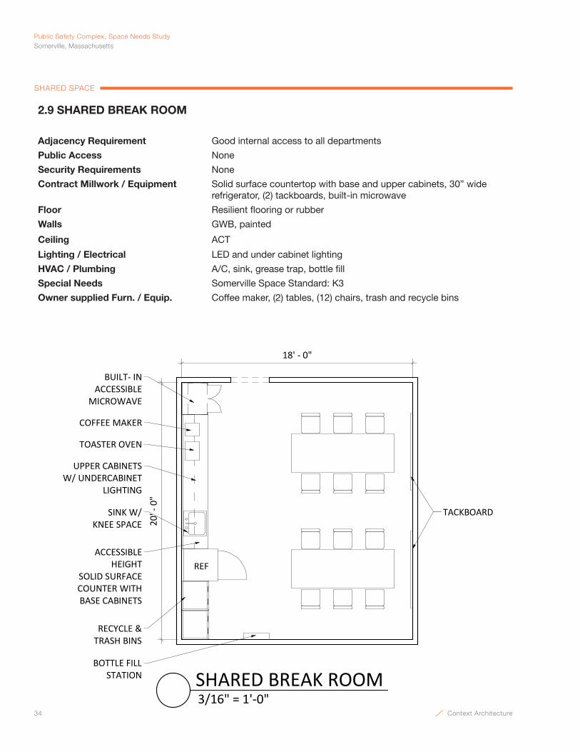
34 Context Architecture
Public Safety Complex, Space Needs StudySomerville, Massachusetts
SHARED SPACE
18' - 0"
20' -
0"
TACKBOARD
RECYCLE & TRASH BINS
REF
UPPER CABINETS W/ UNDERCABINET
LIGHTING
BUILT- INACCESSIBLE
MICROWAVE
COFFEE MAKER
TOASTER OVEN
BOTTLE FILL STATION
SINK W/KNEE SPACE
ACCESSIBLE HEIGHT
SOLID SURFACECOUNTER WITHBASE CABINETS
3/16" = 1'-0"SHARED BREAK ROOM
2.9 SHARED BREAK ROOM
Adjacency Requirement Good internal access to all departments
Public Access None
Security Requirements None
Contract Millwork / Equipment Solid surface countertop with base and upper cabinets, 30” wide refrigerator, (2) tackboards, built-in microwave
Floor Resilient flooring or rubber
Walls GWB, painted
Ceiling ACT
Lighting / Electrical LED and under cabinet lighting
HVAC / Plumbing A/C, sink, grease trap, bottle fill
Special Needs Somerville Space Standard: K3
Owner supplied Furn. / Equip. Coffee maker, (2) tables, (12) chairs, trash and recycle bins
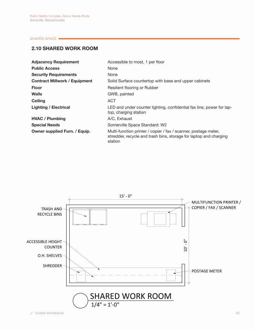
Context Architecture 35
PublicSafetyComplex,SpaceNeedsStudySomerville,Massachusetts
SHARED SPACE
MULTIFUNCTION PRINTER / COPIER / FAX / SCANNER
POSTAGE METER
O.H. SHELVES
SHREDDER
ACCESSIBLE HEIGHTCOUNTER
15' - 0"
TRASH AND RECYCLE BINS
10' -
0"
1/4" = 1'-0"SHARED WORK ROOM
2.10 SHARED WORK ROOM
Adjacency Requirement Accessible to most, 1 per floor
Public Access None
Security Requirements None
Contract Millwork / Equipment Solid Surface countertop with base and upper cabinets
Floor Resilient flooring or Rubber
Walls GWB, painted
Ceiling ACT
Lighting / Electrical LED and under counter lighting, confidential fax line, power for lap-top, charging station
HVAC / Plumbing A/C, Exhaust
Special Needs Somerville Space Standard: W2
Owner supplied Furn. / Equip. Multi-function printer / copier / fax / scanner, postage meter, shredder, recycle and trash bins, storage for laptop and charging station
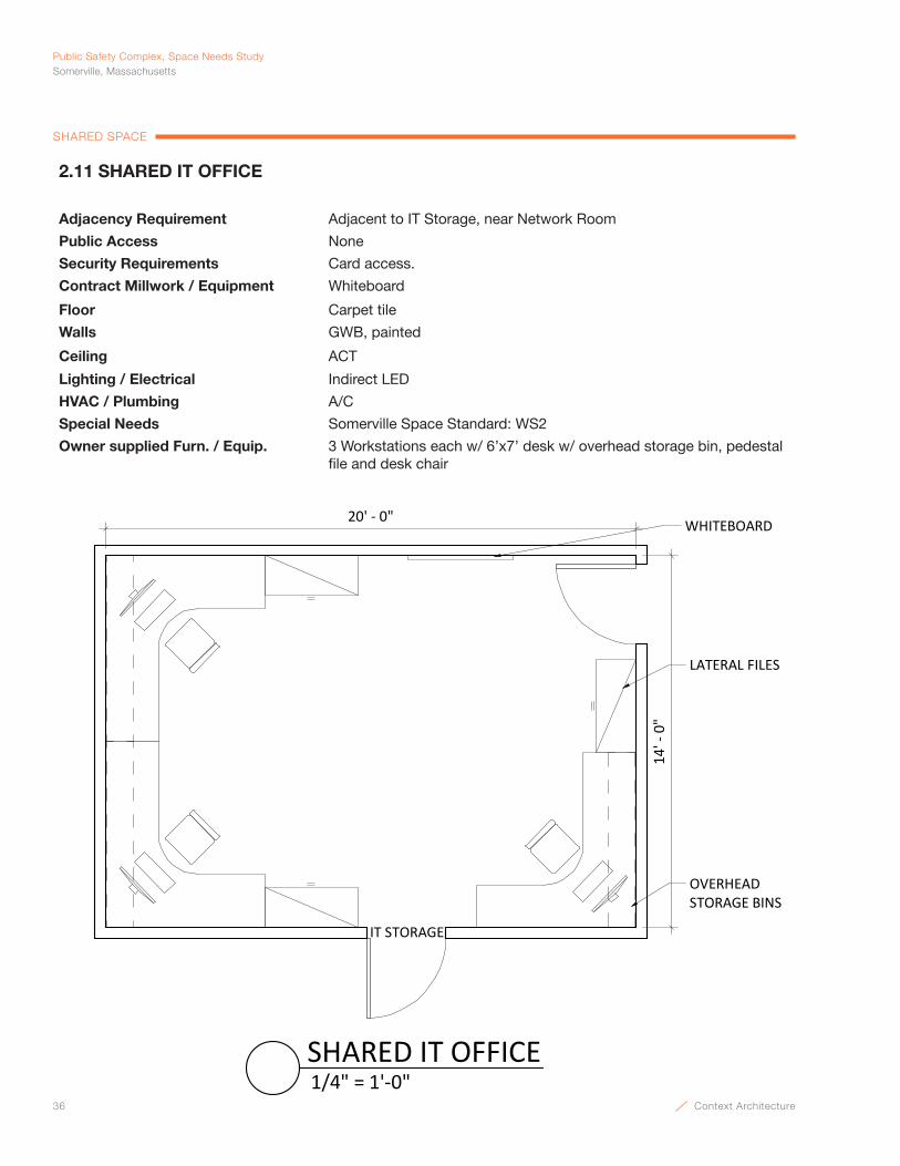
36 Context Architecture
Public Safety Complex, Space Needs StudySomerville, Massachusetts
SHARED SPACE
2.11 SHARED IT OFFICE
Adjacency Requirement Adjacent to IT Storage, near Network Room
Public Access None
Security Requirements Card access.
Contract Millwork / Equipment Whiteboard
Floor Carpet tile
Walls GWB, painted
Ceiling ACT
Lighting / Electrical Indirect LED
HVAC / Plumbing A/C
Special Needs Somerville Space Standard: WS2
Owner supplied Furn. / Equip. 3 Workstations each w/ 6’x7’ desk w/ overhead storage bin, pedestal file and desk chair
14' -
0"
20' - 0" WHITEBOARD
OVERHEADSTORAGE BINS
LATERAL FILES
IT STORAGE
1/4" = 1'-0"SHARED IT OFFICE

Context Architecture 37
PublicSafetyComplex,SpaceNeedsStudySomerville,Massachusetts
SHARED SPACE
2.12 SHARED IT WORKSHOP
Adjacency Requirement Access from IT Offices
Public Access None
Security Requirements None
Contract Millwork / Equipment Solid surface countertop with base and upper cabinets
Floor Resilient flooring or Rubber
Walls GWB, painted
Ceiling ACT
Lighting / Electrical LED and under counter lighting, wiremold
HVAC / Plumbing A/C, Exhaust
Special Needs None
Owner supplied Furn. / Equip. Test-bed with fiber for network switch
10' -
0"
14' - 0"
O.H. SHELVES
BASE CABINET
TEST BED WORKSTATION
1/4" = 1'-0"SHARED IT WORKSHOP
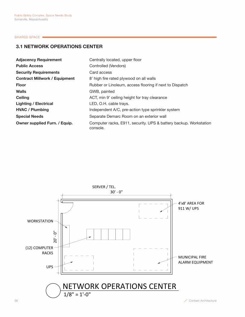
38 Context Architecture
Public Safety Complex, Space Needs StudySomerville, Massachusetts
SHARED SPACE
3.1 NETWORK OPERATIONS CENTER
Adjacency Requirement Centrally located, upper floor
Public Access Controlled (Vendors)
Security Requirements Card access
Contract Millwork / Equipment 8’ high fire rated plywood on all walls
Floor Rubber or Linoleum, access flooring if next to Dispatch
Walls GWB, painted
Ceiling ACT, min 9’ ceiling height for tray clearance
Lighting / Electrical LED, O.H. cable trays.
HVAC / Plumbing Independent A/C, pre-action type sprinkler system
Special Needs Separate Demarc Room on an exterior wall
Owner supplied Furn. / Equip. Computer racks, E911, security. UPS & battery backup. Workstation console.
30' - 0"
20' -
0"
SERVER / TEL.
WORKSTATION
(12) COMPUTER RACKS
4'x8' AREA FOR911 W/ UPS
UPS
MUNICIPAL FIRE ALARM EQUIPMENT
1/8" = 1'-0"NETWORK OPERATIONS CENTER
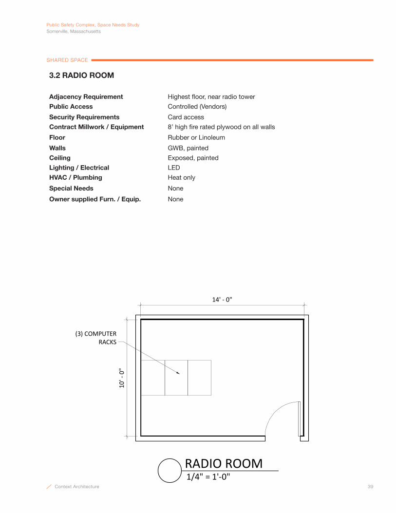
Context Architecture 39
PublicSafetyComplex,SpaceNeedsStudySomerville,Massachusetts
SHARED SPACE
3.2 RADIO ROOM
Adjacency Requirement Highest floor, near radio tower
Public Access Controlled (Vendors)
Security Requirements Card access
Contract Millwork / Equipment 8’ high fire rated plywood on all walls
Floor Rubber or Linoleum
Walls GWB, painted
Ceiling Exposed, painted
Lighting / Electrical LED
HVAC / Plumbing Heat only
Special Needs None
Owner supplied Furn. / Equip. None
14' - 0"
10' -
0"
(3) COMPUTERRACKS
1/4" = 1'-0"RADIO ROOM
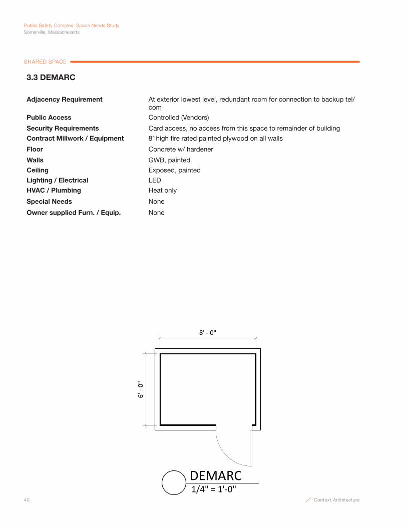
40 Context Architecture
Public Safety Complex, Space Needs StudySomerville, Massachusetts
SHARED SPACE
3.3 DEMARC
Adjacency Requirement At exterior lowest level, redundant room for connection to backup tel/com
Public Access Controlled (Vendors)
Security Requirements Card access, no access from this space to remainder of building
Contract Millwork / Equipment 8’ high fire rated painted plywood on all walls
Floor Concrete w/ hardener
Walls GWB, painted
Ceiling Exposed, painted
Lighting / Electrical LED
HVAC / Plumbing Heat only
Special Needs None
Owner supplied Furn. / Equip. None
8' - 0"
6' -
0"
1/4" = 1'-0"DEMARC
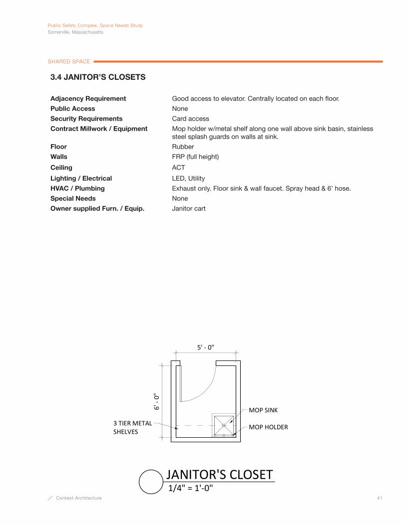
Context Architecture 41
PublicSafetyComplex,SpaceNeedsStudySomerville,Massachusetts
SHARED SPACE
3.4 JANITOR’S CLOSETS
Adjacency Requirement Good access to elevator. Centrally located on each floor.
Public Access None
Security Requirements Card access
Contract Millwork / Equipment Mop holder w/metal shelf along one wall above sink basin, stainless steel splash guards on walls at sink.
Floor Rubber
Walls FRP (full height)
Ceiling ACT
Lighting / Electrical LED, Utility
HVAC / Plumbing Exhaust only. Floor sink & wall faucet. Spray head & 6’ hose.
Special Needs None
Owner supplied Furn. / Equip. Janitor cart
5' - 0"
6' -
0"
MOP SINK
MOP HOLDER3 TIER METALSHELVES
1/4" = 1'-0"JANITOR'S CLOSET
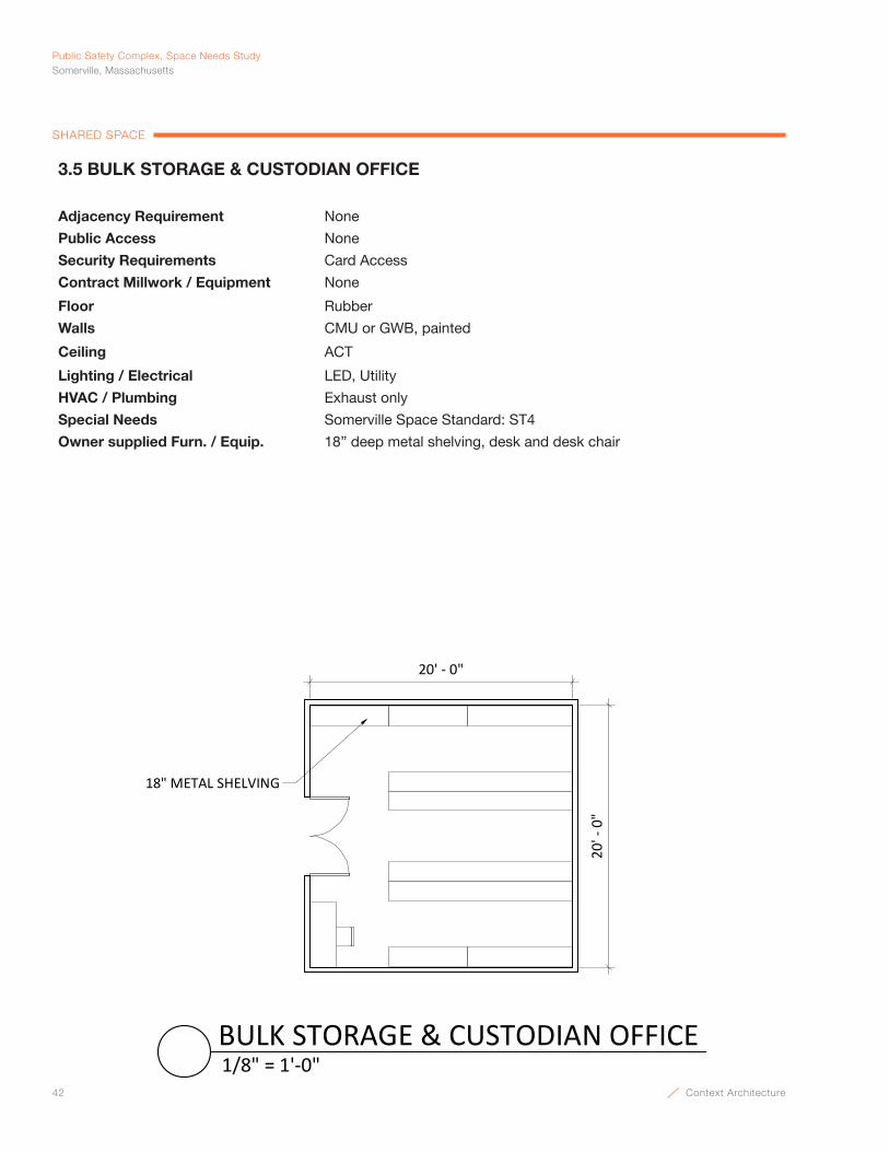
42 Context Architecture
Public Safety Complex, Space Needs StudySomerville, Massachusetts
SHARED SPACE
3.5 BULK STORAGE & CUSTODIAN OFFICE
Adjacency Requirement None
Public Access None
Security Requirements Card Access
Contract Millwork / Equipment None
Floor Rubber
Walls CMU or GWB, painted
Ceiling ACT
Lighting / Electrical LED, Utility
HVAC / Plumbing Exhaust only
Special Needs Somerville Space Standard: ST4
Owner supplied Furn. / Equip. 18” deep metal shelving, desk and desk chair
18" METAL SHELVING
20' - 0"
20' -
0"
1/8" = 1'-0"BULK STORAGE & CUSTODIAN OFFICE
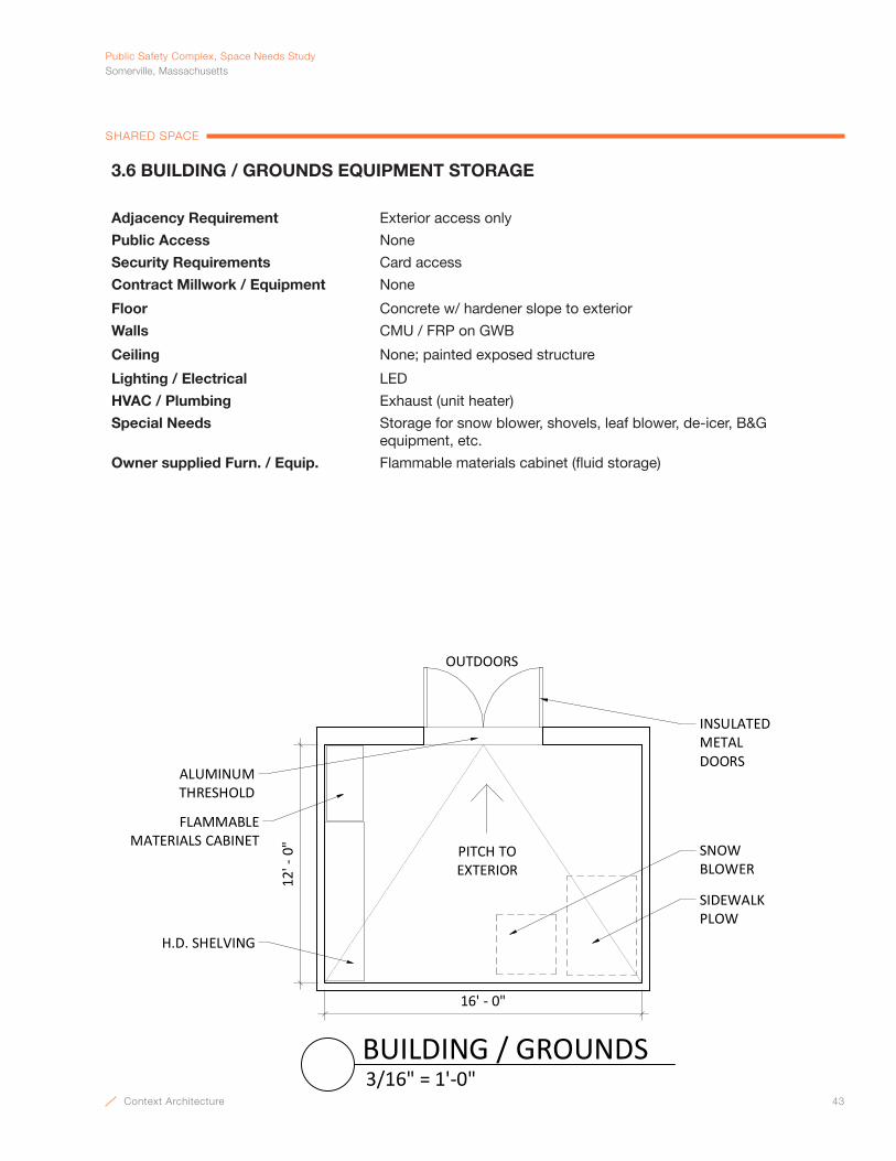
Context Architecture 43
PublicSafetyComplex,SpaceNeedsStudySomerville,Massachusetts
SHARED SPACE
3.6 BUILDING / GROUNDS EQUIPMENT STORAGE
Adjacency Requirement Exterior access only
Public Access None
Security Requirements Card access
Contract Millwork / Equipment None
Floor Concrete w/ hardener slope to exterior
Walls CMU / FRP on GWB
Ceiling None; painted exposed structure
Lighting / Electrical LED
HVAC / Plumbing Exhaust (unit heater)
Special Needs Storage for snow blower, shovels, leaf blower, de-icer, B&G equipment, etc.
Owner supplied Furn. / Equip. Flammable materials cabinet (fluid storage)
16' - 0"
12' -
0"
OUTDOORS
PITCH TO EXTERIOR
FLAMMABLE MATERIALS CABINET
H.D. SHELVING
ALUMINUM THRESHOLD
INSULATEDMETALDOORS
SIDEWALK PLOW
SNOW BLOWER
3/16" = 1'-0"BUILDING / GROUNDS

44 Context Architecture
Public Safety Complex, Space Needs StudySomerville, Massachusetts
SHARED SPACE
3.7 TRASH & RECYCLING ROOM
Adjacency Requirement Near exterior door
Public Access None
Security Requirements None
Contract Millwork / Equipment None
Floor Concrete w/hardener
Walls CMU w/ epoxy paint or GWB w/FRP panels
Ceiling GWB, painted
Lighting / Electrical Utility LED
HVAC / Plumbing Exhaust only, floor drain
Special Needs None
Owner supplied Furn. / Equip. (9) 50 gallon rolling waste bins, (9) recycling bins
16' -
0"
16' - 0"
RECYCLINGBIN
TRASHBIN
RECYCLINGBIN
RECYCLINGBIN
RECYCLINGBIN
RECYCLINGBIN
RECYCLINGBIN
RECYCLINGBIN
RECYCLINGBIN
RECYCLINGBIN
TRASHBIN
TRASHBIN
TRASHBIN
TRASHBIN
TRASHBIN
TRASHBIN
TRASHBIN
TRASHBIN
FLOOR DRAIN
1/4" = 1'-0"TRASH & RECYCLING
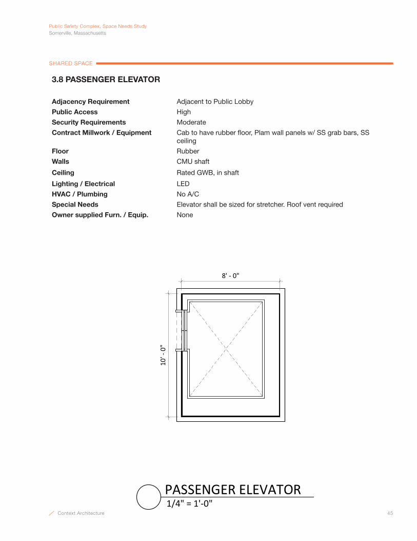
Context Architecture 45
PublicSafetyComplex,SpaceNeedsStudySomerville,Massachusetts
SHARED SPACE
3.8 PASSENGER ELEVATOR
Adjacency Requirement Adjacent to Public Lobby
Public Access High
Security Requirements Moderate
Contract Millwork / Equipment Cab to have rubber floor, Plam wall panels w/ SS grab bars, SS ceiling
Floor Rubber
Walls CMU shaft
Ceiling Rated GWB, in shaft
Lighting / Electrical LED
HVAC / Plumbing No A/C
Special Needs Elevator shall be sized for stretcher. Roof vent required
Owner supplied Furn. / Equip. None
8' - 0"
10' -
0"
1/4" = 1'-0"PASSENGER ELEVATOR

46 Context Architecture
Public Safety Complex, Space Needs StudySomerville, Massachusetts
SHARED SPACE
3.9 ELEVATOR MACHINE ROOM
Adjacency Requirement Adjacent to Elevator
Public Access None
Security Requirements Card access
Contract Millwork / Equipment 8’ high fire rated plywood at all walls over GWB
Floor Rubber
Walls Rated GWB, painted
Ceiling Rated GWB, painted
Lighting / Electrical LED, utility
HVAC / Plumbing A/C
Special Needs None
Owner supplied Furn. / Equip. None
8' ‐ 0"
10' ‐ 0"
1/4" = 1'‐0"ELEVATOR MACHINE ROOM

Context Architecture 47
PublicSafetyComplex,SpaceNeedsStudySomerville,Massachusetts
SHARED SPACE
3.10 MECHANICAL ROOM
Adjacency Requirement None
Public Access None
Security Requirements Card access
Contract Millwork / Equipment 8’ high fire rated plywood at all walls
Floor Concrete w/ hardener
Walls GWB, painted
Ceiling None, painted structure
Lighting / Electrical LED, utility
HVAC / Plumbing Floor drains at equipment, exhaust, hose bib
Special Needs Housekeeping pads at equipment
Owner supplied Furn. / Equip. None
30' - 0"
20' -
0"
FLOOR DRAIN
HOUSEKEEPING PADSFOR EQUIPMENT
HOSE BIB
3/16" = 1'-0"MECHANICAL ROOM

48 Context Architecture
Public Safety Complex, Space Needs StudySomerville, Massachusetts
SHARED SPACE
3.11 SPRINKLER / WATER SERVICE
Adjacency Requirement None
Public Access None
Security Requirements Card access
Contract Millwork / Equipment None
Floor Concrete w/ hardener
Walls GWB, painted
Ceiling None, painted structure
Lighting / Electrical LED, utility. Power required for equipment
HVAC / Plumbing Floor drain at inspector test station, heat only
Special Needs None
Owner supplied Furn. / Equip. None
14' ‐ 0"
8' ‐ 0"
FLOOR DRAIN
1/4" = 1'‐0"SPRINKLER / WATER SERVICE

Context Architecture 49
PublicSafetyComplex,SpaceNeedsStudySomerville,Massachusetts
SHARED SPACE
3.12 MAIN ELECTRICAL ROOM
Adjacency Requirement None
Public Access None
Security Requirements Card access
Contract Millwork / Equipment 8’ high fire rated plywood on all walls
Floor Concrete w/ hardener
Walls GWB, painted
Ceiling None, painted structure
Lighting / Electrical LED, utility
HVAC / Plumbing Heat only
Special Needs Closers required at doors
Owner supplied Furn. / Equip. None
30' - 0"
16' -
0"
POWER PANELS
3/16" = 1'-0"MAIN ELECTRICAL ROOM
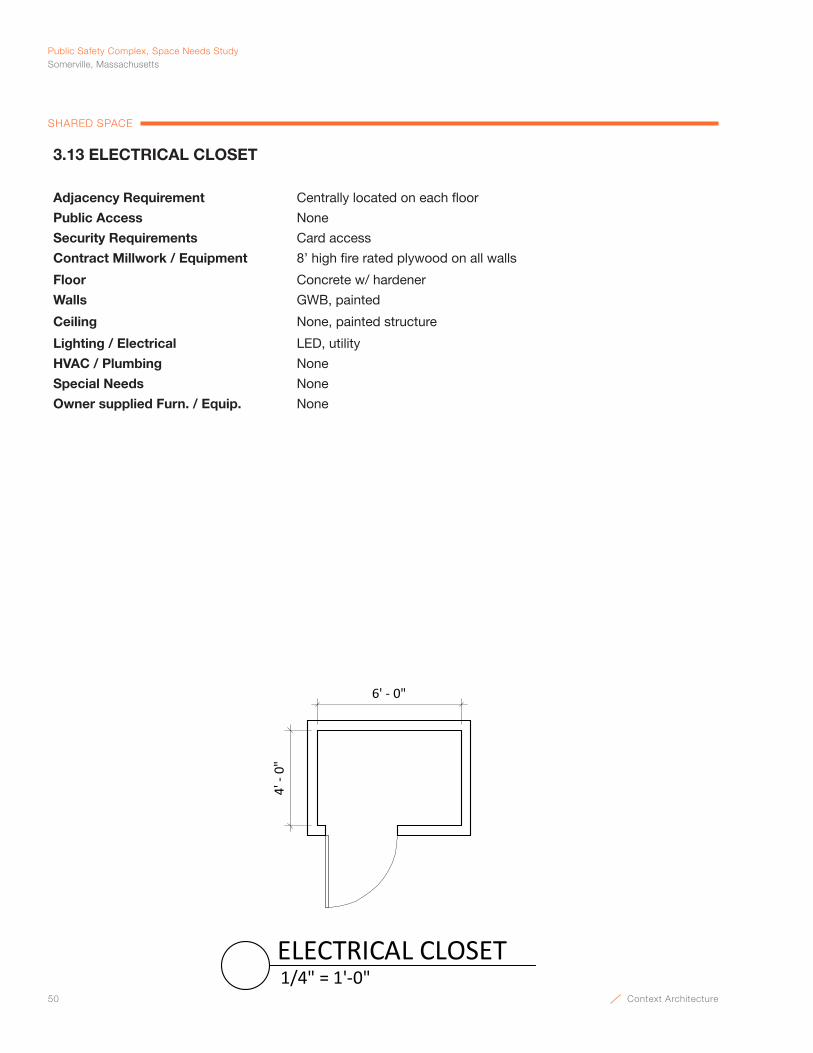
50 Context Architecture
Public Safety Complex, Space Needs StudySomerville, Massachusetts
SHARED SPACE
3.13 ELECTRICAL CLOSET
Adjacency Requirement Centrally located on each floor
Public Access None
Security Requirements Card access
Contract Millwork / Equipment 8’ high fire rated plywood on all walls
Floor Concrete w/ hardener
Walls GWB, painted
Ceiling None, painted structure
Lighting / Electrical LED, utility
HVAC / Plumbing None
Special Needs None
Owner supplied Furn. / Equip. None
6' - 0"
4' -
0"
1/4" = 1'-0"ELECTRICAL CLOSET
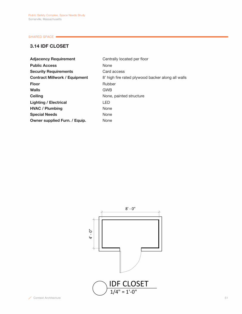
Context Architecture 51
PublicSafetyComplex,SpaceNeedsStudySomerville,Massachusetts
SHARED SPACE
3.14 IDF CLOSET
Adjacency Requirement Centrally located per floor
Public Access None
Security Requirements Card access
Contract Millwork / Equipment 8’ high fire rated plywood backer along all walls
Floor Rubber
Walls GWB
Ceiling None, painted structure
Lighting / Electrical LED
HVAC / Plumbing None
Special Needs None
Owner supplied Furn. / Equip. None
8' - 0"
4' -
0"
1/4" = 1'-0"IDF CLOSET

52 Context Architecture
Public Safety Complex, Space Needs StudySomerville, Massachusetts
SHARED SPACE
3.15 AUTOMATIC TRANSFER SWITCH
Adjacency Requirement Locate next to Electrical Room
Public Access None
Security Requirements Card access
Contract Millwork / Equipment 8’ high fire rated plywood backer on 1 wall
Floor Concrete w/ hardener
Walls 2 hour rated GWB, painted
Ceiling 2 hour rated GWB, painted
Lighting / Electrical LED, utility
HVAC / Plumbing None
Special Needs None
Owner supplied Furn. / Equip. None
4' - 0"
8' -
0"
FIRE RATED PLYWOOD BACKER
2 HOUR RATED ROOM
FIRE RATED METAL DOOR & FRAME
1/4" = 1'-0"AUTOMATIC TRANFSER SWITCH

Context Architecture 53
Police DepartmentSpace NeedsCHARLES FEMINO, INTERIM POLICE CHIEF

54 Context Architecture

Context Architecture 55
PublicSafetyComplex,SpaceNeedsStudySomerville,Massachusetts
POLICE DEPARTMENT
WHITEBOARD
LATERAL FILES
COUNTERTOPMULTI-FUNCTION
PRINTER
BOOKCASE
TV ABOVE
15' - 0"
11' -
0"
OVERHEAD STORAGE BIN
1/4" = 1'-0"POLICE CHIEF
4.1 POLICE CHIEF
Adjacency Requirement Adjacent to Administration Assistant and Conference Room
Public Access Moderate
Security Requirements Card access
Contract Millwork / Equipment Whiteboard, coat rod, shelf
Floor Carpet tile
Walls GWB, painted
Ceiling ACT
Lighting / Electrical Indirect LED; CATV
HVAC / Plumbing A/C
Special Needs Somerville Space Standards: PO1
Owner supplied Furn. / Equip. Desk w/ return, (2) 42” overhead storage bins, desk chair, (2) 42” 4-drawer lateral files, (2) bookcase, countertop multi-function printer, table and (4) chairs, TV

56 Context Architecture
Public Safety Complex, Space Needs StudySomerville, Massachusetts
POLICE DEPARTMENT
WHITEBOARD
LATERAL FILES
TV ABOVE
12' - 0"
8' -
0"
OVERHEAD STORAGE BIN
1/4" = 1'-0"DEPUTY CHIEF
4.2 DEPUTY CHIEF
Adjacency Requirement Adjacent to Administration Assistant and Conference Room
Public Access Moderate
Security Requirements Card access
Contract Millwork / Equipment Whiteboard, coat rod, shelf
Floor Carpet tile
Walls GWB, painted
Ceiling ACT
Lighting / Electrical Indirect LED; CATV
HVAC / Plumbing A/C
Special Needs Somerville Space Standards: PO3
Owner supplied Furn. / Equip. Desk, 42” overhead storage bin, desk chair, (2) 42” 4-drawer lateral files, guest chair, TV
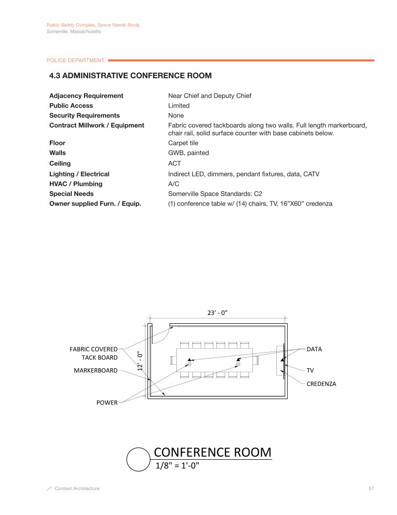
Context Architecture 57
PublicSafetyComplex,SpaceNeedsStudySomerville,Massachusetts
POLICE DEPARTMENT
12' -
0"
23' - 0"
1/8" = 1'-0"CONFERENCE ROOM
MARKERBOARD
DATA
CREDENZA
TV
FABRIC COVEREDTACK BOARD
POWER
4.3 ADMINISTRATIVE CONFERENCE ROOM
Adjacency Requirement Near Chief and Deputy Chief
Public Access Limited
Security Requirements None
Contract Millwork / Equipment Fabric covered tackboards along two walls. Full length markerboard, chair rail, solid surface counter with base cabinets below.
Floor Carpet tile
Walls GWB, painted
Ceiling ACT
Lighting / Electrical Indirect LED, dimmers, pendant fixtures, data, CATV
HVAC / Plumbing A/C
Special Needs Somerville Space Standards: C2
Owner supplied Furn. / Equip. (1) conference table w/ (14) chairs, TV, 16”X60” credenza
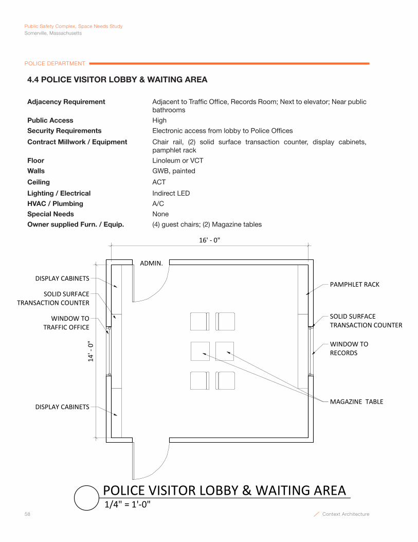
58 Context Architecture
Public Safety Complex, Space Needs StudySomerville, Massachusetts
POLICE DEPARTMENT
SOLID SURFACE TRANSACTION COUNTER
MAGAZINE TABLEDISPLAY CABINETS
ADMIN.
16' - 0"
14' -
0"
WINDOW TO TRAFFIC OFFICE
WINDOW TORECORDS
PAMPHLET RACKDISPLAY CABINETS
SOLID SURFACE TRANSACTION COUNTER
1/4" = 1'-0"POLICE VISITOR LOBBY & WAITING AREA
4.4 POLICE VISITOR LOBBY & WAITING AREA
Adjacency Requirement Adjacent to Traffic Office, Records Room; Next to elevator; Near public bathrooms
Public Access High
Security Requirements Electronic access from lobby to Police Offices
Contract Millwork / Equipment Chair rail, (2) solid surface transaction counter, display cabinets, pamphlet rack
Floor Linoleum or VCT
Walls GWB, painted
Ceiling ACT
Lighting / Electrical Indirect LED
HVAC / Plumbing A/C
Special Needs None
Owner supplied Furn. / Equip. (4) guest chairs; (2) Magazine tables
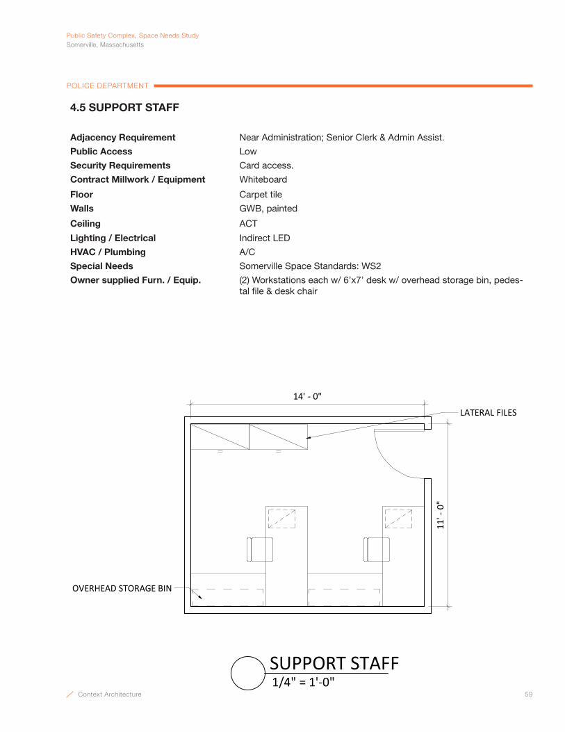
Context Architecture 59
PublicSafetyComplex,SpaceNeedsStudySomerville,Massachusetts
POLICE DEPARTMENT
LATERAL FILES
14' - 0"
11' -
0"
OVERHEAD STORAGE BIN
1/4" = 1'-0"SUPPORT STAFF
4.5 SUPPORT STAFF
Adjacency Requirement Near Administration; Senior Clerk & Admin Assist.
Public Access Low
Security Requirements Card access.
Contract Millwork / Equipment Whiteboard
Floor Carpet tile
Walls GWB, painted
Ceiling ACT
Lighting / Electrical Indirect LED
HVAC / Plumbing A/C
Special Needs Somerville Space Standards: WS2
Owner supplied Furn. / Equip. (2) Workstations each w/ 6’x7’ desk w/ overhead storage bin, pedes-tal file & desk chair

60 Context Architecture
Public Safety Complex, Space Needs StudySomerville, Massachusetts
POLICE DEPARTMENT
14' - 0"
21' -
0"
LATERAL FILES
OVERHEAD STORAGE BIN
3/16" = 1'-0"FINANCIAL SERVICES / PAYROLL
4.6 FINANCIAL SERVICES / PAYROLL
Adjacency Requirement Contains, Financial Analyst, Senior Clerk, Payroll Assistant
Public Access None
Security Requirements Card access.
Contract Millwork / Equipment None
Floor Carpet tile
Walls GWB, painted
Ceiling ACT
Lighting / Electrical Indirect LED
HVAC / Plumbing A/C
Special Needs Somerville Space Standards: WS2
Owner supplied Furn. / Equip. (3) Workstations each w/ 6’x7’ desk w/ overhead storage bin, pedes-tal file & desk chair; (6) 42” 4-drawer lateral cabinets
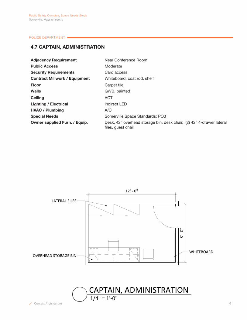
Context Architecture 61
PublicSafetyComplex,SpaceNeedsStudySomerville,Massachusetts
POLICE DEPARTMENT
WHITEBOARD
LATERAL FILES
12' - 0"
8' -
0"
OVERHEAD STORAGE BIN
1/4" = 1'-0"CAPTAIN, ADMINISTRATION
4.7 CAPTAIN, ADMINISTRATION
Adjacency Requirement Near Conference Room
Public Access Moderate
Security Requirements Card access
Contract Millwork / Equipment Whiteboard, coat rod, shelf
Floor Carpet tile
Walls GWB, painted
Ceiling ACT
Lighting / Electrical Indirect LED
HVAC / Plumbing A/C
Special Needs Somerville Space Standards: PO3
Owner supplied Furn. / Equip. Desk, 42” overhead storage bin, desk chair, (2) 42” 4-drawer lateral files, guest chair

62 Context Architecture
Public Safety Complex, Space Needs StudySomerville, Massachusetts
POLICE DEPARTMENT
14' ‐ 0"
28' ‐ 0"
LATERAL FILES OVERHEAD STORAGE BIN
1/8" = 1'‐0"SPECIAL OPERATIONS & TRAINING
4.8 SPECIAL OPERATIONS & TRAINING
Adjacency Requirement Near Administration; Training Lieutenant, Sp Ops Lt, Sgt & Homeland Sgt.
Public Access Limited
Security Requirements Card access.
Contract Millwork / Equipment Whiteboard
Floor Carpet tile
Walls GWB, painted
Ceiling ACT
Lighting / Electrical Indirect LED
HVAC / Plumbing A/C
Special Needs Somerville Space Standards: WS2
Owner supplied Furn. / Equip. (4) Workstations each w/ 6’x7’ desk w/ overhead storage bin, pedes-tal file & desk chair; (8) 42” 4-drawer lateral cabinets
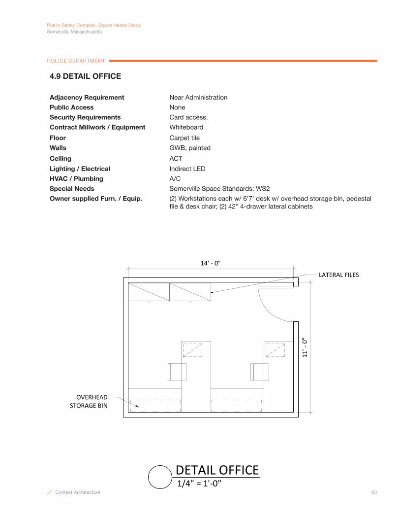
Context Architecture 63
PublicSafetyComplex,SpaceNeedsStudySomerville,Massachusetts
POLICE DEPARTMENT
LATERAL FILES
14' - 0"
11' -
0"
OVERHEAD STORAGE BIN
1/4" = 1'-0"DETAIL OFFICE
4.9 DETAIL OFFICE
Adjacency Requirement Near Administration
Public Access None
Security Requirements Card access.
Contract Millwork / Equipment Whiteboard
Floor Carpet tile
Walls GWB, painted
Ceiling ACT
Lighting / Electrical Indirect LED
HVAC / Plumbing A/C
Special Needs Somerville Space Standards: WS2
Owner supplied Furn. / Equip. (2) Workstations each w/ 6’7’ desk w/ overhead storage bin, pedestal file & desk chair; (2) 42” 4-drawer lateral cabinets
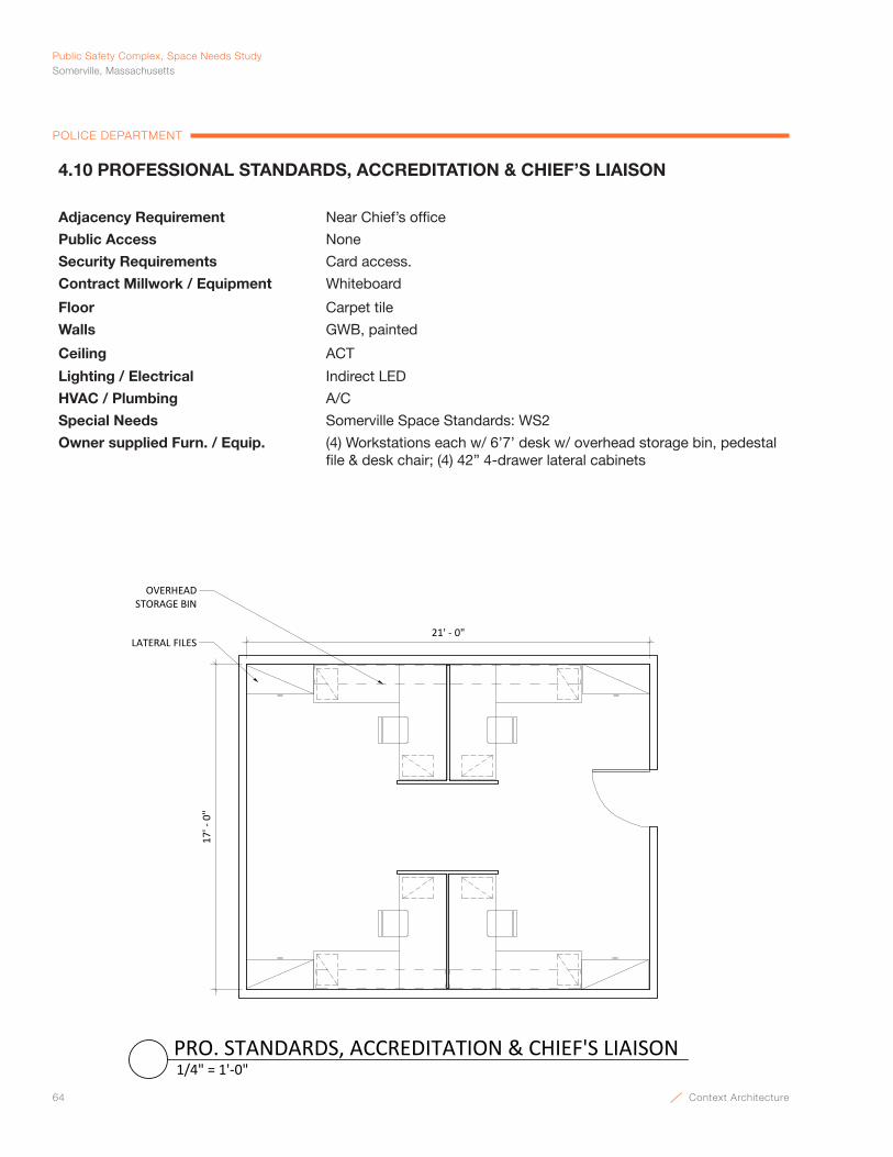
64 Context Architecture
Public Safety Complex, Space Needs StudySomerville, Massachusetts
POLICE DEPARTMENT
LATERAL FILES21' ‐ 0"
17' ‐ 0"
OVERHEAD STORAGE BIN
1/4" = 1'‐0"PRO. STANDARDS, ACCREDITATION & CHIEF'S LIAISON
4.10 PROFESSIONAL STANDARDS, ACCREDITATION & CHIEF’S LIAISON
Adjacency Requirement Near Chief’s office
Public Access None
Security Requirements Card access.
Contract Millwork / Equipment Whiteboard
Floor Carpet tile
Walls GWB, painted
Ceiling ACT
Lighting / Electrical Indirect LED
HVAC / Plumbing A/C
Special Needs Somerville Space Standards: WS2
Owner supplied Furn. / Equip. (4) Workstations each w/ 6’7’ desk w/ overhead storage bin, pedestal file & desk chair; (4) 42” 4-drawer lateral cabinets
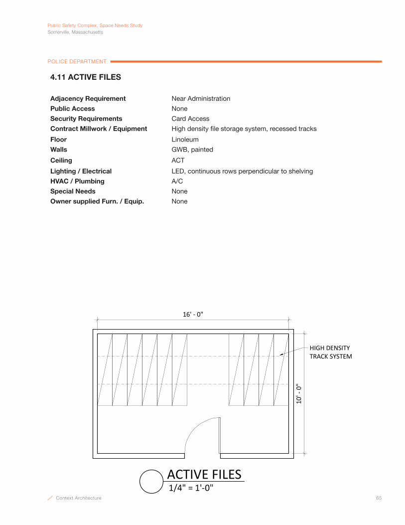
Context Architecture 65
PublicSafetyComplex,SpaceNeedsStudySomerville,Massachusetts
POLICE DEPARTMENT
10' -
0"
16' - 0"
HIGH DENSITY TRACK SYSTEM
1/4" = 1'-0"ACTIVE FILES
4.11 ACTIVE FILES
Adjacency Requirement Near Administration
Public Access None
Security Requirements Card Access
Contract Millwork / Equipment High density file storage system, recessed tracks
Floor Linoleum
Walls GWB, painted
Ceiling ACT
Lighting / Electrical LED, continuous rows perpendicular to shelving
HVAC / Plumbing A/C
Special Needs None
Owner supplied Furn. / Equip. None
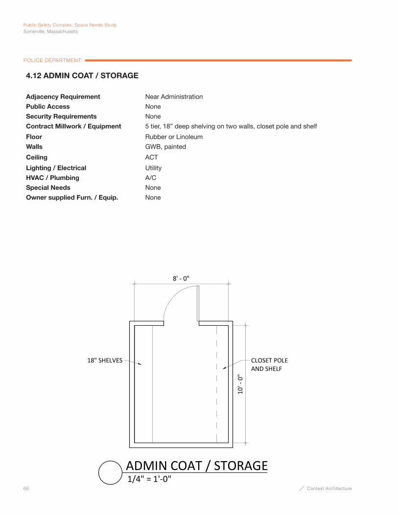
66 Context Architecture
Public Safety Complex, Space Needs StudySomerville, Massachusetts
POLICE DEPARTMENT
18" SHELVES
8' - 0"
10' -
0"
CLOSET POLE AND SHELF
1/4" = 1'-0"ADMIN COAT / STORAGE
4.12 ADMIN COAT / STORAGE
Adjacency Requirement Near Administration
Public Access None
Security Requirements None
Contract Millwork / Equipment 5 tier, 18” deep shelving on two walls, closet pole and shelf
Floor Rubber or Linoleum
Walls GWB, painted
Ceiling ACT
Lighting / Electrical Utility
HVAC / Plumbing A/C
Special Needs None
Owner supplied Furn. / Equip. None
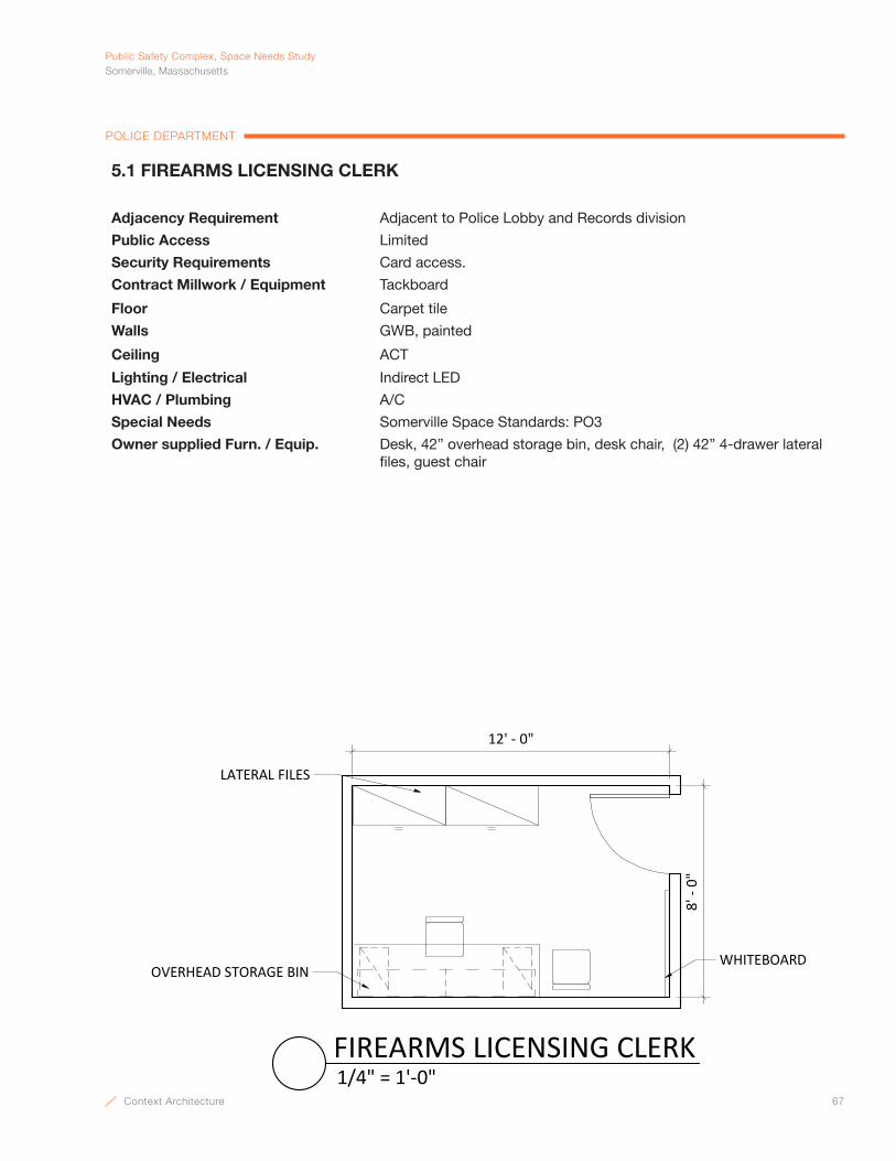
Context Architecture 67
PublicSafetyComplex,SpaceNeedsStudySomerville,Massachusetts
POLICE DEPARTMENT
5.1 FIREARMS LICENSING CLERK
Adjacency Requirement Adjacent to Police Lobby and Records division
Public Access Limited
Security Requirements Card access.
Contract Millwork / Equipment Tackboard
Floor Carpet tile
Walls GWB, painted
Ceiling ACT
Lighting / Electrical Indirect LED
HVAC / Plumbing A/C
Special Needs Somerville Space Standards: PO3
Owner supplied Furn. / Equip. Desk, 42” overhead storage bin, desk chair, (2) 42” 4-drawer lateral files, guest chair
WHITEBOARD
LATERAL FILES
12' ‐ 0"
8' ‐ 0"
OVERHEAD STORAGE BIN
1/4" = 1'‐0"FIREARMS LICENSING CLERK
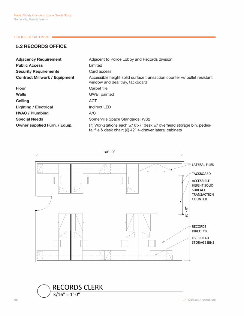
68 Context Architecture
Public Safety Complex, Space Needs StudySomerville, Massachusetts
POLICE DEPARTMENT
OVERHEAD STORAGE BINS
ACCESSIBLE HEIGHT SOLID SURFACE TRANSACTION COUNTER
20' ‐ 0"
30' ‐ 0"
RECORDS DIRECTOR
TACKBOARD
LATERAL FILES
3/16" = 1'‐0"RECORDS CLERK
5.2 RECORDS OFFICE
Adjacency Requirement Adjacent to Police Lobby and Records division
Public Access Limited
Security Requirements Card access.
Contract Millwork / Equipment Accessible height solid surface transaction counter w/ bullet resistant window and deal tray, tackboard
Floor Carpet tile
Walls GWB, painted
Ceiling ACT
Lighting / Electrical Indirect LED
HVAC / Plumbing A/C
Special Needs Somerville Space Standards: WS2
Owner supplied Furn. / Equip. (7) Workstations each w/ 6’x7’ desk w/ overhead storage bin, pedes-tal file & desk chair; (6) 42” 4-drawer lateral cabinets

Context Architecture 69
PublicSafetyComplex,SpaceNeedsStudySomerville,Massachusetts
POLICE DEPARTMENT
5.3 COHR CLINICAL SUPERVISION
Adjacency Requirement Near CHOR office, used for staff training
Public Access Low
Security Requirements Electronic access
Contract Millwork / Equipment Chair rail
Floor Carpet Tile or VCT
Walls GWB
Ceiling ACT
Lighting / Electrical Indirect LED
HVAC / Plumbing A/C
Special Needs None
Owner supplied Furn. / Equip. (2) Chairs; (1) working table
10' - 0"
WORKING TABLE
10' -
0"
1/4" = 1'-0"COHR CLINICAL SUPERVISION

70 Context Architecture
Public Safety Complex, Space Needs StudySomerville, Massachusetts
POLICE DEPARTMENT
5.4 COHR OFFICES
Adjacency Requirement Adjacent to COHR Reception
Public Access Limited
Security Requirements Card access
Contract Millwork / Equipment None
Floor Carpet tile
Walls GWB, painted
Ceiling ACT
Lighting / Electrical Indirect LED, power and data to cubicles
HVAC / Plumbing A/C
Special Needs Somerville Space Standards: WS2
Owner supplied Furn. / Equip. (10) Workstations each w/ 6’x7’ desk w/ overhead storage bin, ped-estal file & desk chair; Medium height cubicle walls
28' ‐ 6"
30' ‐ 0"
OVERHEADSTORAGE BINS
MEDIUM HEIGHTCUBE WALLS
DIRECTOR
JAIL DIVERSIONOFFICE
WORK ROOM
CONFERENCE ROOM
CLINICALSUPERVISION
1/8" = 1'‐0"COHR OFFICES

Context Architecture 71
PublicSafetyComplex,SpaceNeedsStudySomerville,Massachusetts
POLICE DEPARTMENT
WHITEBOARD
LATERAL FILES
TV ABOVE
12' - 0"
8' -
0"
OVERHEAD STORAGE BIN
1/4" = 1'-0"COHR DIRECTOR
5.5 COHR DIRECTOR
Adjacency Requirement Adjacent to COHR Offices
Public Access Limited
Security Requirements Card access
Contract Millwork / Equipment Whiteboard, coat rod, shelf
Floor Carpet tile
Walls GWB, painted
Ceiling ACT
Lighting / Electrical Indirect LED, CATV
HVAC / Plumbing A/C
Special Needs Somerville Space Standards: PO3
Owner supplied Furn. / Equip. Desk w/ return, (2) 42” overhead storage bins, desk chair, (2) 42” 4-drawer lateral files, TV
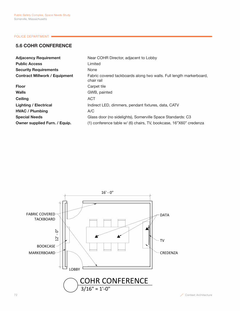
72 Context Architecture
Public Safety Complex, Space Needs StudySomerville, Massachusetts
POLICE DEPARTMENT
5.6 COHR CONFERENCE
Adjacency Requirement Near COHR Director, adjacent to Lobby
Public Access Limited
Security Requirements None
Contract Millwork / Equipment Fabric covered tackboards along two walls. Full length markerboard, chair rail
Floor Carpet tile
Walls GWB, painted
Ceiling ACT
Lighting / Electrical Indirect LED, dimmers, pendant fixtures, data, CATV
HVAC / Plumbing A/C
Special Needs Glass door (no sidelights), Somerville Space Standards: C3
Owner supplied Furn. / Equip. (1) conference table w/ (6) chairs, TV, bookcase, 16”X60” credenza
12' -
0"
TV
DATAFABRIC COVEREDTACKBOARD
MARKERBOARD CREDENZA
BOOKCASE
LOBBY
16' - 0"
3/16" = 1'-0"COHR CONFERENCE
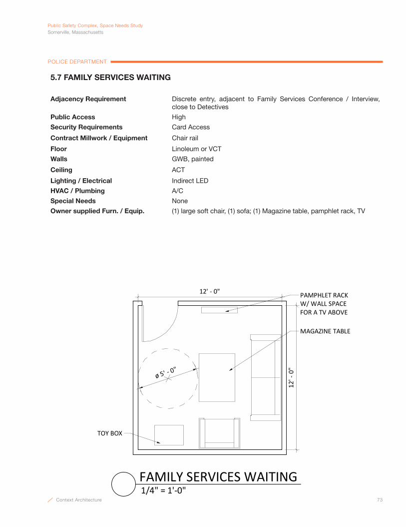
Context Architecture 73
PublicSafetyComplex,SpaceNeedsStudySomerville,Massachusetts
POLICE DEPARTMENT
12' - 0"12
' - 0
"
MAGAZINE TABLE
ø 5' - 0"
PAMPHLET RACK W/ WALL SPACE FOR A TV ABOVE
TOY BOX
1/4" = 1'-0"FAMILY SERVICES WAITING
5.7 FAMILY SERVICES WAITING
Adjacency Requirement Discrete entry, adjacent to Family Services Conference / Interview, close to Detectives
Public Access High
Security Requirements Card Access
Contract Millwork / Equipment Chair rail
Floor Linoleum or VCT
Walls GWB, painted
Ceiling ACT
Lighting / Electrical Indirect LED
HVAC / Plumbing A/C
Special Needs None
Owner supplied Furn. / Equip. (1) large soft chair, (1) sofa; (1) Magazine table, pamphlet rack, TV

74 Context Architecture
Public Safety Complex, Space Needs StudySomerville, Massachusetts
POLICE DEPARTMENT
DATA
12' - 0"
14' -
0"
FABRIC COVEREDTACKBOARD
MARKERBOARD
SOFA
BASE CABINET
BOTTLE FILL
ACCESSIBLE HEIGHTCOAT ALCOVE W/ROD AND SHELF
COFFEE MACHINE
WALL PHONE
1/4" = 1'-0"FAMILY SERVICES CONFERENCE / INTERVIEW
5.8 FAMILY SERVICES CONFERENCE / INTERVIEW
Adjacency Requirement Adjacent to Family Services Waiting, near private Bathrooms
Public Access High
Security Requirements Privacy w/ occupied function
Contract Millwork / Equipment Fabric covered tackboard, full length markerboard, chair rail, accessible height base cabinet, coat rod, shelf
Floor Carpet tile
Walls GWB, painted
Ceiling ACT
Lighting / Electrical Indirect LED, dimmers, pendant fixtures, data, CATV
HVAC / Plumbing A/C, water bottle fill
Special Needs Soft Furnishings, windows acceptable on upper floor
Owner supplied Furn. / Equip. (1) Sofa, (2) chairs, (1) table, coffee machine
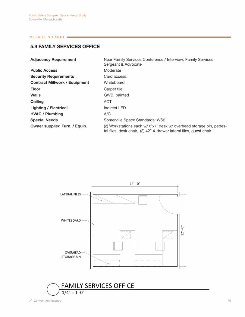
Context Architecture 75
PublicSafetyComplex,SpaceNeedsStudySomerville,Massachusetts
POLICE DEPARTMENT
WHITEBOARD
LATERAL FILES
14' ‐ 0"12
' ‐ 0"
OVERHEAD STORAGE BIN
1/4" = 1'‐0"FAMILY SERVICES OFFICE
5.9 FAMILY SERVICES OFFICE
Adjacency Requirement Near Family Services Conference / Interview; Family ServicesSergeant & Advocate
Public Access Moderate
Security Requirements Card access.
Contract Millwork / Equipment Whiteboard
Floor Carpet tile
Walls GWB, painted
Ceiling ACT
Lighting / Electrical Indirect LED
HVAC / Plumbing A/C
Special Needs Somerville Space Standards: WS2
Owner supplied Furn. / Equip. (2) Workstations each w/ 6’x7’ desk w/ overhead storage bin, pedes-tal files, desk chair, (2) 42” 4-drawer lateral files, guest chair
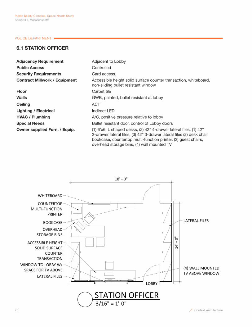
76 Context Architecture
Public Safety Complex, Space Needs StudySomerville, Massachusetts
POLICE DEPARTMENT
14' -
0"
LATERAL FILES
OVERHEAD STORAGE BINS
WHITEBOARD
LOBBY
18' - 0"
BOOKCASE
WINDOW TO LOBBY W/ SPACE FOR TV ABOVE
ACCESSIBLE HEIGHTSOLID SURFACE
COUNTER TRANSACTION
COUNTERTOPMULTI-FUNCTION
PRINTER
LATERAL FILES
(4) WALL MOUNTEDTV ABOVE WINDOW
3/16" = 1'-0"STATION OFFICER
6.1 STATION OFFICER
Adjacency Requirement Adjacent to Lobby
Public Access Controlled
Security Requirements Card access.
Contract Millwork / Equipment Accessible height solid surface counter transaction, whiteboard, non-sliding bullet resistant window
Floor Carpet tile
Walls GWB, painted, bullet resistant at lobby
Ceiling ACT
Lighting / Electrical Indirect LED
HVAC / Plumbing A/C, positive pressure relative to lobby
Special Needs Bullet resistant door, control of Lobby doors
Owner supplied Furn. / Equip. (1) 6’x6’ L shaped desks, (2) 42” 4-drawer lateral files, (1) 42” 2-drawer lateral files, (3) 42” 3-drawer lateral files (2) desk chair, bookcase, countertop multi-function printer, (2) guest chairs, overhead storage bins, (4) wall mounted TV
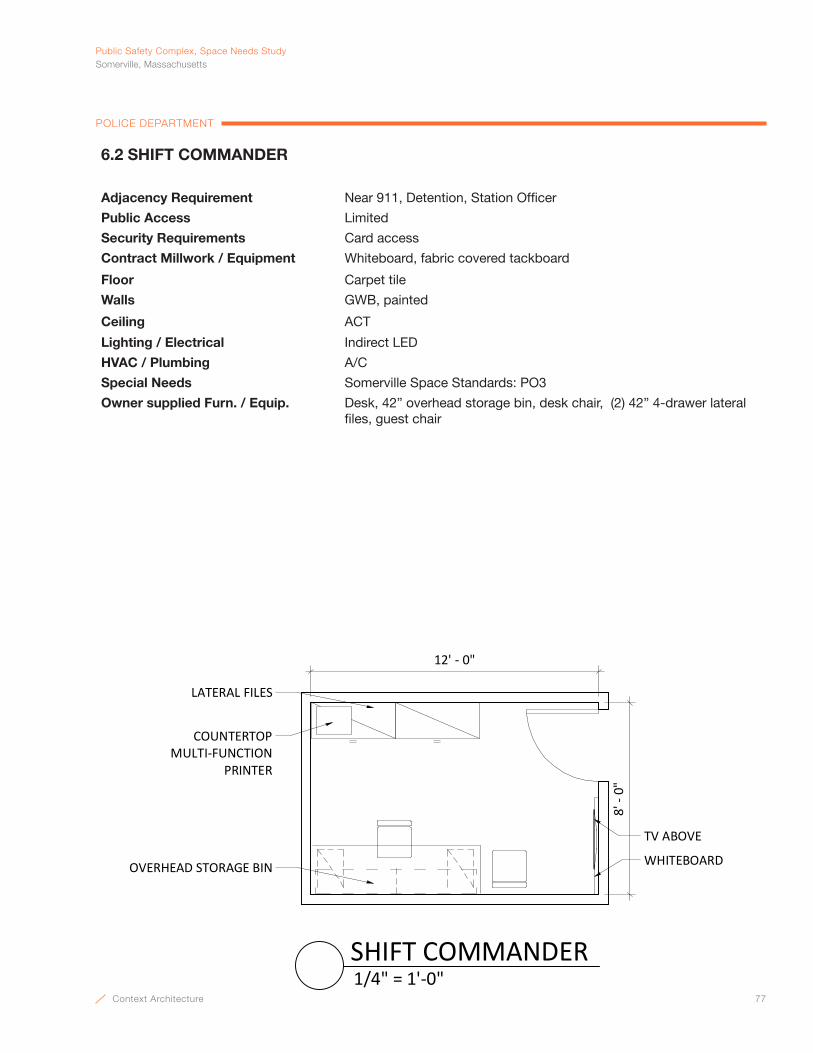
Context Architecture 77
PublicSafetyComplex,SpaceNeedsStudySomerville,Massachusetts
POLICE DEPARTMENT
WHITEBOARD
COUNTERTOPMULTI-FUNCTION
PRINTER
LATERAL FILES
TV ABOVE
12' - 0"
8' -
0"
OVERHEAD STORAGE BIN
1/4" = 1'-0"SHIFT COMMANDER
6.2 SHIFT COMMANDER
Adjacency Requirement Near 911, Detention, Station Officer
Public Access Limited
Security Requirements Card access
Contract Millwork / Equipment Whiteboard, fabric covered tackboard
Floor Carpet tile
Walls GWB, painted
Ceiling ACT
Lighting / Electrical Indirect LED
HVAC / Plumbing A/C
Special Needs Somerville Space Standards: PO3
Owner supplied Furn. / Equip. Desk, 42” overhead storage bin, desk chair, (2) 42” 4-drawer lateral files, guest chair

78 Context Architecture
Public Safety Complex, Space Needs StudySomerville, Massachusetts
POLICE DEPARTMENT
LATERAL FILES
20' -
0"
WHITEBOARD
18' - 0"
FABRIC COVEREDTACKBOARD
OVERHEAD STORAGE BINS
1/8" = 1'-0"STREET COMMANDER
6.3 STREET COMMANDER
Adjacency Requirement Near Patrol
Public Access Limited
Security Requirements Card access
Contract Millwork / Equipment Whiteboard, fabric covered tackboard
Floor Carpet tile
Walls GWB, painted
Ceiling ACT
Lighting / Electrical Indirect LED
HVAC / Plumbing A/C
Special Needs Somerville Space Standards: WS2
Owner supplied Furn. / Equip. (2) Workstations each w/ 6’x7’ desk w/ overhead storage bin, pedes-tal file & desk chair

Context Architecture 79
PublicSafetyComplex,SpaceNeedsStudySomerville,Massachusetts
POLICE DEPARTMENT
WHITEBOARD
COUNTERTOPMULTI-FUNCTION
PRINTER
LATERAL FILES
TV ABOVE
12' - 0"
8' -
0"
OVERHEAD STORAGE BIN
1/4" = 1'-0"NEIGHBORHOOD POLICING SUPERVISOR
6.4 NEIGHBORHOOD POLICING SUPERVISOR
Adjacency Requirement Near Patrol
Public Access Moderate
Security Requirements Card access.
Contract Millwork / Equipment Whiteboard
Floor Carpet tile
Walls GWB, painted
Ceiling ACT
Lighting / Electrical Indirect LED
HVAC / Plumbing A/C
Special Needs Somerville Space Standards: PO3
Owner supplied Furn. / Equip. Desk, 42” overhead storage bin, desk chair, (2) 42” 4-drawer lateral files, guest chair

80 Context Architecture
Public Safety Complex, Space Needs StudySomerville, Massachusetts
POLICE DEPARTMENT
6.5 PATROL OPEN OFFICE
Adjacency Requirement Near Patrol; Ward, Count, Vision Zero & Traffic
Public Access None
Security Requirements Card access
Contract Millwork / Equipment None
Floor Carpet tile
Walls GWB, painted
Ceiling ACT
Lighting / Electrical Indirect LED, power and data to cubicles
HVAC / Plumbing A/C
Special Needs Somerville Space Standards: WS2
Owner supplied Furn. / Equip. (20) Workstations each w/ 6’x7’ desk w/ overhead storage bin, ped-estal file & desk chair
40' ‐ 0"
40' ‐ 0"
WHITEBOARD
COUNTERTOPMULTI‐FUNCTION
PRINTER
LATERAL FILES
TV ABOVE
OVERHEAD STORAGE BIN
1/8" = 1'‐0"PATROL OPEN OFFICE

Context Architecture 81
PublicSafetyComplex,SpaceNeedsStudySomerville,Massachusetts
POLICE DEPARTMENT
DATA
12' - 0"
10' -
0"
FABRIC COVERED TACKBOARD
MARKERBOARD
TV
16X60 CREDENZA
COUNTERTOPMULTI-FUNCTIONPRINTER
1/4" = 1'-0"TRAFFIC CONFERENCE / INTERVIEW
6.6 TRAFFIC CONFERENCE & INTERVIEW
Adjacency Requirement Near Traffic Clerk
Public Access Limited
Security Requirements None
Contract Millwork / Equipment Fabric covered tackboards along two walls. Full length markerboard, chair rail, solid surface counter with base cabinets below.
Floor Carpet tile
Walls GWB, painted
Ceiling ACT
Lighting / Electrical Indirect LED, dimmers, pendant fixtures, data, CATV
HVAC / Plumbing A/C
Special Needs None
Owner supplied Furn. / Equip. (1) conference 4’ round table w/ (4) chairs, TV, countertop multi-function printer, 16”x60” Credenza

82 Context Architecture
Public Safety Complex, Space Needs StudySomerville, Massachusetts
POLICE DEPARTMENT
10' -
0"
14' - 0"
(8) LATERAL FILES
1/4" = 1'-0"TRAFFIC FILES
6.7 TRAFFIC FILES
Adjacency Requirement Near Traffic
Public Access None
Security Requirements None
Contract Millwork / Equipment None
Floor Rubber or Linoleum
Walls GWB, painted
Ceiling ACT
Lighting / Electrical Indirect light
HVAC / Plumbing A/C
Special Needs None
Owner supplied Furn. / Equip. (8) 42” 4-drawer lateral files

Context Architecture 83
PublicSafetyComplex,SpaceNeedsStudySomerville,Massachusetts
POLICE DEPARTMENT
6.8 TRAFFIC EQUIPMENT STORAGE ROOM
Adjacency Requirement Near Traffic
Public Access None
Security Requirements None
Contract Millwork / Equipment 24” deep metal shelving on two walls
Floor Rubber or Linoleum
Walls GWB, painted
Ceiling ACT
Lighting / Electrical Utility
HVAC / Plumbing A/C
Special Needs None
Owner supplied Furn. / Equip. None
10' -
0"
14' - 0"
24" METAL SHELVING
1/4" = 1'-0"TRAFFIC EQUIPMENT STORAGE ROOM

84 Context Architecture
Public Safety Complex, Space Needs StudySomerville, Massachusetts
POLICE DEPARTMENT
28' - 0"
20' -
0"
WHITEBOARDPODIUM
TV
ACCESSIBLE HEIGHTCOUNTER W/
BASE CABINETS
TACKBOARD
LARGE FORMAT WALLMOUNTED MONITOR
1/8" = 1'-0"ROLL CALL
6.9 ROLL CALL
Adjacency Requirement Next to Patrol and Sergeants Office, near Locker Rooms
Public Access None
Security Requirements High
Contract Millwork / Equipment Accessible height solid surface countertop with base cabinets, (2) whiteboards, tackboard
Floor Resilient flooring or linoleum
Walls GWB, painted
Ceiling ACT
Lighting / Electrical Indirect LED and under counter lighting, CATV
HVAC / Plumbing A/C
Special Needs None
Owner supplied Furn. / Equip. Space for (16) battery chargers, (8) 20’” x 60” training tables w/ (16) chairs. Podium, TV, storage for (20) spare radios & chargers, (30) flashlights, large format wall mounted monitor
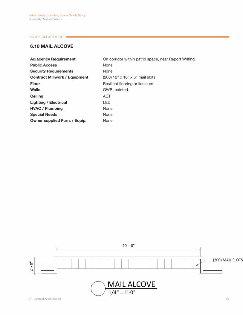
Context Architecture 85
PublicSafetyComplex,SpaceNeedsStudySomerville,Massachusetts
POLICE DEPARTMENT
2' -
0"
20' - 0"
(200) MAIL SLOTS
1/4" = 1'-0"MAIL ALCOVE
6.10 MAIL ALCOVE
Adjacency Requirement On corridor within patrol space, near Report Writing
Public Access None
Security Requirements None
Contract Millwork / Equipment (200) 12” x 16” x 5” mail slots
Floor Resilient flooring or linoleum
Walls GWB, painted
Ceiling ACT
Lighting / Electrical LED
HVAC / Plumbing None
Special Needs None
Owner supplied Furn. / Equip. None
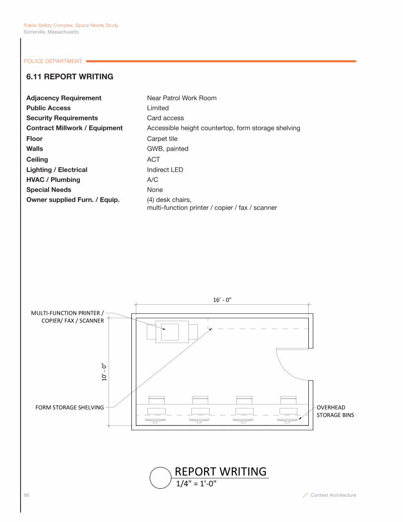
86 Context Architecture
Public Safety Complex, Space Needs StudySomerville, Massachusetts
POLICE DEPARTMENT
16' - 0"
10' -
0"
FORM STORAGE SHELVING OVERHEAD STORAGE BINS
MULTI-FUNCTION PRINTER / COPIER/ FAX / SCANNER
1/4" = 1'-0"REPORT WRITING
6.11 REPORT WRITING
Adjacency Requirement Near Patrol Work Room
Public Access Limited
Security Requirements Card access
Contract Millwork / Equipment Accessible height countertop, form storage shelving
Floor Carpet tile
Walls GWB, painted
Ceiling ACT
Lighting / Electrical Indirect LED
HVAC / Plumbing A/C
Special Needs None
Owner supplied Furn. / Equip. (4) desk chairs, multi-function printer / copier / fax / scanner

Context Architecture 87
PublicSafetyComplex,SpaceNeedsStudySomerville,Massachusetts
POLICE DEPARTMENT
16' - 0"
10' -
0"
SHELVING OVERHEAD STORAGE BINS
MULTI-FUNCTION PRINTER / COPIER/ FAX / SCANNER
EMERGENCYBUTTON
ACCESSIBLE HEIGHTSOLID SURFACECOUNTERTOP
1/4" = 1'-0"PATROL EVIDENCE PREP
6.12 PATROL EVIDENCE PREP.
Adjacency Requirement Near Patrol Work Room
Public Access Limited
Security Requirements Card access
Contract Millwork / Equipment Accessible height countertop, form storage shelving
Floor Carpet tile
Walls GWB, painted
Ceiling ACT
Lighting / Electrical Indirect LED, Emergency button
HVAC / Plumbing A/C
Special Needs None
Owner supplied Furn. / Equip. Multi-function printer / copier / fax / scanner, evidence packaging supplies
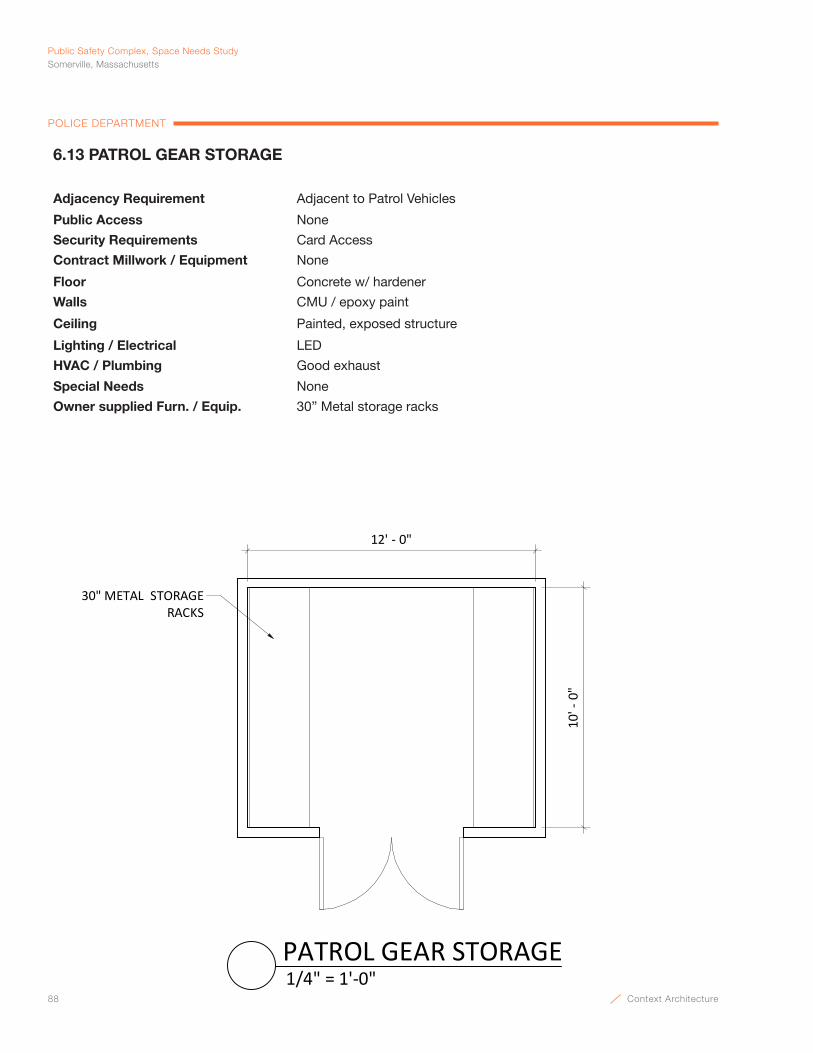
88 Context Architecture
Public Safety Complex, Space Needs StudySomerville, Massachusetts
POLICE DEPARTMENT
10' -
0"
12' - 0"
30" METAL STORAGE RACKS
1/4" = 1'-0"PATROL GEAR STORAGE
6.13 PATROL GEAR STORAGE
Adjacency Requirement Adjacent to Patrol Vehicles
Public Access None
Security Requirements Card Access
Contract Millwork / Equipment None
Floor Concrete w/ hardener
Walls CMU / epoxy paint
Ceiling Painted, exposed structure
Lighting / Electrical LED
HVAC / Plumbing Good exhaust
Special Needs None
Owner supplied Furn. / Equip. 30” Metal storage racks
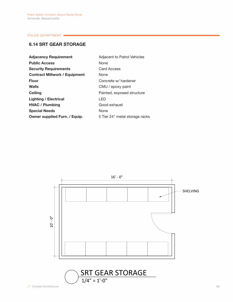
Context Architecture 89
PublicSafetyComplex,SpaceNeedsStudySomerville,Massachusetts
POLICE DEPARTMENT
10' -
0"
16' - 0"
SHELVING
1/4" = 1'-0"SRT GEAR STORAGE
6.14 SRT GEAR STORAGE
Adjacency Requirement Adjacent to Patrol Vehicles
Public Access None
Security Requirements Card Access
Contract Millwork / Equipment None
Floor Concrete w/ hardener
Walls CMU / epoxy paint
Ceiling Painted, exposed structure
Lighting / Electrical LED
HVAC / Plumbing Good exhaust
Special Needs None
Owner supplied Furn. / Equip. 5 Tier 24” metal storage racks

90 Context Architecture
Public Safety Complex, Space Needs StudySomerville, Massachusetts
POLICE DEPARTMENT
14' - 0"
11' -
0"
OVERHEAD STORAGE BIN
1/4" = 1'-0"ANIMAL CONTROL
6.17 ANIMAL CONTROL
Adjacency Requirement Near Administration
Public Access None
Security Requirements Card access.
Contract Millwork / Equipment Whiteboard
Floor Carpet tile
Walls GWB, painted
Ceiling ACT
Lighting / Electrical Indirect LED
HVAC / Plumbing A/C
Special Needs Somerville Space Standards: WS2
Owner supplied Furn. / Equip. (2) Workstations each w/ 6’7’ desk w/ overhead storage bin, pedestal file & desk chair

Context Architecture 91
PublicSafetyComplex,SpaceNeedsStudySomerville,Massachusetts
POLICE DEPARTMENT
WHITEBOARD
COUNTERTOPMULTI‐FUNCTION
PRINTER
LATERAL FILES
TV ABOVE
OVERHEAD STORAGE BIN
40' ‐ 0"
40' ‐ 0"
1/8" = 1'‐0"DETECTIVES OPEN OFFICE
7.1 DETECTIVES OPEN OFFICE
Adjacency Requirement Near Detective Clerk
Public Access None
Security Requirements Card access
Contract Millwork / Equipment None
Floor Carpet tile
Walls GWB, painted, partial glass wall, demountable wall systems
Ceiling ACT
Lighting / Electrical Indirect LED
HVAC / Plumbing A/C
Special Needs None
Owner supplied Furn. / Equip. (20) Workstations each w/ 6’x7’ desk w/ overhead storage bin, pedestal file & desk chair; (6) 42” 4-drawer lateral cabinets
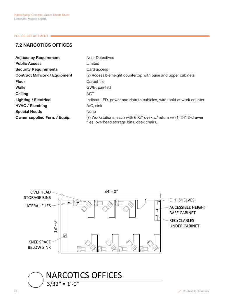
92 Context Architecture
Public Safety Complex, Space Needs StudySomerville, Massachusetts
POLICE DEPARTMENT
OVERHEAD STORAGE BINS
LATERAL FILES ACCESSIBLE HEIGHTBASE CABINET
O.H. SHELVES
RECYCLABLES UNDER CABINET
34' ‐ 0"
18' ‐ 0"
KNEE SPACE BELOW SINK
3/32" = 1'‐0"NARCOTICS OFFICES
7.2 NARCOTICS OFFICES
Adjacency Requirement Near Detectives
Public Access Limited
Security Requirements Card access
Contract Millwork / Equipment (2) Accessible height countertop with base and upper cabinets
Floor Carpet tile
Walls GWB, painted
Ceiling ACT
Lighting / Electrical Indirect LED, power and data to cubicles, wire mold at work counter
HVAC / Plumbing A/C, sink
Special Needs None
Owner supplied Furn. / Equip. (7) Workstations, each with 6’X7’ desk w/ return w/ (1) 24” 2-drawer files, overhead storage bins, desk chairs,

Context Architecture 93
PublicSafetyComplex,SpaceNeedsStudySomerville,Massachusetts
POLICE DEPARTMENT
10' - 0"
10' -
0" CAMERA
AUTOMATIC DOOR BOTTOM
1/4" = 1'-0"INTERROGATION
7.3 INTERROGATION
Adjacency Requirement Near confidential entry
Public Access High
Security Requirements Card access in and out
Contract Millwork / Equipment None
Floor Carpet tile
Walls GWB, painted
Ceiling ACT
Lighting / Electrical Pendant fixtures, CCTV camera, microphone, in use light outside room, automatic door bottom
HVAC / Plumbing A/C
Special Needs Acoustic privacy
Owner supplied Furn. / Equip. Table w/ (4) chairs
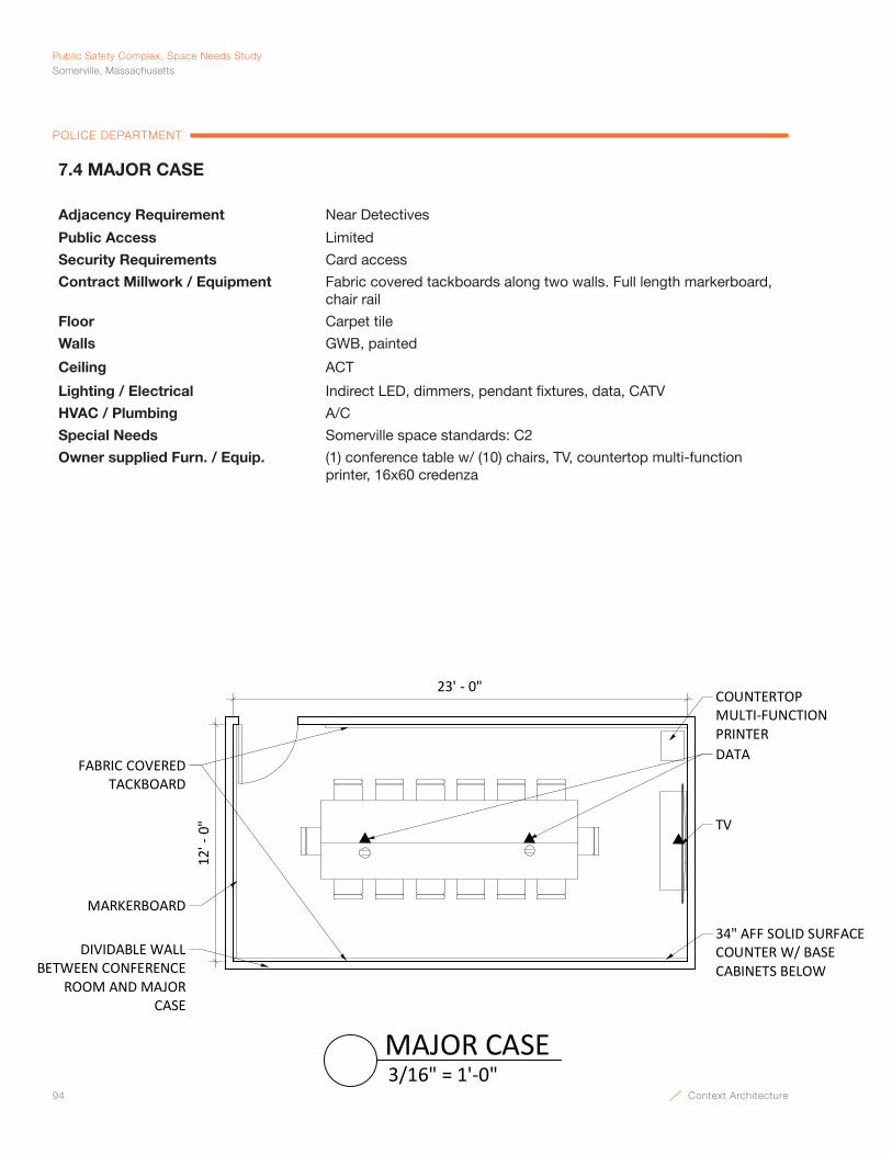
94 Context Architecture
Public Safety Complex, Space Needs StudySomerville, Massachusetts
POLICE DEPARTMENT
DATA
TV
34" AFF SOLID SURFACECOUNTER W/ BASECABINETS BELOW
FABRIC COVERED TACKBOARD
MARKERBOARD
DIVIDABLE WALLBETWEEN CONFERENCE
ROOM AND MAJOR CASE
COUNTERTOP MULTI-FUNCTIONPRINTER
12' -
0"
23' - 0"
3/16" = 1'-0"MAJOR CASE
7.4 MAJOR CASE
Adjacency Requirement Near Detectives
Public Access Limited
Security Requirements Card access
Contract Millwork / Equipment Fabric covered tackboards along two walls. Full length markerboard, chair rail
Floor Carpet tile
Walls GWB, painted
Ceiling ACT
Lighting / Electrical Indirect LED, dimmers, pendant fixtures, data, CATV
HVAC / Plumbing A/C
Special Needs Somerville space standards: C2
Owner supplied Furn. / Equip. (1) conference table w/ (10) chairs, TV, countertop multi-function printer, 16x60 credenza
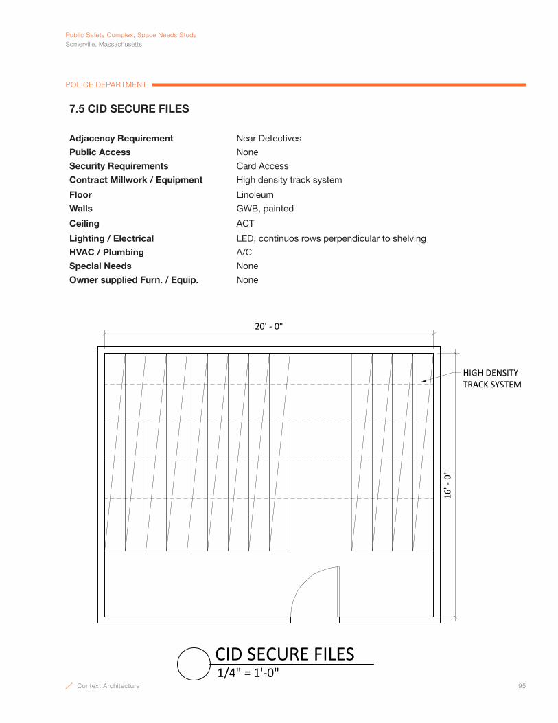
Context Architecture 95
PublicSafetyComplex,SpaceNeedsStudySomerville,Massachusetts
POLICE DEPARTMENT
DATA
TV
34" AFF SOLID SURFACECOUNTER W/ BASECABINETS BELOW
FABRIC COVERED TACKBOARD
MARKERBOARD
DIVIDABLE WALLBETWEEN CONFERENCE
ROOM AND MAJOR CASE
COUNTERTOP MULTI-FUNCTIONPRINTER
12' -
0"
23' - 0"
3/16" = 1'-0"MAJOR CASE
16' -
0"
20' - 0"
HIGH DENSITY TRACK SYSTEM
1/4" = 1'-0"CID SECURE FILES
7.5 CID SECURE FILES
Adjacency Requirement Near Detectives
Public Access None
Security Requirements Card Access
Contract Millwork / Equipment High density track system
Floor Linoleum
Walls GWB, painted
Ceiling ACT
Lighting / Electrical LED, continuos rows perpendicular to shelving
HVAC / Plumbing A/C
Special Needs None
Owner supplied Furn. / Equip. None
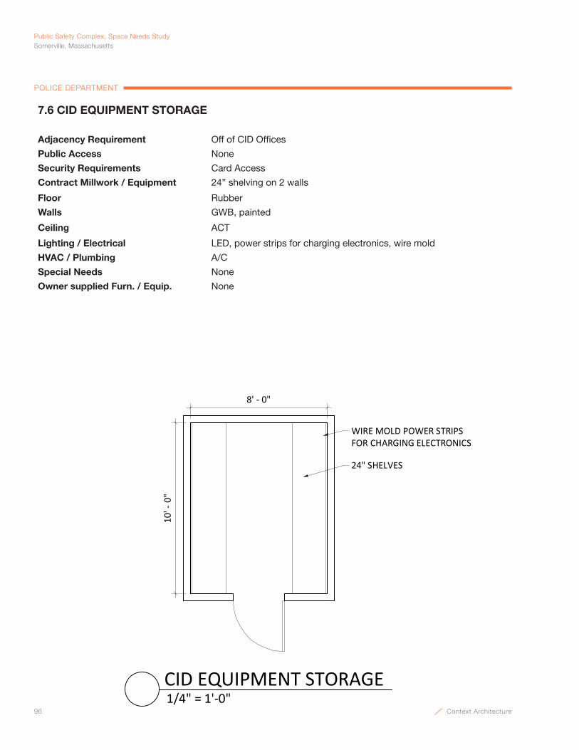
96 Context Architecture
Public Safety Complex, Space Needs StudySomerville, Massachusetts
POLICE DEPARTMENT
8' - 0"
10' -
0"
24" SHELVES
WIRE MOLD POWER STRIPS FOR CHARGING ELECTRONICS
1/4" = 1'-0"CID EQUIPMENT STORAGE
7.6 CID EQUIPMENT STORAGE
Adjacency Requirement Off of CID Offices
Public Access None
Security Requirements Card Access
Contract Millwork / Equipment 24” shelving on 2 walls
Floor Rubber
Walls GWB, painted
Ceiling ACT
Lighting / Electrical LED, power strips for charging electronics, wire mold
HVAC / Plumbing A/C
Special Needs None
Owner supplied Furn. / Equip. None

Context Architecture 97
PublicSafetyComplex,SpaceNeedsStudySomerville,Massachusetts
POLICE DEPARTMENT
7.7 DIGITAL FORENSICS
Adjacency Requirement Near Evidence
Public Access None
Security Requirements Card access
Contract Millwork / Equipment 8’ Accessible height counterto w/ base and upper cabinets
Floor Carpet tile
Walls GWB, painted
Ceiling ACT
Lighting / Electrical Indirect LED, multiple data / power drops, wiremold power
HVAC / Plumbing A/C
Special Needs Somerville Space Standards: WS2
Owner supplied Furn. / Equip. (3) Workstations, each with 6’X7’ desk w/ return, overhead storage bins, desk chairs, (2) 42” 4-drawer lateral files, evidence locker outside w/ power
20' - 0"
14' -
0"
OVERHEAD STORAGE BINS
LATERAL FILES
O.H. SHELVES
ACCESSIBLE HEIGHTBASE CABINET
WIREMOLD POWERSTRIPS
1/4" = 1'-0"DIGITAL FORENSICS
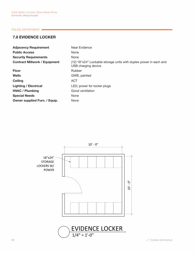
98 Context Architecture
Public Safety Complex, Space Needs StudySomerville, Massachusetts
POLICE DEPARTMENT
7.8 EVIDENCE LOCKER
Adjacency Requirement Near Evidence
Public Access None
Security Requirements None
Contract Millwork / Equipment (12) 18”x24” Lockable storage units with duplex power in each and USB charging device
Floor Rubber
Walls GWB, painted
Ceiling ACT
Lighting / Electrical LED; power for locker plugs
HVAC / Plumbing Good ventilation
Special Needs None
Owner supplied Furn. / Equip. None
10' -
0"
18"x24" STORAGE
LOCKERS W/POWER
10' - 0"
1/4" = 1'-0"EVIDENCE LOCKER

Context Architecture 99
PublicSafetyComplex,SpaceNeedsStudySomerville,Massachusetts
POLICE DEPARTMENT
LATERAL FILES
OVERHEAD STORAGE BINS
WHITEBOARDWHITEBOARD
OVERHEADSTORAGE BINS
16' - 0"
14' -
0"
COUNTERTOP MULTI-FUNCTIONPRINTER
BAR-CODE PRINTER
HEAT SEALER
1/4" = 1'-0"EVIDENCE TECHNICIAN OFFICE
7.9 EVIDENCE TECHNICIAN OFFICE
Adjacency Requirement Adjacent to Evidence Processing
Public Access None
Security Requirements Card access.
Contract Millwork / Equipment (2) Whiteboard
Floor Carpet tile
Walls GWB, painted w/ plywood security liner
Ceiling GWB painted
Lighting / Electrical Indirect LED, power at counter
HVAC / Plumbing A/C
Special Needs Somerville Space Standard: WS2
Owner supplied Furn. / Equip. (2) 6’x7’ L shaped desks, (2) 42” 4-drawer lateral files, (2) desk chair, bookcase, countertop multi-function printer, (2) guest chairs, overhead storage bins

100 Context Architecture
Public Safety Complex, Space Needs StudySomerville, Massachusetts
POLICE DEPARTMENT
18' - 0"KNEE SPACE
EVIDENCESTORAGE
EVIDENCE TECH. OFFICE
34" AFF WORK COUNTER
EVIDENCE LOCKER
REF UNIT (4 CELLS)
12' -
0"
1/4" = 1'-0"EVIDENCE PROCESSING
7.10 EVIDENCE PROCESSING
Adjacency Requirement Near Booking, Report Writing, direct access to Evidence
Public Access None
Security Requirements Card access in and out
Contract Millwork / Equipment Base and wall cabinets; stainless steel counter w/ slots above for forms; evidence pass through (36) lockers of varying sizes, (1) REF unit (4 cells)
Floor Epoxy
Walls GWB, painted w/ plywood security liner
Ceiling GWB painted
Lighting / Electrical Indirect LED, CCTV cameras, data
HVAC / Plumbing A/C
Special Needs None
Owner supplied Furn. / Equip. Chair
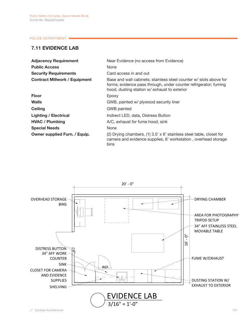
Context Architecture 101
PublicSafetyComplex,SpaceNeedsStudySomerville,Massachusetts
POLICE DEPARTMENT
20' - 0"16
' - 0
"
DRYING CHAMBER
FUME W/EXHAUSTSINK
34" AFF WORK COUNTER
SHELVING
REF.
34" AFF STAINLESS STEEL MOVABLE TABLE
CLOSET FOR CAMERA AND EVIDENCE
SUPPLIES
AREA FOR PHOTOGRAPHYTRIPOD SETUP
OVERHEAD STORAGEBINS
DUSTING STATION W/EXHAUST TO EXTERIOR
DISTRESS BUTTON
3/16" = 1'-0"EVIDENCE LAB
7.11 EVIDENCE LAB
Adjacency Requirement Near Evidence (no access from Evidence)
Public Access None
Security Requirements Card access in and out
Contract Millwork / Equipment Base and wall cabinets; stainless steel counter w/ slots above for forms; evidence pass through, under counter refrigerator; fuming hood, dusting station w/ exhaust to exterior
Floor Epoxy
Walls GWB, painted w/ plywood security liner
Ceiling GWB painted
Lighting / Electrical Indirect LED, data, Distress Button
HVAC / Plumbing A/C, exhaust for fume hood, sink
Special Needs None
Owner supplied Furn. / Equip. (2) Drying chambers, (1) 3.5’ x 6’ stainless steel table, closet for camera and evidence supplies, 6’ workstation , overhead storage bins

102 Context Architecture
Public Safety Complex, Space Needs StudySomerville, Massachusetts
POLICE DEPARTMENT
26' -
0"
37' - 0"
HIGH DENSITY TRACK SYSTEM
REFRIGERATOR
STORAGE SHELVING
ø 5' - 0"
EVIDENCEPROCESSING
EVIDENCELAB
1' 6" FIXED SHELVING ON THE END WALLS
1/8" = 1'-0"EVIDENCE, GENERAL STORAGE
7.12 EVIDENCE, GENERAL STORAGE
Adjacency Requirement Direct access from Evidence Processing
Public Access None
Security Requirements Card access in and out
Contract Millwork / Equipment High density track system, storage shelving
Floor Linoleum or Resilient
Walls GWB,painted w/ plywood security liner
Ceiling GWB, painted
Lighting / Electrical LED, continuos rows perpendicular to shelving, CCTV cameras
HVAC / Plumbing A/C
Special Needs None
Owner supplied Furn. / Equip. (2) Refrigerators

Context Architecture 103
PublicSafetyComplex,SpaceNeedsStudySomerville,Massachusetts
POLICE DEPARTMENT
20' - 0"
10' -
0"
STORAGE SHELVING
GUN RACKS STORAGE SHELVING
1/4" = 1'-0"EVIDENCE, WEAPONS STORAGE
7.13 EVIDENCE, WEAPONS STORAGE
Adjacency Requirement Direct access from Evidence
Public Access None
Security Requirements Card access in and out
Contract Millwork / Equipment 5 tier 18” deep metal shelving along (2) walls
Floor Linoleum or Resilient
Walls GWB, painted w/ plywood security liner
Ceiling GWB, painted
Lighting / Electrical LED, CCTV cameras
HVAC / Plumbing A/C
Special Needs None
Owner supplied Furn. / Equip. Gun racks
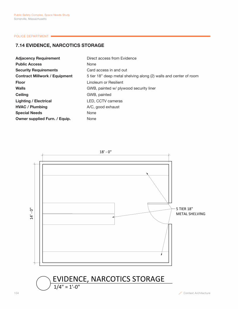
104 Context Architecture
Public Safety Complex, Space Needs StudySomerville, Massachusetts
POLICE DEPARTMENT
18' - 0"
14' -
0" 5 TIER 18"
METAL SHELVING
1/4" = 1'-0"EVIDENCE, NARCOTICS STORAGE
7.14 EVIDENCE, NARCOTICS STORAGE
Adjacency Requirement Direct access from Evidence
Public Access None
Security Requirements Card access in and out
Contract Millwork / Equipment 5 tier 18” deep metal shelving along (2) walls and center of room
Floor Linoleum or Resilient
Walls GWB, painted w/ plywood security liner
Ceiling GWB, painted
Lighting / Electrical LED, CCTV cameras
HVAC / Plumbing A/C, good exhaust
Special Needs None
Owner supplied Furn. / Equip. None
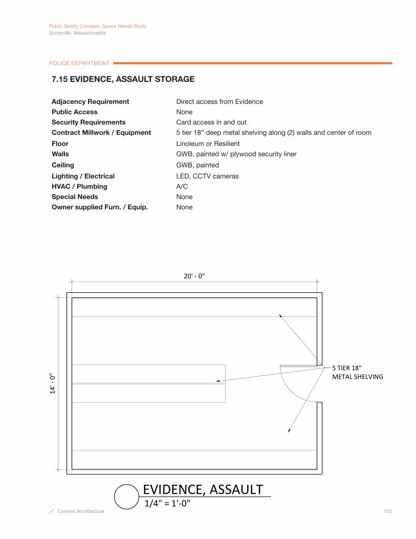
Context Architecture 105
PublicSafetyComplex,SpaceNeedsStudySomerville,Massachusetts
POLICE DEPARTMENT
20' - 0"
14' -
0"
5 TIER 18" METAL SHELVING
1/4" = 1'-0"EVIDENCE, ASSAULT
7.15 EVIDENCE, ASSAULT STORAGE
Adjacency Requirement Direct access from Evidence
Public Access None
Security Requirements Card access in and out
Contract Millwork / Equipment 5 tier 18” deep metal shelving along (2) walls and center of room
Floor Linoleum or Resilient
Walls GWB, painted w/ plywood security liner
Ceiling GWB, painted
Lighting / Electrical LED, CCTV cameras
HVAC / Plumbing A/C
Special Needs None
Owner supplied Furn. / Equip. None
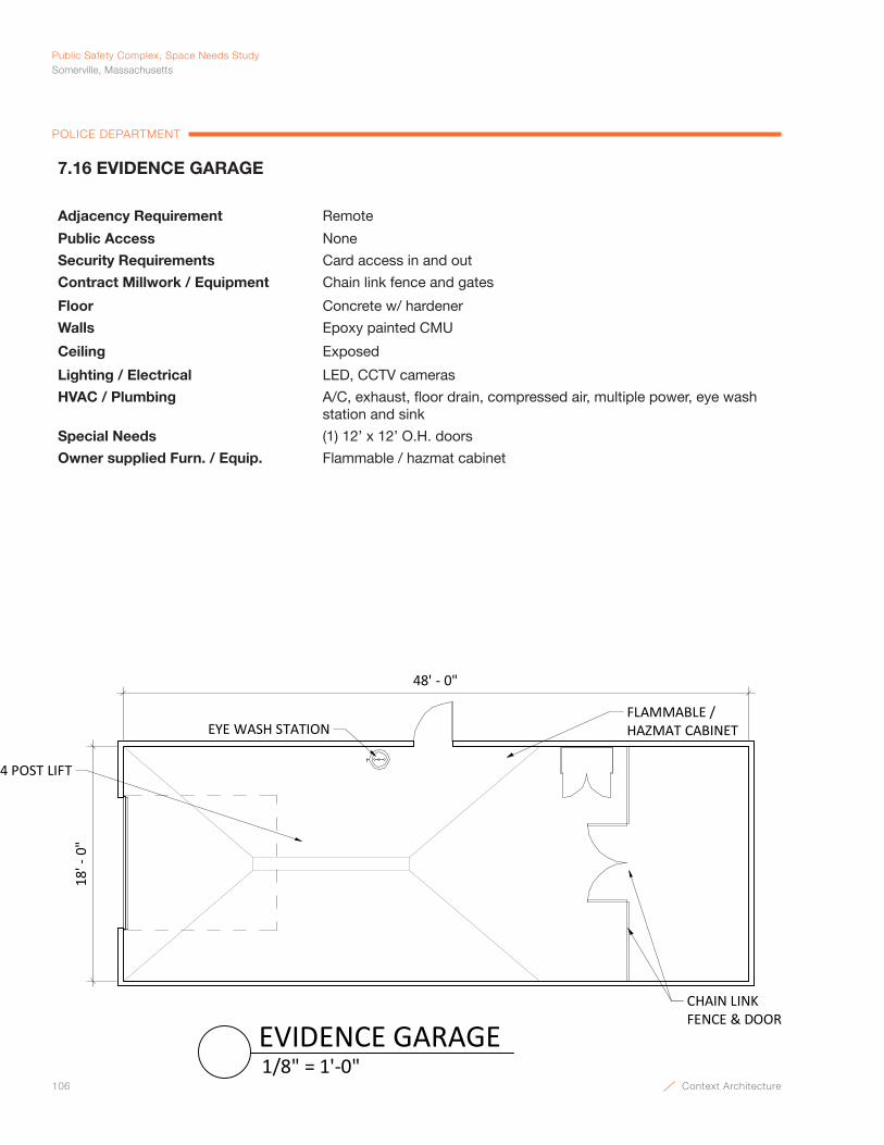
106 Context Architecture
Public Safety Complex, Space Needs StudySomerville, Massachusetts
POLICE DEPARTMENT
CHAIN LINK FENCE & DOOR
18' -
0"
EYE WASH STATIONFLAMMABLE /HAZMAT CABINET
4 POST LIFT
48' - 0"
1/8" = 1'-0"EVIDENCE GARAGE
7.16 EVIDENCE GARAGE
Adjacency Requirement Remote
Public Access None
Security Requirements Card access in and out
Contract Millwork / Equipment Chain link fence and gates
Floor Concrete w/ hardener
Walls Epoxy painted CMU
Ceiling Exposed
Lighting / Electrical LED, CCTV cameras
HVAC / Plumbing A/C, exhaust, floor drain, compressed air, multiple power, eye wash station and sink
Special Needs (1) 12’ x 12’ O.H. doors
Owner supplied Furn. / Equip. Flammable / hazmat cabinet
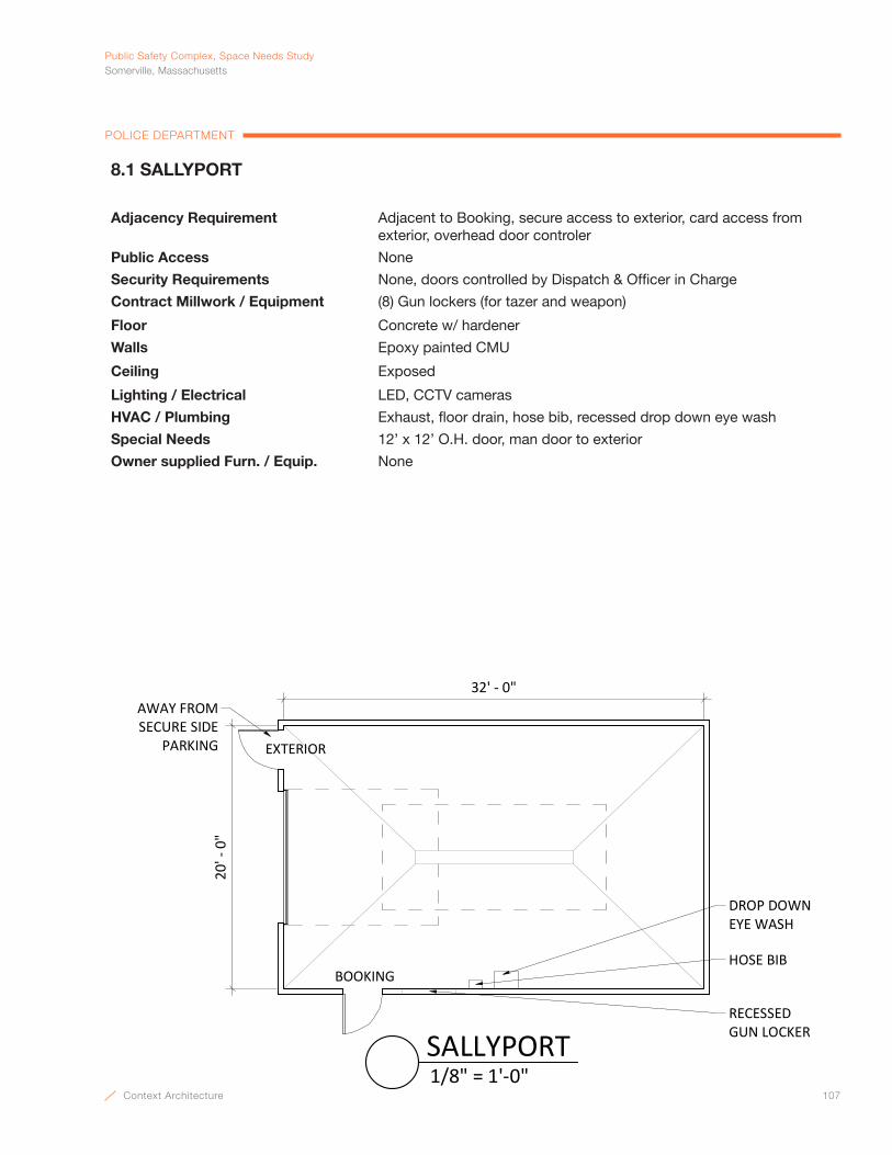
Context Architecture 107
PublicSafetyComplex,SpaceNeedsStudySomerville,Massachusetts
POLICE DEPARTMENT
8.1 SALLYPORT
Adjacency Requirement Adjacent to Booking, secure access to exterior, card access from exterior, overhead door controler
Public Access None
Security Requirements None, doors controlled by Dispatch & Officer in Charge
Contract Millwork / Equipment (8) Gun lockers (for tazer and weapon)
Floor Concrete w/ hardener
Walls Epoxy painted CMU
Ceiling Exposed
Lighting / Electrical LED, CCTV cameras
HVAC / Plumbing Exhaust, floor drain, hose bib, recessed drop down eye wash
Special Needs 12’ x 12’ O.H. door, man door to exterior
Owner supplied Furn. / Equip. None
20' -
0"
32' - 0"
BOOKING
RECESSED GUN LOCKER
EXTERIOR
DROP DOWNEYE WASH
HOSE BIB
AWAY FROM SECURE SIDE
PARKING
1/8" = 1'-0"SALLYPORT
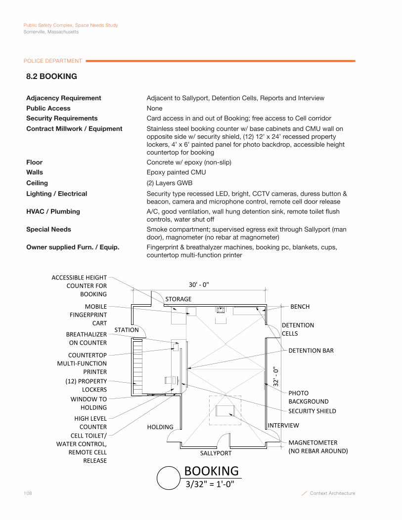
108 Context Architecture
Public Safety Complex, Space Needs StudySomerville, Massachusetts
POLICE DEPARTMENT
DETENTION BAR
BENCH
BREATHALIZER ON COUNTER
SALLYPORT
30' - 0"
(12) PROPERTY LOCKERS
STATION
32' -
0"
HOLDING
SECURITY SHIELD
INTERVIEW
DETENTIONCELLS
MOBILE FINGERPRINT
CART
CELL TOILET/WATER CONTROL,
REMOTE CELL RELEASE
PHOTOBACKGROUNDWINDOW TO
HOLDING
COUNTERTOPMULTI-FUNCTION
PRINTER
HIGH LEVEL COUNTER
ACCESSIBLE HEIGHTCOUNTER FOR
BOOKING
MAGNETOMETER(NO REBAR AROUND)
STORAGE
3/32" = 1'-0"BOOKING
8.2 BOOKING
Adjacency Requirement Adjacent to Sallyport, Detention Cells, Reports and Interview
Public Access None
Security Requirements Card access in and out of Booking; free access to Cell corridor
Contract Millwork / Equipment Stainless steel booking counter w/ base cabinets and CMU wall on opposite side w/ security shield, (12) 12’ x 24’ recessed property lockers, 4’ x 6’ painted panel for photo backdrop, accessible height countertop for booking
Floor Concrete w/ epoxy (non-slip)
Walls Epoxy painted CMU
Ceiling (2) Layers GWB
Lighting / Electrical Security type recessed LED, bright, CCTV cameras, duress button & beacon, camera and microphone control, remote cell door release
HVAC / Plumbing A/C, good ventilation, wall hung detention sink, remote toilet flush controls, water shut off
Special Needs Smoke compartment; supervised egress exit through Sallyport (man door), magnometer (no rebar at magnometer)
Owner supplied Furn. / Equip. Fingerprint & breathalyzer machines, booking pc, blankets, cups, countertop multi-function printer

Context Architecture 109
PublicSafetyComplex,SpaceNeedsStudySomerville,Massachusetts
POLICE DEPARTMENT
8.3 DETENTION CELLS
Adjacency Requirement Adjacent to Booking
Public Access None
Security Requirements Remote release from Booking and Officer in Charge
Contract Millwork / Equipment S.S. Bench, recessed toilet paper holding
Floor Concrete w/ sloped epoxy (non-slip), drain into corridor
Walls Epoxy painted CMU
Ceiling Welded steel plate
Lighting / Electrical Security LED, mic and speaker, CCTV camera
HVAC / Plumbing A/C, combination toilet / sink detention fixture
Special Needs 1 pod of 4, 4 individually sight and sound separated male and female detention room areas, provide flexibility in use of detention rooms. Meet Mass Police Accrediting Standards, Mass Department of Public Health Regulations and Mass Access Code. All to be handicap accessible
Owner supplied Furn. / Equip. None
CL
SECURITY LIGHT BELOW CEILING
CORNER MOUNTED CAMERA PORT BELOW CEILING
CELL BUNK W/ CMU WALL BELOW
STAINLESS STEEL LAV-TOILET COMBINATION
CELL CHASE ACCESS DOOR
1/8"
RECESSED TOILET PAPER HOLDER
ANTI-SUICIDE PLATE
9' - 0"
8' -
0"
1/8"
3/8" = 1'-0"DETENTION CELLS

110 Context Architecture
Public Safety Complex, Space Needs StudySomerville, Massachusetts
POLICE DEPARTMENT
8' -
0"
8' - 0"
4' - 0" SHELVINGRACKS
1/4" = 1'-0"DETENTION STORAGE
8.4 DETENTION STORAGE ROOM
Adjacency Requirement Access from Booking
Public Access None
Security Requirements Remote release, card access in and out
Contract Millwork / Equipment (2) 4’ - 0” Shelving racks
Floor Concrete w/ sloped epoxy (non-slip), drain into corridor
Walls Epoxy painted CMU
Ceiling (2) Layers GWB, painted
Lighting / Electrical Security LED, mic and speaker
HVAC / Plumbing A/C
Special Needs None
Owner supplied Furn. / Equip. None
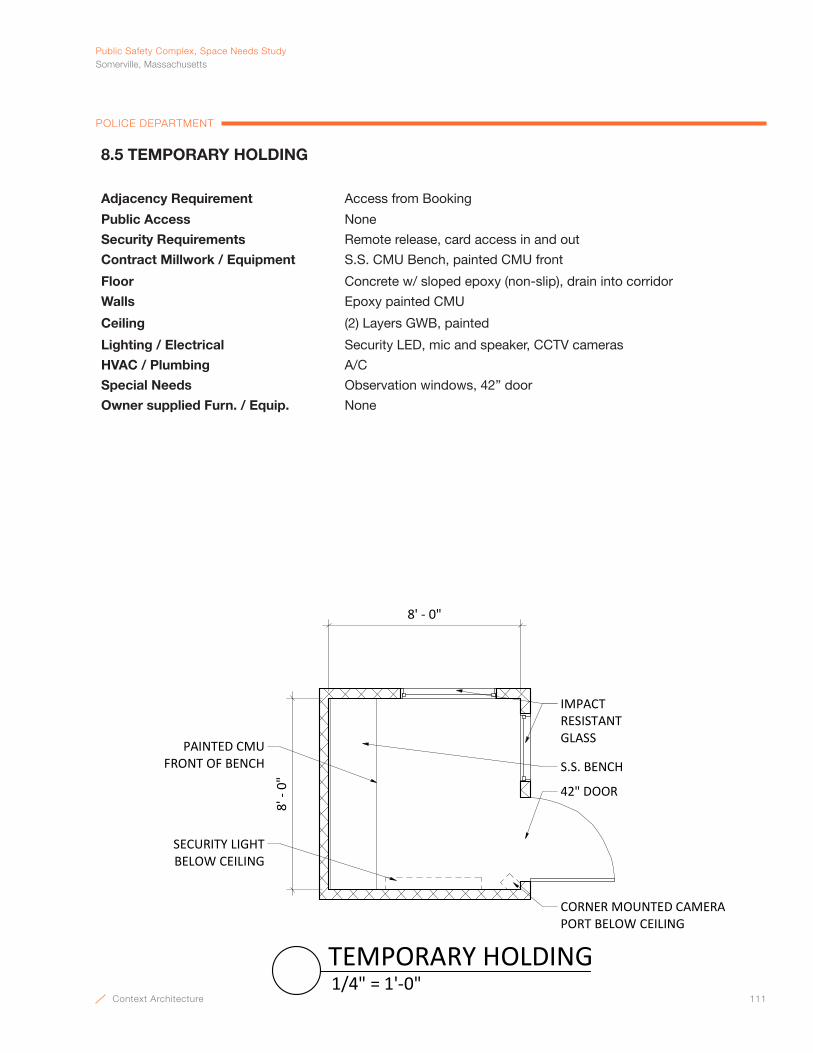
Context Architecture 111
PublicSafetyComplex,SpaceNeedsStudySomerville,Massachusetts
POLICE DEPARTMENT
IMPACT RESISTANT GLASS
S.S. BENCH
8' - 0"
8' -
0"
CORNER MOUNTED CAMERAPORT BELOW CEILING
42" DOOR
PAINTED CMUFRONT OF BENCH
SECURITY LIGHT BELOW CEILING
1/4" = 1'-0"TEMPORARY HOLDING
8.5 TEMPORARY HOLDING
Adjacency Requirement Access from Booking
Public Access None
Security Requirements Remote release, card access in and out
Contract Millwork / Equipment S.S. CMU Bench, painted CMU front
Floor Concrete w/ sloped epoxy (non-slip), drain into corridor
Walls Epoxy painted CMU
Ceiling (2) Layers GWB, painted
Lighting / Electrical Security LED, mic and speaker, CCTV cameras
HVAC / Plumbing A/C
Special Needs Observation windows, 42” door
Owner supplied Furn. / Equip. None
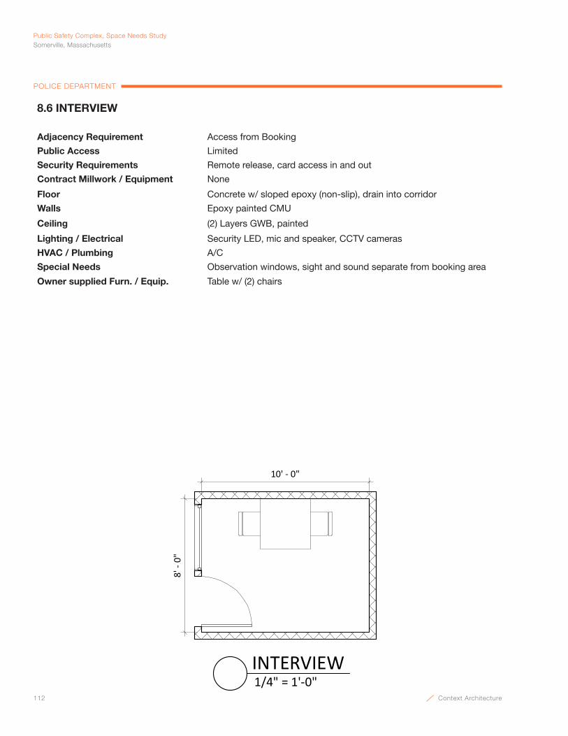
112 Context Architecture
Public Safety Complex, Space Needs StudySomerville, Massachusetts
POLICE DEPARTMENT
10' - 0"
8' -
0"
1/4" = 1'-0"INTERVIEW
8.6 INTERVIEW
Adjacency Requirement Access from Booking
Public Access Limited
Security Requirements Remote release, card access in and out
Contract Millwork / Equipment None
Floor Concrete w/ sloped epoxy (non-slip), drain into corridor
Walls Epoxy painted CMU
Ceiling (2) Layers GWB, painted
Lighting / Electrical Security LED, mic and speaker, CCTV cameras
HVAC / Plumbing A/C
Special Needs Observation windows, sight and sound separate from booking area
Owner supplied Furn. / Equip. Table w/ (2) chairs
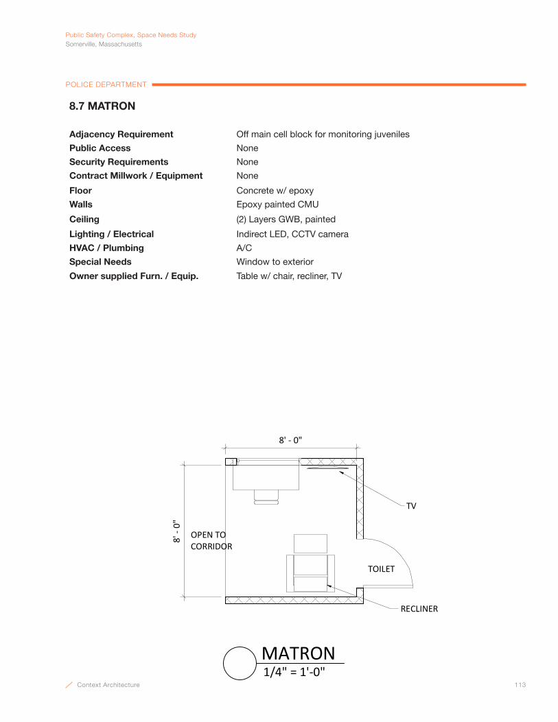
Context Architecture 113
PublicSafetyComplex,SpaceNeedsStudySomerville,Massachusetts
POLICE DEPARTMENT
8' -
0"
TOILET
RECLINER
TV
OPEN TOCORRIDOR
8' - 0"
1/4" = 1'-0"MATRON
8.7 MATRON
Adjacency Requirement Off main cell block for monitoring juveniles
Public Access None
Security Requirements None
Contract Millwork / Equipment None
Floor Concrete w/ epoxy
Walls Epoxy painted CMU
Ceiling (2) Layers GWB, painted
Lighting / Electrical Indirect LED, CCTV camera
HVAC / Plumbing A/C
Special Needs Window to exterior
Owner supplied Furn. / Equip. Table w/ chair, recliner, TV
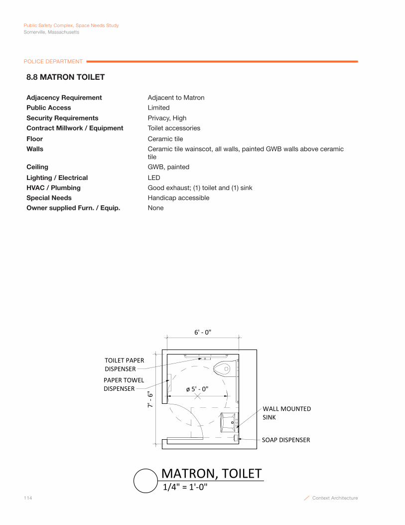
114 Context Architecture
Public Safety Complex, Space Needs StudySomerville, Massachusetts
POLICE DEPARTMENT
ø 5' - 0"PAPER TOWELDISPENSER
TOILET PAPERDISPENSER
WALL MOUNTEDSINK
SOAP DISPENSER
7' -
6"
6' - 0"
1/4" = 1'-0"MATRON, TOILET
8.8 MATRON TOILET
Adjacency Requirement Adjacent to Matron
Public Access Limited
Security Requirements Privacy, High
Contract Millwork / Equipment Toilet accessories
Floor Ceramic tile
Walls Ceramic tile wainscot, all walls, painted GWB walls above ceramic tile
Ceiling GWB, painted
Lighting / Electrical LED
HVAC / Plumbing Good exhaust; (1) toilet and (1) sink
Special Needs Handicap accessible
Owner supplied Furn. / Equip. None
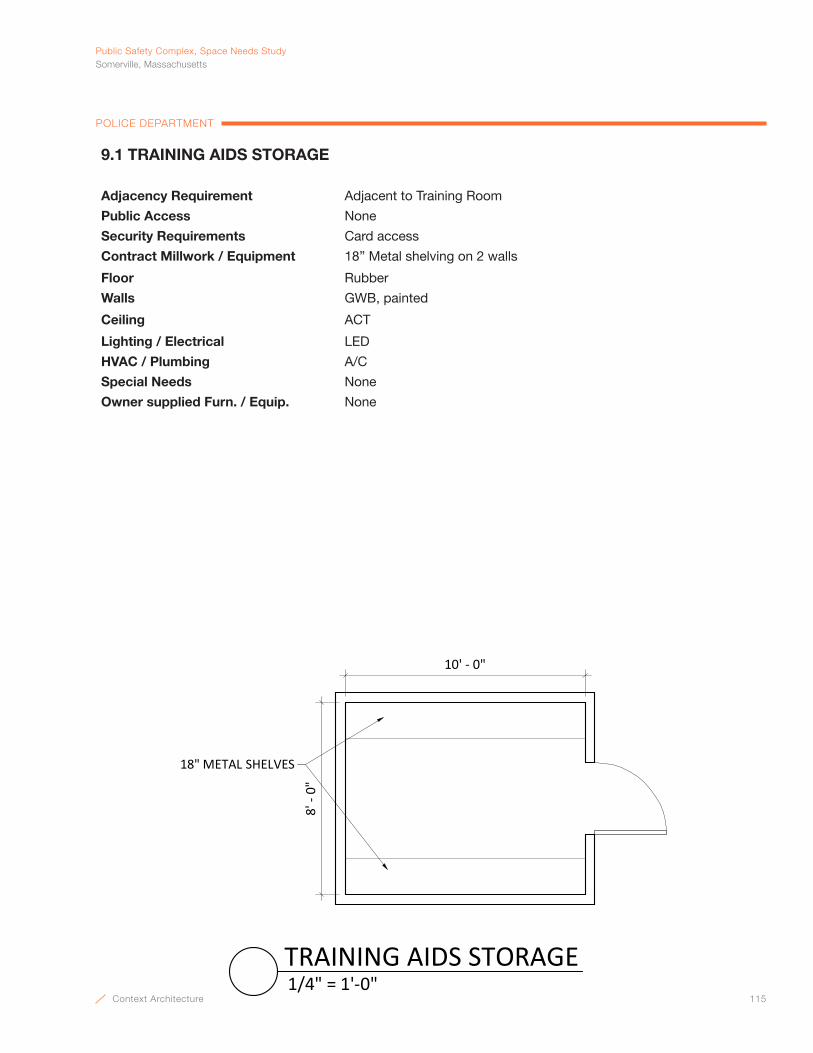
Context Architecture 115
PublicSafetyComplex,SpaceNeedsStudySomerville,Massachusetts
POLICE DEPARTMENT
18" METAL SHELVES
8' -
0"
10' - 0"
1/4" = 1'-0"TRAINING AIDS STORAGE
9.1 TRAINING AIDS STORAGE
Adjacency Requirement Adjacent to Training Room
Public Access None
Security Requirements Card access
Contract Millwork / Equipment 18” Metal shelving on 2 walls
Floor Rubber
Walls GWB, painted
Ceiling ACT
Lighting / Electrical LED
HVAC / Plumbing A/C
Special Needs None
Owner supplied Furn. / Equip. None
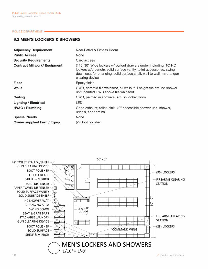
116 Context Architecture
Public Safety Complex, Space Needs StudySomerville, Massachusetts
POLICE DEPARTMENT
50' -
0"
66' - 0"
ø 5' - 0"
SOLID SURFACE SHELF & MIRROR
SOLID SURFACE VANITYPAPER TOWEL DISPENSER
SOAP DISPENSER
(96) LOCKERSBOOT POLISHER
SOLID SURFACE SHELF
SWING DOWNSEAT & GRAB BARS
GUN CLEARING DEVICE
HC SHOWER W/4' CHANGING AREA
42" TOILET STALL W/SHELF
FIREARMS CLEARING STATION
STACKABLE LAUNDRY
ø 5' - 0"
COMMAND WING(28) LOCKERS
SOLID SURFACE SHELF & MIRROR
BOOT POLISHERGUN CLEARING DEVICE
FIREARMS CLEARING STATION
1/16" = 1'-0"MEN'S LOCKERS AND SHOWERS
9.2 MEN’S LOCKERS & SHOWERS
Adjacency Requirement Near Patrol & Fitness Room
Public Access None
Security Requirements Card access
Contract Millwork/ Equipment (115) 30” Wide lockers w/ pullout drawers under including (10) HC lockers w/o bench), solid surface vanity, toilet accessories, swing down seat for changing, solid surface shelf, wall to wall mirrors, gun clearing device
Floor Epoxy finish
Walls GWB, ceramic tile wainscot, all walls, full height tile around shower unit, painted GWB above tile wainscot
Ceiling GWB, painted in showers, ACT in locker room
Lighting / Electrical LED
HVAC / Plumbing Good exhaust; toilet, sink, 42” accessible shower unit, shower, urinals, floor drains
Special Needs None
Owner supplied Furn./ Equip. (2) Boot polisher

Context Architecture 117
PublicSafetyComplex,SpaceNeedsStudySomerville,Massachusetts
POLICE DEPARTMENT
9.3 WOMEN’S LOCKERS & SHOWERS
Adjacency Requirement Near Patrol & Fitness Room
Public Access None
Security Requirements Card access
Contract Millwork/ Equipment (28) 30” Wide lockers w/ pullout drawers under including (2) HC lockers w/o bench), solid surface vanity, toilet accessories, swing down seat for changing, solid surface shelf, wall to wall mirrors, gun clearing device
Floor Epoxy
Walls GWB, ceramic tile wainscot, all walls, full height tile around shower unit, painted GWB above tile wainscot
Ceiling GWB, painted in showers, ACT in locker room
Lighting / Electrical LED
HVAC / Plumbing Good exhaust; toilet, sink, 42” accessible shower unit, shower, urinals, floor drains
Special Needs None
Owner supplied Furn./ Equip. (2) Boot polisher
26' -
0"
42' - 0"
SOLID SURFACE VANITY
PAPER TOWEL DISPENSERSOAP DISPENSER
SOLID SURFACE SHELF
SWING DOWN SEAT & GRAB BARS
(22) LOCKERS
ø 5' - 0"BOOT POLISHERGUN CLEARING DEVICE
SOLID SURFACE SHELF & MIRROR
ø 5' - 0"
42" TOILET STALL W/ SHELF
FIREARMS CLEARINGSTATION
HC SHOWER W/4' CHANGING AREA
STACKABLE LAUNDRY
COMMAND WING
(8) LOCKERS
5' -
0 3/
4"9'
- 6"
3/32" = 1'-0"WOMEN'S LOCKERS AND SHOWERS

118 Context Architecture
Public Safety Complex, Space Needs StudySomerville, Massachusetts
POLICE DEPARTMENT
28' - 0"
25' -
0"
SIMULATOR
TRAINING SIMULATIONCONTROL
1/8" = 1'-0"FIREARMS TRAINING SIMULATION
9.4 FIREARMS TRAINING SIMULATION (F.A.T.S.)
Adjacency Requirement None
Public Access None
Security Requirements Card access
Contract Millwork / Equipment None
Floor Rubber sports flooring
Walls GWB, painted
Ceiling High noise reduction ACT 10’ ceiling minimum
Lighting / Electrical LED, CCTV cameras
HVAC / Plumbing A/C
Special Needs None
Owner supplied Furn. / Equip. Control desk inside space
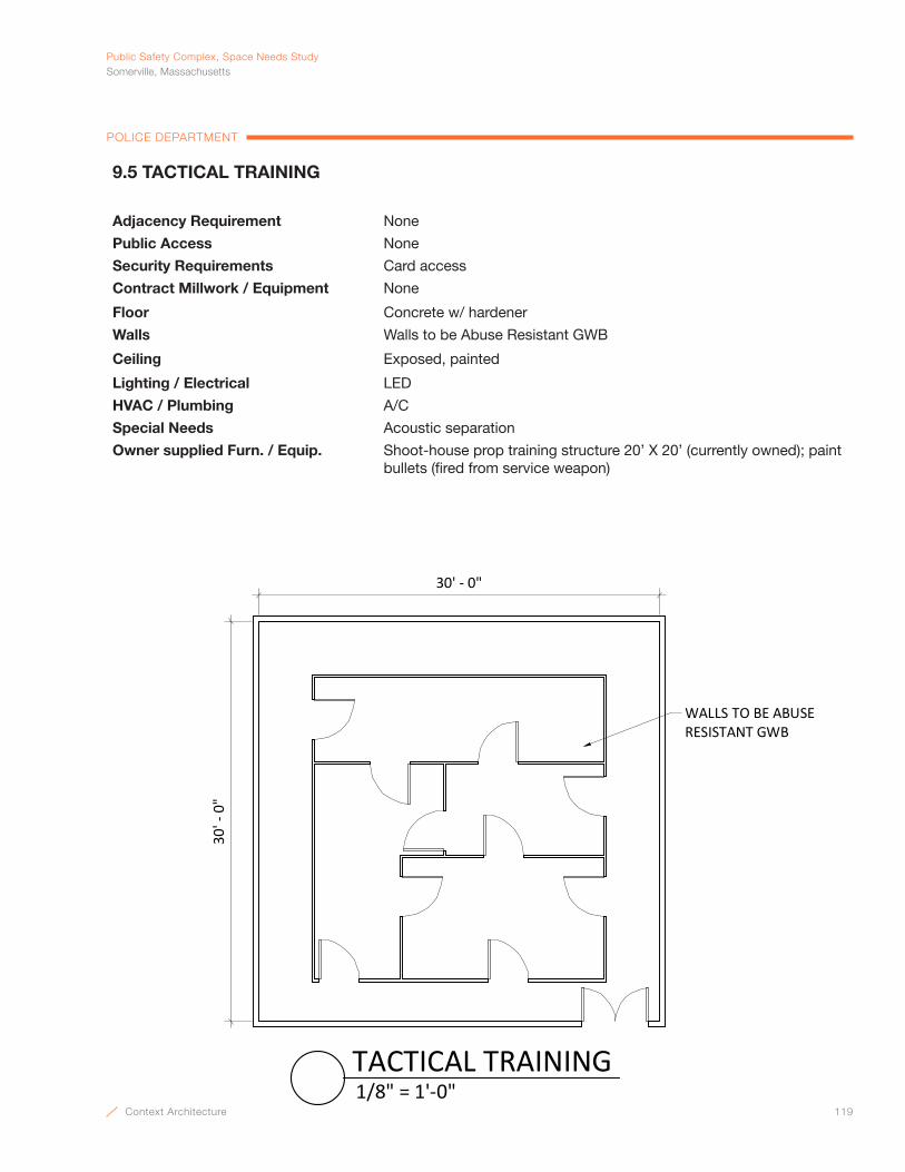
Context Architecture 119
PublicSafetyComplex,SpaceNeedsStudySomerville,Massachusetts
POLICE DEPARTMENT
9.5 TACTICAL TRAINING
Adjacency Requirement None
Public Access None
Security Requirements Card access
Contract Millwork / Equipment None
Floor Concrete w/ hardener
Walls Walls to be Abuse Resistant GWB
Ceiling Exposed, painted
Lighting / Electrical LED
HVAC / Plumbing A/C
Special Needs Acoustic separation
Owner supplied Furn. / Equip. Shoot-house prop training structure 20’ X 20’ (currently owned); paint bullets (fired from service weapon)
WALLS TO BE ABUSERESISTANT GWB
30' -
0"
30' - 0"
1/8" = 1'-0"TACTICAL TRAINING

120 Context Architecture
Public Safety Complex, Space Needs StudySomerville, Massachusetts
POLICE DEPARTMENT
14' - 0"
PORTABLE WEAPONS CLEANING STATION
SPACE FOR FOLDING TABLE
EXHAUST HOOD34" AFFS.S. COUNTER
COMPRESSED AIR STATION
12" METALSHELVING
10' -
0"
1/4" = 1'-0"FIREARMS CLEANING
9.6 FIREARMS CLEANING
Adjacency Requirement Near Patrol
Public Access None
Security Requirements Card access
Contract Millwork / Equipment 34” AFF SS counter w/ base cabinets, SS exhaust chamber, 12” shelving
Floor Rubber
Walls GWB, painted
Ceiling ACT
Lighting / Electrical LED, task lighting, data
HVAC / Plumbing A/C, Connect to exhaust hood at work bench, compressed air, stainless steel sink
Special Needs None
Owner supplied Furn. / Equip. Portable weapon cleaning station

Context Architecture 121
PublicSafetyComplex,SpaceNeedsStudySomerville,Massachusetts
POLICE DEPARTMENT
10' -
0"
20' - 0"
RACKINGSYSTEM
FIREPROOF AMMUNITION CABINET
SHELVINGUNITS
1/4" = 1'-0"FIREARMS STORAGE
9.7 FIREARMS STORAGE
Adjacency Requirement Near Firearms Cleaning
Public Access None
Security Requirements Card access
Contract Millwork / Equipment None
Floor Rubber
Walls GWB, painted
Ceiling ACT
Lighting / Electrical LED, CCTV cameras
HVAC / Plumbing A/C
Special Needs None
Owner supplied Furn. / Equip. Racking system, fireproof ammunition cabinets, 5 tier shelving units
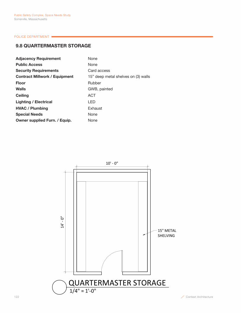
122 Context Architecture
Public Safety Complex, Space Needs StudySomerville, Massachusetts
POLICE DEPARTMENT
14' -
0"
10' - 0"
15" METALSHELVING
1/4" = 1'-0"QUARTERMASTER STORAGE
9.8 QUARTERMASTER STORAGE
Adjacency Requirement None
Public Access None
Security Requirements Card access
Contract Millwork / Equipment 15” deep metal shelves on (3) walls
Floor Rubber
Walls GWB, painted
Ceiling ACT
Lighting / Electrical LED
HVAC / Plumbing Exhaust
Special Needs None
Owner supplied Furn. / Equip. None

Context Architecture 123
PublicSafetyComplex,SpaceNeedsStudySomerville,Massachusetts
POLICE DEPARTMENT
22' -
0"
40' - 0"
RECESSED HIGH DENSITYTRACK SYSTEM
ø 5' - 0"
SUPPLY STORAGECABINET
MULTI-FUNCTION PRINTER /COPIER / SCANNER
3/32" = 1'-0"INACTIVE RECORD STORAGE
9.9 INACTIVE RECORD STORAGE
Adjacency Requirement Remote
Public Access None
Security Requirements Card access
Contract Millwork / Equipment Recessed high density file storage system
Floor Linoleum
Walls GWB
Ceiling ACT
Lighting / Electrical LED, continuous rows perpendicular to shelving
HVAC / Plumbing No overhead piping of any kind (above or below ceiling)
Special Needs Does not need to Follow MA Sec State Record Keeping Standards
Owner supplied Furn. / Equip. 2’ x 4’ Work table and chair, multi-function printer / copier / scanner, supply storage cabinet
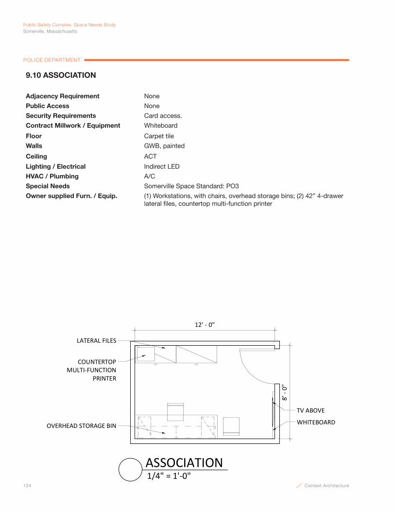
124 Context Architecture
Public Safety Complex, Space Needs StudySomerville, Massachusetts
POLICE DEPARTMENT
WHITEBOARD
COUNTERTOPMULTI-FUNCTION
PRINTER
LATERAL FILES
TV ABOVE
12' - 0"
8' -
0"
OVERHEAD STORAGE BIN
1/4" = 1'-0"ASSOCIATION
9.10 ASSOCIATION
Adjacency Requirement None
Public Access None
Security Requirements Card access.
Contract Millwork / Equipment Whiteboard
Floor Carpet tile
Walls GWB, painted
Ceiling ACT
Lighting / Electrical Indirect LED
HVAC / Plumbing A/C
Special Needs Somerville Space Standard: PO3
Owner supplied Furn. / Equip. (1) Workstations, with chairs, overhead storage bins; (2) 42” 4-drawer lateral files, countertop multi-function printer

Context Architecture 125
PublicSafetyComplex,SpaceNeedsStudySomerville,Massachusetts
POLICE DEPARTMENT
30' -
0"
34' - 0"
1/8" = 1'-0"MOTORCYCLES
9.11 MOTORCYCLES
Adjacency Requirement In Garage
Public Access None
Security Requirements Card access to Garage
Contract Millwork / Equipment None
Floor Concrete w/ hardener
Walls Exposed, painted. Striped parking lines
Ceiling Exposed, painted
Lighting / Electrical Power for motorcycle battery chargers
HVAC / Plumbing Exhaust
Special Needs None
Owner supplied Furn. / Equip. (8) Motorcycles
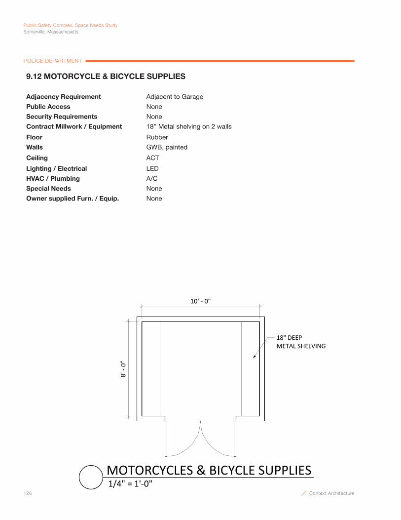
126 Context Architecture
Public Safety Complex, Space Needs StudySomerville, Massachusetts
POLICE DEPARTMENT
10' - 0"
8' -
0"
18" DEEP METAL SHELVING
1/4" = 1'-0"MOTORCYCLES & BICYCLE SUPPLIES
9.12 MOTORCYCLE & BICYCLE SUPPLIES
Adjacency Requirement Adjacent to Garage
Public Access None
Security Requirements None
Contract Millwork / Equipment 18” Metal shelving on 2 walls
Floor Rubber
Walls GWB, painted
Ceiling ACT
Lighting / Electrical LED
HVAC / Plumbing A/C
Special Needs None
Owner supplied Furn. / Equip. None
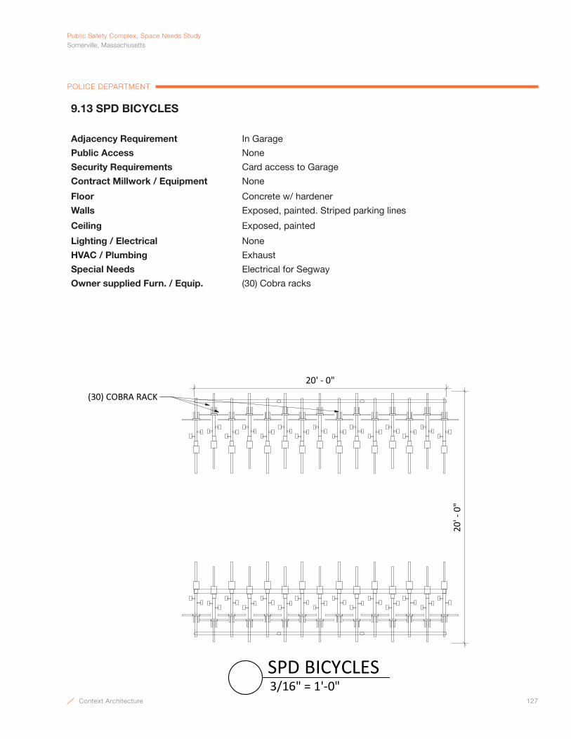
Context Architecture 127
PublicSafetyComplex,SpaceNeedsStudySomerville,Massachusetts
POLICE DEPARTMENT
(30) COBRA RACK
20' - 0"
20' -
0"
3/16" = 1'-0"SPD BICYCLES
9.13 SPD BICYCLES
Adjacency Requirement In Garage
Public Access None
Security Requirements Card access to Garage
Contract Millwork / Equipment None
Floor Concrete w/ hardener
Walls Exposed, painted. Striped parking lines
Ceiling Exposed, painted
Lighting / Electrical None
HVAC / Plumbing Exhaust
Special Needs Electrical for Segway
Owner supplied Furn. / Equip. (30) Cobra racks
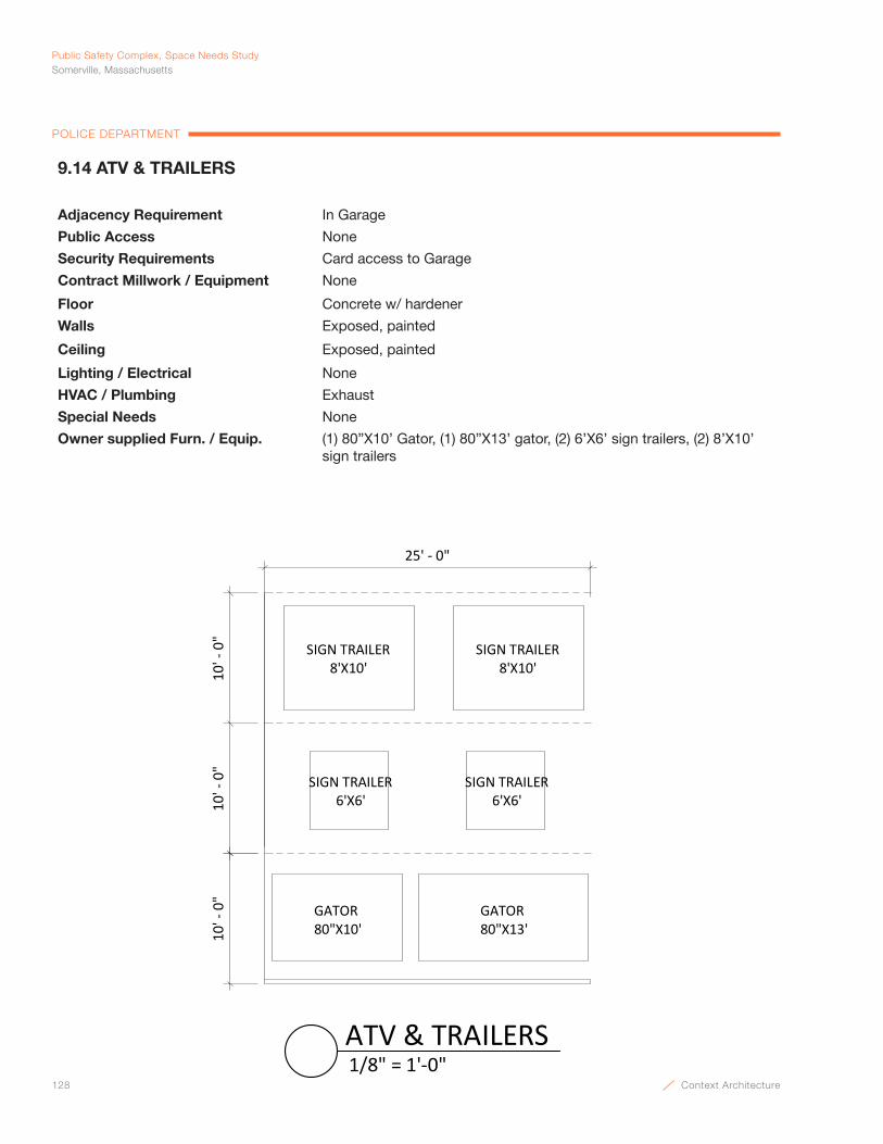
128 Context Architecture
Public Safety Complex, Space Needs StudySomerville, Massachusetts
POLICE DEPARTMENT
10' -
0"
25' - 0"
10' -
0"
10' -
0"
GATOR80"X10'
SIGN TRAILER6'X6'
SIGN TRAILER8'X10'
GATOR80"X13'
SIGN TRAILER6'X6'
SIGN TRAILER8'X10'
1/8" = 1'-0"ATV & TRAILERS
9.14 ATV & TRAILERS
Adjacency Requirement In Garage
Public Access None
Security Requirements Card access to Garage
Contract Millwork / Equipment None
Floor Concrete w/ hardener
Walls Exposed, painted
Ceiling Exposed, painted
Lighting / Electrical None
HVAC / Plumbing Exhaust
Special Needs None
Owner supplied Furn. / Equip. (1) 80”X10’ Gator, (1) 80”X13’ gator, (2) 6’X6’ sign trailers, (2) 8’X10’ sign trailers
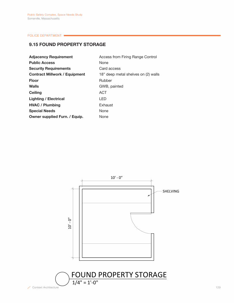
Context Architecture 129
PublicSafetyComplex,SpaceNeedsStudySomerville,Massachusetts
POLICE DEPARTMENT
9.15 FOUND PROPERTY STORAGE
Adjacency Requirement Access from Firing Range Control
Public Access None
Security Requirements Card access
Contract Millwork / Equipment 18” deep metal shelves on (2) walls
Floor Rubber
Walls GWB, painted
Ceiling ACT
Lighting / Electrical LED
HVAC / Plumbing Exhaust
Special Needs None
Owner supplied Furn. / Equip. None
10' - 0"
10' -
0"
SHELVING
1/4" = 1'-0"FOUND PROPERTY STORAGE
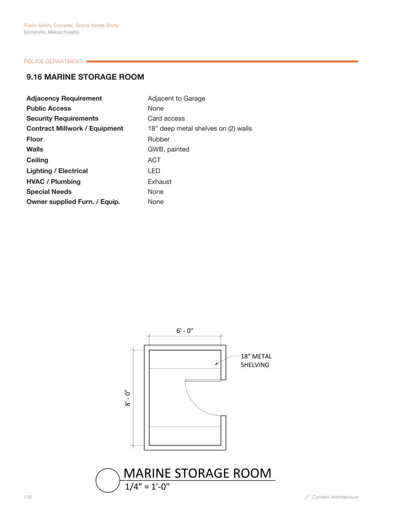
130 Context Architecture
Public Safety Complex, Space Needs StudySomerville, Massachusetts
POLICE DEPARTMENT
9.16 MARINE STORAGE ROOM
Adjacency Requirement Adjacent to Garage
Public Access None
Security Requirements Card access
Contract Millwork / Equipment 18” deep metal shelves on (2) walls
Floor Rubber
Walls GWB, painted
Ceiling ACT
Lighting / Electrical LED
HVAC / Plumbing Exhaust
Special Needs None
Owner supplied Furn. / Equip. None
6' - 0"
8' -
0"
18" METALSHELVING
1/4" = 1'-0"MARINE STORAGE ROOM
Context Architecture 131
Fire DepartmentSpace NeedsCHARLES BREEN, FIRE CHIEF

132 Context Architecture
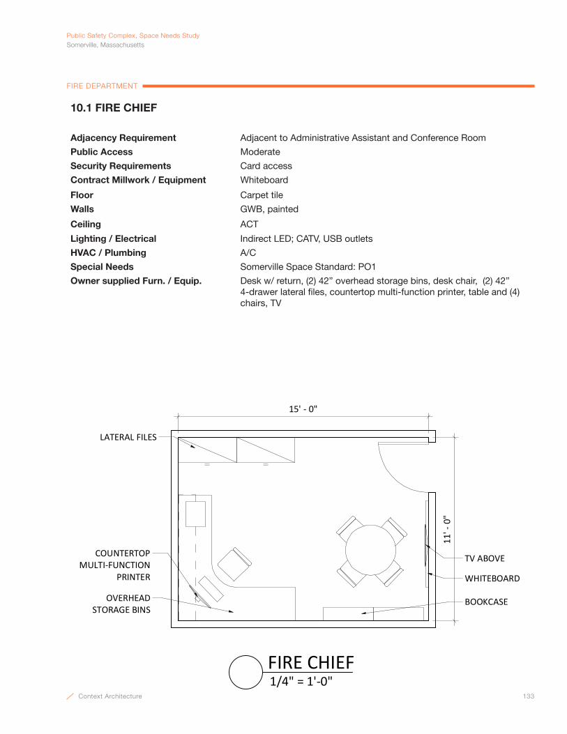
Context Architecture 133
PublicSafetyComplex,SpaceNeedsStudySomerville,Massachusetts
FIRE DEPARTMENT
10.1 FIRE CHIEF
Adjacency Requirement Adjacent to Administrative Assistant and Conference Room
Public Access Moderate
Security Requirements Card access
Contract Millwork / Equipment Whiteboard
Floor Carpet tile
Walls GWB, painted
Ceiling ACT
Lighting / Electrical Indirect LED; CATV, USB outlets
HVAC / Plumbing A/C
Special Needs Somerville Space Standard: PO1
Owner supplied Furn. / Equip. Desk w/ return, (2) 42” overhead storage bins, desk chair, (2) 42” 4-drawer lateral files, countertop multi-function printer, table and (4) chairs, TV
WHITEBOARD
LATERAL FILES
COUNTERTOPMULTI-FUNCTION
PRINTER
OVERHEAD STORAGE BINS
BOOKCASE
TV ABOVE
15' - 0"
11' -
0"
1/4" = 1'-0"FIRE CHIEF
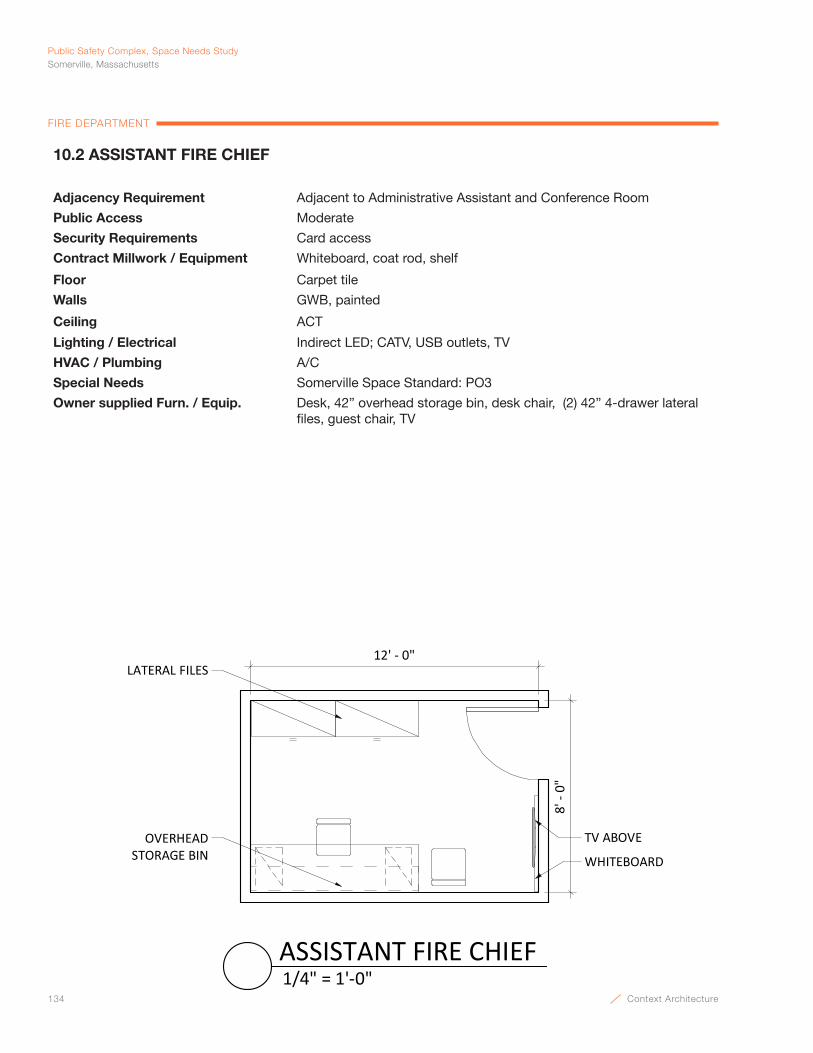
134 Context Architecture
Public Safety Complex, Space Needs StudySomerville, Massachusetts
FIRE DEPARTMENT
LATERAL FILES
WHITEBOARD
TV ABOVEOVERHEAD STORAGE BIN
12' - 0"
8' -
0"
1/4" = 1'-0"ASSISTANT FIRE CHIEF
10.2 ASSISTANT FIRE CHIEF
Adjacency Requirement Adjacent to Administrative Assistant and Conference Room
Public Access Moderate
Security Requirements Card access
Contract Millwork / Equipment Whiteboard, coat rod, shelf
Floor Carpet tile
Walls GWB, painted
Ceiling ACT
Lighting / Electrical Indirect LED; CATV, USB outlets, TV
HVAC / Plumbing A/C
Special Needs Somerville Space Standard: PO3
Owner supplied Furn. / Equip. Desk, 42” overhead storage bin, desk chair, (2) 42” 4-drawer lateral files, guest chair, TV
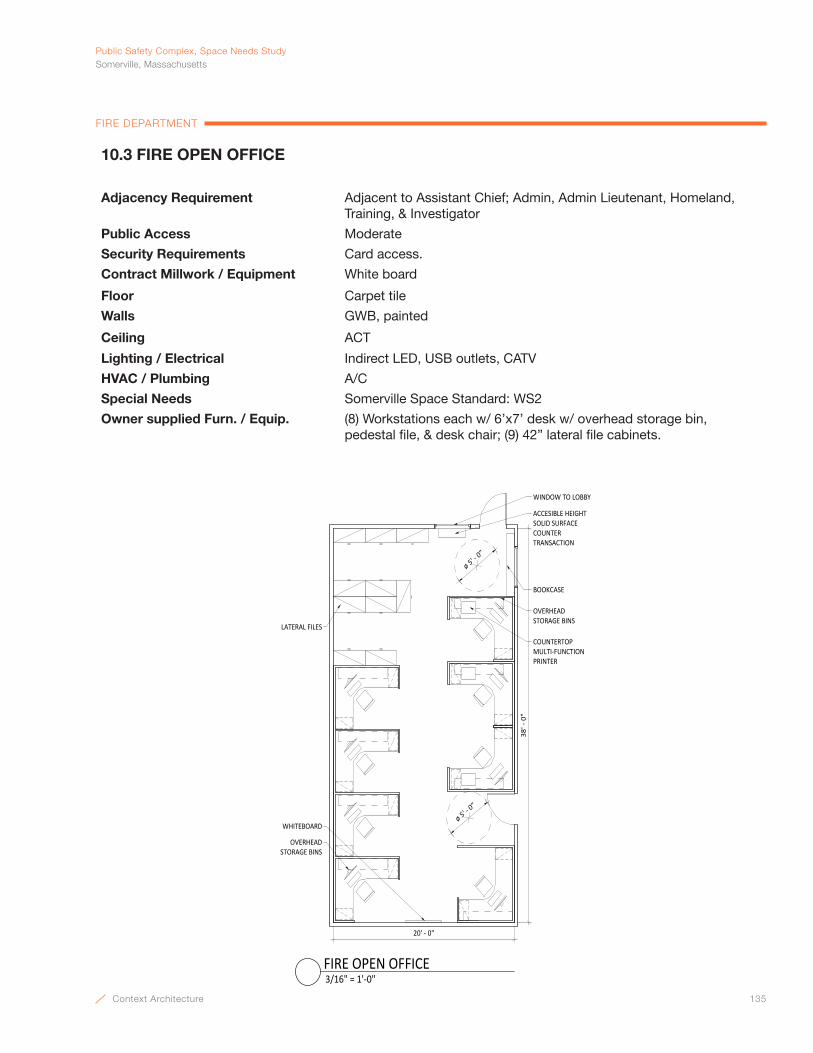
Context Architecture 135
PublicSafetyComplex,SpaceNeedsStudySomerville,Massachusetts
FIRE DEPARTMENT
10.3 FIRE OPEN OFFICE
Adjacency Requirement Adjacent to Assistant Chief; Admin, Admin Lieutenant, Homeland, Training, & Investigator
Public Access Moderate
Security Requirements Card access.
Contract Millwork / Equipment White board
Floor Carpet tile
Walls GWB, painted
Ceiling ACT
Lighting / Electrical Indirect LED, USB outlets, CATV
HVAC / Plumbing A/C
Special Needs Somerville Space Standard: WS2
Owner supplied Furn. / Equip. (8) Workstations each w/ 6’x7’ desk w/ overhead storage bin, pedestal file, & desk chair; (9) 42” lateral file cabinets.
OVERHEAD STORAGE BINS
38' ‐ 0"
20' ‐ 0"
ø 5' ‐ 0
"
OVERHEAD STORAGE BINS
COUNTERTOPMULTI‐FUNCTION PRINTER
WHITEBOARD
BOOKCASE
WINDOW TO LOBBY
ACCESIBLE HEIGHTSOLID SURFACE COUNTER TRANSACTION
LATERAL FILES
ø 5' ‐ 0
"
3/16" = 1'‐0"FIRE OPEN OFFICE

136 Context Architecture
Public Safety Complex, Space Needs StudySomerville, Massachusetts
FIRE DEPARTMENT
10.4 FIRE VISITOR LOBBY & WAITING AREA
Adjacency Requirement Adjacent to Admin; Next to elevator; Near public bathrooms
Public Access High
Security Requirements Electronic access from lobby to Fire Offices controlled by Admin
Contract Millwork / Equipment Chair rail, solid surface counter transaction, display cabinets
Floor Linoleum or VCT
Walls GWB
Ceiling ACT
Lighting / Electrical Indirect LED
HVAC / Plumbing A/C
Special Needs None
Owner supplied Furn. / Equip. (2) guest chairs; (1) Magazine table
8' - 0"
10' -
0"
ACCESSIBLE HEIGHTSOLID SURFACE
TRANSACTION COUNTER MAGAZINE TABLE
DISPLAY CABINETS
ADMIN.
1/4" = 1'-0"FIRE VISITOR LOBBY & WAITING AREA

Context Architecture 137
PublicSafetyComplex,SpaceNeedsStudySomerville,Massachusetts
FIRE DEPARTMENT
10.5 FIRE TRAINING AIDS STORAGE
Adjacency Requirement Off of Community Room
Public Access None
Security Requirements Card Access
Contract Millwork / Equipment 5 Tier 18” metal shelving on 2 walls
Floor Rubber
Walls GWB, painted
Ceiling ACT
Lighting / Electrical LED
HVAC / Plumbing A/C
Special Needs None
Owner supplied Furn. / Equip. None
18" METAL SHELVES
8' -
0"10' - 0"
1/4" = 1'-0"FIRE TRAINING AIDS STORAGE

138 Context Architecture
Public Safety Complex, Space Needs StudySomerville, Massachusetts
FIRE DEPARTMENT
10.6 CONFERENCE ROOM
Adjacency Requirement Near Chief and Assist. Chief
Public Access Limited
Security Requirements None
Contract Millwork / Equipment Fabric covered tackboards along two walls. Full length markerboard, chair rail
Floor Carpet tile
Walls GWB, painted
Ceiling ACT
Lighting / Electrical Indirect LED, dimmers, pendant fixtures, data, CATV
HVAC / Plumbing A/C
Special Needs Somerville Space Standard: C3
Owner supplied Furn. / Equip. (1) conference table w/ (12) chairs, (1) TV, 16”X60” credenza
12' -
0"
23' - 0"
3/16" = 1'-0"CONFERENCE ROOM
MARKERBOARD
DATA
CREDENZA
TV
FABRIC COVEREDTACKBOARD
POWER
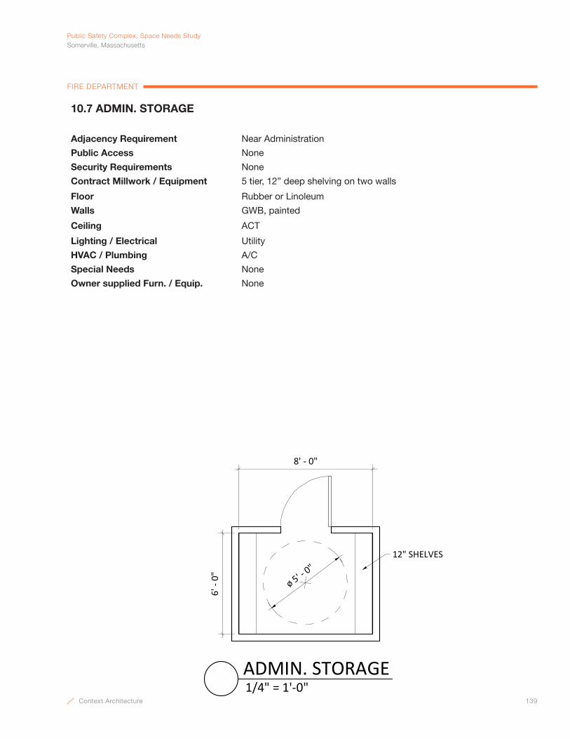
Context Architecture 139
PublicSafetyComplex,SpaceNeedsStudySomerville,Massachusetts
FIRE DEPARTMENT
10.7 ADMIN. STORAGE
Adjacency Requirement Near Administration
Public Access None
Security Requirements None
Contract Millwork / Equipment 5 tier, 12” deep shelving on two walls
Floor Rubber or Linoleum
Walls GWB, painted
Ceiling ACT
Lighting / Electrical Utility
HVAC / Plumbing A/C
Special Needs None
Owner supplied Furn. / Equip. None
12" SHELVES
6' -
0"
ø 5' - 0"
8' - 0"
1/4" = 1'-0"ADMIN. STORAGE
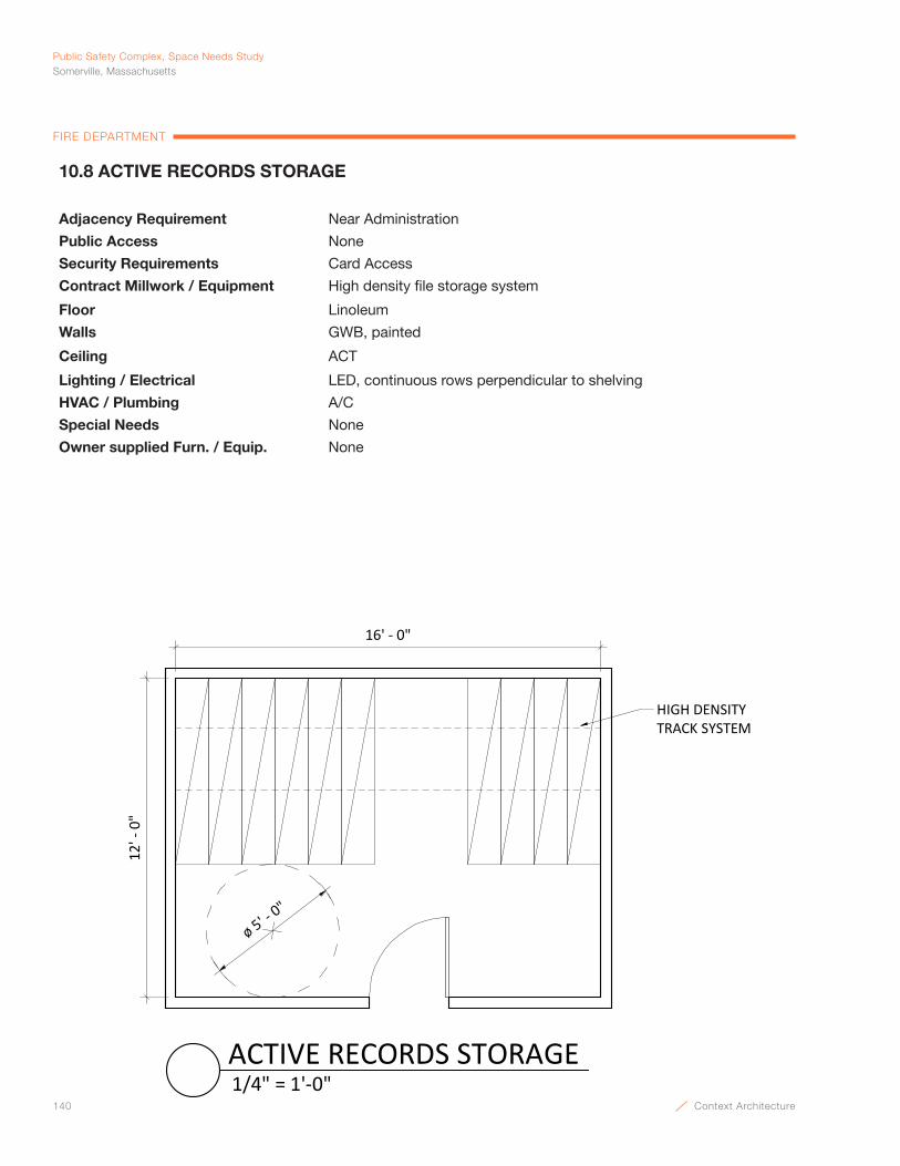
140 Context Architecture
Public Safety Complex, Space Needs StudySomerville, Massachusetts
FIRE DEPARTMENT
10.8 ACTIVE RECORDS STORAGE
Adjacency Requirement Near Administration
Public Access None
Security Requirements Card Access
Contract Millwork / Equipment High density file storage system
Floor Linoleum
Walls GWB, painted
Ceiling ACT
Lighting / Electrical LED, continuous rows perpendicular to shelving
HVAC / Plumbing A/C
Special Needs None
Owner supplied Furn. / Equip. None
16' - 0"
HIGH DENSITY TRACK SYSTEM
ø 5' - 0"
12' -
0"
1/4" = 1'-0"ACTIVE RECORDS STORAGE

Context Architecture 141
PublicSafetyComplex,SpaceNeedsStudySomerville,Massachusetts
FIRE DEPARTMENT
11.1 APPARATUS ROOM
Adjacency Requirement Near Firefighter’s Quarters and Support Spaces.
Public Access None
Security Requirements Card access
Contract Millwork / Equipment None
Floor Concrete w/ H.D. Floor Hardener
Walls CMU w/ epoxy paint
Ceiling Painted, exposed structure
Lighting / Electrical Low Level Night Lighting, Rapid Response; Overhead door power; Overhead Light Curtain, Red/green lights w/ door controls at doors/dispatch/reports & trucks, recess all devices & boxes in CMU
HVAC / Plumbing No AC; Vehicle exhaust system; water fill @ columns (1 ½" lines); Overhead compressed air lines (1 drop per truck), trench drains, reels @ exterior wall, hose bibs @ walls, recess all in slab & CMU walls
Special Needs Overhead doors to be 14' x 14'. (3) 18’ bays.
Owner supplied Furn. / Equip. Front line: Engine 3 (35’), Boat on Trailer (21’), Emergency Management Trailer (21’); Reserve: (2) Engine (35’), Storage Trailer (21’)
RESERVEENGINE
35'
ENGINE 335'
RESERVE ENGINE
35'
RESERVELADDER
60'
EMERGENCYMAN.
21'
STORAGETRAILER
21'
4' -
0"4'
- 0"
6' - 0"
16' - 0"
6' - 0"
6' - 0"
38' - 0"
RESERVEENGINE
35'
BOATTRAILER
21'
6' - 0" 6' - 0""PRIME MOVER" PICKUP
24'
4' -
0"
RAMP
RAMP
HOSE BIB
3/64" = 1'-0"APPARATUS ROOM
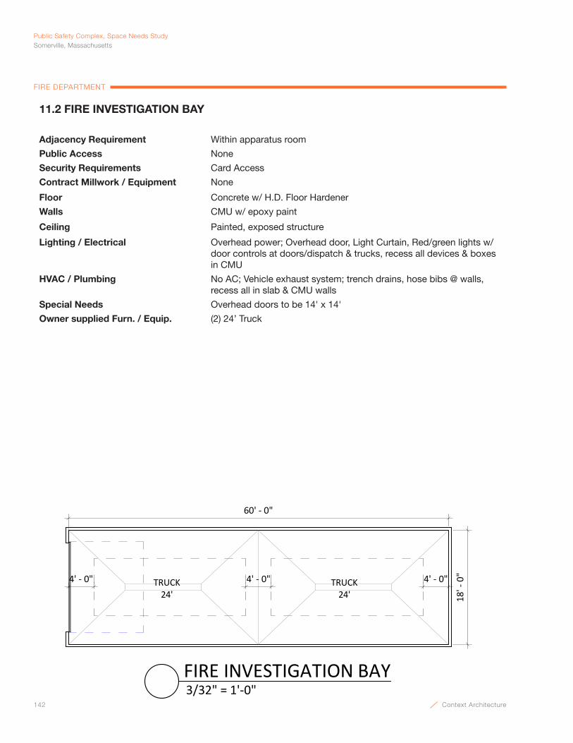
142 Context Architecture
Public Safety Complex, Space Needs StudySomerville, Massachusetts
FIRE DEPARTMENT
11.2 FIRE INVESTIGATION BAY
Adjacency Requirement Within apparatus room
Public Access None
Security Requirements Card Access
Contract Millwork / Equipment None
Floor Concrete w/ H.D. Floor Hardener
Walls CMU w/ epoxy paint
Ceiling Painted, exposed structure
Lighting / Electrical Overhead power; Overhead door, Light Curtain, Red/green lights w/ door controls at doors/dispatch & trucks, recess all devices & boxes in CMU
HVAC / Plumbing No AC; Vehicle exhaust system; trench drains, hose bibs @ walls, recess all in slab & CMU walls
Special Needs Overhead doors to be 14' x 14'
Owner supplied Furn. / Equip. (2) 24’ Truck
18' -
0"
60' - 0"
TRUCK24'
4' - 0" 4' - 0" 4' - 0"TRUCK24'
3/32" = 1'-0"FIRE INVESTIGATION BAY
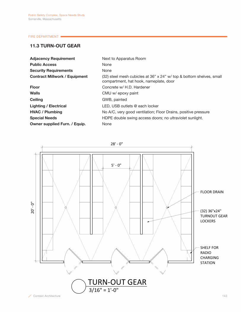
Context Architecture 143
PublicSafetyComplex,SpaceNeedsStudySomerville,Massachusetts
FIRE DEPARTMENT
11.3 TURN-OUT GEAR
Adjacency Requirement Next to Apparatus Room
Public Access None
Security Requirements None
Contract Millwork / Equipment (32) steel mesh cubicles at 36” x 24” w/ top & bottom shelves, small compartment, hat hook, nameplate, door
Floor Concrete w/ H.D. Hardener
Walls CMU w/ epoxy paint
Ceiling GWB, painted
Lighting / Electrical LED, USB outlets @ each locker
HVAC / Plumbing No A/C, very good ventilation; Floor Drains, positive pressure
Special Needs HDPE double swing access doors; no ultraviolet sunlight.
Owner supplied Furn. / Equip. None
28' - 0"
20' -
0"
(32) 36"x24" TURNOUT GEAR LOCKERS
FLOOR DRAIN
5' - 0"
SHELF FORRADIO CHARGINGSTATION
3/16" = 1'-0"TURN-OUT GEAR

144 Context Architecture
Public Safety Complex, Space Needs StudySomerville, Massachusetts
FIRE DEPARTMENT
11.4 HOSE & FOAM STORAGE
Adjacency Requirement Next to Apparatus Room, possibly share Police Bike Storage if accessible to Fire
Public Access None
Security Requirements None
Contract Millwork / Equipment 18” deep heavy duty galv. shelving 3 tiers high to hold foam buckets
Floor Concrete w/ H.D. hardener
Walls CMU w/ epoxy paint
Ceiling Painted, exposed structure
Lighting / Electrical LED
HVAC / Plumbing No A/C; very good ventilation; floor drain
Special Needs No ultraviolet light; foam storage in 5 gal. buckets & (2) 55 gallon drums
Owner supplied Furn. / Equip. Rolling hose storage rack (50”x 20”)
10' - 0"
FOAM STORAGE AREA w/ (2) 55-GAL. DRUMS
ROLLING HOSE RACK(BY OWNER)
10' -
0"
3 TIER 18" HEAVY DUTY
WALL SHELVES
1/4" = 1'-0"HOSE & FOAM STORAGE
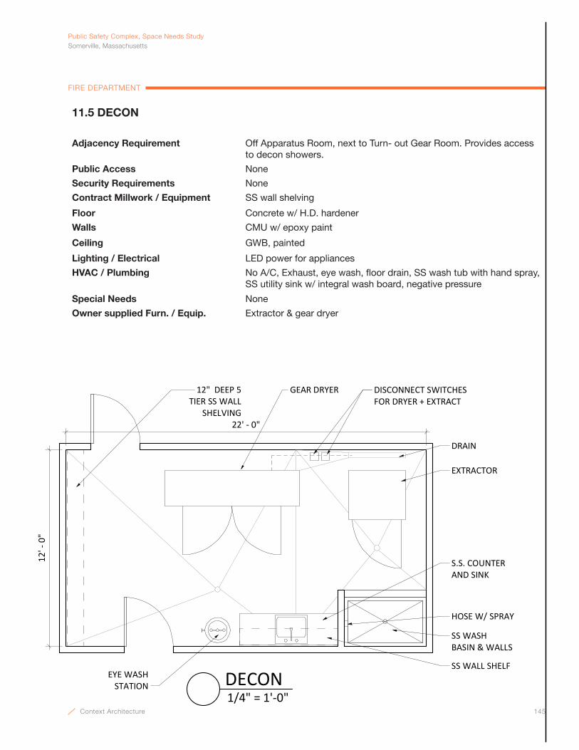
Context Architecture 145
PublicSafetyComplex,SpaceNeedsStudySomerville,Massachusetts
FIRE DEPARTMENT
11.5 DECON
Adjacency Requirement Off Apparatus Room, next to Turn- out Gear Room. Provides access to decon showers.
Public Access None
Security Requirements None
Contract Millwork / Equipment SS wall shelving
Floor Concrete w/ H.D. hardener
Walls CMU w/ epoxy paint
Ceiling GWB, painted
Lighting / Electrical LED power for appliances
HVAC / Plumbing No A/C, Exhaust, eye wash, floor drain, SS wash tub with hand spray, SS utility sink w/ integral wash board, negative pressure
Special Needs None
Owner supplied Furn. / Equip. Extractor & gear dryer
22' - 0"
12' -
0"
12" DEEP 5 TIER SS WALL
SHELVING
HOSE W/ SPRAY
S.S. COUNTER AND SINK
EYE WASH STATION
EXTRACTOR
DRAIN
SS WALL SHELF
SS WASH BASIN & WALLS
GEAR DRYER DISCONNECT SWITCHES FOR DRYER + EXTRACT
1/4" = 1'-0"DECON
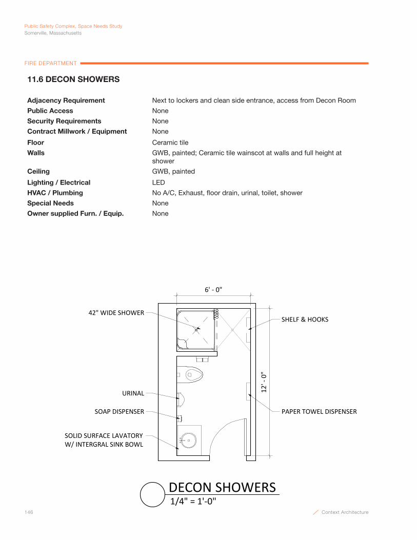
146 Context Architecture
Public Safety Complex, Space Needs StudySomerville, Massachusetts
FIRE DEPARTMENT
11.6 DECON SHOWERS
Adjacency Requirement Next to lockers and clean side entrance, access from Decon Room
Public Access None
Security Requirements None
Contract Millwork / Equipment None
Floor Ceramic tile
Walls GWB, painted; Ceramic tile wainscot at walls and full height at shower
Ceiling GWB, painted
Lighting / Electrical LED
HVAC / Plumbing No A/C, Exhaust, floor drain, urinal, toilet, shower
Special Needs None
Owner supplied Furn. / Equip. None
6' - 0"
12' -
0"
42" WIDE SHOWER
URINAL
SOAP DISPENSER PAPER TOWEL DISPENSER
SOLID SURFACE LAVATORY W/ INTERGRAL SINK BOWL
SHELF & HOOKS
1/4" = 1'-0"DECON SHOWERS
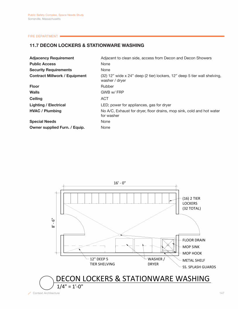
Context Architecture 147
PublicSafetyComplex,SpaceNeedsStudySomerville,Massachusetts
FIRE DEPARTMENT
11.7 DECON LOCKERS & STATIONWARE WASHING
Adjacency Requirement Adjacent to clean side, access from Decon and Decon Showers
Public Access None
Security Requirements None
Contract Millwork / Equipment (32) 12” wide x 24” deep (2 tier) lockers, 12” deep 5 tier wall shelving, washer / dryer
Floor Rubber
Walls GWB w/ FRP
Ceiling ACT
Lighting / Electrical LED; power for appliances, gas for dryer
HVAC / Plumbing No A/C, Exhaust for dryer, floor drains, mop sink, cold and hot water for washer
Special Needs None
Owner supplied Furn. / Equip. None
8' -
6"
16' - 0"
(16) 2 TIER LOCKERS (32 TOTAL)
WASHER / DRYER
12" DEEP 5TIER SHELVING
MOP SINK
FLOOR DRAIN
MOP HOOK
METAL SHELF
SS. SPLASH GUARDS
1/4" = 1'-0"DECON LOCKERS & STATIONWARE WASHING
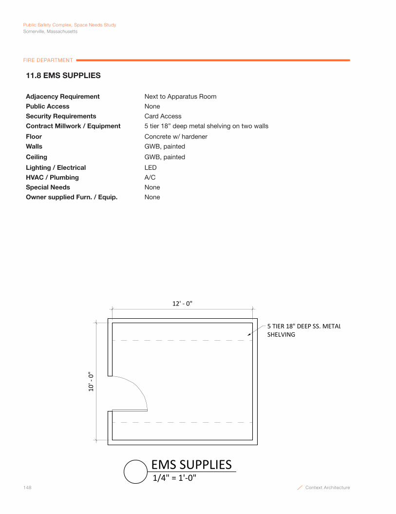
148 Context Architecture
Public Safety Complex, Space Needs StudySomerville, Massachusetts
FIRE DEPARTMENT
11.8 EMS SUPPLIES
Adjacency Requirement Next to Apparatus Room
Public Access None
Security Requirements Card Access
Contract Millwork / Equipment 5 tier 18” deep metal shelving on two walls
Floor Concrete w/ hardener
Walls GWB, painted
Ceiling GWB, painted
Lighting / Electrical LED
HVAC / Plumbing A/C
Special Needs None
Owner supplied Furn. / Equip. None
10' -
0"
12' - 0"
5 TIER 18" DEEP SS. METAL SHELVING
1/4" = 1'-0"EMS SUPPLIES

Context Architecture 149
PublicSafetyComplex,SpaceNeedsStudySomerville,Massachusetts
FIRE DEPARTMENT
11.9 GEAR SUPPLY
Adjacency Requirement Off Apparatus Room
Public Access None
Security Requirements None
Contract Millwork / Equipment 5 tier 18” deep metal shelving on two walls
Floor Concrete w/ hardener
Walls CMU w/ epoxy paint
Ceiling Painted, exposed structure
Lighting / Electrical LED
HVAC / Plumbing Good exhaust
Special Needs None
Owner supplied Furn. / Equip. None
10' -
0"
12' - 0"
5 TIER 18" DEEP METAL SHELVING
1/4" = 1'-0"GEAR SUPPLY
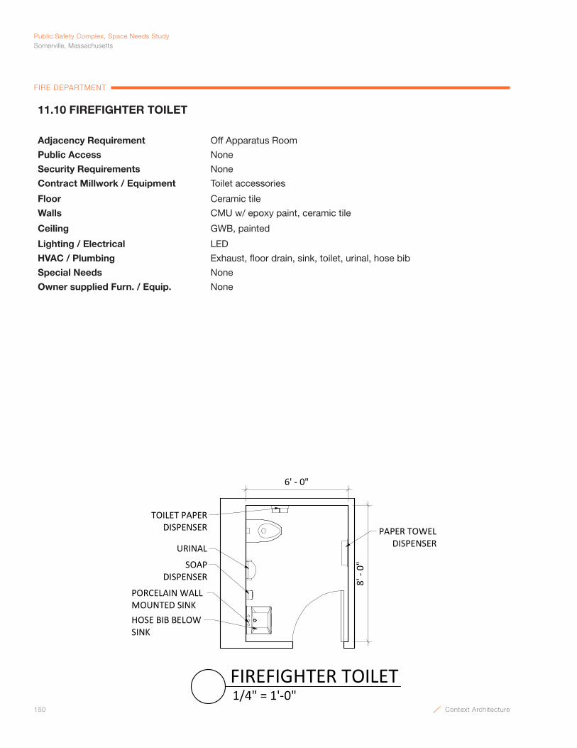
150 Context Architecture
Public Safety Complex, Space Needs StudySomerville, Massachusetts
FIRE DEPARTMENT
11.10 FIREFIGHTER TOILET
Adjacency Requirement Off Apparatus Room
Public Access None
Security Requirements None
Contract Millwork / Equipment Toilet accessories
Floor Ceramic tile
Walls CMU w/ epoxy paint, ceramic tile
Ceiling GWB, painted
Lighting / Electrical LED
HVAC / Plumbing Exhaust, floor drain, sink, toilet, urinal, hose bib
Special Needs None
Owner supplied Furn. / Equip. None
6' - 0"
8' -
0"
TOILET PAPER DISPENSER
URINAL
SOAPDISPENSER
PAPER TOWEL DISPENSER
PORCELAIN WALL MOUNTED SINKHOSE BIB BELOWSINK
1/4" = 1'-0"FIREFIGHTER TOILET
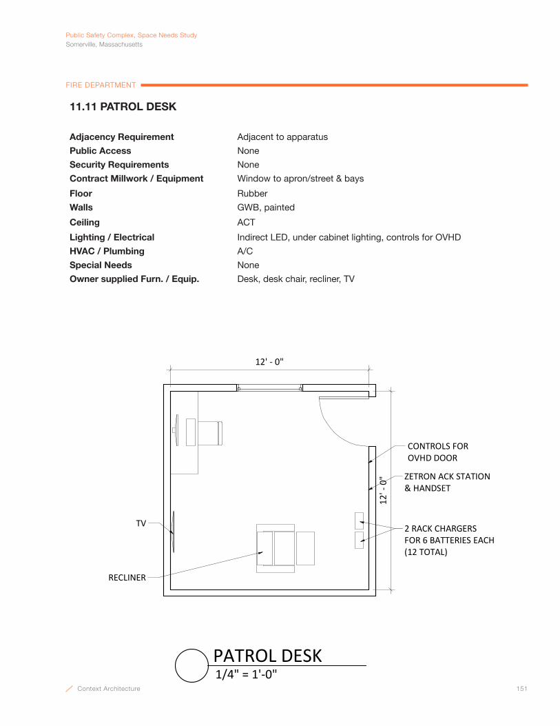
Context Architecture 151
PublicSafetyComplex,SpaceNeedsStudySomerville,Massachusetts
FIRE DEPARTMENT
11.11 PATROL DESK
Adjacency Requirement Adjacent to apparatus
Public Access None
Security Requirements None
Contract Millwork / Equipment Window to apron/street & bays
Floor Rubber
Walls GWB, painted
Ceiling ACT
Lighting / Electrical Indirect LED, under cabinet lighting, controls for OVHD
HVAC / Plumbing A/C
Special Needs None
Owner supplied Furn. / Equip. Desk, desk chair, recliner, TV
12' - 0"
12' -
0" ZETRON ACK STATION
& HANDSET
2 RACK CHARGERS FOR 6 BATTERIES EACH (12 TOTAL)
RECLINER
TV
CONTROLS FOR OVHD DOOR
1/4" = 1'-0"PATROL DESK
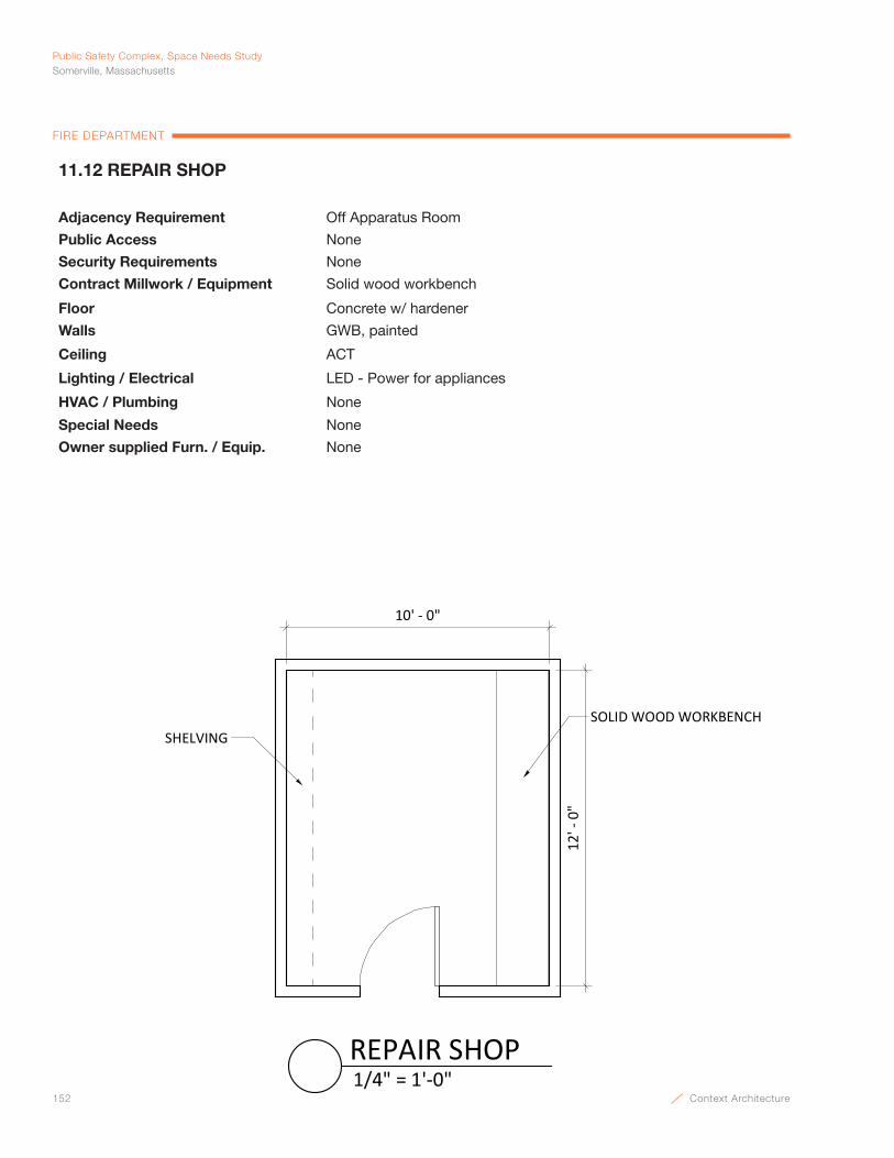
152 Context Architecture
Public Safety Complex, Space Needs StudySomerville, Massachusetts
FIRE DEPARTMENT
11.12 REPAIR SHOP
Adjacency Requirement Off Apparatus Room
Public Access None
Security Requirements None
Contract Millwork / Equipment Solid wood workbench
Floor Concrete w/ hardener
Walls GWB, painted
Ceiling ACT
Lighting / Electrical LED - Power for appliances
HVAC / Plumbing None
Special Needs None
Owner supplied Furn. / Equip. None
12' -
0"
10' - 0"
SHELVINGSOLID WOOD WORKBENCH
1/4" = 1'-0"REPAIR SHOP
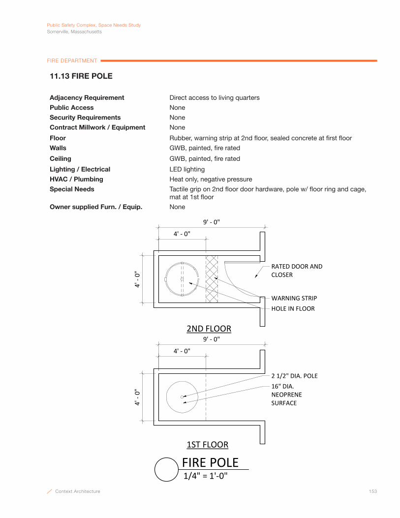
Context Architecture 153
PublicSafetyComplex,SpaceNeedsStudySomerville,Massachusetts
FIRE DEPARTMENT
4' -
0"
2 1/2" DIA. POLE16" DIA. NEOPRENE SURFACE
1ST FLOOR
2ND FLOOR9' - 0"
4' - 0"
4' -
0"
HOLE IN FLOORWARNING STRIP
4' - 0"
9' - 0"
RATED DOOR ANDCLOSER
1/4" = 1'-0"FIRE POLE
11.13 FIRE POLE
Adjacency Requirement Direct access to living quarters
Public Access None
Security Requirements None
Contract Millwork / Equipment None
Floor Rubber, warning strip at 2nd floor, sealed concrete at first floor
Walls GWB, painted, fire rated
Ceiling GWB, painted, fire rated
Lighting / Electrical LED lighting
HVAC / Plumbing Heat only, negative pressure
Special Needs Tactile grip on 2nd floor door hardware, pole w/ floor ring and cage, mat at 1st floor
Owner supplied Furn. / Equip. None

154 Context Architecture
Public Safety Complex, Space Needs StudySomerville, Massachusetts
FIRE DEPARTMENT
5 TIER 18" DEEP METAL SHELVING
25' ‐ 0"
14' ‐ 0"
3/16" = 1'‐0"FIRE BIKE PATROL STORAGE
11.14 FIRE BIKE PATROL STORAGE
Adjacency Requirement Off Apparatus Room, Possibly share police bike storage if accessible to fire.
Public Access None
Security Requirements None
Contract Millwork / Equipment 5 tier 18” deep metal shelving on one wall
Floor Concrete w/ hardener
Walls CMU w/ epoxy paint
Ceiling Painted, exposed structure
Lighting / Electrical LED
HVAC / Plumbing Good exhaust
Special Needs None
Owner supplied Furn. / Equip. 12 Bikes, bike racking system
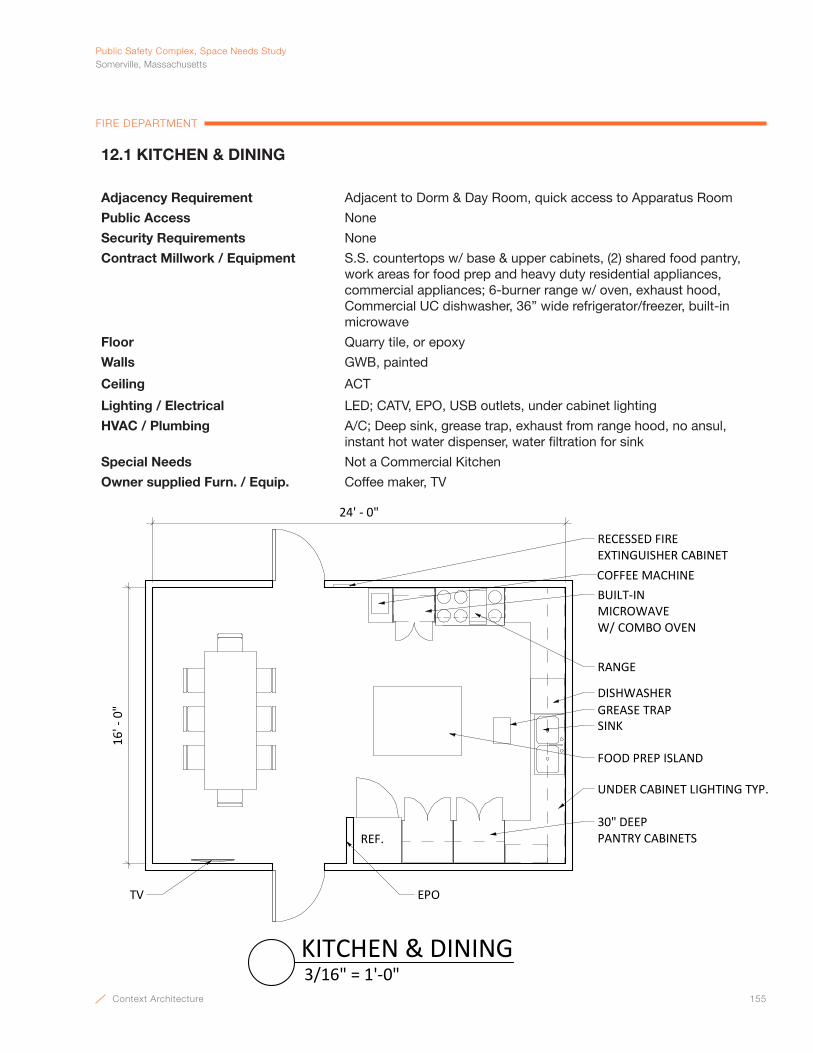
Context Architecture 155
PublicSafetyComplex,SpaceNeedsStudySomerville,Massachusetts
FIRE DEPARTMENT
12.1 KITCHEN & DINING
Adjacency Requirement Adjacent to Dorm & Day Room, quick access to Apparatus Room
Public Access None
Security Requirements None
Contract Millwork / Equipment S.S. countertops w/ base & upper cabinets, (2) shared food pantry, work areas for food prep and heavy duty residential appliances, commercial appliances; 6-burner range w/ oven, exhaust hood, Commercial UC dishwasher, 36” wide refrigerator/freezer, built-in microwave
Floor Quarry tile, or epoxy
Walls GWB, painted
Ceiling ACT
Lighting / Electrical LED; CATV, EPO, USB outlets, under cabinet lighting
HVAC / Plumbing A/C; Deep sink, grease trap, exhaust from range hood, no ansul, instant hot water dispenser, water filtration for sink
Special Needs Not a Commercial Kitchen
Owner supplied Furn. / Equip. Coffee maker, TV
24' - 0"
16' -
0"
RANGE
30" DEEPPANTRY CABINETS
SINK
FOOD PREP ISLAND
DISHWASHER
COFFEE MACHINE
REF.
EPOTV
RECESSED FIRE EXTINGUISHER CABINET
UNDER CABINET LIGHTING TYP.
GREASE TRAP
BUILT-IN MICROWAVEW/ COMBO OVEN
3/16" = 1'-0"KITCHEN & DINING
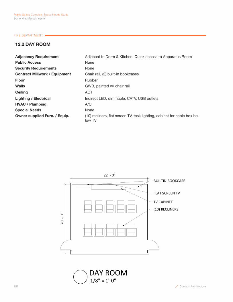
156 Context Architecture
Public Safety Complex, Space Needs StudySomerville, Massachusetts
FIRE DEPARTMENT
12.2 DAY ROOM
Adjacency Requirement Adjacent to Dorm & Kitchen, Quick access to Apparatus Room
Public Access None
Security Requirements None
Contract Millwork / Equipment Chair rail, (2) built-in bookcases
Floor Rubber
Walls GWB, painted w/ chair rail
Ceiling ACT
Lighting / Electrical Indirect LED, dimmable; CATV, USB outlets
HVAC / Plumbing A/C
Special Needs None
Owner supplied Furn. / Equip. (10) recliners, flat screen TV, task lighting, cabinet for cable box be-low TV
20' -
0"
22' - 0"
(10) RECLINERS
FLAT SCREEN TV
TV CABINET
BUILTIN BOOKCASE
1/8" = 1'-0"DAY ROOM

Context Architecture 157
PublicSafetyComplex,SpaceNeedsStudySomerville,Massachusetts
FIRE DEPARTMENT
12.3 SHOWERS
Adjacency Requirement Near Firefighter Dorm Rooms
Public Access None
Security Requirements Privacy
Contract Millwork / Equipment Solid Surface, lavatory w/ integral bowl, toilet accessories continuous mirrors above counter; full length mirror, swing down seat
Floor Ceramic tile
Walls GWB, ceramic tile wainscot typ., full height at showers, painted GWB above tile wainscot
Ceiling GWB, painted
Lighting / Electrical LED w/ sensor
HVAC / Plumbing A/C; exhaust; (1) shower w/ drying area, (1) toilet, (1) sink, floor drains
Special Needs None
Owner supplied Furn. / Equip. None
12' - 0"
6' -
6"
MIRRORSOLID SURFACEVANITY
SOAP DISPENSER
PAPER TOWEL DISPENSER
TOILET PAPERDISPENSER
SWING DOWN SEAT
SOLID SURFACESHELF
URINAL
MARBLE THRESHOLD
1/4" = 1'-0"SHOWERS

158 Context Architecture
Public Safety Complex, Space Needs StudySomerville, Massachusetts
FIRE DEPARTMENT
12.4 OFFICER’S DORM
Adjacency Requirement Near showers, Kitchen and Day Room, quick access to Apparatus room
Public Access None
Security Requirements Privacy
Contract Millwork / Equipment None
Floor Carpet tile
Walls Painted GWB w/ sound insulation
Ceiling ACT
Lighting / Electrical LED - 2 levels; data/ telephone jacks, USB outlets
HVAC / Plumbing A/C
Special Needs Space for fold out cot
Owner supplied Furn. / Equip. Extra-long bed, night table, desk, desk chair, chair, TV, (4) wardrobes, countertop multi-function printer, 2-drawer lateral files, bookcase
12' - 0" 10' - 0"10
' - 0
"NIGHT TABLEBED
WARDROBELOCKERS
TVTO OFFICE
LATERAL FILES
BOOKSHELF
COUNTERTOPMULTI-FUNCTIONPRINTER
1/4" = 1'-0"OFFICER'S DORM
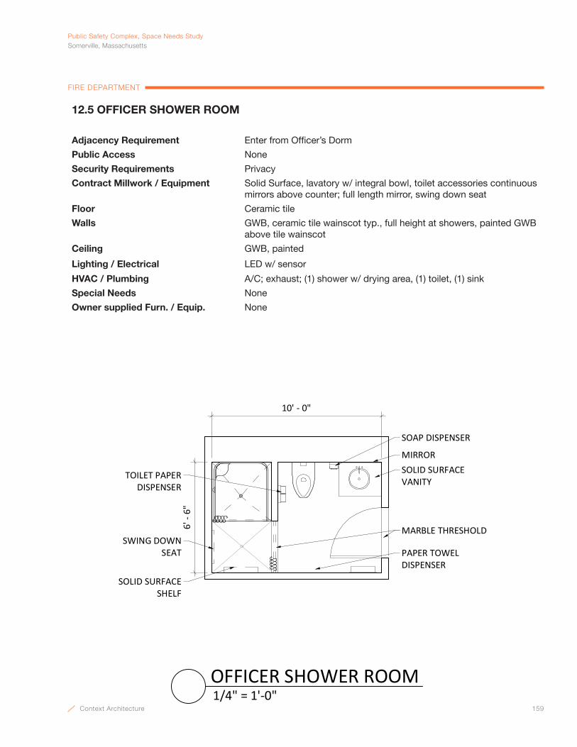
Context Architecture 159
PublicSafetyComplex,SpaceNeedsStudySomerville,Massachusetts
FIRE DEPARTMENT
12.5 OFFICER SHOWER ROOM
Adjacency Requirement Enter from Officer’s Dorm
Public Access None
Security Requirements Privacy
Contract Millwork / Equipment Solid Surface, lavatory w/ integral bowl, toilet accessories continuous mirrors above counter; full length mirror, swing down seat
Floor Ceramic tile
Walls GWB, ceramic tile wainscot typ., full height at showers, painted GWB above tile wainscot
Ceiling GWB, painted
Lighting / Electrical LED w/ sensor
HVAC / Plumbing A/C; exhaust; (1) shower w/ drying area, (1) toilet, (1) sink
Special Needs None
Owner supplied Furn. / Equip. None
10' - 0"
6' -
6"
MIRRORSOLID SURFACEVANITY
SOAP DISPENSER
PAPER TOWEL DISPENSER
TOILET PAPERDISPENSER
SWING DOWN SEAT
SOLID SURFACESHELF
MARBLE THRESHOLD
1/4" = 1'-0"OFFICER SHOWER ROOM
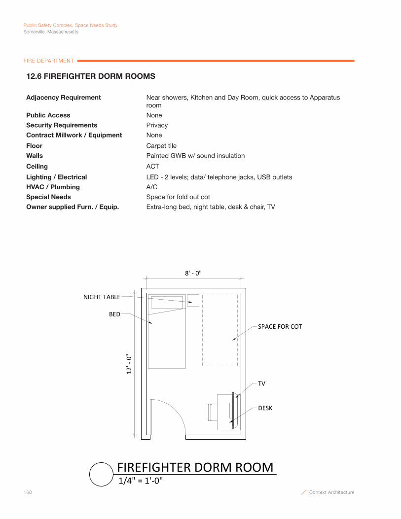
160 Context Architecture
Public Safety Complex, Space Needs StudySomerville, Massachusetts
FIRE DEPARTMENT
12.6 FIREFIGHTER DORM ROOMS
Adjacency Requirement Near showers, Kitchen and Day Room, quick access to Apparatus room
Public Access None
Security Requirements Privacy
Contract Millwork / Equipment None
Floor Carpet tile
Walls Painted GWB w/ sound insulation
Ceiling ACT
Lighting / Electrical LED - 2 levels; data/ telephone jacks, USB outlets
HVAC / Plumbing A/C
Special Needs Space for fold out cot
Owner supplied Furn. / Equip. Extra-long bed, night table, desk & chair, TV
12' -
0"
8' - 0"
BED
NIGHT TABLE
SPACE FOR COT
DESK
TV
1/4" = 1'-0"FIREFIGHTER DORM ROOM
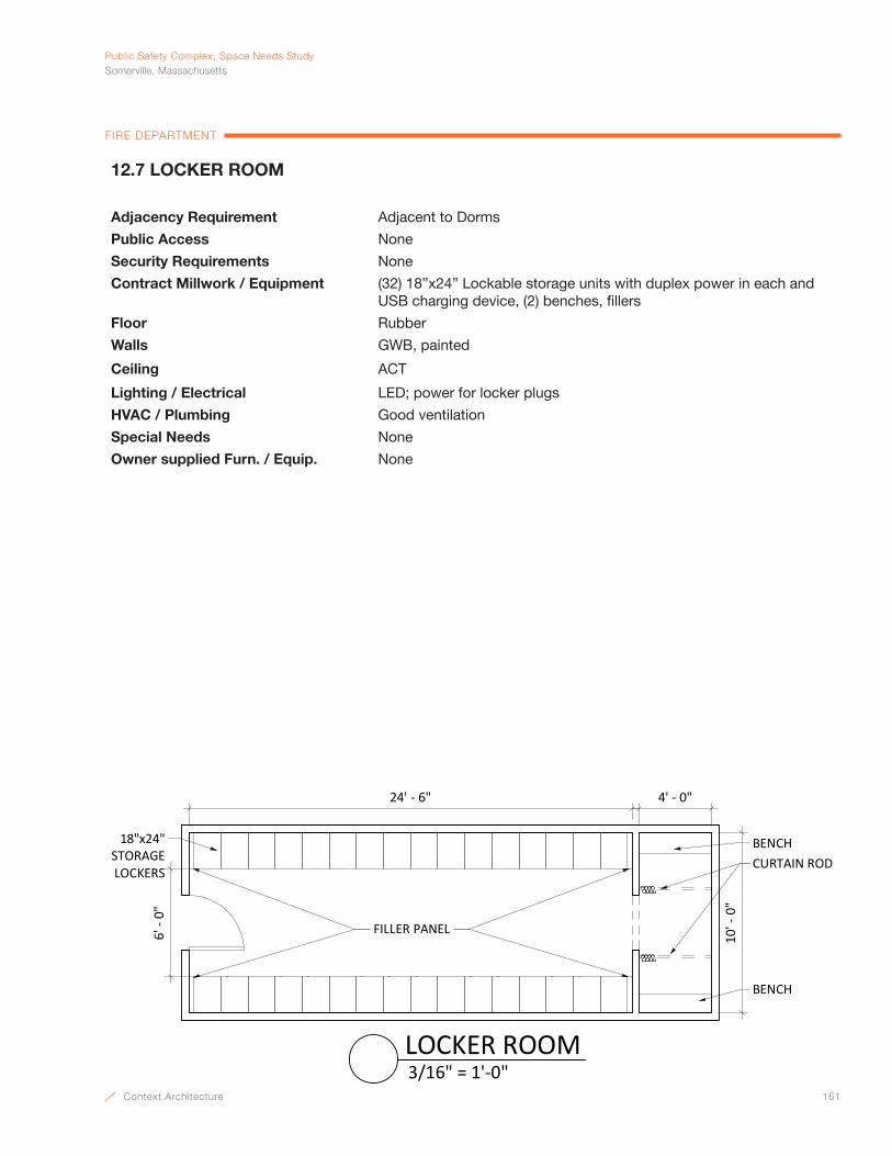
Context Architecture 161
PublicSafetyComplex,SpaceNeedsStudySomerville,Massachusetts
FIRE DEPARTMENT
12.7 LOCKER ROOM
Adjacency Requirement Adjacent to Dorms
Public Access None
Security Requirements None
Contract Millwork / Equipment (32) 18”x24” Lockable storage units with duplex power in each and USB charging device, (2) benches, fillers
Floor Rubber
Walls GWB, painted
Ceiling ACT
Lighting / Electrical LED; power for locker plugs
HVAC / Plumbing Good ventilation
Special Needs None
Owner supplied Furn. / Equip. None
10' -
0"
24' - 6"
18"x24" STORAGELOCKERS
6' -
0"
4' - 0"
CURTAIN ROD
FILLER PANEL
BENCH
BENCH
3/16" = 1'-0"LOCKER ROOM
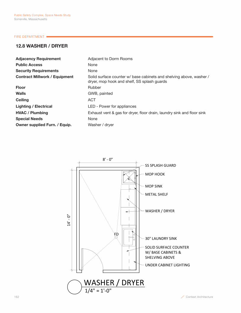
162 Context Architecture
Public Safety Complex, Space Needs StudySomerville, Massachusetts
FIRE DEPARTMENT
12.8 WASHER / DRYER
Adjacency Requirement Adjacent to Dorm Rooms
Public Access None
Security Requirements None
Contract Millwork / Equipment Solid surface counter w/ base cabinets and shelving above, washer / dryer, mop hook and shelf, SS splash guards
Floor Rubber
Walls GWB, painted
Ceiling ACT
Lighting / Electrical LED - Power for appliances
HVAC / Plumbing Exhaust vent & gas for dryer, floor drain, laundry sink and floor sink
Special Needs None
Owner supplied Furn. / Equip. Washer / dryer
8' - 0"
SOLID SURFACE COUNTERW/ BASE CABINETS &SHELVING ABOVE
14' -
0"
WASHER / DRYER
UNDER CABINET LIGHTING
MOP SINK
FD
MOP HOOK
SS SPLASH GUARD
METAL SHELF
30" LAUNDRY SINK
1/4" = 1'-0"WASHER / DRYER

Context Architecture 163
PublicSafetyComplex,SpaceNeedsStudySomerville,Massachusetts
FIRE DEPARTMENT
12.9 QUARTERMASTER STORAGE
Adjacency Requirement Near Firefighters Quarters & Kitchen
Public Access None
Security Requirements None
Contract Millwork / Equipment 15” deep metal shelves on (3) walls
Floor Linoleum
Walls GWB, painted
Ceiling ACT
Lighting / Electrical LED
HVAC / Plumbing Ventilation
Special Needs None
Owner supplied Furn. / Equip. None
10' -
0"
8' - 0"
15" METALSHELVING
1/4" = 1'-0"QUARTERMASTER STORAGE

164 Context Architecture
Public Safety Complex, Space Needs StudySomerville, Massachusetts
FIRE DEPARTMENT
13.1 AUXILIARY BAY
Adjacency Requirement Within apparatus room
Public Access None
Security Requirements Card Access
Contract Millwork / Equipment None
Floor Concrete w/ H.D. Floor Hardener
Walls CMU w/ epoxy paint
Ceiling Painted, exposed structure
Lighting / Electrical Low Level Night Lighting, Overhead power; Overhead door Light Curtain, Red/geen lights w/ door controls at doors/dispatch & trucks
HVAC / Plumbing No AC; Vehicle exhaust system, hose bibs @ walls, trench drains
Special Needs Overhead door to be 14’ x 14’.
Owner supplied Furn. / Equip. (2) Truck (24’)
18' -
0"4' - 0" 4' - 0"4' - 0"
TRUCK24'
TRUCK24'
60' - 0"OTHER BAYS
EXTERIOR
AUXILIARY STORAGE
3/32" = 1'-0"AUXILIARY BAY
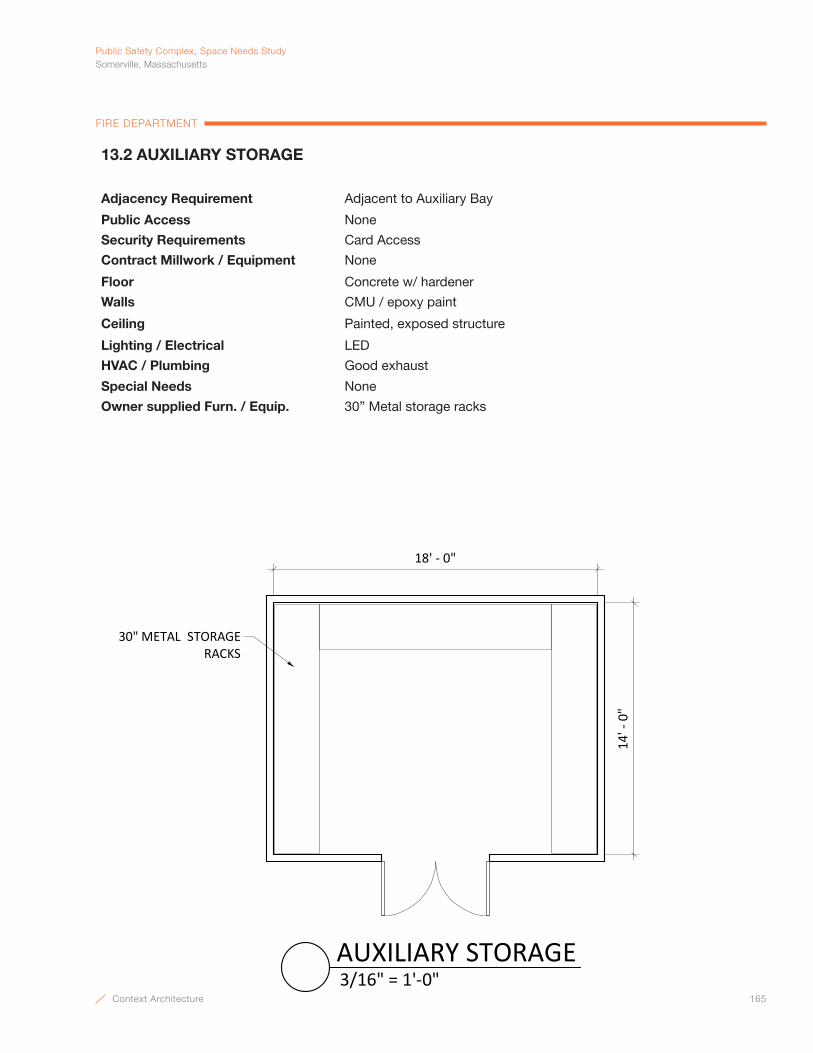
Context Architecture 165
PublicSafetyComplex,SpaceNeedsStudySomerville,Massachusetts
FIRE DEPARTMENT
13.2 AUXILIARY STORAGE
Adjacency Requirement Adjacent to Auxiliary Bay
Public Access None
Security Requirements Card Access
Contract Millwork / Equipment None
Floor Concrete w/ hardener
Walls CMU / epoxy paint
Ceiling Painted, exposed structure
Lighting / Electrical LED
HVAC / Plumbing Good exhaust
Special Needs None
Owner supplied Furn. / Equip. 30” Metal storage racks
14' -
0"
18' - 0"
30" METAL STORAGE RACKS
3/16" = 1'-0"AUXILIARY STORAGE
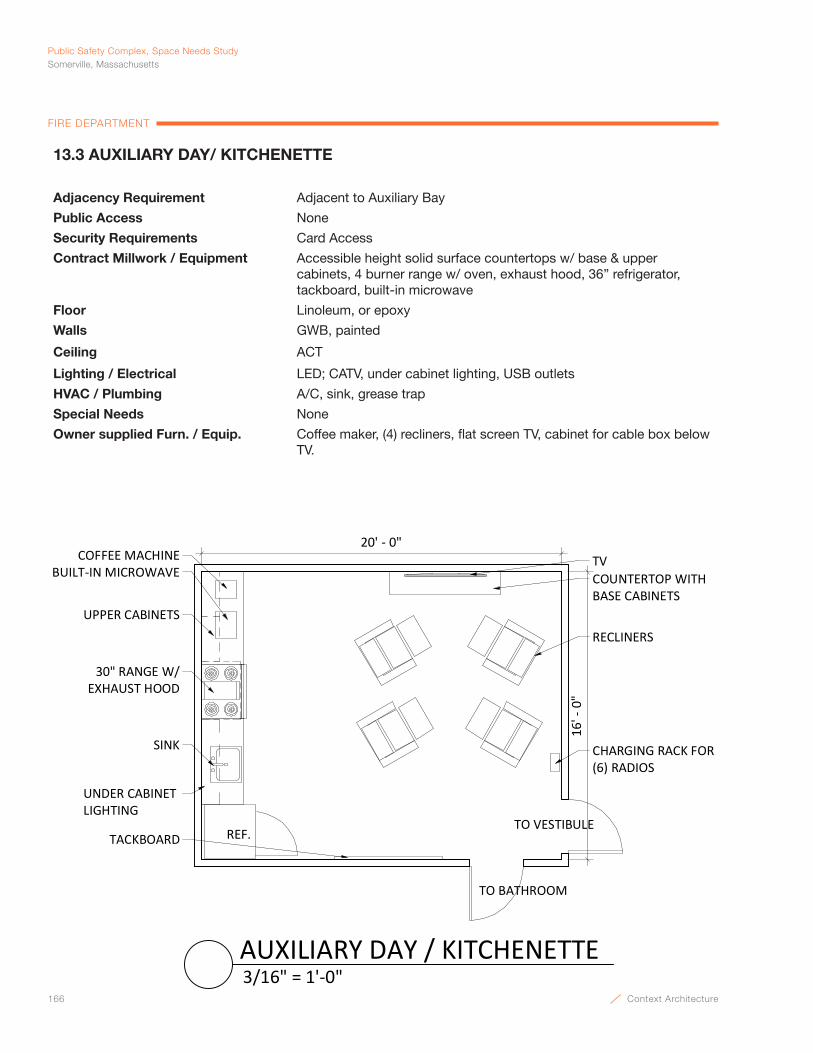
166 Context Architecture
Public Safety Complex, Space Needs StudySomerville, Massachusetts
FIRE DEPARTMENT
13.3 AUXILIARY DAY/ KITCHENETTE
Adjacency Requirement Adjacent to Auxiliary Bay
Public Access None
Security Requirements Card Access
Contract Millwork / Equipment Accessible height solid surface countertops w/ base & upper cabinets, 4 burner range w/ oven, exhaust hood, 36” refrigerator, tackboard, built-in microwave
Floor Linoleum, or epoxy
Walls GWB, painted
Ceiling ACT
Lighting / Electrical LED; CATV, under cabinet lighting, USB outlets
HVAC / Plumbing A/C, sink, grease trap
Special Needs None
Owner supplied Furn. / Equip. Coffee maker, (4) recliners, flat screen TV, cabinet for cable box below TV.
20' - 0"
16' -
0"
TV
RECLINERSUPPER CABINETS
BUILT-IN MICROWAVECOFFEE MACHINE
COUNTERTOP WITHBASE CABINETS
30" RANGE W/EXHAUST HOOD
SINK
REF.TO VESTIBULE
TO BATHROOM
UNDER CABINET LIGHTING
TACKBOARD
CHARGING RACK FOR(6) RADIOS
3/16" = 1'-0"AUXILIARY DAY / KITCHENETTE

Context Architecture 167
PublicSafetyComplex,SpaceNeedsStudySomerville,Massachusetts
FIRE DEPARTMENT
13.4 AUXILIARY TURN-OUT GEAR
Adjacency Requirement Next to Auxiliary Bay
Public Access None
Security Requirements None
Contract Millwork / Equipment (20) steel mesh cubicles at 36” x 24” w/ top & bottom shelves, small compartment, hat hook, nameplate, door
Floor Concrete w/ H.D. Hardener
Walls CMU w/ epoxy paint
Ceiling Painted, exposed structure
Lighting / Electrical LED, USB outlets
HVAC / Plumbing No A/C, very good ventilation; Floor Drains, positive pressure
Special Needs HDPE double swing access doors; no ultraviolet sunlight.
Owner supplied Furn. / Equip. None
20' - 0"
20' -
0"
(20) 36"x24" TURNOUT GEAR LOCKERS
FLOOR DRAIN
3/16" = 1'-0"AUXILIARY TURN-OUT GEAR

168 Context Architecture
Public Safety Complex, Space Needs StudySomerville, Massachusetts
FIRE DEPARTMENT
13.5 SHOWER
Adjacency Requirement Off Auxiliary Day Room
Public Access None
Security Requirements None
Contract Millwork / Equipment Solid Surface lavatory w/ integral bowl, toilet accessories continuous mirrors above counter; full length mirror, solid surface shelf, swing down seat
Floor Ceramic tile
Walls Ceramic tile wainscot on all walls, full height tile around shower unit, painted GWB above tile wainscot
Ceiling GWB, painted
Lighting / Electrical LED
HVAC / Plumbing No A/C, good ventilation, floor drain, sink, toilet
Special Needs None
Owner supplied Furn. / Equip. None
8' -
0"
11' - 0"
SOLID SURFACE VANITY
MIRROR
SOAP DISPENSER
TOILET PAPERDISPENSER
PAPER TOWELDISPENSER
SWING DOWN SEAT
SOLID SURFACE SHELF
MARBLE THRESHOLD
1/4" = 1'-0"SHOWER

Context Architecture 169
Emergency ManagementSpace Needs
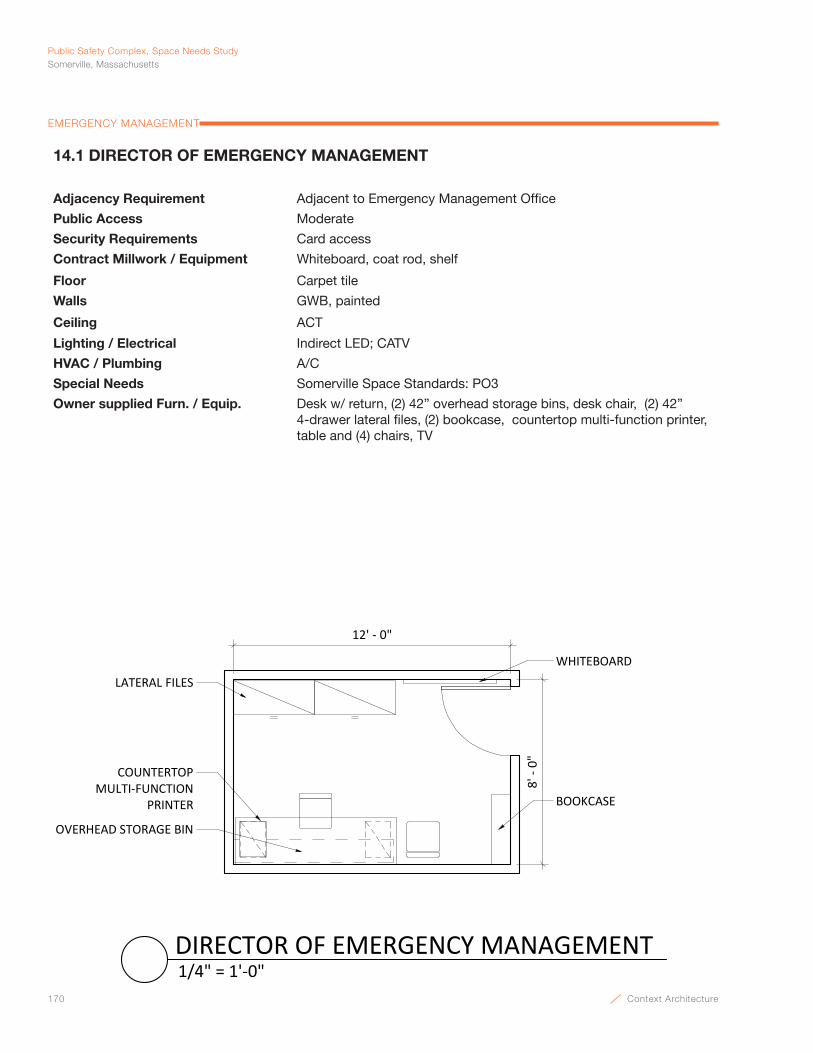
170 Context Architecture
Public Safety Complex, Space Needs StudySomerville, Massachusetts
EMERGENCY MANAGEMENT
WHITEBOARDLATERAL FILES
COUNTERTOPMULTI‐FUNCTION
PRINTER BOOKCASE
12' ‐ 0"
8' ‐ 0"
OVERHEAD STORAGE BIN
1/4" = 1'‐0"DIRECTOR OF EMERGENCY MANAGEMENT
14.1 DIRECTOR OF EMERGENCY MANAGEMENT
Adjacency Requirement Adjacent to Emergency Management Office
Public Access Moderate
Security Requirements Card access
Contract Millwork / Equipment Whiteboard, coat rod, shelf
Floor Carpet tile
Walls GWB, painted
Ceiling ACT
Lighting / Electrical Indirect LED; CATV
HVAC / Plumbing A/C
Special Needs Somerville Space Standards: PO3
Owner supplied Furn. / Equip. Desk w/ return, (2) 42” overhead storage bins, desk chair, (2) 42” 4-drawer lateral files, (2) bookcase, countertop multi-function printer, table and (4) chairs, TV
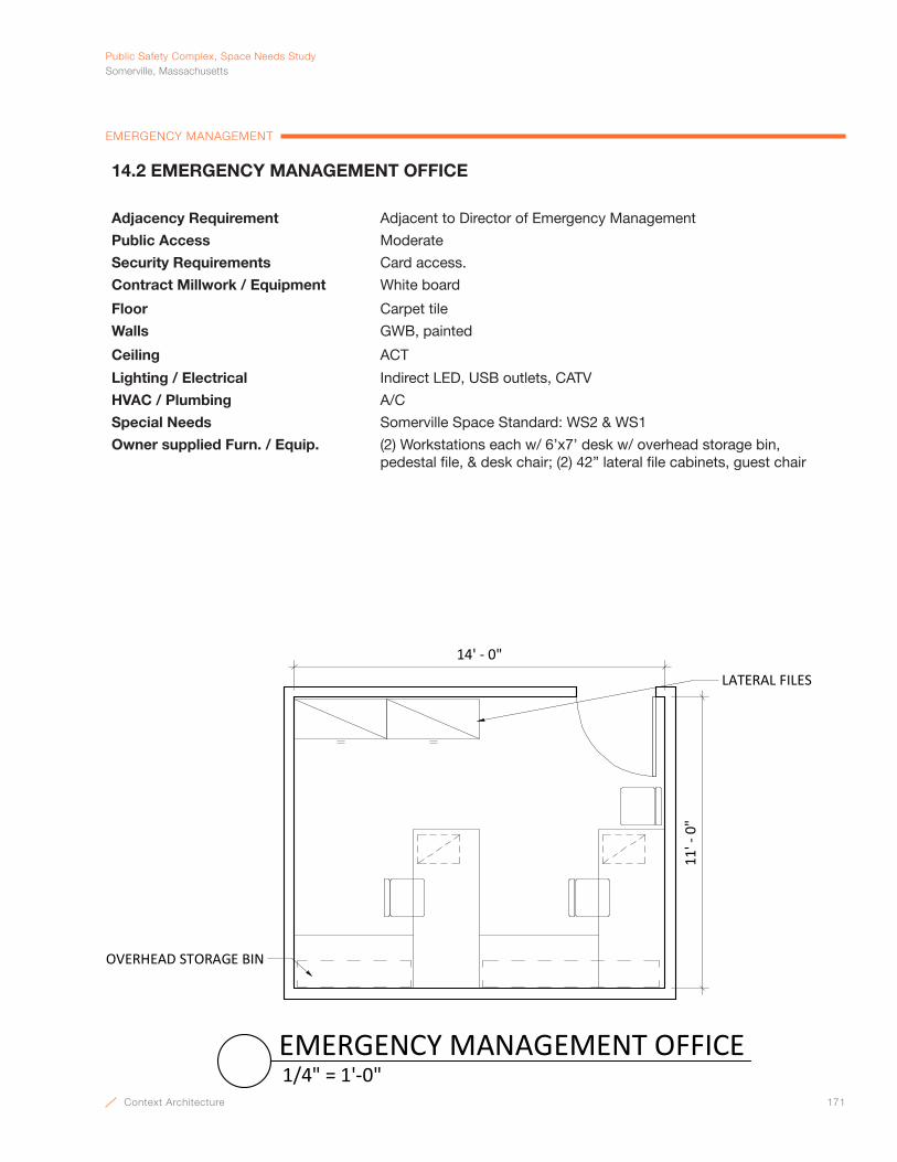
Context Architecture 171
PublicSafetyComplex,SpaceNeedsStudySomerville,Massachusetts
EMERGENCY MANAGEMENT
LATERAL FILES
14' - 0"
11' -
0"
OVERHEAD STORAGE BIN
1/4" = 1'-0"EMERGENCY MANAGEMENT OFFICE
14.2 EMERGENCY MANAGEMENT OFFICE
Adjacency Requirement Adjacent to Director of Emergency Management
Public Access Moderate
Security Requirements Card access.
Contract Millwork / Equipment White board
Floor Carpet tile
Walls GWB, painted
Ceiling ACT
Lighting / Electrical Indirect LED, USB outlets, CATV
HVAC / Plumbing A/C
Special Needs Somerville Space Standard: WS2 & WS1
Owner supplied Furn. / Equip. (2) Workstations each w/ 6’x7’ desk w/ overhead storage bin, pedestal file, & desk chair; (2) 42” lateral file cabinets, guest chair


Context Architecture 173
PARKING DEPARTMENTSUZANNE RINFRET, DIRECTOR OF PARKING

174 Context Architecture
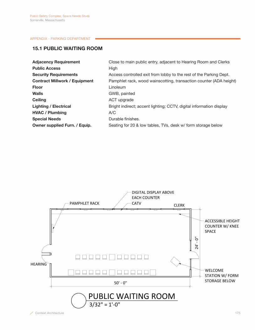
Context Architecture 175
PublicSafetyComplex,SpaceNeedsStudySomerville,Massachusetts
APPENDIX - PARKING DEPARTMENT
15.1 PUBLIC WAITING ROOM
Adjacency Requirement Close to main public entry, adjacent to Hearing Room and Clerks
Public Access High
Security Requirements Access controlled exit from lobby to the rest of the Parking Dept.
Contract Millwork / Equipment Pamphlet rack, wood wainscotting, transaction counter (ADA height)
Floor Linoleum
Walls GWB, painted
Ceiling ACT upgrade
Lighting / Electrical Bright indirect; accent lighting; CCTV, digital information display
HVAC / Plumbing A/C
Special Needs Durable finishes.
Owner supplied Furn. / Equip. Seating for 20 & low tables, TVs, desk w/ form storage below
50' ‐ 0"
24' ‐ 0"
HEARING
CLERKPAMPHLET RACK CATV
DIGITAL DISPLAY ABOVE EACH COUNTER
WELCOME STATION W/ FORM STORAGE BELOW
ACCESSIBLE HEIGHT COUNTER W/ KNEE SPACE
3/32" = 1'‐0"PUBLIC WAITING ROOM
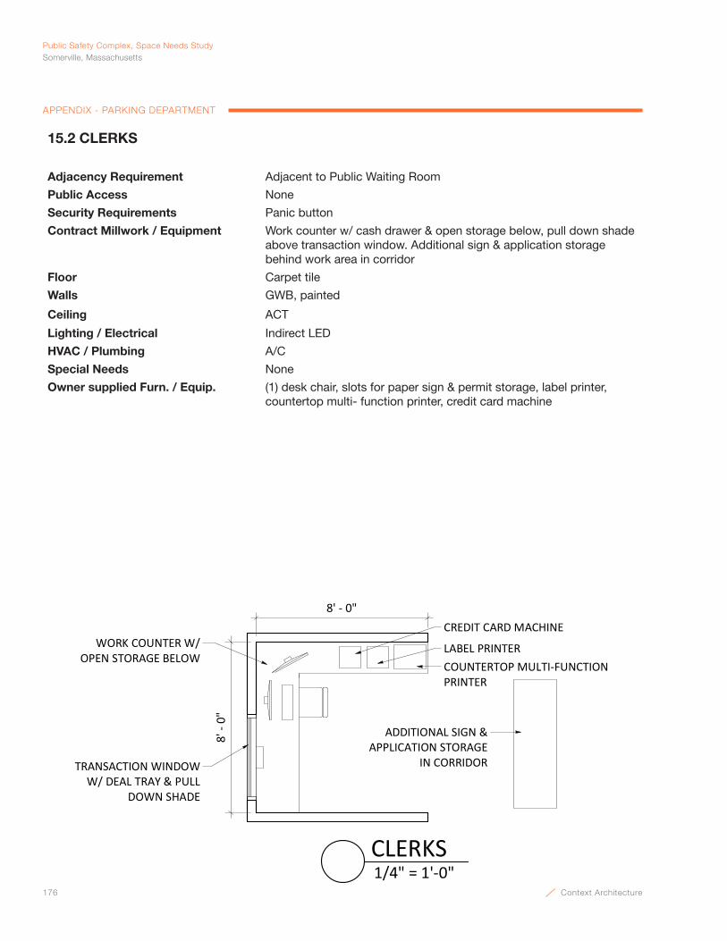
176 Context Architecture
Public Safety Complex, Space Needs StudySomerville, Massachusetts
APPENDIX - PARKING DEPARTMENT
8' - 0"
8' -
0"
WORK COUNTER W/ OPEN STORAGE BELOW
ADDITIONAL SIGN & APPLICATION STORAGE
IN CORRIDOR
COUNTERTOP MULTI-FUNCTIONPRINTER
LABEL PRINTER
CREDIT CARD MACHINE
TRANSACTION WINDOW W/ DEAL TRAY & PULL
DOWN SHADE
1/4" = 1'-0"CLERKS
15.2 CLERKS
Adjacency Requirement Adjacent to Public Waiting Room
Public Access None
Security Requirements Panic button
Contract Millwork / Equipment Work counter w/ cash drawer & open storage below, pull down shade above transaction window. Additional sign & application storage behind work area in corridor
Floor Carpet tile
Walls GWB, painted
Ceiling ACT
Lighting / Electrical Indirect LED
HVAC / Plumbing A/C
Special Needs None
Owner supplied Furn. / Equip. (1) desk chair, slots for paper sign & permit storage, label printer, countertop multi- function printer, credit card machine
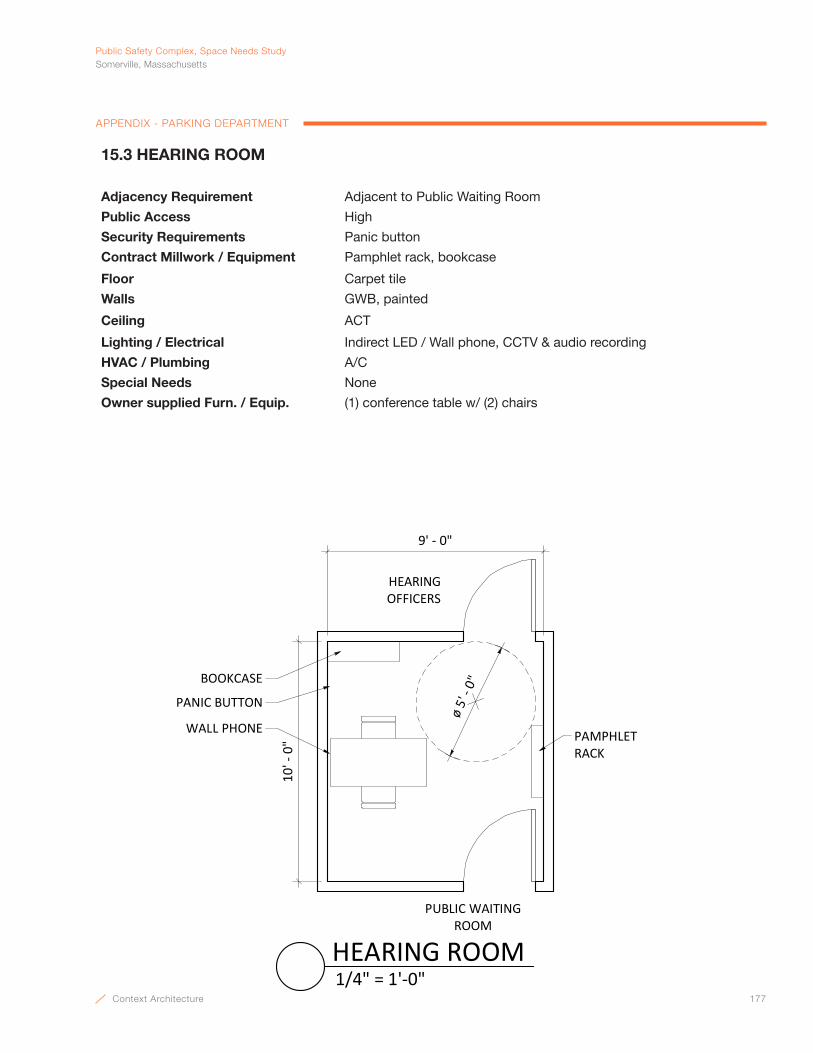
Context Architecture 177
PublicSafetyComplex,SpaceNeedsStudySomerville,Massachusetts
APPENDIX - PARKING DEPARTMENT
9' - 0"
10' -
0" PAMPHLET
RACK
PANIC BUTTON
HEARING OFFICERS
PUBLIC WAITING ROOM
BOOKCASE
WALL PHONE
ø 5'
- 0"
1/4" = 1'-0"HEARING ROOM
15.3 HEARING ROOM
Adjacency Requirement Adjacent to Public Waiting Room
Public Access High
Security Requirements Panic button
Contract Millwork / Equipment Pamphlet rack, bookcase
Floor Carpet tile
Walls GWB, painted
Ceiling ACT
Lighting / Electrical Indirect LED / Wall phone, CCTV & audio recording
HVAC / Plumbing A/C
Special Needs None
Owner supplied Furn. / Equip. (1) conference table w/ (2) chairs
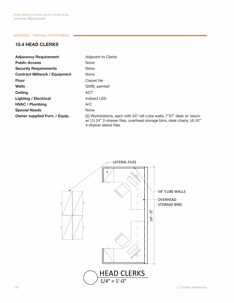
178 Context Architecture
Public Safety Complex, Space Needs StudySomerville, Massachusetts
APPENDIX - PARKING DEPARTMENT
OVERHEAD STORAGE BINS
LATERAL FILES
14' -
0"
54" CUBE WALLS
1/4" = 1'-0"HEAD CLERKS
15.4 HEAD CLERKS
Adjacency Requirement Adjacent to Clerks
Public Access None
Security Requirements None
Contract Millwork / Equipment None
Floor Carpet tile
Walls GWB, painted
Ceiling ACT
Lighting / Electrical Indirect LED
HVAC / Plumbing A/C
Special Needs None
Owner supplied Furn. / Equip. (2) Workstations, each with 54” tall cube walls, 7’X7’ desk w/ return w/ (1) 24” 2-drawer files, overhead storage bins, desk chairs, (4) 42” 4-drawer lateral files
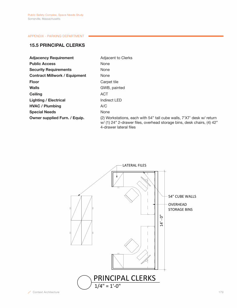
Context Architecture 179
PublicSafetyComplex,SpaceNeedsStudySomerville,Massachusetts
APPENDIX - PARKING DEPARTMENT
OVERHEAD STORAGE BINS
LATERAL FILES14
' - 0
"
54" CUBE WALLS
1/4" = 1'-0"PRINCIPAL CLERKS
15.5 PRINCIPAL CLERKS
Adjacency Requirement Adjacent to Clerks
Public Access None
Security Requirements None
Contract Millwork / Equipment None
Floor Carpet tile
Walls GWB, painted
Ceiling ACT
Lighting / Electrical Indirect LED
HVAC / Plumbing A/C
Special Needs None
Owner supplied Furn. / Equip. (2) Workstations, each with 54” tall cube walls, 7’X7’ desk w/ return w/ (1) 24” 2-drawer files, overhead storage bins, desk chairs, (4) 42” 4-drawer lateral files
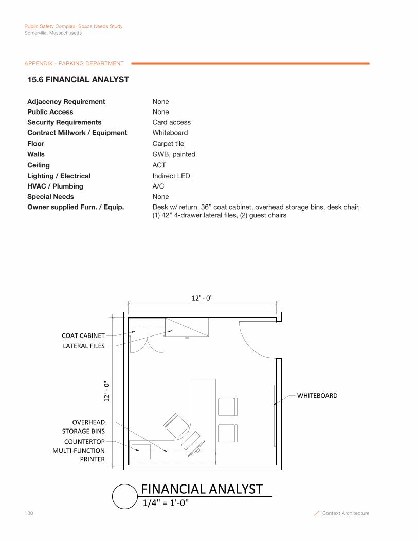
180 Context Architecture
Public Safety Complex, Space Needs StudySomerville, Massachusetts
APPENDIX - PARKING DEPARTMENT
LATERAL FILESCOAT CABINET
OVERHEAD STORAGE BINSCOUNTERTOP
MULTI-FUNCTION PRINTER
12' -
0"
12' - 0"
WHITEBOARD
1/4" = 1'-0"FINANCIAL ANALYST
15.6 FINANCIAL ANALYST
Adjacency Requirement None
Public Access None
Security Requirements Card access
Contract Millwork / Equipment Whiteboard
Floor Carpet tile
Walls GWB, painted
Ceiling ACT
Lighting / Electrical Indirect LED
HVAC / Plumbing A/C
Special Needs None
Owner supplied Furn. / Equip. Desk w/ return, 36” coat cabinet, overhead storage bins, desk chair, (1) 42” 4-drawer lateral files, (2) guest chairs
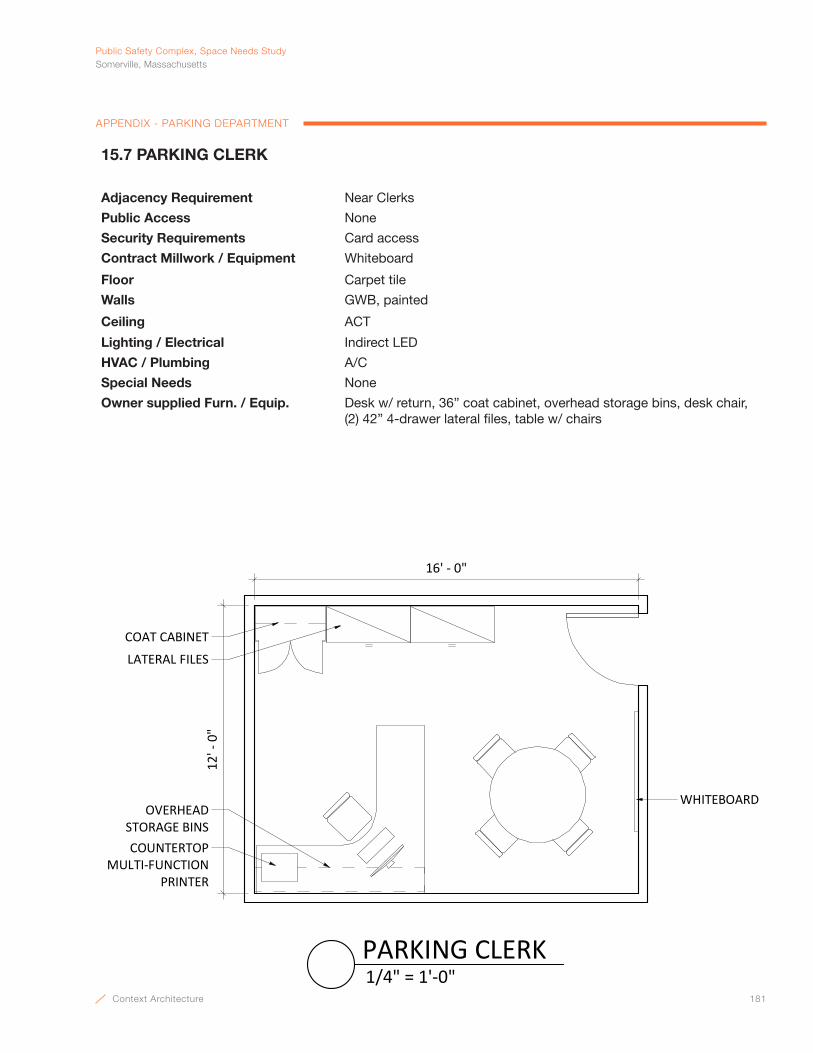
Context Architecture 181
PublicSafetyComplex,SpaceNeedsStudySomerville,Massachusetts
APPENDIX - PARKING DEPARTMENT
LATERAL FILES
COAT CABINET
OVERHEAD STORAGE BINSCOUNTERTOP
MULTI-FUNCTION PRINTER
12' -
0"
16' - 0"
WHITEBOARD
1/4" = 1'-0"PARKING CLERK
15.7 PARKING CLERK
Adjacency Requirement Near Clerks
Public Access None
Security Requirements Card access
Contract Millwork / Equipment Whiteboard
Floor Carpet tile
Walls GWB, painted
Ceiling ACT
Lighting / Electrical Indirect LED
HVAC / Plumbing A/C
Special Needs None
Owner supplied Furn. / Equip. Desk w/ return, 36” coat cabinet, overhead storage bins, desk chair, (2) 42” 4-drawer lateral files, table w/ chairs
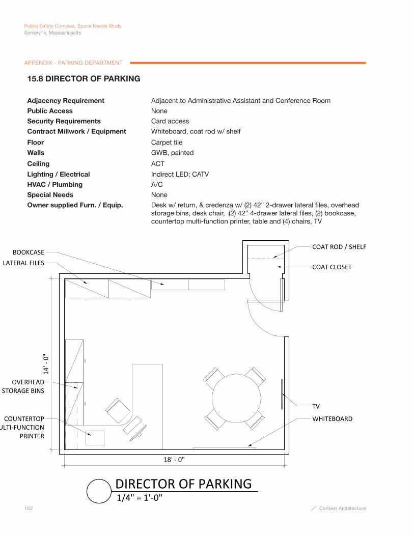
182 Context Architecture
Public Safety Complex, Space Needs StudySomerville, Massachusetts
APPENDIX - PARKING DEPARTMENT
WHITEBOARD
COAT CLOSETLATERAL FILES
COUNTERTOPMULTI-FUNCTION
PRINTER
OVERHEAD STORAGE BINS
BOOKCASE
TV
COAT ROD / SHELF
18' - 0"
14' -
0"
1/4" = 1'-0"DIRECTOR OF PARKING
15.8 DIRECTOR OF PARKING
Adjacency Requirement Adjacent to Administrative Assistant and Conference Room
Public Access None
Security Requirements Card access
Contract Millwork / Equipment Whiteboard, coat rod w/ shelf
Floor Carpet tile
Walls GWB, painted
Ceiling ACT
Lighting / Electrical Indirect LED; CATV
HVAC / Plumbing A/C
Special Needs None
Owner supplied Furn. / Equip. Desk w/ return, & credenza w/ (2) 42” 2-drawer lateral files, overhead storage bins, desk chair, (2) 42” 4-drawer lateral files, (2) bookcase, countertop multi-function printer, table and (4) chairs, TV
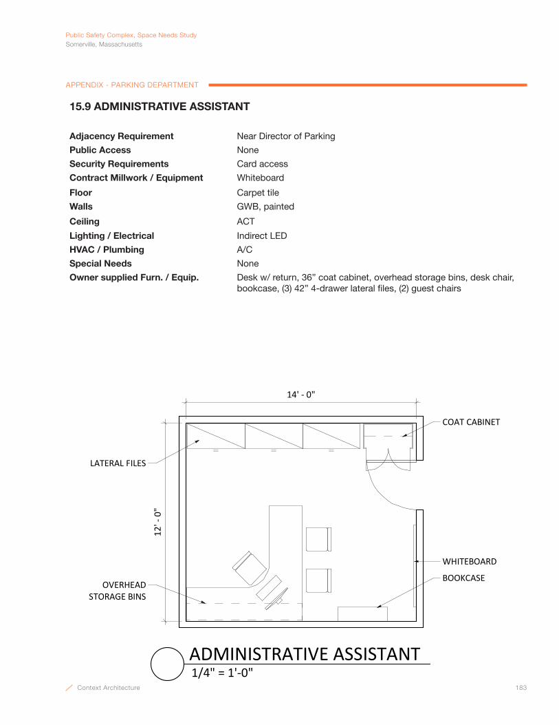
Context Architecture 183
PublicSafetyComplex,SpaceNeedsStudySomerville,Massachusetts
APPENDIX - PARKING DEPARTMENT
COAT CABINET
OVERHEAD STORAGE BINS
12' -
0"
14' - 0"
LATERAL FILES
WHITEBOARD
BOOKCASE
1/4" = 1'-0"ADMINISTRATIVE ASSISTANT
15.9 ADMINISTRATIVE ASSISTANT
Adjacency Requirement Near Director of Parking
Public Access None
Security Requirements Card access
Contract Millwork / Equipment Whiteboard
Floor Carpet tile
Walls GWB, painted
Ceiling ACT
Lighting / Electrical Indirect LED
HVAC / Plumbing A/C
Special Needs None
Owner supplied Furn. / Equip. Desk w/ return, 36” coat cabinet, overhead storage bins, desk chair, bookcase, (3) 42” 4-drawer lateral files, (2) guest chairs
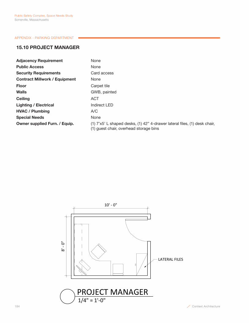
184 Context Architecture
Public Safety Complex, Space Needs StudySomerville, Massachusetts
APPENDIX - PARKING DEPARTMENT
10' - 0"
8' -
0"
LATERAL FILES
1/4" = 1'-0"PROJECT MANAGER
15.10 PROJECT MANAGER
Adjacency Requirement None
Public Access None
Security Requirements Card access
Contract Millwork / Equipment None
Floor Carpet tile
Walls GWB, painted
Ceiling ACT
Lighting / Electrical Indirect LED
HVAC / Plumbing A/C
Special Needs None
Owner supplied Furn. / Equip. (1) 7’x5’ L shaped desks, (1) 42” 4-drawer lateral files, (1) desk chair, (1) guest chair, overhead storage bins
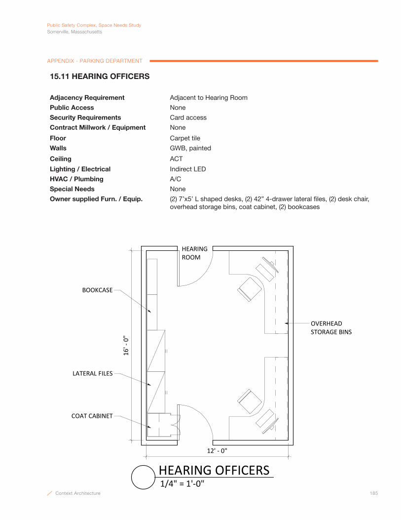
Context Architecture 185
PublicSafetyComplex,SpaceNeedsStudySomerville,Massachusetts
APPENDIX - PARKING DEPARTMENT
12' - 0"
16' -
0"
OVERHEAD STORAGE BINS
LATERAL FILES
BOOKCASE
HEARING ROOM
COAT CABINET
1/4" = 1'-0"HEARING OFFICERS
15.11 HEARING OFFICERS
Adjacency Requirement Adjacent to Hearing Room
Public Access None
Security Requirements Card access
Contract Millwork / Equipment None
Floor Carpet tile
Walls GWB, painted
Ceiling ACT
Lighting / Electrical Indirect LED
HVAC / Plumbing A/C
Special Needs None
Owner supplied Furn. / Equip. (2) 7’x5’ L shaped desks, (2) 42” 4-drawer lateral files, (2) desk chair, overhead storage bins, coat cabinet, (2) bookcases
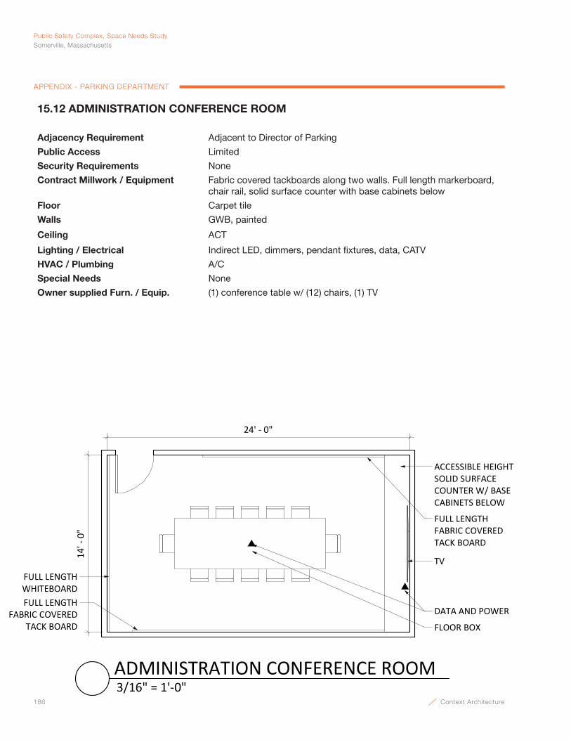
186 Context Architecture
Public Safety Complex, Space Needs StudySomerville, Massachusetts
APPENDIX - PARKING DEPARTMENT
ACCESSIBLE HEIGHT SOLID SURFACE COUNTER W/ BASE CABINETS BELOW
DATA AND POWER
FULL LENGTH FABRIC COVERED TACK BOARD
FULL LENGTH FABRIC COVERED
TACK BOARD
FULL LENGTH WHITEBOARD
24' - 0"
14' -
0"
TV
FLOOR BOX
3/16" = 1'-0"ADMINISTRATION CONFERENCE ROOM
15.12 ADMINISTRATION CONFERENCE ROOM
Adjacency Requirement Adjacent to Director of Parking
Public Access Limited
Security Requirements None
Contract Millwork / Equipment Fabric covered tackboards along two walls. Full length markerboard, chair rail, solid surface counter with base cabinets below
Floor Carpet tile
Walls GWB, painted
Ceiling ACT
Lighting / Electrical Indirect LED, dimmers, pendant fixtures, data, CATV
HVAC / Plumbing A/C
Special Needs None
Owner supplied Furn. / Equip. (1) conference table w/ (12) chairs, (1) TV
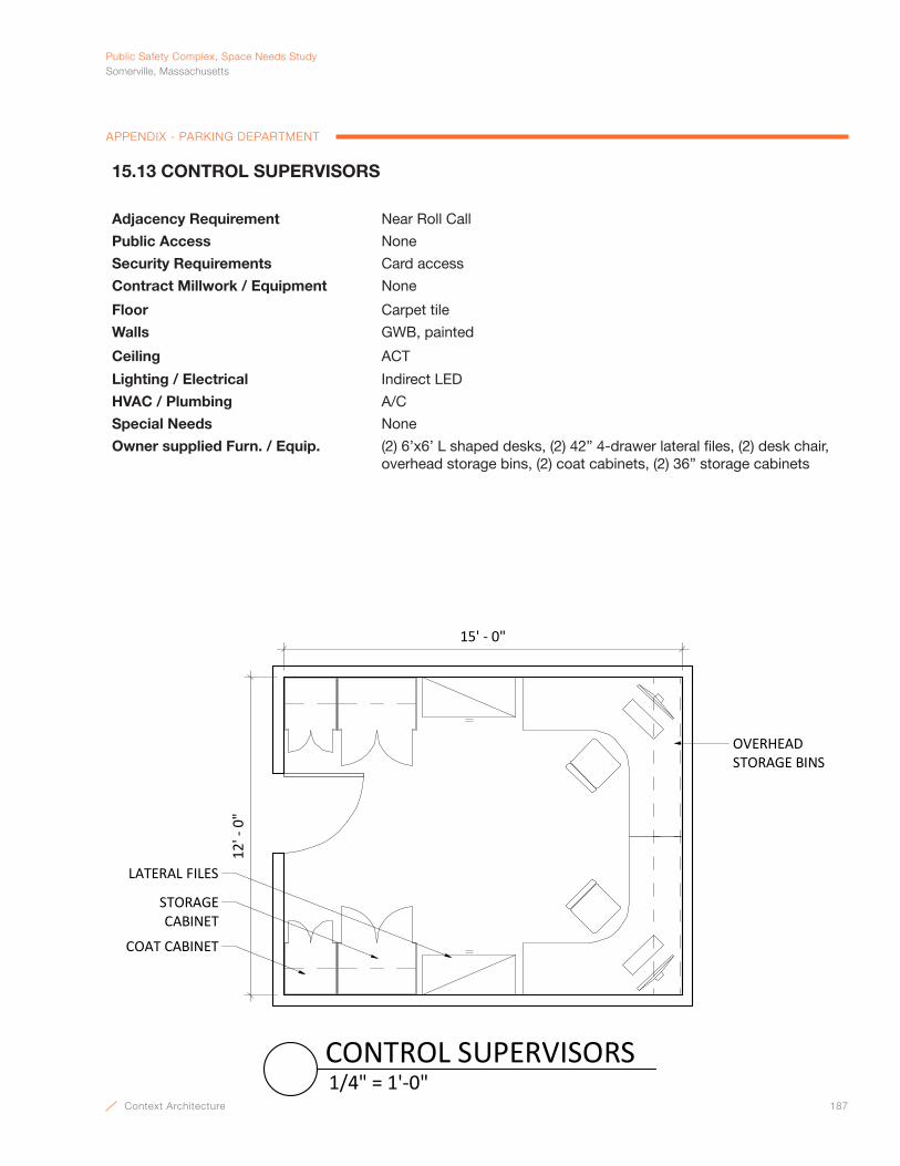
Context Architecture 187
PublicSafetyComplex,SpaceNeedsStudySomerville,Massachusetts
APPENDIX - PARKING DEPARTMENT
15' - 0"
12' -
0"
OVERHEAD STORAGE BINS
LATERAL FILES
STORAGE CABINET
COAT CABINET
1/4" = 1'-0"CONTROL SUPERVISORS
15.13 CONTROL SUPERVISORS
Adjacency Requirement Near Roll Call
Public Access None
Security Requirements Card access
Contract Millwork / Equipment None
Floor Carpet tile
Walls GWB, painted
Ceiling ACT
Lighting / Electrical Indirect LED
HVAC / Plumbing A/C
Special Needs None
Owner supplied Furn. / Equip. (2) 6’x6’ L shaped desks, (2) 42” 4-drawer lateral files, (2) desk chair, overhead storage bins, (2) coat cabinets, (2) 36” storage cabinets
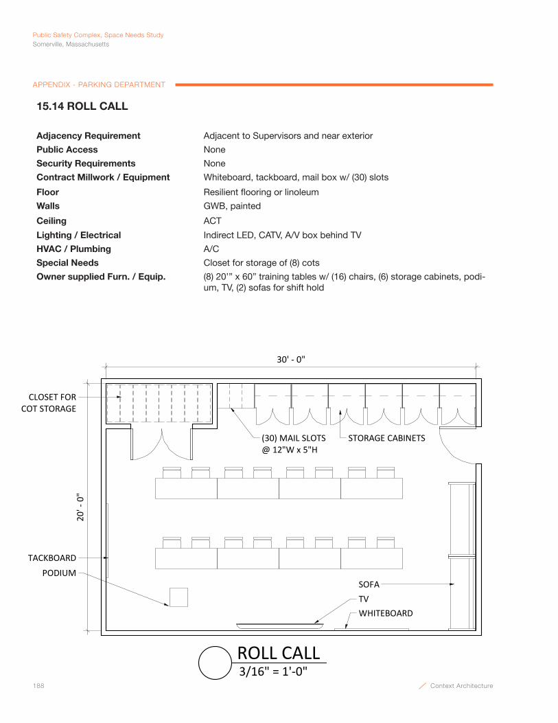
188 Context Architecture
Public Safety Complex, Space Needs StudySomerville, Massachusetts
APPENDIX - PARKING DEPARTMENT
30' ‐ 0"
20' ‐ 0"
TACKBOARDPODIUM
WHITEBOARDTV
(30) MAIL SLOTS @ 12"W x 5"H
STORAGE CABINETS
CLOSET FOR COT STORAGE
SOFA
3/16" = 1'‐0"ROLL CALL
15.14 ROLL CALL
Adjacency Requirement Adjacent to Supervisors and near exterior
Public Access None
Security Requirements None
Contract Millwork / Equipment Whiteboard, tackboard, mail box w/ (30) slots
Floor Resilient flooring or linoleum
Walls GWB, painted
Ceiling ACT
Lighting / Electrical Indirect LED, CATV, A/V box behind TV
HVAC / Plumbing A/C
Special Needs Closet for storage of (8) cots
Owner supplied Furn. / Equip. (8) 20’” x 60” training tables w/ (16) chairs, (6) storage cabinets, podi-um, TV, (2) sofas for shift hold

Context Architecture 189
PublicSafetyComplex,SpaceNeedsStudySomerville,Massachusetts
APPENDIX - PARKING DEPARTMENT
18' - 0"
20' -
0"
TACKBOARD
RECYCLE & TRASH BINS
REF
ACCESSIBLE HEIGHT UPPER CABINETS W/
UNDERCABINET LIGHTING
BUILT-IN MICROWAVE
COFFEE MAKER
TOASTER OVEN
BOTTLE FILL STATION
ACCESSIBLE HEIGHT COUNTERTOP
3/16" = 1'-0"BREAK ROOM
15.15 BREAK ROOM
Adjacency Requirement Within Parking Offices
Public Access None
Security Requirements None
Contract Millwork / Equipment Solid surface countertop with base and upper cabinets, fully accessible 30” wide refrigerator, (2) tackboards, built-in microwave
Floor Rubber
Walls GWB, painted
Ceiling ACT
Lighting / Electrical LED and under cabinet lighting
HVAC / Plumbing A/C, good exhaust system / sink, bottle fill
Special Needs None
Owner supplied Furn. / Equip. Coffee maker, toaster oven, (2) tables each w/ (6) chairs, recycle & trash bins
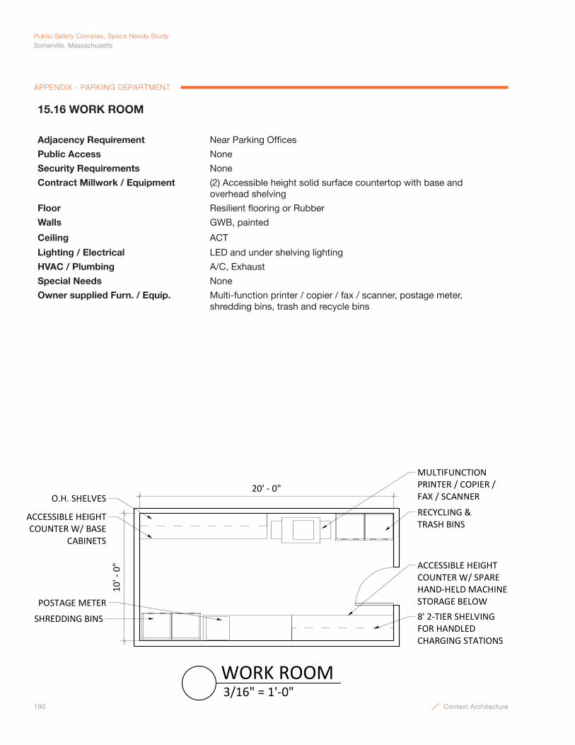
190 Context Architecture
Public Safety Complex, Space Needs StudySomerville, Massachusetts
APPENDIX - PARKING DEPARTMENT
POSTAGE METER
10' -
0"
20' - 0"
MULTIFUNCTION PRINTER / COPIER / FAX / SCANNER
RECYCLING & TRASH BINS
ACCESSIBLE HEIGHT COUNTER W/ BASE
CABINETS
O.H. SHELVES
SHREDDING BINS 8' 2-TIER SHELVING FOR HANDLED CHARGING STATIONS
ACCESSIBLE HEIGHT COUNTER W/ SPARE HAND-HELD MACHINE STORAGE BELOW
3/16" = 1'-0"WORK ROOM
15.16 WORK ROOM
Adjacency Requirement Near Parking Offices
Public Access None
Security Requirements None
Contract Millwork / Equipment (2) Accessible height solid surface countertop with base and overhead shelving
Floor Resilient flooring or Rubber
Walls GWB, painted
Ceiling ACT
Lighting / Electrical LED and under shelving lighting
HVAC / Plumbing A/C, Exhaust
Special Needs None
Owner supplied Furn. / Equip. Multi-function printer / copier / fax / scanner, postage meter, shredding bins, trash and recycle bins
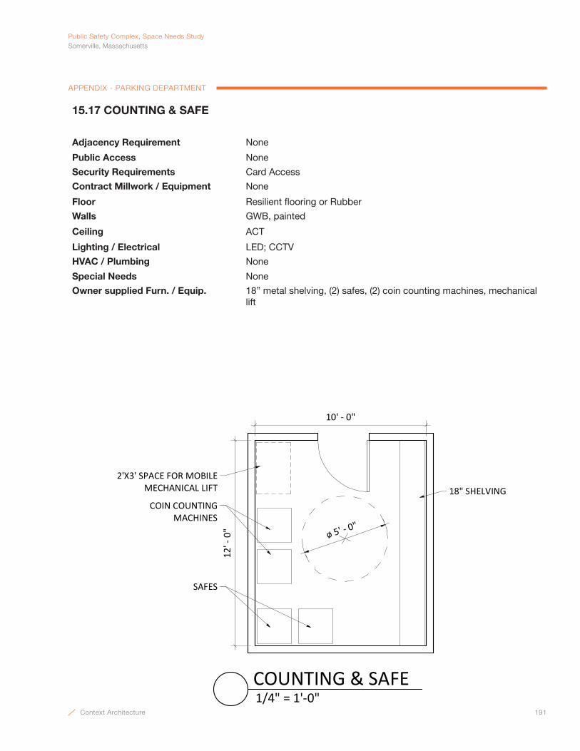
Context Architecture 191
PublicSafetyComplex,SpaceNeedsStudySomerville,Massachusetts
APPENDIX - PARKING DEPARTMENT
18" SHELVING
12' -
0"
2'X3' SPACE FOR MOBILE MECHANICAL LIFT
COIN COUNTING MACHINES
SAFES
10' - 0"
ø 5' - 0"
1/4" = 1'-0"COUNTING & SAFE
15.17 COUNTING & SAFE
Adjacency Requirement None
Public Access None
Security Requirements Card Access
Contract Millwork / Equipment None
Floor Resilient flooring or Rubber
Walls GWB, painted
Ceiling ACT
Lighting / Electrical LED; CCTV
HVAC / Plumbing None
Special Needs None
Owner supplied Furn. / Equip. 18” metal shelving, (2) safes, (2) coin counting machines, mechanical lift

192 Context Architecture
Public Safety Complex, Space Needs StudySomerville, Massachusetts
APPENDIX - PARKING DEPARTMENT
18" SHELVING
10' - 0"
12' -
0"
SPACE FOR ROLLING CART
ø 5' - 0"
1/4" = 1'-0"PAPER SIGN STORAGE
15.18 PAPER SIGN STORAGE
Adjacency Requirement None
Public Access None
Security Requirements Card Access
Contract Millwork / Equipment None
Floor Resilient flooring or Rubber
Walls GWB, painted
Ceiling ACT
Lighting / Electrical LED; CCTV
HVAC / Plumbing None
Special Needs None
Owner supplied Furn. / Equip. 18” metal shelving
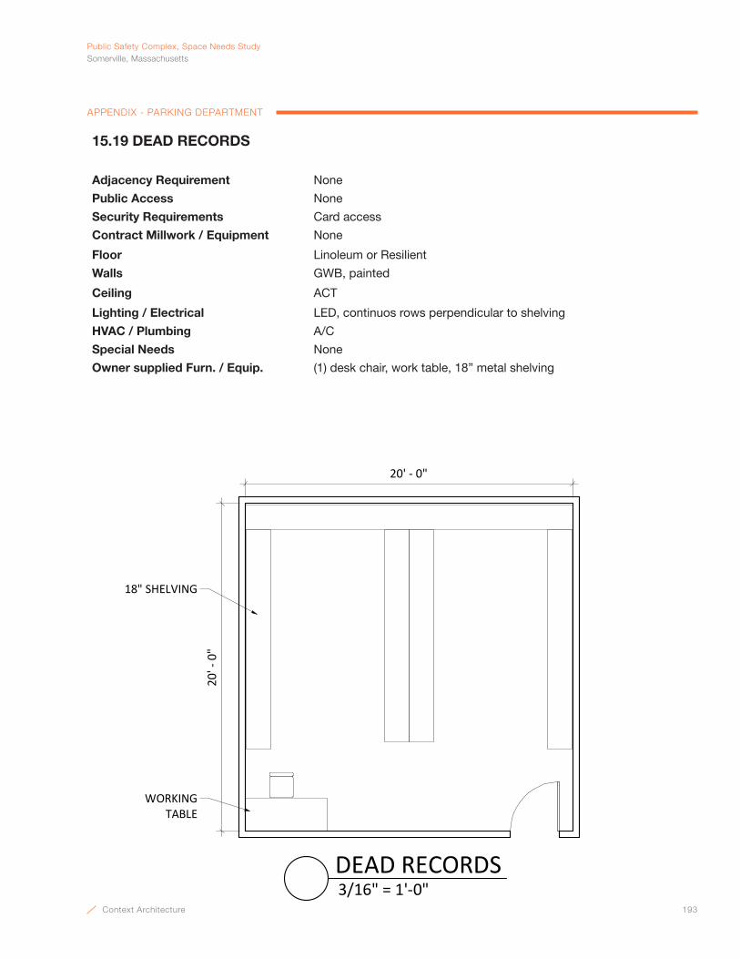
Context Architecture 193
PublicSafetyComplex,SpaceNeedsStudySomerville,Massachusetts
APPENDIX - PARKING DEPARTMENT
20' - 0"
20' -
0"
WORKING TABLE
18" SHELVING
3/16" = 1'-0"DEAD RECORDS
15.19 DEAD RECORDS
Adjacency Requirement None
Public Access None
Security Requirements Card access
Contract Millwork / Equipment None
Floor Linoleum or Resilient
Walls GWB, painted
Ceiling ACT
Lighting / Electrical LED, continuos rows perpendicular to shelving
HVAC / Plumbing A/C
Special Needs None
Owner supplied Furn. / Equip. (1) desk chair, work table, 18” metal shelving
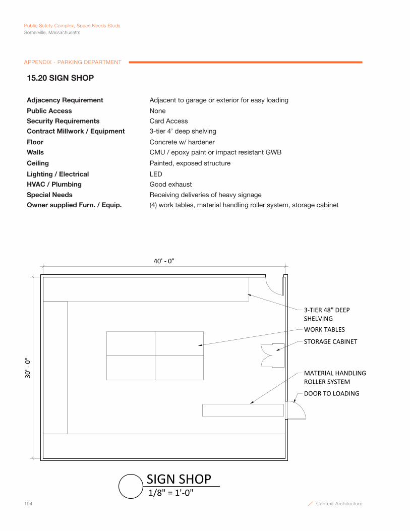
194 Context Architecture
Public Safety Complex, Space Needs StudySomerville, Massachusetts
APPENDIX - PARKING DEPARTMENT
40' - 0"
30' -
0"
3-TIER 48" DEEP SHELVINGWORK TABLES
DOOR TO LOADING
MATERIAL HANDLING ROLLER SYSTEM
STORAGE CABINET
1/8" = 1'-0"SIGN SHOP
15.20 SIGN SHOP
Adjacency Requirement Adjacent to garage or exterior for easy loading
Public Access None
Security Requirements Card Access
Contract Millwork / Equipment 3-tier 4’ deep shelving
Floor Concrete w/ hardener
Walls CMU / epoxy paint or impact resistant GWB
Ceiling Painted, exposed structure
Lighting / Electrical LED
HVAC / Plumbing Good exhaust
Special Needs Receiving deliveries of heavy signage
Owner supplied Furn. / Equip. (4) work tables, material handling roller system, storage cabinet
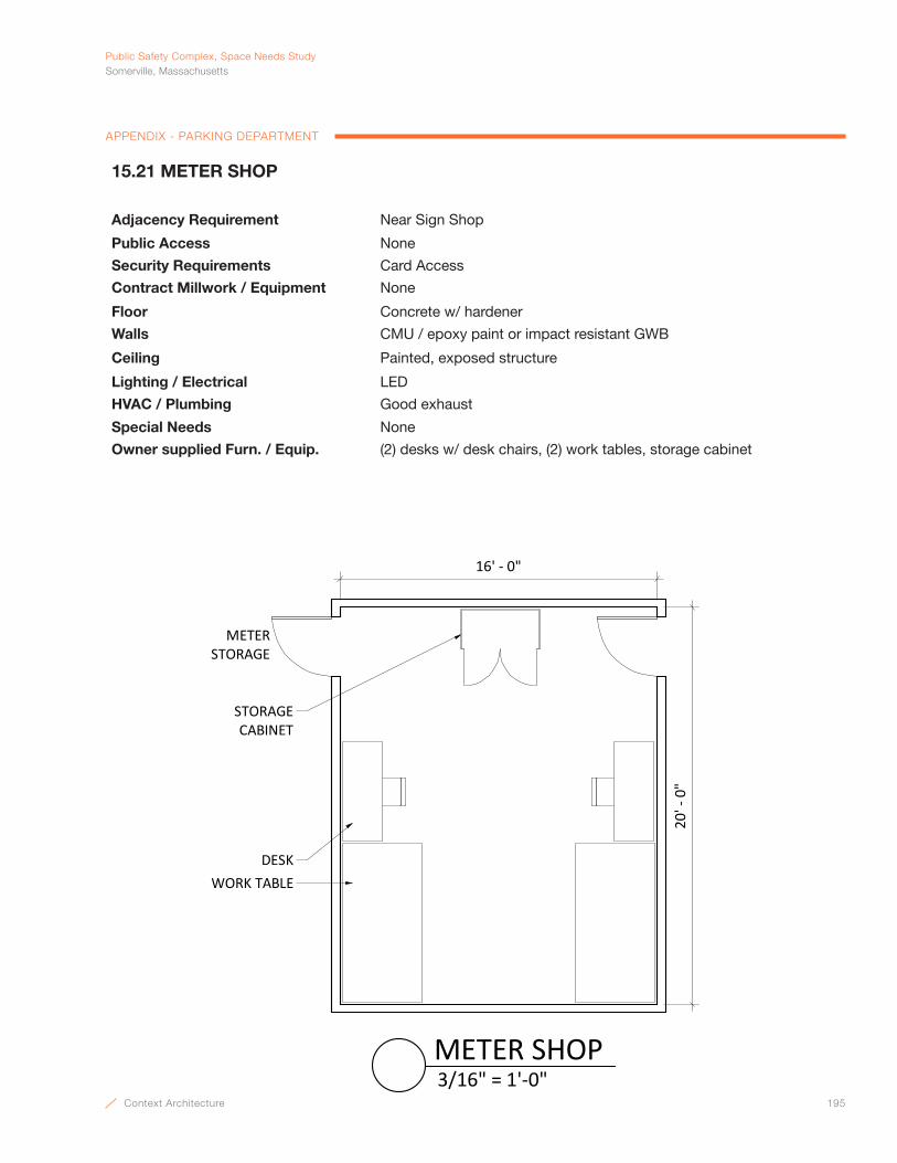
Context Architecture 195
PublicSafetyComplex,SpaceNeedsStudySomerville,Massachusetts
APPENDIX - PARKING DEPARTMENT
16' - 0"
20' -
0"
DESKWORK TABLE
STORAGE CABINET
METER STORAGE
3/16" = 1'-0"METER SHOP
15.21 METER SHOP
Adjacency Requirement Near Sign Shop
Public Access None
Security Requirements Card Access
Contract Millwork / Equipment None
Floor Concrete w/ hardener
Walls CMU / epoxy paint or impact resistant GWB
Ceiling Painted, exposed structure
Lighting / Electrical LED
HVAC / Plumbing Good exhaust
Special Needs None
Owner supplied Furn. / Equip. (2) desks w/ desk chairs, (2) work tables, storage cabinet

196 Context Architecture
Public Safety Complex, Space Needs StudySomerville, Massachusetts
APPENDIX - PARKING DEPARTMENT
30" SHELVING
30' - 0"
20' -
0"
STORAGE CABINET
DOOR TO LOADING
MATERIAL HANDLING ROLLER SYSTEM
3/16" = 1'-0"METER STORAGE
15.22 METER STORAGE
Adjacency Requirement Adjacent to garage or exterior for easy loading, near Meter Shop
Public Access None
Security Requirements Card Access
Contract Millwork / Equipment None
Floor Concrete w/ hardener
Walls CMU / epoxy paint or impact resistant GWB
Ceiling Painted, exposed structure
Lighting / Electrical LED
HVAC / Plumbing None
Special Needs None
Owner supplied Furn. / Equip. 30” metal shelving, material handling roller system, storage cabinet
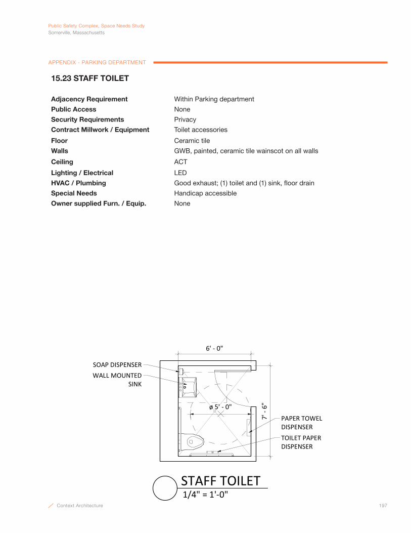
Context Architecture 197
PublicSafetyComplex,SpaceNeedsStudySomerville,Massachusetts
APPENDIX - PARKING DEPARTMENT
SOAP DISPENSER
6' - 0"
7' -
6"
WALL MOUNTED SINK
ø 5' - 0"
PAPER TOWEL DISPENSERTOILET PAPER DISPENSER
1/4" = 1'-0"STAFF TOILET
15.23 STAFF TOILET
Adjacency Requirement Within Parking department
Public Access None
Security Requirements Privacy
Contract Millwork / Equipment Toilet accessories
Floor Ceramic tile
Walls GWB, painted, ceramic tile wainscot on all walls
Ceiling ACT
Lighting / Electrical LED
HVAC / Plumbing Good exhaust; (1) toilet and (1) sink, floor drain
Special Needs Handicap accessible
Owner supplied Furn. / Equip. None

198 Context Architecture
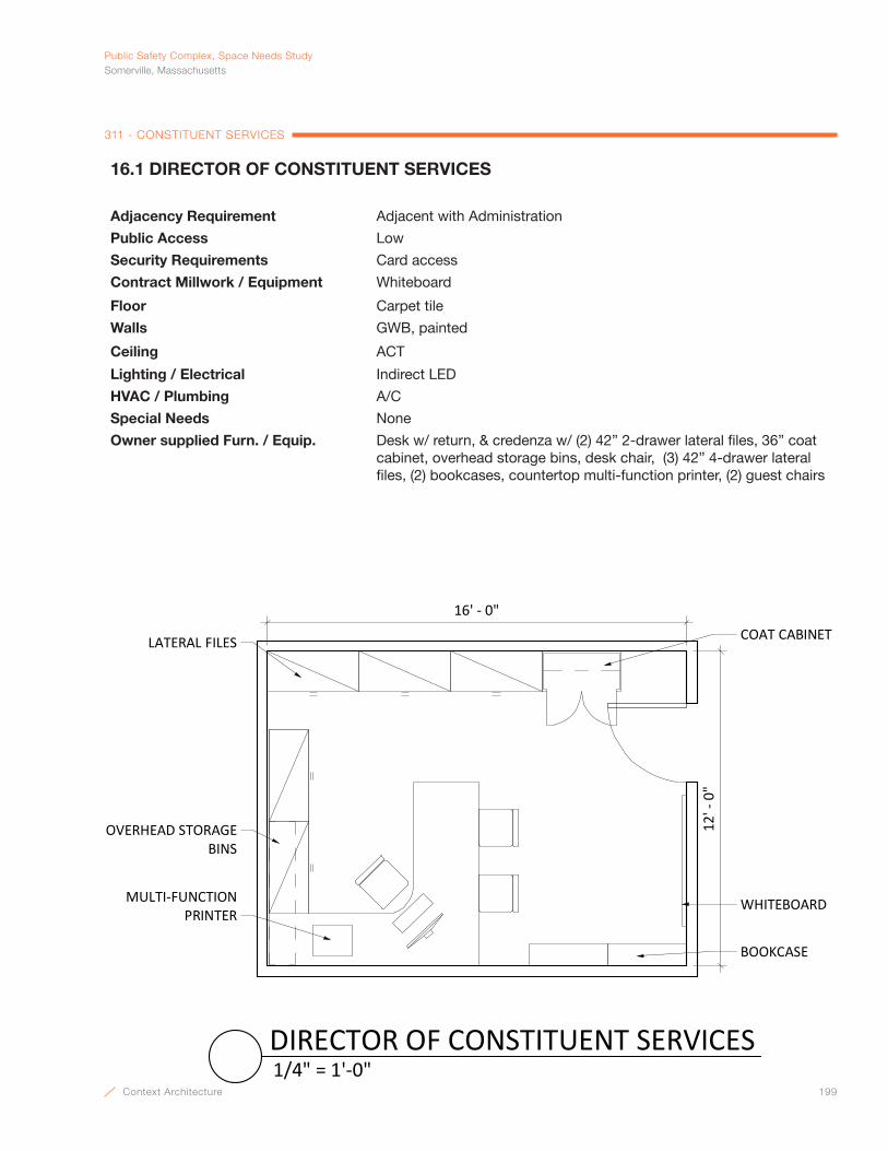
Context Architecture 199
PublicSafetyComplex,SpaceNeedsStudySomerville,Massachusetts
311 - CONSTITUENT SERVICES
16.1 DIRECTOR OF CONSTITUENT SERVICES
Adjacency Requirement Adjacent with Administration
Public Access Low
Security Requirements Card access
Contract Millwork / Equipment Whiteboard
Floor Carpet tile
Walls GWB, painted
Ceiling ACT
Lighting / Electrical Indirect LED
HVAC / Plumbing A/C
Special Needs None
Owner supplied Furn. / Equip. Desk w/ return, & credenza w/ (2) 42” 2-drawer lateral files, 36” coat cabinet, overhead storage bins, desk chair, (3) 42” 4-drawer lateral files, (2) bookcases, countertop multi-function printer, (2) guest chairs
COAT CABINET
WHITEBOARD
LATERAL FILES
OVERHEAD STORAGEBINS
MULTI-FUNCTIONPRINTER
BOOKCASE
12' -
0"
16' - 0"
1/4" = 1'-0"DIRECTOR OF CONSTITUENT SERVICES
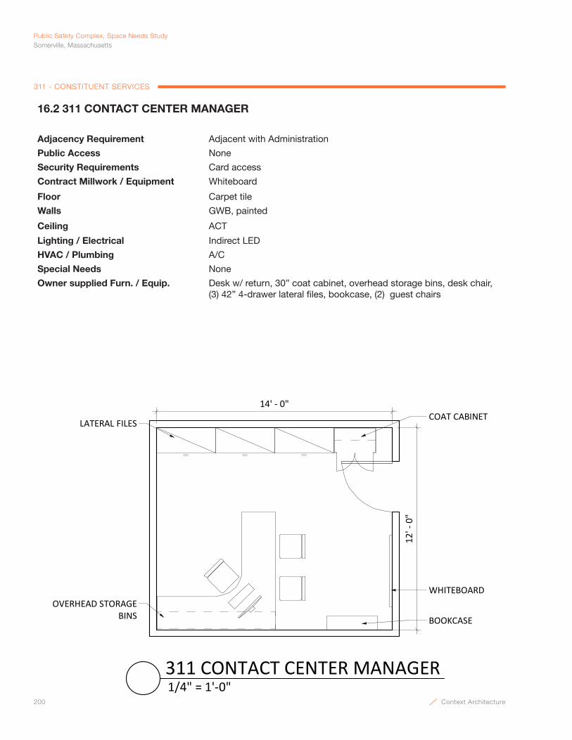
200 Context Architecture
Public Safety Complex, Space Needs StudySomerville, Massachusetts
311 - CONSTITUENT SERVICES
COAT CABINET
WHITEBOARD
LATERAL FILES
OVERHEAD STORAGEBINS BOOKCASE
14' - 0"12
' - 0
"
1/4" = 1'-0"311 CONTACT CENTER MANAGER
16.2 311 CONTACT CENTER MANAGER
Adjacency Requirement Adjacent with Administration
Public Access None
Security Requirements Card access
Contract Millwork / Equipment Whiteboard
Floor Carpet tile
Walls GWB, painted
Ceiling ACT
Lighting / Electrical Indirect LED
HVAC / Plumbing A/C
Special Needs None
Owner supplied Furn. / Equip. Desk w/ return, 30” coat cabinet, overhead storage bins, desk chair, (3) 42” 4-drawer lateral files, bookcase, (2) guest chairs

Context Architecture 201
PublicSafetyComplex,SpaceNeedsStudySomerville,Massachusetts
311 - CONSTITUENT SERVICES
16.3 CUSTOMER EXPERIENCE MANAGER
Adjacency Requirement Adjacent with Administration
Public Access Moderate
Security Requirements Card access
Contract Millwork / Equipment Whiteboard
Floor Carpet tile
Walls GWB, painted
Ceiling ACT
Lighting / Electrical Indirect LED
HVAC / Plumbing A/C
Special Needs None
Owner supplied Furn. / Equip. Desk w/ return, 30” coat cabinet, overhead storage bins, desk chair, (3) 42” 4-drawer lateral files, bookcase, (2) guest chairs
COAT CABINET
WHITEBOARD
LATERAL FILES
OVERHEAD STORAGEBINS BOOKCASE
14' - 0"
12' -
0"
1/4" = 1'-0"CUSTOMER EXPERIENCE MANAGER
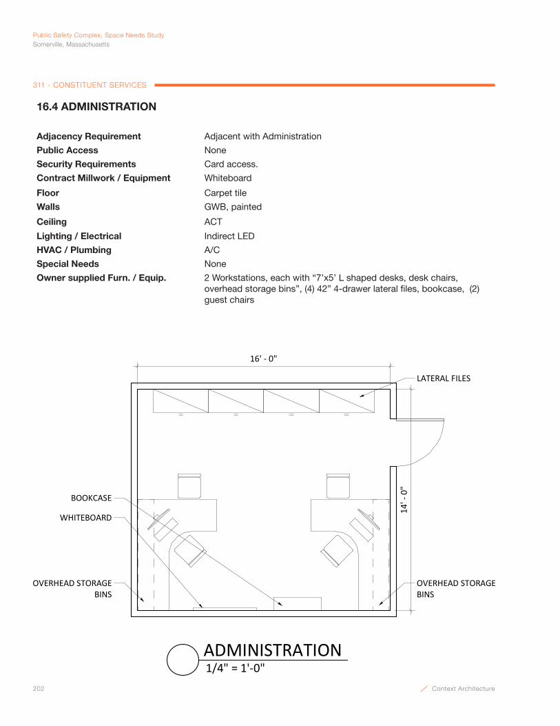
202 Context Architecture
Public Safety Complex, Space Needs StudySomerville, Massachusetts
311 - CONSTITUENT SERVICES
16.4 ADMINISTRATION
Adjacency Requirement Adjacent with Administration
Public Access None
Security Requirements Card access.
Contract Millwork / Equipment Whiteboard
Floor Carpet tile
Walls GWB, painted
Ceiling ACT
Lighting / Electrical Indirect LED
HVAC / Plumbing A/C
Special Needs None
Owner supplied Furn. / Equip. 2 Workstations, each with “7’x5’ L shaped desks, desk chairs, overhead storage bins”, (4) 42” 4-drawer lateral files, bookcase, (2) guest chairs
LATERAL FILES
BOOKCASE
OVERHEAD STORAGEBINS
WHITEBOARD
OVERHEAD STORAGEBINS
16' - 0"
14' -
0"
1/4" = 1'-0"ADMINISTRATION
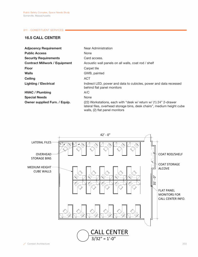
Context Architecture 203
PublicSafetyComplex,SpaceNeedsStudySomerville,Massachusetts
311 - CONSTITUENT SERVICES
16.5 CALL CENTER
Adjacency Requirement Near Administration
Public Access None
Security Requirements Card access.
Contract Millwork / Equipment Acoustic wall panels on all walls, coat rod / shelf
Floor Carpet tile
Walls GWB, painted
Ceiling ACT
Lighting / Electrical Indirect LED, power and data to cubicles, power and data recessed behind flat panel monitors
HVAC / Plumbing A/C
Special Needs None
Owner supplied Furn. / Equip. (22) Workstations, each with “desk w/ return w/ (1) 24” 2-drawer lateral files, overhead storage bins, desk chairs”, medium height cube walls, (2) flat panel monitors
42' - 0"
35' -
0"
LATERAL FILES
OVERHEAD STORAGE BINS
MEDIUM HEIGHTCUBE WALLS
COAT ROD/SHELF
COAT STORAGE ALCOVE
FLAT PANEL MONITORS FOR CALL CENTER INFO.
3/32" = 1'-0"CALL CENTER
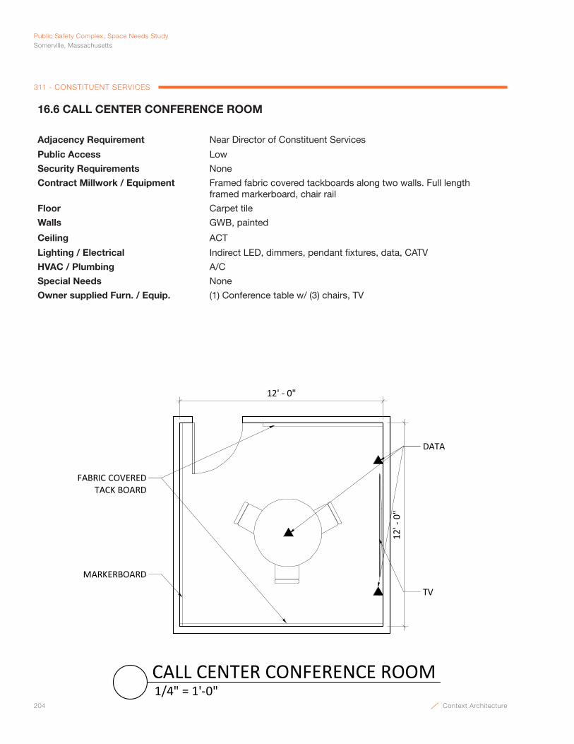
204 Context Architecture
Public Safety Complex, Space Needs StudySomerville, Massachusetts
311 - CONSTITUENT SERVICES
16.6 CALL CENTER CONFERENCE ROOM
Adjacency Requirement Near Director of Constituent Services
Public Access Low
Security Requirements None
Contract Millwork / Equipment Framed fabric covered tackboards along two walls. Full length framed markerboard, chair rail
Floor Carpet tile
Walls GWB, painted
Ceiling ACT
Lighting / Electrical Indirect LED, dimmers, pendant fixtures, data, CATV
HVAC / Plumbing A/C
Special Needs None
Owner supplied Furn. / Equip. (1) Conference table w/ (3) chairs, TV
12' -
0"
12' - 0"
FABRIC COVEREDTACK BOARD
MARKERBOARD
TV
DATA
1/4" = 1'-0"CALL CENTER CONFERENCE ROOM
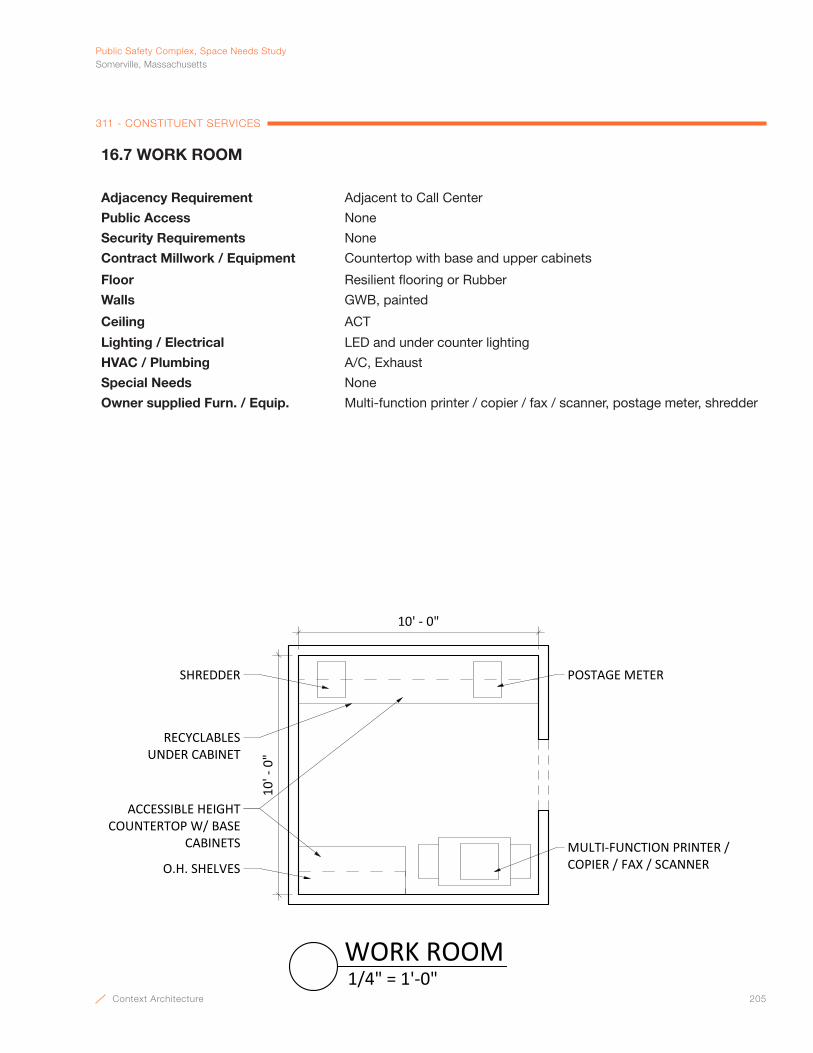
Context Architecture 205
PublicSafetyComplex,SpaceNeedsStudySomerville,Massachusetts
311 - CONSTITUENT SERVICES
16.7 WORK ROOM
Adjacency Requirement Adjacent to Call Center
Public Access None
Security Requirements None
Contract Millwork / Equipment Countertop with base and upper cabinets
Floor Resilient flooring or Rubber
Walls GWB, painted
Ceiling ACT
Lighting / Electrical LED and under counter lighting
HVAC / Plumbing A/C, Exhaust
Special Needs None
Owner supplied Furn. / Equip. Multi-function printer / copier / fax / scanner, postage meter, shredder
10' ‐ 0"
10' ‐ 0"
MULTI‐FUNCTION PRINTER / COPIER / FAX / SCANNERO.H. SHELVES
ACCESSIBLE HEIGHT COUNTERTOP W/ BASE
CABINETS
RECYCLABLES UNDER CABINET
SHREDDER POSTAGE METER
1/4" = 1'‐0"WORK ROOM
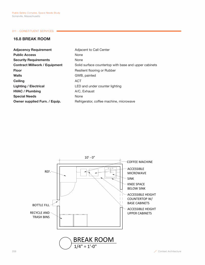
206 Context Architecture
Public Safety Complex, Space Needs StudySomerville, Massachusetts
311 - CONSTITUENT SERVICES
16.8 BREAK ROOM
Adjacency Requirement Adjacent to Call Center
Public Access None
Security Requirements None
Contract Millwork / Equipment Solid surface countertop with base and upper cabinets
Floor Resilient flooring or Rubber
Walls GWB, painted
Ceiling ACT
Lighting / Electrical LED and under counter lighting
HVAC / Plumbing A/C, Exhaust
Special Needs None
Owner supplied Furn. / Equip. Refrigerator, coffee machine, microwave
COFFEE MACHINE
REF.
SINK
10' ‐ 0"
KNEE SPACE BELOW SINK
ACCESSIBLE HEIGHT UPPER CABINETS
ACCESSIBLE HEIGHT COUNTERTOP W/BASE CABINETS
ACCESSIBLE MICROWAVE
BOTTLE FILL
RECYCLE AND TRASH BINS
1/4" = 1'‐0"BREAK ROOM
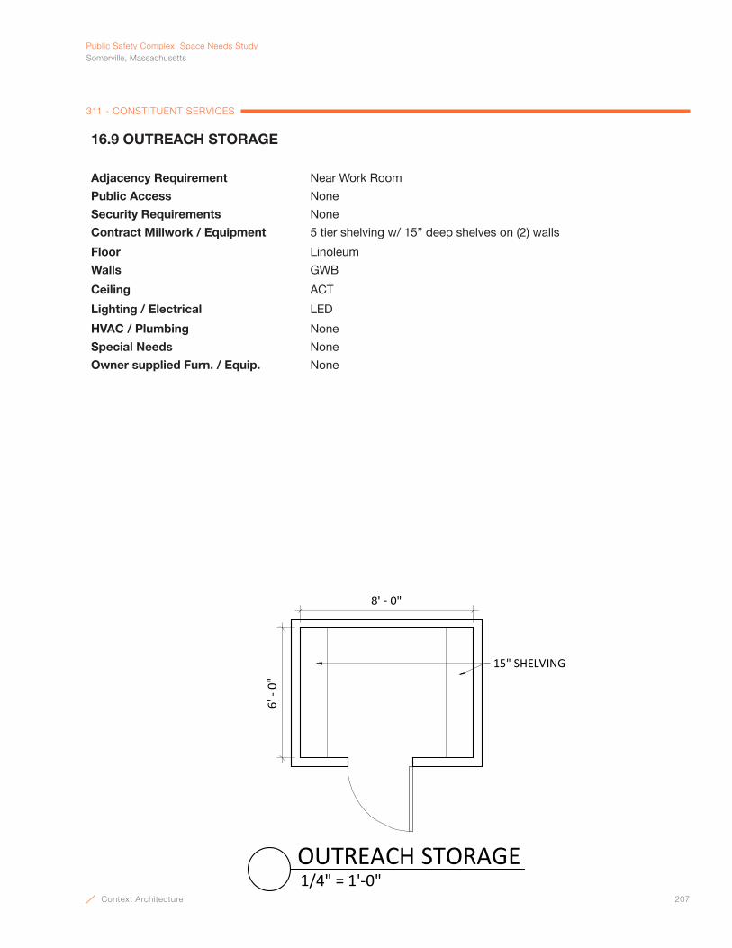
Context Architecture 207
PublicSafetyComplex,SpaceNeedsStudySomerville,Massachusetts
311 - CONSTITUENT SERVICES
8' - 0"
6' -
0"
15" SHELVING
1/4" = 1'-0"OUTREACH STORAGE
16.9 OUTREACH STORAGE
Adjacency Requirement Near Work Room
Public Access None
Security Requirements None
Contract Millwork / Equipment 5 tier shelving w/ 15” deep shelves on (2) walls
Floor Linoleum
Walls GWB
Ceiling ACT
Lighting / Electrical LED
HVAC / Plumbing None
Special Needs None
Owner supplied Furn. / Equip. None

208 Context Architecture
Public Safety Complex, Space Needs StudySomerville, Massachusetts
311 - CONSTITUENT SERVICES
6' - 0"
3' -
0"
24" SHELVES
POWER STRIPS FORCHARGING ELECTRONICS
1/4" = 1'-0"COMPUTER EQUIPMENT STORAGE
16.10 COMPUTER EQUIPMENT STORAGE
Adjacency Requirement Near Work Room
Public Access None
Security Requirements Card access
Contract Millwork / Equipment 5 tier shelving w/ 2’ deep shelves
Floor Linoleum
Walls GWB
Ceiling ACT
Lighting / Electrical LED, power strips for charging electronics and laptop batteries
HVAC / Plumbing AC for equipment
Special Needs None
Owner supplied Furn. / Equip. None

Context Architecture 209
PublicSafetyComplex,SpaceNeedsStudySomerville,Massachusetts
END OF DOCUMENT
SOMERVILLE PUBLIC SAFETY BUILDING Somerville, Massachusetts 02143
Project No. 2006.00
NARRATIVE 8/13/2021
E. HAZMAT REPORT
April 27, 2021
Ms. Angela CampbellProject ManagerContext Architecture68 Harrison AvenueBoston, MA 02111
Reference: Hazardous Materials Consulting ServicesCity of Somerville – 90 Washington Street
Dear Ms. Campbell:
Thank you for the opportunity for Universal Environmental Consultants (UEC) to provide professional services.
UEC was contracted by Context Architecture to retain the services of a demolition contractor (Contractor) to excavate around the foundations walls to expose any suspect Asbestos Containing Materials (ACM) that might be found below grade. The scope also included for the Contractor to perform selective destructive demolition of the building slab to expose any suspect ACM that might be found.
Excavation at couple locations around the foundation walls and destructive testing of the slab were performed and no suspect ACM was found.
Please do not hesitate to call me at (508) 628-5486 if you have questions about our services.
Very truly yours,
Universal Environmental Consultants
_____________________________Ammar M. DiebPresident
UEC:\221 190.00\Letter.DOC

SOMERVILLE PUBLIC SAFETY BUILDING Somerville, Massachusetts 02143 Project No. 2006.00
SYNTHETIC ATHLETIC FLOORING CONFORMED PERMIT SET 09 65 66 - 2 3/25/2019
The Somerville Public Safety Building is proposed for the 90 Washington Street parcel at the former location of a retail mall. The site is being divided into three parcels A, B and C with a planned realignment of New Washington Street which will bisect the property into Parcel A, B and Parcel C. Parcels A and C will be developed as separate projects. Parcel B will become the site for the new Public Safety Building.
The new Somerville Public Safety Building will be designed to accommodate Engine 3 Fire Apparatus, Fire Administration Offices, Police Administration Offices and Police Patrol and will include a Community Room among other City offices. The building is a 4-story, Category IV commercial building, approximately 74,000 SF. The proposed building will also include a 3-story, attached open-air parking garage, approximately 57,000 SF which will house police vehicles.
Soil remediation will occur as part of an earlier phase of the project and preliminary preparations for utility trenching and roadway preparation will also occur as part of the Early Site package.
The tail end parcel of Parcel B will be designed to include a below-grade geothermal well field and a public park at grade.

SOMERVILLE PUBLIC SAFETY BUILDING Somerville, Massachusetts 02143
Project No. 2006.00
NARRATIVE 8/13/2021
F LIST OF DRAWINGS
CIVIL:
V101 EXISTING CONDITIONS PLAN
V102 EXISTING CONDITIONS PLAN
C101 SITE PLAN
C102 SITE PLAN
C103 UTILITY PLAN
C104 UTILITY PLAN
LANDSCAPE:
L1.0 LANDSCAPE PLAN
ARCHITECTURAL:
A1.1 ABBREVIATIONS LEGENDS SYMBOLS
A1.2 WALL TYP LEGEND
A1.3 BUILDING CODE ANALYSIS
A2.0 SITE PLAN
AS.2 FIRST FLOOR PLAN
A2.2 MEZZANINE FLOOR PLAN
A2.3 SECOND FLOOR PLAN
A2.4 THIRD FLOOR PLAN
A2.5 FOURTH FLOOR PLAN
A2.6 ROOF PLAN
A2.7 FIRST FLOOR PLAN-GARAGE
A2.8 SECOND FLOOR PLAN-GARAGE
A2.9 ROOF PLAN-GARAGE
A2.10 ROOF PLAN-GARAGE PV PANEL
A3.1 BUILDING ELEVATIONS
A3.2 BUILDING ELEVATIONS
A3.3 BUILDING PERSPECTIVES

SOMERVILLE PUBLIC SAFETY BUILDING Somerville, Massachusetts 02143 Project No. 2006.00
SYNTHETIC ATHLETIC FLOORING CONFORMED PERMIT SET 09 65 66 - 2 3/25/2019
A4.1 BUILDING SECTIONS
A4.2 BUILDING SECTIONS
A4.3 WALL SECTIONS
A8.1 FIRST FLOOR RCP
A8.2 MEZZANINE RCP
A8.3 SECOND FLOOR RCP
A8.4 THIRD FLOOR RCP
A8.5 FOURTH FLOOR RCP
A9.2 ENLARGED PLAN-DETENTION
A10.1 MILLWORK
A10.2 MILLWORK
Copyright © 2022 FDOKUMEN