Solutions for Power switching, monitoring and conversion
300
GENERAL CATALOG Solutions for Power switching, monitoring and conversion UL/CSA Ed.2 When energy matters
-
Upload
khangminh22 -
Category
Documents
-
view
2 -
download
0
Transcript of Solutions for Power switching, monitoring and conversion
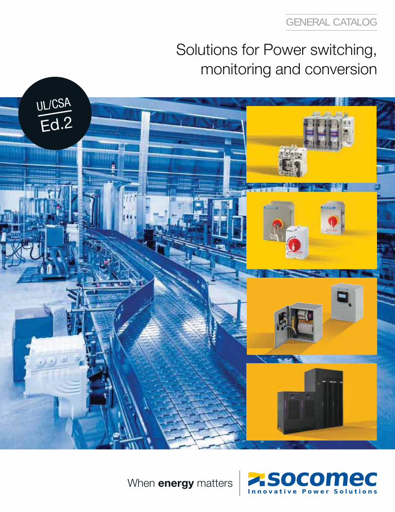
GENERAL CATALOG
Solutions for Power switching,monitoring and conversion
UL/CSA
Ed.2
When energy matters
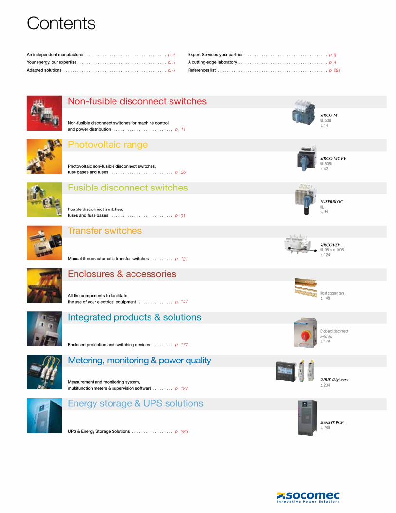
Contents
An independent manufacturer . . . . . . . . . . . . . . . . . . . . . . . . . . . . . . . . . . . p.
Your energy, our expertise . . . . . . . . . . . . . . . . . . . . . . . . . . . . . . . . . . . . . . p.
Adapted solutions . . . . . . . . . . . . . . . . . . . . . . . . . . . . . . . . . . . . . . . . . . . . . p.
Expert Services your partner . . . . . . . . . . . . . . . . . . . . . . . . . . . . . . . . . . . . p.
A cutting-edge laboratory . . . . . . . . . . . . . . . . . . . . . . . . . . . . . . . . . . . . . . . p.
References list . . . . . . . . . . . . . . . . . . . . . . . . . . . . . . . . . . . . . . . . . . . . . . . . p.
Non-fusible disconnect switches
Non-fusible disconnect switches for machine control
and power distribution . . . . . . . . . . . . . . . . . . . . . . . . . . p.
Enclosures & accessories
All the components to facilitate
the use of your electrical equipment . . . . . . . . . . . . . . . p.
Transfer switches
Manual & non-automatic transfer switches . . . . . . . . . . p.
Fusible disconnect switches
Fusible disconnect switches,
fuses and fuse bases . . . . . . . . . . . . . . . . . . . . . . . . . . . p.
Photovoltaic range
Photovoltaic non-fusible disconnect switches,
fuse bases and fuses . . . . . . . . . . . . . . . . . . . . . . . . . . . p.
Energy storage & UPS solutions
UPS & Energy Storage Solutions . . . . . . . . . . . . . . . . . . p.
Metering, monitoring & power quality
Measurement and monitoring system,
multifunction meters & supervision software . . . . . . . . . p.
Integrated products & solutions
Enclosed protection and switching devices . . . . . . . . . p.
SIRCO M UL 508
SIRCO MC PV UL 508i
FUSERBLOC UL
SIRCOVER UL 8 008
SUNSYS PCS2
DIRIS Digiware
Enclosed disconnect switches
Rigid copper bars
2 General Catalog UL/CSA Ed. 2
4
5
6
8
9
294
p. 14
p. 204
p. 286
p. 42
p. 94
p. 148
p. 178
p. 124
36
11
91
121
147
177
187
285
SIRCO UL 98
SIRCO PV UL 98B compact
RM CC
TVSS Surge switch
Flexible copper bars
SIRCO M UL 98
RM-RMS
ATyS UL 1008
Insulated copper braids
SIRCO PV UL 98B
SUNSYS Xtend ESS NETYS PL-120V
NETYS RT-120V
TE / TR/ iTR / TF current sensors
DIRIS GRS485 to EthernetDIRIS A
DIRIS DigiBOX
Busbar supports
DIRIS B
3General Catalog UL/CSA Ed. 2
p. 22
p. 246
p. 288 p. 290 p. 292
p. 50
p. 108
p. 150
p. 136
p. 28
p. 220
p. 76
p. 114
p. 152 p. 154
p. 36
p. 242 p. 248 p. 272

4 General Catalog UL/CSA Ed. 2
For the energy performance of your critical installationsThe benefit of a specialist
SY
DIV
419 A
innovative!
of test platforms
37,675 ft2
One of the leading
independent power
testing labs in Europe
70,000on-site interventions per year
Nearly 400 experts
in commissioning,
technical audit,
consultancy and
maintenance
of turnover invested in
10 %
Always at the
cutting-edge of
technology for
innovative, high-
quality products
independent manufacturer
1
Since its foundation more than 9 years ago, SOCOMEC continues to design and manufacture its core products in Europe. Notably solutions for its primary mission: the availability, control and safety of low voltage electrical networks.
As an independent manufacturer, the Group is committed to constant innovation to
customer requirements and fully in keeping with international standards.
“Optimizing the performance of your system throughout its life cycle” - this is the commitment carried out every day by the SOCOMEC teams around the world, wherever your business is located.
improve the energy performance of electrical installations in infrastructures as well as industrial and commercial sites.
Throughout its history, SOCOMEC has constantly anticipated market changes by developing cutting-edge technologies, providing solutions that are adapted to

5General Catalog UL/CSA Ed. 2
Your energy, our expertise
With its wide range of continuously evolving products, solutions and services, Socomec are recognized experts in the cutting-edge technologies used for ensuring the highest availability of the electrical power supply to critical facilities and buildings, including:
static uninterruptible power supplies (UPS) for high-quality power free of distortions
and interruptions occurring on the primary power supply,
changeover of static, high availability sources for transferring the supply to an operational back-up source,
permanent monitoring of the electrical facilities to prevent failures and reduce operating losses,
energy storage for ensuring the proper energy mix of buildings and for stabilization of the power grid.
Power conversionEnsuring the availability and storage of high quality power
Active in the industrial switching market since its foundation in 1922, Socomec is today an undisputed leader in the field of low voltage switchgear, providing expert solutions that ensure:
isolation and on load breaking for the most demanding switching applications,
continuity of the power supply to electrical facilities via manual remotely operated or automatic transfer switching equipment.
protection of persons and assets via fuse-based and other specialist solutions.
Power switchingManaging power and protecting persons and facilities
Socomec is committed to delivering a wide range of value-added services to ensure the reliability and optimization of end-users’ equipment:
prevention and service operations to lower the risks and enhance the efficiency of operations,
measurement and analysis of a wide range of electrical parameters leading to
recommendations for improving the site’s power quality,
optimization of the total cost of ownership and support for a safe transition when migrating from an old to a new generation of equipment,
consultancy, deployment and training from the project engineering stage through to final procurement,
performance assessment of the electrical installation throughout the life cycle of the products via analysis of data transmitted by connected devices.
Expert Services
energy
© D
atad
ock
AP
PLI
57
5A
AP
PLI
76
0A
Socomec solutions, from current sensors through to a wide choice of innovative scalable software packages are driven by experts in energy performance. They meet the critical requirements of facility managers and operators of commercial, industrial and local authority buildings for:
measuring energy consumption, identifying sources of excess consumption and raising the awareness of occupants about their impact,
limiting reactive energy and avoiding the associated tariff penalties,
using the best available tariffs, checking utility bills and accurately distributing energy billing among consumer entities,
monitoring and detecting insulation faults.
Power monitoringManaging the energy performance of buildings
AP
PLI
57
1A

Adapted solutionsto meet your energy objectives
Energy conversion in environments with harsh restrictions
NAVAL SHIPS
SIRCOVER Manually operated transfer switch
Reducing your energy bills and energy dependency
SMART BUILDINGS
ENERGY MANAGEMENT software packages
DIRIS Digiware multi-circuit measurement system
SUNSYS XTEND ESSATyS non-automatic transfer switch
Disconnect switches for photovoltaic applications
Guaranteeing the performance, security and durability of your photovoltaic facilities
RENEWABLE ENERGY
Helping you to meet the challenge of energy demand and response
PUBLIC DISTRIBUTION AND SMART GRID
SIRCO Disconnect switches
Assuring your business continuity and visitor safety
SHOPPING MALLS
NETYS PL-120 & NETYS RT-120 Single PhaseUPS
DIRIS DigiBOXenclosed single & multi-point metering solution
SUNSYS XTEND ESS
SUNSYS XTEND ESS
SUNSYS XTEND ESS
Controlling and securing your ene
FUSERBLOC fuse combination switches
HEAVY
SIRCO Disconnect switches
SIRCOVER Manually operated transfer switch
DIRIS DigiBOXenclosed single & multi-point metering solution
DIRIS DigiwareDC multi-circuit measurement system
6 General Catalog UL/CSA Ed. 2
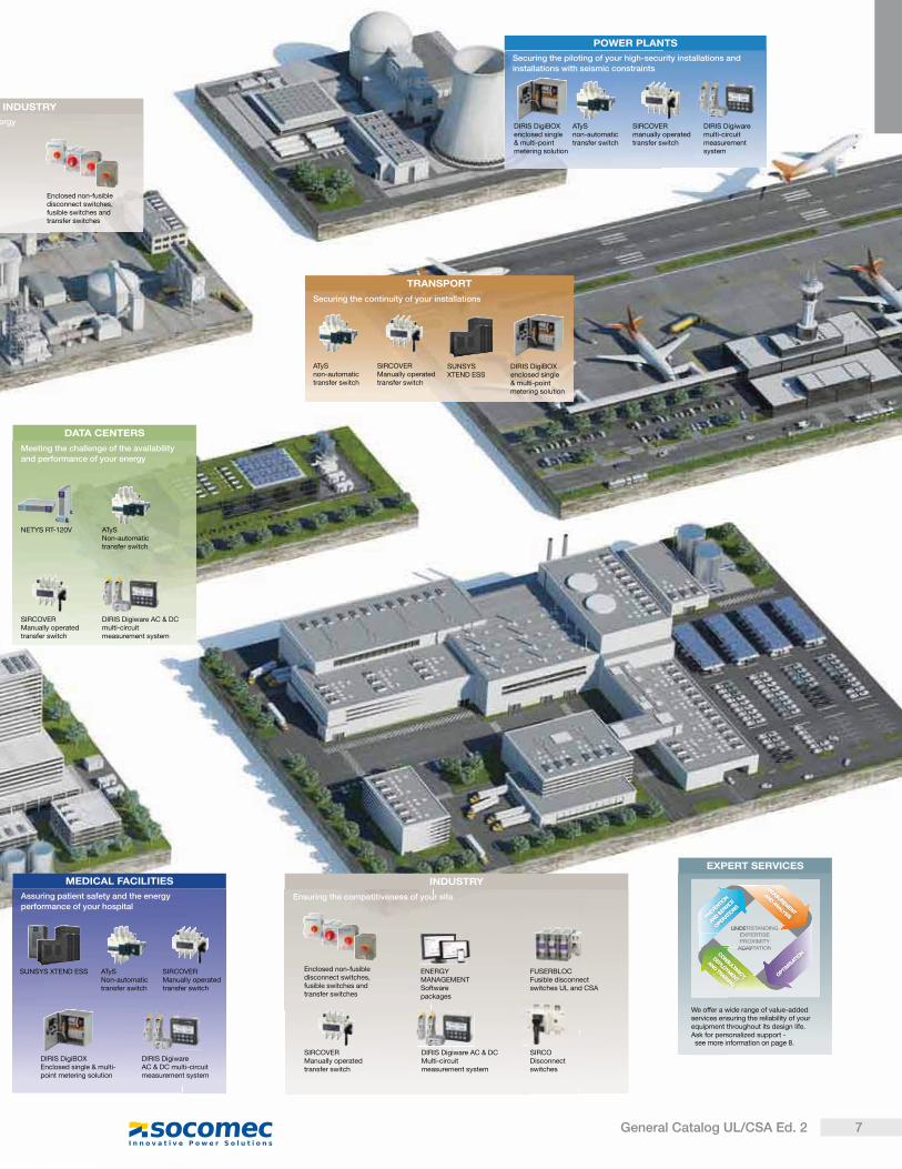
NETYS RT-120V
Meeting the challenge of the availability and performance of your energy
DATA CENTERS
SIRCOVER Manually operated transfer switch
SIRCOVER Manually operated transfer switch
ATyS non-automatic transfer switch
ATyS Non-automatic transfer switch
Securing the continuity of your installations
TRANSPORT
FUSERBLOCFusible disconnect switches UL and CSA
Ensuring the competitiveness of your site
INDUSTRY
ENERGY MANAGEMENT Software packages
ergy
Assuring patient safety and the energy performance of your hospital
MEDICAL FACILITIES
DIRIS Digiware AC & DC multi-circuit measurement system
DIRIS Digiware AC & DC multi-circuit measurement system
INDUSTRY
DIRIS Digiware AC & DC Multi-circuit measurement system
SIRCO Disconnect switches
Securing the piloting of your high-security installations and installations with seismic constraints
POWER PLANTS
DIRIS Digiwaremulti-circuit measurement system
EXPERT SERVICES
We offer a wide range of value-added services ensuring the reliability of your equipment throughout its design life.Ask for personalized support -
UNDERSTANDINGEXPERTISEPROXIMITY
ADAPTATION
OPTIM
ISATIO
N
OPTIM
ISATIO
N
MEASUREM
ENT
AND ANALYSIS
MEASUREM
ENT
AND ANALYSIS
CONSULTANCY,
DEPLOYM
ENT
AND TRAINING
CONSULTANCY,
DEPLOYM
ENT
AND TRAINING
PREVENTION
AND SERVIC
E
OPERAT
IONS
PREVENTION
AND SERVIC
E
OPERAT
IONS
Enclosed non-fusible disconnect switches, fusible switches and transfer switches
SUNSYS XTEND ESS
DIRIS DigiBOXenclosed single & multi-point metering solution
DIRIS DigiBOXenclosed single & multi-point metering solution
SIRCOVER manually operated transfer switch
ATyS non-automatic transfer switch
SUNSYS XTEND ESS SIRCOVER Manually operated transfer switch
ATyS Non-automatic transfer switch
DIRIS DigiBOXEnclosed single & multi-point metering solution
Enclosed non-fusible disconnect switches, fusible switches and transfer switches
SIRCOVER Manually operated transfer switch
7General Catalog UL/CSA Ed. 2
see more information on page 8.

8 General Catalog UL/CSA Ed. 2
Expert Services your partnerenabling available, safe and efficient energy
SOCOMEC is committed to
deliver a wide range of value-
added services to ensure
the availability of your critical
installation, the safety of your site
operations and the performance
optimization of your low voltage
equipment during its life cycle.
The expertise and proximity of our
specialists are there to ensure
the reliability and durability of your
equipment.
AP
PLI 724 A
Our global presence includes:
10 branches in France,
12 European subsidiaries,
8 Asian subsidiaries,
representatives in 70+ countries.
Distributors
Subsidiaries
Contact us
On-site service management 65,000 service operations per year (mainly preventive visits).
98% Service Level Agreement compliance rate.
Technical hotline network 20+ languages spoken.
3 advanced technical support centres.
100,000+ incoming calls handled per year.
Certified expertise 5,000 hours of technical training deployed per year (product, methodology and safety).
Key figuresMore than 400 Socomec experts supported by 200 engineers and technicians from our distributors, drive the solutions to your specific needs.
CA
RTE
063 H
CO
RP
O 2
69 A
SIT
E 5
88 A
AP
PLI 571 A
9 General Catalog UL/CSA Ed. 2
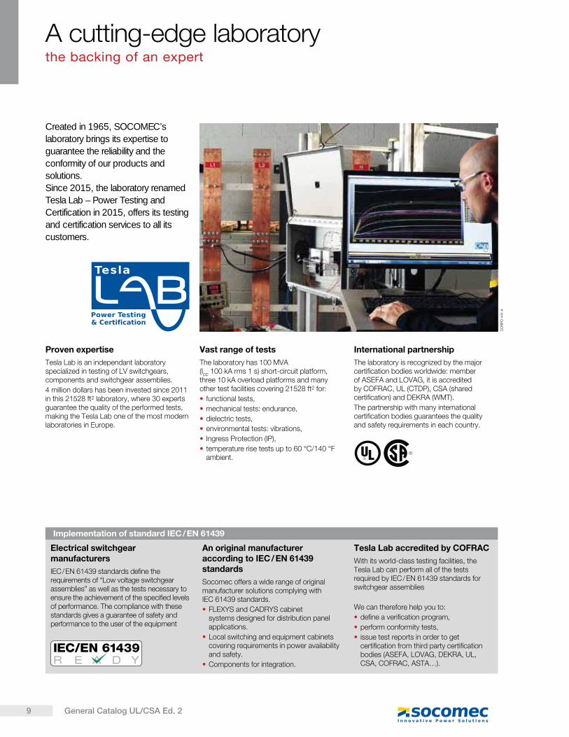
Created in 1965, SOCOMEC’s
laboratory brings its expertise to
guarantee the reliability and the
conformity of our products and
solutions.
Since 2015, the laboratory renamed
Tesla Lab – Power Testing and
Certification in 2015, offers its testing
and certification services to all its
customers.
A cutting-edge laboratorythe backing of an expert
Proven expertise
Tesla Lab is an independant laboratory specialized in testing of LV switchgears, components and switchgear assemblies.
4 million dollars has been invested since 2011 in this 21528 ft2 laboratory, where 30 experts guarantee the quality of the performed tests, making the Tesla Lab one of the most modern laboratories in Europe.
Vast range of tests
The laboratory has 100 MVA (Icc 100 kA rms 1 s) short-circuit platform, three 10 kA overload platforms and many other test facilities covering 21528 ft2 for:
functional tests,
mechanical tests: endurance,
dielectric tests,
environmental tests: vibrations,
Ingress Protection (IP),
temperature rise tests up to 60 °C/140 °F ambient.
International partnership
The laboratory is recognized by the major certification bodies worldwide: member of ASEFA and LOVAG, it is accredited by COFRAC, UL (CTDP), CSA (shared certification) and DE RA (WMT).
The partnership with many international certification bodies guarantees the quality and safety requirements in each country.
Electrical switchgear manufacturers
IEC / EN 61439 standards define the requirements of “Low voltage switchgear assemblies” as well as the tests necessary to ensure the achievement of the specified levels of performance. The compliance with these standards gives a guarantee of safety and performance to the user of the equipment
An original manufacturer according to IEC / EN 61439 standards
Socomec offers a wide range of original manufacturer solutions complying with IEC 61439 standards.
FLEXYS and CADRYS cabinet systems designed for distribution panel applications.
Local switching and equipment cabinets covering requirements in power availability and safety.
Components for integration.
Tesla Lab accredited by COFRAC
With its world-class testing facilities, the Tesla Lab can perform all of the tests required by IEC / EN 61439 standards for switchgear assemblies
We can therefore help you to:
define a verification program,
perform conformity tests,
issue test reports in order to get certification from third party certification bodies (ASEFA, LOVAG, DE RA, UL, CSA, COFRAC, ASTA ).
Implementation of standard IEC / EN 61439
CO
RP
O 4
41 A
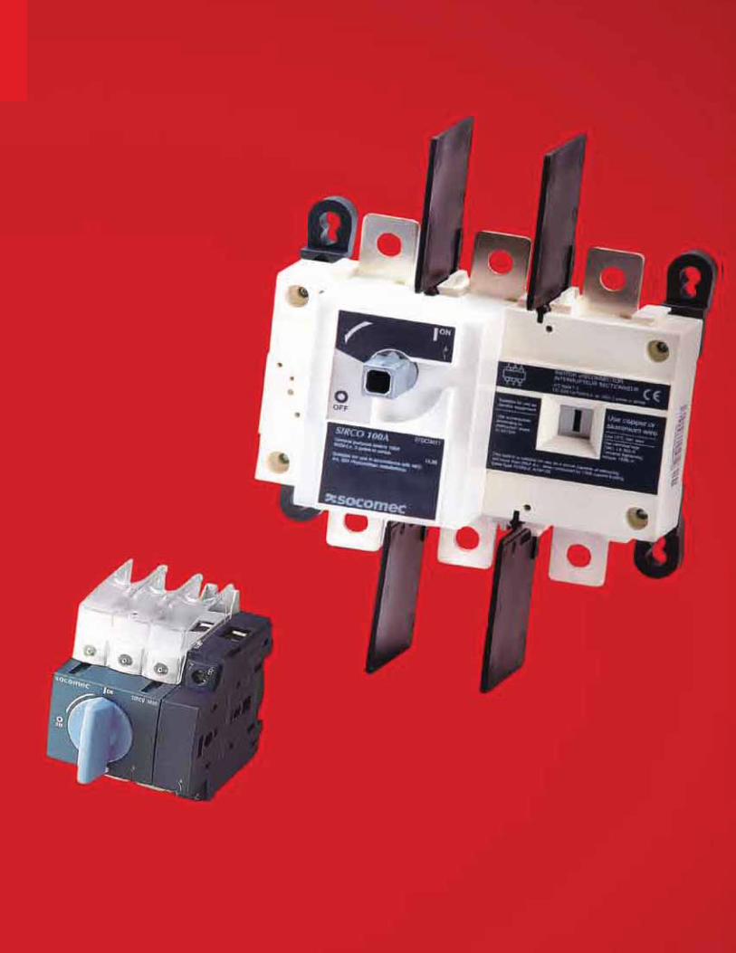
AC non-fusible disconnect switches
Non-fusible disconnect switches
Selection guide . . . . . . . . . . . . . . . . . . . . . . . . . . . . . . . . . . . . . . . . . . . . . . . . . . . . . . . . . . . . . .
TVSS Surge switch Special designs
SIRCO M UL 98 30 to 100 A
SIRCO M UL 508 16 to 100 A
SIRCO UL 98 100 to 1200 A
SOCOMEC offers a range of pre-equipped enclosure in polyester, polycarbonate, stainless steel or painted steel.
Enclosed solution
p. 12
p. 178
p. 14
p. 28
p. 22
p. 36
11General Catalog UL/CSA Ed. 2
These requirements cover enclosed or dead front switches doesn’t need to be capitalized, with or without provision for fuses, at 600 V or less.
These products are used as disconnecting means without restrictions ; they are heavy duty products requiring 2 inches (50 mm) minimum of creepage distance, which gives a maximum safety for users and installation. The short circuit withstand of those products goes up to 200 kA.
This requirements cover Molded-case Circuit Breaker, Molded case switches and fused Molded-case switches, rated at 600 volts or less and 6 000 amperes or less.
UL 98 - Enclosed and dead front switches(equivalent to CSA-C22.2 no 4)
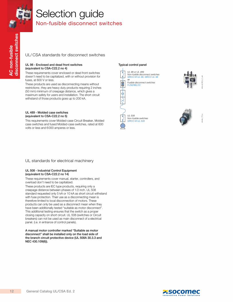
Typical control panel
UL 489 - Molded case switches(equivalent to CSA-C22.2 no 5)
UL 98 or UL 489Non-fusible disconnect switchesSIRCO M UL 98, SIRCO UL 98
Fusible disconnect switchesFUSERBLOC
UL 508Non-fusible switchesSIRCO M UL 508
or
sirc
om
_174_a
sirc
o-u
l_022_b
_1_c
at
UL/ CSA standards for disconnect switches
These requirements cover manual, starter, controllers, and overload don’t need to be capitalized.
These products are IEC type products, requiring only a creepage distance between phases of 1/2 inch. UL 508 standard requested only 5 kA or 10 kA as short circuit withstand with fuse protection. Their use as a disconnecting mean is therefore limited to local disconnection of motors. These products can only be used as a disconnect mean when they have been additionally tested “suitable as motor disconnect”. This additional testing ensures that the switch as a proper closing capacity on short circuit. UL 508 (switches or Circuit breakers) can not be used as main disconnect of a electrical panel. (i.e. in entrance of control panels).
A manual motor controller marked “Suitable as motor disconnect” shall be installed only on the load side of the branch circuit protective device (UL 508A 30.3.3 and NEC 430.109(6)).
UL 508 - Industrial Control Equipment(equivalent to CSA-C22.2 no 14)
UL standards for electrical machinery
Selection guideNon-fusible disconnect switches
AC
no
n-f
usib
le
dis
co
nn
ec
t sw
itc
he
s
12 General Catalog UL/CSA Ed. 2
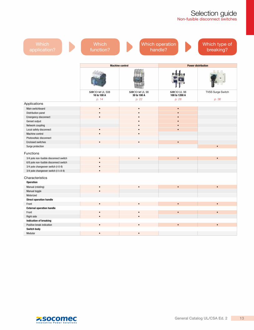
Whichapplication?
Which operation handle?
Whichfunction?
Which type of breaking?
Machine control Power distribution
SIRCO M UL 50816 to 100 A
SIRCO M UL 9830 to 100 A
SIRCO UL 98100 to 1 00 A
TVSS Surge Switch
Applications
Main switchboard
Distribution panel
Emergency disconnect
Genset output
Network coupling
Local safety disconnect
Machine control
Photovoltaic disconnect
Enclosed switches
Surge protection
Functions
3/4 pole non-fusible disconnect switch
6/8 pole non-fusible disconnect switch
3/4 pole changeover switch (I-0-II)
3/4 pole changeover switch (I-I+II-II)
Characteristics
Operation
Manual (rotating)
Manual toggle
Motorized
Direct operation handle
Front
External operation handle
Front
Right side
Indication of breaking
Positive break indication
Switch body
Modular
Selection guide Non-fusible disconnect switches
p. 14 p. 22 p. 28 p. 36
13General Catalog UL/CSA Ed. 2
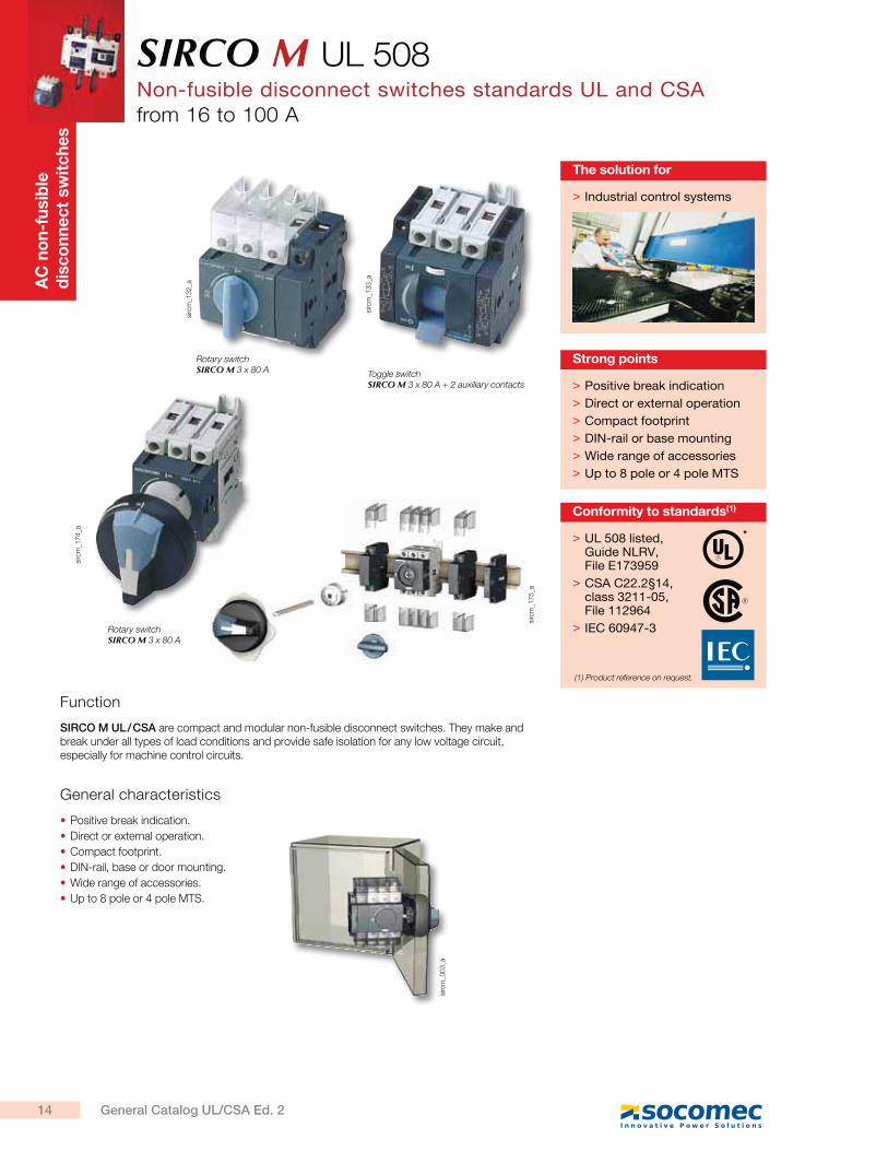
SIRCO M UL 508Non-fusible disconnect switches standards UL and CSAfrom 16 to 100 A
AC
no
n-f
usib
le
dis
co
nn
ec
t sw
itc
he
s
sirc
m_1
32
_a
sirc
m_1
33
_a
sirc
m_1
74
_a
sirc
m_1
75
_a
sirc
m_0
03
_a
Toggle switch SIRCO M 3 x 80 A + 2 auxiliary contacts
Rotary switch SIRCO M 3 x 80 A
Rotary switch SIRCO M 3 x 80 A
Function
SIRCO M UL / CSA are compact and modular non-fusible disconnect switches. They make and break under all types of load conditions and provide safe isolation for any low voltage circuit, especially for machine control circuits.
General characteristics
Positive break indication.
Direct or external operation.
Compact footprint.
DIN-rail, base or door mounting.
Wide range of accessories.
Up to 8 pole or 4 pole MTS.
> Industrial control systems
The solution for
> UL 508 listed, Guide NLRV, File E173959
> CSA C22.2§14, class 3211-05, File 112964
> IEC 60947-3
Conformity to standards(1)
*
(1) Product reference on request.
> Positive break indication
> Direct or external operation
> Compact footprint
> DIN-rail or base mounting
> Wide range of accessories
> Up to 8 pole or 4 pole MTS
Strong points
14 General Catalog UL/CSA Ed. 2
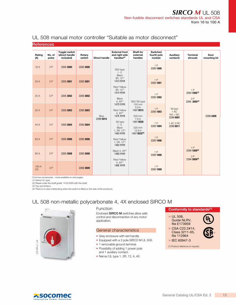
SIRCO M UL 508Non-fusible disconnect switches standards UL and CSA
from 16 to 100 A
References
Rating (A)
No. of poles
Toggle switch (direct handle
included)Rotary switch Direct handle
External front and right side
handles(4)
Shaft for external handles
Switched fourth pole
moduleAuxiliary contacts
Terminal shrouds
Door mounting kit
16 A 3 P 2205 3000 2200 3000
Blue2299 5012
S00 typeI - 0
Black 3R, 12(1)
1473 1111
Red / Yellow 3R, 12(1)
1474 1111
Black 4, 4X(1)
147D 1111
Red / Yellow 4, 4X(1)
147E 1111
S0 type I - 0
Black 1, 3R, 12(1)
1483 1111
Red / Yellow 1, 3R, 12(1)
1484 1111
Black 4, 4X(1)
148D 1111
Red / Yellow 4, 4X(1)
148E 1111
S00 / S0 type150 mm
5.9 in1407 0515
200 mm 7.9 in
1407 0520
320 mm 12.6 in
1407 0532(2)
1 P2200 1000
M type 1 AC
NO + NC2299 0001
1 AC 2 NC2299 0011
1 P2294 1005(3)
3 P2294 3005(3)
2299 3409
20 A 3 P 2205 3001 2200 30011 P
2200 1001
25 A 3 P 2205 3002 2200 30021 P
2200 1002
32 A 3 P 2205 3003 2200 30031 P
2200 1003
40 A 3 P 2205 3004 2200 30041 P
2200 1004
63 A 3 P 2205 3006 2200 30061 P
2200 1006
1 P2294 1009(3)
3 P
2294 3009(3)
80 A 3 P 2205 3008 2200 30081 P
2200 1008
100 A CD
3 P 2200 30091 P
2200 1009
Common accessories - more available on next pages.
(1) Nema / UL type.
(2) Please order the shaft guide: 1419 0000 with the shaft.
(3) Top and bottom.
(4) There is no door interlocking when the switch is fitted on the side of the enclosure.
UL 508 manual motor controller “Suitable as motor disconnect”co
ff_3
68
_a_1
_cat
FunctionEnclosed SIRCO M switches allow safe control and disconnection of any motor application.
General characteristics
Grey enclosure with red handle.
Equipped with a 3 pole SIRCO M UL 508.
1 removable ground terminal.
Possibility of adding 1 power pole and 1 auxiliary contact.
Nema / UL type 1, 3R, 12, 4, 4X.
UL 508 non-metallic polycarbonate 4, 4X enclosed SIRCO M
> UL 508, Guide NLRV, file E173959
> CSA C22.2#14, Class 3211-05, file 112964
> IEC 60947-3
Conformity to standards(1)
(1) Product reference on request.
15General Catalog UL/CSA Ed. 2
SIRCO M UL 508Non-fusible disconnect switches standards UL and CSAfrom 16 to 100 A
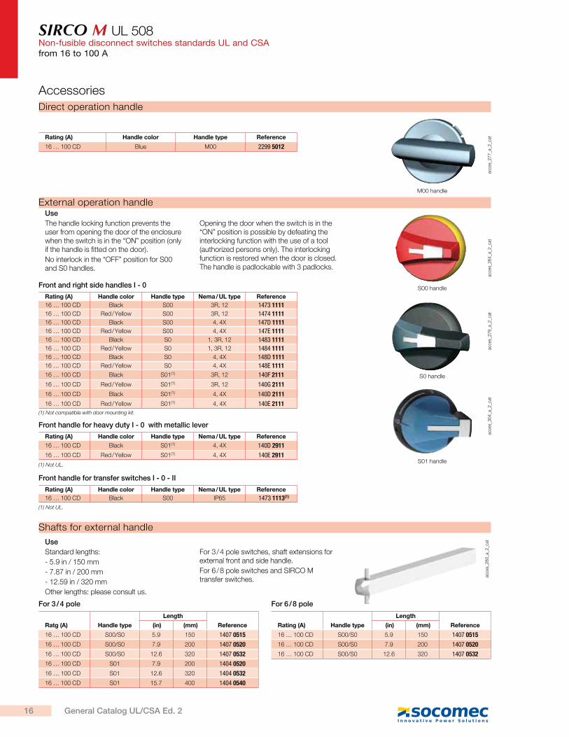
Shafts for external handle
acce
s_2
80
_a_2
_catUse
Standard lengths:
- 5.9 in / 150 mm
- 7.87 in / 200 mm
- 12.59 in / 320 mm
Other lengths: please consult us.
For 3 / 4 pole switches, shaft extensions for external front and side handle.
For 6 / 8 pole switches and SIRCO M transfer switches.
Direct operation handle
acce
s_2
77
_a_2
_catRating (A) Handle color Handle type Reference
16 … 100 CD Blue M00 2299 5012
Accessories
Ratg (A) Handle type
Length
Reference (in) (mm)
16 … 100 CD S00/S0 5.9 150 1407 0515
16 … 100 CD S00/S0 7.9 200 1407 0520
16 … 100 CD S00/S0 12.6 320 1407 0532
16 … 100 CD S01 7.9 200 1404 0520
16 … 100 CD S01 12.6 320 1404 0532
16 … 100 CD S01 15.7 400 1404 0540
For 3 / 4 pole
Rating (A) Handle type
Length
Reference (in) (mm)
16 … 100 CD S00/S0 5.9 150 1407 0515
16 … 100 CD S00/S0 7.9 200 1407 0520
16 … 100 CD S00/S0 12.6 320 1407 0532
For 6 / 8 pole
M00 handle
acce
s_2
79
_a_2
_cat
acce
s_3
04
_a_2
_cat
S0 handle
S01 handle
acce
s_2
64
_a_2
_cat
S00 handle
External operation handleUse
The handle locking function prevents the user from opening the door of the enclosure when the switch is in the “ON” position (only if the handle is fitted on the door).
No interlock in the “OFF” position for S00 and S0 handles.
Opening the door when the switch is in the “ON” position is possible by defeating the interlocking function with the use of a tool (authorized persons only). The interlocking function is restored when the door is closed. The handle is padlockable with 3 padlocks.
Rating (A) Handle color Handle type Nema / UL type Reference
16 … 100 CD Black S00 3R, 12 1473 1111
16 … 100 CD Red / Yellow S00 3R, 12 1474 1111
16 … 100 CD Black S00 4, 4X 147D 1111
16 … 100 CD Red / Yellow S00 4, 4X 147E 1111
16 … 100 CD Black S0 1, 3R, 12 1483 1111
16 … 100 CD Red / Yellow S0 1, 3R, 12 1484 1111
16 … 100 CD Black S0 4, 4X 148D 1111
16 … 100 CD Red / Yellow S0 4, 4X 148E 1111
16 … 100 CD Black S01(1) 3R, 12 140F 2111
16 … 100 CD Red / Yellow S01(1) 3R, 12 140G 2111
16 … 100 CD Black S01(1) 4, 4X 140D 2111
16 … 100 CD Red / Yellow S01(1) 4, 4X 140E 2111
Front and right side handles I - 0
Rating (A) Handle color Handle type Nema / UL type Reference
16 … 100 CD Black S00 IP65 1473 1113(1)
Front handle for transfer switches I - 0 - II
(1) Not compatible with door mounting kit.
Rating (A) Handle color Handle type Nema / UL type Reference
16 … 100 CD Black S01(1) 4, 4X 140D 2911
16 … 100 CD Red / Yellow S01(1) 4, 4X 140E 2911
Front handle for heavy duty I - 0 with metallic lever
(1) Not UL.
(1) Not UL.
16 General Catalog UL/CSA Ed. 2
SIRCO M UL 508Non-fusible disconnect switches standards UL and CSA
from 16 to 100 A
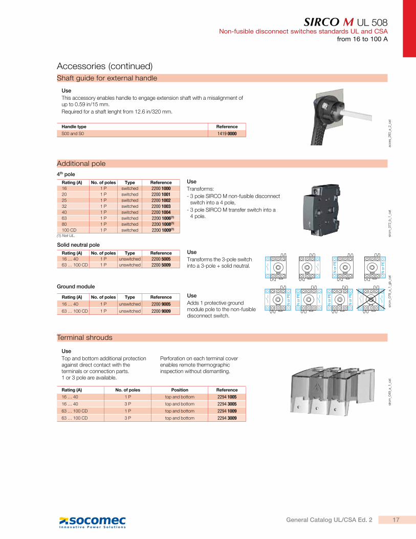
Terminal shrouds
sirc
m_0
49
_a_1
_cat
Use
Top and bottom additional protection against direct contact with the terminals or connection parts. 1 or 3 pole are available.
Perforation on each terminal cover enables remote thermographic inspection without dismantling.
Rating (A) No. of poles Position Reference
16 … 40 1 P top and bottom 2294 1005
16 … 40 3 P top and bottom 2294 3005
63 … 100 CD 1 P top and bottom 2294 1009
63 … 100 CD 3 P top and bottom 2294 3009
Shaft guide for external handle
acce
s_2
60
_a_2
_cat
Use
This accessory enables handle to engage extension shaft with a misalignment of up to 0.59 in/15 mm.
Required for a shaft lenght from 12.6 in/320 mm.
Handle type Reference
S00 and S0 1419 0000
Accessories (continued)
Additional pole
sirc
m_0
72
_b_1
_cat
4th pole
Use
Transforms:
- 3 pole SIRCO M non-fusible disconnect switch into a 4 pole,
- 3 pole SIRCO M transfer switch into a 4 pole.
Rating (A) No. of poles Type Reference
16 1 P switched 2200 100020 1 P switched 2200 100125 1 P switched 2200 100232 1 P switched 2200 100340 1 P switched 2200 100463 1 P switched 2200 1006(1)
80 1 P switched 2200 1008(1)
100 CD 1 P switched 2200 1009(1)
(1) Not UL.
N o
r P
E
N o
r P
E
N o
r P
E
N o
r P
E
N o
r P
E
N o
r P
E
sirc
m_0
78
_a_1
_gb
_cat
Solid neutral pole
Use
Transforms the 3-pole switch into a 3-pole + solid neutral.
Rating (A) No. of poles Type Reference
16 … 40 1 P unswitched 2200 500563 … 100 CD 1 P unswitched 2200 5009
Ground module
Use
Adds 1 protective ground module pole to the non-fusible disconnect switch.
Rating (A) No. of poles Type Reference
16 … 40 1 P unswitched 2200 9005
63 … 100 CD 1 P unswitched 2200 9009
17General Catalog UL/CSA Ed. 2
SIRCO M UL 508Non-fusible disconnect switches standards UL and CSAfrom 16 to 100 A
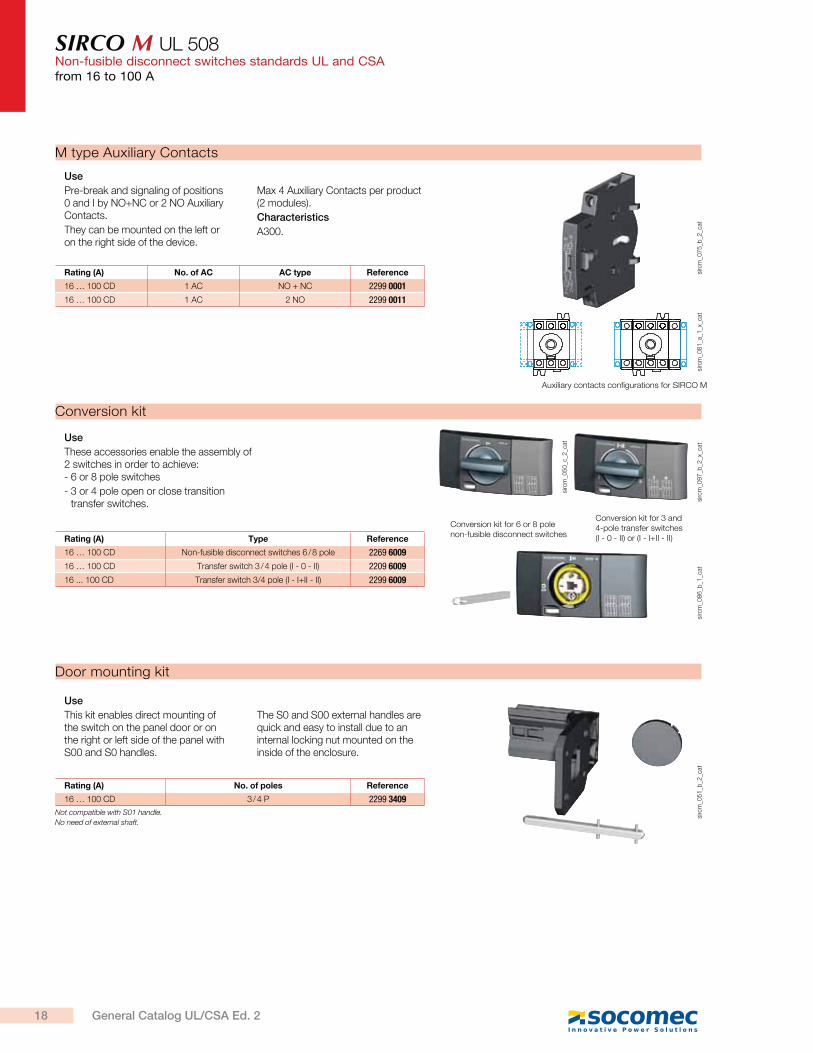
Conversion kit
sirc
m_0
86
_b_1
_cat
sirc
m_0
97
_b_2
_x_c
at
Conversion kit for 3 and 4-pole transfer switches (I - 0 - II) or (I - I+II - II)
sirc
m_0
50
_c_2
_cat
Conversion kit for 6 or 8 pole non-fusible disconnect switches
Use
These accessories enable the assembly of 2 switches in order to achieve: - 6 or 8 pole switches
- 3 or 4 pole open or close transition transfer switches.
Rating (A) Type Reference
16 … 100 CD Non-fusible disconnect switches 6 / 8 pole 2269 6009
16 … 100 CD Transfer switch 3 / 4 pole (I - 0 - II) 2209 6009
16 ... 100 CD Transfer switch 3/4 pole (I - I+II - II) 2299 6009
sirc
m_0
51
_b_2
_cat
Door mounting kit
Use
This kit enables direct mounting of the switch on the panel door or on the right or left side of the panel with S00 and S0 handles.
The S0 and S00 external handles are quick and easy to install due to an internal locking nut mounted on the inside of the enclosure.
Rating (A) No. of poles Reference
16 … 100 CD 3 / 4 P 2299 3409
Rating (A) No. of AC AC type Reference
16 … 100 CD 1 AC NO + NC 2299 0001
16 … 100 CD 1 AC 2 NO 2299 0011
M type Auxiliary Contacts
sirc
m_0
81
_a_1
_x_c
atsi
rcm
_07
5_b
_2_c
at
Use
Pre-break and signaling of positions 0 and I by NO+NC or 2 NO Auxiliary Contacts.
They can be mounted on the left or on the right side of the device.
Max 4 Auxiliary Contacts per product (2 modules).
Characteristics
A300.
Auxiliary contacts configurations for SIRCO M
Not compatible with S01 handle.
No need of external shaft.
18 General Catalog UL/CSA Ed. 2
SIRCO M UL 508Non-fusible disconnect switches standards UL and CSA
from 16 to 100 A
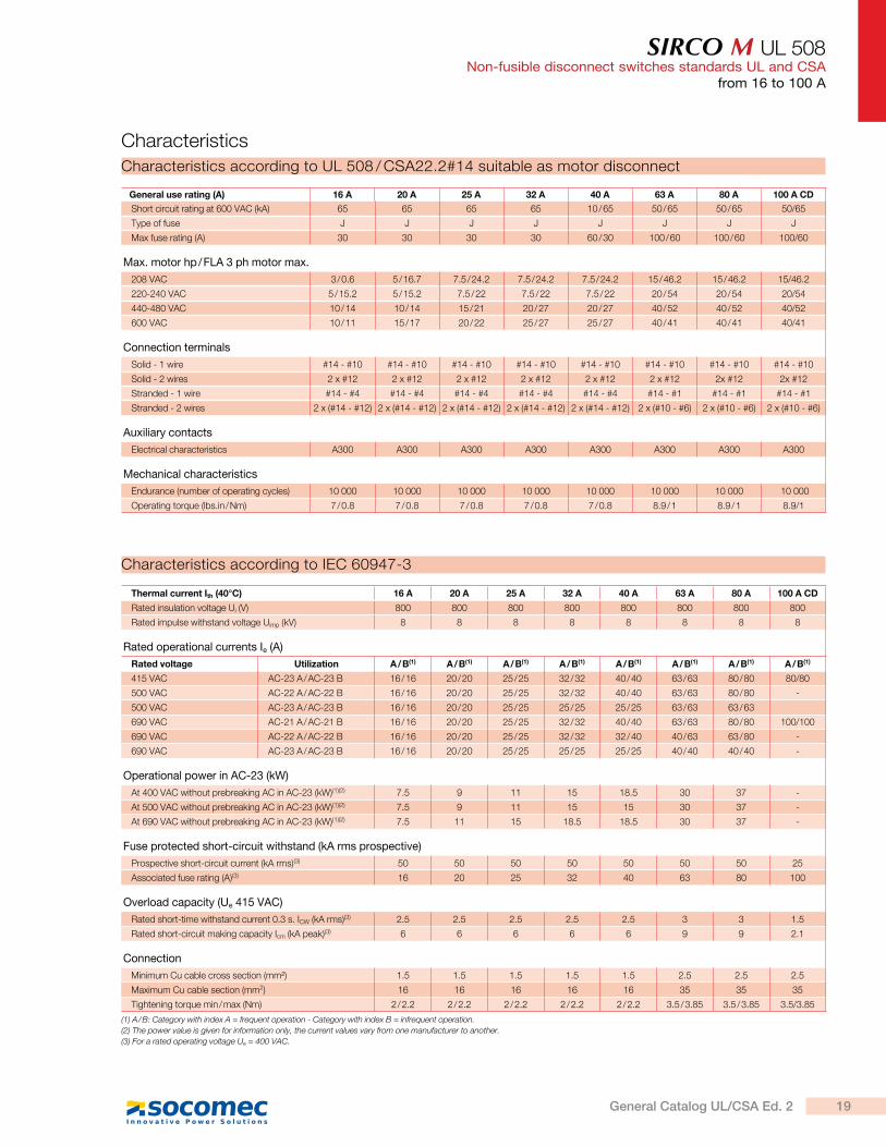
Characteristics according to UL 508 / CSA22.2#14 suitable as motor disconnect
Characteristics
General use rating (A) 16 A 20 A 25 A 32 A 40 A 63 A 80 A 100 A CD
Short circuit rating at 600 VAC (kA) 65 65 65 65 10 / 65 50 / 65 50 / 65 50/65
Type of fuse J J J J J J J J
Max fuse rating (A) 30 30 30 30 60 / 30 100 / 60 100 / 60 100/60
Max. motor hp / FLA 3 ph motor max.
208 VAC 3 / 0.6 5 / 16.7 7.5 / 24.2 7.5 / 24.2 7.5 / 24.2 15 / 46.2 15 / 46.2 15/46.2
220-240 VAC 5 / 15.2 5 / 15.2 7.5 / 22 7.5 / 22 7.5 / 22 20 / 54 20 / 54 20/54
440-480 VAC 10 / 14 10 / 14 15 / 21 20 / 27 20 / 27 40 / 52 40 / 52 40/52
600 VAC 10 / 11 15 / 17 20 / 22 25 / 27 25 / 27 40 / 41 40 / 41 40/41
Connection terminals
Solid - 1 wire #14 - #10 #14 - #10 #14 - #10 #14 - #10 #14 - #10 #14 - #10 #14 - #10 #14 - #10
Solid - 2 wires 2 x #12 2 x #12 2 x #12 2 x #12 2 x #12 2 x #12 2x #12 2x #12
Stranded - 1 wire #14 - #4 #14 - #4 #14 - #4 #14 - #4 #14 - #4 #14 - #1 #14 - #1 #14 - #1
Stranded - 2 wires 2 x (#14 - #12) 2 x (#14 - #12) 2 x (#14 - #12) 2 x (#14 - #12) 2 x (#14 - #12) 2 x (#10 - #6) 2 x (#10 - #6) 2 x (#10 - #6)
Auxiliary contacts
Electrical characteristics A300 A300 A300 A300 A300 A300 A300 A300
Mechanical characteristics
Endurance (number of operating cycles) 10 000 10 000 10 000 10 000 10 000 10 000 10 000 10 000
Operating torque (lbs.in / Nm) 7 / 0.8 7 / 0.8 7 / 0.8 7 / 0.8 7 / 0.8 8.9 / 1 8.9 / 1 8.9/1
Thermal current Ith (40°C) 16 A 20 A 25 A 32 A 40 A 63 A 80 A 100 A CD
Rated insulation voltage Ui (V) 800 800 800 800 800 800 800 800
Rated impulse withstand voltage Uimp (kV) 8 8 8 8 8 8 8 8
Rated operational currents Ie (A)
Rated voltage Utilization A / B(1) A / B(1) A / B(1) A / B(1) A / B(1) A / B(1) A / B(1) A / B(1)
415 VAC AC-23 A / AC-23 B 16 / 16 20 / 20 25 / 25 32 / 32 40 / 40 63 / 63 80 / 80 80/80
500 VAC AC-22 A / AC-22 B 16 / 16 20 / 20 25 / 25 32 / 32 40 / 40 63 / 63 80 / 80 -
500 VAC AC-23 A / AC-23 B 16 / 16 20 / 20 25 / 25 25 / 25 25 / 25 63 / 63 63 / 63
690 VAC AC-21 A / AC-21 B 16 / 16 20 / 20 25 / 25 32 / 32 40 / 40 63 / 63 80 / 80 100/100
690 VAC AC-22 A / AC-22 B 16 / 16 20 / 20 25 / 25 32 / 32 32 / 40 40 / 63 63 / 80 -
690 VAC AC-23 A / AC-23 B 16 / 16 20 / 20 25 / 25 25 / 25 25 / 25 40 / 40 40 / 40 -
Operational power in AC-23 (kW)
At 400 VAC without prebreaking AC in AC-23 (kW)(1)(2) 7.5 9 11 15 18.5 30 37 -
At 500 VAC without prebreaking AC in AC-23 (kW)(1)(2) 7.5 9 11 15 15 30 37 -
At 690 VAC without prebreaking AC in AC-23 (kW)(1)(2) 7.5 11 15 18.5 18.5 30 37 -
Fuse protected short-circuit withstand (kA rms prospective)
Prospective short-circuit current (kA rms)(3) 50 50 50 50 50 50 50 25
Associated fuse rating (A)(3) 16 20 25 32 40 63 80 100
Overload capacity (Ue 415 VAC)
Rated short-time withstand current 0.3 s. ICW (kA rms)(3) 2.5 2.5 2.5 2.5 2.5 3 3 1.5
Rated short-circuit making capacity Icm (kA peak)(3) 6 6 6 6 6 9 9 2.1
Connection
Minimum Cu cable cross section (mm²) 1.5 1.5 1.5 1.5 1.5 2.5 2.5 2.5
Maximum Cu cable section (mm2) 16 16 16 16 16 35 35 35
Tightening torque min / max (Nm) 2 / 2.2 2 / 2.2 2 / 2.2 2 / 2.2 2 / 2.2 3.5 / 3.85 3.5 / 3.85 3.5/3.85
(1) A / B: Category with index A = frequent operation - Category with index B = infrequent operation.
(2) The power value is given for information only, the current values vary from one manufacturer to another.
(3) For a rated operating voltage Ue = 400 VAC.
Characteristics according to IEC 60947-3
19General Catalog UL/CSA Ed. 2

SIRCO M UL 508Non-fusible disconnect switches standards UL and CSAfrom 16 to 100 A
Toggle operation
90°
2.68
F
TM5
M
NG AC
3.19
2.52
61.97
2.87
F1 0.35F10.35
21 2
1
68
50
0.248.88.8
81
73
64
sirc
m_0
52
_b_1
_gb
_cat
1. Position for 1 switched fourth pole module (1 per device max.) or 1 unswitched neutral pole or 1 protective ground module or 1 auxiliary contact.
2. Position for 1 auxiliary contact only.
Note: Maximum of 4 additional blocks.
Direct operation with handle
2.67
F
TM5
M
NG AC
2.52
0.241.97
2.95
F1F10.35
21 2
175
64
650
68
8.88.80.35
sirc
m_0
53
_b_1
_gb
_cat
External front handle External side handle
J
2.68
F
T
M5
M
1.42D
NG AC
E1.423.19
2.52
0.23
1.96
1.99
F10.35 F1
ø 2.
79
3681
64
50.6
6
50
8.8 8.8
68
ø 71
36
0.35
801.
61
44
BA C
45
25
1.77
0.98
41
3.15
1.73
2
21
1
sirc
m-u
l_0
02
_c_1
_gb
_cat
1. Position for 1 switched fourth pole module (1 per device max.) or 1 unswitched neutral pole or 1 ground module or 1 auxiliary contact.
2. Position for 1 auxiliary contact only.
Note: Maximum of 4 additional blocks.
Rating (A) Units
Overall dimensions Terminal shrouds Switch body Switch mounting Connection
D min D max E min E max AC F F1 G J M N T
16 … 40in 1.18 9.25 3.94 14.64 4.33 1.77 0.59 2.67 0.59 1.18 2.95 0.59
mm 30 235 100 372 110 45 15 68 15 30 75 15
63 … 100 CDin 1.18 9.25 3.93 14.64 4.33 2.06 0.69 2.99 0.69 1.38 3.35 0.69
mm 30 235 100 372 110 52.5 17.5 76 17.5 35 85 17.5
Direct front handle for 6 / 8-pole non-fusible disconnect switches or 3 / 4-pole transfer switches
External front handle for 6 / 8-pole non-fusible disconnect switches or 3 / 4-pole transfer switches
X
N G 2.67
T T 0.292.06
MF2
2.06
FJ
F1F10.35
21
21
52.5
68
8.8
52.5
8.87.5
0.35sirc
m_0
55
_c_1
_gb
_cat
1. Position for 1 switched fourth pole module (1 per device max.) or 1 unswitched neutral pole or 1 ground module or 1 auxiliary contact.
2. Position for 1 auxiliary contact only.
Note: Maximum of 4 additional blocks.
Rating (A) Units
Overall dimensions Switch body Switch mounting Connection
E min E max F F1 F2 G J M N T X
16 … 40in 4.13 14.64 3.83 0.59 1.77 2.67 1.92 1.18 2.95 0.59 0.29
mm 105 372 97.5 15 45 68 48.75 30 75 15 7.5
63 … 100 CDin 4.13 14.65 4.13 0.69 2.06 2.99 2.06 1.38 3.35 0.69 0.34
mm 105 372 105 17.5 52.5 76 52.5 35 85 17.5 8.75
Dimensions (in / mm)
1.42E
1.77
3.07
1.361.690.24
3.50
ø 2.
79
89
78
43 34.76
36
ø 7145
16 to 100 A
20 General Catalog UL/CSA Ed. 2
SIRCO M UL 508Non-fusible disconnect switches standards UL and CSA
from 16 to 100 A
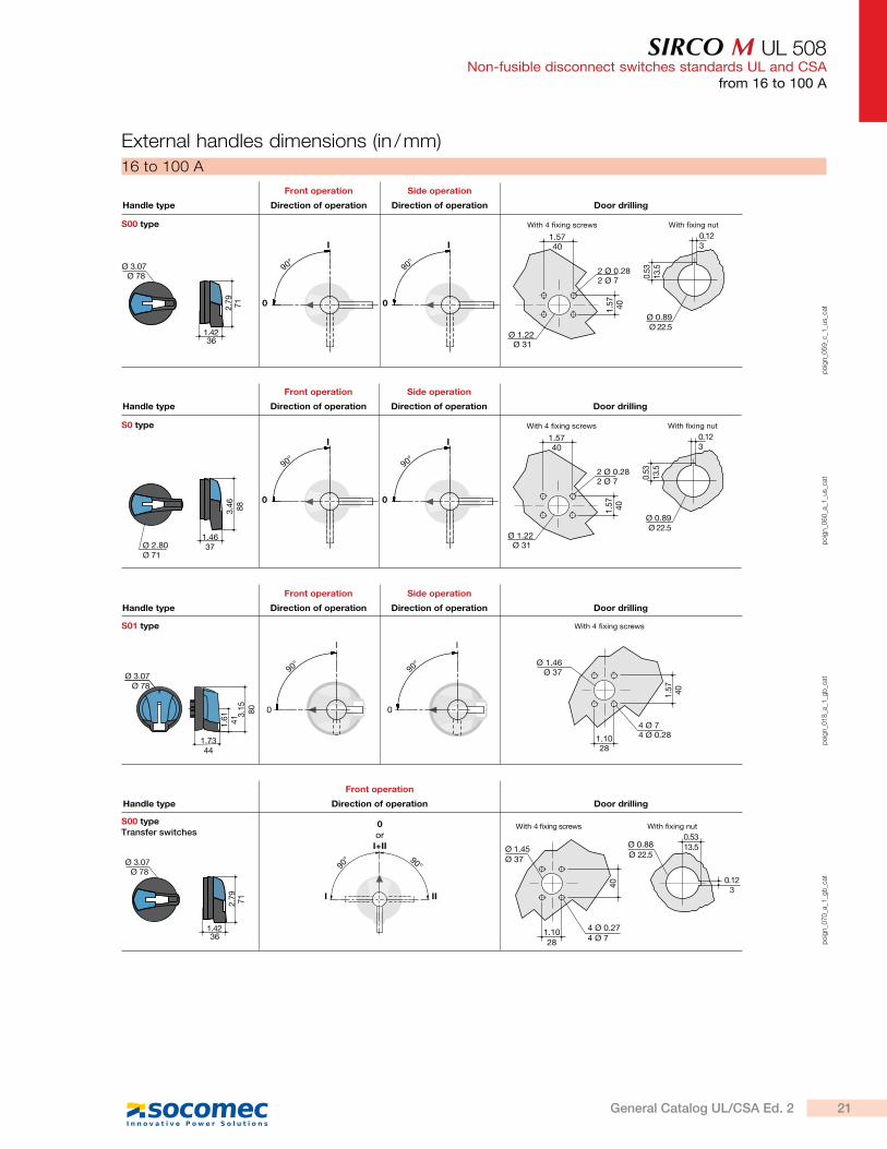
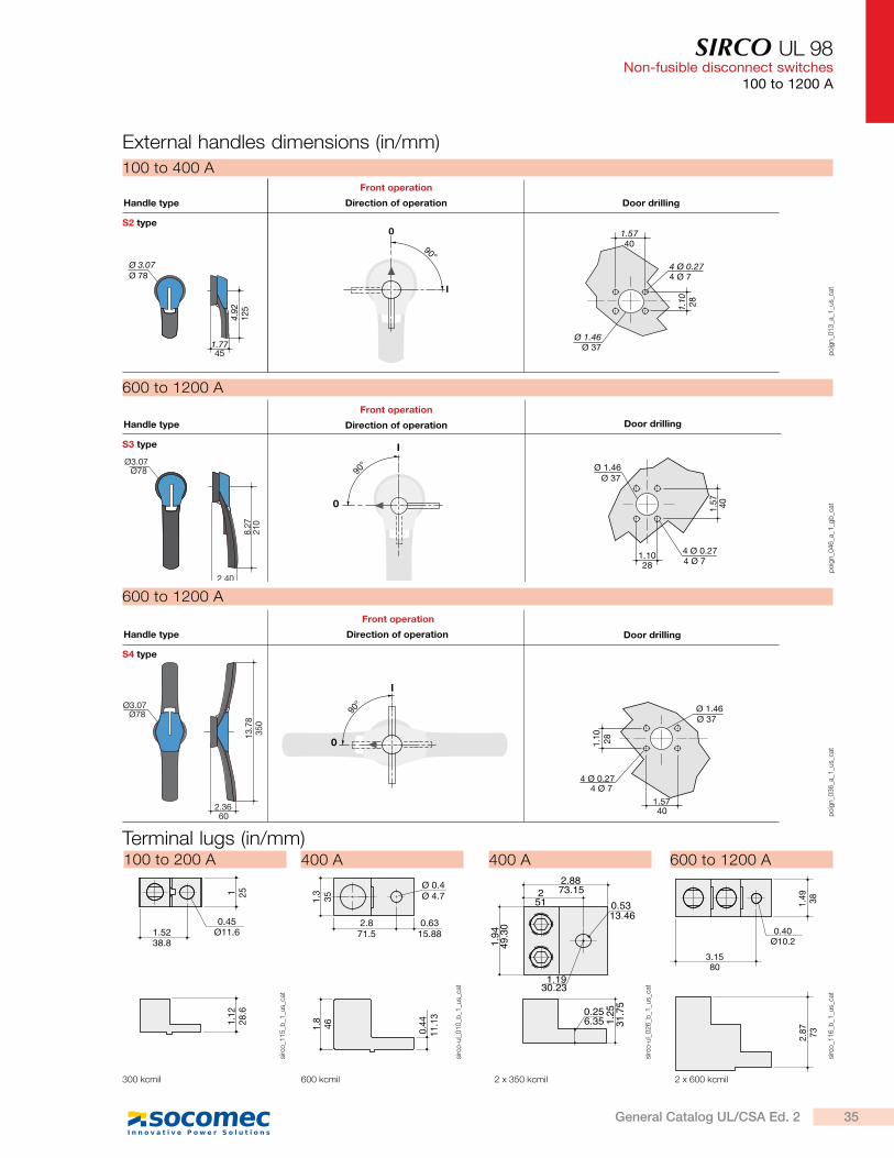
External handles dimensions (in / mm)
0
I
90°
0
I
90°
1.5740
2 Ø 0.282 Ø 7
Ø 1.22 Ø 31
1.57 40
0.53
13.5
Ø 0.89Ø 22.5
0.123
With fixing nutWith 4 fixing screwsS00 type
Direction of operation Direction of operation Door drillingHandle type
Front operation Side operation
Ø 3.07
1.42
2.79
Ø 78
36
71
po
ign_0
59
_c_1
_us_
cat
16 to 100 A
0
I
90°
0
I
90°
1.5740
2 Ø 0.282 Ø 7
Ø 1.22 Ø 31
1.57 40
0.53
13.5
Ø 0.89Ø 22.5
0.123
With fixing nutWith 4 fixing screwsS0 type
Direction of operation Direction of operation Door drillingHandle type
Front operation Side operation
Ø 2.80Ø 71
1.4637
3.46 88
po
ign_0
60
_a_1
_us_
cat
S00 typeTransfer switches
0or
I+II
I II
90° 90°
0.5313.5Ø 0.88
Ø 22.5
0.12340
1.1028
Ø 1.45Ø 37
4 Ø 0.274 Ø 7
With fixing nutWith 4 fixing screws
Direction of operation Door drillingHandle type
Front operation
Ø 3.07
1.42
2.79
Ø 78
36
71
po
ign_0
70
_a_1
_gb
_cat
po
ign_0
18
_a_1
_gb
_cat
S01 type With 4 fixing screws
Direction of operation Direction of operation Door drillingHandle type
Front operation Side operation
0
I
90°
0
I
90°1.
57 40
1.1028
Ø 1.46Ø 37
4 Ø 74 Ø 0.28
3.15 80
1.61 41
1.7344
Ø 3.07Ø 78
21General Catalog UL/CSA Ed. 2
SIRCO M UL 98Non-fusible disconnect switches standards UL and CSAfrom 30 to 100 A
AC
no
n-f
usib
le
dis
co
nn
ec
t sw
itc
he
s
sirc
m_1
00
_a_1
_cat
UL 98 non-fusible disconnect switches
Rating (A)No. of poles
Switch body
Direct handle
External front and right side handles
Shafts for external front and side
handles
Switched fourth pole
moduleUnswitched neutral pole
Ground module
Auxiliary contacts
Terminal shrouds
30 A 3 P 2201 3003
Blue2299 5032
S0 type I - 0
Black 4, 4X
148D 1111
Red/Yellow 4, 4X
148E 1111
150 mm 5.9 in
1407 0515
200 mm 7.9 in
1407 0520
320 mm 12.6 in
1407 0532(1)
1 P2201 1003
1 P2200 5011
1 P2200 9011
M type 1 AC
NO + NC2299 0001
M type
1 AC 2 NC2299 0011
1 P2294 1011(2)
3 P
2294 3016(2)
60 A 3 P 2201 30061 P
2201 1006
100 A 3 P 2200 30101 P
2200 1010
Common accessories - more available on next pages.
(1) Shaft guide reference 14190000, is required for shaft length over 12.6 in / 320 mm.
(2) Top and bottom.
References
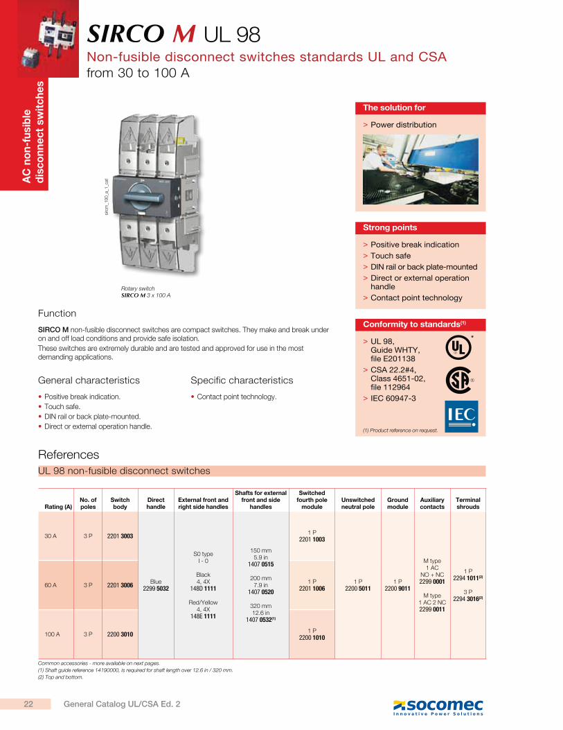
Rotary switch SIRCO M 3 x 100 A
Function
SIRCO M non-fusible disconnect switches are compact switches. They make and break under on and off load conditions and provide safe isolation.
These switches are extremely durable and are tested and approved for use in the most demanding applications.
General characteristics Specific characteristics
Positive break indication.
Touch safe.
DIN rail or back plate-mounted.
Direct or external operation handle.
Contact point technology.
> UL 98, Guide WHTY, file E201138
> CSA 22.2#4, Class 4651-02, file 112964
> IEC 60947-3
Conformity to standards(1)
*
(1) Product reference on request.
> Power distribution
The solution for
> Positive break indication
> Touch safe
> DIN rail or back plate-mounted
> Direct or external operation handle
> Contact point technology
Strong points
22 General Catalog UL/CSA Ed. 2
SIRCO M UL 98Non-fusible disconnect switches
from 30 to 100 A
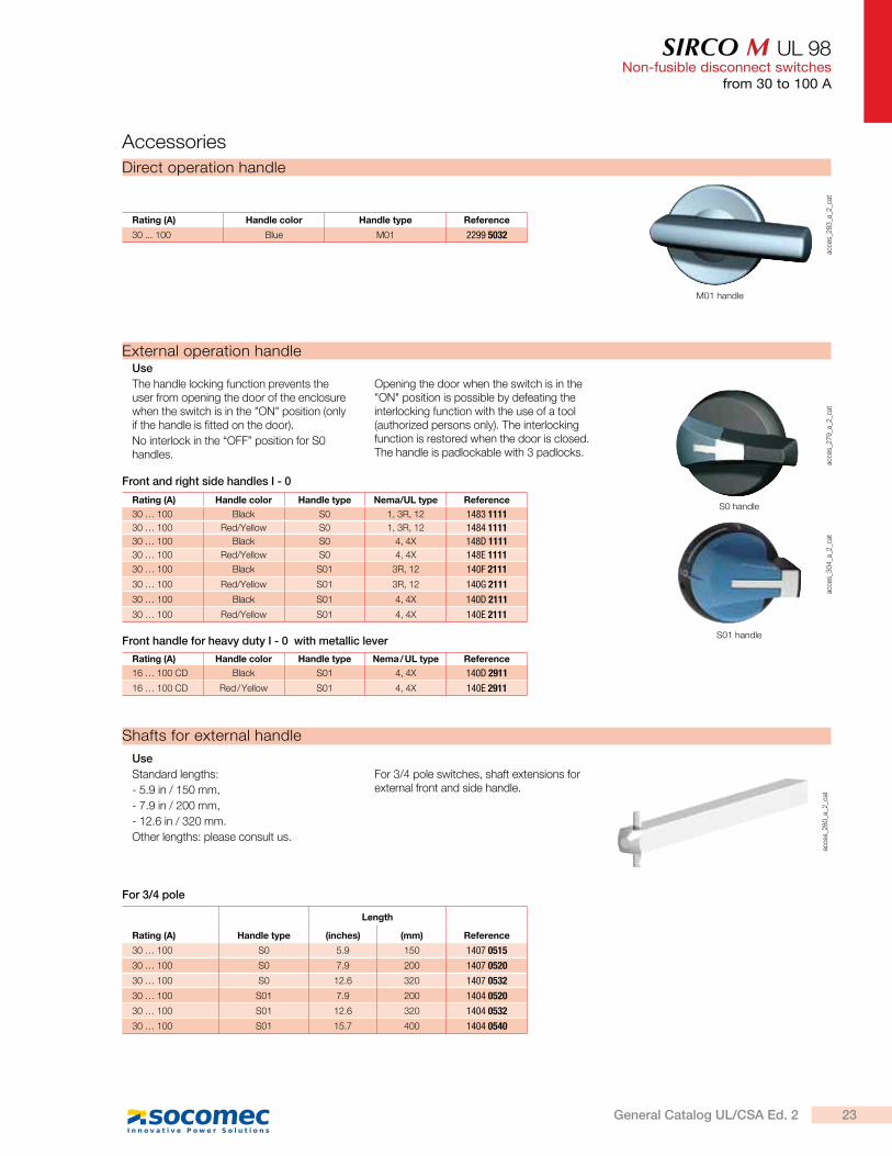
Direct operation handle
acce
s_2
83
_a_2
_cat
M01 handle
Rating (A) Handle color Handle type Reference
30 ... 100 Blue M01 2299 5032
Accessories
Shafts for external handle
acce
s_2
80
_a_2
_cat
Use
Standard lengths:
- 5.9 in / 150 mm,
- 7.9 in / 200 mm,
- 12.6 in / 320 mm.
Other lengths: please consult us.
For 3/4 pole switches, shaft extensions for external front and side handle.
For 3/4 pole
acce
s_2
79
_a_2
_cat
acce
s_3
04
_a_2
_cat
S0 handle
S01 handle
External operation handleUse
The handle locking function prevents the user from opening the door of the enclosure when the switch is in the "ON" position (only if the handle is fitted on the door).
No interlock in the “OFF” position for S0 handles.
Opening the door when the switch is in the "ON" position is possible by defeating the interlocking function with the use of a tool (authorized persons only). The interlocking function is restored when the door is closed. The handle is padlockable with 3 padlocks.
Rating (A) Handle color Handle type Nema/UL type Reference
30 … 100 Black S0 1, 3R, 12 1483 1111
30 … 100 Red/Yellow S0 1, 3R, 12 1484 1111
30 … 100 Black S0 4, 4X 148D 1111
30 … 100 Red/Yellow S0 4, 4X 148E 1111
30 … 100 Black S01 3R, 12 140F 2111
30 … 100 Red/Yellow S01 3R, 12 140G 2111
30 … 100 Black S01 4, 4X 140D 2111
30 … 100 Red/Yellow S01 4, 4X 140E 2111
Front and right side handles I - 0
Rating (A) Handle type
Length
Reference(inches) (mm)
30 … 100 S0 5.9 150 1407 0515
30 … 100 S0 7.9 200 1407 0520
30 … 100 S0 12.6 320 1407 0532
30 … 100 S01 7.9 200 1404 0520
30 … 100 S01 12.6 320 1404 0532
30 … 100 S01 15.7 400 1404 0540
Rating (A) Handle color Handle type Nema / UL type Reference
16 … 100 CD Black S01 4, 4X 140D 2911
16 … 100 CD Red / Yellow S01 4, 4X 140E 2911
Front handle for heavy duty I - 0 with metallic lever
23General Catalog UL/CSA Ed. 2
SIRCO M UL 98Non-fusible disconnect switchesfrom 30 to 100 A
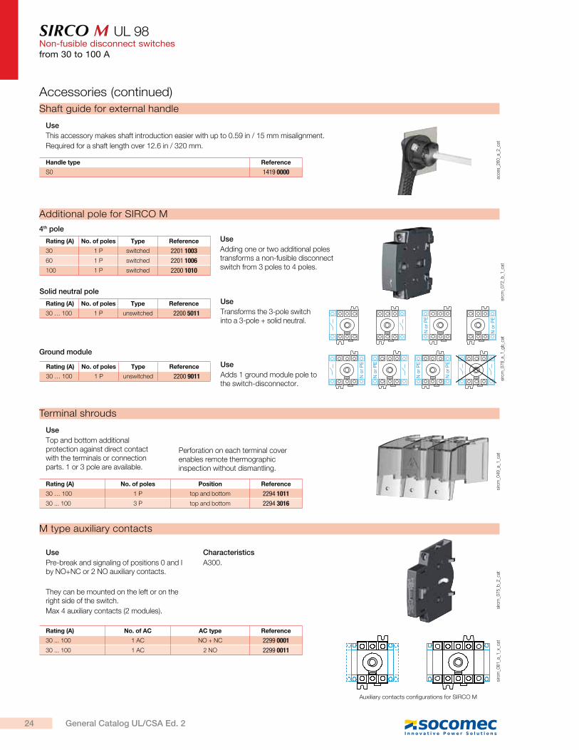
M type auxiliary contacts
sirc
m_0
81
_a_1
_x_c
at
Auxiliary contacts configurations for SIRCO M
sirc
m_0
75
_b_2
_cat
Use
Pre-break and signaling of positions 0 and I by NO+NC or 2 NO auxiliary contacts.
They can be mounted on the left or on the right side of the switch.
Max 4 auxiliary contacts (2 modules).
Characteristics
A300.
Rating (A) No. of AC AC type Reference
30 ... 100 1 AC NO + NC 2299 0001
30 ... 100 1 AC 2 NO 2299 0011
Terminal shrouds
sirc
m_0
49
_a_1
_cat
Use
Top and bottom additional protection against direct contact with the terminals or connection parts. 1 or 3 pole are available.
Perforation on each terminal cover enables remote thermographic inspection without dismantling.
Rating (A) No. of poles Position Reference
30 … 100 1 P top and bottom 2294 1011
30 ... 100 3 P top and bottom 2294 3016
Shaft guide for external handle
acce
s_2
60
_a_2
_cat
Use
This accessory makes shaft introduction easier with up to 0.59 in / 15 mm misalignment.
Required for a shaft length over 12.6 in / 320 mm.
Handle type Reference
S0 1419 0000
Rating (A) No. of poles Type Reference
30 … 100 1 P unswitched 2200 9011
Rating (A) No. of poles Type Reference
30 … 100 1 P unswitched 2200 5011
Rating (A) No. of poles Type Reference
30 1 P switched 2201 1003
60 1 P switched 2201 1006
100 1 P switched 2200 1010
Additional pole for SIRCO M
sirc
m_0
72
_b_1
_cat
4th pole
Use
Adding one or two additional poles transforms a non-fusible disconnect switch from 3 poles to 4 poles.
N o
r P
E
N o
r P
E
N o
r P
E
N o
r P
E
N o
r P
E
N o
r P
E
sirc
m_0
78
_a_1
_gb
_cat
Solid neutral pole
Use
Transforms the 3-pole switch into a 3-pole + solid neutral.
Ground module
Use
Adds 1 ground module pole to the switch-disconnector.
Accessories (continued)
24 General Catalog UL/CSA Ed. 2
SIRCO M UL 98Non-fusible disconnect switches
from 30 to 100 A
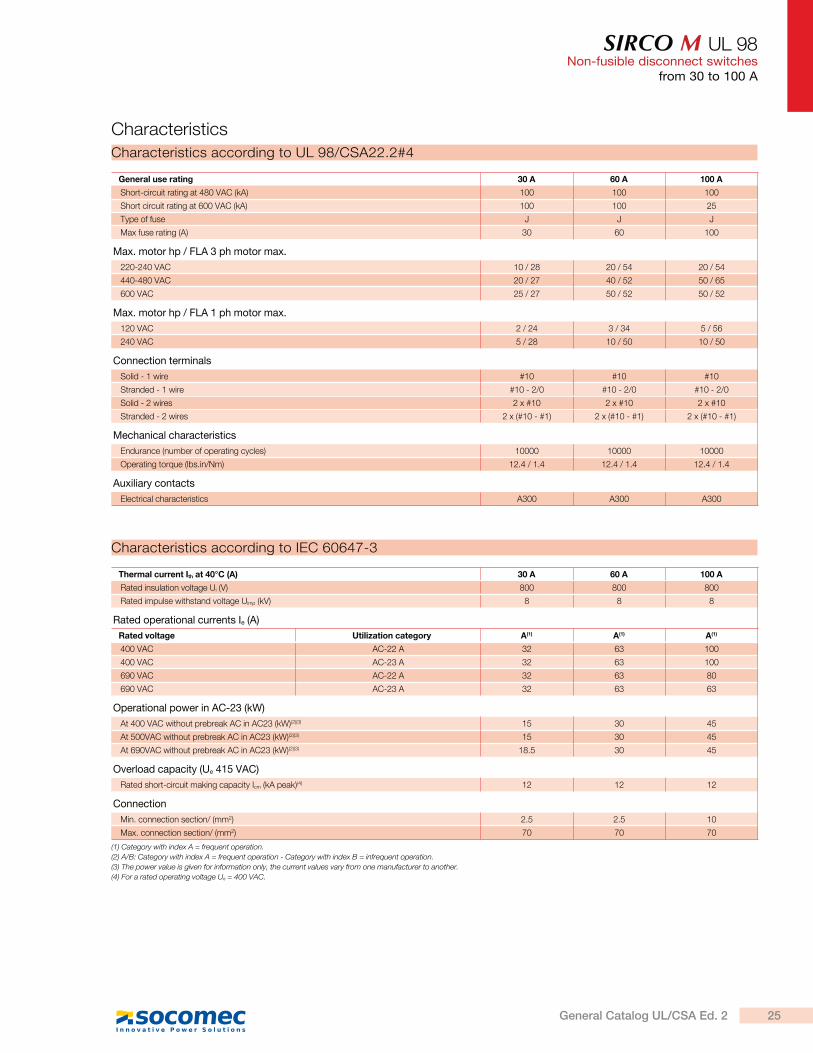
General use rating 30 A 60 A 100 A
Short-circuit rating at 480 VAC (kA) 100 100 100
Short circuit rating at 600 VAC (kA) 100 100 25
Type of fuse J J J
Max fuse rating (A) 30 60 100
Max. motor hp / FLA 3 ph motor max.
220-240 VAC 10 / 28 20 / 54 20 / 54
440-480 VAC 20 / 27 40 / 52 50 / 65
600 VAC 25 / 27 50 / 52 50 / 52
Max. motor hp / FLA 1 ph motor max.
120 VAC 2 / 24 3 / 34 5 / 56
240 VAC 5 / 28 10 / 50 10 / 50
Connection terminals
Solid - 1 wire #10 #10 #10
Stranded - 1 wire #10 - 2/0 #10 - 2/0 #10 - 2/0
Solid - 2 wires 2 x #10 2 x #10 2 x #10
Stranded - 2 wires 2 x (#10 - #1) 2 x (#10 - #1) 2 x (#10 - #1)
Mechanical characteristics
Endurance (number of operating cycles) 10000 10000 10000
Operating torque (lbs.in/Nm) 12.4 / 1.4 12.4 / 1.4 12.4 / 1.4
Auxiliary contacts
Electrical characteristics A300 A300 A300
Characteristics
Characteristics according to UL 98/CSA22.2#4
Characteristics according to IEC 60647-3
Thermal current Ith at 40°C (A) 30 A 60 A 100 A
Rated insulation voltage Ui (V) 800 800 800
Rated impulse withstand voltage Uimp (kV) 8 8 8
Rated operational currents Ie (A)
Rated voltage Utilization category A(1) A(1) A(1)
400 VAC AC-22 A 32 63 100
400 VAC AC-23 A 32 63 100
690 VAC AC-22 A 32 63 80
690 VAC AC-23 A 32 63 63
Operational power in AC-23 (kW)
At 400 VAC without prebreak AC in AC23 (kW)(2)(3) 15 30 45
At 500VAC without prebreak AC in AC23 (kW)(2)(3) 15 30 45
At 690VAC without prebreak AC in AC23 (kW)(2)(3) 18.5 30 45
Overload capacity (Ue 415 VAC)
Rated short-circuit making capacity Icm (kA peak)(4) 12 12 12
Connection
Min. connection section/ (mm2) 2.5 2.5 10
Max. connection section/ (mm2) 70 70 70
(1) Category with index A = frequent operation.
(2) A/B: Category with index A = frequent operation - Category with index B = infrequent operation.
(3) The power value is given for information only, the current values vary from one manufacturer to another.
(4) For a rated operating voltage Ue = 400 VAC.
25General Catalog UL/CSA Ed. 2
SIRCO M UL 98Non-fusible disconnect switchesfrom 30 to 100 A
30 to 100 A
Dimensions (in/mm)
Direct operation with handle
75
64
53
0.246 8.8 8.8
M5
2.95
2.52
2.09
G
0.35 0.35TF1 F1
N AC
M
F
21
21
sirc
m_0
56
_d_1
_gb
_cat
1. Location for: 1 switched fourth pole module (1 per device max.) or 1 unswitched neutral pole or 1 protective earth module or 1 auxiliary contact.
2. Position for 1 auxiliary contact module only.
Note: max 2 additional blocks.
External front operation External side operation
37E
813.19
2.5264
2.0953
0.246
50.61.99
J
G N AC
MF
0.358.8
0.358.8
F1 T F1M5
883.46
ø 71
2.79
D D37
1.4637
1.46
2
12
1
803.15
411.61
1.7344
A B
1.46
sirc
m_0
57
_d_1
_gb
_cat
1. Location for: 1 switched fourth pole module (1 per device max.) or 1 unswitched neutral pole or 1 protective earth module or 1 auxiliary contact.
2. Position for 1 auxiliary contact module only.
Note: max 2 additional blocks.
A. S01 handle
B. S00 handle
Rating (A) / Frame size
Overall dimensions Terminal shrouds Switch body Switch mounting Connection
D min D max E min E max AC F F1 G J M N T
30 … 100 / M3mm 30 201 100 372 189 78 26 124,6 13 26 131,4 26
in 1.18 7.93 3.94 14.64 7.44 3,07 1.02 4,90 0.51 1.02 5.17 1.02
26 General Catalog UL/CSA Ed. 2
SIRCO M UL 98Non-fusible disconnect switches
from 30 to 100 A
External handles dimensions (in/mm)
0
I
90°
0
I
90°
1.5740
2 Ø 0.282 Ø 7
Ø 1.22 Ø 31
1.57 40
0.53
13.5
Ø 0.89Ø 22.5
0.123
With fixing nutWith 4 fixing screwsS0 type
Direction of operation Direction of operation Door drillingHandle type
Front operation Side operation
Ø 2.80Ø 71
1.4637
3.46 88
po
ign_0
60
_a_1
_us_
cat
30 to 100 A
S01 type With 4 fixing screws
Direction of operation Direction of operation Door drillingHandle type
Front operation Side operation
0
I
90°
0
I
90°
1.57 40
1.1028
Ø 1.46Ø 37
4 Ø 74 Ø 0.28
3.15 80
1.61 41
1.7344
Ø 3.07Ø 78
po
ign_0
18
_a_1
_us_
cat
27General Catalog UL/CSA Ed. 2
SIRCO UL 98Non-fusible switches standards UL and CSA100 to 1200 A
AC
no
n-f
usib
le
dis
co
nn
ec
t sw
itc
he
s
sirc
o_0
93
_b_1
_cat
sirc
o-u
l_0
22
_b_1
_cat
> Please consult us
Customized solutions
Function
SIRCO non-fusible disconnect switches are heavy duty switches that break and make power circuits on and off load and provide safety isolation.
These switches are extremely durable and are tested and approved for use in the most demanding applications.
General characteristics
Positive break indication.
Fully visualized disconnection.
High thermal and dynamic withstand.
Severe utilization categories.
High electrical and mechanical endurance.
> UL 98, Guide WHTY, file E201138
> CSA 22.2#4, Class 4652-04, file 112964
> IEC 60947-3
Conformity to standards(1)
*
(1) Product reference on request.
SIRCO3 x 200 A
SIRCO3 x 600 A
> Reliability
> Safety of property and personnel
> Simplicity
> Easy assembling
Strong points
> Power distribution
The solution for
28 General Catalog UL/CSA Ed. 2
SIRCO UL 98Non-fusible disconnect switches
100 to 1200 A
Rating (A)No. of poles Switch body Direct handle External handle
Shaft for external handle Auxiliary contacts
Terminal protection screens Terminal Lugs kits
100 A
3 P 2700 3011
Black2699 5052
S2 type Black
1, 3R, 12142F 2111(1)
Red/Yellow 1, 3R, 12
142G 2111(1)
Black 4, 4X
142D 2111(1)
Red/Yellow 4, 4X
142E 2111(1)
200 mm 7.9 inches1400 1020
320 mm
12.6 inches1400 1032
400 mm
15.7 inches1400 1040
1st contactNO/NC
2799 0021
2nd contact NO/NC
2799 0022
3 P2798 3021(2)
3 P2798 8021(3)
4 P2798 4021(4)
3 P3954 3020(4)
4 P3954 4020(4)
4 P 2700 4011
200 A
3 P 2700 3021
4 P 2700 4021
400 A
3 P 2700 30413 P
2798 3041(2) 3 P
2798 8041(3) 4 P
2798 4041(4)
3 P3954 3040(4)
4 P3954 4040(4)
4 P 2700 4041
600 A
3 P 2700 3060
Black3799 6012
S3 type Black 4, 4X
143D 3111(1)
Red/Yellow 4, 4X
143E 3111(1)
200 mm 7.9 inches1401 1520
320 mm
12.6 Inches1401 1532
400 mm
15.7 Inches1401 1540
3 P2798 3060(4)
4 P2798 4060(4)
3 P3954 3060
4 P3954 4060 4 P 2700 4060
800 A
3 P 2700 3080
3 P2798 3120(4)
4 P2798 4120(4)
3 P3954 3120
4 P3954 4120
4 P 2700 4080
1000 A
3 P 2700 3100
4 P 2700 4100
1200 A
3 P 2700 3120
4 P 2700 4120
Common accessories - more available on next pages
(1) Defeatable handle.
(2) Top.
(3) Bottom.
(4) Top or bottom.
(5) Max. 4 ACs.
References
Accessories
Direct operation handleac
ces_
11
4_a
_1_c
at
B type handle
acce
s_1
35
_a_2
_cat
H type handle
Rating (A) Color Handle type Reference
100 ... 400 Black B 2699 5052
600 ... 1200 Black H 3799 6012
29General Catalog UL/CSA Ed. 2
SIRCO UL 98Non-fusible disconnect switches100 to 1200 A
acce
s_1
44
_b_1
_cat
Xac
ces_
20
2_a
acce
s_3
69
_a_1
_cat
Shaft for external handle
Use
Standard lengths:
- 7.9 in / 200 mm,
- 12.6 in / 320 mm,
- 15.7 in / 400 mm.
Other lengths: please consult us.
Rating (A)Dimension
X (in)Dimension
X (mm)Handle
typeLength (inches)
Length (mm) Reference
100 … 400 5.31 ... 10.43 135 ... 265 S2 7.9 200 1400 1020
100 … 400 5.31 ... 15.16 135 ... 385 S2 12.6 320 1400 1032
100 … 400 5.31 ... 18.31 135 ... 465 S2 15.7 400 1400 1040
100 … 400 5.31 … 22.25 135 … 565 S2 19.7 500 1400 1050
600 … 1200 8.70 ... 13.50 221 … 343 S3, S4 7.9 200 1401 1520
600 … 1200 8.70 ... 18.23 221 ... 463 S3, S4 12.6 320 1401 1532
600 … 1200 8.70 ... 21.38 221 … 543 S3, S4 15.7 400 1401 1540
600 … 1200 8.70 … 26.73 221 … 679 S3, S4 19.7 536 1401 1554(1)
Alternative color S-type handle cover
acce
s_1
98
_a_1
_cat
Use
For single lever handles type S1, S2, S3 and double lever handle, type S4.
Other colors: please consult us.
Handle color Pack qty Handle type Reference
Light grey 50 S2, S3 1401 0001
Dark grey 50 S2, S3 1401 0011
Light grey 50 S4 1401 0031
Dark grey 50 S4 1401 0041
S-type handle raiser
acce
s_1
87
_a_1
_cat
Use
Enables S-type handles to be fitted in place of existing older style Socomec handles. Adapter can also be utilized as a spacer to increase the distance between the panel door and the handle lever.
Dimensions
Adds 0.47 in /12 mm to the depth.
Handle color Pack qty Nema type Reference
Black 10 1, 3R, 12 1493 0000
Accessories (continued)
acce
s_2
36
_a_2
_cat
Heavy duty S2 type handle
acce
s_1
52
_a_2
_cat
S4 type handle
acce
s_1
66
_a_2
_cat
S3 type handle
acce
s_1
50
_a_1
_cat
S2 type handle
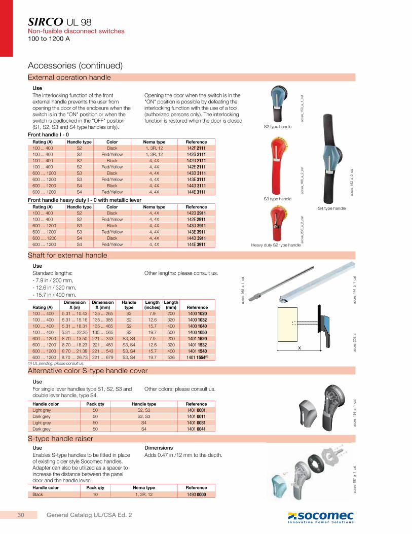
External operation handle
Use
The interlocking function of the front external handle prevents the user from opening the door of the enclosure when the switch is in the "ON" position or when the switch is padlocked in the "OFF" position (S1, S2, S3 and S4 type handles only).
Opening the door when the switch is in the "ON" position is possible by defeating the interlocking function with the use of a tool (authorized persons only). The interlocking function is restored when the door is closed.
Rating (A) Handle type Color Nema type Reference
100 ... 400 S2 Black 1, 3R, 12 142F 2111
100 ... 400 S2 Red/Yellow 1, 3R, 12 142G 2111
100 ... 400 S2 Black 4, 4X 142D 2111
100 ... 400 S2 Red/Yellow 4, 4X 142E 2111
600 … 1200 S3 Black 4, 4X 143D 3111
600 … 1200 S3 Red/Yellow 4, 4X 143E 3111
600 … 1200 S4 Black 4, 4X 144D 3111
600 … 1200 S4 Red/Yellow 4, 4X 144E 3111
Front handle I - 0
Rating (A) Handle type Color Nema type Reference
100 ... 400 S2 Black 4, 4X 142D 2911
100 ... 400 S2 Red/Yellow 4, 4X 142E 2911
600 … 1200 S3 Black 4, 4X 143D 3911
600 … 1200 S3 Red/Yellow 4, 4X 143E 3911
600 .... 1200 S4 Black 4, 4X 144D 3911
600 … 1200 S4 Red/Yellow 4, 4X 144E 3911
Front handle heavy duty I - 0 with metallic lever
(1) UL pending, please consult us.
30 General Catalog UL/CSA Ed. 2
SIRCO UL 98Non-fusible disconnect switches
100 to 1200 A
Shaft guide for external handle
acce
s_2
60
_a_2
_cat
Use
This accessory makes shaft introduction easier with up to 0.59 in / 15 mm misalignment.
Required for a shaft length over 12.6 in / 320 mm.
Description Reference
Shaft guide 1429 0000
Terminal lugsul_
03
2_a
Use
Connection of bare copper cables onto the lugs (without lugs).
Rating max (A) Wires rangeNo wires per lug
Lugs per kit Wires Reference
100 ... 200 #6 - 300MCM 1 2 Cu / Al 3954 2020
100 ... 200 #6 - 300MCM 1 3 Cu / Al 3954 3020
100 ... 200 #6 - 300MCM 1 4 Cu / Al 3954 4020
400 #4 - 600MCM 1 2 Cu / Al 3954 2040
400 #4 - 600MCM 1 3 Cu / Al 3954 3040
400 #4 - 600MCM 1 4 Cu / Al 3954 4040
400 2x (#6 - 350MCM) 2 2 Cu / Al 3954 2041
400 2x (#6 - 350MCM) 2 3 Cu / Al 3954 3041
400 2x (#6 - 350MCM) 2 4 Cu / Al 3954 4041
600 2x (#2 - 600MCM) 1 2 Cu / Al 3954 2060
600 2x (#2 - 600MCM) 2 3 Cu / Al 3954 3060
600 2x (#2 - 600MCM) 2 4 Cu / Al 3954 4060
800 … 1200 4x (#2 - 600MCM) 2 6 Cu / Al 3954 3120
800 … 1200 4x (#2 - 600MCM) 2 8 Cu / Al 3954 4120
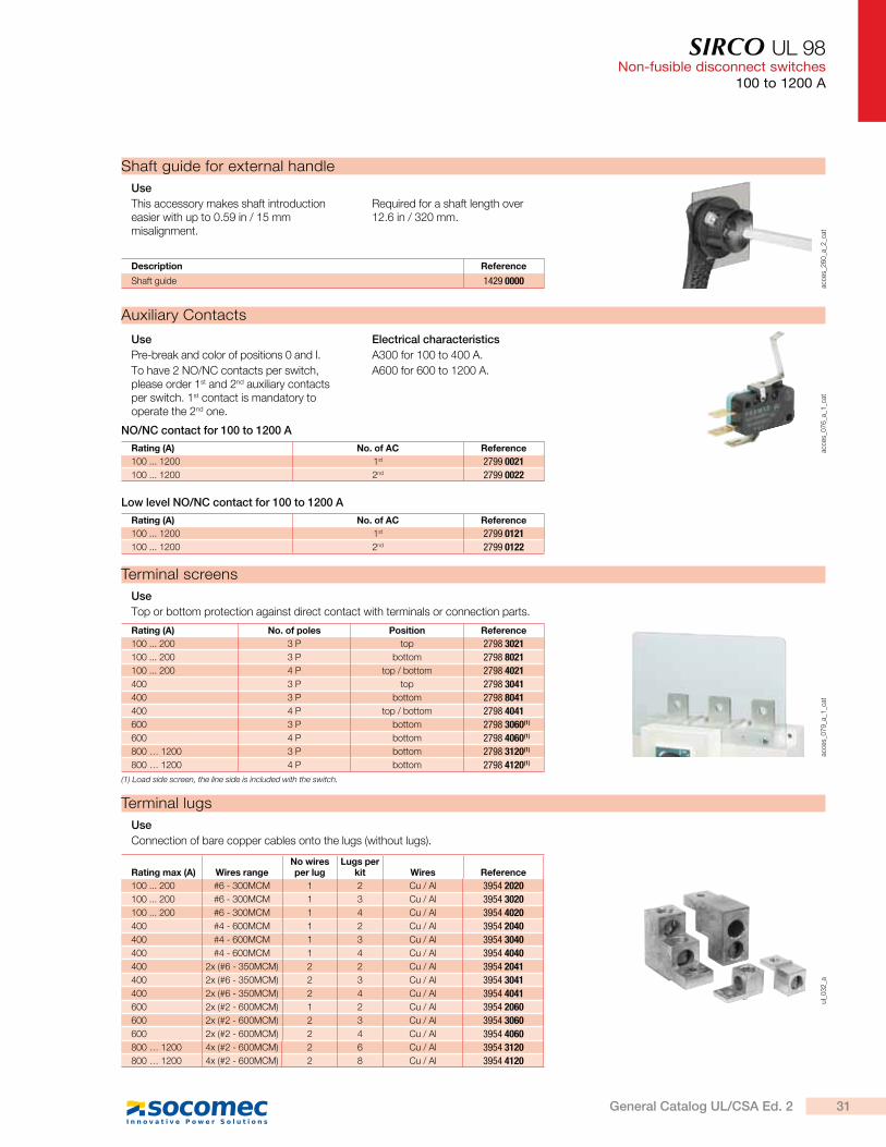
Terminal screens
acce
s_0
79
_a_1
_cat
Use
Top or bottom protection against direct contact with terminals or connection parts.
Rating (A) No. of poles Position Reference
100 ... 200 3 P top 2798 3021
100 ... 200 3 P bottom 2798 8021
100 ... 200 4 P top / bottom 2798 4021
400 3 P top 2798 3041
400 3 P bottom 2798 8041
400 4 P top / bottom 2798 4041
600 3 P bottom 2798 3060(1)
600 4 P bottom 2798 4060(1)
800 … 1200 3 P bottom 2798 3120(1)
800 … 1200 4 P bottom 2798 4120(1)
(1) Load side screen, the line side is included with the switch.
Auxiliary Contacts
acce
s_0
76
_a_1
_cat
Use
Pre-break and color of positions 0 and I.
To have 2 NO/NC contacts per switch, please order 1st and 2nd auxiliary contacts per switch. 1st contact is mandatory to operate the 2nd one.
Electrical characteristics
A300 for 100 to 400 A.
A600 for 600 to 1200 A.
Rating (A) No. of AC Reference
100 ... 1200 1st 2799 0021
100 ... 1200 2nd 2799 0022
NO/NC contact for 100 to 1200 A
Rating (A) No. of AC Reference
100 ... 1200 1st 2799 0121
100 ... 1200 2nd 2799 0122
Low level NO/NC contact for 100 to 1200 A
31General Catalog UL/CSA Ed. 2
SIRCO UL 98Non-fusible disconnect switches100 to 1200 A
SIRCO UL 98 - 100 to 1200 AGeneral use rating (A) 100 A 200 A 400 A 600 A 800 A 1000 A 1200 A
Short circuit rating at 600 VAC (kA) 200 200 200 200 100 100 100
Type of fuse J J J J L L L
Max. fuse rating (A) 100 200 400 600 800 1000 1200
Max. motor hp / FLA 3 ph motor max.
220-240 VAC 30 / 80 75 / 196 125 / 312 200 / 480 200 / 480 200 / 480 200 / 480
440-480 VAC 75 / 96 150 / 180 250 / 302 400 / 477 500 / 590 500 / 590 500 / 590
600 VAC 100 / 99 200 / 192 350 / 336 350 / 336 500 / 472 500 / 472 500 / 472
Max. motor hp / FLA 1 ph motor max.
220-240 VAC 10/50 10/50
Max. motor hp / DC FLA motor max.
125 VDC(1) 10 / 76 15 / 112 20 / 148 20 / 148
250 VDC(2) 15 / 55 15 / 55 50 / 173 50 / 173
Connection terminals
Min. connection section / AWG #6 #6 2x #6 / #4 2x #2 4x #2 4x #2 4x #2
Max. connection section / AWG 300MCM 300MCM2x 350 / 600MCM
2x 600MCM 4x 600MCM 4x 600MCM 4x 600MCM
Mechanical characteristics
Endurance (number of operating cycles) 10000 8000 6000 6000 3500 3500 3500
Operating torque (lbs.in/Nm) 88.5/10 88.5/10 128.3/14.5 327.5/37 442.5/50 442.5/50 442.5/50
Auxiliary contacts
Electrical characteristics A300 A300 A300 A600 A600 A600 A600
Characteristics
(1) 2 pole in series.
(2) 3 pole in series.
Characteristics according to UL 98/CSA 22.2#4
Characteristics according to IEC 60947-3
SIRCO UL 98 - 600 to 1200 AThermal current Ith (40°C) 600 A 800 A 1000 A 1200 A
Rated insulation voltage Ui (V) 1000 1000 1000 1000
Rated impulse withstand voltage Uimp (kV) 12 12 12 12
Rated operational currents Ie (A)
Rated voltage Utilization category A(1) A(1) A(1) A(1)
400 VAC AC-22 A 630 800 1000 1200
400 VAC AC-23 A 630 800 1000 1000
690 VAC AC-22 A 500 630 630 630
690 VAC AC-23 A 200 400 400 400
Connection
Min. Cu cable cross section (mm²) 2 x 150 2 x 185 2 x 240
Min. Cu busbar section (mm²) 2 x 30 x 5 2 x 40 x 5 2 x 50 x 5 2 x 60 x 5
Operational power in AC-23 (kW)
At 400 VAC without prebreaking AC in AC23 (kW)(2)(3) 355 450 560 560
At 500 VAC without prebreaking AC in AC23 (kW)(2)(3) 450 560 560 560
At 690 VAC without prebreaking AC in AC23 (kW)(2)(3) 185 400 400 400
Overload capacity (Ue 415 VAC)
Rated short-circuit making capacity Icm (kA peak)(4) 48 75 48 75
(1) Category with index A = frequent operation.
(2) A/B: Category with index A = frequent operation - Category with index B = infrequent operation.
(3) The power value is given for information only, the current values vary from one manufacturer to another.
(4) For a rated operating voltage Ue = 400 VAC.
32 General Catalog UL/CSA Ed. 2
SIRCO UL 98Non-fusible disconnect switches
100 to 1200 A
Y
AC
KC
AV
N AA
H
ZJ1 U
R1
M
ADT
F C
1
R2
W
sirc
o-u
l_0
11
_a_2
_x_c
at
1. Terminal shrouds
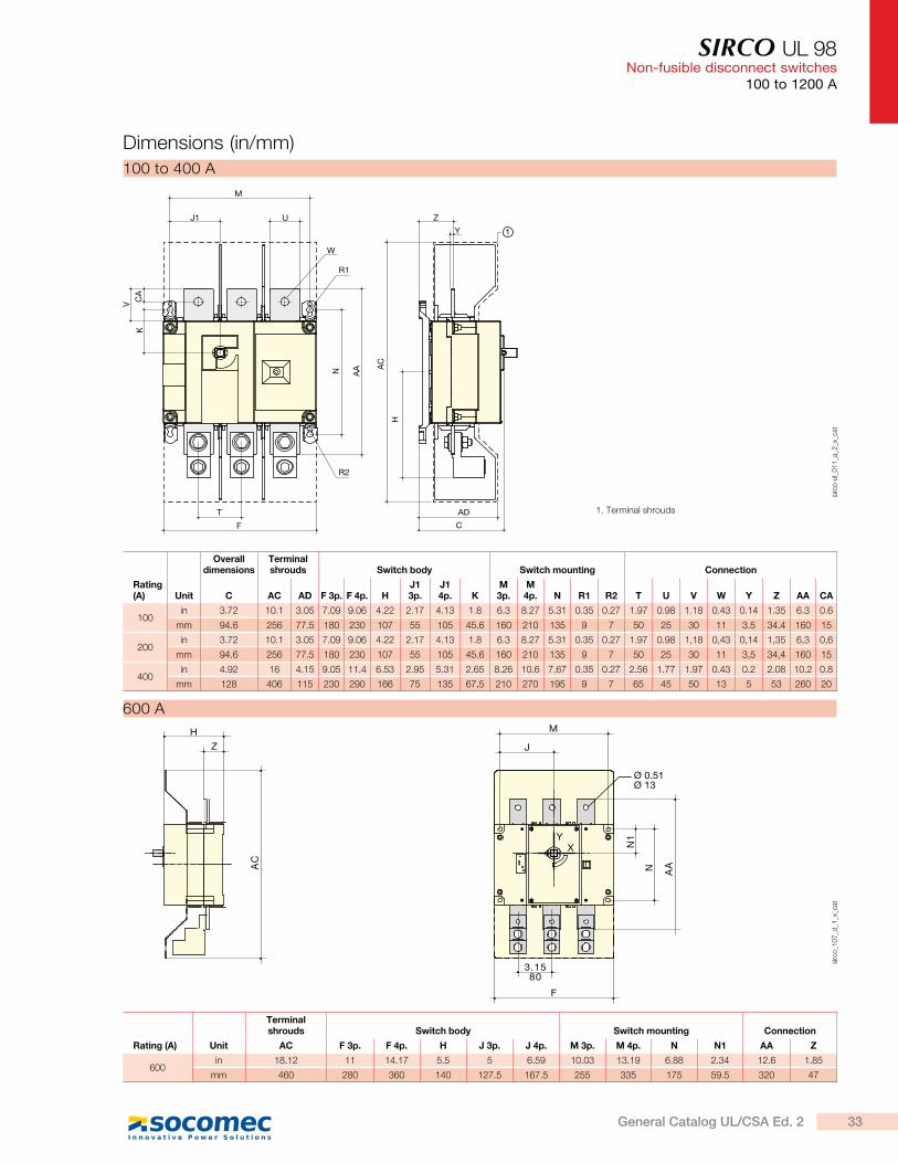
Rating (A) Unit
Overall dimensions
Terminal shrouds Switch body Switch mounting Connection
C AC AD F 3p. F 4p. HJ1 3p.
J1 4p. K
M 3p.
M 4p. N R1 R2 T U V W Y Z AA CA
100in 3.72 10.1 3.05 7.09 9.06 4.22 2.17 4.13 1.8 6.3 8.27 5.31 0.35 0.27 1.97 0.98 1.18 0.43 0.14 1.35 6.3 0.6
mm 94.6 256 77.5 180 230 107 55 105 45.6 160 210 135 9 7 50 25 30 11 3.5 34.4 160 15
200in 3.72 10.1 3.05 7.09 9.06 4.22 2.17 4.13 1.8 6.3 8.27 5.31 0.35 0.27 1.97 0.98 1,18 0,43 0,14 1,35 6,3 0,6
mm 94.6 256 77.5 180 230 107 55 105 45.6 160 210 135 9 7 50 25 30 11 3,5 34,4 160 15
400in 4.92 16 4.15 9.05 11.4 6.53 2.95 5.31 2.65 8.26 10.6 7.67 0.35 0.27 2.56 1.77 1.97 0.43 0.2 2.08 10.2 0.8
mm 128 406 115 230 290 166 75 135 67,5 210 270 195 9 7 65 45 50 13 5 53 260 20
100 to 400 A
Dimensions (in/mm)
H
Z
AC
3.1580
M
Ø 0.51Ø 13
J
N1
N AA
F
XY
sirc
o_1
07
_d_1
_x_c
at
Rating (A)
Terminal shrouds Switch body Switch mounting Connection
Unit AC F 3p. F 4p. H J 3p. J 4p. M 3p. M 4p. N N1 AA Z
600in 18.12 11 14.17 5.5 5 6.59 10.03 13.19 6.88 2.34 12.6 1.85
mm 460 280 360 140 127.5 167.5 255 335 175 59.5 320 47
600 A
33General Catalog UL/CSA Ed. 2

SIRCO UL 98Non-fusible disconnect switches100 to 1200 A
4.72120
M
J
F
XY
N
N2
0.78 20
0.78 20
1.5740
Ø 0.43Ø 11
H
ZA
C
N1
8.85
225
sirc
o_2
28
_d_1
_x_c
at
Terminal shrouds Switch body Switch mounting
Rating (A) Unit AC F 3p. F 4p. H J 3p. J 4p. M 3p. M 4p. N N1
800in 18.12 14.64 19.37 5.5 6.83 9.19 13.66 18.38 6.88 2.34
mm 460 372 492 140 173.5 233.5 347 467 175 59.5
1 000in 18.12 14.64 19.37 5.5 6.83 9.19 13.66 18.38 6.88 2.34
mm 460 372 492 140 173.5 233.5 347 467 175 59.5
1 200in 18.12 14.64 19.37 5.5 6.83 9.19 13.66 18.38 6.88 2.34
mm 460 372 492 140 173.5 233.5 347 467 175 59.5
800 to 1200 A
Front direct handle
602.36
853.35
190
7.48
sirc
o_2
67
_b_1
_x_c
at
600 to 1200 A
Front direct handle
Dimensions (in/mm) (continued)
100 to 400 A
1.5740
5.31
135
1.7945.5
sirc
o-u
l_0
27
_a_1
_x_c
at
Mounting orientation
3/4 pole
sirc
o-u
l_0
28
_a_1
_x_c
at
34 General Catalog UL/CSA Ed. 2
SIRCO UL 98Non-fusible disconnect switches
100 to 1200 A
External handles dimensions (in/mm)
Direction of operation Door drillingHandle type
Front operation
1.5740
4 Ø 0.274 Ø 7
Ø 1.46Ø 37
1.10 28
S2 type
90°
I
0
Ø 3.07Ø 78
4.92
125
1.7745 p
oig
n_0
13
_a_1
_us_
cat
100 to 400 A
Terminal lugs (in/mm)
3.1580
1.49 38
2.87 73
0.40Ø10.2
sirc
o_1
16
_b_1
_us_
cat
2 x 600 kcmil
600 to 1200 A
2.871.5
Ø 0.4Ø 4.71.
335
1.8
46 0.44
11.1
3
0.6315.88
sirc
o-u
l_0
10
_b_1
_us_
cat
600 kcmil
400 A
1.5238.8
1 251.
1228
.6
0.45Ø11.6
sirc
o_1
15
_b_1
_us_
cat
300 kcmil
100 to 200 A
Handle type
S3 type
Ø3.07
90°
I
0
2.40
8.27
1.57
1.10
Ø 1.46
4 Ø 0.27
Ø78
210
Ø 37
40
4 Ø 728
Direction of operation
Front operationDoor drilling
po
ign_0
46
_a_1
_gb
_cat
600 to 1200 A
2.36
13.7
8
Ø3.07
90°
I
0
1.57
1.10
Ø 1.46
4 Ø 0.27
Ø78
350
60
Ø 37
28
4 Ø 7
40
Direction of operationHandle type
Front operation
S4 type
Door drilling
po
ign_0
36
_a_1
_us_
cat
600 to 1200 A
2.8873.152
51 0.5313.46
1.1930.23
1.94
49.30
0.256.35 1.
2531.75
sirc
o-u
l_0
26
_b_1
_us_
cat
2 x 350 kcmil
400 A
35General Catalog UL/CSA Ed. 2
AC
no
n-f
usib
le
dis
co
nn
ec
t sw
itc
he
s
sirc
o_1
23
_a_2
_cat
L1
L2
L3
L4
Surge switch
TVSS
sirc
o-u
l_0
21
_a_1
_x_c
at
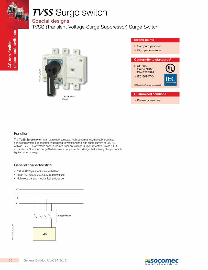
TVSS Surge switchSpecial designsTVSS (Transient Voltage Surge Suppressor) Surge Switch
> Compact product
> High performance
Strong points
> Please consult us
Customized solutions
Function
The TVSS Surge switch is an extremely compact, high performance, manually operated, non-fused switch. It is specifically designed to withstand the high surge current of 200 kA with an 8 x 20 s waveform seen in today’s transient voltage Surge Protective Device (SPD) applications. Socomec Surge Switch uses a unique contact design that actually clamp contacts tighter during a surge.
General characteristics
200 kA 8/20 s shockwave withstand.
Rated 100 A 600 VAC UL 508 general use.
High electrical and mechanical endurance.
> UL 508, Guide NRNT, File E224992
> IEC 60947-3
Conformity to standards(1)
(1) Product reference on request.
SIRCO 200 A 3 pole
36 General Catalog UL/CSA Ed. 2
TVSS Surge switchSpecial designs
TVSS (Transient Voltage Surge Suppressor) Surge Switch
References
Characteristics
3 pole 4 pole
TVSS Surge Switch - Front operation - 3/4 pole
Rating (A) No. of poles Switch body Direct handle Door interlocked external Shaft for external handle Terminal shrouds
8/20 s 200 KA 600 VAC
3 P 2700 3017
Black2699 5042
Red
2699 5043
S1 type Black
141F 2111
S1 type Red/Yellow 141G 2111
S1 type Black
141D 2111
S1 type Red/Yellow 141E 2111
200 mm1400 1020
320 mm1400 1032
400 mm
1400 1040
3 P2694 3014(1)
4 P
2694 4014(1)
4 P 2700 4017
Common accessories - more available on next pages
(1) Top or bottom.
0.39
1.420.86
0.78
6.69
3.35
0.1
0.39
Ø2.16
Ø0.35
2.952.950.79
92
0.83
1.37
2.56
4.53
75 7520 Ø9
Ø5.5
2036
22
170
10
8511
5
3.62
21
3.5
652.
5
10
sirc
o-u
l_0
19
_a_1
_gb
_cat
0.391.42
1.1
0.79
5.51
3.35 65
10
Ø2.16
Ø0.352.951.77
0.79
92
0.83
1.38
2.56
4.52
3.5
21
65
85
115
10
28
140
3620
20
45 75Ø9
Ø5.5
2.56
0.4
3.62
sirc
o-u
l_0
20
_a_1
_gb
_cat
UL 508 100 A 600 VAC General use
Dimensions (in/mm)
Front direct handle
1.5740
3.15 80
1.7945.5
sirc
o-u
l_0
81
_a_1
_x_c
at.e
ps
37General Catalog UL/CSA Ed. 2

Photovoltaic range
Photovoltaic disconnect switches
SIRCO PV UL 98B compact320 to 600 A
A fully tested range for all your PV applications …………………………………………………
Our experts are here for you to make your project a success.
Expert Services
SIRCO MOT PV2000 A
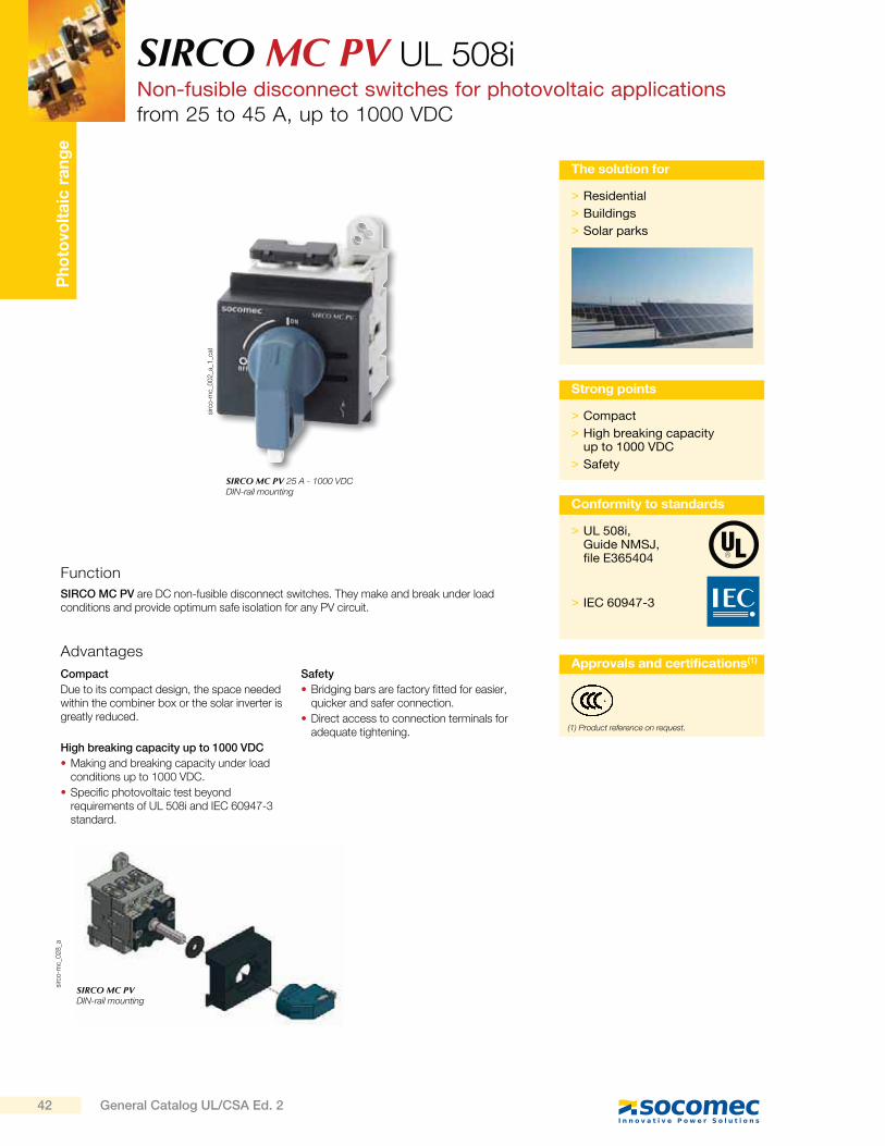
SIRCO MC PVUL 508i25 to 45 A
RM PV30 A
SIRCO PV UL 98B100 to 2000 A
p. 50p. 42
p. 76
p. 88
p. 84
p. 40
see page 8.
39General Catalog UL/CSA Ed. 2
Ph
oto
volt
aic
ra
ng
eA fully tested range for all your PV applications
Using tested and certified components is key for the success of the design for any photovoltaic system. The SIRCO PV range is tested and certified according to main standards used in the photovoltaic industry.
Global approvals
Our SIRCO PV solar disconnect range meets UL 98B, UL 508i, IEC 60947-3 Standards and bear the CE mark. Using the SOCOMEC range in your design is therefore a unique opportunity to standardize your components and use the same switches on 5 continents.
PV critical current
Under particular conditions (cloudy, days, evenings…) PV systems can deliver a low current at high voltage. This type of current is extremely difficult to interrupt.
Standard AC or DC products are usually not tested in these particular conditions and could therefore be unable to interrupt low currents at high DC voltage. If the electrical arc produced is not interrupted it may result in operator injury or fire. The SIRCO PV range has been specifically designed and tested to interrupt the current under all current / voltage conditions.
Short Circuit
The complete UL 98B range is tested to
withstand a short circuit of 10 kA for a duration of 50 ms without any specific protection. This allows the use of any
overcurrent protection device for line
protection.
Our UL 508i have been tested at 5 kA with fuses.
Thermal current test
Thermal tests have been performed according to both IEC and UL standards.
Our UL 98 switches are certified up to 60 C AM IENT without derating
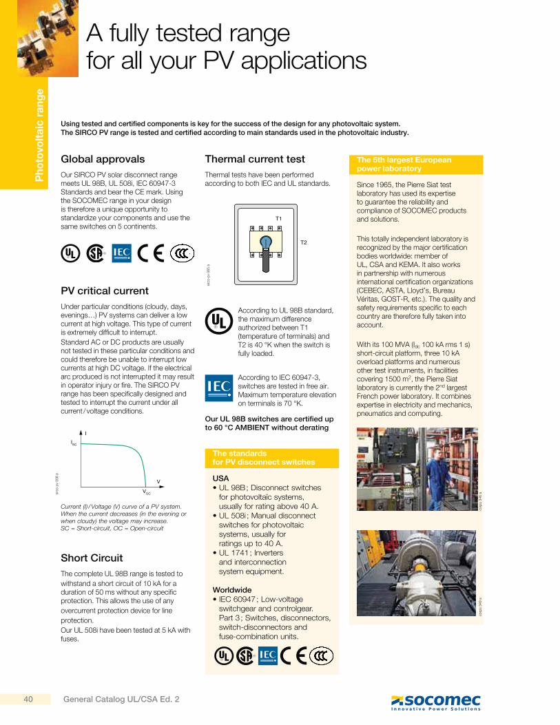
According to UL 98B standard, the maximum difference authorized between T1 (temperature of terminals) and T2 is 40 °K when the switch is fully loaded.
According to IEC 60947-3, switches are tested in free air. Maximum temperature elevation on terminals is 70 °K.
T1
T2
The 5th largest European power laboratory
Since 1965, the Pierre Siat test laboratory has used its expertise to guarantee the reliability and compliance of SOCOMEC products and solutions.
This totally independent laboratory is recognized by the major certification bodies worldwide: member of UL, CSA and KEMA. It also works in partnership with numerous international certification organizations (CEBEC, ASTA, Lloyd’s, Bureau Véritas, GOST-R, etc.). The quality and safety requirements specific to each country are therefore fully taken into account.
With its 100 MVA (Idc 100 kA rms 1 s) short-circuit platform, three 10 kA overload platforms and numerous other test instruments, in facilities covering 1500 m2, the Pierre Siat laboratory is currently the 2nd largest French power laboratory. It combines expertise in electricity and mechanics, pneumatics and computing.
corp
o 3
46 a
corp
o 3
49 a
Current (I) / Voltage (V) curve of a PV system. When the current decreases (in the evening or when cloudy) the voltage may increase. SC = Short-circuit, OC = Open-circuit
I
V
VOC
ISC
sirc
o p
v 008 a
sirc
o-p
v 065 a
The standards for PV disconnect switches
USA UL 98B ; Disconnect switches for photovoltaïc systems, usually for rating above 40 A.
UL 508i ; Manual disconnect switches for photovoltaic systems, usually for ratings up to 40 A.
UL 1741 ; Inverters and interconnection system equipment.
orldwide IEC 60947 ; Low-voltage switchgear and controlgear. Part 3 ; Switches, disconnectors, switch-disconnectors and fuse-combination units.
40 General Catalog UL/CSA Ed. 2
Typical PV architecture
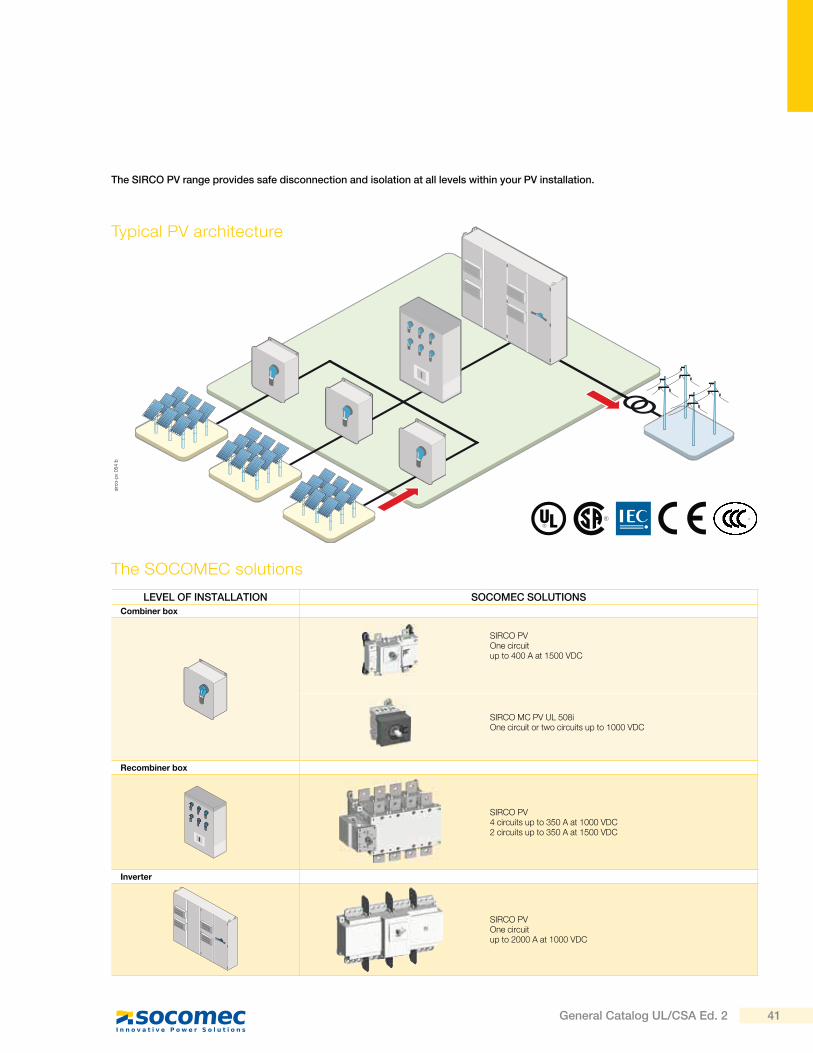
The SIRCO PV range provides safe disconnection and isolation at all levels within your PV installation.
The SOCOMEC solutions
LEVEL OF INSTALLATION SOCOMEC SOLUTIONS
Combiner box
SIRCO PVOne circuitup to 400 A at 1500 VDC
SIRCO MC PV UL 508iOne circuit or two circuits up to 1000 VDC
Recombiner box
SIRCO PV4 circuits up to 350 A at 1000 VDC2 circuits up to 350 A at 1500 VDC
Inverter
SIRCO PVOne circuitup to 2000 A at 1000 VDC
sirc
o-p
v 054 b
41General Catalog UL/CSA Ed. 2
Ph
oto
volt
aic
ra
ng
eSIRCO MC PV UL 508iNon-fusible disconnect switches for photovoltaic applicationsfrom 25 to 45 A, up to 1000 VDC
sirc
o-m
c_0
02
_a_1
_cat
sirc
o-m
c_0
28
_a
SIRCO MC PV 25 A - 1000 VDCDIN-rail mounting
SIRCO MC PVDIN-rail mounting
Function
SIRCO MC PV are DC non-fusible disconnect switches. They make and break under load conditions and provide optimum safe isolation for any PV circuit.
Advantages
Compact
Due to its compact design, the space needed within the combiner box or the solar inverter is greatly reduced.
High breaking capacity up to 1000 VDC
Making and breaking capacity under load conditions up to 1000 VDC.
Specific photovoltaic test beyond requirements of UL 508i and IEC 60947-3 standard.
Safety
Bridging bars are factory fitted for easier, quicker and safer connection.
Direct access to connection terminals for adequate tightening.
> Compact
> High breaking capacity up to 1000 VDC
> Safety
Strong points
> Residential
> Buildings
> Solar parks
The solution for
> UL 508i,Guide NMSJ,file E365404
> IEC 60947-3
Conformity to standards
Approvals and certifications(1)
(1) Product reference on request.
42 General Catalog UL/CSA Ed. 2
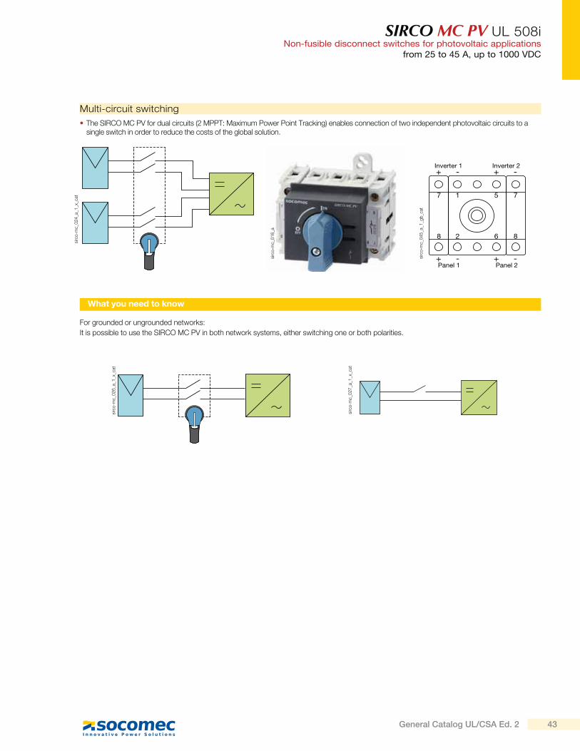
SIRCO MC PV UL 508iNon-fusible disconnect switches for photovoltaic applications
from 25 to 45 A, up to 1000 VDC
Multi-circuit switching
The SIRCO MC PV for dual circuits (2 MPPT: Maximum Power Point Tracking) enables connection of two independent photovoltaic circuits to a single switch in order to reduce the costs of the global solution.
For grounded or ungrounded networks:
It is possible to use the SIRCO MC PV in both network systems, either switching one or both polarities.
sirc
o-m
c_0
16
_a
sirc
o-m
c_0
45
_a_1
_gb
_cat
sirc
o-m
c_0
26
_a_1
_x_c
at
sirc
o-m
c_0
27
_a_1
_x_c
at
sirc
o-m
c_0
24
_a_1
_x_c
at
-+
1 5
2
7
8
7
86
-+Inverter 1
-+Inverter 2
Panel 1-+
Panel 2
What you need to know
43General Catalog UL/CSA Ed. 2
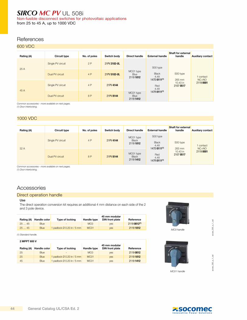
SIRCO MC PV UL 508iNon-fusible disconnect switches for photovoltaic applicationsfrom 25 to 45 A, up to 1000 VDC
References
600 VDC
1000 VDC
Rating (A) Circuit type No. of poles Switch body Direct handle External handleShaft for external
handle Auxiliary contact
25 A
Single PV circuit 2 P 21PV 2102-UL
MC01 typeBlue
2119 1012
S00 type
Black4.4X
147D 0111(1)
Red4.4X
147R 0111(1)
S00 type
265 mm10.43 in
2107 0517
1 contact NC+NO
2119 0001
Dual PV circuit 4 P 21PV 5102-UL
45 A
Single PV circuit 4 P 21PV 4144
Dual PV circuit 8 P 21PV 8144MC01 type
Blue2119 1412
Rating (A) Circuit type No. of poles Switch body Direct handle External handleShaft for external
handle Auxiliary contact
32 A
Single PV circuit 4 P 21PV 4144MC01 type
Black2119 1012
S00 type
Black4.4X
147D 0111(1)
Red4.4X
147R 0111(1)
S00 type
265 mm10.43 in
2107 0517
1 contact NC+NO
2119 0001
Dual PV circuit 8 P 21PV 8144MC01 type
Black2119 1412
Common accessories - more available on next pages.
(1) Door interlocking.
Common accessories - more available on next pages.
(1) Door interlocking.
Accessories
Direct operation handle
acce
s_3
05
_a_1
_cat
MC0 handle
acce
s_2
93
_a_1
_cat
MC01 handle
Rating (A) Handle color Type of locking Handle type45 mm modular DIN front plate Reference
25 … 45 Blue - MC0 yes 2119 0012(1)
25 … 45 Blue 1 padlock 0.20 in / 5 mm MC01 yes 2119 1012
2 MPPT 600 V
Rating (A) Handle color Type of locking Handle type45 mm modular DIN front plate Reference
25 Blue - MC0 yes 2119 0012
25 Blue 1 padlock 0.20 in / 5 mm MC01 yes 2119 1012
45 Blue 1 padlock 0.20 in / 5 mm MC01 yes 2119 1412
(1) Standard handle.
Use
The direct operation conversion kit requires an additional 4 mm distance on each side of the 2 and 3 pole device.
44 General Catalog UL/CSA Ed. 2
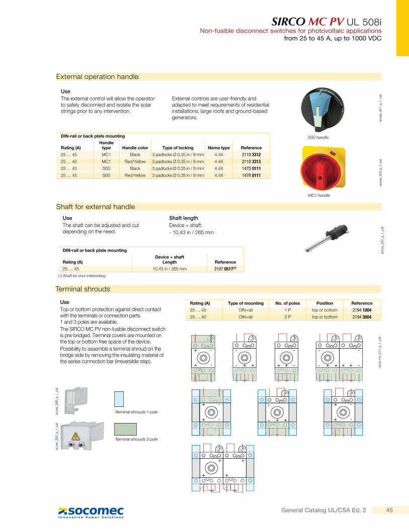
SIRCO MC PV UL 508iNon-fusible disconnect switches for photovoltaic applications
from 25 to 45 A, up to 1000 VDC
External operation handle
acce
s_3
02
_a_1
_cat
acce
s_3
41
_a_1
_cat
Use
The external control will allow the operator to safely disconnect and isolate the solar strings prior to any intervention.
External controls are user-friendly and adapted to meet requirements of residential installations, large roofs and ground-based generators.
DIN-rail or back plate mounting
Rating (A)Handle
type Handle color Type of locking Nema type Reference
25 … 45 MC1 Black 3 padlocks 0.35 in / 8 mm 4.4X 2119 3312
25 … 45 MC1 Red/Yellow 3 padlocks 0.35 in / 8 mm 4.4X 2119 3313
25 … 45 S00 Black 3 padlocks 0.35 in / 8 mm 4.4X 147D 0111
25 … 45 S00 Red/Yellow 3 padlocks 0.35 in / 8 mm 4.4X 147R 0111
MC1 handle
S00 handle
Shaft for external handle
acce
s_2
97
_a_1
_cat
Use
The shaft can be adjusted and cut depending on the need.
Shaft length
Device + shaft:
- 10.43 in / 265 mm
DIN-rail or back plate mounting
Rating (A)Device + shaft
Length Reference
25 … 45 10.43 in / 265 mm 2107 0517(1)
(1) Shaft for door interlocking.
Terminal shrouds
Use
Top or bottom protection against direct contact with the terminals or connection parts. 1 and 3 poles are available.
The SIRCO MC PV non-fusible disconnect switch is pre-bridged. Terminal covers are mounted on the top or bottom free space of the device.
Possibility to assemble a terminal shroud on the bridge side by removing the insulating material of the series connection bar (irreversible step).
Rating (A) Type of mounting No. of poles Position Reference
25 … 45 DIN-rail 1 P top or bottom 2194 1004
25 … 45 DIN-rail 3 P top or bottom 2194 3004
acce
s_2
99
_a_1
_cat
acce
s_3
00
_a_1
_cat
+
+
-
-
-
- ++
+
+
-
-
+
+
-
-
-
- ++
-
-++
-
- ++
-
-++
+
+
+
+
sirc
o-m
c_0
11
_e_1
_cat
Terminal shrouds 1 pole
Terminal shrouds 3 pole
45General Catalog UL/CSA Ed. 2
SIRCO MC PV UL 508iNon-fusible disconnect switches for photovoltaic applicationsfrom 25 to 45 A, up to 1000 VDC
Characteristics
25 A 45 A
General use rating with 200% overload extra test
Rated voltage Number of poles of the device Number of PV circuits (A) (A)
600 VDC 2 P 1 25 -
600 VDC 4 P 1 - 45
600 VDC 2 x 2 P 2 25 -
600 VDC 2 x 4 P 2 - 45
1000 VDC 4 P 1 - 32
1000 VDC 2 x 4 P 2 - 32
Short-circuit capacity at 600 VDC
Prospective short-circuit current (kA rms) 5 5
Type of fuse gPV gPV
Associated fuse rating (A) 25 80
Short-circuit capacity at 1000 VDC
Prospective short-circuit current (kA rms) 5 5
Connection terminals
Min. connection wire range / AWG (solid or stranded) 14 / 7 14 / 3
Mechanical characteristics
Durability (number of operating cycles) 30 000 30 000
Tightening torque (Nm) 2 2
Rated current 25 A 45 A
Thermal current Ith at 40°C (A) 25 45
Thermal current at 50°C (A) 25 45
Thermal current at 60°C (A) 25 45
Rated insulation voltage Ui (V) 1000 1000
Rated impulse withstand voltage Uimp (kV) 8 8
Rated operational currents Ie (A)
Rated voltage Number of poles of the device Number of PV circuits (A) (A)
600 VDC 2 P 1 30 -
600 VDC 4 P 1 - 40
600 VDC 2 x 2 P 2 30 -
600 VDC 2 x 4 P 2 - 40
1000 VDC 2 P 1 10 -
1000 VDC 4 P 1 - 40
1000 VDC 2 x 2 P 2 10 -
1000 VDC 2 x 4 P 2 - 40
according to UL 508i
according to IEC 60947-3
46 General Catalog UL/CSA Ed. 2
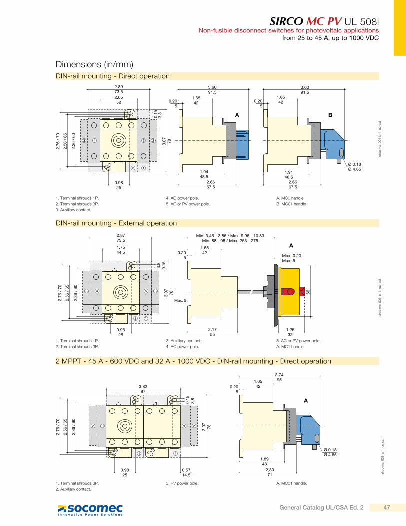
SIRCO MC PV UL 508iNon-fusible disconnect switches for photovoltaic applications
from 25 to 45 A, up to 1000 VDC
2 MPPT - 45 A - 600 VDC and 32 A - 1000 VDC - DIN-rail mounting - Direct operation
1. Terminal shrouds 3P.
2. Auxiliary contact.
3. PV power pole. A. MC01 handle.
3.8297
3.07 78
2.76
/ 70
0.9825
0.5714.5
2.36
/ 60
2.56
/ 65
0.15
3.8
3.74951.65
420.205
1.8948
Ø 0.18Ø 4.65
2,8071
A
3 22 3
1 1
sirc
o-m
c_0
39
_a_1
_us_
cat
Dimensions (in/mm)
DIN-rail mounting - Direct operation
1. Terminal shrouds 1P.
2. Terminal shrouds 3P.
3. Auxiliary contact.
4. AC power pole.
5. AC or PV power pole.
A. MC0 handle
B. MC01 handle
3.6091.5
1.6542
1.9148.5
Ø 0.18Ø 4.65
2.6667.5
3 3
12
4 5
2.8973.52.0552
3.07 78
2.76
/ 70
0.9825
2.36
/ 60
2.56
/ 65
0.15
3.8
3.6091.5
1.65420.20
50.20
5
1.9448.5
2.6667.5
A B
sirc
o-m
c_0
04
_b_1
_us_
cat
DIN-rail mounting - External operation
2.8773.5
1.7544.5
3.07 78
2.76
/ 70
0.9825
2.36
/ 60
2.56
/ 65
3.8
0.15
Min. 3.46 - 3.86 / Max. 9.96 - 10.83Min. 88 - 98 / Max. 253 - 275
1.65420.20
5
2.1755
Max. 0.20Max. 5
66
1.2632
A
3 3
12
4 5
sirc
o-m
c_0
05
_b_1
_xus_
cat
1. Terminal shrouds 1P.
2. Terminal shrouds 3P.
3. Auxiliary contact.
4. AC power pole.
5. AC or PV power pole.
A. MC1 handle
Max. 5
47General Catalog UL/CSA Ed. 2
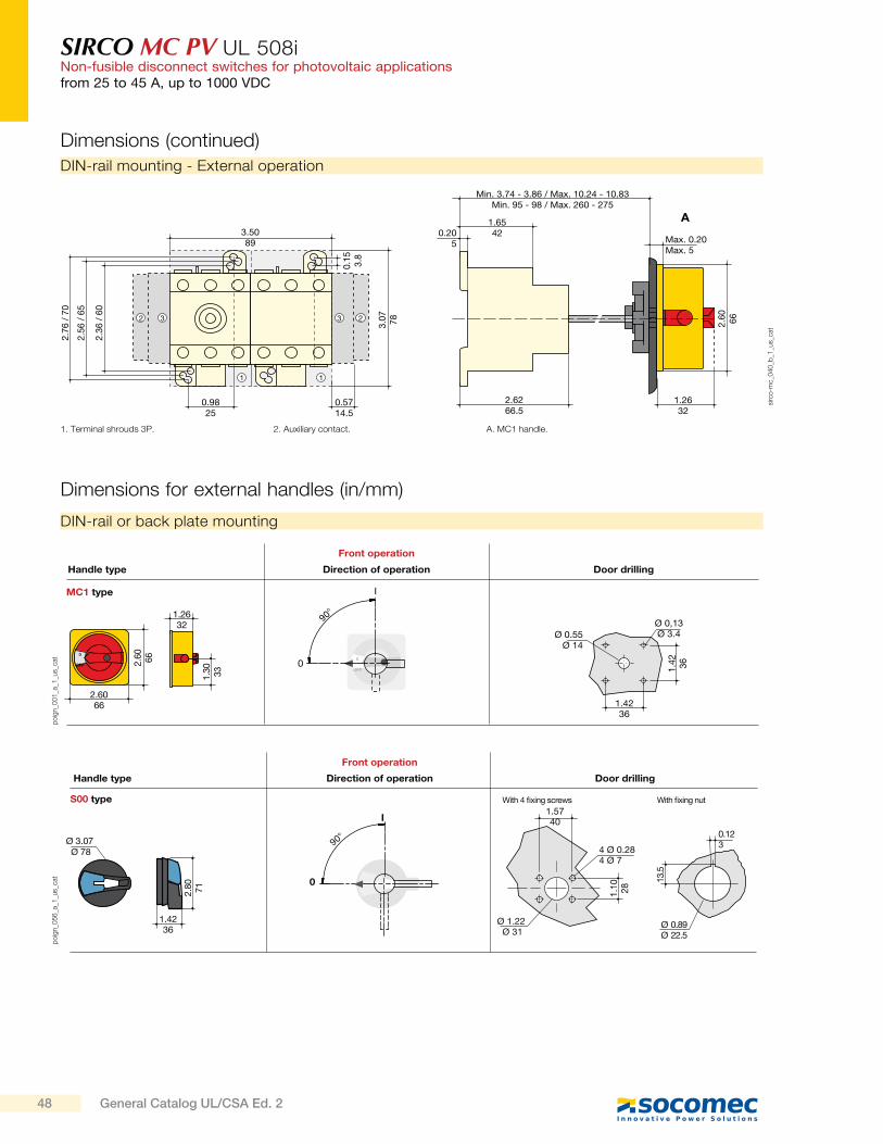
SIRCO MC PV UL 508iNon-fusible disconnect switches for photovoltaic applicationsfrom 25 to 45 A, up to 1000 VDC
Dimensions for external handles (in/mm)
DIN-rail or back plate mounting
po
ign_0
01
_a_1
_us_
cat
po
ign_0
56
_a_1
_us_
cat
1.5740
4 Ø 0.284 Ø 7
Ø 1.22 Ø 31
1.10 28
S00 type
0
I
90°
13.5
Ø 0.89Ø 22.5
0.123Ø 3.07
Ø 78
1.4236
2.80 71
With fixing nutWith 4 fixing screws
Direction of operation Door drillingHandle type
Front operation
0
OFF
0
OFF
1.30 33
1.2632
2.6066
2.60 66
Ø 0.55Ø 14
Ø 0,13Ø 3.4
1.4236
1.42 360
I
90°
Direction of operation Door drillingHandle type
Front operation
MC1 type
DIN-rail mounting - External operation
1. Terminal shrouds 3P. 2. Auxiliary contact. A. MC1 handle.
Min. 3.74 - 3.86 / Max. 10.24 - 10.83Min. 95 - 98 / Max. 260 - 275
1.65420.20
5
2.6266.5
Max. 0.20Max. 5
2.60 66
1.2632
A3.5089
3.07 78
0.9825
0.5714.5
0.15 3.8
3 22 3
1 1
2.76
/ 70
2.36
/ 60
2.56
/ 65
sirc
o-m
c_0
40
_b_1
_us_
cat
Dimensions (continued)
48 General Catalog UL/CSA Ed. 2
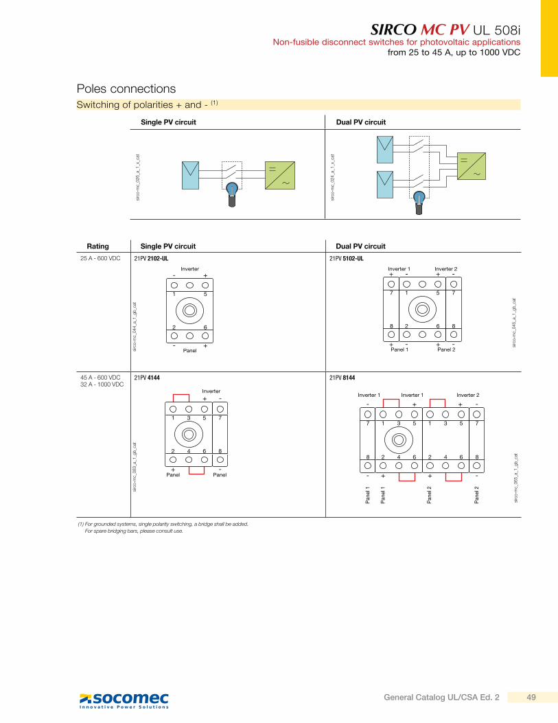
SIRCO MC PV UL 508iNon-fusible disconnect switches for photovoltaic applications
from 25 to 45 A, up to 1000 VDC
Rating Single PV circuit Dual PV circuit
25 A - 600 VDC 21PV 2102-UL 21PV 5102-UL
45 A - 600 VDC32 A - 1000 VDC
21PV 4144 21PV 8144
Poles connections
-
1 5
2 6
+
- +Inverter
Panel
+
1 3 5
2 4 6
7
8
-
+ -Inverter
Panel Panel
-+
1 5
2
7
8
7
86
-+Inverter 1
-+Inverter 2
Panel 1-+
Panel 2
+
1 3 5
2 4 6
Pan
el 1
Pan
el 1
+
1 3 5
2 4 6
Inverter 2
Pan
el 2
Pan
el 2
-
7
8
- + +
-
7
8
-Inverter 1 Inverter 1
sirc
o-m
c_0
44
_a_1
_gb
_cat
sirc
o-m
c_0
83
_a_1
_gb
_cat
sirc
o-m
c_0
45
_a_1
_gb
_cat
sirc
o-m
c_0
65
_a_1
_gb
_cat
Switching of polarities + and - (1)
Single PV circuit Dual PV circuit
sirc
o-m
c_0
26
_a_1
_x_c
at
sirc
o-m
c_0
24
_a_1
_x_c
at
(1) For grounded systems, single polarity switching, a bridge shall be added.
For spare bridging bars, please consult use.
49General Catalog UL/CSA Ed. 2

Ph
oto
volt
aic
ra
ng
eSIRCO PV UL 98BDisconnect switches for photovoltaic applicationsfrom 100 to 2000 A, up to 1500 VDC
Function
SIRCO PV UL 98B are manually operated multipolar disconnect switches. They make and break under load conditions and provide safety isolation for any PV circuit up to 1000 VDC (as per UL 98B standard) and 1500 VDC (as per IEC 60947-3). They comply with NEC Atr. 690 (US National Electrical Code) concerning photovoltaic installations. They are compliant for use within solar inverters and enclosures governed by standard UL1741.
SIRCO PV are extremely durable switches that have been tested and approved for use in the most demanding environments.
They have been designed and tested for all types of applications: Grounded, floating and bipolar.
> Patented switching technology
> Positive break indication
> Up to 1000 VDC as per characteristics by UL 98B
> Up to 1500 VDC as per characteristics by IEC 60947-3
> Suitable for use in accordance with NEC Art. 690
Strong points
> UL 98B,Guide WHVA,file E346418
> CSA C22.2#4, Class 4651-02,file 112964
> IEC 60947-3
Conformity to standards
Advantages
Performance
A glass fiber reinforced polyester break chamber with an arc extinguishing system provides a patented safety disconnection system offering rapid extinguishing of the electric arc up to 1500 VDC and current interruption up to 2000 A.
Back-to-back double disconnect switch
The system of back-to-back double switches enables:
- on load operation of two switches with a single handle,
- compact solution when connecting two separate photovoltaic circuits compared with the use of two separate switches,
- easy connection,
- voltages above 1000 VDC are broken by the use of two poles in series.
Approvals and certifications (1)
(1) Product reference on request.
sirc
o-p
v_0
58
_a_1
_cat
sirc
o-p
v_0
59
_a_1
_cat
> Combiner box
> Recombiner box
> Inverter
The solution for
50 General Catalog UL/CSA Ed. 2
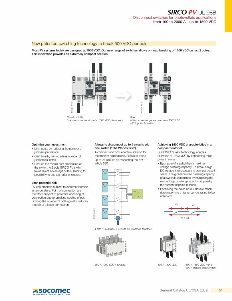
SIRCO PV UL 98BDisconnect switches for photovoltaic applications
from 100 to 2000 A - up to 1500 VDC
New patented switching technology to break 500 VDC per pole
Most PV systems today are designed at 1000 VDC. Our new range of switches allows on-load breaking of 1000 VDC on just 2 poles. This innovation provides an extremely compact solution.
Classic solutionExample of connection of a 1000 VDC disconnect.
NewWith our new range we can break 1000 VDC with 2 poles in series.
sirc
o p
v 0
66
a
sirc
o p
v 0
67
a
Achieving 1500 VDC characteristics in a compact footprint
SOCOMEC’s new technology enables utilization at 1500 VDC by connecting three poles in series.
Each pole of a switch has a maximum voltage breaking capacity. To break a high DC voltage it is necessary to connect poles in series. The global on-load breaking capacity of a switch is determined by multiplying the max voltage breaking capacity per pole by the number of poles in series.
Paralleling the poles on our double-stack design permits a higher current rating to be achieved.
Optimize your investment
Limit costs by reducing the number of jumpers per device.
Gain time by having a less number of jumpers to install.
Reduce the overall heat dissipation of the switch. A 2 pole SIRCO PV switch takes direct advantage of this, leading to possibility to use a smaller enclosure.
Limit potential risk
PV equipment is subject to extreme variation in temperature. Point of connection are therefore subject to potential loosening of connection due to breaking cooling effect. Limiting the number of poles greatly reduces the risk of a loose connection.
Allows to disconnect up to 4 circuits with one switch (“The Worlds first”)
A compact and cost effective solution for recombiner applications. Allows to break
up to 24 circuits by respecting the NEC article 690.
4 MPPT switches, 4 circuits are switched together.
400 A 1500 VDC 800 A 1500 VDC with a 400 A double stack switch.
350 A 1000 VDC 4 circuits.
SIR
CO
MC
059 A
V1
V1 + V2
V2
SIR
CO
PV
056 A
SIR
CO
PV
052
A
SIR
CO
PV
055
A
51General Catalog UL/CSA Ed. 2
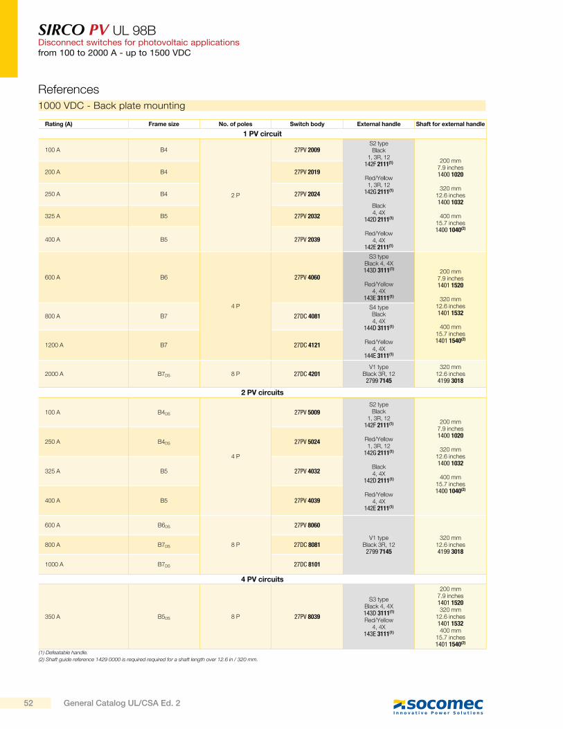
SIRCO PV UL 98BDisconnect switches for photovoltaic applicationsfrom 100 to 2000 A - up to 1500 VDC
1000 VDC - Back plate mounting
References
Rating (A) Frame size No. of poles Switch body External handle Shaft for external handle
1 PV circuit
100 A B4
2 P
27PV 2009S2 typeBlack
1, 3R, 12142F 2111(1)
Red/Yellow1, 3R, 12
142G 2111(1)
Black4, 4X
142D 2111(1)
Red/Yellow4, 4X
142E 2111(1)
200 mm7.9 inches1400 1020
320 mm12.6 inches1400 1032
400 mm15.7 inches1400 1040(2)
200 A B4 27PV 2019
250 A B4 27PV 2024
325 A B5 27PV 2032
400 A B5 27PV 2039
600 A B6
4 P
27PV 4060
S3 typeBlack 4, 4X143D 3111(1)
Red/Yellow4, 4X
143E 3111(1)
200 mm7.9 inches1401 1520
320 mm12.6 inches1401 1532
400 mm15.7 inches1401 1540(2)
800 A B7 27DC 4081
S4 typeBlack4, 4X
144D 3111(1)
Red/Yellow4, 4X
144E 3111(1)
1200 A B7 27DC 4121
2000 A B7DS 8 P 27DC 4201V1 type
Black 3R, 122799 7145
320 mm12.6 inches4199 3018
2 PV circuits
100 A B4DS
4 P
27PV 5009S2 typeBlack
1, 3R, 12142F 2111(1)
Red/Yellow1, 3R, 12
142G 2111(1)
Black4, 4X
142D 2111(1)
Red/Yellow4, 4X
142E 2111(1)
200 mm7.9 inches1400 1020
320 mm12.6 inches1400 1032
400 mm15.7 inches1400 1040(2)
250 A B4DS 27PV 5024
325 A B5 27PV 4032
400 A B5 27PV 4039
600 A B6DS
8 P
27PV 8060
V1 typeBlack 3R, 12
2799 7145
320 mm12.6 inches4199 3018
800 A B7DS 27DC 8081
1000 A B7DS 27DC 8101
4 PV circuits
350 A B5DS 8 P 27PV 8039
S3 typeBlack 4, 4X143D 3111(1)
Red/Yellow4, 4X
143E 3111(1)
200 mm7.9 inches1401 1520320 mm
12.6 inches1401 1532400 mm
15.7 inches1401 1540(2)
(1) Defeatable handle.
(2) Shaft guide reference 1429 0000 is required required for a shaft length over 12.6 in / 320 mm.
52 General Catalog UL/CSA Ed. 2
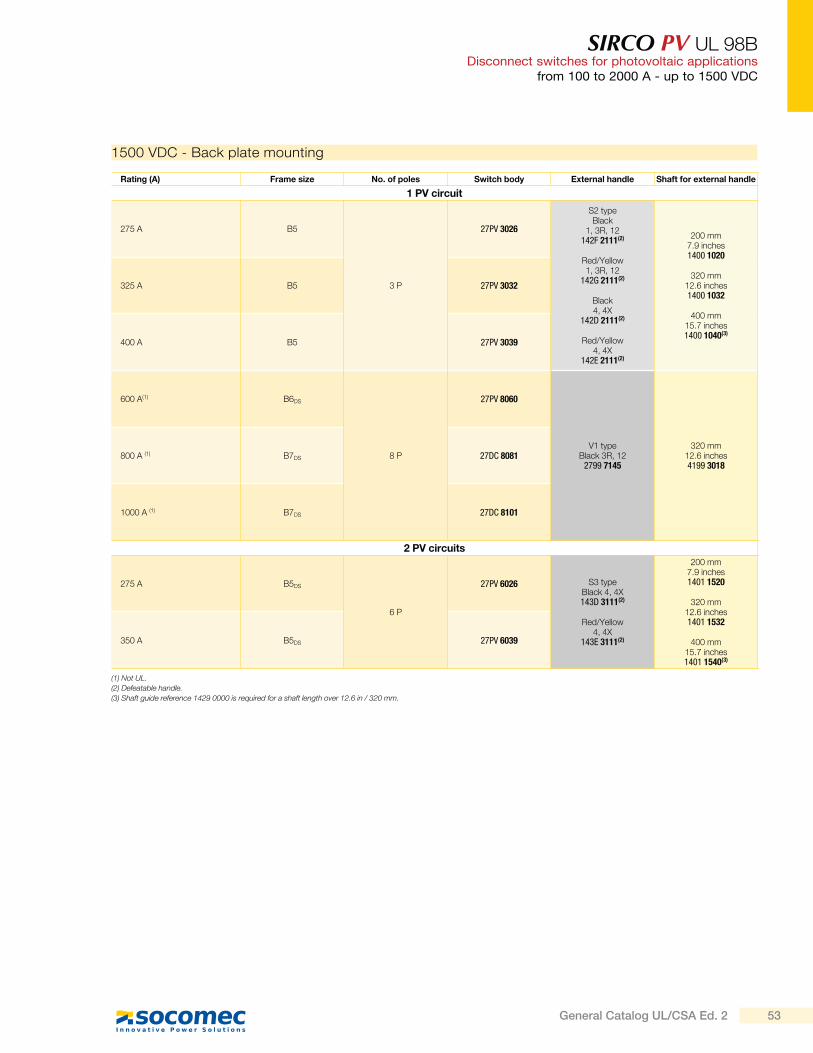
SIRCO PV UL 98BDisconnect switches for photovoltaic applications
from 100 to 2000 A - up to 1500 VDC
1500 VDC - Back plate mounting
Rating (A) Frame size No. of poles Switch body External handle Shaft for external handle
1 PV circuit
275 A B5
3 P
27PV 3026
S2 typeBlack
1, 3R, 12142F 2111(2)
Red/Yellow1, 3R, 12
142G 2111(2)
Black4, 4X
142D 2111(2)
Red/Yellow4, 4X
142E 2111(2)
200 mm7.9 inches1400 1020
320 mm12.6 inches1400 1032
400 mm15.7 inches1400 1040(3)
325 A B5 27PV 3032
400 A B5 27PV 3039
600 A(1) B6DS
8 P
27PV 8060
V1 typeBlack 3R, 12
2799 7145
320 mm12.6 inches4199 3018
800 A (1) B7DS 27DC 8081
1000 A (1) B7DS 27DC 8101
2 PV circuits
275 A B5DS
6 P
27PV 6026 S3 typeBlack 4, 4X143D 3111(2)
Red/Yellow4, 4X
143E 3111(2)
200 mm7.9 inches1401 1520
320 mm12.6 inches1401 1532
400 mm15.7 inches1401 1540(3)
350 A B5DS 27PV 6039
(1) Not UL.
(2) Defeatable handle.
(3) Shaft guide reference 1429 0000 is required for a shaft length over 12.6 in / 320 mm.
53General Catalog UL/CSA Ed. 2
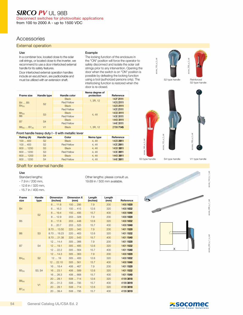
SIRCO PV UL 98BDisconnect switches for photovoltaic applicationsfrom 100 to 2000 A - up to 1500 VDC
Accessories
External operation
acce
s_1
50
_a_2
_cat
S2 type handle
acce
s_1
66
_a_2
_cat
S3 type handle
acce
s_1
52
_a_2
_cat
S4 type handle
acce
s_2
36
_a_2
_cat
Reinforced S2 type handle
Frame size Handle type Handle colorNema degree of
protection Reference
B4 … B5B4DS
S2
Black1, 3R, 12
142F 2111Red/Yellow 142G 2111
Black
4, 4X
142D 2111Red/Yellow 142E 2111
B5DS
B6S3
Black 143D 3111Red/Yellow 143E 3111
B7 S4Black 144D 3111
Red/Yellow 144E 3111
B6DS … B7DS V1 Black 1, 3R, 12 2799 7145
acce
ss_1
89
_a_2
_cat
V1 type handle
Use
In a combiner box, located close to the solar cell strings, or located close to the inverter, we recommend to use a door interlocked external handle for its safety features.
Door interlocked external operation handles include an escutcheon, are padlockable and must be utilized with an extension shaft.
Example
The locking function of the enclosure in the "ON" position will force the operator to safely disconnect and isolate the solar cell strings prior to any intervention. Opening the door when the switch is on "ON" position is possible by defeating the locking function using a tool (authorized persons only). The interlocking function is restored when the door is re-closed.
Shaft for external handle
acce
s_1
44
_b_1
_cat
acce
s_3
69
_a_1
_cat
X
acce
s_2
02
_a_1
_x_c
at
Use
Standard lengths:
- 7.9 in / 200 mm,
- 12.6 in / 320 mm,
- 15.7 in / 400 mm.
Other lengths: please consult us.
19.69 in / 500 mm available.
Frame size
Handle type
Dimension (inches)
Dimension X (mm)
Length (inches)
Length (mm) Reference
B4
S2
6 … 11.6 150 … 295 7.9 200 1400 1020
6 … 16.3 150 … 415 12.6 320 1400 1032
6 … 19.4 150 … 495 15.7 400 1400 1040
B5
8 … 12.9 203 … 328 7.9 200 1400 1020
8 … 17.6 203 … 448 12.6 320 1400 1032
8 … 20.7 203 … 525 15.7 400 1400 1040
B6 S3
8.70 … 13.50 220 … 343 7.9 200 1401 1520
8.70 … 18.23 220 … 463 12.6 320 1401 1532
8.70 … 21.38 220 … 543 15.7 400 1401 1540
B7 S4
12 … 14.4 305 … 366 7.9 200 1401 1520
12 … 19.1 305 … 485 12.6 320 1401 1532
12 … 22.2 305 … 564 15.7 400 1401 1540
B4DS S2
12 … 14.3 305 … 363 7.9 200 1400 1020
12 … 19 305 … 483 12.6 320 1400 1032
12 … 22.10 305 … 561 15.7 400 1400 1040
B5DS S3, S4
16 … 18.4 406 … 467 7.9 200 1401 1520
16 … 23.1 406 … 589 12.6 320 1401 1532
16 … 26.3 406 … 668 15.7 400 1401 1540
B6DS
V1
20 … 28.1 508 … 714 12.6 320 4199 3018
20 … 31.3 508 … 795 15.7 400 4199 3019
B7DS
20 … 28.1 508 … 714 12.6 320 4199 3018
20 … 39.4 508 … 795 15.7 400 4199 3019
Rating (A) Handle type Color Nema type Reference
100 ... 400 S2 Black 4, 4X 142D 2911
100 ... 400 S2 Red/Yellow 4, 4X 142E 2911
600 … 1200 S3 Black 4, 4X 143D 3911
600 … 1200 S3 Red/Yellow 4, 4X 143E 3911
600 .... 1200 S4 Black 4, 4X 144D 3911
600 … 1200 S4 Red/Yellow 4, 4X 144E 3911
Front handle heavy duty I - 0 with metallic lever
54 General Catalog UL/CSA Ed. 2
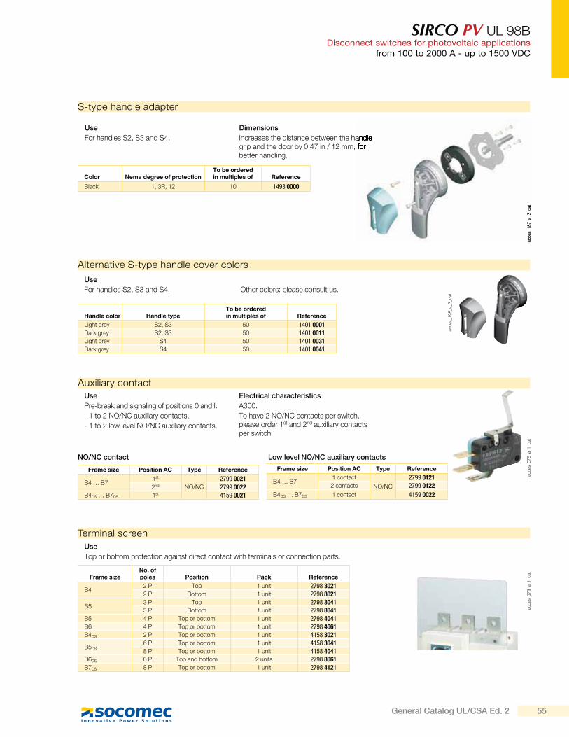
SIRCO PV UL 98BDisconnect switches for photovoltaic applications
from 100 to 2000 A - up to 1500 VDC
Auxiliary contact
acce
s_0
76
_a_1
_cat
Use
Pre-break and signaling of positions 0 and I:
- 1 to 2 NO/NC auxiliary contacts,
- 1 to 2 low level NO/NC auxiliary contacts.
Electrical characteristics
A300.
To have 2 NO/NC contacts per switch, please order 1st and 2nd auxiliary contacts per switch.
Frame size Position AC Type Reference
B4 … B71st
NO/NC
2799 0021
2nd 2799 0022B4DS … B7DS 1st 4159 0021
Frame size Position AC Type Reference
B4 … B71 contact
NO/NC
2799 01212 contacts 2799 0122
B4DS … B7DS 1 contact 4159 0022
Terminal screenac
ces_
07
9_a
_1_c
at
Use
Top or bottom protection against direct contact with terminals or connection parts.
Frame sizeNo. of poles Position Pack Reference
B42 P Top 1 unit 2798 30212 P Bottom 1 unit 2798 8021
B53 P Top 1 unit 2798 30413 P Bottom 1 unit 2798 8041
B5 4 P Top or bottom 1 unit 2798 4041B6 4 P Top or bottom 1 unit 2798 4061B4DS 2 P Top or bottom 1 unit 4158 3021
B5DS
6 P Top or bottom 1 unit 4158 30418 P Top or bottom 1 unit 4158 4041
B6DS 8 P Top and bottom 2 units 2798 8061B7DS 8 P Top or bottom 1 unit 2798 4121
Alternative S-type handle cover colors
acce
s_1
98
_a_3
_cat
Use
For handles S2, S3 and S4. Other colors: please consult us.
Handle color Handle typeTo be orderedin multiples of Reference
Light grey S2, S3 50 1401 0001Dark grey S2, S3 50 1401 0011Light grey S4 50 1401 0031Dark grey S4 50 1401 0041
S-type handle adapter
acce
s_1
87
_a_3
_cat
Use
For handles S2, S3 and S4.
Dimensions
Increases the distance between the handle grip and the door by 0.47 in / 12 mm, for better handling.
Color Nema degree of protectionTo be orderedin multiples of Reference
Black 1, 3R, 12 10 1493 0000
NO/NC contact Low level NO/NC auxiliary contacts
55General Catalog UL/CSA Ed. 2
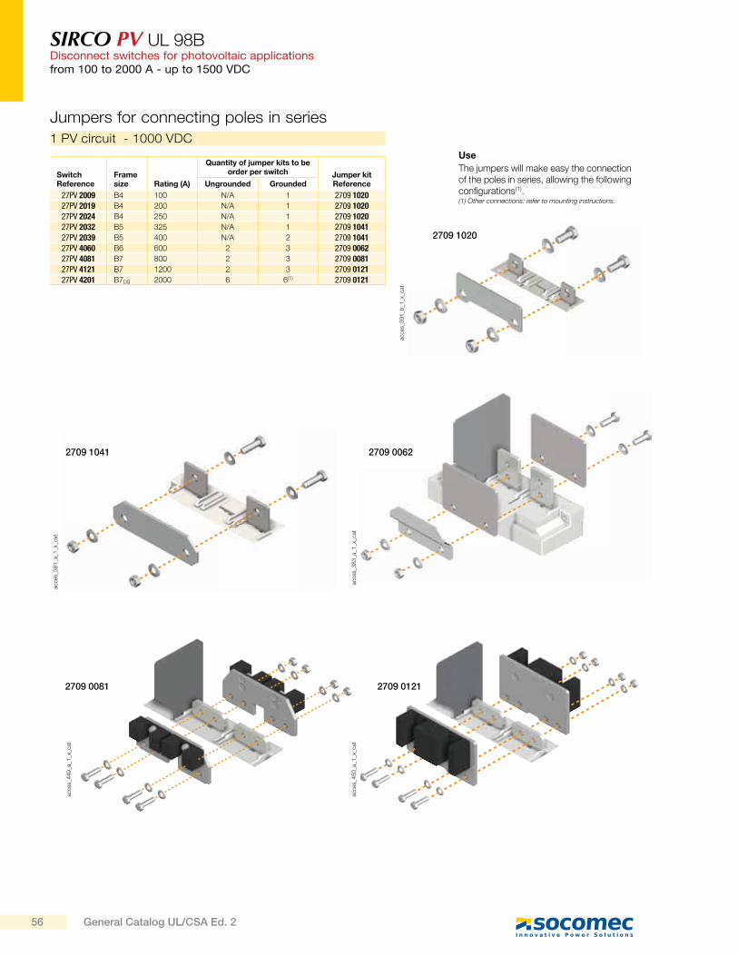
SIRCO PV UL 98BDisconnect switches for photovoltaic applicationsfrom 100 to 2000 A - up to 1500 VDC
1 PV circuit - 1000 VDC
Use
The jumpers will make easy the connection of the poles in series, allowing the following configurations(1).(1) Other connections: refer to mounting instructions.
Switch Reference
Frame size Rating (A)
Quantity of jumper kits to be order per switch Jumper kit
ReferenceUngrounded Grounded
27PV 2009 B4 100 N/A 1 2709 102027PV 2019 B4 200 N/A 1 2709 102027PV 2024 B4 250 N/A 1 2709 102027PV 2032 B5 325 N/A 1 2709 104127PV 2039 B5 400 N/A 2 2709 104127PV 4060 B6 600 2 3 2709 006227PV 4081 B7 800 2 3 2709 008127PV 4121 B7 1200 2 3 2709 012127PV 4201 B7DS 2000 6 6(1) 2709 0121
Jumpers for connecting poles in series
acce
s_3
91
_b_1
_x_c
at
2709 1020
acce
s_4
49
_a_1
_x_c
at
2709 0081
acce
s_4
50
_a_1
_x_c
at
2709 0121
acce
s_3
83
_a_1
_x_c
at
2709 0062
acce
s_3
81
_a_1
_x_c
at
2709 1041
56 General Catalog UL/CSA Ed. 2
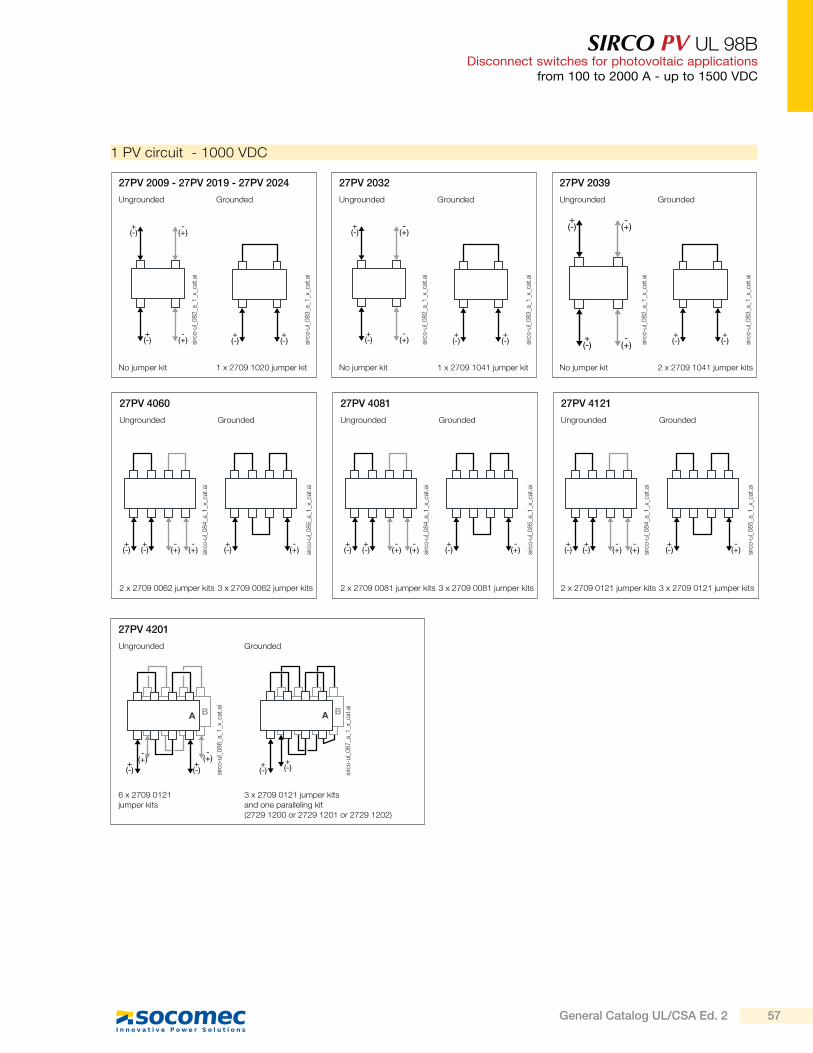
SIRCO PV UL 98BDisconnect switches for photovoltaic applications
from 100 to 2000 A - up to 1500 VDC
1 PV circuit - 1000 VDC
27PV 2009 - 27PV 2019 - 27PV 2024
GroundedUngrounded
No jumper kit 1 x 2709 1020 jumper kit
+(-)
+(-) si
rco
-ul_
08
3_a
_1_x
_cat
.ai
-(+)
-(+)
+(-)
+(-)
sirc
o-u
l_0
82
_a_1
_x_c
at.a
i
+(-)
+(-) si
rco
-ul_
08
3_a
_1_x
_cat
.ai
27PV 2032
GroundedUngrounded
No jumper kit 1 x 2709 1041 jumper kit
-(+)
-(+)
+(-)
+(-)
sirc
o-u
l_0
82
_a_1
_x_c
at.a
i
+(-)
+(-) si
rco
-ul_
08
3_a
_1_x
_cat
.ai
27PV 2039
GroundedUngrounded
No jumper kit 2 x 2709 1041 jumper kits
27PV 4060
GroundedUngrounded
2 x 2709 0062 jumper kits 3 x 2709 0062 jumper kits
27PV 4081
GroundedUngrounded
2 x 2709 0081 jumper kits 3 x 2709 0081 jumper kits
27PV 4121
GroundedUngrounded
2 x 2709 0121 jumper kits 3 x 2709 0121 jumper kits
-(+)
-(+)
+(-)
+(-)
-(+)
-(+)
+(-)
+(-)
-(+)
-(+)
+(-)
+(-)
-(+)
+(-)
-(+)
+(-)
-(+)
+(-)si
rco
-ul_
08
4_a
_1_x
_cat
.ai
sirc
o-u
l_0
84
_a_1
_x_c
at.a
i
sirc
o-u
l_0
84
_a_1
_x_c
at.a
i
sirc
o-u
l_0
85
_a_1
_x_c
at.a
i
sirc
o-u
l_0
85
_a_1
_x_c
at.a
i
sirc
o-u
l_0
85
_a_1
_x_c
at.a
i
27PV 4201
GroundedUngrounded
6 x 2709 0121 jumper kits
3 x 2709 0121 jumper kits and one paralleling kit (2729 1200 or 2729 1201 or 2729 1202)
+(-)
+(-)
-(+)
-(+)
sirc
o-u
l_0
86
_a_1
_x_c
at.a
i
+(-)
+(-)
sirc
o-u
l_0
87
_a_1
_x_c
at.a
i
-(+)
-(+)
+(-)
+(-)
sirc
o-u
l_0
82
_a_1
_x_c
at.a
i
57General Catalog UL/CSA Ed. 2
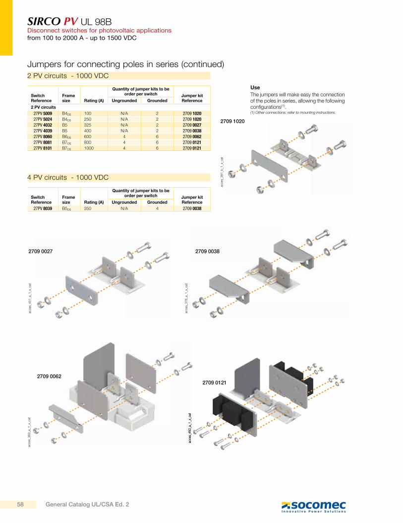
SIRCO PV UL 98BDisconnect switches for photovoltaic applicationsfrom 100 to 2000 A - up to 1500 VDC
acce
s_3
91
_b_1
_x_c
at
2709 1020
acce
s_4
51
_a_1
_x_c
at
2709 0027
acce
s_4
50
_a_1
_x_c
at
2709 0121
acce
s_3
83
_a_1
_x_c
at
2709 0062
acce
s_3
78
_a_1
_x_c
at
2709 0038
4 PV circuits - 1000 VDC
Use
The jumpers will make easy the connection of the poles in series, allowing the following configurations(1).(1) Other connections: refer to mounting instructions.
Switch Reference
Frame size Rating (A)
Quantity of jumper kits to be order per switch Jumper kit
ReferenceUngrounded Grounded
2 PV circuits
27PV 5009 B4DS 100 N/A 2 2709 102027PV 5024 B4DS 250 N/A 2 2709 102027PV 4032 B5 325 N/A 2 2709 002727PV 4039 B5 400 N/A 2 2709 003827PV 8060 B6DS 600 4 6 2709 006227PV 8081 B7DS 800 4 6 2709 012127PV 8101 B7DS 1000 4 6 2709 0121
Switch Reference
Frame size Rating (A)
Quantity of jumper kits to be order per switch Jumper kit
ReferenceUngrounded Grounded
27PV 8039 B5DS 350 N/A 4 2709 0038
Jumpers for connecting poles in series (continued)
2 PV circuits - 1000 VDC
58 General Catalog UL/CSA Ed. 2
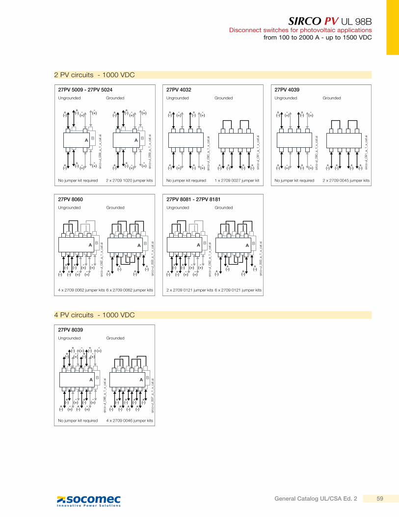
SIRCO PV UL 98BDisconnect switches for photovoltaic applications
from 100 to 2000 A - up to 1500 VDC
2 PV circuits - 1000 VDC
27PV 5009 - 27PV 5024 27PV 4032
Grounded GroundedUngrounded Ungrounded
No jumper kit required No jumper kit required2 x 2709 1020 jumper kits 1 x 2709 0027 jumper kit
27PV 4039
GroundedUngrounded
No jumper kit required 2 x 2709 0045 jumper kits
4 PV circuits - 1000 VDC
27PV 8039
GroundedUngrounded
No jumper kit required 4 x 2709 0046 jumper kits
27PV 8060
GroundedUngrounded
4 x 2709 0062 jumper kits 6 x 2709 0062 jumper kits
27PV 8081 - 27PV 8181
GroundedUngrounded
2 x 2709 0121 jumper kits 6 x 2709 0121 jumper kits
-(+)
-(+)
+(-)
+(-) -
(+)
-(+)
+(-)
+(-)
sirc
o-u
l_0
88
_a_1
_x_c
at.a
i
-(+)
-(+)
+(-)
+(-) -
(+)
-(+)
+(-)
+(-)
sirc
o-u
l_0
89
_a_1
_x_c
at.a
i
-(+)
+(-)
-(+)
+(-)
-(+)
+(-)
-(+)
+(-)
sirc
o-u
l_0
90
_a_1
_x_c
at.a
i
+(-)
+(-)
+(-)
+(-) si
rco
-ul_
09
1_a
_1_x
_cat
.ai
-(+)
+(-)
-(+)
+(-)
-(+)
+(-)
-(+)
+(-)
sirc
o-u
l_0
90
_a_1
_x_c
at.a
i
+(-)
+(-)
+(-)
+(-) si
rco
-ul_
09
1_a
_1_x
_cat
.ai
+(-)
+(-)
-(+)
-(+)
+(-)
+(-)
-(+)
-(+) si
rco
-ul_
09
2_a
_1_x
_cat
.ai
+(-)
+(-)
-(+)
-(+)
+(-)
+(-)
-(+)
-(+) si
rco
-ul_
09
2_a
_1_x
_cat
.ai
+(-)
+(-)
+(-)
+(-)
sirc
o-u
l_0
93
_a_1
_x_c
at.a
i
+(-)
+(-)
+(-)
+(-)
sirc
o-u
l_0
93
_a_1
_x_c
at.a
i
+(-)
+(-)
-(+)
-(+)
+(-)
+(-)
-(+)
-(+)
+(-)
+(-)
-(+)
-(+)
+(-)
+(-)
-(+)
-(+)
sirc
o-u
l_0
96
_a_1
_x_c
at.a
i
+(-)
+(-)
+(-)
+(-)
+(-)
+(-)
+(-)
+(-)
sirc
o-u
l_0
97
_a_1
_x_c
at.a
i
59General Catalog UL/CSA Ed. 2
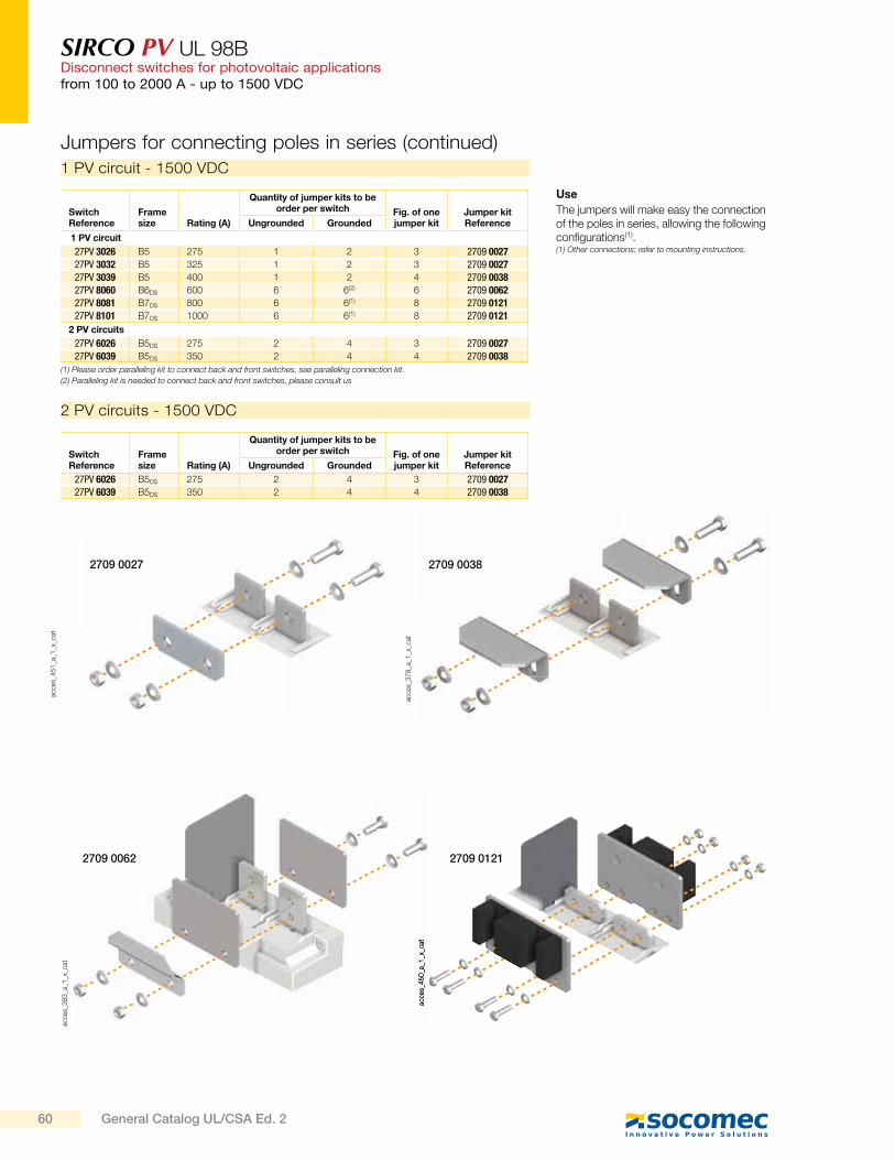
SIRCO PV UL 98BDisconnect switches for photovoltaic applicationsfrom 100 to 2000 A - up to 1500 VDC
1 PV circuit - 1500 VDC
Use
The jumpers will make easy the connection of the poles in series, allowing the following configurations(1).(1) Other connections: refer to mounting instructions.
(1) Please order paralleling kit to connect back and front switches, see paralleling connection kit.
(2) Paralleling kit is needed to connect back and front switches, please consult us
Switch Reference
Frame size Rating (A)
Quantity of jumper kits to be order per switch Fig. of one
jumper kitJumper kit ReferenceUngrounded Grounded
1 PV circuit
27PV 3026 B5 275 1 2 3 2709 002727PV 3032 B5 325 1 2 3 2709 002727PV 3039 B5 400 1 2 4 2709 003827PV 8060 B6DS 600 6 6(2) 6 2709 006227PV 8081 B7DS 800 6 6(1) 8 2709 012127PV 8101 B7DS 1000 6 6(1) 8 2709 0121
2 PV circuits
27PV 6026 B5DS 275 2 4 3 2709 002727PV 6039 B5DS 350 2 4 4 2709 0038
2 PV circuits - 1500 VDC
Switch Reference
Frame size Rating (A)
Quantity of jumper kits to be order per switch Fig. of one
jumper kitJumper kit ReferenceUngrounded Grounded
27PV 6026 B5DS 275 2 4 3 2709 002727PV 6039 B5DS 350 2 4 4 2709 0038
Jumpers for connecting poles in series (continued)
acce
s_4
51
_a_1
_x_c
at
2709 0027
acce
s_4
50
_a_1
_x_c
at
2709 0121
acce
s_3
83
_a_1
_x_c
at
2709 0062
acce
s_3
78
_a_1
_x_c
at
2709 0038
60 General Catalog UL/CSA Ed. 2
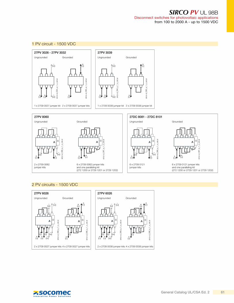
SIRCO PV UL 98BDisconnect switches for photovoltaic applications
from 100 to 2000 A - up to 1500 VDC
1 PV circuit - 1500 VDC
27PV 3026 - 27PV 3032 27PV 3039
Grounded GroundedUngrounded Ungrounded
1 x 2709 0027 jumper kit 1 x 2709 0038 jumper kit2 x 2709 0027 jumper kits 2 x 2709 0038 jumper kit
2 PV circuits - 1500 VDC
27PV 6026
GroundedUngrounded
2 x 2709 0027 jumper kits 4 x 2709 0027 jumper kits
27PV 6026
GroundedUngrounded
2 x 2709 0038 jumper kits 4 x 2709 0038 jumper kits
27PV 8060
GroundedUngrounded
2 x 2709 0062 jumper kits
6 x 2709 0062 jumper kits and one paralleling kit (272 1200 or 2729 1201 or 2729 1202)
27DC 8081 - 27DC 8101
GroundedUngrounded
6 x 2709 0121 jumper kits
6 x 2709 0121 jumper kits and one paralleling kit (272 1200 or 2729 1201 or 2729 1202)
-(+)
-(+)
+(-)
+(-)
sirc
o-u
l_0
94
_a_1
_x_c
at.a
i
-(+)
-(+)
+(-)
+(-) si
rco
-ul_
09
4_a
_1_x
_cat
.ai
+(-)
+(-)
sirc
o-u
l_0
95
_a_1
_x_c
at.a
i
+(-)
+(-)
sirc
o-u
l_0
95
_a_1
_x_c
at.a
i
+(-)
+(-)
-(+)
-(+)
sirc
o-u
l_0
86
_a_1
_x_c
at.a
i
+(-)
+(-)
-(+)
-(+)
sirc
o-u
l_0
86
_a_1
_x_c
at.a
i+(-)
+(-)
sirc
o-u
l_0
87
_a_1
_x_c
at.a
i
+(-)
+(-)
sirc
o-u
l_0
87
_a_1
_x_c
at.a
i
+(-)
+(-)
+(-)
+(-)
-(+)
-(+)
-(+)
-(+)
sirc
o-u
l_0
98
_a_1
_x_c
at.a
i
+(-)
+(-)
+(-)
+(-)
-(+)
-(+)
-(+)
-(+)
sirc
o-u
l_0
98
_a_1
_x_c
at.a
i
+(-)
+(-)
+(-)
+(-)
sirc
o-u
l_0
99
_a_1
_x_c
at.a
i
+(-)
+(-)
+(-)
+(-)
sirc
o-u
l_0
99
_a_1
_x_c
at.a
i
61General Catalog UL/CSA Ed. 2
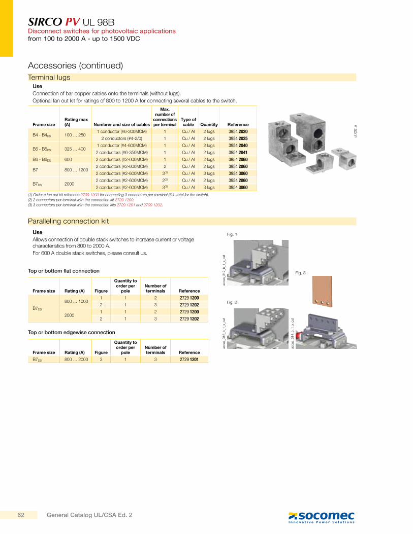
SIRCO PV UL 98BDisconnect switches for photovoltaic applicationsfrom 100 to 2000 A - up to 1500 VDC
Accessories (continued)
Terminal lugs
ul_
03
2_a
Use
Connection of bar copper cables onto the terminals (without lugs).
Optional fan out kit for ratings of 800 to 1200 A for connecting several cables to the switch.
Frame sizeRating max (A) Numbrer and size of cables
Max. number of
connections per terminal
Type of cable Quantity Reference
B4 - B4DS 100 … 2501 conductor (#6-300MCM) 1 Cu / Al 2 lugs 3954 2020
2 conductors (#4-2/0) 1 Cu / Al 2 lugs 3954 2025
B5 - B5DS 325 … 4001 conductor (#4-600MCM) 1 Cu / Al 2 lugs 3954 2040
2 conductors (#6-350MCM) 1 Cu / Al 2 lugs 3954 2041
B6 - B6DS 600 2 conductors (#2-600MCM) 1 Cu / Al 2 lugs 3954 2060
B7 800 … 12002 conductors (#2-600MCM) 2 Cu / Al 2 lugs 3954 2060
2 conductors (#2-600MCM) 3(1) Cu / Al 3 lugs 3954 3060
B7DS 20002 conductors (#2-600MCM) 2(2) Cu / Al 2 lugs 3954 2060
2 conductors (#2-600MCM) 3(3) Cu / Al 3 lugs 3954 3060
(1) Order a fan out kit reference 2709 1203 for connecting 3 connectors per terminal (6 in total for the switch).
(2) 2 connectors per terminal with the connection kit 2729 1200.
(3) 3 connectors per terminal with the connection kits 2729 1201 and 2709 1202.
Use
Allows connection of double stack switches to increase current or voltage characteristics from 800 to 2000 A.
For 600 A double stack switches, please consult us.
Frame size Rating (A) Figure
Quantity to order per
poleNumber of terminals Reference
B7DS
800 … 10001 1 2 2729 1200
2 1 3 2729 1202
20001 1 2 2729 1200
2 1 3 2729 1202
Frame size Rating (A) Figure
Quantity to order per
poleNumber of terminals Reference
B7DS 800 … 2000 3 1 3 2729 1201
acce
s_3
13
_b_1
_x_c
at
acce
s_3
14
_b_1
_x_c
at
acce
s_3
12
_b_1
_x_c
at
Fig. 1
Fig. 2
Fig. 3Top or bottom flat connection
Top or bottom edgewise connection
Paralleling connection kit
62 General Catalog UL/CSA Ed. 2
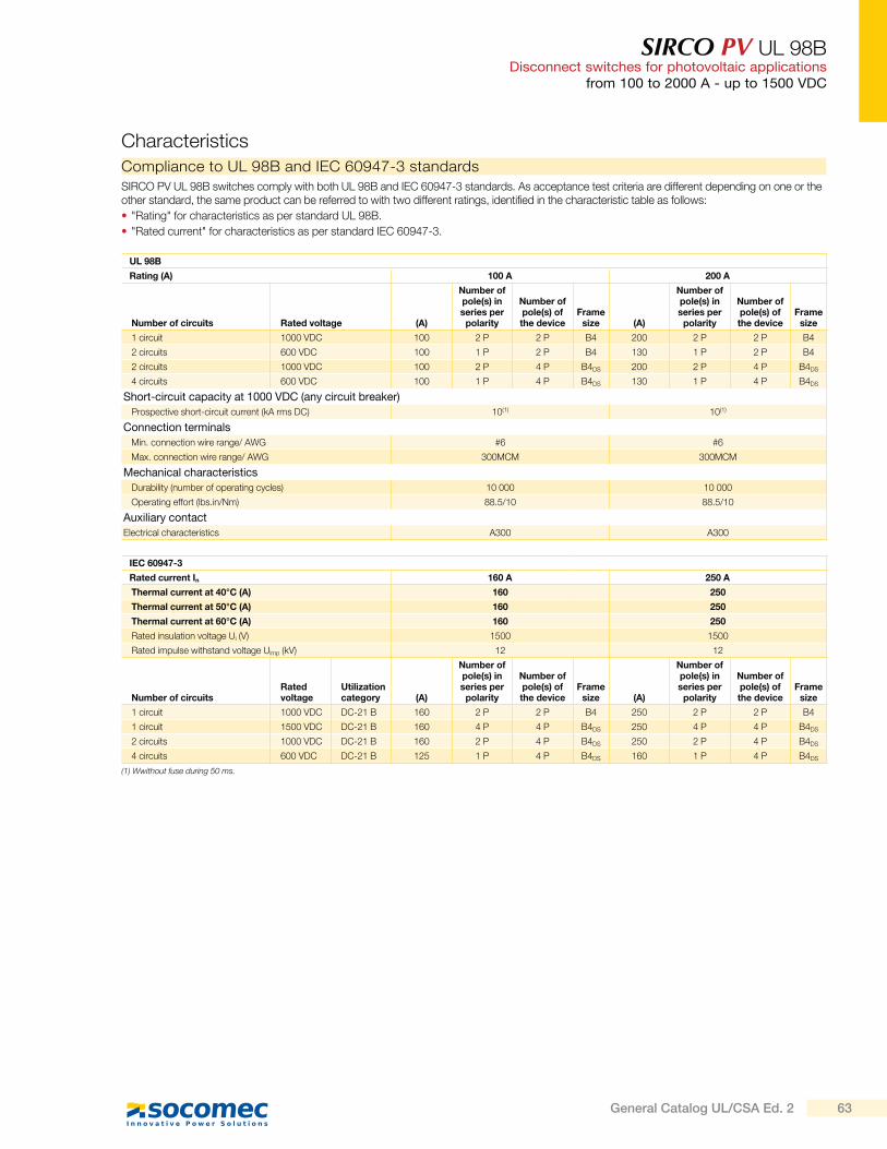
SIRCO PV UL 98BDisconnect switches for photovoltaic applications
from 100 to 2000 A - up to 1500 VDC
Characteristics
UL 98B
Rating (A) 100 A 200 A
Number of circuits Rated voltage (A)
Number of pole(s) in series per
polarity
Number of pole(s) of the device
Frame size (A)
Number of pole(s) in series per
polarity
Number of pole(s) of the device
Frame size
1 circuit 1000 VDC 100 2 P 2 P B4 200 2 P 2 P B4
2 circuits 600 VDC 100 1 P 2 P B4 130 1 P 2 P B4
2 circuits 1000 VDC 100 2 P 4 P B4DS 200 2 P 4 P B4DS
4 circuits 600 VDC 100 1 P 4 P B4DS 130 1 P 4 P B4DS
Short-circuit capacity at 1000 VDC (any circuit breaker)
Prospective short-circuit current (kA rms DC) 10(1) 10(1)
Connection terminals
Min. connection wire range/ AWG #6 #6
Max. connection wire range/ AWG 300MCM 300MCM
Mechanical characteristics
Durability (number of operating cycles) 10 000 10 000
Operating effort (lbs.in/Nm) 88.5/10 88.5/10
Auxiliary contact
Electrical characteristics A300 A300
(1) Wwithout fuse during 50 ms.
IEC 60947-3
Rated current In 160 A 250 A
Thermal current at 40°C (A) 160 250
Thermal current at 50°C (A) 160 250
Thermal current at 60°C (A) 160 250
Rated insulation voltage Ui (V) 1500 1500
Rated impulse withstand voltage Uimp (kV) 12 12
Number of circuitsRated voltage
Utilization category (A)
Number of pole(s) in series per
polarity
Number of pole(s) of the device
Frame size (A)
Number of pole(s) in series per
polarity
Number of pole(s) of the device
Frame size
1 circuit 1000 VDC DC-21 B 160 2 P 2 P B4 250 2 P 2 P B4
1 circuit 1500 VDC DC-21 B 160 4 P 4 P B4DS 250 4 P 4 P B4DS
2 circuits 1000 VDC DC-21 B 160 2 P 4 P B4DS 250 2 P 4 P B4DS
4 circuits 600 VDC DC-21 B 125 1 P 4 P B4DS 160 1 P 4 P B4DS
SIRCO PV UL 98B switches comply with both UL 98B and IEC 60947-3 standards. As acceptance test criteria are different depending on one or the other standard, the same product can be referred to with two different ratings, identified in the characteristic table as follows:
"Rating" for characteristics as per standard UL 98B.
"Rated current" for characteristics as per standard IEC 60947-3.
Compliance to UL 98B and IEC 60947-3 standards
63General Catalog UL/CSA Ed. 2
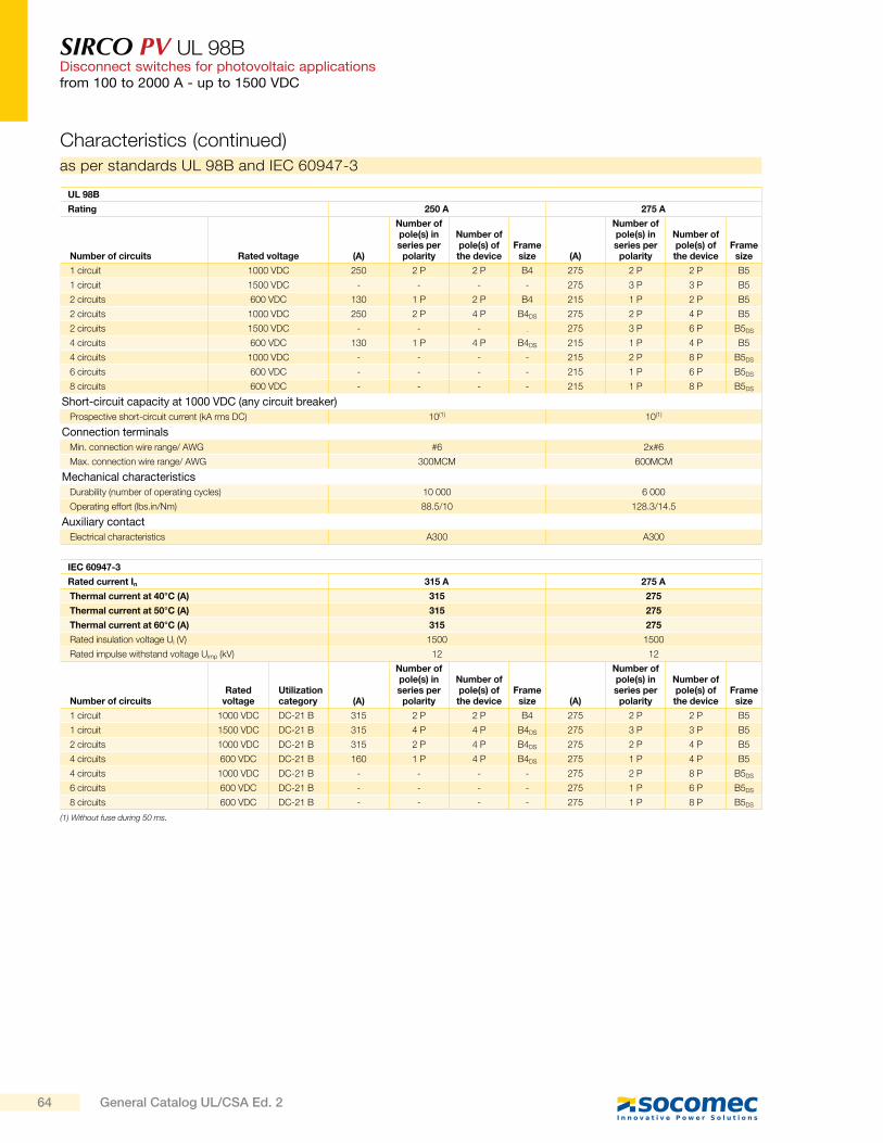
SIRCO PV UL 98BDisconnect switches for photovoltaic applicationsfrom 100 to 2000 A - up to 1500 VDC
as per standards UL 98B and IEC 60947-3
UL 98B
Rating 250 A 275 A
Number of circuits Rated voltage (A)
Number of pole(s) in series per
polarity
Number of pole(s) of the device
Frame size (A)
Number of pole(s) in series per
polarity
Number of pole(s) of the device
Frame size
1 circuit 1000 VDC 250 2 P 2 P B4 275 2 P 2 P B5
1 circuit 1500 VDC - - - - 275 3 P 3 P B5
2 circuits 600 VDC 130 1 P 2 P B4 215 1 P 2 P B5
2 circuits 1000 VDC 250 2 P 4 P B4DS 275 2 P 4 P B5
2 circuits 1500 VDC - - - - 275 3 P 6 P B5DS
4 circuits 600 VDC 130 1 P 4 P B4DS 215 1 P 4 P B5
4 circuits 1000 VDC - - - - 215 2 P 8 P B5DS
6 circuits 600 VDC - - - - 215 1 P 6 P B5DS
8 circuits 600 VDC - - - - 215 1 P 8 P B5DS
Short-circuit capacity at 1000 VDC (any circuit breaker)
Prospective short-circuit current (kA rms DC) 10(1) 10(1)
Connection terminals
Min. connection wire range/ AWG #6 2x#6
Max. connection wire range/ AWG 300MCM 600MCM
Mechanical characteristics
Durability (number of operating cycles) 10 000 6 000
Operating effort (lbs.in/Nm) 88.5/10 128.3/14.5
Auxiliary contact
Electrical characteristics A300 A300
(1) Without fuse during 50 ms.
IEC 60947-3
Rated current In 315 A 275 A
Thermal current at 40°C (A) 315 275
Thermal current at 50°C (A) 315 275
Thermal current at 60°C (A) 315 275
Rated insulation voltage Ui (V) 1500 1500
Rated impulse withstand voltage Uimp (kV) 12 12
Number of circuitsRated
voltageUtilization category (A)
Number of pole(s) in series per
polarity
Number of pole(s) of the device
Frame size (A)
Number of pole(s) in series per
polarity
Number of pole(s) of the device
Frame size
1 circuit 1000 VDC DC-21 B 315 2 P 2 P B4 275 2 P 2 P B5
1 circuit 1500 VDC DC-21 B 315 4 P 4 P B4DS 275 3 P 3 P B5
2 circuits 1000 VDC DC-21 B 315 2 P 4 P B4DS 275 2 P 4 P B5
4 circuits 600 VDC DC-21 B 160 1 P 4 P B4DS 275 1 P 4 P B5
4 circuits 1000 VDC DC-21 B - - - - 275 2 P 8 P B5DS
6 circuits 600 VDC DC-21 B - - - - 275 1 P 6 P B5DS
8 circuits 600 VDC DC-21 B - - - - 275 1 P 8 P B5DS
Characteristics (continued)
64 General Catalog UL/CSA Ed. 2
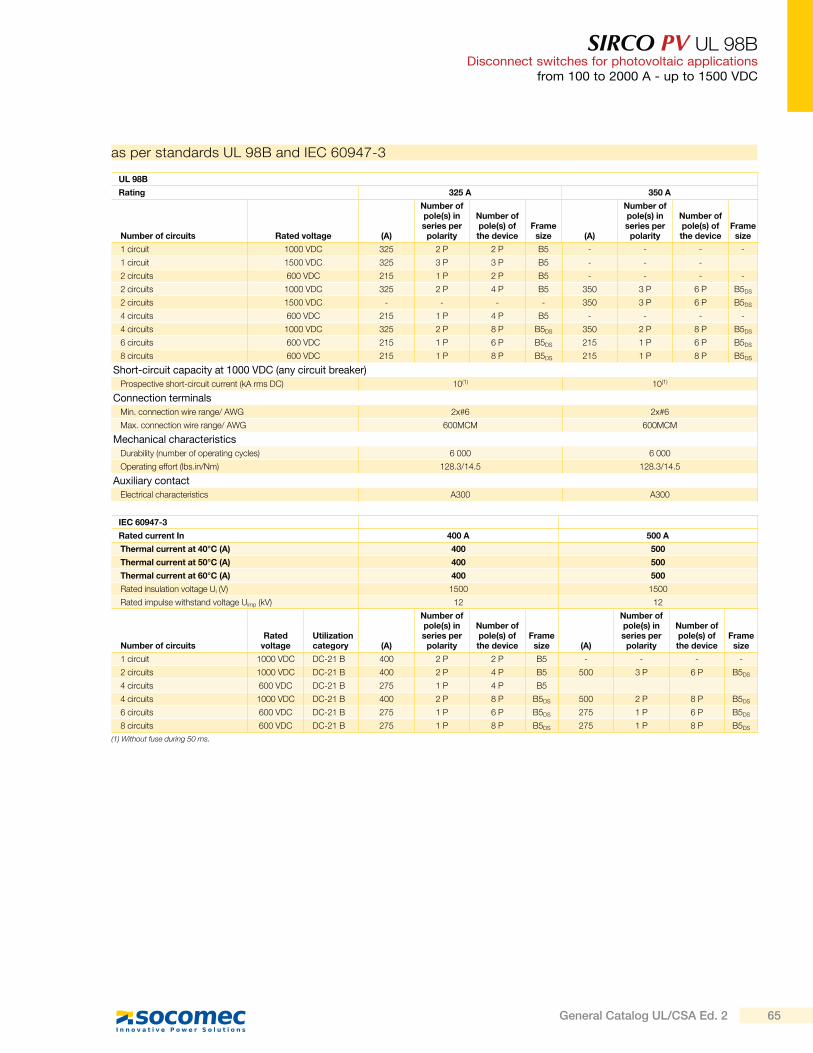
SIRCO PV UL 98BDisconnect switches for photovoltaic applications
from 100 to 2000 A - up to 1500 VDC
as per standards UL 98B and IEC 60947-3
UL 98B
Rating 325 A 350 A
Number of circuits Rated voltage (A)
Number of pole(s) in series per
polarity
Number of pole(s) of the device
Frame size (A)
Number of pole(s) in series per
polarity
Number of pole(s) of the device
Frame size
1 circuit 1000 VDC 325 2 P 2 P B5 - - - -
1 circuit 1500 VDC 325 3 P 3 P B5 - - -
2 circuits 600 VDC 215 1 P 2 P B5 - - - -
2 circuits 1000 VDC 325 2 P 4 P B5 350 3 P 6 P B5DS
2 circuits 1500 VDC - - - - 350 3 P 6 P B5DS
4 circuits 600 VDC 215 1 P 4 P B5 - - - -
4 circuits 1000 VDC 325 2 P 8 P B5DS 350 2 P 8 P B5DS
6 circuits 600 VDC 215 1 P 6 P B5DS 215 1 P 6 P B5DS
8 circuits 600 VDC 215 1 P 8 P B5DS 215 1 P 8 P B5DS
Short-circuit capacity at 1000 VDC (any circuit breaker)
Prospective short-circuit current (kA rms DC) 10(1) 10(1)
Connection terminals
Min. connection wire range/ AWG 2x#6 2x#6
Max. connection wire range/ AWG 600MCM 600MCM
Mechanical characteristics
Durability (number of operating cycles) 6 000 6 000
Operating effort (lbs.in/Nm) 128.3/14.5 128.3/14.5
Auxiliary contact
Electrical characteristics A300 A300
IEC 60947-3
Rated current In 400 A 500 A
Thermal current at 40°C (A) 400 500
Thermal current at 50°C (A) 400 500
Thermal current at 60°C (A) 400 500
Rated insulation voltage Ui (V) 1500 1500
Rated impulse withstand voltage Uimp (kV) 12 12
Number of circuitsRated
voltageUtilization category (A)
Number of pole(s) in series per
polarity
Number of pole(s) of the device
Frame size (A)
Number of pole(s) in series per
polarity
Number of pole(s) of the device
Frame size
1 circuit 1000 VDC DC-21 B 400 2 P 2 P B5 - - - -
2 circuits 1000 VDC DC-21 B 400 2 P 4 P B5 500 3 P 6 P B5DS
4 circuits 600 VDC DC-21 B 275 1 P 4 P B5
4 circuits 1000 VDC DC-21 B 400 2 P 8 P B5DS 500 2 P 8 P B5DS
6 circuits 600 VDC DC-21 B 275 1 P 6 P B5DS 275 1 P 6 P B5DS
8 circuits 600 VDC DC-21 B 275 1 P 8 P B5DS 275 1 P 8 P B5DS
(1) Without fuse during 50 ms.
65General Catalog UL/CSA Ed. 2
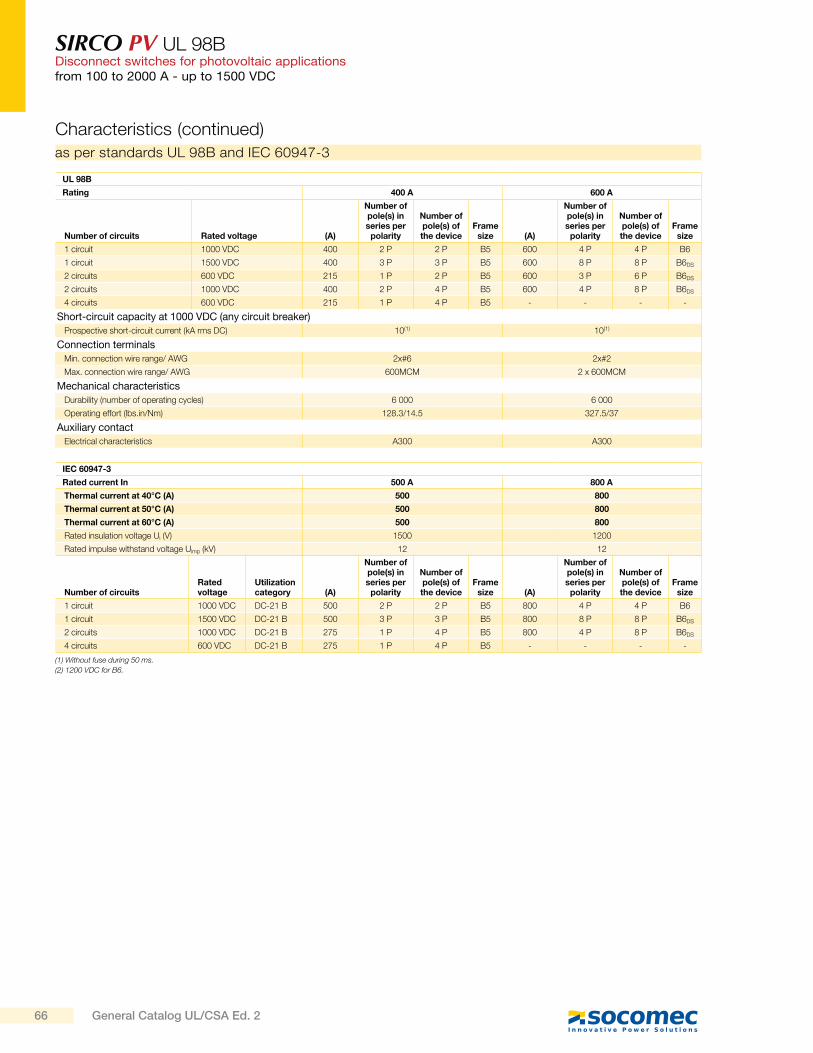
SIRCO PV UL 98BDisconnect switches for photovoltaic applicationsfrom 100 to 2000 A - up to 1500 VDC
Characteristics (continued)
as per standards UL 98B and IEC 60947-3
UL 98B
Rating 400 A 600 A
Number of circuits Rated voltage (A)
Number of pole(s) in series per
polarity
Number of pole(s) of the device
Frame size (A)
Number of pole(s) in series per
polarity
Number of pole(s) of the device
Frame size
1 circuit 1000 VDC 400 2 P 2 P B5 600 4 P 4 P B6
1 circuit 1500 VDC 400 3 P 3 P B5 600 8 P 8 P B6DS
2 circuits 600 VDC 215 1 P 2 P B5 600 3 P 6 P B6DS
2 circuits 1000 VDC 400 2 P 4 P B5 600 4 P 8 P B6DS
4 circuits 600 VDC 215 1 P 4 P B5 - - - -
Short-circuit capacity at 1000 VDC (any circuit breaker)
Prospective short-circuit current (kA rms DC) 10(1) 10(1)
Connection terminals
Min. connection wire range/ AWG 2x#6 2x#2
Max. connection wire range/ AWG 600MCM 2 x 600MCM
Mechanical characteristics
Durability (number of operating cycles) 6 000 6 000
Operating effort (lbs.in/Nm) 128.3/14.5 327.5/37
Auxiliary contact
Electrical characteristics A300 A300
IEC 60947-3
Rated current In 500 A 800 A
Thermal current at 40°C (A) 500 800
Thermal current at 50°C (A) 500 800
Thermal current at 60°C (A) 500 800
Rated insulation voltage Ui (V) 1500 1200
Rated impulse withstand voltage Uimp (kV) 12 12
Number of circuitsRated voltage
Utilization category (A)
Number of pole(s) in series per
polarity
Number of pole(s) of the device
Frame size (A)
Number of pole(s) in series per
polarity
Number of pole(s) of the device
Frame size
1 circuit 1000 VDC DC-21 B 500 2 P 2 P B5 800 4 P 4 P B6
1 circuit 1500 VDC DC-21 B 500 3 P 3 P B5 800 8 P 8 P B6DS
2 circuits 1000 VDC DC-21 B 275 1 P 4 P B5 800 4 P 8 P B6DS
4 circuits 600 VDC DC-21 B 275 1 P 4 P B5 - - - -
(1) Without fuse during 50 ms.
(2) 1200 VDC for B6.
66 General Catalog UL/CSA Ed. 2
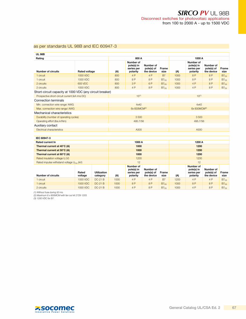
SIRCO PV UL 98BDisconnect switches for photovoltaic applications
from 100 to 2000 A - up to 1500 VDC
UL 98B
Rating 800 A 1000 A
Number of circuits Rated voltage (A)
Number of pole(s) in series per
polarity
Number of pole(s) of the device
Frame size (A)
Number of pole(s) in series per
polarity
Number of pole(s) of the device
Frame size
1 circuit 1000 VDC 800 4 P 4 P B7 1000 8 P 8 P B7DS
1 circuit 1500 VDC 800 8 P 8 P B7DS 1000 8 P 8 P B7DS
2 circuits 600 VDC 800 3 P 6 P B7DS 1000 4 P 8 P B7DS
2 circuits 1000 VDC 800 4 P 8 P B7DS 1000 4 P 8 P B7DS
Short-circuit capacity at 1000 VDC (any circuit breaker)
Prospective short-circuit current (kA rms DC) 10(1) 10(1)
Connection terminals
Min. connection wire range/ AWG 4x#2 4x#2
Max. connection wire range/ AWG 6x 600MCM(2) 6x 600MCM(2)
Mechanical characteristics
Durability (number of operating cycles) 3 500 3 500
Operating effort (lbs.in/Nm) 495.7/56 495.7/56
Auxiliary contact
Electrical characteristics A300 A300
as per standards UL 98B and IEC 60947-3
IEC 60947-3
Rated current In 1000 A 1200 A
Thermal current at 40°C (A) 1000 1200
Thermal current at 50°C (A) 1000 1200
Thermal current at 60°C (A) 1000 1200
Rated insulation voltage Ui (V) 1200 1200
Rated impulse withstand voltage Uimp (kV) 12 12
Number of circuitsRated voltage
Utilization category (A)
Number of pole(s) in series per
polarity
Number of pole(s) of the device
Frame size (A)
Number of pole(s) in series per
polarity
Number of pole(s) of the device
Frame size
1 circuit 1000 VDC DC-21 B 1000 4 P 4 P B7 1200 4 P 4 P B7DS
1 circuit 1500 VDC DC-21 B 1000 8 P 8 P B7DS 1000 8 P 8 P B7DS
2 circuits 1000 VDC DC-21 B 1000 4 P 8 P B7DS 1000 4 P 8 P B7DS
(1) Without fuse during 50 ms.
(2) Maximum 6 x 600MCM with fan out kit 2729 1203.
(3) 1200 VDC for B7.
67General Catalog UL/CSA Ed. 2
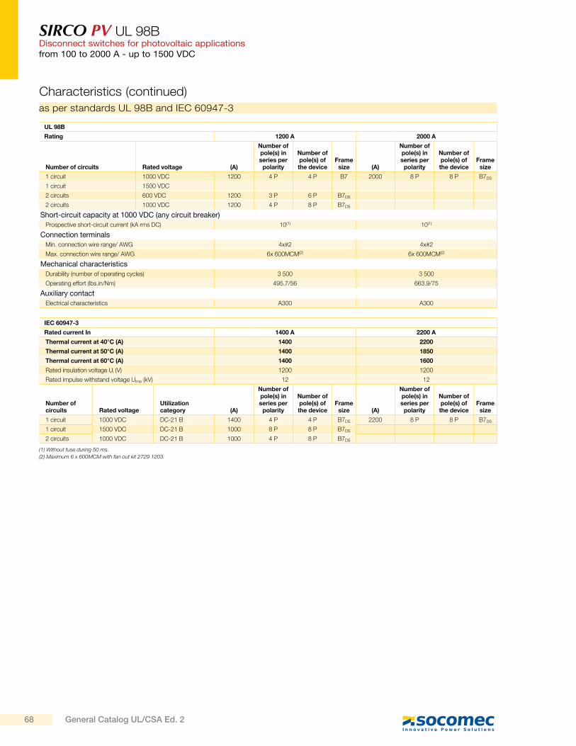
SIRCO PV UL 98BDisconnect switches for photovoltaic applicationsfrom 100 to 2000 A - up to 1500 VDC
UL 98B
Rating 1200 A 2000 A
Number of circuits Rated voltage (A)
Number of pole(s) in series per
polarity
Number of pole(s) of the device
Frame size (A)
Number of pole(s) in series per
polarity
Number of pole(s) of the device
Frame size
1 circuit 1000 VDC 1200 4 P 4 P B7 2000 8 P 8 P B7DS
1 circuit 1500 VDC
2 circuits 600 VDC 1200 3 P 6 P B7DS
2 circuits 1000 VDC 1200 4 P 8 P B7DS
Short-circuit capacity at 1000 VDC (any circuit breaker)
Prospective short-circuit current (kA rms DC) 10(1) 10(1)
Connection terminals
Min. connection wire range/ AWG 4x#2 4x#2
Max. connection wire range/ AWG 6x 600MCM(2) 6x 600MCM(2)
Mechanical characteristics
Durability (number of operating cycles) 3 500 3 500
Operating effort (lbs.in/Nm) 495.7/56 663.9/75
Auxiliary contact
Electrical characteristics A300 A300
as per standards UL 98B and IEC 60947-3
IEC 60947-3
Rated current In 1400 A 2200 A
Thermal current at 40°C (A) 1400 2200
Thermal current at 50°C (A) 1400 1850
Thermal current at 60°C (A) 1400 1600
Rated insulation voltage Ui (V) 1200 1200
Rated impulse withstand voltage Uimp (kV) 12 12
Number of circuits Rated voltage
Utilization category (A)
Number of pole(s) in series per
polarity
Number of pole(s) of the device
Frame size (A)
Number of pole(s) in series per
polarity
Number of pole(s) of the device
Frame size
1 circuit 1000 VDC DC-21 B 1400 4 P 4 P B7DS 2200 8 P 8 P B7DS
1 circuit 1500 VDC DC-21 B 1000 8 P 8 P B7DS
2 circuits 1000 VDC DC-21 B 1000 4 P 8 P B7DS
(1) Without fuse during 50 ms.
(2) Maximum 6 x 600MCM with fan out kit 2729 1203.
Characteristics (continued)
68 General Catalog UL/CSA Ed. 2
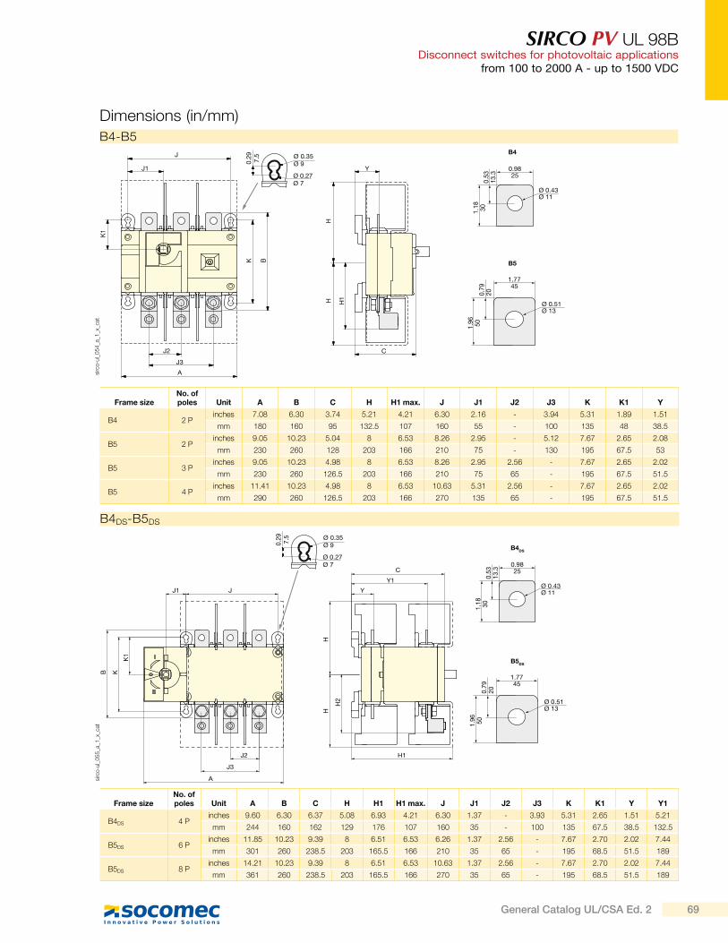
SIRCO PV UL 98BDisconnect switches for photovoltaic applications
from 100 to 2000 A - up to 1500 VDC
Dimensions (in/mm)K
1
K B
HH H1
J1 Y
J2 C
J3
A
J
0.9825
Ø 0.43Ø 11
0.53
13.3
1.18 30
1.7745
Ø 0.51Ø 13
0.79
20
1.96 50
B4
B5
Ø 0.35Ø 9
Ø 0.27Ø 7
0.29 7.5
sirc
o-u
l_0
54
_a_1
_x_c
at
Frame sizeNo. of poles Unit A B C H H1 max. J J1 J2 J3 K K1 Y
B4 2 Pinches 7.08 6.30 3.74 5.21 4.21 6.30 2.16 - 3.94 5.31 1.89 1.51
mm 180 160 95 132.5 107 160 55 - 100 135 48 38.5
B5 2 Pinches 9.05 10.23 5.04 8 6.53 8.26 2.95 - 5.12 7.67 2.65 2.08
mm 230 260 128 203 166 210 75 - 130 195 67.5 53
B5 3 Pinches 9.05 10.23 4.98 8 6.53 8.26 2.95 2.56 - 7.67 2.65 2.02
mm 230 260 126.5 203 166 210 75 65 - 195 67.5 51.5
B5 4 Pinches 11.41 10.23 4.98 8 6.53 10.63 5.31 2.56 - 7.67 2.65 2.02
mm 290 260 126.5 203 166 270 135 65 - 195 67.5 51.5
B4-B5
0.9825
Ø 0.43Ø 11
0.53
13.3
1.18 30
1.7745
Ø 0.51Ø 13
0.79
20
1.96 50
B4DS
B5DS
C
Y1
Y
H1J2
J3
JJ1
K1
HH
H2
KB
A
Ø 0.35Ø 9
Ø 0.27Ø 7
0.29 7.5
sirc
o-u
l_0
55
_a_1
_x_c
at
B4DS-B5DS
Frame sizeNo. of poles Unit A B C H H1 H1 max. J J1 J2 J3 K K1 Y Y1
B4DS 4 Pinches 9.60 6.30 6.37 5.08 6.93 4.21 6.30 1.37 - 3.93 5.31 2.65 1.51 5.21
mm 244 160 162 129 176 107 160 35 - 100 135 67.5 38.5 132.5
B5DS 6 Pinches 11.85 10.23 9.39 8 6.51 6.53 6.26 1.37 2.56 - 7.67 2.70 2.02 7.44
mm 301 260 238.5 203 165.5 166 210 35 65 - 195 68.5 51.5 189
B5DS 8 Pinches 14.21 10.23 9.39 8 6.51 6.53 10.63 1.37 2.56 - 7.67 2.70 2.02 7.44
mm 361 260 238.5 203 165.5 166 270 35 65 - 195 68.5 51.5 189
69General Catalog UL/CSA Ed. 2
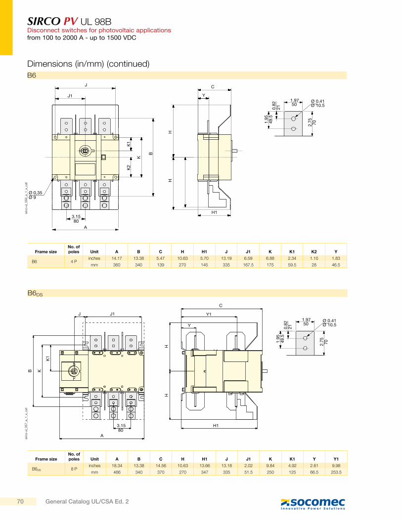
SIRCO PV UL 98BDisconnect switches for photovoltaic applicationsfrom 100 to 2000 A - up to 1500 VDC
Frame sizeNo. of poles Unit A B C H H1 J J1 K K1 K2 Y
B6 4 Pinches 14.17 13.38 5.47 10.63 5.70 13.19 6.59 6.88 2.34 1.10 1.83
mm 360 340 139 270 145 335 167.5 175 59.5 28 46.5
C
Y
K
B
HH
K2
K1
J1
J
Ø 0,35Ø 9
A
3.1580
H1
1.9750
0.82
21
2.75 701.
9549
.5
Ø 0.41Ø 10.5
sirc
o-u
l_0
56
_a_1
_x_c
at
B6
J1
C
Y1
H1
Y
J
3.1580
A
B K
HH
K1
1.9750
0.82
21
Ø 0.41Ø 10.5
2.75 701.
9549
.5
sirc
o-u
l_0
57
_a_1
_x_c
at
B6DS
Frame sizeNo. of poles Unit A B C H H1 J J1 K K1 Y Y1
B6DS 8 Pinches 18.34 13.38 14.56 10.63 13.66 13.18 2.02 9.84 4.92 2.61 9.98
mm 466 340 370 270 347 335 51.5 250 125 66.5 253.5
Dimensions (in/mm) (continued)
70 General Catalog UL/CSA Ed. 2
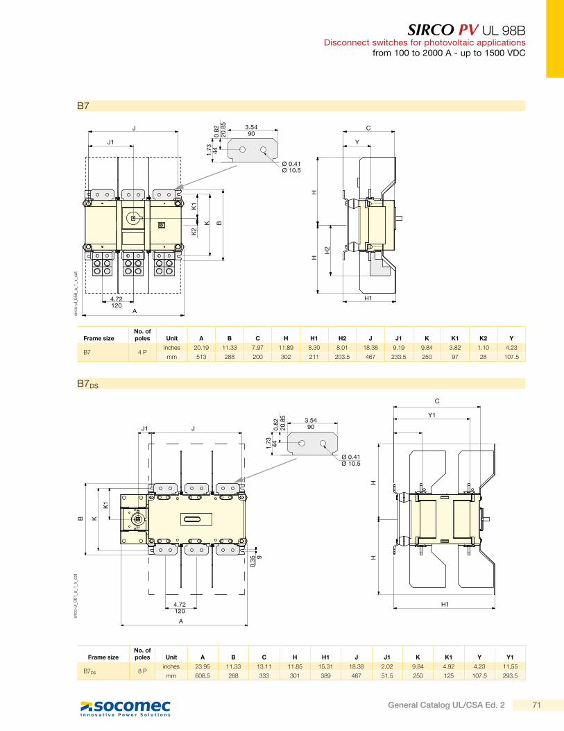
SIRCO PV UL 98BDisconnect switches for photovoltaic applications
from 100 to 2000 A - up to 1500 VDC
Ø 0.41Ø 10.5
3.5490
1.73 44
0.82
20.8
5
J
C
HH
B K
K1
0.35 9
Y1
H1
A
J1
4.72120
sirc
o-u
l_0
61
_a_1
_x_c
at
B7DS
Frame sizeNo. of poles Unit A B C H H1 J J1 K K1 Y Y1
B7DS 8 Pinches 23.95 11.33 13.11 11.85 15.31 18.38 2.02 9.84 4.92 4.23 11.55
mm 608.5 288 333 301 389 467 51.5 250 125 107.5 293.5
Ø 0.41Ø 10.5
3.5490
1.73 44
0.82
20.8
5
J C
J1 Y
H1
H
H2
H
K1
K B
K2
A
4.72120
sirc
o-u
l_0
58
_a_1
_x_c
at
B7
Frame sizeNo. of poles Unit A B C H H1 H2 J J1 K K1 K2 Y
B7 4 Pinches 20.19 11.33 7.97 11.89 8.30 8.01 18.38 9.19 9.84 3.82 1.10 4.23
mm 513 288 200 302 211 203.5 467 233.5 250 97 28 107.5
71General Catalog UL/CSA Ed. 2

SIRCO PV UL 98BDisconnect switches for photovoltaic applicationsfrom 100 to 2000 A - up to 1500 VDC
Dimensions for external handles (in/mm)
Direction of operation Door drillingHandle type
Front operation
1.5740
4 Ø 0.274 Ø 7
Ø 1.46Ø 37
1.10 28
S2 type
90°
I
0
Ø 3.07Ø 78
4.92
125
1.7745
po
ign_0
13
_a_1
_us_
cat
B4 - B4DS - B5
po
ign_0
35
_a_1
_us_
cat
B5DS - B6
Direction of operationHandle type
Front operation
S3 type
Door drilling
Ø 3.07
2.40
8.27
1.57
1.10
Ø 1.46
4 Ø 0.27
Ø 78
210
61
Ø 37
404 Ø 728
90°
0
72 General Catalog UL/CSA Ed. 2
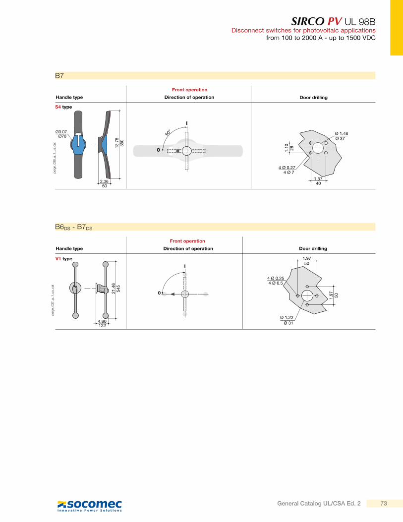
SIRCO PV UL 98BDisconnect switches for photovoltaic applications
from 100 to 2000 A - up to 1500 VDC
po
ign_0
36
_a_1
_us_
cat
B7
2.36
13.7
8
Ø3.07
90°
I
0
1.57
1.10
Ø 1.46
4 Ø 0.27
Ø78
350
60
Ø 37
28
4 Ø 7
40
Direction of operationHandle type
Front operation
S4 type
Door drilling
V1 type
Ø 1.22
1.97
1.97
4 Ø 0.25
I
0
4.80
21.4
6
Direction of operation Door drillingHandle type
Front operation
122
545
50
4 Ø 6.5
50
Ø 31
po
ign_0
37
_a_1
_us_
cat
B6DS - B7DS
73General Catalog UL/CSA Ed. 2
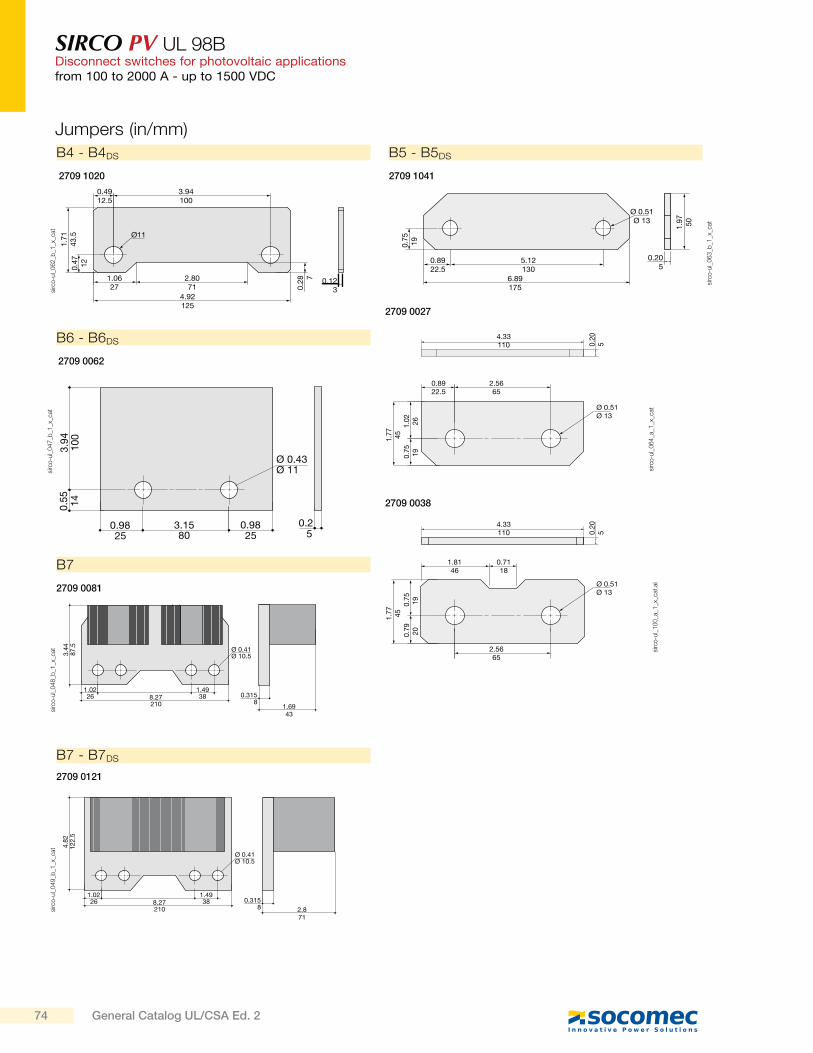
SIRCO PV UL 98BDisconnect switches for photovoltaic applicationsfrom 100 to 2000 A - up to 1500 VDC
Jumpers (in/mm)
B5 - B5DS
Ø11
0.4912.5
1.7
143.5
0.4
712
0.2
8 72.8071
0.123
4.92125
1.0627
3.94100
sirc
o-u
l_0
62
_b_1
_x_c
at
B4 - B4DS
2709 1020
Ø 0.51Ø 13
0.8922.5
2.5665
4.33110
1.7
745
0.2
05
1.0
226
0.7
519
sirc
o-u
l_0
64
_a_1
_x_c
at
2709 0027
2709 0038
4.33110 0
.20
5
1.7
745
0.7
519
0.7
920
1.8146
0.7118
2.5665
Ø 0.51Ø 13
sirc
o-u
l_1
00
_a_1
_x_c
at.a
i
0.205
0.8922.5
5.12130
6.89175
1.9
750
0.7
519
Ø 0.51Ø 13
sirc
o-u
l_0
63
_b_1
_x_c
at
2709 1041
1.02 1.4926 38 0.315
1.6943
88.27210
Ø 0.41Ø 10.53.
4487
.5
sirc
o-u
l_0
48
_b_1
_x_c
at
B7
2709 0081
1.02 1.4926 38 0.315
8 2.871
8.27210
Ø 0.41Ø 10.5
4.82
122.
5
sirc
o-u
l_0
49
_b_1
_x_c
at
B7 - B7DS
2709 0121
0.98 3.158025
0.25
0.9825
0.55
3.94
100
14
Ø 0.43Ø 11si
rco
-ul_
04
7_b
_1_x
_cat
B6 - B6DS
2709 0062
74 General Catalog UL/CSA Ed. 2
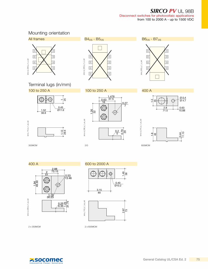
SIRCO PV UL 98BDisconnect switches for photovoltaic applications
from 100 to 2000 A - up to 1500 VDC
Mounting orientation
All frames B4DS - B5DS B6DS - B7DS
sirc
o-u
l_0
28
_a_1
_x_c
at
sirc
o-u
l_0
29
_a_1
_x_c
at
sirc
o_0
30
_a_1
_x_c
at
3.1580
1.49 38
2.87 73
0.40Ø10.2
sirc
o_1
16
_b_1
_us_
cat
2 x 600MCM
600 to 2000 A
2/0
1.47637.50.63
16 0.277
1.26 32
0.25 0.
79 20
sirc
o-u
l_0
38
_a_1
_us_
cat
100 to 250 A
Terminal lugs (in/mm)
1.5238.8
1 251.
1228
.6
0.45Ø11.6
sirc
o_1
15
_b_1
_us_
cat
300MCM
100 to 250 A
2.871.5
Ø 0.4Ø 4.71.
335
1.8
46 0.44
11.1
3
0.6315.88
sirc
o-u
l_0
10
_a_1
_us_
cat
400 A
600MCM
2.8873.152
51 0.5313.46
1.1930.23
1.94
49.30
0.256.35 1.
2531.75
sirc
o-u
l_0
26
_b_1
_us_
cat
2 x 350MCM
400 A
75General Catalog UL/CSA Ed. 2
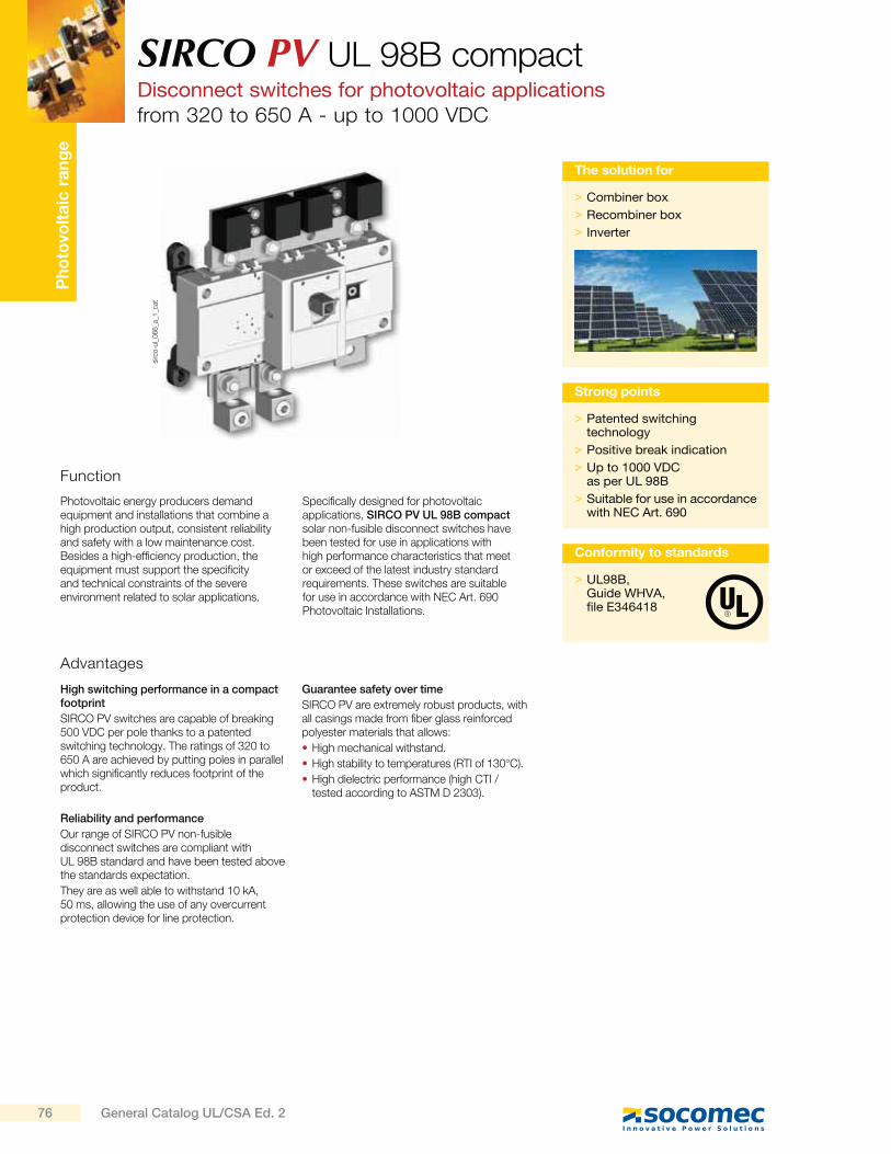
Ph
oto
volt
aic
ra
ng
eSIRCO PV UL 98B compactDisconnect switches for photovoltaic applicationsfrom 320 to 650 A - up to 1000 VDC
Function
Photovoltaic energy producers demand equipment and installations that combine a high production output, consistent reliability and safety with a low maintenance cost. Besides a high-efficiency production, the equipment must support the specificity and technical constraints of the severe environment related to solar applications.
Specifically designed for photovoltaic applications, SIRCO PV UL 98B compact solar non-fusible disconnect switches have been tested for use in applications with high performance characteristics that meet or exceed of the latest industry standard requirements. These switches are suitable for use in accordance with NEC Art. 690 Photovoltaic Installations.
> Patented switching technology
> Positive break indication
> Up to 1000 VDC as per UL 98B
> Suitable for use in accordance with NEC Art. 690
Strong points
> UL98B,Guide WHVA, file E346418
Conformity to standards
Advantages
High switching performance in a compact footprint
SIRCO PV switches are capable of breaking 500 VDC per pole thanks to a patented switching technology. The ratings of 320 to 650 A are achieved by putting poles in parallel which significantly reduces footprint of the product.
Reliability and performance
Our range of SIRCO PV non-fusible disconnect switches are compliant with UL 98B standard and have been tested above the standards expectation.
They are as well able to withstand 10 kA, 50 ms, allowing the use of any overcurrent protection device for line protection.
Guarantee safety over time
SIRCO PV are extremely robust products, with all casings made from fiber glass reinforced polyester materials that allows:
High mechanical withstand.
High stability to temperatures (RTI of 130°C).
High dielectric performance (high CTI / tested according to ASTM D 2303).
sirc
o-u
l_0
66
_a_1
_cat
> Combiner box
> Recombiner box
> Inverter
The solution for
76 General Catalog UL/CSA Ed. 2
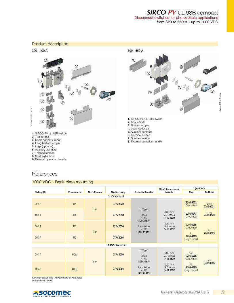
SIRCO PV UL 98B compactDisconnect switches for photovoltaic applications
from 320 to 650 A - up to 1000 VDC
Product description
sirc
o-u
l_0
79
_a_2
_x_c
at
sirc
o-u
l_0
80
_a_2
_x_c
at
1. SIRCO PV UL 98B switch2. Top jumper3. Short bottom jumper4. Long bottom jumper5. Lugs (optional)6. Auxiliary contacts7. Terminal screen8. Shaft extension9. External operation handle
1000 VDC - Back plate mounting
Rating (A) Frame size No. of poles Switch body External handleShaft for external
handle
jumpers
Top Bottom
1 PV circuit
320 A B4
3 P
27PV 2029
S2 type
Black4, 4X
142D 2111(1)
Red/Yellow4, 4X
142E 2111(1)
200 mm7.9 inches1400 1020
320 mm12.6 inches1400 1032
2709 5032Grounded
Short 2709 0021
Long2709 0043400 A B4 27PV 2038
2709 5043Grounded
500 A B5
4 P
27PV 20502709 5065Grounded
2x2709 0065
Ungrounded
2x2709 0065
600 A B5 27PV 2065
2 PV circuits
500 A B5DS
8 P
27PV 5050
S2 type
Black4, 4X
143D 3111(1)
Red/Yellow4, 4X
143E 3111(1)
200 mm7.9 inches1401 1520
320 mm12.6 inches1401 1532
2x2709 5065Grounded
4x2709 0065
Ungrounded
4x2709 0065
650 A B5DS 27PV 5065
References
Common accessories - more available on next pages.
(1) Defeatable handle.
2
1
36
7
5
5
4
5
8
9
7
320 - 400 A 500 - 650 A
1. SIRCO PV UL 98B switch2. Top jumper3. Bottom jumper4. Lugs (optional)5. Auxiliary contacts6. Terminal screen7. Shaft extension8. External operation handle
5
71
4
3
6
6
8
2
77General Catalog UL/CSA Ed. 2
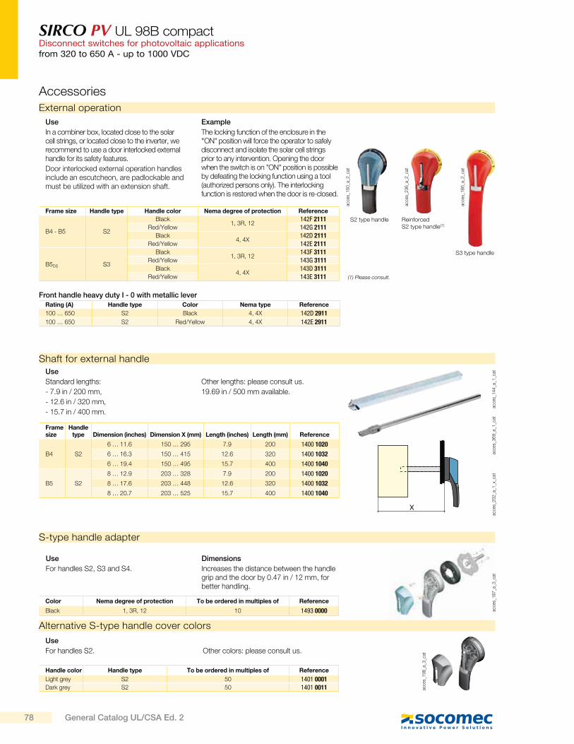
SIRCO PV UL 98B compactDisconnect switches for photovoltaic applicationsfrom 320 to 650 A - up to 1000 VDC
Alternative S-type handle cover colors
acce
s_1
98
_a_3
_cat
Use
For handles S2. Other colors: please consult us.
Handle color Handle type To be ordered in multiples of Reference
Light grey S2 50 1401 0001Dark grey S2 50 1401 0011
S-type handle adapter
acce
s_1
87
_a_3
_cat
Use
For handles S2, S3 and S4.
Dimensions
Increases the distance between the handle grip and the door by 0.47 in / 12 mm, for better handling.
Color Nema degree of protection To be ordered in multiples of Reference
Black 1, 3R, 12 10 1493 0000
Accessories
External operation
acce
s_1
50
_a_2
_cat
S2 type handle
acce
s_2
36
_a_2
_cat
acce
s_1
66
_a_2
_cat
Reinforced S2 type handle(1)
S3 type handle
Frame size Handle type Handle color Nema degree of protection Reference
B4 - B5 S2
Black1, 3R, 12
142F 2111Red/Yellow 142G 2111
Black4, 4X
142D 2111Red/Yellow 142E 2111
B5DS S3
Black1, 3R, 12
143F 3111Red/Yellow 143G 3111
Black4, 4X
143D 3111Red/Yellow 143E 3111
Use
In a combiner box, located close to the solar cell strings, or located close to the inverter, we recommend to use a door interlocked external handle for its safety features.
Door interlocked external operation handles include an escutcheon, are padlockable and must be utilized with an extension shaft.
Example
The locking function of the enclosure in the "ON" position will force the operator to safely disconnect and isolate the solar cell strings prior to any intervention. Opening the door when the switch is on "ON" position is possible by defeating the locking function using a tool (authorized persons only). The interlocking function is restored when the door is re-closed.
acce
s_1
44
_a_1
_cat
acce
s_3
69
_a_1
_cat
Shaft for external handle
X
acce
s_2
02
_a_1
_x_c
at
Use
Standard lengths:
- 7.9 in / 200 mm,
- 12.6 in / 320 mm,
- 15.7 in / 400 mm.
Other lengths: please consult us.
19.69 in / 500 mm available.
Frame size
Handle type Dimension (inches) Dimension X (mm) Length (inches) Length (mm) Reference
B4 S2
6 … 11.6 150 … 295 7.9 200 1400 1020
6 … 16.3 150 … 415 12.6 320 1400 1032
6 … 19.4 150 … 495 15.7 400 1400 1040
B5 S2
8 … 12.9 203 … 328 7.9 200 1400 1020
8 … 17.6 203 … 448 12.6 320 1400 1032
8 … 20.7 203 … 525 15.7 400 1400 1040
(1) Please consult.
Rating (A) Handle type Color Nema type Reference
100 … 650 S2 Black 4, 4X 142D 2911
100 … 650 S2 Red/Yellow 4, 4X 142E 2911
Front handle heavy duty I - 0 with metallic lever
78 General Catalog UL/CSA Ed. 2
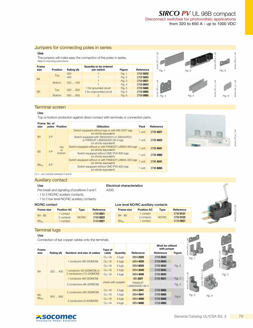
SIRCO PV UL 98B compactDisconnect switches for photovoltaic applications
from 320 to 650 A - up to 1000 VDC
Auxiliary contact
acce
s_0
76
_a_1
_cat
Use
Pre-break and signaling of positions 0 and I:
- 1 to 2 NO/NC auxiliary contacts,
- 1 to 2 low level NO/NC auxiliary contacts.
Electrical characteristics
A300.
Frame size Position AC Type Reference
B4 - B51 contact
NO/NC
2799 0021
2 contacts 2799 0022B5DS 1 contact 4159 0021
Frame size Position AC Type Reference
B4 - B51 contact
NO/NC
2799 01212 contacts 2799 0122
B5DS 1 contact 4159 0021
NO/NC contact Low level NO/NC auxiliary contacts
Terminal screen
acce
s_0
79
_a_1
_cat
Use
Top or bottom protection against direct contact with terminals or connection parts.
Frame size
No. of poles Position Utilization Pack Reference
B4 3 P
topor
bottom
Switch equipped without lugs or with NSI 350T lugs (or strictly equivalent)
1 unit 2798 4021
Switch equipped with 3954x020(1) or 3954x040(1) or PANDUIT LAM2SA300-38-3 lugs
(or strictly equivalent)1 unit 2798 4022
B5 4 P
Switch equipped without or with PANDUIT LAM2A-350 lugs (or strictly equivalent)
1 unit 2798 4041
Switch equipped without CMC PV2-600 lugs (or strictly equivalent)
1 unit 2798 4065
B5DS 8 P
Switch equipped without or with PANDUIT LAM2A-350 lugs (or strictly equivalent)
1 unit 2798 4041
Switch equipped without CMC PV2-600 lugs (or strictly equivalent)
1 unit 2798 8065
(1) x – any number between 0 and 9.
Terminal lugsUse
Connection of bar copper cables onto the terminals.
Frame size Rating (A) Numbrer and size of cables
Type of cable Quantity Reference
Must be utilized with jumper
Reference Figure
B4 320 … 400
1 conductor (#6-300MCM)
Cu / Al 2 lugs 3954 2020 2709 0043
Fig. 2
Cu / Al 4 lugs 3954 4020 2709 0043
Cu / Al 6 lugs 3954 6020 2709 0043
1 conductor (#2-600MCM) or2 conductors (1/0-250MCM)
Cu / Al 2 lugs 3954 2040 2709 0043
Cu / Al 4 lugs 3954 4040 2709 0043
1 conductor (#6-350MCM)
check with supplier
NSI 350T 2709 0021 Fig. 1
2 conductors (#6-300MCM)PANDUIT
LAM2SA300-38-3- Fig. 3
B5 - B5DS
500 … 650
2 conductors (#6-350MCM)Cu / Al 2 lugs 3954 2041 2709 0065
Fig.4Cu / Al 4 lugs 3954 4041 2709 0065
2 conductors (2-600MCM)Cu / Al 4 lugs 3954 4060 2709 0065
Cu / Al 8 lugs 3954 8060 2709 0065
Fig. 1
Fig. 3
Fig. 2
Jumpers for connecting poles in series
Use
The jumpers will make easy the connection of the poles in series.Refer to mounting instructions.
Frame size Position Rating (A)
Quantity to be ordered per switch Figure Reference
B4
Top320 1 Fig. 1 2709 5032400 1 Fig. 2 2709 5043
Bottom 320 … 4001 Fig. 3 2709 00211 Fig. 4 2709 0043
B5Top 500 … 600
1 for grounded circuit Fig. 5 2709 50652 for ungrounded circuit Fig. 6 2709 0065
Bottom 500 … 650 2 Fig. 6 2709 0065
Fig. 1 Fig. 2 Fig. 3
Fig. 4 Fig. 5 Fig. 6
Fig. 4
acce
s_4
37
_a_1
_cat
acce
s_4
40
_a_1
_cat
acce
s_4
38
_a_1
_cat
acce
s_4
41
_a_1
_cat
acce
s_4
39
_a_1
_cat
acce
s_4
42
_a_1
_cat
acce
s_4
43
_a_1
_cat
acce
s_4
45
_a_1
_cat
acce
s_4
46
_a_1
_cat
acce
s_4
44
_a_1
_cat
79General Catalog UL/CSA Ed. 2
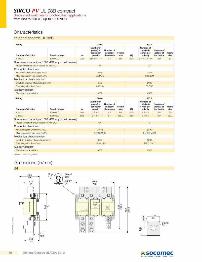
SIRCO PV UL 98B compactDisconnect switches for photovoltaic applicationsfrom 320 to 650 A - up to 1000 VDC
as per standards UL 98B
Rating 320 A 400 A
Number of circuits Rated voltage (A)
Number of pole(s) in series per
polarity
Number of pole(s) of the device
Frame size (A)
Number of pole(s) in series per
polarity
Number of pole(s) of the device
Frame size
1 circuit 1000 VDC 320 2 P in // + 1 P 3 P B4 400 2 P in // + 1 P 3 P B4
Short-circuit capacity at 1000 VDC (any circuit breaker)
Prospective short-circuit current (kA rms DC) 10(1) 10(1)
Connection terminals
Min. connection wire range/ AWG 2x#6 2x#6
Max. connection wire range/ AWG 600MCM 600MCM
Mechanical characteristics
Durability (number of operating cycles) 6000 6000
Operating effort (lbs.in/Nm) 88.5/10 88.5/10
Auxiliary contact
Electrical characteristics A300 A300
Characteristics
(1) Without fuse during 50 ms.
Dimensions (in/mm)
4.56116
1.5138.5
3.6292
3.7495
6.2
91
60
9.3
52
37
.5
10
.12
57
.5
9.05230
Ø 0.35Ø 9
Ø 0.27Ø 7
0.2
97
.5
1.3835
Ø 0.43Ø 11
0.5
91
5
1.3
83
5
B4
Rating 500 A 650 A
Number of circuits Rated voltage (A)
Number of pole(s) in series per
polarity
Number of pole(s) of the device
Frame size (A)
Number of pole(s) in series per
polarity
Number of pole(s) of the device
Frame size
1 circuit 1000 VDC 500 2 P in // 4 P B5 650 2 P in // 4 P B5
2 circuit 1000 VDC 500 2 P in // 8 P B5DS 650 2 P in // 8 P B5DS
Short-circuit capacity at 1000 VDC (any circuit breaker)
Prospective short-circuit current (kA rms DC) 10(1) 10(1)
Connection terminals
Min. connection wire range/ AWG 2 x #2 2 x #2
Max. connection wire range/ AWG 2 x 600 MCM 2 x 600 MCM
Mechanical characteristics
Durability (number of operating cycles) 6000 6000
Operating effort (lbs.in/Nm) 128.3 / 14.5 128.3 / 14.5
Auxiliary contact
Electrical characteristics A300 A300
sirc
o-u
l_0
78
_a_1
_x_c
at
80 General Catalog UL/CSA Ed. 2
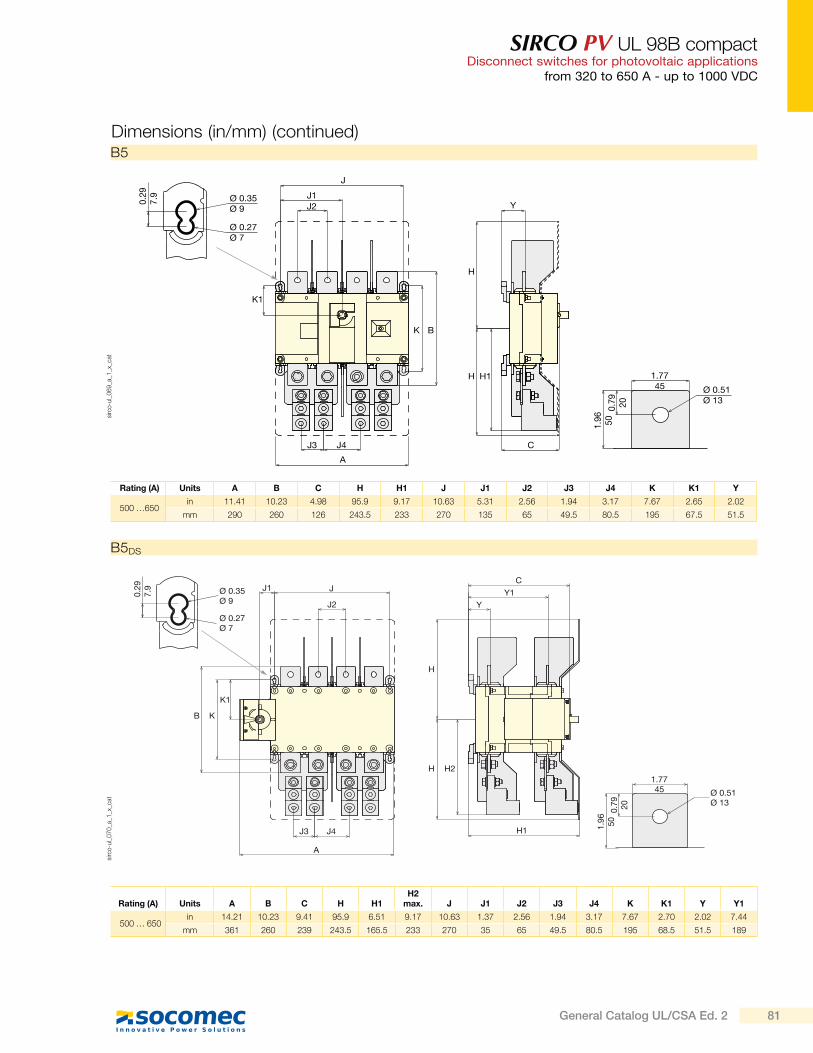
SIRCO PV UL 98B compactDisconnect switches for photovoltaic applications
from 320 to 650 A - up to 1000 VDC
Dimensions (in/mm) (continued)B5
B5DS
Rating (A) Units A B C H H1 J J1 J2 J3 J4 K K1 Y
500 …650 in 11.41 10.23 4.98 95.9 9.17 10.63 5.31 2.56 1.94 3.17 7.67 2.65 2.02
mm 290 260 126 243.5 233 270 135 65 49.5 80.5 195 67.5 51.5
Rating (A) Units A B C H H1H2
max. J J1 J2 J3 J4 K K1 Y Y1
500 … 650in 14.21 10.23 9.41 95.9 6.51 9.17 10.63 1.37 2.56 1.94 3.17 7.67 2.70 2.02 7.44
mm 361 260 239 243.5 165.5 233 270 35 65 49.5 80.5 195 68.5 51.5 189
0.2
97
.9 Ø 0.35Ø 9
Ø 0.27Ø 7
A
J4J3
BK
K1
H
H 1.7745
1.9
65
00
.79
20
Y
H1
C
J2
J1
J
Ø 0.51Ø 13
sirc
o-u
l_0
69
_a_1
_x_c
at
0.2
97.9 Ø 0.35
Ø 9
Ø 0.27Ø 7
JJ1
J2
K1
KB
J3 J4
A
H1
H2H
H
Y
Y1
C
1.7745
1.9
650
0.7
920
Ø 0.51Ø 13
sirc
o-u
l_0
70
_a_1
_x_c
at
81General Catalog UL/CSA Ed. 2
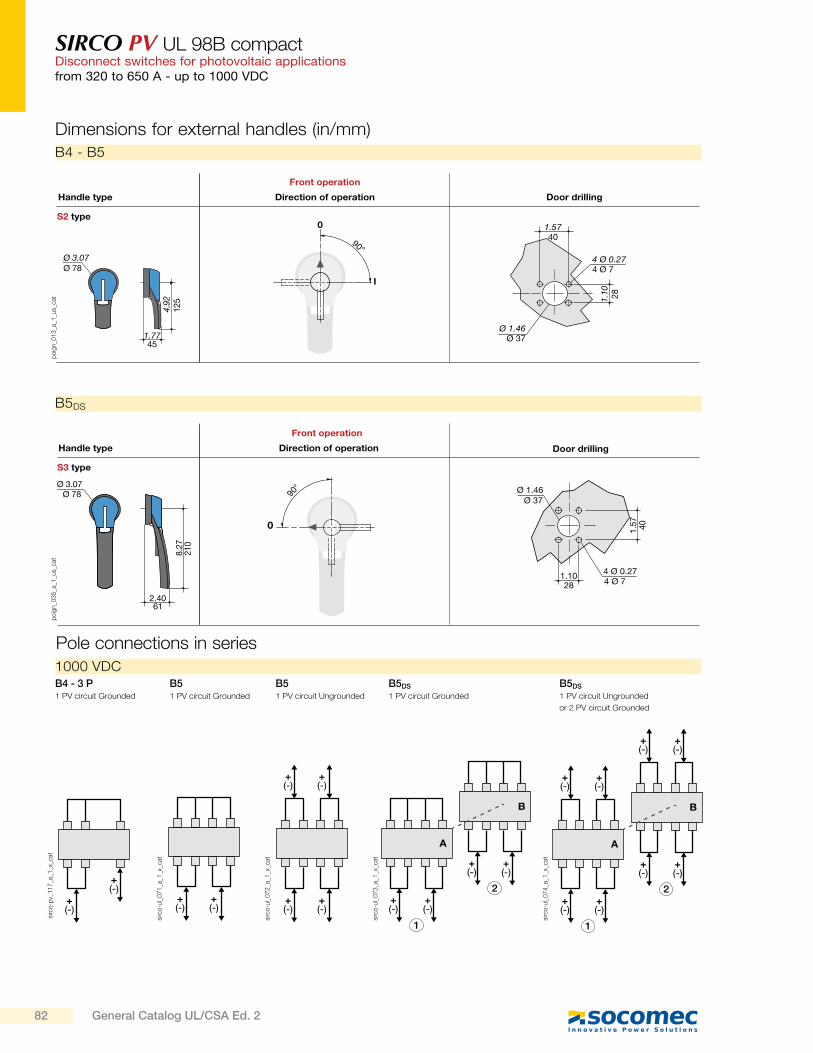
SIRCO PV UL 98B compactDisconnect switches for photovoltaic applicationsfrom 320 to 650 A - up to 1000 VDC
Dimensions for external handles (in/mm)
Direction of operation Door drillingHandle type
Front operation
1.5740
4 Ø 0.274 Ø 7
Ø 1.46Ø 37
1.10 28
S2 type
90°
I
0
Ø 3.07Ø 78
4.92
125
1.7745
po
ign_0
13
_a_1
_us_
cat
B4 - B5
Direction of operationHandle type
Front operation
S3 type
Door drilling
Ø 3.07
2.40
8.27
1.57
1.10
Ø 1.46
4 Ø 0.27
Ø 78
210
61
Ø 37
40
4 Ø 728
90°
0
po
ign_0
35
_a_1
_us_
cat
B5DS
1000 VDC
sirc
o-p
v_1
17
_a_1
_x_c
at
+(-)
+(-)
B4 - 3 P1 PV circuit Grounded
B51 PV circuit Grounded
B5DS
1 PV circuit Grounded
B51 PV circuit Ungrounded
B5DS
1 PV circuit Ungrounded
or 2 PV circuit Grounded
Pole connections in series
+(-)
+(-)
+(-)
+(-)
+(-)
+(-)
1
2+(-)
+(-)
+(-)
+(-)
A
B
1
2+(-)
+(-)
+(-)
+(-)
+(-)
+(-)
+(-)
+(-)
A
B
sirc
o-u
l_0
71
_a_1
_x_c
at
sirc
o-u
l_0
72
_a_1
_x_c
at
sirc
o-u
l_0
73
_a_1
_x_c
at
sirc
o-u
l_0
74
_a_1
_x_c
at
82 General Catalog UL/CSA Ed. 2

SIRCO PV UL 98B compactDisconnect switches for photovoltaic applications
from 320 to 650 A - up to 1000 VDC
600MCM
2.871.5
Ø 0.4Ø 4.71.
335
1.8
46 0.44
11.1
3
0.6315.88
sirc
o-u
l_0
10
_a_1
_us_
cat
Terminal lugs (in/mm)
1.5238.8
1 251.
1228
.6
0.45Ø11.6
sirc
o_1
15
_b_1
_us_
cat
300MCM
3954 x020(1)
(1) x – any number between 0 and 9. (1) x – any number between 0 and 9.
3954 x040 (1)
Jumpers (in / mm)
0.49
Ø0.43
0.47
0.59
1.97 0.49 0.1612.5 50 12.5 4
Ø11
1215
sirc
o-u
l_0
08
_a_1
_x_c
at
Ref.: 2709 0021
4 x Ø 0.434 x Ø 11
3.3485
0.154
0.3
5 90
.74
19
1.9
85
0.5
2.4
76
2.8
1.9650
0.7820
Ref.: 2709 0043
Ref.: 2709 5065 Ref.: 2709 0065
3.1580
1.49 38
2.87 73
0.40Ø10.2
sirc
o_1
16
_b_1
_us_
cat
2.8873.152
51 0.5313.46
1.1930.23
1.94
49.30
0.256.35 1.
2531.75
sirc
o-u
l_0
26
_b_1
_us_
cat
3954 x041(1) - 2 x 350 MCM 3954 x060(1) - 2 x 600 MCM
B5 - B5DSB4
sirc
o-u
l_0
77
_a_1
_x_c
at
0.195
1.9650
1.9650
7.28185
4 x Ø 0.434 x Ø 11
0.3
910
2.4
863
1.9650
Ref.: 2709 5032
sirc
o-u
l_0
74
_a_1
_x_c
at
1.4
83
7.6
0.195
1.9650
1.9650
7.28185
4 x Ø 0.434 x Ø 11
0.3
91
02
.48
63
1.9650
Ref.: 2709 5043
sirc
o-u
l_0
75
_a_1
_x_c
at
3.1
58
01
8.5
0.7
3 1.08 2.56 2.56 2.56
27.5 65 65 65
0.205
4 x Ø 0.514 x Ø 13
2.56250
4 x Ø 13 65 22.54 x Ø 0.51 2.56 0.89
4.5311
0.16449.5
1.95
82.5
82.5
0.87 22
0.73
18.5
po
ign_0
67
_a_1
_x_c
at
po
ign_0
68
_a_1
_x_c
at
83General Catalog UL/CSA Ed. 2
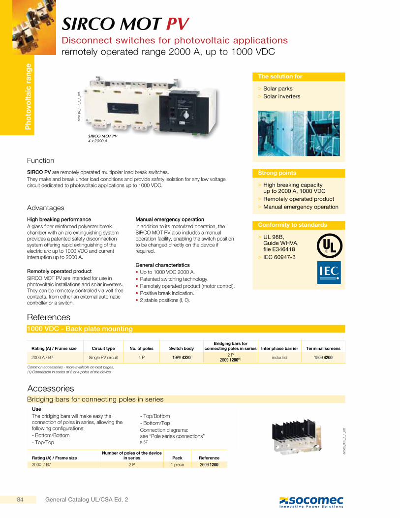
Ph
oto
volt
aic
ra
ng
e
sirc
o-p
v_1
07
_a_1
_cat
SIRCO MOT PVDisconnect switches for photovoltaic applicationsremotely operated range 2000 A, up to 1000 VDC
Function
Advantages
SIRCO PV are remotely operated multipolar load break switches.
They make and break under load conditions and provide safety isolation for any low voltage circuit dedicated to photovoltaic applications up to 1000 VDC.
High breaking performance
A glass fiber reinforced polyester break chamber with an arc extinguishing system provides a patented safety disconnection system offering rapid extinguishing of the electric arc up to 1000 VDC and current interruption up to 2000 A.
Remotely operated product
SIRCO MOT PV are intended for use in photovoltaic installations and solar inverters. They can be remotely controlled via volt-free contacts, from either an external automatic controller or a switch.
Manual emergency operation
In addition to its motorized operation, the SIRCO MOT PV also includes a manual operation facility, enabling the switch position to be changed directly on the device if required.
General characteristics
Up to 1000 VDC 2000 A.
Patented switching technology.
Remotely operated product (motor control).
Positive break indication.
2 stable positions (I, 0).
> High breaking capacity up to 2000 A, 1000 VDC
> Remotely operated product
> Manual emergency operation
Strong points
> Solar parks
> Solar inverters
The solution for
SIRCO MOT PV4 x 2000 A
References
1000 VDC - Back plate mounting
Rating (A) / Frame size Circuit type No. of poles Switch bodyBridging bars for
connecting poles in series Inter phase barrier Terminal screens
2000 A / B7 Single PV circuit 4 P 19PV 43202 P
2609 1200(1) included 1509 4200
Common accessories - more available on next pages.
(1) Connection in series of 2 or 4 poles of the device.
Accessories
> UL 98B,Guide WHVA,file E346418
> IEC 60947-3
Conformity to standards
Bridging bars for connecting poles in series
Use
The bridging bars will make easy the connection of poles in series, allowing the following configurations:
- Bottom/Bottom
- Top/Top
- Top/Bottom
- Bottom/Top
Connection diagrams: see “Pole series connections”
Rating (A) / Frame sizeNumber of poles of the device
in series Pack Reference
2000 / B7 2 P 1 piece 2609 1200
acce
s_3
92
_a_1
_cat
84 General Catalog UL/CSA Ed. 2
p. 87
SIRCO MOT PVDisconnect switches for photovoltaic applicationsremotely operated range 2000 A, up to 1000 VDC
Accessories (continued)Auxiliary contact
acce
s_0
65
_a_1
_cat
svr_
05
8_a
_1_c
at
Use
Pre-break and signalisation of position I:
1 to 2 NO/NC auxiliary contacts (1 as standard).
Low level auxiliary contacts: please consult us.
Connection to the control circuit
By 0.25 in / 6.35 mm fast-on terminal.
Electrical characteristics
30 000 operations.
References
NO/NC changeover contact
Rating (A) / Frame size Contact(s) Reference
2000 / B7 2nd 1999 1032
Characteristics
Operating current Ie (A)
Rating (A)Nominal current
(A)250 VACAC-13
400 VACAC-13
24 VDCAC-13
48 VDCAC-13
2000 16 12 8 14 6
acce
s_2
07
_a_2
_cat
Terminal screens
Use
Top and bottom protection against direct contact with terminals or connection parts.
Rating (A) / Frame size No. of poles Position Reference
2000 / B7 4 P top or bottom 1509 4200
acce
s_0
36
_a_2
_cat
Inter phase barrier
Use
Safety isolation between the terminals.
Rating (A) / Frame size No. of poles Reference
2000 / B7 4 P included
2 position padlocking (I - 0)Use
Enables padlocking in position I (product can be padlocked in position 0 as standard).
Factory fitted.
Rating (A) / Frame size Reference
2000 / B7 9599 0004
atys
_85
4_a
_1_c
at
Key handle interlocking systemat
ys_8
53
_a_1
_cat
Use
Motorised and manual operations can be locked in position 0 using a RONIS EL11AP lock.
Factory fitted.
As standard, locking in position 0.
Optional padlocking in 2 positions: Locking in position 0 and I.
Rating (A) /Frame size Reference
2000 / B7 9599 1004
Other specific accessories
Low level auxiliary contacts.
85General Catalog UL/CSA Ed. 2
SIRCO MOT PVDisconnect switches for photovoltaic applicationsremotely operated range 2000 A, up to 1000 VDC
Accessories (continued)
Door protective surround
atys
_595_a
_2_c
at
Use
When direct access to the SIRCO MOT front face (mode selection, manual operation, display…) is required, the door surround can be utilised to provide a clean and safe finish to the panel's cut-out.
Rating (A) /Frame size Reference
2000 / B7 1529 0080
Characteristics as per standards UL 98B and IEC 60947-3
2000 A / B7
Thermal current Ith at 40°C 2000 A
Rated insulation voltage Ui (V) 1200
Rated impulse withstand voltage Uimp (kV) 12
Frame size B7
Rated operational currents Ie (A)
Rated voltageUtilisation category
Number of poles of the device
Number of pole(s) in series per polarity
Ambient temperature (°C) (A)
1000 VDC DC-21 B 4 P 2 P + and 2 P - 40 2000
1000 VDC DC-21 B 4 P 2 P + and 2 P - 50 1800
1000 VDC DC-21 B 4 P 2 P + and 2 P - 60 1600
1000 VDC DC-21 B 4 P 2 P + and 2 P - 65 1520
Switching time
I - 0 1.60
Power supply
Power supply. 230 VAC min. / max. (VAC) 166/332
Control supply power demand
Power supply 230 VAC inrush / nominal (VA) 460/230
Connection
Rigid Cu cable cross-section (mm2) -
Maximum Cu busbar width (mm) 100
Tightening torque min/max (Nm) 40/45
Mechanical characteristics
Durability (number of operating cycles)(1) 3000
Weight of a 4 pole device (kg) 42
(1) Improved endurances: Please consult us.
UL 98B
Rating 2000 A
Number of circuits Rated voltage (A) Number of pole(s) in series per polarity Number of pole(s) of the device Frame size
1 circuit 1000 VDC 2000 4 P 4 P B7
Short-circuit capacity at 1000 VDC (any circuit breaker)
Prospective short-circuit current (kA rms DC) 10(1)
Connection terminals
Use copper bar min. cross section 2 x 80 x 8
Maximum bars width Cu 3.94 in (100 mm)
Mechanical characteristics
Durability (number of operating cycles) 6 000
Operating effort min./max. (lbs.in/Nm) 354/398 lb.in (40/45 Nm)
86 General Catalog UL/CSA Ed. 2
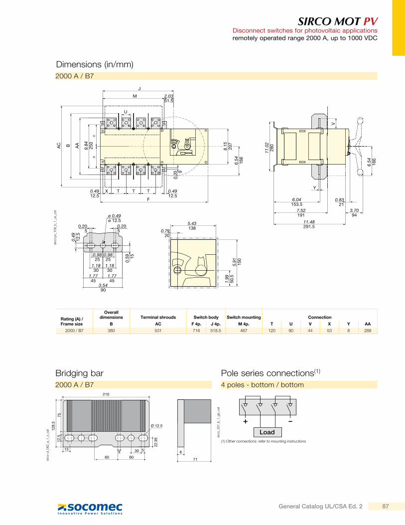
SIRCO MOT PVDisconnect switches for photovoltaic applicationsremotely operated range 2000 A, up to 1000 VDC
Dimensions (in/mm)
Rating (A) / Frame size
Overall dimensions Terminal shrouds Switch body Switch mounting Connection
B AC F 4p. J 4p. M 4p. T U V X Y AA
2000 / B7 380 531 716 518.5 467 120 90 44 53 8 288
2000 A / B7
F
0.4912.5
=
8.15
207
6.54
166
0.35 9
11.0
228
0
6.54
166
V
=9.
8425
0
AA
0.4912.5
11.48291.5
7.52191
6.04153.5
3.7094
0.8321
YX
M 2.0351.5
J
T T T
BAC
U
1.99
50.5
0.7920
5.43138
5.91
1500.59 15
0.205
0.205
0.49
12.5
0.9825
0.9825
1.1830
1.1830
1.7745
3.5490
1.7745
ø 0.49ø 12.5
sirc
o-p
v_1
09
_b_1
_us_
cat
Bridging bar
71
815
12.5
Ø 12.5
5
22.9
5
5 30
6060
128.
5
75
210
sirc
o-u
l_0
62
_a_1
_x_c
at
2000 A / B7
Pole series connections(1)
Load
-+
sirc
o_3
07
_b_1
_gb
_cat
4 poles - bottom / bottom
(1) Other connections: refer to mounting instructions
87General Catalog UL/CSA Ed. 2
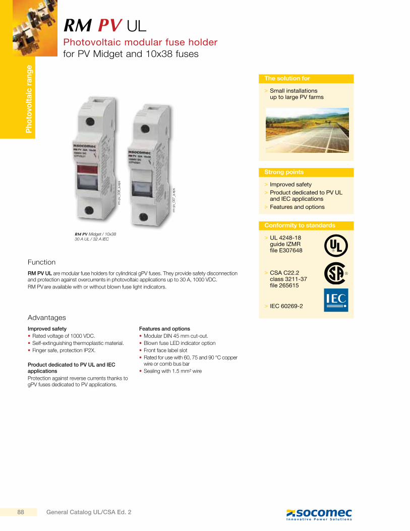
Ph
oto
volt
aic
ra
ng
eRM PV UL Photovoltaic modular fuse holderfor PV Midget and 10x38 fuses
Function
RM PV UL are modular fuse holders for cylindrical gPV fuses. They provide safety disconnection and protection against overcurrents in photovoltaic applications up to 30 A, 1000 VDC.
RM PV are available with or without blown fuse light indicators.
Advantages
Improved safety
Rated voltage of 1000 VDC.
Self-extinguishing thermoplastic material.
Finger safe, protection IP2X.
Product dedicated to PV UL and IEC applications
Protection against reverse currents thanks to gPV fuses dedicated to PV applications.
Features and options
Modular DIN 45 mm cut-out.
Blown fuse LED indicator option
Front face label slot
Rated for use with 60, 75 and 90 °C copper wire or comb bus bar
Sealing with 1.5 mm² wire
> Improved safety
> Product dedicated to PV UL and IEC applications
> Features and options
Strong points
RM PV Midget / 10x3830 A UL / 32 A IEC
> Small installations up to large PV farms
The solution for
> UL 4248-18guide IZMRfile E307648
> CSA C22.2class 3211-37file 265615
> IEC 60269-2
Conformity to standards
rm-p
v_0
07
_a.e
ps
rm-p
v_0
08
_a.e
ps
88 General Catalog UL/CSA Ed. 2
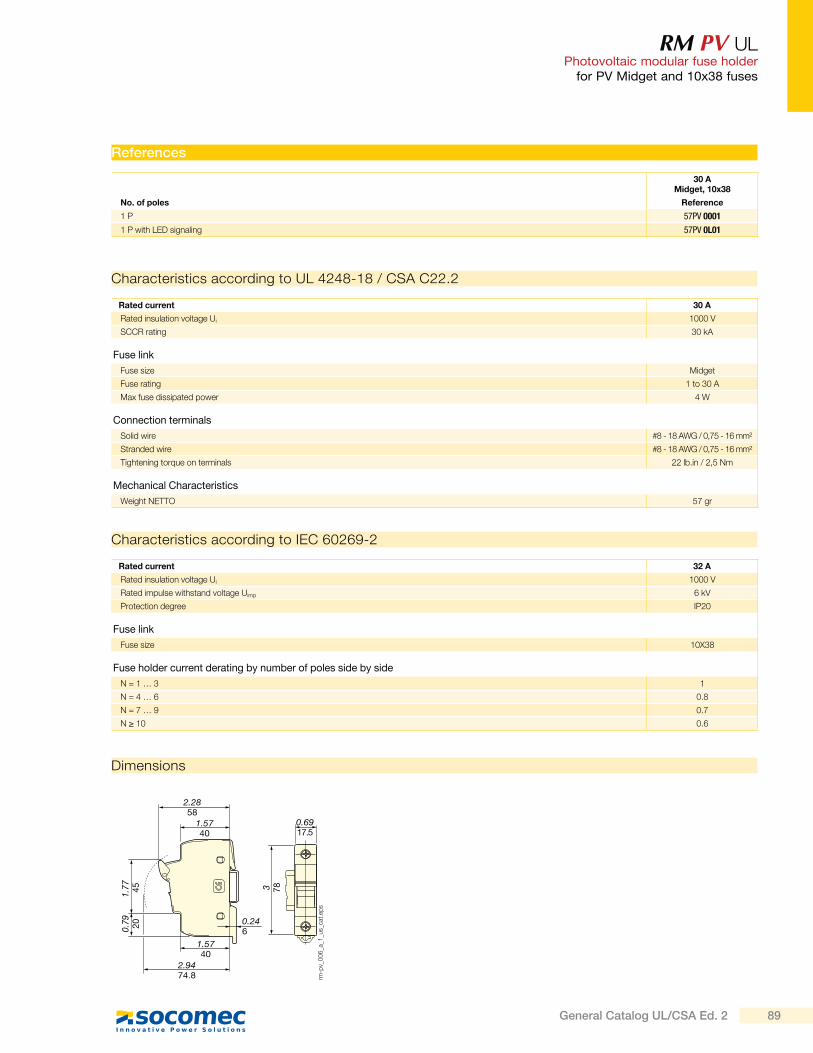
RM PV UL Photovoltaic modular fuse holder
for PV Midget and 10x38 fuses
References
30 AMidget, 10x38
No. of poles Reference
1 P 57PV 0001
1 P with LED signaling 57PV 0L01
Characteristics according to IEC 60269-2
Rated current 32 A
Rated insulation voltage Ui 1000 V
Rated impulse withstand voltage Uimp 6 kV
Protection degree IP20
Fuse link
Fuse size 10X38
Fuse holder current derating by number of poles side by side
N = 1 … 3 1
N = 4 … 6 0.8
N = 7 … 9 0.7
N 10 0.6
Rated current 30 A
Rated insulation voltage Ui 1000 V
SCCR rating 30 kA
Fuse link
Fuse size Midget
Fuse rating 1 to 30 A
Max fuse dissipated power 4 W
Connection terminals
Solid wire #8 - 18 AWG / 0,75 - 16 mm²
Stranded wire #8 - 18 AWG / 0,75 - 16 mm²
Tightening torque on terminals 22 lb.in / 2,5 Nm
Mechanical Characteristics
Weight NETTO 57 gr
Characteristics according to UL 4248-18 / CSA C22.2
Dimensions
2.2858
1.5740
1.77
45
0.79 20
1.5740
0.246
2.9474.8
0.6917.5
3 78
rm-p
v_0
06
_a_1
_us_
cat.
eps
89General Catalog UL/CSA Ed. 2
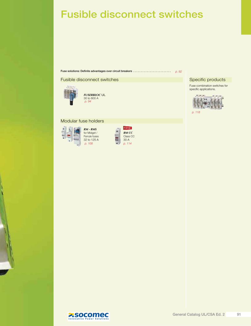
Fusible disconnect switches
Fusible disconnect switches
Fuse solutions: Definite advantages over circuit breakers . . . . . . . . . . . . . . . . . . . . . . . . .
FUSERBLOC UL30 to 800 A
Modular fuse holders
RM - RMSfor Midget /
Ferrule fuses
32 to 125 A
RM CCClass CC
30 A
new
Specific products
Fuse combination switches for specific applications.
p. 94
p. 114p. 108
p. 92
p. 118
91General Catalog UL/CSA Ed. 2
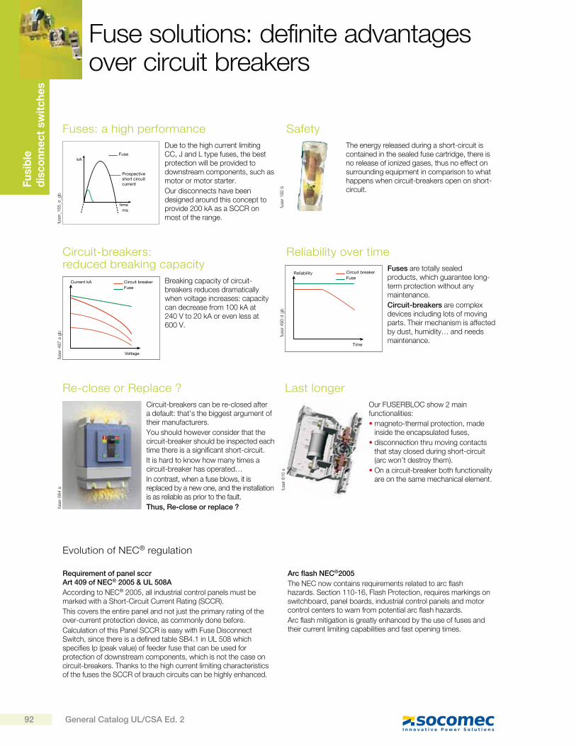
Fu
sib
le
dis
co
nn
ec
t sw
itc
he
sFuse solutions: definite advantages over circuit breakers
fuse
r_1
85
_e_g
b
Safety
The energy released during a short-circuit is contained in the sealed fuse cartridge, there is no release of ionized gases, thus no effect on surrounding equipment in comparison to what happens when circuit-breakers open on short-circuit.
fuse
r 1
92
b
Reliability over time
Fuses are totally sealed products, which guarantee long-term protection without any maintenance.
Circuit-breakers are complex devices including lots of moving parts. Their mechanism is affected by dust, humidity… and needs maintenance.
Reliability
Time
Circuit breakerFuse
fuse
r 4
90
d g
b
Last longer
Our FUSERBLOC show 2 main functionalities:
magneto-thermal protection, made inside the encapsulated fuses,
disconnection thru moving contacts that stay closed during short-circuit (arc won’t destroy them).
On a circuit-breaker both functionality are on the same mechanical element.
fuse
r 6
10
a
Fuses: a high performance
Due to the high current limiting CC, J and L type fuses, the best protection will be provided to downstream components, such as motor or motor starter.
Our disconnects have been designed around this concept to provide 200 kA as a SCCR on most of the range.
Arc flash NEC®2005
The NEC now contains requirements related to arc flash hazards. Section 110-16, Flash Protection, requires markings on switchboard, panel boards, industrial control panels and motor control centers to warn from potential arc flash hazards.
Arc flash mitigation is greatly enhanced by the use of fuses and their current limiting capabilities and fast opening times.
Evolution of NEC® regulation
Requirement of panel sccr Art 409 of NEC® 2005 & UL 508A
According to NEC® 2005, all industrial control panels must be marked with a Short-Circuit Current Rating (SCCR).
This covers the entire panel and not just the primary rating of the over-current protection device, as commonly done before.
Calculation of this Panel SCCR is easy with Fuse Disconnect Switch, since there is a defined table SB4.1 in UL 508 which specifies Ip (peak value) of feeder fuse that can be used for protection of downstream components, which is not the case on circuit-breakers. Thanks to the high current limiting characteristics of the fuses the SCCR of brauch circuits can be highly enhanced.
Circuit-breakers: reduced breaking capacity
Breaking capacity of circuit-breakers reduces dramatically when voltage increases: capacity can decrease from 100 kA at 240 V to 20 kA or even less at 600 V.
Current kA
Voltage
Circuit breakerFuse
fuse
r 4
87
a g
b
Re-close or Replace ?
Circuit-breakers can be re-closed after a default: that’s the biggest argument of their manufacturers.
You should however consider that the circuit-breaker should be inspected each time there is a significant short-circuit.
It is hard to know how many times a circuit-breaker has operated…
In contrast, when a fuse blows, it is replaced by a new one, and the installation is as relia ble as prior to the fault.
Thus, Re-close or replace ?fuse
r 6
64
a
kA
mstime
Prospectiveshort circuitcurrent
Fuse
92 General Catalog UL/CSA Ed. 2
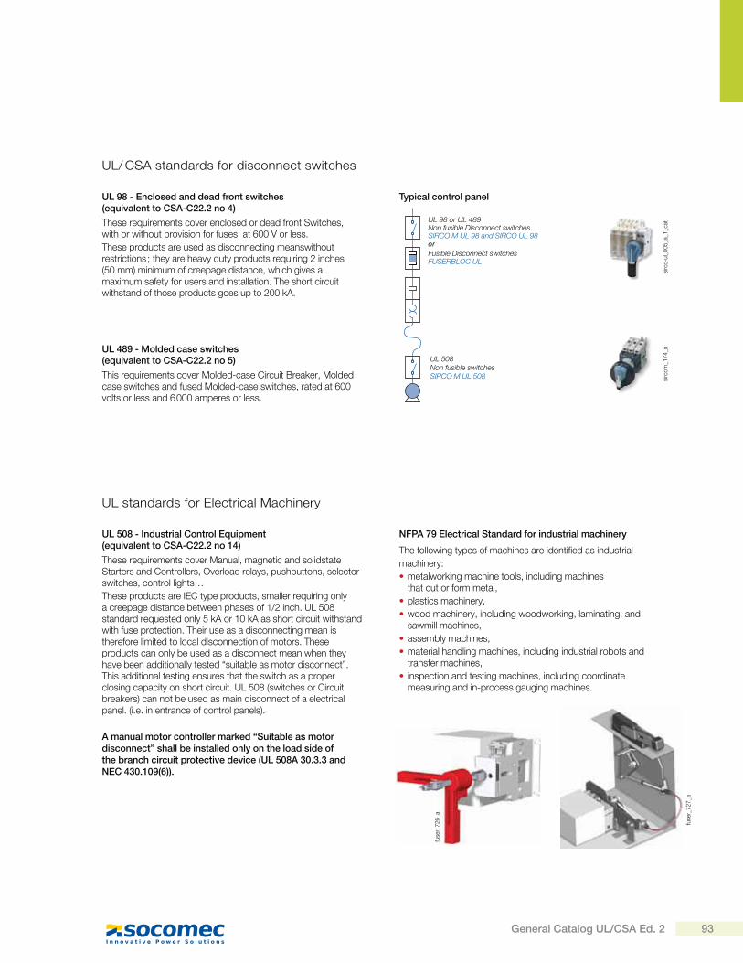
These requirements cover enclosed or dead front Switches, with or without provision for fuses, at 600 V or less.
These products are used as disconnecting meanswithout restrictions ; they are heavy duty products requiring 2 inches (50 mm) minimum of creepage distance, which gives a maximum safety for users and installation. The short circuit withstand of those products goes up to 200 kA.
This requirements cover Molded-case Circuit Breaker, Molded case switches and fused Molded-case switches, rated at 600 volts or less and 6 000 amperes or less.
UL 98 - Enclosed and dead front switches(equivalent to CSA-C22.2 no 4)
Typical control panel
UL 489 - Molded case switches(equivalent to CSA-C22.2 no 5)
UL 98 or UL 489Non fusible Disconnect switchesSIRCO M UL 98 and SIRCO UL 98
Fusible Disconnect switchesFUSERBLOC UL
UL 508Non fusible switchesSIRCO M UL 508
or
sirc
om
_17
4_a
fuse
r_7
27
_a
fuse
r_7
26
_a
sirc
o-u
l_0
05
_a_1
_cat
UL/ CSA standards for disconnect switches
These requirements cover Manual, magnetic and solidstate Starters and Controllers, Overload relays, pushbuttons, selector switches, control lights…
These products are IEC type products, smaller requiring only a creepage distance between phases of 1/2 inch. UL 508 standard requested only 5 kA or 10 kA as short circuit withstand with fuse protection. Their use as a disconnecting mean is therefore limited to local disconnection of motors. These products can only be used as a disconnect mean when they have been additionally tested “suitable as motor disconnect”. This additional testing ensures that the switch as a proper closing capacity on short circuit. UL 508 (switches or Circuit breakers) can not be used as main disconnect of a electrical panel. (i.e. in entrance of control panels).
A manual motor controller marked “Suitable as motor disconnect” shall be installed only on the load side of the branch circuit protective device (UL 508A 30.3.3 and NEC 430.109(6)).
The following types of machines are identified as industrial
machinery:
metalworking machine tools, including machines that cut or form metal,
plastics machinery,
wood machinery, including woodworking, laminating, and sawmill machines,
assembly machines,
material handling machines, including industrial robots and transfer machines,
inspection and testing machines, including coordinate measuring and in-process gauging machines.
UL 508 - Industrial Control Equipment(equivalent to CSA-C22.2 no 14)
NFPA 79 Electrical Standard for industrial machinery
UL standards for Electrical Machinery
93General Catalog UL/CSA Ed. 2
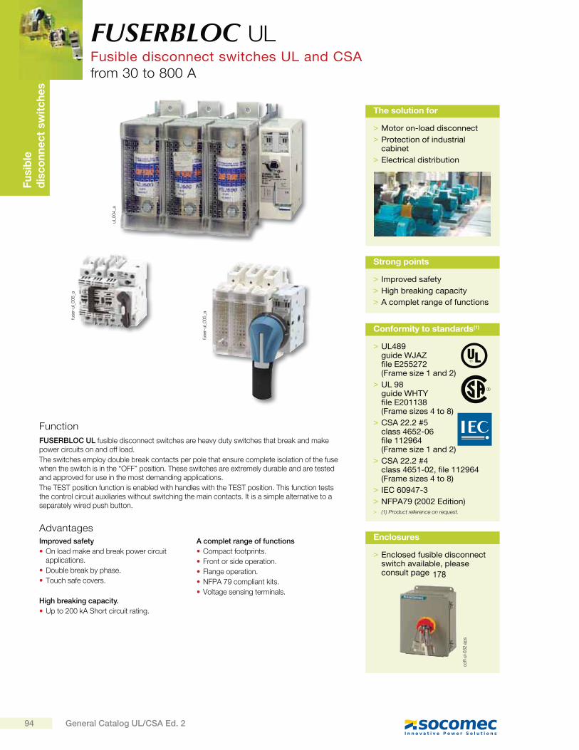
Fu
sib
led
isc
on
ne
ct
sw
itc
he
s
fuse
r-ul_
00
6_a
fuse
r-ul_
00
5_a
ul_
00
4_a
FUSERBLOC UL Fusible disconnect switches UL and CSAfrom 30 to 800 A
Function
Advantages
FUSERBLOC UL fusible disconnect switches are heavy duty switches that break and make power circuits on and off load.
The switches employ double break contacts per pole that ensure complete isolation of the fuse when the switch is in the “OFF” position. These switches are extremely durable and are tested and approved for use in the most demanding applications.
The TEST position function is enabled with handles with the TEST position. This function tests the control circuit auxiliaries without switching the main contacts. It is a simple alternative to a separately wired push button.
Improved safety
On load make and break power circuit applications.
Double break by phase.
Touch safe covers.
High breaking capacity.
Up to 200 kA Short circuit rating.
A complet range of functions
Compact footprints.
Front or side operation.
Flange operation.
NFPA 79 compliant kits.
Voltage sensing terminals.
> Motor on-load disconnect
> Protection of industrial cabinet
> Electrical distribution
The solution for
> Improved safety
> High breaking capacity
> A complet range of functions
Strong points
> UL489guide WJAZfile E255272 (Frame size 1 and 2)
> UL 98guide WHTYfile E201138(Frame sizes 4 to 8)
> CSA 22.2 #5class 4652-06file 112964 (Frame size 1 and 2)
> CSA 22.2 #4class 4651-02, file 112964 (Frame sizes 4 to 8)
> IEC 60947-3
> NFPA79 (2002 Edition) > (1) Product reference on request.
Conformity to standards(1)
> Enclosed fusible disconnect switch available, please consult page
Enclosures
coff-
ul-0
32
.ep
s
178
94 General Catalog UL/CSA Ed. 2
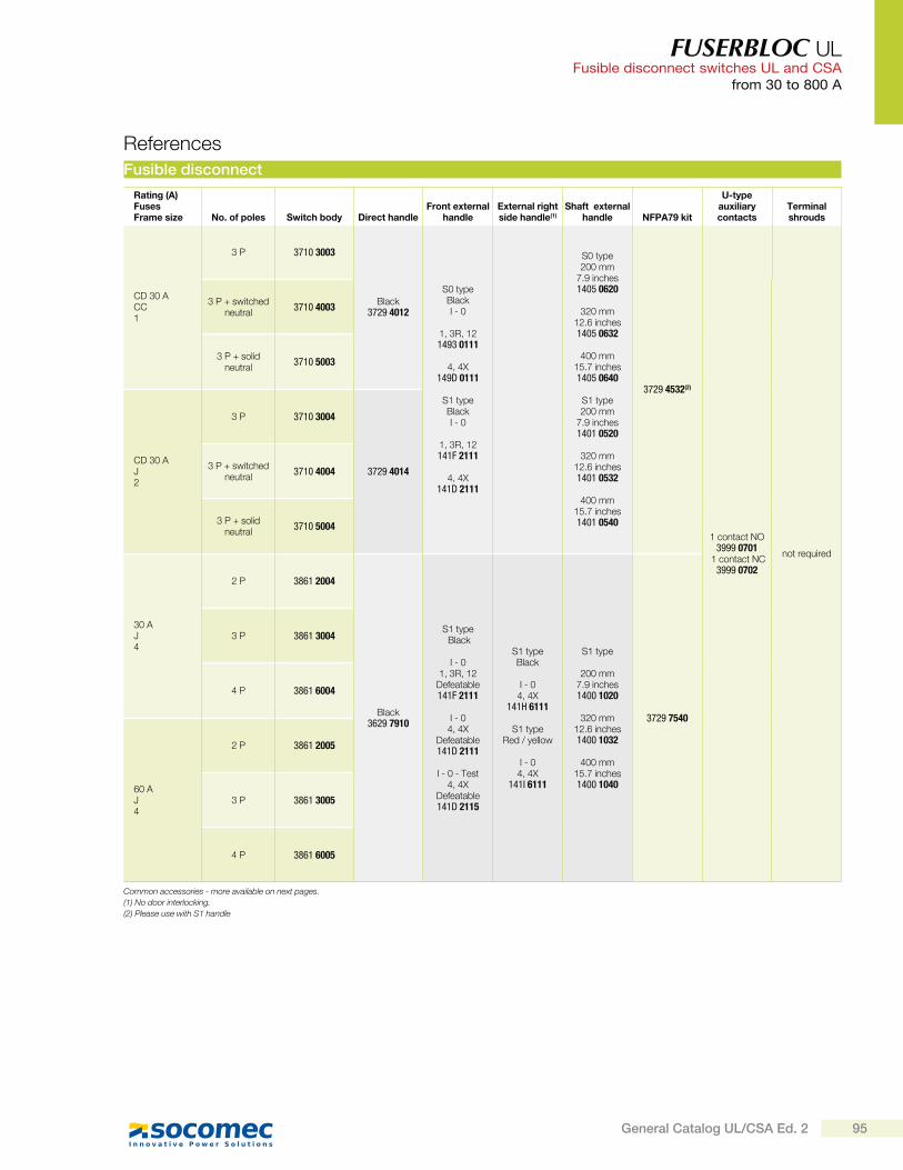
FUSERBLOC UL Fusible disconnect switches UL and CSA
from 30 to 800 A
Fusible disconnect
Rating (A) FusesFrame size No. of poles Switch body Direct handle
Front external handle
External right side handle(1)
Shaft external handle NFPA79 kit
U-type auxiliary contacts
Terminal shrouds
CD 30 ACC1
3 P 3710 3003
Black3729 4012
S0 type Black I - 0
1, 3R, 121493 0111
4, 4X
149D 0111
S1 type Black I - 0
1, 3R, 12141F 2111
4, 4X
141D 2111
S0 type 200 mm
7.9 inches1405 0620
320 mm 12.6 inches1405 0632
400 mm 15.7 inches1405 0640
S1 type 200 mm
7.9 inches1401 0520
320 mm 12.6 inches1401 0532
400 mm15.7 inches1401 0540
3729 4532(2)
1 contact NO3999 0701
1 contact NC3999 0702
not required
3 P + switched neutral
3710 4003
3 P + solid neutral
3710 5003
CD 30 AJ2
3 P 3710 3004
3729 4014 3 P + switched
neutral3710 4004
3 P + solid neutral
3710 5004
30 AJ4
2 P 3861 2004
Black3629 7910
S1 type Black
I - 0 1, 3R, 12
Defeatable141F 2111
I - 0 4, 4X
Defeatable141D 2111
I - 0 - Test 4, 4X
Defeatable141D 2115
S1 type Black
I - 0 4, 4X
141H 6111
S1 type Red / yellow
I - 0 4, 4X
141I 6111
S1 type
200 mm 7.9 inches1400 1020
320 mm
12.6 inches1400 1032
400 mm15.7 inches1400 1040
3729 7540
3 P 3861 3004
4 P 3861 6004
60 AJ4
2 P 3861 2005
3 P 3861 3005
4 P 3861 6005
References
Common accessories - more available on next pages.
(1) No door interlocking.
(2) Please use with S1 handle
95General Catalog UL/CSA Ed. 2
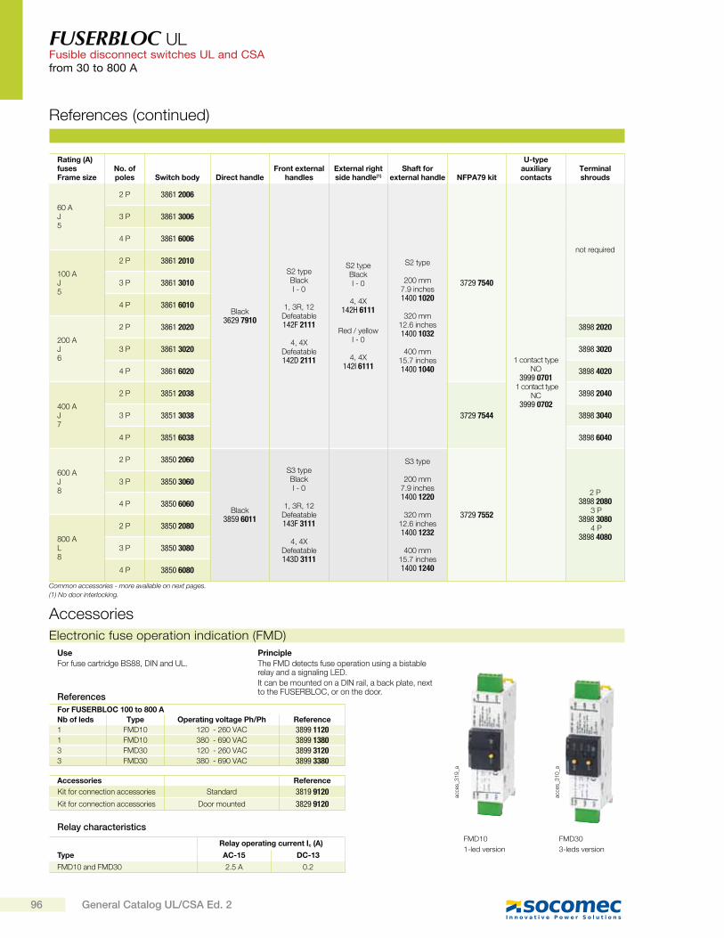
FUSERBLOC UL Fusible disconnect switches UL and CSAfrom 30 to 800 A
Rating (A) fusesFrame size
No. of poles Switch body Direct handle
Front external handles
External right side handle(1)
Shaft for external handle NFPA79 kit
U-type auxiliary contacts
Terminal shrouds
60 AJ5
2 P 3861 2006
Black3629 7910
S2 type Black I - 0
1, 3R, 12 Defeatable142F 2111
4, 4X
Defeatable142D 2111
S2 type BlackI - 0
4, 4X142H 6111
Red / yellowI - 0
4, 4X142I 6111
S2 type
200 mm 7.9 inches1400 1020
320 mm
12.6 inches1400 1032
400 mm15.7 inches1400 1040
3729 7540
1 contact type NO
3999 0701 1 contact type
NC3999 0702
not required
3 P 3861 3006
4 P 3861 6006
100 AJ5
2 P 3861 2010
3 P 3861 3010
4 P 3861 6010
200 AJ6
2 P 3861 2020 3898 2020
3 P 3861 3020 3898 3020
4 P 3861 6020 3898 4020
400 AJ7
2 P 3851 2038
3729 7544
3898 2040
3 P 3851 3038 3898 3040
4 P 3851 6038 3898 6040
600 AJ8
2 P 3850 2060
Black3859 6011
S3 type Black I - 0
1, 3R, 12 Defeatable143F 3111
4, 4X Defeatable143D 3111
S3 type
200 mm 7.9 inches1400 1220
320 mm
12.6 inches1400 1232
400 mm15.7 inches1400 1240
3729 7552
2 P3898 2080
3 P3898 3080
4 P3898 4080
3 P 3850 3060
4 P 3850 6060
800 AL8
2 P 3850 2080
3 P 3850 3080
4 P 3850 6080
References (continued)
Common accessories - more available on next pages.
(1) No door interlocking.
Electronic fuse operation indication (FMD)
acce
s_3
19
_a
Use
For fuse cartridge BS88, DIN and UL.
Principle
The FMD detects fuse operation using a bistable relay and a signaling LED.
It can be mounted on a DIN rail, a back plate, next to the FUSERBLOC, or on the door.
For FUSERBLOC 100 to 800 A
Nb of leds Type Operating voltage Ph/Ph Reference
1 FMD10 120 - 260 VAC 3899 11201 FMD10 380 - 690 VAC 3899 13803 FMD30 120 - 260 VAC 3899 31203 FMD30 380 - 690 VAC 3899 3380
acce
s_3
10
_a
References
Accessories Reference
Kit for connection accessories Standard 3819 9120
Kit for connection accessories Door mounted 3829 9120
Relay characteristics
Type
Relay operating current Ic (A)
AC-15 DC-13
FMD10 and FMD30 2.5 A 0.2
FMD10
1-led version
FMD30
3-leds version
Accessories
96 General Catalog UL/CSA Ed. 2
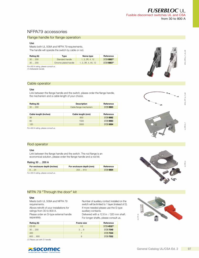
FUSERBLOC UL Fusible disconnect switches UL and CSA
from 30 to 800 A
Rod operator
ul_
04
3_a
Use
Link between the flange handle and the switch. The rod flange is an economical solution, please order the flange handle and a rod kit.
For enclosure depth (inches) For enclosure depth (mm) Reference
8 … 24 203 … 613 3729 9904
sirc
o_2
46
_a_1
_us_
cat
Flange handle for flange operation
Use
Meets both UL 508A and NFPA 79 requirements.
The handle will operate the switch by cable or rod.
Rating (A) Type Nema type Reference
30 … 200 Standard handle 1, 3, 3R, 4, 12 3729 9002(1)
30 … 200 Chrome plated handle 1, 3, 3R, 4, 4X, 12 3729 9003(1)
NFPA79 accessories
NFPA 79 "Through the door" kit
ul_
12
1_b
Use
Meets both UL 508A and NFPA 79 requirements.
Allows retrofit of your installations for ratings from 30 to 800 A.
Please order an S-type external handle separately.
Number of auxiliary contact installed on the switch will be limited to 1 layer (instead of 2).
If more needed please use the S type auxiliary contacts.
Delivered with a 12.6 in / 320 mm shaft.
For longer shafts, please consult us.
Rating (A) Frame size Reference
CD 30 1/2 3729 4532(1)
30 … 200 3 … 6 3729 7540
400 7 3729 7544
600 … 800 8 3729 7552
ul_
04
2_b
_1si
rco
_24
7_a
_1_c
at
Cable operator
Use
Link between the flange handle and the switch, please order the flange handle, the mechanism and a cable length of your choice.
Cable length (inches) Cable length (mm) Reference
36 900 3729 9992
60 1500 3729 9993
120 3000 3729 9994
Rating (A) Description Reference
30 … 200 Cable flange mechanism 3729 9903
For 400 A rating, please consult us.
(1) Defeatable handle.
Rating 30 … 200 A
For 400 A rating, please consult us.
For 400 A rating, please consult us.
(1) Please use with S1 handle.
97General Catalog UL/CSA Ed. 2
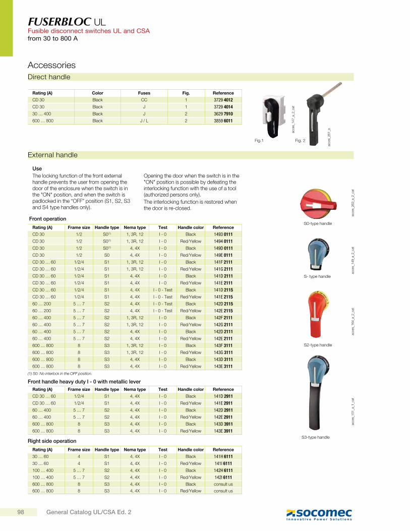
FUSERBLOC UL Fusible disconnect switches UL and CSAfrom 30 to 800 A
acce
s_2
61
_a
Rating (A) Color Fuses Fig. Reference
CD 30 Black CC 1 3729 4012
CD 30 Black J 1 3729 4014
30 … 400 Black J 2 3629 7910
600 … 800 Black J / L 2 3859 6011
Fig. 2
acce
s_1
47
_a_2
_cat
Fig.1
Direct handle
Accessories
acce
s_1
49
_a_2
_cat
S- type handle
acce
s_1
64
_a_2
_cat
S2-type handle
External handle
Use
The locking function of the front external handle prevents the user from opening the door of the enclosure when the switch is in the "ON" position, and when the switch is padlocked in the “OFF” position (S1, S2, S3 and S4 type handles only).
Opening the door when the switch is in the "ON" position is possible by defeating the interlocking function with the use of a tool (authorized persons only).
The interlocking function is restored when the door is re-closed.
acce
s_1
51
_a_1
_cat
S3-type handle
acce
s_2
63
_a_2
_cat
S0-type handleRating (A) Frame size Handle type Nema type Test Handle color Reference
CD 30 1/2 S0(1) 1, 3R, 12 I - 0 Black 1493 0111
CD 30 1/2 S0(1) 1, 3R, 12 I - 0 Red/Yellow 1494 0111
CD 30 1/2 S0(1) 4, 4X I - 0 Black 149D 0111
CD 30 1/2 S0 4, 4X I - 0 Red/Yellow 149E 0111
CD 30 … 60 1/2/4 S1 1, 3R, 12 I - 0 Black 141F 2111
CD 30 … 60 1/2/4 S1 1, 3R, 12 I - 0 Red/Yellow 141G 2111
CD 30 … 60 1/2/4 S1 4, 4X I - 0 Black 141D 2111
CD 30 … 60 1/2/4 S1 4, 4X I - 0 Red/Yellow 141E 2111
CD 30 … 60 1/2/4 S1 4, 4X I - 0 - Test Black 141D 2115
CD 30 … 60 1/2/4 S1 4, 4X I - 0 - Test Red/Yellow 141E 2115
60 … 200 5 … 7 S2 4, 4X I - 0 - Test Black 142D 2115
60 … 200 5 … 7 S2 4, 4X I - 0 - Test Red/Yellow 142E 2115
60 … 400 5 … 7 S2 1, 3R, 12 I - 0 Black 142F 2111
60 … 400 5 … 7 S2 1, 3R, 12 I - 0 Red/Yellow 142G 2111
60 … 400 5 … 7 S2 4, 4X I - 0 Black 142D 2111
60 … 400 5 … 7 S2 4, 4X I - 0 Red/Yellow 142E 2111
600 … 800 8 S3 1, 3R, 12 I - 0 Black 143F 3111
600 … 800 8 S3 1, 3R, 12 I - 0 Red/Yellow 143G 3111
600 … 800 8 S3 4, 4X I - 0 Black 143D 3111
600 … 800 8 S3 4, 4X I - 0 Red/Yellow 143E 3111
(1) S0: No interlock in the OFF position.
Front operation
Rating (A) Frame size Handle type Nema type Test Handle color Reference
30 … 60 4 S1 4, 4X I - 0 Black 141H 6111
30 … 60 4 S1 4, 4X I - 0 Red/Yellow 141I 6111
100 … 400 5 … 7 S2 4, 4X I - 0 Black 142H 6111
100 … 400 5 … 7 S2 4, 4X I - 0 Red/Yellow 142I 6111
600 … 800 8 S3 4, 4X I - 0 Black consult us
600 … 800 8 S3 4, 4X I - 0 Red/Yellow consult us
Right side operation
Rating (A) Frame size Handle type Nema type Test Handle color Reference
CD 30 … 60 1/2/4 S1 4, 4X I - 0 Black 141D 2911
CD 30 … 60 1/2/4 S1 4, 4X I - 0 Red/Yellow 141E 2911
60 … 400 5 … 7 S2 4, 4X I - 0 Black 142D 2911
60 … 400 5 … 7 S2 4, 4X I - 0 Red/Yellow 142E 2911
600 … 800 8 S3 4, 4X I - 0 Black 143D 3911
600 … 800 8 S3 4, 4X I - 0 Red/Yellow 143E 3911
Front handle heavy duty I - 0 with metallic lever
98 General Catalog UL/CSA Ed. 2
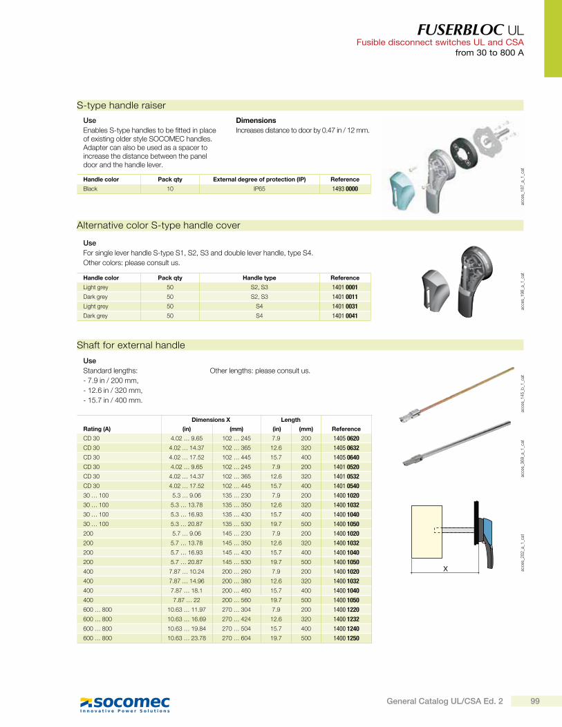
FUSERBLOC UL Fusible disconnect switches UL and CSA
from 30 to 800 A
acce
s_1
87
_a_1
_cat
Handle color Pack qty External degree of protection (IP) Reference
Black 10 IP65 1493 0000
S-type handle raiser
Use
Enables S-type handles to be fitted in place of existing older style SOCOMEC handles. Adapter can also be used as a spacer to increase the distance between the panel door and the handle lever.
Dimensions
Increases distance to door by 0.47 in / 12 mm.
Alternative color S-type handle cover
acce
s_1
98
_a_1
_cat
Use
For single lever handle S-type S1, S2, S3 and double lever handle, type S4.
Other colors: please consult us.
Handle color Pack qty Handle type Reference
Light grey 50 S2, S3 1401 0001
Dark grey 50 S2, S3 1401 0011
Light grey 50 S4 1401 0031
Dark grey 50 S4 1401 0041
X acce
s_2
02
_a_1
_cat
acce
s_3
69
_a_1
_cat
acce
s_1
45
_b_1
_cat
Shaft for external handle
Dimensions X Length
Rating (A) (in) (mm) (in) (mm) Reference
CD 30 4.02 … 9.65 102 … 245 7.9 200 1405 0620
CD 30 4.02 … 14.37 102 … 365 12.6 320 1405 0632
CD 30 4.02 … 17.52 102 … 445 15.7 400 1405 0640
CD 30 4.02 … 9.65 102 … 245 7.9 200 1401 0520
CD 30 4.02 … 14.37 102 … 365 12.6 320 1401 0532
CD 30 4.02 … 17.52 102 … 445 15.7 400 1401 0540
30 … 100 5.3 … 9.06 135 … 230 7.9 200 1400 1020
30 … 100 5.3 … 13.78 135 … 350 12.6 320 1400 1032
30 … 100 5.3 … 16.93 135 … 430 15.7 400 1400 1040
30 … 100 5.3 … 20.87 135 … 530 19.7 500 1400 1050
200 5.7 … 9.06 145 … 230 7.9 200 1400 1020
200 5.7 … 13.78 145 … 350 12.6 320 1400 1032
200 5.7 … 16.93 145 … 430 15.7 400 1400 1040
200 5.7 … 20.87 145 … 530 19.7 500 1400 1050
400 7.87 … 10.24 200 … 260 7.9 200 1400 1020
400 7.87 … 14.96 200 … 380 12.6 320 1400 1032
400 7.87 … 18.1 200 … 460 15.7 400 1400 1040
400 7.87 … 22 200 … 560 19.7 500 1400 1050
600 … 800 10.63 … 11.97 270 … 304 7.9 200 1400 1220
600 … 800 10.63 … 16.69 270 … 424 12.6 320 1400 1232
600 … 800 10.63 … 19.84 270 … 504 15.7 400 1400 1240
600 … 800 10.63 … 23.78 270 … 604 19.7 500 1400 1250
Use
Standard lengths:
- 7.9 in / 200 mm,
- 12.6 in / 320 mm,
- 15.7 in / 400 mm.
Other lengths: please consult us.
99General Catalog UL/CSA Ed. 2

FUSERBLOC UL Fusible disconnect switches UL and CSAfrom 30 to 800 A
acce
s_0
83
_a_1
_catNO+NC auxiliary contacts
Rating (A) Number of contacts Reference
30 … 800 1 3999 U041
30 … 800 2 3999 U042
acce
s_0
51
_a_1
_cat
S-type auxiliary contacts
Use
Side operated auxiliary contacts for FUSERBLOC 30 to 400 A, position OFF and ON signalled by 1 to 4 NO + NC auxiliary contacts.
Electrical characteristics
A600/D600.
S-type auxiliary contacts are signaling position I and 0.
U-type auxiliary contacts
A
Bac
ces_
05
6_a
_1_c
atac
ces_
04
3_a
_1_x
_cat
Use
U-type AC can be configured to be operated on both, standard and TEST position switches from CD 30 to 800 A. Each slot can accommodate up to 2 interlocked ACs.
- For CD 30A/CC, a maximum of 4 ACs (8 with an additional holder):
- For CD 30A/J, maximum 2 ACs (6 with an additional holder),
- For 30 to 200A/J, maximum 4 ACs,
- For 400 to 800A/L, maximum 8 ACs.
Electrical characteristics
A600.
When FUSERBLOC is front operated, ACs are prebreak and signaling position I and 0. When FUSERBLOC is side operated, Acs are signaling positions I and 0.
NO auxiliary contacts
Rating (A) Number of contacts Reference
CD 30 … 800 1 3999 0701
NC auxiliary contacts
Rating (A) Number of contacts Reference
CD 30 … 800 1 3999 0702
Contact holder for additional auxiliary contacts
Rating (A) Fuses Reference
CD 30 CC 3999 0710
CD 30 J 3999 0710
Accessories (continued)
Shaft guide for external handle
acce
s_2
60
_a_2
_cat
Use
This accessory enables handle to engage shaft with a misalignment of up to 0.59 in / 15 mm.
Required for a shaft length over 400 mm for S1 to S3 handles and for a shaft from 12.6 in / 320 mm for S0 handle.
Description Reference
Shaft guide for S1 to S3 handles 1429 0000
Shaft guide for S0 handle 1419 0000
CD 30 : U-type auxiliary contacts cannot be mounted on switches with direct operation handle
External front operation shaft support accessory
Use
This support maintains shaft position for extension shafts greater than 12.6 in / 320 mm in length.
Rating (A) Frame size Reference
50 … 400 11 … 16 3899 0400
fuse
r_6
98
_a_2
_cat
100 General Catalog UL/CSA Ed. 2
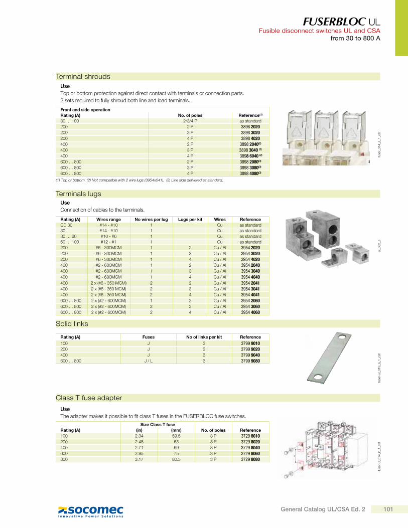
FUSERBLOC UL Fusible disconnect switches UL and CSA
from 30 to 800 A
Terminal shrouds
fuse
r_3
14
_a_1
_cat
Use
Top or bottom protection against direct contact with terminals or connection parts.
2 sets required to fully shroud both line and load terminals.
Front and side operation
Rating (A) No. of poles Reference(1)
30 … 100 2/3/4 P as standard
200 2 P 3898 2020200 3 P 3898 3020200 4 P 3898 4020400 2 P 3898 2040(2)
400 3 P 3898 3040 (2)
400 4 P 3898 6040 (2)
600 … 800 2 P 3898 2080(3)
600 … 800 3 P 3898 3080(3)
600 … 800 4 P 3898 4080(3)
(1) Top or bottom. (2) Not compatible with 2 wire lugs (3954x041). (3) Line side delivered as standard.
ul_
03
2_a
Terminals lugsUse
Connection of cables to the terminals.
Rating (A) Wires range No wires per lug Lugs per kit Wires Reference
CD 30 #14 - #10 1 Cu as standard
30 #14 - #10 1 Cu as standard
30 … 60 #10 - #6 1 Cu as standard
60 … 100 #12 - #1 1 Cu as standard
200 #6 - 300MCM 1 2 Cu / Al 3954 2020200 #6 - 300MCM 1 3 Cu / Al 3954 3020200 #6 - 300MCM 1 4 Cu / Al 3954 4020400 #2 - 600MCM 1 2 Cu / Al 3954 2040400 #2 - 600MCM 1 3 Cu / Al 3954 3040
400 #2 - 600MCM 1 4 Cu / Al 3954 4040
400 2 x (#6 - 350 MCM) 2 2 Cu / Al 3954 2041400 2 x (#6 - 350 MCM) 2 3 Cu / Al 3954 3041400 2 x (#6 - 350 MCM) 2 4 Cu / Al 3954 4041600 … 800 2 x (#2 - 600MCM) 1 2 Cu / Al 3954 2060600 … 800 2 x (#2 - 600MCM) 2 3 Cu / Al 3954 3060600 … 800 2 x (#2 - 600MCM) 2 4 Cu / Al 3954 4060
Class T fuse adapter
Use
The adapter makes it possible to fit class T fuses in the FUSERBLOC fuse switches.
Size Class T fuse
Rating (A) (in) (mm) No. of poles Reference
100 2.34 59.5 3 P 3729 8010200 2.48 63 3 P 3729 8020400 2.71 69 3 P 3729 8040600 2.95 75 3 P 3729 8060800 3.17 80.5 3 P 3729 8080
fuse
r-ul_
01
4_b
_1_c
at
Solid links
Rating (A) Fuses No of links per kit Reference
100 J 3 3799 9010200 J 3 3799 9020400 J 3 3799 9040600 … 800 J / L 3 3799 9080
fuse
r-ul_
01
9_a
_1_c
at
101General Catalog UL/CSA Ed. 2
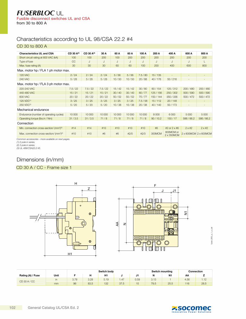
FUSERBLOC UL Fusible disconnect switches UL and CSAfrom 30 to 800 A
Dimensions (in/mm)
H
Z
H1
fuse
r_6
55
_a_1
_x_c
at
Switch body Switch mounting Connection
Rating (A) / Fuse Unit F H H1 J J1 N N1 AA Z
CD 30 A / CCin 3.78 3.28 5.19 1.47 0.59 3.13 1 4.56 1.12
mm 96 83.5 132 37.5 15 79.5 25.5 116 28.5
CD 30 A / CC - Frame size 1
CD 30 to 800 A
Characteristics according to UL 98/CSA 22.2 #4
AA N
N1
F
J J1
Characteristics UL and CSA CD 30 A(3) CD 30 A(3) 30 A 60 A 60 A 100 A 200 A 400 A 600 A 800 A
Short circuit rating at 600 VAC (kA) 100 100 200 100 200 200 200 200 200 200
Type of fuse CC J J J J J J J J L
Max. fuse rating (A) 30 30 30 60 60 100 200 400 600 800
Max. motor hp / FLA 1 ph motor max.
120 VAC 2 / 24 2 / 24 2 / 24 5 / 56 5 / 56 7.5 / 80 15 / 135 - - -
240 VAC 5 / 28 5 / 28 5 / 28 10 / 50 10 / 50 20 / 88 40 / 176 50 / 216 - -
Max. motor hp / FLA 3 ph motor max.
220-240 VAC 7.5 / 22 7.5 / 22 7.5 / 22 15 / 42 15 / 42 30 / 80 60 / 154 125 / 312 200 / 480 200 / 480
440-480 VAC 15 / 21 15 / 21 15 / 21 30 / 40 30 / 40 60 / 77 125 / 156 250 / 302 500 / 590 500 / 590
600 VAC 20 / 22 20 / 22 20 / 22 50 / 52 50 / 52 75 / 77 150 / 144 350 / 336 500 / 472 500 / 472
125 VDC(1) 3 / 25 3 / 25 3 / 25 3 / 25 3 / 25 7.5 / 58 15 / 112 20 / 148 - -
250 VDC(2) 5 / 20 5 / 20 5 / 20 10 / 38 10 / 38 20 / 38 40 / 140 50 / 173 - -
Mechanical endurance
Endurance (number of operating cycles) 10 000 10 000 10 000 10 000 10 000 10 000 8 000 6 000 5 000 5 000
Operating torque (lbs.in / Nm) 31 / 3.5 31 / 3.5 71 / 8 71 / 8 71 / 8 71 / 8 90 / 10.2 150 / 17 586 / 66.2 586 / 66.2
Connection
Min. connection cross-section/ (mm2)(2) #14 #14 #10 #10 #10 #10 #6 #2 or 2 x #6 2 x #2 2 x #2
Max. connection cross-section/ (mm2)(2) #10 #10 #6 #6 #2/0 #2/0 300MCM600MCM or 2 x 350MCM
2 x 600MCM 2 x 600MCM
Common accessories - more available on next pages.
(1) 2 pole in series.
(2) 3 pole in series.
(3) UL 489/CSA22.2 5.
102 General Catalog UL/CSA Ed. 2
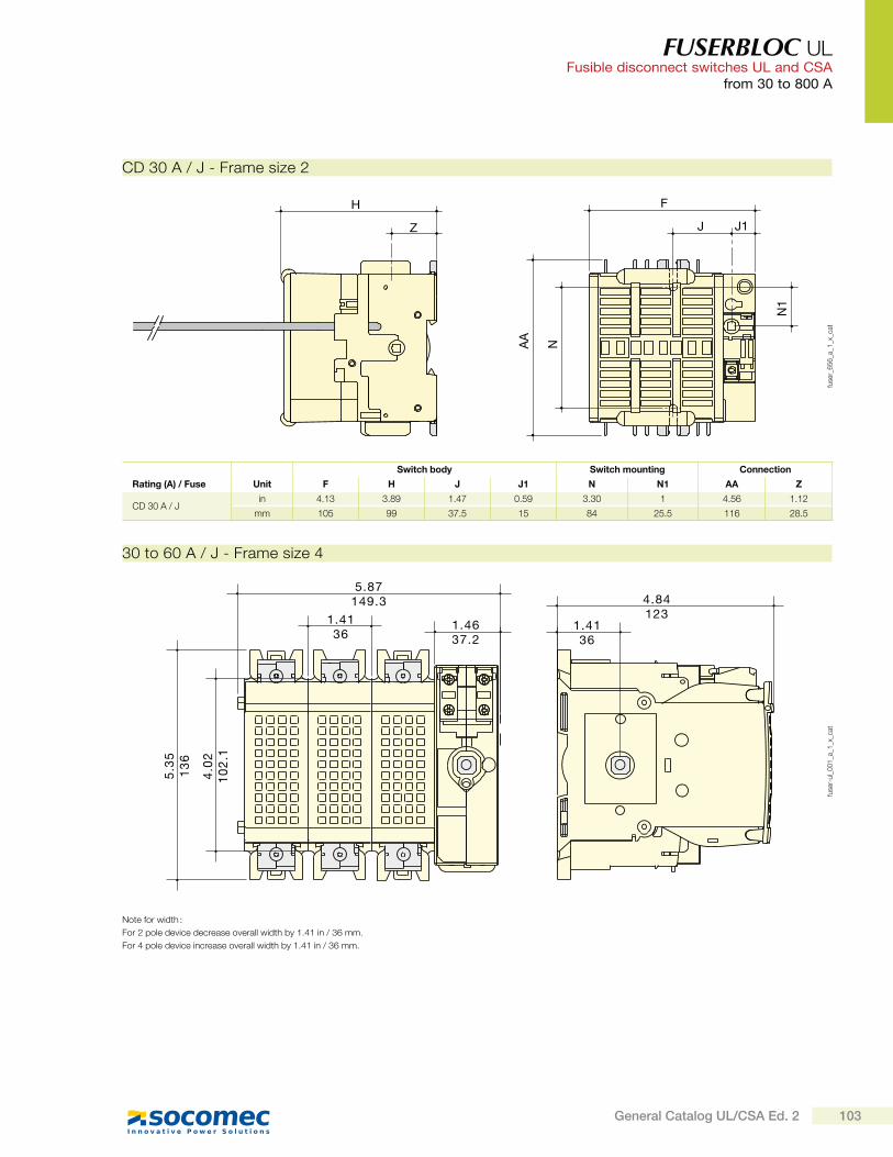
FUSERBLOC UL Fusible disconnect switches UL and CSA
from 30 to 800 A
H
Z
fuse
r_6
56
_a_1
_x_c
at
Switch body Switch mounting Connection
Rating (A) / Fuse Unit F H J J1 N N1 AA Z
CD 30 A / Jin 4.13 3.89 1.47 0.59 3.30 1 4.56 1.12
mm 105 99 37.5 15 84 25.5 116 28.5
CD 30 A / J - Frame size 25
.35
13
6
5.87149.3
1.4136
1.4637.2
4.84123
1.4136
4.0
21
02
.1
fuse
r-ul_
00
1_a
_1_x
_cat
30 to 60 A / J - Frame size 4
F
J J1
AA
N
N1
Note for width :
For 2 pole device decrease overall width by 1.41 in / 36 mm.
For 4 pole device increase overall width by 1.41 in / 36 mm.
103General Catalog UL/CSA Ed. 2
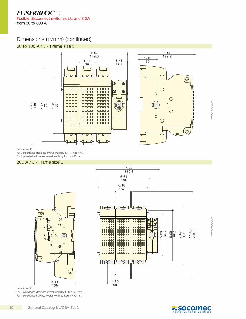
FUSERBLOC UL Fusible disconnect switches UL and CSAfrom 30 to 800 A
Dimensions (in/mm) (continued)
7.3
21
86
5.87149.3
1.4136
1.4637.2
4.81122.21.41
36
6.7
71
72
5.2
31
33
fuse
r-ul_
00
2_a
_1_x
_cat
60 to 100 A / J - Frame size 5
7.72196.2
6.61168
6.18157
1.4136
5.11130
1.9650
5.2
81
34
.2
6.5
01
65
.2
7.6
71
95
11
.46
29
1.3
fuse
r-ul_
00
3_a
_1_x
_cat
200 A / J - Frame size 6
Note for width :
For 2 pole device decrease overall width by 1.41 in / 36 mm.
For 4 pole device increase overall width by 1.41 in / 36 mm.
Note for width:
For 2 pole device decrease overall width by 1.96 in / 50 mm.
For 4 pole device increase overall width by 1.96 in / 50 mm.
104 General Catalog UL/CSA Ed. 2
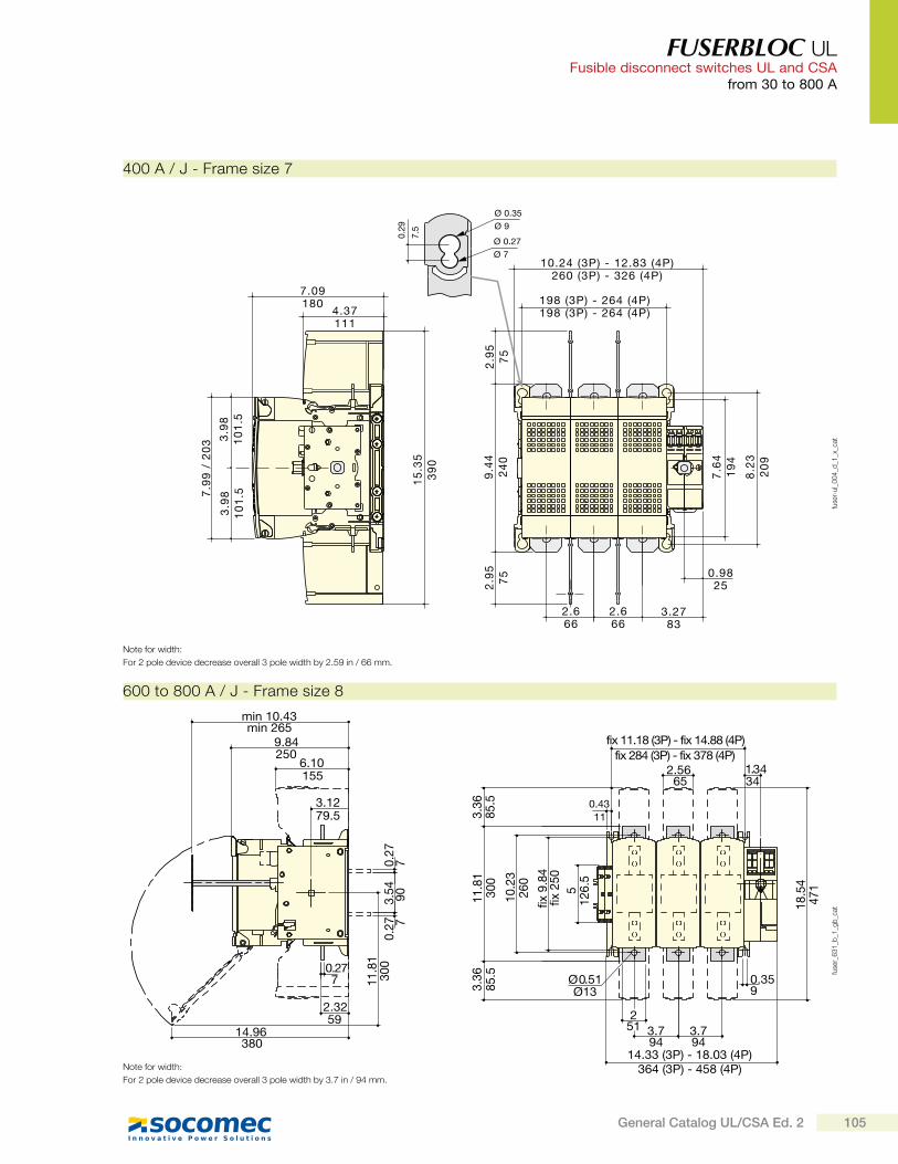
FUSERBLOC UL Fusible disconnect switches UL and CSA
from 30 to 800 A
7.09
4.37
10.24 (3P) - 12.83 (4P)
198 (3P) - 264 (4P)
2.6 2.6 3.27
0.98
180
111
260 (3P) - 326 (4P)
198 (3P) - 264 (4P)
66 66 83
252.9
59
.44
7.6
4
8.2
3
15
.35
7.9
9 /
20
3
3.9
83
.98
0.29
7.5
Ø 0.35Ø 9
Ø 0.27Ø 7
2.9
57
52
40
19
4
20
9
39
0
10
1.5
10
1.5
75
fuse
r-ul_
00
4_d
_1_x
_cat
400 A / J - Frame size 7
9.84250
6.10155
3.1279.5
0.277
2.3259
14.96380
min 10.43min 265
Ø 0.51Ø13
0.4311
fix 11.18 (3P) - fix 14.88 (4P)fix 284 (3P) - fix 378 (4P)
65 342.56 1.34
251
0.359
3.7 3.794
14.33 (3P) - 18.03 (4P) 364 (3P) - 458 (4P)
94
fix 9
.84
fix 2
505
126.
5
11.8
1
18.5
447
1260
10.2
3
300
3.36
85.5
3.36
85.5
70.27
0.27 7
11.8
130
0903.54
fuse
r_6
31
_b_1
_gb
_cat
600 to 800 A / J - Frame size 8
Note for width:
For 2 pole device decrease overall 3 pole width by 2.59 in / 66 mm.
Note for width:
For 2 pole device decrease overall 3 pole width by 3.7 in / 94 mm.
105General Catalog UL/CSA Ed. 2
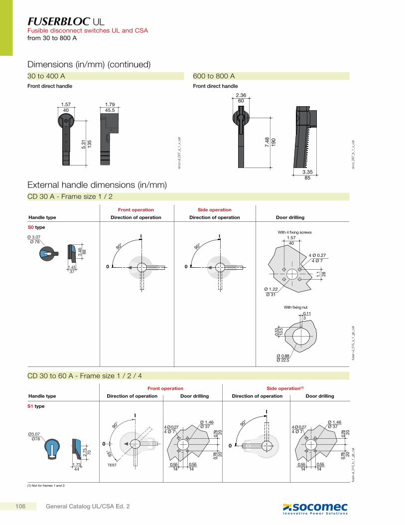
FUSERBLOC UL Fusible disconnect switches UL and CSAfrom 30 to 800 A
External handle dimensions (in/mm)
S1 type
0
I
90°
Ø3.07
1.73
2.75
65°
TEST
90°
I
0
Direction of operationHandle type
Front operation
Door drilling Direction of operation
Side operation(1)
Door drilling
Ø78
70
44
0.78
4 Ø 0.27
0.55
Ø 1.46
4 Ø 7Ø 37
2020
140.5514
0.78
0.78
4 Ø 0.27
0.55
Ø 1.46
4 Ø 7Ø 37
2020
140.5514
0.78
(1) Not for frames 1 and 2.
fuse
r-ul_
01
5_b
_1_g
b_c
at
CD 30 to 60 A - Frame size 1 / 2 / 4
Ø 78
37
88
S0 type
Door drillingHandle type
0
I
90°
Direction of operation
Front operation
0
I
90°
Direction of operation
Side operation
Ø 3.07
1.45
3.46
13.5
Ø 22.5
3
40
4 Ø 7
Ø 31
1.57
4 Ø 0.27
Ø 1.22
281.1
With fixing nut
With 4 fixing screws
0.11
0.53
Ø 0.88fu
ser-
ul_
01
5_a
_1_g
b_c
at
CD 30 A - Frame size 1 / 2
Front direct handle
602.36
853.35
190
7.48
sirc
o_2
67
_b_1
_x_c
at
600 to 800 A
Front direct handle
30 to 400 A
1.5740
5.31
135
1.7945.5
sirc
o-u
l_0
27
_a_1
_x_c
at
Dimensions (in/mm) (continued)
106 General Catalog UL/CSA Ed. 2
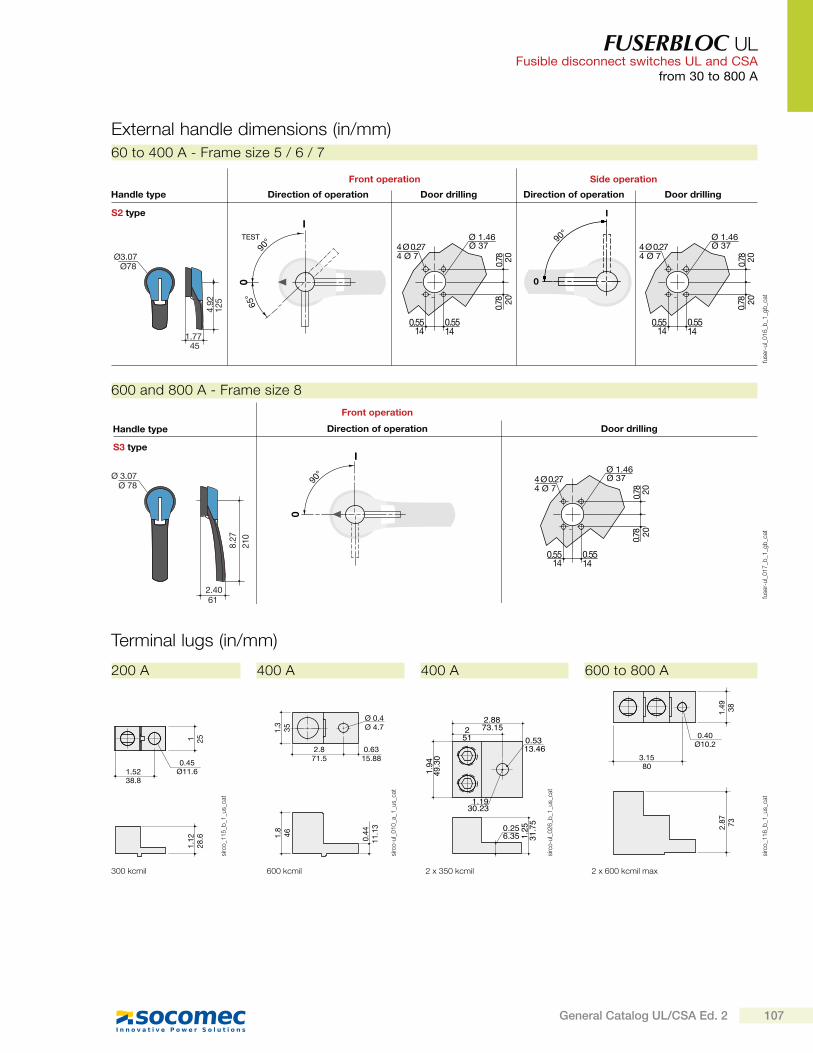
FUSERBLOC UL Fusible disconnect switches UL and CSA
from 30 to 800 A
S2 type
0
I
90°
65°
TEST
90°
I
0
Ø78
1.77
4.92
Direction of operationHandle type
Front operation
Door drilling Direction of operation
Side operation
Door drilling
Ø3.07
0.78
4 Ø 0.27
0.55
Ø 1.46
4 Ø 7Ø 37
2020
140.5514
0.78
45
125
0.78
4 Ø 0.27
0.55
Ø 1.46
4 Ø 7Ø 37
2020
140.5514
0.78
fuse
r-ul_
01
6_b
_1_g
b_c
at
60 to 400 A - Frame size 5 / 6 / 7
S3 type
612.40
210
8.27
90°
I
0
Direction of operationHandle type
Front operation
Door drilling
Ø 3.07Ø 78
0.78
4 Ø 0.27
0.55
Ø 1.46
4 Ø 7Ø 37
2020
140.5514
0.78
fuse
r-ul_
01
7_b
_1_g
b_c
at
600 and 800 A - Frame size 8
External handle dimensions (in/mm)
Terminal lugs (in/mm)
1.5238.8
1 251.
1228
.6
0.45Ø11.6
sirc
o_1
15
_b_1
_us_
cat
300 kcmil
200 A
2.871.5
Ø 0.4Ø 4.71.
335
1.8
46 0.44
11.1
3
0.6315.88
sirc
o-u
l_0
10
_a_1
_us_
cat
600 kcmil
400 A
3.1580
1.49 38
2.87 73
0.40Ø10.2
sirc
o_1
16
_b_1
_us_
cat
2 x 600 kcmil max
600 to 800 A
2.8873.152
51 0.5313.46
1.1930.23
1.94
49.30
0.256.35 1.
2531.75
sirc
o-u
l_0
26
_b_1
_us_
cat
2 x 350 kcmil
400 A
107General Catalog UL/CSA Ed. 2
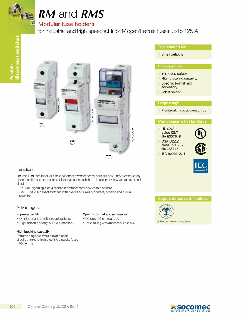
Fu
sib
led
isc
on
ne
ct
sw
itc
he
s
rm_0
60
_a_1
_cat
rm_0
66
_a_1
_cat
rm_0
62
_a_1
_cat
RM and RMSModular fuse holdersfor industrial and high speed (uR) for Midget / Ferrule fuses up to 125 A
Function
RM and RMS are modular fuse disconnect switches for cylindrical fuses. They provide safety disconnection and protection against overloads and short-circuits in any low voltage electrical circuit.
- RM: Non-signalling fuse disconnect switches for fuses without strikers.
- RMS: Fuse disconnect switches with pre-break auxiliary contact, position and blown indication.
Advantages
Improved safety
Omnipolar and simultaneous breaking.
High dielectric strength. IP2X protection.
High breaking capacity
Protection against overloads and short-circuits thanks to high breaking capacity fuses (100 kA rms).
Specific format and accessory
Modular 45-mm cut-out.
Interlocking with accessory possible.
RM32 A
RMS50 A
RMS100 A
> Small outputs
The solution for
> Improved safety
> High breaking capacity
> Specific format and accessory
> Label holder
Strong points
> Pre-break, please consult us
Large range
> UL 4248-1guide IZLTfile E307648
> CSA C22.2class 3211-37file 265615
> IEC 60269-2,-1
Compliance with standards
Approvals and certifications(1)
(1) Product reference on request.
108 General Catalog UL/CSA Ed. 2
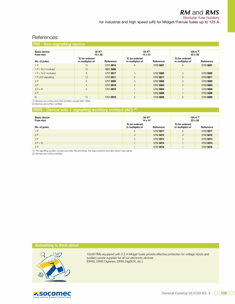
RM and RMS Modular fuse holders
for industrial and high speed (uR) for Midget / Ferrule fuses up to 125 A
Basic deviceFuse size
32 A(1)
10 x 3850 A(2)
14 x 51100 A (2)
22 x 58
No. of polesTo be orderedin multiples of Reference
To be orderedin multiples of Reference
To be orderedin multiples of Reference
1 P 12 5701 0015 6 5702 5001 6 5703 5001
1 P + N (1 module) 12 5601 5005
1 P + N (2 modules) 6 5701 0017 3 5702 5005 3 5703 5005
1 P LED signalling 12 5701 0011 6 5702 0011 6 5703 0011
2 P 6 5701 0020 3 5702 5002 3 5703 5002
3 P 4 5701 0018 2 5702 5003 2 5703 5003
3 P + N 3 5701 0019 1 5702 5004 1 5703 5004
4 P 1 5702 5006 1 5703 5006
N 12 5701 0016 6 5702 5000 6 5703 5000
RM - Non-signalling device
RMS - Device with 1 signalling auxiliary contact (AC) (1)
References
Basic deviceFuse size
50 A(2)
14 x 51100 A (2)
22 x 58
No. of polesTo be orderedin multiples of Reference
To be orderedin multiples of Reference
1 P 6 5702 5011 6 5703 5011
2 P 3 5702 5012 3 5703 5012
3 P 2 5702 5013 2 5703 5013
3 P + N 1 5702 5014 1 5703 5014
4 P 1 5702 5016 1 5703 5016
(1) The signalling auxiliary contact provides the pre-break, the fuse presence and also blown fuse signal.
(2) Devices are cURus-certified.
(1) Devices are cURus and CSA-certified, except 5601 5005.
(2) Devices are cURus-certified.
Something to think about
10x38 RMs equipped with 0.5 A Midget fuses provide effective protection for voltage inputs and auxiliary power supplies for all our electronic devices (DIRIS, DIRIS Digiware, DIRIS DigiBOX, etc.)
109General Catalog UL/CSA Ed. 2
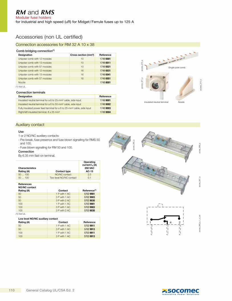
RM and RMS Modular fuse holdersfor industrial and high speed (uR) for Midget / Ferrule fuses up to 125 A
Auxiliary contact
1 24
acce
s_0
68
_a_1
_x_c
atac
ces_
36
6_a
acce
s_3
67
_a
acce
s_3
65
_aUse
1 or 2 NO/NC auxiliary contacts:
- Pre-break, fuse presence and fuse blown signalling for RMS 50 and 100.
- Fuse blown signalling for RM 50 and 100.
Connection
By 6.35 mm fast-on terminal.
References
NO/NC contact
Rating (A) Contact Reference(1)
50 1 P with 1 AC 5702 990150 3 P with 1 AC 5702 990350 3 P with 2 AC 5702 9030100 1 P with 1 AC 5703 9901100 3 P with 1 AC 5703 9903100 3 P with 2 AC 5703 9030
Low level NO/NC auxiliary contact
Rating (A) Contact Reference
50 1 P with 1 AC 5702 9911
50 3 P with 1 AC 5702 9913
100 1 P with 1 AC 5703 9911
100 3 P with 1 AC 5703 9913
Characteristics
Operating current Ie (A)
250 VAC
Rating (A) Contact type AC-13
50 … 100 NO/NC contact 2.5
50 … 100 Two-level NO/NC contact 0.1
acce
ss_3
70
_aac
cess
_37
1_a
acce
ss_3
72
_a
Connection accessories for RM 32 A 10 x 38
Comb bridging connection(1)
Designation Cross-section (mm²) Reference
Unipolar comb with 12 modules 10 1749 0001
Unipolar comb with 13 modules 10 1749 0011
Unipolar comb with 57 modules 10 1749 0021
Unipolar comb with 12 modules 16 1749 0031
Unipolar comb with 13 modules 16 1749 0041
Unipolar comb with 57 modules 16 1749 0051
Nozzle 1749 8001
Connection terminals
Designation Reference
Insulated neutral terminal for a 6 to 25-mm² cable, side input 1749 9001
Insulated neutral terminal for a 6 to 50-mm² cable, side input 1749 9002
Fully insulated power feed terminal for a 6 to 25-mm² cable, side input 1749 9003
Right/left insulated terminal, 6 x 25 mm² 1749 9004
Single-pole comb.
Insulated neutral terminal. Nozzle.
Accessories (non UL certified)
(1) Not UL.
(1) Not UL.
110 General Catalog UL/CSA Ed. 2
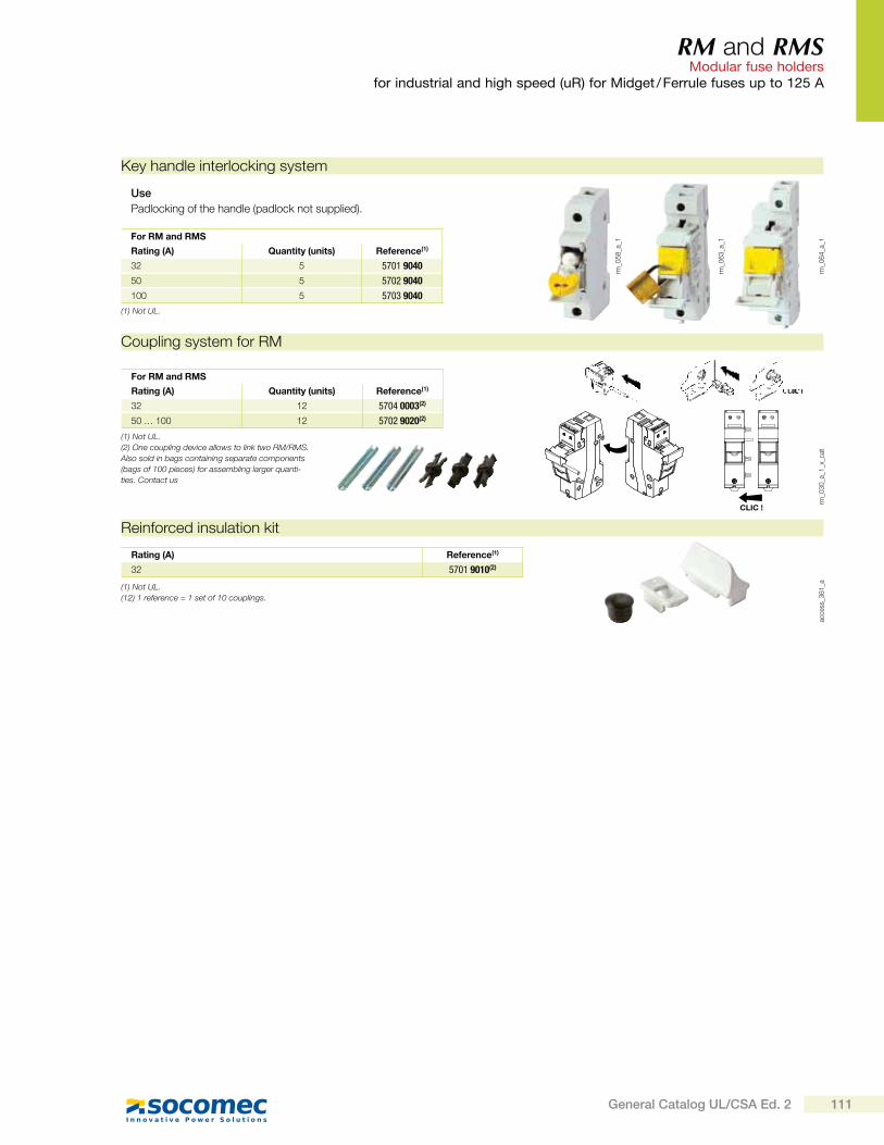
RM and RMS Modular fuse holders
for industrial and high speed (uR) for Midget / Ferrule fuses up to 125 A
Reinforced insulation kit
rm_0
30
_a_1
_x_c
at
For RM and RMS
Rating (A) Quantity (units) Reference(1)
32 12 5704 0003(2)
50 … 100 12 5702 9020(2)
Rating (A) Reference(1)
32 5701 9010(2)
(1) Not UL.
(2) One coupling device allows to link two RM/RMS.
Also sold in bags containing separate components
(bags of 100 pieces) for assembling larger quanti-
ties. Contact us
(1) Not UL.
(12) 1 reference = 1 set of 10 couplings.
Key handle interlocking system
Coupling system for RM
rm_0
64
_a_1
rm_0
63
_a_1
rm_0
58
_a_1
Use
Padlocking of the handle (padlock not supplied).
For RM and RMS
Rating (A) Quantity (units) Reference(1)
32 5 5701 9040
50 5 5702 9040
100 5 5703 9040
CLIC !
acce
ss_3
61
_a
(1) Not UL.
111General Catalog UL/CSA Ed. 2
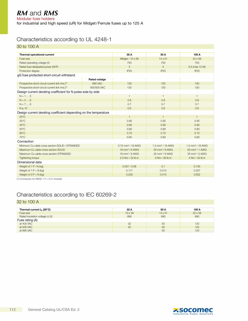
RM and RMS Modular fuse holdersfor industrial and high speed (uR) for Midget / Ferrule fuses up to 125 A
Thermal current Ith (20°C) 32 A 50 A 100 A
Fuse size 10 x 38 14 x 51 22 x 58
Rated insulation voltage Ui (V) 690 690 690
Fuse rating (A) at 400 VAC 32 50 125
at 500 VAC 32 50 125
at 690 VAC 50 125
Characteristics according to IEC 60269-2
Characteristics according to UL 4248-1
32 to 100 A
Thermal operational current 30 A 50 A 100 A
Fuse size Midget / 10 x 38 14 x 51 22 x 58
Rated operating voltage (V) 750 750 750
Rated fuse dissipated power (W/P) 3 5 9.5 (max 12 W)
Protection degree IP20 IP20 IP20
gG fuse protected short-circuit withstand
Rated volatge
Prospective short-circuit current (kA rms.)(1) 690 VAC 100 100 100
Prospective short-circuit current (kA rms.)(1) 400/500 VAC 120 120 120
Design current derating coefficient for N poles side by side
N = 1 … 3 1 1 1
N = 4 … 6 0.8 0.8 0.8
N = 7 … 9 0.7 0.7 0.7
N 10 0.6 0.6 0.6
Design current derating coefficient depending on the temperature
20°C 1 1 1
30°C 0.95 0.95 0.95
40°C 0.90 0.90 0.90
50°C 0.80 0.80 0.80
60°C 0.70 0.70 0.70
70°C 0.60 0.60 0.60
Connection
Minimum Cu cable cross-section SOLID / STRANDED 0.75 mm² / 18 AWG 1.5 mm² / 16 AWG 1.5 mm² / 16 AWG
Maximum Cu cable cross-section SOLID 16 mm² / 8 AWG 35 mm² / 8 AWG 50 mm² / 1 AWG
Maximum Cu cable cross-section STRANDED 16 mm² / 8 AWG 25 mm² / 6 AWG 35 mm² / 2 AWG
Tightening torque 2.5 Nm / 22 lb.in 3 Nm / 26 lb.in 4 Nm / 35 lb.in
Dimensional data
Weight of 1 P / N (kg) 0.057 / 0.06 0.1 0.155
Weight of 1 P + N (kg) 0.117 0.215 0.327
Weight of 3 P + N (kg) 0.229 0.415 0.632
(1) Connection for RM32 1 P + N (1 module).
30 to 100 A
112 General Catalog UL/CSA Ed. 2

RM and RMS Modular fuse holders
for industrial and high speed (uR) for Midget / Ferrule fuses up to 125 A
RM / RMS 100 A unipolar and multipolar RM 32 A Ref.: 5601 5005
RM 32 A RM / RMS 50 A unipolar and multipolar
Dimensions
2.28581.5740
1.77 45
0.79 20
1.5740
0.246
2.9574.8
2.0552.5
1.3835
0.6917.5
3.07 78
1.9549.5
2.99 / 76
3.96 / 100.7
1.57 40
1.39
35.3
4.17 / 1063.32 / 79.52.0853
1.0426.5
4.33
110
1.9549.5
1.77 45
1.85 47
5.63 / 143
4.98
126.
5
4.23107.5
2.871.5
1.435.5
1.9549.5
376.5
4102.5
1.9549.5
rm_0
69
_b_1
_us_
cat
rm_0
67
_a_1
_us_
cat
rm_0
68
_a_1
_us_
cat
rm-p
v_0
02
_a_1
_us_
cat
3.1379.5
2.4612.256
1.77 45
0.65
16.5
0.3910
1.6943
12.5
1.26 3.2
0.6917.5
3 78
113General Catalog UL/CSA Ed. 2
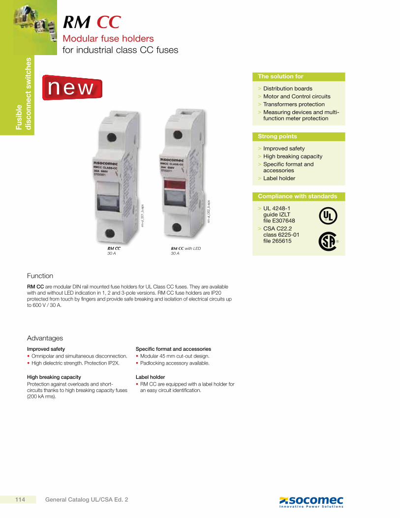
Fu
sib
led
isc
on
ne
ct
sw
itc
he
sRM CCModular fuse holdersfor industrial class CC fuses
Function
RM CC are modular DIN rail mounted fuse holders for UL Class CC fuses. They are available with and without LED indication in 1, 2 and 3-pole versions. RM CC fuse holders are IP20 protected from touch by fingers and provide safe breaking and isolation of electrical circuits up to 600 V / 30 A.
Advantages
Improved safety
Omnipolar and simultaneous disconnection.
High dielectric strength. Protection IP2X.
High breaking capacity
Protection against overloads and short-circuits thanks to high breaking capacity fuses (200 kA rms).
Specific format and accessories
Modular 45 mm cut-out design.
Padlocking accessory available.
Label holder
RM CC are equipped with a label holder for an easy circuit identification.
RM CC with LED30 A
RM CC30 A
> Distribution boards
> Motor and Control circuits
> Transformers protection
> Measuring devices and multi-function meter protection
The solution for
> Improved safety
> High breaking capacity
> Specific format and accessories
> Label holder
Strong pointsrm
-ul_
00
1_b
.ep
s
rm-u
l_0
02
_b.e
ps
new
> UL 4248-1guide IZLTfile E307648
> CSA C22.2 class 6225-01 file 265615
Compliance with standards
114 General Catalog UL/CSA Ed. 2
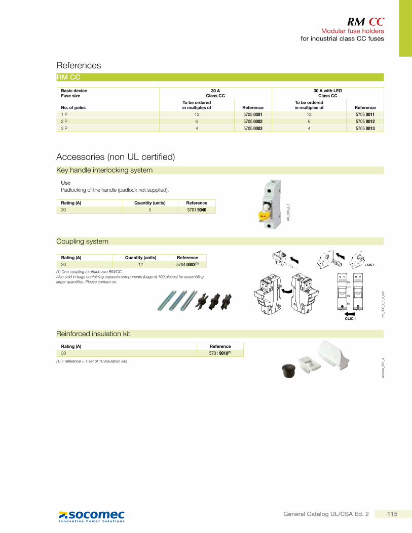
RM CC Modular fuse holders
for industrial class CC fuses
Basic deviceFuse size
30 AClass CC
30 A with LEDClass CC
No. of polesTo be orderedin multiples of Reference
To be orderedin multiples of Reference
1 P 12 5705 0001 12 5705 0011
2 P 6 5705 0002 6 5705 0012
3 P 4 5705 0003 4 5705 0013
RM CC
References
Accessories (non UL certified)
Key handle interlocking system
rm_0
58
_a_1
Use
Padlocking of the handle (padlock not supplied).
Rating (A) Quantity (units) Reference
30 5 5701 9040
rm_0
30
_a_1
_x_c
at
Rating (A) Quantity (units) Reference
30 12 5704 0003(1)
(1) One coupling to attach two RM/CC.
Also sold in bags containing separate components (bags of 100 pieces) for assembling
larger quantities. Please contact us.
Coupling system
CLIC !
Reinforced insulation kit
Rating (A) Reference
30 5701 9010(1)
(1) 1 reference = 1 set of 10 insulation kits
acce
ss_3
61
_a
115General Catalog UL/CSA Ed. 2
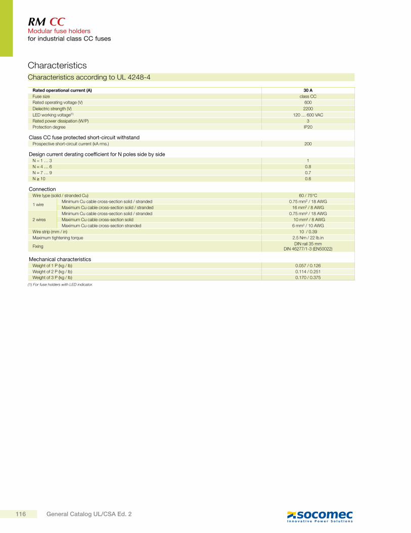
RM CC Modular fuse holdersfor industrial class CC fuses
Rated operational current (A) 30 A
Fuse size class CC
Rated operating voltage (V) 600
Dielectric strength (V) 2200
LED working voltage(1) 120 … 600 VAC
Rated power dissipation (W/P) 3
Protection degree IP20
Class CC fuse protected short-circuit withstandProspective short-circuit current (kA rms.) 200
Design current derating coefficient for N poles side by sideN = 1 … 3 1
N = 4 … 6 0.8
N = 7 … 9 0.7
N 10 0.6
ConnectionWire type (solid / stranded Cu) 60 / 75°C
1 wireMinimum Cu cable cross-section solid / stranded 0.75 mm2 / 18 AWG
Maximum Cu cable cross-section solid / stranded 16 mm2 / 8 AWG
2 wires
Minimum Cu cable cross-section solid / stranded 0.75 mm² / 18 AWG
Maximum Cu cable cross-section solid 10 mm² / 8 AWG
Maximum Cu cable cross-section stranded 6 mm² / 10 AWG
Wire strip (mm / in) 10 / 0.39
Maximum tightening torque 2.5 Nm / 22 lb.in
FixingDIN rail 35 mm
DIN 46277/1-3 (EN50022)
Mechanical characteristicsWeight of 1 P (kg / lb) 0.057 / 0.126
Weight of 2 P (kg / lb) 0.114 / 0.251
Weight of 3 P (kg / lb) 0.170 / 0.375
(1) For fuse holders with LED indicator.
Characteristics
Characteristics according to UL 4248-4
116 General Catalog UL/CSA Ed. 2
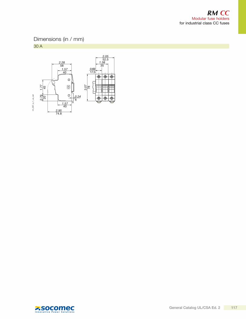
RM CC Modular fuse holders
for industrial class CC fuses
30 A
Dimensions (in / mm)
2.28581.5740
1.77 45
0.79 20
1.5740
0.246
2.9574.8
2.0552.5
1.3835
0.6917.5
3.07 78
rm_0
67
_a_1
_us_
cat
117General Catalog UL/CSA Ed. 2
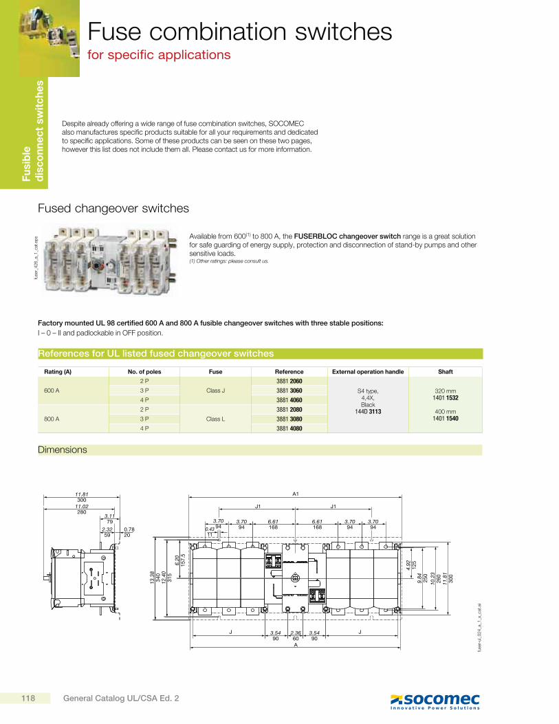
Fu
sib
le
dis
co
nn
ec
t sw
itc
he
sFuse combination switchesfor specific applications
Despite already offering a wide range of fuse combination switches, SOCOMEC also manufactures specific products suitable for all your requirements and dedicated to specific applications. Some of these products can be seen on these two pages, however this list does not include them all. Please contact us for more information.
Fused changeover switches
Available from 600(1) to 800 A, the FUSERBLOC changeover switch range is a great solution for safe guarding of energy supply, protection and disconnection of stand-by pumps and other sensitive loads.(1) Other ratings: please consult us.
fuse
r_4
26
_a_1
_cat
.ep
s
Factory mounted UL 98 certified 600 A and 800 A fusible changeover switches with three stable positions:
I – 0 – II and padlockable in OFF position.
Rating (A) No. of poles Fuse Reference External operation handle Shaft
600 A
2 P
Class J
3881 2060
S4 type, 4,4X, Black
144D 3113
320 mm1401 1532
400 mm1401 1540
3 P 3881 3060
4 P 3881 4060
800 A
2 P
Class L
3881 2080
3 P 3881 3080
4 P 3881 4080
References for UL listed fused changeover switches
Dimensions
11.81300
11.02280
3.1179 3.70
943.7094
3.7094
3.7094
6.61168
3.5490
2.3660A
A1
J
J1 J1
J3.5490
6.611680.43
110.7820
2.3259
13.3
834
012
.40
315
6.20
157.
5
4.92
125
9.84
250
10.2
326
011
.81
300
fuse
r-ul_
02
4_a
_1_x
_cat
.ai
118 General Catalog UL/CSA Ed. 2
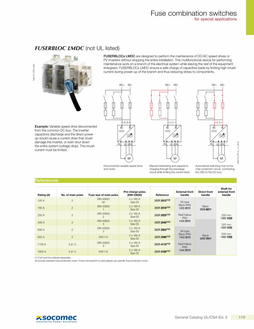
Fuse combination switchesfor special applications
FUSERBLOC LMDC (not UL listed)
fuse
r-lm
_00
2_a
.ep
s
Example: Variable speed drive disconnected from the common DC bus. The inverter capacitors discharge and the direct power up would cause a current draw that could damage the inverter, or even shut down the entire system (voltage drop). This inrush current must be limited.
DC+
B+ B-
DC-
M
PE U V W
DC+
B+ B-
DC-
M
PE U V W
DC+
B+ B-
DC-
M
PE U V W
fuse
r-lm
_01
2_a
_1_x
_cat
.ai
Disconnected variable speed drive and motor
Manuel interlocking and capacitors charging through the precharge circuit while limiting the current draw.
Automatical switching over to the main protection circuit, connecting the VSD to the DC bus.
Rating (A) No. of main poles Fuse size of main polesPre-charge poles
(DIN 43620) ReferenceExternal front
handleDirect front
handle
Shaft for external front
handle
125 A 2DIN 43620
002 x 160 ASize 00
38DR 2012(1)(2)S3 type
Black IP651433 3111
Red/Yellow IP65
1434 3111
Black3899 6011
200 mm1400 1220
320 mm
1400 1232
500 mm1400 1250
160 A 2DIN 43620
12 x 160 ASize 00
38DR 2016(1)(2)
250 A 2DIN 43620
22 x 160 ASize 00
38DR 2025(1)(2)
400 A 2DIN 43620
32 x 160 ASize 00
38DR 2040(1)(2)
Black3899 7011
630 A 2DIN 43620
32 x 160 ASize 00
38DR 2063(1)(2)S4 type
Black IP651443 3111
Red/Yellow IP65
1444 3111
900 A 2 KN/1102 x 160 ASize 00
38DR 2090(1)(2)
1100 A 4 (2 //)DIN 43620
32 x 160 ASize 00
38DR 4110(1)(2)
1600 A 4 (2 //) KN/1102 x 160 ASize 00
38DR 4160(1)(2)
(1) Coil must be ordered separately.
(2) Include standard fuse protection cover. If fuse microswitch is used please use specific fuse protection cover.
References
FUSERBLOCs LMDC are designed to perform the maintenance of DC/AC speed drives or PV inverters without stopping the entire installation. This multifunctional device for performing maintenance work on a branch of the electrical system while leaving the rest of the equipment energised. FUSERBLOCs LMDC ensure a safe charge of capacitive loads by limiting high inrush current during power-up of the branch and thus reducing stress to components.
119General Catalog UL/CSA Ed. 2
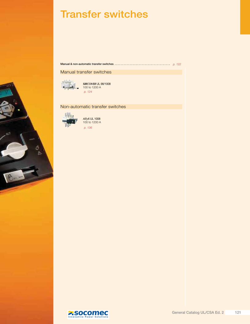
Transfer switches
Manual transfer switches
Non-automatic transfer switches
SIRCOVER UL 98/1008100 to 1200 A
ATyS UL 1008100 to 1200 A
Manual & non-automatic transfer switches . . . . . . . . . . . . . . . . . . . . . . . . . . . . . . . . . . . . .
p. 124
p. 122
p. 136
121General Catalog UL/CSA Ed. 2

Tra
nsfe
r sw
itc
he
sManual & non-automatic transfer switches
Typical applications
SIRCOVER UL 1008Manual
transfer switching equipment
ATyS UL 1008Non-automatic
transfer switching equipment
MTSE(Manual)
RTSE(Remotely operated)
A range of manual or non-automatic transfer switches up to 1200 A
The ATyS UL 1008 range provides safe transfer for mains/genset and genset/genset applications.
Mains/Mains Mains/Genset Genset/Genset
ATyS ATyS ATyS
atys
-ul_
00
5_b
_1_c
at
atys
-ul_
00
6_b
_1_c
at
atys
-ul_
00
7_b
_1_c
at
122 General Catalog UL/CSA Ed. 2
ATyS UL 1008 transfer switches are rated from 100 to 1200 A and designed for use in total system optional standby power applications for the safe transfer of a load supply between a normal and an alternate source.
Optional standby systems are those systems installed to provide an alternate source of power for structures for which a power outage could cause discomfort or interruption or damage to products or processes.
UL Applications
Function
ATYS and SIRCOVER UL 1008 transfer switching equipment ensure:
Maintenance free transfer switching equipment with a robust and reliable design.
Power control and safety between a normal and an alternate source.
Integrated and robust switch disconnection.
A stable OFF position with integrated padlocking to facilitate safe downstream maintenance.
Positive break indication with clear visible position indication I - 0 - II.
An inherent failsafe mechanical interlock prevents asynchronous paralleling of the two sources.
Stable positions (I – 0 – II) non-affected by typical vibration and shock.
Constant pressure on the contacts non affected by network voltage perturbation.
Quick, easy and extremely safe manual operation.
Along with the above, the ATyS also includes:
A simple and secure motorization remote controls interface.
Integrated switch position auxiliary contacts.
An active “product availability” status feedback.
Compatibility with virtually any make of ATS, AMF and Genset controller provided with volt-free contacts.
Power supply continuity for most electrically controlled total system optional standby power applications.
SOCOMEC UL products
The ATYS UL is a full load break transfer switch where the main switching components are from proven technology devices (SIRCOVER - Manual Transfer Switches) also fulfilling requirements in UL 98 and IEC 60947-3 standards. The transfer is done in open transition with a minimum supply interruption during transfer ensuring full compliance with UL 1008 and IEC 60947-6-1 international TSE standards.
As a stand-alone product, the ATyS is a non-automatic power transfer switch (an electrically operated transfer switch that is not self-acting), generally used in applications where the load is non-emergency, does not require automatic transfer and where operating persons can be made available to initiate the transfer.
The electrical control of the ATyS UL may be direct through push-buttons and dry contacts fitted onto the enclosure door or through a dedicated local or remote ATS controller.
Your preferred brand of ATS controller, genset / AMF controller or power / building management system, may easily be paired with the ATyS to provide a complete automatic transfer switch to suit your needs.
ATyS have three stable positions (I-0-II) which can be selected remotely, via volt-free contacts, or directly, through use of the emergency operation handle; emergency operation requires no supply to be present. The OFF position provides disconnection of both supplies ensuring downstream isolation for safe maintenance.
123General Catalog UL/CSA Ed. 2
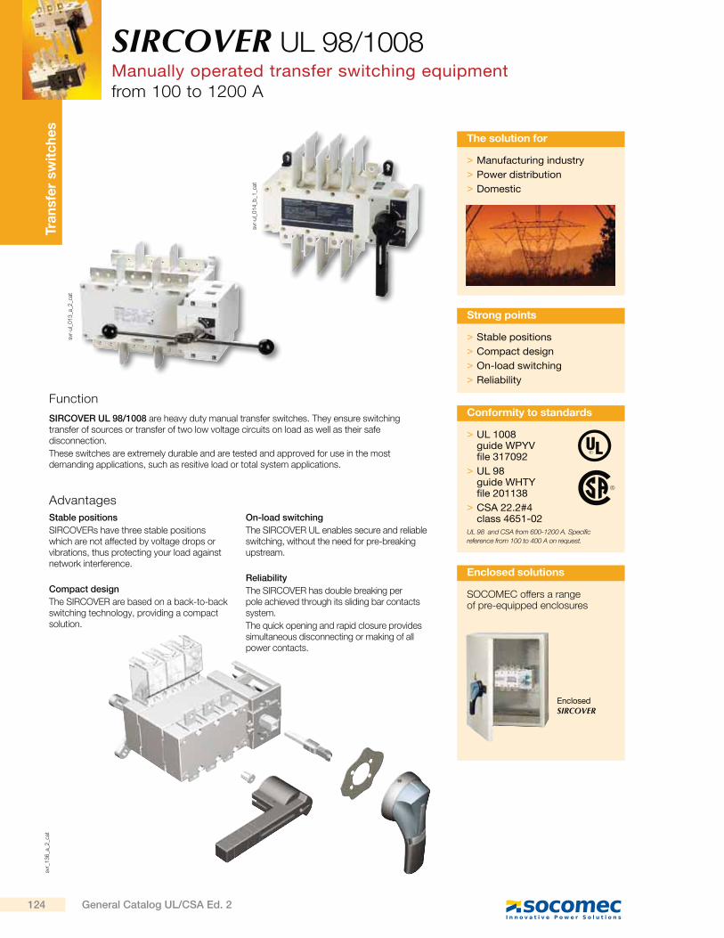
Tra
nsfe
r sw
itc
he
ssv
r_1
36
_a_2
_cat
svr-
ul_
01
4_b
_1_c
at
svr-
ul_
01
3_a
_2_c
at
SIRCOVER UL 98/1008Manually operated transfer switching equipmentfrom 100 to 1200 A
Function
Advantages
SIRCOVER UL 98/1008 are heavy duty manual transfer switches. They ensure switching transfer of sources or transfer of two low voltage circuits on load as well as their safe disconnection.
These switches are extremely durable and are tested and approved for use in the most demanding applications, such as resitive load or total system applications.
Stable positions
SIRCOVERs have three stable positions which are not affected by voltage drops or vibrations, thus protecting your load against network interference.
Compact design
The SIRCOVER are based on a back-to-back switching technology, providing a compact solution.
On-load switching
The SIRCOVER UL enables secure and reliable switching, without the need for pre-breaking upstream.
Reliability
The SIRCOVER has double breaking per pole achieved through its sliding bar contacts system.
The quick opening and rapid closure provides simultaneous disconnecting or making of all power contacts.
> Manufacturing industry
> Power distribution
> Domestic
The solution for
> Stable positions
> Compact design
> On-load switching
> Reliability
Strong points
> UL 1008guide WPYV file 317092
> UL 98guide WHTY file 201138
> CSA 22.2#4class 4651-02
UL 98 and CSA from 600-1200 A. Specific
reference from 100 to 400 A on request.
Conformity to standards
SOCOMEC offers a range of pre-equipped enclosures
Enclosed solutions
Enclosed SIRCOVER
124 General Catalog UL/CSA Ed. 2
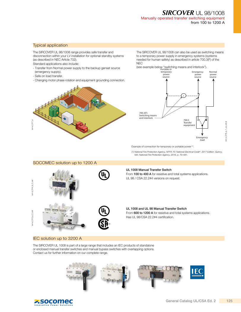
SIRCOVER UL 98/1008Manually operated transfer switching equipment
from 100 to 1200 A
Typical application
The SIRCOVER UL 98/1008 range provides safe transfer and disconnection within your LV installation for optional standby systems (as described in NEC Article 702).
Standard applications also include:
- Transfer from Normal power supply to the backup genset source (emergency supply).
- Safe on load transfer.
- Changing motor phase rotation and equipment grounding connection.
SOCOMEC solution up to 1200 A
UL 1008 Manual Transfer Switch
From 100 to 400 A for resistive and total systems applications.
UL 98 / CSA 22.2#4 versions on request.
svr-
ul_
01
4_b
_2_c
atsv
r-ul_
01
7_a
svr-
ul_
01
3_a
_2_c
at
UL 1008 and UL 98 Manual Transfer Switch
From 600 to 1200 A for resistive and total systems applications.
Has UL 98/CSA 22.2#4 certification.
IEC solution up to 3200 A
The SIRCOVER UL 1008 is part of a large range that includes an IEC products of standalone or enclosed manual transfer switches and manual bypass switches with overlapping options. Contact us for further information on our complete range.
The SIRCOVER UL 98/1008 can also be used as switching means to a temporary power supply in emergency systems (systems needed for human safety) as described in article 700.3(F) of the NEC (see example below “switching means and interlock”).
Example of connection for temporary or portable power (1).
(1) National Fire Protection Agency, NFPA 70: National Electrical Code®. 2017 Edition. Quincy,
MA: National Fire Protection Agency, 2016, p. 70–581.
Normalpowersource
Emergencypowersource
Portable ortemporary
powersource
I
700.3(F) Switching meansand interlock
700.5 Transferequipment
Emergencyload sv
r-ul_
01
8_a
_1_u
s_ca
t.ai
125General Catalog UL/CSA Ed. 2
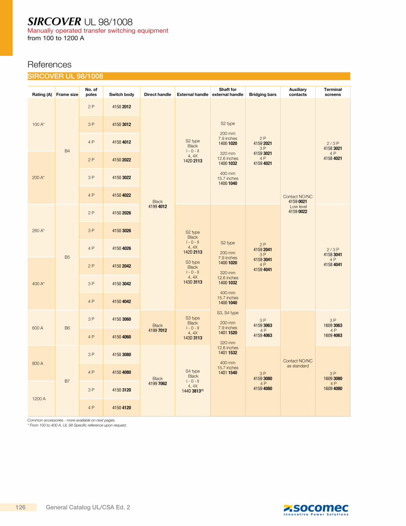
SIRCOVER UL 98/1008Manually operated transfer switching equipmentfrom 100 to 1200 A
SIRCOVER UL 98/1008
Rating (A) Frame sizeNo. of poles Switch body Direct handle External handle
Shaft for external handle Bridging bars
Auxiliary contacts
Terminal screens
100 A*
B4
2 P 4150 2012
Black4199 4012
S2 type Black
I - 0 - II 4, 4X
142D 2113
S2 type
200 mm 7.9 inches1400 1020
320 mm
12.6 inches1400 1032
400 mm
15.7 inches1400 1040
2 P 4159 2021
3 P4159 3021
4 P4159 4021
Contact NO/NC4159 0021 Low level4159 0022
2 / 3 P4158 3021
4 P4158 4021
3 P 4150 3012
4 P 4150 4012
200 A*
2 P 4150 2022
3 P 4150 3022
4 P 4150 4022
260 A*
B5
2 P 4150 2026
S2 type Black
I - 0 - II 4, 4X
142D 2113
S3 type Black
I - 0 - II 4, 4X
143D 3113
S2 type
200 mm7.9 inches1400 1020
320 mm12.6 inches1400 1032
400 mm15.7 inches1400 1040
S3, S4 type
200 mm 7.9 inches1401 1520
320 mm
12.6 inches1401 1532
400 mm
15.7 inches1401 1540
2 P4159 2041
3 P4159 3041
4 P4159 4041
2 / 3 P4158 3041
4 P4158 4041
3 P 4150 3026
4 P 4150 4026
400 A*
2 P 4150 2042
3 P 4150 3042
4 P 4150 4042
600 A B6
3 P 4150 3060
Black4199 7012
S3 type Black
I - 0 - II 4, 4X
143D 3113
3 P4159 3063
4 P4159 4063
Contact NO/NCas standard
3 P1609 3063
4 P1609 4063 4 P 4150 4060
800 A
B7
3 P 4150 3080
Black4199 7062
S4 type Black I - 0 - II 4, 4X
144D 3813(1)
3 P4159 3080
4 P4159 4080
3 P1609 3080
4 P1609 4080
4 P 4150 4080
1200 A
3 P 4150 3120
4 P 4150 4120
Common accessories - more available on next pages.
* From 100 to 400 A, UL 98 Specific reference upon request.
References
126 General Catalog UL/CSA Ed. 2
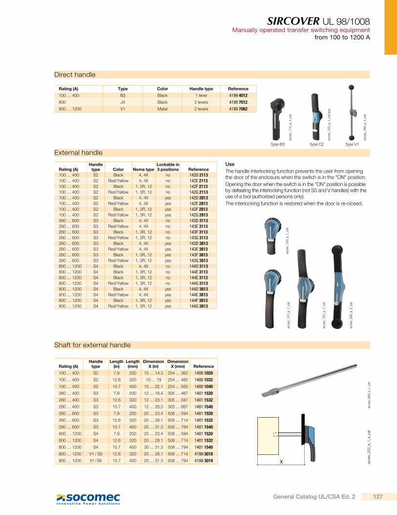
SIRCOVER UL 98/1008Manually operated transfer switching equipment
from 100 to 1200 A
Shaft for external handle
acce
s_3
69
_a_1
_cat
Rating (A)Handle
typeLength
(in)Length (mm)
Dimension X (in)
Dimension X (mm) Reference
100 … 400 S2 7.9 200 10 … 14.3 254 … 362 1400 1020
100 … 400 S2 12.6 320 10 … 19 254 … 482 1400 1032
100 … 400 S2 15.7 400 10 … 22.1 254 … 562 1400 1040
260 … 400 S3 7.9 200 12 … 18.4 305 … 467 1401 1520
260 … 400 S3 12.6 320 12 … 23.1 305 … 587 1401 1532
260 … 400 S3 15.7 400 12 … 26.3 305 … 667 1401 1540
260 … 600 S3 7.9 200 20 … 23.4 508 … 594 1401 1520
260 … 600 S3 12.6 320 20 … 28.1 508 … 714 1401 1532
260 … 600 S3 15.7 400 20 … 31.3 508 … 794 1401 1540
800 … 1200 S4 7.9 200 20 … 23.4 508 … 594 1401 1520
800 … 1200 S4 12.6 320 20 … 28.1 508 … 714 1401 1532
800 … 1200 S4 15.7 400 20 … 31.3 508 … 794 1401 1540
800 … 1200 V1 / S5 12.6 320 20 … 28.1 508 … 714 4199 3018
800 … 1200 V1 / S5 15.7 400 20 … 31.3 508 … 794 4199 3019
Direct handle
Rating (A) Type Color Handle type Reference
100 … 400 B3 Black 1 lever 4199 4012
600 J4 Black 2 levers 4199 7012
800 … 1200 V1 Metal 2 levers 4199 7062
X acce
s_2
02
_a_1
_x_c
at
External handle
acce
s_1
52
_a_1
_cat
acce
s_1
51
_a_1
_cat
acce
s_1
50
_a_1
_cat
Use
The handle interlocking function prevents the user from opening the door of the enclosure when the switch is in the "ON" position.
Opening the door when the switch is in the "ON" position is possible by defeating the interlocking function (not S5 and V handles) with the use of a tool (authorized persons only).
The interlocking function is restored when the door is re-closed.
Rating (A)Handle
type Color Nema typeLockable in 3 positions Reference
100 … 400 S2 Black 4, 4X no 142D 2113100 … 400 S2 Red/Yellow 4, 4X no 142E 2113100 … 400 S2 Black 1, 3R, 12 no 142F 2113100 … 400 S2 Red/Yellow 1, 3R, 12 no 142G 2113100 … 400 S2 Black 4, 4X yes 142D 2813100 … 400 S2 Red/Yellow 4, 4X yes 142E 2813100 … 400 S2 Black 1, 3R, 12 yes 142F 2813100 … 400 S2 Red/Yellow 1, 3R, 12 yes 142G 2813260 … 600 S3 Black 4, 4X no 143D 3113260 … 600 S3 Red/Yellow 4, 4X no 143E 3113260 … 600 S3 Black 1, 3R, 12 no 143F 3113260 … 600 S3 Red/Yellow 1, 3R, 12 no 143G 3113260 … 600 S3 Black 4, 4X yes 143D 3813260 … 600 S3 Red/Yellow 4, 4X yes 143E 3813260 … 600 S3 Black 1, 3R, 12 yes 143F 3813260 … 600 S3 Red/Yellow 1, 3R, 12 yes 143G 3813800 … 1200 S4 Black 4, 4X no 144D 3113800 … 1200 S4 Black 1, 3R, 12 no 144E 3113800 … 1200 S4 Black 1, 3R, 12 no 144E 3113800 … 1200 S4 Red/Yellow 1, 3R, 12 no 144G 3113800 … 1200 S4 Black 4, 4X yes 144D 3813800 … 1200 S4 Red/Yellow 4, 4X yes 144E 3813800 … 1200 S4 Black 1, 3R, 12 yes 144F 3813800 … 1200 S4 Red/Yellow 1, 3R, 12 yes 144G 3813
acce
s_2
86
_a_2
_cat
acce
s_1
14
_a_1
_cat
Type B3
acce
s_1
53
_a_1
_cat
.ep
s
Type C2
acce
s_1
89
_a_1
_cat
Type V1
127General Catalog UL/CSA Ed. 2
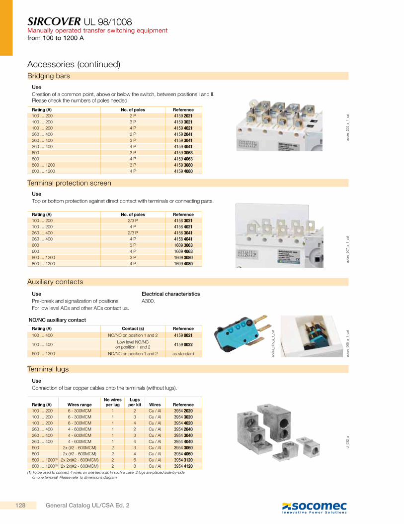
SIRCOVER UL 98/1008Manually operated transfer switching equipmentfrom 100 to 1200 A
Bridging bars
acce
s_2
05
_a_1
_cat
Use
Creation of a common point, above or below the switch, between positions I and II. Please check the numbers of poles needed.
Rating (A) No. of poles Reference
100 … 200 2 P 4159 2021
100 … 200 3 P 4159 3021
100 … 200 4 P 4159 4021
260 … 400 2 P 4159 2041
260 … 400 3 P 4159 3041
260 … 400 4 P 4159 4041
600 3 P 4159 3063
600 4 P 4159 4063
800 … 1200 3 P 4159 3080
800 … 1200 4 P 4159 4080
Auxiliary contacts
Use
Pre-break and signalization of positions.
For low level ACs and other ACs contact us.
Electrical characteristics
A300.
Rating (A) Contact (s) Reference
100 … 400 NO/NC on position 1 and 2 4159 0021
100 … 400Low level NO/NC
on position 1 and 24159 0022
600 … 1200 NO/NC on position 1 and 2 as standard
Terminal protection screen
acce
s_2
07
_a_1
_cat
Use
Top or bottom protection against direct contact with terminals or connecting parts.
Rating (A) No. of poles Reference
100 … 200 2/3 P 4158 3021
100 … 200 4 P 4158 4021
260 … 400 2/3 P 4158 3041
260 … 400 4 P 4158 4041
600 3 P 1609 3063
600 4 P 1609 4063
800 … 1200 3 P 1609 3080
800 … 1200 4 P 1609 4080
Terminal lugs
ul_
03
2_a
Use
Connection of bar copper cables onto the terminals (without lugs).
(1) To be used to connect 4 wires on one terminal. In such a case, 2 lugs are placed side-by-side
on one terminal. Please refer to dimensions diagram
Rating (A) Wires rangeNo wires per lug
Lugs per kit Wires Reference
100 … 200 6 - 300MCM 1 2 Cu / Al 3954 2020
100 … 200 6 - 300MCM 1 3 Cu / Al 3954 3020
100 … 200 6 - 300MCM 1 4 Cu / Al 3954 4020
260 … 400 4 - 600MCM 1 2 Cu / Al 3954 2040
260 … 400 4 - 600MCM 1 3 Cu / Al 3954 3040
260 … 400 4 - 600MCM 1 4 Cu / Al 3954 4040
600 2x (#2 - 600MCM) 2 3 Cu / Al 3954 3060
600 2x (#2 - 600MCM) 2 4 Cu / Al 3954 4060
800 … 1200(1) 2x 2x(#2 - 600MCM) 2 6 Cu / Al 3954 3120
800 … 1200(1) 2x 2x(#2 - 600MCM) 2 8 Cu / Al 3954 4120
NO/NC auxiliary contact
acce
s_0
65
_a_1
_cat
acce
s_0
65
_a_1
_cat
Accessories (continued)
128 General Catalog UL/CSA Ed. 2

SIRCOVER UL 98/1008Manually operated transfer switching equipment
from 100 to 1200 A
Characteristics
Characteristics according to UL 1008
General use rating at 600 VAC and 250 VDC (A) Specific reference upon request 600 A 800 A 1200 A
Frame size B6 B7
Short-circuit rating at 600 VAC (kA) - - - - 200 100 100
Type of fuse - - - - J L L
Max. fuse rating (A) - - - - 600 800 1200
Max. motor, hp / FLA 3 ph motor max.
220-240 VAC - - - - 200 / 480 - -
440-480 VAC - - - - 400 / 477 - -
600 VAC - - - - 500 / 472 - -
Mechanical characteristics
Endurance (number of operating cycles) - - - - 5000 3500 2500
Operating torque (lbs.in/Nm) - - - - 327.5/37 442.5/50 442.5/50
Auxiliary contacts
Electrical characteristics A300 A300 A300 A300 A300 A300 A300
Characteristics according to UL 98/CSA 22.2#4
100 to 400 A / B4 - B5
sirc
o-u
l_0
29
_a_1
_x_c
at
600 to 1200 A / B6 - B7
sirc
o-u
l_0
30
_a_1
_x_c
at
Mounting orientation
General use rating (A) 100 A 200 A 260 A 400 A 600 A 800 A 1200 A
Frame size B4 B5 B6 B7
Operation voltage 2 P - 3/4 P 240/600 240/600 240/600 240/600 -/600 -/600 -/600
Short circuit rating at 600 VAC with fuses (kA)
Short circuit rating at 600 VAC (kA) 100 100 65 65 100 100 100
Type of fuse J J J J L L L
Max fuse rating (A) 200 400 600 600 800 1000 1600
Short circuit rating at 600 VAC with “Specific Circuit Breaker” (kA)
Square D JJ breaker 250 A - 2 P 240 VAC - 3/4 P 480 VAC 65 65 - - - - -
Schneider Electric NSX-F 160 A - 3/4 P 480 VAC 35 - - - - - -
Short circuit rating at 600 VAC with “Any Breaker” (kA)
Short circuit rating (kA) 10 10 14 14 35 35 35
Short circuit capacity (ms) 25 25 50 50 50 50 50
Rated operational current
240 VAC “Total System” (A) 100 200 260 400 400 700 700
240 VAC resistive load (A) 100 200 260 400 600 800 1200
480 VAC “Total System” (A) 100 100 260 400 350 600 600
480 VAC resistive load (A) 100 200 260 400 600 800 1200
600 VAC “Total System” (A) 100 100 200 200 - - -
600 VAC resistive load (A) 100 200 260 400 600 800 1200
Mechanical endurance
Endurance (number of operating cycles) 6050 6050 6050 4050 3050 3050 3050
Connection terminals
Min. connection section / AWG #6 #6 #4 / 2 X 1 /0 #4 / 2 X 1 /0 2 x #2 2 x #2 4 x #2
Max. connection section / AWG 300MCM 300MCM600MCM /
2 X 250MCM600MCM /
2 X 250MCM2x 600MCM 2x 600MCM 4 x 600MCM
129General Catalog UL/CSA Ed. 2
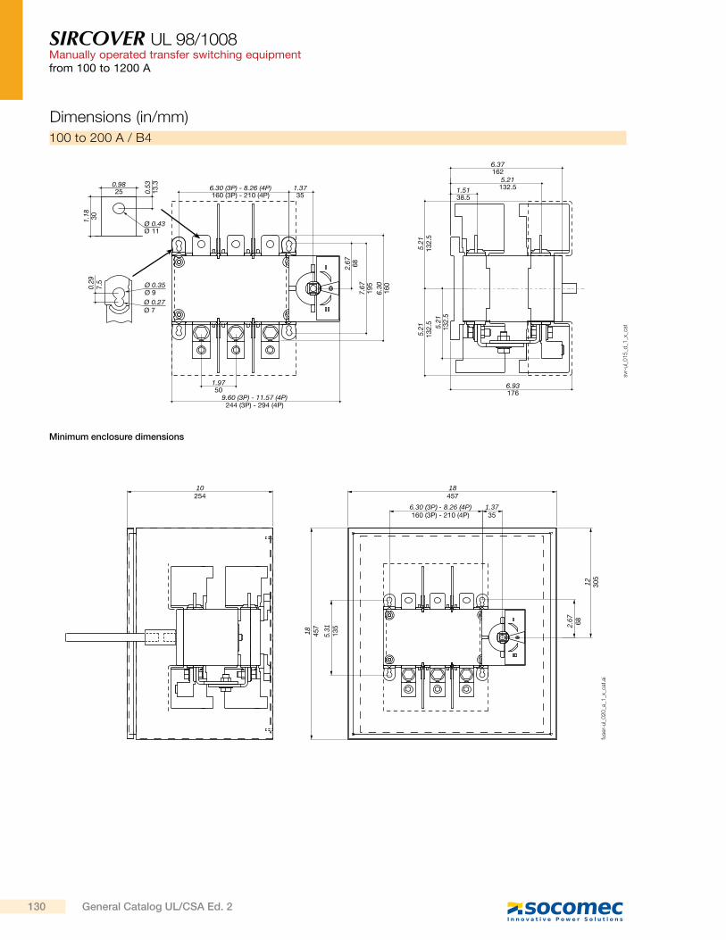
SIRCOVER UL 98/1008Manually operated transfer switching equipmentfrom 100 to 1200 A
100 to 200 A / B4
Dimensions (in/mm)
0.9825 6.30 (3P) - 8.26 (4P)
160 (3P) - 210 (4P)1.3735
1.9750
9.60 (3P) - 11.57 (4P)244 (3P) - 294 (4P)
6.37162
6.93176
5.21132.51.51
38.5
0.53
13.3
1.18 30
5.21
132.
5
2.67 68
7.67
195
6.30
160
5.21
132.
5 5.21
132.
5
Ø 0.43Ø 11
Ø 0.27Ø 7
0.29
7.5 Ø 0.35
Ø 9
svr-
ul_
01
5_d
_1_x
_cat
10254
18 457
5.31
135 2.
67 68
12 305
18457
1.3735
6.30 (3P) - 8.26 (4P)160 (3P) - 210 (4P)
fuse
r-ul_
02
0_a
_1_x
_cat
.ai
Minimum enclosure dimensions
130 General Catalog UL/CSA Ed. 2

SIRCOVER UL 98/1008Manually operated transfer switching equipment
from 100 to 1200 A
8.26 (3P) - 10.63 (4P)210 (3P) - 270 (4P)
1.3735
2.70
68.5
7.67
195
10.2
326
0
9.41239
7.481902.04
52
8 203
6.53
166
8 203
6.51165.5
2.5665
11.85 (3P) - 14.21 (4P)301 (3P) - 361 (4P)
Ø 0.27Ø 7
0.29
7.5 Ø 0.35
Ø 9
1.3845 0.
49 20
1.96 50
Ø 0.5Ø 13
svr-
ul_
01
6_b
_1_x
_cat
260 to 400 A / B5
12305
24610
1.3735
30 762
7.67
195
3.84
97.5
15 381
8.26 (2/3P) - 10.63 (4P)210 (2/3P) - 270 (4P)
fuse
r-ul_
02
1_a
_1_x
_cat
.ai
Minimum enclosure dimensions
131General Catalog UL/CSA Ed. 2
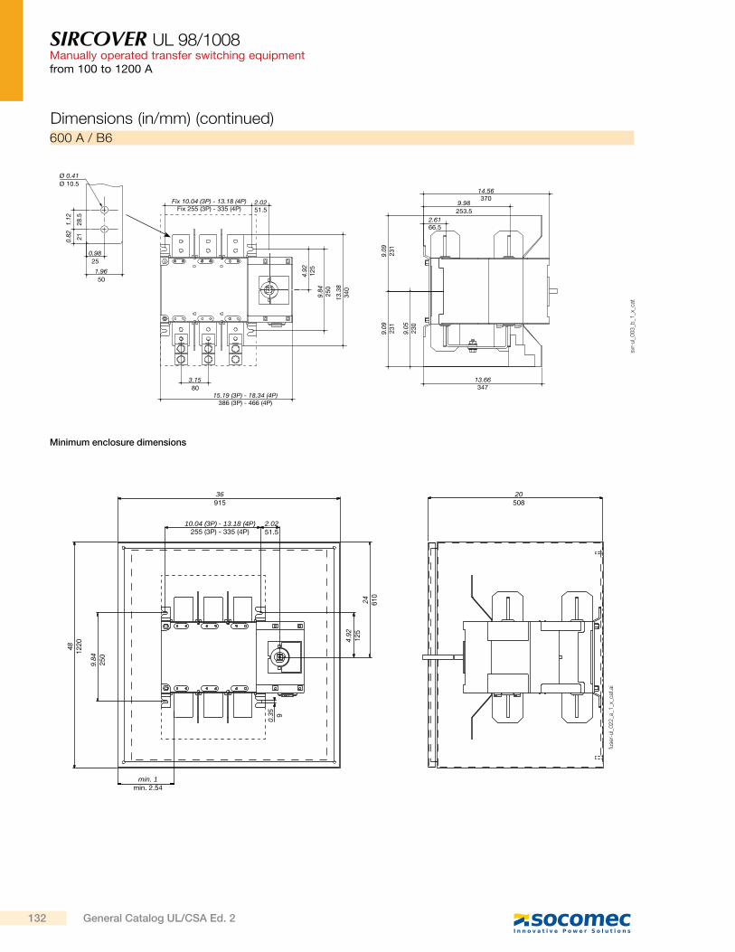
SIRCOVER UL 98/1008Manually operated transfer switching equipmentfrom 100 to 1200 A
14.56370Fix 10.04 (3P) - 13.18 (4P)
Fix 255 (3P) - 335 (4P)
3.1580
1.9650
0.9825
0.82 21
1.12
28.5
2.0251.5
2.6166.5
9.09
231
4.92
125
9.84
250
13.3
834
0
Ø 0.41Ø 10.5
9.05
230
13.66347
9.09
231
15.19 (3P) - 18.34 (4P)386 (3P) - 466 (4P)
9.98253.5
svr-
ul_
00
3_b
_1_x
_cat
600 A / B6
36915
min. 1min. 2.54
2.0251.5
481220
0.35 9
4.92
125
24 610
9.84
250
20508
10.04 (3P) - 13.18 (4P)255 (3P) - 335 (4P)
fuse
r-ul_
02
2_a
_1_x
_cat
.ai
Minimum enclosure dimensions
Dimensions (in/mm) (continued)
132 General Catalog UL/CSA Ed. 2
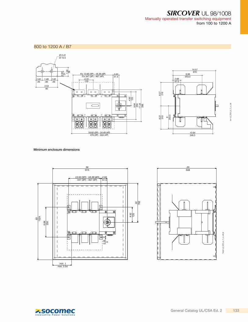
SIRCOVER UL 98/1008Manually operated transfer switching equipment
from 100 to 1200 A
14.57370
18.82 (3P) - 24.49 (4P)478 (3P) - 622 (4P)
4.72120
Fix 13.66 (3P) - 18.38 (4P)Fix 347 (3P) - 467 (4P)
2.0251.5
2.6667.5
4.92
125
9.84
250
11.3
428
8
8.27
210
13.64346.5
Ø 0.41Ø 10.5
3.5490
1.0226
1.4938
1.0226
0.82 21 1.
49 38
8.27
210 8
203.
5
9.98253.5
svr-
ul_
00
4_d
_1_x
_cat
800 to 1200 A / B7
36915
min. 1min. 2.54
2.0251.5
601524
0.35 9
4.92
125
30 762
9.84
250
20508
13.66 (3P) - 18.38 (4P)347 (3P) - 467 (4P)
fuse
r-ul_
02
3_a
_1_x
_cat
.ai
Minimum enclosure dimensions
133General Catalog UL/CSA Ed. 2
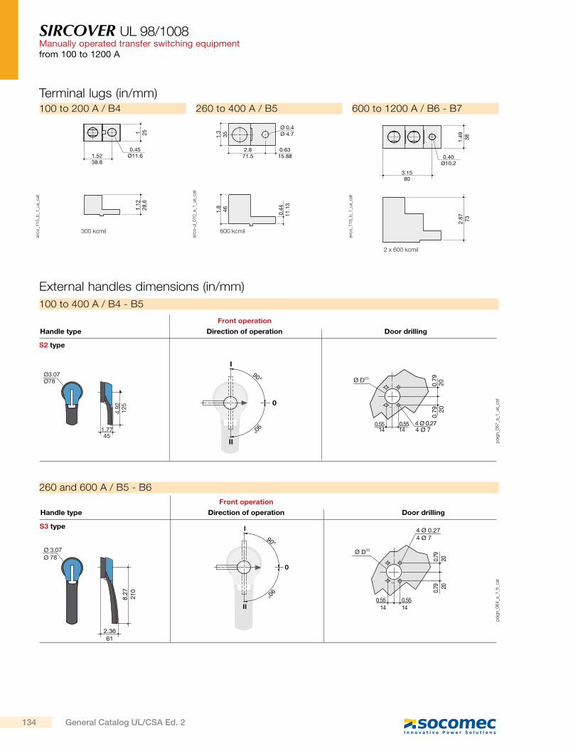
SIRCOVER UL 98/1008Manually operated transfer switching equipmentfrom 100 to 1200 A
po
ign_0
64
_a_1
_fr_
cat
Ø 3.07Ø 78
2.3661
8.27
210
90°
90°
I
II
0
4 Ø 0.274 Ø 7
0.5514
0.5514
0.79
200.
79 20
(1)Ø D
S3 type
Direction of operationHandle type
Front operation
Door drilling
260 and 600 A / B5 - B6
Terminal lugs (in/mm)
3.1580
1.49 38
2.87 73
0.40Ø10.2
sirc
o_1
16
_b_1
_us_
cat
2 x 600 kcmil
600 to 1200 A / B6 - B7
2.871.5
Ø 0.4Ø 4.71.
335
1.8
46 0.44
11.1
3
0.6315.88
sirc
o-u
l_0
10
_a_1
_us_
cat
600 kcmil
260 to 400 A / B5
1.5238.8
1 251.
1228
.60.45
Ø11.6
sirc
o_1
15
_b_1
_us_
cat
300 kcmil
100 to 200 A / B4
External handles dimensions (in/mm)
po
ign_0
67
_a_1
_us_
cat
S2 type
Direction of operationHandle type
Front operation
Door drilling
Ø3.07
1.77
4.92
4 Ø 0.270.550.55
0.79(1)Ø D
90°
90°
I
II
Ø78
45
125
14 14 4 Ø 7
2020
0.79
0
100 to 400 A / B4 - B5
134 General Catalog UL/CSA Ed. 2
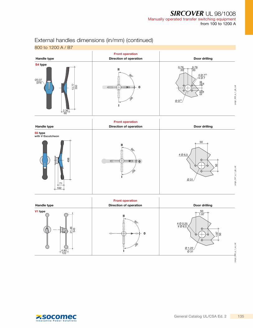
SIRCOVER UL 98/1008Manually operated transfer switching equipment
from 100 to 1200 A
External handles dimensions (in/mm) (continued)
po
ign_0
65
_a_1
_gb
_cat0
I
II
2.36
13.7
7(2)4 Ø 7
(1)Ø D
90°
90°
S4 type
Ø78
350
60
4 Ø 7
0.55
0.55 14
14
0.792020
0.79
Ø3.07
Direction of operationHandle type
Front operation
Door drilling
800 to 1200 A / B7
V1 type
Ø 1.22
1.97
50
4 Ø 0.25
4.80
21.4
6
122
545
1.97
4 Ø 6.5
50
Ø 31
0
I
II
90°
90°
Direction of operationHandle type
Front operation
Door drilling
po
ign_0
66
_a_1
_us_
cat
S5 typewith V Escutcheon
90°
498
I
II
0
90°
71
102
50
Ø 31
50
4 Ø 6,5
Handle type Direction of operation
Front operation
Door drilling
po
ign_0
47
_a_1
_gb
_cat
135General Catalog UL/CSA Ed. 2
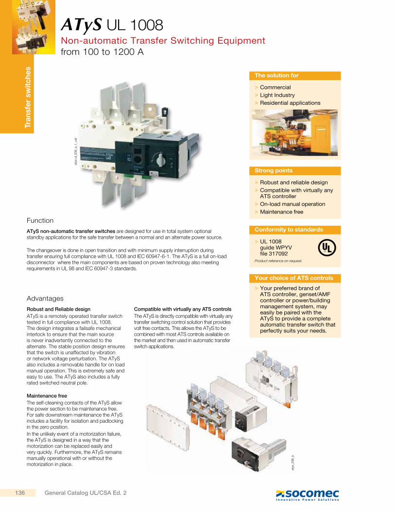
Tra
nsfe
r sw
itc
he
s
> Robust and reliable design
> Compatible with virtually any ATS controller
> On-load manual operation
> Maintenance free
Strong points
Function
ATyS non-automatic transfer switches are designed for use in total system optional standby applications for the safe transfer between a normal and an alternate power source.
The changeover is done in open transition and with minimum supply interruption during transfer ensuring full compliance with UL 1008 and IEC 60947-6-1. The ATyS is a full on-load disconnector where the main components are based on proven technology also meeting requirements in UL 98 and IEC 60947-3 standards.
Advantages
Robust and Reliable design
ATyS is a remotely operated transfer switch tested in full compliance with UL 1008. The design integrates a failsafe mechanical interlock to ensure that the main source is never inadvertently connected to the alternate. The stable position design ensures that the switch is unaffected by vibration or network voltage perturbation. The ATyS also includes a removable handle for on load manual operation. This is extremely safe and easy to use. The ATyS also includes a fully rated switched neutral pole.
Maintenance free
The self-cleaning contacts of the ATyS allow the power section to be maintenance free. For safe downstream maintenance the ATyS includes a facility for isolation and padlocking in the zero position.
In the unlikely event of a motorization failure, the ATyS is designed in a way that the motorization can be replaced easily and very quickly. Furthermore, the ATyS remains manually operational with or without the motorization in place.
Compatible with virtually any ATS controls
The ATyS is directly compatible with virtually any transfer switching control solution that provides volt free contacts. This allows the ATyS to be combined with most ATS controls available on the market and then used in automatic transfer switch applications.
> Your preferred brand of ATS controller, genset/AMF controller or power/building management system, may easily be paired with the ATyS to provide a complete automatic transfer switch that perfectly suits your needs.
Your choice of ATS controls
atys
_29
8_b
ATyS UL 1008Non-automatic Transfer Switching Equipmentfrom 100 to 1200 A
> Commercial
> Light Industry
> Residential applications
The solution for
> UL 1008guide WPYV file 317092
Product reference on request.
Conformity to standards
atys
-ul_
00
8_a
_1_c
at
136 General Catalog UL/CSA Ed. 2
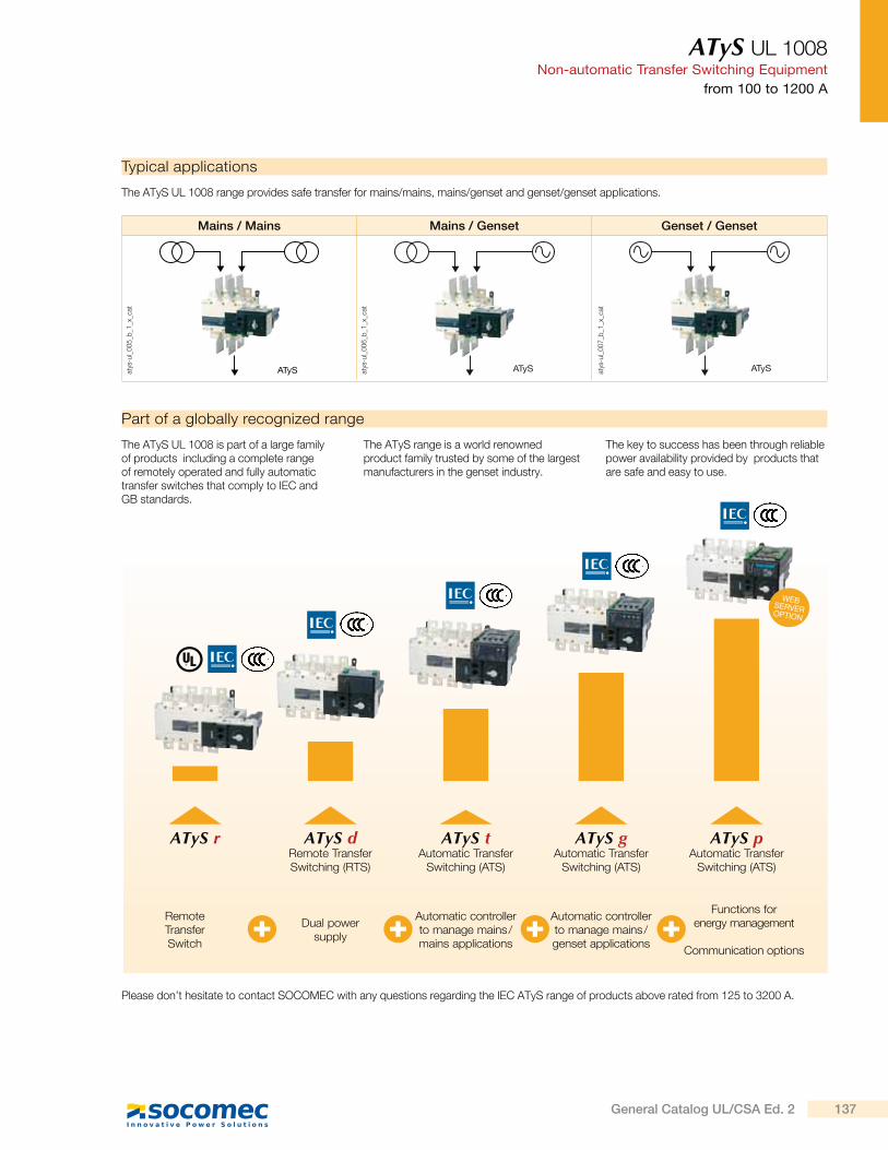
ATyS UL 1008Non-automatic Transfer Switching Equipment
from 100 to 1200 A
Typical applications
The ATyS UL 1008 range provides safe transfer for mains/mains, mains/genset and genset/genset applications.
Mains / Mains Mains / Genset Genset / Genset
ATyS ATyS ATyS
Part of a globally recognized range
The ATyS UL 1008 is part of a large family of products including a complete range of remotely operated and fully automatic transfer switches that comply to IEC and GB standards.
The ATyS range is a world renowned product family trusted by some of the largest manufacturers in the genset industry.
The key to success has been through reliable power availability provided by products that are safe and easy to use.
Please don’t hesitate to contact SOCOMEC with any questions regarding the IEC ATyS range of products above rated from 125 to 3200 A.
atys
-ul_
00
5_b
_1_x
_cat
atys
-ul_
00
6_b
_1_x
_cat
atys
-ul_
00
7_b
_1_x
_cat
WEBSERVER OPTION
ATyS r
RemoteTransferSwitch
Dual powersupply
Automatic controller to manage mains /mains applications
Automatic controller to manage mains /genset applications
Functions forenergy management
Communication options
ATyS dRemote Transfer Switching (RTS)
ATyS tAutomatic Transfer
Switching (ATS)
ATyS gAutomatic Transfer
Switching (ATS)
ATyS pAutomatic Transfer
Switching (ATS)
137General Catalog UL/CSA Ed. 2
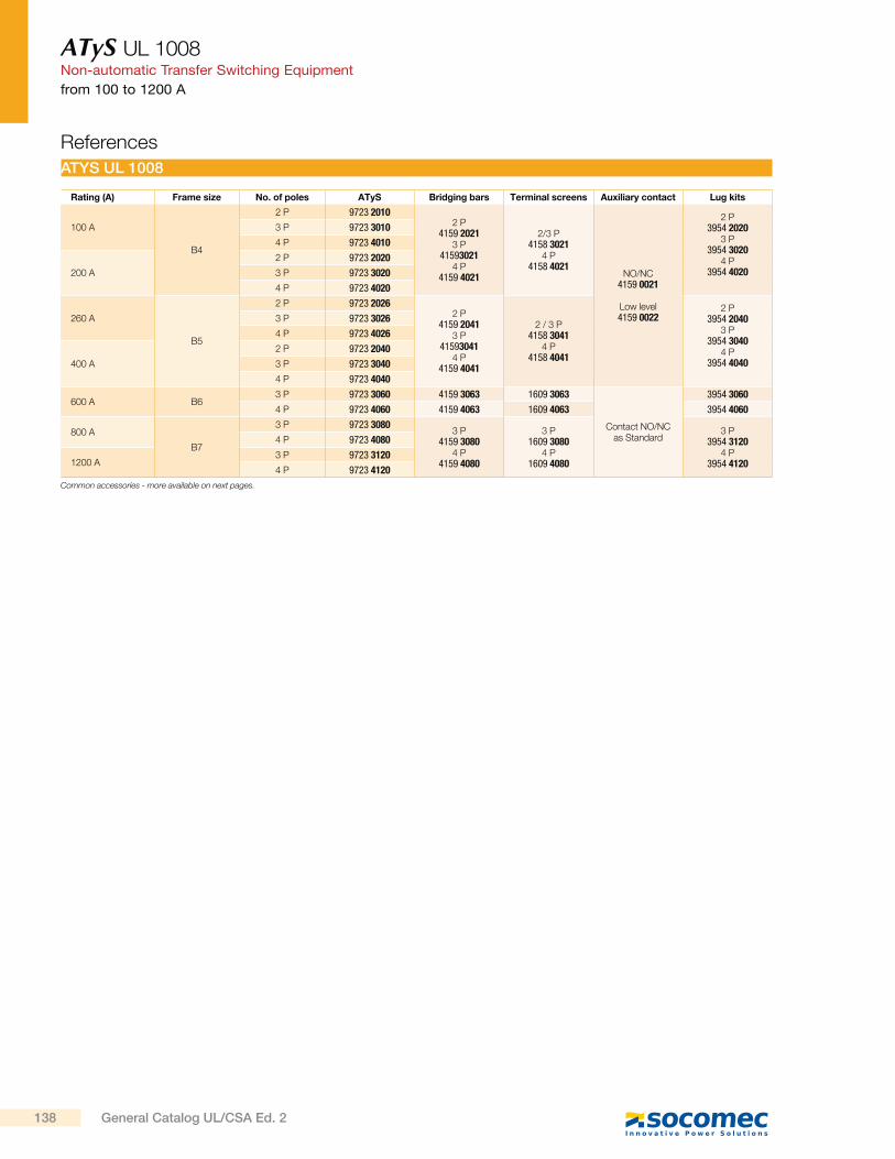
ATyS UL 1008Non-automatic Transfer Switching Equipment
from 100 to 1200 A
References
ATYS UL 1008
Rating (A) Frame size No. of poles ATyS Bridging bars Terminal screens Auxiliary contact Lug kits
100 A
B4
2 P 9723 20102 P
4159 20213 P
415930214 P
4159 4021
2/3 P4158 3021
4 P4158 4021
NO/NC4159 0021
Low level4159 0022
2 P3954 2020
3 P3954 3020
4 P3954 4020
3 P 9723 3010
4 P 9723 4010
200 A
2 P 9723 2020
3 P 9723 3020
4 P 9723 4020
260 A
B5
2 P 9723 20262 P
4159 20413 P
415930414 P
4159 4041
2 / 3 P4158 3041
4 P4158 4041
2 P3954 2040
3 P3954 3040
4 P3954 4040
3 P 9723 3026
4 P 9723 4026
400 A
2 P 9723 2040
3 P 9723 3040
4 P 9723 4040
600 A B63 P 9723 3060 4159 3063 1609 3063
Contact NO/NC as Standard
3954 3060
4 P 9723 4060 4159 4063 1609 4063 3954 4060
800 A
B7
3 P 9723 30803 P
4159 30804 P
4159 4080
3 P1609 3080
4 P1609 4080
3 P3954 3120
4 P3954 4120
4 P 9723 4080
1200 A3 P 9723 3120
4 P 9723 4120
Common accessories - more available on next pages.
138 General Catalog UL/CSA Ed. 2

ATyS UL 1008Non-automatic Transfer Switching Equipment
from 100 to 1200 A
Accessories
Bridging bars
acce
s_2
05
_a_2
_cat
Use
For bridging power terminals on the top or bottom side of the switch. When ordering one reference is required per switch. Please check numbers of poles needed.
Rating (A) No. of poles Reference
100 … 200 2 P 4159 2021
100 … 200 3 P 4159 3021
100 … 200 4 P 4159 4021
260 … 400 2 P 4159 2041
260 … 400 3 P 4159 3041
260 … 400 4 P 4159 4041
600 3 P 4159 3063
600 4 P 4159 4063
800 … 1200 3 P 4159 3080
800 … 1200 4 P 4159 4080
A maximum of 2 Aux contacts per position may be added.
Auxiliary contacts
Use
Pre-break and signalling of positions I and II: each reference provides 1 NO/NC auxiliary contact for positions I and II. ATyS are supplied with 1 NO auxiliary contact for all three positions as standard.
acce
s_0
65
_a_1
_cat
acce
s_0
65
_a_1
_cat
Rating (A) Contact (s) Reference
100 ... 400 NO/NC on position 1 and 2 4159 0021
100 ... 400Low level NO/NC
on position 1 and 24159 0022
600 ... 1200 NO/NC on position 1 and 2 as standard
Terminal screens
acce
s_2
07
_a_2
_cat
Use
Top and bottom protection against direct contact with terminals or connecting parts.
Rating (A) No. of poles Reference
100 … 200 2/3 P 4158 3021
100 … 200 4 P 4158 4021
260 … 400 2/3 P 4158 3041
260 … 400 4 P 4158 4041
600 3 P 1609 3063
600 4 P 1609 4063
800 … 1200 3 P 1609 3080
800 … 1200 4 P 1609 4080
Terminal lugs
ul_
03
2_a
Use
Connection of bare copper cables onto the terminals (without lugs).
(1) To be used to connect 4 wires on one terminal. In such a case, 2 lugs are placed side-by-side on one terminal. Please refer to dimensions diagram
Rating (A) Wires range No wires per lug Lugs per kit Wires Reference
100 ... 200 6 - 300MCM 1 2 Cu / Al 3954 2020
100 ... 200 6 - 300MCM 1 3 Cu / Al 3954 3020
100 ... 200 6 - 300MCM 1 4 Cu / Al 3954 4020
260 … 400 4 - 600MCM 1 2 Cu / Al 3954 2040
260 … 400 4 - 600MCM 1 3 Cu / Al 3954 3040
260 … 400 4 - 600MCM 1 4 Cu / Al 3954 4040
600 2x (#2 - 600MCM) 2 3 Cu / Al 3954 3060
600 2x (#2 - 600MCM) 2 4 Cu / Al 3954 4060
800 … 1200(1) 2x 2x(#2 - 600MCM) 2 6 Cu / Al 3954 3120
800 … 1200(1) 2x 2x(#2 - 600MCM) 2 8 Cu / Al 3954 4120
139General Catalog UL/CSA Ed. 2
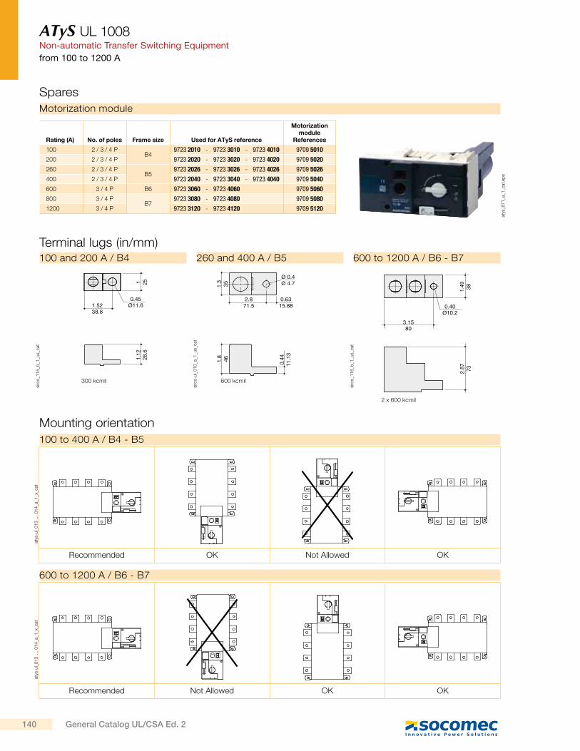
ATyS UL 1008Non-automatic Transfer Switching Equipment
from 100 to 1200 A
Mounting orientation
100 to 400 A / B4 - B5
600 to 1200 A / B6 - B7
Recommended OK Not Allowed OK
Recommended Not Allowed OK OK
atys
-ul_
01
3 …
01
4_a
_1_x
_cat
atys
-ul_
01
3 …
01
4_a
_1_x
_cat
Terminal lugs (in/mm)
3.1580
1.49 38
2.87 73
0.40Ø10.2
sirc
o_1
16
_b_1
_us_
cat
600 to 1200 A / B6 - B7
2.871.5
Ø 0.4Ø 4.71.
335
1.8
46 0.44
11.1
3
0.6315.88
sirc
o-u
l_0
10
_a_1
_us_
cat
600 kcmil
260 and 400 A / B5
1.5238.8
1 251.
1228
.6
0.45Ø11.6
sirc
o_1
15
_b_1
_us_
cat
300 kcmil
100 and 200 A / B4
2 x 600 kcmil
SparesMotorization module
Rating (A) No. of poles Frame size Used for ATyS reference
Motorization module
References
100 2 / 3 / 4 PB4
9723 2010 - 9723 3010 - 9723 4010 9709 5010
200 2 / 3 / 4 P 9723 2020 - 9723 3020 - 9723 4020 9709 5020
260 2 / 3 / 4 PB5
9723 2026 - 9723 3026 - 9723 4026 9709 5026
400 2 / 3 / 4 P 9723 2040 - 9723 3040 - 9723 4040 9709 5040
600 3 / 4 P B6 9723 3060 - 9723 4060 9709 5060
800 3 / 4 PB7
9723 3080 - 9723 4080 9709 5080
1200 3 / 4 P 9723 3120 - 9723 4120 9709 5120
atys
_87
1_a
_1_c
at.e
ps
140 General Catalog UL/CSA Ed. 2
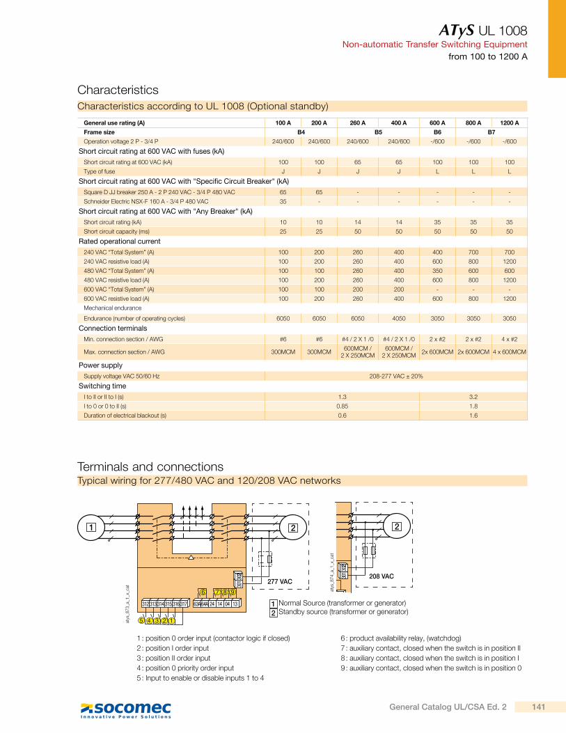
ATyS UL 1008Non-automatic Transfer Switching Equipment
from 100 to 1200 A
Characteristics
Characteristics according to UL 1008 (Optional standby)
Terminals and connections
5
6
4 3 2 1
1 2
277 VAC
7
3013
022
312 313 314 315 316 317 63A64A 24 14 04 13
8 9
atys
_87
3_a
_1_x
_cat
atys
_87
4_a
_1_x
_cat
Normal Source (transformer or generator) Standby source (transformer or generator)21
Typical wiring for 277/480 VAC and 120/208 VAC networks
2
3013
022
208 VAC
1 : position 0 order input (contactor logic if closed)
2 : position I order input
3 : position II order input
4 : position 0 priority order input
5 : Input to enable or disable inputs 1 to 4
6 : product availability relay, (watchdog)
7 : auxiliary contact, closed when the switch is in position II
8 : auxiliary contact, closed when the switch is in position I
9 : auxiliary contact, closed when the switch is in position 0
General use rating (A) 100 A 200 A 260 A 400 A 600 A 800 A 1200 A
Frame size B4 B5 B6 B7
Operation voltage 2 P - 3/4 P 240/600 240/600 240/600 240/600 -/600 -/600 -/600
Short circuit rating at 600 VAC with fuses (kA)
Short circuit rating at 600 VAC (kA) 100 100 65 65 100 100 100
Type of fuse J J J J L L L
Short circuit rating at 600 VAC with "Specific Circuit Breaker" (kA)
Square D JJ breaker 250 A - 2 P 240 VAC - 3/4 P 480 VAC 65 65 - - - - -
Schneider Electric NSX-F 160 A - 3/4 P 480 VAC 35 - - - - - -
Short circuit rating at 600 VAC with "Any Breaker" (kA)
Short circuit rating (kA) 10 10 14 14 35 35 35
Short circuit capacity (ms) 25 25 50 50 50 50 50
Rated operational current
240 VAC “Total System” (A) 100 200 260 400 400 700 700
240 VAC resistive load (A) 100 200 260 400 600 800 1200
480 VAC “Total System” (A) 100 100 260 400 350 600 600
480 VAC resistive load (A) 100 200 260 400 600 800 1200
600 VAC “Total System” (A) 100 100 200 200 - - -
600 VAC resistive load (A) 100 200 260 400 600 800 1200
Mechanical endurance
Endurance (number of operating cycles) 6050 6050 6050 4050 3050 3050 3050
Connection terminals
Min. connection section / AWG #6 #6 #4 / 2 X 1 /0 #4 / 2 X 1 /0 2 x #2 2 x #2 4 x #2
Max. connection section / AWG 300MCM 300MCM600MCM /
2 X 250MCM600MCM /
2 X 250MCM2x 600MCM 2x 600MCM 4 x 600MCM
Power supply
Supply voltage VAC 50/60 Hz 208-277 VAC ± 20%
Switching time
I to II or II to I (s) 1.3 3.2
I to 0 or 0 to II (s) 0.85 1.8
Duration of electrical blackout (s) 0.6 1.6
141General Catalog UL/CSA Ed. 2
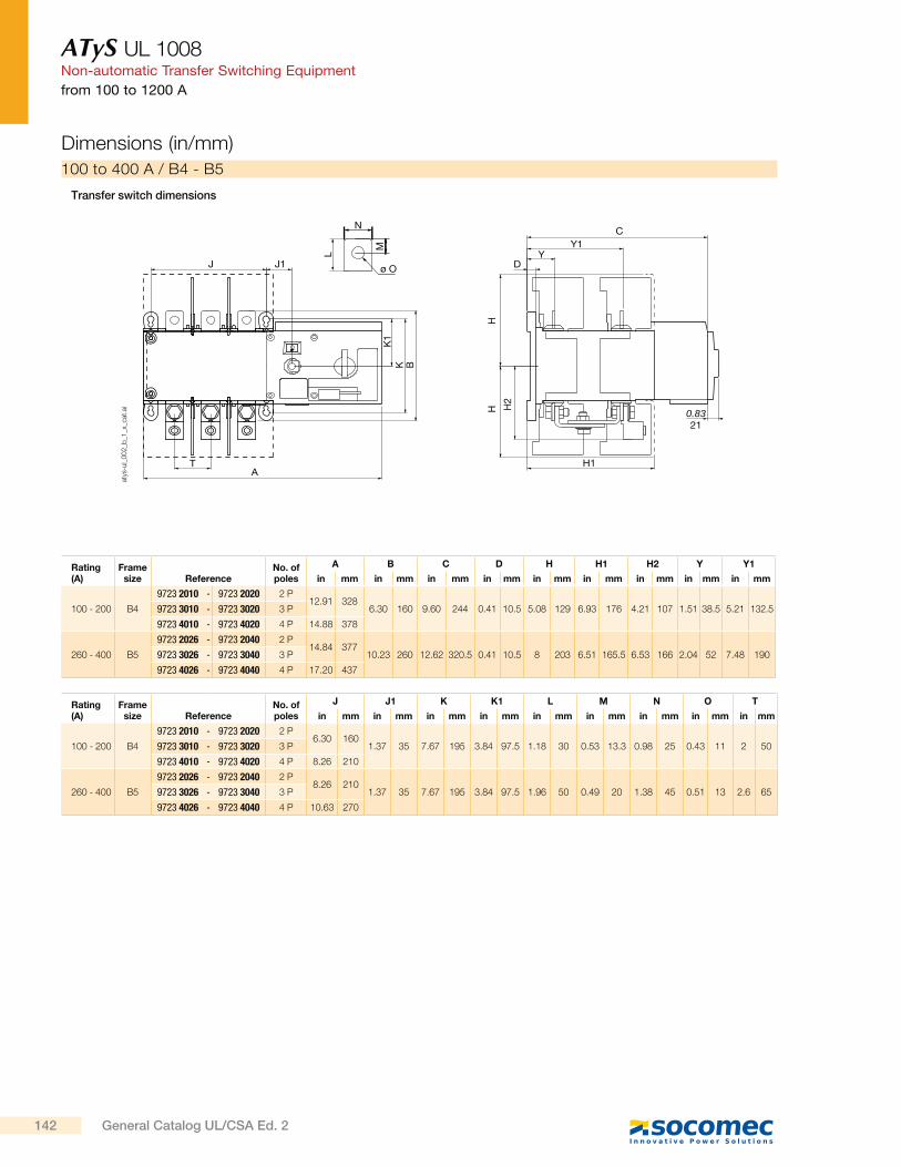
ATyS UL 1008Non-automatic Transfer Switching Equipment
from 100 to 1200 A
Dimensions (in/mm)
100 to 400 A / B4 - B5
Transfer switch dimensions
Rating (A)
Frame size Reference
No. of poles
A B C D H H1 H2 Y Y1
in mm in mm in mm in mm in mm in mm in mm in mm in mm
100 - 200 B4
9723 2010 - 9723 2020 2 P12.91 328
6.30 160 9.60 244 0.41 10.5 5.08 129 6.93 176 4.21 107 1.51 38.5 5.21 132.59723 3010 - 9723 3020 3 P
9723 4010 - 9723 4020 4 P 14.88 378
260 - 400 B5
9723 2026 - 9723 2040 2 P14.84 377
10.23 260 12.62 320.5 0.41 10.5 8 203 6.51 165.5 6.53 166 2.04 52 7.48 1909723 3026 - 9723 3040 3 P
9723 4026 - 9723 4040 4 P 17.20 437
Rating (A)
Frame size Reference
No. of poles
J J1 K K1 L M N O T
in mm in mm in mm in mm in mm in mm in mm in mm in mm
100 - 200 B4
9723 2010 - 9723 2020 2 P6.30 160
1.37 35 7.67 195 3.84 97.5 1.18 30 0.53 13.3 0.98 25 0.43 11 2 509723 3010 - 9723 3020 3 P
9723 4010 - 9723 4020 4 P 8.26 210
260 - 400 B5
9723 2026 - 9723 2040 2 P8.26 210
1.37 35 7.67 195 3.84 97.5 1.96 50 0.49 20 1.38 45 0.51 13 2.6 659723 3026 - 9723 3040 3 P
9723 4026 - 9723 4040 4 P 10.63 270
C
J
A
K1
K B
T
J1
Y1Y
H1
0.8321
HH H
2
N
L
M
ø O D
atys
-ul_
00
2_b
_1_x
_cat
.ai
142 General Catalog UL/CSA Ed. 2
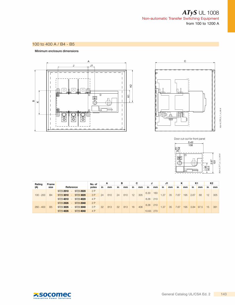
ATyS UL 1008Non-automatic Transfer Switching Equipment
from 100 to 1200 A
100 to 400 A / B4 - B5
Door cut-out for front panel
Minimum enclosure dimensions
Rating (A)
Frame size Reference
No. of poles
A B C J J1 K K1 K2
in mm in mm in mm in mm in mm in mm in mm in mm
100 - 200 B4
9723 2010 - 9723 2020 2 P
24 610 24 610 12 3056.30 160
1.37 35 7.67 195 2.67 68 12 3059723 3010 - 9723 3020 3 P
9723 4010 - 9723 4020 4 P 8.26 210
260 - 400 B5
9723 2026 - 9723 2040 2 P
32 813 32 813 16 4068.26 210
1.37 35 7.67 195 3.84 97.5 15 3819723 3026 - 9723 3040 3 P
9723 4026 - 9723 4040 4 P 10.63 270
J
K1
K2
J1
CA
B K
atys
-ul_
00
9_b
_1_x
_cat
.ai
1.98
50.5
0.7820
5.43138
3.97
101
atys
-ul_
01
7_a
_1_x
_cat
.ai
143General Catalog UL/CSA Ed. 2
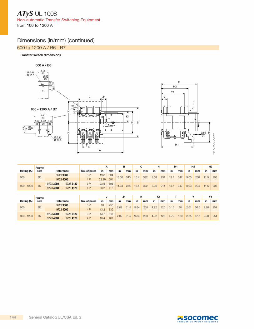
ATyS UL 1008Non-automatic Transfer Switching Equipment
from 100 to 1200 A
600 to 1200 A / B6 - B7
Transfer switch dimensions
Rating (A)Frame
size Reference No. of poles
A B C H H1 H2 H3
in mm in mm in mm in mm in mm in mm in mm
600 B69723 3060 3 P 19.8 504
13.38 340 15.4 392 9.09 231 13.7 347 9.05 230 11.5 2939723 4060 4 P 22.99 584
800 - 1200 B79723 3080 - 9723 3120 3 P 23.5 596
11.34 288 15.4 392 8.30 211 13.7 347 8.03 204 11.5 2939723 4080 - 9723 4120 4 P 28.2 716
Rating (A)Frame
size Reference No. of poles
J J1 K K1 T Y Y1
in mm in mm in mm in mm in mm in mm in mm
600 B69723 3060 3 P 10 255
2.02 51.5 9.84 250 4.92 125 3.15 80 2.61 66.5 9.98 2549723 4060 4 P 13.2 335
800 - 1200 B79723 3080 - 9723 3120 3 P 13.7 347
2.02 51.5 9.84 250 4.92 125 4.72 120 2.65 67.7 9.98 2549723 4080 - 9723 4120 4 P 18.4 467
Dimensions (in/mm) (continued)
A
J
C
Y
H1
Y1
J1
H3
T
BK
K1
H
H H
0.35 9
0.8321Ø 0.41
Ø 10.5
3.5490
1.4938
1.0226
1.0226
1.49 38
1.9650
0.9825
0.82 21
0.82 21
1.12
28.5
Ø 0.41Ø 10.5
600 A / B6
800 - 1200 A / B7
atys
-ul_
01
8_a
_1_x
_cat
.ai
144 General Catalog UL/CSA Ed. 2
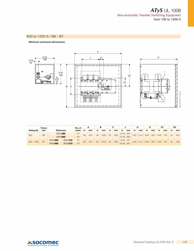
ATyS UL 1008Non-automatic Transfer Switching Equipment
from 100 to 1200 A
600 to 1200 A / B6 - B7
Minimum enclosure dimensions
Rating (A)Frame
size ReferenceNo. of poles
A B C J J1 K K1 K2
in mm in mm in mm in mm in mm in mm in mm in mm
600 B69723 3060 3 P
36 915 48 1220 20 50810.04 255
2.02 51.5 9.84 250 4.92 125 24 6109723 4060 4 P 12.18 355
800 - 1200 B79723 3080 - 9723 3120 3 P
36 915 60 1524 20 50813.66 347
2.02 51.5 9.84 250 4.92 125 30 7629723 4080 - 9723 4120 4 P 18.38 467
A
J J1 C
K
K1
K2
B
5.431380.79
20
5.91150
0.7920
atys
-ul_
01
9_a
_1_x
_cat
.ai
145General Catalog UL/CSA Ed. 2

Enclosures & accessories
Busbar
Flexible copper bars
Insulated copper braidsEdgewise mountingbusbar supports
new
Rigid copper bars
p. 150p. 148
p. 152 p. 154
147General Catalog UL/CSA Ed. 2
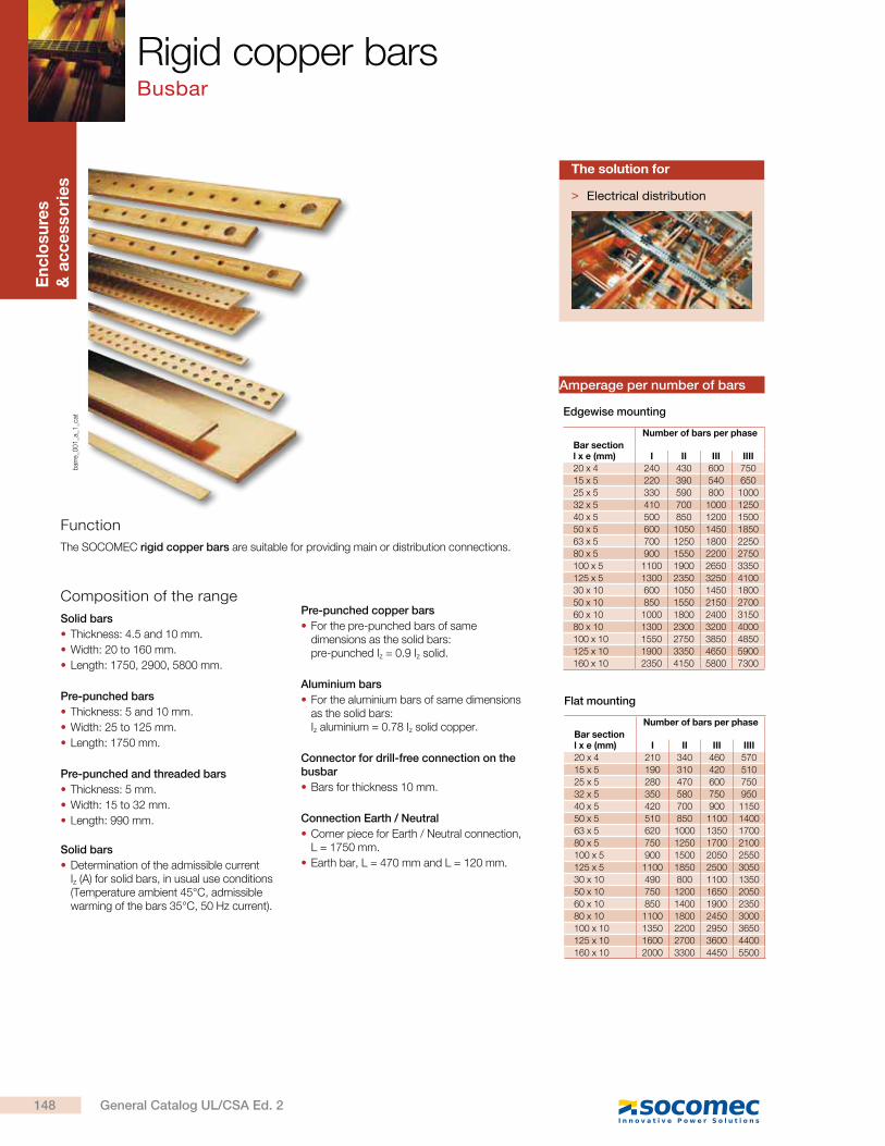
En
clo
su
res
& a
cc
esso
rie
s
Bar sectionl x e (mm)
Number of bars per phase
I II III IIII
20 x 4 240 430 600 750
15 x 5 220 390 540 650
25 x 5 330 590 800 1000
32 x 5 410 700 1000 1250
40 x 5 500 850 1200 1500
50 x 5 600 1050 1450 1850
63 x 5 700 1250 1800 2250
80 x 5 900 1550 2200 2750
100 x 5 1100 1900 2650 3350
125 x 5 1300 2350 3250 4100
30 x 10 600 1050 1450 1800
50 x 10 850 1550 2150 2700
60 x 10 1000 1800 2400 3150
80 x 10 1300 2300 3200 4000
100 x 10 1550 2750 3850 4850
125 x 10 1900 3350 4650 5900
160 x 10 2350 4150 5800 7300
Edgewise mounting
Bar sectionl x e (mm)
Number of bars per phase
I II III IIII
20 x 4 210 340 460 570
15 x 5 190 310 420 510
25 x 5 280 470 600 750
32 x 5 350 580 750 950
40 x 5 420 700 900 1150
50 x 5 510 850 1100 1400
63 x 5 620 1000 1350 1700
80 x 5 750 1250 1700 2100
100 x 5 900 1500 2050 2550
125 x 5 1100 1850 2500 3050
30 x 10 490 800 1100 1350
50 x 10 750 1200 1650 2050
60 x 10 850 1400 1900 2350
80 x 10 1100 1800 2450 3000
100 x 10 1350 2200 2950 3650
125 x 10 1600 2700 3600 4400
160 x 10 2000 3300 4450 5500
Flat mounting
Amperage per number of bars
bar
re_0
01
_a_1
_cat
Rigid copper bars Busbar
Function
The SOCOMEC rigid copper bars are suitable for providing main or distribution connections.
Composition of the range
Solid bars
Thickness: 4.5 and 10 mm.
Width: 20 to 160 mm.
Length: 1750, 2900, 5800 mm.
Pre-punched bars
Thickness: 5 and 10 mm.
Width: 25 to 125 mm.
Length: 1750 mm.
Pre-punched and threaded bars
Thickness: 5 mm.
Width: 15 to 32 mm.
Length: 990 mm.
Solid bars
Determination of the admissible current Iz (A) for solid bars, in usual use conditions (Temperature ambient 45°C, admissible warming of the bars 35°C, 50 Hz current).
Pre-punched copper bars
For the pre-punched bars of same dimensions as the solid bars:pre-punched Iz = 0.9 Iz solid.
Aluminium bars
For the aluminium bars of same dimensions as the solid bars:Iz aluminium = 0.78 Iz solid copper.
Connector for drill-free connection on the busbar
Bars for thickness 10 mm.
Connection Earth / Neutral
Corner piece for Earth / Neutral connection, L = 1750 mm.
Earth bar, L = 470 mm and L = 120 mm.
> Electrical distribution
The solution for
148 General Catalog UL/CSA Ed. 2
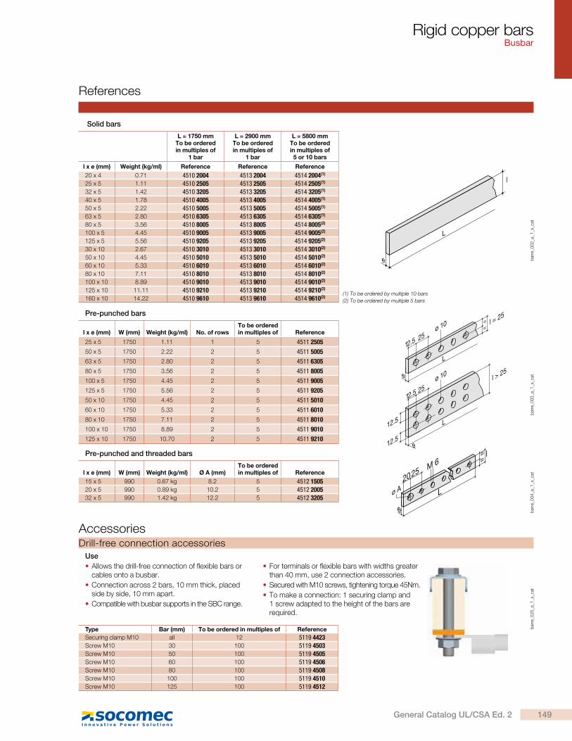
Rigid copper bars Busbar
References
Pre-punched bars
l x e (mm) W (mm) Weight (kg/ml) No. of rowsTo be ordered in multiples of Reference
25 x 5 1750 1.11 1 5 4511 2505
50 x 5 1750 2.22 2 5 4511 5005
63 x 5 1750 2.80 2 5 4511 6305
80 x 5 1750 3.56 2 5 4511 8005
100 x 5 1750 4.45 2 5 4511 9005
125 x 5 1750 5.56 2 5 4511 9205
50 x 10 1750 4.45 2 5 4511 5010
60 x 10 1750 5.33 2 5 4511 6010
80 x 10 1750 7.11 2 5 4511 8010
100 x 10 1750 8.89 2 5 4511 9010
125 x 10 1750 10.70 2 5 4511 9210e
12.5
12.5
L
12 .5
l > 25
25ø 10e
L
12 .525
==
l = 25
ø 10
bar
re_0
03
_a_1
_x_c
at
Drill-free connection accessories
bar
re_0
20
_a_1
_x_c
at
Use
Allows the drill-free connection of flexible bars or cables onto a busbar.
Connection across 2 bars, 10 mm thick, placed side by side, 10 mm apart.
Compatible with busbar supports in the SBC range.
For terminals or flexible bars with widths greater than 40 mm, use 2 connection accessories.
Secured with M10 screws, tightening torque 45Nm.
To make a connection: 1 securing clamp and 1 screw adapted to the height of the bars are required.
Type Bar (mm) To be ordered in multiples of Reference
Securing clamp M10 all 12 5119 4423Screw M10 30 100 5119 4503Screw M10 50 100 5119 4505Screw M10 60 100 5119 4506Screw M10 80 100 5119 4508Screw M10 100 100 5119 4510Screw M10 125 100 5119 4512
Solid bars
e
L
l
bar
re_0
02
_a_1
_x_c
at
L = 1750 mmTo be ordered in multiples of
1 bar
L = 2900 mmTo be ordered in multiples of
1 bar
L = 5800 mmTo be ordered in multiples of5 or 10 bars
l x e (mm) Weight (kg/ml) Reference Reference Reference
20 x 4 0.71 4510 2004 4513 2004 4514 2004(1)
25 x 5 1.11 4510 2505 4513 2505 4514 2505(1)
32 x 5 1.42 4510 3205 4513 3205 4514 3205(1)
40 x 5 1.78 4510 4005 4513 4005 4514 4005(1)
50 x 5 2.22 4510 5005 4513 5005 4514 5005(1)
63 x 5 2.80 4510 6305 4513 6305 4514 6305(1)
80 x 5 3.56 4510 8005 4513 8005 4514 8005(2)
100 x 5 4.45 4510 9005 4513 9005 4514 9005(2)
125 x 5 5.56 4510 9205 4513 9205 4514 9205(2)
30 x 10 2.67 4510 3010 4513 3010 4514 3010(2)
50 x 10 4.45 4510 5010 4513 5010 4514 5010(2)
60 x 10 5.33 4510 6010 4513 6010 4514 6010(2)
80 x 10 7.11 4510 8010 4513 8010 4514 8010(2)
100 x 10 8.89 4510 9010 4513 9010 4514 9010(2)
125 x 10 11.11 4510 9210 4513 9210 4514 9210(2)
160 x 10 14.22 4510 9610 4513 9610 4514 9610(2)(1) To be ordered by multiple 10 bars
(2) To be ordered by multiple 5 bars
Pre-punched and threaded bars
l x e (mm) W (mm) Weight (kg/ml) Ø A (mm)To be ordered in multiples of Reference
15 x 5 990 0.67 kg 8.2 5 4512 150520 x 5 990 0.89 kg 10.2 5 4512 200532 x 5 990 1.42 kg 12.2 5 4512 3205
e
L
==
l
M 6
ø A2025
bar
re_0
04
_a_1
_x_c
atAccessories
149General Catalog UL/CSA Ed. 2

En
clo
su
res
& a
cc
esso
rie
sb
arre
_01
1_a
_1_c
at
Insulated flexible copper barsBusbars
Function
Advantages
Characteristics
SOCOMEC insulated flexible copper bars are mainly utilized for providing the power connections between series of distribution busbars and the disconnection devices within an electrical panel.
The insulated layered copper allows the flexible copper bar to be easily formed to provide a customized solution.
Easy to install
Compact version.
High level of flexibility enabling easy manipulation of the busbar.
Reduced installation time with the elimination of terminal lugs and their crimping.
Increased safety by the elimination of crimped connections
Better behaviour under short-circuit conditions.
Decreased number of heating points.
More reliable connections.
Width of 9 to 100 mm.
Copper layer thickness from 0.8 to 1 mm.
Length of 2 m.
Conductor
Layers of electrolytic copper Cu/ETP, final annealing state.
Insulator
High temperature co-extruded vinyl compound on the copper strips (insulation thickness: 1.5 to 2 mm).
Self-extinguisher: NFC 32200 and UL 94 V0.
Continuous temperature withstand: 105 °C.
Shore hardness A: 89 +/- 2.
Module 100 % elongation: 16 Mpa.
Resistance to elongation: 15 % mini.
Breaking stress: 20 Mpa.
Transversal volume resistivity: 6.1015 .
Oxygen index: 29.5 %.
Scratch and tear resistant.
Insulated flexible busbar
Operating-temperature range: from -40 °C to +105 °C.
Maximum operating voltage: 1000 VAC / 1500 VDC.
Alternating voltage withstand (10 minute test):
- between core and insulation: 16.5 kV,
- between two insulating elements in contact: 33 kV,
- Conductivity: 100 IACS,
- HV < 50,
- Resistance to traction Rm > 200 N/cm²,
- Stretch before break 35 %,
- Resistivity: 1.724 micro /cm at 20 °C.
> Electrical distribution
The solution for
> Easy to install
> Increased safety by the elimination of crimped connections
Strong points
> Specific lengths
> Halogen-free
> Tin plated on request
Available on request
> UL 67 and UL 891guide QEUY2file E495516
Conformity to standards
150 General Catalog UL/CSA Ed. 2
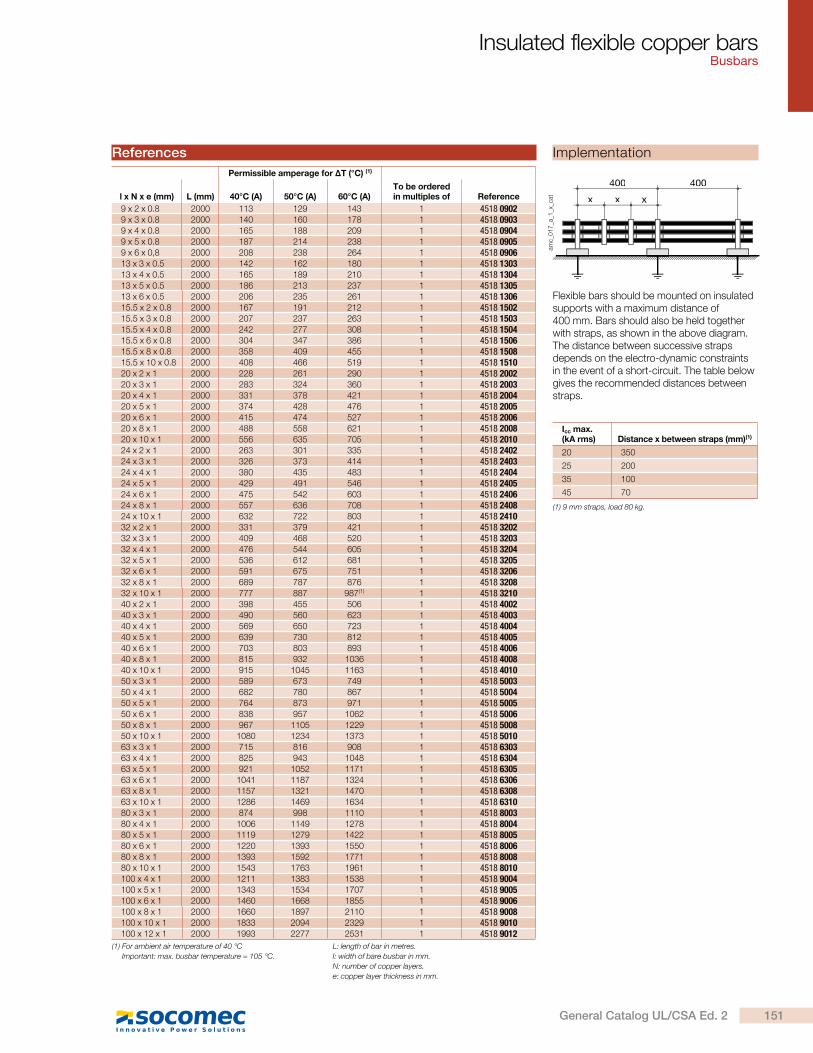
Insulated flexible copper bars Busbars
Icc max.(kA rms) Distance x between straps (mm)(1)
20 350
25 200
35 100
45 70
400
xxx
400
amc_
01
7_a
_1_x
_cat
(1) 9 mm straps, load 80 kg.
Implementation
Flexible bars should be mounted on insulated supports with a maximum distance of 400 mm. Bars should also be held together with straps, as shown in the above diagram. The distance between successive straps depends on the electro-dynamic constraints in the event of a short-circuit. The table below gives the recommended distances between straps.
Permissible amperage for T (°C) (1)
l x N x e (mm) L (mm) 40°C (A) 50°C (A) 60°C (A)To be ordered in multiples of Reference
9 x 2 x 0.8 2000 113 129 143 1 4518 09029 x 3 x 0.8 2000 140 160 178 1 4518 09039 x 4 x 0.8 2000 165 188 209 1 4518 09049 x 5 x 0.8 2000 187 214 238 1 4518 09059 x 6 x 0,8 2000 208 238 264 1 4518 090613 x 3 x 0.5 2000 142 162 180 1 4518 130313 x 4 x 0.5 2000 165 189 210 1 4518 130413 x 5 x 0.5 2000 186 213 237 1 4518 130513 x 6 x 0.5 2000 206 235 261 1 4518 130615.5 x 2 x 0.8 2000 167 191 212 1 4518 150215.5 x 3 x 0.8 2000 207 237 263 1 4518 150315.5 x 4 x 0.8 2000 242 277 308 1 4518 150415.5 x 6 x 0.8 2000 304 347 386 1 4518 150615.5 x 8 x 0.8 2000 358 409 455 1 4518 150815.5 x 10 x 0.8 2000 408 466 519 1 4518 151020 x 2 x 1 2000 228 261 290 1 4518 200220 x 3 x 1 2000 283 324 360 1 4518 200320 x 4 x 1 2000 331 378 421 1 4518 200420 x 5 x 1 2000 374 428 476 1 4518 200520 x 6 x 1 2000 415 474 527 1 4518 200620 x 8 x 1 2000 488 558 621 1 4518 200820 x 10 x 1 2000 556 635 705 1 4518 201024 x 2 x 1 2000 263 301 335 1 4518 240224 x 3 x 1 2000 326 373 414 1 4518 240324 x 4 x 1 2000 380 435 483 1 4518 240424 x 5 x 1 2000 429 491 546 1 4518 240524 x 6 x 1 2000 475 542 603 1 4518 240624 x 8 x 1 2000 557 636 708 1 4518 240824 x 10 x 1 2000 632 722 803 1 4518 241032 x 2 x 1 2000 331 379 421 1 4518 320232 x 3 x 1 2000 409 468 520 1 4518 320332 x 4 x 1 2000 476 544 605 1 4518 320432 x 5 x 1 2000 536 612 681 1 4518 320532 x 6 x 1 2000 591 675 751 1 4518 320632 x 8 x 1 2000 689 787 876 1 4518 320832 x 10 x 1 2000 777 887 987(1) 1 4518 321040 x 2 x 1 2000 398 455 506 1 4518 400240 x 3 x 1 2000 490 560 623 1 4518 400340 x 4 x 1 2000 569 650 723 1 4518 400440 x 5 x 1 2000 639 730 812 1 4518 400540 x 6 x 1 2000 703 803 893 1 4518 400640 x 8 x 1 2000 815 932 1036 1 4518 400840 x 10 x 1 2000 915 1045 1163 1 4518 401050 x 3 x 1 2000 589 673 749 1 4518 500350 x 4 x 1 2000 682 780 867 1 4518 500450 x 5 x 1 2000 764 873 971 1 4518 500550 x 6 x 1 2000 838 957 1062 1 4518 500650 x 8 x 1 2000 967 1105 1229 1 4518 500850 x 10 x 1 2000 1080 1234 1373 1 4518 501063 x 3 x 1 2000 715 816 908 1 4518 630363 x 4 x 1 2000 825 943 1048 1 4518 630463 x 5 x 1 2000 921 1052 1171 1 4518 630563 x 6 x 1 2000 1041 1187 1324 1 4518 630663 x 8 x 1 2000 1157 1321 1470 1 4518 630863 x 10 x 1 2000 1286 1469 1634 1 4518 631080 x 3 x 1 2000 874 998 1110 1 4518 800380 x 4 x 1 2000 1006 1149 1278 1 4518 800480 x 5 x 1 2000 1119 1279 1422 1 4518 800580 x 6 x 1 2000 1220 1393 1550 1 4518 800680 x 8 x 1 2000 1393 1592 1771 1 4518 800880 x 10 x 1 2000 1543 1763 1961 1 4518 8010100 x 4 x 1 2000 1211 1383 1538 1 4518 9004100 x 5 x 1 2000 1343 1534 1707 1 4518 9005100 x 6 x 1 2000 1460 1668 1855 1 4518 9006100 x 8 x 1 2000 1660 1897 2110 1 4518 9008100 x 10 x 1 2000 1833 2094 2329 1 4518 9010100 x 12 x 1 2000 1993 2277 2531 1 4518 9012
References
(1) For ambient air temperature of 40 °C
Important: max. busbar temperature = 105 °C.
L: length of bar in metres.
I: width of bare busbar in mm.
N: number of copper layers.
e: copper layer thickness in mm.
151General Catalog UL/CSA Ed. 2
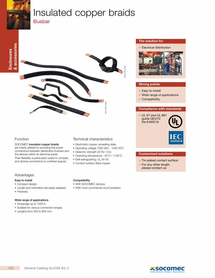
En
clo
su
res
& a
cc
esso
rie
s
bar
re_0
22
_a.e
ps
Insulated copper braidsBusbar
Function
Advantages
SOCOMEC insulated copper braids are mainly utilised for providing the power connections between distribution busbars and the devices within an electrical panel.
Their flexibility is particularly suited to complex and diverse connections in confined spaces.
Easy to install
Compact design.
Length and orientation are easily adapted.
Prewired.
Wide range of applications
Amperage up to 1000 A.
Suitable for various connection ranges.
Lengths from 200 to 800 mm.
Compatibility
With SOCOMEC devices.
With most commercial circuit breakers.
> Easy to install
> Wide range of applications
> Compatibility
Strong points
Technical characteristics
Electrolytic copper, annealing state
Operating voltage 1000 VAC - 1500 VDC
Dielectric strength 20 KV / mm
Operating temperature: -40°C / +105°C
Self-extinguishing: UL 94 V0
Contact surface: Bare copper > Tin-plated contact surface
> For any other length, please contact us
Customised solutions
> UL 67 and UL 891 guide QEUY2 file E495516
Compliance with standards
> Electrical distribution
The solution for
bar
re_0
23
_a.e
ps
152 General Catalog UL/CSA Ed. 2
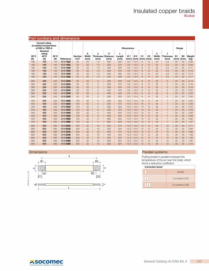
Insulated copper braidsBusbar
Current rating at ambient temperature
of 630 to 7000 A Dimensions Range
35°C (A)
Nominal rating45°C (A)
55°C (A) Reference
Section mm2
A Width (mm)
e Thickness
(mm)
X Distance
(mm)
L Length (mm)
Ø 1 (mm)
Ø 2 (mm)
C1 (mm)
C2 (mm)
h Width (mm)
f Thickness
(mm)
B1
(mm)
B2
(mm)Weight
(kg)
180 160 140 4516 1620 25 20 1.5 200 220 8.5 10.5 8 12 22 3.5 25 30 0.08
180 160 140 4516 1625 25 20 1.5 250 270 8.5 10.5 8 12 22 3.5 25 30 0.09
180 160 140 4516 1630 25 20 1.5 300 320 8.5 10.5 8 12 22 3.5 25 30 0.11
180 160 140 4516 1635 25 20 1.5 350 370 8.5 10.5 8 12 22 3.5 25 30 0.12
180 160 140 4516 1640 25 20 1.5 400 420 8.5 10.5 8 12 22 3.5 25 30 0.14
180 160 140 4516 1650 25 20 1.5 500 520 8.5 10.5 8 12 22 3.5 25 30 0.17
280 250 220 4516 2520 50 20 3 200 220 8.5 10.5 8 12 22 5 25 30 0.14
280 250 220 4516 2525 50 20 3 250 270 8.5 10.5 8 12 22 5 25 30 0.16
280 250 220 4516 2530 50 20 3 300 320 8.5 10.5 8 12 22 5 25 30 0.19
280 250 220 4516 2535 50 20 3 350 370 8.5 10.5 8 12 22 5 25 30 0.22
280 250 220 4516 2540 50 20 3 400 420 8.5 10.5 8 12 22 5 25 30 0.25
280 250 220 4516 2550 50 20 3 500 520 8.5 10.5 8 12 22 5 25 30 0.30
440 400 320 4516 4020 120 32 5 200 222 10.5 10.5 10 12 34 7 25 30 0.30
440 400 320 4516 4025 120 32 5 250 272 10.5 10.5 10 12 34 7 25 30 0.36
440 400 320 4516 4030 120 32 5 300 322 10.5 10.5 10 12 34 7 25 30 0.43
440 400 320 4516 4035 120 32 5 350 372 10.5 10.5 10 12 34 7 25 30 0.49
440 400 320 4516 4040 120 32 5 400 422 10.5 10.5 10 12 34 7 25 30 0.56
440 400 320 4516 4050 120 32 5 500 522 10.5 10.5 10 12 34 7 25 30 0.69
440 400 320 4516 4060 120 32 5 600 622 10.5 10.5 10 12 34 7 25 30 0.82
440 400 320 4516 4080 120 32 5 800 822 10.5 10.5 10 12 34 7 25 30 1.07
690 630 560 4516 6325 240 32 10 250 274 12.5 10.5 12 12 34 12 35 30 0.71
690 630 560 4516 6330 240 32 10 300 324 12.5 10.5 12 12 34 12 35 30 0.84
690 630 560 4516 6335 240 32 10 350 374 12.5 10.5 12 12 34 12 35 30 0.96
690 630 560 4516 6340 240 32 10 400 424 12.5 10.5 12 12 34 12 35 30 1.09
690 630 560 4516 6350 240 32 10 500 524 12.5 10.5 12 12 34 12 35 30 1.35
690 630 560 4516 6360 240 32 10 600 624 12.5 10.5 12 12 34 12 35 30 1.60
690 630 560 4516 6380 240 32 10 800 824 12.5 10.5 12 12 34 12 35 30 2.10
Part numbers and dimensions
Putting braids in parallel increases the temperature of the air near the braid, which forms a reduction coefficient
Correction factor
Current
2 x current x 0.8
3 x current x 0.65
Dimensions Parallel systems
C2
B2
Ø2
B1
X
A
Ø1C1
hfe
L
tres
s_0
01
_a_1
_x_c
at
153General Catalog UL/CSA Ed. 2
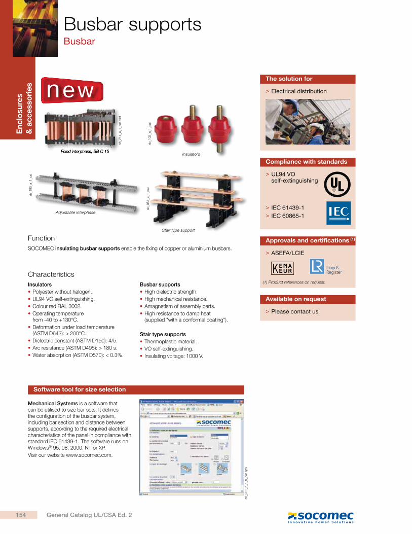
En
clo
su
res
& a
cc
esso
rie
s
Fixed interphase, SB C 15
sb_2
14
_a_1
_cat
.psd
sb_1
03
_a_1
_cat
sb_0
84
_a_1
_cat
sb_1
95
_a_1
_cat
Busbar supportsBusbar
Adjustable interphase
Insulators
Stair type support
Function
Characteristics
SOCOMEC insulating busbar supports enable the fixing of copper or aluminium busbars.
Insulators
Polyester without halogen.
UL94 VO self-extinguishing.
Colour red RAL 3002.
Operating temperature from -40 to +130°C.
Deformation under load temperature (ASTM D643): > 200°C.
Dielectric constant (ASTM D150): 4/5.
Arc resistance (ASTM D495): > 180 s.
Water absorption (ASTM D570): < 0.3%.
Busbar supports
High dielectric strength.
High mechanical resistance.
Amagnetism of assembly parts.
High resistance to damp heat (supplied "with a conformal coating").
Stair type supports
Thermoplastic material.
VO self-extinguishing.
Insulating voltage: 1000 V.
> Electrical distribution
The solution for
> Please contact us
Available on request
Mechanical Systems is a software that can be utilised to size bar sets. It defines the configuration of the busbar system, including bar section and distance between supports, according to the required electrical characteristics of the panel in compliance with standard IEC 61439-1. The software runs on Windows® 95, 98, 2000, NT or XP.
Visir our website www.socomec.com.
Software tool for size selection
new
sb_2
01
_b_1
_fr_
cat.
eps
> ASEFA/LCIE
Approvals and certifications (1)
(1) Product references on request.
> UL94 VO self-extinguishing
> IEC 61439-1
> IEC 60865-1
Compliance with standards
154 General Catalog UL/CSA Ed. 2
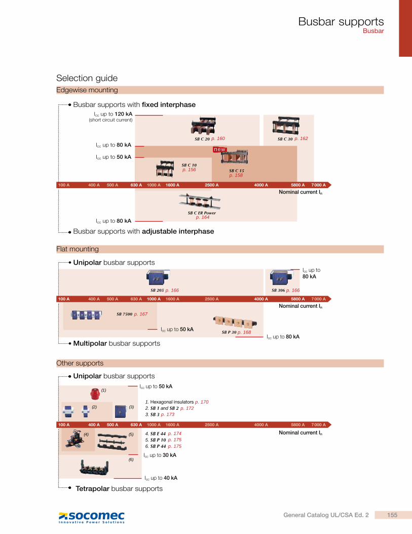
Busbar supportsBusbar
Selection guide
4. SB E 445. SB P 10 6. SB P 44
1. Hexagonal insulators 2. SB 1 and SB 23. SB 3
(4) (5)
(6)
(1)
(2) (3)
Nominal current In
Unipolar busbar supports
Tetrapolar busbar supports
Icc up to 40 kA
Icc up to 30 kA
Icc up to 50 kA
SB 205 SB 306
SB 7500
SB P 30
Nominal current In
Unipolar busbar supports
Multipolar busbar supports
Icc up to 80 kA
Icc up to 80 kA
Icc up to 50 kA
Edgewise mounting
SB C 10SB C 15
SB C 20 SB C 30
SB C ER Power
Nominal current In
Icc up to 50 kA
Icc up to 80 kA
Icc up to 120 kA(short circuit current)
Busbar supports with fixed interphase
Busbar supports with adjustable interphase
Icc up to 80 kA
Flat mounting
Other supports
new
100 A 400 A 500 A 630 A 1000 A 1600 A 2500 A 4000 A 5800 A 7 000 A
100 A 400 A 500 A 630 A 1000 A 1600 A 2500 A 4000 A 5800 A 7 000 A
100 A 400 A 500 A 630 A 1000 A 1600 A 2500 A 4000 A 5800 A 7 000 A
155General Catalog UL/CSA Ed. 2
p. 170
p. 167
p. 166 p. 166
p. 156p. 158
p. 160 p. 162
p. 164
p. 168
p. 172p. 173
p. 174p. 175p. 175
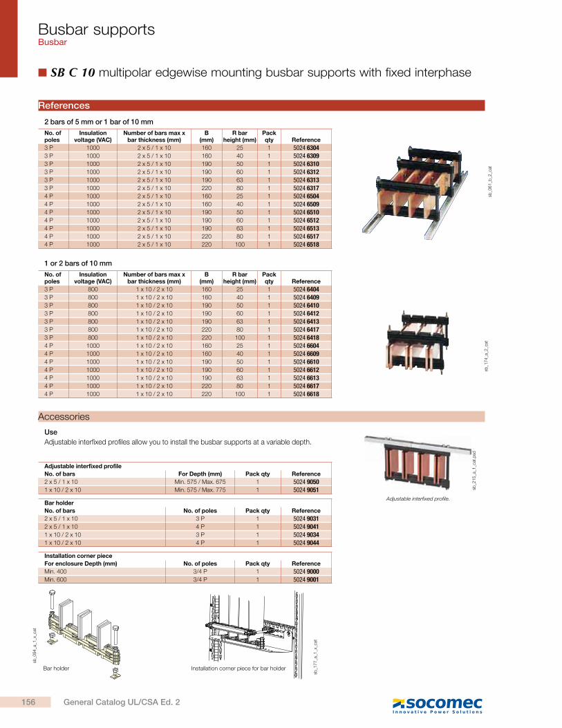
Busbar supportsBusbar
SB C 10 multipolar edgewise mounting busbar supports with fixed interphase
2 bars of 5 mm or 1 bar of 10 mm
No. of poles
Insulation voltage (VAC)
Number of bars max x bar thickness (mm)
B(mm)
R bar height (mm)
Pack qty Reference
3 P 1000 2 x 5 / 1 x 10 160 25 1 5024 63043 P 1000 2 x 5 / 1 x 10 160 40 1 5024 63093 P 1000 2 x 5 / 1 x 10 190 50 1 5024 63103 P 1000 2 x 5 / 1 x 10 190 60 1 5024 63123 P 1000 2 x 5 / 1 x 10 190 63 1 5024 63133 P 1000 2 x 5 / 1 x 10 220 80 1 5024 63174 P 1000 2 x 5 / 1 x 10 160 25 1 5024 65044 P 1000 2 x 5 / 1 x 10 160 40 1 5024 65094 P 1000 2 x 5 / 1 x 10 190 50 1 5024 65104 P 1000 2 x 5 / 1 x 10 190 60 1 5024 65124 P 1000 2 x 5 / 1 x 10 190 63 1 5024 65134 P 1000 2 x 5 / 1 x 10 220 80 1 5024 65174 P 1000 2 x 5 / 1 x 10 220 100 1 5024 6518
sb_0
61
_b_2
_cat
References
Adjustable interfixed profile
No. of bars For Depth (mm) Pack qty Reference
2 x 5 / 1 x 10 Min. 575 / Max. 675 1 5024 90501 x 10 / 2 x 10 Min. 575 / Max. 775 1 5024 9051
1 or 2 bars of 10 mm
No. of poles
Insulation voltage (VAC)
Number of bars max x bar thickness (mm)
B(mm)
R bar height (mm)
Pack qty Reference
3 P 800 1 x 10 / 2 x 10 160 25 1 5024 64043 P 800 1 x 10 / 2 x 10 160 40 1 5024 64093 P 800 1 x 10 / 2 x 10 190 50 1 5024 64103 P 800 1 x 10 / 2 x 10 190 60 1 5024 64123 P 800 1 x 10 / 2 x 10 190 63 1 5024 64133 P 800 1 x 10 / 2 x 10 220 80 1 5024 64173 P 800 1 x 10 / 2 x 10 220 100 1 5024 64184 P 1000 1 x 10 / 2 x 10 160 25 1 5024 66044 P 1000 1 x 10 / 2 x 10 160 40 1 5024 66094 P 1000 1 x 10 / 2 x 10 190 50 1 5024 66104 P 1000 1 x 10 / 2 x 10 190 60 1 5024 66124 P 1000 1 x 10 / 2 x 10 190 63 1 5024 66134 P 1000 1 x 10 / 2 x 10 220 80 1 5024 66174 P 1000 1 x 10 / 2 x 10 220 100 1 5024 6618
sb_1
74
_a_2
_cat
Bar holder
No. of bars No. of poles Pack qty Reference
2 x 5 / 1 x 10 3 P 1 5024 90312 x 5 / 1 x 10 4 P 1 5024 90411 x 10 / 2 x 10 3 P 1 5024 90341 x 10 / 2 x 10 4 P 1 5024 9044
sb_1
77
_a_1
_x_c
at
sb_0
94
_a_1
_x_c
at
Accessories
Bar holder Installation corner piece for bar holder
Use
Adjustable interfixed profiles allow you to install the busbar supports at a variable depth.
Installation corner piece
For enclosure Depth (mm) No. of poles Pack qty Reference
Min. 400 3/4 P 1 5024 9000Min. 600 3/4 P 1 5024 9001
sb_2
15
_a_1
_cat
.psd
Adjustable interfixed profile.
156 General Catalog UL/CSA Ed. 2
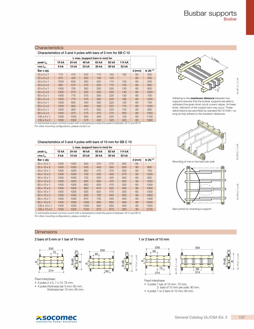
Busbar supportsBusbar
(1) Admissible busbar nominal current with a temperature inside the panel of between 45°C and 80°C.
For other mounting configurations, please contact us.
peak Isc
L max. (support bars in mm) for
15 kA 24 kA 48 kA 63 kA 82 kA 114 kA
rms Isc 9 kA 12 kA 23 kA 30 kA 39 kA 52 kA
Bar x qty d (mm) Iz (A) (1)
25 x 5 x 1 775 475 225 175 140 100 60 330
25 x 5 x 2 675 425 200 160 125 60 590
40 x 5 x 1 1000 625 300 225 175 130 60 500
40 x 5 x 2 950 575 275 225 170 125 60 850
50 x 5 x 1 1000 700 350 250 200 130 60 600
50 x 5 x 2 1000 675 325 250 200 145 60 1050
60 x 5 x 1 1000 775 375 300 225 130 60 700
60 x 5 x 2 1000 775 375 300 225 165 60 1200
63 x 5 x 1 1000 800 400 300 225 130 60 700
63 x 5 x 2 1000 800 400 300 225 170 60 1250
80 x 5 x 1 1000 950 475 350 225 125 60 900
80 x 5 x 2 1000 975 475 375 275 200 60 1550
100 x 5 x 1 1000 1000 550 400 225 125 60 1100
100 x 5 x 2 1000 1000 575 425 325 225 60 1900
peak Isc
L max. (support bars in mm) for
15 kA 24 kA 48 kA 63 kA 82 kA 114 kA
rms Isc 9 kA 12 kA 23 kA 30 kA 39 kA 52 kA
Bar x qty d (mm) Iz (A) (1)
25 x 10 x 1 1000 1000 500 375 275 200 65
25 x 10 x 2 1000 1000 525 400 300 200 90 850
40 x 10 x 1 1000 1000 650 475 375 250 65 700
40 x 10 x 2 1000 1000 700 525 400 275 90 1250
50 x 10 x 1 1000 1000 725 550 425 300 65 850
50 x 10 x 2 1000 1000 800 600 475 325 90 1550
60 x 10 x 1 1000 1000 800 625 475 325 65 1000
60 x 10 x 2 1000 1000 900 675 525 350 90 1800
63 x 10 x 1 1000 1000 825 625 475 350 65 1050
63 x 10 x 2 1000 1000 925 700 550 350 90 1850
80 x 10 x 1 1000 1000 975 725 550 400 65 1300
80 x 10 x 2 1000 1000 1000 850 650 350 90 2300
100 x 10 x 1 1000 1000 1000 850 650 400 65 1550
100 x 10 x 2 1000 1000 1000 975 675 350 90 2750
Mounting of one or two bars per pole
Characteristics
Adhering to the maximum distance between two supports ensures that the busbar supports are able to withstand the given short circuit current values. At these limits, distortion of the copper bars may occur. These deformations are permitted by standard IEC 61439-1 so long as they adhere to the insulation distances.
(1) Admissible busbar nominal current with a temperature inside the panel of between 45°C and 80°C.
For other mounting configurations, please contact us.
L max.
d
sb_0
21
_b_1
_fr_
cat
sb_0
54
_b_1
_x_c
atsb
_04
5_b
_1_x
_cat
Bars joined by reversing a support
2 bars of 5 mm or 1 bar of 10 mm 1 or 2 bars of 10 mm
Fixed interphase:
3 poles 2 x 5, 1 x 10: 75 mm.
4 poles thickness bar 5 mm: 60 mm, thickness bar 10 mm: 65 mm.
Dimensions
Fixed interphase:
3 poles 1 bar of 10 mm : 75 mm, 2 bars of 10 mm per pole: 90 mm.
4 poles 1 or 2 bars of 10 mm: 90 mm.
R
250
274
75
R+6
6
B
20
R
250
65
60 20
R+6
6
B
sb_1
12
_e_1
_x_c
at
R
250
274
90
75
sb_1
87
_b_1
_x_c
at
37490
35020
R+6
6
B
sb_1
78
_b_1
_x_c
at
Characteristics of 3 and 4 poles with bars of 5 mm for SB C 10
Characteristics of 3 and 4 poles with bars of 10 mm for SB C 10
157General Catalog UL/CSA Ed. 2
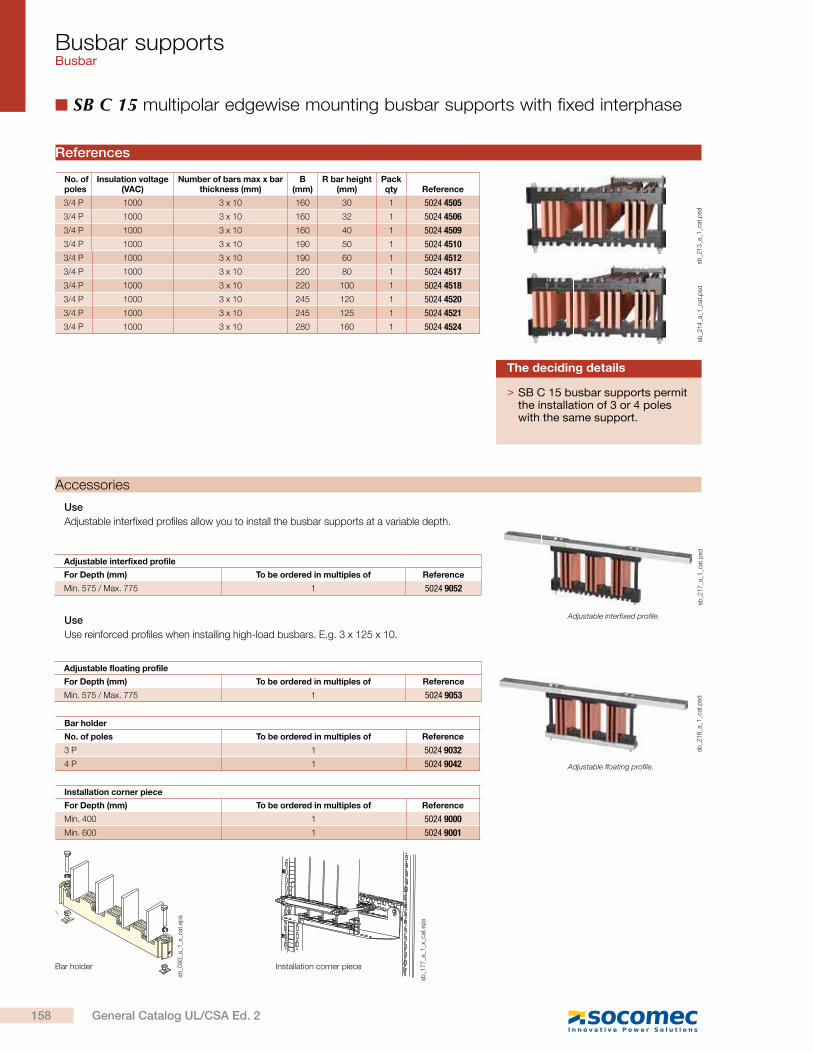
Busbar supportsBusbar
SB C 15 multipolar edgewise mounting busbar supports with fixed interphase
References
Bar holder
No. of poles To be ordered in multiples of Reference
3 P 1 5024 9032
4 P 1 5024 9042
Installation corner piece
For Depth (mm) To be ordered in multiples of Reference
Min. 400 1 5024 9000
Min. 600 1 5024 9001
Adjustable interfixed profile
For Depth (mm) To be ordered in multiples of Reference
Min. 575 / Max. 775 1 5024 9052
Adjustable floating profile
For Depth (mm) To be ordered in multiples of Reference
Min. 575 / Max. 775 1 5024 9053
Accessories
Use
Adjustable interfixed profiles allow you to install the busbar supports at a variable depth.
Use
Use reinforced profiles when installing high-load busbars. E.g. 3 x 125 x 10.
> SB C 15 busbar supports permit the installation of 3 or 4 poles with the same support.
The deciding details
sb_0
93
_a_1
_x_c
at.e
ps
sb_1
77
_a_1
_x_c
at.e
ps
sb_2
13
_a_1
_cat
.psd
sb_2
14
_a_1
_cat
.psd
sb_2
17
_a_1
_cat
.psd
sb_2
18
_a_1
_cat
.psd
Adjustable interfixed profile.
Adjustable floating profile.
Bar holder Installation corner piece
No. of poles
Insulation voltage (VAC)
Number of bars max x bar thickness (mm)
B (mm)
R bar height (mm)
Pack qty Reference
3/4 P 1000 3 x 10 160 30 1 5024 4505
3/4 P 1000 3 x 10 160 32 1 5024 4506
3/4 P 1000 3 x 10 160 40 1 5024 4509
3/4 P 1000 3 x 10 190 50 1 5024 4510
3/4 P 1000 3 x 10 190 60 1 5024 4512
3/4 P 1000 3 x 10 220 80 1 5024 4517
3/4 P 1000 3 x 10 220 100 1 5024 4518
3/4 P 1000 3 x 10 245 120 1 5024 4520
3/4 P 1000 3 x 10 245 125 1 5024 4521
3/4 P 1000 3 x 10 280 160 1 5024 4524
158 General Catalog UL/CSA Ed. 2
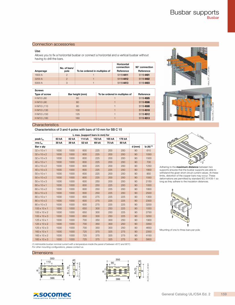
Busbar supportsBusbar
Connection accessories
Use
Allows you to fix a horizontal busbar or connect a horizontal and a vertical busbar without having to drill the bars.
AmperageNo. of bars/
pole To be ordered in multiples of
Horizontal connection 90° connection
Reference Reference
1600 A 2 1 5119 4411 5119 4401
3200 A 2 1 5119 4412 5119 4402
5000 A 3 1 5119 4413 5119 4403
Screws
Type of screw Bar height (mm) To be ordered in multiples of Reference
H M10 L80 60 1 5119 4505
H M10 L90 60 1 5119 4506
H M10 L110 80 1 5119 4508
H M10 L130 100 1 5119 4510
H M10 L150 125 1 5119 4512
H M10 L180 160 1 5119 4513
CharacteristicsCharacteristics of 3 and 4 poles with bars of 10 mm for SB C 15
Dimensions
kdry
s_5
37
_a_1
_cat
.ep
s
kdry
s_5
38
_a_1
_cat
.ep
s
L max.
d
Adhering to the maximum distance between two supports ensures that the busbar supports are able to withstand the given short circuit current values. At these limits, distortion of the copper bars may occur. These deformations are permitted by standard IEC 61439-1 so long as they adhere to the insulation distances.
Mounting of one to three bars per pole
peak Isc
L max. (support bars in mm) for
63 kA 82 kA 114 kA 152 kA 165 kA 176 kA
rms Isc 30 kA 39 kA 52 kA 69 kA 75 kA 80 kA
Bar x qty d (mm) Iz (A) (1)
32 x 10 x 1 1000 1000 600 225 200 200 90 610
32 x 10 x 2 1000 1000 600 225 200 200 90 1050
32 x 10 x 3 1000 1000 600 225 200 200 90 1500
40 x 10 x 1 1000 1000 600 225 200 200 90 700
40 x 10 x 2 1000 1000 600 225 200 200 90 1250
40 x 10 x 3 1000 1000 600 225 225 200 90 1800
50 x 10 x 1 1000 1000 600 225 200 200 90 850
50 x 10 x 2 1000 1000 600 225 200 200 90 1550
50 x 10 x 3 1000 1000 600 250 200 200 90 2150
60 x 10 x 1 1000 1000 600 250 225 200 90 1000
60 x 10 x 2 1000 1000 600 250 225 200 90 1800
60 x 10 x 3 1000 1000 600 250 225 200 90 2500
80 x 10 x 1 1000 1000 600 275 225 225 90 1300
80 x 10 x 2 1000 1000 600 275 225 225 90 2300
80 x 10 x 3 1000 1000 600 275 225 225 90 3200
100 x 10 x 1 1000 1000 650 300 250 225 90 1550
100 x 10 x 2 1000 1000 650 300 250 225 90 2750
100 x 10 x 3 1000 1000 650 300 250 225 90 3250
125 x 10 x 1 1000 1000 700 350 300 250 90 1900
125 x 10 x 2 1000 1000 700 350 300 250 90 3350
125 x 10 x 3 1000 1000 700 350 300 250 90 4650
160 x 10 x 1 1000 1000 725 375 325 275 90 2350
160 x 10 x 2 1000 1000 725 375 325 275 90 4150
160 x 10 x 3 1000 1000 725 375 325 275 90 5800
(1) Admissible busbar nominal current with a temperature inside the panel of between 45°C and 80°C.
For other mounting configurations, please contact us.
35090
40
B
R+7
0
R
386
sb_2
22
_a_1
_x_c
at.e
ps
350110
40
B
R +
70
386
R
sb_2
23
_a_1
_x_c
at.e
ps
159General Catalog UL/CSA Ed. 2
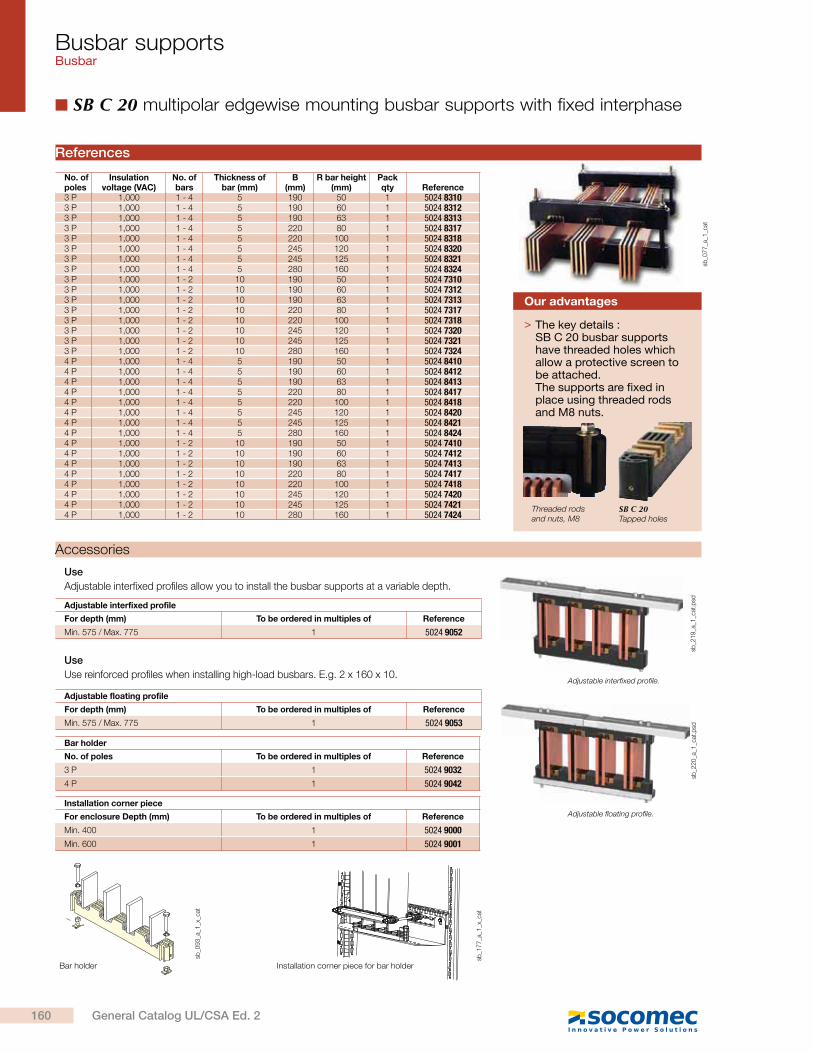
Busbar supportsBusbar
SB C 20 multipolar edgewise mounting busbar supports with fixed interphase
Installation corner piece for bar holder
sb_0
93
_a_1
_x_c
at
sb_1
77
_a_1
_x_c
at
Bar holder
No. of poles
Insulation voltage (VAC)
No. ofbars
Thickness ofbar (mm)
B(mm)
R bar height (mm)
Pack qty Reference
3 P 1,000 1 - 4 5 190 50 1 5024 83103 P 1,000 1 - 4 5 190 60 1 5024 83123 P 1,000 1 - 4 5 190 63 1 5024 83133 P 1,000 1 - 4 5 220 80 1 5024 83173 P 1,000 1 - 4 5 220 100 1 5024 83183 P 1,000 1 - 4 5 245 120 1 5024 83203 P 1,000 1 - 4 5 245 125 1 5024 83213 P 1,000 1 - 4 5 280 160 1 5024 83243 P 1,000 1 - 2 10 190 50 1 5024 73103 P 1,000 1 - 2 10 190 60 1 5024 73123 P 1,000 1 - 2 10 190 63 1 5024 73133 P 1,000 1 - 2 10 220 80 1 5024 73173 P 1,000 1 - 2 10 220 100 1 5024 73183 P 1,000 1 - 2 10 245 120 1 5024 73203 P 1,000 1 - 2 10 245 125 1 5024 73213 P 1,000 1 - 2 10 280 160 1 5024 73244 P 1,000 1 - 4 5 190 50 1 5024 84104 P 1,000 1 - 4 5 190 60 1 5024 84124 P 1,000 1 - 4 5 190 63 1 5024 84134 P 1,000 1 - 4 5 220 80 1 5024 84174 P 1,000 1 - 4 5 220 100 1 5024 84184 P 1,000 1 - 4 5 245 120 1 5024 84204 P 1,000 1 - 4 5 245 125 1 5024 84214 P 1,000 1 - 4 5 280 160 1 5024 84244 P 1,000 1 - 2 10 190 50 1 5024 74104 P 1,000 1 - 2 10 190 60 1 5024 74124 P 1,000 1 - 2 10 190 63 1 5024 74134 P 1,000 1 - 2 10 220 80 1 5024 74174 P 1,000 1 - 2 10 220 100 1 5024 74184 P 1,000 1 - 2 10 245 120 1 5024 74204 P 1,000 1 - 2 10 245 125 1 5024 74214 P 1,000 1 - 2 10 280 160 1 5024 7424
sb_0
77
_a_1
_cat
> The key details :SB C 20 busbar supports have threaded holes which allow a protective screen to be attached.The supports are fixed in place using threaded rods and M8 nuts.
Our advantages
SB C 20Tapped holes
Threaded rods and nuts, M8
Accessories
Use
Adjustable interfixed profiles allow you to install the busbar supports at a variable depth.
Use
Use reinforced profiles when installing high-load busbars. E.g. 2 x 160 x 10.
Adjustable interfixed profile
For depth (mm) To be ordered in multiples of Reference
Min. 575 / Max. 775 1 5024 9052
Adjustable floating profile
For depth (mm) To be ordered in multiples of Reference
Min. 575 / Max. 775 1 5024 9053
Bar holder
No. of poles To be ordered in multiples of Reference
3 P 1 5024 9032
4 P 1 5024 9042
Installation corner piece
For enclosure Depth (mm) To be ordered in multiples of Reference
Min. 400 1 5024 9000
Min. 600 1 5024 9001
sb_2
19
_a_1
_cat
.psd
sb_2
20
_a_1
_cat
.psd
Adjustable interfixed profile.
Adjustable floating profile.
References
160 General Catalog UL/CSA Ed. 2
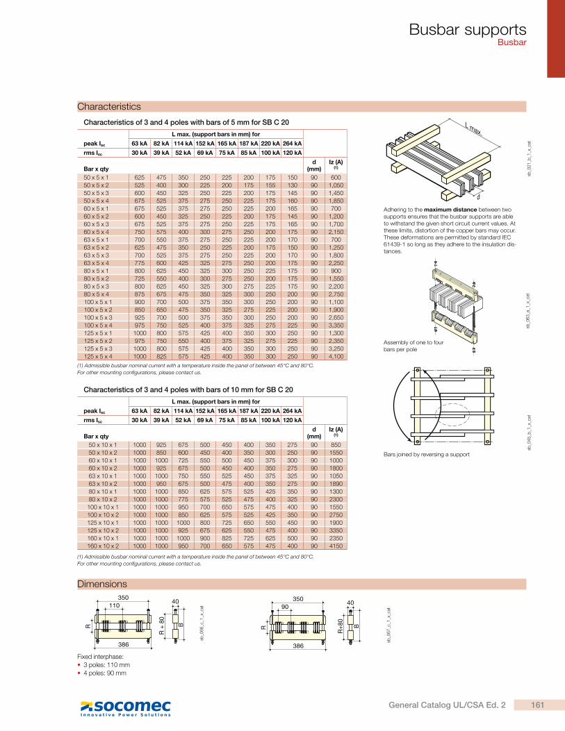
Busbar supportsBusbar
Dimensions
Fixed interphase:
3 poles: 110 mm
4 poles: 90 mm
R
35040
110
386
R +
80
B
sb_0
66
_c_1
_x_c
at
R
35090
386
40
R+8
0
B
sb_0
67
_c_1
_x_c
at
Adhering to the maximum distance between two supports ensures that the busbar supports are able to withstand the given short circuit current values. At these limits, distortion of the copper bars may occur. These deformations are permitted by standard IEC 61439-1 so long as they adhere to the insulation dis-tances.
Bars joined by reversing a support
L max.
d
sb_0
21
_b_1
_x_c
atpeak Isc
L max. (support bars in mm) for
63 kA 82 kA 114 kA 152 kA 165 kA 187 kA 220 kA 264 kA
rms Isc 30 kA 39 kA 52 kA 69 kA 75 kA 85 kA 100 kA 120 kA
Bar x qtyd
(mm)Iz (A)
(1)
50 x 5 x 1 625 475 350 250 225 200 175 150 90 600
50 x 5 x 2 525 400 300 225 200 175 155 130 90 1,050
50 x 5 x 3 600 450 325 250 225 200 175 145 90 1,450
50 x 5 x 4 675 525 375 275 250 225 175 160 90 1,850
60 x 5 x 1 675 525 375 275 250 225 200 165 90 700
60 x 5 x 2 600 450 325 250 225 200 175 145 90 1,200
60 x 5 x 3 675 525 375 275 250 225 175 165 90 1,700
60 x 5 x 4 750 575 400 300 275 250 200 175 90 2,150
63 x 5 x 1 700 550 375 275 250 225 200 170 90 700
63 x 5 x 2 625 475 350 250 225 200 175 150 90 1,250
63 x 5 x 3 700 525 375 275 250 225 200 170 90 1,800
63 x 5 x 4 775 600 425 325 275 250 200 175 90 2,250
80 x 5 x 1 800 625 450 325 300 250 225 175 90 900
80 x 5 x 2 725 550 400 300 275 250 200 175 90 1,550
80 x 5 x 3 800 625 450 325 300 275 225 175 90 2,200
80 x 5 x 4 875 675 475 350 325 300 250 200 90 2,750
100 x 5 x 1 900 700 500 375 350 300 250 200 90 1,100
100 x 5 x 2 850 650 475 350 325 275 225 200 90 1,900
100 x 5 x 3 925 700 500 375 350 300 250 200 90 2,650
100 x 5 x 4 975 750 525 400 375 325 275 225 90 3,350
125 x 5 x 1 1000 800 575 425 400 350 300 250 90 1,300
125 x 5 x 2 975 750 550 400 375 325 275 225 90 2,350
125 x 5 x 3 1000 800 575 425 400 350 300 250 90 3,250
125 x 5 x 4 1000 825 575 425 400 350 300 250 90 4,100
sb_0
63
_a_1
_x_c
at
(1) Admissible busbar nominal current with a temperature inside the panel of between 45°C and 80°C.
For other mounting configurations, please contact us.
sb_0
45
_b_1
_x_c
at
peak Isc
L max. (support bars in mm) for
63 kA 82 kA 114 kA 152 kA 165 kA 187 kA 220 kA 264 kA
rms Isc 30 kA 39 kA 52 kA 69 kA 75 kA 85 kA 100 kA 120 kA
Bar x qtyd
(mm)Iz (A)
(1)
50 x 10 x 1 1000 925 675 500 450 400 350 275 90 850
50 x 10 x 2 1000 850 600 450 400 350 300 250 90 1550
60 x 10 x 1 1000 1000 725 550 500 450 375 300 90 1000
60 x 10 x 2 1000 925 675 500 450 400 350 275 90 1800
63 x 10 x 1 1000 1000 750 550 525 450 375 325 90 1050
63 x 10 x 2 1000 950 675 500 475 400 350 275 90 1890
80 x 10 x 1 1000 1000 850 625 575 525 425 350 90 1300
80 x 10 x 2 1000 1000 775 575 525 475 400 325 90 2300
100 x 10 x 1 1000 1000 950 700 650 575 475 400 90 1550
100 x 10 x 2 1000 1000 850 625 575 525 425 350 90 2750
125 x 10 x 1 1000 1000 1000 800 725 650 550 450 90 1900
125 x 10 x 2 1000 1000 925 675 625 550 475 400 90 3350
160 x 10 x 1 1000 1000 1000 900 825 725 625 500 90 2350
160 x 10 x 2 1000 1000 950 700 650 575 475 400 90 4150
(1) Admissible busbar nominal current with a temperature inside the panel of between 45°C and 80°C.
For other mounting configurations, please contact us.
Characteristics
Assembly of one to four bars per pole
Characteristics of 3 and 4 poles with bars of 5 mm for SB C 20
Characteristics of 3 and 4 poles with bars of 10 mm for SB C 20
161General Catalog UL/CSA Ed. 2

Busbar supportsBusbar
SB C 30 multipolar edgewise mounting busbar supports with fixed interphase
ReferencesNo. of poles
Insulation voltage (VAC)
No. of bars
Thickness of bar (mm)
B(mm)
R bar height (mm)
Pack qty Reference
3 P 1,000 1 - 3 10 190 50 1 5024 53103 P 1,000 1 - 3 10 190 60 1 5024 53123 P 1,000 1 - 3 10 190 63 1 5024 53133 P 1,000 1 - 3 10 190 70 1 5024 53153 P 1,000 1 - 3 10 220 80 1 5024 53173 P 1,000 1 - 3 10 220 100 1 5024 53183 P 1,000 1 - 3 10 245 120 1 5024 53203 P 1,000 1 - 3 10 245 125 1 5024 53213 P 1,000 1 - 3 10 280 160 1 5024 53243 P 1,000 1 - 3 10 325 200 1 5024 53254 P 1,000 1 - 3 10 190 50 1 5024 55104 P 1,000 1 - 3 10 190 60 1 5024 55124 P 1,000 1 - 3 10 190 63 1 5024 55134 P 1,000 1 - 3 10 190 70 1 5024 55154 P 1,000 1 - 3 10 220 80 1 5024 55174 P 1,000 1 - 3 10 220 100 1 5024 55184 P 1,000 1 - 3 10 245 120 1 5024 55204 P 1,000 1 - 3 10 245 125 1 5024 55214 P 1,000 1 - 3 10 280 160 1 5024 55244 P 1,000 1 - 3 10 325 200 1 5024 5525
sb_1
73
_a_2
_cat
Installation corner piece for bar holder
sb_1
22
_b_1
_x_c
at
sb_1
80
_a_1
_x_c
at
Bar holder
Accessories
Use
Adjustable interfixed profiles allow you to install the busbar supports at a variable depth.
Use
Use reinforced profiles when installing high-load busbars. E.g. 3 x 125 x 10.
Adjustable interfixed profile
For depth (mm) To be ordered in multiples of Reference
Min. 575 / Max. 775 1 5024 9054
Adjustable floating profile
For depth (mm) To be ordered in multiples of Reference
Min. 575 / Max. 775 1 5024 9055
Bar holder
No. of poles To be ordered in multiples of Reference
3/4 P 1 5024 9033
Installation corner piece
For depth (mm) To be ordered in multiples of Reference
Min. 600 1 5024 9001
sb_2
19
_a_1
_cat
.psd
sb_2
20
_a_1
_cat
.psd
Adjustable interfixed profile.
Adjustable floating profile.
162 General Catalog UL/CSA Ed. 2

Busbar supportsBusbar
Fixed interphase:
3 poles: 185 mm
4 poles: 130 mm
Dimensions525
560
185
R
40
B
R +
80
sb_1
46
_d_1
_x_c
at
525
560
R +
80
130 40
R Bsb
_15
7_d
_1_x
_cat
Mounting of one to three bars per pole
L max.
d
sb_0
21
_b_1
_x_c
atsb
_16
2_a
_1_x
_cat
Adhering to the maximum distance between two supports ensures that the busbar supports are able to withstand the given short circuit current values. At these limits, distortion of the copper bars may occur. These deformations are permitted by standard IEC 61439-1 so long as they adhere to the insulation distances.
peak Isc
L max. (support bars in mm) for
63 kA 82 kA 114 kA 152 kA 165 kA 187 kA 220 kA 264 kA
rms Isc 30 kA 39 kA 52 kA 69 kA 75 kA 85 kA 100 kA 120 kA
Bar x qtyd
(mm)Iz (A)
(1)
50 x 10 x 1 1000 1000 800 600 550 475 400 350 130 850
50 x 10 x 2 1000 900 650 475 450 400 325 275 130 1,550
50 x 10 x 3 725 550 400 300 275 225 200 175 130 2,150
60 x 10 x 1 1000 1000 875 650 600 525 450 375 130 1,000
60 x 10 x 2 1000 1000 725 525 500 425 375 300 130 1,800
60 x 10 x 3 825 625 450 325 300 275 225 175 130 2,500
63 x 10 x 1 1000 1000 900 675 600 550 450 375 130 1,050
63 x 10 x 2 1000 1000 725 550 500 450 375 300 130 1,850
63 x 10 x 3 850 650 450 350 325 275 225 200 130 2,600
80 x 10 x 1 1000 1000 1000 750 675 600 500 425 130 1,300
80 x 10 x 2 1000 1000 825 625 575 500 425 350 130 2,300
80 x 10 x 3 1000 750 550 400 375 325 275 225 130 3,200
100 x 10 x 1 1000 1000 1000 825 750 675 575 475 130 1,550
100 x 10 x 2 1000 1000 925 675 625 550 475 400 130 2,750
100 x 10 x 3 1000 900 650 475 425 375 325 275 130 3,250
125 x 10 x 1 1000 1000 1000 925 850 750 625 525 130 1,900
125 x 10 x 2 1000 1000 1000 750 675 600 500 425 130 3,350
125 x 10 x 3 1000 1000 750 550 525 450 375 325 130 4,650
160 x 10 x 1 1000 1000 1000 1000 925 825 700 575 130 2,350
160 x 10 x 2 1000 1000 1000 750 700 625 525 425 130 4,150
160 x 10 x 3 1000 1000 900 675 625 550 475 375 130 5,800
200 x 10 x 1 1000 1000 1000 1000 1000 900 750 625 130 2,850
200 x 10 x 2 1000 1000 925 700 625 550 475 400 130 5,050
200 x 10 x 3 1000 1000 725 525 500 425 375 300 130 7,000
(1) Admissible busbar nominal current with a temperature inside the panel of between 45°C and 80°C.
For other mounting configurations, please contact us.
CharacteristicsCharacteristics of 3 and 4 poles with bars of 10 mm for SB C 30
Connection accessories
Use
Allows you to fix a horizontal busbar or connect a horizontal and a vertical busbar without having to drill the bars.
AmperageNo. of bars/
pole To be ordered in multiples of
Horizontal connection 90° connection
Reference Reference
1600 A 2 1 5119 4411 5119 4401
3200 A 2 1 5119 4412 5119 4402
5000 A 3 1 5119 4413 5119 4403
Screws
Type of screw Bar height (mm) To be ordered in multiples of Reference
H M10 L80 60 1 5119 4505
H M10 L90 60 1 5119 4506
H M10 L110 80 1 5119 4508
H M10 L130 100 1 5119 4510
H M10 L150 125 1 5119 4512
H M10 L180 160 1 5119 4513
kdry
s_5
38
_a_1
_cat
.ep
s
kdry
s_5
37
_a_1
_cat
.ep
s
163General Catalog UL/CSA Ed. 2
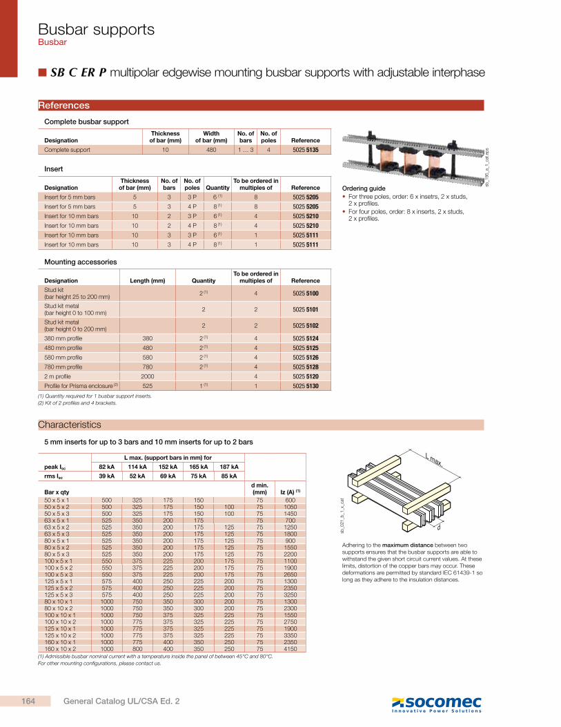
Busbar supportsBusbar
SB C ER P multipolar edgewise mounting busbar supports with adjustable interphase
References
Ordering guide
For three poles, order: 6 x insetrs, 2 x studs, 2 x profiles.
For four poles, order: 8 x inserts, 2 x studs, 2 x profiles.
sb_1
95
_a_1
_cat
.ep
s
DesignationThickness
of bar (mm)No. of bars
No. of poles Quantity
To be ordered in multiples of Reference
Insert for 5 mm bars 5 3 3 P 6 (1) 8 5025 5205
Insert for 5 mm bars 5 3 4 P 8 (1) 8 5025 5205
Insert for 10 mm bars 10 2 3 P 6 (1) 4 5025 5210
Insert for 10 mm bars 10 2 4 P 8 (1) 4 5025 5210
Insert for 10 mm bars 10 3 3 P 6 (1) 1 5025 5111
Insert for 10 mm bars 10 3 4 P 8 (1) 1 5025 5111
DesignationThickness
of bar (mm)Width
of bar (mm)No. of bars
No. of poles Reference
Complete support 10 480 1 … 3 4 5025 5135
(1) Quantity required for 1 busbar support inserts.
(2) Kit of 2 profiles and 4 brackets.
Designation Length (mm) QuantityTo be ordered in
multiples of Reference
Stud kit (bar height 25 to 200 mm)
2 (1) 4 5025 5100
Stud kit metal (bar height 0 to 100 mm)
2 2 5025 5101
Stud kit metal (bar height 0 to 200 mm)
2 2 5025 5102
380 mm profile 380 2 (1) 4 5025 5124
480 mm profile 480 2 (1) 4 5025 5125
580 mm profile 580 2 (1) 4 5025 5126
780 mm profile 780 2 (1) 4 5025 5128
2 m profile 2000 4 5025 5120
Profile for Prisma enclosure (2) 525 1 (1) 1 5025 5130
Mounting accessories
Insert
Complete busbar support
5 mm inserts for up to 3 bars and 10 mm inserts for up to 2 bars
Characteristics
Adhering to the maximum distance between two supports ensures that the busbar supports are able to withstand the given short circuit current values. At these limits, distortion of the copper bars may occur. These deformations are permitted by standard IEC 61439-1 so long as they adhere to the insulation distances.
peak Isc
L max. (support bars in mm) for
82 kA 114 kA 152 kA 165 kA 187 kA
rms Isc 39 kA 52 kA 69 kA 75 kA 85 kA
Bar x qtyd min. (mm) Iz (A) (1)
50 x 5 x 1 500 325 175 150 75 60050 x 5 x 2 500 325 175 150 100 75 105050 x 5 x 3 500 325 175 150 100 75 145063 x 5 x 1 525 350 200 175 75 70063 x 5 x 2 525 350 200 175 125 75 125063 x 5 x 3 525 350 200 175 125 75 180080 x 5 x 1 525 350 200 175 125 75 90080 x 5 x 2 525 350 200 175 125 75 155080 x 5 x 3 525 350 200 175 125 75 2200100 x 5 x 1 550 375 225 200 175 75 1100100 x 5 x 2 550 375 225 200 175 75 1900100 x 5 x 3 550 375 225 200 175 75 2650125 x 5 x 1 575 400 250 225 200 75 1300125 x 5 x 2 575 400 250 225 200 75 2350125 x 5 x 3 575 400 250 225 200 75 325080 x 10 x 1 1000 750 350 300 200 75 130080 x 10 x 2 1000 750 350 300 200 75 2300100 x 10 x 1 1000 750 375 325 225 75 1550100 x 10 x 2 1000 775 375 325 225 75 2750125 x 10 x 1 1000 775 375 325 225 75 1900125 x 10 x 2 1000 775 375 325 225 75 3350160 x 10 x 1 1000 775 400 350 250 75 2350160 x 10 x 2 1000 800 400 350 250 75 4150
(1) Admissible busbar nominal current with a temperature inside the panel of between 45°C and 80°C.
For other mounting configurations, please contact us.
L max.
d
sb_0
21
_b_1
_x_c
at
164 General Catalog UL/CSA Ed. 2

Busbar supportsBusbar
Dimensions
Mounting
1 to 3 bars of 5 mm thickness, per phase.
1 to 3 bars of 10 mm thickness, per phase.
Interphase distance: min. 70 mm and max. 200 mm.
Use 2 studs positioned symmetrically on the extremity of the poles or between the outermost poles.
A (mm) Enclosure (mm)
380 400
480 500
580 600
780 800
Characteristics (continued)
Adhering to the maximum distance between two supports ensures that the busbar supports are able to withstand the given short circuit current values. At these limits, distortion of the copper bars may occur. These deformations are permitted by standard IEC 61439-1 so long as they adhere to the insulation distances.
10 mm insert / 3 bars
d d d
A
10.870
R R+
73
sb_2
21
_a_1
_x_c
at.a
i10 mm insert / 3 bars
R R+
73
d
A
d
10.875
sb_1
99
_b_1
_x_c
at.a
i
5 mm insert / 3 bars
A
d d
5.875
R R+
73
sb_1
98
_b_1
_x_c
at.a
i
10 mm insert / 2 bars
(1) Admissible busbar nominal current with a temperature inside the panel of between 45°C and 80°C.
For other mounting configurations, please contact us.
L max.
d
sb_0
21
_b_1
_x_c
at.e
ps
peak Isc
L max. (bar supports in mm)
63 kA 82 kA 114 kA 152 kA 165 kA 187 kA
rms Isc 30 kA 39 kA 52 kA 69 kA 75 kA 85 kA
Bar x qty d (mm) Iz (A) (1)
50 x 10 x 1 1000 1000 650 250 200 150 70 850
50 x 10 x 2 1000 1000 650 250 200 150 70 1550
50 x 10 x 3 1000 1000 650 250 200 150 70 2150
63 x 10 x 1 1000 1000 675 275 225 175 70 1050
63 x 10 x 2 1000 1000 675 275 225 175 70 1850
63 x 10 x 3 1000 1000 675 275 225 175 70 2600
80 x 10 x 1 1000 1000 700 300 250 175 70 1300
80 x 10 x 2 1000 1000 700 300 250 175 70 2300
80 x 10 x 3 1000 1000 700 300 250 175 70 3200
100 x 10 x 1 1000 1000 725 325 275 175 70 1550
100 x 10 x 2 1000 1000 725 325 275 175 70 2750
100 x 10 x 3 1000 1000 725 325 275 175 70 3250
125 x 10 x 1 1000 1000 725 350 275 200 70 1900
125 x 10 x 2 1000 1000 725 350 275 200 70 3350
125 x 10 x 3 1000 1000 725 350 275 200 70 4650
160 x 10 x 1 1000 1000 750 350 300 200 70 2350
160 x 10 x 2 1000 1000 750 350 300 200 70 4150
160 x 10 x 3 1000 1000 750 350 300 200 70 5800
165General Catalog UL/CSA Ed. 2
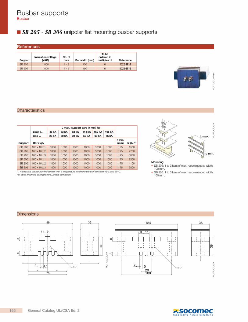
Busbar supportsBusbar
SB 205 - SB 306 unipolar flat mounting busbar supports
L max.
d min.
Mounting
SB 205: 1 to 3 bars of max. recommended width 100 mm.
SB 306: 1 to 3 bars of max. recommended width 160 mm.
Support
peak Isc
L max. (support bars in mm) for
48 kA 63 kA 82 kA 114 kA 152 kA 165 kA
rms Isc 23 kA 30 kA 39 kA 52 kA 69 kA 75 kA
Bar x qtyd min. (mm) Iz (A) (1)
SB 205 100 x 10 x 1 1000 1000 1000 1000 1000 1000 125 1550
SB 205 100 x 10 x 2 1000 1000 1000 1000 1000 1000 125 2750
SB 205 100 x 10 x 3 1000 1000 1000 1000 1000 1000 125 3850
SB 306 160 x 10 x 1 1000 1000 1000 1000 1000 1000 175 2350
SB 306 160 x 10 x 2 1000 1000 1000 1000 1000 1000 175 4150
SB 306 160 x 10 x 3 1000 1000 1000 1000 1000 1000 175 5800
(1) Admissible busbar nominal current with a temperature inside the panel of between 45°C and 80°C.
For other mounting configurations, please contact us.
sb_1
52
_a_1
_x_c
at
Characteristics
99
75= =
6 4,5
35
38
88
8
11 9
sb_1
75
_a_1
_x_c
at
124
10020
7 5
35
38
88
8
9 11
sb_1
76
_a_1
_x_c
atDimensions
SupportInsulation voltage
(VAC)No. of bars Bar width (mm)
To be ordered in
multiples of Reference
SB 205 1,000 1 - 3 100 6 5022 5110
SB 306 1,000 1 - 3 160 6 5023 6110
References
sb_1
17
_a_1
_cat
.ep
s
166 General Catalog UL/CSA Ed. 2
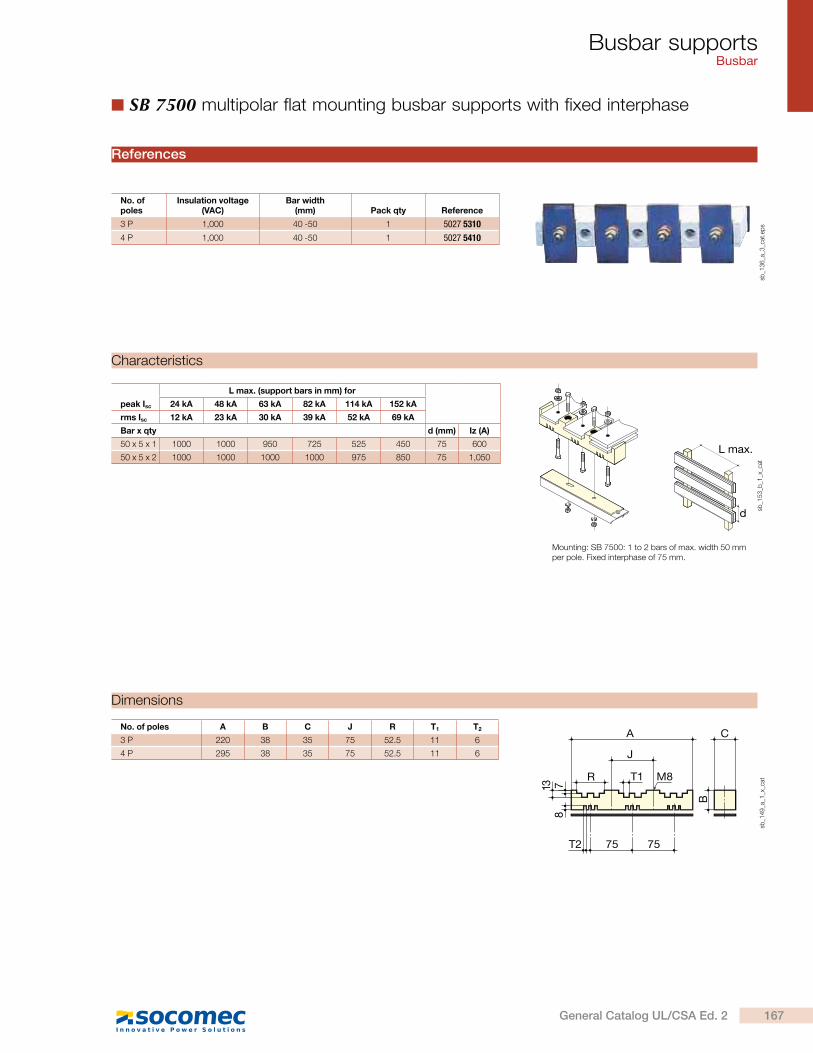
Busbar supportsBusbar
SB 7500 multipolar flat mounting busbar supports with fixed interphase
L max.
d
peak Isc
L max. (support bars in mm) for
24 kA 48 kA 63 kA 82 kA 114 kA 152 kA
rms Isc 12 kA 23 kA 30 kA 39 kA 52 kA 69 kA
Bar x qty d (mm) Iz (A)
50 x 5 x 1 1000 1000 950 725 525 450 75 600
50 x 5 x 2 1000 1000 1000 1000 975 850 75 1,050
Mounting: SB 7500: 1 to 2 bars of max. width 50 mm per pole. Fixed interphase of 75 mm.
sb_1
53
_b_1
_x_c
at
Characteristics
No. of poles A B C J R T1 T2
3 P 220 38 35 75 52.5 11 6
4 P 295 38 35 75 52.5 11 6
78
13
M8
A
T1
J
R
C
B
75T2 75
sb_1
49
_a_1
_x_c
at
Dimensions
No. of poles
Insulation voltage (VAC)
Bar width (mm) Pack qty Reference
3 P 1,000 40 -50 1 5027 5310
4 P 1,000 40 -50 1 5027 5410
References
sb_1
36
_a_3
_cat
.ep
s
167General Catalog UL/CSA Ed. 2
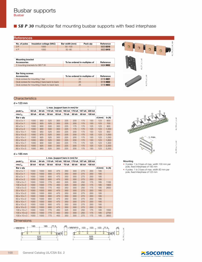
Busbar supportsBusbar
SB P 30 multipolar flat mounting busbar supports with fixed interphase
Mounting
3 poles: 1 to 3 bars of max. width 100 mm per pole, fixed interphase of 185 mm
4 poles: 1 to 3 bars of max. width 80 mm per pole, fixed interphase of 123 mm
peak Isc
L max. (support bars in mm) for
63 kA 84 kA 110 kA 143 kA 165 kA 176 kA 187 kA 220 kA
rms Isc 30 kA 40 kA 50 kA 65 kA 75 kA 80 kA 85 kA 100 kA
Bar x qty d (mm) Iz (A)
50 x 5 x 1 1000 1000 800 475 350 300 275 200 185
63 x 5 x 1 1000 1000 800 475 350 300 275 200 185
80 x 5 x 1 1000 1000 800 475 350 300 275 200 185
80 x 5 x 2 1000 1000 800 475 350 300 275 200 185
100 x 5 x 1 1000 1000 775 450 325 300 250 175 185 1100
100 x 5 x 2 1000 1000 775 450 325 300 250 175 185 1900
100 x 5 x 3 1000 1000 775 450 350 300 250 175 185 2650
50 x 10 x 1 1000 1000 800 475 350 300 275 200 185
50 x 10 x 2 1000 1000 800 475 350 300 275 200 185
63 x 10 x 1 1000 1000 800 475 350 300 275 200 185
63 x 10 x 2 1000 1000 800 475 350 300 275 200 185
80 x 10 x 1 1000 1000 800 475 350 300 275 200 185
80 x 10 x 2 1000 1000 800 475 350 300 275 200 185
80 x 10 x 3 1000 1000 800 475 350 300 275 200 185
100 x 10 x 1 1000 1000 775 450 325 300 250 175 185 1550
100 x 10 x 2 1000 1000 775 450 350 300 250 175 185 2750
100 x 10 x 3 1000 1000 775 450 350 300 275 175 185 3850
peak Isc
L max. (support bars in mm) for
63 kA 84 kA 110 kA 143 kA 165 kA 176 kA 187 kA 220 kA
rms Isc 30 kA 40 kA 50 kA 65 kA 75 kA 80 kA 85 kA 100 kA
Bar x qty d (mm) Iz (A)
50 x 5 x 1 1000 950 525 300 225 200 175 130 123 600
63 x 5 x 1 1000 925 525 300 225 200 175 130 123 700
80 x 5 x 1 1000 900 500 300 225 175 175 125 123 900
80 x 5 x 2 1000 900 500 300 225 175 175 125 123 1,550
50 x 10 x 1 1000 950 525 300 225 200 175 130 123 850
50 x 10 x 2 1000 975 525 300 225 200 175 135 123 1,550
63 x 10 x 1 1000 925 525 300 225 200 175 130 123 1,050
63 x 10 x 2 1000 950 525 300 225 200 175 130 123 1,850
80 x 10 x 1 1000 900 500 300 225 175 175 125 123 1,300
80 x 10 x 2 1000 925 500 300 225 200 175 125 123 2,300
80 x 10 x 3 1000 950 525 300 225 200 175 130 123 3,200
sb_1
60
_a_1
_x_c
at
L max.
d
sb_2
00
_a_1
_x_c
at
Characteristics
sb_1
54
_c_1
_x_c
at
525
185 77,5
36
40185
560525560
4077,5123123123
55 36 55
M8/M10 M8/M10
Dimensions
No. of poles Insulation voltage (VAC) Bar width (mm) Pack qty Reference
3 P 1000 50 -100 1 5023 03104 P 1000 50 -80 1 5023 0410
Mounting bracket
Accessories To be ordered in multiples of Reference
2 mounting brackets for SB P 30 1 5024 9002
Bar fixing screws
Accessories To be ordered in multiples of Reference
Grub screws for mounting 1 bar 25 5119 4601Grub screws for mounting 2 bars back-to-back 25 5119 4602Grub screws for mounting 3 back-to-back bars 25 5119 4603 sb
_21
0_a
_1_c
at
sb_2
11
_a_1
_cat
References
d = 123 mm
d = 185 mm
sb_1
23
_a_3
_cat
_.ep
s
168 General Catalog UL/CSA Ed. 2
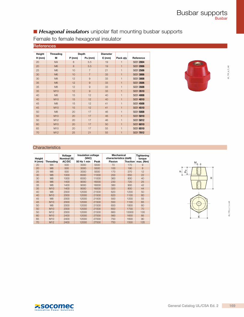
Busbar supportsBusbar
Hexagonal insulators unipolar flat mounting busbar supports
sb_1
04
_a_2
_cat
Characteristics
E
M
P Pu
H
sb_1
05
_c_1
_x_c
at
HeightH (mm) Threading
VoltageNominal (V)
AC/DC
Insulation voltage (VAC)
Mechanical characteristics (daN)
Tighteningtorque
max. (Nm)50 Hz 1 min Peak Flexion Traction
20 M4 500 3000 5500 70 170 9
20 M6 500 3000 5500 100 190 8
25 M6 500 3000 5500 170 370 12
30 M6 1000 6000 11000 200 650 22
30 M8 1000 6000 11000 360 800 40
35 M6 1400 9000 16000 230 720 25
35 M8 1400 9000 16000 380 900 42
35 M10 1400 9000 16000 320 800 44
40 M8 2000 12000 21500 620 1200 50
40 M10 2000 12000 21500 620 1100 60
45 M8 2000 12000 21500 550 1200 55
45 M10 2000 12000 21500 550 1100 65
50 M8 2000 12000 21500 650 1800 60
50 M10 2000 12000 21500 650 1700 70
50 M12 2000 12000 21500 660 13000 130
60 M10 2400 12000 27000 560 1600 85
65 M10 2400 12000 27000 750 1600 90
70 M12 2400 12000 27000 750 1500 135
Female to female hexagonal insulator
References
Height Threading Depth Diameter
H (mm) M P (mm) Pu (mm) E (mm) Pack qty Reference
20 M4 8 5.5 19 1 5031 2004
20 M6 8 5.5 19 1 5031 2006
25 M6 10 7 21 1 5031 2506
30 M6 10 7 33 1 5031 3006
30 M8 12 9 33 1 5031 3008
35 M6 12 9 33 1 5031 3506
35 M8 12 9 33 1 5031 3508
35 M10 12 9 33 1 5031 3510
40 M8 15 12 40 1 5031 4008
40 M10 15 12 40 1 5031 4010
45 M8 15 12 41 1 5031 4508
45 M10 15 12 41 1 5031 4510
50 M8 20 17 46 1 5031 5008
50 M10 20 17 46 1 5031 5010
50 M12 20 17 46 1 5031 5012
60 M10 20 17 50 1 5031 6010
65 M10 20 17 55 1 5031 6510
70 M12 25 21 55 1 5031 7012
169General Catalog UL/CSA Ed. 2
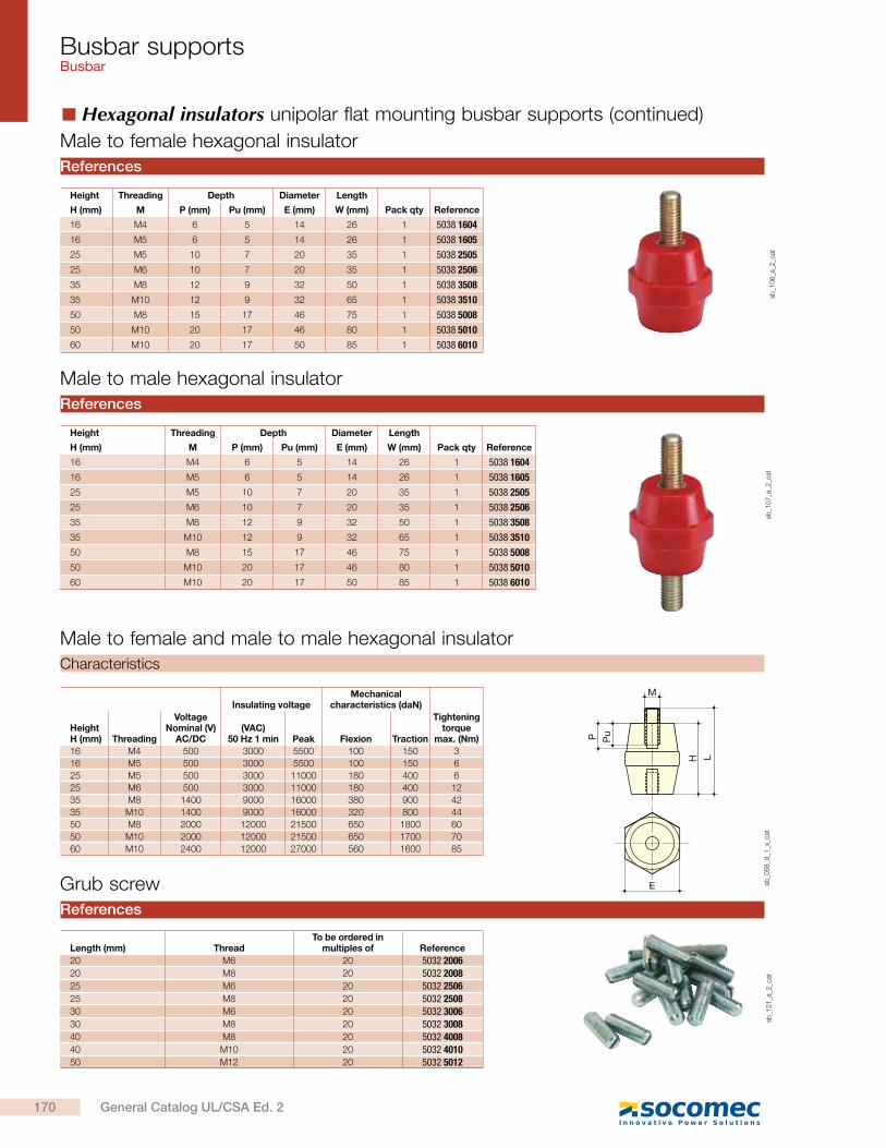
Busbar supportsBusbar
Male to female and male to male hexagonal insulator
M
E
PuP
LH
sb_0
58
_d_1
_x_c
at
Insulating voltageMechanical
characteristics (daN)
HeightH (mm) Threading
VoltageNominal (V)
AC/DC(VAC)
50 Hz 1 min Peak Flexion Traction
Tighteningtorque
max. (Nm)
16 M4 500 3000 5500 100 150 3
16 M5 500 3000 5500 100 150 6
25 M5 500 3000 11000 180 400 6
25 M6 500 3000 11000 180 400 12
35 M8 1400 9000 16000 380 900 42
35 M10 1400 9000 16000 320 800 44
50 M8 2000 12000 21500 650 1800 60
50 M10 2000 12000 21500 650 1700 70
60 M10 2400 12000 27000 560 1600 85
Characteristics
sb_1
06
_a_2
_cat
Male to female hexagonal insulator
References
sb_1
07
_a_2
_cat
Male to male hexagonal insulator
References
Length (mm) ThreadTo be ordered in
multiples of Reference
20 M6 20 5032 200620 M8 20 5032 200825 M6 20 5032 250625 M8 20 5032 250830 M6 20 5032 300630 M8 20 5032 300840 M8 20 5032 400840 M10 20 5032 401050 M12 20 5032 5012
sb_1
21
_a_2
_cat
Grub screw
References
Height Threading Depth Diameter Length
H (mm) M P (mm) Pu (mm) E (mm) W (mm) Pack qty Reference
16 M4 6 5 14 26 1 5038 1604
16 M5 6 5 14 26 1 5038 1605
25 M5 10 7 20 35 1 5038 2505
25 M6 10 7 20 35 1 5038 2506
35 M8 12 9 32 50 1 5038 3508
35 M10 12 9 32 65 1 5038 3510
50 M8 15 17 46 75 1 5038 5008
50 M10 20 17 46 80 1 5038 5010
60 M10 20 17 50 85 1 5038 6010
Hexagonal insulators unipolar flat mounting busbar supports (continued)
170 General Catalog UL/CSA Ed. 2
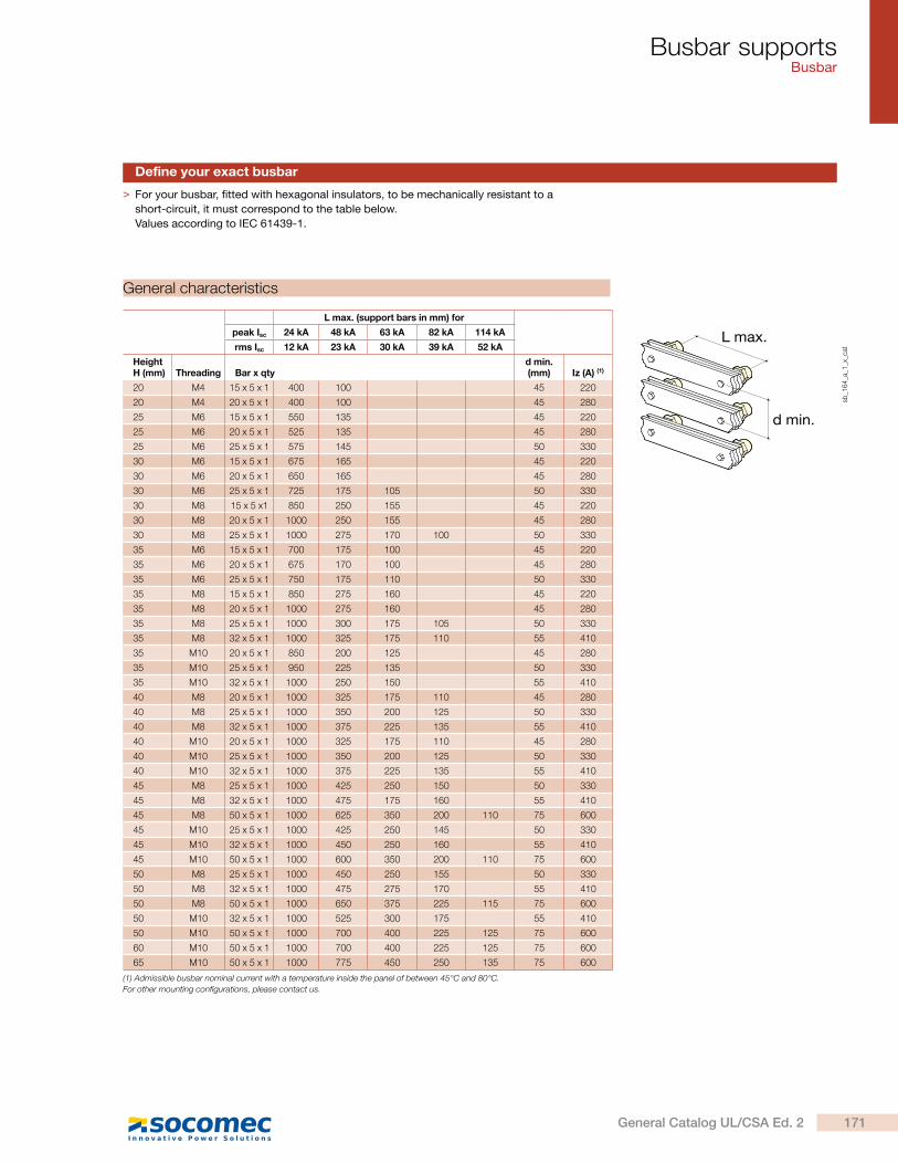
Busbar supportsBusbar
> For your busbar, fitted with hexagonal insulators, to be mechanically resistant to a
short-circuit, it must correspond to the table below.
Values according to IEC 61439-1.
L max.
d min.
sb_1
64
_a_1
_x_c
at
L max. (support bars in mm) for
peak Isc 24 kA 48 kA 63 kA 82 kA 114 kA
rms Isc 12 kA 23 kA 30 kA 39 kA 52 kA
Height H (mm) Threading Bar x qty
d min. (mm) Iz (A) (1)
20 M4 15 x 5 x 1 400 100 45 220
20 M4 20 x 5 x 1 400 100 45 280
25 M6 15 x 5 x 1 550 135 45 220
25 M6 20 x 5 x 1 525 135 45 280
25 M6 25 x 5 x 1 575 145 50 330
30 M6 15 x 5 x 1 675 165 45 220
30 M6 20 x 5 x 1 650 165 45 280
30 M6 25 x 5 x 1 725 175 105 50 330
30 M8 15 x 5 x1 850 250 155 45 220
30 M8 20 x 5 x 1 1000 250 155 45 280
30 M8 25 x 5 x 1 1000 275 170 100 50 330
35 M6 15 x 5 x 1 700 175 100 45 220
35 M6 20 x 5 x 1 675 170 100 45 280
35 M6 25 x 5 x 1 750 175 110 50 330
35 M8 15 x 5 x 1 850 275 160 45 220
35 M8 20 x 5 x 1 1000 275 160 45 280
35 M8 25 x 5 x 1 1000 300 175 105 50 330
35 M8 32 x 5 x 1 1000 325 175 110 55 410
35 M10 20 x 5 x 1 850 200 125 45 280
35 M10 25 x 5 x 1 950 225 135 50 330
35 M10 32 x 5 x 1 1000 250 150 55 410
40 M8 20 x 5 x 1 1000 325 175 110 45 280
40 M8 25 x 5 x 1 1000 350 200 125 50 330
40 M8 32 x 5 x 1 1000 375 225 135 55 410
40 M10 20 x 5 x 1 1000 325 175 110 45 280
40 M10 25 x 5 x 1 1000 350 200 125 50 330
40 M10 32 x 5 x 1 1000 375 225 135 55 410
45 M8 25 x 5 x 1 1000 425 250 150 50 330
45 M8 32 x 5 x 1 1000 475 175 160 55 410
45 M8 50 x 5 x 1 1000 625 350 200 110 75 600
45 M10 25 x 5 x 1 1000 425 250 145 50 330
45 M10 32 x 5 x 1 1000 450 250 160 55 410
45 M10 50 x 5 x 1 1000 600 350 200 110 75 600
50 M8 25 x 5 x 1 1000 450 250 155 50 330
50 M8 32 x 5 x 1 1000 475 275 170 55 410
50 M8 50 x 5 x 1 1000 650 375 225 115 75 600
50 M10 32 x 5 x 1 1000 525 300 175 55 410
50 M10 50 x 5 x 1 1000 700 400 225 125 75 600
60 M10 50 x 5 x 1 1000 700 400 225 125 75 600
65 M10 50 x 5 x 1 1000 775 450 250 135 75 600
(1) Admissible busbar nominal current with a temperature inside the panel of between 45°C and 80°C.
For other mounting configurations, please contact us.
Define your exact busbar
General characteristics
171General Catalog UL/CSA Ed. 2
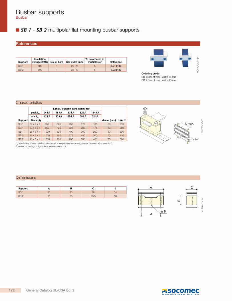
Busbar supportsBusbar
SB 1 - SB 2 multipolar flat mounting busbar supports
Support
peak Isc
L max. (support bars in mm) for
24 kA 48 kA 63 kA 82 kA 114 kA
rms Isc 12 kA 23 kA 30 kA 39 kA 52 kA
Bar x qty d min. (mm) Iz (A) (1)
SB 1 20 x 3 x 1 650 325 250 175 135 50 210
SB 1 20 x 5 x 1 850 425 325 250 175 50 280
SB 1 25 x 5 x 1 1000 525 400 300 200 50 330
SB 2 32 x 5 x 1 1000 750 575 450 300 70 410
SB 2 40 x 5 x 1 1000 950 700 550 400 70 500
L max.
d min.
sb_1
50
_a_1
_x_c
at
(1) Admissible busbar nominal current with a temperature inside the panel of between 45°C and 80°C.
For other mounting configurations, please contact us.
Characteristics
Support A B C J
SB 1 50 23 20 34
SB 2 68 23 23.5 50
J
A C
B
ø 6 sb_0
14
_c_1
_x_c
at
Dimensions
Ordering guide
SB 1: bar of max. width 25 mm
SB 2: bar of max. width 40 mm
SupportInsulation
voltage (VAC) No. of bars Bar width (mm)To be ordered in
multiples of Reference
SB 1 690 1 20 -25 6 5021 0110
SB 2 690 1 32 -40 6 5022 0110
References
sb_1
08
_a_2
_cat
.ep
s
172 General Catalog UL/CSA Ed. 2
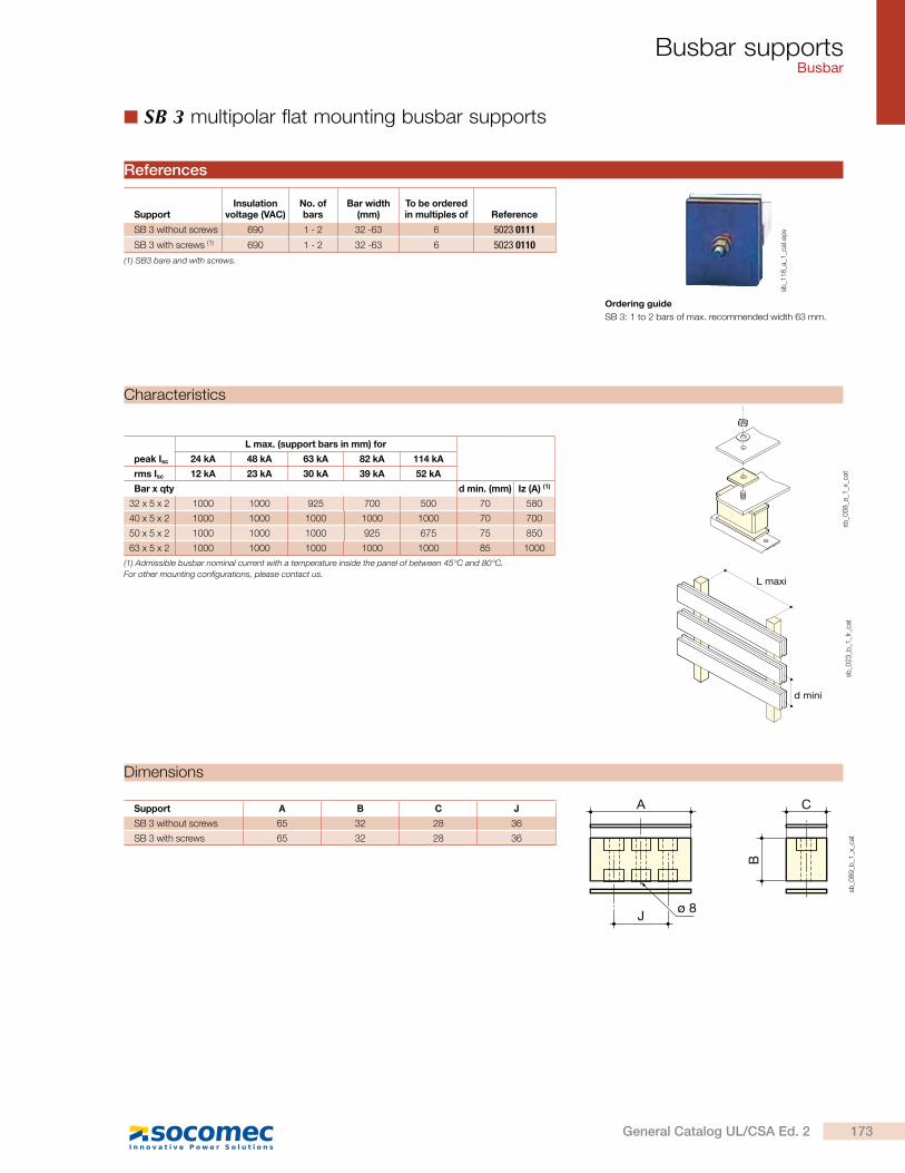
Busbar supportsBusbar
SB 3 multipolar flat mounting busbar supports
peak Isc
L max. (support bars in mm) for
24 kA 48 kA 63 kA 82 kA 114 kA
rms Isc 12 kA 23 kA 30 kA 39 kA 52 kA
Bar x qty d min. (mm) Iz (A) (1)
32 x 5 x 2 1000 1000 925 700 500 70 580
40 x 5 x 2 1000 1000 1000 1000 1000 70 700
50 x 5 x 2 1000 1000 1000 925 675 75 850
63 x 5 x 2 1000 1000 1000 1000 1000 85 1000
sb_0
08
_a_1
_x_c
at
L maxi
d mini
sb_0
23
_b_1
_fr_
cat
(1) Admissible busbar nominal current with a temperature inside the panel of between 45°C and 80°C.
For other mounting configurations, please contact us.
Characteristics
Support A B C J
SB 3 without screws 65 32 28 36
SB 3 with screws 65 32 28 36
J
A C
B
ø 8
sb_0
89
_b_1
_x_c
at
Dimensions
Ordering guide
SB 3: 1 to 2 bars of max. recommended width 63 mm.
SupportInsulation
voltage (VAC)No. of bars
Bar width (mm)
To be ordered in multiples of Reference
SB 3 without screws 690 1 - 2 32 -63 6 5023 0111
SB 3 with screws (1) 690 1 - 2 32 -63 6 5023 0110
(1) SB3 bare and with screws.
References
sb_1
18
_a_1
_cat
.ep
s
173General Catalog UL/CSA Ed. 2

Busbar supportsBusbar
SB E 44 tetrapolar stair type supports
Mounting with eliptical holes: 150 to 170 mm.Type 1: Busbars including 3 (or more) equally spaced SB E 44 supports.
Type 2: Busbars with 3 (or more) SB E 44 supports with doubled intermediary supports.
Support
L max. (support bars in mm) for
peak Isc 10 kA 15 kA 24 kA 38 kA 48 kA 63 kA
rms Isc 6 kA 9 kA 12 kA 19 kA 23 kA 30 kA
Bar x qty Iz (A) (1)
Type 1 15 x 3 x 1 950 625 400 250 175 160Type 1 15 x 5 x 1 1000 825 500 300 175 220Type 1 15 x 6 x 1 1000 900 550 300 200 250Type 1 15 x 8 x 1 1000 1000 650 300 200 290Type 1 20 x 3 x 1 1000 825 525 300 175 210Type 1 20 x 5 x 1 1000 1000 675 300 175 280Type 1 20 x 6 x 1 1000 1000 750 300 175 310Type 1 20 x 8 x 1 1000 1000 775 300 175 370Type 1 32 x 5 x 1 1000 1000 675 250 170 410Type 1 32 x 6 x 1 1000 1000 675 250 170 460Type 2 15 x 3 x 1 950 625 400 250 200 150 160Type 2 15 x 5 x 1 1000 825 500 325 250 175 220Type 2 15 x 6 x 1 1000 900 550 350 275 200 250Type 2 15 x 8 x 1 1000 1000 650 400 325 225 290Type 2 20 x 3 x 1 1000 825 525 325 250 200 210Type 2 20 x 5 x 1 1000 1000 675 425 325 225 280Type 2 20 x 6 x 1 1000 1000 750 450 375 225 310Type 2 20 x 8 x 1 1000 1000 850 525 375 225 370Type 2 32 x 5 x 1 1000 1000 1000 525 325 175 410Type 2 32 x 6 x 1 1000 1000 1000 525 325 175 460
(1) Admissible busbar nominal current with a temperature inside the panel of between 45°C and 80°C.
For other mounting configurations, please contact us. N.B.: Iz indicated is for a solid (undrilled) busbar.
L 25
50
25L
35.5
76
35.5 35.5
70
6.2
3535
49.5
15.520.5
140180
90
L 25
25L
sb_0
41
_b_1
_x_c
at
sb_0
36
_e_1
_x_c
at
sb_0
47
_a_1
_x_c
at
Characteristics
Dimensions
No. of poles Pack qty Reference
4 P 1 5028 0410Accessories Pack qty Reference
270 mm long protection screen kit 1 5028 0411420 mm long protection screen kit 1 5028 0412620 mm long protection screen kit 1 5028 0413Set of 20 protection screen adaption spacers 1 5028 0415
References
sb_0
38
_a_3
_cat
.ep
s
174 General Catalog UL/CSA Ed. 2
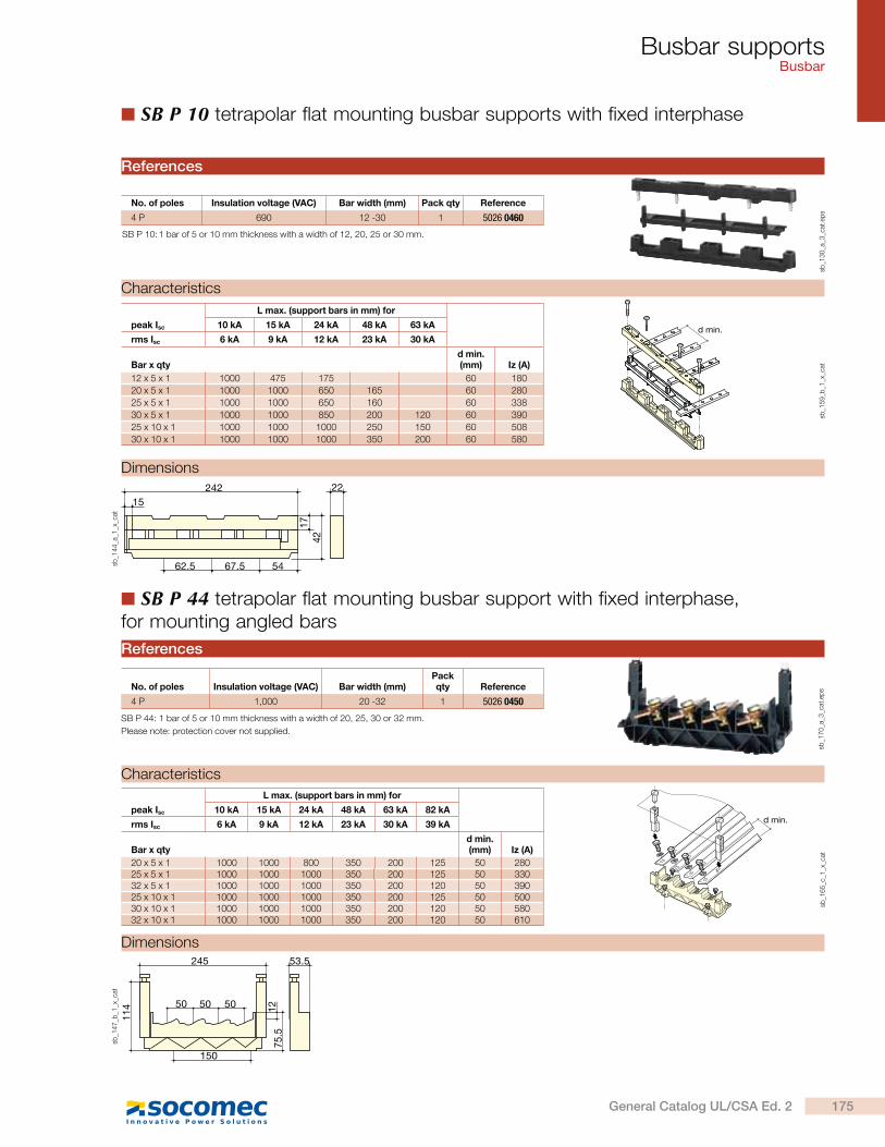
Busbar supportsBusbar
peak Isc
L max. (support bars in mm) for
10 kA 15 kA 24 kA 48 kA 63 kA
rms Isc 6 kA 9 kA 12 kA 23 kA 30 kA
Bar x qtyd min. (mm) Iz (A)
12 x 5 x 1 1000 475 175 60 180
20 x 5 x 1 1000 1000 650 165 60 280
25 x 5 x 1 1000 1000 650 160 60 338
30 x 5 x 1 1000 1000 850 200 120 60 390
25 x 10 x 1 1000 1000 1000 250 150 60 508
30 x 10 x 1 1000 1000 1000 350 200 60 580
peak Isc
L max. (support bars in mm) for
10 kA 15 kA 24 kA 48 kA 63 kA 82 kA
rms Isc 6 kA 9 kA 12 kA 23 kA 30 kA 39 kA
Bar x qtyd min. (mm) Iz (A)
20 x 5 x 1 1000 1000 800 350 200 125 50 28025 x 5 x 1 1000 1000 1000 350 200 125 50 33032 x 5 x 1 1000 1000 1000 350 200 120 50 39025 x 10 x 1 1000 1000 1000 350 200 125 50 50030 x 10 x 1 1000 1000 1000 350 200 120 50 58032 x 10 x 1 1000 1000 1000 350 200 120 50 610
d min.
d min.
sb_1
65
_c_1
_x_c
atsb
_15
9_b
_1_x
_cat
SB P 10 tetrapolar flat mounting busbar supports with fixed interphase
5050 50 1275
.5
245
150
114
53.5
sb_1
47
_b_1
_x_c
at
SB P 44 tetrapolar flat mounting busbar support with fixed interphase, for mounting angled bars
Characteristics
No. of poles Insulation voltage (VAC) Bar width (mm) Pack qty Reference
4 P 690 12 -30 1 5026 0460
SB P 10: 1 bar of 5 or 10 mm thickness with a width of 12, 20, 25 or 30 mm.
References
Characteristics
sb_1
44
_a_1
_x_c
at
15242 22
1742
62.5 67.5 54
Dimensions
Dimensions
sb_1
30
_a_3
_cat
.ep
s
No. of poles Insulation voltage (VAC) Bar width (mm)Pack qty Reference
4 P 1,000 20 -32 1 5026 0450
SB P 44: 1 bar of 5 or 10 mm thickness with a width of 20, 25, 30 or 32 mm.
Please note: protection cover not supplied.
References
sb_1
70
_a_3
_cat
.ep
s
175General Catalog UL/CSA Ed. 2

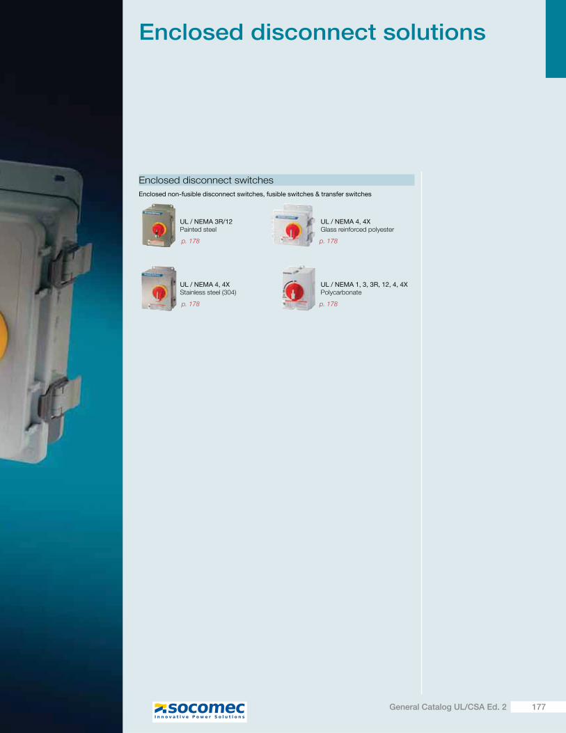
Enclosed disconnect solutions
Enclosed disconnect switches
UL / NEMA 3R/12Painted steel
UL / NEMA 4, 4XStainless steel (304)
UL / NEMA 4, 4XGlass reinforced polyester
UL / NEMA 1, 3, 3R, 12, 4, 4XPolycarbonate
Enclosed non-fusible disconnect switches, fusible switches & transfer switches
p. 178 p. 178
p. 178p. 178
177General Catalog UL/CSA Ed. 2
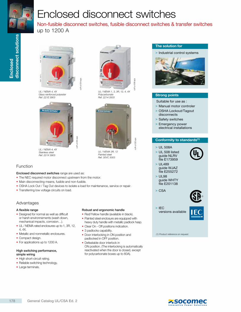
En
clo
se
d
dis
co
nn
ec
t so
luti
on
sEnclosed disconnect switchesNon-fusible disconnect switches, fusible disconnect switches & transfer switches up to 1200 A
Suitable for use as :
> Manual motor controler
> OSHA Lockout/Tagout disconnects
> Safety switches
> Emergency power electrical installations
Strong points
> Industrial control systems
The solution for
Function
Enclosed disconnect switches range are used as:
The NEC required motor disconnect upstream from the motor.
Main disconnecting means, fusible and non-fusible.
OSHA Lock Out / Tag Out devices to isolate a load for maintenance, service or repair.
Transferring low voltage circuits on load.
Advantages
A flexible range
Designed for normal as well as difficult or harsh environnements (wash down, mechanical impacts, corrosion…).
UL / NEMA rated enclosures up to 1, 3R, 12, 4, 4X.
Metallic and nonmetallic enclosures.
Compact design.
For applications up to 1200 A.
High switching performance, simple wiring
High short-circuit rating.
Reliable switching technology.
Large terminals.
Robust and ergonomic handle
Red/Yellow handle (available in black).
Painted steel enclosure are equipped with heavy duty handle with metallic padlock hasp.
Clear On - Off positions indication.
3 padlocks capability.
Door interlocking in ON position and padlocked in OFF position.
Defeatable door interlock in ON position. (The interlocking is automatically reactivated when the door is closed, except for polycarbonate boxes up to 60A).
> UL 508A
> UL 508 listed guide NLRV file E173959
> UL489 guide WJAZ file E255272
> UL98 guide WHTY file E201138
> CSA
> IEC versions available
Conformity to standards(1)
(1) Product reference on request.
coff-
ul-0
08
.ep
sco
ff-ul-0
32
.ep
s
coff-
ul-0
04
.ep
s
coff-
ul-0
34
.ep
s
UL / NEMA 4, 4XGlass reinforced polyesterRef. 221E 3903
UL / NEMA 1, 3, 3R, 12, 4, 4XPolycarbonateRef. 2214 3503
UL / NEMA 3R, 12Painted steelRef. 30VC 3003
UL / NEMA 4, 4XStainless steelRef. 221X 3903
178 General Catalog UL/CSA Ed. 2
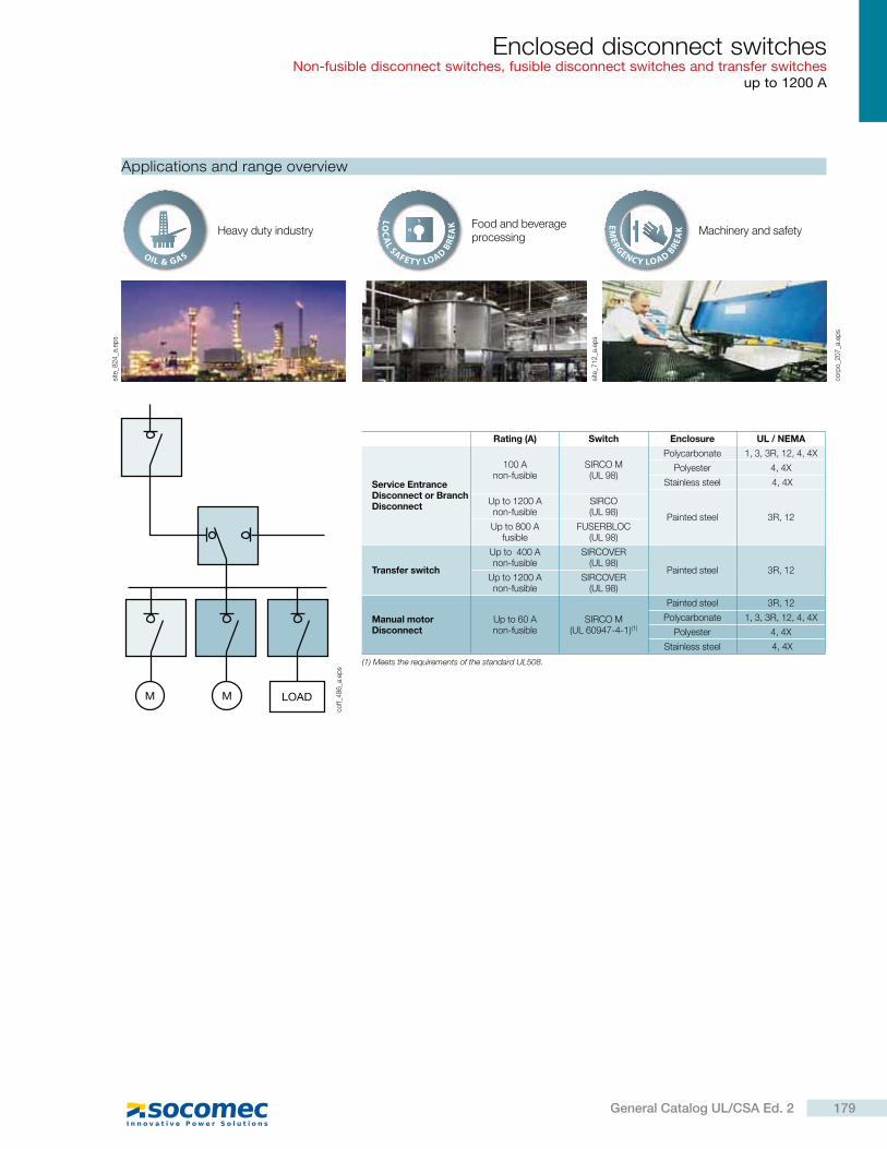
Enclosed disconnect switchesNon-fusible disconnect switches, fusible disconnect switches and transfer switches
up to 1200 A
Applications and range overview
Heavy duty industryFood and beverage processing
Machinery and safety
corp
o_2
07
_a.e
ps
site
_82
4_a
.ep
s
coff_
48
6_a
.ep
s
site
_71
2_a
.ep
s
Rating (A) Switch Enclosure UL / NEMA
Service Entrance Disconnect or Branch Disconnect
100 A non-fusible
SIRCO M (UL 98)
Polycarbonate 1, 3, 3R, 12, 4, 4X
Polyester 4, 4X
Stainless steel 4, 4X
Painted steel 3R, 12
Up to 1200 A non-fusible
SIRCO (UL 98)
Up to 800 A fusible
FUSERBLOC (UL 98)
Transfer switch
Up to 400 A non-fusible
SIRCOVER (UL 98)
Painted steel 3R, 12Up to 1200 A non-fusible
SIRCOVER (UL 98)
Manual motor Disconnect
Up to 60 A non-fusible
SIRCO M (UL 60947-4-1)(1)
Painted steel 3R, 12
Polycarbonate 1, 3, 3R, 12, 4, 4X
Polyester 4, 4X
Stainless steel 4, 4X
(1) Meets the requirements of the standard UL508.
179General Catalog UL/CSA Ed. 2
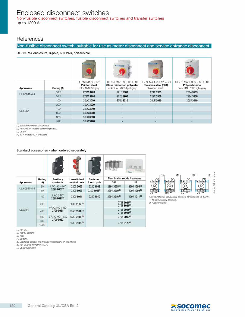
Enclosed disconnect switchesNon-fusible disconnect switches, fusible disconnect switches and transfer switchesup to 1200 A
Non-fusible disconnect switch, suitable for use as motor disconnect and service entrance disconnect
UL / NEMA enclosure, 3-pole, 600 VAC, non-fusible
Standard accessories - when ordered separately
References
Configuration of the auxiliary contacts for enclosed SIRCO M.
1. M type auxiliary contacts.
2. Additional pole.
Approvals Rating (A)
UL / NEMA 3R, 12(2)
Painted steelcolor ANSI 61 gray
UL / NEMA 1, 3R, 12, 4, 4XGlass reinforced polyester
color RAL 7035 light-gray
UL / NEMA 1, 3R, 12, 4, 4XStainless steel (304)
brushed finish
UL / NEMA 1, 3, 3R, 12, 4, 4XPolycarbonate
color RAL 7035 light-gray
UL 60947-4-130(1) 221M 3703 221E 3903 221X 3903 2214 3503
60(1) 222M 3706 222E 3906 222X 3906 2224 3506
UL 508A
100 30UC 3010 30UL 3010 30UF 3010 30UJ 3010
200 30UC 3020 - - -
400 30UC 3040 - - -
600 30UC 3060 - - -
800 30UC 3080 - - -
1200 30UC 3120 - - -
(1) Suitable for motor disconnect.
(2) Handle with metallic padlocking hasp.
(3) UL 98
(4) 30 A in large 60 A enclosure
ApprovalsRating
(A)Auxiliary contacts
Unswitched neutral pole
Switched fourth pole
Terminal shrouds / screens
3 P 1 P
UL 60947-4-130 1 AC NO + NC
2299 0001(6)
1 AC 2 NC2299 0011(6)
2200 5005 2200 1003 2294 3005(2) 2294 1005(2)
60 2200 5009 2200 1006(1) 2294 3009(2) 2294 1009(2)
UL508A
100 2200 5011 2200 1010 2294 3016(2) 2294 1011(2)
200
1st AC NO + NC2799 0021
2nd AC NO + NC2799 0022
30AC 0102 (7)
-
2798 3021(3)
2798 8021(4)
400 30AC 0104 (7) 2798 3041(3)
2798 8041(4)
600 30AC 0106 (7) 2798 3060(5)
80030AC 0108 (7) 2798 3120(5)
1200
(1) Not UL.
(2) Top or bottom.
(3) Top.
(4) Bottom.
(5) Load side screen, the line side is included with the switch.
(6) Not UL only for rating 100 A.
(7) UL components
2111
sirc
m-u
l_0
12
_a_1
_cat
.ep
s
180 General Catalog UL/CSA Ed. 2
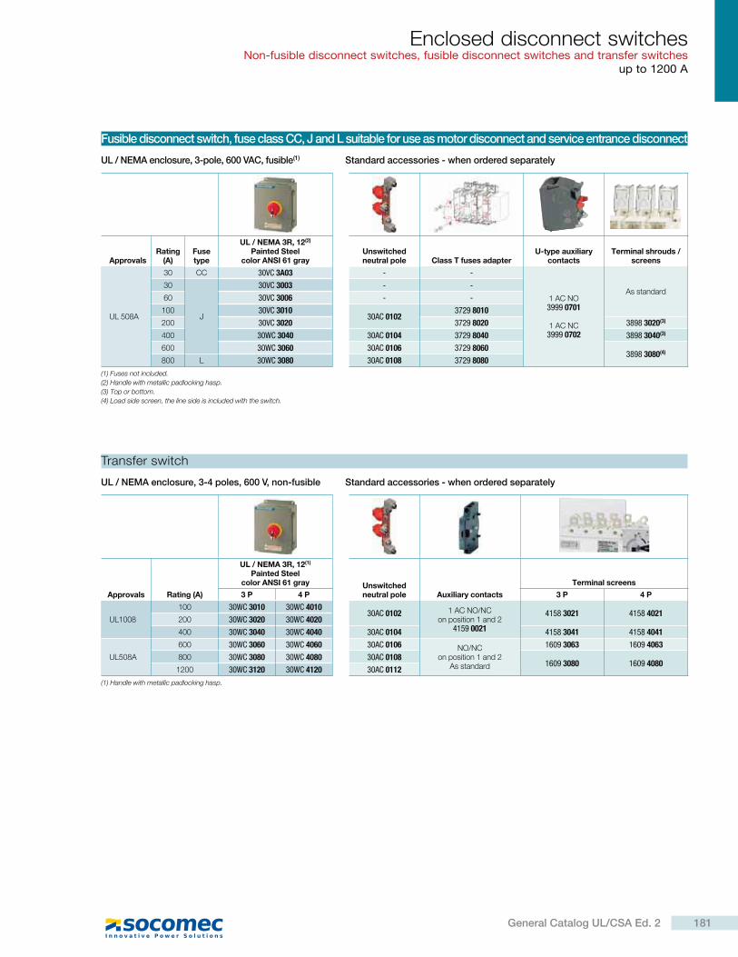
Enclosed disconnect switchesNon-fusible disconnect switches, fusible disconnect switches and transfer switches
up to 1200 A
Fusible disconnect switch, fuse class CC, J and L suitable for use as motor disconnect and service entrance disconnect
Transfer switch
UL / NEMA enclosure, 3-pole, 600 VAC, fusible(1)
UL / NEMA enclosure, 3-4 poles, 600 V, non-fusible
Standard accessories - when ordered separately
Standard accessories - when ordered separately
ApprovalsRating
(A)Fuse type
UL / NEMA 3R, 12(2)
Painted Steelcolor ANSI 61 gray
Unswitched neutral pole Class T fuses adapter
U-type auxiliary contacts
Terminal shrouds / screens
UL 508A
30 CC 30VC 3A03 - -
1 AC NO3999 0701
1 AC NC3999 0702
As standard30
J
30VC 3003 - -
60 30VC 3006 - -
100 30VC 301030AC 0102
3729 8010
200 30VC 3020 3729 8020 3898 3020(3)
400 30WC 3040 30AC 0104 3729 8040 3898 3040(3)
600 30WC 3060 30AC 0106 3729 80603898 3080(4)
800 L 30WC 3080 30AC 0108 3729 8080
(1) Fuses not included.
(2) Handle with metallic padlocking hasp.
(3) Top or bottom.
(4) Load side screen, the line side is included with the switch.
Approvals Rating (A)
UL / NEMA 3R, 12(1)
Painted Steel color ANSI 61 gray Unswitched
neutral pole Auxiliary contacts
Terminal screens
3 P 4 P 3 P 4 P
UL1008
100 30WC 3010 30WC 401030AC 0102 1 AC NO/NC
on position 1 and 24159 0021
4158 3021 4158 4021200 30WC 3020 30WC 4020
400 30WC 3040 30WC 4040 30AC 0104 4158 3041 4158 4041
UL508A
600 30WC 3060 30WC 4060 30AC 0106 NO/NCon position 1 and 2
As standard
1609 3063 1609 4063
800 30WC 3080 30WC 4080 30AC 01081609 3080 1609 4080
1200 30WC 3120 30WC 4120 30AC 0112
(1) Handle with metallic padlocking hasp.
181General Catalog UL/CSA Ed. 2
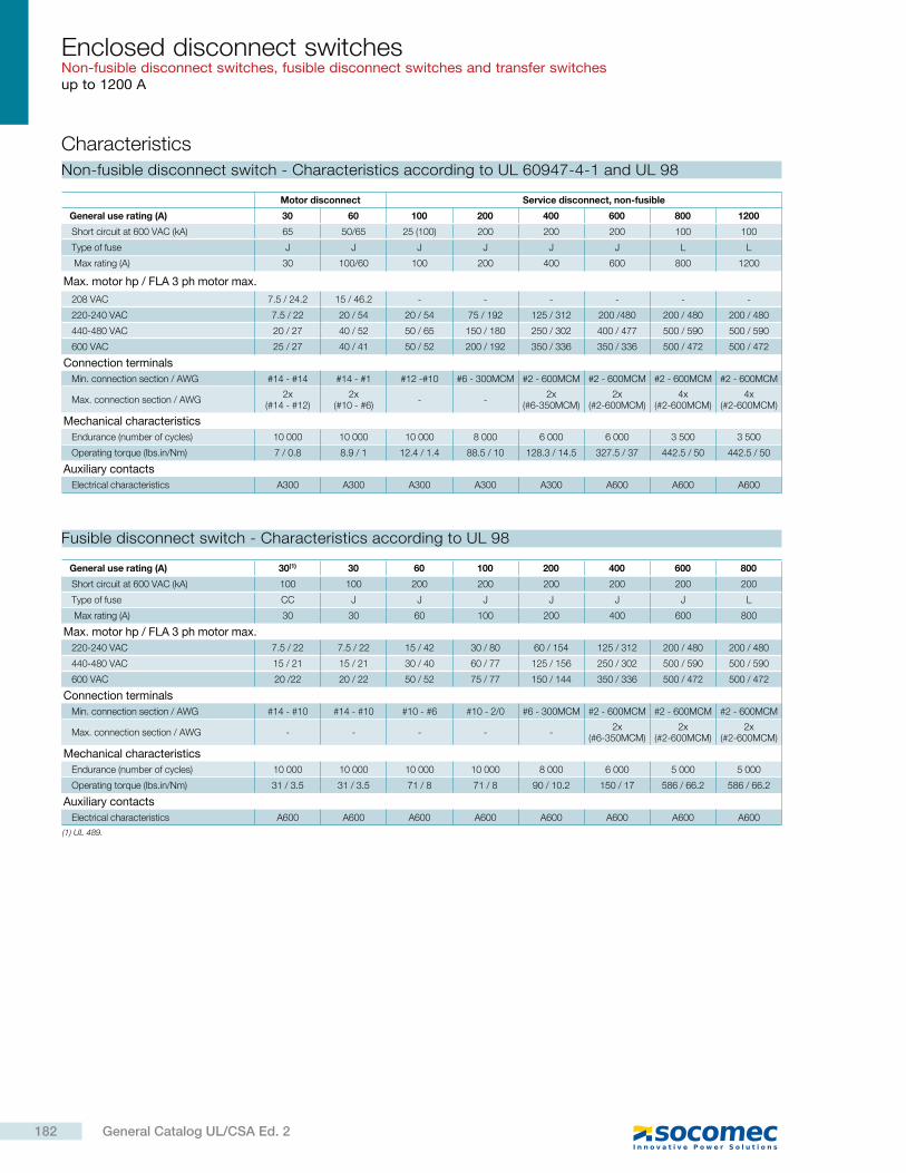
Enclosed disconnect switchesNon-fusible disconnect switches, fusible disconnect switches and transfer switchesup to 1200 A
Characteristics
Non-fusible disconnect switch - Characteristics according to UL 60947-4-1 and UL 98
Motor disconnect Service disconnect, non-fusible
General use rating (A) 30 60 100 200 400 600 800 1200
Short circuit at 600 VAC (kA) 65 50/65 25 (100) 200 200 200 100 100
Type of fuse J J J J J J L L
Max rating (A) 30 100/60 100 200 400 600 800 1200
Max. motor hp / FLA 3 ph motor max.
208 VAC 7.5 / 24.2 15 / 46.2 - - - - - -
220-240 VAC 7.5 / 22 20 / 54 20 / 54 75 / 192 125 / 312 200 /480 200 / 480 200 / 480
440-480 VAC 20 / 27 40 / 52 50 / 65 150 / 180 250 / 302 400 / 477 500 / 590 500 / 590
600 VAC 25 / 27 40 / 41 50 / 52 200 / 192 350 / 336 350 / 336 500 / 472 500 / 472
Connection terminals
Min. connection section / AWG #14 - #14 #14 - #1 #12 -#10 #6 - 300MCM #2 - 600MCM #2 - 600MCM #2 - 600MCM #2 - 600MCM
Max. connection section / AWG2x
(#14 - #12)2x
(#10 - #6)- -
2x (#6-350MCM)
2x (#2-600MCM)
4x (#2-600MCM)
4x (#2-600MCM)
Mechanical characteristics
Endurance (number of cycles) 10 000 10 000 10 000 8 000 6 000 6 000 3 500 3 500
Operating torque (lbs.in/Nm) 7 / 0.8 8.9 / 1 12.4 / 1.4 88.5 / 10 128.3 / 14.5 327.5 / 37 442.5 / 50 442.5 / 50
Auxiliary contacts
Electrical characteristics A300 A300 A300 A300 A300 A600 A600 A600
(1) UL 489.
Fusible disconnect switch - Characteristics according to UL 98
General use rating (A) 30(1) 30 60 100 200 400 600 800
Short circuit at 600 VAC (kA) 100 100 200 200 200 200 200 200
Type of fuse CC J J J J J J L
Max rating (A) 30 30 60 100 200 400 600 800
Max. motor hp / FLA 3 ph motor max.
220-240 VAC 7.5 / 22 7.5 / 22 15 / 42 30 / 80 60 / 154 125 / 312 200 / 480 200 / 480
440-480 VAC 15 / 21 15 / 21 30 / 40 60 / 77 125 / 156 250 / 302 500 / 590 500 / 590
600 VAC 20 /22 20 / 22 50 / 52 75 / 77 150 / 144 350 / 336 500 / 472 500 / 472
Connection terminals
Min. connection section / AWG #14 - #10 #14 - #10 #10 - #6 #10 - 2/0 #6 - 300MCM #2 - 600MCM #2 - 600MCM #2 - 600MCM
Max. connection section / AWG - - - - -2x
(#6-350MCM)2x
(#2-600MCM)2x
(#2-600MCM)
Mechanical characteristics
Endurance (number of cycles) 10 000 10 000 10 000 10 000 8 000 6 000 5 000 5 000
Operating torque (lbs.in/Nm) 31 / 3.5 31 / 3.5 71 / 8 71 / 8 90 / 10.2 150 / 17 586 / 66.2 586 / 66.2
Auxiliary contacts
Electrical characteristics A600 A600 A600 A600 A600 A600 A600 A600
182 General Catalog UL/CSA Ed. 2
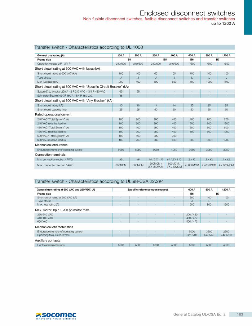
Enclosed disconnect switchesNon-fusible disconnect switches, fusible disconnect switches and transfer switches
up to 1200 A
General use rating at 600 VAC and 250 VDC (A) Specific reference upon request 600 A 800 A 1200 A
Frame size B6 B7
Short-circuit rating at 600 VAC (kA) - - - - 200 100 100
Type of fuse - - - - J L L
Max. fuse rating (A) - - - - 600 800 1200
Max. motor, hp / FLA 3 ph motor max.
220-240 VAC - - - - 200 / 480 - -
440-480 VAC - - - - 400 / 477 - -
600 VAC - - - - 500 / 472 - -
Mechanical characteristics
Endurance (number of operating cycles) - - - - 5000 3500 2500
Operating torque (lbs.in/Nm) - - - - 327.5/37 442.5/50 442.5/50
Auxiliary contacts
Electrical characteristics A300 A300 A300 A300 A300 A300 A300
Transfer switch - Characteristics according to UL 98/CSA 22.2#4
Transfer switch - Characteristics according to UL 1008
General use rating (A) 100 A 200 A 260 A 400 A 600 A 800 A 1200 A
Frame size B4 B5 B6 B7
Operation voltage 2 P - 3/4 P 240/600 240/600 240/600 240/600 -/600 -/600 -/600
Short circuit rating at 600 VAC with fuses (kA)
Short circuit rating at 600 VAC (kA) 100 100 65 65 100 100 100
Type of fuse J J J J L L L
Max fuse rating (A) 200 400 600 600 800 1000 1600
Short circuit rating at 600 VAC with “Specific Circuit Breaker” (kA)
Square D JJ breaker 250 A - 2 P 240 VAC - 3/4 P 480 VAC 65 65 - - - - -
Schneider Electric NSX-F 160 A - 3/4 P 480 VAC 35 - - - - - -
Short circuit rating at 600 VAC with “Any Breaker” (kA)
Short circuit rating (kA) 10 10 14 14 35 35 35
Short circuit capacity (ms) 25 25 50 50 50 50 50
Rated operational current
240 VAC “Total System” (A) 100 200 260 400 400 700 700
240 VAC resistive load (A) 100 200 260 400 600 800 1200
480 VAC “Total System” (A) 100 100 260 400 350 600 600
480 VAC resistive load (A) 100 200 260 400 600 800 1200
600 VAC “Total System” (A) 100 100 200 200 - - -
600 VAC resistive load (A) 100 200 260 400 600 800 1200
Mechanical endurance
Endurance (number of operating cycles) 6050 6050 6050 4050 3050 3050 3050
Connection terminals
Min. connection section / AWG #6 #6 #4 / 2 X 1 /0 #4 / 2 X 1 /0 2 x #2 2 x #2 4 x #2
Max. connection section / AWG 300MCM 300MCM600MCM /
2 X 250MCM600MCM /
2 X 250MCM2x 600MCM 2x 600MCM 4 x 600MCM
183General Catalog UL/CSA Ed. 2
Enclosed disconnect switchesNon-fusible disconnect switches, fusible disconnect switches and transfer switchesup to 1200 A
UL / NEMA enclosure 1, 3R, 12 - painted steel
H
G
W
X Y
D
Ø 0.31 0.082Ø 8
FZco
ff_4
88
_a.e
ps
Non-fusible disconnect switch up to 100 A
Rating (A) Unit H W D G F X Y Z Weight (lbs)
0 … 30in 6.0 6.0 4.8 4.0 6.8 6.9 6.6 7.5
6mm 152.4 152.4 120.7 101.6 171.5 176.3 167.6 190.5
0 … 60in 8.0 6.0 4.8 4.0 8.8 6.9 6.6 9.5
7mm 203.2 152.4 120.7 101.6 222.3 176.3 167.6 241.3
0 ... 100in 12.0 10.0 6.8 8.0 12.8 10.9 8.6 13.5
16mm 304.8 254.0 171.5 203.2 323.9 277.9 218.4 342.9
Fusible disconnect switch up to 100 A
Rating (A) Unit H W D G F X Y Z Weight (lbs)
0 … 30in 10.0 8.0 6.8 6.0 10.8 8.9 8.8 11.5
11mm 254.0 203.2 171.5 152.4 273.1 227.1 223.5 292.1
0 … 60in 12.0 10.0 8.8 8.0 12.8 10.9 10.4 13.5
18mm 304.8 254.0 222.3 203.2 323.9 277.9 264.2 342.9
0 ... 100in 14.0 12.0 8.8 10.0 14.8 12.9 10.4 15.5
24mm 355.6 304.8 222.3 254.0 374.7 328.7 264.2 393.7
Dimensions (in/mm)
UL / NEMA enclosure 1, 3R, 12, 4, 4X - stainless steel (304)
Non-fusible disconnect switch up to 100 A
Rating (A) Unit H W D G F X Y Z Weight (lbs)
0 … 30 in 6.29 6.26 4.84 4 6.75 6.97 6.38 7.50
4.4mm 159 159 123 102 171 177 162 191
0 … 60 in 8.26 6.26 4.84 4 8.75 6.97 6.38 9.50
6.6mm 210 159 123 102 222 177 162 241
0 … 100 in 12 10 6 8 12.75 11 8.4 13.5
12mm 305 254 152 203 324 280 213 343
H
G
W
X Y
DFZ
Ø 0.31 0.082Ø 8
coff_
48
9_a
.ep
s
UL / NEMA enclosure 1, 3R, 12, 4, 4X - glass reinforced polyester
Non-fusible disconnect switch up to 100 A
Rating (A) Unit H W D G F X Y Z Weight (lbs)
0 … 30 in 7.12 7.24 5.27 4.56 7.36 7.99 6.97 8.15
4.4mm 181 184 134 116 187 203 177 207
0 … 60 in 9.13 7.24 5.27 4.56 9.37 7.99 6.97 10.16
6.6mm 232 184 134 116 238 203 177 258
0 … 100 in 12.08 11.23 7.28 8.56 13.34 12.05 8.97 14.08
11mm 307 285 185 217 339 306 228 358
X
W
Z H F
G 0.28
Y
D
7Ø 0.25 x 0.38Ø 6 x 10 co
ff_4
87
_a.e
ps
UL / NEMA enclosure 1, 3, 3R, 12, 4, 4X - polycarbonate
Non-fusible disconnect switch up to 100 A
Rating (A) Unit H W D G F Y Z Weight (lbs)
0 … 30 in 5.9 3.9 3.62 0 6 4.37 6.38
4.4mm 150 99 92 0 152.5 111 162
0 … 60 in 7.8 4.94 3.62 4.45 7.32 4.37 8.27
6.6mm 198 125.5 92 113 186 111 210
0 … 100 in 11.81 8.27 5.35 7.44 9.37 7.12 11.81
9mm 300 210 136 189 238 181 300
W
Z H F
G
YD
0.154
0.25
Ø 0.34 x 0.2Ø 8.5 x 5
Ø 0.34 x 0.2Ø 8.5 x 5
coff_
49
1_a
.ep
s
184 General Catalog UL/CSA Ed. 2
Enclosed disconnect switchesNon-fusible disconnect switches, fusible disconnect switches and transfer switches
up to 1200 A
UL / NEMA enclosure 1, 3R, 12 - painted steel
W D
G Y
Z
H
F
coff_
49
0_a
.ep
s
Note: dimensions are subject to change. Please consult us for verification.
Non-fusible disconnect switch > 100 A
Rating (A) Unit H W D G F X Y Z Weight (lbs)
200in 24.0 16.0 6.8 14.0 24.8 16.9 8.6 25.5
80mm 609.6 406.4 171.5 355.6 628.7 430.3 218.4 647.7
400in 30.0 20.0 10.8 18.0 30.8 20.9 12.6 31.5
115mm 762.0 508.0 273.1 457.2 781.1 531.9 320.0 800.1
600in 42.0 24.0 12.8 22.0 42.8 24.9 15.3 43.5
230mm 1066.8 609.6 323.9 558.8 1085.9 633.5 387.9 1104.9
800 … 1200in 60.0 36.0 12.8 34.0 60.8 36.9 15.3 61.5
332mm 1524.0 914.4 323.9 863.6 1543.1 938.3 387.9 1562.1
Fusible disconnect switch > 100 A
Rating (A) Unit H W D G F Y Z Weight (lbs)
200 Ain 24.0 20.0 10.8 18.0 24.8 20.9 12.6 25.5
92mm 609.6 508.0 273.1 457.2 628.7 531.9 320.0 647.7
400 Ain 42.0 32.0 12.8 30.0 42.8 32.9 14.6 43.5
200mm 1066.8 812.8 323.9 762.0 1085.9 836.7 370.8 1104.9
600 Ain 48.0 36.0 12.8 34.0 48.8 36.9 15.3 49.5
268mm 1219.2 914.4 323.9 863.6 1238.3 938.3 387.9 1257.3
800 Ain 60.0 36.0 12.8 34.0 60.8 36.9 15.3 61.5
332mm 1524.0 914.4 323.9 863.6 1543.1 938.3 387.9 1562.1
Transfer switch 100 A
Rating (A) Unit H W D G F Y Z Weight (lbs)
100 … 200in 24.0 20.0 10.8 18.0 24.8 20.9 12.6 25.5
95mm 609.6 508.0 273.1 457.2 628.7 531.9 320.0 647.7
400in 30.0 24.0 16.8 22.0 30.8 24.9 19.3 31.5
185mm 762.0 609.6 425.5 558.8 781.1 633.5 489.5 800.1
600in 48.0 36.0 20.8 34.0 48.8 36.9 23.3 49.5
321mm 1219.2 914.4 527.1 863.6 1238.3 938.3 591.1 1257.3
800 … 1200in 60.0 36.0 20.8 34.0 60.8 36.9 23.3 61.5
460mm 1524.0 914.4 527.1 863.6 1543.1 938.3 591.1 1562.1
185General Catalog UL/CSA Ed. 2
Metering, monitoring& power quality
Software suite
DIRIS Digiware D and C
DIRIS A-40
DIRIS B
Current transformers
DIRIS G
DIRIS DigiBOX
Datalogger
DIRIS Digiware S
DIRIS A-20
DIRIS Digiware U
DIRIS A-30
DIRIS Digiware I
DIRIS A-10
Single-circuit metering, measurement & analysis
Multi-circuit metering & measurement Current sensors
Current transformers
Communication interfaces
Enclosed metering solutions
Integrated technologies . . . . . . . . . . . . . . . . . . . . . . . . . . . . . . . . . . . . . . . . . . . . . . . . . . . . .
Selection guide measurement and monitoring system for electrical installations AC . . . .
Selection guide measurement and monitoring system for electrical installations DC . . .
Selection guide multifunction meters . . . . . . . . . . . . . . . . . . . . . . . . . . . . . . . . . . . . . . . . . .
Selection guide software solutions . . . . . . . . . . . . . . . . . . . . . . . . . . . . . . . . . . . . . . . . . . . .
DIRIS Management software tools
WEBVIEWEmbedded web server
AC current sensorsTE, TR, TF
DC current sensors
DIRIS Digiware AC
DIRIS Digiware DC
DIRIS Digiware Udc
DIRIS Digiware IO
DIRIS Digiware Idc
new
new
p. 200
p. 196
p. 190
p. 188
p. 204
p. 212
p. 228
p. 242
p. 262
p. 278
p. 240
p. 248
p. 210p. 220
p. 216 p. 236
p. 232
p. 256
p. 266
p. 280
p. 270
p. 272
p. 276
p. 246
p. 202
187General Catalog UL/CSA Ed. 2
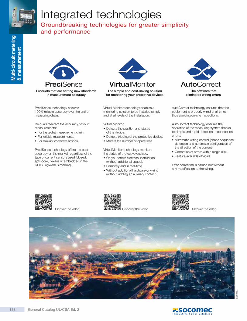
Products that are setting new standards in measurement accuracy
PreciSense technology ensures 100% reliable accuracy over the entire measuring chain.
Be guaranteed of the accuracy of your measurements:
For the global measurement chain.
For reliable measurements.
For relevant corrective actions.
PreciSense technology offers the best accuracy on the market regardless of the type of current sensors used (closed, split-core, flexible or embedded in the DIRIS Digiware S module).
The simple and cost-saving solution for monitoring your protective devices
Virtual Monitor technology enables a monitoring solution to be installed simply and at all levels of the installation.
Virtual Monitor:
Detects the position and status of the device.
Detects tripping of the protective device.
Meters the number of operations.
VirtualMonitor technology monitors the status of protective devices:
On your entire electrical installation (without additional space).
Remotely and in real-time.
Without additional hardware or wiring (without adding an auxiliary contact).
The software that eliminates wiring errors
AutoCorrect technology ensures that the equipment is properly wired at all times, thus avoiding on-site inspections.
AutoCorrect technology ensures the operation of the measuring system thanks to simple and rapid detection of connection errors:
Automatic wiring control (phase sequence detection and automatic configuration of the direction of the current).
Correction of errors with a single click.
Feature available off-load.
Error correction is carried out without any modification to the wiring.
Discover the video Discover the video Discover the video
SY
DIV
_419_A
VirtualMonitor AutoCorrectPreciSense
Integrated technologies Groundbreaking technologies for greater simplicity and performance
Mu
lti-
cir
cu
it m
ete
rin
g
& m
easu
rem
en
t
188 General Catalog UL/CSA Ed. 2
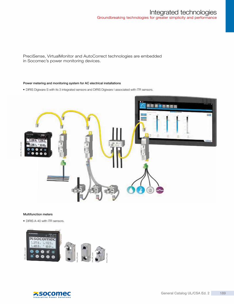
DIRIS Digiware S with its 3 integrated sensors and DIRIS Digiware I associated with iTR sensors.
DIRIS A-40 with iTR sensors.
Multifunction meters
PreciSense, VirtualMonitor and AutoCorrect technologies are embedded in Socomec’s power monitoring devices.
Power metering and monitoring system for AC electrical installations
diri
s_989_a
_us.
eps
diri
s-d
w_1
43_a
_us.
eps
tore
_078_a
.ep
s
tore
_080_a
.ep
s
tore
_074_a
.ep
s
Integrated technologiesGroundbreaking technologies for greater simplicity and performance
189General Catalog UL/CSA Ed. 2
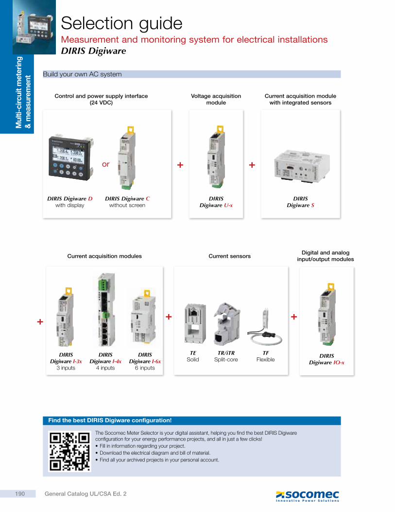
Build your own AC system
Find the best DIRIS Digiware configuration!
Control and power supply interface (24 VDC)
DIRIS Digiware D with display
DIRIS Digiware C without screen
DIRIS Digiware U-x
Voltage acquisition module
DIRIS Digiware S
Current acquisition module with integrated sensors
+ +or
DIRIS Digiware IO-x
Digital and analog input/output modules
+ ++
DIRIS Digiware I-3x
3 inputs
DIRIS Digiware I-4x
4 inputs
DIRIS Digiware I-6x
6 inputs
Current acquisition modules Current sensors
TESolid
TR/iTRSplit-core
TFFlexible
The Socomec Meter Selector is your digital assistant, helping you find the best DIRIS Digiware configuration for your energy performance projects, and all in just a few clicks!
Fill in information regarding your project.
Download the electrical diagram and bill of material.
Find all your archived projects in your personal account.
Selection guideMeasurement and monitoring system for electrical installationsDIRIS Digiware
Mu
lti-
cir
cu
it m
ete
rin
g
& m
easu
rem
en
t
190 General Catalog UL/CSA Ed. 2
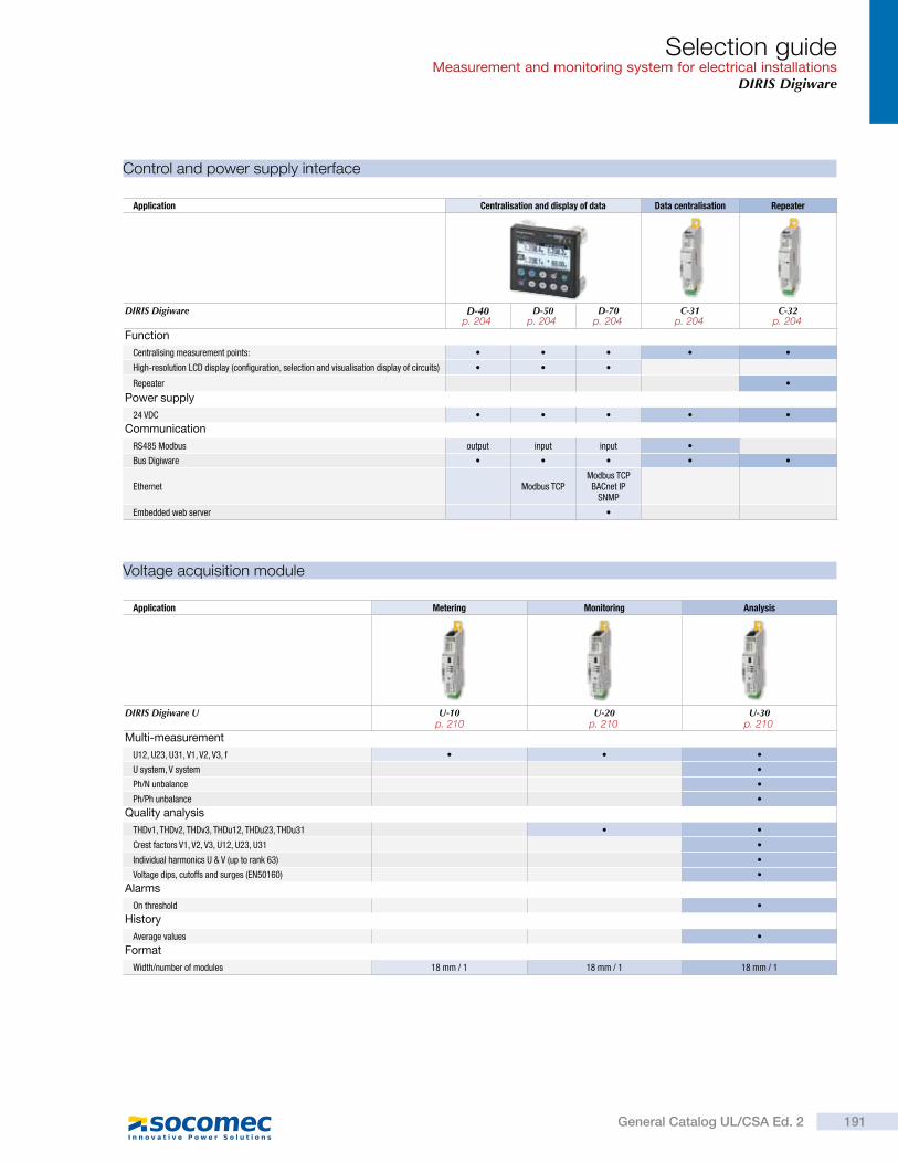
Application Centralisation and display of data Data centralisation Repeater
DIRIS Digiware D-40 D-50 D-70 C-31 C-32
Function
Centralising measurement points:
High-resolution LCD display (configuration, selection and visualisation display of circuits)
Repeater
Power supply
24 VDC
Communication
RS485 Modbus output input input
Bus Digiware
Ethernet Modbus TCPModbus TCP
BACnet IPSNMP
Embedded web server
Control and power supply interface
Application Metering Monitoring Analysis
DIRIS Digiware U U-10 U-20 U-30
Multi-measurement
U12, U23, U31, V1, V2, V3, f
U system, V system
Ph/N unbalance
Ph/Ph unbalance
Quality analysis
THDv1, THDv2, THDv3, THDu12, THDu23, THDu31
Crest factors V1, V2, V3, U12, U23, U31
Individual harmonics U & V (up to rank 63)
Voltage dips, cutoffs and surges (EN50160)
Alarms
On threshold
History
Average values
Format
Width/number of modules 18 mm / 1 18 mm / 1 18 mm / 1
Voltage acquisition module
Selection guideMeasurement and monitoring system for electrical installations
DIRIS Digiware
191General Catalog UL/CSA Ed. 2
p. 204 p. 204 p. 204 p. 204 p. 204
p. 210 p. 210 p. 210
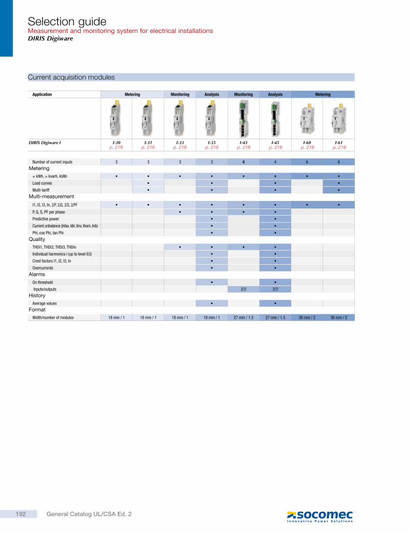
Application Metering Monitoring Analysis Monitoring Analysis Metering
DIRIS Digiware I I-30 I-31 I-33 I-35 I-43 I-45 I-60 I-61
Number of current inputs 3 3 3 3 4 4 6 6
Metering
± kWh, ± kvarh, kVAh
Load curves
Multi-tariff
Multi-measurement
I1, I2, I3, In, P, Q, S, PF
P, Q, S, PF per phase
Predictive power
Current unbalance (Inba, Idir, Iinv, Ihom, Inb)
Phi, cos Phi, tan Phi
Quality
THDi1, THDi2, THDi3, THDin
Individual harmonics I (up to level 63)
Crest factors l1, l2, l3, ln
Overcurrents
Alarms
On threshold
Inputs/outputs 2/2 2/2
History
Average values
Format
Width/number of modules 18 mm / 1 18 mm / 1 18 mm / 1 18 mm / 1 27 mm / 1.5 27 mm / 1.5 36 mm / 2 36 mm / 2
Current acquisition modules
Selection guideMeasurement and monitoring system for electrical installationsDIRIS Digiware
192 General Catalog UL/CSA Ed. 2
p. 216 p. 216 p. 216 p. 216 p. 216 p. 216 p. 216 p. 216
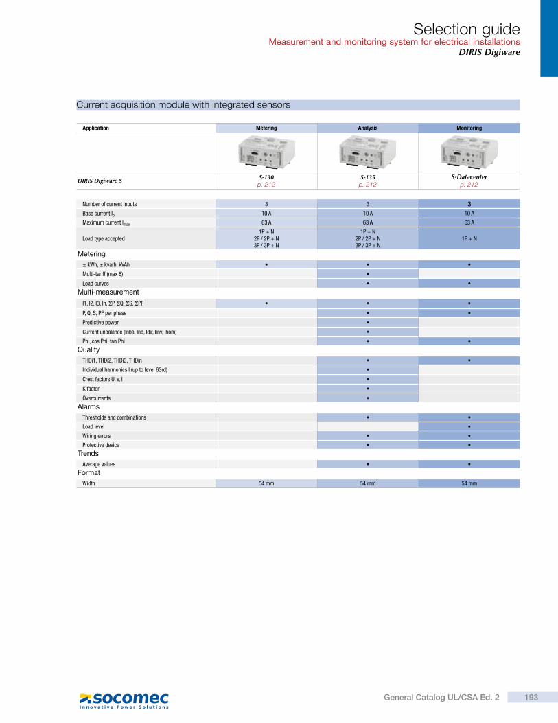
Current acquisition module with integrated sensors
Application Metering Analysis Monitoring
DIRIS Digiware S S-130 S-135 S-Datacenter
Number of current inputs 3 3 3
Base current Ib 10 A 10 A 10 A
Maximum current Imax 63 A 63 A 63 A
Load type accepted1P + N
2P / 2P + N3P / 3P + N
1P + N2P / 2P + N3P / 3P + N
1P + N
Metering
± kWh, ± kvarh, kVAh
Multi-tariff (max 8)
Load curves
Multi-measurement
I1, I2, I3, In, P, Q, S, PF
P, Q, S, PF per phase
Predictive power
Current unbalance (Inba, Inb, Idir, Iinv, Ihom)
Phi, cos Phi, tan Phi
Quality
THDi1, THDi2, THDi3, THDin
Individual harmonics I (up to level 63rd)
Crest factors U, V, I
K factor
Overcurrents
Alarms
Thresholds and combinations
Load level
Wiring errors
Protective device
Trends
Average values
Format
Width 54 mm 54 mm 54 mm
Selection guideMeasurement and monitoring system for electrical installations
DIRIS Digiware
193General Catalog UL/CSA Ed. 2
p. 212 p. 212 p. 212
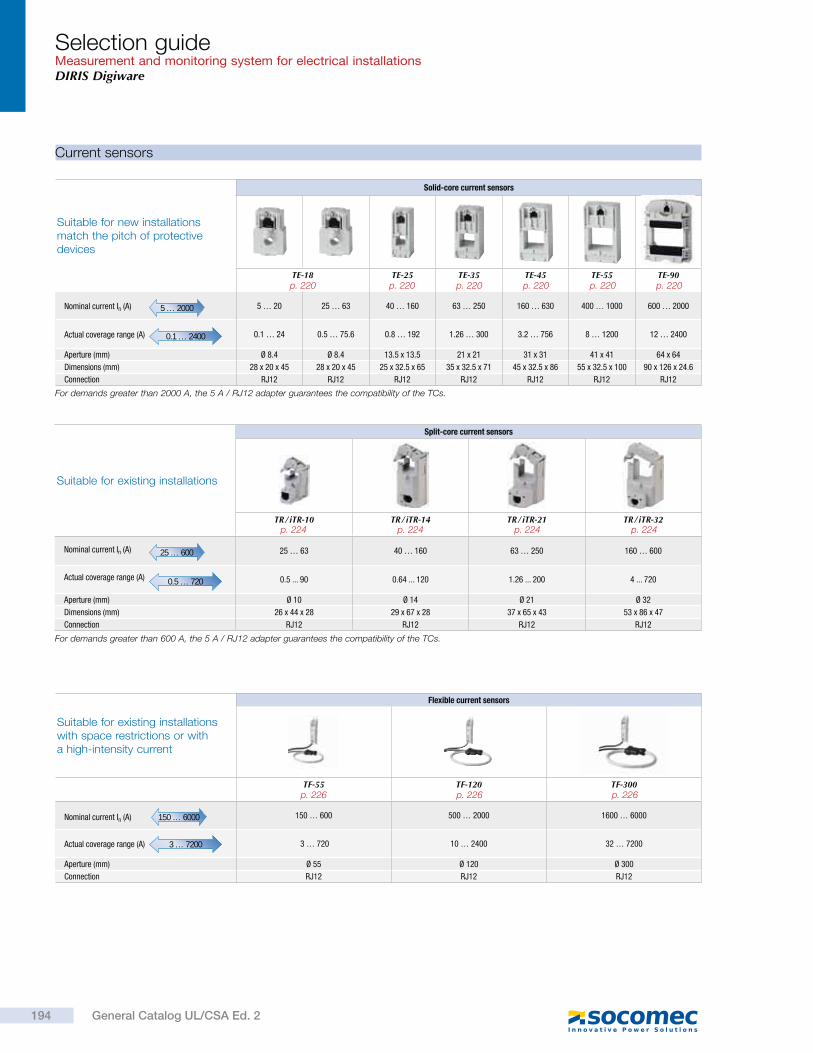
Suitable for existing installations with space restrictions or with a high-intensity current
Flexible current sensors
TF-55 TF-120 TF-300
Nominal current In (A) 150 … 6000 150 … 600 500 … 2000 1600 … 6000
Actual coverage range (A)
3 … 7200 3 … 720 10 … 2400 32 … 7200
Aperture (mm) Ø 55 Ø 120 Ø 300
Connection RJ12 RJ12 RJ12
Suitable for new installations match the pitch of protective devices
Solid-core current sensors
TE-18 TE-25 TE-35 TE-45 TE-55 TE-90
Nominal current In (A) 5 … 2000 5 … 20 25 … 63 40 … 160 63 … 250 160 … 630 400 … 1000 600 … 2000
Actual coverage range (A) 0.1 … 2400 0.1 … 24 0.5 … 75.6 0.8 … 192 1.26 … 300 3.2 … 756 8 … 1200 12 … 2400
Aperture (mm) Ø 8.4 Ø 8.4 13.5 x 13.5 21 x 21 31 x 31 41 x 41 64 x 64
Dimensions (mm) 28 x 20 x 45 28 x 20 x 45 25 x 32.5 x 65 35 x 32.5 x 71 45 x 32.5 x 86 55 x 32.5 x 100 90 x 126 x 24.6
Connection RJ12 RJ12 RJ12 RJ12 RJ12 RJ12 RJ12
For demands greater than 2000 A, the 5 A / RJ12 adapter guarantees the compatibility of the TCs.
Current sensors
Suitable for existing installations
Split-core current sensors
TR / iTR-10 TR / iTR-14 TR / iTR-21 TR / iTR-32
Nominal current In (A) 25 … 600 25 … 63 40 … 160 63 … 250 160 … 600
Actual coverage range (A) 0.5 … 720 0.5 ... 90 0.64 ... 120 1.26 ... 200 4 ... 720
Aperture (mm) Ø 10 Ø 14 Ø 21 Ø 32
Dimensions (mm) 26 x 44 x 28 29 x 67 x 28 37 x 65 x 43 53 x 86 x 47
Connection RJ12 RJ12 RJ12 RJ12
For demands greater than 600 A, the 5 A / RJ12 adapter guarantees the compatibility of the TCs.
Selection guideMeasurement and monitoring system for electrical installationsDIRIS Digiware
194 General Catalog UL/CSA Ed. 2
p. 220 p. 220 p. 220 p. 220 p. 220 p. 220
p. 226 p. 226 p. 226
p. 224p. 224p. 224p. 224
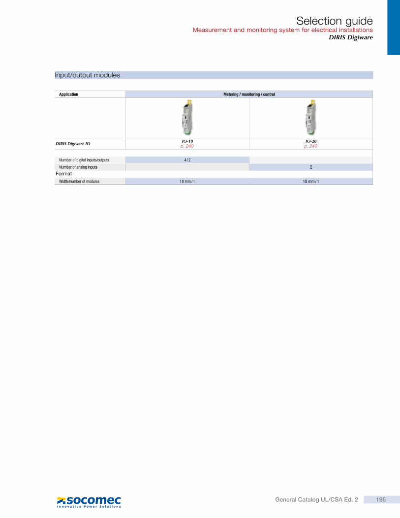
Input/output modules
Application Metering / monitoring / control
DIRIS Digiware IO IO-10 IO-20
Number of digital inputs/outputs 4 / 2
Number of analog inputs 2
Format
Width/number of modules 18 mm / 1 18 mm / 1
Selection guideMeasurement and monitoring system for electrical installations
DIRIS Digiware
195General Catalog UL/CSA Ed. 2
p. 240 p. 240
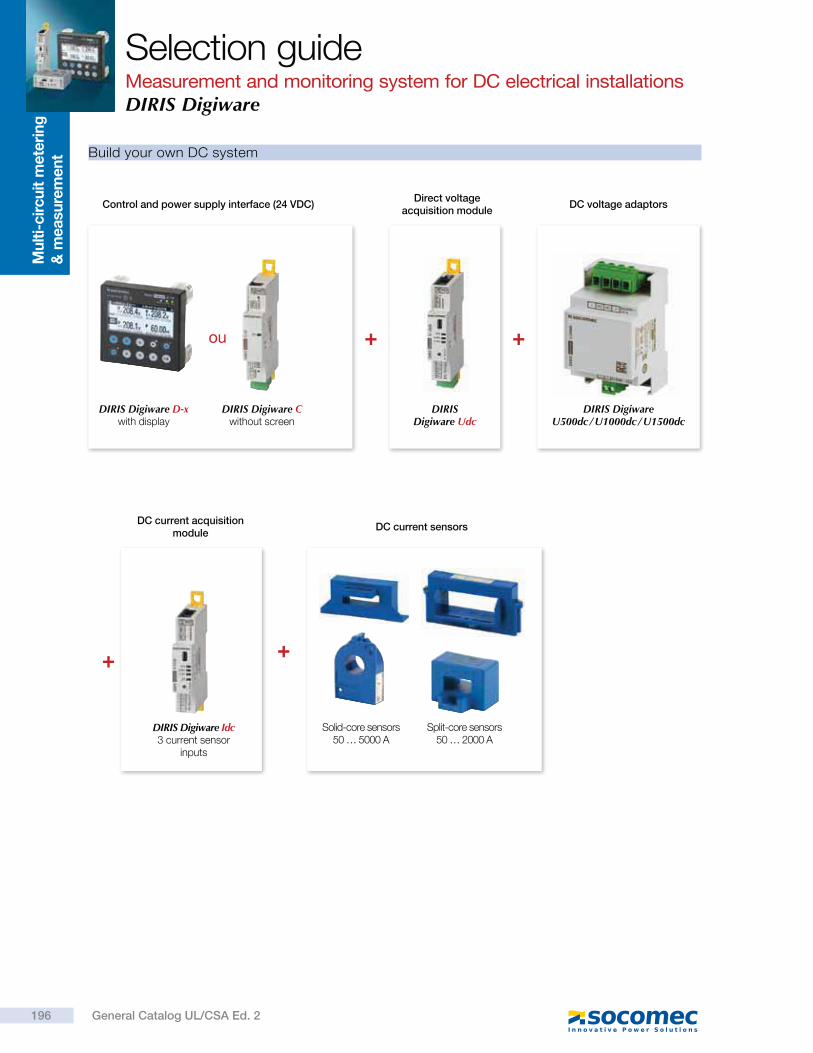
Control and power supply interface (24 VDC)
DIRIS Digiware D-x with display
DIRIS Digiware C without screen
DIRIS Digiware Udc
Direct voltage acquisition module
DIRIS Digiware U500dc / U1000dc / U1500dc
DC voltage adaptors
+ +ou
+ +
DIRIS Digiware Idc 3 current sensor
inputs
DC current acquisition module
Build your own DC system
DC current sensors
Solid-core sensors50 … 5000 A
Split-core sensors50 … 2000 A
Selection guideMeasurement and monitoring system for DC electrical installationsDIRIS Digiware
Mu
lti-
cir
cu
it m
ete
rin
g
& m
easu
rem
en
t
196 General Catalog UL/CSA Ed. 2
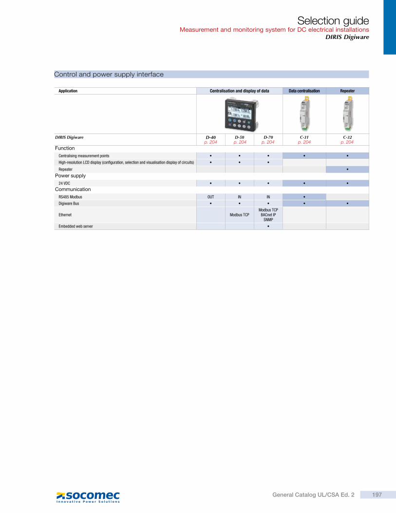
Application Centralisation and display of data Data centralisation Repeater
DIRIS Digiware D-40 D-50 D-70 C-31 C-32
Function
Centralising measurement points
High-resolution LCD display (configuration, selection and visualisation display of circuits)
Repeater
Power supply
24 VDC
Communication
RS485 Modbus OUT IN IN
Digiware Bus
Ethernet Modbus TCPModbus TCP
BACnet IPSNMP
Embedded web server
Control and power supply interface
Selection guideMeasurement and monitoring system for DC electrical installations
DIRIS Digiware
197General Catalog UL/CSA Ed. 2
p. 204 p. 204 p. 204 p. 204 p. 204
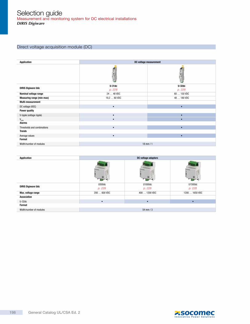
Direct voltage acquisition module (DC)
Application DC voltage measurement
DIRIS Digiware UdcU-31dc U-32dc
Nominal voltage range 24 … 48 VDC 60 … 150 VDC
Measuring range (min-max) 19,2 … 60 VDC 48 … 180 VDC
Multi-measurement
DC voltage (VDC)
Power quality
V ripple (voltage ripple)
Vrms
Alarms
Thresholds and combinations
Trends
Average values
Format
Width/number of modules 18 mm / 1
Application DC voltage adaptors
DIRIS Digiware UdcU500dc U1000dc U1500dc
Max. voltage range 200 … 600 VDC 400 … 1200 VDC 1200 … 1650 VDC
Association
U-32dc
Format
Width/number of modules 54 mm / 3
Selection guideMeasurement and monitoring system for DC electrical installationsDIRIS Digiware
198 General Catalog UL/CSA Ed. 2
p. 228 p. 228
p. 228 p. 228 p. 228
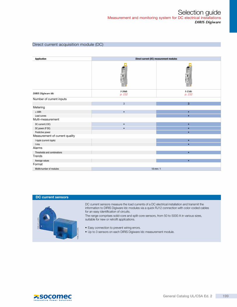
Direct current acquisition module (DC)
Application Direct current (DC) measurement modules
DIRIS Digiware IdcI-30dc I-35dc
Number of current inputs
3 3
Metering
± kWh
Load curves
Multi-measurement
DC current (I DC)
DC power (P DC)
Predictive power
Measurement of current quality
I ripple (current ripple)
I rms
Alarms
Thresholds and combinations
Trends
Average values
Format
Width/number of modules 18 mm / 1
DC current sensors
TO
RE
_071_A
.EP
S
TO
RE
_072_A
.EP
S
DC current sensors measure the load currents of a DC electrical installation and transmit the information to DIRIS Digiware Idc modules via a quick RJ12 connection with color-coded cables for an easy identification of circuits.
The range comprises solid-core and split-core sensors, from 50 to 5000 A in various sizes, suitable for new or retrofit applications.
Easy connection to prevent wiring errors.
Up to 3 sensors on each DIRIS Digiware Idc measurement module.
Selection guideMeasurement and monitoring system for DC electrical installations
DIRIS Digiware
199General Catalog UL/CSA Ed. 2
p. 232 p. 232
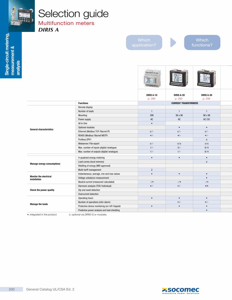
Which application?
Which functions?
DIRIS A-10 DIRIS A-20 DIRIS A-30
Functions CURRENT TRANSFORMERS
General characteristics
Remote display
Number of loads 1 1 1
Mounting DIN 96 x 96 96 x 96
Power supply AC AC AC / DC
All In One
Optional modules
Ethernet (Modbus TCP / Bacnet IP) o / - o / - o / -
RS485 (Modbus / Bacnet MSTP) / - / - / -
Profibus DPV1 o
Webserver / File export o / - o / o o / o
Max. number of inputs (digital / analogue) 1 / - 3 / - 6 / 4
Max. number of outputs (digital / analogue) 1 / - 1 / - 6 / 4
Manage energy consumptions
4-quadrant energy metering
Load curves (local memory) o
Rebilling of energy (MID approved)
Multi-tariff management 2
Monitor the electrical installation
Instantaneous, average, min and max values
Voltage unbalance measurement
Neutral current (measured / calculated) - / - / - /
Check the power quality
Harmonic analysis (THD / Individual) / - / - /
Dip and swell detection
Overcurrent detection
Manage the loads
Operating hours
Number of operations (info / alarm) / - / -
Protective device monitoring (on / off / tripped)
Predictive power analysis and load shedding
: integrated in the product. o: optional via DIRIS-G or modules.
Selection guideMultifunction metersDIRIS A
Sin
gle
-circ
uit m
eter
ing
, m
easu
rem
ent
&
anal
ysis
p. 266 p. 262 p. 256
200 General Catalog UL/CSA Ed. 2

Which dimensions?
Which communication
protocol?
Which options?
DIRIS -10 DIRIS -30
DIRIS A-40Modbus
DIRIS A-40Modbus + Profibus
DIRIS A-40Modbus + Ethernet
SMART SENSORS
1 to 4 1 to 4 1
DIN DIN 96 x 96
AC AC AC
/ o / o - / - - / - /
/ o / o / - / - / -
o o - -
o / o o / o o / o o / o /
2 / 2 3 / -
2 / 2 2 / -
8 8 4
/ / - /
/ - / /
/ - / /
Selection guideMultifunction meters
DIRIS A
p. 248 p. 248 p. 242 p. 242 p. 242
201General Catalog UL/CSA Ed. 2
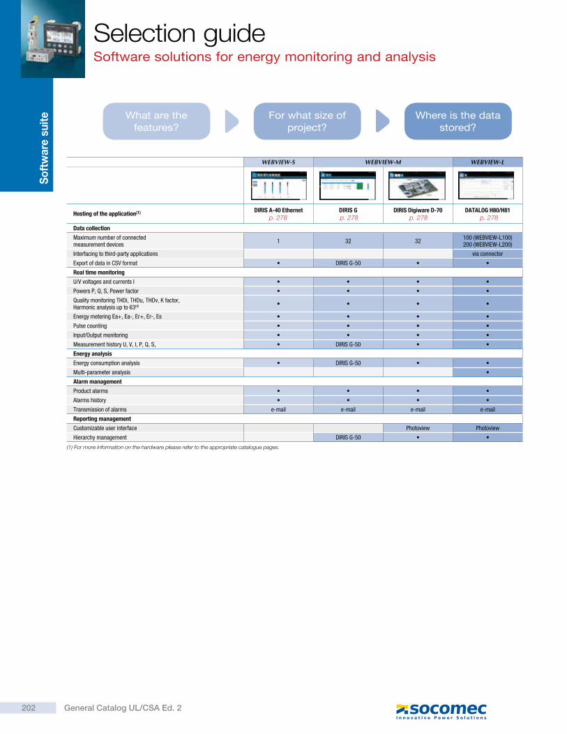
WEBVIEW-S WEBVIEW-M WEBVIEW-L
Hosting of the application(1) DIRIS A-40 Ethernet DIRIS G DIRIS Digiware D-70 DATALOG H80/H81
Data collection
Maximum number of connected measurement devices
1 32 32100 (WEBVIEW-L100)200 (WEBVIEW-L200)
Interfacing to third-party applications via connector
Export of data in CSV format DIRIS G-50
Real time monitoring
U/V voltages and currents I
Powers P, Q, S, Power factor
Quality monitoring THDi, THDu, THDv, K factor,Harmonic analysis up to 63rd
Energy metering Ea+, Ea-, Er+, Er-, Es
Pulse counting
Input/Output monitoring
Measurement history U, V, I, P, Q, S, DIRIS G-50
Energy analysis
Energy consumption analysis DIRIS G-50
Multi-parameter analysis
Alarm management
Product alarms
Alarms history
Transmission of alarms e-mail e-mail e-mail e-mail
Reporting management
Customizable user interface Photoview Photoview
Hierarchy management DIRIS G-50
(1) For more information on the hardware please refer to the appropriate catalogue pages.
What are the features?
Where is the data stored?
For what size of project?
Selection guideSoftware solutions for energy monitoring and analysis
So
ftw
are
su
ite
p. 278 p. 278 p. 278 p. 278
202 General Catalog UL/CSA Ed. 2
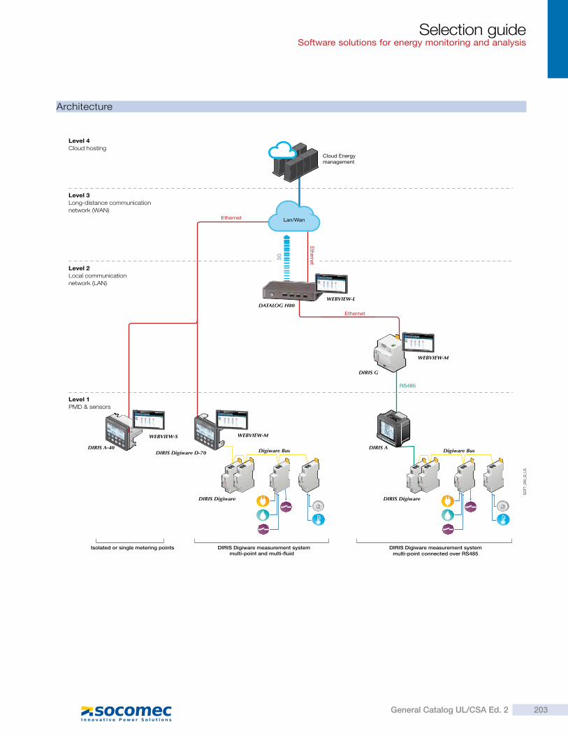
Architecture
SO
FT_0
60_B
_US
Ethernet
Eth
ernet
Isolated or single metering points DIRIS Digiware measurement systemmulti-point and multi- uid
Level 1
PMD & sensors
Level 2
Local communication
network (LAN)
Level 3
Long-distance communication
network (WAN)
Level 4
Cloud hosting
Cloud Energymanagement
Lan/Wan
DIRIS Digiware measurement systemmulti-point connected over RS485
Ethernet
DIRIS A
DATALOG H80
RS485
3G
Digiware BusDIRIS A-40
DIRIS G
WEBVIEW-L
WEBVIEW-M
WEBVIEW-MWEBVIEW-S
DIRIS Digiware D-70
DIRIS Digiware
Digiware Bus
DIRIS Digiware
Selection guideSoftware solutions for energy monitoring and analysis
203General Catalog UL/CSA Ed. 2
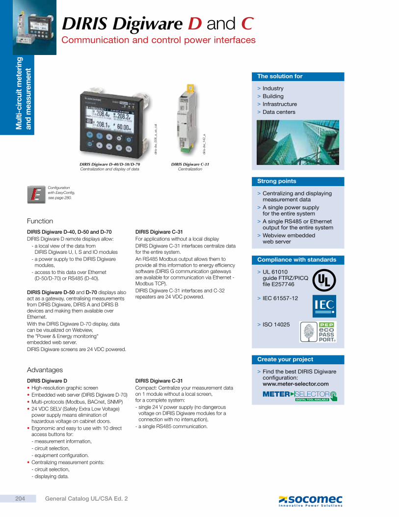
Mu
lti-
cir
cu
it m
ete
rin
g
an
d m
easu
rem
en
tDIRIS Digiware D and CCommunication and control power interfaces
Function
DIRIS Digiware D-40, D-50 and D-70
DIRIS Digiware D remote displays allow:
- a local view of the data from DIRIS Digiware U, I, S and IO modules
- a power supply to the DIRIS Digiware modules,
- access to this data over Ethernet (D-50/D-70) or RS485 (D-40).
DIRIS Digiware D-50 and D-70 displays also act as a gateway, centralising measurements from DIRIS Digiware, DIRIS A and DIRIS B devices and making them available over Ethernet.
With the DIRIS Digiware D-70 display, data can be visualized on Webview, the "Power & Energy monitoring" embedded web server.
DIRIS Digiware screens are 24 VDC powered.
DIRIS Digiware C-31
For applications without a local display
DIRIS Digiware C-31 interfaces centralize data for the entire system.
An RS485 Modbus output allows them to provide all this information to energy efficiency software (DIRIS G communication gateways are available for communication via Ethernet - Modbus TCP).
DIRIS Digiware C-31 interfaces and C-32 repeaters are 24 VDC powered.
> Centralizing and displaying measurement data
> A single power supply for the entire system
> A single RS485 or Ethernet output for the entire system
> Webview embedded web server
Strong points
Advantages
DIRIS Digiware D
High-resolution graphic screen
Embedded web server (DIRIS Digiware D-70)
Multi-protocols (Modbus, BACnet, SNMP)
24 VDC SELV (Safety Extra Low Voltage) power supply means elimination of hazardous voltage on cabinet doors.
Ergonomic and easy to use with 10 direct access buttons for:
- measurement information,
- circuit selection,
- equipment configuration.
Centralizing measurement points:
- circuit selection,
- displaying data.
DIRIS Digiware C-31
Compact: Centralize your measurement data on 1 module without a local screen, for a complete system:
- single 24 V power supply (no dangerous voltage on DIRIS Digiware modules for a connection with no interruption),
- a single RS485 communication.
> Industry
> Building
> Infrastructure
> Data centers
The solution for
diri
s-d
w_0
06
_a_u
s_ca
t
diri
s-d
w_1
42
_a
DIRIS Digiware D-40/D-50/D-70Centralization and display of data
DIRIS Digiware C-31Centralization
> UL 61010guide FTRZ/PICQfile E257746
> IEC 61557-12
> ISO 14025
Compliance with standards
Configuration
with EasyConfig,
> Find the best DIRIS Digiware configuration:www.meter-selector.com
Create your project
204 General Catalog UL/CSA Ed. 2
see page 280.
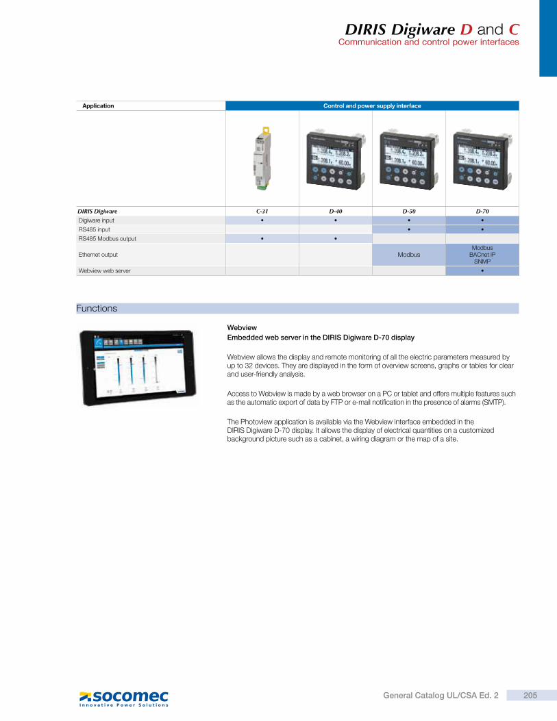
DIRIS Digiware D and CCommunication and control power interfaces
Application Control and power supply interface
DIRIS Digiware C-31 D-40 D-50 D-70
Digiware input
RS485 input
RS485 Modbus output
Ethernet output ModbusModbus
BACnet IPSNMP
Webview web server
Webview
Embedded web server in the DIRIS Digiware D-70 display
Webview allows the display and remote monitoring of all the electric parameters measured by up to 32 devices. They are displayed in the form of overview screens, graphs or tables for clear and user-friendly analysis.
Access to Webview is made by a web browser on a PC or tablet and offers multiple features such as the automatic export of data by FTP or e-mail notification in the presence of alarms (SMTP).
The Photoview application is available via the Webview interface embedded in the DIRIS Digiware D-70 display. It allows the display of electrical quantities on a customized background picture such as a cabinet, a wiring diagram or the map of a site.
Functions
205General Catalog UL/CSA Ed. 2
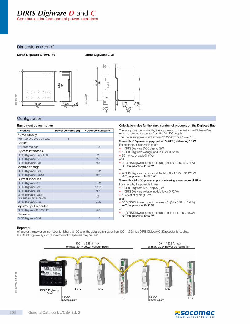
DIRIS Digiware D and CCommunication and control power interfaces
Configuration
The total power consumed by the equipment connected to the Digiware Bus must not exceed the power from the 24 VDC supply.
The power supply must not exceed 20 W/70°C or 27 W/40°C.
Size with P15 power supply (ref: 4829 0120) delivering 15 W
For example, it is possible to use
1 DIRIS Digiware D-50 display (2W)
1 DIRIS Digiware voltage module U-xx (0.72 W)
50 metres of cable (1.5 W)
and
20 DIRIS Digiware current modules I-3x (20 x 0.52 = 10.4 W) Total power = 14.62 W
or
9 DIRIS Digiware current modules I-4x (9 x 1.125 = 10.125 W) Total power = 14.345 W.
Size with a 24 VDC power supply delivering a maximum of 20 W
For example, it is possible to use
1 DIRIS Digiware D-50 display (2W)
1 DIRIS Digiware voltage module U-xx (0.72 W)
164 feet of cable (1.5 W)
and
30 DIRIS Digiware current modules I-3x (30 x 0.52 = 15.6 W) Total power = 19.82 W
or
14 DIRIS Digiware current modules I-4x (14 x 1.125 = 15.72) Total power = 19.97 W.
Equipment consumption Calculation rules for the max. number of products on the Digiware Bus
diri
s-d
w_0
39
_b_1
_en_c
at
RepeaterWhenever the power consumption is higher than 20 W or the distance is greater than 100 m /328 ft, a DIRIS Digiware C-32 repeater is required.
In a DIRIS Digiware system, a maximum of 2 repeaters may be used.
100 m / 328 ft maxor max. 20 W power consumption
100 m / 328 ft maxor max. 20 W power consumption
U-xx I-3x I-3xC-32
I-4x I-4x24 VDC power supply
24 VDC power supply
DIRIS Digiware D-x0
Dimensions (in/mm)
DIRIS Digiware D-40/D-50 DIRIS Digiware C-31
C-3x3.
54
0.70 2.56
1.73 0.59
90
18 65
44 15
diri
s-d
w_0
62
diri
s-d
w_0
37
3.8292
0.711.061827
92
3.82
Product Power delivered (W) Power consumed (W)
Power supplyP15 100-240 VAC / 24 VDC 15
Cables164-foot package 1,5
System interfacesDIRIS Digiware D-40/D-50 2
DIRIS Digiware D-70 2,5
DIRIS Digiware C-31 0,8
Module voltageDIRIS Digiware U-xx 0,72
DIRIS Digiware U-3xdc 0,6
Current modulesDIRIS Digiware I-3x 0,52
DIRIS Digiware I-4x 1,125
DIRIS Digiware I-6x 0,7
DIRIS Digiware I-3xdc (+ 3 DC current sensors)
2
DIRIS Digiware S-xx 0,35
Input/output modulesDIRIS Digiware IO-10/IO-20 0,5
RepeaterDIRIS Digiware C-32 1,5
206 General Catalog UL/CSA Ed. 2

DIRIS Digiware D and CCommunication and control power interfaces
Connections (continued)
*
RS485 120 120
DIRIS Digiware D-40
Digiware Bus
24 VDC
(20 W max)
NC
RS48
5D
igiw
are
LIYCY-CY
SLAVE
24 V
SU
PP
LY
24 VDC(20 W max)
DigiwareBus
*24 VDC
(20 W max)
RS485
DIRIS Digiware D-50
Digiware Bus
Ethernet
120
NC
RS48
5D
igiw
are
LIYCY-CY
Ethernet
DigiwareBus
MASTER
24 VDC(20 W max)
Ethe
rnet
24 V
SU
PP
LY
RS485
DIRIS Digiware D-70
Webview
Digiware Bus
Ethernet
120
NC
RS48
5D
igiw
are
LIYCY-CY
Ethernet
DigiwareBus
MASTER
24 VDC(20 W max)
Ethe
rnet
24 V
SU
PP
LY
DIRIS Digiware D-40
DIRIS Digiware D-50
DIRIS Digiware D-70
diri
s-d
w_0
57
_b_1
_cat
diri
s-d
w_0
56
_b_1
_cat
diri
s-d
w_0
56
_a_1
_cat
(*) 1A / 24 VDC fuse protection is recommended if the 24 VDC power supply is not provided by Socomec.
(**) On DIRIS Digiware D-40 and D-50 displays, class B radiated power is obtained using ferrites (ref. 4829 0048) on the power supply (two turns).
(*) 1A / 24 VDC fuse protection is recommended if the 24 VDC power supply is not provided by Socomec.
(**) On DIRIS Digiware D-40 and D-50 displays, class B radiated power is obtained using ferrites (ref. 4829 0048) on the power supply (two turns).
(*) 1A / 24 VDC fuse protection is recommended if the 24 VDC power supply is not provided by Socomec.
207General Catalog UL/CSA Ed. 2
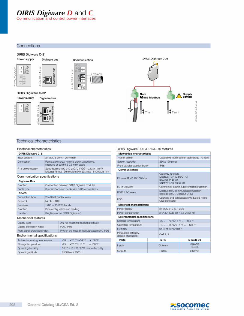
DIRIS Digiware D and CCommunication and control power interfaces
Technical characteristics
Environmental specifications
Ambient operating temperature -10 … +70 °C/+14 °F … +158 °F
Storage temperature -25 … +70 °C/-13 °F … + 158 °F
Operating humidity 55 °C / 131 °F / 97% relative humidity
Operating altitude 6560 feet / 2000 m
Mechanical features
Casing type DIN-rail mounting module and base
Casing protection index IP20 / IK06
Front panel protection index IP40 on the nose in modular assembly / IK06
Electrical characteristics
DIRIS Digiware C-31
Input voltage 24 VDC ± 20 % - 20 W max
Connection Removable screw terminal block, 2 positions,stranded or solid 0.2-2.5 mm² cable
P15 power supply Specifications 100-240 VAC/ 24 VDC - 0.63 A - 15 WModular format - Dimensions (H x L): 3.5 x 1 in/90 x 25 mm
Communication specifications
Digiware Bus
Function Connection between DIRIS Digiware modules
Cable type Specific Socomec cable with RJ45 connections
RS485
Connection type 2 to 3 half duplex wires
Protocol Modbus RTU
Baudrate 1200 to 115 200 bauds
Function Data configuration and reading
Location Single-point on DIRIS Digiware C
Ports D-40 D-50/D-70
Inputs DigiwareDigiware RS485
Outputs RS485 Ethernet
DIRIS Digiware D-40/D-50/D-70 features
Mechanical characteristics
Type of screen Capacitive touch-screen technology, 10 keys
Screen resolution 350 x 160 pixels
Front panel protection index IP65
Communication
Ethernet RJ45 10/100 Mbs
Gateway function:Modbus TCP (D-50/D-70)BACnet IP (D-70)SNMP v1, v2, v3 (D-70)
RJ45 Digiware Control and power supply interface function
RS485 2-3 wiresModbus RTU communication function(input D-50/D-70/output D-40)
USBUpgrade and configuration via type B micro USB connector
Electrical characteristics
Power supply 24 VDC +10 % / -20%
Power consumption 2 VA (D-40/D-50) / 2.5 VA (D-70)
Environmental specifications
Storage temperature -20 … +70 °C/-4 °F … +158 °F
Operating temperature -10 … +55 °C/+14 °F … +131 °F
Humidity 95 % at 40 °C/104 °F
Installation category, degree of pollution
CAT III, 2
NC
RS
48
5 LIYCY-CYS
up
ply
24
VD
C1
2O
N
Communication
diri
s-d
w_0
18
_b_1
_x_c
at
diri
s-d
w_0
57
_a_1
_en_c
at
24 V
SU
PP
LYR
S485NC
DIG
IWA
RE
BU
S
RJ4
5
Digiware busPower supply
DIRIS Digiware C-31
diri
s-d
w_0
12
_a_1
_x_c
at
diri
s-d
w_0
23
_b_1
_x_c
at
DIG
IWA
RE
BU
S
RJ4
5 INO
UT
24 V
SU
PP
LY
Digiware busPower supply
DIRIS Digiware C-32
diri
s-d
w_0
24
_b_1
_x_c
at
diri
s-d
w_0
13
_a_1
_x_c
at
7 mm
24VDCSupply
7 mm
Com
RS485 Modbus
DIRIS Digiware C-31
Connections
208 General Catalog UL/CSA Ed. 2
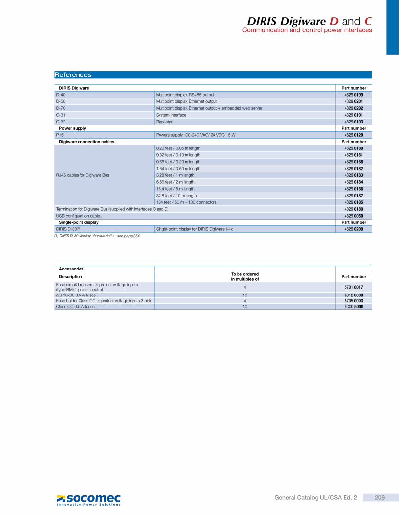
DIRIS Digiware D and CCommunication and control power interfaces
References
DIRIS Digiware Part number
D-40 Multipoint display, RS485 output 4829 0199
D-50 Multipoint display, Ethernet output 4829 0201
D-70 Multipoint display, Ethernet output + embedded web server 4829 0202
C-31 System interface 4829 0101
C-32 Repeater 4829 0103
Power supply Part number
P15 Powers supply 100-240 VAC/ 24 VDC 15 W 4829 0120
Digiware connection cables Part number
RJ45 cables for Digiware Bus
0.20 feet / 0.06 m length 4829 0189
0.32 feet / 0.10 m length 4829 0181
0.66 feet / 0.20 m length 4829 0188
1.64 feet / 0.50 m length 4829 0182
3.28 feet / 1 m length 4829 0183
6.56 feet / 2 m length 4829 0184
16.4 feet / 5 m length 4829 0186
32.8 feet / 10 m length 4829 0187
164 feet / 50 m + 100 connectors 4829 0185
Termination for Digiware Bus (supplied with interfaces C and D) 4829 0180
USB configuration cable 4829 0050
Single-point display Part number
DIRIS D-30(1) Single-point display for DIRIS Digiware I-4x 4829 0200
(1) DIRIS D-30 display characteristics
Accessories
DescriptionTo be orderedin multiples of
Part number
Fuse circuit breakers to protect voltage inputs (type RM) 1 pole + neutral
4 5701 0017
gG 10x38 0.5 A fuses 10 6012 0000Fuse holder Class CC to protect voltage inputs 3 pole 4 5705 0003Class CC 0.5 A fuses 10 6CC0 5000
see page 254.
209General Catalog UL/CSA Ed. 2
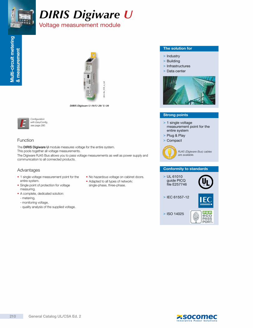
Mu
lti-
cir
cu
it m
ete
rin
g
& m
easu
rem
en
t
Function
The DIRIS Digiware U module measures voltage for the entire system. This pools together all voltage measurements.
The Digiware RJ45 Bus allows you to pass voltage measurements as well as power supply and communication to all connected products.
> 1 single voltage measurement point for the entire system
> Plug & Play
> Compact
Strong points
Advantages
1 single voltage measurement point for the entire system.
Single point of protection for voltage measuring.
A complete, dedicated solution:
- metering,
- monitoring voltage,
- quality analysis of the supplied voltage.
No hazardous voltage on cabinet doors.
Adapted to all types of network: single-phase, three-phase.
> Industry
> Building
> Infrastructures
> Data center
The solution for
diri
s-d
w_0
05
_a_c
atDIRIS Digiware U-10/U-20/ U-30
Configuration
with EasyConfig,
DIRIS Digiware UVoltage measurement module
RJ45 (Digiware Bus) cables are available.
RJ45
C
ommunication
> UL 61010guide PICQfile E257746
> IEC 61557-12
> ISO 14025
Conformity to standards
210 General Catalog UL/CSA Ed. 2
see page 280.
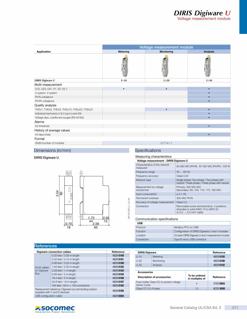
DIRIS Digiware UVoltage measurement module
Dimensions (in/mm)
DIRIS Digiware U
3.54
0.70 2.56
1.73 0.59
90
18 65
44 15
diri
s-d
w_0
59
_a_1
_us_
cat
Voltage measurement moduleApplication Metering Monitoring Analysis
DIRIS Digiware U U-10 U-20 U-30
Multi-measurement
U12, U23, U31, V1, V2, V3, f
U system, V system
Ph/N unbalance
Ph/Ph unbalance
Quality analysis
THDv1, THDv2, THDv3, THDu12, THDu23, THDu31
Individual harmonics U & V (up to rank 63)
Voltage dips, cutoffs and surges (EN 50160)
Alarms
On threshold
History of average values
45 days (max)
Format
Width/number of modules 0.71 in / 1
Specifications
Communication specifications
USB
Protocol Modbus RTU on USB
Function Configuration of DIRIS Digiware U and I modules
Location On each DIRIS Digiware U and I measurement module
Connection Type B micro USB connector
Measuring characteristics
Voltage measurement - DIRIS Digiware U
Characteristics of the network measured
50-300 VAC (Ph/N) - 87-520 VAC (Ph/Ph) - CAT III
Frequency range 45 … 65 Hz
Frequency accuracy Class 0.02
Network type Single-phase/ Two-phase / Two-phase with neutral / Three-phase / Three-phase with neutral
Measurement by voltage transformer
Primary: 400 000 VACSecondary: 60, 100, 110, 173, 190 VAC
Input consumption 0.1 VA
Permanent overload 300 VAC Ph/N
Accuracy of voltage measurement Class 0.2
Connection Removable screw terminal block, 4 positions,stranded or solid AWG 10 to AWG 32 or 0.2 … 2.5 mm² cable
References
Digiware connection cables Reference
RJ45 cables for Digiware Bus
0.20 feet / 0.06 m length 4829 0189
0.32 feet / 0.10 m length 4829 0181
0.66 feet / 0.20 m length 4829 0188
1.64 feet / 0.50 m length 4829 0182
3.28 feet / 1 m length 4829 0183
6.56 feet / 2 m length 4829 0184
16.4 feet / 5 m length 4829 0186
32.8 feet / 10 m length 4829 0187
164 feet / 50 m + 100 connectors 4829 0185
Replacement reference: Digiware bus terminating resistor (supplied with C and D devices)
4829 0180
USB configuration cable 4829 0050
DIRIS Digiware Reference
U-10 Metering 4829 0105
U-20 Monitoring 4829 0106
U-30 Analysis 4829 0102
Accessories
Description of accessoriesTo be orderedin multiples of
Reference
Fuse holder Class CC to protect voltage inputs 3 pole
4 5705 0003
Class CC 0.5 A fuses 10 6CC0 5000
211General Catalog UL/CSA Ed. 2
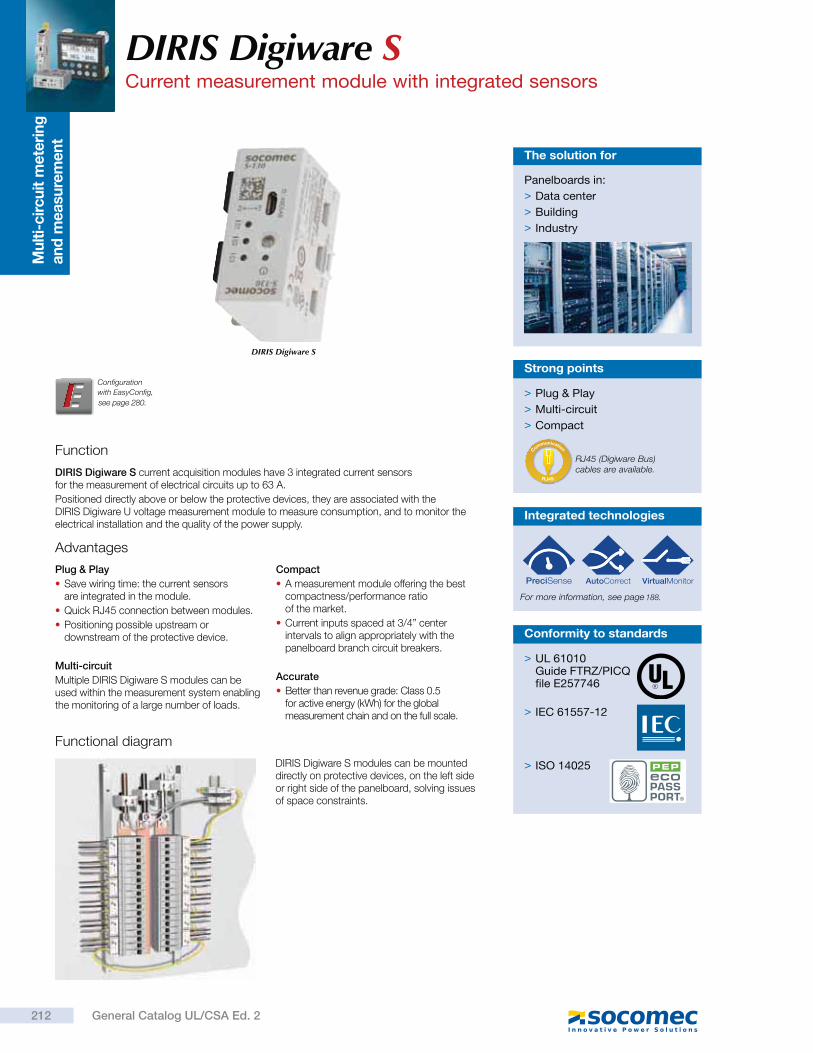
Mu
lti-
cir
cu
it m
ete
rin
g
an
d m
easu
rem
en
t
Function
DIRIS Digiware S current acquisition modules have 3 integrated current sensors for the measurement of electrical circuits up to 63 A.
Positioned directly above or below the protective devices, they are associated with the DIRIS Digiware U voltage measurement module to measure consumption, and to monitor the electrical installation and the quality of the power supply.
Advantages
Plug & Play
Save wiring time: the current sensors are integrated in the module.
Quick RJ45 connection between modules.
Positioning possible upstream or downstream of the protective device.
Multi-circuit
Multiple DIRIS Digiware S modules can be used within the measurement system enabling the monitoring of a large number of loads.
Compact
A measurement module offering the best compactness/performance ratio of the market.
Current inputs spaced at 3/4” center intervals to align appropriately with the panelboard branch circuit breakers.
Accurate
Better than revenue grade: Class 0.5 for active energy (kWh) for the global measurement chain and on the full scale.
Functional diagram
Panelboards in:
> Data center
> Building
> Industry
The solution for
DIRIS Digiware S
Configuration
with EasyConfig,
DIRIS Digiware SCurrent measurement module with integrated sensors
> Plug & Play
> Multi-circuit
> Compact
Strong points
RJ45 (Digiware Bus) cables are available.
RJ45
C
ommunication
DIRIS Digiware S modules can be mounted directly on protective devices, on the left side or right side of the panelboard, solving issues of space constraints.
Integrated technologies
For more information, see page
> UL 61010 Guide FTRZ/PICQfile E257746
> IEC 61557-12
> ISO 14025
Conformity to standards
212 General Catalog UL/CSA Ed. 2
see page 280.
188.
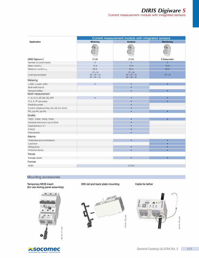
DIRIS Digiware SCurrent measurement module with integrated sensors
Current measurement module with integrated sensorsApplication Metering Analysis Monitoring
DIRIS Digiware S S-130 S-135 S-DatacenterNumber of current inputs 3 3 3
Basic current Ib 10 A 10 A 10 A
Maximum current Imax 63 A 63 A 63 A
Load type accepted1P + N
2P / 2P + N3P / 3P + N
1P + N2P / 2P + N3P / 3P + N
1P + N
Metering
± kWh, ± kvarh, kVAh
Multi-tariff (max 8)
Demand profiles
Multi-measurement
I1, I2, I3, In, P, Q, S, PF
P, Q, S, PF per phase
Predictive power
Current unbalance (Inba, Inb, Idir, Iinv, Ihom)
Phi, cos Phi, tan Phi
Quality
THDi1, THDi2, THDi3, THDin
Individual harmonics I (up to 63rd)
Crest factors U, V, I
K factor
Overcurrents
Alarms
Thresholds and combinations
Load level
Wiring errors
Protective device
Trends
Average values
Format
Width 2.13 in
Mounting accessories
Temporary MCB insert (for use during panel assembly)
DIN rail and back plate mounting Cable tie tether
diri
s-d
w_1
39
_a.e
ps
diri
s-d
w_1
38
_a.e
ps
diri
s-d
w_1
37
_a.e
ps
213General Catalog UL/CSA Ed. 2
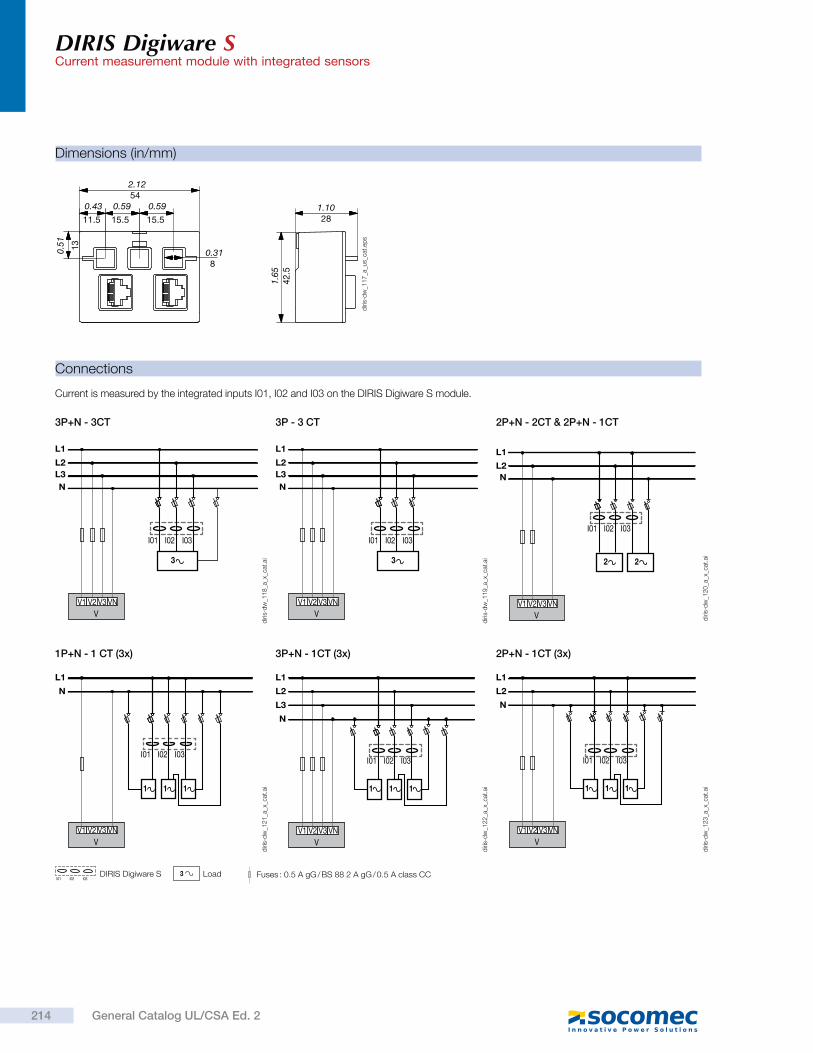
DIRIS Digiware SCurrent measurement module with integrated sensors
Connections
3 Load Fuses : 0.5 A gG / BS 88 2 A gG / 0.5 A class CCI01 I02 I03
DIRIS Digiware S
Current is measured by the integrated inputs I01, I02 and I03 on the DIRIS Digiware S module.
3P+N - 3CT 2P+N - 2CT & 2P+N - 1CT
3P+N - 1CT (3x)
3P - 3 CT
1P+N - 1 CT (3x) 2P+N - 1CT (3x)
V1 V2 V3 VN
V
L1
L2
L3
N
3
I01 I02 I03
I01 I02 I03
V1 V2 V3 VN
V
L1
L2
N
2 2
I01 I02 I03
V1 V2 V3 VN
V
L1
L2
L3
N
111
V1 V2 V3 VN
V
L1
L2
L3
N
3
I01 I02 I03
I01 I02 I03
V1 V2 V3 VN
V
L1
N
111
I01 I02 I03
V1 V2 V3 VN
V
L1
L2
N
111
diri
s-d
w_1
23
_a_x
_cat
.ai
diri
s-d
w_1
22
_a_x
_cat
.ai
diri
s-d
w_1
21
_a_x
_cat
.ai
diri
s-d
w_1
20
_a_x
_cat
.ai
diri
s-d
w_1
19
_a_x
_cat
.ai
diri
s-d
w_1
18
_a_x
_cat
.ai
Dimensions (in/mm)
2.1254
0.59
15.5
0.59
15.5
0.43
11.5
0.51 13
0.318
1.1028
1.65
42.5
diri
s-d
w_1
17
_a_u
s_ca
t.ep
s
214 General Catalog UL/CSA Ed. 2
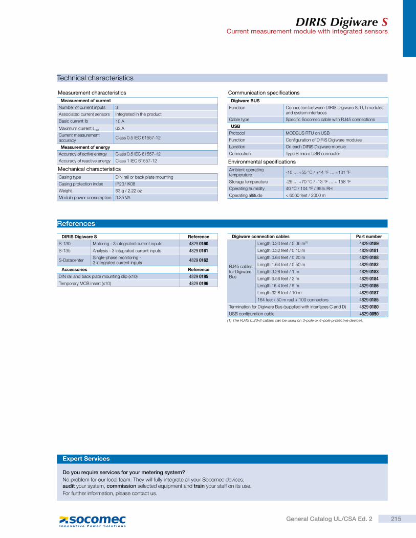
DIRIS Digiware SCurrent measurement module with integrated sensors
Technical characteristics
Measurement characteristics
Mechanical characteristics
Measurement of current
Number of current inputs 3
Associated current sensors Integrated in the product
Basic current Ib 10 A
Maximum current Imax 63 A
Current measurement accuracy
Class 0.5 IEC 61557-12
Casing type DIN rail or back plate mounting
Casing protection index IP20 / IK08
Weight 63 g / 2.22 oz
Module power consumption 0.35 VA
Measurement of energy
Accuracy of active energy Class 0.5 IEC 61557-12
Accuracy of reactive energy Class 1 IEC 61557-12
Communication specifications
Digiware BUS
Function Connection between DIRIS Digiware S, U, I modules and system interfaces
Cable type Specific Socomec cable with RJ45 connections
USB
Protocol MODBUS RTU on USB
Function Configuration of DIRIS Digiware modules
Location On each DIRIS Digiware module
Connection Type B micro USB connector
Environmental specifications
Ambient operating temperature
-10 … +55 °C / +14 °F … +131 °F
Storage temperature -25 … +70 °C / -13 °F … + 158 °F
Operating humidity 40 °C / 104 °F / 95% RH
Operating altitude < 6560 feet / 2000 m
References
DIRIS Digiware S Reference
S-130 Metering - 3 integrated current inputs 4829 0160
S-135 Analysis - 3 integrated current inputs 4829 0161
S-DatacenterSingle-phase monitoring - 3 integrated current inputs
4829 0162
Accessories Reference
DIN rail and back plate mounting clip (x10) 4829 0195
Temporary MCB insert (x10) 4829 0196
Digiware connection cables Part number
RJ45 cables for Digiware Bus
Length 0.20 feet / 0.06 m(1) 4829 0189
Length 0.32 feet / 0.10 m 4829 0181
Length 0.64 feet / 0.20 m 4829 0188
Length 1.64 feet / 0.50 m 4829 0182
Length 3.28 feet / 1 m 4829 0183
Length 6.56 feet / 2 m 4829 0184
Length 16.4 feet / 5 m 4829 0186
Length 32.8 feet / 10 m 4829 0187
164 feet / 50 m reel + 100 connectors 4829 0185
Termination for Digiware Bus (supplied with interfaces C and D) 4829 0180
USB configuration cable 4829 0050
(1) The RJ45 0.20-ft cables can be used on 3-pole or 4-pole protective devices.
Expert Services
Do you require services for your metering system?
No problem for our local team. They will fully integrate all your Socomec devices, audit your system, commission selected equipment and train your staff on its use.
For further information, please contact us.
215General Catalog UL/CSA Ed. 2
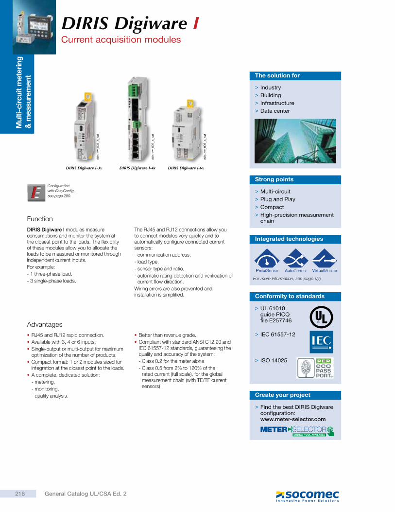
Mu
lti-
cir
cu
it m
ete
rin
g
& m
easu
rem
en
t
Function
DIRIS Digiware I modules measure consumptions and monitor the system at the closest point to the loads. The flexibility of these modules allow you to allocate the loads to be measured or monitored through independent current inputs.
For example:
- 1 three-phase load,
- 3 single-phase loads.
The RJ45 and RJ12 connections allow you to connect modules very quickly and to automatically configure connected current sensors:
- communication address,
- load type,
- sensor type and ratio,
- automatic rating detection and verification of current flow direction.
Wiring errors are also prevented and installation is simplified.
> Multi-circuit
> Plug and Play
> Compact
> High-precision measurement chain
Strong points
Advantages
RJ45 and RJ12 rapid connection.
Available with 3, 4 or 6 inputs.
Single-output or multi-output for maximum optimization of the number of products.
Compact format: 1 or 2 modules sized for integration at the closest point to the loads.
A complete, dedicated solution:
- metering,
- monitoring,
- quality analysis.
Better than revenue grade.
Compliant with standard ANSI C12.20 and IEC 61557-12 standards, guaranteeing the quality and accuracy of the system:
- Class 0.2 for the meter alone
- Class 0.5 from 2% to 120% of the rated current (full scale), for the global measurement chain (with TE/TF current sensors)
> Industry
> Building
> Infrastructure
> Data center
The solution for
diri
s-d
w_0
04
_a_c
at
diri
s-d
w_0
07
_a_c
at
diri
s-d
w_0
07
_a_c
at
DIRIS Digiware I-3x DIRIS Digiware I-4x DIRIS Digiware I-6x
> UL 61010 guide PICQ file E257746
> IEC 61557-12
> ISO 14025
Conformity to standards
Configuration
with EasyConfig,
DIRIS Digiware I Current acquisition modules
Integrated technologies
For more information, see page
> Find the best DIRIS Digiware configuration:www.meter-selector.com
Create your project
216 General Catalog UL/CSA Ed. 2
see page 280.
188.
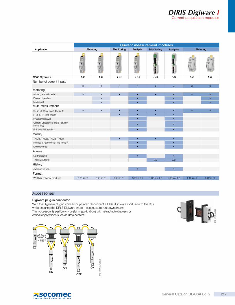
DIRIS Digiware ICurrent acquisition modules
Current measurement modulesApplication Metering Monitoring Analysis Monitoring Analysis Metering
DIRIS Digiware I I-30 I-31 I-33 I-35 I-43 I-45 I-60 I-61
Number of current inputs
3 3 3 3 4 4 6 6
Metering
± kWh, ± kvarh, kVAh
Demand profiles
Multi-tariff
Multi-measurement
I1, I2, I3, In, P, Q, S, PF
P, Q, S, PF per phase
Predictive power
Current unbalance (Inba, Idir, Iinv, Ihom, Inb)
Phi, cos Phi, tan Phi
Quality
THDi1, THDi2, THDi3, THDin
Individual harmonics I (up to 63rd)
Overcurrents
Alarms
On threshold
Inputs/outputs 2/2 2/2
History
Average values
Format
Width/number of modules 0.71 in / 1 0.71 in / 1 0.71 in / 1 0.71 in / 1 1.06 in / 1.5 1.06 in / 1.5 1.42 in / 2 1.42 in / 2
Digiware plug-in connector
With the Digiware plug-in connector you can disconnect a DIRIS Digiware module form the Bus while ensuring the DIRIS Digiware system continues to run downstream. This accessory is particularly useful in applications with retractable drawers or critical applications such as data centers.
Accessories
I-3x
U-xx
= TEST
ON
ON
OFF
ON
CLICK
I-3x
I-3x
I-3x
diri
s-o
_02
5_a
.ep
s
diri
s-o
_02
6_a
_1_c
at.a
i
217General Catalog UL/CSA Ed. 2
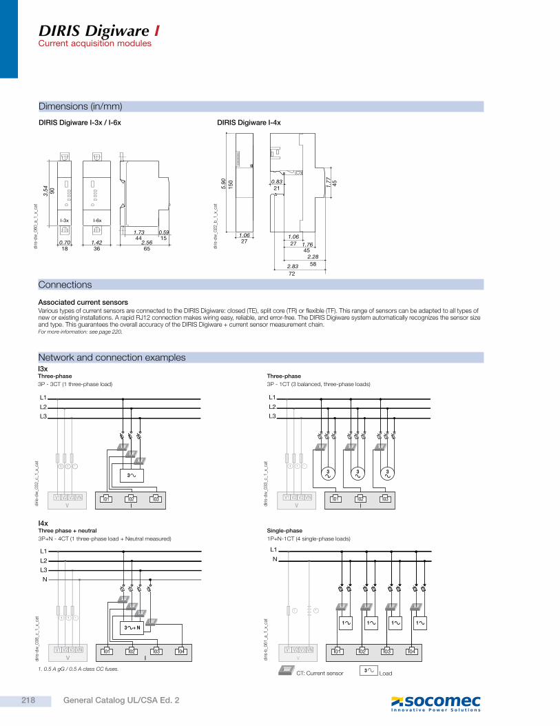
DIRIS Digiware ICurrent acquisition modules
Connections
diri
s-d
w_0
32
_c_1
_x_c
at
Three-phase
3P - 3CT (1 three-phase load)
V1 V2 V3 VN
V II01 I02 I03
3
L1
L2
L3
111
diri
s-d
w_0
33
_c_1
_x_c
at
Three-phase
3P - 1CT (3 balanced, three-phase loads)
V1 V2 V3 VN
V I
333
I01 I02 I03
L1
L2
L3
111
diri
s-b
_06
1_a
_1_x
_cat
Single-phase
1P+N-1CT (4 single-phase loads)
IV
V1 V2 V3 VN
L1
N
I02 I03I01 I04
1 1 1 1
1
Network and connection examples
1. 0.5 A gG / 0.5 A class CC fuses. 3 Load CT: Current sensor
diri
s-d
w_0
38
_c_1
_x_c
at
Three phase + neutral
3P+N - 4CT (1 three-phase load + Neutral measured)
II01 I02 I03 I04
N
V1 V2 V3 VN
V
L1
L2
L3
3 + N
1 1 1
Associated current sensorsVarious types of current sensors are connected to the DIRIS Digiware: closed (TE), split core (TR) or flexible (TF). This range of sensors can be adapted to all types of new or existing installations. A rapid RJ12 connection makes wiring easy, reliable, and error-free. The DIRIS Digiware system automatically recognizes the sensor size and type. This guarantees the overall accuracy of the DIRIS Digiware + current sensor measurement chain.For more information:
I3x
I4x
Dimensions (in/mm)
DIRIS Digiware I-3x / I-6x
I-6xI-3x
3.54
0.70 1.42 2.56
1.73 0.59
90
18 36 65
44 15
diri
s-d
w_0
60
_a_1
_x_c
at
DIRIS Digiware I-4x
72
271.06
1.7645
271.06
0.83215.
9015
0
582.28
2.83
451.77
diri
s-d
w_0
22
_b_1
_x_c
at
218 General Catalog UL/CSA Ed. 2
see page 220.
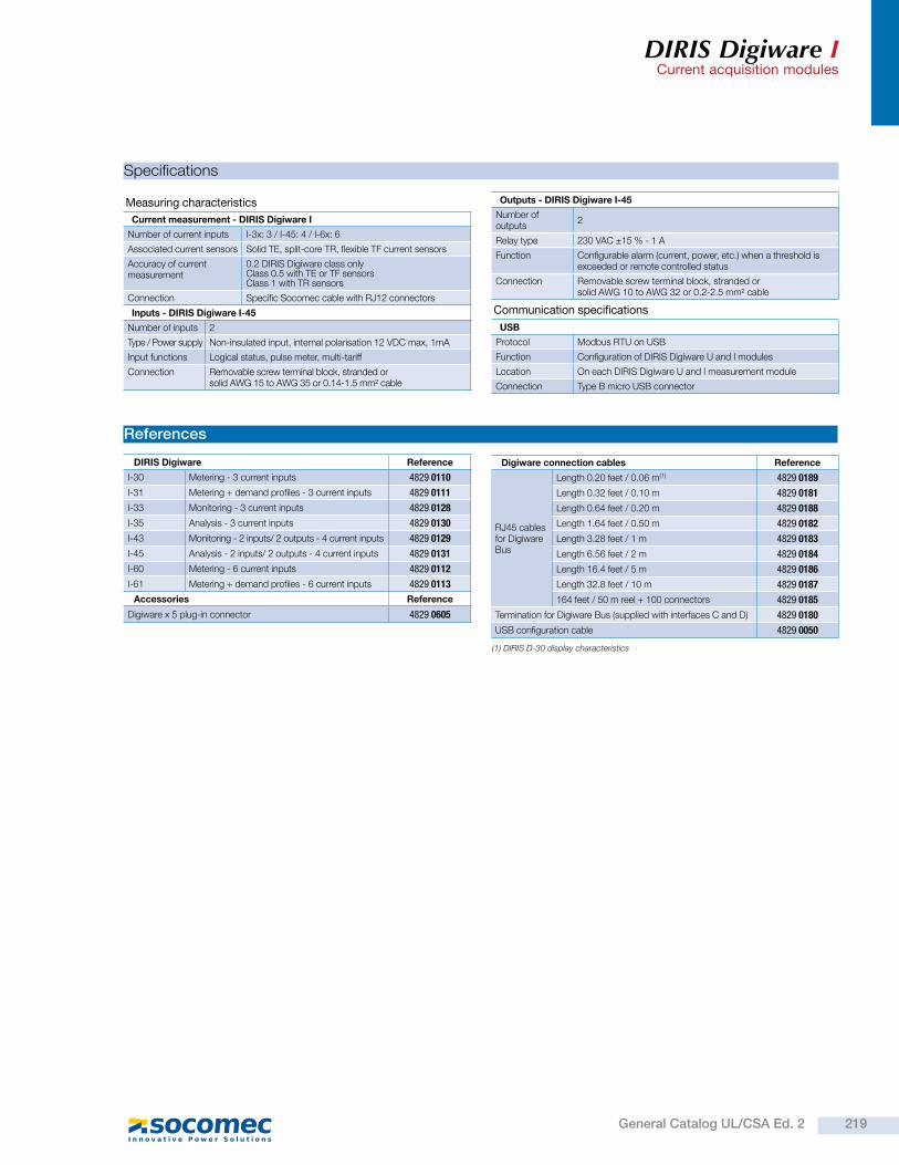
DIRIS Digiware ICurrent acquisition modules
Specifications
Measuring characteristics
Current measurement - DIRIS Digiware I
Number of current inputs I-3x: 3 / I-45: 4 / I-6x: 6
Associated current sensors Solid TE, split-core TR, flexible TF current sensors
Accuracy of current measurement
0.2 DIRIS Digiware class only Class 0.5 with TE or TF sensors Class 1 with TR sensors
Connection Specific Socomec cable with RJ12 connectors
Inputs - DIRIS Digiware I-45
Number of inputs 2
Type / Power supply Non-insulated input, internal polarisation 12 VDC max, 1mA
Input functions Logical status, pulse meter, multi-tariff
Connection Removable screw terminal block, stranded orsolid AWG 15 to AWG 35 or 0.14-1.5 mm² cable
Outputs - DIRIS Digiware I-45
Number of outputs
2
Relay type 230 VAC ±15 % - 1 A
Function Configurable alarm (current, power, etc.) when a threshold is exceeded or remote controlled status
Connection Removable screw terminal block, stranded orsolid AWG 10 to AWG 32 or 0.2-2.5 mm² cable
Communication specifications
USB
Protocol Modbus RTU on USB
Function Configuration of DIRIS Digiware U and I modules
Location On each DIRIS Digiware U and I measurement module
Connection Type B micro USB connector
References
DIRIS Digiware Reference
I-30 Metering - 3 current inputs 4829 0110
I-31 Metering + demand profiles - 3 current inputs 4829 0111
I-33 Monitoring - 3 current inputs 4829 0128
I-35 Analysis - 3 current inputs 4829 0130
I-43 Monitoring - 2 inputs/ 2 outputs - 4 current inputs 4829 0129
I-45 Analysis - 2 inputs/ 2 outputs - 4 current inputs 4829 0131
I-60 Metering - 6 current inputs 4829 0112
I-61 Metering + demand profiles - 6 current inputs 4829 0113
Accessories Reference
Digiware x 5 plug-in connector 4829 0605
(1) DIRIS D-30 display characteristics
Digiware connection cables Reference
RJ45 cables for Digiware Bus
Length 0.20 feet / 0.06 m(1) 4829 0189
Length 0.32 feet / 0.10 m 4829 0181
Length 0.64 feet / 0.20 m 4829 0188
Length 1.64 feet / 0.50 m 4829 0182
Length 3.28 feet / 1 m 4829 0183
Length 6.56 feet / 2 m 4829 0184
Length 16.4 feet / 5 m 4829 0186
Length 32.8 feet / 10 m 4829 0187
164 feet / 50 m reel + 100 connectors 4829 0185
Termination for Digiware Bus (supplied with interfaces C and D) 4829 0180
USB configuration cable 4829 0050
219General Catalog UL/CSA Ed. 2
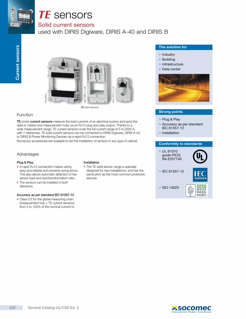
Cu
rre
nt
se
nso
rs TE sensorsSolid current sensorsused with DIRIS Digiware, DIRIS A-40 and DIRIS B
TE solid sensors
Function
TE smart current sensors measure the load currents of an electrical system and send the data to meters and measurement hubs via an RJ12 plug-and-play output. Thanks to a wide measurement range, TE current sensors cover the full current range of 5 to 2000 A, with 7 references. TE solid current sensors can be connected to DIRIS Digiware, DIRIS A-40, or DIRIS B Power Monitoring Devices via a rapid RJ12 connection.
Numerous accessories are available to aid the installation of sensors in any type of cabinet.
> Plug & Play
> Accuracy as per standard IEC 61557-12
> Installation
Strong points
Advantages
Plug & Play
A rapid RJ12 connection makes wiring easy and reliable and prevents wiring errors. This also allows automatic detection of the sensor type and size/transformation ratio.
The sensors can be installed in both directions.
Accuracy as per standard IEC 61557-12
Class 0.5 for the global measuring chain (measurement hub + TE current sensors) from 2 to 120% of the nominal current In.
Installation
The TE solid sensor range is specially designed for new installations, and has the same pitch as the most common protective devices.
> Industry
> Building
> Infrastructure
> Data center
The solution for
diri
s-t_
01
0_a
_1_c
at
diri
s-t_
00
3_a
_1_c
at
tore
_06
5_a
> UL 61010guide PICQfile E257746
> IEC 61557-12
> ISO 14025
Conformity to standards
220 General Catalog UL/CSA Ed. 2
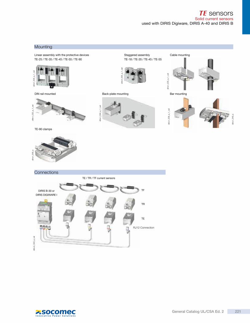
TE sensorsSolid current sensors
used with DIRIS Digiware, DIRIS A-40 and DIRIS B
Mounting
Connections
DIN rail mounted
diri
s-t_
03
3_a
_1_c
at
diri
s-t_
03
6_a
_1_c
at
Bar mounting
diri
s-t_
03
4_a
_1_c
at
Back-plate mounting
Staggered assembly
TE-18 / TE-35 / TE-45 / TE-55
diri
s-t_
00
5_a
_1_c
at
diri
s-t_
03
5_a
_1_c
at
Cable mountingLinear assembly with the protective devices
TE-25 / TE-35 / TE-45 / TE-55 / TE-90
diri
s-t_
00
5_a
_1_c
at
TE-90 clamps
diri
s-t_
04
8_a
diri
s-t_
04
9_a
diri
s-b
_03
3_a
_cat
TE / TR / TF current sensors
TR
TF
TE
RJ12 Connection
DIRIS B-30 or
DIRIS DIGIWARE I
221General Catalog UL/CSA Ed. 2

TE sensorsSolid current sensorsused with DIRIS Digiware, DIRIS A-40 and DIRIS B
Dimensions (in/mm)
TE - Solid current sensors
TE-18
DW
HØ
Model Nominal current range (A) Actual coverage range (A) Pitch (in/mm) H x W x D (in/mm) F (in/mm) T (in/mm)
TE-18 5 … 20/25 ... 63 0.1 … 24/0.5 … 75 0.7/18 1.77 x 1.10 x 0.79/45 x 28 x 20 Ø 0.33/8.6 -
TE-25 40 … 160 0.8 … 192 0.98/25 2.56 x 0.98 x 1.28/65 x 25 x 32.5 0.53 x 0.53/13.5 x 13.5 0.69/17.5
TE-35 63 … 250 1.26 … 300 1.37/35 2.79 x 1.37 x 1.28/71 x 35 x 32.5 0.82 x 0.82 / 21 x 21 0.69/17.5
TE-45 160 … 630 3.2 … 756 1.77/45 3.38 x 1.77 x 1.28/86 x 45 x 32.5 1.22 x 1.22 / 31 x 31 0.77/19.5
TE-55 400 … 1000 8 … 1200 2.16/55 3.93 x 2.16 x 1.28/100 x 55 x 32.5 1.61 x 1.61 / 41 x 41 0.85/21.5
TE-90 600 … 2000 12 … 2400 3.54/90 4.96 x 3.54 x 0.97/126 x 90 x 24.6 2.52 x 2.52 / 64 x 64 -
TE-25 / TE-35 / TE-45 / TE-55 TE-90
DW
H
T
= F =
==
==
1
1
D0.09
2.2
W
1.41
0.77
36
19.7
= F =
H
diri
s-t_
02
3_b
_1_e
n_c
at
diri
s-t_
04
7_a
_1_e
n_c
at
1. Switch mounting
Mounting accessories
diri
s-t_
04
2_a
- 0
43
_a -
04
4_a
- 0
45
_a
Mounting accessories delivered with TE sensors:
Switch mounting TE-18 TE-25
TE-35TE-45TE-55 TE-90
DIN rail and back-plate
1 pc 2 pcs
DIN rail 2 pcs 2 pcs
Back-plate 4 pcs 4 pcs 6 pcs
Busbar 2 pcs
Compatible accessories
Adapter for CT with 5A secondary With this adapter you can use a current transformer with a 5 A output on the DIRIS Digiware and DIRIS B-30.For use with standard 5 A sensors for measuring applications of > 2000 A. The dimensions are the same as the TE-18.
Coupling link Associated with the TE range, this accessory is for inter-connecting the sensors when linear or staggered mounted.
Sealable cover Using a sealable cover guarantees the immunity of the sensor connection on TE/TR/TF current sensors.
diri
s-t_
02
0_a
_1_c
at
diri
s-t_
04
6_a
_1_c
at
diri
s-t_
04
1_a
_1_c
at
222 General Catalog UL/CSA Ed. 2
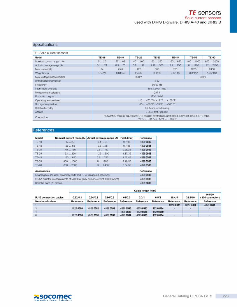
TE sensorsSolid current sensors
used with DIRIS Digiware, DIRIS A-40 and DIRIS B
Specifications
References
Accessories Reference
Coupling link (20 linear assembly parts and 10 for staggered assembly) 4829 0598
CT/5A adapter (measurements of >2000 A) (max primary current 10000 A/5/A) 4829 0599
Sealable caps (20 pieces) 4829 0600
RJ12 connection cables
Cable length (ft/m)
0.32/0.1 0.64/0.2 0.96/0.3 1.64/0.5 3.3/1 6.5/2 16.4/5 32.8/10164/50
+ 100 connectors
Number of cables Reference Reference Reference Reference Reference Reference Reference Reference Reference
1 - - - - - - 4829 0602 4829 0603 4829 06013 4829 0580 4829 0581 4829 0582 4829 0595 4829 0583 4829 0584 - - -
4 - - - 4829 0596 4829 0588 4829 0589 - - -
6 4829 0590 4829 0591 4829 0592 4829 0597 4829 0593 4829 0594 - - -
TE - Solid current sensors
Model TE-18 TE-18 TE-25 TE-35 TE-45 TE-55 TE-90
Nominal current range In (A) 5 … 20 25 … 63 40 … 160 63 … 250 160 … 630 400 … 1000 600 … 2000
Actual coverage range (A) 0.1 … 24 0.5 … 75 0.8 … 192 1.26 … 300 3.2 … 756 8 … 1200 12 … 2400
Max. current (A) 24 75.6 192 300 756 1200 2400
Weight (oz/g) 0.84/24 0.84/24 2.4/69 3.1/89 4.9/140 6.6/187 5.75/163
Max. voltage (phase/neutral) 300 V 600 V
Rated withstand voltage 3 kV
Frequency 50/60 Hz
Intermittent overload 10 x In over 1 sec
Measurement category CAT III
Protection degree IP30 / IK06
Operating temperature -10 … +70 °C / +14 °F … +158 °F
Storage temperature -25 … +85 °C / -13 °F … +185 °F
Relative humidity 95 % non-condensing
Altitude < 6560 feet / 2000 m
ConnectionSOCOMEC cable or equivalent RJ12 straight, twisted pair, unshielded 300 V cat. III UL 61010 cable.
-40 °C … +85 °C / -40 °F … +185 °F
Model Nominal current range (A) Actual coverage range (A) Pitch (mm) Reference
TE-18 5 … 20 0.1 … 24 0.7/18 4829 0500
TE-18 25 … 63 0.5 … 75 0.7/18 4829 0501
TE-25 40 … 160 0.8 … 192 0.98/25 4829 0502
TE-35 63 … 250 1.26 … 300 1.37/35 4829 0503
TE-45 160 … 630 3.2 … 756 1.77/45 4829 0504
TE-55 400 … 1000 8 … 1200 2.16/55 4829 0505
TE-90 600 … 2000 12 … 2400 3.54/90 4829 0506
223General Catalog UL/CSA Ed. 2
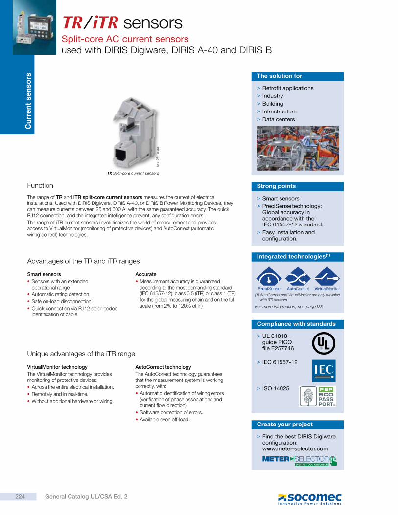
Cu
rre
nt
se
nso
rsTR / iTR sensorsSplit-core AC current sensorsused with DIRIS Digiware, DIRIS A-40 and DIRIS B
TR Split-core current sensors
Function
The range of TR and iTR split-core current sensors measures the current of electrical installations. Used with DIRIS Digiware, DIRIS A-40, or DIRIS B Power Monitoring Devices, they can measure currents between 25 and 600 A, with the same guaranteed accuracy. The quick RJ12 connection, and the integrated intelligence prevent, any configuration errors.
The range of iTR current sensors revolutionizes the world of measurement and provides access to VirtualMonitor (monitoring of protective devices) and AutoCorrect (automatic wiring control) technologies.
> Smart sensors
> PreciSense technology: Global accuracy in accordance with the IEC 61557-12 standard.
> Easy installation and configuration.
Strong points
Advantages of the TR and iTR ranges
Smart sensors
Sensors with an extended operational range.
Automatic rating detection.
Safe on-load disconnection.
Quick connection via RJ12 color-coded identification of cable.
Accurate
Measurement accuracy is guaranteed according to the most demanding standard (IEC 61557-12): class 0.5 (iTR) or class 1 (TR) for the global measuring chain and on the full scale (from 2% to 120% of In)
> Retrofit applications
> Industry
> Building
> Infrastructure
> Data centers
The solution for
> UL 61010guide PICQfile E257746
> IEC 61557-12
> ISO 14025
Compliance with standards
Integrated technologies(1)
For more information, see page
(1) AutoCorrect and VirtualMonitor are only available
with iTR sensors.
tore
_07
4_a
.ep
s
Unique advantages of the iTR range
VirtualMonitor technology
The VirtualMonitor technology provides monitoring of protective devices:
Across the entire electrical installation.
Remotely and in real-time.
Without additional hardware or wiring.
AutoCorrect technology
The AutoCorrect technology guarantees that the measurement system is working correctly, with:
Automatic identification of wiring errors (verification of phase associations and current flow direction).
Software correction of errors.
Available even off-load.
> Find the best DIRIS Digiware configuration:www.meter-selector.com
Create your project
188.
224 General Catalog UL/CSA Ed. 2
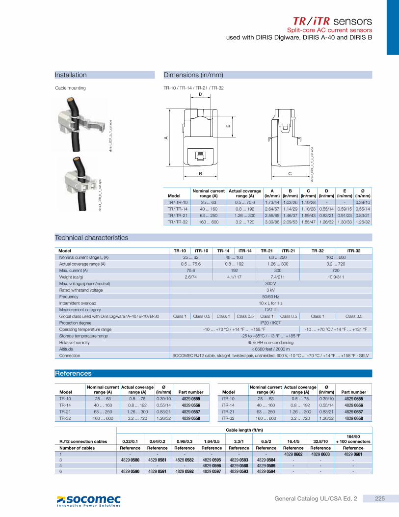
TR / iTR sensorsSplit-core AC current sensors
used with DIRIS Digiware, DIRIS A-40 and DIRIS B
Installation Dimensions (in/mm)
Cable mounting TR-10 / TR-14 / TR-21 / TR-32
ModelNominal current
range (A)Actual coverage
range (A)A
(in/mm)B
(in/mm)C
(in/mm)D
(in/mm)E
(in/mm)Ø
(in/mm)
TR / iTR-10 25 ... 63 0.5 ... 75.6 1.73/44 1.02/26 1.10/28 - - 0.39/10
TR / iTR-14 40 ... 160 0.8 ... 192 2.64/67 1.14/29 1.10/28 0.55/14 0.59/15 0.55/14
TR / iTR-21 63 ... 250 1.26 ... 300 2.56/65 1.46/37 1.69/43 0.83/21 0.91/23 0.83/21
TR / iTR-32 160 ... 600 3.2 ... 720 3.39/86 2.09/53 1.85/47 1.26/32 1.30/33 1.26/32
Technical characteristics
References
Model TR-10 iTR-10 TR-14 iTR-14 TR-21 iTR-21 TR-32 iTR-32
Nominal current range In (A) 25 ... 63 40 ... 160 63 ... 250 160 ... 600
Actual coverage range (A) 0.5 ... 75.6 0.8 ... 192 1.26 ... 300 3.2 ... 720
Max. current (A) 75.6 192 300 720
Weight (oz/g) 2.6/74 4.1/117 7.4/211 10.9/311
Max. voltage (phase/neutral) 300 V
Rated withstand voltage 3 kV
Frequency 50/60 Hz
Intermittent overload 10 x In for 1 s
Measurement category CAT III
Global class used with Diris Digiware / A-40 / B-10 / B-30 Class 1 Class 0.5 Class 1 Class 0.5 Class 1 Class 0.5 Class 1 Class 0.5
Protection degree IP20 / IK07
Operating temperature range -10 … +70 °C / +14 °F … +158 °F -10 … +70 °C / +14 °F … +131 °F
Storage temperature range -25 to +85°C / -13 °F … +185 °F
Relative humidity 95% RH non-condensing
Altitude < 6560 feet / 2000 m
Connection SOCOMEC RJ12 cable, straight, twisted pair, unshielded, 600 V, -10 °C ... +70 °C / +14 °F ... +158 °F - SELV
ModelNominal current
range (A)Actual coverage
range (A)Ø
(in/mm) Part number
TR-10 25 … 63 0.5 ... 75 0.39/10 4829 0555
TR-14 40 … 160 0.8 ... 192 0.55/14 4829 0556
TR-21 63 … 250 1.26 ... 300 0.83/21 4829 0557
TR-32 160 … 600 3.2 … 720 1.26/32 4829 0558
ModelNominal current
range (A)Actual coverage
range (A)Ø
(in/mm) Part number
iTR-10 25 … 63 0.5 … 75 0.39/10 4829 0655
iTR-14 40 … 160 0.8 … 192 0.55/14 4829 0656
iTR-21 63 … 250 1.26 … 300 0.83/21 4829 0657
iTR-32 160 … 600 3.2 … 720 1.26/32 4829 0658
diri
s-t_
03
7_b
_1_c
at.e
ps
diri
s-t_
03
8_b
_1_c
at.e
ps
D
A
E
B C
diri
s-t_
02
4_c
_1_x
_cat
.ep
s
RJ12 connection cables
Cable length (ft/m)
0.32/0.1 0.64/0.2 0.96/0.3 1.64/0.5 3.3/1 6.5/2 16.4/5 32.8/10164/50
+ 100 connectors
Number of cables Reference Reference Reference Reference Reference Reference Reference Reference Reference
1 - - - - - - 4829 0602 4829 0603 4829 06013 4829 0580 4829 0581 4829 0582 4829 0595 4829 0583 4829 0584 - - -
4 - - - 4829 0596 4829 0588 4829 0589 - - -
6 4829 0590 4829 0591 4829 0592 4829 0597 4829 0593 4829 0594 - - -
225General Catalog UL/CSA Ed. 2
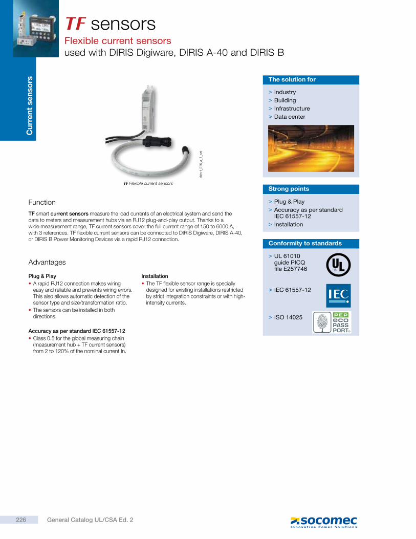
Cu
rre
nt
se
nso
rsTF sensorsFlexible current sensorsused with DIRIS Digiware, DIRIS A-40 and DIRIS B
TF Flexible current sensors
Function
TF smart current sensors measure the load currents of an electrical system and send the data to meters and measurement hubs via an RJ12 plug-and-play output. Thanks to a wide measurement range, TF current sensors cover the full current range of 150 to 6000 A, with 3 references. TF flexible current sensors can be connected to DIRIS Digiware, DIRIS A-40, or DIRIS B Power Monitoring Devices via a rapid RJ12 connection.
> Plug & Play
> Accuracy as per standard IEC 61557-12
> Installation
Strong points
Advantages
Plug & Play
A rapid RJ12 connection makes wiring easy and reliable and prevents wiring errors. This also allows automatic detection of the sensor type and size/transformation ratio.
The sensors can be installed in both directions.
Accuracy as per standard IEC 61557-12
Class 0.5 for the global measuring chain (measurement hub + TF current sensors) from 2 to 120% of the nominal current In.
Installation
The TF flexible sensor range is specially designed for existing installations restricted by strict integration constraints or with high-intensity currents.
> Industry
> Building
> Infrastructure
> Data center
The solution for
diri
s-t_
01
6_a
_1_c
at
> UL 61010guide PICQfile E257746
> IEC 61557-12
> ISO 14025
Conformity to standards
226 General Catalog UL/CSA Ed. 2
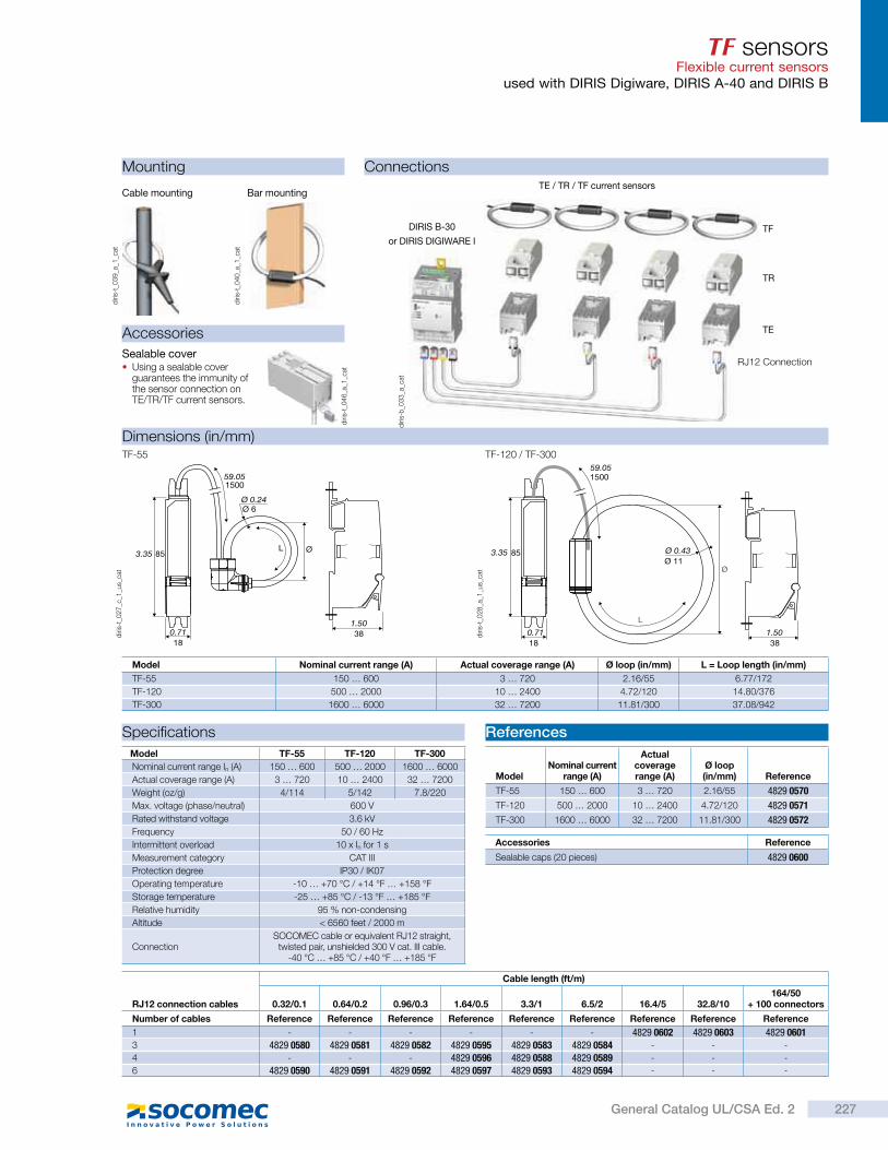
TF sensorsFlexible current sensors
used with DIRIS Digiware, DIRIS A-40 and DIRIS B
Mounting
Dimensions (in/mm)
Connections
diri
s-t_
03
9_a
_1_c
at
diri
s-t_
04
0_a
_1_c
at
Bar mountingCable mounting
TF-55 TF-120 / TF-300
0.71
3.35 85
Ø 0.24Ø 6
L Ø
59.051500
1.50
1838
3818
85Ø 11
L
Ø
1500
0.71
3.35 Ø 0.43
59.05
1.50
Model Nominal current range (A) Actual coverage range (A) Ø loop (in/mm) L = Loop length (in/mm)
TF-55 150 … 600 3 … 720 2.16/55 6.77/172
TF-120 500 … 2000 10 … 2400 4.72/120 14.80/376
TF-300 1600 … 6000 32 … 7200 11.81/300 37.08/942
diri
s-t_
02
7_c
_1_u
s_ca
t
diri
s-t_
02
8_a
_1_u
s_ca
t
Accessories
Sealable cover Using a sealable cover guarantees the immunity of the sensor connection on TE/TR/TF current sensors.
diri
s-t_
04
6_a
_1_c
at
Specifications References
Model TF-55 TF-120 TF-300
Nominal current range In (A) 150 … 600 500 … 2000 1600 … 6000
Actual coverage range (A) 3 … 720 10 … 2400 32 … 7200
Weight (oz/g) 4/114 5/142 7.8/220
Max. voltage (phase/neutral) 600 V
Rated withstand voltage 3.6 kV
Frequency 50 / 60 Hz
Intermittent overload 10 x In for 1 s
Measurement category CAT III
Protection degree IP30 / IK07
Operating temperature -10 … +70 °C / +14 °F … +158 °F
Storage temperature -25 … +85 °C / -13 °F … +185 °F
Relative humidity 95 % non-condensing
Altitude < 6560 feet / 2000 m
ConnectionSOCOMEC cable or equivalent RJ12 straight, twisted pair, unshielded 300 V cat. III cable.
-40 °C … +85 °C / +40 °F … +185 °F
Accessories Reference
Sealable caps (20 pieces) 4829 0600
ModelNominal current
range (A)
Actual coverage range (A)
Ø loop (in/mm) Reference
TF-55 150 … 600 3 … 720 2.16/55 4829 0570
TF-120 500 … 2000 10 … 2400 4.72/120 4829 0571
TF-300 1600 … 6000 32 … 7200 11.81/300 4829 0572
diri
s-b
_03
3_a
_cat
TE / TR / TF current sensors
TR
TF
TE
RJ12 Connection
DIRIS B-30
or DIRIS DIGIWARE I
RJ12 connection cables
Cable length (ft/m)
0.32/0.1 0.64/0.2 0.96/0.3 1.64/0.5 3.3/1 6.5/2 16.4/5 32.8/10164/50
+ 100 connectors
Number of cables Reference Reference Reference Reference Reference Reference Reference Reference Reference
1 - - - - - - 4829 0602 4829 0603 4829 06013 4829 0580 4829 0581 4829 0582 4829 0595 4829 0583 4829 0584 - - -
4 - - - 4829 0596 4829 0588 4829 0589 - - -
6 4829 0590 4829 0591 4829 0592 4829 0597 4829 0593 4829 0594 - - -
227General Catalog UL/CSA Ed. 2
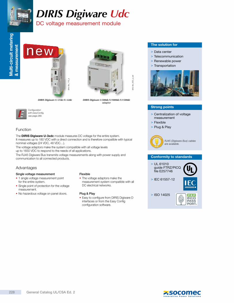
Mu
lti-
cir
cu
it m
ete
rin
g
& m
easu
rem
en
t
Function
The DIRIS Digiware U-3xdc module measures DC voltage for the entire system. It measures up to 180 VDC with a direct connection and is therefore compatible with typical nominal voltages (24 VDC, 48 VDC…).
The voltage adaptors make the system compatible with all voltage levels up to 1650 VDC to respond to the needs of all applications.
The RJ45 Digiware Bus transmits voltage measurements along with power supply and communication to all connected products.
Advantages
Single voltage measurement
1 single voltage measurement point for the entire system.
Single point of protection for the voltage measurement.
No hazardous voltage on panel doors.
Flexible
The voltage adaptors make the measurement system compatible with all DC electrical networks.
Plug & Play
Easy to configure from DIRIS Digiware D interfaces or from the Easy Config configuration software.
> Data center
> Telecommunication
> Renewable power
> Transportation
The solution for
diri
s-d
w_1
16
_a
diri
s-d
w_0
05
_a_c
at
DIRIS Digiware U-31dc/U-32dc DIRIS Digiware U500dc/U1000dc/U1500dc adaptor
Configuration
with EasyConfig,
DIRIS Digiware UdcDC voltage measurement module
> Centralization of voltage measurement
> Flexible
> Plug & Play
Strong points
RJ45 (Digiware Bus) cables are available.
RJ45
C
ommunication
new
> UL 61010guide FTRZ/PICQfile E257746
> IEC 61557-12
> ISO 14025
Conformity to standards
228 General Catalog UL/CSA Ed. 2
see page 280.
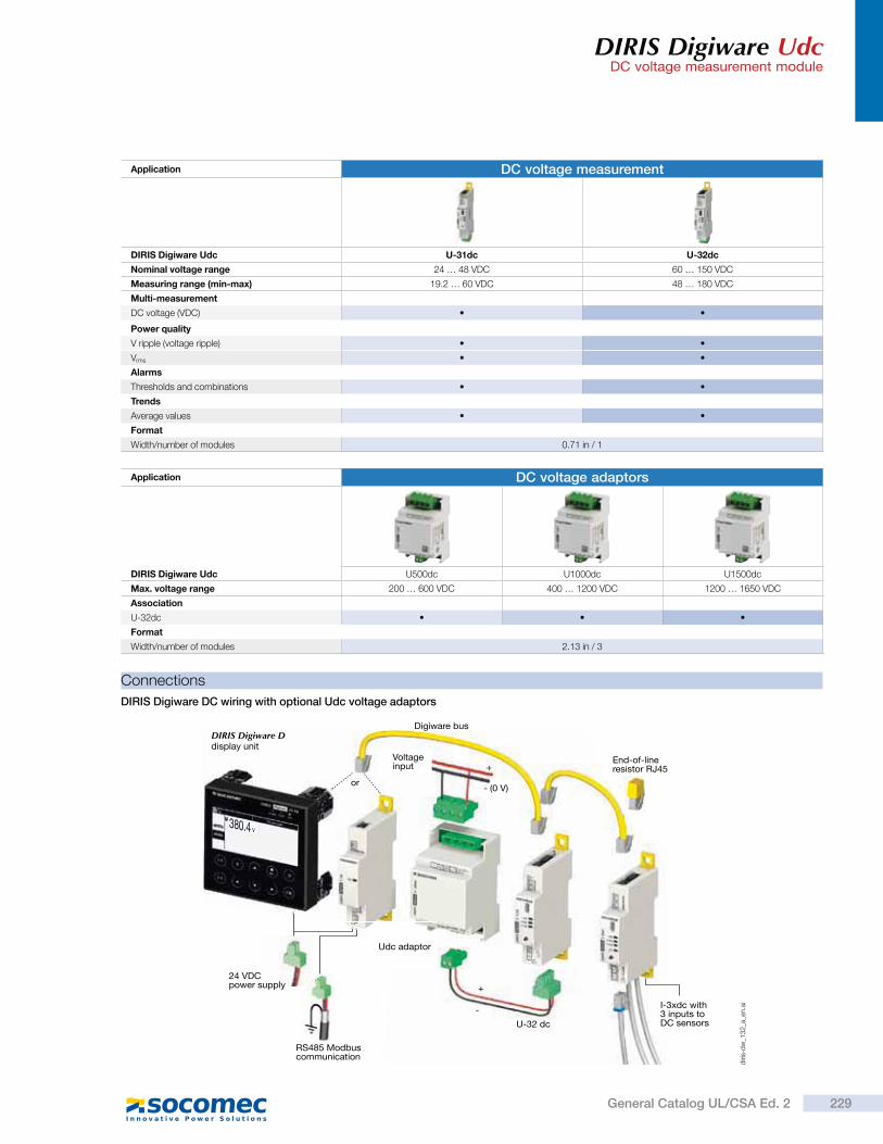
DIRIS Digiware UdcDC voltage measurement module
Application DC voltage measurement
DIRIS Digiware Udc U-31dc U-32dc
Nominal voltage range 24 … 48 VDC 60 … 150 VDC
Measuring range (min-max) 19.2 … 60 VDC 48 … 180 VDC
Multi-measurement
DC voltage (VDC)
Power quality
V ripple (voltage ripple)
Vrms
Alarms
Thresholds and combinations
Trends
Average values
Format
Width/number of modules 0.71 in / 1
Application DC voltage adaptors
DIRIS Digiware Udc U500dc U1000dc U1500dc
Max. voltage range 200 … 600 VDC 400 … 1200 VDC 1200 … 1650 VDC
Association
U-32dc
Format
Width/number of modules 2.13 in / 3
Connections
DIRIS Digiware DC wiring with optional Udc voltage adaptors
380.4 v
DIRIS Digiware Ddisplay unit
Digiware bus
Voltage input
or
End-of-line resistor RJ45
I-3xdc with 3 inputs to DC sensorsU-32 dc
RS485 Modbuscommunication
Udc adaptor
24 VDCpower supply
+
- (0 V)
+
-
diri
s-d
w_1
32
_a_e
n.a
i
229General Catalog UL/CSA Ed. 2
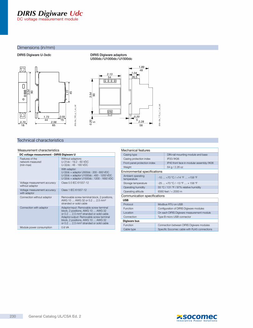
DIRIS Digiware UdcDC voltage measurement module
Technical characteristics
Measurement characteristics
DC voltage measurement - DIRIS Digiware U
Features of the network measured (min-max)
Without adaptors:U-31dc : 19.2 - 60 VDCU-32dc : 48 - 180 VDC
With adaptor:U-32dc + adaptor U500dc : 200 - 600 VDCU-32dc + adaptor U1000dc : 400 - 1200 VDCU-32dc + adaptor U1500dc : 1200 - 1650 VDC
Voltage measurement accuracy without adaptor
Class 0.5 IEC 61557-12
Voltage measurement accuracy with adaptor
Class 1 IEC 61557-12
Connection without adaptor Removable screw terminal block, 2 positions, AWG 10 … AWG 32 or 0.2 … 2.5 mm² stranded or solid cable
Connection with adaptor Adaptor input: Removable screw terminal block, 2 positions, AWG 10 … AWG 32 or 0.2 … 2.5 mm² stranded or solid cableAdaptor output: Removable screw terminal block, 2 positions, AWG 10 … AWG 32 or 0.2 … 2.5 mm² stranded or solid cable
Module power consumption 0.6 VA
Environmental specifications
Ambient operating temperature
-10 … +70 °C / +14 °F … +158 °F
Storage temperature -25 … +70 °C / -13 °F … + 158 °F
Operating humidity 55 °C / 131 °F / 97% relative humidity
Operating altitude 6560 feet / < 2000 m
Communication specifications
USB
Protocol Modbus RTU on USB
Function Configuration of DIRIS Digiware modules
Location On each DIRIS Digiware measurement module
Connection Type B micro USB connector
Digiware bus
Function Connection between DIRIS Digiware modules
Cable type Specific Socomec cable with RJ45 connections
Mechanical features
Casing type DIN-rail mounting module and base
Casing protection index IP20 / IK06
Front panel protection index IP40 front face in modular assembly / IK06
Weight 64 g / 2.26 oz
Dimensions (in/mm)
DIRIS Digiware U-3xdc DIRIS Digiware adaptors U500dc / U1000dc / U1500dc
diri
s-d
w_1
06
_a_1
_us_
cat
diri
s--d
w_1
15
_a_1
_us_
cat
451.773.54 90
0.7018
2.56
1.73 0.59
65
44 15
1.8948
1.04
26.5
58
53.
540.
2090
2.28
542.13
50.20
230 General Catalog UL/CSA Ed. 2
DIRIS Digiware UdcDC voltage measurement module
References
Digiware connection cables Part number
RJ45 cables for Digiware Bus
Length 0.20 feet / 0.06 m 4829 0189
Length 0.32 feet / 0.10 m 4829 0181
Length 1.64 feet / 0.50 m 4829 0182
Length 3.28 feet / 1 m 4829 0183
Length 6.56 feet / 2 m 4829 0184
Length 16.4 feet / 5 m 4829 0186
Length 32.8 feet / 10 m 4829 0187
164 feet / 50 m reel + 100 connectors 4829 0185
Termination for Digiware Bus (supplied with interfaces C and D) 4829 0180
USB configuration cable 4829 0050
DIRIS Digiware Part number
U-31dc Voltage measurement 19.2 … 60 VDC 4829 0150
U-32dc Voltage measurement 48 … 180 VDC 4829 0151
U500dc Voltage adaptor 200 … 600 VDC 4829 0153
U1000dc Voltage adaptor 400 … 1200 VDC 4829 0154
U1500dc Voltage adaptor 1200 … 1650 VDC 4829 0155
231General Catalog UL/CSA Ed. 2
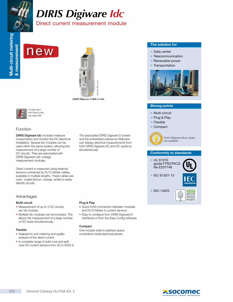
Mu
lti-
cir
cu
it m
ete
rin
g
& m
easu
rem
en
t
Function
DIRIS Digiware Idc modules measure consumption and monitor the DC electrical installation. Several Idc modules can be used within the same system, allowing the measurement of a large number of DC circuits. They are associated with DIRIS Digiware Udc voltage measurement modules.
Direct current is measured using external sensors connected by RJ12-Molex cables, available in multiple lengths. These cables are color coded (brown, orange, white) to easily identify circuits.
The associated DIRIS Digiware D screen and the embedded webserver Webview can display electrical measurements from both DIRIS Digiware AC and DC systems simultaneously.
> Multi-circuit
> Plug & Play
> Flexible
> Compact
Strong points
Advantages
Multi-circuit
Measurement of up to 3 DC circuits per Idc module.
Multiple Idc modules can be included. This allows the measurement of a large number of DC loads simultaneously.
Flexible
Adapted to suit metering and quality analysis of the direct current.
A complete range of solid core and split core DC current sensors from 50 to 5000 A.
Plug & Play
Quick RJ45 connection between modules and RJ12-Molex to current sensors.
Easy to configure from DIRIS Digiware D interfaces or from the Easy Config software.
Compact
One module wide to address space constraints inside electrical panels.
DIRIS Digiware I-30dc/I-35dc
Configuration
with EasyConfig,
DIRIS Digiware Idc Direct current measurement module
RJ45 (Digiware Bus) cables are available.
RJ45
C
ommunication
new
diri
s-d
w_0
95
_b.e
ps
> Data center
> Telecommunication
> Renewable power
> Transportation
The solution for
> UL 61010guide FTRZ/PICQfile E257746
> IEC 61557-12
> ISO 14025
Conformity to standards
232 General Catalog UL/CSA Ed. 2
see page 280.
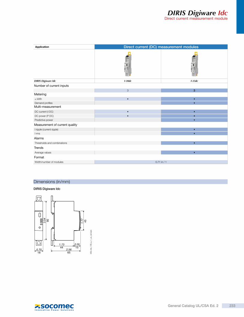
DIRIS Digiware IdcDirect current measurement module
Application Direct current (DC) measurement modules
DIRIS Digiware Idc I-30dc I-35dc
Number of current inputs
3 3
Metering
± kWh
Demand profiles
Multi-measurement
DC current (I DC)
DC power (P DC)
Predictive power
Measurement of current quality
I ripple (current ripple)
I rms
Alarms
Thresholds and combinations
Trends
Average values
Format
Width/number of modules 0.71 in / 1
Dimensions (in/mm)
DIRIS Digiware Idc
451.773.54 90
0.7018
2.56
1.73 0.59
65
44 15
diri
s-d
w_1
06
_a_1
_us_
cat.
eps
233General Catalog UL/CSA Ed. 2
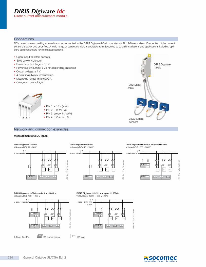
DIRIS Digiware IdcDirect current measurement module
Connections
DIRIS Digiware U-31dc
Voltage (VDC): 19 - 60 V
DIRIS Digiware U-32dc + adaptor U1000dc
Voltage (VDC): 400 - 1200 V
DIRIS Digiware U-32dc + adaptor U1500dc
VDC voltage: 1200 - 1500 V +10%
DIRIS Digiware U-32dc
Voltage (VDC): 48 - 180 V
DIRIS Digiware U-32dc + adaptor U500dc
Voltage (VDC): 200 - 600 V
I
- + NC NC
V
0 V± 19 - 60 VDC
I01 I02 I03
1 1 1
U-31
dc
I-3xd
c
I
NC NC - +
V
0 V± 48 - 180 VDC
I01 I02 I03
1 1 1
U-32
dc
I-3xd
c
I
NC NC - +
V
0 V± 200 - 600 VDC
I01 I02 I03
1 1 1
- +
- NC NC +
U-32
dc
I-3xd
c
U500
dc
I
NC NC - +
V
0 V± 400 - 1200 VDC
I01 I02 I03
1 1 1
- +
NC- NC +
U-32
dc
I-3xd
c
U100
0dc
I
NC NC - +
V
0 V± 1200 - 1500 VDC
+ 10%
I01 I02 I03
1 1 1
- +
NC- NC +
U-32
dc
I-3xd
c
U150
0dc
Network and connection examples
1. Fuse: 2A gPV1
DC load DC current sensor
Measurement of 3 DC loads
DC current is measured by external sensors connected to the DIRIS Digiware I-3xdc modules via RJ12-Molex cables. Connection of the current sensors is quick and error-free. A wide range of current sensors is available from Socomec to suit all installations and applications including split-core current sensors for retrofit applications.
Open-loop Hall effect sensors
Solid core or split core.
Power supply voltage: ± 15 V.
Power supply current: ± 25 mA depending on sensor.
Output voltage: ± 4 V.
4-point male Molex terminal strip.
Measuring range: 16 to 6000 A.
Category III overvoltage.
PIN 1: + 15 V (+ Vc)
PIN 2: - 15 V (- Vc)
PIN 3: sensor input (M)
PIN 4: 0 V sensor (0)
RJ12-Molex cable
DIRIS Digiware I-3xdc
3 DC current sensors
diri
s-d
w_1
13
_a_1
_x_c
at.e
ps
diri
s-d
w_1
12
_a_1
_x_c
at.e
ps
diri
s-d
w_1
11
_a_1
_x_c
at.e
ps
diri
s-d
w_1
10
_a_1
_x_c
at.e
ps
diri
s-d
w_1
09
_a_1
_x_c
at.e
ps
1 2 3 4
234 General Catalog UL/CSA Ed. 2
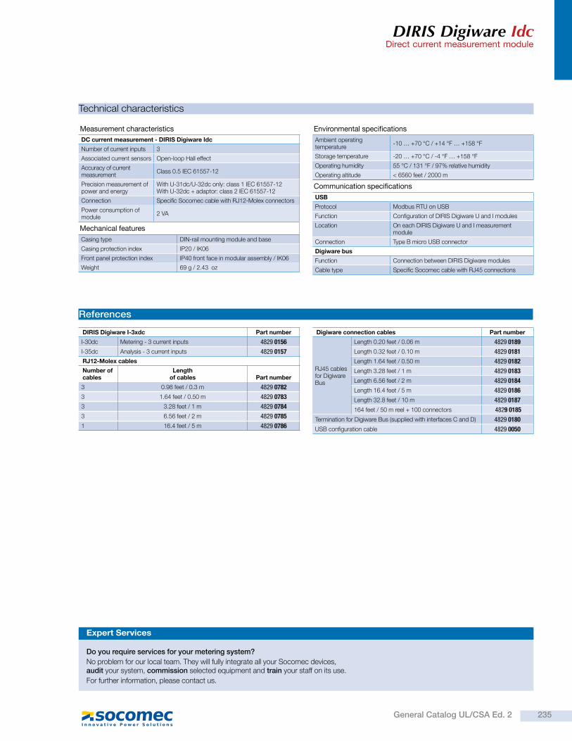
DIRIS Digiware IdcDirect current measurement module
Technical characteristics
Measurement characteristics
DC current measurement - DIRIS Digiware Idc
Number of current inputs 3
Associated current sensors Open-loop Hall effect
Accuracy of current measurement
Class 0.5 IEC 61557-12
Precision measurement of power and energy
With U-31dc/U-32dc only: class 1 IEC 61557-12With U-32dc + adaptor: class 2 IEC 61557-12
Connection Specific Socomec cable with RJ12-Molex connectors
Power consumption of module
2 VA
Environmental specifications
Ambient operating temperature
-10 … +70 °C / +14 °F … +158 °F
Storage temperature -20 … +70 °C / -4 °F … +158 °F
Operating humidity 55 °C / 131 °F / 97% relative humidity
Operating altitude < 6560 feet / 2000 m
Communication specifications
USB
Protocol Modbus RTU on USB
Function Configuration of DIRIS Digiware U and I modules
Location On each DIRIS Digiware U and I measurement module
Connection Type B micro USB connector
Digiware bus
Function Connection between DIRIS Digiware modules
Cable type Specific Socomec cable with RJ45 connections
References
DIRIS Digiware I-3xdc Part number
I-30dc Metering - 3 current inputs 4829 0156
I-35dc Analysis - 3 current inputs 4829 0157
RJ12-Molex cables
Number of cables
Length of cables Part number
3 0.98 feet / 0.3 m 4829 0782
3 1.64 feet / 0.50 m 4829 0783
3 3.28 feet / 1 m 4829 0784
3 6.56 feet / 2 m 4829 0785
1 16.4 feet / 5 m 4829 0786
Digiware connection cables Part number
RJ45 cables for Digiware Bus
Length 0.20 feet / 0.06 m 4829 0189
Length 0.32 feet / 0.10 m 4829 0181
Length 1.64 feet / 0.50 m 4829 0182
Length 3.28 feet / 1 m 4829 0183
Length 6.56 feet / 2 m 4829 0184
Length 16.4 feet / 5 m 4829 0186
Length 32.8 feet / 10 m 4829 0187
164 feet / 50 m reel + 100 connectors 4829 0185
Termination for Digiware Bus (supplied with interfaces C and D) 4829 0180
USB configuration cable 4829 0050
Expert Services
Do you require services for your metering system?
No problem for our local team. They will fully integrate all your Socomec devices, audit your system, commission selected equipment and train your staff on its use.
For further information, please contact us.
Mechanical features
Casing type DIN-rail mounting module and base
Casing protection index IP20 / IK06
Front panel protection index IP40 front face in modular assembly / IK06
Weight 69 g / 2.43 oz
235General Catalog UL/CSA Ed. 2
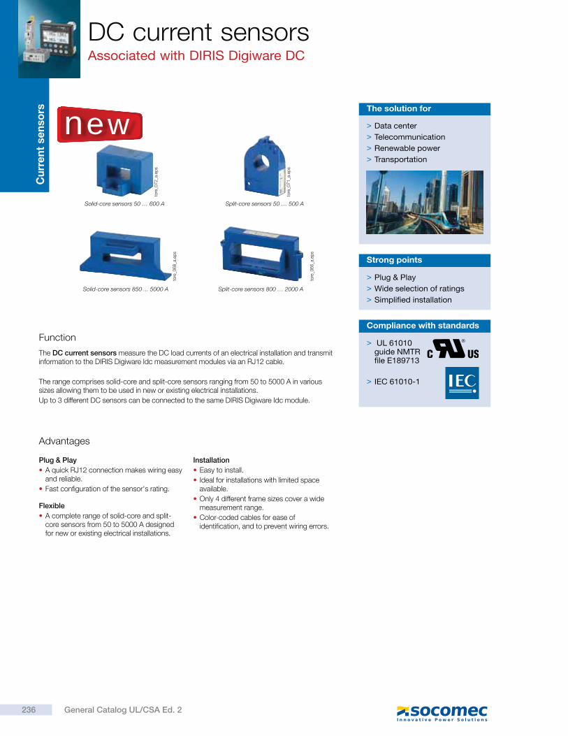
Cu
rre
nt
se
nso
rsDC current sensorsAssociated with DIRIS Digiware DC
Solid-core sensors 50 … 600 A
Solid-core sensors 850 ... 5000 A
Split-core sensors 50 … 500 A
Split-core sensors 800 … 2000 A
Function
The DC current sensors measure the DC load currents of an electrical installation and transmit information to the DIRIS Digiware Idc measurement modules via an RJ12 cable.
The range comprises solid-core and split-core sensors ranging from 50 to 5000 A in various sizes allowing them to be used in new or existing electrical installations.
Up to 3 different DC sensors can be connected to the same DIRIS Digiware Idc module.
Advantages
Plug & Play
A quick RJ12 connection makes wiring easy and reliable.
Fast configuration of the sensor's rating.
Flexible
A complete range of solid-core and split-core sensors from 50 to 5000 A designed for new or existing electrical installations.
Installation
Easy to install.
Ideal for installations with limited space available.
Only 4 different frame sizes cover a wide measurement range.
Color-coded cables for ease of identification, and to prevent wiring errors.
> Plug & Play
> Wide selection of ratings
> Simplified installation
Strong points
new > Data center
> Telecommunication
> Renewable power
> Transportation
The solution for
tore
_06
6_a
.ep
s
tore
_06
8_a
.ep
s
tore
_07
1_a
.ep
s
tore
_07
2_a
.ep
s
> UL 61010guide NMTRfile E189713
> IEC 61010-1
Compliance with standards
236 General Catalog UL/CSA Ed. 2
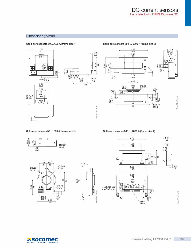
DC current sensorsAssociated with DIRIS Digiware DC
Dimensions (in/mm)
Solid-core sensors 50 … 600 A (frame size 1)
Split-core sensors 50 … 500 A (frame size 1)
Solid-core sensors 850 … 5000 A (frame size 2)
Split-core sensors 800 … 2000 A (frame size 2)
6.30160
4.09104
5.83148
6.85174
5.91150
1.16 1.16129.5 29.525.5
2 x
0.22
2 x
5.5
4 x Ø 0.13 x 10⁴ x Ø 3.3 x 10
Ø 0.22Ø 5.5
0.31 8
0.98
0.59
25
15
0.91
1.57
23
40 86 86
1.9750
1.7745
0.7920
0.359
tore
_09
1_a
_1_u
s.ai
Ø
0.8
52
1.5
0.65
16
.50.
328
.25
0.71 0.7118 18
Ø 0.83Ø 21
1.50 38
1.97
50
0.12 3
1.8146
Ø 0.1Ø 2.5
0.123
2.72 69
0.1
2.5
0.13Ø 3.2
Ø 0.13Ø 3.2
Ø 0.13Ø 3.2
tore
_09
0_a
_1_u
s.ai
Ø 0.22Ø 5.5
4.96126
1.4637
0.5915
0.225.7
0.22
5.5
0.50
12.8
12.5
0.49
5.50.22
0.31 8
1445.67
0.16 4
0.83
0.83 21
21
2.44 62
4.251082.5264
(2.02)(51.3)1.81461.69430.71
18
0.47
12
0.16 4
Ø 0.22Ø 5.5
tore
_09
2_a
_1_u
s.ai
1.5740
0.8020.4
0.41
10
.4
0.12 3
Ø 0.1Ø 2.5
0.39 9.8
0.19
4.8
1.18 30
0.12.5
0.338.3
0.7920
1.1830
0.20.255
Ø 0.18Ø 4.5
0.9022.8
0.63160.4110.4
tore
_09
3_a
_1_u
s.ai
237General Catalog UL/CSA Ed. 2
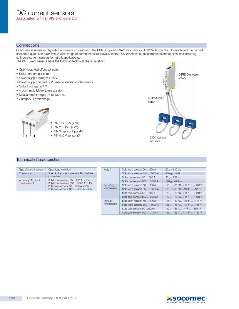
DC current sensorsAssociated with DIRIS Digiware DC
Connections
Technical characteristics
DC current is measured by external sensors connected to the DIRIS Digiware I-3xdc modules via RJ12-Molex cables. Connection of the current sensors is quick and error-free. A wide range of current sensors is available from Socomec to suit all installations and applications including split-core current sensors for retrofit applications. The DC current sensors have the following technical characteristics:
Open-loop Hall effect sensors.
Solid-core or split-core.
Power supply voltage: ± 15 V.
Power supply current: ± 25 mA depending on the sensor.
Output voltage: ± 4 V.
4-point male Molex terminal strip.
Measurement range: 16 to 5000 A.
Category III overvoltage.
PIN 1: + 15 V (+ Vc)
PIN 2: - 15 V (- Vc)
PIN 3: sensor input (M)
PIN 4: 0 V sensor (0)
RJ12-Molex cable
DIRIS Digiware I-3xdc
3 DC current sensors
1 2 3 4
Type of current sensor Open-loop Hall effect
Connection Specific Socomec cable with RJ12-Molex connectors
Accuracy of current measurement
Solid-core sensors: 50 ... 600 A: < 1%Solid-core sensors: 850 ... 5000 A: < 1%Split-core sensors: 50 ... 500 A: < 2%Split-core sensors: 800 ... 2000 A: < 2%
Weight Solid-core sensors 50 … 600 A 60 g / 2.12 oz
Solid-core sensors 850 … 5000 A 450 g / 15.87 oz
Split-core sensors 50 … 500 A 80 g / 2.82 oz
Split-core sensors 800 … 2000 A 590 g / 20.8 oz
Operating temperature
Solid-core sensors 50 … 600 A -10 … +80 °C / +14 °F … +176 °F
Solid-core sensors 850 … 5000 A -25 … +85 °C / -13 °F … +185 °F
Split-core sensors 50 … 500 A -10 … +70 °C / +14 °F … +158 °F
Split-core sensors 800 … 2000 A -10 … +70 °C / +14 °F … +158 °F
Storage temperature
Solid-core sensors 50 … 600 A -25 … +80 °C / -13 °F … +176 °F
Solid-core sensors 850 … 5000 A -25 … +85 °C / -13 °F … +185 °F
Split-core sensors 50 ... 500 A -20 … +85 °C / -4 °F … +185 °F
Split-core sensors 800 … 2000 A -25 … +85 °C / -13 °F … +185 °F
238 General Catalog UL/CSA Ed. 2
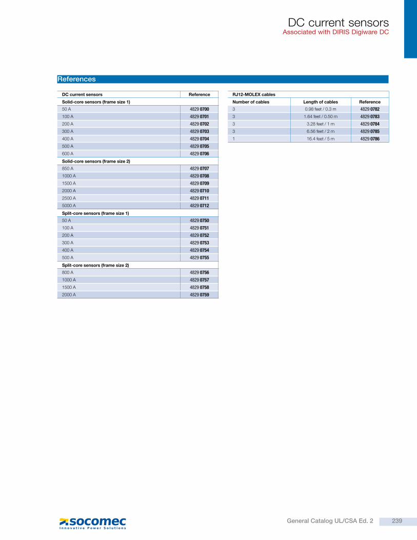
DC current sensorsAssociated with DIRIS Digiware DC
References
DC current sensors Reference
Solid-core sensors (frame size 1)
50 A 4829 0700
100 A 4829 0701
200 A 4829 0702
300 A 4829 0703
400 A 4829 0704
500 A 4829 0705
600 A 4829 0706
Solid-core sensors (frame size 2)
850 A 4829 0707
1000 A 4829 0708
1500 A 4829 0709
2000 A 4829 0710
2500 A 4829 0711
5000 A 4829 0712
Split-core sensors (frame size 1)
50 A 4829 0750
100 A 4829 0751
200 A 4829 0752
300 A 4829 0753
400 A 4829 0754
500 A 4829 0755
Split-core sensors (frame size 2)
800 A 4829 0756
1000 A 4829 0757
1500 A 4829 0758
2000 A 4829 0759
RJ12-MOLEX cables
Number of cables Length of cables Reference
3 0.98 feet / 0.3 m 4829 0782
3 1.64 feet / 0.50 m 4829 0783
3 3.28 feet / 1 m 4829 0784
3 6.56 feet / 2 m 4829 0785
1 16.4 feet / 5 m 4829 0786
239General Catalog UL/CSA Ed. 2
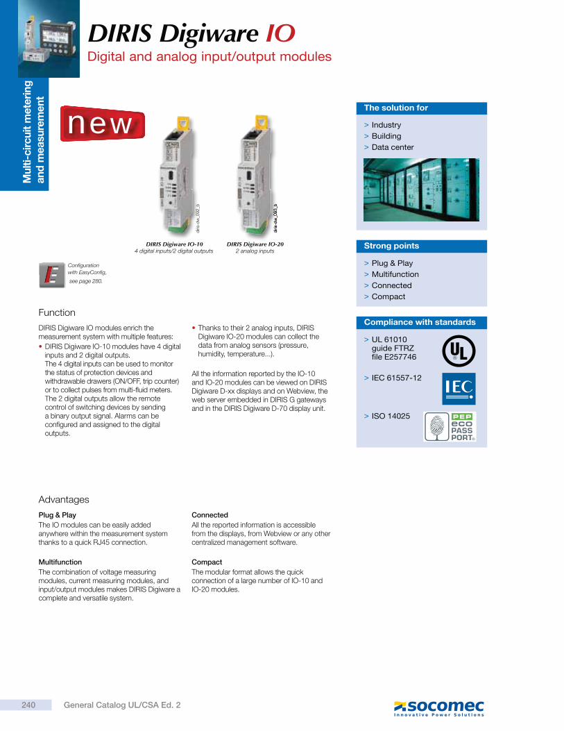
Mu
lti-
cir
cu
it m
ete
rin
g
an
d m
easu
rem
en
t
Function
DIRIS Digiware IO modules enrich the measurement system with multiple features:
DIRIS Digiware IO-10 modules have 4 digital inputs and 2 digital outputs. The 4 digital inputs can be used to monitor the status of protection devices and withdrawable drawers (ON/OFF, trip counter) or to collect pulses from multi-fluid meters. The 2 digital outputs allow the remote control of switching devices by sending a binary output signal. Alarms can be configured and assigned to the digital outputs.
Thanks to their 2 analog inputs, DIRIS Digiware IO-20 modules can collect the data from analog sensors (pressure, humidity, temperature...).
All the information reported by the IO-10 and IO-20 modules can be viewed on DIRIS Digiware D-xx displays and on Webview, the web server embedded in DIRIS G gateways and in the DIRIS Digiware D-70 display unit.
> Plug & Play
> Multifunction
> Connected
> Compact
Strong points
Advantages
Plug & Play
The IO modules can be easily added anywhere within the measurement system thanks to a quick RJ45 connection.
Multifunction
The combination of voltage measuring modules, current measuring modules, and input/output modules makes DIRIS Digiware a complete and versatile system.
Connected
All the reported information is accessible from the displays, from Webview or any other centralized management software.
Compact
The modular format allows the quick connection of a large number of IO-10 and IO-20 modules.
> Industry
> Building
> Data center
The solution for
> UL 61010guide FTRZfile E257746
> IEC 61557-12
> ISO 14025
Compliance with standards
DIRIS Digiware IO-104 digital inputs/2 digital outputs
DIRIS Digiware IO-202 analog inputs
Configuration
with EasyConfig,
DIRIS Digiware IO Digital and analog input/output modules
new
diri
s-d
w_0
92
_b
diri
s-d
w_0
93
_b
240 General Catalog UL/CSA Ed. 2
see page 280.
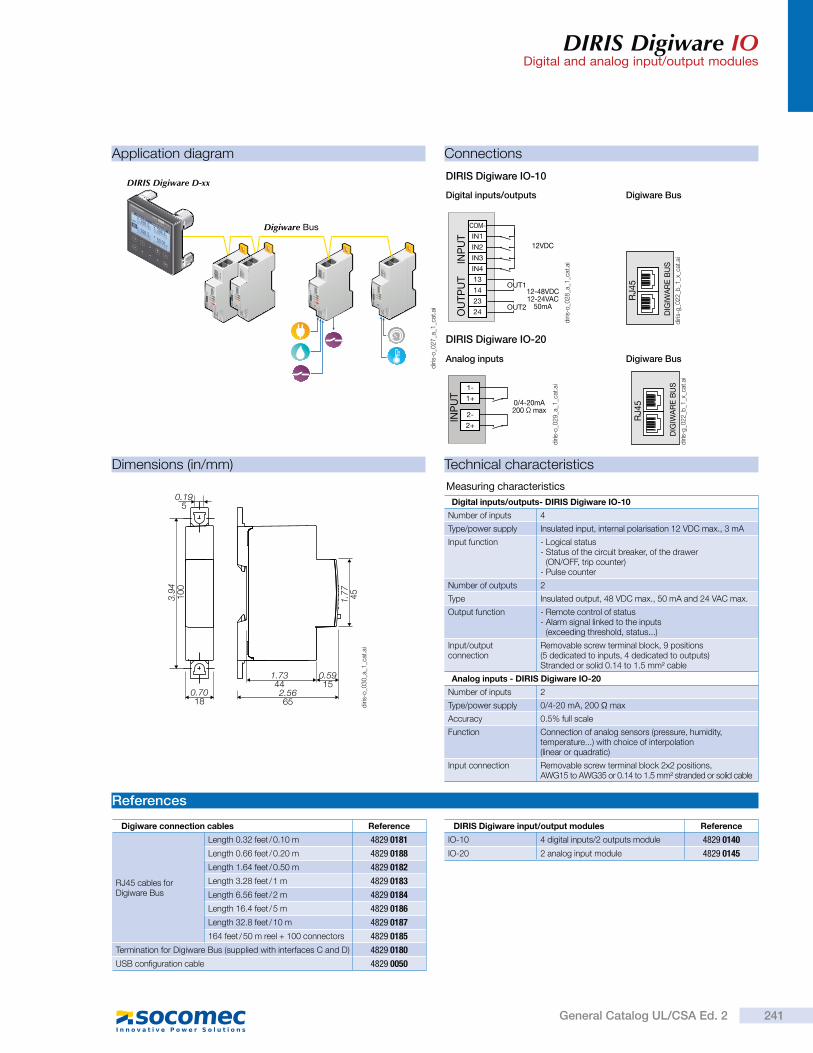
DIRIS Digiware IODigital and analog input/output modules
Digiware BusDigital inputs/outputs
Digiware BusAnalog inputs
DIRIS Digiware IO-10
DIRIS Digiware IO-20
Dimensions (in/mm)
References
Technical characteristics
Application diagram Connections
Digiware Bus
DIRIS Digiware D-xx
13
14
23
24
12-48VDC12-24VAC
50mA
12VDC
IN1
COM-
IN2
IN3
IN4
OUT1
OUT2
OU
TP
UT
INP
UT
DIG
IWA
RE
BU
S
RJ4
5
DIG
IWA
RE
BU
S
RJ4
50/4-20mA200 max
1+
1-
2+
2-INP
UT
1.7344
0.5915
2.5665
1.7
74
5
0.7018
0.195
3.9
41
00
Digiware connection cables Reference
RJ45 cables for Digiware Bus
Length 0.32 feet / 0.10 m 4829 0181
Length 0.66 feet / 0.20 m 4829 0188
Length 1.64 feet / 0.50 m 4829 0182
Length 3.28 feet / 1 m 4829 0183
Length 6.56 feet / 2 m 4829 0184
Length 16.4 feet / 5 m 4829 0186
Length 32.8 feet / 10 m 4829 0187
164 feet / 50 m reel + 100 connectors 4829 0185
Termination for Digiware Bus (supplied with interfaces C and D) 4829 0180
USB configuration cable 4829 0050
Measuring characteristics
Digital inputs/outputs- DIRIS Digiware IO-10
Number of inputs 4
Type/power supply Insulated input, internal polarisation 12 VDC max., 3 mA
Input function - Logical status- Status of the circuit breaker, of the drawer
(ON/OFF, trip counter)- Pulse counter
Number of outputs 2
Type Insulated output, 48 VDC max., 50 mA and 24 VAC max.
Output function - Remote control of status- Alarm signal linked to the inputs
(exceeding threshold, status...)
Input/output connection
Removable screw terminal block, 9 positions (5 dedicated to inputs, 4 dedicated to outputs)Stranded or solid 0.14 to 1.5 mm² cable
Analog inputs - DIRIS Digiware IO-20
Number of inputs 2
Type/power supply 0/4-20 mA, 200 max
Accuracy 0.5% full scale
Function Connection of analog sensors (pressure, humidity, temperature...) with choice of interpolation (linear or quadratic)
Input connection Removable screw terminal block 2x2 positions,AWG15 to AWG35 or 0.14 to 1.5 mm² stranded or solid cable
diri
s-o
_02
8_a
_1_c
at.a
i
diri
s-g
_02
2_b
_1_x
_cat
.ai
diri
s-g
_02
2_b
_1_x
_cat
.ai
diri
s-o
_02
9_a
_1_c
at.a
i
diri
s-o
_02
7_a
_1_c
at.a
i
DIRIS Digiware input/output modules Reference
IO-10 4 digital inputs/2 outputs module 4829 0140
IO-20 2 analog input module 4829 0145
diri
s-o
_03
0_a
_1_c
at.a
i
241General Catalog UL/CSA Ed. 2
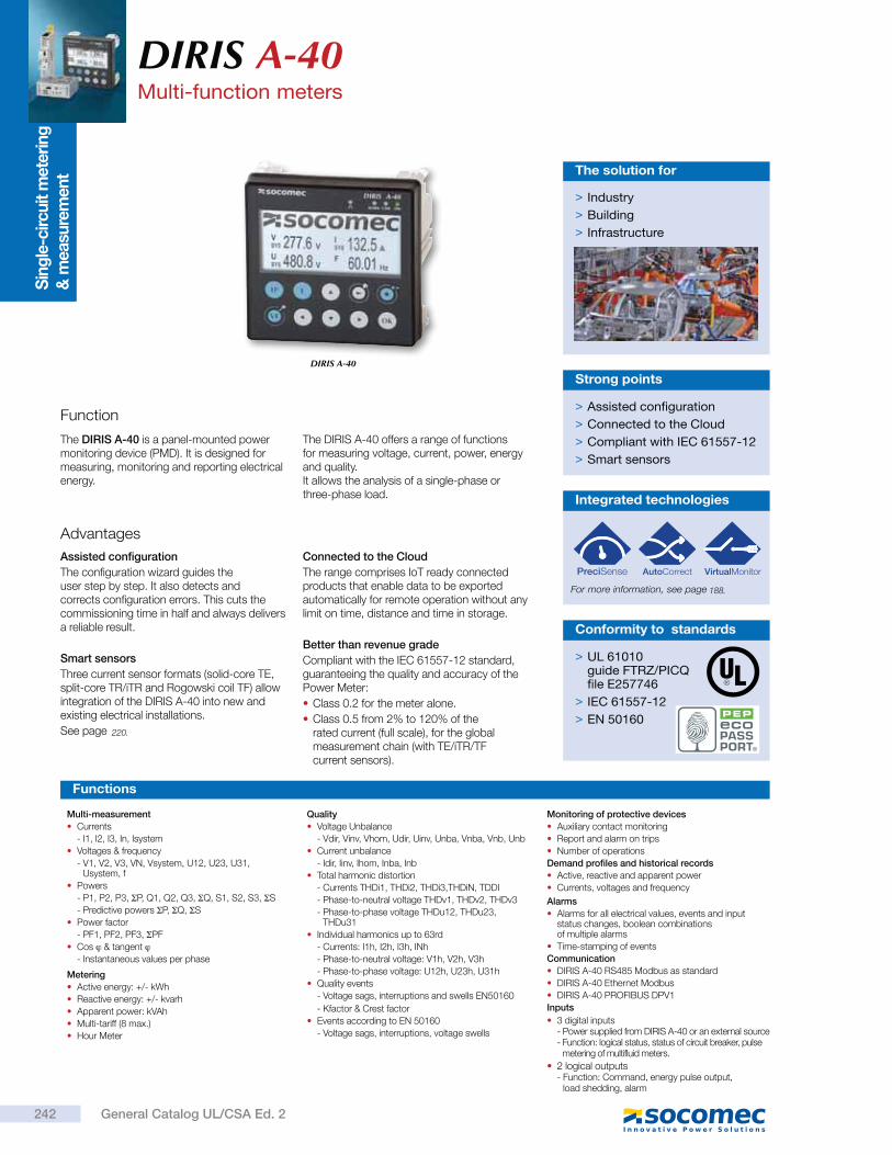
Sin
gle
-circuit m
ete
ring
&
measu
rem
ent
DIRIS A-40Multi-function meters
DIRIS A-40
Function
The DIRIS A-40 is a panel-mounted power monitoring device (PMD). It is designed for measuring, monitoring and reporting electrical energy.
The DIRIS A-40 offers a range of functions for measuring voltage, current, power, energy and quality. It allows the analysis of a single-phase or three-phase load.
> Assisted configuration
> Connected to the Cloud
> Compliant with IEC 61557-12
> Smart sensors
Strong points
Advantages
Assisted configuration
The configuration wizard guides the user step by step. It also detects and corrects configuration errors. This cuts the commissioning time in half and always delivers a reliable result.
Smart sensors
Three current sensor formats (solid-core TE, split-core TR/iTR and Rogowski coil TF) allow integration of the DIRIS A-40 into new and existing electrical installations.
See page
Connected to the Cloud
The range comprises IoT ready connected products that enable data to be exported automatically for remote operation without any limit on time, distance and time in storage.
Better than revenue grade
Compliant with the IEC 61557-12 standard, guaranteeing the quality and accuracy of the Power Meter:
Class 0.2 for the meter alone.
Class 0.5 from 2% to 120% of the rated current (full scale), for the global measurement chain (with TE/iTR/TF current sensors).
> Industry
> Building
> Infrastructure
The solution for
> UL 61010guide FTRZ/PICQfile E257746
> IEC 61557-12
> EN 50160
Conformity to standards
Multi-measurement
Currents
- I1, I2, I3, In, Isystem
Voltages & frequency
- V1, V2, V3, VN, Vsystem, U12, U23, U31, Usystem, f
Powers
- P1, P2, P3, P, Q1, Q2, Q3, Q, S1, S2, S3, S
- Predictive powers P, Q, S
Power factor
- PF1, PF2, PF3, PF
Cos & tangent
- Instantaneous values per phase
Metering
Active energy: +/- kWh
Reactive energy: +/- kvarh
Apparent power: kVAh
Multi-tariff (8 max.)
Hour Meter
Quality
Voltage Unbalance
- Vdir, Vinv, Vhom, Udir, Uinv, Unba, Vnba, Vnb, Unb
Current unbalance
- Idir, Iinv, Ihom, Inba, Inb
Total harmonic distortion
- Currents THDi1, THDi2, THDi3,THDiN, TDDI
- Phase-to-neutral voltage THDv1, THDv2, THDv3
- Phase-to-phase voltage THDu12, THDu23, THDu31
Individual harmonics up to 63rd
- Currents: I1h, I2h, I3h, INh
- Phase-to-neutral voltage: V1h, V2h, V3h
- Phase-to-phase voltage: U12h, U23h, U31h
Quality events
- Voltage sags, interruptions and swells EN50160
- Kfactor & Crest factor
Events according to EN 50160
- Voltage sags, interruptions, voltage swells
Monitoring of protective devices
Auxiliary contact monitoring
Report and alarm on trips
Number of operations
Demand profiles and historical records
Active, reactive and apparent power
Currents, voltages and frequency
Alarms
Alarms for all electrical values, events and input status changes, boolean combinations of multiple alarms
Time-stamping of events
Communication
DIRIS A-40 RS485 Modbus as standard
DIRIS A-40 Ethernet Modbus
DIRIS A-40 PROFIBUS DPV1
Inputs
3 digital inputs- Power supplied from DIRIS A-40 or an external source- Function: logical status, status of circuit breaker, pulse
metering of multifluid meters.
2 logical outputs- Function: Command, energy pulse output,
load shedding, alarm
Functions
Integrated technologies
For more information, see page
242 General Catalog UL/CSA Ed. 2
220.
188.
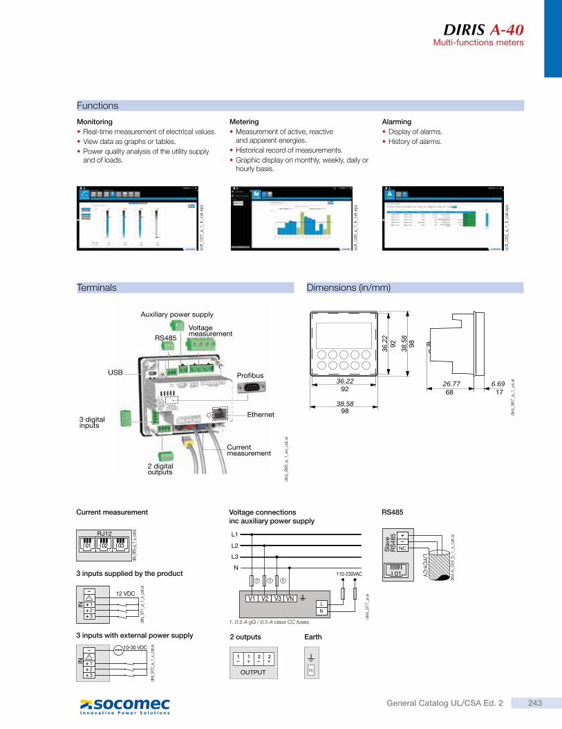
DIRIS A-40Multi-functions meters
Dimensions (in/mm)
38.58
36.22 26.77 6.69
9838
,58
98
9236
.22
92
68 17
3 inputs supplied by the product
3 inputs with external power supply 2 outputs Earth
Current measurement
NCSla
veR
S4
85
LIY
CY-C
YI 01
RS485Voltage connections inc auxiliary power supply
1. 0.5 A gG / 0.5 A class CC fuses.
110-230VACN
L1
L2
L3
V2 V3 VNV1
N
L
111
OUTPUT
Monitoring
Real-time measurement of electrical values.
View data as graphs or tables.
Power quality analysis of the utility supply and of loads.
Metering
Measurement of active, reactive and apparent energies.
Historical record of measurements.
Graphic display on monthly, weekly, daily or hourly basis.
Alarming
Display of alarms.
History of alarms.
Functions
Terminals
diri
s_9
77
_a.a
i
RJ12
I 03I 02I 01
diris
_969
_a_1
_x_c
at.a
i
diri
s-b
_02
4_b
_1_x
_cat
.ai
123
IN
10-30 VDC
diris
_972
_a_1
_x_c
at.a
i
123
IN
12 VDC
diris_
971_
a_1_
x_ca
t.ai
USB
RS485
Auxiliary power supply
Voltage measurement
3 digital inputs
Ethernet
Pro bus
2 digital outputs
Current measurement
diri
s_9
68
_a_1
_en_c
at.a
i
diri
s_9
67
_a_1
_us.
ai
soft_0
25
_a_1
_fr_
cat.
eps
soft_0
36
_a_1
_fr_
cat.
eps
soft_0
27
_a_1
_fr_
cat.
eps
243General Catalog UL/CSA Ed. 2
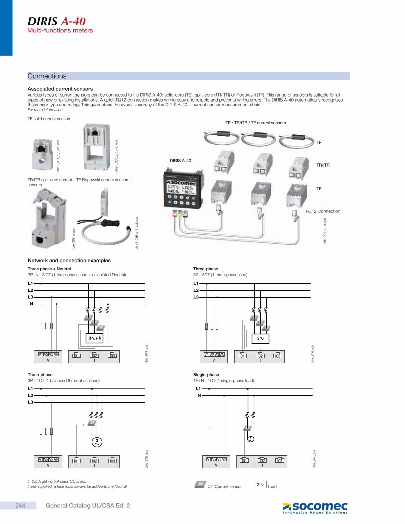
DIRIS A-40Multi-functions meters
Connections
Associated current sensorsVarious types of current sensors can be connected to the DIRIS A-40: solid-core (TE), split-core (TR/iTR) or Rogowski (TF). This range of sensors is suitable for all types of new or existing installations. A quick RJ12 connection makes wiring easy and reliable and prevents wiring errors. The DIRIS A-40 automatically recognizes the sensor type and rating. This guarantees the overall accuracy of the DIRIS A-40 + current sensor measurement chain.For more information:
TE solid current sensors
Three phase + Neutral
3P+N - 3 CT (1 three-phase load + calculated Neutral)
Three-phase
3P - 1CT (1 balanced three-phase load)
Single-phase
1P+N - 1CT (1 single-phase load)
N
V1 V2 V3 VN
V I
L1
L2
L3
I01 I02 I03
3 + N
V1 V2 V3 VN
V I
L1
L2
L3
3
I01 I02 I03 V1 V2 V3 VN
V I
L1
N
I02 I03
1
I01
Network and connection examples
1. 0.5 A gG / 0.5 A class CC fuses.
If self-supplied, a fuse must always be added to the Neutral.3
Load CT: Current sensor
TR/iTR split-core current sensors
TF Rogowski current sensors
Three-phase
3P - 3CT (1 three-phase load)
V1 V2 V3 VN
V I
L1
L2
L3
I01 I02 I03
3
DIRIS A-40
TE / TR/iTR / TF current sensors
TR/iTR
TF
TE
RJ12 Connection
diri
s_9
74
_a.a
id
iris_
97
6_a
.ai
diri
s_9
75
_a.a
id
iris_
97
3_a
.ai
diri
s_9
91
_a_u
s.ep
s
diri
s-t_
01
6_a
_1_c
at.e
ps
tore
_08
2_a
.ep
s
diri
s-t_
00
3_a
_1_c
at.e
ps
diri
s-t_
00
1_a
_1_c
at.e
ps
244 General Catalog UL/CSA Ed. 2
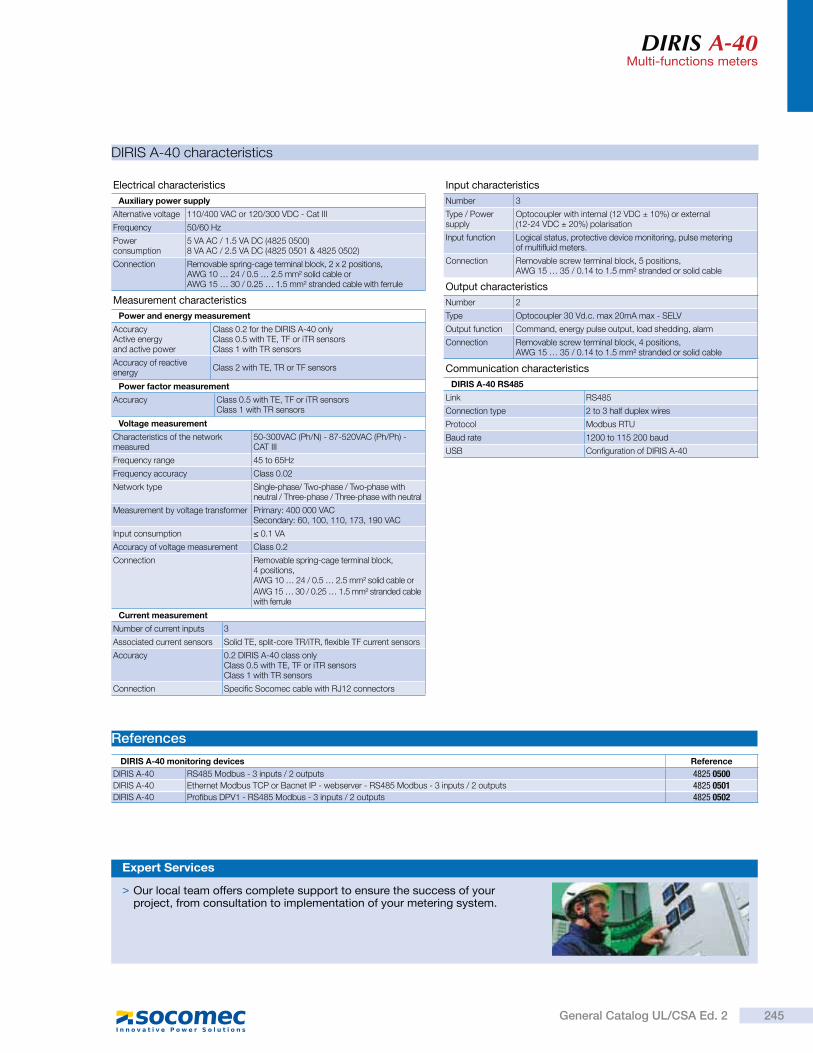
DIRIS A-40Multi-functions meters
References
DIRIS A-40 monitoring devices Reference
DIRIS A-40 RS485 Modbus - 3 inputs / 2 outputs 4825 0500DIRIS A-40 Ethernet Modbus TCP or Bacnet IP - webserver - RS485 Modbus - 3 inputs / 2 outputs 4825 0501DIRIS A-40 Profibus DPV1 - RS485 Modbus - 3 inputs / 2 outputs 4825 0502
DIRIS A-40 characteristics
Current measurement
Number of current inputs 3
Associated current sensors Solid TE, split-core TR/iTR, flexible TF current sensors
Accuracy 0.2 DIRIS A-40 class only Class 0.5 with TE, TF or iTR sensorsClass 1 with TR sensors
Connection Specific Socomec cable with RJ12 connectors
Voltage measurement
Characteristics of the network measured
50-300VAC (Ph/N) - 87-520VAC (Ph/Ph) - CAT III
Frequency range 45 to 65Hz
Frequency accuracy Class 0.02
Network type Single-phase/ Two-phase / Two-phase with neutral / Three-phase / Three-phase with neutral
Measurement by voltage transformer Primary: 400 000 VACSecondary: 60, 100, 110, 173, 190 VAC
Input consumption 0.1 VA
Accuracy of voltage measurement Class 0.2
Connection Removable spring-cage terminal block, 4 positions,AWG 10 … 24 / 0.5 … 2.5 mm² solid cable or
AWG 15 … 30 / 0.25 … 1.5 mm² stranded cablewith ferrule
Measurement characteristics
Power and energy measurement
AccuracyActive energy and active power
Class 0.2 for the DIRIS A-40 only Class 0.5 with TE, TF or iTR sensorsClass 1 with TR sensors
Accuracy of reactive energy
Class 2 with TE, TR or TF sensors
Electrical characteristics
Auxiliary power supply
Alternative voltage 110/400 VAC or 120/300 VDC - Cat III
Frequency 50/60 Hz
Power consumption
5 VA AC / 1.5 VA DC (4825 0500)8 VA AC / 2.5 VA DC (4825 0501 & 4825 0502)
Connection Removable spring-cage terminal block, 2 x 2 positions,AWG 10 … 24 / 0.5 … 2.5 mm² solid cable orAWG 15 … 30 / 0.25 … 1.5 mm² stranded cable with ferrule
Input characteristics
Number 3
Type / Power supply
Optocoupler with internal (12 VDC ± 10%) or external (12-24 VDC ± 20%) polarisation
Input function Logical status, protective device monitoring, pulse metering of multifluid meters.
Connection Removable screw terminal block, 5 positions,AWG 15 … 35 / 0.14 to 1.5 mm² stranded or solid cable
Output characteristics
Number 2
Type Optocoupler 30 Vd.c. max 20mA max - SELV
Output function Command, energy pulse output, load shedding, alarm
Connection Removable screw terminal block, 4 positions,AWG 15 … 35 / 0.14 to 1.5 mm² stranded or solid cable
Communication characteristics
DIRIS A-40 RS485
Link RS485
Connection type 2 to 3 half duplex wires
Protocol Modbus RTU
Baud rate 1200 to 115 200 baud
USB Configuration of DIRIS A-40
Power factor measurement
Accuracy Class 0.5 with TE, TF or iTR sensorsClass 1 with TR sensors
> Our local team offers complete support to ensure the success of your project, from consultation to implementation of your metering system.
Expert Services
245General Catalog UL/CSA Ed. 2
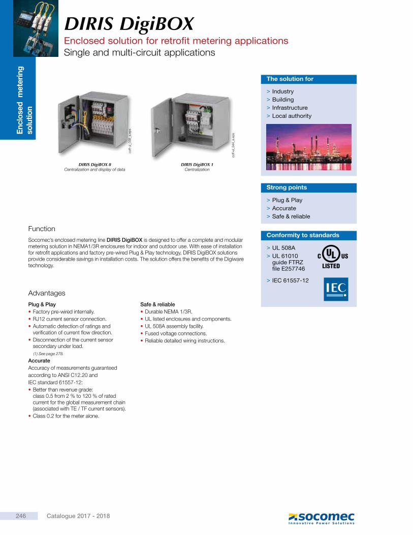
En
clo
sed
m
ete
rin
g
solu
tio
n
DIRIS DigiBOXEnclosed solution for retrofit metering applicationsSingle and multi-circuit applications
Function
Socomec’s enclosed metering line DIRIS DigiBOX is designed to offer a complete and modular metering solution in NEMA1/3R enclosures for indoor and outdoor use. With ease of installation for retrofit applications and factory pre-wired Plug & Play technology, DIRIS DigiBOX solutions provide considerable savings in installation costs. The solution offers the benefits of the Digiware technology.
> Plug & Play
> Accurate
> Safe & reliable
Strong points
Advantages
Plug & Play
Factory pre-wired internally.
RJ12 current sensor connection.
Automatic detection of ratings and verification of current flow direction.
Disconnection of the current sensor secondary under load.
Accurate
Accuracy of measurements guaranteed
according to ANSI C12.20 and
IEC standard 61557-12:
Better than revenue grade:class 0.5 from 2 % to 120 % of rated current for the global measurement chain (associated with TE / TF current sensors).
Class 0.2 for the meter alone.
Safe & reliable
Durable NEMA 1/3R.
UL listed enclosures and components.
UL 508A assembly facility.
Fused voltage connections.
Reliable detailed wiring instructions.
> Industry
> Building
> Infrastructure
> Local authority
The solution for
DIRIS DigiBOX 8Centralization and display of data
DIRIS DigiBOX 1Centralization
> UL 508A
> UL 61010guide FTRZfile E257746
> IEC 61557-12
Conformity to standardsco
ff-ul_
04
4_a
.ep
s
coff-
ul_
03
8_a
.ep
s
246 Catalogue 2017 - 2018
(1) See page 278.
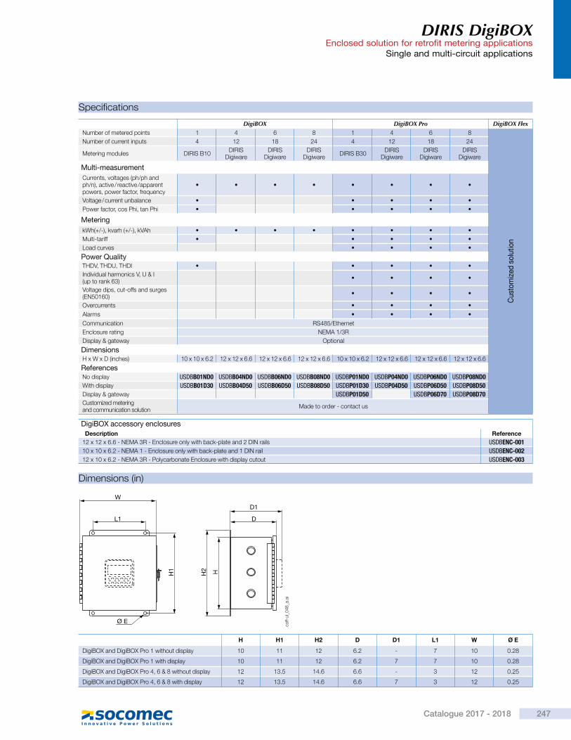
DIRIS DigiBOX Enclosed solution for retrofit metering applications
Single and multi-circuit applications
Dimensions (in)
Specifications
DigiBOX DigiBOX Pro DigiBOX FlexNumber of metered points 1 4 6 8 1 4 6 8
Cus
tom
ized
so
lutio
n
Number of current inputs 4 12 18 24 4 12 18 24
Metering modules DIRIS B10DIRIS
DigiwareDIRIS
DigiwareDIRIS
DigiwareDIRIS B30
DIRIS Digiware
DIRIS Digiware
DIRIS Digiware
Multi-measurement
Currents, voltages (ph/ph and ph/n), active / reactive /apparent powers, power factor, frequency
Voltage / current unbalance
Power factor, cos Phi, tan Phi
Metering
kWh(+/-), kvarh (+/-), kVAh
Multi-tariff
Load curves
Power QualityTHDV, THDU, THDI
Individual harmonics V, U & I (up to rank 63)
Voltage dips, cut-offs and surges (EN50160)
Overcurrents
Alarms
Communication RS485/Ethernet
Enclosure rating NEMA 1/3R
Display & gateway Optional
DimensionsH x W x D (inches) 10 x 10 x 6.2 12 x 12 x 6.6 12 x 12 x 6.6 12 x 12 x 6.6 10 x 10 x 6.2 12 x 12 x 6.6 12 x 12 x 6.6 12 x 12 x 6.6
ReferencesNo display USDBB01ND0 USDBB04ND0 USDBB06ND0 USDBB08ND0 USDBP01ND0 USDBP04ND0 USDBP06ND0 USDBP08ND0
With display USDBB01D30 USDBB04D50 USDBB06D50 USDBB08D50 USDBP01D30 USDBP04D50 USDBP06D50 USDBP08D50
Display & gateway USDBP01D50 USDBP06D70 USDBP08D70
Customized metering and communication solution
Made to order - contact us
H H1 H2 D D1 L1 W Ø E
DigiBOX and DigiBOX Pro 1 without display 10 11 12 6.2 - 7 10 0.28
DigiBOX and DigiBOX Pro 1 with display 10 11 12 6.2 7 7 10 0.28
DigiBOX and DigiBOX Pro 4, 6 & 8 without display 12 13.5 14.6 6.6 - 3 12 0.25
DigiBOX and DigiBOX Pro 4, 6 & 8 with display 12 13.5 14.6 6.6 7 3 12 0.25
L1
H1 HH2
Ø E
W
D
D1
coff-
ul_
04
8_a
.ai
DigiBOX accessory enclosures
Description Reference
12 x 12 x 6.6 - NEMA 3R - Enclosure only with back-plate and 2 DIN rails USDBENC-001
10 x 10 x 6.2 - NEMA 1 - Enclosure only with back-plate and 1 DIN rail USDBENC-002
12 x 10 x 6.2 - NEMA 3R - Polycarbonate Enclosure with display cutout USDBENC-003
247Catalogue 2017 - 2018
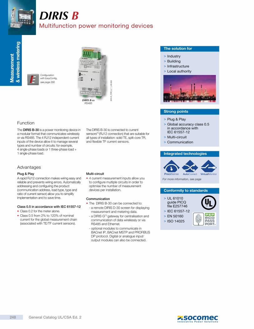
Measu
rem
ent
& w
irele
ss m
ete
ring
DIRIS BMultifunction power monitoring devices
Function
The DIRIS B-30 is a power monitoring device in a modular format that communicates wirelessly or via RS485. The 4 RJ12 independent current inputs of the device allow it to manage several types and number of circuits: for example, 4 single-phase loads or 1 three-phase load + 1 single-phase load.
The DIRIS B-30 is connected to current sensors(1) (RJ12 connection) that are suitable for all types of installation: solid TE, split-core TR, and flexible TF current sensors.
> Plug & Play
> Global accuracy class 0.5 in accordance with IEC 61557-12
> Multi-circuit
> Communication
Strong points
Advantages
Plug & Play
A rapid RJ12 connection makes wiring easy and reliable and prevents wiring errors. Automatically addressing and configuring the product (communication address, load type, type and ratio of current sensor) allow you to simplify implementation and to save time.
Class 0.5 in accordance with IEC 61557-12
Class 0.2 for the meter alone.
Class 0.5 from 2% to 120% of nominal current for the global measurement chain (associated with TE/TF current sensors).
Multi-circuit
4 current measurement inputs allow you to configure multiple circuits in order to optimise the number of measurement devices per installation.
Communication
The DIRIS B-30 can be connected to:
- a remote DIRIS D-30 screen for displaying measurement and metering data.
- a DIRIS G(1) gateway for centralisation and communication of data wirelessly or via RS485 and Ethernet.
- optional modules to communicate in BACnet IP, BACnet MSTP and PROFIBUS DP protocol. Digital or analogue input/output modules can also be connected.
> Industry
> Building
> Infrastructure
> Local authority
The solution for
Configuration
with EasyConfig,
> UL 61010guide PICQfile E257746
> IEC 61557-12
> EN 50160
> ISO 14025
Conformity to standards
DIRIS B-xxRS485
diri
s-b
_03
8_a
_1_c
at.e
ps
Integrated technologies
For more information, see page
248 General Catalog UL/CSA Ed. 2
.
see page 280.
DIRIS BMultifunction power monitoring devices
Accessories
DIRIS B sealing cover Prevents access to the cabling of the monitoring device.
USB configuration cable (2 m) Advanced configuration of DIRIS B gateways can be achieved using the EASY CONFIG software via Ethernet or direct USB connection.
Application Local metering Local analysis
DIRIS B B-10 RS485 B-30 RS485
Number of current inputs
4 4
Metering
± kWh, ± kvarh, kVAh
Load curves
Multi-tariff
Multi-measurement
U12, U23, U31, V1, V2, V3, f
U system, V system
I1, I2, I3, In, P, Q, S, PF
P, Q, S, PF per phase
Predictive power
Ph/N unbalance
Ph/Ph unbalance
Current unbalance (Inba, Idir, Iinv, Ihom, Inb)
Phi, cos Phi, tan Phi
Quality analysis
THDv1, THDv2, THDv3, THDu12, THDu23, THDu31
THDi1, THDi2, THDi3, THDin
Individual harmonics U & V (up to rank 63)
Individual harmonics I (up to rank 63)
Crest factor I1, I2, I3, In
Crest factor V1, V2, V3, U12, U23, U31
Sags, interruptions, swells (EN 50160)
Overcurrents
Alarms
On threshold
Inputs/outputs
History of average values
45 days (max)
Communication
RS485 Modbus
868 Mhz radio-frequency
2 inputs (status / pulse)
diri
s-b
_03
9_a
.ep
s
249General Catalog UL/CSA Ed. 2

DIRIS BMultifunction power monitoring devices
DIRIS D-30 display
DIRIS D-30 Connection
diri
s-d
_00
1_a
_1_c
at
diri
s-d
_00
4_b
_1_x
_cat
RJ9
DIRIS BDIRIS D-30
Optional modules
DIRIS O-m Provides a second RS485 Modbus communication port to the DIRIS B for simultaneous sending of information via RS485 to two supervision stations.
DIRIS O-p Adds a PROFIBUS DPV1 communication port to the DIRIS B.
DIRIS O-b/ip Adds a BACnet IP communication port to the DIRIS B.
DIRIS O-b/mstp Adds a BACnet MSTP communication port to the DIRIS B.
Optional modules (4 max.)*
Digital inputs/outputs
Analogue inputs/outputs
Temperature inputs
Communication protocols
* maximum 4 optional modules with maximum 1 temperature
module and 1 communication module
(Modbus, PROFIBUS, BACnet IP or BACnet MSTP).
DIRIS O-iod 2 digital inputs centralises the metering pulses or the input status changes of the auxiliary contacts.
2 digital outputs can be connected to configurable alarms warning of exceeded thresholds (power, current, etc.) or can be piloted remotely.
DIRIS O-ioa 2 inputs (4-20 mA) centralise analogue sensors (pressure, humidity, temperature, etc.)
2 outputs (4-20 mA) report the measurements (power, currents, etc.) to PLCs.
DIRIS O-it 3 temperature inputs to be connected to PT100 or PT1000 sensors.
Ambient air temperature:
DIRIS O
diri
s-b
_03
1_a
Optional module DIRIS B
250 General Catalog UL/CSA Ed. 2
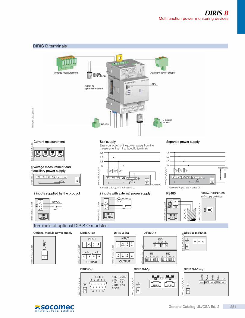
DIRIS BMultifunction power monitoring devices
DIRIS B terminals
Terminals of optional DIRIS O modules
diri
s-d
_02
7_b
_1_g
b_c
at
diri
s-b
_01
9_a
_1_x
_cat
diri
s-b
_02
1_a
_1_x
_cat
diri
s-b
_02
2_a
_1_x
_cat
diri
s-o
_01
0_a
_1_x
_cat
diri
s-b
_02
3_a
_1_x
_cat
diri
s-b
_02
5_a
_1_x
_cat
diri
s-b
_02
6_a
_1_x
_cat
diri
s-b
_02
4_b
_1_x
_cat
V2 VNV3 V1VNV1
NL
Voltage measurement and auxiliary power supply
diri
s-o
_01
1_a
_1_x
_cat
INPUT
OUTPUT
DIRIS O-iod
SU
PP
LY
Optional module power supply
12
IN
12 VDC
I 04
2 inputs supplied by the product
12
IN
10-30 VDC
I 04
2 inputs with external power supply
diri
s-o
_01
4_a
_1_x
_cat DIRIS O-m RS485
Current measurement
diri
s-o
_01
2_a
_1_x
_cat
INPUT
OUTPUT
DIRIS O-ioa
NCSla
veR
S4
85
LIY
CY-C
YI 01
RS485 RJ9 for DIRIS D-30(self-supply and data)
diri
s-o
_01
5_a
_1_x
_cat
SUBD 9
DIRIS O-p
diri
s-o
_01
6_a
_1_x
_cat ETH
DIRIS O-b/ip
diri
s-o
_01
7_a
_1_x
_cat
DIRIS O-b/mstp
110-230VACN
L1
L2
L3
V2 VNV3 V1VNV1
N
L
111
Separate power supply
N
L
N
L1
L2
L3
V2 VNV3
110-230VAC
V1VNV1
111
Self supplyEasy connection of the power supply from the measurement terminal (specific terminals)
diri
s-o
_01
3_a
_1_x
_cat
IN3
DIRIS O-it
1. Fuses 0.5 A gG / 0.5 A class CC.1. Fuses 0.5 A gG / 0.5 A class CC.
RJ9
DIRIS Ooptional module
USB
DisplayDIRIS D-30
Voltage measurement
2 digital inputs
Auxiliary power supply
RS485
IN1 IN2
RJ12
I 04I 03I 02I 01
diri
s-b
_02
0_b
_1_x
_cat
251General Catalog UL/CSA Ed. 2
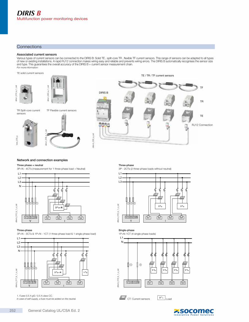
DIRIS BMultifunction power monitoring devices
Connections
Associated current sensorsVarious types of current sensors can be connected to the DIRIS B: Solid TE , split-core TR , flexible TF current sensors. This range of sensors can be adapted to all types of new or existing installations. A rapid RJ12 connection makes wiring easy and reliable and prevents wiring errors. The DIRIS B automatically recognises the sensor size and type. This guarantees the overall accuracy of the DIRIS B + current sensor measurement chain.For more information:
diri
s-t_
01
0_a
_1_c
at
diri
s-t_
00
3_a
_1_c
atd
iris-
t_0
16
_a_1
_cat
TE solid current sensors
diri
s-b
_01
5_b
_1_x
_cat
diri
s-b
_01
7_b
_1_x
_cat
diri
s-b
_01
8_b
_1_x
_cat
Three phase + neutral
3P+N - 4CTs (measurement for 1 three-phase load + Neutral)
Three-phase
3P+N - 3CTs & 1P+N - 1CT (1 three-phase load & 1 single-phase load)
Single-phase
1P+N-1CT (4 single-phase loads)
II01 I02 I03 I04
N
V1 V2 V3 VN
V
L1
L2
L3
3 + N
1 1 1 1
N
V1 V2 V3 VN
V I
L1
L2
L3
I01 I02 I03 I04
3 + N 1
1 1 1 1
V I
V1 V2 V3 VN
L1
N
I02 I03I01 I04
1 1 1 1
11
Network and connection examples
1. Fuses 0.5 A gG / 0.5 A class CC.
In case of self-supply, a fuse must be added on the neutral.3
Load CT: Current sensors
TR Split-core current sensors
TF Flexible current sensors
diri
s-b
_01
6_b
_1_x
_cat
Three-phase
3P - 2CTs (2 three-phase loads without neutral)
V1 V2 V3 VN
V I
L1
L2
L3
I01 I02 I03 I04
3 3
1 1 1
diri
s-b
_03
3_a
_cat
DIRIS B
TE / TR / TF current sensors
TR
TF
TE
RJ12 Connection
tore
_07
8_a
252 General Catalog UL/CSA Ed. 2
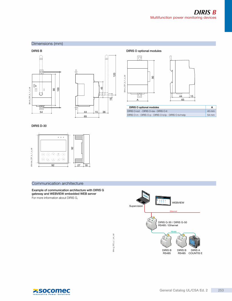
DIRIS BMultifunction power monitoring devices
Communication architecture
Example of communication architecture with DIRIS G gateway and WEBVIEW embedded WEB server
For more information about DIRIS G,
diri
s-g
_00
3_a
_1_e
n_c
at
WEBVIEW
Ethernet
Supervision
DIRIS ACOUNTIS E
DIRIS BRS485
DIRIS BRS485
DIRIS G-30 / DIRIS G-50RS485 / Ethernet
RS485
Dimensions (mm)
DIRIS B
DIRIS D-30
DIRIS O optional modules
54
90 100
44 15
65
36
45
120
15 A44 15
65
90
DIRIS O optional modules A
DIRIS O-iod - DIRIS O-ioa - DIRIS O-it 45 mm
DIRIS O-m - DIRIS O-p - DIRIS O-b/ip - DIRIS O-b/mstp 54 mm
diri
s-b
_00
4_b
_1_x
_cat
diri
s-o
_00
1_b
_1_x
_cat
diri
s-d
w_0
37
_b_1
_x_c
at
92 1827
92
253General Catalog UL/CSA Ed. 2
DIRIS BMultifunction power monitoring devices
DIRIS B characteristics DIRIS D-30 display characteristics
Current measurement
Number of current inputs 4
Associated current sensors Solid TE , split-core TR , flexible TF current sensors
Accuracy Class 0.2 DIRIS B alone Class 0.5 with TE or TF current sensorsClass 1 with TR current sensors
Connection RJ12 connectors with specific SOCOMEC cable
Voltage measurement
Network characteristics measured 50-300VAC (Ph/N) - 87-520VAC (Ph/Ph) - CAT III
Frequency range 45 … 65Hz
Frequency accuracy Class 0.02
Network type Single-phase / Two-phase / Two-phase with neutral / Three-phase / Three-phase with neutral
Measurement by voltage transformer Primary: 400 000 VACSecondary: 60, 100, 110, 173, 190 VAC
Input consumption 0.1 VA
Permanent overload 300VAC Ph/N
Voltage measurement accuracy Class 0.2
Connection Removable spring-cage terminal, 2 x 6 positions, 0.5 … 2.5 mm² solid cable or 0.25 … 1.5 mm² stranded cable with ferrule
Measurement characteristics
Energy and power measurement
AccuracyActive energy and active power
Class 0.2 DIRIS B alone Class 0.5 with TE or TF current sensors Class 1 with TR current sensors
Reactive energy accuracy Class 2 with TE, TR or TF current sensors
Electrical characteristics
Auxiliary power supply
AC voltage 110-230VAC ±15 % (Ph/N ou Ph/Ph) Cat III
Frequency 50/60 Hz
Consumption < 2VA without display < 6VA with display
Connection Removable spring-cage terminal, 2 x 2 positions, 0.5 … 2.5 mm² solid cable or 0.25 … 1.5 mm² stranded cable with ferrule
Environment characteristics
Operating temperature -10 … +70 °C
Storage temperature -25 … +85 °C
Operating humidity 55 °C / 97% relative humidity
Operating altitude 2000 m
Vibration 1G from 10 Hz to 100Hz
Input characteristics
Number 2
Type / Power supply
Optocoupler internal polarisation (12 VDC ± 10 %) or external polarisation (10-30 VDC ± 10%)
Input function Logic status, pulse meter or synchronisation pulse status (input 1)
Communication characteristics
DIRIS B RS485
Link RS485
Connection type 2 … 3 half duplex wires
Protocol Modbus RTU
Speed 1200 … 115200 bauds
USB DIRIS B RS485 configuration
DIRIS B-30 RF
Link Wireless radio frequency
Frequency band 868 MHz (low frequency: 868.1 MHz and high frequency: 869.5875 MHz)
Speed 38400 bauds
USB DIRIS B-30 RF configuration
Mechanical characteristics
Screen type Capacitive touch-screen technology, 10 keys
Screen resolution 350 x 160 pixels
Single product connection
RJ9 Self-supply and data
Micro-USB Updating
Degree of protection IP65 (front face)
Environment
Storage temperature (°C) -20 ... +70°C
Operating temperature (°C) -20 ... +70°C
Humidity 95 % to 40°C
Installation category CAT III
Degree of pollution 2
Power factor measurement
Accuracy Class 0.5 with TE or TF current sensors Class 1 with TR current sensors
DIRIS O optional modules characteristics
DIRIS O-iod - 2 digital inputs/2 digital outputs
Number of inputs 2 per optional modules - max. 4 optional modules
TypeOptocoupler internal polarisation (12 VDC ± 10 %) or external polarisation (10-30 VDC ± 10%)
Function Logic status or pulse meter
Number of outputs 2 per optional modules - max. 4 optional modules
Type Relay / 230VAC ±15 % - 1 A
FunctionConfigurable alarm (current, power,…) on threshold overruns or remote controlled status
Inputs/Outputs connection
Removable screw terminal, 4 positions, 0.14 to 1.5 mm² stranded or solid cable
DIRIS O-ioa - 2 analogue inputs/2 analogue outputs
Number of inputs 2 per optional modules - max. 4 optional modules
Type 4-20 mA
FunctionConnection of analogue sensors (pressure, humidity, temperature…)
Number of outputs 2 per optional modules - max. 4 optional modules
Type 4-20 mA
Function Transmission of measurement image (current, power…) to PLCs
DIRIS O-it - 3 temperature inputs
Number of inputs 3 external inputs + 1 measurement for ambient temperature
Dynamic -20 °C to 150 °C
Type PT100 or PT1000
Function inputs 1, 2 and 3 Temperature measurement
DIRIS O-m - RS485 communication
Link RS485 2 … 3 half duplex wires
Protocol Modbus RTU
Speed 1200 … 115200 bauds
ConnectionRemovable screw terminal, 3 positions, 0.14 to 1.5 mm² stranded or solid cable
DIRIS O-p - PROFIBUS communication
Protocol PROFIBUS DPV1
DIRIS O-b/ip - BACnet IP communication
Protocol BACnet IP
Speed 10 … 100 Mbit/s
DIRIS O-b/mstp - BACnet MSTP communication
Protocol BACnet MSTP
Speed 9600 … 76800 bauds
Power supply(1)
AC voltage 110-230 VAC ±15 %
Frequency 50/60 Hz
(1) No power supply on DIRIS O-it.
254 General Catalog UL/CSA Ed. 2
DIRIS BMultifunction power monitoring devices
References
DIRIS O optional modules Reference
DIRIS O-iod 2 digital inputs / 2 digital outputs 4829 0030
DIRIS O-ioa 2 analogue inputs/2 analogue outputs 4-20 mA 4829 0031
DIRIS O-it 3 temperature inputs PT 100 / PT 1000 4829 0032
DIRIS O-m RS485 Modbus communication 4829 0033
DIRIS O-p PROFIBUS communication 4829 0034
DIRIS O-b/ip BACnet IP communication 4829 0035
DIRIS O-b/mstp BACnet MSTP communication 4829 0036
Accessories Reference
DIRIS D-30 - Single-point display 4829 0200
RJ9 cable for DIRIS D-30 display - 1.5 m 4829 0280
RJ9 cable for DIRIS D-30 display - 3 m 4829 0281
DIRIS B-30 sealing cover for I/O terminals 4829 0049
USB configuration cable 4829 0050
DIRIS B monitoring devices Reference
DIRIS B-10 RS485 - Modbus - 230 VAC 4829 0010DIRIS B-30 RS485 - Modbus - 230 VAC 4829 0000
255General Catalog UL/CSA Ed. 2
Sin
gle
-circu
it m
eter
ing
, m
ea
sure
me
nt
&
an
aly
sis
DIRIS A-30Multifunction power metering & monitoring device - PMD
Functions
Multi-measurement
Currents
- instantaneous: I1, I2, I3, In, Isystem
- average/max average: I1, I2, I3, In
Voltages & frequency
- instantaneous: V1, V2, V3, U12, U23, U31, F, Vsystem, Usystem
- average/max average: V1, V2, V3, U12, U23, U31, F
Powers
- instantaneous: 3P, P, 3Q, Q, 3S, S
- max average: P, Q, S
- predictive: ( P), ( Q), ( S)
Power factors
- instantaneous: 3PF, PF
- average/max average: PF
Kfactor
Metering
Active energy: +/- kWh
Reactive energy: +/- kvarh
Effective power: kVAh
Timetable:
Harmonic analysis
Total Harmonic Distortion
- Currents: thd I1, thd I2, thd I3, thd In
- Phase-to-neutral voltage: thd V1, thd V2, thd V3
Phase-to-phase voltage: thd U12, thd U23, thd U31
Individual harmonics up to 63rd
- Currents: HI1, HI2, HI3, HIn
- Phase-to-neutral voltage: HV1, HV2, HV3,
- Phase-to-phase voltages: HU12, HU23, HU31
Demand profiles (1)
Active & reactive power: P+/- ; Q+/-
Voltages & frequency: V1, V2, V3, U12, U23, U31, F
Events (1)
Alarms on all electrical parameters.
Communications (1)
RS485 (Modbus & Profibus-DP)
Ethernet (Modbus/TCP or Modbus RTU over TCP and Web server)
Ethernet with RS485 Modbus RTU gateway over TCP
Inputs/Outputs(1)
Pulse metering
Remote control/command
Alarm report
Pulse report
Analog output
Analog 0/4- 20 mA
(1) Available with additional storage module
(see following pages).
diri
s_5
81
_h_1
_us_
cat
Advantages
User-friendly operation
With its large backlit multiple-display screen with 6 hot keys, the DIRIS A-30 is easy to use.
Detects wiring errors.
The DIRIS A-30 is provided with a correction function for CT wiring errors.
Customizable
The DIRIS A-30 can be equipped with additional modules that give the user flexibility throughout the service life of the product. Communication modules and additional digital or analog inputs/outputs can be used to increase its range of functionality.
Compliant with ANSI C12.20
Reference standard for PMDs (Power metering & monitoring devices), IEC 61557-12 guarantees performance levels and satisfactory performance from the PMDs under the environmental conditions typical of industrial and tertiary applications.
DIRIS A-30
FunctionThe DIRIS A-30 is a power metering and monitoring device that provides the user with all of the measurements needed to complete energy efficiency projects and to ensure the monitoring of electrical distribution.
All the information can be used and analyzed remotely using energy efficiency software packages.
> Industry
> Building
> Infrastructures
The solution for
> User-friendly operation
> Detects wiring errors.
> Customizable
> Web server function
> Compliant with ANSI C12.20
Strong points
Functional diagram
RS485
DIRIS A-30 DIRIS A-30 DIRIS A-30
Ethe
rnet
Energy efficiency software
PLC
DIRIS A-30
> UL 61010guide PICQfile E257746
> ANSI C12.20
> IEC 61557-12
> IEC 62053-22 class 0.5 S
> IEC 62053-23class 2
Compliance with standards
diri
s_9
86
_a_u
s.p
sd
256 General Catalog UL/CSA Ed. 2
DIRIS A-30Multifunction power metering & monitoring device - PMD
Integratable modules
diri
s_7
73
_a
DIRIS® A-30
diri
s_4
45
_a_1
_cat
2 configurable pulse outputs (type, weight and run) on ±kWh, ±kvarh and kVAh.
Pulse outputs
diri
s_4
47
_a_1
_cat
RS485 link with MODBUS® protocol (speed up to 38400 baud).
MODBUS® communication
diri
s_4
48
_a_1
_cat You can connect a maximum of 2 modules, i.e. 4 analog outputs.
2 outputs can be allocated to:
3I, In, 3V, 3U, F, ± P, ± Q, S, PFL/C, I sys, Vsys, Usys, Ppred, Q pred, Spred, T°C internal, T°C 1, T°C 2, T°C3 and to 30 VDC power supply.
Analog outputs
diri
s_4
49
_a_1
_cat
You can connect a maximum of 3 modules, i.e. 6 inputs / 6 outputs.
2 outputs can be allocated to:
- monitoring: 3I, In, 3V, 3U, F, ± P, ± Q, S, PFL/C, THD 3I, THD In, THD 3V, THD 3U, Ppred, Qpred, Spred, T°C internal, T°C 1, T°C2, T°C3 and of time counter,
- remote control,
- timed remote control,
- 2 inputs for pulse counting.
2 inputs - 2 outputs
diri
s_6
82
_a_1
_cat
Memory function up to max. 62 days for P+, P-, Q+, Q- with an internal or external synchronization signal every 5, 8, 10, 15, 20, 30 and 60 minutes.
Memory function for the last 10 timed and dated alarms.
Memory function for the last min and max instantaneous values for 3U, 3V, 3I, In, F, P±, Q±, S, THD 3U, THD 3V, THD, 3U, THD, 3V, THD, 3I, THD In.
Memory function of average values 3U, 3V et F as a function of synchronization (maximum 60 days).
Storage capability
1 2 3 4 5 6 7diri
s_9
84
x_a_
1_c
at
1. Backlit LCD display
2. Pushbutton for currents and for connection correction function
3. Pushbutton for voltages and frequency..
4. Pushbutton for active, reactive and effective powers and for power factor.
5. Pushbutton for maximum and average values for currents and power levels.
6. Pushbutton for harmonics.
7. Pushbutton for electrical energy meters, timers and impulse counters
Front panel
Ethernet link with MODBUS/TCP or MODBUS RTU over TCP.
Connect 1 to 247 RS485 MODBUS slaves.
Integrated webserver function (1).
Ethernet communication with RS485 MODBUS gateway
diri
s_7
76
_a_1
_cat
diri
s_7
77
_a_1
_cat
Ethernet communication Ethernet link with MODBUS/TCP or MODBUS RTU over TCP.
Integrated web server function (1).
257General Catalog UL/CSA Ed. 2
DIRIS A-30Multifunction power metering & monitoring device - PMD
Accessories
UL recognized Current Transformers
diri
s_7
20
_a_2
_cat
IP65 protection
Terminals
DIRIS A-30
A U XV3 VNV1 V2
I3I2I1
S2S1 S2S1 S2S1
diri
s_5
69
_a_1
_x_c
at
S1 - S2 : current inputs
AUX : auxiliary power supplies Us
V1- V2 - V3 - VN : voltage inputs
DIRIS A-30
0 V - +
R = 120 RS4850n
1
DIRIS A-30 diri
s_5
71
_a_1
_x_c
at
RS485 link.
R = 120 : internal resistance for the RS485 end of line termination.
5 6 7 8
DIRIS A-30
0/4-20 mAOUT 1
0/4-20 mAOUT 2
-+ -+
diri
s_5
73
_a_1
_x_c
at
5 - 6 : analog output n°1.
7 - 8 : analog output n°2.
1 2 3 4
DIRIS A-30OUT 1 OUT 2
diri
s_5
72
_a_1
_x_c
at
1 - 2 : pulse output n°1.
3 - 4 : relay output n°2.
9 10 11 12
DIRIS A-30IN 1
OUT 2A-Cd
OUT 1A-Cd
1 3 14 15 16
IN 2- + - +
diri
s_5
74
_b_1
_x_c
at
9 - 10 : relay output n°1.
11 - 12 : relay output n°2.
13 - 14 : optical input n°1.
15 - 16 : optical input n°2.
17 18
DIRIS A-30
INsynchro
-+
diri
s_6
83
_a_1
_x_c
at
17 - 18 : synchronization input.
DIRIS A-30
10 BASE T100 BASE T
RJ45
diri
s_7
52
_a_1
_x_c
at
DIRIS A-30
10 BASE T100 BASE T
RJ45
0 V +-
RS485gateway R = 120Ω
0n1
diri
s_7
51
_c_1
_fr_
cat
Communication module Analog output modulePulse output module
2 input / 2 output module Memory module
Ethernet module Ethernet module + RS485 MODBUS gateway
traf
o_2
11
_a_f
ront
traf
o_2
11
_a_f
ront
258 General Catalog UL/CSA Ed. 2
DIRIS A-30Multifunction power metering & monitoring device - PMD
Dimensions (in/mm)
Type Panel mounting
Dimensions W x H x D3.78 x 3.78 x 2.36 in /96 x 96 x 60 mm
Case degree of protection IP30
Front degree of protection IP52
Display type Backlit LCD display
Type of terminal strips Fixed or detachable
Section of connection for voltages and other terminals
AWG 34 … 10 / 0.2 … 2.5 mm2
Section of connection for currents AWG 20 … 9 / 0.5 … 6 mm2
Weight 14.11 oz / 400 g
Measurement of currents on insulated inputs (TRMS)
Via CT primary 9,999 A
Via CT secondary 1 or 5 A
Measurement range 0 … 11 kA
Input consumption 0,1 VA
Measurement updating period 1 s
Accuracy 0.2%
Permanent overload 6 A
Intermittent overload 10 In for 1 s
Voltage measurements (TRMS)
Direct measurement between phases 50 to 500 VAC
Direct measurement between phase and neutral 28 to 289 VAC
VT primary measurement 500,000 VAC
VT secondary measurement 60, 100, 110, 173, 190 VAC
Frequency 50 / 60 Hz
Input consumption 0,1 VA
Measurement updating period 1 s
Accuracy 0.2%
Current - voltage product
Limitation for CT 1 A 10,000,000
Limitation for CT 5 A 10,000,000
Power measurement
Measurement updating period 1 s
Accuracy 0.5%
Power factor measurement
Measurement updating period 1 s
Accuracy 0.5%
Frequency measurement
Measurement range 45 … 65 Hz
Measurement updating period 1 s
Accuracy 0.1%
Energy accuracy
Active (according to IEC 62053-22) Class 0.5 S
Reactive (according to IEC 62053-23) Class 2
Auxiliary power supply
Alternative voltage 110 …400 VAC
AC tolerance ± 10 %
Direct current 120 … 350 VDC / 12 … 48 VDC
DC tolerance ± 20 % / - 6 … + 20 %
Frequency 50 / 60 Hz
Power consumption 10 VA
Electrical characteristics
Module 2 inputs - 2 outputs: outputs (alarms / control)
Number of relays 2(1)
Type 250 VAC - 5 A - 1150 VA
Module 2 inputs - 2 outputs: optical coupler inputs
Number 2(1)
Power supply 10 … 30 VDC
Minimum width of signal 10 ms
Minimum length between 2 pulses 18 ms
Type Optical couplers
Pulse output module
Number of relays 2
Type 100 VDC - 0.5 A - 10 VA
Max. number of manoeuvres 108
Analog output module
Number of outputs 2(2)
Type Insulated
Scale 0 / 4 … 20 mA
Load resistance 600
Maximum current 30 mA
MODBUS communication module
Link RS485
Type 2 to 3 half duplex wires
Protocol MODBUS® RTU
MODBUS® speed 4800 to 38400 baud
PROFIBUS DP communication module
Link SUB-D9
Protocol PROFIBUS® DP
PROFIBUS® speed 9.8 kbaud … 12 Mbaud
Ethernet communication module
Connection technology RJ45
Baud rate 10 base T / 100 base T
Protocol MODBUS TCP or MODBUS RTU on TCP
Operating conditions
Operating temperature range - 10 … + 55 °C / +14 °F … +131 °F
Storage temperature - 20 … + 85 °C / -4 °F … +185 °F
Relative humidity 95%
(1) Max. 3 modules / DIRIS.
(2) Max. 2 modules / DIRIS.
DIRIS A40
92 + 0.8- 0.0
3.62 + 0.03- 0.0
3.62 + 0.03- 0.0
92 + 0.8- 0.0
3.78 96
96
3.781.77
1.38
0.59 4535
15
diri
s_5
82
_f_1
_x_c
at
259General Catalog UL/CSA Ed. 2
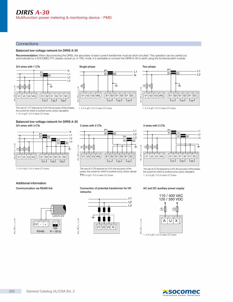
DIRIS A-30Multifunction power metering & monitoring device - PMD
Recommendation: When disconnecting the DIRIS, the secondary of each current transformer must be short-circuited. This operation can be carried out automatically by a SOCOMEC PTI: please consult us. In TNC mode, it is advisable to connect the DIRIS A-30 to earth using the functional earth module.
Balanced low-voltage network for DIRIS A-30
Connections
V1 V2 V3 VN
S2P1S1
NL1L2L3
I3I2I1
S2S1 S2S1 S2S1
1 1 1
diri
s_3
92
_d_1
_x_c
at
The use of 1 CT reduces by 0.5% the accuracy of the phases, the current for which is worked out by vector calculation.
3/4 wires with 1 CTs
V1 V2 V3 VN
S2S1P1 L1
N
I3I2I1
S2S1 S2S1 S2S1
1
diri
s_3
93
_e_1
_x_c
at
Single-phase
V1 V2 V3 VN
S2P1S1
L1L2
I3I2I1
S2S1 S2S1 S2S1
1 1
diri
s_3
94
_d_1
_x_c
at
Two-phase
1. 0.5 A gG / 0.5 A class CC fuses. 1. 0.5 A gG / 0.5 A class CC fuses.
1. 0.5 A gG / 0.5 A class CC fuses.
Balanced low-voltage network for DIRIS A-30
NL1L2L3
S2
S2
P1S1
P1S1
V1 V2 V3 VN
I3I2I1
S2S1 S2S1 S2S1
1 1 1
diri
s_3
95
_d_1
_x_c
at
3/4 wires with 3 CTs
1. 0.5 A gG / 0.5 A class CC fuses. The use of 2 CTs reduces by 0.5% the accuracy of the phase, the current for which is worked out by vector calcula-tion.
diri
s_3
96
_d_1
_x_c
at
L1L2L3
S2
S2P1S1
P1S1
V1 V2 V3 VN
I3I2I1
S2S1 S2S1 S2S1
1 1 1
3 wires with 2 CTs
1. 0.5 A gG / 0.5 A class CC fuses.
The use of 2 CTs reduces by 0.5% the accuracy of the phase, the current for which is worked out by vector calculation.
L1L2L3
S2P1S1
P1S1
V1 V2 V3 VN
I3I2I1
S2S1 S2S1 S2S1
1 1 1
diri
s_3
97
_d_1
_x_c
at
3 wires with 2 CTs
1. 0.5 A gG / 0.5 A class CC fuses.
Additional information
RS485
0 V - +ON
LIYCY-CY
diri
s_3
98
_c_1
_x_c
at
Communication via RS485 link
V1 V2 V3 N
L1L2L3
diri
s_3
99
_b_1
_x_c
at
Connection of potential transformer for HV
networks
A U X
110 / 400 VAC120 / 350 VDC
11
diri
s_4
00
_i_1
_x_c
at
AC and DC auxiliary power supply
1. 0.5 A gG / 0.5 A class CC fuses.
260 General Catalog UL/CSA Ed. 2
DIRIS A-30Multifunction power metering & monitoring device - PMD
References
Basic device DIRIS A-30
Auxiliary power supply Us Part number
110 ... 400 VAC / 120 ... 350 VDC 4825 040312 ... 48 VDC 4825 0405
Options
Plug-in modules(1) Part number
Pulse outputs 4825 0090RS485 MODBUS® communication 4825 0092Analog outputs 4825 00932 inputs - 2 outputs 4825 0094Storage capability 4825 0097Ethernet communication (integrated web server function)(2) 4825 0203Ethernet communication + RS485 gateway (integrated web server function)(2) 4825 0204
(1) Ease of integration of additional functions (maximum 4 slots on A-30).
(2) Dimensions: 2 slots.
AccessoriesTo be orderedin multiples of
Part number
IP65 protection. 1 4825 0089Integration kit for 144 x 96 mm cutout 1 4825 0088Fuse circuit breakers to protect voltage inputs (type RM) 3 pole 4 5701 0018Fuse circuit breakers to protect the auxiliary power supply (type RM) 1 pole + neutral 6 5701 0017gG 10x38 0.5 A fuses 10 6012 0000Range of UL recognized current transformers 1
Management software for DIRIS
> Our local team offers complete support to ensure the success of your project, from consultation to implementation of your metering system.
Expert Services
261General Catalog UL/CSA Ed. 2
See 188.
See 188.
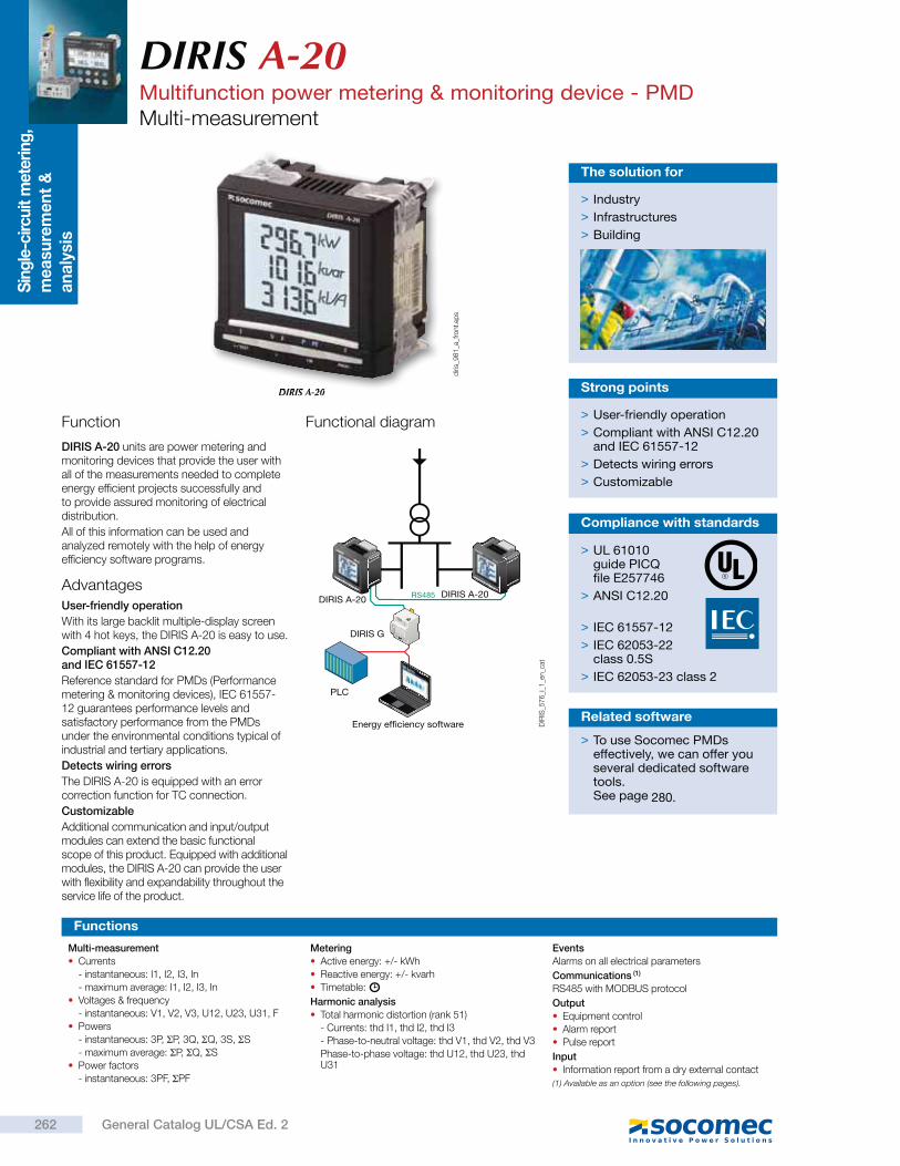
Sin
gle
-circu
it m
eter
ing
, m
ea
sure
me
nt
&
an
aly
sis
DIRIS A-20Multifunction power metering & monitoring device - PMDMulti-measurement
DIRIS A-20
Function
DIRIS A-20 units are power metering and monitoring devices that provide the user with all of the measurements needed to complete energy efficient projects successfully and to provide assured monitoring of electrical distribution.
All of this information can be used and analyzed remotely with the help of energy efficiency software programs.
> Industry
> Infrastructures
> Building
The solution for
> User-friendly operation
> Compliant with ANSI C12.20 and IEC 61557-12
> Detects wiring errors
> Customizable
Strong points
Functions
Multi-measurement
Currents
- instantaneous: I1, I2, I3, In
- maximum average: I1, I2, I3, In
Voltages & frequency
- instantaneous: V1, V2, V3, U12, U23, U31, F
Powers
- instantaneous: 3P, P, 3Q, Q, 3S, S
- maximum average: P, Q, S
Power factors
- instantaneous: 3PF, PF
Metering
Active energy: +/- kWh
Reactive energy: +/- kvarh
Timetable:
Harmonic analysis
Total harmonic distortion (rank 51)
- Currents: thd I1, thd I2, thd I3
- Phase-to-neutral voltage: thd V1, thd V2, thd V3
Phase-to-phase voltage: thd U12, thd U23, thd U31
Events
Alarms on all electrical parameters
Communications (1)
RS485 with MODBUS protocol
Output
Equipment control
Alarm report
Pulse report
Input
Information report from a dry external contact
(1) Available as an option (see the following pages).
RS485DIRIS A-20 DIRIS A-20
Energy efficiency software
PLC
DIRIS G
DIR
IS_5
76
_i_1
_en_c
at
Advantages
User-friendly operation
With its large backlit multiple-display screen with 4 hot keys, the DIRIS A-20 is easy to use.
Compliant with ANSI C12.20 and IEC 61557-12
Reference standard for PMDs (Performance metering & monitoring devices), IEC 61557-12 guarantees performance levels and satisfactory performance from the PMDs under the environmental conditions typical of industrial and tertiary applications.
Detects wiring errors
The DIRIS A-20 is equipped with an error correction function for TC connection.
Customizable
Additional communication and input/output modules can extend the basic functional scope of this product. Equipped with additional modules, the DIRIS A-20 can provide the user with flexibility and expandability throughout the service life of the product.
Functional diagram
diri
s_9
81
_a_f
ront.
eps
> To use Socomec PMDs effectively, we can offer you several dedicated software tools.See page
Related software
> UL 61010guide PICQfile E257746
> ANSI C12.20
> IEC 61557-12
> IEC 62053-22 class 0.5S
> IEC 62053-23 class 2
Compliance with standards
262 General Catalog UL/CSA Ed. 2
280.
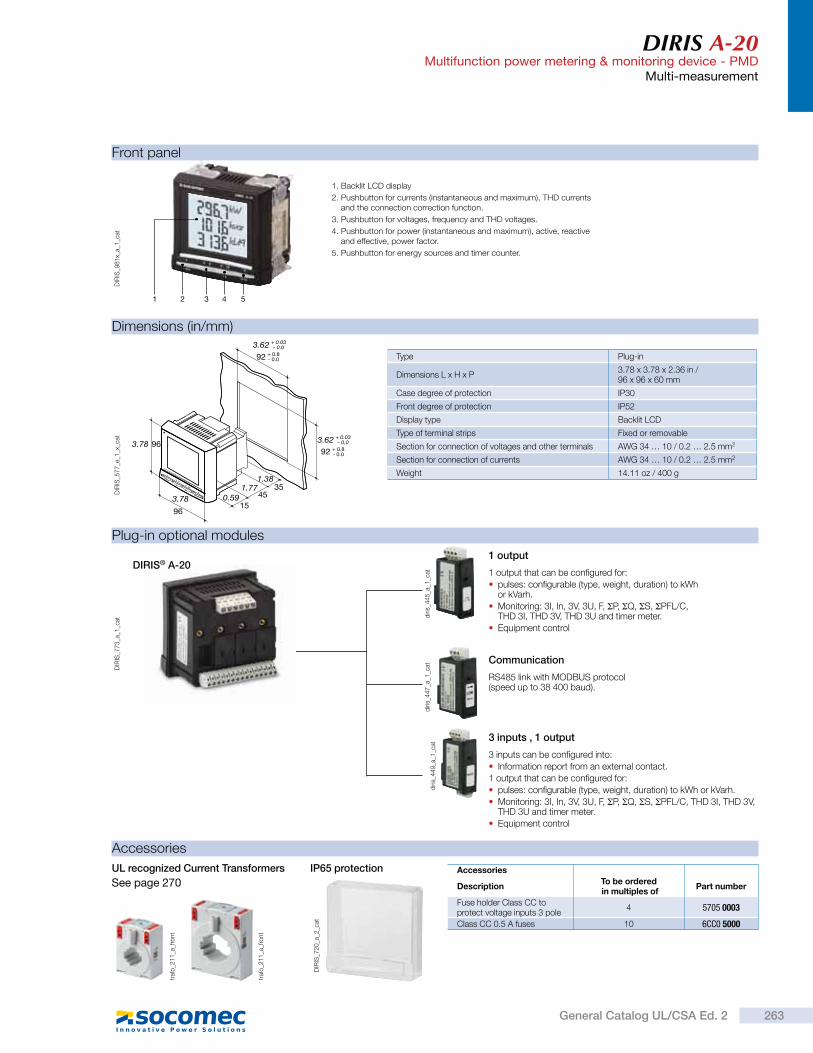
DIRIS A-20Multifunction power metering & monitoring device - PMD
Multi-measurement
54321
DIR
IS_9
81
x_a_
1_c
at
1. Backlit LCD display
2. Pushbutton for currents (instantaneous and maximum), THD currents and the connection correction function.
3. Pushbutton for voltages, frequency and THD voltages.
4. Pushbutton for power (instantaneous and maximum), active, reactive and effective, power factor.
5. Pushbutton for energy sources and timer counter.
Front panel
Plug-in optional modules
DIR
IS_7
73
_a_1
_cat
diri
s_4
45
_a_1
_cat 1 output that can be configured for:
pulses: configurable (type, weight, duration) to kWh or kVarh.
Monitoring: 3I, In, 3V, 3U, F, P, Q, S, PFL/C, THD 3I, THD 3V, THD 3U and timer meter.
Equipment control
1 output
diri
s_4
47
_a_1
_cat
RS485 link with MODBUS protocol (speed up to 38 400 baud).
3 inputs can be configured into:
Information report from an external contact.
1 output that can be configured for:
pulses: configurable (type, weight, duration) to kWh or kVarh.
Monitoring: 3I, In, 3V, 3U, F, P, Q, S, PFL/C, THD 3I, THD 3V, THD 3U and timer meter.
Equipment control
Communication
3 inputs , 1 output
DIRIS® A-20
diri
s_4
49
_a_1
_cat
Dimensions (in/mm)
Type Plug-in
Dimensions L x H x P3.78 x 3.78 x 2.36 in /96 x 96 x 60 mm
Case degree of protection IP30
Front degree of protection IP52
Display type Backlit LCD
Type of terminal strips Fixed or removable
Section for connection of voltages and other terminals AWG 34 … 10 / 0.2 … 2.5 mm2
Section for connection of currents AWG 34 … 10 / 0.2 … 2.5 mm2
Weight 14.11 oz / 400 g5/TEST 4 OK PROG
I V F P PF E
92 + 0.8- 0.0
3.62 + 0.03- 0.0
3.62 + 0.03- 0.0
92 + 0.8- 0.0
3.78 96
96
3.781.77
1.38
0.59 4535
15
DIR
IS_5
77
_e_1
_x_c
at
Accessories
UL recognized Current Transformers
DIR
IS_7
20
_a_2
_cat
IP65 protection
traf
o_2
11
_a_f
ront
traf
o_2
11
_a_f
ront
Accessories
DescriptionTo be ordered in multiples of
Part number
Fuse holder Class CC to protect voltage inputs 3 pole
4 5705 0003
Class CC 0.5 A fuses 10 6CC0 5000
263General Catalog UL/CSA Ed. 2
See page 270
DIRIS A-20Multifunction power metering & monitoring device - PMDMulti-measurement
Low voltage balanced network
Connection
Voltage measurements (TRMS)
Direct measurement between phases 50 … 500 VAC
Direct measurement between phase and neutral
28 … 289 VAC
Input consumption 0.1 VA
Measurement updating period 1 s
Accuracy 0.2%
Power measurement
Measurement updating period 1 s
Accuracy 0.5%
Power factor measurement
Measurement updating period 1 s
Accuracy 0.5%
Frequency measurement
Measurement range 45 … 65 Hz
Measurement updating period 1 s
Accuracy 0.1%
Energy accuracyActive (according to IEC 62053-22) Class 0.5 SReactive (in acc. with CEI 62053-23) Class 2Auxiliary power supplyAlternative voltage 110 … 400 VACAC tolerance ± 10%DC voltage 120 … 289 VDCDC tolerance ± 20%Frequency 50 / 60 HzPower consumption 10 VA
Pulse or alarm outputNumber 1Type 100 VDC - 0.5 A - 10 VAMax. number of manoeuvres 108
InputsNumber 3Power supply 10 … 30 VDCMinimum width of signal 10 msMinimum length between 2 pulses 18 msType Optical couplersCommunicationLink RS485Type 2 to 3 half duplex wiresProtocol MODBUS® in RTU modeMODBUS® speed 1400 … 38400 baud
Operating conditions
Operating temperature range - 10 … + 55 °C / +14 °F … +131 °F
Storage temperature - 20 … + 70 °C / -4 °F … +158 °F
Relative humidity 95%
Electrical characteristics
Terminals
DIRIS A20
A U XV3 VNV1 V2
I3I2I1
S2S1 S2S1 S2S1
DIR
IS_5
78
_a_1
_x_c
at S1 - S2 : current inputs.
AUX : auxiliary power supply Us.
V1, V2, V3 & VN : voltage inputs.
0 V - +
R = 120RS4850n
1
DIRIS A20
DIR
IS_5
79
_a_1
_x_c
at
RS485 link.
R = 120 : internal resistance for the RS485 link.
Module communication
1 8 19
DIRIS A20
OUT 11 9 18
DIRIS A20
OUT 1
1 2 13
IN 3
+ - + - + -
1 4 15
IN 2
1 6 17
IN 1
DIR
IS_5
80
_b_1
_x_c
at
18 - 19 : output n°1
Output or alarm module Module with 3 inputs, 1 output
The 1CT solution reduces by 0.5% the accuracy of the phase for which the current is deduced by a vector calculation.
3/4 wires with 1 CT Single-phase Two-phase
Current measurement (TRMS)
Via CT primary 9 999 A
Via CT secondary 5 A
Measurement range 0 … 11 kA
Input consumption 0.6 VA
Measurement updating period 1 s
Accuracy 0.2%
Permanent overload 6 A
Intermittent overload 10 In over 1 sec
1. 0.5 A gG / 0.5 A class CC fuses.1. 0.5 A gG / 0.5 A class CC fuses.1. 0.5 A gG / 0.5 A class CC fuses.
Recommendation
- For IT earthing systems, it is recommended that the CT secondary is not connected to earth.
- When disconnecting the DIRIS, the secondary of each current transformer must be short-circuited. This operation can be carried out automatically by a SOCOMEC PTI: please consult us.
diri
s_3
92
_d_1
_x_c
at
V1 V2 V3 VN
S2P1S1
NL1L2L3
I3I2I1
S2S1 S2S1 S2S1
1 1 1
diri
s_3
93
_d_1
_x_c
at
V1 V2 V3 VN
S2S1P1 L1
N
I3I2I1
S2S1 S2S1 S2S1
1
diri
s_3
94
_d_1
_x_c
at
V1 V2 V3 VN
S2P1S1
L1L2
I3I2I1
S2S1 S2S1 S2S1
1 1
264 General Catalog UL/CSA Ed. 2
DIRIS A-20Multifunction power metering & monitoring device - PMD
Multi-measurement
Low voltage unbalanced network
NL1L2L3
S2
S2
P1S1
P1S1
V1 V2 V3 VN
I3I2I1
S2S1 S2S1 S2S1
1 1 1
diri
s_3
95
_d_1
_fr_
cat
3/4 wires with 3 CTs
L1L2L3
S2
S2P1S1
P1S1
V1 V2 V3 VN
I3I2I1
S2S1 S2S1 S2S1
1 1 1
diri
s_3
96
_d_1
_fr_
cat
The 2CT solution reduces by 0.5% the accuracy of the phase for which the current is deduced by a vector calculation.
3 wires with 2 CTs
L1L2L3
S2P1S1
P1S1
V1 V2 V3 VN
I3I2I1
S2S1 S2S1 S2S1
1 1 1
diri
s_3
97
_e_1
_x_c
at
The 2CT solution reduces by 0.5% the accuracy of the phase for which the current is deduced by a vector calculation.
3 wires with 2 CTs
References
Basic device DIRIS A-20
Auxiliary power supply Us Part number
110 … 400 VAC / 120 … 350 VDC 4825 0402Options
Plug-in optional modules Part number
On/Off output. 4825 0080RS485 MODBUS® communication 4825 00823 inputs, 1 output 4825 0083Accessories
Designation of accessories To be ordered in multiples of Part number
Protection IP65 1 4825 0089Plug-in kit for cutout 144 x 96 mm 1 4825 0088Fuse holder Class CC to protect voltage inputs 3 pole 4 5705 0003Class CC 0.5 A fuses 10 6CC0 5000Ferrite for use with communication modules 1 4899 0011Range of UL recognized current transformers 1 See page
Software associated with DIRIS See page
1. 0.5 A gG / 0.5 A class CC fuses.
Additional information
RS485
0 V - +ON
LIYCY-CY
diri
s_3
98
_c_1
_x_c
at
Communication via RS485 link
A U X
110 / 400 VAC120 / 350 VDC
11
diri
s_4
00
_i_1
_fr_
cat
AC and DC auxiliary power supply
1. 0.5 A gG / 0.5 A class CC fuses.
1. 0.5 A gG / 0.5 A class CC fuses. 1. 0.5 A gG / 0.5 A class CC fuses.
> Our local team offers complete support to ensure the success of your project, from consultation to implementation of your metering system.
Expert Services
265General Catalog UL/CSA Ed. 2
270280
Sin
gle
-circu
it m
eter
ing
, m
ea
sure
me
nt
&
an
aly
sis
DIRIS A-10Multifunction meters - PMDmodular multifunction meter
Function
Advantages
The DIRIS A-10 is a modular multifunction meter for measuring electrical values in low voltage networks.
It allows all electrical parameters to be displayed and utilized for communication and/or output functions.
Easy to use
Five direct access pushbuttons enable all measurements to be clearly viewed on the backlit LCD display.
Integrated temperature sensor
It allows variations in temperature to be detected.
Detects wiring errors
An integrated test function can be utilized to detect incorrect wiring and to automatically correct CT installation errors.
Compliant with ANSI C12.20 and IEC 61557-12
IEC 61557-12 is a high-level standard for all PMDs (Performance Monitoring Devices) that are designed to measure and monitor electrical parameters in distribution networks.
Compliance with IEC 61557-12 ensures a high level of equipment performance, in terms of metrology, as well as mechanical and environmental aspects (EMC, temperature, etc.).
> Industry
> Infrastructures
> Building
The solution for
> Easy to use
> Integrated temperature sensor
> Detects wiring errors
> Compliant with ANSI C12.20 and IEC 61557-12
Strong points
Functions
Multi-measurement
Currents
- instantaneous: I1, I2, I3, In
- maximum average: I1, I2, I3, In
Voltages & frequency
- instantaneous: V1, V2, V3, U12, U23, U31, F
Power
- instantaneous: 3P, P, 3Q, Q, 3S, S
- maximum average: P, Q, S
Power factors
- instantaneous: 3PF, PF
Metering
Active energy: +/- kWh
Reactive energy: +/- kVarh
Hours:
Harmonic analysis
Total harmonic distortion (level 51)
- Currents: thd I1, thd I2, thd I3
- Phase-to-neutral voltage: thd V1, thd V2, thd V3
- Phase-to-phase voltage: thd U12, thd U23, thd U31
Dual tariff function
Selection of one out of 2 billing tariffs
Events
Alarms on all electrical values
Communications(1)
RS485 with MODBUS protocol
Input
Tariff selection
Remote device status
Output
Remote command of device
Alarm report
Pulse report(1) Available on specific version (see the following pages).
485
ETHGeneral measurementreport
Curves for current per phase
PC
PLC
Energy efficiency software
RS485DIRIS A-10 DIRIS A-10
TEST
OK
PROG
TEST
OK
PROG
diri
s_8
08
_f_1
_gb
_cat
Principle diagram
> UL 61010guide PICQfile E257746
> ANSI C12.20
> IEC 61557-12
> IEC 62053-22 class 0.5S
> IEC 62053-23class 2
Conformity to standards
DIRIS A-10
diri
s_9
78
_a_f
ront.
eps
266 General Catalog UL/CSA Ed. 2
DIRIS A-10Multifunction meters - PMDmodular multifunction meter
1. Backlit LCD display.
2. Direct access key for currents (instant and maximum), current THD and test function.
3. Direct access key for voltages, frequency and voltage THD.
4. Direct access key for active, reactive and apparent power (instantaneous and max. values) and power factor.
5. Direct access key for energies.
6. Pushbutton for hour meter, temperature and programming menu access.
7. Metrological LED.
Front panel
Dimensions (in/mm)
Type modular
Number of modules 4
Dimensions W x H x D 2.83 x 3.54 x 2.51 in / 72 x 90 x 64 mm
Case degree of protection IP 30
Front degree of protection IP 52
Display type backlit LCD display
Voltage and current connection cross-section
AWG 6 / 4 mm2
Connection cross-section for AUX supply, input, output and comms.
AWG 10 / 2.5 mm2
Weight7.23 oz / 205 g (4825 0400)7.58 oz / 215 g (4825 0401)
2.8372
3.54 90 45 1.77
1.7344
2.5164
diri
s_8
09
_b_1
_x_c
at
Current measurement (TRMS)
Via CT primary 9 999 A
Via CT secondary 5 A
Measurement range 0 … 11 kA
Input consumption 0.6 VA
Measurement updating period 1 s
Accuracy 0.2 %
Permanent overload 6 A
Intermittent overload 10 In for 1 s
Voltage measurements (TRMS)
Direct measurement between phases 50 … 500 VAC
Direct measurement between phase and neutral 28 … 289 VAC
Input consumption 0.1 VA
Measurement updating period 1 s
Accuracy 0.2 %
Power measurement
Measurement updating period 1 s
Accuracy 0.5 %
Power factor measurement
Measurement updating period 1 s
Accuracy 0.5 %
Frequency measurement
Measurement range 45 … 65 Hz
Measurement updating period 1 s
Accuracy 0.1 %
Energy accuracy
Active (according to IEC 62053-22) Class 0.5 S
Reactive (according to IEC 62053-23) Class 2
Auxiliary power supply
Alternating voltage 110 … 277 VAC
AC tolerance ± 15 %
Frequency 50 / 60 Hz
Consumption < 3 VA
Digital output (pulses or on/off)
Number 1
Type 20 / 30 VDC - 0.5 A - 10 VA
Max. number of operations 108
Communication
Link RS485
Type 2 … 3 half duplex wires
Protocol MODBUS RTU
MODBUS® speed 2400 … 38400 bauds
Operating conditions
Operating temperature - 10 … + 55 °C / +14 °F … +131 °F
Storage temperature - 20 … + 70 °C / -4 °F … +158 °F
Relative humidity 85 %
Electrical characteristics
Input (tariff)
Number 1
Type 0 VAC: T1 / 200-277 VAC: T2
1
234567
diri
s_9
78
x_a_
1_c
at
Accessories
DescriptionTo be orderedin multiples of
Reference
Fuse holder Class CC to protect voltage inputs 3 pole
4 5705 0003
Class CC 0.5 A fuses 10 6CC0 5000
267General Catalog UL/CSA Ed. 2
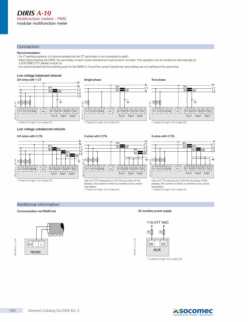
DIRIS A-10Multifunction meters - PMDmodular multifunction meter
Connection
Recommendation:
- For IT earthing systems, it is recommended that the CT secondary is not connected to earth.
- When disconnecting the DIRIS, the secondary of each current transformer must be short-circuited. This operation can be carried out automatically by a SOCOMEC PTI: please consult us.
- It is recommended that the earthing point for the DIRIS A-10 and the current transformer secondaries are not earthed at the same time.
V1 V2 V3 VN
S2P1S1
NL1L2L3
I3I2I1
S2S1 S2S1 S2S1
1 1 1
diri
s_8
10
_a_1
_gb
_cat
3/4 wires with 1 CT
V1 V2 V3 VN
S2P1S1
L1N
I3I2I1
S2S1 S2S1 S2S1
1
diri
s_8
11
_a_1
_gb
_cat
Single-phase
V1 V2 V3 VN
S2P1S1
L1L2
I3I2I1
S2S1 S2S1 S2S1
1 1
diri
s_8
12
_a_1
_gb
_cat
Two-phase
Additional information
RS485
0 V - +
LIYCY-CY
diri
s_8
20
_a_1
_x_c
at
Communication via RS485 link
AUX
110-277 VAC
20 22
11
diri
s_8
21
_e_1
_x_c
at
AC auxiliary power supply
Low voltage unbalanced network
NL1L2L3
S2
S2P1S1
P1S1
V1 V2 V3VNI3I2I1
S2S1 S2S1 S2S1
1 1 1
diri
s_8
13
_a_1
_gb
_cat
3/4 wires with 3 CTs
L1L2L3S2
S2P1S1
P1S1
V1 V2 V3 VNI3I2I1
S2S1 S2S1 S2S1
1 1 1
diri
s_8
14
_a_1
_gb
_cat
Use of 2 CTs reduces by 0.5% the accuracy of the phases, the current of which is worked out by vector calculation.
3 wires with 2 CTs
L1L2L3S2
P1S1
P1S1
V1 V2 V3 VNI3I2I1
S2S1 S2S1 S2S1
1 1 1
diri
s_8
15
_a_1
_gb
_cat
Use of 2 CTs reduces by 0.5% the accuracy of the phases, the current of which is worked out by vector calculation.
3 wires with 2 CTs
Low voltage balanced network
1. Fuses 0.5 A gG / 0.5 A class CC. 1. Fuses 0.5 A gG / 0.5 A class CC. 1. Fuses 0.5 A gG / 0.5 A class CC.
1. Fuses 0.5 A gG / 0.5 A class CC.1. Fuses 0.5 A gG / 0.5 A class CC.
1. Fuses 0.5 A gG / 0.5 A class CC.
1. Fuses 0.5 A gG / 0.5 A class CC.
268 General Catalog UL/CSA Ed. 2
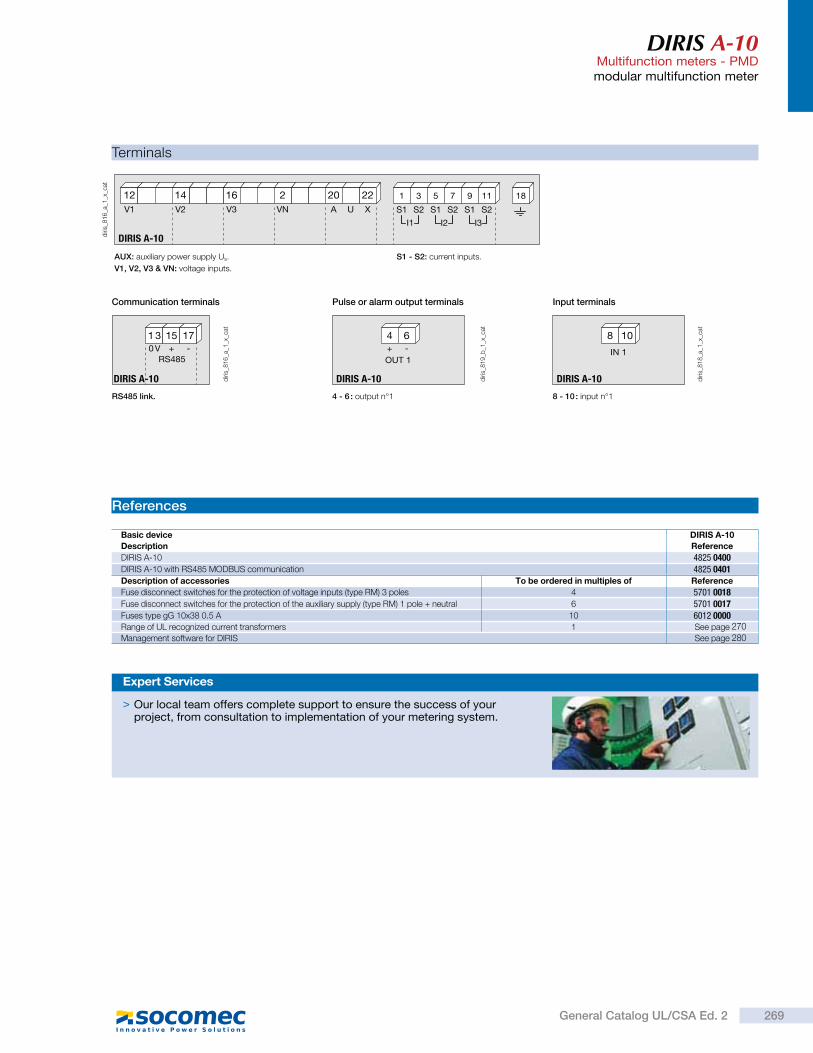
DIRIS A-10Multifunction meters - PMDmodular multifunction meter
Terminals
DIRIS A-10
20 2216 212 14
I3I2I1
31 75 119
A U XV3 VNV1 V2 S2S1 S2S1 S2S1
18
diri
s_8
16
_a_1
_x_c
at
AUX: auxiliary power supply Us.
V1, V2, V3 & VN: voltage inputs.
S1 - S2: current inputs.
1 3 15 170 V + -
RS485
DIRIS A-10 diri
s_8
16
_a_1
_x_c
at
RS485 link.
Communication terminals
4 6
DIRIS A-10
OUT 1+ -
diri
s_8
19
_b_1
_x_c
at
4 - 6 : output n°1
Pulse or alarm output terminals
8 10
DIRIS A-10
IN 1
diri
s_8
18
_a_1
_x_c
at
8 - 10 : input n°1
Input terminals
References
Basic device DIRIS A-10
Description Reference
DIRIS A-10 4825 0400DIRIS A-10 with RS485 MODBUS communication 4825 0401Description of accessories To be ordered in multiples of Reference
Fuse disconnect switches for the protection of voltage inputs (type RM) 3 poles 4 5701 0018Fuse disconnect switches for the protection of the auxiliary supply (type RM) 1 pole + neutral 6 5701 0017Fuses type gG 10x38 0.5 A 10 6012 0000Range of UL recognized current transformers 1 See page
Management software for DIRIS See page
> Our local team offers complete support to ensure the success of your project, from consultation to implementation of your metering system.
Expert Services
269General Catalog UL/CSA Ed. 2
270280
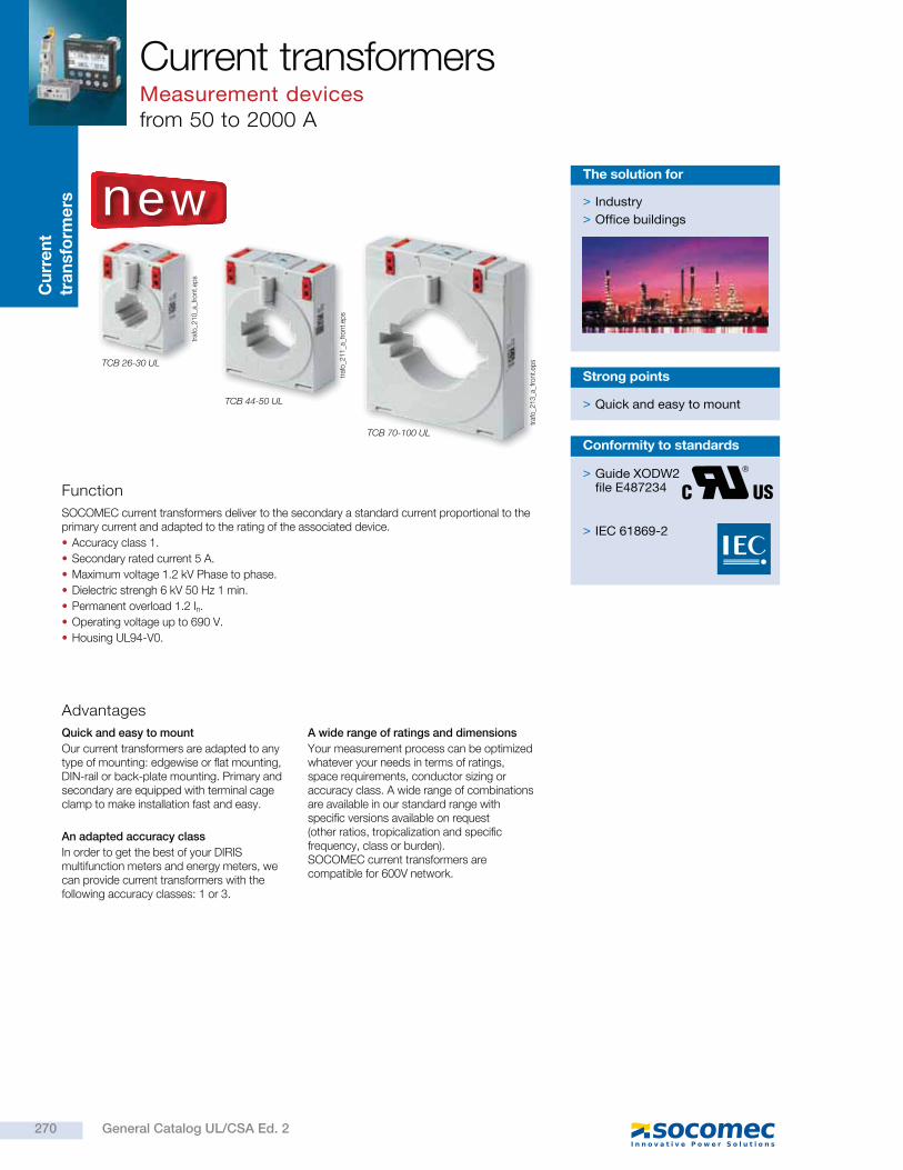
Cu
rre
nt
tra
nsfo
rme
rsCurrent transformersMeasurement devicesfrom 50 to 2000 A
Function
Advantages
SOCOMEC current transformers deliver to the secondary a standard current proportional to the primary current and adapted to the rating of the associated device.
Accuracy class 1.
Secondary rated current 5 A.
Maximum voltage 1.2 kV Phase to phase.
Dielectric strengh 6 kV 50 Hz 1 min.
Permanent overload 1.2 In.
Operating voltage up to 690 V.
Housing UL94-V0.
Quick and easy to mount
Our current transformers are adapted to any type of mounting: edgewise or flat mounting, DIN-rail or back-plate mounting. Primary and secondary are equipped with terminal cage clamp to make installation fast and easy.
An adapted accuracy class
In order to get the best of your DIRIS multifunction meters and energy meters, we can provide current transformers with the following accuracy classes: 1 or 3.
A wide range of ratings and dimensions
Your measurement process can be optimized whatever your needs in terms of ratings, space requirements, conductor sizing or accuracy class. A wide range of combinations are available in our standard range with specific versions available on request (other ratios, tropicalization and specific frequency, class or burden). SOCOMEC current transformers are compatible for 600V network.
> Quick and easy to mount
Strong points
> Industry
> Office buildings
The solution for
traf
o_2
10
_a_f
ront.
eps
traf
o_2
11
_a_f
ront.
eps
TCB 26-30 UL
TCB 44-50 UL
traf
o_2
13
_a_f
ront.
eps
TCB 70-100 UL
> Guide XODW2file E487234
> IEC 61869-2
Conformity to standards
new
270 General Catalog UL/CSA Ed. 2
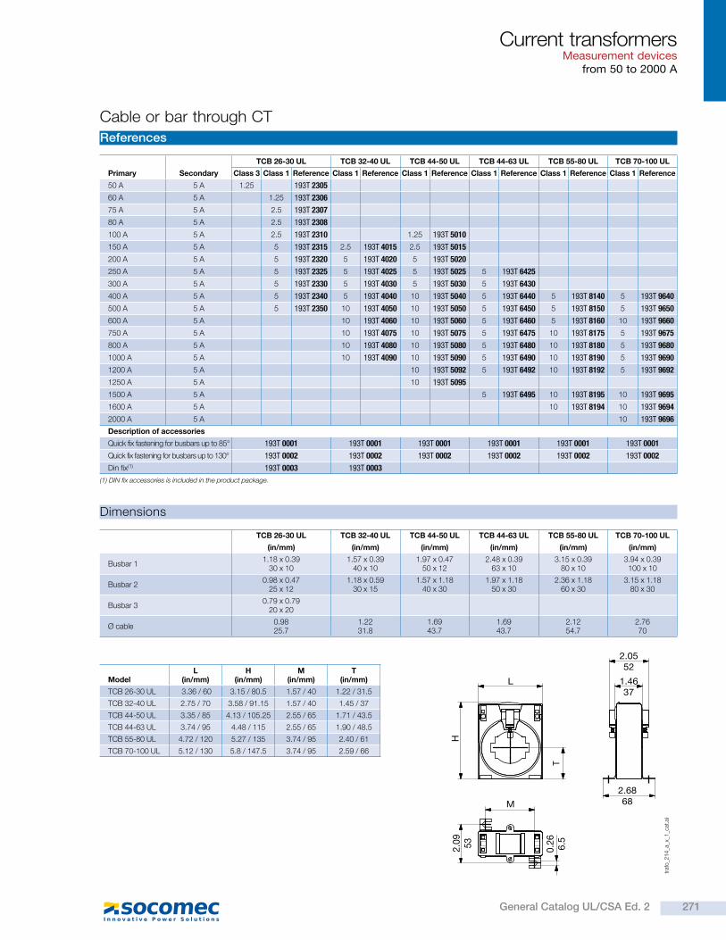
Current transformersMeasurement devices
from 50 to 2000 A
Cable or bar through CT
References
Dimensions
Primary Secondary
TCB 26-30 UL TCB 32-40 UL TCB 44-50 UL TCB 44-63 UL TCB 55-80 UL TCB 70-100 UL
Class 3 Class 1 Reference Class 1 Reference Class 1 Reference Class 1 Reference Class 1 Reference Class 1 Reference
50 A 5 A 1.25 193T 2305
60 A 5 A 1.25 193T 2306
75 A 5 A 2.5 193T 2307
80 A 5 A 2.5 193T 2308
100 A 5 A 2.5 193T 2310 1.25 193T 5010
150 A 5 A 5 193T 2315 2.5 193T 4015 2.5 193T 5015
200 A 5 A 5 193T 2320 5 193T 4020 5 193T 5020
250 A 5 A 5 193T 2325 5 193T 4025 5 193T 5025 5 193T 6425
300 A 5 A 5 193T 2330 5 193T 4030 5 193T 5030 5 193T 6430
400 A 5 A 5 193T 2340 5 193T 4040 10 193T 5040 5 193T 6440 5 193T 8140 5 193T 9640
500 A 5 A 5 193T 2350 10 193T 4050 10 193T 5050 5 193T 6450 5 193T 8150 5 193T 9650
600 A 5 A 10 193T 4060 10 193T 5060 5 193T 6460 5 193T 8160 10 193T 9660
750 A 5 A 10 193T 4075 10 193T 5075 5 193T 6475 10 193T 8175 5 193T 9675
800 A 5 A 10 193T 4080 10 193T 5080 5 193T 6480 10 193T 8180 5 193T 9680
1000 A 5 A 10 193T 4090 10 193T 5090 5 193T 6490 10 193T 8190 5 193T 9690
1200 A 5 A 10 193T 5092 5 193T 6492 10 193T 8192 5 193T 9692
1250 A 5 A 10 193T 5095
1500 A 5 A 5 193T 6495 10 193T 8195 10 193T 9695
1600 A 5 A 10 193T 8194 10 193T 9694
2000 A 5 A 10 193T 9696
Description of accessories
Quick fix fastening for busbars up to 85° 193T 0001 193T 0001 193T 0001 193T 0001 193T 0001 193T 0001
Quick fix fastening for busbars up to 130° 193T 0002 193T 0002 193T 0002 193T 0002 193T 0002 193T 0002
Din fix(1) 193T 0003 193T 0003
TCB 26-30 UL TCB 32-40 UL TCB 44-50 UL TCB 44-63 UL TCB 55-80 UL TCB 70-100 UL
(in/mm) (in/mm) (in/mm) (in/mm) (in/mm) (in/mm)
Busbar 11.18 x 0.39
30 x 101.57 x 0.39
40 x 101.97 x 0.47
50 x 122.48 x 0.39
63 x 103.15 x 0.39
80 x 103.94 x 0.39 100 x 10
Busbar 20.98 x 0.47
25 x 121.18 x 0.59
30 x 151.57 x 1.18
40 x 301.97 x 1.18
50 x 302.36 x 1.18
60 x 303.15 x 1.18
80 x 30
Busbar 30.79 x 0.79
20 x 20
Ø cable0.9825.7
1.22 31.8
1.69 43.7
1.69 43.7
2.12 54.7
2.76 70
ModelL
(in/mm)H
(in/mm)M
(in/mm)T
(in/mm)
TCB 26-30 UL 3.36 / 60 3.15 / 80.5 1.57 / 40 1.22 / 31.5
TCB 32-40 UL 2.75 / 70 3.58 / 91.15 1.57 / 40 1.45 / 37
TCB 44-50 UL 3.35 / 85 4.13 / 105.25 2.55 / 65 1.71 / 43.5
TCB 44-63 UL 3.74 / 95 4.48 / 115 2.55 / 65 1.90 / 48.5
TCB 55-80 UL 4.72 / 120 5.27 / 135 3.74 / 95 2.40 / 61
TCB 70-100 UL 5.12 / 130 5.8 / 147.5 3.74 / 95 2.59 / 66
T
L
2.6868
1.4637
2.0552
M
H2.0
953
0.2
66.5
traf
o_2
14
_a_x
_1_c
at.a
i
(1) DIN fix accessories is included in the product package.
271General Catalog UL/CSA Ed. 2
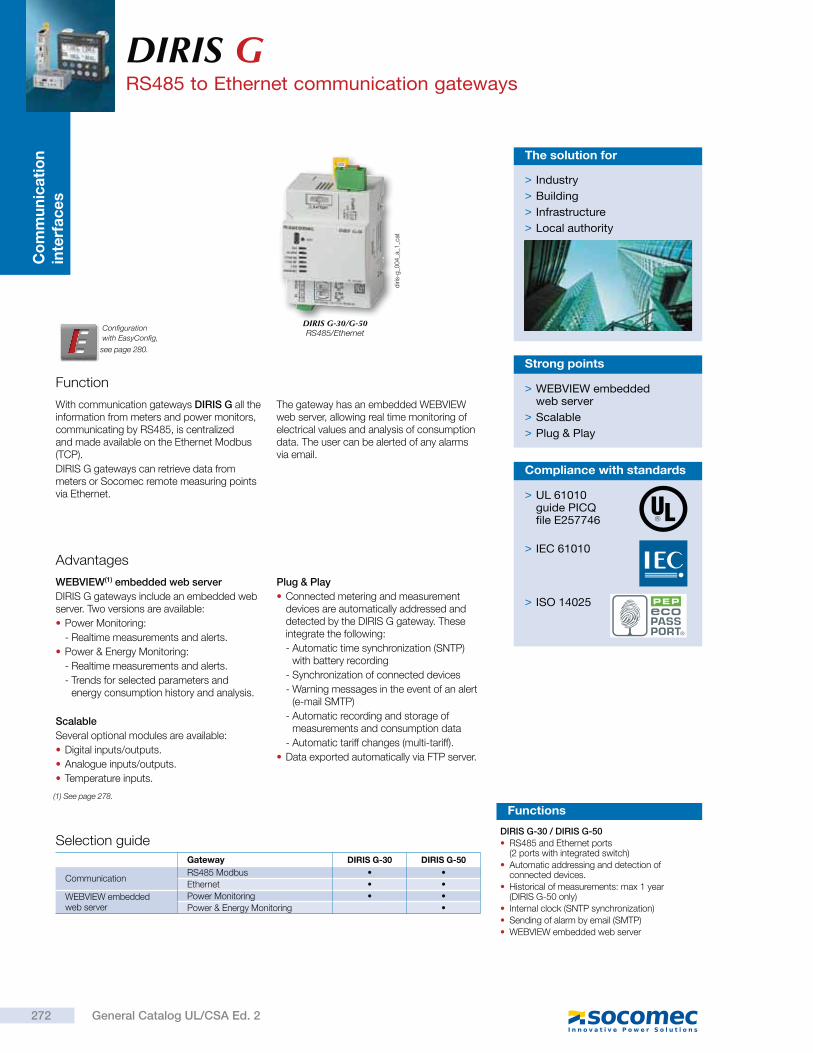
Co
mm
un
ica
tio
n
inte
rfa
ce
sDIRIS GRS485 to Ethernet communication gateways
Function
With communication gateways DIRIS G all the information from meters and power monitors, communicating by RS485, is centralized and made available on the Ethernet Modbus (TCP).
DIRIS G gateways can retrieve data from meters or Socomec remote measuring points via Ethernet.
The gateway has an embedded WEBVIEW web server, allowing real time monitoring of electrical values and analysis of consumption data. The user can be alerted of any alarms via email.
> WEBVIEW embedded web server
> Scalable
> Plug & Play
Strong points
Advantages
WEBVIEW(1) embedded web server
DIRIS G gateways include an embedded web server. Two versions are available:
Power Monitoring:
- Realtime measurements and alerts.
Power & Energy Monitoring:
- Realtime measurements and alerts.
- Trends for selected parameters and energy consumption history and analysis.
Scalable
Several optional modules are available:
Digital inputs/outputs.
Analogue inputs/outputs.
Temperature inputs.
Plug & Play
Connected metering and measurement devices are automatically addressed and detected by the DIRIS G gateway. These integrate the following:
- Automatic time synchronization (SNTP) with battery recording
- Synchronization of connected devices
- Warning messages in the event of an alert (e-mail SMTP)
- Automatic recording and storage of measurements and consumption data
- Automatic tariff changes (multi-tariff).
Data exported automatically via FTP server.
> Industry
> Building
> Infrastructure
> Local authority
The solution for
> UL 61010guide PICQfile E257746
> IEC 61010
> ISO 14025
Compliance with standards
Configuration
with EasyConfig,
diri
s-g
_00
4_a
_1_c
at
DIRIS G-30/G-50RS485/Ethernet
Selection guide
Gateway DIRIS G-30 DIRIS G-50
CommunicationRS485 Modbus
Ethernet
WEBVIEW embedded web server
Power Monitoring
Power & Energy Monitoring
Functions
DIRIS G-30 / DIRIS G-50
RS485 and Ethernet ports (2 ports with integrated switch)
Automatic addressing and detection of connected devices.
Historical of measurements: max 1 year (DIRIS G-50 only)
Internal clock (SNTP synchronization)
Sending of alarm by email (SMTP)
WEBVIEW embedded web server
272 General Catalog UL/CSA Ed. 2
(1) See page 278.
see page 280.
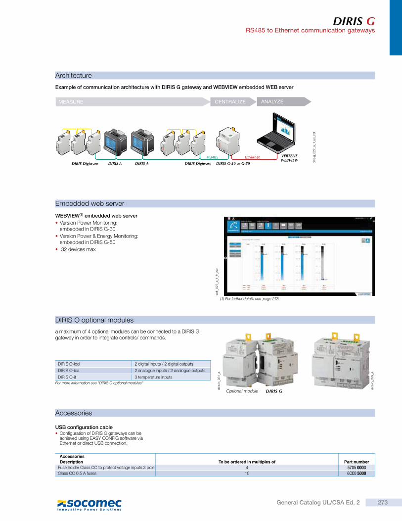
DIRIS GRS485 to Ethernet communication gateways
Architecture
DIRIS O optional modules
a maximum of 4 optional modules can be connected to a DIRIS G gateway in order to integrate controls/ commands.
DIRIS O-iod 2 digital inputs / 2 digital outputs
DIRIS O-ioa 2 analogue inputs / 2 analogue outputs
DIRIS O-it 3 temperature inputs
For more information see "DIRIS O optional modules"
WEBVIEW(1) embedded web server
Version Power Monitoring: embedded in DIRIS G-30
Version Power & Energy Monitoring: embedded in DIRIS G-50
32 devices max
Embedded web server
soft_0
27
_a_1
_fr_
cat
Accessories
USB configuration cable Configuration of DIRIS G gateways can be achieved using EASY CONFIG software via Ethernet or direct USB connection.
(1) For further details see
Example of communication architecture with DIRIS G gateway and WEBVIEW embedded WEB server
diri
s-g
_02
7_a
_1_u
s_ca
t
diri
s-b
_03
1_a
diri
s-b
_02
9_a
Optional module DIRIS G
RS485
DIRIS Digiware DIRIS A DIRIS A DIRIS Digiware DIRIS G-30 or G-50
Ethernet VERTELISWEBVIEW
MEASURE CENTRALIZE ANALYZE
Accessories
Description To be ordered in multiples of Part number
Fuse holder Class CC to protect voltage inputs 3 pole 4 5705 0003Class CC 0.5 A fuses 10 6CC0 5000
273General Catalog UL/CSA Ed. 2
page 278.
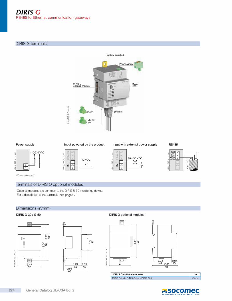
DIRIS GRS485 to Ethernet communication gateways
DIRIS O optional modules
A 441.73
150.59
652.56
903.54
diri
s-o
_00
1_b
_1_x
_cat
DIRIS O optional modules A
DIRIS O-iod - DIRIS O-ioa - DIRIS O-it 45 mm
DIRIS G terminals
Terminals of DIRIS O optional modules
Optional modules are common to the DIRIS B-30 monitoring device.
For a description of the terminals
110-230 VAC
NL
Power supply
diri
s-g
_01
5_a
_1_x
_cat
diri
s-g
_02
0_b
_1_g
b_c
atIN
RS
48
5 NC
12 VDC
Input powered by the product
diri
s-g
_01
6_a
_1_x
_cat
INR
S4
85 NC
10 - 30 VDC
Input with external power supply
diri
s-g
_01
7_a
_1_x
_cat
Mast
er
RS
48
5 NC
LIY
CY-C
Y
RS485
diri
s-g
_01
8_a
_1_x
_cat
1 digitalinput
RS485
Power supply
MicroUSB
DIRIS Ooptional module
Ethernet
Battery (supplied)
NC: not connected
Dimensions (in/mm)
DIRIS G-30 / G-50
45
622.44
903.
93
1.77
3.54
100
44 150.591.73
2.5665
diri
s-g
_00
1_b
_1_u
s_ca
t
274 General Catalog UL/CSA Ed. 2
see page 270.
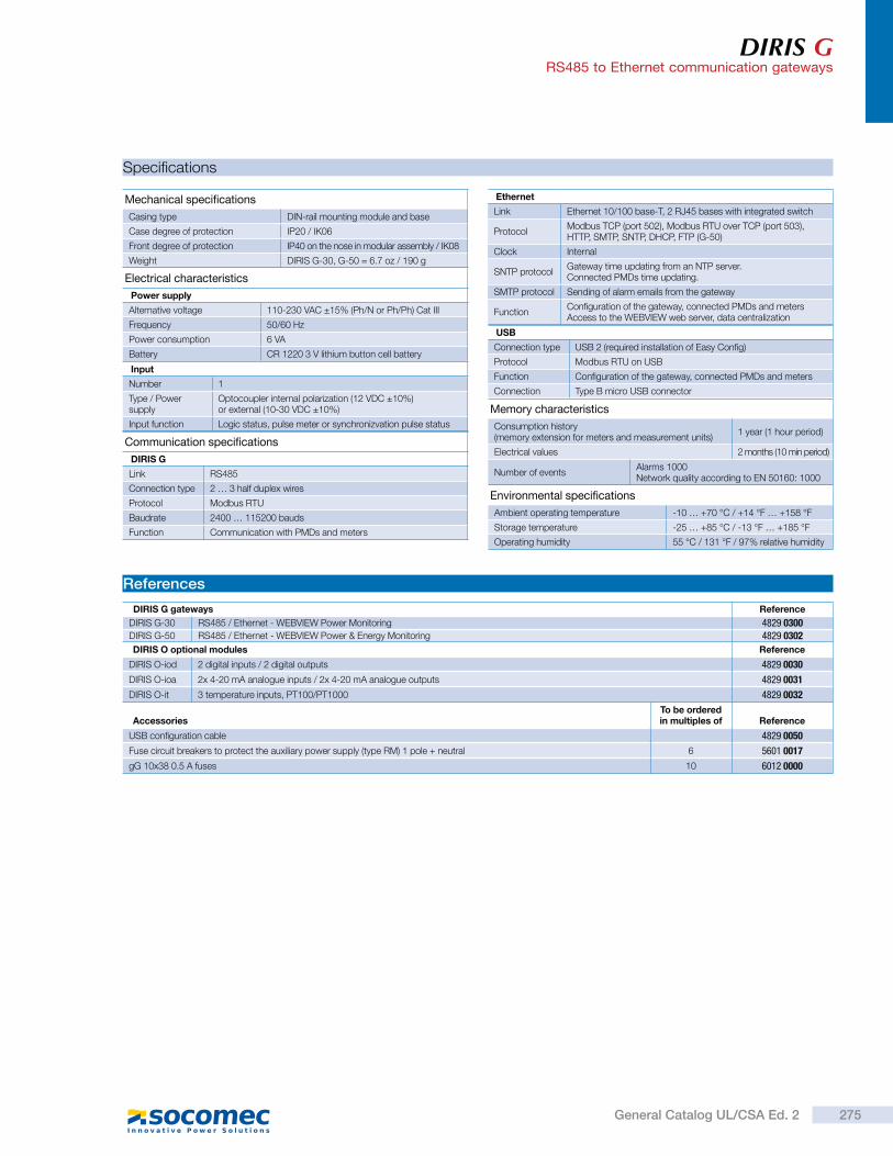
DIRIS GRS485 to Ethernet communication gateways
Specifications
References
DIRIS G gateways Reference
DIRIS G-30 RS485 / Ethernet - WEBVIEW Power Monitoring 4829 0300DIRIS G-50 RS485 / Ethernet - WEBVIEW Power & Energy Monitoring 4829 0302
Mechanical specifications
Casing type DIN-rail mounting module and base
Case degree of protection IP20 / IK06
Front degree of protection IP40 on the nose in modular assembly / IK08
Weight DIRIS G-30, G-50 = 6.7 oz / 190 g
Electrical characteristics
Power supply
Alternative voltage 110-230 VAC ±15% (Ph/N or Ph/Ph) Cat III
Frequency 50/60 Hz
Power consumption 6 VA
Battery CR 1220 3 V lithium button cell battery
Communication specifications
DIRIS G
Link RS485
Connection type 2 … 3 half duplex wires
Protocol Modbus RTU
Baudrate 2400 … 115200 bauds
Function Communication with PMDs and meters
USB
Connection type USB 2 (required installation of Easy Config)
Protocol Modbus RTU on USB
Function Configuration of the gateway, connected PMDs and meters
Connection Type B micro USB connector
DIRIS O optional modules Reference
DIRIS O-iod 2 digital inputs / 2 digital outputs 4829 0030
DIRIS O-ioa 2x 4-20 mA analogue inputs / 2x 4-20 mA analogue outputs 4829 0031
DIRIS O-it 3 temperature inputs, PT100/PT1000 4829 0032
AccessoriesTo be orderedin multiples of Reference
USB configuration cable 4829 0050
Fuse circuit breakers to protect the auxiliary power supply (type RM) 1 pole + neutral 6 5601 0017
gG 10x38 0.5 A fuses 10 6012 0000
Input
Number 1
Type / Power supply
Optocoupler internal polarization (12 VDC ±10%) or external (10-30 VDC ±10%)
Input function Logic status, pulse meter or synchronizvation pulse status
Ethernet
Link Ethernet 10/100 base-T, 2 RJ45 bases with integrated switch
ProtocolModbus TCP (port 502), Modbus RTU over TCP (port 503), HTTP, SMTP, SNTP, DHCP, FTP (G-50)
Clock Internal
SNTP protocolGateway time updating from an NTP server.Connected PMDs time updating.
SMTP protocol Sending of alarm emails from the gateway
FunctionConfiguration of the gateway, connected PMDs and metersAccess to the WEBVIEW web server, data centralization
Environmental specifications
Ambient operating temperature -10 … +70 °C / +14 °F … +158 °F
Storage temperature -25 … +85 °C / -13 °F … +185 °F
Operating humidity 55 °C / 131 °F / 97% relative humidity
Memory characteristics
Consumption history (memory extension for meters and measurement units)
1 year (1 hour period)
Electrical values 2 months (10 min period)
Number of eventsAlarms 1000Network quality according to EN 50160: 1000
275General Catalog UL/CSA Ed. 2
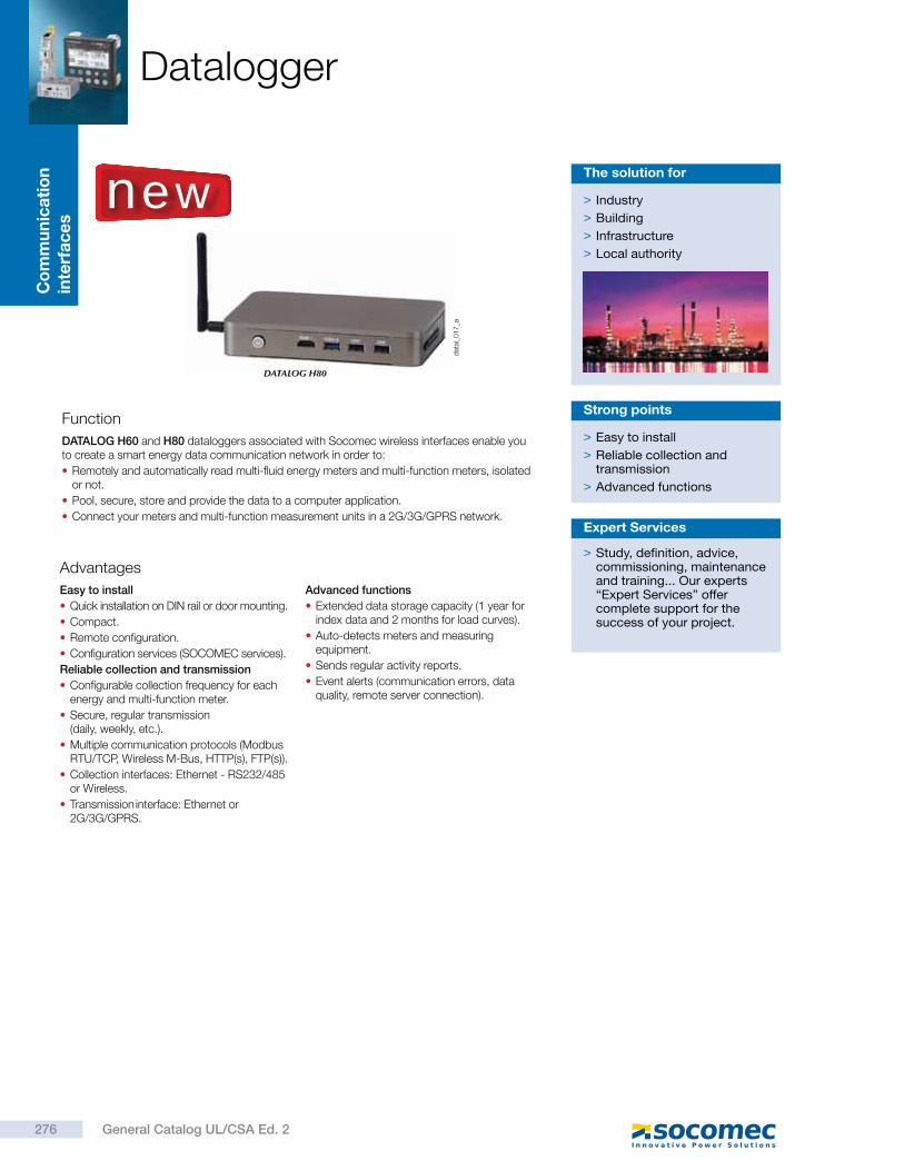
Co
mm
un
ica
tio
n
inte
rfa
ce
sDatalogger
Function
Advantages
DATALOG H60 and H80 dataloggers associated with Socomec wireless interfaces enable you to create a smart energy data communication network in order to:
Remotely and automatically read multi-fluid energy meters and multi-function meters, isolated or not.
Pool, secure, store and provide the data to a computer application.
Connect your meters and multi-function measurement units in a 2G/3G/GPRS network.
Easy to install
Quick installation on DIN rail or door mounting.
Compact.
Remote configuration.
Configuration services (SOCOMEC services).
Reliable collection and transmission
Configurable collection frequency for each energy and multi-function meter.
Secure, regular transmission (daily, weekly, etc.).
Multiple communication protocols (Modbus RTU/TCP, Wireless M-Bus, HTTP(s), FTP(s)).
Collection interfaces: Ethernet - RS232/485 or Wireless.
Transmission interface: Ethernet or 2G/3G/GPRS.
Advanced functions
Extended data storage capacity (1 year for index data and 2 months for load curves).
Auto-detects meters and measuring equipment.
Sends regular activity reports.
Event alerts (communication errors, data quality, remote server connection).
> Easy to install
> Reliable collection and transmission
> Advanced functions
Strong points
> Industry
> Building
> Infrastructure
> Local authority
The solution for
dat
al_0
17
_a
DATALOG H80
new
> Study, definition, advice, commissioning, maintenance and training... Our experts “Expert Services” offer complete support for the success of your project.
Expert Services
276 General Catalog UL/CSA Ed. 2
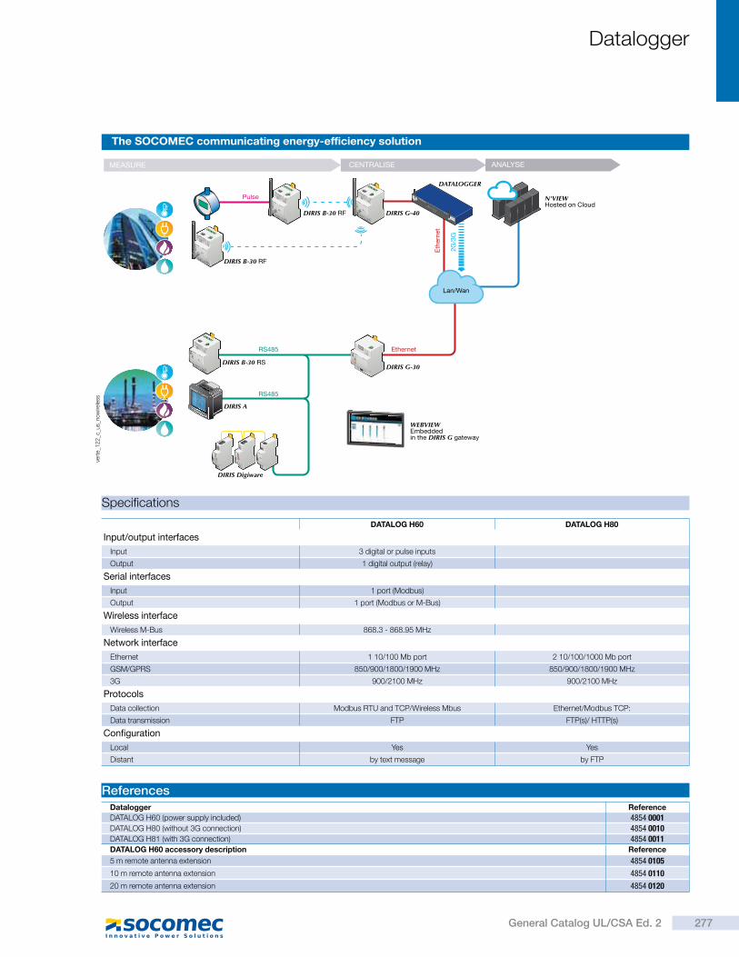
Datalogger
The SOCOMEC communicating energy-efficiency solution
vert
e_1
22
_c_u
s_no
wire
less
Specifications
ReferencesDatalogger Reference
DATALOG H60 (power supply included) 4854 0001DATALOG H80 (without 3G connection) 4854 0010DATALOG H81 (with 3G connection) 4854 0011DATALOG H60 accessory description Reference
5 m remote antenna extension 4854 0105
10 m remote antenna extension 4854 0110
20 m remote antenna extension 4854 0120
DATALOG H60 DATALOG H80
Input/output interfaces
Input 3 digital or pulse inputs
Output 1 digital output (relay)
Serial interfaces
Input 1 port (Modbus)
Output 1 port (Modbus or M-Bus)
Wireless interface
Wireless M-Bus 868.3 - 868.95 MHz
Network interface
Ethernet 1 10/100 Mb port 2 10/100/1000 Mb port
GSM/GPRS 850/900/1800/1900 MHz 850/900/1800/1900 MHz
3G 900/2100 MHz 900/2100 MHz
Protocols
Data collection Modbus RTU and TCP/Wireless Mbus Ethernet/Modbus TCP:
Data transmission FTP FTP(s)/ HTTP(s)
Configuration
Local Yes Yes
Distant by text message by FTP
2G
/3G
Eth
ern
et
N'VIEWHosted on Cloud
DIRIS B-30 RF
DIRIS B-30 RS
DIRIS B-30 RF DIRIS G-40
DIRIS G-30
RS485
RS485
DIRIS A
DIRIS Digiware
Pulse
Ethernet
Lan/Wan
MEASURE CENTRALISE ANALYSE
DATALOGGER
WEBVIEWEmbedded in the DIRIS G gateway
277General Catalog UL/CSA Ed. 2
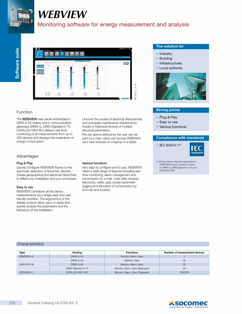
So
ftw
are
su
ite
soft_0
27
_a_1
_fr_
cat
Function
The WEBVIEW web server embedded in DIRIS A-40 meters and in communication gateways (DIRIS G, DIRIS Digiware D-70, DATALOG H80/H81) delivers real-time monitoring of all measurements from up to 200 devices and displays the breakdown of energy consumption.
Uncover the causes of electrical disturbances and anticipate maintenance requirements thanks to historical records of multiple electrical parameters.
Pre-set alarms defined by the user can be sent by e-mail. Users can access WEBVIEW via a web browser on a laptop or a tablet.
Advantages
Plug & Play
Quickly configure WEBVIEW thanks to the automatic detection of Socomec devices. Create geographical and electrical hierarchies to reflect your installation and your processes.
Easy to use
WEBVIEW centralizes all the device measurements via a single clear and user friendly interface. The ergonomics of the display screens allow users to easily and quickly analyse the parameters and the behaviour of the installation.
Various functions
Very easy to configure and to use, WEBVIEW offers a wide range of features including real-time monitoring, alarm management and transmission by e-mail, multi-utility analysis (electricity, water, gas), power parameter logging and allocation of consumption by end-use and location.
> Plug & Play
> Easy to use
> Various functions
Strong points
> Industry
> Building
> Infrastructures
> Local authority
The solution for
Type Hosting Functions Number of measurement devices
WEBVIEW-S DIRIS A-40 Monitor, Alarm, View 1
WEBVIEW-M
DIRIS G-30 Monitor, View 32
DIRIS G-50 Monitor, Alarm, View, 32
DIRIS Digiware D-70 Monitor, Alarm, View, Represent 32
WEBVIEW-L DATALOG H80 / H81 Monitor, Alarm, View, Represent 100/200
Characteristics
WEBVIEWMonitoring software for energy measurement and analysis
> IEC 62974-1(1)
(1) Energy Server standard applicable to
WEBVIEW-M and L versions hosted
on DIRIS G, DIRIS Digiware D-70 and
DATALOG H80.
Compliance with standards
278 General Catalog UL/CSA Ed. 2
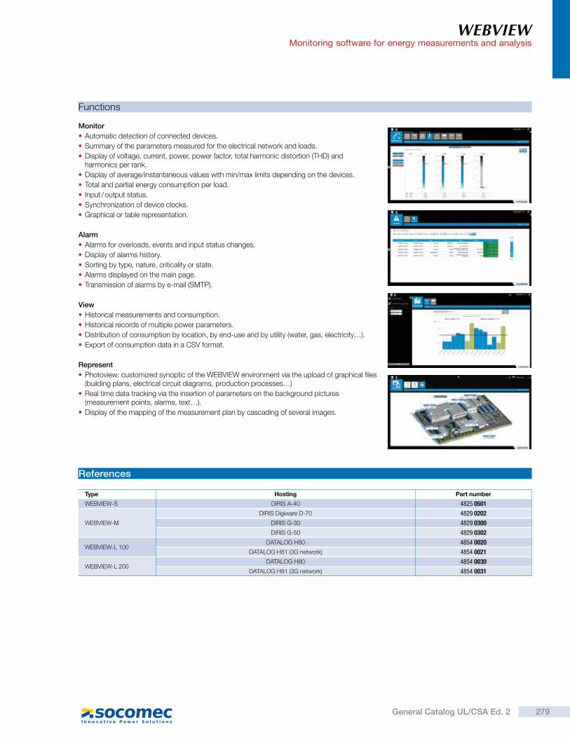
WEBVIEWMonitoring software for energy measurements and analysis
Monitor
Automatic detection of connected devices.
Summary of the parameters measured for the electrical network and loads.
Display of voltage, current, power, power factor, total harmonic distortion (THD) and harmonics per rank.
Display of average/instantaneous values with min/max limits depending on the devices.
Total and partial energy consumption per load.
Input / output status.
Synchronization of device clocks.
Graphical or table representation.
Alarm
Alarms for overloads, events and input status changes.
Display of alarms history.
Sorting by type, nature, criticality or state.
Alarms displayed on the main page.
Transmission of alarms by e-mail (SMTP).
View
Historical measurements and consumption.
Historical records of multiple power parameters.
Distribution of consumption by location, by end-use and by utility (water, gas, electricity…).
Export of consumption data in a CSV format.
Represent
Photoview: customized synoptic of the WEBVIEW environment via the upload of graphical files (building plans, electrical circuit diagrams, production processes…)
Real time data tracking via the insertion of parameters on the background pictures (measurement points, alarms, text…).
Display of the mapping of the measurement plan by cascading of several images.
References
Functions
Type Hosting Part number
WEBVIEW-S DIRIS A-40 4825 0501
WEBVIEW-M
DIRIS Digiware D-70 4829 0202
DIRIS G-30 4829 0300
DIRIS G-50 4829 0302
WEBVIEW-L 100DATALOG H80 4854 0020
DATALOG H81 (3G network) 4854 0021
WEBVIEW-L 200DATALOG H80 4854 0030
DATALOG H81 (3G network) 4854 0031
279General Catalog UL/CSA Ed. 2
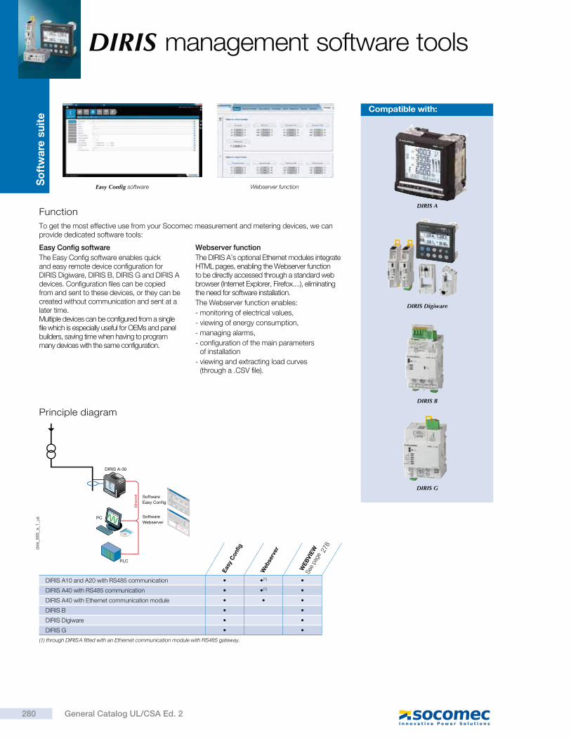
So
ftw
are
su
ite
DIRIS management software tools
Function
Principle diagram
To get the most effective use from your Socomec measurement and metering devices, we can provide dedicated software tools:
PC
Ethe
rnet
PLC
SoftwareWebserver
SoftwareEasy Config
DIRIS A-30
diri
s_8
85
_a_1
_us
Easy Config software Webserver function
Easy Config software
The Easy Config software enables quick and easy remote device configuration for DIRIS Digiware, DIRIS B, DIRIS G and DIRIS A devices. Configuration files can be copied from and sent to these devices, or they can be created without communication and sent at a later time. Multiple devices can be configured from a single file which is especially useful for OEMs and panel builders, saving time when having to program many devices with the same configuration.
Webserver function
The DIRIS A’s optional Ethernet modules integrate HTML pages, enabling the Webserver function to be directly accessed through a standard web browser (Internet Explorer, Firefox....), eliminating the need for software installation.
The Webserver function enables:
- monitoring of electrical values,
- viewing of energy consumption,
- managing alarms,
- configuration of the main parameters of installation
- viewing and extracting load curves (through a .CSV file).
Compatible with:
(1) through DIRIS A fitted with an Ethernet communication module with RS485 gateway.
DIRIS A10 and A20 with RS485 communication (1)
DIRIS A40 with RS485 communication (1)
DIRIS A40 with Ethernet communication module
DIRIS B
DIRIS Digiware
DIRIS G
Eas
y C
onf
ig
Web
serv
er
WEB
VIE
WSee
pag
e
DIRIS A
DIRIS Digiware
DIRIS B
DIRIS G
280 General Catalog UL/CSA Ed. 2
278
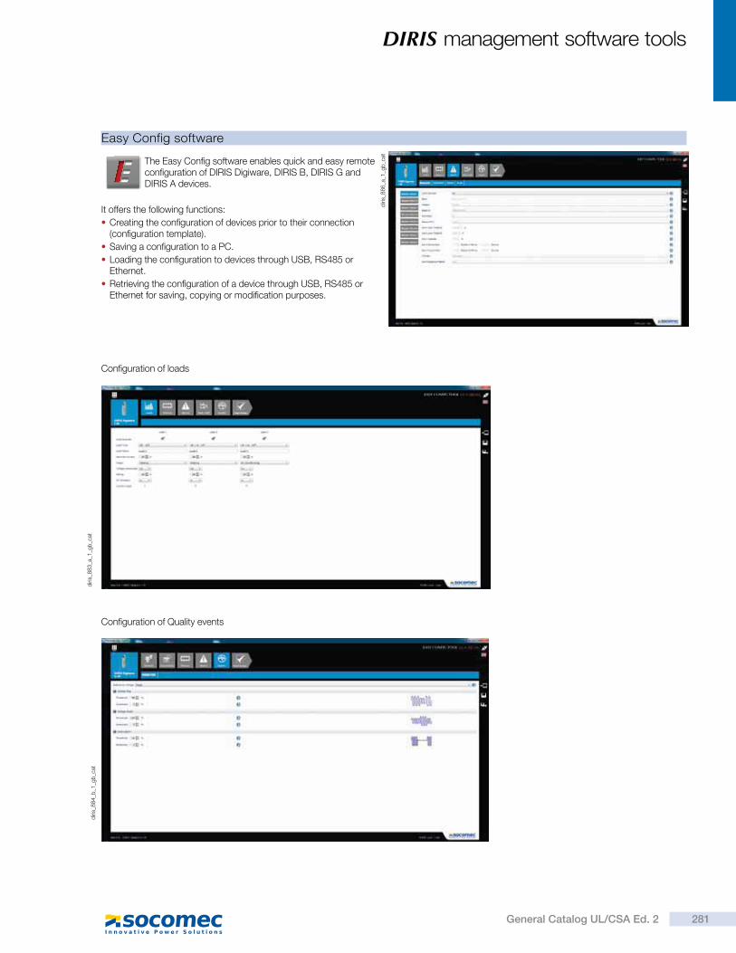
DIRIS management software tools
The Easy Config software enables quick and easy remote configuration of DIRIS Digiware, DIRIS B, DIRIS G and DIRIS A devices.
It offers the following functions:
Creating the configuration of devices prior to their connection (configuration template).
Saving a configuration to a PC.
Loading the configuration to devices through USB, RS485 or Ethernet.
Retrieving the configuration of a device through USB, RS485 or Ethernet for saving, copying or modification purposes.
Easy Config software
diri
s_8
86
_a_1
_gb
_cat
diri
s_8
83
_a_1
_gb
_cat
Configuration of loads
diri
s_8
84
_b_1
_gb
_cat
Configuration of Quality events
281General Catalog UL/CSA Ed. 2
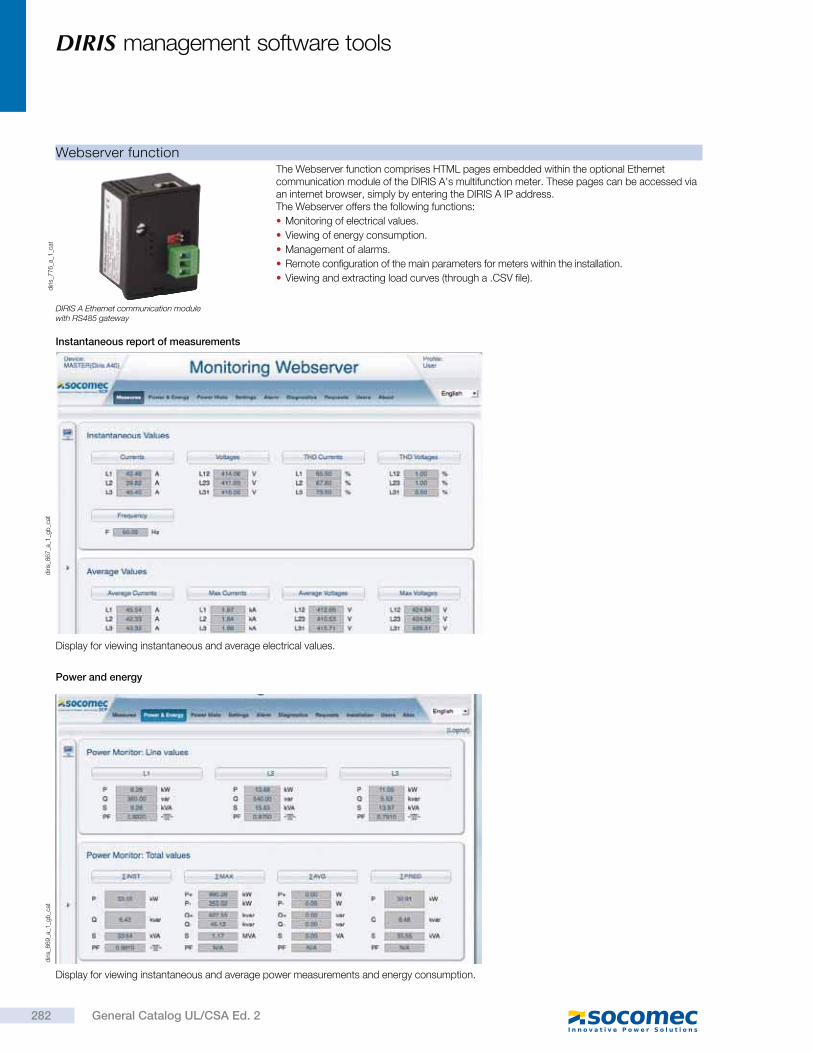
DIRIS management software tools
Webserver functionThe Webserver function comprises HTML pages embedded within the optional Ethernet communication module of the DIRIS A's multifunction meter. These pages can be accessed via an internet browser, simply by entering the DIRIS A IP address. The Webserver offers the following functions:
Monitoring of electrical values.
Viewing of energy consumption.
Management of alarms.
Remote configuration of the main parameters for meters within the installation.
Viewing and extracting load curves (through a .CSV file).
Display for viewing instantaneous and average electrical values.
Display for viewing instantaneous and average power measurements and energy consumption.
diri
s_7
76
_a_1
_cat
DIRIS A Ethernet communication module with RS485 gateway
diri
s_8
67
_a_1
_gb
_cat
diri
s_8
69
_a_1
_gb
_cat
Instantaneous report of measurements
Power and energy
282 General Catalog UL/CSA Ed. 2
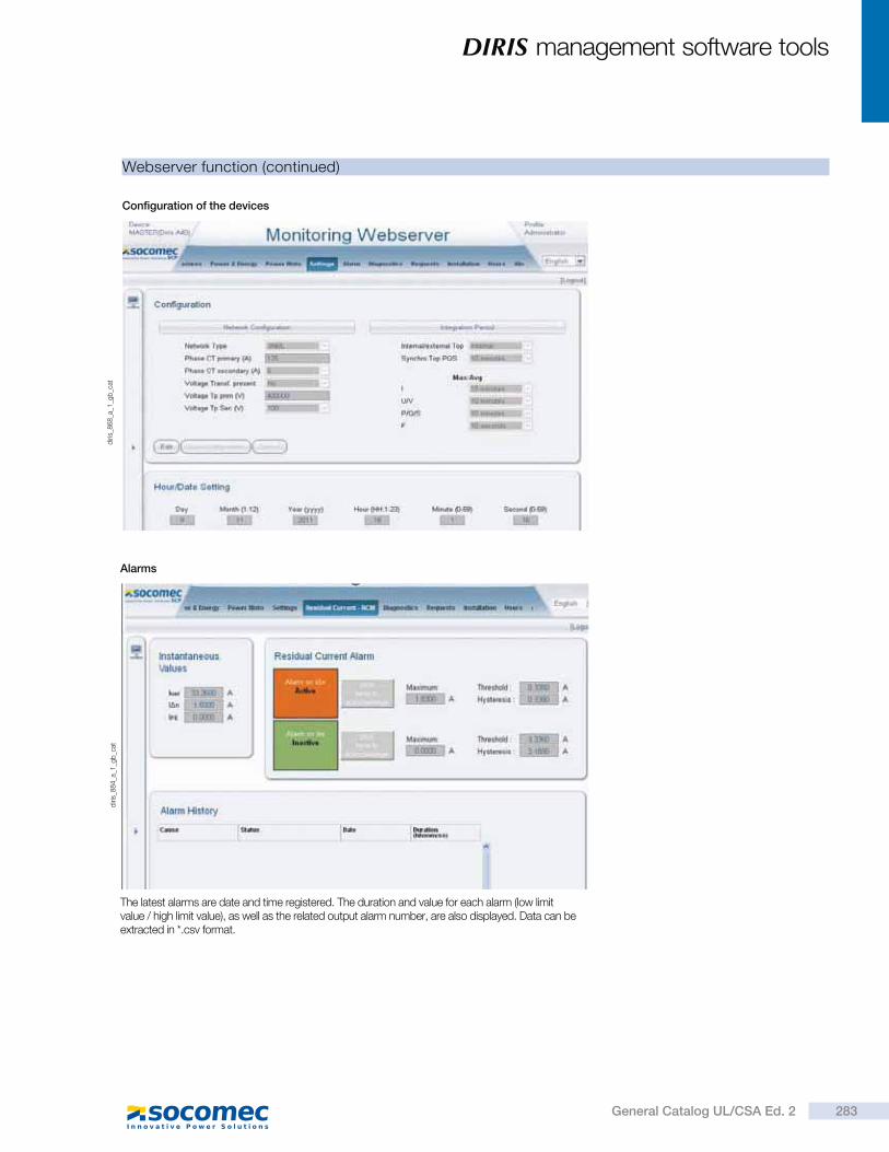
DIRIS management software tools
Webserver function (continued)
The latest alarms are date and time registered. The duration and value for each alarm (low limit value / high limit value), as well as the related output alarm number, are also displayed. Data can be extracted in *.csv format.
diri
s_8
68
_a_1
_gb
_cat
Configuration of the devices
Alarms
diri
s_8
84
_a_1
_gb
_cat
283General Catalog UL/CSA Ed. 2
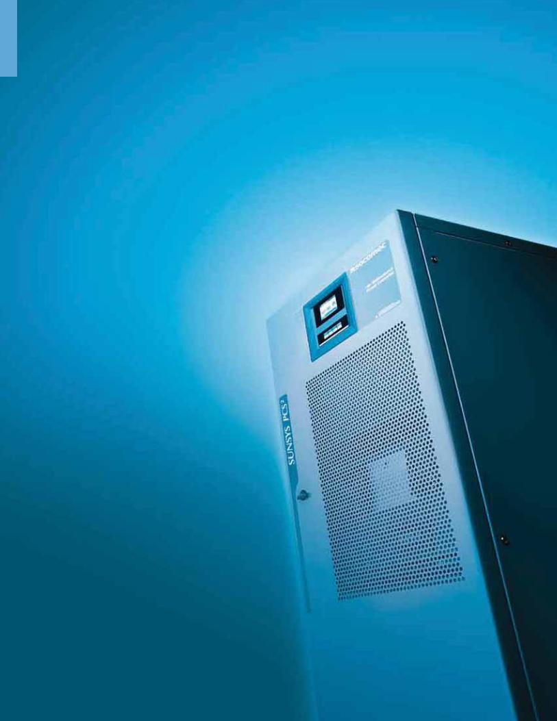
Power Conversion
On-Grid Energy Storage
Power Conversion System for energy storage
Energy Storage System architecture
Smart Grid LV Energy Storage
Single-phase UPS
SUNSYS PCS2
33 kW up to MW
SUNSYS Xtend ESS33 kW up to MW
NETYS PL-120V350 and 750 VA
NETYS RT-120V1000 to 3000 VA
newnew
p. 288
p. 288
p. 290 p. 292
285General Catalog UL/CSA Ed. 2

On
-Gri
d
En
erg
y S
tora
ge
SUNSYS PCS2
Power Conversion System for energy storage from 33 kW up to MW - UL 1741 SA
The solution for
MV/LV grids with:
> A high proportion of renewable energy
> High peak demands
Strong points
> High performance
> Total flexibility
> Maximum availability
> Easy to manage and maintain
Compliance with specifications
> UL 1741 SA
Grid code & rules compliance
> IEEE 1547
> HECO Rule 14H
> California rule 21
SU
NS
YS
_194_A
The SUNSYS PCS2 is a modular bidirectional power converter for energy storage.
Thanks to its modular parallel configuration, several MW can be reached.
The manufacturer’s guarantee
We offer a comprehensive support service package: commissioning, on-site testing, preventive maintenance visits, 24-hour call out and rapid on-site repairs, genuine spare parts, etc.
References
www.socomec.com/references-smart-solutions_en.html
Complementary solutions
We can also offer you SUNSYS XTEND ESS, UL 9540 certified Energy Storage System Architecture including batteries and AC and DC distribution modules.
High performance
The SUNSYS PCS2 modular design provides high output efficiency even with low power thanks to its Dynamic Power Control function.
Total flexibility
The SUNSYS PCS2 is a modular and scalable solution making it easy to adapt to future evolution. Its design also enables it to be used to update existing photovoltaic installations.
What’s more, its compatibility with multiple battery technologies provides a lot of flexibility to the installation.
Maximum availability
Its modular design enables fully secure "hot swapping" of conversion modules, allowing the rest of the installation to continue working. This operation can be performed without special clearance.
Easy to manage and maintain
The SUNSYS PCS² is a full front access solution allowing quick and easy, comfortable, safe and risk-free installation and maintenance.
Thanks to its display on the front face, it also enables ergonomic operation and monitoring.
286 General Catalog UL/CSA Ed. 2
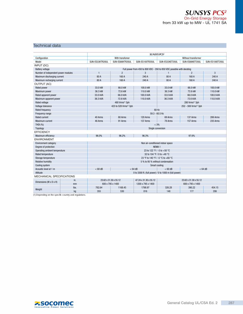
SUNSYS PCS2 On-Grid Energy Storage
from 33 kW up to MW - UL 1741 SA
Technical data
SUNSYS PCS²Configuration With transfomer Without transformer
Model SUN-ES33KTR20UL SUN-ES66KTR20UL SUN-ES100TR20UL SUN-ES33KET20UL SUN-ES66KET20UL SUN-ES100ET20UL
INPUT (DC)
Battery voltage Full power from 450 to 800 VDC - 350 to 850 VDC possible with derating
Number of independent power modules 1 2 3 1 2 3
Maximum discharging current 80 A 160 A 240 A 80 A 160 A 240 A
Maximum recharging current 80 A 160 A 240 A 80 A 160 A 240 A
OUTPUT (AC)
Rated power 33.0 kW 66.0 kW 100.0 kW 33.0 kW 66.0 kW 100.0 kW
Maximum power 36.3 kW 72.6 kW 110.0 kW 36.3 kW 72.6 kW 110.0 kW
Rated apparent power 33.0 kVA 66.0 kVA 100.0 kVA 33.0 kVA 66.0 kVA 100.0 kVA
Maximum apparent power 36.3 kVA 72.6 kVA 110.0 kVA 36.3 kVA 72.6 kVA 110.0 kVA
Rated voltage 480 Vrms(1) 3ph 280 Vrms(1) 3ph
Voltage tolerance 423 to 528 Vrms(1) 3ph 252 - 308 Vrms(1) 3ph
Rated frequency 60 Hz
Frequency range 59.3 - 60.5 Hz
Rated current 40 Arms 80 Arms 120 Arms 69 Arms 137 Arms 206 Arms
Maximum current 46 Arms 91 Arms 137 Arms 78 Arms 157 Arms 235 Arms
THDI (%) < 3%
Topology Single conversion
EFFICIENCY
Maximum efficiency 96.0% 96.2% 96.3% 97.6%
ENVIRONMENT
Environment category Non air-conditioned indoor space
Degree of protection NEMA 1
Operating ambient temperature 23 to 122 °F / -5 to +50 °C
Rated temperature 32 to 104 °F / 0 to +40 °C
Storage temperature 23 °F to 140 °F / -5 °C to +60 °C
Relative humidity 5 % to 95 % without condensation
Cooling system Smart cooling
Acoustic level at 1 m < 60 dB < 64 dB < 60 dB < 64 dB
Altitude 0 to 3300 ft. (full power) / 0 to 1000 m (full power)
MECHANICAL SPECIFICATIONS
Dimensions (W x D x H)in. 23.62 x 31.30 x 55.12 47.24 x 31.30 x 55.12 23.62 x 31.30 x 55.12
mm 600 x 795 x 1400 1200 x 795 x 1400 600 x 795 x 1400
Weightlbs. 782.64 1168.45 1798.97 326.28 390.22 454.15
kg 355 530 816 148 177 206
(1) Depending on the specific country and regulations.
287General Catalog UL/CSA Ed. 2
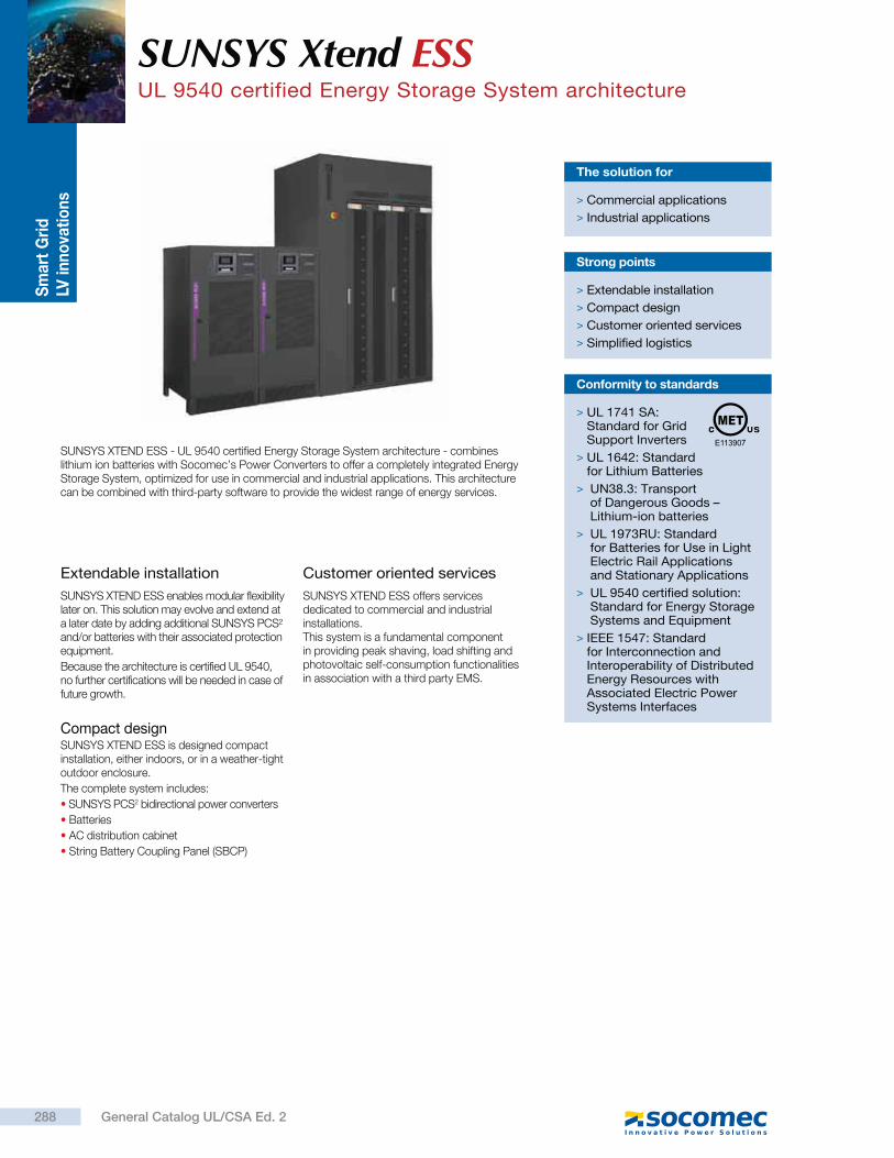
Sm
art
Gri
d
LV in
no
vati
on
s
Extendable installation
SUNSYS XTEND ESS enables modular flexibility later on. This solution may evolve and extend at a later date by adding additional SUNSYS PCS² and/or batteries with their associated protection equipment.
Because the architecture is certified UL 9540, no further certifications will be needed in case of future growth.
Compact designSUNSYS XTEND ESS is designed compact installation, either indoors, or in a weather-tight outdoor enclosure.
The complete system includes:
SUNSYS PCS2 bidirectional power converters
Batteries
AC distribution cabinet
String Battery Coupling Panel (SBCP)
Customer oriented services
SUNSYS XTEND ESS offers services dedicated to commercial and industrial installations. This system is a fundamental component in providing peak shaving, load shifting and photovoltaic self-consumption functionalities in association with a third party EMS.
SUNSYS XTEND ESS - UL 9540 certified Energy Storage System architecture - combines lithium ion batteries with Socomec’s Power Converters to offer a completely integrated Energy Storage System, optimized for use in commercial and industrial applications. This architecture can be combined with third-party software to provide the widest range of energy services.
The solution for
> Commercial applications
> Industrial applications
Strong points
> Extendable installation
> Compact design
> Customer oriented services
> Simplified logistics
Conformity to standards
> UL 1741 SA: Standard for Grid Support Inverters
> UL 1642: Standard for Lithium Batteries
> UN38.3: Transport of Dangerous Goods – Lithium-ion batteries
> UL 1973RU: Standard for Batteries for Use in Light Electric Rail Applications and Stationary Applications
> UL 9540 certified solution: Standard for Energy Storage Systems and Equipment
> IEEE 1547: Standard for Interconnection and Interoperability of Distributed Energy Resources with Associated Electric Power Systems Interfaces
SUNSYS Xtend ESSUL 9540 certified Energy Storage System architecture
288 General Catalog UL/CSA Ed. 2
SUNSYS Xtend ESS UL 9540 certified Energy Storage System architecture
SUNSYS XTEND ESS creates a complete solution with a limited number of references for easy ordering and covering a wide range of configurations, power and back-up time.
Simplified logistics
Characteristics
Possible SUNSYS Xtend ESS architectures
Dimensions
Architecture based onSUNSYS
PCS2 33TRSUNSYS
PCS2 66TRSUNSYS
PCS2 100TRSUNSYS
PCS2 33TLSUNSYS
PCS2 66TLSUNSYS
PCS2 100TL
INPUT (DC)
Battery chemistry Lithium-Ion
Number of independent power modules 1 2 3 1 2 3
OUTPUT (AC)
Rated apparent power 33.000 VA 66.000 VA 100.000 VA 33.000 VA 66.000 VA 100.000 VA
Rated voltage (Un) 480 V rms 3ph 288 V rms 3ph
Voltage range 423 - 528 V rms 3ph 252 - 308 V rms 3ph
Rated frequency (Fn) 60 Hz
Frequency range 59.3 - 60.5 Hz
Efficiency -
Maximum efficiency 96
ENVIRONMENT
Environmental category Non-air-conditionned indoor space
Degree of protection NEMA 1
Operating ambiant temperature 0 to + 40 °C
CERTIFICATIONS
Power converter UL1741 SA - IEEE 1557
Battery UL 1642- UN 38.3 - UL 1973 RU
Product certification UL 9540
Number of SUNSYS PCS2 Number of batteries Dimensions
(W x D x H) (inch)
1 1 55.9 x 36.6 x 90.5
1 2 76.3 x 36.6 x 90.5
1 3 96.8 x 36.6 x 90.5
1 4 117.3 x 36.6 x 90.5
2 2 100 x 36.6 x 90.5
2 3 120.5 x 36.6 x 90.5
2 4 141 x 36.6 x 90.5
2 5 161.4 x 36.6 x 90.5
2 6 181.9 x 36.6 x 90.5
2 7 202.4 x 36.6 x 90.5
3 2 123.6 x 36.6 x 90.5
3 4 164.6 x 36.6 x 90.5
3 5 185 x 36.6 x 90.5
3 6 205.5 x 36.6 x 90.5
3 7 226 x 36.6 x 90.5
3 8 246.5 x 36.6 x 90.5
4 3 167.8 x 36.6 x 90.5
4 4 188.2 x 36.6 x 90.5
4 5 208.7 x 36.6 x 90.5
4 6 229.2 x 36.6 x 90.5
4 7 249.6 x 36.6 x 90.5
4 8 270.1 x 36.6 x 90.5
Power (kW) Architecture Reference
33With transformer SUN-ES33KTR20UL
Transformerless SUN-ES33KET20UL
66With transformer SUN-ES66KTR20UL
Transformerless SUN-ES66KET20UL
100With transformer SUN-ES100TR20UL
Transformerless SUN-ES100ET20UL
Batteries
1 x 137 kWh 2 x 137 kWh 3 x 137 kWh 4 x 137 kWh 5 x 137 kWh 6 x 137 kWh 7 x 137 kWh 8 x 137 kWh
SU
NS
YS
PC
S2
1 x 33 kW 3.5 hours - - - - - - -
1 x 66 kW 1.5 hours 3.5 hours - - - - - -
2 x 66 kW - 1.5 hours 2,5 hours 3.5 hours - - - -
3 x 66 kW - 1 hour 1,5 hours 2.5 hours 3 hours 3,5 hours 4 hours -
4 x 66 kW - - 1 hour 1.5 hours 2 hours 2,5 hours 3 hours 3,5 hours
1 x 100 kW 1 hour 2 hours 3.5 hours 4.5 hours - - - -
2 x 100 kW - 1 hour 1.5 hours 2 hours 3 hours 3,5 hours 4 hours -
3 x 100 kW - - 1 hour 1.5 hours 2 hours - 2,5 hours 3 hours
4 x 100 kW - - - 1 hour 1.5 hours - 2 hours -
Type of cabinet Reference
Master protection cabinet 74401 00000
Slave protection cabinet 74421 00000
String Battery Coupling Panel (SBCP)
Energy (kWh) Battery type Reference
137 Energy 8ES_BE137_UL
BatteriesBidirectional Power Converters - SUNSYS PCS²
Reference
74311 XXX01
AC distribution cabinet
up to 8up to 4
289General Catalog UL/CSA Ed. 2
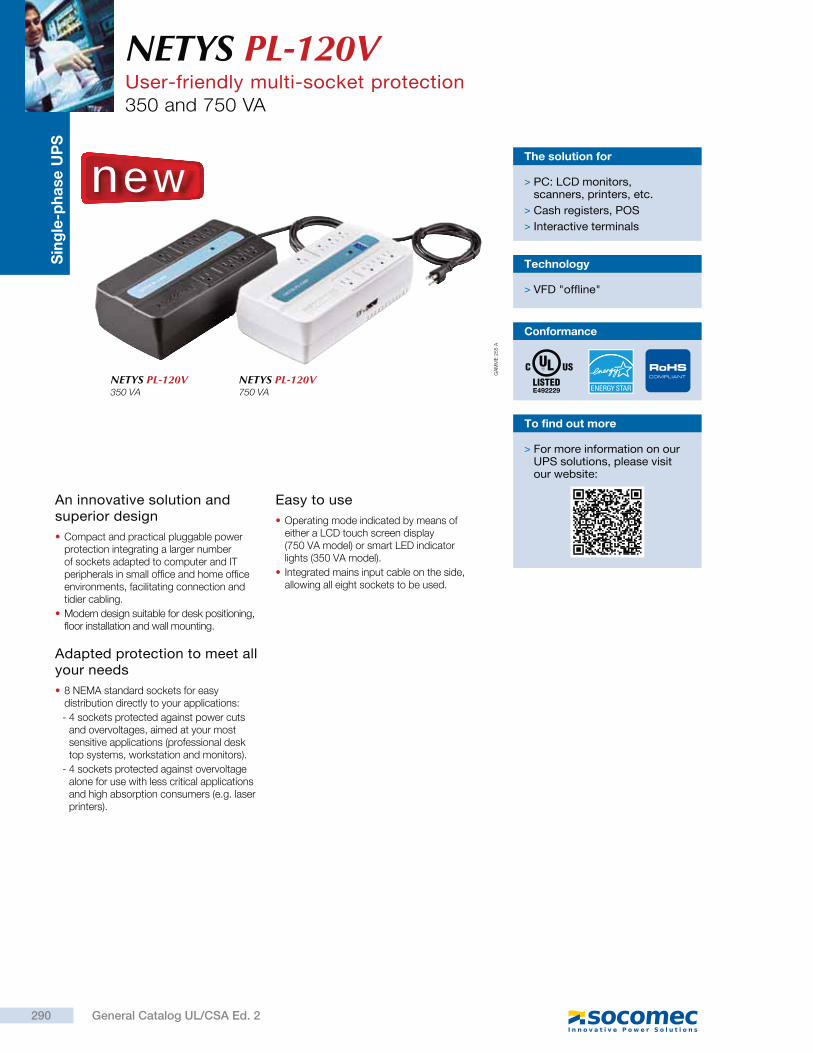
Sin
gle
-ph
ase
UP
S
An innovative solution and superior design
Compact and practical pluggable power protection integrating a larger number of sockets adapted to computer and IT peripherals in small office and home office environments, facilitating connection and tidier cabling.
Modern design suitable for desk positioning, floor installation and wall mounting.
Adapted protection to meet all your needs
8 NEMA standard sockets for easy distribution directly to your applications:
- 4 sockets protected against power cuts and overvoltages, aimed at your most sensitive applications (professional desk top systems, workstation and monitors).
- 4 sockets protected against overvoltage alone for use with less critical applications and high absorption consumers (e.g. laser printers).
Easy to use
Operating mode indicated by means of either a LCD touch screen display (750 VA model) or smart LED indicator lights (350 VA model).
Integrated mains input cable on the side, allowing all eight sockets to be used.
The solution for
> PC: LCD monitors, scanners, printers, etc.
> Cash registers, POS
> Interactive terminals
Technology
> VFD "offline"
GA
MM
E 2
55 A
NETYS PL-120V350 VA
NETYS PL-120V750 VA
NETYS PL-120VUser-friendly multi-socket protection350 and 750 VA
Conformance
new
RoHSCOMPLIANT
To find out more
> For more information on our UPS solutions, please visit our website:
290 General Catalog UL/CSA Ed. 2
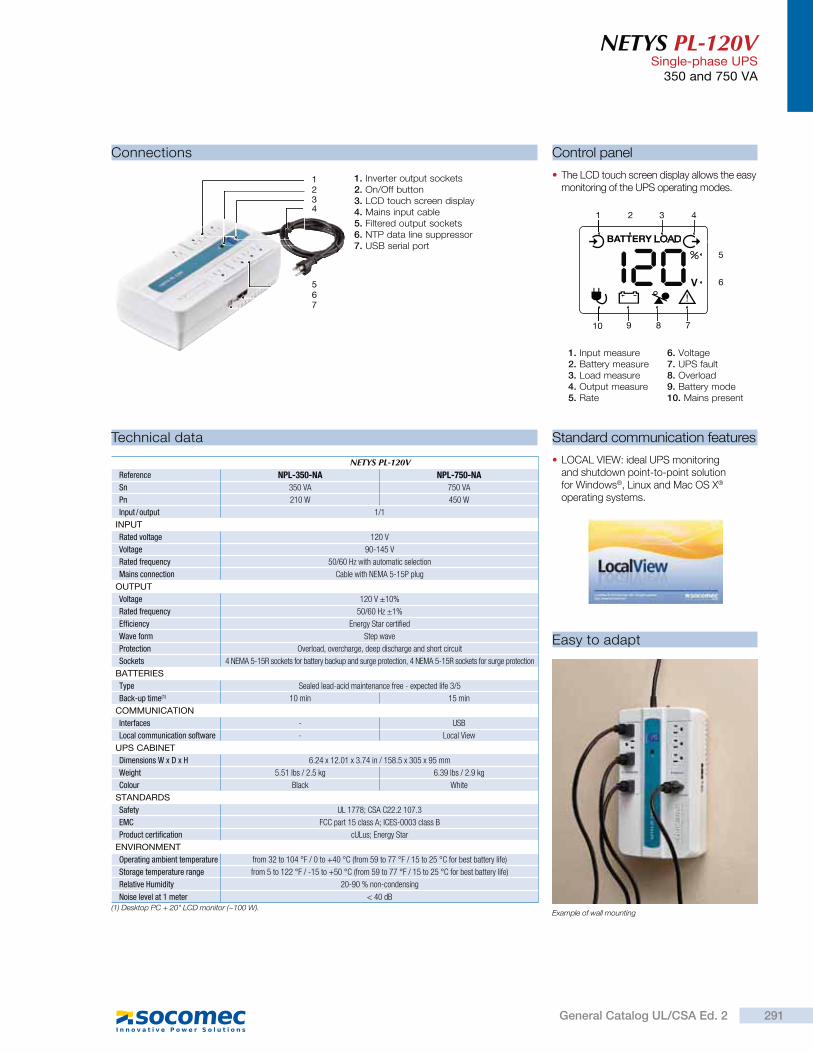
NETYS PL-120V Single-phase UPS
350 and 750 VA
Easy to adapt
Standard communication features
LOCAL VIEW: ideal UPS monitoring and shutdown point-to-point solution for Windows®, Linux and Mac OS X® operating systems.
Control panel
The LCD touch screen display allows the easy monitoring of the UPS operating modes.
1. Inverter output sockets2. On/Off button3. LCD touch screen display 4. Mains input cable5. Filtered output sockets6. NTP data line suppressor7. USB serial port
1. Input measure2. Battery measure3. Load measure4. Output measure5. Rate
6. Voltage7. UPS fault8. Overload9. Battery mode10. Mains present
Connections
1
32
5
4
67
Technical data
NETYS PL-120VReference NPL-350-NA NPL-750-NA
Sn 350 VA 750 VA
Pn 210 W 450 W
Input / output 1/1
INPUT
Rated voltage 120 V
Voltage 90-145 V
Rated frequency 50/60 Hz ith automatic selection
Mains connection Cable ith NEMA 5-15 plu
OUTPUT
Voltage 120 V ±10%
Rated frequency 50/60 Hz ±1%
Efficiency Ener Star certified
Wave form Step a e
Protection erload, o erchar e, deep dischar e and short circuit
Sockets 4 NEMA 5-15R soc ets for batter bac up and sur e protection, 4 NEMA 5-15R soc ets for sur e protection
BATTERIES
Type Sealed lead-acid maintenance free - expected life 3/5
Back-up time(1) 10 min 15 min
COMMUNICATION
Interfaces - US
Local communication software - Local Vie
UPS CABINET
Dimensions W x D x H 6.24 x 12.01 x 3.74 in / 158.5 x 305 x 95 mm
Weight 5.51 lbs / 2.5 6.39 lbs / 2.9
Colour lac White
STANDARDS
Safety UL 1778 CSA C22.2 107.3
EMC CC part 15 class A ICES-0003 class
Product certification cULus Ener Star
ENVIRONMENT
Operating ambient temperature from 32 to 104 ° / 0 to +40 °C (from 59 to 77 ° / 15 to 25 °C for best batter life)
Storage temperature range from 5 to 122 ° / -15 to +50 °C (from 59 to 77 ° / 15 to 25 °C for best batter life)
Relative Humidity 20-90 % non-condensin
Noise level at 1 meter 40 d(1) Desktop PC + 20" LCD monitor (~100 W).
Example of wall mounting
1 2 3 4
5
6
78910
291General Catalog UL/CSA Ed. 2
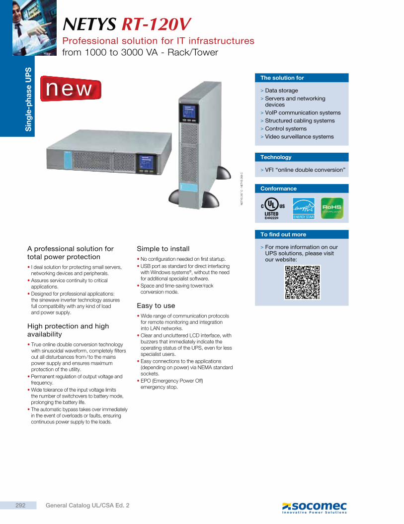
Sin
gle
-ph
ase
UP
S
A professional solution for total power protection
I deal solution for protecting small servers, networking devices and peripherals.
Assures service continuity to critical applications.
Designed for professional applications: the sinewave inverter technology assures full compatibility with any kind of load and power supply.
High protection and high availability
True online double conversion technology with sinusoidal waveform, completely filters out all disturbances from / to the mains power supply and ensures maximum protection of the utility.
Permanent regulation of output voltage and frequency.
Wide tolerance of the input voltage limits the number of switchovers to battery mode, prolonging the battery life.
The automatic bypass takes over immediately in the event of overloads or faults, ensuring continuous power supply to the loads.
Simple to install
No configuration needed on first startup.
USB port as standard for direct interfacing with Windows systems®, without the need for additional specialist software.
Space and time-saving tower/rack conversion mode.
Easy to use
Wide range of communication protocols for remote monitoring and integration into LAN networks.
Clear and uncluttered LCD interface, with buzzers that immediately indicate the operating status of the UPS, even for less specialist users.
Easy connections to the applications (depending on power) via NEMA standard sockets.
EPO (Emergency Power Off) emergency stop.
The solution for
> Data storage
> Servers and networking devices
> VoIP communication systems
> Structured cabling systems
> Control systems
> Video surveillance systems
Technology
> VFI “online double conversion”
NETYS RT-120VProfessional solution for IT infrastructuresfrom 1000 to 3000 VA - Rack/Tower
NE
TY
S 2
67 C
- N
ETY
S 2
68 C
new
To find out more
> For more information on our UPS solutions, please visit our website:
Conformance
RoHSCOMPLIANT
292 General Catalog UL/CSA Ed. 2
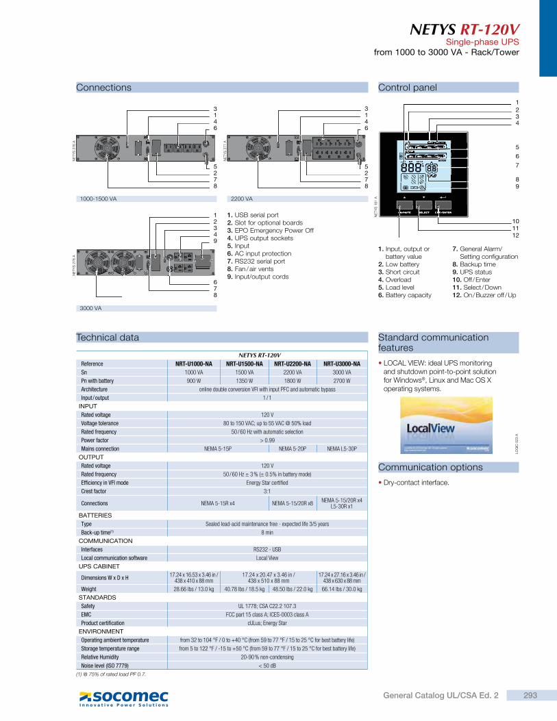
NETYS RT-120VSingle-phase UPS
from 1000 to 3000 VA - Rack/Tower
Standard communication features
LOCAL VIEW: ideal UPS monitoring and shutdown point-to-point solution for Windows®, Linux and Mac OS X operating systems.
Communication options
Dry-contact interface.
Connections Control panel
1. USB serial port2. Slot for optional boards3. EPO Emergency Power Off4. UPS output sockets5. Input6. AC input protection7. RS232 serial port8. Fan / air vents9. Input/output cords
1. Input, output or battery value
2. Low battery3. Short circuit4. Overload5. Load level6. Battery capacity
7. General Alarm/Setting configuration
8. Backup time9. UPS status10. Off / Enter11. Select / Down12. On / Buzzer off / Up
LOAD
VHz
BATTERY
34
5
6
7
89
2
1
101112
1000-1500 VA 2200 VA
3000 VA
Technical data
NETYS RT-120VReference NRT-U1000-NA NRT-U1500-NA NRT-U2200-NA NRT-U3000-NA
Sn 1000 VA 1500 VA 2200 VA 3000 VA
Pn with battery 900 W 1350 W 1800 W 2700 W
Architecture online double conversion VFI with input PFC and automatic bypass
Input / output 1 / 1
INPUT
Rated voltage 120 V
Voltage tolerance 80 to 150 VAC; up to 55 VAC @ 50% load
Rated frequency 50 / 60 Hz with automatic selection
Power factor > 0.99
Mains connection NEMA 5-15P NEMA 5-20P NEMA L5-30P
OUTPUT
Rated voltage 120 V
Rated frequency 50 / 60 Hz ± 3 % (± 0.5% in battery mode)
Efficiency in VFI mode Energy Star certified
Crest factor 3:1
Connections NEMA 5-15R x4 NEMA 5-15/20R x8 NEMA 5-15/20R x4L5-30R x1
BATTERIES
Type Sealed lead-acid maintenance free - expected life 3/5 years
Back-up time(1) 8 min
COMMUNICATION
Interfaces RS232 - USB
Local communication software Local View
UPS CABINET
Dimensions W x D x H 17.24 x 16.53 x 3.46 in / 438 x 410 x 88 mm
17.24 x 20.47 x 3.46 in / 438 x 510 x 88 mm
17.24 x 27.16 x 3.46 in / 438 x 630 x 88 mm
Weight 28.66 lbs / 13.0 kg 40.78 lbs / 18.5 kg 48.50 lbs / 22.0 kg 66.14 lbs / 30.0 kg
STANDARDS
Safety UL 1778; CSA C22.2 107.3
EMC FCC part 15 class A; ICES-0003 class A
Product certification cULus; Energy Star
ENVIRONMENT
Operating ambient temperature from 32 to 104 °F / 0 to +40 °C (from 59 to 77 °F / 15 to 25 °C for best battery life)
Storage temperature range from 5 to 122 °F / -15 to +50 °C (from 59 to 77 °F / 15 to 25 °C for best battery life)
Relative Humidity 20-90 % non-condensing
Noise level (ISO 7779) < 50 dB
46
13
5
78
2
NE
TY
S 2
76 A
78
6
94321
NE
TY
S 2
78 A
NE
TY
S 1
61 A
LO
GIC
023 A
46
13
5
78
2
NE
TY
S 2
77 A
(1) @ 75% of rated load PF 0.7.
293General Catalog UL/CSA Ed. 2
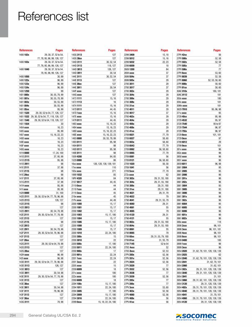
294 General Catalog UL/CSA Ed. 2
References list
References Pages References Pages References Pages References Pages
1400 102x 29, 30, 37, 52 to 54,
77, 78, 95, 96, 99, 126, 127
1400 103x 29, 30, 37, 52 to 54,
77, 78, 95, 96, 99, 126, 127
1400 1040 29, 30, 37, 52 to 54,
78, 95, 96, 99, 126, 127
1400 1050 30, 99
1400 122x 96, 99
1400 123x 96, 99
1400 124x 96, 99
1400 1250 99
1401 000x 30, 55, 78, 99
1401 001x 30, 55, 78, 99
1401 003x 30, 55, 99
1401 004x 30, 55, 99
1401 05xx 95, 99
1401 1520 29, 30, 52 to 54, 77, 126, 127
1401 1532 29, 30, 52 to 54, 77, 118, 126, 127
1401 1540 29, 30, 52 to 54, 118, 126, 127
1401 1554 30
1404 xxxx 16, 23
1405 xxxx 95, 99
1407 xxxx 15, 16, 22, 23
140D xxxx 16, 23
140E xxxx 16, 23
140F xxxx 16, 23
140G xxxx 16, 23
1419 0000 17, 24, 100
141D 2111 37, 95, 98
141D 2115 95, 98
141D 2911 98
141E 2111 37, 98
141E 2115 98
141E 29xx 98
141F 2111 37, 95, 98
141G 2111 37, 98
141H xxxx 95, 98
141I xxxx 95, 98
1429 0000 31, 100
142D 2111 29, 30, 52 to 54, 77, 78, 96, 98
142D 2113 126, 127
142D 2115 98
142D 2813 127
142D 2911 30, 54, 78, 98
142E 2111 29, 30, 52 to 54, 77, 78, 98
142E 2113 127
142E 2115 98
142E 2813 127
142E 2911 30, 54, 78, 98
142F 2111 29, 30, 52 to 54, 78, 96, 98
142F 2113 127
142F 28xx 127
142G 2111 29, 30, 52 to 54, 78, 98
142G 2113 127
142G 28xx 127
142H xxxx 96, 98
142I xxxx 96, 98
143D 3111 29, 30, 52 to 54, 77, 78, 96, 98
143D 3113 126, 127
143D 3813 127
143D 3911 30, 54, 98
143E 3111 29, 30, 52 to 54, 77, 78, 98
143E 3113 127
143E 38xx 127
143E 3911 30, 54, 98
143F 3111 78, 96, 98
143F 3113 127
143F 38xx 127
143G 3111 78, 98
143G 3113 127
143G 38xx 127
144D 3111 30, 52, 54
144D 3113 118, 127
144D 3813 126, 127
144D 3911 30, 54
144E 3111 30, 52, 54
144E 3113 127
144E 38xx 127
144E 3911 30, 54
144F xxxx 127
144G xxxx 127
1473 1111 15, 16
1473 1113 16
1474 1111 15, 16
147D 0111 44, 45
147D 1xxx 15, 16
147E xxxx 15, 16
147R 0111 44, 45
1483 xxxx 15, 16, 23
1484 xxxx 15, 16, 23
148D xxxx 15, 16, 22, 23
148E xxxx 15, 16, 22, 23
1493 0000 30, 55, 78, 99
1493 0111 95, 98
1494 0111 98
149D 0111 95, 98
149E 0111 98
1509 4200 84, 85
1529 0080 86
16xx xxxx 126, 128, 138, 139, 181
17xx xxxx 110
193x xxxx 271
1999 1032 85
19PV 4320 84
2107 0517 44, 45
2119 0xxx 44
2119 1xxx 44
2119 3xxx 45
219x xxxx 45
21Px xxxx 44, 49
2200 1000 15, 17
2200 1001 15, 17
2200 1002 15, 17
2200 1003 15, 17, 180
2200 1004 15, 17
2200 1006 15, 17, 180
2200 1008 15, 17
2200 1009 15, 17
2200 1010 22, 24, 180
2200 300x 15
2200 3010 22
2200 500x 17, 180
2200 5011 22, 24, 180
2200 900x 17
2200 901x 22, 24
2201 1xxx 22, 24
2201 3xxx 22
2205 xxxx 15
2209 6009 18
221x xxxx 180
222x xxxx 180
2269 6009 18
2294 100x 15, 17, 180
2294 1011 22, 24, 180
2294 3005 17, 180
2294 3009 15, 17, 180
2294 3016 22, 24, 180
2299 0xxx 15, 18, 22, 24, 180
2299 3409 15, 18
2299 5012 15, 16
2299 5032 22, 23
2299 6009 18
2609 1200 84
2694 xxxx 37
2699 504x 37
2699 505x 29
2700 3011 29
2700 3017 37
2700 302x 29
2700 304x 29
2700 306x 29
2700 308x 29
2700 31xx 29
2700 4011 29
2700 4017 37
2700 402x 29
2700 404x 29
2700 406x 29
2700 408x 29
2700 41xx 29
2709 0021 77, 79
2709 0027 58, 60
2709 003x 58, 60
2709 0043 77, 79
2709 0062 56, 58, 60
2709 0065 77, 79
2709 0081 56
2709 0121 56, 58, 60
2709 1020 56, 58
2709 1041 56
2709 5xxx 77, 79
272x xxxx 62
2798 302x 29, 31, 55, 180
2798 304x 29, 31, 55, 180
2798 306x 29, 31, 180
2798 31xx 29, 31, 180
2798 4021 29, 31, 79
2798 4022 79
2798 4041 29, 31, 55, 79
2798 4060 29, 31
2798 4061 55
2798 4065 79
2798 4120 29, 31
2798 4121 55
2798 802x 29, 31, 55, 180
2798 804x 29, 31, 55, 180
2798 8061 55
2798 8065 79
2799 00xx 29, 31, 55, 79, 180
2799 01xx 31, 55, 79
2799 7145 52 to 54
27DC 4xxx 52
27DC 8xxx 52, 53
27PV 200x 52, 56
27PV 201x 52, 56
27PV 2024 52, 56
27PV 2029 77
27PV 2032 52, 56
27PV 2038 77
27PV 2039 52, 56
27PV 205x 77
27PV 206x 77
27PV 3xxx 53, 60
27PV 403x 52, 58
27PV 4060 52, 56
27PV 408x 56
27PV 41xx 56
27PV 42xx 56
27PV 500x 52, 58
27PV 502x 52, 58
27PV 505x 77
27PV 506x 77
27PV 6xxx 53, 60
27PV 8039 52, 58
27PV 8060 52, 53, 58, 60
27PV 808x 58, 60
27PV 81xx 58, 60
30AC 010x 180, 181
30AC 0112 181
30Ux xxxx 180
30Vx xxxx 181
30Wx xxxx 181
3629 7910 95, 96, 98
371x xxxx 95
3729 40xx 95, 98
3729 4532 95, 97
3729 7540 95 to 97
3729 7544 96, 97
3729 755x 96, 97
3729 8xxx 101, 181
3729 9xxx 97
3799 6012 29
3799 9xxx 101
381x xxxx 96
382x xxxx 96
3850 xxxx 96
3851 xxxx 96
3859 6011 96, 98
3861 2004 95
3861 2005 95
3861 2006 96
3861 201x 96
3861 202x 96
3861 3004 95
3861 3005 95
3861 3006 96
3861 301x 96
3861 302x 96
3861 6004 95
3861 6005 95
3861 6006 96
3861 601x 96
3861 602x 96
388x xxxx 118
3898 2xxx 96, 101
3898 3xxx 96, 101, 181
3898 4xxx 96, 101
3898 6xxx 96, 101
3899 0400 100
3899 1xxx 96
3899 3xxx 96
3954 2020 31, 62, 79, 101, 128, 138, 139
3954 2025 62
3954 2040 31, 62, 79, 101, 128, 138, 139
3954 2041 31, 62, 79, 101
3954 2060 31, 62, 101
3954 302x 29, 31, 101, 128, 138, 139
3954 3040 29, 31, 101, 128, 138, 139
3954 3041 31, 101
3954 3060 29, 31, 62, 101, 128, 138, 139
3954 3120 29, 31, 128, 138, 139
3954 402x 29, 31, 79, 101, 128, 138, 139
3954 4040 29, 31, 79, 101, 128, 138, 139
3954 4041 31, 79, 101
3954 4060 29, 31, 79, 101, 128, 138, 139
3954 4120 29, 31, 128, 138, 139
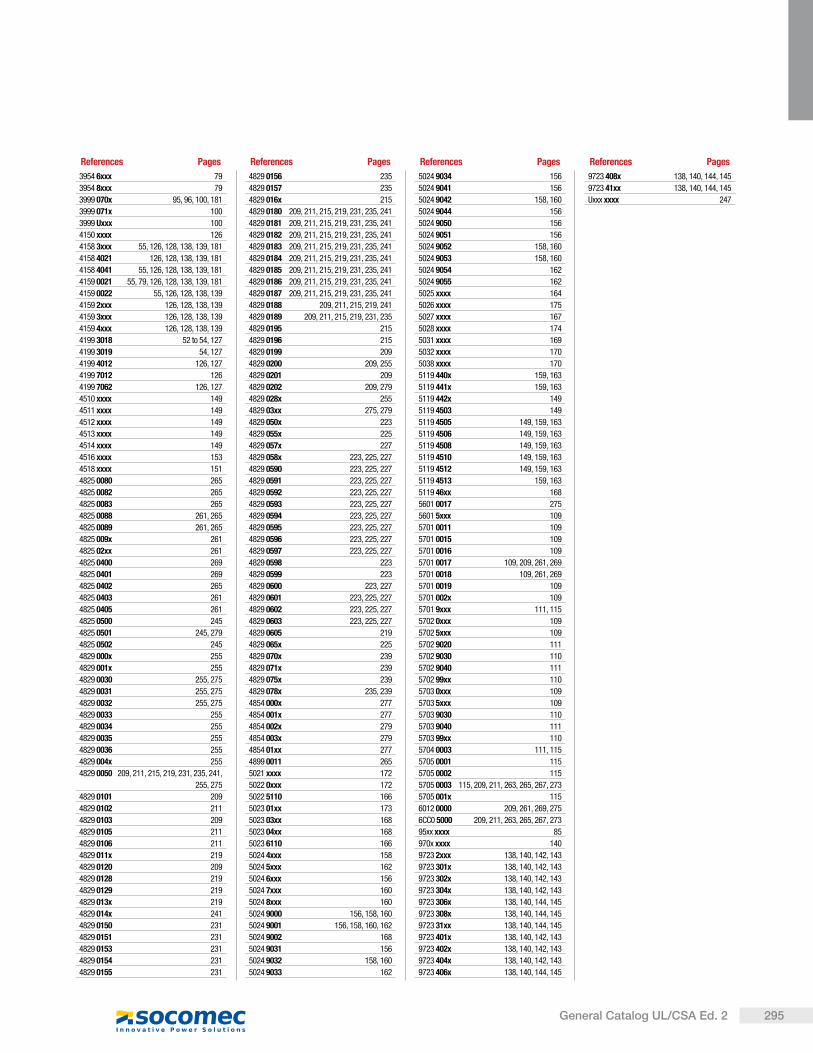
295General Catalog UL/CSA Ed. 2
References Pages References Pages References Pages References Pages
3954 6xxx 79
3954 8xxx 79
3999 070x 95, 96, 100, 181
3999 071x 100
3999 Uxxx 100
4150 xxxx 126
4158 3xxx 55, 126, 128, 138, 139, 181
4158 4021 126, 128, 138, 139, 181
4158 4041 55, 126, 128, 138, 139, 181
4159 0021 55, 79, 126, 128, 138, 139, 181
4159 0022 55, 126, 128, 138, 139
4159 2xxx 126, 128, 138, 139
4159 3xxx 126, 128, 138, 139
4159 4xxx 126, 128, 138, 139
4199 3018 52 to 54, 127
4199 3019 54, 127
4199 4012 126, 127
4199 7012 126
4199 7062 126, 127
4510 xxxx 149
4511 xxxx 149
4512 xxxx 149
4513 xxxx 149
4514 xxxx 149
4516 xxxx 153
4518 xxxx 151
4825 0080 265
4825 0082 265
4825 0083 265
4825 0088 261, 265
4825 0089 261, 265
4825 009x 261
4825 02xx 261
4825 0400 269
4825 0401 269
4825 0402 265
4825 0403 261
4825 0405 261
4825 0500 245
4825 0501 245, 279
4825 0502 245
4829 000x 255
4829 001x 255
4829 0030 255, 275
4829 0031 255, 275
4829 0032 255, 275
4829 0033 255
4829 0034 255
4829 0035 255
4829 0036 255
4829 004x 255
4829 0050 209, 211, 215, 219, 231, 235, 241,
255, 275
4829 0101 209
4829 0102 211
4829 0103 209
4829 0105 211
4829 0106 211
4829 011x 219
4829 0120 209
4829 0128 219
4829 0129 219
4829 013x 219
4829 014x 241
4829 0150 231
4829 0151 231
4829 0153 231
4829 0154 231
4829 0155 231
4829 0156 235
4829 0157 235
4829 016x 215
4829 0180 209, 211, 215, 219, 231, 235, 241
4829 0181 209, 211, 215, 219, 231, 235, 241
4829 0182 209, 211, 215, 219, 231, 235, 241
4829 0183 209, 211, 215, 219, 231, 235, 241
4829 0184 209, 211, 215, 219, 231, 235, 241
4829 0185 209, 211, 215, 219, 231, 235, 241
4829 0186 209, 211, 215, 219, 231, 235, 241
4829 0187 209, 211, 215, 219, 231, 235, 241
4829 0188 209, 211, 215, 219, 241
4829 0189 209, 211, 215, 219, 231, 235
4829 0195 215
4829 0196 215
4829 0199 209
4829 0200 209, 255
4829 0201 209
4829 0202 209, 279
4829 028x 255
4829 03xx 275, 279
4829 050x 223
4829 055x 225
4829 057x 227
4829 058x 223, 225, 227
4829 0590 223, 225, 227
4829 0591 223, 225, 227
4829 0592 223, 225, 227
4829 0593 223, 225, 227
4829 0594 223, 225, 227
4829 0595 223, 225, 227
4829 0596 223, 225, 227
4829 0597 223, 225, 227
4829 0598 223
4829 0599 223
4829 0600 223, 227
4829 0601 223, 225, 227
4829 0602 223, 225, 227
4829 0603 223, 225, 227
4829 0605 219
4829 065x 225
4829 070x 239
4829 071x 239
4829 075x 239
4829 078x 235, 239
4854 000x 277
4854 001x 277
4854 002x 279
4854 003x 279
4854 01xx 277
4899 0011 265
5021 xxxx 172
5022 0xxx 172
5022 5110 166
5023 01xx 173
5023 03xx 168
5023 04xx 168
5023 6110 166
5024 4xxx 158
5024 5xxx 162
5024 6xxx 156
5024 7xxx 160
5024 8xxx 160
5024 9000 156, 158, 160
5024 9001 156, 158, 160, 162
5024 9002 168
5024 9031 156
5024 9032 158, 160
5024 9033 162
5024 9034 156
5024 9041 156
5024 9042 158, 160
5024 9044 156
5024 9050 156
5024 9051 156
5024 9052 158, 160
5024 9053 158, 160
5024 9054 162
5024 9055 162
5025 xxxx 164
5026 xxxx 175
5027 xxxx 167
5028 xxxx 174
5031 xxxx 169
5032 xxxx 170
5038 xxxx 170
5119 440x 159, 163
5119 441x 159, 163
5119 442x 149
5119 4503 149
5119 4505 149, 159, 163
5119 4506 149, 159, 163
5119 4508 149, 159, 163
5119 4510 149, 159, 163
5119 4512 149, 159, 163
5119 4513 159, 163
5119 46xx 168
5601 0017 275
5601 5xxx 109
5701 0011 109
5701 0015 109
5701 0016 109
5701 0017 109, 209, 261, 269
5701 0018 109, 261, 269
5701 0019 109
5701 002x 109
5701 9xxx 111, 115
5702 0xxx 109
5702 5xxx 109
5702 9020 111
5702 9030 110
5702 9040 111
5702 99xx 110
5703 0xxx 109
5703 5xxx 109
5703 9030 110
5703 9040 111
5703 99xx 110
5704 0003 111, 115
5705 0001 115
5705 0002 115
5705 0003 115, 209, 211, 263, 265, 267, 273
5705 001x 115
6012 0000 209, 261, 269, 275
6CC0 5000 209, 211, 263, 265, 267, 273
95xx xxxx 85
970x xxxx 140
9723 2xxx 138, 140, 142, 143
9723 301x 138, 140, 142, 143
9723 302x 138, 140, 142, 143
9723 304x 138, 140, 142, 143
9723 306x 138, 140, 144, 145
9723 308x 138, 140, 144, 145
9723 31xx 138, 140, 144, 145
9723 401x 138, 140, 142, 143
9723 402x 138, 140, 142, 143
9723 404x 138, 140, 142, 143
9723 406x 138, 140, 144, 145
9723 408x 138, 140, 144, 145
9723 41xx 138, 140, 144, 145
Uxxx xxxx 247

296 General Catalog UL/CSA Ed. 2
Notes
297 General Catalog UL/CSA Ed. 2
Notes
298General Catalog UL/CSA Ed. 2
Notes

Model: SOCOMECProduction: SOCOMECPhotography: Martin Bernhart and Studio ObjectifPrinting: XXXXXX
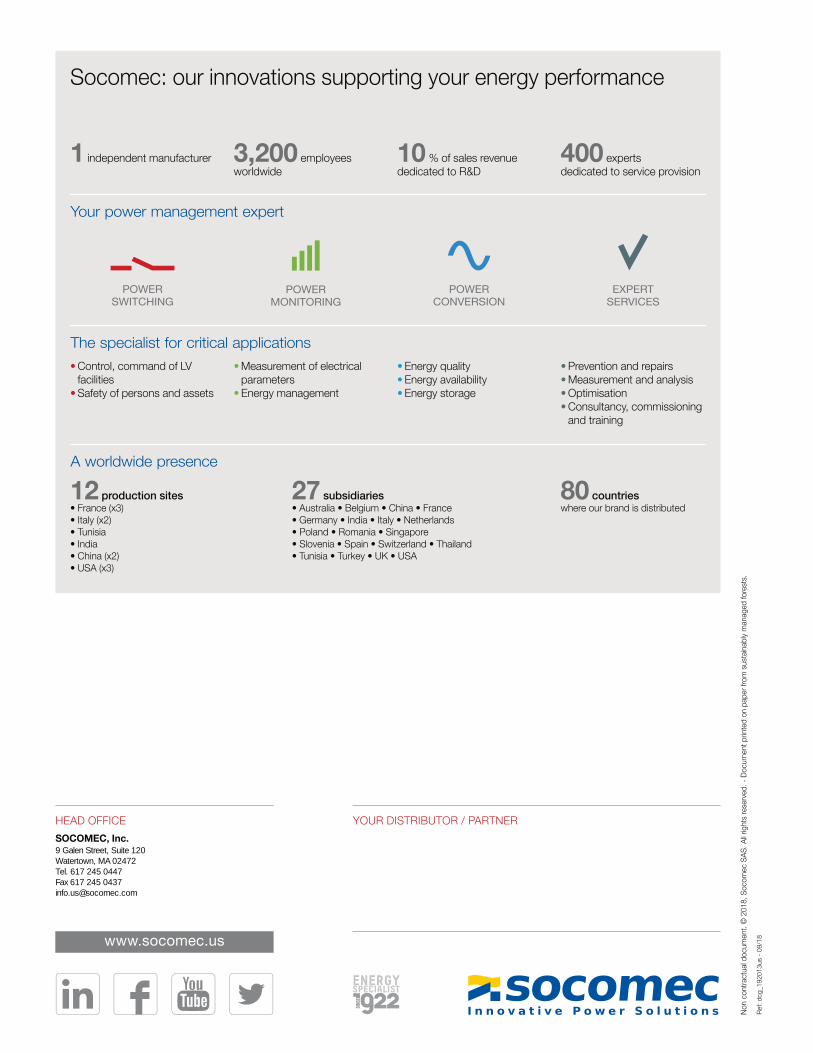
HEAD OFFICE
SOCOMEC, Inc.9 Galen Street, Suite 120Watertown, MA 02472Tel. 617 245 0447Fax 617 245 [email protected]
YOUR DISTRIBUTOR / PARTNER
www.socomec.us
Non c
ontr
actu
al d
ocu
men
t.
2018, S
oco
mec
SA
S. A
ll rig
hts
res
erve
d. -
Docu
men
t p
rinte
d o
n p
aper
fro
m s
ust
ainab
ly m
anag
ed fore
sts.
Socomec: our innovations supporting your energy performance
The specialist for critical applications
Your power management expert
10 % of sales revenue dedicated to R&D
Energy quality Energy availability Energy storage
400 experts dedicated to service provision
Prevention and repairs Measurement and analysis Optimisation Consultancy, commissioning and training
1 independent manufacturer
Control, command of LV facilities Safety of persons and assets
3,200 employees worldwide
Measurement of electrical parameters Energy management
A worldwide presence
80 countries where our brand is distributed
12 production sites France (x3) Italy (x2) Tunisia India China (x2) USA (x3)
27 subsidiaries Australia Belgium China France Germany India Italy Netherlands Poland Romania Singapore Slovenia Spain Switzerland Thailand Tunisia Turkey UK USA
POWERSWITCHING
POWERMONITORING
POWERCONVERSION
EXPERTSERVICES
Ref: d
cg_1
92013
us
- 09/1
8