Software Engineering - MIS - Alagappa University
154
4 -442, AMAILICAIR. ominr,asm ALAGAPPA UNIVERSITY (Reaccredited with 'A' Grade by NAAC) Karaikudi 630 003 AlagaPP. C DIRECTORATE OF DISTANCE EDUCATION 191 M.Sc (Information Technology) PAPER - 2.3 - 71 - g 4 SOFTWARE ENGINEERING for Private Use Only Copyright Reserved
-
Upload
khangminh22 -
Category
Documents
-
view
0 -
download
0
Transcript of Software Engineering - MIS - Alagappa University

4
-442, AMAILICAIR.
ominr,asm ALAGAPPA UNIVERSITY (Reaccredited with 'A' Grade by NAAC)
Karaikudi 630 003 AlagaPP. C
DIRECTORATE OF DISTANCE EDUCATION
191 M.Sc (Information Technology)
PAPER - 2.3 -71- g 4
SOFTWARE ENGINEERING
for Private Use Only Copyright Reserved

ALAGAPPA UNIVERSITY (Accredited with 'A' Grade by NAAC)
KARAIKUDI - 630 003, TAMILNADU
DIRECTORATE OF DISTANCE EDUCATION
M.Sc.
Information Technology
PAPER - 2.3 Software Engineering
Copy Right Reserved For Private use only
(AU/DDE/D2/Printing 11/Order No. 6 /2014-15 / Date : 12.09.2014 Copies 500) Karthick Printers, Trichy.

PAPER - 2.2: SOFTWARE ENGINEERING
UNIT I : Introduction — Software — Software Engineering — Size Factors — Quality and Productivity Factors — Development Process Models — Linear Sequential — Prototyping RAD —Iterative Enhancement — Spiral — Role of Management in Software Development — Software Metrics — Process and project metrics.
UNIT II : Software Project Planning — Estimating Software Scope, Resources, Project Estimation — Software Cost Estimation — Cost Factors — Estimation Techniques — Estimating Software maintenance Cost — Planning an Organizational Structure: Project Structure —Programming Team Structure.
UNIT III : Project Scheduling and Tracking: Concept — Defining Task set — Scheduling plan —Planning for Quality Assurance — Quality Standards — Software Configuration Management —Risk Management: Software Risks — Identification — Projection — Mitigation — Monitoring and Management — Software Reviews.
UNIT IV : Software Requirement Specification — Problem Analysis — Structuring information — Information Flow — Prototyping — Structured Analysis — Requirement Specification Analysis — Characteristics — Components — Structure — Specification Techniques.
UNIT V : Software Design — Concepts — Principles — Module level concepts — Design methodology — Architectural Design — Transform mapping Design — Interface Design —Interface Design guidelines — Procedural Design — Software Testing Methods : Test Case Design —White Box — Basis Path Testing — Control Structure Testing — Block Box Testing —Testing Strategies : Unit — Integration — Validation — System.
Reference Books:
1. Roger S. Pressman, Software Engineering — A practitioner's Approach, McGraw-Gill(2000) 2. Richard Fairlay, Software Engineering Concepts McGraw Hill Book Company (1997) 3. Pankaj Jalote — An Integrated Approach to Software Engineering Narosa Publishing House
(1991)
Study Material Prepared by Dr.K.Kuppusamy, M.Sc, M.CA., M.Phil.,Ph.D Senior Lecturer Dept. of Computer Science & Engg., Alagappa University, Karaikudi

UNIT — I
SOFTWARE ENGINEERING
Introduction — Software — Software Engineering — Size Factors — Quality and Productivity Factors — Development Process Models — Linear Sequential — Prototyping RAD — Iterative Enhancement — Spiral — Role of Management in Sct‘ftware Development — Software Metrics — Process and project metrics.
After studying this chapter, the students can able to D Define software and software engineering > Explain the layered approach of software engineering D Explain the quality attributes of a software D Mention the factors influencing quality and productivity of a
software D Define a process model > Describe various process models > List out advantages and limitations of various process models > Describe the management responsibilities in software
development D Describe the issues of management in software development > Define software metrics > Explain process and product metrics
INTRODUCTION
Today, computer software is the single most important technology on the world stage. Software is the driving force behind the personal computer revolution. It is embedded in systems of all kinds like transportation, medical, telecommunications, military, industrial, entertainment, automated office etc. It is a product that software professionals build and then support over the long term. It encompasses programs that execute within a computer of any size and architecture, content that is presented as the computer programs execute, and documents in both hardcopy and virtual forms that encompass all forms of
2

electronic media. As software's importance has grown, the software community has continually attempted to develop technologies that will make it easier, faster, and less expensive to build and maintain high quality computer programs. As a result, the field of software engineering has evolved into a technological discipline of considerable importance.
SOFTWARE
Software is not merely a collection of computer programs. It is synonymous with software product. A computer software includes the source code and all the associated. documents and documentation that constitute a software product. Requirement documents, design specifications, source code, test plans, principles of operations, quality assurance procedures, software problem reports, maintenance procedures, user's manuals, installation instructions, and training aids are all components of a software product. Software products include system level software as well as application software developed to solve specific problems for end users of computing systems.
In order to develop a software product, user needs and constraints must be determined and explicitly stated; the product must designed to accommodate implementers, users, and maintainers; the source code must be carefully implemented and thoroughly tested, and supporting documents such as the principles of operations, the users manual are must be prepared. A systematic approach is necessary to develop and maintain the software products. Since, 1968, the applications of digital computers have become increasingly diverse, complex, and critical to modern society. As a result, the field of software engineering has evolved into a technological discipline of considerable importance.
SOFTWARE ENGINEERING
Now, with the advancement of technology, the cost of hardware is consistently decreasing and the cost of software is increasing. The main reason for the high cost of software is that software technology is still labour intensive. Software projects are often very large involving many people, and span over many years. The development of these systems is often done in an adhoc manner; resulting in frequent schedule slippage and cost overruns in software projects. Hence, there is an urgent need for project software development methodologies and project management techniques. This is where Software engineering comes in.
3

Tools
A quality product
4
According to Boehm (BOE76a), software engineering involves "the practical application of scientific knowledge to the design and construction of computer programs and the associated documentation required to develop, operate, and maintain them".
Software Engineering is the technological and managerial discipline concerned with systematic production and maintenance of software products that are developed and modified on time and within cost estimates.
The primary goals of the software engineering are to improve the quality of the software products and to increase the productivity of software engineers.
Software engineering is a new technological discipline distinct from, but based on the foundations of, computer science, management science, economics, communication skills, and the engineering approach to problem solving.
Software engineering can be treated as a layered technology. Any engineering approach (including software engineering) must rest on an organizational commitment to quality. The bedrock that supports software engineering is a quality focus. The generic layered structure of software engineering is given in Fig.1.1.
The foundation for software engineering is the process layer. Process defines a framework for a set of Key Process Area that must be established for effective delivery of software engineering technology. The key process area form the basis for management control of software projects and establish the context in which technical methods are applied, work products (methods, documents, data, reports, forms, etc) are produced, milestones are established, quality is ensured, and change is properly managed.
Fig. 1.1 Software Engineering

Software Engineering methods provide the technical "how to 's " for building software. Methods encompass a broad array of tasks that include requirement analysis, design, program construction, testing and maintenance. Software engineering methods rely on a set of basic principles that govern each of the technology and include modeling activities and other descriptive techniques. Software engineering tools provide automated or semi automated support for the process and the methods. When tools are integrated so that information created by one tool can be used by another, a system for the support of software development, called Computer Aided Software Engineering (CASE) is established.
PROJECT SIZE CATEGORIES
Project size is a major factor that determines the level of management control and the types of tools and techniques required on a software project. The size of the projects are measured based on the duration, number of persons involved and line of source code written. Bases on these criteria the projects can be categorized as:
• Trivial Projects
• Small Projects
• Medium Size Projects
• Large Projects
• Very Large Projects
Trivial Projects: This type of projects also called mini project, which may be handled by a single person that is one programmer working for a few days or a few weeks. The program size of the product is less than 500 statements with 10 to 20 subroutines. The program developed for the exclusive use of the programmer. So, it may be considered as personal software. To develop such little programs, there is a need for formal analysis, elaborate design documentation, extensive test planning and supporting documents. However, these programs can be improved by some analysis, structured design and coding and by methodical testing.
Small Projects: A small project employs one programmer for 1 to 6 months. The product has 1000 to 2000 lines of source code packaged in 20 to 50 subroutines. These programs have no interaction with other programs. This type
5

of project requires little interaction among programmers or between programmers and customers. A systematic review should be used on small project in short degree of formality. Programs written for scientific applications to solve numerical problems, commercial applications for data manipulation and report generation and a student projects for the fulfillment of their courses and examples for small projects.
Medium size projects : This type of projects require one to two years to develop the programs. The human resource may be two to five in the development of the programs result in 10000 to 50000 lines of source code packages in 250 to 1000 routines. These projects have a few interactions with other programs. Medium size programs include compiler, assemblers, inventory systems, management information systems and process control applications. A certain degree of formality is required in planning, documents and project reviews. So, these programs require interaction among programmers and communication with customers. Use of systematic software engineering principles on a medium size projects can result in improved product quality, increases programmer productivity and better satisfaction of customer needs.
Large Projects : The duration of the large projects is two to five years. Nearly 5 to 20 personnel involved in this type of projects. The program includes 50000 to 100000 lines of source code with more number of subroutines. This project has significant interactions with other programs and software systems. Products under this type projects are :
■ Compilers ■ Time-sharing systems ■ Database management systems ■ Graphics applications and ■ Real time systems
Very Large Projects : This type of projects requires 100 to 1000 man power for a period of 4 to 5 years. The program size is 1 million source instructions. This type projects generally consists of several sub systems, each of which forms a large system. The subsystems have complex instructions with one another and with other separately developed system. The examples of very large systems are :
■ Real time processing systems
6

■ Telecommunication systems ■ Multitasking system
• QUALITY AND PRODUCTIVITY FACTORS
The basic goal of software engineering is to produce high quality software at low cost. There are a number of factors that determine software quality. Software quality can be viewed in three dimensions namely
➢ Product operations > Product Transitions > Product Revision
The product operations deal with quality factors such as correctness, reliability, and efficiency.
Product Transitions deal with quality factors like portability and interoperability.
The product revision is concerned with those aspects related to modification of programs and includes factors like maintainability and testability.
Correctness is the extent to which a program satisfies its specifications
Reliability is the property, which defines how well the software meets its requirements
Efficiency is the amount of computing resources and code required by a program to perform its function.
Maintainability is the effort required to locate and fix errors in operating programs.
Testability is the effort required to test to ensure that the system or a module performs its intended function.
Flexibility is the effort required to modify an operational program.
Portability is the effort required to transfer the software from one hardware and/or software system environment to another.
Reusability is the extent to which parts of the software can be reused in other related applications.
Interoperability is the effort required to couple the system with other systems.
7

The following Figure 1.2 shows the three dimensions view of software quality.
Portability
Reusability
Interoperability
‹z' Product Operations
Maintainability
Flexibility
Testability
Correctness Reliability Efficiency Integrity Usability
Fig. 1.2 Views of Software Quality
Development and maintenance of software products are complex tasks. The degree of formality and the amount of time spent on various activities will vary with the size and complexity of product, but systematic activities are, in fact, necessary. Development and maintenance of high quality software products requires technical and managerial skills comparable to those in more traditional engineering disciplines. Software quality and programmer productivity can be improved by improving the processes used to develop and maintain software products. Some factors that influence quality and productivity are:
Individual ability Team communication
Product complexity Appropriate notations Systematic approaches Change Control Level of technology Required Level of reliability
Available Time Problem understanding Stability of requirements Required skills Facilities and resources Adequacy of Training
Management skills Appropriate goals
8

Individual Ability : Production and maintenance of software products are labour intensive activities. Productivity and quality are direct functions of individual ability and effort. The two aspects to ability are: the general competence of the individual mean basic ability to write computer programs and familiarity of the individual with the particular application area. Lack of familiarity with the application area can result in low productivity and poor quality.
Product Complexity: There are three levels of product complexity namely application programs, utility programs and system level programs. The application programs include scientific and data processing routines written in high-level languages. Utility programs include compilers, assemblers, linkage editors, and loaders. They may be written assembly language or high-level languages. System programs include data communication packages, control systems, operating systems, which are usually written in assembly languages. Application programs have the highest productivity and systems programs the lower productivity. Utility programs can be produced at a rate 5 to 10 times, and application programs at a rate 25 to 100 times, that of system programs.
Appropriate Notations: Appropriate notations provide vehicles of communication among project personnel and introduce the possibility of using automated software tools to manipulate the notations and verity proper usage. Good notations can clarify the relationship and interactions of interest, while poor notations complicate the interface with good practice. Appropriate notations provide vehicles of communication among project personnel and introduce the possibility of using automated software tools to manipulate the notations and verify proper usage.
Systematic Approaches: In every field of endeavor there are certain accepted procedures and techniques. The existence of these standard practices is one of the distinguishing characteristics of a professional discipline.
Change Control : Software must compensate the design deficiencies in the hardware and software is often tailored to satisfy differing requirements of different customers. The flexibility of software is great strength and a great source of difficulty in software engineering. Requirements can also change due to poor understanding of the problem. Some projects experience, constantly changing requirements, which can quickly undermine project morale. The devastating effects of constantly changing requirements can be minimized by
9

planning for change and by formalizing the mechanism of change. Planning for a software project must include plans for change control.
Level of Technology: The level of techno1h utilized on a software project accounts for such factors as the programming language, the machine environment, the programming practices, and the,software tools.
Level of Reliability: Every software product must posses a basic level of reliability; however, extreme reliability is gained only with great care in analysis, design, implementation, system testing and maintenance of the software product.
Problem Understanding: Failure to understand the problem is a difficult issue. This leads to affect the quality as well as the productivity of the product. Often the customer does not truly understand the nature of the problem and/or doest not understand the capabilities and limitations of computers. Most customers are not trained to think in logical, algorithmic terms, and often do not understand the true nature of their needs. Often the developer does not understand the application and has trouble communicating with the customer because of differences in educational backgrounds, viewpoints, and technical jargon. Careful planning, customer interviews, task observation, prototyping, a preliminary version of the user's manual and precise product specifications can increase both customer and developer understanding of the problem to be solved.
Available Time: The difficulty of a project, and the programmer productivity and software quality, are sensitive functions of the time available for product development or modification. Determining optimum staffing levels and proper elapsed times for various activities in software development is an important and difficult aspect of cost and resource estimation.
Required Skills: The practice of software engineering requires a vast range of skills. Extracting information from customer in order to establish user needs demands good communication skills. Requirement identification and analysis, design activities require good creative problem solving skills. Coding requires good program writing skills, implementation of software requires concentrated attention to details; debugging often requires the deductive skills. Preparation of documents requires good writing skills. Working with customers and other developers requires good oral and interpersonal communication skills.
10

Facilities and Resources: Software project managers must be effective in dealing with the factors that motivate and frustrate programmers if they are to maintain high product quality, higher programmer productivity, and high job satisfaction.
Adequacy of Training: Adequate training to the entry level programmers in various phases like analysis, design, development, testing and maintenance will useful to remove the lacking of various skills in software development.
Management Skills: Software projects are often supervised by managers who have little, if any, knowledge of software engineering. Many of the problems in software project management are unique and difficult to manage due to the differences in design methods, notations, development tools, and issues of concern. Hence management skills are needed to manage these types of problems during software development.
Appropriate Goals: The primary goal of software engineering is development of software products that are appropriate for their intended use. Ideally, every software product should provide optimal levels of generality, efficiency, and reliability. An appropriate trade off between productivity and quality factors can be achieved by adhering to the goals and requirements established for the software product during project planning.
DEVELOPMENT PROCESS MODELS
A development process is a set of activities together with an ordering relationship between activities. If it is performed in a manner that satisfies the ordering relationship then it will produce the desired product. A process model is an abstract representation of a development process.
In software development, the objective is to produce high quality software. Hence, the software development process is a sequence of activities that will produce quality software. The process includes the activities like requirement analysis, design, coding, testing and evaluation. A software development process model specifies how these activities. A software development process model specifies how these activities are organized in the software development effort.
11

The purpose of specifying a development process model is to suggest a overall process for developing software. There are various development process models proposed for software development include:
• Linear Sequential or Waterfall Model
• Spiral Model
• Rapid Application Development (RAD) Model
• Prototyping Model
Linear Sequential Model
The linear sequential process model is the simplest process model. It is sometimes called the classic life cycle or Waterfall model. It suggests a systematic sequential approach to software development that begins with the specification requirements and progress through planning, analysis, design, coding, testing and maintenance
With this model, the sequence of activities performed in a software development project is : requirement analysis, project planning, systeni design, detailed design, coding and unit testing, system integration and testing. The descriptions of each activities given below :
Information Gathering and Modeling As the software is a part of larger system, the work begins by establishing
requirements for all system elements and then allocating some subset of these requirements to software. Analysis encompasses requirements gathering at the system level with a small amount of top-level analysis and design. Information gathering encompasses requirements gather at the strategic business level and at the business area level.
Planning Planning is a critical activity in software development A good plan is
based on the requirements of the system and should be done before later phases begin. Planning usually overlaps with the requirement analysis, and a plan is ready before the later phases begin. This plan is an additional input to all the later phases. Preliminary estimates and work schedule are prepared during the planning phase. Refined estimates are presented at a preliminary design review, and the final cost and schedule are established at the critical design review.
12

Software Requirement Analysis
The requirements gathering process in intensified and focused specifically on software. To understand the nature of the program to be built, the software engineer must understand the information domain for the software as well as requirement function, behaviour, performances and interfacing. Requirements for both the system and the software are documented and reviewed with the customer.
System Design
The design process translates requirements into a representation of the software that can be assessed for quality before coding phase begins. The design requirement is documented and becomes a part of the software configuration. Design is concerned with identifying software components like functions, data streams and data stores, and specifying relationships among components, specifying software structure, maintaining a record of design decisions, and providing blueprint for implementation phase. Design consists of architectural design and detailed design. Architectural design, involves identifying the software components, decoupling and decomposing them into processing modules and conceptual data structures and specifying the interconnections among components. Detailed design is concerned with the details of "how to"; how to package the processing modules and how to implement the processing algorithms, data structures, and interconnections among modules and data structures.
Coding
The design must be translated into a machine-readable form. That is, the design specification The code generation step performs this task. Once the design phase is completed, the coding phase starts. If design is performed in a detailed manner, code generation can be accomplished mechanically.
Testing
Once code has been generated, program testing begins. The testing process focuses on the logical internals of the software, assuring that all statements have been tested, and on the functional externals that is, conducting tests to uncover errors and ensure that defined input will produce actual results that agree with required results. System testing involves two kinds of activities: integration testing and acceptance testing. Developing strategy for integrating
13

the components of a software system into a functioning whole requires careful planning so that modules are available for integration when needed.
Acceptance testing involves planning and execution of various types of tests in order to demonstrate that the implemented software system satisfies the requirements stated in the requirements document.
Maintenance
Once the acceptance test is over, the software system is released for production work then enters the maintenance phase. Maintenance activities include enhancement of capabilities, adaptation of the software to new processing environments, and correction of software bugs.
Some of the problems that are encountered when this model is applied given below :
■ Real projects rarely follow the sequential flow that the model proposes. Although the linear model can accommodate iteration, it does so indirectly. As a result, changes can cause confusion as the project team proceeds.
■ It is often difficult for the customer to state all requirements explicitly. The linear model requires this and has difficulty accommodating the natural uncertainty that exists at the beginning of many projects.
■ The customer must have patience. A working version of the programs will not be available until late in the project time span. A major blunder, if undetected until the working program is reviewed, can be disastrous.
■ Developers are often delayed unnecessarily.
Each of these problems is real. However, the classic life cycle paradigm has a definite and important place in software engineering work. It provides a template into which methods for analysis, design, coding, testing and maintenance can replaced. While it does have weaknesses, it is significantly better than a haphazard approach to software development.
14

Prototyping Model
Often a customer defines a set of general objectives for software but does not identify detailed input, processing or output requirements. In other cases, developer may be ensuring of the efficiency of an algorithm, the adaptability of an operating system, or the form that human machine interaction should take. In these and many other situations, a prototype paradigm may offer the best approach.
• Listen to Customer
Build / revise Mack-up
•
Customer test drives Mack-up
Fig. 1.3 The prototype paradigm
The goal of a prototyping-based development process is to counter the limitations of the linear sequential model. The basic idea here is that instead of freezing the requirements before any design or coding can proceed; a throwaWay prototype is built to help understand the requirements. This prototype is developed based on the currently known requirements. A development of the prototype undergoes design, coding and testing, but each of these phases is not done very formally or thoroughly. By using this prototype, the client can get an actual feel of the system, because the interactions with the prototype can enable the client to better understand the requirements of the desired system. It is an attractive idea for complicated and large systems for which there is no manual process or existing system to help determine the requirements. The process model of the prototyping approach is given in the following Fig 1.4.
15

Requriement Analysis
Design
Code
Test
The basic reasons for use of prototyping is the cost involved in this approach. The prototypes are usually not complete systems and many of the details are not built in the prototype. The goal is to provide a system with overall functionality. Besides, the cost of testing and writing detailed documents is reduced. These factors help reduce the cost of developing the prototype.
The prototype paradigm begins with requirements gathering. Developer and customer meet and define the overall objectives for the software, identify whatever requirements are known, and outline areas where further definition is mandatory.
Design Code
Fig. 1.4 The Prototyping Model
A quick design then occurs. The quick design leads to the construction of a prototype. The prototype is evaluated by the customer / user and is used to refine requirements for the software to be developed. Iteration occurs as the prototype is tuned to satisfy the needs of the customer at the same time enabling the developer to better understand what needs to be done.
Ideally, the prototype serves as a mechanism for identifying software requirements. If a marking prototype is built, the developer attempts to make use of existing program fragments or applies tools (e.g. report generators, window managers, etc.) that enable working programs to be generated.
For prototyping, for the purposes of requirement analysis to be feasible, its cost must be kept low consequently; only those features are included in the
16
Test

prototype that will have a valuable return from the user experience. Exception handling, recovery and conformance to some standards and formats are typically not included in prototypes.
In prototyping, as the prototype is to be discarded, there is no point in implementing those parts of the requirements that are already well understood. Hence, the focus of the development is to include those features that are not properly understood.
Another important cost-cutting measure is to reduce testing. Because testing consumes a major part of development expenditure during regular software development, this has a considerable impact in reducing costs. By using this type of methods, it is possible to keep the cost of prototype less than a few percent of the total development costs.
The prototype can serve as "the first system". The one that Brooks recommended is throw away. But this may be an idealized view. It is free that both customer and developers like the prototyping paradigm. Users get a feel for the actual system and developers get to build something immediately. Yet, prototyping can also be problematic for the following reasons:
1) The customers sees what appears to be working versions of the software unaware that in the rush to get it working. It is not considered overall software quality or long term maintainability. When informed that the product must be rebuilt so that high levels of quality can be maintained the customer demands that "a few fixes" be applied to make the prototype a working product.
2) The developer often makes implementation compromises in order to get a prototype working quickly. An inappropriate operating system or programming language may be used simply because it is available and known; an inefficient algorithm may be implemented simply to demonstrate capability. The less-ideal choices have now become an integral part of the system.
3) Prototyping is often not used, as it is fraud that development costs may become large.
Although problem can occur, prototyping can be an effective paradigm for software engineering. In some situations, the cost of software development without prototyping may be more than with prototyping. There are two major
17

reasons for this. First, the experience of developing the prototype might reduce the cost of the later phases when the actual software development is done. Secondly, in many projects the requirements are constantly changing, particularly when development takes a long time. The change in the requirements at a large state during development substantially increases the cost of the project. In addition, because the client and users get experience with the system, it is more likely that the requirements. This again will lead to fewer changes in the requirements later. Hence, the costs incurred due to changes in the requirement may be substantially reduced by prototyping. Hence, the cost of the development after the prototype can be substantially less than the cost without prototyping.
Overall, in projects where requirements are not properly understood in the beginning, using the prototype process model can be the most effective method for developing the software. It is an excellent technique for reducing some type of risk associates with a project.
Iterative Enhancement Model
The iterative enhancement model tries to combine the benefits of both prototyping and linear sequential model. The basic idea is that the software should be developed in increments, each increment adding some functional capability to the system, until the full system is implemented. At each step, extensions and design modifications can be made.
In the first step of this model, a simple initial implementation is done for a subset of the overall problem. This subset is one that contains some of the key aspects of the problem which are easy to understand and implement, and which form a useful and usable system. A project control list is created that contains, in order, all the tasks that must be performed to obtain the final implementation.
Each step consists of removing the next step from the list, designing the implementation for the selected task, coding and testing the implementation, and performing an analysis of the partial system obtained after this step and updating the list as a result of the analysis. The process is iterated until the project control list is empty, at which time the final implementation of the system will be available. The iterative enhancement model is shown in the following Figure 1.5.
18

Design
Code Test
An advantage of this approach is that it can result in better testing since testing each increment is likely to be easier than testing the entire system, as in the linear sequential model. Furthermore, as in prototyping, the increments provide feedback to the client, which is useful for determining the final requirements.
Increment 1
Analysis
Increment 2
Analysis
Design Code Test
Increment 3
Analysis Design Code Test
Increment n --11* -♦ Analysis Design Code Test
Fig. 1.5 Iterative Enhancement Model
The Spiral Model
The spiral model provides the potential for rapid development of incremental version of the software. The activities in this model can be organized like a spiral. The spiral has many cycles. The radial dimension represents the cumulative cost incurred in accomplishing the steps done so far, and the angular dimension represents the progress made in completing each cycle of the spiral. The model is shown in the following Figure 1.6.
19

Requirements validation
Design validation and verification
Implementation: test
Develop, venty next-level product
:test
integration ; and test
, • , ,Acceptanee
Code
The steps involved in this model are
o Identification of objectives, alternatives and constraints for that cycle
o Evaluation of alternatives, identification of uncertainties and risks
o Developing strategies to resolve uncertainties and risks.
o Development of software and verification of next level
o Planning for next phase
A Cumulative Cost
Progress through steps
Evaluate alternatives, identify, resolve risks
Determine objectives, alternatives, constraints
Risk analysis
Risk analysis
Operational Prototype
Risk Proto- y Proto-
Risk analysis
-
Proto-type 3
analysis type I Commitment
Review partition .-•
type 2 --------------Simulations, models, benchmarks
Concept of ----------------- Detailed
Requirements plan lite-cycle plan Operation-
Software requireritentS design
•-r
Software product . design
Development plan
Integration and test plan
Plan next phases
20

Fig. 1.6 Spiral Model
The risk driven nature of the spiral model allows it to accommodate any mixture of specification oriented, prototype oriented, simulation oriented, or some other approach. The feature of this model is that each cycle of the spiral is completed by a review, which covers all the products developed during that cycle, including plan for the next cycle. The spiral model works for development as well as enhancement projects.
In a typical application of the spiral model, one might start with round zero, in which the feasibility of the basic project objectives is studied. These project objectives may or may not lead to a development / enhancement project. The alternatives considered in this round are also typically very high level. In round one, a concept of operation might be developed. The objectives are stated more precisely and quantitatively and the cost and other constraints are defined precisely. The risks are typically, whether or not the goals can be met within the constraints. The plan for the next phase will be developed which will involve defining separate activities for the project. In round two the top-level requirements are developed. In succeeding rounds the actual development may be done. In this model, in addition to the development activities, it incorporates some of the management and planning activities are involved. For high-risk projects, this might be a preferred model.
Rapid Application Development Model (RAD Model)
RAD model is an incremental software process model that emphasizes a short development cycle. The RAD model is a "high speed" adaptation of the linear sequential. In this model, rapid development is achieved by using a component based construction approach. If requirements are well understood and project :,cope is constrained, the RAD process enables a development team to create a "fully functional system" within a very short time period.
Like other process models, the RAD approach maps into the generic framework activities. Communication works to understand the business problem and the information characteristics that the software must accommodate. Planning is essential because multiple software teams work in parallel on different system functions. Modeling encompasses three major phases —business modeling, data modeling and process modeling — and establishes design representations that serve as the basis for RAD's construction activity.
21

Construction emphasizes the use of preexisting software components and the application of automatic code generation. Finally, deployment establishes a basis for subsequent iterations, if required.
Obviously, the time constraints imposed on a RAD project demand "scalable scope". If a business application can be modularized in a way that enables each major function to be completed in less than three months, it is a candidate for RAD. Each major function can be addressed by a separate RAD team and then integrated to form a whole. The RAD approach has some drawbacks.
1) For large, but scalable projects, RAD require sufficient human resources to create the right number of RAD teams;
2) If developers and customers are not committed to the rapid fire activities necessary to complete the system in a much abbreviated time frame, RAD projects will fail;
3) If a system cannot be properly modularized, building the components necessary for RAD will be problematic;
4) If high performance is an issue, and performance is to be achieved through tuning the interfaces to system components, the RAD approach may not work; and
5) RAD may not be appropriate when technical risks are high.
ROLE OF MANAGEMENT IN SOFTWARE DEVELOPMENT
Proper management is an integral part of software development. Technical and managerial activities are equally important to the success of software project. A large software development project involves many people working for a long period. For these people to work efficiently they have to be organized properly and work must be divided into several parts so that people can work independently. The progress of these parts must be monitored and corrective actions taken, if needed, to ensure that the overall project progresses smoothly. The responsibilities of the management in software development include developing business plans, recruiting customers, developing marketing strategies, recruiting employees and providing training to the employees.
The major issues to be addressed by the project management are :
22

i) Process management ii) Resource allocation and iii) Development schedule
Process management is concerned with ensuring that the development process is actually followed. The key issue is how does one know that the specified process model is being followed correctly. The objective of the resource allocation is to how to allocate resources optimally while minimizing the overall resource requirement for the project. The central issue in the project schedule is to determine what is realistic schedule, and then can ensure that the schedule is followed.
The other concerns of the project management include the following:
■ Methods for organizing and monitoring a project
■ Cost estimation techniques ■ Resource allocation policies ■ Budgetary control ■ Project milestones
■ Establishing quality assurance procedures
■ Maintaining control of various product versions
■ Fostering communication among project members
■ Communicating with customers
■ Developing contractual agreements with customers
■ Ensuring that the legal and contractual terms of the project are observed.
Besides some of the management problems identified are :
1. Planning for software engineering projects is generally poor
2. Procedures and techniques for the selection of project personnel are poor
3. The accountability of many software engineering projects is poor
4. The ability to accurately estimate the resources required is poor
5. Success criteria for software development projects are frequently inappropriate.
23

6. Decision rules to aid in selecting the proper organizational structure are not available.
7. Decision rules to aid in selecting the correct management techniques for software engineering projects are not available.
8. Procedures, methods, and techniques for designing a project control system are not readily available.
9. Procedures, techniques, strategies and aids that will provide visibility of progress to the project personnel are not available.
10. Standards and techniques for measuring quality of performance and the quantity of production expected are not available.
Some of the methods mentioned for solving these problems were :
1. Educate and train top management, project managers, and software
developers.
2. Enforce the sue of standards, procedures, and documentation
3. Analyze data from prior software projects to determine effective methods
4. Define objectives in terms of quality desired
5. Define quality in terms of deliverables
6. Establish success priority criteria
7. Allow for contingencies
8. Develop truthful, accurate cost and schedule estimates that are accepted by management and customer, and manage to them.
9. Select project managers based on ability to manage software projects, rather than on technical ability or availability.
10. Make specific work assignments to software developers and apply job performance standards.
Another factor contributing to the problems of software project management is that programmers and managers tend to have differing perceptions. Problem solutions originated by managers are often perceived by
24

the programmers as fixing minor aspects of the situation. Similarly, problems perceived by programmers are often regarded as insignificant by managers.
SOFTWARE METRICS
Software metrics are quantifiable measures that could be used to measure different characteristics of a software system or the software development process. Software metrics has no physical attributes; conventional metrics are not much help in designing metrics for software. A number of metrics have been proposed to quantify things like the size, complexity, and reliability of a software product.
There are various types of metrics used for software development namely product metrics, process metrics and project metrics.
Product metrics are used to quantify characteristics of the product being developed. Process metrics are used to quantify characteristics of the environment or the process being employed to develop the software. Process metrics aim to measure such considerations as productivity, cost and resource requirements, and the effect of development techniques and tools. Project metrics enable a software project manager to assess the status of ongoing project, track potential tasks, uncover problem areas, adjust work flow or tasks and evaluate the project team's ability to control quality of software work products.
Metrics simply provide the scale for quantifying qualities. Actual measurement must be performed on a given software system in order to use metrics for quantifying characteristics of the given software. Some characteristics can be directly measured; others might have to be deduced by other measurement. The measurement is necessary for employing metrics.
If a metric is not measured directly, we call the metric indirect. Some factors, like software quality cannot be measured directly, either because there are no means to measure the metric directly, or because the final product whose metric is of interest still does not exist. Since the software doest not yet exists, the metric will have to be predicted from the factors that can be measured.
Metrics and measurement are necessary aspects of managing a software development project. For effective monitoring, the management needs to get
25

information about the project, how far it has progressed, how much development has taken place, how far behind schedule it is, what is the quality of the development so far, etc. Based on this information, decisions can be made about the project. Without proper metrics to quantify the required information, subjective opinion would have to be used, but this unreliable and goes against the fundamental goals of engineering.
There are number of metrics that have been defined for quantifying properties of the software and the software development process. The most ones are the Lines of Code (LOC) to specify the size of software, and Person Months to specify the effort needed or spent on a project.
PROCESS METRICS
Process metrics are collected across all projects and over long periods. Their intent is to provide a set of process indicators that lead to long-term software process improvement. The only way to improve any process is to measure specific attributes of the process, develop a set of meaningful metrics based on these attributes, and then use the metrics to provide indicators that will lead to a strategy for improvement.
The efficacy of a software process is measured indirectly. That is, a set of metrics based on the outcomes that can be derived from the process is derived. Outcomes include
❖ Measures of errors uncovered before release of the software
❖ Defects delivered to and reported by end-users
❖ Work products delivered
❖ Human effort expended
❖ Time expended
❖ Schedule conformance and other measures
In addition, the process metrics can also measured by measuring the characteristics of specific software engineering tasks. Software process metrics can provide significant benefit as an organization works to improve its overall level of process maturity. However, like all metrics, these can be misused, creating more problems than they solve.
26

PROJECT METRICS
Unlike software process metrics that are used for strategic purposes, software project metrics are tactical. That is, project metrics and the indicators derived from them are used by a project manager and a software team to adapt project workflow and technical activities.
The application of project metrics occurs during estimation. Metrics collected from past projects are used as a basis from which effort and time estimates are made for current software work. As a project proceeds, measures of effort and time expended are compared to original estimates. The project manager uses these data to monitor and control progress.
The intent of project metrics is twofold. First, these metrics are used to minimize the development schedule by making the adjustments necessary to avoid delays and mitigate potential problems and risks. Second, project metrics are used to assess product quality on an ongoing basis and, when necessary, modify the technical approach to improve quality. As quality improves, defects are minimized. As the defect counts goes down, the amount of rework required during the project is also reduced. This leads to a reduction in overall project cost.
Review Questions : 1. Define the terms Software, Software Engineering
2. How are the software projects categorized based on their size? Explain.
3. What are quality attributes of a software? How are they measured?
4. Explain various factors influence the quality and productivity of a software.
5. What is a process model? Explain the Linear Sequential process model
6. What is prototyping Model? Explain.
7. Explain the RAD process model and its features.
8. Describe the role of management in software development.
9. Explain various managerial issues in software development.
10. What are software metrics? Explain with example.
27

UNIT—II
SOFTWARE PROJECT PLANNING
Software Project Planning — Estimating Software Scope, Resources, Project Estimation — Software Cost Estimation — Cost Factors — Estimation Techniques — Estimating Software maintenance Cost — Planning an Organizational Structure: Project Structure — Programming Team Structure.
After studying this unit, the learners able to
> Understand the concept of software project planning
> Identifies the project planning activities
> Understand the software scope
➢ Define the term resource
➢ Describe various types of resources
➢ Explain the approaches to solve sizing problem
> Write the factors influencing cost of a quality software
➢ Explain various cost estimation Techniques
> Enumerate various project formats
> Compare different team structures in software development
INTRODUCTION
Software project management process begins with a set of activities that are collectively called project planning. Before the project can begin, the project manager and the software development team must estimate the work to be done, the resources that will be required, and the time that will elapse from start to finish. Once these activities are accomplished, the software development team must establish a project schedule that defines software engineering tasks and responsibilities of the individuals.
28

Although estimating is as much art as it is science, this important activity need not be conducted in a haphazard manner. Useful techniques for time and effort estimation do exist. Process and Project metrics can provide historical perspective and powerful input for the generation of quantitative estimates. Past Experience can aid immeasurably as estimates are developed and reviewed. Because estimation lays a foundation for all other project.
Estimation of resources, cost and schedule for a software engineering effort requires experience, access to good historical information (metrics). Estimation carries inherent risk and this risk leads to uncertainty. The availability of historical information has a strong influence on estimation risk. Estimation risk is measured by the degree of uncertainty in the quantitative estimates established for resources, cost, and schedule. If project scope is poorly understood or project requirements are subject to change, uncertainty and estimation risk become dangerously high. The planner and customer should recognize that variability in software requirements means instability in cost and schedule.
The objective of software project planning is to provide a framework that enables the manager to make reasonable estimates of resources, cost and schedule. These estimates are made within a limited time frame at the beginning of a software project and should be updated regularly as the project progresses. In addition, estimates should attempt to define "best case" and "worst case" scenarios so that project outcomes can be bounded.
SOFTWARE SCOPE
Software scope describes function, performance, constraints, interfaces, and reliability. Functions describe in the statement of scope are evaluated and in some cases refined to provide more detail prior to the beginning of estimation. Because both cost and schedule estimates are functionally oriented, some degree of decomposition is often useful. Performance considerations encompass processing and response time requirements. Constraints identify limits placed on the software by external hardware, available memory, or other existing systems. Once scope is understood, the software team and others must work to determine if it can be done within the dimensions namely Technology, Finance, Time and Resources. This is a crucial, although often overlooked, part of the estimation process.
29

RESOURCES
The second task of the software project planning is estimation of resources required to accomplish the software development effort. The following fig.2.1 shows the development resources as a pyramid. The development hardware and software tools — sits at the foundation of the resources pyramid and provides the infrastructure to support the development effort. At a higher level the reusable software components, which is software building blocks that can dramatically reduce development costs and accelerate delivery are encountered. At the top of the pyramid is the primary resource-person.
Each resource is specified with four characteristics: description of the resource, a statement of availability, time when the resource will be required; duration of time that resource will be applied. The last two characteristics can be viewed as a time window. Availability of the resource for a specified window must be established at the earliest practical time.
People
Reusable Software
Components
Hardware/Software Tools
Fig.2.1 Resources
Human Resources
The planner begins by evaluating scope and selecting the skills required to completing the development. Both organizational position (e.g. manager, senior software engineer) and specialty (e.g. telecommunications, database, client/server) are specified. For relatively small projects a single individual may perform all software engineering tasks consulting with specialists as required. For larger projects, the software team may be geographically dispersed across a number of different locations. Hence, the location of each human resource is
30

specified. The number of people required for a software project can be determined only after an estimate of development effort is made.
Reusable Software Resources
Any discussion of the software resource would be incomplete without recognition of reusability — that is, the creation and reuse of software building blocks. Such building blocks must be catalogued for easy reference, standardized for easy application, and validated for easy integration. The component based software resource are categorized as:
• Off-the-shelf components • Full-experience components • Partial-experience components • New components
Off-the-shelf components : Existing software can be acquired from a third party or has been developed internally for a past project.
Full-experience components : Existing specifications, designs, code, or test data developed for past projects are similar to the software to be built for the current project. Members of the current software team have had full experience in the application are represented by these components.
Partial-experience components : Existing specifications, designs, code, or test data developed for past projects are related to the software to be built for the current project but will require substantial modification. Members of the current software team have only limited experience in the application area represented by these components.
New Components : Software components must be built by the software team specifically for the needs of the current project.
Environmental Resources
The environment that supports the software project, often called a software engineering environment (SEE), incorporates hardware and software. Hardware provides a platform that supports the tools (software) required to produce the work products that are an outcome of good software engineering practice. Because most software organizations have multiple constituencies that require access to the SEE, a project planner must prescribe the time window
31

required for hardware and software and verify that these resources will be available.
SOFTWARE PROJECT ESTIMATION
In the early days of computing, software costs comprised a small percentage of overall computer-based system cost. An order of magnitude error in estimation of software cost had relatively little impact. Today, software is the most expensive element in most computer-based systems. A large cost estimation error can make the difference between profit and loss. Cost overrun can be disastrous for the developer.
Software cost and effort estimation will never be an exact science. Too many variables — human, technical, environmental, political — can affect the ultimate cost of software and effort applied to develop it. To achieve a reliable cost and effort estimates, a number of options arise:
1. Delay estimation until late in the project (obviously 100% accurate estimates is achieved after the project is completed).
2. Base estimates on similar projects that have already been completed
3. Use relatively simple "decomposition techniques" to generate project cost and effort estimates.
4. Use one or more empirical models for software cost and effort estimation.
Automated estimation tools implement one or more decomposition techniques or empirical models. When combined with an interactive option for estimating, each of the viable software cost estimation options is only as good as the historical data used to seed the estimate. If no historical data exist, costing rests on a very shaky foundation.
DECOMPOSITION TECHNIQUES
Software project estimation is a form of problem solving, and in most cases, the problem to be solved (i.e. developing a cost and effort estimate for a software project) is too complex to be considered in piece. For this reasons, the problem is decomposed and re-characterized it as a set of smaller problems.
32

Before an estimate can be made, the project planner must understand the scope of the software to be built and generate an estimate of its "size".
Software Sizing :
A project estimate is only as good as the estimate of the size of the work to be accomplished, sizing represents the project planners major challenge. In the context of project planning, size refers to a quantifiable outcome of the software project. If a direct approach is taken, size can be measured in lines of code (LOC). If an indirect approach is chosen, size is represented as function points (FP).
The accuracy of a software project estimate is predicated on a number of things :
• The degree to which the planner has properly estimated the size of the product to be built
• The ability to translate the size estimate into human effort, calendar time, and dollars (a function of the availability of reliable software metrics from past projects)
• The degree to which the project plan reflects the abilities fo the software team
• The stability of product requirements and the environment that supports the software engineering effort.
Putnam and Myers suggest four different approaches to the sizing problem:
"Fuzzy Logic" Sizing:
This approach uses the approximate reasoning techniques that are the cornerstone of fuzzy logic. To apply this approach, the planner must identify the type of application, establish its magnitude on a qualitative scale, and then refine the magnitude within the original range.
Function Point Sizing:
The planner develops estimates of the information domain characteristics.
Standards Component Sizing :
Software is composed of a number of different "standard components" that are generic to a particular application area.
33

Change Sizing:
This approach is used when a project encompasses the use of existing software that must be modified in some way as part of a project.
PROBLEM BASED ESTIMATION
Lines of Code (LOC) and Function points (FP) were described as measures from which productivity metrics and be computed. LOC and FP data are used in two ways during software project estimation.
1. As an estimation variable to "size" each element of the software and
2. As baseline metrics collected from past projects and used in conjunction with estimation variables to develop cost and effort projections.
LOC and FP estimation are distinct estimation techniques. The project planner begins with a bounded statement of software scope and from the statement attempts to decompose software into problem functions that can each be estimated individually. LOC or FP is then estimated for each function. Alternatively, the planner may choose another component for sizing such as classes or objects, changes, or business processes affected.
Baseline productivity metric (e.g LOC/pm or FP/pm5) are then applied to the appropriate estimation variable, and cost or effort for the function is derived. Function estimates are combined to produce an overall estimate for the entire project.
The LOC and FP estimation techniques differ in the level of detail required for decomposition and the target of the partitioning. When LOC is used as the estimation variable, decomposition is essential and is often taken to considerable levels of detail. The greater the degree of partitioning, the more likely reasonably accurate estimates of LOC can be developed.
For FP estimates, decomposition works differently. Rather than focusing on function, each of the information domain characteristics like number of external inputs, outputs, inquiries, logical files and interface files as well as the complexity adjustment values for the factors like backup and recovery, data communication, distributed processing, performance critical, internal processing
34

complex, code designed for reuse etc. are estimated. The resultant estimates can then be used to derive a FP value that can be tied to past data and used to generate and estimate.
PROCESS BASED ESTIMATION
The most common technique for estimating a project is to base the estimate on the process that will be used. That is, the process is decomposed into a relatively small set of tasks and the effort required to accomplish-egilytask is estimated.
Like problem-based techniques, process-based estimation begins with a delineation of software functions obtained from the project scope. A series of framework activities must be performed for each function. Once problem functions and process activities are melded, the planner estimates the effort that will be required to accomplish each software process activity for each software function.
Cost and effort for each function and framework activity are computed as the last step. If process-based estimation is performed independently of LOC or FP estimation, we now have two or three estimates for cost and effort that may be compared and reconciled. If both sets of estimates show reasonable agreement, there is good reason to believe that the estimates are reliable. If not, the results of these decomposition techniques show little agreement, further investigation and analysis must be conducted.
SOFTWARE COST ESTIMATION
Estimating the cost of a software product is one of the most difficult and error prone tasks in software engineering. It is difficult to make an accurate cost estimate during the planning phase of software development because of the large number of unknown factors at that time. In recognition of this problem, some organization uses a series of cost estimates. A preliminary estimate is prepared during the planning phase and presented at the project feasibility review. An improved estimate is presented at the software requirements review, and the final estimate is presented at the preliminary design review. Each estimate is a refinement of the previous one, and is based on the additional information gained as a result of additional work activities.
35

SOFTWARE COST FACTORS
Before considering the cost estimation techniques, consider the fundamental limitations of cost estimation. One can provide cost estimate at any point in the software life cycle, and the accuracy of the estimate will depend on the amount of accurate information we have about the final product. Clearly, when the product is delivered, the cost can be accurately determined; all the data about the project and the resources spend on it is fully known by then. This is cost estimation with complete knowledge about the project. On the other hand, when the project is being initiated, during the feasibility study, we have only some idea of the classes of data the system will get and produce, and the major functionaty of the system. There is large uncertainty about the actual specifications of the system.
Specifications with uncertainty represent a range of possible final products, and not one precisely defined product. Hence, the cost estimation cannot '1..4 accurate. Estimates at this phase of the project can be off by as much as a factor of four from the actual final cost.
As the system is fully and accurately specified, the uncertainties are reduced, and more accurate cost estimates can be made. For example, once the requirements are completely specified, then more accurate cost estimates can be made as compared to the estimates after the feasibility study. Once the design is complete, the estimates can be made still more accurately. For actual cost estimation, cost models have to be developed, which are used for estimation. The accuracy of the actual cost estimates will depend on the effectiveness and accuracy of the cost model employed.
There are many factors that influence the cost of a software product. The effects of most of these factors, and hence the cost of a development or maintenance effort, are difficult to estimate. Major factors that influence software costs are :
• Programmer ability • Product complexity • Product size • Available time • Required Reliability • Level of Technology
36

The cost for a project is a function of many parameters. The major factors listed above are considered as parameters. Among these, the size of the project is the foremost one. More resources are required for a larger project. In some studies it has been found that programmer ability can have productivity variations of up to a factor of ten. Product complexity has an effect on development effort, as more complex projects that are the same size as simpler projects require more effort. Similarly, reliability requirements have considerable impact on cost; the more the reliability need, the higher the development cost.
In fact, the cost increases with reliability is not linear, and if often exponential. Many of these factor cannot be easily quantified or measured or cannot be accurately estimated in the early phases when cost estimates are made. Hence, for actual cost estimation, cost models have to be developed, which are used for estimation.
The goal of a cost model is to discover relationships between the cost and a set of characteristics that we can measure or estimate. These models have matured considerably, generally give fairly accurate estimates.
SOFTWARE COST ESTIMATION TECHNIQUES
In most organizations, software cost estimates is based on past performance. Historical data are used to identify cost factors and determine the relative importance of various factors within the environment of that organization.
Cost estimate can be made either top-down or bottom-up. Top-down estimation first focuses on system level costs, such as the computing resources and personal required to develop the system, cost of configuration management, quality assurance, system integration, training, and publications. Personnel costs are estimated by examining the cost of similar past projects.
• Bottom-up cost estimation first estimates the cost to develop each module. Those costs are combined to arrive at an overall estimate. It emphasizes the costs associated with developing individual system components but fail to account for system level costs. In practice, both top-down and bottom up cost estimates should be developed, compared, and iterated to eliminate differences. Various techniques used for cost estimation are:
37

• Expert Judgment
• Delphi Cost Estimation
• Work Break down structures
• Algorithmic Cost Model
Expert Judgment
This method is a top-down estimation technique. It relics on the experience, background, and business sense of one or more key people in the organization. The advantage of this technique, namely, experience, can also be liability. The expert may be confident that the project is similar to a previous one, but may have overlooked some factors that make the new project significantly different. Or, the expert making the estimate may not have experience with a project similar to the present one.
In order to compensate for these factors, groups of experts sometimes prepare a consensus estimate. This tends to minimize individual oversights and lack of familiarity with particular projects, and neutralizes personal biases and the desire to win the contract through an overly optimistic estimate.
Delphi Cost Estimation
To overcome the limitations and disadvantage of group estimation, this technique has been adapted to software estimation. The cost estimation is performed in the following manner:
1. A coordinator provides each estimator with the System definition document and a form for recording a cost estimate.
2. Estimators study the definition and complete their estimates anonymously. They may ask questions of the coordinator, but they do not discuss their estimates with one another.
3. The coordinator prepares and distributes a summary of the estimators' responses, and includes any unusual rationales noted by the estimators.
4. Estimators complete another estimate, again anonymously, using the results from the previous estimate. Estimators whose estimates
38

Parser
Input System Output Subsystem
Transform Subsystem
Results Computer
Data Validator
Product
Read Module
differ sharply from the group may be asked, anonymously, to provide justification for their estimates.
5. The process is iterated for as many rounds as required. No group discussion is allowed during the entire process.
Work Breakdown Structures
It is a bottom up cost estimation technique. It is a hierarchical chart that accounts for the individual parts of a system. A work breakdown structures (WBS) chart can indicate either product hierarchy or process hierarchy.
Product hierarchy identifies the product components and indicates the manner in which the components are interconnected. The product WBS chart is given below :
Fig.2.2 Product based Work Break down Structure
A WBS chart of process hierarchy identifies the work activities and the relationships among those activities. Using the WBS technique, costs are estimated by assigning costs to each individual component in the chart and summing the costs. The process WBS chart is given in Fig.
39

Process
Project
Deve op
System
Services Memt ment
Test
Design Code Unit Comp Publica Debug Test Service tions
Plan Review and
Integra tion
Accept
Audit
Fig.2.3 Process based Work Break down Structure
The basic advantages of WBS technique are in identifying and accounting for various process and product factors, and in making explicit exactly, which costs are included in the estimate.
Algorithmic Cost Models
Algorithmic cost estimators compute the estimated cost of a software system as the sum of the costs of the modules and subsystems that comprise the system. So this type of estimation model coming under bottom up cost estimators.
The Constructive Cost Model (COCOMO) is an algorithmic cost model describe by Boehm. This model also estimates the total effort in terms of the person-months of the technical project staff. Using this model, first obtain an initial estimate of the development effort from the estimate of thousands of delivered lines of source code (KDL). Second, determine the effort multipliers from different attributes of the project and third, using the effort multiplier adjusts the estimate for all attributes by multiplying the initial estimate with all the effort multipliers.
40

There are 15 different attributes, called cost driver attributes, which determine the effort multipliers. These effort multipliers depend on product, computer, personnel and technology attributes (called project attributes). The following table summarizes the COCOMO effort multipliers and their ranges of values.
Multiplier Range of Values
Product Attributes
Required Software Reliability 0.75 to 1.40
Database Size 0.94 to 1.16
Product Complexity 0.70 to 1.65
Computer Attributes
Execution time constraint 1.00 to 1.66 Main Storage constraint 1.00 to 1.56 Virtual machine volatility 0.87 to 1.30 Computer turnaround time 0.87 to 1.15
Personnel Attributes
Analyst capability 1.46 to 0.71 Applications experience 1.42 to 0.70 Programmer capability 1.29 to 0.82 Virtual Machine experience 1.21 to 0.90
Programming language experience 1.14 to 0.95
Project Attributes
Modern Programming experience 1.24 to 0.82
Use of software tools 1.24 to 0.83
Required Development schedule 1.23 to 1.10
The step by step cost estimation procedure using COCOMO is given below :
1. Identify all subsystems and modules in the project
2. Estimate the size of each module and calculate the size of each subsystem and the total system
3. Specify module level effort multipliers for each module. The module level multipliers are: product complexity, programmer
.
41

capability, virtual machine experience, and programming language experience.
4. Compute the module effort and development time estimates for each module using the nominal estimator equations and the module level effort multipliers.
5. Specify the remaining 11 effort multipliers for each subsystem.
6. From steps 4 and 5, compute the estimated effort and development time for each subsystem.
7. From step 6, compute the total system effort and development time.
8. Perform a sensitivity analysis on the estimate to establish trade off benefits.
9. Add other development costs, such as planning and analysis, that are not included in the estimate
10. Compare the estimate one developed, i):>, o9-down Delphi estimation. Identify and rectify the dific:. .licesin the estimates.
COCOMO provides three levels of models of increasing complexity: basic, intermediate and detailed. The version of COCOMO outlined here is Boehm's intermediate model. The detailed model is the most complex. It has different effort multipliers for the different phases for a given cost driver. The purpose of using this model is to indicate the factors that influence software cost and the manner in which COCOMO accounts for those factors.
ESTIMATING SOFTWARE MAINTENANCE COSTS
Software maintenance activities include adding enhancements to the product, adapting the product to new processing environments, and correcting problems. A widely used rule of thumb for the distribution of maintenance activities is 50 percent for enhancements, 20 percent for adaptation, and 20 percent for error correction. The major concerns about maintenance during the planning phase of a software project are estimating the number of maintenance programmers that will be needed and specifying the facilities required for maintenance.
A widely used estimator of maintenance personnel is the number of source lines that can be maintained by an individual programmer. An estimate of the number of full time software personnel needed for software maintenance
42

can be determined by dividing the estimated number of source instructions to be maintained by the estimated number of instructions that can be maintained by a maintenance programmer. For example, if a maintenance programmer can maintain 32 KDSI, then two maintenance programmers are required to maintain 64 KDSI,
FSPm = (64 KDSI) / (32 KDSI/FSP) = 2 FSP„,
Boehm suggests that maintenance effort can be estimated by use of an activity ratio, which is the number of source instructions to be added and modified in any given time period divided by the total number of instructions.
ACT = (DSIadded DSInindified) / DSI,ntai
The activity ratio is then multiplied by the number programmer months required for development in a given time period to determine the number of programmer months required for maintenance in the corresponding time period.
PMn, = ACT * MMdev
A further enhancement is provided by an effort adjustment fact EAF, which recognizes that the effort multipliers for maintenance may be different from the effort multipliers used for development.
PMm = ACT * EAF * MMdev
PLANNING AN ORGANIZATION STRUCTURE
The tasks that are performed during the lifetime of a software product include planning, product development, services, publications, quality assurance, support and maintenance.
• The planning task identifies external customers and internal product needs, conducts feasibility studies, and monitors progress from beginning to end of the product life cycle.
• The development task specifies, designs, implements, debugs, tests and integrates the product.
• The service task provides automated tools and performs configuration management, product distribution and miscellaneous administrative support.
43

• The publication task develops users manuals, installation instructions, principles of operations and other supporting documents.
• The quality assurance provides independent evaluation of source code and publications prior to releasing them to customers.
• The support task promotes the product, trains users, installs the product and provides continuing liaison between users and other tasks.
• The maintenance task provides error correction and minor enhancement throughout the productive life of the software product.
Major enhancements and adaptation of the software to new processing environments are treated as new development activities in this scheme. Several variations on this structure are possible. Methods for organizing these tasks include the project format, the functional format, and the matrix format.
PROJECT STRUCTURE Project Format
Use of project format involves assembling a team of programmers who conduct a project from start to finish. Project team members do the product definition, designing, implementation, testing, and conducts the project reviews and prepare the supporting documents. After completing these phases, some of the team members will stay with the product during installation and maintenance while others will be moved on to a new project. They too have the responsibility for the maintenance of the delivered product.
Functional Format
In the project format project team members, conduct the project from the beginning to end. However, in functional format a different team of programmers performs each phase of the project. The team members performing one particular phase generate the work products for that phase. It is then passed on to the next team who in turn generate the work products for the phase.
The various teams along with the function performed by them and the work products generated by them are given the following table.
44

SLNo Team Function and/or Work Products
1 Planning and Analysis Team System Definition
Project Plan
2 Product Definition team Software Requirement Analysis
Software Requirement Specification
3 Design Team Designing the product to confirm with the system
4 Implementation Team Implementation, debugging and Unit Testing
5 System Testing Team Integration Testing, Acceptance Testing
6 Quality Assurance Team Certifying the quality of all work products.
7 Maintenance Team Maintenance of the product during system's useful life.
Planning analysis team prepares system Definition and project plan. These work products are then passed to the Product Definition team. These work products are passed to the next team in the same way as they are evolved.
A variation on the functional format involves three teams. 1. Analysis team 2. Design Implementation team 3. Testing and maintenance team
In this scheme, a support group provides publications, maintains the facilities and provides installation and training. The functional format requires more communication among teams than the project format. As the team members are concerned with one particular phase, they become specialists, which result in proper documentation. Team members are rotated from one function another to provide career development.
45

Matrix Format
Each function has its own management team and a group of specialists who are concerned only with that function. The structure of matrix format is given in the following fig. 2.4.
The organization is having different team of specialists for each of the function of the organization. The various functions of an organization are :
• Development • Services • Publications • Test Fig. 2.4 Matrix format • Maintenance Product Structure
General Management
Development Services Publications Test Maintenance
Prod. Mana ger 1
Prod. Mana ger 2
Prod. Mana ger 3
Sub Project I
Sub Project 2
Sub Project 3
Sub Project I
Sub Project 2
Sub Project 3
Sub Project 1
Sub Project I
Sub Project 3
Sub Project I

The organization may take more than one project at any time. Each project has project manager. The project manager is organizationally a member of the planning function or the development function. The project manager generates and reviews documents and may participate in design implementation and testing of the product.
Software development team members organizationally belong to the development function but work under the supervision of a particular project manager. The team members may work on one or more project under the supervision of one or more project managers.
In matrix format, each member has at least two bosses. This results in ambiguities that are to be resolved. In spite of the problems created by matrix organizations, they are increasingly popular because special expertise can be concentrated in particular functions, which results in efficient and effective utilization of personnel also project staffing is eased because personnel can be brought into a project as needed and returned in their functional organization when they are no longer needed. The workload of the team members are balanced o that returning r functional organization are assigned to other projects or they spend son, in their functional organization to acquire new skills.
PROGRAMMING TEAM STRUCTURE
Every programmer team must have an internal structure. The best structure for a particular project depends on the nature of the project and the product and on the characteristics of the individual team members. There are three basic team structures.
• Democratic team Structure • Chief Programmer team Structure • Hierarchical team Structure
The characteristics of various team structures are discussed below:
Democratic Team Structure
In this structure all the team members participate in all decisions. • The idealized democratic team structure is also called as an "egoless team". The
47

management and communication paths in an egoless team are illustrated in fig.2.5.
Fig. 2.5 Democratic Team Structure and Communication Paths
In an egoless team, goals are set and decisions are made by group consensus. Group leadership is moved from one member to the other based on the activity and the capability of the team members.
A democratic team is slightly different from that of the egoless team. In democratic team, one individual is designated as the team leader. He is responsible for the co-ordination of the team activities and making decisions in critical situations. The leadership is not rotated among the team members as it happens in the egoless team.
Advantages of the democratic team structure
• Opportunity for each team members to contribute to decisions.
• Team members can learn from one another
a Involvement in the project is increased as the team members are participating in each and every activity of the team.
• As the problem is discussed in an open no threatening work environment, the job satisfaction is higher in the democratic team.
Despite having so many advantages, the democratic team also has some disadvantages.
• Decision-making in the critical situations is difficult, as it requires the agreement of all the team members.
• Co-ordination among the team members is essential
48

• Less individual responsibility and authority can result in less initiative and less personal drive from team members.
Chief Programmer Team Structure
Chief programmer team structures are highly structured. In this structure, a chief programmer is assisted and supported by other team members. The management structure and communication paths of chief programmer teams are illustrated in the following fig 2.6.
Chief Programmer
Librarian
Backup
Program
Programmers Consultant
Fig.2.6 Chief Programmer Team Structure Communication Paths
A team of programmers works under the chief programmer. The chief programmer designs the product implements critical parts of the product and makes all major technical decisions. Work is allocated to the programmers by the chief programmer. The programmers write code, debug, document and unit test it.
The back-up programmer serves as consultant to the chief programmer on various technical problems; provides liaison with the customer, the publication group and quality assurance group. They may also perform some analysis, design and implementation under supervision of the chief programmer.
A program librarian maintains the entire program listings, design documents, test plans etc., in a central location. The chief programmer is assisted by an administrative program manager, who handles administrative details. In chief programmer team structure the emphasis is to provide complete
49

technical and administrative support to the chief programmer who has responsibility and authority for development of software product.
Chief programmer teams have the advantages of centralized decision-making and reduced communication paths. However, this team structure has the disadvantages that the effectiveness of the chief programmer team is sensitive to the chief programmer's technical and managerial abilities.
Chief programmer teams are effective in two situations, first, in data processing applications where the chief programmer has responsibility for sensitive financial software packages and the packages can be written by relatively unskilled programmers and second, in situations where one senior programmer and several junior programmers are assigned to a project. In the second case, the chief programmer team structure is used to train the junior programmers and to evolve the team structure into a hierarchical or democratic team when the junior programmers have obtained enough experience to assume responsibility for various project activities.
Hierarchical Team Structure
A third team structure, called the hierarchical team structure tries to combine the strengths of the democratic and chief programmer teams structures. It consists of a project leader who has a group of senior programmers under him, while under each senior programmer is a group of junior programmers. The group of senior programmer and his junior programmers behave like a ego-less team, but communication among different groups occurs only through the senior programmers of the groups. The senior programmers also communicate with the project leader. Such a team has fewer communication paths than a democratic team, but has more paths than a chief programmer team structure. This structure works best for large projects, which are reasonably straightforward. It is not well suited for very simple projects or for research type projects.
A large project may have several levels in hierarchy. The hierarchical team structure has a major disadvantage. The competent and experienced programmers may be promoted to management positions. Even though higher salary and prestige are associated with higher position, the promotion may have doubly negative effect of losing a good programmer and creating a poor manager. The competent programmers need not have a good communication skill and managerial skill that are essential for a good manager. The following fig.2.7 shows the structure and its communication paths.
50

Junior Program
Project Leader
z Senior Programmer
Fig. 2.7. Hierarchical Structure and Communication paths
Thus, three basic programming team structures democratic, the chief programmers and the hierarchical team structures were discussed. Variations on these structures are also possible. For example, a large project might be organized as a hierarchy of chief programmer teams, or each member of a democratic team might be the project leader of a hierarchical team that is responsible for a subsystem of the software product.
Review Questions :
1. Explain various types of resources in software development.
2. Discuss the problem based and project based estimation.
3. What is a software cost? Write down various factors influence the software cost.
4. Explain various software cost estimation methods.
5. How will you estimate software maintenance cost? Explain.
6. Describe different project organization structure.
7. Explain different approaches to sizing problem.
8. Write down the factors by which accuracy of project estimate is predicted.
9. Explain the COCOMO cost estimation procedure.
10. What are the programming team structures? Explain the advantages and disadvantages of each.
51

UNIT — III
PROJECT SCHEDULING AND TRACKING
Project Scheduling and Tracking : Concept — Defining Task set Scheduling plan — Planning for Quality Assurance — Quality Standards Software Configuration Management — Risk Management: Software Risks Identification — Projection — Mitigation — Monitoring and Management Software Reviews.
After completion of this unit, the learners can able to ➢ Understand the concept of software project scheduling. ➢ Define various types of software projects ➢ Write the guidelines for project scheduling ➢ Define task set for scheduling ➢ Track the software project scheduling ➢ Under the concept of quality assurance ➢ Explain quality assurance activities ➢ Describe the importance of quality standards ➢ Explain the elements of ISO 9001 Quality standards ➢ Prepare SQA plan ➢ Explain the role of configuration management team ➢ Define software risks ➢ Categorize software risks ➢ Explain risk management activities ➢ Sketch the Risk Mitigation, Monitoring and Management Plan ➢ Describe the Formal technical Review ➢ List the guidelines for software reviews
INTRODUCTION
Software project scheduling is an activity that distributes estimated effort across the planned project duration by allocating the effort to specific software engineering task. During early stages of project planning, a macroscopic schedule is developed. This schedule identifies all major process framework activities and the product functions to which they are applied. Once the project
52

started, each entry on the macroscopic schedule is refined into a detailed schedule. Here, specific software tasks are identified and scheduled.
Scheduling can be viewed in two different perspectives. In the first, an end-date for release of a computer-based system has already been established. The software organization is constrained to distribute effort within the prescribed time frame. In the second view, rough chronological bounds have been discussed but that the end-date is set by the organization. Effort is distributed to make best use of resources and an end-date is defined after careful analysis of the software. 1
A number of basic principles guide software project scheduling:
Compartmentalization : The project must be compartmentalized into a number of manageable activities, actions, and tasks. To accomplish compartmentalization, both the product and the process are decomposed.
Interdependency : The interdependency of each compartmentalized activity, action, or task must be determined.
Time Allocation : Each task to be scheduled must be allocated some number of work units. In addition, each task must be assigned a start data and a completion date that are a function of the interdependencies and whether work will be conducted on a full time or part time basis.
Effort Validation : Every project has a defined number of people on the software team. As time allocation occurs, the project manager must ensure that no more than the allocated number of people have been scheduled at any given time.
Defined Responsibilities : Every task is scheduled should be assigned to a specific team member
Defined Outcomes : Every task that is scheduled should have a defined outcome. For software projects, the outcome is normally a work product or a part of a work product.
Defined Milestones : Every task or group of tasks should be associated with a project milestone. A milestone is accomplished when one or more work products has been reviewed for quality and has been approved.
53

DEFINING A TASK SET
In order to develop a project schedule, a task set must be distributed on the project time line. The task set will vary depending upon the project type and the degree of rigor. Most of the organizations encounter the following projects :
Concept development projects that are initiated to explore some new business concept or application of some new technology
New application development projects that are undertaken as a consequence of a specific customer request.
Application enhancement projects that occur when existing software under goes major modifications to function, performance, or interfaces that are observable by the end-user.
Application maintenance projects that correct, adapt, or extend existing software in ways that may not be immediately obvious to the end user.
Reengineering projects that are undertaken with the intend of rebuilding an existing system in whole or in part.
Each of the project types describe may be approached using a process model that is linear sequential, iterative, or spiral model. In some cases, one project type flows smoothly into the next. Concept development projects that succeed often evolve into new application development projects. As a new application development project ends, an application enhancement project begins. This progression is both natural and predictable and, will occur regardless of the process model that is adopted by an organization.
Concept development projects are initiated when the potential for some new technology must be explored. There is no certainty that the technology will be applicable, but a customer believes that potential benefit exists. Concept development projects are approached by applying the following major tasks.
> Concept scoping determines the overall scope of the project
> Preliminary concept planning establishes the organization's ability to undertake the work implied by the project scope.
> Technology risk assessment evaluates the risk associated with the technology to the implemented as part of project scope.
54

➢ Proof of concept demonstrates the viability of a new technology in the software context.
D Concept implementation implements the concept representation in a manner that can be reviewed by a customer and is used for "marketing" purpose when a concept must be sold to other customers or management.
D Customer reaction to the concept solicits feedback on a new technology concept and targets specific customer applications.
SCHEDULING
Once the task set is defined then find the interdependencies of the individual tasks and subtasks. Individual tasks and subtask have interdependencies base on their sequence of execution. Besides, if more number of person involved in the software projects, sometimes the development activities and tasks will be performed in parallel. If so, concurrent tasks must be coordinated so that they will be complete when later tasks require their work products.
To identify the task sequence and dependencies, an activity network or task network is to be constructed. This network is a graphic representation of the task flow for a project, which will provide input to project scheduling tool. As parallel tasks occur asynchronously, the planner must determine intertask dependencies to ensure continuous progress toward completion. Also, the project manager should be aware of those tasks that lie on the critical path. That is, task that must be completed on schedule if the project as a whole is to be completed on schedule.
Project Evaluation and Review Technique (PERT) and the critical path method (CPM) are two methods used for project scheduling and that can be applied in software development. Both PERT and CPM provide quantitative tools that allow the software planner to
a) Determine the critical path — the chain of tasks that determines the duration of the project
b) Establish "most likely" time estimates for individual tasks by applying statistical models and
55

c) Calculate "boundary times" that define a time "window" for a particular task.
While creating a software project schedule, the planner begins with a set of tasks and constructs the tasks network. If automated tools are used, the work breakdown structure is used as input to the task network. Effort, duration and start date are then input for each task in task network. In addition, the tasks may be assigned to specific individuals. With these input, a timeline chart or Gantt chart is generated for the entire project. It depicts a software project schedule that emphasizes the concept scoping task. Once the timeline chart is generated, using its outcome, project tables are produced. Project table provides listing of all project tasks, their planned and actual start and end dates, and a variety of related information. Used in conjunction with the timeline chart and project tables enable the project manager to track progress.
TRACKING THE SCHEDULE
The project schedule provides a road map for a software project manger. If it has been properly developed, the project schedule defines the tasks and milestones that must be tracked and controlled as the project proceeds. Tracking can be accomplished in a number of different ways.
.•. Conducting periodic project status meetings in which each team member reports progress and problems.
❖ Evaluating the results of all reviews conducted throughout the software engineering process.
❖ Determining whether formal project milestones have been accomplished by the scheduled date.
❖ Comparing actual start date to planned start date for each project task listed in the resource table.
❖ Meeting informally with practitioners to obtain their subjective assessment of progress to date and problems on the horizon.
Control is employed by a software project manager to administer project resources, cope with problem, and direct project staff. If things are going well control is light. However, when problems occur, the project manager must exercise control to reconcile them as quickly as possible. After a problem has
56

been diagnosed, additional resources may be focused on the problem area: staff may be redeployed or the project schedule can be redefined. In this way, using the project schedule as a guide, the project manager can track and control each step in the software process.
PLANNING FOR QUALITY ASSURANCE
Software Quality Assurance
Software Quality Assurance (SQA) is defined as a planned and systematic approach to the evaluation of the quality of and adherence to software product standards, processes, and procedures. SQA includes the process of assuring that standards and procedures are established and are followed throughout the software acquisition life cycle.
Compliance with agreed-upon standards and procedures is evaluated through process monitoring, product evaluation, and audits. Software ' development and control processes should include quality assurance approval points, where an SQA evaluation of the product may be done in relation to the applicable standards.
Quality assurance consists of a set of auditing and reporting functions that assess the effectiveness and completeness of quality control activities. Quality control involves the series of inspections, reviews and tests used throughout the software process to ensure each work product meets the requirements placed upon it.
The goal of quality assurance is to provide management with the data necessary to be informed about product quality, thereby gaining insight and confidence that product quality is meeting its goals. Of course, if the data provided through quality assurance identify problems, it is management's responsibility to address the problems and apply the necessary resources to resolve quality issues.
Software Quality Assurance Activities
Software quality assurance is composed of a variety of tasks associated with two different constituencies — the software engineer who do technical work and an SQA group that has responsibility for quality assurance planning, oversight, record keeping, analysis and reporting.
57

Software engineers address quality by applying solid technical methods and measures, conducting formal technical reviews, and performing well planned software testing.
The SQA group is to assist the software team in achieving a high quality end product. The set of SQA activities include quality assurance planning, oversight, record keeping, analysis and reporting. These activities are performed by an independent SQA group that conducts the following activities:
> Prepares an SQA plan for a project
> Participates in the development of the project's software process description
> Reviews software engineering activities to verify compliance with the defined software process
➢ Audits designated software work products to verify compliance with those defined as part of the software process.
➢ Ensures that deviations in software work and work products are documented and handled according to a documented procedure.
> Records any noncompliance and reports to senior management.
In general, Product evaluation and process monitoring are considered as the SQA activities. These activities assure the software development and control processes are correctly carried out and that the project's procedures and standards are followed. Products are monitored for conformance to standards and processes are monitored for conformance to procedures. Audits are a key technique used to perform product evaluation and process monitoring.
Product evaluation is an SQA activity that assures standards are being followed. Ideally, the first products monitored by SQA should be the project's standards and procedures. SQA assures that clear and achievable standards exist and then evaluates compliance of the software product to the established standards.
Process monitoring is an SQA activity that ensures that appropriate steps to carry out the process are being followed. SQA monitors processes by comparing the actual steps carried out with those in the documented procedures.
58
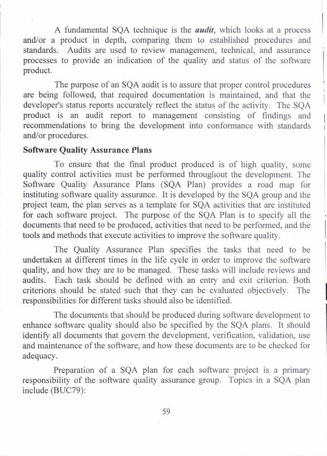
A fundamental SQA technique is the audit, which looks at a process and/or a product in depth, comparing them to established procedures and standards. Audits are used to review management, technical, and assurance processes to provide an indication of the quality and status of the software product.
The purpose of an SQA audit is to assure that proper control procedures are being followed, that required documentation is maintained, and that the developer's status reports accurately reflect the status of the activity. The SQA product is an audit report to management consisting of findings and recommendations to bring the development into conformance with standards and/or procedures.
Software Quality Assurance Plans
To ensure that the final product produced is of high quality, some quality control activities must be performed throughout the development. The Software Quality Assurance Plans (SQA Plan) provides a road map for instituting software quality assurance. It is developed by the SQA group and the project team, the plan serves as a template for SQA activities that are instituted for each software project. The purpose of the SQA Plan is to specify all the documents that need to be produced, activities that need to be performed, and the tools and methods that execute activities to improve the software quality.
The Quality Assurance Plan specifies the tasks that need to be undertaken at different times in the life cycle in order to improve the software quality, and how they are to be managed. These tasks will include reviews and audits. Each task should be defined with an entry and exit criterion. Both criterions should be stated such that they can be evaluated objectively. The responsibilities for different tasks should also be identified.
The documents that should be produced during software development to enhance software quality should also be specified by the SQA plans. It should identify all documents that govern the development, verification, validation, use and maintenance of the software, and how these documents are to be checked for adequacy.
Preparation of a SQA plan for each software project is a primary responsibility of the software quality assurance group. Topics in a SQA plan include (BUC79):
59

1. Purpose and scope of the plan
2. Documents referenced in the plan
3. Organizational structure, tasks to be performed, and specific responsibilities as they relate to product quality
4. Documents to be prepared and checks to be made for adequacy of the documentation
5. Standards, practices, and conventions to be used
6. Reviews and audits to be conducted
7. A configuration management plan that identifies software product items, controls and implements changes, and records and reports changed status
8. Practices and procedures to be followed in reporting, tracking, and resolving software problems
9. Specific tools and techniques to be used to support quality assurance activities
10. Methods and facilities to be used to maintain and store controlled versions of identified software
11. Methods and facilities to be used to protect computer program physical media
12. Provisions for ensuring the quality of vendor-provided and subcontractor developed software.
13. Methods and facilities to be used in collecting, maintaining, and retaining quality assurance records.
Quality Standards and Procedures
Establishing standards and procedures for software development is critical, since these provide the framework from which the software evolves. Standards are the established criteria to which the software products are compared. Procedures are the established criteria to which the development and control processes are compared. Standards and procedures establish the prescribed methods for developing software; the SQA role is to ensure their existence and adequacy. Proper documentation of standards and procedures is necessary since the SQA activities of process monitoring, product evaluation, and auditing rely upon explicit definitions to measure project compliance.
60

Types of Standards include:
Documentation Standards specify form and content for planning, control, and product documentation and provide consistency throughout a project.
•.410 Design Standards specify the form and content of the design product. They provide rules and methods for translating the software requirements into the software design and for representing it in the design documentation.
Code Standards specify the language in which the code is to be written and define any restrictions on use of language features. They define legal language structures, style conventions, rules for data structures and interfaces, and internal code documentation.
Procedures are explicit steps to be followed in carrying out a process. All processes should have documented procedures. Examples of processes for which procedures are needed are configuration management, nonconformance reporting and corrective action, testing, and formal inspections.
The ISO 9000 Quality Standards
A quality assurance system may be defined as the organizational structures, responsibilities, procedures, processes, and resources for implementing quality management. ISO 9000 describes quality assurance elements in generic terms that can be applied to any business regardless of products or services offered.
To become registered to one of the quality assurance system models contained in ISO 9000, their party auditors for compliance to the standard and for effective operation scrutinize a company's quality system and operations. Upon successful registration by the auditors, a company is issued a certificate from a registration body represented by the auditors. Semiannual surveillance audits ensure continued compliance to the standard.
The ISO 9000 quality assurance models treat an enterprise as a network of interconnected processes. For a quality system to be ISO-compliant, these processes must address the areas identified in the standard and must be documented. Documenting a process helps an organization understand, control and improve it. It is opportunity to understand, control, and improve the process
61

network that offers, perhaps, the greatest benefit to organizations' those design and implement ISO-compliant quality system.
ISO 9000 describes the elements of a quality assurance system in general terms. These elements include the organizational structure, procedures, processes, and resources needed to implement quality planning, quality control, quality assurance and quality improvement. However, ISO 9000 does not describe how an organization should implement these quality system elements. Consequently, the challenge lies in designing and implementing a quality assurance system that meets the standard and fits the company's products, services, and culture.
The ISO 9001 Standard
ISO 9001 is the quality assurance standard that applies to software engineering. The standard contains 20 requirements that must be present for an effective quality assurance system. Because the ISO 9001 standard is applicable to all engineering disciplines, a special set of ISO guidelines (ISO 9000-3) have been developed to help interpret the standard for use in the software process. The 20 requirements delineated by ISO 9001 address the following topics:
1. Management Responsibility
2. Quality System
3. Contract Review
4. Design Control •
5. Document and Data Control
6. Purchasing
7. Control of customer supplied product
8. Product identification and traceability
9. Process Control 10. Inspecting and Testing
11. Control of Inspection, measuring the test equipment
12. Inspection and Test status 13. Control of nonconforming product
14. Corrective and preventive action 15. Handling, storage, packaging, preservation, and delivery
62

16. Control of quality records
17. Internal Quality Audits
18. Training
19. Servicing
20. Statistical Techniques
In order for a software organization to become registered to ISO 9001, it must establish policies and procedures to address each of the requirements noted above and then be able to demonstrate that these policies and procedures are hence followed.
The following outline defines the basic elements of the ISO 9001-2000 standard.
Establish the elements of a quality management system Develop, implement, and improve the system
Define a policy that emphasizes the importance of the system
Document the quality system Describe the process
Produce and operational manual
Develop methods for controlling documents,
Establish methods for record keeping
Support quality control and assurance Promote the importance of quality among all stackholders.
Focus on customer satisfaction
Define a quality plan that addresses objectives, responsibilities and authority.
Define communication mechanism among stackholders.
Establish review mechanisms for the quality management system Identify review and feedback mechanisms
Define follow-up procedures
Identify quality resources including personnel, training, and infrastructure elements. Establish control mechanisms
For Planning
63

For customer requirements
For technical activities (e.g. analysis, design, testing)
For project monitoring and management
Define methods for remediation Access quality data and metrics
Define approach for continuous process and quality improvement
Software Configuration Management
Throughout the development, software consists of a collection of items (such as programs, data, and document) that can easily be changed. During any software development, the design, code and even requirements are often changed. The easily-changeable nature of software and the facts that changes often take place, require that changes be done in a controlled manner. Software Configuration Management (SCM) [Bes79, Bes84, Iee87] is the discipline for systematically controlling the changes that take place during development.
The need for configuration management further arises since software can exist in two different forms — executable and non- executable [Bes79]. The executable form consists of the sequences of instruction that can be executed on computer hardware. The non executable form comprises documentation such as the requirements specification, design specification, code listing, and the documents describing the software. As well as maintaining consistency within a form, due to these two forms there is additional problem of maintaining correspondence between the two forms. Since, in the early stages of development, software may not exist in executable form, SCM is easier towards the start of the development and gets more complex towards the end.
There are four major elements of SCM [Ber79]---configuration identification, control, status accounting, and auditing. These components and their general goals are given in fig 3.1
SCM
Identification Control Status Accounting
Auditing
64

Identification
Control
Status Accounting
Auditing
What is the system configuration and what are the Configuration items?
How should changes to the configuration be controlled?
What changes have been made in the configuration?
Is the system being built to satisfy the needs?
Fig. 3.1 Components of SCM
Configuration Identification
The basic goal of SCM is to manage the configuration of the software as it evolves during development. The configuration of the software is essentially the arrangement or organization of its different functional units or components. An important concept in SCM is that of a "baseline". A baseline forms a reference point in the development of a system, and is formally defined after certain phases in development and can be changed only through the changes procedures specified by the SCM policy. Effective management of the software configuration requires careful definition of the different baselines, and controlling the changes to these baselines.
At the time it is established, a software baseline represents the software in the most recent state. After changes are made (through SCM) to this baseline, the state of the software is defined by the most recent baseline and the changes that were made. Baselines are typically established after the completion of a phase. Some of the common baselines are functional baseline, design baseline, and product baseline. Functional baseline is generally the requirements document that specifies the functional requirements for the software. Design baseline consists of the different components in the software and their designs. Products baseline represents the developed system.
The most elementary entity during configuration identification is the software configuration item (SCI). A SCI is a document or an artifact that is explicitly placed under configuration control and that can be regarded as a basic unit for modification. Examples of SCIs are : requirements document, design document, code of a module, test plan. A baseline is essentially a set of SCIs. The first baseline (the functional baseline) may consist of only one SCI — the requirement document. As development proceeds, the number of SCIs grows and the baseline gets more complex. For example, the design baseline will
65

contain different design objects as the SCIs. The functional and design baselines contain only nonexecutable entities, existing only in the form of documentation.
Since the baseline consists of the SCIs, SCM starts with identification of configuration items.
Configuration Control
Configuration control focuses on managing changes to the different forms of the SCIs. The engineering change proposal is the basic document that is used for defining and requesting a change to an SCI. This proposal describes the proposed change, the rationale for it, baselines and SCIs that are affected and cost and schedule impacts.
The engineering change proposals are set to a configuration control board (CBB) The CCB is a group of people responsible for configuration management. The CCB evaluates the request based on its effect on the project, and the benefit due to the change. Based on this analysis the CCB may approve or disapprove the change. If a change is approved then it is the duty of the CCB to inform all parties affected by the change.
The third important factor in configuration control is the procedure for controlling the changes. Once a engineering change proposal has been approved by the CCB, the actual change in the SCI will occur. The procedures for making these changes must be specified. Tools can be used to enforce these procedures.
Status Accounting and Auditing
The task of status accounting is to record how the system evolves and what is its current state. The basic function is to record the activities related to the other SCM functions. Though it is an administrative work but gets complex since both the executable and nonexecutable forms exists at this stage and their correspondence and consistency has to be maintained during changes. Some examples of things that have to be recorded by the accounting procedures are: time of establishment of a baseline, the time when a SCI came into being, information about each SCI, engineering change proposal status, status of the approved changes, and deficiencies uncovered during auditing.
Configuration auditing is concerned with determining how accurately the current software system implements the system defined in the baseline and the
66

requirements document, and with increasing the visibility and traceability of software. Auditing procedures are also responsible for establishing a new baseline. Auditing procedures may be different baselines.
Software Configuration Management (SCM) Plans
The SCM plan, like other plans, has to identify all the activities that must be performed, give guidelines for performing the activities, and allocate resources for them.
The SCM plan needs to specify the type of SCIs that will be selected and the stages during the project where baselines should be established. For configuration control, the plans has to identify the different members of the configuration control board, the forms to be used for engineering change proposals, and policies, procedures and tools for controlling the changes. A SCM plan should include a plan for configuration accounting and auditing. This part of the plan should state how information on the status of configuration items is to be collected, verified, processed, and reported. It should specify all the reports that need to be filed by the people identified as responsible for making the changes. It should also specify the stages at which major audits must be held, the items to be covered during audits, and the procedures to be ;used for resolving problems that occur during audits.
RISK MANAGEMENT
Risk management is an emerging area particularly for large projects, which aims to address the problem of identifying and managing the risks associated with a software project. Risk in a project is the possibility that the defined goals cannot be met. The basic motivation of having risk management is to avoid disasters or heavy losses. When risk is considered in the context of software engineering, three conceptual underpinnings are always in evidence. The first concern is future — what risks might cause the software project to go awry? The second concern is Change — how will changes in customer requirements, development technologies, target environments, and all other entities connected to the project affect timeliness and overall success? Last the choices — what methods and tools should we use, how many people should be
67

involved, how much emphasis on quality is "enough"?. There are number of activities and strategies that have to be performed for effective risk management.
Reactive and Proactive Risk Strategies
Reactive strategy monitors the project for likely risks. Resources are set aside to deal with them, should they become actual problems. More commonly, the software team does nothing about risks until something goes wrong. Then the team flies into action in an attempt to correct the problem rapidly. This is often called fire-fighting mode. When this fails, "crisis management" takes over and the project is in real jeopardy.
A considerably more intelligent strategy for risk management is to be proactive. A proactive strategy begins long before technical work is initiated. Potential risks are identified, their probability and impact are assessed, and they are ranked by importance. Then, the software team establishes a plan for managing risk. The primary objective is to avoid risk, but because not all risks can be avoided, the team works to develop a contingency plan that will enable it to respond in a controlled and effective manner.
Software Risks
At a very high level the software risks can have two characteristics:
Uncertainty — The event the characterizes the risk may or may not happen; i.e. there are no 100% probable risks;
Loss — if the risk becomes a reality, unwanted consequences or losses will occur.
When risks are analysed, it is important to quantify the level of uncertainties and degree of loss associated with each risk. To accomplish this, different categories of risks are considered.
Project Risks — threaten the project plan. That is, if project risks become real, it is likely that project schedule will slip and that costs will increase. Project risks identify potential budgetary, schedule, personnel, resource, stakeholder, and requirements problems and their impact on a software project. Project Complexity, size and the degree of structural uncertainty were also defined as project risk factors.
68

Technical Risks threaten the quality and timelines of the software to be produced. If a technical risk becomes a reality, implementation may become difficult or impossible. Technical risks identify potential design, implementation, interface, verification, and maintenance problems. In addition, specification ambiguity, technical uncertainty, technical obsolescence are also risk factors. Technical risks occur because the problem is harder to solve.
Business Risks threaten the viability of the software to be built. Business risks often jeopardize the project or the product. Candidates for the top five business risks are :
1. Building an excellent product or system that no one really wants (market risk)
2. Building a product that no longer fits into the overall business strategy for the company (strategy risk)
3. Building a product that the sales force doesn't understand how to sell (sales risk)
4. Losing the support of senior management due to a change in focus or a change in people (management risk), and
5. Losing budgetary or personnel commitment (budget risk).
General categorization of other risks proposed by Charette is Known risks are those that can be uncovered after careful evaluation of the project plan. Predictable risks are extrapolated from past period experience (e.g. staff turnover, poor communication with the customer etc). Unpredictable risks are the joker in the deck. They can and do occur, but they are extremely difficult to identify in advance.
RISK MANAGEMENT ACTIVITIES
There are number of activities that have to be performed for effective risk management include
a) Risk identification b) Risk Projection c) Risk Mitigation d) Risk Monitoring and e) Risk Management
69

Risk Identification
The major planning activity in risk management is assessment and consequent planning for risk control during the development. Risk identification is the first step in risk assessment, which identifies all the different risks in a particular project. These risks are project dependent, and their identification is clearly necessary before they can be prioritized and removed.
Risk identification is a systematic attempt to specify risks to the project plan (estimates, schedule, resources, loading etc.). By identifying an predictable risks, the project manager takes a first step toward avoiding them when possible and controlling them when necessary.
There are two distinct types of risks for each of the categories. Generic risks and Product-specific risks. Generic risks are potential threat to every software project. Product-specific risks can only be identified by those with a clear understanding of the technology, the people, and the environment that is specific the project at hand.
Creating a risk item list is one method for identifying risks. The checklist can be used for risk identification and focuses on some subset of known and predictable risks in the following generic sub categories:
• Product size - risk associated with the overall size of the software to be built or modified.
• Business impact — risks associated with constraints imposed by management or the marketplace.
• Customer characteristics — risks associated with the sophistication of the customer and the developer's ability to communicate with the customer in a timely manner.
• Process definition — risks associated with the degree to which the software process has been defined and is followed by the development organization.
• Development environment — risks associated with the availability and quality of the tools to be used to build the product.
70

• Technology to be built — risks associated with the complexity of the system to be built and the "newness" of the technology that is packaged by the system.
• Staff size and experience — risks associated with the overall technical and project experience of the software engineers who will do the work.
The risk item checklist can be organized in different ways. A different risk item checklist format simply lists characteristics that are relevant to each generic subcategory. Finally, a set of "risk components and drivers" is listed along with their probability of occurrence. The risk components are defined in the following manner:
• Performance risk — the degree of uncertainty that the product will meet its requirements and be fit for its intended use.
• Cost risk — the degree of uncertainty that the project budget will be maintained.
• Support risk — the degree of uncertainty that the resultant software will be easy to correct, adapt, and enhance.
• Schedule risk — the degree of uncertainty that the project schedule will be maintained and that the product will be delivered on time.
The impact of each risk driver on the risk component is divided into one of four impact categories namely i) negligible ii) marginal iii) critical and iv) catastrophic. The impact category is chosen based on the characterization of the potential consequence of errors or failure. The checklist, components and drivers are used whenever risk analysis and management are instituted.
RISK PROJECTION
Risk projection, also called risk estimation, attempts to rate each risk in two ways —
i) the likelihood or probability that the risk is real and
ii) the consequences of the problems associated with the risk, should it occur.
71

By prioritizing risks, the team can allocate resources where they will have the most impact. In order to prioritize the risks, the project planner along with project manager and other technical staff a performs the following four risk projection steps:
• Establish a scale that reflects the perceived likelihood of a risk
• Delineate the consequences of the risk
• Estimate the impact of the risk on the project and the product.
• Note the overall accuracy of the risk projection so that there will be no misunderstandings.
Developing a Risk Table
A risk table provides a project manager with a simple technique for risk projection. The risk table can be implemented as a spreadsheet model. This enables easy manipulation and sorting of entries. A weighted average can be used if one risk component has more significance for a project.
A risk table contains 4 columns. Using the item checklist the project team lists all risks in the first column of the table. Each risk is categorized in the second column (e.g. project size risk, business risk etc.). The probability of occurrence of each risk is entered in the third column. Next, the impact of each risk is assessed. Each risk component is assessed and an impact category is determined. The impact category is placed in the fourth column of the table. The categories for each of the four risk components — performance, support, cost, and schedule — are averaged to determine an overall impact value. A weighted average can be used if one risk component has more significance for a project.
Once the four columns of the risk table have been completed, the table is sorted by probability and by impact. High probability, high impact risks percolate to the top of the table, and low probability risks drop to the bottom. This accomplishes the risk prioritization.
Assessing Risk Impact
Three factors affecting the consequences that are likely if a risk does occur: its nature, its scope, and its timing. The nature of the risk indicates the problems that are likely if it occurs. The scope of a risk combines the severity with its overall distribution. Finally, the timing of a risk considers when and for
72

how long the impact will be felt. The following steps are recommended to determine the overall consequences of a risk:
• Determine the average probability of occurrence value for each risk component.
• Determine the impact for each component based on the criteria.
• Complete the risk table and analyze the results.
Risk Assessment
Risk assessment is another risk management activity. Earlier sets of triplets as [risk, likelihood, impact] pairs are identified. During risk assessment, we examine the accuracy of the estimates that we made during risk project, attempt to prioritize the risks that have been uncovered, and begin thinking about ways to control and/or avert risks that are likely to occur.
For assessment to be useful, a risk referent level must be defined. For most software projects, cost, schedule, and performance represent three levels. That is, there is a level for cost overrun, schedule slippage or performance degradation that will cause the project to be terminated. Here, the decision whether to proceed with the project or terminate it has been taken by considering the break point, called referent point.
The following steps are to be performed during risk assessment.
i) Define the risk referent levels for the project ii) Attempt to develop a relationship between each triplet pair and each of
the reference levels.
iii) Project the set of referent points that define a region of termination bounded by a curve or areas of uncertainty.
iv) Try to predict how compound combinations of risks will affect a referent level.
RISK MITIGATION, MONITORING AND MANAGEMENT
All of the risk analysis activities presented to this point have a single goal — to assist the project team in developing a strategy for dealing with risk. An effective strategy must consider three issues:
73

■ Risk Avoidance
■ Risk Monitoring
■ Risk management and contingency planning
If a software team adopts a proactive approach to risk, avoidance is always the best strategy. This is achieved by developing a plan for risk mitigation. To mitigate the risk, project management must develop a strategy for reducing turnover. Among the possible steps to be taken are :
• Meet with current staff to determine causes for turnover
• Mitigate those causes that are under our control before the project starts.
• Once the project commences, assume turnover will occur and develop techniques to ensure continuity when people leave.
• Organize project teams so that information about each development activity is widely dispersed
• Define documentation standards and establish mechanisms to ensure that documents are developed in a timely manner
• Conduct peer reviews of all work
• Assign a back staff member for every critical technologist.
As the project proceeds, risk monitoring activities commence. The project manager monitors factors that may provide an indication of whether the risk is becoming more or less likely. The following factors can be monitored in the case of high staff turnover.
• General attitude of team members based on project pressures
• The degree to which the team has jelled
• Interpersonal relationships among team members
• Potential problems with compensation and benefits
• The availability of jobs within the company and outside it
In addition to monitoring these factors, a project manager should monitor the effectiveness of risk mitigation steps.
Risk management and contingency planning assumes that mitigation efforts have failed and that the risk becomes a reality. Continuing the example,
74

the project is well underway, and a number of people announce that they will be leaving. If the mitigation strategy has been followed, backup is available, information is documented, and knowledge has been dispersed across the team.
Risk is not limited to the software project itself. Risks can occur after the software has been successfully developed and delivered to the customer. These risks are typically associated with the consequences of software failure in the field.
Software safety and hazard analysis are software quality assurance activities that focus on the identification and assessment of potential hazards that may affect software negatively and cause an entire system to fail. If hazards can be identified early in the software engineering process, software design features can be specified that will either eliminate or control potential hazards.
The RMMM PLAN
A risk management strategy can be included in the software project plan or the risk management steps can be organized into a plan called Risk Mitigation, Monitoring and Management Plan (RMMM Plan). The RMMM plan documents all work performed as part of risk analysis and is used by the project manager as part of the overall project plan. The format of the RMMM plan is given below :
RMMM PLAN
I Introduction 1. Scope and Purpose of Document 2. Overview of major risks 3. Responsibilities
a. Management b. Technical Staff
II. Project Risk Table 1. Description of all risks above cut-off 2. Factors influencing probability and impact
III Risk Mitigation, Monitoring, Management n. Risk #n
75

a. Mitigation i. General Strategy ii. Specific steps to mitigate the risk
b. Monitoring i. Factors to be monitored ii. Monitoring Approach
c. Management i. Contingency plan ii. Special consideration
IV. RMMM Plan Interaction Schedule
V. SUMMARY
Once the RMMM Plan has been developed and the project has begun, risk mitigation and monitoring steps commence. As discussed earlier, risk mitigation is a problem avoidance activity. Risk monitoring is a project tracking activity with three primary objectives:
■ To assess whether predicted risks do, in fact occur.
■ To ensure that risk aversion steps defined for the risk are being properly applied; and
■ To collect information that can be used for future risk analysis.
In many cases, the problems that occur during a project can be traced to more than one risk. Another job of risk monitoring is to determine the origin throughout the project.
SOFTWARE REVIEWS
Software reviews are a filter for the software engineering process. That is, reviews are applied at various points during software engineering and serve to uncover errors and defects that can then be removed. Software reviews purify the software engineering activities analysis, design, and coding.
There are many different types of reviews that can be conducted as part of software engineering. They are :
• An informal meeting around the coffee machine is a form of review, if technical problems are discussed.
76

• A formal presentation of software design to an audience of customers, management, and technical staff is also a form of review.
However, a Formal Technical Review (FTR) sometimes called walkthrough or an inspection is the most effective filer from a quality assurance standpoint. It is an effective means for uncovering errors and improving software quality.
Formal Technical Review (FTR)
A formal technical review is a software quality control activity performed by software personnel. The objectives of FTR are :
1. To uncover errors in function, logic, or implementation for any representation of the software
2. To verify that the software under review meets its requirements
3. To ensure that the software has been represented according to predefined standards.
4. To achieve software that is developed in a uniform manner, and
5. To make projects more manageable.
The FTR is actually a class of reviews that includes walkthroughs, inspections, round robin reviews, and other small group technical assessments of software. Each FTR is conducted as a meeting. It will be successful only if it is properly planned, controlled and attended.
The Review Meeting
Every review meeting should abide by the following constraints regardless of the FTR format that is chosen. The constraints are :
• Three or five people should be involved in the review
• Advance preparation should occur but should require no more than two hours of work for each person
• The duration of the review meeting should be less than two hours.
The focus of the FTR is on a work product. The individual who has developed the work product called the producer informs the project leader that the work product is complete and that a review is required.
77

The project leader contacts a review leader, who evaluates the product for readiness, generates copies of product materials, and distributes them to two or three reviewers for advance preparation.
Each reviewer is expected to spend between one and two hours reviewing the product. Concurrently the review leader also reviews the product and establishes an agenda for review meeting.
The review meeting is attended by the review leader, all reviewers, and the producer. One of the reviewers takes on the role of recorder, that is, individual who records all important issues raised during the review. The FTR begins with an introduction of the agenda and a brief introduction by the producer. The producer then proceeds to "walkthrough" the work product, explaining the material, while reviewers raise issues base on their advance preparation. When valid problems or errors are discovered, the recorder notes each.
At the end of review meeting, all attendees of the FTR must decide whether to accept the product without further modification or to reject the product due to sever errors, or to accept the product provisionally. The decision made, all FTR attendees complete a sign-off, indicating their participation and their concurrence with the review team's findings.
Review Reporting and Record Keeping
During FTR, recorder (one of the reviewers) records all issues that have been raised. These are summarized at the end of the review meeting and a review list is produced. In addition, a sample review summary report is prepared. The review summary report provides answers for the following questions:
• What was reviewed?
• Who reviewed it?
• What were the findings and conclusions?
The review issues list serves two purposes : 1) to identify problem areas within the product and 2) to serve as an action item checklist that guides the producer as corrections are made.
78

Review Guidelines
The guidelines for the conduct of formal technical review must be established in advance, distributed to all reviewers, agreed upon, and then followed. A set of guidelines for the conduct of formal technical review is given below:
• Review the product, not the producer
• Set an agenda and maintain it
• Limit debate and rebuttal
• Enunciate problem area
• Take written notes
• Limit the number of participants and insist upon advance preparation
• Develop a checklist for each product that is likely to be reviewed
• Allocate resources and schedule time for FTRs.
• Conduct meaningful training for all reviewers.
• Review your early reviews.
As many variables have an impact on a successful review, the software organization should experiment to determine what approach works best in a local context.
A Review Checklist
The FTR can be conducted during each step in the software engineering process. The following are the brief checklist that can be used to assess product that are derived as part of software development.
1. System Engineering — The system specification allocated function and performance to many system elements. Some of the areas covered in the checklist are:
• Are interfaces between system elements defined?
• Are design constraints established for each element?
• Has the best alternative been selected?
• Is the solution technologically feasible?
• Is there consistency among all system elements?
79

2. Software Project Planning — It assesses risk and develops estimates for resources, cost and schedule based on the software allocation established as part of the system engineering activity. The review of the software project plan establishes the degree of risk. The following checklist is applicable:
• Is terminology clear? • Are resources adequate for scope? • Is software scope unambiguously-defined and bounded? • Is the schedule consistent?
3. Software Requirement Analysis — A number of FTRs are conducted for the requirement of a large system and may be augmented by reviews and the evaluation of prototypes as well as customer meetings. The following checklists are applicable.
• Is problem partitioning complete? • Are external and internal interfaces properly defined? • _ Are all requirements traceable to system level? • Are prototyping been conducted for the user/customer? • Are validation criteria complete?
4. Software Design — The 'preliminary design' review assesses the translation of requirements to the design of data and architecture. Another type called as 'Design walk through' concentrates on the procedural correctness of algorithms as they are implemented within program modules. The following checklists are applicable for preliminary design review.
• Is the program architecture factored? • Is effective modularity achieved? • Are modules functionally independent? • Is the data structure consistent with software requirements? • Has maintainability been considered?
The following are checklist for design walk through.
• Is the algorithm logically correct? • Is the logical complexity reasonable? • Are local data structures properly defined?
80

• Is compound or inverse logic used?
• Has maintainability been considered?
6. Coding — Although coding is a mechanistic outgrowth of procedural design, errors can be introduced as the design is translated into a programming language. This is true if the programming language does not directly support data and control structures represented in the design, the following checklist is applicable.
• Are there misspellings?
• Has proper use of language conventions been used?
• Are there incorrect or ambiguous comments?
• Are data types and data declarations proper?
• Are physical constants correct?
7. Software Testing — The completeness and effectiveness of testing can be improved by assessing any test plans and procedure that have been created. The checklist for test plan is:
• Are major function demonstrated early?
• Is the test plan consistent with overall project plan?
• Has a test schedule been explicitly defined?
• Are test resources and tools identified and available?
• Has stress testing for software been specified?
The checklist for Test procedure is:
• Is error handling to be tested?
• Are boundary values to be tested?
• Are timing and performance to be tested?
• Have all the independent logic paths been tested?>
• Have test cases been identified and listed with expected results?
8. Maintenance — The review checklists for software development are equally valid for software maintenance phase. The checklist for maintenance is given below:
81

• Have side effects associated with change been considered?
• Has the request for change been documented and evaluated?
• Has the chance once made been documented and reported to all interested parties?
• Have appropriate FTSs been conducted?
• Has the final acceptance review been conducted to ensure that all software has been properly updated, tested and replaced?
Review Questions :
1. What is project scheduling? Explain.
2. Explain the guidelines for software project scheduling.
3. Explain various project scheduling methods.
4. How will you track the scheduling? Explain.
5. What is software quality assurance? Explain.
6. Describe various quality assurance activities.
7. Write short notes on SQA plan.
8. What is configuration management? Explain.
9. What are software risks? Explain with example.
10. Explain various risk management activities.
11. Describe the importance of formal technical review.
12. Enumerate the guidelines for conducting reviews.
82

UNIT - IV
SOFTWARE REQUIREMENT SPECIFICATION
Software Requirement Specification — Problem Analysis — Structuring information — Information Flow — Prototyping — Structured Analysis —Requirement Specification Analysis — Characteristics — Components — Structure — Specification Techniques.
After completion of this unit, the students can able to
> Understand what the software requirement specification is
> Explain the activities involved in the requirement specification phase
> Describe the structuring information methods
> Understand the concept of Data flow diagram
> Explain the prototyping method of problem analysis
> Describe the structured requirement analysis method
> Explain the role of Software Requirement Specification
➢ Explain the components of Software Requirement Specification
> Summarise the characteristics of SRS
> Frame the structure of SRS document > Validate the SRS document ➢ Describe the formal requirement specification techniques
INTRODUCTION
A complete understanding of software requirement is essential to the success of a software development effort. A fundamental problem of software engineering is the problem of scale. The complexity and size of applications employing automation and consequently the complexity and size of software system are continuously increasing. As the scale changes to more complex and larger software systems, new problem occur that did not exist in small systems, which leads to a redefining of priority of the activities that go into developing software. The main assumption was that the developers understood the problem clearly when it was explained to them, generally informally.
83
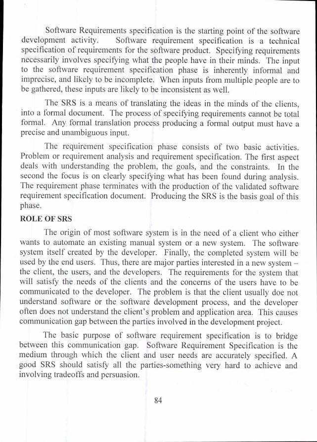
Software Requirements specification is the starting point of the software development activity. Software requirement specification is a technical specification of requirements for the software product. Specifying requirements necessarily involves specifying what the people have in their minds. The input to the software requirement specification phase is inherently informal and imprecise, and likely to be incomplete. When inputs from multiple people are to be gathered, these inputs are likely to be inconsistent as well.
The SRS is a means of translating the ideas in the minds of the clients, into a formal document. The process of specifying requirements cannot be total formal. Any formal translation process producing a formal output must have a precise and unambiguous input.
The requirement specification phase consists of two basic activities. Problem or requirement analysis and requirement specification. The first aspect deals with understanding the problem, the goals, and the constraints. In the second the focus is on clearly specifying what has been found during analysis. The requirement phase terminates with the production of the validated software requirement specification document. Producing the SRS is the basis goal of this phase.
ROLE OF SRS
The origin of most software system is in the need of a client who either wants to automate an existing manual system or a new system. The software system itself created by the developer. Finally, the completed system will be used by the end users. Thus, there are major parties interested in a new system —the client, the users, and the developers. The requirements for the system that will satisfy the needs of the clients and the concerns of the users have to be communicated to the developer. The problem is that the client usually doe not understand software or the software development process, and the developer often does not understand the client's problem and application area. This causes communication gap between the parties involved in the development project.
The basic purpose of software requirement specification is to bridge between this communication gap. Software Requirement Specification is the medium through which the client and user needs are accurately specified. A good SRS should satisfy all the parties-something very hard to achieve and involving tradeoffs and persuasion.
84

The development process of SRS helps the clients to understand their needs. It is especially useful if the software system is not for automating an existing manual system, but for creating an entirely new system. A good SRS provides the following benefits:
• Establishing the basis for agreement between client and supplier on what the software product will do.
• Reducing the development cost.
• Providing a reference for validation of the final product. The SRS assists the client in determining if the software meets the requirements.
PROBLEM ANALYSIS
In the requirement specification phase, the first activity to be performed is Problem or Requirement Analysis. Problem analysis is done to obtain a clear understanding of the needs of the clients and the users, and what exactly is desired from the software. It leads to the actual specification. The people performing the analysis of called Analysts are also responsible for specifying the requirements.
Problem analysis involves interviewing the client and end users. These people and the existing documents about the current mode of operation are the basic source of information for the analyst. The process of obtaining answers to question that might rise in an analyst's mind continues until the analyst fees that all the information has been obtained.
During this analysis process, a large amount of information is collected in forms of answers to questions, questionnaires, information from documentation and so forth. One of the major problems during analysis is how to organize the information obtained so the information can be effectively evaluated for completeness and consistency. The second major problem during analysis is resolving the contradiction that may exist in the information from different parties. The contradictions occur since the perceived goals of the system may be quite different for the end users and the client. During analysis the interpersonal skills of an analyst are important. Interviewing the users and client requires good communication skills.
During this analysis phase, the following methods are used to organize the information and provide the way how to proceed with the analysis activity.
85

• Structuring Information
• Data or Information Flow
• Structured Analysis
• Prototyping
The short descriptions of these methods are discussed in the following session.
Structuring Information
In the analysis phase, collecting information about the system to be developed is not very difficult but deciding which information should be collected is difficult. Determining what questions to ask or what questions to put in a questionnaire is the challenging part of information collection. Properly structuring available information is essential if properly directed questions are to be formed, answers to which will uncover information.
Three methods are used for structuring information during the problem analysis namely,
• Partitioning • Abstraction
• Projection
Partitioning captures the "whole/part of relationship between entities or problems. It is essential to understanding large and complex systems. Comprehending the entire system with its complexities is difficult, if not impossible, unless the problem is broken into an understanding of its parts, and how the parts relate to each other. Hence, partitioning is used when it is difficult to describe a system without describing it in term of its parts.
Abstraction is another basic technique to problem analysis that is used by all analysts either consciously or by instinct. When using abstraction, an entity or a problem in general terms is defined, and the details are provided separately. The abstraction method provides the analyst with the tool to consider a problem at a suitable level of abstraction, where the general system is comprehended, and then the details are analysed later.
Projection is the third method which is extremely useful in analysis. Projection is defining the system from multiple points of view by taking the
86

projection of the system from different perspectives. Projecting three dimensional object on the three different two dimensional planes is a similar process. In projection, the problem is studied from different perspectives, and then the different projections obtained are combined to form the analysis for the complete system. The advantage of this method is that trying to describe the system from a global view point is difficult and error prone, and one is more likely to forget some features of the system.
Data or Information Flow
Data Flow Diagram (DFD) is one another commonly used tool for understanding the flow of data or information in software to be developed. DFDs are quite general and are not limited to problem analysis for software requirements specification. DFDs are very useful in understanding a system and can be effectively used for partitioning during analysis.
A DFD shows the flow of data through a system. It shows the movement of data through the different transformations or processes in the system. The processes are shown by a circle called bubbles and data flows are represented by named arrows entering or leaving the bubbles. A rectangle represents a source or sink, and is a net originator or consumer of data. In DFD all external files are shown as a labeled open ended rectangle called data stores. The DFD is presented in a hierarchical fashion. That is, the first data flow diagram called a level 0 DFD represents the system as a whole. Subsequent data flow diagrams refine the level 0 diagram, providing increasing detail with each subsequent level.
To construct a DFD, start by identifying the major inputs and outputs. Minor outputs like error messages should be ignored. Then starting from the inputs work toward the outputs, identifying the major processes (transforms). Some guidelines to construct a DFD are:
• The level 0 DFD should depict the system as a single bubble; • Primary input and output should be carefully noted; • Refinement should begin by isolating candidate processes, data, and
data stores to be represented at the next level. • All arrow and bubbles should be labeled with meaningful names
87

• Information flow continuity must be maintained from level to level and
• One bubble at a time should be refined.
. In a DFD, data flows are identified by giving unique names. These names are chosen so that they convey some "meaning about what the data is. However, the precise structure of data flows is not specified in a DFD. The data dictionary is a repository of various data flows defined in a DFD. The associated data dictionary states precisely the structure of each data flow in the DFD. Components in the structure of a data flow may also be specified in the data dictionary, as well as the structure of files shown in the DFD.
The DFD should be carefully scrutinized to make sure that all the processes in the physical environment are shown in the DFD. It should also be ensured that none of the data flows is actually carrying control information. A data flow without any structure or composition is a potential candidate for control information.
Structured Analysis
During analysis, identification of functions and data which are necessary to solve a particular problem is important. The structured analysis method focuses on functions and the data consumed ad produced by these function. This method helps an analyst decide what type of information to obtain at different points in analysis, the helps in organizing information so that the analyst is not overwhelmed by the complexity of the problem.
It is a top-down approach which relies heavily on the use of data flow diagrams. It is a technique that analyses and also produces the specifications. The first step in this method is to study the physical environment. During this, DFD of the current non-automated system is drawn, showing the input and output data flows of the system, how the data flows through the system, and what re the processes operating on the data.
The basic purpose of analyzing the current system is to obtain a logical DFD for the system, where each data flow and each process is a logical entity or operation, rather than an actual name. Drawing a DFD for the physical system is only to provide a reasonable starting point for drawing the logical DFD. Hence, the next step in the analysis is to draw the logical equivalents of the DFD for the physical system. During this step, the DFD of the physical environment is taken
88

and all specific physical data flows are represented by their logical equivalents. This phase also ends when the DFD has been verified by the user.
In the first two steps, the current system is modeled. The next step is to develop a logical model of the new system after the changes have been incorporated, and a DFD is drawn to show how data will flow in the new system. The DFD for the new system will replace only that part o the existing DFD that is within this boundary. The inputs and outputs of the new DFD should be same as the inputs for the DFD within the boundary.
The next step is to establish the man-machine boundary by specifying what will be automated and what will remain manual in the DFD for the new system. Different possibilities may exist depending on what is automated, and the degree of automation. The next two steps are evaluating the different options and then packaging or presenting the specifications.
Structured analysis provides methods for organizing and representing information about systems. It also provides guidelines for checking the accuracy of the information. Hence, for understanding and analyzing an existing system, this method provides useful tools. Most of the guidelines given in structured analysis are only applicable in the first two steps, when the DFD for a current system is to be constructed. For analyzing the final system and constructing the DFD or the data dictionary for the new system to be built, this technique does not provide much guidance. The study and understanding of the existing system will help the analyst in this job, but there is no direct help from the method of structured analysis.
Prototyping
Prototyping is another method of analyzing a problem. In this method, a partial system is constructed which is then used by the client, user and the developers to gain a better understanding of the problem and needs. Prototyping emphasizes that actual practical experience is the best aid for understanding needs since it is often difficult to visualize a system. Through the actual experience with the prototype, the client's needs can be understood clearly. Once the needs are clear, the specification phase begins, resulting in the requirement specification document, when is then used as the basis of software development.
89

A prototype is always a partial system. According Davis, there are two approaches to prototyping namely, throwaway and evolutionary.
In the throwaway approach the prototype is constructed with the idea that it will be discarded after the analysis is complete, and the final system will be
built from scratch. In the evolutionary approach, the prototype is built with the idea that it
will eventually be converted into the final system. The first one leads to the prototyping based process model, while the latter leads to the iterative
enhancement model. The activities involved in the prototype problem analysis approach are:
■ Develop preliminary SRS for the system, which is the SRS for the
prototype
■ Build the prototype
■ Achieve user and client experience in using the prototype
■ Develop the final SRS for the system and
■ Develop the final system
Developing SRS for the prototype requires identifying the areas of the system that should be included in the prototype. In general, where requirements tend to be unclear and vague, or where the clients and users are unsure or keep changing their mind, a prototype would be useful. Prototype is developed in much the same way as any software is developed, with a basic difference in the development approach. Many of the bookkeeping documenting, and quality control activities that are usually performed during software product development are kept to a minimum during prototyping. Efficiency concerns also take a back seat, and often very high level, interpretive languages are used
for prototyping.
SOFTWARE REQUIREMENT SPECIFICATION (SRS)
The second activity to be performed in the requirement specification phase is specifying the requirements of the system ie. Requirement specification. Once the problem analysis is complete, the requirements must be written or specified. The final output is the software requirements specification document. For smaller problems or problems that can easily be comprehended, the
90

specification activity might come after the entire analysis is complete. However, it is more likely that problem analysis and specification are done concurrently.
Characteristics of SRS
In order to achieve and satisfy the goal of a system, an SRS should have certain properties and should contain different types of requirements. The desirable characteristics of an SRS are given below:
• Understandable • Unambiguous • Complete • Verifiable • Consistent • Modifiable • Traceable
An SRS should be understandable, as one of the goals of the requirements phase is to produce a document upon which the client, the users and developers can agree. Since multiple parties need to understand and approve the SRS, it is of utmost importance that the SRS should be understandable.
An SRS is unambiguous if and only if every requirement stated has one and only one interpretation. Requirements are often written in natural language, which are inherently ambiguous. If the requirements are specified in a natural language, the SRS writer has to be especially careful to ensure that there are no ambiguities. To avoid ambiguities, the requirements can be written by using some formal requirements specification language. The major disadvantage of using formal languages is the large effort required to write an SRS and the high cost of doing so.
An SRS is complete if everything the software is supposed to do is in the SRS. A complete SRS defines the responses of the software to all classes of input data. For specifying all the requirements, the requirements relating to functionality, performance, design constraints, attributes and external interfaces must be specified.
A requirement is verifiable if there exists some cost-effective process that can check if the final software meets that requirement. An SRS is verifiable if
91

an only if every stated requirement is verifiable. This implies that the requirements should have as little subjectivity as possible because subjective requirements are difficult to verify. Unambiguity is essentially for verifiability.
An SRS is consistent if there is no requirement that conflicts with another. Terminology can cause inconsistencies. Different requirements may use different terms to refer to the same object. There may be logical or temporal conflict between requirements causing inconsistencies. This occurs if the SRS contains two or more requirements whose logical or temporal characteristics cannot be satisfied together by any software system.
Writing an SRS is an iterative process. When the requirements of a system are specified, they are later modified as the needs of the client change with time. Hence, an SRS should be easy to modify. An SRS is modifiable if its structure and style is such that any necessary change can be made easily. Presence of redundancy is a major hindrance to modifiability
An SRS is traceable if the origin of each of its requirements is clear and it facilitates the referencing of each requirement in future development. There are two types of traceability namely forward and backward traceability. Forward traceability means that each requirement should be traceable to some design and code elements. Backward traceability requires that it should be possible to trace design and code elements to the requirements they support. Traceability aids verification and validation.
Of all these characteristics, completeness is the most important. The most common problem in requirements specification is when some of the requirements of the client are not specified. This necessitates additions and modifications to the requirements later in the development of cycle which are often expensive to incorporate.
Components of an SRS
Completeness of specifications is difficult to achieve and even more difficult to verify. Having guidelines about what different things an SRS should specify will help in completely specifying the requirements. The different components of software requirements specification are:
> Functional Requirements > Performance Requirements
92

Software Requirement Specification
Document
Design Constraints
erformance Requirements
> Design constraints > External Interfaces
E. Functional Requirements
•
V
External Interfaces
Fig.4.1 Components of SRS
Functional Requirements Functional Requirements specify which outputs should be produced from
the given inputs. They describe the relationship between the input and output of the system. For each functional requirement, a detailed description of all the data inputs and their source, the units of measure, and the range of valid inputs must be specified. All the operations to be performed on the input data to obtain the output should be specified. This includes specifying the validity check on the input and output data, parameters affected by the operation, and equations or other logical operations which must be used to transform the inputs into
corresponding outputs.
The functional requirement must clearly state what the system should do if the system behaviour in abnormal situations like invalid input or error during computation. The SRS should specify the behaviour of the system for invalid
93

inputs and invalid outputs. Furthermore, the behaviour of the system for valid input but the normal operation cannot be performed should also be specified.
Performance Requirements
This component specifies the performance constraints on the software system. All the requirements relating to the performance characteristics of the system must be clearly specified. There are two types of performance requirements namely static and dynamic.
The static requirements are those that do not impose constraints on the execution characteristics of the system. These include requirements like the number of terminals to be supported, and number of simultaneous users to be supported, number of files and their sizes that the system has to process.
The dynamic requirements specify constraints on the execution behaviors of the system. These include response time and throughput constraints on the system. Response time is the expected time for the completion of an operation under specified circumstances. Throughput is the expected number of operations that can be performed in a unit time. All of these requirements should be stated in measurable terms.
Design Constraints
Some of the factors like design standards, resource limits operating environment, reliability and security requirements and policies that may restrict the choice of system designers. Hence, an SRS document should identify and specify all such constraints.
Standard Compliance : This specifies the requirements for the standards that the system must follow. The standards may include the report format and accounting procedures.
Hardware Limitations: The software may have to operate on some existing or pre determined hardware, thus imposing restrictions on the design. Hardware limitations can include the type of machines to be used, operating system available on system, languages supported, and limits on primary and secondary storage.
Reliability and Fault Tolerance: Fault tolerance requirements can place major constraint on how the system is to be designed. Fault tolerance requirements often make the system more complex and expensive. Requirements about
94

system behaviour in the face of certain kinds of faults is specified. Reliability requirements are very important for critical applications.
Security: Security requirements are significant in defense systems and many database systems. Security requirements place restrictions on the use of certain commands, control assess to data, provide different kinds of access requirements for different people, require the use of passwords, and cryptography techniques, and maintain a log of activities in the system.
Internal Interface Requirements
All the possible interactions of the software with people, hardware, and other software should be clearly specified. For the user interface, the characteristics of each user interface of the software product should be specified. A preliminary user manual should be created with all user commands, screen formats, an explanation of how the system will appear to the user, and feedback and error messages.
For hardware interface requirement, the SRS should specify the logical characteristics of each interface between the software product and the hardware components. If the software is to execute on existing hardware or on pre-determined hardware, all the characteristics of the hardware including memory restrictions, should be specified. The interface requirement should specify the interface with other software which the system will use or which will use the system. This includes the interface with the operating system and other applications. The message content and format of each interface should be specified.
Structure of Software Requirement Specification Document and Validation
SRS document
The software requirement specification is produced at the culmination of the analysis task. The function and performance allocated to software are referred by establishing a complete information description, a detailed functional and behavioural description, an indication of performance requirements and design constraints, appropriate validation criteria and other data pertinent to requirement. For this it may be necessary to organize the requirements document as sections and sub sections.
95

A simplified outline presented below which is derived from the IEEE guide to software requirement specifications.
SOFTWARE REQUIREMENT SPECIFICATION DOCUMENT
FORMAT
1. Introduction
1.1 Purpose
1.2 Scope
1.3 Definitions, Acronyms and Abbreviations
1.4 Overview
2. General Description
2.1 Product Perspective
2.2 Production Functions
2.3 User Characteristics
2.4 General Constraints
2.5 Assumptions and Dependencies
3. Functional Requirements
3.1 Functional Requirements I
3.1.1 Introduction
3.1.2 Inputs
3.1.3 Processing
3.1.4 Outputs
3.2 Functional Requirements II
4. External Interface Requirements
4.1 User Interfaces
4.2 Hardware Interfaces
4.3 Software Interfaces
5. Performance Requirements
96

6. Design Constraints
6.1 Standards Compliance
6.2 Hardware Limitations
7. Other Requirements
8. Bibliography
9. Appendix
The document should provide the goals and objectives of the software, describing in the context of computer based system. So, the introduction section contains the purpose, scope and overview of the requirement document. Any definitions that are used also listed.
Section 2 describes the general factors that affect the product and its requirements. Product perspective is the relationship of the product to other products. A general high level description of the functions to be performed by the product is given. Schematic diagrams showing a high level view of different functions and their relationships with each other can often be useful. Besides, typical characteristics of the eventual end user and general constraints are also specified.
In the sections 3,4,5 and 6 specify the particular requirements. All the details the software developer needs to create a design and eventually implement the system are specified. If there are any other requirements that have not been described, they are specified in Section 7. One of the features to be included in the requirement document is that it can be easily modifiable according to any change in the software made. I.e. it is useful if possible, future modifications that can be foreseen at the requirements specification time be outlined, so that the system can be designed to ensure that the modifications can 'easily accommodate those changes. All the references that are cited in the document should be given in section 8.
Validation
The development of software starts with the requirement specification document, which is also used to determine whether or not the delivered software system is acceptable. It is therefore important that the requirement specification contains no errors and specifies the client's requirements correctly. Hence it is
97

extremely desirable to detect errors in the requirements before the design and developments of the software begin.
The basic objective of requirement validation activity is to ensure that the SRS reflects the actual requirements accurately and clearly. A related objective is to check that the SRS document is itself of "good quality".
Before discussing validation methods, type of errors that typically occurs in an SRS should be considered. Many different types of errors are possible, but the most common errors that occur can be classified into four types.
> Omission > Inconsistency > Incorrect fact and ➢ Ambiguity
Omission is a common error in requirements. It this type of error, some user requirements is simply not included in the SRS, the omitted requirement may be related to the behaviour of the system, its performance, constraints or any other factor.
Another common form of error in requirements is inconsistency. Inconsistency can be due to contraction within the requirements themselves or to incompatibility of the stated requirements with the actual requirements of the client or with the environment in which the will operate.
The third common error is incorrect fact that occurs when some fact recorded in the SRS is not correct.
The fourth common type of error is ambiguity. This occurs when there are some requirements that have multiple meanings, which leads to confuse the reader. Some of the common methods of requirement validation is given below:
• Requirement Review • Other automated methods
➢ Reading ➢ Constructing scenarios ➢ Automated Cross-referencing ➢ Prototyping
98

Requirements Review
Requirements review is a review by a group of people to find error and point out other matters of concern in the requirements specifications of concern in the requirements specifications of a system. This group should includes the author of the requirements document, some one who understands the need of clients, a person of the design team, and the person responsible for maintaining the requirement documents.
Other Methods
Requirement review remains the most commonly used and viable means for requirement validation. However, there are approaches that may be applicable for some systems or parts of the system or systems that have been specified formally.
Reading
The objective of reading is to have some one other than the author of the requirements read the requirement specification document to identify the potential problems. By having the requirements read by another person who may have has different "interpretation" of requirements, many of the requirements problem caused by misinterpretation or ambiguities can be identified.
Constructing Scenarios
Scenarios describe different situations of how the system will work once it is optional. The most common are for constructing scenarios is that of system-user interaction. It is good for classifying misunderstanding in the human-computer interaction area. They are of limited value for verifying the consistency and completeness of requirements.
Automated Cross Referencing
It uses processors to verify some properties of requirements. Any automated processing of requirements is possible if the requirements are written in a language specially designed for machine processing. They can be analyzed for internal consistency among different elements of requirements.
99

Prototyping
Though prototypes are generally built to verify requirements, it is quite useful in verifying the feasibility of some the requirements and checking the user interface. Prototyping can be very helpful for a clear understanding of requirements, removing misconceptions, and aiding clients and developers in requirement analysis.
FORMAL SPECIFICATION TECHNIQUES
Specifying the functional characteristics of a software product is one the most important activities to be accomplished during requirement analysis. The notations used in the formal techniques have the advantage of being concise and unambiguous. They support formal reasoning about the functional specifications, and they provide a basis for verification of the resulting software product. Some of the techniques that have been used to specify the requirement specification are discussed below.
Structured English
Natural languages have been widely used for specifying requirements. The major advantage of using a natural language is that both client and supplier understanding the language. Specifying the problem to be solved in a natural language is an expected outcome in the evolution of software engineering. As software requirements grew more complex, the requirements were specified in written form, rather than orally.
The use of natural languages has some important drawbacks. By the very nature of a natural language, written requirements will be imprecise and ambiguous. Efforts to be more precise and complete result in voluminous requirement specification documents, as natural languages are quite verbose. Due to these drawbacks, there is effort to move from natural language to formal languages for requirement specification.
To reduce drawbacks, natural language is used in a structural fashion. In structured English, requirements are broken into sections, and paragraphs. Each paragraph is then broken into sub-paragraphs. Many organizations also specify strict uses of some words like "shall", "perhaps", "should" etc and try to reduce
100

the use of common phrases in order to improve the precision, and reduce the verbosity and ambiguity.
Regular Expressions
Regular expressions can be used to specify the structure of symbol strings. String specification is useful for specifying such things as input data, command sequence, and contents of a message. Regular expressions can be considered at grammar for specifying the valid sequences in a language, and can be automatically processed. There are a few basic constructs allowed in regular expressions.
Atoms : The basic symbols or the alphabet of the language
Composition : Formed by concatenating two regular expressions. For regular expressions rl and r2, concatenation is expressed by (r1, r2), and denotes concatenation of strings represented by r1 and r2.
Alternation : Specifies the either/ore relationships. For rl and r2, alternation is specified by (r1 I r2 ) and denotes the union of the sets of strings specified by rl and r2.
Closure : Specifies repeated occurrence of a regular expression. This is the most powerful of the constructs. For a regular expression r, closure is specified by (r)u*d. which means that strings denoted by r and concatenated zero or more times.
With these basic constructs many data streams can be defined. Hierarchical specifications can also be constructed by using abstract names for specifying the regular expressions, and then giving the regular expression specification for those names.
Example : Consider a file consists of student records. Each student record has the name of student, student registration number, followed by the sequence of courses the student has taken. This input file can easily be specified as a regular expression.
Record file = (Name SSN courses)*
Name = (Last First)
Last, First =
SSN = digit digit digit digit digit digit digit digit digit
101

Digit = (011121...4))
Courses = (C_number)*
C_number can be specified depending on convensions followed. (e.g. CS123, PY301...) Once the regular expression is specified, checking that a given input is a valid string in the language can be done automatically.
Decision Table
Decision Table is another technique used for requirement specification. It provides a mechanism for specifying complex decisions logic. It is a formal, table based notation which can be automatically processed to check for qualities like completeness, and lack of ambiguities.
It has two parts conditions and actions. The conditions part states all the conditions that are applied to the system logic. The actions are the various actions that can be taken depending on the conditions. Thus, the table specifies under what combination of conditions what actions are to be performed. Decision rules, include in a decision table state what procedure to follow when certain conditions exist. The decision table is made up of four sections. Condition statements, conditions entries, action statements and action entries.
Conditions Decision Rules
Condition Statements Condition entries
Action Statements Action Entries
The condition statement identifies the relevant conditions. Condition entries tell which value, if any, applies for a particular condition. Actions statements list the set of all steps that can be taken when a certain condition occurs. Action entries show what specific actions in the set to take when selection conditions or combinations of conditions are true. Sometimes notes are added below the table to indicate when to use the table or to distinguish it from other decision tables.
The columns on the right hand side of the table, linking conditions and actions, from decision rules, which state the conditions that must be satisfied for
102

a particular set of actions to be taken. The decision rule incorporates all the conditions that must be true, not just one condition at a time.
Example : The decision table in the following figure describes the actions taken in handling payments from patients in a medical clinic.
Conditions Decision Rules
Cl : Patient has basic health insurance
C2 : Patient has social health insurance
1
Y
N
2
N
Y
3
Y
Y
4
N
N
Al : Pay amount of office call
A2 : Pay nothing
A3 : Pay full amount for Services
X
X X
X
The actions taken depend on whether the patient has medical insurance, and if so, which type. Two types of insurance coverage are identified : basic health insurance (Conditionl — Cl) and social health insurance (Condition2 —C2) That the first condition may or may not exist is represented by Y and N in the condition entries potion of the table. Four rules relate the combinations of conditions 1 and 2 to three different actions: the patient must pay the cost of the office call but no other charges; the patient pays none of the charges; or the patient pays the full cost of treatment.
Reading this table, it is clear that, when C 1 and C2 are Yes and No. respectively; the rule states that action Al should be applied: the patient pays only for the cost of the office call. When the values for condition Cl and C2 are reversed (Cl is No. and C2 is Yes), rule 2 indicates that action A2 should apply, the patient need not pay for any of the charges.
According to rule 3, the action A2 is to be used again, this time because both Cl and C2 are Yes. If rules 2 and 3 are compared, it can be concluded that the value for condition C 1 is relevant to invoking action A2; as long as the patient has social health insurance coverage, regardless of other insurance, no payment is required. Finally, 1 rulo....4 stipulates that, if both Cl and C2 are No staff members must follow A3: the patient must pay the full charges for visiting the clinic.
103

Transition Tables : Transition tables are used to specify changes in the state of a system as a function of driving forces.
The state of summarizes the status of all entities in the system at a particular time. Given the current state and the current conditions, the next state results, if, when in state S 1, condition C 1 results in a transition to Sk, we say f(Si, Cj) = Sk.
The format of a simple transition table is given below:
Current State Current Input
a b
SO
S1
SO
Si
S1
SO
Next State
Fig.4.2 Transition Table
Transition Diagram : It is an alternative representation of transition tables. In a transition diagram, states become nodes in a directed graph and transitions are represented as arcs between nodes. Arcs are labeled with conditions that cause transitions. Transition diagrams and transition tables are representations for finite state automata. The following fig.4.3 illustrates transition diagram for the transition table given above.
a a
Fig.4.3 Transition diagram
Decision tables and transition tables are notations for specifying actions as functions of the conditions that initiate those actions. Decision tables specify actions in terms of complex decision logic, and transition tables incorporate the
104

concept of system state. The best choice among tabular forms for requirements specification depends on the particular situation being specified.
Finite State Automata : Finite state automata includes the concept of all state as well as input data streams. A FSA has a finite set of states and specifies transition between the states. The transition from one state to another is based on the input. An FSA can be specified pictorially, formally as grammar and transition rules, or as a transition table. FSAs are used extensively for specifying communication protocols. They are not used much in data procession type of applications.
An SRS, in order to satisfy its goals, should possess certain characteristics. The requirement specification should be complete in that all possible requirements should be specified. It should be consistent, with no conflicting requirements. The requirements should be verifiable. The requirement specification should also be modifiable and traceable.
Review Questions :
1. What is requirement specification? Explain.
2. Explain the methods used to structuring the information.
3. Discuss the prototyping method of problem analysis.
4. Write short notes on Decision Table
5. Explain the purpose of Data Flow diagram.
6. What are the components of SRS? Explain.
7. Explain the characteristics of SRS.
8. Sketch the structure of SRS document
9. Discuss various formal requirement specification techniques.
10. Describe the evaluation methods of SRS document.
105

UNIT — V
SOFTWARE DESIGN AND TESTING
Software Design — Concepts — Principles — Module level concepts —Design methodology — Architectural Design — Transform mapping Design —Interface Design — Interface Design guidelines — Procedural Design — Software Testing Methods : Test Case Design —White Box — Basis Path Testing — Control Structure Testing — Block Box Testing — Testing Strategies : Unit — Integration —Validation — System.
After studying this unit material, the learners able to
➢ Understand the software design concepts
➢ Explain the design principles
➢ Describe the module level concepts like coupling and cohesion
➢ Under the use of Context diagram and DFD in software design
➢ Explain the role Interface design elements
➢ Summarise the User Interface design principles or guidelines
➢ Describe the Software testing principles
➢ Explain various test case design strategies
➢ Compares White Box and Block Box testing
➢ Understand the Control structure testing procedure
➢ Explain the procedure of Unit testing
➢ Discuss various form of Integration testing
➢ Explain various tests involved in system testing
INTRODUCTION
Once the analysis phase is completed and the requirement specification document for the system has been developed and available, the design phase starts. While the requirement specification activity is entirely problem domain, design is the first step to moving from the problem domain towards the solution domain. Design is essentially the bridge between requirement specification and the final solution for satisfying the requirements.
105 A

System design is an iterative process through which requirements are translated into a blueprint for constructing the system. The blueprint depicts a holistic view of the system. That is, the design is represented at a high level of abstraction. As design iterations occur, subsequent refinement leads to design representations at much lower levels of abstraction. System design includes the activities: architectural design, transform mapping design and interface design.
Architectural design defines the relationship between major structural elements of the system, the architectural styles and design patterns, and the constraints. The architectural style is a transformation that is imposed on the design of an entire system. The design patterns are those, which can be used to achieve the requirements and the constraints that affect the way in which the architectural can be implemented. The structure of the system can be derived from the system specification, the analysis model, and the interaction of subsystems defined within the analysis model.
The interface design describes how the system communicates with systems that interoperative with it, and which humans who use it. An interface implies a flow of information and a specific type of behaviour.
Throughout the design process, the quality of the evolving design is assessed. McGlaughlin suggests three characteristics that serve as a guide for the evaluation of a good design.
➢ The design must implement all of the explicit requirements contained in the analysis model, and it must accommodate all of the implicit requirements desired by the customer.
➢ The design must be a readable, understandable guide for those who generate code and for those who test and subsequently support the software.
➢ The design should provide a complete picture of the software, addressing the data, functional, and behavioral domains from an implementation perspective.
DESIGN OBJECTIVES
The design of a system is correct if a system built precisely according to the design satisfies the requirements of that system. Clearly, the goal during the design phase is to produce correct designs. The goal of the design process is not
106

simply to produce a design for the system. Instead, the goal is to find the best possible design, within the limitations imposed by the requirements.
To evaluate a design, some properties and criteria are to be specified. Some of the desirable properties used for a software design are:
• Verifiability
• Completeness
• Consistency
• Efficiency
• Traceability
• S imp 1 icity/Understandability
The property of verifiability of a design is concerned with how easily the correctness of the design can be argued.
Traceability is an important property that can aid design verification. It requires that all design elements must be traceable to the requirements.
Completeness requires that all the different components of the design should be specified. That is, all the relevant data structures, modules, external interfaces, and module interconnections are specified.
Consistency requires that there are no inherent inconsistencies in the design.
Efficiency of any system is concerned with the proper use of scarce resources by the system.
Simplicity and Understandability are perhaps the most important quality criteria for software systems. A simple and understandable design will go a long way in making the job of the maintainer easier. A simple design is likely to have a high degree of independence between modules. This will further simplify the task of module modification.
DESIGN CONCEPTS
Producing the design of a system is a complex task. In this section some basic guiding principles that can be employed to produce the design of a system. Some of these design concepts concerned with providing means to effectively
107

handle the complexity of the design process. Fundamental concepts of design include abstraction, structure, information hiding, modularity, Functional independence, refinement and refactoring.
Abstraction
Abstraction is very powerful concept that is used in all-engineering disciplines. Abstraction is a tool that permits a designer to consider a component at an abstract level, without worrying about the details of the implementation of the component. An abstraction of a component describes the external behaviour of that component, without bothering about the internal details that produce the behaviour.
There are three abstraction mechanisms are widely used in software design namely, functional abstraction, data abstraction, and control abstraction. These mechanisms allow us to control to the complexity of the design process by systematically proceeding from the abstract to the concrete.
Functional abstraction involves the use of parameterized subprograms. The ability to parameterize a subprogram and to bind different parameter values on different invocations of the subprogram is a powerful abstraction mechanism.
Data abstraction involves specifying a data type or a data object by specifying legal operations on objects; representation and manipulation details are suppressed.
Control abstraction is the third commonly used abstraction mechanism in software design. Control abstraction is used to state a desired effect without stating the exact mechanism of control. IF statements and WHILE statements in programming languages are abstractions of machine code implementations that are involve conditional jump instructions. At the architectural design level, control abstraction permits specification of sequential subprograms, exception handlers and coroutines and concurrent programs units without concern for the exact details of implementation.
Structure
Software structure alludes to "the overall structure of the system and the ways in which that structure provides conceptual integrity for a system". In simple, software structure means the organization of program components
108

(modules), the manner in which these components interact, and the structure of data that are used by the components.
Patterns
A pattern is a named piece of insight, which conveys the essence of a proven solution to recurring problem within a certain context amidst competing concerns. A design pattern describes a design structure that solves a particular design problem within a specific context and along with forces that may have an impact on the manner in which the pattern is applied and used.
The intent of each design pattern is to provide a description that enables a designer to determine 1) whether the pattern is applicable to the current work, 2) whether the pattern can be reused and 3) whether the pattern can serve as a guide for developing a; similar, but functionality or structurally different pattern.
Information Hiding
Information hiding is a fundamental design concept for software. The principle of information hiding was formulated by Parnas. When a software system is designed using the information hiding approach, each module in the system hides the internal details of its processing activities and modules communicate only through well-defined interfaces.
The principle of Information hiding suggests that modules be "characterized by design decisions that hides from all others. In other words, modules should be specified and designed so that information contained within a module is inaccessible to other modules that have no need for such information.
In addition to hiding of difficult and changeable design decisions, other candidates for information hiding include:
1. A data structure, its internal linkage, and the implementation details of the procedures that manipulate it.
2. The format of control blocks such as those for queues in an operating system.
3. Character codes, ordering of character sets, and other implementation details.
4. Shifting, masking, and other machine dependent details.
109

Modularity
Software architecture and design patterns embody modularity; that is, software is divided into separately named and addressable components, sometimes called modules that are integrated to satisfy problem requirements. It has been stated that "modularity is the single attribute of software that allows a program to be intellectually manageable". Modular systems consist of well-defined, manageable units with well-defined interfaces among the units. Desirable properties of a modular system include:
1. Each processing abstraction is a well-defined subsystem that is potentially useful in other applications.
2. Each function in each abstraction has a single, well-defined purpose.
3. Each function manipulates no more than one major data structure.
4. Functions share global data selectively. It is easy to identify all routines that share a major data structure.
5. Functions that manipulate instances of abstract data types are encapsulated with the data structure being manipulated.
Modularity enhances design clarity, which in turn eases implementation, debugging, testing, documenting, and maintenance of the software product.
Functional Independence
The concept of functional independence is a direct outgrowth of modularity and the concepts of abstraction and information hiding. It is achieved by developing modules in software in such a manner that each module addresses a specific sub function of requirements has simple interface. Software with independent modules is easier to develop because function may be compartmentalized and interfaces are simplified. Independent modules are easier to maintain. Hence, functional independence is a key to good design, and design is the key to software quality.
Refinement
Refinement is a process of elaboration. Software refinement is a top-down design strategy. The statement describes function or information conceptually but provides no information about the internal workings of the function or the internal structure of the data. Refinement causes the designer to
110

elaborate on the original statement, providing more and more detail as each successive refinement occurs. It helps the designer to reveal low-level details as design progresses.
Refactoring
Refactoring is a reorganization technique that simplifies the design of a component without changing its function or behaviour. It is the process of changing a software system in such a way that it does not alter the external behaviour of the code yet improves its internal structure. When software is refactored, the existing design is examined for redundancy, unused design elements, inefficient algorithms, poorly constructed or inappropriate data structures, or any other design failure that can be corrected to yield a better design.
DESIGN PRINCIPLES
Software design is both a process and a model. The design process is a set of iterative steps that enable the designer to describe all aspects of the software to be built. It is important to note, however, that the design process is not simply a cookbook. Creative skill, past experience, a sense of what makes "good" software and an overall commitment to quality are critical success factors for a competent design.
The design model is the equivalent of an architect's plans for a house. It begins by representing the totality of the thing to be built and slowly refines the thing to provide guidance for constructing each detail. Similarly, the design model that is created for software provides a variety of different views of the computer program.
Basic design principles enable the software engineer to navigate the design process. Davis suggests a set of principles for software design, which have been adapted and extended in the following list:
> The Design process should not suffer the "tunnelvision". A good designer should consider alternative approaches, judging each based on the requirements of the problem.
111

➢ The design should be traceable to the design model. Because the single element of the design model often traces to multiple requirements, it is necessary to have a means for tracking how requirements have been satisfied by the design model.
➢ The design should not reinvent the wheel. Systems are constructed using a set of design patterns, many of which have likely been encountered before. These patterns, often called reusable design components, should always be chosen as an alternative to reinvention. Time is short and resources are limited. Design time should be invested in representing truly new ideas and integrating those patterns that already exist.
➢ The design should "minimize the intellectual distance" between the software and the problem as it exists in the real world. That is, the structure of the software design should mimic the structure of the problem domain.
➢ The design should exhibit uniformity and integration. A design is uniform if it appears that one person developed the entire thing. Rules of style and format should be defined for a design team before design work begins. A design is integrated if care is taken in defining interfaces between design components.
➢ The design should be structured to accommodate change. Many of the design concepts enable a design to achieve this principle. The design should be structured to degrade gently, even when aberrant data, events, or operating conditions are uncolored.
➢ Design is not coding and coding is not design. Even when detailed procedural designs are created for program components, the level of abstraction of the design model is higher than source code. The only design decisions made at the coding level address the small implementation details that enable the productional design to be coded.
➢ The design should be assessed for quality, as it is being created, not after the fact.
➢ The design should be reviewed to minimize conceptual errors. There is sometimes a tendency to focus on minutiae when the
112

design is reviewed, missing the forest for the trees. A designer should ensure that major conceptual elements of the design have been addressed before worrying about the syntax of the design model.
When the design principles described above are properly applied, the software engineer creates a design that exhibits both external and internal quality factors. External quality factors are those properties of the software that can be readily observed by users.
Internal quality factors are of importance to software engineers. They lead to a high-quality design from the technical perspective. To achieve internal quality factors, the designer must understand basic design concepts.
MODULE LEVEL CONCEPTS
A module is logically separable part of a program. It is a program unit that is discreet and identifiable with respect to compiling and loading. In terms of a common programming language constructs, a module can be a macro, a function, a procedure or subroutine, a process or a package. A system is considered modular if it consists of discreet components such that each component supports a well-defined abstraction, and if a change to one component has minimal impact on other components. Modularity is a desirable property in a system. A software system cannot be made modular by simply chopping it into a set of modules. Some criteria must be used to select modules so that the modules support well-defined abstractions and are solvable and modifiable separately. Coupling and Cohesion are two such modularization criteria, which are often used together.
COU PLING
A fundamental goal of software design is to structure the software product so that the number and complexity of inter connections between modules is minimized. An appealing set of heuristics for achieving this goal involves the concepts of coupling and cohesion. Coupling between modules is the strength of interconnections between modules, or a measure of interdependence among modules. Highly coupled modules are joined by strong interconnections, while loosely coupled modules have weak interconnections. Independent modules have no inter connections. The strength of coupling between two modules is
113

influenced by the complexity of the interface, the type of connection, and the type of communication. Coupling between modules can be ranked on a scale of strongest (least desirable) to weakest (Most desirable) as follows:
1. Content coupling
2. Common coupling
3. Control coupling
4. Stamp coupling
5. Data coupling
Content coupling occurs when one module modifies local data values or instructions in another module. Content coupling can occur in assembly language programs.
In common coupling, modules are bound together by global data structures. For instance, common coupling results when all routines in a program reference a single common data block.
Control coupling involves passing control flags (as parameters or globals) between modules so that one module controls the sequence of processing steps in another module.
Stamp coupling is similar to common coupling, except that global data items are shared selectively among routines that require the data. Stamp coupling is more desirable than common coupling because fewer modules will have to be modified if a shared data structure is modified.
Data coupling involves the use of parameter lists to pass data items between routines.
The most desirable form of coupling between modules is a combination of stamp and data coupling.
Cohesion
Coupling reduces when elements that are in different modules have little or no bonds between them. Another way to achieve this effect is to strengthen the bond between elements of the same module, by maximizing the relationship between elements of the same module. Cohesion is the concept that tries to capture is intra-module. With cohesion, how closely the elements of a module are related to each other is determined.
114

The internal cohesion of a module is measured in terms of the strength of binding of elements within the module. Cohesion of elements occurs on the scale of weakest (least desirable) to strongest (most desirable) in the following order:
1. Coincidental cohesion 2.. Logical cohesion 3. Temporal cohesion 4. Procedural cohesion 5. Communication cohesion 6. Sequential cohesion 7. Functional cohesion 8. Informational cohesion
Coincidental cohesion occurs when the elements within a module have no meaningful relationship among the elements of a module. The Coincidental cohesion can occur if an existing program is modularized by segmenting it into several small modules.
Logical cohesion implies some relationship among the elements of the module.
Temporal cohesion is the same as logical cohesion except that the elements are also related in time and are executed together.
A procedurally cohesive module contains elements that belong to a common procedural unit. Procedurally cohesive modules often occur when modular structure is determined from some form of flowchart. Procedural cohesion often cuts across functional lines. A module with only procedural cohesion may contain only part of a complete function, or parts of a several function.
A module with communicational cohesion has elements that are related by a reference to the same input or output data. That is, in a communicationally bound module, the elements are together because they operate on the same input or output data.
Sequential cohesion of elements occurs when the output of one element is the input for the next element. Consequently, a sequentially bound module may contain several functions or parts of different functions. Sequentially cohesive
115
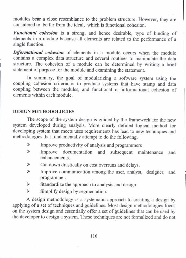
modules bear a close resemblance to the problem structure. However, they are considered to be far from the ideal, which is functional cohesion.
Functional cohesion is a strong, and hence desirable, type of binding of elements in a module because all elements are related to the performance of a single function.
Informational cohesion of elements in a module occurs when the module contains a complex data structure and several routines to manipulate the data structure. The cohesion of a module can be determined by writing a brief statement of purpose for the module and examining the statement.
In summary, the goal of modularizing a software system using the coupling cohesion criteria is to produce systems that have stamp and data coupling between the modules, and functional or informational cohesion of elements within each module.
DESIGN METHODOLOGIES
The scope of the system design is guided by the framework for the new system developed during analysis. More clearly defined logical method for developing system that meets uses requirements has lead to new techniques and methodologies that fundamentally attempt to do the following.
➢ Improve productivity of analysis and programmers
➢ Improve documentation and subsequent maintenance and enhancements.
➢ Cut down drastically on cost overruns and delays. ➢ Improve communication among the user, analyst, designer, and
programmer.
➢ Standardize the approach to analysis and design.
➢ Simplify design by segmentation.
A design methodology is a systematic approach to creating a design by applying of a set of techniques and guidelines. Most design methodologies focus on the system design and essentially offer a set of guidelines that can be used by the developer to design a system. These techniques are not formalized and do not
116

reduce the design activity to a sequence of steps that ca be followed by the designer.
Input to the design phase is the specifications for the system to be designed. Hence, a reasonable entry criteria can be that the specifications are stable and have been approved, hoping that the approval mechanism will ensure that the specifications are complete, consistent, unambiguous, etc. The output of the top- level design phase is the architectural design or the stem design for the software system to be built. This can be produced with or without using a design methodology. A reasonable exist criteria for the phase could be that the design has been verified against the input specifications and has been evaluated and approached for quality.
ARCHITECTURAL DESIGN
Design in an activity concerned with making major decisions. It Shares with programming a concern for abstracting information representation and processing sequences, but the level of detail is quite different at the extremes. Design builds coherent, well planned representations of programs that concentrate on the interrelationships of parts at the higher level and the logical operations involved in the lower levels.
Architectural design represents the structure of data and program components that are required to build a computer based system. It considers the architectural style that the system will take, the structure and properties of the components that constitute the system, and the interrelationships that occur among all architectural components of a system.
Architectural design begins by defining the external entities that the software interacts with and the nature of the interaction. This information can be acquired from the analysis phase. Once context is modeled, and all external software interfaces are described, the designer specifies the structure of the system by defining and refining software components that implement the architecture. This process continues iteratively until a complete architectural structure has been described.
117

Target System 4--. Uses
Peers
Used by •
ses Actors
Depends on
Representing the System in Context
At the architectural design level, a software architect uses an architectural context diagram to model the manner in which software interacts with entities external to its boundaries. The structure of the architectural context diagram is given in fig.5.1.
Superordinate systems
Subordinate Systems
Fig. 5.1 Architectural Context diagram
Referring to the Fig.5.1, systems that interoperate with the target system are represented as:
Superordinate systems — those systems that use the target system as part of some higher level processing scheme
Subordinate systems — those systems that are used by the target system and provide data or processing that are necessary to complete target system functionality
I
118

Peer-level systems — those systems that interact on a peer-to-peer basis.
Actors — those entities that interact with the target system by producing or consuming information that is necessary for requisite processing.
Each of these external entities communicates with the target system through an interface. (the small rectangles).
Defining Archetypes
An archetype is a class or pattern that represents a core abstraction that is critical to the design of an architecture for the target system. In general, a relatively small set of archetypes is required to design even relatively complex systems. The target system architecture is composed of these archetypes, which represent stable elements of the architecture but may be instantiated in many different ways based on the behaviour of the system.
Refining the Architecture into Components
As the software architecture is refined into components, the structure of the system begins to emerge. The components of the software architecture are derived from three sources — the application domain, the infrastructure domain, and the interface domain. Hence, the application domain that must be addressed within the software architecture. The architecture must accommodate many infrastructure components that enable application components, but have no business connection to the application domain. Hence, the application domain and infrastructure domain are the sources for the derivation and refinement of components. The interfaces depicted in the architecture context diagram imply one or more specialized components that process the data that flow across the interface.
Describing Instantiations of the System
The architectural design that has been modeled to this point is still relatively high level. The context of the system has been represented; archetypes that indicate the important abstractions within the problem domain have been defined; the overall structure of the system is apparent; and the major software components have been identified. However, further refinement is still necessary. To accomplish this, an actual instantiation of the architecture is developed. That
119

is, the architecture is applied to a specific problem with the intent of demonstrating that the structure and components are appropriate.
TRANSFORM MAPPING DESIGN
Transform mapping is a set of design steps that allows a Data Flow Diagram (DFD) with transform flow characteristics to be mapped into a specific architectural style.
Step 1: Review the fundamental system model.
The fundamental system model or context diagram depicts the security function as a single transformation, representing the external producers and consumers of data that flow into and out of the function.
Step 2: Review and refine data flow diagrams for the software.
Information obtained from the analysis models is refined to produce greater detail.
Step 3: Determine whether the DFD has transform or transaction flow characteristics.
In general, information flow within a system can always be represented as transform. However, when an obvious transaction characteristic is encountered, a different design mapping is recommended. In this step, the designer selects global (software-wide) flow characteristics based on the prevailing nature of the DFD. In addition, local regions of transform or transaction flow are isolated. These sub flows can be used to refine program architecture.
Step 4: Isolate the transform center by specifying incoming and outgoing flow boundaries.
The incoming flows described as a path that converts information from external to internal form; outgoing flow converts from internal to external form. Incoming and outgoing flow boundaries are open to interpretation.
Step 5: Perform "first-level factoring".
The program architecture derived using this mapping results in a top-down distribution of control. Factoring results in a program structure in which top-level components perform decision-making and low- level components
120
perform most input, computation, and output work. Middle-level components perform some control and do moderate amounts of work. When transform flow is encountered, a DFD is mapped to a specific structure that provides control fork incoming, transform, and outgoing information processing.
Step 6: Perform "second-level factoring".
Second-level factoring is accomplished by mapping individual transforms of a DFD into appropriate modules within the architecture. Beginning at the transform center boundary and moving outward along incoming and then outgoing paths, transforms are mapped into subordinate levels of the software structure.
Step 7: Refine the first-iteration architecture using design heuristics for improved software quality.
A first-iteration architecture can always be refined by applying concepts of functional independence. Components are exploded or imploded to produce sensible factoring, good cohesion, minimal coupling, and most importantly, a structure that can be implemented without difficulty, tested without confusion, and maintained without grief.
The objective of the preceding seven steps is to develop an architectural representation of software. That is, once structure is defined, we can evaluate and refine software architecture by viewing it as a whole. Modifications made at this time require little additional work, yet can have a profound impact on software quality.
INTERFACE DESIGN
The Interface design is yet another activity in the system design phase. The Interface design focuses on three areas of concern: 1) the design of interfaces between software components 2) the design of interfaces between the software and external entities and 3) the design of the interface between a human and the computer.
There are three important elements of interface design:
• The user interface
121

• External interfaces to other systems, devices, networks and consumers of information and
• Internal interfaces between various design components.
The interface design tells how the information flows into and out of the system and how it is communicated among the components defined as a part of the architecture.
The design of internal interfaces is closely aligned with component level design. The design of external interfaces requires definitive information about the entity to which information is sent or received. In every case, the information should be collected during requirement phase and verified once the interface design commences.
User interface design creates an effective communication medium between a human and a computer. Following a set of interface design principles, design identifies interface objects and actions and then creates a screen layout that forms the basis for a user interface prototype.
User interface design begins with the identification of user, task, and environmental requirements. Once user tasks have been identified, user scenarios are created and analysed to define a set of interface objects and actions. These form the basis for the creation of screen layouts that depict graphical design and placement of icons, definition of descriptive screen text, specification and titling for windows, and specification of major and minor menu items. Tools are used to prototype and ultimately implement the design model, and the result is evaluated for quality. The following list provides the suggested user interface design steps.
Using information developed during interface analysis, define interface objects and actions. (functions)
Define events (user actions) that will cause the state of the user interface to change.
Depict each interface state as it will actually look to the end-user.
Indicate how the user interprets the state of the system from information provided through the interface.
122

In some cases, the interface designer may begin with sketches of each interface state and then work backward to define objects, actions, and other important design information. Regardless of the sequence of design task, the designer must
• always follow the guidelines for Interface design given below;
• model how the interface will be implemented, and
• consider the environment (display technology, operating system, development tools) that will be used.
INTERFACE DESIGN GUIDELINES
User interface design has as much to do with the study of people as it does with technology issues. Some of the questions like given below must be asked and answered during the user interface design phase.
• Who is the user?
• How does the user learn to interact with a new computer based system?
• How does the user interpret information produced by the system?
• What will the user expect of the system?
To perform the user interface design effectively, Theo)Mandel [MAN 97] provides three "golden rules" that form the basis for a set of user interface design principles that guide the designer.
> Place the user in Control > Reduce the user's memory load > Make the interface consistent
The guidelines or design principles that allow the user to maintain control
• Define interaction modes in a way that does not force a user into unnecessary or undesired actions.
• Provide for flexible interaction
• Allow user interaction to be interruptible and undoable
123

• Streamline interaction as skill levels advance and allow the interaction be customized
• Hide technical internals from the casual user
• Design for direct interaction with objects that appear on the screen.
The design principles or guidelines that enable an interface to reduce the user's memory load:
1 • Reduce demand on short-term memory • Establish meaningful defaults • Define shortcuts that are intuitive • The visual layout of the interface should be based on a real world
metaphor.
• Disclose information in a progressive fashion
The interface should present and acquire information in a consistent fashion. This implies that 1) all visual information is organized according to a design standard that is maintained throughout all screen displays, (2) input mechanisms are constrained to a limited set that is used consistently throughout the application, and (3) mechanisms for navigating from task to task are consistently defined and implemented.
The user interface design guidelines that help make the interface consistent.
• Allow the user to put the current task into a meaningful context
• Maintain consistency across a family of applications
• If past interactive models have created use expectations, do not make changes unless there is compelling reason to do so.
SYSTEM TESTING
Once source code has been generated, software must be tested to uncover as many errors as possible before delivery to the customer. The main objective of the testing phase is to design a series of test cases that have a high likelihood of finding errors. As a developer's point of view, the objective is to design tests that systematically uncover different classes of errors and to do so with a minimum amount of time and effort.
124

Testing Principles
Principles play an important role in all engineering disciplines. Testing principles are important to test specialists because they provide the foundation for developing testing knowledge and acquiring testing skills. They also provide guidance for defining testing activities as performed in the practice of a test specialist.
According to Davis [DAV95] a set of testing principles is given below:
> All tests should be traceable to customer requirements
> Tests should be planned long before testing begins
> The pareto principle applies to software testing
> Testing should begin "in the small" and progress toward testing "in the large".
> Exhaustive testing is not possible
> Testing should be conducted by third party
Glen ford Myers has outlined a set of testing principles and some of the principles are listed below:
> Testing is the process of executing a program using a set of test cases, with the intent of finding errors.
> A good test case is one that has a high probability of finding an as-yet undiscovered error.
> Test results should be inspected meticulously
> A test case must contain the expected output or result
> Test cases should be developed for both valid and invalid input conditions.
> The probability of the existence of undiscovered error in a program is proportional to the number of errors already detected in that program.
> Testing should be carried out by a group that is independent of the development group.
> Tests must be repeatable and reusable
125

➢ Testing should be planned
➢ Testing activities should be integrated into the software life cycle.
➢ Testing is a creative and challenging task.
Test Case
A test case is a test related item which contains the following items.
i) A set of test inputs (ii) Execution conditions iii) Expected outputs
TEST CASE DESIGN STRATEGIES
As per the principles, the test specialist wants to maximize use of time and resources knows that he/she needs to develop effective test cases have high probability of finding an as yet-undiscovered error. There are two approaches that can be used to design test cases namely white box and black box strategies.
WHILE BOX TESTING
This approach focuses on the inner structure of the software to be tested. To design test cases using this strategy the tester must have a knowledge of that structure. The code, or a suitable pseudo code lists representation must be available. The tester selects test cases to exercise specific internal structural elements to determine if they are working properly. White box testing sometimes called glass box testing, uses the control structures described as part of component level design to derive test cases. Using white box testing k., methods, the software engineer can derive test cases that
1) Guarantee that all independent paths within a module have been exercised atleast once
2) Exercise all logical decisions on their true and false sides.
3) Execute all loops at their boundaries and within their operational . bounds, and
4) Exercise internal data structure to ensure their validity
BASIS PATH TESTING
Basis path testing is a white box testing technique first proposed by Tome McCabe. The basis path method enables the test case designer to derive a logical complexity measure of a procedural design and use this measure as a guide for defining a basis set of execution paths. Test cases derived to exercise
126

the basis set are guaranteed to execute every statement in the program atleast one time during testing.
Flow Graph Notation
The flow graph depicts logical control flow using the notation given in the fig. 5.2. Each structured construct has a corresponding flow graph symbol. To illustrate the use of a flow graph, consider the procedural design representation in Fig. 5.3. Here, a flow chart is used to shows the program control structure. Fig. 5.4 maps the flowchart into a corresponding flow graph. In fig. 5.4, each circle, called a flow graph node, represents one or more procedural statements. A sequence of process boxes and a decision symbol can map into a single node. The arrows on the flow graph, called edges or links, represent flow of control and are analogous to flow chart arrows. An edge must terminate at a nod, even if the node does not represent any procedural statements. Anas bounded by edges and nodes are called regions. When counting regions, include the area outside the graph and count it as a region.
0
0 Sequence \
Until
While
•
Case
Until
Fig. 5.2 Flow graph notation
127

4
R
9 aL t 0..1 0
7
11
Fig. 5.3 Flow Chart
Any procedural design representation can be translated into flow graph. In fig. 5.5, a program design language (PDL) segment and its corresponding flow graph are shown. Note that the PDL statements have been numbered and corresponding number is used for the flow graph.
When compound conditions are encountered in a procedural design, the generation of a flow graph becomes slightly more complicated. A compound condition occurs when one or more Boolean operators (Logical OR, AND, NAND, NOR) are present in a conditional statement. Referring to Fig. 5.6 the PDL segment translates into the flow graph shown.
128

Edges
Fig. 5.4 Flow Graph
PDL
Procedure : Sort 1 : do while records remain read record: 2 : is record field 1 = 0 3 : Then process record; store in buffer;
increment counter; 4 : else if record field2 =0 5 : then reset counter; 6 : else process record; store in file; 7a: end if 7b: endif 8 : end
Fig. 5.5 Translating PDL to a flow graph:
129
Node

Predicate node
IF a or b Then procedure X Else procedure Y END IF
Fig. 5.6 Compound Logic
Cyclomatic Complexity
Cyclomatic complexity is a software metric that provides a quantitative measure of the logical complexity of a program. When this metric is used in the context of the basis path testing method, the value computed for cyclomatic complexity is determined. This defines the number of independent paths in the basis set of a program and provides an upper bound for the number of tests that must be conducted to ensure that all statements have been executed at least once.
An independent path is any path through the program that introduces atleast one new set of processing statements or a new condition. When stated in terms of flow graph, an independent path must move along atleast one edge that has not been traversed before the path is defined. For example, a set of independent paths for the flow graph illustrated in fig. 5.4
Path 1 : 1-11 Path 2 : 1-2-3-4-5-10-1-11 Path 3 : 1-2-3-6-8-9-10-1-11 Path 4 : 1-2-3-6-7-9-10-1-11
Note that each new path introduces a new edge. The path
1-2-3-4-5-10-1-2-3-6-8-9-10-1-1 1
is not considered to be an independent path because it is sifiaply a combination of already specified paths and does not traverse any new edges.
130

Complexity is computed in one of three ways :
1. The number of regions of the flow graph corresponds to the cyclomatic complexity.
2. Cyclomatic complexity, v(G) for a flow graph G is defined as v(G) = E-N+2 where E is the number of flow graph edges and N is the number of flow graph nodes.
3. Cyclomatic complexity, v(G), for a flow graph G is also defined as v(G) = P+1 where P is the predicate nodes contained in the flow graph G.
Referring to the flow graph 5.3, the cyclomatic complexity can be computed using the 3 ways just noted
1. The flow graph has four regions 2. v(G) = 11 edges — 9 edges + 2 = 4 3. v(G) =3 predicate nodes + 1 = 4
Deriving Test Cases
The basis path testing method can be applied to a procedural design or to source code. The following steps can be applied to derive the basis set.
1. Using the design or code as a foundation, draw a corresponding flow graph
2. Determine the cyclomatic complexity of the resultant flow graph.
3. Determine a basis set of linearly independent paths 4. Prepare test cases that will force execution of each path in the basis
Once all test cases have been completed, the tester can be sure that all statements in the program have been executed at least once.
BLACK BOX TESTING
Black box testing focuses on the functional requirements of the software. It enables the software engineer to derive sets of input conditions that will fully exercise all functional requirements for a program. This approach only considers software behaviour and functionality and especially useful for revealing requirements and specification defects. It is not an alternative to white
131
.10

box approach. Rather, black box testing is a complementary approach that is likely to uncover a different class of errors than white box methods.
Block box testing attempts to find errors in the following categories :
➢ Incorrect or missing functions ➢ Interface errors ➢ Errors in data structures or external database access ➢ Behaviour or performance errors and ➢ Initialization and termination errors
By applying block box techniques, a set of test cases that satisfy the following criteria can be derived.
1) Test cases that reduce, by a count that is greater than one the number of additional test cases that must be designed to achieve reasonable testing and
2) Test cases that tell something abut the presence or absence of classes of errors, rather than an error associated with the specific test at hand.
There are various methods and combinations of the methods are used to detect different types of defects. Some of the block box techniques, which have greater practicality namely i) Equivalence partitioning and ii) Boundary value analysis are discussed below:
Equivalence Partitioning Method
If a tester is viewing the software under test as a black box with well-defined inputs and outputs, a good approach to selecting test inputs is to use a method called Equivalence Partitioning. Equivalence portioning is a block box testing method that divides the input domain of a program into classes of data from which test cases can be derived. It strives to define a test case that uncovers classes of errors, thereby reducing the total number of test cases that must be developed. It has the following advantages:
1. It eliminates the need for exhaustive testing, which is not feasible
2. It guides a tester in selecting a subset of test inputs with a high probability of detecting a defect
3. It allows a tester to cover a larger domain of inputs/outputs with a smaller subset selected from an equivalence class.
132

Test case design for equivalence partitioning is based on an evaluation of equivalence classes for an input domain. If a set of objects can be linked by relationships that are symmetric, transitive, and reflexive, an equivalence class is present. An equivalence class represents a set of valid or invalid states for input conditions. An input condition is either a specific numeric value, a range of values, a set of related values, or a Boolean condition. Equivalence classes may be defined according to the following guidelines.
1. If an input condition specifies a range, one valid and two invalid equivalence classes are defined
2. If an input condition requires a specific value, one valid and two invalid equivalence classes are defined
3. If an input condition specifies a member of a set, one valid and one invalid equivalence class are defined
4. If an input condition is Boolean, one valid and one invalid class are defined.
By applying these guidelines for the derivation of equivalence classes, test cases for each input domain data object can be developed and executed. Test cases are selected so that the largest number of attributes of an equivalence class is exercised at once.
Boundary Value Analysis
Equivalence partitioning gives the tester a useful tool with which to develop black box based test cases for the software under test. The method requires that a tester has access to a specification of input/output behaviour for the target software. The test cases developed based on equivalence class partitioning can be strengthened by use of another technique called boundary value analysis.
Boundary Value Analysis is a test case design technique that complements equivalence partitioning. Rather than selecting any element of an equivalence class, Boundary Value Analysis requires that the tester select elements close to the edges, so that both the upper and lower edges of an equivalence class are covered by test cases. As in the case of equivalence class partitioning, the ability to develop high quality test cases with the use of boundary values requires experience. Some guidelines given below are useful for getting started with boundary value analysis.
133

1. If an input condition for the software under test is specified as a range of values, develop valid test cases for the ends of the range, and invalid test cases for possibilities just above and below the ends of the range.
2. If an input condition for the software under test is specified as a number of values, develop valid test cases for the minimum and maximum numbers as well as invalid test cases that include one less and one greater than the maximum and minimum.
3. If the input or output of the software under test is an ordered set, such as a table or a linear list, develop tests that focus on the first and last elements of the set.
It is important for the tester to keep in mind that equivalence partitioning and boundary value analysis methods apply to testing both inputs and outputs of the software under test. In both the methods, conditions are not combined. Each condition is considered separately, and test cases are developed to insure coverage of all the individual conditions.
CONTROL STRUCTURE TESTING Condition Testing
Condition testing is a test case design method that exercises the logical conditions contained in a program module. A simple condition is Boolean variable or a relational expression. A compound condition is composed of two or more simple conditions, Boolean operators, and parenthesis. A condition without relational expression is referred to as a Boolean expression. Hence, the possible types of elements in a condition include a Boolean operator, a Boolean variable, a pair of parentheses, a relational operator, or an arithmetic expression. If a condition is incorrect, then atleast one component of the condition is incorrect. The condition testing method focuses on testing each condition in the program to ensure that it does not contain errors.
Data Flow Testing
The data flow testing method selects test paths of a program according to the locations of definitions and uses of variables in the program. To illustrate, consider each statement in a program is assigned a unique statement number and that each function does not modify its parameters or global variables. For a statement S as its statement number,
134

DEF(S) = { X I statement S contains a definition of X} USE(S) = { X I statement S contains a use of X }
If statement S is an if or loop statement, its DEF set is empty and its USE set is based on the condition of statement S. The definition of variable X at statement S is said to be live at statement S' if there exists a path from statement S to statement S' that contains no other definition of X.
Loop Testing
Repetition structures or loop structures are used mostly in all algorithms implemented in a software. So, it is necessary to test the correctness of the structures. Loop testing is a white box testing technique that focuses exclusive on the validity of loop structures. Four different classes of loops can be defined. Simple loops, concatenated loops, nested loops, and unstructured loops.
Nested Loops Simple Loops
Concatenated Loops
Unstructured Loops Fig. 5.7 Classes of loops
135

Simple loops :The following set of tests can be applied to simple loops.
1) Skip the loop entirely 2) Only one pass through the loop 3) Two passes through the loop 4) m passes through the loop where m < n 5) n-1, n, n+1 passes through the loop
Nested Loops : In the case of nested loops, the number of possible tests would increases as the level of nesting increased. Beizer suggested an approach that will help to reduce the number tests.
• Start at the innermost loop. Set all other loops to minimum values.
• Conduct simple loop tests for the innermost loop while holding the outer loops at their minimum iteration parameter value. Add other tests for out-of-range or excluded values.
• Work outward, conducting tests for the next loop, but keeping all other outer loops at minimum values and other nested loops to "typical" values.
• Continue until all loops have been tested.
Concatenated Loops : Concatenated loops can be tested using the approach defined for simple loops if each of the loops is independent of the other. However, if two loops are concatenated and the loop counter for loop 1 is used as the initial value for loop2, then keep the loops are not independent. When the loops are independent, the approach applied to nested loops is recommended.
Unstructured loops : Whenever possible, this class of loops should be redesigned to reflect the use of the structural programming constructs.
TESTING STRATEGIES
Testing is a set of activities that can be planned in advance and conducted systematically. A strategy for software testing integrates software test case design methods into a well planned series of steps that result in the successful construction of software. A strategy provides a road map that describes the steps to be conducted as part of testing, when these steps are planned and then
136

Module
undertaken. A software testing strategy should be flexible enough to promote a customized testing approach. It must accommodate low level tests that are necessary to verify that a small source code segment has been correctly implemented as well as high level tests that validate major system functions against customer requirements. A strategy must provide guidance for the practitioner and a set of milestones for the manager. A number of software testing strategies have been proposed and implemented. In this section some the strategies are discussed.
UNIT TEST
A unit is the smallest possible testable software component. It is viewed as a function or procedure implemented in a procedural language. The principal goal for unit testing is insure that each individual software unit is functioning according to its specification. The unit should be tested by an independent tester. Using the component level design description as a guide, important control paths are tested to uncover errors within the boundary of the module.
The relative complexity of tests and the errors those tests uncover is limited by the constrained scope established for unit testing. The unit test focuses on the internal processing logic and data structures within the boundaries of a component. This type of testing can be conducted in parallel for multiple components.
Int- ace Local data structures Boundary conditions Independent paths Error handling paths
Fig. 5. 8 Unit Test
Test Cases
137

In the unit testing process, the module interface is tested to ensure that information properly flows into and out of the program unit under test. Local data structures are examined to ensure that data stored temporarily maintains its integrity during all steps in al algorithm's execution. All independent paths through the control structure are exercised to ensure that all statements in a module have been executed at least once. Boundary conditions are tested to ensure that the module operates properly at boundaries established to limit or restrict processing.
Tests of data flow across a module interface are required before any other test is initiated. Local data structures should be exercised and the local impact on global data should be ascertained during unit testing.
The unit test cases should uncover errors such as
• Comparison of different data types
• Incorrect logical operators or precedence
• Expectation of equality when precision error making equality likely;
• Incorrect comparison of variables
• Improper or nonexistent loop termination
• Failure to exit when divergent iteration is encountered, and
• Improperly modified loop variables.
Unit testing is simplified when a component with high cohesion is designed. When only one function is addressed y a component, the number of test cases is reduced and errors can be more easily predicted and uncovered.
INTEGRATION TEST
Once the unit test is completed, a test summary report should be prepared. This is a valuable document for the groups responsible for integration and system tests. Integration test for procedural code has to major goals:
➢ To detect defects that occur on the interfaces of units
> To assemble the individual units into working subsystems and finally a complete system that is ready for system test.
138

In unit test, the defects that are related to the functionality and structure of the unit are detected. There is some simple testing of unit interfaces when the units interact with drivers and stubs.
However, the unit interfaces are more adequately tested during integration test when each unit is finally connected to a full and working implementation of those units calls it, and those that call it.
> Integration testing works best as an interactive process in procedural oriented system.
➢ One unit at a time is integrated into a set of previously integrated modules, which have passed a set of integration tests.
> The interfaces and functionality of the new unit in combination with the previously integrated units is tested.
➢ When a subsystem is built from units integrated in this stepwise manner, then performance, security, and stress tests can be performed on this subsystem.
Integrating one unit at a time helps the testers in several ways.
➢ It keeps the number of new interfaces to be examined small, so tests can focus on these interfaces only.
> Massive failures that often occur when multiple units are integrated at once is avoided.
> It allows defect search and repair to be confined to a small known number of components and interfaces.
➢ Independent subsystems can be integrated in parallel as long as the required units are available.
There are two major integration strategies
• Bottom-up integration
• Top-down integration
In both of these strategies, only one module at a time is added to the growing subsystem. To plan the order of integration of the modules in such system a structure chart is used.
139

Bottom Up Integration
Bottom up integration of the modules begins with testing the lowest level modules, those at the bottom of the structure chart. These modules do not call other modules. Drivers are needed to test these modules. The next step is to integrate modules on the next upper level of the structure chart whose subordinate modules have already been tested. In this process, after a module has been tested, its driver can be replaced by an actual module. This next module be integrated may also need a driver, and this will be the case until we reach the highest level of the structure chart. This type of testing has the advantage that the lower level modules are usually well tested early in the integration process.
A bottom up integration strategy may be implemented with the following steps :
1) Low-level components are combined into clusters that perform a specific software sub function.
2) A driver ( a control program for testing) is written to coordinate test case input and output.
3) The cluster is tested
4) Drivers are removed and clusters are combined moving upward in the program structure.
In the fig 5.9, bottom up integration process is illustrated. Components are combined to form clusters 1, 2, and 3. Each of the clusters is tested using a driver shown as a dashed line. Components in clusters 1 and 2 are subordinate to Ma. Drivers Di and D2 are removed and the clusters are interfaced directly to Ma. Similarly, driver D3 for cluster 3 is removed prior to integration with module Ma and Mb will ultimately be integrated with component Me, and so forth.
140

D3
Cluster
Mc
___--------
Ma Mb ...._„—„,....
D 1 D2
3
Cluster 2 Cluster 1
Fig. 5. 9 Bottom up Integration
Top Down Integration Test
Top down integration testing is an incremental approach to construction of the software architecture. Top down integration starts at the top of the module hierarchy. The rule of thumb for selecting candidates for the integration sequence says that when choosing a candidate module to be integrated next, at least one of the module's subordinate (calling) modules must have been previously tested. Top down integration ensures that the upper level modules are tested early in integration. Top down integration requires the development of complex stubs to drive significant data upward, but bottom up integration requires drivers so there is not a clear cut advantage with respect to developing test harnesses.
141

M4
Fig. 5.10 Top down integration
Referring to fig.5.10 Depth first integration integrates all components on a major control path of the program structure. Selection of a major path is an arbitrary. For example, selecting the left hand path, components MI, M2, M5 would be integrated first. Next M8 or M6 would be integrated. Then, the central and right hand control paths are built.
Breadth first integration incorporates all components directly subordinate at each level, moving across the structure horizontally. Form the fig. Components M2, M3 and M4 would be integrated first. The next control level, M5, M6, and so on, follows. The integration process is performed in a series of
five steps.
1) The main control module is used as a test driver, and stubs are substituted for all components directly subordinate to the main control module.
2) Depending on the integration approach selected (ie. depth first or breadth first), subordinate stubs are replaced one at a time with actual components
3) Test are conducted as each component is integrated
4) On completion of each set of tests, another stub is replaced with the real component
142

5) Regression testing may be conducted to ensure that new errors have not been introduced.
Validation Testing
Validation testing begins at the culmination of integration testing, when individual components have been tested, the software is completely assembled as a package, and interfacing errors have been uncovered and corrected. This test focuses on user visible actions and user-recognizable output from the system. Validation can be defined in many ways, but a simple definition is that validation succeeds when software functions in a manner that can be reasonably expected by the customer.
Validation Test Criteria
Software validation is achieved through a series of tests that demonstrate conformity with requirements. A test plan outlines the classes of tests to be conducted, and a test procedure defines specific test cases. Both the plan and procedure ensure that all functional requirements are satisfied, all behavioural characteristics are achieved, all performance requirements are attained, documentation is correct, and usability and other requirements are met.
After each validation test case has been conducted, one of two possible conditions exist.:
1) The function or performance characteristic conforms to specification and is accepted, or
2) A deviation from specification is uncovered and a deficiency list is created.
The deviation or error discovered at this stage in a project can be corrected prior to scheduled delivery.
Configuration Review
The second element of the validation process is a configuration review. The intend of the review is to ensure that all elements of the software configuration have been properly developed, are cataloged.
143

Alpha and Beta Testing
If software is developed as a product to be used by many customers, it is impractical to perform formal acceptance tests with each one. A test process called alpha and beta testing to uncover errors that only the end-user seems able to find.
The alpha test is conducted at the developer's site by end-users. The software is used in a natural setting with the developer "looking over the shoulder" of typical users and recording errors and usage problems. Alpha tests are conducted in a controlled environment.
The beta test is conducted at en-user sites. The beta test is a "live" application of the software in an environment that cannot be controlled by the developer. The end-user records all problems that are encountered during the beta testing and reports these to the developer at regular intervals.
SYSTEM TEST
When integration tests are completed, a software system has been assembled and its major subsystems have been tested. System test planning should begin at the requirements phase with the development of a master test plan and requirements based tests. System testing itself requires a large amount of resources. The goal is to ensure that the system performs according to its requirements.
System test evaluates both functional behaviour and quality requirements such as reliability, usability, performance and security. This phase of testing is especially useful for detecting external hardware and software interface defects (causing race conditions, deadlocks, problems with interrupts and exception handling, ineffective memory usage). In fact system test serves as a good rehearsal scenario for acceptance test. There are several types of system tests as follows:
> Functional testing > Performance testing ➢ Stress testing > Configuration testing ➢ Security testing > Recovery testing
144

An-important tool for implementing system tests is a load generator
A load generator is essential for testing quality requirements such as performance and stress. A load is a series of inputs that simulate a group of transactions
A transaction is a unit of work seen from the system user's view. A transaction consists of a set of operations that may be performed by a person, software system, or a device that is outside the system. A use case can be used to describe a transaction.
Fully integrated software system
System Tests
User Manuals Requirements
documents
. Functional Stress and Security Configuration Performance Tests load tests tests tests tests
I V V V V I
Recovery tests
Tests completed and passed
System ready for acceptance test
Fig. 5. 10 Types of System Tests
Functional Testing
Functional tests at the system level are used to ensure that the behaviour of the system adheres to the requirements specification. All functional requirements for the system must be achievable by the system. Functional tests are block box in nature. The focus is on the inputs and proper outputs for each function. Functional tests are black box in nature, equivalence class partitioning
145

and boundary value analysis are useful methods that can be used to generate test cases. State based tests are also valuable.
The functional tests should focus on the following goals: > All types or classes of legal inputs must be accepted by the software > All classes of illegal inputs must be rejected > All possible classes of system output must exercised and examined ➢ All effective system states and state transitions must be exercised
and examined > All functions must be exercised.
Performance Testing
An examination of a requirements document shows that there are two major types of requirements.
➢ Functional requirements: Users describe what functions the software should perform.
➢ Quality requirements : Users describe quality levels expected for the software.
The goal of system performance tests is to see if the software meets the performance requirements. The tests learn from it whether there are any hardware or software factors that impact on the system's performance. It is used to tune the system, that is, to optimize the allocation of system resources. Resources for performance testing must be allocated in the system test plan. Among the resources are :
> A source of transactions to drive the experiments
➢ An experimental testbed that includes hardware and software the system under test interacts with.
➢ Instrumentation or probes that help to collect the performance data. Probes may be hardware or software in nature. Some probe tasks are event counting and event "duration measurement.
> A set of tools to collect, store, process and interpret the data.
146

Stress Testing
When a system is tested with a load that causes it to allocate its resources in maximum amounts, this is called stress testing.
The goal of stress test is to try to break the system; find the circumstances under which it will crash. The stress test can reveal defects in real time and other types of systems, as well as weak areas where poor design could cause unavailability of service. Stress testing often uncovers race conditions, deadlocks, depletion of resources in unusual or unplanned pattern, and upsets in normal operation of the software system.
Stress testing is supported by many of the resources used for performance test as given in the figure above. This includes the load generator. The testers set the load generator parameters so that load levels cause stress to the system. As in the case of performance test, special equipment and laboratory space may be needed for the stress tests.
Configuration Testing
Configuration testing allows testers to evaluate system performance and availability when hardware exchanges and reconfigurations occur. Configuration testing requires many resources including the multiple hardware devices used for this test. According to Beizer configuration testing has the following objectives:
• Show that all the configuration changing commands and menus work properly
• Show that all interchangeable devices are really interchangeable, and that they each enter the proper states for the specified conditions.
• Show that the systems' performance level is maintained when devices are interchanged, or when they fail.
Security Testing
Designing and testing software systems to insure that they are safe and secure is a big issue facing software developers and testers. Security testing evaluates system characteristics that relate to the availability, integrity, and confidentiality of system data and services. Users/clients should be encouraged
147

to make sure their security needs are clearly known at requirements time, so that security issues can be addressed by designers and testers.
Recovery Testing
Recovery testing subjects a system to losses of resources in order to determine if it can recover properly from these losses. This type of testing especially important for transaction system, for example, online banking software. A Test scenario might be to emulate loss of a device during a transaction. Tests would determine if the system could return to a well known state, and that no transactions have been compromised.
Beizer advises that testers focus on the following areas during recovery testing:
Restart — The current system state and transaction states are discarded. Tester must insure that all transactions have been reconstructed correctly and that all devices are in the proper state. The system should then be able to begin to process new transactions.
Switchover — The ability of the system to switch to a new processor must be tested. Switchover is the result of a command or a detection of a faulty processor by a monitor.
Review Questions :
1. What is system design? Explain fundamental design principles. 2. Explain the system design concepts. 3. What is coupling and cohesion? Explain. 4. Discuss the architectural design methodology. 5. Describe various steps in transform mapping design. 6. List the guidelines for Interface design 7. What is testing? Explain the testing principles. 8. How does white box testing differ from black box testing. 9. Write short notes on Unit Testing 10. Explain various types of system tests.
148

MODEL QUESTION PAPER PAPER • 22 SOFTWARE ENGINEERING
Time : 3 Hrs Marks :
100 Answer any FIVE questions
All questions carry equal marks
1.a) How are the software projects categorized based on the size? Explain. b) What is software quality? Explain the factors affecting quality and
productivity of a software.
2. a) What is a process model? Explain any one process models and its advantages.
b) Explain the role of management in software development.
3.a) Explain various activities Involved in project planning. b)' Describe the COCOMO cost estimation model.
4. a) What are the team structures? Explain. b) What is project scheduling? Write the guidelines for project scheduling
5. a) Explain various risk management activities b) What are the elements of ISO 9001 quality standard.
6. a) Explain the components and characteristics of Software Requirement Specification.
b) What is Data Flow Diagram? Explain with example.
7.a) Explain the fundamental concept and principles of software design. b) What is software testing? Explain various testing strategies.
8. Write short notes on a) Software Review b) Software Configuration Management c) White box testing
149


1
Elevate Educate Empower
Alagappa University formed in 1985 has emerged from the galaxy of institutions initially founded by the munificent and multifaceted personality, Dr. RM Alagappa Chettiar in his home town at Karaikudi. Groomed to prominence as yet another academic constellation in Tamil Nadu, it is located in a sprawling and ideally suited expanse of about 420 acres in Karaikudi.
Alagappa University was established in 1985 under an Act of the State Legislature. The University is recognised under Sec. 2(f) and Sec.12(B) of the University Grants Commission. It is a member of the Association of Commonwealth Universities and the Association of Indian Universities. The University is accredited with 'A' Grade by NAAC.
The Directorate of Distance Education offers various innovative, job-oriented and socially relevant academic programmes in the field of Arts, Science, IT, Education and Management at the graduate and post- graduate levels. It has an excellent network of Study Centres throughout the country for providing effective service to the student community.
The distance education programmes are also offered in South-East Asian countries such as Singapore and Malaysia; in Middle-East countries, viz., Bahrain, Qatar, Dubai; and also at Nepal and Sri Lanka. The programmes are well received in India and abroad.
ALAGAPPA UNIVERSITY (Reaccredited with 'A' Grade by NAAC)
Karaikudi 630 003
DIRECTORATE OF DISTANCE EDUCATION (Recognized by Distance Pucaticn Council, (DEC) New Deihl)