SL1000 - Hach
38
DOC022.53.80457 SL1000 08/2017, Edition 5 User Manual
-
Upload
khangminh22 -
Category
Documents
-
view
0 -
download
0
Transcript of SL1000 - Hach

DOC022.53.80457
SL100008/2017, Edition 5
User Manual


Table of ContentsSpecifications .............................................................................................................. 3
General information .................................................................................................. 3Safety information........................................................................................................ 3
Use of hazard information.................................................................................... 4Precautionary labels ............................................................................................. 4Certification...........................................................................................................4
Product overview......................................................................................................... 5Product components .................................................................................................... 5
Installation ..................................................................................................................... 5Lithium battery safety ...................................................................................................6Install the battery ......................................................................................................... 6Charge the battery ....................................................................................................... 7Install the hand strap................................................................................................... 7
User interface and navigation .............................................................................. 8Display description.......................................................................................................8Keypad description...................................................................................................... 9
Startup ...........................................................................................................................10Set the power to on....................................................................................................10Change the language................................................................................................ 10Change the date and time......................................................................................... 10
Standard operation .................................................................................................. 10Use an operator ID.................................................................................................... 10Use a site ID.............................................................................................................. 10Complete Chemkey measurements .......................................................................... 11Connect a probe........................................................................................................ 12Complete probe measurements ................................................................................ 13
Calibration ................................................................................................................... 14Calibrate the probe.................................................................................................... 14Factory calibration..................................................................................................... 14Calibrate the meter for a specific Chemkey parameter ............................................. 15Probe verification....................................................................................................... 15Chemkey verification................................................................................................. 15
Data log ......................................................................................................................... 15Import data to Excel ................................................................................................... 16Look at data in a web browser ................................................................................... 16
Advanced operation ................................................................................................ 16Configure the meter ................................................................................................... 16Select the Chemkey settings..................................................................................... 17Select the probe settings........................................................................................... 18
Select the pH options......................................................................................... 18Select the conductivity options........................................................................... 19Select the LDO options.......................................................................................20
Select the salinity correction factor .............................................................. 20Select the fluoride options.................................................................................. 21
1

Select the nitrate options.................................................................................... 22Select the chloride options................................................................................. 22Select the sodium options.................................................................................. 23Select the ammonium options............................................................................ 24Select the ORP options...................................................................................... 25
Add operators, notes, sites and routes...................................................................... 25Set up routes...................................................................................................... 26
See the system information....................................................................................... 27Upgrade the meter software...................................................................................... 27
Maintenance ............................................................................................................... 27Clean spills ................................................................................................................ 28Clean the instrument ..................................................................................................28Clean or replace parts ............................................................................................... 28Charge or replace the battery .................................................................................... 29Prepare for shipping.................................................................................................. 30
Troubleshooting ....................................................................................................... 30Do a diagnostic check................................................................................................31
Replacement parts and accessories ............................................................... 32
Table of Contents
2
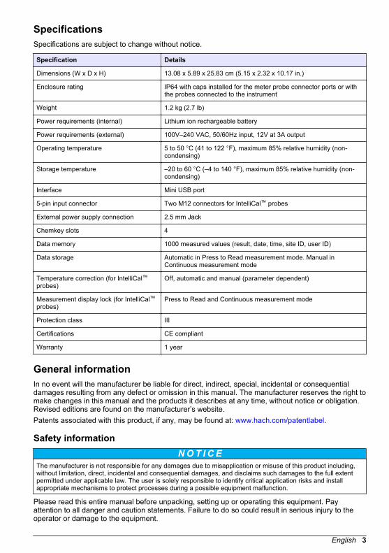
SpecificationsSpecifications are subject to change without notice.
Specification Details
Dimensions (W x D x H) 13.08 x 5.89 x 25.83 cm (5.15 x 2.32 x 10.17 in.)
Enclosure rating IP64 with caps installed for the meter probe connector ports or withthe probes connected to the instrument
Weight 1.2 kg (2.7 lb)
Power requirements (internal) Lithium ion rechargeable battery
Power requirements (external) 100V–240 VAC, 50/60Hz input, 12V at 3A output
Operating temperature 5 to 50 °C (41 to 122 °F), maximum 85% relative humidity (non-condensing)
Storage temperature –20 to 60 °C (–4 to 140 °F), maximum 85% relative humidity (non-condensing)
Interface Mini USB port
5-pin input connector Two M12 connectors for IntelliCal™ probes
External power supply connection 2.5 mm Jack
Chemkey slots 4
Data memory 1000 measured values (result, date, time, site ID, user ID)
Data storage Automatic in Press to Read measurement mode. Manual inContinuous measurement mode
Temperature correction (for IntelliCal™probes)
Off, automatic and manual (parameter dependent)
Measurement display lock (for IntelliCal™probes)
Press to Read and Continuous measurement mode
Protection class III
Certifications CE compliant
Warranty 1 year
General informationIn no event will the manufacturer be liable for direct, indirect, special, incidental or consequentialdamages resulting from any defect or omission in this manual. The manufacturer reserves the right tomake changes in this manual and the products it describes at any time, without notice or obligation.Revised editions are found on the manufacturer’s website.Patents associated with this product, if any, may be found at: www.hach.com/patentlabel.
Safety informationN O T I C E
The manufacturer is not responsible for any damages due to misapplication or misuse of this product including,without limitation, direct, incidental and consequential damages, and disclaims such damages to the full extentpermitted under applicable law. The user is solely responsible to identify critical application risks and installappropriate mechanisms to protect processes during a possible equipment malfunction.
Please read this entire manual before unpacking, setting up or operating this equipment. Payattention to all danger and caution statements. Failure to do so could result in serious injury to theoperator or damage to the equipment.
English 3

Make sure that the protection provided by this equipment is not impaired. Do not use or install thisequipment in any manner other than that specified in this manual.
Use of hazard information
D A N G E R Indicates a potentially or imminently hazardous situation which, if not avoided, will result in death or serious injury.
W A R N I N G Indicates a potentially or imminently hazardous situation which, if not avoided, could result in death or seriousinjury.
C A U T I O N Indicates a potentially hazardous situation that may result in minor or moderate injury.
N O T I C E Indicates a situation which, if not avoided, may cause damage to the instrument. Information that requires specialemphasis.
Precautionary labelsRead all labels and tags attached to the instrument. Personal injury or damage to the instrumentcould occur if not observed. A symbol on the instrument is referenced in the manual with aprecautionary statement.
This symbol, if noted on the instrument, references the instruction manual for operation and/or safetyinformation.
Electrical equipment marked with this symbol may not be disposed of in European domestic or publicdisposal systems. Return old or end-of-life equipment to the manufacturer for disposal at no charge tothe user.
Certification
EN 55011/CISPR 11 Notification WarningThis is a Class A product. In a domestic environment this product may cause radio interference inwhich case the user may be required to take adequate measures.Canadian Radio Interference-Causing Equipment Regulation, IECS-003, Class A:Supporting test records reside with the manufacturer.This Class A digital apparatus meets all requirements of the Canadian Interference-CausingEquipment Regulations.Cet appareil numérique de classe A répond à toutes les exigences de la réglementation canadiennesur les équipements provoquant des interférences.FCC Part 15, Class "A" LimitsSupporting test records reside with the manufacturer. The device complies with Part 15 of the FCCRules. Operation is subject to the following conditions:
1. The equipment may not cause harmful interference.2. The equipment must accept any interference received, including interference that may cause
undesired operation.
Changes or modifications to this equipment not expressly approved by the party responsible forcompliance could void the user's authority to operate the equipment. This equipment has been testedand found to comply with the limits for a Class A digital device, pursuant to Part 15 of the FCC rules.These limits are designed to provide reasonable protection against harmful interference when the
4 English

equipment is operated in a commercial environment. This equipment generates, uses and canradiate radio frequency energy and, if not installed and used in accordance with the instructionmanual, may cause harmful interference to radio communications. Operation of this equipment in aresidential area is likely to cause harmful interference, in which case the user will be required tocorrect the interference at their expense. The following techniques can be used to reduceinterference problems:
1. Disconnect the equipment from its power source to verify that it is or is not the source of theinterference.
2. If the equipment is connected to the same outlet as the device experiencing interference, connectthe equipment to a different outlet.
3. Move the equipment away from the device receiving the interference.4. Reposition the receiving antenna for the device receiving the interference.5. Try combinations of the above.
Product overviewThe SL1000 portable parallel analyzer measures a maximum of six parameters at the same time indrinking water and other clean water applications. The meter uses Chemkeys® and digitalIntelliCAL™ probes to measure different parameters in water. The meter automatically identifies thetype of Chemkey that is installed or the type of probe that is connected to the meter.The meter can use a maximum of four Chemkeys and a maximum of two probes for measurements.Refer to Figure 1.
Figure 1 Product overview
1 Mini USB port 5 Display
2 Probe connector port caps 6 Keypad
3 Probe connection ports 7 Chemkey slots
4 Power access port 8 Sample detector
Product componentsMake sure that all components have been received. Refer to the supplied packaging guide. If anyitems are missing or damaged, contact the manufacturer or a sales representative immediately.
InstallationW A R N I N G
Multiple hazards. Only qualified personnel must conduct the tasks described in this section of thedocument.
English 5

Lithium battery safetyW A R N I N G
Fire and explosion hazard. Lithium batteries may get hot, explode or ignite and cause serious injury ifexposed to abuse conditions.
• Do not use the battery if there is visible damage.• Do not use the battery after strong shock or vibration occurs.• Do not expose the battery to fire.• Keep the battery at temperatures less than 60 ºC (140 ºF).• Keep the battery dry and away from water.• Prevent contact between the positive and negative battery terminals.• Do not let unauthorized persons touch the battery.• Discard the battery in accordance with local, regional and national regulations.
Install the batteryW A R N I N G
Fire and explosion hazard. This equipment contains a high energy lithium battery which can ignite andcause fire or explosion, even without power. To maintain the safety provided by the instrumentenclosure, the instrument enclosure covers must be installed and secured with the supplied hardware.
Only use the supplied lithium battery. Refer to Figure 2 for battery installation or removal.
6 English
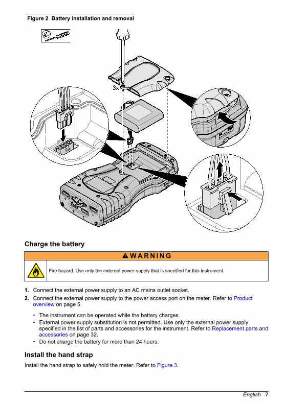
Figure 2 Battery installation and removal
Charge the batteryW A R N I N G
Fire hazard. Use only the external power supply that is specified for this instrument.
1. Connect the external power supply to an AC mains outlet socket.2. Connect the external power supply to the power access port on the meter. Refer to Product
overview on page 5.
• The instrument can be operated while the battery charges.• External power supply substitution is not permitted. Use only the external power supply
specified in the list of parts and accessories for the instrument. Refer to Replacement parts andaccessories on page 32.
• Do not charge the battery for more than 24 hours.
Install the hand strapInstall the hand strap to safely hold the meter. Refer to Figure 3.
English 7

Figure 3 Hand strap installation
User interface and navigation
Display descriptionRefer to Figure 4 and Figure 5 for the measurement screen description.
Figure 4 Measurement screen (top part)
1 Date and time 7 Primary measurement value (user-selectedparameter)
2 Battery status 8 Stability icon with warning icon and warningmessage
3 USB (COM port) active connection icon whencommunication class is selected
9 Probe icon, port number, parameter or probe name
4 Progress bar (not completed measurement) 10 Slot number, parameter name and chemicalsymbol
5 Calibration status icon (calibration not correct) 11 Very important message for devices (followed byerror and then warning message)6 Secondary measurement (user-selected parameter)
8 English

Figure 5 Measurement screen (lower part)
1 Probe icon, port number, parameter or probe name 8 Active arrow keys
2 Calibration status icon (calibration correct) 9 Site ID icon and site name
3 Secondary measurement value (user-selectedparameter)
10 Routes icon (shows when routes is set to on)
4 Tertiary measurement value (user-selectedparameter)
11 Options (contextual: Details, exit, cancel, select,deselect)
5 Right and left arrows to select the applicable site ID 12 Primary measurement value (user selected)
6 Options (contextual: Read, select, OK, delete) 13 Stability icon
7 Checkmark: Completed measurement on site
Keypad descriptionRefer to Figure 6 for the keypad description and navigation information.
Figure 6 Keypad description
1 POWER key 4 RIGHT selection key (contextual): Read samples,delete, select or confirm options, opens sub-menus
2 MAIN MENU key: Select verification, calibration,routes, settings, data log, information, diagnostics,operator ID and site ID
5 Navigation keys UP, DOWN, RIGHT, LEFT1: Scrollthrough menus, enter numbers and letters.
3 LEFT selection key (contextual): Details,select/deselect, cancels or exits the current menuscreen to the previous one
6 HOME: Go to the main measurement screen.
1 UP, DOWN: Scroll through measurements when there are more than four measurements,RIGHT, LEFT: Scroll through operator and sample IDs.
English 9

Startup
Set the power to onPush the POWER key to set the meter to on or off. If the meter does not power on, make sure thatthe battery is correctly installed.
Change the languageSelect the display language when the meter is set to on for the first time. Change the language fromthe Settings menu.
1. Push Settings>Language.2. Select the applicable language.
Change the date and timeThere are two options to set the date and time and format:
• Set the date and time when the meter is set to on for the first time.• Set the date and time from the Date & Time menu.
1. Select Settings>Meter>Date & Time.2. Use the arrow keys to select the format for the date and time and then enter the current time and
date information.The current date and time will be shown on the display and on the logged measurement data.
Standard operation
Use an operator IDThe operator ID tag associates measurements with an individual operator. All stored data will includethe operator ID.To easily manage operator IDs, use the web application "tool.htm". Refer to Add operators, notes,sites and routes on page 25.
1. Push Main Menu>Operator ID.2. Select an option.
Option Description
Mode Set the Operator ID function to on or off (default).
Select Select an ID from a list. The current ID will be associated with sample data until a different ID isselected. Use the UP and DOWN arrows to select an operator ID from the home screen. It ispossible to select the operator ID on the measurement screen before a Chemkey is in the slot or aprobe is attached.
Create Enter a name for a new operator ID.
Delete Erase an existing operator ID.
Use a site IDSelect the site ID tag to associate measurements with a particular sample or with a location. Ifassigned, stored data will include this ID.
10 English

To easily manage site IDs, use the web application "tool.htm". Refer to Add operators, notes, sitesand routes on page 25.
1. Push Main Menu>Site ID.2. Select an option.
Option Description
Mode Set the Site ID function to manual, auto, off or routes. Manual—Select a site ID manually. Auto—The samples are numbered in sequence for each measurement until a different ID is selected. Off—The site ID function is set to off (default). Routes—Supplies an ordered subset of the completesite ID list.
Select Select an ID from a list. The current ID will be associated with the sample data until a different ID isselected. Set Site ID>Show to Yes. Use the RIGHT or LEFT arrow to select the current site ID onthe measurement screen. Make sure that Site ID>Show is set to Yes and at least one Chemkey isin the slot or one probe is attached.
Create Add a new site ID.
Delete Erase existing site ID(s).Note: Make sure to select the Manual mode to delete a site ID.
Show Shows the site ID on the measurement screen. Set to on or off.
Routes Supplies an ordered list of site IDs. If a route is selected, the site IDs automatically show on themeasurement screen and are recorded. Push the RIGHT arrow to select the next location. Use theweb application "tool.htm" to set up the routes. Refer to Add operators, notes, sites and routeson page 25 for more information.
Notes Record special information and add this information to an event log.
Complete Chemkey measurementsN O T I C E
Do not start a new Chemkey measurement when other Chemkey measurements are not yet completed. Only putthe meter in the sample once for a Chemkey measurement.
To complete a measurement with the Chemkey(s), do the procedure that follows. Refer to Figure 7.Multiple probe measurements can be completed at the same time. Refer to Complete probemeasurements on page 13.
1. Set the meter power to on.2. If complete traceability is necessary, enter a site ID and operator ID before measurement. Refer
to Use an operator ID on page 10 and Use a site ID on page 10.3. Push the applicable Chemkey(s) fully, in one movement, into the slot(s) 1 to 4. Make sure to
always use a new Chemkey for each measurement. It is important to push the Chemkey all of theway into the slot.When a Chemkey is in a slot, do not move or touch the Chemkey.2
4. Rinse the sample cup with the sample.5. Fill the meter sample cup to the fill-line with the sample.6. Put the meter into the meter sample cup.7. Wait for the sound alert and/or the meter removal animation (within 1 to 2 seconds), then
immediately remove the meter from the sample cup.Put the meter back into the case and wait until the measurement is completed. The parametershave different reaction times. The display shows a progress bar with the time that remains untilthe measurement is completed.
8. The measurement values are shown on the display.Note: When an error shows, push Details for more information.
2 A monochloramine Chemkey and a free ammonia Chemkey are both necessary to obtain a freeammonia measurement.
English 11

Figure 7 Chemkey sample measurement
Connect a probeN O T I C E
Do not discard the probe connector port caps. Make sure that the probe connector port caps are installed whenno probe is connected.
Make sure that the display shows the current time and date and then plug the probe into the meter.Refer to Figure 8.Note: The time stamp for a probe is set when the probe is first connected to the meter. This time stamp makes itpossible to record the probe history and record the time when measurements are made.
12 English

Figure 8 Probe connections
Complete probe measurementsDo the procedure that follows to complete a measurement with probe(s). Refer to Figure 9. MultipleChemkey measurements can be completed at the same time. Refer to Complete Chemkeymeasurements on page 11.
1. Calibrate the probes before initial use. Refer to Calibrate the probe on page 14.Note: For the best accuracy, calibrate the probes daily.
2. Set the date and time in the meter before the probe is attached. Refer to Change the date andtime on page 10.The probe must have the correct service-life time stamp.
3. If complete traceability is necessary, enter a site ID and operator ID before measurement. Referto Use an operator ID on page 10 and Use a site ID on page 10.
4. Remove the probe connector port caps and attach the probe(s). Refer to Figure 8 on page 13 forthe probe connection.Note: Do not discard the probe connector port caps. Install the probe connector port caps again when no probeis connected.
5. Rinse the sample flasks with sample.6. Fill the sample flask with sample so that the sensor is fully in the sample.7. Put the probe(s) into the probe sample flasks and push Read if the measurement mode is set to
Press to Read. Refer to the probe documentation for more information.8. The measurement values are shown on the display.
English 13

Figure 9 Sample measurement
CalibrationC A U T I O N
Chemical exposure hazard. Obey laboratory safety procedures and wear all of the personal protectiveequipment appropriate to the chemicals that are handled. Refer to the current safety data sheets(MSDS/SDS) for safety protocols.
Calibrate the probeEach probe uses a different type of calibration solution. Make sure to calibrate the probes frequentlyto maintain the highest level of accuracy. The meter will show the calibration status. If the calibrationis not correct, the calibration icon with the question mark shows until the probe is calibratedcorrectly. When the calibration is correct, the calibration icon with the green checkmark shows. Forstep-by-step instructions, refer to the documents that are included with each probe. Refer to Selectthe probe settings on page 18 for the calibration settings.
1. Connect a probe.2. Push Main Menu>Calibrate to start a calibration.3. Select the applicable probe if more than one is connected to the instrument.
Note: If only one probe is attached this step does not show.
4. Complete the instructions shown on the display to calibrate the probe.Note: For an ISE probe, push the RIGHT arrow to go to the next calibration standard as necessary. Measurestandards from low concentration to high concentration.
5. If necessary, do a verification. Refer to Probe verification on page 15.
Factory calibrationThe manufacturer recommends that a full factory calibration be completed annually to make sure thatthe system operates as intended. Please contact the Hach Service Center serving your location.
14 English

Calibrate the meter for a specific Chemkey parameterEach Chemkey uses different calibration setups. Refer to Select the Chemkey settings on page 17for the calibration settings.
1. Push the applicable Chemkey(s) slowly, in one movement, into the slot(s) 1 to 4.2. Push Main Menu>Calibrate to start a calibration.3. Select the applicable Chemkey.4. Enter the applicable standard adjust value.5. Complete the instructions shown on the display to calibrate the Chemkey.6. If necessary, do a verification. Refer to Chemkey verification on page 15.
Probe verification
1. Push Main Menu>Verification to start a verification.2. Select the applicable device.3. Complete the instructions shown on the display to do the verification.
Note: To change the standard that is used for verification, push Main Menu>Settings>Probe>[SelectProbe]>Verification Options>Standard.
Chemkey verificationThere are two options to complete a Chemkey verification. Use a parameter-specific Chemkey or asystem verification Chemkey for the verification. Refer to Replacement parts and accessorieson page 32.
• Parameter-specific Chemkey:
1. Push the parameter specific Chemkey slowly, in one movement, into the slot(s) 1 to 4.2. Then, push Main Menu>Verification to start the verification.3. Complete the menu guided process.
• System verification Chemkey:
1. Push Main Menu>Verification to start a verification.2. Then, push the system verification Chemkey slowly, in one movement, into the first slot.3. Complete the menu guided process.
Data logThe data log shows all saved measurements.
1. Push Main Menu>Data Log.2. Select an option.
Option Description
All Logs by Date Shows sample measurement results: The probe name, probe serial number, value,unit, temperature, time, date, notes, operator ID, site ID and calibration details. Thelast measurement shows on the display. Push the LEFT arrow to look at the previousmeasurements.
Current Cal onProbe
Shows the calibration details for the most recent calibration. If the probe has not beencalibrated by the user, the factory calibration data is shown.
Cal History onProbe
Shows a list of the times when the probe was calibrated. Select a date and time toview a summary of the calibration data.
Delete Data Log Erases all data of the meter at once. The device data will be kept.
English 15

Import data to ExcelW A R N I N G
Electrical shock hazard. Externally connected equipment must have an applicable country safetystandard assessment.
The meter stores the data log in an XML format. The site ID, sequence, date and time, parameter,measured value, units, operator ID, slot #, Chemkey lot code and the meter serial number can bestored in an Excel spreadsheet.
1. Set the meter power to on.2. Connect the meter with the USB cable to the computer. The meter shows as a drive "Hach
Portable Parallel Analysis" on the computer.3. Open the "DataTemplate" folder from the drive.4. Open the "LogTemplate.xltx" file.5. Right click on the cell "A2" and select XML>Import.6. Select all log files from the "Data" folder from the "Hach Portable Parallel Analysis" drive.7. Click Import.
The data log is shown in the Excel spreadsheet.8. Save the file to the computer or to a USB flash drive if necessary.9. Safely remove the meter from the computer. Click on the icon with the green arrow "Safely
Remove Hardware and Eject Media" in the task bar.Note: Some icons can be found under "Show hidden icons" in the task bar.
10. Disconnect the USB cable from the meter.
Look at data in a web browserTo look at the data log in a web browser, do the steps that follow. The site ID, sequence, date andtime, parameter, measured value, units, operator ID, slot #, Chemkey lot code and the meter serialnumber are shown in the selected web browser.
1. Set the meter power to on.2. Connect the meter with the USB cable to the computer. The meter shows as a drive "Hach
Portable Parallel Analysis" on the computer.3. Open the "Data" folder from the drive.4. Open a data log file.
• Open the "LogNN.XML" (NN = digits from 0 to 9) in any browser.• From the web browser, click File>Open menu and browse to the "Data" folder.
5. Save the file to the computer or to a USB flash drive if necessary.6. Safely remove the meter from the computer. Click on the icon with the green arrow "Safely
Remove Hardware and Eject Media" in the task bar.Note: Some icons can be found under "Show hidden icons" in the task bar.
7. Disconnect the USB cable from the meter.
Advanced operation
Configure the meterSelect more options to configure the meter.
16 English

1. Push Main Menu>Settings>Meter.2. Select an option.
Option Description
Date & Time Set the date and time. Refer to Change the date and time on page 10.
Display Adjust the brightness and the contrast of the display. The brightest setting is 100 andthe darkest setting is 0 (default: 75). The contrast settings are from 100 to 0 (default:75).
Sounds Set the sounds for key push, sample acquisition, stability alert, test complete,error/warning, low battery and charge complete.
Volume Adjust the sound volume for the selected sound options from 0 to 100 (default: 100).
Auto-Shutoff Timer To maximize battery life, set a time period after which the meter will automatically setthe power to off if no key is pushed (1, 2, 5, 10 (default), 30 minutes, 1 hour, 2 hours).The auto-shutoff timer is disabled when the AC Adapter is connected to the meter.
Backlight Power Set a time period after which the backlight will automatically power off if no key ispushed (1, 2, 5 (default), 10, 30 minutes, 1, hour or never).
Temperature Units Select the degrees Celsius (default) or Fahrenheit.
USB Device Class Select Mass Storage (default) or Communications. Mass Storage— The meterbecomes a drive on the computer. Files can be moved from the meter to the PC orfrom the PC to the meter. Communications—The meter becomes a virtual serialdevice and lets the PC send commands to the meter. Contact technical support.
Upgrade Software Select to upgrade the meter software. Refer to Upgrade the meter softwareon page 27.
Restart Set the meter power to off and then to on again. Only use this function when the meterdoes not operate correctly.Note: If the meter does not respond to any key pushes, push and hold the power keyfor 15 seconds to restart the meter. Data can get lost when the meter restarts.
Restore Defaults Change all settings back to the factory defaults.
Select the Chemkey settingsEvery Chemkey has different advanced options from which to select.
1. Push Main Menu>Settings>Chemkey.2. To record the measurement by parameter or chemical form, select Display Label.
Note: When the chemical form is selected, more measurements can show on the screen without scrolling up ordown.
3. Select the applicable parameter.4. Select an option.
Option Description
Chemical Form Select the alternate chemical form.
Calibration method Select Factory or Standard Adjust (default) calibration methods. Factory—Use theoriginal factory calibration. Standard Adjust—Complete a test on a knownstandard at a concentration near the top of the test range. Use this function toadjust the result to align the standard concentration.
Standard Adjust Value Change the default value that is used for the standard adjust.
Verification Standard Change the verification standard and enter a new standard value.
5. To change all Chemkey settings back to the default values, select Restore Chemkey Defaults.
English 17

Select the probe settingsEach probe has different advanced options from which to select.Note: It is not necessary to connect the probes to select the probe settings. The probe settings are kept on theinstrument.
1. Push Main Menu>Settings>Probe.2. Select an option.
Option Description
Measurement Mode Select Press to Read (default) or Continuous. Press to Read—Push Read tocomplete one probe measurement only. Continuous—The current measurementvalue is shown continuously. Push Store for data storage.
Display Label Select the Parameter Name (default) or the Probe Type to show on the display.
pH Options Select Measurement, Calibration, Verification or Restore options. Refer to Select thepH options on page 18.
Conductivity Options Select Measurement, Calibration, Verification or Restore options. Refer to Select theconductivity options on page 19.
LDO Options Select Measurement, Calibration or Restore options. Refer to Select the LDOoptions on page 20.
Fluoride Options Select Measurement, Calibration, Verification or Restore options. Refer to Select thefluoride options on page 21.
Nitrate Options Select Measurement, Calibration, Verification or Restore options. Refer to Select thenitrate options on page 22.
Chloride Options Select Measurement, Calibration, Verification or Restore options. Refer to Select thechloride options on page 22.
Sodium Options Select Measurement, Calibration, Verification or Restore options. Refer to Select thesodium options on page 23.
Ammonium Options Select Measurement, Calibration, Verification or Restore options. Refer to Select theammonium options on page 24.
ORP Options Select Measurement, Calibration, Verification or Restore options. Refer to Select theORP options on page 25.
Select the pH optionsSelect more options for a pH probe.
1. Push Main Menu>Settings>Probe>pH Options.2. Select an option.
Option Description
MeasurementOptions
Select the display configuration, resolution and the manual temperature correction.Display Configuration—Select the parameters and the sequence the parameters showon the display. To change the sequence or set a parameter to not show on the display,push the UP or DOWN arrow to select the parameter, push the RIGHT arrow to select theparameter, then push the UP or DOWN arrow to move the parameter. Resolution—Select the applicable resolution: 0.1 pH – Fast, 0.01 pH – Fast (default), 0.01 pH –Medium, 0.01 pH – Slow or 0.001 pH - Slow. Manual Temp Correction—Apply only toprobes without an automatic temperature compensation. Enter the necessary temperaturevalue. Range: -10 to 110 ºC (14 to 230 ºF)
18 English

Option Description
CalibrationOptions
Select the buffer set, slope limit and calibration frequency. Buffer Set—Select theapplicable custom buffer set from the list. Slope Limit—Sets the slope limit. The slope(calibration curve) must fall within set limits for successful calibration.Cal Frequency—Select the necessary calibration frequency: Off (default), 2, 4, 8 hours, 1, 5 or 7 days.After the amount of time selected occurs (e.g., 8 hours), the calibration icon with thequestion mark shows on the display until the probe is calibrated again or the CalFrequency setting is changed.
VerificationOptions
Select the standard, acceptance criteria and failure invalidates calibration setting.Standard—Select the applicable standard to use for calibration verification from the list.Acceptance Criteria—Enter the range for satisfactory measurements. Example: If theacceptance criteria is 0.1 pH and the measured standard is 7 pH, then the acceptablerange will be 6.9 to 7.1 pH. Failure Invalidates Cal—If "Yes" is selected and a probeverification fails, the calibration icon with the question mark shows on the display untilthe probe is calibrated again, the meter power is set to off or the probe is disconnected. If"No" is selected, this function is disabled. Refer to Figure 4 on page 8 and Figure 5on page 9.
RestoreDefaults
Restore the settings for the selected probe type to the default settings.
Select the conductivity optionsSelect more options for a conductivity probe.
1. Push Main Menu>Settings>Probe>Conductivity Options.2. Select an option.
Option Description
MeasurementOptions
Select the display configuration, measurement units, salinity units, temperature correction,reference temperature and TDS information. Display Configuration—Select theparameters and the sequence the parameters show on the display. To change thesequence or set a parameter to not show on the display, push the UP or DOWN arrow toselect the parameter, push the RIGHT arrow to select the parameter, then push the UP orDOWN arrow to move the parameter. Units—Select Auto (default), µS/cm or ms/cm.Salinity Units—Selects the units for salinity (‰ (default), ppt (parts per thousand), g/kg or<unitless>. The units selected do not change the value shown. Temperature Correction—Select Correction Off, Linear, NaCl-Nonlinear (default) or Natural Water. TempCorrection Factor—Enabled when the temperature correction is set to Linear. Adjuststhe result by a percentage for each degree Celcius that the temperature of the sample isdifferent than the reference temperature. For example, if the temperature of the sample is-2 °C less than the reference temperature, the measured value is 10 mS/cm and thetemperature correction factor is 2%, then the result shown is: 10 mS/cm – ((2 × .02) ×10 mS/cm)) = 9.6 mS/cm. Reference Temperature—Select 20 ºC or 25 ºC for thereference temperature. TDS Form—Select NaCl or Custom. TDS Factor—Shows onlywhen the TDS Form is set to Custom and TDS is set to show on the display. To determinethe conversion factor for a specific solution of a known TDS value, measure theconductivity of the solution and divide the mg/L TDS value by the conductivity valuereported. For example, a solution of a known TDS value of 64 g/L and the measuredconductivity value of 100 mS/cm has a conversion factor of 64 ÷ 100 or 0.64. A commonfactor for high-salinity samples is 0.64.
CalibrationOptions
Standard—Select the applicable standard calibration unit.
English 19

Option Description
VerificationOptions
Select the standard, acceptance criteria and failure invalidates calibration setting.Standard—Select the applicable standard to use for calibration verification from the list.Acceptance Criteria—Enter the range for satisfactory measurements. Example: If theacceptance criteria is 0.1 pH and the measured standard is 7 pH, then the acceptablerange will be 6.9 to 7.1 pH. Failure Invalidates Cal—If "Yes" is selected and a probeverification fails, the calibration icon with the question mark shows on the display untilthe probe is calibrated again, the meter power is set to off or the probe is disconnected. If"No" is selected, this function is disabled. Refer to Figure 4 on page 8 and Figure 5on page 9.
RestoreDefaults
Restore the settings for the selected probe type to the default settings.
Select the LDO optionsSelect more options for the LDO probe.
1. Push Main Menu>Settings>Probe>LDO Options.2. Select an option.
Option Description
MeasurementOptions
Select the display configuration, the resolution or the manual temperature correction.Display Configuration—Select the parameters that show on the display. Resolution—Select the applicable resolution: Fast - (0.35 mg/L)/min, Medium - (0.15 mg/L)/min(default) or Slow - (0.05 mg/L)/min. Pressure units—Select the applicable pressure unit:hPa (default), mBar, inHg or mmHg. Sal Correction Mode—Salinity lowers the solubilityof dissolved oxygen in water. To correct for salinity in the sample, select Manual or Auto.When Auto is selected, the connected conductivity probe provides the salinity value whenput in the sample. When Manual is selected, enter the salinity value of the sample in theSal Correction Factor setting. Sal Correction Factor— Shows only when the SalCorrection Mode is set to Manual. Refer to Select the salinity correction factoron page 20 to select the value.
CalibrationOptions
Set the calibration method and enter the standard value. Calibration method—Selectthe applicable user calibration or factory calibration from the list. Standard—Edit theapplicable value for the standard. Range: 2.000 to 20.000 mg/L
Restore Defaults Restore the settings for the selected probe type to the default settings.
Select the salinity correction factor
1. Use a conductivity meter to measure the conductivity of the sample in mS/cm at a referencetemperature of 20 °C (68 °F).
2. Use Table 1 to estimate the salinity correction factor in parts per thousand (‰) saturation.
20 English

Table 1 Salinity saturation (‰) per conductivity value (mS/cm)
mS/cm ‰ mS/cm ‰ mS/cm ‰ mS/cm ‰
5 3 16 10 27 18 38 27
6 4 17 11 28 19 39 28
7 4 18 12 29 20 40 29
8 5 19 13 30 21 42 30
9 6 20 13 31 22 44 32
10 6 21 14 32 22 46 33
11 7 22 15 33 23 48 35
12 8 23 15 34 24 50 37
13 8 24 17 35 25 52 38
14 9 25 17 36 25 54 40
15 10 26 18 37 26
Select the fluoride optionsSelect more options for a fluoride probe.
1. Push Main Menu>Settings>Probe>Fluoride Options.2. Select an option.
Option Description
MeasurementOptions
Select the display configuration, digits of precision, measurement units, auto stabilizationand stability criteria. Display Configuration—Select the parameters and the sequencethe parameters show on the display. To change the sequence or set a parameter to notshow on the display, push the UP or DOWN arrow to select the parameter, push theRIGHT arrow to select the parameter, then push the UP or DOWN arrow to move theparameter. Digits of Precision—Sets the significant digits shown—2, 3 (default) or 4.Units—Sets the preferred unit for measurements—mg/L (default), μg/L, %, ppm or ppb.Auto Stabilization—Sets auto stabilization—on (default) or off. The default stability driftrate is 1.0 mV/min. Stability Criteria—When Auto Stabilization is off, sets the stabilitycriteria—0.1 to 9.9 mV/min.
• Lower stability criteria will require longer stabilization times, but the measurement willbe more precise.
• Higher stability criteria will require shorter stabilization times, but the measurementsmay be less precise.
CalibrationOptions
Select the calibration frequency and slope limit. Cal Frequency—Select the necessarycalibration frequency: Off (default), 2, 4, 8 hours, 1, 5 or 7 days. After the amount of timeselected occurs (e.g., 8 hours), the calibration icon with the question mark shows onthe display until the probe is calibrated again or the Cal Frequency setting is changed.Slope Limit—Sets the slope limit. The slope (calibration curve) must fall within set limitsfor successful calibration.
English 21

Option Description
VerificationOptions
Select the standard, acceptance criteria and failure invalidates calibration setting.Standard—Select the applicable standard to use for calibration verification from the list.Acceptance Criteria—Enter the range for satisfactory measurements. Example: If theacceptance criteria is 1.0 % and the measured standard is 70 mg/L, then the acceptablerange will be 69.3 to 70.7 mg/L. Failure Invalidates Cal—If "Yes" is selected and a probeverification fails, the calibration icon with the question mark shows on the display untilthe probe is calibrated again, the meter power is set to off or the probe is disconnected. If"No" is selected, this function is disabled. Refer to Figure 4 on page 8 and Figure 5on page 9.
RestoreDefaults
Restore the settings for the selected probe type to the default settings.
Select the nitrate optionsSelect more options for a nitrate probe.
1. Push Main Menu>Settings>Probe>Nitrate Options.2. Select an option.
Option Description
MeasurementOptions
Select the display configuration, chemical form, digits of precision, measurement units,auto stabilization or stability criteria. Display Configuration—Select the parameters andthe sequence the parameters show on the display. To change the sequence or set aparameter to not show on the display, push the UP or DOWN arrow to select theparameter, push the RIGHT arrow to select the parameter, then push the UP or DOWNarrow to move the parameter. Chemical Form—Sets the chemical form in which theconcentration shows—NO3
- or NO3--N. Digits of Precision—Sets the significant digits
shown—2, 3 (default) or 4. Units—Sets the preferred unit for measurements—mg/L(default), μg/L, %, ppm or ppb. Auto Stabilization—Sets auto stabilization—on (default)or off. The default stability drift rate is 1.0 mV/min. Stability Criteria—When AutoStabilization is off, sets the stability criteria—0.1 to 9.9 mV/min.
• Lower stability criteria will require longer stabilization times, but the measurement willbe more precise.
• Higher stability criteria will require shorter stabilization times, but the measurementsmay be less precise.
CalibrationOptions
Select the calibration frequency and slope limit. Cal Frequency—Select the necessarycalibration frequency: Off (default), 2, 4, 8 hours, 1, 5 or 7 days. After the amount of timeselected occurs (e.g., 8 hours), the calibration icon with the question mark shows onthe display until the probe is calibrated again or the Cal Frequency setting is changed.Slope Limit—Sets the slope limit. The slope (calibration curve) must fall within set limitsfor successful calibration.
VerificationOptions
Select the standard, acceptance criteria and failure invalidates calibration setting.Standard—Select the applicable standard to use for calibration verification from the list.Acceptance Criteria—Enter the range for satisfactory measurements. Example: If theacceptance criteria is 1.0 % and the measured standard is 70 mg/L, then the acceptablerange will be 69.3 to 70.7 mg/L. Failure Invalidates Cal—If "Yes" is selected and a probeverification fails, the calibration icon with the question mark shows on the display untilthe probe is calibrated again, the meter power is set to off or the probe is disconnected. If"No" is selected, this function is disabled. Refer to Figure 4 on page 8 and Figure 5on page 9.
RestoreDefaults
Restore the settings for the selected probe type to the default settings.
Select the chloride optionsSelect more options for a chloride probe.
22 English

1. Push Main Menu>Settings>Probe>Chloride Options.2. Select an option.
Option Description
MeasurementOptions
Select the display configuration, digits of precision, measurement units, auto stabilizationand stability criteria. Display Configuration—Select the parameters and the sequencethe parameters show on the display. To change the sequence or set a parameter to notshow on the display, push the UP or DOWN arrow to select the parameter, push theRIGHT arrow to select the parameter, then push the UP or DOWN arrow to move theparameter. Digits of Precision—Sets the significant digits shown—2, 3 (default) or 4.Units—Sets the preferred unit for measurements—mg/L (default), μg/L, %, ppm or ppb.Auto Stabilization—Sets auto stabilization—on (default) or off. The default stability driftrate is 1.0 mV/min. Stability Criteria—When Auto Stabilization is off, sets the stabilitycriteria—0.1 to 9.9 mV/min.
• Lower stability criteria will require longer stabilization times, but the measurement willbe more precise.
• Higher stability criteria will require shorter stabilization times, but the measurementsmay be less precise.
CalibrationOptions
Select the calibration frequency and slope limit. Cal Frequency—Select the necessarycalibration frequency: Off (default), 2, 4, 8 hours, 1, 5 or 7 days. After the amount of timeselected occurs (e.g., 8 hours), the calibration icon with the question mark shows onthe display until the probe is calibrated again or the Cal Frequency setting is changed.Slope Limit—Sets the slope limit. The slope (calibration curve) must fall within set limitsfor successful calibration.
VerificationOptions
Select the standard, acceptance criteria and failure invalidates calibration setting.Standard—Select the applicable standard to use for calibration verification from the list.Acceptance Criteria—Enter the range for satisfactory measurements. Example: If theacceptance criteria is 1.0 % and the measured standard is 70 mg/L, then the acceptablerange will be 69.3 to 70.7 mg/L. Failure Invalidates Cal—If "Yes" is selected and a probeverification fails, the calibration icon with the question mark shows on the display untilthe probe is calibrated again, the meter power is set to off or the probe is disconnected. If"No" is selected, this function is disabled. Refer to Figure 4 on page 8 and Figure 5on page 9.
RestoreDefaults
Restore the settings for the selected probe type to the default settings.
Select the sodium optionsSelect more options for a sodium probe.
1. Push Main Menu>Settings>Probe>Sodium Options.2. Select an option.
Option Description
MeasurementOptions
Select the display configuration, digits of precision, measurement units, auto stabilizationand stability criteria. Display Configuration—Select the parameters and the sequencethe parameters show on the display. To change the sequence or set a parameter to notshow on the display, push the UP or DOWN arrow to select the parameter, push theRIGHT arrow to select the parameter, then push the UP or DOWN arrow to move theparameter. Digits of Precision—Sets the significant digits shown—2, 3 (default) or 4.Units—Sets the preferred unit for measurements—mg/L (default), μg/L, %, ppm or ppb.Auto Stabilization—Sets auto stabilization—on (default) or off. The default stability driftrate is 1.0 mV/min. Stability Criteria—When Auto Stabilization is off, sets the stabilitycriteria—0.1 to 9.9 mV/min.
• Lower stability criteria will require longer stabilization times, but the measurement willbe more precise.
• Higher stability criteria will require shorter stabilization times, but the measurementsmay be less precise.
English 23

Option Description
CalibrationOptions
Select the calibration frequency and slope limit. Cal Frequency—Select the necessarycalibration frequency: Off (default), 2, 4, 8 hours, 1, 5 or 7 days. After the amount of timeselected occurs (e.g., 8 hours), the calibration icon with the question mark shows onthe display until the probe is calibrated again or the Cal Frequency setting is changed.Slope Limit—Sets the slope limit. The slope (calibration curve) must fall within set limitsfor successful calibration.
VerificationOptions
Select the standard, acceptance criteria and failure invalidates calibration setting.Standard—Select the applicable standard to use for calibration verification from the list.Acceptance Criteria—Enter the range for satisfactory measurements. Example: If theacceptance criteria is 1.0 % and the measured standard is 70 mg/L, then the acceptablerange will be 69.3 to 70.7 mg/L. Failure Invalidates Cal—If "Yes" is selected and a probeverification fails, the calibration icon with the question mark shows on the display untilthe probe is calibrated again, the meter power is set to off or the probe is disconnected. If"No" is selected, this function is disabled. Refer to Figure 4 on page 8 and Figure 5on page 9.
RestoreDefaults
Restore the settings for the selected probe type to the default settings.
Select the ammonium optionsSelect more options for an ammonium probe.
1. Push Main Menu>Settings>Probe>Ammonium Options.2. Select an option.
Option Description
MeasurementOptions
Select the display configuration, chemical form, digits of precision, measurement units,auto stabilization or stability criteria. Display Configuration—Select the parameters andthe sequence the parameters show on the display. To change the sequence or set aparameter to not show on the display, push the UP or DOWN arrow to select theparameter, push the RIGHT arrow to select the parameter, then push the UP or DOWNarrow to move the parameter. Chemical Form—Sets the chemical form in which theconcentration shows—NH4+, NH4
+-NH3 or NH4+-N. Digits of Precision—Sets the
significant digits shown—2, 3 (default) or 4. Units—Sets the preferred unit formeasurements—mg/L (default), μg/L, %, ppm or ppb. Auto Stabilization—Sets autostabilization—on (default) or off. The default stability drift rate is 1.0 mV/min. StabilityCriteria—When Auto Stabilization is off, sets the stability criteria—0.1 to 9.9 mV/min.
• Lower stability criteria will require longer stabilization times, but the measurement willbe more precise.
• Higher stability criteria will require shorter stabilization times, but the measurementsmay be less precise.
CalibrationOptions
Select the calibration frequency and slope limit. Cal Frequency—Select the necessarycalibration frequency: Off (default), 2, 4, 8 hours, 1, 5 or 7 days. After the amount of timeselected occurs (e.g., 8 hours), the calibration icon with the question mark shows onthe display until the probe is calibrated again or the Cal Frequency setting is changed.Slope Limit—Sets the slope limit. The slope (calibration curve) must fall within set limitsfor successful calibration.
VerificationOptions
Select the standard, acceptance criteria and failure invalidates calibration setting.Standard—Select the applicable standard to use for calibration verification from the list.Acceptance Criteria—Enter the range for satisfactory measurements. Example: If theacceptance criteria is 1.0 % and the measured standard is 70 mg/L, then the acceptablerange will be 69.3 to 70.7 mg/L. Failure Invalidates Cal—If "Yes" is selected and a probeverification fails, the calibration icon with the question mark shows on the display untilthe probe is calibrated again, the meter power is set to off or the probe is disconnected. If"No" is selected, this function is disabled. Refer to Figure 4 on page 8 and Figure 5on page 9.
RestoreDefaults
Restore the settings for the selected probe type to the default settings.
24 English

Select the ORP optionsSelect more options for an ORP probe.
1. Push Main Menu>Settings>Probe>ORP Options.2. Select an option.
Option Description
MeasurementOptions
Display Configuration—Select the parameters and the sequence the parameters showon the display. To change the sequence or set a parameter to not show on the display,push the UP or DOWN arrow to select the parameter, push the RIGHT arrow to select theparameter, then push the UP or DOWN arrow to move the parameter. Response Time—Set the response time (Fast (2 mV/minute), Medium (1 mV/minute) or Slow(0.5 mV/minute). The response time affects the speed of the measurement by adjustingthe stabilization criteria.
CalibrationOptions
Standard—Select the applicable standard to use for calibration from the list. Offset Limit—Sets the offset limits (±1 mV to 250 mV). The calibration measurement must fall withinthe offset limit for a successful calibration. Cal Frequency—Select the necessarycalibration frequency: Off (default), 2, 4, 8 hours, 1, 5 or 7 days. After the amount of timeselected occurs (e.g., 8 hours), the calibration icon with the question mark shows onthe display until the probe is calibrated again or the Cal Frequency setting is changed.Standard Value—Selects the value of the standard to use for calibration (-1200 to1200 mV). This option only shows when Custom is selected in the Standard setting.
VerificationOptions
Select the standard, acceptance criteria and failure invalidates calibration setting.Standard—Select the applicable standard to use for calibration verification from the list.Acceptance Criteria—Enter the range for satisfactory measurements. Example: If theacceptance criteria is 1.0 % and the measured standard is 70 mg/L, then the acceptablerange will be 69.3 to 70.7 mg/L. Failure Invalidates Cal—If "Yes" is selected and a probeverification fails, the calibration icon with the question mark shows on the display untilthe probe is calibrated again, the meter power is set to off or the probe is disconnected. If"No" is selected, this function is disabled. Refer to Figure 4 on page 8 and Figure 5on page 9. Standard Value—Selects the value of the standard to use for calibrationverification (-1200 to 1200 mV). This option only shows when Custom is selected in theStandard setting.
RestoreDefaults
Restore the settings for the selected probe type to the default settings.
Add operators, notes, sites and routesAdd operators, notes, sites and routes to the meter with the web application "tool.htm".
1. Set the meter power to on.2. Connect the meter with the USB cable to the computer. The meter shows as a drive "Hach
Portable Parallel Analysis" on the computer.3. Open the "tools.htm" file. The Start page of the program "SL/1000 PPA Tool Set" opens in the
standard internet browser.4. Click on Browse (Internet Explorer and Firefox) or Choose File (Chrome) to select the
WebConfigCache.zip file from the "Hach Portable Parallel Analysis" drive.5. Click Open to open the "Manage Site List" web page.6. Click Operators, Notes, Sites or Routes from the main menu tab.
Option Description
Operators Add new operator. An operator ID is associated with the person who completes the water test.The current operator ID is logged with each measurement.
Notes Add notes to record special information about a measurement. Add this information to an eventlog.
English 25

Option Description
Sites Add a new site. A site can be associated with a specific measurement sample, such as alocation name or sampling point where the water test is taken. The current site ID is logged witheach measurement. If applicable add the site ID to a specific route.
Routes Add a route with an ordered list of site IDs. Enter a name for each route that is connected to thelist of sites to be visited. The current route is logged with each measurement. Refer to Set uproutes on page 26 for more detailed information.
7. Type the applicable name or information in the lower box and click Add.8. Select one or more names or information and click Up or Down to change the order of the list.9. Select one or more names or information and click Delete to erase the applicable name or
information.10. Click Save to save all information to the meter.
A Save File dialog prompt may open or the file is saved to the "Downloads" folder. If the file issaved in the "Downloads" folder, copy the downloaded WebConfigCache.zip file to the "HachPortable Parallel Analysis" drive.
11. Confirm with OK to replace the "WebConfigCache.zip" on the "Hach Portable Parallel Analysis"drive.Note: Make sure to keep the current name of the "WebConfigCache.zip" file.
12. Safely remove the meter from the computer. Click on the icon with the green arrow "SafelyRemove Hardware and Eject Media" in the task bar.Note: Some icons can be found under "Show hidden icons" in the task bar.
13. Disconnect the USB cable from the meter.14. The new changes are available on the meter.
Set up routesA route is an ordered list of sites that are associated with measurements for a particular sample or alocation. Use the steps that follow to set up routes for daily management.
1. Select Routes from the main menu tab.2. Add one or more routes names. Type the applicable names in the lower box and click Add.3. Click Edit to add the applicable sites to the selected route.4. To change the order of the list, highlight one or more names and click Up or Down.
To erase a site from the list, highlight one or more names and click Remove.Note: The site ID will remain in the master site ID list, even if a route is removed.
5. Click Save to save all information to the meter.A Save File dialog prompt may open or the file is saved to the "Downloads" folder. If the file issaved in the "Downloads" folder, copy the downloaded WebConfigCache.zip file to the "HachPortable Parallel Analysis" drive.
6. Confirm with OK to replace the "WebConfigCache.zip" on the "Hach Portable Parallel Analysis"drive.Note: Make sure to keep the current name of the "WebConfigCache.zip" file.
7. Safely remove the meter from the computer. Click on the icon with the green arrow "SafelyRemove Hardware and Eject Media" in the task bar.Note: Some icons can be found under "Show hidden icons" in the task bar.
8. Disconnect the USB cable from the meter.9. Push Main Menu>Site ID>Mode>Route.10. Push OK.11. Push Routes and select the applicable route.12. Push the HOME key. The first site of the selected route is shown on the display.13. Select the next site from the route list with the RIGHT and LEFT arrows.
The current route and site are logged with each measurement.
26 English
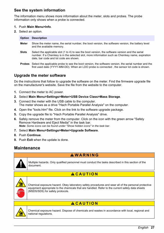
See the system informationThe information menu shows more information about the meter, slots and probes. The probeinformation only shows when a probe is connected.
1. Push Main Menu>Info.2. Select an option.
Option Description
Meter Show the meter name, the serial number, the boot version, the software version, the battery leveland the available memory.
Slots Select the applicable slot (1 to 4) to see the boot version, the software version and the serialnumber. If a Chemkey is in the selected slot, more information such as Chemkey name, expirationdate, bar code and lot code are shown.
Probes Select the applicable probe to see the boot version, the software version, the serial number and thefirst used date (YYYY-MM-DD). When an LDO probe is connected , the sensor lot code is shown.
Upgrade the meter softwareDo the instructions that follow to upgrade the software on the meter. Find the firmware upgrade fileon the manufacturer's website. Save the file from the website to the computer.
1. Connect the meter to AC power.2. Select Main Menu>Settings>Meter>USB Device Class>Mass Storage.3. Connect the meter with the USB cable to the computer.
The meter shows as a drive "Hach Portable Parallel Analysis" on the computer.4. Open the "tools.htm" file. Click on the link to the software upgrade package.5. Copy the upgrade file to "Hach Portable Parallel Analysis" drive.6. Safely remove the meter from the computer. Click on the icon with the green arrow "Safely
Remove Hardware and Eject Media" in the task bar.Note: Some icons can be found under "Show hidden icons" in the task bar.
7. Select Main Menu>Settings>Meter>Upgrade Software.8. Push Continue.9. Push Exit when the update is done.
MaintenanceW A R N I N G
Multiple hazards. Only qualified personnel must conduct the tasks described in this section of thedocument.
C A U T I O N
Chemical exposure hazard. Obey laboratory safety procedures and wear all of the personal protectiveequipment appropriate to the chemicals that are handled. Refer to the current safety data sheets(MSDS/SDS) for safety protocols.
C A U T I O N Chemical exposure hazard. Dispose of chemicals and wastes in accordance with local, regional andnational regulations.
English 27

Clean spillsC A U T I O N
Chemical exposure hazard. Dispose of chemicals and wastes in accordance with local, regional andnational regulations.
1. Obey all facility safety protocols for spill control.2. Discard the waste according to applicable regulations.
Clean the instrumentClean the exterior of the instrument with a moist cloth and a mild soap solution and then wipe theinstrument dry as necessary.
Clean or replace partsFor some errors and warnings it is a requirement to clean the Chemkey slots, the optical windows,the barcode window, the sample detector or to replace the trays. Use isopropyl alcohol to clean theparts. Use water and a mild detergent to clean the light shield. Make sure to move the cotton tippedapplicator in one direction only. Refer to Figure 10 to remove the optics access cover, the light shieldand the trays. Refer to Figure 11 and Figure 12 for the detailed cleaning procedure.Items to collect: Cotton tipped applicator, isopropyl alcohol, water and a mild detergent
Figure 10 Parts removal and reassembly
28 English

Figure 11 Clean sample detector, light shield and access cover
1 Sample detector 3 Optics access cover
2 Light shield
Figure 12 Clean trays and Chemkey slots
1 Tray 3 Barcode window
2 Optical window 4 Chemkey slot
Charge or replace the batteryCharge the battery when the battery power level is low. Replace the battery when the battery doesnot hold a charge. Only use the specified battery supplied by the manufacturer. Refer to Install thebattery on page 6 and Replacement parts and accessories on page 32.
English 29

Prepare for shippingN O T I C E
Potential instrument damage. Drain all water from the unit before shipment to prevent damage from freezingtemperatures.
Contact technical support for instructions before the shipment to the manufacturer.
• Clean and decontaminate the instrument before shipping.• Ship the instrument with the battery installed in the meter, but make sure that the battery is not
connected to the connector.• Disconnect the probes and remove the Chemkeys before shipping.• Ship the instrument in the original packaging or ship the instrument in an alternative safe
packaging.
TroubleshootingError/Warning Possible cause Solution
Barcode read errorPlease reinsertChemkey(s)
Chemkey does not operatecorrectly. Chemkey is notinstalled correctly.
• Put the Chemkey into the slot again.• Use a new Chemkey.• Clean the barcode window. Refer to Figure 12
on page 29.• If the problem still occurs, contact technical support.
Sample aspirateerror.
Chemkey does not operatecorrectly. Chemkey is not fullypushed into the slot.
Use a new Chemkey and make sure to push theChemkey all of the way into the slot. If the problem stilloccurs, contact technical support.
Chemkey Leaked.Try another
Chemkey expired The time for the Chemkey isexpired.
Measurement Error(1–4)
A measurement erroroccurred in the specified slot.
Parameter notsupported
The parameter is notavailable in the installedinstrument software.
Upgrade the instrument software. Search for "SL1000" onwww.hach.com. Go to theDownloads>Software/Firmware section and follow theinstructions on the website.
Used Chemkey—Replace
The Chemkey has alreadybeen used or there is water inthe slot.
Use a new Chemkey. If the problem still occurs, dry outthe slot and the instrument and try again. If the problemstill occurs, contact technical support.
Tray leaked.Replace tray.
A problem with the measuredtray occurred.
Replace the tray. Refer to Figure 10 on page 28. If theproblem still occurs, contact technical support.
Heater ErrorReplace Tray
The tray does not operatecorrectly.
Remove fromsample.
The meter was put into thesample before the meter wasready.
Wait until the meter is ready to be put into the sample.
Sample removed toosoon
Put another Chemkey into the slot. Wait until the meter isready to be put into the sample.
30 English

Error/Warning Possible cause Solution
Too much time insample
The Chemkeys were left inthe sample too long. Ameasurement error occurred.
Remove the Chemkeys immediately when prompted.
The sample detector pin areais dirty if the warning showswhile the meter is not in thesample.
Clean the sample detector pin area. Refer to Clean orreplace parts on page 28. If the problem still occurs,contact technical support.
Over Range The concentration is morethan the upper limit of thecurrent method.
Dilute the sample and do the measurement again.
Under Range The concentration is less thanthe lower limit of the currentmethod.
—
Tray too cold. The meter may be too cold toheat the tray or the heater isnot operational.
Move the meter to a warmer ambient temperature andmeasure again. Replace the tray.
Tray too hot. The meter is too hot to makea correct measurement.
Make sure to cool the meter or move the meter out of thewarm ambient area.
Too much ambientlight. Insert Chemkeyin darkerenvironment
The ambient light is too highto read the barcode.
Move the meter to a darker environment and put theChemkey into the slot again.
Low Light. CleanChemkey slot.
Chemkey does not operatecorrectly. Chemkey is notinstalled correctly.
• Put the Chemkey into the slot in one push.• Use a new Chemkey.• Clean the Chemkey slot. Refer to Figure 12
on page 29.• If the problem still occurs, contact technical support.
Instrument requiresservice.
Module failure. Use the modules that operate correctly. Contact technicalsupport to repair the defective module.
Sample not found. • The sample cup is not filledto the fill line.
• The sample conductivity isless than 2 µS/cm.
• Make sure that the sample cup is filled to the fill line.• Make sure that the sample conductivity is more than
2 µS/cm.• Clean the sample detector. Refer to Figure 11
on page 29.• If the problem still occurs, contact technical support.
Do a diagnostic checkThe diagnostic menu shows the information about the current versions of the meter and the option toformat the memory card.
1. Push Main Menu>Diagnostics.2. Select an option.
Option Description
Disk Space Show the disk space for the user memory and for the internal memory.
Config Versions Show the configuration versions of the meter settings.
English 31

Option Description
Method Versions Show the method versions of the meter.
Format Memory Erase all meter data.Note: All meter data (e.g., meter configuration, site IDs, operator IDs, routes, notes,templates and more) will be lost when Format Memory is completed.
Replacement parts and accessoriesW A R N I N G
Personal injury hazard. Use of non-approved parts may cause personal injury, damage to theinstrument or equipment malfunction. The replacement parts in this section are approved by themanufacturer.
Note: Product and Article numbers may vary for some selling regions. Contact the appropriate distributor or refer tothe company website for contact information.
Replacement parts
Description Item no.
Battery 9094900
Battery door 9436600
Replacement nosecone (optics access cover) 9431700
Tray 9377700
Hand strap 9436700
Light shield, optics access cover 9432900
Power cable (US) 1801000
Power cable (EU) YAA080
Power cable (UK) XLH057
Power cable (CH) XLH051
External power supply (without power cable) 8497000
Sample cup 9418100
Flask, 90 mL 8610400
Probe connector cap 5210000
Accessories
Description Item no.
Chlorine verification Chemkey® 9427900
System verification Chemkey® 9436800
IntelliCAL™ LDO101 Standard Luminescent/Optical Dissolved Oxygen (LDO) Probe,1-Meter Cable LDO10101
IntelliCAL™ PHC201 Standard Gel Filled pH Electrode, 1 meter cable PHC20101
IntelliCAL™ PHC281 pH Ultra Refillable pH Electrode, 1 meter cable PHC28101
IntelliCAL™ CDC401 Standard Conductivity Probe, 1 meter cable CDC40101
IntelliCAL™ ISEF121 Fluoride Ion Selective Electrode (ISE), 1 meter cable ISEF12101
32 English
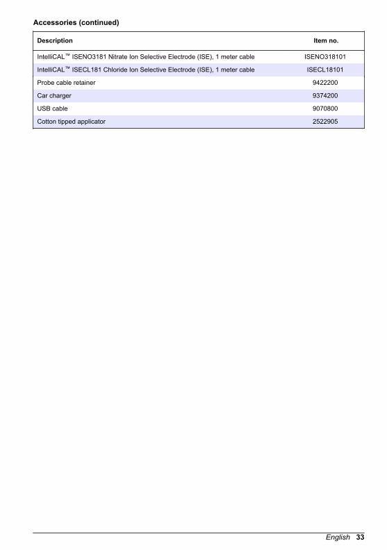
Accessories (continued)
Description Item no.
IntelliCAL™ ISENO3181 Nitrate Ion Selective Electrode (ISE), 1 meter cable ISENO318101
IntelliCAL™ ISECL181 Chloride Ion Selective Electrode (ISE), 1 meter cable ISECL18101
Probe cable retainer 9422200
Car charger 9374200
USB cable 9070800
Cotton tipped applicator 2522905
English 33

34 English


*DOC022.53.80457*
HACH COMPANY World HeadquartersP.O. Box 389, Loveland, CO 80539-0389 U.S.A.Tel. (970) 669-3050(800) 227-4224 (U.S.A. only)Fax (970) [email protected]
HACH LANGE GMBHWillstätterstraße 11D-40549 Düsseldorf, GermanyTel. +49 (0) 2 11 52 88-320Fax +49 (0) 2 11 52 [email protected]
HACH LANGE Sàrl6, route de Compois1222 VésenazSWITZERLANDTel. +41 22 594 6400Fax +41 22 594 6499
© Hach Company/Hach Lange GmbH, 2014–2015, 2017.All rights reserved.