SIST-TP-CEN-TR-13121-5-2018.pdf - iTeh Standards
15
2003-01.Slovenski inštitut za standardizacijo. Razmnoževanje celote ali delov tega standarda ni dovoljeno. GRP tanks and vessels for use above ground - Part 5: Example calculation of a GRP- vessel 23.020.10 Stationary containers and tanks ICS: Ta slovenski standard je istoveten z: CEN/TR 13121-5:2017 SIST-TP CEN/TR 13121-5:2018 en 01-maj-2018 SIST-TP CEN/TR 13121-5:2018 SLOVENSKI STANDARD iTeh STANDARD PREVIEW (standards.iteh.ai) SIST-TP CEN/TR 13121-5:2018 https://standards.iteh.ai/catalog/standards/sist/08fcf530-0c6e-483e-8684- b820e2d5e161/sist-tp-cen-tr-13121-5-2018
-
Upload
khangminh22 -
Category
Documents
-
view
0 -
download
0
Transcript of SIST-TP-CEN-TR-13121-5-2018.pdf - iTeh Standards

2003-01.Slovenski inštitut za standardizacijo. Razmnoževanje celote ali delov tega standarda ni dovoljeno.
Nadzemni rezervoarji in posode iz umetnih mas, ojačanih s steklenimi vlakni - 5.del: Primer izračuna
GRP tanks and vessels for use above ground - Part 5: Example calculation of a GRP-vessel
23.020.10 Nepremične posode inrezervoarji
Stationary containers and tanks
ICS:
Ta slovenski standard je istoveten z: CEN/TR 13121-5:2017
SIST-TP CEN/TR 13121-5:2018 en
01-maj-2018
SIST-TP CEN/TR 13121-5:2018SLOVENSKI STANDARD
iTeh STANDARD PREVIEW(standards.iteh.ai)
SIST-TP CEN/TR 13121-5:2018https://standards.iteh.ai/catalog/standards/sist/08fcf530-0c6e-483e-8684-
b820e2d5e161/sist-tp-cen-tr-13121-5-2018

SIST-TP CEN/TR 13121-5:2018
iTeh STANDARD PREVIEW(standards.iteh.ai)
SIST-TP CEN/TR 13121-5:2018https://standards.iteh.ai/catalog/standards/sist/08fcf530-0c6e-483e-8684-
b820e2d5e161/sist-tp-cen-tr-13121-5-2018
TECHNICAL REPORT RAPPORT TECHNIQUE TECHNISCHER BERICHT
CEN/TR 13121-5 May 2017
ICS 23.020.10 English Version GRP tanks and vessels for use above ground - Part 5: Example calculation of a GRP-vessel This Technical Report was approved by CEN on 18 April 2017. It has been drawn up by the Technical Committee CEN/TC 210. CEN members are the national standards bodies of Austria, Belgium, Bulgaria, Croatia, Cyprus, Czech Republic, Denmark, Estonia, Finland, Former Yugoslav Republic of Macedonia, France, Germany, Greece, Hungary, Iceland, Ireland, Italy, Latvia, Lithuania, Luxembourg, Malta, Netherlands, Norway, Poland, Portugal, Romania, Serbia, Slovakia, Slovenia, Spain, Sweden, Switzerland, Turkey and United Kingdom.
EUROPEAN COMMITTEE FOR STANDARDIZATION C O M I T É E U R O P É E N D E N O R M A L I S A T I O N E U R O P Ä I S C H E S K O M I T E E F Ü R N O R M U N G CEN-CENELEC Management Centre: Avenue Marnix 17, B-1000 Brussels
© 2017 CEN All rights of exploitation in any form and by any means reserved worldwide for CEN national Members. Ref. No. CEN/TR 13121-5:2017 E
SIST-TP CEN/TR 13121-5:2018
iTeh STANDARD PREVIEW(standards.iteh.ai)
SIST-TP CEN/TR 13121-5:2018https://standards.iteh.ai/catalog/standards/sist/08fcf530-0c6e-483e-8684-
b820e2d5e161/sist-tp-cen-tr-13121-5-2018

CEN/TR 13121-5:2017 (E)
2
Contents Page
European foreword ....................................................................................................................................................... 5
Introduction .................................................................................................................................................................... 6
1 Scope .................................................................................................................................................................... 7
2 General ................................................................................................................................................................ 7
3 Dimensions of the tank ................................................................................................................................. 7
4 Building materials .......................................................................................................................................... 9
5 Loadings (9) ...................................................................................................................................................... 9
6 Limit strain for laminate (8.2.2) ............................................................................................................. 11
7 Influence factors (7.9.5.2) ......................................................................................................................... 11
8 Partial safety factors (Table 12) ............................................................................................................. 12
9 Combination factors (Table 11) .............................................................................................................. 12
10 Analysis of the cylinder .............................................................................................................................. 12 10.1 Influence factor A5 ....................................................................................................................................... 12 10.2 Characteristic strength values ................................................................................................................. 13 10.3 Moduli of elasticity ...................................................................................................................................... 13 10.4 Analysis of the cylinder in axial direction ........................................................................................... 13 10.4.1 Proof of strength (Ultimate limit state) ............................................................................................... 14 10.4.2 Proof of strain (Serviceability limit state) .......................................................................................... 17 10.4.3 Stability proof (Ultimate limit state) ..................................................................................................... 19 10.5 Analysis of the cylinder in tangential direction ................................................................................ 21 10.5.1 Strength analysis (Ultimate limit state) ............................................................................................... 21 10.5.2 Proof of strain (Serviceability limit state) .......................................................................................... 23 10.5.3 Stability proof for the cylindrical shell tangential (Ultimate limit state) ................................ 23 10.5.4 Critical buckling pressure for rings (Ultimate limit state) ........................................................... 24 10.6 Earthquake design of the cylinder ......................................................................................................... 26 10.6.1 Analysis of the cylinder in axial direction ........................................................................................... 26 10.6.2 Analysis of the cylinder in tangential direction ................................................................................ 29
11 Opening in the cylinder .............................................................................................................................. 30 11.1 Analysis in circumferential direction ................................................................................................... 31 11.1.1 Proof of strength ........................................................................................................................................... 31 11.1.2 Proof of strain ................................................................................................................................................ 31 11.2 Analysis in axial direction ......................................................................................................................... 32 11.2.1 Proof of strength ........................................................................................................................................... 32 11.2.2 Proof of strain ................................................................................................................................................ 32
12 Analysis of the skirt ..................................................................................................................................... 33 12.1 Internal forces of the skirt ........................................................................................................................ 33 12.2 Proof of strength (Ultimate limit state) ............................................................................................... 34 12.2.1 Design value of actions ............................................................................................................................... 34 12.2.2 Design value of corresponding resistance .......................................................................................... 34 12.2.3 Verification ..................................................................................................................................................... 35 12.3 Proof of strain (Serviceability limit state) .......................................................................................... 35 12.3.1 Design value of actions ............................................................................................................................... 35
SIST-TP CEN/TR 13121-5:2018
iTeh STANDARD PREVIEW(standards.iteh.ai)
SIST-TP CEN/TR 13121-5:2018https://standards.iteh.ai/catalog/standards/sist/08fcf530-0c6e-483e-8684-
b820e2d5e161/sist-tp-cen-tr-13121-5-2018

CEN/TR 13121-5:2017 (E)
3
12.3.2 Limit design value of serviceability criterion..................................................................................... 35 12.3.3 Verification ..................................................................................................................................................... 35 12.4 Stability proof (Ultimate limit state) ..................................................................................................... 35 12.4.1 Design value of actions ............................................................................................................................... 35 12.4.2 Design value of corresponding resistance ........................................................................................... 36 12.4.3 Verification ..................................................................................................................................................... 36 12.5 Earthquake design of the skirt ................................................................................................................. 36 12.5.1 Internal forces Earthquake ....................................................................................................................... 36 12.5.2 Proof of strength (Ultimate limit state) ................................................................................................ 37 12.5.3 Proof of strain (Serviceability limit state) ........................................................................................... 37 12.5.4 Stability proof (Ultimate limit state) ..................................................................................................... 38
13 Overlay laminate connection skirt - vessel ......................................................................................... 39 13.1 Proof of strength (Ultimate limit state) ................................................................................................ 39 13.1.1 Design value of actions ............................................................................................................................... 39 13.1.2 Design value of corresponding resistance ........................................................................................... 40 13.1.3 Verification ..................................................................................................................................................... 40 13.2 Proof of strain (Serviceability limit state) ........................................................................................... 40 13.2.1 Design value of actions ............................................................................................................................... 40 13.2.2 Limit design value of serviceability criterion..................................................................................... 40 13.2.3 Verification ..................................................................................................................................................... 40 13.3 Seismic design of the skirt overlay ......................................................................................................... 41 13.3.1 Proof of strength (Ultimate limit state) ................................................................................................ 41 13.3.2 Proof of strain (Serviceability limit state) ........................................................................................... 41
14 Analysis of the bottom ................................................................................................................................ 42 14.1 Influence factor A5 ........................................................................................................................................ 42 14.2 Characteristic strength values ................................................................................................................. 42 14.3 Moduli of elasticity ....................................................................................................................................... 42 14.4 Actions, which cause internal forces for the bottom ....................................................................... 42 14.5 Strength analysis (Ultimate limit state) ............................................................................................... 42 14.5.1 Design value of actions ............................................................................................................................... 42 14.5.2 Proof of strain (Serviceability limit state) ........................................................................................... 44 14.5.3 Stability proof of the bottom (Ultimate limit state) ......................................................................... 45
15 Lower part of the cylinder (Region 1) ................................................................................................... 46 15.1 Strength analysis (Ultimate limit state) ............................................................................................... 46 15.1.1 Design value of corresponding resistance ........................................................................................... 47 15.1.2 Verification ..................................................................................................................................................... 47 15.2 Proof of strain (Serviceability limit state) ........................................................................................... 47 15.2.1 Design value of actions ............................................................................................................................... 47 15.2.2 Limit design value of serviceability criterion..................................................................................... 47 15.2.3 Verification ..................................................................................................................................................... 47 15.3 Earthquake design of region 1 (Ultimate limit state) ...................................................................... 48 15.3.1 Strength analysis (Ultimate limit state) ............................................................................................... 48 15.3.2 Proof of strain (Serviceability limit state) ........................................................................................... 48
16 Upper part of the skirt (Region 2) .......................................................................................................... 49 16.1 Strength analysis (Ultimate limit state) ............................................................................................... 49 16.1.1 Design value of corresponding resistance ........................................................................................... 50 16.1.2 Verification ..................................................................................................................................................... 50 16.2 Proof of strain (Serviceability limit state) ........................................................................................... 50 16.2.1 Design value of actions ............................................................................................................................... 50 16.2.2 Limit design value of serviceability criterion..................................................................................... 50 16.2.3 Verification ..................................................................................................................................................... 50
SIST-TP CEN/TR 13121-5:2018
iTeh STANDARD PREVIEW(standards.iteh.ai)
SIST-TP CEN/TR 13121-5:2018https://standards.iteh.ai/catalog/standards/sist/08fcf530-0c6e-483e-8684-
b820e2d5e161/sist-tp-cen-tr-13121-5-2018

CEN/TR 13121-5:2017 (E)
4
16.3 Seismic design of region 2 (Ultimate limit state) ............................................................................. 51 16.3.1 Strength analysis (Ultimate limit state) ............................................................................................... 51 16.3.2 Design value of corresponding resistance .......................................................................................... 51 16.3.3 Verification ..................................................................................................................................................... 51 16.4 Proof of strain (Serviceability limit state) .......................................................................................... 51 16.4.1 Design value of actions ............................................................................................................................... 51 16.4.2 Limit design value of serviceability criterion .................................................................................... 51 16.4.3 Verification ..................................................................................................................................................... 52
17 Flange design ................................................................................................................................................. 52
18 Anchorage ....................................................................................................................................................... 57 18.1 Anchorage for wind loads (Permanent / Transient situation) .................................................... 57 18.1.1 Uplifting anchor force ................................................................................................................................. 57 18.1.2 Anchor shear force....................................................................................................................................... 57 18.2 Anchorage for seismic loads (Seismic design situation) ................................................................ 57 18.2.1 Uplifting anchor force ................................................................................................................................. 57 18.2.2 Anchor shear force....................................................................................................................................... 58
SIST-TP CEN/TR 13121-5:2018
iTeh STANDARD PREVIEW(standards.iteh.ai)
SIST-TP CEN/TR 13121-5:2018https://standards.iteh.ai/catalog/standards/sist/08fcf530-0c6e-483e-8684-
b820e2d5e161/sist-tp-cen-tr-13121-5-2018

CEN/TR 13121-5:2017 (E)
5
European foreword
This document (CEN/TR 13121-5:2017) has been prepared by Technical Committee CEN/TC 210 “GRP tanks and vessels”, the secretariat of which is held by SFS.
Attention is drawn to the possibility that some of the elements of this document may be the subject of patent rights. CEN [and/or CENELEC] shall not be held responsible for identifying any or all such patent rights.
SIST-TP CEN/TR 13121-5:2018
iTeh STANDARD PREVIEW(standards.iteh.ai)
SIST-TP CEN/TR 13121-5:2018https://standards.iteh.ai/catalog/standards/sist/08fcf530-0c6e-483e-8684-
b820e2d5e161/sist-tp-cen-tr-13121-5-2018

CEN/TR 13121-5:2017 (E)
6
Introduction
EN 13121 consists of the following parts:
— EN 13121-1, GRP tanks and vessels for use above ground — Part 1: Raw materials — Specification and acceptance conditions
— EN 13121-2, GRP tanks and vessels for use above ground — Part 2: Composite materials — Chemical resistance
— EN 13121-3, GRP tanks and vessels for use above ground — Part 3: Design and workmanship
— EN 13121-4, GRP tanks and vessels for use above ground — Part 4: Delivery, installation and maintenance
— CEN/TR 13121-5, GRP tanks and vessels for use above ground — Part 5: Example calculation of a GRP-tank (this report)
These five parts together define the responsibilities of the tank or vessel manufacturer and the materials to be used in their manufacture.
EN 13121-1 specifies the requirements and acceptance conditions for the raw materials - resins, curing agents, thermoplastics linings, reinforcing materials and additives. These requirements are necessary in order to establish the chemical resistance properties determined in EN 13121-2 and the mechanical, thermal and design properties determined in EN 13121-3. Together with the workmanship principles determined in Part 3, requirements and acceptance conditions for raw materials ensure that the tank or vessel will be able to meet its design requirements. EN 13121-4 of this standard specifies recommendations for delivery, handling, installation and maintenance of GRP tanks and vessels. This part of EN 13121 gives guidance in use of the standard. CEN/TC 210 has found it necessary to publish an example calculation of a vessel according to EN 13121-3 due to the standards complexity, and for the understanding of how the standard complies with EN 1990:s principles and requirements for safety, serviceability and durability of structures.
The design and manufacture of GRP tanks and vessels involve a number of different materials such as resins, thermoplastics and reinforcing fibres and a number of different manufacturing methods. It is implicit that vessels and tanks covered by this standard are made only by manufacturers who are competent and suitably equipped to comply with all the requirements of this standard, using materials manufactured by competent and experienced material manufacturers.
Metallic vessels, and those manufactured from other isotropic, homogeneous materials, are conveniently designed by calculating permissible loads based on measured tensile and ductility properties. GRP, on the other hand, is a laminar material, manufactured through the successive application of individual layers of reinforcement. As a result there are many possible combinations of reinforcement type that will meet the structural requirement of any one-design case. This allows the designer to select the laminate construction best suited to the available manufacturing facilities and hence be most cost effective.
SIST-TP CEN/TR 13121-5:2018
iTeh STANDARD PREVIEW(standards.iteh.ai)
SIST-TP CEN/TR 13121-5:2018https://standards.iteh.ai/catalog/standards/sist/08fcf530-0c6e-483e-8684-
b820e2d5e161/sist-tp-cen-tr-13121-5-2018

CEN/TR 13121-5:2017 (E)
7
1 Scope
This Technical Report gives guidance for the design of a vessel using the standard EN 13121-3 GRP tanks and vessels for use above ground. The calculation is done according to the advanced design method given in EN 13121-3:2016, 7.9.3 with approved laminates and laminate properties.
2 General
Vessels or vessel structures may contain such structural elements or solutions for which this standard does not provide sufficient guidance. In that case, other methods shall be used in order to obtain a safe structure.
This example calculation is based on a pressurized GRP vessel with an internal diameter of D 3000 mm. The cylindrical parts of the vessel are filament wound. Its bottom and roof are torispherical dished ends that are hand laid up using mixed laminates. Protection against medium attack is obtained by a chemical resistance layer (CRL).
The tank is located outdoors in a seismic area.
IMPORTANT – This example doesn’t cover all necessary verifications for the calculation of the GRP tank. Additional verifications have to be performed for the roof, the upper cylinder, etc.
3 Dimensions of the tank
Sketch of the tank dimensions:
SIST-TP CEN/TR 13121-5:2018
iTeh STANDARD PREVIEW(standards.iteh.ai)
SIST-TP CEN/TR 13121-5:2018https://standards.iteh.ai/catalog/standards/sist/08fcf530-0c6e-483e-8684-
b820e2d5e161/sist-tp-cen-tr-13121-5-2018

CEN/TR 13121-5:2017 (E)
8
General Dimensions:
Diameter: D = 3 000 mm
Total height: Htot = 8 000 mm Cylinder:
Thickness cylinder 1: tCyl,1 = tC1 = 9,2 mm
Thickness cylinder 2: tCyl,2 = tC2 = 11,7 mm
Thickness cylinder at roof: tZ,R = 30,0 mm
Thickness cylinder at bottom: tZ,B = 46,1 mm
Total cylinder length: lCyl.tot = 6 610 mm
Distance between stiffeners: ls.1 = 3700 mm ls.2 = 3303 mm
Thickness of the stiffener: tS = 20 mm
SIST-TP CEN/TR 13121-5:2018
iTeh STANDARD PREVIEW(standards.iteh.ai)
SIST-TP CEN/TR 13121-5:2018https://standards.iteh.ai/catalog/standards/sist/08fcf530-0c6e-483e-8684-
b820e2d5e161/sist-tp-cen-tr-13121-5-2018

CEN/TR 13121-5:2017 (E)
9
Width of the stiffener: bS = 260 mm Skirt:
Thickness skirt: tSk = 17,0 mm
Thickness overlay laminate: t02 = 7,0 mm
Height of the skirt: HSk = 890 mm Roof:
Thickness calotte: tR = 13,0 mm
Radius calotte: RR = 3000 mm
Thickness knuckle roof: tRk = 30,0 mm
Radius knuckle: rRk = 300 mm
Height of the roof: HR = 590 mm Bottom:
Thickness calotte: tB = 16,5 mm
Radius calotte: RB = 3 000 mm
Thickness knuckle: tBk = 45,0 mm
Radius knuckle: rBk = 300 mm
Height of the bottom: HB = 590 mm
4 Building materials
Resin type: UP-resin, Resin group 4
5 Loadings (9)
LC 1: Dead load
The assumed dead loads for the separate tank parts are:
Roof: WR,k = 4 kN Area load: wR,k = 0,57 kN/m2
Cylinder + rings: WC,k = 19 kN
Bottom: WB,k = 4 kN Area load: wB,k = 0,57 kN/m2
Skirt: WSk = 3 kN Total dead load of the vessel: Wtot = 30 kN
LC 2: Liquid filling
Density of the medium ρliquid = 1,30 kg/dm3
Filling height hliquid = 7 000 mm
Volume V = 52,0 m3 LC 3: Long time design overpressure
Design pressure PSop.l = 2,000 bar ≡ 0,20 N/mm2 LC 4: Short time design overpressure
SIST-TP CEN/TR 13121-5:2018
iTeh STANDARD PREVIEW(standards.iteh.ai)
SIST-TP CEN/TR 13121-5:2018https://standards.iteh.ai/catalog/standards/sist/08fcf530-0c6e-483e-8684-
b820e2d5e161/sist-tp-cen-tr-13121-5-2018

CEN/TR 13121-5:2017 (E)
10
Design pressure PSop.s = 2,500 bar ≡ 0,25 N/mm2 LC 5: Long time design negative pressure
Design pressure PSep.l = 0,000 bar ≡ 0,00 N/mm2 LC 6: Short time design negative pressure
Design pressure PSep.s = 0,050 bar ≡ 0,005 N/mm2 LC 7: Wind (9.2.2)
Peak velocity pressure qp = 0,8 kN/m2 (EN 1991–1-4)
Force coefficient (cylindrical vessel) cf = 0,8
External pressure arising from wind load: 0,6 0,6 0,8 0,48 / ²wind pp q kN m= ⋅ = ⋅ = LC 8: Snow (9.2.1)
Characteristic snow load sk = 0,85 kN/m2 (EN 1991–1-3)
Shape coefficient μ = 0,80
Snow load 0,85 0,8 0,68 / ²snow kp s kN mµ= ⋅ = ⋅ =
LC 9: Personnel loading (9.2.8)
Live load on the roof paccess = 1,5 kN/m2 LC 10: Temperature
Design temperature TS = 50°C
Difference in temperature ΔT = 20 K LC 11: Earthquake (9.2.3.4)
Reference peak ground acceleration
agR = 1,00 m/s2
Importance factor γ1 = 1,4
Design ground acceleration γ= ⋅ = ⋅ =1 1 00 1 4 1 40g gRa a m s, , , / ²
Ground type according to EN 1998–1
D
Viscous damping 5 %
Control periods of the response spectrum
TB = 0,20 s TC = 0,8 s TD = 2,0 s
Soil factor S = 1,35
Behaviour factor q = 1,5
Bending modulus cylinder tangential
Eϕ,b = 19 000 N/mm2
Bending modulus cylinder axial
Ex,b = 12 000 N/mm2
Modulus of elasticity for short time impact φ= ⋅ ⋅ = ⋅ ⋅ =1 5 1 5 19 000 12 000 22 650e b x bE E E N mm, ,, , / ²
Cylinder thickness lower t1/2 approximately tSk = 17 mm
SIST-TP CEN/TR 13121-5:2018
iTeh STANDARD PREVIEW(standards.iteh.ai)
SIST-TP CEN/TR 13121-5:2018https://standards.iteh.ai/catalog/standards/sist/08fcf530-0c6e-483e-8684-
b820e2d5e161/sist-tp-cen-tr-13121-5-2018
CEN/TR 13121-5:2017 (E)
11
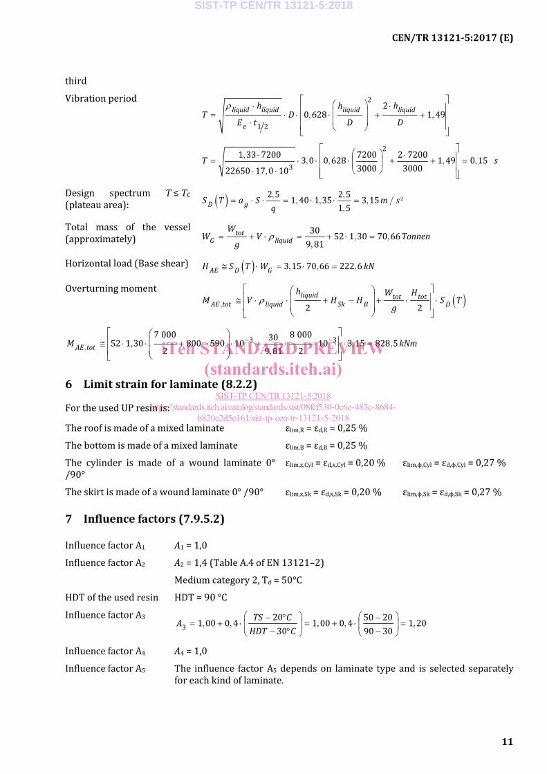
third
Vibration period ρ ⋅ ⋅ = ⋅ ⋅ ⋅ + + ⋅
2
1 2
20 628 1 49liquid liquid liquid liquid
e
h h hT D
E t D D, ,
⋅ ⋅ = ⋅ ⋅ ⋅ + + = ⋅ ⋅
2
31 33 7200 7200 2 72003 0 0 628 1 49 0 15
3000 300022650 17 0 10T s,
, , , ,,
Design spectrum T ≤ TC (plateau area): ( ) = ⋅ ⋅ = ⋅ ⋅ =
2 5 2 51 40 1 35 3 151 5D gS T a S m s
q, ,
, , , / ²,
Total mass of the vessel (approximately) ρ= + ⋅ = + ⋅ =
30 52 1 30 70 669 81
totG liquid
WW V Tonnen
g, ,
,
Horizontal load (Base shear) ( )≅ ⋅ = ⋅ =3 15 70 66 222 6AE D GH S T W kN , , ,
Overturning moment ( )ρ
≅ ⋅ ⋅ + − + ⋅ ⋅
2 2
liquid tot totAE tot liquid Sk B D
h W HM V H H S T
g,
− − ≅ ⋅ ⋅ + − ⋅ + ⋅ ⋅ ⋅ =
3 37 000 8 0003052 1 30 800 590 10 10 3 15 828 52 9 81 2AE totM kNm, , , ,
,
6 Limit strain for laminate (8.2.2)
For the used UP resin is:
The roof is made of a mixed laminate εlim,R = εd,R = 0,25 %
The bottom is made of a mixed laminate εlim,B = εd,B = 0,25 %
The cylinder is made of a wound laminate 0° /90°
εlim,x,Cyl = εd,x,Cyl = 0,20 % εlim,ϕ,Cyl = εd,ϕ,Cyl = 0,27 %
The skirt is made of a wound laminate 0° /90° εlim,x,Sk = εd,x,Sk = 0,20 % εlim,ϕ,Sk = εd,ϕ,Sk = 0,27 %
7 Influence factors (7.9.5.2)
Influence factor A1 A1 = 1,0
Influence factor A2 A2 = 1,4 (Table A.4 of EN 13121–2)
Medium category 2, Td = 50°C
HDT of the used resin HDT = 90 °C
Influence factor A3 − ° −= + ⋅ = + ⋅ =
− ° − 3
20 50 201 00 0 4 1 00 0 4 1 2030 90 30
TS CAHDT C
, , , , ,
Influence factor A4 A4 = 1,0
Influence factor A5 The influence factor A5 depends on laminate type and is selected separately for each kind of laminate.
SIST-TP CEN/TR 13121-5:2018
iTeh STANDARD PREVIEW(standards.iteh.ai)
SIST-TP CEN/TR 13121-5:2018https://standards.iteh.ai/catalog/standards/sist/08fcf530-0c6e-483e-8684-
b820e2d5e161/sist-tp-cen-tr-13121-5-2018

CEN/TR 13121-5:2017 (E)
12
8 Partial safety factors (Table 12)
Action Symbol Situation
P/T A/AE
Independent permanent actions (s.a): unfavourable favourable For liquid filling unfavourable favourable Independent variable actions: unfavourable favourable Accidental actions: Seismic actions:
γG,sup γG,inf γG,sup γG,inf γQ,sup γQ,inf γA γAE
1,35 1,00 1,35
0 1,50
0
1,00 1,00 1,00
0 1,00
0 1,00 1,00
9 Combination factors (Table 11)
In the following table are shown the relevant Ψ-factors for this example.
Action ψ0 ψ1 ψ2
Pressures: - Long term pressures - Short-term pressures
1,0 0
1,0 0
1,0 0
Imposed loads in buildings, category (see EN 1991–1-1) - Category H: roofs
0 0 0
Snow loads on buildings (see EN 1991–1-3)a): Remainder of CEN Member States, - for sites located at altitude H ≤ 1000 m a.s.l.
0,5 0,2 0
Wind loads on buildings (see EN 1991–1-4) 0,6 0,2 0
Temperature (non-fire) in buildings (see EN 1991–1-5) 0,6 0,5 0
10 Analysis of the cylinder
The cylinder is made of a wound laminate 0° / 90°. For mechanical properties are used historic test data. They are verified with tests in accordance to 7.9.3.
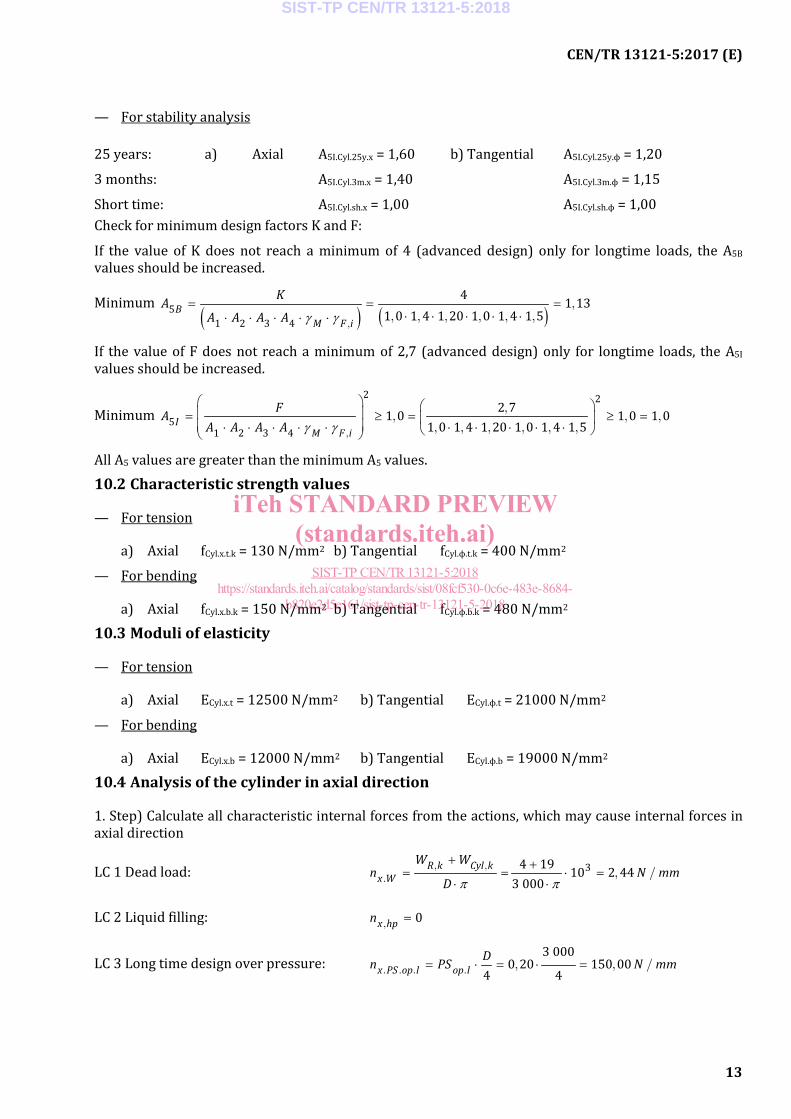
10.1 Influence factor A5
— For stress analysis
25 years: a) Axial A5B.Cyl.25y.x = 1,60 b) Tangential A5B.Cyl.25y.ϕ = 1,20
3 months: A5B.Cyl.3m.x = 1,40 A5B.Cyl.3m.ϕ = 1,15
Shorttime: A5B.Cyl.sh.x = 1,00 A5B.Cyl.sh.ϕ = 1,00
SIST-TP CEN/TR 13121-5:2018
iTeh STANDARD PREVIEW(standards.iteh.ai)
SIST-TP CEN/TR 13121-5:2018https://standards.iteh.ai/catalog/standards/sist/08fcf530-0c6e-483e-8684-
b820e2d5e161/sist-tp-cen-tr-13121-5-2018
CEN/TR 13121-5:2017 (E)
13
— For stability analysis
25 years: a) Axial A5I.Cyl.25y.x = 1,60 b) Tangential A5I.Cyl.25y.ϕ = 1,20
3 months: A5I.Cyl.3m.x = 1,40 A5I.Cyl.3m.ϕ = 1,15
Short time: A5I.Cyl.sh.x = 1,00 A5I.Cyl.sh.ϕ = 1,00 Check for minimum design factors K and F:
If the value of K does not reach a minimum of 4 (advanced design) only for longtime loads, the A5B values should be increased.
Minimum ( ) ( )γ γ
= = =⋅ ⋅ ⋅ ⋅ ⋅⋅ ⋅ ⋅ ⋅ ⋅
51 2 3 4
4 1 131 0 1 4 1 20 1 0 1 4 1 5B
M F i
KAA A A A ,
,, , , , , ,
If the value of F does not reach a minimum of 2,7 (advanced design) only for longtime loads, the A5I values should be increased.
Minimum γ γ
= ≥ = ≥ = ⋅ ⋅ ⋅ ⋅ ⋅ ⋅ ⋅ ⋅ ⋅ ⋅
2 2
51 2 3 4
2 71 0 1 0 1 01 0 1 4 1 20 1 0 1 4 1 5I
M F i
FAA A A A ,
,, , ,
, , , , , ,
All A5 values are greater than the minimum A5 values.
10.2 Characteristic strength values
— For tension
a) Axial fCyl.x.t.k = 130 N/mm2 b) Tangential fCyl.ϕ.t.k = 400 N/mm2
— For bending
a) Axial fCyl.x.b.k = 150 N/mm2 b) Tangential fCyl.ϕ.b.k = 480 N/mm2
10.3 Moduli of elasticity
— For tension
a) Axial ECyl.x.t = 12500 N/mm2 b) Tangential ECyl.ϕ.t = 21000 N/mm2
— For bending
a) Axial ECyl.x.b = 12000 N/mm2 b) Tangential ECyl.ϕ.b = 19000 N/mm2
10.4 Analysis of the cylinder in axial direction
1. Step) Calculate all characteristic internal forces from the actions, which may cause internal forces in axial direction
LC 1 Dead load: π π
+ += = ⋅ =
⋅ ⋅34 19 10 2 44
3 000R k Cyl k
x W
W Wn N mm
D, ,
. , /
LC 2 Liquid filling: = 0x hpn ,
LC 3 Long time design over pressure: = ⋅ = ⋅ =3 000
0 20 150 004 4x PS op l op lDn PS N mm. . . . , , /
SIST-TP CEN/TR 13121-5:2018
iTeh STANDARD PREVIEW(standards.iteh.ai)
SIST-TP CEN/TR 13121-5:2018https://standards.iteh.ai/catalog/standards/sist/08fcf530-0c6e-483e-8684-
b820e2d5e161/sist-tp-cen-tr-13121-5-2018