Applicable to the B.Tech., Dual Degree (B.Tech+M.Tech.), 2 ...

Strength of Material
1
S H A S H I K A N T ' S N O T E S

COURSE CONTENT IN BRIEF
1. Simple stress and strain
2. Statically indeterminate problems and thermal stresses
3. Shearing force and bending moment
4. Stresses due to bending
5. Stresses due to shearing
6. Slope and deflection of beams
7. Stresses due to Torsion in circular shaft
8. Variation of stress at a point
9. Stresses due to fluid pressure in thick and thin cylinder
10. Stability of columns
2
S H A S H I K A N T ' S N O T E S

Books for Reference
1. Mechanics of Materials, by E.P.Popov
2. Mechanics of Materials, by E J Hearn
3. Strength of materials, by Beer and Johnston
4. Strength of materials, by F L Singer & Andrew Pytel
5. Strength of Materials, by B.S. Basavarajaiah & P. Mahadevappa
6. Strength of Materials, by Ramamruthum
7. Strength of Materials, by S S Bhavikatti
3
S H A S H I K A N T ' S N O T E S

• Normal stress and strain
• Hooke‟s law
• Modulus of elasticity
• Tension test on ductile and brittle materials
• Factor of safety and allowable stress
• Poisson's ratio
• Shear stress and shear strain
• Modulus of rigidity
• Tapering bar and stepped bar subjected to axial load
CHAPTER – I
Simple stress & strain
4
S H A S H I K A N T ' S N O T E S

The subject strength of materials deals with the relations between
externally applied loads and their internal effects on bodies. The
bodies are no longer assumed to be rigid and the deformations,
however small, are of major interest
Alternatively the subject may be called the mechanics of solids.
CHAPTER – I Introduction
The subject, strength of materials or mechanics of materials involves
analytical methods for determining the strength , stiffness
(deformation characteristics), and stability of various load carrying
members.
5
S H A S H I K A N T ' S N O T E S

Engineering Mechanics
Mechanics of Solids Mechanics of Fluids
Rigid Bodies Deformable
Bodies
Statics Dynamics Strength of
Materials
Theory of
Elasticity Theory of
Plasticity
Ideal
Fluids Viscous
Fluids
Compressible
Fluids
Branches of Mechanics 6
S H A S H I K A N T ' S N O T E S

GENERAL CONCEPTS
STRESS
No engineering material is perfectly rigid and hence, when a
material is subjected to external load, it undergoes
deformation.
While undergoing deformation, the particles of the material
offer a resisting force (internal force). When this resisting
force equals applied load the equilibrium condition exists
and hence the deformation stops.
These internal forces maintain the externally applied forces
in equilibrium.
7
S H A S H I K A N T ' S N O T E S

Stress = internal resisting force / resisting cross sectional area
The internal force resisting the deformation per unit area is
called as stress or intensity of stress.
STRESS 8
A
R
S H A S H I K A N T ' S N O T E S

gigapascal, 1GPa = 1×10⁹ N/m2
= 1×10³ MPa
= 1×10³ N/mm2
SI unit for stress
N/m2 also designated as a pascal (Pa)
Pa = N/m2
kilopascal, 1kPa = 1000 N/m2
megapascal, 1 MPa = 1×10⁶ N/m2
= 1×10⁶ N/(106mm2) = 1N/mm2
1 MPa = 1 N/mm2
STRESS 9
S H A S H I K A N T ' S N O T E S

AXIAL LOADING – NORMAL STRESS
Consider a uniform bar of cross
sectional area A, subjected to a tensile
force P.
Consider a section AB normal to the
direction of force P
Let R is the total resisting force acting
on the cross section AB.
Then for equilibrium condition,
R = P
Then from the definition of stress,
normal stress = ζ = R/A = P/A
P
P
P
R
B A
R
P
STRESS
10
ζ = Normal Stress Symbol: S H A S H I K A N T ' S N O T E S

Direct or Normal Stress:
AXIAL LOADING – NORMAL STRESS
Intensity of resisting force perpendicular to or normal to the
section is called the normal stress.
Normal stress may be tensile or compressive
Tensile stress: stresses that cause pulling on the surface of the
section, (particles of the materials tend to pull
apart causing extension in the direction of force)
Compressive stress: stresses that cause pushing on the surface of
the section, (particles of the materials tend to
push together causing shortening in the
direction of force)
STRESS
11
S H A S H I K A N T ' S N O T E S

• The resultant of the internal forces for an
axially loaded member is normal to a
section cut perpendicular to the member
axis.
A
P
A
Favg
A
0lim
• The force intensity on that section is
defined as the normal stress.
STRESS
12
S H A S H I K A N T ' S N O T E S

STRAIN
STRAIN :
when a load acts on the material it will undergo deformation.
Strain is a measure of deformation produced by the application of
external forces.
If a bar is subjected to a direct load, and hence a stress, the bar will
changes in length. If the bar has an original length L and change in
length by an amount δL, the linear strain produced is defined as,
L
L
Original length
Change in length =
Strain is a dimension less quantity.
13
Linear strain,
S H A S H I K A N T ' S N O T E S

LINEAR STRAIN
strain normal
stress
L
A
P
L
A
P
A
P
2
2
LL
A
P
2
2
14
S H A S H I K A N T ' S N O T E S

STRESS-STRAIN DIAGRAM
In order to compare the strength of various materials it is necessary
to carry out some standard form of test to establish their relative
properties.
One such test is the standard tensile test in which a circular bar of
uniform cross section is subjected to a gradually increasing tensile
load until failure occurs.
Measurement of change in length over a selected gauge length of the
bar are recorded throughout the loading operation by means of
extensometers.
A graph of load verses extension or stress against strain is drawn as
shown in figure.
15
S H A S H I K A N T ' S N O T E S

STRESS-STRAIN DIAGRAM
Typical tensile test curve for mild steel
16
S H A S H I K A N T ' S N O T E S
STRESS-STRAIN DIAGRAM
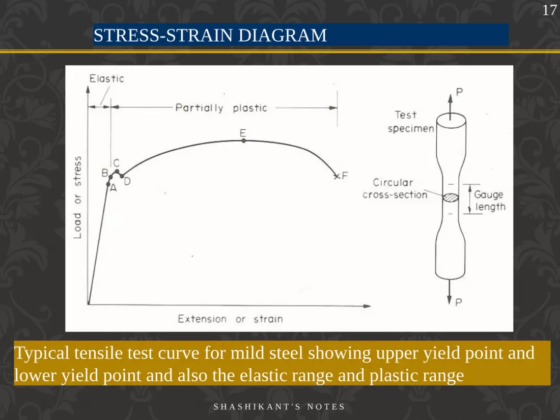
Typical tensile test curve for mild steel showing upper yield point and
lower yield point and also the elastic range and plastic range
17
S H A S H I K A N T ' S N O T E S

Limit of Proportionality :
From the origin O to a point called proportionality limit the stress
strain diagram is a straight line. That is stress is proportional to
strain. Hence proportional limit is the maximum stress up to which
the stress – strain relationship is a straight line and material behaves
elastically.
From this we deduce the well known relation, first postulated by
Robert Hooke in 1678, that stress is proportional to strain.
Beyond this point, the stress is no longer proportional to strain
A
PPP Load at proportionality limit
Original cross sectional area =
18
Stress-strain Diagram
S H A S H I K A N T ' S N O T E S

Elastic limit:
It is the stress beyond which the material will not return to its
original shape when unloaded but will retain a permanent
deformation called permanent set. For most practical purposes it can
often be assumed that points corresponding proportional limit and
elastic limit coincide.
Beyond the elastic limit plastic deformation occurs and strains are
not totally recoverable. There will be thus some permanent
deformation when load is removed.
A
PEE Load at proportional limit
Original cross sectional area =
19
Stress-strain Diagram
S H A S H I K A N T ' S N O T E S

Yield point:
It is the point at which there is an appreciable elongation or yielding
of the material without any corresponding increase of load.
A
PYY Load at yield point
Original cross sectional area =
20
Stress-strain Diagram
S H A S H I K A N T ' S N O T E S

Ultimate strength:
It is the stress corresponding to maximum load recorded during the
test. It is stress corresponding to maximum ordinate in the stress-
strain graph.
A
PUU Maximum load taken by the material
Original cross sectional area =
21
Stress-strain Diagram
S H A S H I K A N T ' S N O T E S

Rupture strength (Nominal Breaking stress):
It is the stress at failure.
For most ductile material including structural steel breaking stress is
somewhat lower than ultimate strength because the rupture strength
is computed by dividing the rupture load (Breaking load) ,which is
less than the maximum load which it can bear, by the original cross
sectional area.
A
PBB
load at breaking (failure)
Original cross sectional area =
True breaking stress = load at breaking (failure)
Actual cross sectional area
22
Stress-strain Diagram
S H A S H I K A N T ' S N O T E S

The capacity of a material to allow these large plastic deformations is
a measure of ductility of the material
After yield point the graph becomes much more shallow and covers
a much greater portion of the strain axis than the elastic range.
Ductile Materials:
The capacity of a material to allow large extension i.e. the ability to
be drawn out plastically is termed as its ductility. Material with high
ductility are termed ductile material.
Example: Low carbon steel, mild steel, gold, silver, aluminum
23
Stress-strain Diagram
S H A S H I K A N T ' S N O T E S

Stress-strain Diagram
Percentage elongation
in length
A measure of ductility is obtained by measurements of the
percentage elongation in length or percentage reduction in area,
defined as,
increase in gauge length (up to fracture)
original gauge length ×100
Percentage reduction in
area original area ×100
=
=
Reduction in cross sectional area of necked portion (at fracture)
24
S H A S H I K A N T ' S N O T E S

Stress-strain Diagram
Brittle Materials
A brittle material is one which exhibits relatively small extensions
before fracture so that plastic region of the tensile test graph is
much reduced.
Example: steel with higher carbon content, cast iron, concrete, brick
25
S H A S H I K A N T ' S N O T E S
2
2
1000
)(
)(
in
lbksi
insquareinch
lbpoundspsi
STRESS-STRAIN DIAGRAM: DUCTILE
MATERIALS
26
S H A S H I K A N T ' S N O T E S

STRESS-STRAIN DIAGRAM: BRITTLE
MATERIALS
Stress-strain diagram for a typical brittle material
27
S H A S H I K A N T ' S N O T E S

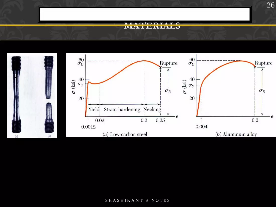
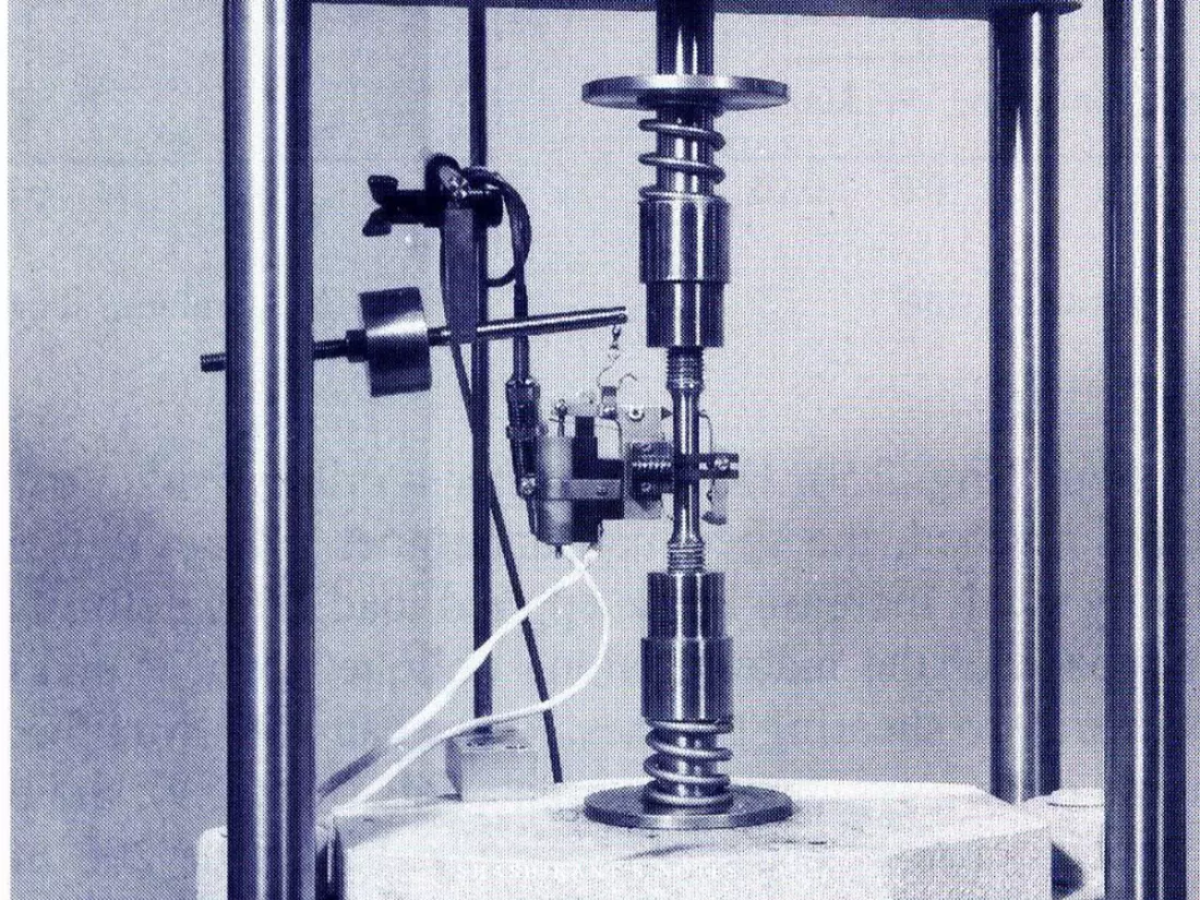
STRESS-STRAIN TEST
Machine used to test tensile test specimen test specimen with tensile load
L = gauge length
28
S H A S H I K A N T ' S N O T E S
4
29
S H A S H I K A N T ' S N O T E S

HOOKE”S LAW
Hooke‟s Law
For all practical purposes, up to certain limit the relationship
between normal stress and linear strain may be said to be linear for
all materials
Thomas Young in 1807 introduced a constant of proportionality that
came to be known as Young‟s modulus.
stress (ζ) α strain (ε)
stress (ζ)
strain (ε) = constant
stress (ζ)
strain (ε) = E
Modulus of Elasticity
Young‟s Modulus =
30
or
S H A S H I K A N T ' S N O T E S
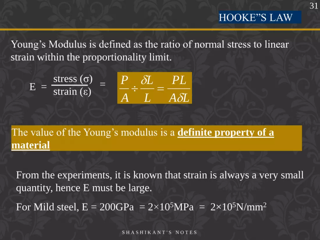
HOOKE”S LAW
Young‟s Modulus is defined as the ratio of normal stress to linear
strain within the proportionality limit.
From the experiments, it is known that strain is always a very small
quantity, hence E must be large.
For Mild steel, E = 200GPa = 2×10⁵MPa = 2×10⁵N/mm2
stress (ζ)
strain (ε) = E =
LA
PL
L
L
A
P
The value of the Young‟s modulus is a definite property of a
material
31
S H A S H I K A N T ' S N O T E S

Material Density
(kg/m3)
Young's Modulus
109 N/m2
Ultimate Strength Su
106 N/m2
Yield Strength Sy
106 N/m2
Steel 7860 200 400 250
Aluminum 2710 70 110 95
Glass 2190 65 50 ...
Concrete 2320 30 40 ...
Wood 525 13 50 ...
Bone 1900 9 170 ...
Polystyrene 1050 3 48 ...
32
S H A S H I K A N T ' S N O T E S

HOOKE’S LAW: MODULUS OF
ELASTICITY
Below the yield stress
Elasticity of Modulus
or Modulus Youngs
E
E
Strength is affected by alloying, heat
treating, and manufacturing process but
stiffness (Modulus of Elasticity) is not.
Stress-strain diagram for Iron and
different grades of steel
33
S H A S H I K A N T ' S N O T E S

STRESS-STRAIN
DIAGRAM
Hard drawn wire materials Various types of nylon and
polycarbonate
34
S H A S H I K A N T ' S N O T E S

ELASTIC VS. PLASTIC
BEHAVIOR
• If the strain disappears
when the stress is removed,
the material is said to
behave elastically.
• When the strain does not return to zero after the
stress is removed, the material is said to behave
plastically.
• The largest stress for
which this occurs is called
the elastic limit.
35
S H A S H I K A N T ' S N O T E S

ELASTIC VS. PLASTIC
BEHAVIOR
For certain materials, for example, high carbon steel and non-ferrous
metals, it is not possible to detect any difference between the upper
and lower yield points and in some cases no yield point exists at all.
In such cases a proof stress is used to indicate beginning of plastic
strain.
Proof stress is the stress corresponding to a fixed permanent strain
in stress-strain diagram.
For example: 0.1% proof stress indicates that stress which, when
removed, produces a permanent strain or “set” of 0.1% of the
original gauge length.
36
S H A S H I K A N T ' S N O T E S

PROOF
STRESS
Determination of 0.1%
proof stress
Permanent deformation or “set”
after straining beyond yield point
37
S H A S H I K A N T ' S N O T E S

DEFORMATIONS UNDER AXIAL
LOADING
AE
P
EE
• From Hooke‟s Law:
• From the definition of strain:
L
• Equating and solving for the
deformation,
AE
PL
• With variations in loading, cross-
section or material properties,
i ii
ii
EA
LP
38
S H A S H I K A N T ' S N O T E S

Derive an expression for the total extension of the tapered bar of
circular cross section shown in the figure, when subjected to an axial
tensile load W
W W
A B
L Diameter
d1 Diameter
d2
39
S H A S H I K A N T ' S N O T E S

Consider an element of length, dx at a distance x from A
B
W W
A
x d1 d2 dx
Diameter at x,
xL
ddd
12
1c/s area at x, 21
2
44kxd
d x
xkd 1
Change in length over a
length dx is
Ekxd
Wdx
AE
PL
dx2
14
Change in length over a
length L is
L
Ekxd
Wdx
0 2
14
40
S H A S H I K A N T ' S N O T E S

By putting d1+kx = t,
Then k dx = dt
L
Et
k
dtW
0 2
4
LLL
kxdEk
W
tEk
Wt
Ek
W
0100
12
)(
1414
1
4
Edd
WL
dEd
WL
4
4
2121
41
S H A S H I K A N T ' S N O T E S

Derive an expression for the total extension of the tapered bar AB of
rectangular cross section and uniform thickness, as shown in the
figure, when subjected to an axial tensile load W.(b is the thickness of
the bar).
W W
A B
L
d1 d2
b
b
42
S H A S H I K A N T ' S N O T E S

W W
A B
x
d1 d2
b
b dx
Consider an element of length, dx at a distance x from A
depth at x,
xL
ddd
12
1c/s area at x, bkxd 1
xkd 1
Change in length over a
length dx is
Ebkxd
Wdx
AE
PL
dx 1
43
S H A S H I K A N T ' S N O T E S

Change in length over a
length L is
L
Ebkxd
Wdx
01
12 loglog ddkEb
Pee
12
12
loglog303.2
ddddEb
LP
44
S H A S H I K A N T ' S N O T E S

Derive an expression for the total extension produced by self weight
of a uniform bar, when the bar is suspended vertically.
L
Diameter
d
45
S H A S H I K A N T ' S N O T E S

P1 x
P1 = weight of the bar below
the section,
= volume × specific weight
= (π d2/4)× x ×
= A× x ×
Diameter
d
dx dx
element
Extension of the element due to weight of the bar below that,
AE
dxxA
AE
dxP
AE
PL
dx
)(1
46
S H A S H I K A N T ' S N O T E S

The above expression can also be written as
Hence the total extension entire bar
E
L
E
x
AE
dxxAL
L
22
)( 2
0
2
0
AE
PL
AE
LAL
A
A
E
L
2
1
2
)(
2
2
Where, P = (AL)×
= total weight of the bar
47
S H A S H I K A N T ' S N O T E S

SHEAR STRESS
Consider a block or portion of a material shown in Fig.(a) subjected to
a set of equal and opposite forces P. then there is a tendency for one
layer of the material to slide over another to produce the form failure
as shown in Fig.(b)
P
The resisting force developed by any plane ( or section) of the block
will be parallel to the surface as shown in Fig.(c).
P Fig. a Fig. b Fig. c
P
P
R R
The resisting forces acting parallel to the surface per unit area is called
as shear stress.
48
S H A S H I K A N T ' S N O T E S

Shear stress (η) = Shear resistance
Area resisting shear
η
If block ABCD subjected to shearing stress as shown in Fig.(d),
then it undergoes deformation. The shape will not remain
rectangular, it changes into the form shown in Fig.(e), as AB'C'D.
B
Fig. d
Shear strain
A
P
This shear stress will always be tangential to the area on which it acts
η D
C
A
η B'
D
C'
A
η
B C
Fig. e
49
S H A S H I K A N T ' S N O T E S
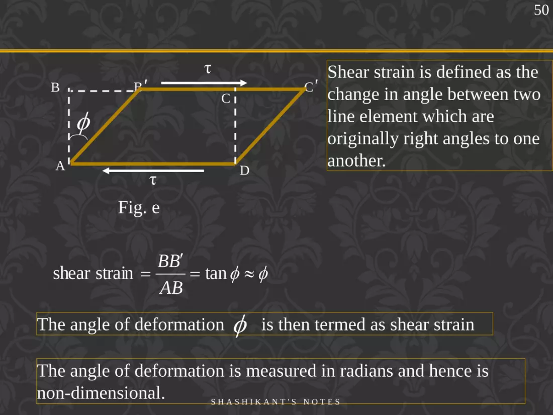
The angle of deformation is measured in radians and hence is
non-dimensional.
D
η B' C'
A η
Fig. e
B C
tanstrain shear AB
BB
The angle of deformation is then termed as shear strain
50
Shear strain is defined as the
change in angle between two
line element which are
originally right angles to one
another.
S H A S H I K A N T ' S N O T E S

SHEAR MODULUS
For materials within the proportionality limit the shear strain is
proportional to the shear stress. Hence the ratio of shear stress to shear
strain is a constant within the proportionality limit.
For Mild steel, G= 80GPa = 80,000MPa = 80,000N/mm2
Shear stress (η)
Shear strain (θ) = constant =
The value of the modulus of rigidity is a definite property of a
material
G Shear Modulus
or
Modulus of Rigidity
=
51
S H A S H I K A N T ' S N O T E S

EXAMPLE: SHEARING STRESS
• Forces P and P‘ are applied
transversely to the member AB.
A
Pave
• The corresponding average shear stress is,
• The resultant of the internal shear force
distribution is defined as the shear of the
section and is equal to the load P.
• Corresponding internal forces act in the
plane of section C and are called
shearing forces.
• The shear stress distribution cannot be
assumed to be uniform.
52
S H A S H I K A N T ' S N O T E S

Double shear
Consider the simple riveted lap joint shown in the Fig.(a). When load is
applied to the plates as shown in the figure the rivet is subjected to shear
forces tending to shear it on one plane as indicated.
Shear stress η (in double shear) = P/2A
But the joint with two cover plates, shown in Fig.(b), the rivet is
subjected to possible shearing on two faces, which is called as double
shear. In such cases twice the area of the rivet is resisting the applied
forces so that the shear stress set up is given by
Fig. a Fig. b
P
P
P
P
53
S H A S H I K A N T ' S N O T E S

A
F
A
Pave
Single Shear
A
F
A
P
2ave
Double Shear
Examples
54
S H A S H I K A N T ' S N O T E S

PIN SHEARING
STRESSES
• The cross-sectional area for
pins at D
26
2
2 m104912
mm25
rA
MPa102m10491
N105026
3
,
A
PaveC
• The force on the pin at C is equal
to the force exerted by the rod BC,
example: Shearing Stress
To find the shearing stress in
pin.
55
Rod BC
S H A S H I K A N T ' S N O T E S

• The cross-sectional area for pins at D,
& E 26
2
2 m104912
mm25
rA
• The pin at A is in double shear with a
total force equal to the force exerted
by the boom AB,
MPa7.40)m10491(2
kN40
2 26,
A
PaveA
example: Double shear 56
Rod AB
S H A S H I K A N T ' S N O T E S

η
State of simple shear
Force on the face AB = P = η × AB × t
Consider an element ABCD in a strained material subjected to shear stress, η as shown in the figure
Where, t is the thickness of the element.
η
A B
C D
Force on the face DC is also equal to P
57
S H A S H I K A N T ' S N O T E S
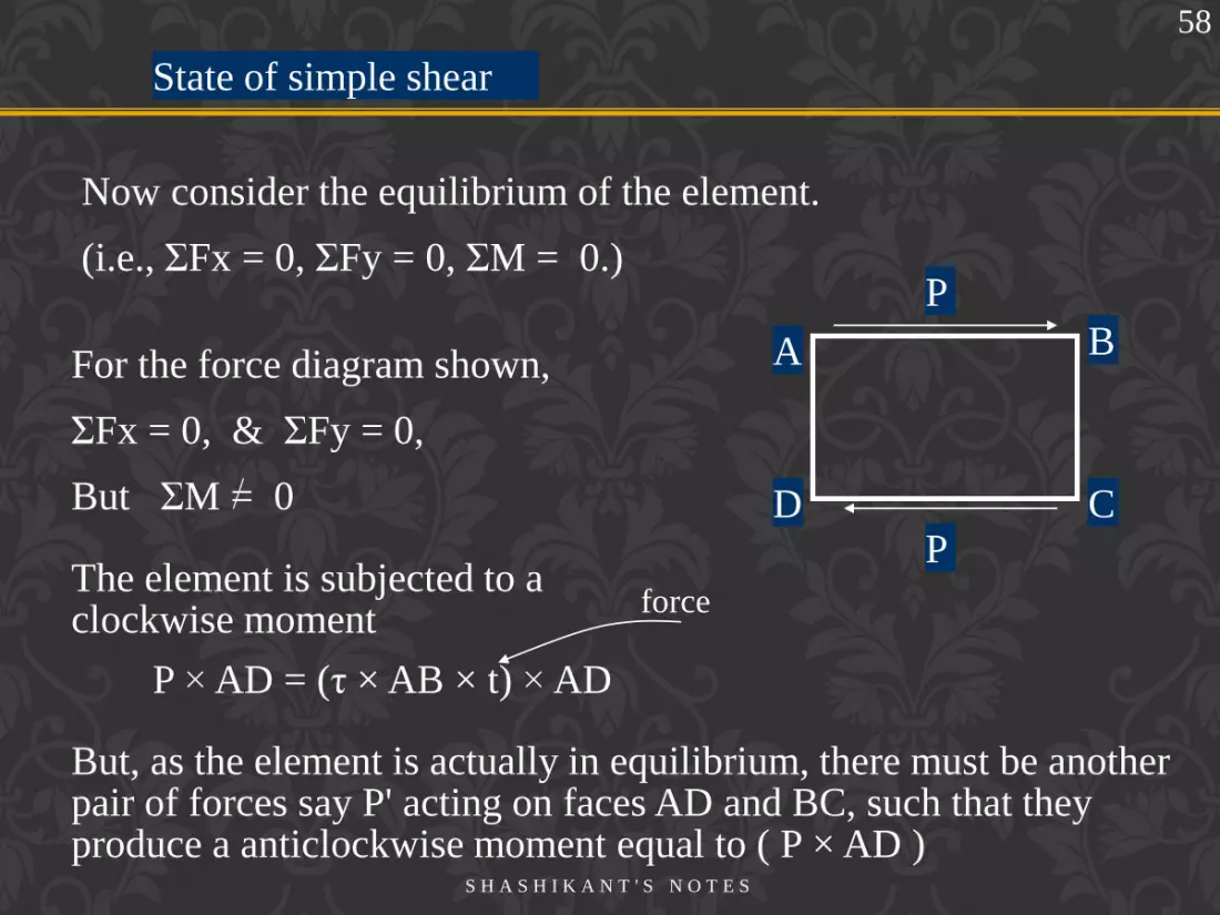
P
State of simple shear
The element is subjected to a clockwise moment
Now consider the equilibrium of the element.
(i.e., ΣFx = 0, ΣFy = 0, ΣM = 0.)
P × AD = (η × AB × t) × AD
P
A B
C D
But, as the element is actually in equilibrium, there must be another pair of forces say P' acting on faces AD and BC, such that they produce a anticlockwise moment equal to ( P × AD )
For the force diagram shown,
ΣFx = 0, & ΣFy = 0,
But ΣM = 0
58
force
S H A S H I K A N T ' S N O T E S

State of simple shear
Equn.(1) can be written as
If η1 is the intensity of the shear stress on the faces AD and BC, then P ' can be written as,
P ' = η ' × AD × t
P ' × AB = P × AD
= (η × AB × t)× AD ----- (1)
P
P
A B
C D
P ' P '
(η ' × AD× t ) × AB = (η × AB × t) × AD ----- (1)
η ' = η
59
η
η
A B
C D
η ' η '
S H A S H I K A N T ' S N O T E S

State of simple shear
Thus in a strained material a shear stress is always
accompanied by a balancing shear of same intensity at right
angles to itself. This balancing shear is called
“complementary shear”.
The shear and the complementary
shear together constitute a state of
simple shear
A B
C D
η'= η
η
η
η'= η
60
S H A S H I K A N T ' S N O T E S

Direct stress due to pure shear
Consider a square element of side „a‟ subjected to shear stress
as shown in the Fig.(a). Let the thickness of the square be
unity.
Fig.(b) shows the deformed shape of the element. The length of
diagonal DB increases, indicating that it is subjected to tensile stress.
Similarly the length of diagonal AC decreases indicating that
compressive stress.
a
A B
C D
η
η
η
η
a
A B
C D
η
η
η
η a
a
Fig.(a). Fig.(b).
61
S H A S H I K A N T ' S N O T E S

Direct stress due to pure shear
Now consider the section, ADC of the element, Fig.(c).
Resolving the forces in the X-direction shown
a
Fig.(c).
a
a
A
C D
a2
For equilibrium
A ζn
C D
η
η
a
X
n
n aa
Fx
45cos212
0
62
S H A S H I K A N T ' S N O T E S

Direct stress due to pure shear
Therefore the intensity of normal tensile stress developed on
plane BD is numerically equal to the intensity of shear stress.
Similarly it can be proved that the intensity of compressive stress
developed on plane AC is numerically equal to the intensity of shear
stress.
63
S H A S H I K A N T ' S N O T E S

Poisson‟s Ratio:
Consider the rectangular bar shown in Fig.(a) subjected to a tensile
load. Under the action of this load the bar will increase in length by
an amount δL giving a longitudinal strain in the bar of
POISSON‟S RATIO
l
ll
Fig.(a)
64
S H A S H I K A N T ' S N O T E S

The associated lateral strains will be equal and are of opposite sense
to the longitudinal strain.
POISSON‟S RATIO
The bar will also exhibit, reduction in dimension laterally, i.e. its
breadth and depth will both reduce. These change in lateral
dimension is measured as strains in the lateral direction as given
below.
d
d
b
blat
Provided the load on the material is retained within the elastic range
the ratio of the lateral and longitudinal strains will always be
constant. This ratio is termed Poisson’s ratio (µ)
POISSON‟S RATIO Lateral strain
Longitudinal strain =
ll
dd
)(
ll
bb
)(
OR
65
S H A S H I K A N T ' S N O T E S

Poisson‟s Ratio = µ
For most engineering metals the value of µ lies between 0.25 and
0.33
In general
z
y
x P P
Poisson‟s Ratio Lateral strain
Strain in the direction of
load applied
=
x
x
y
y
ll
l
l
OR
x
x
z
z
ll
ll
Lx
Ly Lz
66
S H A S H I K A N T ' S N O T E S
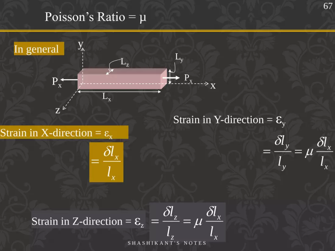
Poisson‟s Ratio = µ
In general
Strain in X-direction = εx
z
y
x Px Px
Lx
Ly Lz
x
x
l
l
Strain in Y-direction = εy
Strain in Z-direction = εz
x
x
y
y
l
l
l
l
x
x
z
z
l
l
l
l
67
S H A S H I K A N T ' S N O T E S

Poisson‟s Ratio Load applied in Y-direction
Poisson‟s Ratio Lateral strain
Strain in the direction of
load applied
=
y
y
x
x
l
l
ll
OR
y
y
z
z
l
l
ll
z
y
x
Py
Lx
Ly Lz
Py
Strain in X-direction = εx
y
y
x
x
l
l
l
l
68
S H A S H I K A N T ' S N O T E S

Poisson‟s Ratio Load applied in Z-direction
Poisson‟s Ratio Lateral strain
Strain in the direction of
load applied
=
z
z
x
x
ll
ll
OR
z
z
y
y
ll
l
l
y
z
x
Pz
Lx
Ly Lz
Pz
Strain in X-direction = εx
z
z
x
x
l
l
l
l
69
S H A S H I K A N T ' S N O T E S

Load applied in X & Y direction
Strain in X-direction = εx
z
y
x Px Px
Lx
Ly Lz
Py
Py
Strain in Y-direction = εy
EE
xy
Strain in Z-direction = εz
EE
xy
EE
yx
70
S H A S H I K A N T ' S N O T E S

General case:
Strain in X-direction = εx
Strain in Y-direction = εy
Strain in Z-direction = εz
z
y
x Px Px
Py
Py Pz
Pz
71
EEE
zyxx
EEE
zxy
y
EEE
xyzz
ζx
ζz
ζy
ζx
ζz ζy
S H A S H I K A N T ' S N O T E S

Bulk Modulus
Bulk Modulus
A body subjected to three mutually perpendicular equal direct stresses
undergoes volumetric change without distortion of shape.
If V is the original volume and dV is the change in volume, then
dV/V is called volumetric strain.
Bulk modulus, K
A body subjected to three mutually perpendicular equal direct stresses
then the ratio of stress to volumetric strain is called Bulk Modulus.
V
dV
72
S H A S H I K A N T ' S N O T E S

RELATIONSHIP BETWEEN VOLUMETRIC STRAIN AND
LINEAR STRAIN
Relative to the unstressed state, the change in
volume per unit volume is
eunit volumper in volume change
1111111
zyx
zyxzyx
dV
Consider a cube of side 1unit, subjected to three
mutually perpendicular direct stresses as shown
in the figure.
73
S H A S H I K A N T ' S N O T E S

RELATIONSHIP BETWEEN VOLUMETRIC STRAIN
AND LINEAR STRAIN
EEE
zyx
EEE
zxy
EEE
xyz
zyx
E
21
zyxV
dV
Volumetric strain
74
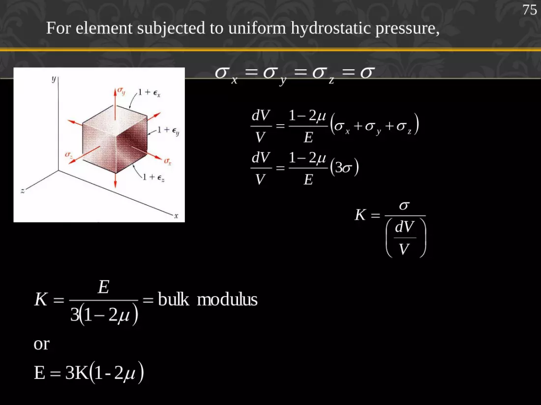
For element subjected to uniform hydrostatic pressure,
2-13KE
or
modulusbulk 213
E
K
zyx
321
21
EV
dV
EV
dVzyx
V
dVK
75

Relationship between young’s modulus of elasticity (E) and
modulus of rigidity (G) :-
A
D η
B
η
a
a 45˚
A1
θ θ
B1
Consider a square element ABCD of side „a‟ subjected to pure shear
„η‟. DA'B'C is the deformed shape due to shear η. Drop a perpendicular
AH to diagonal A'C.
Strain in the diagonal AC = η /E – μ (- η /E) [ ζn= η ]
= η /E [ 1 + μ ] -----------(1)
Strain along the diagonal AC=(A'C–AC)/AC=(A'C–CH)/AC=A'H/AC
C
H
76
S H A S H I K A N T ' S N O T E S

In Δle AA'H
Cos 45˚ = A'H/AA'
A'H= AA' × 1/√2
AC = √2 × AD ( AC = √ AD2 +AD2)
Strain along the diagonal AC = AA'/ (√2 × √2 × AD)=θ/2 ----(2)
Modulus of rigidity = G = η /θ
θ = η /G
Substituting in (2)
Strain along the diagonal AC = η /2G -----------(3)
Equating (1) & (3)
η /2G = η /E[1+μ]
E=2G(1+ μ)
77
S H A S H I K A N T ' S N O T E S

Substituting in (1)
E = 2G[ 1+(3K – 2G)/ (2G+6K)]
E = 18GK/( 2G+6K) E = 9GK/(G+3K)
Relationship between E, G, and K:-
We have
E = 2G( 1+ μ) -----------(1)
E = 3K( 1-2μ) -----------(2)
Equating (1) & (2)
2G( 1+ μ) =3K( 1- 2μ)
2G + 2Gμ=3K- 6Kμ
μ= (3K- 2G) /(2G +6K)
78
S H A S H I K A N T ' S N O T E S

Working stress: It is obvious that one cannot take risk of loading a
member to its ultimate strength, in practice. The maximum stress to
which the material of a member is subjected to in practice is called
working stress.
This value should be well within the elastic limit in elastic design
method.
Factor of safety: Because of uncertainty of loading conditions,
design procedure, production methods, etc., designers generally
introduce a factor of safety into their design, defined as follows
Factor of safety = Allowable working stress
Maximum stress
Allowable working stress
Yield stress (or proof stress) or
79
S H A S H I K A N T ' S N O T E S

Homogeneous: A material which has a uniform structure throughout
without any flaws or discontinuities.
Malleability: A property closely related to ductility, which defines a
material‟s ability to be hammered out in to thin sheets
80
Isotropic: If a material exhibits uniform properties throughout in all
directions it is said to be isotropic.
Anisotropic: If a material does not exhibits uniform properties
throughout in all directions it is said to be anisotropic or nonisotropic.
S H A S H I K A N T ' S N O T E S

SAINT-VENANT’S
PRINCIPLE
• Loads transmitted through
rigid plates result in uniform
distribution of stress and
strain.
• Concentrated loads result in
large stresses in the vicinity of
the load application point.
81
S H A S H I K A N T ' S N O T E S

SAINT-VENANT’S
PRINCIPLE
• Saint-Venant’s Principle:
Stress distribution may be
assumed independent of the mode
of load application except in the
immediate vicinity of load
application points.
• Stress and strain distributions
become uniform at a relatively
short distance from the load
application points.
82
b
S H A S H I K A N T ' S N O T E S

The normal stress at a particular point may
not be equal to the average stress but the
resultant of the stress distribution must
satisfy
A
ave dAdFAP
83
S H A S H I K A N T ' S N O T E S

Exercise Problems
1 An aluminum tube is rigidly fastened between a brass rod and
steel rod. Axial loads are applied as indicated in the figure.
Determine the stresses in each material and total deformation.
Take Ea=70GPa, Eb=100GPa, Es=200GPa
500mm 700mm 600mm
steel aluminum
brass 20kN 15kN 15kN 10kN
Ab=700mm2
Aa=1000mm2
As=800mm2
Ans: ζb=28.57MPa, ζa=5MPa, ζs=12.5MPa, δl = - 0.142mm
84
S H A S H I K A N T ' S N O T E S

Example 7
2. A 2.4m long steel bar has uniform diameter of 40mm for a
length of 1.2m and in the next 0.6m of its length its diameter
gradually reduces to „D‟ mm and for remaining 0.6m of its
length diameter remains the same as shown in the figure. When
a load of 200kN is applied to this bar extension observed is
equal to 2.59mm. Determine the diameter „D‟ of the bar. Take E
=200GPa
Ф = 40mm
Ф = D mm
200kN 200kN
500mm 500mm 1000mm
85
S H A S H I K A N T ' S N O T E S

Exercise Problems
3 The diameter of a specimen is found to reduce by 0.004mm when
it is subjected to a tensile force of 19kN. The initial diameter of
the specimen was 20mm. Taking modulus of rigidity as 40GPa
determine the value of E and µ
Ans: E=110GPa, µ=0.36
4 A circular bar of brass is to be loaded by a shear load of 30kN.
Determine the necessary diameter of the bars (a) in single shear
(b) in double shear, if the shear stress in material must not exceed
50MPa.
Ans: 27.63mm, 19.54mm
86
S H A S H I K A N T ' S N O T E S

Exercise Problems
5 Determine the largest weight W that can be supported by the two
wires shown. Stresses in wires AB and AC are not to exceed
100MPa and 150MPa respectively. The cross sectional areas of
the two wires are 400mm2 for AB and 200mm2 for AC.
Ans: 33.4kN
W A
C B
300 450
87
S H A S H I K A N T ' S N O T E S

Exercise Problems
6 A homogeneous rigid bar of weight 1500N carries a 2000N load
as shown. The bar is supported by a pin at B and a 10mm
diameter cable CD. Determine the stress in the cable
Ans: 87.53MPa
3m
A C B
2000 N
3m
D
88
S H A S H I K A N T ' S N O T E S

7. A stepped bar with three different cross-sectional areas, is
fixed at one end and loaded as shown in the figure. Determine
the stress and deformation in each portions. Also find the net
change in the length of the bar. Take E = 200GPa
250mm 270mm 320mm
300mm2 450mm2
250mm2
10kN 40kN
20kN
Ans: -33.33, -120, 22.2MPa, -0.042, -0.192, 0.03mm, -0.204mm
89
S H A S H I K A N T ' S N O T E S

8 The coupling shown in figure is constructed from steel of
rectangular cross-section and is designed to transmit a tensile
force of 50kN. If the bolt is of 15mm diameter calculate:
a) The shear stress in the bolt;
b) The direct stress in the plate;
c) The direct stress in the forked end of the coupling.
Ans: a)141.5MPa, b)166.7MPa, c)83.3MPa
90
S H A S H I K A N T ' S N O T E S

Exercise Problems
9 The maximum safe compressive stress in a hardened steel punch
is limited to 1000MPa, and the punch is used to pierce circular
holes in mild steel plate 20mm thick. If the ultimate shearing
stress is 312.5MPa, calculate the smallest diameter of hole that
can be pierced.
Ans: 25mm
91
10. A rectangular bar of 250mm long is 75mm wide and 25mm
thick. It is loaded with an axial tensile load of 200kN, together
with a normal compressive force of 2000kN on face
75mm×250mm and a tensile force 400kN on face
25mm×250mm. Calculate the change in length, breadth,
thickness and volume. Take E = 200GPa & µ=0.3
Ans: 0.15,0.024,0.0197mm, 60mm3 S H A S H I K A N T ' S N O T E S
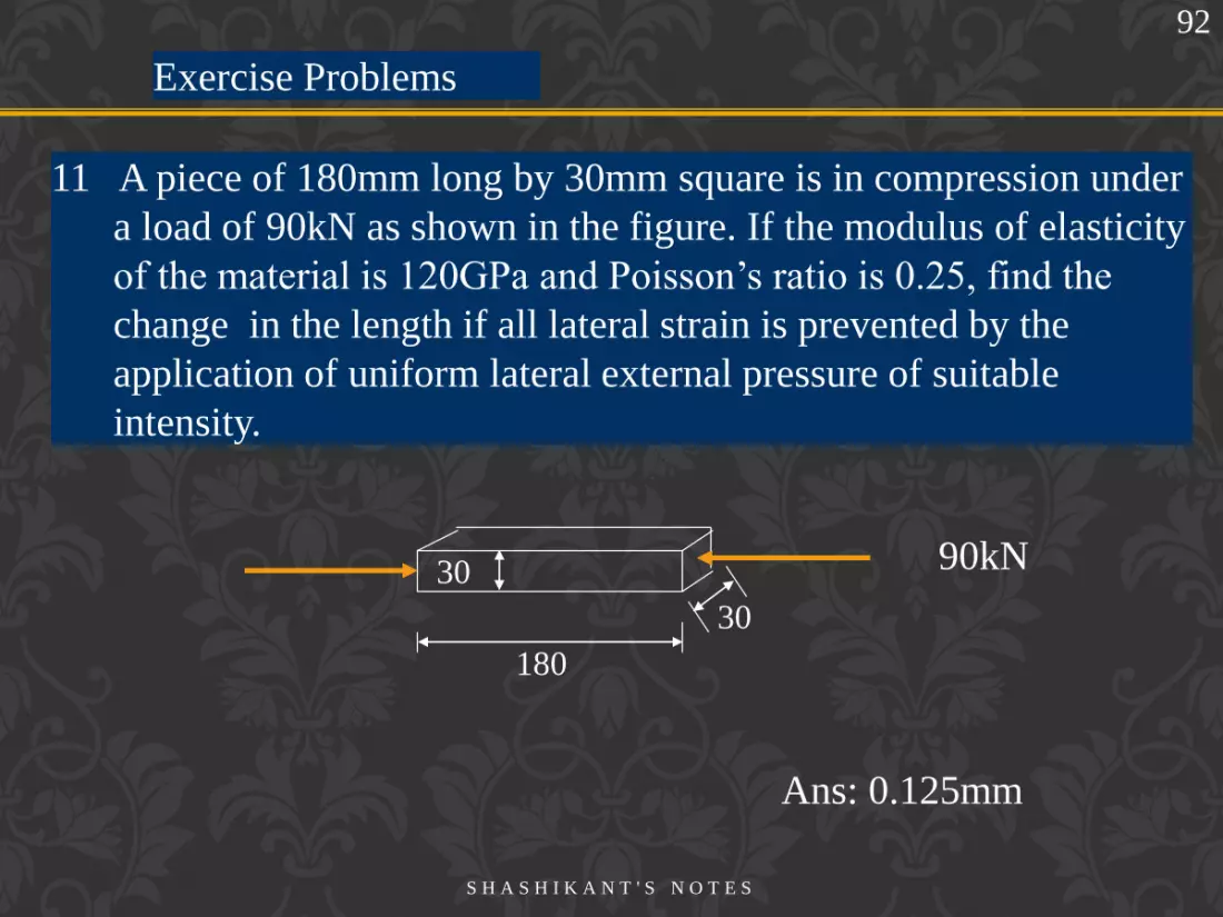
Exercise Problems
11 A piece of 180mm long by 30mm square is in compression under
a load of 90kN as shown in the figure. If the modulus of elasticity
of the material is 120GPa and Poisson‟s ratio is 0.25, find the
change in the length if all lateral strain is prevented by the
application of uniform lateral external pressure of suitable
intensity.
180
90kN 30
30
Ans: 0.125mm
92
S H A S H I K A N T ' S N O T E S

12. Define the terms: stress, strain, elastic limit, proportionality
limit, yield stress, ultimate stress, proof stress, true stress, factor
of safety, Young‟s modulus, modulus of rigidity, bulk modulus,
Poisson's ratio,
13. Draw a typical stress-strain diagram for mild steel rod under
tension and mark the salient points.
14. Diameter of a bar of length „L‟ varies from D1 at one end to D2
at the other end. Find the extension of the bar under the axial load
P
15. Derive the relationship between Young‟s modulus and modulus
of rigidity.
93
S H A S H I K A N T ' S N O T E S

17. A flat plate of thickness „t‟ tapers uniformly from a width b1at
one end to b2 at the other end, in a length of L units. Determine
the extension of the plate due to a pull P.
18. Find the extension of a conical rod due to its own weight when
suspended vertically with its base at the top.
19. Prove that a material subjected to pure shear in two perpendicular
planes has a diagonal tension and compression of same
magnitude at 45o to the planes of shear.
16. Derive the relationship between Young‟s modulus and Bulk
modulus.
94
S H A S H I K A N T ' S N O T E S

95
20 For a given materials E=1.1×10⁵N/mm2& G=0.43×10⁵N/mm2
.Find bulk modulus & lateral contraction of round bar 40mm
diameter & 2.5m length when stretched by 2.5mm.
ANS: K=83.33Gpa, Lateral contraction=0.011mm
21. The modulus of rigidity of a material is 0.8×10⁵N/mm2 , when
6mm×6mm bar of this material subjected to an axial pull of
3600N.It was found that the lateral dimension of the bar is
changed to 5.9991mm×5.9991mm. Find µ & E. ANS: µ=0.31,
E= 210Gpa.
S H A S H I K A N T ' S N O T E S
Copyright © 2022 FDOKUMEN