
Variable silhouette energy image representations for recognizing human actions
IEEE TRANSACTIONS ON SYSTEMS, MAN AND CYBERNETICS, PART B 1
Silhouette-based 3D Model Reconstruction from
Multiple Images
Adem Yasar Mulayim, Ulas Yılmaz, Volkan Atalay
Abstract
The goal of this study is to investigate the reconstruction of 3D graphical models of real objects in a controlled
imaging environment and present the work done in our group based on silhouette-based reconstruction. Although many
parts of the whole system have been well-known in the literature and in practice, the main contribution of the paper
is that it describes a complete, end-to-end system explained in detail. Based on a multi-image calibration method,
an algorithm to extract the rotation axis of a turn-table has been developed. Furthermore, this can be extended to
estimate robustly the initial bounding volume of the object to be modeled. The disadvantages of the silhouette-based
reconstruction can be removed by an algorithm using photoconsistency. This algorithm has a simpler visibility check,
and it eliminates the selection of threshold existing in similar algorithms. Besides, in order to construct the appearance,
we use the concept of particles. The reconstruction results are shown both on real world and synthetic objects.
Keywords
3D object modeling, silhouette-based reconstruction, photoconsistency, texture mapping
I. INTRODUCTION
RECONSTRUCTION of a complex three dimensional (3D) rigid object from its two dimensional (2D)
images is a challenging computer vision problem under general imaging conditions. Without a priori
information about the imaging environment (camera geometry, lighting conditions, object and background
surface properties, etc.), it becomes very difficult to infer the 3D structure of the captured rigid object. For
practical 3D reconstruction solutions, the problem can be simplified by using controlled imaging environments.
Ulas Yılmaz and Volkan Atalay are working at the Department of Computer Engineering, Middle East Technical University,
TR-06531, Ankara, Turkey as research assistant and associate proffesor, respectively. Adem Yasar Mulayim had recently received
his PhD from the same Department. Emails: [email protected], [email protected] and [email protected].
IEEE TRANSACTIONS ON SYSTEMS, MAN AND CYBERNETICS, PART B 2
In such an environment, camera makes a controlled motion around the object, and background surface and
lighting are selected to reduce the specularities on the acquired image. A setup consisting of a rotary table
(turn-table) with a fixed camera is generally used in order to obtain a controlled camera motion around the
object [1], [2]. The camera has to be calibrated in such a setup to obtain the internal and external parameters
defining the physical properties of the camera and the camera imaging positions with respect to the rotary
table turn angles [1], [2], [3], [4], [5] although other alternatives also exist [6]. A silhouette-based volume
intersection algorithm can then be applied to reconstruct a coarse 3D volume (approximated visual hull) of
the object by using the previously obtained camera parameters for the acquired images [1], [2], [6], [7], [8],
[9], [10], [11], [12], [13], [14]. Furthermore, in order to give a realistic appearance to the constructed model,
texture or the color information can be added [15], [16], [17], [18], [19], [20], [21].
In this paper, we describe a 3D object modeling system using silhouette-based volume intersection method
for reconstruction under a controlled imaging environment and present the work done in our group for such a
reconstruction. In order to capture images around an object and to find the camera parameters corresponding
to these views, we use an acquisition system composed of a fixed camera and a rotary table as shown in Figure 1.
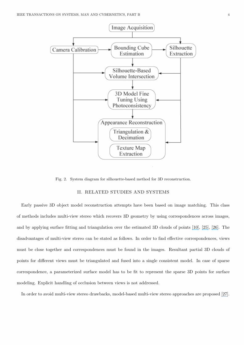
The system diagram is shown in Figure 2, and its details are discussed in the remaining sections of this
paper. In order to compute the parameters of the camera, we use a multi-image calibration approach [22]. Due
to our acquisition setup, the rotation axis and distance from the camera center to this rotation axis remain
the same during the turns of the table. Based on this idea, a vision-based geometrical calibration algorithm
have been developed for the rotary table [3]. One of the advantages of this algorithm is that it is more robust
than the single image calibration methods. Furthermore, we can compute very easily the distance between
the rotation axis of the table with respect to the camera center which in fact facilitates the calculation of the
bounding box [23]. The initial estimation of the bounding box is not an essential step but leads to more efficient
computations in the subsequent steps. Keeping the number of voxels constant, the size of the bounding box
affects the resolution of the final model: smaller the box, less the quantization effects. Use of particles during
the appearance reconstruction is a relatively new topic and we have been able to implement this idea although

IEEE TRANSACTIONS ON SYSTEMS, MAN AND CYBERNETICS, PART B 3
Fig. 1. System setup for image acquisition.
there are also similar studies [19]. There are disadvantages of the silhouette-based reconstruction algorithm. In
this context, we have implemented an algorithm which removes the disadvantages using photoconsistency [24].
Although many parts of the whole system have been well-known in the literature and in practice, the main
contribution of the paper is that it describes a complete, end-to-end system explained in detail in which the
essential algorithms are given so that interested reader can easily implement the approach.
The organization of this paper is as follows. We first describe the related studies and the systems in the
following section. Vision-based geometrical calibration algorithm, extraction of the rotation axis and a robust
estimation of the initial bounding box are explained in Section III. The voxelization of this initial volume with
respect to the images is given in IV. Our model fine tuning approach is described in detail in Section V. In
Section VI, surface triangulation of the resultant volume and the appearance reconstruction of the triangulated
model is explained. Sample reconstructions are shown in Section VII. The paper concludes with Section VIII
in which we discuss the presented study and state eventual improvements.
IEEE TRANSACTIONS ON SYSTEMS, MAN AND CYBERNETICS, PART B 4
Fig. 2. System diagram for silhouette-based method for 3D reconstruction.
II. RELATED STUDIES AND SYSTEMS
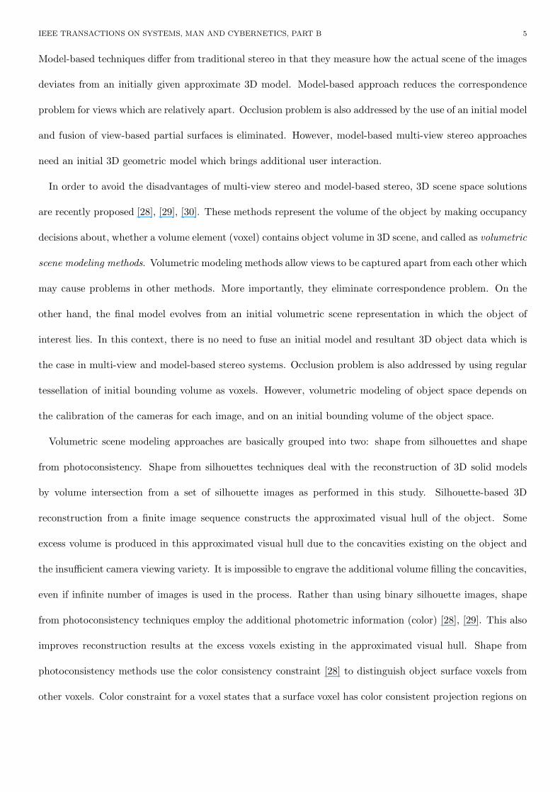
Early passive 3D object model reconstruction attempts have been based on image matching. This class
of methods includes multi-view stereo which recovers 3D geometry by using correspondences across images,
and by applying surface fitting and triangulation over the estimated 3D clouds of points [10], [25], [26]. The
disadvantages of multi-view stereo can be stated as follows. In order to find effective correspondences, views
must be close together and correspondences must be found in the images. Resultant partial 3D clouds of
points for different views must be triangulated and fused into a single consistent model. In case of sparse
correspondence, a parameterized surface model has to be fit to represent the sparse 3D points for surface
modeling. Explicit handling of occlusion between views is not addressed.
In order to avoid multi-view stereo drawbacks, model-based multi-view stereo approaches are proposed [27].
IEEE TRANSACTIONS ON SYSTEMS, MAN AND CYBERNETICS, PART B 5
Model-based techniques differ from traditional stereo in that they measure how the actual scene of the images
deviates from an initially given approximate 3D model. Model-based approach reduces the correspondence
problem for views which are relatively apart. Occlusion problem is also addressed by the use of an initial model
and fusion of view-based partial surfaces is eliminated. However, model-based multi-view stereo approaches
need an initial 3D geometric model which brings additional user interaction.
In order to avoid the disadvantages of multi-view stereo and model-based stereo, 3D scene space solutions
are recently proposed [28], [29], [30]. These methods represent the volume of the object by making occupancy
decisions about, whether a volume element (voxel) contains object volume in 3D scene, and called as volumetric
scene modeling methods. Volumetric modeling methods allow views to be captured apart from each other which
may cause problems in other methods. More importantly, they eliminate correspondence problem. On the
other hand, the final model evolves from an initial volumetric scene representation in which the object of
interest lies. In this context, there is no need to fuse an initial model and resultant 3D object data which is
the case in multi-view and model-based stereo systems. Occlusion problem is also addressed by using regular
tessellation of initial bounding volume as voxels. However, volumetric modeling of object space depends on
the calibration of the cameras for each image, and on an initial bounding volume of the object space.
Volumetric scene modeling approaches are basically grouped into two: shape from silhouettes and shape
from photoconsistency. Shape from silhouettes techniques deal with the reconstruction of 3D solid models
by volume intersection from a set of silhouette images as performed in this study. Silhouette-based 3D
reconstruction from a finite image sequence constructs the approximated visual hull of the object. Some
excess volume is produced in this approximated visual hull due to the concavities existing on the object and
the insufficient camera viewing variety. It is impossible to engrave the additional volume filling the concavities,
even if infinite number of images is used in the process. Rather than using binary silhouette images, shape
from photoconsistency techniques employ the additional photometric information (color) [28], [29]. This also
improves reconstruction results at the excess voxels existing in the approximated visual hull. Shape from
photoconsistency methods use the color consistency constraint [28] to distinguish object surface voxels from
other voxels. Color constraint for a voxel states that a surface voxel has color consistent projection regions on
IEEE TRANSACTIONS ON SYSTEMS, MAN AND CYBERNETICS, PART B 6
the images from which it is seen. Use of shape from photoconsistency approach avoids point correspondence
difficulties. 3D reconstruction based on photoconsistency requires camera parameters for each used view and
a model for the object surface reflectance. Furthermore, a very important issue in these methods is the
criterion for consistency check. Most of the consistency criteria require a threshold or an input from the user.
In addition, voxel visibility problem has to be well addressed since the color consistency check for a voxel
requires the set of images from which the voxel is visible. Efficiency in the visibility test for every voxel is
essential. In order to easily maintain visibility information for voxels, voxel coloring algorithm proposed by
Seitz and Dyer [28] restricts the position of cameras so that no object point is contained within the convex
hull of the camera centers. However, there are several extensions to the initial voxel coloring algorithm for
the visibility problem [29], [30], [31], [32], [33]. Instead of using these extensions and alternatives requiring
additional space and complex updates as carving progress, or using multi sweeps along the coordinate axes,
traversing a ray from the voxel center through the camera center is proposed to check visibility in our study.
It is also possible to find the maximum photoconsistent voxels on the ray and this eliminates threshold checks
while carving the voxel from the initial set. This algorithm is mostly inspired from Matsumoto et.al. [14].
In the recent years, there was a significant interest in 3D reconstruction from uncalibrated views [6], [34],
[35], [36]. These auto-calibration techniques have been the object of a tremendous amount of work [37],
[38], [39], [40], [41] and effective methods to derive the epipolar geometry and the trifocal tensor from point
correspondences have been devised [6], [42]. However, most of these methods assume that it is possible to run
an interest operator such as a corner detector [6], [41] to extract from one of the images a sufficiently large
number of points that can then be reliably matched in the other images. When using images exhibiting too
little texture, such interest points are not reliable. It has been shown that projective, affine and Euclidean
reconstructions can be obtained from uncalibrated views [36], [37], [43], [44], [45]. However, these methods
are sensitive to noise and initialization [45] and generally, the reconstruction results are valid up to a scale
factor.
Historically, one of the first complete 3D modeling system based on silhouette images is the series of studies
by Niem et.al. [1], [46] which is also called Hannover system. Many concepts and techniques of the current
IEEE TRANSACTIONS ON SYSTEMS, MAN AND CYBERNETICS, PART B 7
systems are based on the ones explained and implemented in this system. In the Hannover system, although
there is an attempt to refine the model, the method is not explained demonstrated well. Another system has
been proposed by Matsumoto et.al. [2]. Several concepts, such as voting in the implementation of volume
intersection are introduced by this group. Furthermore, carving the voxels of the model resulting from shape
from silhouette by the use of multiple view-based stereo has also been described [14]. On the other hand,
the details and the experimental results are not given. The system described by Gibson et.al. [47] requires
no pre-calibration of the camera and uses full perspective geometry. The authors claim that self-calibration
is used. However, there is no detailed information given in the paper regarding to this subject. Fitzgibbon
et.al. [6] describe the projective geometry of single axis rotation (rotation similar to that discussed in our
work) and give its automatic and optimal estimation from an image sequence. However, it is shown that
3D structure and cameras can be calibrated up to an overall two-parameter ambiguity. The two parameter
reconstruction ambiguity is removed by specifying camera aspect ratio and parallel scene lines. Apart from
the use of uncalibrated multiple views, the system is very similar to that of Hannover. In addition, the work
does not indicate any further refinement to remove disadvantages of volume intersection method. A study
which is in the same direction as the previous one is by Mendonca et.al. [48] in which a method is described
for motion estimation for an object rotating around a fixed axis. Based on this information, 3D positions of
the points on the contours of the object is then found by the triangulation and epipolar parameterization. The
method is relatively simple and elegant, particularly compared to that proposed by Fitzgibbon et.al. [6] since
a few number of correspondences is sufficient. One point which is not very clear in the study of Mendonca
et.al. [48] is that for the reconstruction of an object model, some kind of interpolation would be required since
only contour information is used. Furthermore, only a few number of results are demonstrated. Our study
has several common points with the work by Schmitt et.al. [19], [49]. However, our work differs particularly
in the calibration, bounding box finding and the carving aspects.
IEEE TRANSACTIONS ON SYSTEMS, MAN AND CYBERNETICS, PART B 8
III. VISION-BASED GEOMETRICAL CALIBRATION OF A TURN-TABLE AND
EXTRACTION OF ROTATION AXIS
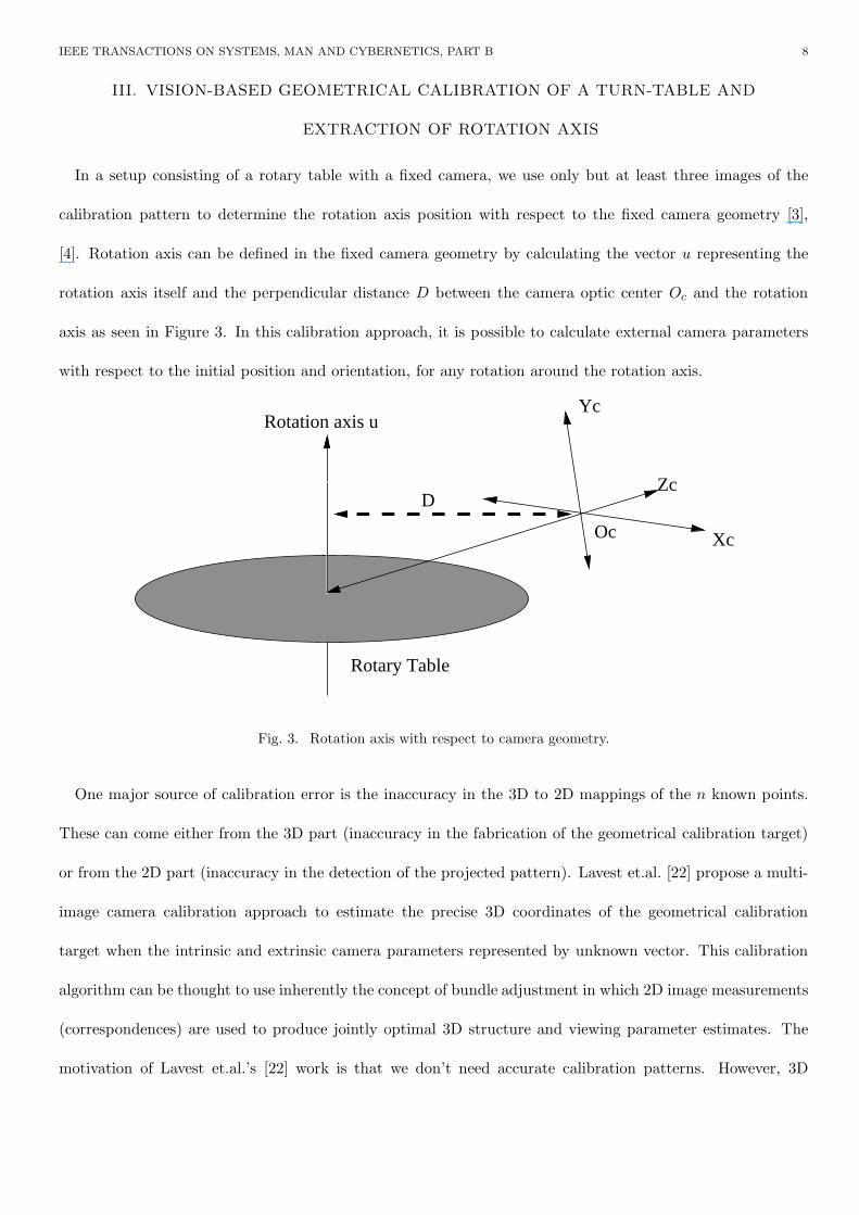
In a setup consisting of a rotary table with a fixed camera, we use only but at least three images of the
calibration pattern to determine the rotation axis position with respect to the fixed camera geometry [3],
[4]. Rotation axis can be defined in the fixed camera geometry by calculating the vector u representing the
rotation axis itself and the perpendicular distance D between the camera optic center Oc and the rotation
axis as seen in Figure 3. In this calibration approach, it is possible to calculate external camera parameters
with respect to the initial position and orientation, for any rotation around the rotation axis.
Oc
Yc
Xc
Zc
Rotary Table
D
Rotation axis u
Fig. 3. Rotation axis with respect to camera geometry.
One major source of calibration error is the inaccuracy in the 3D to 2D mappings of the n known points.
These can come either from the 3D part (inaccuracy in the fabrication of the geometrical calibration target)
or from the 2D part (inaccuracy in the detection of the projected pattern). Lavest et.al. [22] propose a multi-
image camera calibration approach to estimate the precise 3D coordinates of the geometrical calibration
target when the intrinsic and extrinsic camera parameters represented by unknown vector. This calibration
algorithm can be thought to use inherently the concept of bundle adjustment in which 2D image measurements
(correspondences) are used to produce jointly optimal 3D structure and viewing parameter estimates. The
motivation of Lavest et.al.’s [22] work is that we don’t need accurate calibration patterns. However, 3D
IEEE TRANSACTIONS ON SYSTEMS, MAN AND CYBERNETICS, PART B 9
positions of calibration pattern points provide an initial guess. Then, starting from the 2D positions of
pattern points extracted from images, the camera parameters for the image sequence and the 3D positions of
pattern points are estimated. Therefore, we may say that Lavest et.al.’s [22] method is a bundle adjustment.
Rotation axis of the turn-table with respect to the fixed camera coordinate frame can be defined by a unit
vector u in the direction of the rotation axis and by the translation vector D perpendicular to u, corresponding
to the projection of the optical center of the camera onto the rotation axis as shown in Figure 3. Using
the rigid transformations Qi between the fixed camera and position i of the calibration pattern, a vector
u representing the rotation axis, and a point p on this vector defined in the camera coordinates can be
calculated geometrically [3], [4]. This is totally a geometric computation which does not depend on an
estimation procedure. In our study, we use the extracted rotation axis to estimate the initial bounding box
of the object in the silhouette-based reconstruction.
If the camera parameters and the object silhouettes on the images are known, the coarse object volume which
is in fact a convex hull of the object can be computed. In this procedure, we first estimate the bounding box
which is the rectangular prism or box having the minimum volume and at the same time including the object.
Since the rotation axis of the rotary table is defined with respect to the camera geometry by the calibration
process, the bounding box is calculated easily by backprojecting the silhouette bounding rectangles from all
of the imaging views and then intersecting the resultant open volumes [23].
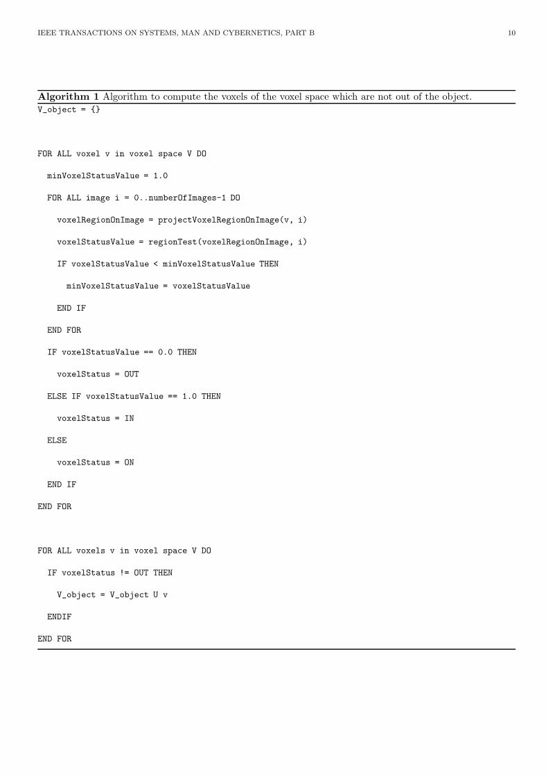
IV. VOXELIZATION
After obtaining the bounding box of the object to be modeled, we then discretize it by dividing into small
cubes or voxels. Assuming that each side of the box is divided into n voxels, a voxel space V containing n3
voxels is generated. Subsequently, we project each cube in the voxel space V onto the images by using the
related camera parameters. If the projected cube region on any selected image is totally not contained by the
silhouette region, it is removed from the voxel space. Otherwise, it is kept in the object voxel space either as
the ’ON’ voxel or as the ’IN’ voxel with respect to the result of voxel projection region tests for all the views.
Algorithm 1 basically gives the idea.
IEEE TRANSACTIONS ON SYSTEMS, MAN AND CYBERNETICS, PART B 10
Algorithm 1 Algorithm to compute the voxels of the voxel space which are not out of the object.V_object = {}
FOR ALL voxel v in voxel space V DO
minVoxelStatusValue = 1.0
FOR ALL image i = 0..numberOfImages-1 DO
voxelRegionOnImage = projectVoxelRegionOnImage(v, i)
voxelStatusValue = regionTest(voxelRegionOnImage, i)
IF voxelStatusValue < minVoxelStatusValue THEN
minVoxelStatusValue = voxelStatusValue
END IF
END FOR
IF voxelStatusValue == 0.0 THEN
voxelStatus = OUT
ELSE IF voxelStatusValue == 1.0 THEN
voxelStatus = IN
ELSE
voxelStatus = ON
END IF
END FOR
FOR ALL voxels v in voxel space V DO
IF voxelStatus != OUT THEN
V_object = V_object U v
ENDIF
END FOR
IEEE TRANSACTIONS ON SYSTEMS, MAN AND CYBERNETICS, PART B 11
V. 3D MODEL FINE TUNING USING PHOTOCONSISTENCY
Silhouette-based 3D reconstruction using a finite set of object images results in an approximated visual hull
of the object. The obtained visual hull is guaranteed to enclose the object in 3D space, since it is the maximal
shape which gives the same silhouette as the actual object images for all camera views used in the acquisition
of the images. However, excess voxels (volume) is produced in the visual hull which is approximated by a
silhouette-based volume intersection approach, because of the concavities on the object and the insufficient
camera viewing variety. Since it is very challenging to find the best views to eliminate the excess voxels
coming from the insufficient camera viewing variety, and it is impossible to engrave the additional voxels
filling the concave regions, silhouette-based reconstruction have to be augmented with another method. Using
photometric information existing in the consecutive images from the acquired image sequence is a practical
candidate, if the object surface contains well grained texture and if there exists corresponding regions in the
consecutive images.
In the practical turn-table and a fixed camera acquisition environment, if the turn angle between each
acquisition step is smaller than 180o, consecutive images from the sequence would contain the same object
regions as the object topology permits. The area of this common observation regions for the consecutive
camera positions increases as the turn step angle decreases.
In the approximated visual hull of the object obtained from finite set of images, each surface voxel has a
set of images from which the voxel can be seen. If it is assumed that a surface voxel placed in correct depth
meaning that it is on the real object surface, then stereo theory states that its projections on the images from
which it can be seen, must be the corresponding regions. In other words voxels in the approximated visual
hull, having correct depth placement have photoconsistent projections on the images from which voxels are
seen without occlusion.
The idea, theory and algorithm of using photoconsistency and carving in volumetric voxel spaces is first
introduced by [28] and have recently been improved by several researchers [14], [28], [29], [30], [50]. The
approaches using photoconsistency is generally called voxel coloring. Starting from an initial set of opaque
IEEE TRANSACTIONS ON SYSTEMS, MAN AND CYBERNETICS, PART B 12
voxels, voxel coloring algorithm carves the voxels that are not photoconsistent as it iterates on the opaque
voxels. The algorithm stops when all the opaque voxels are color consistent. However, in these studies either
the approach is not applicable to our case or there is no clear explanation for the implementation. Therefore,
here we describe in detail how the previous ideas can be applied to our case and efficiently implemented.
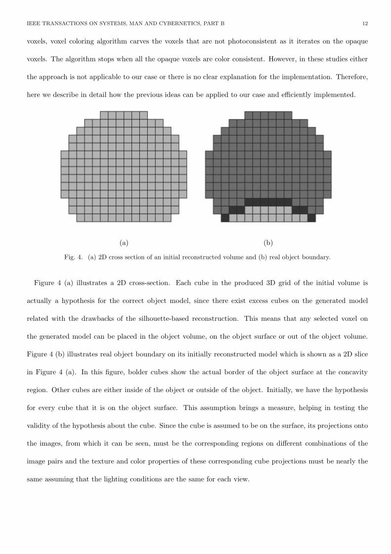
(a) (b)
Fig. 4. (a) 2D cross section of an initial reconstructed volume and (b) real object boundary.
Figure 4 (a) illustrates a 2D cross-section. Each cube in the produced 3D grid of the initial volume is
actually a hypothesis for the correct object model, since there exist excess cubes on the generated model
related with the drawbacks of the silhouette-based reconstruction. This means that any selected voxel on
the generated model can be placed in the object volume, on the object surface or out of the object volume.
Figure 4 (b) illustrates real object boundary on its initially reconstructed model which is shown as a 2D slice
in Figure 4 (a). In this figure, bolder cubes show the actual border of the object surface at the concavity
region. Other cubes are either inside of the object or outside of the object. Initially, we have the hypothesis
for every cube that it is on the object surface. This assumption brings a measure, helping in testing the
validity of the hypothesis about the cube. Since the cube is assumed to be on the surface, its projections onto
the images, from which it can be seen, must be the corresponding regions on different combinations of the
image pairs and the texture and color properties of these corresponding cube projections must be nearly the
same assuming that the lighting conditions are the same for each view.
IEEE TRANSACTIONS ON SYSTEMS, MAN AND CYBERNETICS, PART B 13
In order to test the photoconsistency of an individual voxel, the image set from which the voxel is visible
must be determined correctly and efficiently. Visibility checking is the elusive part of the algorithms based
on photoconsistency since opaque voxels occlude each other in a complex and constantly changing pattern as
carving progress. To simplify visibility check Seitz and Dyer use ordinal visibility constraint on the camera
locations bringing single pass visibility test for all opaque voxels [28]. However the ordinal visibility constraint
has a significant limitation since it requires all camera locations placed at one side of the scene. Solutions
for arbitrary camera placement have been proposed by using multiple plane sweeps along the positive and
negative directions of each coordinate axes [29], and by using special data structures named as item buffers
and layered depth images [30].
Instead of using item buffers or layered depth images requiring additional space and complex updates as
carving progress, or using multi sweeps along the coordinate axes, traversing a ray from the voxel center
through the camera center is proposed to check visibility in our study. A voxel v is invisible from a view
i if there exists other opaque voxels in between v and the camera center i, otherwise the voxel v is visible.
Since it is also possible to find the maximum photoconsistent voxels on the ray, it also helps to eliminate
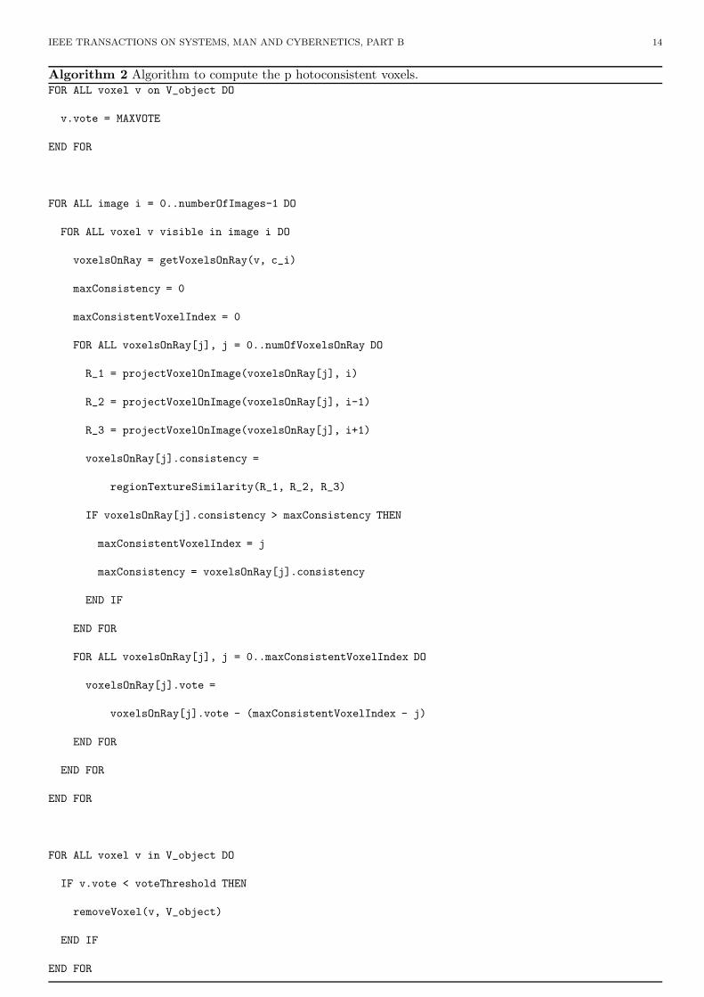
threshold checks while carving the voxel from the initial opaque set. Algorithm 2 which is mostly inspired
from Matsumoto et.al. [14] outlines our carving solution.
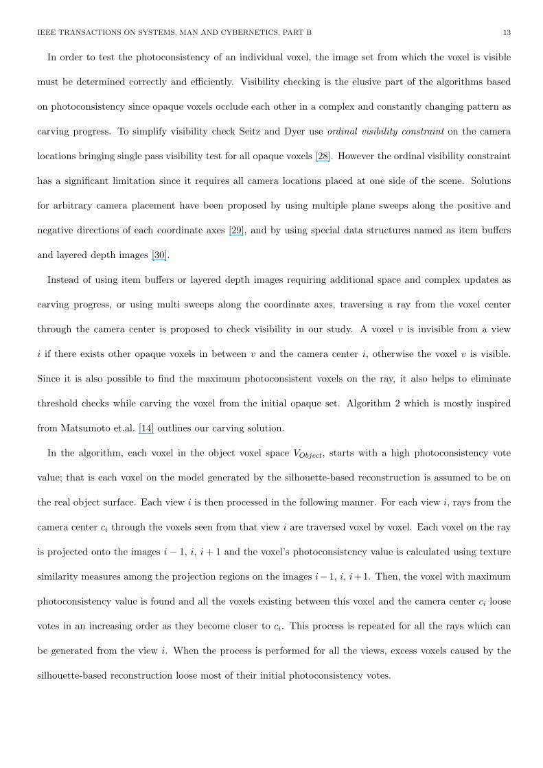
In the algorithm, each voxel in the object voxel space VObject, starts with a high photoconsistency vote
value; that is each voxel on the model generated by the silhouette-based reconstruction is assumed to be on
the real object surface. Each view i is then processed in the following manner. For each view i, rays from the
camera center ci through the voxels seen from that view i are traversed voxel by voxel. Each voxel on the ray
is projected onto the images i − 1, i, i + 1 and the voxel’s photoconsistency value is calculated using texture
similarity measures among the projection regions on the images i−1, i, i+1. Then, the voxel with maximum
photoconsistency value is found and all the voxels existing between this voxel and the camera center ci loose
votes in an increasing order as they become closer to ci. This process is repeated for all the rays which can
be generated from the view i. When the process is performed for all the views, excess voxels caused by the
silhouette-based reconstruction loose most of their initial photoconsistency votes.
IEEE TRANSACTIONS ON SYSTEMS, MAN AND CYBERNETICS, PART B 14
Algorithm 2 Algorithm to compute the p hotoconsistent voxels.FOR ALL voxel v on V_object DO
v.vote = MAXVOTE
END FOR
FOR ALL image i = 0..numberOfImages-1 DO
FOR ALL voxel v visible in image i DO
voxelsOnRay = getVoxelsOnRay(v, c_i)
maxConsistency = 0
maxConsistentVoxelIndex = 0
FOR ALL voxelsOnRay[j], j = 0..numOfVoxelsOnRay DO
R_1 = projectVoxelOnImage(voxelsOnRay[j], i)
R_2 = projectVoxelOnImage(voxelsOnRay[j], i-1)
R_3 = projectVoxelOnImage(voxelsOnRay[j], i+1)
voxelsOnRay[j].consistency =
regionTextureSimilarity(R_1, R_2, R_3)
IF voxelsOnRay[j].consistency > maxConsistency THEN
maxConsistentVoxelIndex = j
maxConsistency = voxelsOnRay[j].consistency
END IF
END FOR
FOR ALL voxelsOnRay[j], j = 0..maxConsistentVoxelIndex DO
voxelsOnRay[j].vote =
voxelsOnRay[j].vote - (maxConsistentVoxelIndex - j)
END FOR
END FOR
END FOR
FOR ALL voxel v in V_object DO
IF v.vote < voteThreshold THEN
removeVoxel(v, V_object)
END IF
END FOR

IEEE TRANSACTIONS ON SYSTEMS, MAN AND CYBERNETICS, PART B 15
Voxel coloring algorithms iteratively process surface voxels by checking whether their photoconsistency
values are higher or lower than a predefined threshold. However it is not easy to find a color threshold
which succeeds well in both the dark and bright parts of a scene if red-green-blue (RGB) color space is used.
Additionally inconsistent lighting makes thresholding even more difficult in a fixed light and a turn-table
environment. Threshold selection for the removal of a voxel v can be eliminated by looking at the voxel
photoconsistency values on the ray starting from the camera center and passing through the voxel v. Voxels
on the ray can also be voted according to their distance from the maximum photoconsistent voxel. Voting
approach is selected in our study since it converges to final solution faster than iterative processing of surface
voxels. In such a voting approach a voteThreshold is used. However an adaptive voteThreshold value can be
selected easier than a predefined photoconsistency threshold. Also it can be selected as a small value in our
algorithm to guarantee false voxel removals stay at minimum with the cost of slower convergence.
VI. APPEARANCE RECONSTRUCTION
For the sake of simplicity in texture mapping and visualization of the reconstructed object in 3D, volumetric
voxel representation should be transformed to a representation by triangular patches. A simple and practical
technique, called as Marching Cubes algorithm [51], [52] is generally used in the computer graphics society to
do such a conversion. Marching cubes algorithm uses the isolevel information of the vertices of the voxel in
order to interpolate an isosurface passing through the voxel. Having constructed the geometry of the object,
we need to recover the appearance; that is the texture of the surface should be determined. Texture mapping
is a well-known technique that is used to achieve a high degree of realism in virtual reality applications.
In image-based 3D model reconstruction, the texture of the model is extracted from the images of the
object. This increases the realism of the reconstructed model considerably [18]. In spite of its drawbacks due
to the lack of the third dimension information, conventional 2D texturing remains the most popular approach
in texture mapping. In our system, we use 2D textures, but to reduce the drawbacks of 2D texturing, the
concept of particles is used, [19], [53], [54], [55], [56]. We do an abstraction on the actual representation; we
consider our model to be a surface composed of 2D particles with three attributes:
IEEE TRANSACTIONS ON SYSTEMS, MAN AND CYBERNETICS, PART B 16
1. position, −→P (x, y, z)
2. normal, −→N (x, y, z)
3. color, −→C (h, s, v).
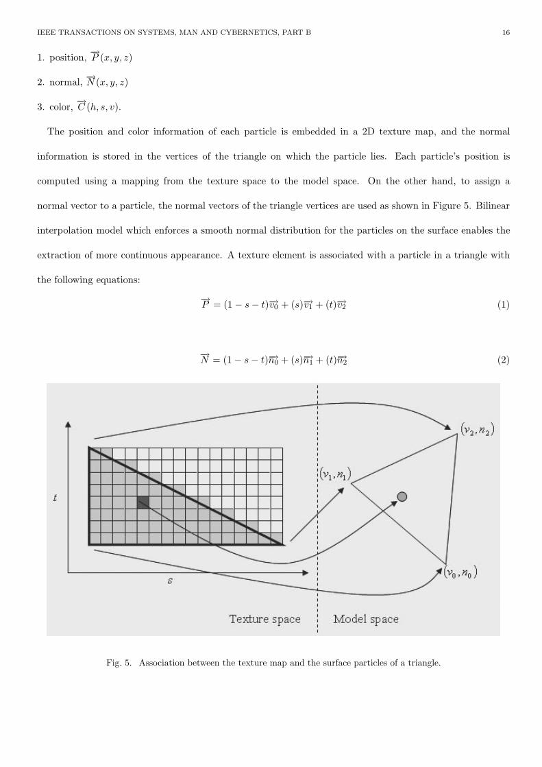
The position and color information of each particle is embedded in a 2D texture map, and the normal
information is stored in the vertices of the triangle on which the particle lies. Each particle’s position is
computed using a mapping from the texture space to the model space. On the other hand, to assign a
normal vector to a particle, the normal vectors of the triangle vertices are used as shown in Figure 5. Bilinear
interpolation model which enforces a smooth normal distribution for the particles on the surface enables the
extraction of more continuous appearance. A texture element is associated with a particle in a triangle with
the following equations:
−→P = (1 − s − t)−→v0 + (s)−→v1 + (t)−→v2 (1)
−→N = (1 − s − t)−→n0 + (s)−→n1 + (t)−→n2 (2)
Fig. 5. Association between the texture map and the surface particles of a triangle.
IEEE TRANSACTIONS ON SYSTEMS, MAN AND CYBERNETICS, PART B 17
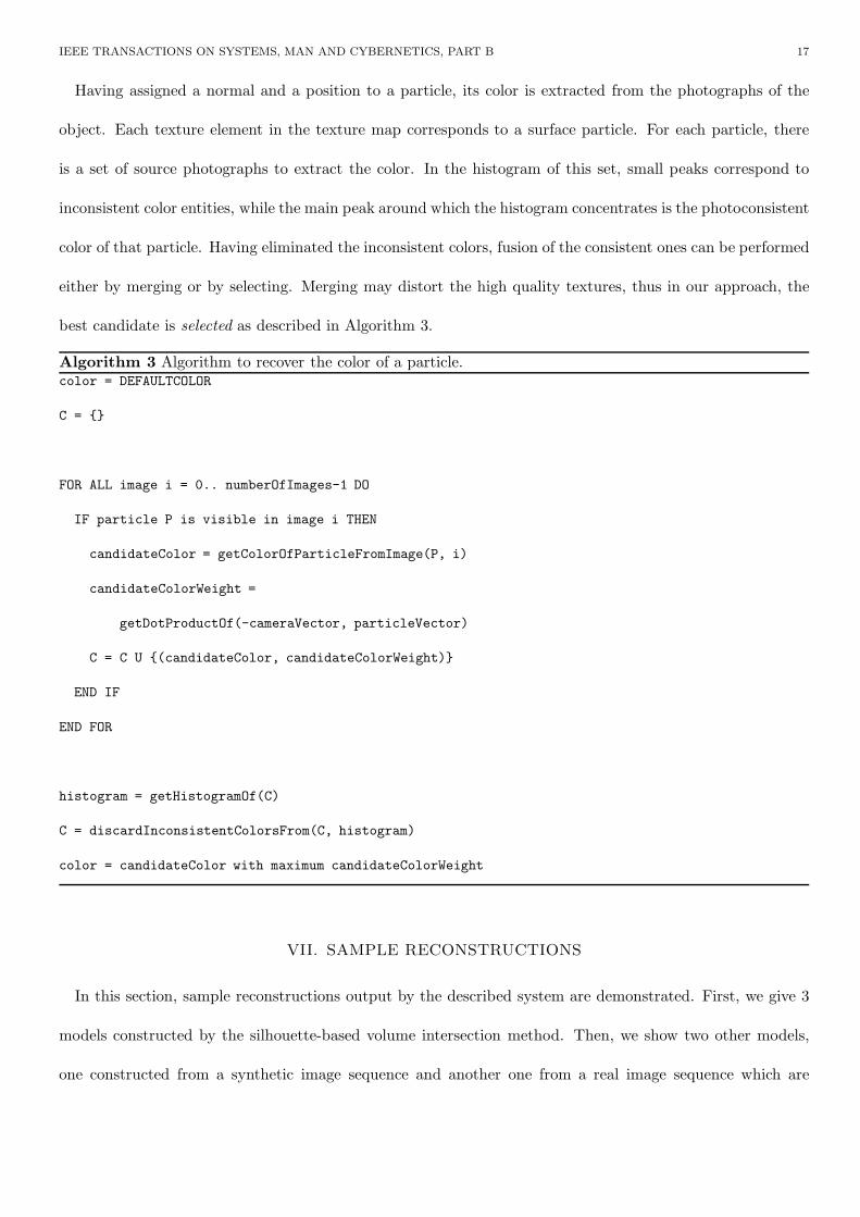
Having assigned a normal and a position to a particle, its color is extracted from the photographs of the
object. Each texture element in the texture map corresponds to a surface particle. For each particle, there
is a set of source photographs to extract the color. In the histogram of this set, small peaks correspond to
inconsistent color entities, while the main peak around which the histogram concentrates is the photoconsistent
color of that particle. Having eliminated the inconsistent colors, fusion of the consistent ones can be performed
either by merging or by selecting. Merging may distort the high quality textures, thus in our approach, the
best candidate is selected as described in Algorithm 3.
Algorithm 3 Algorithm to recover the color of a particle.color = DEFAULTCOLOR
C = {}
FOR ALL image i = 0.. numberOfImages-1 DO
IF particle P is visible in image i THEN
candidateColor = getColorOfParticleFromImage(P, i)
candidateColorWeight =
getDotProductOf(-cameraVector, particleVector)
C = C U {(candidateColor, candidateColorWeight)}
END IF
END FOR
histogram = getHistogramOf(C)
C = discardInconsistentColorsFrom(C, histogram)
color = candidateColor with maximum candidateColorWeight
VII. SAMPLE RECONSTRUCTIONS
In this section, sample reconstructions output by the described system are demonstrated. First, we give 3
models constructed by the silhouette-based volume intersection method. Then, we show two other models,
one constructed from a synthetic image sequence and another one from a real image sequence which are
IEEE TRANSACTIONS ON SYSTEMS, MAN AND CYBERNETICS, PART B 18
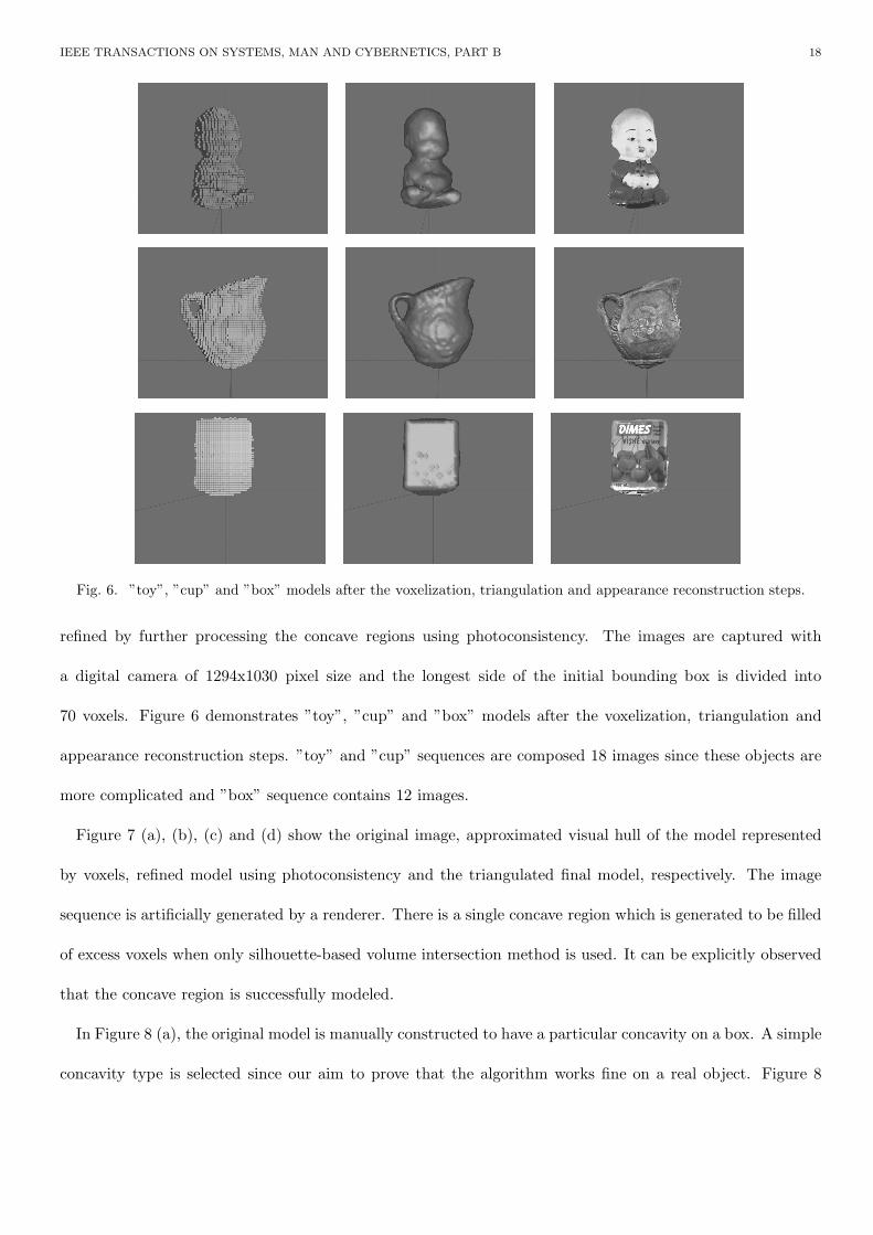
Fig. 6. ”toy”, ”cup” and ”box” models after the voxelization, triangulation and appearance reconstruction steps.
refined by further processing the concave regions using photoconsistency. The images are captured with
a digital camera of 1294x1030 pixel size and the longest side of the initial bounding box is divided into
70 voxels. Figure 6 demonstrates ”toy”, ”cup” and ”box” models after the voxelization, triangulation and
appearance reconstruction steps. ”toy” and ”cup” sequences are composed 18 images since these objects are
more complicated and ”box” sequence contains 12 images.
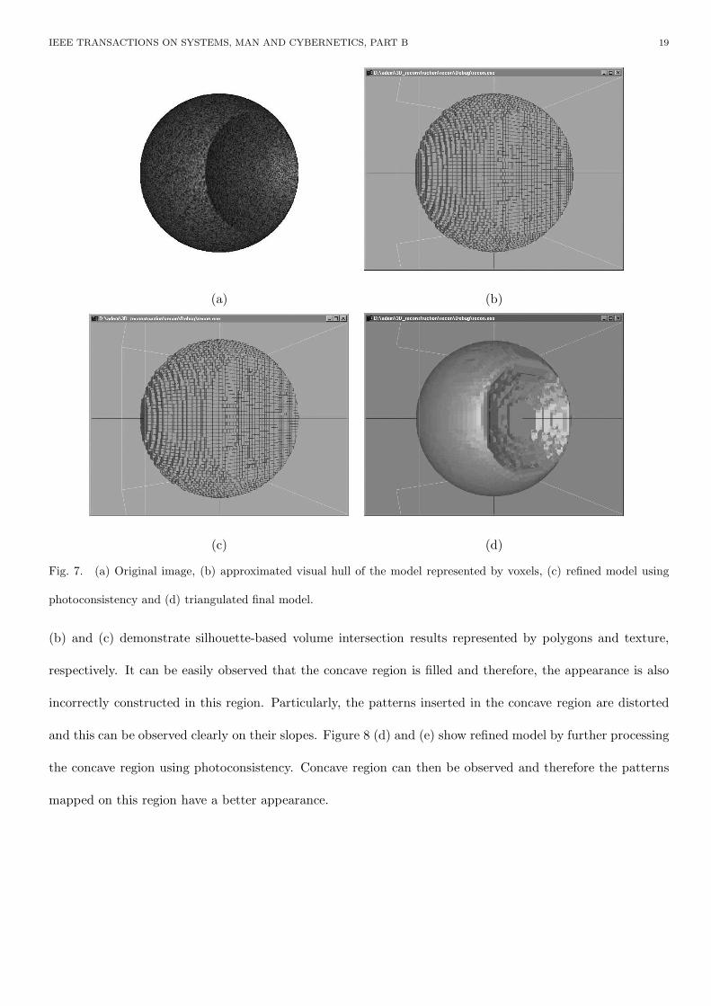
Figure 7 (a), (b), (c) and (d) show the original image, approximated visual hull of the model represented
by voxels, refined model using photoconsistency and the triangulated final model, respectively. The image
sequence is artificially generated by a renderer. There is a single concave region which is generated to be filled
of excess voxels when only silhouette-based volume intersection method is used. It can be explicitly observed
that the concave region is successfully modeled.
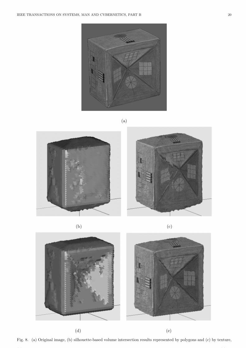
In Figure 8 (a), the original model is manually constructed to have a particular concavity on a box. A simple
concavity type is selected since our aim to prove that the algorithm works fine on a real object. Figure 8
IEEE TRANSACTIONS ON SYSTEMS, MAN AND CYBERNETICS, PART B 19
(a) (b)
(c) (d)
Fig. 7. (a) Original image, (b) approximated visual hull of the model represented by voxels, (c) refined model using
photoconsistency and (d) triangulated final model.
(b) and (c) demonstrate silhouette-based volume intersection results represented by polygons and texture,
respectively. It can be easily observed that the concave region is filled and therefore, the appearance is also
incorrectly constructed in this region. Particularly, the patterns inserted in the concave region are distorted
and this can be observed clearly on their slopes. Figure 8 (d) and (e) show refined model by further processing
the concave region using photoconsistency. Concave region can then be observed and therefore the patterns
mapped on this region have a better appearance.
IEEE TRANSACTIONS ON SYSTEMS, MAN AND CYBERNETICS, PART B 20
(a)
(b) (c)
(d) (e)
Fig. 8. (a) Original image, (b) silhouette-based volume intersection results represented by polygons and (c) by texture,
( ) fi f ( )

IEEE TRANSACTIONS ON SYSTEMS, MAN AND CYBERNETICS, PART B 21
VIII. CONCLUSIONS AND FUTURE WORK
3D object model reconstruction using silhouette-based volume intersection is a simple and robust method,
but it has some drawbacks. In this paper, a complete image-based 3D model reconstruction system is described
in detail. Based on a multi-image calibration method, an algorithm to extract rotation axis of a turn-table has
been developed. Furthermore, this can be extended to estimate robust and smaller initial bounding volume of
the object to be modeled. Better estimation of bounding volume helps in producing better voxel representation
of the visual hull of the object. Keeping the number of voxels constant, the size of the bounding box affects
the resolution of the final model: smaller the bounding box, lesser the quantization effect on the model.
The main drawback of the silhouette-based volume intersection approach is the additional excess volume
coming from insufficient number of viewing positions and from the concavities on the object to be modeled.
In order to carve excess voxels from the inferred visual hull which is approximated by silhouette-based volume
intersection, an algorithm based on photoconsistency is developed. Voxel visibility checking and photocon-
sistency threshold in deciding removal of a voxel are the elusive parts of the carving algorithm. Instead of
using camera placement constraints or recently developed alternatives requiring additional space and complex
updates as carving progress, or using multi sweeps along the coordinate axes, traversing a ray from the voxel
center through the camera center is proposed to check visibility in our study. A voxel is visible from a given
camera if there is no other opaque voxels in between them. Visibility check starts from a surface voxel and
trace the voxel space on the voxel to camera ray. If an opaque voxel is met, then the algorithm stops and
decides that the voxel is invisible. Better estimation of initial bounding volume helps again in cutting the
visibility search space on a ray since the search is cut at the boundaries of the bounding volume. Recent space
carving and voxel coloring approaches use a predefined photoconsistency threshold to decide removal of a voxel
from the object voxel space. In these approaches, different results are obtained by using different choices of
the photoconsistency threshold. It is not easy to find a color threshold which succeeds well in both the dark
and bright parts of a scene if red-green-blue (RGB) color space is used. Also, inconsistent lighting, which is an
important problem with a fixed light source and an object rotating on a turn-table, makes thresholding even
IEEE TRANSACTIONS ON SYSTEMS, MAN AND CYBERNETICS, PART B 22
more difficult. The CIELab color space can be used instead of RGB space to apply a single color threshold
for the bright and dim portions of the scene, and using a color space separating chromaticity and luminance
may reduce the inconsistent lighting problem, but the problem of a good threshold selection still remains. In
our study, threshold selection is eliminated by finding the maximum photoconsistent voxel on the ray starting
from the camera center and pass through a selected surface voxel.
Our results show that the excess voxels can be removed successfully. Results of the described algorithm are
demonstrated on a synthetic and a real object.
Unlike recent space carving and voxel coloring methods representing the final appearance by giving pho-
toconsistent colors to each voxel, the resultant carved solution is triangulated in our studyo and the final
appearance is obtained by using the concept of particles. The surface, in addition to its actual representation,
is considered as a collection of surface particles. The color of each particle is extracted from the images and
combined in a 2D texture map. Since particles are smaller primitives, the appearance is continuous on the
surface. This is a solution to the boundary discontinuity problem of most previous studies. The employed
photoconsistency reduces also the artifacts of bad illumination. Representation of the final model by triangles
enables the model to be converted into well known graphical formats such as VRML very easily.
One of the most important progresses to be added to this study is the detection of possible concave regions.
Such a detection of concave regions would lower the computational complexity and also avoids the application
of the algorithm onto non-concave parts of the model. It can also be interesting to develop an intelligent
sculpting tool for the elimination of concave regions.
ACKNOWLEDGEMENTS
This study is partially supported by TUBITAK (Scientific and Technical Research Council of Turkey) under
the grant EEEAG-199E024, by METU Graduate School of Natural and Applied Sciences and by METU
Research Grant. Adem Y. Mulayim’s study is supported by TUBITAK Integrated PhD Program.

IEEE TRANSACTIONS ON SYSTEMS, MAN AND CYBERNETICS, PART B 23
References
[1] W. Niem and J. Wingbermuhle, “Automatic reconstruction of 3d objects using a mobile monoscopic camera,” in International
Conference on Recent Advances in 3D Imaging and Modeling, May 1997, pp. 173–180.
[2] Y. Matsumoto, H. Terasaki, K. Sugimoto, and T. Arakawa, “A portable three-dimensional digitizer,” in International
Conference on Recent Advances in 3D Digital Imaging and Modeling, May 1997, pp. 197–204.
[3] A. Y. Mulayim, Y. Yemez, F. Schmitt, and V. Atalay, “Rotation axis extraction of a turn table viewed by a fixed camera,”
in Vision Modeling and Visualisation, November 1999, pp. 35–42.
[4] A. Y. Mulayim, F. Schmitt, and V. Atalay, “Vision-based geometrical calibration of a turn-table for 3d object reconstruction,”
Tech. Rep. TR-2000-01, Middle East Technical University, 2000.
[5] P. Ramanathan, E. Steinbach, and B. Girod, “Silhouette-based multiple-view camera calibration,” in Vision, Modeling and
Visualization, 2000, pp. 3–10.
[6] A. W. Fitzgibbon, G. Cross, and A. Zisserman, “Automatic 3d model construction for turn-table sequences,” in SMILE
Workshop on Structure from Multiple Images in Large Scale Environments, R. Koch and L. Van Gool, Eds. June 1998, pp.
154–170, Springer-Verlag, http://www.robots.ox.ac.uk/ vgg.
[7] M. Potmesil, “Generating octree models of 3d objects from their silhouettes in a sequence of images,” Computer Vision
Graphics and Image Processing, vol. 40, no. 1, pp. 1–29, October 1987.
[8] R. Szelisky, “Rapid octree construction from image sequences,” Computer Vision Graphics and Image Processing, vol. 58,
no. 1, pp. 23–32, July 1993.
[9] C. S. Zhao and R. Mohr, “Relative 3d regularized b-spline surface reconstruction through image sequences,” in European
Conference on Computer Vision, May 1994, pp. 417–426.
[10] J. Y. Zheng, “Acquiring 3-d models from a sequence of contours,” IEEE Transations on Pattern Analysis and Machine
Intelligence, vol. 16, no. 2, pp. 163–178, February 1994.
[11] W. B. Seales and O. D. Faugeras, “Building 3 dimensional object models from image sequences,” Computer Vision and
Image Understanding, vol. 61, no. 3, pp. 308–324, May 1995.
[12] E. Boyer, “Object models from contour sequences,” in European Conference on Computer Vision, 1996, pp. 109–118.
[13] S. Sullivan and J. Ponce, “Automatic model construction, pose estimation, and object recognition from photographs using
triangular splines,” IEEE Transactions on Pattern Analysis and Machine Intelligence, vol. 20, no. 10, October 1998.
[14] Y. Matsumoto, K. Fujimura, and T. Kitamura, “Shape-from-silhouette/stereo and its application to 3-d digitizer,” in Discrete
Geometry for Computer Imagery Conference, Lecture Notes in Computer Science 1568, 1999, pp. 177–188.
[15] W. Niem and H. Broszio, “Mapping texture from multiple camera views onto 3d object models for computer animation,” in
International Workshop on Stereoscopic and Three Dimensional Imaging, September 1995, pp. 99–105.

IEEE TRANSACTIONS ON SYSTEMS, MAN AND CYBERNETICS, PART B 24
[16] S. Genc and V. Atalay, “Texture extraction from photographs and rendering with dynamic texture mapping,” in 10th
International Conference on Image Analysis and Processing, September 1999.
[17] H. P. A. Lensch, W. Heidrich, and H-P. Seidel, “Automated texture registration and stitching for real world models,” in
Pacific Graphics, October 2000, pp. 317–337.
[18] F. M. Weinhaus and V. Devarajan, “Texture mapping 3d models of real-world scenes,” ACM Computing Surveys, vol. 29,
no. 4, pp. 325–365, December 1997.
[19] F. Schmitt and Y. Yemez, “3d color object reconstruction from 2d image sequences,” in International Conference on Image
Processing, October 1999, pp. 65–69.
[20] E. Ofek, E. Shilat, A. Rappoport, and M. Werman, “Multiresolution textures from image sequences,” IEEE Computer
Graphics and Applications, vol. 17, no. 2, pp. 18–29, March-April 1997.
[21] J. P. Neugebauer and K. Klein, “Texturing of 3d models of real world objects from multiple unregistered photographic
views,” Computer Graphics Forum, vol. 18, no. 3, pp. 245–256, September 1999.
[22] J. M. Lavest, M. Viala, and M. Dhome, “Do we really need an accurate calibration pattern to achieve a reliable camera
calibration?,” in European Conference on Computer Vision, 1998, pp. 158–174.
[23] A. Y. Mulayim, O. Ozun, V. Atalay, and F. Schmitt, “On the silhouette based 3d reconstruction and initial bounding cube
estimation,” in Vision Modeling and Visualisation, November 2000, pp. 11–18.
[24] A. Y. Mulayim and V. Atalay, “Multibaseline stereo coreection for silhouette-based 3d model reconstruction from multiple
images,” in SPIE, Three-Dimensional Image Capture and Applications IV, January 2001, pp. 24–25.
[25] T. Kanade, M. Okutomi, and T. Nakahara, “A multiple-baseline method,” in DARPA Image Understanding Workshop,
1992, pp. 409–426.
[26] T. Kanade, S. B. Kang, J. Webb, and C. L. Zitnick, “A multibaseline stereo system with active illumination and real-time
image acquisition,” in International Conference on Computer Vision, 1995, pp. 88–93.
[27] P. E. Debevec, C. J. Taylor, and J. Malik, “Modeling and rendering architecture from photographs: A hybrid geometry and
image-based approach,” in SIGGRAPH’96, Computer Graphics Proceedings, Annual Conference Series, August 1996, pp.
11–20.
[28] S. M. Seitz and C. R. Dyer, “Photorealistic scene reconstruction by voxel coloring,” International Journal of Computer
Vision, vol. 35, no. 2, pp. 151–173, 1999.
[29] K. N. Kutulakos and S. M. Seitz, “A theory of shape by space carving,” Internation Journal of Computer Vision, vol. 38,
no. 3, pp. 1999–218, 2000.
[30] W. B. Culbertson, T. Malzbender, and G. Slabaugh, “Generalized voxel coloring,” in International Conference on Computer
Vision, September 1999, pp. 100–115.
IEEE TRANSACTIONS ON SYSTEMS, MAN AND CYBERNETICS, PART B 25
[31] N. Max, “Hierarchical rendering of trees from precomputed multi-layer z-buffers,” in Eurographics Rendering Workshop,
1996, pp. 165–174.
[32] J. Shade, S. Gortler, L. He, and R. Szelisky, “Layered depth images,” in SIGGRAPH, 1998, pp. 231–242.
[33] P. Eisert, E. Steinbach, and B. Girod, “Multi-hypothesis, volumetric reconstruction of 3-d objects from multiple calibrated
camera views,” in International Conference on Acoustics Speech and Signal Processing. March 1999, pp. 3509–3512, Phoenix.
[34] M. Pollefeys, R. Koch, M. Vergauwen, and L. Van Gool, “Automated reconstruction of 3d scenes from sequences of images,”
Isprs Journal Of Photogrammetry And Remote Sensing, vol. 55, no. 4, pp. 251–267, 2000.
[35] P. A. Beardsley, P. H. S. Torr, and A. Zisserman, “3d model acquisition from extended image sequence,” in European
Conference on Computer Vision, 1996, pp. 683–695.
[36] R. Koch, M. Pollefeys, and L. Van Gool, “Multi viewpoint stereo from uncalibrated video sequences,” in European Conference
on Computer Vision, 1998, pp. 55–71.
[37] O. D. Faugeras, “What can be seen in three dimensions with an uncalibrated stereo rig?,” in European Conference on
Computer Vision, G. Sandini, Ed., Santa Margherita Ligure, Italy, May 1992, pp. 563–578, Springer-Verlag, Lecture Notes
in Computer Science.
[38] R. I. Hartley, “Estimation of relative camera positions for uncalibrated cameras,” in European Conference on Computer
Vision. May 1992, pp. 579–587, Springer-Verlag.
[39] Q. T. Luong and T. Vieville, “Canonical representations for the geometries of multiple projective views,” Computer Vision
and Image Understanding, vol. 64, no. 2, pp. 193–229, 1996.
[40] B. Triggs, “Linear projective reconstruction from matching tensors,” Image and Vision Computing, vol. 15, no. 8, pp.
617–625, 1997.
[41] M. Pollefeys, R. Koch, and L. Van Gool, “Self-calibration and metric reconstruction in spite of varying and unknown internal
camera parameters,” International Journal of Computer Vision, vol. 32, no. 1, pp. 7–25, 1999.
[42] Z. Zhang, R. Deriche, O. Faugeras, and Q. T. Luong, “A robust technique for matching two uncalibrated images through
the recovery of the unknown epipolar geometry,” Artificial Intelligence Journal, vol. 78, pp. 87–119, October 1995.
[43] R. I. Hartley and A. Zisserman, Multiple View Geometry in Computer Vision, Cambridge University Press, September 2000.
[44] S. J. Maybank and O. D. Faugeras, “A theory of self-calibration of a moving camera,” International Journal of Computer
Vision, vol. 8, no. 2, pp. 123–151, 1992.
[45] A. Fusiello, “Uncalibrated euclidean reconstruction: a review,” Image and Vision Computing, vol. 18, no. 67, pp. 555–563,
May 2000.
[46] W. Niem and R. Buschmann, “Automatic modelling of 3d natural objects from multiple views,” 1994.
[47] D. P. Gibson, N. W. Campbell, and B. T. Thomas, “The generation of 3d models without camera calibration,” in Computers
and Graphics. June 1998, pp. 146–149, ACTA Press.
IEEE TRANSACTIONS ON SYSTEMS, MAN AND CYBERNETICS, PART B 26
[48] P. R. S. Mendonca, K-Y. K. Wong, and R. Cipolla, “Camera pose estimation and reconstruction from image profiles under
circular motion,” in European Conference on Computer Vision, David Vernon, Ed., Dublin, Ireland, June/July 2000, pp.
864–877, Springer-Verlag.
[49] C. H. Esteban and F. Schmitt, “Multi-stereo 3d object reconstruction,” in International Symposium on 3D Data Processing
Visualization and Transmission, G. M. Cortelazzo and C. Guerra, Eds., Padova, Italy, June 2002, pp. 159–166, IEEE
Computer Society.
[50] L. Zhang and S. M. Seitz, “Image-based multiresolution modeling by surface deformation,” Tech. Rep. CMU-RI-TR-00-07,
Robotics Institute Carnegie Mellon University, 2000.
[51] W. E. Lorensen and H. E. Cline, “Marching cubes: A high resolution 3d surface reconstruction algorithm,” ACM Computer
Graphics, vol. 21, no. 4, pp. 163–169, 1987.
[52] C. Montani, R. Scateni, and R. Scopigno, “Discretized marching cubes,” in Visualization, 1994, pp. 281–287.
[53] W. T. Reeves, “Particle systems - a technique for modeling a class of fuzzy objects,” ACM Transactions of Graphics, vol. 2,
no. 2, pp. 91–108, April 1983.
[54] R. Szelisky and D. Tonnesen, “Surface modeling with oriented particles,” Computer Graphics (SIGGRAPH’92), vol. 26, no.
2, pp. 185–194, July 1992.
[55] T. Nishita and Y. Dobashi, “Modeling and rendering of various natural phenomena consisting of particles,” in Computer
Graphics International Conference, July 2001, pp. 149–156.
[56] J. M. Dischler and D. Ghazanfarpour, “A survey of 3d texturing,” Computers and Graphics, vol. 25, no. 1, pp. 135–151,
February 2001.
Adem Yasar Mulayim has received his PhD in November 2002 from the Department of Computer En-
gineering at Middle East Technical University, Ankara, Turkey. He also received his BSc and MSc degrees
in computer engineering from the same department in 1993 and 1996, respectively. His research interests
include computer vision, modeling, terrain image analysis, perceptual organization, image processing and
pattern recognition.
Ulas Yılmaz is a doctoral candidate and a research assistant at the Department of Computer Engineering
at Middle East Technical University, Ankara, Turkey. He received his BSc and MSc degrees in computer
engineering from Middle East Technical University in 1999 and 2002, respectively. His research interests
include computer vision, computer graphics and pattern recognition. He is a member of the Turkish Pattern
Recognition and Image Analysis Society.

IEEE TRANSACTIONS ON SYSTEMS, MAN AND CYBERNETICS, PART B 27
Volkan Atalay is an associate professor of computer engineering at the Middle East Technical University.
Previously, he was a visiting scholar at the New Jersey Institute of Technology. He received a BSc and an MSc
in electrical engineering from Middle East Technical University and a Ph.D. in computer science from the
Universite Rene Descartes-Paris V, Paris, France. His research interests include computer vision, document
analysis and applications of neural networks. He is a member of the IEEE Computer Society and the Turkish Pattern Recognition
and Image Analysis Society.
Copyright © 2022 FDOKUMEN