Shape and director-field transformation of tactoids
13
Deformable homeotropic nematic droplets in a magnetic field Ronald H. J. Otten and Paul van der Schoot Citation: J. Chem. Phys. 137, 154901 (2012); doi: 10.1063/1.4756946 View online: http://dx.doi.org/10.1063/1.4756946 View Table of Contents: http://jcp.aip.org/resource/1/JCPSA6/v137/i15 Published by the American Institute of Physics. Additional information on J. Chem. Phys. Journal Homepage: http://jcp.aip.org/ Journal Information: http://jcp.aip.org/about/about_the_journal Top downloads: http://jcp.aip.org/features/most_downloaded Information for Authors: http://jcp.aip.org/authors
-
Upload
independent -
Category
Documents
-
view
0 -
download
0
Transcript of Shape and director-field transformation of tactoids

Deformable homeotropic nematic droplets in a magnetic fieldRonald H. J. Otten and Paul van der Schoot Citation: J. Chem. Phys. 137, 154901 (2012); doi: 10.1063/1.4756946 View online: http://dx.doi.org/10.1063/1.4756946 View Table of Contents: http://jcp.aip.org/resource/1/JCPSA6/v137/i15 Published by the American Institute of Physics. Additional information on J. Chem. Phys.Journal Homepage: http://jcp.aip.org/ Journal Information: http://jcp.aip.org/about/about_the_journal Top downloads: http://jcp.aip.org/features/most_downloaded Information for Authors: http://jcp.aip.org/authors
THE JOURNAL OF CHEMICAL PHYSICS 137, 154901 (2012)
Deformable homeotropic nematic droplets in a magnetic fieldRonald H. J. Otten1,2,a) and Paul van der Schoot1,3
1Theory of Polymers and Soft Matter and Eindhoven Polymer Laboratories, Eindhoven Universityof Technology, P.O. Box 513, 5600 MB Eindhoven, The Netherlands2Dutch Polymer Institute, P.O. Box 902, 5600 AX Eindhoven, The Netherlands3Institute for Theoretical Physics, Utrecht University, Leuvenlaan 4, 3584 CE Utrecht, The Netherlands
(Received 3 November 2011; accepted 18 September 2012; published online 15 October 2012)
We present a Frank-Oseen elasticity theory for the shape and structure of deformable nematicdroplets with homeotropic surface anchoring in the presence of a magnetic field. Inspired by re-cent experimental observations, we focus on the case where the magnetic susceptibility is negative,and find that small drops have a lens shape with a homogeneous director field for any magnetic-fieldstrength, whereas larger drops are spherical and have a radial director field, at least if the magneticfield is weak. For strong magnetic fields the hedgehog configuration transforms into a split-core linedefect that, depending on the anchoring strength, can be accompanied by an elongation of the tac-toid itself. We present a three-dimensional phase diagram that shows the tactoid shape and directorfield for a given anchoring strength, tactoid size, and magnetic-field strength. Our findings rational-ize the different shapes and structures that recently have been observed experimentally for nematicdroplets found in dispersions of gibbsite platelets in two types of solvent. © 2012 American Instituteof Physics. [http://dx.doi.org/10.1063/1.4756946]
I. INTRODUCTION
Nematic droplets consisting of a liquid-crystalline ma-terial are often observed in dispersions of sufficiently aniso-metric colloidal particles under conditions where the isotropicand nematic phase co-exist.1–7 These so-called tactoids havebeen investigated quite intensively over the last few decades,not least because of their interesting and sometimes un-usual shapes and internal structures and relevance to displaytechnology.2 These include oblate and prolate droplet shapeswith round and sharp edges, and director-field structures in-volving surface and bulk point defects as well as ring-shapeddisclination lines and bipolar twisted “parity-broken” directorfields, all depending on the size of the drops and the shape ofthe colloids.1, 3–9
Because the shape and structure of tactoids result in ef-fect from a competition among surface, anchoring, and elas-tic forces, studying them provides quantitative informationon material properties of liquid crystals, including the elasticconstants, surface tension, and anchoring strength of the di-rector field to the interface between the co-existing isotropicand nematic phases.3, 4, 6–12 Tactoids in lyotropic systems aremore suitable for this purpose than those in thermotrop-ics because of the extremely low surface free energies inlyotropics.13–15
Studies on tactoids in dispersions of rod-like colloidalparticles such as vanadium pentoxide,1, 3, 4 f-actin,5 tobaccomosaic virus,16 boehmite,17 and fd virus,18 have shown thatthese drops tend to have a bipolar director field in which thecurved field lines run from one virtual surface point defect(boojum) to another on the other side of the drop. The reasonfor this tendency for bipolar director fields is that rod-like
a)Electronic mail: [email protected].
particles for entropic reasons prefer planar alignment of thedirector to the interface. Theoretically one only expects thisto be so if the drops are sufficiently large relative to somelength scale set by the elastic and interfacial properties of thenematic drops.19 Tactoids with uniform director fields havebeen observed in computer simulations and recently alsoin dispersions of carbon nanotubes.6, 20, 21 The structure oftactoids with planar anchoring conditions have been studiedtheoretically in great detail.3–6, 8, 9, 17
Tactoids of plate-like colloids seem to have a very dif-ferent director field from those of rod-shaped ones, althoughto date much fewer systems have been studied. The ratherintricate stabilization of plate-like colloids is presumablythe reason for this.13, 22–24 Tactoids have been observedin dispersions of sterically and charge-stabilized gibbsiteplatelets.22, 25, 30, 31 For these systems both uniform and radialdirector fields have been observed, the latter as a result of thetendency of plate-like particles to align homeotropically tointerfaces, again for entropic reasons.31 The radial directorfield is characterized by a hedgehog point defect in the centerof the drop,2, 25–27 which in fact could also be a small ringdefect.28, 29
Theoretically, much less is known of the structure ofthis kind of drop, in particular in the presence of an exter-nal orienting field, such as a magnetic field. Extensive ex-perimental studies have recently been done on tactoids ofgibbsite platelets in the presence of an externally appliedmagnetic field.30, 31 Two types of system were studied: onewhere the particles were stabilized sterically and dispersedin bromotoluene, and another in an aqueous solution wherethe platelets were charge-stabilized. Surprisingly, the type ofsolvent turned out to cause markedly different behavior. Inboth solvents the tactoids were observed to exhibit a sharp,Frederiks-like transition from a radial director field with a
0021-9606/2012/137(15)/154901/12/$30.00 © 2012 American Institute of Physics137, 154901-1
154901-2 R. H. J. Otten and P. van der Schoot J. Chem. Phys. 137, 154901 (2012)
point defect that stretches (“splits”) to a line defect if sub-jected to a sufficiently strong magnetic field. For the caseof the sterically stabilized gibbsite this stretching was fol-lowed by an elongation of the drop itself for yet strongerfields, whereas in the aqueous system the drops remainedspherical.30
In fact, the existence of a split-core line defect was pre-dicted theoretically about a decade ago by Mkaddem andGartland,29 indicating that it may be stabilized by an exter-nally applied magnetic field. However, this would only bepossible if the nematogens have a negative diamagnetic sus-ceptibility, which is the case for gibbsite. So, this correspondsexactly to the situation that was experimentally investigated,30
and confirmed that the split-core configuration can be stabi-lized by the magnetic field.
In this work we present a detailed discussion of a macro-scopic theory that was shown in previous work to be ableto rationalize the experimental observations on tactoids ofgibbsite.30, 31 We stress that the theoretical results presentedin these earlier papers were completely aimed at rationalizingvery specific experimental results and that these papers con-tain no discussion at all on how these theoretical results wereobtained and how generally valid they are beyond the specificcases. We focus now not on a comparison with experimentsbut a full analysis of the theory and its ramifications for alltypes of nematic tactoid characterized by a homeotropic sur-face anchoring and negative magnetic susceptibility, omittedin Refs. 30 and 31. The current manuscript contains a fullanalytical characterization of the exact shape of homeotropicdrops with a homogeneous director field and the differences inshape and energy with one that can be more directly obtainedfrom cut spheres, the aspect ratio of drops with a split-coredefect and the length of this defect.
We have summarized our main results in a series of sta-bility diagrams, making our theory straightforward to applyin practical situations, and we discuss in detail the possiblecrossover routes between different tactoid structures in thepresence of a magnetic field. Our approach is variational andlargely based on trial functions for shapes and director fields,but we have been able to solve the problem analytically. Wedescribe how the director-field configuration and the tactoidshape are governed by a competition between the surface ten-sion, anchoring strength, bulk elastic properties of the nematicand the response to the magnetic field.
In agreement with experimental observations, we findthat small drops are lens-shaped with a homogeneous direc-tor field for any magnetic-field strength and larger drops arespherical with a hedgehog point defect for weak or zero mag-netic field. If the magnetic field is strong enough, a split-coreline defect in the direction of this field becomes more favor-able than the point defect. For even stronger fields, the tac-toid itself may, depending on the anchoring strength, stretchto a prolate shape that becomes more spherical again athigher field strengths still. The latter conclusion is a predic-tion amenable to experimental verification although it doesrequire much stronger magnetic fields than used, e.g., inRefs. 30 and 31. We are also interested in the crossover fromone director-field structure to another, so we also examineplausible crossover routes. We find that two plausible routes
between uniform and radial director fields are always char-acterized by a free energy barrier. Intermediates are never sta-ble, implying that even though observed experimentally, thesemust be non-equilibrium structures caused by the creaming orsedimenting of the tactoids in the gravitational field.
The remainder of this paper is structured as follows. InSec. II we first present the ingredients of the theory and inSec. III we discuss drops with a uniform director field. Next,we consider non-uniform director fields in spherical drops inSec. IV and in non-spherical drops in Sec. V. In Sec. VI weexplain our phase diagrams for the optimal tactoid shape andstructures and our methodology to obtain them. Next, we dis-cuss the crossover routes from uniform to radial director fieldin Sec. VII. Finally, we discuss the validity of our model andthe results in Sec. VIII.
II. INGREDIENTS OF THE THEORY
We first present the ingredients of our macroscopicFrank-Oseen elasticity theory that enables us to rationalizethe experimental observations described in the Introduction.32
Our free energy F = Ft + Fa + Fe + Fm of a tactoid of volumeV consists of four contributions associated with the bare sur-face tension (subscript t) and surface anchoring (a), the elasticdeformation (e), and the magnetic field (m).
1. The surface and anchoring energy Ft + Fa we take of theRapini-Papoular type,33
Ft + Fa =∫
A
d2�r(γ + ζ sin2 α), (1)
where the integration is taken over the entire surfacearea A of the drop and α is the angle between the sur-face normal �q = �q(�r) and the director field �n = �n(�r) atthe interface. In Eq. (1) γ denotes the bare surface ten-sion and ζ the surface anchoring, i.e., the anchoring freeenergy per unit area of the drop interface. As alreadyannounced, colloidal platelets for entropic reasons pre-fer homeotropic alignment of the director field to theinterface,13 implying ζ > 0, which is the case we shallbe focusing on. This form of the interfacial energy hasbeen shown to be a very accurate representation for rod-like particles,6 and we presume it reasonable for disk-like ones as well;
2. The Oseen-Frank free energy of elastic deformationreads32
Fe = 1
2
∫V
d3�r(K1 (∇ · �n)2 + K3 (∇ × �n)2), (2)
if we ignore twist deformation and contributions fromthe saddle-splay and splay-bend deformation, where theintegration is over the volume V of the drop, and K1 andK3 are the splay and bend elastic constant, respectively.Inspired by the experimental observations, we also ig-nore any contributions from bend deformations,36 andreturn to this in the discussion;
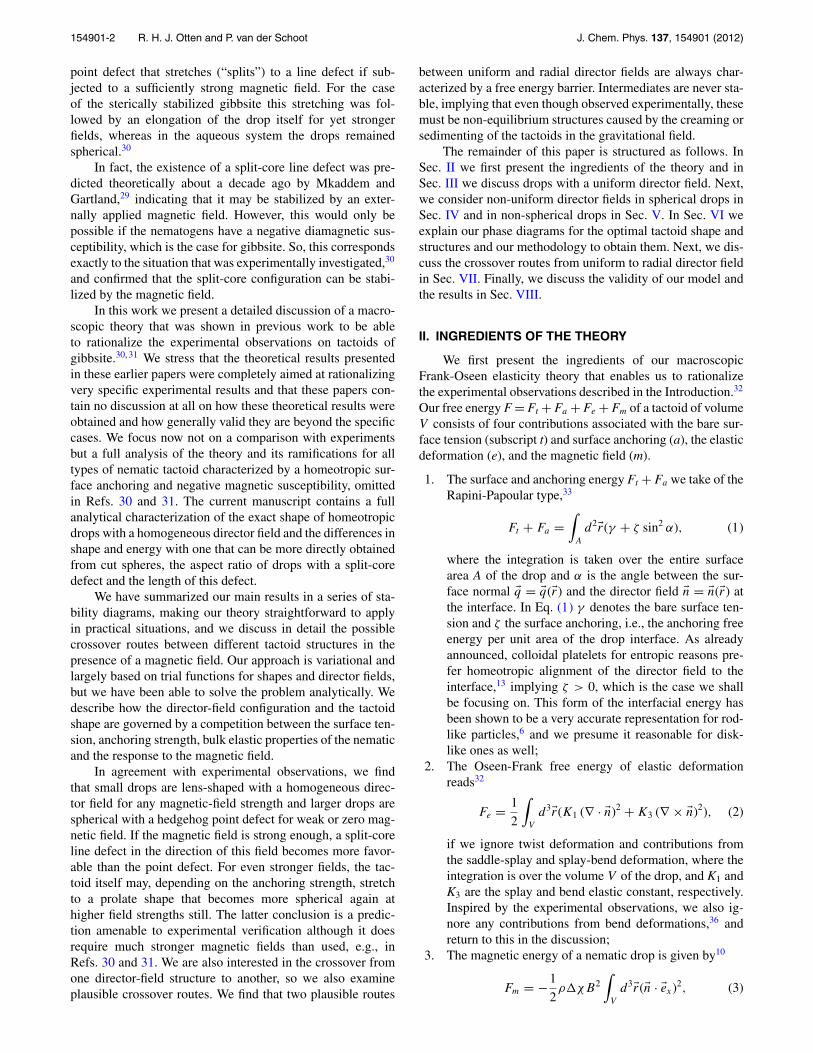
3. The magnetic energy of a nematic drop is given by10
Fm = −1
2ρ�χB2
∫V
d3�r(�n · �ex)2, (3)
154901-3 R. H. J. Otten and P. van der Schoot J. Chem. Phys. 137, 154901 (2012)
where we have dropped a term that does not dependon the orientation of the director field,10 ρ is the par-ticle number density, �χ the diamagnetic susceptibil-ity anisotropy (dimensions J/T2), and B the magnitudeof the magnetic field that we choose to be in the x-direction described by the unit vector �ex . As our the-ory intends to explain the observations on dispersionsof gibbsite platelets that have a negative magnetic sus-ceptibility we presume �χ < 0,25, 30, 34 so the particleshave a tendency to orient their director perpendicular tothe magnetic field.
From Eqs. (1), (2), and (3) we deduce that the four freeenergies scale as Ft ∼ γ R2, Fa ∼ ζR2, Fe ∼ K1R, and Fm
∼ �R3, with � ≡ −ρ�χB2 (J/m3) the strength of themagnetic field, and R a measure of the tactoid size, i.e., theradius in case of a spherical drop. We immediately see thatfor sufficiently small tactoids the elastic deformation must bedominant, giving rise to a uniform director field irrespectiveof the magnetic-field strength. On the other hand, for verylarge drops the magnetic energy becomes dominant, forcingthe particles to comply with the orientation imposed by thisfield.
The relative magnitude of these free-energy scalings pro-vides us with more information in terms of three dimen-sionless groups that follow naturally from this comparisonand that turn out to be important for the remainder of thispaper.
1. If we compare both surface terms, we find a dimension-less anchoring strength ω ≡ ζ /γ . For large values of ω
the anchoring is dominant over the bare surface tension,indicating a preference to deform the interface over anunfavorable surface anchoring of the director field.
2. Combining elastic with surface or anchoring energiesgives a scaled droplet size R ≡ Rγ /K1 = Rζ /K1ω. Forsmall values of R and Rω the elastic energy dominatesover the surface and anchoring energy, leading to a ho-mogeneous director field at the expense of a deformeddroplet and imperfect surface anchoring.
3. Taking the ratio of the magnetic and surface energy gives�R/γ ≡ β2R, with β2 ≡ �K1/γ 2, which is proportionalto B2. It is a positive quantity for in our case �χ < 0. Aswe also have the identity β2 = FmFe/F
2t , a large value
of β2 means either a dominant magnetic field or dom-inant elasticity, the director field either adopting a uni-form director field or forming a split-core line defect inthe direction of the magnetic field.
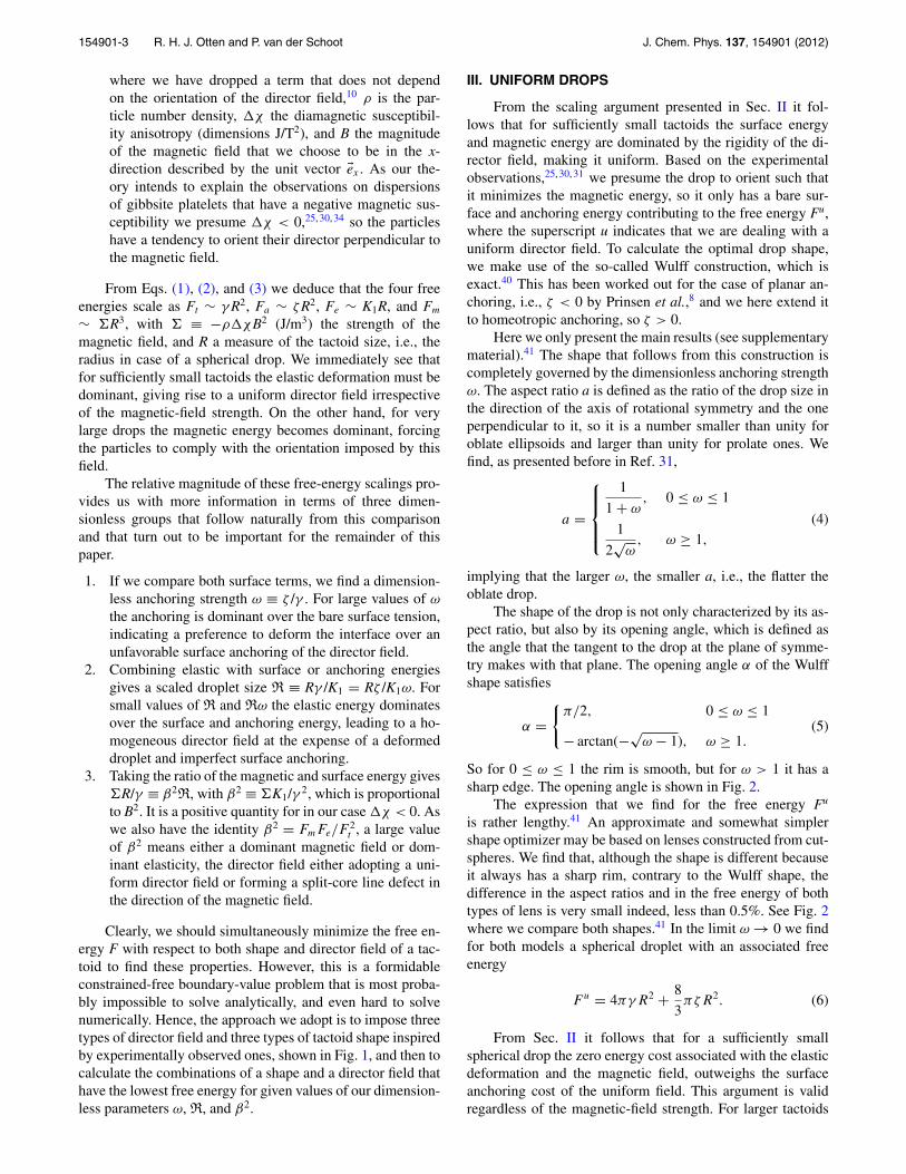
Clearly, we should simultaneously minimize the free en-ergy F with respect to both shape and director field of a tac-toid to find these properties. However, this is a formidableconstrained-free boundary-value problem that is most proba-bly impossible to solve analytically, and even hard to solvenumerically. Hence, the approach we adopt is to impose threetypes of director field and three types of tactoid shape inspiredby experimentally observed ones, shown in Fig. 1, and then tocalculate the combinations of a shape and a director field thathave the lowest free energy for given values of our dimension-less parameters ω, R, and β2.
III. UNIFORM DROPS
From the scaling argument presented in Sec. II it fol-lows that for sufficiently small tactoids the surface energyand magnetic energy are dominated by the rigidity of the di-rector field, making it uniform. Based on the experimentalobservations,25, 30, 31 we presume the drop to orient such thatit minimizes the magnetic energy, so it only has a bare sur-face and anchoring energy contributing to the free energy Fu,where the superscript u indicates that we are dealing with auniform director field. To calculate the optimal drop shape,we make use of the so-called Wulff construction, which isexact.40 This has been worked out for the case of planar an-choring, i.e., ζ < 0 by Prinsen et al.,8 and we here extend itto homeotropic anchoring, so ζ > 0.
Here we only present the main results (see supplementarymaterial).41 The shape that follows from this construction iscompletely governed by the dimensionless anchoring strengthω. The aspect ratio a is defined as the ratio of the drop size inthe direction of the axis of rotational symmetry and the oneperpendicular to it, so it is a number smaller than unity foroblate ellipsoids and larger than unity for prolate ones. Wefind, as presented before in Ref. 31,
a =
⎧⎪⎪⎨⎪⎪⎩
1
1 + ω, 0 ≤ ω ≤ 1
1
2√
ω, ω ≥ 1,
(4)
implying that the larger ω, the smaller a, i.e., the flatter theoblate drop.
The shape of the drop is not only characterized by its as-pect ratio, but also by its opening angle, which is defined asthe angle that the tangent to the drop at the plane of symme-try makes with that plane. The opening angle α of the Wulffshape satisfies
α ={
π/2, 0 ≤ ω ≤ 1
− arctan(−√ω − 1), ω ≥ 1.
(5)
So for 0 ≤ ω ≤ 1 the rim is smooth, but for ω > 1 it has asharp edge. The opening angle is shown in Fig. 2.
The expression that we find for the free energy Fu
is rather lengthy.41 An approximate and somewhat simplershape optimizer may be based on lenses constructed from cut-spheres. We find that, although the shape is different becauseit always has a sharp rim, contrary to the Wulff shape, thedifference in the aspect ratios and in the free energy of bothtypes of lens is very small indeed, less than 0.5%. See Fig. 2where we compare both shapes.41 In the limit ω → 0 we findfor both models a spherical droplet with an associated freeenergy
Fu = 4πγR2 + 8
3πζR2. (6)
From Sec. II it follows that for a sufficiently smallspherical drop the zero energy cost associated with the elasticdeformation and the magnetic field, outweighs the surfaceanchoring cost of the uniform field. This argument is validregardless of the magnetic-field strength. For larger tactoids
154901-4 R. H. J. Otten and P. van der Schoot J. Chem. Phys. 137, 154901 (2012)
FIG. 1. Based on recent experimental observations on disk-like colloids25, 30, 31 we consider three types of director field: a homogeneous field, a three-dimensional radial field, and a two-dimensional radial field around a split-core line defect, capped by a three-dimensional radial field. These three directorfields can occur in spherical, oblate, and prolate shapes. The disks are not drawn to scale and merely serve to indicate their orientation.
the anchoring conditions become increasingly important, sothe uniform director field can no longer be maintained. Inzero field the strong anchoring requirements are fulfilled by athree-dimensional radial director field with a hedgehog point
FIG. 2. A comparison of the lens shapes that follow from the Wulff con-struction (solid lines) and the cut sphere (dashed lines). The aspect ratio a,i.e., the ratio of the short and long axis of the lens shape, is a smoothly de-creasing function of the anchoring strength ω (a). The opening angle showsa non-differentiable crossover from a smooth to a sharp boundary (b). Inset:the free-energy difference between the exact Wulff and the cut-sphere shapes�F is at most 0.5%.
defect in the center of the tactoid, see Fig. 1. In nonzero fieldthis configuration cannot be maintained because of the highmagnetic-energy costs. These configurations we discuss inSec. IV.
IV. NON-UNIFORM SPHERICAL DROP
The free energy of a tactoid with non-uniform directorfield has additional contributions associated with a director-field distortion and the magnetic field. In that case of athree-dimensional radial director field with a hedgehog pointdefect, the only contribution from the interfacial energy isFh
t = 4πγR2 (superscript h). Using spherical coordinates,the elastic deformation energy and magnetic energy are di-rectly found to be Fh
e = 8πK1R, because (∇ · �n)2 = 4/r2,and Fh
m = 29π�R3 with � ≡ −ρ�χB2 as introduced before.
Note that we ignored the free energy associated with the coreof the defect.
154901-5 R. H. J. Otten and P. van der Schoot J. Chem. Phys. 137, 154901 (2012)
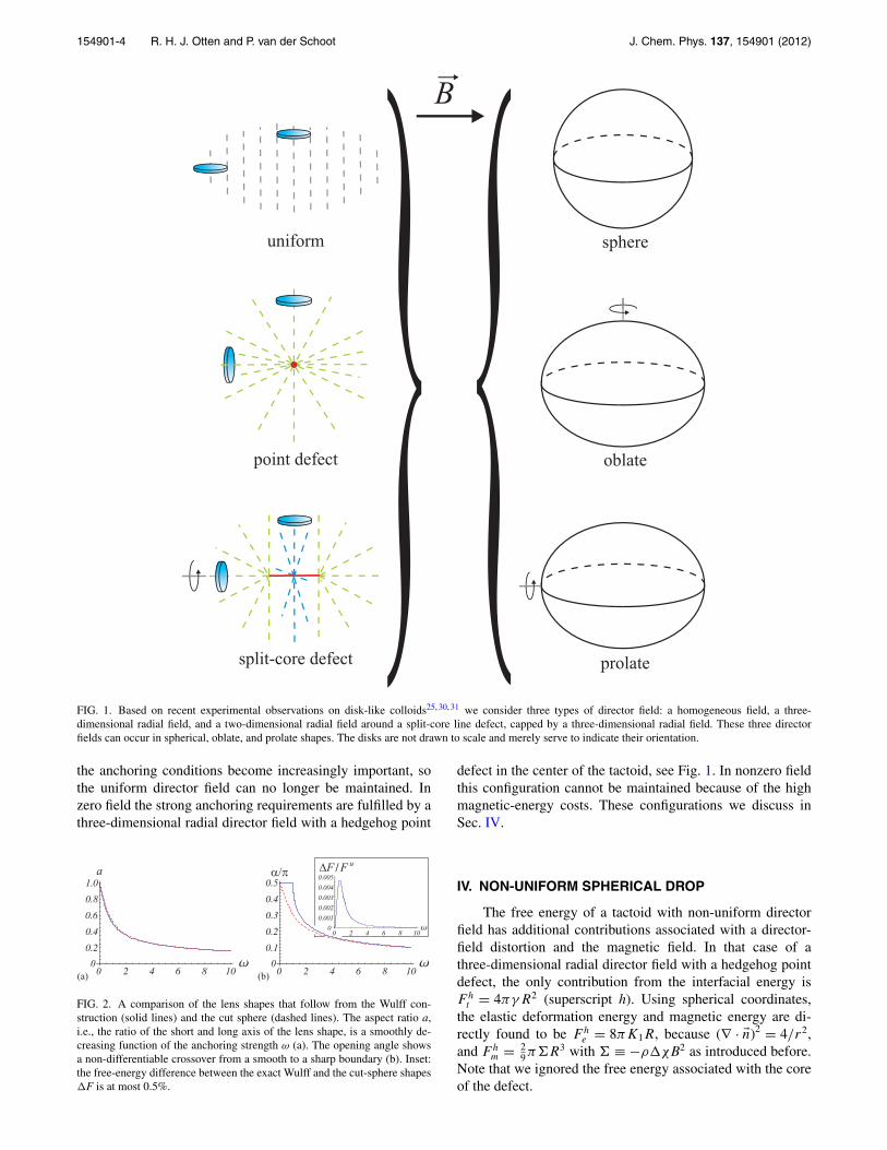
BB
FIG. 3. In order to lower the magnetic energy of the drop in a sufficientlystrong magnetic field, the point defect (left) can stretch to a “split-core” linedefect in the direction of the magnetic field �B (middle).30, 31 The defect lengthincreases with the field strength (right).
Hence, the total free energy of the spherical tactoid withradial director field becomes
Fh = 4πγR2 + 8πK1R + 2
9π�R3. (7)
In the absence of a magnetic field, � = 0, we can estimatefor what droplet size R the hedgehog is energetically more fa-vorable than the uniform field. We see from Eqs. (6) and (7)that Fh < Fu gives 8πK1R < 8
3πζR2, or Rω > 3. Hence, fordroplets with a radius larger than 3K1/ζ anchoring has the up-per hand such that the surface-anchoring forces drive the di-rector field into the hedgehog configuration. For lens-shapeddroplets, described in Sec. III, we find that our exact but cum-bersome expressions for the crossover value can be very wellpresented by Rω = 3 + 4ω/5 for all values of ω.
For large enough tactoids the hedgehog configuration ismore favorable than the homogeneous lens shape but for a suf-ficiently strong magnetic field it cannot be maintained eitherbecause in that case the magnetic energy becomes too large.To comply with the orientation imposed by the magnetic fieldfor a larger fraction of the particles, the tactoid can, besidesadopting a uniform director field, split the point defect intotwo, connected by a line defect of topological charge +1 inthe direction of the magnetic field. See Fig. 3.
To model this we presume the director field around thisline defect to be radial in two dimensions, and realize that thevolume around it has minimal magnetic energy penalty. Inthe remainder of the tactoid the director field is presumed tohave a three-dimensional splay deformation stemming fromthe original point defect. So, compared to the hedgehog thisconfiguration has a lower magnetic energy penalty, which iseven zero for a defect throughout the entire tactoid, but it hasa higher elastic deformation energy and nonzero anchoringenergy.
Invoking these assumptions on the director field, we sep-arate the computation of the anchoring, elastic, and magneticenergies into a part from the “axis” with the two-dimensionalsplay deformation, and a part from the ends with the three-dimensional splay deformation. In both parts we presumeperfect cylindrical symmetry by invoking cylindrical coordi-nates. For a given line-defect length L we compute the con-tributions to the free energy Fsc of the split-core defect (su-perscript sc), and we compute the optimal length of the linedefect by putting ∂Fsc/∂L = 0. The resulting equation is usedto eliminate the variable L from the free energy Fsc, enabling
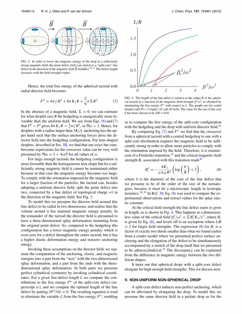
FIG. 4. The length of the line defect L relative to the radius R of the spheri-cal tactoid as a function of the magnetic-field strength β2/ω2 as obtained byminimizing the free energy Fsc with respect to L. The graphs are for scaleddroplet radii R = 5 (right), 10, and 20 (left). The value for the size of the coreb has been chosen to be b/R = 0.01.
us to compare the free energy of the split-core configurationwith the hedgehog and the drop with uniform director field.41
By comparing Eq. (7) and Fsc we find that the crossoverfrom a spherical tactoid with a central hedgehog to one with asplit-core disclination requires the magnetic field to be suffi-ciently strong in order to allow more particles to comply withthe orientation imposed by the field. Therefore, it is reminis-cent of a Frederiks transition,42 and the critical magnetic-fieldstrength Bc associated with this transition reads30
B2c = − 4K1
ρ�χR2
(log
(b
R
)+ 2
), (8)
where b is the diameter of the core of the line defect thatwe presume to be of the order of the size of the nemato-gens, because it must be a microscopic length in lyotropicnematics.38, 39 In Ref. 30, Eq. (8) was used to compare the ex-perimental observations and extract values for the splay elas-tic constant.
At the critical field strength the line defect starts to growin length, as is shown in Fig. 4. This happens at a dimension-less value of the critical field β2
c /ω2 = �B2
c K1/ζ2, where Bc
is given by Eq. (8), and levels off to an asymptote where L/R= 2 for larger field strengths. The expression (8) for Bc is afactor of exactly two thirds smaller than what we found earlierfrom a cruder model where we presumed perfect surface an-choring and the elongation of the defect to be simultaneouslyaccompanied by a stretch of the drop itself that we presumedto be spherocylindrical.25 The discrepancy can be explainedfrom the difference in magnetic energy between the two dif-ferent shapes.
It turns out that spherical drops with a split-core defectelongate for high enough field strengths. This we discuss next.
V. NON-UNIFORM NON-SPHERICAL DROP
A split-core defect induces non-perfect anchoring, whichcan be alleviated by elongating the drop. To model this wepresume the same director field in a prolate drop as for the
154901-6 R. H. J. Otten and P. van der Schoot J. Chem. Phys. 137, 154901 (2012)
spherical drop with a split-core defect. Obviously, the volumeof the drop is conserved. The calculation of our free energy ofan arbitrary prolate ellipsoid of revolution is rather involved,especially that of the anchoring free energy, so we perform aperturbation calculation near the sphere limit. For the latter wetake as a starting point the perfectly spherical drop for whichour calculation is exact.41 This approach is justified by theexperimental observation that in practice the deviation fromthe spherical shape of the observed prolate shape is small.30
The perturbation expansion we need to perform in boththe shape and the length of the line defect because the lat-ter adjusts to the droplet shape. Hence, one perturbation pa-rameter is the deviation of the aspect ratio from that of thesphere, i.e., unity, and the other is the deviation of the line-defect length from that of the sphere. The calculation is againfar from trivial, and here we only outline the concepts.41
The free energy F scp of the prolate shape (subscript p) we
find from the free energy Fsc(L, ε = 0) for the sphere withdefect length L and deviation ε = 0 from the aspect ratio ofunity of the sphere. The equation for F sc
p reads
F scp (Lp, ε) = F sc(L, 0) + ε
∂F sc
∂ε
∣∣∣∣ε=0
+ δL∂F sc
∂L
∣∣∣∣ε=0
+ 1
2ε2 ∂2F sc
∂ε2
∣∣∣∣ε=0
+ 1
2(δL)2 ∂2F sc
∂L2
∣∣∣∣ε=0
+ ε δL∂2F sc
∂ε∂L
∣∣∣∣ε=0
+ O(ε3, (δL)3), (9)
where Lp = L + δL is the length of the line defect in the pro-late ellipsoid. We optimize F sc
p with respect to the parametersε and δL, so we put ∂F sc
p /∂δL = 0 and ∂F scp /∂ε = 0, giving
∂F sc
∂ε
∣∣∣∣ε=0
+ ε∂2F sc
∂ε2
∣∣∣∣ε=0
+ δL∂2F sc
∂ε∂L
∣∣∣∣ε=0
= 0, (10)
∂F sc
∂L
∣∣∣∣ε=0
+ δL∂2F sc
∂L2
∣∣∣∣ε=0
+ εδL∂2F sc
∂ε∂L
∣∣∣∣ε=0
= 0. (11)
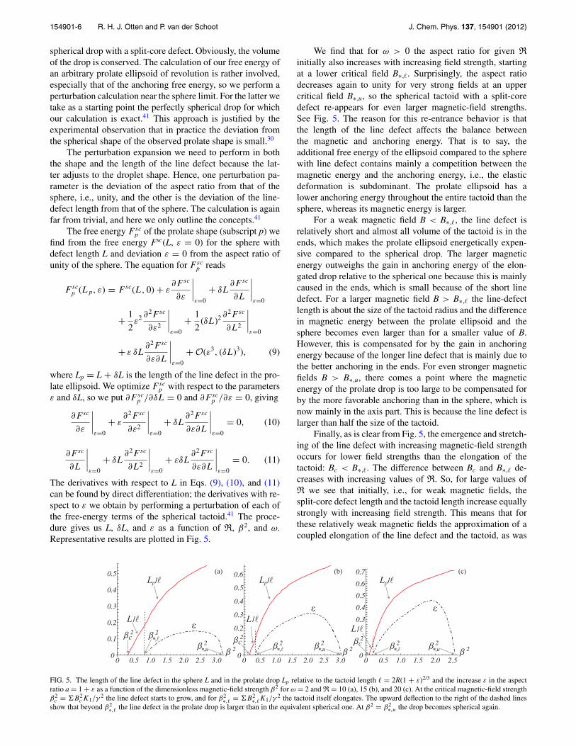
The derivatives with respect to L in Eqs. (9), (10), and (11)can be found by direct differentiation; the derivatives with re-spect to ε we obtain by performing a perturbation of each ofthe free-energy terms of the spherical tactoid.41 The proce-dure gives us L, δL, and ε as a function of R, β2, and ω.Representative results are plotted in Fig. 5.
We find that for ω > 0 the aspect ratio for given R
initially also increases with increasing field strength, startingat a lower critical field B∗,�. Surprisingly, the aspect ratiodecreases again to unity for very strong fields at an uppercritical field B∗,u, so the spherical tactoid with a split-coredefect re-appears for even larger magnetic-field strengths.See Fig. 5. The reason for this re-entrance behavior is thatthe length of the line defect affects the balance betweenthe magnetic and anchoring energy. That is to say, theadditional free energy of the ellipsoid compared to the spherewith line defect contains mainly a competition between themagnetic energy and the anchoring energy, i.e., the elasticdeformation is subdominant. The prolate ellipsoid has alower anchoring energy throughout the entire tactoid than thesphere, whereas its magnetic energy is larger.
For a weak magnetic field B < B∗,�, the line defect isrelatively short and almost all volume of the tactoid is in theends, which makes the prolate ellipsoid energetically expen-sive compared to the spherical drop. The larger magneticenergy outweighs the gain in anchoring energy of the elon-gated drop relative to the spherical one because this is mainlycaused in the ends, which is small because of the short linedefect. For a larger magnetic field B > B∗,� the line-defectlength is about the size of the tactoid radius and the differencein magnetic energy between the prolate ellipsoid and thesphere becomes even larger than for a smaller value of B.However, this is compensated for by the gain in anchoringenergy because of the longer line defect that is mainly due tothe better anchoring in the ends. For even stronger magneticfields B > B∗,u, there comes a point where the magneticenergy of the prolate drop is too large to be compensated forby the more favorable anchoring than in the sphere, which isnow mainly in the axis part. This is because the line defect islarger than half the size of the tactoid.
Finally, as is clear from Fig. 5, the emergence and stretch-ing of the line defect with increasing magnetic-field strengthoccurs for lower field strengths than the elongation of thetactoid: Bc < B∗,�. The difference between Bc and B∗,� de-creases with increasing values of R. So, for large values ofR we see that initially, i.e., for weak magnetic fields, thesplit-core defect length and the tactoid length increase equallystrongly with increasing field strength. This means that forthese relatively weak magnetic fields the approximation of acoupled elongation of the line defect and the tactoid, as was
(b)(a) (c)
c
*
3 3
L /p
,
L /pL /p
L / L /L /
c c,u**,
*,
,u*,u*
FIG. 5. The length of the line defect in the sphere L and in the prolate drop Lp relative to the tactoid length � = 2R(1 + ε)2/3 and the increase ε in the aspectratio a = 1 + ε as a function of the dimensionless magnetic-field strength β2 for ω = 2 and R = 10 (a), 15 (b), and 20 (c). At the critical magnetic-field strengthβ2
c = �B2c K1/γ
2 the line defect starts to grow, and for β2∗,� = �B2
∗,�K1/γ2 the tactoid itself elongates. The upward deflection to the right of the dashed lines
show that beyond β2∗,� the line defect in the prolate drop is larger than in the equivalent spherical one. At β2 = β2∗,u the drop becomes spherical again.
154901-7 R. H. J. Otten and P. van der Schoot J. Chem. Phys. 137, 154901 (2012)
made previously in a much cruder model,25 is in fact quitereasonable.
In Sec. VI we present the stability diagrams and explainhow we compute them.
VI. STABILITY DIAGRAMS
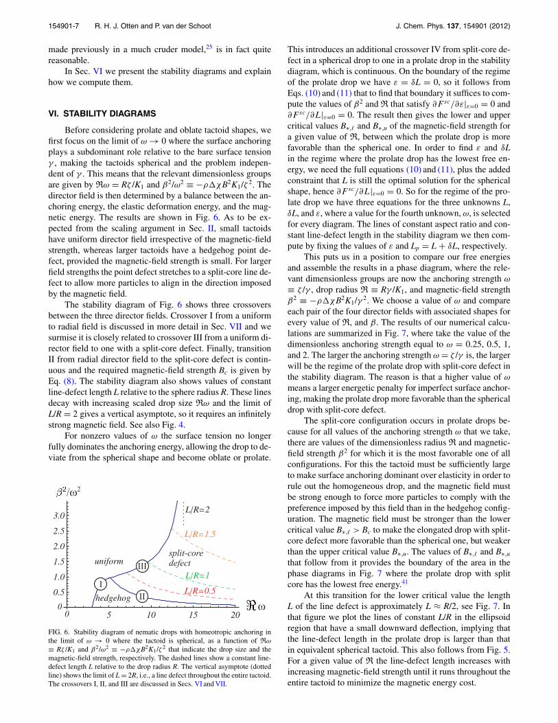
Before considering prolate and oblate tactoid shapes, wefirst focus on the limit of ω → 0 where the surface anchoringplays a subdominant role relative to the bare surface tensionγ , making the tactoids spherical and the problem indepen-dent of γ . This means that the relevant dimensionless groupsare given by Rω = Rζ /K1 and β2/ω2 ≡ −ρ�χB2K1/ζ 2. Thedirector field is then determined by a balance between the an-choring energy, the elastic deformation energy, and the mag-netic energy. The results are shown in Fig. 6. As to be ex-pected from the scaling argument in Sec. II, small tactoidshave uniform director field irrespective of the magnetic-fieldstrength, whereas larger tactoids have a hedgehog point de-fect, provided the magnetic-field strength is small. For largerfield strengths the point defect stretches to a split-core line de-fect to allow more particles to align in the direction imposedby the magnetic field.
The stability diagram of Fig. 6 shows three crossoversbetween the three director fields. Crossover I from a uniformto radial field is discussed in more detail in Sec. VII and wesurmise it is closely related to crossover III from a uniform di-rector field to one with a split-core defect. Finally, transitionII from radial director field to the split-core defect is contin-uous and the required magnetic-field strength Bc is given byEq. (8). The stability diagram also shows values of constantline-defect length L relative to the sphere radius R. These linesdecay with increasing scaled drop size Rω and the limit ofL/R = 2 gives a vertical asymptote, so it requires an infinitelystrong magnetic field. See also Fig. 4.
For nonzero values of ω the surface tension no longerfully dominates the anchoring energy, allowing the drop to de-viate from the spherical shape and become oblate or prolate.
FIG. 6. Stability diagram of nematic drops with homeotropic anchoring inthe limit of ω → 0 where the tactoid is spherical, as a function of Rω
≡ Rζ /K1 and β2/ω2 ≡ −ρ�χB2K1/ζ 2 that indicate the drop size and themagnetic-field strength, respectively. The dashed lines show a constant line-defect length L relative to the drop radius R. The vertical asymptote (dottedline) shows the limit of L = 2R, i.e., a line defect throughout the entire tactoid.The crossovers I, II, and III are discussed in Secs. VI and VII.
This introduces an additional crossover IV from split-core de-fect in a spherical drop to one in a prolate drop in the stabilitydiagram, which is continuous. On the boundary of the regimeof the prolate drop we have ε = δL = 0, so it follows fromEqs. (10) and (11) that to find that boundary it suffices to com-pute the values of β2 and R that satisfy ∂F sc/∂ε|ε=0 = 0 and∂F sc/∂L|ε=0 = 0. The result then gives the lower and uppercritical values B∗,� and B∗,u of the magnetic-field strength fora given value of R, between which the prolate drop is morefavorable than the spherical one. In order to find ε and δLin the regime where the prolate drop has the lowest free en-ergy, we need the full equations (10) and (11), plus the addedconstraint that L is still the optimal solution for the sphericalshape, hence ∂F sc/∂L|ε=0 = 0. So for the regime of the pro-late drop we have three equations for the three unknowns L,δL, and ε, where a value for the fourth unknown, ω, is selectedfor every diagram. The lines of constant aspect ratio and con-stant line-defect length in the stability diagram we then com-pute by fixing the values of ε and Lp = L + δL, respectively.
This puts us in a position to compare our free energiesand assemble the results in a phase diagram, where the rele-vant dimensionless groups are now the anchoring strength ω
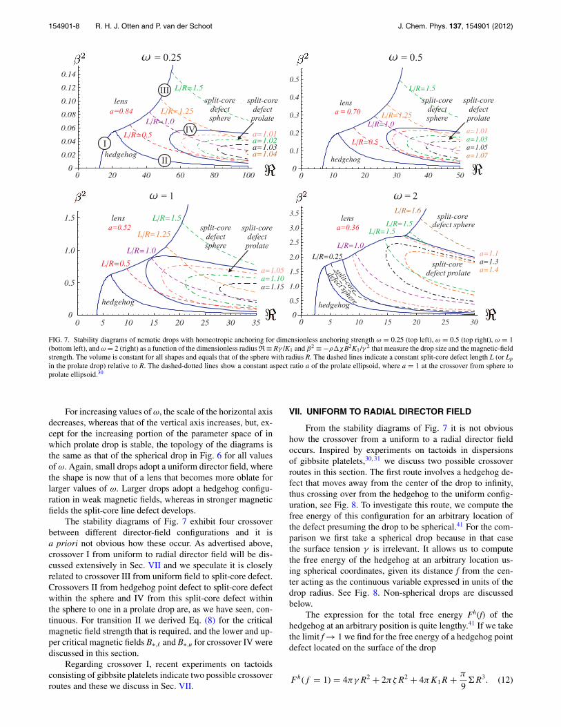
≡ ζ /γ , drop radius R ≡ Rγ /K1, and magnetic-field strengthβ2 ≡ −ρ�χB2K1/γ 2. We choose a value of ω and compareeach pair of the four director fields with associated shapes forevery value of R, and β. The results of our numerical calcu-lations are summarized in Fig. 7, where take the value of thedimensionless anchoring strength equal to ω = 0.25, 0.5, 1,and 2. The larger the anchoring strength ω = ζ /γ is, the largerwill be the regime of the prolate drop with split-core defect inthe stability diagram. The reason is that a higher value of ω
means a larger energetic penalty for imperfect surface anchor-ing, making the prolate drop more favorable than the sphericaldrop with split-core defect.
The split-core configuration occurs in prolate drops be-cause for all values of the anchoring strength ω that we take,there are values of the dimensionless radius R and magnetic-field strength β2 for which it is the most favorable one of allconfigurations. For this the tactoid must be sufficiently largeto make surface anchoring dominant over elasticity in order torule out the homogeneous drop, and the magnetic field mustbe strong enough to force more particles to comply with thepreference imposed by this field than in the hedgehog config-uration. The magnetic field must be stronger than the lowercritical value B∗,� > Bc to make the elongated drop with split-core defect more favorable than the spherical one, but weakerthan the upper critical value B∗,u. The values of B∗,� and B∗,u
that follow from it provides the boundary of the area in thephase diagrams in Fig. 7 where the prolate drop with splitcore has the lowest free energy.41
At this transition for the lower critical value the lengthL of the line defect is approximately L ≈ R/2, see Fig. 7. Inthat figure we plot the lines of constant L/R in the ellipsoidregion that have a small downward deflection, implying thatthe line-defect length in the prolate drop is larger than thatin equivalent spherical tactoid. This also follows from Fig. 5.For a given value of R the line-defect length increases withincreasing magnetic-field strength until it runs throughout theentire tactoid to minimize the magnetic energy cost.
154901-8 R. H. J. Otten and P. van der Schoot J. Chem. Phys. 137, 154901 (2012)
FIG. 7. Stability diagrams of nematic drops with homeotropic anchoring for dimensionless anchoring strength ω = 0.25 (top left), ω = 0.5 (top right), ω = 1(bottom left), and ω = 2 (right) as a function of the dimensionless radius R ≡ Rγ /K1 and β2 ≡ −ρ�χB2K1/γ 2 that measure the drop size and the magnetic-fieldstrength. The volume is constant for all shapes and equals that of the sphere with radius R. The dashed lines indicate a constant split-core defect length L (or Lp
in the prolate drop) relative to R. The dashed-dotted lines show a constant aspect ratio a of the prolate ellipsoid, where a = 1 at the crossover from sphere toprolate ellipsoid.30
For increasing values of ω, the scale of the horizontal axisdecreases, whereas that of the vertical axis increases, but, ex-cept for the increasing portion of the parameter space of inwhich prolate drop is stable, the topology of the diagrams isthe same as that of the spherical drop in Fig. 6 for all valuesof ω. Again, small drops adopt a uniform director field, wherethe shape is now that of a lens that becomes more oblate forlarger values of ω. Larger drops adopt a hedgehog configu-ration in weak magnetic fields, whereas in stronger magneticfields the split-core line defect develops.
The stability diagrams of Fig. 7 exhibit four crossoverbetween different director-field configurations and it isa priori not obvious how these occur. As advertised above,crossover I from uniform to radial director field will be dis-cussed extensively in Sec. VII and we speculate it is closelyrelated to crossover III from uniform field to split-core defect.Crossovers II from hedgehog point defect to split-core defectwithin the sphere and IV from this split-core defect withinthe sphere to one in a prolate drop are, as we have seen, con-tinuous. For transition II we derived Eq. (8) for the criticalmagnetic field strength that is required, and the lower and up-per critical magnetic fields B∗,� and B∗,u for crossover IV werediscussed in this section.
Regarding crossover I, recent experiments on tactoidsconsisting of gibbsite platelets indicate two possible crossoverroutes and these we discuss in Sec. VII.
VII. UNIFORM TO RADIAL DIRECTOR FIELD
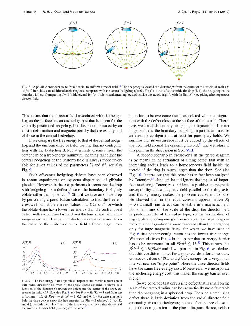
From the stability diagrams of Fig. 7 it is not obvioushow the crossover from a uniform to a radial director fieldoccurs. Inspired by experiments on tactoids in dispersionsof gibbsite platelets,30, 31 we discuss two possible crossoverroutes in this section. The first route involves a hedgehog de-fect that moves away from the center of the drop to infinity,thus crossing over from the hedgehog to the uniform config-uration, see Fig. 8. To investigate this route, we compute thefree energy of this configuration for an arbitrary location ofthe defect presuming the drop to be spherical.41 For the com-parison we first take a spherical drop because in that casethe surface tension γ is irrelevant. It allows us to computethe free energy of the hedgehog at an arbitrary location us-ing spherical coordinates, given its distance f from the cen-ter acting as the continuous variable expressed in units of thedrop radius. See Fig. 8. Non-spherical drops are discussedbelow.
The expression for the total free energy Fh(f) of thehedgehog at an arbitrary position is quite lengthy.41 If we takethe limit f → 1 we find for the free energy of a hedgehog pointdefect located on the surface of the drop
Fh(f = 1) = 4πγR2 + 2πζR2 + 4πK1R + π
9�R3. (12)
154901-9 R. H. J. Otten and P. van der Schoot J. Chem. Phys. 137, 154901 (2012)
FIG. 8. A possible crossover route from a radial to uniform director field.31 The hedgehog is located at a distance fR from the center of the tactoid of radius R,so f > 0 introduces an additional anchoring cost compared with the central hedgehog (f = 0). For f < 1 the defect is inside the drop (left), the hedgehog on theboundary follows from putting f = 1 (middle), and for f > 1 it is virtual, meaning located outside the tactoid (right), with the limit f → ∞ giving a homogeneousdirector field.
This means that the director field associated with the hedge-hog on the surface has an anchoring cost that is absent for thecentrally positioned hedgehog, but this is compensated by anelastic deformation and magnetic penalty that are exactly halfof those in the central hedgehog.
If we compare the free energy to that of the central hedge-hog and the uniform director field, we find that no configura-tion with the hedgehog defect at a finite distance from thecenter can be a free-energy minimum, meaning that either thecentral hedgehog or the uniform field is always more favor-able for given values of the parameters R and β2, see alsoFig. 9.
Such off-center hedgehog defects have been observedin recent experiments on aqueous dispersions of gibbsiteplatelets. However, in these experiments it seems that the dropwith hedgehog point defect close to the boundary is slightlyoblate rather than spherical.31 Still, if we take an oblate dropby performing a perturbation calculation to find the free en-ergy, we find that there are no values of ω, R and β2 for whichthe oblate shape has a lower free energy than the central pointdefect with radial director field and the lens shape with a ho-mogeneous field. Hence, in order to make the crossover fromthe radial to the uniform director field a free-energy maxi-
(b)(a)F/K R1 F/K R1
ff00
FIG. 9. The free energy F of a spherical drop of radius R with a point defectwith radial director field, with K1 the splay elastic constant, is shown as afunction of the distance f between the defect and the center of the drop, ex-pressed in units of R. See also Fig. 8. (a) For Rω = Rζ /K1 = 3 and from topto bottom −ρ�χB2K1/ζ 2 = β2/ω2 = 1, 0.5, and 0. (b) For zero magneticfield the three curves show the free energies for Rω = 2 (dashed), 3 (solid),and 4 (dotted-dashed). For Rω = 3 the free energy of the central defect andthe uniform director field (f → ∞) are the same.31
mum has to be overcome that is associated with a configura-tion with the defect close to the surface of the tactoid. There-fore, we conclude that any hedgehog configuration off-centerin general, and the boundary hedgehog in particular, must bean unstable configuration, at least for pure splay fields. Wesurmise that its occurrence must be caused by the effects ofthe flow field around the creaming tactoid,31 and we return tothis point in the discussion in Sec. VIII.
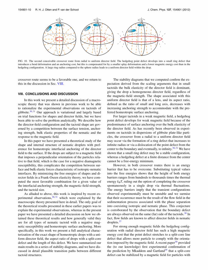
A second scenario in crossover I in the phase diagramis by means of the formation of a ring defect that with anincreasing radius leads to a homogeneous field inside thetactoid if the ring is much larger than the drop. See alsoFig. 10. It turns out that this route has in fact been analyzedby Terentjev,35 although he did ignore the impact of imper-fect anchoring. Terentjev considered a positive diamagneticsusceptibility and a magnetic field parallel to the ring axis,and this symmetry makes the problem equivalent to ours.He showed that in the equal-constant approximation K1
= K3 a small ring defect can be stable in a magnetic field.For small rings on the scale of the drop the director fieldis predominantly of the splay type, so the assumption ofnegligible anchoring energy is reasonable. For larger ring de-fects this configuration is more favorable than the hedgehogonly for large magnetic fields, for which we have seen inFig. 6 that neither configuration has the lowest free energy.We conclude from Fig. 4 in that paper that an energy barrierhas to be overcome for all R2β2 � 15.35 This means thatβ2/ω2 � 15/(Rω)2 and if we plot this in Fig. 6, we deducethat this condition is met for a spherical drop for almost anycrossover values of Rω and β2/ω2, except for a very smallinterval near the “triple point” where the three director fieldshave the same free-energy cost. Moreover, if we incorporatethe anchoring energy cost, this makes the energy barrier evenhigher.
So we conclude that only a ring defect that is small on thescale of the tactoid radius can be energetically more favorablethan the hedgehog in a spherical drop. For such a small ringdefect there is little deviation from the radial director fieldemanating from the hedgehog point defect, so we chose toomit this configuration in the phase diagram. Hence, neither
154901-10 R. H. J. Otten and P. van der Schoot J. Chem. Phys. 137, 154901 (2012)
FIG. 10. The second conceivable crossover route from radial to uniform director field. The hedgehog point defect develops into a small ring defect thatintroduces a bend deformation and an anchoring cost, but this is compensated for by a smaller splay deformation and a lower magnetic energy cost than in thehedgehog configuration. A large ring radius compared to the sphere radius leads to a uniform director field within the drop.
crossover route seems to be a favorable one, and we return tothis in the discussion in Sec. VIII.
VIII. CONCLUSIONS AND DISCUSSION
In this work we present a detailed discussion of a macro-scopic theory that was shown in previous work to be ableto rationalize the experimental observations on tactoids ofgibbsite.30, 31 Our approach is variational and largely basedon trial functions for shapes and director fields, but we havebeen able to solve the problem analytically. We describe howthe director-field configuration and the tactoid shape are gov-erned by a competition between the surface tension, anchor-ing strength, bulk elastic properties of the nematic and theresponse to the magnetic field.
In this paper we have presented a theoretical study of theshape and internal structure of nematic droplets with pref-erence for homeotropic interfacial anchoring of the directorfield to the surface. If the drops are subject to a magnetic fieldthat imposes a perpendicular orientation of the particles rela-tive to that field, which is the case for a negative diamagneticsusceptibility, this complicates the competition between sur-face and bulk elastic forces characteristic of isotropic-nematicinterfaces. By minimizing the free energies of shapes and di-rector fields in a Frank-Oseen elasticity theory, we have com-puted the most favorable combination for a given value ofthe interfacial anchoring strength, the magnetic-field strength,and the tactoid size.
As alluded to above, this work is inspired by recent ex-perimental observations,30, 31 which were explained by themacroscopic theory presented here in detail. The only goal ofthe theoretical results presented in these earlier papers was toexplain the experimental observations, whereas in the presentpaper we have presented a detailed discussion on how we ob-tained these theoretical results and how generally valid theyare for all types of nematic tactoid with a negative mag-netic susceptibility and homeotropic surface anchoring. Morespecifically, in this work we present a full analytical charac-terization of the exact shape of homeotropic drops with a uni-form director field, the aspect ratio of drops with a split-coredefect and the length of this defect. We have summarized ourmain results in a series of stability diagrams, and we have dis-cussed in detail plausible transition paths between differenttactoid structures.
The stability diagrams that we computed confirm the ex-pectation derived from the scaling arguments that in smalltactoids the bulk elasticity of the director field is dominant,giving the drop a homogeneous director field, regardless ofthe magnetic-field strength. The shape associated with thisuniform director field is that of a lens, and its aspect ratio,defined as the ratio of small and long axis, decreases withincreasing anchoring strength to accommodate with the pre-ferred homeotropic surface anchoring.
For larger tactoids in a weak magnetic field, a hedgehogpoint defect develops for weak magnetic field because of thepredominance of surface anchoring over the bulk elasticity ofthe director field. As has recently been observed in experi-ments on tactoids in dispersions of gibbsite plate-like parti-cles, the crossover from a radial to a uniform director fieldmay occur via the formation of a ring defect that increases toinfinite radius or via a dislocation of the point defect from thecenter to the boundary and eventually, to infinity.30, 31 We haveshown that a small ring defect may be a stable configuration,whereas a hedgehog defect at a finite distance from the centercannot be a free-energy minimum.
However, in both crossover routes there is an energybarrier that has to be overcome. Substituting typical valuesinto the free energies shows that the height of both energybarriers ranges from hundreds to thousands times the thermalenergy kBT, ruling out the option of completing the crossoverspontaneously in a single drop via thermal fluctuations.The energy barriers imply that the transient configurationsobserved experimentally must be unstable and we surmisethat their occurrence must be the result of the flow field in thesedimentation process associated with the phase separationinto coexisting isotropic and nematic phase. This conjectureis corroborated by the observation that the boundary defectare always observed on the same (far) side of the tactoids.30 Infact, flow fields are known to affect director fields in nematicdroplets.37
For strong enough magnetic fields the hedgehog config-uration with radial director field has such a high magneticenergy cost that the point defect stretches to a split-core linedefect that allows more particle to comply with the orienta-tion imposed by the magnetic field. A recent paper30 providedthe (to our knowledge) first experimental confirmation ofthe prediction by Mkaddem and Gartland29 that a split-coredefect can be stabilized by a magnetic field for particles with
154901-11 R. H. J. Otten and P. van der Schoot J. Chem. Phys. 137, 154901 (2012)
a negative diamagnetic susceptibility anisotropy, which isthe case for the plate-like gibbsite platelets that were usedin the experiments.30 In this work we have shown how thedominant magnetic field forces the particles to adopt such asplit-core configuration and for what values of the drop sizeand magnetic-field strength it should be stable.
In fact, many more of our theoretical results are borneout by the experiments that were conducted recently. First,a uniform director field was observed for small enoughdroplets.30, 31 Second, for sufficiently large drops in a weakor absent magnetic field, a hedgehog point defect with radialdirector field in a spherical drop develops. Third, in the split-core configuration for even stronger fields the length of theline defect increases with increasing magnetic-field strengthup to a point were the defect line runs through the entire tac-toid. We note that this limiting case requires a very strong fieldsuch that the alignment of the isotropic background becomessignificant, making it difficult to observe the details of thedrop experimentally. Depending on the anchoring strength,the drop itself may stretch to a prolate shape, and this wasalso observed in experiments on tactoids of sterically stabi-lized gibbsite. Interestingly, tactoids in dispersion of charge-stabilized gibbsite remained spherical.30
We put forward that a difference in the anchoringstrength is the cause of different experimental observationsin the two types of dispersion. Indeed, by fitting to ourtheoretical predictions the observed aspect ratio of the dropsin the sterically stabilized system and line-defect length inboth the sterically stabilized and the charge-stabilized system,we extracted values of K1 = 1.0 ± 0.5 × 10⁻¹³ N, γ = 2 ± 1× 10⁻⁸ N/m, and ω ≈ 2 for the sterically stabilized gibbsite,and K1 = 2 ± 1 × 10⁻¹³ N and ζ = 4 ± 2 × 10⁻⁸ N/m forthe charge-stabilized gibbsite.30, 31 The latter system exhibitsno deviation from the spherical shape, making the analysisindependent of the dominant bare surface tension γ andgiving ω = ζ /γ → 0. The values of K1 are in agreement withearlier results from a much cruder model25 and with capillaryrise experiments for gibbsite platelets in toluene that weresterically stabilized,13 but the value of the surface tensionof γ = 3 × 10⁻⁹ N/m in that work is much smaller thanwhat we find here. The value ω ≈ 2 is required to reach theaspect ratios that were observed recently in the experimentson sterically stabilized gibbsite using bromotoluene,30 whichis significantly larger than the value of approximately ω
= 0.5 that was found from the mentioned capillary riseexperiments.13 It should be noted that these experiments arevery sensitive to the experimental procedure.43
There are two possible caveats of our model. The first isthat we neglected the influence of the magnetic field on thematerial parameters. The second is that except for the con-figuration with ring defect, we only consider splay deforma-tions of the director field. Although it might appear that theobserved director fields exhibit merely a splay deformation,any bend deformation could give a significant contribution be-cause a value of K3 ≈ 7 × 10⁻¹⁴ N has recently been observedfor platelets,34 which would favor a bend deformation over asplay distortion. This has to be compared to the value of K1
≈ 1 − 2 × 10⁻¹³ N that was found recently from the com-parison between the experiments and our model.31 However,
it seems unlikely that the incorporation of the bend and/orsaddle-splay elastic constant can account for the large discrep-ancy between the calculated value of the anchoring strengthand surface tension that follow from the model, and the valueobtained earlier from capillary rise experiments.13, 25
As already mentioned above, we also neglected the effectof the magnetic field on the material parameters in this work,which may be questionable because of, e.g., the alignmentof the background isotropic phase for with increasing fieldstrength. The alignment of the isotropic phase must affect thevalues of the surface tension and anchoring strength that pre-sumably become smaller due to the alignment. Moreover, themagnetic field increases the nematic order parameter of thenematic phase, which should affect the splay elastic constantK1 and the anchoring strength ζ . This impact is different forthe two parameters because the anchoring strength is propor-tional to the nematic order parameter and the elastic constantscales with the square of it.10 The elastic force and surface-anchoring forces compete with the magnetic force against de-formation, so an underestimation of K1 would lead to a toolarge value of the surface tension. Still, the question remainswhether this effect is strong enough to explain the large dis-crepancy between the quoted values of the surface tension.
ACKNOWLEDGMENTS
The work of R.O. forms part of the research programmeof the Dutch Polymer Institute (DPI, Project No. 648). Theauthors thank Lia Verhoeff and Henk Lekkerkerker for con-ducting the experiments and many stimulating discussions.
1H. Zocher, Zeits. f. Anorg. Chemie 147, 91 (1925).2P. Drzaic, Liquid Crystal Dispersions (World Scientific, Singapore, 1995).3A. V. Kaznacheev, M. M. Bogdanov, and S. A. Taraskin, J. Exp. Theor.Phys. 95, 57 (2002).
4A. V. Kaznacheev, M. M. Bogdanov, and A. S. Sonin, J. Exp. Theor. Phys.97, 1159 (2003).
5P. W. Oakes, J. Viamontes, and J. X. Tang, Phys. Rev. E 75, 061902(2007).
6N. Puech, E. Grelet, P. Poulin, C. Blanc, and P. Van der Schoot, Phys. Rev.E 82, 020702 (2010).
7L. Tortora and O. D. Lavrentovich, Proc. Natl. Acad. Sci. U.S.A. 108, 5163(2011).
8P. Prinsen and P. van der Schoot, Phys. Rev. E 68, 021701 (2003).9P. Prinsen and P. van der Schoot, Eur. Phys. J. E 13, 35 (2004).
10P. G. de Gennes and J. Prost, The Physics of Liquid Crystals (OxfordUniversity Press, 1993).
11J. X. Tang and S. Fraden, Liq. Cryst. 19, 459 (1995).12S. Fraden, A. J. Hurd, R. B. Meyer, M. Cahoon, and D. L. Casper, J. Phys.
(Paris), Colloq. 46, C3–85 (1985).13D. van der Beek, H. Reich, P. van der Schoot, M. Dijkstra, T. Schilling, R.
Vink, M. Schmidt, R. van Roij, and H. Lekkerkerker, Phys. Rev. Lett. 97,087801 (2006).
14W. L. Chen, T. Sato, and A. Teramoto, Macromolecules 29, 4283 (1996).15W. L. Chen, T. Sato, and A. Teramoto, Macromolecules 31, 6506 (1998).16J. D. Bernal and I. Fankuchen, J. Gen. Physiol. 25, 111 (1941).17H. Zocher and C. Török, Kolloid-Z. 170, 140 (1960).18Z. Dogic and S. Fraden, Philos. Trans. R. Soc. London 359, 997 (2001).19P. van der Schoot, J. Phys. Chem. B 103, 8804 (1999).20Y. Trukhina, S. Jungblut, P. van der Schoot, and T. Schilling, J. Chem. Phys.
130, 164513 (2009).21A. Cuetos and M. Dijkstra, Phys. Rev. Lett. 98, 095701 (2007).22F. M. van der Kooij and H. N. W. Lekkerkerker, J. Phys. Chem. B 102,
7829–7832 (1998).23F. M. van der Kooij, K. Kassapidou, and H. N. W. Lekkerkerker, Nature
(London) 406, 868–871 (2000).
154901-12 R. H. J. Otten and P. van der Schoot J. Chem. Phys. 137, 154901 (2012)
24A. B. D. Brown, S. M. Clarke, and A. R. Rennie, Langmuir 14, 3129–3132(1998).
25A. A. Verhoeff, R. H. J. Otten, P. van der Schoot, and H. N. W. Lekkerk-erker, J. Phys. Chem. B 113, 3704–3708 (2009).
26A. Kilian, Liq. Cryst. 14, 1189 (1993).27O. D. Lavrentovich, Liq. Cryst. 24, 117 (1998).28E. Penzenstadler and H. R. Trebin, J. Phys. (France) 50, 1027 (1989).29S. Mkaddem and E. C. Gartland, Phys. Rev. E 62, 6694 (2000).30A. A. Verhoeff, R. H. J. Otten, P. van der Schoot, and H. N. W. Lekkerk-
erker, J. Chem. Phys. 134, 044904 (2011).31A. A. Verhoeff, R. H. J. Otten, I. A. Bakelaar, P. van der Schoot, and H. N.
W. Lekkerkerker, Langmuir 27, 116 (2011).32F. C. Frank, Discuss. Faraday Soc. 25, 19–28 (1958).33A. Rapini and M. Papoular, J. Phys. (Paris), Colloq. 30, C4–54 (1969).
34D. van der Beek et al., Phys. Rev. E 73, 041402 (2006).35E. M. Terentjev, Phys. Rev. E 51, 1330 (1995).36In Sec. VII we consider a ring defect that has a director field with both a
splay and a bend deformation, but in the parameter range where this con-figuration is most favorable, it has hardly any bend deformation.
37A. Fernandez-Nieves, D. R. Link, M. Marquez, and D. A. Weitz, Phys. Rev.Lett. 98, 087801 (2007).
38R. B. Zasadzinski and J. Meyer, Phys. Rev. Lett. 56, 636 (1986).39W. Song, I. A. Kinloch, and A. H. Windle, Science 302, 1363 (2003).40G. Z. Wulff, Z. Kristallogr. 34, 449 (1901).41See supplementary material at http://dx.doi.org/10.1063/1.4756946 for de-
tails of the derivaiton.42V. Frederiks and V. Zolina, Trans. Faraday Soc. 29, 919 (1933).43A. A. Verhoeff, private communication (October 24, 2011).