Service Manual - Canon
358
9 8 7 6 5 4 3 2 1 imageRUNNER 1750/1740/1730 Series Service Manual Revision 1 September 26, 2011
-
Upload
khangminh22 -
Category
Documents
-
view
0 -
download
0
Transcript of Service Manual - Canon

987654321
imageRUNNER 1750/1740/1730 Series
Service Manual
Revision 1September 26, 2011
ApplicationThis manual has been issued by Canon Inc. for qualified persons to learn technical theory, installation, maintenance, and repair of products. This manual covers all localities where the products are sold. For this reason, there may be information in this manual that does not apply to your locality.
CorrectionsThis manual may contain technical inaccuracies or typographical errors due to improvements or changes in products. When changes occur in applicable products or in the contents of this manual, Canon will release technical information as the need arises. In the event of major changes in the contents of this manual over a long or short period, Canon will issue a new edition of this manual.
The following paragraph does not apply to any countries where such provisions are inconsistent with local law.
TrademarksThe product names and company names used in this manual are the registered trademarks of the individual companies.
CopyrightThis manual is copyrighted with all rights reserved. Under the copyright laws, this manual may not be copied, reproduced or translated into another language, in whole or in part, without the consent of Canon Inc.
© CANON INC. 2011
CautionUse of this manual should be strictly supervised to avoid disclosure of confidential information.
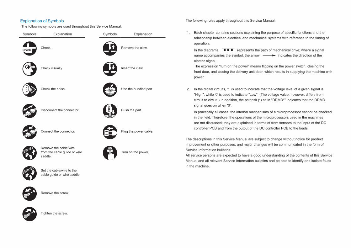
Explanation of SymbolsThe following symbols are used throughout this Service Manual.
Symbols Explanation Symbols Explanation
Check. Remove the claw.
Check visually. Insert the claw.
Check the noise. Use the bundled part.
Disconnect the connector. Push the part.
Connect the connector. Plug the power cable.
Remove the cable/wire from the cable guide or wire saddle.
Turn on the power.
Set the cable/wire to the cable guide or wire saddle.
Remove the screw.
Tighten the screw.
The following rules apply throughout this Service Manual:
1. Each chapter contains sections explaining the purpose of specific functions and the relationship between electrical and mechanical systems with reference to the timing of operation.
In the diagrams, represents the path of mechanical drive; where a signal name accompanies the symbol, the arrow indicates the direction of the electric signal. The expression "turn on the power" means flipping on the power switch, closing the front door, and closing the delivery unit door, which results in supplying the machine with power.
2. In the digital circuits, '1' is used to indicate that the voltage level of a given signal is "High", while '0' is used to indicate "Low". (The voltage value, however, differs from circuit to circuit.) In addition, the asterisk (*) as in "DRMD*" indicates that the DRMD signal goes on when '0'.
In practically all cases, the internal mechanisms of a microprocessor cannot be checked in the field. Therefore, the operations of the microprocessors used in the machines are not discussed: they are explained in terms of from sensors to the input of the DC controller PCB and from the output of the DC controller PCB to the loads.
The descriptions in this Service Manual are subject to change without notice for product improvement or other purposes, and major changes will be communicated in the form of Service Information bulletins.All service persons are expected to have a good understanding of the contents of this Service Manual and all relevant Service Information bulletins and be able to identify and isolate faults in the machine.
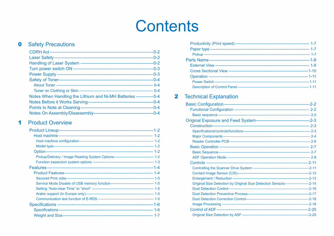
Contents0 Safety Precautions
CDRH Act -----------------------------------------------------------------------0-2Laser Safety --------------------------------------------------------------------0-2Handling of Laser System --------------------------------------------------0-2Turn power switch ON -------------------------------------------------------0-3Power Supply ------------------------------------------------------------------0-3Safety of Toner -----------------------------------------------------------------0-4
About Toner ------------------------------------------------------------------------- 0-4Toner on Clothing or Skin -------------------------------------------------------- 0-4
Notes When Handling the Lithium and Ni-MH Batteries ------------0-4Notes Before it Works Serving ---------------------------------------------0-4Points to Note at Cleaning --------------------------------------------------0-4Notes On Assembly/Disassembly -----------------------------------------0-4
1 Product OverviewProduct Lineup -----------------------------------------------------------------1-2
Host machine ----------------------------------------------------------------------- 1-2Host machine configuration -------------------------------------------------------------- 1-2Model type ------------------------------------------------------------------------------------ 1-2
Option --------------------------------------------------------------------------------- 1-2Pickup/Delivery / Image Reading System Options --------------------------------- 1-2Function expansion system options --------------------------------------------------- 1-3
Features -------------------------------------------------------------------------1-4Product Features ------------------------------------------------------------------- 1-4
Secured Print Jobs ------------------------------------------------------------------------- 1-5Service Mode Disable of USB memory function ------------------------------------ 1-5Setting “Auto-clear Time” to “short” ---------------------------------------------------- 1-5Arabic support (In Europe only) --------------------------------------------------------- 1-5Communication test function of E-RDS ----------------------------------------------- 1-5
Specifications ------------------------------------------------------------------1-6Specifications ----------------------------------------------------------------------- 1-6Weight and Size -------------------------------------------------------------------- 1-7
Productivity (Print speed) -------------------------------------------------------- 1-7Paper type --------------------------------------------------------------------------- 1-7
Pickup ----------------------------------------------------------------------------------------- 1-7Parts Name ---------------------------------------------------------------------1-8
External View ----------------------------------------------------------------------- 1-8Cross Sectional View ------------------------------------------------------------1-10Operation --------------------------------------------------------------------------- 1-11
Power Switch -------------------------------------------------------------------------------1-11Description of Control Panel ------------------------------------------------------------1-11
2 Technical ExplanationBasic Configuration -----------------------------------------------------------2-2
Functional Configuration --------------------------------------------------------- 2-2Basic sequence ----------------------------------------------------------------------------- 2-2
Original Exposure and Feed System -------------------------------------2-3Construction ------------------------------------------------------------------------- 2-3
Specifications/controls/functions -------------------------------------------------------- 2-3Major Components ------------------------------------------------------------------------- 2-4Reader Controller PCB -------------------------------------------------------------------- 2-6
Basic Operation -------------------------------------------------------------------- 2-7Basic Sequence ----------------------------------------------------------------------------- 2-7ADF Operation Mode ---------------------------------------------------------------------- 2-8
Controls ----------------------------------------------------------------------------- 2-11Controlling the Scanner Drive System -----------------------------------------------2-11Contact Image Sensor (CIS) ------------------------------------------------------------2-12Enlargement / Reduction ----------------------------------------------------------------2-13Original Size Detection by Original Size Detection Sensors --------------------2-14Dust Detection Control -------------------------------------------------------------------2-16Dust Detection Preventive Process ---------------------------------------------------2-17Dust Detection Correction Control-----------------------------------------------------2-18Image Processing -------------------------------------------------------------------------2-18
Control of ADF ---------------------------------------------------------------------2-20Original Size Detection by ADF --------------------------------------------------------2-20
Pickup and Feed Operations -----------------------------------------------------------2-22Reversal Operation------------------------------------------------------------------------2-22Delivery Operation-------------------------------------------------------------------------2-24Jam Detection ------------------------------------------------------------------------------2-25
Work of Service -------------------------------------------------------------------2-26Periodically Replaced Parts -------------------------------------------------------------2-26Consumable Parts -------------------------------------------------------------------------2-26Periodical Servicing -----------------------------------------------------------------------2-26When replacing the parts ----------------------------------------------------------------2-26
Main Controller -------------------------------------------------------------- 2-27Overview ----------------------------------------------------------------------------2-27
Configuration/Function -------------------------------------------------------------------2-27Controls -----------------------------------------------------------------------------2-28
Image Data Flow ---------------------------------------------------------------------------2-28Image Processing Module Configuration --------------------------------------------2-28Reader Unit Input Image Processing -------------------------------------------------2-29Compression/Expansion/Edit Processing Block -----------------------------------2-29Printer Output Image Processing ------------------------------------------------------2-30Image Data Flow of Copy Function ---------------------------------------------------2-30Image Data Flow of SEND Function --------------------------------------------------2-31Image Data Flow of FAX Transmission Function ----------------------------------2-31Image Data Flow of FAX Reception Function --------------------------------------2-32Image Data Flow of PDL Function ----------------------------------------------------2-32
Service Tasks ----------------------------------------------------------------------2-33Periodically Replaced Parts -------------------------------------------------------------2-33Consumable Parts -------------------------------------------------------------------------2-33Periodical Servicing -----------------------------------------------------------------------2-33
Laser Exposure System --------------------------------------------------- 2-34Construction ------------------------------------------------------------------------2-34
Specifications/Controls/Functions -----------------------------------------------------2-34Main Configuration Parts ----------------------------------------------------------------2-34Control System Configuration ----------------------------------------------------------2-35
Basic Sequence -------------------------------------------------------------------2-36Basic Sequence ----------------------------------------------------------------------------2-36
Various Controls -------------------------------------------------------------------2-37Controlling the Laser Activation Timing ----------------------------------------------2-37Controlling the Intensity of Laser Light -----------------------------------------------2-39Controlling the Laser Scanner Motor -------------------------------------------------2-39
Controlling the Laser Shutter -----------------------------------------------------------2-39Image Formation System ------------------------------------------------- 2-40
Basic Configuration ---------------------------------------------------------------2-40List of Image Formation Specifications ----------------------------------------------2-40Major Components in image formation system ------------------------------------2-41Image Formation Process ---------------------------------------------------------------2-42
Basic Sequence -------------------------------------------------------------------2-43Initial rotation sequence ------------------------------------------------------------------2-43Sequence at printing ----------------------------------------------------------------------2-43Last rotation sequence -------------------------------------------------------------------2-43
Controls -----------------------------------------------------------------------------2-44Drum Unit ------------------------------------------------------------------------------------2-44Developing Assembly ---------------------------------------------------------------------2-45Toner Supply Area -------------------------------------------------------------------------2-46Transfer Unit --------------------------------------------------------------------------------2-48Chang in bias by user mode (Special Mode) ---------------------------------------2-49Waste Toner Box ---------------------------------------------------------------------------2-49
Service Tasks ----------------------------------------------------------------------2-50Periodically Replaced Parts -------------------------------------------------------------2-50Consumable Parts -------------------------------------------------------------------------2-50Periodical Servicing -----------------------------------------------------------------------2-50
Fixing System ---------------------------------------------------------------- 2-51Overview ----------------------------------------------------------------------------2-51
Features --------------------------------------------------------------------------------------2-51Specifications -------------------------------------------------------------------------------2-51Major Components ------------------------------------------------------------------------2-52
Controls -----------------------------------------------------------------------------2-53Fixing Temperature Control (temperature control) --------------------------------2-53Standby Temperature Controll ----------------------------------------------------------2-54Print temperature control ----------------------------------------------------------------2-54Down Sequence Control -----------------------------------------------------------------2-56Change in fixing performance by user mode (Special Mode) ------------------2-57Pre-fixing arch level control -------------------------------------------------------------2-58Protection function-------------------------------------------------------------------------2-59
Service Tasks ----------------------------------------------------------------------2-59Periodically Replaced Parts -------------------------------------------------------------2-59Consumable Parts -------------------------------------------------------------------------2-59Periodical Servicing -----------------------------------------------------------------------2-59
Pickup Feed System ------------------------------------------------------- 2-60Overview ----------------------------------------------------------------------------2-60
Specifications -------------------------------------------------------------------------------2-60Parts Configuration ------------------------------------------------------------------------2-60Paper Path ----------------------------------------------------------------------------------2-62
Controls -----------------------------------------------------------------------------2-63Overview -------------------------------------------------------------------------------------2-63Cassette Pickup Assembly --------------------------------------------------------------2-63Multi-purpose Tray Pickup Assembly -------------------------------------------------2-67Fixing/Registration Assembly -----------------------------------------------------------2-67Delivery Assembly -------------------------------------------------------------------------2-68Reverse/Duplex Assembly --------------------------------------------------------------2-69Jam Detection ------------------------------------------------------------------------------2-70
Work of Service -------------------------------------------------------------------2-71Periodical ServicePeriodical Service -------------------------------------------------2-71Consumables -------------------------------------------------------------------------------2-71Periodically Servicing ---------------------------------------------------------------------2-71
External Auxiliary System ------------------------------------------------- 2-72Controls -----------------------------------------------------------------------------2-72
Software counter ---------------------------------------------------------------------------2-72Fan --------------------------------------------------------------------------------------------2-72Power supply -------------------------------------------------------------------------------2-73
Service Tasks ----------------------------------------------------------------------2-75Periodically Replaced Parts -------------------------------------------------------------2-75Consumable Parts -------------------------------------------------------------------------2-75Periodical Servicing -----------------------------------------------------------------------2-75
Embedded RDS ------------------------------------------------------------- 2-76Product Overview -----------------------------------------------------------------2-76
Overview -------------------------------------------------------------------------------------2-76Features and benefits --------------------------------------------------------------------2-76
Service cautions -------------------------------------------------------------------2-76E-RDS Setup -----------------------------------------------------------------------2-77
Confirmation and preparation in advance -------------------------------------------2-77E-RDS setting items ----------------------------------------------------------------------2-80Steps to E-RDS settings -----------------------------------------------------------------2-80Initializing E-RDS settings ---------------------------------------------------------------2-82COM-LOG Report -------------------------------------------------------------------------2-82
FAQ -----------------------------------------------------------------------------------2-83
Troubleshooting -------------------------------------------------------------------2-84Error code and strings -----------------------------------------------------------2-86
3 Periodical ServiceList of periodically replacement parts, consumable parts and locations for cleaning ---------------------------------------------------------3-2
periodically replacement parts -------------------------------------------------- 3-2Consumable parts ----------------------------------------------------------------- 3-2
4 Disassembly/AssemblyPreface --------------------------------------------------------------------------4-2
Outline -------------------------------------------------------------------------------- 4-2List of Parts ---------------------------------------------------------------------4-3
External View ----------------------------------------------------------------------- 4-3Front Side ------------------------------------------------------------------------------------- 4-3Rear Side ------------------------------------------------------------------------------------- 4-4Internal View --------------------------------------------------------------------------------- 4-4
List of Main Unit -------------------------------------------------------------------- 4-5Electrical Components ------------------------------------------------------------ 4-7
ADF Unit -------------------------------------------------------------------------------------- 4-7Reader Unit ---------------------------------------------------------------------------------- 4-8Printer Unit ----------------------------------------------------------------------------------- 4-9
List of Connectors ----------------------------------------------------------- 4-15External Cover/Internal System ----------------------------------------- 4-22
Location -----------------------------------------------------------------------------4-22Front Side ------------------------------------------------------------------------------------4-22Rear Side ------------------------------------------------------------------------------------4-23Internal View --------------------------------------------------------------------------------4-23
Removing the Front Cover -----------------------------------------------------4-24Procedure ------------------------------------------------------------------------------------4-24
Removing the Rear Cover ------------------------------------------------------4-24Procedure ------------------------------------------------------------------------------------4-24
Removing the Right Front Cover ----------------------------------------------4-25Procedure ------------------------------------------------------------------------------------4-25
Removing the Right Rear Cover ----------------------------------------------4-26Procedure ------------------------------------------------------------------------------------4-26
Removing the Right Door Unit -------------------------------------------------4-26
Preparation ----------------------------------------------------------------------------------4-26Procedure ------------------------------------------------------------------------------------4-26
Removing the Left Cover -------------------------------------------------------4-27Preparation ----------------------------------------------------------------------------------4-27Procedure ------------------------------------------------------------------------------------4-27
Removing the Inner Rear Cover ----------------------------------------------4-28Preparation ----------------------------------------------------------------------------------4-28Procedure ------------------------------------------------------------------------------------4-28
Removing the Delivery Outer Cover -----------------------------------------4-29Procedure ------------------------------------------------------------------------------------4-29
Removing the Delivery Inner Cover ------------------------------------------4-29Preparation ----------------------------------------------------------------------------------4-29Procedure ------------------------------------------------------------------------------------4-29
Removing the Right Inner Cover ----------------------------------------------4-30Preparation ----------------------------------------------------------------------------------4-30Procedure ------------------------------------------------------------------------------------4-30
Removing the Left Inner Cover ------------------------------------------------4-32Preparation ----------------------------------------------------------------------------------4-32Procedure ------------------------------------------------------------------------------------4-32
Removing the Support Column Cover ---------------------------------------4-32Preparation ----------------------------------------------------------------------------------4-32Procedure ------------------------------------------------------------------------------------4-32
Removing the Reader Front Cover -------------------------------------------4-33Preparation ----------------------------------------------------------------------------------4-33Procedure ------------------------------------------------------------------------------------4-33
Removing the Reader Rear Cover -------------------------------------------4-34Preparation ----------------------------------------------------------------------------------4-34Procedure ------------------------------------------------------------------------------------4-34
Removing the Reader Bottom Cover ----------------------------------------4-36Preparation ----------------------------------------------------------------------------------4-36Procedure ------------------------------------------------------------------------------------4-36
Removing the Control Panel Unit ---------------------------------------------4-36Preparation ----------------------------------------------------------------------------------4-36Procedure ------------------------------------------------------------------------------------4-36
Original Exposure/Feed System ---------------------------------------- 4-39Location -----------------------------------------------------------------------------4-39Removing the Copyboard Glass ----------------------------------------------4-40
Procedure ------------------------------------------------------------------------------------4-40
When Replacing the Copyboard Glass ----------------------------------------------4-41Removing the ADF Reading Glass -------------------------------------------4-42
When Replacing the ADF Reading Glass -------------------------------------------4-43Removing the ADF Unit ---------------------------------------------------------4-43
Procedure ------------------------------------------------------------------------------------4-43Removing the Reader Unit -----------------------------------------------------4-44
Preparation ----------------------------------------------------------------------------------4-44Procedure ------------------------------------------------------------------------------------4-44
Removing the Reader Controller PCB ---------------------------------------4-46Preparation ----------------------------------------------------------------------------------4-46Procedure ------------------------------------------------------------------------------------4-46
Removing the CIS Unit ----------------------------------------------------------4-47Preparation ----------------------------------------------------------------------------------4-47Procedure ------------------------------------------------------------------------------------4-47When Replacing the CIS Unit ----------------------------------------------------------4-48
Removing the ADF Upper Cover Unit ---------------------------------------4-48Procedure ------------------------------------------------------------------------------------4-48
Removing the ADF Separation Pad ------------------------------------------4-50Procedure ------------------------------------------------------------------------------------4-50
Removing the ADF Pickup Roller Unit ---------------------------------------4-51Preparation ----------------------------------------------------------------------------------4-51Procedure ------------------------------------------------------------------------------------4-51
Removing the ADF Pickup Tray -----------------------------------------------4-52Procedure ------------------------------------------------------------------------------------4-52
Removing the ADF Pickup Unit -----------------------------------------------4-53Preparation ----------------------------------------------------------------------------------4-53Procedure ------------------------------------------------------------------------------------4-53
Controller System ----------------------------------------------------------- 4-57Location -----------------------------------------------------------------------------4-57Removing the DC Controller PCB --------------------------------------------4-57
Preparation before Replacement ------------------------------------------------------4-57Preparation ----------------------------------------------------------------------------------4-57Procedure ------------------------------------------------------------------------------------4-57After Replacement/RAM Clearing -----------------------------------------------------4-58
Removing the Main Controller PCB ------------------------------------------4-58Preparation before Replacement ------------------------------------------------------4-58Preparation ----------------------------------------------------------------------------------4-58Procedure ------------------------------------------------------------------------------------4-58
After Replacement-------------------------------------------------------------------------4-60Removing the HVT PCB --------------------------------------------------------4-60
Preparation ----------------------------------------------------------------------------------4-60Procedure ------------------------------------------------------------------------------------4-60
Removing the Power Supply PCB --------------------------------------------4-62Preparation ----------------------------------------------------------------------------------4-62Procedure ------------------------------------------------------------------------------------4-62
Laser Exposure System --------------------------------------------------- 4-63Location -----------------------------------------------------------------------------4-63Removing the Laser Scanner Unit --------------------------------------------4-63
Preparation ----------------------------------------------------------------------------------4-63Procedure ------------------------------------------------------------------------------------4-63After Replacing the Laser Scanner Unit ---------------------------------------------4-65
Image Formation System ------------------------------------------------- 4-66Location -----------------------------------------------------------------------------4-66Removing the Waste Toner Container ---------------------------------------4-67
Procedure ------------------------------------------------------------------------------------4-67Removing the Toner Cartridge -------------------------------------------------4-68
Procedure ------------------------------------------------------------------------------------4-68Removing the Drum Unit --------------------------------------------------------4-68
Preparation ----------------------------------------------------------------------------------4-68Procedure ------------------------------------------------------------------------------------4-68
Removing the Developing Assembly -----------------------------------------4-69Preparation ----------------------------------------------------------------------------------4-69Procedure ------------------------------------------------------------------------------------4-69
Removing the Transfer Roller --------------------------------------------------4-71Procedure ------------------------------------------------------------------------------------4-71
Removing the Separation Static Eliminator --------------------------------4-72Procedure ------------------------------------------------------------------------------------4-72
Removing the Main Drive Unit -------------------------------------------------4-73Preparation ----------------------------------------------------------------------------------4-73Procedure ------------------------------------------------------------------------------------4-73
Removing the Hopper Unit -----------------------------------------------------4-75Preparation ----------------------------------------------------------------------------------4-75Procedure ------------------------------------------------------------------------------------4-75
Fixing System ---------------------------------------------------------------- 4-79Location -----------------------------------------------------------------------------4-79
Removing the Fixing Assembly ------------------------------------------------4-79Procedure ------------------------------------------------------------------------------------4-79
Removing the Fixing Drive Unit -----------------------------------------------4-81Preparation ----------------------------------------------------------------------------------4-81Procedure ------------------------------------------------------------------------------------4-81
Pickup Feed System ------------------------------------------------------- 4-83Location -----------------------------------------------------------------------------4-83Removing the Cassette Feed Roller -----------------------------------------4-83
Procedure ------------------------------------------------------------------------------------4-83Removing the Cassette Separation Roller ---------------------------------4-85
Procedure ------------------------------------------------------------------------------------4-85Removing the Cassette Pickup Roller ---------------------------------------4-86
Procedure ------------------------------------------------------------------------------------4-86Removing the Cassette Pickup Idler Gear ---------------------------------4-87
Preparation ----------------------------------------------------------------------------------4-87Procedure ------------------------------------------------------------------------------------4-87
Removing the Cassette Pickup Unit -----------------------------------------4-87Preparation ----------------------------------------------------------------------------------4-87Procedure ------------------------------------------------------------------------------------4-87
Removing the Multi-purpose Tray Pickup Roller --------------------------4-88Procedure ------------------------------------------------------------------------------------4-88
Removing the Multi-purpose Tray Separation Pad -----------------------4-91Preparation ----------------------------------------------------------------------------------4-91Procedure ------------------------------------------------------------------------------------4-91
Removing the Delivery/Reverse Unit ----------------------------------------4-92Preparation ----------------------------------------------------------------------------------4-92Procedure ------------------------------------------------------------------------------------4-92
5 AdjustmentOverview ------------------------------------------------------------------------5-2
Adjustment when replacing parts ---------------------------------------------- 5-2Image Position Adjustment ------------------------------------------------------ 5-2
Adjustment when Replacing the Parts -----------------------------------5-3Original Exposure and Feed System ----------------------------------------- 5-3
When Replacing the CIS Unit ----------------------------------------------------------- 5-3When Replacing the Copyboard Glass ----------------------------------------------- 5-3When Replacing the ADF Reading Glass -------------------------------------------- 5-4

Main Controller System ---------------------------------------------------------- 5-4Before Replacing the Main Controller PCB ------------------------------------------ 5-4After Replacing the Main Controller PCB --------------------------------------------- 5-4Before Replacing the DC Controller PCB -------------------------------------------- 5-5After Replacing the DC Controller PCB ----------------------------------------------- 5-5When Replacing the RAM PCB --------------------------------------------------------- 5-5
Laser Exposure System ---------------------------------------------------------- 5-5After Replacing the Laser Scanner Unit ---------------------------------------------- 5-5
Image Position Adjustment -------------------------------------------------5-6Left Edge Margin Adjustment --------------------------------------------------- 5-6Leading Edge Non-image Width Adjustment ------------------------------- 5-6Left Edge Non-image Width Adjustment ------------------------------------- 5-7Image Position Adjustment for ADF ------------------------------------------- 5-8
Creation of Adjusting Test Sheet -------------------------------------------------------- 5-8Squareness Adjustment ------------------------------------------------------------------- 5-8Adjustment of Image Magnification Factor for Sub Scanning Section -------- 5-9Horizontal Registration Adjustment ---------------------------------------------------5-10Leading Edge Registration Adjustment ----------------------------------------------5-10
6 TroubleshootingInitial Check --------------------------------------------------------------------6-2
List of Initial Check Items -------------------------------------------------------- 6-2Test Print ------------------------------------------------------------------------6-3
Overview ----------------------------------------------------------------------------- 6-3Steps to Select a Test Print Type ---------------------------------------------- 6-3How to View the Test Print ------------------------------------------------------- 6-4
Grid (TYPE=01) ----------------------------------------------------------------------------- 6-4Halftone (TYPE=02) ----------------------------------------------------------------------- 6-4Solid black (TYPE=03) -------------------------------------------------------------------- 6-5Solid white (TYPE=04) -------------------------------------------------------------------- 6-54dot-6space / dot-6space (TYPE=06 / 07) ------------------------------------------- 6-6
Troubleshooting items -------------------------------------------------------6-7List of Troubleshooting Items --------------------------------------------------- 6-7Image Failure ----------------------------------------------------------------------- 6-7
Toner soiling at the back side of paper ------------------------------------------------ 6-7Soiling at the leading/trailing edge of paper ----------------------------------------- 6-7Poor transfer of the image, hollow character ---------------------------------------- 6-8
Image smear/toner bleed/condensation ---------------------------------------------- 6-8Large curl of paper ------------------------------------------------------------------------- 6-9Paper jam in solid image when the leading edge margin is small (1 to 4mm) --6-9Jam with thin paper (63g/cm2 or lighter) --------------------------------------------- 6-9The toner bottle set lever cannot be operated or is hard to operate. ---------- 6-9Abnormal noise at pickup from the Multi-purpose Tray -------------------------6-10
Software to Be Upgraded and Upgrading Method ------------------ 6-11Overview ---------------------------------------------------------------------------- 6-11Procedure ---------------------------------------------------------------------------6-12
7 Error CodeOverview ------------------------------------------------------------------------7-2
Outline -------------------------------------------------------------------------------- 7-2Error Code ----------------------------------------------------------------------7-3
Error Code Details ----------------------------------------------------------------- 7-3Error codes related to Fax ------------------------------------------------------7-10
Overview -------------------------------------------------------------------------------------7-10User error codes ---------------------------------------------------------------------------7-10Service error codes -----------------------------------------------------------------------7-10
Jam Code --------------------------------------------------------------------- 7-12Main Unit ----------------------------------------------------------------------------7-12ADF -----------------------------------------------------------------------------------7-13Staple Finisher-H1 ----------------------------------------------------------------7-14
Alarm Code ------------------------------------------------------------------- 7-15Alarm Code Details ---------------------------------------------------------------7-15
8 Service ModeOutline ---------------------------------------------------------------------------8-2
Outline of Service Mode ---------------------------------------------------------- 8-2Using the Mode --------------------------------------------------------------------- 8-3Setting of Bit Switch --------------------------------------------------------------- 8-3
Outline ----------------------------------------------------------------------------------------- 8-3Back-Up ------------------------------------------------------------------------------ 8-4Service Label ----------------------------------------------------------------------- 8-4
Details of Service Mode -----------------------------------------------------8-5
#SSSW ------------------------------------------------------------------------------- 8-5SSSW Composition ------------------------------------------------------------------------ 8-5Details ----------------------------------------------------------------------------------------- 8-5
#MENU ------------------------------------------------------------------------------8-15Menu Switch Composition ---------------------------------------------------------------8-15Deatails ---------------------------------------------------------------------------------------8-15
#NUMERIC -------------------------------------------------------------------------8-16Numerical Parameter Composition----------------------------------------------------8-16Details ----------------------------------------------------------------------------------------8-17
#SCAN -------------------------------------------------------------------------------8-22Setting of Scanner Functions (SCANNER) -----------------------------------------8-22SCAN SW -----------------------------------------------------------------------------------8-25Numeric Parameter Settings (Numeric Prama.) -----------------------------------8-26READER -------------------------------------------------------------------------------------8-27
#PRINT ------------------------------------------------------------------------------8-32Numerin Parameter Settings (Numeric Prama). -----------------------------------8-32Service Soft Switch Settings (PRINTER) --------------------------------------------8-33List of Functions ----------------------------------------------------------------------------8-34List of Functions(PRINT CST) ----------------------------------------------------------8-37
#NETWORK ------------------------------------------------------------------------8-38Configuration --------------------------------------------------------------------------------8-38Confirmation of contents of CA certificate -------------------------------------------8-39
#CODEC ----------------------------------------------------------------------------8-39Configuration --------------------------------------------------------------------------------8-39Details ----------------------------------------------------------------------------------------8-39
#SYSTEM ---------------------------------------------------------------------------8-40Configuration --------------------------------------------------------------------------------8-40Details of Bit Switch -----------------------------------------------------------------------8-40Details of System Numeric --------------------------------------------------------------8-41
#ACC ---------------------------------------------------------------------------------8-42Configuration --------------------------------------------------------------------------------8-42
#COUNTER ------------------------------------------------------------------------8-42Counters -------------------------------------------------------------------------------------8-42Clearing Counters -------------------------------------------------------------------------8-43
#LMS ---------------------------------------------------------------------------------8-43Configuration --------------------------------------------------------------------------------8-43Outline ----------------------------------------------------------------------------------------8-44Details ----------------------------------------------------------------------------------------8-44
Method of confirming license option --------------------------------------------------8-44Inactivity of the transmitted license----------------------------------------------------8-44Erasing a License--------------------------------------------------------------------------8-46
#E-RDS ------------------------------------------------------------------------------8-47Configuration --------------------------------------------------------------------------------8-47
#REPORT ---------------------------------------------------------------------------8-47Configuration --------------------------------------------------------------------------------8-47Details ----------------------------------------------------------------------------------------8-48
#DOWNLOAD ---------------------------------------------------------------------8-52Download ------------------------------------------------------------------------------------8-52
#CLEAR -----------------------------------------------------------------------------8-52Configuration --------------------------------------------------------------------------------8-52
#DISPLAY ---------------------------------------------------------------------------8-53Configuration --------------------------------------------------------------------------------8-53
#ROM --------------------------------------------------------------------------------8-53Configuration --------------------------------------------------------------------------------8-53
#TEST MODE ---------------------------------------------------------------------8-53Outline ----------------------------------------------------------------------------------------8-53Configuration --------------------------------------------------------------------------------8-54Details ----------------------------------------------------------------------------------------8-54
9 InstallationHow to check this Installation Procedure -------------------------------9-2
When Using the parts included in the package ---------------------------- 9-2Symbols in the Illustration ------------------------------------------------------- 9-2
Installation ----------------------------------------------------------------------9-2Option Installation Sequence ----------------------------------------------9-2Drum Heater-D1 ---------------------------------------------------------------9-3
Points to Note at Installation ---------------------------------------------------- 9-3Checking the Contents ----------------------------------------------------------- 9-3Check Items when Turning OFF the Power --------------------------------- 9-3Installation Outline Drawing ----------------------------------------------------- 9-3Installation Procedure ------------------------------------------------------------- 9-4
Removing the Covers---------------------------------------------------------------------- 9-4Before Installing ----------------------------------------------------------------------------- 9-5Installing the Environment Drum Heater ---------------------------------------------- 9-8
Copy Card Reader-F1 ----------------------------------------------------- 9-11
Check Item of the Contents ---------------------------------------------------- 9-11Points to Note at Installation --------------------------------------------------- 9-11Checking the Contents ---------------------------------------------------------- 9-11
Copy Card Reader-F1 --------------------------------------------------------------------9-11Copy Card Reader Attachment-C1 ----------------------------------------------------9-11
Check Items when Turning OFF the Power --------------------------------9-12Installation Outline Drawing ----------------------------------------------------9-12Installation Procedure ------------------------------------------------------------9-12
Assembling the Card Reader -----------------------------------------------------------9-12Removing the Covers---------------------------------------------------------------------9-14Installing the Card Reader Kit ----------------------------------------------------------9-16
Registering the Card IDs --------------------------------------------------------9-21System Upgrade RAM-C1 ------------------------------------------------ 9-22
Checking the Contents ----------------------------------------------------------9-22Check Items when Turning OFF the Power --------------------------------9-22Installation Outline Drawing ----------------------------------------------------9-22Installation Procedure ------------------------------------------------------------9-22
Removing the Covers---------------------------------------------------------------------9-22Before Installing ----------------------------------------------------------------------------9-23Installing the SO-DIMM ------------------------------------------------------------------9-24
AppendixService Tools --------------------------------------------------------------------- II
Special Tools --------------------------------------------------------------------------- IIOils and Solvents --------------------------------------------------------------------- II
General Timing Chart ----------------------------------------------------------IIIBasic sequence at printing (A4 single-sided print (2 sheets), cassette) IIIBasic sequence at printing (A4 double-sided print (1 sheet), cassette) IV
General Circuit Diagram ------------------------------------------------------- VGeneral Circuit Diagram (1/10) ----------------------------------------------------VGeneral Circuit Diagram (2/10) ---------------------------------------------------VIGeneral Circuit Diagram (3/10) -------------------------------------------------- VIIGeneral Circuit Diagram (4/10) ------------------------------------------------- VIIIGeneral Circuit Diagram (5/10) --------------------------------------------------- IXGeneral Circuit Diagram (6/10) ----------------------------------------------------XGeneral Circuit Diagram (7/10) ---------------------------------------------------XI
General Circuit Diagram (8/10) -------------------------------------------------- XIIGeneral Circuit Diagram (9/10) ------------------------------------------------- XIIIGeneral Circuit Diagram (10/10) -----------------------------------------------XIV
List of User Mode ------------------------------------------------------------- XVCommon Settings -------------------------------------------------------------------XVTimer Settings -----------------------------------------------------------------------XVAdjustment/Cleaning --------------------------------------------------------------XVIReport Settings ---------------------------------------------------------------------XVICopy Settings -----------------------------------------------------------------------XVICommunications Settings ------------------------------------------------------- XVIIPrinter Settings ------------------------------------------------------------------- XVIII
Settings Menu ----------------------------------------------------------------------------- XVIIIPCL Settings*1 ---------------------------------------------------------------------------- XVIIIPS Settings* -------------------------------------------------------------------------------- XVIIIOther Settings ----------------------------------------------------------------------------- XVIII
Address Book Settings -----------------------------------------------------------XIXRegister Address ----------------------------------------------------------------------------XIXOne-touch Buttons --------------------------------------------------------------------------XX
System Management Settings --------------------------------------------------XXISystem Manager Info.Setting ------------------------------------------------------------XXIDevice Info. Settings -----------------------------------------------------------------------XXIDept. ID Management ---------------------------------------------------------------------XXIUser ID Management ----------------------------------------------------------------------XXINetwork Settings ----------------------------------------------------------------------------XXICommunications Settings -------------------------------------------------------------- XXIIIForwarding Settings ----------------------------------------------------------------------XXIVStore/Print When Forwarding ----------------------------------------------------------XXIVRemote UI ----------------------------------------------------------------------------------XXIVRestrict the Send Function -------------------------------------------------------------XXIVAuto Online/Offline -----------------------------------------------------------------------XXIVRegister LDAP Server --------------------------------------------------------------------XXVJob Log Display ----------------------------------------------------------------------------XXVMemory Media Store Log ----------------------------------------------------------------XXVLicense Registrastion ---------------------------------------------------------------------XXVUSB Device ---------------------------------------------------------------------------------XXVDept. ID/User Name Display ------------------------------------------------------------XXVPDL Selection (PnP) ----------------------------------------------------------------------XXVMemory Media Settings ------------------------------------------------------------------XXV

Update Firmware --------------------------------------------------------------------------XXVVolume Control --------------------------------------------------------------------XXV
Backup Data ----------------------------------------------------------------- XXVI
■CDRH Act ■Laser Safety ■Handling of Laser System ■Turn power switch ON ■Power Supply ■Safety of Toner ■Notes When Handling the Lithium and Ni-MH Batteries ■Notes Before it Works Serving ■Points to Note at Cleaning ■Notes On Assembly/Disassembly
Safety Precautions
imageRUNNER
1750/1740/1730 Series
0-2
0-2
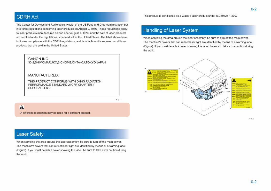
CDRH ActThe Center for Devices and Radiological Health of the US Food and Drug Administration put into force regulations concerning laser products on August 2, 1976. These regulations apply to laser products manufactured on and after August 1, 1976, and the sale of laser products not certified under the regulations is banned within the Untied States. The label shown here indicates compliance with the CDRH regulations, and its attachment is required on all laser products that are sold in the United States.
CANON INC.
MANUFACTURED:
30-2,SHIMOMARUKO,3-CHOME,OHTA-KU,TOKYO,JAPAN
THIS PRODUCT CONFORMS WITH DHHS RADIATIONPERFORMANCE STANDARD 21CFR CHAPTER 1SUBCHAPTER J.
A different description may be used for a different product.
Laser SafetyWhen servicing the area around the laser assembly, be sure to turn off the main power.The machine's covers that can reflect laser light are identified by means of a warning label (Figure). If you must detach a cover showing the label, be sure to take extra caution during the work.
F-0-1
This product is certificated as a Class 1 laser product under IEC60825-1:2007.
Handling of Laser SystemWhen servicing the area around the laser assembly, be sure to turn off the main power.The machine's covers that can reflect laser light are identified by means of a warning label (Figure). If you must detach a cover showing the label, be sure to take extra caution during the work.
F-0-2
0-3
0-3
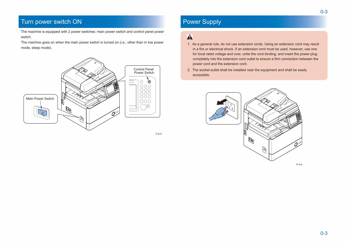
Turn power switch ONThe machine is equipped with 2 power switches: main power switch and control panel power switch.The machine goes on when the main power switch is turned on (i.e., other than in low power mode, sleep mode).
Control Panel Power Switch
Main Power Switch
F-0-3
Power Supply
1. As a general rule, do not use extension cords. Using an extension cord may result in a fire or electrical shock. If an extension cord must be used, however, use one for local rated voltage and over, untie the cord binding, and insert the power plug completely into the extension cord outlet to ensure a firm connection between the power cord and the extension cord.
2. The socket-outlet shall be installed near the equipment and shall be easily accessible.
F-0-4

0-4
0-4
Safety of Toner
About TonerThe machine's toner is a non-toxic material made of plastic, iron, and small amounts of dye.
Do not throw toner into fire. It may cause explosion.
Toner on Clothing or Skin• If your clothing or skin has come into contact with toner, wipe it off with tissue; then, wash it
off with water.• Do not use warm water, which will cause the toner to jell and fuse permanently with the
fibers of the cloth.• Tonner is easy to react with plastic material, avoid contact with plastic.
Notes When Handling the Lithium and Ni-MH Batteries
RISK OF EXPLOSION IF BATTERY IS REPLACED BY AN INCORRECT TYPE.
DISPOSE OF USED BATTERIES ACCORDING TO THE INSTRUCTIONS.
The following warnings are given to comply with Safety Principles (EN60950).
Wenn mit dem falschen Typ ausgewechselt, besteht Explosionsgefahr.
Gebrauchte Batterien gemäß der Anleitung beseitigen.
Notes Before it Works Serving
At servicing, be sure to turn OFF the power source according to the specified steps and disconnect the power plug.
Points to Note at Cleaning
When performing cleaning using organic solvent such as alcohol, be sure to check that the component of solvent is vaporized completely before assembling.
Notes On Assembly/DisassemblyFollow the items below to assemble/disassemble the device.1. Disconnect the power plug to avoid any potential dangers during assembling/disassembling
works.2. If not specially instructed, reverse the order of disassembly to reinstall.3. Ensure to use the right screw type (length, diameter, etc.) at the right position when
assembling.4. To keep electric conduction, binding screws with washers are used to attach the grounding
wire and the varistor. Ensure to use the right screw type when assembling.5. Unless it is specially needed, do not operate the device with some parts removed.6. Never remove the paint-locked screws when disassembling.
F-0-5

1
1 Product Overview
Product Overview ■Product Lineup ■Features ■Specifications ■Parts Name
1
11-2
1-2
Product Overview > Product Lineup > Option > Pickup/Delivery / Image Reading System Options
Product Overview > Product Lineup > Option > Pickup/Delivery / Image Reading System Options
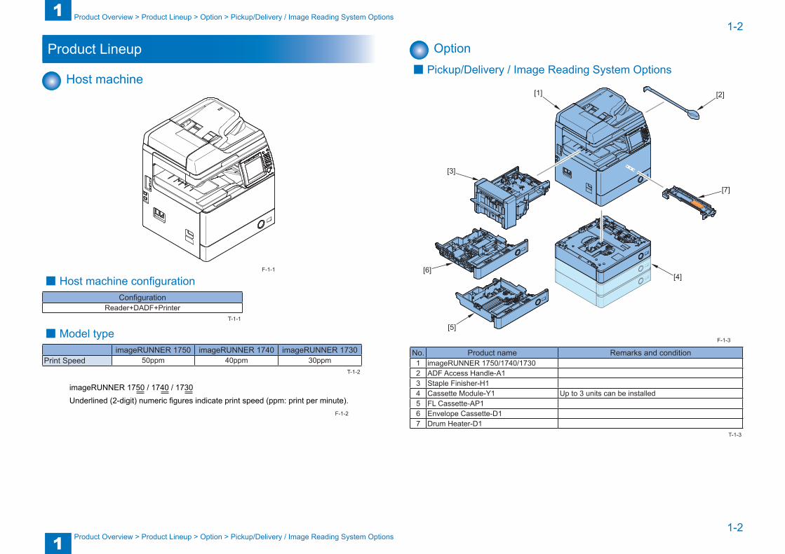
Product Lineup
Host machine
■ Host machine configurationConfiguration
Reader+DADF+Printer
■ Model typeimageRUNNER 1750 imageRUNNER 1740 imageRUNNER 1730
Print Speed 50ppm 40ppm 30ppm
imageRUNNER 1750 / 1740 / 1730Underlined (2-digit) numeric figures indicate print speed (ppm: print per minute).
F-1-1
T-1-1
T-1-2
F-1-2
Option ■ Pickup/Delivery / Image Reading System Options
[1] [2]
[3]
[4][6]
[7]
[5]
No. Product name Remarks and condition1 imageRUNNER 1750/1740/17302 ADF Access Handle-A13 Staple Finisher-H14 Cassette Module-Y1 Up to 3 units can be installed5 FL Cassette-AP16 Envelope Cassette-D17 Drum Heater-D1
F-1-3
T-1-3
1
11-3
1-3
Product Overview > Product Lineup > Option > Function expansion system options
Product Overview > Product Lineup > Option > Function expansion system options
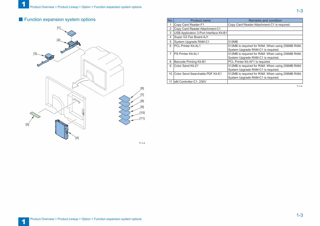
■ Function expansion system options
[1]
[10]
[2]
[11]
[3]
[4]
[5]
[6]
[7]
[8]
[9]
F-1-4
No. Product name Remarks and condition1 Copy Card Reader-F1 Copy Card Reader Attachment-C1 is required.2 Copy Card Reader Attachment-C13 USB Application 3-Port Interface Kit-B14 Super G3 Fax Board-AJ15 System Upgrade RAM-C1 512MB6 PCL Printer Kit-AL1 512MB is required for RAM. When using 256MB RAM,
System Upgrade RAM-C1 is required.7 PS Printer Kit-AL1 512MB is required for RAM. When using 256MB RAM,
System Upgrade RAM-C1 is required.8 Barcode Printing Kit-B1 PCL Printer Kit-AF1 is required.9 Color Send Kit-Z1 512MB is required for RAM. When using 256MB RAM,
System Upgrade RAM-C1 is required.10 Color Send Searchable PDF Kit-E1 512MB is required for RAM. When using 256MB RAM,
System Upgrade RAM-C1 is required.11 eM Controller-C1, 230V
T-1-4
1
11-4
1-4
Product Overview > Features > Product Features
Product Overview > Features > Product Features
Features
Product Features
Low running cost
Low running cost
Fixing AssemblyDrum UnitWaste Toner Box
Drum Unit
Low running cost
Toner Cartridge
Depth: 500mm or less.
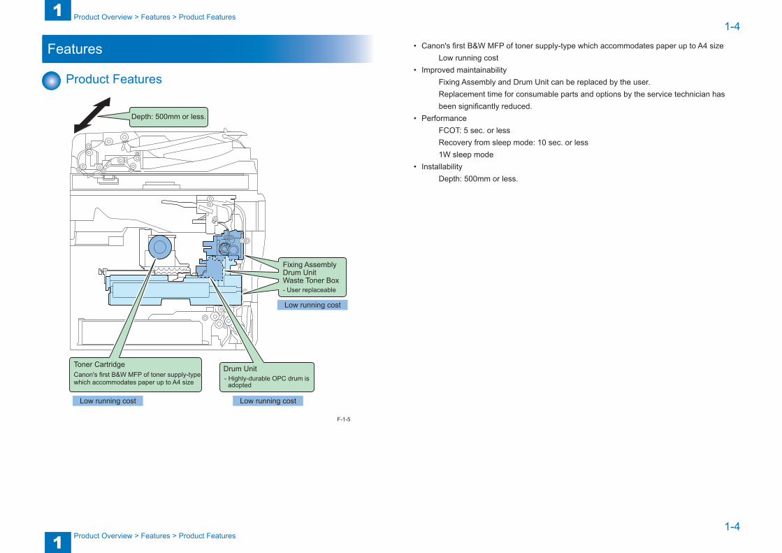
Canon's first B&W MFP of toner supply-typewhich accommodates paper up to A4 size - Highly-durable OPC drum is
adopted
- User replaceable
F-1-5
• Canon's first B&W MFP of toner supply-type which accommodates paper up to A4 size Low running cost
• Improved maintainability Fixing Assembly and Drum Unit can be replaced by the user.Replacement time for consumable parts and options by the service technician has been significantly reduced.
• Performance FCOT: 5 sec. or lessRecovery from sleep mode: 10 sec. or less1W sleep mode
• Installability Depth: 500mm or less.
1
11-5
1-5
Product Overview > Features > Product Features > Communication test function of E-RDS
Product Overview > Features > Product Features > Communication test function of E-RDS
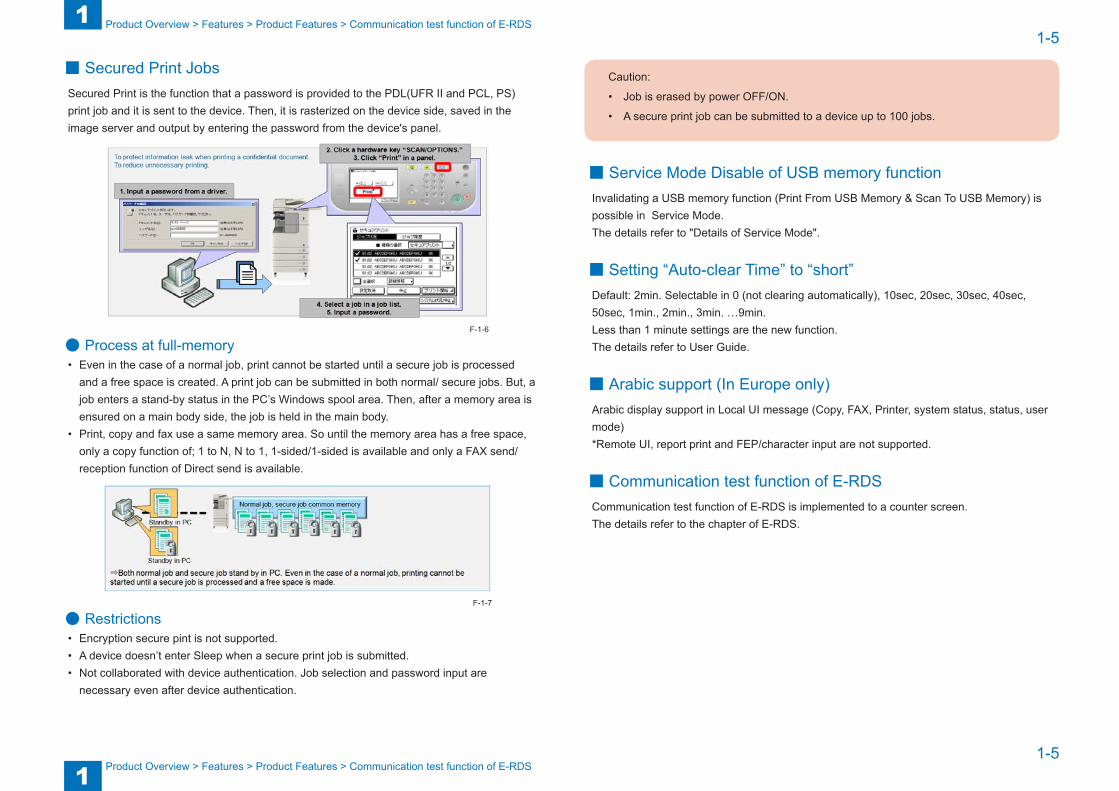
■ Secured Print JobsSecured Print is the function that a password is provided to the PDL(UFR II and PCL, PS) print job and it is sent to the device. Then, it is rasterized on the device side, saved in the image server and output by entering the password from the device's panel.
● Process at full-memory• Even in the case of a normal job, print cannot be started until a secure job is processed
and a free space is created. A print job can be submitted in both normal/ secure jobs. But, a job enters a stand-by status in the PC’s Windows spool area. Then, after a memory area is ensured on a main body side, the job is held in the main body.
• Print, copy and fax use a same memory area. So until the memory area has a free space, only a copy function of; 1 to N, N to 1, 1-sided/1-sided is available and only a FAX send/reception function of Direct send is available.
● Restrictions• Encryption secure pint is not supported. • A device doesn’t enter Sleep when a secure print job is submitted. • Not collaborated with device authentication. Job selection and password input are
necessary even after device authentication.
F-1-6
F-1-7
Caution:
• Job is erased by power OFF/ON.
• A secure print job can be submitted to a device up to 100 jobs.
■ Service Mode Disable of USB memory functionInvalidating a USB memory function (Print From USB Memory & Scan To USB Memory) is possible in Service Mode. The details refer to "Details of Service Mode".
■ Setting “Auto-clear Time” to “short”Default: 2min. Selectable in 0 (not clearing automatically), 10sec, 20sec, 30sec, 40sec, 50sec, 1min., 2min., 3min. …9min. Less than 1 minute settings are the new function.The details refer to User Guide.
■ Arabic support (In Europe only)Arabic display support in Local UI message (Copy, FAX, Printer, system status, status, user mode)*Remote UI, report print and FEP/character input are not supported.
■ Communication test function of E-RDSCommunication test function of E-RDS is implemented to a counter screen.The details refer to the chapter of E-RDS.
1
11-6
1-6
Product Overview > Specifications > Specifications
Product Overview > Specifications > Specifications
Specifications
SpecificationsItem Specifications
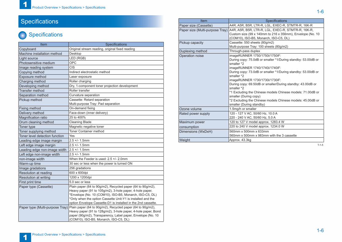
Copyboard Original stream reading, original fixed readingMachine installation method DesktopLight source LED (RGB)Photosensitive medium OPCImage reading system CISCopying method Indirect electrostatic methodExposure method Laser exposureCharging method Roller chargingDeveloping method Dry, 1-component toner projection developmentTransfer method Roller transferSeparation method Curvature separationPickup method Cassette: Retard separation
Multi-purpose Tray: Pad separationFixing method On-demand fixingDelivery method Face-down (inner delivery)Magnification ratio 25 to 400%Drum cleaning method Cleaning BladeToner type Magnetic negative tonerToner supplying method Toner Container methodToner level detection function YesLeading edge image margin 2.5 +/- 1.5mmLeft edge image margin 2.5 +/- 1.5mmLeading edge non-image width 2.5 +/- 1.5mmLeft edge non-image width 2.5 +/- 1.5mm non-image width When the Feeder is used: 2.5 +/- 2.0mmWarm-up time 30 sec or less when the power is turned ONImage gradations 256 gradationsResolution at reading 600 x 600dpiResolution at writing 1200 x 1200dpiFirst print time 5.0 sec or lessPaper type (Cassette) Plain paper (64 to 90g/m2), Recycled paper (64 to 90g/m2),
Heavy paper (91 to 105g/m2), 3-hole paper, 4-hole paper, *Envelope (No. 10 (COM10), ISO-B5, Monarch, ISO-C5, DL)*Only when the option Cassette Unit-Y1 is installed and the option Envelope Cassette-D1 is installed in the 2nd cassette.
Paper type (Multi-purpose Tray) Plain paper (64 to 90g/m2), Recycled paper (64 to 90g/m2), Heavy paper (91 to 128g/m2), 3-hole paper, 4-hole paper, Bond paper (90g/m2), Transparency, Label paper, Envelope (No. 10 (COM10), ISO-B5, Monarch, ISO-C5, DL)
Item SpecificationsPaper size (Cassette) A4R, A5R, B5R, LTR-R, LGL, EXEC-R, STMTR-R, 16K-RPaper size (Multi-purpose Tray) A4R, A5R, B5R, LTR-R, LGL, EXEC-R, STMTR-R, 16K-R,
Custom size (99 x 140mm to 216 x 356mm), Envelope (No. 10 (COM10), ISO-B5, Monarch, ISO-C5, DL)
Pickup capacity Cassette: 550 sheets (80g/m2)Multi-purpose Tray: 100 sheets (80g/m2)
Duplexing method Through-pass duplexOperation noise imageRUNNER 1750/1750i/1750iF:
During copy: 75.0dB or smaller *1/During standby: 53.00dB or smaller *2 imageRUNNER 1740/1740i/1740iF: During copy: 73.0dB or smaller *1/During standby: 53.00dB or smaller *2 imageRUNNER 1730/1730i/1730iF: During copy: 69.50dB or smaller/During standby: 43.00dB or smaller *2 *1 Excluding the Chinese models Chinese models: 71.00dB or smaller (During copy) *2 Excluding the Chinese models Chinese models: 45.00dB or smaller (During standby)
Ozone volume 1.5mg/h or smallerRated power supply 120 - 127 V AC, 50/60 Hz, 10.0 A
220 - 240 V AC, 50/60 Hz, 5.0 AMaximum powerconsumption
120 to 127 V model approx. 1283.4 W220 to 240 V model approx. 1234.0 W
Dimensions (WxDxH) 560mm x 500mm x 633mm 560mm x 500mm x 983mm with the 3 cassette
Weight Approx. 43.3kgT-1-5
1
11-7
1-7
Product Overview > Specifications > Paper type > Pickup
Product Overview > Specifications > Paper type > Pickup
Weight and Size
Product nameWidth (mm)
Depth (mm)
Height (mm)
Weight Approx. (kg)
imageRUNNER 1750/1750i/1740/1740i /1730/1730i
560 500 633 44.3
imageRUNNER 1750iF/1740iF/1730iF(with FAX)
560 500 633 45.1
Staple Finisher-H1 798 395 263 10.5Cassette Module-Y1 540 500 158 7.7Copy Card Reader-F1 96 88 40 0.2
Productivity (Print speed)
Size ModePapertype
Paper basis
weight (g/m2)
imageRUNNER1750 1740 1730
CassetteMulti-
purpose Tray
CassetteMulti-
purpose Tray
CassetteMulti-
purpose Tray
A4-R 1-sided Plain paper
64-90 50 40 40 40 30 30
Heavy paper
91-105 45 40 40 40 30 30106-128 - 21 - 21 - 21
2-sided Plain paper
64-90 49 39 39 39 29 29
Heavy paper
91-105 44 39 39 39 29 29106-128 - - - - - -
LTR-R 1-sided Plain paper
64-90 52 40 42 40 32 30
Heavy paper
91-105 45 40 42 40 32 30106-128 - 21 - 21 - 21
2-sided Plain paper
64-90 48 37 39 37 30 28
Heavy paper
91-105 42 37 39 37 30 28106-128 - - - - - -
A5-R / STMT-R
1-sided Plain paper
64-90 25 25 25 25 25 25
Heavy paper
91-105 25 25 25 25 25 25106-128 - 17 - 17 - 17
2-sided Plain paper
64-90 22 22 22 22 22 22
Heavy paper
91-105 22 22 22 22 22 22106-128 - - - - - -
T-1-6
T-1-7
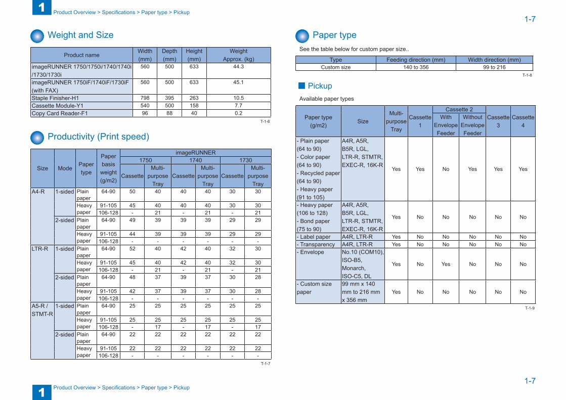
Paper typeSee the table below for custom paper size..
Type Feeding direction (mm) Width direction (mm)Custom size 140 to 356 99 to 216
■ PickupAvailable paper types
Paper type (g/m2)
SizeMulti-
purpose Tray
Cassette 1
Cassette 2Cassette
3Cassette
4With
Envelope Feeder
Without Envelope Feeder
- Plain paper (64 to 90)- Color paper (64 to 90)- Recycled paper (64 to 90)- Heavy paper (91 to 105)
A4R, A5R, B5R, LGL, LTR-R, STMTR, EXEC-R, 16K-R
Yes Yes No Yes Yes Yes
- Heavy paper (106 to 128)- Bond paper (75 to 90)
A4R, A5R, B5R, LGL, LTR-R, STMTR, EXEC-R, 16K-R
Yes No No No No No
- Label paper A4R, LTR-R Yes No No No No No- Transparency A4R, LTR-R Yes No No No No No- Envelope No.10 (COM10),
ISO-B5, Monarch, ISO-C5, DL
Yes No Yes No No No
- Custom size paper
99 mm x 140 mm to 216 mm x 356 mm
Yes No No No No No
T-1-8
T-1-9
1
11-8
1-8
Product Overview > Parts Name > External View
Product Overview > Parts Name > External View
Parts Name
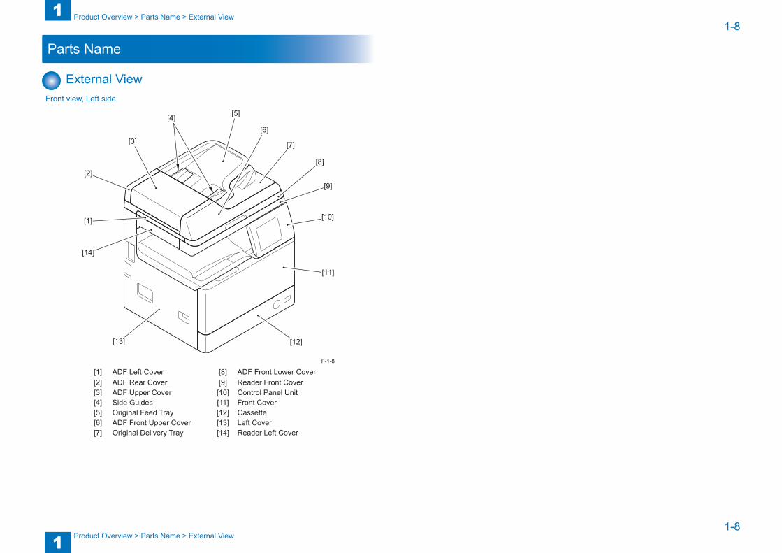
External ViewFront view, Left side
[14]
[13] [12]
[11]
[10]
[5][4]
[3]
[2]
[1]
[6]
[7]
[8]
[9]
[1] ADF Left Cover [8] ADF Front Lower Cover[2] ADF Rear Cover [9] Reader Front Cover[3] ADF Upper Cover [10] Control Panel Unit[4] Side Guides [11] Front Cover[5] Original Feed Tray [12] Cassette[6] ADF Front Upper Cover [13] Left Cover[7] Original Delivery Tray [14] Reader Left Cover
F-1-8

1
11-9
1-9
Product Overview > Parts Name > External View
Product Overview > Parts Name > External View
Rear view, Right side
[10]
[11]
[12]
[1]
[2]
[3]
[4]
[5]
[6]
[7]
[8]
[9]
[1] Reader Rear Cover [7] Right Door Unit[2] Reader Controller Cover [8] Right Rear Fan Cover[3] Rear Cover [9] Right Front Fan Cover[4] Right Rear Cover [10] Support Column Cover[5] Multi-purpose Tray Pickup Unit [11] Reader Right Front Cover[6] Right Front Cover [12] Reader Right Rear Cover
F-1-9
Delivery Assembly
[1]
[2]
[3]
[4]
[5]
[6]
[1] Reader Bottom Cover[2] Delivery Inner Cover[3] Delivery Outer Cover[4] Delivery Stopper[5] Inner Rear Cover[6] Reverse Tray
F-1-10

1
11-10
1-10
Product Overview > Parts Name > Cross Sectional View
Product Overview > Parts Name > Cross Sectional View
Cross Sectional View
[12]
[13]
[14]
[15]
[16]
[17]
[18]
[22]
[19]
[20]
[21]
[23][24]
[25][26][27][28][29][30]
[31]
[32]
[33]
[34]
[35]
[36][11]
[10][1] [2] [3] [4] [5] [6] [7] [8] [9]
F-1-11
[1] Lead Roller 1 [19] Transfer Roller[2] Registration Roller [20] Duplex Feed Roller 2[3] Lead Roller 2 [21] Registration Roller[4] ADF Feed Roller [22] Multi-purpose Tray Pullout Roller[5] ADF Delivery Reverse Roller [23] Multi-purpose Tray Pickup Roller[6] ADF Pickup Roller [24] Multi-purpose Tray Separation Pad[7] ADF Separation Pad [25] Vertical Path Roller[8] ADF Delivery Roller [26] Separation Roller (Cassette)[9] ADF Reverse Roller [27] Feed Roller (Cassette)[10] Drum Unit [28] Pickup Roller (Cassette)[11] Reverse Roller [29] Primary Charging Roller[12] Expansion Delivery Kit [30] Developing Assembly[13] Delivery Roller [31] Laser Scanner Unit[14] Fixing Outlet Roller [32] Toner Container[15] Duplex Feed Roller 1 [33] Hopper[16] Pressure Roller [34] Copyboard Glass[17] Fixing Film Unit [35] CIS Unit[18] Photosensitive Drum [36] ADF Reading Glass
1
11-11
1-11
Product Overview > Parts Name > Operation > Description of Control Panel
Product Overview > Parts Name > Operation > Description of Control Panel
Operation ■ Power Switch
● Types of Power Switches
Control Panel Power Switch
Main Power Switch
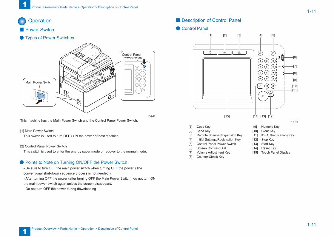
This machine has the Main Power Switch and the Control Panel Power Switch.
[1] Main Power SwitchThis switch is used to turn OFF / ON the power of host machine.
[2] Control Panel Power SwitchThis switch is used to enter the energy saver mode or recover to the normal mode.
● Points to Note on Turning ON/OFF the Power Switch- Be sure to turn OFF the main power switch when turning OFF the power. (The conventional shut-down sequence process is not needed.)- After turning OFF the power (after turning OFF the Main Power Switch), do not turn ON the main power switch again unless the screen disappears.- Do not turn OFF the power during downloading
F-1-12
■ Description of Control Panel
● Control Panel
[11][10]
[12][13][14][15]
[1] [2] [3] [4] [5]
[6]
[7]
[8]
[9]
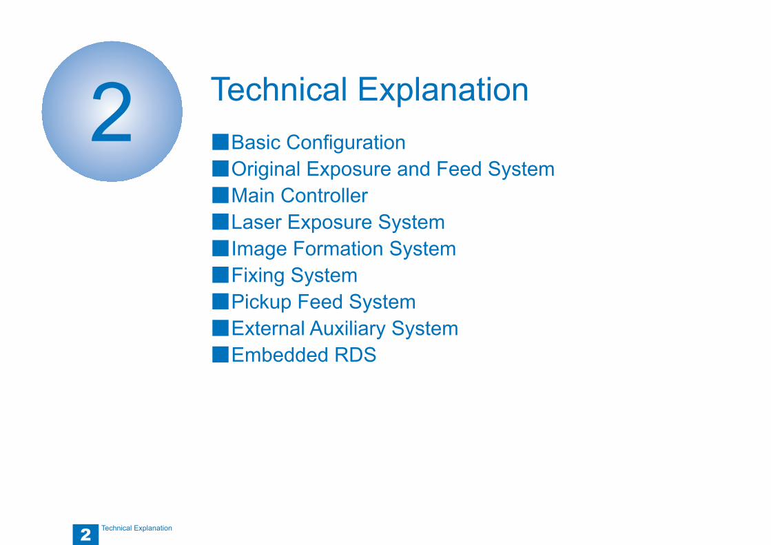
[1] Copy Key [9] Numeric Key[2] Send Key [10] Clear Key[3] Remote Scanner/Expansion Key [11] ID (Authentication) Key[4] Initial Settings/Registration Key [12] Stop Key[5] Control Panel Power Switch [13] Start Key[6] Screen Contrast Dial [14] Reset Key[7] Volume Adjustment Key [15] Touch Panel Display[8] Counter Check Key
F-1-13

1
11-12
1-12
Product Overview > Parts Name > Operation > Description of Control Panel
Product Overview > Parts Name > Operation > Description of Control Panel
● Main MenuFunctions Key Location
Copy Copy KeyControl PanelSend*1 or FAX*2 Send Key
Scan or Direct Print Scan/Option KeySystem Monitor [System Monitor] Touch Panel Display
*1 To enable SEND function, Simple Send Expansion Kit-Y1 is required .*2 To enable FAX function, Super G3 Fax Board-AG1 is required..
● Settings/Registration Menu
[1] Common Settings [6] Copy Settings[2] Timer Settings [7] Communications Settings [3] Adjustment/Cleaning [8] Printer Settings[4] Report output [9] Address Book Settings [5] System Manager Settings
T-1-10
2
2 Technical Explanation
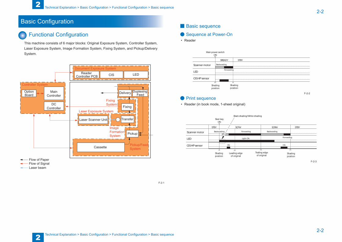
Technical Explanation ■Basic Configuration ■Original Exposure and Feed System ■Main Controller ■Laser Exposure System ■Image Formation System ■Fixing System ■Pickup Feed System ■External Auxiliary System ■Embedded RDS
2
22-2
2-2
Technical Explanation > Basic Configuration > Functional Configuration > Basic sequence
Technical Explanation > Basic Configuration > Functional Configuration > Basic sequence
Basic Configuration
Functional ConfigurationThis machine consists of 6 major blocks: Original Exposure System, Controller System, Laser Exposure System, Image Formation System, Fixing System, and Pickup/Delivery System.
Flow of PaperFlow of SignalLaser beam
Reader Controller PCB CIS LED
Document Exposure System
MainController
DCController
OptionBoard
Controller System
Duplexing FeedDelivery
Transfer
Pickup
Fixing
Fixing System
ImageFormationSystem
Pickup/Feed System
Laser Exposure System
Cassette
Laser Scanner Unit
F-2-1
■ Basic sequence
● Sequence at Power-On• Reader
Backwarding
Main power switchON
SREADY STBY
Scanner motor
LED
CIS HP sensor
Shadingposition
Shadingposition
Forwarding
● Print sequence• Reader (in book mode, 1-sheet original)
Backwarding
Start keyON
SCRWSCFWSTBY STBY
Scanner motor
LED
CIS HP sensor
Black shading/White shading
Leading edgeof original
Shadingposition
Shadingposition
Trailing edgeof original
ForwardingBackwarding
ForwardingLight-ON
ON ON
F-2-2
F-2-3

2
22-3
2-3
Technical Explanation > Original Exposure and Feed System > Construction > Specifications/controls/functions
Technical Explanation > Original Exposure and Feed System > Construction > Specifications/controls/functions
Original Exposure and Feed System
Construction ■ Specifications/controls/functions
The major specifications, controls and functions of the original exposure and feed system are described below.
Item Specification/functionOriginal exposure LEDOriginal scan In book mode Original scan is performed by moving the contact image sensor
(CIS).In ADF mode Original stream reading is performed with the contact image
sensor (CIS) fixed.Read resolution B/W: 600 dpi (main scanning) x 600 dpi (sub scanning)
(Color SEND: 300 dpi (main scanning) x 600 dpi (sub scanning))Gradation 256 gradationCarriage position detection CIS HP sensor (PS24)Magnification 25% to 400%
Main scanning direction
Image is processed on main controller PCB.
Sub scanning direction
Image is processed on main controller PCB.
Lens Rod lens arrayOriginal reading sensor Number of lens: 1
Number of pixels: Total 5148 (incl. 5104 effective pixels)Maximum original scan width: 216mm
CIS drive control Drive control by Reader motor (M10)Original size detection
In book mode Main scanning direction: by reflection sensor (AB/Inch)Sub scanning direction: by reflection sensor (AB/Inch)
In ADF mode Main scanning direction: by photo interrupter on ADFSub scanning direction: by photo interrupter on ADF
ADF original pickup method Auto pickup/delivery methodADF setting direction of original Original tray pickup: face-up stackingADF setting position of original Original tray pickup: center referenceADF separation method of original Upper separation by separation padADF scanning method of original Stream readingADF weight of original
1-sided AB: 42 to 128 g/m2Inch: 50 to 128 g/m2
2-sided 50 to 128 g/m2Color original 64 to 128 g/m2B/W or Color mixed original
50 to 128 g/m2 (Color: 64 to 128 g/m2)
Original longer than 432mm
60 to 90 g/m2 (1-sided, 1-sheet feeding)
Item Specification/functionADF original size A4R, B5R, A5, A5R, LGL, LTRR, STMTR, STMT, 16K-R (For
STMT, horizontal scanning only)Original width direction: 139.7 to 219 mmOriginal feed direction: 128 to 356 mm (In banner paper printing mode: maximum 630 mm)
ADF original tray capacity 100 sheets (80 g/m2 paper, original height: 10mm or less)ADF original processing mode 1-sided original processing
2-sided original processingADF original size detection function
Yes (standard size)
ADF mixed original mode function
Mix of same configuration mode
Yes (weight of original same as continuous feed mode)Assured combination for mix with same configurationA5/A4R, STMT/LTRR/LGL
Mix of different configuration mode
No
Book original Yes (The thickness of the book original must not exceed 30 mm.)
ADF done stamp function NoT-2-1

2
22-4
2-4
Technical Explanation > Original Exposure and Feed System > Construction > Major Components
Technical Explanation > Original Exposure and Feed System > Construction > Major Components
■ Major Components
● Reader UnitFollowing shows major components of reader unit.
Contact image sensor (CIS)
CIS HP sensor (PS24)
Reader controller PCB (PCB3)
ADF open/closed detection sensor (PS23)
Original size detection sensor 1 (PS22)
Original size detection sensor 2 (PS21)
Reader motor (M10)
Item Notation Specification/functionReader motor M10 Stepping motor: controls the carriage drive.CIS HP sensor PS24 Photo interrupter: detects the home position of CIS
unit.ADF open/closed detection sensor
PS23 Photo interrupter: detects the opening or closing of ADF. (detects the opening or closing of the ADF at approximate 18 degrees.)
Original size detection sensor 1 PS22 Detects the original size. (AB/Inch)Original size detection sensor 2 PS21 Detects the original size. (AB/Inch)Contact image sensor - Reads the original. (LED + Light guide + CIS unit)Reader controller PCB PCB3 Controls the reader unit and ADF unit.
F-2-4
T-2-2
● ADF unitFollowing shows major components of ADF unit.
1) Cross Section
Pickup roller
Separation pad
Feed roller
Registration roller
Lead roller 1
Lead roller 2
Reversal rollerDelivery reversal roller
Delivery rollerOriginal pickup tray
Platen guide
Original delivery tray
Delivery reversal flapper 2
Delivery reversal flapper 1
Delivery reversal roller (upper)
Item Specification/functionPickup roller Picks up the original.Feed roller Separates and feeds the original.Separation pad Separates the original.Registration roller Feeds the original and forms a skew feed correction loop.Lead roller 1 Feeds the original before reading.Lead roller 2 Feeds the original after reading.Delivery reversal roller Delivers the original and performs upstream reversal feed of
the original.Delivery reversal roller (upper) Separated from the mating delivery reversal roller by the roller
release solenoid during reverse feed of the original.Delivery roller Delivers the original.Reversal roller Performs downstream reversal feed of the original.Platen guide Original read section.Delivery reversal flapper 1 Switches between the upstream reversal path and the
downstream reversal path.Delivery reversal flapper 2 Switches between the upstream reversal path and the delivery
path.Original pickup tray Allows you to load an original.Original delivery tray Stacks the delivered originals.
F-2-5
T-2-3
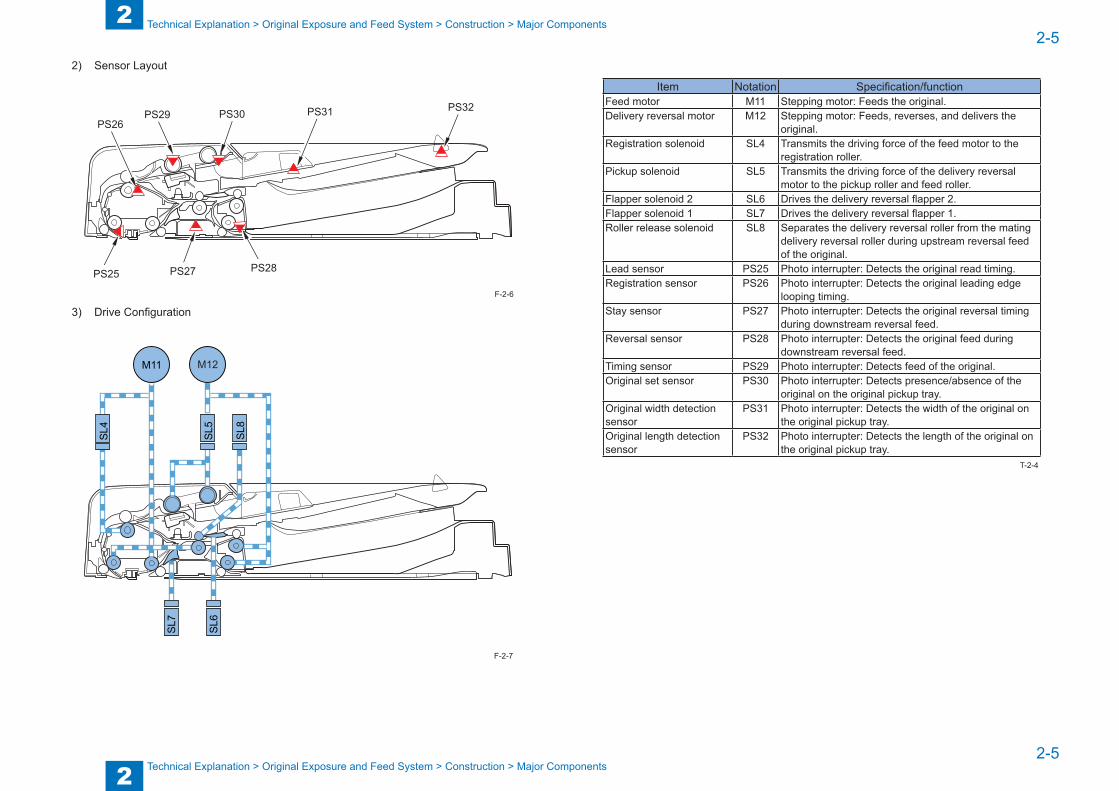
2
22-5
2-5
Technical Explanation > Original Exposure and Feed System > Construction > Major Components
Technical Explanation > Original Exposure and Feed System > Construction > Major Components
2) Sensor Layout
PS26PS29 PS30
PS25 PS27 PS28
PS31 PS32
3) Drive Configuration
SL4
M11
SL6
SL7
SL5
M12
SL8
F-2-6
F-2-7
Item Notation Specification/functionFeed motor M11 Stepping motor: Feeds the original.Delivery reversal motor M12 Stepping motor: Feeds, reverses, and delivers the
original.Registration solenoid SL4 Transmits the driving force of the feed motor to the
registration roller.Pickup solenoid SL5 Transmits the driving force of the delivery reversal
motor to the pickup roller and feed roller.Flapper solenoid 2 SL6 Drives the delivery reversal flapper 2.Flapper solenoid 1 SL7 Drives the delivery reversal flapper 1.Roller release solenoid SL8 Separates the delivery reversal roller from the mating
delivery reversal roller during upstream reversal feed of the original.
Lead sensor PS25 Photo interrupter: Detects the original read timing.Registration sensor PS26 Photo interrupter: Detects the original leading edge
looping timing.Stay sensor PS27 Photo interrupter: Detects the original reversal timing
during downstream reversal feed.Reversal sensor PS28 Photo interrupter: Detects the original feed during
downstream reversal feed.Timing sensor PS29 Photo interrupter: Detects feed of the original.Original set sensor PS30 Photo interrupter: Detects presence/absence of the
original on the original pickup tray.Original width detection sensor
PS31 Photo interrupter: Detects the width of the original on the original pickup tray.
Original length detection sensor
PS32 Photo interrupter: Detects the length of the original on the original pickup tray.
T-2-4
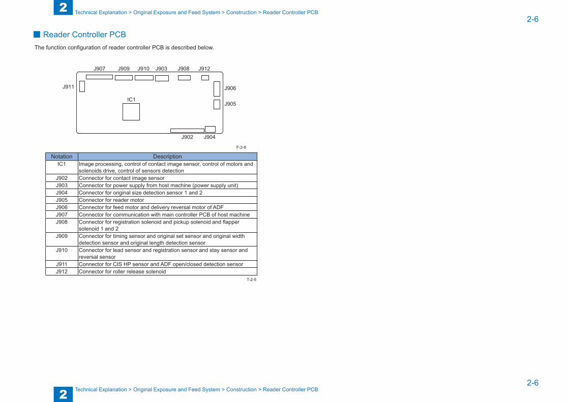
2
22-6
2-6
Technical Explanation > Original Exposure and Feed System > Construction > Reader Controller PCB
Technical Explanation > Original Exposure and Feed System > Construction > Reader Controller PCB
■ Reader Controller PCBThe function configuration of reader controller PCB is described below.
J907
J911
J909
IC1
J910 J903 J908 J912
J906
J905
J904J902
Notation DescriptionIC1 Image processing, control of contact image sensor, control of motors and
solenoids drive, control of sensors detectionJ902 Connector for contact image sensorJ903 Connector for power supply from host machine (power supply unit)J904 Connector for original size detection sensor 1 and 2J905 Connector for reader motorJ906 Connector for feed motor and delivery reversal motor of ADFJ907 Connector for communication with main controller PCB of host machineJ908 Connector for registration solenoid and pickup solenoid and flapper
solenoid 1 and 2J909 Connector for timing sensor and original set sensor and original width
detection sensor and original length detection sensorJ910 Connector for lead sensor and registration sensor and stay sensor and
reversal sensorJ911 Connector for CIS HP sensor and ADF open/closed detection sensorJ912 Connector for roller release solenoid
F-2-8
T-2-5
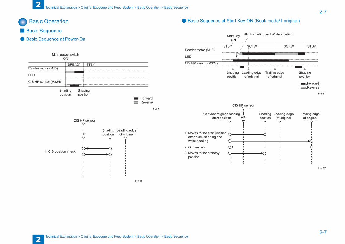
2
22-7
2-7
Technical Explanation > Original Exposure and Feed System > Basic Operation > Basic Sequence
Technical Explanation > Original Exposure and Feed System > Basic Operation > Basic Sequence
Basic Operation ■ Basic Sequence
● Basic Sequence at Power-On
:Reverse :Forward
Main power switchON
SREADY STBYReader motor (M10)
LED
CIS HP sensor (PS24)
Shadingposition
Shadingposition
Shadingposition
Leading edgeof original
1. CIS position check
CIS HP sensor
HP
F-2-9
F-2-10
● Basic Sequence at Start Key ON (Book mode/1 original)
:Reverse :Forward
SCRWSCFWSTBY STBY
Start keyON
Reader motor (M10)
LED
CIS HP sensor (PS24)
Black shading and White shading
Leading edgeof original
Shadingposition
Shadingposition
Trailing edgeof original
Copyboard glass readingstart position
1. Moves to the start position after black shading and white shading
3. Moves to the standby position
2. Original scan
Shadingposition
Leading edgeof original
Trailing edgeof original
CIS HP sensor
HP
F-2-11
F-2-12

2
22-8
2-8
Technical Explanation > Original Exposure and Feed System > Basic Operation > ADF Operation Mode
Technical Explanation > Original Exposure and Feed System > Basic Operation > ADF Operation Mode
● Basic Sequence at Start Key ON (ADF mode/1 original)
:Reverse :Forward
Black shading and White shadingStart keyON
SCFWSCRWSTBY STBYReader motor (M10)
LED
CIS HP sensor (PS24)
Stream readingposition
Trailing edgeof original
Shadingposition
Shadingposition
Shadingposition
Stream readingstart position
1. Black shading and White shading and Original scan
CIS HP sensor
HP
Copyboard glassreading start
position
F-2-13
F-2-14
■ ADF Operation ModeADF has four operation modes.Operation mode names and outline of operations and associated print modes are given in the following table:
Operation mode name Outline of operation Associated print modeForward pickup/delivery Picks up, reads, and then delivers
an original.Single-sided original → Single-sided printSingle-sided original → Double-sided print
Forward pickup/reversal delivery
Picks up, reads, and then reverses and delivers an original
Double-sided original → Double-sided printDouble-sided original → Single-sided print
T-2-6

2
22-9
2-9
Technical Explanation > Original Exposure and Feed System > Basic Operation > ADF Operation Mode
Technical Explanation > Original Exposure and Feed System > Basic Operation > ADF Operation Mode
● Forward Pickup/Delivery (Single-sided original → Single-sided print) Operation
The original flows as shown below.
Note:
This operation is performed for all single-sided originals irrespective of whether original width are the same or different.
• Operation of single-sided original reading (2 originals)
- 1st original: Pickup
- 1st original: Formation of loop
- 1st original: Reading- 2nd original: Pickup and Formation of loop
- 1st original: Delivery- 2nd original: Reading
- 2nd original: Delivery
- End of job
F-2-15
● Forward Pickup/Reversal Delivery (Double-sided original → Double-sided print) Operation
The original flows as shown below.
Note:
This operation is performed for all single-sided originals irrespective of whether original width are the same or different.
• Operation of double-sided original reading (2 originals)
- 1st original: Feeding to downstream reversal path- 2nd original: Formation of loop
- 1st original: Pickup
- 1st original: Formation of loop
- 1st original: Reading
- 1st original: Feeding to upstream reversal path
- 1st original: Reversal and Formation of loop
- 1st original: Reading of reverse side- 2nd original: Pickup
Next
F-2-16
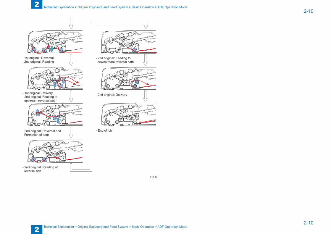
2
22-10
2-10
Technical Explanation > Original Exposure and Feed System > Basic Operation > ADF Operation Mode
Technical Explanation > Original Exposure and Feed System > Basic Operation > ADF Operation Mode
- 1st original: Reversal- 2nd original: Reading
- End of job
- 1st original: Delivery- 2nd original: Feeding to upstream reversal path
- 2nd original: Reversal and Formation of loop
- 2nd original: Reading of reverse side
- 2nd original: Feeding to downstream reversal path
- 2nd original: Delivery
F-2-17
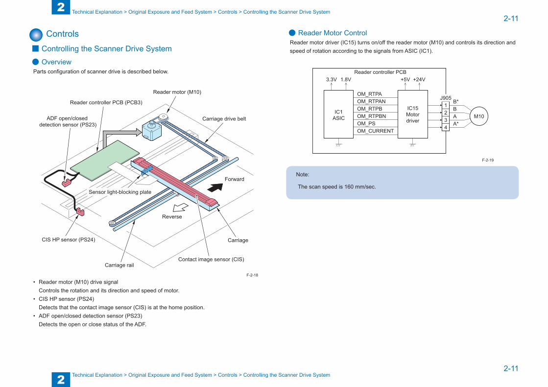
2
22-11
2-11
Technical Explanation > Original Exposure and Feed System > Controls > Controlling the Scanner Drive System
Technical Explanation > Original Exposure and Feed System > Controls > Controlling the Scanner Drive System
Controls ■ Controlling the Scanner Drive System
● OverviewParts configuration of scanner drive is described below.
Carriage drive belt
Forward
Reverse
Carriage
Carriage rail
Reader motor (M10)
Reader controller PCB (PCB3)
CIS HP sensor (PS24)
Sensor light-blocking plate
Contact image sensor (CIS)
ADF open/closed detection sensor (PS23)
• Reader motor (M10) drive signalControls the rotation and its direction and speed of motor.
• CIS HP sensor (PS24)Detects that the contact image sensor (CIS) is at the home position.
• ADF open/closed detection sensor (PS23)Detects the open or close status of the ADF.
F-2-18
● Reader Motor ControlReader motor driver (IC15) turns on/off the reader motor (M10) and controls its direction and speed of rotation according to the signals from ASIC (IC1).
Reader controller PCB3.3V +24V
OM_RTPAOM_RTPANOM_RTPBOM_RTPBNOM_PS
+5V
J905B*BAA*
IC1ASIC
IC15Motordriver
1234
M10
OM_CURRENT
1.8V
Note:
The scan speed is 160 mm/sec.
F-2-19

2
22-12
2-12
Technical Explanation > Original Exposure and Feed System > Controls > Contact Image Sensor (CIS)
Technical Explanation > Original Exposure and Feed System > Controls > Contact Image Sensor (CIS)
1) Forward Movement during Image ScanDuring image scanning, the reader controller PCB controls the reader motor (M10) to control the contact image sensor (CIS) operation.
Startposition
Acceleration
Leading edgeof original
Constant speed
Trailing edgeof original
Deceleration
Stop
Movementspeed
Movement distance
[1] [2] [3] [4]
[1] Acceleration area: The motor accelerates to the speed specified for each mode.[2] Runup area: A margin to stabilize the speed.[3] Image read area: The image is read at a constant speed.[4] Deceleration area: Upon detection of the trailing edge, the motor decelerates rapidly and stops.
2) Backward Movement after Image ScanAfter image scan, the carriage moves back to the contact image sensor (CIS) shading position at the constant speed (160 mm/sec).
F-2-20
■ Contact Image Sensor (CIS)
● OutlineThe original is exposed to light and read using the contact image sensor (CIS) to read the image on a line-by-line basis.
Light guide
LED (R/G/B)
Original readingsensor array
Rod lens array
Image reading line
Copyboard glass
LED (R/G/B)
Scan direction
Light guideLight guide
LED
CCD
Rod lens array
Component FunctionLED Illuminates the original.Light guide Illuminates the entire image line with the LED light.Rod lens array Collects the light reflected by the original.Original reading sensor array Receives the light that passed through the rod lens array.
F-2-21
T-2-7
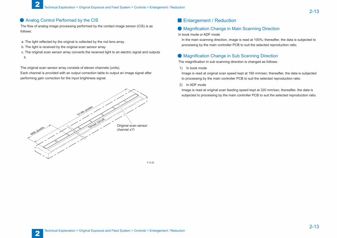
2
22-13
2-13
Technical Explanation > Original Exposure and Feed System > Controls > Enlargement / Reduction
Technical Explanation > Original Exposure and Feed System > Controls > Enlargement / Reduction
● Analog Control Performed by the CISThe flow of analog image processing performed by the contact image sensor (CIS) is as follows:
a. The light reflected by the original is collected by the rod lens array. b. The light is received by the original scan sensor array. c. The original scan sensor array converts the received light to an electric signal and outputs
it.
The original scan sensor array consists of eleven channels (units).Each channel is provided with an output correction table to output an image signal after performing gain correction for the input brightness signal.
Driver circuit
11
Original scan sensorchannel x113
2
1
468 pixels
5148 pixels
F-2-22
■ Enlargement / Reduction
● Magnification Change in Main Scanning DirectionIn book mode or ADF mode
In the main scanning direction, image is read at 100%; thereafter, the data is subjected to processing by the main controller PCB to suit the selected reproduction ratio.
● Magnification Change in Sub Scanning DirectionThe magnification in sub scanning direction is changed as follows:
1) In book modeImage is read at original scan speed kept at 160 mm/sec; thereafter, the data is subjected to processing by the main controller PCB to suit the selected reproduction ratio.
2) In ADF modeImage is read at original scan feeding speed kept at 320 mm/sec; thereafter, the data is subjected to processing by the main controller PCB to suit the selected reproduction ratio.
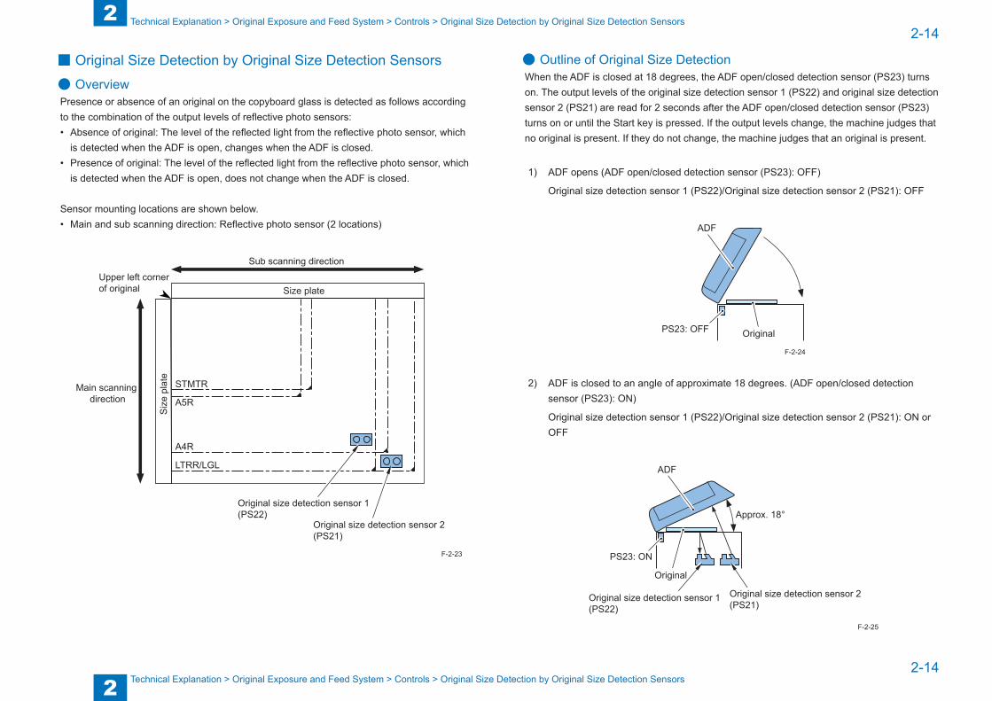
2
22-14
2-14
Technical Explanation > Original Exposure and Feed System > Controls > Original Size Detection by Original Size Detection Sensors
Technical Explanation > Original Exposure and Feed System > Controls > Original Size Detection by Original Size Detection Sensors
■ Original Size Detection by Original Size Detection Sensors
● OverviewPresence or absence of an original on the copyboard glass is detected as follows according to the combination of the output levels of reflective photo sensors:• Absence of original: The level of the reflected light from the reflective photo sensor, which
is detected when the ADF is open, changes when the ADF is closed.• Presence of original: The level of the reflected light from the reflective photo sensor, which
is detected when the ADF is open, does not change when the ADF is closed.
Sensor mounting locations are shown below.• Main and sub scanning direction: Reflective photo sensor (2 locations)
A4R
A5R
Size plate
LTRR/LGL
Upper left cornerof original
Sub scanning direction
STMTR
Siz
e pl
ate
Main scanning direction
Original size detection sensor 1(PS22)
Original size detection sensor 2(PS21)
F-2-23
● Outline of Original Size DetectionWhen the ADF is closed at 18 degrees, the ADF open/closed detection sensor (PS23) turns on. The output levels of the original size detection sensor 1 (PS22) and original size detection sensor 2 (PS21) are read for 2 seconds after the ADF open/closed detection sensor (PS23) turns on or until the Start key is pressed. If the output levels change, the machine judges that no original is present. If they do not change, the machine judges that an original is present.
1) ADF opens (ADF open/closed detection sensor (PS23): OFF)
Original size detection sensor 1 (PS22)/Original size detection sensor 2 (PS21): OFF
PS23: OFF
ADF
Original
2) ADF is closed to an angle of approximate 18 degrees. (ADF open/closed detection sensor (PS23): ON)
Original size detection sensor 1 (PS22)/Original size detection sensor 2 (PS21): ON or OFF
Approx. 18°
ADF
PS23: ON
Original size detection sensor 2(PS21)
Original
Original size detection sensor 1(PS22)
F-2-24
F-2-25
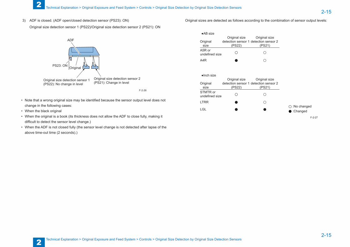
2
22-15
2-15
Technical Explanation > Original Exposure and Feed System > Controls > Original Size Detection by Original Size Detection Sensors
Technical Explanation > Original Exposure and Feed System > Controls > Original Size Detection by Original Size Detection Sensors
3) ADF is closed. (ADF open/closed detection sensor (PS23): ON)
Original size detection sensor 1 (PS22)/Original size detection sensor 2 (PS21): ON
ADF
PS23: ON
Original size detection sensor 2(PS21): Change in level
Original size detection sensor 1(PS22): No change in level
Original
• Note that a wrong original size may be identified because the sensor output level does not change in the following cases:
• When the black original• When the original is a book (its thickness does not allow the ADF to close fully, making it
difficult to detect the sensor level change.)• When the ADF is not closed fully (the sensor level change is not detected after lapse of the
above time-out time (2 seconds).)
F-2-26
Original sizes are detected as follows according to the combination of sensor output levels:
●AB size
A5R or undefined size
A4R
Originalsize
Original sizedetection sensor 1
(PS22)
Original sizedetection sensor 2
(PS21)
:No changed :Changed
●Inch size
STMTR or undefined size
LTRR
LGL
Originalsize
Original sizedetection sensor 1
(PS22)
Original sizedetection sensor 2
(PS21)
F-2-27
2
22-16
2-16
Technical Explanation > Original Exposure and Feed System > Controls > Dust Detection Control
Technical Explanation > Original Exposure and Feed System > Controls > Dust Detection Control
Related Service Mode:
• Select the following service mode to determine whether to detect the original size:
SCAN > READER > OPTION > USER > SIZE-DET
<Setting value>
0: The original size is not detected.
1: The original size is detected.
• Select the following service mode to switch between AB and inch sizes:
SCAN > READER > OPTION > BODY > SENS-CNF
<Setting value>
0: AB size
1: Inch size
• When both the original size detection sensor 1 (PS22) and the original size detection sensor 2 (PS21) detect no original (sensor output levels do not change), select the following service mode to change the original size to be detected:
SCAN > READER > OPTION > BODY > UNK-A5R
<Setting value>
0: Undefined size
1: A5R or STMTR
■ Dust Detection Control
● OverviewIn ADF mode, the machine changes the original read position or corrects the read image depending on the presence/absence of dust on the ADF reading glass or platen guide, thus preventing dust from showing up in the image.
The control of dust detection is as follows:
1) Dust detection preventive process
2) Dust detection correction control

2
22-17
2-17
Technical Explanation > Original Exposure and Feed System > Controls > Dust Detection Preventive Process
Technical Explanation > Original Exposure and Feed System > Controls > Dust Detection Preventive Process
■ Dust Detection Preventive ProcessThe contact image sensor (CIS) detects the reflected light from the ADF reading glass and platen guide surface (at the read position) to judge presence or absence of dust.This process is performed when the power is turned on or each time a job is completed.The dust detection process is performed at three positions (A, B, and C) as follows regardless of whether there is dust:
1) The dust detection process is performed at position A.
2) The dust detection position moves to position B to perform the dust detection process there.
3) The dust detection position moves to position C to perform the dust detection process there.
4-a) The dust-free position is determined as the original read position in the order of priority (A > B > C).
4-b) If dust is detected at all of positions A, B, and C, position A is determined as the original read position.
0.5mm0.5mm
A B C
Contact image sensor unit
Platen guide
ADF reading glass
Lens
Position DescriptionA Reference position for readB About 0.5 mm to the right of the reference position AC About 1.0 mm to the right of the reference position A
Note:
When dust has been detected at all of positions A, B, and C, setting an original on the ADF will show a message that prompts the user to clean the glass surface.
F-2-28
T-2-8
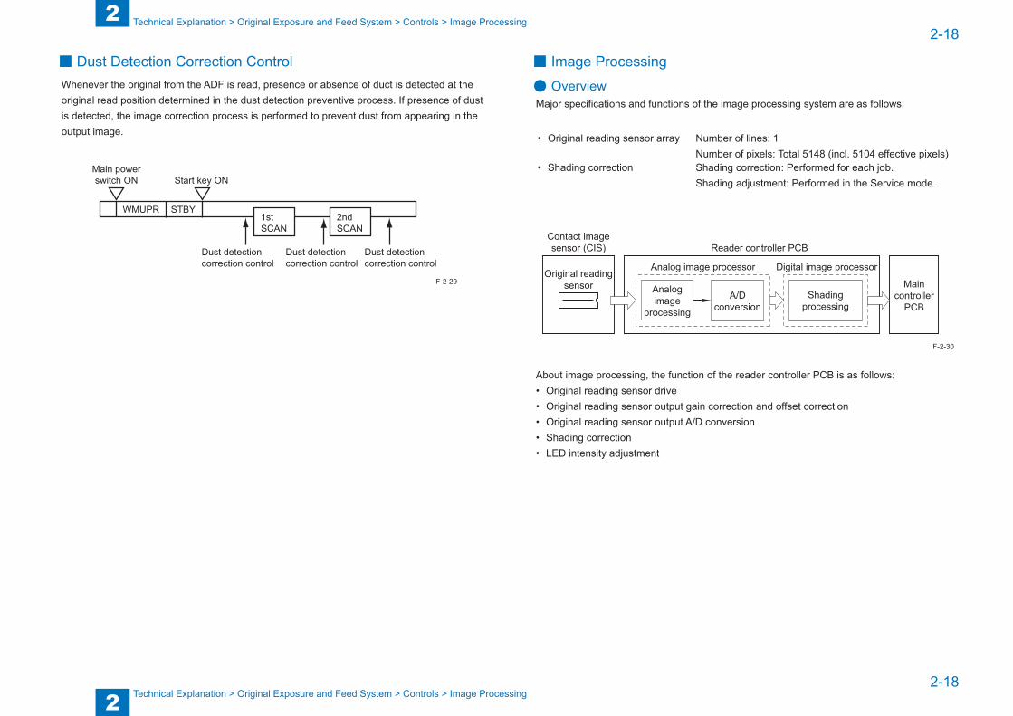
2
22-18
2-18
Technical Explanation > Original Exposure and Feed System > Controls > Image Processing
Technical Explanation > Original Exposure and Feed System > Controls > Image Processing
■ Dust Detection Correction ControlWhenever the original from the ADF is read, presence or absence of duct is detected at the original read position determined in the dust detection preventive process. If presence of dust is detected, the image correction process is performed to prevent dust from appearing in the output image.
Main powerswitch ON
Dust detection correction control
Dust detection correction control
STBYWMUPR
Start key ON
1stSCAN
2ndSCAN
Dust detection correction control
F-2-29
■ Image Processing
● OverviewMajor specifications and functions of the image processing system are as follows:
• Original reading sensor array Number of lines: 1Number of pixels: Total 5148 (incl. 5104 effective pixels)
• Shading correction Shading correction: Performed for each job.Shading adjustment: Performed in the Service mode.
Reader controller PCB
Original readingsensor
Analog image processor Digital image processor
Shadingprocessing
A/Dconversion
Contact imagesensor (CIS)
Maincontroller
PCB
Analogimage
processing
About image processing, the function of the reader controller PCB is as follows:• Original reading sensor drive• Original reading sensor output gain correction and offset correction• Original reading sensor output A/D conversion• Shading correction• LED intensity adjustment
F-2-30
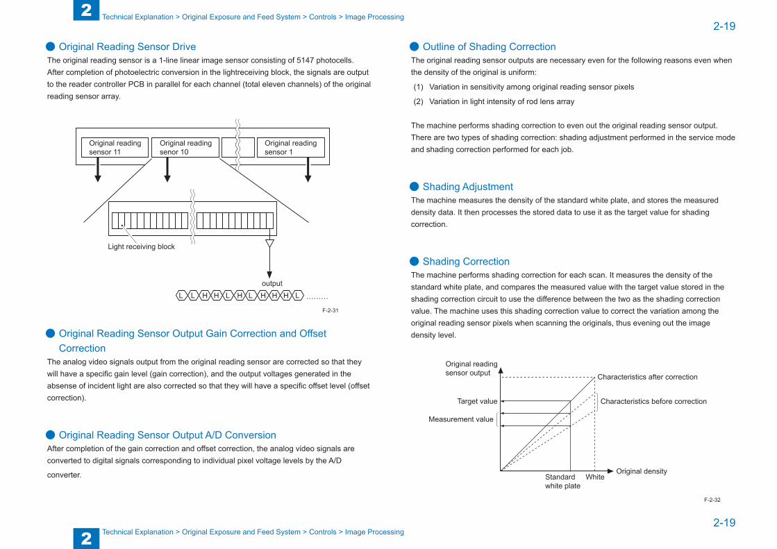
2
22-19
2-19
Technical Explanation > Original Exposure and Feed System > Controls > Image Processing
Technical Explanation > Original Exposure and Feed System > Controls > Image Processing
● Original Reading Sensor DriveThe original reading sensor is a 1-line linear image sensor consisting of 5147 photocells. After completion of photoelectric conversion in the lightreceiving block, the signals are output to the reader controller PCB in parallel for each channel (total eleven channels) of the original reading sensor array.
Original readingsensor 1
Original readingsensor 11
Original readingsenor 10
HL L HH L HL H H L ………
output
Light receiving block
● Original Reading Sensor Output Gain Correction and Offset Correction
The analog video signals output from the original reading sensor are corrected so that they will have a specific gain level (gain correction), and the output voltages generated in the absense of incident light are also corrected so that they will have a specific offset level (offset correction).
● Original Reading Sensor Output A/D ConversionAfter completion of the gain correction and offset correction, the analog video signals are converted to digital signals corresponding to individual pixel voltage levels by the A/D
converter.
F-2-31
● Outline of Shading CorrectionThe original reading sensor outputs are necessary even for the following reasons even when the density of the original is uniform:
(1) Variation in sensitivity among original reading sensor pixels
(2) Variation in light intensity of rod lens array
The machine performs shading correction to even out the original reading sensor output.There are two types of shading correction: shading adjustment performed in the service mode and shading correction performed for each job.
● Shading AdjustmentThe machine measures the density of the standard white plate, and stores the measured density data. It then processes the stored data to use it as the target value for shading correction.
● Shading CorrectionThe machine performs shading correction for each scan. It measures the density of the standard white plate, and compares the measured value with the target value stored in the shading correction circuit to use the difference between the two as the shading correction value. The machine uses this shading correction value to correct the variation among the original reading sensor pixels when scanning the originals, thus evening out the image density level.
Original readingsensor output
Original densityStandard white plate
Characteristics before correctionTarget value
Measurement value
Characteristics after correction
White
F-2-32

2
22-20
2-20
Technical Explanation > Original Exposure and Feed System > Control of ADF > Original Size Detection by ADF
Technical Explanation > Original Exposure and Feed System > Control of ADF > Original Size Detection by ADF
● LED Intensity AdjustmentThe machine adjusts the length of time during which the LED turns on for each scan so that the image scan level of the original reading sensor will be specific level.
Related Service Mode:
• CIS gain and offset correction
SCAN > READER > FUNCTION > CCD > CCD-ADJ
• DF white level adjustment
SCAN > READER > FUNCTION > CCD > DF-WLVL1 (Original glass scan)
SCAN > READER > FUNCTION > CCD > DF-WLVL2 (Stream reading scan)
SCAN > READER > FUNCTION > CCD > DF-WLVL3 (Original glass scan)
SCAN > READER > FUNCTION > CCD > DF-WLVL4 (Stream reading scan)
Control of ADF ■ Original Size Detection by ADF
The size of the original set on the ADF is detected by the following two methods:
1) Initial detection of document size
2) Final detection of document size
Feeding direction
Original width detection sensor (PS31)
Original length detection sensor (PS32)
OriginalLead sensor (PS25)
F-2-33

2
22-21
2-21
Technical Explanation > Original Exposure and Feed System > Control of ADF > Original Size Detection by ADF
Technical Explanation > Original Exposure and Feed System > Control of ADF > Original Size Detection by ADF
● Initial Detection of Original SizeThe length (feed-directional size) of the original set in the original pickup tray is detected by the original length detection sensor (PS32), and its width (cross-directional size) is detected by the original width detection sensor (PS31).The original size is judged as follows according to the combination of the states of these two sensors:
• AB size
Original sizeOriginal width detection sensor
(PS31)Original length detection sensor
(PS32)A4R ON OFFA5R or undefined size OFF OFF
• Inch size
Original sizeOriginal width detection sensor
(PS31)Original length detection sensor
(PS32)LGL ON ONLTRR ON OFFSTMTR or undefined size OFF OFFLGL OFF ON
When both the original width detection sensor (PS31) and the original length detection sensor (PS32) detect no original, select the following service mode to change the original size to be detected:• SCAN > FEEDER > OPTION > UNK-A5R
<Setting value>0: Undefined size1: A5R or STMTR
● Final Detection of Original SizeThe original length is judged by the distance the original runs from the moment the lead sensor (PS25) turns on (the leading edge of the original is detected) to the moment it turns off (the trailing edge of the original is detected).The original size is finally determined according to the width detected by the original width detection sensor (PS31) and the length detected by the lead sensor (PS25).
T-2-9
T-2-10
Related Service Mode:
• Select the following service mode to switch between AB and inch sizes of the original fed by the ADF:
SCAN > SW > 005 > Bit 1 and Bit 2
<Setting value>
Size setting Bit 1 Bit 2AB size 1 0Inch size 0 1
T-2-11

2
22-22
2-22
Technical Explanation > Original Exposure and Feed System > Control of ADF > Reversal Operation
Technical Explanation > Original Exposure and Feed System > Control of ADF > Reversal Operation
■ Pickup and Feed OperationsThe pickup unit consists of two rollers, a pickup roller and a feed roller.When the Start key is turned on (the original pickup signal is input), the delivery reversal motor (M12) turns in the normal direction, the pickup solenoid (SL5) turns off to lower the pickup unit, and then the pickup roller and feed roller turn to pick up and feed the original.A shutter and a separation pad are provided to prevent double feed of originals during pickup operation. The separation pad is used to separate the original.When the original arriving at the registration roller loops, the pickup solenoid (SL5) turns on to raise the pickup unit.Then, the registration solenoid (SL4) turns on and the feed motor (M11) turns to rotate the registration roller, feeding the original.
OriginalPickup roller
Shutter
Shutter
Separation pad
Feed roller
Delivery reversal motor (M12)
Pickup solenoid (SL5)
F-2-34
■ Reversal OperationReversal operation is performed in the duplex printing mode or various sized originals printing mode.There are two types of reversal operations: upstream reversal feed operation and downstream reversal feed operation.Either type of reversal feed operation is selected according to the following conditions:
1) Upstream reversal feed operation• When the front side is read in the duplex printing mode• When the front side is read in the various sized originals printing mode
2) Downstream reversal feed operation• When the back side is read in the duplex printing mode• When the back side is read in the various sized originals printing mode

2
22-23
2-23
Technical Explanation > Original Exposure and Feed System > Control of ADF > Reversal Operation
Technical Explanation > Original Exposure and Feed System > Control of ADF > Reversal Operation
● Upstream Reversal Feed OperationAfter the front of the original is read, the flapper solenoid 1 (SL7) turns off and the flapper solenoid 2 (SL6) turns on to feed the original to the upstream reversal path with the delivery reversal flapper 1 and delivery reversal flapper 2.When the original is fed by the registration roller, the roller release solenoid (SL8) turns on to raise the delivery reversal roller, thus preventing the delivery reversal roller from applying pressure to the paper.
1) The flapper solenoid 1 turns off and the flapper solenoid 2 turns on to feed the original to the upstream reversal path.
SL7 SL
6
Delivery reversal flapper 1Flapper solenoid 1: OFF
Delivery reversal flapper 2Flapper solenoid 2: ON
2) After being fed by the specified distance in the upstream reversal path, the original stops.
SL6 Delivery reversal flapper 2
Flapper solenoid 2: ON
Delivery reversal roller
F-2-35
F-2-36
3) The delivery reversal roller turns in the reverse direction to feed the original for back side read. After the original arrives at the registration roller, the roller release solenoid (SL8) turns on to raise the delivery reversal roller.
SL6
SL8
Delivery reversal flapper 2Flapper solenoid 2: ON
Delivery reversal roller (upper)Roller release solenoid: ON
Registration roller
F-2-37

2
22-24
2-24
Technical Explanation > Original Exposure and Feed System > Control of ADF > Delivery Operation
Technical Explanation > Original Exposure and Feed System > Control of ADF > Delivery Operation
● Downstream Reversal Feed OperationAfter the back side of the original is read, the flapper solenoid 1 (SL7) turns on to feed the original to the downstream reversal path using the delivery reversal flapper 1. Then, the original is delivered with the reversal roller and delivery roller.
1) The flapper solenoid 1 turns on to feed the original to the downstream reversal path.
SL7 Delivery reversal flapper 1
Flapper solenoid 1: ON
2) After being fed by the specified distance in the downstream reversal path, the original stops.
Reversal roller
3) The reversal roller turns in the reverse direction to deliver the original.
Delivery roller
F-2-38
F-2-39
F-2-40
■ Delivery OperationAfter being read, the original is delivered to the original delivery tray using the delivery reversal roller and delivery roller.
1) The flapper solenoid 1 turns off and the flapper solenoid 2 turns off to feed the original.
SL7 SL
6
Delivery reversal flapper 1Flapper solenoid 1: OFF
Delivery reversal flapper 2Flapper solenoid 2: OFF
2) The original is delivered to the original delivery tray.
Original delivery tray
F-2-41
F-2-42
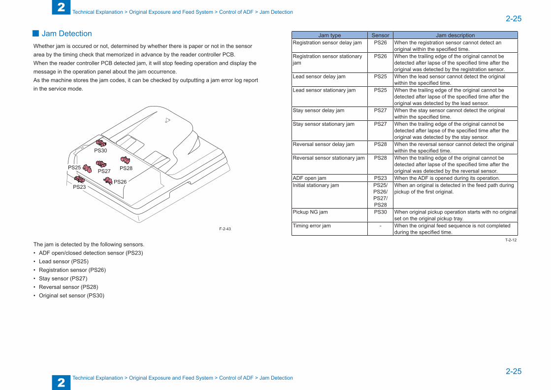
2
22-25
2-25
Technical Explanation > Original Exposure and Feed System > Control of ADF > Jam Detection
Technical Explanation > Original Exposure and Feed System > Control of ADF > Jam Detection
■ Jam DetectionWhether jam is occured or not, determined by whether there is paper or not in the sensor area by the timing check that memorized in advance by the reader controller PCB.When the reader controller PCB detected jam, it will stop feeding operation and display the message in the operation panel about the jam occurrence.As the machine stores the jam codes, it can be checked by outputting a jam error log report in the service mode.
PS23
PS25
PS26
PS27 PS28
PS30
The jam is detected by the following sensors.• ADF open/closed detection sensor (PS23)• Lead sensor (PS25)• Registration sensor (PS26)• Stay sensor (PS27)• Reversal sensor (PS28)• Original set sensor (PS30)
F-2-43
Jam type Sensor Jam descriptionRegistration sensor delay jam PS26 When the registration sensor cannot detect an
original within the specified time.Registration sensor stationary jam
PS26 When the trailing edge of the original cannot be detected after lapse of the specified time after the original was detected by the registration sensor.
Lead sensor delay jam PS25 When the lead sensor cannot detect the original within the specified time.
Lead sensor stationary jam PS25 When the trailing edge of the original cannot be detected after lapse of the specified time after the original was detected by the lead sensor.
Stay sensor delay jam PS27 When the stay sensor cannot detect the original within the specified time.
Stay sensor stationary jam PS27 When the trailing edge of the original cannot be detected after lapse of the specified time after the original was detected by the stay sensor.
Reversal sensor delay jam PS28 When the reversal sensor cannot detect the original within the specified time.
Reversal sensor stationary jam PS28 When the trailing edge of the original cannot be detected after lapse of the specified time after the original was detected by the reversal sensor.
ADF open jam PS23 When the ADF is opened during its operation.Initial stationary jam PS25/
PS26/PS27/PS28
When an original is detected in the feed path during pickup of the first original.
Pickup NG jam PS30 When original pickup operation starts with no original set on the original pickup tray.
Timing error jam - When the original feed sequence is not completed during the specified time.
T-2-12
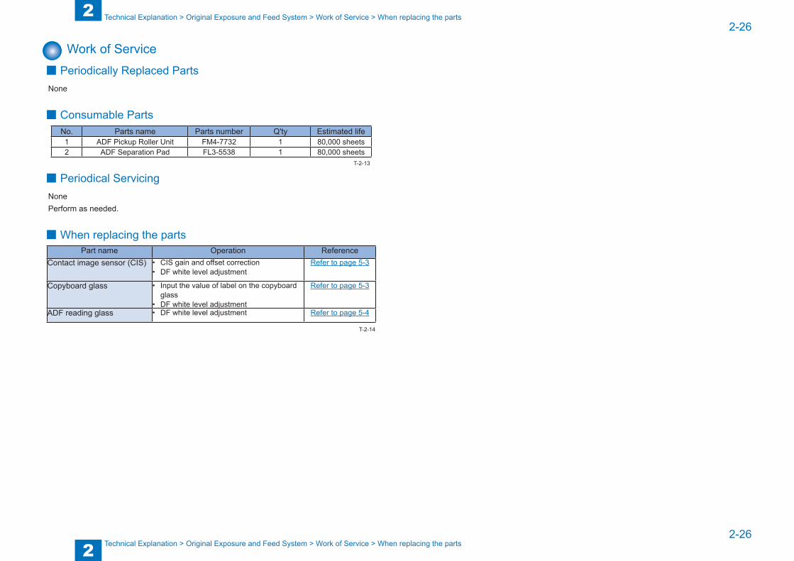
2
22-26
2-26
Technical Explanation > Original Exposure and Feed System > Work of Service > When replacing the parts
Technical Explanation > Original Exposure and Feed System > Work of Service > When replacing the parts
Work of Service ■ Periodically Replaced Parts
None
■ Consumable PartsNo. Parts name Parts number Q'ty Estimated life1 ADF Pickup Roller Unit FM4-7732 1 80,000 sheets2 ADF Separation Pad FL3-5538 1 80,000 sheets
■ Periodical ServicingNonePerform as needed.
■When replacing the partsPart name Operation Reference
Contact image sensor (CIS) • CIS gain and offset correction• DF white level adjustment
Refer to page 5-3
Copyboard glass • Input the value of label on the copyboard glass
• DF white level adjustment
Refer to page 5-3
ADF reading glass • DF white level adjustment Refer to page 5-4
T-2-13
T-2-14
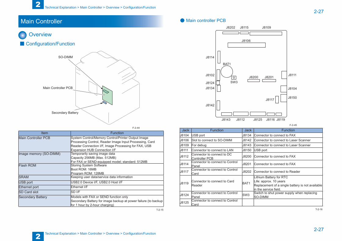
2
22-27
2-27
Technical Explanation > Main Controller > Overview > Configuration/Function
Technical Explanation > Main Controller > Overview > Configuration/Function
Main Controller
Overview ■ Configuration/Function
Secondary Battery
Main Controller PCB
SO-DIMM
Item FunctionMain Controller PCB System Control/Memory Control/Printer Output Image
Processing Control, Reader Image Input Processing, Card Reader Connection I/F, Image Processing for FAX, USB Expansion HUB Connection I/F
Image memory (SO-DIMM) Temporarily saving image dataCapacity 256MB (Max. 512MB)For FAX or SEND-equipped model; standard: 512MB
Flash ROM Storing System SoftwareBoot ROM: 16MBProgram ROM: 128MB
SRAM Keeping user data/service data information
USB port USB2.0 Device I/F, USB2.0 Host I/FEthernet port Ethernet I/FSD Card slot SD I/FSecondary Battery Models with FAX or SEND function only
Secondary Battery for image backup at power failure (to backup for 1 hour by 2-hour charging)
F-2-44
T-2-15
● Main controller PCBJ8109
J8106
J8202 J8115
J8200 J8201
J8114
BAT1
J8102
J8124J8134
J8142
J8143 J8112 J8125 J8116 J8119
J8117 J8150
J8104
J8111
SW3
Jack Function Jack FunctionJ8104 USB port J8134 Connector to connect to FAXJ8106 Slot to connect to SO-DIMM J8142 Connector to connect to Laser ScannerJ8109 For debug J8143 Connector to connect to Laser ScannerJ8111 Connector to connect to LAN J8150 USB port
J8112 Connector to connect to DC Controller PCB J8200 Connector to connect to FAX
J8114 Connector to connect to Control Panel J8201 Connector to connect to FAX
J8117 Connector to connect to Control Card J8202 Connector to connect to Reader
J8119 Connector to connect to Card Reader BAT1
Lithium Battery for RTCLife: approx. 10 years Replacement of a single battery is not available in the service field.
J8124 Connector to connect to Control Panel SW3 Switch to shut power supply when replacing
SO-DIMM
J8125 Connector to connect to Control Card
F-2-45
T-2-16

2
22-28
2-28
Technical Explanation > Main Controller > Controls > Image Processing Module Configuration
Technical Explanation > Main Controller > Controls > Image Processing Module Configuration
Controls ■ Image Data Flow
A
A
A
PC
Original
Copy
Print output
Scan
Image data
Other iR machine
- SEND - FAX - PullScan - E-Mail - PDL Print
F-2-46
■ Image Processing Module Configuration
Processes image data foroutput to the printer unit.
Printer unit output imageprocessing block
Reader unit input image processing blockProcesses the image dataread by the reader unit.
Main Controller PCB
Reader Controller PCB
DC Controller PCB
SO-DIMM
F-2-47
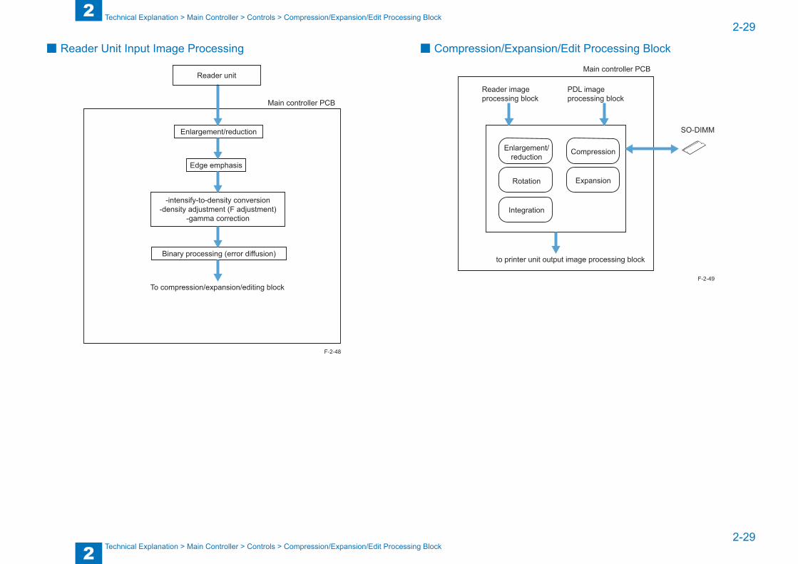
2
22-29
2-29
Technical Explanation > Main Controller > Controls > Compression/Expansion/Edit Processing Block
Technical Explanation > Main Controller > Controls > Compression/Expansion/Edit Processing Block
■ Reader Unit Input Image Processing
Binary processing (error diffusion)
To compression/expansion/editing block
Edge emphasis
Enlargement/reduction
-intensify-to-density conversion-density adjustment (F adjustment)
-gamma correction
Main controller PCB
Reader unit
F-2-48
■ Compression/Expansion/Edit Processing Block
Main controller PCB
to printer unit output image processing block
Enlargement/reduction
Rotation
Integration
Compression
Expansion
Reader imageprocessing block
PDL imageprocessing block
SO-DIMM
F-2-49
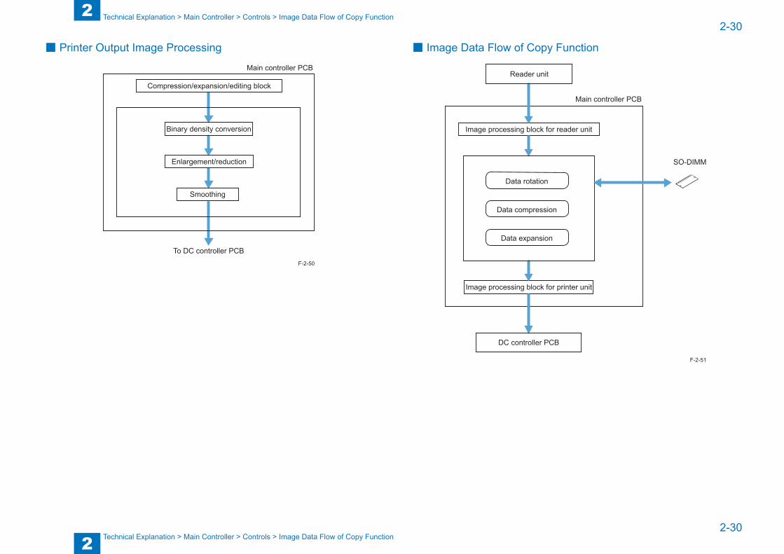
2
22-30
2-30
Technical Explanation > Main Controller > Controls > Image Data Flow of Copy Function
Technical Explanation > Main Controller > Controls > Image Data Flow of Copy Function
■ Printer Output Image Processing
Main controller PCB
To DC controller PCB
Compression/expansion/editing block
Binary density conversion
Enlargement/reduction
Smoothing
F-2-50
■ Image Data Flow of Copy Function
Main controller PCB
Image processing block for printer unit
Image processing block for reader unit
Reader unit
Data compression
Data rotation
Data expansion
SO-DIMM
DC controller PCB
F-2-51

2
22-31
2-31
Technical Explanation > Main Controller > Controls > Image Data Flow of FAX Transmission Function
Technical Explanation > Main Controller > Controls > Image Data Flow of FAX Transmission Function
■ Image Data Flow of SEND Function
Image processing block for reader unit
Reader unit
Main controller PCB
Data rotation
Data expansion
Resolution conversion
SO-DIMM
USB2.0
To network
(compression data)
Ethernet port
F-2-52
■ Image Data Flow of FAX Transmission Function
Image processing block for reader unit
Image processing block for FAX
Super G3 Fax Board
Main controller PCB
Data rotation
Data compression
Data expansion
SO-DIMM
Reader unit
F-2-53

2
22-32
2-32
Technical Explanation > Main Controller > Controls > Image Data Flow of PDL Function
Technical Explanation > Main Controller > Controls > Image Data Flow of PDL Function
■ Image Data Flow of FAX Reception Function
Image processing block for printer unit
Image processing block for fax
Super G3 Fax Board
Main controller PCB
Data compression
Data rotation
Data expansion
SO-DIMM
DC controller PCB
F-2-54
■ Image Data Flow of PDL Function
Rendering processing block
Compression/expansion/editing block
Processing block for printer unit
DC controller PCB
Main controller PCB
SO-DIMM
Ethernet
PDL
F-2-55
2
22-33
2-33
Technical Explanation > Main Controller > Service Tasks > Periodical Servicing
Technical Explanation > Main Controller > Service Tasks > Periodical Servicing
Service Tasks ■ Periodically Replaced Parts
None.
■ Consumable PartsNone.
■ Periodical ServicingNone.
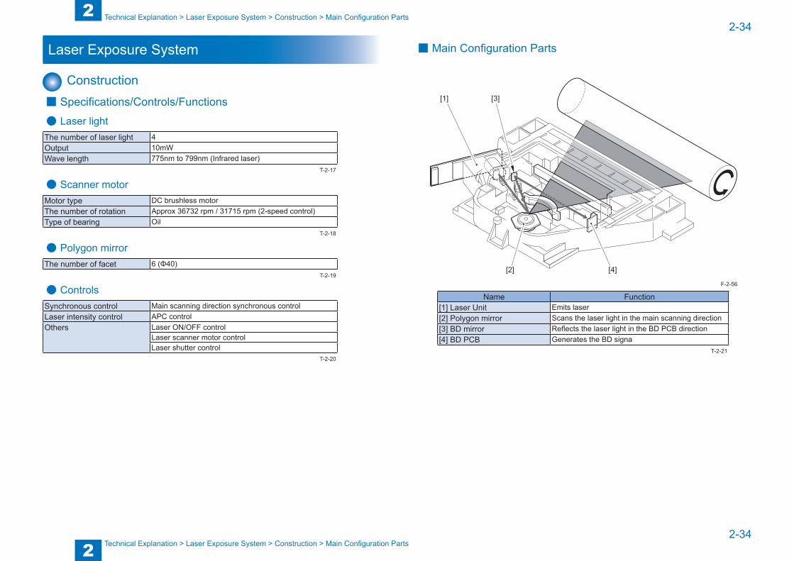
2
22-34
2-34
Technical Explanation > Laser Exposure System > Construction > Main Configuration Parts
Technical Explanation > Laser Exposure System > Construction > Main Configuration Parts
Laser Exposure System
Construction ■ Specifications/Controls/Functions
● Laser lightThe number of laser light 4Output 10mWWave length 775nm to 799nm (Infrared laser)
● Scanner motorMotor type DC brushless motorThe number of rotation Approx 36732 rpm / 31715 rpm (2-speed control)Type of bearing Oil
● Polygon mirrorThe number of facet 6 (Φ40)
● ControlsSynchronous control Main scanning direction synchronous controlLaser intensity control APC controlOthers Laser ON/OFF control
Laser scanner motor controlLaser shutter control
T-2-17
T-2-18
T-2-19
T-2-20
■ Main Configuration Parts
[1]
[2] [4]
[3]
Name Function[1] Laser Unit Emits laser[2] Polygon mirror Scans the laser light in the main scanning direction[3] BD mirror Reflects the laser light in the BD PCB direction[4] BD PCB Generates the BD signa
F-2-56
T-2-21
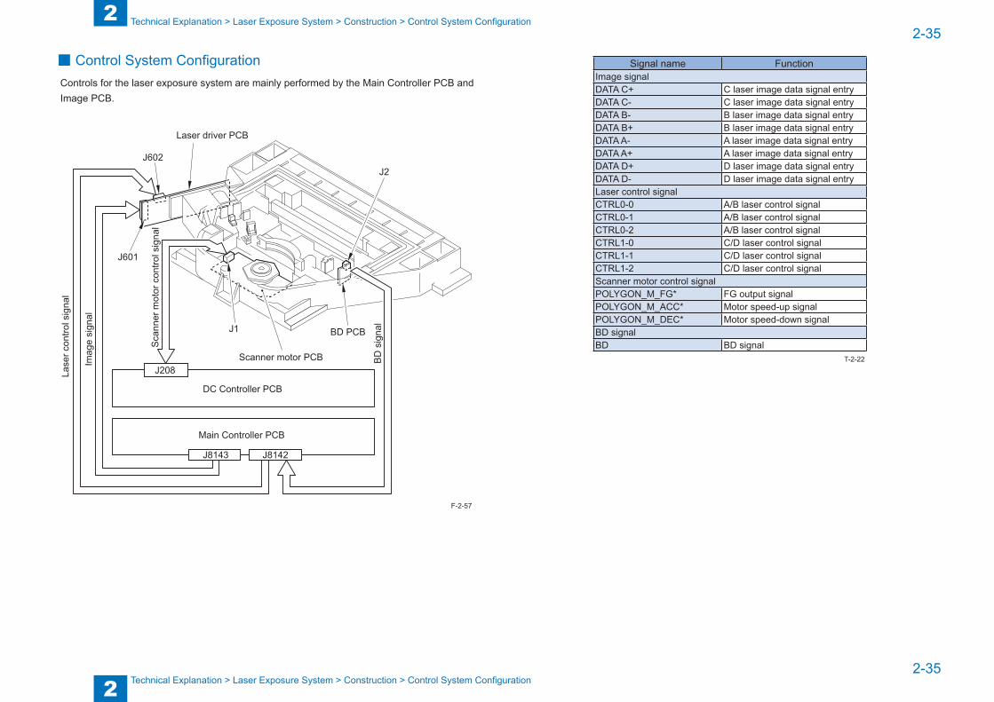
2
22-35
2-35
Technical Explanation > Laser Exposure System > Construction > Control System Configuration
Technical Explanation > Laser Exposure System > Construction > Control System Configuration
■ Control System ConfigurationControls for the laser exposure system are mainly performed by the Main Controller PCB and Image PCB.
J8143
DC Controller PCB
J8142
J208
J602
J601
J2
J1
Laser driver PCB
Scanner motor PCB
BD PCB
BD
sig
nal
Main Controller PCB
Imag
e si
gnal
Lase
r con
trol s
igna
l
Sca
nner
mot
or c
ontro
l sig
nal
F-2-57
Signal name FunctionImage signalDATA C+ C laser image data signal entryDATA C- C laser image data signal entryDATA B- B laser image data signal entryDATA B+ B laser image data signal entryDATA A- A laser image data signal entryDATA A+ A laser image data signal entryDATA D+ D laser image data signal entryDATA D- D laser image data signal entryLaser control signalCTRL0-0 A/B laser control signalCTRL0-1 A/B laser control signalCTRL0-2 A/B laser control signalCTRL1-0 C/D laser control signalCTRL1-1 C/D laser control signalCTRL1-2 C/D laser control signalScanner motor control signalPOLYGON_M_FG* FG output signalPOLYGON_M_ACC* Motor speed-up signalPOLYGON_M_DEC* Motor speed-down signalBD signalBD BD signal
T-2-22
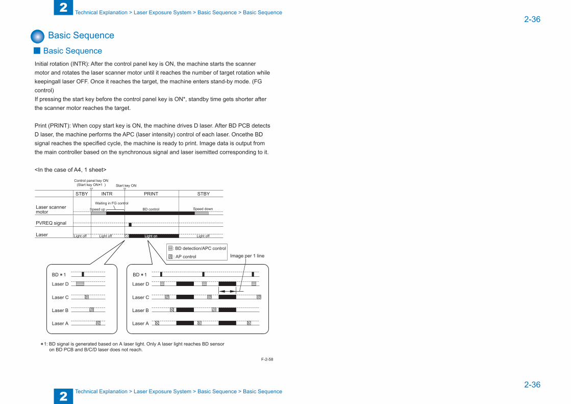
2
22-36
2-36
Technical Explanation > Laser Exposure System > Basic Sequence > Basic Sequence
Technical Explanation > Laser Exposure System > Basic Sequence > Basic Sequence
Basic Sequence ■ Basic Sequence
Initial rotation (INTR): After the control panel key is ON, the machine starts the scanner motor and rotates the laser scanner motor until it reaches the number of target rotation while keepingall laser OFF. Once it reaches the target, the machine enters stand-by mode. (FG control)If pressing the start key before the control panel key is ON*, standby time gets shorter after the scanner motor reaches the target.
Print (PRINT): When copy start key is ON, the machine drives D laser. After BD PCB detects D laser, the machine performs the APC (laser intensity) control of each laser. Oncethe BD signal reaches the specified cycle, the machine is ready to print. Image data is output from the main controller based on the synchronous signal and laser isemitted corresponding to it.
<In the case of A4, 1 sheet>
PRINT STBYSTBY INTR
Laser scanner motor
PVREQ signal
Laser
Control panel key ON(Start key ON 1 ) Start key ON
Laser D
Image per 1 line
Waiting in FG control
BD control
Light on Light offLight offLight off
Speed down
1: BD signal is generated based on A laser light. Only A laser light reaches BD sensor on BD PCB and B/C/D laser does not reach.
Laser C
Laser B
Laser A
BD 1
Laser D
Laser C
Laser B
Laser A
: BD detection/APC control
: AP control
BD 1
Speed up
F-2-58
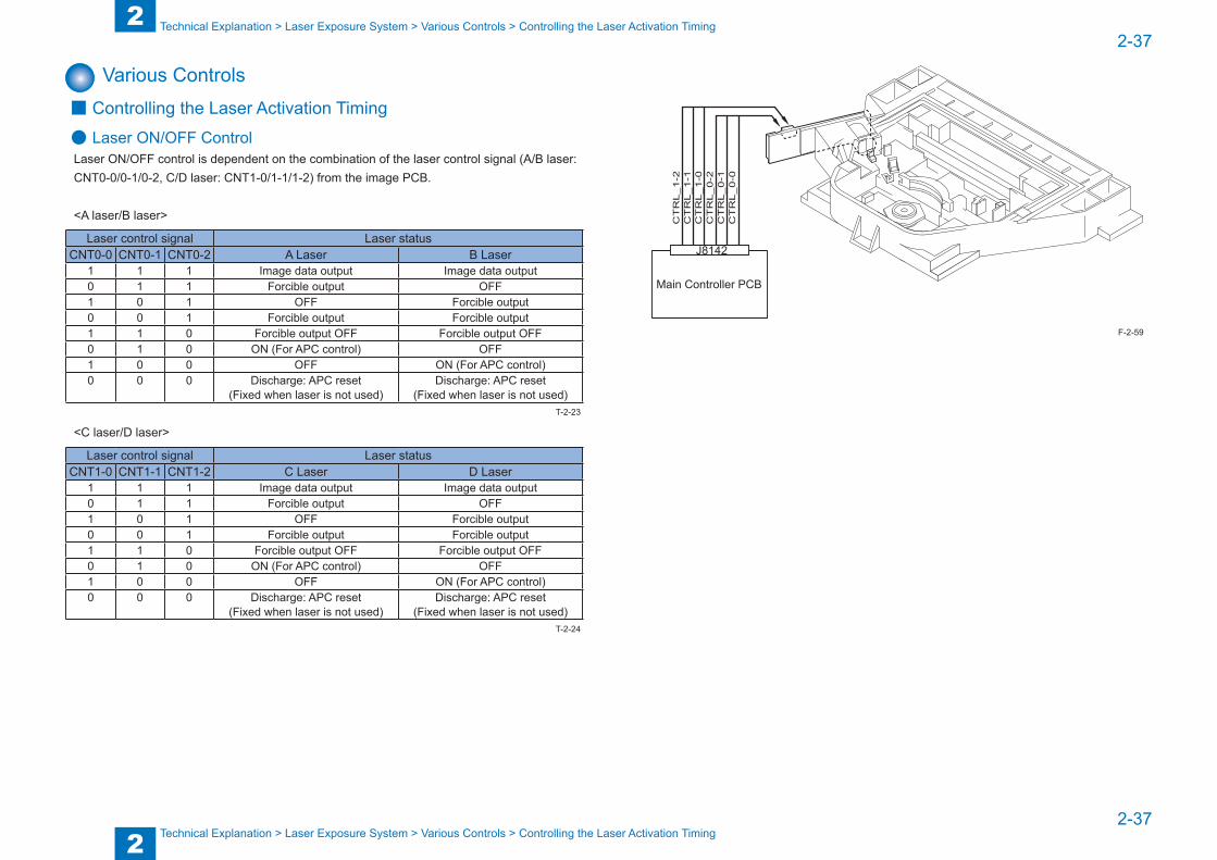
2
22-37
2-37
Technical Explanation > Laser Exposure System > Various Controls > Controlling the Laser Activation Timing
Technical Explanation > Laser Exposure System > Various Controls > Controlling the Laser Activation Timing
Various Controls ■ Controlling the Laser Activation Timing
● Laser ON/OFF ControlLaser ON/OFF control is dependent on the combination of the laser control signal (A/B laser: CNT0-0/0-1/0-2, C/D laser: CNT1-0/1-1/1-2) from the image PCB.
<A laser/B laser>
Laser control signal Laser statusCNT0-0 CNT0-1 CNT0-2 A Laser B Laser
1 1 1 Image data output Image data output0 1 1 Forcible output OFF1 0 1 OFF Forcible output0 0 1 Forcible output Forcible output1 1 0 Forcible output OFF Forcible output OFF0 1 0 ON (For APC control) OFF1 0 0 OFF ON (For APC control)0 0 0 Discharge: APC reset
(Fixed when laser is not used)Discharge: APC reset
(Fixed when laser is not used)
<C laser/D laser>
Laser control signal Laser statusCNT1-0 CNT1-1 CNT1-2 C Laser D Laser
1 1 1 Image data output Image data output0 1 1 Forcible output OFF1 0 1 OFF Forcible output0 0 1 Forcible output Forcible output1 1 0 Forcible output OFF Forcible output OFF0 1 0 ON (For APC control) OFF1 0 0 OFF ON (For APC control)0 0 0 Discharge: APC reset
(Fixed when laser is not used)Discharge: APC reset
(Fixed when laser is not used)
T-2-23
T-2-24
J8142
Main Controller PCB
CT
RL_1-2
CT
RL_1-1
CT
RL_1-0
CT
RL_0-2
CT
RL_0-1
CT
RL_0-0
F-2-59
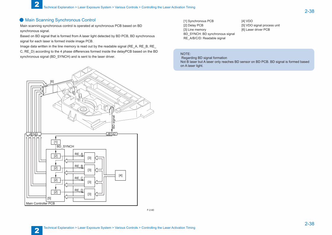
2
22-38
2-38
Technical Explanation > Laser Exposure System > Various Controls > Controlling the Laser Activation Timing
Technical Explanation > Laser Exposure System > Various Controls > Controlling the Laser Activation Timing
● Main Scanning Synchronous ControlMain scanning synchronous control is operated at synchronous PCB based on BD synchronous signal.Based on BD signal that is formed from A laser light detected by BD PCB, BD synchronous signal for each laser is formed inside image PCB.Image data written in the line memory is read out by the readable signal (RE_A, RE_B, RE_C, RE_D) according to the 4 phase differences formed inside the delayPCB based on the BD synchronous signal (BD_SYNCH) and is sent to the laser driver.
J8143
BD_SYNCH
[6]
[3]RE_A[2]
[3]RE_B[2]
[3]RE_C[2]
[3]RE_D[2]
[5]
[1]
J8142
[4]
BD
sig
nal
Main Controller PCB
F-2-60
[1] Synchronous PCB [4] VDO[2] Delay PCB [5] VDO signal process unit[3] Line memory [6] Laser driver PCBBD_SYNCH: BD synchronous signalRE_A/B/C/D: Readable signal
NOTE: Regarding BD signal formationNot B laser but A laser only reaches BD sensor on BD PCB. BD signal is formed based on A laser light.

2
22-39
2-39
Technical Explanation > Laser Exposure System > Various Controls > Controlling the Laser Shutter
Technical Explanation > Laser Exposure System > Various Controls > Controlling the Laser Shutter
■ Controlling the Intensity of Laser Light
● APC ControlThe machine monitors the laser light that is emitted to the built-in photo diode of laser diode and adjusts the laser to appropriate intensity.
■ Controlling the Laser Scanner Motor
● Controlling the Laser Scanner MotorFrom when the laser scanner motor starts and the laser scanner motor reaches the number of target rotation to before image formation starts, the machine controlsthe rotation speed by referring to the laser scanner motor rotation speed signal (FG signal).During image formation, it controls the laser scanner motor rotationspeed based on BD signal.Laser scanner motor rotation speed is controlled by speed-up signal (ACC signal) and speed-down signal (DEC signal).
AC
CD
EC
FG
J208
DC Controller PCB
F-2-61
■ Controlling the Laser Shutter
● Laser Shutter ControlWhen the right door opens, laser shutter will be closed by laser shutter link that works in conjunction with the right door and the laser light is blocked. Also, whenthe front door or right door open is detected, laser scanner motor and the laser emission will be turned OFF.
[1]
[2] [2]
[2]
[1][3] [3] [1]
DOOR CLOSED DOOR OPEN
[1] Laser shutter[2] Laser shutter link (works in conjunction with the right door)[3] Laser unit
F-2-62
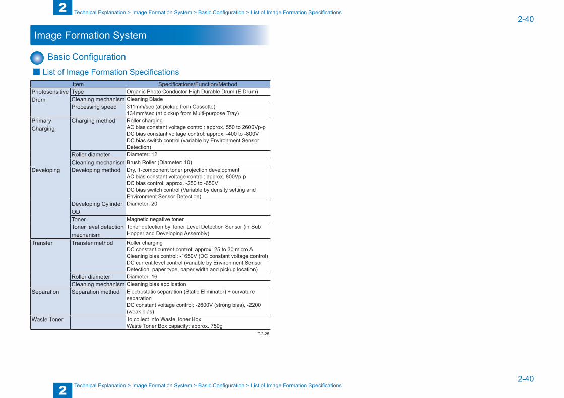
2
22-40
2-40
Technical Explanation > Image Formation System > Basic Configuration > List of Image Formation Specifications
Technical Explanation > Image Formation System > Basic Configuration > List of Image Formation Specifications
Image Formation System
Basic Configuration ■ List of Image Formation Specifications
Item Specifications/Function/MethodPhotosensitive Drum
Type Organic Photo Conductor High Durable Drum (E Drum) Cleaning mechanism Cleaning BladeProcessing speed 311mm/sec (at pickup from Cassette)
134mm/sec (at pickup from Multi-purpose Tray)Primary Charging
Charging method Roller chargingAC bias constant voltage control: approx. 550 to 2600Vp-pDC bias constant voltage control: approx. -400 to -800VDC bias switch control (variable by Environment Sensor Detection)
Roller diameter Diameter: 12Cleaning mechanism Brush Roller (Diameter: 10)
Developing Developing method Dry, 1-component toner projection developmentAC bias constant voltage control: approx. 800Vp-pDC bias control: approx. -250 to -650VDC bias switch control (Variable by density setting and Environment Sensor Detection)
Developing Cylinder OD
Diameter: 20
Toner Magnetic negative tonerToner level detection mechanism
Toner detection by Toner Level Detection Sensor (in Sub Hopper and Developing Assembly)
Transfer Transfer method Roller chargingDC constant current control: approx. 25 to 30 micro ACleaning bias control: -1650V (DC constant voltage control)DC current level control (variable by Environment Sensor Detection, paper type, paper width and pickup location)
Roller diameter Diameter: 16Cleaning mechanism Cleaning bias application
Separation Separation method Electrostatic separation (Static Eliminator) + curvature separationDC constant voltage control: -2600V (strong bias), -2200 (weak bias)
Waste Toner To collect into Waste Toner BoxWaste Toner Box capacity: approx. 750g
T-2-25
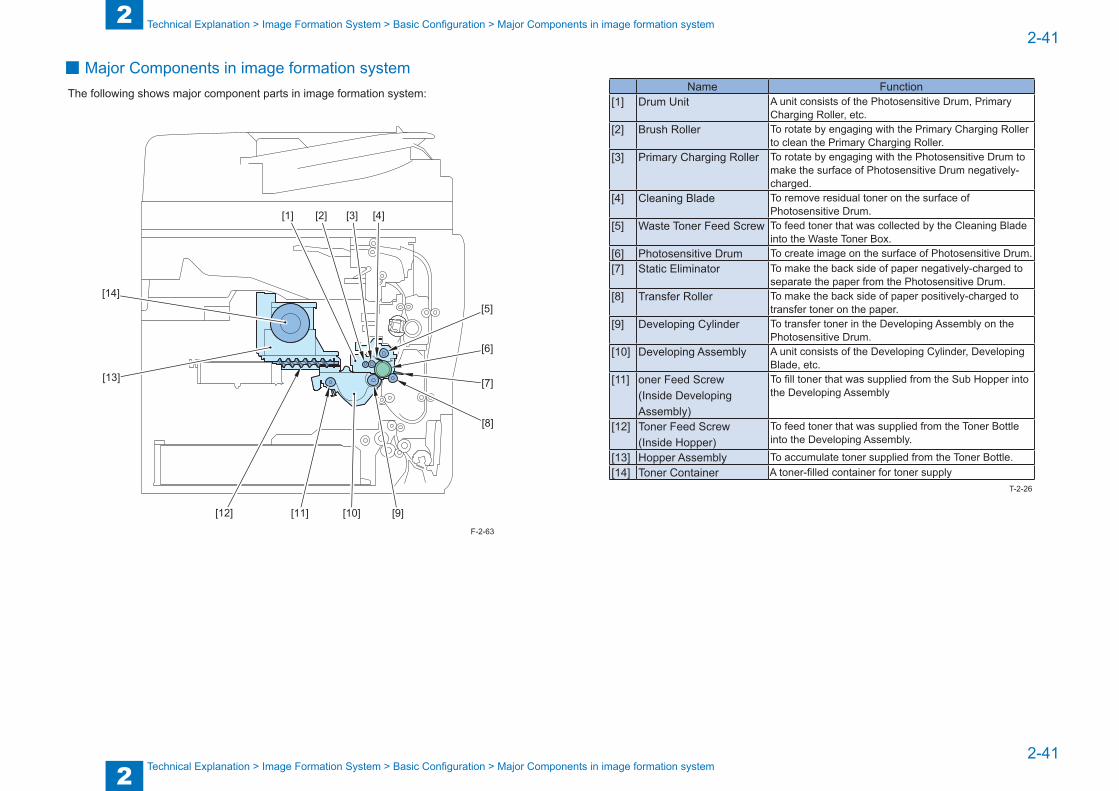
2
22-41
2-41
Technical Explanation > Image Formation System > Basic Configuration > Major Components in image formation system
Technical Explanation > Image Formation System > Basic Configuration > Major Components in image formation system
■ Major Components in image formation systemThe following shows major component parts in image formation system:
[1] [2] [3]
[10][11]
[4]
[5]
[6]
[7]
[8]
[9][12]
[13]
[14]
F-2-63
Name Function[1] Drum Unit A unit consists of the Photosensitive Drum, Primary
Charging Roller, etc.[2] Brush Roller To rotate by engaging with the Primary Charging Roller
to clean the Primary Charging Roller.[3] Primary Charging Roller To rotate by engaging with the Photosensitive Drum to
make the surface of Photosensitive Drum negatively-charged.
[4] Cleaning Blade To remove residual toner on the surface of Photosensitive Drum.
[5] Waste Toner Feed Screw To feed toner that was collected by the Cleaning Blade into the Waste Toner Box.
[6] Photosensitive Drum To create image on the surface of Photosensitive Drum.[7] Static Eliminator To make the back side of paper negatively-charged to
separate the paper from the Photosensitive Drum.[8] Transfer Roller To make the back side of paper positively-charged to
transfer toner on the paper.[9] Developing Cylinder To transfer toner in the Developing Assembly on the
Photosensitive Drum.[10] Developing Assembly A unit consists of the Developing Cylinder, Developing
Blade, etc.[11] oner Feed Screw
(Inside Developing Assembly)
To fill toner that was supplied from the Sub Hopper into the Developing Assembly
[12] Toner Feed Screw(Inside Hopper)
To feed toner that was supplied from the Toner Bottle into the Developing Assembly.
[13] Hopper Assembly To accumulate toner supplied from the Toner Bottle.[14] Toner Container A toner-filled container for toner supply
T-2-26
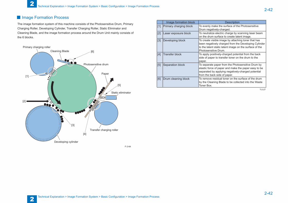
2
22-42
2-42
Technical Explanation > Image Formation System > Basic Configuration > Image Formation Process
Technical Explanation > Image Formation System > Basic Configuration > Image Formation Process
■ Image Formation ProcessThe image formation system of this machine consists of the Photosensitive Drum, Primary Charging Roller, Developing Cylinder, Transfer Charging Roller, Static Eliminator and Cleaning Blade, and the image formation process around the Drum Unit mainly consists of the 6 blocks.
[1]
[4]
[6]Cleaning BladePrimary charging roller
[2]
[3]
[5]
Photosensitive drum
Static eliminator
Transfer charging roller
Paper
Developing cylinderF-2-64
Image formation block Description[1] Primary charging block To evenly make the surface of the Photosensitive
Drum negatively-charged.[2] Laser exposure block To neutralize electric charge by scanning laser beam
on the drum surface to create latent image.[3] Developing block To create visible image by attaching toner that has
been negatively charged from the Developing Cylinder to the latent static latent image on the surface of the Photosensitive Drum.
[4] Transfer block To apply positively-charged potential from the back side of paper to transfer toner on the drum to the paper.
[5] Separation block To separate paper from the Photosensitive Drum by elastic force of paper and make the paper easy to be separated by applying negatively-charged potential from the back side of paper.
[6] Drum cleaning block To remove residual toner on the surface of the drum by the Cleaning Blade to be collected into the Waste Toner Box.
T-2-27
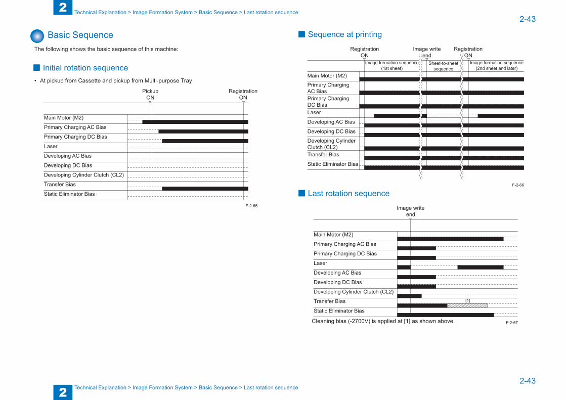
2
22-43
2-43
Technical Explanation > Image Formation System > Basic Sequence > Last rotation sequence
Technical Explanation > Image Formation System > Basic Sequence > Last rotation sequence
Basic SequenceThe following shows the basic sequence of this machine:
■ Initial rotation sequence• At pickup from Cassette and pickup from Multi-purpose Tray
PickupON
RegistrationON
Primary Charging AC Bias
Main Motor (M2)
Primary Charging DC Bias
Laser
Developing AC Bias
Developing DC Bias
Developing Cylinder Clutch (CL2)
Transfer Bias
Static Eliminator Bias
F-2-65
■ Sequence at printing
Primary ChargingAC Bias
Main Motor (M2)
Primary ChargingDC BiasLaser
Developing AC Bias
Developing DC Bias
Developing CylinderClutch (CL2)Transfer Bias
Static Eliminator Bias
Image formation sequence(1st sheet)
Image formation sequence(2nd sheet and later)
Sheet-to-sheetsequence
RegistrationON
RegistrationON
Image writeend
■ Last rotation sequence
Image writeend
Primary Charging AC Bias
Main Motor (M2)
Primary Charging DC Bias
Laser
Developing AC Bias
Developing DC Bias
Developing Cylinder Clutch (CL2)
Transfer Bias
Static Eliminator Bias
[1]
Cleaning bias (-2700V) is applied at [1] as shown above.
F-2-66
F-2-67
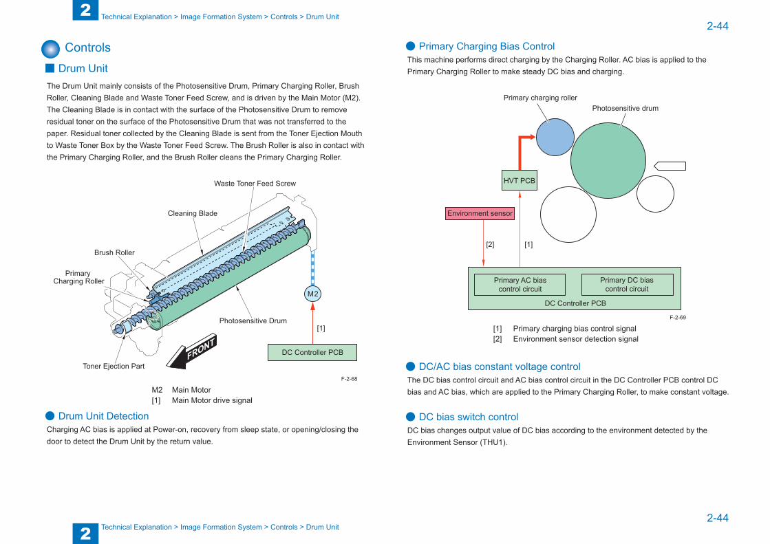
2
22-44
2-44
Technical Explanation > Image Formation System > Controls > Drum Unit
Technical Explanation > Image Formation System > Controls > Drum Unit
Controls ■ Drum Unit
The Drum Unit mainly consists of the Photosensitive Drum, Primary Charging Roller, Brush Roller, Cleaning Blade and Waste Toner Feed Screw, and is driven by the Main Motor (M2).The Cleaning Blade is in contact with the surface of the Photosensitive Drum to remove residual toner on the surface of the Photosensitive Drum that was not transferred to the paper. Residual toner collected by the Cleaning Blade is sent from the Toner Ejection Mouth to Waste Toner Box by the Waste Toner Feed Screw. The Brush Roller is also in contact with the Primary Charging Roller, and the Brush Roller cleans the Primary Charging Roller.
M 2
DC Controller PCB
Photosensitive Drum
Waste Toner Feed Screw
Toner Ejection Part
Brush Roller
Cleaning Blade
Primary Charging Roller
[1]
M2 Main Motor[1] Main Motor drive signal
● Drum Unit DetectionCharging AC bias is applied at Power-on, recovery from sleep state, or opening/closing the door to detect the Drum Unit by the return value.
F-2-68
● Primary Charging Bias ControlThis machine performs direct charging by the Charging Roller. AC bias is applied to the Primary Charging Roller to make steady DC bias and charging.
Photosensitive drum
[2]
Environment sensor
[1]
Primary charging roller
HVT PCB
Primary DC biascontrol circuit
Primary AC biascontrol circuit
DC Controller PCB
[1] Primary charging bias control signal[2] Environment sensor detection signal
● DC/AC bias constant voltage controlThe DC bias control circuit and AC bias control circuit in the DC Controller PCB control DC bias and AC bias, which are applied to the Primary Charging Roller, to make constant voltage.
● DC bias switch controlDC bias changes output value of DC bias according to the environment detected by the Environment Sensor (THU1).
F-2-69
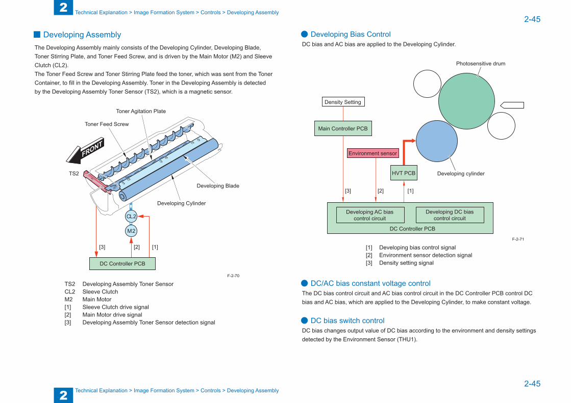
2
22-45
2-45
Technical Explanation > Image Formation System > Controls > Developing Assembly
Technical Explanation > Image Formation System > Controls > Developing Assembly
■ Developing AssemblyThe Developing Assembly mainly consists of the Developing Cylinder, Developing Blade, Toner Stirring Plate, and Toner Feed Screw, and is driven by the Main Motor (M2) and Sleeve Clutch (CL2).The Toner Feed Screw and Toner Stirring Plate feed the toner, which was sent from the Toner Container, to fill in the Developing Assembly. Toner in the Developing Assembly is detected by the Developing Assembly Toner Sensor (TS2), which is a magnetic sensor.
M 2
CL 2
DC Controller PCB
Developing Cylinder
Developing Blade
Toner Agitation Plate
Toner Feed Screw
TS2
[1][2][3]
TS2 Developing Assembly Toner Sensor CL2 Sleeve ClutchM2 Main Motor[1] Sleeve Clutch drive signal[2] Main Motor drive signal[3] Developing Assembly Toner Sensor detection signal
F-2-70
● Developing Bias ControlDC bias and AC bias are applied to the Developing Cylinder.
[3]
Density Setting
Main Controller PCB
Photosensitive drum
Developing cylinder
[2]
Environment sensor
[1]
HVT PCB
Developing AC biascontrol circuit
DC Controller PCB
Developing DC biascontrol circuit
[1] Developing bias control signal[2] Environment sensor detection signal[3] Density setting signal
● DC/AC bias constant voltage controlThe DC bias control circuit and AC bias control circuit in the DC Controller PCB control DC bias and AC bias, which are applied to the Developing Cylinder, to make constant voltage.
● DC bias switch controlDC bias changes output value of DC bias according to the environment and density settings detected by the Environment Sensor (THU1).
F-2-71
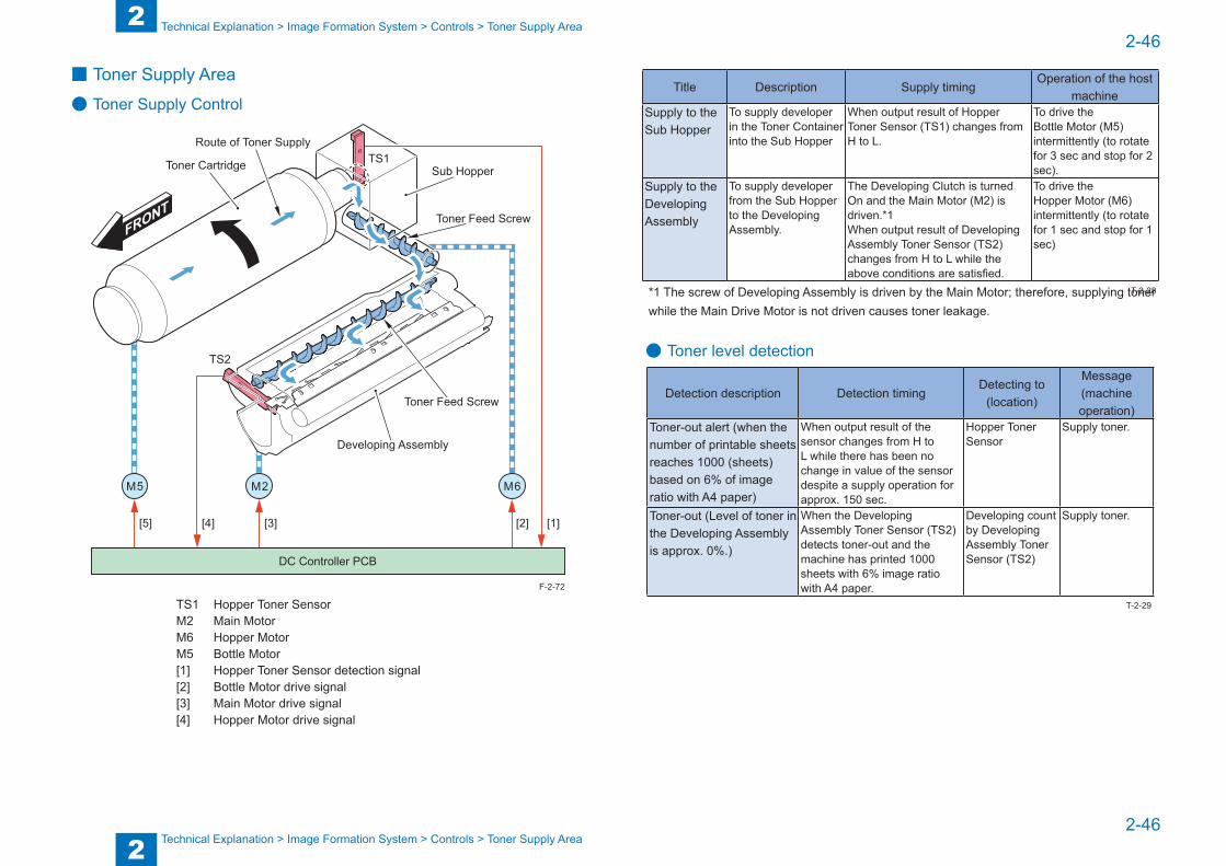
2
22-46
2-46
Technical Explanation > Image Formation System > Controls > Toner Supply Area
Technical Explanation > Image Formation System > Controls > Toner Supply Area
■ Toner Supply Area
● Toner Supply Control
M 2M 5 M 6
DC Controller PCB
[1][2][3][4][5]
TS1
TS2
Toner Cartridge Sub Hopper
Toner Feed Screw
Developing Assembly
Route of Toner Supply
Toner Feed Screw
TS1 Hopper Toner Sensor M2 Main MotorM6 Hopper MotorM5 Bottle Motor[1] Hopper Toner Sensor detection signal [2] Bottle Motor drive signal[3] Main Motor drive signal[4] Hopper Motor drive signal
F-2-72
Title Description Supply timingOperation of the host
machineSupply to the Sub Hopper
To supply developer in the Toner Container into the Sub Hopper
When output result of Hopper Toner Sensor (TS1) changes from H to L.
To drive the Bottle Motor (M5) intermittently (to rotate for 3 sec and stop for 2 sec).
Supply to the Developing Assembly
To supply developer from the Sub Hopper to the Developing Assembly.
The Developing Clutch is turned On and the Main Motor (M2) is driven.*1When output result of Developing Assembly Toner Sensor (TS2) changes from H to L while the above conditions are satisfied.
To drive the Hopper Motor (M6) intermittently (to rotate for 1 sec and stop for 1 sec)
*1 The screw of Developing Assembly is driven by the Main Motor; therefore, supplying toner while the Main Drive Motor is not driven causes toner leakage.
● Toner level detection
Detection description Detection timingDetecting to
(location)
Message (machine operation)
Toner-out alert (when the number of printable sheets reaches 1000 (sheets) based on 6% of image ratio with A4 paper)
When output result of the sensor changes from H to L while there has been no change in value of the sensor despite a supply operation for approx. 150 sec.
Hopper Toner Sensor
Supply toner.
Toner-out (Level of toner in the Developing Assembly is approx. 0%.)
When the Developing Assembly Toner Sensor (TS2) detects toner-out and the machine has printed 1000 sheets with 6% image ratio with A4 paper.
Developing count by Developing Assembly Toner Sensor (TS2)
Supply toner.
T-2-28
T-2-29
2
22-47
2-47
Technical Explanation > Image Formation System > Controls > Toner Supply Area
Technical Explanation > Image Formation System > Controls > Toner Supply Area
● Detection for replacing Toner ContainerThis machine does not have a sensor to detect replacement of a Toner Container. Therefore, execute the toner supply sequence as follows to determine replacement of a Toner Container.• Toner supply sequence1. Make the Main Motor (M2), Developing Clutch, Hopper Motor (M6) and Bottle Motor (M5)
driven to supply toner.2. When the Hopper Level Sensor detects presence of toner, the machine resumes normal
operation. When the Hopper Level Sensor failed to detect presence of toner for more than 60 sec, it is determined that there has been no replacement of a Toner Container.
• Replacement when the power is turned ONWhen the Front Cover is opened/closed, the machine determines that a Toner Container has been replaced and executes toner supply sequence.
• Replacement when the power is turned OFF or the machine is at sleep 2 stateThe machine executes the toner supply sequence at power-on if there was a toner-out alert or toner-out message when the power was turned OFF the last time.
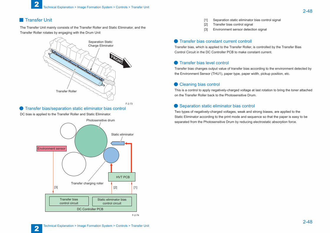
2
22-48
2-48
Technical Explanation > Image Formation System > Controls > Transfer Unit
Technical Explanation > Image Formation System > Controls > Transfer Unit
■ Transfer UnitThe Transfer Unit mainly consists of the Transfer Roller and Static Eliminator, and the Transfer Roller rotates by engaging with the Drum Unit
Separation Static Charge Eliminator
Transfer Roller
● Transfer bias/separation static eliminator bias controlDC bias is applied to the Transfer Roller and Static Eliminator.
[3]
Environment sensor
Photosensitive drum
Static eliminator
Transfer charging roller[1]
HVT PCB
[2]
Transfer biascontrol circuit
DC Controller PCB
Static eliminator biascontrol circuit
F-2-73
F-2-74
[1] Separation static eliminator bias control signal[2] Transfer bias control signal[3] Environment sensor detection signal
● Transfer bias constant current controllTransfer bias, which is applied to the Transfer Roller, is controlled by the Transfer Bias Control Circuit in the DC Controller PCB to make constant current.
● Transfer bias level controlTransfer bias changes output value of transfer bias according to the environment detected by the Environment Sensor (THU1), paper type, paper width, pickup position, etc.
● Cleaning bias controlThis is a control to apply negatively-charged voltage at last rotation to bring the toner attached on the Transfer Roller back to the Photosensitive Drum.
● Separation static eliminator bias controlTwo types of negatively-charged voltages, weak and strong biases, are applied to the Static Eliminator according to the print mode and sequence so that the paper is easy to be separated from the Photosensitive Drum by reducing electrostatic absorption force.

2
22-49
2-49
Technical Explanation > Image Formation System > Controls > Waste Toner Box
Technical Explanation > Image Formation System > Controls > Waste Toner Box
■ Chang in bias by user mode (Special Mode)Special mode settings in user mode include a mode to change the density or improve the separation performance by changing the bias. The following describes the mode which executes bias control.
User mode Overview Setting value Control detailsSpecial Mode M (Density adjustment)
To change the density by chancing the value of transfer bias.
Standard (Default)
Normal control
Low The density is lightened by weakening the bias.
High The density is darkened by strengthening the bias.
Special Mode O (Separation priority mode)
To control the separation bias in the case of frequent jams on the 2nd side when using backside of printed paper, etc.
Off(Default)
Normal control
On Separation bias at paper feed is strengthened. Also, the leading edge margin is set to 4.5mm.
Special Mode E (Background density adjustment mode)
To darken the density of background such as watermark.
Off(Default)
Normal control
On The background density is darkened by strengthening the transfer bias.
T-2-30
■Waste Toner Box
● OverviewThe toner, which was not transferred to the paper but attached on the Photosensitive Drum, is removed by the Cleaning Blade that is in contact with the Photosensitive Drum, and then fed into the Waste Toner Box by the Waste Toner Feed Screw.There is a screw for feeding toner in the Waste Toner Box. This screw is driven by the Waste Toner Motor and engaged with movement of the Hopper Motor.Note that there is no mechanism to detect presence of a Waste Toner Box with this machine. The Front Cover cannot be closed unless the Waste Toner Box is mechanically installed; therefore, the machine is not driven without having the Waste Toner Box installed
Waste Toner Full Sensor (PS2)
Waste Toner Feed Screw
Toner
Waste Toner Box
PS2 Waste toner full level sensorF-2-75
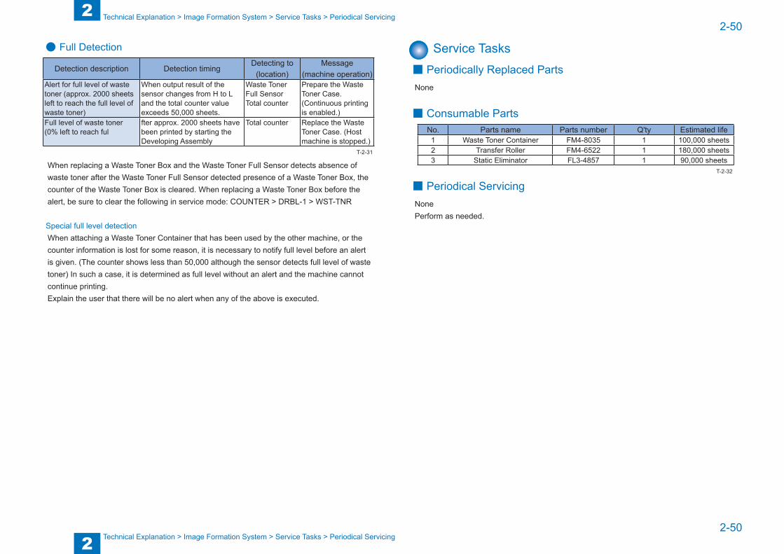
2
22-50
2-50
Technical Explanation > Image Formation System > Service Tasks > Periodical Servicing
Technical Explanation > Image Formation System > Service Tasks > Periodical Servicing
● Full Detection
Detection description Detection timingDetecting to
(location)Message
(machine operation) Alert for full level of waste toner (approx. 2000 sheets left to reach the full level of waste toner)
When output result of the sensor changes from H to L and the total counter value exceeds 50,000 sheets.
Waste Toner Full SensorTotal counter
Prepare the Waste Toner Case. (Continuous printing is enabled.)
Full level of waste toner(0% left to reach ful
fter approx. 2000 sheets have been printed by starting the Developing Assembly
Total counter Replace the Waste Toner Case. (Host machine is stopped.)
When replacing a Waste Toner Box and the Waste Toner Full Sensor detects absence of waste toner after the Waste Toner Full Sensor detected presence of a Waste Toner Box, the counter of the Waste Toner Box is cleared. When replacing a Waste Toner Box before the alert, be sure to clear the following in service mode: COUNTER > DRBL-1 > WST-TNR
Special full level detectionWhen attaching a Waste Toner Container that has been used by the other machine, or the counter information is lost for some reason, it is necessary to notify full level before an alert is given. (The counter shows less than 50,000 although the sensor detects full level of waste toner) In such a case, it is determined as full level without an alert and the machine cannot continue printing.Explain the user that there will be no alert when any of the above is executed.
T-2-31
Service Tasks ■ Periodically Replaced Parts
None
■ Consumable PartsNo. Parts name Parts number Q'ty Estimated life1 Waste Toner Container FM4-8035 1 100,000 sheets2 Transfer Roller FM4-6522 1 180,000 sheets3 Static Eliminator FL3-4857 1 90,000 sheets
■ Periodical ServicingNonePerform as needed.
T-2-32

2
22-51
2-51
Technical Explanation > Fixing System > Overview > Specifications
Technical Explanation > Fixing System > Overview > Specifications
Fixing System
Overview ■ FeaturesThis machine uses the on-demand fixing method.
Fixing Delivery RollerSeparation Guide
Fixing Heater
Fixing Film
Fixing Inlet Guide Fixing Inlet Guide
Pressure Roller
F-2-76
■ SpecificationsItem Function/method
Fixing method On-demand fixingFixing speed 139mm/sec (1/1-speed high: 0.8% acceleration)
137mm/sec (1/1-speed)133mm/sec (1/1-speed slow: 3.1% deceleration)
Fixing Heater Ceramic HeaterControl temperature 208 deg C (plain paper) *1Temperature Control Main Thermistor, Sub ThermistorCleaning mechanism Cleaning RollerEdge temperature rising control Down sequenceFixing Arch Control Loop SensorProtection function Main Thermistor, Sub Thermistor,
Thermoswitch (Rated operational temperature: 250 deg C)
*1. The figure varies depending on fixing mode and fixing temperature at the start of Startup control.
T-2-33
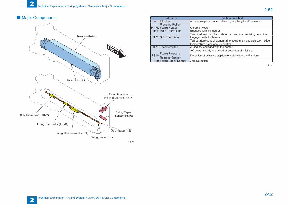
2
22-52
2-52
Technical Explanation > Fixing System > Overview > Major Components
Technical Explanation > Fixing System > Overview > Major Components
■ Major Components
Pressure Roller
Fixing Film Unit
Fixing Heater (H1)
Sub Heater (H2)
Fixing Thermistor (THM1)
Sub Thermistor (THM2)
Fixing Thermoswitch (TP1)
Fixing Pressure Release Sensor (PS18)
Fixing Paper Sensor (PS19)
F-2-77
Part name Function / method--- Film Unit A toner image on paper is fixed by applying heat/pressure.--- Pressure Roller
H1/H2 Fixing Heater Ceramic HeaterTH1 Main Thermistor Engaged with the heater
Temperature control and abnormal temperature rising detectionTH2 Sub Thermistor Engaged with the heater
Temperature control, abnormal temperature rising detection, edge temperature-rising/cooling control
TP1 Thermoswitch A kind not engaged with the heater.AC power supply is blocked at detection of a failure.
PS18Fixing Pressure Release Sensor
Detection of pressure application/release to the Film Unit
PS19 Fixing Paper Sensor Jam DetectionT-2-34
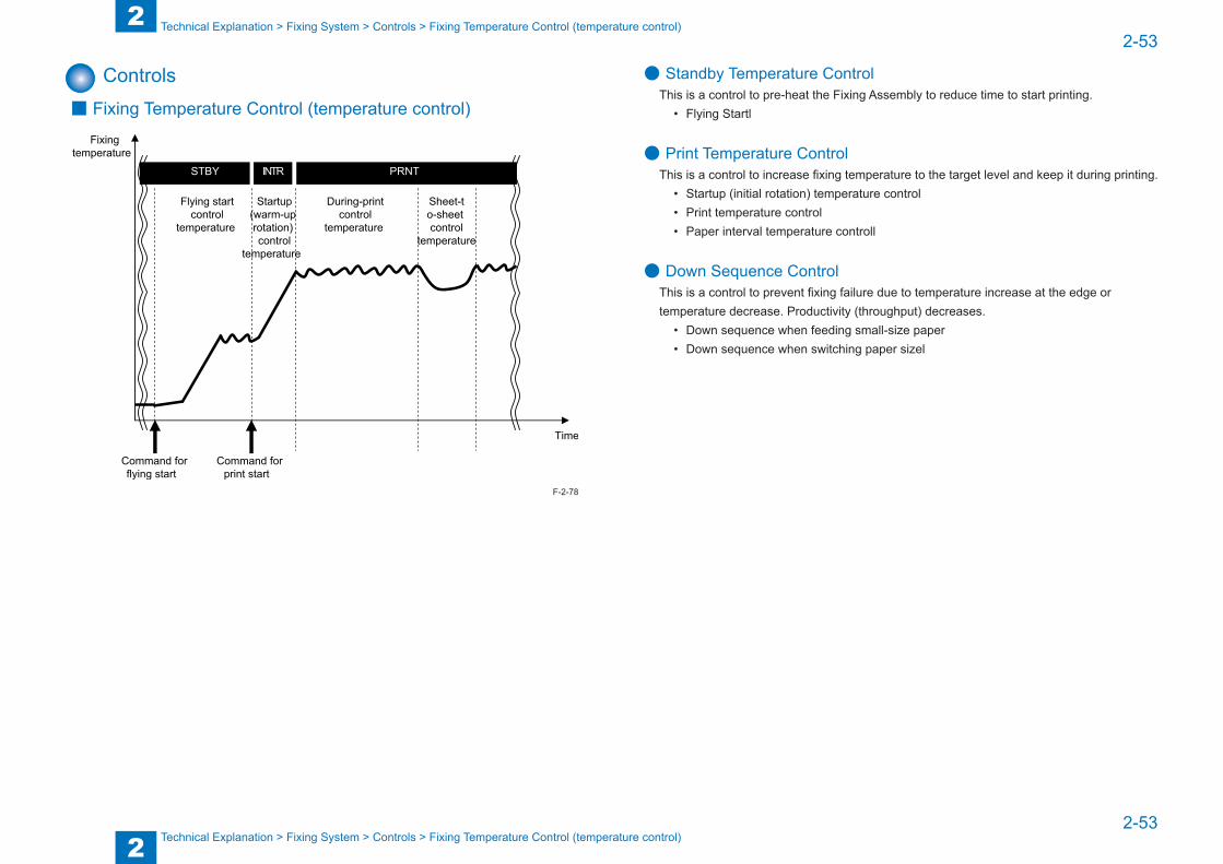
2
22-53
2-53
Technical Explanation > Fixing System > Controls > Fixing Temperature Control (temperature control)
Technical Explanation > Fixing System > Controls > Fixing Temperature Control (temperature control)
Controls ■ Fixing Temperature Control (temperature control)
F-2-78
● Standby Temperature ControlThis is a control to pre-heat the Fixing Assembly to reduce time to start printing.
• Flying Startl
● Print Temperature ControlThis is a control to increase fixing temperature to the target level and keep it during printing.
• Startup (initial rotation) temperature control• Print temperature control• Paper interval temperature controll
● Down Sequence ControlThis is a control to prevent fixing failure due to temperature increase at the edge or temperature decrease. Productivity (throughput) decreases.
• Down sequence when feeding small-size paper• Down sequence when switching paper sizel
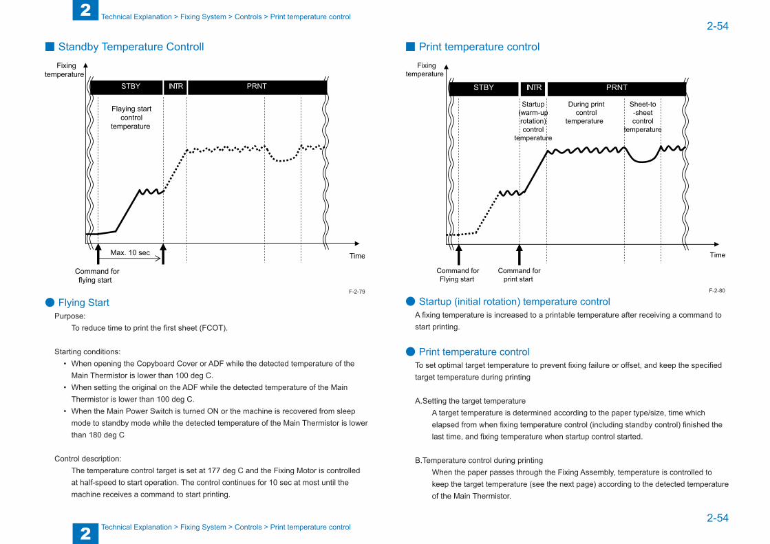
2
22-54
2-54
Technical Explanation > Fixing System > Controls > Print temperature control
Technical Explanation > Fixing System > Controls > Print temperature control
■ Standby Temperature Controll
Max. 10 sec
● Flying StartPurpose:
To reduce time to print the first sheet (FCOT).
Starting conditions:• When opening the Copyboard Cover or ADF while the detected temperature of the
Main Thermistor is lower than 100 deg C.• When setting the original on the ADF while the detected temperature of the Main
Thermistor is lower than 100 deg C.• When the Main Power Switch is turned ON or the machine is recovered from sleep
mode to standby mode while the detected temperature of the Main Thermistor is lower than 180 deg C
Control description:The temperature control target is set at 177 deg C and the Fixing Motor is controlled at half-speed to start operation. The control continues for 10 sec at most until the machine receives a command to start printing.
F-2-79
■ Print temperature control
● Startup (initial rotation) temperature controlA fixing temperature is increased to a printable temperature after receiving a command to start printing.
● Print temperature controlTo set optimal target temperature to prevent fixing failure or offset, and keep the specified target temperature during printing
A.Setting the target temperatureA target temperature is determined according to the paper type/size, time which elapsed from when fixing temperature control (including standby control) finished the last time, and fixing temperature when startup control started.
B.Temperature control during printingWhen the paper passes through the Fixing Assembly, temperature is controlled to keep the target temperature (see the next page) according to the detected temperature of the Main Thermistor.
F-2-80
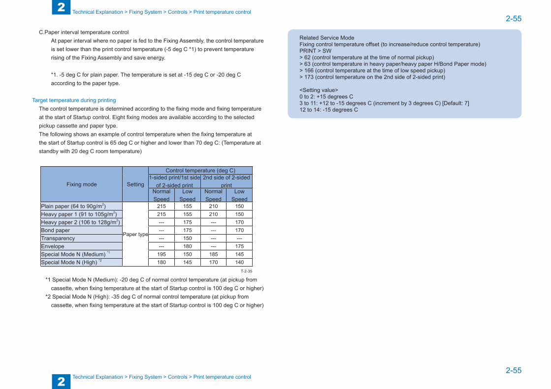
2
22-55
2-55
Technical Explanation > Fixing System > Controls > Print temperature control
Technical Explanation > Fixing System > Controls > Print temperature control
C.Paper interval temperature controlAt paper interval where no paper is fed to the Fixing Assembly, the control temperature is set lower than the print control temperature (-5 deg C *1) to prevent temperature rising of the Fixing Assembly and save energy.
*1. -5 deg C for plain paper. The temperature is set at -15 deg C or -20 deg C according to the paper type.
Target temperature during printingThe control temperature is determined according to the fixing mode and fixing temperature at the start of Startup control. Eight fixing modes are available according to the selected pickup cassette and paper type.The following shows an example of control temperature when the fixing temperature at the start of Startup control is 65 deg C or higher and lower than 70 deg C: (Temperature at standby with 20 deg C room temperature)
Fixing mode Setting
Control temperature (deg C)1-sided print/1st side
of 2-sided print2nd side of 2-sided
printNormal Speed
Low Speed
Normal Speed
Low Speed
Plain paper (64 to 90g/m2)
Paper type
215 155 210 150Heavy paper 1 (91 to 105g/m2) 215 155 210 150Heavy paper 2 (106 to 128g/m2) --- 175 --- 170Bond paper --- 175 --- 170Transparency --- 150 --- ---Envelope --- 180 --- 175Special Mode N (Medium) *1 195 150 185 145Special Mode N (High) *2 180 145 170 140
*1 Special Mode N (Medium): -20 deg C of normal control temperature (at pickup from cassette, when fixing temperature at the start of Startup control is 100 deg C or higher)
*2 Special Mode N (High): -35 deg C of normal control temperature (at pickup from cassette, when fixing temperature at the start of Startup control is 100 deg C or higher)
T-2-35
Related Service ModeFixing control temperature offset (to increase/reduce control temperature) PRINT > SW> 62 (control temperature at the time of normal pickup)> 63 (control temperature in heavy paper/heavy paper H/Bond Paper mode)> 166 (control temperature at the time of low speed pickup)> 173 (control temperature on the 2nd side of 2-sided print)
<Setting value>0 to 2: +15 degrees C3 to 11: +12 to -15 degrees C (increment by 3 degrees C) [Default: 7]12 to 14: -15 degrees C
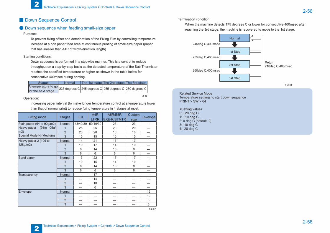
2
22-56
2-56
Technical Explanation > Fixing System > Controls > Down Sequence Control
Technical Explanation > Fixing System > Controls > Down Sequence Control
■ Down Sequence Control
● Down sequence when feeding small-size paperPurpose:
To prevent fixing offset and deterioration of the Fixing Film by controlling temperature increase at a non paper feed area at continuous printing of small-size paper (paper that has smaller than A4R of width-direction length)
Starting conditions:Down sequence is performed in a stepwise manner. This is a control to reduce throughput on a step-by-step basis as the detected temperature of the Sub Thermistor reaches the specified temperature or higher as shown in the table below for consecutive 400msec during printing.
Stages Normal The 1st stage The 2nd stage The 3rd stageA temperature to go for the next stage
235 degrees C 245 degrees C 255 degrees C 260 degrees C
Operation:Increasing paper interval (to make longer temperature control at a temperature lower than that of normal print) to reduce fixing temperature in 4 stages at most.
Fixing mode Stages LGLA4R
LTRRA5R/B5R
EXE-R/STMTRCustom
sizeEnvelope
Plain paper (64 to 90g/m2)Heavy paper 1 (91to 105g/m2)Special Mode N (Medium)
Normal 43/40/30 50/40/30 25 23 ---1 25 25 20 20 ---2 20 20 18 18 ---3 15 15 15 15 ---
Heavy paper 2 (106 to 128g/m2)
Normal 14 21 17 17 ---1 10 17 14 10 ---2 8 14 10 8 ---3 6 6 6 6 ---
Bond paper Normal 13 22 17 17 ---1 10 15 14 10 ---2 8 14 10 8 ---3 6 6 6 6 ---
Transparency Normal --- 17 --- --- ---1 --- 14 --- --- ---2 --- 10 --- --- ---3 --- 6 --- --- ---
Envelope Normal --- --- --- --- 121 --- --- --- --- 102 --- --- --- --- 83 --- --- --- --- 6
T-2-36
T-2-37
Termination condition:When the machine detects 175 degrees C or lower for consecutive 400msec after reaching the 3rd stage, the machine is recovered to move to the 1st stage.
245deg C,400msec
255deg C,400msecReturn210deg C,400msec
260deg C,400msec
Normal
1st Step
2st Step
3st Step
Related Service ModeTemperature settings to start down sequencePRINT > SW > 64
<Setting value>0: +20 deg C1: +10 deg C2: 0 deg C [default: 2]3: -10 deg C4: -20 deg C
F-2-81
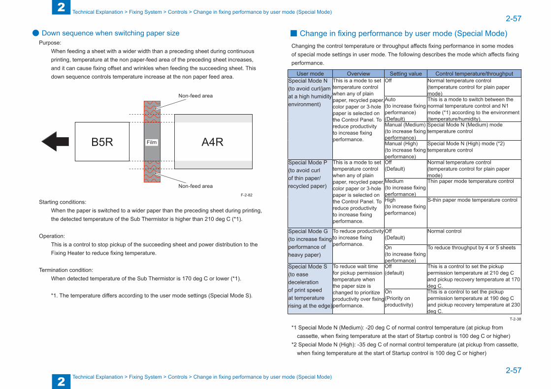
2
22-57
2-57
Technical Explanation > Fixing System > Controls > Change in fixing performance by user mode (Special Mode)
Technical Explanation > Fixing System > Controls > Change in fixing performance by user mode (Special Mode)
● Down sequence when switching paper sizePurpose:
When feeding a sheet with a wider width than a preceding sheet during continuous printing, temperature at the non paper-feed area of the preceding sheet increases, and it can cause fixing offset and wrinkles when feeding the succeeding sheet. This down sequence controls temperature increase at the non paper feed area.
Film
Non-feed area
Non-feed area
Starting conditions:When the paper is switched to a wider paper than the preceding sheet during printing, the detected temperature of the Sub Thermistor is higher than 210 deg C (*1).
Operation:This is a control to stop pickup of the succeeding sheet and power distribution to the Fixing Heater to reduce fixing temperature.
Termination condition:When detected temperature of the Sub Thermistor is 170 deg C or lower (*1).
*1. The temperature differs according to the user mode settings (Special Mode S).
F-2-82
■ Change in fixing performance by user mode (Special Mode)Changing the control temperature or throughput affects fixing performance in some modes of special mode settings in user mode. The following describes the mode which affects fixing performance.
User mode Overview Setting value Control temperature/throughputSpecial Mode N(to avoid curl/jam at a high humidity environment)
This is a mode to set temperature control when any of plain paper, recycled paper, color paper or 3-hole paper is selected on the Control Panel. To reduce productivity to increase fixing performance.
Off Normal temperature control (temperature control for plain paper mode)
Auto(to increase fixing performance)(Default)
This is a mode to switch between the normal temperature control and N1 mode (*1) according to the environment (temperature/humidity).
Manual (Medium)(to increase fixing performance)
Special Mode N (Medium) mode temperature control
Manual (High)(to increase fixing performance)
Special Mode N (High) mode (*2) temperature control
Special Mode P(to avoid curl of thin paper/recycled paper)
This is a mode to set temperature control when any of plain paper, recycled paper, color paper or 3-hole paper is selected on the Control Panel. To reduce productivity to increase fixing performance.
Off(Default)
Normal temperature control (temperature control for plain paper mode)
Medium(to increase fixing performance)
Thin paper mode temperature control
High(to increase fixing performance)
S-thin paper mode temperature control
Special Mode G(to increase fixing performance of heavy paper)
To reduce productivity to increase fixing performance.
Off(Default)
Normal control
On(to increase fixing performance)
To reduce throughput by 4 or 5 sheets
Special Mode S(to ease deceleration of print speed at temperature rising at the edge)
To reduce wait time for pickup permission temperature when the paper size is changed to prioritize productivity over fixing performance.
Off(default)
This is a control to set the pickup permission temperature at 210 deg C and pickup recovery temperature at 170 deg C.
On(Priority on productivity)
This is a control to set the pickup permission temperature at 190 deg C and pickup recovery temperature at 230 deg C.
*1 Special Mode N (Medium): -20 deg C of normal control temperature (at pickup from cassette, when fixing temperature at the start of Startup control is 100 deg C or higher)
*2 Special Mode N (High): -35 deg C of normal control temperature (at pickup from cassette, when fixing temperature at the start of Startup control is 100 deg C or higher)
T-2-38

2
22-58
2-58
Technical Explanation > Fixing System > Controls > Pre-fixing arch level control
Technical Explanation > Fixing System > Controls > Pre-fixing arch level control
■ Pre-fixing arch level controlPurpose:
Constantly creating an optimal arch between the transfer and fixing areas prevents a shock, which occurs when the paper's trailing edge passes through the Registration Roller, and obtains an optimal image.
Pressure Roller
Photosensitive Drum
Transfer Roller
Arch Sensor (PS9)
Registration Roller
Fixing Film
Sensor: OFF
Sensor: ON
F-2-83
Starting conditions:This control is performed every time the paper is fed.
Operation:The Arch Sensor detects a paper arch between the transfer nip and fixing nip to change the drive speed of the Fixing Motor.
1) When the paper's leading edge goes over 35mm from the Transfer Roller, drive speed of the Fixing Motor is reduced by 3.1% against the process speed. The reduced speed is maintained until the paper creates an arch and the Arch Sensor is turned ON.
2) After the Arch Sensor has been detected ON for consecutive 50msec or longer, drive speed of the Fixing Motor is increased by 0.8% against the process speed. The increased speed is maintained until the paper arch disappears and the Arch Sensor is turned OFF.loop.
3) After the Arch Sensor has been detected OFF for consecutive 50msec or longer, drive speed of the Fixing Motor is reduced by 3.1% against the process speed. The reduced speed is maintained until the paper creates an arch and the Arch Sensor is turned ON.
4) Repeat steps 2) and 3). When the paper's trailing edge reaches at 10mm before the Transfer Roller, drive speed of the Fixing Motor is increased by 0.8% against the process speed.
5) Go back to step 1) in the case of continuous printing. The machine goes to the last rotation operation in the case of 1 sheet print.
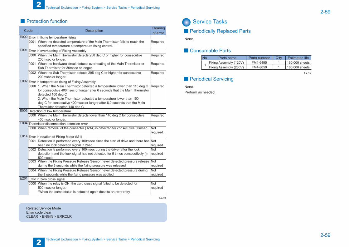
2
22-59
2-59
Technical Explanation > Fixing System > Service Tasks > Periodical Servicing
Technical Explanation > Fixing System > Service Tasks > Periodical Servicing
■ Protection function
Code DescriptionClearing of error
E000 Error in fixing temperature rising0001 When the detected temperature of the Main Thermistor fails to reach the
specified temperature at temperature rising control.Required
E001 Error in overheating of Fixing Assembly0000 When the Main Thermistor detects 250 deg C or higher for consecutive
200msec or longer.Required
0001 When the hardware circuit detects overheating of the Main Thermistor or Sub Thermistor for 30msec or longer.
Required
0002 When the Sub Thermistor detects 295 deg C or higher for consecutive 200msec or longer.
Required
E002 Error in temperature rising of Fixing Assembly0000 1. When the Main Thermistor detected a temperature lower than 115 deg C
for consecutive 400msec or longer after 6 seconds that the Main Thermistor detected 100 deg C2. When the Main Thermistor detected a temperature lower than 150 deg C for consecutive 400msec or longer after 6.0 seconds that the Main Thermistor detected 140 deg C
Required
E003 Detection of low temperature0000 When the Main Thermistor detects lower than 140 deg C for consecutive
400msec or longer.Required
E004 Thermistor disconnection detection error0000 When removal of the connector (J214) is detected for consecutive 30msec. Not
requiredE014 Error in rotation of Fixing Motor (M1)
0001 Detection is performed every 100msec since the start of drive and there has been no lock detection signal in 2sec.
Not required
0002 Detection is performed every 100msec during the drive (after the lock detection) and the lock signal has not detected for 5 times consecutively (in 500msec).
Not required
0003 When the Fixing Pressure Release Sensor never detected pressure release during the 3 seconds while the fixing pressure was released
Not required
0004 When the Fixing Pressure Release Sensor never detected pressure during the 3 seconds while the fixing pressure was applied
Not required
E261 Error in zero cross signal0000 When the relay is ON, the zero cross signal failed to be detected for
500msec or longer.*When the same status is detected again despite an error retry.
Not required
Related Service ModeError code clearCLEAR > ENGIN > ERRCLR
T-2-39
Service Tasks ■ Periodically Replaced Parts
None.
■ Consumable PartsNo. Parts name Parts number Q'ty Estimated life
1Fixing Assembly (120V) FM4-6495 1 160,000 sheets Fixing Assembly (230V) FM4-8050 1 160,000 sheets
■ Periodical ServicingNone.Perform as needed.
T-2-40
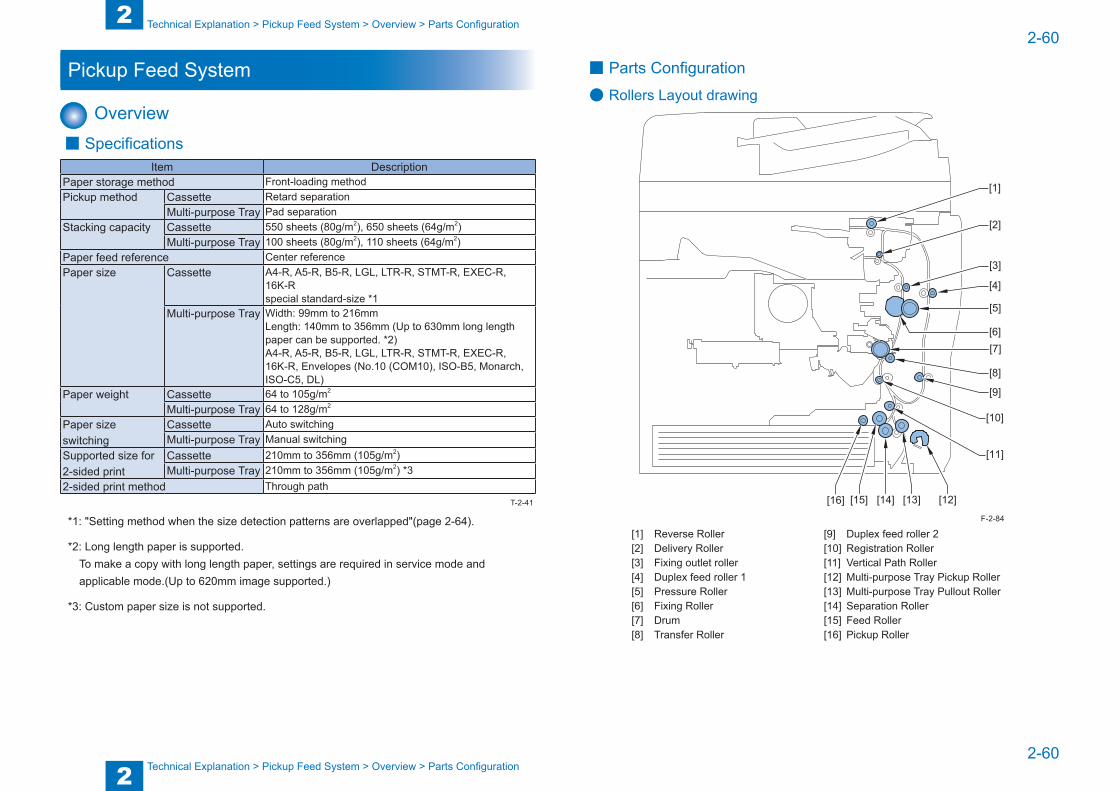
2
22-60
2-60
Technical Explanation > Pickup Feed System > Overview > Parts Configuration
Technical Explanation > Pickup Feed System > Overview > Parts Configuration
Pickup Feed System
Overview ■ Specifications
Item DescriptionPaper storage method Front-loading methodPickup method Cassette Retard separation
Multi-purpose Tray Pad separationStacking capacity Cassette 550 sheets (80g/m2), 650 sheets (64g/m2)
Multi-purpose Tray 100 sheets (80g/m2), 110 sheets (64g/m2)Paper feed reference Center referencePaper size Cassette A4-R, A5-R, B5-R, LGL, LTR-R, STMT-R, EXEC-R,
16K-Rspecial standard-size *1
Multi-purpose Tray Width: 99mm to 216mmLength: 140mm to 356mm (Up to 630mm long length paper can be supported. *2)A4-R, A5-R, B5-R, LGL, LTR-R, STMT-R, EXEC-R, 16K-R, Envelopes (No.10 (COM10), ISO-B5, Monarch, ISO-C5, DL)
Paper weight Cassette 64 to 105g/m2
Multi-purpose Tray 64 to 128g/m2 Paper size switching
Cassette Auto switchingMulti-purpose Tray Manual switching
Supported size for 2-sided print
Cassette 210mm to 356mm (105g/m2)Multi-purpose Tray 210mm to 356mm (105g/m2) *3
2-sided print method Through path
*1: "Setting method when the size detection patterns are overlapped"(page 2-64).
*2: Long length paper is supported.To make a copy with long length paper, settings are required in service mode and applicable mode.(Up to 620mm image supported.)
*3: Custom paper size is not supported.
T-2-41
■ Parts Configuration
● Rollers Layout drawing
[10]
[11]
[12][13][14][15][16]
[1]
[2]
[3]
[4]
[5]
[6][7]
[8]
[9]
[1] Reverse Roller [9] Duplex feed roller 2[2] Delivery Roller [10] Registration Roller[3] Fixing outlet roller [11] Vertical Path Roller[4] Duplex feed roller 1 [12] Multi-purpose Tray Pickup Roller[5] Pressure Roller [13] Multi-purpose Tray Pullout Roller[6] Fixing Roller [14] Separation Roller[7] Drum [15] Feed Roller[8] Transfer Roller [16] Pickup Roller
F-2-84
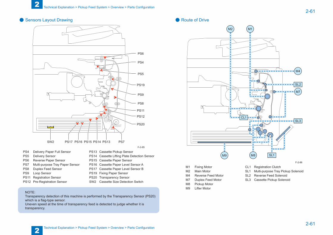
2
22-61
2-61
Technical Explanation > Pickup Feed System > Overview > Parts Configuration
Technical Explanation > Pickup Feed System > Overview > Parts Configuration
● Sensors Layout Drawing
PS20
PS13 PS7PS14PS15PS16PS17SW2
PS12
PS11
PS8
PS9
PS19
PS5
PS4
PS6
PS4 Delivery Paper Full Sensor PS13 Cassette Pickup SensorPS5 Delivery Sensor PS14 Cassette Lifting Plate Detection SensorPS6 Reverse Paper Sensor PS15 Cassette Paper SensorPS7 Multi-purpose Tray Paper Sensor PS16 Cassette Paper Level Sensor APS8 Duplex Feed Sensor PS17 Cassette Paper Level Sensor BPS9 Loop Sensor PS19 Fixing Paper SensorPS11 Registration Sensor PS20 Transparency SensorPS12 Pre-Registration Sensor SW2 Cassette Size Detection Switch
NOTE:Transparency detection of this machine is performed by the Transparency Sensor (PS20) which is a flag-type sensor.Uneven speed at the time of transparency feed is detected to judge whether it is transparency.
F-2-85
● Route of Drive
M4
M7
SL2
SL3
SL1M8M9
CL1
M2 M1
M1 Fixing Motor CL1 Registration ClutchM2 Main Motor SL1 Multi-purpose Tray Pickup SolenoidM4 Reverse Feed Motor SL2 Reverse Feed SolenoidM7 Duplex Feed Motor SL3 Cassette Pickup SolenoidM8 Pickup MotorM9 Lifter Motor
F-2-86
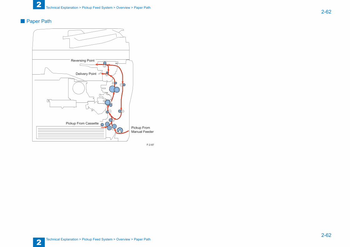
2
22-62
2-62
Technical Explanation > Pickup Feed System > Overview > Paper Path
Technical Explanation > Pickup Feed System > Overview > Paper Path
■ Paper Path
Pickup From Cassette
Reversing Point
Delivery Point
Pickup From Manual Feeder
F-2-87
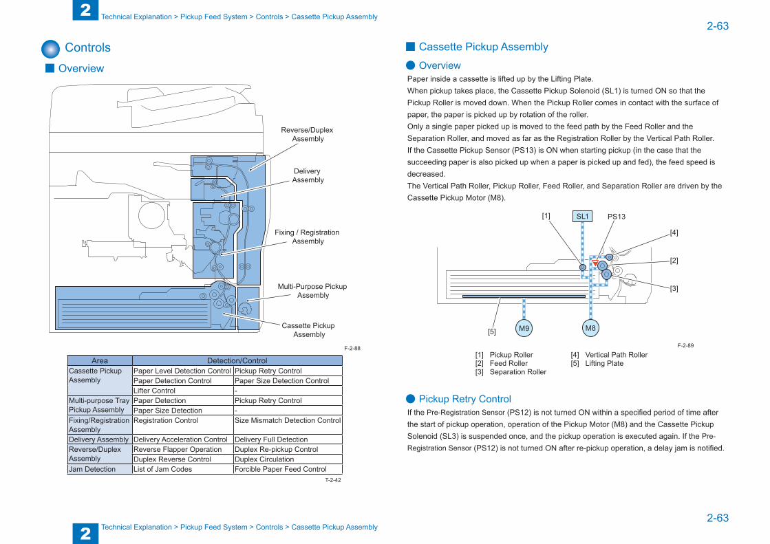
2
22-63
2-63
Technical Explanation > Pickup Feed System > Controls > Cassette Pickup Assembly
Technical Explanation > Pickup Feed System > Controls > Cassette Pickup Assembly
Controls ■ Overview
Reverse/Duplex Assembly
Fixing / Registration Assembly
Delivery Assembly
Multi-Purpose Pickup Assembly
Cassette Pickup Assembly
Area Detection/ControlCassette Pickup Assembly
Paper Level Detection Control Pickup Retry ControlPaper Detection Control Paper Size Detection ControlLifter Control -
Multi-purpose Tray Pickup Assembly
Paper Detection Pickup Retry ControlPaper Size Detection -
Fixing/Registration Assembly
Registration Control Size Mismatch Detection Control
Delivery Assembly Delivery Acceleration Control Delivery Full DetectionReverse/Duplex Assembly
Reverse Flapper Operation Duplex Re-pickup ControlDuplex Reverse Control Duplex Circulation
Jam Detection List of Jam Codes Forcible Paper Feed Control
F-2-88
T-2-42
■ Cassette Pickup Assembly
● OverviewPaper inside a cassette is lifted up by the Lifting Plate.When pickup takes place, the Cassette Pickup Solenoid (SL1) is turned ON so that the Pickup Roller is moved down. When the Pickup Roller comes in contact with the surface of paper, the paper is picked up by rotation of the roller.Only a single paper picked up is moved to the feed path by the Feed Roller and the Separation Roller, and moved as far as the Registration Roller by the Vertical Path Roller.If the Cassette Pickup Sensor (PS13) is ON when starting pickup (in the case that the succeeding paper is also picked up when a paper is picked up and fed), the feed speed is decreased.The Vertical Path Roller, Pickup Roller, Feed Roller, and Separation Roller are driven by the Cassette Pickup Motor (M8).
SL1
M8M9
PS13
[5]
[1]
[2]
[3]
[4]
[1] Pickup Roller [4] Vertical Path Roller[2] Feed Roller [5] Lifting Plate[3] Separation Roller
● Pickup Retry ControlIf the Pre-Registration Sensor (PS12) is not turned ON within a specified period of time after the start of pickup operation, operation of the Pickup Motor (M8) and the Cassette Pickup Solenoid (SL3) is suspended once, and the pickup operation is executed again. If the Pre-Registration Sensor (PS12) is not turned ON after re-pickup operation, a delay jam is notified.
F-2-89
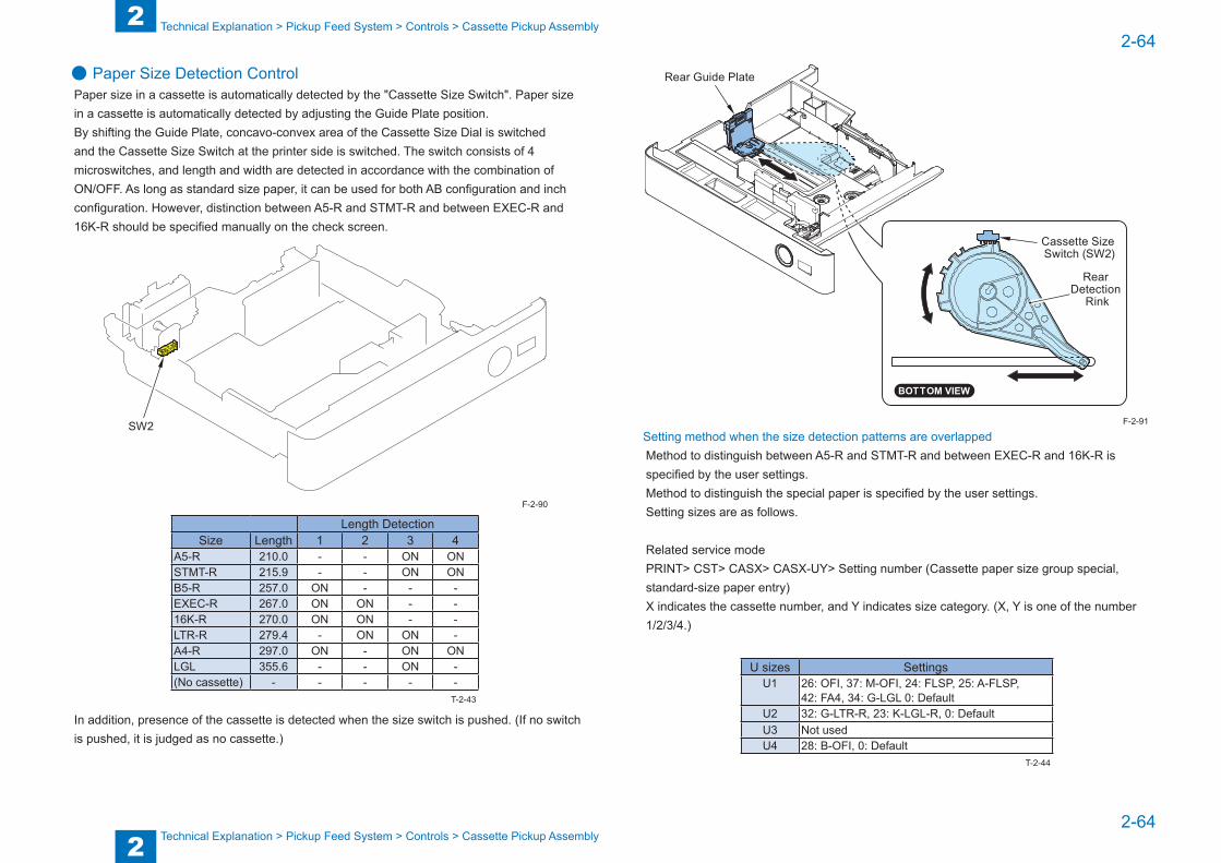
2
22-64
2-64
Technical Explanation > Pickup Feed System > Controls > Cassette Pickup Assembly
Technical Explanation > Pickup Feed System > Controls > Cassette Pickup Assembly
● Paper Size Detection ControlPaper size in a cassette is automatically detected by the "Cassette Size Switch". Paper size in a cassette is automatically detected by adjusting the Guide Plate position.By shifting the Guide Plate, concavo-convex area of the Cassette Size Dial is switched and the Cassette Size Switch at the printer side is switched. The switch consists of 4 microswitches, and length and width are detected in accordance with the combination of ON/OFF. As long as standard size paper, it can be used for both AB configuration and inch configuration. However, distinction between A5-R and STMT-R and between EXEC-R and 16K-R should be specified manually on the check screen.
SW2
Length DetectionSize Length 1 2 3 4
A5-R 210.0 - - ON ONSTMT-R 215.9 - - ON ONB5-R 257.0 ON - - -EXEC-R 267.0 ON ON - -16K-R 270.0 ON ON - -LTR-R 279.4 - ON ON -A4-R 297.0 ON - ON ONLGL 355.6 - - ON -(No cassette) - - - - -
In addition, presence of the cassette is detected when the size switch is pushed. (If no switch is pushed, it is judged as no cassette.)
F-2-90
T-2-43
Rear Guide Plate
Cassette Size Switch (SW2)
Rear Detection
Rink
Setting method when the size detection patterns are overlappedMethod to distinguish between A5-R and STMT-R and between EXEC-R and 16K-R is specified by the user settings.Method to distinguish the special paper is specified by the user settings.Setting sizes are as follows.
Related service modePRINT> CST> CASX> CASX-UY> Setting number (Cassette paper size group special, standard-size paper entry)X indicates the cassette number, and Y indicates size category. (X, Y is one of the number 1/2/3/4.)
U sizes SettingsU1 26: OFI, 37: M-OFI, 24: FLSP, 25: A-FLSP,
42: FA4, 34: G-LGL 0: DefaultU2 32: G-LTR-R, 23: K-LGL-R, 0: DefaultU3 Not usedU4 28: B-OFI, 0: Default
F-2-91
T-2-44
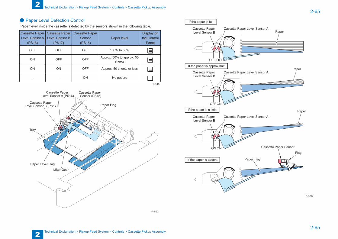
2
22-65
2-65
Technical Explanation > Pickup Feed System > Controls > Cassette Pickup Assembly
Technical Explanation > Pickup Feed System > Controls > Cassette Pickup Assembly
● Paper Level Detection ControlPaper level inside the cassette is detected by the sensors shown in the following table.
Cassette Paper Level Sensor A
(PS16)
Cassette Paper Level Sensor B
(PS17)
Cassette Paper Sensor (PS15)
Paper levelDisplay on the Control
Panel
OFF OFF OFF 100% to 50%
ON OFF OFF Approx. 50% to approx. 50 sheets
ON ON OFF Approx. 50 sheets or less
- - ON No papers
Tray
Paper Flag
Cassette Paper Sensor (PS15)
Cassette Paper Level Sensor A (PS16)
Cassette Paper Level Sensor B (PS17)
Paper Level Flag
Lifter Gear
T-2-45
F-2-92
OFFOFF
OFF
ON
ON
ON
Cassette Paper Level Sensor B
Cassette Paper Level Sensor A
If the paper is full
If the paper is approx.half
If the paper is a little
If the paper is absent
Cassette Paper Level Sensor B
Cassette Paper Level Sensor A
Cassette Paper Level Sensor B
Cassette Paper Level Sensor APaper
Paper
Paper
Paper Tray
Flag
Cassette Paper Sensor
F-2-93

2
22-66
2-66
Technical Explanation > Pickup Feed System > Controls > Cassette Pickup Assembly
Technical Explanation > Pickup Feed System > Controls > Cassette Pickup Assembly
● Paper Detection ControlAfter the Cassette Lifting Plate Detection Sensor (PS14) is turned ON, the Cassette Paper Sensor (PS15) detects presence/absence of paper. When the Cassette Paper Sensor (PS15) is ON, absence of paper is notified.In addition, if the Cassette Lifting Plate Detection Sensor (PS14) is not turned ON even raising the Lifter for 3 seconds, absence of paper is notified.
Lifting Plate Flag
Lifting Plate
Lifter
Paper Flag
PS14
PS15
M9
F-2-94
● Lifter ControlWhen Cassette is setThe Lifting Plate is raised until the Cassette Lifting Plate Detection Sensor (PS14) is turned ON.
During pickupThe behavior is determined in accordance with the detection when the Cassette Pickup Solenoid (SL3) is turned ON and the detection by the Cassette Lifting Plate Detection Sensor (PS14) executed 100msec. later.
100msec. later after Cassette Pickup Solenoid (SL3) is turned ONON OFF
When the Cassette Pickup Solenoid (SL3) is turned ON
ON - If the same detection continues for 5 consecutive sheets, the Lifting Plate is raised until the Cassette Lifting Plate Detection Sensor (PS14) is turned ON.
OFF - Raising the Lifting Plate immediately until the Cassette Lifting Plate Detection Sensor (PS14) is turned ON.
Lifting Plate Flag
Lifting Plate
Lifter
PS14M9
SL3
T-2-46
F-2-95

2
22-67
2-67
Technical Explanation > Pickup Feed System > Controls > Fixing/Registration Assembly
Technical Explanation > Pickup Feed System > Controls > Fixing/Registration Assembly
■ Multi-purpose Tray Pickup Assembly
● OverviewPaper on the Multi-purpose Tray Pickup Tray of the Multi-purpose Tray Pickup Unit is pushed against the Multi-purpose Tray Pickup Roller by the Lifting Plate, and only a single sheet of paper is separated and fed by the work of the Multi-purpose Tray Pickup Roller and the Separation Pad.
Side Guide
Pressure Spring
Paper Detection Lever
Multi-purpose Tray
Multi-purpose Tray Separation Pad
Manual Feeder Paper Sensor (PS7)
SL1M8
Pickup Guide Plate
Multi-purpose Tray Pickup Roller
● Pickup Retry ControlIf the Pre-Registration Sensor (PS12) is not turned ON within the specified period of time after the start of pickup operation, detection by the Multi-purpose Tray Paper Sensor (PS7) is referred.• When Multi-purpose Tray Paper Sensor (PS7) is ON:
Execute the pickup operation again. If the Pre-Registration Sensor (PS12) is not turned ON after the start of re-pickup operation, a delay jam is notified.
• When Multi-purpose Tray Paper Sensor (PS7) is OFF:Terminate the pickup operation.
● Paper DetectionPresence/absence of paper is detected by the Multi-purpose Tray Paper Sensor (PS7).When absence of paper is detected but the same size and same type of papers exist in another paper source, auto cassette change is executed.
F-2-96
■ Fixing/Registration Assembly
● Registration ControlThe Registration Roller is driven by the Main Motor (M2). There is the Registration Clutch (CL1) between the Registration Roller and the Main Motor, and it controls ON/OFF of the Registration Roller to align the paper with the image on the drum at the specified registration.In addition, the speed is decreased right before a paper hits the Registration Roller so that hitting sound is alleviated (speed is not decreased when picking up from the Cassette 1 of imageRUNNER 1730/1740).
CL1M2
Registration Roller
F-2-97

2
22-68
2-68
Technical Explanation > Pickup Feed System > Controls > Delivery Assembly
Technical Explanation > Pickup Feed System > Controls > Delivery Assembly
● Size Mismatch Detection ControlWhether the size is mismatched is determined by paper length.The time a paper passes through the Registration Sensor (PS11) is converted into distance. Compared with the paper size (specified by the user in case of the Multi-purpose Tray Pickup Tray) detected by the Cassette Size Detection Switch (SW1), if the measured distance is shorter than the specified distance (16mm), it is judged that the size is mismatched.Priority of the size mismatch detection control is lower than other controls. In addition, due to the behavioral error of paper, the measured distance has a margin of error of approx. +6mm.
Paper size mismatch cannot be detected with the following combinations because the difference in paper size is small.• A4-R, LTR-R• A5-R, STATEMENT-R• B5-R, EXEC-R, 16K-R
In case of envelope, paper size mismatch is not detected (because detection by the Registration Sensor (PS11) is not stable when feeding the envelope).
■ Delivery Assembly
● Delivery Acceleration ControlSince elasticity of bond paper is low, delivery speed is increased when feeding the bond paper to improve the stackability.
Condition for acceleration: When the Finisher is not installed, and the bond paper is setTiming for acceleration: When the trailing edge of paper passes through the Fixing Paper Sensor (PS19)Timing to return the speed: When the Registration Clutch (CL1) is turned ON for the succeeding paper
PS19
Pressure Roller
Delivery Speed Increased Position
Fixing Outlet Roller
Delivery RollerBond Paper M1
● Delivery Full DetectionIf the Delivery Paper Full Sensor (PS4) is ON for a specified period of time, it is notified to the Main Controller PCB. After the notification, printing stops by the Controller's decision.
PS4
Detection Lever
Delivery Point
F-2-98
F-2-99
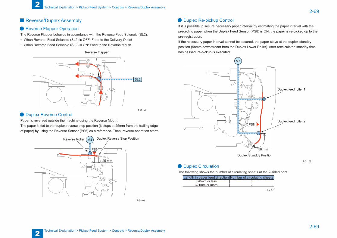
2
22-69
2-69
Technical Explanation > Pickup Feed System > Controls > Reverse/Duplex Assembly
Technical Explanation > Pickup Feed System > Controls > Reverse/Duplex Assembly
■ Reverse/Duplex Assembly
● Reverse Flapper OperationThe Reverse Flapper behaves in accordance with the Reverse Feed Solenoid (SL2).• When Reverse Feed Solenoid (SL2) is OFF: Feed to the Delivery Outlet• When Reverse Feed Solenoid (SL2) is ON: Feed to the Reverse Mouth
Reverse Flapper
SL2
● Duplex Reverse ControlPaper is reversed outside the machine using the Reverse Mouth.The paper is fed to the duplex reverse stop position (it stops at 25mm from the trailing edge of paper) by using the Reverse Sensor (PS6) as a reference. Then, reverse operation starts.
PS6
M4Reverse Roller Duplex Reverse Stop Position
25 mm
F-2-100
F-2-101
● Duplex Re-pickup ControlIf it is possible to secure necessary paper interval by estimating the paper interval with the preceding paper when the Duplex Feed Sensor (PS8) is ON, the paper is re-picked up to the pre-registration.If the necessary paper interval cannot be secured, the paper stays at the duplex standby position (58mm downstream from the Duplex Lower Roller). After recalculated standby time has passed, re-pickup is executed.
Duplex feed roller 1
PS8
58 mm
Duplex feed roller 2
Duplex Standby Position
M7
● Duplex CirculationThe following shows the number of circulating sheets at the 2-sided print.
Length in paper feed direction Number of circulating sheets320mm or less 3321mm or more 2
F-2-102
T-2-47
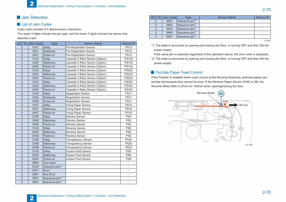
2
22-70
2-70
Technical Explanation > Pickup Feed System > Controls > Jam Detection
Technical Explanation > Pickup Feed System > Controls > Jam Detection
■ Jam Detection
● List of Jam CodesA jam code consists of 4 alphanumeric characters.The upper 2 digits indicate the jam type, and the lower 2 digits indicate the sensor that detected a jam.
ACC ID Jam Code Type Sensor Name Sensor ID3 0101 Delay Pre-Registration Sensor PS123 0201 Stationary Pre-Registration Sensor PS123 0A01 Power-on Pre-Registration Sensor PS123 0102 Delay Cassette 2 Retry Sensor (Option) PS1033 0202 Stationary Cassette 2 Retry Sensor (Option) PS1033 0A02 Power-on Cassette 2 Retry Sensor (Option) PS1033 0103 Delay Cassette 3 Retry Sensor (Option) PS2033 0203 Stationary Cassette 3 Retry Sensor (Option) PS2033 0A03 Power-on Cassette 3 Retry Sensor (Option) PS2033 0104 Delay Cassette 4 Retry Sensor (Option) PS3033 0204 Stationary Cassette 4 Retry Sensor (Option) PS3033 0A04 Power-on Cassette 4 Retry Sensor (Option) PS3033 0105 Delay Registration Sensor PS113 0205 Stationary Registration Sensor PS113 0A05 Power-on Registration Sensor PS113 0107 Delay Fixing Paper Sensor PS193 0207 Stationary Fixing Paper Sensor PS193 0A07 Power-on Fixing Paper Sensor PS193 0108 Delay Delivery Sensor PS53 0208 Stationary Delivery Sensor PS53 0A08 Power-on Delivery Sensor PS53 010A Delay Reverse Sensor PS63 020A Stationary Reverse Sensor PS63 0A0A Power-on Reverse Sensor PS63 010B Delay Transparency Sensor PS203 020B Stationary Transparency Sensor PS203 0A0B Power-on Transparency Sensor PS203 010D Delay Duplex Feed Sensor PS83 020D Stationary Duplex Feed Sensor PS83 0A0D Power-on Duplex Feed Sensor PS83 0B00 Door open - -3 0CA0 Sequence jam*2 - -3 0CF1 Error*1 - -3 0D91 Size Error - -3 9901 Sequence jam*2 - -3 9902 Sequence jam*2 - -
ACC ID Jam Code Type Sensor Name Sensor ID3 9903 Sequence jam*2 - -3 9904 Sequence jam*2 - -3 9905 Sequence jam*2 - -3 9906 Sequence jam*2 - -3 9907 Sequence jam*2 - -
*1: The state is recovered by opening and closing the Door, or turning OFF and then ON the power supply.
If the same jam is detected regardless of the operation above, the error code is displayed.*2: The state is recovered by opening and closing the Door, or turning OFF and then ON the
power supply.
● Forcible Paper Feed ControlIf the Finisher is installed when a jam occurs at the Reverse Assembly, jammed papers are forcibly fed because they cannot be seen. If the Reverse Paper Sensor (PS6) is ON, the Reverse Motor (M4) is driven for 100mm when opening/closing the door.
PS6
M4Reverse Roller
100 mm
T-2-48
F-2-103
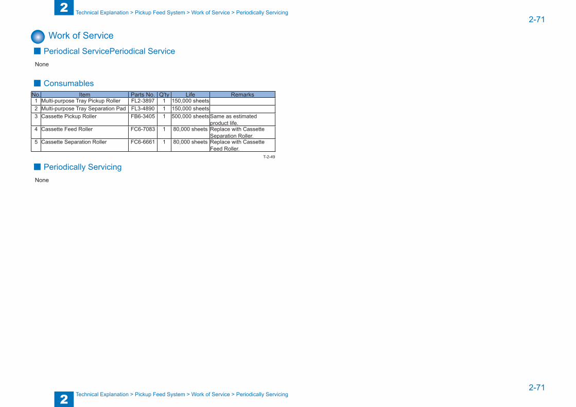
2
22-71
2-71
Technical Explanation > Pickup Feed System > Work of Service > Periodically Servicing
Technical Explanation > Pickup Feed System > Work of Service > Periodically Servicing
Work of Service ■ Periodical ServicePeriodical Service
None
■ ConsumablesNo. Item Parts No. Q'ty Life Remarks1 Multi-purpose Tray Pickup Roller FL2-3897 1 150,000 sheets2 Multi-purpose Tray Separation Pad FL3-4890 1 150,000 sheets3 Cassette Pickup Roller FB6-3405 1 500,000 sheets Same as estimated
product life.4 Cassette Feed Roller FC6-7083 1 80,000 sheets Replace with Cassette
Separation Roller.5 Cassette Separation Roller FC6-6661 1 80,000 sheets Replace with Cassette
Feed Roller.
■ Periodically ServicingNone
T-2-49

2
22-72
2-72
Technical Explanation > External Auxiliary System > Controls > Fan
Technical Explanation > External Auxiliary System > Controls > Fan
External Auxiliary System
Controls ■ Software counter
Count-up timing differs depending on the following conditions:• Print mode (1-sided/2nd side of 2-sided print, 1st side of 2-sided print)• Differs depending on the delivery position (Staple Finisher)
Delivery position
Print mode1-sided print/2nd side of
2-sided print1st side of 2-sided print
Count-up timingHost machine Delivery Tray Delivery Sensor (PS5) Duplex Feed Sensor (PS8)Staple Finisher Delivery Sensor (S2)
T-2-50
■ Fan
● OverviewLocation of Fans
FM4
FM1
FM8FM7
FM5
FM3
FM2FM6
No. Name Function Error codesFAN1 Delivery Cooling Fan (Rear) To cool the Delivery Assembly E822-0004,E822-0005FAN2 Delivery Cooling Fan (Center) To cool the Delivery Assembly E822-0002,E822-0003FAN3 Delivery Cooling Fan (Front) To cool the Delivery Assembly E822-0000,E822-0001FAN4 Power Supply Cooling Fan To cool power supply E804-0000,E804-0001FAN5 Heat Exhaust Fan (Front) To exhaust heat in the machine E805-0002,E805-0003FAN6 Heat Exhaust Fan (Rear) To exhaust heat in the machine E805-0000,E805-0001FAN7 Developing Cooling Fan (Front) To cool the Developing
Assembly and laserE820-0000,E820-0001
FAN8 Developing Cooling Fan (Rear) To cool the Developing Assembly and laser
E820-0002,E820-0003
F-2-104
T-2-51
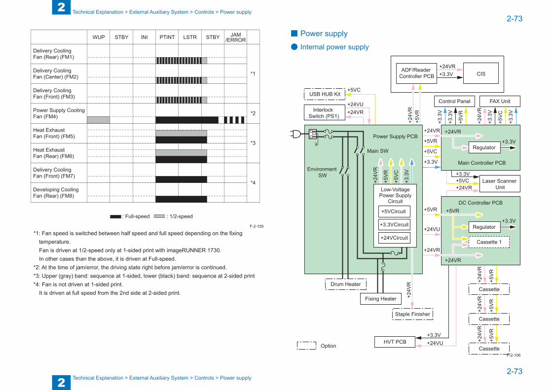
2
22-73
2-73
Technical Explanation > External Auxiliary System > Controls > Power supply
Technical Explanation > External Auxiliary System > Controls > Power supply
PTINT LSTRSTBY STBY JAM/ERRORWUP INI
*1
*2
*3
*4
Delivery Cooling Fan (Rear) (FM1)
Delivery Cooling Fan (Center) (FM2)
Delivery Cooling Fan (Front) (FM3)
Power Supply Cooling Fan (FM4)
Heat Exhaust Fan (Front) (FM5)
Heat Exhaust Fan (Rear) (FM6)
Delivery Cooling Fan (Front) (FM7)
Developing Cooling Fan (Rear) (FM8)
: Full-speed : 1/2-speed
*1: Fan speed is switched between half speed and full speed depending on the fixing temperature.Fan is driven at 1/2-speed only at 1-sided print with imageRUNNER 1730.In other cases than the above, it is driven at Full-speed.
*2: At the time of jam/error, the driving state right before jam/error is continued.*3: Upper (gray) band: sequence at 1-sided, lower (black) band: sequence at 2-sided print*4: Fan is not driven at 1-sided print.
It is driven at full speed from the 2nd side at 2-sided print.
F-2-105
■ Power supply
● Internal power supply
+3.3V+24VU
+24V
R
+5V
R
+3.3
V
+3.3
V
+5V
C
+3.3
V
+3.3
V
+24V
R
+5VC
+5VR
+3.3V
+24VR
+5VR
+24VR
+24VU
+24VR+24VU
+5VC
+5VC
+24V
R+2
4VR
+5V
R+5
VR
+5V
R
+24VR
Option
+3.3V
+5V
R+2
4VR
+24VR+3.3V
Interlock Switch (PS1)
USB HUB Kit
ADF/Reader Controller PCB CIS
+5V
C
+5V
R
+3.3
V
+24V
R
Main SW
Power Supply PCB
+24V
R
Fixing Heater
Drum Heater
Environment SW
Low-VoltagePower Supply
Circuit
+5VCircuit
+3.3VCircuit
+24VCircuit
HVT PCB
Staple Finisher
Cassette
Cassette
Cassette
DC Controller PCB+5VR
+3.3V
Laser Scanner Unit
Main Controller PCB
+24VR
+24VR
+3.3V
Control Panel FAX Unit
Cassette 1
Regulator
Regulator
F-2-106
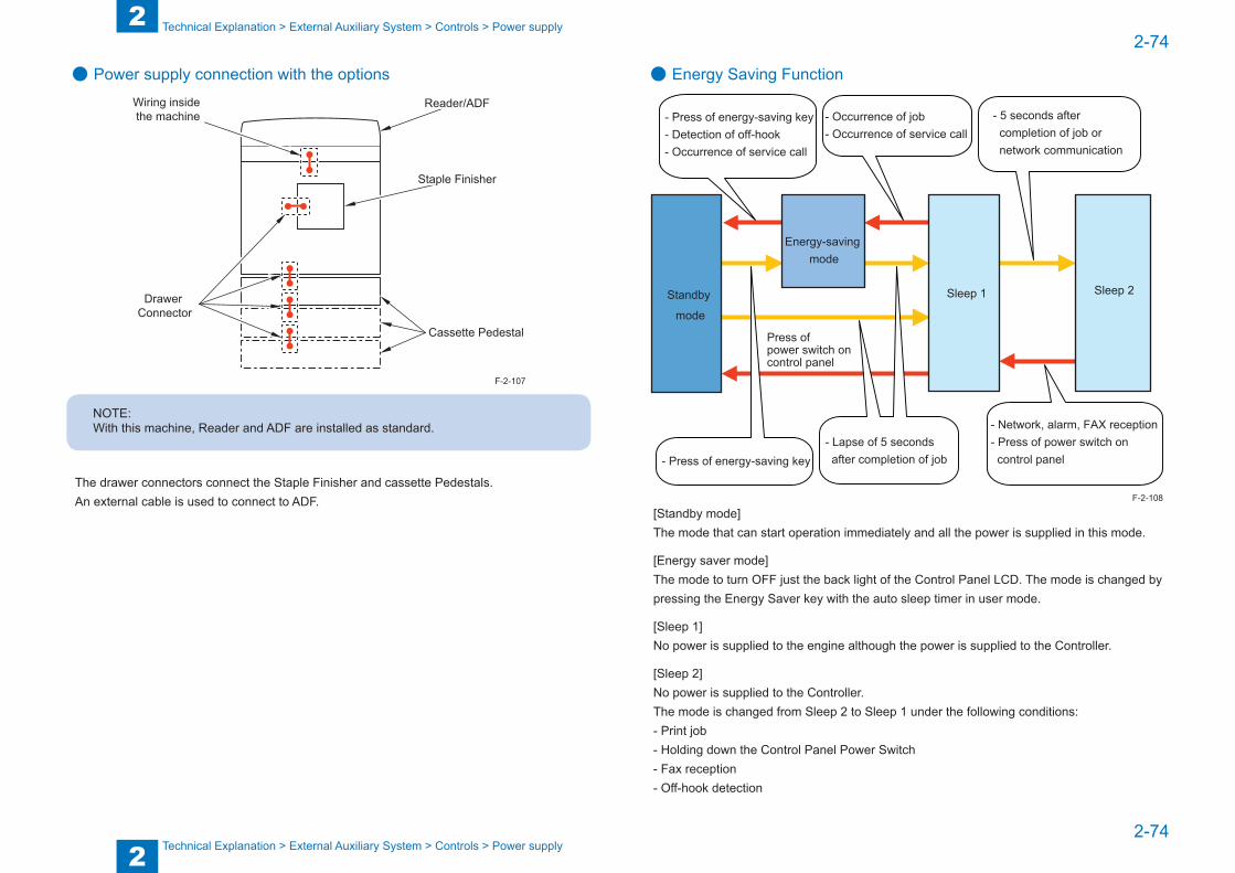
2
22-74
2-74
Technical Explanation > External Auxiliary System > Controls > Power supply
Technical Explanation > External Auxiliary System > Controls > Power supply
● Power supply connection with the options
Staple Finisher
Reader/ADFWiring inside the machine
Drawer Connector
Cassette Pedestal
NOTE:With this machine, Reader and ADF are installed as standard.
The drawer connectors connect the Staple Finisher and cassette Pedestals.An external cable is used to connect to ADF.
F-2-107
● Energy Saving Function
Energy-saving mode
Sleep 1Standby
mode
Sleep 2
- Press of energy-saving key- Detection of off-hook- Occurrence of service call
Press of power switch on control panel
- Occurrence of job- Occurrence of service call
- Press of energy-saving key- Lapse of 5 seconds after completion of job
- 5 seconds after completion of job or network communication
- Network, alarm, FAX reception- Press of power switch on control panel
[Standby mode]The mode that can start operation immediately and all the power is supplied in this mode.
[Energy saver mode]The mode to turn OFF just the back light of the Control Panel LCD. The mode is changed by pressing the Energy Saver key with the auto sleep timer in user mode.
[Sleep 1]No power is supplied to the engine although the power is supplied to the Controller.
[Sleep 2]No power is supplied to the Controller.The mode is changed from Sleep 2 to Sleep 1 under the following conditions:- Print job- Holding down the Control Panel Power Switch- Fax reception- Off-hook detection
F-2-108
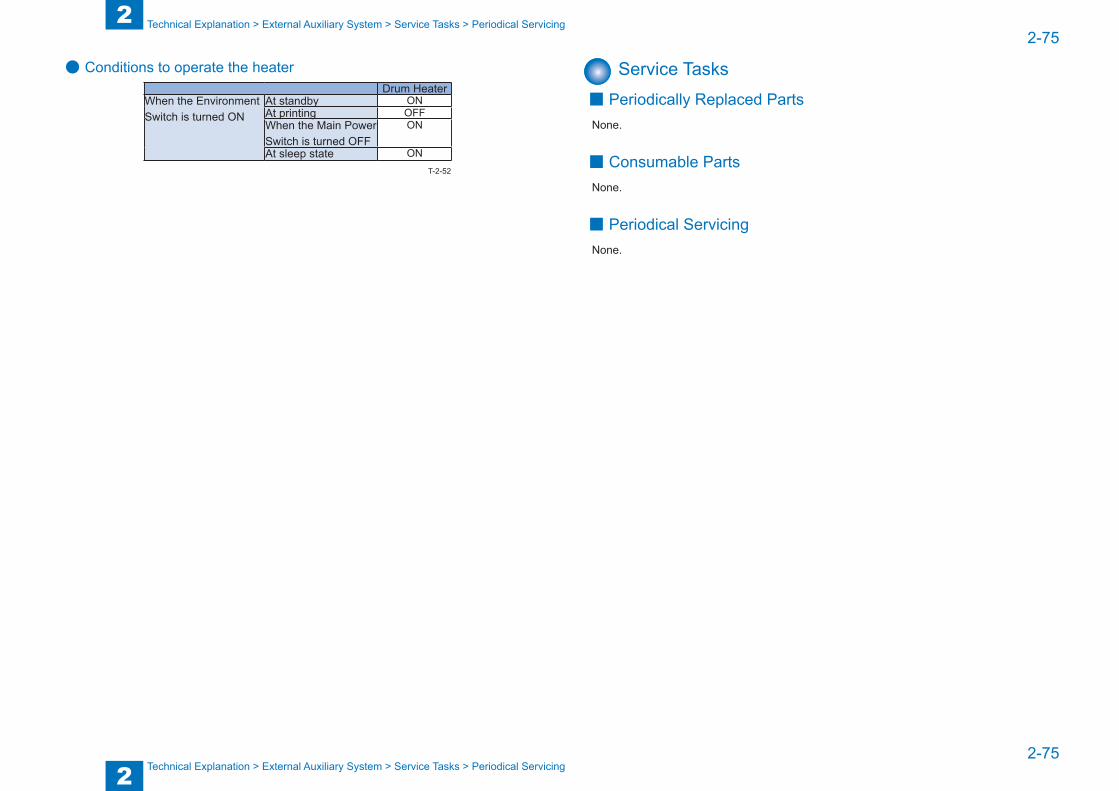
2
22-75
2-75
Technical Explanation > External Auxiliary System > Service Tasks > Periodical Servicing
Technical Explanation > External Auxiliary System > Service Tasks > Periodical Servicing
● Conditions to operate the heaterDrum Heater
When the Environment Switch is turned ON
At standby ONAt printing OFFWhen the Main Power Switch is turned OFF
ON
At sleep state ONT-2-52
Service Tasks ■ Periodically Replaced Parts
None.
■ Consumable PartsNone.
■ Periodical ServicingNone.
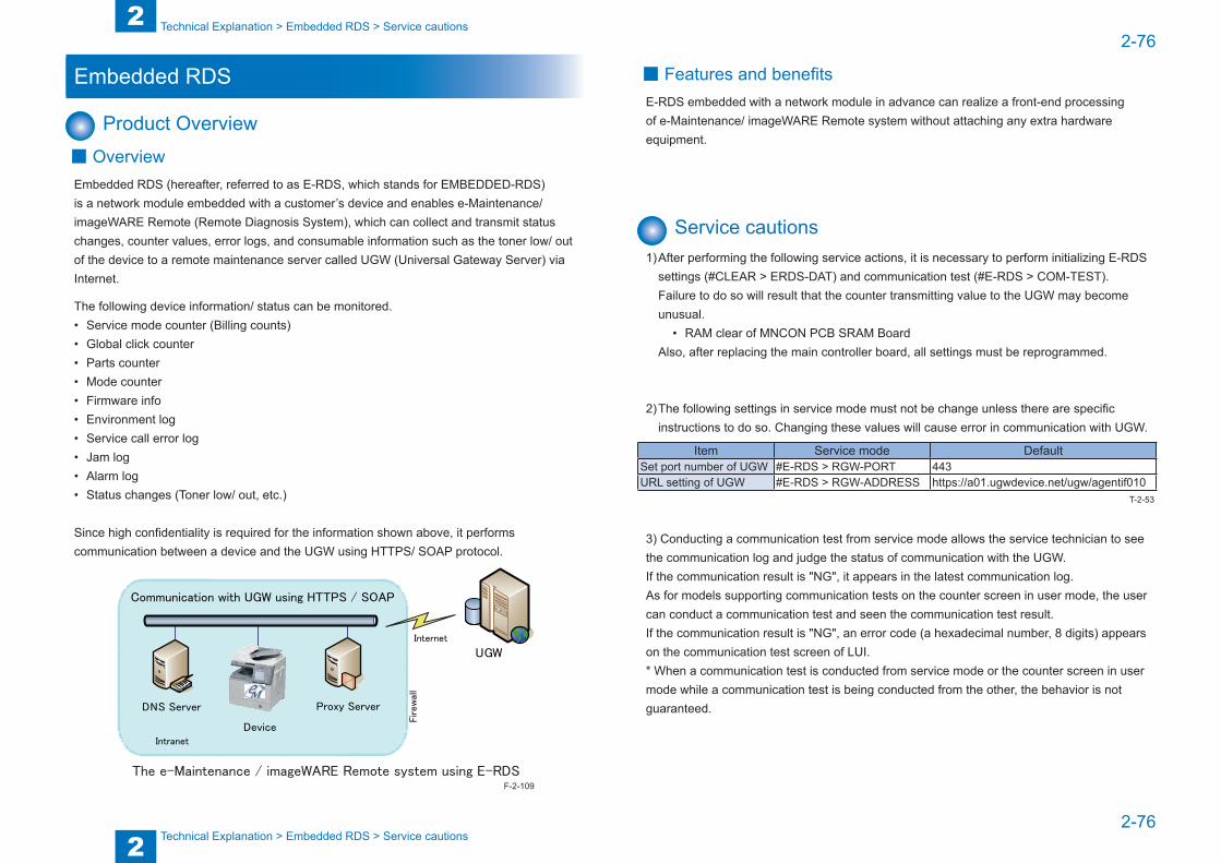
2
22-76
2-76
Technical Explanation > Embedded RDS > Service cautions
Technical Explanation > Embedded RDS > Service cautions
Embedded RDS
Product Overview ■ Overview
Embedded RDS (hereafter, referred to as E-RDS, which stands for EMBEDDED-RDS) is a network module embedded with a customer’s device and enables e-Maintenance/ imageWARE Remote (Remote Diagnosis System), which can collect and transmit status changes, counter values, error logs, and consumable information such as the toner low/ out of the device to a remote maintenance server called UGW (Universal Gateway Server) via Internet.
The following device information/ status can be monitored.• Service mode counter (Billing counts)• Global click counter• Parts counter• Mode counter• Firmware info• Environment log• Service call error log• Jam log• Alarm log• Status changes (Toner low/ out, etc.)
Since high confidentiality is required for the information shown above, it performs communication between a device and the UGW using HTTPS/ SOAP protocol.
The e-Maintenance / imageWARE Remote system using E-RDS
Internet
UGW
Proxy Server
Intranet
Firew
all
Communication with UGW using HTTPS / SOAP
DNS Server
Device
F-2-109
■ Features and benefitsE-RDS embedded with a network module in advance can realize a front-end processing of e-Maintenance/ imageWARE Remote system without attaching any extra hardware equipment.
Service cautions1) After performing the following service actions, it is necessary to perform initializing E-RDS
settings (#CLEAR > ERDS-DAT) and communication test (#E-RDS > COM-TEST). Failure to do so will result that the counter transmitting value to the UGW may become unusual.
• RAM clear of MNCON PCB SRAM BoardAlso, after replacing the main controller board, all settings must be reprogrammed.
2) The following settings in service mode must not be change unless there are specific instructions to do so. Changing these values will cause error in communication with UGW.
Item Service mode DefaultSet port number of UGW #E-RDS > RGW-PORT 443URL setting of UGW #E-RDS > RGW-ADDRESS https://a01.ugwdevice.net/ugw/agentif010
3) Conducting a communication test from service mode allows the service technician to see the communication log and judge the status of communication with the UGW.If the communication result is "NG", it appears in the latest communication log.As for models supporting communication tests on the counter screen in user mode, the user can conduct a communication test and seen the communication test result.If the communication result is "NG", an error code (a hexadecimal number, 8 digits) appears on the communication test screen of LUI.* When a communication test is conducted from service mode or the counter screen in user mode while a communication test is being conducted from the other, the behavior is not guaranteed.
T-2-53
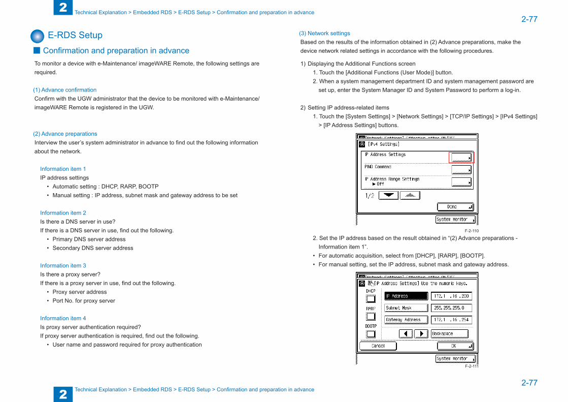
2
22-77
2-77
Technical Explanation > Embedded RDS > E-RDS Setup > Confirmation and preparation in advance
Technical Explanation > Embedded RDS > E-RDS Setup > Confirmation and preparation in advance
E-RDS Setup ■ Confirmation and preparation in advance
To monitor a device with e-Maintenance/ imageWARE Remote, the following settings are required.
(1) Advance confirmationConfirm with the UGW administrator that the device to be monitored with e-Maintenance/ imageWARE Remote is registered in the UGW.
(2) Advance preparationsInterview the user’s system administrator in advance to find out the following information about the network.
Information item 1IP address settings
• Automatic setting : DHCP, RARP, BOOTP• Manual setting : IP address, subnet mask and gateway address to be set
Information item 2Is there a DNS server in use?If there is a DNS server in use, find out the following.
• Primary DNS server address• Secondary DNS server address
Information item 3Is there a proxy server?If there is a proxy server in use, find out the following.
• Proxy server address• Port No. for proxy server
Information item 4Is proxy server authentication required?If proxy server authentication is required, find out the following.
• User name and password required for proxy authentication
(3) Network settingsBased on the results of the information obtained in (2) Advance preparations, make the device network related settings in accordance with the following procedures.
1) Displaying the Additional Functions screen1. Touch the [Additional Functions (User Mode)] button.2. When a system management department ID and system management password are
set up, enter the System Manager ID and System Password to perform a log-in.
2) Setting IP address-related items1. Touch the [System Settings] > [Network Settings] > [TCP/IP Settings] > [IPv4 Settings]
> [IP Address Settings] buttons.
2. Set the IP address based on the result obtained in “(2) Advance preparations - Information item 1”.
• For automatic acquisition, select from [DHCP], [RARP], [BOOTP].• For manual setting, set the IP address, subnet mask and gateway address.
F-2-110
F-2-111
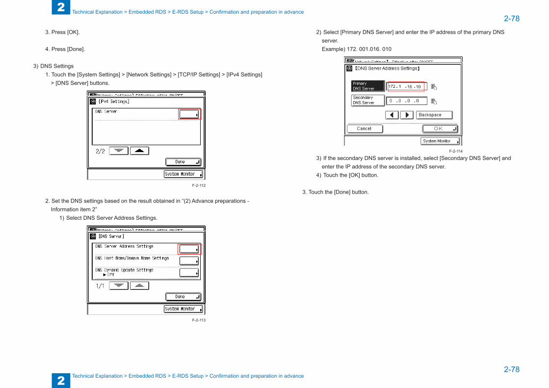
2
22-78
2-78
Technical Explanation > Embedded RDS > E-RDS Setup > Confirmation and preparation in advance
Technical Explanation > Embedded RDS > E-RDS Setup > Confirmation and preparation in advance
3. Press [OK].
4. Press [Done].
3) DNS Settings1. Touch the [System Settings] > [Network Settings] > [TCP/IP Settings] > [IPv4 Settings]
> [DNS Server] buttons.
2. Set the DNS settings based on the result obtained in “(2) Advance preparations - Information item 2”
1) Select DNS Server Address Settings.
F-2-112
F-2-113
2) Select [Primary DNS Server] and enter the IP address of the primary DNS server.Example) 172. 001.016. 010
3) If the secondary DNS server is installed, select [Secondary DNS Server] and enter the IP address of the secondary DNS server.
4) Touch the [OK] button.
3. Touch the [Done] button.
F-2-114
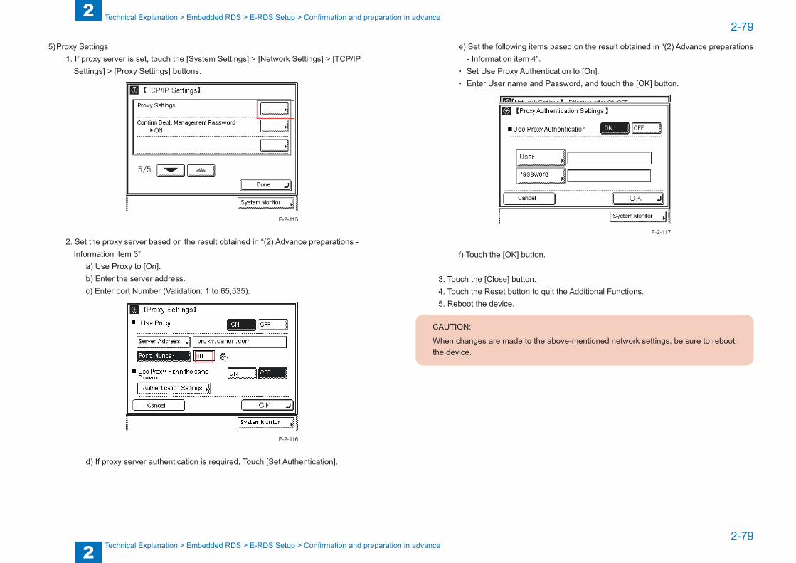
2
22-79
2-79
Technical Explanation > Embedded RDS > E-RDS Setup > Confirmation and preparation in advance
Technical Explanation > Embedded RDS > E-RDS Setup > Confirmation and preparation in advance
5) Proxy Settings1. If proxy server is set, touch the [System Settings] > [Network Settings] > [TCP/IP
Settings] > [Proxy Settings] buttons.
2. Set the proxy server based on the result obtained in “(2) Advance preparations - Information item 3”.
a) Use Proxy to [On].b) Enter the server address.c) Enter port Number (Validation: 1 to 65,535).
d) If proxy server authentication is required, Touch [Set Authentication].
F-2-115
F-2-116
e) Set the following items based on the result obtained in “(2) Advance preparations - Information item 4”.
• Set Use Proxy Authentication to [On].• Enter User name and Password, and touch the [OK] button.
f) Touch the [OK] button.
3. Touch the [Close] button.4. Touch the Reset button to quit the Additional Functions.5. Reboot the device.
CAUTION:
When changes are made to the above-mentioned network settings, be sure to reboot the device.
F-2-117

2
22-80
2-80
Technical Explanation > Embedded RDS > E-RDS Setup > Steps to E-RDS settings
Technical Explanation > Embedded RDS > E-RDS Setup > Steps to E-RDS settings
■ E-RDS setting itemsItem Description
#E-RDS >E-RDS SWITCH
Disable/Enable of Embedded-RDS function0: Disable/ 1:Enablee-Maintenance/ imageWARE Remote system to send device information, counter data, error statuses to the UGW.Default : 0 (not in use)
#E-RDS >RGW-ADDRESS
URL of UGWDefault : https://a01.ugwdevice.net/ugw/agentif010
#E-RDS >RGW-PORT
Set port number of UGWValidation : 1 to 65,535Default : 443
#E-RDS >COM-TEST
Execution of a communication test with UGW / Display of the resultPerform Communication test with UGW and set "OK" or "NG" as the result.
#E-RDS >COM-LOG
Display of detailed information about a communication error with UGWError information of a connection failure with UGW is displayed.Error occurrence date and time, error code, and detailed error information are displayed.Max 5 latest loggings retainedMax 128 characters for Error information.
#CLEAR >ERDS-DAT
Initialization of E-RDS SRAM dataSRAM data of E-RDS is initialized and returned to the factory setting value at shipment.
#CLEAR >CA-KEY
Initialization of CA certificateWhen the power is turned OFF/ ON after execution, the CA certificate in the factory setting is automatically installed.
#REPORT >REPORT OUTPUT >ERDS COM LOG LIST
COM-LOG ReportThe report output of the communication error logging information on five affairs can be carried out.
T-2-54
■ Steps to E-RDS settings1. Start [Service Mode].
1) Press [Additional Functions (User Mode)] button on the control panel.2) Press [2] buttons on the control panel.3) Press [8] buttons on the control panel.4) Press [Additional Functions (User Mode)] button on the control panel.
The example of the service mode indication screen
#E-RDS
E-RDS SWITCH 001 1
OK Key
Key
#E-RDS
#E-RDS
RGW-ADDRESS https://a01.ugwdevi..
OK Key
Key
#RGW-ADDRESS :A
#E-RDS
RGW-PORT 001 443
OK Key
Key
#RGW-PORT
#E-RDS
COM-TEST COM-TEST OK
OK Key
Key
#E-RDS
#E-RDS
COM-LOG 2011 03/24 11:56
OK Key No:1 Ecode:870F2052
Key
#E-RDS
SCALLCMP OK
OK Key #SCALLCMP
F-2-118
F-2-119
2
22-81
2-81
Technical Explanation > Embedded RDS > E-RDS Setup > Steps to E-RDS settings
Technical Explanation > Embedded RDS > E-RDS Setup > Steps to E-RDS settings
2. Select #CLEAR > ERDS-DAT and touch the [OK] button.
NOTE:This operation initializes the E-RDS settings to factory setting values.For the setting values to be initialized, see the section of “Initializing E-RDS settings”.
3. Perform installation or deletion of the CA certificate if necessary, and reboot the device.• Installation of the CA certificate: Perform installation from Remote UI.• Deletion of the CA certificate: When the following operation is performed, the CA certificate
in the factory setting is automatically installed.
CAUTION:
After following procedure, the registered key and CA certificate are deleted, and only the CA certificate installed at the time of shipment is registered.
It is therefore necessary to check with the user in advance.
(1) Start [Service Mode].(2) Select #CLEAR > CA-KEY and touch the [OK] button.(3) Reboot the device.
CAUTION:
If a key and a CA certificate have been registered in order to use a function other than E-RDS, it is necessary to register again from Remote UI.
4. Start [Service Mode]. (See 1. for the procedure.)
5. Select #E-RDS > E-RDS SWITCH, and set value "1" then touch [OK].
NOTE:This operation enables the communication function with UGW.
CAUTION:
The following settings i.e. #E-RDS > RGW-ADDRESS and #E-RDS > RGW-PORT in Service mode must not be change unless there are specific instructions to do so.
Changing these values will cause error in communication with UGW.
6. Select #E-RDS > COM-TEST and then touch [OK].
NOTE:This initiates the communication test between the device and the UGW.
If the communication is successful, “OK” is displayed. If “NG” (failed) appears, refer to the “Troubleshooting“ and repeat until “OK” is displayed.
NOTE:The communication results with UGW can be distinguished by referring to the COM-LOG. By performing the communication test with UGW, E-RDS acquires schedule information and starts monitoring and meter reads operation.
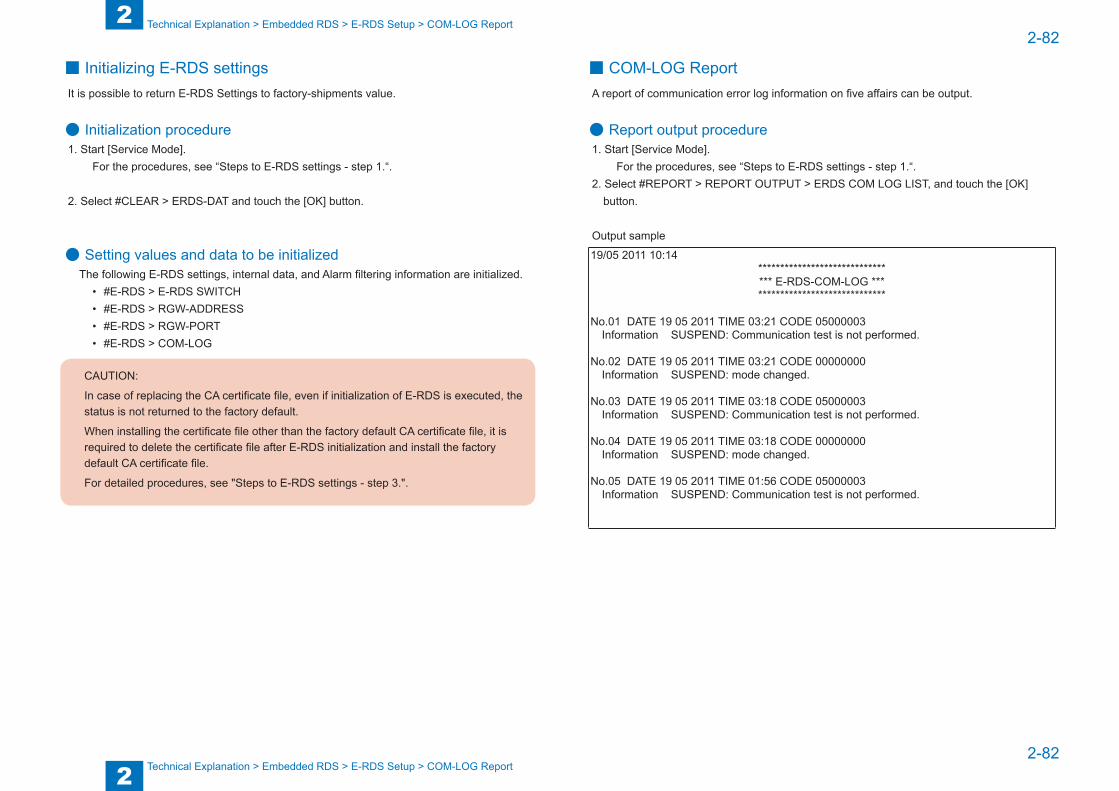
2
22-82
2-82
Technical Explanation > Embedded RDS > E-RDS Setup > COM-LOG Report
Technical Explanation > Embedded RDS > E-RDS Setup > COM-LOG Report
■ Initializing E-RDS settingsIt is possible to return E-RDS Settings to factory-shipments value.
● Initialization procedure1. Start [Service Mode].
For the procedures, see “Steps to E-RDS settings - step 1.“.
2. Select #CLEAR > ERDS-DAT and touch the [OK] button.
● Setting values and data to be initializedThe following E-RDS settings, internal data, and Alarm filtering information are initialized.
• #E-RDS > E-RDS SWITCH• #E-RDS > RGW-ADDRESS• #E-RDS > RGW-PORT• #E-RDS > COM-LOG
CAUTION:
In case of replacing the CA certificate file, even if initialization of E-RDS is executed, the status is not returned to the factory default.
When installing the certificate file other than the factory default CA certificate file, it is required to delete the certificate file after E-RDS initialization and install the factory default CA certificate file.
For detailed procedures, see "Steps to E-RDS settings - step 3.".
■ COM-LOG ReportA report of communication error log information on five affairs can be output.
● Report output procedure1. Start [Service Mode].
For the procedures, see “Steps to E-RDS settings - step 1.“.2. Select #REPORT > REPORT OUTPUT > ERDS COM LOG LIST, and touch the [OK]
button.
Output sample
19/05 2011 10:14******************************** E-RDS-COM-LOG ********************************
No.01 DATE 19 05 2011 TIME 03:21 CODE 05000003Information SUSPEND: Communication test is not performed.
No.02 DATE 19 05 2011 TIME 03:21 CODE 00000000Information SUSPEND: mode changed.
No.03 DATE 19 05 2011 TIME 03:18 CODE 05000003Information SUSPEND: Communication test is not performed.
No.04 DATE 19 05 2011 TIME 03:18 CODE 00000000Information SUSPEND: mode changed.
No.05 DATE 19 05 2011 TIME 01:56 CODE 05000003Information SUSPEND: Communication test is not performed.
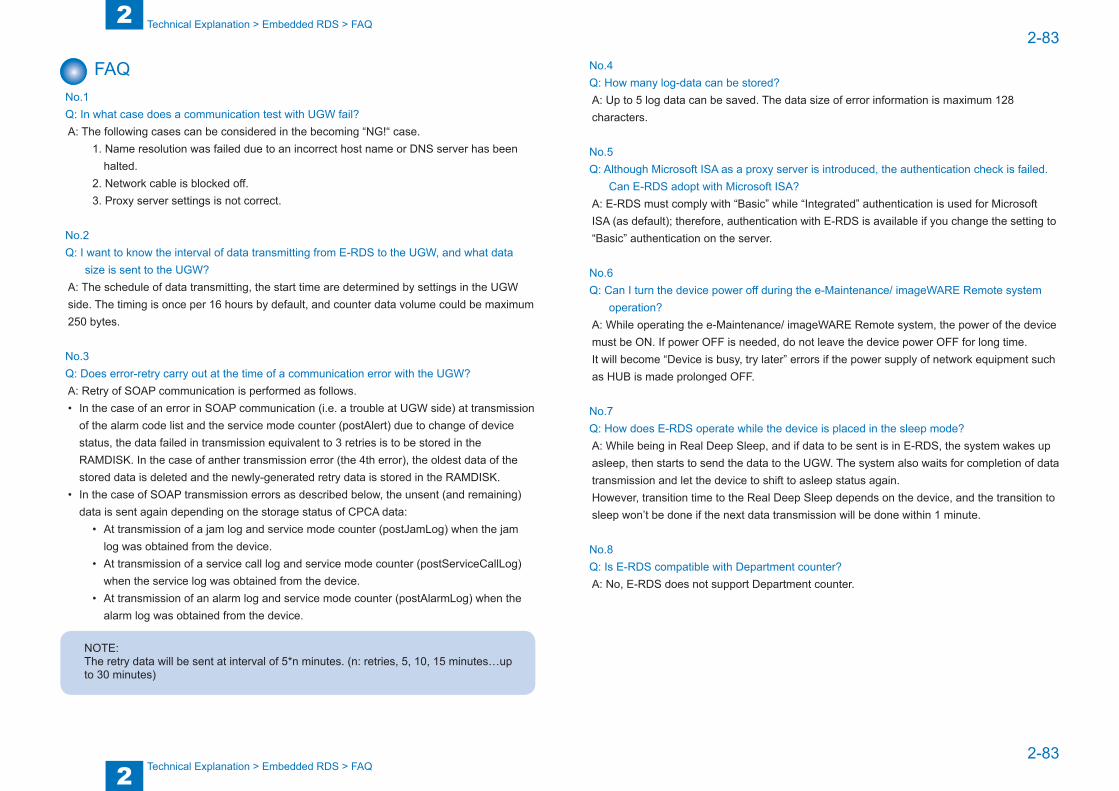
2
22-83
2-83
Technical Explanation > Embedded RDS > FAQ
Technical Explanation > Embedded RDS > FAQ
FAQNo.1Q: In what case does a communication test with UGW fail?A: The following cases can be considered in the becoming “NG!“ case.
1. Name resolution was failed due to an incorrect host name or DNS server has been halted.
2. Network cable is blocked off.3. Proxy server settings is not correct.
No.2Q: I want to know the interval of data transmitting from E-RDS to the UGW, and what data
size is sent to the UGW?A: The schedule of data transmitting, the start time are determined by settings in the UGW side. The timing is once per 16 hours by default, and counter data volume could be maximum 250 bytes.
No.3Q: Does error-retry carry out at the time of a communication error with the UGW?A: Retry of SOAP communication is performed as follows.• In the case of an error in SOAP communication (i.e. a trouble at UGW side) at transmission
of the alarm code list and the service mode counter (postAlert) due to change of device status, the data failed in transmission equivalent to 3 retries is to be stored in the RAMDISK. In the case of anther transmission error (the 4th error), the oldest data of the stored data is deleted and the newly-generated retry data is stored in the RAMDISK.
• In the case of SOAP transmission errors as described below, the unsent (and remaining) data is sent again depending on the storage status of CPCA data:
• At transmission of a jam log and service mode counter (postJamLog) when the jam log was obtained from the device.
• At transmission of a service call log and service mode counter (postServiceCallLog) when the service log was obtained from the device.
• At transmission of an alarm log and service mode counter (postAlarmLog) when the alarm log was obtained from the device.
NOTE:The retry data will be sent at interval of 5*n minutes. (n: retries, 5, 10, 15 minutes…up to 30 minutes)
No.4Q: How many log-data can be stored?A: Up to 5 log data can be saved. The data size of error information is maximum 128 characters.
No.5Q: Although Microsoft ISA as a proxy server is introduced, the authentication check is failed.
Can E-RDS adopt with Microsoft ISA?A: E-RDS must comply with “Basic” while “Integrated” authentication is used for Microsoft ISA (as default); therefore, authentication with E-RDS is available if you change the setting to “Basic” authentication on the server.
No.6Q: Can I turn the device power off during the e-Maintenance/ imageWARE Remote system
operation?A: While operating the e-Maintenance/ imageWARE Remote system, the power of the device must be ON. If power OFF is needed, do not leave the device power OFF for long time.It will become “Device is busy, try later” errors if the power supply of network equipment such as HUB is made prolonged OFF.
No.7Q: How does E-RDS operate while the device is placed in the sleep mode?A: While being in Real Deep Sleep, and if data to be sent is in E-RDS, the system wakes up asleep, then starts to send the data to the UGW. The system also waits for completion of data transmission and let the device to shift to asleep status again.However, transition time to the Real Deep Sleep depends on the device, and the transition to sleep won’t be done if the next data transmission will be done within 1 minute.
No.8Q: Is E-RDS compatible with Department counter?A: No, E-RDS does not support Department counter.

2
22-84
2-84
Technical Explanation > Embedded RDS > Troubleshooting
Technical Explanation > Embedded RDS > Troubleshooting
TroubleshootingNo.1Symptom: A communication test (COM-TEST) results NGCause: Initial settings or network conditions is incomplete.Remedy 1: Check and take actions mentioned below.1) Check network connections
Is the status indicator LED for the HUB port to which the main unit is connected ON?YES: Proceed to Step 2).NO: Check that the network cable is properly connected.
2) Confirm loop back addressSelect [Additional Functions (User Mode)] > [System Settings] > [Network Settings] > [TCP/IP Settings] > [IPv4 Settings] > [PING Command], enter “127.0.0.1”, and touch the [Start] button.
Does the screen display “Response from the host.”?YES: Proceed to Step 3).NO: There is a possibility that the main unit’s network settings are wrong. Check the details of the IPv4 settings once more.
3) Confirmation from another PC connected to same network.Request the user to ping the main unit from a PC connected to same network.Does the main unit respond?
YES: Proceed to Step 4).NO: Confirm the details of the main unit’s IP address and subnet mask settings.
F-2-120
4) Confirm DNS connection(a) Select [Additional Functions (User Mode)] > [System Settings] > [Network Settings] >
[TCP/IP Settings] > [IPv4 Settings] > [DNS Settings] > [DNS Server Address Settings], write down the primary and secondary addresses of the DNS server.
(b) Press Reset key.
(c) Select [Additional Functions (User Mode)] > [System Settings] > [Network Settings] > [TCP/IP Settings] > [IPv4 Settings] > [PING Command], enter the primary DNS server noted down in step a) as the IP address, and touch the [Start] button.
Does the screen display “Response from the host.”? YES: Proceed to Remedy 2.NO: Enter the secondary DNS server noted down in step a) as the IP address, and then touch Start.
Does the screen display “Response from the host.”? YES: Proceed to Remedy 2.NO: There is a possibility that the DNS server address is wrong. Reconfirm the address with the user’s system administrator.
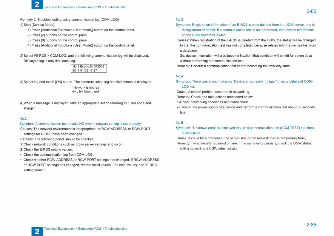
2
22-85
2-85
Technical Explanation > Embedded RDS > Troubleshooting
Technical Explanation > Embedded RDS > Troubleshooting
Remedy 2: Troubleshooting using communication log (COM-LOG)1) Start [Service Mode].
1) Press [Additional Functions (User Mode)] button on the control panel.2) Press [2] buttons on the control panel.3) Press [8] buttons on the control panel.4) Press [Additional Functions (User Mode)] button on the control panel.
2) Select #E-RDS > COM-LOG, and the following communication log will be displayed. Displayed log is only five latest log.
No:1 Ecode:840F2003 2011 01/09 17:27
3) Select log and touch [OK] button. The communication log detailed screen is displayed. *Network is not rea dy , try later : get
4) When a message is displayed, take an appropriate action referring to “Error code and strings”.
No.2Symptom: A communication test results NG even if network setting is set properly.Causes: The network environment is inappropriate, or RGW-ADDRESS or RGW-PORT
settings for E-RDS have been changed.Remedy: The following points should be checked.1) Check network conditions such as proxy server settings and so on.2) Check the E-RDS setting values.• Check the communication log from COM-LOG.• Check whether RGW-ADDRESS or RGW-PORT settings has changed. If RGW-ADDRESS
or RGW-PORT settings has changed, restore initial values. For initial values, see “E-RDS setting items”.
No.3Symptom: Registration information of an E-RDS is once deleted from the UGW server, and is
re-registered after that. If a communication test is not performed, then device information on the UGW becomes invalid.
Causes: When registration of the E-RDS is deleted from the UGW, the status will be changed to that the communication test has not completed because related information has lost from a database.So, device information will also become invalid if that condition will be left for seven days without performing the communication test.
Remedy: Perform a communication test before becoming the invalidity state.
No.4Symptom: There was a log, indicating “Device is not ready, try later” in error details of COM-
LOG list.Cause: A certain problem occurred in networking.Remedy: Check and take actions mentioned below.1) Check networking conditions and connections.2) Turn on the power supply of a device and perform a communication test about 60 seconds
later.
No.5 Symptom: “Unknown error” is displayed though a communication test (COM-TEST) has done
successfully.Cause: It could be a problem at the server side or the network load is temporarily faulty.Remedy: Try again after a period of time. If the same error persists, check the UGW status
with a network and UGW administrator.

2
22-86
2-86
Technical Explanation > Embedded RDS > Error code and strings
Technical Explanation > Embedded RDS > Error code and strings
Error code and stringsThe following error information is output in the communication error log details display screen.(Here, “a server” means UGW.)
• The error information are displayed in the following form.[*] [Error strings] [Method name] [Error details provided by UGW]
NOTE:“*” is added to the top of the error text in the case of an error in communication test (method name: getConfiguration or communicationTest) only.
No. Code Error strings Cause Remedy 1 0000 0000 SUSPEND: mode
changed.Unmatched Operation Mode Clear E-RDS
2 0500 0003 SUSPEND: Communication test is not performed.
Rebooting the device while the communication test had not been performed although E-RDS is enabled.
Perform a communication test (COM-TEST).
3 0xxx 0003 Server schedule is not exist
Blank schedule data have been received from UGW.
Check the device settings status with the UGW administrator.
4 0xxx 0003 Communication test is not performed
Communication test has not completed.
Perform and complete a communication test (COM-TEST).
5 84xx 0003 E-RDS switch is setted OFF
A communication test has been attempted with the E-RDS switch being OFF.
Set E-RDS switch (E-RDS SWITCH) to 1, and then perform a communication test (COM-TEST).
6 8600 00028600 00038600 01018600 02018600 03058600 03068600 04018600 04038600 04148600 0415
Event Registration is Failed
Processing (event processing) within the device has failed.
Turn the device OFF/ ON. If the error persists, replace the device system software. (Upgrade)
7 8700 0306 SRAM version unmatch!
Improper value is written in at the head of the Main Controller PCB 2 SRAM domain of E-RDS.
Turn the device OFF/ ON.
8 8xxx 0004 Operation is not supported
Method which E-RDS is not supporting attempted.
Contact help desk
No. Code Error strings Cause Remedy 9 8xxx 0101 Server response
error (NULL)Communication with UGW has been successful, but an error of some sort has prevented UGW from responding. When (Null) is displayed at the end of the message, this indicates that there has been an error in the HTTPS communication method.
Try again after a period of time. If the error persists, check the UGW status with the UGW administrator.
10 8xxx 02018xxx 02028xxx 02038xxx 02048xxx 0206
Server schedule is invalid
During the communication test, there has been some kind of error in the schedule values passed from UGW.
When the error occurs, report the details to the support section. And then, after the UGW side has responded, try the communication test again.
11 8xxx 02078xxx 0208
Internal Schedule is broken
The schedule data in the inside of E-RDS is not right.
Perform a communication test (COM-TEST).
12 8xxx 0221 Server specified list is too big
Alert filtering error: The number of elements of the list specified by the server is over restriction value.
Specify the number of elements of alert filtering correctly. (Alarm filtering is not supported)
13 8xxx 0222 Server specified list is wrong
Alert filtering error: Unjust value is included in the element of the list specified by the server.
Specify the element of alert filtering with the right value. (Alarm filtering is not supported)
14 8xxx 0304 Device is busy, try later
The semaphore consumption error at the time of a communication test.
Try again a communication test after a period of time.
15 8xxx 2000 Unknown error Some other kind of communication error has occurred.
Try again after a period of time. If the error persists, check the UGW status with the UGW administrator.
16 8xxx 2001 URL Scheme error(not https)
The header of the URL of the registered UGW is not in https format.
Check that the value of URL of UGW (RGW-ADDRESS) is https://a01.ugwdevice.net/ugw/agentif010.
17 8xxx 2002 URL server specified is illegal
A URL different to that specified by the UGW has been set.
Check that the value of URL of UGW (RGW-ADDRESS) is https://a01.ugwdevice.net/ugw/agentif010.
18 8xxx 2003 Network is not ready, try later
Communication attempted without confirming network connection, just after booting up a device in which the network preparations are not ready.
Check the network connection, as per the initial procedures described in the troubleshooting. Perform a communication test (COM-TEST) about 60 seconds later, after turn on the device.
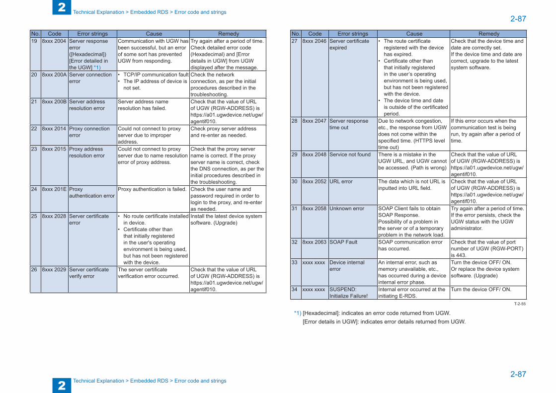
2
22-87
2-87
Technical Explanation > Embedded RDS > Error code and strings
Technical Explanation > Embedded RDS > Error code and strings
No. Code Error strings Cause Remedy 19 8xxx 2004 Server response
error ([Hexadecimal]) [Error detailed in the UGW] *1)
Communication with UGW has been successful, but an error of some sort has prevented UGW from responding.
Try again after a period of time. Check detailed error code (Hexadecimal) and [Error details in UGW] from UGW displayed after the message.
20 8xxx 200A Server connection error
• TCP/IP communication fault• The IP address of device is
not set.
Check the network connection, as per the initial procedures described in the troubleshooting.
21 8xxx 200B Server address resolution error
Server address name resolution has failed.
Check that the value of URL of UGW (RGW-ADDRESS) is https://a01.ugwdevice.net/ugw/agentif010.
22 8xxx 2014 Proxy connection error
Could not connect to proxy server due to improper address.
Check proxy server address and re-enter as needed.
23 8xxx 2015 Proxy address resolution error
Could not connect to proxy server due to name resolution error of proxy address.
Check that the proxy server name is correct. If the proxy server name is correct, check the DNS connection, as per the initial procedures described in the troubleshooting.
24 8xxx 201E Proxy authentication error
Proxy authentication is failed. Check the user name and password required in order to login to the proxy, and re-enter as needed.
25 8xxx 2028 Server certificate error
• No route certificate installed in device.
• Certificate other than that initially registered in the user's operating environment is being used, but has not been registered with the device.
Install the latest device system software. (Upgrade)
26 8xxx 2029 Server certificate verify error
The server certificate verification error occurred.
Check that the value of URL of UGW (RGW-ADDRESS) is https://a01.ugwdevice.net/ugw/agentif010.
No. Code Error strings Cause Remedy 27 8xxx 2046 Server certificate
expired• The route certificate
registered with the device has expired.
• Certificate other than that initially registered in the user’s operating environment is being used, but has not been registered with the device.
• The device time and date is outside of the certificated period.
Check that the device time and date are correctly set. If the device time and date are correct, upgrade to the latest system software.
28 8xxx 2047 Server response time out
Due to network congestion, etc., the response from UGW does not come within the specified time. (HTTPS level time out)
If this error occurs when the communication test is being run, try again after a period of time.
29 8xxx 2048 Service not found There is a mistake in the UGW URL, and UGW cannot be accessed. (Path is wrong)
Check that the value of URL of UGW (RGW-ADDRESS) is https://a01.ugwdevice.net/ugw/agentif010.
30 8xxx 2052 URL error The data which is not URL is inputted into URL field.
Check that the value of URL of UGW (RGW-ADDRESS) is https://a01.ugwdevice.net/ugw/agentif010.
31 8xxx 2058 Unknown error SOAP Client fails to obtain SOAP Response. Possibility of a problem in the server or of a temporary problem in the network load.
Try again after a period of time. If the error persists, check the UGW status with the UGW administrator.
32 8xxx 2063 SOAP Fault SOAP communication error has occurred.
Check that the value of port number of UGW (RGW-PORT) is 443.
33 xxxx xxxx Device internal error
An internal error, such as memory unavailable, etc., has occurred during a device internal error phase.
Turn the device OFF/ ON. Or replace the device system software. (Upgrade)
34 xxxx xxxx SUSPEND: Initialize Failure!
Internal error occurred at the initiating E-RDS.
Turn the device OFF/ ON.
*1) [Hexadecimal]: indicates an error code returned from UGW. [Error details in UGW]: indicates error details returned from UGW.
T-2-55

3
3 Periodical Service
Periodical Service ■List of periodically replacement parts, consumable parts and locations for cleaning
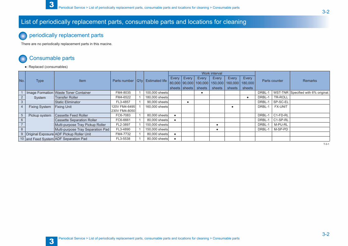
3
33-2
3-2
Periodical Service > List of periodically replacement parts, consumable parts and locations for cleaning > Consumable parts
Periodical Service > List of periodically replacement parts, consumable parts and locations for cleaning > Consumable parts
List of periodically replacement parts, consumable parts and locations for cleaning
periodically replacement partsThere are no periodically replacement parts in this macine.
Consumable parts●: Replaced (consumables)
No. Type Item Parts number Q'ty Estimated life
Work interval
Parts counter RemarksEvery 80,000 sheets
Every 90,000 sheets
Every 100,000 sheets
Every 150,000 sheets
Every 160,000 sheets
Every 180,000 sheets
1 Image Formation System
Waste Toner Container FM4-8035 1 100,000 sheets ● DRBL-1 WST-TNR Specified with 6% original.2 Transfer Roller FM4-6522 1 180,000 sheets ● DRBL-1 TR-ROLL3 Static Eliminator FL3-4857 1 90,000 sheets ● DRBL-1 SP-SC-EL4 Fixing System Fixing Unit 120V FM4-6495
230V FM4-80501 160,000 sheets ● DRBL-1 FX-UNIT
5 Pickup system Cassette Feed Roller FC6-7083 1 80,000 sheets ● DRBL-1 C1-FD-RL6 Cassette Separation Roller FC6-6661 1 80,000 sheets ● DRBL-1 C1-SP-RL7 Multi-purpose Tray Pickup Roller FL2-3897 1 150,000 sheets ● DRBL-1 M-PU-RL8 Multi-purpose Tray Separation Pad FL3-4890 1 150,000 sheets ● DRBL-1 M-SP-PD9 Original Exposure
and Feed SystemADF Pickup Roller Unit FM4-7732 1 80,000 sheets ●
10 ADF Separation Pad FL3-5538 1 80,000 sheets ●T-3-1
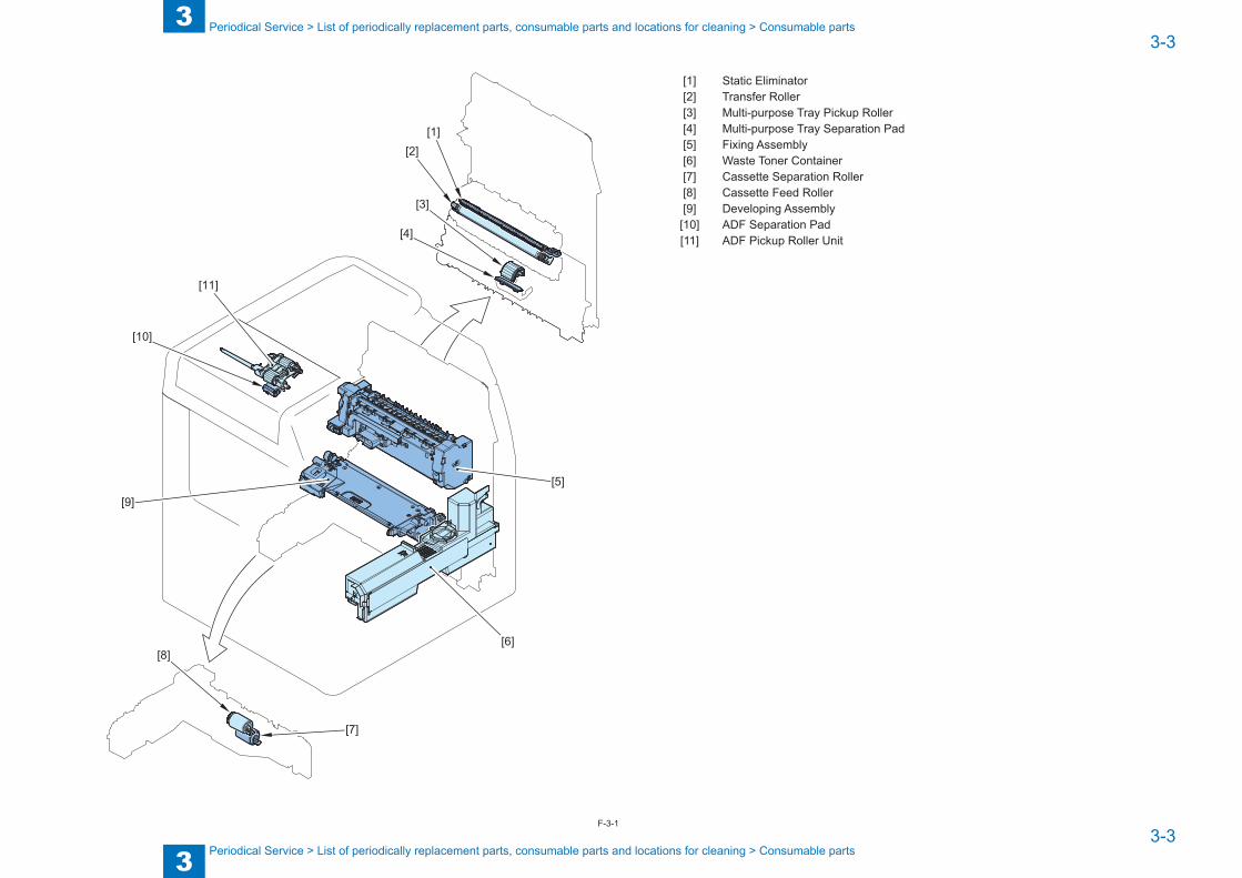
3
33-3
3-3
Periodical Service > List of periodically replacement parts, consumable parts and locations for cleaning > Consumable parts
Periodical Service > List of periodically replacement parts, consumable parts and locations for cleaning > Consumable parts
[11]
[10]
[5]
[6]
[4]
[3]
[2][1]
[7]
[8]
[9]
[1] Static Eliminator[2] Transfer Roller[3] Multi-purpose Tray Pickup Roller[4] Multi-purpose Tray Separation Pad[5] Fixing Assembly[6] Waste Toner Container[7] Cassette Separation Roller[8] Cassette Feed Roller[9] Developing Assembly[10] ADF Separation Pad[11] ADF Pickup Roller Unit
F-3-1

4
4 Disassembly/Assembly
Disassembly/Assembly ■Preface ■List of Parts ■List of Connectors ■External Cover/Internal System ■Original Exposure/Feed System ■Controller System ■Laser Exposure System ■Image Formation System ■Fixing System ■Pickup Feed System
4
44-2
4-2
Disassembly/Assembly > Preface > Outline
Disassembly/Assembly > Preface > Outline
Preface
OutlineThis chapter describes disassembly and reassembly procedures of the printer.The service technician is to identify the cause of printer failures according to the "Chapter 6 TROUBLESHOOTING"on Page 3-1-1 and to follow the disassembly procedures of each part to replace the defective parts or the consumable parts.Note the following precautions when working on the printer.1. CAUTION: Before disassembling or reassembling the printer, be sure to disconnect its
power cord from the electrical outlet2. During disassembly, reassembly or transportation of the printer, remove the cartridge if
required.When the cartridge is out of the printer, put it in a protective bag even in a short period of time to prevent the adverse effect of light.
3. Reassembling procedures are followed by the reverse of disassembly unless otherwise specified.
4. Note the length, diameters, and locations of screws as you remove them. When reassembling the printer, be sure to use them in their original locations.
5. Do not run the printer with any parts removed as a general rule.6. Ground yourself by touching the metal part of the printer before handling the PCB to
reduce the possibility of damage caused by static electricity.7. When you replace the part that the rating plate or the product code label is attached, be
sure to remove the rating plate or the product code label and put it to the new part.

4
44-3
4-3
Disassembly/Assembly > List of Parts > External View > Front Side
Disassembly/Assembly > List of Parts > External View > Front Side
List of Parts
External View ■ Front Side
[14]
[13] [12]
[11]
[10]
[5][4]
[3]
[2]
[1]
[6]
[7]
[8]
[9]
No. Name Reference[1] ADF Left Cover -[2] ADF Rear Cover -[3] ADF Upper Cover (Refer to page 4-48)[4] Side Guide Plate -[5] Original Feed Tray (Refer to page 4-52)[6] ADF Front Upper Cover -[7] Original Delivery Tray -[8] ADF Front Lower Cover -[9] Reader Front Cover (Refer to page 4-33)[10] Control Panel Unit (Refer to page 4-36)[11] Front Cover (Refer to page 4-24)[12] Cassette -
F-4-1
No. Name Reference[13] Left Cover (Refer to page 4-27)[14] Reader Left Cover -
[1]
[2]
[3]
[4]
[5]
[6]
No. Name Reference[1] Reader Bottom Cover (Refer to page 4-36)[2] Delivery Inner Cover (Refer to page 4-29)[3] Delivery Outer Cover (Refer to page 4-29)[4] Delivery Stopper -[5] Inner Rear Cover (Refer to page 4-28)[6] Reverse Tray -
T-4-1
F-4-2
T-4-2
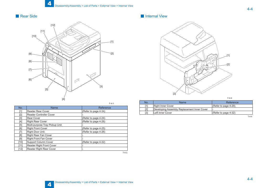
4
44-4
4-4
Disassembly/Assembly > List of Parts > External View > Internal View
Disassembly/Assembly > List of Parts > External View > Internal View
■ Rear Side
[10]
[11]
[12]
[1]
[2]
[3]
[4]
[5]
[6]
[7]
[8]
[9]
No. Name Reference[1] Reader Rear Cover (Refer to page 4-34)[2] Reader Controller Cover -[3] Rear Cover (Refer to page 4-24)[4] Right Rear Cover (Refer to page 4-26)[5] Multi-purpose Tray Pickup Unit -[6] Right Front Cover (Refer to page 4-25)[7] Right Door Unit (Refer to page 4-26)[8] Right Rear Fan Cover -[9] Right Front Fan Cover -
[10] Support Column Cover (Refer to page 4-32)[11] Reader Right Front Cover -[12] Reader Right Rear Cover -
F-4-3
T-4-3
■ Internal View
[1]
[2]
[3]
No. Name Reference[1] Right Inner Cover (Refer to page 4-29)[2] Developing Assembly Replacement Inner Cover -[3] Left Inner Cover (Refer to page 4-32)
F-4-4
T-4-4
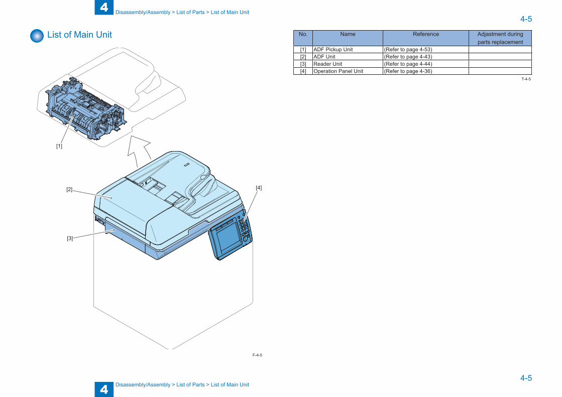
4
44-5
4-5
Disassembly/Assembly > List of Parts > List of Main Unit
Disassembly/Assembly > List of Parts > List of Main Unit
List of Main Unit
[1]
[2]
[3]
[4]
F-4-5
No. Name Reference Adjastment during parts replacement
[1] ADF Pickup Unit (Refer to page 4-53)[2] ADF Unit (Refer to page 4-43)[3] Reader Unit (Refer to page 4-44)[4] Operation Panel Unit (Refer to page 4-36)
T-4-5

4
44-6
4-6
Disassembly/Assembly > List of Parts > List of Main Unit
Disassembly/Assembly > List of Parts > List of Main Unit
[7]
[6]
[5]
[2]
[4]
[3]
[1]
F-4-6
No. Name Reference Adjastment during parts replacement
[1] Fixing Drive Unit (Refer to page 4-81)[2] Right Door Unit (Refer to page 4-26)[3] Transfer Unit -[4] Multi-purpose Tray Unit -[5] Fixing Assembly (Refer to page 4-79)[6] Pre-registration Guide Unit -[7] Casstte Pickup Unit (Refer to page 4-87)
T-4-6
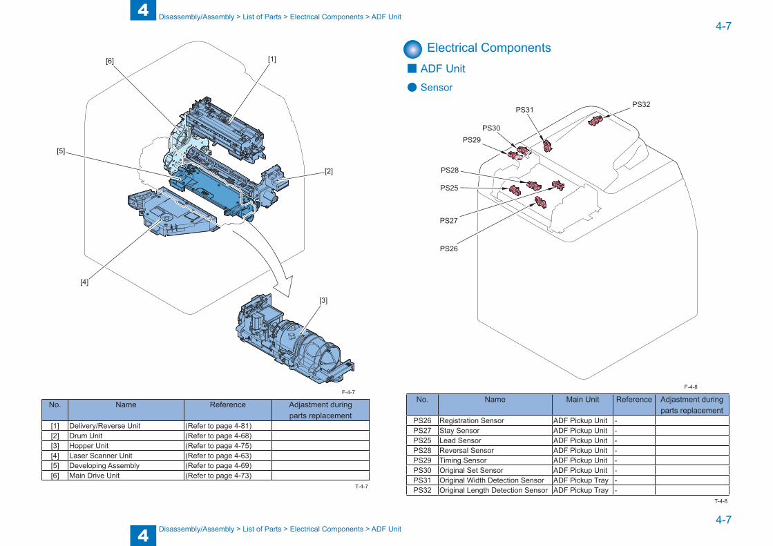
4
44-7
4-7
Disassembly/Assembly > List of Parts > Electrical Components > ADF Unit
Disassembly/Assembly > List of Parts > Electrical Components > ADF Unit
[1][6]
[5]
[4]
[3]
[2]
No. Name Reference Adjastment during parts replacement
[1] Delivery/Reverse Unit (Refer to page 4-81)[2] Drum Unit (Refer to page 4-68)[3] Hopper Unit (Refer to page 4-75)[4] Laser Scanner Unit (Refer to page 4-63)[5] Developing Assembly (Refer to page 4-69)[6] Main Drive Unit (Refer to page 4-73)
F-4-7
T-4-7
Electrical Components ■ ADF Unit
● Sensor
PS26
PS27
PS25
PS28
PS29PS30
PS31PS32
No. Name Main Unit Reference Adjastment during parts replacement
PS26 Registration Sensor ADF Pickup Unit -PS27 Stay Sensor ADF Pickup Unit -PS25 Lead Sensor ADF Pickup Unit -PS28 Reversal Sensor ADF Pickup Unit -PS29 Timing Sensor ADF Pickup Unit -PS30 Original Set Sensor ADF Pickup Unit -PS31 Original Width Detection Sensor ADF Pickup Tray -PS32 Original Length Detection Sensor ADF Pickup Tray -
F-4-8
T-4-8

4
44-8
4-8
Disassembly/Assembly > List of Parts > Electrical Components > Reader Unit
Disassembly/Assembly > List of Parts > Electrical Components > Reader Unit
● Solenoid/Motor
SL4
M11M12
SL5SL6
SL7
SL8
No. Name Main Unit Reference Adjastment during parts replacement
SL8 Roller Release Solenoid ADF Pickup Unit -SL7 Flapper Solenoid 1 ADF Pickup Unit -SL4 Registration Solenoid ADF Pickup Unit -M11 Feed Motor ADF Pickup Unit -M12 Delivery Reversal Motor ADF Pickup Unit -SL5 Pickup Solenoid ADF Pickup Unit -SL6 Flapper Solenoid 2 ADF Pickup Unit -
F-4-9
T-4-9
■ Reader Unit
PCB3
M10
PS22
PS21
PS24
PS23
No. Name Main Unit Reference Adjastment during parts replacement
PS24 CIS HP Sensor Reader Unit -PS23 ADF Open/Closed Detection
SensorReader Unit -
PCB3 Reader Controller PCB Reader Unit (Refer to page 4-46)M10 Reader Motor Reader Unit -PS21 Original Size Detection Sensor 1 Reader Unit -PS22 Original Size Detection Sensor 2 Reader Unit -
F-4-10
T-4-10
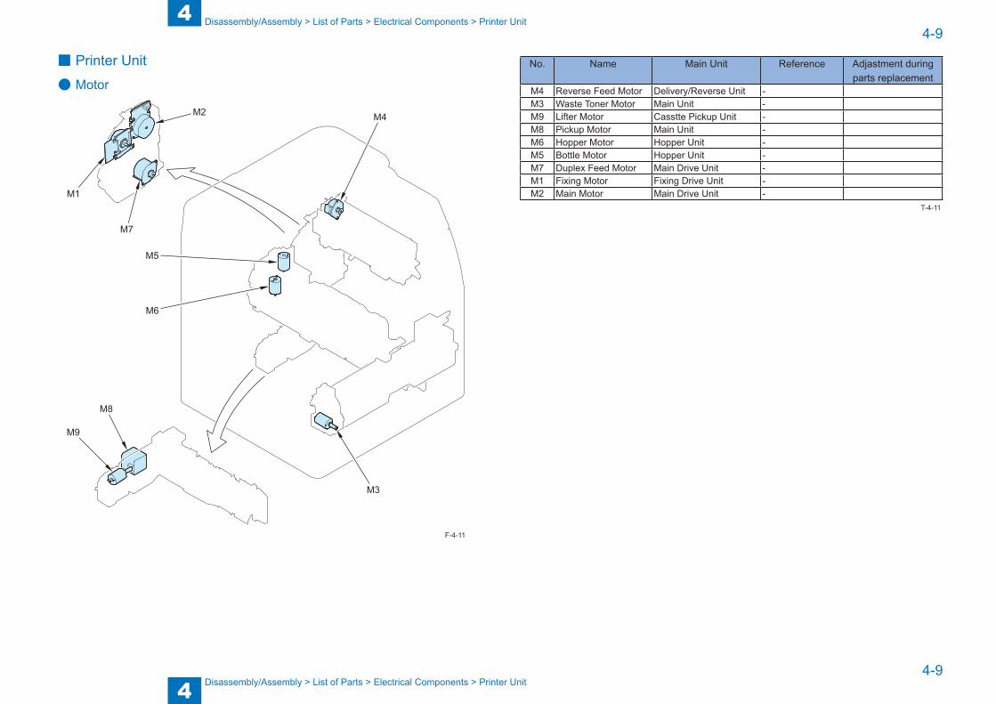
4
44-9
4-9
Disassembly/Assembly > List of Parts > Electrical Components > Printer Unit
Disassembly/Assembly > List of Parts > Electrical Components > Printer Unit
■ Printer Unit
● Motor
M4
M3
M9
M8
M6
M5
M7
M1
M2
F-4-11
No. Name Main Unit Reference Adjastment during parts replacement
M4 Reverse Feed Motor Delivery/Reverse Unit -M3 Waste Toner Motor Main Unit -M9 Lifter Motor Casstte Pickup Unit -M8 Pickup Motor Main Unit -M6 Hopper Motor Hopper Unit -M5 Bottle Motor Hopper Unit -M7 Duplex Feed Motor Main Drive Unit -M1 Fixing Motor Fixing Drive Unit -M2 Main Motor Main Drive Unit -
T-4-11
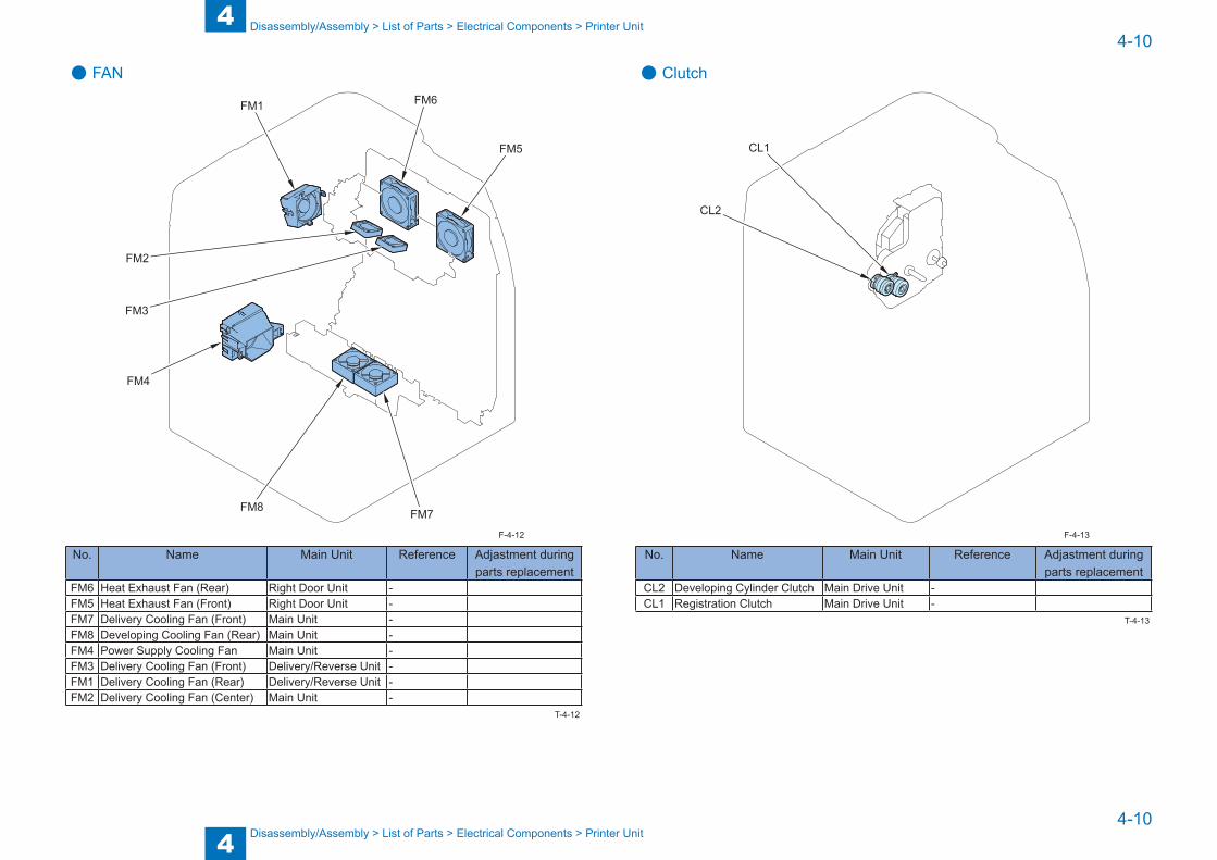
4
44-10
4-10
Disassembly/Assembly > List of Parts > Electrical Components > Printer Unit
Disassembly/Assembly > List of Parts > Electrical Components > Printer Unit
● FANFM6
FM5
FM7FM8
FM4
FM3
FM2
FM1
No. Name Main Unit Reference Adjastment during parts replacement
FM6 Heat Exhaust Fan (Rear) Right Door Unit -FM5 Heat Exhaust Fan (Front) Right Door Unit -FM7 Delivery Cooling Fan (Front) Main Unit -FM8 Developing Cooling Fan (Rear) Main Unit -FM4 Power Supply Cooling Fan Main Unit -FM3 Delivery Cooling Fan (Front) Delivery/Reverse Unit -FM1 Delivery Cooling Fan (Rear) Delivery/Reverse Unit -FM2 Delivery Cooling Fan (Center) Main Unit -
F-4-12
T-4-12
● Clutch
CL2
CL1
No. Name Main Unit Reference Adjastment during parts replacement
CL2 Developing Cylinder Clutch Main Drive Unit -CL1 Registration Clutch Main Drive Unit -
F-4-13
T-4-13

4
44-11
4-11
Disassembly/Assembly > List of Parts > Electrical Components > Printer Unit
Disassembly/Assembly > List of Parts > Electrical Components > Printer Unit
● Solenoid
SL2
SL3
SL1
No. Name Main Unit Reference Adjastment during parts replacement
SL3 Cassette Pickup Solenoid Casstte Pickup Unit -SL1 Multi-purpose Tray Pickup
SolenoidMulti-purpose Tray Unit -
SL2 Reverse Feed Solenoid Right Door Unit -
F-4-14
T-4-14
● Heater/SpeakerTHM2
THM1
TP1
H2
H1SP1
No. Name Main Unit Reference Adjastment during parts replacement
THM1 Fixing Thermistor Fixing Assembly -THM2 Sub Thermistor Fixing Assembly -TP1 Fixing Thermoswitch Fixing Assembly -H2 Sub Heater Fixing Assembly -H1 Fixing Heater Fixing Assembly -
SP1 Speaker Main Unit -
F-4-15
T-4-15
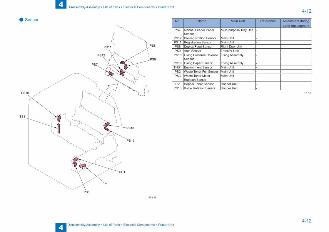
4
44-12
4-12
Disassembly/Assembly > List of Parts > Electrical Components > Printer Unit
Disassembly/Assembly > List of Parts > Electrical Components > Printer Unit
● Sensor
PS7
PS12
PS11 PS8
PS9
PS18
PS19
THU1
PS2
PS3
TS1
PS10
F-4-16
No. Name Main Unit Reference Adjastment during parts replacement
PS7 Manual Feeder Paper Sensor
Multi-purpose Tray Unit -
PS12 Pre-registration Sensor Main Unit -PS11 Registration Sensor Main Unit -PS8 Duplex Feed Sensor Right Door Unit -PS9 Arch Sensor Transfer Unit -
PS18 Fixing Pressure Release Sensor
Fixing Assembly -
PS19 Fixing Paper Sensor Fixing Assembly -THU1 Environment Sensor Main Unit -PS2 Waste Toner Full Sensor Main Unit -PS3 Waste Toner Motor
Rotation SensorMain Unit -
TS1 Hopper Toner Sensor Hopper Unit -PS10 Bottle Rotation Sensor Hopper Unit -
T-4-16
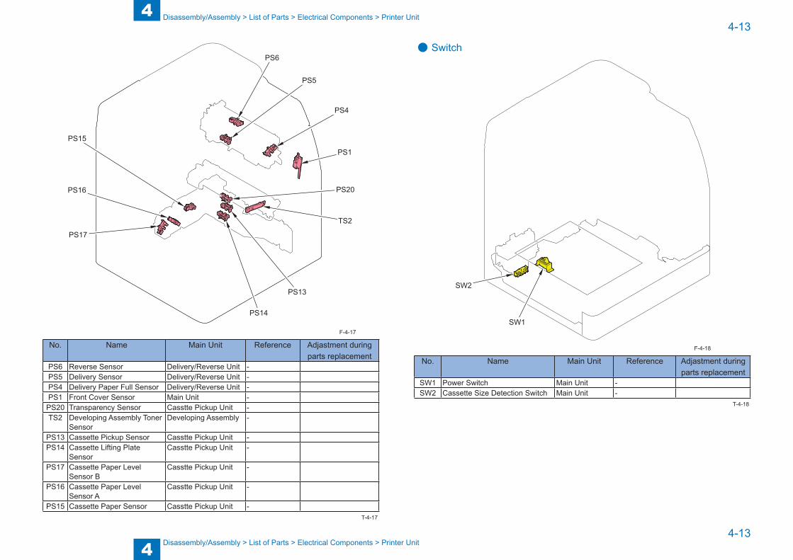
4
44-13
4-13
Disassembly/Assembly > List of Parts > Electrical Components > Printer Unit
Disassembly/Assembly > List of Parts > Electrical Components > Printer Unit
PS15
PS16
PS6
PS5
PS4
PS20
PS1
TS2
PS13
PS14
PS17
No. Name Main Unit Reference Adjastment during parts replacement
PS6 Reverse Sensor Delivery/Reverse Unit -PS5 Delivery Sensor Delivery/Reverse Unit -PS4 Delivery Paper Full Sensor Delivery/Reverse Unit -PS1 Front Cover Sensor Main Unit -PS20 Transparency Sensor Casstte Pickup Unit -TS2 Developing Assembly Toner
SensorDeveloping Assembly -
PS13 Cassette Pickup Sensor Casstte Pickup Unit -PS14 Cassette Lifting Plate
SensorCasstte Pickup Unit -
PS17 Cassette Paper Level Sensor B
Casstte Pickup Unit -
PS16 Cassette Paper Level Sensor A
Casstte Pickup Unit -
PS15 Cassette Paper Sensor Casstte Pickup Unit -
F-4-17
T-4-17
● Switch
SW1
SW2
No. Name Main Unit Reference Adjastment during parts replacement
SW1 Power Switch Main Unit -SW2 Cassette Size Detection Switch Main Unit -
F-4-18
T-4-18

4
44-14
4-14
Disassembly/Assembly > List of Parts > Electrical Components > Printer Unit
Disassembly/Assembly > List of Parts > Electrical Components > Printer Unit
● PCB
PCB4
PCB7
PCB5
PCB6
PCB10
PCB2
PCB1
No. Name Main Unit Reference Adjastment during parts replacement
PCB4 Control Panel CPU PCB Operation Panel Unit (Refer to page 4-36)PCB7 Leser Driver PCB Laser Scanner Unit -PCB5 HVT PCB Main Unit (Refer to page 4-60)PCB6 Power Supply PCB Main Unit (Refer to page 4-62)PCB10 FAX PCB Main Unit -PCB2 Main Controller PCB Main Unit (Refer to page 4-58)PCB1 DC Controller PCB Main Unit (Refer to page 4-57)
F-4-19
T-4-19

4
44-15
4-15
Disassembly/Assembly > List of Connectors
Disassembly/Assembly > List of Connectors
List of Connectors
J213
J2233J2235
J2241
J2234
J2301J2236
J2237
J2238
J2239J2240
J212
J2218
J2219
J2220
J2222
J2223
J2217
J2221
J301J202
J2213 J2300
J2214
J2210
J2211
J2212
J2215
J210
J No. Symbol Name Relay Connector Relay Connector J No. Symbol Name REMARKSJ202 PCB1 DC Controller PCB J301 PCB5 HVT PCBJ210 PCB1 DC Controller PCB J2213 FM2 Delivery Cooling Fan (Center)J210 PCB1 DC Controller PCB J21 J40 J2300 FM1 Delivery Cooling Fan (Rear)J210 PCB1 DC Controller PCB J21 J40 J2214 FM3 Delivery Cooling Fan (Front)J210 PCB1 DC Controller PCB J21 J2210 PS4 Delivery Paper Full SensorJ210 PCB1 DC Controller PCB J21 J2211 PS5 Delivery SensorJ210 PCB1 DC Controller PCB J21 J2212 PS6 Reverse SensorJ210 PCB1 DC Controller PCB J21 J2215 M4 Reverse Feed MotorJ212 PCB1 DC Controller PCB J14 J2218 SL1 Multi-purpose Tray Pickup Solenoid
F-4-20

4
44-16
4-16
Disassembly/Assembly > List of Connectors
Disassembly/Assembly > List of Connectors
J No. Symbol Name Relay Connector Relay Connector J No. Symbol Name REMARKSJ212 PCB1 DC Controller PCB J8 J2219 SL2 Reverse Feed SolenoidJ212 PCB1 DC Controller PCB J8 J2220 FM5 Heat Exhaust Fan (Front)J212 PCB1 DC Controller PCB J8 J2221 FM6 Heat Exhaust Fan (Rear)J212 PCB1 DC Controller PCB J8 J2222 PS8 Duplex Feed SensorJ212 PCB1 DC Controller PCB J8 J5 J2223 PS9 Arch SensorJ212 PCB1 DC Controller PCB J8 J2217 PS7 Multi-purpose Tray Paper SensorJ213 PCB1 DC Controller PCB J20 J2233 M8 Pickup MotorJ213 PCB1 DC Controller PCB J13 J2241 SW2 Cassette Size Detection SwitchJ213 PCB1 DC Controller PCB J9 J2234 SL3 Cassette Pickup SolenoidJ213 PCB1 DC Controller PCB J9 J2235 M9 Lifter MotorJ213 PCB1 DC Controller PCB J9 J2236 PS13 Cassette Pickup SensorJ213 PCB1 DC Controller PCB J9 J2237 PS14 Cassette Lifting Plate SensorJ213 PCB1 DC Controller PCB J9 J2238 PS15 Cassette Paper SensorJ213 PCB1 DC Controller PCB J9 J2239 PS16 Cassette Paper Level Sensor AJ213 PCB1 DC Controller PCB J9 J2240 PS17 Cassette Paper Level Sensor BJ213 PCB1 DC Controller PCB J9 J2301 PS20 Transparency Sensor
T-4-20
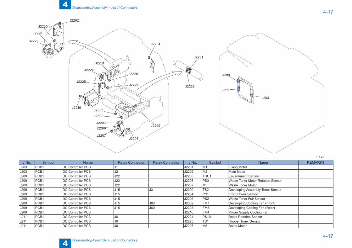
4
44-17
4-17
Disassembly/Assembly > List of Connectors
Disassembly/Assembly > List of Connectors
J2231
J2232
J2224
J2225
J2226
J2227
J2228
J2230
J2229
J2202
J203
J2201
J211
J2209
J2204
J2205
J2216
J209
J2203
J2302
J2303
J2206
J2207
J No. Symbol Name Relay Connector Relay Connector J No. Symbol Name REMARKSJ203 PCB1 DC Controller PCB J1 J2201 M1 Fixing MotorJ203 PCB1 DC Controller PCB J2 J2202 M2 Main MotorJ209 PCB1 DC Controller PCB J22 J2203 THU1 Environment SensorJ209 PCB1 DC Controller PCB J22 J2206 PS3 Waste Toner Motor Rotation SensorJ209 PCB1 DC Controller PCB J22 J2207 M3 Waste Toner MotorJ209 PCB1 DC Controller PCB J15 J3 J2209 TS2 Developing Assembly Toner SensorJ209 PCB1 DC Controller PCB J15 J2204 PS1 Front Cover SensorJ209 PCB1 DC Controller PCB J15 J2205 PS2 Waste Toner Full SensorJ209 PCB1 DC Controller PCB J15 J60 J2302 FM7 Developing Cooling Fan (Front)J209 PCB1 DC Controller PCB J15 J60 J2303 FM8 Developing Cooling Fan (Rear)J209 PCB1 DC Controller PCB J2216 FM4 Power Supply Cooling FanJ211 PCB1 DC Controller PCB J6 J2224 PS10 Bottle Rotation SensorJ211 PCB1 DC Controller PCB J6 J2225 TS1 Hopper Toner SensorJ211 PCB1 DC Controller PCB J6 J2226 M5 Bottle Motor
F-4-21

4
44-18
4-18
Disassembly/Assembly > List of Connectors
Disassembly/Assembly > List of Connectors
J No. Symbol Name Relay Connector Relay Connector J No. Symbol Name REMARKSJ211 PCB1 DC Controller PCB J6 J2227 M6 Hopper MotorJ211 PCB1 DC Controller PCB J2228 CL1 Registration ClutchJ211 PCB1 DC Controller PCB J2229 CL2 Developing Cylinder ClutchJ211 PCB1 DC Controller PCB J2230 M7 Duplex Feed MotorJ211 PCB1 DC Controller PCB J7 J2231 PS11 Registration SensorJ211 PCB1 DC Controller PCB J7 J2232 PS12 Pre-registration Sensor
T-4-21
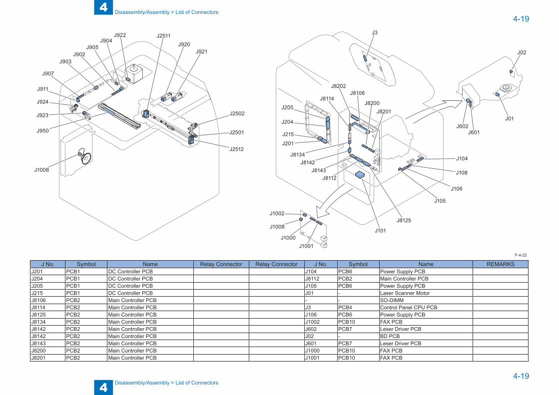
4
44-19
4-19
Disassembly/Assembly > List of Connectors
Disassembly/Assembly > List of Connectors
J1002
J1000J1001
J101
J8125
J8143J8112
J201
J215
J8142J8134
J8201J205
J204
J105
J104
J601
J01
J02
J602
J3
J1008
J923
J921
J2502
J2512
J2501
J920
J922
J905J904
J902J903
J907
J911
J924
J2511
J950
J108
J106
J8114J8106
J8202
J8200
J1008
J No. Symbol Name Relay Connector Relay Connector J No. Symbol Name REMARKSJ201 PCB1 DC Controller PCB J104 PCB6 Power Supply PCBJ204 PCB1 DC Controller PCB J8112 PCB2 Main Controller PCBJ205 PCB1 DC Controller PCB J105 PCB6 Power Supply PCBJ215 PCB1 DC Controller PCB J01 - Laser Scanner MotorJ8106 PCB2 Main Controller PCB - - SO-DIMMJ8114 PCB2 Main Controller PCB J3 PCB4 Control Panel CPU PCBJ8125 PCB2 Main Controller PCB J106 PCB6 Power Supply PCBJ8134 PCB2 Main Controller PCB J1002 PCB10 FAX PCBJ8142 PCB2 Main Controller PCB J602 PCB7 Leser Driver PCBJ8142 PCB2 Main Controller PCB J02 - BD PCBJ8143 PCB2 Main Controller PCB J601 PCB7 Leser Driver PCBJ8200 PCB2 Main Controller PCB J1000 PCB10 FAX PCBJ8201 PCB2 Main Controller PCB J1001 PCB10 FAX PCB
F-4-22
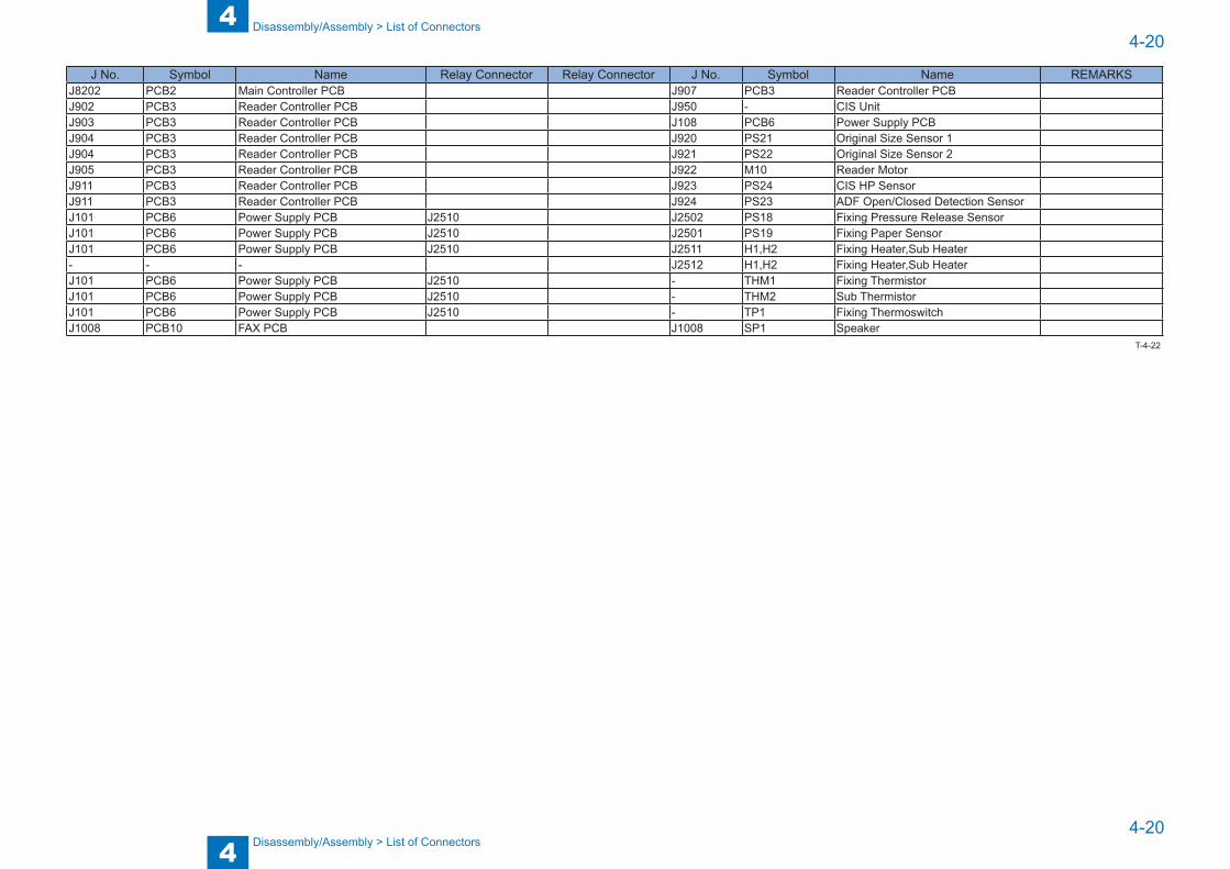
4
44-20
4-20
Disassembly/Assembly > List of Connectors
Disassembly/Assembly > List of Connectors
J No. Symbol Name Relay Connector Relay Connector J No. Symbol Name REMARKSJ8202 PCB2 Main Controller PCB J907 PCB3 Reader Controller PCBJ902 PCB3 Reader Controller PCB J950 - CIS UnitJ903 PCB3 Reader Controller PCB J108 PCB6 Power Supply PCBJ904 PCB3 Reader Controller PCB J920 PS21 Original Size Sensor 1J904 PCB3 Reader Controller PCB J921 PS22 Original Size Sensor 2J905 PCB3 Reader Controller PCB J922 M10 Reader MotorJ911 PCB3 Reader Controller PCB J923 PS24 CIS HP SensorJ911 PCB3 Reader Controller PCB J924 PS23 ADF Open/Closed Detection SensorJ101 PCB6 Power Supply PCB J2510 J2502 PS18 Fixing Pressure Release SensorJ101 PCB6 Power Supply PCB J2510 J2501 PS19 Fixing Paper SensorJ101 PCB6 Power Supply PCB J2510 J2511 H1,H2 Fixing Heater,Sub Heater- - - J2512 H1,H2 Fixing Heater,Sub HeaterJ101 PCB6 Power Supply PCB J2510 - THM1 Fixing ThermistorJ101 PCB6 Power Supply PCB J2510 - THM2 Sub ThermistorJ101 PCB6 Power Supply PCB J2510 - TP1 Fixing ThermoswitchJ1008 PCB10 FAX PCB J1008 SP1 Speaker
T-4-22

4
44-21
4-21
Disassembly/Assembly > List of Connectors
Disassembly/Assembly > List of Connectors
J928J930
J931J927
J939J940
J944
J943J949
J942
J936
J937
J960
J929
J926
J906
J908
J909
J910
J912
J No. Symbol Name Relay Connector Relay Connector J No. Symbol Name REMARKSJ906 PCB3 Reader Controller PCB J928 M12 Delivery Reversal MotorJ906 PCB3 Reader Controller PCB J929 M11 Feed MotorJ908 PCB3 Reader Controller PCB J925 J936 SL6 Flapper Solenoid 2J908 PCB3 Reader Controller PCB J925 J937 SL7 Flapper Solenoid 1J908 PCB3 Reader Controller PCB J926 SL4 Registration SolenoidJ908 PCB3 Reader Controller PCB J927 SL5 Pickup SolenoidJ909 PCB3 Reader Controller PCB J930 PS29 Timing SensorJ909 PCB3 Reader Controller PCB J931 PS30 Original Set SensorJ909 PCB3 Reader Controller PCB J932 J939 PS31 Original Width Detection SensorJ909 PCB3 Reader Controller PCB J932 J940 PS32 Original Length Detection SensorJ910 PCB3 Reader Controller PCB J947 J949 PS28 Reversal SensorJ910 PCB3 Reader Controller PCB J956 J944 PS27 Stay SensorJ910 PCB3 Reader Controller PCB J933 J943 PS26 Registration SensorJ910 PCB3 Reader Controller PCB J933 J942 PS25 Lead SensorJ912 PCB3 Reader Controller PCB J958 J960 SL8 Roller Release Solenoid
F-4-23
T-4-23

4
44-22
4-22
Disassembly/Assembly > External Cover/Internal System > Location > Front Side
Disassembly/Assembly > External Cover/Internal System > Location > Front Side
External Cover/Internal System
Location ■ Front Side
[14]
[13] [12]
[11]
[10]
[5][4]
[3]
[2]
[1]
[6]
[7]
[8]
[9]
No. Name Reference[1] ADF Left Cover -[2] ADF Rear Cover -[3] ADF Upper Cover (Refer to page 4-48)[4] Side Guide Plate -[5] Original Feed Tray (Refer to page 4-52)[6] ADF Front Upper Cover -[7] Original Delivery Tray -[8] ADF Front Lower Cover -[9] Reader Front Cover (Refer to page 4-33)[10] Control Panel Unit (Refer to page 4-36)[11] Front Cover (Refer to page 4-24)[12] Cassette -
F-4-24
No. Name Reference[13] Left Cover (Refer to page 4-27)[14] Reader Left Cover -
[1]
[2]
[3]
[4]
[5]
[6]
No. Name Reference[1] Reader Bottom Cover (Refer to page 4-36)[2] Delivery Inner Cover (Refer to page 4-29)[3] Delivery Outer Cover (Refer to page 4-29)[4] Delivery Stopper -[5] Inner Rear Cover (Refer to page 4-28)[6] Reverse Tray -
T-4-24
F-4-25
T-4-25
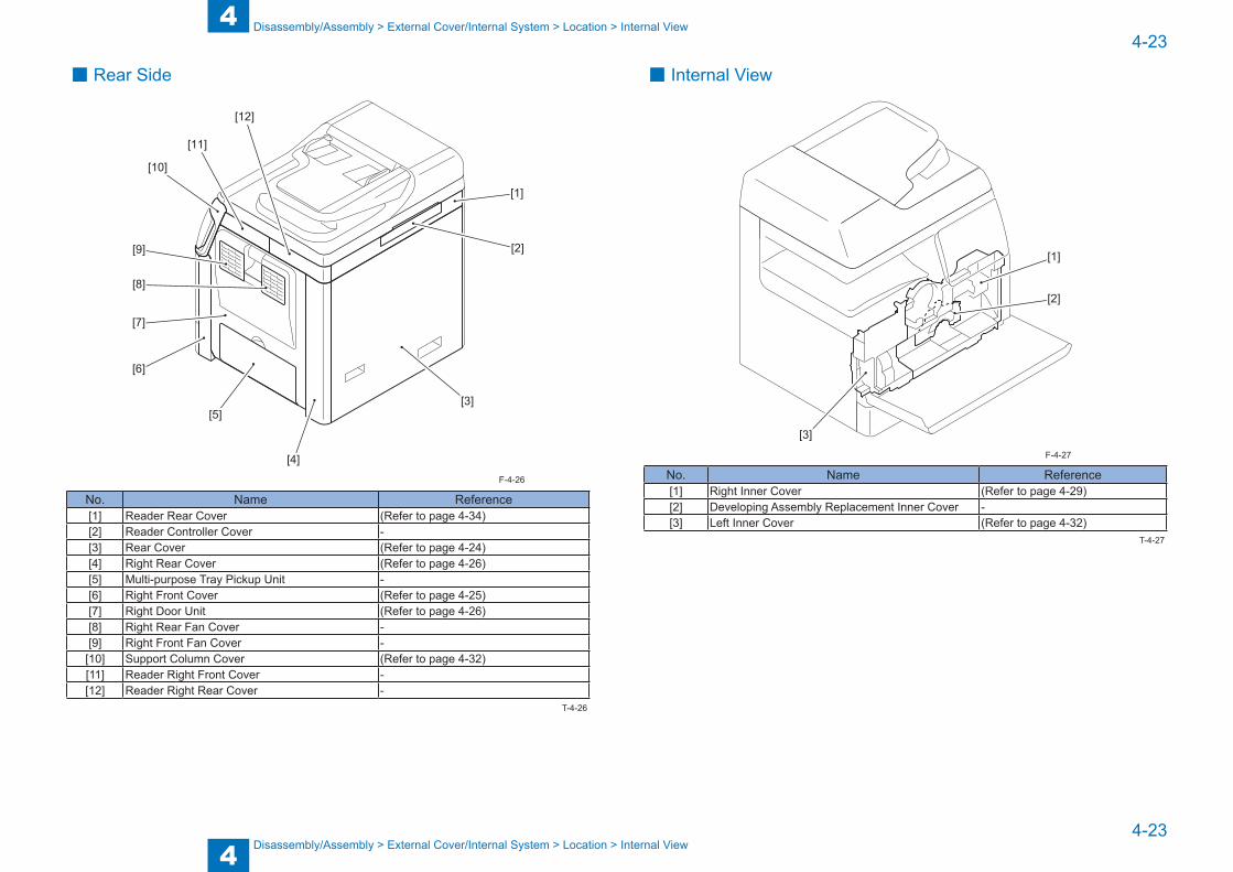
4
44-23
4-23
Disassembly/Assembly > External Cover/Internal System > Location > Internal View
Disassembly/Assembly > External Cover/Internal System > Location > Internal View
■ Rear Side
[10]
[11]
[12]
[1]
[2]
[3]
[4]
[5]
[6]
[7]
[8]
[9]
No. Name Reference[1] Reader Rear Cover (Refer to page 4-34)[2] Reader Controller Cover -[3] Rear Cover (Refer to page 4-24)[4] Right Rear Cover (Refer to page 4-26)[5] Multi-purpose Tray Pickup Unit -[6] Right Front Cover (Refer to page 4-25)[7] Right Door Unit (Refer to page 4-26)[8] Right Rear Fan Cover -[9] Right Front Fan Cover -
[10] Support Column Cover (Refer to page 4-32)[11] Reader Right Front Cover -[12] Reader Right Rear Cover -
F-4-26
T-4-26
■ Internal View
[1]
[2]
[3]
No. Name Reference[1] Right Inner Cover (Refer to page 4-29)[2] Developing Assembly Replacement Inner Cover -[3] Left Inner Cover (Refer to page 4-32)
F-4-27
T-4-27
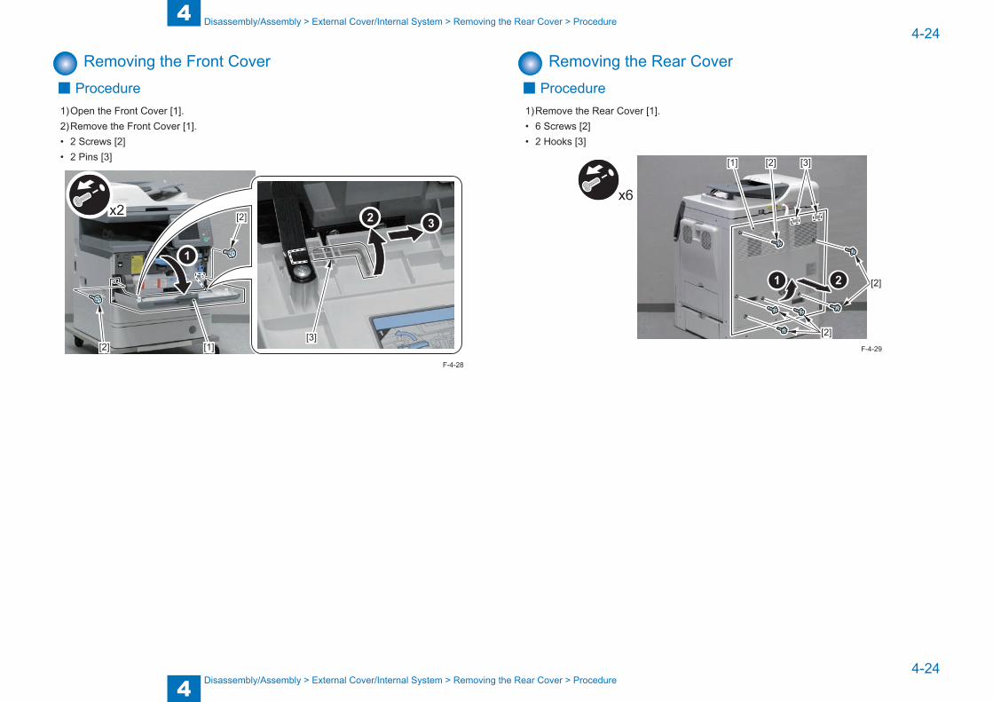
4
44-24
4-24
Disassembly/Assembly > External Cover/Internal System > Removing the Rear Cover > Procedure
Disassembly/Assembly > External Cover/Internal System > Removing the Rear Cover > Procedure
Removing the Front Cover ■ Procedure
1) Open the Front Cover [1].2) Remove the Front Cover [1].• 2 Screws [2]• 2 Pins [3]
x2
[1][2]
[2]
[3]
F-4-28
Removing the Rear Cover ■ Procedure
1) Remove the Rear Cover [1].• 6 Screws [2]• 2 Hooks [3]
[2]
[2]
[2] [3]
x6
[1]
F-4-29
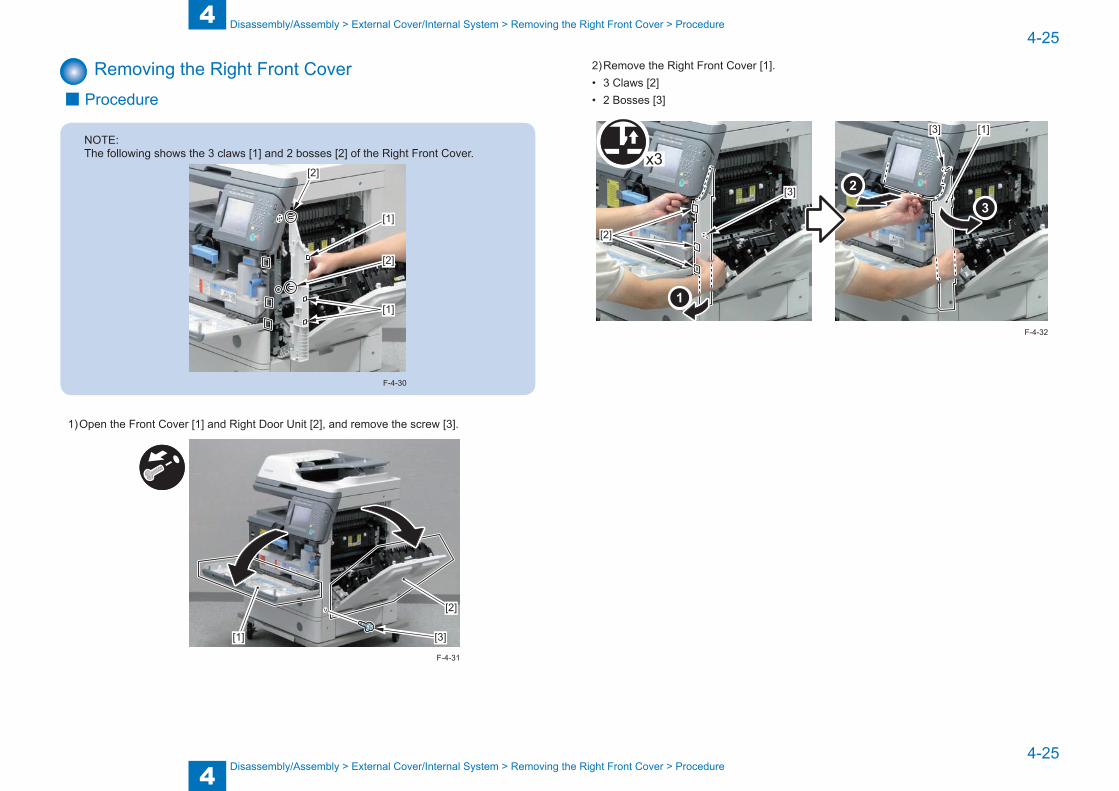
4
44-25
4-25
Disassembly/Assembly > External Cover/Internal System > Removing the Right Front Cover > Procedure
Disassembly/Assembly > External Cover/Internal System > Removing the Right Front Cover > Procedure
Removing the Right Front Cover ■ Procedure
NOTE:The following shows the 3 claws [1] and 2 bosses [2] of the Right Front Cover.
[1]
[1]
[2]
[2]
F-4-30
1) Open the Front Cover [1] and Right Door Unit [2], and remove the screw [3].
[1]
[2]
[3]
F-4-31
2) Remove the Right Front Cover [1].• 3 Claws [2]• 2 Bosses [3]
x3
[2]
[3]
[3] [1]
F-4-32

4
44-26
4-26
Disassembly/Assembly > External Cover/Internal System > Removing the Right Door Unit > Procedure
Disassembly/Assembly > External Cover/Internal System > Removing the Right Door Unit > Procedure
Removing the Right Rear Cover ■ Procedure
NOTE:The following shows the 2 claws [1], 1 boss [2] and 1 hook [3].
[1]
[1]
[2]
[3]
F-4-33
1) Open the Right Door Unit [1].2) Remove the Right Rear Cover [2].• 1 Screw [3]• 2 Claws [4]• 1 Boss [5]• 1 Hook [6]
[3][1]
[4]
[4]
[2]
[6]
[5]x2
F-4-34
Removing the Right Door Unit ■ Preparation
1) Remove the Right Front Cover.(Refer to page 4-25)2) Remove the Right Rear Cover.(Refer to page 4-26)
■ Procedure1) Pull out the cassette.2) While holding the Right Door Unit, remove the 2 Door Fixtures [1] on the Rear and Front.• 2 Screws [2]
x2
[1]
[1]
[2]
[2]
F-4-35

4
44-27
4-27
Disassembly/Assembly > External Cover/Internal System > Removing the Left Cover > Procedure
Disassembly/Assembly > External Cover/Internal System > Removing the Left Cover > Procedure
3) Remove the Right Door Unit [1].• 2 Wire Saddle [2]• 2 Connectors [3]• 5 Screws [4]
x3[1]
[4]
[3]
[4]
x2
x2
x2[2]
[2]
[3]
F-4-36
Removing the Left Cover ■ Preparation
1) Remove the Rear Cover.(Refer to page 4-24)2) Remove the Delivery Outer Cover.(Refer to page 4-29)
■ Procedure1) Open the cassette [1], and remove the Left Cover [2] while lifting the host machine.• 1 Screw [3]• 5 Claws [4]• 4 Hooks [5]
CAUTION:
When lifting the host machine, hold the rear side of the bottom of the Reader Unit.
F-4-37

4
44-28
4-28
Disassembly/Assembly > External Cover/Internal System > Removing the Inner Rear Cover > Procedure
Disassembly/Assembly > External Cover/Internal System > Removing the Inner Rear Cover > Procedure
x5
[1][4]
[4]
[2]
[3]
[5]
[5]
F-4-38
Removing the Inner Rear Cover ■ Preparation
1) Remove the Rear Cover.(Refer to page 4-24)2) Remove the Delivery Outer Cover.(Refer to page 4-29)3) Remove the Left Cover.(Refer to page 4-27)
■ Procedure1) Remove the Inner Rear Cover [1].• 1 Claw [2]• 6 Hooks [3]
[1]
[2] [3]
[3]
[3]
F-4-39

4
44-29
4-29
Disassembly/Assembly > External Cover/Internal System > Removing the Delivery Inner Cover > Procedure
Disassembly/Assembly > External Cover/Internal System > Removing the Delivery Inner Cover > Procedure
Removing the Delivery Outer Cover ■ Procedure
1) Open the Front Cover [1], and remove the Delivery Outer Cover [2].• 1 Claw [3]• 3 Hooks [4]
[1] [2]
[3] [4]
F-4-40
Removing the Delivery Inner Cover ■ Preparation
1) Remove the Rear Cover.(Refer to page 4-24)2) Remove the Delivery Outer Cover.(Refer to page 4-29)3) Remove the Left Cover.(Refer to page 4-27)4) Remove the Inner Rear Cover.(Refer to page 4-28)
■ Procedure1) Remove the Control Panel Unit [1].2) Remove the Delivery Inner Cover [2].• 1 Claw [3]
[1]
[2]
[3]
F-4-41
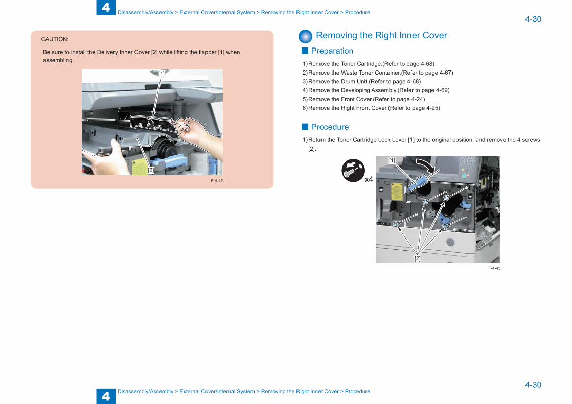
4
44-30
4-30
Disassembly/Assembly > External Cover/Internal System > Removing the Right Inner Cover > Procedure
Disassembly/Assembly > External Cover/Internal System > Removing the Right Inner Cover > Procedure
CAUTION:
Be sure to install the Delivery Inner Cover [2] while lifting the flapper [1] when assembling.
[2]
[1]
F-4-42
Removing the Right Inner Cover ■ Preparation
1) Remove the Toner Cartridge.(Refer to page 4-68)2) Remove the Waste Toner Container.(Refer to page 4-67)3) Remove the Drum Unit.(Refer to page 4-68)4) Remove the Developing Assembly.(Refer to page 4-69)5) Remove the Front Cover.(Refer to page 4-24)6) Remove the Right Front Cover.(Refer to page 4-25)
■ Procedure1) Return the Toner Cartridge Lock Lever [1] to the original position, and remove the 4 screws
[2].
x4
[2]
[1]
F-4-43
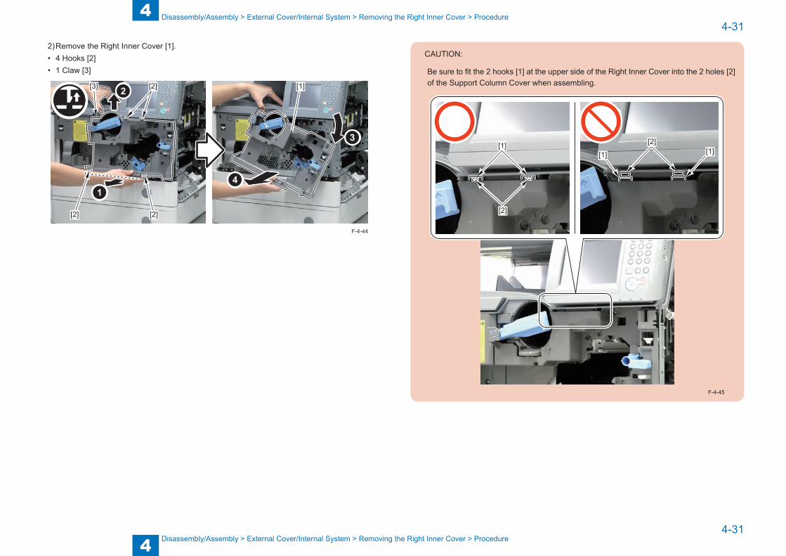
4
44-31
4-31
Disassembly/Assembly > External Cover/Internal System > Removing the Right Inner Cover > Procedure
Disassembly/Assembly > External Cover/Internal System > Removing the Right Inner Cover > Procedure
2) Remove the Right Inner Cover [1].• 4 Hooks [2]• 1 Claw [3]
[1]
[2] [2]
[3] [2]
F-4-44
CAUTION:
Be sure to fit the 2 hooks [1] at the upper side of the Right Inner Cover into the 2 holes [2] of the Support Column Cover when assembling.
[1][1] [1]
[2]
[2]
F-4-45

4
44-32
4-32
Disassembly/Assembly > External Cover/Internal System > Removing the Support Column Cover > Procedure
Disassembly/Assembly > External Cover/Internal System > Removing the Support Column Cover > Procedure
Removing the Left Inner Cover ■ Preparation
1) Remove the Toner Cartridge.(Refer to page 4-68)2) Remove the Waste Toner Container.(Refer to page 4-67)3) Remove the Drum Unit.(Refer to page 4-68)4) Remove the Developing Assembly.(Refer to page 4-69)5) Remove the Front Cover.(Refer to page 4-24)6) Remove the Right Front Cover.(Refer to page 4-25)7) Remove the Right Inner Cover.(Refer to page 4-30)
■ Procedure1) Remove the Left Inner Cover [1].• 3 Screws [2]
x3[1]
[2]
[2]
F-4-46
Removing the Support Column Cover ■ Preparation
1) Remove the Rear Cover.(Refer to page 4-24)2) Remove the Delivery Outer Cover.(Refer to page 4-29)3) Remove the Left Cover.(Refer to page 4-27)4) Remove the Inner Rear Cover.(Refer to page 4-28)5) Remove the Delivery Inner Cover.(Refer to page 4-29)6) Remove the Reader Front Cover.(Refer to page 4-33)7) Remove the Right Front Cover.(Refer to page 4-25)
■ Procedure1) Lift the Control Panel Unit [1], and remove the Support Column Cover [2].• 1 Claw [3]• 1 Boss [4]
[1]
[2]
[3][4]
F-4-47
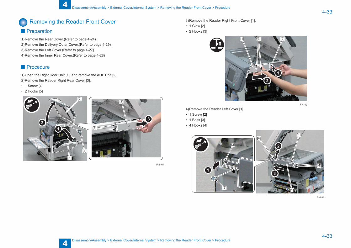
4
44-33
4-33
Disassembly/Assembly > External Cover/Internal System > Removing the Reader Front Cover > Procedure
Disassembly/Assembly > External Cover/Internal System > Removing the Reader Front Cover > Procedure
Removing the Reader Front Cover ■ Preparation
1) Remove the Rear Cover.(Refer to page 4-24)2) Remove the Delivery Outer Cover.(Refer to page 4-29)3) Remove the Left Cover.(Refer to page 4-27)4) Remove the Inner Rear Cover.(Refer to page 4-28)
■ Procedure1) Open the Right Door Unit [1], and remove the ADF Unit [2].2) Remove the Reader Right Rear Cover [3].• 1 Screw [4]• 2 Hooks [5]
[1]
[2][3]
[4]
[5]
F-4-48
3) Remove the Reader Right Front Cover [1].• 1 Claw [2]• 2 Hooks [3]
[1] [2][3]
4) Remove the Reader Left Cover [1].• 1 Screw [2]• 1 Boss [3]• 4 Hooks [4]
[1]
[4][4]
[4]
[2]
[3]
F-4-49
F-4-50
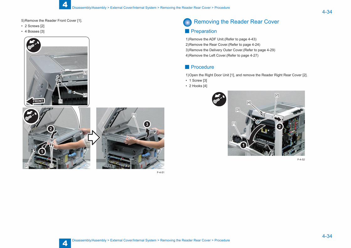
4
44-34
4-34
Disassembly/Assembly > External Cover/Internal System > Removing the Reader Rear Cover > Procedure
Disassembly/Assembly > External Cover/Internal System > Removing the Reader Rear Cover > Procedure
5) Remove the Reader Front Cover [1].• 2 Screws [2]• 4 Bosses [3]
[1]
[3][2]
[3]
[3]
[2]
F-4-51
Removing the Reader Rear Cover ■ Preparation
1) Remove the ADF Unit.(Refer to page 4-43)2) Remove the Rear Cover.(Refer to page 4-24)3) Remove the Delivery Outer Cover.(Refer to page 4-29)4) Remove the Left Cover.(Refer to page 4-27)
■ Procedure1) Open the Right Door Unit [1], and remove the Reader Right Rear Cover [2].• 1 Screw [3]• 2 Hooks [4]
[1]
[2]
[3]
[4]
F-4-52
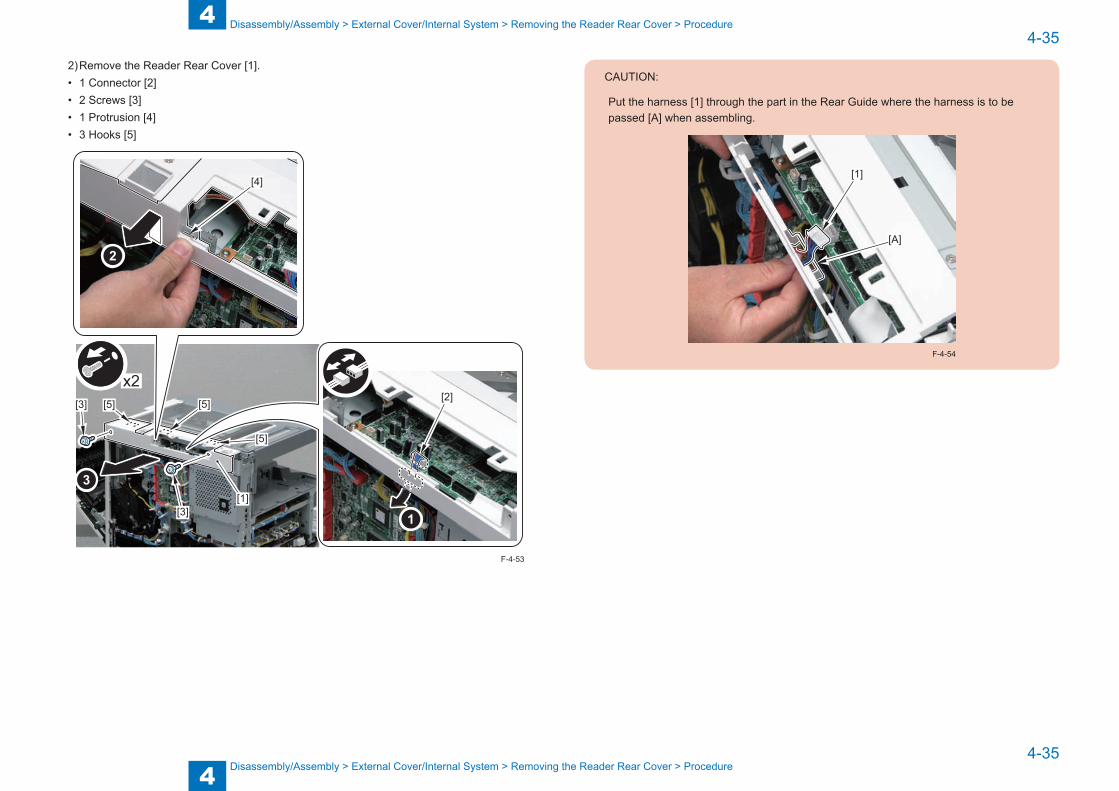
4
44-35
4-35
Disassembly/Assembly > External Cover/Internal System > Removing the Reader Rear Cover > Procedure
Disassembly/Assembly > External Cover/Internal System > Removing the Reader Rear Cover > Procedure
2) Remove the Reader Rear Cover [1].• 1 Connector [2]• 2 Screws [3]• 1 Protrusion [4]• 3 Hooks [5]
x2
[4]
[1]
[3]
[3]
[5] [5]
[5]
[2]
F-4-53
CAUTION:
Put the harness [1] through the part in the Rear Guide where the harness is to be passed [A] when assembling.
[1]
[A]
F-4-54
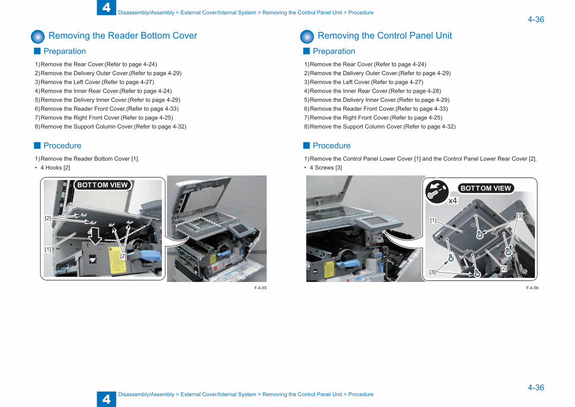
4
44-36
4-36
Disassembly/Assembly > External Cover/Internal System > Removing the Control Panel Unit > Procedure
Disassembly/Assembly > External Cover/Internal System > Removing the Control Panel Unit > Procedure
Removing the Reader Bottom Cover ■ Preparation
1) Remove the Rear Cover.(Refer to page 4-24)2) Remove the Delivery Outer Cover.(Refer to page 4-29)3) Remove the Left Cover.(Refer to page 4-27)4) Remove the Inner Rear Cover.(Refer to page 4-24)5) Remove the Delivery Inner Cover.(Refer to page 4-29)6) Remove the Reader Front Cover.(Refer to page 4-33)7) Remove the Right Front Cover.(Refer to page 4-25)8) Remove the Support Column Cover.(Refer to page 4-32)
■ Procedure1) Remove the Reader Bottom Cover [1].• 4 Hooks [2]
[2]
[2][1]
F-4-55
Removing the Control Panel Unit ■ Preparation
1) Remove the Rear Cover.(Refer to page 4-24)2) Remove the Delivery Outer Cover.(Refer to page 4-29)3) Remove the Left Cover.(Refer to page 4-27)4) Remove the Inner Rear Cover.(Refer to page 4-28)5) Remove the Delivery Inner Cover.(Refer to page 4-29)6) Remove the Reader Front Cover.(Refer to page 4-33)7) Remove the Right Front Cover.(Refer to page 4-25)8) Remove the Support Column Cover.(Refer to page 4-32)
■ Procedure1) Remove the Control Panel Lower Cover [1] and the Control Panel Lower Rear Cover [2].• 4 Screws [3]
x4
[3]
[3][1]
[2]
F-4-56

4
44-37
4-37
Disassembly/Assembly > External Cover/Internal System > Removing the Control Panel Unit > Procedure
Disassembly/Assembly > External Cover/Internal System > Removing the Control Panel Unit > Procedure
2) Disconnect the Flat Cable [1].• 1 Guide [2]
[1]
[2]
F-4-57
3) Remove the Control Panel Unit [1].• 4 Screws [2]• 1 Hook [3]
x2 x2
[2]
[2]
[2]
[1]
[2]
[3]
F-4-58
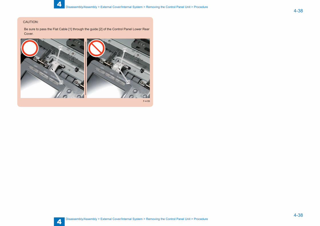
4
44-38
4-38
Disassembly/Assembly > External Cover/Internal System > Removing the Control Panel Unit > Procedure
Disassembly/Assembly > External Cover/Internal System > Removing the Control Panel Unit > Procedure
CAUTION:
Be sure to pass the Flat Cable [1] through the guide [2] of the Control Panel Lower Rear Cover.
[1]
[2] [2]
[1]
F-4-59

4
44-39
4-39
Disassembly/Assembly > Original Exposure/Feed System > Location
Disassembly/Assembly > Original Exposure/Feed System > Location
Original Exposure/Feed System
Location
[7]
[6]
[4]
[2]
[1]
[3]
[5]
[9]
[8]
[10]
[11]
F-4-60
No. Name Main Unit Reference Adjastment during parts replacement
[1] ADF Separation Pad ADF Pickup Unit (Refer to page 4-50)[2] ADF Pickup Roller Unit ADF Upper Cover Unit (Refer to page 4-51)[3] ADF Upper Cover Unit ADF Unit (Refer to page 4-48)[4] ADF Pickup Tray ADF Unit (Refer to page 4-52)[5] ADF Pickup Unit ADF Unit (Refer to page 4-53)[6] ADF Unit Main Unit (Refer to page 4-43)[7] Reader Unit Main Unit (Refer to page 4-44)[8] Copyboard Glass Reader Unit (Refer to page 4-40)[9] CIS Unit Reader Unit (Refer to page 4-47)
[10] ADF Reading Glass Reader Unit (Refer to page 4-42)[11] Reader Controller PCB Reader Unit (Refer to page 4-46)
T-4-28
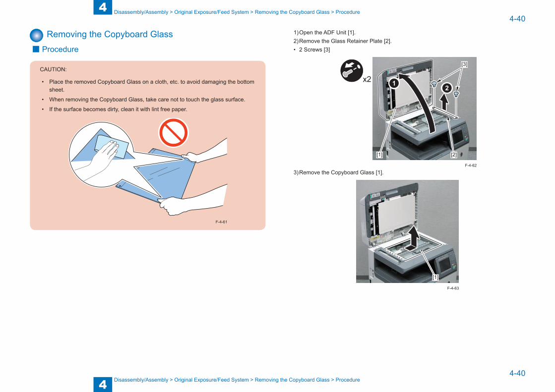
4
44-40
4-40
Disassembly/Assembly > Original Exposure/Feed System > Removing the Copyboard Glass > Procedure
Disassembly/Assembly > Original Exposure/Feed System > Removing the Copyboard Glass > Procedure
Removing the Copyboard Glass ■ Procedure
CAUTION:
• Place the removed Copyboard Glass on a cloth, etc. to avoid damaging the bottom sheet.
• When removing the Copyboard Glass, take care not to touch the glass surface.
• If the surface becomes dirty, clean it with lint free paper.
F-4-61
1) Open the ADF Unit [1].2) Remove the Glass Retainer Plate [2].• 2 Screws [3]
x2
[1]
[3]
[2]
3) Remove the Copyboard Glass [1].
[1]
F-4-62
F-4-63
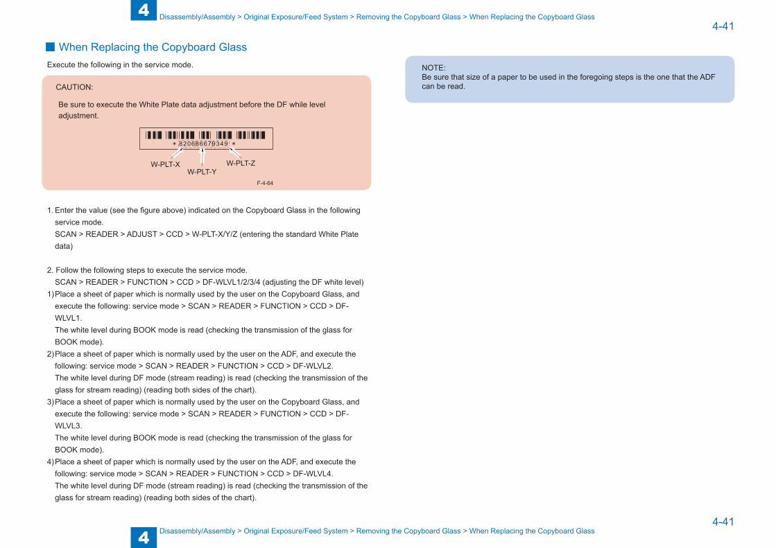
4
44-41
4-41
Disassembly/Assembly > Original Exposure/Feed System > Removing the Copyboard Glass > When Replacing the Copyboard Glass
Disassembly/Assembly > Original Exposure/Feed System > Removing the Copyboard Glass > When Replacing the Copyboard Glass
■When Replacing the Copyboard GlassExecute the following in the service mode.
CAUTION:
Be sure to execute the White Plate data adjustment before the DF while level adjustment.
W-PLT-XW-PLT-Y
W-PLT-Z
F-4-64
1. Enter the value (see the figure above) indicated on the Copyboard Glass in the following service mode. SCAN > READER > ADJUST > CCD > W-PLT-X/Y/Z (entering the standard White Plate data)
2. Follow the following steps to execute the service mode.SCAN > READER > FUNCTION > CCD > DF-WLVL1/2/3/4 (adjusting the DF white level)
1) Place a sheet of paper which is normally used by the user on the Copyboard Glass, and execute the following: service mode > SCAN > READER > FUNCTION > CCD > DF-WLVL1.The white level during BOOK mode is read (checking the transmission of the glass for BOOK mode).
2) Place a sheet of paper which is normally used by the user on the ADF, and execute the following: service mode > SCAN > READER > FUNCTION > CCD > DF-WLVL2.The white level during DF mode (stream reading) is read (checking the transmission of the glass for stream reading) (reading both sides of the chart).
3) Place a sheet of paper which is normally used by the user on the Copyboard Glass, and execute the following: service mode > SCAN > READER > FUNCTION > CCD > DF-WLVL3.The white level during BOOK mode is read (checking the transmission of the glass for BOOK mode).
4) Place a sheet of paper which is normally used by the user on the ADF, and execute the following: service mode > SCAN > READER > FUNCTION > CCD > DF-WLVL4.The white level during DF mode (stream reading) is read (checking the transmission of the glass for stream reading) (reading both sides of the chart).
NOTE:Be sure that size of a paper to be used in the foregoing steps is the one that the ADF can be read.
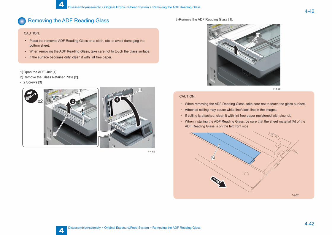
4
44-42
4-42
Disassembly/Assembly > Original Exposure/Feed System > Removing the ADF Reading Glass
Disassembly/Assembly > Original Exposure/Feed System > Removing the ADF Reading Glass
Removing the ADF Reading Glass
CAUTION:
• Place the removed ADF Reading Glass on a cloth, etc. to avoid damaging the bottom sheet.
• When removing the ADF Reading Glass, take care not to touch the glass surface.
• If the surface becomes dirty, clean it with lint free paper.
1) Open the ADF Unit [1].2) Remove the Glass Retainer Plate [2].• 2 Screws [3]
[1]
x2
[3]
[2]
F-4-65
3) Remove the ADF Reading Glass [1].
[1]
CAUTION:
• When removing the ADF Reading Glass, take care not to touch the glass surface.
• Attached soiling may cause white line/black line in the images.
• If soiling is attached, clean it with lint free paper moistened with alcohol.
• When installing the ADF Reading Glass, be sure that the sheet material [A] of the ADF Reading Glass is on the left front side.
[A]
F-4-67
F-4-66

4
44-43
4-43
Disassembly/Assembly > Original Exposure/Feed System > Removing the ADF Unit > Procedure
Disassembly/Assembly > Original Exposure/Feed System > Removing the ADF Unit > Procedure
■When Replacing the ADF Reading Glass1. Follow the following steps to execute the service mode.
SCAN > READER > FUNCTION > CCD > DF-WLVL1/2/3/4 (adjusting the DF white level)1) Place a sheet of paper which is normally used by the user on the Copyboard Glass, and
execute the following: service mode > SCAN > READER > FUNCTION > CCD > DF-WLVL1.The white level during BOOK mode is read (checking the transmission of the glass for BOOK mode).
2) Place a sheet of paper which is normally used by the user on the ADF, and execute the following: service mode > SCAN > READER > FUNCTION > CCD > DF-WLVL2.The white level during DF mode (stream reading) is read (checking the transmission of the glass for stream reading) (reading both sides of the chart).
3) Place a sheet of paper which is normally used by the user on the Copyboard Glass, and execute the following: service mode > SCAN > READER > FUNCTION > CCD > DF-WLVL3.The white level during BOOK mode is read (checking the transmission of the glass for BOOK mode).
4) Place a sheet of paper which is normally used by the user on the ADF, and execute the following: service mode > SCAN > READER > FUNCTION > CCD > DF-WLVL4.The white level during DF mode (stream reading) is read (checking the transmission of the glass for stream reading) (reading both sides of the chart).
NOTE:Be sure that size of a paper to be used in the foregoing steps is the one that the ADF can be read.
Removing the ADF Unit ■ Procedure
1) Remove the Reader Controller Cover [1].• 2 Claws [2]
x2[1]
[2]
[2]
2) Remove the 5 connectors [1] and the Grounding Wire [2] of the ADF Harness.• 1 Screw [3]
x5
[2]
[3] [1] [1]
F-4-68
F-4-69
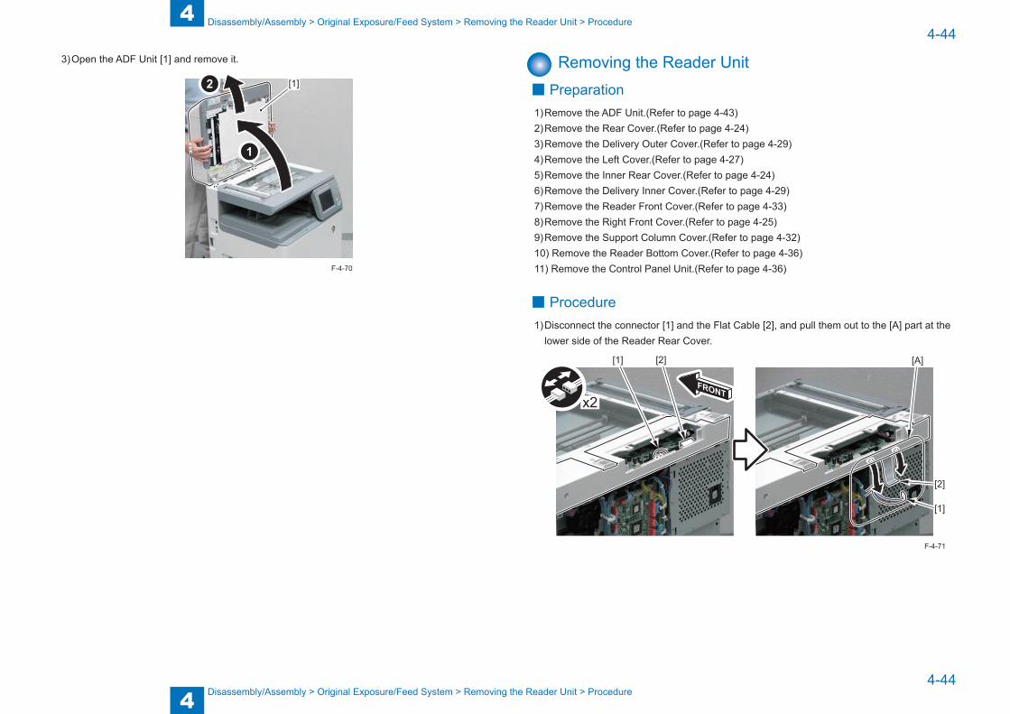
4
44-44
4-44
Disassembly/Assembly > Original Exposure/Feed System > Removing the Reader Unit > Procedure
Disassembly/Assembly > Original Exposure/Feed System > Removing the Reader Unit > Procedure
3) Open the ADF Unit [1] and remove it.
[1]
F-4-70
Removing the Reader Unit ■ Preparation
1) Remove the ADF Unit.(Refer to page 4-43)2) Remove the Rear Cover.(Refer to page 4-24)3) Remove the Delivery Outer Cover.(Refer to page 4-29)4) Remove the Left Cover.(Refer to page 4-27)5) Remove the Inner Rear Cover.(Refer to page 4-24)6) Remove the Delivery Inner Cover.(Refer to page 4-29)7) Remove the Reader Front Cover.(Refer to page 4-33)8) Remove the Right Front Cover.(Refer to page 4-25)9) Remove the Support Column Cover.(Refer to page 4-32)10) Remove the Reader Bottom Cover.(Refer to page 4-36)11) Remove the Control Panel Unit.(Refer to page 4-36)
■ Procedure1) Disconnect the connector [1] and the Flat Cable [2], and pull them out to the [A] part at the
lower side of the Reader Rear Cover.
x2
[1] [2]
[1]
[A]
[2]
F-4-71

4
44-45
4-45
Disassembly/Assembly > Original Exposure/Feed System > Removing the Reader Unit > Procedure
Disassembly/Assembly > Original Exposure/Feed System > Removing the Reader Unit > Procedure
2) Pass the Flat Cable [1] through the hole [A] of the plate and downward.3) Remove the 2 Screws [2].
[1] [2][A]
x2
4) Remove the Reader Right Front Fixation Plate [1] and the Reader Right Rear Fixation Plate [2].
• 4 Screws [3]
x4
[1] [2] [3]
[3]
F-4-72
F-4-73
5) Remove the Reader Unit [1].• 4 Screws [2]
x4
[1]
[2]
F-4-74

4
44-46
4-46
Disassembly/Assembly > Original Exposure/Feed System > Removing the Reader Controller PCB > Procedure
Disassembly/Assembly > Original Exposure/Feed System > Removing the Reader Controller PCB > Procedure
Removing the Reader Controller PCB ■ Preparation
1) Remove the ADF Unit.(Refer to page 4-43)2) Remove the Rear Cover.(Refer to page 4-24)3) Remove the Delivery Outer Cover.(Refer to page 4-29)4) Remove the Left Cover.(Refer to page 4-27)5) Remove the Reader Rear Cover.(Refer to page 4-34)6) Remove the Copyboard Glass.(Refer to page 4-40)
■ Procedure1) Remove the Reader Controller PCB [1].• 1 Harness Retainer [2]• 3 Connectors [3]• 2 Flat Cables [4]• 2 Screws [5]
x2 x5
[1][2]
[3]
[3]
[3][4]
[4][5]
[5]
F-4-75
CAUTION:
Fit the Reader Controller PCB [1] into the 2 grooves [A] of the plate when assembling.
[1]
[A]
F-4-76
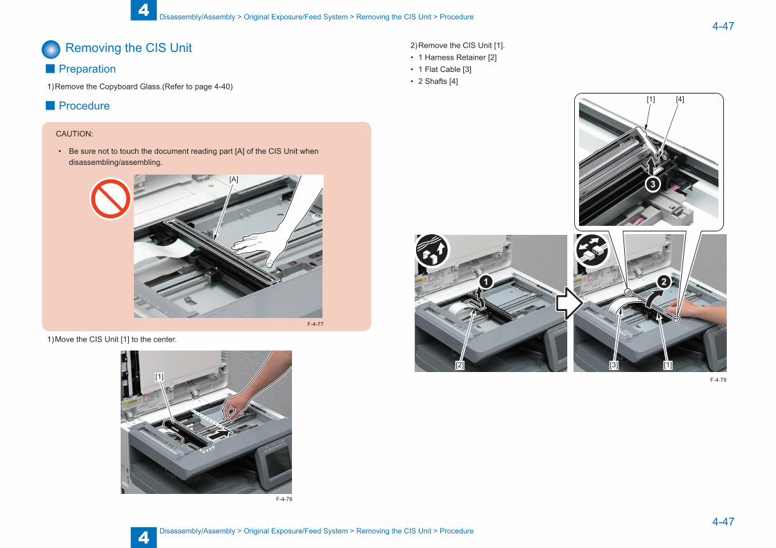
4
44-47
4-47
Disassembly/Assembly > Original Exposure/Feed System > Removing the CIS Unit > Procedure
Disassembly/Assembly > Original Exposure/Feed System > Removing the CIS Unit > Procedure
Removing the CIS Unit ■ Preparation
1) Remove the Copyboard Glass.(Refer to page 4-40)
■ Procedure
CAUTION:
• Be sure not to touch the document reading part [A] of the CIS Unit when disassembling/assembling.
[A]
F-4-77
1) Move the CIS Unit [1] to the center.
[1]
F-4-78
2) Remove the CIS Unit [1].• 1 Harness Retainer [2]• 1 Flat Cable [3]• 2 Shafts [4]
[1]
[1]
[2] [3]
[4]
F-4-79

4
44-48
4-48
Disassembly/Assembly > Original Exposure/Feed System > Removing the ADF Upper Cover Unit > Procedure
Disassembly/Assembly > Original Exposure/Feed System > Removing the ADF Upper Cover Unit > Procedure
■When Replacing the CIS UnitPerform the following operation after replacing the CIS Unit.
● CIS gain and offset correction1) Enter service mode.
SCAN > READER > FUNCTION > CCD > CCD-ADJ2) Press "OK".
After this operation, output correction of the Contact Image Sensor is automatically performed to set the parameter.
3) After auto adjustment is completed, OK is displayed. (It will take approx. 15 seconds for this adjustment. During that time, display on the Control Panel will not be changed.)
● DF white level adjustment (book mode scan/stream reading scan)1) Place a sheet of paper which is normally used by the user on the Copyboard Glass,
and execute the following: service mode > SCAN > READER > FUNCTION > CCD > DFWLVL1.The white level during BOOK mode is read (checking the transmission of the glass for BOOK mode).
2) Place a sheet of paper which is normally used by the user on the ADF, and execute the following: service mode > SCAN > READER > FUNCTION > CCD > DF-WLVL2.The white level during DF mode (stream reading) is read (checking the transmission of the glass for stream reading) (reading both sides of the chart).
3) Place a sheet of paper which is normally used by the user on the Copyboard Glass, and execute the following: service mode > SCAN > READER > FUNCTION > CCD > DF-WLVL3.The white level during BOOK mode is read (checking the transmission of the glass for BOOK mode).
4) Place a sheet of paper which is normally used by the user on the ADF, and execute the following: service mode > SCAN > READER > FUNCTION > CCD > DF-WLVL4.The white level during DF mode (stream reading) is read (checking the transmission of the glass for stream reading) (reading both sides of the chart).
Removing the ADF Upper Cover Unit ■ Procedure
CAUTION:
Be sure not to touch the surface of the Roller and the Pad when disassembling/assembling.
1) While pulling the [A] part of the ADF Front Cover, release the [B] part which works as an open/close stopper and open the ADF Upper Cover Unit [1].
[1] [A][B]
F-4-80
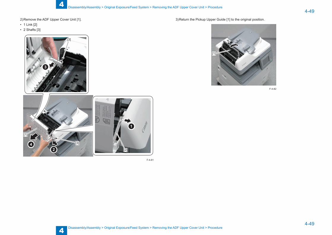
4
44-49
4-49
Disassembly/Assembly > Original Exposure/Feed System > Removing the ADF Upper Cover Unit > Procedure
Disassembly/Assembly > Original Exposure/Feed System > Removing the ADF Upper Cover Unit > Procedure
2) Remove the ADF Upper Cover Unit [1].• 1 Link [2]• 2 Shafts [3]
[3]
[3]
[2]
[1]
F-4-81
3) Return the Pickup Upper Guide [1] to the original position.
[1]
F-4-82
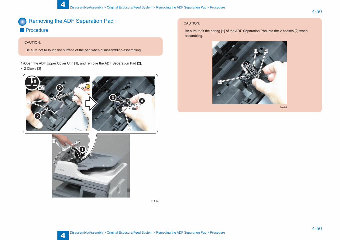
4
44-50
4-50
Disassembly/Assembly > Original Exposure/Feed System > Removing the ADF Separation Pad > Procedure
Disassembly/Assembly > Original Exposure/Feed System > Removing the ADF Separation Pad > Procedure
Removing the ADF Separation Pad ■ Procedure
CAUTION:
Be sure not to touch the surface of the pad when disassembling/assembling.
1) Open the ADF Upper Cover Unit [1], and remove the ADF Separation Pad [2].• 2 Claws [3]
x2
[3]
[1]
[2]
F-4-83
CAUTION:
Be sure to fit the spring [1] of the ADF Separation Pad into the 2 bosses [2] when assembling.
[2]
[1] [2]
F-4-84
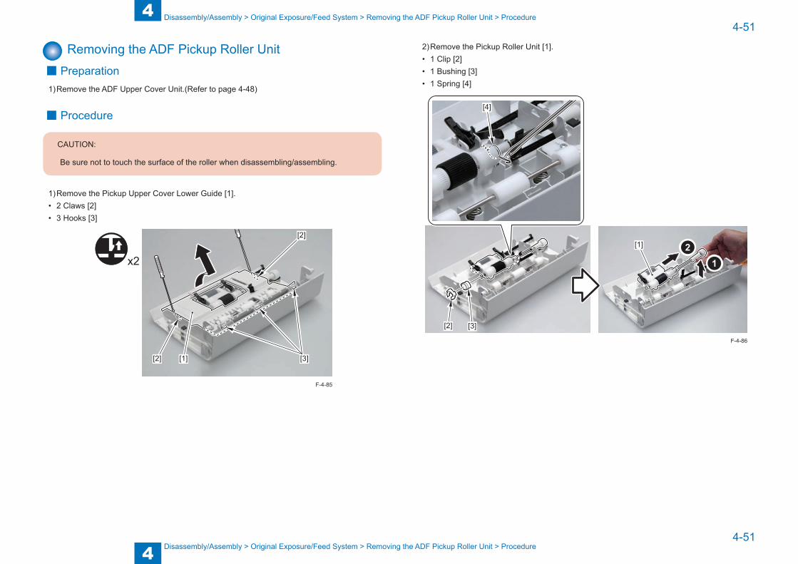
4
44-51
4-51
Disassembly/Assembly > Original Exposure/Feed System > Removing the ADF Pickup Roller Unit > Procedure
Disassembly/Assembly > Original Exposure/Feed System > Removing the ADF Pickup Roller Unit > Procedure
Removing the ADF Pickup Roller Unit ■ Preparation
1) Remove the ADF Upper Cover Unit.(Refer to page 4-48)
■ Procedure
CAUTION:
Be sure not to touch the surface of the roller when disassembling/assembling.
1) Remove the Pickup Upper Cover Lower Guide [1].• 2 Claws [2]• 3 Hooks [3]
[1]
[2]
[2] [3]
x2
F-4-85
2) Remove the Pickup Roller Unit [1].• 1 Clip [2]• 1 Bushing [3]• 1 Spring [4]
[2] [3]
[4]
[1]
F-4-86

4
44-52
4-52
Disassembly/Assembly > Original Exposure/Feed System > Removing the ADF Pickup Tray > Procedure
Disassembly/Assembly > Original Exposure/Feed System > Removing the ADF Pickup Tray > Procedure
CAUTION:
• Be sure to install the 4 flags [1] of the ADF Pickup Roller Unit under the 2 flags [2] of the Upper Cover Unit when assembling.
• Hook the 2 edges [3] of the spring on the 2 grooves [A] when assembling.
[1]
[1][2]
[1]
[3]
[3]
[A]
[A]
F-4-87
Removing the ADF Pickup Tray ■ Procedure
1) Open the ADF Upper Cover Unit [1], and remove the ADF Rear Cover [2].• 2 Screws [3]• 1 Claw [4]• 2 Boss [5]
x2
[2]
[3]
[5]
[1]
[4]
F-4-88
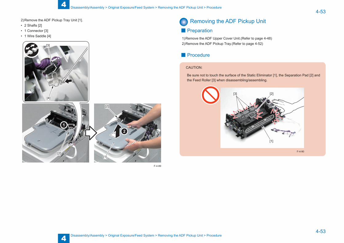
4
44-53
4-53
Disassembly/Assembly > Original Exposure/Feed System > Removing the ADF Pickup Unit > Procedure
Disassembly/Assembly > Original Exposure/Feed System > Removing the ADF Pickup Unit > Procedure
2) Remove the ADF Pickup Tray Unit [1].• 2 Shafts [2]• 1 Connector [3]• 1 Wire Saddle [4]
[1][2]
[2]
[3]
[4]
F-4-89
Removing the ADF Pickup Unit ■ Preparation
1) Remove the ADF Upper Cover Unit.(Refer to page 4-48)2) Remove the ADF Pickup Tray.(Refer to page 4-52)
■ Procedure
CAUTION:
Be sure not to touch the surface of the Static Eliminator [1], the Separation Pad [2] and the Feed Roller [3] when disassembling/assembling.
[1]
[2][3]
F-4-90
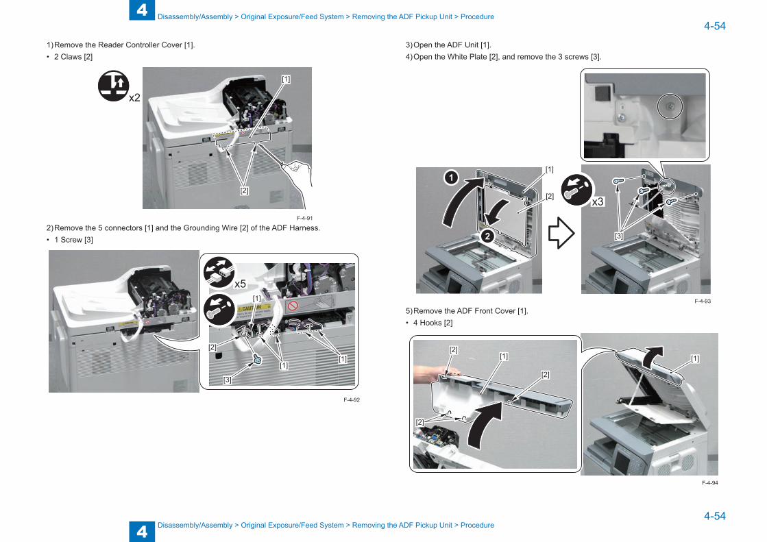
4
44-54
4-54
Disassembly/Assembly > Original Exposure/Feed System > Removing the ADF Pickup Unit > Procedure
Disassembly/Assembly > Original Exposure/Feed System > Removing the ADF Pickup Unit > Procedure
1) Remove the Reader Controller Cover [1].• 2 Claws [2]
x2
[1]
[2]
2) Remove the 5 connectors [1] and the Grounding Wire [2] of the ADF Harness.• 1 Screw [3]
x5
[2]
[3]
[1]
[1]
[1]
F-4-91
F-4-92
3) Open the ADF Unit [1].4) Open the White Plate [2], and remove the 3 screws [3].
x3
[3]
[1]
[2]
5) Remove the ADF Front Cover [1].• 4 Hooks [2]
[1][1][2]
[2]
[2]
F-4-93
F-4-94

4
44-55
4-55
Disassembly/Assembly > Original Exposure/Feed System > Removing the ADF Pickup Unit > Procedure
Disassembly/Assembly > Original Exposure/Feed System > Removing the ADF Pickup Unit > Procedure
6) Close the White Plate [1] and the ADF [2].
[1]
[2]
7) Remove the 4 screws [1].
[1]
[1]
x4
F-4-95
F-4-96
8) Remove the ADF Pickup Unit [1].• 1 Hook [2]
CAUTION:
When removing the ADF Pickup Unit, be careful that the ADF Unit becomes open due to its own weight becoming smaller.
F-4-97
[1]
[2]
F-4-98
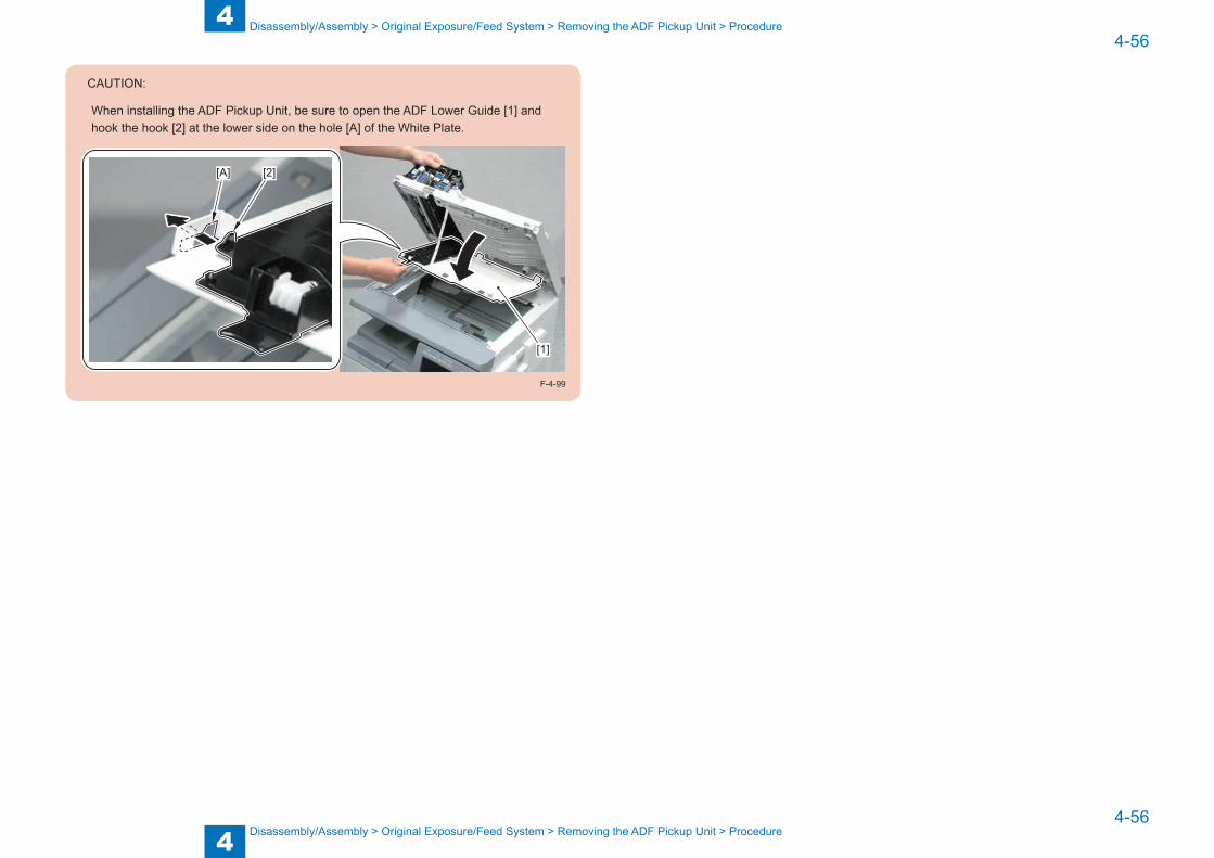
4
44-56
4-56
Disassembly/Assembly > Original Exposure/Feed System > Removing the ADF Pickup Unit > Procedure
Disassembly/Assembly > Original Exposure/Feed System > Removing the ADF Pickup Unit > Procedure
CAUTION:
When installing the ADF Pickup Unit, be sure to open the ADF Lower Guide [1] and hook the hook [2] at the lower side on the hole [A] of the White Plate.
[1]
[2][A]
F-4-99

4
44-57
4-57
Disassembly/Assembly > Controller System > Removing the DC Controller PCB > Procedure
Disassembly/Assembly > Controller System > Removing the DC Controller PCB > Procedure
Controller System
Location
[1]
[2]
[3]
[4]
No. Name Main Unit Reference Adjastment during parts replacement
[1] HVT PCB Main Unit (Refer to page 4-60)[2] Power Supply PCB Main Unit (Refer to page 4-62)[3] Main Controller PCB Main Unit (Refer to page 4-58)[4] DC Controller PCB Main Unit (Refer to page 4-57)
F-4-100
T-4-29
Removing the DC Controller PCB ■ Preparation before Replacement
1) Request the user to backup the user data using remote UI.2) If possible, output the data of the unprocessed jobs.
After replacing the DC Controller PCB, the data of the unprocessed jobs will be deleted.3) Print out the list of the service mode setting value in the service mode.
REPORT> REPORT OUTPUT> SERVICE DATA LIST
■ Preparation1) Remove the Rear Cover.(Refer to page 4-24)
■ Procedure1) Remove the DC Controller PCB [1].• 15 Connectors [2]• 4 Screws [3]
[1]
[2][2]
[2]
[2] [2]
[3][3]
[3]
[3]
x4
x15
F-4-101
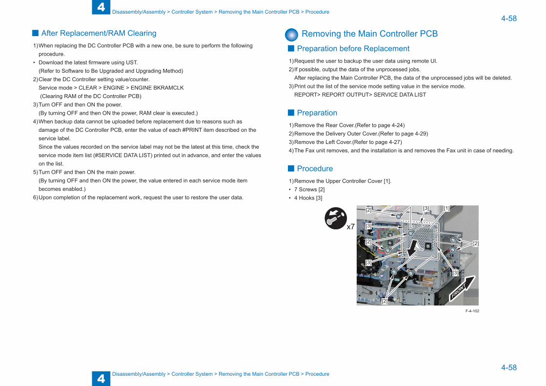
4
44-58
4-58
Disassembly/Assembly > Controller System > Removing the Main Controller PCB > Procedure
Disassembly/Assembly > Controller System > Removing the Main Controller PCB > Procedure
■ After Replacement/RAM Clearing1) When replacing the DC Controller PCB with a new one, be sure to perform the following
procedure.• Download the latest firmware using UST.
(Refer to Software to Be Upgraded and Upgrading Method)2) Clear the DC Controller setting value/counter.
Service mode > CLEAR > ENGINE > ENGINE BKRAMCLK (Clearing RAM of the DC Controller PCB)
3) Turn OFF and then ON the power.(By turning OFF and then ON the power, RAM clear is executed.)
4) When backup data cannot be uploaded before replacement due to reasons such as damage of the DC Controller PCB, enter the value of each #PRINT item described on the service label.Since the values recorded on the service label may not be the latest at this time, check the service mode item list (#SERVICE DATA LIST) printed out in advance, and enter the values on the list.
5) Turn OFF and then ON the main power.(By turning OFF and then ON the power, the value entered in each service mode item becomes enabled.)
6) Upon completion of the replacement work, request the user to restore the user data.
Removing the Main Controller PCB ■ Preparation before Replacement
1) Request the user to backup the user data using remote UI.2) If possible, output the data of the unprocessed jobs.
After replacing the Main Controller PCB, the data of the unprocessed jobs will be deleted.3) Print out the list of the service mode setting value in the service mode.
REPORT> REPORT OUTPUT> SERVICE DATA LIST
■ Preparation1) Remove the Rear Cover.(Refer to page 4-24)2) Remove the Delivery Outer Cover.(Refer to page 4-29)3) Remove the Left Cover.(Refer to page 4-27)4) The Fax unit removes, and the installation is and removes the Fax unit in case of needing.
■ Procedure1) Remove the Upper Controller Cover [1].• 7 Screws [2]• 4 Hooks [3]
x7
[1]
[2]
[3]
[3]
[3]
[3]
[2]
[2]
[2]
F-4-102
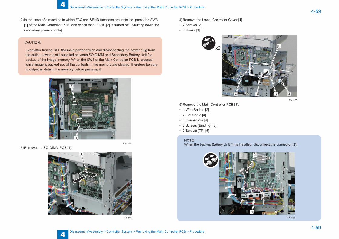
4
44-59
4-59
Disassembly/Assembly > Controller System > Removing the Main Controller PCB > Procedure
Disassembly/Assembly > Controller System > Removing the Main Controller PCB > Procedure
2) In the case of a machine in which FAX and SEND functions are installed, press the SW3 [1] of the Main Controller PCB, and check that LED10 [2] is turned off. (Shutting down the secondary power supply)
CAUTION:
Even after turning OFF the main power switch and disconnecting the power plug from the outlet, power is still supplied between SO-DIMM and Secondary Battery Unit for backup of the image memory. When the SW3 of the Main Controller PCB is pressed while image is backed up, all the contents in the memory are cleared, therefore be sure to output all data in the memory before pressing it.
[1]
[2]
3) Remove the SO-DIMM PCB [1].
[1]
F-4-103
F-4-104
4) Remove the Lower Controller Cover [1].• 2 Screws [2]• 2 Hooks [3]
[1]
[2] [2][3] [3]
x2
5) Remove the Main Controller PCB [1].• 1 Wire Saddle [2]• 2 Flat Cable [3]• 6 Connectors [4]• 2 Screws (Binding) [5]• 7 Screws (TP) [6]
NOTE:When the backup Battery Unit [1] is installed, disconnect the connector [2].
[1]
[2]
F-4-106
F-4-105
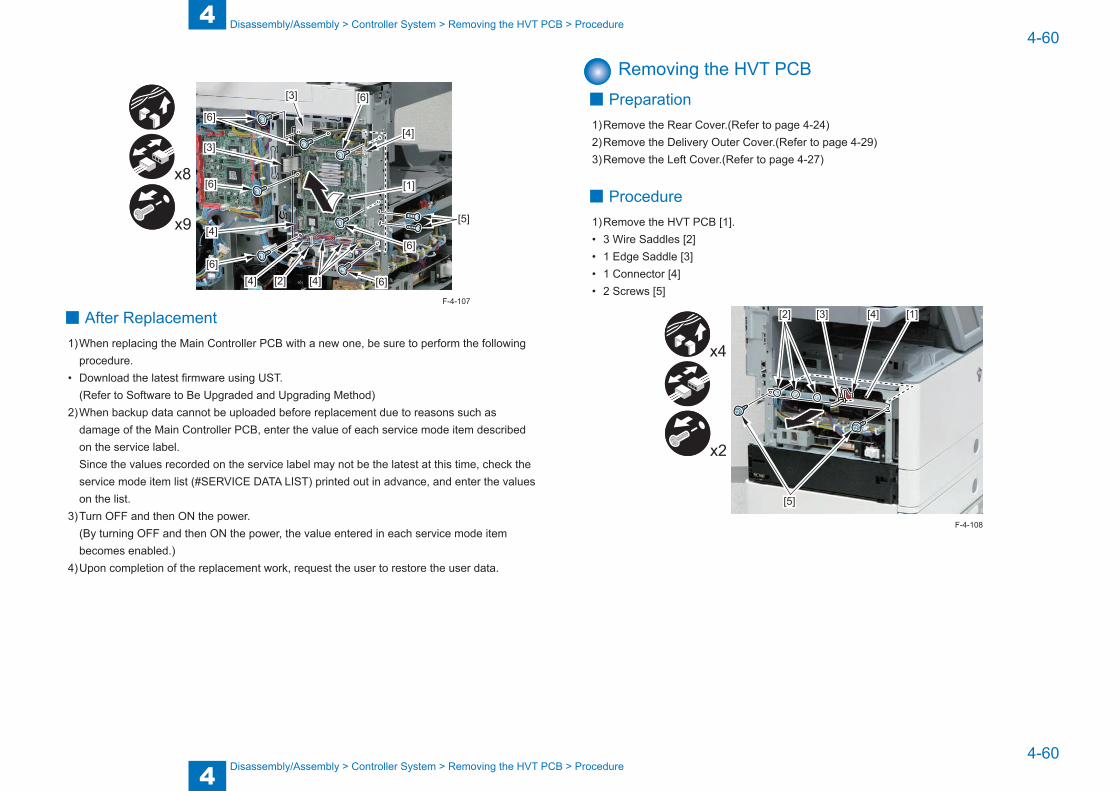
4
44-60
4-60
Disassembly/Assembly > Controller System > Removing the HVT PCB > Procedure
Disassembly/Assembly > Controller System > Removing the HVT PCB > Procedure
[1]
[2]
[3]
[3]
[4]
[4]
[4]
[4][5]
[6]
[6]
[6]
[6]
[6]
[6]
x9
x8
■ After Replacement1) When replacing the Main Controller PCB with a new one, be sure to perform the following
procedure.• Download the latest firmware using UST.
(Refer to Software to Be Upgraded and Upgrading Method)2) When backup data cannot be uploaded before replacement due to reasons such as
damage of the Main Controller PCB, enter the value of each service mode item described on the service label.Since the values recorded on the service label may not be the latest at this time, check the service mode item list (#SERVICE DATA LIST) printed out in advance, and enter the values on the list.
3) Turn OFF and then ON the power.(By turning OFF and then ON the power, the value entered in each service mode item becomes enabled.)
4) Upon completion of the replacement work, request the user to restore the user data.
F-4-107
Removing the HVT PCB ■ Preparation
1) Remove the Rear Cover.(Refer to page 4-24)2) Remove the Delivery Outer Cover.(Refer to page 4-29)3) Remove the Left Cover.(Refer to page 4-27)
■ Procedure1) Remove the HVT PCB [1].• 3 Wire Saddles [2]• 1 Edge Saddle [3]• 1 Connector [4]• 2 Screws [5]
[1][2] [3] [4]
[5]
x4
x2
F-4-108

4
44-61
4-61
Disassembly/Assembly > Controller System > Removing the HVT PCB > Procedure
Disassembly/Assembly > Controller System > Removing the HVT PCB > Procedure
CAUTION:
Be sure to fit the 2 edges [2] of the plate of the HVT PCB into the 2 rails [1] on the host machine side when assembling.
[1]
[2]
[1]
[2]
[1]
[2]
F-4-109
CAUTION:
Be sure that the 7 contact points [1] of the HVT PCB are in contact with the 7 Contact Springs [2] of the High Voltage Main Guide when assembling.
[1]
[2]
[1]
[2]
[1] [1]
[2][2]
F-4-110
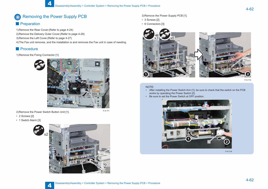
4
44-62
4-62
Disassembly/Assembly > Controller System > Removing the Power Supply PCB > Procedure
Disassembly/Assembly > Controller System > Removing the Power Supply PCB > Procedure
Removing the Power Supply PCB ■ Preparation
1) Remove the Rear Cover.(Refer to page 4-24)2) Remove the Delivery Outer Cover.(Refer to page 4-29)3) Remove the Left Cover.(Refer to page 4-27)4) The Fax unit removes, and the installation is and removes the Fax unit in case of needing.
■ Procedure1) Remove the Fixing Connector [1].
[1]
2) Remove the Power Switch Button Unit [1].• 2 Screws [2]• 1 Switch Alarm [3]
[1]
[2][3]
x2
F-4-111
F-4-112
3) Remove the Power Supply PCB [1].• 3 Screws [2]• 6 Connectors [3]
[2]
[3]
[3]
[2]
x6x3
[1]
NOTE:• After installing the Power Switch Arm [1], be sure to check that the switch on the PCB
works by operating the Power Switch [2]. • Be sure to set the Power Switch at OFF position.
[2]
[1]
F-4-114
F-4-113

4
44-63
4-63
Disassembly/Assembly > Laser Exposure System > Removing the Laser Scanner Unit > Procedure
Disassembly/Assembly > Laser Exposure System > Removing the Laser Scanner Unit > Procedure
Laser Exposure System
Location
[1]
No. Name Main Unit Reference Adjastment during parts replacement
[1] Laser Scanner Unit Main Unit (Refer to page 4-63)
F-4-115
T-4-30
Removing the Laser Scanner Unit ■ Preparation
1) Remove the Rear Cover.(Refer to page 4-24)2) Remove the Delivery Outer Cover.(Refer to page 4-29)3) Remove the Left Cover.(Refer to page 4-27)4) Remove the HVT PCB.(Refer to page 4-60)
■ Procedure
CAUTION:
Be sure not to disassemble the Laser Scanner Unit because it requires adjustment.
1) Remove the Laser Scanner Fixation Plate [1].• 1 Screw [2]2) Free the harness [3] from the guide [A].
[1]
[2]
[3][A]
F-4-116

4
44-64
4-64
Disassembly/Assembly > Laser Exposure System > Removing the Laser Scanner Unit > Procedure
Disassembly/Assembly > Laser Exposure System > Removing the Laser Scanner Unit > Procedure
3) Remove the 3 Reuse Bands [1] and the connector [2], and pull out the Laser Scanner Unit [3] to the front.
CAUTION:
When disassembling/assembling, be careful not to touch the PCB [4] installed in the Laser Scanner Unit. (Touching the PCB may change the adjustment value as the PCB is equipped with laser intensity adjustment volume resistor.)
x3
[3][4][2] [1]
4) Remove the Laser Scanner Unit [1].• 2 Sponges [2]• 3 Connectors [3]
[1] [2]
[3]
[3]
x3
F-4-117
F-4-118
CAUTION:
Be sure to fit the 3 bosses [1] of the Laser Scanner Unit into the 3 holes [2] of the plate of the host machine when assembling.
[1]
[2][2]
F-4-119
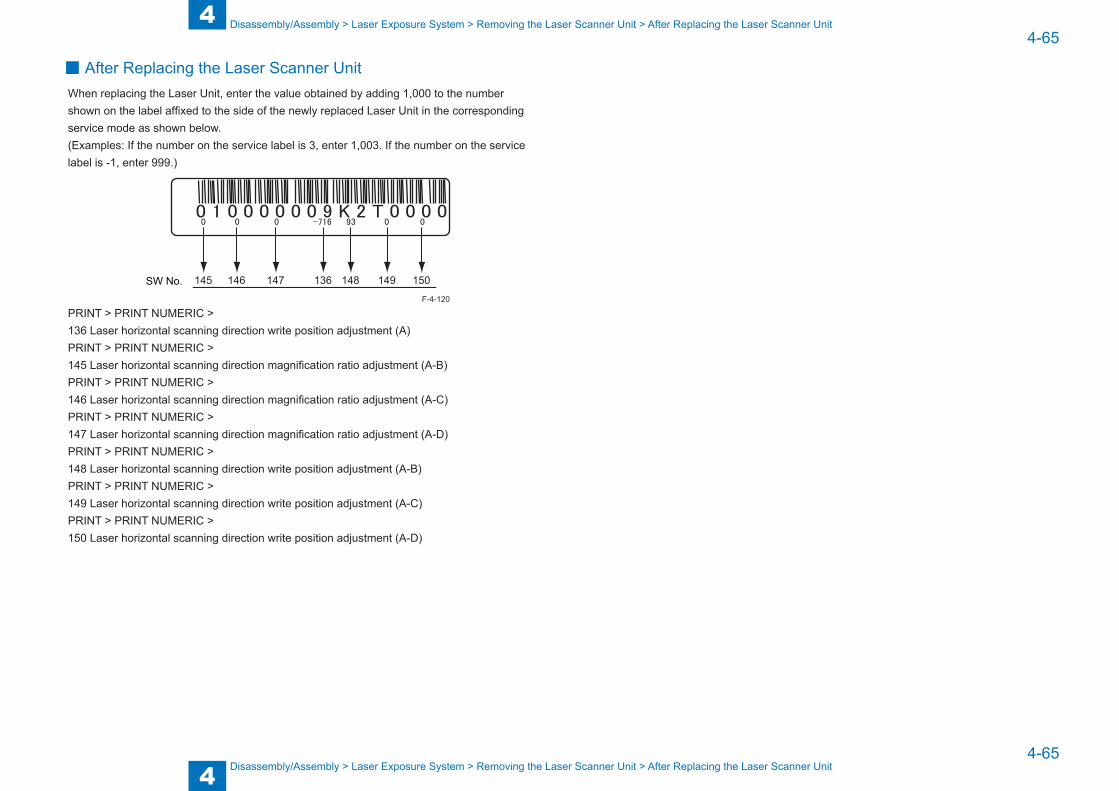
4
44-65
4-65
Disassembly/Assembly > Laser Exposure System > Removing the Laser Scanner Unit > After Replacing the Laser Scanner Unit
Disassembly/Assembly > Laser Exposure System > Removing the Laser Scanner Unit > After Replacing the Laser Scanner Unit
■ After Replacing the Laser Scanner UnitWhen replacing the Laser Unit, enter the value obtained by adding 1,000 to the number shown on the label affixed to the side of the newly replaced Laser Unit in the corresponding service mode as shown below.(Examples: If the number on the service label is 3, enter 1,003. If the number on the service label is -1, enter 999.)
145 146 147 136 148 149 150SW No.
PRINT > PRINT NUMERIC > 136 Laser horizontal scanning direction write position adjustment (A)PRINT > PRINT NUMERIC > 145 Laser horizontal scanning direction magnification ratio adjustment (A-B)PRINT > PRINT NUMERIC > 146 Laser horizontal scanning direction magnification ratio adjustment (A-C)PRINT > PRINT NUMERIC > 147 Laser horizontal scanning direction magnification ratio adjustment (A-D)PRINT > PRINT NUMERIC > 148 Laser horizontal scanning direction write position adjustment (A-B)PRINT > PRINT NUMERIC > 149 Laser horizontal scanning direction write position adjustment (A-C)PRINT > PRINT NUMERIC > 150 Laser horizontal scanning direction write position adjustment (A-D)
F-4-120
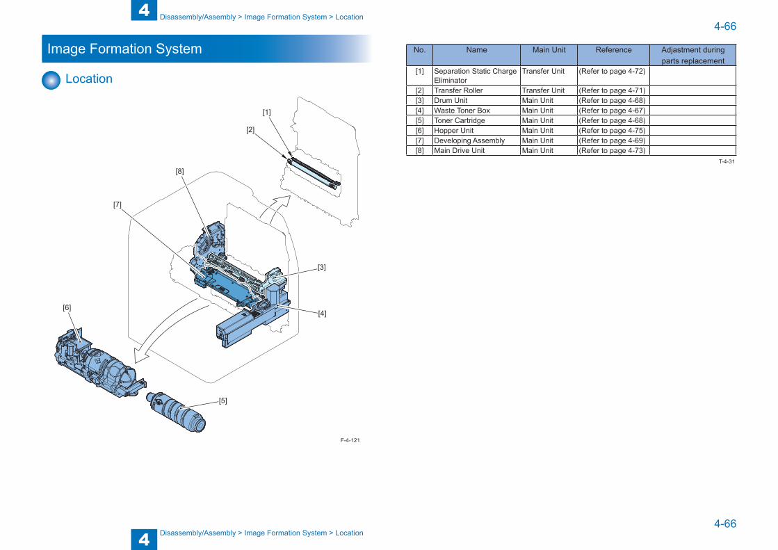
4
44-66
4-66
Disassembly/Assembly > Image Formation System > Location
Disassembly/Assembly > Image Formation System > Location
Image Formation System
Location
[3]
[5]
[6]
[7]
[8]
[2]
[1]
[4]
F-4-121
No. Name Main Unit Reference Adjastment during parts replacement
[1] Separation Static Charge Eliminator
Transfer Unit (Refer to page 4-72)
[2] Transfer Roller Transfer Unit (Refer to page 4-71)[3] Drum Unit Main Unit (Refer to page 4-68)[4] Waste Toner Box Main Unit (Refer to page 4-67)[5] Toner Cartridge Main Unit (Refer to page 4-68)[6] Hopper Unit Main Unit (Refer to page 4-75)[7] Developing Assembly Main Unit (Refer to page 4-69)[8] Main Drive Unit Main Unit (Refer to page 4-73)
T-4-31
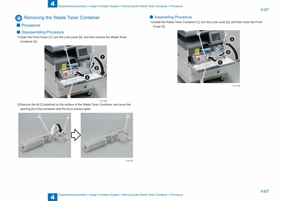
4
44-67
4-67
Disassembly/Assembly > Image Formation System > Removing the Waste Toner Container > Procedure
Disassembly/Assembly > Image Formation System > Removing the Waste Toner Container > Procedure
Removing the Waste Toner Container ■ Procedure
● Disassembling Procedure1) Open the Front Cover [1], turn the Lock Lever [2], and then remove the Waste Toner
Container [3].
[1]
[3] [2]
2) Remove the lid [1] attached on the surface of the Waste Toner Container, and cover the opening [A] of the container with the lid to prevent spills.
[1] [1][A]
F-4-122
F-4-123
● Assembling Procedure1) Install the Waste Toner Container [1], turn the Lock Lever [2], and then close the Front
Cover [3].
[1]
[3]
[2]
F-4-124
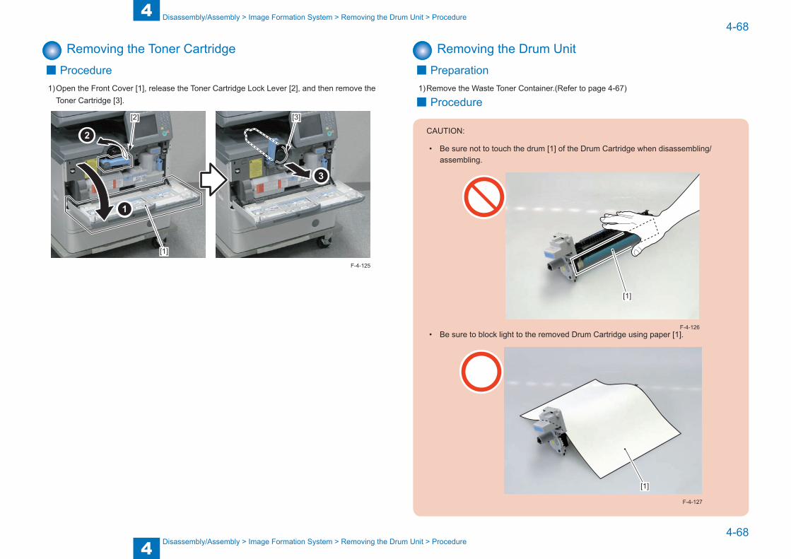
4
44-68
4-68
Disassembly/Assembly > Image Formation System > Removing the Drum Unit > Procedure
Disassembly/Assembly > Image Formation System > Removing the Drum Unit > Procedure
Removing the Toner Cartridge ■ Procedure
1) Open the Front Cover [1], release the Toner Cartridge Lock Lever [2], and then remove the Toner Cartridge [3].
[2]
[1]
[3]
F-4-125
Removing the Drum Unit ■ Preparation
1) Remove the Waste Toner Container.(Refer to page 4-67)
■ Procedure
CAUTION:
• Be sure not to touch the drum [1] of the Drum Cartridge when disassembling/assembling.
[1]
• Be sure to block light to the removed Drum Cartridge using paper [1].
[1]
F-4-126
F-4-127

4
44-69
4-69
Disassembly/Assembly > Image Formation System > Removing the Developing Assembly > Procedure
Disassembly/Assembly > Image Formation System > Removing the Developing Assembly > Procedure
1) Open the Right Door Unit [1], release the Developing Pressure Lock Lever [2].2) Release the Drum Cartridge Lock Lever [3], and then remove the Drum Cartridge [4].
[1][4]
[3][2]
F-4-128
Removing the Developing Assembly ■ Preparation
1) Remove the Waste Toner Container.(Refer to page 4-67)2) Remove the Drum Unit.(Refer to page 4-68)
■ Procedure
CAUTION:
• Place paper [1], and then place the Developing Assembly.
• Be sure not to tilt the Developing Assembly to prevent toner from spilling from the Toner Duct [2] when disassembling/assembling
[1]
[2]
F-4-129
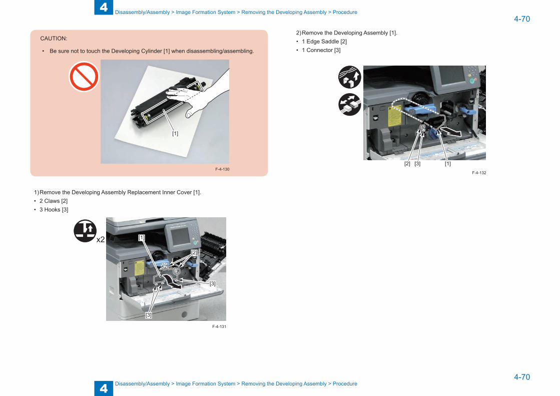
4
44-70
4-70
Disassembly/Assembly > Image Formation System > Removing the Developing Assembly > Procedure
Disassembly/Assembly > Image Formation System > Removing the Developing Assembly > Procedure
CAUTION:
• Be sure not to touch the Developing Cylinder [1] when disassembling/assembling.
[1]
F-4-130
1) Remove the Developing Assembly Replacement Inner Cover [1].• 2 Claws [2]• 3 Hooks [3]
x2 [1]
[3]
[3]
[2]
F-4-131
2) Remove the Developing Assembly [1].• 1 Edge Saddle [2]• 1 Connector [3]
[1][2] [3]F-4-132
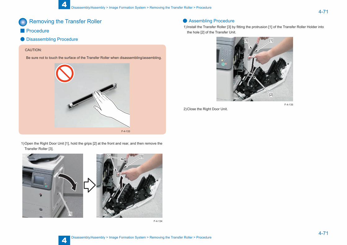
4
44-71
4-71
Disassembly/Assembly > Image Formation System > Removing the Transfer Roller > Procedure
Disassembly/Assembly > Image Formation System > Removing the Transfer Roller > Procedure
Removing the Transfer Roller ■ Procedure
● Disassembling Procedure
CAUTION:
Be sure not to touch the surface of the Transfer Roller when disassembling/assembling.
F-4-133
1) Open the Right Door Unit [1], hold the grips [2] at the front and rear, and then remove the Transfer Roller [3].
[1]
[3][2]
F-4-134
● Assembling Procedure1) Install the Transfer Roller [3] by fitting the protrusion [1] of the Transfer Roller Holder into
the hole [2] of the Transfer Unit.
[1]
[2]
[3]
2) Close the Right Door Unit.F-4-135

4
44-72
4-72
Disassembly/Assembly > Image Formation System > Removing the Separation Static Eliminator > Procedure
Disassembly/Assembly > Image Formation System > Removing the Separation Static Eliminator > Procedure
Removing the Separation Static Eliminator ■ Procedure
● Disassembling Procedure
CAUTION:
Be sure not to touch the surface of the Transfer Roller when disassembling/assembling.
F-4-136
1) Open the Right Door Unit [1], and remove the Separation Static Eliminator [2].
[1][2]
F-4-137
● Assembling Procedure1) Install the Separation Static Eliminator [3] by fitting the 3 protrusions [1] of the Transfer Unit
into the grooves [2] of the Separation Static Eliminator.
[2]
[2] [3]
[1]
CAUTION:
Be sure to hook the claw [1] of the grip on the protrusion [2] of the Transfer Unit when assembling.
[1]
[1] [2] [2]
F-4-139
2) Close the Right Door Unit.
F-4-138
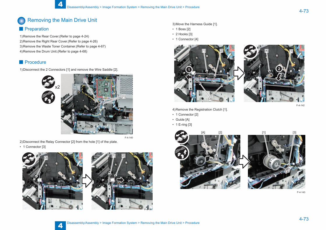
4
44-73
4-73
Disassembly/Assembly > Image Formation System > Removing the Main Drive Unit > Procedure
Disassembly/Assembly > Image Formation System > Removing the Main Drive Unit > Procedure
Removing the Main Drive Unit ■ Preparation
1) Remove the Rear Cover.(Refer to page 4-24)2) Remove the Right Rear Cover.(Refer to page 4-26)3) Remove the Waste Toner Container.(Refer to page 4-67)4) Remove the Drum Unit.(Refer to page 4-68)
■ Procedure1) Disconnect the 2 Connectors [1] and remove the Wire Saddle [2].
x2
[1]
[2]
2) Disconnect the Relay Connector [2] from the hole [1] of the plate.• 1 Connector [3]
[1] [2][3]
F-4-140
F-4-141
3) Move the Harness Guide [1].• 1 Boss [2]• 2 Hooks [3]• 1 Connector [4]
[1] [4] [1][2]
[3]
4) Remove the Registration Clutch [1].• 1 Connector [2]• Guide [A] • 1 E-ring [3]
[1][2] [3][A]
F-4-142
F-4-143

4
44-74
4-74
Disassembly/Assembly > Image Formation System > Removing the Main Drive Unit > Procedure
Disassembly/Assembly > Image Formation System > Removing the Main Drive Unit > Procedure
CAUTION:
When assembling the Registration Clutch, be sure to align the cut-off [1] of the clutch with the protrusion [2] of the Drive Unit
[1][2]
F-4-144
5) Remove the Drive Unit [1].• 6 Screws [2]
x6
[1][2] [2]
F-4-145
CAUTION:
Be sure to fit the bearing [1] of the Drive Unit into the hole [2] of the plate on the host machine side when assembling.
[1][2]F-4-146
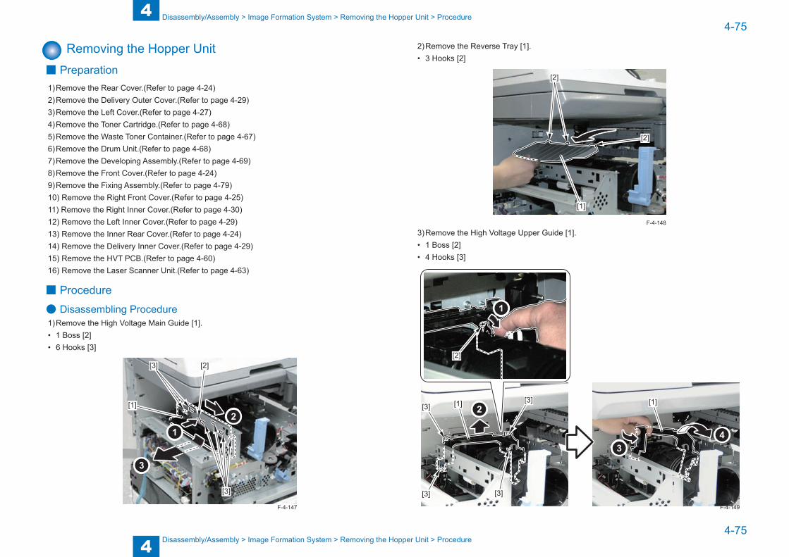
4
44-75
4-75
Disassembly/Assembly > Image Formation System > Removing the Hopper Unit > Procedure
Disassembly/Assembly > Image Formation System > Removing the Hopper Unit > Procedure
Removing the Hopper Unit ■ Preparation
1) Remove the Rear Cover.(Refer to page 4-24)2) Remove the Delivery Outer Cover.(Refer to page 4-29)3) Remove the Left Cover.(Refer to page 4-27)4) Remove the Toner Cartridge.(Refer to page 4-68)5) Remove the Waste Toner Container.(Refer to page 4-67)6) Remove the Drum Unit.(Refer to page 4-68)7) Remove the Developing Assembly.(Refer to page 4-69)8) Remove the Front Cover.(Refer to page 4-24)9) Remove the Fixing Assembly.(Refer to page 4-79)10) Remove the Right Front Cover.(Refer to page 4-25)11) Remove the Right Inner Cover.(Refer to page 4-30)12) Remove the Left Inner Cover.(Refer to page 4-29)13) Remove the Inner Rear Cover.(Refer to page 4-24)14) Remove the Delivery Inner Cover.(Refer to page 4-29)15) Remove the HVT PCB.(Refer to page 4-60)16) Remove the Laser Scanner Unit.(Refer to page 4-63)
■ Procedure
● Disassembling Procedure1) Remove the High Voltage Main Guide [1].• 1 Boss [2]• 6 Hooks [3]
[1]
[2][3]
[3]
F-4-147
2) Remove the Reverse Tray [1].• 3 Hooks [2]
[1]
[2]
[2]
3) Remove the High Voltage Upper Guide [1].• 1 Boss [2]• 4 Hooks [3]
[1] [1][3][3]
[3][3]
[2]
F-4-148
F-4-149

4
44-76
4-76
Disassembly/Assembly > Image Formation System > Removing the Hopper Unit > Procedure
Disassembly/Assembly > Image Formation System > Removing the Hopper Unit > Procedure
4) Remove the Hopper Unit [1].• 1 Connector [2]• 1 Edge Saddle [3]• 4 Screws [4]
NOTE:Since installation of the Toner Container decreases the possibility of toner scattering, it is recommended to install the Toner Container when there is no problem with it.
F-4-150
CAUTION:
When removing the Hopper Unit, be sure not to spill toner from the Toner Supply Mouth [1] and the Toner Open/Close Shutter [2].
[1]
[2]
F-4-151
x4
[2]
[3]
[4]
[4]
[4]
[4]
[1]
● Assembling Procedure1) Install the Hopper Unit [1].• 1 Connector [2]• 1 Edge Saddle [3]• 4 Screws [4]
NOTE:Since installation of the Toner Container decreases the possibility of toner scattering, it is recommended to install the Toner Container when there is no problem with it.
F-4-153
F-4-152

4
44-77
4-77
Disassembly/Assembly > Image Formation System > Removing the Hopper Unit > Procedure
Disassembly/Assembly > Image Formation System > Removing the Hopper Unit > Procedure
CAUTION:
When installing the Hopper Unit, be sure not to spill toner from the Toner Supply Mouth [1] and the Toner Open/Close Shutter [2].
[1]
[2]
F-4-154
CAUTION:
When installing the Hopper Unit with toner inside, be sure to install it after removing the Support Column Cover. There is a high possibility of toner scattering during the work if it is not removed.
Removing the Support Column Cover (Refer to page 4-32)
[2]
[3]
[4]
[4]
[4]
[4]
[1]
x4
F-4-155
2) Install the High Voltage Upper Guide [1].• 1 Boss [2]• 4 Hooks [3]
[1] [3][3]
[3][3]
[2]
3) Install the Reverse Tray [1].• 3 Hooks [2]
[1]
[2]
[2]
F-4-156
F-4-157

4
44-78
4-78
Disassembly/Assembly > Image Formation System > Removing the Hopper Unit > Procedure
Disassembly/Assembly > Image Formation System > Removing the Hopper Unit > Procedure
4) Install the High Voltage Main Guide [1].• 1 Boss [2]• 6 Hooks [3]
[1]
[3]
[3]
[2]
CAUTION:
When assembling the High Voltage Main Guide, be sure that the 7 Contact Springs [1] are in contact with the [A] part of the High Voltage Lower Guide.
[A]
[A] [1]
[1]
F-4-159
F-4-158
5) Install the Laser Scanner Unit.6) Install the HVT PCB.7) Install the Delivery Inner Cover.8) Install the Inner Rear Cover.9) Install the Left Inner Cover.10) Install the Right Inner Cover.11) Install the Right Front Cover.12) Install the Fixing Assembly.13) Install the Front Cover.14) Install the Developing Assembly.15) Install the Drum Unit.16) Install the Waste Toner Container.17) Install the Toner Cartridge.18) Install the Left Cover.19) Install the Delivery Outer Cover.20) Install the Rear Cover.
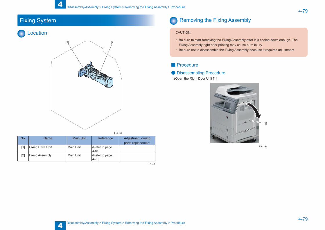
4
44-79
4-79
Disassembly/Assembly > Fixing System > Removing the Fixing Assembly > Procedure
Disassembly/Assembly > Fixing System > Removing the Fixing Assembly > Procedure
Fixing System
Location[1] [2]
No. Name Main Unit Reference Adjastment during parts replacement
[1] Fixing Drive Unit Main Unit (Refer to page 4-81)
[2] Fixing Assembly Main Unit (Refer to page 4-79)
F-4-160
T-4-32
Removing the Fixing Assembly
CAUTION:
• Be sure to start removing the Fixing Assembly after it is cooled down enough. The Fixing Assembly right after printing may cause burn injury.
• Be sure not to disassemble the Fixing Assembly because it requires adjustment.
■ Procedure
● Disassembling Procedure1) Open the Right Door Unit [1].
[1]
F-4-161
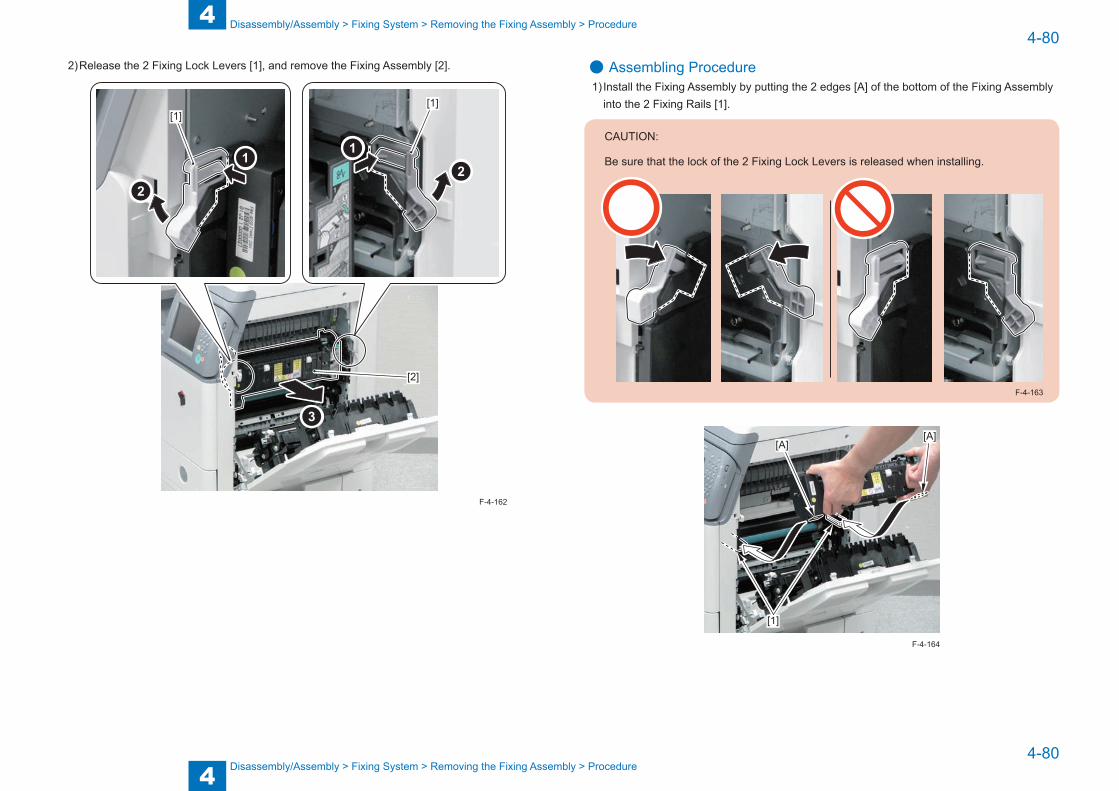
4
44-80
4-80
Disassembly/Assembly > Fixing System > Removing the Fixing Assembly > Procedure
Disassembly/Assembly > Fixing System > Removing the Fixing Assembly > Procedure
2) Release the 2 Fixing Lock Levers [1], and remove the Fixing Assembly [2].
[1][1]
[2]
F-4-162
● Assembling Procedure1) Install the Fixing Assembly by putting the 2 edges [A] of the bottom of the Fixing Assembly
into the 2 Fixing Rails [1].
CAUTION:
Be sure that the lock of the 2 Fixing Lock Levers is released when installing.
F-4-163
[1]
[A][A]
F-4-164

4
44-81
4-81
Disassembly/Assembly > Fixing System > Removing the Fixing Drive Unit > Procedure
Disassembly/Assembly > Fixing System > Removing the Fixing Drive Unit > Procedure
2) Lock the 2 Fixing Lock Levers [1], and secure the Fixing Assembly [2].
[1] [1][2]
3) Close the Right Door Unit.F-4-165
Removing the Fixing Drive Unit ■ Preparation
1) Remove the Rear Cover.(Refer to page 4-24)2) Remove the Right Rear Cover.(Refer to page 4-26)3) Remove the Waste Toner Container.(Refer to page 4-67)4) Remove the Drum Unit.(Refer to page 4-68)5) Remove the Main Drive Unit.(Refer to page 4-73)6) Remove the Fixing Assembly.(Refer to page 4-79)
■ Procedure1) Disconnect the 2 Connectors [1] and remove the 2 Wire Saddles [2] and the Reuse Band [3].
[1]
[2]
x2
x2
[3]
F-4-166
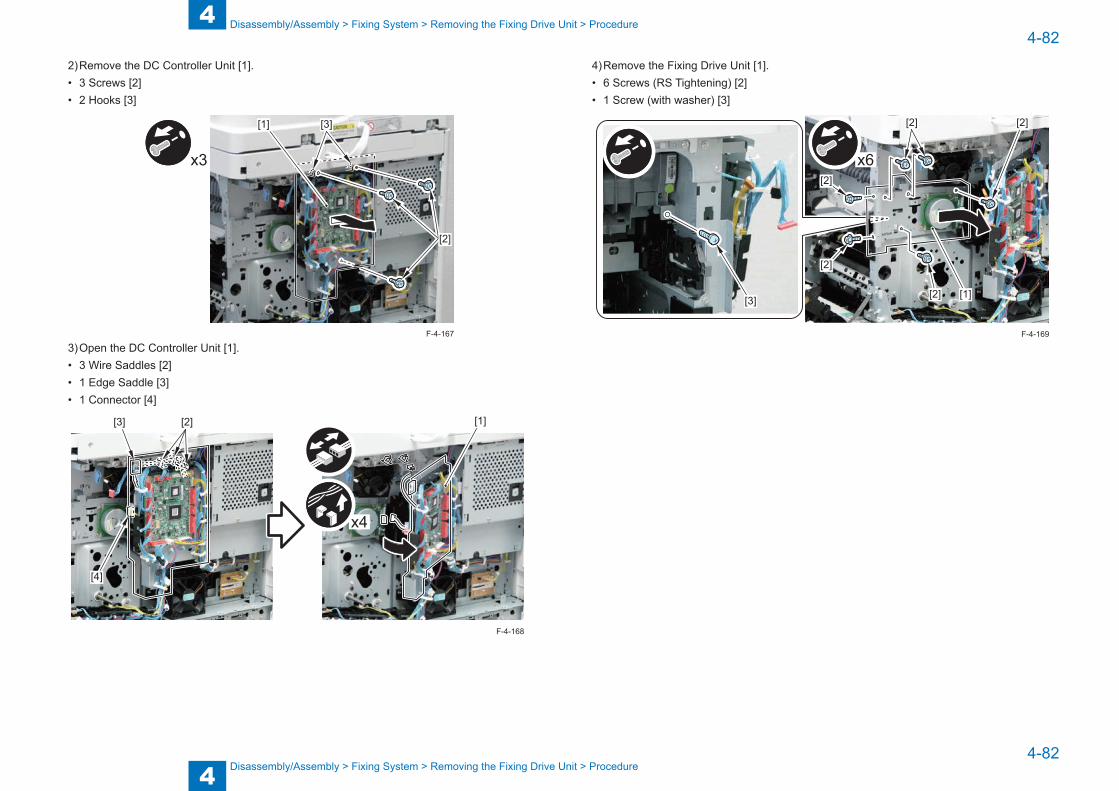
4
44-82
4-82
Disassembly/Assembly > Fixing System > Removing the Fixing Drive Unit > Procedure
Disassembly/Assembly > Fixing System > Removing the Fixing Drive Unit > Procedure
2) Remove the DC Controller Unit [1].• 3 Screws [2]• 2 Hooks [3]
x3
[1] [3]
[2]
3) Open the DC Controller Unit [1].• 3 Wire Saddles [2]• 1 Edge Saddle [3]• 1 Connector [4]
[1][2][3]
[4]
x4
F-4-167
F-4-168
4) Remove the Fixing Drive Unit [1].• 6 Screws (RS Tightening) [2]• 1 Screw (with washer) [3]
x6
[1]
[2]
[2]
[2] [2]
[2][3]
F-4-169
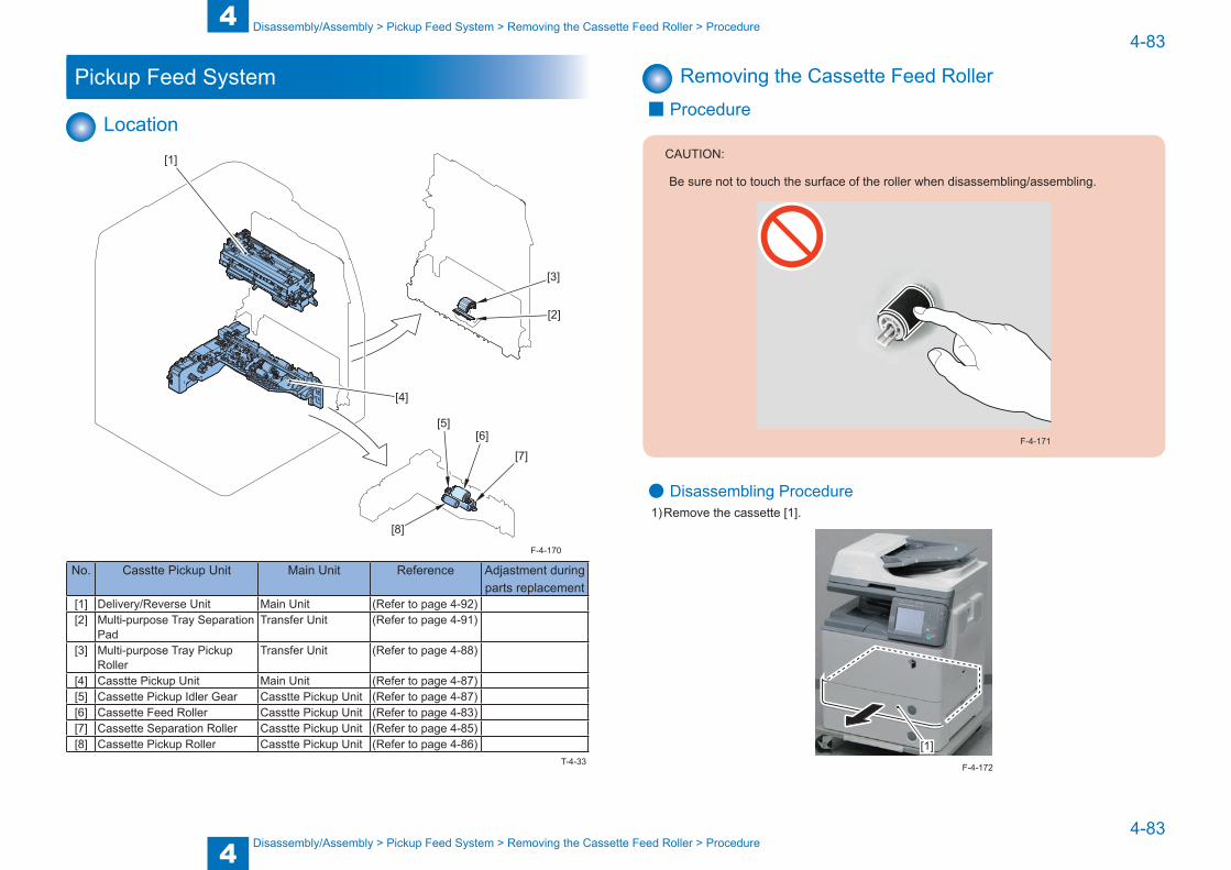
4
44-83
4-83
Disassembly/Assembly > Pickup Feed System > Removing the Cassette Feed Roller > Procedure
Disassembly/Assembly > Pickup Feed System > Removing the Cassette Feed Roller > Procedure
Pickup Feed System
Location
[2]
[3]
[4]
[1]
[5][6]
[7]
[8]
No. Casstte Pickup Unit Main Unit Reference Adjastment during parts replacement
[1] Delivery/Reverse Unit Main Unit (Refer to page 4-92)[2] Multi-purpose Tray Separation
PadTransfer Unit (Refer to page 4-91)
[3] Multi-purpose Tray Pickup Roller
Transfer Unit (Refer to page 4-88)
[4] Casstte Pickup Unit Main Unit (Refer to page 4-87)[5] Cassette Pickup Idler Gear Casstte Pickup Unit (Refer to page 4-87)[6] Cassette Feed Roller Casstte Pickup Unit (Refer to page 4-83)[7] Cassette Separation Roller Casstte Pickup Unit (Refer to page 4-85)[8] Cassette Pickup Roller Casstte Pickup Unit (Refer to page 4-86)
F-4-170
T-4-33
Removing the Cassette Feed Roller ■ Procedure
CAUTION:
Be sure not to touch the surface of the roller when disassembling/assembling.
F-4-171
● Disassembling Procedure1) Remove the cassette [1].
[1]
F-4-172
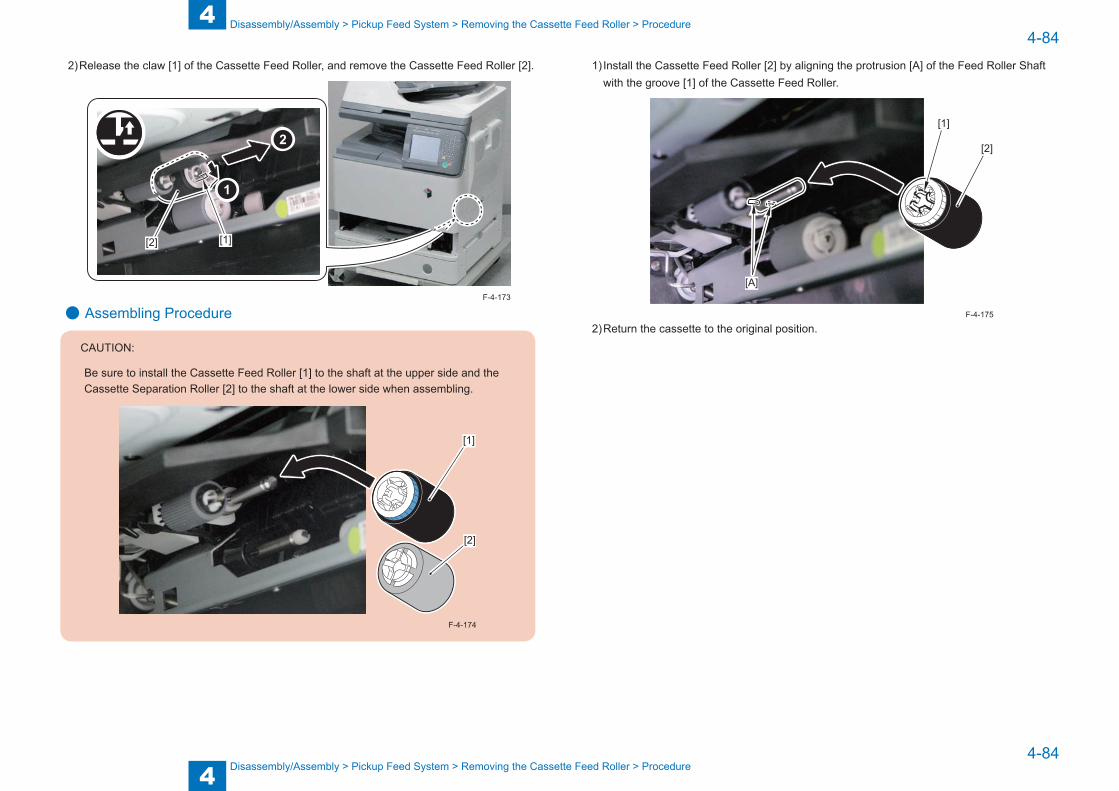
4
44-84
4-84
Disassembly/Assembly > Pickup Feed System > Removing the Cassette Feed Roller > Procedure
Disassembly/Assembly > Pickup Feed System > Removing the Cassette Feed Roller > Procedure
2) Release the claw [1] of the Cassette Feed Roller, and remove the Cassette Feed Roller [2].
[1][2]
● Assembling Procedure
CAUTION:
Be sure to install the Cassette Feed Roller [1] to the shaft at the upper side and the Cassette Separation Roller [2] to the shaft at the lower side when assembling.
[1]
[2]
F-4-174
F-4-173
1) Install the Cassette Feed Roller [2] by aligning the protrusion [A] of the Feed Roller Shaft with the groove [1] of the Cassette Feed Roller.
[1]
[2]
[A]
2) Return the cassette to the original position.F-4-175

4
44-85
4-85
Disassembly/Assembly > Pickup Feed System > Removing the Cassette Separation Roller > Procedure
Disassembly/Assembly > Pickup Feed System > Removing the Cassette Separation Roller > Procedure
Removing the Cassette Separation Roller ■ Procedure
CAUTION:
Be sure not to touch the surface of the roller when disassembling/assembling.
F-4-176
● Disassembling Procedure1) Remove the cassette [1].
[1]
F-4-177
2) Release the claw [1] of the Cassette Separation Roller, and remove the Cassette Separation Roller [2].
[1][2]
● Assembling Procedure
CAUTION:
Be sure to install the Cassette Feed Roller [1] to the shaft at the upper side and the Cassette Separation Roller [2] to the shaft at the lower side when assembling.
[1]
[2]
F-4-179
F-4-178

4
44-86
4-86
Disassembly/Assembly > Pickup Feed System > Removing the Cassette Pickup Roller > Procedure
Disassembly/Assembly > Pickup Feed System > Removing the Cassette Pickup Roller > Procedure
1) Install the Cassette Separation Roller [2] by aligning the protrusion [A] of the Separation Roller Shaft with the groove [1] of the Cassette Separation Roller.
[A]
[A]
[1]
[2]
2) Return the cassette to the original position.F-4-180
Removing the Cassette Pickup Roller ■ Procedure
CAUTION:
Be sure not to touch the surface of the roller when disassembling/assembling.
1) Remove the cassette.2) Remove the Fixation Pin [1], and remove the Cassette Feed Roller [2].
[1]
[2]
F-4-181
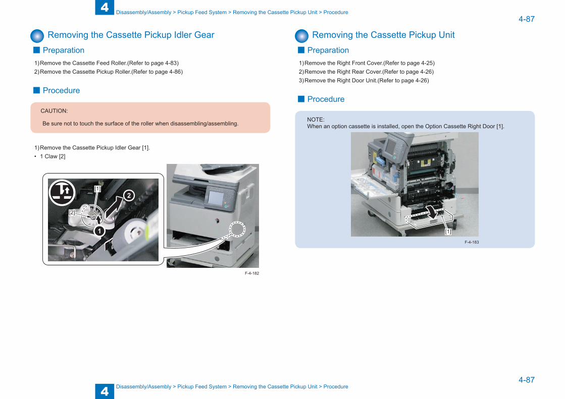
4
44-87
4-87
Disassembly/Assembly > Pickup Feed System > Removing the Cassette Pickup Unit > Procedure
Disassembly/Assembly > Pickup Feed System > Removing the Cassette Pickup Unit > Procedure
Removing the Cassette Pickup Idler Gear ■ Preparation
1) Remove the Cassette Feed Roller.(Refer to page 4-83)2) Remove the Cassette Pickup Roller.(Refer to page 4-86)
■ Procedure
CAUTION:
Be sure not to touch the surface of the roller when disassembling/assembling.
1) Remove the Cassette Pickup Idler Gear [1].• 1 Claw [2]
[1]
[2]
F-4-182
Removing the Cassette Pickup Unit ■ Preparation
1) Remove the Right Front Cover.(Refer to page 4-25)2) Remove the Right Rear Cover.(Refer to page 4-26)3) Remove the Right Door Unit.(Refer to page 4-26)
■ Procedure
NOTE:When an option cassette is installed, open the Option Cassette Right Door [1].
[1]
F-4-183
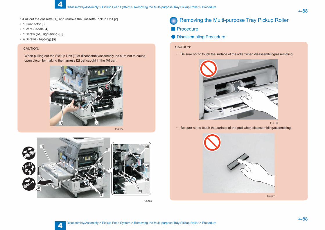
4
44-88
4-88
Disassembly/Assembly > Pickup Feed System > Removing the Multi-purpose Tray Pickup Roller > Procedure
Disassembly/Assembly > Pickup Feed System > Removing the Multi-purpose Tray Pickup Roller > Procedure
1) Pull out the cassette [1], and remove the Cassette Pickup Unit [2].• 1 Connector [3]• 1 Wire Saddle [4]• 1 Screw (RS Tightening) [5]• 4 Screws (Tapping) [6]
CAUTION:
When pulling out the Pickup Unit [1] at disassembly/assembly, be sure not to cause open circuit by making the harness [2] get caught in the [A] part.
[1] [2]
[A]
F-4-184
x5[6]
[1][2]
[5]
[3]
[4]
[6]
F-4-185
Removing the Multi-purpose Tray Pickup Roller ■ Procedure
● Disassembling Procedure
CAUTION:
• Be sure not to touch the surface of the roller when disassembling/assembling.
• Be sure not to touch the surface of the pad when disassembling/assembling.F-4-186
F-4-187

4
44-89
4-89
Disassembly/Assembly > Pickup Feed System > Removing the Multi-purpose Tray Pickup Roller > Procedure
Disassembly/Assembly > Pickup Feed System > Removing the Multi-purpose Tray Pickup Roller > Procedure
1) Open the Multi-purpose Tray Pickup Tray [1].
[1]
2) Remove the Pickup Roller Cover [1].• 2 Claws [2]
x2[2]
[2][1]
F-4-188
F-4-189
3) Release the 2 claws [1] of the Pickup Roller Holder on the right and left, and move the 2 Pickup Roller Holder [2].
[1][1][2]
x2
4) Lower the Multi-purpose Tray Separation Pad [1], and remove the Multi-purpose Tray Pickup Roller [2].
[1][2]
F-4-190
F-4-191
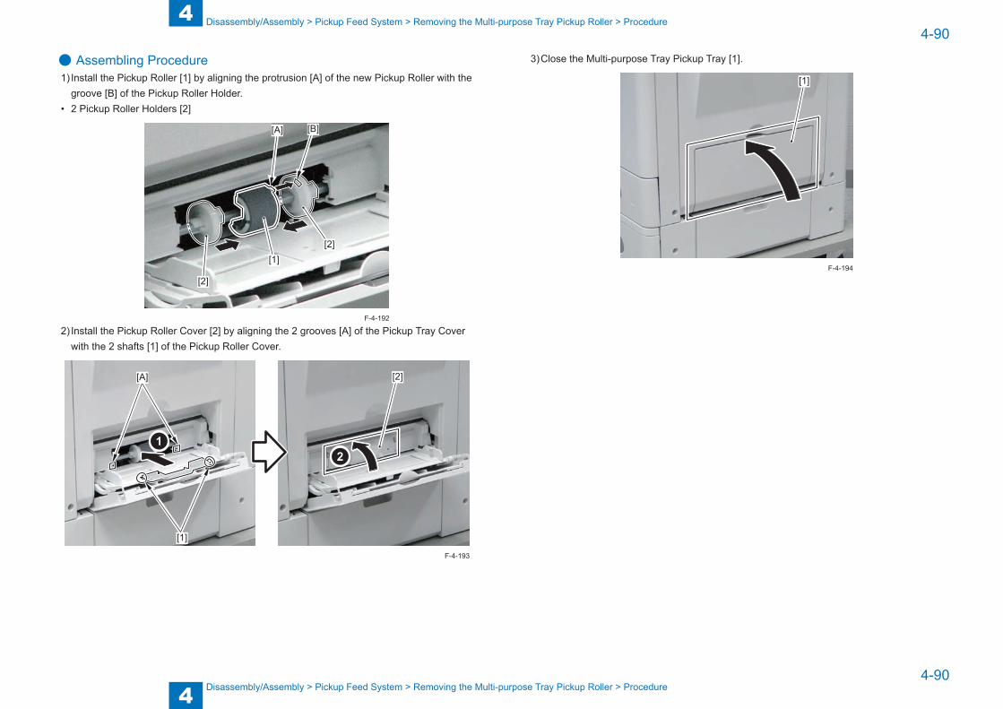
4
44-90
4-90
Disassembly/Assembly > Pickup Feed System > Removing the Multi-purpose Tray Pickup Roller > Procedure
Disassembly/Assembly > Pickup Feed System > Removing the Multi-purpose Tray Pickup Roller > Procedure
● Assembling Procedure1) Install the Pickup Roller [1] by aligning the protrusion [A] of the new Pickup Roller with the
groove [B] of the Pickup Roller Holder.• 2 Pickup Roller Holders [2]
[2]
[1][2]
[A] [B]
2) Install the Pickup Roller Cover [2] by aligning the 2 grooves [A] of the Pickup Tray Cover with the 2 shafts [1] of the Pickup Roller Cover.
[2][A]
[1]
F-4-192
F-4-193
3) Close the Multi-purpose Tray Pickup Tray [1].
[1]
F-4-194

4
44-91
4-91
Disassembly/Assembly > Pickup Feed System > Removing the Multi-purpose Tray Separation Pad > Procedure
Disassembly/Assembly > Pickup Feed System > Removing the Multi-purpose Tray Separation Pad > Procedure
Removing the Multi-purpose Tray Separation Pad ■ Preparation
1) Remove the Multi-purpose Tray Pickup Roller.(Refer to page 4-88)
■ Procedure
● Disassembling Procedure
CAUTION:
Be sure not to touch the surface of the pad when disassembling/assembling.
F-4-195
1) Lower the Multi-purpose Tray Pickup Tray [1], release the 2 bosses [2] of the Multi-purpose Tray Separation Pad, and then remove the Multi-purpose Tray Separation Pad [3].
[1]
[2][3]
● Assembling Procedure1) Install the Multi-purpose Tray Separation Pad [1] by aligning the 3 protrusions [A] of the
new Multi-purpose Tray Separation Pad with the 3 grooves [B] of the Separation Pad Holder.
[1]
[B]
[A]
F-4-196
F-4-197

4
44-92
4-92
Disassembly/Assembly > Pickup Feed System > Removing the Delivery/Reverse Unit > Procedure
Disassembly/Assembly > Pickup Feed System > Removing the Delivery/Reverse Unit > Procedure
Removing the Delivery/Reverse Unit ■ Preparation
1) Remove the Fixing Assembly.(Refer to page 4-79)2) Remove the Rear Cover.(Refer to page 4-24)
■ Procedure1) Remove the Reverse Tray [1].• 3 Hooks [2]
[1]
[2]
2) Disconnect the connector [1], and remove the Wire Saddle [2], the Edge Saddle [3] and the 2 screws [4].
x2x2
[1][2][3][4]
F-4-198
F-4-199
3) While putting the connector [1] into the inside of the host machine, remove the Delivery/Reverse Unit [2].
• 2 Bosses [3]• 1 Hook [4]
[1]
[2][3]
[3]
[4]
F-4-200
5
5 Adjustment
Adjustment ■Overview ■Adjustment when Replacing the Parts ■Image Position Adjustment
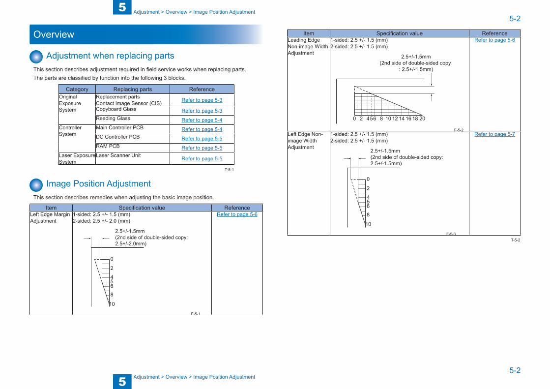
5
55-2
5-2
Adjustment > Overview > Image Position Adjustment
Adjustment > Overview > Image Position Adjustment
Overview
Adjustment when replacing partsThis section describes adjustment required in field service works when replacing parts.The parts are classified by function into the following 3 blocks.
Category Replacing parts ReferenceOriginal Exposure System
Replacement partsContact Image Sensor (CIS) Refer to page 5-3
Copyboard Glass Refer to page 5-3Reading Glass Refer to page 5-4
Controller System
Main Controller PCB Refer to page 5-4DC Controller PCB Refer to page 5-5RAM PCB Refer to page 5-5
Laser Exposure System
Laser Scanner Unit Refer to page 5-5
Image Position AdjustmentThis section describes remedies when adjusting the basic image position.
Item Specification value ReferenceLeft Edge Margin Adjustment
1-sided: 2.5 +/- 1.5 (mm)2-sided: 2.5 +/- 2.0 (mm)
10
8654
2
0
2.5+/-1.5mm(2nd side of double-sided copy: 2.5+/-2.0mm)
Refer to page 5-6
T-5-1
F-5-1
Item Specification value ReferenceLeading Edge Non-image Width Adjustment
1-sided: 2.5 +/- 1.5 (mm)2-sided: 2.5 +/- 1.5 (mm)
2 54 6 8 10 12 14 16 18 200
2.5+/-1.5mm(2nd side of double-sided copy
: 2.5+/-1.5mm)
Refer to page 5-6
Left Edge Non-image Width Adjustment
1-sided: 2.5 +/- 1.5 (mm)2-sided: 2.5 +/- 1.5 (mm)
10
8654
2
0
2.5+/-1.5mm(2nd side of double-sided copy: 2.5+/-1.5mm)
Refer to page 5-7F-5-2
F-5-3T-5-2
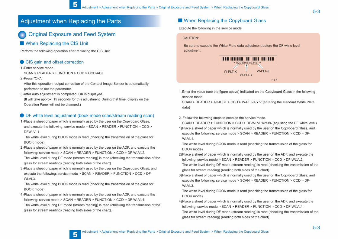
5
55-3
5-3
Adjustment > Adjustment when Replacing the Parts > Original Exposure and Feed System > When Replacing the Copyboard Glass
Adjustment > Adjustment when Replacing the Parts > Original Exposure and Feed System > When Replacing the Copyboard Glass
Adjustment when Replacing the Parts
Original Exposure and Feed System ■When Replacing the CIS Unit
Perform the following operation after replacing the CIS Unit.
● CIS gain and offset correction1) Enter service mode.
SCAN > READER > FUNCTION > CCD > CCD-ADJ2) Press "OK".
After this operation, output correction of the Contact Image Sensor is automatically performed to set the parameter.
3) After auto adjustment is completed, OK is displayed. (It will take approx. 15 seconds for this adjustment. During that time, display on the Operation Panel will not be changed.)
● DF white level adjustment (book mode scan/stream reading scan)1) Place a sheet of paper which is normally used by the user on the Copyboard Glass,
and execute the following: service mode > SCAN > READER > FUNCTION > CCD > DFWLVL1.The white level during BOOK mode is read (checking the transmission of the glass for BOOK mode).
2) Place a sheet of paper which is normally used by the user on the ADF, and execute the following: service mode > SCAN > READER > FUNCTION > CCD > DF-WLVL2.The white level during DF mode (stream reading) is read (checking the transmission of the glass for stream reading) (reading both sides of the chart).
3) Place a sheet of paper which is normally used by the user on the Copyboard Glass, and execute the following: service mode > SCAN > READER > FUNCTION > CCD > DF-WLVL3.The white level during BOOK mode is read (checking the transmission of the glass for BOOK mode).
4) Place a sheet of paper which is normally used by the user on the ADF, and execute the following: service mode > SCAN > READER > FUNCTION > CCD > DF-WLVL4.The white level during DF mode (stream reading) is read (checking the transmission of the glass for stream reading) (reading both sides of the chart).
■When Replacing the Copyboard GlassExecute the following in the service mode.
CAUTION:
Be sure to execute the White Plate data adjustment before the DF while level adjustment.
W-PLT-XW-PLT-Y
W-PLT-Z
F-5-4
1. Enter the value (see the figure above) indicated on the Copyboard Glass in the following service mode. SCAN > READER > ADJUST > CCD > W-PLT-X/Y/Z (entering the standard White Plate data)
2. Follow the following steps to execute the service mode.SCAN > READER > FUNCTION > CCD > DF-WLVL1/2/3/4 (adjusting the DF white level)
1) Place a sheet of paper which is normally used by the user on the Copyboard Glass, and execute the following: service mode > SCAN > READER > FUNCTION > CCD > DF-WLVL1.The white level during BOOK mode is read (checking the transmission of the glass for BOOK mode).
2) Place a sheet of paper which is normally used by the user on the ADF, and execute the following: service mode > SCAN > READER > FUNCTION > CCD > DF-WLVL2.The white level during DF mode (stream reading) is read (checking the transmission of the glass for stream reading) (reading both sides of the chart).
3) Place a sheet of paper which is normally used by the user on the Copyboard Glass, and execute the following: service mode > SCAN > READER > FUNCTION > CCD > DF-WLVL3.The white level during BOOK mode is read (checking the transmission of the glass for BOOK mode).
4) Place a sheet of paper which is normally used by the user on the ADF, and execute the following: service mode > SCAN > READER > FUNCTION > CCD > DF-WLVL4.The white level during DF mode (stream reading) is read (checking the transmission of the glass for stream reading) (reading both sides of the chart).
5
55-4
5-4
Adjustment > Adjustment when Replacing the Parts > Main Controller System > After Replacing the Main Controller PCB
Adjustment > Adjustment when Replacing the Parts > Main Controller System > After Replacing the Main Controller PCB
NOTE:Be sure that size of a paper to be used in the foregoing steps is the one that the ADF can be read.
■When Replacing the ADF Reading Glass1. Follow the following steps to execute the service mode.
SCAN > READER > FUNCTION > CCD > DF-WLVL1/2/3/4 (adjusting the DF white level)1) Place a sheet of paper which is normally used by the user on the Copyboard Glass, and
execute the following: service mode > SCAN > READER > FUNCTION > CCD > DF-WLVL1.The white level during BOOK mode is read (checking the transmission of the glass for BOOK mode).
2) Place a sheet of paper which is normally used by the user on the ADF, and execute the following: service mode > SCAN > READER > FUNCTION > CCD > DF-WLVL2.The white level during DF mode (stream reading) is read (checking the transmission of the glass for stream reading) (reading both sides of the chart).
3) Place a sheet of paper which is normally used by the user on the Copyboard Glass, and execute the following: service mode > SCAN > READER > FUNCTION > CCD > DF-WLVL3.The white level during BOOK mode is read (checking the transmission of the glass for BOOK mode).
4) Place a sheet of paper which is normally used by the user on the ADF, and execute the following: service mode > SCAN > READER > FUNCTION > CCD > DF-WLVL4.The white level during DF mode (stream reading) is read (checking the transmission of the glass for stream reading) (reading both sides of the chart).
NOTE:Be sure that size of a paper to be used in the foregoing steps is the one that the ADF can be read.
Main Controller System ■ Before Replacing the Main Controller PCB
1) Request the user to backup the user data using remote UI.2) If possible, output the data of the unprocessed jobs.
After replacing the DC Controller PCB, the data of the unprocessed jobs will be deleted.3) Print out the list of the service mode setting value in the service mode.
REPORT> REPORT OUTPUT> SERVICE DATA LIST
■ After Replacing the Main Controller PCB1) When replacing the Main Controller PCB with a new one, be sure to perform the following
procedure.• Download the latest firmware using UST.
(Refer to Software to Be Upgraded and Upgrading Method)2) When backup data cannot be uploaded before replacement due to reasons such as
damage of the Main Controller PCB, enter the value of each service mode item described on the service label.Since the values recorded on the service label may not be the latest at this time, check the service mode item list (#SERVICE DATA LIST) printed out in advance, and enter the values on the list.
3) Turn OFF and then ON the power.(By turning OFF and then ON the power, the value entered in each service mode item becomes enabled.)
4) Upon completion of the replacement work, request the user to restore the user data.
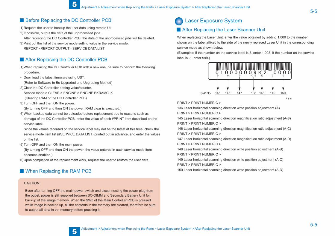
5
55-5
5-5
Adjustment > Adjustment when Replacing the Parts > Laser Exposure System > After Replacing the Laser Scanner Unit
Adjustment > Adjustment when Replacing the Parts > Laser Exposure System > After Replacing the Laser Scanner Unit
■ Before Replacing the DC Controller PCB1) Request the user to backup the user data using remote UI.2) If possible, output the data of the unprocessed jobs.
After replacing the DC Controller PCB, the data of the unprocessed jobs will be deleted.3) Print out the list of the service mode setting value in the service mode.
REPORT> REPORT OUTPUT> SERVICE DATA LIST
■ After Replacing the DC Controller PCB1) When replacing the DC Controller PCB with a new one, be sure to perform the following
procedure.• Download the latest firmware using UST.
(Refer to Software to Be Upgraded and Upgrading Method)2) Clear the DC Controller setting value/counter.
Service mode > CLEAR > ENGINE > ENGINE BKRAMCLK (Clearing RAM of the DC Controller PCB)
3) Turn OFF and then ON the power.(By turning OFF and then ON the power, RAM clear is executed.)
4) When backup data cannot be uploaded before replacement due to reasons such as damage of the DC Controller PCB, enter the value of each #PRINT item described on the service label.Since the values recorded on the service label may not be the latest at this time, check the service mode item list (#SERVICE DATA LIST) printed out in advance, and enter the values on the list.
5) Turn OFF and then ON the main power.(By turning OFF and then ON the power, the value entered in each service mode item becomes enabled.)
6) Upon completion of the replacement work, request the user to restore the user data.
■When Replacing the RAM PCB
CAUTION:
Even after turning OFF the main power switch and disconnecting the power plug from the outlet, power is still supplied between SO-DIMM and Secondary Battery Unit for backup of the image memory. When the SW3 of the Main Controller PCB is pressed while image is backed up, all the contents in the memory are cleared, therefore be sure to output all data in the memory before pressing it.
Laser Exposure System ■ After Replacing the Laser Scanner Unit
When replacing the Laser Unit, enter the value obtained by adding 1,000 to the number shown on the label affixed to the side of the newly replaced Laser Unit in the corresponding service mode as shown below.(Examples: If the number on the service label is 3, enter 1,003. If the number on the service label is -1, enter 999.)
145 146 147 136 148 149 150SW No.
PRINT > PRINT NUMERIC > 136 Laser horizontal scanning direction write position adjustment (A)PRINT > PRINT NUMERIC > 145 Laser horizontal scanning direction magnification ratio adjustment (A-B)PRINT > PRINT NUMERIC > 146 Laser horizontal scanning direction magnification ratio adjustment (A-C)PRINT > PRINT NUMERIC > 147 Laser horizontal scanning direction magnification ratio adjustment (A-D)PRINT > PRINT NUMERIC > 148 Laser horizontal scanning direction write position adjustment (A-B)PRINT > PRINT NUMERIC > 149 Laser horizontal scanning direction write position adjustment (A-C)PRINT > PRINT NUMERIC > 150 Laser horizontal scanning direction write position adjustment (A-D)
F-5-5
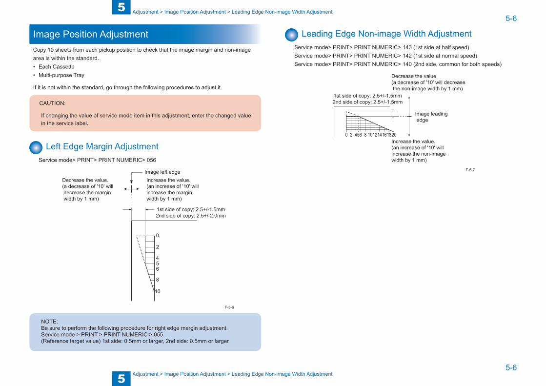
5
55-6
5-6
Adjustment > Image Position Adjustment > Leading Edge Non-image Width Adjustment
Adjustment > Image Position Adjustment > Leading Edge Non-image Width Adjustment
Image Position AdjustmentCopy 10 sheets from each pickup position to check that the image margin and non-image area is within the standard.• Each Cassette• Multi-purpose Tray
If it is not within the standard, go through the following procedures to adjust it.
CAUTION:
If changing the value of service mode item in this adjustment, enter the changed value in the service label.
Left Edge Margin AdjustmentService mode> PRINT> PRINT NUMERIC> 056
10
8
654
2
0
1st side of copy: 2.5+/-1.5mm2nd side of copy: 2.5+/-2.0mm
Image left edgeIncrease the value.(an increase of '10' will increase the margin width by 1 mm)
Decrease the value. (a decrease of '10' will decrease the margin width by 1 mm)
NOTE:Be sure to perform the following procedure for right edge margin adjustment.Service mode > PRINT > PRINT NUMERIC > 055(Reference target value) 1st side: 0.5mm or larger, 2nd side: 0.5mm or larger
F-5-6
Leading Edge Non-image Width AdjustmentService mode> PRINT> PRINT NUMERIC> 143 (1st side at half speed)Service mode> PRINT> PRINT NUMERIC> 142 (1st side at normal speed)Service mode> PRINT> PRINT NUMERIC> 140 (2nd side, common for both speeds)
2 54 6 8 1012141618200
1st side of copy: 2.5+/-1.5mm2nd side of copy: 2.5+/-1.5mm
Image leading edge
Decrease the value.(a decrease of '10' will decrease the non-image width by 1 mm)
Increase the value.(an increase of '10' will increase the non-image width by 1 mm)
F-5-7

5
55-7
5-7
Adjustment > Image Position Adjustment > Left Edge Non-image Width Adjustment
Adjustment > Image Position Adjustment > Left Edge Non-image Width Adjustment
Left Edge Non-image Width AdjustmentService mode > PRINT> PRINT NUMERIC> 034 (Multi-purpose Tray)Service mode > PRINT> PRINT NUMERIC> 035 (Cassette 1)Service mode > PRINT> PRINT NUMERIC> 036 (Cassette 2 (option))Service mode > PRINT> PRINT NUMERIC> 037 (Cassette 3 (option))Service mode > PRINT> PRINT NUMERIC> 038 (Cassette 4 (option))
10
8
654
2
0
1st side of copy: 2.5+/-1.5mm2nd side of copy: 2.5+/-1.5mm
Image edge
Increase the value.(an increase of '10' will increase the non-image width by 1 mm)
Decrease the value. (a decrease of '10' will decrease the non-image width by 1 mm)
F-5-8

5
55-8
5-8
Adjustment > Image Position Adjustment > Image Position Adjustment for ADF > Squareness Adjustment
Adjustment > Image Position Adjustment > Image Position Adjustment for ADF > Squareness Adjustment
Image Position Adjustment for ADF ■ Creation of Adjusting Test Sheet
Creation method: Draw straight lines on the A4-size or LTR-size paper.
10m
m
10mm
10mm
10mm
<When using A4-size paper>
Draw straight lines
(Feeding direction)
10mm
210m
m
297mm
10m
m10mm
10mm
10mm
<When using LTR-size paper>
Draw straight lines
(Feeding direction)
10mm21
6mm
279mm
F-5-9
F-5-10
■ Squareness Adjustment
1) Create a test sheet, place it on the ADF, and make a copy of it.
2) Check the image squareness at the leading edges of the test sheet and copied paper. Measure dimensions A and B and obtain the difference between them. Adjust the squareness so that the amount of skew is within specification.
Copy of test sheet
A
B
(Feeding direction)
• A - B standard: 0±1.5mmF-5-11
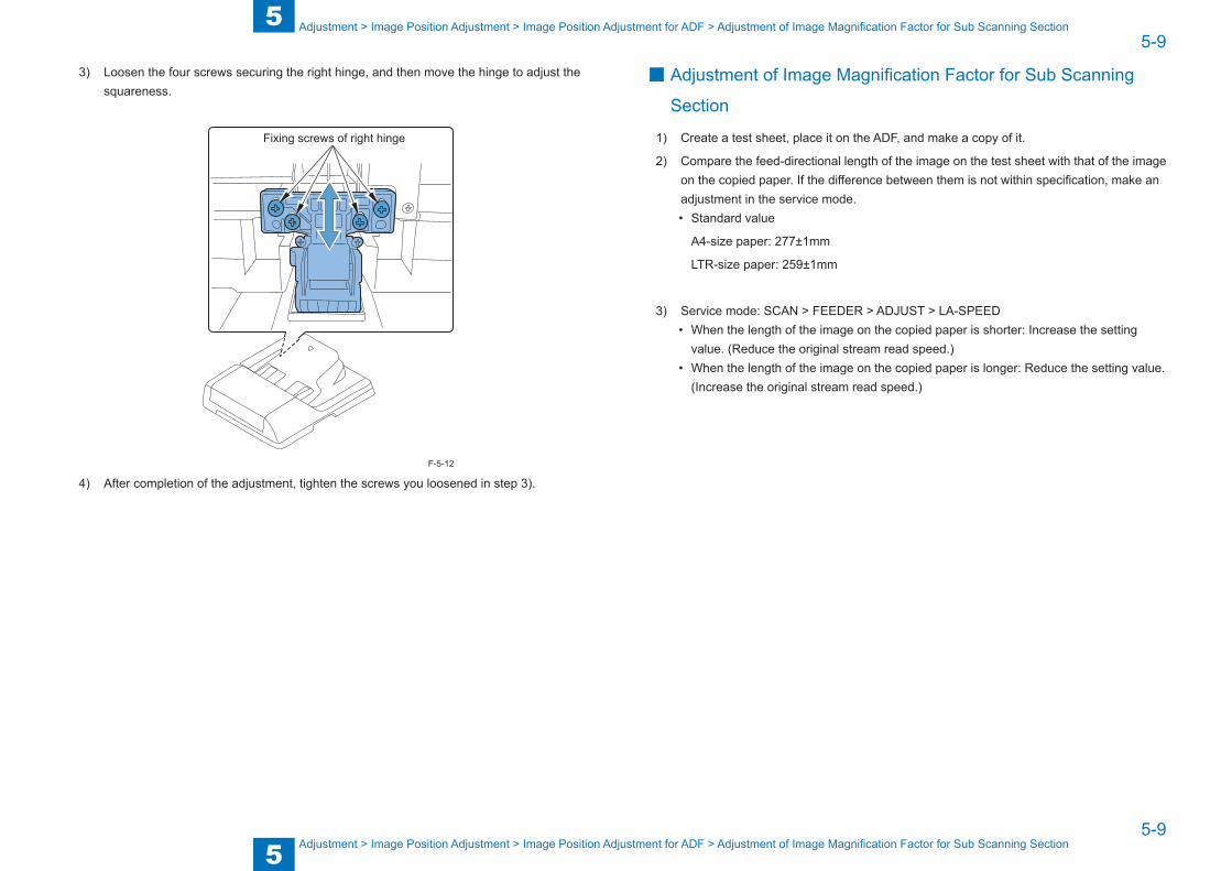
5
55-9
5-9
Adjustment > Image Position Adjustment > Image Position Adjustment for ADF > Adjustment of Image Magnification Factor for Sub Scanning Section
Adjustment > Image Position Adjustment > Image Position Adjustment for ADF > Adjustment of Image Magnification Factor for Sub Scanning Section
3) Loosen the four screws securing the right hinge, and then move the hinge to adjust the squareness.
Fixing screws of right hinge
4) After completion of the adjustment, tighten the screws you loosened in step 3).
F-5-12
■ Adjustment of Image Magnification Factor for Sub Scanning
Section
1) Create a test sheet, place it on the ADF, and make a copy of it.
2) Compare the feed-directional length of the image on the test sheet with that of the image on the copied paper. If the difference between them is not within specification, make an adjustment in the service mode.• Standard value
A4-size paper: 277±1mm
LTR-size paper: 259±1mm
3) Service mode: SCAN > FEEDER > ADJUST > LA-SPEED• When the length of the image on the copied paper is shorter: Increase the setting
value. (Reduce the original stream read speed.)• When the length of the image on the copied paper is longer: Reduce the setting value.
(Increase the original stream read speed.)

5
55-10
5-10
Adjustment > Image Position Adjustment > Image Position Adjustment for ADF > Leading Edge Registration Adjustment
Adjustment > Image Position Adjustment > Image Position Adjustment for ADF > Leading Edge Registration Adjustment
■ Horizontal Registration Adjustment
1) Create a test sheet, place it on the ADF, and make a copy of it.
2) Compare the horizontal registration of the test sheet with that of the copied paper.
Make an adjustment to conform to the following standard value:
Copy of test sheet
(Feeding direction)
10±2mm
• Standard value: Within 10mm±2mm
3) Open the ADF.
4) Loosen the adjusting screw, and then move the slide guide forward or backward with reference to the scale marks.
Adjusting screw
5) After completion of the adjustment, tighten the adjusting screw you loosened in step 4.)
F-5-13
F-5-14
■ Leading Edge Registration Adjustment
1) Create a test sheet, place it on the ADF, and make a copy of it.
2) Compare the leading-edge registration of the test sheet with that of the copied paper. If required, adjust the leading edge registration to the following value:
Copy of test sheet
(Feeding direction)
Leading edge marginL
• Standard value: 10mm±2mm
3) Service mode: SCAN > FEEDER > ADJUST > DOCST• When the image is shifted to the left: Reduce the setting value. • When the image is shifted to the right: Increase the setting value.
Note:
After completion of the adjustment, check the squareness. If it is not within specification, make adjustments again starting with the squareness adjustment.
F-5-15

6
6 Troubleshooting
Troubleshooting ■Initial Check ■Test Print ■Troubleshooting items ■Software to Be Upgraded and Upgrading Method
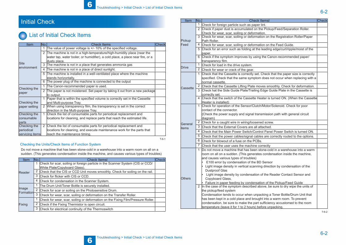
6
66-2
6-2
Troubleshooting > Initial Check > List of Initial Check Items
Troubleshooting > Initial Check > List of Initial Check Items
Initial Check
List of Initial Check ItemsItem No. Check Items Check
Site environment
1 The value of power voltage is +/- 10% of the specified voltage.2 The machine is not in a high-temperature/high-humidity place (near the
water tap, water boiler, or humidifier), a cold place, a place near fire, or a dusty place.
3 The machine is not in a place that generates ammonia gas4 The machine is not in a place of direct sunlight.5 The machine is installed in a well-ventilated place where the machine
stands horizontally.6 The power plug of the machine is connected to the output
Checking the paper
1 The Canon-recommended paper is used.2 The paper is not moistened. Set paper by taking it out from a new package
to output.
Checking the paper setting
1 Paper that is within the specified volume is correctly set in the Cassette and Multi-purpose Tray.
2 When using transparency film, the transparency is set in the correct direction in the Multi-purpose Tray.
Checking the consumable parts
1 Check the list of consumable parts for periodical replacement and locations for cleaning, and replace parts that reach the estimated life.
Checking the periodical servicing items
2 Check the list of consumable parts for periodical replacement and locations for cleaning, and execute maintenance work for the parts that reach the maintenance timing.
Checking the Units/Check Items of Function SystemDo not move a machine that has been stone-cold in a warehouse into a warm room on all on a sudden. (This generates condensation inside the machine, and causes various types of troubles)
Item No. Check Itemsl Check
Reader
1 Check for scar, soiling or foreign particle in the Scanner System (CIS or CCD/White Plate/Copyboard Glass).
2 Check that the CIS or CCD Unit moves smoothly. Check for soiling on the rail.3 Check for flicker with CIS or CCD.4 Check for condensation in the Scanner System.
Image Formation
1 The Drum Unit/Toner Bottle is securely installed.2 Check for scar or soiling on the Photosensitive Drum.3 Check for wear, scar, soiling or deformation on the Transfer Roller.
Fixing1 Check for wear, scar, soiling or deformation on the Fixing Film/Pressure Roller.2 Check if the Fixing Thermistor is open circuit.3 Check for electrical continuity of the Thermoswitch
T-6-1
Item No. Check Itemsl Check
Pickup Feed
1 Check for foreign particle such as paper lint.2 Check if paper dust is accumulated on the Pickup/Feed/Separation Roller.
Check for wear, scar, soiling or deformation.3 Check for wear, scar, soiling or deformation on the Registration Roller/Paper
Path Roller.4 Check for wear, scar, soiling or deformation on the Feed Guide.5 Check for an error such as folding at the leading edge/curl/ripple/moist of the
paper.6 Check if the symptom improves by using the Canon-recommended paper/
transparency film.
Drive1 Check for load in the drive system.2 Check for wear or crack of the gear.
Cassette
1 Check that the Cassette is correctly set. Check that the paper size is correctly specified. Check that the same symptom does not occur when replacing with a normal cassette.
2 Check that the Cassette Lifting Plate moves smoothly. Check for deformation.3 Check hat the Side Guide Plate/Trailing Edge Guide Plate in the Cassette is
correctly set.4 Check that the switch of the Cassette Heater is turned ON. (When the Cassette
Heater is installed)
General items
1 Check for operation of the Sensor/Clutch/Motor/Solenoid. Check for poor contact of the connector.(Check the power supply and signal transmission path with general circuit diagram)
2 Check for a caught wire in wiring/loosened screw.3 Check that the External Covers are all attached.4 Check that the Main Power Switch/Control Panel Power Switch is turned ON.5 Check that the power cables/signal cables are correctly routed to the options.6 Check for blowout of a fuse on the PCBs.7 Check that the user uses the machine correctly
Others
1 Do not move a machine that has been stone-cold in a warehouse into a warm room on all on a sudden. (This generates condensation inside the machine, and causes various types of troubles)• E100 error by condensation of the BD Sensor• Light image density in vertical scanning direction by condensation of the
Dustproof Glas• Light image density by condensation of the Reader Contact Sensor and
Copyboard Glass.• Failure in paper feeding by condensation of the Pickup/Feed Guide
2 In the case of the symptom described above, be sure to dry wipe the units of the pickup/feed systemCondensation tends to occur when unpacking a Toner Bottle/Drum Unit that has been kept in a cold place and brought into a warm room. To prevent condensation, be sure to make the part sufficiency accustomed to the room temperature (leave it for 1 to 2 hours) before unpacking.
T-6-2
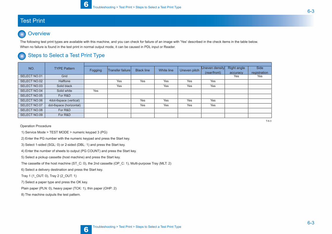
6
66-3
6-3
Troubleshooting > Test Print > Steps to Select a Test Print Type
Troubleshooting > Test Print > Steps to Select a Test Print Type
Test Print
OverviewThe following test print types are available with this machine, and you can check for failure of an image with 'Yes' described in the check items in the table below.When no failure is found in the test print in normal output mode, it can be caused in PDL input or Reader.
Steps to Select a Test Print Type
NO. TYPE Pattern Fogging Transfer failure Black line White line Uneven pitchUneven density
(rear/front)Right angle accuracy
Side registration
SELECT NO.01 Grid Yes YesSELECT NO.02 Halftone Yes Yes Yes Yes YesSELECT NO.03 Solid black Yes Yes Yes YesSELECT NO.04 Solid white YesSELECT NO.05 For R&DSELECT NO.06 4dot-6space (vertical) Yes Yes Yes YesSELECT NO.07 dot-6space (horizontal) Yes Yes Yes YesSELECT NO.08 For R&DSELECT NO.09 For R&D
Operation Procedure
1) Service Mode > TEST MODE > numeric keypad 3 (PG)
2) Enter the PG number with the numeric keypad and press the Start key.
3) Select 1-sided (SGL: 0) or 2-sided (DBL: 1) and press the Start key.
4) Enter the number of sheets to output (PG COUNT) and press the Start key.
5) Select a pickup cassette (host machine) and press the Start key.
The cassette of the host machine (ST_C: 0), the 2nd cassette (OP_C: 1), Multi-purpose Tray (MLT: 2)
6) Select a delivery destination and press the Start key.
Tray 1 (1_OUT: 0), Tray 2 (2_OUT: 1)
7) Select a paper type and press the OK key.
Plain paper (PLN: 0), heavy paper (TCK: 1), thin paper (OHP: 2)
8) The machine outputs the test pattern.
T-6-3
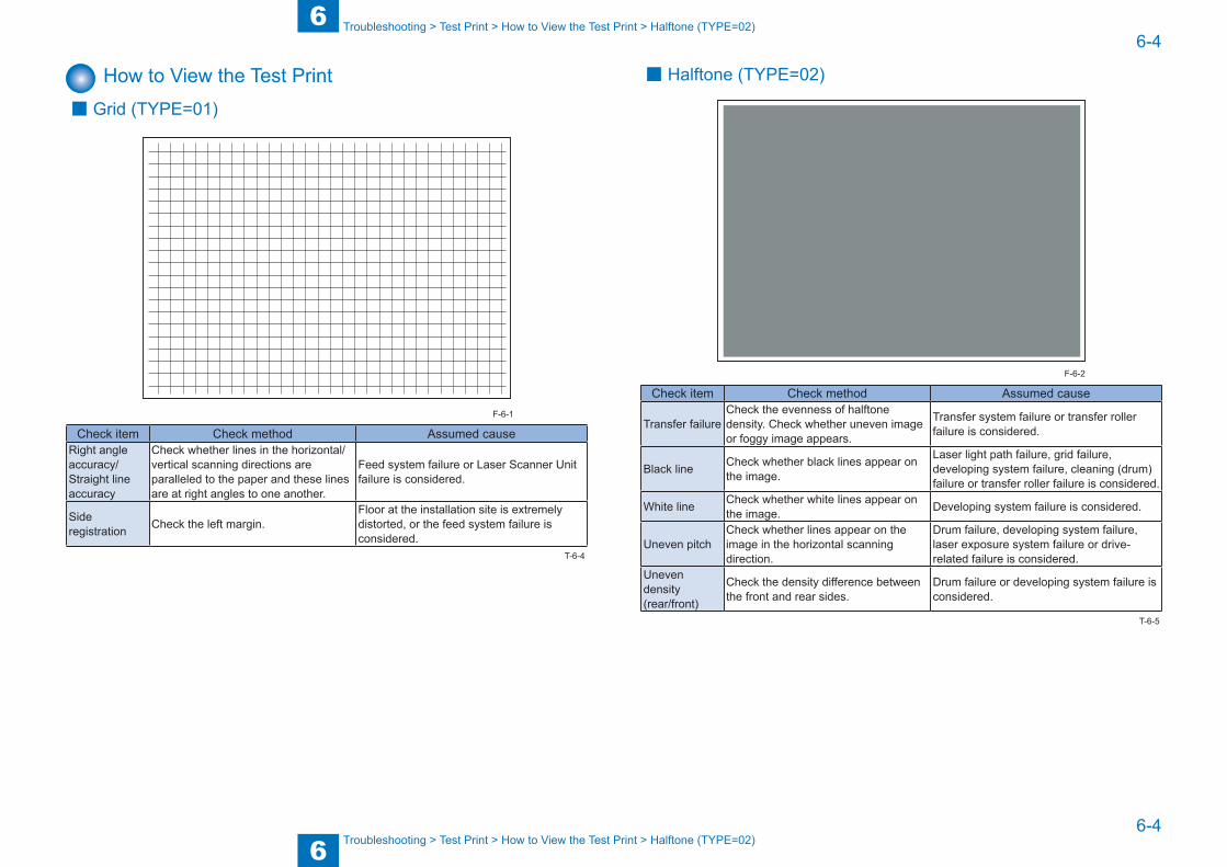
6
66-4
6-4
Troubleshooting > Test Print > How to View the Test Print > Halftone (TYPE=02)
Troubleshooting > Test Print > How to View the Test Print > Halftone (TYPE=02)
How to View the Test Print ■ Grid (TYPE=01)
Check item Check method Assumed causeRight angle accuracy/Straight line accuracy
Check whether lines in the horizontal/vertical scanning directions are paralleled to the paper and these lines are at right angles to one another.
Feed system failure or Laser Scanner Unit failure is considered.
Side registration Check the left margin.
Floor at the installation site is extremely distorted, or the feed system failure is considered.
F-6-1
T-6-4
■ Halftone (TYPE=02)
Check item Check method Assumed cause
Transfer failureCheck the evenness of halftone density. Check whether uneven image or foggy image appears.
Transfer system failure or transfer roller failure is considered.
Black line Check whether black lines appear on the image.
Laser light path failure, grid failure, developing system failure, cleaning (drum) failure or transfer roller failure is considered.
White line Check whether white lines appear on the image. Developing system failure is considered.
Uneven pitchCheck whether lines appear on the image in the horizontal scanning direction.
Drum failure, developing system failure, laser exposure system failure or drive-related failure is considered.
Uneven density(rear/front)
Check the density difference between the front and rear sides.
Drum failure or developing system failure is considered.
F-6-2
T-6-5

6
66-5
6-5
Troubleshooting > Test Print > How to View the Test Print > Solid white (TYPE=04)
Troubleshooting > Test Print > How to View the Test Print > Solid white (TYPE=04)
■ Solid black (TYPE=03)
Check item Check method Assumed cause
Transfer failureCheck the evenness of halftone density. Check whether uneven image or foggy image appears.
Transfer system failure is considered.
White line Check whether white lines appear on the image. Developing system failure is considered.
Uneven pitchCheck whether lines appear on the image in the horizontal scanning direction.
Drum failure, developing system failure, laser exposure system failure or drive-related failure is considered.
Uneven density(rear/front)
Check the density difference between the front and rear sides.
Drum failure or developing system failure is considered.
F-6-3
T-6-6
■ Solid white (TYPE=04)
Check item Check method Assumed cause
Fogging Check whether foggy image appears in the blank area.
Drum failure, laser exposure system failure or developing system failure is considered.
F-6-4
T-6-7
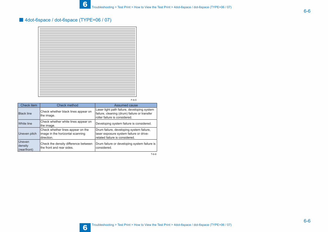
6
66-6
6-6
Troubleshooting > Test Print > How to View the Test Print > 4dot-6space / dot-6space (TYPE=06 / 07)
Troubleshooting > Test Print > How to View the Test Print > 4dot-6space / dot-6space (TYPE=06 / 07)
■ 4dot-6space / dot-6space (TYPE=06 / 07)
Check item Check method Assumed cause
Black line Check whether black lines appear on the image.
Laser light path failure, developing system failure, cleaning (drum) failure or transfer roller failure is considered.
White line Check whether white lines appear on the image. Developing system failure is considered.
Uneven pitchCheck whether lines appear on the image in the horizontal scanning direction.
Drum failure, developing system failure, laser exposure system failure or drive-related failure is considered.
Uneven density(rear/front)
Check the density difference between the front and rear sides.
Drum failure or developing system failure is considered.
F-6-5
T-6-8

6
66-7
6-7
Troubleshooting > Troubleshooting items > Image Failure > Soiling at the leading/trailing edge of paper
Troubleshooting > Troubleshooting items > Image Failure > Soiling at the leading/trailing edge of paper
Troubleshooting items
List of Troubleshooting ItemsCategory Item Reference
Image Failure Soiling Toner soiling at the back side of paper 6-1Soiling at the leading/trailing edge of paper 6-1
Toner bleed/white spot
Poor transfer of the image, hollow character 6-1Image smear/toner bleed/condensation 6-1
Operation failure
Paper jam Large curl of paper 6-2Jam of thin paper (63g/cm2 or lighter) 6-2Jam of paper with solid image when the leading edge margin is small (1 to 4mm)
6-2
Failure in setting The toner bottle set lever cannot be operated or is hard to operate.
6-2
Abnormal noise Abnormal noise at pickup from Multi-purpose Tray
6-3
Image Failure ■ Toner soiling at the back side of paper
[Location]Fixing Assembly (circumference of Pressure Roller: iR2545/2535: 94mm, iR2530/2525/2520: 78.5mm)Transfer Roller (roller circumference: 50mm)
T-6-9
F-6-6
[Cause]Fixing Assembly: Toner on the paper comes off and adheres to the Pressure Roller, and then the toner adheres to the back side of the paper.Transfer Roller: Toner remains on the Drum that has stopped at the time of paper jam, and then the residual toner on the Drum adheres to the Transfer Roller during a recovery operation.
[Condition]Fixing Assembly: Under conditions that causes poor fixing performance, such as low temperature environment, or when feeding a large number of sheets of halftone image. Or the Fixing Unit comes to the end of its life for replacement.Transfer Roller: When a paper jam occurs. Or the Transfer Roller comes to the end of its life for replacement
[Field Remedy]Fixing Assembly: user mode > Cleaning/Adjustment > Fixing Assembly CleaningTransfer Roller: user mode > Cleaning/Adjustment > Transfer Cleaning
■ Soiling at the leading/trailing edge of paper
[Location]Pre-transfer Guide,Fixing Inlet Guide
F-6-7
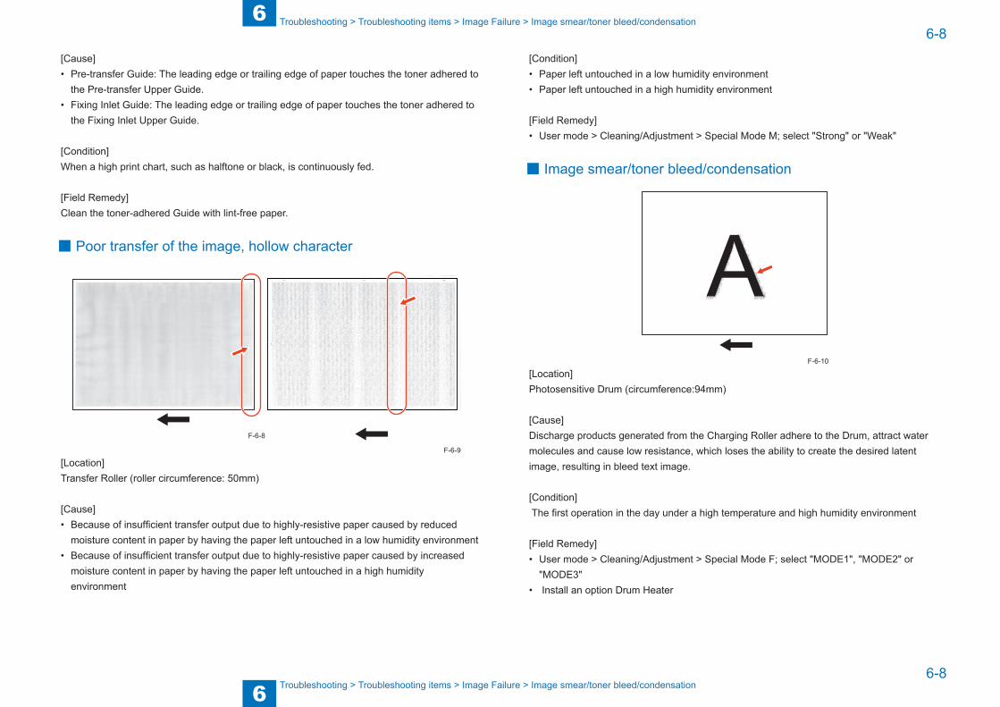
6
66-8
6-8
Troubleshooting > Troubleshooting items > Image Failure > Image smear/toner bleed/condensation
Troubleshooting > Troubleshooting items > Image Failure > Image smear/toner bleed/condensation
[Cause]• Pre-transfer Guide: The leading edge or trailing edge of paper touches the toner adhered to
the Pre-transfer Upper Guide.• Fixing Inlet Guide: The leading edge or trailing edge of paper touches the toner adhered to
the Fixing Inlet Upper Guide.
[Condition]When a high print chart, such as halftone or black, is continuously fed.
[Field Remedy]Clean the toner-adhered Guide with lint-free paper.
■ Poor transfer of the image, hollow character
[Location]Transfer Roller (roller circumference: 50mm)
[Cause]• Because of insufficient transfer output due to highly-resistive paper caused by reduced
moisture content in paper by having the paper left untouched in a low humidity environment• Because of insufficient transfer output due to highly-resistive paper caused by increased
moisture content in paper by having the paper left untouched in a high humidity environment
F-6-8
F-6-9
[Condition]• Paper left untouched in a low humidity environment• Paper left untouched in a high humidity environment
[Field Remedy]• User mode > Cleaning/Adjustment > Special Mode M; select "Strong" or "Weak"
■ Image smear/toner bleed/condensation
[Location]Photosensitive Drum (circumference:94mm)
[Cause]Discharge products generated from the Charging Roller adhere to the Drum, attract water molecules and cause low resistance, which loses the ability to create the desired latent image, resulting in bleed text image.
[Condition] The first operation in the day under a high temperature and high humidity environment
[Field Remedy]• User mode > Cleaning/Adjustment > Special Mode F; select "MODE1", "MODE2" or
"MODE3"• Install an option Drum Heater
F-6-10
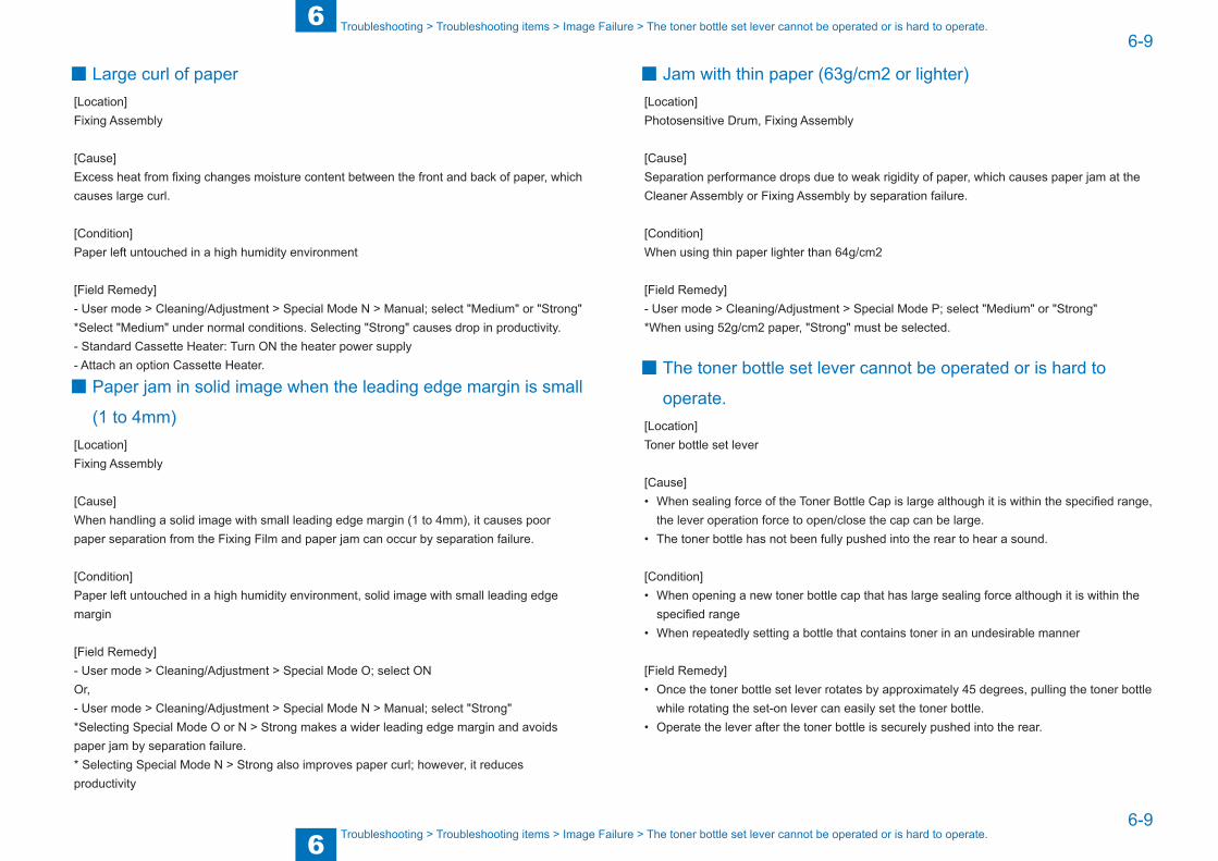
6
66-9
6-9
Troubleshooting > Troubleshooting items > Image Failure > The toner bottle set lever cannot be operated or is hard to operate.
Troubleshooting > Troubleshooting items > Image Failure > The toner bottle set lever cannot be operated or is hard to operate.
■ Large curl of paper[Location]Fixing Assembly
[Cause]Excess heat from fixing changes moisture content between the front and back of paper, which causes large curl.
[Condition]Paper left untouched in a high humidity environment
[Field Remedy]- User mode > Cleaning/Adjustment > Special Mode N > Manual; select "Medium" or "Strong" *Select "Medium" under normal conditions. Selecting "Strong" causes drop in productivity.- Standard Cassette Heater: Turn ON the heater power supply- Attach an option Cassette Heater.
■ Paper jam in solid image when the leading edge margin is small
(1 to 4mm) [Location]Fixing Assembly
[Cause]When handling a solid image with small leading edge margin (1 to 4mm), it causes poor paper separation from the Fixing Film and paper jam can occur by separation failure.
[Condition]Paper left untouched in a high humidity environment, solid image with small leading edge margin
[Field Remedy]- User mode > Cleaning/Adjustment > Special Mode O; select ON Or, - User mode > Cleaning/Adjustment > Special Mode N > Manual; select "Strong" *Selecting Special Mode O or N > Strong makes a wider leading edge margin and avoids paper jam by separation failure.* Selecting Special Mode N > Strong also improves paper curl; however, it reduces productivity
■ Jam with thin paper (63g/cm2 or lighter)[Location]Photosensitive Drum, Fixing Assembly
[Cause]Separation performance drops due to weak rigidity of paper, which causes paper jam at the Cleaner Assembly or Fixing Assembly by separation failure.
[Condition]When using thin paper lighter than 64g/cm2
[Field Remedy]- User mode > Cleaning/Adjustment > Special Mode P; select "Medium" or "Strong"*When using 52g/cm2 paper, "Strong" must be selected.
■ The toner bottle set lever cannot be operated or is hard to
operate.[Location]Toner bottle set lever
[Cause]• When sealing force of the Toner Bottle Cap is large although it is within the specified range,
the lever operation force to open/close the cap can be large.• The toner bottle has not been fully pushed into the rear to hear a sound.
[Condition]• When opening a new toner bottle cap that has large sealing force although it is within the
specified range• When repeatedly setting a bottle that contains toner in an undesirable manner
[Field Remedy]• Once the toner bottle set lever rotates by approximately 45 degrees, pulling the toner bottle
while rotating the set-on lever can easily set the toner bottle.• Operate the lever after the toner bottle is securely pushed into the rear.

6
66-10
6-10
Troubleshooting > Troubleshooting items > Image Failure > Abnormal noise at pickup from the Multi-purpose Tray
Troubleshooting > Troubleshooting items > Image Failure > Abnormal noise at pickup from the Multi-purpose Tray
■ Abnormal noise at pickup from the Multi-purpose Tray [Location]Gear of the Right Cover Unit
[Cause]Depending on the position to secure the lower belt for securing the Right Door, the belt cannot be fitted into the escape hole but Z-folded when closing the Right Cover Unit, which pushes the Right Door out and the gear at the Right Door side is not fully engaged with the gear at the machine side, resulting in abnormal noise.
[Condition]When reattaching a belt of the Right Cover Unit
[Field Remedy]Be sure to secure the lower belt to the Right Cover Unit as follows.Front side: Check that the belt is fitted into the escape hole when closing the Right Cover Unit.Rear side: Hold the belt to avoid displacement by securing the screw so that the belt is secured almost parallel or facing slightly downward.
Escape hole
F-6-11
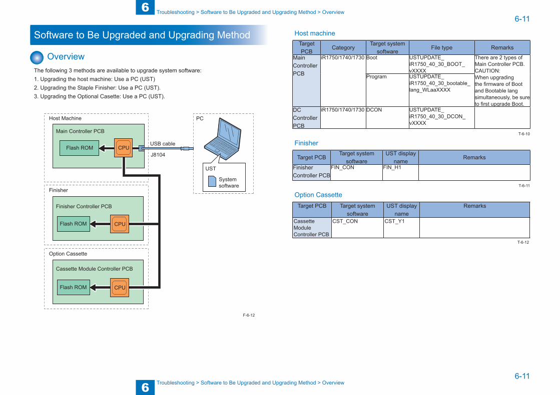
6
66-11
6-11
Troubleshooting > Software to Be Upgraded and Upgrading Method > Overview
Troubleshooting > Software to Be Upgraded and Upgrading Method > Overview
Software to Be Upgraded and Upgrading Method
OverviewThe following 3 methods are available to upgrade system software: 1. Upgrading the host machine: Use a PC (UST)2. Upgrading the Staple Finisher: Use a PC (UST).3. Upgrading the Optional Casette: Use a PC (UST).
USB cable
PC
J8104Flash ROM
Host Machine
Finisher
Main Controller PCB
Finisher Controller PCB
Flash ROM
Option Cassette
Cassette Module Controller PCB
UST
System software
CPU
CPU
Flash ROM CPU
F-6-12
Host machineTarget PCB
CategoryTarget system
softwareFile type Remarks
Main Controller PCB
iR1750/1740/1730 Boot USTUPDATE_iR1750_40_30_BOOT_vXXXX
There are 2 types of Main Controller PCB.CAUTION:When upgrading the firmware of Boot and Bootable lang simultaneously, be sure to first upgrade Boot.
Program USTUPDATE_iR1750_40_30_bootable_lang_WLaaXXXX
DC Controller PCB
iR1750/1740/1730 DCON USTUPDATE_iR1750_40_30_DCON_vXXXX
Finisher
Target PCBTarget system
softwareUST display
nameRemarks
Finisher Controller PCB
FIN_CON FIN_H1
Option CassetteTarget PCB Target system
softwareUST display
nameRemarks
Cassette Module Controller PCB
CST_CON CST_Y1
T-6-10
T-6-11
T-6-12
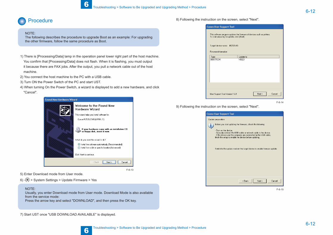
6
66-12
6-12
Troubleshooting > Software to Be Upgraded and Upgrading Method > Procedure
Troubleshooting > Software to Be Upgraded and Upgrading Method > Procedure
Procedure
NOTE:The following describes the procedure to upgrade Boot as an example: For upgrading the other firmware, follow the same procedure as Boot.
1) There is [Processing/Data] lamp in the operation panel lower right part of the host machine. You confirm that [Processing/Data] does not flash. When it is flashing, you must output it because there are FAX jobs. After the output, you pull a network cable out of the host machine.
2) You connect the host machine to the PC with a USB cable.3) Turn ON the Power Switch of the PC and start UST.4) When turning On the Power Switch, a wizard is displayed to add a new hardware, and click
"Cancel".
5) Enter Download mode from User mode.
6) > System Settings > Update Firmware > Yes
NOTE:Usually, you enter Download mode from User mode. Download Mode is also available from the service mode:Press the arrow key and select "DOWNLOAD", and then press the OK key.
7) Start UST once "USB DOWNLOAD AVAILABLE" is displayed.
F-6-13
8) Following the instruction on the screen, select "Next".
9) Following the instruction on the screen, select "Next".
F-6-14
F-6-15

6
66-13
6-13
Troubleshooting > Software to Be Upgraded and Upgrading Method > Procedure
Troubleshooting > Software to Be Upgraded and Upgrading Method > Procedure
10) Following the instruction on the screen, select "Next".
NOTE:Selecting firmware of a wrong model does not display "Select by printer name".
F-6-17
F-6-16
11) Following the instruction on the screen, select "Start".
12) Following the instruction on the screen, select "Yes".
13) The following screen is displayed. "UPDATING FIRMWARE" is displayed on the Control Panel of this machine.
F-6-18
F-6-19
F-6-20
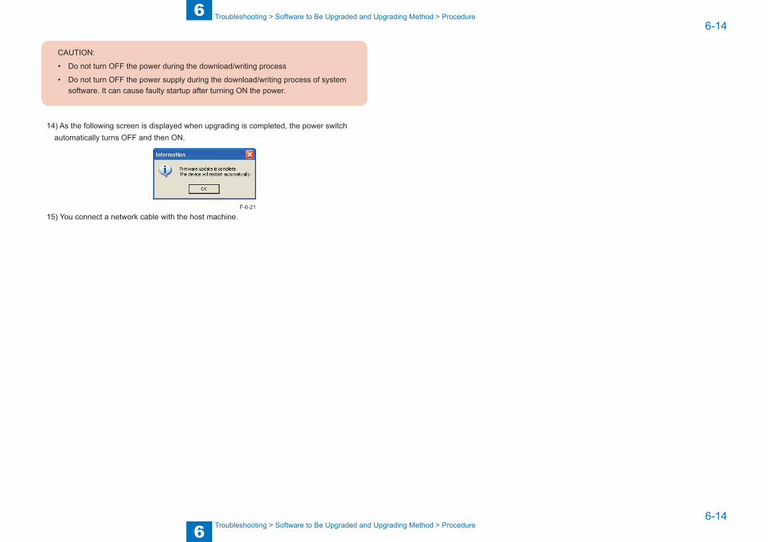
6
66-14
6-14
Troubleshooting > Software to Be Upgraded and Upgrading Method > Procedure
Troubleshooting > Software to Be Upgraded and Upgrading Method > Procedure
CAUTION:
• Do not turn OFF the power during the download/writing process
• Do not turn OFF the power supply during the download/writing process of system software. It can cause faulty startup after turning ON the power.
14) As the following screen is displayed when upgrading is completed, the power switch automatically turns OFF and then ON.
15) You connect a network cable with the host machine.F-6-21
7
7 Error Code
Error Code ■Overview ■Error Code ■Jam Code ■Alarm Code

7
77-2
7-2
Error Code > Overview > Outline
Error Code > Overview > Outline
Overview
OutlineThis chapter describes various codes which are displayed when a failure occurs on the product. These are classified into 3 codes as follows.
Code type Explanation ReferenceError code This code is displayed when an error occurs on the machine. Refer to page 7-3Jam code This code is displayed when a jam occurs inside the machine. Refer to page 7-12Alarm code This code is displayed when a function of the machine is
malfunctioned.Refer to page 7-15
T-7-1
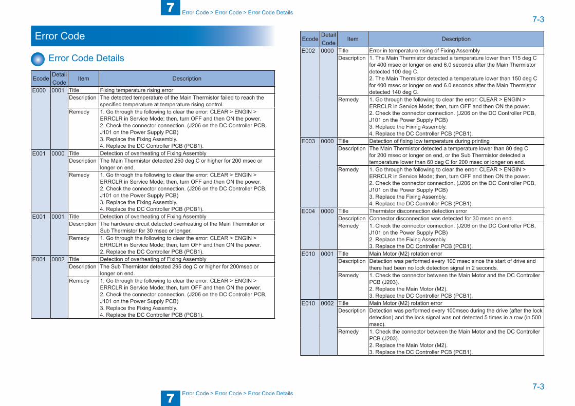
7
77-3
7-3
Error Code > Error Code > Error Code Details
Error Code > Error Code > Error Code Details
Error Code
Error Code Details
EcodeDetail Code
Item Description
E000 0001 Title Fixing temperature rising errorDescription The detected temperature of the Main Thermistor failed to reach the
specified temperature at temperature rising control.Remedy 1. Go through the following to clear the error: CLEAR > ENGIN >
ERRCLR in Service Mode; then, turn OFF and then ON the power.2. Check the connector connection. (J206 on the DC Controller PCB, J101 on the Power Supply PCB)3. Replace the Fixing Assembly.4. Replace the DC Controller PCB (PCB1).
E001 0000 Title Detection of overheating of Fixing AssemblyDescription The Main Thermistor detected 250 deg C or higher for 200 msec or
longer on end.Remedy 1. Go through the following to clear the error: CLEAR > ENGIN >
ERRCLR in Service Mode; then, turn OFF and then ON the power.2. Check the connector connection. (J206 on the DC Controller PCB, J101 on the Power Supply PCB)3. Replace the Fixing Assembly.4. Replace the DC Controller PCB (PCB1).
E001 0001 Title Detection of overheating of Fixing AssemblyDescription The hardware circuit detected overheating of the Main Thermistor or
Sub Thermistor for 30 msec or longer.Remedy 1. Go through the following to clear the error: CLEAR > ENGIN >
ERRCLR in Service Mode; then, turn OFF and then ON the power.2. Replace the DC Controller PCB (PCB1).
E001 0002 Title Detection of overheating of Fixing AssemblyDescription The Sub Thermistor detected 295 deg C or higher for 200msec or
longer on end.Remedy 1. Go through the following to clear the error: CLEAR > ENGIN >
ERRCLR in Service Mode; then, turn OFF and then ON the power.2. Check the connector connection. (J206 on the DC Controller PCB, J101 on the Power Supply PCB)3. Replace the Fixing Assembly.4. Replace the DC Controller PCB (PCB1).
EcodeDetail Code
Item Description
E002 0000 Title Error in temperature rising of Fixing AssemblyDescription 1. The Main Thermistor detected a temperature lower than 115 deg C
for 400 msec or longer on end 6.0 seconds after the Main Thermistor detected 100 deg C.2. The Main Thermistor detected a temperature lower than 150 deg C for 400 msec or longer on end 6.0 seconds after the Main Thermistor detected 140 deg C.
Remedy 1. Go through the following to clear the error: CLEAR > ENGIN > ERRCLR in Service Mode; then, turn OFF and then ON the power.2. Check the connector connection. (J206 on the DC Controller PCB, J101 on the Power Supply PCB)3. Replace the Fixing Assembly.4. Replace the DC Controller PCB (PCB1).
E003 0000 Title Detection of fixing low temperature during printingDescription The Main Thermistor detected a temperature lower than 80 deg C
for 200 msec or longer on end, or the Sub Thermistor detected a temperature lower than 60 deg C for 200 msec or longer on end.
Remedy 1. Go through the following to clear the error: CLEAR > ENGIN > ERRCLR in Service Mode; then, turn OFF and then ON the power.2. Check the connector connection. (J206 on the DC Controller PCB, J101 on the Power Supply PCB)3. Replace the Fixing Assembly.4. Replace the DC Controller PCB (PCB1).
E004 0000 Title Thermistor disconnection detection errorDescription Connector disconnection was detected for 30 msec on end.Remedy 1. Check the connector connection. (J206 on the DC Controller PCB,
J101 on the Power Supply PCB)2. Replace the Fixing Assembly.3. Replace the DC Controller PCB (PCB1).
E010 0001 Title Main Motor (M2) rotation errorDescription Detection was performed every 100 msec since the start of drive and
there had been no lock detection signal in 2 seconds.Remedy 1. Check the connector between the Main Motor and the DC Controller
PCB (J203).2. Replace the Main Motor (M2).3. Replace the DC Controller PCB (PCB1).
E010 0002 Title Main Motor (M2) rotation errorDescription Detection was performed every 100msec during the drive (after the lock
detection) and the lock signal was not detected 5 times in a row (in 500 msec).
Remedy 1. Check the connector between the Main Motor and the DC Controller PCB (J203).2. Replace the Main Motor (M2).3. Replace the DC Controller PCB (PCB1).

7
77-4
7-4
Error Code > Error Code > Error Code Details
Error Code > Error Code > Error Code Details
EcodeDetail Code
Item Description
E013 0001 Title Error in rotation of Waste Toner Motor (M3)Description Lock detection flag was monitored every 2msec, and the same level
was detected 600 times in a row.Remedy 1. Check the connector connection between the Waste Toner Motor and
the DC Controller PCB (J209).2. Replace the Waste Toner Motor (M3).3. Replace the DC Controller PCB (PCB1).
E014 0001 Title Fixing Motor (M1) rotation errorDescription Detection was performed every 100 msec since the start of drive and
there had been no lock detection signal in 2 seconds.Remedy 1. Check the connector connection between the Fixing Motor and the
DC Controller PCB (J203). 2. Replace the Fixing Motor (M1).3. Replace the DC Controller PCB (PCB1)
E014 0002 Title Fixing Motor (M1) rotation errorDescription Detection was performed every 100 msec during the drive (after the
lock detection) and the lock signal was not detected 5 times in a row (in 500 msec).
Remedy 1. Check the connector connection between the Fixing Motor and the DC Controller PCB (J203). 2. Replace the Fixing Motor (M1).3. Replace the DC Controller PCB (PCB1).
E014 0003 Title Fixing Motor (M1) pressure release errorDescription Pressure release had never been detected in 3.0 seconds.Remedy 1. Check the connector connection between the Fixing Motor and the
DC Controller PCB (J203). 2. Replace the Fixing Motor (M1).3. Replace the DC Controller PCB (PCB1).
E014 0004 Title Fixing Motor (M1) pressurization errorDescription Pressurization had never been detected in 3.0 seconds.Remedy 1. Check the connector connection between the Fixing Motor and the
DC Controller PCB (J203). 2. Replace the Fixing Motor (M1).3. Replace the DC Controller PCB (PCB1).
EcodeDetail Code
Item Description
E020 0000 Title Detection of toner clog between the Hopper and the Developing Assembly
Description When the Developing Assembly Toner Sensor (TS2) detected "toner-absent" and the Hopper Toner Sensor (TS1) detected "toner-present", the Hopper Motor (M6) was rotated 194 times with intermissions of 1 second, but the Developing Assembly Toner Sensor (TS2) could not detect "toner-present".* If paper is being fed, the error occurs after the paper has been delivered.
Remedy 1. Check rotation of the Hopper Motor Gear. (If it is rotating, the sensor may not be detecting correctly. In that case, execute Service Mode>CLEAR>ENGIN>TNRINST to supply toner to the Developing Assembly.)2. Replace the Developing Assembly Toner Sensor (TS2).3. Replace the Hopper Toner Sensor (TS1).4. Replace the DC Controller PCB (PCB1).
E024 0000 Title Connector disconnection of the Developing Assembly Toner Sensor (TS2) or the DC Controller PCB (J209)
Description Developing Assembly Toner Sensor (TS2) connection detection signals were not detected 10 times in a row in 100 msec.* If paper is being fed, the error occurs after the paper has been delivered.
Remedy 1. Check the connection of the Connector (J209).2. Replace the Developing Assembly Toner Sensor (TS2).3. Replace the DC Controller PCB (PCB1).
E024 0001 Title Detection of disconnection of the Developing Assembly Toner Sensor (TS2)
Description At normal speed: Developing Assembly Toner Sensor (TS2) signals were detected 7500 times in a row at intervals of 100 msec.At low speed: Developing Assembly Toner Sensor (TS2) signals were detected 4500 times in a row at intervals of 100 msec.
Remedy 1. Check the connection of the Connector (J209).2. Correct the wiring.3. Replace the Developing Assembly Toner Sensor (TS2).
E025 0000 Title Connector disconnection of the Hopper Toner Sensor (TS1) or the DC Controller PCB (J211)
Description Hopper Toner Sensor (TS1) connection detection signals were not detected 10 times in a row in 100 msec.* If paper is being fed, the error occurs after the paper has been delivered.
Remedy 1. Check the connection of the Connector (J211).2. Replace the Hopper Toner Sensor (TS1).3. Replace the DC Controller PCB (PCB1).
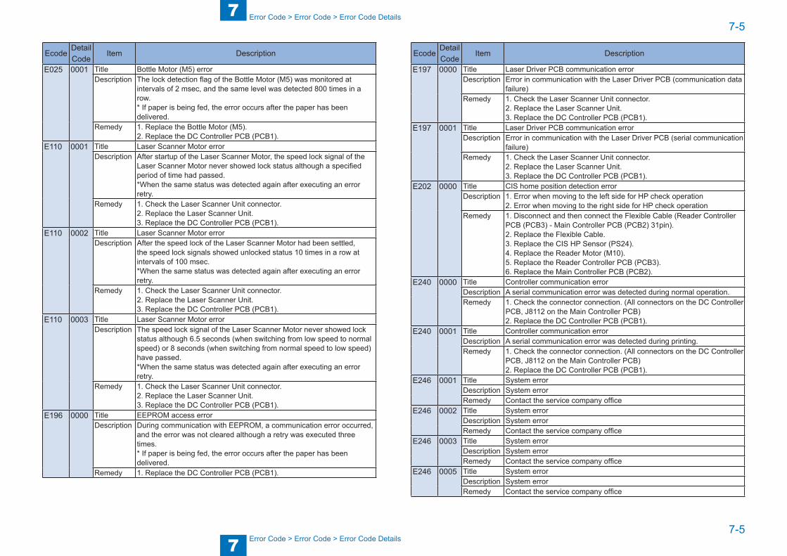
7
77-5
7-5
Error Code > Error Code > Error Code Details
Error Code > Error Code > Error Code Details
EcodeDetail Code
Item Description
E025 0001 Title Bottle Motor (M5) errorDescription The lock detection flag of the Bottle Motor (M5) was monitored at
intervals of 2 msec, and the same level was detected 800 times in a row.* If paper is being fed, the error occurs after the paper has been delivered.
Remedy 1. Replace the Bottle Motor (M5).2. Replace the DC Controller PCB (PCB1).
E110 0001 Title Laser Scanner Motor errorDescription After startup of the Laser Scanner Motor, the speed lock signal of the
Laser Scanner Motor never showed lock status although a specified period of time had passed.*When the same status was detected again after executing an error retry.
Remedy 1. Check the Laser Scanner Unit connector.2. Replace the Laser Scanner Unit.3. Replace the DC Controller PCB (PCB1).
E110 0002 Title Laser Scanner Motor errorDescription After the speed lock of the Laser Scanner Motor had been settled,
the speed lock signals showed unlocked status 10 times in a row at intervals of 100 msec.*When the same status was detected again after executing an error retry.
Remedy 1. Check the Laser Scanner Unit connector.2. Replace the Laser Scanner Unit.3. Replace the DC Controller PCB (PCB1).
E110 0003 Title Laser Scanner Motor errorDescription The speed lock signal of the Laser Scanner Motor never showed lock
status although 6.5 seconds (when switching from low speed to normal speed) or 8 seconds (when switching from normal speed to low speed) have passed.*When the same status was detected again after executing an error retry.
Remedy 1. Check the Laser Scanner Unit connector.2. Replace the Laser Scanner Unit.3. Replace the DC Controller PCB (PCB1).
E196 0000 Title EEPROM access errorDescription During communication with EEPROM, a communication error occurred,
and the error was not cleared although a retry was executed three times.* If paper is being fed, the error occurs after the paper has been delivered.
Remedy 1. Replace the DC Controller PCB (PCB1).
EcodeDetail Code
Item Description
E197 0000 Title Laser Driver PCB communication errorDescription Error in communication with the Laser Driver PCB (communication data
failure)Remedy 1. Check the Laser Scanner Unit connector.
2. Replace the Laser Scanner Unit.3. Replace the DC Controller PCB (PCB1).
E197 0001 Title Laser Driver PCB communication errorDescription Error in communication with the Laser Driver PCB (serial communication
failure)Remedy 1. Check the Laser Scanner Unit connector.
2. Replace the Laser Scanner Unit.3. Replace the DC Controller PCB (PCB1).
E202 0000 Title CIS home position detection errorDescription 1. Error when moving to the left side for HP check operation
2. Error when moving to the right side for HP check operationRemedy 1. Disconnect and then connect the Flexible Cable (Reader Controller
PCB (PCB3) - Main Controller PCB (PCB2) 31pin).2. Replace the Flexible Cable.3. Replace the CIS HP Sensor (PS24).4. Replace the Reader Motor (M10).5. Replace the Reader Controller PCB (PCB3).6. Replace the Main Controller PCB (PCB2).
E240 0000 Title Controller communication errorDescription A serial communication error was detected during normal operation.Remedy 1. Check the connector connection. (All connectors on the DC Controller
PCB, J8112 on the Main Controller PCB)2. Replace the DC Controller PCB (PCB1).
E240 0001 Title Controller communication errorDescription A serial communication error was detected during printing.Remedy 1. Check the connector connection. (All connectors on the DC Controller
PCB, J8112 on the Main Controller PCB)2. Replace the DC Controller PCB (PCB1).
E246 0001 Title System errorDescription System errorRemedy Contact the service company office
E246 0002 Title System errorDescription System errorRemedy Contact the service company office
E246 0003 Title System errorDescription System errorRemedy Contact the service company office
E246 0005 Title System errorDescription System errorRemedy Contact the service company office
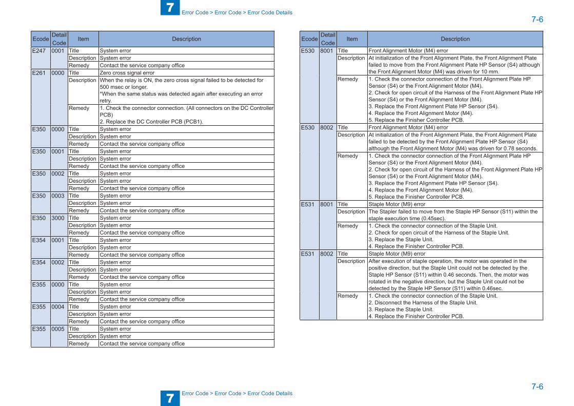
7
77-6
7-6
Error Code > Error Code > Error Code Details
Error Code > Error Code > Error Code Details
EcodeDetail Code
Item Description
E247 0001 Title System errorDescription System errorRemedy Contact the service company office
E261 0000 Title Zero cross signal errorDescription When the relay is ON, the zero cross signal failed to be detected for
500 msec or longer.*When the same status was detected again after executing an error retry.
Remedy 1. Check the connector connection. (All connectors on the DC Controller PCB)2. Replace the DC Controller PCB (PCB1).
E350 0000 Title System errorDescription System errorRemedy Contact the service company office
E350 0001 Title System errorDescription System errorRemedy Contact the service company office
E350 0002 Title System errorDescription System errorRemedy Contact the service company office
E350 0003 Title System errorDescription System errorRemedy Contact the service company office
E350 3000 Title System errorDescription System errorRemedy Contact the service company office
E354 0001 Title System errorDescription System errorRemedy Contact the service company office
E354 0002 Title System errorDescription System errorRemedy Contact the service company office
E355 0000 Title System errorDescription System errorRemedy Contact the service company office
E355 0004 Title System errorDescription System errorRemedy Contact the service company office
E355 0005 Title System errorDescription System errorRemedy Contact the service company office
EcodeDetail Code
Item Description
E530 8001 Title Front Alignment Motor (M4) errorDescription At initialization of the Front Alignment Plate, the Front Alignment Plate
failed to move from the Front Alignment Plate HP Sensor (S4) although the Front Alignment Motor (M4) was driven for 10 mm.
Remedy 1. Check the connector connection of the Front Alignment Plate HP Sensor (S4) or the Front Alignment Motor (M4).2. Check for open circuit of the Harness of the Front Alignment Plate HP Sensor (S4) or the Front Alignment Motor (M4).3. Replace the Front Alignment Plate HP Sensor (S4).4. Replace the Front Alignment Motor (M4).5. Replace the Finisher Controller PCB.
E530 8002 Title Front Alignment Motor (M4) errorDescription At initialization of the Front Alignment Plate, the Front Alignment Plate
failed to be detected by the Front Alignment Plate HP Sensor (S4) although the Front Alignment Motor (M4) was driven for 0.78 seconds.
Remedy 1. Check the connector connection of the Front Alignment Plate HP Sensor (S4) or the Front Alignment Motor (M4).2. Check for open circuit of the Harness of the Front Alignment Plate HP Sensor (S4) or the Front Alignment Motor (M4).3. Replace the Front Alignment Plate HP Sensor (S4).4. Replace the Front Alignment Motor (M4).5. Replace the Finisher Controller PCB.
E531 8001 Title Staple Motor (M9) errorDescription The Stapler failed to move from the Staple HP Sensor (S11) within the
staple execution time (0.45sec).Remedy 1. Check the connector connection of the Staple Unit.
2. Check for open circuit of the Harness of the Staple Unit.3. Replace the Staple Unit.4. Replace the Finisher Controller PCB.
E531 8002 Title Staple Motor (M9) errorDescription After execution of staple operation, the motor was operated in the
positive direction, but the Staple Unit could not be detected by the Staple HP Sensor (S11) within 0.46 seconds. Then, the motor was rotated in the negative direction, but the Staple Unit could not be detected by the Staple HP Sensor (S11) within 0.46sec.
Remedy 1. Check the connector connection of the Staple Unit.2. Disconnect the Harness of the Staple Unit.3. Replace the Staple Unit.4. Replace the Finisher Controller PCB.
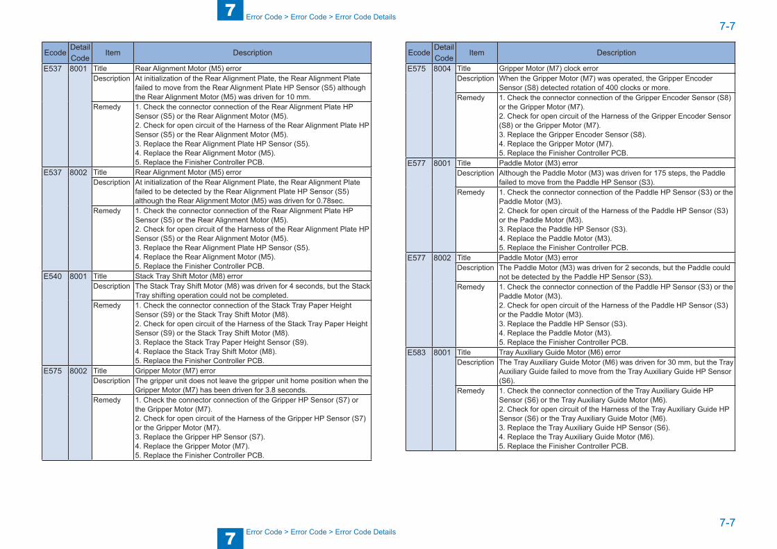
7
77-7
7-7
Error Code > Error Code > Error Code Details
Error Code > Error Code > Error Code Details
EcodeDetail Code
Item Description
E537 8001 Title Rear Alignment Motor (M5) errorDescription At initialization of the Rear Alignment Plate, the Rear Alignment Plate
failed to move from the Rear Alignment Plate HP Sensor (S5) although the Rear Alignment Motor (M5) was driven for 10 mm.
Remedy 1. Check the connector connection of the Rear Alignment Plate HP Sensor (S5) or the Rear Alignment Motor (M5).2. Check for open circuit of the Harness of the Rear Alignment Plate HP Sensor (S5) or the Rear Alignment Motor (M5).3. Replace the Rear Alignment Plate HP Sensor (S5).4. Replace the Rear Alignment Motor (M5).5. Replace the Finisher Controller PCB.
E537 8002 Title Rear Alignment Motor (M5) errorDescription At initialization of the Rear Alignment Plate, the Rear Alignment Plate
failed to be detected by the Rear Alignment Plate HP Sensor (S5) although the Rear Alignment Motor (M5) was driven for 0.78sec.
Remedy 1. Check the connector connection of the Rear Alignment Plate HP Sensor (S5) or the Rear Alignment Motor (M5).2. Check for open circuit of the Harness of the Rear Alignment Plate HP Sensor (S5) or the Rear Alignment Motor (M5).3. Replace the Rear Alignment Plate HP Sensor (S5).4. Replace the Rear Alignment Motor (M5).5. Replace the Finisher Controller PCB.
E540 8001 Title Stack Tray Shift Motor (M8) errorDescription The Stack Tray Shift Motor (M8) was driven for 4 seconds, but the Stack
Tray shifting operation could not be completed.Remedy 1. Check the connector connection of the Stack Tray Paper Height
Sensor (S9) or the Stack Tray Shift Motor (M8).2. Check for open circuit of the Harness of the Stack Tray Paper Height Sensor (S9) or the Stack Tray Shift Motor (M8).3. Replace the Stack Tray Paper Height Sensor (S9).4. Replace the Stack Tray Shift Motor (M8).5. Replace the Finisher Controller PCB.
E575 8002 Title Gripper Motor (M7) errorDescription The gripper unit does not leave the gripper unit home position when the
Gripper Motor (M7) has been driven for 3.8 seconds.Remedy 1. Check the connector connection of the Gripper HP Sensor (S7) or
the Gripper Motor (M7).2. Check for open circuit of the Harness of the Gripper HP Sensor (S7) or the Gripper Motor (M7).3. Replace the Gripper HP Sensor (S7).4. Replace the Gripper Motor (M7).5. Replace the Finisher Controller PCB.
EcodeDetail Code
Item Description
E575 8004 Title Gripper Motor (M7) clock errorDescription When the Gripper Motor (M7) was operated, the Gripper Encoder
Sensor (S8) detected rotation of 400 clocks or more.Remedy 1. Check the connector connection of the Gripper Encoder Sensor (S8)
or the Gripper Motor (M7).2. Check for open circuit of the Harness of the Gripper Encoder Sensor (S8) or the Gripper Motor (M7).3. Replace the Gripper Encoder Sensor (S8).4. Replace the Gripper Motor (M7).5. Replace the Finisher Controller PCB.
E577 8001 Title Paddle Motor (M3) errorDescription Although the Paddle Motor (M3) was driven for 175 steps, the Paddle
failed to move from the Paddle HP Sensor (S3).Remedy 1. Check the connector connection of the Paddle HP Sensor (S3) or the
Paddle Motor (M3).2. Check for open circuit of the Harness of the Paddle HP Sensor (S3) or the Paddle Motor (M3).3. Replace the Paddle HP Sensor (S3).4. Replace the Paddle Motor (M3).5. Replace the Finisher Controller PCB.
E577 8002 Title Paddle Motor (M3) errorDescription The Paddle Motor (M3) was driven for 2 seconds, but the Paddle could
not be detected by the Paddle HP Sensor (S3).Remedy 1. Check the connector connection of the Paddle HP Sensor (S3) or the
Paddle Motor (M3).2. Check for open circuit of the Harness of the Paddle HP Sensor (S3) or the Paddle Motor (M3).3. Replace the Paddle HP Sensor (S3).4. Replace the Paddle Motor (M3).5. Replace the Finisher Controller PCB.
E583 8001 Title Tray Auxiliary Guide Motor (M6) errorDescription The Tray Auxiliary Guide Motor (M6) was driven for 30 mm, but the Tray
Auxiliary Guide failed to move from the Tray Auxiliary Guide HP Sensor (S6).
Remedy 1. Check the connector connection of the Tray Auxiliary Guide HP Sensor (S6) or the Tray Auxiliary Guide Motor (M6).2. Check for open circuit of the Harness of the Tray Auxiliary Guide HP Sensor (S6) or the Tray Auxiliary Guide Motor (M6).3. Replace the Tray Auxiliary Guide HP Sensor (S6).4. Replace the Tray Auxiliary Guide Motor (M6).5. Replace the Finisher Controller PCB.

7
77-8
7-8
Error Code > Error Code > Error Code Details
Error Code > Error Code > Error Code Details
EcodeDetail Code
Item Description
E583 8002 Title Tray Auxiliary Guide Motor (M6) errorDescription The Tray Auxiliary Guide Motor (M6) was driven for 1.8 seconds, but the
Tray Auxiliary Guide could not be detected by the Tray Auxiliary Guide HP Sensor (S6).
Remedy 1. Check the connector connection of the Tray Auxiliary Guide HP Sensor (S6) or the Tray Auxiliary Guide Motor (M6).2. Check for open circuit of the Harness of the Tray Auxiliary Guide HP Sensor (S6) or the Tray Auxiliary Guide Motor (M6).3. Replace the Tray Auxiliary Guide HP Sensor (S6).4. Replace the Tray Auxiliary Guide Motor (M6).5. Replace the Finisher Controller PCB.
E719 0000 Title Error in communication with the Copy Card Reader-F1 (serial communication)
Description Card Reader was not connected at department management setting.Remedy 1. Check the connection with the Card Reader.
2. Remove the Card Reader, and execute the following: service mode > #CLEAR > ERR > E719.
E736 0000 Title Fax Board mismatch errorDescription Combination of the Fax Board type and the country was mismatched.Remedy This error occurred in the following cases.
- Fax Board for non-Chinese models was installed to a Chinese model. - Fax Board for Chinese models was installed to a non-Chinese model.- For Chinese models, replace the Fax Board with that for Chinese models.- For non-Chinese models, replace the Fax Board with that for non-Chinese models.
E804 0000 Title Power Supply Cooling Fan (FM4) errorDescription A lock signal was detected for 5 seconds while the Power Supply
Cooling Fan (FM4) was being stopped.*The same status was detected again after executing an error retry.
Remedy 1. Disconnect and then connect the connector (J209) on the DC Controller PCB (PCB1) to check the connection.2. Replace the Power Supply Cooling Fan (FM4).3. Replace the DC Controller PCB (PCB1).
E804 0001 Title Error in rotation of the Power Supply Cooling Fan (FM4)Description A lock signal could not be detected for 5 seconds while the Power
Supply Cooling Fan (FM4) was being driven.*The same status was detected again after executing an error retry.
Remedy 1. Disconnect and then connect the connector (J209) on the DC Controller PCB (PCB1) to check the connection.2. Replace the Power Supply Cooling Fan (FM4).3. Replace the DC Controller PCB (PCB1).
EcodeDetail Code
Item Description
E805 0000 Title Heat Exhaust Fan (Rear) (FM6) errorDescription A lock signal was detected for 5 seconds while the Heat Exhaust Fan
(Rear) (FM6) was being stopped.*The same status was detected again after executing an error retry.
Remedy 1. Disconnect and then connect the connector (J212) on the DC Controller PCB (PCB1) to check the connection.2. Replace the Heat Exhaust Fan (Rear) (FM6).3. Replace the DC Controller PCB (PCB1).
E805 0001 Title Error in rotation of the Heat Exhaust Fan (Rear) (FM6)Description A lock signal could not be detected for 5 seconds while the Heat
Exhaust Fan (Rear) (FM6) was being driven.*The same status was detected again after executing an error retry.
Remedy 1. Disconnect and then connect the connector (J212) on the DC Controller PCB (PCB1) to check the connection.2. Replace the Heat Exhaust Fan (Rear) (FM6).3. Replace the DC Controller PCB (PCB1).
E805 0002 Title Heat Exhaust Fan (Front) (FM5) errorDescription A lock signal was detected for 5 seconds while the Heat Exhaust Fan
(Front) (FM5) was being stopped.*The same status was detected again after executing an error retry.
Remedy 1. Disconnect and then connect the connector (J212) on the DC Controller PCB (PCB1) to check the connection.2. Replace the Heat Exhaust Fan (Front) (FM5).3. Replace the DC Controller PCB (PCB1).
E805 0003 Title Error in rotation of the Heat Exhaust Fan (Front) (FM5)Description A lock signal was detected for 5 seconds while the Heat Exhaust Fan
(Front) (FM5) was being driven.*The same status was detected again after executing an error retry.
Remedy 1. Disconnect and then connect the connector (J212) on the DC Controller PCB (PCB1) to check the connection.2. Replace the Heat Exhaust Fan (Front) (FM5).3. Replace the DC Controller PCB (PCB1).
E820 0000 Title Developing Cooling Fan (Front) (FM7) errorDescription A lock signal was detected for 5 seconds while the Developing Cooling
Fan (Front) (FM7) was being driven.*The same status was detected again after executing an error retry.
Remedy 1. Disconnect and then connect the connector (J209) on the DC Controller PCB (PCB1) to check the connection.2. Replace the Developing Cooling Fan (Front) (FM7).3. Replace the DC Controller PCB (PCB1).

7
77-9
7-9
Error Code > Error Code > Error Code Details
Error Code > Error Code > Error Code Details
EcodeDetail Code
Item Description
E820 0001 Title Error in rotation of the Developing Cooling Fan (Front) (FM7)Description A lock signal could not be detected for 5 seconds while the Developing
Cooling Fan (Front) (FM7) was being driven.*The same status was detected again after executing an error retry.
Remedy 1. Disconnect and then connect the connector (J209) on the DC Controller PCB (PCB1) to check the connection.2. Replace the Developing Cooling Fan (Front) (FM7).3. Replace the DC Controller PCB (PCB1).
E820 0002 Title Developing Cooling Fan (Rear) (FM8) errorDescription A lock signal was detected for 5 seconds while the Developing Cooling
Fan (Rear) (FM8) was being stopped.*The same status was detected again after executing an error retry..
Remedy 1. Disconnect and then connect the connector (J209) on the DC Controller PCB (PCB1) to check the connection.2. Replace the Developing Cooling Fan (Rear) (FM8).3. Replace the DC Controller PCB (PCB1).
E820 0003 Title Error in rotation of the Developing Cooling Fan (Rear) (FM8)Description A lock signal was detected for 5 seconds while the Developing Cooling
Fan (Rear) (FM8) was being driven.*The same status was detected again after executing an error retry.
Remedy 1. Disconnect and then connect the connector (J209) on the DC Controller PCB (PCB1) to check the connection.2. Replace the Developing Cooling Fan (Rear) (FM8).3. Replace the DC Controller PCB (PCB1).
E822 0000 Title Delivery Cooling Fan (Front) (FM3) errorDescription A lock signal was detected for 5 seconds while the Delivery Cooling Fan
(Front) (FM3) was being driven.*The same status was detected again after executing an error retry.
Remedy 1. Disconnect and then connect the connector (J210) on the DC Controller PCB (PCB1) to check the connection.2. Replace the Delivery Cooling Fan (Front) (FM3).3. Replace the DC Controller PCB (PCB1).
E822 0001 Title Error in rotation of the Delivery Cooling Fan (Front) (FM3)Description A lock signal was detected for 5 seconds while the Delivery Cooling Fan
(Front) (FM3) was being driven.*The same status was detected again after executing an error retry.
Remedy 1. Disconnect and then connect the connector (J210) on the DC Controller PCB (PCB1) to check the connection.2. Replace the Delivery Cooling Fan (Front) (FM3).3. Replace the DC Controller PCB (PCB1).
EcodeDetail Code
Item Description
E822 0002 Title Delivery Cooling Fan (Center) (FM2) errorDescription A lock signal was detected for 5 seconds while the Delivery Cooling Fan
(Center) (FM2) was being driven.*The same status was detected again after executing an error retry.
Remedy 1. Disconnect and then connect the connector (J210) on the DC Controller PCB (PCB1) to check the connection.2. Replace the Delivery Cooling Fan (Center) (FM2).3. Replace the DC Controller PCB (PCB1).
E822 0003 Title Error in rotation of the Delivery Cooling Fan (Center) (FM2)Description A lock signal was detected for 5 seconds while the Delivery Cooling Fan
(Center) (FM2) was being driven.*The same status was detected again after executing an error retry.
Remedy 1. Disconnect and then connect the connector (J210) on the DC Controller PCB (PCB1) to check the connection.2. Replace the Delivery Cooling Fan (Center) (FM2).3. Replace the DC Controller PCB (PCB1).
E822 0004 Title Delivery Cooling Fan (Rear) (FM1) errorDescription A lock signal was detected for 5 seconds while the Delivery Cooling Fan
(Rear) (FM1) was being driven.*The same status was detected again after executing an error retry.
Remedy 1. Disconnect and then connect the connector (J210) on the DC Controller PCB (PCB1) to check the connection.2. Replace the Delivery Cooling Fan (Rear) (FM1).3. Replace the DC Controller PCB (PCB1).
E822 0005 Title Error in rotation of the Delivery Cooling Fan (Rear) (FM1)Description A lock signal was detected for 5 seconds while the Delivery Cooling Fan
(Rear) (FM1) was being driven.*The same status was detected again after executing an error retry.
Remedy 1. Disconnect and then connect the connector (J210) on the DC Controller PCB (PCB1) to check the connection.2. Replace the Delivery Cooling Fan (Rear) (FM1).3. Replace the DC Controller PCB (PCB1).
T-7-2
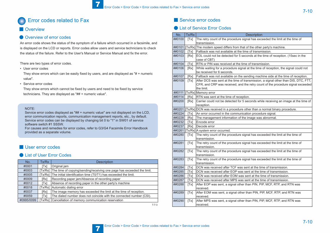
7
77-10
7-10
Error Code > Error Code > Error codes related to Fax > Service error codes
Error Code > Error Code > Error codes related to Fax > Service error codes
Error codes related to Fax ■ Overview
● Overview of error codesAn error code shows the status of the symptom of a failure which occurred in a facsimile, and is displayed on the LCD or reports. Error codes allow users and service technicians to check the status of the failure. Refer to the User's Manual or Service Manual and fix the error.
There are two types of error codes.• User error codes
They show errors which can be easily fixed by users, and are displayed as "# + numeric value".
• Service error codesThey show errors which cannot be fixed by users and need to be fixed by service technicians. They are displayed as "## + numeric value".
NOTE:Service error codes displayed as "## + numeric value" are not displayed on the LCD, error communication reports, communication management reports, etc., by default. Service error codes can be displayed by changing bit 0 to "1" in SW01 of service software switch #1 SSSW.For causes and remedies for error codes, refer to G3/G4 Facsimile Error Handbook provided as a separate volume.
■ User error codes
● List of User Error CodesNo. Tx/Rx Description
#0001 [Tx] Original jam#0003 [Tx/Rx] The time of copying/sending/receiving one page has exceeded the limit.#0005 [Tx/Rx] The initial identification time (T0/T1) has exceeded the limit.#0009 [Rx] Recording paper jam/Absence of recording paper#0012 [Tx] Absence of recording paper in the other party's machine#0018 [Tx/Rx] Automatic dialing error#0037 [Rx] The image memory has exceeded the limit at the time of reception.#0059 [Tx] The dialed number does not coincide with the connected number (CSI).
#0995/0099 [Tx/Rx] Cancellation of memory communication reservationT-7-3
■ Service error codes
● List of Service Error CodesNo. Tx/Rx Description
##0100 [Tx] The retry count of the procedure signal has exceeded the limit at the time of transmission.
##0101 [Tx/Rx] The modem speed differs from that of the other party's machine.##0102 [Tx] Fallback was not available at the time of transmission.##0103 [Rx] EOL could not be detected for 5 seconds at the time of reception. (15sec in the
case of CBT)##0104 [Tx] RTN or PIN was received at the time of transmission.##0106 [Rx] While waiting for a procedure signal at the time of reception, the signal could not
be received for 6 seconds.##0107 [Rx] Fallback was not available on the sending machine side at the time of reception.##0109 [Tx] After DCS was sent at the time of transmission, a signal other than DIS, DTC, FTT,
CFR, and CRP was received, and the retry count of the procedure signal exceeded the limit.
##0111 [Tx/Rx] Memory error##0114 [Rx] RTN was sent at the time of reception.##0200 [Rx] Carrier could not be detected for 5 seconds while receiving an image at the time of
reception.##0201 [Tx/Rx] DCN was received in a procedure other than a normal binary procedure.##0224 [Tx] An error occurred in the communication procedure signal.##0228 [Rx] The management information of the image was abnormal.##0232 [Tx] Encode error##0237 [Rx] Decode error##0261 [Tx/Rx] A system error occurred.##0280 [Tx] The retry count of the procedure signal has exceeded the limit at the time of
transmission.##0281 [Tx] The retry count of the procedure signal has exceeded the limit at the time of
transmission.##0282 [Tx] The retry count of the procedure signal has exceeded the limit at the time of
transmission.##0283 [Tx] The retry count of the procedure signal has exceeded the limit at the time of
transmission.##0284 [Tx] DCN was received after TCF was sent at the time of transmission.##0285 [Tx] DCN was received after EOP was sent at the time of transmission.##0286 [Tx] DCN was received after EOM was sent at the time of transmission.##0287 [Tx] DCN was received after MPS was sent at the time of transmission.##0288 [Tx] After EOP was sent, a signal other than PIN, PIP, MCF, RTP, and RTN was
received.##0289 [Tx] After EOM was sent, a signal other than PIN, PIP, MCF, RTP, and RTN was
received.##0290 [Tx] After MPS was sent, a signal other than PIN, PIP, MCF, RTP, and RTN was
received.
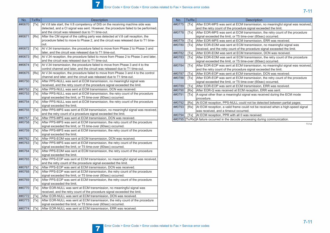
7
77-11
7-11
Error Code > Error Code > Error codes related to Fax > Service error codes
Error Code > Error Code > Error codes related to Fax > Service error codes
No. Tx/Rx Description##0670 [Tx] At V.8 late start, the V.8 competency of DIS on the receiving machine side was
detected, and a CI signal was sent. However, the procedure failed to be performed, and the circuit was released due to T1 time-out.
##0671 [Rx] After the CM signal of the calling party was detected at V.8 call reception, the procedure failed to move to Phase 2, and the circuit was released due to T1 time-out.
##0672 [Tx] At V.34 transmission, the procedure failed to move from Phase 2 to Phase 3 and later, and the circuit was released due to T1 time-out.
##0673 [Rx] At V.34 reception, the procedure failed to move from Phase 2 to Phase 3 and later, and the circuit was released due to T1 time-out.
##0674 [Tx] At V.34 transmission, the procedure failed to move from Phase 3 and 4 to the control channel and later, and the circuit was released due to T1 time-out.
##0675 [Rx] At V.34 reception, the procedure failed to move from Phase 3 and 4 to the control channel and later, and the circuit was released due to T1 time-out.
##0750 [Tx] After PPS-NULL was sent at ECM transmission, no meaningful signal was received, and the retry count of the procedure signal exceeded the limit.
##0752 [Tx] After PPS-NULL was sent at ECM transmission, DCN was received.##0753 [Tx] After PPS-NULL was sent at ECM transmission, the retry count of the procedure
signal exceeded the limit, or T5 time-over (60sec) occurred.##0754 [Tx] After PPS-NULL was sent at ECM transmission, the retry count of the procedure
signal exceeded the limit.##0755 [Tx] After PPS-MPS was sent at ECM transmission, no meaningful signal was received,
and the retry count of a procedure signal exceeded the limit.##0757 [Tx] After PPS-MPS was sent at ECM transmission, DCN was received.##0758 [Tx] After PPS-MPS was sent at ECM transmission, the retry count of the procedure
signal exceeded the limit, or T5 time-over (60sec) occurred.##0759 [Tx] After PPS-MPS was sent at ECM transmission, the retry count of the procedure
signal exceeded the limit.##0762 [Tx] After PPS-EOM was sent at ECM transmission, DCN was received.##0763 [Tx] After PPS-MPS was sent at ECM transmission, the retry count of the procedure
signal exceeded the limit, or T5 time-over (60sec) occurred.##0764 [Tx] After PPS-EOM was sent at ECM transmission, the retry count of the procedure
signal exceeded the limit.##0765 [Tx] After PPS-EOP was sent at ECM transmission, no meaningful signal was received,
and the retry count of the procedure signal exceeded the limit.##0767 [Tx] After PPS-EOP was sent at ECM transmission, DCN was received.##0768 [Tx] After PPS-EOP was sent at ECM transmission, the retry count of the procedure
signal exceeded the limit, or T5 time-over (60sec) occurred.##0769 [Tx] After PPS-EOP was sent at ECM transmission, the retry count of the procedure
signal exceeded the limit.##0770 [Tx] After EOR-NULL was sent at ECM transmission, no meaningful signal was
received, and the retry count of the procedure signal exceeded the limit.##0772 [Tx] After EOR-NULL was sent at ECM transmission, DCN was received.##0773 [Tx] After EOR-NULL was sent at ECM transmission, the retry count of the procedure
signal exceeded the limit, or T5 time-over (60sec) occurred.##0774 [Tx] After EOR-NULL was sent at ECM transmission, ERR was received.
No. Tx/Rx Description##0775 [Tx] After EOR-MPS was sent at ECM transmission, no meaningful signal was received,
and the retry count of the procedure signal exceeded the limit.##0778 [Tx] After EOR-MPS was sent at ECM transmission, the retry count of the procedure
signal exceeded the limit, or T5 time-over (60sec) occurred.##0779 [Tx] After EOR-MPS was sent at ECM transmission, ERR was received.##0780 [Tx] After EOR-EOM was sent at ECM transmission, no meaningful signal was
received, and the retry count of the procedure signal exceeded the limit.##0782 [Tx] After EOR-EOM was sent at ECM transmission, DCN was received.##0783 [Tx] After EOR-EOM was sent at ECM transmission, the retry count of the procedure
signal exceeded the limit, or T5 time-over (60sec) occurred.##0784 [Tx] After EOR-EOP was sent at ECM transmission, no meaningful signal was received,
and the retry count of the procedure signal exceeded the limit.##0787 [Tx] After EOR-EOP was sent at ECM transmission, DCN was received.##0788 [Tx] After EOR-EOP was sent at ECM transmission, the retry count of the procedure
signal exceeded the limit, or T5 time-over (60sec) occurred.##0789 [Tx] After EOR-EOP was sent at ECM transmission, ERR was received.##0790 [Rx] After EOR-Q was received at ECM reception, ERR was sent.##0791 [Tx] A signal other than a meaningful signal was received during the ECM mode
procedure.##0792 [Rx] At ECM reception, PPS-NULL could not be detected between partial pages.##0793 [Rx] At ECM reception, a valid frame could not be received when a high-speed signal
was received, and a timeout occurred.##0794 [Tx] At ECM reception, PPR with all 0 was received.##0795 [Tx/Rx] A failure occurred in the decode processing during communication.
T-7-4
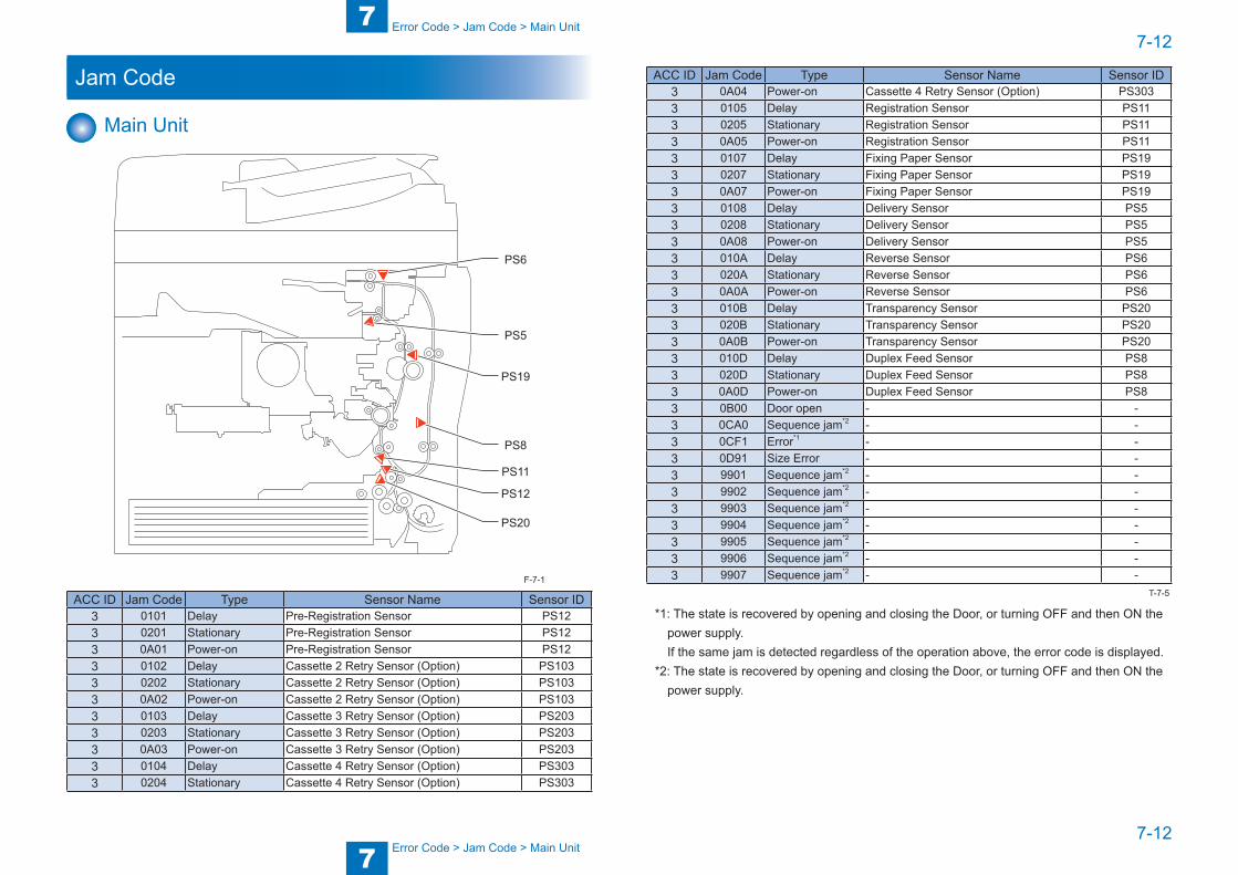
7
77-12
7-12
Error Code > Jam Code > Main Unit
Error Code > Jam Code > Main Unit
Jam Code
Main Unit
PS20
PS12
PS11
PS8
PS19
PS5
PS6
ACC ID Jam Code Type Sensor Name Sensor ID3 0101 Delay Pre-Registration Sensor PS123 0201 Stationary Pre-Registration Sensor PS123 0A01 Power-on Pre-Registration Sensor PS123 0102 Delay Cassette 2 Retry Sensor (Option) PS1033 0202 Stationary Cassette 2 Retry Sensor (Option) PS1033 0A02 Power-on Cassette 2 Retry Sensor (Option) PS1033 0103 Delay Cassette 3 Retry Sensor (Option) PS2033 0203 Stationary Cassette 3 Retry Sensor (Option) PS2033 0A03 Power-on Cassette 3 Retry Sensor (Option) PS2033 0104 Delay Cassette 4 Retry Sensor (Option) PS3033 0204 Stationary Cassette 4 Retry Sensor (Option) PS303
F-7-1
ACC ID Jam Code Type Sensor Name Sensor ID3 0A04 Power-on Cassette 4 Retry Sensor (Option) PS3033 0105 Delay Registration Sensor PS113 0205 Stationary Registration Sensor PS113 0A05 Power-on Registration Sensor PS113 0107 Delay Fixing Paper Sensor PS193 0207 Stationary Fixing Paper Sensor PS193 0A07 Power-on Fixing Paper Sensor PS193 0108 Delay Delivery Sensor PS53 0208 Stationary Delivery Sensor PS53 0A08 Power-on Delivery Sensor PS53 010A Delay Reverse Sensor PS63 020A Stationary Reverse Sensor PS63 0A0A Power-on Reverse Sensor PS63 010B Delay Transparency Sensor PS203 020B Stationary Transparency Sensor PS203 0A0B Power-on Transparency Sensor PS203 010D Delay Duplex Feed Sensor PS83 020D Stationary Duplex Feed Sensor PS83 0A0D Power-on Duplex Feed Sensor PS83 0B00 Door open - -3 0CA0 Sequence jam*2 - -3 0CF1 Error*1 - -3 0D91 Size Error - -3 9901 Sequence jam*2 - -3 9902 Sequence jam*2 - -3 9903 Sequence jam*2 - -3 9904 Sequence jam*2 - -3 9905 Sequence jam*2 - -3 9906 Sequence jam*2 - -3 9907 Sequence jam*2 - -
*1: The state is recovered by opening and closing the Door, or turning OFF and then ON the power supply.
If the same jam is detected regardless of the operation above, the error code is displayed.*2: The state is recovered by opening and closing the Door, or turning OFF and then ON the
power supply.
T-7-5

7
77-13
7-13
Error Code > Jam Code > ADF
Error Code > Jam Code > ADF
ADF
PS32
PS30PS29
PS28
PS25
PS27
PS26
PS31
PS32PS31
PS28 PS27
PS30PS29PS26
PS25
F-7-2
ACC ID Jam Code Type Sensor Name Sensor ID4 0003 Delay Registration sensor PS264 0004 Stationary Registration sensor PS264 0005 Delay Lead sensor PS254 0006 Stationary Lead sensor PS254 0009 Delay Stay sensor PS274 000A Stationary Stay sensor PS274 000B Delay Reversal sensor PS284 000C Stationary Reversal sensor PS284 0044 Stationary
(first document)Registration sensor (first document) PS26
4 0045 Delay (first document)
Lead sensor (first document) PS25
4 0046 Stationary (first document)
Lead sensor (first document) PS25
4 0049 Delay (first document)
Stay sensor (first document) PS27
4 004A Stationary (first document)
Stay sensor (first document) PS27
4 004B Delay (first document)
Reversal sensor (first document) PS28
4 004C Stationary(first document)
Reversal sensor (first document) PS28
4 0071 Timing error - -4 0090 ADF open DADF open/closed detection sensor PS234 0091 User ADF open DADF open/closed detection sensor PS234 0094 Initial stationary Registration sensor or Lead sensor or
Rreversal sensorPS25/PS26/PS28
4 0095 Pickup error Original set sensor PS30T-7-6
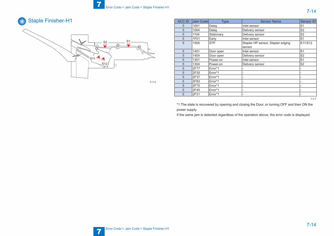
7
77-14
7-14
Error Code > Jam Code > Staple Finisher-H1
Error Code > Jam Code > Staple Finisher-H1
Staple Finisher-H1
S1S2
S11
S12
F-7-3
ACC ID Jam Code Type Sensor Name Sensor ID5 1001 Delay Inlet sensor S15 1004 Delay Delivery sensor S25 1104 Stationary Delivery sensor S25 1F01 Early Inlet sensor S15 1500 STP Stapler HP sensor, Stapler edging
sensorS11/S12
5 1401 Door open Inlet sensor S15 1404 Door open Delivery sensor S25 1301 Power-on Inlet sensor S15 1304 Power-on Delivery sensor S25 2F77 Error*1 - -5 2F30 Error*1 - -5 2F37 Error*1 - -5 2F83 Error*1 - -5 2F75 Error*1 - -5 2F40 Error*1 - -5 2F31 Error*1 - -
*1 The state is recovered by opening and closing the Door, or turning OFF and then ON thepower supply.If the same jam is detected regardless of the operation above, the error code is displayed.
T-7-7
7
77-15
7-15
Error Code > Alarm Code > Alarm Code Details
Error Code > Alarm Code > Alarm Code Details
Alarm Code
Alarm Code Details
In this machine, there are no alarm codes for service technician.
8
8 Service Mode
Service Mode ■Outline ■Details of Service Mode
8
88-2
8-2
Service Mode > Outline > Outline of Service Mode
Service Mode > Outline > Outline of Service Mode
Outline
Outline of Service ModeThe items that follow may be checked/set using the machine's service mode, which is designed the way the service mode used in fax machines is designed in terms of contents and operation.#SSSWUse it to register/set basic fax functions (e.g., error control, echo remedy, communication error correction). Use it to make settings related counter functions.#MENUUse it to register/set items related to functions needed at time of installation (e.g., NL equalizer, transmission level).
#NUMERICThese setting items are for inputting numeric parameters such as the various conditions for the RTN signal transmission.
#SPECIALThese setting items are for telephone network control functions. Do not use.
#NCUThese setting items are for telephone network control functions such as the selection signal transmission conditions and the detection conditions, for the control signals sent from the exchange.
#FAXDo not use.
#SCANThese setting items are for image adjustment in scanning.
#PRINTThese setting items are for image adjustment in printer assembly and for special mode for the field-related measures.
#NETWORKUse it to confirm the contents of the installed CA certificates.
#CODECThis is a setting items related to CODEC.
#SYSTEMThis is a setting items related to SYSTEM.
#ACCRegister the accessories.
#COUNTERUse it to check estimates for maintenance/parts replacement.
#LMSUse it to set the inactivity of the transmitted license and the license inactivity without transmitting.
#E-RDSThis is a setting items related to e-RDS (Embedded RDS).
#REPORTUse it to generate reports on various service data.
#DOWNLOADUse it to download firmware to the ROM of a PCB in question.
#CLEARUse it to reset various data to initial settings.
#DISPLAYThe error and detailed code which have happened now are displayed.Display the engine speed of the main controller PCB.
#ROMDisplays ROM information, such as version numbers and checksums.
#TEST MODEMakes various status checks, such as contact sensor, sensor and print status.

8
88-3
8-3
Service Mode > Outline > Setting of Bit Switch > Outline
Service Mode > Outline > Setting of Bit Switch > Outline
Using the Mode
#SSSW
#NUMERIC
#NUMERIC
2) Selecting a Menu ItemSelect the Menu item using the[left arrow]/[right arrow] on thetouch panel.
3) Press [OK].
5) Registering/Setting DataEnter data using the keypad,and then press [OK].
6) Press the [Stop]/[Additionalfunctions]/[Reset] key to endthe service mode.
#NUMERIC
#NUMERIC
0 0 1
0 0 1
0 0 2
0 0 2
0
0
10
4) Selecting a PrarameterSelect the Prarameter using the[left arrow]/[right arrow].
1) Selecting Service Mode
#SSSW
3) Selecting a Menu ItemPress [OK].
2) Press [OK] on thetouch panel.
5) Registering/Setting DataEnter data using the keypad,and then press [OK].
6) Press the [Stop]/[Additionalfunctions]/[Reset] key to endthe service mode.
0 3 3
4) Selecting a Bit SwitchSelect the bit using the[left arrow]/[right arrow] onthe touch panel.
#SSSW
#SSSW
000000000
000000000
<Operation at the time of Bit SW> <Operation at the time of Parameter>
0 3 3#SSSW
000000000
0 3 3#SSSW
000000001
1) Selecting Service Mode
F-8-1
Setting of Bit Switch ■ Outline
Bit Switch CompositionThe items registered and set by each of these switches comprise 8-bit switches. The figure below shows which numbers are assigned to which bits. Each bit has a value of either 0 or 1.
001#SSSW
0 0 0 0 0 0 0 0
Bit 7
Bit 6
Bit 5
Bit 4
Bit 3
Bit 2
Bit 1
Bit 0
CAUTION:
Do not change service data identified as "not used"; they are set as initial settings.
F-8-2
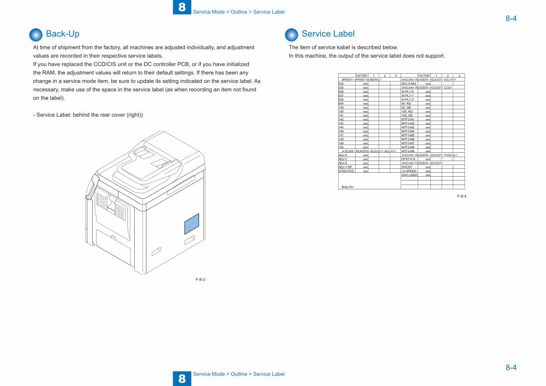
8
88-4
8-4
Service Mode > Outline > Service Label
Service Mode > Outline > Service Label
Back-UpAt time of shipment from the factory, all machines are adjusted individually, and adjustment values are recorded in their respective service labels.If you have replaced the CCD/CIS unit or the DC controller PCB, or if you have initialized the RAM, the adjustment values will return to their default settings. If there has been any change in a service mode item, be sure to update its setting indicated on the service label. As necessary, make use of the space in the service label (as when recording an item not found on the label).
- Service Label: behind the rear cover (right))
F-8-3
Service LabelThe item of service kabel is described below.In this machine, the output of the service label does not support.
FACTORY 1 2 3 FACTORY 1 2 3
034 xxx ADJ-X-MG xxx035 xxx036 xxx W-PLT-X xxx037 xxx W-PLT-Y xxx038 xxx W-PLT-Z xxx054 xxx 50_RG xxx136 xxx 50_GB xxx140 xxx 100_RG xxx141 xxx 100_GB xxx142 xxx MTF3-M1 xxx143 xxx MTF3-M2 xxx145 xxx MTF3-M3 xxx146 xxx MTF3-M4 xxx147 xxx MTF3-M5 xxx148 xxx MTF3-M6 xxx149 xxx MTF3-M7 xxx150 xxx MTF3-M8 xxx
#SCAN> READER> ADJUST> ADJ-XY> MTF3-M9 xxxADJ-X xxx #SCAN> READER> ADJUST> PASCAL>ADJ-Y xxx OFST-P-K xxxADJ-S xxx #SCAN> FEEDER> ADJUST>ADJ-Y-DF xxx DOCST xxxSTRD-POS xxx LA-SPEED xxx
DOC-LNGH xxx
Body No:
#PRINT> #PRINT NUMERIC> #SCAN> READER> ADJUST> ADJ-XY>
#SCAN> READER> ADJUST> CCD>
F-8-4
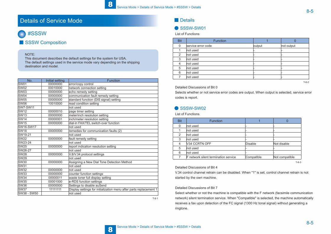
8
88-5
8-5
Service Mode > Details of Service Mode > #SSSW > Details
Service Mode > Details of Service Mode > #SSSW > Details
Details of Service Mode
#SSSW ■ SSSW Composition
NOTE:This document describes the default settings for the system for USA.The default settings used in the service mode vary depending on the shipping destination and model.
No. Initial setting FunctionSW01 00000000 error/copy controlSW02 00010000 network connection settingSW03 00000000 echo remedy settingSW04 00000000 communication fault remedy settingSW05 00000000 standard function (DIS signal) settingSW06 10010000 read condition settingSW7-SW11 not usedSW12 00000010 page timer settingSW13 00000000 meter/inch resolution settingSW14 00000001 inch/meter resolution settingSW15 00000000 dial-in FAX/TEL switch-over functionSW16-SW17 not usedSW18 00000000 remedies for communication faults (2)SW19-21 not usedSW22 00000000 fault remedy settingSW23-24 not usedSW25 00000000 report indication resolution settingSW26-27 not usedSW28 00000000 V.8/V.34 protocol settingsSW29 not usedSW30 00000000 Assigning a New Dial Tone Detection MethodSW31 not usedSW32 00000000 not usedSW33 00000000 counter function settingsSW34 00000011 waste toner full display settingSW35 00001000 e-RDS function settingsSW36 00000000 Settings to disable auSendSW37 11111111 Display settings for initialization menu after parts replacement 1SW38 - SW50 not used
T-8-1
■ Details
● SSSW-SW01List of Functions
Bit Function 1 00 service error code output not output1 not used - -2 not used - -3 not used - -4 not used - -5 not used - -6 not used - -7 not used - -
Detailed Discussions of Bit 0Selects whether or not service error codes are output. When output is selected, service error codes is report.
● SSSW-SW02List of Functions
Bit Function 1 00 not used - -1 not used - -2 not used - -3 not used - -4 V34 CCRTN OFF Disable Not disable5 not used - -6 not used - -7 F network silent termination service Compatible Not compatible
Detailed Discussions of Bit 4V.34 control channel retrain can be disabled. When "1" is set, control channel retrain is not started by the own machine.
Detailed Discussions of Bit 7Select whether or not the machine is compatible with the F network (facsimile communication network) silent termination service. When "Compatible" is selected, the machine automatically receives a fax upon detection of the FC signal (1300 Hz tonal signal) without generating a ringtone.
T-8-2
T-8-3
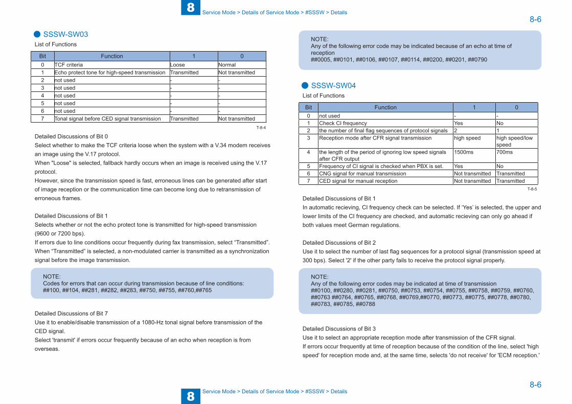
8
88-6
8-6
Service Mode > Details of Service Mode > #SSSW > Details
Service Mode > Details of Service Mode > #SSSW > Details
● SSSW-SW03List of Functions
Bit Function 1 00 TCF criteria Loose Normal1 Echo protect tone for high-speed transmission Transmitted Not transmitted2 not used - -3 not used - -4 not used - -5 not used - -6 not used - -7 Tonal signal before CED signal transmission Transmitted Not transmitted
Detailed Discussions of Bit 0Select whether to make the TCF criteria loose when the system with a V.34 modem receives an image using the V.17 protocol.When "Loose" is selected, fallback hardly occurs when an image is received using the V.17 protocol. However, since the transmission speed is fast, erroneous lines can be generated after start of image reception or the communication time can become long due to retransmission of erroneous frames.
Detailed Discussions of Bit 1Selects whether or not the echo protect tone is transmitted for high-speed transmission(9600 or 7200 bps).If errors due to line conditions occur frequently during fax transmission, select “Transmitted”.When “Transmitted” is selected, a non-modulated carrier is transmitted as a synchronizationsignal before the image transmission.
NOTE:Codes for errors that can occur during transmission because of line conditions:##100, ##104, ##281, ##282, ##283, ##750, ##755, ##760,##765
Detailed Discussions of Bit 7Use it to enable/disable transmission of a 1080-Hz tonal signal before transmission of the CED signal.Select 'transmit' if errors occur frequently because of an echo when reception is from overseas.
T-8-4
NOTE:Any of the following error code may be indicated because of an echo at time of reception##0005, ##0101, ##0106, ##0107, ##0114, ##0200, ##0201, ##0790
● SSSW-SW04List of Functions
Bit Function 1 00 not used - -1 Check CI frequency Yes No2 the number of final flag sequences of protocol signals 2 13 Reception mode after CFR signal transmission high speed high speed/low
speed4 the length of the period of ignoring low speed signals
after CFR output1500ms 700ms
5 Frequency of CI signal is checked when PBX is set. Yes No6 CNG signal for manual transmission Not transmitted Transmitted7 CED signal for manual reception Not transmitted Transmitted
Detailed Discussions of Bit 1In automatic recieving, CI frequency check can be selected. If ‘Yes’ is selected, the upper and lower limits of the CI frequency are checked, and automatic recieving can only go ahead if both values meet German regulations.
Detailed Discussions of Bit 2Use it to select the number of last flag sequences for a protocol signal (transmission speed at 300 bps). Select '2' if the other party fails to receive the protocol signal properly.
NOTE:Any of the following error codes may be indicated at time of transmission##0100, ##0280, ##0281, ##0750, ##0753, ##0754, ##0755, ##0758, ##0759, ##0760, ##0763 ##0764, ##0765, ##0768, ##0769,##0770, ##0773, ##0775, ##0778, ##0780, ##0783, ##0785, ##0788
Detailed Discussions of Bit 3Use it to select an appropriate reception mode after transmission of the CFR signal.If errors occur frequently at time of reception because of the condition of the line, select 'high speed' for reception mode and, at the same time, selects 'do not receive' for 'ECM reception.'
T-8-5
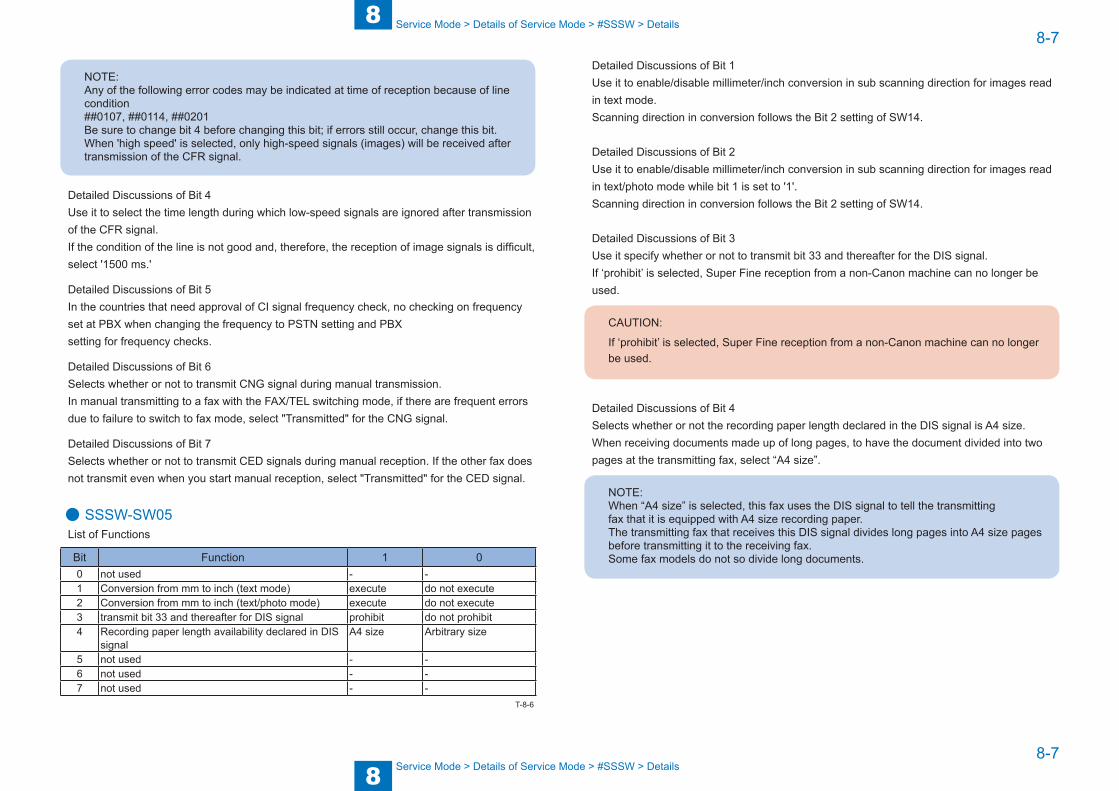
8
88-7
8-7
Service Mode > Details of Service Mode > #SSSW > Details
Service Mode > Details of Service Mode > #SSSW > Details
NOTE:Any of the following error codes may be indicated at time of reception because of line condition##0107, ##0114, ##0201Be sure to change bit 4 before changing this bit; if errors still occur, change this bit.When 'high speed' is selected, only high-speed signals (images) will be received after transmission of the CFR signal.
Detailed Discussions of Bit 4Use it to select the time length during which low-speed signals are ignored after transmission of the CFR signal.If the condition of the line is not good and, therefore, the reception of image signals is difficult, select '1500 ms.'
Detailed Discussions of Bit 5In the countries that need approval of CI signal frequency check, no checking on frequency set at PBX when changing the frequency to PSTN setting and PBXsetting for frequency checks.
Detailed Discussions of Bit 6Selects whether or not to transmit CNG signal during manual transmission.In manual transmitting to a fax with the FAX/TEL switching mode, if there are frequent errors due to failure to switch to fax mode, select "Transmitted" for the CNG signal.
Detailed Discussions of Bit 7Selects whether or not to transmit CED signals during manual reception. If the other fax does not transmit even when you start manual reception, select "Transmitted" for the CED signal.
● SSSW-SW05List of Functions
Bit Function 1 00 not used - -1 Conversion from mm to inch (text mode) execute do not execute2 Conversion from mm to inch (text/photo mode) execute do not execute3 transmit bit 33 and thereafter for DIS signal prohibit do not prohibit4 Recording paper length availability declared in DIS
signalA4 size Arbitrary size
5 not used - -6 not used - -7 not used - -
T-8-6
Detailed Discussions of Bit 1Use it to enable/disable millimeter/inch conversion in sub scanning direction for images read in text mode.Scanning direction in conversion follows the Bit 2 setting of SW14.
Detailed Discussions of Bit 2Use it to enable/disable millimeter/inch conversion in sub scanning direction for images read in text/photo mode while bit 1 is set to '1'.Scanning direction in conversion follows the Bit 2 setting of SW14.
Detailed Discussions of Bit 3Use it specify whether or not to transmit bit 33 and thereafter for the DIS signal.If ‘prohibit’ is selected, Super Fine reception from a non-Canon machine can no longer be used.
CAUTION:
If ‘prohibit’ is selected, Super Fine reception from a non-Canon machine can no longer be used.
Detailed Discussions of Bit 4Selects whether or not the recording paper length declared in the DIS signal is A4 size.When receiving documents made up of long pages, to have the document divided into two pages at the transmitting fax, select “A4 size”.
NOTE:When “A4 size” is selected, this fax uses the DIS signal to tell the transmittingfax that it is equipped with A4 size recording paper.The transmitting fax that receives this DIS signal divides long pages into A4 size pages before transmitting it to the receiving fax.Some fax models do not so divide long documents.
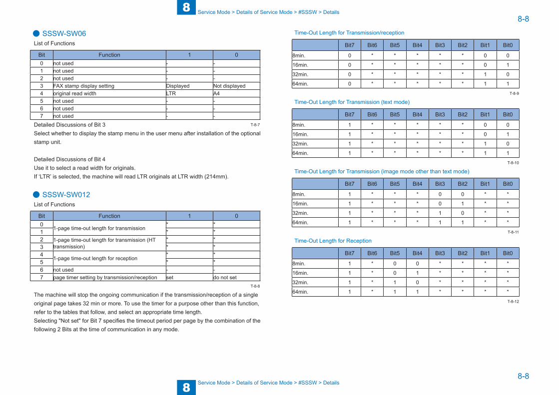
8
88-8
8-8
Service Mode > Details of Service Mode > #SSSW > Details
Service Mode > Details of Service Mode > #SSSW > Details
● SSSW-SW06List of Functions
Bit Function 1 00 not used - -1 not used - -2 not used - -3 FAX stamp display setting Displayed Not displayed4 original read width LTR A45 not used - -6 not used - -7 not used - -
Detailed Discussions of Bit 3Select whether to display the stamp menu in the user menu after installation of the optional stamp unit.
Detailed Discussions of Bit 4Use it to select a read width for originals.If ‘LTR’ is selected, the machine will read LTR originals at LTR width (214mm).
● SSSW-SW012List of Functions
Bit Function 1 00
1-page time-out length for transmission* *
1 * *2 1-page time-out length for transmission (HT
transmission)* *
3 * *4
1-page time-out length for reception* *
5 * *6 not used - -7 page timer setting by transmission/reception set do not set
The machine will stop the ongoing communication if the transmission/reception of a single original page takes 32 min or more. To use the timer for a purpose other than this function, refer to the tables that follow, and select an appropriate time length.Selecting "Not set" for Bit 7 specifies the timeout period per page by the combination of the following 2 Bits at the time of communication in any mode.
T-8-7
T-8-8
Time-Out Length for Transmission/reception
Bit7 Bit6 Bit5 Bit4 Bit3 Bit2 Bit1 Bit0
8min. 0 * * * * * 0 0
16min. 0 * * * * * 0 1
32min. 0 * * * * * 1 0
64min. 0 * * * * * 1 1
Time-Out Length for Transmission (text mode)
Bit7 Bit6 Bit5 Bit4 Bit3 Bit2 Bit1 Bit0
8min. 1 * * * * * 0 0
16min. 1 * * * * * 0 1
32min. 1 * * * * * 1 0
64min. 1 * * * * * 1 1
Time-Out Length for Transmission (image mode other than text mode)
Bit7 Bit6 Bit5 Bit4 Bit3 Bit2 Bit1 Bit0
8min. 1 * * * 0 0 * *
16min. 1 * * * 0 1 * *
32min. 1 * * * 1 0 * *
64min. 1 * * * 1 1 * *
Time-Out Length for Reception
Bit7 Bit6 Bit5 Bit4 Bit3 Bit2 Bit1 Bit0
8min. 1 * 0 0 * * * *
16min. 1 * 0 1 * * * *
32min. 1 * 1 0 * * * *
64min. 1 * 1 1 * * * *
T-8-9
T-8-10
T-8-11
T-8-12
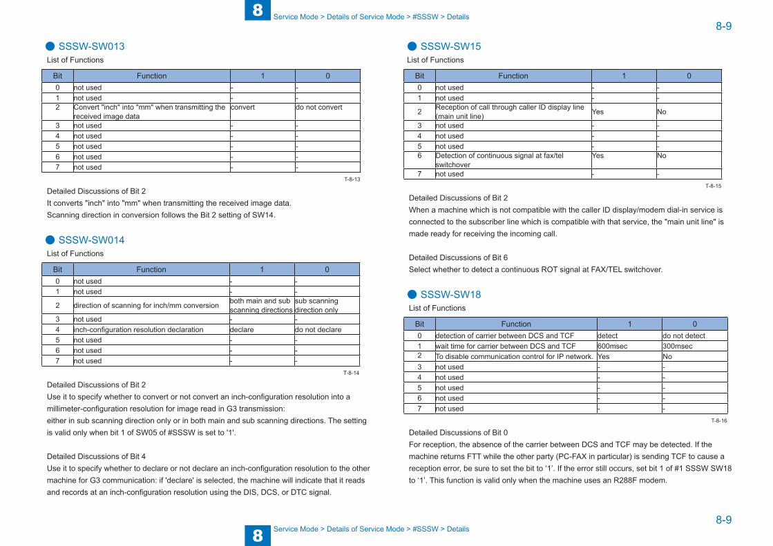
8
88-9
8-9
Service Mode > Details of Service Mode > #SSSW > Details
Service Mode > Details of Service Mode > #SSSW > Details
● SSSW-SW013List of Functions
Bit Function 1 00 not used - -1 not used - -2 Convert "inch" into "mm" when transmitting the
received image dataconvert do not convert
3 not used - -4 not used - -5 not used - -6 not used - -7 not used - -
Detailed Discussions of Bit 2It converts "inch" into "mm" when transmitting the received image data.Scanning direction in conversion follows the Bit 2 setting of SW14.
● SSSW-SW014List of Functions
Bit Function 1 00 not used - -1 not used - -
2 direction of scanning for inch/mm conversion both main and subscanning directions
sub scanningdirection only
3 not used - -4 inch-configuration resolution declaration declare do not declare5 not used - -6 not used - -7 not used - -
Detailed Discussions of Bit 2Use it to specify whether to convert or not convert an inch-configuration resolution into a millimeter-configuration resolution for image read in G3 transmission:either in sub scanning direction only or in both main and sub scanning directions. The setting is valid only when bit 1 of SW05 of #SSSW is set to '1'.
Detailed Discussions of Bit 4Use it to specify whether to declare or not declare an inch-configuration resolution to the other machine for G3 communication: if 'declare' is selected, the machine will indicate that it reads and records at an inch-configuration resolution using the DIS, DCS, or DTC signal.
T-8-13
T-8-14
● SSSW-SW15List of Functions
Bit Function 1 00 not used - -1 not used - -
2 Reception of call through caller ID display line (main unit line) Yes No
3 not used - -4 not used - -5 not used - -6 Detection of continuous signal at fax/tel
switchover Yes No
7 not used - -
Detailed Discussions of Bit 2When a machine which is not compatible with the caller ID display/modem dial-in service is connected to the subscriber line which is compatible with that service, the "main unit line" is made ready for receiving the incoming call.
Detailed Discussions of Bit 6Select whether to detect a continuous ROT signal at FAX/TEL switchover.
● SSSW-SW18List of Functions
Bit Function 1 00 detection of carrier between DCS and TCF detect do not detect1 wait time for carrier between DCS and TCF 600msec 300msec2 To disable communication control for IP network. Yes No3 not used - -4 not used - -5 not used - -6 not used - -7 not used - -
Detailed Discussions of Bit 0For reception, the absence of the carrier between DCS and TCF may be detected. If the machine returns FTT while the other party (PC-FAX in particular) is sending TCF to cause a reception error, be sure to set the bit to ‘1’. If the error still occurs, set bit 1 of #1 SSSW SW18 to ‘1’. This function is valid only when the machine uses an R288F modem.
T-8-15
T-8-16

8
88-10
8-10
Service Mode > Details of Service Mode > #SSSW > Details
Service Mode > Details of Service Mode > #SSSW > Details
Detailed Discussions of Bit 1For reception, the length of time during which the absence of the carrier is detected between DCS and TCF may be set. This bit is valid when ‘1’ is set to bit 0 of #1 SSSW SW18.
Detailed Discussions of Bit 2You can change the parameter relating to communication control for IP network (SSSW-SW02 bit4) to the existing control in a batch process. The parameter value is handled as a fixed value.
● SSSW-SW22List of Functions
Bit Function 1 00 To disable NSX transmission. Yes No1 not used - -2 not used - -3 Prohibit manual polling Yes No4 not used - -5 not used - -6 not used - -7 not used - -
Detailed Discussions of Bit 0Nonstandard protocol (own company mode) can be disabled.
Detailed Discussions of Bit 3Selects whether to prohibit by manual polling (off hook key + start key).
● SSSW-SW25List of Functions
Bit Function 1 0
0 Transmission telephone numbers displayed on reports from CSI
Other fax number Called number
1 not used - -2 If void CSI has been received, handle as non-received CSI.Yes No3 Menu display of message language Display Do not display4 not used - -5 not used - -6 not used - -7 not used - -
T-8-17
T-8-18
Detailed Discussions of Bit 0Selects the transmission telephone number displayed on reports after the completion of transmission.When “Called number” is selected, the telephone number the fax called is displayed on reports.When “Other fax number” is selected, the telephone number sent from the other fax (the CSI signal data) is displayed on reports.
Detailed Discussions of Bit 2At "1" on this Bit, ignore the void CSI if received and if the dial has been made at this point, the dialed number will be indicated on the LCD/ Report screen.At "0" on this Bit, even though the dialed number is acknowledged, LCD/Report screen will indicate nothing.
Detailed Discussions of Bit 3When “Display” is selected, adds a Message Language menu to the user data “System Setting”. This allows selecting different languages which to show displays and reports.
● SSSW-SW28List of Functions
Bit Function 1 00 Caller V.8 protocol No Yes1 Called party V.8 protocol No Yes2 Caller V.8 protocol late start No Yes3 Called party V.8 protocol late start No Yes4 V.34 reception fallback Prohibited Not prohibited5 V.34 transmission fallback Prohibited Not prohibited6 not used - -7 not used - -
Detailed Discussions of Bit 0Select whether to use the V.8 protocol when calling. If NO is selected, the V.8 protocol is inhibited at calling and the V.21 protocol is used
Detailed Discussions of Bit 1Select whether to use the V.8 protocol when called. If NO is selected, the V8 protocol is inhibited when called and the V.21 protocol is used.
T-8-19
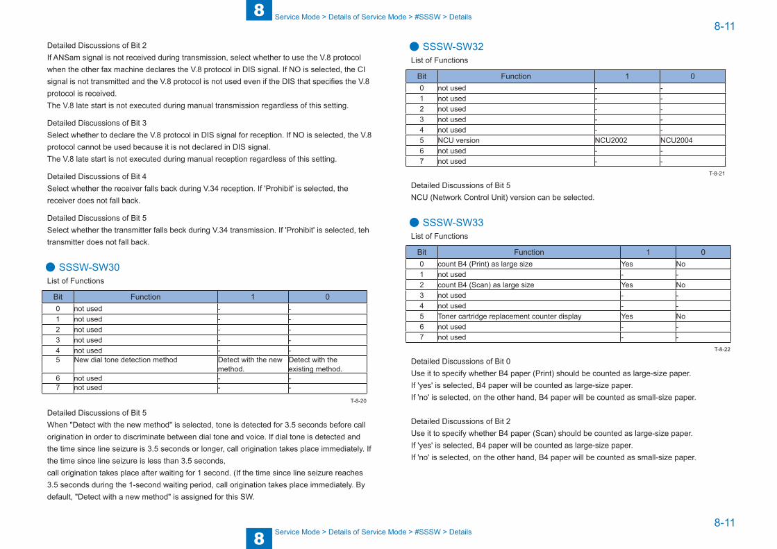
8
88-11
8-11
Service Mode > Details of Service Mode > #SSSW > Details
Service Mode > Details of Service Mode > #SSSW > Details
Detailed Discussions of Bit 2If ANSam signal is not received during transmission, select whether to use the V.8 protocol when the other fax machine declares the V.8 protocol in DIS signal. If NO is selected, the CI signal is not transmitted and the V.8 protocol is not used even if the DIS that specifies the V.8 protocol is received.The V.8 late start is not executed during manual transmission regardless of this setting.
Detailed Discussions of Bit 3Select whether to declare the V.8 protocol in DIS signal for reception. If NO is selected, the V.8 protocol cannot be used because it is not declared in DIS signal.The V.8 late start is not executed during manual reception regardless of this setting.
Detailed Discussions of Bit 4Select whether the receiver falls back during V.34 reception. If 'Prohibit' is selected, the receiver does not fall back.
Detailed Discussions of Bit 5Select whether the transmitter falls beck during V.34 transmission. If 'Prohibit' is selected, teh transmitter does not fall back.
● SSSW-SW30List of Functions
Bit Function 1 00 not used - -1 not used - -2 not used - -3 not used - -4 not used - -5 New dial tone detection method Detect with the new
method.Detect with theexisting method.
6 not used - -7 not used - -
Detailed Discussions of Bit 5When "Detect with the new method" is selected, tone is detected for 3.5 seconds before call origination in order to discriminate between dial tone and voice. If dial tone is detected and the time since line seizure is 3.5 seconds or longer, call origination takes place immediately. If the time since line seizure is less than 3.5 seconds,call origination takes place after waiting for 1 second. (If the time since line seizure reaches 3.5 seconds during the 1-second waiting period, call origination takes place immediately. By default, "Detect with a new method" is assigned for this SW.
T-8-20
● SSSW-SW32List of Functions
Bit Function 1 00 not used - -1 not used - -2 not used - -3 not used - -4 not used - -5 NCU version NCU2002 NCU20046 not used - -7 not used - -
Detailed Discussions of Bit 5NCU (Network Control Unit) version can be selected.
● SSSW-SW33List of Functions
Bit Function 1 00 count B4 (Print) as large size Yes No1 not used - -2 count B4 (Scan) as large size Yes No3 not used - -4 not used - -5 Toner cartridge replacement counter display Yes No6 not used - -7 not used - -
Detailed Discussions of Bit 0Use it to specify whether B4 paper (Print) should be counted as large-size paper.If 'yes' is selected, B4 paper will be counted as large-size paper.If 'no' is selected, on the other hand, B4 paper will be counted as small-size paper.
Detailed Discussions of Bit 2Use it to specify whether B4 paper (Scan) should be counted as large-size paper.If 'yes' is selected, B4 paper will be counted as large-size paper.If 'no' is selected, on the other hand, B4 paper will be counted as small-size paper.
T-8-21
T-8-22
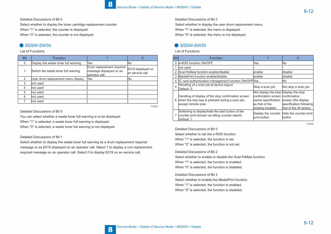
8
88-12
8-12
Service Mode > Details of Service Mode > #SSSW > Details
Service Mode > Details of Service Mode > #SSSW > Details
Detailed Discussions of Bit 5Select whether to display the toner cartridge replacement counter.When "1" is selected, the counter is displayed. When "0" is selected, the counter is not displayed.
● SSSW-SW34List of Functions
Bit Function 1 00 Display the waste toner full warning Yes No
1 Switch the waste toner full warningDrum replacement required message displayed on an operator call
E019 displayed on an service call
2 User drum replacement menu display Yes No3 not used - -4 not used - -5 not used - -6 not used - -7 not used - -
Detailed Discussions of Bit 0You can select whether a waste toner full warning is to be displayed.When "1" is selected, a waste toner full warning is displayed.When "0" is selected, a waste toner full warning is not displayed.
Detailed Discussions of Bit 1Select whether to display the waste toner full warning as a drum replacement required message or as E019 displayed on an operator call. Select 1 to display a rum replacement required message on an operator call. Select 0 to display E019 on an service call.
T-8-23
Detailed Discussions of Bit 2Select whether to display the user drum replacement menu. When "1" is selected, the menu is displayed. When "0" is selected, the menu is not displayed.
● SSSW-SW35List of Functions
Bit Function 1 00 e-RDS function ON/OFF Yes No1 not used - -2 ScanToMeia function enable/disable enable disable3 MediaPrint function enable/disable enable disable4 IC card authentication management function ON/OFFYes No
5 Handling of a scan job at device logoutDefault: 0 Stop a scan job Not stop a scan job
6Handling of display of the stop confirmation screen when the stop key is pressed during a scan job, except remote scan
Not display the stop confirmation screen (same specification as that of the existing models)
Display the stop confirmation screen (the display specification following that of the iR series)
7Switching to display/hide the start button of the counter print (known as billing counter report)Default: 1
Display the counter print button
Hide the counter print button
Detailed Discussions of Bit 0Select whether to set the e-RDS function. When "1" is selected, the function is set. When "0" is selected, the function is not set.
Detailed Discussions of Bit 2Select whether to enable or disable the ScanToMeia function. When "1" is selected, the function is enabled. When "0" is selected, the function is disabled.
Detailed Discussions of Bit 3Select whether to enable the MediaPrint function. When "1" is selected, the function is enabled. When "0" is selected, the function is disabled.
T-8-24
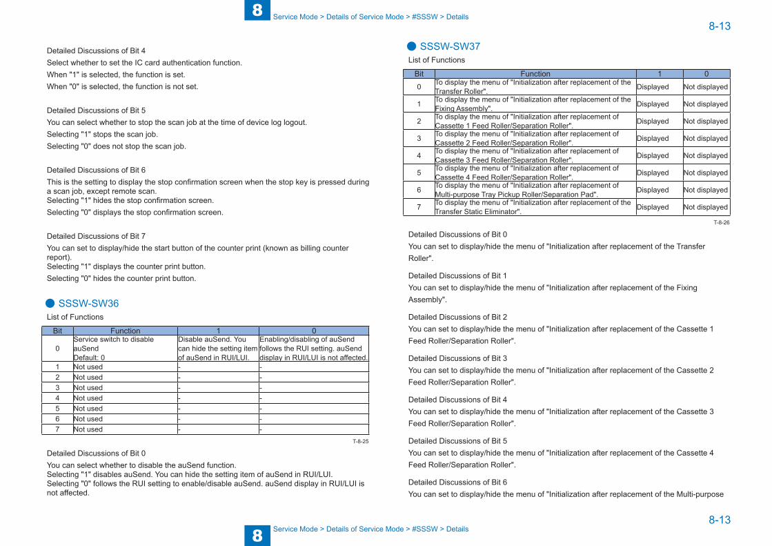
8
88-13
8-13
Service Mode > Details of Service Mode > #SSSW > Details
Service Mode > Details of Service Mode > #SSSW > Details
Detailed Discussions of Bit 4Select whether to set the IC card authentication function. When "1" is selected, the function is set. When "0" is selected, the function is not set.
Detailed Discussions of Bit 5You can select whether to stop the scan job at the time of device log logout.Selecting "1" stops the scan job.Selecting "0" does not stop the scan job.
Detailed Discussions of Bit 6This is the setting to display the stop confirmation screen when the stop key is pressed during a scan job, except remote scan.Selecting "1" hides the stop confirmation screen. Selecting "0" displays the stop confirmation screen.
Detailed Discussions of Bit 7You can set to display/hide the start button of the counter print (known as billing counter report).Selecting "1" displays the counter print button.Selecting "0" hides the counter print button.
● SSSW-SW36List of Functions
Bit Function 1 0
0Service switch to disable auSendDefault: 0
Disable auSend. You can hide the setting item of auSend in RUI/LUI.
Enabling/disabling of auSend follows the RUI setting. auSend display in RUI/LUI is not affected.
1 Not used - -2 Not used - -3 Not used - -4 Not used - -5 Not used - -6 Not used - -7 Not used - -
Detailed Discussions of Bit 0You can select whether to disable the auSend function.Selecting "1" disables auSend. You can hide the setting item of auSend in RUI/LUI.Selecting "0" follows the RUI setting to enable/disable auSend. auSend display in RUI/LUI is not affected.
T-8-25
● SSSW-SW37List of Functions
Bit Function 1 00 To display the menu of "Initialization after replacement of the
Transfer Roller". Displayed Not displayed
1 To display the menu of "Initialization after replacement of the Fixing Assembly". Displayed Not displayed
2 To display the menu of "Initialization after replacement of Cassette 1 Feed Roller/Separation Roller". Displayed Not displayed
3 To display the menu of "Initialization after replacement of Cassette 2 Feed Roller/Separation Roller". Displayed Not displayed
4 To display the menu of "Initialization after replacement of Cassette 3 Feed Roller/Separation Roller". Displayed Not displayed
5 To display the menu of "Initialization after replacement of Cassette 4 Feed Roller/Separation Roller". Displayed Not displayed
6 To display the menu of "Initialization after replacement of Multi-purpose Tray Pickup Roller/Separation Pad". Displayed Not displayed
7 To display the menu of "Initialization after replacement of the Transfer Static Eliminator". Displayed Not displayed
Detailed Discussions of Bit 0You can set to display/hide the menu of "Initialization after replacement of the Transfer Roller".
Detailed Discussions of Bit 1You can set to display/hide the menu of "Initialization after replacement of the Fixing Assembly".
Detailed Discussions of Bit 2You can set to display/hide the menu of "Initialization after replacement of the Cassette 1 Feed Roller/Separation Roller".
Detailed Discussions of Bit 3You can set to display/hide the menu of "Initialization after replacement of the Cassette 2 Feed Roller/Separation Roller".
Detailed Discussions of Bit 4You can set to display/hide the menu of "Initialization after replacement of the Cassette 3 Feed Roller/Separation Roller".
Detailed Discussions of Bit 5You can set to display/hide the menu of "Initialization after replacement of the Cassette 4 Feed Roller/Separation Roller".
Detailed Discussions of Bit 6You can set to display/hide the menu of "Initialization after replacement of the Multi-purpose
T-8-26

8
88-14
8-14
Service Mode > Details of Service Mode > #SSSW > Details
Service Mode > Details of Service Mode > #SSSW > Details
Tray Pickup Roller/Separation Pad".
Detailed Discussions of Bit 7You can set to display/hide the menu of "Initialization after replacement of the Transfer Static Eliminator".

8
88-15
8-15
Service Mode > Details of Service Mode > #MENU > Deatails
Service Mode > Details of Service Mode > #MENU > Deatails
#MENU ■ Menu Switch Composition
No. Function Range of settings005 NL equalizer 1: ON, 0: OFF006 Telephone line monitor 0: DIAL, 1: SERVICEMAN [1], 2: SERVICEMAN [2], 3: OFF007 Transmission level (ATT) From 0 to 15 (ex: 15= -15 dBm)
008 V.34 modulation speed upper limit 0: 3429, 1: 3200, 2: 3000, 3: 2800, 4: 2743, 5: 2400
009 V34 data speed upper limit 0: 33.6kbs, 1: 31.2kbs, 2: 28.8kbs, 3: 26.4kbs, 4: 24.0kbs5: 21.6kbs, 6: 19.2kbs, 7: 16.8kbs, 8: 14.4kbs, 9: 12.0kbs10: 9.6kbs, 11: 7.2kbs, 12: 4.8kbs, 13: 2.4kbs
010 Frequency of pseudoring signal 0: 50Hz, 1: 25Hz, 2: 17Hz
■ Deatails
● 005: NL equalizerUse it to enable-disable the NL equalizer.If errors occur often during communication because of the condition of the line, enable (ON) the NL equalizer.
NOTE:Any of the following error codes may be indicated at time of transmission because of the line condition:##100, ##101, ##102, ##104, ##201, ##281, ##282, ##283, ##750, ##755, ##765, ##774, ##779, ##784, ##789Any of the following error codes may be indicated at time of transmission because of the line condition:##103, ##107, ##114, ##201, ##790, ##793
● 006: Telephone line monitorUse it to s the telephone line monitor function:DIAL: generate the monitor sound of the telephone line using the speaker from the start of transmission to DIS.SERVICEMAN [1]: generate the monitor sound of the telephone line using the speaker from the start of communication to the end of it.SERVICEMAN [2]: generate the monitor sound of the telephone line2 (Option).OFF: do not generate the monitor sound of the telephone line using the speaker.
T-8-27
● 007: ATT transmission levelUse it to set the transmission level (ATT).Raise the transmission level if errors occur frequently at time of communication because of the condition of the line. (It means close to 8)
NOTE:Any of the following error codes may be indicated at time of transmission because of the line condition:##100, ##101, ##102, ##104, ##201, ##280, ##281, ##282, ##283, ##284, ##750, ##752, ##754, ##755, ##757, ##759, ##760, ##762, ##764, ##765,##767, ##769, ##770, ##772, ##774, ##775, ##777, ##779, ##780, ##782, ##784, ##785, ##787, ##789Any of the following error codes may be indicated at time of reception because of the line condition:##103, ##106, ##107, ##201, ##793
● 008: V.34 modulation speed upper limitUse it to set an upper limit to the modulation speed (baud rate) for the V.34 primary channel.
● 009: V.34 data speed upper limitUse it to set an upper limit to the data transmission speed for the V.34 primary channel between 2.4K and 33.6K bps in increments of 2400 bps. (0: 2.4K to 13:33.6K bps).
● 010: Frequency of the pseudo CI signalYou may select a frequency for the pseudo CI signal.Some types of external telephones do not ring when the fax/tel switch-over function is ON. To sound the ring, change the pseudo CI signal.

8
88-16
8-16
Service Mode > Details of Service Mode > #NUMERIC > Numerical Parameter Composition
Service Mode > Details of Service Mode > #NUMERIC > Numerical Parameter Composition
#NUMERIC ■ Numerical Parameter Composition
No. Item Range of settings002 RTN transmission condition (1) 1% to 99%003 RTN transmission condition (2) 2 to 99 item004 RTN transmission condition (3) 1 to 99 lines005 NCC pause time length (pre-ID code) 1 to 60 sec006 NCC pause time length (post-ID code) 1 to 60 sec
008 Time from Right After Dialing by Auto-dialing to Start of Communication 1 to 65 sec
010 line condition identification time length 0 to 9999 (10 msec)011 T.30T1 timer (for reception) 0 to 9999 (10 msec)
012 The maximum number of received lines0 to 65535 (line)* Unlimited in the case of 0
013 T.30 EOL timer 500 to 3000 (10 msec)015 hooking detection time length 0 to 999016 time length to first response at time of fax/tel switchover 0 to 9017 pseudo RBT signal pattern ON time length 0 to 999018 pseudo RBT signal pattern OFF time length (short) 0 to 999019 pseudo RBT signal pattern OFF time length (long) 0 to 999020 pseudo CI signal pattern ON time length 0 to 999021 pseudo CI signal pattern OFF time length (short) 0 to 999022 pseudo CI signal pattern OFF time length (long) 0 to 999023 CNG detection level at time of fax/tel switchover 0 to 7024 pseudo RBT transmission level at time of fax/tel switchover 10 to 20
0 to 20 (120/230V)025 Answering machine connection function signal detection time 0 to 999027 preamble detection time length for V21 low-speed flag 20 (x 10ms)051 Hooking detection threshold 053 Setting of DTMF call origination count at remote reception of fax 055 acquisition period of environmental log data 0 to 480 (60min)
(0: no data acquisition)056 Display the type of soft counter 1 101 (Fixed)057 Display the type of soft counter 2 0 to 999058 Display the type of soft counter 3 0 to 999059 Display the type of soft counter 4 0 to 999060 Display the type of soft counter 5 0 to 999061 Display the type of soft counter 6 0 to 999
062 Communication termination timer at SMTP transmission protocol level
0 to 65535 sec
063 Communication termination timer at SMTP reception protocol level 0 to 65535 sec064 Communication termination timer at POP reception protocol level 0 to 65535 sec065 Communication termination timer at FTP transmission protocol level 0 to 65535 sec
No. Item Range of settings066 Communication termination timer from start to completion of the
transmission of SMTP transmission data0 to 65535 sec
067 Communication termination timer from start to completion of the reception of SMTP reception data
0 to 65535 sec
068 Communication termination timer from start to completion of the reception of POP reception data
0 to 65535 sec
069 Communication termination timer from start to completion of the transmission of FTP transmission data
0 to 65535 sec
074 e-RDS RGW port number 1 to 65535default: 443
075 Interval of transmission for e-RDS 3rd party 1 to 168 (hours)default: 24
T-8-28
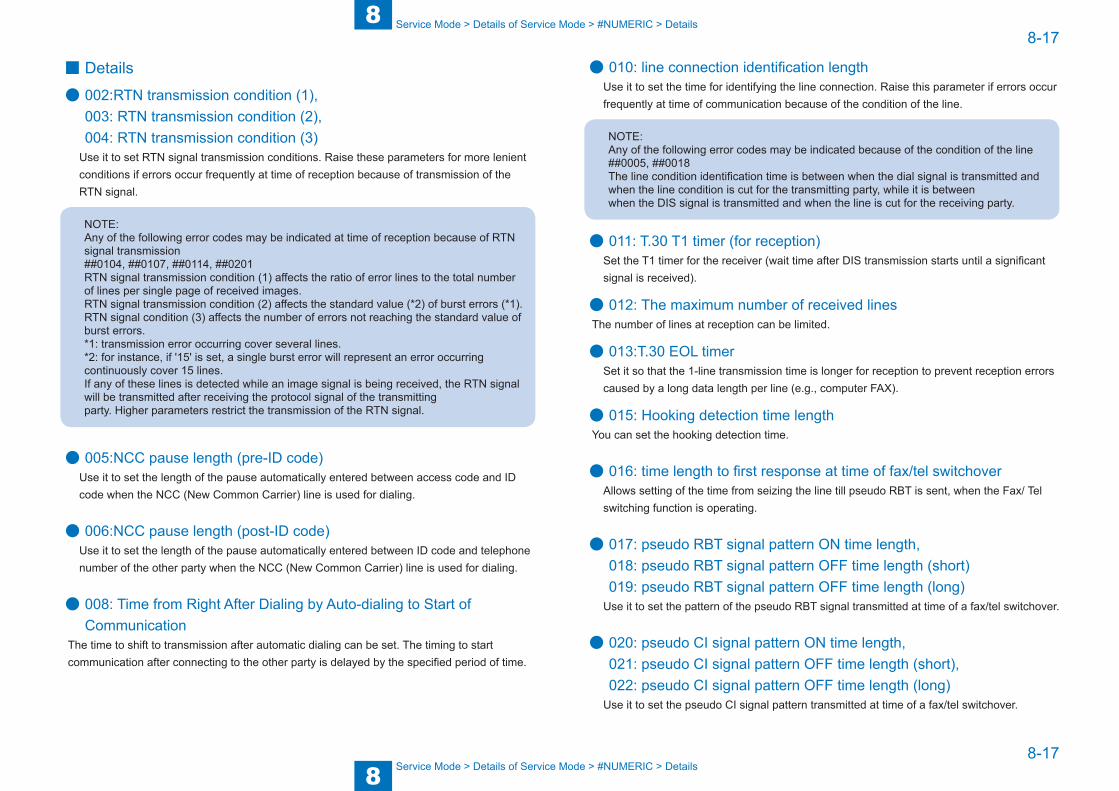
8
88-17
8-17
Service Mode > Details of Service Mode > #NUMERIC > Details
Service Mode > Details of Service Mode > #NUMERIC > Details
■ Details
● 002:RTN transmission condition (1), 003: RTN transmission condition (2), 004: RTN transmission condition (3)
Use it to set RTN signal transmission conditions. Raise these parameters for more lenient conditions if errors occur frequently at time of reception because of transmission of the RTN signal.
NOTE:Any of the following error codes may be indicated at time of reception because of RTN signal transmission##0104, ##0107, ##0114, ##0201RTN signal transmission condition (1) affects the ratio of error lines to the total number of lines per single page of received images.RTN signal transmission condition (2) affects the standard value (*2) of burst errors (*1).RTN signal condition (3) affects the number of errors not reaching the standard value of burst errors.*1: transmission error occurring cover several lines.*2: for instance, if '15' is set, a single burst error will represent an error occurring continuously cover 15 lines.If any of these lines is detected while an image signal is being received, the RTN signal will be transmitted after receiving the protocol signal of the transmittingparty. Higher parameters restrict the transmission of the RTN signal.
● 005:NCC pause length (pre-ID code)Use it to set the length of the pause automatically entered between access code and ID code when the NCC (New Common Carrier) line is used for dialing.
● 006:NCC pause length (post-ID code)Use it to set the length of the pause automatically entered between ID code and telephone number of the other party when the NCC (New Common Carrier) line is used for dialing.
● 008: Time from Right After Dialing by Auto-dialing to Start of Communication
The time to shift to transmission after automatic dialing can be set. The timing to start communication after connecting to the other party is delayed by the specified period of time.
● 010: line connection identification lengthUse it to set the time for identifying the line connection. Raise this parameter if errors occur frequently at time of communication because of the condition of the line.
NOTE:Any of the following error codes may be indicated because of the condition of the line##0005, ##0018The line condition identification time is between when the dial signal is transmitted and when the line condition is cut for the transmitting party, while it is betweenwhen the DIS signal is transmitted and when the line is cut for the receiving party.
● 011: T.30 T1 timer (for reception)Set the T1 timer for the receiver (wait time after DIS transmission starts until a significant signal is received).
● 012: The maximum number of received linesThe number of lines at reception can be limited.
● 013:T.30 EOL timerSet it so that the 1-line transmission time is longer for reception to prevent reception errors caused by a long data length per line (e.g., computer FAX).
● 015: Hooking detection time lengthYou can set the hooking detection time.
● 016: time length to first response at time of fax/tel switchoverAllows setting of the time from seizing the line till pseudo RBT is sent, when the Fax/ Tel switching function is operating.
● 017: pseudo RBT signal pattern ON time length, 018: pseudo RBT signal pattern OFF time length (short) 019: pseudo RBT signal pattern OFF time length (long)
Use it to set the pattern of the pseudo RBT signal transmitted at time of a fax/tel switchover.
● 020: pseudo CI signal pattern ON time length, 021: pseudo CI signal pattern OFF time length (short), 022: pseudo CI signal pattern OFF time length (long)
Use it to set the pseudo CI signal pattern transmitted at time of a fax/tel switchover.
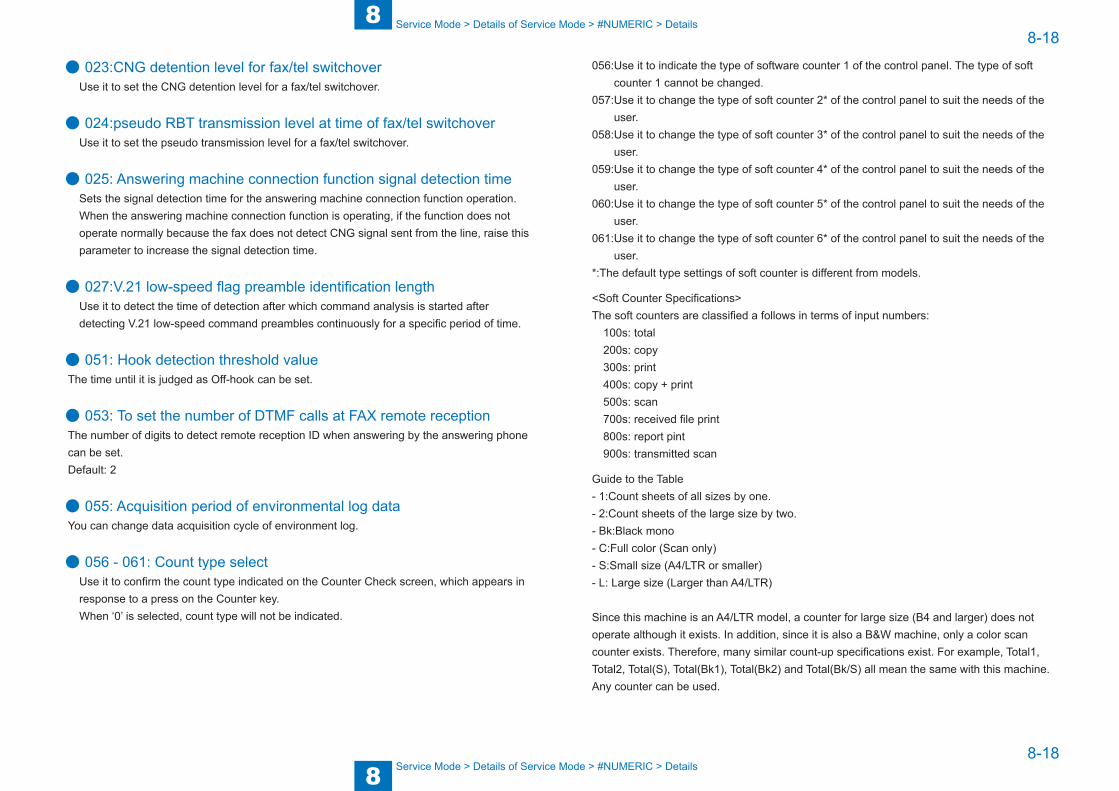
8
88-18
8-18
Service Mode > Details of Service Mode > #NUMERIC > Details
Service Mode > Details of Service Mode > #NUMERIC > Details
● 023:CNG detention level for fax/tel switchoverUse it to set the CNG detention level for a fax/tel switchover.
● 024:pseudo RBT transmission level at time of fax/tel switchoverUse it to set the pseudo transmission level for a fax/tel switchover.
● 025: Answering machine connection function signal detection timeSets the signal detection time for the answering machine connection function operation. When the answering machine connection function is operating, if the function does not operate normally because the fax does not detect CNG signal sent from the line, raise this parameter to increase the signal detection time.
● 027:V.21 low-speed flag preamble identification lengthUse it to detect the time of detection after which command analysis is started after detecting V.21 low-speed command preambles continuously for a specific period of time.
● 051: Hook detection threshold valueThe time until it is judged as Off-hook can be set.
● 053: To set the number of DTMF calls at FAX remote receptionThe number of digits to detect remote reception ID when answering by the answering phone can be set. Default: 2
● 055: Acquisition period of environmental log dataYou can change data acquisition cycle of environment log.
● 056 - 061: Count type select Use it to confirm the count type indicated on the Counter Check screen, which appears in response to a press on the Counter key.When ‘0’ is selected, count type will not be indicated.
056: Use it to indicate the type of software counter 1 of the control panel. The type of soft counter 1 cannot be changed.
057: Use it to change the type of soft counter 2* of the control panel to suit the needs of the user.
058: Use it to change the type of soft counter 3* of the control panel to suit the needs of the user.
059: Use it to change the type of soft counter 4* of the control panel to suit the needs of the user.
060: Use it to change the type of soft counter 5* of the control panel to suit the needs of the user.
061: Use it to change the type of soft counter 6* of the control panel to suit the needs of the user.
*:The default type settings of soft counter is different from models.
<Soft Counter Specifications>The soft counters are classified a follows in terms of input numbers:
100s: total200s: copy300s: print400s: copy + print500s: scan700s: received file print800s: report pint900s: transmitted scan
Guide to the Table- 1:Count sheets of all sizes by one.- 2:Count sheets of the large size by two.- Bk:Black mono- C:Full color (Scan only)- S:Small size (A4/LTR or smaller)- L: Large size (Larger than A4/LTR)
Since this machine is an A4/LTR model, a counter for large size (B4 and larger) does not operate although it exists. In addition, since it is also a B&W machine, only a color scan counter exists. Therefore, many similar count-up specifications exist. For example, Total1, Total2, Total(S), Total(Bk1), Total(Bk2) and Total(Bk/S) all mean the same with this machine. Any counter can be used.

8
88-19
8-19
Service Mode > Details of Service Mode > #NUMERIC > Details
Service Mode > Details of Service Mode > #NUMERIC > Details
No. Counter type
Print systemBk
1-sided 2-sidedLocal copyP
DL print
FAX
printR
eport printLocal copyP
DL print
FAX
printR
eport print
101 Total1 1 1 1 1102 Total2 1 1 1 1103 Total (L) *104 Total (S) 1 1 1 1108 Total (Bk1) 1 1 1 1109 Total (Bk2) 1 1 1 1112 Total (Bk/L) *113 Total (Bk/S) 1 1 1 1114 Total1 (2-sided) 1 1 1 1115 Total2 (2-sided) 1 1 1 1116 L (2-sided) *117 S (2-sided) 1 1 1 1126 TotalA1 1 1 1127 TotalA2 1 1 1128 TotalA (L) *129 TotalA (S) 1 1 1132 TotalA (Bk1) 1 1 1133 TotalA (Bk2) 1 1 1136 TotalA (Bk/L) *137 TotalA (Bk/S) 1 1 1138 TotalA1 (2-sided) 1 1 1139 TotalA2 (2-sided) 1 1 1140 L A (2-sided) *141 S A (2-sided) 1 1 1150 TotalB1 1 1 1151 TotalB2 1 1 1152 TotalB (L) *153 TotalB (S) 1 1 1156 TotalB (Bk1) 1 1 1157 TotalB (Bk2) 1 1 1160 TotalB (Bk/L) *161 TotalB (Bk/S) 1 1 1162 TotalB1 (2-sided) 1 1 1163 TotalB2 (2-sided) 1 1 1164 LB (2-sided) *165 SB (2-sided) 1 1 1201 Copy(Total1) 1202 Copy(Total2) 1
No. Counter type
Print systemBk
1-sided 2-sidedLocal copyP
DL print
FAX
printR
eport printLocal copyP
DL print
FAX
printR
eport print
203 Copy(L) *204 Copy(S) 1205 CopyA (Total1) 1206 CopyA (Total2) 1207 CopyA (L) *208 CopyA (S) 1209 Local copy(Total1) 1210 Local copy(Total2) 1211 Local copy(L) *212 Local copy(S) 1221 Copy(Bk1) 1222 Copy(Bk2) 1227 Copy(Bk/L) *228 Copy(Bk/S) 1237 Copy(Bk/L/2-sided) *238 Copy(Bk/S/2-sided) 1249 CopyA (Bk1) 1250 CopyA (Bk2) 1255 CopyA (Bk/L) *256 CopyA (Bk/S) 1265 CopyA (Bk/L/2-sided) *266 CopyA (Bk/S/2-sided) 1277 Local copy(Bk1) 1278 Local copy(Bk2) 1283 Local copy(Bk/L) *284 Local copy(Bk/S) 1293 Local copy(Bk/L/2-sided) *294 Local copy(Bk/S/2-sided) 1301 Print (Total1) 1 1302 Print (Total2) 1 1303 Print (L) *304 Print (S) 1 1305 PrintA (Total1) 1 1306 PrintA (Total2) 1 1307 PrintA (L) *308 PrintA (S) 1 1313 Print (Bk1) 1 1314 Print (Bk2) 1 1
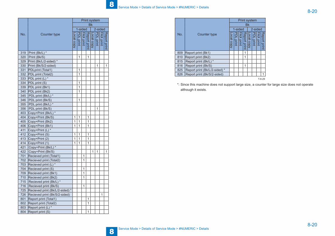
8
88-20
8-20
Service Mode > Details of Service Mode > #NUMERIC > Details
Service Mode > Details of Service Mode > #NUMERIC > Details
No. Counter type
Print systemBk
1-sided 2-sidedLocal copyP
DL print
FAX
printR
eport printLocal copyP
DL print
FAX
printR
eport print
319 Print (Bk/L) *320 Print (Bk/S) 1 1329 Print (Bk/L/2-sided) *330 Print (Bk/S/2-sided) 1 1331 PDLprint (Total1) 1332 PDL print (Total2) 1333 PDL print (L) *334 PDL print (S) 1339 PDL print (Bk1) 1340 PDL print (Bk2) 1345 PDL print (Bk/L) *346 PDL print (Bk/S) 1355 PDL print (Bk/L) *356 PDL print (Bk/S) 1403 Copy+Print (Bk/L) *404 Copy+Print (Bk/S) 1 1 1405 Copy+Print (Bk2) 1 1 1406 Copy+Print (Bk1) 1 1 1411 Copy+Print (L) *412 Copy+Print (S) 1 1 1413 Copy+Print (2) 1 1 1414 Copy+Print (1) 1 1 1421 Copy+Print (Bk/L) *422 Copy+Print (Bk/S) 1 1 1701 Recieved print (Total1) 1702 Recieved print (Total2) 1703 Recieved print (L) *704 Recieved print (S) 1709 Recieved print (Bk1) 1710 Recieved print (Bk2) 1715 Recieved print (Bk/L) *716 Recieved print (Bk/S) 1725 Recieved print (Bk/L/2-sided) *726 Recieved print (Bk/S/2-sided) 1801 Report print (Total1) 1802 Report print (Total2) 1803 Report print (L) *804 Report print (S) 1
No. Counter type
Print systemBk
1-sided 2-sidedLocal copyP
DL print
FAX
printR
eport printLocal copyP
DL print
FAX
printR
eport print
809 Report print (Bk1) 1810 Report print (Bk2) 1815 Report print (Bk/L) *816 Report print (Bk/S) 1825 Report print (Bk/L/2-sided) *826 Report print (Bk/S/2-sided) 1
*: Since this machine does not support large size, a counter for large size does not operate although it exists.
T-8-29
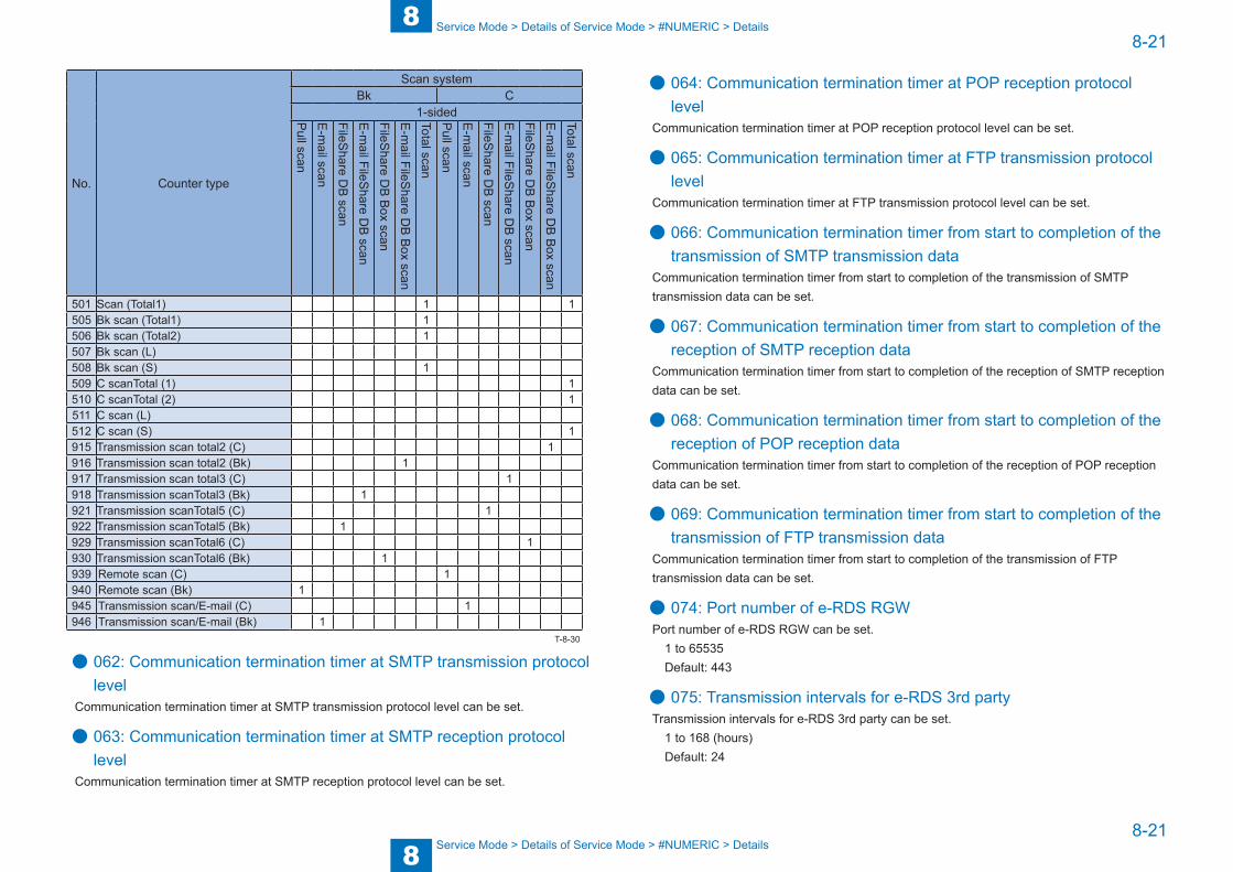
8
88-21
8-21
Service Mode > Details of Service Mode > #NUMERIC > Details
Service Mode > Details of Service Mode > #NUMERIC > Details
No. Counter type
Scan systemBk C
1-sidedPull scan
E-m
ail scan
FileShare D
B scan
E-m
ail FileShare D
B scan
FileShare D
B B
ox scan
E-m
ail FileShare D
B B
ox scan
Total scan
Pull scan
E-m
ail scan
FileShare D
B scan
E-m
ail FileShare D
B scan
FileShare D
B B
ox scan
E-m
ail FileShare D
B B
ox scan
Total scan
501 Scan (Total1) 1 1505 Bk scan (Total1) 1506 Bk scan (Total2) 1507 Bk scan (L)508 Bk scan (S) 1509 C scanTotal (1) 1510 C scanTotal (2) 1511 C scan (L)512 C scan (S) 1915 Transmission scan total2 (C) 1916 Transmission scan total2 (Bk) 1917 Transmission scan total3 (C) 1918 Transmission scanTotal3 (Bk) 1921 Transmission scanTotal5 (C) 1922 Transmission scanTotal5 (Bk) 1929 Transmission scanTotal6 (C) 1930 Transmission scanTotal6 (Bk) 1939 Remote scan (C) 1940 Remote scan (Bk) 1945 Transmission scan/E-mail (C) 1946 Transmission scan/E-mail (Bk) 1
● 062: Communication termination timer at SMTP transmission protocol level
Communication termination timer at SMTP transmission protocol level can be set.
● 063: Communication termination timer at SMTP reception protocol level
Communication termination timer at SMTP reception protocol level can be set.
T-8-30
● 064: Communication termination timer at POP reception protocol level
Communication termination timer at POP reception protocol level can be set.
● 065: Communication termination timer at FTP transmission protocol level
Communication termination timer at FTP transmission protocol level can be set.
● 066: Communication termination timer from start to completion of the transmission of SMTP transmission data
Communication termination timer from start to completion of the transmission of SMTP transmission data can be set.
● 067: Communication termination timer from start to completion of the reception of SMTP reception data
Communication termination timer from start to completion of the reception of SMTP reception data can be set.
● 068: Communication termination timer from start to completion of the reception of POP reception data
Communication termination timer from start to completion of the reception of POP reception data can be set.
● 069: Communication termination timer from start to completion of the transmission of FTP transmission data
Communication termination timer from start to completion of the transmission of FTP transmission data can be set.
● 074: Port number of e-RDS RGWPort number of e-RDS RGW can be set.
1 to 65535 Default: 443
● 075: Transmission intervals for e-RDS 3rd partyTransmission intervals for e-RDS 3rd party can be set.
1 to 168 (hours) Default: 24

8
88-22
8-22
Service Mode > Details of Service Mode > #SCAN > Setting of Scanner Functions (SCANNER)
Service Mode > Details of Service Mode > #SCAN > Setting of Scanner Functions (SCANNER)
#SCAN ■ Setting of Scanner Functions (SCANNER)
Item1 No.Initial
settingAppropriate
guidelineDescription
#SCAN SW SW00 - 04 Not usedSW05: Differs
according to the
location.
Changes "AB configuration/Inch configuration" of the original size detection
SW06 Not used#SCAN NUMERIC
001: - 032: Not used
033: 50 Vertical scan magnification correction (scanning on BOOK)
034: 50 Horizontal scan magnification correction (scanning on BOOK)
035: - 046: Not used047: 50 Vertical scan magnification correction (scanning
on ADF)048: 50 Horizontal scan magnification correction
(scanning on ADF)049: - 134: Not used
135: 30 Leading edge trimming length when performing fax operation using the Copyboard (0.1 mm)
136: - 137: Not used138: 15 Leading edge frame length when performing
copy operation using the Copyboard (0.1 mm)139: - 144: Not used
145: 30 Leading edge trimming length when performing fax operation using the ADF (0.1 mm)
146: 30 Trailing edge trimming length when performing fax operation using the ADF (0.1 mm)
147: 10 Left-right frame length when performing fax operation using the ADF (0.1 mm)
148: 25 Leading edge frame length when performing copy operation using the ADF (0.1 mm)
149: - 164: Not used165: 4 Leading edge frame length when performing
SEND SCAN using the Copyboard (0.1 mm)166: - 167: Not used
168: 0 Leading edge frame length when performing SEND SCAN using the ADF (0.1 mm)
169: - 192: Not used
Item1 No.Initial
settingAppropriate
guidelineDescription
193: 0 0: LEGAL1: FOOLSCAP2: M_OFICIO3: A_FOOLSCAP4: FOLIO5: G_LEGAL7: B_OFICIO8: OFICIO9: E_OFICIO10: F4A
ADF special paper, standardized size: LGL misidentification-readyTo enable the change in this service mode, the following settings need to be changed:#SCAN > #SCAN SW > SW05, #SYSTEM > #SYSTEM SW > SW57
195: 0 0: LTR_R1: FOOLSCAP2: OFFICIO4: G_LTR_R6: K_LGL_R7: EXE_R
ADF special paper, standardized size: LTR_R misidentification-readyTo enable the change in this service mode, the following settings need to be changed:#SCAN > #SCAN SW > SW05, #SYSTEM > #SYSTEM SW > SW57
196: - 290: Not usedT-8-31
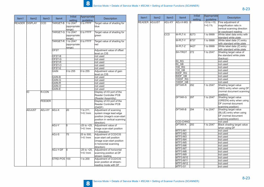
8
88-23
8-23
Service Mode > Details of Service Mode > #SCAN > Setting of Scanner Functions (SCANNER)
Service Mode > Details of Service Mode > #SCAN > Setting of Scanner Functions (SCANNER)
Item1 Item2 Item3 Item4Initial
settingAppropriate
guidelineDescription
READER DISPLAY CCD TARGET-B 1 to 2047 (appropriate range)
0 to FFFF Target value of shading for blue
TARGET-G 1 to 2047 (appropriate range)
0 to FFFF Target value of shading for green
TARGET-R 1 to 2047 (appropriate range)
0 to FFFF Target value of shading for red
OFST Adjustment value of offset level on CIS
OFST-B not usedOFST-G not usedOFST-R not usedOFST-O not usedOFST-E not usedGAIN 0 to 255 0 to 255 Adjustment value of gain
level on CISGAIN-B not usedGAIN-G not usedGAIN-R not usedGAIN-O not usedGAIN-E not used
IO R-CON Display of I/O port of the Reader Controller PCB (Reader Assembly)
FEEDER Display of I/O port of the Reader Controller PCB (DADF)
ADJUST ADJ-XY ADJ-X 20 1 to 211, 1=0.1mm
Adjustment of scanning system image lead edge position (image's scan-start position in vertical scanning direction)
ADJ-Y 0 -25 to +25, 1=0.1mm
Adjustment value of image scan-start position <Y-direction>
ADJ-S 75 25 to 500, 1=0.1mm
Adjustment of CCD/CIS scan-start cell position (image scan-start position in horizontal scanning direction)
ADJ-Y-DF 0 -25 to +25, 1=0.1mm
Adjustment of horizontal scanning position at DF stream reading
STRD-POS 100 1 to 200 Adjustment of CCD/CIS scan position at stream-reading mode with DF
Item1 Item2 Item3 Item4Initial
settingAppropriate
guidelineDescription
READER ADJUST ADJ-XY ADJ-X-MG 0 -10 to +10, 1=0.1%
Fine adjustment of magnification ratio in vertical scanning direction at copyboard reading
CCD W-PLT-X 8273 1 to 9999 White label data entry with standard white plate
W-PLT-Y 8737 1 to 9999 White label data (Y) entry with standard white plate
W-PLT-Z 9427 1 to 9999 White label data (Z) entry with standard white plate
SH-TRGT 272 1 to 2047 Shading target value of the standard white plate (backup)
50_RG not used50_GB not used100_RG not used100_GB not used50DF_RG not used50DF_GB not used100DF_RG not used100DF_GB not usedDFTAR-R 292 1 to 2047 Shading target value
(RED) entry when using DF (normal document scanning position)
DFTAR-G 297 1 to 2047 Shading target value (GREEN) entry when using DF (normal document scanning position)
DFTAR-B 294 1 to 2047 Shading target value (BLUE) entry when using DF (normal document scanning position)
CCD-CHNG not usedDFTAR-K 293 1 to 2047 Black shading target value
when using DFMTF3-M1 not usedMTF3-M2 not usedMTF3-M3 not usedMTF3-M4 not usedMTF3-M5 not usedMTF3-M6 not usedMTF3-M7 not usedMTF3-M8 not usedMTF3-M9 not usedMTF3-M10 not usedMTF3-M11 not usedMTF3-M12 not usedMTF3-S1 not used
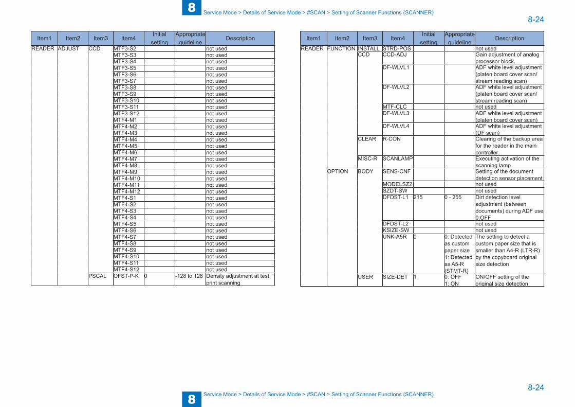
8
88-24
8-24
Service Mode > Details of Service Mode > #SCAN > Setting of Scanner Functions (SCANNER)
Service Mode > Details of Service Mode > #SCAN > Setting of Scanner Functions (SCANNER)
Item1 Item2 Item3 Item4Initial
settingAppropriate
guidelineDescription
READER ADJUST CCD MTF3-S2 not usedMTF3-S3 not usedMTF3-S4 not usedMTF3-S5 not usedMTF3-S6 not usedMTF3-S7 not usedMTF3-S8 not usedMTF3-S9 not usedMTF3-S10 not usedMTF3-S11 not usedMTF3-S12 not usedMTF4-M1 not usedMTF4-M2 not usedMTF4-M3 not usedMTF4-M4 not usedMTF4-M5 not usedMTF4-M6 not usedMTF4-M7 not usedMTF4-M8 not usedMTF4-M9 not usedMTF4-M10 not usedMTF4-M11 not usedMTF4-M12 not usedMTF4-S1 not usedMTF4-S2 not usedMTF4-S3 not usedMTF4-S4 not usedMTF4-S5 not usedMTF4-S6 not usedMTF4-S7 not usedMTF4-S8 not usedMTF4-S9 not usedMTF4-S10 not usedMTF4-S11 not usedMTF4-S12 not used
PSCAL OFST-P-K 0 -128 to 128 Density adjustment at test print scanning
Item1 Item2 Item3 Item4Initial
settingAppropriate
guidelineDescription
READER FUNCTION INSTALL STRD-POS not usedCCD CCD-ADJ Gain adjustment of analog
processor block.DF-WLVL1 ADF white level adjustment
(platen board cover scan/stream reading scan)
DF-WLVL2 ADF white level adjustment (platen board cover scan/stream reading scan)
MTF-CLC not usedDF-WLVL3 ADF white level adjustment
(platen board cover scan)DF-WLVL4 ADF white level adjustment
(DF scan)CLEAR R-CON Clearing of the backup area
for the reader in the main controller.
MISC-R SCANLAMP Executing activation of the scanning lamp
OPTION BODY SENS-CNF Setting of the document detection sensor placement
MODELSZ2 not usedSZDT-SW not usedDFDST-L1 215 0 - 255 Dirt detection level
adjustment (between documents) during ADF use0:OFF
DFDST-L2 not usedKSIZE-SW not usedUNK-A5R 0 0: Detected
as custom paper size1: Detected as A5-R (STMT-R)
The setting to detect a custom paper size that is smaller than A4-R (LTR-R) by the copyboard original size detection
USER SIZE-DET 1 0: OFF1: ON
ON/OFF setting of the original size detection
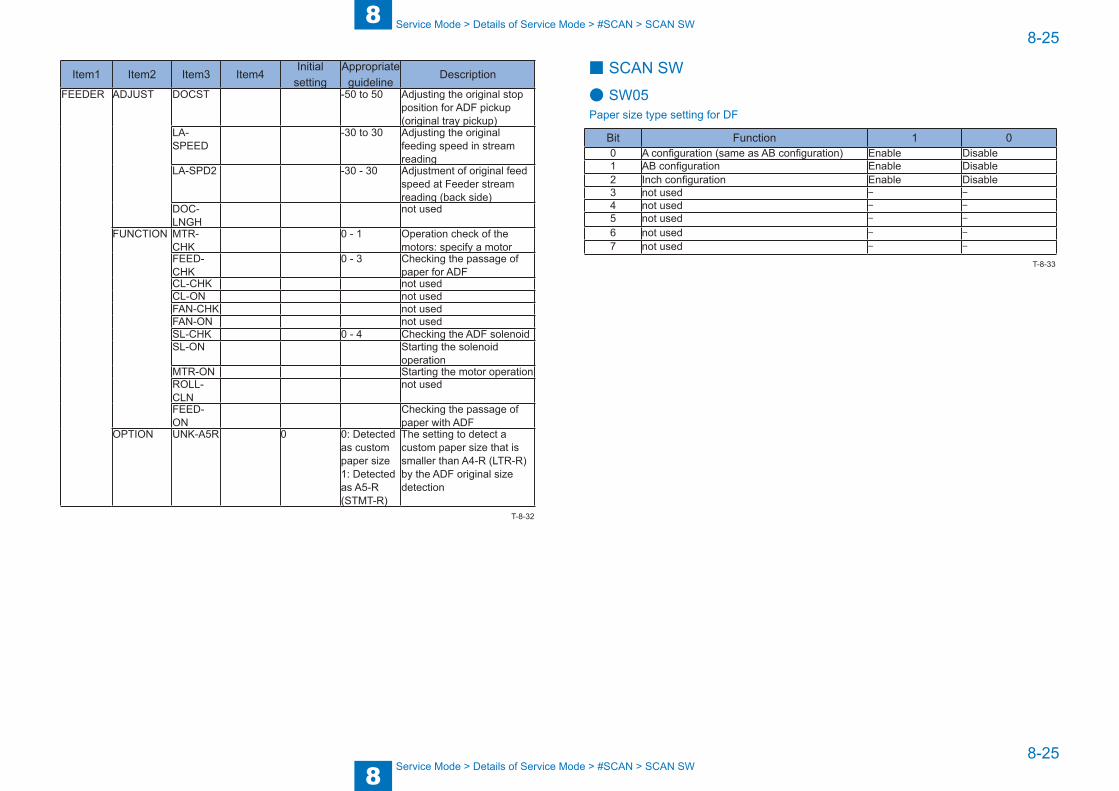
8
88-25
8-25
Service Mode > Details of Service Mode > #SCAN > SCAN SW
Service Mode > Details of Service Mode > #SCAN > SCAN SW
Item1 Item2 Item3 Item4Initial
settingAppropriate
guidelineDescription
FEEDER ADJUST DOCST -50 to 50 Adjusting the original stop position for ADF pickup (original tray pickup)
LA-SPEED
-30 to 30 Adjusting the original feeding speed in stream reading
LA-SPD2 -30 - 30 Adjustment of original feed speed at Feeder stream reading (back side)
DOC-LNGH
not used
FUNCTION MTR-CHK
0 - 1 Operation check of the motors: specify a motor
FEED-CHK
0 - 3 Checking the passage of paper for ADF
CL-CHK not usedCL-ON not usedFAN-CHK not usedFAN-ON not usedSL-CHK 0 - 4 Checking the ADF solenoidSL-ON Starting the solenoid
operationMTR-ON Starting the motor operationROLL-CLN
not used
FEED-ON
Checking the passage of paper with ADF
OPTION UNK-A5R 0 0: Detected as custom paper size1: Detected as A5-R (STMT-R)
The setting to detect a custom paper size that is smaller than A4-R (LTR-R) by the ADF original size detection
T-8-32
■ SCAN SW
● SW05Paper size type setting for DF
Bit Function 1 00 A configuration (same as AB configuration) Enable Disable1 AB configuration Enable Disable2 Inch configuration Enable Disable3 not used - -4 not used - -5 not used - -
6 not used - -
7 not used - -
T-8-33

8
88-26
8-26
Service Mode > Details of Service Mode > #SCAN > Numeric Parameter Settings (Numeric Prama.)
Service Mode > Details of Service Mode > #SCAN > Numeric Parameter Settings (Numeric Prama.)
■ Numeric Parameter Settings (Numeric Prama.)
● 033Vertical scan magnification correctionCorrect the magnification of vertical scanning of a book. The larger the adjustment value, the more the image stretches in the vertical scanning direction.
● 034: Horizontal scan magnification correctionCorrect the magnification of horizontal scanning of a book. The larger the adjustment value, the more the image stretches in the horizontal scanning direction.
● 047: Vertical scan magnification correction (when scanning on a document fed from ADF)
Correct the magnification of vertical scanning of a document fed from the ADF. The larger the adjustment value, the more the image stretches in the vertical scanning direction.
● 048: Horizontal scan magnification correction (when scanning on a document fed from ADF)
Correct the magnification of horizontal scanning of a document fed from the ADF. The smaller the adjustment value, the more the image stretches in the horizontal scanning direction.
● 135: Leading edge trimming length when performing fax operation using the Copyboard (0.1 mm)
As the value is incremented by "1", the leading edge non-image width is increased by 0.1mm.
● 138: Leading edge frame length when performing copy operation using the Copyboard (0.1 mm)
As the value is incremented by 1, the image position moves to the trailing edge side by 0.1mm.
● 145: Leading edge trimming length when performing fax operation using the ADF (0.1 mm)
As the value is incremented by "1", the leading edge non-image width is increased by 0.1mm.
● 146: Trailing edge trimming length when performing fax operation using the ADF (0.1 mm)
As the value is incremented by "1", the trailing edge non-image width is increased by 0.1mm.
● 147: Left-right frame length when performing fax operation using the ADF (0.1 mm)
As the value is incremented by 1, the image position moves to the right edge side by 0.1mm.
● 148: Leading edge frame length when performing copy operation using the ADF (0.1 mm)
As the value is incremented by 1, the image position moves to the trailing edge side by 0.1mm.
● 165: Leading edge frame length when performing SEND SCAN using the Copyboard (0.1 mm)
As the value is incremented by 1, the image position moves to the trailing edge side by 0.1mm.
● 168: Leading edge frame length when performing SEND SCAN using the ADF (0.1 mm)
As the value is incremented by 1, the image position moves to the trailing edge side by 0.1mm.
● 193: ADF special standard-sized paper: LGL misidentification-readySet to use special standard-sized paper that is not otherwise identifiable to the ADF (because it is misidentified as "LEGAL").
0 : LEGAL 1 : FOOLSCAP 2 : M_OFICIO 3 : A_FOOLSCAP 4 : FOLIO5 : G_LEGAL 7 : B_OFICIO 8 : OFICIO 9 : E_OFICIO 10 : F4A
To enable the change in this service mode, the following settings need to be changed:#SCAN > #SCAN SW > SW05, #SYSTEM > #SYSTEM SW > SW57
When 1 to 5, 7 to 9 are set
#SCAN > #SCAN SW > SW05 2 (Inch configuration)#SYSTEM > #SYSTEM SW > SW57 2 (Inch configuration)
When 10 is set
#SCAN > #SCAN SW > SW05 0 or 1 (A configuration, AB configuration)#SYSTEM > #SYSTEM SW > SW57 1 or 0 (A configuration, AB configuration)
8
88-27
8-27
Service Mode > Details of Service Mode > #SCAN > READER
Service Mode > Details of Service Mode > #SCAN > READER
● 195: ADF special standard-sized paper: LTR_R misidentification-ready
Set to use special standard-sized paper that is not otherwise identifiable to the ADF (because it is misidentified as "LTRR").
0: LTR_R 1: FOOLSCAP 2: OFFICIO4: G_LTR_R 6: K_LGL_R 7: EXE_R
To enable the change in this service mode, the following settings need to be changed:#SCAN > #SCAN SW > SW05, #SYSTEM > #SYSTEM SW > SW57
When 1, 2, 4, 7 are set
#SCAN > #SCAN SW > SW05 2 (Inch configuration)#SYSTEM > #SYSTEM SW > SW57 2 (Inch configuration)
When 6 is set
#SCAN > #SCAN SW > SW05 0 or 1 (A configuration, AB configuration)#SYSTEM > #SYSTEM SW > SW57 1 or 0 (A configuration, AB configuration)
■ READER
● #SCAN> READER> DISPLAY> CCD> TARGET-BTarget value of shading for blueIf the scanned image has some failure, check the target value of shading for blue.If the machine continues to display 0 (minimum) or FFFF (maximum), there may be some problem on main controller PCB.Appropriate guideline :1 to 2047
● #SCAN> READER> DISPLAY> CCD> TARGET-GTarget value of shading for greenIf the scanned image has some failure, check the target value of shading for green.If the machine continues to display 0 (minimum) or FFFF (maximum), there may be some problem on main controller PCB.Appropriate guideline :1 to 2047
● #SCAN> READER> DISPLAY> CCD> TARGET-RTarget value of shading for redIf the scanned image has some failure, check the target value of shading for red.If the machine continues to display 0 (minimum) or FFFF (maximum), there may be some problem on main controller PCB.Appropriate guideline :1 to 2047
● #SCAN> READER> DISPLAY> CCD> OFSTAdjustment value of offset level on CISTo judge if this adjustment value is correct when an image fault attributed to CIS occurs.Appropriate guideline :0 to 255
● #SCAN> READER> DISPLAY> CCD> GAINAdjustment value of gain level on CISTo judge if this adjustment value is correct when an image fault attributed to CIS occurs.Appropriate guideline :0 to 255

8
88-28
8-28
Service Mode > Details of Service Mode > #SCAN > READER
Service Mode > Details of Service Mode > #SCAN > READER
● #SCAN> READER> I/O> R-CON> P001Display of I/O port of the Reader Controller PCB (Reader Assembly)Display the I/O state of the sensor of the reader unit.
Bit Name Display contents RemarksBit0 ADF Open/Close Sensor (PS23) 1: Open, 0: CloseBit1 CIS HP Sensor (PS24) 1: HPBit2 Not usedBit3 Not usedBit4 Original Size Sensor 1 (PS22) 1: Document present 0: No documentBit5 Original Size Sensor 2 (PS21) 1: Document present 0: No documentBit6 Not usedBit7 Not used
Bit8-15 Not used
● #SCAN> READER> I/O> FEEDER> P001Display of I/O port of the Reader Controller PCB (DADF)Display the I/O state of the sensor of the ADF unit.
Bit Name Display contents RemarksBit0 Document Width Detection Sensor (PS31) 1: A4-R (LTR-R) or larger,
0: Smaller than A4R (LTR-R)Bit1 Not usedBit2 Document Length Detection Sensor (PS32) 1: LGL or larger, 0: Smaller than LGLBit3 Not usedBit4 Not usedBit5 Read Sensor (PS25) 1: Document present 0: No documentBit6 Timing Sensor (PS29) 1: Document present 0: No documentBit7 Registration Sensor (PS26) 1: Document present 0: No documentBit8 Delivery/Reverse Sensor (PS27)Bit9 Lower Reverse Sensor (PS28) 1: Document present 0: No documentBit10 Not usedBit11 Not usedBit12 Not usedBit13 Document Set Sensor (PS30) 1: Document present 0: No documentBit14 ADF connection check 1: Connected, 0: Not connectedBit15 Not used
T-8-34
T-8-35
● #SCAN> READER> ADJUST> ADJ-XY> ADJ-XAdjustment of scanning system image lead edge position. (image's scan-start position in
vertical scanning direction)0.1mm shift of image scan-start position toward the trail edge direction by 1-increment in the setting.
NOTE:If changing the setting value of this item, be sure to Note the changed value on the service label.
● #SCAN> READER> ADJUST> ADJ-XY> ADJ-YAdjustment value of image scan-start position <Y-direction>0.1mm shift of image scan-start position toward the trail edge direction by 1-increment in the setting.
NOTE:If changing the setting value of this item, be sure to Note the changed value on the service label.
8
88-29
8-29
Service Mode > Details of Service Mode > #SCAN > READER
Service Mode > Details of Service Mode > #SCAN > READER
● #SCAN> READER> ADJUST> ADJ-XY> ADJ-SAdjustment of CIS scan-start cell position. (image scan-start position in horizontal scanning
direction)Adjust the position to measure data for shading correction with standard white plate. This item must not be normally used.
NOTE:If changing the setting value of this item, be sure to Note the changed value on the service label.
● #SCAN> READER> ADJUST> ADJ-XY> ADJ-Y-DFAdjustment of horizontal scanning position at DF stream reading.Adjust horizontal scanning position at DF stream reading. (Because the Original Tray at Feeder side does not have mechanism to adjust side registration.)0.1mm shift of image scan-start position toward the front direction by 1-increment in the setting value.
NOTE:If changing the setting value of this item, be sure to Note the changed value on the service label.
● #SCAN> READER> ADJUST> ADJ-XY> ADJ-Y-POSAdjustment of CIS scan position at stream-reading mode with DF.This item must not be normally used.
NOTE:If changing the setting value of this item, be sure to Note the changed value on the reader's service label.
● #SCAN> READER> ADJUST> ADJ-XY> ADJ-X-MGFine adjustment of magnification ratio in vertical scanning direction at copyboard readingPerform fine adjustment of magnification ratio in vertical scanning direction at copyboard reading.0.1mm shift of image scan-start position toward the front direction by 1-increment in the setting value.
NOTE:If changing the setting value of this item, be sure to Note the changed value on the reader's service label.
● #SCAN> READER> ADJUST> CCD> W-PLT-XWhite label data entry with standard white plate.
● #SCAN> READER> ADJUST> CCD> W-PLT-YWhite label data (Y) entry with standard white plate.
● #SCAN> READER> ADJUST> CCD> W-PLT-ZWhite label data (Z) entry with standard white plate.Execute this mode only when necessary. Do not execute it when unnecessary.
NOTE:Be sure to enter the numeric value on copyboard glass when replacing the copyboard glass.If changing the setting value of this item, be sure to Note the changed value on the service label.
● #SCAN> READER> ADJUST> CCD> SH-TRGTShading target value of the standard white plate (backup).This item must not be normally used.
● #SCAN> READER> ADJUST> CCD> DFTAR-RShading target value (RED) entry when using DF (normal document scanning position).
● #SCAN> READER> ADJUST> CCD> DFTAR-GShading target value (GREEN) entry when using DF (normal document scanning position).
● #SCAN> READER> ADJUST> CCD> DFTAR-BShading target value (BLUE) entry when using DF (normal document scanning position).This item must not be normally used.
● #SCAN> READER> ADJUST> CCD> DFTAR-KBlack shading target value when using DF.This item must not be normally used.
● #SCAN> READER> ADJUST> PASCAL> OFST-P-KDensity adjustment at test print scanning.Execute offset adjustment for test print scanning signal in PASCAL control at auto gradation correction (full correction)
8
88-30
8-30
Service Mode > Details of Service Mode > #SCAN > READER
Service Mode > Details of Service Mode > #SCAN > READER
● #SCAN> READER> FUNCTION> CCD> CCD-ADJGain adjustment of analog processor block (on CCD PCB).The gain of LED of CIS is corrected to set the CIS parameter automatically. (AGC adjustment) Execute this after replacing the CIS unit.
● #SCAN> READER> FUNCTION> CCD> DF-WLVL1ADF white level adjustment (platen board cover scan/stream reading scan).
● #SCAN> READER> FUNCTION> CCD> DF-WLVL2ADF white level adjustment (platen board cover scan/stream reading scan). 1) Place a paper that users normally use on the copyboard glass and execute the following item; SCAN > READER > FUNCTION > CCD > DFWLVL1/ DF-WLVL2: Read the white level in BOOK mode. (Check the transparency of the glass for BOOK mode.)2) Set a paper that users normally use and execute the following item; SCAN > READER > FUNCTION > CCD > DFWLVL1/ DF-WLVL2: Read the white level in DF mode (stream reading). (Check the transparency of the glass for stream reading.) (Read the both sides of chart.) Reading the face: Calculate DFTAR-R
NOTE:Be sure to execute these two items (DF-WLVL1/DF-WLVL2) simultaneously.
● #SCAN> READER> FUNCTION> CCD> DF-WLVL3ADF white level adjustment (platen board cover scan).
NOTE:Scan a blank sheet on the platen and adjust the white level.
● #SCAN> READER> FUNCTION> CCD> DF-WLVL4ADF white level adjustment (DF scan).
NOTE:Scan a blank sheet in stream reading mode and adjust the white level.
● #SCAN> READER> FUNCTION> CLEAR> R-CONClearing of the backup area for the reader in the main controller. Clear the backup area for the reader in the main controller.
● #SCAN> READER> FUNCTION> MISC-R> SCANLAMPThe test checks to see if the scanning lamp is on or not.Execute the when replacing the CIS unit.
● #SCAN> READER> OPTION> BODY> SENS-CNFSetting of the document detection sensor placementThe setting of document detection size is selected in accordance with the document sensor placement.0: AB type1: Inch type
● #SCAN> READER> OPTION> BODY> DFDST-L1Dirt detection level adjustment (between documents) during ADF use.Increase the value when dirt fails to be detected, resulting in black streaks. However, if the value is increased too much, even small-sized dirt of the kind which does not appear on the image will also be detected, and the cleaning instruction screen may appear frequently.Reduce the value if users complain because the cleaning instruction screen which appears when dirt is detected is displayed frequently. Conversely, if the value is reduced too much, black streaks may appear on the images.When '0' is set, the correction control function used when dirt is detected is canceled.
● #SCAN> READER> OPTION> BODY> UNK-A5RThe setting to detect a custom paper size that is smaller than A4-R (LTR-R) by the copyboard
original size detectionThis is the setting whether to detect a custom paper size that is smaller than A4R (LTRR) as A5R (STMTR) by the copyboard original size detection.
0: Detected as custom paper size1: Detected as A5R (STMTR)
● #SCAN> READER> OPTION> USER> SIZE-DETON/OFF setting of the original size detectionTo set ON/OFF of the original size detection.
0: OFF1: ON
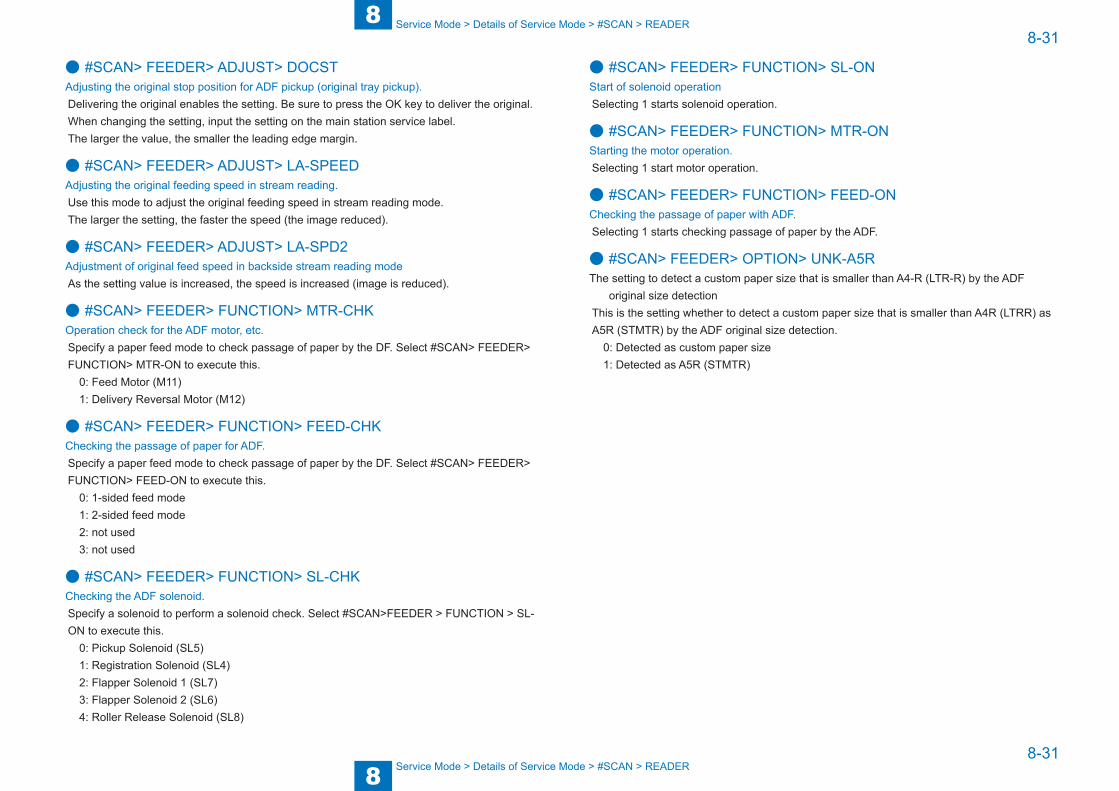
8
88-31
8-31
Service Mode > Details of Service Mode > #SCAN > READER
Service Mode > Details of Service Mode > #SCAN > READER
● #SCAN> FEEDER> ADJUST> DOCSTAdjusting the original stop position for ADF pickup (original tray pickup).Delivering the original enables the setting. Be sure to press the OK key to deliver the original.When changing the setting, input the setting on the main station service label.The larger the value, the smaller the leading edge margin.
● #SCAN> FEEDER> ADJUST> LA-SPEEDAdjusting the original feeding speed in stream reading.Use this mode to adjust the original feeding speed in stream reading mode. The larger the setting, the faster the speed (the image reduced).
● #SCAN> FEEDER> ADJUST> LA-SPD2Adjustment of original feed speed in backside stream reading modeAs the setting value is increased, the speed is increased (image is reduced).
● #SCAN> FEEDER> FUNCTION> MTR-CHKOperation check for the ADF motor, etc.Specify a paper feed mode to check passage of paper by the DF. Select #SCAN> FEEDER> FUNCTION> MTR-ON to execute this.
0: Feed Motor (M11)1: Delivery Reversal Motor (M12)
● #SCAN> FEEDER> FUNCTION> FEED-CHKChecking the passage of paper for ADF.Specify a paper feed mode to check passage of paper by the DF. Select #SCAN> FEEDER> FUNCTION> FEED-ON to execute this.
0: 1-sided feed mode1: 2-sided feed mode2: not used3: not used
● #SCAN> FEEDER> FUNCTION> SL-CHKChecking the ADF solenoid.Specify a solenoid to perform a solenoid check. Select #SCAN>FEEDER > FUNCTION > SL-ON to execute this.
0: Pickup Solenoid (SL5)1: Registration Solenoid (SL4)2: Flapper Solenoid 1 (SL7)3: Flapper Solenoid 2 (SL6)4: Roller Release Solenoid (SL8)
● #SCAN> FEEDER> FUNCTION> SL-ONStart of solenoid operationSelecting 1 starts solenoid operation.
● #SCAN> FEEDER> FUNCTION> MTR-ONStarting the motor operation.Selecting 1 start motor operation.
● #SCAN> FEEDER> FUNCTION> FEED-ONChecking the passage of paper with ADF.Selecting 1 starts checking passage of paper by the ADF.
● #SCAN> FEEDER> OPTION> UNK-A5RThe setting to detect a custom paper size that is smaller than A4-R (LTR-R) by the ADF
original size detectionThis is the setting whether to detect a custom paper size that is smaller than A4R (LTRR) as A5R (STMTR) by the ADF original size detection.
0: Detected as custom paper size1: Detected as A5R (STMTR)
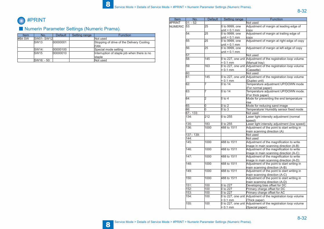
8
88-32
8-32
Service Mode > Details of Service Mode > #PRINT > Numerin Parameter Settings (Numeric Prama).
Service Mode > Details of Service Mode > #PRINT > Numerin Parameter Settings (Numeric Prama).
#PRINT ■ Numerin Parameter Settings (Numeric Prama).Item No. Default Setting range Function
#Bit SW SW01- SW12 Not usedSW13 00000001 Stopping of drive of the Delivery Cooling
FANSW14: 00000100 Special mode settingSW15 00000010 Interruption of staple job when there is no
stapleSW16: - 50: Not used
Item No. Default Setting range Function#PRINT NUMERIC
01: - 52: Not used53: 25 0 to 9999, one
unit = 0.1 mmAdjustment of margin at leading edge of copy
54: 25 0 to 9999, one unit = 0.1 mm
Adjustment of margin at trailing edge of copy
55: 25 0 to 9999, one unit = 0.1 mm
Adjustment of margin at right edge of copy
56: 25 0 to 9999, one unit = 0.1 mm
Adjustment of margin at left edge of copy
57: Not used58: 145 0 to 227, one unit
= 0.1 mmAdjustment of the registration loop volume (Manual tray)
59: 163 0 to 227, one unit = 0.1 mm
Adjustment of the registration loop volume (Cassette)
60: Not used61: 145 0 to 227, one unit
= 0.1 mmAdjustment of the registration loop volume (Duplex unit)
62: 7 0 to 14 Temperature adjustment UP/DOWN mode (For normal paper)
63: 7 0 to 14 Temperature adjustment UP/DOWN mode. (For thick paper)
64: 2 0 to 4 Mode for preventing the end temperature rise
65: 0 0 to 2 Mode for reducing sand image66: 0 0 to 3 Temperature/ Humidity sensor fixed mode67:- 133: Not used134: 212 0 to 255 Laser light intensity adjustment (normal
speed)135: 183 0 to 255 Laser light intensity adjustment (low speed)136: 1000 488 to 1511 Adjustment of the point to start writing in
main scanning direction (A) 137:- 139: Not used144: Not used145: 1000 488 to 1511 Adjustment of the magnification to write
image in main scanning direction (A-B) 146: 1000 488 to 1511 Adjustment of the magnification to write
image in main scanning direction (A-C) 147: 1000 488 to 1511 Adjustment of the magnification to write
image in main scanning direction (A-D) 148: 1000 488 to 1511 Adjustment of the point to start writing in
main scanning direction (A-B)149: 1000 488 to 1511 Adjustment of the point to start writing in
main scanning direction (A-C)150: 1000 488 to 1511 Adjustment of the point to start writing in
main scanning direction (A-D)151: 100 0 to 227 Developing bias offset for DC152: 100 0 to 227 Primary charge offset for DC153: 100 0 to 227 Primary charge offset for AC154: 100 0 to 227, one unit
= 0.1 mmAdjustment of the registration loop volume (Thick paper)
155: 100 0 to 227, one unit = 0.1 mm
Adjustment of the registration loop volume (Special paper)
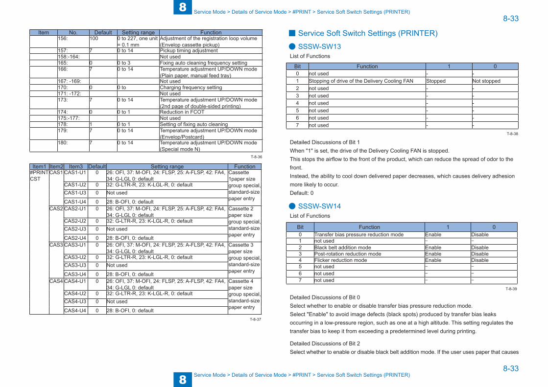
8
88-33
8-33
Service Mode > Details of Service Mode > #PRINT > Service Soft Switch Settings (PRINTER)
Service Mode > Details of Service Mode > #PRINT > Service Soft Switch Settings (PRINTER)
Item No. Default Setting range Function156: 100 0 to 227, one unit
= 0.1 mmAdjustment of the registration loop volume (Envelop cassette pickup)
157: 7 0 to 14 Pickup timing adjustment158:-164: Not used165: 0 0 to 3 Fixing auto cleaning frequency setting166: 7 0 to 14 Temperature adjustment UP/DOWN mode
(Plain paper, manual feed tray)167: -169: Not used170: 0 0 to Charging frequency setting171: -172: Not used173: 7 0 to 14 Temperature adjustment UP/DOWN mode
(2nd page of double-sided printing)174: 0 0 to 1 Reduction in FCOT175:-177: Not used178: 1 0 to 1 Setting of fixing auto cleaning179: 7 0 to 14 Temperature adjustment UP/DOWN mode
(Envelop/Postcard)180: 7 0 to 14 Temperature adjustment UP/DOWN mode
(Special mode N)
Item1 Item2 Item3 Default Setting range Function#PRINT CST
CAS1 CAS1-U1 0 26: OFI, 37: M-OFI, 24: FLSP, 25: A-FLSP, 42: FA4, 34: G-LGL 0: default
Cassette 1paper size group special, standard-size paper entry
CAS1-U2 0 32: G-LTR-R, 23: K-LGL-R, 0: defaultCAS1-U3 0 Not used
CAS1-U4 0 28: B-OFI, 0: defaultCAS2 CAS2-U1 0 26: OFI, 37: M-OFI, 24: FLSP, 25: A-FLSP, 42: FA4,
34: G-LGL 0: defaultCassette 2 paper size group special, standard-size paper entry
CAS2-U2 0 32: G-LTR-R, 23: K-LGL-R, 0: defaultCAS2-U3 0 Not used
CAS2-U4 0 28: B-OFI, 0: defaultCAS3 CAS3-U1 0 26: OFI, 37: M-OFI, 24: FLSP, 25: A-FLSP, 42: FA4,
34: G-LGL 0: defaultCassette 3 paper size group special, standard-size paper entry
CAS3-U2 0 32: G-LTR-R, 23: K-LGL-R, 0: defaultCAS3-U3 0 Not used
CAS3-U4 0 28: B-OFI, 0: defaultCAS4 CAS4-U1 0 26: OFI, 37: M-OFI, 24: FLSP, 25: A-FLSP, 42: FA4,
34: G-LGL 0: defaultCassette 4 paper size group special, standard-size paper entry
CAS4-U2 0 32: G-LTR-R, 23: K-LGL-R, 0: defaultCAS4-U3 0 Not used
CAS4-U4 0 28: B-OFI, 0: default
T-8-36
T-8-37
■ Service Soft Switch Settings (PRINTER)
● SSSW-SW13List of Functions
Bit Function 1 00 not used - -1 Stopping of drive of the Delivery Cooling FAN Stopped Not stopped2 not used - -3 not used - -4 not used - -5 not used - -6 not used - -7 not used - -
Detailed Discussions of Bit 1When "1" is set, the drive of the Delivery Cooling FAN is stopped. This stops the airflow to the front of the product, which can reduce the spread of odor to the front. Instead, the ability to cool down delivered paper decreases, which causes delivery adhesion more likely to occur. Default: 0
● SSSW-SW14List of Functions
Bit Function 1 00 Transfer bias pressure reduction mode Enable Disable1 not used - -
2 Black belt addition mode Enable Disable3 Post-rotation reduction mode Enable Disable4 Flicker reduction mode Enable Disable5 not used - -
6 not used - -
7 not used - -
Detailed Discussions of Bit 0Select whether to enable or disable transfer bias pressure reduction mode.Select "Enable" to avoid image defects (black spots) produced by transfer bias leaks occurring in a low-pressure region, such as one at a high altitude. This setting regulates the transfer bias to keep it from exceeding a predetermined level during printing.
Detailed Discussions of Bit 2Select whether to enable or disable black belt addition mode. If the user uses paper that causes
T-8-38
T-8-39

8
88-34
8-34
Service Mode > Details of Service Mode > #PRINT > List of Functions
Service Mode > Details of Service Mode > #PRINT > List of Functions
fixed toner on paper to be fused and adhered to drum, selecting "Yes" will clean the drum by forming a black band on the drum surface during the reverse rotation which is performed after printing on 50 sheets.
CAUTION:
Implementation of this mode could result in a drum life falling short of its life expectancy.
Detailed Discussions of Bit 3Select whether to enable or disable post-rotation reduction mode. Selecting "Enable" will reduce the noise caused by the polygon motor by stopping the motor immediately after post-rotation.
Detailed Discussions of Bit 4Select whether to enable or disable flicker reduction mode. Select "Enable" and enter a count to modify fusing temperature control to cancel fluorescent flicking during printing.
CAUTION:
Implementation of this mode would degrade the throughput.
● SSSW-SW15List of Functions
Bit Function 1 00 not used - -1 Interruption of staple job when there is no stapleInterrupted Printing continued2 not used - -3 not used - -4 not used - -5 not used - -6 not used - -7 not used - -
Detailed Discussions of Bit 1The operation when there is no staple during staple job processing can be set.
■ List of Functions
● 053: Margin adjustment at the leading edge of the copyAdjust the margin at the leading edge of the copy. Increasing the value makes the margin at the leading edge larger.
T-8-40
● 054: Margin adjustment at the trailing edge of the copyAdjust the margin at the trailing edge of the copy. Increasing the value makes the margin at the trailing edge larger.
● 055: Margin adjustment at the right edge of the copyAdjust the margin at the right edge of the copy. Increasing the value makes the margin at the right edge larger.
● 056: Margin adjustment at the left edge of the copyAdjust the margin at the left edge of the copy. Increasing the value makes the margin at the left edge larger.
● 058: Adjustment of the registration loop volume (Manual feed tray)If there is a registration loop noise and abrasion while feeding the paper from the manual feed tray, registration loop noise and abrasion could be reduced by adjusting the volume of the registration loop. By making the value larger, loop volume will become bigger.
● 059: Adjustment of the registration loop volume. (Cassette)If there is a registration loop noise and abrasion while feeding the paper from the cassette, registration loop noise and abrasion could be reduced by adjusting the volume of the registration loop. By making the value larger, loop volume will become bigger.
● 061:Adjustment of the registration loop volume. (Duplex unit)If there is a registration loop noise and abrasion while feeding the paper from the duplex unit, registration loop noise and abrasion could be reduced by adjusting the volume of the registration loop. By making the value larger, loop volume will become bigger.
● 062:Temperature adjustment UP/DOWN mode. (For plain paper)The temperature adjustment offset relative to the target fixing temperature of plain paper can be changed in steps of 3˚C. Use this parameter when the fixing performance is low or when it is necessary to prevent the paper from slipping or being curled. Plain paper: Plain paper mode, thin paper mode, S thin paper mode, OHP mode
0 - 2: +15˚C3 - 11: +12 to -15˚C (in steps of 3˚C)12- 14: -15˚C

8
88-35
8-35
Service Mode > Details of Service Mode > #PRINT > List of Functions
Service Mode > Details of Service Mode > #PRINT > List of Functions
● 063:Temperature adjustment UP/DOWN mode. (For rough paper)The temperature adjustment offset relative to the target fixing temperature of thick paper can be changed in steps of 3˚C. Use this parameter when the fixing performance is low or when it is necessary to prevent the paper from slipping or being curled.Thick paper: Thick paper mode, thick paper H mode, bond mode
0 - 2: +15˚C3 - 11: +12 to -15˚C (in steps of 3˚C)12 - 14: -15˚C
● 064:Mode for preventing the temperature rise of the endUser this parameter to reduce the frequency of entering the throughput down mode, suppress edge temperature rise, or prevent soiling due to the high temperature offset.Add/subtract the threshold of the difference in detection temperature between the sub thermistor 1 (2) that starts the full speed operation of the end cooling fan and the sub thermistor 1 (2) that starts the down sequence to/from default threshold temperature.0 - 4: +20 to -20˚C (in steps of 10˚C)
● 065:Mode for reducing sand imageSet when sand image *1 has occurred on the print image.Restraining the scatter of the toner by increasing the electric current of the AC electrification; the sand image could be reduced.
Sand image *1: Multiple black dots and white dots appear on half tone. Or multiple black dots appear on white background.0: Normal.1 to 3: Reducing mode. (Same operation to set 1 to 3)2: Make the print density lower. Set the initial rotation time for fixing to 3 seconds. Does not do it if the initial rotation elongation time has been set to 3 seconds or longer in another service mode.
● 066:Temperature/ Humidity sensor fixed modeChanging to high-pressure environment by using the temperature/ humidity sensor. But when there is an image trouble at the point of changing the environment,fix the temperature and the humidity and do not allow the change of the high-pressure output.
0: Normal.1: Fixed environment of LL. (Temperature of 18 deg C and humidity of 20%)2. Fixed environment of NN. (Temperature of 18-28 deg C and humidity of 20-75%)3. Fixed environment of HH. (Temperature of 28 deg C and humidity of 80%)
● 134: Laser light intensity adjustment (normal speed)Use this mode when reproductivity of thin lines is poor or a problem occurs to laser power (light intensity). Initial value: 212 set as a central value To increase (strengthen) the light intensity, set the value larger than the initial value. To decrease (weaken) the light intensity, set the value smaller than the initial value. Possible setting range Initial value: 0 to 255 (actual effective range is 138 to 255) with 212 set as a central value
● 135: Laser light intensity adjustment (low speed)Use this mode when reproductivity of thin lines is poor or a problem occurs to laser power (light intensity). Initial value: 183 set as a central value To increase (strengthen) the light intensity, set the value larger than the initial value. To decrease (weaken) the light intensity, set the value smaller than the initial value. Possible setting range Initial value: 0 to 255 (actual effective range is 138 to 255) with low speed 183 set as a central value
● 136: Adjustment of the point to start writing in laser's main scanning direction (A)
When replacing the laser unit, enter the unit-specific delay value shown on the label affixed to the unit.
● 145: Adjustment of the magnification to write image in laser's main scanning direction (A-B)
Magnification between lasers A and B. Amount of adjustment of the magnification of laser B of the laser scanner unit. Adjust the magnification of laser B with reference to that of laser A. If the input value is inappropriate, the image quality is degraded.

8
88-36
8-36
Service Mode > Details of Service Mode > #PRINT > List of Functions
Service Mode > Details of Service Mode > #PRINT > List of Functions
● 146: Adjustment of the magnification to write image in laser's main scanning direction (A-C)
Magnification between lasers A and C. Amount of adjustment of the magnification of laser C of the laser scanner unit. Adjust the magnification of laser C with reference to that of laser A. If the input value is inappropriate, the image quality is degraded.
● 147: Adjustment of the magnification to write image in laser's main scanning direction (A-D)
Magnification between lasers A and D. Amount of adjustment of the magnification of laser D of the laser scanner unit. Adjust the magnification of laser D with reference to that of laser A. If the input value is inappropriate, the image quality is degraded.
● 148: Adjustment of the point to start writing in main scanning direction (A-B)
When replacing the laser, enter the delay value (laser main scanning adjustment).
● 149: Adjustment of the point to start writing in main scanning direction (A-C)
When replacing the laser, enter the delay value (laser main scanning adjustment).
● 150: Adjustment of the point to start writing in main scanning direction (A-D)
When replacing the laser, enter the delay value (laser main scanning adjustment).
● 151: Developing bias offset for DCEnter the developing bias offset for DC. When a fault in image occurs (foggy image or light density), enter the developing bias offset for DC. Increasing the value makes the image darker.
● 152: Primary charge offset for DCEnter the value to adjust the primary offset 1 for DC.
● 153: Primary charge offset for ACEnter the value to adjust the primary offset 1 for AC.
● 154: Adjustment of the registration loop volume (Thick paper)Incrementing the value by 1 feeds the paper 0.1 mm further and increases the registration loop volume.
● 155: Adjustment of the registration loop volume (Special paper)Incrementing the value by 1 feeds the paper 0.1 mm further and increases the registration loop volume.
● 156: Adjustment of the registration loop volume (Envelop cassette pickup)
Incrementing the value by 1 feeds the paper 0.1 mm further and increases the registration loop volume.
● 157: Pickup timing adjustmentThis setting is applied to the pickup permission temperature at job start irrespective of the fixing mode. The pickup permission temperature is raised or lowered from the default temperature according to the setting value. Use this parameter to reduce the FCOT or warm-up time.
0 - 2: +15˚C3 - 11: +12 to -15˚C (in steps of 3˚C)12 - 14: -15˚C
● 165: Fixing auto cleaning frequency settingUse this parameter to increase the fixing auto cleaning frequency. Incrementing the value increases the fixing auto cleaning frequency.0: Not cleaned.1: Cleaning control temperature: 225˚C, Cleaning time: 60 sec, Cleaning interval: 500 sheets2: Cleaning control temperature: 225˚C, Cleaning time: 60 sec, Cleaning interval: 200 sheets3: Cleaning control temperature: 225˚C, Cleaning time: 60 sec, Cleaning interval: 100 sheets
● 166: Temperature adjustment UP/DOWN mode (Plain paper, manual feed tray)
The temperature adjustment offset relative to the target fixing temperature of plain paper fed from the manual feed paper can be changed in steps of 3˚C. Use this parameter when the fixing performance is low or when it is necessary to prevent the paper from slipping or being curled.
Plain paper: Plain paper mode, thin paper mode, S thin paper mode, OHP mode 0 - 2: +15˚C3 - 11: +12 to -15˚C (in steps of 3˚C)12 - 14: -15˚C
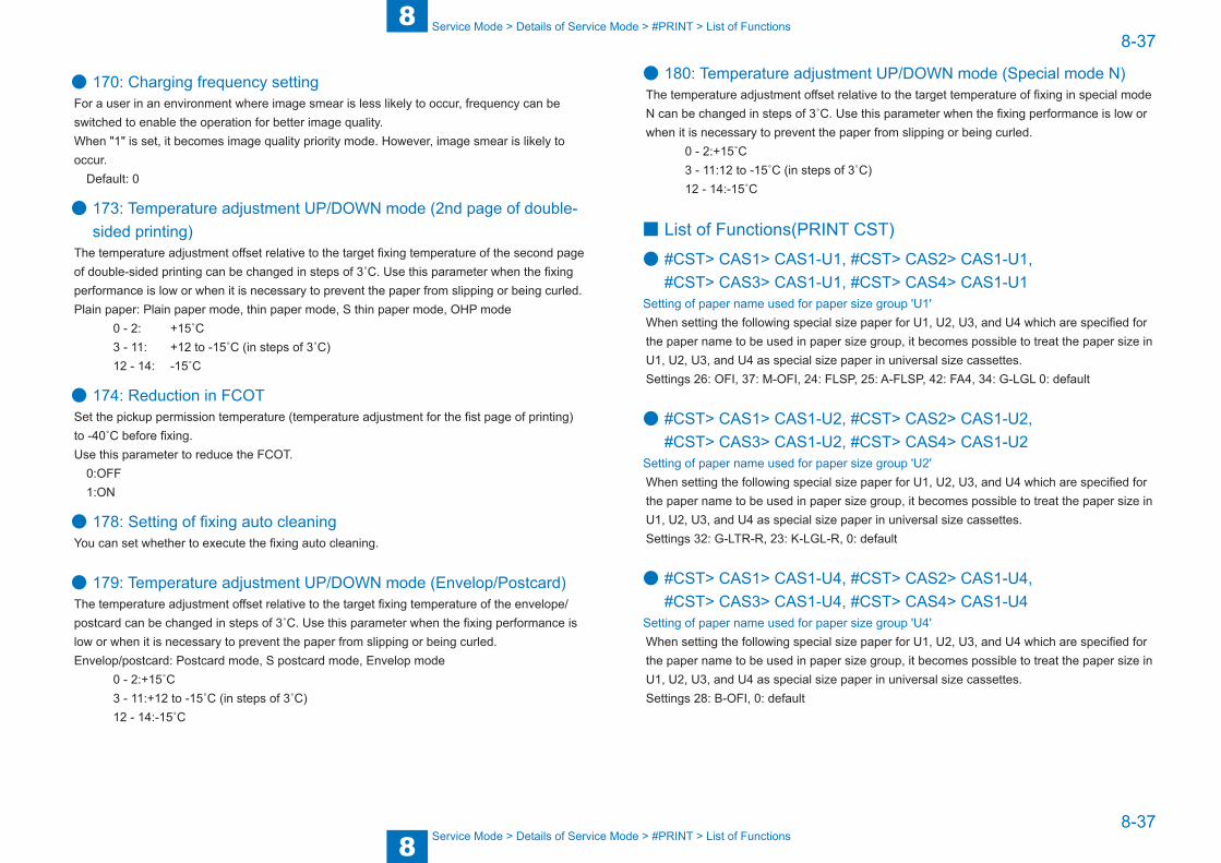
8
88-37
8-37
Service Mode > Details of Service Mode > #PRINT > List of Functions
Service Mode > Details of Service Mode > #PRINT > List of Functions
● 170: Charging frequency settingFor a user in an environment where image smear is less likely to occur, frequency can be switched to enable the operation for better image quality.When "1" is set, it becomes image quality priority mode. However, image smear is likely to occur.
Default: 0
● 173: Temperature adjustment UP/DOWN mode (2nd page of double-sided printing)
The temperature adjustment offset relative to the target fixing temperature of the second page of double-sided printing can be changed in steps of 3˚C. Use this parameter when the fixing performance is low or when it is necessary to prevent the paper from slipping or being curled. Plain paper: Plain paper mode, thin paper mode, S thin paper mode, OHP mode
0 - 2: +15˚C3 - 11: +12 to -15˚C (in steps of 3˚C)12 - 14: -15˚C
● 174: Reduction in FCOTSet the pickup permission temperature (temperature adjustment for the fist page of printing) to -40˚C before fixing. Use this parameter to reduce the FCOT.
0:OFF1:ON
● 178: Setting of fixing auto cleaningYou can set whether to execute the fixing auto cleaning.
● 179: Temperature adjustment UP/DOWN mode (Envelop/Postcard)The temperature adjustment offset relative to the target fixing temperature of the envelope/postcard can be changed in steps of 3˚C. Use this parameter when the fixing performance is low or when it is necessary to prevent the paper from slipping or being curled. Envelop/postcard: Postcard mode, S postcard mode, Envelop mode
0 - 2:+15˚C3 - 11:+12 to -15˚C (in steps of 3˚C)12 - 14:-15˚C
● 180: Temperature adjustment UP/DOWN mode (Special mode N)The temperature adjustment offset relative to the target temperature of fixing in special mode N can be changed in steps of 3˚C. Use this parameter when the fixing performance is low or when it is necessary to prevent the paper from slipping or being curled.
0 - 2:+15˚C3 - 11:12 to -15˚C (in steps of 3˚C)12 - 14:-15˚C
■ List of Functions(PRINT CST)
● #CST> CAS1> CAS1-U1, #CST> CAS2> CAS1-U1, #CST> CAS3> CAS1-U1, #CST> CAS4> CAS1-U1
Setting of paper name used for paper size group 'U1'When setting the following special size paper for U1, U2, U3, and U4 which are specified for the paper name to be used in paper size group, it becomes possible to treat the paper size in U1, U2, U3, and U4 as special size paper in universal size cassettes.Settings 26: OFI, 37: M-OFI, 24: FLSP, 25: A-FLSP, 42: FA4, 34: G-LGL 0: default
● #CST> CAS1> CAS1-U2, #CST> CAS2> CAS1-U2, #CST> CAS3> CAS1-U2, #CST> CAS4> CAS1-U2
Setting of paper name used for paper size group 'U2'When setting the following special size paper for U1, U2, U3, and U4 which are specified for the paper name to be used in paper size group, it becomes possible to treat the paper size in U1, U2, U3, and U4 as special size paper in universal size cassettes.Settings 32: G-LTR-R, 23: K-LGL-R, 0: default
● #CST> CAS1> CAS1-U4, #CST> CAS2> CAS1-U4, #CST> CAS3> CAS1-U4, #CST> CAS4> CAS1-U4
Setting of paper name used for paper size group 'U4'When setting the following special size paper for U1, U2, U3, and U4 which are specified for the paper name to be used in paper size group, it becomes possible to treat the paper size in U1, U2, U3, and U4 as special size paper in universal size cassettes.Settings 28: B-OFI, 0: default

8
88-38
8-38
Service Mode > Details of Service Mode > #NETWORK > Configuration
Service Mode > Details of Service Mode > #NETWORK > Configuration
#NETWORK ■ Configuration
ItemSW No.
BitSetting ranges
Default value
Description
#NETWORK SW
1 - - - Not used2 SEND 1
0-2 - - Not used3 0 or 1 0
(Disabled)Flag to enable mail header printingWhen "1" is set, mail header is added to the print data at the time of e-mail reception.0: Disabled, 1: Enabled
4-7 - - Not used3 SEND 2
0-2 - - Not used3 0 or 1 1 (Not
rotated)Rotation transmission "No" flag0: Rotated, 1: Not rotated
4-6 - - Not used7 0 or 1 0 (Not
deleted)Deletion of an error e-mail from the server at the time of POP reception0: Not deleted, 1: Deleted
4 SEND 30 0 or 1 1
(Enabled)Flag to enable SMTP authentication algorithm (CRAM-MD5)0: Disabled, 1: Enabled
1 0 or 1 1 (Enabled)
Flag to enable SMTP authentication algorithm (PLAIN)0: Disabled, 1: Enabled
2 0 or 1 1 (Enabled)
Flag to enable SMTP authentication algorithm (LOGIN)0: Disabled, 1: Enabled
3-7 - - Not used5 MIB/SNMP
0 0 or 1 00 (Enabled to obtain all the billing counter values)
Billing counter MIB function flagbit0=0, bit1=0: Enabled to obtain all the billing counter valuesbit0=0, bit1=1: Enabled to obtain only the billing counter values displayed on UI bit0=1, bit1=0: Disabled to obtain all the billing counter values
1 0 or 1
2 0 or 1 00 (RW) SNMP (canon_admin) access rightsbit2=0, bit3=0: RWbit2=0, bit3=1: RO bit2=1, bit3=0: Disabled bit2=1, bit3=1: OFF
3 0 or 1
ItemSW No.
BitSetting ranges
Default value
Description
#NETWORK SW
5 4 0 or 1 00 (RW) SNMP (canon_user) access rights bit4=0, bit5=0: RWbit4=0, bit5=1: RO bit4=1, bit5=0: Disabled bit4=1, bit5=1: OFF
5 0 or 1
6-7 - - Not used6-7 - - - Not used8 SEND 4
0 0 or 1 1 (Rotation specifications of fax)
Rotation specifications of I-Fax transmission0: Comply with rotation specifications of e-mail1: Comply with rotation specifications of fax
1-7 - - Not used9 - - - Not used10 Network Configuration
0-2 - - Not used3 0 or 1 0
(Enabled)Acquisition of host name by DHCP (Option 12)0: Enabled, 1: Disabled
4 0 or 1 0 (Enabled)
Registration of host name by DHCP (Option 81)0: Enabled, 1: Disabled
5-7 - - Not used11 Network Configuration (IPv6)
0 0 or 1 0 (IPv6) DNS inquiry priority transport 0: IPv6, 1: IPv4
1-7 - - Not used12 SEND 6 (Destination specified transmission)
0 0 or 1 000 (TIFF) B/W image format at the time of destination specified transmission 000 (all values are "0"): TIFF001 (only the value of bit2 is "1"): PDF
1 0 or 12 0 or 1
3 0 or 1 000 (JPEG) Color image format at the time of destination specified transmission 000 (all values are "0"): JPEG 001 (only the value of bit5 is "1"): PDF
4 0 or 15 0 or 1
6-7 - - Not used13 SEND 7 (Re-transfer after transfer error)
0 0 or 1 000 (TIFF) B/W image format when performing transfer again after transfer error000 (all values are "0"): TIFF001 (only the value of bit2 is "1"): PDF
1 0 or 12 0 or 1
3 0 or 1 000 (JPEG) Color image format when performing transfer again after transfer error000 (all values are "0"): JPEG001 (only the value of bit5 is "1"): PDF
4 0 or 15 0 or 1
6-7 - - Not used14-40 - - - Not used
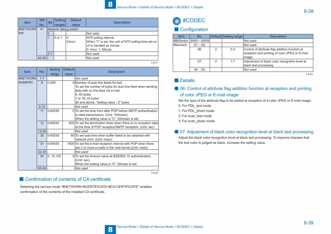
8
88-39
8-39
Service Mode > Details of Service Mode > #CODEC > Details
Service Mode > Details of Service Mode > #CODEC > Details
ItemSW No.
BitSetting ranges
Default value
Description
#NETWORK SW
41 Network debug switch0 - - Not used1 0 or 1 0
(Hour)NTP polling interval When "1" is set, the unit of NTP polling time set on UI is handled as minute.0: Hour, 1: Minute
2-7 - - Not used42-50 - - - Not used
Item No.Setting range
Default value
Description
#NETWORK NUMERIC
1-7 - - Not used8 0-255 0 Number of auto line feeds for text
To set the number of bytes for auto line feed when sending data with no line feed via e-mail. 0: 60 bytes 1 to 19: 20 bytes 20 and above: "setting value - 2" bytes
9-10 - - Not used11 0-65535 0 To set the time from after POP before SMTP authentication
to data transmission. (Unit: 100msec) When the setting value is "0", 300msec is set.
12 0-65535 600 To set the termination timer when there is no reception data at the time of POP reception/SMTP reception. (Unit: sec)
13-29 - - Not used30 0-65535 80 To set wait time when buffer failed to be obtained with
network print. (Unit: msec)31 0-65535 1000 To set the e-mail reception interval with POP when there
are 2 or more e-mails in the mail server.(Unit: msec)32-33 - - Not used
34 0, 10-120 0 To set the timeout value at IEEE802.1X authentication. (Unit: sec) When the setting value is "0", 30msec is set.
35-50 - - Not used
■ Confirmation of contents of CA certificateSelecting the service mode "#NETWORK>#CERTIFICATE>#CA-CERTIFICATE" enables confirmation of the contents of the installed CA certificate.
T-8-41
T-8-42
#CODEC ■ ConfigurationItem No. Default Setting range Description
#BitSwitch SW01- SW09 Not used#Numeric 01: - 05: Not used
06: 2 0-3 Control of attribute flag addition function at reception and printing of color JPEG or E-mail image
07: 4 1-7 Adjustment of black color recognition level at black text processing
08: - 50: Not used
■ Details
● 06: Control of attribute flag addition function at reception and printing of color JPEG or E-mail image
Set the type of the attribute flag to be added at reception of a color JPEG or E-mail image. 0: For PDL_text mode1: For PDL_photo mode2: For scan_text mode3: For scan_photo mode
● 07: Adjustment of black color recognition level at black text processingAdjust the black color recognition level at black text processing. To improve chanses that the text color is judged as black, increase the setting value.
T-8-43
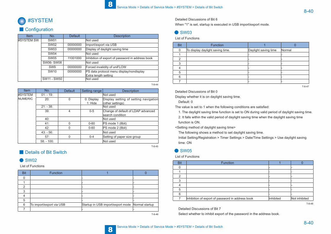
8
88-40
8-40
Service Mode > Details of Service Mode > #SYSTEM > Details of Bit Switch
Service Mode > Details of Service Mode > #SYSTEM > Details of Bit Switch
#SYSTEM ■ Configuration
Item No. Default Description#SYSTEM SW SW01 Not used
SW02 00000000 Import/export via USBSW03 00000000 Display of daylight saving timeSW04 Not usedSW05 11001000 Inhibition of export of password in address book
SW06- SW08 Not usedSW9 00000000 Forced invalidity of uniFLOW
SW10 00000000 PS data protocol menu display/nondisplay Extra length setting
SW11 - SW50 Not used
Item No. Default Setting range Description#SYSTEM NUMERIC
01: - 19: Not used20: 0 0: Display
1: HideDisplay setting of setting navigation (other settings)
21: - 38: Not used39: 4 0-5 Change of default of LDAP advanced
search condition 40: Not used41: 0 0-60 PS mode 1 (8bit)42: 0 0-60 PS mode 2 (8bit)
43: - 56: Not used57: 0 0-4 Setting of paper size group
58: - 100: Not used
■ Details of Bit Switch
● SW02List of Functions
Bit Function 1 00 - -1 - -2 - -3 - -4 - -5 - -6 To import/export via USB Startup in USB import/export mode Normal startup7 - -
T-8-44
T-8-45
T-8-46
Detailed Discussions of Bit 6When "1" is set, startup is executed in USB import/export mode.
● SW03List of Functions
Bit Function 1 00 To display daylight saving time. Daylight saving time Normal1 - -2 - -3 - -4 - -5 - -6 - -7 - -
Detailed Discussions of Bit 0Display whether it is on daylight saving time.
Default: 0The value is set to 1 when the following conditions are satisfied:
1. The daylight saving time function is set to ON during valid period of daylight saving time.2. It falls within the valid period of daylight saving time when the daylight saving time function is ON.
<Setting method of daylight saving time>The following shows a method to set daylight saving time.Initial Setting/Registration > Timer Settings > Date/Time Settings > Use daylight saving time: ON
● SW05List of Functions
Bit Function 1 00 - -1 - -2 - -3 - -4 - -5 - -6 - -7 Inhibition of export of password in address book Inhibited Not inhibited
Detailed Discussions of Bit 7Select whether to inhibit export of the password in the address book.
T-8-47
T-8-48

8
88-41
8-41
Service Mode > Details of Service Mode > #SYSTEM > Details of System Numeric
Service Mode > Details of Service Mode > #SYSTEM > Details of System Numeric
● SW09List of Functions
Bit Function 1 00 PS > Display/hide data protocol menu Displayed Hide1 Long length setting ON OFF2 User time setting flag Set Not set3 Forced invalidity of uniFLOW ON OFF4 - -5 - -6 - -7 - -
Detailed Discussions of Bit 0You can select whether to disable export of PWD in the address book.Default: 0
Detailed Discussions of Bit 1You can select whether to enable long length setting (to extend the range of user-defined size).Default: 1
Detailed Discussions of Bit 2Whether the user made time setting can be checked.
Detailed Discussions of Bit 3Select whether to set the forced invalidity of uniFLOW. Default: 0If turning ON this switch, and turning OFF and then ON the device power while the uniFLOW function is in active state, the uniFLOW function is forcibly deactivated. In addition, when this switch is ON, Activate/Deactivate request from the server is ignored.
● SW10List of Functions
Bit Function 1 00 - -1 To set the display of installation NAVI "Setting screen for date and time". Hidden Display2 To set the display of installation NAVI "Registering user telephone number". Hidden Display3 To set the display of installation NAVI "Setting screen for user abbreviation". Hidden Display4 To set the display of installation NAVI "Selection screen on a line type basis". Hidden Display5 To set the display of installation NAVI "Selection screen for reception mode". Hidden Display6 To set the display of installation NAVI "Setting screen for IP address". Hidden Display7 - -
T-8-49
T-8-50
Detailed Discussions of Bit 1When "1" is set, "Setting screen for date and time" of the installation NAVI can be hidden.
Detailed Discussions of Bit 2When "1" is set, "Registering user telephone number" of the installation NAVI can be hidden.
Detailed Discussions of Bit 3When "1" is set, "Setting screen for user abbreviation" of the installation NAVI can be hidden.
Detailed Discussions of Bit 4When "1" is set, "Selection screen on a line type basis" of the installation NAVI can be hidden.
Detailed Discussions of Bit 5When "1" is set, "Selection screen for reception mode" of the installation NAVI can be hidden.
Detailed Discussions of Bit 6When "1" is set, "Setting screen for IP address" of the installation NAVI can be hidden.
■ Details of System Numeric
● 20: Display setting of installation NAVI (Other settings)When "1" is set, "Other settings" of the installation NAVI can be hidden.Default: 0
● 39: Change of default of LDAP advanced search conditionChange of the default of the LDAP advanced search condition can be set. 0: Includes the next
1: Not include the next
2: Equivalent to the next
3: Not equivalent to the next
4: Starts with the next
5: Finishes with the next
● 41: PS mode 1(8bit)The PS mode 1 (8bit) can be set.
● 42: ePS mode 1(8bit)The PS mde 2 (8bit) can be set.
● 57: Setting of paper size groupA paper size group can be set. 1: AB (PAPER_SIZE_GROUP_AB)2: A (PAPER_SIZE_GROUP_A)3: INCH (PAPER_SIZE_GROUP_INCH)4: AB/INCH (PAPER_SIZE_GROUP_AB_INCH)Initialization takes place when the following service mode is executed: (CLEAR>ALL, TYPE, SERVICE DATA, TEL & USER DATA)
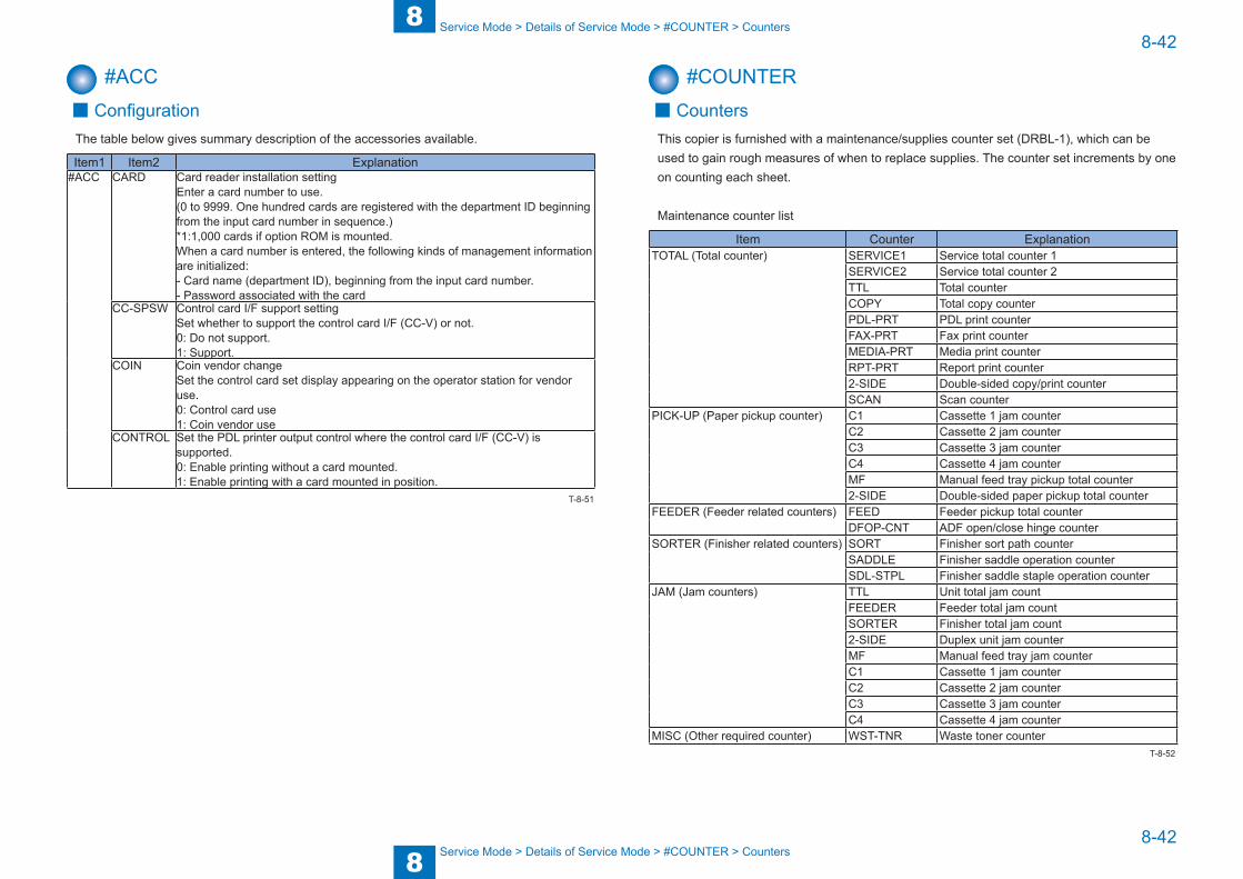
8
88-42
8-42
Service Mode > Details of Service Mode > #COUNTER > Counters
Service Mode > Details of Service Mode > #COUNTER > Counters
#ACC ■ Configuration
The table below gives summary description of the accessories available.
Item1 Item2 Explanation#ACC CARD Card reader installation setting
Enter a card number to use.(0 to 9999. One hundred cards are registered with the department ID beginning from the input card number in sequence.)*1:1,000 cards if option ROM is mounted.When a card number is entered, the following kinds of management information are initialized:- Card name (department ID), beginning from the input card number.- Password associated with the card
CC-SPSW Control card I/F support settingSet whether to support the control card I/F (CC-V) or not.0: Do not support.1: Support.
COIN Coin vendor changeSet the control card set display appearing on the operator station for vendor use.0: Control card use1: Coin vendor use
CONTROL Set the PDL printer output control where the control card I/F (CC-V) is supported.0: Enable printing without a card mounted.1: Enable printing with a card mounted in position.
T-8-51
#COUNTER ■ Counters
This copier is furnished with a maintenance/supplies counter set (DRBL-1), which can be used to gain rough measures of when to replace supplies. The counter set increments by one on counting each sheet.
Maintenance counter list
Item Counter ExplanationTOTAL (Total counter) SERVICE1 Service total counter 1
SERVICE2 Service total counter 2TTL Total counterCOPY Total copy counterPDL-PRT PDL print counterFAX-PRT Fax print counterMEDIA-PRT Media print counterRPT-PRT Report print counter2-SIDE Double-sided copy/print counterSCAN Scan counter
PICK-UP (Paper pickup counter) C1 Cassette 1 jam counterC2 Cassette 2 jam counterC3 Cassette 3 jam counterC4 Cassette 4 jam counterMF Manual feed tray pickup total counter2-SIDE Double-sided paper pickup total counter
FEEDER (Feeder related counters) FEED Feeder pickup total counterDFOP-CNT ADF open/close hinge counter
SORTER (Finisher related counters) SORT Finisher sort path counterSADDLE Finisher saddle operation counterSDL-STPL Finisher saddle staple operation counter
JAM (Jam counters) TTL Unit total jam countFEEDER Feeder total jam countSORTER Finisher total jam count2-SIDE Duplex unit jam counterMF Manual feed tray jam counterC1 Cassette 1 jam counterC2 Cassette 2 jam counterC3 Cassette 3 jam counterC4 Cassette 4 jam counter
MISC (Other required counter) WST-TNR Waste toner counterT-8-52
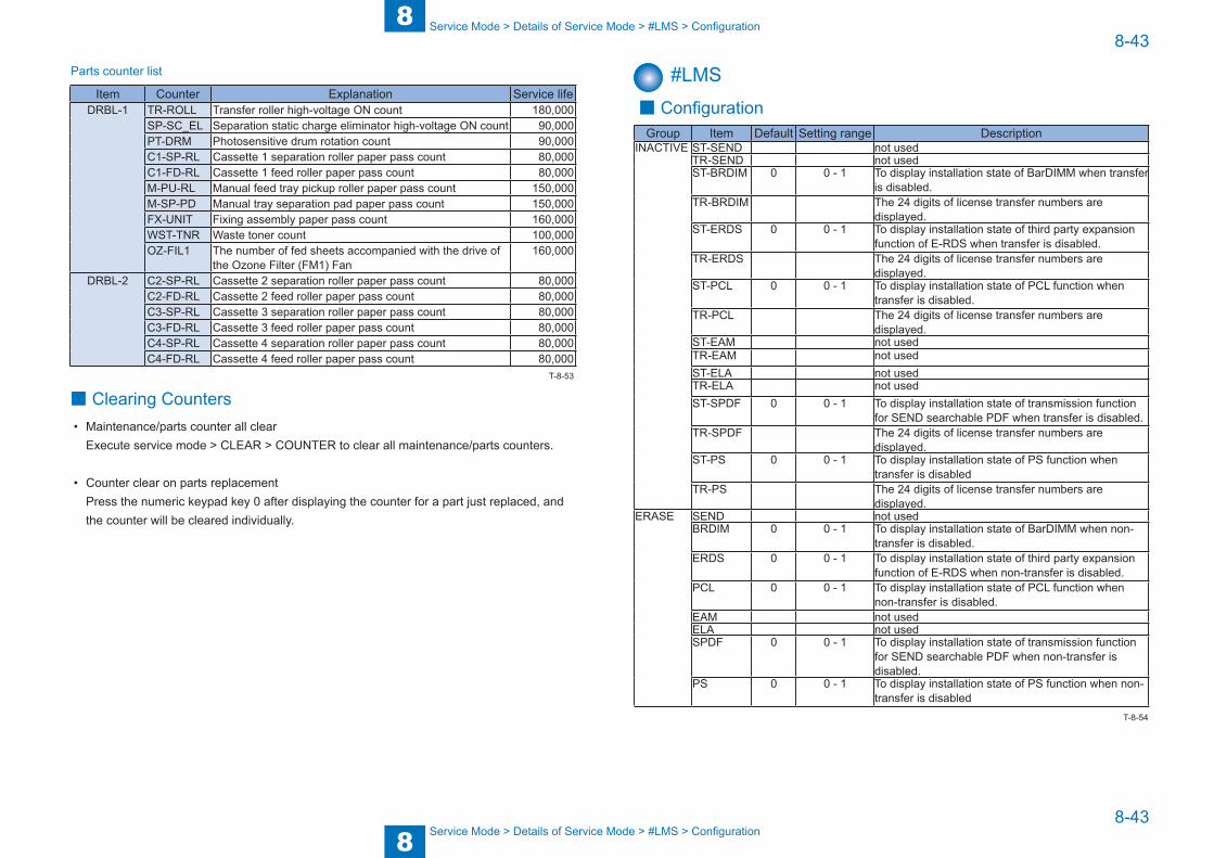
8
88-43
8-43
Service Mode > Details of Service Mode > #LMS > Configuration
Service Mode > Details of Service Mode > #LMS > Configuration
Parts counter list
Item Counter Explanation Service lifeDRBL-1 TR-ROLL Transfer roller high-voltage ON count 180,000
SP-SC_EL Separation static charge eliminator high-voltage ON count 90,000PT-DRM Photosensitive drum rotation count 90,000C1-SP-RL Cassette 1 separation roller paper pass count 80,000C1-FD-RL Cassette 1 feed roller paper pass count 80,000M-PU-RL Manual feed tray pickup roller paper pass count 150,000M-SP-PD Manual tray separation pad paper pass count 150,000FX-UNIT Fixing assembly paper pass count 160,000WST-TNR Waste toner count 100,000OZ-FIL1 The number of fed sheets accompanied with the drive of
the Ozone Filter (FM1) Fan160,000
DRBL-2 C2-SP-RL Cassette 2 separation roller paper pass count 80,000C2-FD-RL Cassette 2 feed roller paper pass count 80,000C3-SP-RL Cassette 3 separation roller paper pass count 80,000C3-FD-RL Cassette 3 feed roller paper pass count 80,000C4-SP-RL Cassette 4 separation roller paper pass count 80,000C4-FD-RL Cassette 4 feed roller paper pass count 80,000
■ Clearing Counters• Maintenance/parts counter all clear
Execute service mode > CLEAR > COUNTER to clear all maintenance/parts counters.
• Counter clear on parts replacementPress the numeric keypad key 0 after displaying the counter for a part just replaced, and the counter will be cleared individually.
T-8-53
#LMS ■ Configuration
Group Item Default Setting range DescriptionINACTIVE ST-SEND not used
TR-SEND not usedST-BRDIM 0 0 - 1 To display installation state of BarDIMM when transfer
is disabled.TR-BRDIM The 24 digits of license transfer numbers are
displayed.ST-ERDS 0 0 - 1 To display installation state of third party expansion
function of E-RDS when transfer is disabled.TR-ERDS The 24 digits of license transfer numbers are
displayed.ST-PCL 0 0 - 1 To display installation state of PCL function when
transfer is disabled.TR-PCL The 24 digits of license transfer numbers are
displayed.ST-EAM not usedTR-EAM not usedST-ELA not usedTR-ELA not usedST-SPDF 0 0 - 1 To display installation state of transmission function
for SEND searchable PDF when transfer is disabled. TR-SPDF The 24 digits of license transfer numbers are
displayed.ST-PS 0 0 - 1 To display installation state of PS function when
transfer is disabledTR-PS The 24 digits of license transfer numbers are
displayed.ERASE SEND not used
BRDIM 0 0 - 1 To display installation state of BarDIMM when non-transfer is disabled.
ERDS 0 0 - 1 To display installation state of third party expansion function of E-RDS when non-transfer is disabled.
PCL 0 0 - 1 To display installation state of PCL function when non-transfer is disabled.
EAM not usedELA not usedSPDF 0 0 - 1 To display installation state of transmission function
for SEND searchable PDF when non-transfer is disabled.
PS 0 0 - 1 To display installation state of PS function when non-transfer is disabled
T-8-54
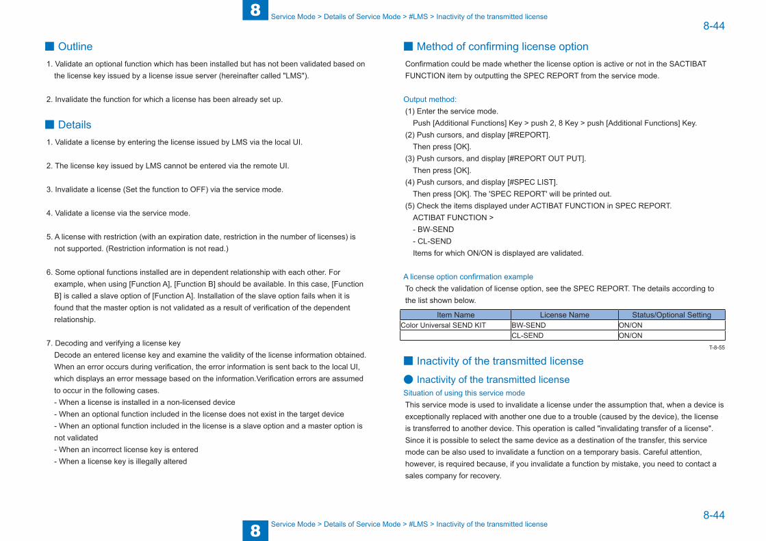
8
88-44
8-44
Service Mode > Details of Service Mode > #LMS > Inactivity of the transmitted license
Service Mode > Details of Service Mode > #LMS > Inactivity of the transmitted license
■ Outline1. Validate an optional function which has been installed but has not been validated based on
the license key issued by a license issue server (hereinafter called "LMS").
2. Invalidate the function for which a license has been already set up.
■ Details1. Validate a license by entering the license issued by LMS via the local UI.
2. The license key issued by LMS cannot be entered via the remote UI.
3. Invalidate a license (Set the function to OFF) via the service mode.
4. Validate a license via the service mode.
5. A license with restriction (with an expiration date, restriction in the number of licenses) is not supported. (Restriction information is not read.)
6. Some optional functions installed are in dependent relationship with each other. For example, when using [Function A], [Function B] should be available. In this case, [Function B] is called a slave option of [Function A]. Installation of the slave option fails when it is found that the master option is not validated as a result of verification of the dependent relationship.
7. Decoding and verifying a license key Decode an entered license key and examine the validity of the license information obtained. When an error occurs during verification, the error information is sent back to the local UI, which displays an error message based on the information.Verification errors are assumed to occur in the following cases.- When a license is installed in a non-licensed device- When an optional function included in the license does not exist in the target device- When an optional function included in the license is a slave option and a master option is not validated- When an incorrect license key is entered- When a license key is illegally altered
■ Method of confirming license optionConfirmation could be made whether the license option is active or not in the SACTIBAT FUNCTION item by outputting the SPEC REPORT from the service mode.
Output method:(1) Enter the service mode.
Push [Additional Functions] Key > push 2, 8 Key > push [Additional Functions] Key.(2) Push cursors, and display [#REPORT].
Then press [OK].(3) Push cursors, and display [#REPORT OUT PUT].
Then press [OK].(4) Push cursors, and display [#SPEC LIST].
Then press [OK]. The 'SPEC REPORT' will be printed out.(5) Check the items displayed under ACTIBAT FUNCTION in SPEC REPORT.
ACTIBAT FUNCTION >- BW-SEND- CL-SENDItems for which ON/ON is displayed are validated.
A license option confirmation exampleTo check the validation of license option, see the SPEC REPORT. The details according to the list shown below.
Item Name License Name Status/Optional SettingColor Universal SEND KIT BW-SEND ON/ON
CL-SEND ON/ON
■ Inactivity of the transmitted license
● Inactivity of the transmitted licenseSituation of using this service modeThis service mode is used to invalidate a license under the assumption that, when a device is exceptionally replaced with another one due to a trouble (caused by the device), the license is transferred to another device. This operation is called "invalidating transfer of a license". Since it is possible to select the same device as a destination of the transfer, this service mode can be also used to invalidate a function on a temporary basis. Careful attention, however, is required because, if you invalidate a function by mistake, you need to contact a sales company for recovery.
T-8-55
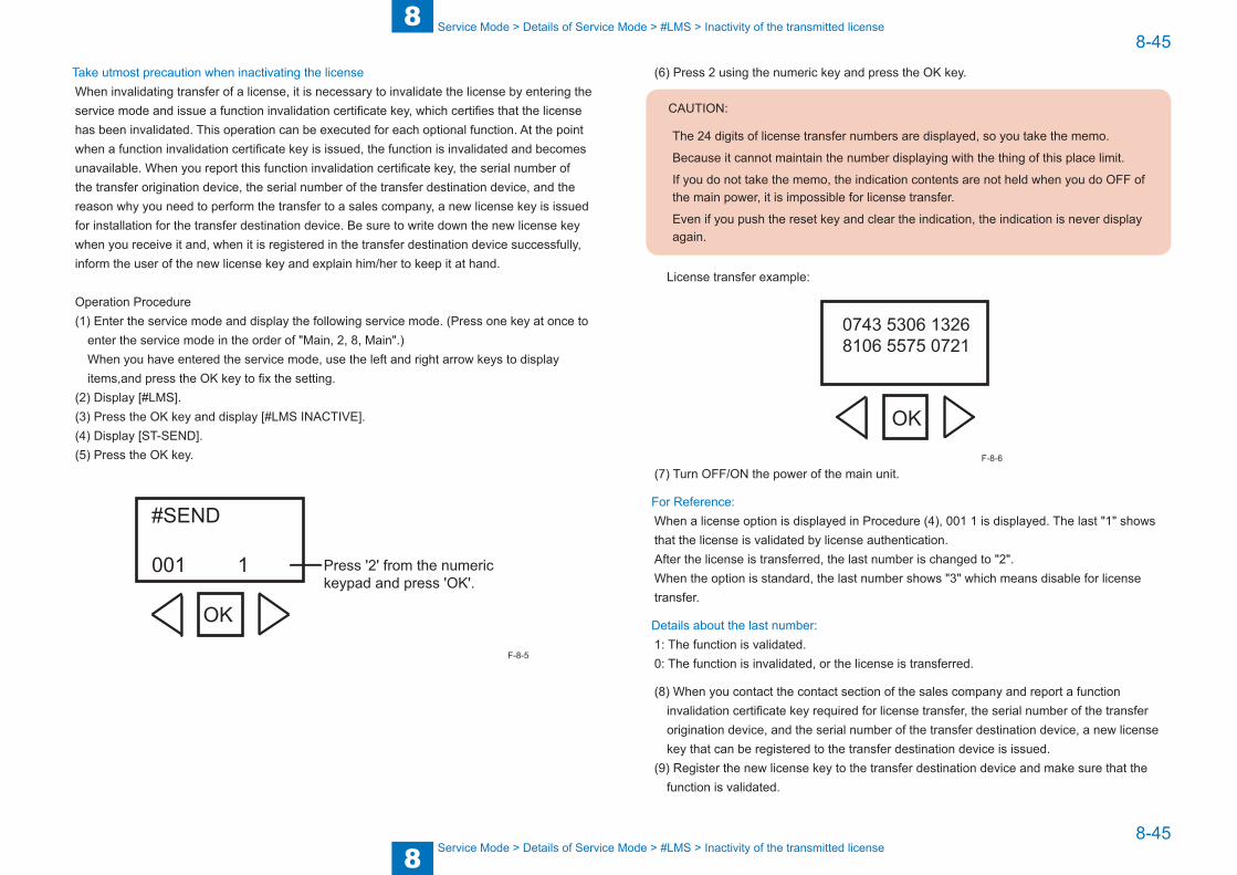
8
88-45
8-45
Service Mode > Details of Service Mode > #LMS > Inactivity of the transmitted license
Service Mode > Details of Service Mode > #LMS > Inactivity of the transmitted license
Take utmost precaution when inactivating the licenseWhen invalidating transfer of a license, it is necessary to invalidate the license by entering the service mode and issue a function invalidation certificate key, which certifies that the license has been invalidated. This operation can be executed for each optional function. At the point when a function invalidation certificate key is issued, the function is invalidated and becomes unavailable. When you report this function invalidation certificate key, the serial number of the transfer origination device, the serial number of the transfer destination device, and the reason why you need to perform the transfer to a sales company, a new license key is issued for installation for the transfer destination device. Be sure to write down the new license key when you receive it and, when it is registered in the transfer destination device successfully, inform the user of the new license key and explain him/her to keep it at hand.
Operation Procedure(1) Enter the service mode and display the following service mode. (Press one key at once to
enter the service mode in the order of "Main, 2, 8, Main".) When you have entered the service mode, use the left and right arrow keys to display items,and press the OK key to fix the setting.
(2) Display [#LMS].(3) Press the OK key and display [#LMS INACTIVE].(4) Display [ST-SEND].(5) Press the OK key.
OK
#SEND
001 1 Press '2' from the numeric keypad and press 'OK'.
F-8-5
(6) Press 2 using the numeric key and press the OK key.
CAUTION:
The 24 digits of license transfer numbers are displayed, so you take the memo.
Because it cannot maintain the number displaying with the thing of this place limit.
If you do not take the memo, the indication contents are not held when you do OFF of the main power, it is impossible for license transfer.
Even if you push the reset key and clear the indication, the indication is never display again.
License transfer example:
OK
0743 5306 13268106 5575 0721
(7) Turn OFF/ON the power of the main unit.
For Reference:When a license option is displayed in Procedure (4), 001 1 is displayed. The last "1" shows that the license is validated by license authentication.After the license is transferred, the last number is changed to "2".When the option is standard, the last number shows "3" which means disable for licensetransfer.
Details about the last number:1: The function is validated.0: The function is invalidated, or the license is transferred.
(8) When you contact the contact section of the sales company and report a function invalidation certificate key required for license transfer, the serial number of the transfer origination device, and the serial number of the transfer destination device, a new license key that can be registered to the transfer destination device is issued.
(9) Register the new license key to the transfer destination device and make sure that the function is validated.
F-8-6

8
88-46
8-46
Service Mode > Details of Service Mode > #LMS > Erasing a License
Service Mode > Details of Service Mode > #LMS > Erasing a License
■ Erasing a License
● Erasing a LicenseWhen you invalidate a license option on a temporary basis or when you do not use it for a long period of time, you can invalidate the function by erasing the license.The license can be validated by registering the license number again.
Procedure to erase a licenseYou can erase a license by entering the service mode.
Operation Procedure:(1) Enter the service mode and display the following service mode.
When you have entered the service mode, use the right and left arrow keys to display items,and press the OK key to fix the setting.
(2) Display [#LMS].(3) Press the OK key and display [#LMS ERASE].(4) Display [SEND].(5) Press the OK key.(6) Turn OFF/ON the power of the main unit.
For Reference:There is no function to display the license registration numbers in the main unit. Therefore, when there is a possibility to restore the license after erasing it, make sure that a user has written down the license registration number.When a license option is displayed in Procedure (4), 001 1 is displayed. The last "1" shows that the license is validated by license authentication.After the license is erased, the last number is changed to "2".
When the option is standard, the last number shows "3" which means disable for licensetransfer.Details about the last number:1: The function is validated.2: The function is invalidated, or a license is transferred.3: The function is invalidated, or the license does not exist.

8
88-47
8-47
Service Mode > Details of Service Mode > #REPORT > Configuration
Service Mode > Details of Service Mode > #REPORT > Configuration
#E-RDS ■ Configuration
Settings related to e-RDS are described below.
Item Default Setting range DescriptionE-RDS SWITCH
0 0 or 1 e-RDS OFF/ON setting (0:OFF / 1:ON)When used (ON), the counter information and error information are sent to UGW.Default: 0 (OFF)
RGW-ADDRESS
URL of UGW Character string length:129byte (including NULL, one-byte codes only)
URL of UGWDefault: URL of actual UGWCharacter string length: 129 bytes (including NULL, one-byte codes only)
RGW-PORT 443 1-65535 Port No. of UGW Setting range: 1 to 65535
CNT-DATE Setting of the date of sending the counter information to the server (Valid after input of license).Set the start date of the schedule to send the counter information to the server using a third party expansion function of E-RDS.Refer to the user mode date setting.(12 digits: YYYYMMDDHHMM)YYYY: Year MM: Month DD: Day HH: Hour MM: Minute
CNT-INTV 24 1-168 (on a weekly basis)
Setting of the interval of sending the counter information to the server (Valid after input of license).Set the interval of sending the counter information to the server using a third party expansion function of E-RDS.
COM-TEST Execution of communication test An attempt is made to connect to UGW, judges whether connection is successful, and displays "COM-TEST OK" or "COMTEST NG" as the judgment result.
COM-LOG Details of communication test result. The log of errors in communication with UGW is displayed.The error information includes the error occurrence time, error code, and details of the error.Maximum log count: 5Error information length: Max. 128 characters (excluding NULL)
T-8-56
#REPORT ■ Configuration
The table below lists the kinds of reports that are supported.
Item ExplanationSERVICE DATA LIST "Service mode service soft switch output (SSSW, MENU, NUMERIC
Param., SPECIAL, NCU, SCAN, PRINT, SYSTEM, ROM, start date)"
SYSTEM DATA LIST "Service mode service soft switch output (SSSW, MENU, NUMERIC Param., SPECIAL, NCU, SCAN, PRINT, SYSTEM, ROM, start date) System dump list output"
SYSTEM DUMP LIST Transmission count, reception count, record chart count, error count and other outputs
COUNTER LIST Counter outputERROR LOG LIST Jam and error history outputSPEC LIST Type setting, print speed, memory size, ROM indication, adjustment
data and other outputsSERVICE LABEL Not used.ERDS COM LOG LIST Output of communication error log information related to e-RDS
T-8-57

8
88-48
8-48
Service Mode > Details of Service Mode > #REPORT > Details
Service Mode > Details of Service Mode > #REPORT > Details
■ Details
● System Data ListUse it to check the settings associated with the service soft switch and service parameters.
#SSSW SW01 ----- 00000000 SW02 ----- 10000000 SW03 ----- 00000000 SW04 ----- 10000000 SW05 ----- 00000000 SW06 ----- 10000000 SW07 ----- 00000000 SW08 ----- 00000000 SW09 ----- 00000000 SW10 ----- 00000000 SW11 ----- 00000000 SW12 ----- 00000011 SW13 ----- 00000000 SW14 ----- 00000000 SW15 ----- 00000000 SW16 ----- 00000000 SW17 ----- 00000000 SW18 ----- 00000000 SW19 ----- 00011000 SW20 ----- 00000000 SW21 ----- 00000000 SW22 ----- 00000000 SW23 ----- 00000000 SW24 ----- 00000000 SW25 ----- 00000000 SW26 ----- 00100000 SW27 ----- 00000000 SW28 ----- 00000000 SW29 ----- 00000000 SW30 ----- 00000000 SW31 ----- 00000000 SW32 ----- 00000000 SW33 ----- 00000000 SW34 ----- 00000000 SW35 ----- 00000000 SW36 ----- 00000000 SW37 ----- 00000000 SW38 ----- 00000000 SW39 ----- 00000000 SW40 ----- 00000000 SW41 ----- 00000000 SW42 ----- 00000000 SW43 ----- 00000000 SW44 ----- 00000000 SW45 ----- 00000000 SW46 ----- 00000000 SW47 ----- 00000000 SW48 ----- 00000000 SW49 ----- 00000000 SW50 ----- 00000000
#MENU 01: ----- 0 02: ----- 0 03: ----- 0 04: ----- 0 05: ----- 0
********************************* SYSTEM DATA LIST *********************************
16/10 2009 14:10 001
F-8-7
● System Dump ListUse it to check the history of communications, both successful and error.
CLEAR DATE 10/16/2009
TXA4RXA43360021600960014400144009600STDMH
G3
[1]
[3]
[2]
[3]
[4]
[5]
[6]
[7]
[8]
[9]
#000 0 0 0
0 0 0
0 0 0 0
0 0 0 0 0
0 0 0 0 0 0
0 0 0 0 0 0 0
0 0 0 0 0 0 0
0 0 0 0 0 0
============
=
700700000720
0
10/16 2009 13:00 0001
B4
B43120019200720012000120007200FINEMR
ECM
READ SCAN = 43 / 43
TTL = 63 / 63C-S-TTL = 0 / 0K-S-TTL = 51 / 51
=
=========
=
0
000000050
7
A3
A328800168004800TC9600
4800SUPERMMR
=
=====
===
0
00000
007
LTR26400144002400TC7200
2400ULTRAJBIG
=====
===
00000
000 JPEG = 0
LGL2400012000
===
000
*1: TX, number of total pages transmission.*2: Total number of pages transmitted/received according to original size.*3: RX, number of total pages reception.*4: Total number of pages transmitted and received for each modem speed.*5: Total number of pages transmitted/received in connection with different modem speeds
(Standard, Fine, Super Fine, Ultra Fine).*6: Total number of pages transmitted and received for each coding method.*7: Total number of pages transmitted and received in each mode .*8: Total number of pages printed/scanned.*9: Total number of occurrences for error code .
F-8-8
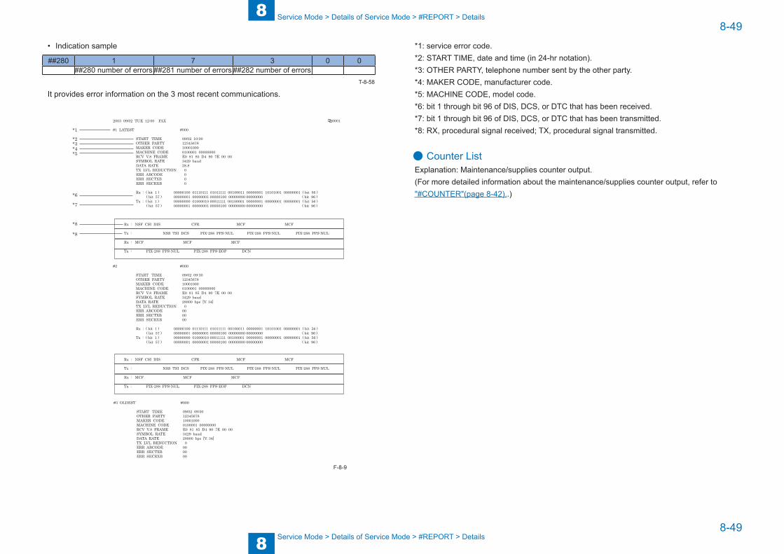
8
88-49
8-49
Service Mode > Details of Service Mode > #REPORT > Details
Service Mode > Details of Service Mode > #REPORT > Details
• Indication sample
##280 1 7 3 0 0##280 number of errors ##281 number of errors ##282 number of errors
It provides error information on the 3 most recent communications.
*1
*2
*8
*3*4*5
*6
*7
2003 09/02 TUE 12:00 FAX
#1 LATEST #000
START TIME 09/02 10:00 OTHER PARTY 12345678 MAKER CODE 10001000 MACHINE CODE 0100001 00000000 RCV V.8 FRAME E0 81 85 D4 90 7E 00 00 SYMBOL RATE 3429 baud DATA RATE 28.8 TX LVL REDUCTION 0 ERR ABCODE 0 ERR SECTXB 0 ERR SECRXB 0
Rx : ( bit 1 ) 00000100 01110111 01011111 00100011 00000001 10101001 00000001 ( bit 56 ) ( bit 57 ) 00000001 00000001 00000100 00000000 00000000 ( bit 96 ) Tx : ( bit 1 ) 00000000 01000010 00011111 00100001 00000001 00000001 00000001 ( bit 56 ) ( bit 57 ) 00000001 00000001 00000100 00000000 00000000 ( bit 96 )
0001
Rx : NSF CSI DIS CFR MCF MCF
Tx : NSS TSI DCS PIX-288 PPS-NUL PIX-288 PPS-NUL PIX-288 PPS-NUL
Rx : MCF MCF MCF
Tx : PIX-288 PPS-NUL PIX-288 PPS-EOP DCN
#2 #000
START TIME 09/02 09:30 OTHER PARTY 12345678 MAKER CODE 10001000 MACHINE CODE 0100001 00000000 RCV V.8 FRAME E0 81 85 D4 90 7E 00 00 SYMBOL RATE 3429 baud DATA RATE 28800 bps [V. 34] TX LVL REDUCTION 0 ERR ABCODE 00 ERR SECTXB 00 ERR SECRXB 00
Rx : ( bit 1 ) 00000100 01110111 01011111 00100011 00000001 10101001 00000001 ( bit 56 ) ( bit 57 ) 00000001 00000001 00000100 00000000 00000000 ( bit 96 ) Tx : ( bit 1 ) 00000000 01000010 00011111 00100001 00000001 00000001 00000001 ( bit 56 ) ( bit 57 ) 00000001 00000001 00000100 00000000 00000000 ( bit 96 )
Rx : NSF CSI DIS CFR MCF MCF
Tx : NSS TSI DCS PIX-288 PPS-NUL PIX-288 PPS-NUL PIX-288 PPS-NUL
Rx : MCF MCF MCF
Tx : PIX-288 PPS-NUL PIX-288 PPS-EOP DCN
#3 OLDEST #000
START TIME 09/02 09:00 OTHER PARTY 12345678 MAKER CODE 10001000 MACHINE CODE 0100001 00000000 RCV V.8 FRAME E0 81 85 D4 90 7E 00 00 SYMBOL RATE 3429 baud DATA RATE 28800 bps [V. 34] TX LVL REDUCTION 0 ERR ABCODE 00 ERR SECTXB 00 ERR SECRXB 00
*8
T-8-58
F-8-9
*1: service error code.*2: START TIME, date and time (in 24-hr notation).*3: OTHER PARTY, telephone number sent by the other party.*4: MAKER CODE, manufacturer code.*5: MACHINE CODE, model code.*6: bit 1 through bit 96 of DIS, DCS, or DTC that has been received.*7: bit 1 through bit 96 of DIS, DCS, or DTC that has been transmitted.*8: RX, procedural signal received; TX, procedural signal transmitted.
● Counter ListExplanation: Maintenance/supplies counter output.(For more detailed information about the maintenance/supplies counter output, refer to "#COUNTER"(page 8-42)..)
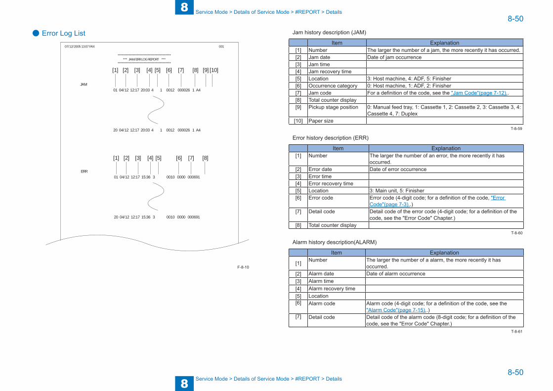
8
88-50
8-50
Service Mode > Details of Service Mode > #REPORT > Details
Service Mode > Details of Service Mode > #REPORT > Details
● Error Log List
****************************************** JAM/ERR LOG REPORT ***
***************************************
07/12/2005 13:07 FAX 001
[1] [2] [3] [4] [5] [6] [7] [8] [9] [10]
[1] [2] [3] [4] [5] [6] [7] [8]
JAM 01 04/12 12:17 20:03 4 1 0012 000026 1 A4
20 04/12 12:17 20:03 4 1 0012 000026 1 A4
ERR 01 04/12 12:17 15:36 3 0010 0000 000691
20 04/12 12:17 15:36 3 0010 0000 000691
F-8-10
Jam history description (JAM)
Item Explanation[1] Number The larger the number of a jam, the more recently it has occurred.[2] Jam date Date of jam occurrence[3] Jam time[4] Jam recovery time[5] Location 3: Host machine, 4: ADF, 5: Finisher[6] Occurrence category 0: Host machine, 1: ADF, 2: Finisher[7] Jam code For a definition of the code, see the "Jam Code"(page 7-12)..[8] Total counter display[9] Pickup stage position 0: Manual feed tray, 1: Cassette 1, 2: Cassette 2, 3: Cassette 3, 4:
Cassette 4, 7: Duplex[10] Paper size
Error history description (ERR)
Item Explanation[1] Number The larger the number of an error, the more recently it has
occurred.[2] Error date Date of error occurrence[3] Error time[4] Error recovery time[5] Location 3: Main unit, 5: Finisher[6] Error code Error code (4-digit code; for a definition of the code, "Error
Code"(page 7-3)..)[7] Detail code Detail code of the error code (4-digit code; for a definition of the
code, see the "Error Code" Chapter.)[8] Total counter display
Alarm history description(ALARM)
Item Explanation
[1] Number The larger the number of a alarm, the more recently it has occurred.
[2] Alarm date Date of alarm occurrence[3] Alarm time[4] Alarm recovery time[5] Location[6] Alarm code Alarm code (4-digit code; for a definition of the code, see the
"Alarm Code"(page 7-15)..)[7] Detail code Detail code of the alarm code (8-digit code; for a definition of the
code, see the "Error Code" Chapter.)
T-8-59
T-8-60
T-8-61

8
88-51
8-51
Service Mode > Details of Service Mode > #REPORT > Details
Service Mode > Details of Service Mode > #REPORT > Details
● Spec List
******************************** SPEC REPORT ***
*****************************
2009 10/09 16:31 0001
TYPELBP SPEEDTOTAL MEMORYMAINOPTIONBOOTLANGLANG LIBRARYLANG FILE VIENTNAMESE CHINESE(TRAD. ) TURKISH SWEDISH
BULGARIANECONTOPT-CAS 1OPT-CAS 2OPT-CAS 3OPT-DUPOPT-FINMEDIAACTIBAT FUNCTION BDL-IMAGE (1200) FAX NETWORK PCL PC-SCAN BW-SEND CL-SEND PAF BDL-IMAGE (600) E-RDS BAR-DIMM SERCHABLE PDF eAM eLA PS
_ _ _ _ __ _ _ _ __ _ _ _ __ _ _ _ __ _ _ _ __ _ _ _ __ _ _ _ __ _ _ _ _
_ _ _ _ __ _ _ _ __ _ _ _ __ _ _ _ _
_ _ _ _ __ _ _ _ __ _ _ _ __ _ _ _ __ _ _ _ __ _ _ _ __ _ _ _ __ _ _ _ _
_ _ _ _ __ _ _ _ __ _ _ _ __ _ _ _ __ _ _ _ __ _ _ _ __ _ _ _ __ _ _ _ __ _ _ _ __ _ _ _ __ _ _ _ __ _ _ _ __ _ _ _ __ _ _ _ __ _ _ _ _
JAPAN45cpm256MBWLaa-07-09
BOOT-V0023
00000010
00000010000000100000001000000010
000000100303000000000000000000000000
OFFONONONONOFFOFFOFFOFFOFFOFFOFFOFFOFFOFF
[1][2][3]
[4]
[5]
[1] Type setting[2] Print speed[3] Memory size[4] ROM version (MAIN/BOOT/LANG*1(language liblary/
language file version)ECONT/option cassette/duplex unit/finisher)
[5] Activation function ON/OFF
F-8-11
07/12/2005 13:07 FAX 002
PARAM TYPE OPTION/ENABLE SW BDL-IMAGE (1200) FAX NETWORK PCL PC-SCAN BW-SEND CL-SEND PAF BDSS BDL-IMAGE (600) COUNTER E-RDS BAR-DIMM SERCHABLE PDF eAM eLA PS BODY No. ENGINE CODE SIZE TYPE PRODUCT NAMETOTAL TTL COPY FAX-PRT PDL-PRT RPT-PRT MEDIA-PRT PICT-PRT TONER-YELLOW TONER-MAGENTA TONER-CYAN TONER-BLACKOPTYION ROMUSB MEMORYSD CARDUSB SERIAL No.MAC ADDRESSNUMBER OF LOGS ACTIVITY (FAX) ACTIVITY PRINTJOB ACCOUNT COPY PDL PRINT RX PRINT REPORT MEDIA/PICT BRIDGE JAM SERVICE CALL ENVIROMENT ALARMCOUNTER
_ _ _ _ _
_ _ _ _ __ _ _ _ __ _ _ _ __ _ _ _ __ _ _ _ __ _ _ _ __ _ _ _ __ _ _ _ __ _ _ _ __ _ _ _ _
_ _ _ _ __ _ _ _ __ _ _ _ __ _ _ _ __ _ _ _ _
_ _ _ _ __ _ _ _ __ _ _ _ __ _ _ _ _
_ _ _ _ __ _ _ _ __ _ _ _ __ _ _ _ __ _ _ _ __ _ _ _ __ _ _ _ __ _ _ _ __ _ _ _ __ _ _ _ __ _ _ _ __ _ _ _ _
_ _ _ _ __ _ _ _ __ _ _ _ _
_ _ _ _ __ _ _ _ _
_ _ _ _ __ _ _ _ __ _ _ _ __ _ _ _ __ _ _ _ __ _ _ _ __ _ _ _ __ _ _ _ __ _ _ _ __ _ _ _ _
1 : JP
OFF / OFFOFF / OFFOFF / OFFON / OFFON / OFFON / OFFON / OFFON / OFFON / OFFON / OFFON / OFFON / OFFON / OFFON / OFFON / OFFON / OFFON / OFFFUYxxxxx200800421 : ABXXX
0006880006850000000000000000000000000000000000000000000000000000000MBOFF0MB00XXXXXXXX00 00 85 51 60 1C
00
000003000ON
[11][12]
[8][9][10]
[14]
[13]
[6]
[7]
[6] Not used [11] USB serial number[7] Total counter (TOTAL/COPY/FAX/
PDL/REPORT record counts)[12] MAC address
[8] Option ROM availability [13] output the number of histories (communication history, copy/print/report/JOB history of the reception print, jam history, E code history, humidity log)
[9] USB memory availability [14] Counter ON/OFF[10] SD card volume
F-8-12

8
88-52
8-52
Service Mode > Details of Service Mode > #CLEAR > Configuration
Service Mode > Details of Service Mode > #CLEAR > Configuration
#DOWNLOAD ■ Download
The following parts of this unit can be upgraded by executing download mode using the service support tool (UST)(for more information, see the "Software to Be Upgraded and Upgrading Method"(page 6-11).):
Main unitROM mounted on the main controller PCB (BOOT+PROGRAM)ROM mounted on the DC controller PCB (DCON)
AccessoryROM mounted on the finisher controller PCB(FIN_CON)
#CLEAR ■ ConfigurationGroup Item Description
TEL & USER DATA
Clears all user-registered and -set areas of telephone registration data and user data. (Telephone registration refers to the registration of codes on one-touch dialing, abbreviated dialing, and group dialing.)
SERVICE DATA Clears theservice data. User data is not cleared. COUNTER Clears the maintenance counter, parts counter and mode-
specific counters. Initializes the counter (numerator) in the system dump list.
SOFT-CNT Not usedTYPE Initializes user data and service data to suit specified destination
settings.HIST ACTIVITY Initializes the activity report
ACCOUNT Clears print histories.JAM Clears the jam history.ERR Clear the error (error code) history.ALARM Clears the alarm history.ENVIROMENT Initializes the enviroment log data.
CARD Clears department management information held in the controller before the card reader is demounted.
ERR E719 Clears card reader errors.PWD Clears the system administrator's password.FILE SYSTEM Not used
Group Item DescriptionFORMAT USB MEMORY Format the USB memory.
LICENSE DRIVE Clears the drive for license file. FMT-SD 512 Format the 512MB SD card.
1024 Format the 1204MB SD card. 2048 Format the 2048MB SD card.
CA-KEY Initializes an installed CA certification. (Displayed only after activation of the e-RDS function.)
ERDS-DAT The settings related to e-RDS are cleared to the factory settings. (Displayed only after activation of the e-RDS function.)
DEPT_USER_CLEAR
Turns off the department-based ID management and user management functions.
SYSTEM_INFO_CLEAR
Clears the system management identification number.
ENGIN ERRCLR Clears the engine errors.BKRAMCLR Clears the engine backup RAM.TNRINST Supplies toner from the toner cartridge to the developing
assembly. TONER-INSTALLED
SET Cancels the operation to clear toner supply and toner stirring performed at installation.Use this item when canceling the below CLEAR operation after executing it.
CLEAR Clears toner supply and toner stirring performed at installation.Toner supply and toner stirring are performed when the power is turned ON next time.Do not use it in the normal operation since toner scattering inside the machine may occur when it is used 5 times or more.
ALL Clears user and service data (except for some scan parameters and print parameters), and the counter setting/registration data in the system dump list, except for the print count.
T-8-62
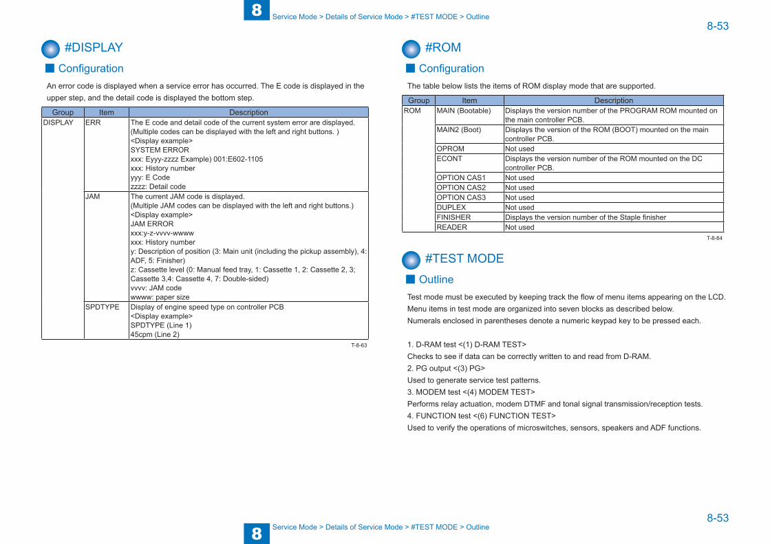
8
88-53
8-53
Service Mode > Details of Service Mode > #TEST MODE > Outline
Service Mode > Details of Service Mode > #TEST MODE > Outline
#DISPLAY ■ Configuration
An error code is displayed when a service error has occurred. The E code is displayed in the upper step, and the detail code is displayed the bottom step.
Group Item DescriptionDISPLAY ERR The E code and detail code of the current system error are displayed.
(Multiple codes can be displayed with the left and right buttons. )<Display example>SYSTEM ERRORxxx: Eyyy-zzzz Example) 001:E602-1105xxx: History numberyyy: E Codezzzz: Detail code
JAM The current JAM code is displayed. (Multiple JAM codes can be displayed with the left and right buttons.)<Display example>JAM ERRORxxx:y-z-vvvv-wwwwxxx: History numbery: Description of position (3: Main unit (including the pickup assembly), 4: ADF, 5: Finisher)z: Cassette level (0: Manual feed tray, 1: Cassette 1, 2: Cassette 2, 3; Cassette 3,4: Cassette 4, 7: Double-sided)vvvv: JAM codewwww: paper size
SPDTYPE Display of engine speed type on controller PCB <Display example>SPDTYPE (Line 1)45cpm (Line 2)
T-8-63
#ROM ■ Configuration
The table below lists the items of ROM display mode that are supported.
Group Item DescriptionROM MAIN (Bootable) Displays the version number of the PROGRAM ROM mounted on
the main controller PCB.MAIN2 (Boot) Displays the version of the ROM (BOOT) mounted on the main
controller PCB.OPROM Not usedECONT Displays the version number of the ROM mounted on the DC
controller PCB.OPTION CAS1 Not usedOPTION CAS2 Not usedOPTION CAS3 Not usedDUPLEX Not usedFINISHER Displays the version number of the Staple finisherREADER Not used
#TEST MODE ■ Outline
Test mode must be executed by keeping track the flow of menu items appearing on the LCD. Menu items in test mode are organized into seven blocks as described below. Numerals enclosed in parentheses denote a numeric keypad key to be pressed each.
1. D-RAM test <(1) D-RAM TEST>Checks to see if data can be correctly written to and read from D-RAM.2. PG output <(3) PG>Used to generate service test patterns.3. MODEM test <(4) MODEM TEST>Performs relay actuation, modem DTMF and tonal signal transmission/reception tests.4. FUNCTION test <(6) FUNCTION TEST>Used to verify the operations of microswitches, sensors, speakers and ADF functions.
T-8-64
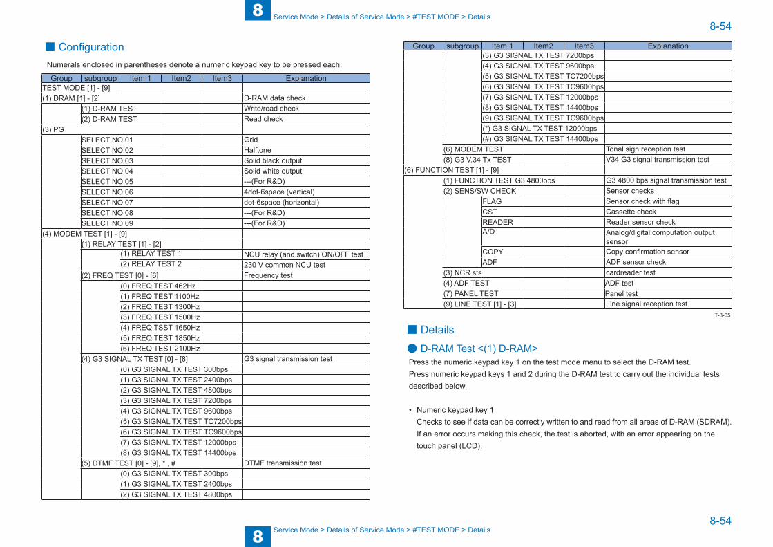
8
88-54
8-54
Service Mode > Details of Service Mode > #TEST MODE > Details
Service Mode > Details of Service Mode > #TEST MODE > Details
■ ConfigurationNumerals enclosed in parentheses denote a numeric keypad key to be pressed each.
Group subgroup Item 1 Item2 Item3 ExplanationTEST MODE [1] - [9](1) DRAM [1] - [2] D-RAM data check
(1) D-RAM TEST Write/read check(2) D-RAM TEST Read check
(3) PGSELECT NO.01 GridSELECT NO.02 HalftoneSELECT NO.03 Solid black outputSELECT NO.04 Solid white outputSELECT NO.05 ---(For R&D)SELECT NO.06 4dot-6space (vertical)SELECT NO.07 dot-6space (horizontal)SELECT NO.08 ---(For R&D)SELECT NO.09 ---(For R&D)
(4) MODEM TEST [1] - [9](1) RELAY TEST [1] - [2]
(1) RELAY TEST 1 NCU relay (and switch) ON/OFF test(2) RELAY TEST 2 230 V common NCU test
(2) FREQ TEST [0] - [6] Frequency test(0) FREQ TEST 462Hz(1) FREQ TEST 1100Hz(2) FREQ TEST 1300Hz(3) FREQ TEST 1500Hz(4) FREQ TSST 1650Hz(5) FREQ TEST 1850Hz(6) FREQ TEST 2100Hz
(4) G3 SIGNAL TX TEST [0] - [8] G3 signal transmission test(0) G3 SIGNAL TX TEST 300bps(1) G3 SIGNAL TX TEST 2400bps(2) G3 SIGNAL TX TEST 4800bps(3) G3 SIGNAL TX TEST 7200bps(4) G3 SIGNAL TX TEST 9600bps(5) G3 SIGNAL TX TEST TC7200bps(6) G3 SIGNAL TX TEST TC9600bps(7) G3 SIGNAL TX TEST 12000bps(8) G3 SIGNAL TX TEST 14400bps
(5) DTMF TEST [0] - [9], * , # DTMF transmission test(0) G3 SIGNAL TX TEST 300bps(1) G3 SIGNAL TX TEST 2400bps(2) G3 SIGNAL TX TEST 4800bps
Group subgroup Item 1 Item2 Item3 Explanation(3) G3 SIGNAL TX TEST 7200bps(4) G3 SIGNAL TX TEST 9600bps(5) G3 SIGNAL TX TEST TC7200bps(6) G3 SIGNAL TX TEST TC9600bps(7) G3 SIGNAL TX TEST 12000bps(8) G3 SIGNAL TX TEST 14400bps(9) G3 SIGNAL TX TEST TC9600bps(*) G3 SIGNAL TX TEST 12000bps(#) G3 SIGNAL TX TEST 14400bps
(6) MODEM TEST Tonal sign reception test(8) G3 V.34 Tx TEST V34 G3 signal transmission test
(6) FUNCTION TEST [1] - [9](1) FUNCTION TEST G3 4800bps G3 4800 bps signal transmission test(2) SENS/SW CHECK Sensor checks
FLAG Sensor check with flagCST Cassette checkREADER Reader sensor checkA/D Analog/digital computation output
sensor COPY Copy confirmation sensor ADF ADF sensor check
(3) NCR sts cardreader test(4) ADF TEST ADF test(7) PANEL TEST Panel test(9) LINE TEST [1] - [3] Line signal reception test
■ Details
● D-RAM Test <(1) D-RAM>Press the numeric keypad key 1 on the test mode menu to select the D-RAM test.Press numeric keypad keys 1 and 2 during the D-RAM test to carry out the individual tests described below.
• Numeric keypad key 1Checks to see if data can be correctly written to and read from all areas of D-RAM (SDRAM). If an error occurs making this check, the test is aborted, with an error appearing on the touch panel (LCD).
T-8-65

8
88-55
8-55
Service Mode > Details of Service Mode > #TEST MODE > Details
Service Mode > Details of Service Mode > #TEST MODE > Details
• Numeric keypad key 2Checks to see if data can be correctly read from all areas of D-RAM (SDRAM). If an error occurs making this check, the test is aborted, with an error appearing on the touch panel (LCD).
D-RAM TEST 29888KB*******......
D-RAM TEST 29888KB......
Press numeric keypad key 1
29888KB:Total size of D-RAM memory (byte)*:Size of written to memory :Size of read from memory
29888KB:Total size of D-RAM memory (byte) :Size of read from memory
D-RAM TEST[1] - [2]
Nomal end
D-RAM TEST 29888KBcomplete (no error)
Press numeric keypad key 2
● PG Output <(3) PG>Press the numeric keypad key 3 on the test mode menu to select the PG output.Press numeric keypad keys during the print test to generate test patterns as described below. Nine kinds of service test patterns are available. Other test patterns are reserved for factory/development purposes.
No. Test patternSELECT NO.01 GridSELECT NO.02 HalftoneSELECT NO.03 Solid black outputSELECT NO.04 Solid white outputSELECT NO.05 ---(For R&D)SELECT NO.06 4dot-6space (vertical)SELECT NO.07 dot-6space (horizontal)SELECT NO.08 ---(For R&D)SELECT NO.09 ---(For R&D)
F-8-13
T-8-66
Procedure1) Enter the PG number with numeric keys, then press the START key. 2) Select single-sided (SGL: 0) or double-sided (DBL: 1), then press the START key. 3) Enter the number of prints to be output (PG COUNT), then press the START key. 4) Specify the paper drawer (main unit), then press the START key.
Main unit cassette (ST_C: 0), 2nd cassette (OP_C: 1), Manual feed tray (MLT: 2)5) Specify the paper eject slot, then press the START key.
Tray 1 (1_OUT: 0), Tray2 (2_OUT: 1)6) Select a paper type, then press the OK key.
Plain paper (PLN: 0), Thick paper (TCK: 1),Thin paper (OHP: 2)7) A test pattern is output.
● MODEM Test <(4) MODEM TEST>These tests test modem and NCU transmission and reception. The modem tests check whether signals are sent correctly from the modem by comparing the sound of the signals from the speaker with the sounds from a normal modem.End this test by pressing the Stop key.
Keypad Type Description1 Relay Test Use it to turn on/off a selected relay to execute a switch-
over test.2 Frequency test The modem sends tonal signals from the modular jack
and the speaker.4 G3 signal transmission test The modem sends G3 signals from the modular jack
and the speaker.5 DTMF signal reception test Use it to generate the DTMF signal coming from the
modem using the telephone line terminal and the speaker.
6 Tonal signal reception test Use it to monitor a specific frequency and the DTMF signal received from the telephone line terminal by causing them to be indicated on the LCD (i.e., the presence/absence as detected). The reception signal is generated by the speaker.
8 V.34 G3 signal transmission test The modem sends V.34 G3 signals from the modular jack and the speaker.
Relay TestPress '1'or '2' on the keypad on the Modem test menu to select relay test mode. Use the keypad to operate the various relays of the NCU. '2' on the keypad is used for 230V machine.
T-8-67

8
88-56
8-56
Service Mode > Details of Service Mode > #TEST MODE > Details
Service Mode > Details of Service Mode > #TEST MODE > Details
• Numeric keypad key 1The input key and relay are shown below:
RELAY TEST1 OFF OFFOFF OFF OFF OFF
[1] [2] [3] [4] [5] [6]Relay CML P S H D RKeypad 0 1 2 3 4 5
[1] [2]
[3] [4] [5] [6]
• Numeric keypad key 2The input key and relay are shown below:
RELAY TEST2 OFF OFFOFF OFF OFF OFF OFF
[1] [2] [3] [4] [5] [6] [7]Relay CITS2 C1 NORG DCSEL DCLIM IPSEL1 IPSEL2Keypad 0 1 2 3 4 5 6
[1] [2]
[3] [4] [5] [6] [7]
CAUTION:
The touch panel (LCD) is turned on or off in relation to the transmission of the relay operation signal as is operated on the keypad; for this reason, you cannot use the touch panel (LCD) to check a fault on a single relay.
Frequency TestA press on '2' on the keypad from the MODEM test menu selects the frequency test.In this test, signals of the following frequencies from the modem are transmitted using the telephone line terminal and the speaker. To select a different frequency,
F-8-14
F-8-15
Keypad Frequency1 462Hz2 1100Hz3 1300Hz4 1500Hz5 1650Hz6 1850Hz7 2100Hz
NOTE:The frequency and the output level of individual frequencies are in keeping with the output level set in service mode.
G3 Signal Transmission TestA press on '4' on the keypad from the MODEM test menu selects the G3 signal transmission test. In this test, the following G3 signals from the modem are transmitted using the telephone line terminal and the speaker. To select a different transmission speed, use the keypad.
Keypad Transmission speed0 300bps1 2400bps2 4800bps3 7200bps4 9600bps5 TC7200bps6 TC9600bps7 12000bps8 14400bps
NOTE:The output level of individual signals is in keeping with the setting made in service mode.
A press on '5' on the MODEM test menu selects the DTMF signal transmission test. In the test, the following DTMF signals from the modem are transmitted using the telephone line terminal and the speaker. The number pressed on the keypad selects a specific DTMF signal.
NOTE:The output level of individual signals is in keeping with the setting made in service mode.
T-8-68
T-8-69
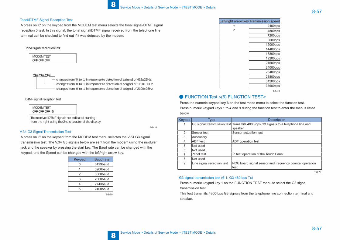
8
88-57
8-57
Service Mode > Details of Service Mode > #TEST MODE > Details
Service Mode > Details of Service Mode > #TEST MODE > Details
Tonal/DTMF Signal Reception TestA press on '6' on the keypad from the MODEM test menu selects the tonal signal/DTMF signal reception 0 test. In this signal, the tonal signal/DTMF signal received from the telephone line terminal can be checked to find out if it was detected by the modem.
MODEM TESTOFF OFF OFF
OFF OFF OFFchanges from '0' to '1' in response to detection of a signal of 462±25Hz.changes from '0' to '1' in response to detection of a signal of 1100±30Hz.changes from '0' to '1' in response to detection of a signal of 2100±25Hz.
Tonal signal reception test
MODEM TESTOFF OFF OFF 5
DTMF signal reception test
The received DTMF signals are indicated startingfrom the right using the 2nd character of the display.
V.34 G3 Signal Transmission TestA press on '8' on the keypad from the MODEM test menu selectes the V.34 G3 signal transmission test. The V.34 G3 signals below are sent from the modem using the modular jack and the speaker by pressing the start key. The Baud rate can be changed with the keypad, and the Speed can be changed with the left/right arrow key.
Keypad Baud rate0 3429baud1 3200baud2 3000baud3 2800baud4 2743baud5 2400baud
F-8-16
T-8-70
Left/right arrow keyTransmission speed<>
2400bps4800bps7200bps9600bps
12000bps14400bps16800bps19200bps21600bps24000bps26400bps28800bps31200bps33600bps
● FUNCTION Test <(6) FUNCTION TEST>Press the numeric keypad key 6 on the test mode menu to select the function test.Press numeric keypad keys 1 to 4 and 9 during the function test to enter the menus listed below.
Keypad Type Description1 G3 signal transmission test Transmits 4800-bps G3 signals to a telephone line and
speaker2 Sensor test Sensor actuation test3 Accessory4 ADF test ADF operation test5 Not used6 Not used7 Panel test To test operation of the Touch Panel.8 Not used9 Line signal reception test NCU board signal sensor and frequency counter operation
test
G3 signal transmission test (6-1: G3 480 bps Tx)Press numeric keypad key 1 on the FUNCTION TEST menu to select the G3 signal transmission test.This test transmits 4800-bps G3 signals from the telephone line connection terminal and speaker.
T-8-71
T-8-72

8
88-58
8-58
Service Mode > Details of Service Mode > #TEST MODE > Details
Service Mode > Details of Service Mode > #TEST MODE > Details
Sensor test (6-2: SENSOR)This mode is used to verify the status of the unit sensors from the touch panel (LCD) indications. Press numeric keypad key 3 on the FUNCTION TEST menu to select the sensor test. To select a minor item, press the START key. The touch panel (LCD) indications change as the associated sensors turn on and off.
Group Item Description Detail(2) SENS/SW CHECK
FLAG Sensor check with flag (manual check)
CT: Waste Toner Full Sensor (PS2) 0: Available, 1: FullDO: Front Cover Sensor (PS1) 0: closed, 1: OpenF1: Delivery Paper Full Sensor (PS4) 0: Available, 1: Full
CST Cassette check
SU: Cassette Pickup Sensor (PS13) 0: OFF, 1: ONPE: Cassette Paper Sensor (PS15) 0: OFF, 1: ONZA: Cassette Paper Level Sensor A/B (PS16/PS17)
(2 digits) Right: A, Left: B0: OFF, 1: ON
S1: Cassette Size Detection Switch (SW2)
0: OFF, 1: ON(4 digits)
NA: Cassette Lifting Plate Sensor (PS14)
0: OFF, 1: ON
READER Reader sensor check
CO: ADF Open/Close Sensor (PS23) 0/Document presence, 1/Document absenc
HP: CIS HP Sensor (PS24) 0: besides HP, 1: HPSIZE: Document size: Paper size indicated in a mix of Original Size Sensor 1/2 (PS21/PS22)
AB configuration: A4R, NONE (any size other than A4R)Inch configuration: LTRR, LGL, NONE (any size other than LTRR, LGL)
1 (Left): Original Size Sensor 1 (PS21) 0: OFF, 1: ON1 (Right): Original Size Sensor 2 (PS22)
0: OFF, 1: ON
A/D Analog/digital computation output sensor
HOP: Hopper Toner Sensor (TS1) output value
0: With toner, 1: Without toner
DEV: Developing Assembly Toner Sensor (TS2) output value
0: With toner, 1: Without toner
TEP: Environment Sensor (THU1) Temperature output value
Temperature in the machine
HUM: Environment Sensor (THU1) Humidity output value
Humidity in the machine
COPY Copy confirmation sensor
MP: Manual Feeder Paper Sensor (PS7)
0: OFF, 1: ON
RE: Pre-registration Sensor (PS12) 0: OFF, 1: ONRP: Loop Sensor (PS9) 0: OFF, 1: ONFX: Delivery Sensor (PS5) 0: OFF, 1: ONEX: Fixing Paper Sensor (PS19) 0: OFF, 1: ON
Group Item Description Detail(2) SENS/SW CHECK
ADF ADF sensor check
W1: Document Width Detection Sensor (PS31)
0: OFF, 1: ON
L1: Document Length Detection Sensor (PS32)
0: OFF, 1: ON
DR: Read Sensor (PS25) 0: OFF, 1: ONRG: Registration Sensor (PS26) 0: OFF, 1: ONDS: Document Set Sensor (PS30) 0: OFF, 1: ONTM: Timing Sensor (PS29) 0: OFF, 1: ONRE: Delivery/Reverse Sensor (PS27) 0: OFF, 1: ONST: Lower Reverse Sensor (PS28) 0: OFF, 1: ON
Card reader test <6-3: NCR sts>Press numeric keypad key 3 on the FACULTY menu to select the card reader test. In this test, verify the successful operations of the card reader.
NCR Sts:12345678DPT MGN OK RDY 1234
[1] Card reader and card availability indication Card available: Eight-digit card ID No card: Card None No card reader available: NCR None
[2] Card type and card reader status indication DPT: Department card PRC: Unit pricing card MAX: Upper limit setting card ERS: Erased card SRV: Service card (No indication): No card
[3] Card type MGN: Magnetic card OPT: Optical card
[1]
[2] [3] [4] [5] [6]
Press numeric keypad key 3
[4] Can status OK: Normal scan ERR: Scan error NG: Nonstandard error (No indication): No card
[5] Equipment status IN: Initialization in progress RDY: Ready [6] Card reader version indication Four-digit number
T-8-73
F-8-17

8
88-59
8-59
Service Mode > Details of Service Mode > #TEST MODE > Details
Service Mode > Details of Service Mode > #TEST MODE > Details
ADF test <6-4: ADF TEST>Execute the ADF feed test. Select 1-sided/2-sided to execute the test.
Panel test <6-7: PANEL TEST>Execute the test for LCD, LED, keys, and coordinate position.
Line signal reception test <6-9: LINE DETECT>Press numeric keypad key 9 on the FACULTY menu to select the line signal reception test. In this test, verify the successful operations of the NCU signal sensor and the frequency counter. Menu 1 detects the CI state, while menu 3 detects the CNG signal.
• Test menu 1Press numeric keypad key 1 on the LINE DETECT menu to select test menu 1. When CI is detected on the telephone line connection terminal, the touch panel (LCD) display changes from OFF to ON, indicating the received frequency. The touch panel (LCD) also displays the on-hook or off-hook state of an external telephone set as detected. The touch panel (LCD) displays, from left to right, CI, CI frequency, hook port and FC with indications of 1:ON and 0:OFF.
• Test menu 2Press numeric keypad key 2 on the LINE DETECT menu to select test menu 2. When the CNG signal is detected on the telephone line connection terminal, the touch panel (LCD) display changes from OFF to ON, indicating the received frequency. The touch panel (LCD) displays the status of CML, CNG and FED detection, from left to right, with ON/OFF indications. Numeric keypad key 2 turns on the CML relay to detect CNG.
• Test menu 3Press numeric keypad key 3 on the LINE DETECT menu to select test menu 3. When the CNG signal is detected on the telephone line connection terminal, the touch panel (LCD) display changes from OFF to ON, indicating the received frequency. The touch panel (LCD) displays the status of CML, CNG and FED detection, from left to right, with ON/OFF indications. Numeric keypad key 3 turns off the CML relay to detect CNG.
9
9 Installation
Installation ■How to check this Installation Procedure ■Installation ■Option Installation Sequence ■Drum Heater-D1 ■Copy Card Reader-F1 ■System Upgrade RAM-C1

9
99-2
9-2
Installation > Option Installation Sequence
Installation > Option Installation Sequence
How to check this Installation Procedure
When Using the parts included in the packageA symbol is described on the illustration in the case of using the parts included in the package of this product.
Symbols in the IllustrationThe frequently-performed operations are described with symbols in this procedure.
Connector
Disconnect
Screw
Tighten Remove Connect Secure Free
Harness
PushInsert Plug in Turn on
Sound CheckCheck Visual Check
Claw
Remove
Checking instruction
F-9-1
F-9-2
InstallationThis machine is installed by the user.For details of installation procedure, refer to the User's Manual.
Option Installation SequenceWhen installing options of this machine, be sure to note the following points.1) When installing the Drum Heater-D1, be sure to install it first.2) When installing the Copy Card Reader-F1 or USB Application 3-Port Interface Kit-B1 and Super G3 Fax Board-AJ1 at the same time, be sure to install the Copy Card Reader-F1 or USB Application 3-Port Interface Kit-B1 first.3) Be sure to install the Super G3 Fax Board-AJ1 last.
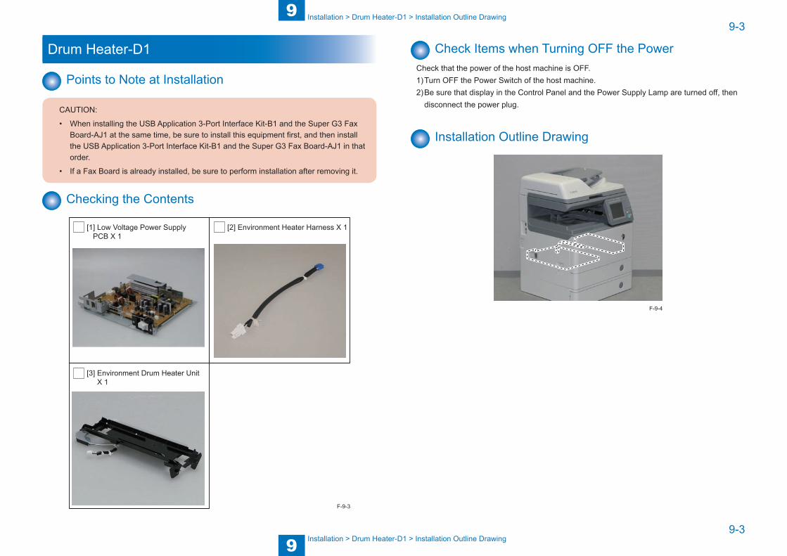
9
99-3
9-3
Installation > Drum Heater-D1 > Installation Outline Drawing
Installation > Drum Heater-D1 > Installation Outline Drawing
Drum Heater-D1
Points to Note at Installation
CAUTION:
• When installing the USB Application 3-Port Interface Kit-B1 and the Super G3 Fax Board-AJ1 at the same time, be sure to install this equipment first, and then install the USB Application 3-Port Interface Kit-B1 and the Super G3 Fax Board-AJ1 in that order.
• If a Fax Board is already installed, be sure to perform installation after removing it.
Checking the Contents
[1] Low Voltage Power Supply PCB X 1
[2] Environment Heater Harness X 1
[3] Environment Drum Heater Unit X 1
F-9-3
Check Items when Turning OFF the PowerCheck that the power of the host machine is OFF.1) Turn OFF the Power Switch of the host machine.2) Be sure that display in the Control Panel and the Power Supply Lamp are turned off, then
disconnect the power plug.
Installation Outline Drawing
F-9-4
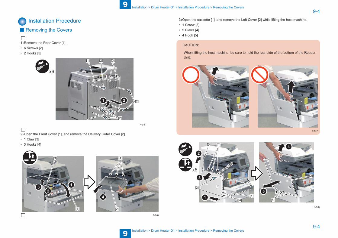
9
99-4
9-4
Installation > Drum Heater-D1 > Installation Procedure > Removing the Covers
Installation > Drum Heater-D1 > Installation Procedure > Removing the Covers
Installation Procedure ■ Removing the Covers
1) Remove the Rear Cover [1].• 6 Screws [2]• 2 Hooks [3]
[2]
[2]
[2] [3]
x6
[1]
2) Open the Front Cover [1], and remove the Delivery Outer Cover [2].• 1 Claw [3]• 3 Hooks [4]
[1] [2]
[3] [4]
F-9-5
F-9-6
3) Open the cassette [1], and remove the Left Cover [2] while lifting the host machine.• 1 Screw [3]• 5 Claws [4]• 4 Hook [5]
CAUTION:
When lifting the host machine, be sure to hold the rear side of the bottom of the Reader Unit.
F-9-7
x5
[1][4]
[4]
[2]
[3]
[5]
[5]
F-9-8

9
99-5
9-5
Installation > Drum Heater-D1 > Installation Procedure > Before Installing
Installation > Drum Heater-D1 > Installation Procedure > Before Installing
■ Before Installing
1) Turn the Lock Lever [1], and remove the Waste Toner Container [2].
[1][2]
2) Open the Right Door Unit [1], release the Drum Cartridge Lock Lever [2], and then remove the Drum Cartridge [3].
CAUTION:
Be sure not to touch the drum [1] of the Drum Cartridge.
[1]
F-9-10
F-9-9
CAUTION:
Be sure to block light to the removed Drum Cartridge using paper [1].
[1]
F-9-11
[1][2]
[3]
F-9-12
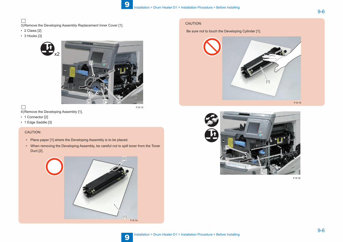
9
99-6
9-6
Installation > Drum Heater-D1 > Installation Procedure > Before Installing
Installation > Drum Heater-D1 > Installation Procedure > Before Installing
3) Remove the Developing Assembly Replacement Inner Cover [1].• 2 Claws [2]• 3 Hooks [3]
[1]
[2]
[2][3]
x2
4) Remove the Developing Assembly [1].• 1 Connector [2]• 1 Edge Saddle [3]
CAUTION:
• Place paper [1] where the Developing Assembly is to be placed.
• When removing the Developing Assembly, be careful not to spill toner from the Toner Duct [2].
[1]
[2]
F-9-14
F-9-13
CAUTION:
Be sure not to touch the Developing Cylinder [1].
[1]
F-9-15
[1]
[3]
[2]
F-9-16
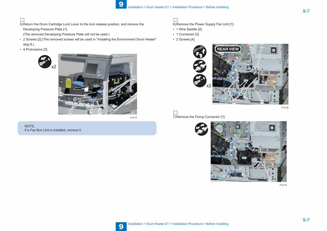
9
99-7
9-7
Installation > Drum Heater-D1 > Installation Procedure > Before Installing
Installation > Drum Heater-D1 > Installation Procedure > Before Installing
5) Return the Drum Cartridge Lock Lever to the lock release position, and remove the Developing Pressure Plate [1].(The removed Developing Pressure Plate will not be used.)
• 2 Screws [2] (The removed screws will be used in "Installing the Environment Drum Heater" step 6.)
• 4 Protrusions [3]
x2
[1][2] [3]
[3]
[3]
NOTE:If a Fax Box Unit is installed, remove it.
F-9-17
6) Remove the Power Supply Fan Unit [1].• 1 Wire Saddle [2]• 1 Connector [3]• 2 Screws [4]
[1]
[2][3]
[4]
x2
7) Remove the Fixing Connector [1].
[1]
F-9-18
F-9-19
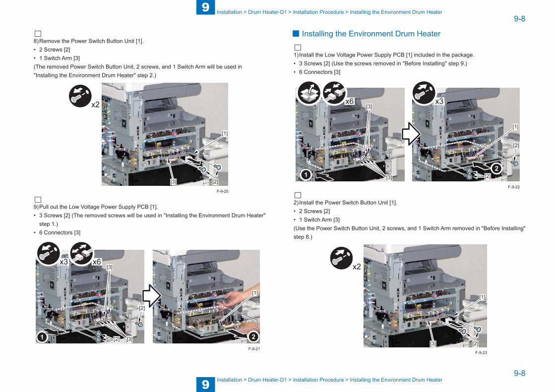
9
99-8
9-8
Installation > Drum Heater-D1 > Installation Procedure > Installing the Environment Drum Heater
Installation > Drum Heater-D1 > Installation Procedure > Installing the Environment Drum Heater
8) Remove the Power Switch Button Unit [1].• 2 Screws [2]• 1 Switch Arm [3](The removed Power Switch Button Unit, 2 screws, and 1 Switch Arm will be used in "Installing the Environment Drum Heater" step 2.)
[1]
[2][3]
x2
9) Pull out the Low Voltage Power Supply PCB [1].• 3 Screws [2] (The removed screws will be used in "Installing the Environment Drum Heater"
step 1.)• 6 Connectors [3]
[2]
[3]
[3]
[2]
x6x3
[1]
F-9-20
F-9-21
■ Installing the Environment Drum Heater
1) Install the Low Voltage Power Supply PCB [1] included in the package.• 3 Screws [2] (Use the screws removed in "Before Installing" step 9.)• 6 Connectors [3]
[3]
[3] [2]
[2]
x6 x3
[1]
2) Install the Power Switch Button Unit [1].• 2 Screws [2]• 1 Switch Arm [3](Use the Power Switch Button Unit, 2 screws, and 1 Switch Arm removed in "Before Installing" step 8.)
[1]
[2][3]
x2
F-9-22
F-9-23
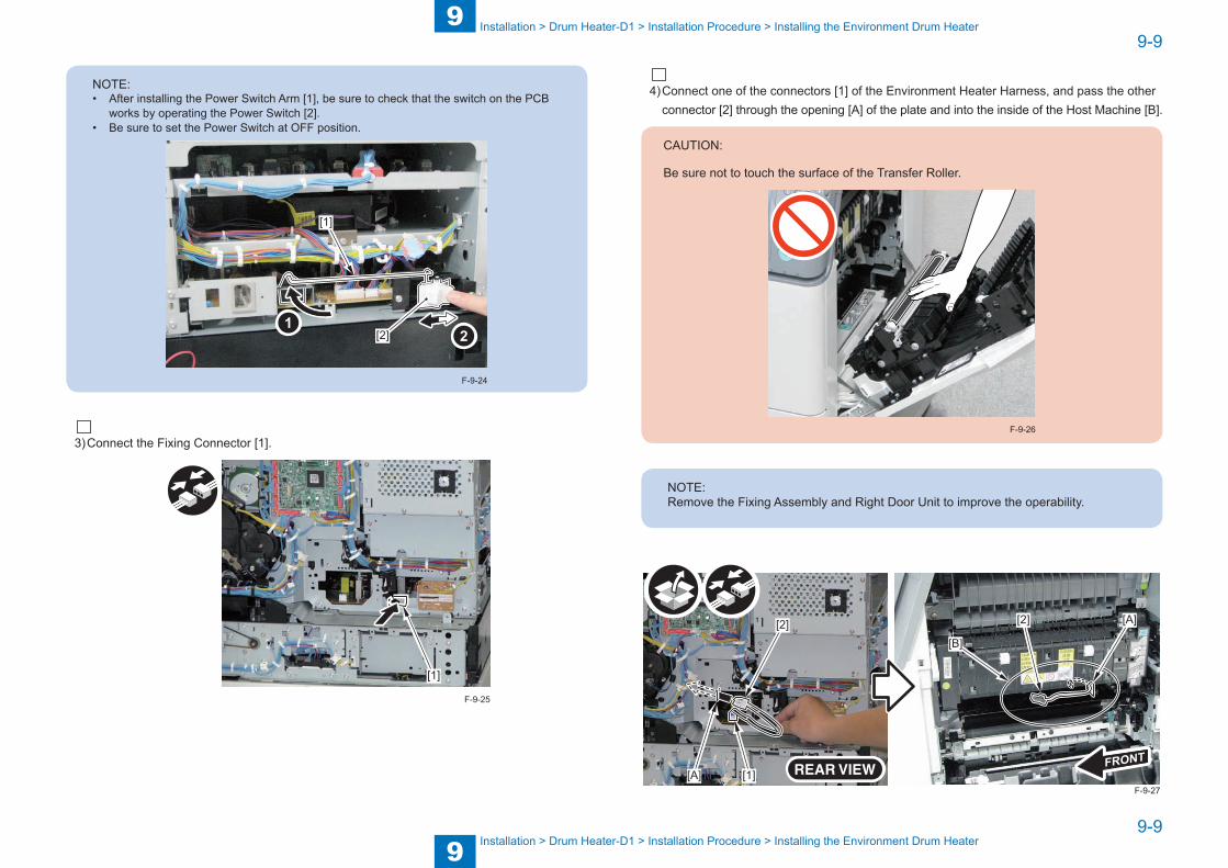
9
99-9
9-9
Installation > Drum Heater-D1 > Installation Procedure > Installing the Environment Drum Heater
Installation > Drum Heater-D1 > Installation Procedure > Installing the Environment Drum Heater
NOTE:• After installing the Power Switch Arm [1], be sure to check that the switch on the PCB
works by operating the Power Switch [2]. • Be sure to set the Power Switch at OFF position.
[2]
[1]
F-9-24
3) Connect the Fixing Connector [1].
[1]
F-9-25
4) Connect one of the connectors [1] of the Environment Heater Harness, and pass the other connector [2] through the opening [A] of the plate and into the inside of the Host Machine [B].
CAUTION:
Be sure not to touch the surface of the Transfer Roller.
F-9-26
NOTE:Remove the Fixing Assembly and Right Door Unit to improve the operability.
[1]
[2]
[A]
[A]
[B]
[2]
F-9-27
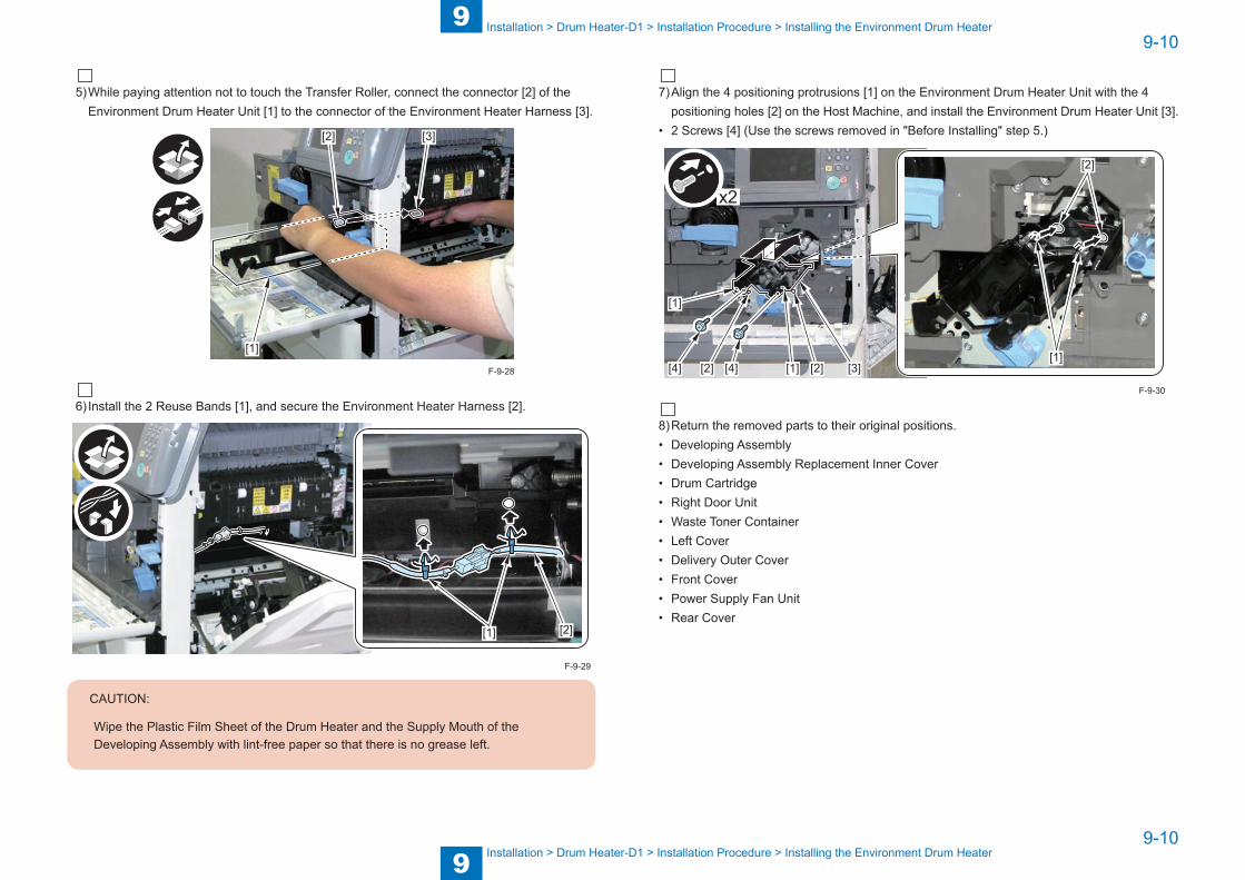
9
99-10
9-10
Installation > Drum Heater-D1 > Installation Procedure > Installing the Environment Drum Heater
Installation > Drum Heater-D1 > Installation Procedure > Installing the Environment Drum Heater
5) While paying attention not to touch the Transfer Roller, connect the connector [2] of the Environment Drum Heater Unit [1] to the connector of the Environment Heater Harness [3].
[1]
[2] [3]
6) Install the 2 Reuse Bands [1], and secure the Environment Heater Harness [2].
[1] [2]
CAUTION:
Wipe the Plastic Film Sheet of the Drum Heater and the Supply Mouth of the Developing Assembly with lint-free paper so that there is no grease left.
F-9-28
F-9-29
7) Align the 4 positioning protrusions [1] on the Environment Drum Heater Unit with the 4 positioning holes [2] on the Host Machine, and install the Environment Drum Heater Unit [3].
• 2 Screws [4] (Use the screws removed in "Before Installing" step 5.)
[1]
[2]
[1]
[1]
[3][2] [2][4] [4]
x2
8) Return the removed parts to their original positions.• Developing Assembly• Developing Assembly Replacement Inner Cover• Drum Cartridge• Right Door Unit• Waste Toner Container• Left Cover• Delivery Outer Cover• Front Cover• Power Supply Fan Unit• Rear Cover
F-9-30
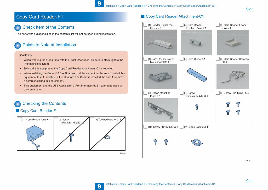
9
99-11
9-11
Installation > Copy Card Reader-F1 > Checking the Contents > Copy Card Reader Attachment-C1
Installation > Copy Card Reader-F1 > Checking the Contents > Copy Card Reader Attachment-C1
Copy Card Reader-F1
Check Item of the ContentsThe parts with a diagonal line in the contents list will not be used during installation.
Points to Note at Installation
CAUTION:
• When working for a long time with the Right Door open, be sure to block light to the Photosensitive Drum .
• To install this equipment, the Copy Card Reader Attachment-C1 is required.
• When installing the Super G3 Fax Board-AJ1 at the same time, be sure to install this equipment first. In addition, if the standard Fax Board is installed, be sure to remove it before installing this equipment.
• This equipment and the USB Application 3-Port Interface Kit-B1 cannot be used at the same time.
Checking the Contents ■ Copy Card Reader-F1
[1] Card Reader Unit X 1 [2] Screw (RS tight; M4x10) X 1
[3] Toothed washer X 1
F-9-31
■ Copy Card Reader Attachment-C1
[1] Reader Right Front Cover X 1
[2] Card Reader Fixation Plate X 1
[3] Card Reader Lower Cover X 1
[4] Card Reader Lower Mounting Plate X 1
[5] Cord Guide X 1 [6] Card Reader Harness X 1
[7] Option Mounting Plate X 1
[8] Screw (Binding; M4x6) X 1
[9] Screw (TP; M3x4) X 4
[10] Screw (TP; M4x8) X 2 [11] Edge Saddle X 1
F-9-32

9
99-12
9-12
Installation > Copy Card Reader-F1 > Installation Procedure > Assembling the Card Reader
Installation > Copy Card Reader-F1 > Installation Procedure > Assembling the Card Reader
Check Items when Turning OFF the PowerCheck that the power of the host machine is OFF.1) Turn OFF the Power Switch of the host machine.2) Be sure that display in the Control Panel and the Power Supply Lamp are turned off, then
disconnect the power plug.
Installation Outline Drawing
F-9-33
Installation Procedure ■ Assembling the Card Reader
1) Remove the Card Reader Lower Cover [1] from the Card Reader Unit.(The removed Card Reader Lower Cover and screw will not be used.)
• 1 Screw [2]
[1]
[2]
2) Remove the Card Reader Fixation Plate [1] from the Card Reader Unit.(The removed Card Reader Fixation Plate will not be used.)
• 1 Screw [2] (The removed screw will be used in step 4.)
[1]
[2]
F-9-34
F-9-35

9
99-13
9-13
Installation > Copy Card Reader-F1 > Installation Procedure > Assembling the Card Reader
Installation > Copy Card Reader-F1 > Installation Procedure > Assembling the Card Reader
3) Free the Grounding Wire [1] from the Card Reader Unit.(The removed screw and toothed washer will be used in step 5.)
• 1 Screw [2]• 1 Toothed Washer [3]
[2]
[1]
[3]
[1]
4) Install the Card Reader Lower Mounting Plate [1] on the Card Reader Unit.• 1 Screw [2] (Use the screw removed in step 2.)• 1 Edge Saddle [3]
[1]
[3]
[2]
F-9-36
F-9-37
5) Install the Grounding Wire [1] on the Card Reader Unit.• 1 Screw [2] (Use the screw removed in step 3.)• 1 Toothed Washer [3] (Use the toothed washer removed in step 3.)
[1][2]
[3]
[1]
6) Pass the Card Reader Harness [1] through the Edge Saddle [2].
[1] [2]
F-9-38
F-9-39
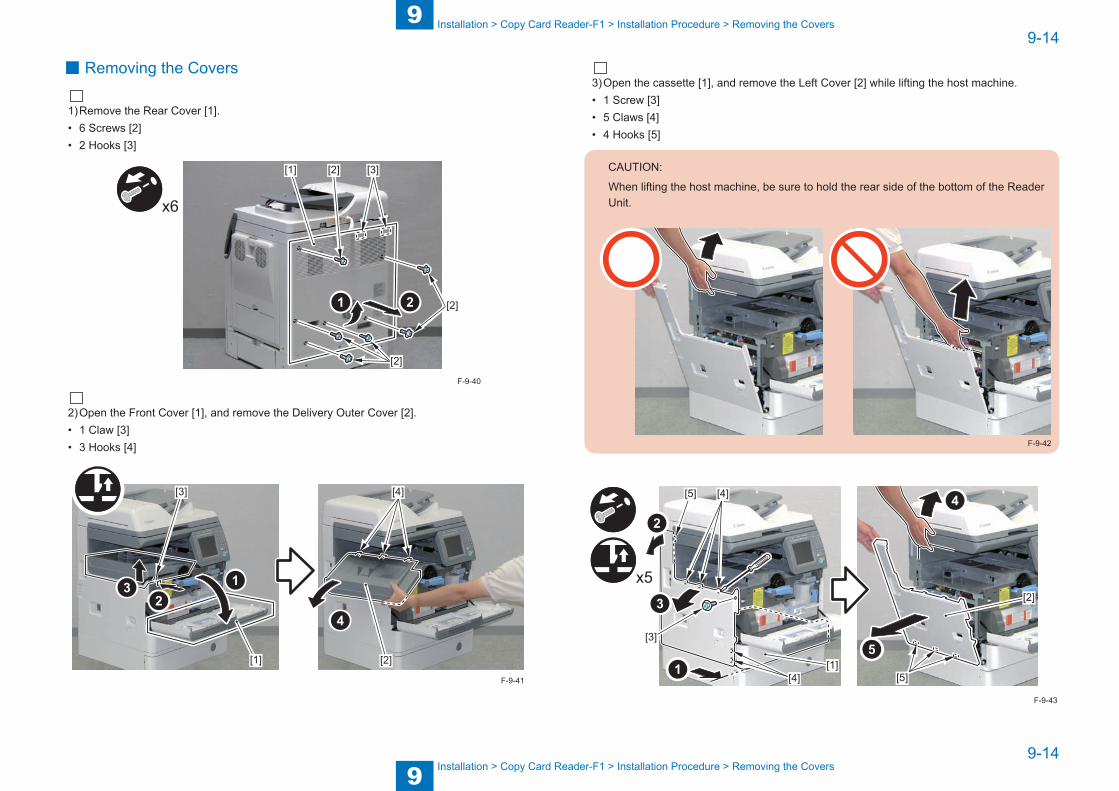
9
99-14
9-14
Installation > Copy Card Reader-F1 > Installation Procedure > Removing the Covers
Installation > Copy Card Reader-F1 > Installation Procedure > Removing the Covers
■ Removing the Covers
1) Remove the Rear Cover [1].• 6 Screws [2]• 2 Hooks [3]
[2]
[2]
[2] [3]
x6
[1]
2) Open the Front Cover [1], and remove the Delivery Outer Cover [2].• 1 Claw [3]• 3 Hooks [4]
[1] [2]
[3] [4]
F-9-40
F-9-41
3) Open the cassette [1], and remove the Left Cover [2] while lifting the host machine.• 1 Screw [3]• 5 Claws [4]• 4 Hooks [5]
CAUTION:
When lifting the host machine, be sure to hold the rear side of the bottom of the Reader Unit.
F-9-42
x5
[1][4]
[4]
[2]
[3]
[5]
[5]
F-9-43
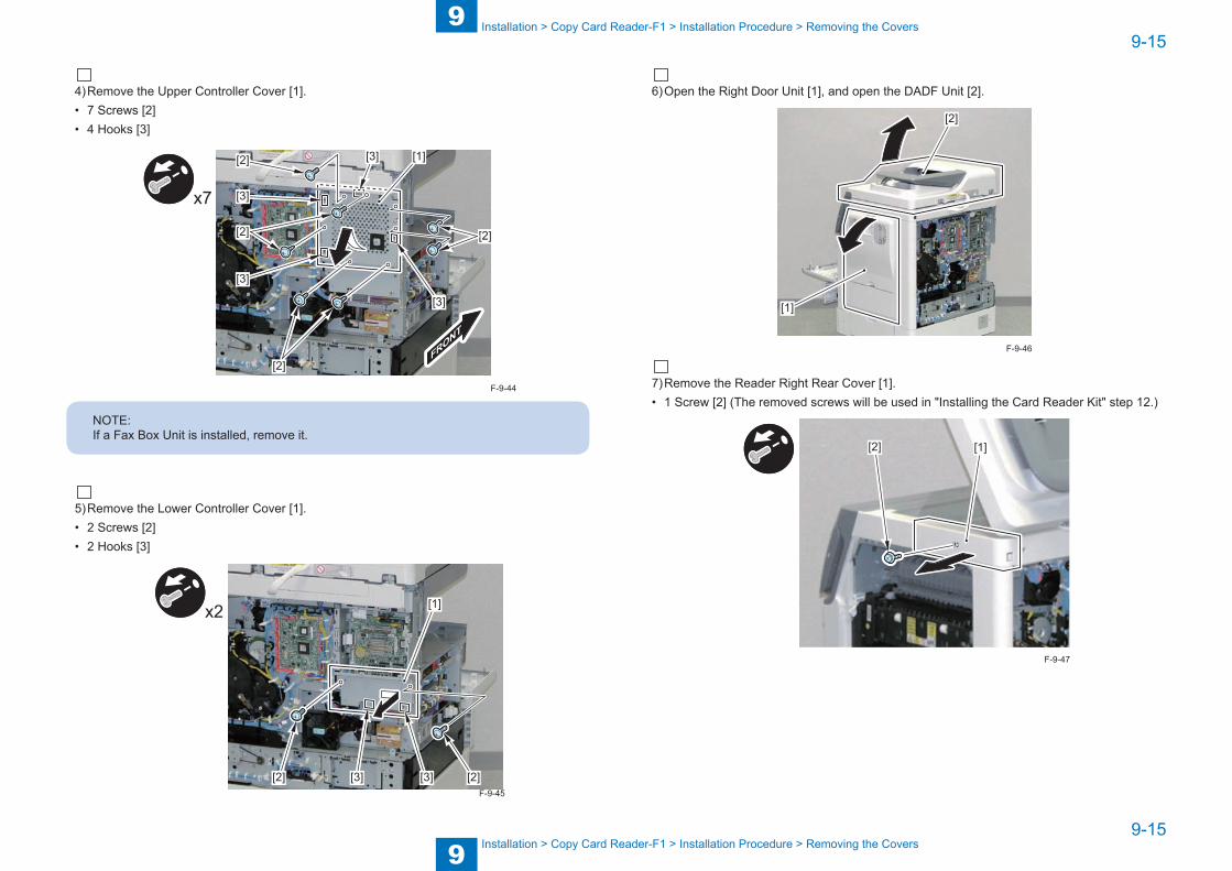
9
99-15
9-15
Installation > Copy Card Reader-F1 > Installation Procedure > Removing the Covers
Installation > Copy Card Reader-F1 > Installation Procedure > Removing the Covers
4) Remove the Upper Controller Cover [1].• 7 Screws [2]• 4 Hooks [3]
x7
[1]
[2]
[3]
[3]
[3]
[3]
[2]
[2]
[2]
NOTE:If a Fax Box Unit is installed, remove it.
5) Remove the Lower Controller Cover [1].• 2 Screws [2]• 2 Hooks [3]
[1]
[2] [2][3] [3]
x2
F-9-44
F-9-45
6) Open the Right Door Unit [1], and open the DADF Unit [2].
[1]
[2]
7) Remove the Reader Right Rear Cover [1].• 1 Screw [2] (The removed screws will be used in "Installing the Card Reader Kit" step 12.)
[1][2]
F-9-46
F-9-47
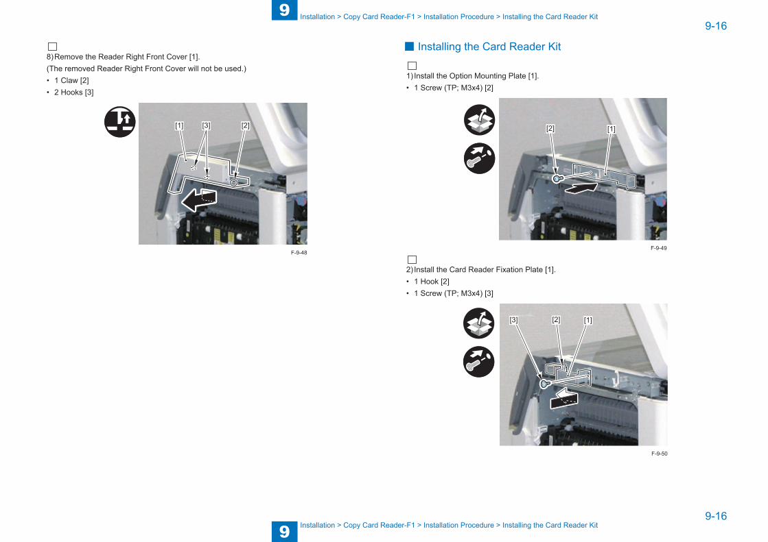
9
99-16
9-16
Installation > Copy Card Reader-F1 > Installation Procedure > Installing the Card Reader Kit
Installation > Copy Card Reader-F1 > Installation Procedure > Installing the Card Reader Kit
8) Remove the Reader Right Front Cover [1].(The removed Reader Right Front Cover will not be used.)• 1 Claw [2]• 2 Hooks [3]
[1] [2][3]
F-9-48
■ Installing the Card Reader Kit
1) Install the Option Mounting Plate [1].• 1 Screw (TP; M3x4) [2]
[1][2]
2) Install the Card Reader Fixation Plate [1].• 1 Hook [2]• 1 Screw (TP; M3x4) [3]
[2] [1][3]
F-9-49
F-9-50
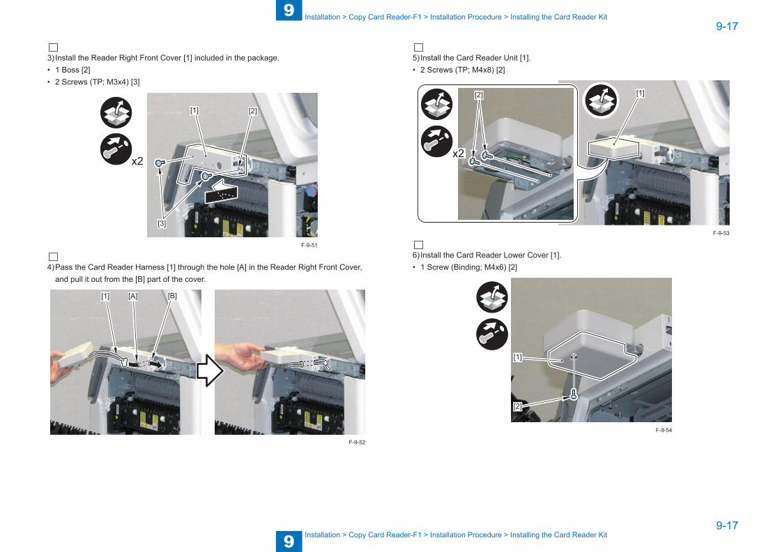
9
99-17
9-17
Installation > Copy Card Reader-F1 > Installation Procedure > Installing the Card Reader Kit
Installation > Copy Card Reader-F1 > Installation Procedure > Installing the Card Reader Kit
3) Install the Reader Right Front Cover [1] included in the package.• 1 Boss [2]• 2 Screws (TP; M3x4) [3]
x2
[2][1]
[3]
4) Pass the Card Reader Harness [1] through the hole [A] in the Reader Right Front Cover, and pull it out from the [B] part of the cover.
[A] [B][1]
F-9-51
F-9-52
5) Install the Card Reader Unit [1].• 2 Screws (TP; M4x8) [2]
[1]
x2
[2]
6) Install the Card Reader Lower Cover [1].• 1 Screw (Binding; M4x6) [2]
[1]
[2]
F-9-53
F-9-54
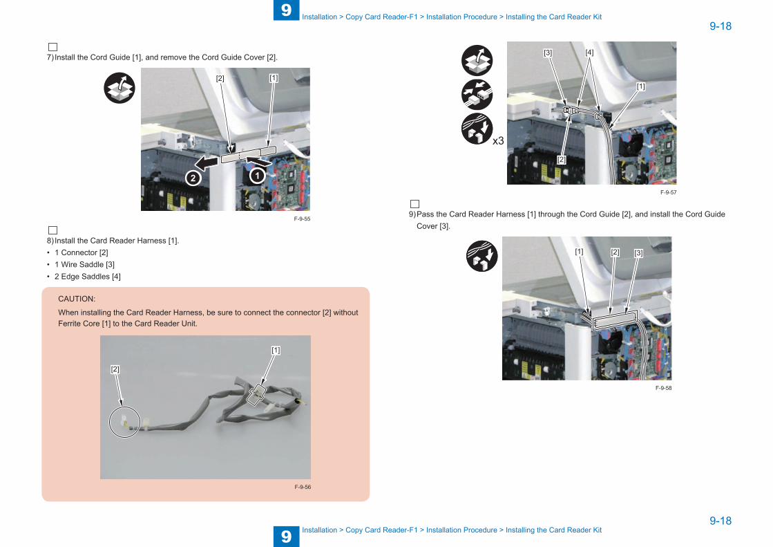
9
99-18
9-18
Installation > Copy Card Reader-F1 > Installation Procedure > Installing the Card Reader Kit
Installation > Copy Card Reader-F1 > Installation Procedure > Installing the Card Reader Kit
7) Install the Cord Guide [1], and remove the Cord Guide Cover [2].
[2] [1]
8) Install the Card Reader Harness [1].• 1 Connector [2]• 1 Wire Saddle [3]• 2 Edge Saddles [4]
CAUTION:
When installing the Card Reader Harness, be sure to connect the connector [2] without Ferrite Core [1] to the Card Reader Unit.
[1]
[2]
F-9-56
F-9-55
[3]
[2]
[1]
[4]
x3
9) Pass the Card Reader Harness [1] through the Cord Guide [2], and install the Cord Guide Cover [3].
[1] [2] [3]
F-9-57
F-9-58

9
99-19
9-19
Installation > Copy Card Reader-F1 > Installation Procedure > Installing the Card Reader Kit
Installation > Copy Card Reader-F1 > Installation Procedure > Installing the Card Reader Kit
10) Install the Card Reader Harness [1] to the Main Controller.• 7 Wire Saddles [2]• 1 Connector [3]• 1 Edge Saddle [4]
x8
[2]
[1]
[4]
[3]
[2]
[2]
11) Cut off the [A] part of the Reader Right Rear Cover with nippers.• 3 Joints [1]
[A]
[1]
[1]
CAUTION:
Be sure to check that there is no burr.
F-9-59
F-9-60
12) Pass the Card Reader Harness [1] through the [A] part of the Reader Right rear Cover, and return the Reader Right Rear Cover [2] to its original position.
• 2 Protrusions [3]• 1 Screw [4] (Use the screws removed in “Removing the Covers” step 7.)
[A]
[3]
[4]
[1]
[2]
13) Close the DADF Unit and the Right Door Unit.
F-9-61
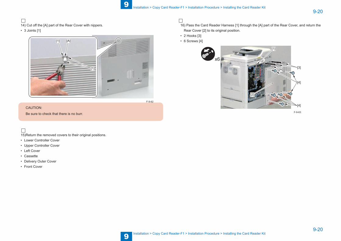
9
99-20
9-20
Installation > Copy Card Reader-F1 > Installation Procedure > Installing the Card Reader Kit
Installation > Copy Card Reader-F1 > Installation Procedure > Installing the Card Reader Kit
14) Cut off the [A] part of the Rear Cover with nippers.• 3 Joints [1]
[1]
[1]
[A]
CAUTION:
Be sure to check that there is no burr.
15)Return the removed covers to their original positions.• Lower Controller Cover• Upper Controller Cover• Left Cover• Cassette• Delivery Outer Cover• Front Cover
F-9-62
16) Pass the Card Reader Harness [1] through the [A] part of the Rear Cover, and return the Rear Cover [2] to its original position.
• 2 Hooks [3]• 6 Screws [4]
x6
[2]
[A] [3]
[4]
[4]
[1]
F-9-63

9
99-21
9-21
Installation > Copy Card Reader-F1 > Registering the Card IDs
Installation > Copy Card Reader-F1 > Registering the Card IDs
Registering the Card IDs
After installing the Card Reader, register the card numbers to be used in the service mode of the host machine.If they are not registered, cards will not be recognized when inserted.
1) Plug the power cord into the outlet.2) Turn on the main power switch.3) Enter service mode.4) Get in Service Mode (# ACC> CARD) and enter the card number to use (1 to 2000).• Enter the smallest card number of the cards used by the user.• From the entered number, up to 1000 cards can be used.5) Turn main power switch off and on again.
6) Press Additional Functions to enter user mode.7) Select System Settings > Department ID Management > ON, and perform various settings.(See User Manual CD-ROM > System Setings Guide > Chapter 1 Before You Start > Setting
System Management Mode) 8) Insert the card with registered valid number to check it's at standby state.
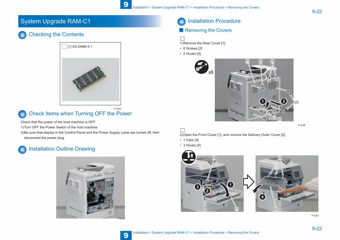
9
99-22
9-22
Installation > System Upgrade RAM-C1 > Installation Procedure > Removing the Covers
Installation > System Upgrade RAM-C1 > Installation Procedure > Removing the Covers
System Upgrade RAM-C1
Checking the Contents
[1] SO-DIMM X 1
Check Items when Turning OFF the PowerCheck that the power of the host machine is OFF.1) Turn OFF the Power Switch of the host machine.2) Be sure that display in the Control Panel and the Power Supply Lamp are turned off, then
disconnect the power plug.
Installation Outline Drawing
F-9-64
F-9-65
Installation Procedure ■ Removing the Covers
1) Remove the Rear Cover [1].• 6 Screws [2]• 2 Hooks [3]
[2]
[2]
[2] [3]
x6
[1]
2) Open the Front Cover [1], and remove the Delivery Outer Cover [2].• 1 Claw [3]• 3 Hooks [4]
[1] [2]
[3] [4]
F-9-66
F-9-67
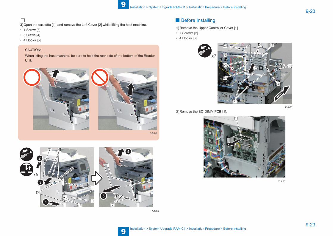
9
99-23
9-23
Installation > System Upgrade RAM-C1 > Installation Procedure > Before Installing
Installation > System Upgrade RAM-C1 > Installation Procedure > Before Installing
3) Open the cassette [1], and remove the Left Cover [2] while lifting the host machine.• 1 Screw [3]• 5 Claws [4]• 4 Hooks [5]
CAUTION:
When lifting the host machine, be sure to hold the rear side of the bottom of the Reader Unit.
F-9-68
x5
[1][4]
[4]
[2]
[3]
[5]
[5]
F-9-69
■ Before Installing1) Remove the Upper Controller Cover [1].• 7 Screws [2]• 4 Hooks [3]
x7
[1]
[2]
[3]
[3]
[3]
[3]
[2]
[2]
[2]
2) Remove the SO-DIMM PCB [1].
[1]
F-9-70
F-9-71
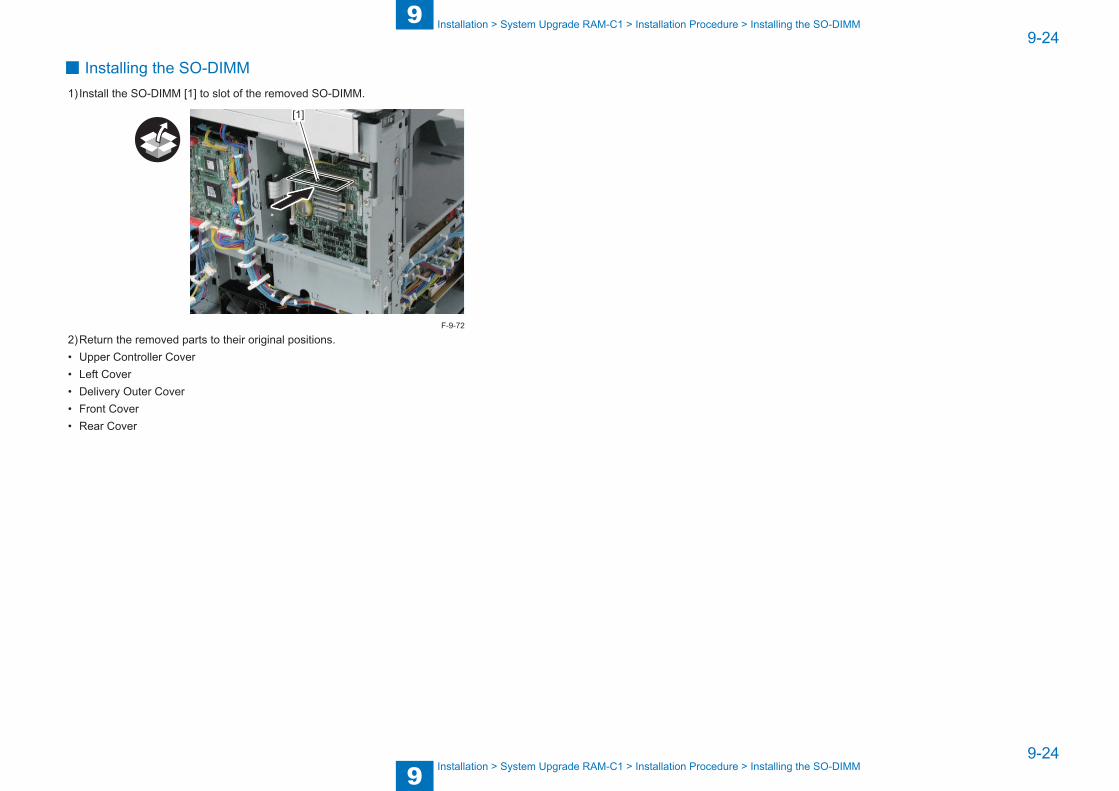
9
99-24
9-24
Installation > System Upgrade RAM-C1 > Installation Procedure > Installing the SO-DIMM
Installation > System Upgrade RAM-C1 > Installation Procedure > Installing the SO-DIMM
■ Installing the SO-DIMM1) Install the SO-DIMM [1] to slot of the removed SO-DIMM.
[1]
2) Return the removed parts to their original positions.• Upper Controller Cover• Left Cover• Delivery Outer Cover• Front Cover• Rear Cover
F-9-72
■Service Tools ■General Timing Chart ■General Circuit Diagram ■List of User Mode
Appendix
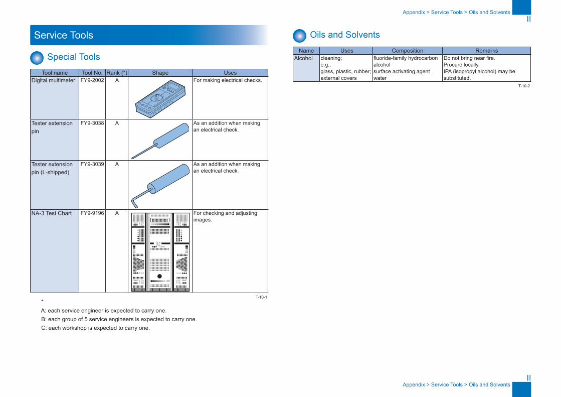
II
II
Appendix > Service Tools > Oils and Solvents
Appendix > Service Tools > Oils and Solvents
Service Tools
Special ToolsTool name Tool No. Rank (*) Shape Uses
Digital multimeter FY9-2002 A For making electrical checks.
Tester extension pin
FY9-3038 A As an addition when making an electrical check.
Tester extension pin (L-shipped)
FY9-3039 A As an addition when making an electrical check.
NA-3 Test Chart FY9-9196 A For checking and adjusting images.
* A: each service engineer is expected to carry one. B: each group of 5 service engineers is expected to carry one. C: each workshop is expected to carry one.
T-10-1
Oils and SolventsName Uses Composition Remarks
Alcohol cleaning;e.g.,glass, plastic, rubber; external covers
fluoride-family hydrocarbonalcoholsurface activating agentwater
Do not bring near fire.Procure locally.IPA (isopropyl alcohol) may be substituted.
T-10-2

III
III
App
endi
x >
Gen
eral
Tim
ing
Cha
rt >
Bas
ic s
eque
nce
at p
rintin
g (A
4 si
ngle
-sid
ed p
rint (
2 sh
eets
), ca
sset
te)
App
endi
x >
Gen
eral
Tim
ing
Cha
rt >
Bas
ic s
eque
nce
at p
rintin
g (A
4 si
ngle
-sid
ed p
rint (
2 sh
eets
), ca
sset
te)
General Timing Chart
Basic sequence at printing (A4 single-sided print (2 sheets), cassette)
STBY LSTR STBYINTR PRINT
Start key ON
Developing AC bias
Primary charging DC bias
Developing DC bias
Transfer bias
Static eliminator bias
Developing cylinder clutch (CL2)
Laser
Pickup motor (M8)
Cassette pickup solenoid (SL3)
Cassette pickup sensor (PS13)
Registration sensor (PS11)
Registration clutch (CL1)
Fixing motor (M1)
Delivery sensor (PS5)
Main motor (M2)
Fixing heater (H1)
Sub heater (H2)
Primary charging AC bias
Sequence
F-10-1

IV
IV
App
endi
x >
Gen
eral
Tim
ing
Cha
rt >
Bas
ic s
eque
nce
at p
rintin
g (A
4 do
uble
-sid
ed p
rint (
1 sh
eet),
cas
sette
)
App
endi
x >
Gen
eral
Tim
ing
Cha
rt >
Bas
ic s
eque
nce
at p
rintin
g (A
4 do
uble
-sid
ed p
rint (
1 sh
eet),
cas
sette
)
Basic sequence at printing (A4 double-sided print (1 sheet), cassette)
LSTR STBYINTR PRINT
Start key ON
Duplex feed sensor (PS8)
Fixing motor (M1)
Delivery sensor (PS5)
Fixing heater (H1)
Sub heater (H2)
Sequence
Developing AC bias
Primary charging DC bias
Developing DC bias
Transfer bias
Static eliminator bias
Developing cylinder clutch (CL2)
Laser
Pickup motor (M8)
Cassette pickup solenoid (SL3)
Cassette pickup sensor (PS13)
Registration sensor (PS11)
Registration clutch (CL1)
Reverse feed motor (M4)
Reverse feed solenoid (SL2)
Main motor (M2)
Reverse paper sensor (PS6)
Duplex feed motor (M7)
Primary charging AC bias
Reverse rotation
STBY
F-10-2
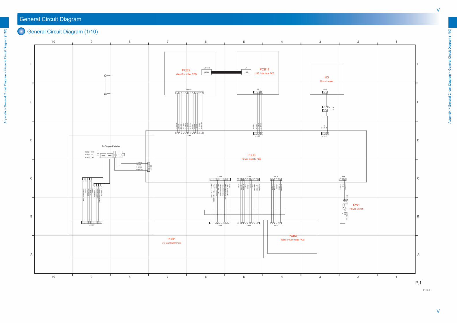
V
V
App
endi
x >
Gen
eral
Circ
uit D
iagr
am >
Gen
eral
Circ
uit D
iagr
am (1
/10)
App
endi
x >
Gen
eral
Circ
uit D
iagr
am >
Gen
eral
Circ
uit D
iagr
am (1
/10)
General Circuit Diagram
General Circuit Diagram (1/10)
12345678910
12345678910
F
E
D
C
B
A
F
E
D
C
B
A
P.1
NO
COM
A5 B4
N.C
P GND
USBUSB
N.C
+5V
R
+24V
R1
+24V
R1
+24V
U
+24V
U
ZE
RO
CR
OS
S
HE
AT
ER
1 O
N
HE
AT
ER
2 O
N
DO
OR
OP
EN
L G
ND
L G
ND
Power Supply PCB
GN
D
AC
TY
PE
2 (1
00)
AC
TY
PE
1 (1
20/2
30)
+5V
C
+5V
C
L GND
+24V
R2
EN
GIN
E E
NB
L
GN
D
FIN
TX
D
FIN
RX
D
GN
D
FIN
EN
BL
FIN
RE
SE
T
FIN
DO
WN
LO
AD
FIN
DC
T
L G
ND
L G
ND
+5V
R
+5V
R
J1
H N
+24V
R1
P G
ND
+5V
R
L G
ND
L G
ND
L G
ND
ES
S1
ES
S2
+3.3
VR
L G
ND
+5V
C
P G
ND
+24V
R2
+24V
R1
+24V
R1
GN
D
GN
D
GN
D
GN
D
RE
LA
Y O
N*
EN
V H
EA
TE
R O
N
J8104
71 65432 8 9
J207
121181 2 3 4 5 6 7 9 10
J106
9 8 23456 17
J1052345 1
J108
71 65432 8 9
J205
23
41
J1
09
+24VR2
+5VR
1 32
J102
21
J032 3 41
J2
2 3 41
J107
1097654321 8 11 12
J8125
2345 1
J9038 1234567910
J201
8 1234567910
J10423 1
J103
FT
21
10
FT
21
09
14
21 J11M
21 J11F
41 2 3
J2521DH
J2521DB
J2521DA
21
PCB6
Power SwitchSW1
DC Controller PCBPCB1 Reader Controller PCB
PCB3
Drum HeaterH3
USB Interface PCBPCB11
Main Controller PCBPCB2
MT3
MT2
4 1235
23
To Staple Finisher
F-10-3
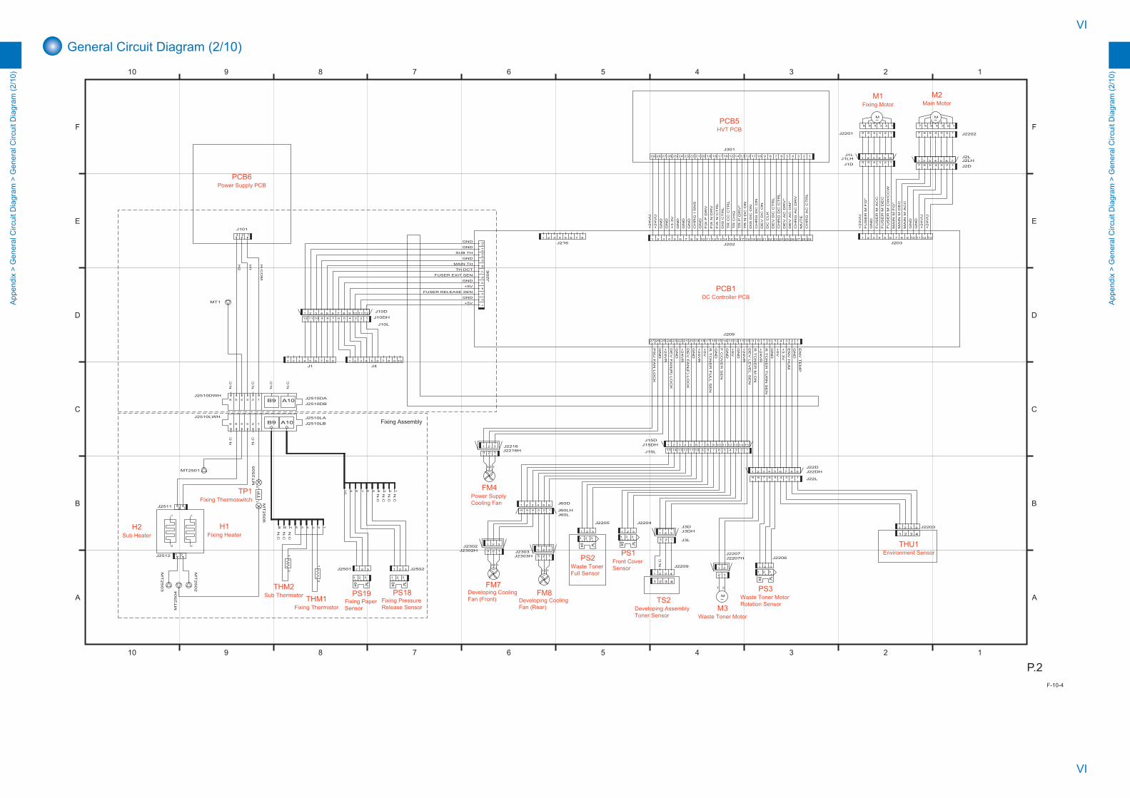
VI
VI
App
endi
x >
Gen
eral
Circ
uit D
iagr
am >
Gen
eral
Circ
uit D
iagr
am (2
/10)
App
endi
x >
Gen
eral
Circ
uit D
iagr
am >
Gen
eral
Circ
uit D
iagr
am (2
/10)
General Circuit Diagram (2/10)
12345678910
12345678910
F
E
D
C
B
A
F
E
D
C
B
A
P.2
B9
TP
MM
M
B9 A10
A10
GN
D
GN
D
+24V
R
+24V
R
123123
3 2 1
N.C
GN
D
GN
D
1 2 3 4
N.C
N.C
N.C
N.C
N.C
2
+24V
R
GN
D
+24V
U
N.C
N.C
N.C
+24V
U
GN
D
GN
D
+24V
U
H1
H2
H-C
OM
FU
SE
R M
AC
C
FU
SE
R M
DE
C
FU
SE
R M
CW
/CC
W
MA
IN M
DE
C
MA
IN M
AC
C
GN
D
+5V
DE
V L
EV
EL S
EN
GN
D
GND
SUB TH
GND
GND
MAIN TH
TH DCT
GND
+5V
FUSER RELEASE SEN
GND
+5V
FUSER EXIT SEN
1
N.C
N.C
1 2 3 4
Fixing Assembly
CH
RG
AC
DR
V
CH
RG
AC
CT
RL
CH
RG
DC
CT
RL
DE
V D
C C
TR
L
DC
CLK
DE
V D
C O
N
CH
RG
DC
ON
DIS
DC
ON
TR
N D
C O
N
TR
CC
CT
RL
DIS
CT
RL
FIX
N C
TR
L
FIX
N D
RV
FIX
P D
RV
CH
RG
I S
NS
GN
D
+3.3
V
GN
D
GN
D
+24V
U
+24V
U
GN
D
TR
CH
G
TR
P D
RV
*
DE
V A
C D
RV
*
DE
V A
C O
N*
MU
TE
FU
SE
R M
FG
*
MA
IN M
FG
*
R T
ON
ER
M O
N
+24V
R
GN
D
F C
OV
ER
SE
N
GN
D
+5V
+3.3
V
EN
V H
UM
GN
D
EN
V T
EM
P
N.C
N.C
+5V
N.C
R T
ON
ER
FU
LL S
EN
R T
ON
ER
TU
RN
SE
N
+24V
R
GN
D
PS
U F
AN
LO
CK
DE
V F
AN
(F) L
OC
K
DE
V F
AN
(R) L
OC
K
J2510LA3 2 146 5
J2510LWH
15 14 13 12 11 10 9 8 23456 17J15L
J22DH7 16 5 4 3 289 J22L
151413121110982 3 4 5 61 7J15D
982 3 4 5 61 7J22D
1234567891012131415161718192021222324252627 11
J209
654321 J60D
1 2 3J2303
123456
J60LJ60LH
J2302HJ2303H
321J2302
1 2 3
J2204
1 2 3
1 2 3 4
J2209
29 28 27 26 25 24 23 22 21 20 19 18 17 16 15 14 13 12 11 10 9 8 7 6 5 4 3 2 1
J301
1 2 3 4 5 6 7 8 9 10 11 12 13 14 15 16 17 18 19 20 21 22 23 24 25 26 27 28 29
J202
13121110982 3 4 5 61 7
J2031 2 3 4 5 6 7 8
J216
J3DH
123 J3L
12
11
10
98
23
45
61
7
J2
06
982 3 4 5 61 7
J110982 3 4 5 61 7
J4
23 1
J101
1 2 3 J2216J2216H
1 2 3 4 J2203
123
56 4 123J2510DWH
1 2 3
J2206
1 2
J2207
J2LH
1 2 3
J2205
J2207H
121110982 3 4 5 61 7 J10D
12 11 10 9 8 23456 17
J10L
MT1
1 2 3 4 5 6 7J2L
1234567 J2D123456J1D
J1LH 1 2 3 4 5 6J1L
123456J2201 1234567 J2202
321
321
MT
25
06
MT
25
05
MT
25
02
J2510DAJ2510DB
21J2512
12J2511
MT2501
1 2
6 5 4 3 2 1 7 6 5 3 2 14
M2Main Motor
M1Fixing Motor
PCB5HVT PCB
PCB1DC Controller PCB
THU1Environment Sensor
M3Waste Toner Motor
THM1Fixing Thermistor
THM2Sub Thermistor
H1Fixing Heater
H2Sub Heater
TP1Fixing Thermoswitch
PS18Fixing Pressure Release Sensor
PS19Fixing Paper Sensor
FM4Power Supply Cooling Fan
FM8Developing Cooling Fan (Rear)
FM7Developing Cooling Fan (Front)
PS1Front Cover Sensor
PS2Waste Toner Full Sensor
TS2Developing Assembly Toner Sensor
PS3Waste Toner Motor Rotation Sensor
PCB6Power Supply PCB
21
12
12 2
1
12
MT
25
03
MT
25
04
J2510LB
4 1235678910
4 12356789
1 2 3J2501 321 J2502321
1 2 3
J3D
1 2 3
321
123
J15DH
J10DH
F-10-4

VII
VII
App
endi
x >
Gen
eral
Circ
uit D
iagr
am >
Gen
eral
Circ
uit D
iagr
am (3
/10)
App
endi
x >
Gen
eral
Circ
uit D
iagr
am >
Gen
eral
Circ
uit D
iagr
am (3
/10)
General Circuit Diagram (3/10)
12345678910
12345678910
F
E
D
C
B
A
F
E
D
C
B
A
P.3
M
P S
P S
MSL
CLCLM
P S
SL SL
M
M
M
GN
D
CS
T S
IZE
1
CS
T S
IZE
3
CS
T S
IZE
4
CS
T S
IZE
2
OH
P S
EN
+5V
+24V
R
GN
D
3 2 1
21
22 12 1 2 1
21
3 2
1
2 1
321
321
+24V
R
+5V
GN
D
+5V
+24V
R
GN
D
+5V
GN
D
+5V
GN
D
+5V
GN
D
GN
D
+5V
EX
IT S
EN
CS
T L
EV
EL A
SE
N
CS
T L
EV
EL B
SE
N
GN
D
GN
D
+24F
U2
RE
VE
RS
E S
L O
N
GN
D
+5V
GN
D
N.C
+5V
GN
D
DU
PLE
X M
B*
DU
PLE
X M
B
CS
T P
AP
ER
SE
N
+24V
R
HO
PP
ER
M O
N
RE
GIS
T C
L O
N
+24V
R
+24V
R
SLE
EV
E C
L O
N
+24V
R
RE
GIS
T S
EN
GN
D
PR
E R
EG
IST
SE
N
+5V
BO
TT
LE
TU
RN
SE
N
GN
D
+24V
R
+24V
R
DU
PLE
X S
EN
RO
OP
SE
N
DU
PLE
X M
A
DU
PLE
X M
A*
N.C
321
34 1
23
321
RE
VE
RS
E S
EN
EX
IT F
ULL S
EN
RE
AR
FA
N L
OC
K
11 2 3 4
12345
MU
LT
I P
AP
ER
SE
N
GN
D
+5V
MU
LT
I F
EE
D S
L O
N
+24F
U2
EX
HA
US
T F
FA
N L
OC
K
EX
HA
US
T R
FA
N L
OC
K
RE
VE
RS
E M
A
RE
VE
RS
E M
B*
RE
VE
RS
E M
B
LIF
T S
EN
+5V
GN
D
+5V
FE
ED
SE
N
GN
D
+5V
GN
D
RE
VE
RS
E M
A*
HO
PP
ER
LE
VE
L S
EN
+24V
R
BO
TT
LE
M O
N
GN
D
N.C
FE
ED
M B
*
FE
ED
M B
FE
ED
M A
*
FE
ED
M A
EX
IT F
AN
LO
CK
(R)
+5V
GN
D
GN
D
N.C
EX
IT F
AN
LO
CK
(F)
LIF
T M
ON
+24V
R
+24V
R
FE
ED
SL O
N
123
3 2 1
J2236
11 23222120191817161514131210987654321J9L
123 J5DJ5DH
J8DH
Right Door Unit
J7DH
12345678910121314151617181920212223 11J9D
1 2 3 4 5 6 7 8 9 10 11 12 13 14 15 16 17 18 19 20 21 22 23 24 25 26 27 28 29 30 31
J213
J21DH18 17 16 15 14 13 12 11 10 9 8 23456 1719 J21L
1 2 3J2210
1971 65432 8 9 10 11 12 13 14 15 16 17 18J21D
1 2 3 4 5 6 J40D
6 5 4 3 2 1J40L
1 2 3J2300
J2300H
J40LH
123456 J7L
12
12345678910111213141516171819202122232425
J211
123
3 2 1
J2238
321
J20LH1 2 3 4J20L
1234 J20D
1 2 3 4 5 6 J2233
54321 6
1 2 3J2214
J2214HJ2215H
1234
321
J2213H
12345 J2241
4321 J22301 2 3 4 J2225
10982 3 4 5 61 7J6D
123 J2223
17 16 15 14 13 12 11 10 9 8 23456 17 J8D
12 J14D
2 1
J2218
1716151413121110982 3 4 5 61 7J8L
1 2 3J5L
1 2 J2226J2226H
J14LH1 2J14L
J2218H
J2220H
123J2217
1 2 3
123 J2219J2219H
21
1 2 3 4 5J13LJ13LH
12345 J13D
J2228H J2227H1 2 J2229
J2234H
1 2 3 4 5 6J7D
1 2 3
2 1
21 J2228
2 1 2 1
21
J2235H
123
J2235
1 2
321
1 2 3 4J2215
J6LH
1233 2 1 3 2 1 123
321
3 2 1
3 2 1
123
PS7Multi-purpose Tray Paper Sensor
PS9Arch Sensor
PS8Duplex Feed Sensor
SL2Reverse Feed Solenoid
PS20Transparency Sensor
PS17Cassette Paper Level Sensor B
PS16Cassette Paper Level Sensor A
PS15Cassette Paper Sensor
PS14Cassette Lifting Plate Sensor
PS13Cassette Pickup Sensor
M9Lifter Motor
SW2Cassette Size Detection Switch
M8Pickup Motor
PCB1DC Controller PCB
M4Reverse Feed Motor
PS6Reverse Sensor
PS5Delivery Sensor
FM1Delivery Cooling Fan (Rear)
FM2Delivery Cooling Fan (Center)
PS12Pre-registration Sensor
PS11Registration Sensor
M7Duplex Feed Motor
CL2Developing Cylinder Clutch
CL1Registration Clutch
M6Hopper Motor
M5Bottle Motor
TS1Hopper Toner Sensor
PS10Bottle Rotation Sensor
FM3Delivery Cooling Fan (Front)
PS4Delivery Paper Full Sensor
SL3Cassette Pickup Solenoid
SL1Multi-purpose Tray Pickup Solenoid
FM6Heat Exhaust Fan (Rear)
FM5Heat Exhaust Fan (Front)
3211 2 3321
10 9 8 23456 17 J6L
2 1
J2234
123 J2222
321
321J22111 2 3J2212
3 2 1
J2240
123
J2239
123
J2237
321 J22311 2 3 J2232
3 2 1 J2220J2221H
123J2221
4321
1 2 3 J2213
1 2 J22271 2 3 J2224
J2229H
321
181716151413121110982 3 4 5 61 7 19
J212
123
J2301
3 2 1
12345678910121314151617181920212223 11
J210
J9DH
F-10-5
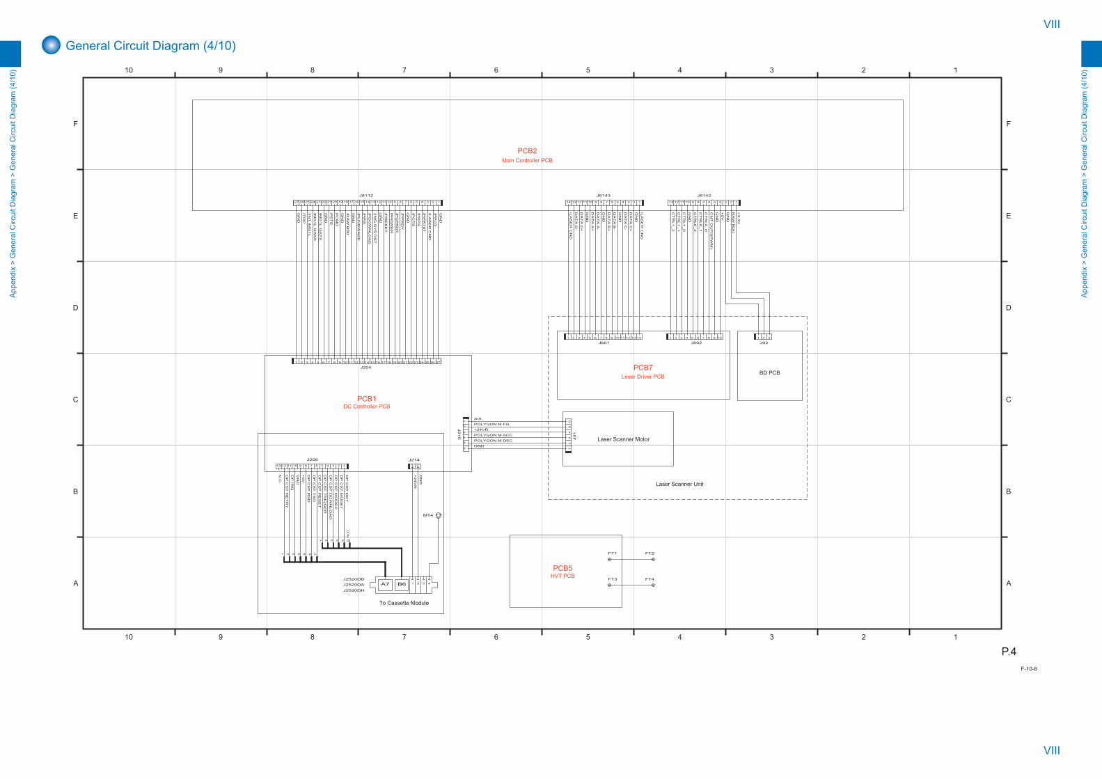
VIII
VIII
App
endi
x >
Gen
eral
Circ
uit D
iagr
am >
Gen
eral
Circ
uit D
iagr
am (4
/10)
App
endi
x >
Gen
eral
Circ
uit D
iagr
am >
Gen
eral
Circ
uit D
iagr
am (4
/10)
General Circuit Diagram (4/10)
12345678910
12345678910
F
E
D
C
B
A
F
E
D
C
B
A
P.4
A7 B6
N.C
.
+24VR
GN
D
OP
CS
T M
OD
E1
+5V
+5V
CT
RL0_0
CT
RL0_1
CT
RL0_2
+3.3
V
CT
RL1_0
CT
RL1_1
CT
RL1_2
GN
D
S/S
Laser Scanner Unit
BD PCB
PCB2Main Controller PCB
PCB1DC Controller PCB
PCB5HVT PCB
PCB7Leser Driver PCB
+24V
R
To Cassette Module
OP
CS
T D
CT
GN
D
GN
D
OP
IRQ
POLYGON M FG
POLYGON M DEC
POLYGON M ACC
OP
CS
T M
OD
E2
OP
CS
T D
OW
NLO
AD
OP
CS
T T
RIG
GE
R
OP
CS
T R
ES
ET
OP
CS
T T
XD
OP
CS
T R
XD
OP
CS
T R
ET
RY
CN
T O
UT
0(P
WM
)
DA
TA
D-
GN
D
DA
TA
C+
DA
TA
D+
DA
TA
C-
GN
D
DA
TA
A+
GN
D
DA
TA
B-
DA
TA
A-
DA
TA
B+
GN
D
/PP
RT
ST
PS
TS
RA
W B
D0
GND
N.C
.
/LA
SE
R C
ND
/PP
O3
/PR
TS
/PC
TS
/PP
RD
Y
PP
OW
ER
/PR
ES
ET
/PC
PR
DY
/IMG
SY
S R
ST
/PD
OW
NLO
AD
/PP
I0
/PLIV
EW
AK
E
/RA
W B
D0
PC
MD
GN
D
GN
D
GN
D
GN
D
GN
D
GN
D
IMG
1L G
AT
X
IMG
1L G
AR
X
GN
D
/INT
IMG
1L
/TO
P
/LA
SE
R C
ND
/LA
SE
R C
ND
GN
D
Laser Scanner Motor
13 12 11 10 9 8 23456 17
J208
1127 26 25 24 23 22 21 20 19 18 17 16 15 14 13 12 10 9 8 7 6 5 4 3 2 1
J8112
1 2 3 4 5 6 7 8 9 10 12 13 14 15 16 17 18 19 20 21 22 23 24 25 26 2711
J204
12
34
56
J2
15
65
43
21
J0
1
14 13 12 11 10 9 8 23456 17
J8143
13 12 11 10 9 8 23456 17
J8142
1413121110982 3 4 5 61 7
J60110982 3 4 5 61 7
J6021 2 3
J02
J2520DBJ2520DA 41 2 3
J2520DH
FT4
FT2
FT3
FT1
21
J214
4 65321
765321 4
MT4
F-10-6

IX
IX
App
endi
x >
Gen
eral
Circ
uit D
iagr
am >
Gen
eral
Circ
uit D
iagr
am (5
/10)
App
endi
x >
Gen
eral
Circ
uit D
iagr
am >
Gen
eral
Circ
uit D
iagr
am (5
/10)
General Circuit Diagram (5/10)
12345678910
12345678910
F
E
D
C
B
A
F
E
D
C
B
A
P.5
MO
DE
M S
NS
I
LP
L2
LP
L1
HO
OK
2
HO
OK
1
CI2
LP
RD
CM
LD
HR
D
CA
IDD
GN
D
CI1
GN
D
RE
AD
ER
FF
C IN
GN
D
SIC
LK
GN
D
SIL
OA
D
GN
D
HP
S
RX
1-
RX
1+
RX
CLK
-
GN
D
RX
CLK
+
GN
D
RX
3-
RX
3+
GN
D
DE
S
AD
F E
XIT
AD
F R
EG
GN
D
AD
F C
OV
ER
SE
NS
IRQ
AD
F R
EV
ER
SE
GN
D
SIZ
E O
N
MO
T IR
Q
GN
D
/RE
SE
T R
EA
DE
R
RE
AD
ER
FF
C O
UT
GN
D
UI T
XD
GN
D
UI R
XD
QV
GA
LC
DE
N
+3.3
VR
QV
GA
ST
AR
TP
GN
D
/UI S
OF
TS
W
+3.3
VP
AN
EL
BK
LT
ON
QV
GA
LA
TC
HP
+5V
PA
NE
L
+5V
PA
NE
L
/RE
SE
T U
I
GN
D
/QV
GA
XC
LK
QV
GA
UD
0
QV
GA
UD
1
QV
GA
UD
2
QV
GA
UD
3
GN
D
SID
AT
AI
SID
AT
AO
MO
DE
M S
NS
AG
ND
GN
D
BU
Z
IPS
EL
CIV
S
DC
LIM
SR
D
PR
D/P
RD
PU
LS
E
MO
DE
M S
NS
O
EX
BU
S D
AT
A0
EX
BU
S D
AT
A1
EX
BU
S D
AT
A3
EX
BU
S D
AT
A2
GN
D
EX
BU
S D
AT
A4
EX
BU
S D
AT
A5
EX
BU
S D
AT
A6
EX
BU
S D
AT
A7
GN
D
EX
BU
S A
DD
R0
EX
BU
S A
DD
R1
EX
BU
S A
DD
R2
EX
BU
S A
DD
R3
GN
D
/MO
DE
M C
S
/RE
SE
T M
OD
EM
EX
BU
S A
DD
R4
EX
BU
S A
DD
R5
EX
BU
S A
DD
R6
MO
DE
M S
NS
I
+3.3
V
+3.3
VR
GN
D
+24V
+5V
C
VOUT 2
VOUT 1
USB USB LAN/M
OD
EM
_W
E
/MO
DE
M_O
E
12
J1
00
8
21 J1
00
32
31 J1
00
4
123456
J811520 18 16
1
2
3
4
5
6
7
8
9
10
11131517192123
121422
J8114
201816
1
2
3
4
5
6
7
8
9
10
11 13 15 17 19 21 23
12 14 22
J324 302826201816
1
2
3
4
5
6
7
8
9
10
11 13 15 17 19 21 23 25 27 29
12 14 22
31
J907
2430 28 26 20 18 16
1
2
3
4
5
6
7
8
9
10
11131517192123252729
121422
31
J8202
24201816
1
2
3
4
5
6
7
8
9
10
11 13 15 17 19 21 23
12 14 22
J8201
201816
1
2
3
4
5
6
7
8
9
10
11 13 15 17 19 21
12 14
J8200
1 2 3 4 5
J8134
1 2 3 4 5
J1002201816
1
2
3
4
5
6
7
8
9
10
11 13 15 17 19 21
12 14
J1000
24201816
1
2
3
4
5
6
7
8
9
10
11 13 15 17 19 21 23
12 14 22
J1001
2
1
SP1Speaker
PCB10FAX PCB
PCB2Main Controller PCB
PCB3Reader Controller PCB
PCB4Control Panel CPU PCB
F-10-7
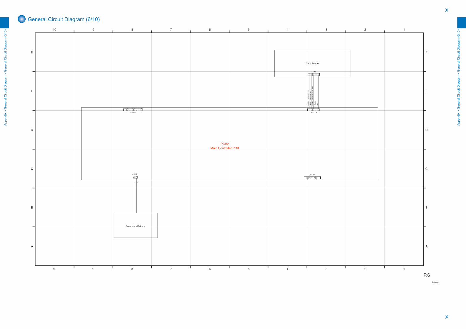
X
X
App
endi
x >
Gen
eral
Circ
uit D
iagr
am >
Gen
eral
Circ
uit D
iagr
am (6
/10)
App
endi
x >
Gen
eral
Circ
uit D
iagr
am >
Gen
eral
Circ
uit D
iagr
am (6
/10)
General Circuit Diagram (6/10)
12345678910
12345678910
F
E
D
C
B
A
F
E
D
C
B
A
P.6
CA
RD
RE
DE
R C
OU
NT
+5V
C
GN
D
12
J8124
+-
CA
RD
RE
DE
R T
X
CA
RD
RE
DE
R R
X
Card Reader
Secondary Battery
PCB2Main Controller PCB
1234567
J8117
1 2 3 4 5
J8119
12345
J10
1 2 3 4 5 6 7 8
J8116
F-10-8
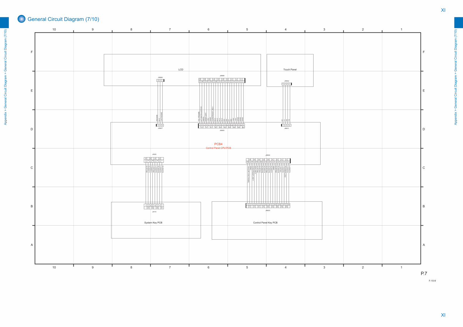
XI
XI
App
endi
x >
Gen
eral
Circ
uit D
iagr
am >
Gen
eral
Circ
uit D
iagr
am (7
/10)
App
endi
x >
Gen
eral
Circ
uit D
iagr
am >
Gen
eral
Circ
uit D
iagr
am (7
/10)
General Circuit Diagram (7/10)
12345678910
12345678910
F
E
D
C
B
A
F
E
D
C
B
A
P.7
1
2
3
4
5
6
7
8
PCB4Control Panel CPU PCB
LCD
Control Panel Key PCB
L-D
GT
5
L-R
TN
1
K-D
GT
4
K-R
TN
3
L-D
GT
4
PO
WE
R-L
ED
L-D
GT
3
GN
D
K-D
GT
7
K-D
GT
5
K-R
TN
4
K-D
GT
3
K-D
GT
6
K-R
TN
1
K-R
TN
2
ES
S-K
EY
CO
NT
RA
ST
-KE
Y
+5V
(VR
VO
LT
AG
E)
GN
D
YD
FR
AM
E
LP
DA
TA
-LA
TC
H
XS
CL
DIS
P-O
FF
+5V
GN
D
CO
NT
RA
ST
-AD
J
N.C
N.C
N.C
N.C
D3
D2
D1
D0
+5V
+5V
GN
D
GN
D
GN
D
AN
OD
E
N.C
CA
TH
OD
E
X1
Y1
X2
Y2
System Key PCB
1
2
3
4
5
6
7
8
J669
J670
K-D
GT
2
L-D
GT
2
K-D
GT
0
L-D
GT
0
L-R
TN
0
L-D
GT
1
K-D
GT
1
K-R
TN
0
Touch Panel
1234
J662
1 2 3 4
J661
123
J66820 18 16
1
2
3
4
5
6
7
8
9
10
1113151719
1214
J666
1 2 3
J667
1816
1
2
3
4
5
6
7
8
9
10
11 13 15 17 19
12 14
J663
18 16
1
2
3
4
5
6
7
8
9
10
1113151719
1214
J664
201816
1
2
3
4
5
6
7
8
9
10
11 13 15 17 19
12 14
J665
F-10-9
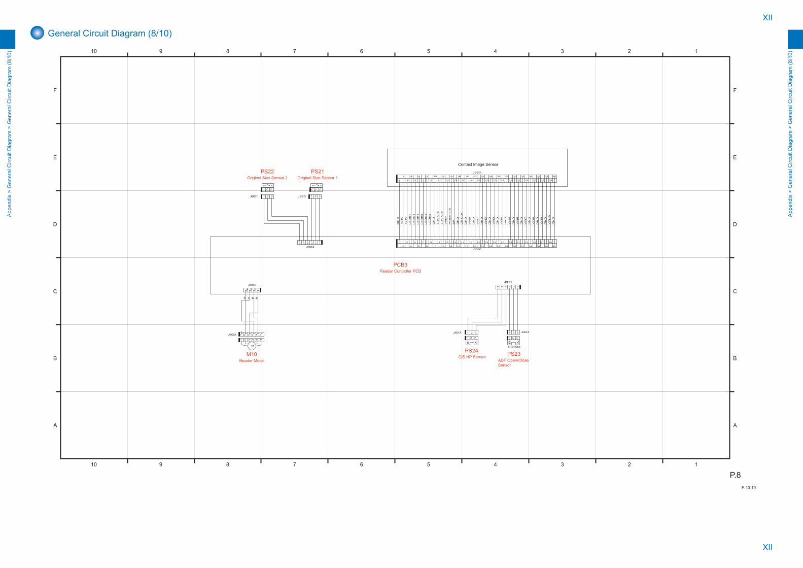
XII
XII
App
endi
x >
Gen
eral
Circ
uit D
iagr
am >
Gen
eral
Circ
uit D
iagr
am (8
/10)
App
endi
x >
Gen
eral
Circ
uit D
iagr
am >
Gen
eral
Circ
uit D
iagr
am (8
/10)
General Circuit Diagram (8/10)
12345678910
12345678910
F
E
D
C
B
A
F
E
D
C
B
A
P.8
P SP S
M
GN
D
GN
D
GN
D
GN
D
GN
D
GN
D
GN
D
GN
D
GN
D
GN
D
GN
D
GN
D
Contact Image Sensor
PS24CIS HP Sensor
PCB3Reader Controller PCB
PS21Original Size Sensor 1
PS22Original Size Sensor 2
M10Reader Motor
PS23ADF Open/Close Sensor
+24V
+24V
LE
DB
1
LE
DG
1
LE
DR
1
LE
DB
2
LE
DG
2
LE
DR
2
GN
D
3.3
V C
IS
3.3
V C
IS
VR
EF
MO
DE
CIS
SP
GN
D
CS
CLK
GN
D
VIN
0
VIN
1
VIN
2
VIN
3
VIN
4
VIN
5
VIN
6
VIN
7
VIN
8
VIN
9
VIN
10
A B B-
A-
1 2 3J921
32154321 6
321J920
1 2 3J923
123456
J904
3 4 5 61 2J922
234 1
J905
321 J924
123456
J911
221412
393735333129272523211917151311
10
9
8
7
6
5
4
3
2
1
16 18 20 26 28 30 32 34 36 38 4024J902
24 4038363432302826201816
1
2
3
4
5
6
7
8
9
10
11 13 15 17 19 21 23 25 27 29 31 33 35 37 39
12 14 22
J950
321
1 2 3
SR903
1 2 3
F-10-10
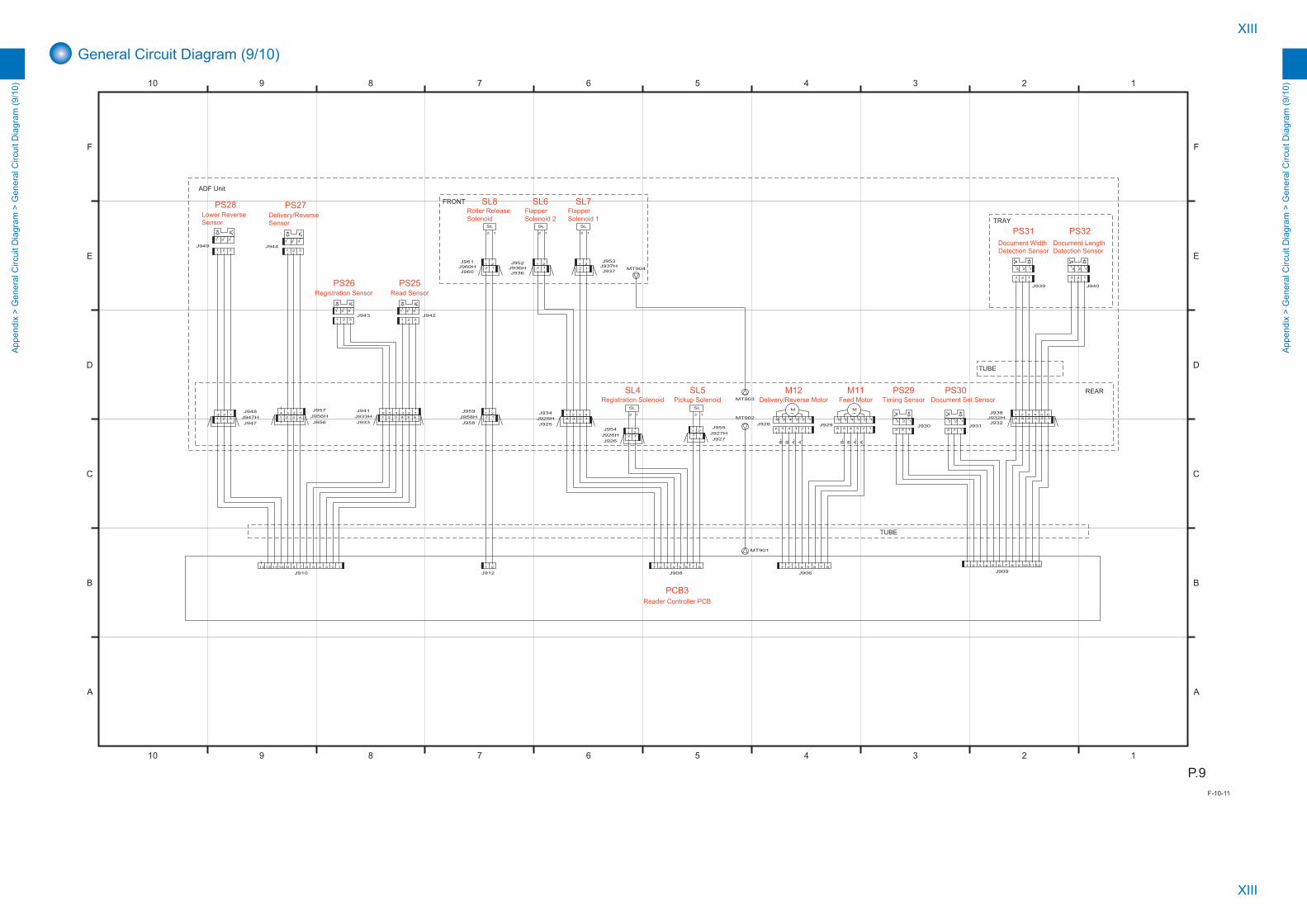
XIII
XIII
App
endi
x >
Gen
eral
Circ
uit D
iagr
am >
Gen
eral
Circ
uit D
iagr
am (9
/10)
App
endi
x >
Gen
eral
Circ
uit D
iagr
am >
Gen
eral
Circ
uit D
iagr
am (9
/10)
General Circuit Diagram (9/10)
12345678910
12345678910
F
E
D
C
B
A
F
E
D
C
B
A
P.9
SL
SLSL
SLSL
M M
A-
Reader Controller PCBPCB3
BA B-
A
TRAY
ADF Unit
B-
B A-
REAR
TUBE
FRONT
TUBE
12
J936J936H2 1
J960
123456J932
J932H1 2 3 4 5 6J938
J933H 654321
J933
6 5 4 3 2 1J941
J960H1 2J961 21J952
1 2 3 4J934
2 1J927
J927H
J925H 4 3 2 1
J925
1 2 3 4 5 6 7 8
J906
MT903
MT904
1 2 3J942
1 2 3J949
1 2 3
J958H 12
J958
21J959
1 2
J912
MT9021 2 3J947
J947H J956H4 3 2 1
J957
1 2 3 4J956
3 2 1J948
J937H3 2 1
PS32Document Length Detection Sensor
3 2 1
J940
123
PS31Document Width Detection Sensor
123
J939
6 5 4 3 2 1J929
123456J928
123J930
MT901
121110982 3 4 5 61 7
J909
123456
M11Feed Motor
6 5 4 3 2 1
Delivery/Reverse MotorM12
3 2 1J931
3 2 1
PS30Document Set Sensor
123
PS29Timing Sensor
1 2 3J944
1 2 3
321
321J943
1 2 3
PS25Read Sensor
PS26Registration Sensor
PS27Delivery/Reverse Sensor
PS28Lower Reverse Sensor
J926H1 2
J9542 1
J926
21J955
12J937
21J953
12
SL6Flapper Solenoid 2
12
SL7Flapper Solenoid 1
2 1
SL4Registration Solenoid
2 1
SL5Pickup Solenoid
2 1
SL8Roller Release Solenoid
13 12 11 10 9 8 23456 17
J91087654321
J908
F-10-11

XIV
XIV
App
endi
x >
Gen
eral
Circ
uit D
iagr
am >
Gen
eral
Circ
uit D
iagr
am (1
0/10
)
App
endi
x >
Gen
eral
Circ
uit D
iagr
am >
Gen
eral
Circ
uit D
iagr
am (1
0/10
)
General Circuit Diagram (10/10)
12345678910
12345678910
F
E
D
C
B
A
F
E
D
C
B
A
P.10
SL
B6A7
A7 B6
M
M
GN
D(P
)
+5V
+24R
GN
D(L
)
GN
D(L
)
GN
D(L
)
+24R
+5V
GN
D(L
)
OP
C_R
EQ
OP
C_T
XD
OP
C_IR
QO
PC
_R
EQ
OP
C_IR
Q
OP
C_R
XD
OP
C_R
ES
ET
OP
C_T
RG
OP
C_D
L
OP
C_M
OD
E1
OP
C_M
OD
E2
UP
_O
PC
_D
CT
OP
C_R
XD
OP
C_T
XD
OP
C_R
ES
ET
OP
C_T
RG
OP
C_D
L
OP
C_M
OD
E1
OP
C_M
OD
E2
L_O
PC
_D
CT
OP
C_S
IZE
_4
OP
C_S
IZE
_3
GN
D(L
)
OP
C_S
IZE
_2
OP
C_S
IZE
_1
GN
D(L
)
+5V
GN
D(P
)
OP
C_F
EE
D_/M
A
OP
C_F
EE
D_/M
B
OP
C_F
EE
D_M
B
OP
C_F
EE
D_M
A
+24R
OP
C_F
EE
D_S
OL O
N
+24R
OP
C_LIF
T_M
OT
OR
ON
OP
C_R
ET
RY
_S
EN
S
GN
D(L
)
OP
C_P
AP
ER
_S
EN
S
GN
D(L
)
+5V
OP
C_LIF
T_S
EN
S
GN
D(L
)
+5V
OP
C_F
EE
D_S
EN
S
GN
D(L
)
+5V
OP
C_LE
VE
L_B
_S
EN
S
GN
D(L
)
+5V
GN
D(L
)
OP
C_LE
VE
L_A
_S
EN
S
+5V
+5V
OP
C_D
OO
R_S
EN
S
Cassette Module Controller PCB
PCB101
Pickup MotorM101
Cassette Pickup SolenoidSL101 Lifter Motor
M102
Cassette Pickup Sensor
PS107Cassette Lifting Plate Detection Sensor
PS101Cassette Paper Sensor
PS102Cassette Retry Sensor
PS103Cassette Paper Level Sensor A
PS104Cassette Paper Level Sensor B
PS105Cassette Right Cover Sensor
PS106Cassette Size Detection Switch
To Lower Cassette Module
To Upper Cassette Module or Host Machine
SW101
1 2 3 4 5 J1805D
123
J1001LJ1001LH
41 2 3
J1802DWH
MT1
41 2 3J1802LWH
MT2
181716151413121110982 3 4 5 61 7 19 J1806DJ1806DH
18 17 16 15 14 13 12 11 10 9 8 23456 1719J1806L
J1805LH12345J1805L
2 1
SOLD1SOLD2
1 2 3J1001D
1 2 3 4 5
J10111 2 3
J10071 2 3
J10041 2 3J1005
1 2 3J1006
1 2 3J1008
1 2 3J1009
1 2 3J1010
1234567891012131415161718192021222324252627 11
J806
12
34
J8
08
1 2 3
15 14 13 12 11 10 9 8 23456 17
J804
13121110982 3 4 5 61 7
J802
2 31
J803
123456J1003
1 2 3
J1002H
2 1J1002
5 4 3 2 16
1 2 3 4 5
J807
J1802LBJ1802LA
J1802DAJ1802DB
21
J801
982 3 4 5 61 7
J805
1 2 3
21
1 2 3
4 12356
4 123567
41 2 3 5 6 7
41 2 3 5 6
3211 2 31 2 3
J1802DA_BUS[0:7]
J1802DB_BUS[0:6]
J1802LB_BUS[0:6]
J1802LA_BUS[0:7]
F-10-12
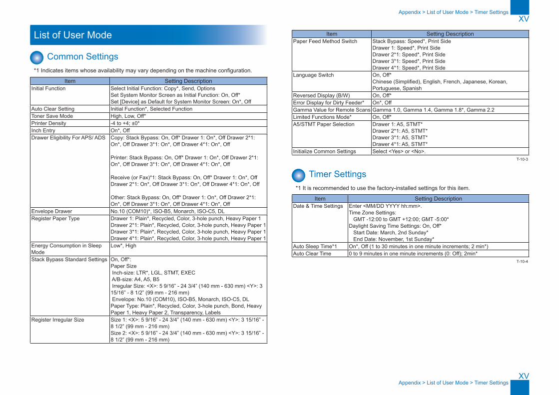
XV
XV
Appendix > List of User Mode > Timer Settings
Appendix > List of User Mode > Timer Settings
List of User Mode
Common Settings*1 Indicates items whose availability may vary depending on the machine configuration.
Item Setting DescriptionInitial Function Select Initial Function: Copy*, Send, Options
Set System Monitor Screen as Initial Function: On, Off* Set [Device] as Default for System Monitor Screen: On*, Off
Auto Clear Setting Initial Function*, Selected FunctionToner Save Mode High, Low, Off*Printer Density -4 to +4; ±0*Inch Entry On*, OffDrawer Eligibility For APS/ ADS Copy: Stack Bypass: On, Off* Drawer 1: On*, Off Drawer 2*1:
On*, Off Drawer 3*1: On*, Off Drawer 4*1: On*, Off
Printer: Stack Bypass: On, Off* Drawer 1: On*, Off Drawer 2*1: On*, Off Drawer 3*1: On*, Off Drawer 4*1: On*, Off
Receive (or Fax)*1: Stack Bypass: On, Off* Drawer 1: On*, Off Drawer 2*1: On*, Off Drawer 3*1: On*, Off Drawer 4*1: On*, Off
Other: Stack Bypass: On, Off* Drawer 1: On*, Off Drawer 2*1: On*, Off Drawer 3*1: On*, Off Drawer 4*1: On*, Off
Envelope Drawer No.10 (COM10)*, ISO-B5, Monarch, ISO-C5, DLRegister Paper Type Drawer 1: Plain*, Recycled, Color, 3-hole punch, Heavy Paper 1
Drawer 2*1: Plain*, Recycled, Color, 3-hole punch, Heavy Paper 1 Drawer 3*1: Plain*, Recycled, Color, 3-hole punch, Heavy Paper 1 Drawer 4*1: Plain*, Recycled, Color, 3-hole punch, Heavy Paper 1
Energy Consumption in Sleep Mode
Low*, High
Stack Bypass Standard Settings On, Off*: Paper Size Inch-size: LTR*, LGL, STMT, EXEC A/B-size: A4, A5, B5 Irregular Size: <X>: 5 9/16” - 24 3/4” (140 mm - 630 mm) <Y>: 3 15/16” - 8 1/2” (99 mm - 216 mm) Envelope: No.10 (COM10), ISO-B5, Monarch, ISO-C5, DL Paper Type: Plain*, Recycled, Color, 3-hole punch, Bond, Heavy Paper 1, Heavy Paper 2, Transparency, Labels
Register Irregular Size Size 1: <X>: 5 9/16” - 24 3/4” (140 mm - 630 mm) <Y>: 3 15/16” - 8 1/2” (99 mm - 216 mm) Size 2: <X>: 5 9/16” - 24 3/4” (140 mm - 630 mm) <Y>: 3 15/16” - 8 1/2” (99 mm - 216 mm)
Item Setting DescriptionPaper Feed Method Switch Stack Bypass: Speed*, Print Side
Drawer 1: Speed*, Print Side Drawer 2*1: Speed*, Print Side Drawer 3*1: Speed*, Print Side Drawer 4*1: Speed*, Print Side
Language Switch On, Off* Chinese (Simplified), English, French, Japanese, Korean, Portuguese, Spanish
Reversed Display (B/W) On, Off*Error Display for Dirty Feeder* On*, OffGamma Value for Remote Scans Gamma 1.0, Gamma 1.4, Gamma 1.8*, Gamma 2.2Limited Functions Mode* On, Off*A5/STMT Paper Selection Drawer 1: A5, STMT*
Drawer 2*1: A5, STMT* Drawer 3*1: A5, STMT* Drawer 4*1: A5, STMT*
Initialize Common Settings Select <Yes> or <No>.
Timer Settings*1 It is recommended to use the factory-installed settings for this item.
Item Setting DescriptionDate & Time Settings Enter <MM/DD YYYY hh:mm>.
Time Zone Settings: GMT -12:00 to GMT +12:00; GMT -5:00* Daylight Saving Time Settings: On, Off* Start Date: March, 2nd Sunday* End Date: November, 1st Sunday*
Auto Sleep Time*1 On*, Off (1 to 30 minutes in one minute increments; 2 min*)Auto Clear Time 0 to 9 minutes in one minute increments (0: Off); 2min*
T-10-3
T-10-4
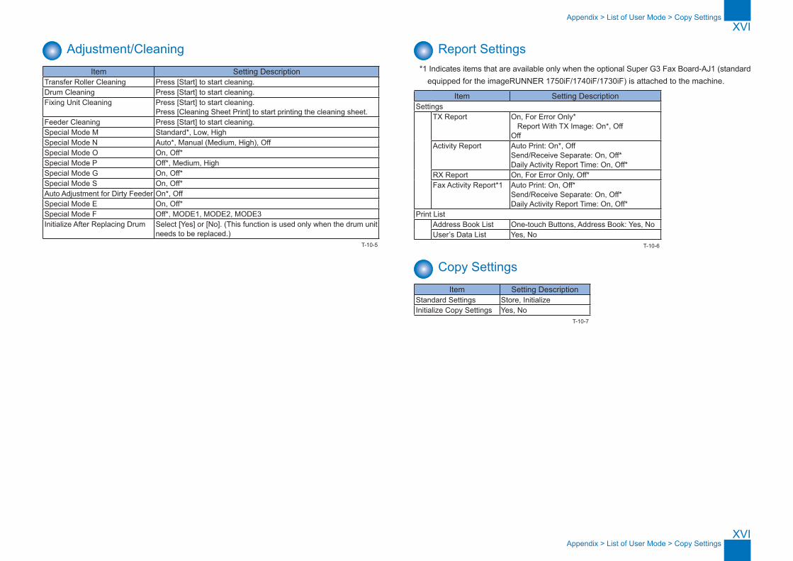
XVI
XVI
Appendix > List of User Mode > Copy Settings
Appendix > List of User Mode > Copy Settings
Adjustment/CleaningItem Setting Description
Transfer Roller Cleaning Press [Start] to start cleaning.Drum Cleaning Press [Start] to start cleaning.Fixing Unit Cleaning Press [Start] to start cleaning.
Press [Cleaning Sheet Print] to start printing the cleaning sheet.Feeder Cleaning Press [Start] to start cleaning.Special Mode M Standard*, Low, HighSpecial Mode N Auto*, Manual (Medium, High), OffSpecial Mode O On, Off*Special Mode P Off*, Medium, HighSpecial Mode G On, Off*Special Mode S On, Off*Auto Adjustment for Dirty Feeder On*, OffSpecial Mode E On, Off*Special Mode F Off*, MODE1, MODE2, MODE3Initialize After Replacing Drum Select [Yes] or [No]. (This function is used only when the drum unit
needs to be replaced.)T-10-5
Report Settings*1 Indicates items that are available only when the optional Super G3 Fax Board-AJ1 (standard
equipped for the imageRUNNER 1750iF/1740iF/1730iF) is attached to the machine.
Item Setting DescriptionSettings TX Report On, For Error Only*
Report With TX Image: On*, Off Off
Activity Report Auto Print: On*, Off Send/Receive Separate: On, Off* Daily Activity Report Time: On, Off*
RX Report On, For Error Only, Off*Fax Activity Report*1 Auto Print: On, Off*
Send/Receive Separate: On, Off* Daily Activity Report Time: On, Off*
Print ListAddress Book List One-touch Buttons, Address Book: Yes, NoUser’s Data List Yes, No
Copy SettingsItem Setting Description
Standard Settings Store, InitializeInitialize Copy Settings Yes, No
T-10-6
T-10-7
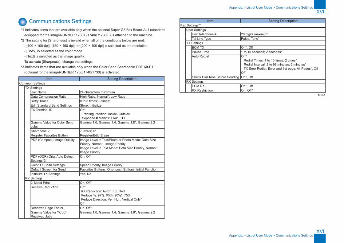
XVII
XVII
Appendix > List of User Mode > Communications Settings
Appendix > List of User Mode > Communications Settings
Communications Settings*1 Indicates items that are available only when the optional Super G3 Fax Board-AJ1 (standard
equipped for the imageRUNNER 1750iF/1740iF/1730iF) is attached to the machine.*2 The setting for [Sharpness] is invalid when all of the conditions below are met.
- [100 × 100 dpi], [150 × 150 dpi], or [200 × 100 dpi] is selected as the resolution.- [B&W] is selected as the color mode.- [Text] is selected as the image quality.To activate [Sharpness], change the settings.
*3 Indicates items that are available only when the Color Send Searchable PDF Kit-E1 (optional for the imageRUNNER 1750/1740/1730) is activated.
Item Setting DescriptionCommon Settings TX Settings
Unit Name 24 characters maximumData Compression Ratio High Ratio, Normal*, Low RatioRetry Times 0 to 5 times; 3 times*Edit Standard Send Settings Store, InitializeTX Terminal ID On*
Printing Position: Inside, Outside Telephone # Mark*1: FAX*, TEL
Gamma Value for Color Send Jobs
Gamma 1.0, Gamma 1.4, Gamma 1.8*, Gamma 2.2
Sharpness*2 7 levels; 4*Register Favorites Button Register/Edit, ErasePDF (Compact) Image Quality Image Level in Text/Photo or Photo Mode: Data Size
Priority, Normal*, Image Priority Image Level in Text Mode: Data Size Priority, Normal*, Image Priority
PDF (OCR) Orig. Auto Detect. Settings*3
On, Off
Color TX Scan Settings Speed Priority, Image PriorityDefault Screen for Send Favorites Buttons, One-touch Buttons, Initial FunctionInitialize TX Settings Yes, No
RX Settings2-Sided Print On, Off*Receive Reduction On*
RX Reduction: Auto*, Fix. Red. Reduce %: 97%, 95%, 90%*, 75% Reduce Direction: Ver. Hor., Vertical Only* Off
Received Page Footer On, Off*Gamma Value for YCbCr Received Jobs
Gamma 1.0, Gamma 1.4, Gamma 1.8*, Gamma 2.2
Item Setting DescriptionFax Settings*1
User SettingsUnit Telephone # 20 digits maximumTel Line Type Pulse, Tone*
TX SettingsECM TX On*, OffPause Time 1 to 15 seconds; 2 seconds*Auto Redial On*
Redial Times: 1 to 10 times; 2 times* Redial Interval: 2 to 99 minutes; 2 minutes* TX Error Redial: Error and 1st page, All Pages*, Off Off
Check Dial Tone Before Sending On*, OffRX Settings
ECM RX On*, OffRX Restriction On, Off*
T-10-8

XVIII
XVIII
Appendix > List of User Mode > Printer Settings > Other Settings
Appendix > List of User Mode > Printer Settings > Other Settings
Printer Settings ■ Settings Menu
*1 The Offset and Staple modes are available only when the optional Staple Finisher-H1 is attached to the machine.
Item Setting DescriptionDefault PapaerSize LTR*, STMT, EXECUTIV, No. 10 (COM10), MONARCH, ISO-C5, ISO-B5,
DL, A4, B5, A5, LGLDefault PaperType Plain*, Color, Recycled, Heavy Paper 1, Transparency, Bond, Labels,
3Hole Punch Paper, EnvelopeCopies 1* to 9992-Sided Printing Off*, OnPrint Quality Image Refinement On*, Off
Density 9 levels; 5*Toner Save Off*, OnLine Refinement On*, OffHorizontal Line Off*, Level 1, Level 2, Level 3, Level 4Vertical Line Off*, Level 1, Level 2, Level 3, Level 4
LayoutBinding Location Long Edge*, Short EdgeMargin -1.90 to +1.90Inches; 00.00Inches*
Auto Continue Off*, OnTimeout On (5 to 300sec), Off; 15sec*Finishing Off*, Collate, Offset+Collate*1, Offset+Group*1, Staple+Collate*1Personality Auto*, PCL, PSMode Priority Off*, PCL, PSAuto Select
PCL On*, OffPS On*, Off
Initialize Off*, On
■ PCL Settings*1*1 To use the PCL Printer function with the imageRUNNER 1750/1740/1730, the optional PCL Printer Kit-AL1 is required.*2 The BarDIMM function is available only when it is activated.
Item Setting DescriptionPaper Save OFF*, ONOrientation Portrait*, LandscapeFont Number 0* to 104Point Size 4.00 to 999.75 point; 12.00*Pitch 0.44 to 99.99 cpi; 10.00*
T-10-9
Item Setting DescriptionForm Lines 5 to 128 lines; 60*Symbol Set PC8*, PC850, PC851, PC852, PC862, PC864, PC866, PC8DN, PC8GRK,
PC8TK, PC1004, PIFONT, PSMATH, PSTEXT, ROMAN8, VNINTL, VNMATH, VNUS, WIN30, WINARB, WINBALT, WINCYR, WINGRK, WINL1, WINL2, WINL5, ARABIC8, DESKTOP, GREEK8, HEBREW7, HEBREW8, ISO4, ISO6, ISO11, ISO15, ISO17, ISO21, ISO60, ISO69, ISOCYR, ISOGRK, ISOHEB, ISOL1, ISOL2, ISOL5, ISOL6, LEGAL, MATH8, MCTEXT, MSPUBL, PC775
Custom Paper Off*, OnUnit of Measure Inches*, MillimetersX dimension 05.51 to 24.80 inch; 14.00*Y dimension 03.90 to 08.50 inch; 08.50*Append CR to LF No*, YesWiden A4 Print Off*, OnHalftones Text Resolution*, High Resolution, Tone, Gradation
Graphics Tone*, Gradation, Resolution, High ResolutionImage Tone*, Gradation, Resolution, High Resolution
BarDIMM*2 Enable*, DisableFreeScape ~, ", #, $, /, \, ?, {, }, |, OFF
■ PS Settings** To use the PS Printer function with the imageRUNNER 1750/1740/1730, the optional PS Printer Kit-AL1 is required.
Item Setting DescriptionJob Timeout 0 to 3600 seconds; 0s*Wait Timeout 0 to 3600 seconds; 300s*Print PS Errors Off*, OnHalftones Text High Resolution*, Gradation, Resolution
Graphics Gradation*, Resolution, High ResolutionImage Gradation*, Resolution, High Resolution
■ Other SettingsItem Setting Description
Ppr Size Override Off*, On
T-10-10
T-10-11
T-10-12

XIX
XIX
Appendix > List of User Mode > Address Book Settings > Register Address
Appendix > List of User Mode > Address Book Settings > Register Address
Address Book Settings ■ Register Address
Item Setting DescriptionRegister New add. Fax
Register Name Max. 16 charactersDestination Registration Max. 16 charactersFax Number Max. 120 characters (+, Pause, Tone, <, >, Backspace,
Space, ISDN sub Address, F net, DT, R, PIN)Option ECM TX OFF/ON*
Sending Speed 33600bps*, 14400bps, 9600bps, 4800bpsLong Distance Domestic*, Long Distance 1, Long Distance 2, Long Distance
3E-mail
Register Name Max. 16 charactersDestination Registration Max. 16 charactersE-Mail Address Max. 120 characters
I-FaxRegister Name Max. 16 charactersDestination Registration Max. 16 charactersI-Fax Address Max. 120 characters
FileRegister Name Max. 16 charactersDestination Registration Max. 16 charactersProtocol FTP*, Windows(SMB)Host Name FTP:Max.47 characters
Windows(SMB):Max. 120 charactersFile Path Max. 120 charactersUser Max. 24 charactersPassword FTP:Max.24 characters
Windows(SMB):Max. 14 charactersGroup
Register Name Max. 16 charactersDestination Registration Max. 16 charactersAddress Book Fax, E-Mail, I-Fax, RemoteFileSystem, JetSend, Box,
LocalPrinterDetails -
Erase -
Item Setting DescriptionNetwork Add. Book
Simple SearchServer to Search Registed LDAP ServerName Max. 120 charactersE-mail Max. 120 charactersFax Max. 120 characters
Detailed SearchServer to Search Registed LDAP ServerAdd Condition Name, E-mail, Fax, Organization, Org.Unit
contains, doesnotcontain, equals, differsfrom, beginswith, endswithMax. 120 characters
(matching) or/andSearch Results
Type All, E-mail, FaxSelect e-mail for I-Fax ON/OFF
Edit -Erase -
T-10-13
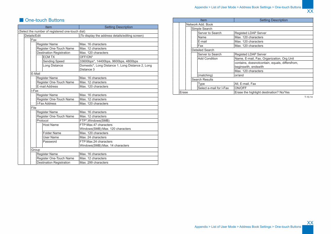
XX
XX
Appendix > List of User Mode > Address Book Settings > One-touch Buttons
Appendix > List of User Mode > Address Book Settings > One-touch Buttons
■ One-touch ButtonsItem Setting Description
(Select the number of registered one-touch dial) Details/Edit (To display the address details/editing screen)
Fax Register Name Max. 16 characters
Register One-Touch Name Max. 12 charactersDestination Registration Max. 120 characters ECM TX OFF/ON*
Sending Speed 33600bps*, 14400bps, 9600bps, 4800bpsLong Distance Domestic*, Long Distance 1, Long Distance 2, Long
Distance 3E-Mail
Register Name Max. 16 charactersRegister One-Touch Name Max. 12 charactersE-mail Address Max. 120 characters
I-FaxRegister Name Max. 16 charactersRegister One-Touch Name Max. 12 charactersI-Fax Address Max. 120 characters
FileRegister Name Max. 16 charactersRegister One-Touch Name Max. 12 charactersProtocol FTP*,Windows(SMB)
Host Name FTP:Max.47 characters Windows(SMB):Max. 120 characters
Folder Name Max. 120 charactersUser Name Max. 24 charactersPassword FTP:Max.24 characters
Windows(SMB):Max. 14 charactersGroup
Register Name Max. 16 charactersRegister One-Touch Name Max. 12 charactersDestination Registration Max. 299 characters
Item Setting DescriptionNetwork Add. Book
Simple SearchServer to Search Registed LDAP ServerName Max. 120 charactersE-mail Max. 120 charactersFax Max. 120 characters
Detailed SearchServer to Search Registed LDAP ServerAdd Condition Name, E-mail, Fax, Organization, Org.Unit
contains, doesnotcontain, equals, differsfrom, beginswith, endswithMax. 120 characters
(matching) or/andSearch Results
Type All, E-mail, FaxSelect e-mail for I-Fax ON/OFF
Erase Erase the highlight destination? No/YesT-10-14
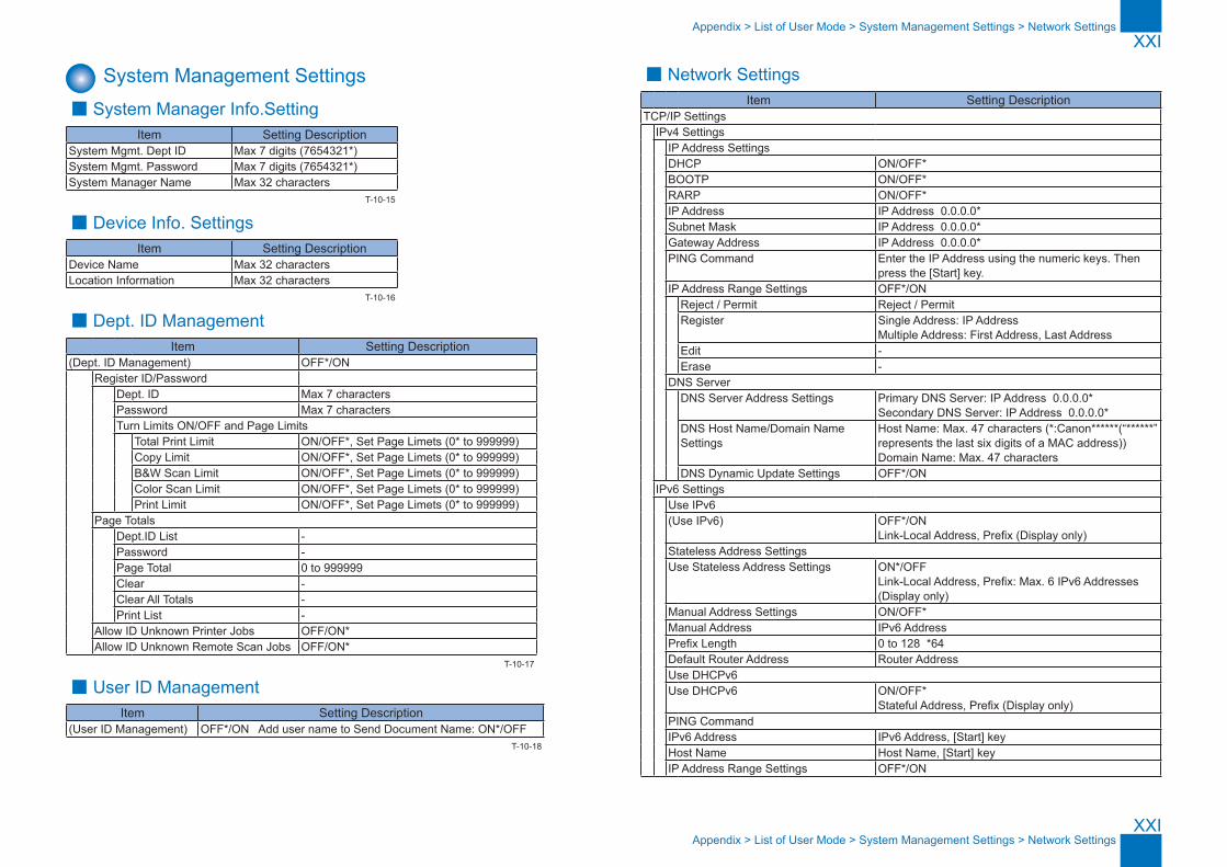
XXI
XXI
Appendix > List of User Mode > System Management Settings > Network Settings
Appendix > List of User Mode > System Management Settings > Network Settings
System Management Settings ■ System Manager Info.Setting
Item Setting DescriptionSystem Mgmt. Dept ID Max 7 digits (7654321*)System Mgmt. Password Max 7 digits (7654321*)System Manager Name Max 32 characters
■ Device Info. SettingsItem Setting Description
Device Name Max 32 charactersLocation Information Max 32 characters
■ Dept. ID ManagementItem Setting Description
(Dept. ID Management) OFF*/ON Register ID/Password
Dept. ID Max 7 charactersPassword Max 7 charactersTurn Limits ON/OFF and Page Limits Total Print Limit ON/OFF*, Set Page Limets (0* to 999999)
Copy Limit ON/OFF*, Set Page Limets (0* to 999999)B&W Scan Limit ON/OFF*, Set Page Limets (0* to 999999)Color Scan Limit ON/OFF*, Set Page Limets (0* to 999999)Print Limit ON/OFF*, Set Page Limets (0* to 999999)
Page Totals Dept.ID List -
Password -Page Total 0 to 999999Clear -Clear All Totals -Print List -
Allow ID Unknown Printer Jobs OFF/ON*Allow ID Unknown Remote Scan Jobs OFF/ON*
■ User ID ManagementItem Setting Description
(User ID Management) OFF*/ON Add user name to Send Document Name: ON*/OFF
T-10-15
T-10-16
T-10-17
T-10-18
■ Network SettingsItem Setting Description
TCP/IP Settings IPv4 Settings
IP Address SettingsDHCP ON/OFF*BOOTP ON/OFF*RARP ON/OFF*IP Address IP Address 0.0.0.0*Subnet Mask IP Address 0.0.0.0*Gateway Address IP Address 0.0.0.0*PING Command Enter the IP Address using the numeric keys. Then
press the [Start] key.IP Address Range Settings OFF*/ON Reject / Permit Reject / Permit
Register Single Address: IP Address Multiple Address: First Address, Last Address
Edit -Erase -
DNS ServerDNS Server Address Settings Primary DNS Server: IP Address 0.0.0.0*
Secondary DNS Server: IP Address 0.0.0.0*DNS Host Name/Domain Name Settings
Host Name: Max. 47 characters (*:Canon******(“******”represents the last six digits of a MAC address)) Domain Name: Max. 47 characters
DNS Dynamic Update Settings OFF*/ONIPv6 Settings
Use IPv6(Use IPv6) OFF*/ON
Link-Local Address, Prefix (Display only)Stateless Address SettingsUse Stateless Address Settings ON*/OFF
Link-Local Address, Prefix: Max. 6 IPv6 Addresses (Display only)
Manual Address Settings ON/OFF*Manual Address IPv6 AddressPrefix Length 0 to 128 *64Default Router Address Router AddressUse DHCPv6Use DHCPv6 ON/OFF*
Stateful Address, Prefix (Display only)PING CommandIPv6 Address IPv6 Address, [Start] keyHost Name Host Name, [Start] keyIP Address Range Settings OFF*/ON

XXII
XXII
Appendix > List of User Mode > System Management Settings > Network Settings
Appendix > List of User Mode > System Management Settings > Network Settings
Item Setting DescriptionReject / Permit Reject / PermitRegister Single Address: IP Address
Multiple Address: First Address, Last AddressEdit -Erase -
DNS ServerDNS Server Address Settings Primary DNS Server: IPv6 Address
Secondary DNS Server: IPv6 AddressDNS Host Name/Domain Name Settings
Use Same Host Name / Domain Name at IPv4: OFF*/ON Host Name: Max. 47 characters (*:Canon******(“******”represents the last six digits of a MAC address)) Domain Name: Max. 47 characters
DNS Dynamic Update Settings DNS Dynamic Update Settings: OFF*/ON Register Manual Address: OFF*/ON Register Stateful Address: OFF*/ON
WINS ConfigurationWINS Resolution ON/OFF*WINS Server IP Address 0.0.0.0*
LPD Settings ON*/OFFRAW Settings
Use RAW ON*/OFFUse Bidirectional OFF*/ON
WSD Print SettingsUse WSD OFF*/ONUse WSD Browsing OFF*/ONUse Multicast Discovery OFF*/ON
SNTP SettingsUse SNTP ON/OFF*Polling Interval 1 to 48 24*NTP Server Address IP Address or Max. 47 charactersNTP Server Check OK, Error
Use PASV Mode for FTP ON/OFF*FTP Extension ON/OFF*
Item Setting DescriptionCertificate Settings
Generate KeyKey Name Max. 24 characters
CA Certificate ListCert. Details Version, Serial Number, Sig. Algorithm, Issue Dest.,
Validity Start, Validity End, Issuer, Public Key, Cert. Thmprn(SHA1)Cert. Verif.
Erase -Register CA Certificate
Register File NameErase -
Key and Certificate ListCert. Details Key Name, Use, CertificateErase -Display Use Loc, -
Register Key and CertificateRegister File NameErase -
Use HTTP OFF/ON*SSL Settings
The key used below can be changed. ListKey and Cert. Set as Def. key, Cert. Details, Display Use Loc.
Port Number SettingsLPD 0 to 65535 (515*)RAW 0 to 65535 (9100*)HTTP 0 to 65535 (80*)SMTP Receive 0 to 65535 (25*)POP3 Receive 0 to 65535 (110*)FTP Sending 0 to 65535 (21*)SMTP Send 0 to 65535 (25*)SNMP 0 to 65535 (161*)WSD 0 to 65535 (3702*)HTTPS 1 to 65535 (443*)
Receiving MAC Address SettingsApply Settings OFF*/ONRegister MAC AddressEdit -Erase -
Proxy SettingsUse Proxy ON/OFF*Server Address IP Address or Max. 128 charactersPort Number 1 to 65535 80*Use Proxy within the Same Domain OFF*/ON

XXIII
XXIII
Appendix > List of User Mode > System Management Settings > Communications Settings
Appendix > List of User Mode > System Management Settings > Communications Settings
Item Setting DescriptionAuthentication Settings
Use Proxy Authentication OFF*/ONUser Max. 24 charactersPassword Max. 24 characters
Confirm Dept. ID Management Password ON/OFF*SMB Settings
Use SMB Client ON*/OFFServer Max. 15 charactersWorkgroup Max. 15 charactersComment Max. 48 charactersLM Announce OFF*/ON
SNMP SettingsUse SNMP ON*/OFFCommunity Name 1 Max. 15 characters (Public*)Writable SNMP 1 OFF*/ONCommunity Name 2 Max. 15 charactersWritable SNMP 2 OFF*/ONGet Printer Mgt. Info from Host OFF*/ON
Enable Dedicated Port OFF/ON*Ethernet Driver Settings
Auto Detect OFF/ON*Communication Mode Half Duplex* , Full DuplexEthernet Type 10 Base-T* , 100 Base-TXMAC Address (Display only)
E-mail/I-FaxSMTP Receive OFF*/ONPOP OFF/ON*Authentication / Encryption
POP Auth. Before Send OFF*/ONSMTP Authentication OFF*/ONUser Name Max. 64 charactersPassword Max. 32 characters
SMTP Server Max. 47 charactersE-mail Address Max. 64 charactersPOP Server Max. 47 charactersPOP Address Max. 32 charactersPOP Password Max. 32 charactersPOP Interval 0 to 99 Minutes *0
Startup Time Settings 0 to 300 Seconds 0*
Item Setting DescriptionIEEE802.1X Settings
USE IEEE802.1X Settings OFF*/ONLogin Name Max. 24 charactersTLS Settings
Use TLS OFF*/ONKey and Certificate Set as Def. key, Cert. Details, Display Use Loc.
TTLS SettingsUse TTLS OFF*/ON
TTLS Set.(TTLS Internal Protocol) MSCHAPv2*/PAPPEAP Settings
Use PEAP OFF*/ONUser Name Max. 24 charactersPassword Max. 24 charactersLogin Name as User Name OFF*/ON
■ Communications SettingsItem Setting Description
E-mail/I-Fax Settings Send Data Size Limit 0 to 99MB (3MB*)
Divide TX Data Oversize OFF*/ONDefault Subject Max. 40 characters (Attached Image*)
Fax Settings*1Send Start Speed 33600*/14400/9600/7200/4800/2400 bpsReceive Start Speed 33600*/14400/9600/7200/4800/2400 bpsPIN Code Access On (Option, Prefix, Suffix), Off*
Memory Lock Settings ON/OFF*Option
Password Max. 7 digitsReport Print ON*/OFFMemory Lock Time Settings ON/OFF*
Memory Lock Start Time 00:00 to 23:59Memory Lock End Time 00:00 to 23:59
Select Country / region Australia (AU), New Zealand (NZ), Hong Kong (HK), Singapore (SG), Malaysia (MY), Vietnam (VN), Argentina (AR), Other (Asia), Other (Latin America), Other (Oceania)
T-10-19
T-10-20

XXIV
XXIV
Appendix > List of User Mode > System Management Settings > Auto Online/Offline
Appendix > List of User Mode > System Management Settings > Auto Online/Offline
■ Forwarding SettingsItem Setting Description
Forwarding Condition Setting All*, Fax, I-FaxValidate/Invalidate Changed OFF*/ONRegister Forwarding Cond. Name Max. 50 characters
Forwarding Condition Setting Fax*, I-Fax Fax selected
Fax Number: "Disregard*, Do Not Exist, equals, differs from, begins with, ends with, contains, does not contain * Only when <Fax>is selected in <Forwarding Conditions Settings>"Max. 20 characters
I-Fax selectedTo: Disregard*, equals, differs from, begins with, ends with, contains,
does not containMax. 120 characters
From: Disregard*, equals, differs from, begins with, ends with, contains, does not containMax. 120 characters
Subject: Disregard*, equals, differs from, begins with, ends with, contains, does not containMax. 120 characters
Forwarding destination Select from the list of registered addressesFile Format "When <Fax> is selected in <Forwarding Conditions Settings>:
TIFF* , PDF Divide into Pages: OFF*/ON When <I-Fax> is selected in <Forwarding Conditions Settings>: Divide into Pages: PDF (B&W)/JPEG (Color), TIFF (B&W)/JPEG (Color), PDF Do not Divide into Pages: PDF, TIFF (B&W)/PDF (Color)"
Forward w/o ConditionReceive Tipe Fax*/I-FaxForwarding destination Select from the list of registered addressesFile Format "When <Fax> is selected in <Receive Tipe>:
TIFF* , PDF Divide into Pages: OFF*/ON When <I-Fax> is selected in <Receive Tipe>: Divide into Pages: PDF (B&W)/JPEG (Color), TIFF (B&W)/JPEG (Color), PDF Do not Divide into Pages: PDF, TIFF (B&W)/PDF (Color)"
Detail/Edit Same as <Register>Erase Is it OK to erase? No/YesPrint List Do you want to print the forwarding conditions list? No/Yes
T-10-21
■ Store/Print When ForwardingItem Setting Description
Print Image ON*, For Error Only, OFFStore Image in Memory For Error Only, Do Not Store*
■ Remote UIItem Setting Description
Remote UI OFF/ON* Use SSL ON/OFF*
■ Restrict the Send FunctionItem Setting Description
Address Book Password Max. 7 digitsRestrict New Address OFF*/ONAllow Fax Driver TX OFF/ON*Restrict Recall OFF*/ONConfirm Entered Fax Numbers OFF*/ONRestrict Sequential Broadcast OFF*, Broadcast Confirmation, Prohibit Broadcast
■ Auto Online/OfflineItem Setting Description
Auto Online OFF*/ONAuto Offline OFF*/ON
T-10-22
T-10-23
T-10-24
T-10-25
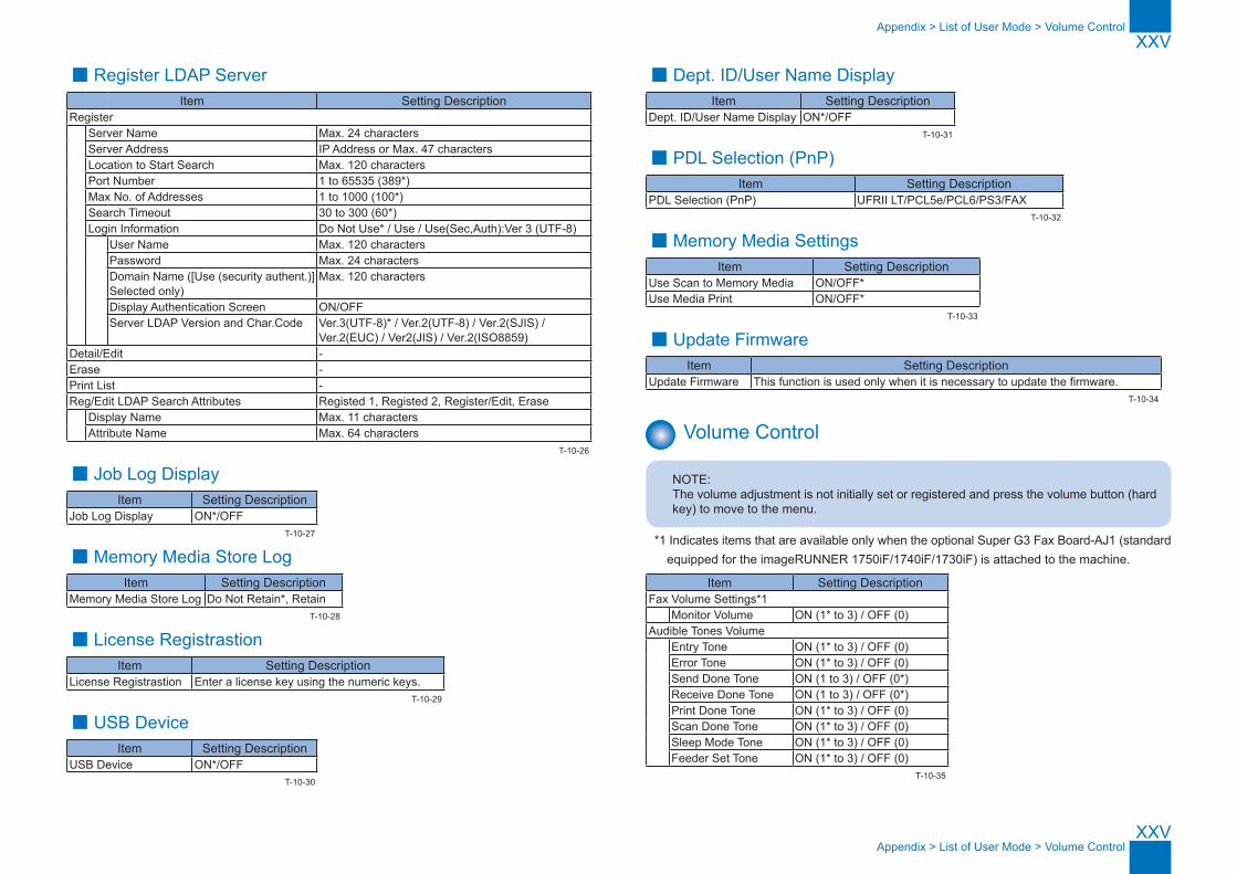
XXV
XXV
Appendix > List of User Mode > Volume Control
Appendix > List of User Mode > Volume Control
■ Register LDAP ServerItem Setting Description
Register Server Name Max. 24 characters
Server Address IP Address or Max. 47 charactersLocation to Start Search Max. 120 charactersPort Number 1 to 65535 (389*)Max No. of Addresses 1 to 1000 (100*)Search Timeout 30 to 300 (60*)Login Information Do Not Use* / Use / Use(Sec,Auth):Ver 3 (UTF-8) User Name Max. 120 characters
Password Max. 24 charactersDomain Name ([Use (security authent.)] Selected only)
Max. 120 characters
Display Authentication Screen ON/OFFServer LDAP Version and Char.Code Ver.3(UTF-8)* / Ver.2(UTF-8) / Ver.2(SJIS) /
Ver.2(EUC) / Ver2(JIS) / Ver.2(ISO8859)Detail/Edit -Erase -Print List -Reg/Edit LDAP Search Attributes Registed 1, Registed 2, Register/Edit, Erase Display Name Max. 11 characters
Attribute Name Max. 64 characters
■ Job Log DisplayItem Setting Description
Job Log Display ON*/OFF
■ Memory Media Store LogItem Setting Description
Memory Media Store Log Do Not Retain*, Retain
■ License RegistrastionItem Setting Description
License Registrastion Enter a license key using the numeric keys.
■ USB DeviceItem Setting Description
USB Device ON*/OFF
T-10-26
T-10-27
T-10-28
T-10-29
T-10-30
■ Dept. ID/User Name DisplayItem Setting Description
Dept. ID/User Name Display ON*/OFF
■ PDL Selection (PnP)Item Setting Description
PDL Selection (PnP) UFRII LT/PCL5e/PCL6/PS3/FAX
■ Memory Media SettingsItem Setting Description
Use Scan to Memory Media ON/OFF*Use Media Print ON/OFF*
■ Update FirmwareItem Setting Description
Update Firmware This function is used only when it is necessary to update the firmware.
Volume Control
NOTE:The volume adjustment is not initially set or registered and press the volume button (hard key) to move to the menu.
*1 Indicates items that are available only when the optional Super G3 Fax Board-AJ1 (standard equipped for the imageRUNNER 1750iF/1740iF/1730iF) is attached to the machine.
Item Setting DescriptionFax Volume Settings*1 Monitor Volume ON (1* to 3) / OFF (0)Audible Tones Volume Entry Tone ON (1* to 3) / OFF (0)
Error Tone ON (1* to 3) / OFF (0)Send Done Tone ON (1 to 3) / OFF (0*)Receive Done Tone ON (1 to 3) / OFF (0*)Print Done Tone ON (1* to 3) / OFF (0)Scan Done Tone ON (1* to 3) / OFF (0)Sleep Mode Tone ON (1* to 3) / OFF (0)Feeder Set Tone ON (1* to 3) / OFF (0)
T-10-31
T-10-32
T-10-33
T-10-34
T-10-35

XXVI
XXVI
App
endi
x >
Bac
kup
Dat
a
App
endi
x >
Bac
kup
Dat
a
Backup Data
Data to Be StoredData
Location
ReplacementDelete
User Backup Service BackupService function
When Replacing Main PCB
DC Controller
PCB
CLEAR > ALL
CLEAR > PWD
CLEAR > HIST*5
CLEAR > SYSTEM
INFO CLEAR
CLEAR > ERDS-
DAT
CLEAR > CA-KEY
Can Data Be Backed up?
MethodRemote UI
Location to Be Stored
Can Data Be Backed up?
MethodLocation to Be Stored
Address Book Main Controller PCB
Clear - Clear - - - - - Yes Add.Func. > Import/Export > Start Export
PC No - -
User Management Data Clear - Clear - - - - -Additional Functions Settings Data
Clear - Clear - - - -
Administrator Password Clear - Clear Clear - Clear - - No - - No - -History *5 - - Clear - Clear *5 - - - No - - No - -SSL Keys *4 Clear - - - - - - Clear *3*4 No - - No - -CA Certificates Clear - - - - - - Clear *3 No - - No - -eRDS Clear - - - - - Clear *2 - No - - No - -Service Mode(Main Controller PCB)
Clear *1 - Clear - - - - - No - - No - -
Service Mode(DC Controller PCB)
DC Controller PCB
- Clear - - - - - - No - - No - -
*1. In service mode, output #REPORT OUTPUT SERVICE DATA LIST #REPORT OUTPUT > SERVICE LABEL. After replacing the board, input the setting value.*2. It is initialized by selecting the following in service mode: #CLEAR > ERDS-DAT.*3. It is initialized by selecting the following in service mode: #CLEAR > CA-KEY.*4. The SSL key is not generated first.*5. You can clear a history in each items under #CLEAR > HIST of the service mode.
ACTIVITY- Initializes the activity report ACCOUNT- Clears print histories. JAM- Clears the jam history. ERR- Clear the error (error code) history. ALARM- Clears the alarm history. ENVP- Initializes the enviroment log data.
T-10-36