Sequential equivalence checking between system level and RTL descriptions
20
Des Autom Embed Syst (2008) 12: 377–396 DOI 10.1007/s10617-008-9033-z Sequential equivalence checking between system level and RTL descriptions Shobha Vasudevan · Vinod Viswanath · Jacob A. Abraham · JiaJin Tu Received: 14 December 2006 / Accepted: 9 October 2008 / Published online: 26 November 2008 © Springer Science+Business Media, LLC 2008 Abstract Sequential equivalence checking between system level descriptions of designs and their Register Transfer Level (RTL) implementations is a very challenging and important problem in the context of Systems on a Chip (SoCs). We propose a technique to alleviate the complexity of the equivalence checking problem, by efficiently decomposing it using com- pare points. Traditionally, equivalence checking techniques use nominal or functional map- ping of latches as compare points. Since we operate at a level where design descriptions are in System Level Languages or Hardware Description Languages, we leverage the informa- tion available to us at this level in deducing sequential compare points. Sequential compare points encapsulate the sequential behavior of designs and are obtained by statically analyz- ing the design descriptions. We decompose the design using sequential compare points and represent the design behavior at these compare points by symbolic expressions. We use a SAT solver to check the equivalence of the symbolic expressions. In order to demonstrate our technique, we present results on a non-trivial case study. We show an equivalence check between a System C description and two different Verilog RTL implementations of a Viterbi decoder, that is a component of the DRM SoC. Keywords Sequential equivalence checking · C vs RTL · SAT solvers · Static analysis of hardware S. Vasudevan ( ) Electrical and Computer Engineering, University of Illinois at Urbana-Champaign, Urbana, IL 61801, USA e-mail: [email protected] J.A. Abraham · J. Tu The Computer Engineering Research Center, University of Texas at Austin, Austin, TX, USA J.A. Abraham e-mail: [email protected] J. Tu e-mail: [email protected] V. Viswanath Intel Corporation, Austin, TX, USA e-mail: [email protected]
-
Upload
independent -
Category
Documents
-
view
1 -
download
0
Transcript of Sequential equivalence checking between system level and RTL descriptions
Des Autom Embed Syst (2008) 12: 377–396DOI 10.1007/s10617-008-9033-z
Sequential equivalence checking between system leveland RTL descriptions
Shobha Vasudevan · Vinod Viswanath ·Jacob A. Abraham · JiaJin Tu
Received: 14 December 2006 / Accepted: 9 October 2008 / Published online: 26 November 2008© Springer Science+Business Media, LLC 2008
Abstract Sequential equivalence checking between system level descriptions of designsand their Register Transfer Level (RTL) implementations is a very challenging and importantproblem in the context of Systems on a Chip (SoCs). We propose a technique to alleviate thecomplexity of the equivalence checking problem, by efficiently decomposing it using com-pare points. Traditionally, equivalence checking techniques use nominal or functional map-ping of latches as compare points. Since we operate at a level where design descriptions arein System Level Languages or Hardware Description Languages, we leverage the informa-tion available to us at this level in deducing sequential compare points. Sequential comparepoints encapsulate the sequential behavior of designs and are obtained by statically analyz-ing the design descriptions. We decompose the design using sequential compare points andrepresent the design behavior at these compare points by symbolic expressions. We use aSAT solver to check the equivalence of the symbolic expressions. In order to demonstrateour technique, we present results on a non-trivial case study. We show an equivalence checkbetween a System C description and two different Verilog RTL implementations of a Viterbidecoder, that is a component of the DRM SoC.
Keywords Sequential equivalence checking · C vs RTL · SAT solvers · Static analysis ofhardware
S. Vasudevan (�)Electrical and Computer Engineering, University of Illinois at Urbana-Champaign, Urbana, IL 61801,USAe-mail: [email protected]
J.A. Abraham · J. TuThe Computer Engineering Research Center, University of Texas at Austin, Austin, TX, USA
J.A. Abrahame-mail: [email protected]
J. Tue-mail: [email protected]
V. ViswanathIntel Corporation, Austin, TX, USAe-mail: [email protected]

378 S. Vasudevan et al.
1 Introduction
System-on-a-chip (SoC) designs contain unprecedented levels of functional and structuralcomplexity in a single system, making their verification a daunting challenge to known veri-fication methodologies. Inordinate amounts of time and effort are spent in the SoC industry,validating a chip for functional and timing requirements. Although simulation based ver-ification is the most widely used technique for validating SoCs, the degree of confidencein these simulations is low for these highly complex, monolithic designs. Formal verifica-tion is desirable due to its high quality assurance, but the known techniques of hardware orsoftware verification are not equipped to handle the size, or the heterogeneity of SoCs. Fu-turistic verification research then, involves new formal methods that are capable of scalingto the SoC domain.
The problem of checking sequential equivalence of a system level model (SLM) withrespect to its implementation in Register Transfer Level (RTL) is a relatively novel domain.An equivalence check at this level, or even at the RTL to RTL level is desirable due to anumber of reasons [17]. Optimizations for power, speed, area or other design parameters isusually done during this stage of design. These optimizations could range from shifting logicbetween flip-flops, or using latches in place of flip-flops in certain portions, or changing thealgorithm of a certain portion of the design to a faster one. In all these cases, an equivalencecheck at this level would enhance the confidence in the optimized implementation, as wellas be more economically viable than detecting bugs at a later stage in the design cycle.
We present an equivalence checking technique to verify system level design descriptionsagainst their implementations in RTL. Our technique involves the efficient decompositionof the equivalence checking problem, in order to make it more tractable. We present an au-tomatic technique to compute high level sequential compare points, to compare variables ofinterest (observables) in the candidate design descriptions. Our compare points are definedas co-ordinates on the space-time axis of the design, denoted by their relative position withrespect to the time domain (clock cycles), and their position in the space domain (data vari-ables). This aligns with the sequential behavior of the designs being compared, and providesan easy, intuitive abstraction of the equivalence checking problem space. We start the twodesign state machines at the same initial state, and step the machines through every cycle,until we reach a sequential compare point.
At the sequential compare points, we construct symbolic expressions for the observablesthat encapsulate the sequential behavior of the designs, until the cycle of comparison. Ateach sequential compare point, we prove the equivalence of the two state machines. usinga lower (Boolean) level engine, which in this work, is a Boolean satisfiability (SAT) solver.The principal gain in our technique is that we are leveraging the expressiveness and infor-mation available to us at the register transfer and system levels. Although significant amountof research has been done on compare points for gate level equivalence checkers, these al-gorithms and heuristics are limited by their domain. On the other hand, since we operate atthe higher, source code level, our sequential compare points are more intuitive and easier todetect. Also, they capture the notion of design progression through time, which is useful inmeaningful decomposition of the equivalence checking state space.
Since the application of our technique in its current version requires the granularity oftime cycles, we use cycle accurate SLM models in this work. We follow the definitions in[3] and [5] for cycle accurate timed functionality and approximately timed communicationmodels of SystemC [20] for our examples and experiments.
We present the results of our technique on a SystemC description and two different Ver-ilog RTL descriptions of a Viterbi decoder [26] module that is a part of the Digital Radio

Sequential equivalence checking between system level and RTL descriptions 379
Mondiale (DRM) SoC [8]. Our results show the performance benefits of using our techniqueto verify real designs.
The principal contributions of this work are the following.
• We present a theoretically sound sequential equivalence checking method between systemlevel design descriptions and their RTL implementations.
• We present an automatic decomposition technique for splitting the equivalence checkingproblem space, by introducing a notion of sequential compare points that exactly modelthe sequential behavior of designs.
• We leverage the expressive power and relative simplicity of high level descriptions in ourequivalence checking, by reasoning entirely at that level.
• Our technique can statically be used to analyze and decompose the source code, in orderto assist Boolean level engines to overcome capacity issues.
• We demonstrate the effectiveness of our technique by checking the equivalence of theimplementation of a real SoC component against its specification.
The outline of the paper is as follows. Section 2 provides an overview of the related workin this, and allied areas. Section 3 details the technique, the algorithm for automatic decom-position, and explains it with a detailed example. Section 3.5 gives the arguments for thecorrectness of our technique. In Sect. 4, a case-study of the Viterbi decoder is presented.Sections 4.1 and 4.2 describe the two implementations of the Viterbi decoder and the verifi-cation process. The results of our experiments are presented in Sect. 4.3. Section 5 containsa brief discussion of the merits and demerits of the technique.
2 Related work
We provide a brief background that explores the related work in the entire spectrum of topicscovered by this work.
Formal verification, especially equivalence checking, has achieved considerable successin the context of hardware. Combinational equivalence checking checks two acyclic, gate-level circuits. Combinational equivalence checkers can also be used to check equivalenceof two sequential designs, provided the state encodings of the two designs are the same.Although this technique has widespread use in many commercial tools, the real challenge ofsequential verification is in verifying two designs with different state encodings. Sequentialsatisfiability engines [13, 18] and sequential ATPG engines [1, 11] solve this problem to alarge extent by unrolling the circuit until a given time frame. Considerable research has beendone to find compare points for latch mapping [2, 4, 23]. However, these techniques operateat the gate level, where they reason in the Boolean domain.
Fewer attempts have been made to apply sequential equivalence checking to the behav-ioral RTL descriptions of designs. In [19] a methodology for checking the combinationalequivalence between C and RTL is described. The C source code is converted to a HardwareDescription Language (HDL) and commercial RTL to RTL equivalence checkers are usedthereafter. The C code is very similar to the RTL, in order for the translation to be achieved,which might not be a scalable solution.
Clarke and Kroening [7, 12] proposed a solution with CBMC, a C-based bounded modelchecking engine that takes a C program and a Verilog implementation. The two programs areunwound together, and converted into a Boolean satisfiability checking problem. The Ver-ilog code is converted to Boolean formulas by a synthesis-like procedure, and an innovativetechnique is described to convert the C-code into Boolean formulas, including pointers and

380 S. Vasudevan et al.
nested loops. However, the capacity of CBMC is limited by space and time considerations.This is due to the fact that the reasoning done by this tool is entirely in the Boolean domain.On the other hand, our technique reasons at the system and register transfer level, splittingthe equivalence checking problem into smaller problems that can be handled by the lowerlevel engines. This static analysis of the source code, before running the problem throughBoolean level engines, is the principal contribution of our technique.
Another approach to equivalence checking between C descriptions, that could be exten-sible to C vs RTL descriptions, is described in [14]. This approach detects and extracts thetextual differences in the two target programs, and then does a dependence analysis usingprogram slicing, to check for the actual differences in the two programs. It then symbolicallysimulates this difference and reports the equivalence checking results. This technique, how-ever, is most effective when the two target programs being compared are very similar to eachother, in function as well as structure. Since this process uses syntactic information entirely,the similarity of the target descriptions is very essential to its application. Our techniquedoes a semantic comparison of the two target programs, with respect to their functionality,and is therefore wider in its scope.
A few commercial tool vendors [6] also aim at solving the sequential equivalence check-ing problem between SLM and RTL. However, this area still presents a major opportunityfor further research.
3 Technique for system level vs RTL equivalence checking
We present a technique for equivalence checking of two high level design descriptions. Ourtechnique involves the automatic decomposition of the equivalence checking state space,from the source code of two candidate designs. We introduce the notion of sequential com-pare points, that encapsulate the sequential behavior of designs, with respect to time as wellas data. In the rest of the paper, we will refer to sequential compare points, simply as com-pare points.
3.1 Selecting observables
In a previous version of the work [24], we selected the observables by visual inspectionfrom a block diagram of the systems. These observables are observed by stepping the state-transition graphs for the two systems. When an observable is assigned in one (specification)system, the other (implementation) system is stepped until the time step where the sameobservable is assigned in it. This time step would then constitute a compare point.
Selecting observables from a block diagram can be prone to poor conjectures, that canlead to omission of some temporary variables worthy of observation. If only the outputsor other prominent signals are observed in a large design, the symbolic expressions mightget intractable. Since the efficiency of the technique largely depends on the decompositionstrategy, the selection of observables is an important step. We propose an alternative semi-formal solution to select observables, that is more reliable than the previously proposedtechnique.
Timing diagrams represent the temporal behavior of signals in a design with referenceto the system clock, as well as other causal signals. When described as a part of the specifi-cation document, the timing diagrams can provide valuable insight about the most relevantsignals in the design. We can obtain the information about when to observe these relevantsignals by simulating the SLM and the RTL model with respect to the same clock. Simu-lation over a few cycles can indicate the relative time latency at which the observables are
Sequential equivalence checking between system level and RTL descriptions 381
available in both the models. We do not need a very high precision simulation model for oursimulations. The simulations can be cycle accurate (or coarser grained accuracy) for eachmodel. Also, since we are not trying to simulate all possible input values, but only a smallsample set of values to identify relative latencies, we do not require a fast simulation model.If timing diagrams descriptions of signals are not provided in the specification, we will notbe able to make educated guesses about the observables. In this case, we would have to relyon the information from the block diagram.
3.2 Reassignments
We have mentioned that relevant timing diagrams can be used to find the observables in thetwo models being compared. If all the bits of an observable variable are assigned together (inone time step) in a model, the variable is included in the list of observables as it is. However,if the bits of the variable are assigned separately (in different time steps), there will be morethan one observable, corresponding to the same variable. We clarify this with an example.
Consider a 32-bit multiplier that we would like to verify, which has mul_result[31:0]as an output, and therefore an observable. If the multiplier RTL model has only one assign-ment statement assigning the entire value mul_result[31:0], then there will be a singleobservable, namely, mul_result added to the list of observables.
Assume the multiplier’s RTL is modeled such that 8 bits of the output are assigneda value together, i.e. at the same time. All the 32 bits of the output are, therefore, as-signed values after 4 such assignments. Each assignment generates an observable formul_result. Hence, there will be 4 observables that correspond to mul_result[7:0],mul_result[15:8], mul_result[23:16], and mul_result[31:24].
Every subset of bits assigned, therefore, has a corresponding observable. We call such as-signments (to different subsets of bits of the same variable), reassignments, as in [25]. Thus,a reassignment for a variable defines a partition of the bits for the variable. In our example,the 4 reassignments define the partition {[31:24], [23:16], [15:8], [7:0]} onthe 32 bits of the output signal mul_result.
In order to illustrate the reassignment process, let us now assume the SLM is modeled asa shift-and-add design which has spec_mul_result as an output variable . This modelassigns a value to the output 1 bit at a time. Therefore, in the SLM model, there will be32 reassignments defining the partition {31,30, . . . 2,1,0} on the bits of the signalspec_mul_result.
Observables are computed for every major variable in the timing diagrams of the twomodels in the following way.
1. The reassignment bit partitions in the SLM and RTL models are computed. In our exam-ple, the SLM partition is {31,30, . . .2,1,0} and the RTL partition is {[31:24],[23:16], [15:8], [7:0]}.
2. A new variable is defined for every set of bits in the pairwise intersection of thesetwo partitions. In our example, the pairwise intersection groups entries of the SLMpartition together. The new observables will be mS1, mS2, mS3, and mS4 corre-sponding to the bit sets {7,6,. . .1,0}, {15,14,. . .9,8}, {23,22,. . .17,16}, and{31,30,. . .25,24} respectively. The new variables in the revised design will be mV1,mV2, mV3, and mV4 corresponding to the bit sets {[7:0], [15:8], [23:16],[31:24]} respectively.
3. The new observables obtained are mapped to establish their correspondence, and addedto the list of observables. In our example, the variables spec_mul_result andmul_result are mapped into four pairs of observables, namely, {(mS1, mV1),(mS2, mV2), (mS3, mV3), (mS4, mV4)}.
382 S. Vasudevan et al.
main (M: System level model, V : RTL model, O: Set of observables)C = φ
while O is not emptyfor every cycle (transition) in the state transition graphs of M and V
if a set of variables S ⊆ O is assigned in cycle ti in the state-transition graphof M check the state-transition graph of V
if o ⊆ S assigned in cycle tj , j ≤ i in V
C = C ∪ {〈ti , o〉}O = O \ o
result = compare(ti , o)
if (result == true)move to the next state in M and V
elsego to error state
compare (t: Time cycle, d: Set of variables)for every variable v in d in M,V
EM = 1, EV = 1while (t ≥ 0)
EMt = symbolic(v, t,M)
EVt = symbolic(v, t,V )
EM = EM ∧ EMt , EV = EV ∧ EV
t
decrement t
ans = check(EM,EV )return ans
symbolic (L: Variable, t: Time cycle, Z: Model)do
for every assignment L = R under control signals X in the current cycle t
E = f (Z[L/R],X, t)
R = L
while R is not an input, or R /∈ O
return E
Fig. 1 Algorithm for proving equivalence between a C-like system and its RTL implementation
We thus compute a partition of the bits for a particular output defined by the reassign-ments in both specification and implementation models. This is a simple heuristic that ap-pears to work well for models with common outputs and possibly some common internalpoints. The list of observables along with the name mapping of the observables in the twomodels is provided to the algorithm in Sect. 3.3.
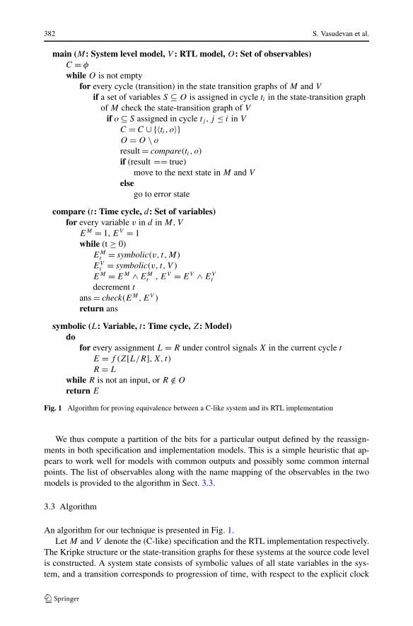
3.3 Algorithm
An algorithm for our technique is presented in Fig. 1.Let M and V denote the (C-like) specification and the RTL implementation respectively.
The Kripke structure or the state-transition graphs for these systems at the source code levelis constructed. A system state consists of symbolic values of all state variables in the sys-tem, and a transition corresponds to progression of time, with respect to the explicit clock

Sequential equivalence checking between system level and RTL descriptions 383
in the system. The signals that are interesting for observation are a part of the list of observ-ables, O . This list is the same for both the systems, as it is assumed that a name mappingis provided for all the primary inputs and observable signals in the designs. The systems areassumed to start in the same initial states, which is an arbitrarily reachable state of the sys-tems. C denotes the list of all compare points. A compare point has a two-tuple description,one for the time cycle, and another for the set of variables that are being compared. This listis empty initially.
The state transition graphs of the two systems are traversed step-by-step. This can bethought of as stepping both the systems in time. After every transition (cycle), the two sys-tems are checked to see if any of the observable variables are assigned. If a variable fromthe list of observables is assigned in one of the systems (say M), the other system (say V ) ischecked to see if the same variable has been assigned in the current, or some previous cycle.If the variable was assigned in V before M , the two systems are compared at the currentcycle, i.e. the current cycle becomes a compare point. If, however, the variable has not yetbeen assigned in V , the two systems are transitioned until the next observable is assigned ineither.
The compare() function compares the observables at a given cycle. Since there may bemore than one observable that is being compared at a cycle, this function takes a set ofvariables. For each of these variables, a symbolic expression is computed at the “current”time cycle, t . The symbolic expressions computed in every previous cycle, until t = 0 areiteratively concatenated in both the systems, to obtain EM and EV . The two expressionsEM and EV are now checked for equivalence using a SAT solver. The check() functioncorresponds to the SAT solver call in our algorithm. It may be noted, however, that otherequation solving engines may also be employed to check the equivalence of expressions atthis stage.
The symbolic() function computes the symbolic expression at a given cycle. For everyassignment to a given variable, it substitutes the right hand side of the definition for thevariable (denoted by Z[L/R] for any model Z) along with the control signal information X,required for the substitution. X is a Boolean expression that represents the constraints on thecontrol signals. The substitutions M[L/R],V [L/R] are valid when X is true. The symbolicexpression also identifies the cycle t in which it holds true. This expression is computed byf () in the algorithm.
If during this substitution, a primary input or a previously “observed” observable isreached, the substitution stops. This is valid because the two systems have been provedequivalent with respect to this observable in a previous compare point. From that cycle on-wards, the two systems are always equivalent with respect to those observables. In a sequen-tial design, the data from the previous cycle progressively gets used in future time cycles.The symbolic expression of the observables at a given compare point remains the same forall future compare points. Therefore, these observables need not be proved equivalent, atevery reference to the corresponding compare point.
If they are found equivalent, the proof proceeds. The comparison process is repeated,until all observables have been “observed”. If they are not found equivalent, an error traceis generated at that compare point. This is very useful, since the equivalence proof can beassumed to hold until the compare point where it fails. If n is the number of observables,T the total number of cycles, and P the size of the program graph on any timeslice, then thetime complexity of running this algorithm would be O(T 2 × n × P ).

384 S. Vasudevan et al.
3.4 Example to show equivalence between SystemC and Verilog
We apply our technique with SystemC as the SLM, due to its recent IEEE 1666-2005 LRMstandardization [15]. SystemC is widely used in the semiconductor and electronic designautomation industry. SystemC is a set of library routines and macros implemented in C++,which makes it possible to simulate concurrent processes, each described by ordinary C++syntax. Instantiated in the SystemC framework, the objects described in this manner maycommunicate in a simulated real-time environment, using signals of all the data types of-fered by C++, some additional ones offered by the SystemC library, as well as user defined.The cycle accurate models of SystemC employed in our examples and experiments are moredetailed than the transaction level models of SystemC [9]. The finite state machines con-structed for traversing the SLM state transition graph in our algorithm, are consequentlymore complex than those corresponding to transaction level models. However, since theSystemC is used in the capacity of a specification language, it outlines the design intentin a very simple manner, as opposed to the efficient, optimal RTL implementation of thealgorithm.
We illustrate our technique using an example that converts a given number in BinaryCoded Decimal (BCD) format into binary format, and then into gray code format. Fig-ure 2 shows a code segment written in SystemC. Figure 3 shows its implementation inVerilog RTL. The clock signal clk_i and input BCD data (dat_bcd_i) are inputs forboth the systems. From the timing diagram in Fig. 4 obtained by simulating these piecesof code, we can see that the intermediate value dat_bin_o is computed in a single cyclein the SystemC, and after two cycles in the Verilog, once the input arrives. Therefore, thefirst comparison point is C1 = (t = t + 2, d = dat_bin_o). Let both the designs start attime t . The symbolic expression s1 for dat_binary_o after all the substitutions as ex-plained in Fig. 1 in the SystemC is dat_bin_o(t + 1) = (dat_bcd_i[4](t + 1) ∗ 10) +dat_bcd_i[3 : 0](t + 1). This denotes that the value of the observable gets computedat t + 1. Every variable is annotated with the corresponding value of time. The symbolicexpression s ′
1 from the Verilog code at cycle for dat_bin_o is dat_bin_o(t + 2) =(dat_bcd_i[4](t +1)? (dat_bcd_i[3 : 0](t)+4′d10) : dat_bcd_i[3 : 0](t)). It is clearthat when s1 and s ′
1 are compared in a SAT solver, the symbolic values of dat_bin_o willbe equal. Similarly, from the timing diagram, we can also see that the output is computedat the second cycle after the arrival of the input in the SystemC, while it is computed at thefourth cycle after the input arrives in Verilog. The second comparison point C2 = (t + 4,dat_gray_o). The symbolic expression s2 in the SystemC design is dat_gray_o(t + 2)
= concat(dat_bin_o[3](t + 1), (dat_bin_o[3](t + 1) ⊕ dat_bin_o[2](t + 1)),(dat_bin_o[2](t + 1) ⊕ dat_bin_o[1](t + 1)), (dat_bin_o[1](t + 1) ⊕dat_bin_o[0](t + 1))) where concat( ) is the bit concatenating function. Since thevalue of dat_bin_o has been proven functionally equal to Verilog at a previous com-parison point, it is reused at C2. The corresponding symbolic expression s ′
2 in Ver-ilog is dat_gray_o(t + 4) = concat(dat_bin_o[3](t + 2), (dat_bin_o[3](t + 2)
⊕ dat_bin_o[2](t + 2)), (dat_bin_o[2](t + 2) ⊕ dat_bin_o[1](t + 2)),(dat_bin_o[1](t + 2) ⊕ dat_bin_o[0](t + 2))). The SAT solver checks for the func-tional equality of the two expressions. However, the annotation with respect to t is not a partof the SAT expression. The two designs are thereby proven equivalent with respect to theinputs and the output.
3.5 Justification of our notion of equivalence
Many notions of sequential equivalence have been proposed in the literature. Most of themadhere to the broad classification of equivalence with respect to a set of initial states [22]

Sequential equivalence checking between system level and RTL descriptions 385
SC_MODULE(bcd_to_bin_to_gray) {sc_in_clk clk_i;sc_in <sc_uint<5>> dat_bcd_i;
sc_out <sc_uint<5>> dat_bin_o;sc_out <sc_uint<5>> dat_gray_o;
sc_uint<4> msb;sc_uint<4> ls_byte;
void convert_code() {msb = dat_bcd_i[4].read();ls_byte = dat_bcd_i[3:0].read();dat_bin_o.write ( (msb * 10) + ls_byte );
}
void convert_code_gray () {dat_gray_o[3].write ( dat_bin_o[3].read() );dat_gray_o[2].write ( dat_bin_o[3].read() ^
dat_bin_o[2].read() );dat_gray_o[1].write ( dat_bin_o[2].read() ^
dat_bin_o[1].read() );dat_gray_o[0].write ( dat_bin_o[1].read() ^
dat_bin_o[0].read() );}
SC_CTOR(bcd_to_bin_to_gray) {SC_METHOD(convert_code);sensitive << dat_bcd_i << clk_i.pos();
SC_METHOD(convert_code_gray);sensitive << dat_bin_o << clk_i.pos();
}};
Fig. 2 Example SystemC code for BCD to binary conversion
or alignability equivalence that can demonstrate resetability across all states [16]. All thesenotions of sequential equivalence are at the gate level, and deal with retiming and synthesisbased optimizations. They also build the state-transition relation in order to reason aboutsequential equivalence. Since we are dealing with a different level of abstraction, we needto define our own notion of sequential equivalence. However, in philosophy, our notion ofequivalence is more along the lines of [22] than the alignability notion of equivalence. Westate our theories of correctness with respect to a set of initial states. This paradigm hashigher scalability, due to the potential leveraging of many existing algorithms. Since weperceive our technique to act synergistically with the existing Boolean level algorithms, weprefer to use this notion of equivalence.

386 S. Vasudevan et al.
module bcd_to_bin_to_gray (clk_i, dat_bcd_i, dat_bin_o,done_o);
input clk_i;input [4:0] dat_bcd_i;output [3:0] dat_bin_o;output [3:0] dat_gray_o;
reg [3:0] dat_bin_o;reg [3:0] dat_gray_o;
reg [3:0] tens_digit;reg [3:0] no_tens_digit;reg tens_select;
always @(posedge clk_i)begin
tens_digit <= dat_bcd_i[3:0] + 4’d10;no_tens_digit <= dat_bcd_i[3:0];tens_select <= dat_bcd_i[4];
end
always @(posedge clk_i)begin
if (tens_select)dat_bin_o <= tens_digit;
elsedat_bin_o <= no_tens_digit;
end
always @(posedge clk_i)begin
dat_gray_o <= {dat_bin_o[3], ^dat_bin_o[3:2],^dat_bin_o[2:1], ^dat_bin_o[1:0]};
end
endmodule
Fig. 3 Example Verilog RTL code for BCD to binary conversion
We present here, a theoretical basis to justify our technique.Let M be the design specification system (model). Let V be its implementation. Let
PI (X) and PO(X) denote the primary inputs and primary outputs of system X, such thatPI (M) = PI (V ) and PO(M) = PO(V ). We assume that a signal name mapping is pro-vided between the two systems. Let n be the longest cycle length (time step) taken to obtainall primary outputs in both systems. Let t = 0 correspond to the time at which both thesystems are at the initial states.

Sequential equivalence checking between system level and RTL descriptions 387
Fig. 4 Timing diagram specifying the circuit behavior
Definition 1 (Symbolic expression) A symbolic expression function, σX(k, s), in a sys-tem X, for a signal s at a point k in time, returns the value s in terms of pi ∈ PI (X)
obtained by successive substitutions of equivalent signals, over t = k, t = k − 1 . . . t = 0.
Definition 2 (Equivalence of symbolic expressions) An equivalence relation ≡, betweentwo symbolic expressions σ1 and σ2 in terms of pi, implies that for all values of pi, theoutputs of s1 and s2 are equal.
Definition 3 (Simulation relation) A simulation relation, ∼k,S , between two systems X andY , for a set of signals S is defined such that ∀i ∈ S,σX(k, i) ≡ σY (k, i).
If the simulation relation holds over a set of signals at a certain time between two systems,it implies that the symbolic expression of every signal in the set is equivalent to the othersystem until that point in time. We need to show that a simulation relation holds over allthe signals that are of interest, i.e. the primary outputs, over all the time that is required tocompute them.
Therefore, our notion of sequential equivalence is V ∼n,PO M .
Definition 4 (Compare point) A compare point C = (t, d) is a co-ordinate on the space-time axis of the design, denoted by its relative position with respect to the time domain t ,and its position in the space or data domain d . In the context of designs, t is in terms ofcycles, and d ⊆ O .
It is obvious that ∀i ∈ d , where C = (k, d),V ∼k,i M ⇒ V ∼C M .We need to show that if a simulation relation holds at a compare point, it can be extended
to hold over any other point in the space-time axis of the design.
Lemma 1 At a given compare point, C = (k, d), if f or i ∈ d,V ∼k,i M ⇒ V ∼l,i M , wherel is any value of t > 0.
Proof intuition From Definition 1, the symbolic expressions σV (k, i) and σM(k, i) are un-rolled until t = 0 and proven equal at t = k. Therefore, for the time window t = 0, t =1, . . . , t = k, the simulation relation holds. In subsequent time windows, like, t = 1, t =2, . . . , t = k + 1, in order that the symbolic expression be equal,
388 S. Vasudevan et al.
(a) the function of a signal in terms of its primary inputs should not change(b) the clock generating function t , remains the same.
(a) Is ensured by the fact that the simulation relation holds at any time k. The symbolicfunction of a signal itself does not change, although different input vectors may arrive atdifferent clock cycles. From Definition 2, the equivalence relation holds for all input values.
(b) Is a trivial result if the clock is completely independent of the data in the design, andthe clock generation function does not change. However, for non-trivial clock generatingfunctions, this is not a trivial result. It therefore, becomes a part of the proof obligation toprove this result for those cases. �
Theorem 1 Let the two systems M and V be described with PI (M) = PI (V ) andPO(M) = PO(V ) = P (O). Let M and V be compared at every compare point Ck = (k, d),such that 0 ≤ k ≤ n. Then, ∀C,V ∼C M ⇒ V ∼n,PO M .
Proof outline The proof follows from induction, where the base case is at time t = 0 andcompare point C0, when the systems start from the same initial state. At any t = k, it canbe assumed that the simulation relation holds in all previous compare points until Ck . Theinduction hypothesis is relieved by using Lemma 1 and substituting equals for equals in theentire symbolic expression obtained. If all the primary outputs are generated by cycle n, atC = (n,PO), the desired simulation relation will hold between the two systems. �
3.6 Error detection
An inherent limitation of our method of selecting comparison points is that the informationabout the cycle of comparison is obtained from the RTL implementation model itself. Thestate-transition graph or the simulation of the RTL provide accurate information about thetime at which an observable is available for comparison according to the design. Since ourtechnique attempts to capture the design progression in time as well as in data space, wepresent a brief discussion about the functional and temporal error scenarios in our domain,and how our technique performs in these scenarios.
There are four possible outcomes of the compare() function in Fig. 1 when comparingSLM and the RTL model at any compare point C = (t, v), such that t is the time at whichthe observable v is computed in the RTL model.
• Functionally and temporally correct.
In this case, check() returns true, t is the correct cycle of computation, and t is the timeof comparison. This is the case when the algorithm will return a true value. This means thatthe symbolic function of v in the RTL is implemented functionally as per specification andat the correct time cycle, as well as compared at the right time.
• Functionally incorrect and temporally correct.
In this case, check() returns false, t is the correct cycle of computation and t is the timeof comparison. This is the case when the algorithm will return a false value. This meansthat the symbolic function of v is not implemented correctly in the RTL. This scenario isdetected by our technique. An error trace is provided between the past compare point andthe current compare point.
• Functionally incorrect and temporally incorrect.

Sequential equivalence checking between system level and RTL descriptions 389
Fig. 5 Viterbidecoder—SystemC designspecification
In this case, the check() procedure returns a false, t is not the correct cycle of computa-tion, and t is the time of comparison. Incorrect cycle of computation refers to a time whentemporally the data is not yet stable. The algorithm now provides a functional error trace, butnot a temporal error trace. In other words, there is a possibility of obtaining false negativesin this scenario, since a mismatch does not indicate if there is an error in the functionality ortiming.
• Functionally correct and temporally incorrect.
In this case, the check() procedure returns a true, t is not the correct cycle of com-putation, and t is the time of comparison. If the design is flawed with respect to time ofcomputation, and if the comparison point is not at the “flawed” cycle, but another cycle,the designs will not match in functionality. However, in the case where the design itself hasa timing bug, and we check at the (incorrect) cycle that the design computes its (correct)data, we will not be able to find the bug, and it can result in a false positive. This situationcannot be avoided, due to the inherent limitation of a sequential equivalence technique thatuses the timing information from the implementation itself. However, in the case where thespecification details the timing, or the SLM model is cycle accurate, this rare case of errorscan be avoided.
4 Equivalence checking of SystemC vs RTL of Viterbi decoder
We perform our experiments on a Viterbi decoder, that is a part of the Digital Radio Mon-diale (DRM), implemented in SystemC. Since the Viterbi decoder module (embedded inthe MLC decoder) took an inordinately long number of simulation cycles, the DRM SoCdesign was partitioned to implement the Viterbi decoder in hardware. This hardware accel-erator was implemented in Verilog RTL, from the initial SystemC description of the Viterbimodule. More details on this process can be obtained from [21].
Optimizations for speed, like pipelining, are typical applications where an equivalencechecking between the system level design and the RTL are desired. Our experiments usesuch optimized implementations to show the efficacy of our technique.
The SystemC specification of the Viterbi decoder is a very basic model, that implementsthe Viterbi decoding algorithm, but has no optimizations for speed, area or power (Fig. 5).The first RTL design we compared against, is a pipelined implementation of the Viterbidecoder, optimized for speed. The second implementation is optimized for area. We showthe results of doing equivalence checking using our technique on these Verilog designs, withrespect to the specification in SystemC.

390 S. Vasudevan et al.
Fig. 6 Viterbi decoder blockdiagram. The decoder inDesign 1 is a pipelined Viterbidecoder with a 2-stage butterfly,with 32 parallel butterfly blocks.The decoder in Design 2 isfurther optimized for area withonly 8 parallel butterfly blocks.The area-optimized design willrun 4 times slower on the Trelliscomputation
Figure 5 shows the basic block diagram of a Viterbi decoder [26]. There are two majorstages to the functionality of the Viterbi decoder. One is collecting the inputs dependingon the Puncture Pattern and storing them in an buffer (FF Buffer). The other stage is theTrellis computation. The next state values of the Trellis matrix are computed by a function(Butterfly network) of current state values of the Trellis matrix and the inputs stored in theFF Buffer.
4.1 Equivalence checking of a pipelined Viterbi design
We started with a SystemC description, as well as the pipelined Verilog RTL implementa-tion of the Viterbi decoder design. Figure 6(a) shows the block diagram of the pipelinedimplementation. From the block diagram, we arrive at the following observables in the ex-periment.
• 8 FIFO entries, each 32-bits wide: FF[7:0][31:0]• 64 Trellis Matrix entries, each 32-bits wide: TM[63:0][31:0]• 2 entries in the MatDec, each 32-bits wide: MD[1:0][31:0]• Decoded output, 32-bits wide: Out[31:0]
The signal (variable) mapping between the two designs is provided. For the sake of read-ability, we denote the observables in the SystemC design with a subscript s, and the ob-servables in the Verilog design with a subscript v. We outline the proof methodology usingour technique. We start both the designs at the reset state initially. We step the two de-signs in tandem. From the state-transition graph of the SystemC design, we observe thatthe output is computed at every cycle. From the state-transition graph of the Verilog design,

Sequential equivalence checking between system level and RTL descriptions 391
Fig. 7 Proof of sequential equivalence checking of pipelined Verilog Viterbi design against SystemC design
however, we observe that the output is computed in the 10th cycle after the reset state. Inaccordance with our algorithm in Fig. 1, we need to step the Verilog design more than theSystemC specification, to arrive at compare points. Figure 7 is a pictorial representation ofthe decomposition of the equivalence checking proof, on the basis of compare points. Thehorizontal axis represents the data (observables), and the vertical axis shows the number ofsystems being compared (in our case, two). Time is represented along the axis normal to theplane of the paper.
The first set of observables FF[7:0][31:0] is available after 8 cycles, at the output of theFF Buffer. The first compare point, is therefore C1 = (t = 8, d = FF[7:0][31:0]).
For each entry i in the FIFO buffer, the FIFO variables are FFs [i][31:0] and FFv [i][31:0].We call the compare() and symbolic() functions at the compare point, and obtain the expres-sions for the FF variables.
In both the designs, the FF Buffer gets updated by the function GetMetricSet(). Therefore,the symbolic expressions correspond to an expansion using this function. The two symbolicexpressions for FFs [i][31:0] and FFv [i][31:0] are checked using a SAT solver. This proce-dure is repeated 8 times, for every entry in the FF Buffer, since each of them has a uniquesymbolic expression.

392 S. Vasudevan et al.
The next comparison point is obtained by stepping the two state machines of the designsafter the 8th cycle. Although the SystemC assigns to an observable every cycle, the Verilogdesign assigns to the next observable at the 10th cycle. The next v ∈ d is the Trellis Matrix,TM[63:0][31:0]. All the entries in this 64 × 32 matrix need to be checked, since the entiretable is updated every 10th cycle. The values of the MatDec decision table, MD[1:0][31:0]is also updated in this cycle, as is the decoded output, Out[31:0]. The intermediate variableevery 9th cycle, btm which is not an observable is shown in lower case in Fig. 4.
The second compare point, is therefore, C2=(t=10, d=TM[63:0][31:0], MD[1:0][31:0],Out[31:0]).
The Trellis Matrix table gets its values from the 32 butterfly blocks in the design, eachof which output 2 entries. The symbolic expression from the RTL, therefore, is a functionof the butterfly blocks. For every 2 entries in the Trellis Matrix, the corresponding symbolicexpression can be obtained from the butterfly. For instance,
TMv [0], TMv[1] = Butterfly(TMv [0], TMv [2], FFv [0][31:0], FFv [7][31:0])
Similarly, in the SystemC design,
TMs [0], TMs[1] = Butterfly(TMs [0], TMs [2], FFs [0][31:0], FFs [7][31:0])
Since FFv [0] = FFs [0] from a previous comparison point C1, the symbolic expression forthese signals are not expanded any further. The symbolic expressions for TMv [0], TMv [1] andTMs [0], TMs [1] are checked for equivalence by the SAT solver. This procedure is repeated32 times, for every pair of entries in the Trellis Metric that need to be checked.
The other observables MD[1:0][31:0] and Out[31:0] are similarly checked for equivalence.The proof of Out[31:0] is not shown in the figure. The results of the check() function arediscussed in the next section.
4.2 Equivalence checking of a pipelined Viterbi design optimized for area
We used our technique to perform equivalence checking of a pipelined Viterbi design, thatis further optimized for area. In this design, the 32 butterfly units are split into 4 stages, eachstage having 8 butterfly units. Figure 8 shows the decomposition of the proof using comparepoints.
Figure 8 shows the same proof progression as discussed in Sect. 4.1 with respect tothe outputs of the FIFO buffers. As in the previous example, the first compare point isC1 = (t = 8, d = FF[7:0][31:0]). Thereafter, the two state machines are stepped in tandem.The next observables, namely the Trellis Matrix and the MatDec decision table values arecomputed at the end of the 10th cycle. However, since the butterfly unit has been dividedinto 4 stages, only 16 values of the Trellis Matrix and 8 values of the MatDec table areobtained at the end of this cycle. The second compare point, therefore, is C2 = (t = 10,d = TM[15:0][31:0], MD[1:0][7:0]).
Similarly, the other compare points are
C3 = (t = 12, d = TM[31:16][31:0],MD[1:0][15:8]),
C4 = (t = 14, d = TM[32:47][31:0],MD[1:0][16:23]) and
C5 = (t = 16, d = TM[47:63][31:0],MD[1:0][23:31],Out[31:0])
The decoded output gets computed at the end of the 16th cycle.

Sequential equivalence checking between system level and RTL descriptions 393
Fig. 8 Proof of sequential equivalence checking of pipelined Verilog Viterbi design with area optimizationsagainst SystemC design

394 S. Vasudevan et al.
Table A
Block/Function Number of clausesin the CNF formula
PLUS 448LESSTHAN 32Trellis condition 14336in the butterflyTrellis computation in 28672each stage of butterflyTrellis per butterfly 57344MatDec each stage 896of butterflyMatDec per butterfly 1792
Table B
Design Number of clausesin the CNF formula
Monolithic Trellis 1892352RTL decomposition (Design 1) 59136RTL decomposition (Design 2) 59136
Table C
Block/Function Number of variables Number of symbolicvariables generated
PLUS 64 2Butterfly 128 66Trellis (monolithic) 2304 2112Trellis (decomposed) 128 66
Fig. 9 Breakdown of number of variables and clauses in the CNF input to zChaff for different blocks
The symbolic expressions for TMs [63:0][31:0] and TMv [63:0][31:0] are similar to thosedescribed in the previous proof subsection. Similarly, the values of the other observablescan be symbolically computed and checked with a SAT solver.
It should be noted that this proof has more compare points than the proof shown in Fig. 4and also requires a sequential progress over more time cycles.
4.3 Experimental results
We use zChaff [10] as the SAT solver to implement the check() function. In order to passthe equivalence checking through zChaff, we had to model the symbolic expressions as aBoolean satisfiability problem. We used the XNOR operation to combine the two targetsymbolic expressions. In order to provide a glimpse into the complexity and size of our de-sign, we present some relevant statistics in Fig. 9. Table A gives a breakdown of number ofclauses in the CNF formula for various blocks. PLUS and LESSTHAN were two primary

Sequential equivalence checking between system level and RTL descriptions 395
functions used to synthesize the RTL into symbolic Boolean expressions. We can observethe benefits of our technique of splitting monolithic equivalence functions into smaller func-tions. Using our decomposition technique, we created 32 independent CNF formulas, thatwere input to zChaff. Each of these formulas had 59136 clauses and 128 variables. Withoutthis decomposition, the monolithic Trellis computation would generate a CNF with nearly1.9 million clauses. zChaff is unable to check the equivalence of this monolithic Trellis (doesnot finish), whereas, the equivalence of the decomposed Trellis is easily checked.
An interesting observation is, due to our decomposition methodology, the size of the CNFfor the pipelined version is exactly the same as the non-pipelined design. This shows thatthe equivalence checking problem can be greatly reduced using a high level decomposition,in order to make it easier for lower level engines. These observations are captured in tablesTable B and Table C.
Table C shows the number of symbolic variables generated at the higher level for somefunctions. The actual Boolean variables generated by expanding these functions are in thesecond column. The symbolic variables at the higher level have fewer variables due to the“uninterpreted” nature of these functions. When used in the form of pre-verified (or sepa-rately verified) blocks, these functions can be blackboxed to produce far fewer clauses inthe SAT engine. For example, the addition of two 32-bit variables would yield 64 Booleanvariables. When left uninterpreted as a PLUS function, the two addition operands can beviewed as higher level symbols and passed as 2 variables to the SAT engine.
5 Discussion and conclusions
We have shown a novel technique for sequential equivalence checking of a system levelspecification and its implementation in RTL. Our technique decomposes the equivalencechecking problem using automatically computed compare points. We demonstrate the ef-ficiency of our technique using a non-trivial example. We have in the past constructed thetechnique to do RTL to RTL combinational equivalence checking at the higher level [25].Our current work, in principle, can be also be applied to RTL to RTL sequential equivalencechecking, since it is effective for source to source checking at the higher level. One of thelimitations of this technique is that it requires the high level model to be synchronized by aclock. Also, the technique is not scalable in the number of cycles. As the number of cyclesgets larger, the size of the expression grows quadratically, causing capacity problems for thelower level SAT engine.
We show our technique using SystemC as our system level modeling language, due to itsrecent IEEE standardization. Our technique, however, can be applied to other system levellanguages also. In its current form, this technique cannot handle pointers, nested loops orother software specific constructs. In future, we plan to extend this work to handle a largersubset of the C-like description language.
Since this work primarily seeks to decompose the problem into more tractable sub-problems, it might be usable in conjunction with existing tools and techniques. The in-formation content at the source code level can be exploited to assist existing technologiesto tackle the SoC verification problem. This work motivates the necessity to reason at thehigher levels in the design cycle, in order to work toward scalable verification solutions.
In this work, we have used high level analysis only for structural decomposition of thetwo models. In future work, we plan to analyze the symbolic expressions generated by thetechnique at the higher level, before passing them into Boolean level solvers. For instance,the PLUS and LESSTHAN have been used as uninterpreted functions in the case study
396 S. Vasudevan et al.
shown here. A semantic analysis can be carried out on other such high level operators, thatoperate on many bits at a time. The “interpretation” of the operators can then be done by aBoolean engine after considerable high level analysis that reduces the size of the problem.We believe that this would result in increasing the verification capacity of existing engines.
References
1. Abraham JA, Vedula VM, Saab DG (2002) Verifying properties using sequential ATPG. In: Proceedingsof the IEEE international test conference, pp 194–200
2. Anastasakis D, Damiano R, Ma H-KT, Stanion T (2002) A practical and efficient method for compare-point matching. In: Proceedings of the 39th design automation conference, pp 305–310
3. Black DC, Donovan J (2005) SystemC: From the ground up. Springer, Berlin4. Burch JR, Singhal V (1998) Robust latch mapping for combinational equivalence checking. In: Proceed-
ings of the IEEE/ACM international conference on computer-aided design, pp. 563–5695. Cai L, Gajski D (2003) Transaction level modeling: an overview. In: Proceedings of the 1st
IEEE/ACM/IFIP international conference on hardware/software codesign and system synthesis, pp 19–24
6. Calypto design systems http://www.calypto.com7. Clarke E, Kroening D (2003) Hardware verification using ANSI-C programs as a reference. In: Proceed-
ings of the IEEE Asia south pacific—Design automation conference, pp 308–3118. Digital radio mondiale http://www.drm.org9. Ghenassia F (ed) (2006) Transaction-level modeling with SystemC: TLM concepts and applications for
embedded systems. Springer, Berlin10. Fu Z, Mahajan Y, Malik S, zChaff Solver http://www.princeton.edu/~zchaff/zchaff.html11. Huang S-Y, Cheng K-T, Chen K-C (2001) Verifying sequential equivalence using ATPG techniques. In:
ACM transactions on design automation of electronic systems, pp 244–27512. Kroening D, Clarke E, Yorav K (2003) Behavioral consistency of C and Verilog programs using bounded
model checking. In: Proceedings of the 40th IEEE design automation conference, pp 368–37113. Lu F, Iyer MK, Parthasarathy G, Wang L-C, Cheng K-T, Chen K-C (2005) An efficient sequential SAT
solver with improved search strategies. In: Proceedings of the IEEE design automation and test in Eu-rope, pp 1102–1107
14. Matsumoto T, Saito H, Fujita M (2005) An equivalence checking method for C descriptions based onsymbolic simulation with textual differences. In: IEICE transactions on fundamentals of electronics,communications and computer sciences, pp 3315–3323
15. Open SystemC initiative http://www.systemc.org16. Pixley C (1992) A theory and implementation of sequential hardware equivalence. In: IEEE transactions
on computer-aided design of integrated circuits and systems17. Pixley C (2001) Formal verification of commercial integrated circuits. In: IEEE design and test of com-
puters18. Prasad MR, Biere A, Gupta A (2005) A survey of recent advances in SAT-based formal verification.
Softw Test Technol Transf (STTT) 7(2):156–17319. Smria L, Mehra R, Pangrle B, Ekanayake A, Seawright A, Ng D (2002) RTL C-based methodology
for designing and verifying a multi-threaded processor. In: Proceedings of the 39th design automationconference, pp 123–128
20. SystemC reference manual http://homes.dsi.unimi.it/~pedersin/AD/SystemC_v201_LRM.pdf21. Tu J (2006) Viterbi decoder coprocessor in the DRM application SoC. Masters Report, University of
Texas at Austin22. van Eijk C (1998) Sequential equivalence checking without state space traversal. In: Proceedings of the
IEEE design automation and test in Europe23. van Eijk C, Jess J (1995) Detection of equivalent state variables in finite state machine verification. In:
ACM/IEEE international workshop on logic synthesis, pp 3.35–3.4424. Vasudevan S, Abraham JA, Viswanath V, Tu J (2006) Automatic decomposition for sequential equiva-
lence checking of system level and RTL descriptions. In: Proceedings of 4th ACM-IEEE internationalconference on formal methods and models for codesign (MEMOCODE). IEEE, pp 71–80
25. Vasudevan S, Viswanath V, Sumners RW, Abraham JA (2007) Automatic verification of arithmetic cir-cuits in RTL using stepwise refinement of term rewriting systems. IEEE Trans Comput 56(10):1401–1414
26. Viterbi A (1967) Error bounds for convolutional codes and an asymptotically optimum decoding algo-rithm. In: IEEE transactions on information theory, pp 260–269