Candidate Handbook LEED Green Associate Green Building Certification Institute Valid for April 2011
Upload
khangminh22Category
view
4download
0
11209 North Tatum Blvd., Suite 160 Phoenix, AZ 85028 main 602.996.6399 www.bpce.com
September 8, 2015 Ms. Valerie Robinson, Assoc. AIA, LEED AP Healthcare Designer 8901 E Pima Center Pkwy #205 Scottsdale, AZ 85258 SUBJECT: SJRHC ALS EPILIPSY PROJECT / 7499.03
SUBMITTAL 26 00 00 - 01 GEAR PACKAGE - RESUBMITTAL Dear Valerie: I received an e-mail copy of the above subject project submittal data on 8/31/15 which is proposed for use on this project. My comments are included below: A. NO EXCEPTIONS TAKEN:
1. CIRCUIT BREAKER a. Manufacturer: General Electric b. Ampacity: 80 Amps c. Poles: 3 d. Molded case
2. TRANSFORMER a. Manufacturer: General Electric b. KVA: 45 c. Primary voltage: 480V, 3PH d. Secondary voltage: 208V, 3PH e. Windings: copper f. Sound levels: 45dB g. Temperature rating: 150 deg h. Taps: 2.5% above, 2.5% below. i. Accessories
i. Shielding: ES
3. PANELBOARDS (04NLE): a. Manufacturer: General Electric b. Dimensions: 76.5”H x 20”W x 5.75”D c. Sections: 1 d. Enclosure: NEMA 1
i. Door in Door e. Voltage: 120/208V, 3PH, 4W f. Bus rating: 225A
i. Material/plating: Copper ii. Bracing: 10k AIC
g. Incoming feed: Top h. Main Breaker: 150A i. Branch breakers, type
i. Ratings: 20A1P

11209 North Tatum Blvd., Suite 160, Phoenix, AZ 85028 main 602.996.6399 www.bpce.com
ii. Spaces j. Mounting: Surface
4. DISCONNECTS (80A): a. Manufacturer: General Electric b. Type: Fusible, Heavy Duty c. Dimensions: 22.5” H x 10.12” W x 9.78” D d. Enclosure: NEMA 1 e. Amp rating: 100A f. Poles: 3 g. Fusing: 80A
Sincerely, BRIDGERS & PAXTON CONSULTING ENGINEERS, INC. John M. Montaño, P.E. Principal / Electrical Engineer H:\7499.03\Construction\Submittals\Div-26 Electrical\0001-260000-01 Electrical Gear response 9-8-15.docx
9/8/15
Project #:
Review is only for the limited purpose of checking for conformance with information given and the design concept expressed on the Contract Documents. Review is not conducted for the purpose of determining the accuracy or completeness of other details such as dimensions or quantities or for substantiating instructions for installation or performance of equipment or systems designed by the Contractor, all of which remain the responsibility of the Contractor. Review or acceptance of a specific item shall not indicate approval of an assembly of which the item is a component. Review neither extends nor alters any contractual obligations of the Architect or Contractor and review shall not relieve the Contractor of responsibility for any deviation from the requirements of the Contract Documents.
Accepted Accepted as Noted
Revise and Resubmit Rejected
Review Not Needed
By: Date:
14005054/14005055/14005056/14005057
Valerie Robinson 09/09/2015
BNI NeuroOncology/Stroke/Epilepsy/ALS Exp PH3
Reviewed for architectural items only.

Detailed, Grouped by Each Number
Submittal Transmittal
KITCHELL CONTRACTORS INC. of AZSJHMC ALS Phase 3 Project # 6092A
240 W THOMAS PHOENIX, AZ 85013
Tel: Fax:
Date: 8/28/2015 Reference Number: 0009
Transmitted To: Transmitted By: Jaxon KellyValerie Robinson
ARCHSOL, LLC KITCHELL CONTRACTORS INC. of AZ8901 EAST PIMA CENTER PARKWAYSUITE 205SCOTTSDALE, AZ 85258Tel: (480) 471-8267Fax: (480) 471-8268
1707 E HIGHLANDPHOENIX, AZ 85016Tel: (602) 222-5300Fax: (602) 263-8593
Submittal Package No Description Due Date Package ActionQty
For Approval9/1/2015Electrical Gear - Revised0001 - 26 00 00 - 011
Transmitted For Delivered Via Tracking Number
E-mailApproval
Notes Item ActionItems DescriptionQty
1 Panelboards Section 26 24 26
2 Transformers Section 26 22 00
3 Disconnects Section 26 28 16
Contact Name Copies NotesCompany NameCc:
Remarks
Resubmitting on General Electric panelboard, transformer, disconnect and breaker for approval.
Signature Signed Date
Prolog Manager Printed on: 8/28/2015 KCI_Integated Page 1
Date: ______________
Project #: _____________________________________
Submittal #: ________________
Submittal Name : _____________________________________
These documents have been reviewed and approved for general conformance with the Contract Documents. The approval is not to be construed as direction from the Contractor to the Subcontractor to deviate from the requirements of the Contract Documents.
Resubmitted as NotedNot in Compliance with Drawings and Specifications
Submittal Review
By : __________________________________George Zakar
Reviewed
Jaxon Kelly
6092A0001-260000-00 8-28-15
Electrical Gear - Revised
X

Gear Package
SJHMC ALS Phase III
Contractor: Kitchell
1707 East Highland Suite 100 Phoenix, AZ. 85016
Subcontractor: Corbins Electric
4829 S. 38th Street Phoenix, AZ 85040
Contact:
Alex Dzogola [email protected]
C. 602-291-4634 D. 602-794-6025
Corbins Job # 150103

SUMBITTAL NO:
DATE:
PROJECT NAME:
SPECIFICATION #:
SPECIFICATION:
DRAWING NO:
MANUFACTURER:
INTENDED USE:
CONTRACTOR:
ADDRESS:
CITY, STATE, ZIP:
SUBCONTRACTOR:
ADDRESS:
CITY, STATE, ZIP:
SUPPLIER:
ADDRESS:
CITY, STATE, ZIP:
1707 East Highland, Suite 100
SUBMITTAL
01 RESPONSE
8/25/2015
SJHMC ALS Phase III
26
Electrical Gear
E2-601
General Electric
Distribution
Kitchell
Phoenix, AZ. 85040
ADDITIONAL INFORMATION
Phoenix, AZ. 85016
Corbins Electric
4829 S. 38th St.
Phoenix, AZ. 85040
RDC Electrical
3411 S 44th Street

August 24, 2015
SUBMITTAL DATA
ELECTRICAL DISTRIBUTION EQUIPMENT
SJHMC ALS EXP. PHASE 3
Prepared for
Corbins Electric
4829 S. 38th ST.
Phoenix, AZ 85040


imagination at work
GE Consumer & IndustrialElectrical Distribution
Record Plus™ FB 100 Current Limiting Molded Case Circuit Breakers
Catalog/Selection Guide

uv
w
x
yz
{
FB 100 Amp Frame Overview
u Breaker Frame Ratingv Product Descriptionw Standards & Markingsx Interrupting Ratingsy Lug Data & Torque Infoz Catalog Number{ Push to Trip
FB Breaker Markings
FB breakers are NOT marked LINE/LOAD and can be reverse fed.
Interrupting Ratings
Dimensions
Catalog Number StructureF B N 3 6 TE 050 R
Frame Rating Interruption Voltage RatedFamily (Amperes) Capacity Poles Rating Type Current (A)1 Connection
F = Record B = 100 V = 35kA 1 = 1 pole 6 = 600/347 TE = Fixed Thermal 015 – 100 R = Standard, No Lugs
Plus N = 65kA 2 = 2 poles Magnetic R2 = Load Lugs Only
H = 100 kA 3 = 3 poles RV = A-Series AD Plus Lighting
L = 150kA Panel (Includes load lugs 1Available ampere ratings: 15, 20, 25, 30, 35, 40, 45, 50, 60, 70, 80, 90, 100. and panel connections)
AmpereRating
MaximumVoltage Type Poles
UL Listed Interrupting Ratingrms Symmetrical Amperes (Thousands)
AC Voltage240 277 347 480 600/347
15-100600Y/347
Vac
FBV1 35 35 22 - -2 65 - - 35 223 65 - - 35 22
FBN1 65 65 25 - -2 150 - - 65 253 150 - - 65 25
FBH1 100 100 35 - -2 200 - - 100 353 200 - - 100 35
FBL1 100 100 42 - -2 200 - - 150 423 200 - - 150 42
UL file E-11592
HACR 15 to 100A 1, 2, 3 PoleHID 15 to 50A 1, 2, 3 Pole
NAVAL 15 to 100A 1, 2, 3 PoleCu/Al 60/75°C 15 to 100A 1, 2, 3 Pole
Current Limiting 15 to 100A 1, 2, 3 Pole
Dimensions(inches)
Poles1 2 3
A 3.88 3.88 3.88B 3.28 3.28 3.28C 1.06 1.06 1.06D 1.36 2.74 4.11E NA 0.69 1.38F NA 1.38 1.38
G1 5.11 5.11 5.11G2 5.01 5.01 5.01H 6.45 6.45 6.45
"D" "F""E"
"D"
"H"
"G2"
"G1"
"H"
"G2"
"G1"
"D"
"E" "E"
"F"
"H"
"G2"
"G1"
"C""B"
"A"
F B V 3 6 TE 080 RV

Internal AccessoriesRefer to Next Page for Mounting Locations & Limitations
Shunt Trip & Undervoltage Release
UL Listed for field installation. Accessories are prewired from the factory with 36 inch long leads (#18 AWG). Shunt trip wire leads are black and UVR wire leads are blue.
Bell Alarm & Auxiliary Switches
UL Listed for field installation. Accessories are prewired from the factory with 36 inch long leads. Reference instruction sheet DEH-40324 for wire lead colors.
External Accessories
Padlock Devices LugsSuitable for use on 1, 2 and 3 pole FB breakers
Panelboard Mounting KitsPanelboard Description Catalog Number Notes
A-Series AD PlusBreaker Mounting Kit - A-Series AD Plus Panelboard
ASPFB12PKit includes screws and washers for mountingup to 12 poles. Order FB breaker with “RV”suffix for A-Series AD Plus Panelboards.
Spectra™ Bolt-on
Bolt-On FB Strap and Cover Kit 2 Pole AMCB4FBFP
These kits can also be used to mount single pole breakers. Order FB breaker with “R2” suffix for Spectra Series™ PowerPanelboards.
Bolt-On FB Strap Kit 2 Pole AMCB4FB
Bolt-On FB Strap and Cover Kit 3 Pole AMCB6FBFP
Bolt-On FB Strap Kit 3 Pole AMCB6FB
Mounting Hardware Only (No Brackets or Straps) AHKBFB1
Spectra™ Plug-in
FB Module 2 Pole with Covers AMC4FBFP
FB Module 2 Pole AMC4FB
FB Module 3 Pole with Covers AMC6FBFP
FB Module 3 Pole AMC6FB
Mounting Hardware – Single Breaker AHKFB1
Spectra™ ADS
FB Module 2 Pole with Covers ADS AMC4FBSFP
FB Module 2 Pole ADS AMC4FBS
FB Module 3 Pole with Covers ADS AMC6FBSFP
FB Module 3 Pole ADS AMC6FBS
DescriptionCatalog Number(Individual Lugs)
Catalog Number(3-Lug Kits)
Wire Range (60/75° CInsulated Conductor)
Torque Tool
Lug (15 to 20A) FCAL12 FCALK12 14-10 AWG Cu/Al 25-32 lb-in Slot
Lug (25 to 60A) FCAL13 FCALK13 10-4 AWG Cu/Al 25-32 lb-in 5/32” Hex
Lug (70 to 100A) FCAL14 FCALK14 4-1/0 AWG Cu/Al 25-32 lb-in 5/32” Hex
Description Catalog Number
Padlock, Fixed Toggle FB1PF
Padlock, EUSERC Toggle FB1PE
Bell Alarm Switches Auxiliary Switches
ContactConfiguration
Contacts Contact Rating Wire Leads
Catalog NumbersFABAM10W FAS10LW FAS10RW 1 NO (Form A) Standard
5A @ 277Vac0.3A @ 125Vdc
#16 AWGFABAM01W FAS01LW FAS01RW 1 NC (Form B) Standard
FABAM11W FAS11LW FAS11RW 1 NO + 1 NC (Form C) Standard#18 AWG
FABAM11GW FAS11LGW FAS11RGW 1 NO + 1 NC (Form C) Gold plated 1A @ 30Vac/dc
Shunt Trip Undervoltage Release
Vac Vdc Catalog Numbers- 12 FASHTBW n/a
24 24 FASHTDW FAUVRDW48 48 FASHTFW FAUVRFW
110 - 130 110 - 125 FASHTJW FAUVRJW120 - FASHTKW FAUVRKW
220 - 240 250 FASHTNW FAUVRNW277 - FASHT7W FAUVR7W
400 - 480 - FASHTUW FAUVRUW
GE Consumer & Industrial41 Woodford Avenue, Plainville, CT 06062www.geindustrial.com
© 2006 General Electric Company
DEP-131A (05/06)
FB BreakerInstallation Instructions DEH-41073Fact Sheet DET-406
FB Breaker AccessoriesBell Alarm & Aux. Switch DEH-40324Shunt Trip & UVR DEH-40363Padlock Device DEH-40521Lug Kits DEH-40532
PanelboardsA-Series AD Plus Catalog/Selection Guide DEP-134A-Series AD Plus Fact Sheet DET-397Spectra Power Panel - Plug-in Kits DEH-41123Spectra Power Panel - Bolt-on Kits DEH-41124Spectra Power Panel - Filler Plates DEH-41125
Series Ratings DET-008
Outline DrawingsFB 1 Pole 10091632SH1FB 2 Pole 10091636SH1FB 3 Pole 10091641SH1
Time Current Curves15A FB & FC DES-01320A FB & FC DES-01425A FB & FC DES-01530A FB & FC DES-01635A FB & FC DES-01740A FB & FC DES-01845A FB & FC DES-01950A FB & FC DES-02060A FB & FC DES-02170A FB & FC DES-02280A FB & FC DES-02390A FB & FC DES-024100A FB & FC DES-025
Peak Let-Through Current/Energy CurvesFB & FC Peak Let-Through Current DES-030FB & FC Let-Through Energy DES-031
imagination at work
Data are subject to change without notice. Should further information be desired, or should particular problems arise that are not sufficiently coveredhere for the purchaser’s purposes, the matter should be referred to the General Electric Company.
Publications & ReferencesAvailable for download from www.geindustrial.com/publibrary
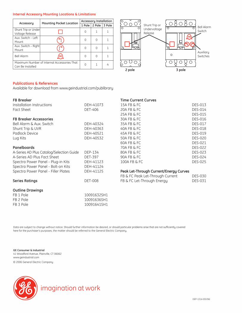
Accessory Mounting Pocket LocationAccessory Installation1 Pole 2 Pole 3 Pole
Shunt Trip or UnderVoltage Release
0 1 1
Aux. Switch - LeftMount
0 0 1
Aux. Switch - RightMount
0 0 1
Bell Alarm 0 0 1
Maximum Number of Internal Accessories ThatCan Be Installed
0 1 4
Internal Accessory Mounting Locations & Limitations
Shunt Trip orUndervoltageRelease
2 pole 3 pole
Bell AlarmSwitch
AuxiliarySwitches

45KV
A T
ransformer - 04T
E


imagination at work
Typical AQ/AL PanelboardInstallationConsult instructions NEMA PB-1.1 located in the circuit directory on the front door before installing this panelboard.If necessary, order replacement manual from supplier.
Wiring Guidelines (Cu or Al)• Use 60°C or 75°C ampacity sized wire on line and neutral
and equipment ground terminals.• Standard wire sizes listed in this publication may be
changed by using alternate terminal kits.• Refer to circuit breakers for allowable wire temperature
rating, wire size and tightening torque.• Neutral rated for 200% panelboard phase current option.
• Use copper wire only at neutral main lugs- 125A (1) neutral cables 250 mcm maximum- 225A (2) neutral cables 250 mcm maximum- 400A (2) neutral cables 600 mcm maximum- 600A (4) neutral cables 350 mcm maximum
Suitable for nonlinear loads, 200% rated neutral, additional“Y” lugs provided for 200% neutral.
Short Circuit Current RatingThe panelboard’s maximum short circuit interrupting ratingin rms symmetrical amperes, is equal to the lowest inter-rupting rating of any device installed, except as noted in theseries rating listed in DEH-40007, with integral or remotemain circuit breaker or fusible switch installed upstream ofthe panelboard. Devices to be installed or replacement unitsshall be from the same manufacturer, of the same type, andhave equal or greater interrupting capacity.
Maximum continuous loads on main or branch circuits shallnot exceed 80% of the ratings of the listed circuit breakers.Branch breaker straps suitable for 180A maximum.
Tripped BreakerIf the breaker trips, handle will be in intermediate position.
Instructions To Restore Power1. Move handle to OFF position.2. Then move handle to ON position.
Seismic RatingMeets or Exceeds the Requirements According to• IEEE-693-2005
High Level with 1.8 Amplication Factor• IBC-2006
Sds = 1.3g, Ss = 200%, Ip = 1.5, for z/h > 0Sds = 2.0g, Ss = 300%, Ip = 1.5, for z/h = 0In accordance with ICC-ES-AC156
Polybag ContentsA polybag of goods supplied with every panelboard interiorcontains:• Arc flash label• DEH-40007 Series Ratings, Wiring Diagrams &
Circuit Directory• Series rating sticker• Front installation instructions• ANSI PB1 documentation• Circuit numbering stickers (1-84)• Front and shield mounting screws
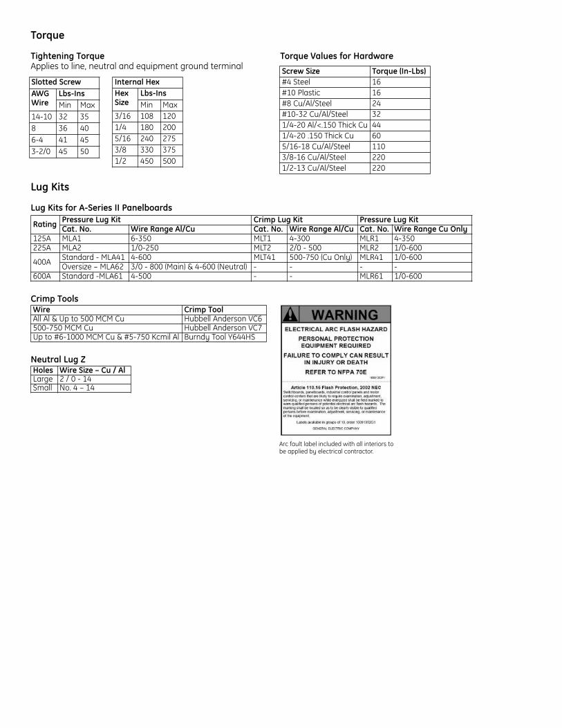
Torque
Tightening Torque Torque Values for HardwareApplies to line, neutral and equipment ground terminal
Lug Kits
Lug Kits for A-Series II Panelboards
Crimp Tools
Neutral Lug Z
Arc fault label included with all interiors tobe applied by electrical contractor.
Holes Wire Size – Cu / AlLarge 2 / 0 - 14Small No. 4 – 14
Wire Crimp ToolAll Al & Up to 500 MCM Cu Hubbell Anderson VC6500-750 MCM Cu Hubbell Anderson VC7Up to #6-1000 MCM Cu & #5-750 Kcmil Al Burndy Tool Y644HS
Rating Pressure Lug Kit Crimp Lug Kit Pressure Lug KitCat. No. Wire Range Al/Cu Cat. No. Wire Range Al/Cu Cat. No. Wire Range Cu Only
125A MLA1 6-350 MLT1 4-300 MLR1 4-350225A MLA2 1/0-250 MLT2 2/0 - 500 MLR2 1/0-600
400A Standard - MLA41 4-600 MLT41 500-750 (Cu Only) MLR41 1/0-600Oversize – MLA62 3/0 - 800 (Main) & 4-600 (Neutral) - - - -
600A Standard -MLA61 4-500 - - MLR61 1/0-600
Screw Size Torque (In-Lbs)#4 Steel 16#10 Plastic 16#8 Cu/Al/Steel 24#10-32 Cu/Al/Steel 321/4-20 Al/<.150 Thick Cu 441/4-20 .150 Thick Cu 605/16-18 Cu/Al/Steel 1103/8-16 Cu/Al/Steel 2201/2-13 Cu/Al/Steel 220
Internal HexHexSize
Lbs-InsMin Max
3/16 108 1201/4 180 2005/16 240 2753/8 330 3751/2 450 500
Slotted ScrewAWGWire
Lbs-InsMin Max
14-10 32 358 36 406-4 41 453-2/0 45 50
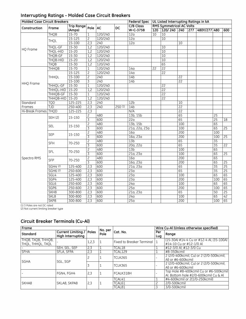
Interrupting Ratings - Molded Case Circuit Breakers
(1) 3 Poles are not DC rated(2) Not current limiting breaker type
Circuit Breaker Terminals (Cu-Al)Frame
Poles No. perPole Cat. No.
Wire Cu-Al (Unless otherwise specified)
Standard Current Limiting /High Interrupting
PerLug Range
THQB, TXQB, THHQB,THQL, THHQL, TXQL - 1,2,3 1 Fixed to Breaker Terminal 1 (15-30A) #14-4 Cu or #12-4 Al, (35-100A)
#14-10 Cu or #12-1/0 Al- SEH, SEL, SEP 2,3 1 TCAL18 1 #12-3/0 Al; #12-3/0 CuSFHA SFLA, SFPA 2,3 1 TCAL129 1 #8-350kcmil
SGHA SGL, SGP2 1 TCLK265 - 2 (2/0-400kcmil, Cu) or 2 (2/0-500kcmil,
Al) or #6-600kcmil
3 1 TCLK365 - 2 (2/0-400kcmil, Cu) or 2 (2/0-500kcmil,Al) or #6-600kcmil
- FGN4, FGH4 2,3 1 FCALK318H - Top Hole #8-400kcmil Cu or #6-500kcmilAl. Bottom hole #2/0-600kcmil Cu & Al
SKHA8 SKLA8, SKPA8 2,3 1TCAL41 1 #4-600kcmil or 2(1/0-250kcmil)TCAL61 2 2/0-500kcmilTCAL81 3 3/0-500kcmil
Molded Case Circuit Breakers Federal Spec UL Listed Interrupting Ratings in kA
Construction Frame Trip Range(Amps) Pole AC DC C/B Class
W-C-375BRMS Symmetrical AC Volts120 120/ 240 240 277 480Y/277 480 600
HQ Frame
THQB 15-70 1 120/240 12a 10 10
THQL15-125 2 120/240 12a 1015-100 2,3 240 12a 10
THQL-GF 15-30 1,2 120/240 10THQL-HID 15-20 1,2 120/240 10THQB-GF 15-30 1,2 120/240 10THQB-HID 15-20 1,2 120/240 10TXQB 15-30 1,2 120/240 65
HHQ Frame
THHQB 15-70 1 120/240 14a 22 22
THHQL15-125 2 120/240 14a 2215-100 2 240 14b 2215-100 3 240 14b 22
THHQL-GF 15-30 1 120/240 22THHQL-HID 15-20 1,2 120/240 22THHQB-GF 15-30 1 120/240 22THHQB-HID 15-20 1,2 120/240 22
StandardFrames
TQD 125-225 2,3 240 12b 10TJD 250-400 2,3 240 250 (1) 14b 22
Hi-Break Frames THQD 125-225 2,3 N/A 22
Spectra RMS
SEH (2) 15-1502 480 13b, 15b 65 253 600 22a 65 25 18
SEL 15-1502 480 13b, 15b 100 653 600 21a, 22a, 23a 100 65 25
SEP 15-1502 480 16a 200 1003 600 16a, 23a 200 100 25
SFH 70-2502 480 13b 65 353 600 20a, 22a 65 35 22
SFL 70-2502 480 13b 100 653 600 21a, 23a 100 65 25
SFP 70-2502 480 16a 200 653 600 16a, 23a 200 65 25
SGH4 (2) 125-400 2,3 600 21a, 23a 65 35 25SGH6 (2) 250-600 2,3 600 23a 65 35 25SGL4 125-400 2,3 600 23a 100 65 65SGP4 125-400 2,3 600 23a 200 100 65SGL6 250-600 2,3 600 24a 100 65 65SGP6 250-600 2,3 600 25a 200 100 65SKH8 300-800 2,3 600 21a, 23a 65 50 25SKL8 300-800 2,3 600 24a 100 65 42SKP8 300-800 2,3 600 25a 200 100 65

Wiring Space
Minimum Wiring Space, From End of Lug to Box Wall, in Inches
(1) To side wall (2) Box width is 30” and 7.81” deep
Wiring Space – Branch Circuit Breakers
Branch Circuit Devices Frame No. of Poles Minimum Wiring Spaces ToSide Wall (20" Wide Box)
Double Branched Bolt-on Devices THQL, THHQL, THQB, THHQB 1,2,3 6.5"Horizontal Subfeeds Single Branch Mounted TQD, THQD 2,3 5.5"
Main rating in amps
Main Lugs Only, toEnd Wall Frame
Type Mounting
Main Circuit BreakerPhase Lug Neutral Lug
Phase Lug Neutral Lug To Side Wall(20" Wide box) To End Wall
125A MLO, 100A Main Breaker 6 6 TEY, SE Horizontal 5 - 6225A 12 12 TFJ, SF Vertical - 6 12400A 15 11 (1) SF, SG, FG Vertical - 15 11 (1)
600A 15 11 (1) SG Vertical - 16 -800A (2) 15 11 (1) SK Vertical - 18 -
Typical PanelboardFront view with trim removed
Typical Front w/Concealed Hinges and Trim Adjusting ScrewsSurface mounting – add 1/4” to inside box dimensionsFlush mounting – add 1 1/2” to inside box dimensions
For 3/8” Bolt
Box Width(Inside)
Box
Hei
ght (
Insi
de)
3 3
3
3
Typical Box
Enclosures
(1) “B” suffix provides blank end walls. Order “K” suffix for endwalls with knockouts.(2) Standard boxes are 20" wide by 5.81" deep. (3) Flush fronts are 1 1/2" larger than box. Surface fronts are 1/4" larger.
Box Options
(1) Add to base box product number.(2) Includes field installable gutter barrier.
Permanent Circuit Number Kits
Front Options
Stainless Steel EnclosuresDimensions (inches) Cat No.H W D UL Standard CSA Labeled25.5 20 6 AB254S AB254AS 25.5 30 8 AB254DWS AB254DWAS 31.5 20 6 AB314S AB314AS 31.5 30 8 AB314DWS AB314DWAS 37.5 20 6 AB374S AB374AS 37.5 30 8 AB374DWS AB374DWAS 43.5 20 6 AB434S AB434AS 43.5 30 8 AB434DWS AB434DWAS 49.5 20 6 AB494S AB494AS 49.5 30 8 AB494DWS AB494DWAS 55.5 20 6 AB554S AB554AS 55.5 30 8 AB554DWS AB554DWAS 64.5 20 6 AB644S AB644AS 64.5 30 8 AB644DWS AB644DWAS 76.5 20 6 AB764S AB764AS 76.5 30 8 AB764DWS AB764DWAS
Description Cat. No. Suffix (1)
Screw cover CFront hinged to box DYale 5116 w/Rosette Lock YCorbin 15767 Lock LGE 75 Key Lock ECorbin 60 Key Lock JDoor within a door (2) PStainless steel (3) S 30” wide WNameplate NScrew on nameplate UMetal directory M
Description Cat. No.1-48 APN48 43-84 APN84 85-126 APN126
Description Cat. No. Suffix (1)
Painted Box P 30" wide (2) W NEMA 3R/12/4S/4X 3 or 4 NEMA 4X (316 Stainless Steel) 4S
Panel Size Box Front Cat. No. (3)Cat. No. (1) Size Inches (2)
0-25.5 AB25B 25.5 AF25F,S 28.5-31.5 AB31B 31.5 AF31F,S 34.5-37.5 AB37B 37.5 AF37F,S 40.5-43.5 AB43B 43.5 AF43F,S 46.5-49.5 AB49B 49.5 AF49F,S 52.5-55.5 AB55B 55.5 AF55F,S 57.5-64.5 AB64B 64.5 AF64F,S 67.5-76.5 AB76B 76.5 AF76F,S
(1) Add to base frontcatalog number.
(2) Consists of two lock-able doors—one overpanel interior andone over box wiringgutters. Yale locksnot available.
(3) Flush only. Availablewith C and N options.

AccessoriesField Installed Kits/Replacement Parts
Filler Plates
Breaker Mounting Hardware KitsFor mounting breaker in existing space
Equipment Grounds
Bonding Kits
Installation & Maintenance KitOrder catalog number PROCARE. Kit includes:(5) filler plate hardware kits(9) bus stud nuts(5) MLA1 filler plates(2) 225A phase barriers(2) feed-thru barriers(1) 400/600A phase barrier(50) directory cards/rating books(50) circuit number strips (1-48)(50) circuit number strips (43-84)(5) standard locks & keys(50) deadfront screws(10) AQ/AE front hardware kits(10) AD front hardware kits(50) service disconnect labels(50) main labels
Parts
Box ExtensionsBolts to box with or without endwall in place. Extensions canbe combined to obtain lengths greater than 18 and 24 inches.
Box Extension Covers Only10 covers per kit Description Cat. No.9" Covers Surface ASPABX09S 9" Covers Flush ASPABX09F 18" Covers Surface ASPABX18S 18" Covers Flush ASPABX18F 64" to 76" Covers Surface ASPABX20S 64" to 76" Covers Flush ASPABX20F
Box Width andDepth Box Mounting Box Extension
Length (Inches) Cat. No.
20 x 5.81
Flush 9 ABX2509F 18 ABX2518F 24 ABX2524F
Surface
9 ABX2509S 18 ABX2518S 24 ABX2524S 31 ABX2531S 37 ABX2537S 43 ABX2543S 49 ABX2549S 55 ABX2555S 64 ABX2564S 76 ABX2576S
30 x 5.81 Flush 18 ABX3518F
24 ABX3524F
Surface 18 ABX3518S 24 ABX3524S
30 x 7.81 Flush 18 ABX3718F
24 ABX3724F
Surface 18 ABX3718S 24 ABX3724S
Description Cat. No.Directory Card 139C5612P3Replacement Lock with Std. Key 569B737P1Replacement Lock with GE75 Key 569B737P2Additional Keys for Above Lock 569B737P5Circuit Numbering Strips 1-48 569B806G1Circuit Numbering Strips 49-84 569B806G2Circuit Numbering Strips 85-126 569B806G3Adhesive Backed Lamicoid Nameplate 3/4" x 3" 315A7190P1Metal Directory Card Holder 139C5491G1Directory Card Holder 139C5491P4Delta Hi-leg Conversion Kit, to Add B-PhasePlug on AL Panels APHBL
Bolt on AE/AQ Panels APHBQNEMA 3R/12 Tamper Proof Tork Screw Kit NEMATRX2P to 3P TQD Conv. Kit ASP2PTQD3P 2P to 3P SF Conv. Kit for horizontal subfeed ASP2PTFJ3P AD 25 to 65 kAIC Barrier kit ASP25AD65KA1 Service Entrance Kit ASPSERENT2 wire Relay Kit ASP2WRelay Yale Lock Kit ASPYALE47 Corbin Lock Kit ASPCORBNTEU1 2-3 pole TQD Mechanical Interlock TQDFM1 AQ/AL/AE Rail Bracket ASPAQLEBKT Front Flush Adjust Kit ASPFLUSHADJAE Front Mounting Kit 139C5720G3AQ/AL Front Mounting Kit 139C5720G6 AD Front Mounting Kit 139C5728G9 Front Hinge to Box Mounting Kit 139C5700G6 Front Extension Mounting Kit 139C5700G11
Description Cat. No.For Split & Load End Neutral 343L886G16
For 225A Horizontal Neutrals 343L886G13
225A Horizontal Neutral To Convert 3W to 4W ASP225HNCP125/225A Horizontal Neutral Conversion fromService Entrance to Non-Service Entrance ASPHNCPSENOT
125/225A Horizontal Neutral to Convert fromNon-Service Entrance to Service Entrance. ASPHNCPSE
Item Description Wire Range Cat. No.
MetalEquipmentGround
Bonded#14-#8 Cu, #12-#8 Al(small holes); #14-#4 Cu,#6-#4 Al (large holes)
TGL2
Extruded Bonded#14-#8 Cu, #12-#8 Al(small holes); #14-#4 Cu,#6-#4 Al (large holes)
EGS12
AluminumEquipmentGround
Extruded Bonded (1) #6-350MCM AEBGExtruded Isolated (2) #6-250MCM AEIG
Main Lug#14-#8 Cu, #12-#8 Al(small holes); #14-#4 Cu,#6-#4 Al (large holes)
TGL2
CopperEquipmentGround
Bonded#14-#8 Cu, #12-#8 Al(small holes); #14-#4 Cu,#6-#4 Al (large holes)
TGC2
Extruded Bonded (1) #4-350MCM AEBGCExtruded Isolated (1) #6-250MCM AEIGCInsulated Isolated 2/0 max. ASPGIBC
Breaker Type Cat. No.TED/THED4/SE ASPTED3PTQD/THQD ASPTQD3PFB ASPFB12P
Breaker Type Cat. No.THQB/THHQB/THQL/THHQL/TEY TQLFP1TQD/THQD/TED4/SE/FB TEDFP1
AEBG
AEBGC
AEIG
AEIGC
ASPGIBC
Endwall KitsField installed. 1 each, for standard 20"w x5.81"d boxes.
Type Cat. No.Blank ABEW2Knockout ABEW2

imagination at work
GE41 Woodford Avenue, Plainville, CT 06062www.geelectrical.com
© 2008 General Electric Company
DE-42A REV 02 (6/08)
SpecificationsA-Series Panelboards and branch breakers meet or exceedthe following standards and specifications:• UL 50 Cabinets and Boxes• UL 67 Panelboards• UL 489 Circuit Breakers• NEMA AB-1 Circuit Breakers• NEMA PB-1 and PB-1.1 Panelboards• US Federal Spec W-P.115B Panelboards• US Federal Spec W-C375b Gen Circuit Breakers
Boxes• Galvanized steel• Blank end walls are standard; knockouts are available
when specified• Boxes furnished with provisions for ground bus as standard
Fronts• Finished in ANSI-61 grey polyester powder coat paint.• Equipped with corrosion-resistant Valox combination
catch and lock door latch (doors over 48" high providedwith 2 latches)
• Equipped with concealed hinges and trim adjusting screws• Directory holder permanently mounted to door
Panels• Dead front construction• Interiors are factory assembled on rigid steel frames• Metal gages in accordance with UL and NEMA standards• Solderless, anti-turn main lugs suitable for copper or
aluminium wires are front removable and branch strapsare silver-plated copper fully rated at 100 amperes
• Main bus is aluminum with copper branch connectionsunless otherwise specified
• Main disconnect device is identified when supplied, andnumbers are provided for branch circuits
• Interior base assemblies are Noryl and provide breakermounting and busbar insulation
PublicationsE-DET-465 Certification of Seismic ComplianceDE-42A Typical AL/AQ Panelboard Technical InformationDEH 40007 Lighting Panels Rating Labels, Wiring Diagrams
and Circuit DirectoryDEH 047 TED, THED, SED, SHE, SEL, SEP Circuit Breaker
Mounting InstructionsDEH 059 SGH, SFL, SFP Circuit Breaker Mounting InstructionsDEH 060 SGH, SGL, SGP Circuit Breaker Mounting
InstructionsDEH 061 SKH, SKL, SKP Circuit Breaker Mounting InstructionsDEH 065 TQD, THQD Circuit Breaker Mounting Instructions

80A Fusible Disconnect
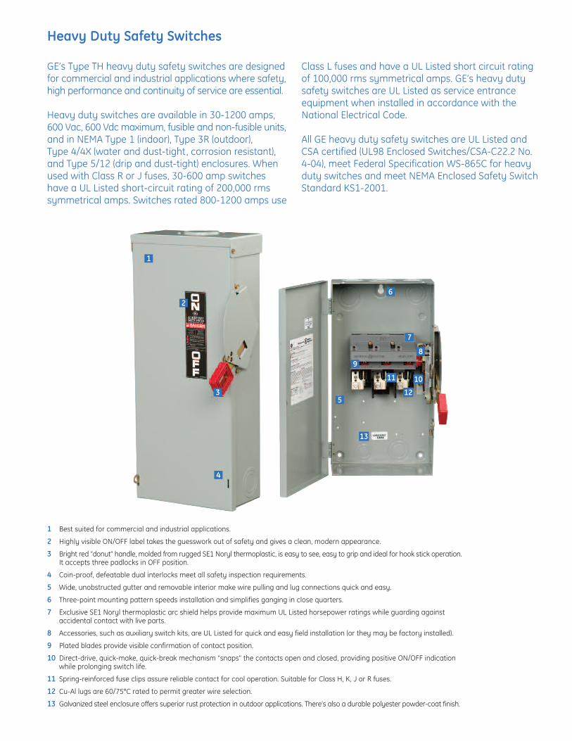
Heavy Duty Safety Switches
GE’s Type TH heavy duty safety switches are designedfor commercial and industrial applications where safety,high performance and continuity of service are essential.
Heavy duty switches are available in 30-1200 amps,600 Vac, 600 Vdc maximum, fusible and non-fusible units,and in NEMA Type 1 (indoor), Type 3R (outdoor), Type 4/4X (water and dust-tight, corrosion resistant),and Type 5/12 (drip and dust-tight) enclosures. Whenused with Class R or J fuses, 30-600 amp switcheshave a UL Listed short-circuit rating of 200,000 rmssymmetrical amps. Switches rated 800-1200 amps use
Class L fuses and have a UL Listed short circuit ratingof 100,000 rms symmetrical amps. GE’s heavy dutysafety switches are UL Listed as service entranceequipment when installed in accordance with theNational Electrical Code.
All GE heavy duty safety switches are UL Listed andCSA certified (UL98 Enclosed Switches/CSA-C22.2 No.4-04), meet Federal Specification WS-865C for heavyduty switches and meet NEMA Enclosed Safety SwitchStandard KS1-2001.
1 Best suited for commercial and industrial applications.
2 Highly visible ON/OFF label takes the guesswork out of safety and gives a clean, modern appearance.
3 Bright red “donut” handle, molded from rugged SE1 Noryl thermoplastic, is easy to see, easy to grip and ideal for hook stick operation.It accepts three padlocks in OFF position.
4 Coin-proof, defeatable dual interlocks meet all safety inspection requirements.
5 Wide, unobstructed gutter and removable interior make wire pulling and lug connections quick and easy.
6 Three-point mounting pattern speeds installation and simplifies ganging in close quarters.
7 Exclusive SE1 Noryl thermoplastic arc shield helps provide maximum UL Listed horsepower ratings while guarding against accidental contact with live parts.
8 Accessories, such as auxiliary switch kits, are UL Listed for quick and easy field installation (or they may be factory installed).
9 Plated blades provide visible confirmation of contact position.
10 Direct-drive, quick-make, quick-break mechanism “snaps” the contacts open and closed, providing positive ON/OFF indication while prolonging switch life.
11 Spring-reinforced fuse clips assure reliable contact for cool operation. Suitable for Class H, K, J or R fuses.
12 Cu-Al lugs are 60/75°C rated to permit greater wire selection.
13 Galvanized steel enclosure offers superior rust protection in outdoor applications. There’s also a durable polyester powder-coat finish.
13
10
12
11
2
1
6
5
7
89
3
4

B16
Applications: Loadcenters Panelboards Switchboards Bus duct Feeder circuits Non-inductive loads Lighting circuits
A2K-R & A6K-R Fast Acting/Class RK1
These fast-acting fuses deliver a high degree of current limitation where you need it mostCurrent-limiting A2K and A6K fuses provide excellent protection where high available short circuit currents exist. These fast-acting fuses are particularly good for branch/feeder circuits and back-up protection.
Ratings:A2K Volts : 250VAC / DCAmps : 1 to 600AIR : 200kA I.R. AC
: 20kA I.R. DCA6K Volts : 600VAC / 300VDCAmps: : 1 to 600AIR : 200kA I.R. AC
: 20kA I.R. DC
Approvals: UL listed to standard 248-12 File
E2137 CSA certi ed to standard
C22.2 No. 248.12 Self-certi ed for DC per UL248
Features/Benefits: Rejection style design prevents replacement by other fuse classes Fiberglass body provides dimensional stability in harsh industrial
environments Easy-to-read imprint label for quick recognition and replacement High degree of current limitation for low peak let-thru current
Highlights Highly current-limiting Fast-acting Rejection style
Jaxon/KCIParent company of:Ferraz Shawmut, Inc.

For the most current product performance data visit ep-us.mersen.com and use catalog search. B17
B
Catalog Numbers (amps)
A2K-R & A6K-R Fast Acting/Class RK1
Dimensions
Recommended Fuse Blocks With Box Connectors For Amp-Trap® Class RK1 Fuses
0-60A
61-600A
250V 600V
A2K1R A2K35R A2K175R A6K1R A6K35R A6K175R
A2K3R A2K40R A2K200R A6K3R A6K40R A6K200R
- A2K45R A2K225R A6K4R A6K45R A6K225R
A2K5R A2K50R A2K250R A6K5R A6K50R A6K250R
A2K6R A2K60R A2K300R A6K6R A6K60R A6K300R
- A2K70R A2K350R A6K8R A6K70R A6K350R
A2K10R A2K80R A2K400R A6K10R A6K80R A6K400R
A2K15R A2K100R A2K500R A6K15R A6K100R A6K500R
A2K20R A2K110R A2K600R A6K20R A6K110R A6K600R
A2K25R A2K125R A6K25R A6K125R
A2K30R A2K150R A6K30R A6K150R
Fuse Ampere Rating
Catalog Number
250V 600V
1-Pole 3-Pole 1-Pole 3-Pole
0-30 20306R 20308R 60306R 60308R
31-60 20606R 20608R 60606R 60608R
61-100 21036R 21038R 61036R 61038R
101-200 22001R 22003R 62001R 62003R
201-400 24001R 24003R 64001R 64003R
401-600 2631R 2633R 6631R 6633R
A variety of pole configurations and termination provisions are available. Refer to Section H for details.
Ampere RatingA B C D E
in mm in mm in mm in mm in mm
250V-A2K Fuses
0-30 2 51 9/16 14 - - - - - -
31-60 3 76 13/16 21 - - - - - -
61-100 5-7/8 149 1-1/16 27 1/8 3 3/4 19 1 25
101-200 7-1/8 181 1-9/16 40 3/16 5 1-1/8 28 1-3/8 35
201-400 8-5/8 219 2-1/16 53 1/4 6 1-5/8 41 1-7/8 48
401-600 10-3/8 264 2-9/16 66 1/4 6 2 51 2-1/4 57
600V-A6K Fuses
0-30 5 127 13/16 21 - - - - - -
31-60 5-1/2 139 1-1/16 27 - - - - - -
61-100 7-7/8 200 1-5/16 34 1/8 3 3/4 19 1 25
101-200 9-5/8 244 1-13/16 46 3/16 5 1-1/8 28 1-3/8 35
201-400 11-5/8 295 2-9/16 66 1/4 6 1-5/8 41 1-7/8 48
401-600 13-3/8 340 3-1/8 80 1/4 6 2 51 2-1/4 57
Copyright © 2022 FDOKUMEN