selos_126-289_us.pdf - TECHNIKA GKM Kft
164
Technical information • The information regarding cross sectional area and connection types pertains to unprepared wires without ferrules Ferrules are not necessary for secure connection. • The voltage ratings apply to the terminals in their intended application. When different products are mounted adjacent to each other, the proper isolation distances must be adhered to. • If the ground blocks of the selos product family are not used in block assemblies, but are mounted to the rail as single terminal blocks, end clamps have to be used. • A detailed description of technical data, the standards requirements, and the application conditions are available under facts & DATA ATEX regulation • For the use of DIN rail terminal blocks in Ex areas, the regulations of EN 50014 apply; whereas for increased safety EExe the regulations of EN 50019 must be followed. For an approximation of the laws of the EU member states, directive 94/9/EG was created, which is generally known as ATEX 100a and which is the basis for harmonization in this field. ATEX stands for ”atmosphere explosive” while 100a refers to the corresponding article of the EC contract. • Directive ATEX 100a applies for protection against dust and gas explosions in all industrial Ex areas and in mining. The testing and certificating institutes named in directive ATEX 100a must follow accreditation procedures which are the same all over Europe. • In accordance with EN 50014/50019 and ATEX 100a, these certificating institutes issue EC certificates for prototype tests. These prototype test certificates for components together with the corresponding quality system certification of the supplier are required to obtain the so-called ATEX approval. • In combination with the O mark, the markings of the Wieland terminal blocks have the following meaning: O Identification II Device group 2 Category G D Areas KEMA Name of testing institute ATEX... Certifcate, year of testing, number Mounting instructions for EEx e applications • If feed through blocks are mounted directly adjacent to feed through blocks of a different size, or directly adjacent to ground blocks, the open side of a group of the same type of blocks has to be covered by a partition. • If adjacent terminal blocks are jumpered by a cross connector, the required isolation distances have to be maintained by inserting a partition between the different block groups, in front of or behind the cross-connected terminal block group. • If the terminal blocks are mixed with other certified series and sizes and if their accessories are used, the required creepage distances and clearances must be adhered to. • The DIN rail terminal blocks must be installed in a housing that meets the requirements of an approved protection type according to EN 50 014 sec.1.2 or EN 50 289-1. The housings must have protection degree IP54 or higher depending on the protection type selected. DQS certification for all company sectors • Quality standard as per DIN ISO 9001 in Development, Production and Assembly • Continued control of the quality standard by means of regular internal and external quality audits • Compatible with certificates of other countries: – BSI Certificate, Great Britain – SQS Certificate, Switzerland – Aib-Vincotte Certificate, Belgium – ÖQS Certificate, Austria Screw connection with rising cage clamp 0.5 to 150 mm 2 • Standard DIN rail terminal blocks • Duo DIN rail terminal blocks • Multi-tier blocks • Initiator/actuator blocks • Measuring/disconnect blocks • Fuse blocks • Function blocks • DIN rail terminal blocks with pluggable connection • Miniature terminal blocks • DIN rail terminal blocks for junction boxes • High current blocks selos according to US standard UL 94 V-0 ■ Elastic clamping body ■ Rated cross section: 2.5 to 150 mm 2 ■ Connection range: 0.5 to 185 mm 2 ■ Universal foot All Wieland Components which require A general certification are A certified, and identified with the A logo.
-
Upload
khangminh22 -
Category
Documents
-
view
3 -
download
0
Transcript of selos_126-289_us.pdf - TECHNIKA GKM Kft

Technical information• The information regarding cross sectional area and connection
types pertains to unprepared wires without ferrulesFerrules are not necessary for secure connection.
• The voltage ratings apply to the terminals in their intendedapplication. When different products are mounted adjacent toeach other, the proper isolation distances must be adhered to.
• If the ground blocks of the selos product family are not used inblock assemblies, but are mounted to the rail as single terminalblocks, end clamps have to be used.
• A detailed description of technical data, the standards requirements, and the application conditions are available under facts & DATA
ATEX regulation• For the use of DIN rail terminal blocks in Ex areas, the
regulations of EN 50014 apply; whereas for increased safetyEExe the regulations of EN 50019 must be followed. For anapproximation of the laws of the EU member states, directive94/9/EG was created, which is generally known as ATEX 100aand which is the basis for harmonization in this field. ATEXstands for ”atmosphere explosive” while 100a refers to the corresponding article of the EC contract.
• Directive ATEX 100a applies for protection against dust and gasexplosions in all industrial Ex areas and in mining.The testing and certificating institutes named in directive ATEX100a must follow accreditation procedures which are the sameall over Europe.
• In accordance with EN 50014/50019 and ATEX 100a, thesecertificating institutes issue EC certificates for prototype tests. These prototype test certificates for components together withthe corresponding quality system certification of the supplier arerequired to obtain the so-called ATEX approval.
• In combination with theOmark, the markings of the Wielandterminal blocks have the following meaning:
O IdentificationII Device group2 CategoryG D AreasKEMA Name of testing institute
ATEX... Certifcate, year of testing, number
Mounting instructions for EEx e applications• If feed through blocks are mounted directly adjacent to feed
through blocks of a different size, or directly adjacent to groundblocks, the open side of a group of the same type of blocks hasto be covered by a partition.
• If adjacent terminal blocks are jumpered by a cross connector,the required isolation distances have to be maintained byinserting a partition between the different block groups, in frontof or behind the cross-connected terminal block group.
• If the terminal blocks are mixed with other certified series andsizes and if their accessories are used, the required creepagedistances and clearances must be adhered to.
• The DIN rail terminal blocks must be installed in a housing that meets the requirements of an approved protection typeaccording to EN 50 014 sec.1.2 or EN 50 289-1. The housingsmust have protection degree IP54 or higher depending on theprotection type selected.
DQS certification
for all company sectors• Quality standard as per DIN ISO 9001
in Development, Production and Assembly• Continued control of the quality standard by means of regular
internal and external quality audits• Compatible with certificates of other countries:
– BSI Certificate, Great Britain– SQS Certificate, Switzerland– Aib-Vincotte Certificate, Belgium– ÖQS Certificate, Austria
Screw connection with rising cage clamp 0.5 to 150 mm2
• Standard DIN rail terminal blocks• Duo DIN rail terminal blocks• Multi-tier blocks• Initiator/actuator blocks• Measuring/disconnect blocks• Fuse blocks• Function blocks• DIN rail terminal blocks with pluggable connection• Miniature terminal blocks• DIN rail terminal blocks for junction boxes• High current blocks
selos according to US standard UL 94 V-0
Elastic clamping body
Rated cross section: 2.5 to 150 mm2
Connection range: 0.5 to 185 mm2
Universal foot
All Wieland Components which require A generalcertification are A certified, and identified with the A logo.

Screw Connection,Type WKN
selos
DIN Rail Terminal Blocks
127

128 Subject to change without further notice
selosselosDIN rail terminal blockswith screw connection, type WKN
WK 2,5-4 KOI/U WK 2,5-4 KOI/U-NGN WK 2,5-4 KOI/U-PGN
Page 156/157
WK 2,5/U WK 4/U WK 6/U WK 10/U WKN 16/U
WKN 35/U a WKN 70/U WKN 150/U
WKN 4 ETK/U WKN 10 ETK/U WKN 16 ETK/U
WAK 16/2 BLAU,
WAK 35/2 BLAU,
WAK 35/2
WK 2,5 SL WK 4 SL WK 6 SL WKN 10 SL WKN 16 SL
WKN 35 SL/U WKN 70 SL/U 9700 A/35 E S
WK 4 TKG...SIST
WK 4 TKG... DIST
WK 4/D/1/2/U WK 4/D/2/2/U WK 4/D E/U WK 4/D/2/2SL/U
WK 4 E/U WK 4 E/U/VB WK 4 E/U WK 4 E/rot WK 4 E SL/U
WKN 2,5 E/U WKN 2,5 E/U/VB
WK 4 TKG-TRST/U WK 4 TKS D/U
WK 4 THSI 5x20/U
WK 4 THSI 6,3x32/U WK 10/SI…/U WK 10/SI/U with indicator WK 10/SI/U D
Page 138/139
Page 140/141
Page 142/143
Page 144/146
Page 146/147
Page 148/149
Page 150/151
WK 2,5-4 KI/U WK 2,5-3 D/U WK 2,5-4 KI/SL WK 2,5-3 D/SL
Page 152/153
Page 154/155
Page 158/159
Page 160/161
Page 162/163
WK 4 TKG...THSI 5x20
WK 4 TKG...THSI 6,3x32 WK 4/TKM
WK 4 TKG-TRST/U WK 4 TKS D/U
9700 A/70 E S Supply set
WK 4/TKM

129Subject to change without further notice
selosDIN rail terminal blockswith screw connection, type WKN
WK 4/Si-D/U 5 x 25
9700 B/30 Si E 18/S 359700 B/30 Si E 14/S 35 9700 B/30 Si E 14/S 32
9785 U/... 9785 U/... - SPT 9786 U/12
9786 U/TSK... 9760 U/8 TKE...
WK 2,5 U/D/8113 S/V WK 2,5 U/D/8113 S/V/LED 25 WK 2,5 U/D/8113 S/V/LED 50
WK 2,5 U/8113 S/V WK 2,5 U/8113 S/V/LED 25 WK 2,5 U/8113 S/V/LED 50 WK 2,5 U/8113 S/V/VK WK 2,5 U/D/8113 S/H
WK 4 3-6 S 1 K/U WK 4 5 S 2,8 1 K/U WK 4-3-6 S 1 K/IW/U WK 4-5 S 2,8 1 K/IW/U WK/5-10 S/U
WK/3-6 S/IW/U WK/3-6 S/U WK/4-8 S/IW/U WK/4-8 S/U WK/3-6 S KO/U
WK 4/U
WK6 TK/35
WKI 10/U
WK6 TK P3/35
WKM 2,5 F1/15 WKM 2,5 F2/15 WKM 2,5/15 WKM 4/15 WKM 4 SL/15
Page 164/165
Page 166/167
Page 168/169
Page 170/171
Page 172/173
Page 174/176
Page 176/177
Page 178/179
Page 180/181
Page 182/183
Page 186/187
Page 190/191
Page 192/193
WK 2,5 U/D/8113 S/V/VK
9700 B/30 Si E 18/S 32
WK 4/U F1 WK 4/U F2
WKI 16/U
WKI 16 ETK/U
WAK 16/2 BLAU,
WAK 35/2 BLAU,
WAK 35/2
WKI 35/U
WKN 4 ETK/U WKI 10 ETK/U

130 Subject to change without further notice
selosselosDIN rail terminal blockswith screw connection, type WKN
WK 2,5 SL/35 WK 4 SL/35 WKI 10 SL/35 WKI 16 SL/35 WKI 35 SL/35
WKI 10 PEN/35 WKI 16 PEN/35 WKI 35 PEN/35
WKI 4 TKG-D-SL
RFK 1/95... S35
Cross connectors
Page 196/197
Page 204/205
Page 202/203
Page 208/209
Page 210/211
Page 212/213
Page 214/215
Page 216/217
Page 218/219
Page 220/221
Page 222/223
Page 224/225
Page 194/195
WKI 4 NTN-D-SL
WKI 4 DU WKI 4 D-D
BK M 10/32
BK M 10/35
RFK 1/150... S35
RFK 1/240... S35
BK M 12/35
RFK 1/150... PA
RFK 1/240... PARFK 1/185... S35
WKI 4 D-D-SL WKI 4 N-D-SL WKI 4 NT-D-SL (-GL)
Single cover for cross connectors Partition plate Partition
Cross connectors, insulated
Cross connectors, uninsulated
Selectable connecting linkJumper bars, insulated
Angled support bracket Jumper bars, uninsulated
BK M 6/32
BK M 6/35
BK M 8/32
BK M 8/35
RFK 1/95... PA
RFK 1/185... PA

131Subject to change without further notice
selosDIN rail terminal blockswith screw connection, type WKN
Cover over 10 blocks Cover strips with warning symbol Cover
wieplan wiemarc wieplot
Rapid mounting tool Insulating sleeves
marcom
Test plug/ring lugs Short-circuit plug Test plug
6 mm2/8 mm spacing
Test plug
10 mm2/10 mm spacing16 mm2/12 mm spacing35 mm2/16 mm spacing
Page 228/229
Page 232/233
Page 230/231
Page 234/235
Page 236/237
Page 238/239
Page 240/241
Page 226/227
End clamp for TS 35 End clamp for TS 15End clamp for TS 35 End clamp with U footEnd clamp for TS 35
Marking tags Marking tag Marking tagMarking strips Marking tag
Marking tags Marking tag carrier
2.5 mm2/5 mm spacing 4 mm2/6 mm spacing
TS 35x7,5 TS 35x15 TS 15x15 TS 32TS 35x15
Tear-off marking strips with 10 marking tags each
selosselos
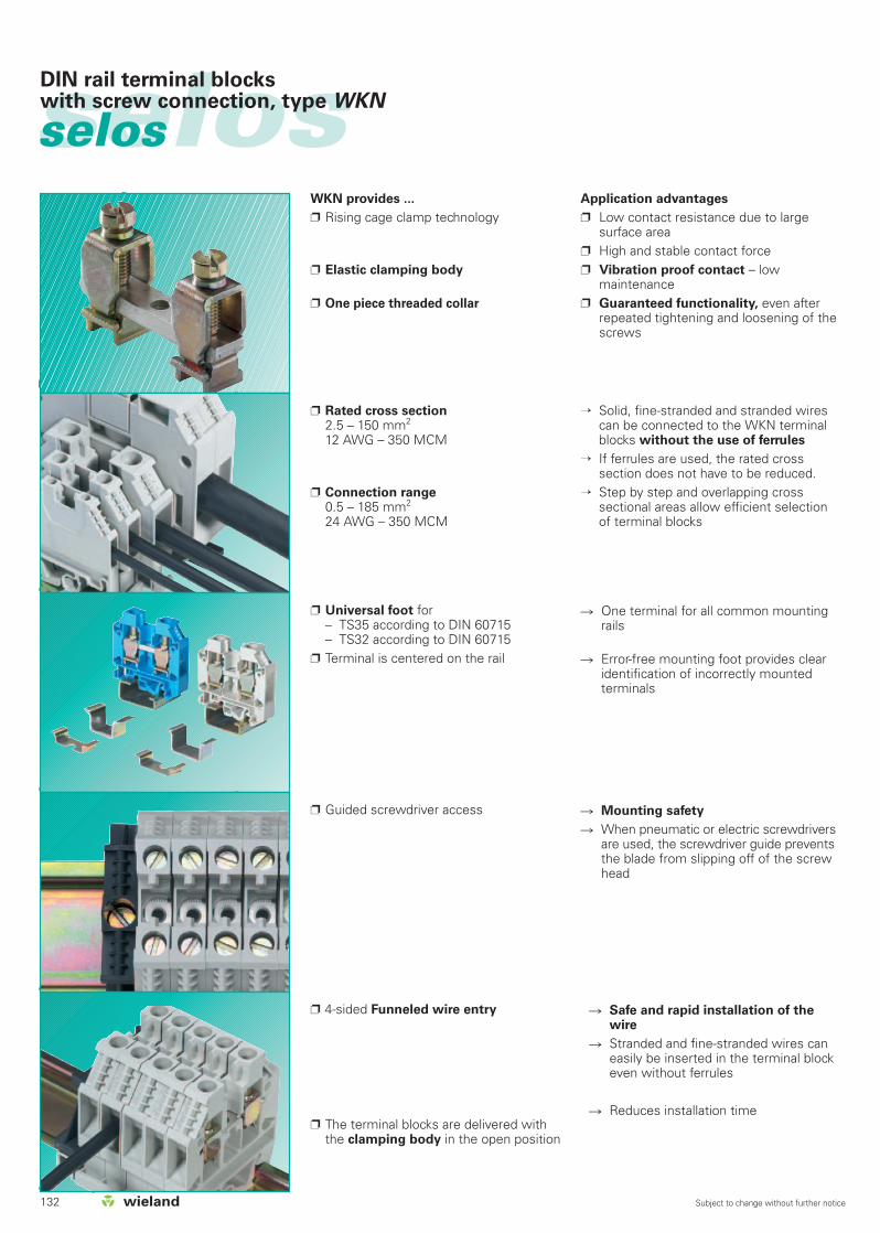
Guided screwdriver access
4-sided Funneled wire entry
The terminal blocks are delivered with the clamping body in the open position
Mounting safety
When pneumatic or electric screwdriversare used, the screwdriver guide preventsthe blade from slipping off of the screwhead
Safe and rapid installation of thewire
Stranded and fine-stranded wires caneasily be inserted in the terminal blockeven without ferrules
Reduces installation time
One terminal for all common mountingrails
Error-free mounting foot provides clearidentification of incorrectly mountedterminals
Rated cross section2.5 – 150 mm2
12 AWG – 350 MCM
Connection range0.5 – 185 mm2
24 AWG – 350 MCM
Universal foot for– TS35 according to DIN 60715– TS32 according to DIN 60715
Terminal is centered on the rail
→ Solid, fine-stranded and stranded wirescan be connected to the WKN terminalblocks without the use of ferrules
→ If ferrules are used, the rated crosssection does not have to be reduced.
→ Step by step and overlapping crosssectional areas allow efficient selectionof terminal blocks
WKN provides ...
Rising cage clamp technology
Elastic clamping body
One piece threaded collar
Application advantages
Low contact resistance due to largesurface area
High and stable contact force Vibration proof contact – low
maintenance Guaranteed functionality, even after
repeated tightening and loosening of thescrews
DIN rail terminal blockswith screw connection, type WKN
132 Subject to change without further notice

selosDIN rail terminal blockswith screw connection, type WKN
133Subject to change without further notice
Material
Special alloys and surface treatment Low contact resistance High resistance to corrosion
Captive hardware
Metal parts: Current carrying bar: tin pated; brass
or copper Clamping body and clamping screws:
steel, zinc-plated and dichromated
Insulating housing: Use of Polyamide 66/6
for its excellent chemical and mechanical properties(for more information see sectionfacts & DATA)
Material according to US standard UL 94-V0
Accessories: Stamped components: bright copper Test bolts and selectable connecting
links: galvanized copper alloy
The clamping screws are securelycaptive within the insulating housing.
Tapered plastic fins in the screw turretgrip the screw head to ensure a secure connection
The screw design prevents the screwfrom coming out of the clampingbody. Turning the screwdriver counterclockwise will cause the screw to spinin the idle position. This guaranteessafe installation when using pneumatic or electric screwdrivers
DQS certificates for all product families
Quality standard as per DIN ISO 9001 In Development, Production, Assembly Continued control of the
quality standard by means of regularinternal and external quality audits
Compatible with certificates of othercountries:
– BSI Certificate, Great Britain– SQS Certificate, Switzerland– Aib-Vincotte Certificate, Belgium– ÖQS Certificate, Austria
Various German and international approvalsare available for feed-through terminal blocks.They are indicated in detail on the corresponding product pages. The feed-throughblocks of series WK/WKN are approved for theincreased-safety type of protection Eex “e”according to DIN EN 50019/VDE 0170/0171part 6 where indicated. No type test isrequired for the Eex “i” type of protection.
Note:
The information regarding cross sectionalarea and connection types pertains tounprepared wires without ferrules.
The voltage ratings apply to the terminalsin their intended application. Whendifferent products are mounted adjacentto each other, the proper isolationdistances must be adhered to. For thispurpose, Wieland offers a large selectionof appropriate accessories.
A detailed description of technical data,the standards’ requirements, and theapplication conditions can be found inpart facts & DATA.

selosselos DIN rail terminal blockswith screw connection, type WKN
134 Subject to change without further notice
Cover with warning symbol
Cover with warning symbol to snap onto blocks which remain live when themain switch is disconnected (VDE 0113)
Partition plates
Full rated voltage is maintained whenusing partition plate with cross connectors (jumpers)
The cover can only be removed with ascrewdriver
Can be installed post assembly
The partition plates can only beremoved with a screwdriver
The cross connector covers protectthe user against accidental contact
Various marking options are availablewith the standard Wieland markingsystem
Cross connection (jumpering)
Potential commoning can be achieved bymeans of cross connectors (jumpers) orjumper bars
Number of poles: 2 to 6;cut-to-order strips available in up toapprox. 45 cm in any pole configurationrequired
Number of poles: 2 to 12; with cut-to-order strips higher pole configurationscan be achieved
Cross connectors (jumpers) are mounted in the center thread of thecurrent carrying bar
They are preassembled for easy installationand the screws are secured againstaccidental loosening.
In order to keep the rated voltage, endplates, partitions or partition plates mustbe used
Terminal blocks of different potentialsmust be mounted in partitioned order
When using jumper combs you mustinsert the comb and the wire together into the clamping body
AWG must be reduced to the next sizewhen using jumper combs
All insulated cross connectors IVB WK...and insulated jumper combs IVK WK...are protected against accidental contactaccording to VBG 4
Marking accessories
Single marking tags to match theterminal block spacing
Snap-on marking strips (10 individualmarking tags per strip) for rapid marking
Tear-off marking strips marking up to 3-digits per terminal block
Custom marking upon request
selosDIN rail terminal blockswith screw connection, type WKN
135Subject to change without further notice
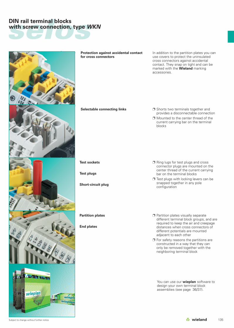
Selectable connecting links
Protection against accidental contactfor cross connectors
Shorts two terminals together andprovides a disconnectable connection
Mounted to the center thread of thecurrent carrying bar on the terminalblocks
Ring lugs for test plugs and crossconnector plugs are mounted on thecenter thread of the current carryingbar on the terminal blocks
Test plugs with locking levers can besnapped together in any pole configuration
In addition to the partition plates you canuse covers to protect the uninsulatedcross connectors against accidentalcontact. They snap on tight and can bemarked with the Wieland marking accessories.
Test sockets
Test plugs
Short-circuit plug
Partition plates visually separatedifferent terminal block groups, and arerequired to keep the air and creepagedistances when cross connectors ofdifferent potentials are mountedadjacent to each other
For safety reasons the partitions areconstructed in a way that they can only be removed together with the neighboring terminal block
Partition plates
End plates
You can use our wieplan software todesign your own terminal block assemblies (see page 36/37).
selosselos DIN rail terminal blockswith screw connection, type WKN
136 Subject to change without further notice
29321
17
4
18
5
96
8
7
12
11
10
13
16
15
14
30
23
19
2420
21
2627
22
25
28
selosDIN rail terminal blockswith screw connection, type WKN
137Subject to change without further notice
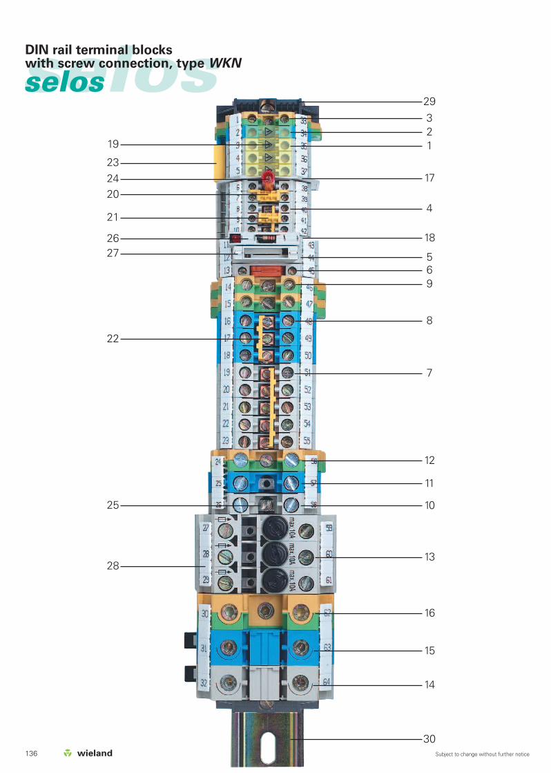
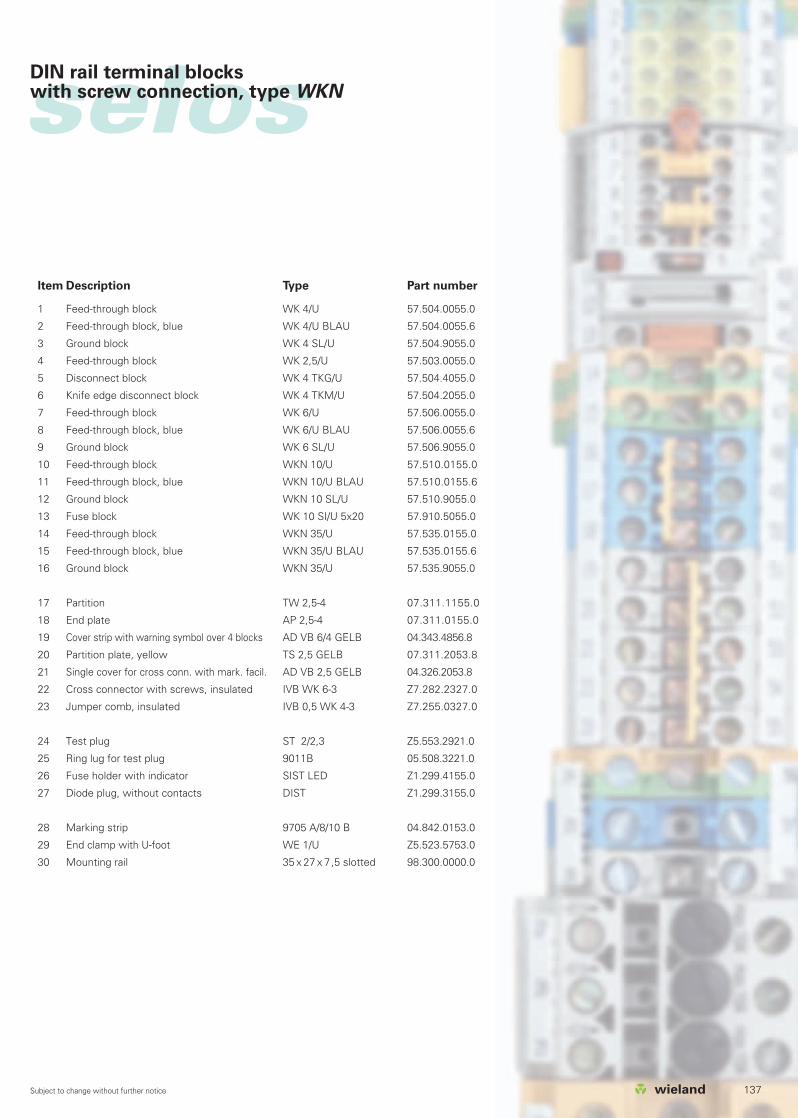
Item Description Type Part number
1 Feed-through block WK 4/U 57.504.0055.0
2 Feed-through block, blue WK 4/U BLAU 57.504.0055.6
3 Ground block WK 4 SL/U 57.504.9055.0
4 Feed-through block WK 2,5/U 57.503.0055.0
5 Disconnect block WK 4 TKG/U 57.504.4055.0
6 Knife edge disconnect block WK 4 TKM/U 57.504.2055.0
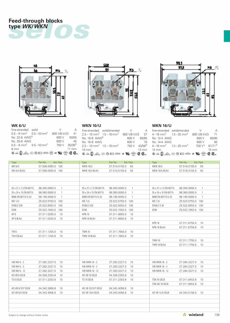
7 Feed-through block WK 6/U 57.506.0055.0
8 Feed-through block, blue WK 6/U BLAU 57.506.0055.6
9 Ground block WK 6 SL/U 57.506.9055.0
10 Feed-through block WKN 10/U 57.510.0155.0
11 Feed-through block, blue WKN 10/U BLAU 57.510.0155.6
12 Ground block WKN 10 SL/U 57.510.9055.0
13 Fuse block WK 10 SI/U 5x20 57.910.5055.0
14 Feed-through block WKN 35/U 57.535.0155.0
15 Feed-through block, blue WKN 35/U BLAU 57.535.0155.6
16 Ground block WKN 35/U 57.535.9055.0
17 Partition TW 2,5-4 07.311.1155.0
18 End plate AP 2,5-4 07.311.0155.0
19 Cover strip with warning symbol over 4 blocks AD VB 6/4 GELB 04.343.4856.8
20 Partition plate, yellow TS 2,5 GELB 07.311.2053.8
21 Single cover for cross conn. with mark. facil. AD VB 2,5 GELB 04.326.2053.8
22 Cross connector with screws, insulated IVB WK 6-3 Z7.282.2327.0
23 Jumper comb, insulated IVB 0,5 WK 4-3 Z7.255.0327.0
24 Test plug ST 2/2,3 Z5.553.2921.0
25 Ring lug for test plug 9011B 05.508.3221.0
26 Fuse holder with indicator SIST LED Z1.299.4155.0
27 Diode plug, without contacts DIST Z1.299.3155.0
28 Marking strip 9705 A/8/10 B 04.842.0153.0
29 End clamp with U-foot WE 1/U Z5.523.5753.0
30 Mounting rail 35 x 27 x 7,5 slotted 98.300.0000.0

138 Subject to change without further notice
selosselos Feed-through blocks type WK/WKN
Type Part No. Std. Pack Type Part No. Std. Pack
WK 2,5/U 57.503.0055.0 100
WK 2,5/U BLAU 57.503.0055.6 100
35 x 27 x 7,5 EN 60715 98.300.0000.0 1
35 x 24 x 15 EN 60715 98.360.0000.0 1
9006 EN 60715 G-32 98.190.0000.0 1
WE 1/U Z5.523.5753.0 100
9708/2 S35 Z5.522.8553.0 100
9708 Z5.522.7053.0 100
AP 2,5 - 4 07.311.0155.0 10
AP 2,5 - 4 BLAU 07.311.0155.6 10
TW 2,5 - 4 07.311.1155.0 10
TW 2,5 - 4 BLAU 07.311.1155.6 10
IVB WK 2,5 - 2 Z7.280.2227.0 10
IVB WK 2,5 - 3 Z7.280.2327.0 10
IVB WK 2,5 - 12 Z7.280.3227.0 10
AD VB 2,5 GELB 04.326.2053.8 10
TS 2,5 GELB 07.311.2053.8 10
AD VB 5/10 P GELB 04.342.3556.8 10
AD VB 5/4 GELB 04.343.4756.8 10
0344OII 2GDEEx eIIEN 60 947-7-1/DIN VDE 0611 T1UL ratings field/factory wiringCSA ratingsKEMA 01 ATEX 2114 U1) EN 50019/EN 50014Width Wire strip lengthApprovals
WK 2,5/U
fine-stranded solid V A0.5 – 2.5 mm2 0.5 – 4 mm2 800 V/8 kV/3 24No. 22-12 AWG 600 V 20/30No. 24-12 AWG 600 V 25 0.5 – 2.5 mm2 0.5 – 4 mm2 750 V 235 mm 9 mm
aüigotuCf+qkwh
WK 4/U 57.504.0055.0 100
WK 4/U BLAU 57.504.0055.6 100
35 x 27 x 7,5 EN 60715 98.300.0000.0 1
35 x 24 x 15 EN 60715 98.360.0000.0 1
9006 EN 60715 G-32 98.190.0000.0 1
WE 1/U Z5.523.5753.0 100
9708/2 S35 Z5.522.8553.0 100
9708 Z5.522.7053.0 100
AP 2,5 - 4 07.311.0155.0 10
AP 2,5 - 4 BLAU 07.311.0155.6 10
TW 2,5 - 4 07.311.1155.0 10
TW 2,5 - 4 BLAU 07.311.1155.6 10
IVB WK 4 - 2 Z7.281.1227.0 10
IVB WK 4 - 3 Z7.281.1327.0 10
IVB WK 4 - 12 Z7.281.2227.0 10
AD VB 4 GELB 04.326.2153.8 10
TS 4 GELB 07.311.2153.8 10
AD VB 6/10 P GELB 04.342.3656.8 10
AD VB 6/4 GELB 04.343.4856.8 10
UL wire connection variations4) or 2x no. 14 sol/str AWG
or 2x no. 16 sol/str AWGor 2x no. 18 sol/str AWGor 3x no. 20 sol/str AWG or 3x no. 22 sol/str AWG
5) or 2x no. 12 sol/str AWGor 2x no. 16 sol/str AWGor 3x no. 18 sol/str AWG or 3x no. 22 sol/str AWG
6) or 2x no. 12 sol/str AWGor 2x no. 14 sol/str AWGor 3x no. 16 sol/str AWG
WK 4/U
fine-stranded solid V A0.5 – 4 mm2 0.5 – 6 mm2 800 V/8 kV/3 32No. 22-10 AWG4) 600 V 30/35No. 20-10 AWG 600 V 40 0.5 – 4 mm2 0.5 – 6 mm2 750 V 14/273)
6 mm 9 mm
aüigotuCf+qkwh
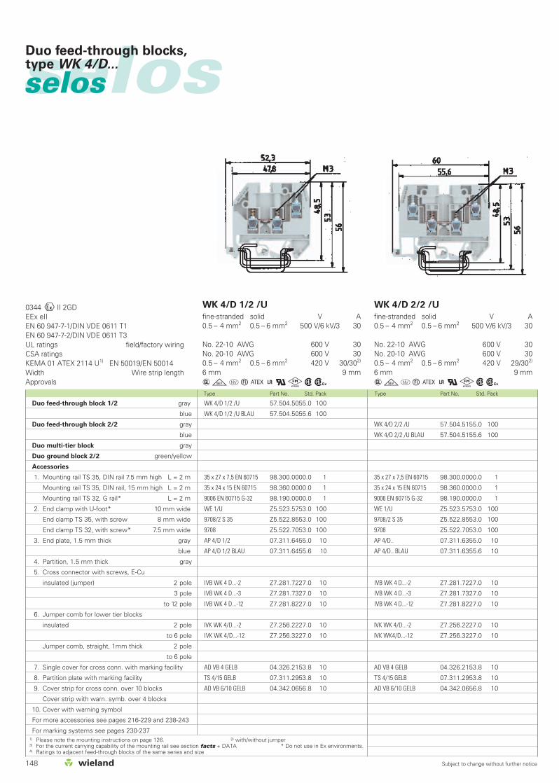
*) For maintaining the proper isolation distances, the open side of a feed-through terminal block as well as both sides of a jumper areto be covered by partitions.
1) Please note the mounting instructions on page 126. 2) Do not use in Ex environments. 3) with/without jumper
Feed-through block gray
Feed-through block EEx i blue
Accessories
1. Mounting rail TS 35, DIN rail 7.5 mm high L = 2 m
Mounting rail TS 35, DIN rail, 15 mm high L = 2 m
Mounting rail TS 32, G rail2) L = 2 m
2. End clamp with U-foot2) 10 mm wide
End clamp TS 35, with screw 8 mm wide
End clamp TS 32, with screw2) 7.5 mm wide
3. End plate, 1.5 mm thick gray
blue
End plate, 2 mm thick gray
blue
4. Partition, 1.5 mm thick gray
blue
Partition, 2 mm thick gray
blue
Partition, 3 mm thick gray
blue
5. Cross connector with screws, E-Cu
insulated (jumper) 2 pole
3 pole
to 12 pole
6. Single cover for cross conn. with mark.facility
7. Partition plate with marking facility
Partition plate with cover
8. Cover strip for cross conn. over 10 blocks with test hole
Cover strip with warning symbol over 4 blocks
For more accessories see pages 216-229 and 238-243
For marking systems see pages 230-237
139Subject to change without further notice
Type Part No. Std. Pack Type Part No. Std. Pack Type Part No. Std. Pack
selos
WKN 10/U 57.510.0155.0 50
WKN 10/U BLAU 57.510.0155.6 50
35 x 27 x 7,5 EN 60715 98.300.0000.0 1
35 x 24 x 15 EN 60715 98.360.0000.0 1
9006 EN 60715 G-32 98.190.0000.0 1
WE 1/U Z5.523.5753.0 100
9708/2 S35 Z5.522.8553.0 100
9708 Z5.522.7053.0 100
APN 10 07.311.6655.0 10
APN 10 BLAU 07.311.6655.6 10
TWN 10 07.311.7655.0 10
TWN 10 BLAU 07.311.7655.6 10
IVB WKN 10 - 2 Z7.283.2227.0 10
IVB WKN 10 - 3 Z7.283.2327.0 10
IVB WKN 10 - 12 Z7.283.3227.0 10
AD VB 10 GELB 04.326.2353.8 10
TS 10 GELB 07.311.2353.8 10
AD VB 10/10 P GELB 04.342.4056.8 10
AD VB 10/4 GELB 04.343.5056.8 10
WK 6/U 57.506.0055.0 100
WK 6/U BLAU 57.506.0055.6 100
35 x 27 x 7,5 EN 60715 98.300.0000.0 1
35 x 24 x 15 EN 60715 98.360.0000.0 1
9006 EN 60715 G-32 98.190.0000.0 1
WE 1/U Z5.523.5753.0 100
9708/2 S35 Z5.522.8553.0 100
9708 Z5.522.7053.0 100
AP 6 07.311.0255.0 10
AP 6 BLAU 07.311.0255.6 10
TW 6 07.311.1255.0 10
TW 6 BLAU 07.311.1255.6 10
IVB WK 6 - 2 Z7.282.2227.0 10
IVB WK 6 - 3 Z7.282.2327.0 10
IVB WK 6 - 12 Z7.282.3227.0 10
AD VB 6 GELB 04.326.2253.8 10
TS 6 GELB 07.311.2253.8 10
AD VB 8/10 P GELB 04.342.3856.8 10
AD VB 8/4 GELB 04.343.4956.8 10
WK 6/Ufine-stranded solid V A0.5 – 6 mm2 0.5 –10 mm2 800 V/8 kV/3 41No. 22-8 AWG5) 600 V 50/50No. 20-8 AWG 600 V 45 0.5 – 6 mm2 0.5 –10 mm2 750 V 35/383)
8 mm 11 mm
aüigotuCf+qkwh
WKN 10/U
fine-stranded solid/stranded V A2.5 – 10 mm2 1.5 – 16 mm2 800 V/8 kV/3 57No. 16-6 AWG6) 600 V 65/65No. 16-6 AWG 600 V 70 2.5 – 10 mm2 1.5 – 16 mm2 750 V 43/563)
10 mm 13 mm
aüigotuC+qkwh
WKN 16/U 57.516.0155.0 50
WKN 16/U BLAU 57.516.0155.6 50
35 x 27 x 7,5 EN 60715 98.300.0000.0 1
35 x 24 x 15 EN 60715 98.360.0000.0 1
9006 EN 60715 G-32 98.190.0000.0 1
WE 1/U Z5.523.5753.0 100
9708/2 S 35 Z5.522.8553.0 100
9708 Z5.522.7053.0 100
APN 16 07.311.6755.0 10
APN 16 BLAU 07.311.6755.6 10
TWN 16 07.311.7755.0 10
TWN 16 BLAU 07.311.7755.6 10
IVB WKN 16 - 2 Z7.284.2227.0 10
IVB WKN 16 - 3 Z7.284.2327.0 10
IVB WKN 16 - 12 Z7.284.3227.0 10
TSN 16 GELB 07.311.8453.8 10
TSN AD 16 GELB 07.311.8553.8 10
AD VB 12/4 GELB 04.343.5156.8 10
WKN 16/U
fine-stranded solid/stranded V A4 – 16 mm2 1.5 – 25 mm2 800 V/8 kV/3 71No. 12-4 AWG 600 V 85/90No. 14-4 AWG 600 V 954 – 16 mm2 1.5 – 25 mm2 750 V* 61/713)
12 mm 15 mm
aüigotuC+qkwh
Feed-through blocks type WK/WKN
140 Subject to change without further notice
Type Part No. Std. Pack Type Part No. Std. Pack
selosselos Feed-through blocks type WKN
Feed-through block gray
Feed-through block EEx i blue
Accessories
1. Mounting rail TS 35, DIN rail 7.5 mm high L = 2 m
Mounting rail TS 35, DIN rail, 15 mm high L = 2 m
Mounting rail TS 32, G rail2) L = 2 m
2. End clamp with U-foot2) 10 mm wide
End clamp TS 35, with screw 8 mm wide
End clamp TS 32, with screw2) 7.5 mm wide
3. End plate, 1.5 mm thick gray
blue
End plate, 2 mm thick gray
blue
4. Partition, 1.5 mm thick gray
blue
Partition, 2 mm thick gray
blue
Partition, 3 mm thick gray
blue
5. Cross connector with screws, E-Cu
insulated (jumper) 2 pole
3 pole
to 12 pole
6. Single cover for cross conn. with mark.facility
7. Partition plate with marking facility
Partition plate with cover
8. Cover strip for cross conn. over 10 blocks
Cover strip with warning symbol over 4 blocks
For more accessories see pages 216-229 and 238-243
For marking systems see pages 230-237
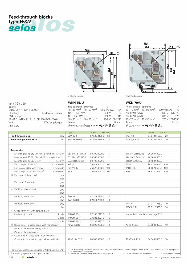
WKN 35/U 57.535.0155.0 20
WKN 35/U BLAU 57.535.0155.6 20
35 x 27 x 7,5 EN 60715 98.300.0000.0 1
35 x 24 x 15 EN 60715 98.360.0000.0 1
9006 EN 60715 G-32 98.190.0000.0 1
WE 2/U Z5.523.5653.0 100
9708/2 S 35 Z5.522.8553.0 100
9708 Z5.522.7053.0 100
TWN 35 07.311.7855.0 10
TWN 35 BLAU 07.311.7855.6 10
IVB WKN 35 - 2 Z7.285.2227.0 5
IVB WKN 35 - 3 Z7.285.2327.0 5
IVB WKN 35 - 12 Z7.285.3227.0 5
AD VB 35 GELB 04.326.2553.8 10
AD VB 16/4 GELB 04.343.5256.8 10
WKN 70/U 57.570.0155.0 20
WKN 70/U BLAU 57.570.0155.6 20
35 x 27 x 7,5 EN 60715 98.300.0000.0 1
35 x 24 x 15 EN 60715 98.360.0000.0 1
9006 EN 60715 G-32 98.190.0000.0 1
WE 2/U Z5.523.5653.0 100
9708/2 S 35 Z5.522.8553.0 100
9708 Z5.522.7053.0 100
TWN 70 07.311.7955.0 10
TWN 70 BLAU 07.311.7955.6 10
jumper bars unisulated see page 222
AD VB 70 GELB 04.326.2653.8 10
AD VB 24/4 GELB 04.343.5356.8 10
0344OII 2GDEEx eIIEN 60 947-7-1/DIN VDE 0611 T1UL ratings field/factory wiringCSA ratingsKEMA 01 ATEX 2114 U1) EN 50019/EN 50014Width Wire strip lengthApprovals
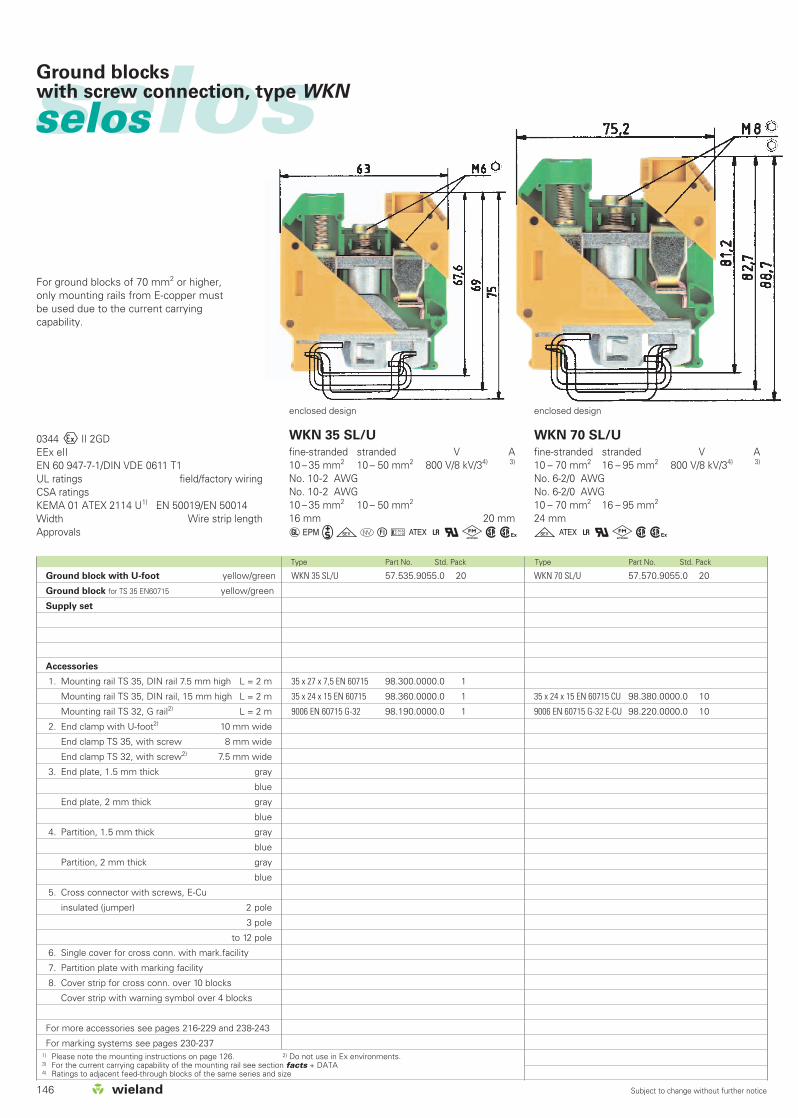
WKN 35/U
fine-stranded stranded V A10 – 35 mm2 10 – 50 mm2 800 V/8 kV/3 124No. 10-1/0 AWG 600 V 150No. 12-2 AWG 600 V 11010 – 35 mm2 10 – 50 mm2 750 V* 86/1243)
16 mm 18 mm
aGüotuC+qkwh
WKN 70/U
fine-stranded stranded V A10 – 70 mm2 16 – 95 mm2 800 V/8 kV/3 179No. 6-2/0 AWG 600 V 175/175No. 6-2/0 AWG 600 V 17010 – 70 mm2 16 – 95 mm2 750 V 179/1793)
24 mm 24 mm
aüoC+qkwh
enclosed design enclosed design
*) For maintaining the proper isolation distances, the open side of a feed-through terminal block as well as both sides of a jumper areto be covered by partitions.
1) Please note the mounting instructions on page 126. 2) Do not use in Ex environments. 3) with/without jumper

141Subject to change without further notice
Type Part No. Std. Pack
selos
WKN 150/U 57.597.0155.0 10
WKN 150/U BLAU 57.597.0155.6 10
35 x 27 x 7,5 EN 60715 98.300.0000.0 1
35 x 24 x 15 EN 60715 98.360.0000.0 1
9006 EN 60715 G-32 98.190.0000.0 1
WE 2/U Z5.523.5653.0 100
9708/2 S 35 Z5.522.8553.0 100
9708 Z5.522.7053.0 100
jumper bars unisulated see page 222
AD VB 28/4 GELB 04.343.5456.8 10
WKN 150/U
fine-stranded stranded V A35 –150 mm2 35 –185 mm2 1000 V/8 kV/3 309No. 2/0 AWG - 350 kcmil 600 V 335/335No. 2/0 AWG - 350 kcmil 600 V 36535 –150 mm2 35 –185 mm2 750 V 290/3093)
28 mm 30 mm
üC+qkwh
enclosed design
Feed-through blocks type WKN

142 Subject to change without further notice
selosselos Neutral disconnect blocks for installation with U-foot, type WKN
Current carrying capability: fine-stranded: 10 mm2 45 Astranded: 16 mm2 50 A
Current carrying capability: fine-stranded: 4 mm2 25 Asolid: 6 mm2 30 A
EN 60 947-7-1/DIN VDE 0611 T1UL ratings/CSA ratings field/factory wiringWidth Wire strip lengthApprovals
WKN 4 ETK/U
fine-stranded solid V A0.5 – 4 mm2 0.5 – 6 mm2 400 V/6 kV/3*)
6 mm 9 mm
igw
WKN 10 ETK/U
fine-stranded solid/stranded V A1 – 10 mm2 1– 16 mm2 400 V/6 kV/3*)
10 mm 13 mm
igwType Part No. Std. Pack Type Part No. Std. Pack
WKN 10 ETK/U 57.510.8155.0 50
35 x 27 x 7,5 EN 60715 98.300.0000.0 1
35 x 24 x 15 EN 60715 98.360.0000.0 1
9006 EN 60715 G-32 98.190.0000.0 1
WE 1/U Z5.523.5753.0 100
9708/2 S35 Z5.522.8553.0 100
9708 Z5.522.7053.0 100
APN 10 ETK 07.312.0955.0 10
WKI SH/U 01.108.3255.0 10
9813 M 98.290.0000.0 1
9813 M SN 98.290.1000.0 1
AD VB 10 GELB 04.326.2353.8 10
WKN 4 ETK/U 57.504.8155.0 100
35 x 27 x 7,5 EN 60715 98.300.0000.0 1
35 x 24 x 15 EN 60715 98.360.0000.0 1
9006 EN 60715 G-32 98.190.0000.0 1
WE 1/U Z5.523.5753.0 100
9708/2 S35 Z5.522.8553.0 100
9708 Z5.522.7053.0 100
APN 4 ETK 07.312.1155.0 10
WKI SH/U 01.108.3255.0 10
9813 M 98.290.0000.0 1
9813 M SN 98.290.1000.0 1
AD VB 4 GELB 04.326.2153.8 10
Neutral disconnect block blue
Connector clamps for busbar blue
unplated
Accessories
1. Mounting rail TS 35, DIN rail 7.5 mm high L = 2 m
Mounting rail TS 35, DIN rail, 15 mm high L = 2 m
Mounting rail TS 32, G rail L = 2 m
2. End clamp with U-foot 10 mm wide
End clamp TS 35, with screw 8 mm wide
End clamp TS 32, with screw 7.5 mm wide
3. End plate, 1.5 mm thick gray
blue
End plate, 2 mm thick gray
blue
4. Partition, 1.5 mm thick gray
blue
Partition, 2 mm thick gray
blue
Partition, 3 mm thick gray
blue
5. Busbar support 10 x 3 4 mm wide
6. Busbar E-Cu, 10 x 3 L = 1 m
Busbar, tin-plated, 10 x 3 L = 1 m
7. Single cover for cross conn. with mark.facility
8. Partition plate with marking facility
Partition plate with cover
9. Cover strip for cross conn. over 10 blocks
Cover strip with warning symbol over 4 blocks
For more accessories see pages 216-229 and 238-243
For marking systems see pages 230-237
*) For use in grounded networks 690/400 V
143Subject to change without further notice
Type Part No. Std. Pack Type Part No. Std. Pack Type Part No. Std. Pack
selos
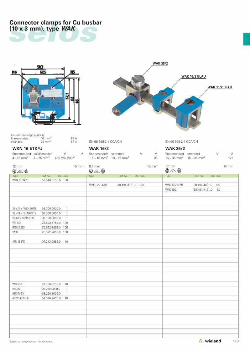
Current carrying capability: fine-stranded: 16 mm2 62 Astranded: 25 mm2 67 A
WKN 16 ETK/U
fine-stranded solid/stranded V A4 – 16 mm2 4 – 25 mm2 400 V/6 kV/3*)
12 mm 15 mm
igw
EN 60 998-2-1 CCA/CH EN 60 998-2-1 CCA/CH
WAK 35/2 BLAU 30.494.4021.6 100
WAK 35/2 30.494.4121.0 50
WAK 16/2 BLAU 30.494.3021.6 100
Connector clamps for Cu busbar (10 x 3 mm), type WAK
WAK 16/2
fine-stranded stranded V A1.5 – 16 mm2 10 – 16 mm2 76
8.4 mm 16 mm
igW
WAK 35/2
fine-stranded stranded V A16 – 35 mm2 16 – 35 mm2 125
17 mm 14 mm
igWWKN 16 ETK/U 57.516.8155.0 50
35 x 27 x 7,5 EN 60715 98.300.0000.0 1
35 x 24 x 15 EN 60715 98.360.0000.0 1
9006 EN 60715 G-32 98.190.0000.0 1
WE 1/U Z5.523.5753.0 100
9708/2 S35 Z5.522.8553.0 100
9708 Z5.522.7053.0 100
APN 16 ETK 07.312.0855.0 10
WKI SH/U 01.108.3255.0 10
9813 M 98.290.0000.0 1
9813 M SN 98.290.1000.0 1
AD VB 16 GELB 04.326.2453.8 10
WAK 35/2
WAK 16/2 BLAU
WAK 35/2 BLAU
144 Subject to change without further notice
0344OII 2GDEEx eIIEN 60 947-7-1/DIN VDE 0611 T1UL ratings field/factory wiringCSA ratingsKEMA 01 ATEX 2114 U1) EN 50019/EN 50014Width Wire strip lengthApprovals
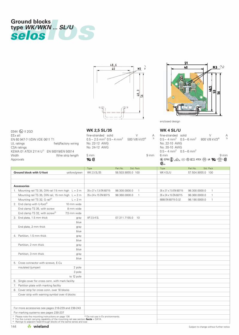
WK 2,5 SL/35
fine-stranded solid V A0.5 – 2.5 mm2 0.5 – 4 mm2 500 V/6 kV/34) 3)
No. 22-12 AWGNo. 24-12 AWG
5 mm 9 mm
qw
WK 4 SL/U
fine-stranded solid V A0.5 – 4 mm2 0.5 – 6 mm2 800 V/8 kV/34) 3)
No. 22-10 AWGNo. 20-10 AWG0.5 – 4 mm2 0.5 – 6 mm2
6 mm 9 mm
aGigotuCf+qkwh
Type Part No. Std. Pack Type Part No. Std. Pack
selosselosGround blockstype WK/WKN ... SL/U
WK 2,5 SL/35 56.503.9055.0 100
35 x 27 x 7,5 EN 60715 98.300.0000.0 1
35 x 24 x 15 EN 60715 98.360.0000.0 1
AP 2,5-4 SL 07.311.7155.0 10
WK 4 SL/U 57.504.9055.0 100
35 x 27 x 7,5 EN 60715 98.300.0000.0 1
35 x 24 x 15 EN 60715 98.360.0000.0 1
9006 EN 60715 G-32 98.190.0000.0 1
1) Please note the mounting instructions on page 126 2) Do not use in Ex environments.3) For the current carrying capability of the mounting rail see section facts + DATA4) Ratings to adjacent feed-through blocks of the same series and size
enclosed design
Ground block with U-foot yellow/green
Accessories
1. Mounting rail TS 35, DIN rail 7.5 mm high L = 2 m
Mounting rail TS 35, DIN rail, 15 mm high L = 2 m
Mounting rail TS 32, G rail2) L = 2 m
2. End clamp with U-foot2) 10 mm wide
End clamp TS 35, with screw 8 mm wide
End clamp TS 32, with screw2) 7.5 mm wide
3. End plate, 1.5 mm thick gray
blue
End plate, 2 mm thick gray
blue
4. Partition, 1.5 mm thick gray
blue
Partition, 2 mm thick gray
blue
Partition, 3 mm thick gray
blue
5. Cross connector with screws, E-Cu
insulated (jumper) 2 pole
3 pole
to 12 pole
6. Single cover for cross conn. with mark.facility
7. Partition plate with marking facility
8. Cover strip for cross conn. over 10 blocks
Cover strip with warning symbol over 4 blocks
For more accessories see pages 216-229 and 238-243
For marking systems see pages 230-237

145Subject to change without further notice
selos
WK 6 SL/U
fine-stranded solid V A0.5 – 6 mm2 0.5 –10 mm2 800 V/8 kV/34) 3)
No. 22-8 AWGNo. 20-8 AWG0.5 – 6 mm2 0.5 –10 mm2
8 mm 12 mm
aGigotuC+qkwh
WKN 10 SL/U
fine-stranded solid/stranded V A2.5 – 10 mm2 1.5 – 16 mm2 800 V/8 kV/34) 3)
No. 16-6 AWGNo. 16-6 AWG2.5 – 10 mm2 1.5 – 16 mm2
10 mm 13 mm
aGigotuC+qkwh
WKN 16 SL/U
fine-stranded solid/stranded V A4 – 16 mm2 1.5 –25 mm2 800 V/8 kV/34) 3)
No. 12-4 AWGNo. 14-4 AWG4 – 16 mm2 1.5 –25 mm2
12 mm 15 mm
aGigotuC+qkwhType Part No. Std. Pack Type Part No. Std. Pack Type Part No. Std. Pack
Ground blockstype WK/WKN ... SL/U
WK 6 SL/U 57.506.9055.0 100
35 x 27 x 7,5 EN 60715 98.300.0000.0 1
35 x 24 x 15 EN 60715 98.360.0000.0 1
9006 EN 60715 G-32 98.190.0000.0 1
WKN 10 SL/U 57.510.9055.0 50
35 x 27 x 7,5 EN 60715 98.300.0000.0 1
35 x 24 x 15 EN 60715 98.360.0000.0 1
9006 EN 60715 G-32 98.190.0000.0 1
WKN 16 SL/U 57.516.9055.0 50
35 x 27 x 7,5 EN 60715 98.300.0000.0 1
35 x 24 x 15 EN 60715 98.360.0000.0 1
9006 EN 60715 G-32 98.190.0000.0 1
enclosed design enclosed design enclosed design
146 Subject to change without further notice
Type Part No. Std. Pack Type Part No. Std. Pack
selosselos Ground blockswith screw connection, type WKN
0344OII 2GDEEx eIIEN 60 947-7-1/DIN VDE 0611 T1UL ratings field/factory wiringCSA ratingsKEMA 01 ATEX 2114 U1) EN 50019/EN 50014Width Wire strip lengthApprovals
WKN 35 SL/U
fine-stranded stranded V A10 – 35 mm2 10 – 50 mm2 800 V/8 kV/34) 3)
No. 10-2 AWGNo. 10-2 AWG10 – 35 mm2 10 – 50 mm2
16 mm 20 mm
aGigotuC+qkwh
WKN 35 SL/U 57.535.9055.0 20
35 x 27 x 7,5 EN 60715 98.300.0000.0 1
35 x 24 x 15 EN 60715 98.360.0000.0 1
9006 EN 60715 G-32 98.190.0000.0 1
WKN 70 SL/U
fine-stranded stranded V A10 – 70 mm2 16 – 95 mm2 800 V/8 kV/34) 3)
No. 6-2/0 AWGNo. 6-2/0 AWG10 – 70 mm2 16 – 95 mm2
24 mm
gC+qkwh
WKN 70 SL/U 57.570.9055.0 20
35 x 24 x 15 EN 60715 CU 98.380.0000.0 10
9006 EN 60715 G-32 E-CU 98.220.0000.0 10
enclosed design
For ground blocks of 70 mm2 or higher, only mounting rails from E-copper mustbe used due to the current carryingcapability.
enclosed design
1) Please note the mounting instructions on page 126. 2) Do not use in Ex environments.3) For the current carrying capability of the mounting rail see section facts + DATA4) Ratings to adjacent feed-through blocks of the same series and size
Ground block with U-foot yellow/green
Ground block for TS 35 EN60715 yellow/green
Supply set
Accessories
1. Mounting rail TS 35, DIN rail 7.5 mm high L = 2 m
Mounting rail TS 35, DIN rail, 15 mm high L = 2 m
Mounting rail TS 32, G rail2) L = 2 m
2. End clamp with U-foot2) 10 mm wide
End clamp TS 35, with screw 8 mm wide
End clamp TS 32, with screw2) 7.5 mm wide
3. End plate, 1.5 mm thick gray
blue
End plate, 2 mm thick gray
blue
4. Partition, 1.5 mm thick gray
blue
Partition, 2 mm thick gray
blue
5. Cross connector with screws, E-Cu
insulated (jumper) 2 pole
3 pole
to 12 pole
6. Single cover for cross conn. with mark.facility
7. Partition plate with marking facility
8. Cover strip for cross conn. over 10 blocks
Cover strip with warning symbol over 4 blocks
For more accessories see pages 216-229 and 238-243
For marking systems see pages 230-237
147Subject to change without further notice
selosGround blocksfor TS 35
Supply set
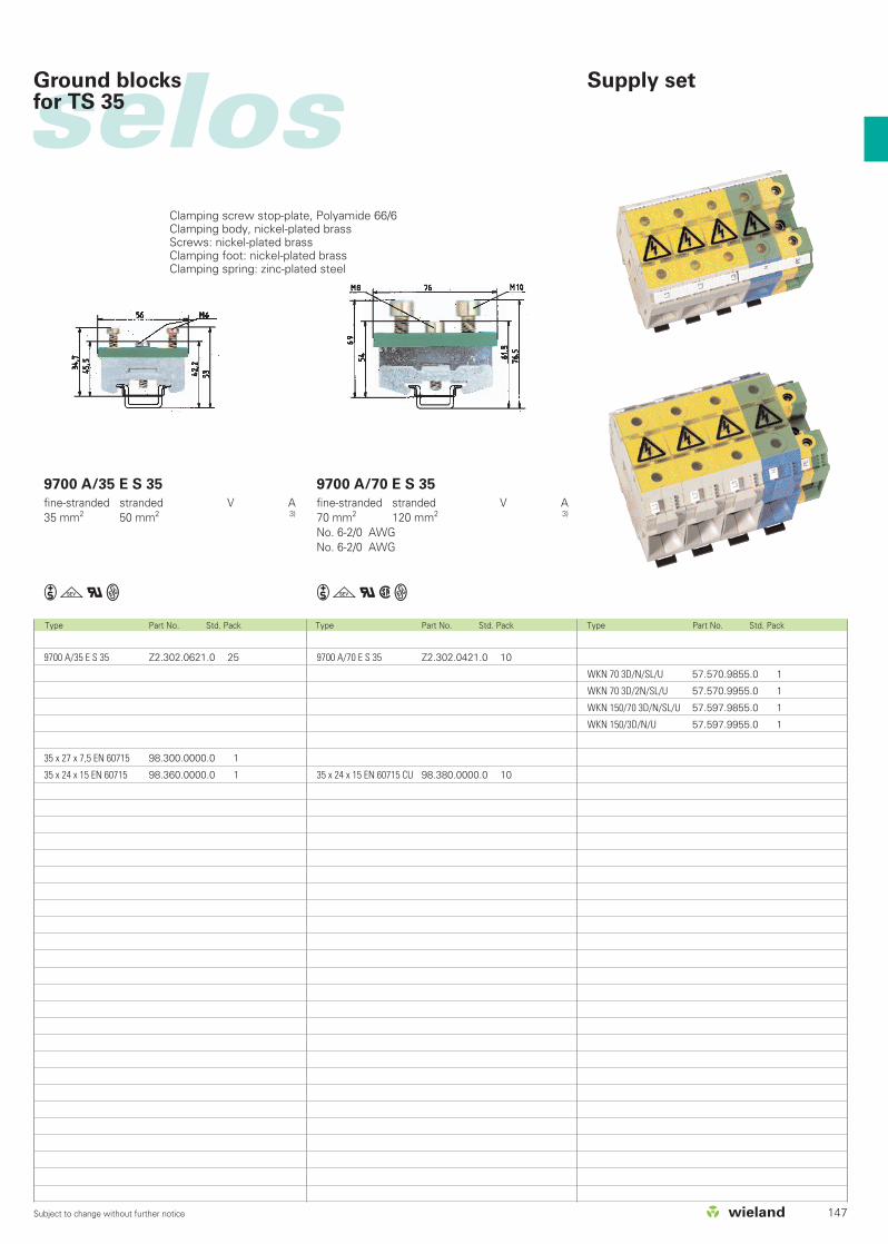
Clamping screw stop-plate, Polyamide 66/6Clamping body, nickel-plated brassScrews: nickel-plated brassClamping foot: nickel-plated brassClamping spring: zinc-plated steel
9700 A/35 E S 35 Z2.302.0621.0 25
35 x 27 x 7,5 EN 60715 98.300.0000.0 1
35 x 24 x 15 EN 60715 98.360.0000.0 1
9700 A/70 E S 35 Z2.302.0421.0 10
35 x 24 x 15 EN 60715 CU 98.380.0000.0 10
WKN 70 3D/N/SL/U 57.570.9855.0 1
WKN 70 3D/2N/SL/U 57.570.9955.0 1
WKN 150/70 3D/N/SL/U 57.597.9855.0 1
WKN 150/3D/N/U 57.597.9955.0 1
Type Part No. Std. Pack Type Part No. Std. Pack Type Part No. Std. Pack
9700 A/35 E S 35
fine-stranded stranded V A35 mm2 50 mm2 3)
igqW
9700 A/70 E S 35
fine-stranded stranded V A70 mm2 120 mm2 3)
No. 6-2/0 AWGNo. 6-2/0 AWG
igqwW
148 Subject to change without further notice
Type Part No. Std. Pack Type Part No. Std. Pack
selosselos Duo feed-through blocks,type WK 4/D...
WK 4/D 1/2 /U 57.504.5055.0 100
WK 4/D 1/2 /U BLAU 57.504.5055.6 100
35 x 27 x 7,5 EN 60715 98.300.0000.0 1
35 x 24 x 15 EN 60715 98.360.0000.0 1
9006 EN 60715 G-32 98.190.0000.0 1
WE 1/U Z5.523.5753.0 100
9708/2 S 35 Z5.522.8553.0 100
9708 Z5.522.7053.0 100
AP 4/D 1/2 07.311.6455.0 10
AP 4/D 1/2 BLAU 07.311.6455.6 10
IVB WK 4 D...-2 Z7.281.7227.0 10
IVB WK 4 D...-3 Z7.281.7327.0 10
IVB WK 4 D...-12 Z7.281.8227.0 10
IVK WK 4/D...-2 Z7.256.2227.0 10
IVK WK 4/D...-12 Z7.256.3227.0 10
. AD VB 4 GELB 04.326.2153.8 10
TS 4/15 GELB 07.311.2953.8 10
AD VB 6/10 GELB 04.342.0656.8 10
WK 4/D 2/2 /U 57.504.5155.0 100
WK 4/D 2/2 /U BLAU 57.504.5155.6 100
35 x 27 x 7,5 EN 60715 98.300.0000.0 1
35 x 24 x 15 EN 60715 98.360.0000.0 1
9006 EN 60715 G-32 98.190.0000.0 1
WE 1/U Z5.523.5753.0 100
9708/2 S 35 Z5.522.8553.0 100
9708 Z5.522.7053.0 100
AP 4/D.. 07.311.6355.0 10
AP 4/D.. BLAU 07.311.6355.6 10
IVB WK 4 D...-2 Z7.281.7227.0 10
IVB WK 4 D...-3 Z7.281.7327.0 10
IVB WK 4 D...-12 Z7.281.8227.0 10
IVK WK 4/D...-2 Z7.256.2227.0 10
IVK WK4/D...-12 Z7.256.3227.0 10
AD VB 4 GELB 04.326.2153.8 10
TS 4/15 GELB 07.311.2953.8 10
AD VB 6/10 GELB 04.342.0656.8 10
0344OII 2GDEEx eIIEN 60 947-7-1/DIN VDE 0611 T1EN 60 947-7-2/DIN VDE 0611 T3UL ratings field/factory wiringCSA ratingsKEMA 01 ATEX 2114 U1) EN 50019/EN 50014Width Wire strip lengthApprovals
WK 4/D 1/2 /U
fine-stranded solid V A0.5 – 4 mm2 0.5 – 6 mm2 500 V/6 kV/3 30
No. 22-10 AWG 600 V 30No. 20-10 AWG 600 V 300.5 – 4 mm2 0.5 – 6 mm2 420 V 30/302)
6 mm 9 mm
agotC+qkwh
WK 4/D 2/2 /U
fine-stranded solid V A0.5 – 4 mm2 0.5 – 6 mm2 500 V/6 kV/3 30
No. 22-10 AWG 600 V 30No. 20-10 AWG 600 V 300.5 – 4 mm2 0.5 – 6 mm2 420 V 29/302)
6 mm 9 mm
agotC+qkwh
1) Please note the mounting instructions on page 126. 2) with/without jumper3) For the current carrying capability of the mounting rail see section facts + DATA * Do not use in Ex environments.4) Ratings to adjacent feed-through blocks of the same series and size
Duo feed-through block 1/2 gray
blue
Duo feed-through block 2/2 gray
blue
Duo multi-tier block gray
Duo ground block 2/2 green/yellow
Accessories
1. Mounting rail TS 35, DIN rail 7.5 mm high L = 2 m
Mounting rail TS 35, DIN rail, 15 mm high L = 2 m
Mounting rail TS 32, G rail* L = 2 m
2. End clamp with U-foot* 10 mm wide
End clamp TS 35, with screw 8 mm wide
End clamp TS 32, with screw* 7.5 mm wide
3. End plate, 1.5 mm thick gray
blue
4. Partition, 1.5 mm thick gray
5. Cross connector with screws, E-Cu
insulated (jumper) 2 pole
3 pole
to 12 pole
6. Jumper comb for lower tier blocks
insulated 2 pole
to 6 pole
Jumper comb, straight, 1mm thick 2 pole
to 6 pole
7. Single cover for cross conn. with marking facility
8. Partition plate with marking facility
9. Cover strip for cross conn. over 10 blocks
Cover strip with warn. symb. over 4 blocks
10. Cover with warning symbol
For more accessories see pages 216-229 and 238-243
For marking systems see pages 230-237
149Subject to change without further notice
selos
Type Part No. Std. Pack Type Part No. Std. Pack
Duo feed-through blocks,type WK 4/D...
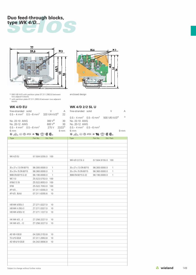
5) 500 V/6 kV/3 with partition plate 07.311.2953.8 betweentwo adjacent blocks
6) with partition plate 07.311.2953.8 between two adjacentblocks
enclosed design
WK 4/D EU 57.504.5255.0 100
35 x 27 x 7,5 EN 60715 98.300.0000.0 1
35 x 24 x 15 EN 60715 98.360.0000.0 1
9006 EN 60715 G-32 98.190.0000.0 1
WE 1/U Z5.523.5753.0 100
9708/2 S 35 Z5.522.8553.0 100
9708 Z5.522.7053.0 100
AP 4/D... 07.311.6355.0 10
AP 4/D.. BLAU 07.311.6355.6 10
IVB WK 4/DEU-2 Z7.271.0227.0 10
IVB WK 4 /DEU-3 Z7.271.0327.0 10
IVB WK 4/DEU-12 Z7.271.1227.0 10
IVK WK 4/D...-2 Z7.256.2227.0 10
IVK WK 4/D...-12 Z7.256.3227.0 10
AD VB 4 GELB 04.326.2153.8 10
TS 4/15 GELB 07.311.2953.8 10
AD VB 6/10 GELB 04.342.0656.8 10
WK 4/D 2/2 SL U 57.504.9155.0 100
35 x 27 x 7,5 EN 60715 98.300.0000.0 1
35 x 24 x 15 EN 60715 98.360.0000.0 1
9006 EN 60715 G-32 98.190.0000.0 1
WK 4/D EU
fine-stranded solid V A0.5 – 4 mm2 0.5 – 6 mm2 320 V/4 kV/35) 22
No. 22-10 AWG 300 V6) 30No. 20-12 AWG 600 V6) 300.5 – 4 mm2 0.5 – 6 mm2 275 V 22/222)
6 mm 9 mm
agotC+qkwh
WK 4/D 2/2 SL U
fine-stranded solid V A
0.5 – 4 mm2 0.5 – 6 mm2 500 V/6 kV/34) 3)
No. 22-10 AWGNo. 20-12 AWG0.5 – 4 mm2 0.5 – 6 mm2
6 mm 9 mm
agotC+qkwh

150 Subject to change without further notice
Type Part No. Std. Pack Type Part No. Std. Pack
selosselos Multi-tier blockstype WK 4 E...
WK 4 E/U 57.404.7055.0 100
35 x 27 x 7,5 EN 60715 98.300.0000.0 1
35 x 24 x 15 EN 60715 98.360.0000.0 1
9006 EN 60715 G-32 98.190.0000.0 1
WE 1/U Z5.523.5753.0 100
9708/2 S 35 Z5.522.8553.0 100
9708 Z5.522.7053.0 100
AP 4 E 07.311.4055.0 10
TW 4 E 07.311.5055.0 10
9215-2 Z7.210.3227.0 50
9215-3 Z7.210.3327.0 50
9215-6 Z7.210.3627.0 50
IVBS WK 4 E-2 Z7.256.4227.0 10
IVBS WK 4 E-6 Z7.256.4627.0 10
IVB WK 4 E-2 Z7.255.2227.0 10
IVB WK 4 E-6 Z7.255.2627.0 10
AD VB 4/15 GELB 04.326.2953.8 10
AD VB 6/10 E GELB 04.342.2656.8 10
WK 4 E/U/VB SCHWARZ 57.404.6955.1 100
35 x 27 x 7,5 EN 60715 98.300.0000.0 1
35 x 24 x 15 EN 60715 98.360.0000.0 1
9006 EN 60715 G-32 98.190.0000.0 1
WE 1/U Z5.523.5753.0 100
9708/2 S 35 Z5.522.8553.0 100
9708 Z5.522.7053.0 100
AP 4 E 07.311.4055.0 10
TW 4 E 07.311.5055.0 10
9215-2 07.210.3227.0 1
9215-3 07.210.3327.0 1
9215-6 07.210.3627.0 1
IVBS WK 4 E-2 Z7.256.4227.0 10
IVBS WK 4 E-6 Z7.256.4627.0 10
IVB WK 4 E-2 Z7.255.2227.0 10
IVB WK 4 E-6 Z7.255.2627.0 10
AD VB 6/10 E GELB 04.342.2656.8 10
0344OII 2GDEEx eIIEN 60 947-7-1/DIN VDE 0611 T1EN 60 947-7-2/DIN VDE 0611 T3UL ratings field/factory wiringCSA ratingsKEMA 02 ATEX 2114 U1) EN 50019/EN 50014Width Wire strip lengthApprovals
WK 4 E/U
fine-stranded solid V A0.5 – 4 mm2 0.5 – 4 mm2 400 V/6 kV/33) 32
No. 22-10 AWG 300 V 20No. 20-12 AWG 300 V 100.5 – 4 mm2 0.5 – 4 mm2 275 V 24/242)
6 mm 9 mm
agotCf+qkwh
WK 4 E/U /VB
fine-stranded solid V A0.5 – 4 mm2 0.5 –4 mm2 400 V/6 kV/3 32
No. 22-10 AWG 300 V 20No. 20-12 AWG 300 V 10
6 mm 9 mm
agotf+qw
1) Please note the mounting instructions on page 126. 2) with/without jumper3) With end plates 500 V/6 kV/34) Ratings to adjacent feed-through blocks of the same series and size5) For the current carrying capability of the mounting rail see section facts + DATA * Do not use in Ex environments.
Multi-tier block gray
Multi-tier block black
Multi-tier block with inverted diode orange
Multi-tier block red
Ground block green/yellow
Accessories
1. Mounting rail TS 35, DIN rail 7.5 mm high L = 2 m
Mounting rail TS 35, DIN rail, 15 mm high L = 2 m
Mounting rail TS 32, G rail* L = 2 m
2. End clamp with U-foot* 10 mm wide
End clamp TS 35, with screw 8 mm wide
End clamp TS 32, with screw* 7.5 mm wide
3. End plate, 1.5 mm thick gray
4. Partition, 1.5 mm thick gray
5. Cross connector with screws, E-Cu
uninsulated for top tier 2 pole
3 pole
to 6 pole
6. Jumper comb for lower tier block
angled, 1 mm thick insulation 2 pole
to 6 pole
Jumper comb for lower tier block
straight, 1 mm thick insulated 2 pole
to 6 pole
7. Single cover for cross conn. with marking facility
8. Snap-in partition plate with marking facility
9. Cover strip for cross conn. over 10 blocks
Cover strip with warning symbol over 4 blocks
For more accessories see pages 216-229 and 238-243
For marking systems see pages 230-237

151Subject to change without further notice
selos
Type Part No. Std. Pack Type Part No. Std. Pack
Multi-tier blockstype WK 4 E...
WK 4 E/U... 57.404.XX55.9 100
WK 4 E/U... 57.404.XX55.5 100
35 x 27 x 7,5 EN 60715 98.300.0000.0 1
35 x 24 x 15 EN 60715 98.360.0000.0 1
9006 EN 60715 G-32 98.190.0000.0 1
WE 1/U Z5.523.5753.0 100
9708/2 S 35 Z5.522.8553.0 100
9708 Z5.522.7053.0 100
AP 4 E 07.311.4055.0 10
TW 4 E 07.311.5055.0 10
IVBS WK 4 E-2 Z7.256.4227.0 10
IVBS WK 4 E-6 Z7.256.4627.0 10
IVB WK 4 E-2 Z7.255.2227.0 10
IVB WK 4 E-6 Z7.255.2627.0 10
enclosed design
WK 4 E SL/U 57.504.9255.0 100
35 x 27 x 7,5 EN 60715 98.300.0000.0 1
35 x 24 x 15 EN 60715 98.360.0000.0 1
9006 EN 60715 G-32 98.190.0000.0 1
WE 1/U Z5.523.5753.0 100
9708/2 S 35 Z5.522.8553.0 100
9708 Z5.522.7053.0 100
WK 4 E SL/U
fine-stranded solid V A
0.5 – 4 mm2 0.5 – 6 mm2 500 V/6 kV/34) 5)
No. 22-12 AWGNo. 22-10 AWG0.5 – 4 mm2 0.5 – 6 mm2
6.2 mm 9 mm
gCqkwh
WK 4 E/U...
fine-stranded solid V A0.5 – 4 mm2 0.5 –4 mm2
No. 22-10 AWGNo. 20-12 AWG
6 mm 9 mm
agotf+qw
57.404.8355.5
57.404.8055.9
with inverted diode
57.404.8255.5
57.404.8155.9
with inverted diode
57.404.7255.5 LED red
57.404.8755.5 LED green
57.404.7455.9 LED red
57.404.7955.5
57.404.8855.9
with inverted diodes
57.404.8455.5
57.404.6255.9
400 V
1 A/1000 V
400 V
1 A/1000 V
24 V DC
R = 2.2 K0.35 W
24 V DC
R = 2.2 K 0.35 W
1 A/400 V
42 V AC1 A/1000 VR = 6.8 K0.6 W
24 V DC
1 AR = 2.2 K 0.35 W

152 Subject to change without further notice
selosselos Multi-tier feed-through block
Type Part No. Std. Pack Type Part No. Std. Pack
EN 60 947-7-1/DIN VDE 0611 T1UL ratings field/factory wiringCSA ratingsWidth Wire strip lengthApprovals
WKN 2,5 E/U
fine-stranded solid V A0.5 – 2.5 mm2 0.5 – 4 mm2 500 V/6 kV/3 24No. 22-12 AWG 600 V 20/25No. 24-12 AWG 600 V 25
5 mm 8 mm
gqw
WKN 2,5 E/U/VB
fine-stranded solid V A0.5 – 2.5 mm2 0.5 – 4 mm2 500 V/6 kV/3 24No. 22-12 AWG 600 V 20/25No. 24-12 AWG 600 V 25
5 mm 8 mm
gqw
Multi-tier feed-through block gray
upper and lower feed-through tier black
connected
Accessories
1. Mounting rail TS 35, DIN rail 7.5 mm high L = 2 m
Mounting rail TS 35, DIN rail 1.5 mm high L = 2 m
Mounting rail TS 32, G rail L = 2 m
2. End clamp with U-foot 10 mm wide
End clamp TS 35, with screw 8 mm wide
End clamp TS 32, with screw 7.5 mm wide
3. End plate 1.5 mm thick
4. Partition 1.5 mm thick
5. Cross connector with screws for upper and lower
feed-through tier, insulated 2 pole
3 pole
to 12 pole
6. Single cover for cross conn. with marking facility
7. Cover strip for cross conn. over 10 blocks
8. Cover strip with warning symbol over 4 blocks
9. Snap-in partition plate
For marking systems see pages 230-237
WKN 2,5 E/U/VB 57.403.6955.1 100
35 x 27 x 7,5 EN 60715 98.300.0000.0 1
35 x 24 x 15 EN 60715 98.360.0000.0 1
9006 EN 60715 G-32 98.190.0000.0 1
WE 1/U Z5.523.5753.0 100
9708/2 S 35 Z5.522.8553.0 100
9708 Z5.522.7053.0 100
APN 2,5 E 07.312.1755.0 10
TWN 2,5 E 07.312.1855.0 10
IVB WK 2,5 - 2 Z7.280.2227.0 10
IVB WK 2,5 - 3 Z7.280.2327.0 10
IVB WK 2,5 - 12 Z7.280.3227.0 10
AD VB 2,5 GELB 04.326.2053.8 10
AD VB 5/10 GELB 04.342.0556.8 10
04.343.4756.8 10
TS 2,5 GELB 07.311.2053.8 10
WKN 2,5 E/U 57.403.7055.0 100
35 x 27 x 7,5 EN 60715 98.300.0000.0 1
35 x 24 x 15 EN 60715 98.360.0000.0 1
9006 EN 60715 G-32 98.190.0000.0 1
WE 1/U Z5.523.5753.0 100
9708/2 S 35 Z5.522.8553.0 100
9708 Z5.522.7053.0 100
APN 2,5 E 07.312.1755.0 10
TWN 2,5 E 07.312.1855.0 10
IVB WK 2,5 - 2 Z7.280.2227.0 10
IVB WK 2,5 - 3 Z7.280.2327.0 10
IVB WK 2,5 - 12 Z7.280.3227.0 10
AD VB 2,5 GELB 04.326.2053.8 10
AD VB 5/10 GELB 04.342.0556.8 10
04.343.4756.8 10
TS 2,5 GELB 07.311.2053.8 10

153
selos
154 Subject to change without further notice
Type Part No. Std. Pack Type Part No. Std. Pack
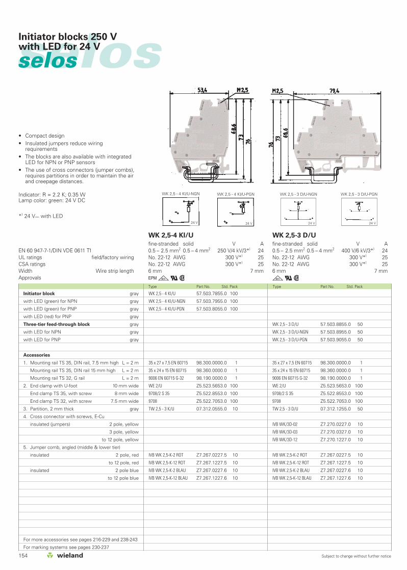
selosselos Initiator blocks 250 Vwith LED for 24 V
• Compact design• Insulated jumpers reduce wiring
requirements• The blocks are also available with integrated
LED for NPN or PNP sensors• The use of cross connectors (jumper combs),
requires partitions in order to maintain the airand creepage distances.
Indicator: R = 2.2 K; 0.35 WLamp color: green: 24 V DC
*) 24 Vy with LED
WK 2,5 - 4 KI/U-NGN WK 2,5 - 4 KI/U-PGN
24 V 24 V
WK 2,5 - 4 KI/U 57.503.7855.0 100
WK 2,5 - 4 KI/U-NGN 57.503.7955.0 100
WK 2,5 - 4 KI/U-PGN 57.503.8055.0 100
35 x 27 x 7,5 EN 60715 98.300.0000.0 1
35 x 24 x 15 EN 60715 98.360.0000.0 1
9006 EN 60715 G-32 98.190.0000.0 1
WE 2/U Z5.523.5653.0 100
9708/2 S 35 Z5.522.8553.0 100
9708 Z5.522.7053.0 100
TW 2,5 - 3 K/U 07.312.0555.0 10
IVB WK 2,5-K-2 ROT Z7.267.0227.5 10
IVB WK 2,5-K-12 ROT Z7.267.1227.5 10
IVB WK 2,5-K-2 BLAU Z7.267.0227.6 10
IVB WK 2,5-K-12 BLAU Z7.267.1227.6 10
EN 60 947-7-1/DIN VDE 0611 T1UL ratings field/factory wiringCSA ratingsWidth Wire strip lengthApprovals
WK 2,5-4 KI/U
fine-stranded solid V A0.5 – 2.5 mm2 0.5 – 4 mm2 250 V/4 kV/3*) 24No. 22-12 AWG 300 V*) 25No. 22-12 AWG 300 V*) 256 mm 7 mm
Ggqw
WK 2,5 - 3 D/U-NGN WK 2,5 - 3 D/U-PGN
24 V 24 V
WK 2,5 - 3 D/U 57.503.8855.0 50
WK 2,5 - 3 D/U-NGN 57.503.8955.0 50
WK 2,5 - 3 D/U-PGN 57.503.9055.0 50
35 x 27 x 7,5 EN 60715 98.300.0000.0 1
35 x 24 x 15 EN 60715 98.360.0000.0 1
9006 EN 60715 G-32 98.190.0000.0 1
WE 2/U Z5.523.5653.0 100
9708/2 S 35 Z5.522.8553.0 100
9708 Z5.522.7053.0 100
TW 2,5 - 3 D/U 07.312.1255.0 50
IVB WK/3D-02 Z7.270.0227.0 10
IVB WK/3D-03 Z7.270.0327.0 10
IVB WK/3D-12 Z7.270.1227.0 10
IVB WK 2,5-K-2 ROT Z7.267.0227.5 10
IVB WK 2,5-K-12 ROT Z7.267.1227.5 10
IVB WK 2,5-K-2 BLAU Z7.267.0227.6 10
IVB WK 2,5-K-12 BLAU Z7.267.1227.6 10
WK 2,5-3 D/U
fine-stranded solid V A0.5 – 2.5 mm2 0.5 – 4 mm2 400 V/6 kV/3*) 24 No. 22-12 AWG 300 V*) 25No. 22-12 AWG 300 V*) 256 mm 7 mm
gqwInitiator block gray
with LED (green) for NPN gray
with LED (green) for PNP gray
with LED (red) for PNP gray
Three-tier feed-through block gray
with LED for NPN gray
with LED for PNP gray
Accessories
1. Mounting rail TS 35, DIN rail, 7.5 mm high L = 2 m
Mounting rail TS 35, DIN rail 15 mm high L = 2 m
Mounting rail TS 32, G rail L = 2 m
2. End clamp with U-foot 10 mm wide
End clamp TS 35, with screw 8 mm wide
End clamp TS 32, with screw 7.5 mm wide
3. Partition, 2 mm thick gray
4. Cross connector with screws, E-Cu
insulated (jumpers) 2 pole, yellow
3 pole, yellow
to 12 pole, yellow
5. Jumper comb, angled (middle & lower tier)
insulated 2 pole, red
to 12 pole, red
insulated 2 pole blue
to 12 pole blue
For more accessories see pages 216-229 and 238-243
For marking systems see pages 230-237
155Subject to change without further notice
Type Part No. Std. Pack Type Part No. Std. Pack
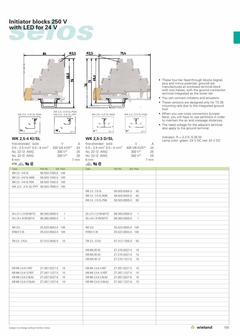
selosInitiator blocks 250 Vwith LED for 24 V
• These four-tier feed-through blocks (signal,plus and minus potential, ground) aremanufactured an enclosed terminal blockwith two halves, with the ground connectionterminal integrated as the lower tier.
• You can connect initiators and actuators.• These versions are designed only for TS 35
mounting rails due to the integrated groundfoot.
• When you use cross connectors (jumperbars), you will have to use partitions in orderto maintain the air and creepage distances.
• The rated voltage for the adjacent terminalalso apply to the ground terminal.
Indicator: R = 2.2 K; 0.35 W Lamp color: green: 24 V DC red: 24 V DC
WK 2,5 - 4 KI SL-NGNWK 2,5 - 4 KI SL-PGNWK 2,5 - 4 KI SL-PRT
24 V 24 V
WK 2,5 - 4 KI SL 56.503.7355.0 100
WK 2,5 - 4 KI SL-NGN 56.503.7455.0 100
WK 2,5 - 4 KI SL-PGN 56.503.7555.0 100
WK 2,5 - 4 KI SL-PRT 56.503.7655.0 100
35 x 27 x 7,5 EN 60715 98.300.0000.0 1
35 x 24 x 15 EN 60715 98.360.0000.0 1
WE 2/U Z5.523.5653.0 100
9708/2 S 35 Z5.522.8553.0 100
TW 2,5 - 3 K/U 07.312.0555.0 10
IVB WK 2,5-K-2 ROT Z7.267.0227.5 10
IVB WK 2,5-K-12 ROT Z7.267.1227.5 10
IVB WK 2,5-K-2 BLAU Z7.267.0227.6 10
IVB WK 2,5-K-12 BLAU Z7.267.1227.6 10
WK 2,5-4 KI/SL
fine-stranded solid V A0.5 – 2.5 mm2 0.5 – 4 mm2 250 V/4 kV/3*) 24No. 22-12 AWG 300 V*) 25No. 22-12 AWG 300 V*) 256 mm 7 mm
Ggqw
WK 2,5 - 3 D SL-NGN WK 2,5 - 3 D SL-PGN
24 V24 V
WK 2,5 - 3 D SL 56.503.8355.0 50
WK 2,5 - 3 D SL-NGN 56.503.8455.0 50
WK 2,5 - 3 D SL-PGN 56.503.8555.0 50
35 x 27 x 7,5 EN 60715 98.300.0000.0 1
35 x 24 x 15 EN 60715 98.360.0000.0 1
WE 2/U Z5.523.5653.0 100
9708/2 S 35 Z5.522.8553.0 100
TW 2,5 - 3 D/U 07.312.1255.0 50
IVB WK/3D-02 Z7.270.0227.0 10
IVB WK/3D-03 Z7.270.0327.0 10
IVB WK/3D-12 Z7.270.1227.0 10
IVB WK 2,5-K-2 ROT Z7.267.0227.5 10
IVB WK 2,5-K-12 ROT Z7.267.1227.5 10
IVB WK 2,5-K-2 BLAU Z7.267.0227.6 10
IVB WK 2,5-K-12 BLAU Z7.267.1227.6 10
WK 2,5-3 D/SL
fine-stranded solid V A0.5 – 2.5 mm2 0.5 – 4 mm2 400 V/6 kV/3*) 24 No. 22-12 AWG 300 V*) 25No. 22-12 AWG 300 V*) 256 mm 7 mm
gqw

156 Subject to change without further notice
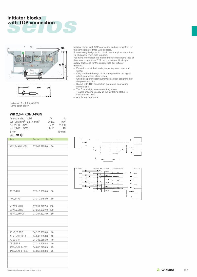
selosselos Initiator blockswith TOP connection
Type Part No. Std. Pack Type Part No. Std. Pack
EN 60 947-7-1/DIN VDE 0611 T1UL ratings field/factory wiringCSA ratingsWidth Wire strip lengthApprovals
WK 2,5-4 KOI/U
fine-stranded solid V A0.5 - 2.5 mm2 0.5 - 4 mm2 400 V/6 kV/3 16*)
No. 22-12 AWG 300 V 20/30No. 22-12 AWG 300 V 255 mm 10 mm
gqw
WK 2,5-4 KOI/U-NGN
fine-stranded solid V A0.5 - 2.5 mm2 0.5 - 4 mm2 24 DC 16*)
No. 22-12 AWG 24 V 20/30No. 22-12 AWG 24 V 255 mm 10 mm
gqw
Indicator: R = 2.2 K; 0.35 WLamp color: green
Initiator block gray
Initiator block W/ LED (NPN) gray
Accessories
1. Mounting rail TS 35, DIN rail 7.5 mm high L = 2 m
Mounting rail TS 35, DIN rail 1.5 mm high L = 2 m
Mounting rail TS 32, G rail L = 2 m
2. End clamp with U-foot 10 mm wide
End clamp TS 35, with screw 8 mm wide
End clamp TS 32, with screw 7.5 mm wide
3. End plate 1.5 mm thick
4. Partition plate 1.5 mm thick
5. Cross connector for voltage supply
uninsulated 2 pole
3 pole
to 20 pole
6. Jumper bar for signal,
uninsulated 2 pole
3 pole
to 6 pole
7. Single cover for cross conn. with marking facility
8. Cover strip with test hole over 10 blocks
9. Cover strip for cross connectors over 10 blocks
10.Partition plate
11.Tear-off marking strip, red, marked “+”
12.Tear-off marking strip, blue, marked “-”
For marking systems see pages 230-237
*) feed-through 16 A
WK 2,5-4 KOI/U-NGN 57.503.7155.0 50
35 x 27 x 7,5 EN 60715 98.300.0000.0 1
35 x 24 x 15 EN 60715 98.360.0000.0 1
9006 EN 60715 G-32 98.190.0000.0 1
WE 1/U Z5.523.5753.0 100
9708/2 S 35 Z5.522.8553.0 100
9708 Z5.522.7053.0 100
AP 2,5-4 KO 07.310.9355.0 50
TW 2,5-4 KO 07.310.9455.0 50
VB WK 2,5 KO-2 07.257.0227.0 100
VB WK 2,5 KO-3 07.257.0327.0 100
VB WK 2,5 KO-20 07.257.2027.0 50
AD VB 2,5 GELB 04.326.2053.8 10
AD VB 5/10 P GELB 04.342.3556.8 10
AD VB 5/10 04.342.0556.0 10
TS 2,5 GELB 07.311.2053.8 10
9705 A/5/10 B + ROT 04.855.0253.5 25
9705 A/5/10 B - BLAU 04.855.0353.6 25
WK 2,5-4 KOI/U 57.503.7055.0 50
35 x 27 x 7,5 EN 60715 98.300.0000.0 1
35 x 24 x 15 EN 60715 98.360.0000.0 1
9006 EN 60715 G-32 98.190.0000.0 1
WE 1/U Z5.523.5753.0 100
9708/2 S 35 Z5.522.8553.0 100
9708 Z5.522.7053.0 100
AP 2,5-4 KO 07.310.9355.0 50
TW 2,5-4 KO 07.310.9455.0 50
VB WK 2,5 KO-2 07.257.0227.0 100
VB WK 2,5 KO-3 07.257.0327.0 100
VB WK 2,5 KO-20 07.257.2027.0 50
VB WK 2,5-2 Z7.280.0227.0 10
VB WK 2,5-3 Z7.280.0327.0 10
VB WK 2,5-6 Z7.280.0627.0 10
AD VB 2,5 GELB 04.326.2053.8 10
AD VB 5/10 P GELB 04.342.3556.8 10
AD VB 5/10 04.342.0556.0 10
TS 2,5 GELB 07.311.2053.8 10
9705 A/5/10 B + ROT 04.855.0253.5 25
9705 A/5/10 B - BLAU 04.855.0353.6 25
157Subject to change without further notice
selosInitiator blockswith TOP connection
Type Part No. Std. Pack
WK 2,5-4 KOI/U-PGN
fine-stranded solid V A0.5 - 2.5 mm2 0.5 - 4 mm2 24 DC 16*)
No. 22-12 AWG 24 V 20/30No. 22-12 AWG 24 V 255 mm 10 mm
gqw
Indicator: R = 2.2 K; 0.35 WLamp color: green
WK 2,5-4 KOI/U-PGN 57.503.7255.0 50
AP 2,5-4 KO 07.310.9355.0 50
TW 2,5-4 KO 07.310.9455.0 50
VB WK 2,5 KO-2 07.257.0227.0 100
VB WK 2,5 KO-3 07.257.0327.0 100
VB WK 2,5 KO-20 07.257.2027.0 50
AD VB 2,5 GELB 04.326.2053.8 10
AD VB 5/10 P GELB 04.342.3556.8 10
AD VB 5/10 04.342.0556.0 10
TS 2,5 GELB 07.311.2053.8 10
9705 A/5/10 B + ROT 04.855.0253.5 25
9705 A/5/10 B - BLAU 04.855.0353.6 25
Initiator blocks with TOP connection and universal foot forthe connection of three wire sensors.Space-saving design which distributes the plus-minus linesvia pluggable, multi-pole jumpers.You have to consider the maximum current carrying load ofthe cross connector of 32A: for the initiator blocks persupply block, and for the current load per initiator.Benefits:– Plus-minus distribution via jumpering saves space and
wiring– Only one feed-through block is required for the signal
which guarantees clear wiring– One block per initiator guarantees a clear assignment of
the power circuits– Blocks with TOP connection guarantee clear wiring
connections– The 5 mm width saves mounting space– Trouble shooting is easy as the switching status is
indicated via LEDs– Ample marking space

158 Subject to change without further notice
selosselos
Type Part No. Std. Pack Type Part No. Std. Pack
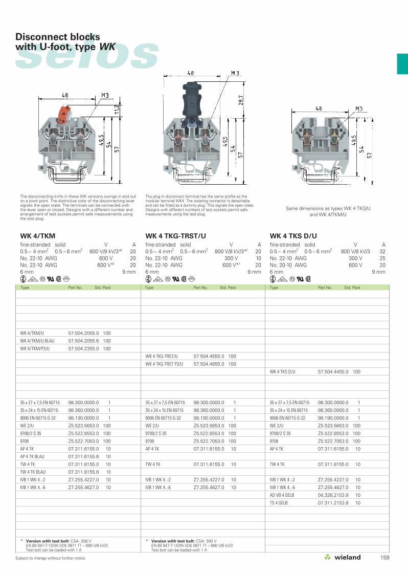
Disconnect blocks with U-foot, type WK
WK 4 TKG/U 57.504.4055.0 100
THSI 6,3x32 Z1.298.1653.0 10
THSI 6,3x32 LED24 Z1.298.1753.0 10
THSI 6,3x32 LED60 Z1.298.1853.0 10
THSI 6,3x32 GL250 Z1.298.1953.0 10
35 x 27 x 7,5 EN 60715 98.300.0000.0 1
35 x 24 x 15 EN 60715 98.360.0000.0 1
9006 EN 60715 G-32 98.190.0000.0 1
WE 2/U Z5.523.5653.0 100
9708/2 S 35 Z5.522.8553.0 100
9708 Z5.522.7053.0 100
AP 4 TK 07.311.6155.0 10
TW 4 TK 07.311.8155.0 10
IVB 1 WK 4..-2 Z7.255.4227.0 10
IVB 1 WK 4..-6 Z7.255.4627.0 10
EN 60 947-7-1/DIN VDE 0611 Teil 1EN 60 127-6/DIN VDE 0820 T6UL ratings field/factory wiringCSA ratingsWidth Wire strip lengthApprovals
WK 4 TKG... mit THSi 5x20
fine-stranded solid V A0.5 – 4 mm2 0.5 – 6 mm2 800 V/8 kV/32) 1)
No. 22-10 AWG 300 V2) 101)
No. 20-10 AWG 250 V2) 6.31)
6 mm 9 mm
igtqw
WK 4 TKG... mit THSi 6,3x32
fine-stranded solid V A0.5 – 4 mm2 0.5 – 6 mm2 800 V/8 kV/32) 1)
No. 22-10 AWG 300 V2) 101)
No. 20-10 AWG 250 V2) 6.31)
6 mm 9 mm
igtqwWK 4 TKG/U 57.504.4055.0 100
THSI 5x20 Z1.298.1053.0 10
THSI 5x20 LED24 Z1.298.1153.0 10
THSI 5x20 LED60 Z1.298.1253.0 10
THSI 5x20 GL250 Z1.298.1353.0 10
35 x 27 x 7,5 EN 60715 98.300.0000.0 1
35 x 24 x 15 EN 60715 98.360.0000.0 1
9006 EN 60715 G-32 98.190.0000.0 1
WE 2/U Z5.523.5653.0 100
9708/2 S 35 Z5.522.8553.0 100
9708 Z5.522.7053.0 100
AP 4 TK 07.311.6155.0 10
TW 4 TK 07.311.8155.0 10
IVB 1 WK 4..-2 Z7.255.4227.0 10
IVB 1 WK 4..-6 Z7.255.4627.0 10
When selecting G fuse inserts, make sure that the specifiedmaximum power is not exceeded.1)
The current is determined by the inserted fuse. 1) Thevoltage range is determined by the built-in LED display.2)
Depending on the application and the installation method,the circumstances for increased temperature must bechecked in the closed fuse holders.Higher ambient temperatures are an additional load for thefuse inserts. Therefore, the reduction of the rated currentmust be considered accordingly in these applications.
Indicator (24 V): Lamp color: redPower consumption: 10.3 mA
Indicator (220 V): Lamp color: redCurrent input: 0.3 mA
Type Rated Overload protection Exclusivevoltage short-circuit protection
Single Group Single Grouparrangement arrangement arrangement arrangement
THSI 5x20 250 V 1.6 W 1.6 W 4.0 W 2.5 WTHSI 6.3x32 500 V 2.5 W 1.6 W 4.0 W 4.0 W
1) Maximum power loss at 23 °C ambient temperature(according to DIN EN 60947-7-3)
Disconnect base block gray
Fuse disconnect lever
Fuse disconnect lever with LED 12– 24 V2)
Fuse disconnect lever with LED 24 – 60 V2)
Fuse disconnect lever with GL 110 – 250 V2)
Knife edge disconnect block gray
blue
– with 2 test bolts gray
Invertible plug disconnect block m. Inver. plug w/o test bolt C.: gray
– with test bolts left and right gray
Feed-through block gray
Accessories
1. Mounting rail TS 35, DIN rail, 7.5 mm high L = 2 m
Mounting rail TS 35, DIN rail 15 mm high L = 2 m
Mounting rail TS 32, G rail L = 2 m
2. End clamp with U-foot 10 mm wide
End clamp TS 35, with screw 8 mm wide
End clamp TS 32, with screw 7.5 mm wide
3. End plate, 1.5 mm thick gray
blue
4. Partition, 1.5 mm thick gray
blue
5. Jumper comb insulated 2 pole
to 6 pole
6. Cover f. cross conn. with marking facility
7. Snap-in partition plate with marking facility
For marking systems see pages 230-237
selos
159Subject to change without further notice
Type Part No. Std. Pack Type Part No. Std. Pack Type Part No. Std. Pack
Disconnect blocks with U-foot, type WK
WK 4/TKM
fine-stranded solid V A0.5 – 4 mm2 0.5 – 6 mm2 800 V/8 kV/3*) 20No. 22-10 AWG 600 V 20No. 22-10 AWG 600 V*) 206 mm 9 mm
igtqwd
WK 4 TKG-TRST/U
fine-stranded solid V A0.5 – 4 mm2 0.5 – 6 mm2 800 V/8 kV/3*) 20No. 22-10 AWG 300 V 10No. 22-10 AWG 600 V*) 206 mm 9 mm
igtqwd
WK 4 TKS D/U
fine-stranded solid V A0.5 – 4 mm2 0.5 – 6 mm2 800 V/8 kV/3 32No. 22-10 AWG 300 V 25No. 20-10 AWG 600 V 206 mm 9 mm
igtqw
WK 4/TKM/U 57.504.2055.0 100
WK 4/TKM/U BLAU 57.504.2055.6 100
WK 4/TKM/P3/U 57.504.2355.0 100
35 x 27 x 7,5 EN 60715 98.300.0000.0 1
35 x 24 x 15 EN 60715 98.360.0000.0 1
9006 EN 60715 G-32 98.190.0000.0 1
WE 2/U Z5.523.5653.0 100
9708/2 S 35 Z5.522.8553.0 100
9708 Z5.522.7053.0 100
AP 4 TK 07.311.6155.0 10
AP 4 TK BLAU 07.311.6155.6 10
TW 4 TK 07.311.8155.0 10
TW 4 TK BLAU 07.311.8155.6 10
IVB 1 WK 4..-2 Z7.255.4227.0 10
IVB 1 WK 4..-6 Z7.255.4627.0 10
*) Version with test bolt: CSA: 300 VEN 60 947-7-1/DIN VDE 0611 T1 – 690 V/6 kV/3Test bolt can be loaded with 1 A
The disconnecting knife in these WK versions swings in and outon a pivot point. The distinctive color of the disconnecting leversignals the open state. The terminals can be connected withthe lever open or closed. Designs with a different number andarrangement of test sockets permit safe measurements usingthe test plug.
The plug in disconnect terminal has the same profile as themodular terminal WK4. The isolating connector is detachableand can be fitted as a dummy plug. This signals the open state.Designs with different numbers of test sockets permit safemeasurements using the test plug.
WK 4 TKG-TRST/U 57.504.4555.0 100
WK 4 TKG-TRST P3/U 57.504.4855.0 100
35 x 27 x 7,5 EN 60715 98.300.0000.0 1
35 x 24 x 15 EN 60715 98.360.0000.0 1
9006 EN 60715 G-32 98.190.0000.0 1
WE 2/U Z5.523.5653.0 100
9708/2 S 35 Z5.522.8553.0 100
9708 Z5.522.7053.0 100
AP 4 TK 07.311.6155.0 10
TW 4 TK 07.311.8155.0 10
IVB 1 WK 4..-2 Z7.255.4227.0 10
IVB 1 WK 4..-6 Z7.255.4627.0 10
*) Version with test bolt: CSA: 300 VEN 60 947-7-1/DIN VDE 0611 T1 – 690 V/6 kV/3Test bolt can be loaded with 1 A
WK 4 TKS D/U 57.504.4455.0 100
35 x 27 x 7,5 EN 60715 98.300.0000.0 1
35 x 24 x 15 EN 60715 98.360.0000.0 1
9006 EN 60715 G-32 98.190.0000.0 1
WE 2/U Z5.523.5653.0 100
9708/2 S 35 Z5.522.8553.0 100
9708 Z5.522.7053.0 100
AP 4 TK 07.311.6155.0 10
TW 4 TK 07.311.8155.0 10
IVB 1 WK 4..-2 Z7.255.4227.0 10
IVB 1 WK 4..-6 Z7.255.4627.0 10
AD VB 4 GELB 04.326.2153.8 10
TS 4 GELB 07.311.2153.8 10
Same dimensions as types WK 4 TKG/U and WK 4/TKM/U

160 Subject to change without further notice
selosselos
Type Part No. Std. Pack Type Part No. Std. Pack
Disconnect blocks with U-foot, type WK
The current carrying load depends on the built-in component.Temporary peak voltage 1000 V.Pole assignment Anode Cathodeof the diode: Cathode Anode
WK 4 TKG/U 57.504.4055.0 100
DIST ... Z1.299.3055.0 10
DIST-1 N 4007-15) Z1.299.3155.0 10
DIST-1 N 4007-26) Z1.299.3355.0 10
DIST-D Z1.299.3255.0 10
35 x 27 x 7,5 EN 60715 98.300.0000.0 1
35 x 24 x 15 EN 60715 98.360.0000.0 1
9006 EN 60715 G-32 98.190.0000.0 1
WE 2/U Z5.523.5653.0 100
9708/2 S 35 Z5.522.8553.0 100
9708 Z5.522.7053.0 100
AP 4 TK 07.311.6155.0 10
TW 4 TK 07.311.8155.0 10
IVB 1 WK 4..-2 Z7.255.4227.0 10
IVB 1 WK 4..-6 Z7.255.4627.0 10
EN 60 947-7-1/DIN VDE 0611 Teil 1EN 60 127-6/DIN VDE 0820 T6UL ratings field/factory wiringCSA ratingsWidth Wire strip lengthApprovals
WK 4 TKG... SIST
fine-stranded solid V A0.5 – 4 mm2 0.5 – 6 mm2 800 V/8 kV/32) 1)
No. 22-10 AWG 300 V 10No. 20-10 AWG 250 V 6.36 mm 9 mm
igtqw
WK 4 TKG... DIST
fine-stranded solid V A0.5 – 4 mm2 0.5 – 6 mm2 800 V/8 kV/3No. 22-10 AWG 300 V 10No. 20-10 AWG 250 V 6.36 mm 9 mm
igtqwWK 4 TKG/U 57.504.4055.0 100
Si ST Z1.299.4055.0 10
Si ST LED Z1.299.4155.0 10
Si ST GL Z1.299.4255.0 10
35 x 27 x 7,5 EN 60715 98.300.0000.0 1
35 x 24 x 15 EN 60715 98.360.0000.0 1
9006 EN 60715 G-32 98.190.0000.0 1
WE 2/U Z5.523.5653.0 100
9708/2 S 35 Z5.522.8553.0 100
9708 Z5.522.7053.0 100
AP 4 TK 07.311.6155.0 10
TW 4 TK 07.311.8155.0 10
IVB 1 WK 4..-2 Z7.255.4227.0 10
IVB 1 WK 4..-6 Z7.255.4627.0 10
When selecting G fuse inserts, make sure that the specifiedmaximum power is not exceeded.1)
The current is determined by the inserted fuse. 1) Thevoltage range is determined by the built-in LED display.2)
Depending on the application and the installation method,the circumstances for increased temperature must bechecked in the closed fuse holders.Higher ambient temperatures are an additional load for thefuse inserts. Therefore, the reduction of the rated currentmust be considered accordingly in these applications.
Indicator (24 V): Lamp color: redPower consumption: 10.3 mA
Indicator (220 V): Lamp color: redCurrent input: 0.3 mA
Type Rated Overload protection Exclusivevoltage short-circuit protection
Single Group Single Grouparrangement arrangement arrangement arrangement
SIST 250 V 1.6 W 1.6 W 2.5 W 1.6 W
1) Maximum power loss at 23 °C ambient temperature(according to DIN EN 60947-7-3)
Disconnect block gray
Fuse holder for 5 x 20 fuse blue
Fuse holder with indicator (24 V) gray
Fuse holder with indicator (110-220 V) gray
Diode plug, without contacts Jmax = 10 A gray
Diode plug - diode Jmax = 11 A gray
Diode plug - diode Jmax = 11 A gray
Diode plug with jumper Jmax = 10 A gray
Knife edge disconnect block gray
blue
– with 2 test bolts gray
Invertible plug disconnect block m. Inver. plug w/o test bolt C.: gray
– with test bolts left and right gray
Feed-through block gray
Accessories
1. Mounting rail TS 35, DIN rail, 7.5 mm high L = 2 m
Mounting rail TS 35, DIN rail 15 mm high L = 2 m
Mounting rail TS 32, G rail L = 2 m
2. End clamp with U-foot 10 mm wide
End clamp TS 35, with screw 8 mm wide
End clamp TS 32, with screw 7.5 mm wide
3. End plate, 1.5 mm thick gray
blue
4. Partition, 1.5 mm thick gray
blue
5. Jumper comb insulated 2 pole
to 6 pole
6. Cover f. cross conn. with marking facility
7. Snap-in partition plate with marking facility
For marking systems see pages 230-237

selos
161Subject to change without further notice
Type Part No. Std. Pack Type Part No. Std. Pack Type Part No. Std. Pack
WK 4/TKM
fine-stranded solid V A0.5 – 4 mm2 0.5 – 6 mm2 800 V/8 kV/3*) 20No. 22-10 AWG 600 V 20No. 22-10 AWG 600 V*) 206 mm 9 mm
igtqwd
WK 4 TKG-TRST/U
fine-stranded solid V A0.5 – 4 mm2 0.5 – 6 mm2 800 V/8 kV/3*) 20No. 22-10 AWG 300 V 10No. 22-10 AWG 600 V*) 206 mm 9 mm
igtqwd
WK 4 TKS D/U
fine-stranded solid V A0.5 – 4 mm2 0.5 – 6 mm2 800 V/8 kV/3 32No. 22-10 AWG 300 V 25No. 20-10 AWG 600 V 206 mm 9 mm
igtqw
WK 4/TKM/U 57.504.2055.0 100
WK 4/TKM/U BLAU 57.504.2055.6 100
WK 4/TKM/P3/U 57.504.2355.0 100
35 x 27 x 7,5 EN 60715 98.300.0000.0 1
35 x 24 x 15 EN 60715 98.360.0000.0 1
9006 EN 60715 G-32 98.190.0000.0 1
WE 2/U Z5.523.5653.0 100
9708/2 S 35 Z5.522.8553.0 100
9708 Z5.522.7053.0 100
AP 4 TK 07.311.6155.0 10
AP 4 TK BLAU 07.311.6155.6 10
TW 4 TK 07.311.8155.0 10
TW 4 TK BLAU 07.311.8155.6 10
IVB 1 WK 4..-2 Z7.255.4227.0 10
IVB 1 WK 4..-6 Z7.255.4627.0 10
*) Version with test bolt: CSA: 300 VEN 60 947-7-1/DIN VDE 0611 T1 – 690 V/6 kV/3Test bolt can be loaded with 1 A
The disconnecting knife in these WK versions swings in and outon a pivot point. The distinctive color of the disconnecting leversignals the open state. The terminals can be connected withthe lever open or closed. Designs with a different number andarrangement of test sockets permit safe measurements usingthe test plug.
The plug in disconnect terminal has the same profile as themodular terminal WK4. The isolating connector is detachableand can be fitted as a dummy plug. This signals the open state.Designs with different numbers of test sockets permit safemeasurements using the test plug.
WK 4 TKG-TRST/U 57.504.4555.0 100
WK 4 TKG-TRST P3/U 57.504.4855.0 100
35 x 27 x 7,5 EN 60715 98.300.0000.0 1
35 x 24 x 15 EN 60715 98.360.0000.0 1
9006 EN 60715 G-32 98.190.0000.0 1
WE 2/U Z5.523.5653.0 100
9708/2 S 35 Z5.522.8553.0 100
9708 Z5.522.7053.0 100
AP 4 TK 07.311.6155.0 10
TW 4 TK 07.311.8155.0 10
IVB 1 WK 4..-2 Z7.255.4227.0 10
IVB 1 WK 4..-6 Z7.255.4627.0 10
*) Version with test bolt: CSA: 300 VEN 60 947-7-1/DIN VDE 0611 T1 – 690 V/6 kV/3Test bolt can be loaded with 1 A
WK 4 TKS D/U 57.504.4455.0 100
35 x 27 x 7,5 EN 60715 98.300.0000.0 1
35 x 24 x 15 EN 60715 98.360.0000.0 1
9006 EN 60715 G-32 98.190.0000.0 1
WE 2/U Z5.523.5653.0 100
9708/2 S 35 Z5.522.8553.0 100
9708 Z5.522.7053.0 100
AP 4 TK 07.311.6155.0 10
TW 4 TK 07.311.8155.0 10
IVB 1 WK 4..-2 Z7.255.4227.0 10
IVB 1 WK 4..-6 Z7.255.4627.0 10
AD VB 4 GELB 04.326.2153.8 10
TS 4 GELB 07.311.2153.8 10
Same dimensions as types WK 4 TKG/U and WK 4/TKM/U
Disconnect blocks with U-foot, type WK

162 Subject to change without further notice
selosselos Fuse blockswith U-foot, type WK
Type Part No. Std. Pack Type Part No. Std. Pack
for 6.3 mm fusesfor 5 mm fuses
WK 4/THSi 5 ... U 57.904.5355.0 50
WK 4/THSi 5 LED 12 U 57.904.5455.0 50
WK 4/THSi 5 LED 24 U 57.904.5555.0 50
WK 4/THSi 5 LED 60 U 57.904.5655.0 50
WK 4/THSi 5 GL 250 U 57.904.5755.0 50
WK 4/THSi 5 GL 500 U 57.904.5855.0 50
35 x 27 x 7,5 EN 60715 98.300.0000.0 1
35 x 24 x15 EN 60715 98.360.0000.0 1
9006 EN 60715 G-32 98.190.0000.0 1
WE 1/U Z5.523.5753.0 100
9708/2 S 35 Z5.522.8553.0 100
9708 Z5.522.7053.0 100
WK 4/THSi 6,3 ... U 57.904.6355.0 50
WK 4/THSi 6,3 LED 12 U 57.904.6455.0 50
WK 4/THSi 6,3 LED 24 U 57.904.6555.0 50
WK 4/THSi 6,3 LED 60 U 57.904.6655.0 50
WK 4/THSi 6,3 GL 250 U 57.904.6755.0 50
WK 4/THSi 6,3 GL 500 U 57.904.6855.0 50
35 x 27 x 7,5 EN 60715 98.300.0000.0 1
35 x 24 x 15 EN 60715 98.360.0000.0 1
9006 EN 60715 G-32 98.190.0000.0 1
WE 1/U Z5.523.5753.0 100
9708/2 S 35 Z5.522.8553.0 100
9708 Z5.522.7053.0 100
The fuse blocks of this type have a flip top disconnect lever. Itaccepts fine-wire fuses of 5 x 20, 5 x 25 and5 x 30 mm (terminal width: 8 mm) or 6.3 x 32 mm (terminal width: 10 mm). The hinged lever haslatch points both in the open and in the closed state, and can besealed. All terminal blocks are available in two differentversions, i.e. with or without red LEDs functioning as indicators.When selecting G fuse inserts, make sure that the specifiedmaximum power loss is not exceeded. 1) The current isdetermined by the inserted fuse.1) The voltage range isdetermined by the built-in LED display.2)
Depending on the application and the installation method, thecircumstances for increased temperature must be checked inthe closed fuse holders.Higher ambient temperatures are an additional load for the fuseinserts. Therefore, the reduction of the rated current must beconsidered accordingly in these applications.
EN 60 947-7-1, EN 60 127-6UL ratings field/factory wiringCSA ratingsWidth Wire strip lengthApprovals
WK 4 THSI 5... /U
fine-stranded solid V A0.5 – 4 mm2 0.5 – 6 mm2 800 V/8 kV/32) 6,31)
No. 22-10 AWG 600 V2) 15No. 22-10 AWG 600 V2) 6.38 mm 8 mm
gqw
WK 4 THSI 6,3... /U
fine-stranded solid V A0.5 – 4 mm2 0.5 – 6 mm2 800 V/8 kV/32) 101)
No. 22-10 AWG 600 V2) 15No. 22-10 AWG 600 V2) 1010 mm 8 mm
gqw
The standard block has a storage location for a replacement fuse.
Type Rated Overload protection Exclusivevoltage short-circuit protection
Single Group Single Grouparrangement arrangement arrangement arrangement
THSI 5x20/25 250 V 1.6 W 1.6 W 4.0 W 2.5 WTHSI 6.3x32 500 V 2.5 W 2.5 W 4.0 W 2.5 WTHSI 5x30 500 V 1.6 W 4.0 W 4.0 W 2.5 W
1) Maximum power loss at 23 °C ambient temperature(according to DIN EN 60947-7-3)
Fuse block gray
– with LED 5 - 12 V ~/y current consumed. 2.3 - 7 mA
– with LED 12 - 24 V ~/ y current consumed. 2.8 - 6.2 mA
– with LED 24 - 60 V ~/ y current consumed. 1.5 - 4 mA
– with lamp 110 -250 V ~/ y current consumed. 0.13 - 0.55 mA
– with lamp 380 -500 V ~/ y current consumed. 0.2 - 0.3 mA
Fuse block gray
– with screw cap A DIN 41674 for G-fuses DIN 41571, 250 V, 5 x 20 mm
– with screw cap B DIN 41674 for G fuses DIN 41576, 250 V, 5 x 25 mm
– with screw cap A DIN 41674 for G-fuses , 500 V, 5 x 30 mm
– with screw cap for G-fuses, 500 V, 1/4 x 11/4” (6.3 x 32 mm)
Feed-through block, same dimensions as fuse block C.: gray
Accessories
1. Mounting rail TS 35, DIN rail, 7.5 mm high L = 2 m
Mounting rail TS 35, DIN rail 15 mm high L = 2 m
Mounting rail TS 32, G rail L = 2 m
2. End clamp with U-foot 10 mm wide
End clamp TS 35, with screw 8 mm wide
End clamp TS 32, with screw 7.5 mm wide
3. End plate, 1.5 mm thick gray
4. Cross connector with screws, E-Cu
uninsulated 2 pole
3 pole
to 6 pole
5. Transparent cover (for 1 block)
For marking systems see pages 230-237
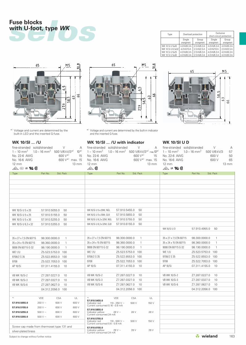
selos
163Subject to change without further notice
Fuse blockswith U-foot, type WK
Type Part No. Std. Pack Type Part No. Std. Pack Type Part No. Std. Pack
*) Voltage and current are determined by the built-in LED and the inserted G-fuse.
WK 10/Si U 5 x 20 57.910.5055.0 50
WK 10/Si U 5 x 25 57.910.5155.0 50
WK 10/Si U 5 x 30 57.910.5255.0 50
WK 10/Si U 6,3 x 32 57.910.5355.0 50
35 x 27 x 7,5 EN 60715 98.300.0000.0 1
35 x 24 x 15 EN 60715 98.360.0000.0 1
9006 EN 60715 G-32 98.190.0000.0 1
WE 1/U Z5.523.5753.0 100
9708/2 S 35 Z5.522.8553.0 100
9708 Z5.522.7053.0 100
AP 10/Si 07.311.4155.0 10
VB WK 10/Si-2 Z7.287.0227.0 10
VB WK 10/Si-3 Z7.287.0327.0 10
VB WK 10/Si-6 Z7.287.0627.0 10
04.312.2056.0 100
Screw cap made from thermoset type 131 and
silver-plated brass
WK10/Si U 5 x 20M, NGL 57.910.5455.0 50
WK10/Si U 5 x 20M, GLB 57.910.5855.0 50
WK10/Si U 6,3 x 32M, NGL 57.910.5755.0 50
WK10/Si U 6,3 x 32M, GLB 57.910.6155.0 50
35 x 27 x 7,5 EN 60715 98.300.0000.0 1
35 x 24 x 15 EN 60715 98.360.0000.0 1
9006 EN 60715 G-32 98.190.0000.0 1
WE 1/U Z5.523.5753.0 100
9708/2 S 35 Z5.522.8553.0 100
9708 Z5.522.7053.0 100
AP 10/Si 07.311.4155.0 10
VB WK 10/Si-2 Z7.287.0227.0 10
VB WK 10/Si-3 Z7.287.0327.0 10
VB WK 10/Si-6 Z7.287.0627.0 10
04.312.2056.0 100
WK10/Si U D 57.910.4955.0 50
35 x 27 x 7,5 EN 60715 98.300.0000.0 1
35 x 24 x 15 EN 60715 98.360.0000.0 1
9006 EN 60715 G-32 98.190.0000.0 1
WE 1/U Z5.523.5753.0 100
9708/2 S 35 Z5.522.8553.0 100
9708 Z5.522.7053.0 100
AP 10/Si 07.311.4155.0 10
VB WK 10/Si-2 Z7.287.0227.0 10
VB WK 10/Si-3 Z7.287.0327.0 10
VB WK 10/Si-6 Z7.287.0627.0 10
04.312.2056.0 100
WK 10/SI ... /U
fine-stranded solid/stranded V A1 – 10 mm2 1.0 – 16 mm2 500 V/6 kV/3*) 10*)
No. 22-6 AWG 600 V*) 15No. 16-6 AWG 600 V*) max. 1512 mm 13 mm
go+qw
WK 10/SI ... /U with indicator
fine-stranded solid/stranded V A1 – 10 mm2 1.0 – 16 mm2 500 V/6 kV/3*) max.10*)
No. 22-6 AWG 600 V*) 15No. 16-6 AWG 600 V*) max. 1512 mm 13 mm
gw
WK 10/SI U D
fine-stranded solid/stranded V A1 – 10 mm2 1.0 – 16 mm2 500 V/6 kV/3 57No. 22-6 AWG 600 V 50No. 16-6 AWG 600 V 6512 mm 13 mm
g+qw
*) VDE CSA UL57.910.5455.0Indicator red 110 - 250 V 500 V 150 VCurrent consumed 0.16 - 0.8 mA
57.910.5855.0Indicator yellow 28 V 28 V 28 VCurrent consumed 24 mA
57.910.5755.0Indicator red 110 - 500 V 500 V 150 VCurrent consumed 0.6 - 0.8 mA
57.910.6155.0Indicator yellow 28 V 28 V 28 VCurrent consumed 24 mA
*) VDE CSA UL
57.910.5055.0 250 V 600 V 600 V
57.910.5155.0 250 V 600 V 600 V
57.910.5255.0 500 V 600 V 600 V
57.910.5355.0 500 V 600 V 600 V
*) Voltage and current are determined by the built-in indicatorand the inserted G-fuse.
Type Overload protection Exclusiveshort-circuit protection
Single Group Single Grouparrangement arrangement arrangement arrangement
WK 10 Si U 5x20 4.0W/6.3A 2.5W/6.3A 4.0W/6.3A 4.0W/6.3AWK 10 Si U 6.3x32 4.0W/10A 2.5W/2.5A 4.0W/10A 2.5W/2.5AWK 10 Si U 5x25 4.0W/6.3A 2.5W/6.3A 4.0W/6.3A 4.0W/6.3AWK 10 Si U 5x30 4.0W/6.3A 2.5W/6.3A 4.0W/6.3A 4.0W/6.3A

164 Subject to change without further notice
selosselos Fuse blockswith U-foot, type WK
Type Part No. Std. Pack
EN 60 947-7-1, EN 60 127-6UL ratingsCSA ratingsWidth Wire strip lengthApprovals
WK 4/Si-D/U 5 x 25
fine-stranded solid V A0.5 – 4 mm2 0.5 – 6 mm2 800 V/8 kV/3*) 6.3*)
No. 20-10 AWG 250 V 1012 mm 9 mm
gwFuse block gray
– Fused feed-through terminal block
(G-screw cap B DIN 41674, 5 x 25 mm – 250 V/6.3 A)
– Fused feed-through terminal block
(G-screw cap A DIN 41674, 5 x 20 mm – 250 V/6.3 A)
Accessories
1. Mounting rail TS 35, DIN rail, 7.5 mm high L = 2 m
Mounting rail TS 35, DIN rail 1.5 mm high L = 2 m
Mounting rail TS 32, G rail
2. End clamp with U-foot 10 mm wide
End clamp TS 35, with screw 8 mm wide
End clamp TS 32, with screw 7.5 mm wide
3. End plate 1.5 mm wide
For marking systems see pages 230-237
WK 4/Si-D/U 5 x 25 57.504.1655.0 50
WK 4/Si-D/U 5 x 20 57.504.1755.0 50
35 x 27 x 7,5 EN 60715 98.300.0000.0 1
35 x 24 x 15 EN 60715 98.360.0000.0 1
9006 EN 60715 G-32 98.190.0000.0 1
WE 1/U Z5.523.5753.0 100
9708/2 S 35 Z5.522.8553.0 100
9780 Z5.522.7053.0 100
AP 4 TK 07.311.6155.0 10
*) Voltage and current are determined by thefuse used.
Rated current in accordance to VDE 0820 T2/EN 60 127-2, up to a power loss of 1.6 W

selos
165

166 Subject to change without further notice
selosselos
Type Part No. Std. Pack Type Part No. Std. Pack
Fuse block for NEOZED® mounting on TS 35 and TS 32 rail
DIN VDE 0636UL ratingsCSA ratingsWidth Wire strip lengthApprovals
9700 B/30 Si E 14/S 35 2–16 A
fine-stranded solid V A1.5 – 4 mm2 1.5 – 4 mm2 400 V ~*) 16*)
30 mm 10 mm
d
9700 B/30 Si E 18/S 35 2–63 A
fine-stranded solid/stranded V A1.5 – 25 mm2 1.5 – 25 mm2 400 V ~*) 63*)
30 mm 12 mm
dFuse block gray
complete with closed insulating housing
Accessories
1. Mounting rail TS 35, DIN rail, 7.5 mm high L = 2 m
Mounting rail TS 35, DIN rail 1.5 mm high L = 2 m
Mounting rail TS 32, G rail
2. End clamp with U-foot 10 mm wide
End clamp TS 35, with screw 8 mm wide
End clamp TS 32, with screw 7.5 mm wide
3. NEOZED® adapter sleeve 2 A – pink
4 A – brown
6 A – green
10 A – red
16 A – gray
20 A – blue
25 A – yellow
35 A – black
50 A – white
4. Cover cap
5. Jumper comb
6 pole
uninsulated 10 pole
6. Special retaining clip
For marking systems see pages 230-237
NEOZED® = registered trademark of Siemens AG
9700 B/30 Si E 18/S 35 56.925.4055.0 20
35 x 27 x 7,5 EN 60715 98.300.0000.0 1
35 x 24 x 15 EN 60715 98.360.0000.0 1
WE 1/U Z5.523.5753.0 100
9708/2 S 35 Z5.522.8553.0 100
05.595.5900.0 50
05.595.6000.0 50
05.595.6100.0 50
05.595.6200.0 50
05.595.6300.0 50
05.595.6400.0 50
05.595.6500.0 50
05.595.6600.0 50
05.595.6700.0 50
04.326.1053.0 100
07.250.3027.0 25
07.250.3127.0 10
05.549.0500.0 1
9700 B/30 Si E 14/S 35 56.904.4055.0 20
35 x 27 x 7,5 EN 60715 98.300.0000.0 1
35 x 24 x 15 EN 60715 98.360.0000.0 1
WE 1/U Z5.523.5753.0 100
9708/2 S 35 Z5.522.8553.0 100
05.595.9200.0 50
05.595.9300.0 50
05.595.9400.0 50
05.595.9500.0 50
04.326.1053.0 100
*) Current and voltage are determined by the fuse

selos
167Subject to change without further notice
Fuse block for NEOZED® mounting on TS 35 and TS 32 rail
Type Part No. Std. Pack Type Part No. Std. Pack
9700 B/30 Si E 14/S 32 2–16 A
fine-stranded solid V A1.5 – 4 mm2 1.5 – 4 mm2 400 V ~*) 16*)
30 mm 10 mm
d
9700 B/30 Si E 18/S 32 2–63 A
fine-stranded solid/stranded V A1.5 – 25 mm2 1.5 – 25 mm2 400 V ~*) 63*)
30 mm 12 mm
d
9700 B/30 Si E 18/S 32 54.925.4055.0 20
9006 EN 60715 G-32 98.360.0000.0 1
WE 1/U Z5.523.5753.0 100
9780 Z5.522.7053.0 100
05.595.5900.0 50
05.595.6000.0 50
05.595.6100.0 50
05.595.6200.0 50
05.595.6300.0 50
05.595.6400.0 50
05.595.6500.0 50
05.595.6600.0 50
05.595.6700.0 50
04.326.1053.0 100
07.250.3027.0 25
07.250.3127.0 10
05.549.0500.0 1
9700 B/30 Si E 14/S 35 54.904.4055.0 20
9006 EN 60715 G-32 98.190.0000.0 1
WE 1/U Z5.523.5753.0 100
9780 Z5.522.7053.0 100
05.595.9200.0 50
05.595.9300.0 50
05.595.9400.0 50
05.595.9500.0 50
04.326.1053.0 100

168 Subject to change without further notice
selosselos Compensating terminals withtrimming potentiometer
Type Part No. Std. Pack Type Part No. Std. Pack
EN 60 947-7-1/DIN VDE 0611 T1UL ratingsCSA ratingsWidth Wire strip lengthApprovals
9785 U/...
fine-stranded solid V A0.5 – 2.5 mm2 0.5 – 2.5 mm2 see description
12 mm 9 mm
9785 U/... - SPT
fine-stranded solid V A0.5 – 2.5 mm2 0.5 – 2.5 mm2 see description
12 mm 9 mm
Compensating terminal gray 10 Ω
with potentiometer 20 Ω
50 Ω
100 Ω
200 Ω
510 Ω
1 kΩ
2 kΩ
5 kΩ
10 kΩ
20 kΩ
50 kΩ
Diode terminal
with bridge rectifier B380 C1500
with optocoupler CNY 17/3
Accessories
1. Mounting rail TS 35, DIN rail 7.5 mm high L = 2 m
Mounting rail TS 35, DIN rail 1.5 mm high L = 2 m
Mounting rail TS 32 G rail L = 2 m
2. End clamp with U-foot 10 mm wide
End clamp TS 35, with screw 8 mm wide
End clamp TS 32, with screw 7.5 mm wide
3. Jumper comb
uninsulated 2 pole
3 pole
to 6 pole
For more accessories see pages 216-229 and 238-243
For marking systems see pages 230-237
9785 U/10 Ω-SPT 57.904.3955.0 50
9785 U/20 Ω-SPT 57.904.4155.0 50
9785 U/50 Ω-SPT 57.904.4255.0 50
9785 U/100 Ω-SPT 57.904.4355.0 50
9785 U/200 Ω-SPT 57.904.4455.0 50
9785 U/500 Ω-SPT 57.904.4555.0 50
9785 U/1 kΩ-SPT 57.904.4655.0 50
9785 U/2 kΩ-SPT 57.904.4755.0 50
9785 U/5 kΩ-SPT 57.904.4855.0 50
9785 U/10 kΩ-SPT 57.904.4955.0 50
9785 U/20 kΩ-SPT 57.904.5055.0 50
9785 U/50 kΩ-SPT 57.904.5155.0 50
35 x 27 x 7,5 EN 60715 98.300.0000.0 1
35 x 24 x 15 EN 60715 98.360.0000.0 1
9006 EN 60715 G-32 98.190.0000.0 1
WE 1/U Z5.523.5753.0 100
9708/2 S 35 Z5.522.8553.0 100
9708 Z5.522.7053.0 100
VB 9786-2 07.253.0227.0 50
VB 9786-3 07.253.0327.0 50
VB 9786-6 07.253.0627.0 50
9785 U/10 Ω 57.904.0055.0 50
9785 U/20 Ω 57.904.0155.0 50
9785 U/50 Ω 57.904.0255.0 50
9785 U/100 Ω 57.904.0355.0 50
9785 U/200 Ω 57.904.0455.0 50
9785 U/500 Ω 57.904.0555.0 50
9785 U/1 kΩ 57.904.0655.0 50
9785 U/2 kΩ 57.904.0755.0 50
9785 U/5 kΩ 57.904.0855.0 50
9785 U/10 kΩ 57.904.0955.0 50
9785 U/20 kΩ 57.904.1055.0 50
9785 U/50 kΩ 57.904.1155.0 50
35 x 27 x 7,5 EN 60715 98.300.0000.0 1
35 x 24 x 15 EN 60715 98.360.0000.0 1
9006 EN 60715 G-32 98.190.0000.0 1
WE 1/U Z5.523.5753.0 100
9708/2 S 35 Z5.522.8553.0 100
9708 Z5.522.7053.0 100
VB 9786-2 07.253.0227.0 50
VB 9786-3 07.253.0327.0 50
VB 9786-6 07.253.0627.0 50
The compensating terminal is available from10 to50 Ohms. The 12 mm width has two clampingpoints for connectring the adjustable resistance andtwo clamping points for connecting the returnconductor. A marking facility is provided for eachclamping point. Switch symbols on the insulatinghousing identify the connections and the directionof rotation for the adjustable resistance. The deviceoperates with a linear characteristic. The finespread of the main spindle enables the desiredresistance value to be set accurately. Insulatinghousing with snap on end section.
Electrical specifications for the compensatingterminal.
Resistor range: 0.25 Ω to 100 ΩResistor tolerance: ± 10%Resistor range: 100 Ω to 50 kΩResistor tolerance ± 20%Limited continuous resistance value:
0.75 W to 70 ºCMax. load: 100 mATemperature coefficient: 0 to +500 ppm/ºCMax. operating voltage: 300 V
as voltage divider

selos
169Subject to change without further notice
Type Part No. Std. Pack
9786 U/12
fine-stranded solid V A0.5 – 2.5 mm2 0.5 – 2.5 mm2 800 V/8 kV/3*) 24*
No. 22-14 AWG 300 V 612 mm 9 mm
9786 U/12 57.904.2055.0 50
9786 U/12 G4 57.904.2555.0 50
9786 U/12 OPK 57.904.2855.0 50
35 x 27 x 7,5 EN 60715 98.300.0000.0 1
35 x 24 x 15 EN 60715 98.360.0000.0 1
9006 EN 60715 G-32 98.190.0000.0 1
WE 1/U Z5.523.5753.0 100
9708/2 S 35 Z5.522.8553.0 100
9708 Z5.522.7053.0 100
VB 9786-2 07.253.0227.0 50
VB 9786-3 07.253.0327.0 50
VB 9786-6 07.253.0627.0 50
Diode block
The diode terminal consists of an insulating housingwith snap-on end section. It has four screw terminalswith four marking points. Solder tabs inside thescrew terminals are available to connect diodes orother components.
*) Current and voltage are determined by theelectronic component.
Material:Insulating housing: Polyamide 66/6,tracking resistantClamping body and screws: Nickel-plated copper alloy

170 Subject to change without further notice
selosselos Thermocouple terminal
Type Part No. Std. Pack
EN 60 947-7-1/DIN VDE 0611 T1UL ratingsCSA ratingsWidth Wire strip lengthApprovals
9786 U/TSK...
fine-stranded solid V A0.5 - 2.5 mm2 0.5 - 2.5 mm2 800 V/8 kV/3*)
12 mm 9 mm
fully enclosed design*) to the adjacent terminal block type 9786 U/...
Thermocouple terminal type T-Cu/CuNi 44
Thermocouple terminal type E-NiCr/CuNi 44
Thermocouple terminal type J-Fe/CuNi 44
Thermocouple terminal type K-NiCr/Ni
Thermocouple terminal type R-PtRh 13/Pt
type S-PtRh 10/Pt
Ground disconnect 24 - 48 V~– with LED
Ground disconnect 110 - 220 V ~– with indicator lamp
Accessories
1. Mounting rail TS 35, DIN rail 7.5 mm high L = 2 m
Mounting rail TS 35, DIN rail 1.5 mm high L = 2 m
Mounting rail TS 32, G rail L = 2 m
2. End clamp with U-foot 10 mm wide
End clamp TS 35, with screw 8 mm wide
End clamp TS 32, with screw 7.5 mm wide
For more accessories see pages 216-229 and 238-243
For marking systems see pages 230-237
9786 U/TSK Cu-CuNi 57.904.7355.0 50
9786 U/TSK NiCr-CuNi 57.904.7055.0 50
9786 U/TSK Fe-CuNi 57.904.7155.0 50
9786 U/TSK NiCr-Ni 57.904.7255.0 50
9786 U/TSK E-Cu-A-Cu 57.904.7455.0 50
35 x 27 x 7,5 EN 60715 98.300.0000.0 1
35 x 24 x 15 EN 60715 98.360.0000.0 1
9006 EN 60715 G-32 98.190.0000.0 1
WE 1/U Z5.523.5753.0 100
9708/2 S 35 Z5.522.8553.0 100
9708 Z5.522.7053.0 100
Field of application:In thermocouple measurement circuits,thermocouples are extended using compensatinglines. Compensating lines are made of materialswhich have the same thermal emf values as thethermocouples up to 200 °C. In the thermocoupleterminals, the combined metals are made up of thesame materials as the compensating lines inaccordance with DIN 43713 and DIN 43714 in orderto ensure that no corrupting thermal voltages forcesare produced and the basic values in accordancewith DIN IED 584 are maintained at thecompensating line.
The thermocouple terminal consists of an insulatinghousing and a snap-in end section.
Example:Fe/constantan Fe/CuNi 44
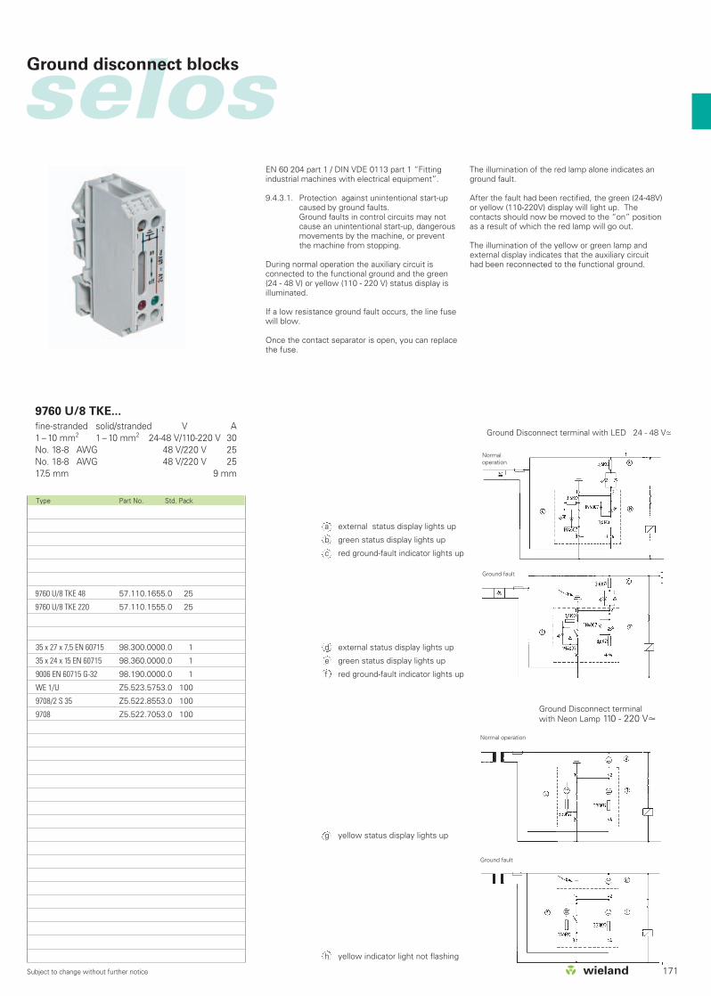
selos
171Subject to change without further notice
Type Part No. Std. Pack
9760 U/8 TKE...
fine-stranded solid/stranded V A1 – 10 mm2 1 – 10 mm2 24-48 V/110-220 V 30No. 18-8 AWG 48 V/220 V 25No. 18-8 AWG 48 V/220 V 2517.5 mm 9 mm
a external status display lights up
b green status display lights up
c red ground-fault indicator lights up
d external status display lights up
e green status display lights up
f red ground-fault indicator lights up
g yellow status display lights up
h yellow indicator light not flashing
9760 U/8 TKE 48 57.110.1655.0 25
9760 U/8 TKE 220 57.110.1555.0 25
35 x 27 x 7,5 EN 60715 98.300.0000.0 1
35 x 24 x 15 EN 60715 98.360.0000.0 1
9006 EN 60715 G-32 98.190.0000.0 1
WE 1/U Z5.523.5753.0 100
9708/2 S 35 Z5.522.8553.0 100
9708 Z5.522.7053.0 100
Ground disconnect blocks
EN 60 204 part 1 / DIN VDE 0113 part 1 “Fittingindustrial machines with electrical equipment”.
9.4.3.1. Protection against unintentional start-upcaused by ground faults.Ground faults in control circuits may notcause an unintentional start-up, dangerousmovements by the machine, or preventthe machine from stopping.
During normal operation the auxiliary circuit isconnected to the functional ground and the green(24 - 48 V) or yellow (110 - 220 V) status display isilluminated.
If a low resistance ground fault occurs, the line fusewill blow.
Once the contact separator is open, you can replacethe fuse.
The illumination of the red lamp alone indicates anground fault.
After the fault had been rectified, the green (24-48V)or yellow (110-220V) display will light up. Thecontacts should now be moved to the “on” positionas a result of which the red lamp will go out.
The illumination of the yellow or green lamp andexternal display indicates that the auxiliary circuithad been reconnected to the functional ground.
Ground Disconnect terminalwith Neon Lamp 110 - 220 V
Ground Disconnect terminal with LED 24 - 48 V~–
Normaloperation
Ground fault
Ground fault
Normal operation
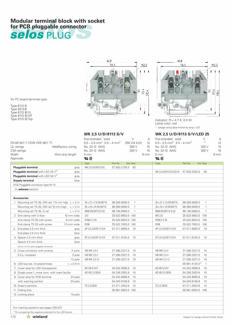
172 Subject to change without further notice
Type Part No. Std. Pack Type Part No. Std. Pack
EN 60 947-7-1/DIN VDE 0611 T1UL ratings field/factory wiringCSA ratingsWidth Wire strip lengthApprovals
WK 2,5 U/D/8113 S/V
fine-stranded solid V A0.5 – 2.5 mm2 0.5 – 4 mm2 250 V/4 kV/3 12No. 22-12 AWG 300 V 15No. 24-12 AWG 300 V 15 5 mm 9 mm
qw
WK 2,5 U/D/8113 S/V/LED 25
fine-stranded solid V A0.5 – 2.5 mm2 0.5 – 4 mm2 1) 12No. 22-12 AWG 300 V 15No. 24-12 AWG 300 V 155 mm 9 mm
qw
WK 2,5 U/D/8113 S/V/LED 25 57.503.2255.0 50
35 x 27 x 7,5 EN 60715 98.300.0000.0 1
35 x 24 x 15 EN 60715 98.360.0000.0 1
9006 EN 60715 G-32 98.190.0000.0 1
WE 2/U Z5.523.5653.0 100
9708/2 S 35 Z5.522.8553.0 100
9708 Z5.522.7053.0 100
AP 2,5 U/D/8113 S/V 07.311.9055.0 10
ZP 2,5 U/D/8113 S/V 07.311.9155.0 10
IVB WK 2,5-2 Z7.280.2227.0 10
IVB WK 2,5-3 Z7.280.2327.0 10
IVB WK 2,5-12 Z7.280.3227.0 10
05.561.4125.01) 1
AD VB 5/10 P 04.342.3556.8 10
AD VB 2,5 GELB 04.326.2053.8 10
04.343.9056.8 10
04.343.9156.8 10
TS 2,5 GELB 07.311.2053.8 10
05.561.0053.0 100
WK 2,5 U/D/8113 S/V... 57.503.2155.0 50
35 x 27 x 7,5 EN 60715 98.300.0000.0 1
35 x 24 x 15 EN 60715 98.360.0000.0 1
9006 EN 60715 G-32 98.190.0000.0 1
2/U Z5.523.5653.0 100
9708/2 S 35 Z5.522.8553.0 100
9708 Z5.522.7053.0 100
AP 2,5 U/D/8113 S/V 07.311.9055.0 10
ZP 2,5 U/D/8113 S/V 07.311.9155.0 10
IVB WK 2,5-2 Z7.280.2227.0 10
IVB WK 2,5-3 Z7.280.2327.0 10
IVB WK 2,5-12 Z7.280.3227.0 10
AD VB 5/10 P 04.342.3556.8 10
AD VB 2,5 GELB 04.326.2053.8 10
04.343.9056.8 10
04.343.9156.8 10
TS 2,5 GELB 07.311.2053.8 10
05.561.0053.0 100
selosselos PLUG
Modular terminal block with socketfor PCB pluggable connector
Indicator: R = 4.7 K; 0.5 WLamp color: red1) voltage rating determinted by lamp / LED
for PC board terminal type:
Type 8113 BType 8313BType 8113 B/VLType 8113 B/VRType 8113 B/Top
Pluggable terminal gray
Pluggable terminal with LED 25 V1) gray
Pluggable terminal with LED 50 V1) gray
Supply terminal blue
PCB Pluggable connector type 8113
(in wiecon section)
Accessories
1. Mounting rail TS 35, DIN rail, 7.5 mm high L = 2 m
Mounting rail TS 35, DIN rail 15 mm high L = 2 m
Mounting rail TS 35, G rail L = 2 m
2. End clamp with U-foot 10 mm wide
End clamp TS 35 with screw 8 mm wide
End clamp TS 32 with screw 7.5 mm wide
3. End plate 2.5 mm thick gray
End plate 2.5 mm thick blue
4. Spacer 2.5 mm thick gray
Spacer 2.5 mm thick blue
use for 7.5 mm pitch pluggable connectors
5. Cross connector with screws, 2 pole
E-Cu, insulated 3 pole
12 pole
6. LED bus bar, tin-plated brass L = 0.4 m
7. Cover strip for LED (transparent)
8. Single cover f. cross conn. with mark.facility
9. Cover strip for PCB terminal 24 pole
with warning symbol 24 pole
10. Snap-in partition
11. Coding strip
12. Locking piece 10 pole
For marking systems see pages 230-2371) For jumpering the negative potential for the LED blocks

173Subject to change without further notice
selos
Type Part No. Std. Pack Type Part No. Std. Pack
WK 2,5 U/D/8113 S/V/LED 50
fine-stranded solid V A0.5 – 2.5 mm2 0.5 – 4 mm2 1) 12No. 22-12 AWG 300 V 15No. 24-12 AWG 300 V 155 mm 9 mm
qw
WK 2,5 U/D/8113 S/V/VK
fine-stranded solid V A0.5 – 2.5 mm2 0.5 – 4 mm2 250 V/4 kV/3 12No. 22-12 AWG 300 V 15No. 24-12 AWG 300 V 155 mm 9 mm
qw
WK 2,5 U/D/8113 S/V/LED 50 57.503.2355.0 50
35 x 27 x 7,5 EN 60715 98.300.0000.0 1
35 x 24 x 15 EN 60715 98.360.0000.0 1
9006 EN 60715 G-32 98.190.0000.0 1
WE 2/U Z5.523.5653.0 100
9708/2 S 35 Z5.522.8553.0 100
9708 Z5.522.7053.0 100
AP 2,5 U/D/8113 S/V 07.311.9055.0 10
ZP 2,5 U/D/8113 S/V 07.311.9155.0 10
IVB WK 2,5-2 Z7.280.2227.0 10
IVB WK 2,5-3 Z7.280.2327.0 10
IVB WK 2,5-12 Z7.280.3227.0 10
05.561.4125.01) 1
AD VB 5/10 P 04.342.3556.8 10
AD VB 2,5 GELB 04.326.2053.8 10
04.343.9056.8 10
04.343.9156.8 10
TS 2,5 GELB 07.311.2053.8 10
05.561.0053.0 100
WK 2,5 U/D/8113 S/V/VK 57.503.2555.6 50
35 x 27 x 7,5 EN 60715 98.300.0000.0 1
35 x 24 x 15 EN 60715 98.360.0000.0 1
9006 EN 60715 G-32 98.190.0000.0 1
WE 2/U Z5.523.5653.0 100
9708/2 S 35 Z5.522.8553.0 100
9708 Z5.522.7053.0 100
AP 2,5 U/D/8113 S/V 07.311.9055.0 10
ZP 2,5 U/D/8113 S/V 07.311.9155.0 10
IVB WK 2,5-2 Z7.280.2227.0 10
IVB WK 2,5-3 Z7.280.2327.0 10
IVB WK 2,5-12 Z7.280.3227.0 10
05.561.4125.01) 1
AD VB 5/10 P 04.342.3556.8 10
AD VB 2,5 GELB 04.326.2053.8 10
04.343.9056.8 10
04.343.9156.8 10
TS 2,5 GELB 07.311.2053.8 10
05.561.0053.0 100
Indicator: R = 10 K; 0.5 WLamp color: red1) voltage rating determined by lamp / LED
Modular terminal block with socketfor PCB pluggable connector
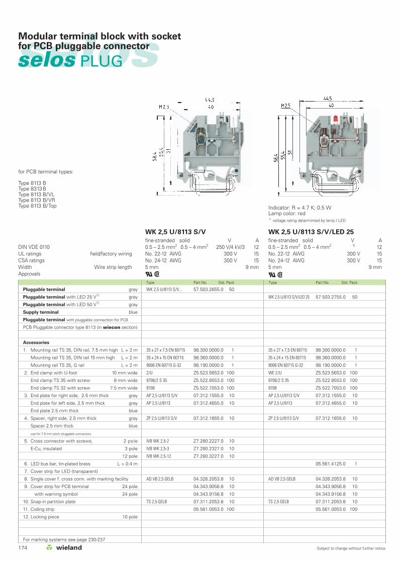
174 Subject to change without further notice
Type Part No. Std. Pack Type Part No. Std. Pack
DIN VDE 0110UL ratings field/factory wiringCSA ratingsWidth Wire strip lengthApprovals
WK 2,5 U/8113 S/V
fine-stranded solid V A0.5 – 2.5 mm2 0.5 – 4 mm2 250 V/4 kV/3 12No. 22-12 AWG 300 V 15No. 24-12 AWG 300 V 15 5 mm 9 mm
qw
WK 2,5 U/8113 S/V/LED 25
fine-stranded solid V A0.5 – 2.5 mm2 0.5 – 4 mm2 1) 12No. 22-12 AWG 300 V 15No. 24-12 AWG 300 V 155 mm 9 mm
qw
WK 2,5 U/8113 S/V/LED 25 57.503.2755.0 50
35 x 27 x 7,5 EN 60715 98.300.0000.0 1
35 x 24 x 15 EN 60715 98.360.0000.0 1
9006 EN 60715 G-32 98.190.0000.0 1
WE 2/U Z5.523.5653.0 100
9708/2 S 35 Z5.522.8553.0 100
9708 Z5.522.7053.0 100
AP 2,5 U/8113 S/V 07.312.1555.0 10
AP 2,5 U/8113 07.312.4655.0 10
ZP 2,5 U/8113 S/V 07.312.1655.0 10
05.561.4125.0 1
AD VB 2,5 GELB 04.326.2053.8 10
04.343.9056.8 10
04.343.9156.8 10
TS 2,5 GELB 07.311.2053.8 10
05.561.0053.0 100
WK 2,5 U/8113 S/V... 57.503.2655.0 50
35 x 27 x 7,5 EN 60715 98.300.0000.0 1
35 x 24 x 15 EN 60715 98.360.0000.0 1
9006 EN 60715 G-32 98.190.0000.0 1
2/U Z5.523.5653.0 100
9708/2 S 35 Z5.522.8553.0 100
9708 Z5.522.7053.0 100
AP 2,5 U/8113 S/V 07.312.1555.0 10
AP 2,5 U/8113 07.312.4655.0 10
ZP 2,5 U/8113 S/V 07.312.1655.0 10
IVB WK 2,5-2 Z7.280.2227.0 10
IVB WK 2,5-3 Z7.280.2327.0 10
IVB WK 2,5-12 Z7.280.3227.0 10
AD VB 2,5 GELB 04.326.2053.8 10
04.343.9056.8 10
04.343.9156.8 10
TS 2,5 GELB 07.311.2053.8 10
05.561.0053.0 100
selosselos PLUG
Modular terminal block with socketfor PCB pluggable connector
Indicator: R = 4.7 K; 0.5 WLamp color: red1) voltage rating determinted by lamp / LED
for PCB terminal types:
Type 8113 BType 8313BType 8113 B/VLType 8113 B/VRType 8113 B/Top
Pluggable terminal gray
Pluggable terminal with LED 25 V1) gray
Pluggable terminal with LED 50 V1) gray
Supply terminal blue
Pluggable terminal with pluggable connection for PCB
PCB Pluggable connector type 8113 (in wiecon section)
Accessories
1. Mounting rail TS 35, DIN rail, 7.5 mm high L = 2 m
Mounting rail TS 35, DIN rail 15 mm high L = 2 m
Mounting rail TS 35, G rail L = 2 m
2. End clamp with U-foot 10 mm wide
End clamp TS 35 with screw 8 mm wide
End clamp TS 32 with screw 7.5 mm wide
3. End plate for right side, 2.5 mm thick gray
End plate for left side, 2.5 mm thick gray
End plate 2.5 mm thick blue
4. Spacer, right side, 2.5 mm thick gray
Spacer 2.5 mm thick blue
use for 7.5 mm pitch pluggable connectors
5. Cross connector with screws, 2 pole
E-Cu, insulated 3 pole
12 pole
6. LED bus bar, tin-plated brass L = 0.4 m
7. Cover strip for LED (transparent)
8. Single cover f. cross conn. with marking facility
9. Cover strip for PCB terminal 24 pole
with warning symbol 24 pole
10. Snap-in partition plate
11. Coding strip
12. Locking piece 10 pole
For marking systems see page 230-237
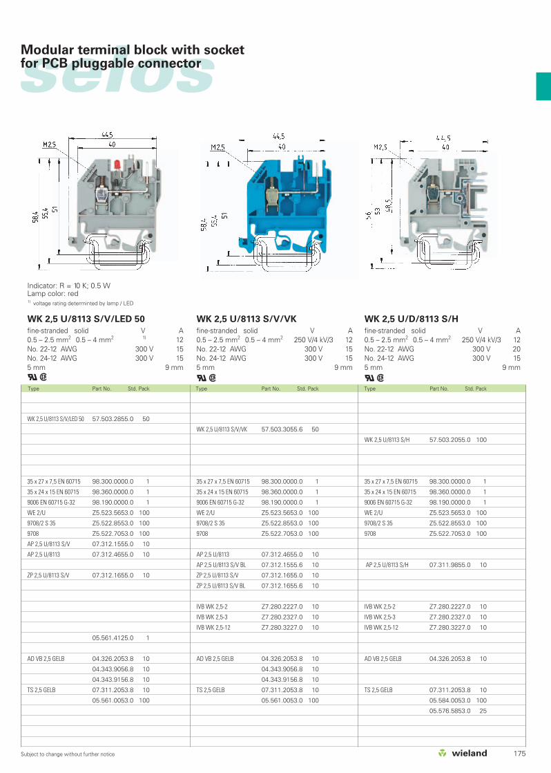
175Subject to change without further notice
Type Part No. Std. Pack Type Part No. Std. Pack Type Part No. Std. Pack
WK 2,5 U/8113 S/V/LED 50
fine-stranded solid V A0.5 – 2.5 mm2 0.5 – 4 mm2 1) 12No. 22-12 AWG 300 V 15No. 24-12 AWG 300 V 155 mm 9 mm
qw
WK 2,5 U/8113 S/V/VK
fine-stranded solid V A0.5 – 2.5 mm2 0.5 – 4 mm2 250 V/4 kV/3 12No. 22-12 AWG 300 V 15No. 24-12 AWG 300 V 155 mm 9 mm
qw
WK 2,5 U/D/8113 S/H
fine-stranded solid V A0.5 – 2.5 mm2 0.5 – 4 mm2 250 V/4 kV/3 12No. 22-12 AWG 300 V 20No. 24-12 AWG 300 V 155 mm 9 mm
qw
WK 2,5 U/8113 S/V/LED 50 57.503.2855.0 50
35 x 27 x 7,5 EN 60715 98.300.0000.0 1
35 x 24 x 15 EN 60715 98.360.0000.0 1
9006 EN 60715 G-32 98.190.0000.0 1
WE 2/U Z5.523.5653.0 100
9708/2 S 35 Z5.522.8553.0 100
9708 Z5.522.7053.0 100
AP 2,5 U/8113 S/V 07.312.1555.0 10
AP 2,5 U/8113 07.312.4655.0 10
ZP 2,5 U/8113 S/V 07.312.1655.0 10
05.561.4125.0 1
AD VB 2,5 GELB 04.326.2053.8 10
04.343.9056.8 10
04.343.9156.8 10
TS 2,5 GELB 07.311.2053.8 10
05.561.0053.0 100
WK 2,5 U/8113 S/V/VK 57.503.3055.6 50
35 x 27 x 7,5 EN 60715 98.300.0000.0 1
35 x 24 x 15 EN 60715 98.360.0000.0 1
9006 EN 60715 G-32 98.190.0000.0 1
WE 2/U Z5.523.5653.0 100
9708/2 S 35 Z5.522.8553.0 100
9708 Z5.522.7053.0 100
AP 2,5 U/8113 07.312.4655.0 10
AP 2,5 U/8113 S/V BL 07.312.1555.6 10
ZP 2,5 U/8113 S/V 07.312.1655.0 10
ZP 2,5 U/8113 S/V BL 07.312.1655.6 10
IVB WK 2,5-2 Z7.280.2227.0 10
IVB WK 2,5-3 Z7.280.2327.0 10
IVB WK 2,5-12 Z7.280.3227.0 10
AD VB 2,5 GELB 04.326.2053.8 10
04.343.9056.8 10
04.343.9156.8 10
TS 2,5 GELB 07.311.2053.8 10
05.561.0053.0 100
WK 2,5 U/8113 S/H 57.503.2055.0 100
35 x 27 x 7,5 EN 60715 98.300.0000.0 1
35 x 24 x 15 EN 60715 98.360.0000.0 1
9006 EN 60715 G-32 98.190.0000.0 1
WE 2/U Z5.523.5653.0 100
9708/2 S 35 Z5.522.8553.0 100
9708 Z5.522.7053.0 100
AP 2,5 U/8113 S/H 07.311.9855.0 10
IVB WK 2,5-2 Z7.280.2227.0 10
IVB WK 2,5-3 Z7.280.2327.0 10
IVB WK 2,5-12 Z7.280.3227.0 10
AD VB 2,5 GELB 04.326.2053.8 10
TS 2,5 GELB 07.311.2053.8 10
05.584.0053.0 100
05.576.5853.0 25
selosModular terminal block with socketfor PCB pluggable connector
Indicator: R = 10 K; 0.5 WLamp color: red1) voltage rating determinted by lamp / LED

176 Subject to change without further notice
Type Part No. Std. Pack Type Part No. Std. Pack
Ratings for use of insulating sleevesEN 60 947-7-1, EN 61 210UL ratings field/factory wiringCSA ratingsWidth Wire strip lengthApprovals
WK 4 3-6 S 1 K/U
fine-stranded solid V A0.5 – 4 mm2 0.5 – 6 mm2 800 V/8 kV/3 20*)
No. 22-12 AWG 300 V 10No. 22-12 AWG 300 V 106 mm 9 mm
aigqw
WK 4 5 S 2,8 1 K/U
fine-stranded solid V A0.5 – 4 mm2 0.5 – 6 mm2 800 V/8 kV/3 20*)
No. 22-12 AWG 300 V 10No. 22-12 AWG 300 V 106 mm 9 mm
aigqw
WK 4 5 S 2,8 1 K/U 57.504.3855.0 100
35 x 27 x 7,5 EN 60715 98.300.0000.0 1
35 x 24 x 15 EN 60715 98.360.0000.0 1
9006 EN 60715 G-32 98.190.0000.0 1
WE 2/U Z5.523.5653.0 100
9708/2 S 35 Z5.522.8553.0 100
9708 Z5.522.7053.0 100
AP4 3 S 1 K 07.311.3855.0 10
05.592.7553.0 2000
05.592.7653.0 2000
IVB WK 4-2 Z7.281.1227.0 10
IVB WK 4-3 Z7.281.1327.0 10
IVB WK 4-12 Z7.281.2227.0 10
AD VB 4 GELB 04.326.2153.8 10
AD VB 6/10 GELB 04.342.0656.8 10
TS 4 GELB 07.311.2153.8 10
WK 4 3-6 S 1 K/U 57.504.3755.0 100
35 x 27 x 7,5 EN 60715 98.300.0000.0 1
35 x 24 x 15 EN 60715 98.360.0000.0 1
9006 EN 60715 G-32 98.190.0000.0 1
2/U Z5.523.5653.0 100
9708/2 S 35 Z5.522.8553.0 100
9708 Z5.522.7053.0 100
AP4 3 S 1 K 07.311.3855.0 10
05.592.7553.0 2000
05.592.7653.0 2000
IVB WK 4-2 Z7.281.1227.0 10
IVB WK 4-3 Z7.281.1327.0 10
IVB WK 4-12 Z7.281.2227.0 10
AD VB 4 GELB 04.326.2153.8 10
AD VB 6/10 GELB 04.342.0656.8 10
TS 4 GELB 07.311.2153.8 10
selosselos PLUG
Feed-through terminal blockswith screw/push-on connection
Push-on connectors 2.8 x 0.8 according to DIN 46247Push-on connectors 2.8 x 0.8 according to DIN 46247Push-on connectors 6.3 x 0.8 according to DIN 46247
*) Current carrying capability according to DIN 46249
Terminal block with screw and push-on connectors
Push-on with 6 connectors 2.8 x 0.8 gray
Push-on with 5 connectors 2.8 x 0.8 gray
Distribution terminal gray
Push-on with 10 connectors
Accessories
1. Mounting rail TS 35, DIN rail, 7.5 mm high L = 2 m
Mounting rail TS 35, DIN rail 15 mm high L = 2 m
Mounting rail TS 35, G rail L = 2 m
2. End clamp with U-foot 10 mm wide
End clamp TS 35 with screw 8 mm wide
End clamp TS 32 with screw 7.5 mm wide
3. End plate, 1.5 mm thick gray
blue
4. Insulating housing for push-on connector yellow
for H0. V-K 1.5 mm2
for H0. V-K 2.5 mm2
5. Cross connector with screws, E-Cu,
insulated 2 pole
3 pole
to 12 pole
6. Jumper rail, tin-plated brass L = 0.4 m
7. Cover strip for LED (transparent)
8. Single cover f. cross conn. with marking facility
9. Cover strip for cross conn. over 10 blocks
10. Partition plate
11. Coding strip
For marking systems see pages 230-237

Type Part No. Std. Pack Type Part No. Std. Pack Type Part No. Std. Pack
WK 4-3-6 S 1 K/IW/U
fine-stranded solid V A0.5 – 4 mm2 0.5 – 6 mm2 800 V/8 kV/3 20*)
No. 22-12 AWG 600 V 10No. 22-12 AWG 300 V 106 mm 9 mm
aigqw
WK 4-5 S 2,8 1 K/IW/U
fine-stranded solid V A0.5 – 4 mm2 0.5 – 6 mm2 800 V/8 kV/3 20*)
No. 22-12 AWG 600 V 10No. 22-12 AWG 300 V 106 mm 9 mm
aigqw
WK/5-10 S/U
fine-stranded solid V A800 V/8 kV/3 20*)
300 V 10No. 22-12 AWG 300 V 106 mm
igqw
WK 4 3-6 S 1 K/IW/U 57.504.2755.0 100
35 x 27 x 7,5 EN 60715 98.300.0000.0 1
35 x 24 x 15 EN 60715 98.360.0000.0 1
9006 EN 60715 G-32 98.190.0000.0 1
WE 2/U Z5.523.5653.0 100
9708/2 S 35 Z5.522.8553.0 100
9708 Z5.522.7053.0 100
AP4 3 S 1 K 07.311.3855.0 10
05.592.7553.0 2000
05.592.7653.0 2000
IVB WK 4-2 Z7.281.1227.0 10
IVB WK 4-3 Z7.281.1327.0 10
IVB WK 4-12 Z7.281.2227.0 10
AD VB 4 GELB 04.326.2153.8 10
AD VB 6/10 GELB 04.342.0656.8 10
TS 4 GELB 07.311.2153.8 10
WK 4 5 S 2,8 1 K/IW/U 57.504.2855.0 100
35 x 27 x 7,5 EN 60715 98.300.0000.0 1
35 x 24 x 15 EN 60715 98.360.0000.0 1
9006 EN 60715 G-32 98.190.0000.0 1
WE 2/U Z5.523.5653.0 100
9708/2 S 35 Z5.522.8553.0 100
9708 Z5.522.7053.0 100
AP4 3 S 1 K 07.311.3855.0 10
05.592.7553.0 2000
05.592.7653.0 2000
IVB WK 4-2 Z7.281.1227.0 10
IVB WK 4-3 Z7.281.1327.0 10
IVB WK 4-12 Z7.281.2227.0 10
AD VB 4 GELB 04.326.2153.8 10
AD VB 6/10 GELB 04.342.0656.8 10
TS 4 GELB 07.311.2153.8 10
WK/5-10 S/U 57.504.3655.0 100
35 x 27 x 7,5 EN 60715 98.300.0000.0 1
35 x 24 x 15 EN 60715 98.360.0000.0 1
9006 EN 60715 G-32 98.190.0000.0 1
WE 2/U Z5.523.5653.0 100
9708/2 S 35 Z5.522.8553.0 100
9708 Z5.522.7053.0 100
AP 5 S 07.311.4655.0 10
05.592.7553.0 2000
05.592.7653.0 2000
IVB WKI 4-2 Z7.271.4227.0 10
IVB WKI 4-3 Z7.271.4327.0 10
IVB WKI 4-12 Z7.271.5227.0 10
AD VB 4 GELB 04.326.2153.8 10
AD VB 6/10 GELB 04.342.0656.8 10
TS 4 GELB 07.311.2153.8 10
selos
177Subject to change without further notice
Feed-through terminal blockswith screw/push-on connection
Push-on connectors 2.8 x 0.8 according to DIN 46247Push-on connectors 6.3 x 0.8 according to DIN 46247
Push-on connectors 2.8 x 0.8 according to DIN 46247 Push-on connectors 2.8 x 0.8 according to DIN 46247Push-on connectors 6.3 x 0.8 according to DIN 46247

178 Subject to change without further notice
Type Part No. Std. Pack Type Part No. Std. Pack
Current carrying capability in accordance withEN 60 947-7-1, EN 61 210UL ratings field/factory wiringCSA ratingsWidth Wire strip lengthApprovals
WK/3-6 S/IW/U
fine-stranded solid V A0.5 – 4 mm2 0.5 – 6 mm2 800 V/8 kV/3 20
600 V 10No. 22-12 AWG 300 V 106 mm
igqw
WK/3-6 S/U
fine-stranded solid V A800 V/8 kV/3 20
300 V 10No. 24-12 AWG 300 V 106 mm
igqw
WK/3-6 S/U 57.504.6655.0 100
35 x 27 x 7,5 EN 60715 98.300.0000.0 1
35 x 24 x 15 EN 60715 98.360.0000.0 1
9006 EN 60715 G-32 98.190.0000.0 1
WE 2/U Z5.523.5653.0 100
9708/2 S 35 Z5.522.8553.0 100
9708 Z5.522.7053.0 100
AP 3 S 07.311.4455.0 50
05.592.7553.0 2000
05.592.7653.0 2000
9703/6-2 Z7.211.0227.0 50
9703/6-3 Z7.211.0327.0 50
9703/6-6 Z7.211.0627.0 50
AD VB 4 GELB 04.326.2153.8 10
AD VB 6-10 GELB 04.342.0656.8 10
TS 4 GELB 07.311.2153.8 10
WK/3-6 S/IW/U 57.504.6755.0 100
35 x 27 x 7,5 EN 60715 98.300.0000.0 1
35 x 24 x 15 EN 60715 98.360.0000.0 1
9006 EN 60715 G-32 98.190.0000.0 1
2/U Z5.523.5653.0 100
9708/2 S 35 Z5.522.8553.0 100
9708 Z5.522.7053.0 100
AP 3 S/IW 07.311.4555.0 50
05.592.7553.0 2000
05.592.7653.0 2000
VB WK/...S/IW/U-2 Z7.281.3227.0 10
VB WK/...S/IW/U-3 Z7.281.3327.0 10
VB WK/...S/IW/U-6 Z7.281.3627.0 10
AD VB 4 GELB 04.326.2153.8 10
AD VB 6-10 GELB 04.342.0656.8 10
TS 4 GELB 07.311.2153.8 10
selosselos PLUG
Distribution terminalsfor push-on connectors
Push-on connectors 2.8 x 0.8 according to DIN 46247Push-on connectors 6.3 x 0.8 according to DIN 46247
Push-on connectors 2.8 x 0.8 according to DIN 46247Push-on connectors 6.3 x 0.8 according to DIN 46247
Current carrying capability in accordance with DIN 46249Push-on connector 2.8 10 A
6.3 20 A
Distribution terminals
with 6 push-on connectors 2.8 x 0.8 gray
Rapid mounting feed-through block
Accessories
1. Mounting rail TS 35, DIN rail, 7.5 mm high L = 2 m
Mounting rail TS 35, DIN rail 15 mm high L = 2 m
Mounting rail TS 35, G rail L = 2 m
2. End clamp with U-foot 10 mm wide
End clamp TS 35 with screw 8 mm wide
End clamp TS 32 with screw 7.5 mm wide
3. End plate, 2.5 mm thick gray
End plate 2.5 mm thick blue
4. Insulating sleeve for tab connector yellow
for H0. V-K 1.5 mm2
for H0. V-K 2.5 mm2
5. Cross connector with screws, E-Cu,
uninsulated 2 pole
3 pole
to 6 pole
6. Jumper rail, tin-plated brass L = 0.4 m
7. Cover strip for LED (transparent)
8. Single cover f. cross conn. with marking facility
9. Cover strip for cross conn. over 10 blocks
Cover strip with warning symbol over 4 blocks
10. Snap-on partition plate
11. Coding piece
For marking systems see page 230-237

Type Part No. Std. Pack Type Part No. Std. Pack Type Part No. Std. Pack
WK/4-8 S/IW/U
fine-stranded solid V A800 V/8 kV/3 20
600 V 10No. 22-12 AWG 300 V 106 mm
igqw
WK/4-8 S/U
fine-stranded solid V A800 V/8 kV/3 20
No. 22-12 AWG 300 V 106 mm
igqw
WK/3-6 S KO/U
fine-stranded solid V A0.5 – 4 mm2 690 V/8 kV/3 20No. 22-12 AWG 300 V 10No. 22-12 AWG 300 V 106 mm 9 mm
igqw
WK/4-8 S/IW/U 57.504.6355.0 100
35 x 27 x 7,5 EN 60715 98.300.0000.0 1
35 x 24 x 15 EN 60715 98.360.0000.0 1
9006 EN 60715 G-32 98.190.0000.0 1
WE 2/U Z5.523.5653.0 100
9708/2 S 35 Z5.522.8553.0 100
9708 Z5.522.7053.0 100
AP 4 S/IW 07.311.4355.0 50
05.592.7553.0 2000
05.592.7653.0 2000
VB WK/...S/IW/U-2 Z7.281.3227.0 10
VB WK/...S/IW/U-3 Z7.281.3327.0 10
VB WK/...S/IW/U-6 Z7.281.3627.0 10
AD VB 4 GELB 04.326.2153.8 10
AD VB 6-10 GELB 04.342.0656.8 10
TS 4 GELB 07.311.2153.8 10
WK/4-8 S/U 57.504.6255.0 100
35 x 27 x 7,5 EN 60715 98.300.0000.0 1
35 x 24 x 15 EN 60715 98.360.0000.0 1
9006 EN 60715 G-32 98.190.0000.0 1
WE 2/U Z5.523.5653.0 100
9708/2 S 35 Z5.522.8553.0 100
9708 Z5.522.7053.0 100
AP 4 S 07.311.4255.0 10
05.592.7553.0 2000
05.592.7653.0 2000
9703/6-2 Z7.211.0227.0 50
9703/6-3 Z7.211.0327.0 50
9703/6-6 Z7.211.0627.0 50
AD VB 4 GELB 04.326.2153.8 10
AD VB 6-10 GELB 04.342.0656.8 10
TS 4 GELB 07.311.2153.8 10
WK/3-6 S KO/U 57.504.7355.0 100
35 x 27 x 7,5 EN 60715 98.300.0000.0 1
35 x 24 x 15 EN 60715 98.360.0000.0 1
9006 EN 60715 G-32 98.190.0000.0 1
WE 2/U Z5.523.5653.0 100
9708/2 S 35 Z5.522.8553.0 100
9708 Z5.522.7053.0 100
9701 A/6 1 S KO TP 2 07.310.5855.0 50
05.592.7553.0 2000
05.592.7653.0 2000
2072/2 Z7.220.0227.0 50
2072/2 Z7.220.0227.0 50
2072/6 Z7.220.0627.0 50
selos
179Subject to change without further notice
Distribution terminalsfor push-on connectors
Push-on connectors 2.8 x 0.8 according to DIN 46247Push-on connectors 6.3 x 0.8 according to DIN 46247
Push-on connectors 2.8 x 0.8 according to DIN 46247Push-on connectors 6.3 x 0.8 according to DIN 46247
Push-on connectors 2.8 x 0.8 according to DIN 46247Push-on connectors 6.3 x 0.8 according to DIN 46247

selosselos Feed-through blocks with solder connection
180 Subject to change without further notice
Type Part No. Std. Pack Type Part No. Std. Pack
EN 60 947-7-1/DIN VDE 0611 T1UL ratingsCSA ratingsWidth Wire strip lengthApprovals
WK 4/U F1
fine-stranded solid V A0.5 - 4 mm2 0.5 - 6 mm2 400 V/6 kV/3 32No. 22-10 AWG 300 V 30No. 22-10 AWG 300 V 206 mm 9 mm
qw
WK 4/U F2
fine-stranded solid V A0.5 - 4 mm2 0.5 - 6 mm2 400 V/6 kV/3 32No. 22-10 AWG 300 V 30No. 22-10 AWG 300 V 206 mm 9 mm
qwFeed-through terminal gray
same dimensions as WK4
Accessories
1. Mounting rail TS 35, DIN rail 7.5 mm high L = 2 m
Mounting rail TS 35, DIN rail 1.5 mm high L = 2 m
Mounting rail TS 32 G rail L = 2 m
2. End clamp with U-foot 10 mm wide
End clamp TS 35, with screw 8 mm wide
End clamp TS 32, with screw 7.5 mm wide
3. End plate, 1.5 mm thick gray
4. Partition, 1.5 mm thick
5. Cross connector with screws, E-Cu
insulated 2 pole
3 pole
to 12 pole
6. Cover for jumper bar with marking capability
7. Partition plate
For marking systems see pages 230-237
WK 4/U F2 57.504.1155.0 100
35 x 27 x 7,5 EN 60715 98.300.0000.0 1
35 x 24 x 15 EN 60715 98.360.0000.0 1
9006 EN 60715 G-32 98.190.0000.0 1
WE 1/U Z5.523.5753.0 100
9708/2 S 35 Z5.522.8553.0 100
9708 Z5.522.7053.0 100
AP 2,5-4 07.311.0155.0 10
TW 2,5-4 07.311.1155.0 10
IVB WK 4-2 Z7.281.1227.0 10
IVB WK 4-3 Z7.281.1327.0 10
IVB WK 4-12 Z7.281.2227.0 10
AD VB 4 GELB 04.326.2153.8 10
TS 4 GELB 07.311.2153.8 10
WK 4/U F1 57.504.1055.0 100
35 x 27 x 7,5 EN 60715 98.300.0000.0 1
35 x 24 x 15 EN 60715 98.360.0000.0 1
9006 EN 60715 G-32 98.190.0000.0 1
WE 1/U Z5.523.5753.0 100
9708/2 S 35 Z5.522.8553.0 100
9708 Z5.522.7053.0 100
AP 2,5-4 07.311.0155.0 10
TW 2,5-4 07.311.1155.0 10
IVB WK 4-2 Z7.281.1227.0 10
IVB WK 4-3 Z7.281.1327.0 10
IVB WK 4-12 Z7.281.2227.0 10
AD VB 4 GELB 04.326.2153.8 10
TS 4 GELB 07.311.2153.8 10
Terminals WK 4/UF1 and WK 4/UF2 should bemounted alternately in order to maintain thecreepages and clearances required for thespecific rated voltages.

selos
181
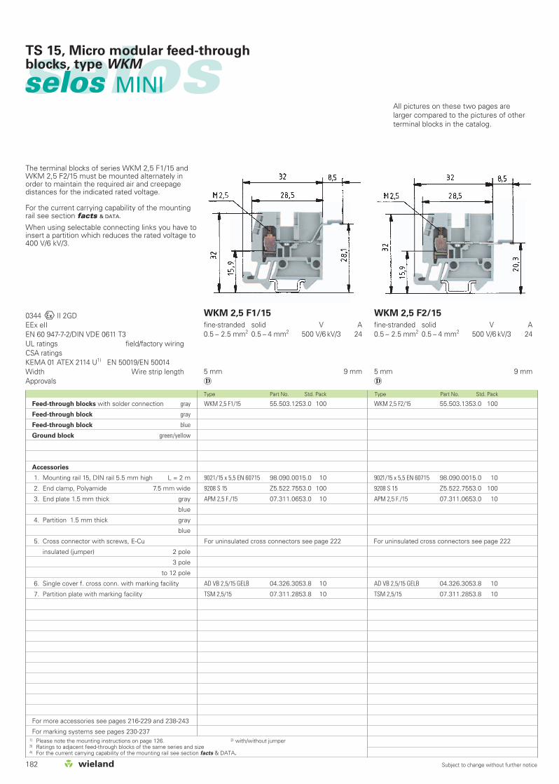
182 Subject to change without further notice
Type Part No. Std. Pack Type Part No. Std. Pack
selosselos MINI
TS 15, Micro modular feed-throughblocks, type WKM
WKM 2,5 F1/15 55.503.1253.0 100
9021/15 x 5,5 EN 60715 98.090.0015.0 10
9208 S 15 Z5.522.7553.0 100
APM 2,5 F./15 07.311.0653.0 10
AD VB 2,5/15 GELB 04.326.3053.8 10
TSM 2,5/15 07.311.2853.8 10
WKM 2,5 F2/15 55.503.1353.0 100
9021/15 x 5,5 EN 60715 98.090.0015.0 10
9208 S 15 Z5.522.7553.0 100
APM 2,5 F./15 07.311.0653.0 10
For uninsulated cross connectors see page 222
AD VB 2,5/15 GELB 04.326.3053.8 10
TSM 2,5/15 07.311.2853.8 10
0344OII 2GDEEx eIIEN 60 947-7-2/DIN VDE 0611 T3UL ratings field/factory wiringCSA ratingsKEMA 01 ATEX 2114 U1) EN 50019/EN 50014Width Wire strip lengthApprovals
WKM 2,5 F1/15
fine-stranded solid V A0.5 – 2.5 mm2 0.5 – 4 mm2 500 V/6 kV/3 24
5 mm 9 mm
z
WKM 2,5 F2/15
fine-stranded solid V A0.5 – 2.5 mm2 0.5 – 4 mm2 500 V/6 kV/3 24
5 mm 9 mm
z
The terminal blocks of series WKM 2,5 F1/15 andWKM 2,5 F2/15 must be mounted alternately inorder to maintain the required air and creepagedistances for the indicated rated voltage.
For the current carrying capability of the mountingrail see section facts & DATA.
When using selectable connecting links you have toinsert a partition which reduces the rated voltage to400 V/6 kV/3.
All pictures on these two pages are larger compared to the pictures of otherterminal blocks in the catalog.
1) Please note the mounting instructions on page 126. 2) with/without jumper3) Ratings to adjacent feed-through blocks of the same series and size4) For the current carrying capability of the mounting rail see section facts & DATA.
Feed-through blocks with solder connection gray
Feed-through block gray
Feed-through block blue
Ground block green/yellow
Accessories
1. Mounting rail 15, DIN rail 5.5 mm high L = 2 m
2. End clamp, Polyamide 7.5 mm wide
3. End plate 1.5 mm thick gray
blue
4. Partition 1.5 mm thick gray
blue
5. Cross connector with screws, E-Cu For uninsulated cross connectors see page 222
insulated (jumper) 2 pole
3 pole
to 12 pole
6. Single cover f. cross conn. with marking facility
7. Partition plate with marking facility
For more accessories see pages 216-229 and 238-243
For marking systems see pages 230-237

183Subject to change without further notice
Type Part No. Std. Pack Type Part No. Std. Pack Type Part No. Std. Pack
selosTS 15, Micro modular feed-throughblocks, type WKM
WKM 2,5/15 55.503.1053.0 100
WKM 2,5/15 BLAU 55.503.1053.6 100
9021/15 x 5,5 EN 60715 98.090.0015.0 10
9208 S 15 Z5.522.7553.0 100
APM 2,5 - 4/15 07.311.0853.0 10
APM 2,5 - 4/15 BLAU 07.311.0853.6 10
TWM 2,5 - 4/15 07.311.1853.0 10
TWM 2,5 - 4/15 BLAU 07.311.1853.6 10
For uninsulated cross connectors see page 222
AD VB 2,5/15 GELB 04.326.3053.8 10
TSM 2,5/15 07.311.2853.8 10
WKM 4 SL/15 55.504.9153.0 100
9021/15 x 5,5 EN 60715 98.090.0015.0 10
9208 S 15 Z5.522.7553.0 100
APM 4 SL/15 07.311.0753.0 10
For uninsulated cross connectors see page 222
WKM 4/15 55.504.1053.0 100
WKM 4/15 BLAU 55.504.1053.6 100
9021/15 x 5,5 EN 60715 98.090.0015.0 10
9208 S 15 Z5.522.7553.0 100
APM 2,5 - 4/15 07.311.0853.0 10
APM 2,5 - 4/15 BLAU 07.311.0853.6 10
TWM 2,5 - 4/15 07.311.1853.0 10
TWM 2,5 - 4/15 BLAU 07.311.1853.6 10
For uninsulated cross connectors see page 222
IVB WK 4 E/U-2 Z7.271.2227.0 10
IVB WK 4 E/U-3 Z7.271.2327.0 10
IVB WK 4 E/U-12 Z7.271.3227.0 10
AD VB 4/15 GELB 04.326.2953.8 10
TSM 4/15 07.311.2953.8 10
WKM 2,5/15
fine-stranded solid V A0.5 – 2.5 mm2 0.5 – 4 mm2 500 V/6 kV/3 25No. 22-14 AWG 300 V 10No. 22-12 AWG 600 V 250.5 – 2.5 mm2 0.5 – 4 mm2 275 V 20/202)
5 mm 9 mm
üiztC+qkwh
WKM 4/15
fine-stranded solid V A0.5 – 4 mm2 0.5 – 6 mm2 500 V/6 kV/3 28No. 22-10 AWG 600 V 30No. 20-10 AWG 600 V 370.5 – 4 mm2 0.5 – 6 mm2 275 V 21/272)
6 mm 9 mm
igC+qkwh
WKM 4 SL/15
fine-stranded solid V A0.5 – 4 mm2 0.5 – 6 mm2 500 V/6 kV/33) 4)
No. 22-14 AWG 300 V 30No. 22-10 AWG0.5 – 4 mm2 0.5 – 6 mm2
6 mm 9 mm
gtC+qkwh
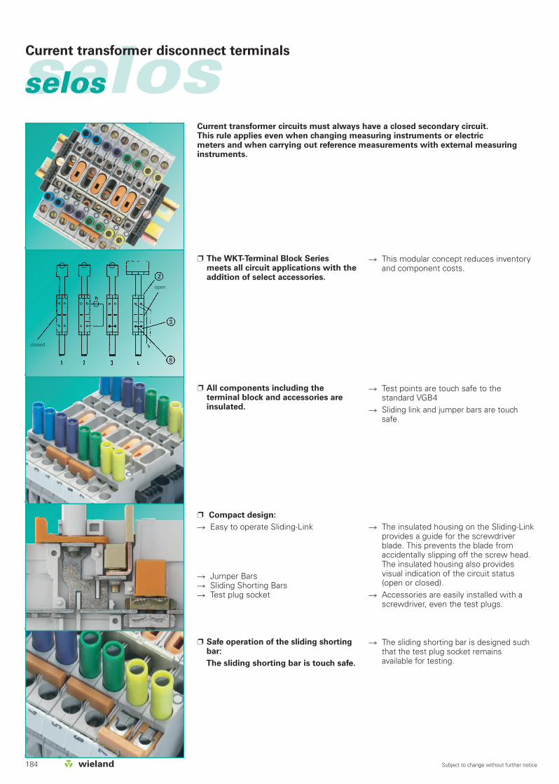
184 Subject to change without further notice
selosselos Current transformer disconnect terminals
Compact design:
Easy to operate Sliding-Link
Jumper Bars Sliding Shorting Bars Test plug socket
Safe operation of the sliding shortingbar:
The sliding shorting bar is touch safe.
The insulated housing on the Sliding-Linkprovides a guide for the screwdriverblade. This prevents the blade fromaccidentally slipping off the screw head.The insulated housing also providesvisual indication of the circuit status(open or closed).
Accessories are easily installed with ascrewdriver, even the test plugs.
The sliding shorting bar is designed suchthat the test plug socket remainsavailable for testing.
Test points are touch safe to the standard VGB4
Sliding link and jumper bars are touchsafe.
The WKT-Terminal Block Series meets all circuit applications with theaddition of select accessories.
All components including theterminal block and accessories areinsulated.
This modular concept reduces inventoryand component costs.
Current transformer circuits must always have a closed secondary circuit. This rule applies even when changing measuring instruments or electric meters and when carrying out reference measurements with external measuringinstruments.
open
closed
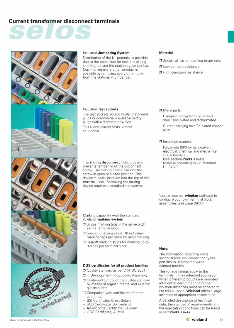
185Subject to change without further notice
selosCurrent transformer disconnect terminals
DQS certificates for all product families
Quality standard as per DIN ISO 9001 in Development, Production, Assembly Continued control of the quality standard
by means of regular internal and externalquality audits
Compatible with certificates of other countries:
– BSI Certificate, Great Britain– SQS Certificate, Switzerland– Aib-Vincotte Certificate, Belgium– ÖQS Certificate, Austria
Marking capability with the standardWieland marking system. Single marking tags in the same pitch
as the terminal block Snap-on marking strips (10 individual
marking tags per strip) for rapid marking Tear-off marking strips for marking up to
3-digits per terminal block
Insulated Test sockets
The test sockets accept Wieland standardplugs or commercially available safetyplugs with a diameter of 4 mm.This allows current tests without shut-down.
The sliding disconnect locking deviceprevents tampering of the disconnectscrew. The locking device can lock thescrew in open or closed position. Thisdevice is easily installed into the top of theterminal block. Removing the lockingdevice requires a standard screwdriver.
Insulated Jumpering System
Distribution of the K - potential is possibledue to the open slots for both the slidingshorting bar and the stationary jumper bar.Commoning every other terminal ispossible by removing every other polefrom the stationary jumper bar.
Material
Special alloys and surface treatments
Low contact resistance
High corrosion resistance
Metal parts
Clamping body/clamping screws:steel, zinc-plated and dichromated
Current carrying bar: Tin plated copperalloy
Insulation material
Polyamide 66/6 for its excellentelectrical, chemical and mechanicalcharacteristics(see section facts & DATA)Material according to US standard UL 94-V0
You can use our wieplan software toconfigure your own terminal blockassemblies (see page 36/37).
Note:
The information regarding crosssectional area and connection typespertains to unprepared wires without ferrules.
The voltage ratings apply to theterminals in their intended application.When different products are mountedadjacent to each other, the properisolation distances must be adhered to.For this purpose, Wieland offers a largeselection of appropriate accessories.
A detailed description of technical data, the standards’ requirements, andthe application conditions can be foundin part facts & DATA.

selosselos Current transformer disconnect terminal block
186 Subject to change without further notice
Type Part No. Std. Pack Type Part No. Std. Pack
EN 60 947-7-1/DIN VDE 0611 T1UL ratings field/factory wiringCSA ratingsWidth Wire strip lengthApprovals
WK6 TK/35 56.106.0553.0 50
35 x 27 x 7,5 EN 60715 98.300.0000.0 1
35 x 24 x 15 EN 60715 98.360.0000.0 1
WE 1/U Z5.523.5753.0 100
9708/2 S 35 Z5.522.8553.0 100
SP WK6 TK 05.563.5453.0 50
IVS WK6 TK-2 Z7.212.2227.0 50
IVS WK6 TK-3 Z7.212.2327.0 50
IVS WK6 TK-4 Z7.212.2427.0 50
IVB WK6 TK-2 Z7.212.1227.0 50
IVB WK6 TK-3 Z7.212.1327.0 50
IVB WK6 TK-4 Z7.212.1427.0 50
IVB WK6 TK-5 Z7.212.1527.0 50
IVB WK6 TK-10 Z7.212.2027.0 50
SB 4 GRAU 05.511.2953.0 10
SB 4 VIOLETT 05.511.2953.9 10
SB 4 GRÜN 05.511.2953.7 10
SB 4 GELB 05.511.2953.8 10
SB 4 BLAU 05.511.2953.6 10
TW 6 TK 07.312.0453.0 10
ZP 6 TK 07.312.9953.0 10
WK6 TK P3/35 56.106.0653.0 50
35 x 27 x 7,5 EN 60715 98.300.0000.0 1
35 x 24 x 15 EN 60715 98.360.0000.0 1
WE 1/U Z5.523.5753.0 100
9708/2 S 35 Z5.522.8553.0 100
SP WK6 TK 05.563.5453.0 50
IVS WK6 TK-2 Z7.212.2227.0 50
IVS WK6 TK-3 Z7.212.2327.0 50
IVS WK6 TK-4 Z7.212.2427.0 50
IVB WK6 TK-2 Z7.212.1227.0 50
IVB WK6 TK-3 Z7.212.1327.0 50
IVB WK6 TK-4 Z7.212.1427.0 50
IVB WK6 TK-5 Z7.212.1527.0 50
IVB WK6 TK-10 Z7.212.2027.0 50
SB 4 GRAU 05.511.2953.0 10
SB 4 VIOLETT 05.511.2953.9 10
SB 4 GRÜN 05.511.2953.7 10
SB 4 GELB 05.511.2953.8 10
SB 4 BLAU 05.511.2953.6 10
TW 6 TK 07.312.0453.0 10
ZP 6 TK 07.312.9953.0 10
WK6 TK/35
fine-stranded solid V A0.5 – 6 mm2 0.5 – 10 mm2 400 V/6 kV/3 32No. 20-8 AWG 600 V 45No. 20-8 AWG 300 V 458 mm 12 mm
qw
WK6 TK P3/35
fine-stranded solid V A0.5 – 6 mm2 0.5 – 10 mm2 400 V/6 kV/3 32No. 20-8 AWG 600 V 45No. 20-8 AWG 300 V 458 mm 12 mm
qwCurrent transformer disconnect terminal
Current transformer disconnect terminal with mounted test bolts
Accessories
1. Mounting rail TS 35, DIN rail 7.5 mm high L = 2 m
Mounting rail TS 35, DIN rail, 15 mm high L = 2 m
Mounting rail TS 32, G rail L = 2 m
2. End clamp with U-foot 10 mm wide
End clamp TS 35 with screw 8 mm wide
End clamp TS32 with screw 7.5 mm wide
3. Disconnect locking device
4. Sliding short-circuit slide
insulated 2 pole
3 pole
4 pole
5. Jumper bar with screws, E-Cu
insulated 2 pole
3 pole
4 pole
5 pole
10 pole
6. Test socket gray
violet
green
yellow
blue
7. Partition
8. Intermediate plate 2 mm thick
For more accessories see pages 216-229 and 238-243
For marking systems see pages 230-237
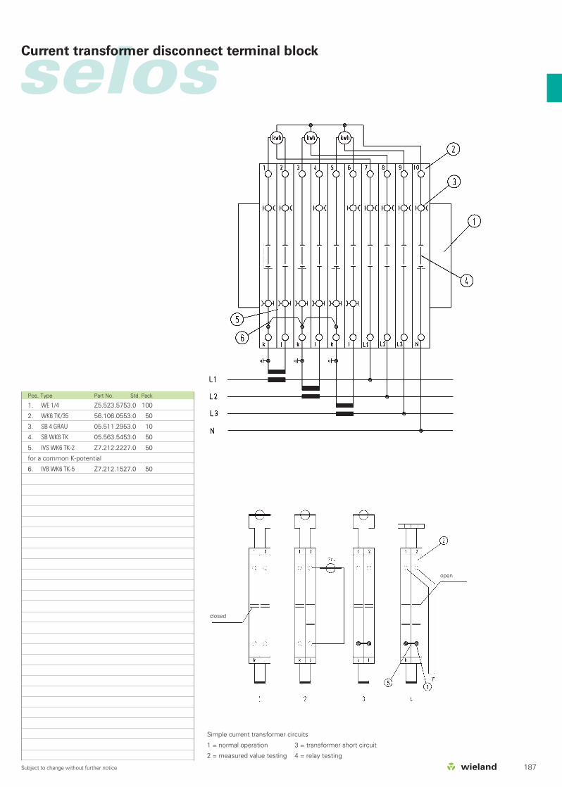
selosCurrent transformer disconnect terminal block
187Subject to change without further notice
Pos. Type Part No. Std. Pack
1. WE 1/4 Z5.523.5753.0 100
2. WK6 TK/35 56.106.0553.0 50
3. SB 4 GRAU 05.511.2953.0 10
4. SB WK6 TK 05.563.5453.0 50
5. IVS WK6 TK-2 Z7.212.2227.0 50
6. IVB WK6 TK-5 Z7.212.1527.0 50
for a common K-potential
Simple current transformer circuits
1 = normal operation 3 = transformer short circuit
2 = measured value testing 4 = relay testing
closed
open
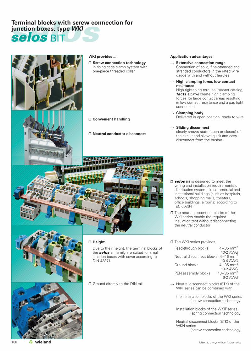
188 Subject to change without further notice
selosselos BIT
WKI provides ...
Screw connection technology in rising cage clamp system with one-piece threaded collar
Convenient handling
Neutral conductor disconnect
Application advantages
Extensive connection range Connection of solid, fine-stranded andstranded conductors in the rated wiregauge with and without ferrules
High clamping force, low contactresistanceHigh tightening torques (master catalog,facts & DATA) create high clampingforces for large contact areas resultingin low contact resistance and a gas tightconnection
Clamping bodyDelivered in open position, ready to wire
Sliding disconnectclearly shows state (open or closed) ofthe circuit and allows quick and easydisconnect from the busbar
selos BIT is designed to meet thewiring and installation requirements ofdistribution systems in commercial andinstitutional buildings (such as hospitals,schools, shopping malls, theaters,office buildings, airports) according toIEC 60364
The neutral disconnect blocks of theWKI series enable the required insulation test without disconnectingthe neutral conductor
The WKI series provides
Feed-through blocks 4 – 35 mm2
10-2 AWGNeutral disconnect blocks 4 –16 mm2
10-4 AWGGround blocks 4 – 35 mm2
10-2 AWGPEN assembly blocks 10– 35 mm2
6-2 AWG
Terminal blocks with screw connection forjunction boxes, type WKI
Ground directly to the DIN rail
Height
Due to their height, the terminal blocks ofthe selos BIT family are suited for smalljunction boxes with cover according toDIN 43871.
Neutral disconnect blocks (ETK) of theWKI series can be combined with ...
the installation blocks of the WKI series(screw connection technology)
Installation blocks of the WKIFseries(spring connection technology)
Neutral disconnect blocks (ETK) of theWKN series
(screw connection technology)

selos
189Subject to change without further notice
DQS certificates for all company divisions
Quality standard as per DIN ISO 9001 In Development, Production and Assembly Continued control of the
quality standard by means of regularinternal and external quality audits
Compatible with certificates of othercountries:
– BSI Certificate, Great Britain– SQS Certificate, Switzerland– Aib-Vincotte Certificate, Belgium– ÖQS Certificate, Austria
Marking facilities
Marking facility at every termination point Tear-off marking strips for 3-digit marking
facilities per block Single marking tags in 5 mm spacing Marking strips (10 individual marking tags)
to snap on to 10 terminal blocks Custom marking upon request
Cover
Cover with warning symbol to snap on toblocks which remain live when the mainswitch is disconnected (VDE 0113)
Cover for uninsulated cross connectors toprevent electrical shock
Can only be removed with a screwdriver Extended covers available to prevent
tampering with terminal block
Partition plates
Provides electrical and visual separationfor adjacent terminal block groups
Pre and post assembly versions Can only be removed with a screwdriver Post assembly version offers marking tag
facility and cover 4-digit marking strip for additional marking
Cross connection
Jumpering with insulated or uninsulatedcross connectors (jumper bars)
Insulated cross connectors are touch-safeaccording to regulation VBG 4
Cross connectors come preassembled Available in 2– 12 pole configurations or as
a field-divisible strip – up to 70 poles When used with an end plate or partition
the cross connector is rated for the samevoltage as the terminal block
Note:
The information regarding cross sectio-nal area and connection types pertains tounprepared wires without ferrules.
The voltage ratings apply to the terminals in their intended application.When different products are mountedadjacent to each other, the properisolation distances must be adhered to.For this purpose, Wieland offers a largeselection of appropriate accessories.
A detailed description of technical data,the standards’ requirements, and theapplication conditions can be found inpart catalog section facts & DATA:“Technical information”.
Terminal blocks with screw connection forjunction boxes, type WKI
Material
Metal parts
Special alloys enable a low contact resistance and provide agas-tight contact area:
Clamping body/clamping screws:Steel, zinc-plated and dichromated
Current carrying bar: tin-plated copper
Insulation material
Polyamide has excellentelectrical, chemical and mechanical characteristics
Insulating housings: Polyamide 66/6
Tracking current resistance: CTI 600
Flammability class: UL 94-V0
(also see master catalog section facts & DATA: Technical information)
You can use our wieplan software toconfigure your own terminal blockassemblies (see page 36/37).
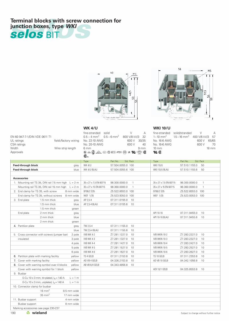
Feed-through block gray
Feed-through block blue
Accessories
1. Mounting rail TS 35, DIN rail 7.5 mm high L = 2 m
Mounting rail TS 35, DIN rail 15 mm high L = 2 m
2. End clamp for TS 35, with screw 8 mm wide
End clamp for TS 35, without screws 8 mm wide
3. End plate 1.5 mm thick gray
1.5 mm thick blue
1.5 mm thick green
End plate 2 mm thick gray
2 mm thick blue
2 mm thick green
4. Partition plate gray
blue
5. Cross connector with screws (jumper bar) 2 pole
insulated 3 pole
4 pole
5 pole
6 pole
6. Partition plate with marking facility yellow
7. Cover with marking facility yellow
8. Cover with warning symbol over 4 blocks yellow
Cover with warning symbol for 1 block yellow
9. Busbar
E-Cu 10 x 3 mm, tin-plated, IN = 140 A L = 1 m
E-Cu 10 x 3 mm, unplated, IN = 140 A L = 1 m
10. Connector clamp for busbar
16 mm2 8.5 mm wide
35 mm2 17 mm wide
11. Busbar support 4 mm wide
Busbar support 8 mm wide
Marking accessories see page 230-237
190 Subject to change without further notice
selosselos BIT
Terminal blocks with screw connection forjunction boxes, type WKI
WK 4/U 57.504.0055.0 100
WK 4/U BLAU 57.504.0055.6 100
35 x 27 x 7,5 EN 60715 98.300.0000.0 1
35 x 27 x 15 EN 60715 98.360.0000.0 1
9708/2 S35 Z5.522.8553.0 100
WEF 1/35 Z5.523.9353.0 100
AP 2,5-4 07.311.0155.0 10
AP 2,5-4 BLAU 07.311.0155.6 10
4. TW 2,5-4 07.311.1155.0 10
TW 2,5-4 BLAU 07.311.1155.6 10
IVB WK 4-2 Z7.281.1227.0 10
IVB WK 4-3 Z7.281.1327.0 10
IVB WK 4-4 Z7.281.1427.0 10
IVB WK 4-5 Z7.281.1527.0 10
IVB WK 4-6 Z7.281.1627.0 10
6. TS 4 GELB 07.311.2153.8 10
7. AD VB 4 GELB 04.326.2153.8 10
8. AB VB 6/4 GELB 04.343.4856.8 10
WKI 10/U 57.510.1155.0 50
WKI 10/U BLAU 57.510.1155.6 50
35 x 27 x 7,5 EN 60715 98.300.0000.0 1
35 x 27 x 15 EN 60715 98.360.0000.0 1
9708/2 S35 Z5.522.8553.0 100
WEF 1/35 Z5.523.9353.0 100
API 10-16 07.311.9455.0 10
API 10-16 BLAU 07.311.9455.6 10
IVB WKN 10-2 Z7.283.2227.0 10
IVB WKN 10-3 Z7.283.2327.0 10
IVB WKN 10-4 Z7.283.2427.0 10
IVB WKN 10-5 Z7.283.2527.0 10
IVB WKN 10-6 Z7.283.2627.0 10
TS 10 GELB 07.311.2353.8 10
AD VB 10 GELB 04.342.1056.8 10
ADI 10/1 GELB 04.325.8553.8 10
Type Part No. Std. Pack Type Part No. Std. Pack
EN 60 947-7-1/DIN VDE 0611 T1UL ratings field-/factory wiringCSA ratingsWidth Wire strip lengthApprovals
WK 4/U
fine-stranded solid V A0.5 – 4 mm2 0.5 – 6 mm2 800 V/8 kV/3 32No. 22-10 AWG 600 V 30/35No. 20-10 AWG 600 V 406 mm 9 mm
aüigotuCf+qkwh
WKI 10/U
fine-stranded solid/stranded V A1–10 mm2 1.5 –16 mm2 400 V/6 kV/3 57No. 16-6 AWG 600 V 65/65No. 16-6 AWG 600 V 7010 mm 18 mm
qw

selos
191Subject to change without further notice
Terminal blocks with screw connection forjunction boxes, type WKI
Type Part No. Std. Pack Type Part No. Std. Pack
WKI 35/U 57.535.1155.0 20
WKI 35/U BLAU 57.535.1155.6 20
35 x 27 x 7,5 EN 60715 98.300.0000.0 1
35 x 27 x 15 EN 60715 98.360.0000.0 1
9708/2 S 35 Z5.522.8553.0 100
API 35 07.311.8855.0 10
API 35 BLAU 07.311.8855.6 10
IVB WKI 35-2 Z7.285.4227.0 5
IVB WKI 35-3 Z7.285.4327.0 5
IVB WKI 35-4 Z7.285.4427.0 5
IVB WKI 35-5 Z7.285.4527.0 5
IVB WKI 35-6 Z7.285.4627.0 5
TS 35 GELB 07.311.8653.8 10
ADI 35/1 GELB 04.325.8753.8 10
WKI 35/U
fine-stranded stranded V A16 – 35 mm2 16 – 50 mm2 400 V/6 kV/3 125No. 10-2 AWG 600 V 95/95No. 10-2 AWG 600 V 11016 mm 13 mm
qw
WKI 16/U 57.516.1155.0 50
WKI 16/U BLAU 57.516.1155.6 50
35 x 27 x 7,5 EN 60715 98.300.0000.0 1
35 x 27 x 15 EN 60715 98.360.0000.0 1
9708/2 S 35 Z5.522.8553.0 100
API 10-16 07.311.9455.0 10
API 10-16 BLAU 07.311.9455.6 10
IVB WKI 16-2 Z7.284.9227.0 10
IVB WKI 16-3 Z7.284.9327.0 10
IVB WKI 16-4 Z7.284.9427.0 10
IVB WKI 16-5 Z7.284.9527.0 10
IVB WKI 16-6 Z7.284.9627.0 10
TS 16 GELB 07.311.2453.8 10
AD VB 16 GELB 04.326.2453.8 10
ADI 16/1 GELB 04.325.8653.8 10
WKI 16/U
fine-stranded solid/stranded V A1–16 mm2 1.5 – 25 mm2 400 V/6 kV/3 76No. 12-4 AWG 600 V 65/90No. 14-4 AWG 600 V 9512 mm 16 mm
qw

192 Subject to change without further notice
selosselos BIT
**) for use in grounded networks
Current carrying capability:fine-stranded: 4 mm2 25 Asolid: 6 mm2 30 A
Current carrying capability:fine-stranded: 10 mm2 45 Astranded: 16 mm2 50 A
WKN 4 ETK/U 57.504.8155.0 100
35 x 27 x 7,5 EN 60715 98.300.0000.0 1
35 x 27 x 15 EN 60715 98.360.0000.0 1
9708/2 S35 Z5.522.8553.0 100
WEF 1/35 Z5.523.9353.0 100
APN 4 ETK 07.311.1155.0 10
9813 M 98.290.0000.0 1
9813 M SN 98.290.1000.0 1
WAK 16/2 BLAU 30.494.3021.6 100
WAK 35/2 30.494.4121.0 50
WKI SH/U 01.108.3255.0 10
WKIF SH/E/35 Z1.108.8453.0 100
WKI 10 ETK/U 57.510.8255.0 50
35 x 27 x 7,5 EN 60715 98.300.0000.0 1
35 x 27 x 15 EN 60715 98.360.0000.0 1
9708/2 S35 Z5.522.8553.0 100
WEF 1/35 Z5.523.9353.0 100
API 10-16 ETK/1 07.312.1955.0 10
9813 M 98.290.0000.0 1
9813 M SN 98.290.1000.0 1
WAK 16/2 BLAU 30.494.3021.6 100
WAK 35/2 30.494.4121.0 50
WKI SH/U 01.108.3255.0 10
WKIF SH/E/35 Z1.108.8453.0 100
Type Part No. Std. Pack Type Part No. Std. Pack
EN 60 947-7-1/DIN VDE 0611 T1UL ratings CSA ratingsWidth Wire strip lengthApprovals
WKN 4 ETK/U
fine-stranded solid V A0.5 – 4 mm2 0.5 – 6 mm2 400 V/6 kV/3**)
No. 20-10 AWG600 V 256 mm 9 mm
igw
WKI 10 ETK/U
fine-stranded solid/stranded V A1 – 10 mm2 1 – 16 mm2 400 V/6 kV/3**)
No. 16-6 AWG 600 V 4510 mm 13 mm
wW
Neutral disconnect blocks with screw connection for junction boxes, type WKI
Neutral-disconnect block blue
Connector clamp for Cu busbar blue
unplated
Accessories
1. Mounting rail TS 35, DIN rail 7.5mm high L = 2 m
Mounting rail TS 35, DIN rail 15mm high L = 2 m
2. End clamp for TS 35, with screw 8 mm wide
End clamp for TS 35, without screws 8 mm wide
3. End plate 1.5 mm thick gray
1.5 mm thick blue
1.5 mm thick green
End plate 2 mm thick gray
2 mm thick blue
2 mm thick green
4. Partition plate gray
blue
5. Cross connector with screws (jumper bar) 2 pole
insulated 3 pole
4 pole
5 pole
6 pole
6. Partition plate with marking facility yellow
7. Cover with marking facility yellow
8. Cover with warning symbol over 4 blocks yellow
Cover with warning symbol for 1 block yellow
9. Busbar
E-Cu 10 x 3 mm, unplated, IN = 140 L = 1 m
E-Cu 10 x 3 mm, tin-plated, IN = 140 A L = 1 m
10.Connector clamp for busbar
16 mm2 8.5 mm wide
35 mm2 17 mm wide
11.Busbar support 4 mm wide
Busbar support 8 mm wide
Marking accessories see page 230-237

selos
193Subject to change without further notice
Current carrying capability:fine-stranded: 16 mm2 62 Astranded: 25 mm2 67 A EN 60 998-2-1 CCA/CH EN 60 998-2-1 CCA/CH
Type Part No. Std. Pack Type Part No. Std. Pack Type Part No. Std. Pack
WKI 16 ETK/U 57.516.8255.0 50
35 x 27 x 7,5 EN 60715 98.300.0000.0 1
35 x 27 x 15 EN 60715 98.360.0000.0 1
9708/2 S35 Z5.522.8553.0 100
API 10-16 ETK/1 07.312.1955.0 10
9813 M 98.290.0000.0 1
9813 M SN 98.290.1000.0 1
WAK 16/2 BLAU 30.494.3021.6 100
WAK 35/2 30.494.4121.0 50
WKI SH/U 01.108.3255.0 10
WKIF SH/E/35 Z1.108.8453.0 100
WAK 35/2 BLAU 30.494.4021.0 50
WAK 35/2 30.494.4121.0 50
9813 M 98.290.0000.0 1
9813 M SN 98.290.1000.0 1
WKI SH/U 01.108.3255.0 10
WKIF SH/E/35 Z1.108.8453.0 100
WAK 16/2 BLAU 30.494.3021.6 100
9813 M 98.290.0000.0 1
9813 M SN 98.290.1000.0 1
WKI SH/U 01.108.3255.0 10
WKIF SH/E/35 Z1.108.8453.0 100
WKI 16 ETK/U
fine-stranded solid/stranded V A1 – 16 mm2 1 – 25 mm2 400 V/6 kV/3**)
No. 14-4 AWG 600 V 6512 mm 15 mm
wW
WAK 16/2
fine-stranded stranded V A1.5 – 16 mm2 10 – 16 mm2 76
8.4 mm 16 mm
igW
WAK 35/2
fine-stranded stranded V A16 – 35 mm2 16 – 35 mm2 125
17 mm 14 mm
igW
Connector clamp for Cu busbar (10 x 3 mm), type WAK
WAK 35/2
WAK 16/2 BLAU
WAK 35/2 BLAU

194 Subject to change without further notice
selosselos BIT
WK 4 SL/35 56.504.9055.0 100
35 x 27 x 7,5 EN 60715 98.300.0000.0 1
35 x 27 x 15 EN 60715 98.360.0000.0 1
9708/2 S35 Z5.522.8553.0 100
WEF 1/35 Z5.523.9353.0 100
AP 2,5-4 SL 07.311.7155.0 10
AD VB4 GELB 04.326.2153.8 10
AD VB 6/4 GELB 04.343.4856.8 10
Type Part No. Std. Pack Type Part No. Std. Pack
WK 2,5 SL/35 56.503.9055.0 100
35 x 27 x 7,5 EN 60715 98.300.0000.0 1
35 x 27 x 15 EN 60715 98.360.0000.0 1
AP 2,5-4 SL 07.311.7155.0 10
AD VB 2,5 GELB 04.326.2053.8 10
AD VB 5/4 GELB 04.343.4756.8 10
EN 60 947-7-2/DIN VDE 0611 T3UL ratings CSA ratingsWidth Wire strip lengthApprovals
WK 2,5 SL/35
fine-stranded solid V A0.5 – 2.5 mm2 0.5 – 4 mm2 500 V/6 kV/3*)
No. 22-12 AWGNo. 24-12 AWG5 mm 9 mm
qw
WK 4 SL/35
fine-stranded solid V A0.5 – 4 mm2 0.5 – 6 mm2 800 V/8 kV/3*)
No. 22-10 AWGNo. 22-10 AWG6 mm 9 mm
Ground blocks with screw connection for junction boxes, type WKI SL
*) Ratings of adjacent feed-through block same series and size
Ground block with U-foot green/yellow
Ground block for TS 35 green/yellow
Accessories
1. Mounting rail TS 35, DIN rail 7.5 mm high L = 2 m
Mounting rail TS 35, DIN rail 15 mm high L = 2 m
2. End clamp for TS 35, with screw 8 mm wide
End clamp for TS 35, without screws 8 mm wide
3. End plate 1.5 mm thick gray
1.5 mm thick blue
1.5 mm thick green
End plate 2 mm thick gray
2 mm thick blue
2 mm thick green
4. Partition plate gray
blue
5. Cross connector with screws (jumper bar) 2 pole
insulated 3 pole
4 pole
5 pole
6 pole
6. Partition plate with marking facility yellow
7. Cover with marking facility yellow
8. Cover with warning symbol over 4 blocks yellow
Cover with warning symbol for 1 block yellow
9. Busbar
E-Cu 10 x 3 mm, tin-plated, IN = 140 L = 1 m
E-Cu 10 x 3 mm, unplated, IN = 140 A L = 1 m
10.Connector clamp for busbar
16 mm2 8.5 mm wide
35 mm2 17 mm wide
11.Busbar support 4 mm wide
Busbar support 8 mm wide
Marking accessories see page 230-237
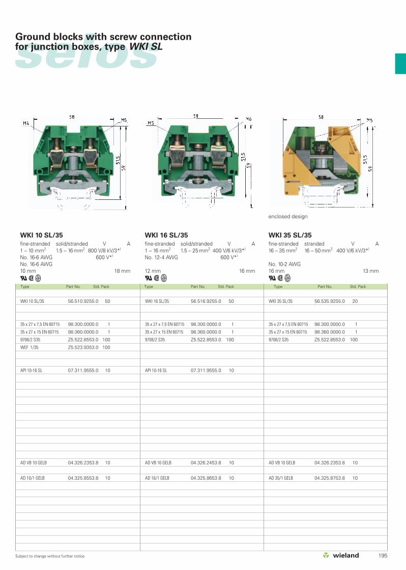
selos
195Subject to change without further notice
Type Part No. Std. Pack Type Part No. Std. Pack Type Part No. Std. Pack
WKI 10 SL/35 56.510.9255.0 50
35 x 27 x 7,5 EN 60715 98.300.0000.0 1
35 x 27 x 15 EN 60715 98.360.0000.0 1
9708/2 S35 Z5.522.8553.0 100
WEF 1/35 Z5.523.9353.0 100
API 10-16 SL 07.311.9555.0 10
AD VB 10 GELB 04.326.2353.8 10
AD 10/1 GELB 04.325.8553.8 10
WKI 16 SL/35 56.516.9255.0 50
35 x 27 x 7,5 EN 60715 98.300.0000.0 1
35 x 27 x 15 EN 60715 98.360.0000.0 1
9708/2 S35 Z5.522.8553.0 100
API 10-16 SL 07.311.9555.0 10
AD VB 16 GELB 04.326.2453.8 10
AD 16/1 GELB 04.325.8653.8 10
WKI 35 SL/35 56.535.9255.0 20
35 x 27 x 7,5 EN 60715 98.300.0000.0 1
35 x 27 x 15 EN 60715 98.360.0000.0 1
9708/2 S35 Z5.522.8553.0 100
AD VB 10 GELB 04.326.2353.8 10
AD 35/1 GELB 04.325.8753.8 10
enclosed design
WKI 10 SL/35
fine-stranded solid/stranded V A1 – 10 mm2 1.5 – 16 mm2 800 V/8 kV/3*)
No. 16-6 AWG 600 V*)
No. 16-6 AWG10 mm 18 mm
qwW
WKI 16 SL/35
fine-stranded solid/stranded V A1 – 16 mm2 1.5 – 25 mm2 400 V/6 kV/3*)
No. 12-4 AWG 600 V*)
12 mm 16 mm
qwW
WKI 35 SL/35
fine-stranded stranded V A16 – 35 mm2 16 – 50 mm2 400 V/6 kV/3*)
No. 10-2 AWG16 mm 13 mm
qwW
Ground blocks with screw connection for junction boxes, type WKI SL

196 Subject to change without further notice
selosselos BIT
Type Part No. Std. Pack
WKI 16 PEN/35 56.516.9455.0 20
35 x 27 x 7,5 EN 60715 98.300.0000.0 1
35 x 27 x 15 EN 60715 98.360.0000.0 1
9708/2 S35 Z5.522.8553.0 100
API 10-16 BLAU 07.311.9455.6 10
TS 16 GELB 07.311.2453.8 10
AD VB 16 GELB 04.326.2453.8 10
AD 16/1 GELB 04.325.8653.8 10
WKI 10 PEN/35 56.510.9455.0 20
35 x 27 x 7,5 EN 60715 98.300.0000.0 1
35 x 27 x 15 EN 60715 98.360.0000.0 1
9708/2 S35 Z5.522.8553.0 100
WEF 1/35 Z5.523.9353.0 100
API 10-16 BLAU 07.311.9455.6 10
TS 10 GELB 07.311.2353.8 10
AD VB 10 GELB 04.326.2353.8 10
ADI 10/1 GELB 04.325.8553.8 10
Type Part No. Std. Pack Type Part No. Std. Pack
EN 60 947-7-1, EN 60 947-7-2UL ratings CSA ratingsWidth Wire strip lengthApprovals
WKI 10 PEN/35
fine-stranded solid/stranded V A1 – 10 mm2 1.5 – 16 mm2 400 V/6 kV/3 57No. 16-6 AWG 600 V 65/65No. 16-6 AWG 600 V 7020 mm 18 mm
WKI 16 PEN/35
fine-stranded solid/stranded V A1 – 16 mm2 1.5 – 25 mm2 400 V/6 kV/3 76No. 12-4 AWG 600 V 65/65No. 14-4 AWG 600 V 9524 mm 16 mm
PEN assembly block with screw connection forjunction boxes, type WKI...
PEN assembly block green/yellow – blue
Accessories
1. Mounting rail TS 35, DIN rail 7.5 mm high L = 2 m
Mounting rail TS 35, DIN rail 15 mm high L = 2 m
2. End clamp for TS 35, with screw 8 mm wide
End clamp for TS 35, without screws 8 mm wide
3. End plate 1.5 mm thick gray
1.5 mm thick blue
1.5 mm thick green
End plate 2 mm thick gray
2 mm thick blue
2 mm thick green
4. Partition plate gray
blue
5. Cross connector with screws (jumper bar) 2 pole
insulated 3 pole
4 pole
5 pole
6 pole
6. Partition plate with marking facility yellow
7. Cover with marking facility yellow
8. Cover with warning symbol over 4 blocks yellow
Cover with warning symbol for 1 block yellow
9. Busbar
E-Cu 10 x 3 mm, tin-plated, IN = 140 L = 1 m
E-Cu 10 x 3 mm, unplated, IN = 140 A L = 1 m
10.Connector clamp for busbar
16 mm2 8.5 mm wide
35 mm2 17 mm wide
11.Busbar support 4 mm wide
Busbar support 8 mm wide
Marking accessories see page 230-237
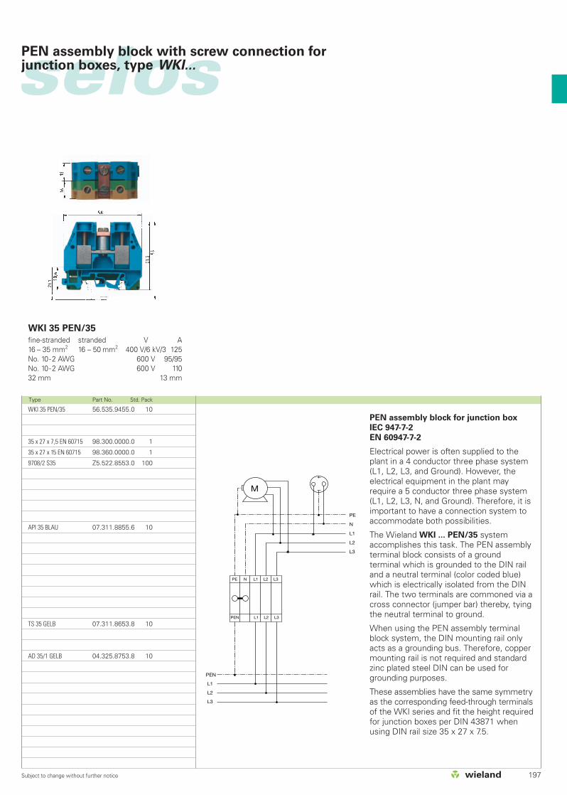
selos
197Subject to change without further notice
WKI 35 PEN/35 56.535.9455.0 10
35 x 27 x 7,5 EN 60715 98.300.0000.0 1
35 x 27 x 15 EN 60715 98.360.0000.0 1
9708/2 S35 Z5.522.8553.0 100
API 35 BLAU 07.311.8855.6 10
TS 35 GELB 07.311.8653.8 10
AD 35/1 GELB 04.325.8753.8 10
Type Part No. Std. Pack
WKI 35 PEN/35
fine-stranded stranded V A16 – 35 mm2 16 – 50 mm2 400 V/6 kV/3 125No. 10-2 AWG 600 V 95/95No. 10-2 AWG 600 V 11032 mm 13 mm
PEN assembly block with screw connection forjunction boxes, type WKI...
PEN assembly block for junction box
IEC 947-7-2
EN 60947-7-2
Electrical power is often supplied to theplant in a 4 conductor three phase system(L1, L2, L3, and Ground). However, theelectrical equipment in the plant mayrequire a 5 conductor three phase system(L1, L2, L3, N, and Ground). Therefore, it isimportant to have a connection system toaccommodate both possibilities.
The Wieland WKI ... PEN/35 systemaccomplishes this task. The PEN assemblyterminal block consists of a ground terminal which is grounded to the DIN railand a neutral terminal (color coded blue)which is electrically isolated from the DINrail. The two terminals are commoned via across connector (jumper bar) thereby, tyingthe neutral terminal to ground.
When using the PEN assembly terminalblock system, the DIN mounting rail onlyacts as a grounding bus. Therefore, coppermounting rail is not required and standardzinc plated steel DIN can be used forgrounding purposes.
These assemblies have the same symmetryas the corresponding feed-through terminalsof the WKI series and fit the height requiredfor junction boxes per DIN 43871 whenusing DIN rail size 35 x 27 x 7.5.
M
PE
N
L1
L2
L3
PE N L1 L2 L3
PEN L1 L2 L3
PEN
L1
L2
L3

198 Subject to change without further notice
selosselos BIT
Three-tier blocks with screw connectionfor junction boxes, type WKI
1112
109
1
2
3
4
5
6
7
8
16
22
21
24
20
26
25
23
18
2519
15
1714
13

WKI 4 N-D-SL 56.404.9455.0
WKI 4 NT-D-SL 56.404.9555.0
WKI 4 D-D-SL 56.404.9855.0
WKI 4 D-D 56.404.9755.0
WKI 16 SL/35 56.516.9255.0
WKI 16 ETK/U 57.516.8255.0
WKI 16 /U BLAU 57.516.1155.6
WKI 16 /U 57.516.1155.0
WK 4 SL/U 57.504.9055.0
WKN 4 ETK/U 57.504.8155.0
WK 4 /U BLAU 57.504.0055.6
WK 4 /U 57.504.0055.0
WAK 16/2 BLAU 30.494.3021.6
9708/2 S35 Z5.522.8553.0
9813 M Sn 98.290.1000.0
35 x 27 x 7,5 98.300.0000.0
WKI SH/U 01.108.3255.0
API 4/2 07.311.6555.0
AD 4/4 GELB 04.343.4856.8
ADI 16/1 GELB 04.325.8553.8
AD VB 16 GELB 04.326.2453.8
TS 16 GELB 07.311.2453.8
IVB WKI 4–12 Z7.271.5227.0
VB WKI 16–3 Z7.289.0327.0
9705 A/6/10 B 04.842.6053.0
9705 A/6/10/5 B 04.842.6553.0
selos
199Subject to change without further notice
Three-tier blocks with screw connectionfor junction boxes, type WKI
Item Description Type Part number
1 Installation blocks
2 Installation blocks
3 Installation blocks
4 Installation blocks
5 Ground block
6 Neutral disconnect block
7 Feed-through block
8 Feed-through block
9 Ground block
10 Neutral disconnect block
11 Feed-through block
12 Feed-through block
13 Connector clamp
14 End clamp
15 Busbar 10 x 3
16 Mounting rail
17 Busbar support
18 End plate
19 Cover with warning symbol
20 Cover with warning symbol
21 Cover with marking facility
22 Partition plate with marking facility
23 Cross connector, insulated (12 pole)
24 Cross connector, uninsulated
25 Marking strip
26 Marking strip
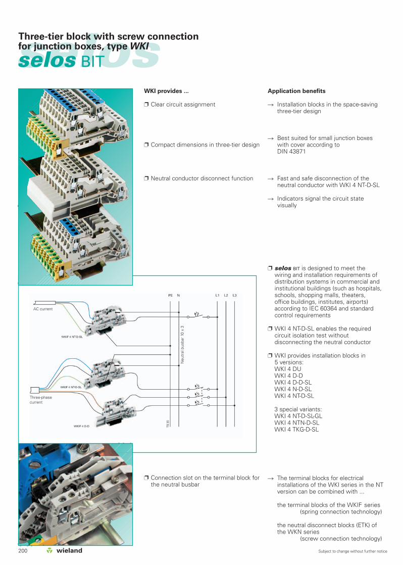
200 Subject to change without further notice
selosselos BIT
Three-tier block with screw connectionfor junction boxes, type WKI
WKI provides ...
Clear circuit assignment
Compact dimensions in three-tier design
Neutral conductor disconnect function
Connection slot on the terminal block forthe neutral busbar
Application benefits
Installation blocks in the space-savingthree-tier design
Best suited for small junction boxeswith cover according to DIN 43871
Fast and safe disconnection of the neutral conductor with WKI 4 NT-D-SL
Indicators signal the circuit state visually
selos BIT is designed to meet the wiring and installation requirements ofdistribution systems in commercial andinstitutional buildings (such as hospitals,schools, shopping malls, theaters, office buildings, institutes, airports)according to IEC 60364 and standardcontrol requirements
WKI 4 NT-D-SL enables the requiredcircuit isolation test without disconnecting the neutral conductor
WKI provides installation blocks in 5 versions:WKI 4 DUWKI 4 D-DWKI 4 D-D-SLWKI 4 N-D-SLWKI 4 NT-D-SL
3 special variants:WKI 4 NT-D-SL-GLWKI 4 NTN-D-SLWKI 4 TKG-D-SL
The terminal blocks for electricalinstallations of the WKI series in the NTversion can be combined with ...
the terminal blocks of the WKIF series(spring connection technology)
the neutral disconnect blocks (ETK) ofthe WKN series
(screw connection technology)
AC current
Three-phasecurrent
Neu
tral
bus
bar
10 x
3

selos
201Subject to change without further notice
Three-tier block with screw connectionfor junction boxes, type WKI
DQS certificates for all company divisions
Quality standard as per DIN ISO 9001 In Development, Production and Assembly
Continued control of thequality standard by means of regularinternal and external quality audits
Compatible with certificates of othercountries:
– BSI Certificate, Great Britain– SQS Certificate, Switzerland– Aib-Vincotte Certificate, Belgium– ÖQS Certificate, Austria
Marking facilities
Marking facility for each terminationpoint
Tear-off marking strips for 3-digit markingfacilities per block
Single marking tags in 5 mm spacing
Marking strips (10 individual markingtags) to snap on to 10 terminal blocks
Custom marking upon request
Connector clamps
Connector clamps for busbar 10 x 3 mm(E-Cu, tin-plated)
WAK 16/2... 0.75 –16 mm2
WAK 35/2... 16 – 35 mm2
Clear identification of the circuit taskwhen the erternal neutral conductor isconnected to the busbar
Jumpering with jumper combs
Jumpering with insulated jumper combs
Jumper comb and conductor areinserted in the clamping body andclamped
Jumpering with cross connectors
Jumpering with insulated and uninsulatedcross connectors (jumperbars)
Cross connectors do not take upclamping space
Uninsulated cross connectors can be cutto length
When using cross connectors, endplates or partitions are required tomaintain max. voltage rating
Note:
The information regarding cross sectio-nal area and connection types pertains tounprepared wires without ferrules.
The voltage ratings apply to the termi-nals in their intended application. Whendifferent products are mounted adjacentto each other, the proper isolationdistances must be adhered to. For thispurpose, Wieland offers a large selec-tion of appropriate accessories.
A detailed description of technical data,the standards’ requirements, and theapplication conditions can be found inpart catalog section facts & DATA:“Technical information”.
Material
Metal parts
Special alloys enable a low contact resistance and provide agas-tight contact area:
Clamping body/clamping screws:Steel, zinc-plated and dichromated
Current carrying bar: tin-plated copper
Insulation material
Polyamide has excellentelectrical, chemical and mechanical characteristics
Insulating housings: Polyamide 66/6
Tracking current resistance: CTI 600
Flammability class: UL 94-V0
(also see master catalog section facts & DATA: Technical information)
You can use our wieplan software toconfigure your own terminal blockassemblies (see page 36/37).
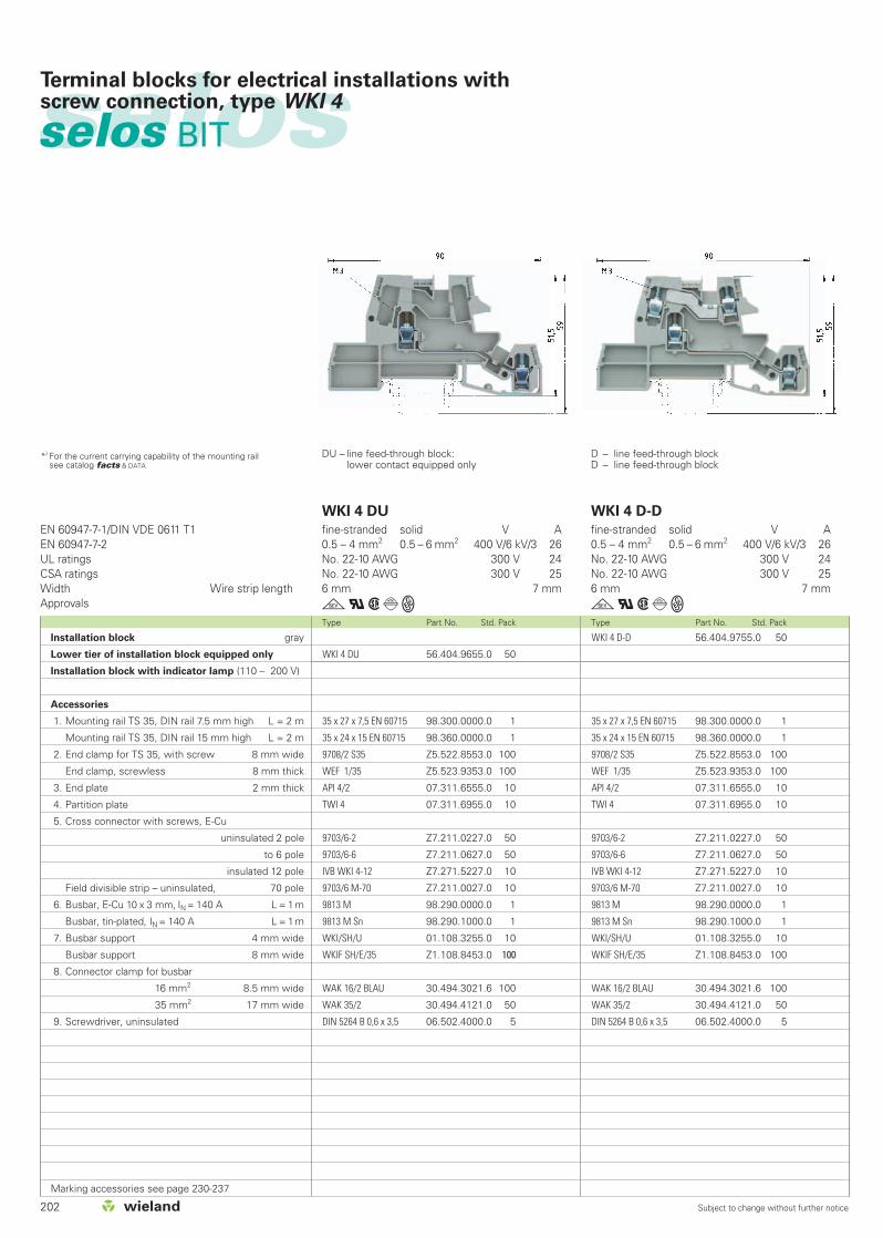
202 Subject to change without further notice
selosselos BIT
Terminal blocks for electrical installations with screw connection, type WKI 4
D – line feed-through blockD – line feed-through block
DU – line feed-through block:lower contact equipped only
EN 60947-7-1/DIN VDE 0611 T1EN 60947-7-2UL ratings CSA ratingsWidth Wire strip lengthApprovals
WKI 4 D-D 56.404.9755.0 50
35 x 27 x 7,5 EN 60715 98.300.0000.0 1
35 x 24 x 15 EN 60715 98.360.0000.0 1
9708/2 S35 Z5.522.8553.0 100
WEF 1/35 Z5.523.9353.0 100
API 4/2 07.311.6555.0 10
TWI 4 07.311.6955.0 10
9703/6-2 Z7.211.0227.0 50
9703/6-6 Z7.211.0627.0 50
IVB WKI 4-12 Z7.271.5227.0 10
9703/6 M-70 Z7.211.0027.0 10
9813 M 98.290.0000.0 1
9813 M Sn 98.290.1000.0 1
WKI/SH/U 01.108.3255.0 10
WKIF SH/E/35 Z1.108.8453.0 100
WAK 16/2 BLAU 30.494.3021.6 100
WAK 35/2 30.494.4121.0 50
DIN 5264 B 0,6 x 3,5 06.502.4000.0 5
Type Part No. Std. Pack Type Part No. Std. Pack
WKI 4 DU
fine-stranded solid V A0.5 – 4 mm2 0.5 – 6 mm2 400 V/6 kV/3 26No. 22-10 AWG 300 V 24No. 22-10 AWG 300 V 256 mm 7 mm
gqwdW
WKI 4 D-D
fine-stranded solid V A0.5 – 4 mm2 0.5 – 6 mm2 400 V/6 kV/3 26No. 22-10 AWG 300 V 24No. 22-10 AWG 300 V 256 mm 7 mm
gqwdW
*) For the current carrying capability of the mounting rail see catalog facts & DATA
WKI 4 DU 56.404.9655.0 50
35 x 27 x 7,5 EN 60715 98.300.0000.0 1
35 x 24 x 15 EN 60715 98.360.0000.0 1
9708/2 S35 Z5.522.8553.0 100
WEF 1/35 Z5.523.9353.0 100
API 4/2 07.311.6555.0 10
TWI 4 07.311.6955.0 10
9703/6-2 Z7.211.0227.0 50
9703/6-6 Z7.211.0627.0 50
IVB WKI 4-12 Z7.271.5227.0 10
9703/6 M-70 Z7.211.0027.0 10
9813 M 98.290.0000.0 1
9813 M Sn 98.290.1000.0 1
WKI/SH/U 01.108.3255.0 10
WKIF SH/E/35 Z1.108.8453.0 100
WAK 16/2 BLAU 30.494.3021.6 100
WAK 35/2 30.494.4121.0 50
DIN 5264 B 0,6 x 3,5 06.502.4000.0 5
Installation block gray
Lower tier of installation block equipped only
Installation block with indicator lamp (110 – 200 V)
Accessories
1. Mounting rail TS 35, DIN rail 7.5 mm high L = 2 m
Mounting rail TS 35, DIN rail 15 mm high L = 2 m
2. End clamp for TS 35, with screw 8 mm wide
End clamp, screwless 8 mm thick
3. End plate 2 mm thick
4. Partition plate
5. Cross connector with screws, E-Cu
uninsulated 2 pole
to 6 pole
insulated 12 pole
Field divisible strip – uninsulated, 70 pole
6. Busbar, E-Cu 10 x 3 mm, IN = 140 A L = 1m
Busbar, tin-plated, IN = 140 A L = 1m
7. Busbar support 4 mm wide
Busbar support 8 mm wide
8. Connector clamp for busbar
16 mm2 8.5 mm wide
35 mm2 17 mm wide
9. Screwdriver, uninsulated
Marking accessories see page 230-237
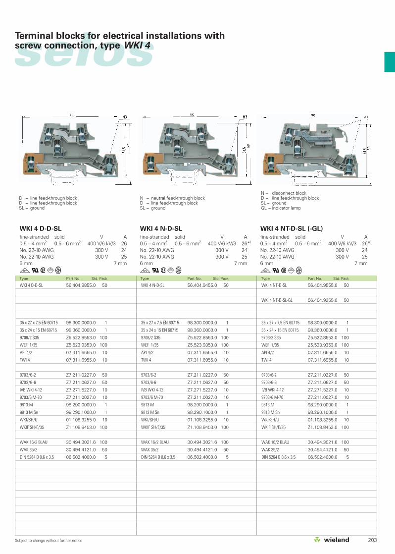
selos
203Subject to change without further notice
Terminal blocks for electrical installations with screw connection, type WKI 4
D – line feed-through blockD – line feed-through blockSL – ground
N – neutral feed-through blockD – line feed-through blockSL – ground
N – disconnect blockD – line feed-through blockSL – groundGL – indicator lamp
WKI 4 N-D-SL 56.404.9455.0 50
35 x 27 x 7,5 EN 60715 98.300.0000.0 1
35 x 24 x 15 EN 60715 98.360.0000.0 1
9708/2 S35 Z5.522.8553.0 100
WEF 1/35 Z5.523.9353.0 100
API 4/2 07.311.6555.0 10
TWI 4 07.311.6955.0 10
9703/6-2 Z7.211.0227.0 50
9703/6-6 Z7.211.0627.0 50
IVB WKI 4-12 Z7.271.5227.0 10
9703/6 M-70 Z7.211.0027.0 10
9813 M 98.290.0000.0 1
9813 M Sn 98.290.1000.0 1
WKI/SH/U 01.108.3255.0 10
WKIF SH/E/35 Z1.108.8453.0 100
WAK 16/2 BLAU 30.494.3021.6 100
WAK 35/2 30.494.4121.0 50
DIN 5264 B 0,6 x 3,5 06.502.4000.0 5
WKI 4 NT-D-SL 56.404.9555.0 50
WKI 4 NT-D-SL-GL 56.404.9255.0 50
35 x 27 x 7,5 EN 60715 98.300.0000.0 1
35 x 24 x 15 EN 60715 98.360.0000.0 1
9708/2 S35 Z5.522.8553.0 100
WEF 1/35 Z5.523.9353.0 100
API 4/2 07.311.6555.0 10
TWI 4 07.311.6955.0 10
9703/6-2 Z7.211.0227.0 50
9703/6-6 Z7.211.0627.0 50
IVB WKI 4-12 Z7.271.5227.0 10
9703/6 M-70 Z7.211.0027.0 10
9813 M 98.290.0000.0 1
9813 M Sn 98.290.1000.0 1
WKI/SH/U 01.108.3255.0 10
WKIF SH/E/35 Z1.108.8453.0 100
WAK 16/2 BLAU 30.494.3021.6 100
WAK 35/2 30.494.4121.0 50
DIN 5264 B 0,6 x 3,5 06.502.4000.0 5
Type Part No. Std. Pack Type Part No. Std. Pack Type Part No. Std. Pack
WKI 4 D-D-SL 56.404.9855.0 50
35 x 27 x 7,5 EN 60715 98.300.0000.0 1
35 x 24 x 15 EN 60715 98.360.0000.0 1
9708/2 S35 Z5.522.8553.0 100
WEF 1/35 Z5.523.9353.0 100
API 4/2 07.311.6555.0 10
TWI 4 07.311.6955.0 10
9703/6-2 Z7.211.0227.0 50
9703/6-6 Z7.211.0627.0 50
IVB WKI 4-12 Z7.271.5227.0 10
9703/6 M-70 Z7.211.0027.0 10
9813 M 98.290.0000.0 1
9813 M Sn 98.290.1000.0 1
WKI/SH/U 01.108.3255.0 10
WKIF SH/E/35 Z1.108.8453.0 100
WAK 16/2 BLAU 30.494.3021.6 100
WAK 35/2 30.494.4121.0 50
DIN 5264 B 0,6 x 3,5 06.502.4000.0 5
WKI 4 D-D-SL
fine-stranded solid V A0.5 – 4 mm2 0.5 – 6 mm2 400 V/6 kV/3 26No. 22-10 AWG 300 V 24No. 22-10 AWG 300 V 256 mm 7 mm
gqwdW
WKI 4 N-D-SL
fine-stranded solid V A0.5 – 4 mm2 0.5 – 6 mm2 400 V/6 kV/3 26*)
No. 22-10 AWG 300 V 24No. 22-10 AWG 300 V 256 mm 7 mm
gqwdW
WKI 4 NT-D-SL (-GL)
fine-stranded solid V A0.5 – 4 mm2 0.5 – 6 mm2 400 V/6 kV/3 26*)
No. 22-10 AWG 300 V 24No. 22-10 AWG 300 V 256 mm 7 mm
gqwdW

204 Subject to change without further notice
selosselos BIT
EN 60 947-7-1, EN 60 947-7-2UL ratings CSA ratingsWidth Wire strip lengthApprovals
WKI 4 NTN-D-SL
fine-stranded solid V A0.5 – 4 mm2 0.5 – 6 mm2 400 V/6 kV/3 26*)
No. 22-10 AWG 300 V 24No. 22-10 AWG 300 V 256 mm 7 mm
gqwdW
WKI 4 TKG-D-SL
fine-stranded solid V A0.5 – 4 mm2 0.5 – 6 mm2 400 V/6 kV/3 26*)
No. 22-10 AWG 300 V 12No. 22-10 AWG 300 V 256 mm 7 mm
gqwd
Terminal blocks for electrical installations withscrew connection, type WKI 4
Busbar application:Position these terminals at the beginning or end ofthe assembly when incorporating the busbarsystem.
WKI 4 NTN-D-SL 56.404.9155.0 50
35 x 27 x 7,5 EN 60715 98.300.0000.0 1
35 x 24 x 15 EN 60715 98.360.0000.0 1
9708/2 S35 Z5.522.8553.0 100
WEF 1/35 Z5.523.5753.0 100
API 4/3 07.311.6855.0 10
9703/6-2 Z7.211.0227.0 50
9703/6-6 Z7.211.0627.0 50
IVB WKI 4-12 Z7.271.5227.0 10
9703/6 M-70 Z7.211.0027.0 10
DIN 5264 B 0,6 x 3,5 06.502.4000.0 5
WKI 4 TKG-D-SL 56.404.8855.0 50
Si ST Z1.299.4055.0 10
Si ST LED Z1.299.4155.0 10
Si ST GL Z1.299.4255.0 10
35 x 27 x 7,5 EN 60715 98.300.0000.0 1
35 x 24 x 15 EN 60715 98.360.0000.0 1
9708/2 S35 Z5.522.8553.0 100
WEF 1/35 Z5.523.9353.0 100
API 4/3 07.311.6855.0 10
9703/6-2 Z7.211.0227.0 50
9703/6-6 Z7.211.0627.0 50
IVB WKI 4-12 Z7.271.5227.0 10
9703/6 M-70 Z7.211.0027.0 10
DIN 5264 B 0,6 x 3,5 06.502.4000.0 5
Type Part No. Std. Pack Type Part No. Std. Pack
Fuse application:Nominal current accord to VDE 0820 T2/EN 60 127-2 when using1.6 W– 6.3 A for single blocks– 4 A for blocks mounted directly adjacent to each otherVoltage and current are determined by the LED and the fuse used in the end application
Ground application:*) For the current carrying capability of the mounting
rail see catalog facts & DATA
NTN – disconnect blockD – line feed-through block:SL – ground
TKG – fuse plug for 5 x 20 fuseD – line feed-through block:SL – ground block
Installation block gray
Fuse holder for 5 x 20 fuse gray
Fuse holder with indicator (24 V) gray
Fuse holder with indicator (110 – 220 V) gray
(G fuse-links DIN 41571, 250 V/6.3 A, 5 x 20 mm)
Accessories
1. Mounting rail TS 35, DIN rail 7.5 mm high L = 2 m
Mounting rail TS 35, DIN rail 15 mm high L = 2 m
2. End clamp for TS 35, with screw 8 mm wide
End clamp, screwless 8 mm thick
3. End plate 2 mm thick
4. Partition plate
5. Cross connector with screws, (jumper bar)
uninsulated 2 pole
to 6 pole
insulated 12 pole
Field-divisible strip – 70 pole
6. Busbar, E-Cu 10 x 3 mm, IN = 140 A L = 1 m
Busbar, tin-plated, IN = 140 A L = 1 m
7. Busbar support 4 mm wide
Busbar support 8 mm wide
8. Connector clamp for busbar
16 mm2 8.5 mm wide
35 mm2 17 mm wide
9. Screwdriver, uninsulated
Marking accessories see page 230-237

selos
205
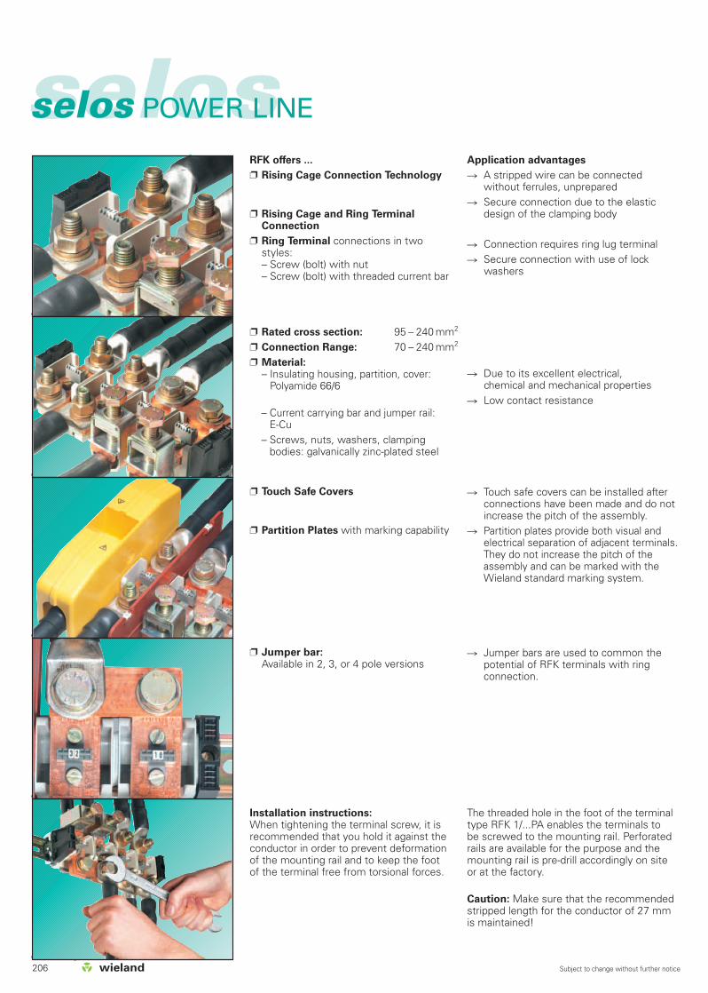
206 Subject to change without further notice
selosselos POWER LINE
Jumper bar:Available in 2, 3, or 4 pole versions
Installation instructions:When tightening the terminal screw, it isrecommended that you hold it against theconductor in order to prevent deformationof the mounting rail and to keep the footof the terminal free from torsional forces.
Jumper bars are used to common thepotential of RFK terminals with ringconnection.
The threaded hole in the foot of the terminaltype RFK 1/...PA enables the terminals tobe screwed to the mounting rail. Perforatedrails are available for the purpose and themounting rail is pre-drill accordingly on siteor at the factory.
Caution: Make sure that the recommendedstripped length for the conductor of 27 mmis maintained!
Touch safe covers can be installed afterconnections have been made and do notincrease the pitch of the assembly.
Partition plates provide both visual andelectrical separation of adjacent terminals.They do not increase the pitch of theassembly and can be marked with theWieland standard marking system.
Rated cross section: 95 – 240 mm2
Connection Range: 70 – 240 mm2
Material:– Insulating housing, partition, cover:
Polyamide 66/6
– Current carrying bar and jumper rail: E-Cu
– Screws, nuts, washers, clampingbodies: galvanically zinc-plated steel
Touch Safe Covers
Partition Plates with marking capability
Due to its excellent electrical, chemical and mechanical properties
Low contact resistance
Application advantages
A stripped wire can be connectedwithout ferrules, unprepared
Secure connection due to the elasticdesign of the clamping body
Connection requires ring lug terminal Secure connection with use of lock
washers
RFK offers ...
Rising Cage Connection Technology
Rising Cage and Ring TerminalConnection
Ring Terminal connections in twostyles:– Screw (bolt) with nut– Screw (bolt) with threaded current bar

selos
207Subject to change without further notice
DQS certificates for all company divisions
Quality standard as per DIN ISO 9001 In Development, Production, Assembly Continued control of the
quality standard by means of regularinternal and external quality audits
Compatible with certificates of other countries:
– BSI Certificate, Great Britain– SQS Certificate, Switzerland– Aib-Vincotte Certificate, Belgium– ÖQS Certificate, Austria
Jumper bar:Available in 2, 3, 4 pole versions
Locking slidesallows the BK series to be locked ontothe DIN rail
With the BK terminal series, it ispossible to common the potential ofadjacent terminals with a jumper bar.
The locking slide ensures securemounting of the BK terminal on the DIN rail. This is important due to largerconductor sizes and higher torquevalues of the BK series.
End plates/partition plates provide bothvisual and electrical separation of adjacentterminals. They do not increase the pitchof the assembly and can be marked withthe Wieland standard marking system.
The marking tag cover is a translucent yellow material which protects the marking tag against dust and other industrial elements.
Material:– Insulated housing: epoxy resin– Ring lug, nut and lock washer:
galvanized steel, zinc plated– Jumper Bar: E-Cu– Locking slide, marking tag, and
marking tag holder: Polyamide
End plates / partition plate withmarking capability
Marking tag cover
Constant operating temperature; 150 °C Nuts, washer, lock washer are included
but are packaged separately
BK offers ...
Ring lug connection
Torque values to ring lug diameterstandard up to 10 Nm
Connection range per ring lug diameter standard DIN 46 234 from 2.5 to 240 mm
Application advantages
No loose wires High contact force ensures a secure
connection with the use of a lockwasher
You can use our wieplan software toconfigure your own terminal blockassemblies (see page 36/37).
A detailed description of technical data,the standards’ requirements, and theapplication conditions can be found inpart facts & DATA.

Type Part No. Std. Pack Type Part No. Std. Pack
DIN VDE 0110UL ratings field/factory wiringCSA ratingsWidth Wire strip lengthApprovals
BK M 6/32 32.630.0042.0 50
9006 EN 60715 G-32 98.190.0000.0 1
WE 1/U Z5.523.5753.0 100
9708 Z5.522.7053.0 100
07.340.4153.0 50
07.340.1153.0 50
04.326.0056.0 100
07.340.2153.0 50
BK M 8/32 32.640.0042.0 50
9006 EN 60715 G-32 98.190.0000.0 1
WE 1/U Z5.523.5753.0 100
9708 Z5.522.7053.0 100
07.340.4153.0 50
or 07.340.4353.0*) 50
07.340.1153.0 50
or 07.340.1353.0*) 50
available on request
available on request
available on request
04.326.0056.0 100
07.340.2153.0 50
or 07.340.2353.0*) 50
*) When selecting the partition consider the air and
creepage distances.
BK M 6/32
V A1500 V 1800 V –... Gr. C2 AWG 600 V 115 18 mm
gw
BK M 8/32
V A1500 V 1800 V –... Gr. C000 AWG 1000 V 200 26 mm
gw
selosselos POWER LINE
Ring lug terminal for 32 mm DIN rail
The wire size is dependent on the hole diameter of the ringterminal of 6.5 mm and the max. ring terminal width of 15 mm
The wire size is dependent on the hole diameter of the ringterminal of 8.4 mm and the max. ring terminal width of 25 mm
Ring lug terminal
Accessories
1. Mounting rail TS 35, DIN rail, 7.5 mm high L = 2 m
Mounting rail TS 35, DIN rail 15 mm high L = 2 m
Mounting rail TS 35, G rail L = 2 m
2. End clamp with U-foot 10 mm wide
End clamp TS32 with screw 8 mm wide
End clamp TS32 with screw 7.5 mm wide
3. End plate with marking capability
4. Partition with marking capability
5. Jumper bar from E-Cu
for 2 blocks available on request
for 3 blocks available on request
for 4 blocks available on request
6. Marking tag cover yellow
7. Marking plate
For marking systems see pages 230-237
208 Subject to change without further notice

Ring lug Wire gauge mm2 Hole diameter Width ofDiameter AWG/MCM of the ring terminal ring terminal
6 2.5 6.5 11
6 6 6.5 11
6 10 6.5 11
6 16 6.5 11
6 25 6.5 12
6 35 6.5 15
8 2.5 8.4 14
8 6 8.4 14
8 10 8.4 14
8 16 8.4 14
8 25 8.4 16
8 35 8.4 16
8 50 8.4 18
8 70 8.4 22
8 95 8.4 24
8 120 8.4 24
10 6 10.5 18
10 10 10.5 18
10 16 10.5 18
10 25 10.5 18
10 35 10.5 18
10 50 10.5 18
10 70 10.5 22
10 95 10.5 24
10 120 10.5 24
10 150 10.5 30
12 10 13 22
12 16 13 22
12 25 13 22
12 35 13 22
12 50 13 22
12 70 13 22
12 95 13 24
12 120 13 24
12 150 13 30
12 185 13 36
12 240 13 38
selos
BK M 10/32
V A1500 V 1800 V –... Gr. C300 AWG 1000 V 285 32 mm
gwBK M 10/32 32.650.0042.0 50
9006 EN 60715 G-32 98.190.0000.0 1
WE 1/U Z5.523.5753.0 100
9708 Z5.522.7053.0 100
07.340.4353.0 50
07.340.1353.0 50
VB RFK 1/95/2/32 07.205.1227.0 20
VB RFK 1/95/3/32 07.205.1327.0 10
VB RFK 1/95/4/32 07.205.1427.0 10
04.326.0056.0 100
07.340.2353.0 50
Standard to DIN 46 234
Ring lug terminal for 32 mm DIN rail
The wire size is dependent on the hole diameter of the ringterminal of 10.5 mm and the max. ring terminal width of 30 mm
Part No. B H
07.340.2153.0 80 22
07.340.2353.0 115 25
07.340.4153.0 80 50
07.340.4353.0 115 62
07.340.1153.0 80 50
07.340.1353.0 115 62
Type Part No. Std. Pack
209Subject to change without further notice

Type Part No. Std. Pack Type Part No. Std. Pack
DIN VDE 0110UL ratings field/factory wiringCSA ratingsWidthApprovals
BK M 8/35 32.540.0053.0 25
35 x 27 x 7,5 EN 60715 98.300.0000.0 1
35 x 24 x 15 EN 60715 98.360.0000.0 1
WE 1/U Z5.523.5753.0 100
9708/2 S 35 Z5.522.8553.0 100
TW BK M 8/35 07.340.3653.0 25
VB BK M 8/35-2 07.205.7227.0 20
VB BK M 8/35-3 07.205.7327.0 10
AD BK M 6-8/35 04.304.0181.0 1
05.564.0753.0 10
1) with partition TW BK
BK M 6/35
V A1000 V/8 kV/31) 125
19.6 mm
uqw
BK M 8/35
V A1000 V/8 kV/31) 150
24.6 mm
uqw
selosselos POWER LINE
Ring lug terminal for TS 35 mm DIN rail
BK M 6/35 32.530.0053.0 25
35 x 27 x 7,5 EN 60715 98.300.0000.0 1
35 x 24 x 15 EN 60715 98.360.0000.0 1
WE 1/U Z5.523.5753.0 100
9708/2 S 35 Z5.522.8553.0 100
TW BK M 6/35 07.340.3553.0 25
VB BK M 6/35-2 07.205.5227.0 20
VB BK M 6/35-3 07.205.5327.0 10
AD BK M 6-8/35 04.304.0181.0 1
05.564.0753.0 10
Ring lug terminal
Accessories
1. Mounting rail TS 35, DIN rail, 7.5 mm high L = 2 m
Mounting rail TS 35, DIN rail 15 mm high L = 2 m
Mounting rail TS 35, G rail L = 2 m
2. End clamp with U-foot 10 mm wide
End clamp TS35 with screw 8 mm wide
End clamp TS32 with screw 7.5 mm wide
3. Partition plate
4. Jumper bar: from E-Cu
for 2 pole
for 3 pole
6. Marking tag
7. Cover
8. Installation clip
For marking systems see pages 230-237 1) with partition TW BK
210 Subject to change without further notice
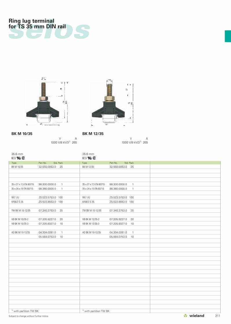
Type Part No. Std. Pack Type Part No. Std. Pack
BK M 10/35 32.550.0053.0 25
35 x 27 x 7,5 EN 60715 98.300.0000.0 1
35 x 24 x 15 EN 60715 98.360.0000.0 1
WE 1/U Z5.523.5753.0 100
9708/2 S 35 Z5.522.8553.0 100
TW BK M 10-12/35 07.340.3753.0 25
VB BK M 10/35-2 07.205.8227.0 20
VB BK M 10/35-3 07.205.8327.0 10
AD BK M 10-12/35 04.304.0281.0 1
05.564.0753.0 10
1) with partition TW BK
BK M 12/35 32.560.0053.0 25
35 x 27 x 7,5 EN 60715 98.300.0000.0 1
35 x 24 x 15 EN 60715 98.360.0000.0 1
WE 1/U Z5.523.5753.0 100
9708/2 S 35 Z5.522.8553.0 100
TW BK M 10-12/35 07.340.3753.0 25
VB BK M 12/35-2 07.205.9227.0 20
VB BK M 12/35-3 07.205.9327.0 10
AD BK M 10-12/35 04.304.0281.0 1
05.564.0753.0 10
1) with partition TW BK
BK M 10/35
V A1000 V/8 kV/31) 265
35.6 mm
uqw
BK M 12/35
V A1000 V/8 kV/31) 265
35.6 mm
uqw
selosRing lug terminal for TS 35 mm DIN rail
211Subject to change without further notice

RFK 1/95 F S 35 56.395.0055.0 10
RFK 1/95 K S 35 56.395.0155.0 10
RFK 1/95 FK S 35 56.395.0255.0 10
RFK 1/95 FM S 35 56.395.1055.0 10
RFK 1/95 FMK S 35 56.395.1255.0 10
35 x 27 x 7,5 EN 60715 98.300.0000.0 1
35 x 24 x 15 EN 60715 98.360.0000.0 1
WE 2/U Z5.523.5653.0 100
9708/2 S35 Z5.522.8553.0 100
9708 Z5.522.7053.0 100
Z7.409.5753.0 10
TE/RFK 1/95 07.340.0353.0 50
VB RFK 1/95/2/32 07.205.1227.0 20
VB RFK 1/95/3/32 07.205.1327.0 10
VB RFK 1/95/4/32 07.205.1427.0 10
Configurations gray F
gray K
gray FK
gray FM
gray FMK
Accessories
1. Mounting rail TS 35, DIN rail, 7.5 mm high L = 2 m
Mounting rail TS 35, DIN rail 15 mm high L = 2 m
Mounting rail TS 35, G rail L = 2 m
2. End clamp with U-foot 10 mm wide
End clamp TS35 with screw 8 mm wide
End clamp TS32 with screw 7.5 mm wide
3. Cover for RFK 1/... yellow
4. Partition/end plate PA 66/6 2.8 mm thick
5. Screws for fixation on the mounting rail
6. Jumper bar for tab connection blocks from E-Cu
for 2 blocks
for 3 blocks
for 4 blocks
For marking systems see pages 230-237
Type Part No. Std. Pack Type Part No. Std. Pack
DIN VDE 0611 Teil 1/EN 60947-7-1UL ratings field/factory wiringCSA ratingsWidth Wire strip lengthApprovals
RFK 1/95 F PA 59.195.0055.0 10
RFK 1/95 K PA 59.195.0155.0 10
RFK 1/95 FK PA 59.195.0255.0 10
RFK 1/95 FM PA 59.195.1055.0 10
RFK 1/95 FMK PA 59.195.1255.0 10
9006 EN 60715 G-32 98.190.0000.0 1
WE 2/U Z5.523.5653.0 100
9708/2 S35 Z5.522.8553.0 100
9708 Z5.522.7053.0 100
Z7.409.5753.0 10
TE/RFK 1/95 07.340.0353.0 50
AM 5 x 12 DIN 933 06.065.0021.0 100
VB RFK 1/95/2/32 07.205.1227.0 20
VB RFK 1/95/3/32 07.205.1327.0 10
VB RFK 1/95/4/32 07.205.1427.0 10
RFK 1/95... S35
fine-stranded V A16-95 mm2 1000 V 2506-3/0 AWG 600 V 2006-3/0 AWG 600 V 20032 mm 27 mm
agou+qw
RFK 1/95... PA
fine-stranded V A16-95 mm2 1000 V 2506-3/0 AWG 600 V 2006-3/0 AWG 600 V 20032 mm 27 mm
agou+qw
selosselos POWER LINETerminal blocks for up to 240 mm2 (500 MCM)
212 Subject to change without further notice
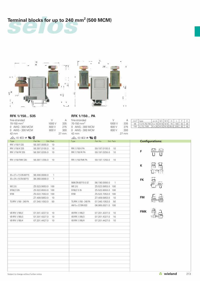
selos
Type Part No. Std. Pack Type Part No. Std. Pack
RFK 1/150 F S35 56.397.0055.0 10
RFK 1/150 K S35 56.397.0155.0 10
RFK 1/150 FK S35 56.397.0255.0 10
RFK 1/150 FMK S35 56.397.1255.0 10
35 x 27 x 7,5 EN 60715 98.300.0000.0 1
35 x 24 x 15 EN 60715 98.360.0000.0 1
WE 2/U Z5.523.5653.0 100
9708/2 S35 Z5.522.8553.0 100
9708 Z5.522.7053.0 100
Z7.409.5853.0 10
TE/RFK 1/150 - 240 PA 07.340.1053.0 50
VB RFK 1/185/2 07.201.4227.0 10
VB RFK 1/185/3 07.201.4327.0 10
VB RFK 1/185/4 07.201.4427.0 10
RFK 1/150 K PA 59.197.0155.0 10
RFK 1/150 FK PA 59.197.0255.0 10
RFK 1/150 FMK PA 59.197.1255.0 10
9006 EN 60715 G-32 98.190.0000.0 1
WE 2/U Z5.523.5653.0 100
9708/2 S 35 Z5.522.8553.0 100
9708 Z5.522.7053.0 100
Z7.409.5853.0 10
TE/RFK 1/150 - 240 PA 07.340.1053.0 50
AM 5 x 12 DIN 933 06.065.0021.0 100
VB RFK 1/185/2 07.201.4227.0 10
VB RFK 1/185/3 07.201.4327.0 10
VB RFK 1/185/4 07.201.4427.0 10
RFK 1/150... S35
fine-stranded V A70-150 mm2 1000 V 3350 AWG - 300 MCM 600 V 2750 AWG - 300 MCM 600 V 30042 mm 27 mm
gou+qw
RFK 1/150... PA
fine-stranded V A70-150 mm2 1000 V 3350 AWG - 300 MCM 600 V 2750 AWG - 300 MCM 600 V 30042 mm 27 mm
gou+qw
Terminal blocks for up to 240 mm2 (500 MCM)
Configurations:
F
K
FK
FM
FMK
mm2 type a x b M I M II H L F E95 F, K, FK, FM, FMK 5 x 18 M10 M 8 78 180 92 46150 K, FK, FMK 6 x 26 M12 M10 85.5 200 92 46
213Subject to change without further notice
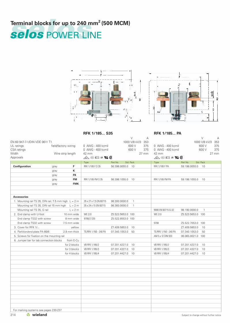
selosselos POWER LINETerminal blocks for up to 240 mm2 (500 MCM)
Type Part No. Std. Pack Type Part No. Std. Pack
EN 60 947-7-1/DIN VDE 0611 T1UL ratings field/factory wiringCSA ratingsWidth Wire strip lengthApprovals
RFK 1/185... PA
V A1000 V/8 kV/3 353
0 AWG - 400 kcmil 600 V 3750 AWG - 400 kcmil 600 V 37542 mm 27 mm
gou+qwRFK 1/185 F S 35 56.398.0055.0 10
RFK 1/185 FM S 35 56.398.1055.0 10
35 x 27 x 7,5 EN 60715 98.300.0000.0 1
35 x 24 x 15 EN 60715 98.360.0000.0 1
WE 2/U Z5.523.5653.0 100
9708/2 S35 Z5.522.8553.0 100
Z7.409.5853.0 10
TE/RFK 1/150 - 240 PA 07.340.1053.0 50
VB RFK 1/185/2 07.201.4227.0 10
VB RFK 1/185/3 07.201.4327.0 10
VB RFK 1/185/4 07.201.4427.0 10
RFK 1/185 F PA 59.198.0055.0 10
RFK 1/185 FM PA 59.198.1055.0 10
9006 EN 60715 G-32 98.190.0000.0 1
WE 2/U Z5.523.5653.0 100
9708 Z5.522.7053.0 100
Z7.409.5853.0 10
TE/RFK 1/150 - 240 PA 07.340.1053.0 50
AM 5 x 12 DIN 933 06.065.0021.0 100
VB RFK 1/185/2 07.201.4227.0 10
VB RFK 1/185/3 07.201.4327.0 10
VB RFK 1/185/4 07.201.4427.0 10
RFK 1/185... S35
V A1000 V/8 kV/3 353
0 AWG - 400 kcmil 600 V 3750 AWG - 400 kcmil 600 V 37542 mm 27 mm
gou+qwConfiguration gray F
gray K
gray FK
gray FM
gray FMK
Accessories
1. Mounting rail TS 35, DIN rail, 7.5 mm high L = 2 m
Mounting rail TS 35, DIN rail 15 mm high L = 2 m
Mounting rail TS 35, G rail L = 2 m
2. End clamp with U-foot 10 mm wide
End clamp TS32 with screw 8 mm wide
End clamp TS32 with screw 7.5 mm wide
3. Cover for RFK 1/... yellow
4. Partition/end plate PA 66/6 2.8 mm thick
5. Screws for fixation on the mounting rail
6. Jumper bar for tab connection blocks from E-Cu
for 2 blocks
for 3 blocks
for 4 blocks
For marking systems see pages 230-237
214 Subject to change without further notice

selosTerminal blocks for up to 240 mm2 (500 MCM)
Type Part No. Std. Pack Type Part No. Std. Pack
RFK 1/240 F S 35*) 56.399.0055.0 10
RFK 1/240 K S 35 56.399.0155.0 10
RFK 1/240 FK S 35*) 56.399.0255.0 10
RFK 1/240 FM S 35*) 56.399.1055.0 10
RFK 1/240 FMK S 35*) 56.399.1255.0 10
35 x 27 x 7,5 EN 60715 98.300.0000.0 1
35 x 24 x 15 EN 60715 98.360.0000.0 1
WE 2/U Z5.523.5653.0 100
9708/2 S 35 Z5.522.8553.0 100
Z7.409.5853.0 10
TE/RFK 1/150 - 240 PA 07.340.1053.0 50
VB RFK 1/240/2 07.201.8227.0 10
VB RFK 1/240/3 07.201.8327.0 10
VB RFK 1/240/4 07.201.8427.0 10
*) Only use ring terminals according to DIN 46234
RFK 1/240 F PA*) 59.199.0055.0 10
RFK 1/240 K PA 59.199.0155.0 10
RFK 1/240 FK PA*) 59.199.0255.0 10
RFK 1/240 FM PA*) 59.199.1055.0 10
RFK 1/240 FMK PA*) 59.199.1255.0 10
9006 EN 60715 G-32 98.190.0000.0 1
WE 2/U Z5.523.5653.0 100
9708 Z5.522.7053.0 100
Z7.409.5853.0 10
TE/RFK 1/150 - 240 PA 07.340.1053.0 50
AM 5 x 12 DIN 933 06.065.0021.0 100
VB RFK 1/240/2 07.201.8227.0 10
VB RFK 1/240/3 07.201.8327.0 10
VB RFK 1/240/4 07.201.8427.0 10
RFK 1/240... S35
fine-stranded stranded V A70-240 mm2 70-240 mm2 1000 V/8 kV/3 415
0 AWG - 500 kcmil 600 V 3753/0 AWG - 500 kcmil 600 V 42542 mm 27 mm
gou+qw
RFK 1/240... PA
fine-stranded stranded V A70-240 mm2 70-240 mm2 1000 V/8 kV/3 415
0 AWG - 500 kcmil 600 V 3753/0 AWG - 500 kcmil 600 V 42542 mm 27 mm
gou+qwConfigurations:
F
K
FK
FM
FMK
mm2 type a x b M I M II H L F E185 F, FM 6 x 26 M 12 – – 200 92 46
F, FM 8 x 26 M 12 – – 200 92 46240 FK, FMK 8 x 26 M 12 M 12 100.5 200 102 46
K 8 x 26 – M 12 100.5 200 112 56
215Subject to change without further notice
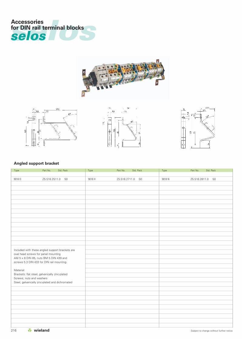
216 Subject to change without further notice
selosselos Accessoriesfor DIN rail terminal blocks
Type Part No. Std. Pack Type Part No. Std. Pack Type Part No. Std. Pack
Angled support bracket
9018 H Z5.516.2711.0 50 9018 N Z5.516.2811.0 509018 D Z5.516.2511.0 50
Included with these angled support brackets are oval head screws for panel mountingAM 5 x 8 DIN 85, nuts BM 5 DIN 439 and screws 5.3 DIN 433 for DIN rail mounting.
Material:Brackets: flat steel, galvanically zinc-platedScrews, nuts and washersSteel, galvanically zinc-plated and dichromated

217Subject to change without further notice
selosAccessoriesfor DIN rail terminal blocks
Type Part No. Std. Pack Type Part No. Std. Pack Type Part No. Std. Pack
WK 4 TKM/U
WK 4/U
WK 4 TKS D/U
WK 4 TKG-TRST/U
0.5 mm thick2 pole VB 0,5 WK 4..-2 07.255.0227.0 503 pole VB 0,5 WK 4..-3 07.255.0327.0 504 pole VB 0,5 WK 4..-4 07.255.0427.0 505 pole VB 0,5 WK 4..-5 07.255.0527.0 106 pole VB 0,5 WK 4..-6 07.255.0627.0 107 pole VB 0,5 WK 4..-7 07.255.0727.0 508 pole VB 0,5 WK 4..-8 07.255.0827.0 109 pole VB 0,5 WK 4..-9 07.255.0927.0 50
10 pole VB 0,5 WK 4..-10 07.255.1027.0 5011 pole VB 0,5 WK 4..-11 07.255.1127.0 5012 pole VB 0,5 WK 4..-12 07.255.1227.0 1070 pole VB 0,5 WK 4.. M-70 07.255.0027.0 10
1 mm thick2 pole VB 1 WK 4..-2 07.255.4227.0 103 pole VB 1 WK 4..-3 07.255.4327.0 104 pole VB 1 WK 4..-4 07.255.4427.0 105 pole VB 1 WK 4..-5 07.255.4527.0 106 pole VB 1 WK 4..-6 07.255.4627.0 107 pole VB 1 WK 4..-7 07.255.4727.0 108 pole VB 1 WK 4..-8 07.255.4827.0 109 pole VB 1 WK 4..-9 07.255.4927.0 10
10 pole VB 1 WK 4..-10 07.255.5027.0 1011 pole VB 1 WK 4..-11 07.255.5127.0 1012 pole VB 1 WK 4..-12 07.255.5227.0 1070 pole VB 1 WK 4.. M-70 07.255.4027.0 10
05.563.5500.0 1WK 4 E/U
1 mm thick2 pole VB WK 4 E-2 07.255.2227.0 103 pole VB WK 4 E-3 07.255.2327.0 104 pole VB WK 4 E-4 07.255.2427.0 105 pole VB WK 4 E-5 07.255.2527.0 106 pole VB WK 4 E-6 07.255.2627.0 107 pole VB WK 4 E-7 07.255.2727.0 108 pole VB WK 4 E-8 07.255.2827.0 109 pole VB WK 4 E-9 07.255.2927.0 10
10 pole VB WK 4 E-10 07.255.3027.0 1011 pole VB WK 4 E-11 07.255.3127.0 1012 pole VB WK 4 E-12 07.255.3227.0 1070 pole VB WK 4 EM-70 07.255.2027.0 10
1 mm thick, angled2 pole VBS WK 4 E-2 07.256.4227.0 103 pole VBS WK 4 E-3 07.256.4327.0 104 pole VBS WK 4 E-4 07.256.4427.0 105 pole VBS WK 4 E-5 07.256.4527.0 106 pole VBS WK 4 E-6 07.256.4627.0 107 pole VBS WK 4 E-7 07.256.4727.0 108 pole VBS WK 4 E-8 07.256.4827.0 109 pole VBS WK 4 E-9 07.256.4927.0 10
10 pole VBS WK 4 E-10 07.256.5027.0 1011 pole VBS WK 4 E-11 07.256.5127.0 1012 pole VBS WK 4 E-12 07.256.5227.0 10
Jumper combs, uninsulated
(for rated voltages of up to 50 V)Label with handling instructions
selos
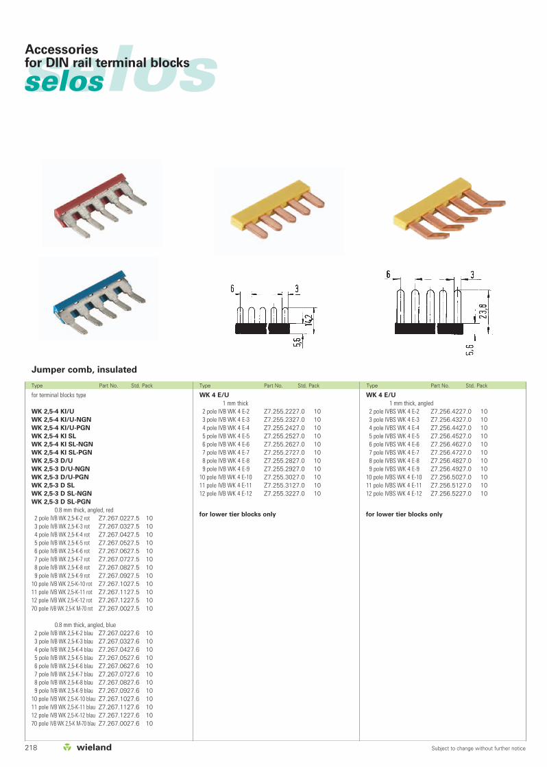
218 Subject to change without further notice
selosselos Accessoriesfor DIN rail terminal blocks
Type Part No. Std. Pack Type Part No. Std. Pack Type Part No. Std. Pack
for terminal blocks type
WK 2,5-4 KI/U
WK 2,5-4 KI/U-NGN
WK 2,5-4 KI/U-PGN
WK 2,5-4 KI SL
WK 2,5-4 KI SL-NGN
WK 2,5-4 KI SL-PGN
WK 2,5-3 D/U
WK 2,5-3 D/U-NGN
WK 2,5-3 D/U-PGN
WK 2,5-3 D SL
WK 2,5-3 D SL-NGN
WK 2,5-3 D SL-PGN
0.8 mm thick, angled, red2 pole IVB WK 2,5-K-2 rot Z7.267.0227.5 103 pole IVB WK 2,5-K-3 rot Z7.267.0327.5 104 pole IVB WK 2,5-K-4 rot Z7.267.0427.5 105 pole IVB WK 2,5-K-5 rot Z7.267.0527.5 106 pole IVB WK 2,5-K-6 rot Z7.267.0627.5 107 pole IVB WK 2,5-K-7 rot Z7.267.0727.5 108 pole IVB WK 2,5-K-8 rot Z7.267.0827.5 109 pole IVB WK 2,5-K-9 rot Z7.267.0927.5 10
10 pole IVB WK 2,5-K-10 rot Z7.267.1027.5 1011 pole IVB WK 2,5-K-11 rot Z7.267.1127.5 1012 pole IVB WK 2,5-K-12 rot Z7.267.1227.5 1070 pole IVB WK 2,5-K M-70 rot Z7.267.0027.5 10
0.8 mm thick, angled, blue2 pole IVB WK 2,5-K-2 blau Z7.267.0227.6 103 pole IVB WK 2,5-K-3 blau Z7.267.0327.6 104 pole IVB WK 2,5-K-4 blau Z7.267.0427.6 105 pole IVB WK 2,5-K-5 blau Z7.267.0527.6 106 pole IVB WK 2,5-K-6 blau Z7.267.0627.6 107 pole IVB WK 2,5-K-7 blau Z7.267.0727.6 108 pole IVB WK 2,5-K-8 blau Z7.267.0827.6 109 pole IVB WK 2,5-K-9 blau Z7.267.0927.6 10
10 pole IVB WK 2,5-K-10 blau Z7.267.1027.6 1011 pole IVB WK 2,5-K-11 blau Z7.267.1127.6 1012 pole IVB WK 2,5-K-12 blau Z7.267.1227.6 1070 pole IVB WK 2,5-K M-70 blau Z7.267.0027.6 10
WK 4 E/U
1 mm thick, angled2 pole IVBS WK 4 E-2 Z7.256.4227.0 103 pole IVBS WK 4 E-3 Z7.256.4327.0 104 pole IVBS WK 4 E-4 Z7.256.4427.0 105 pole IVBS WK 4 E-5 Z7.256.4527.0 106 pole IVBS WK 4 E-6 Z7.256.4627.0 107 pole IVBS WK 4 E-7 Z7.256.4727.0 108 pole IVBS WK 4 E-8 Z7.256.4827.0 109 pole IVBS WK 4 E-9 Z7.256.4927.0 10
10 pole IVBS WK 4 E-10 Z7.256.5027.0 1011 pole IVBS WK 4 E-11 Z7.256.5127.0 1012 pole IVBS WK 4 E-12 Z7.256.5227.0 10
for lower tier blocks only
WK 4 E/U
1 mm thick2 pole IVB WK 4 E-2 Z7.255.2227.0 103 pole IVB WK 4 E-3 Z7.255.2327.0 104 pole IVB WK 4 E-4 Z7.255.2427.0 105 pole IVB WK 4 E-5 Z7.255.2527.0 106 pole IVB WK 4 E-6 Z7.255.2627.0 107 pole IVB WK 4 E-7 Z7.255.2727.0 108 pole IVB WK 4 E-8 Z7.255.2827.0 109 pole IVB WK 4 E-9 Z7.255.2927.0 10
10 pole IVB WK 4 E-10 Z7.255.3027.0 1011 pole IVB WK 4 E-11 Z7.255.3127.0 1012 pole IVB WK 4 E-12 Z7.255.3227.0 10
for lower tier blocks only
Jumper comb, insulated

219Subject to change without further notice
selosAccessoriesfor DIN rail terminal blocks
Type Part No. Std. Pack Type Part No. Std. Pack Type Part No. Std. Pack
for terminal block type
WK 2,5/U Z7.269.4023.0 50
WK 4/U Z7.269.4123.0 50
WK 6/U Z7.269.4223.0 50
WK 4 E/.. Z7.269.2923.0 50
WKM 2,5 Z7.269.3623.0 50
WKM 4 Z7.269.0623.0 50
Selectable connecting links reduce the
nominal voltage to 380 V!
Link: nickel-plated brass
Bolt: nickel-plated brass
Screw: zinc-plated steel
WK 4 TKG/U
WK 4 TKM/U
WK 4/U
WK 4 TKS D/U
WK 4 TKG-TRST/U
0.5 mm thick2 pole IVB 0,5 WK 4..-2 Z7.255.0227.0 103 pole IVB 0,5 WK 4..-3 Z7.255.0327.0 104 pole IVB 0,5 WK 4..-4 Z7.255.0427.0 105 pole IVB 0,5 WK 4..-5 Z7.255.0527.0 106 pole IVB 0,5 WK 4..-6 Z7.255.0627.0 107 pole IVB 0,5 WK 4..-7 Z7.255.0727.0 108 pole IVB 0,5 WK 4..-8 Z7.255.0827.0 109 pole IVB 0,5 WK 4..-9 Z7.255.0927.0 10
10 pole IVB 0,5 WK 4..-10 Z7.255.1027.0 1011 pole IVB 0,5 WK 4..-11 Z7.255.1127.0 1012 pole IVB 0,5 WK 4..-12 Z7.255.1227.0 10
1 mm thick2 pole IVB 1 WK 4..-2 Z7.255.4227.0 103 pole IVB 1 WK 4..-3 Z7.255.4327.0 104 pole IVB 1 WK 4..-4 Z7.255.4427.0 105 pole IVB 1 WK 4..-5 Z7.255.4527.0 106 pole IVB 1 WK 4..-6 Z7.255.4627.0 107 pole IVB 1 WK 4..-7 Z7.255.4727.0 108 pole IVB 1 WK 4..-8 Z7.255.4827.0 109 pole IVB 1 WK 4..-9 Z7.255.4927.0 10
10 pole IVB 1 WK 4..-10 Z7.255.5027.0 1011 pole IVB 1 WK 4..-11 Z7.255.5127.0 1012 pole IVB 1 WK 4..-12 Z7.255.5227.0 10
Selectable connecting link
Jumper comb, insulated
for installation blocks
for terminal block type
WKI 4 D-D
WKI 4 DU
WKI 4 N-D-SL
WKI 4 NT-D-SL... (and variations)
WKI 4 NTN-D-SL
WKI 4 TGK-D-SL
WKI 4 D-D-SL
0.5 mm thick, 6 mm spacing yellow2 pole IVB 0,5 WK 4..-2 Z7.255.0227.0 103 pole IVB 0,5 WK 4..-3 Z7.255.0327.0 104 pole IVB 0,5 WK 4..-4 Z7.255.0427.0 105 pole IVB 0,5 WK 4..-5 Z7.255.0527.0 106 pole IVB 0,5 WK 4..-6 Z7.255.0627.0 107 pole IVB 0,5 WK 4..-7 Z7.255.0727.0 108 pole IVB 0,5 WK 4..-8 Z7.255.0827.0 109 pole IVB 0,5 WK 4..-9 Z7.255.0927.0 10
10 pole IVB 0,5 WK 4..-10 Z7.255.1027.0 1011 pole IVB 0,5 WK 4..-11 Z7.255.1127.0 1012 pole IVB 0,5 WK 4..-12 Z7.255.1227.0 10
1 mm thick, 6 mm spacing yellow2 pole IVB 1 WK 4..-2 Z7.255.4227.0 103 pole IVB 1 WK 4..-3 Z7.255.4327.0 104 pole IVB 1 WK 4..-4 Z7.255.4427.0 105 pole IVB 1 WK 4..-5 Z7.255.4527.0 106 pole IVB 1 WK 4..-6 Z7.255.4627.0 107 pole IVB 1 WK 4..-7 Z7.255.4727.0 108 pole IVB 1 WK 4..-8 Z7.255.4827.0 109 pole IVB 1 WK 4..-9 Z7.255.4927.0 10
10 pole IVB 1 WK 4..-10 Z7.255.5027.0 1011 pole IVB 1 WK 4..-11 Z7.255.5127.0 1012 pole IVB 1 WK 4..-12 Z7.255.5227.0 10
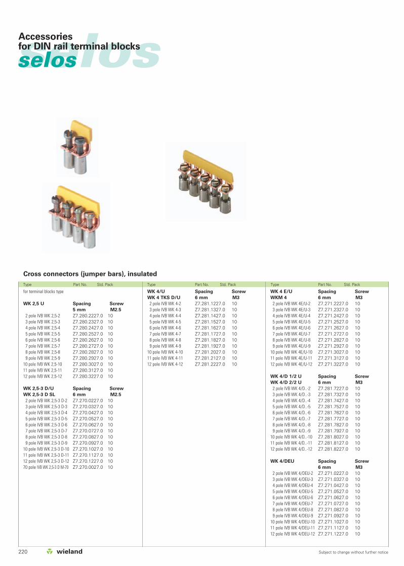
220 Subject to change without further notice
selosselos Accessoriesfor DIN rail terminal blocks
Type Part No. Std. Pack Type Part No. Std. Pack Type Part No. Std. Pack
for terminal blocks type
WK 2,5 U Spacing Screw
5 mm M2.5
2 pole IVB WK 2,5-2 Z7.280.2227.0 103 pole IVB WK 2,5-3 Z7.280.2327.0 104 pole IVB WK 2,5-4 Z7.280.2427.0 105 pole IVB WK 2,5-5 Z7.280.2527.0 106 pole IVB WK 2,5-6 Z7.280.2627.0 107 pole IVB WK 2,5-7 Z7.280.2727.0 108 pole IVB WK 2,5-8 Z7.280.2827.0 109 pole IVB WK 2,5-9 Z7.280.2927.0 10
10 pole IVB WK 2,5-10 Z7.280.3027.0 1011 pole IVB WK 2,5-11 Z7.280.3127.0 1012 pole IVB WK 2,5-12 Z7.280.3227.0 10
WK 2,5-3 D/U Spacing Screw
WK 2,5-3 D SL 6 mm M2.5
2 pole IVB WK 2,5-3 D-2 Z7.270.0227.0 103 pole IVB WK 2,5-3 D-3 Z7.270.0327.0 104 pole IVB WK 2,5-3 D-4 Z7.270.0427.0 105 pole IVB WK 2,5-3 D-5 Z7.270.0527.0 106 pole IVB WK 2,5-3 D-6 Z7.270.0627.0 107 pole IVB WK 2,5-3 D-7 Z7.270.0727.0 108 pole IVB WK 2,5-3 D-8 Z7.270.0827.0 109 pole IVB WK 2,5-3 D-9 Z7.270.0927.0 10
10 pole IVB WK 2,5-3 D-10 Z7.270.1027.0 1011 pole IVB WK 2,5-3 D-11 Z7.270.1127.0 1012 pole IVB WK 2,5-3 D-12 Z7.270.1227.0 1070 pole IVB WK 2,5-3 D M-70 Z7.270.0027.0 10
WK 4 E/U Spacing Screw
WKM 4 6 mm M3
2 pole IVB WK 4E/U-2 Z7.271.2227.0 103 pole IVB WK 4E/U-3 Z7.271.2327.0 104 pole IVB WK 4E/U-4 Z7.271.2427.0 105 pole IVB WK 4E/U-5 Z7.271.2527.0 106 pole IVB WK 4E/U-6 Z7.271.2627.0 107 pole IVB WK 4E/U-7 Z7.271.2727.0 108 pole IVB WK 4E/U-8 Z7.271.2827.0 109 pole IVB WK 4E/U-9 Z7.271.2927.0 10
10 pole IVB WK 4E/U-10 Z7.271.3027.0 1011 pole IVB WK 4E/U-11 Z7.271.3127.0 1012 pole IVB WK 4E/U-12 Z7.271.3227.0 10
WK 4/D 1/2 U Spacing Screw
WK 4/D 2/2 U 6 mm M3
2 pole IVB WK 4/D..-2 Z7.281.7227.0 103 pole IVB WK 4/D..-3 Z7.281.7327.0 104 pole IVB WK 4/D..-4 Z7.281.7427.0 105 pole IVB WK 4/D..-5 Z7.281.7527.0 106 pole IVB WK 4/D..-6 Z7.281.7627.0 107 pole IVB WK 4/D..-7 Z7.281.7727.0 108 pole IVB WK 4/D..-8 Z7.281.7827.0 109 pole IVB WK 4/D..-9 Z7.281.7927.0 10
10 pole IVB WK 4/D..-10 Z7.281.8027.0 1011 pole IVB WK 4/D..-11 Z7.281.8127.0 1012 pole IVB WK 4/D..-12 Z7.281.8227.0 10
WK 4/DEU Spacing Screw
6 mm M3
2 pole IVB WK 4/DEU-2 Z7.271.0227.0 103 pole IVB WK 4/DEU-3 Z7.271.0327.0 104 pole IVB WK 4/DEU-4 Z7.271.0427.0 105 pole IVB WK 4/DEU-5 Z7.271.0527.0 106 pole IVB WK 4/DEU-6 Z7.271.0627.0 107 pole IVB WK 4/DEU-7 Z7.271.0727.0 108 pole IVB WK 4/DEU-8 Z7.271.0827.0 109 pole IVB WK 4/DEU-9 Z7.271.0927.0 10
10 pole IVB WK 4/DEU-10 Z7.271.1027.0 1011 pole IVB WK 4/DEU-11 Z7.271.1127.0 1012 pole IVB WK 4/DEU-12 Z7.271.1227.0 10
WK 4/U Spacing Screw
WK 4 TKS D/U 6 mm M3
2 pole IVB WK 4-2 Z7.281.1227.0 103 pole IVB WK 4-3 Z7.281.1327.0 104 pole IVB WK 4-4 Z7.281.1427.0 105 pole IVB WK 4-5 Z7.281.1527.0 106 pole IVB WK 4-6 Z7.281.1627.0 107 pole IVB WK 4-7 Z7.281.1727.0 108 pole IVB WK 4-8 Z7.281.1827.0 109 pole IVB WK 4-9 Z7.281.1927.0 10
10 pole IVB WK 4-10 Z7.281.2027.0 1011 pole IVB WK 4-11 Z7.281.2127.0 1012 pole IVB WK 4-12 Z7.281.2227.0 10
Cross connectors (jumper bars), insulated
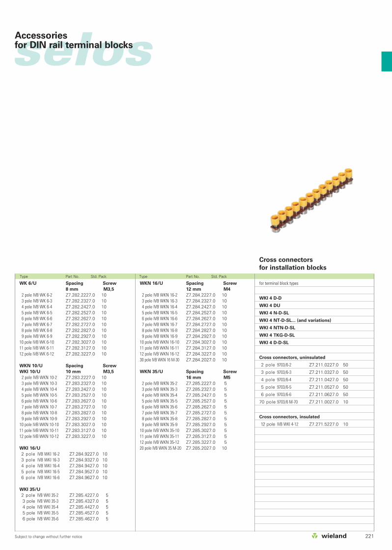
221Subject to change without further notice
selosAccessoriesfor DIN rail terminal blocks
Type Part No. Std. Pack Type Part No. Std. Pack
WKN 16/U Spacing Screw
12 mm M4
2 pole IVB WKN 16-2 Z7.284.2227.0 103 pole IVB WKN 16-3 Z7.284.2327.0 104 pole IVB WKN 16-4 Z7.284.2427.0 105 pole IVB WKN 16-5 Z7.284.2527.0 106 pole IVB WKN 16-6 Z7.284.2627.0 107 pole IVB WKN 16-7 Z7.284.2727.0 108 pole IVB WKN 16-8 Z7.284.2827.0 109 pole IVB WKN 16-9 Z7.284.2927.0 10
10 pole IVB WKN 16-10 Z7.284.3027.0 1011 pole IVB WKN 16-11 Z7.284.3127.0 1012 pole IVB WKN 16-12 Z7.284.3227.0 1030 pole IVB WKN 16 M-30 Z7.284.2027.0 10
WKN 35/U Spacing Screw
16 mm M5
2 pole IVB WKN 35-2 Z7.285.2227.0 53 pole IVB WKN 35-3 Z7.285.2327.0 54 pole IVB WKN 35-4 Z7.285.2427.0 55 pole IVB WKN 35-5 Z7.285.2527.0 56 pole IVB WKN 35-6 Z7.285.2627.0 57 pole IVB WKN 35-7 Z7.285.2727.0 58 pole IVB WKN 35-8 Z7.285.2827.0 59 pole IVB WKN 35-9 Z7.285.2927.0 5
10 pole IVB WKN 35-10 Z7.285.3027.0 511 pole IVB WKN 35-11 Z7.285.3127.0 512 pole IVB WKN 35-12 Z7.285.3227.0 520 pole IVB WKN 35 M-20 Z7.285.2027.0 10
WK 6/U Spacing Screw
8 mm M3,5
2 pole IVB WK 6-2 Z7.282.2227.0 103 pole IVB WK 6-3 Z7.282.2327.0 104 pole IVB WK 6-4 Z7.282.2427.0 105 pole IVB WK 6-5 Z7.282.2527.0 106 pole IVB WK 6-6 Z7.282.2627.0 107 pole IVB WK 6-7 Z7.282.2727.0 108 pole IVB WK 6-8 Z7.282.2827.0 109 pole IVB WK 6-9 Z7.282.2927.0 10
10 pole IVB WK 6-10 Z7.282.3027.0 1011 pole IVB WK 6-11 Z7.282.3127.0 1012 pole IVB WK 6-12 Z7.282.3227.0 10
WKN 10/U Spacing Screw
WKI 10/U 10 mm M3,5
2 pole IVB WKN 10-2 Z7.283.2227.0 103 pole IVB WKN 10-3 Z7.283.2327.0 104 pole IVB WKN 10-4 Z7.283.2427.0 105 pole IVB WKN 10-5 Z7.283.2527.0 106 pole IVB WKN 10-6 Z7.283.2627.0 107 pole IVB WKN 10-7 Z7.283.2727.0 108 pole IVB WKN 10-8 Z7.283.2827.0 109 pole IVB WKN 10-9 Z7.283.2927.0 10
10 pole IVB WKN 10-10 Z7.283.3027.0 1011 pole IVB WKN 10-11 Z7.283.3127.0 1012 pole IVB WKN 10-12 Z7.283.3227.0 10
WKI 16/U
2 pole IVB WKI 16-2 Z7.284.9227.0 103 pole IVB WKI 16-3 Z7.284.9327.0 104 pole IVB WKI 16-4 Z7.284.9427.0 105 pole IVB WKI 16-5 Z7.284.9527.0 106 pole IVB WKI 16-6 Z7.284.9627.0 10
WKI 35/U
2 pole IVB WKI 35-2 Z7.285.4227.0 53 pole IVB WKI 35-3 Z7.285.4327.0 54 pole IVB WKI 35-4 Z7.285.4427.0 55 pole IVB WKI 35-5 Z7.285.4527.0 56 pole IVB WKI 35-6 Z7.285.4627.0 5
Cross connectors
for installation blocks
for terminal block types
WKI 4 D-D
WKI 4 DU
WKI 4 N-D-SL
WKI 4 NT-D-SL... (and variations)
WKI 4 NTN-D-SL
WKI 4 TKG-D-SL
WKI 4 D-D-SL
Cross connectors, uninsulated
2 pole 9703/6-2 Z7.211.0227.0 50
3 pole 9703/6-3 Z7.211.0327.0 50
4 pole 9703/6-4 Z7.211.0427.0 50
5 pole 9703/6-5 Z7.211.0527.0 50
6 pole 9703/6-6 Z7.211.0627.0 50
70 pole 9703/6 M-70 Z7.211.0027.0 10
Cross connectors, insulated
12 pole IVB WKI 4-12 Z7.271.5227.0 10
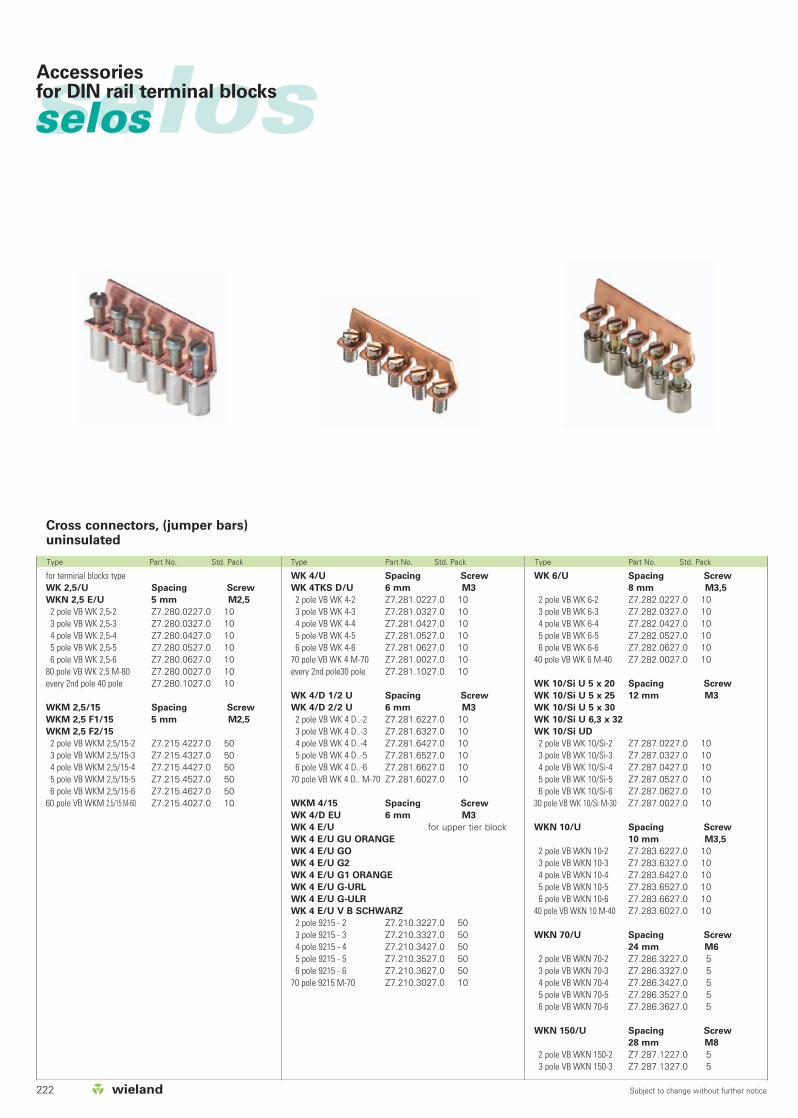
222 Subject to change without further notice
selosselos Accessoriesfor DIN rail terminal blocks
Type Part No. Std. Pack Type Part No. Std. Pack Type Part No. Std. Pack
for terminal blocks typeWK 2,5/U Spacing Screw
WKN 2,5 E/U 5 mm M2,5
2 pole VB WK 2,5-2 Z7.280.0227.0 103 pole VB WK 2,5-3 Z7.280.0327.0 104 pole VB WK 2,5-4 Z7.280.0427.0 105 pole VB WK 2,5-5 Z7.280.0527.0 106 pole VB WK 2,5-6 Z7.280.0627.0 10
80 pole VB WK 2,5 M-80 Z7.280.0027.0 10every 2nd pole 40 pole Z7.280.1027.0 10
WKM 2,5/15 Spacing Screw
WKM 2,5 F1/15 5 mm M2,5
WKM 2,5 F2/15
2 pole VB WKM 2,5/15-2 Z7.215.4227.0 503 pole VB WKM 2,5/15-3 Z7.215.4327.0 504 pole VB WKM 2,5/15-4 Z7.215.4427.0 505 pole VB WKM 2,5/15-5 Z7.215.4527.0 506 pole VB WKM 2,5/15-6 Z7.215.4627.0 50
60 pole VB WKM 2,5/15 M-60 Z7.215.4027.0 10
WK 6/U Spacing Screw
8 mm M3,5
2 pole VB WK 6-2 Z7.282.0227.0 103 pole VB WK 6-3 Z7.282.0327.0 104 pole VB WK 6-4 Z7.282.0427.0 105 pole VB WK 6-5 Z7.282.0527.0 106 pole VB WK 6-6 Z7.282.0627.0 10
40 pole VB WK 6 M-40 Z7.282.0027.0 10
WK 10/Si U 5 x 20 Spacing Screw
WK 10/Si U 5 x 25 12 mm M3
WK 10/Si U 5 x 30
WK 10/Si U 6,3 x 32
WK 10/Si UD
2 pole VB WK 10/Si-2 Z7.287.0227.0 103 pole VB WK 10/Si-3 Z7.287.0327.0 104 pole VB WK 10/Si-4 Z7.287.0427.0 105 pole VB WK 10/Si-5 Z7.287.0527.0 106 pole VB WK 10/Si-6 Z7.287.0627.0 10
30 pole VB WK 10/Si M-30 Z7.287.0027.0 10
WKN 10/U Spacing Screw
10 mm M3,5
2 pole VB WKN 10-2 Z7.283.6227.0 103 pole VB WKN 10-3 Z7.283.6327.0 104 pole VB WKN 10-4 Z7.283.6427.0 105 pole VB WKN 10-5 Z7.283.6527.0 106 pole VB WKN 10-6 Z7.283.6627.0 10
40 pole VB WKN 10 M-40 Z7.283.6027.0 10
WKN 70/U Spacing Screw
24 mm M6
2 pole VB WKN 70-2 Z7.286.3227.0 53 pole VB WKN 70-3 Z7.286.3327.0 54 pole VB WKN 70-4 Z7.286.3427.0 55 pole VB WKN 70-5 Z7.286.3527.0 56 pole VB WKN 70-6 Z7.286.3627.0 5
WKN 150/U Spacing Screw
28 mm M8
2 pole VB WKN 150-2 Z7.287.1227.0 53 pole VB WKN 150-3 Z7.287.1327.0 5
WK 4/U Spacing Screw
WK 4TKS D/U 6 mm M3
2 pole VB WK 4-2 Z7.281.0227.0 103 pole VB WK 4-3 Z7.281.0327.0 104 pole VB WK 4-4 Z7.281.0427.0 105 pole VB WK 4-5 Z7.281.0527.0 106 pole VB WK 4-6 Z7.281.0627.0 10
70 pole VB WK 4 M-70 Z7.281.0027.0 10every 2nd pole30 pole Z7.281.1027.0 10
WK 4/D 1/2 U Spacing Screw
WK 4/D 2/2 U 6 mm M3
2 pole VB WK 4 D..-2 Z7.281.6227.0 103 pole VB WK 4 D..-3 Z7.281.6327.0 104 pole VB WK 4 D..-4 Z7.281.6427.0 105 pole VB WK 4 D..-5 Z7.281.6527.0 106 pole VB WK 4 D..-6 Z7.281.6627.0 10
70 pole VB WK 4 D.. M-70 Z7.281.6027.0 10
WKM 4/15 Spacing Screw
WK 4/D EU 6 mm M3
WK 4 E/U for upper tier blockWK 4 E/U GU ORANGE
WK 4 E/U GO
WK 4 E/U G2
WK 4 E/U G1 ORANGE
WK 4 E/U G-URL
WK 4 E/U G-ULR
WK 4 E/U V B SCHWARZ
2 pole 9215 - 2 Z7.210.3227.0 503 pole 9215 - 3 Z7.210.3327.0 504 pole 9215 - 4 Z7.210.3427.0 505 pole 9215 - 5 Z7.210.3527.0 506 pole 9215 - 6 Z7.210.3627.0 50
70 pole 9215 M-70 Z7.210.3027.0 10
Cross connectors, (jumper bars)uninsulated

223
selos

224 Subject to change without further notice
selosselos Accessoriesfor DIN rail terminal blocks
Type Part No. Std. Pack Type Part No. Std. Pack
WK 4 E/U
WKM 4/15
AD VB 4/15 GELB 04.326.2953.8 10
WK6/U
WK 6 ETK/U
AD VB 6 GELB 04.326.2253.8 10
WKN 10 ETK/U
WKN 10/U
AD VB 10 GELB 04.326.2353.8 10
WK 10/Si U without marking facilities
04.312.2056.0 100
WKN 35/U
AD VB 35 GELB 04.326.2553.8 10
WKN 70/U
AD VB 70 GELB 04.326.2653.8 10
WKI 10
AD VB 10 GELB 04.326.2353.8 10
WKI 16
AD VB 16 GELB 04.326.2453.8 10
for terminal block type
WK 2,5/U
WK 2,5/E/U
AD VB 2,5 GELB 04.326.2053.8 10
WKM 2,5 F..
WKM 2,5/15
AD VB 2,5/15 GELB 04.326.3053.8 10
WK 4/U
WK 4 SL/35
WK 4 ETK/U
WK 4/D..
WK 4 TKS D/U
AD VB 4 GELB 04.326.2153.8 10
Single cover
for cross connector (jumper bar)
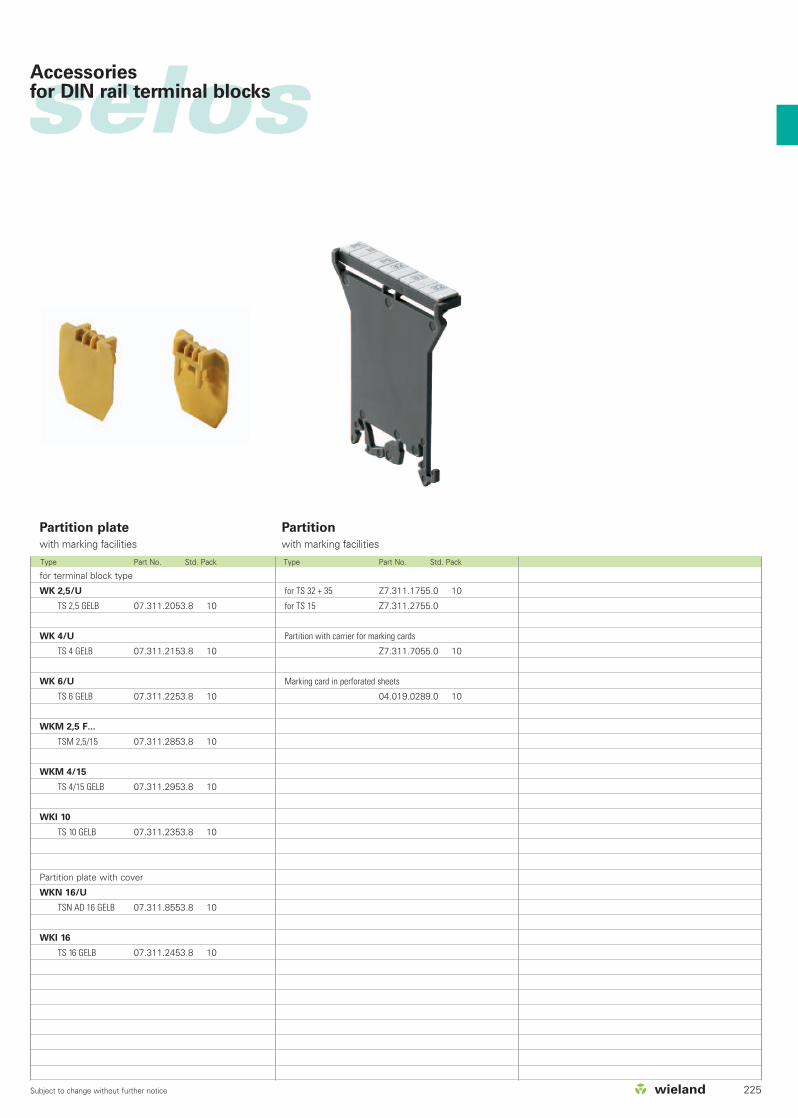
225Subject to change without further notice
selosAccessoriesfor DIN rail terminal blocks
Type Part No. Std. Pack Type Part No. Std. Pack
Partition
with marking facilitiesPartition plate
with marking facilities
for TS 32 + 35 Z7.311.1755.0 10
for TS 15 Z7.311.2755.0
Partition with carrier for marking cards
Z7.311.7055.0 10
Marking card in perforated sheets
04.019.0289.0 10
for terminal block type
WK 2,5/U
TS 2,5 GELB 07.311.2053.8 10
WK 4/U
TS 4 GELB 07.311.2153.8 10
WK 6/U
TS 6 GELB 07.311.2253.8 10
WKM 2,5 F...
TSM 2,5/15 07.311.2853.8 10
WKM 4/15
TS 4/15 GELB 07.311.2953.8 10
WKI 10
TS 10 GELB 07.311.2353.8 10
Partition plate with cover
WKN 16/U
TSN AD 16 GELB 07.311.8553.8 10
WKI 16
TS 16 GELB 07.311.2453.8 10
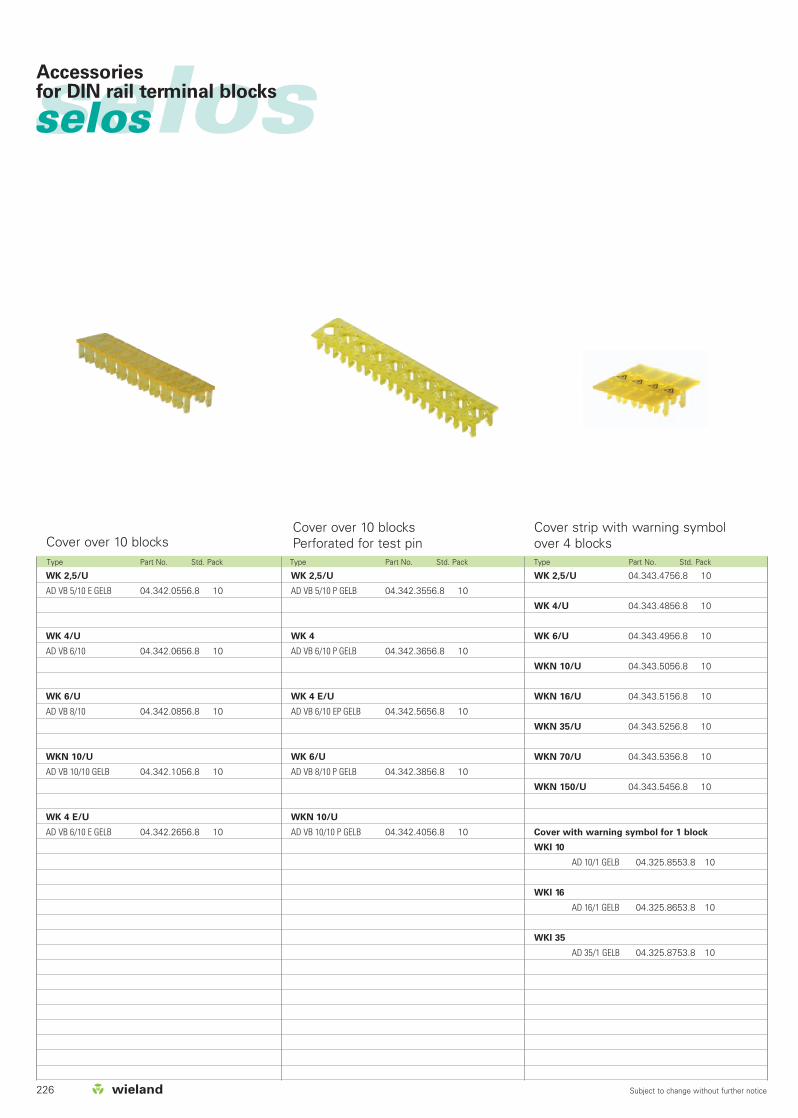
226 Subject to change without further notice
selosselos Accessoriesfor DIN rail terminal blocks
Type Part No. Std. Pack Type Part No. Std. Pack Type Part No. Std. Pack
WK 2,5/U
AD VB 5/10 E GELB 04.342.0556.8 10
WK 4/U
AD VB 6/10 04.342.0656.8 10
WK 6/U
AD VB 8/10 04.342.0856.8 10
WKN 10/U
AD VB 10/10 GELB 04.342.1056.8 10
WK 4 E/U
AD VB 6/10 E GELB 04.342.2656.8 10
WK 2,5/U 04.343.4756.8 10
WK 4/U 04.343.4856.8 10
WK 6/U 04.343.4956.8 10
WKN 10/U 04.343.5056.8 10
WKN 16/U 04.343.5156.8 10
WKN 35/U 04.343.5256.8 10
WKN 70/U 04.343.5356.8 10
WKN 150/U 04.343.5456.8 10
Cover with warning symbol for 1 block
WKI 10
AD 10/1 GELB 04.325.8553.8 10
WKI 16
AD 16/1 GELB 04.325.8653.8 10
WKI 35
AD 35/1 GELB 04.325.8753.8 10
WK 2,5/U
AD VB 5/10 P GELB 04.342.3556.8 10
WK 4
AD VB 6/10 P GELB 04.342.3656.8 10
WK 4 E/U
AD VB 6/10 EP GELB 04.342.5656.8 10
WK 6/U
AD VB 8/10 P GELB 04.342.3856.8 10
WKN 10/U
AD VB 10/10 P GELB 04.342.4056.8 10
Cover over 10 blocksCover over 10 blocksPerforated for test pin
Cover strip with warning symbolover 4 blocks
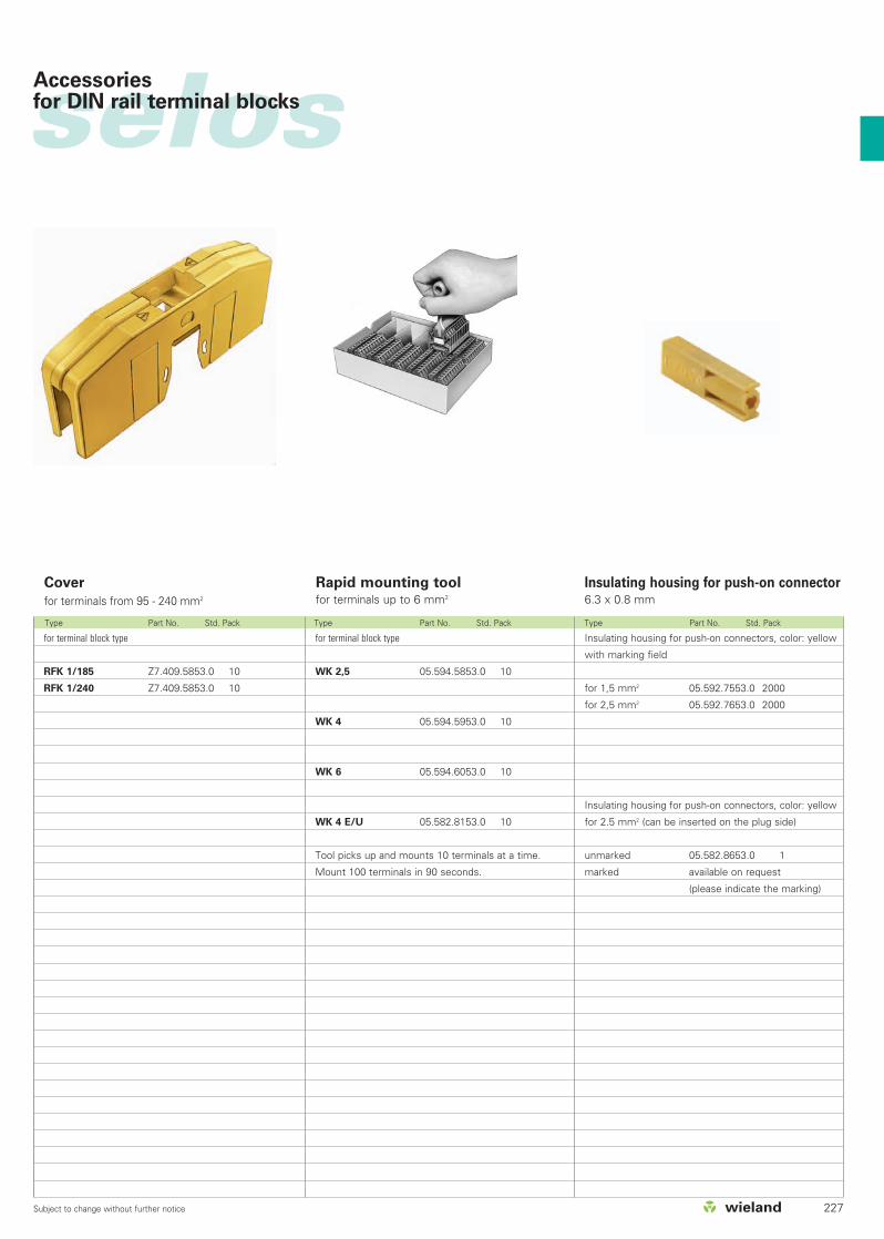
227Subject to change without further notice
selos
Type Part No. Std. Pack Type Part No. Std. Pack Type Part No. Std. Pack
for terminal block type
RFK 1/185 Z7.409.5853.0 10
RFK 1/240 Z7.409.5853.0 10
Cover
for terminals from 95 - 240 mm2
Rapid mounting toolfor terminals up to 6 mm2
Insulating housing for push-on connector6.3 x 0.8 mm
Insulating housing for push-on connectors, color: yellow
with marking field
for 1,5 mm2 05.592.7553.0 2000
for 2,5 mm2 05.592.7653.0 2000
Insulating housing for push-on connectors, color: yellow
for 2.5 mm2 (can be inserted on the plug side)
unmarked 05.582.8653.0 1
marked available on request
(please indicate the marking)
for terminal block type
WK 2,5 05.594.5853.0 10
WK 4 05.594.5953.0 10
WK 6 05.594.6053.0 10
WK 4 E/U 05.582.8153.0 10
Tool picks up and mounts 10 terminals at a time.
Mount 100 terminals in 90 seconds.
Accessoriesfor DIN rail terminal blocks

228 Subject to change without further notice
selosselosAccessoriesfor DIN rail terminal blocks
Test plug 250 V/2 A
WK 2,5
WKN 2,5 E/U
WK 2,5-3 D/U
WK 4 TKMP 3/U
WK 4 TKG-TRST P3/U
WK 4 TKS D/U
WK 2,5 U/8113 S/H
WK 4/U F1
WK 4/U F2
WK 4
WK 4/D1/2 U
WK 4/D2/2 U
WK 4/DEU
WK 4 E.../U
9290... ST 2/2,3 rot Z5.553.2921.0 10
ST 2/2,3 schwarz Z5.533.2921.1 50
ST 2/2,3 blau Z5.553.2921.6 100
WK 6 ST 2/4 Z5.553.3021.0 10
Test Sockets
WK 2,5
WKN 2,5 E/U
WK 2,5-3 D/U
WK 2,5-3 D SL
WK 2,5 U/8113 S/H 05.509.6021.0 10
WK 4
WK 4 TKS D/U
WK 4/U F1
WK 4/U F2 05.508.8921.0 10
WK 4/D1/2 U
WK 4/D2/2 U
WK 4/DEU
WK 4 E.../U 05.508.8821.0 10
Short-circuit plug
WK 4 TKG-TRST P3/U
WK 4/TKM.../U
WK 4 TKS D/U
WK 4/U F1
WK 4/U F2
9290... Z5.553.9400.0 100
Snap-on with
locking lever
for terminal block type
WK 4 230 V/2 A Z1.299.6153.0 10
WK 4 E/U 230 V/5 A Z1.299.9053.0 10
Test plug without locking lever
snap-on Z1.299.8153.0 10
For marking systems see pages 230-237
Test plug Short-circuit plug Test plug (tests off the current bar)
Type Part No. Std. Pack Type Part No. Std. Pack Type Part No. Std. Pack

229Subject to change without further notice
selos
Type Part No. Std. Pack
Accessoriesfor DIN rail terminal blocks
1 pole
without contact pin Z1.299.9253.0 10
1 pole
without contact pin
snap-on Z1.299.9453.0 10
10 pole without contact pins
with locking device and strain relief
marked 1 - 10
PST 10 WK 4 Z1.299.9553.0 10
Contact pin 05.549.1200.0 1
For marking systems see pages 230-237
Test plug (test off the screw)for WK 4 terminal blocks
with locking device and strain relief IImin = 10 mAImax = 3.5 AUmin = 10 VUmax = 250 V ~ 300 V…—
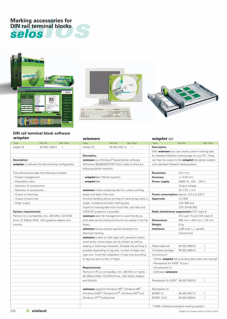
230 Subject to change without further notice
selosselos Marking accessories for DIN rail terminal blocks
Description
With wiemarc you can create custom marking data
for standard Wieland marking tags on your PC. These
can then be output to the wieplot 500 plotter system
onto standard Wieland marking plates.
Resolution: 0.01 mm
Accuracy: +/- 0.05 mm
Power supply: 50/60 Hz, 100 – 240 V,
Output voltage
24 V DC 1.4 A
Power consumption: approx. 0.3 A at 220 V
Approvals: UL1950
CSA 950 and
VDE EN 60 950
Radio interference suppression: FCC class B
FCC part 15 and VDE class B
Dimensions: 660 mm x 440 mm x 125 mm
Weight: 8 kg
Interfaces: USB level 1.1, parallel
(Centronics)
Plotter wieplot 500 95.502.0603.0 1
Complete package 95.502.0604.0 1
consisting of:
– Plotter wieplot 500 (including data cable and manual)
– Receptacle for WSB* (4 pcs.)
– Accessories kit
– Software wiemarc
Receptacle for WSB* 95.502.0620.0 1
Receptacle for
BZ/WKF 1,5 95.502.0627.0 1
BZ/WKF 1,5/10 95.502.0628.0 1
* WSB (=Wieland standard marking system)
wieplot 500Type Part No. Std. Pack Type Part No. Std. Pack Type Part No. Std. Pack
wiemarcDIN rail terminal block software
wieplan
wieplan CD 95.502.1000.0 1
Description:
wieplan is software for terminal strip configuration.
The software provides the following modules:
– Project management
– Plausibility check
– Selection of components
– Selection of accessories
– Output of drawings
– Output of parts lists
– Order output
System requirements:
Pentium 2 or compatible; min. 200 MHz; CD-ROM
drive; 32 MByte RAM, VGA graphics adapter and
monitor.
wiemarc CD 95.502.0501.0 1
Discription
wiemarc is a Windows® based plotter software
(Windows 95/98/ME/NT/XP) that is able to drive the
following plotter systems:
– wieplot MUT (Mutoh system)
– wieplot 500
wiemarc makes preparing data for custom printing
easier and faster than ever.
Intuitive handling allows printing of marking tag cards in
single, multiple and series marking jobs.
Import of marking data from Excel files, text files and
CAD/CAE programs is possible.
wiemarc data file management is user-friendly as
print data can be stored and found very easily in the file
library.
wiemarc knows several special characters for
electrical marking.
wiemarc is able to mark tags with upward or down-
ward series, series steps can be chosen as well as
leading or following characters. Multiple line printing is
possible depending on tag size, number of digits and
type size. Automatic adaptation of type size according
to tag size and number of digits.
Requirements:
Pentium II PC or compatible, min. 200 MHz or higher,
64 MByte RAM, CD-ROM Drive, VGA Grafic Adaptor
and Monitor
wiemarc supports Windows 95®, Windows 98®,
Windows 2000®, Windows NT®, Windows ME® and
Windows XP® Professional.
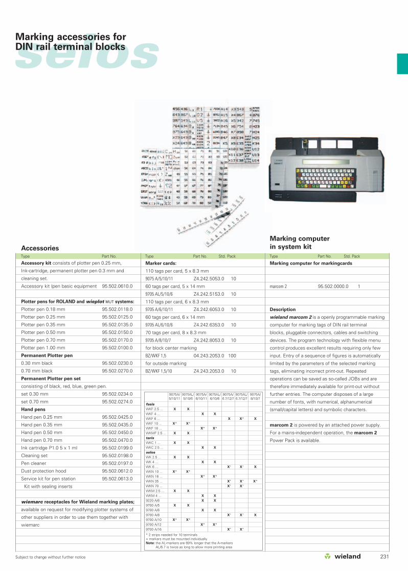
231Subject to change without further notice
Type Part No. Type Part No. Std. Pack Type Part No. Std. Pack
selosMarking accessories for DIN rail terminal blocks
Accessories
Accessory kit consists of plotter pen 0.25 mm,
Ink-cartridge, permanent plotter pen 0.3 mm and
cleaning set.
Accessory kit (pen basic equipment
Plotter pens for ROLAND and wieplot MUT systems:
Plotter pen 0.18 mm
Plotter pen 0.25 mm
Plotter pen 0.35 mm
Plotter pen 0.50 mm
Plotter pen 0.70 mm
Plotter pen 1.00 mm
Permanent Plotter pen
0.30 mm black
0.70 mm black
Permanent Plotter pen set
consisting of black, red, blue, green pen.
set 0.30 mm
set 0.70 mm
Hand pens
Hand pen 0.25 mm
Hand pen 0.35 mm
Hand pen 0.50 mm
Hand pen 0.70 mm
Ink cartridge P1.0 5 x 1 ml
Cleaning set
Pen cleaner
Dust protection hood
Service kit for pen station
Kit with sealing inserts
wiemarc receptacles for Wieland marking plates;
available on request for modifying plotter systems of
other suppliers in order to use them together with
wiemarc
95.502.0610.0
95.502.0118.0
95.502.0125.0
95.502.0135.0
95.502.0150.0
95.502.0170.0
95.502.0100.0
95.502.0230.0
95.502.0270.0
95.502.0234.0
95.502.0274.0
95.502.0425.0
95.502.0435.0
95.502.0450.0
95.502.0470.0
95.502.0199.0
95.502.0198.0
95.502.0197.0
95.502.0612.0
95.502.0613.0
Marking computer
in system kit
Marking computer for markingcards
marcom 2 95.502.0000.0 1
Description
wieland marcom 2 is a openly programmable marking
computer for marking tags of DIN rail terminal
blocks, pluggable connectors, cables and switching
devices. The program technology with flexible menu
control produces excellent results requiring only few
input. Entry of a sequence of figures is automatically
limited by the parameters of the selected marking
tags, eliminating incorrect print-out. Repeated
operations can be saved as so-called JOBs and are
therefore immediately available for print-out without
further entries. The computer disposes of a large
number of fonts, with numerical, alphanumerical
(small/capital letters) and symbolic characters.
marcom 2 is powered by an attached power supply.
For a mains-independent operation, the marcom 2
Power Pack is available.
9075A/5/10/11
9075AL/5/10/6
9075A/6/10/11
9075AL/6/10/6
9075A/6.7/12/7
9075AL/6.7/12/7
9075A/8/10/7
fasisWKF 2.5 ... X X
WKF 4 ... X X
WKF 6 ... X X* X
WKF 10 ... X* X*WKF 16 ... X* X*WKMF 2.5 ... X X
tarisWKC 1 ... X X
WKC 2.5 ... X X
selosWK 2.5 ... X X
WK 4 ... X X
WK 6 ... X+ X+ X
WKN 10 ... X* X*WKN 16 ... X* X*WKN 35 ... X+ X+ X*WKN 70 ... X+ X+
WKM 2.5 ... X X
WKM 4 ... X X
9220 A/6 X X
9700 A/5 X X
9700 A/6 X X
9700 A/8 X+ X+ X
9700 A/10 X* X*9700 A/12 X* X*9700 A/16 X+ X+
* 2 strips needed for 10 terminals + markers must be mounted individuallyNote: the AL-markers are 69% longer that the A-markers
AL/6.7 is twice as long to allow more printing area
9075 A/5/10/11 Z4.242.5053.0 10
9705 AL/5/10/6 Z4.242.5153.0 10
9705 A/6/10/11 Z4.242.6053.0 10
9705 AL/6/10/6 Z4.242.6353.0 10
9705 A/8/10/7 Z4.242.8053.0 10
BZ/WKF 1,5 04.243.2053.0 100
BZ/WKF 1,5/10 Z4.243.2053.0 10
Marker cards:
110 tags per card, 5 x 8.3 mm
60 tags per card, 5 x 14 mm
110 tags per card, 6 x 8.3 mm
60 tags per card, 6 x 14 mm
70 tags per card, 8 x 8.3 mm
for block center marking
for outside marking

232 Subject to change without further notice
selosselos
Type Part No. Std. Pack Type Part No. Std. Pack Type Part No. Std. Pack
Marking accessories for DIN rail terminal blocks
2.5 mm2/5 mm width 4 mm2/6 mm width
Marking strips, unmarked
9705 A/5/10 04.242.5053.0 25
Marking strips, marked
9705 A/5/9 B 1 - 9 04.842.4953.0 25
9705 A/5/10 B* 04.842.5053.0 25
9705 A/5/10 B 1 - 10 04.845.0153.0 25
11 - 20 04.845.0253.0 25
21 - 30 04.845.0353.0 25
31 - 40 04.845.0453.0 25
41 - 50 04.845.0553.0 25
51 - 60 04.845.0653.0 25
61 - 70 04.845.0753.0 25
71 - 80 04.845.0853.0 25
81 - 90 04.845.0953.0 25
91 - 100 04.845.1053.0 25
(10 x) 04.855.0053.0 25
(10 x) 04.855.0153.0 25
+ (10 x) 04.855.0253.0 25
– (10 x) 04.855.0353.0 25
L1 (10 x) 04.855.0453.0 25
L2 (10 x) 04.855.0553.0 25
L3 (10 x) 04.855.0653.0 25
PE (10 x) 04.855.0753.0 25
SL (10 x) 04.855.3153.0 25
N (10 x) 04.855.3253.0 25
F1 (10 x) 04.855.0953.0 25
F2 (10 x) 04.855.1053.0 25
L1, L2, L3, N, PE (2 x) 04.855.0853.0 25
with enlarged marking area
9705 AL/5/10 04.242.5153.0 25
*Custom marking upon request
Marking strips, unmarked
9705 A/6/10 04.242.6053.0 25
Marking strips, marked
9705 A/6/9 B 1 - 9 04.842.5953.0 25
9705 A/6/10 B* 04.842.6053.0 25
9705 A/6/10 B 1 - 10 04.846.0153.0 25
11 - 20 04.846.0253.0 25
21 - 30 04.846.0353.0 25
31 - 40 04.846.0453.0 25
41 - 50 04.846.0553.0 25
51 - 60 04.846.0653.0 25
61 - 70 04.846.0753.0 25
71 - 80 04.846.0853.0 25
81 - 90 04.846.0953.0 25
91 - 100 04.846.1053.0 25
(10 x) 04.856.0053.0 25
(10 x) 04.856.0153.0 25
+ (10 x) 04.856.0253.0 25
– (10 x) 04.856.0353.0 25
L1 (10 x) 04.856.0453.0 25
L2 (10 x) 04.856.0553.0 25
L3 (10 x) 04.856.0653.0 25
PE (10 x) 04.856.0753.0 25
SL (10 x) 04.856.3153.0 25
N (10 x) 04.856.3253.0 25
F1 (10 x) 04.856.0953.0 25
F2 (10 x) 04.856.1053.0 25
L1, L2, L3, N, PE (2 x) 04.856.0853.0 25
with enlarged marking area
9705 AL/6/10 04.242.6353.0 25
6 mm2/8 mm width
Marking strips, unmarked
9705 A/8/10 04.242.8053.0 25
Marking strips, marked
9705 A/8/9 B 1 - 9 04.842.7953.0 25
9705 A/8/10 B* 04.842.8053.0 25
9705 A/8/10 B 1 - 10 04.848.0153.0 25
11 - 20 04.848.0253.0 25
21 - 30 04.848.0353.0 25
31 - 40 04.848.0453.0 25
41 - 50 04.848.0553.0 25
51 - 60 04.848.0653.0 25
61 - 70 04.848.0753.0 25
71 - 80 04.848.0853.0 25
81 - 90 04.848.0953.0 25
91 - 100 04.848.1053.0 25
(10 x) 04.858.0053.0 25
(10 x) 04.858.0153.0 25
+ (10 x) 04.858.0253.0 25
– (10 x) 04.858.0353.0 25
L1 (10 x) 04.858.0453.0 25
L2 (10 x) 04.858.0553.0 25
L3 (10 x) 04.858.0653.0 25
PE (10 x) 04.858.0753.0 25
SL (10 x) 04.858.3153.0 25
N (10 x) 04.858.3253.0 25
F1 (10 x) 04.858.0953.0 25
F2 (10 x) 04.858.1053.0 25
L1, L2, L3, N, PE (2 x) 04.858.0853.0 25

233Subject to change without further notice
Type Part No. Std. Pack Type Part No. Std. Pack Type Part No. Std. Pack
selos
35 mm2/16 mm width
marked for 5 blocks (every 2nd tag) *
9705 A/8/10/5 B 04.842.8553.0 25
16 mm2/12 mm width
marked for 5 blocks (every 2nd tag) *
9705 A/6/10/5 B 04.842.6553.0 25
10 mm2/10 mm width
marked for 5 blocks (every 2nd tag) *
9705 A/5/10/5 B 04.842.5553.0 25
*Custom marking upon request
Marking accessories for DIN rail terminal blocks
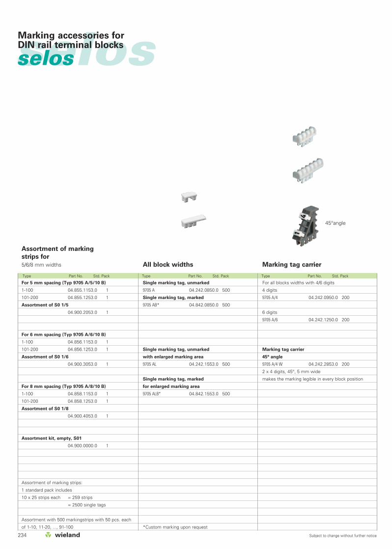
234 Subject to change without further notice
selosselos
Type Part No. Std. Pack Type Part No. Std. Pack Type Part No. Std. Pack
Marking accessories for DIN rail terminal blocks
All block widths
Assortment of marking
strips for
5/6/8 mm widths
Single marking tag, unmarked
9705 A 04.242.0850.0 500
Single marking tag, marked
9705 AB* 04.842.0850.0 500
Single marking tag, unmarked
with enlarged marking area
9705 AL 04.242.1553.0 500
Single marking tag, marked
for enlarged marking area
9705 ALB* 04.842.1553.0 500
*Custom marking upon request
For 5 mm spacing (Typ 9705 A/5/10 B)
1-100 04.855.1153.0 1
101-200 04.855.1253.0 1
Assortment of S0 1/5
04.900.2053.0 1
For 6 mm spacing (Typ 9705 A/6/10 B)
1-100 04.856.1153.0 1
101-200 04.856.1253.0 1
Assortment of S0 1/6
04.900.3053.0 1
For 8 mm spacing (Typ 9705 A/8/10 B)
1-100 04.858.1153.0 1
101-200 04.858.1253.0 1
Assortment of S0 1/8
04.900.4053.0 1
Assortment kit, empty, S01
04.900.0000.0 1
Assortment of marking strips:
1 standard pack includes
10 x 25 strips each = 259 strips
= 2500 single tags
Assortment with 500 markingstrips with 50 pcs. each
of 1-10, 11-20, ..., 91-100
Marking tag carrier
For all blocks widths with 4/6 digits
4 digits
9705 A/4 04.242.0950.0 200
6 digits
9705 A/6 04.242.1250.0 200
Marking tag carrier
45° angle
9705 A/4 W 04.242.2853.0 200
2 x 4 digits, 45°, 5 mm wide
makes the marking legible in every block position
45°angle

235Subject to change without further notice
selosMarking accessories for DIN rail terminal blocks
Marking Type Part No. Std. Pack Marking Type Part No. Std. Pack Marking Type Part No. Std. Pack
Tear-off marking strip with 10 marking tags
marked with the same upper case letter
A 9704 A/AG B 04.841.2250.0 25
B 9704 A/BG B 04.841.2350.0 25
C 9704 A/CG B 04.841.2450.0 25
D 9704 A/DG B 04.841.2550.0 25
E 9704 A/EG B 04.841.2650.0 25
F 9704 A/FG B 04.841.2750.0 25
G 9704 A/GG B 04.841.2850.0 25
H 9704 A/HG B 04.841.2950.0 25
I 9704 A/IG B 04.841.3050.0 25
J 9704 A/JG B 04.841.3150.0 25
K 9704 A/KG B 04.841.3250.0 25
L 9704 A/LG B 04.841.3350.0 25
M 9704 A/MG B 04.841.3450.0 25
N 9704 A/NG B 04.841.3550.0 25
O 9704 A/OG B 04.841.3650.0 25
P 9704 A/PG B 04.841.3750.0 25
Q 9704 A/QG B 04.841.3850.0 25
R 9704 A/RG B 04.841.3950.0 25
S 9704 A/SG B 04.841.4050.0 25
T 9704 A/TG B 04.841.4150.0 25
U 9704 A/UG B 04.841.4250.0 25
V 9704 A/VG B 04.841.4350.0 25
W 9704 A/WG B 04.841.4450.0 25
X 9704 A/XG B 04.841.4550.0 25
Y 9704 A/YG B 04.841.4650.0 25
Z 9704 A/ZG B 04.841.4750.0 25
marked with the same upper case letter
a 9704 A/AK B 04.841.4850.0 25
b 9704 A/BK B 04.841.4950.0 25
c 9704 A/CK B 04.841.5050.0 25
d 9704 A/DK B 04.841.5150.0 25
e 9704 A/EK B 04.841.5250.0 25
f 9704 A/FK B 04.841.5350.0 25
g 9704 A/GK B 04.841.5450.0 25
h 9704 A/HK B 04.841.5550.0 25
i 9704 A/IK B 04.841.5650.0 25
j 9704 A/JK B 04.841.5750.0 25
k 9704 A/KK B 04.841.5850.0 25
l 9704 A/LK B 04.841.5950.0 25
m 9704 A/MK B 04.841.6050.0 25
n 9704 A/NK B 04.841.6150.0 25
o 9704 A/OK B 04.841.6250.0 25
p 9704 A/PK B 04.841.6350.0 25
q 9704 A/QK B 04.841.6450.0 25
r 9704 A/RK B 04.841.6550.0 25
s 9704 A/SK B 04.841.6650.0 25
t 9704 A/TK B 04.841.6750.0 25
u 9704 A/UK B 04.841.6850.0 25
v 9704 A/VK B 04.841.6950.0 25
w 9704 A/WK B 04.841.7050.0 25
x 9704 A/XK B 04.841.7150.0 25
y 9704 A/YK B 04.841.7250.0 25
z 9704 A/ZK B 04.841.7350.0 25
unmarked
9704 A 04.241.1150.0 25
marked with the same number
1 9704 A/1 B 04.841.1150.0 25
2 9704 A/2 B 04.841.1250.0 25
3 9704 A/3 B 04.841.1350.0 25
4 9704 A/4 B 04.841.1450.0 25
5 9704 A/5 B 04.841.1550.0 25
6 9704 A/6 B 04.841.1650.0 25
7 9704 A/7 B 04.841.1750.0 25
8 9704 A/8 B 04.841.1850.0 25
9 9704 A/9 B 04.841.1950.0 25
0 9704 A/0 B 04.841.2050.0 25
marked with consecutive numbers
1-0 9704 A/1-0 B 04.841.2150.0 25
marked with the same symbols
+ 9704 A/+ B 04.841.7450.0 25
– 9704 A/– B 04.841.7550.0 25
/ 9704 A// B 04.841.7650.0 25
. 9704 A/. B 04.841.7750.0 25
1 set of the same numbers
= 10 x 25 strips = 2500 numbers
111 to 000 04.841.9050.0 1
1 set of capital letters
= 26 x 25 strips = 6500 letters
A to Z GB 04.841.9150.0 1
1 set of small letters
= 26 x 25 strips = 6500 letters
a to z KB 04.841.9250.0 1
Assortment with 50 numbers each
1-0 04.900.1053.0 1
Material: Polyamide 66/6 white, marking in black Marking per strip

236 Subject to change without further notice
selosselos
Type Part No. Std. Pack Type Part No. Std. Pack Type Part No. Std. Pack
L B h a e d d1 l1 b L B h a e d d1 l1 b L B h a e d d1 l1 b
Marking tagsThe marking tags are delivered unassembled!
Marking strip Marking strip
Version N:
Material:
special photostable plastic,
transparent, marking card in white
300 B 90.100.1154.0 100
300 90.100.0554.0 100
301 90.100.0754.0 100
303 90.100.0854.0 100
305 90.100.1054.0 100
Version K:
Marking cards in perforated
sheets for marking with a
type writer
300 BK 90.100.1354.0 100
300 K 90.100.1254.0 100
301 K 90.100.1454.0 100
303 K 90.100.1554.0 100
305 K 90.100.1654.0 100
30 17.5 4 11 3.6 4.6 27 14.5
45 17.5 4 26 3.6 4.6 42 14.5
60 30 7 36.5 3.6 4.6 54.5 24.5
90 40 8 55 3.6 4.6 84 34
140 55 8 100 3.6 4.6 134 49
Available in Polyvinylchloride,
1 m long
with marking card and plastic foil cover
315 GK 90.810.3055.0 10
without card, with plastic insert in white opaque
315 GC 90.811.3055.0 10
End piece
315 E 05.590.0052.0 100
1000 16 4 9
1000 16 4 9
Available in Polyvinylchlorid (PVC) black and ivory,
1 m long
with marking card (white) and plastic foil cover
319/13,5 K elf. 90.800.1055.8 10
319/17,5 K elf. 90.800.2055.8 10
319/13,5 K schwarz 90.800.1055.1 10
319/17,5 K schwarz 90.800.2055.1 10
1000 20 4 13.5
1000 24 4 17.5
1000 30.5 4 23.5
1000 20 4 13.5
1000 24 4 17.5
1000 30.5 4 23.5
Marking Accessoriesfor DIN rail terminal blocks

237Subject to change without further notice
Design Part No. Std. Pack Design Part No. Std. Pack Design Part No. Std. Pack
Push button tag 04.210.0752.0 100
Marking card
white for marking tags
(1 sheet = 30 single tags)
04.019.0889.0 1
Aluminum
tag, self-adhesive 05.584.9489.0 1
Marking tag Z4.210.1652.0 100
with carrier
Marking card
white for marking tags
(1 sheet = 30 single tags)
04.019.0889.0 1
Aluminum
tag, self-adhesive 05.584.9489.0 1
Marking tag Z4.210.0652.0 100
with adhesive tape
Marking tag 04.210.0652.0 100
without adhesive tape
Marking card
white for marking tags
(1 sheet = 30 single tags)
04.019.0889.0 1
Aluminum
tag, self-adhesive 05.584.9489.0 1
Marking tag Marking tag Marking tag
Material:Polypropylene, neutral
Material:Polypropylene, neutral
selosMarking Accessoriesfor DIN rail terminal blocks
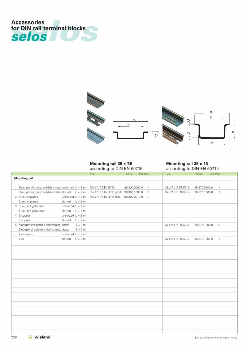
238 Subject to change without further notice
Type Part No. Std. Pack Type Part No. Std. Pack
selosselos Accessoriesfor DIN rail terminal blocks
Mounting rail
1. Steel, galv. zinc-plated and dichromated, unslotted L = 2 m
Steel, galv. zinc-plated and dichromated, slotted L = 2 m
2. Steel, unplated unslotted L = 2 m
Steel, unplated slotted L = 2 m
3. Steel, hot-galvanized unslotted L = 2 m
Steel, hot-galvanized slotted L = 2 m
4. E copper unslotted L = 2 m
E copper slotted L = 2 m
5. Steel,galv. zinc-plated + dichromated, slotted L = 1 m
Steel,galv. zinc-plated + dichromated, slotted L = 2 m
Aluminium unslotted L = 2 m
V2A slotted L = 2 m
35 x 27 x 15 EN 60715 98.370.0000.0 1
35 x 27 x 15 EN 60715 98.370.1000.0 1
35 x 27 x 15 EN 60715 98.375.1000.0 10
35 x 27 x 15 EN 60715 98.370.1001.0 1
35 x 27 x 7,5 EN 60715 98.300.0000.0 1
35 x 27 x 7,5 EN 60715 gelocht 98.300.1000.0 1
35 x 27 x 7,5 EN 60715 blank 98.300.0010.0 1
Mounting rail 35 x 7.5
according to DIN EN 60715Mounting rail 35 x 15
according to DIN EN 60715
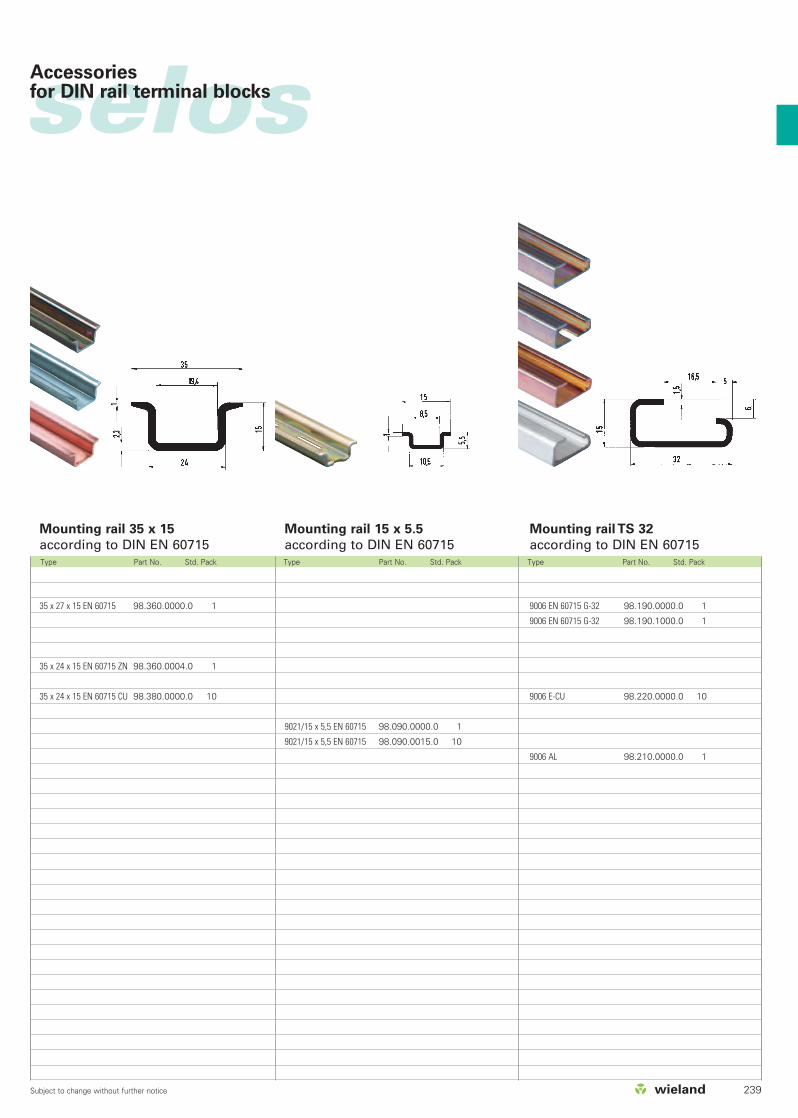
239Subject to change without further notice
Type Part No. Std. Pack Type Part No. Std. Pack Type Part No. Std. Pack
selosAccessoriesfor DIN rail terminal blocks
9021/15 x 5,5 EN 60715 98.090.0000.0 1
9021/15 x 5,5 EN 60715 98.090.0015.0 10
9006 EN 60715 G-32 98.190.0000.0 1
9006 EN 60715 G-32 98.190.1000.0 1
9006 E-CU 98.220.0000.0 10
9006 AL 98.210.0000.0 1
35 x 27 x 15 EN 60715 98.360.0000.0 1
35 x 24 x 15 EN 60715 ZN 98.360.0004.0 1
35 x 24 x 15 EN 60715 CU 98.380.0000.0 10
Mounting rail 35 x 15
according to DIN EN 60715Mounting rail 15 x 5.5
according to DIN EN 60715Mounting rail TS 32
according to DIN EN 60715
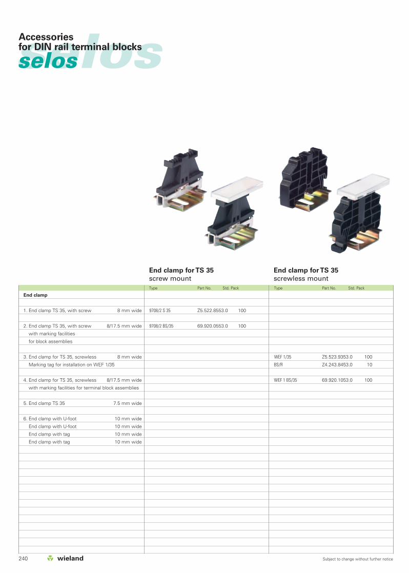
240 Subject to change without further notice
selosselos Accessoriesfor DIN rail terminal blocks
Type Part No. Std. Pack Type Part No. Std. Pack
End clamp
1. End clamp TS 35, with screw 8 mm wide
2. End clamp TS 35, with screw 8/17.5 mm wide
with marking facilities
for block assemblies
3. End clamp for TS 35, screwless 8 mm wide
Marking tag for installation on WEF 1/35
4. End clamp for TS 35, screwless 8/17.5 mm wide
with marking facilities for terminal block assemblies
5. End clamp TS 35 7.5 mm wide
6. End clamp with U-foot 10 mm wide
End clamp with U-foot 10 mm wide
End clamp with tag 10 mm wide
End clamp with tag 10 mm wide
WEF 1/35 Z5.523.9353.0 100
BS/R Z4.243.8453.0 10
WEF 1 BS/35 69.920.1053.0 100
9708/2 S 35 Z5.522.8553.0 100
9708/2 BS/35 69.920.0553.0 100
End clamp for TS 35
screw mountEnd clamp for TS 35
screwless mount

241Subject to change without further notice
selosAccessoriesfor DIN rail terminal blocks
Type Part No. Std. Pack Type Part No. Std. Pack Type Part No. Std. Pack
9708/3 S 35 Z5.523.5153.0 100
WE 2/U Z5.523.5653.0 100
WE 1/U Z5.523.5753.0 100
300 WE2/U 69.920.0653.0 100
300 WE1/U 69.920.0753.0 100
9208/S15 Z5.522.7553.0 100
End clamp with U-footEnd clamp for TS 35 End clamp for TS 15
Polyamide 66/6BracketsZinc-plated steel

selosselos CLASSIC LINE
DIN rail terminal blockswith screw clamp technology, type 9700 A.. S35
242 Subject to change without further notice
9700 A/6 S35 9700 A/8 S35 9700 A/10 S35 9700 A/12 S35
9700 A/16 S35 9700 A/6 ETK S35 9700 A/10 ETK S35
9700 A/6 SL2 S35 9700 A/8 SL2 S35 9700 A/10 SL2 S35 9700 A/16 SL2 S35 9700 A/16 PEN 2 S35
Cross connector Cover with warning symbol Selectable connecting link Test plug Rapid mounting tool
RV2S/... RV2S/...L
wieplan wiemarc wieplot marcom
2.5 mm2/5 mm spacing 4 mm2/6 mm spacing 6 mm2/8 mm spacing 10 mm2/10 mm spacing16 mm2/12 mm spacing35 mm2/16 mm spacing
RV2/A...
SK...
RV2A/...L RV2A/...TP1
WKB 2,5/U WKB 2,5/B/U ST 29/10 S
RV2S/...TP1
WE SH 1, WE SH 2 WE SH3, WE SH4 SKN SH/35, WAK 35/4SKN...
9700 A/8 ETK S35
9700 A/5 S35
TS 35x7,5 TS 35x15 TS 35x15 End clamp TS 35End clamp for TS 35
Marking tags Marking tag carrier Tear-off marking strips with 10 marking tags
Page 248/249
Page 250/251
Page 252/253
Page 254/255
Page 256/257
Page 258/259
Page 260/261
Page 262/263
Page 266/267
Page 268/269
Page 270/271
Page 272/273
Page 274/275

selosDIN rail terminal blockswith screw clamp technology, type 9700 A.. S35
243Subject to change without further notice
KL28/6DSPA
WAK4/3 FFK18/2ZWAK4/1
ST 25/5... ST 28/10 B, ..S, ..BS TS M ... S 35TS M 4/M 6-32
9290 S 9290 L
wieplan wiemarc wieplot
Page 276/277
Page 278/279
Page 280/281
Page 282/283
Page 284/285
Page 286/287
Page 288/289
KSO11/1ZKR
marcom
2.5 mm2/5 mm spacing 4 mm2/6 mm spacing 6 mm2/8 mm spacing 10 mm2/10 mm spacing16 mm2/12 mm spacing35 mm2/16 mm spacing
Marking tag carrier
Assortment of marking strips Tear-off marking strips with 10 marking tags

selosselos CLASSIC LINE
Function and installation safety
selos CLASSIC LINE
– Mounting on TS 35 DIN Rail (DIN 60 715)– Product range:
Feed-through terminalsGround terminalsNeutral Bus terminalsPEN terminals
Incorrect mounting indicator on the topof terminal – terminals mounted incorrectly are
easily identified and fixed.
Save space on the rail– selos Classic Line offers higher
density due to the wire size andterminal block pitch.Connection range Pitch
12 AWG 5 mm10 AWG 6 mm8 AWG 8 mm6 AWG 10 mm4 AWG 12 mm2 AWG 16 mm
Connection range12-2 AWG
Compact design
Connection range: 0.5 – 50 mm2
Solid, fine-stranded and stranded wirescan be connected to the terminal blocksof selos CLASSIC LINE without ferrules,as all block sizes have wire protection.
9700 A S35 offers...
Screw clamp technologymade from nickel-plated copper alloy
Application advantages
Low contact resistance– Clamping body has similar physical
and chemical characteristics as the conductor
– One piece clamping body/current bar Connection of Aluminum Conductors
– Clamping body is able to penetratealuminium oxide
Steel free Clamping Body– High corrosion resistance
DIN rail terminal blockswith screw clamp technology, type 9700 A.. S35
244 Subject to change without further notice
incorrect mounting correct mounting
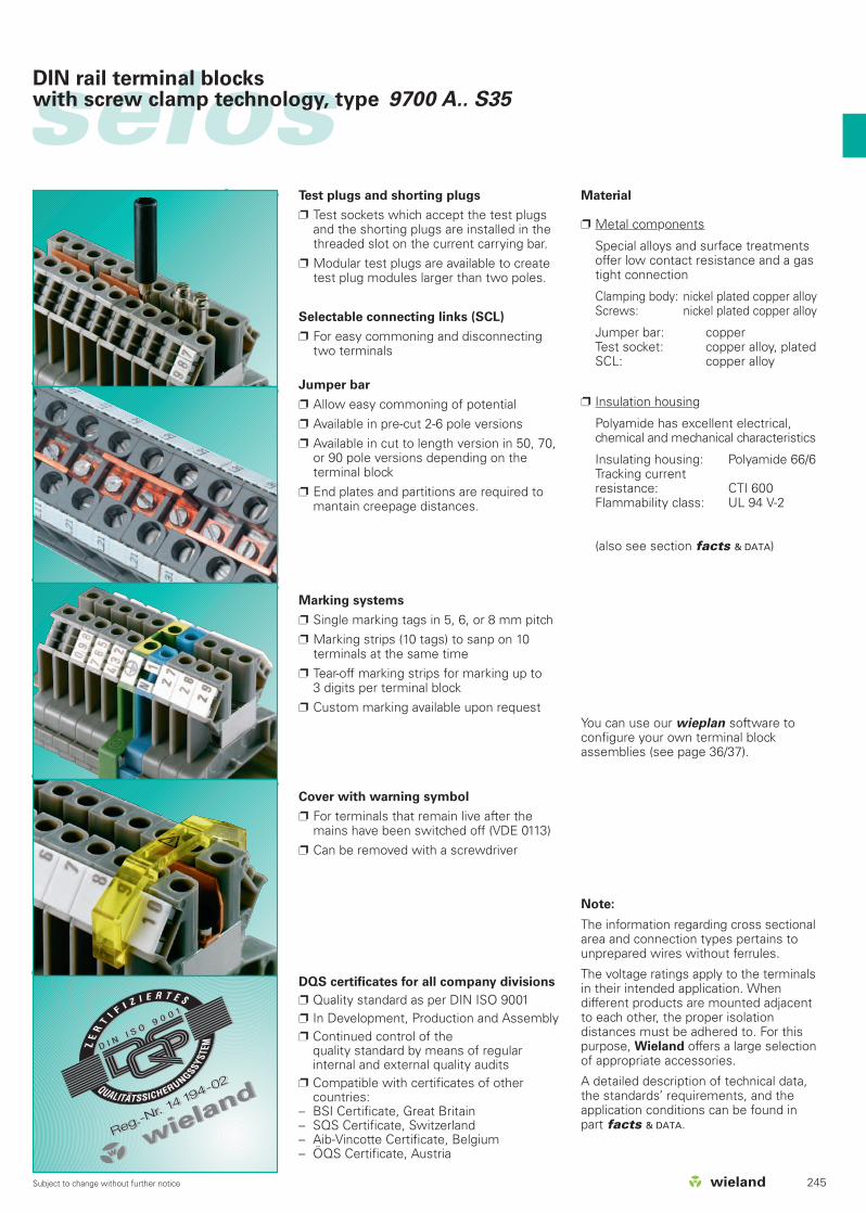
selosDIN rail terminal blockswith screw clamp technology, type 9700 A.. S35
245Subject to change without further notice
Material
Metal components
Special alloys and surface treatmentsoffer low contact resistance and a gastight connection
Clamping body: nickel plated copper alloyScrews: nickel plated copper alloy
Jumper bar: copper Test socket: copper alloy, platedSCL: copper alloy
Insulation housing
Polyamide has excellent electrical,chemical and mechanical characteristics
Insulating housing: Polyamide 66/6Tracking current resistance: CTI 600Flammability class: UL 94 V-2
(also see section facts & DATA)
Note:
The information regarding cross sectionalarea and connection types pertains tounprepared wires without ferrules.
The voltage ratings apply to the terminalsin their intended application. Whendifferent products are mounted adjacentto each other, the proper isolationdistances must be adhered to. For thispurpose, Wieland offers a large selectionof appropriate accessories.
A detailed description of technical data,the standards’ requirements, and theapplication conditions can be found inpart facts & DATA.
DQS certificates for all company divisions
Quality standard as per DIN ISO 9001 In Development, Production and Assembly Continued control of the
quality standard by means of regularinternal and external quality audits
Compatible with certificates of other countries:
– BSI Certificate, Great Britain– SQS Certificate, Switzerland– Aib-Vincotte Certificate, Belgium– ÖQS Certificate, Austria
Cover with warning symbol
For terminals that remain live after themains have been switched off (VDE 0113)
Can be removed with a screwdriver
Marking systems
Single marking tags in 5, 6, or 8 mm pitch Marking strips (10 tags) to sanp on 10
terminals at the same time Tear-off marking strips for marking up to
3 digits per terminal block Custom marking available upon request
Test plugs and shorting plugs
Test sockets which accept the test plugsand the shorting plugs are installed in thethreaded slot on the current carrying bar.
Modular test plugs are available to createtest plug modules larger than two poles.
Selectable connecting links (SCL)
For easy commoning and disconnectingtwo terminals
Jumper bar
Allow easy commoning of potential Available in pre-cut 2-6 pole versions Available in cut to length version in 50, 70,
or 90 pole versions depending on theterminal block
End plates and partitions are required tomantain creepage distances.
You can use our wieplan software toconfigure your own terminal blockassemblies (see page 36/37).

selosselos CLASSIC LINE
DIN rail terminal blockswith screw clamp technology, type 9700 A.. S35
1
2
3
45
6
7
8
9
10
11
12
13
14
16
1729
2419
31
30
2015
32
33
25
28
21
26
22
27
23
18246 Subject to change without further notice

selosDIN rail terminal blockswith screw clamp technology, type 9700 A.. S35
247Subject to change without further notice
9700 A/5 S35 54.003.7553.0
9700 A/5 S35 BLAU 54.003.7553.6
9700 A/6 S35 54.004.7553.0
9700 A/6 ETK S35 54.004.7753.0
9700 A/6 SL2 S35 56.004.9053.0
9700 A/8 S35 54.010.7553.0
9700 A/8 ETK S35 54.010.7753.0
9700 A/8 SL2 S35 56.010.9053.0
9700 A/10 S35 54.016.7553.0
9700 A/10 ETK S35 54.016.7753.0
9700 A/10 SL2 S35 56.016.9053.0
9700 A/16 S35 54.035.7553.0
9700 A/16 S35 BLAU 54.035.7553.6
9700 A/16 SL2 S35 56.035.9053.0
9813 M Sn 98.290.1000.0
35 x 27 x 7.5 98.300.0000.0
9708/2 S35 Z5.522.8553.0
9701/16 SL 07.312.0353.0
2.5 mm2 04.325.1656.0
4 mm2 04.325.1056.0
10 mm2 04.325.1156.0
16 mm2 04.325.1256.0
35 mm2 04.325.1456.0
9703/5-2 Z7.215.0227.0
9703/6-2 Z7.211.0227.0
9703/10-2 Z7.214.0227.0
9703/16-2 Z7.216.0227.0
10 mm2 Z7.269.3023.0
ST 2/2,3 Z5.553.2921.0
2.5 mm2 05.508.8921.0
Z1.299.7153.0
9705 A 04.842.0850.0
9705 A/6/10 B 04.842.6053.0
9705 A/8/10 B 04.842.8053.0
Item Description Type Part number
1 Feed through block
2 Feed-through block, BLUE
3 Feed through block
4 Neutral disconnect block
5 Ground block
6 Feed through block
7 Neutral disconnect block
8 Ground block
9 Feed through block
10 Neutral disconnect block
11 Ground block
12 Feed through block
13 Feed-through block, BLUE
14 Ground block
15 Busbar 10 x 3
16 Mounting rail
17 End clamp for TS 35 withscrew
18 End plate, GREEN
19 Warning cover
20 Warning cover
21 Warning cover
22 Warning cover
23 Warning cover
24 Cross connector with screws, uninsulated
25 Cross connector with screws, uninsulated
26 Cross connector with screws, uninsulated
27 Cross connector with screws, uninsulated
28 Selectable connecting link, complete
29 Test plug with insulated handle, Ø 2.3 mm
Ring lug
30 Test plug with locking lever
31 Marking tag
32 Marking strip
33 Marking strip

248 Subject to change without further notice
Type Part No. Std. Pack Type Part No. Std. Pack
DIN VDE 0611 Teil 3/11.98UL ratings field/factory wiringCSA ratingsWidth Wire strip lengthApprovals
9700 A/5 S35
fine-stranded solid V A0.5 – 2.5 mm2 0.5 – 4 mm2 800 V/8 kV/3 24No. 18-12 AWG 600 V 20/30No. 22-12 AWG 600 V 255 mm 9 mm
igtu+qwW
9700 A/6 S35
fine-stranded solid V A0.5 – 4 mm2 0.5 – 6 mm2 800 V/8 kV/3 32No. 18-10 AWG 600 V 30/30No. 22-10 AWG 600 V 356 mm 9 mm
aigtu+qwW9700 A/5 S35 54.003.7553.0 100
9700 A/5 S35 BLAU 54.003.7553.6 100
35 x 27 x 7,5 EN 60715 98.300.0000.0 1
35 x 27 x 15 EN 60715 98.360.0000.0 1
9708/2 S35 Z5.522.8553.0 100
9701/6 07.310.3153.0 10
9701/6 BLAU 07.310.3153.6 10
9702/6 07.310.3453.0 10
9702/6 BLAU 07.310.3453.6 10
9703/5-2 Z7.215.0227.0 50
9703/5-3 Z7.215.0327.0 50
9703/5-4 Z7.215.0427.0 50
9703/5-5 Z7.215.0527.0 50
9703/5-6 Z7.215.0627.0 50
9703/5-M Z7.215.0027.0 10
Z7.269.3523.0 50
9011 D 05.508.8921.0 10
ST 2/2,3 Z5.553.2921.0 10
04.325.1656.0 10
05.593.5853.0 10
9700 A/6 S35 54.004.7553.0 100
9700 A/6 S35 BLAU 54.004.7553.6 100
35 x 27 x 7,5 EN 60715 98.300.0000.0 1
35 x 27 x 15 EN 60715 98.360.0000.0 1
9708/2 S35 Z5.522.8553.0 100
9701/6 07.310.3153.0 10
9701/6 BLAU 07.310.3153.6 10
9702/6 07.310.3453.0 10
9702/6 BLAU 07.310.3453.6 10
9703/6-2 Z7.211.0227.0 50
9703/6-3 Z7.211.0327.0 50
9703/6-4 Z7.211.0427.0 50
9703/6-5 Z7.211.0527.0 50
9703/6-6 Z7.211.0627.0 50
9703/6-M Z7.211.0027.0 10
Z7.269.2923.0 50
9011 C 05.508.8821.0 10
ST 2/2,3 Z5.553.2921.0 10
04.325.1056.0 10
05.593.4153.0 1
selosselos CLASSIC LINE
Feed-through blockswith screw connection, type 9700 A.. S35
Feed-through terminal gray
Feed-through terminal, (Ex)i blue
Neutral disconnect block blue
Ground block green-yellow
PEN terminal green/yellow - blue
Accessories
1. Mounting rail TS 35, DIN rail, 7.5 mm high L = 2 m
Mounting rail TS 35, DIN rail 15 mm high L = 2 m
2. End clamp TS 35, with screw 8 mm wide
3. End plate gray
blue
green
4. Partition plate gray
blue
5. Jumper bar with screws, 2pole
E-Cu, uninsulated 3pole
4pole
5pole
6pole
Cut-to-order strip 0.6 m long
6. Selectable connecting link
7. Ring lug for test plug
8. Test plug
9. Cover with warn. symbol for 1 block yellow
10. Busbar
E-Cu, 10 x 3 mm, tin-plated, IN = 140 A L = 1 m
E-Cu, 10 x 3 mm, unplated, IN = 140 A L = 1 m
11. Connector clamps for busbar
25 mm2 11.1 mm wide
35 mm2 14.3 mm wide
12. Busbar support 6 mm wide
13. Rapid mounting tool
For marking accessories see pages 258-263
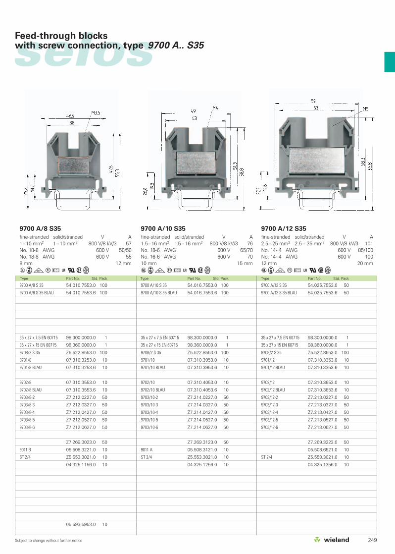
Type Part No. Std. Pack Type Part No. Std. Pack Type Part No. Std. Pack
9700 A/8 S35
fine-stranded solid/stranded V A1– 10 mm2 1– 10 mm2 800 V/8 kV/3 57No. 18-8 AWG 600 V 50/50No. 18-8 AWG 600 V 558 mm 12 mm
aigtu+qwW
9700 A/10 S35
fine-stranded solid/stranded V A1.5– 16 mm2 1.5 – 16 mm2 800 V/8 kV/3 76No. 18-6 AWG 600 V 65/70No. 16-6 AWG 600 V 7010 mm 15 mm
aigtu+qwW
9700 A/12 S35
fine-stranded solid/stranded V A2.5 – 25 mm2 2.5 – 35 mm2 800 V/8 kV/3 101No. 14- 4 AWG 600 V 85/100No. 14- 4 AWG 600 V 10012 mm 20 mm
aigtu+qwW9700 A/8 S 35 54.010.7553.0 100
9700 A/8 S 35 BLAU 54.010.7553.6 100
35 x 27 x 7,5 EN 60715 98.300.0000.0 1
35 x 27 x 15 EN 60715 98.360.0000.0 1
9708/2 S 35 Z5.522.8553.0 100
9701/8 07.310.3253.0 10
9701/8 BLAU 07.310.3253.6 10
9702/8 07.310.3553.0 10
9702/8 BLAU 07.310.3553.6 10
9703/8-2 Z7.212.0227.0 50
9703/8-3 Z7.212.0327.0 50
9703/8-4 Z7.212.0427.0 50
9703/8-5 Z7.212.0527.0 50
9703/8-6 Z7.212.0627.0 50
Z7.269.3023.0 50
9011 B 05.508.3221.0 10
ST 2/4 Z5.553.3021.0 10
04.325.1156.0 10
05.593.5953.0 10
9700 A/10 S 35 54.016.7553.0 100
9700 A/10 S 35 BLAU 54.016.7553.6 100
35 x 27 x 7,5 EN 60715 98.300.0000.0 1
35 x 27 x 15 EN 60715 98.360.0000.0 1
9708/2 S 35 Z5.522.8553.0 100
9701/10 07.310.3953.0 10
9701/10 BLAU 07.310.3953.6 10
9702/10 07.310.4053.0 10
9702/10 BLAU 07.310.4053.6 10
9703/10-2 Z7.214.0227.0 50
9703/10-3 Z7.214.0327.0 50
9703/10-4 Z7.214.0427.0 50
9703/10-5 Z7.214.0527.0 50
9703/10-6 Z7.214.0627.0 50
Z7.269.3123.0 50
9011 A 05.508.3121.0 10
ST 2/4 Z5.553.3021.0 10
04.325.1256.0 10
9700 A/12 S 35 54.025.7553.0 50
9700 A/12 S 35 BLAU 54.025.7553.6 50
35 x 27 x 7,5 EN 60715 98.300.0000.0 1
35 x 27 x 15 EN 60715 98.360.0000.0 1
9708/2 S 35 Z5.522.8553.0 100
9701/12 07.310.3353.0 10
9701/12 BLAU 07.310.3353.6 10
9702/12 07.310.3653.0 10
9702/12 BLAU 07.310.3653.6 10
9703/12-2 Z7.213.0227.0 50
9703/12-3 Z7.213.0327.0 50
9703/12-4 Z7.213.0427.0 50
9703/12-5 Z7.213.0527.0 50
9703/12-6 Z7.213.0627.0 50
Z7.269.3223.0 50
05.508.6521.0 10
ST 2/4 Z5.553.3021.0 10
04.325.1356.0 10
selos
249Subject to change without further notice
Feed-through blockswith screw connection, type 9700 A.. S35
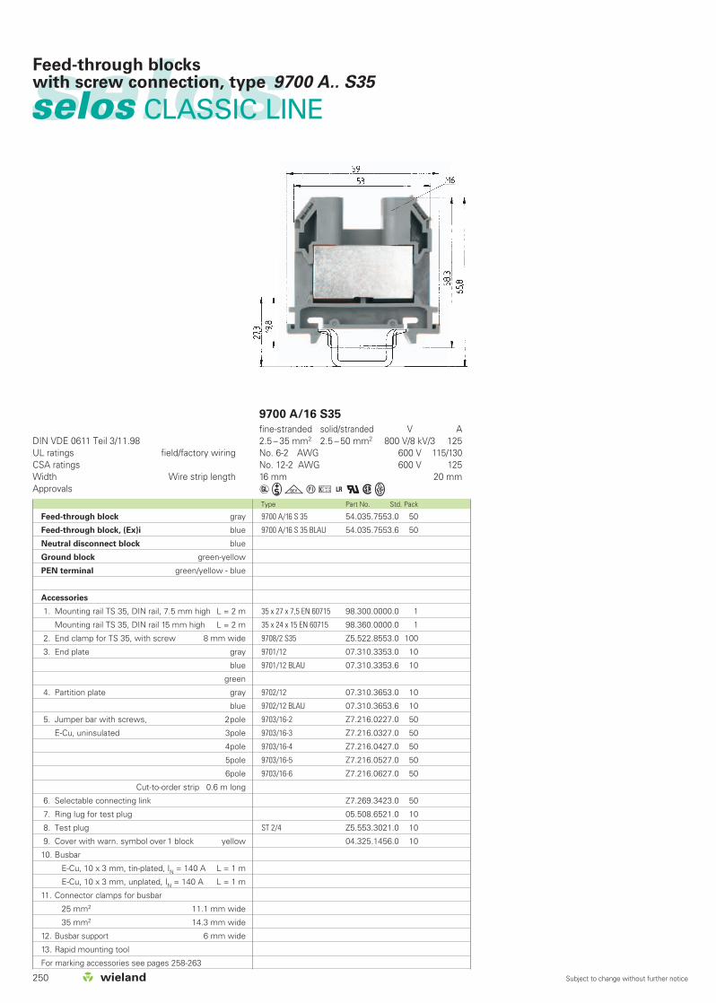
250 Subject to change without further notice
selosselos CLASSIC LINE
Feed-through blockswith screw connection, type 9700 A.. S35
Type Part No. Std. Pack
DIN VDE 0611 Teil 3/11.98UL ratings field/factory wiringCSA ratingsWidth Wire strip lengthApprovals
9700 A/16 S35
fine-stranded solid/stranded V A2.5 – 35 mm2 2.5 – 50 mm2 800 V/8 kV/3 125No. 6-2 AWG 600 V 115/130No. 12-2 AWG 600 V 12516 mm 20 mm
aigtu+qwW9700 A/16 S 35 54.035.7553.0 50
9700 A/16 S 35 BLAU 54.035.7553.6 50
35 x 27 x 7,5 EN 60715 98.300.0000.0 1
35 x 24 x 15 EN 60715 98.360.0000.0 1
9708/2 S35 Z5.522.8553.0 100
9701/12 07.310.3353.0 10
9701/12 BLAU 07.310.3353.6 10
9702/12 07.310.3653.0 10
9702/12 BLAU 07.310.3653.6 10
9703/16-2 Z7.216.0227.0 50
9703/16-3 Z7.216.0327.0 50
9703/16-4 Z7.216.0427.0 50
9703/16-5 Z7.216.0527.0 50
9703/16-6 Z7.216.0627.0 50
Z7.269.3423.0 50
05.508.6521.0 10
ST 2/4 Z5.553.3021.0 10
04.325.1456.0 10
Feed-through block gray
Feed-through block, (Ex)i blue
Neutral disconnect block blue
Ground block green-yellow
PEN terminal green/yellow - blue
Accessories
1. Mounting rail TS 35, DIN rail, 7.5 mm high L = 2 m
Mounting rail TS 35, DIN rail 15 mm high L = 2 m
2. End clamp for TS 35, with screw 8 mm wide
3. End plate gray
blue
green
4. Partition plate gray
blue
5. Jumper bar with screws, 2pole
E-Cu, uninsulated 3pole
4pole
5pole
6pole
Cut-to-order strip 0.6 m long
6. Selectable connecting link
7. Ring lug for test plug
8. Test plug
9. Cover with warn. symbol over 1 block yellow
10. Busbar
E-Cu, 10 x 3 mm, tin-plated, IN = 140 A L = 1 m
E-Cu, 10 x 3 mm, unplated, IN = 140 A L = 1 m
11. Connector clamps for busbar
25 mm2 11.1 mm wide
35 mm2 14.3 mm wide
12. Busbar support 6 mm wide
13. Rapid mounting tool
For marking accessories see pages 258-263
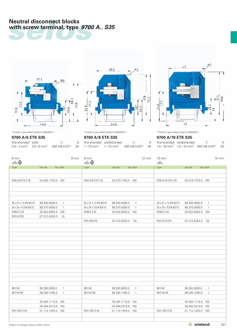
251Subject to change without further notice
Type Part No. Std. Pack Type Part No. Std. Pack Type Part No. Std. Pack
9700 A/6 ETK S35
fine-stranded solid V A0.5 – 4 mm2 0.5 – 6 mm2 400 V/6 kV/3*) 25
6 mm 9 mm
gW
9700 A/8 ETK S35
fine-stranded solid/stranded V A1 – 10 mm2 1 – 10 mm2 400 V/6 kV/3*) 40
8 mm 12 mm
gW
9700 A/10 ETK S35
fine-stranded solid/stranded V A1.5 – 16 mm2 1.5 – 16 mm2 400 V/6 kV/3*) 50
10 mm 15 mm
g
9700 A/8 ETK S 35 54.010.7753.0 100
35 x 27 x 7,5 EN 60715 98.300.0000.0 1
35 x 24 x 15 EN 60715 98.370.0000.0 1
9708/2 S 35 Z5.522.8553.0 100
9701 B/8 ETK 07.310.5253.0 50
9813 M 98.290.0000.0 1
9813 M SN 98.290.1000.0 1
30.494.1110.6 100
30.494.2510.6 100
9701 ASH S 35 01.112.1453.0 100
9700 A/10 ETK S 35 54.016.7753.0 100
35 x 27 x 7,5 EN 60715 98.300.0000.0 1
35 x 24 x 15 EN 60715 98.370.0000.0 1
9708/2 S 35 Z5.522.8553.0 100
9701 B/10 ETK 07.310.5353.0 50
9813 M 98.290.0000.0 1
9813 M SN 98.290.1000.0 1
30.494.1110.6 100
30.494.2510.6 100
9701 ASH S 35 01.112.1453.0 100
selos
*)Install in grounded systems 690/400 V *)Install in grounded systems 690/400 V *)Install in grounded systems 690/400 V
Neutral disconnect blockswith screw terminal, type 9700 A.. S35
9700 A/6 ETK S 35 54.004.7753.0 100
35 x 27 x 7,5 EN 60715 98.300.0000.0 1
35 x 24 x 15 EN 60715 98.370.0000.0 1
9708/2 S 35 Z5.522.8553.0 100
9701/6 ETKL 07.310.4553.0 10
9813 M 98.290.0000.0 1
9813 M SN 98.290.1000.0 1
30.494.1110.6 100
30.494.2510.6 100
9701 ASH S 35 01.112.1453.0 100

252 Subject to change without further notice
Type Part No. Std. Pack Type Part No. Std. Pack
DIN VDE 0611 Teil 3/11.98UL ratings field/factory wiringCSA ratingsWidth Wire strip lengthApprovals
9700 A/6 SL2 S35
fine-stranded solid V A0.5 – 4 mm2 0.5 – 6 mm2 800 V/8 kV/3*) **)
No. 18-10 AWG 600 V*)
No. 22-10 AWG 600 V *)
6 mm 9 mm
ieqwW
9700 A/8 SL2 S35
fine-stranded solid/stranded V A0.5 – 10 mm2 0.5 – 10 mm2 800 V/8 kV/3*) **)
No. 18-8 AWG 600 V*)
No. 18-8 AWG 600 V*)
8 mm 11 mm
ieqwW
9700 A/8 SL 2 S 35 56.010.9053.0 100
35 x 27 x 7,5 EN 60715 98.300.0000.0 1
35 x 24 x 15 EN 60715 98.360.0000.0 1
9708/2 S 35 Z5.522.8553.0 100
9701/8 SL 07.312.0153.0 10
selosselos CLASSIC LINE
Ground blockswith screw technology, type 9700 A.. S35
9700 A/6 SL 2 S 35 56.004.9053.0 100
35 x 27 x 7,5 EN 60715 98.300.0000.0 1
35 x 24 x 15 EN 60715 98.360.0000.0 1
9708/2 S35 Z5.522.8553.0 100
9701/6 SL 07.312.0053.0 10
Feed-through terminal gray
Feed-through block, (Ex)i blue
Neutral disconnect block blue
Ground block green-yellow
PEN terminal green/yellow - blue
Accessories
1. Mounting rail TS 35, DIN rail, 7.5 mm high L = 2 m
Mounting rail TS 35, DIN rail 15 mm high L = 2 m
2. End clamp TS 35, with screw 8 mm wide
3. End plate gray
blue
green
4. Partition plate gray
blue
5. Jumper bar with screws, 2pole
E-Cu, uninsulated 3pole
4pole
5pole
6pole
Cut-to-order strip 0.6 m long
6. Selectable connecting link
7. Ring lug for test plug
8. Test plug
9. Cover with warn. symbol for 1 block yellow
10. Busbar
E-Cu, 10 x 3 mm, tin-plated, IN = 140 A L = 1 m
E-Cu, 10 x 3 mm, unplated, IN = 140 A L = 1 m
11. Connector clamps for busbar
25 mm2 11.1 mm wide
35 mm2 14.3 mm wide
12. Busbar support 6 mm wide
13. Rapid mounting tool
For marking accessories see pages 258-263

253Subject to change without further notice
Type Part No. Std. Pack Type Part No. Std. Pack Type Part No. Std. Pack
9700 A/10 SL2 S35
fine-stranded solid/stranded V A1.5 – 16 mm2 1.5 – 16 mm2 800 V/8 kV/3*) **)
No. 18-6 AWG 600 V*)
No. 16-6 AWG 600 V*)
10 mm 16 mm
ieqwW
9700 A/16 SL2 S35
fine-stranded solid/stranded V A2.5 – 35 mm2 2.5 – 50 mm2 800 V/8 kV/3*) **)
No. 12-2 AWGNo. 12-2 AWG 600 V*)
16 mm 18 mm
ieqwW
9700 A/16 PEN 2 S35
fine-stranded solid/stranded V A2.5 – 35 mm2 2.5 – 50 mm2 500V/6 kV/3**)
32 mm 18 mm
W
9700 A/16 SL 2 S 35 56.035.9053.0 50
35 x 27 x 7,5 EN 60715 98.300.0000.0 1
35 x 24 x 15 EN 60715 98.360.0000.0 1
9708/2 S 35 Z5.522.8553.0 100
9701/16 SL 07.312.0353.0 10
9700 A/16 PEN 2, S 35 56.035.9453.0 20
35 x 27 x 7,5 EN 60715 98.300.0000.0 1
35 x 24 x 15 EN 60715 98.370.0000.0 1
9708/2 S 35 Z5.522.8553.0 100
9701/12 BLAU 07.310.3353.6 10
9702/12 BLAU 07.310.3653.6 10
selosGround blockswith screw technology, type 9700 A.. S35
**)For the ratings to adjacent feed-through blocks ofthe same series and size
9700 A/10 SL 2 S 35 56.016.9053.0 50
35 x 27 x 7,5 EN 60715 98.300.0000.0 1
35 x 24 x 15 EN 60715 98.360.0000.0 1
9708/2 S 35 Z5.522.8553.0 100
9701/10 SL 07.312.0253.0 10
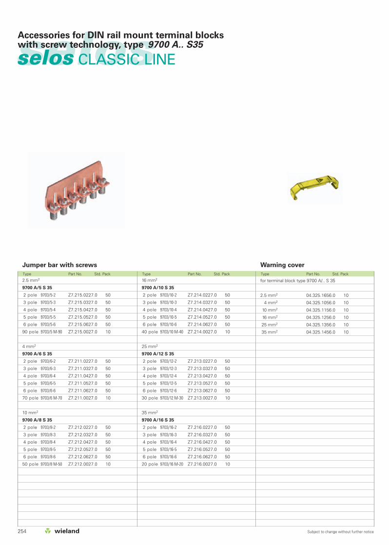
254 Subject to change without further notice
selosselos CLASSIC LINE
Accessories for DIN rail mount terminal blockswith screw technology, type 9700 A.. S35
Warning coverJumper bar with screws
2.5 mm2
9700 A/5 S 35
2 pole 9703/5-2 Z7.215.0227.0 50
3 pole 9703/5-3 Z7.215.0327.0 50
4 pole 9703/5-4 Z7.215.0427.0 50
5 pole 9703/5-5 Z7.215.0527.0 50
6 pole 9703/5-6 Z7.215.0627.0 50
90 pole 9703/5 M-90 Z7.215.0027.0 10
4 mm2
9700 A/6 S 35
2 pole 9703/6-2 Z7.211.0227.0 50
3 pole 9703/6-3 Z7.211.0327.0 50
4 pole 9703/6-4 Z7.211.0427.0 50
5 pole 9703/6-5 Z7.211.0527.0 50
6 pole 9703/6-6 Z7.211.0627.0 50
70 pole 9703/6 M-70 Z7.211.0027.0 10
10 mm2
9700 A/8 S 35
2 pole 9703/8-2 Z7.212.0227.0 50
3 pole 9703/8-3 Z7.212.0327.0 50
4 pole 9703/8-4 Z7.212.0427.0 50
5 pole 9703/8-5 Z7.212.0527.0 50
6 pole 9703/8-6 Z7.212.0627.0 50
50 pole 9703/8 M-50 Z7.212.0027.0 10
Type Part No. Std. Pack Type Part No. Std. Pack Type Part No. Std. Pack
for terminal block type 9700 A/.. S 35
2.5 mm2 04.325.1656.0 10
4 mm2 04.325.1056.0 10
10 mm2 04.325.1156.0 10
16 mm2 04.325.1256.0 10
25 mm2 04.325.1356.0 10
35 mm2 04.325.1456.0 10
16 mm2
9700 A/10 S 35
2 pole 9703/10-2 Z7.214.0227.0 50
3 pole 9703/10-3 Z7.214.0327.0 50
4 pole 9703/10-4 Z7.214.0427.0 50
5 pole 9703/10-5 Z7.214.0527.0 50
6 pole 9703/10-6 Z7.214.0627.0 50
40 pole 9703/10 M-40 Z7.214.0027.0 10
25 mm2
9700 A/12 S 35
2 pole 9703/12-2 Z7.213.0227.0 50
3 pole 9703/12-3 Z7.213.0327.0 50
4 pole 9703/12-4 Z7.213.0427.0 50
5 pole 9703/12-5 Z7.213.0527.0 50
6 pole 9703/12-6 Z7.213.0627.0 50
30 pole 9703/12 M-30 Z7.213.0027.0 10
35 mm2
9700 A/16 S 35
2 pole 9703/16-2 Z7.216.0227.0 50
3 pole 9703/16-3 Z7.216.0327.0 50
4 pole 9703/16-4 Z7.216.0427.0 50
5 pole 9703/16-5 Z7.216.0527.0 50
6 pole 9703/16-6 Z7.216.0627.0 50
20 pole 9703/16 M-20 Z7.216.0027.0 10
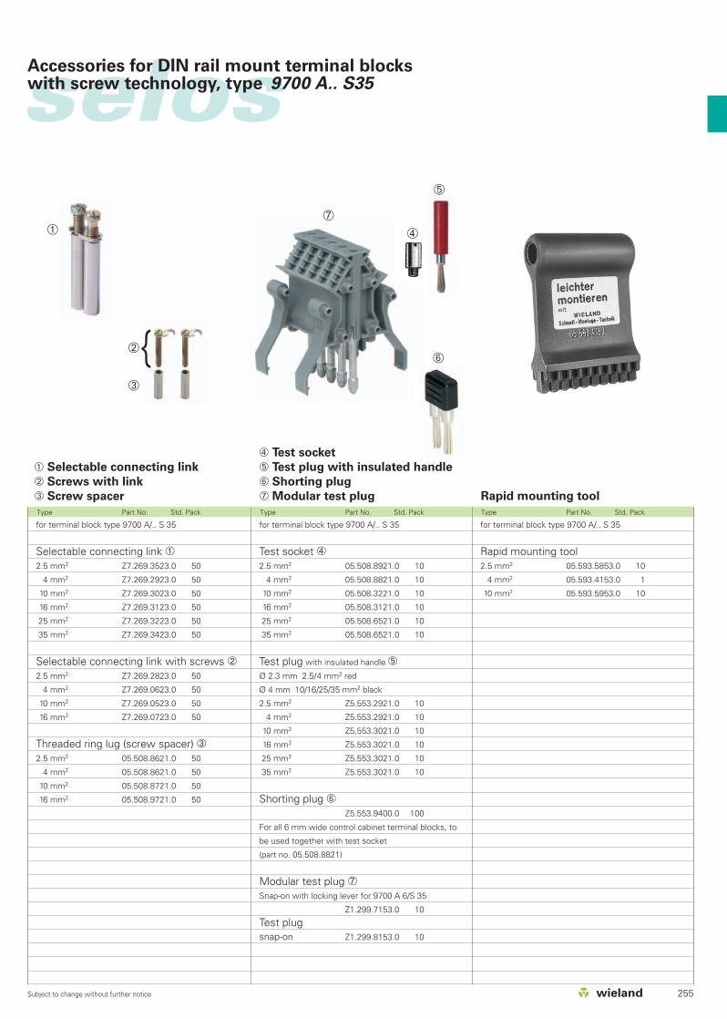
255Subject to change without further notice
selosAccessories for DIN rail mount terminal blockswith screw technology, type 9700 A.. S35
➃ Test socket
➄ Test plug with insulated handle
➅ Shorting plug
➆ Modular test plug Rapid mounting tool
for terminal block type 9700 A/.. S 35
Test socket ➃2.5 mm2 05.508.8921.0 10
4 mm2 05.508.8821.0 10
10 mm2 05.508.3221.0 10
16 mm2 05.508.3121.0 10
25 mm2 05.508.6521.0 10
35 mm2 05.508.6521.0 10
Test plug with insulated handle ➄Ø 2.3 mm 2.5/4 mm2 red
Ø 4 mm 10/16/25/35 mm2 black
2.5 mm2 Z5.553.2921.0 10
4 mm2 Z5.553.2921.0 10
10 mm2 Z5.553.3021.0 10
16 mm2 Z5.553.3021.0 10
25 mm2 Z5.553.3021.0 10
35 mm2 Z5.553.3021.0 10
Shorting plug ➅Z5.553.9400.0 100
For all 6 mm wide control cabinet terminal blocks, to
be used together with test socket
(part no. 05.508.8821)
Modular test plug ➆Snap-on with locking lever for 9700 A 6/S 35
Z1.299.7153.0 10
Test plugsnap-on Z1.299.8153.0 10
➀ Selectable connecting link
➁ Screws with link
➂ Screw spacer
Type Part No. Std. Pack Type Part No. Std. Pack Type Part No. Std. Pack
for terminal block type 9700 A/.. S 35
Selectable connecting link ➀2.5 mm2 Z7.269.3523.0 50
4 mm2 Z7.269.2923.0 50
10 mm2 Z7.269.3023.0 50
16 mm2 Z7.269.3123.0 50
25 mm2 Z7.269.3223.0 50
35 mm2 Z7.269.3423.0 50
Selectable connecting link with screws ➁2.5 mm2 Z7.269.2823.0 50
4 mm2 Z7.269.0623.0 50
10 mm2 Z7.269.0523.0 50
16 mm2 Z7.269.0723.0 50
Threaded ring lug (screw spacer) ➂2.5 mm2 05.508.8621.0 50
4 mm2 05.508.8621.0 50
10 mm2 05.508.8721.0 50
16 mm2 05.508.9721.0 50
for terminal block type 9700 A/.. S 35
Rapid mounting tool2.5 mm2 05.593.5853.0 10
4 mm2 05.593.4153.0 1
10 mm2 05.593.5953.0 10
➀
➁➂
➃
➄
➆
➅

256 Subject to change without further notice
selosselos CLASSIC LINE
Accessories for DIN rail terminal blocks with screw connection
Mounting rail
1. Steel, galv. zinc-plated and dichromated,unslotted L = 2 m
Steel, galv. zinc-plated and dichromated,slottedL = 2 m
2. Steel, unplated unslotted L = 2 m
Steel, unplated slotted L = 2 m
3. Steel, hot-galvanized unslotted L = 2 m
Steel, hot-galvanized slotted L = 2 m
4. E copper unslotted L = 2 m
E copper slotted L = 2 m
End clamp
5. End clamp with screw for 35 mm rail 8 mm wide
6. End clamp with screw for 35 mm rail
with marking plate 8/17.5 mm wide
for terminal strips
7. End clamp, screwless, for 35 mm rail 8 mm wide
8. End clamp, screwless, for 35 mm rail
with marking plate 8/17.5 mm wide
for terminal rails
9. Bus bar holder 8 mm wide
Busbar support, with screw 8 mm
10. Clamping screw for mounting rail
11. Optional label carrier
12. Paper markers in perforated sheet form
(1 sheet = 100 marking tags)
Type Part No. Std. Pack Type Part No. Std. Pack
35 x 27 x 15 EN 60715 98.370.0000.0 1
35 x 27 x 15 EN 60715 98.370.1000.0 1
Mounting rail 35 x 7.5
according to DIN EN 60715
35 x 27 x 7,5 EN 60715 98.300.0000.0 1
35 x 27 x 7,5 EN 60715 gelocht 98.300.1000.0 1
35 x 27 x 7,5 EN 60715 blank 98.300.0010.0 1
Mounting rail 35 x 15
according to DIN EN 60715

257Subject to change without further notice
selosAccessories for DIN rail terminal blocks with screw connection
End clamp for TS 35
Screw mountEnd clamp for TS 35
Screwless mount
9708/2 S 35 Z5.522.8553.0 100
9708/2 BS/35 69.920.0553.0 100
04.019.0289.0 10
Type Part No. Std. Pack Type Part No. Std. Pack Type Part No. Std. Pack
35 x 27 x 15 EN 60715 98.360.0000.0 1
35 x 27 x 15 EN 60715 ZN 98.360.0004.0 1
35 x 27 x 15 EN 60715 CU 98.380.0000.0 10
WEF 1/35 Z5.523.9353.0 100
WEF 1 BS/35 69.920.1053.0 100
WKIF SH/E/35 Z1.108.8453.0 100
69.920.1153.0 100
05.091.0212.0 100
BS/R Z4.243.8453.0 100
04.019.0289.0 10
Mounting rail 35 x 15
according to DIN EN 60715

258 Subject to change without further notice
selosselos CLASSIC LINE
Marking accessories for DIN rail terminal blocks
Description
With wiemarc you can create custom marking data
for standard Wieland marking tags on your PC. These
can then be output to the wieplot 500 plotter system
onto standard Wieland marking plates.
Resolution: 0,01 mm
Accuracy: +/- 0.05 mm
Power supply: 50/60 Hz, 100 – 240 V,
Output voltage
24 V DC 1.4 A
Power consumption: approx. 0.3 A at 220 V
Approvals: UL1950
CSA 950 and
VDE EN 60 950
Radio interference suppression: FCC class B
FCC part 15 and VDE class B
Dimensions: 660 mm x 440 mm x 125 mm
Weight: 8 kg
Interfaces: USB level 1.1, parallel
(Centronics)
Plotter wieplot 500 95.502.0603.0 1
Complete package 95.502.0604.0 1
consisting of:
– Plotter wieplot 500 (including data cable and manual)
– Receptacle for WSB* (4 pcs.)
– Accessories kit
– Software wiemarc
Receptacle for WSB* 95.502.0620.0 1
Receptacle for
BZ/WKF 1,5 95.502.0627.0 1
BZ/WKF 1,5/10 95.502.0628.0 1
* WSB (=Wieland standard marking system)
wieplot 500Type Part No. Std. Pack Type Part No. Std. Pack Type Part No. Std. Pack
wiemarcSoftware for DIN rail terminal blocks
wieplan
wieplan CD 95.502.1000.0 1
Description:
wieplan is software for terminal strip configuration.
The software provides the following modules:
– Project management
– Plausibility check
– Selection of components
– Selection of accessories
– Output of drawings
– Output of parts lists
– Order output
System requirements:
Pentium 2 or compatible; min. 200 MHz; CD-ROM
drive; 32 MByte RAM, VGA graphics adapter and
monitor.
wiemarc CD 95.502.0501.0 1
Discription
wiemarc is a Windows® based plotter software
(Windows 95/98/ME/NT/XP) that is able to drive the
following plotter systems:
– wieplot MUT (Mutoh system)
– wieplot 500
wiemarc makes preparing data for custom printing
easier and faster than ever.
Intuitive handling allows printing of marking tag cards in
single, multiple and series marking jobs.
Import of marking data from Excel files, text files and
CAD/CAE programs is possible.
wiemarc data file management is user-friendly as
print data can be stored and found very easily in the file
library.
wiemarc knows several special characters for
electrical marking.
wiemarc is able to mark tags with upward or
downward series, series steps can be chosen as well
as leading or following characters. Multiple line printing
is possible depending on tag size, number of digits and
type size. Automatic adaptation of type size according
to tag size and number of digits.
Requirements:
Pentium II PC or compatible, min. 200 MHz or higher,
64 MByte RAM, CD-ROM Drive, VGA Grafic Adaptor
and Monitor
wiemarc supports Windows 95®, Windows 98®,
Windows 2000®, Windows NT®, Windows ME® and
Windows XP® Professional.

259Subject to change without further notice
selosMarking accessories for DIN rail terminal blocks
Type Part No. Type Part No. Std. Pack Type Part No. Std. Pack
9075 A/5/10/11 Z4.242.5053.0 10
9705 AL/5/10/6 Z4.242.5153.0 10
9705 A/6/10/11 Z4.242.6053.0 10
9705 AL/6/10/6 Z4.242.6353.0 10
9705 A/8/10/7 Z4.242.8053.0 10
BZ/WKF 1,5 04.243.2053.0 100
BZ/WKF 1,5/10 Z4.243.2053.0 10
Accessories
Accessory kit consists of plotter pen 0.25 mm,
Ink-cartridge, permanent plotter pen 0.3 mm and
cleaning set.
Accessory kit (pen basic equipment
Plotter pens for ROLAND and wieplot MUT systems:
Plotter pen 0.18 mm
Plotter pen 0.25 mm
Plotter pen 0.35 mm
Plotter pen 0.50 mm
Plotter pen 0.70 mm
Plotter pen 1.00 mm
Permanent Plotter pen
0.30 mm black
0.70 mm black
Permanent Plotter pen set
consisting of black, red, blue, green pen.
set 0.30 mm
set 0.70 mm
Hand pens
Hand pen 0.25 mm
Hand pen 0.35 mm
Hand pen 0.50 mm
Hand pen 0.70 mm
Ink cartridge P1.0 5 x 1 ml
Cleaning set
Pen cleaner
Dust protection hood
Service kit for pen station
Kit with sealing inserts
wiemarc receptacles for Wieland marking plates;
available on request for modifying plotter systems of
other suppliers in order to use them together with
wiemarc
95.502.0610.0
95.502.0118.0
95.502.0125.0
95.502.0135.0
95.502.0150.0
95.502.0170.0
95.502.0100.0
95.502.0230.0
95.502.0270.0
95.502.0234.0
95.502.0274.0
95.502.0425.0
95.502.0435.0
95.502.0450.0
95.502.0470.0
95.502.0199.0
95.502.0198.0
95.502.0197.0
95.502.0612.0
95.502.0613.0
Marking computer
in system kit
Marking computer for markingcards
marcom 2 95.502.0000.0 1
Description
wieland marcom 2 is a openly programmable marking
computer for marking tags of DIN rail terminal blocks,
pluggable connectors, cables and switching devices.
The program technology with flexible menu control
produces excellent results requiring only few input.
Entry of a sequence of figures is automatically limited
by the parameters of the selected marking tags,
eliminating incorrect print-out. Repeated operations
can be saved as so-called JOBs and are therefore
immediately available for print-out without further
entries. The computer disposes of a large number of
fonts, with numerical, alphanumerical (small/capital
letters) and symbolic characters.
marcom 2 is powered by an attached power supply.
For a mains-independent operation, the marcom 2
Power Pack is available.
9075A/5/10/11
9075AL/5/10/6
9075A/6/10/11
9075AL/6/10/6
9075A/6.7/12/7
9075AL/6.7/12/7
9075A/8/10/7
fasisWKF 2.5 ... X X
WKF 4 ... X X
WKF 6 ... X X* X
WKF 10 ... X* X*WKF 16 ... X* X*WKMF 2.5 ... X X
tarisWKC 1 ... X X
WKC 2.5 ... X X
selosWK 2.5 ... X X
WK 4 ... X X
WK 6 ... X+ X+ X
WKN 10 ... X* X*WKN 16 ... X* X*WKN 35 ... X+ X+ X*WKN 70 ... X+ X+
WKM 2.5 ... X X
WKM 4 ... X X
9220 A/6 X X
9700 A/5 X X
9700 A/6 X X
9700 A/8 X+ X+ X
9700 A/10 X* X*9700 A/12 X* X*9700 A/16 X+ X+
Marker Cards:
110 tags per card, 5 x 8.3 mm
60 tags per card, 5 x 14 mm
110 tags per card, 6 x 8.3 mm
60 tags per card, 6 x 14 mm
70 Schilder pro Platte, 8 x 8,3 mm
for block center marking
for outside marking
* 2 strips needed for 10 terminals + markers must be mounted individuallyNote: the AL-markers are 69% longer that the A-markers
AL/6.7 is twice as long to allow more printing area

260 Subject to change without further notice
selosselos CLASSIC LINE
Type Part No. Std. Pack Type Part No. Std. Pack Type Part No. Std. Pack
Marking accessories for DIN rail terminal blocks
2.5 mm2/5 mm width 4 mm2/6 mm width
Marking strips, unmarked
9705 A/5/10 04.242.5053.0 25
Marking strips, marked
9705 A/5/9 B 1 - 9 04.842.4953.0 25
9705 A/5/10 B* 04.842.5053.0 25
9705 A/5/10 B 1 - 10 04.845.0153.0 25
11 - 20 04.845.0253.0 25
21 - 30 04.845.0353.0 25
31 - 40 04.845.0453.0 25
41 - 50 04.845.0553.0 25
51 - 60 04.845.0653.0 25
61 - 70 04.845.0753.0 25
71 - 80 04.845.0853.0 25
81 - 90 04.845.0953.0 25
91 - 100 04.845.1053.0 25
(10 x) 04.855.0053.0 25
(10 x) 04.855.0153.0 25
+ (10 x) 04.855.0253.0 25
– (10 x) 04.855.0353.0 25
L1 (10 x) 04.855.0453.0 25
L2 (10 x) 04.855.0553.0 25
L3 (10 x) 04.855.0653.0 25
PE (10 x) 04.855.0753.0 25
SL (10 x) 04.855.3153.0 25
N (10 x) 04.855.3253.0 25
F1 (10 x) 04.855.0953.0 25
F2 (10 x) 04.855.1053.0 25
L1, L2, L3, N, PE (2 x) 04.855.0853.0 25
with enlarged marking area
9705 AL/5/10 04.242.5153.0 25
*Custom marking upon request
Marking strips, unmarked
9705 A/6/10 04.242.6053.0 25
Marking strips, marked
9705 A/6/9 B 1 - 9 04.842.5953.0 25
9705 A/6/10 B* 04.842.6053.0 25
9705 A/6/10 B 1 - 10 04.846.0153.0 25
11 - 20 04.846.0253.0 25
21 - 30 04.846.0353.0 25
31 - 40 04.846.0453.0 25
41 - 50 04.846.0553.0 25
51 - 60 04.846.0653.0 25
61 - 70 04.846.0753.0 25
71 - 80 04.846.0853.0 25
81 - 90 04.846.0953.0 25
91 - 100 04.846.1053.0 25
(10 x) 04.856.0053.0 25
(10 x) 04.856.0153.0 25
+ (10 x) 04.856.0253.0 25
– (10 x) 04.856.0353.0 25
L1 (10 x) 04.856.0453.0 25
L2 (10 x) 04.856.0553.0 25
L3 (10 x) 04.856.0653.0 25
PE (10 x) 04.856.0753.0 25
SL (10 x) 04.856.3153.0 25
N (10 x) 04.856.3253.0 25
F1 (10 x) 04.856.0953.0 25
F2 (10 x) 04.856.1053.0 25
L1, L2, L3, N, PE (2 x) 04.856.0853.0 25
with enlarged marking area
9705 AL/6/10 04.242.6353.0 25
6 mm2/8 mm width
Marking strips, unmarked
9705 A/8/10 04.242.8053.0 25
Marking strips, marked
9705 A/8/9 B 1 - 9 04.842.7953.0 25
9705 A/8/10 B* 04.842.8053.0 25
9705 A/8/10 B 1 - 10 04.848.0153.0 25
11 - 20 04.848.0253.0 25
21 - 30 04.848.0353.0 25
31 - 40 04.848.0453.0 25
41 - 50 04.848.0553.0 25
51 - 60 04.848.0653.0 25
61 - 70 04.848.0753.0 25
71 - 80 04.848.0853.0 25
81 - 90 04.848.0953.0 25
91 - 100 04.848.1053.0 25
(10 x) 04.858.0053.0 25
(10 x) 04.858.0153.0 25
+ (10 x) 04.858.0253.0 25
– (10 x) 04.858.0353.0 25
L1 (10 x) 04.858.0453.0 25
L2 (10 x) 04.858.0553.0 25
L3 (10 x) 04.858.0653.0 25
PE (10 x) 04.858.0753.0 25
SL (10 x) 04.858.3153.0 25
N (10 x) 04.858.3253.0 25
F1 (10 x) 04.858.0953.0 25
F2 (10 x) 04.858.1053.0 25
L1, L2, L3, N, PE (2 x) 04.858.0853.0 25

261Subject to change without further notice
selosMarking accessories for DIN rail terminal blocks
Type Part No. Std. Pack Type Part No. Std. Pack Type Part No. Std. Pack
35 mm2/16 mm width
marked for 5 blocks (every 2nd tag) *
9705 A/8/10/5 B 04.842.8553.0 25
16 mm2/12 mm width
marked for 5 blocks (every 2nd tag) *
9705 A/6/10/5 B 04.842.6553.0 25
10 mm2/10 mm width
marked for 5 blocks (every 2nd tag) *
9705 A/5/10/5 B 04.842.5553.0 25
*Custom marking available on request
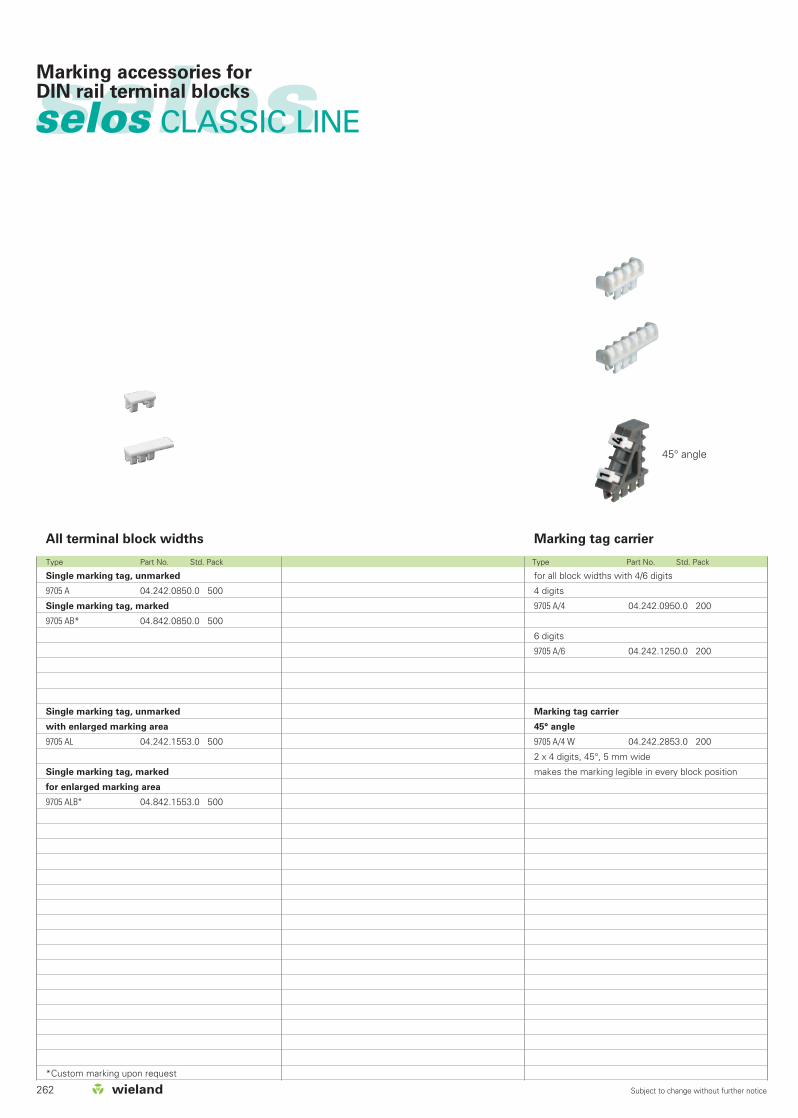
262 Subject to change without further notice
selos
Type Part No. Std. Pack Type Part No. Std. Pack
Marking accessories forDIN rail terminal blocks
All terminal block widths
Single marking tag, unmarked
9705 A 04.242.0850.0 500
Single marking tag, marked
9705 AB* 04.842.0850.0 500
Single marking tag, unmarked
with enlarged marking area
9705 AL 04.242.1553.0 500
Single marking tag, marked
for enlarged marking area
9705 ALB* 04.842.1553.0 500
*Custom marking upon request
Marking tag carrier
for all block widths with 4/6 digits
4 digits
9705 A/4 04.242.0950.0 200
6 digits
9705 A/6 04.242.1250.0 200
Marking tag carrier
45° angle
9705 A/4 W 04.242.2853.0 200
2 x 4 digits, 45°, 5 mm wide
makes the marking legible in every block position
45° angle
selos CLASSIC LINE

selos
263Subject to change without further notice
Marking accessories forDIN rail terminal blocks
Marking Type Part No. Std. Pack Marking Type Part No. Std. Pack Marking Type Part No. Std. Pack
Tear-off marking strip with 10 marking tags
marked with the same upper case letters
A 9704 A/AG B 04.841.2250.0 25
B 9704 A/BG B 04.841.2350.0 25
C 9704 A/CG B 04.841.2450.0 25
D 9704 A/DG B 04.841.2550.0 25
E 9704 A/EG B 04.841.2650.0 25
F 9704 A/FG B 04.841.2750.0 25
G 9704 A/GG B 04.841.2850.0 25
H 9704 A/HG B 04.841.2950.0 25
I 9704 A/IG B 04.841.3050.0 25
J 9704 A/JG B 04.841.3150.0 25
K 9704 A/KG B 04.841.3250.0 25
L 9704 A/LG B 04.841.3350.0 25
M 9704 A/MG B 04.841.3450.0 25
N 9704 A/NG B 04.841.3550.0 25
O 9704 A/OG B 04.841.3650.0 25
P 9704 A/PG B 04.841.3750.0 25
Q 9704 A/QG B 04.841.3850.0 25
R 9704 A/RG B 04.841.3950.0 25
S 9704 A/SG B 04.841.4050.0 25
T 9704 A/TG B 04.841.4150.0 25
U 9704 A/UG B 04.841.4250.0 25
V 9704 A/VG B 04.841.4350.0 25
W 9704 A/WG B 04.841.4450.0 25
X 9704 A/XG B 04.841.4550.0 25
Y 9704 A/YG B 04.841.4650.0 25
Z 9704 A/ZG B 04.841.4750.0 25
marked with the same lower case letters
a 9704 A/AK B 04.841.4850.0 25
b 9704 A/BK B 04.841.4950.0 25
c 9704 A/CK B 04.841.5050.0 25
d 9704 A/DK B 04.841.5150.0 25
e 9704 A/EK B 04.841.5250.0 25
f 9704 A/FK B 04.841.5350.0 25
g 9704 A/GK B 04.841.5450.0 25
h 9704 A/HK B 04.841.5550.0 25
i 9704 A/IK B 04.841.5650.0 25
j 9704 A/JK B 04.841.5750.0 25
k 9704 A/KK B 04.841.5850.0 25
l 9704 A/LK B 04.841.5950.0 25
m 9704 A/MK B 04.841.6050.0 25
n 9704 A/NK B 04.841.6150.0 25
o 9704 A/OK B 04.841.6250.0 25
p 9704 A/PK B 04.841.6350.0 25
q 9704 A/QK B 04.841.6450.0 25
r 9704 A/RK B 04.841.6550.0 25
s 9704 A/SK B 04.841.6650.0 25
t 9704 A/TK B 04.841.6750.0 25
u 9704 A/UK B 04.841.6850.0 25
v 9704 A/VK B 04.841.6950.0 25
w 9704 A/WK B 04.841.7050.0 25
x 9704 A/XK B 04.841.7150.0 25
y 9704 A/YK B 04.841.7250.0 25
z 9704 A/ZK B 04.841.7350.0 25
unmarked
9704 A 04.241.1150.0 25
marked with the same number
1 9704 A/1 B 04.841.1150.0 25
2 9704 A/2 B 04.841.1250.0 25
3 9704 A/3 B 04.841.1350.0 25
4 9704 A/4 B 04.841.1450.0 25
5 9704 A/5 B 04.841.1550.0 25
6 9704 A/6 B 04.841.1650.0 25
7 9704 A/7 B 04.841.1750.0 25
8 9704 A/8 B 04.841.1850.0 25
9 9704 A/9 B 04.841.1950.0 25
0 9704 A/0 B 04.841.2050.0 25
marked with consecutive numbers
1-0 9704 A/1-0 B 04.841.2150.0 25
marked with the same symbols
+ 9704 A/+ B 04.841.7450.0 25
– 9704 A/– B 04.841.7550.0 25
/ 9704 A// B 04.841.7650.0 25
. 9704 A/. B 04.841.7750.0 25
1 set of the same numbers
= 10 x 25 strips = 2500 numbers
111 to 000 04.841.9050.0 1
1 set of upper case letters
= 26 x 25 strips = 6500 letters
A to Z GB 04.841.9150.0 1
1 set of lower case letters
= 26 x 25 strips = 6500 letters
a to z KB 04.841.9250.0 1
Assortment with 50 numbers
1-0 04.900.1053.0 1
Material: Polyamide 66/6 white, marking in black Marking per strip

264
selosselos

265Subject to change without further notice
selosTOP system
The TOP system offers
Terminal block module based on narrowpitch of 5 mm
Top-System allows wire entry andscrewdriver access in the same plane
Universal mounting foot for TS 35 mm DIN rail to EN 60715
TS 32 mm DIN rail to EN 60715
Feed-through terminals located in thecenter
Materials:Insulating housing: Polyamide 66/6Clamping body / clamping screws: steel,zinc-plated and dichromatedCurrent Carrying Bar: Tin-plated copper alloy
TOP plug system
Accepts 10 pole pluggable connector
Coding capability: 28 coding configurations
Pluggable connector with locking levers
Strain relief
TOP system standard
10 pole feed through terminal block module
Orientation perpendicular to the mounting rail
Pitch/width is only 39 mm for 10 terminals
Screw technology
Marking tag system
Snap in marking tag carrier
Marking facility for module
Marking system uses Wieland standardtags
Module is molded with marking 1-10
Potential commoning
Insulated pluggable jumper bars (2-10pole)
Application advantages
Save space in the panel – up to 40%
Ease of inserting and terminating theconductor
Ease of use
Clean and neat wiring
Pluggable connector cannot be mismated
Pluggable connector provides a safeconnection which locks in place
Strain relief with cable ties via holes on themarking plate
Ease of use
Clearly visible and orderly wiring
Secure connection
Mark every termination point
Mark modules individually
Reduces Inventory
Quick and easy installation (no screws)
Increased safety due to tough, securedesign
Easy mounting, secure attachment on alltypes of DIN rail
Due to its excellent electrical, chemicaland mechanical properties
Low contact resistance Each terminal can be marked individually

266 Subject to change without further notice
selosselos
Type Part No. Std. Pack
EN 60 947-7-1/DIN VDE 0611 T1UL ratingsCSA ratingsWidth Wire strip lengthApprovals
Terminal block assembly (screw)
Terminal block assembly (screw/plug)
TOP plug with coding and marking facilities
Accessories
1. Mounting rail TS 35, DIN rail, 7.5 mm high L = 2 m
Mounting rail TS 35, DIN rail 1.5 mm high L = 2 m
Mounting rail TS 32 G rail L = 2 m
2. End clamp with U-foot 10 mm wide
End clamp TS 35, with screw 8 mm wide
End clamp TS 32, with screw 7.5 mm wide
3. Push-in jumper bar
E-Cu insulated 2 pole
3 pole
to 10 pole
4. Mounting adapter for mounting right
parallel to the rail left
Coding pins, 10 each per strip
Marking tag carrier, snap-on
For marking systems see pages 284-289
WKB 2,5/U 57.603.0055.0 10
35 x 27 x 7,5 EN 60715 98.300.0000.0 1
35 x 24 x 15 EN 60715 98.360.0000.0 1
9006 EN 60715 G-32 98.190.0000.0 1
WE 1/U Z5.523.5753.0 100
9708/2 S 35 Z5.522.8553.0 100
9708 Z5.522.7053.0 100
Z7.258.0225.0 10
Z7.258.0325.0 10
Z7.258.1025.0 10
05.523.1610.0 10
05.523.1710.0 10
04.242.3253.0 50
*) When two cross connectors are mounted adjacent toeach other, the rated voltage is reduced to 250 V/4 kV/3
TOP system
WKB 2,5/U
fine-stranded solid V A0.5 - 2.5 mm2 0.5 - 4 mm2 400 V/6 kV/3 20No. 22-12 AWG 300 V 10No. max. 12 AWG 300 V 1039 mm 10 mm
igqw
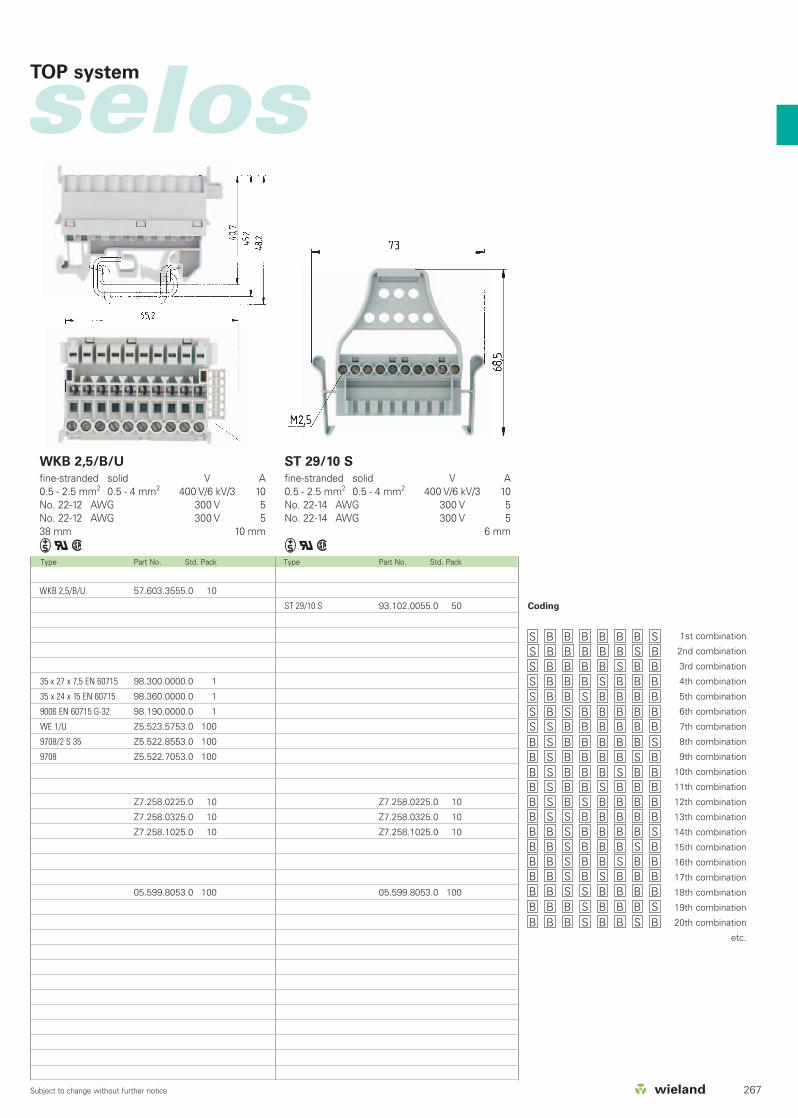
267Subject to change without further notice
selos
Type Part No. Std. Pack Type Part No. Std. Pack
ST 29/10 S 93.102.0055.0 50
Z7.258.0225.0 10
Z7.258.0325.0 10
Z7.258.1025.0 10
05.599.8053.0 100
Coding
1st combination
2nd combination
3rd combination
4th combination
5th combination
6th combination
7th combination
8th combination
9th combination
10th combination
11th combination
12th combination
13th combination
14th combination
15th combination
16th combination
17th combination
18th combination
19th combination
20th combination
etc.
WKB 2,5/B/U 57.603.3555.0 10
35 x 27 x 7,5 EN 60715 98.300.0000.0 1
35 x 24 x 15 EN 60715 98.360.0000.0 1
9006 EN 60715 G-32 98.190.0000.0 1
WE 1/U Z5.523.5753.0 100
9708/2 S 35 Z5.522.8553.0 100
9708 Z5.522.7053.0 100
Z7.258.0225.0 10
Z7.258.0325.0 10
Z7.258.1025.0 10
05.599.8053.0 100
S B B B B B B SS B B B B B S BS B B B B S B BS B B B S B B BS B B S B B B BS B S B B B B BS S B B B B B BB S B B B B B SB S B B B B S BB S B B B S B BB S B B S B B BB S B S B B B BB S S B B B B BB B S B B B B SB B S B B B S BB B S B B S B BB B S B S B B BB B S S B B B BB B B S B B B SB B B S B B S B
TOP system
WKB 2,5/B/U
fine-stranded solid V A0.5 - 2.5 mm2 0.5 - 4 mm2 400 V/6 kV/3 10No. 22-12 AWG 300 V 5No. 22-12 AWG 300 V 538 mm 10 mm
iqw
ST 29/10 S
fine-stranded solid V A0.5 - 2.5 mm2 0.5 - 4 mm2 400 V/6 kV/3 10No. 22-14 AWG 300 V 5No. 22-14 AWG 300 V 5
6 mm
iqw

selosselosDistribution module, 32 pole Pluggable system with shield connection
Type Part No. Std. Pack Type Part No. Std. Pack
Voltage according to DIN VDE 0110 Distribution module gray (per pole)
blue
RV2S/...
Front Rear V A400 V/6 kV/3 *)
3 x 2.8 x 0.8 3 x 2.8 x 0.82 x 2.8 x 0.8 2 x 2.8 x 0.8
RV2S/...L
Front Rear V A400 V/6 kV/3 *)
3 x 2.8 x 0.8 1 solder connection2 x 2.8 x 0.8 1 solder connection
Material: Insulating part: Polyamide 66/6 gray,blueTab connector: tin-plated copperalloySpring contact: tin-plated bronze
Tab connector: 2.8 x 0.8 mm
*) Push-on connector 6.3 mm 20 APush-on connector 2.8 mm 10 ATERMI-POINT 10 A
Distribution module pluggable system gray
blue
Pluggable connector gray
blue
Accessories
1. Spring contact for 0.5 - 1 mm2
Banded contacts
Single contact
4. Spring contact for 0.1 – 0.5 mm2
Banded contacts
Single contact
7. Crimp Tool
8. Contact removal tool
9. Replacement latch
For marking systems see pages 284-289
RV2S/3L 26.500.2153.0 10
RV2S/2L blau 26.500.2453.0 10
RV2S/6 26.500.2053.0 10
RV2S/4 blau 26.500.2353.0 10
268 Subject to change without further notice
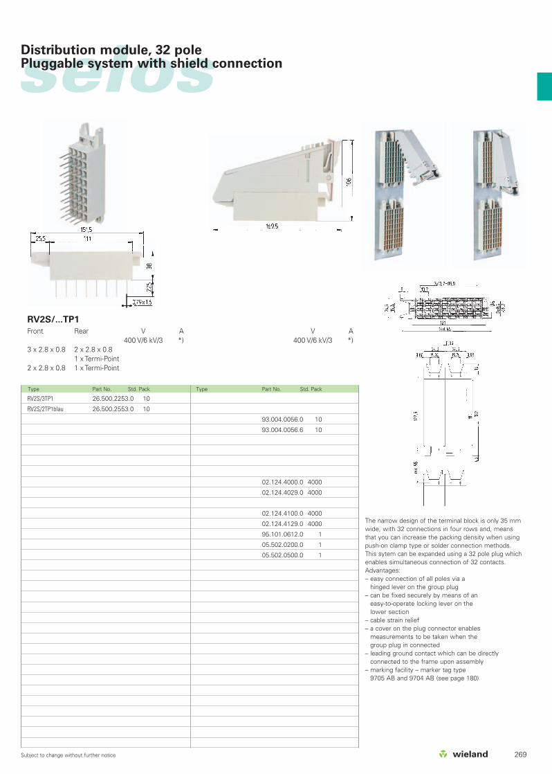
269Subject to change without further notice
selos
Type Part No. Std. Pack Type Part No. Std. Pack
RV2S/...TP1
Front Rear V A400 V/6 kV/3 *)
3 x 2.8 x 0.8 2 x 2.8 x 0.81 x Termi-Point
2 x 2.8 x 0.8 1 x Termi-Point
V A400 V/6 kV/3 *)
93.004.0056.0 10
93.004.0056.6 10
02.124.4000.0 4000
02.124.4029.0 4000
02.124.4100.0 4000
02.124.4129.0 4000
95.101.0612.0 1
05.502.0200.0 1
05.502.0500.0 1
The narrow design of the terminal block is only 35 mmwide, with 32 connections in four rows and, meansthat you can increase the packing density when usingpush-on clamp type or solder connection methods.This sytem can be expanded using a 32 pole plug whichenables simultaneous connection of 32 contacts.Advantages:– easy connection of all poles via a
hinged lever on the group plug– can be fixed securely by means of an
easy-to-operate locking lever on the lower section
– cable strain relief– a cover on the plug connector enables
measurements to be taken when the group plug in connected
– leading ground contact which can be directly connected to the frame upon assembly
– marking facility – marker tag type 9705 AB and 9704 AB (see page 180)
RV2S/3TP1 26.500.2253.0 10
RV2S/2TP1blau 26.500.2553.0 10
Distribution module, 32 pole Pluggable system with shield connection

selosselosDistribution Module 32 pole
Type Part No. Std. Pack Type Part No. Std. Pack
Voltage according to DIN VDE 0110 Stacking coordinate gray (per pole)
blue
RV2/A...
Front Rear V A400 V/6 kV/3 *)
3 x 2.8 x 0.8 3 x 2.8 x 0.82 x 2.8 x 0.8 2 x 2.8 x 0.8
RV2A/...L
Front Rear V A400 V/6 kV/3 *)
3 x 2.8 x 0.8 1 solder connection2 x 2.8 x 0.8 1 solder connection
Material: Insulating part: Polyamide 66/6gray, blueTab connector: tin-plated brassTab connector: 2.8 x 0.8 mm
*) Push-on connector 6.3 mm 20 APush-on connector 2.8 mm 10 ATERMI-POINT 10 A
DIstribution module standard version gray
blue
For marking systems see pages 284-289
RV2A/3L 26.500.4153.0 10
RV2A/2L blau 26.500.4453.0 10
RV2A/6 26.500.4053.0 10
RV2A/4 blau 26.500.4353.0 10
270 Subject to change without further notice

271Subject to change without further notice
selos
Type Part No. Std. Pack
RV2A/...TP1
Front Rear V A400 V/6 kV/3 *)
3 x 2.8 x 0.8 2 x 2.8 x 0.8 1 x Termi-Point
2 x 2.8 x 0.8 1 x Termi-Point
RV2A/3TP1 26.500.4253.0 10
RV2A/2TP blau 26.500.4553.0 10
Distribution module, 32 pole
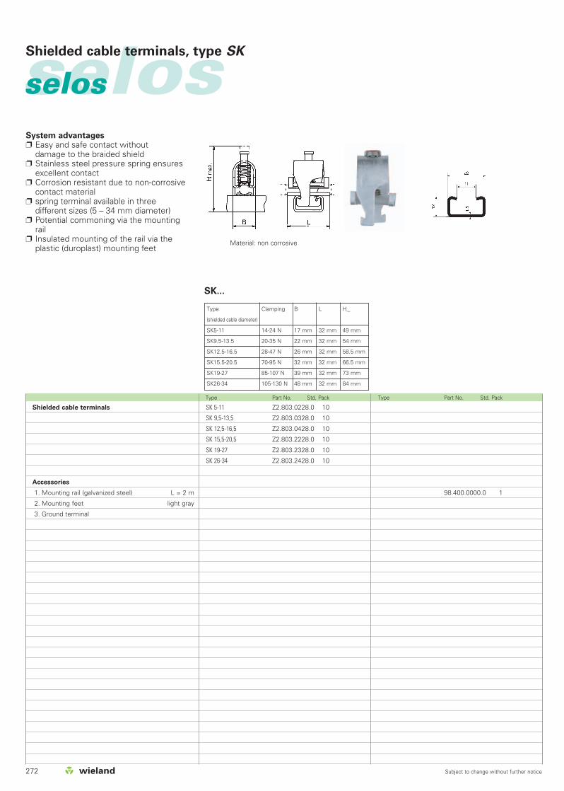
272 Subject to change without further notice
selosselosShielded cable terminals, type SK
Type Part No. Std. Pack Type Part No. Std. Pack
SK...
98.400.0000.0 1
System advantages Easy and safe contact without
damage to the braided shield Stainless steel pressure spring ensures
excellent contact Corrosion resistant due to non-corrosive
contact material spring terminal available in three
different sizes (5 – 34 mm diameter) Potential commoning via the mounting
rail Insulated mounting of the rail via the
plastic (duroplast) mounting feetMaterial: non corrosive
Type Clamping B L Hmax
(shielded cable diameter)
SK5-11 14-24 N 17 mm 32 mm 49 mm
SK9.5-13.5 20-35 N 22 mm 32 mm 54 mm
SK12.5-16.5 28-47 N 26 mm 32 mm 58.5 mm
SK15.5-20.5 70-95 N 32 mm 32 mm 66.5 mm
SK19-27 85-107 N 39 mm 32 mm 73 mm
SK26-34 105-130 N 48 mm 32 mm 84 mm
SK 5-11 Z2.803.0228.0 10
SK 9,5-13,5 Z2.803.0328.0 10
SK 12,5-16,5 Z2.803.0428.0 10
SK 15,5-20,5 Z2.803.2228.0 10
SK 19-27 Z2.803.2328.0 10
SK 26-34 Z2.803.2428.0 10
Shielded cable terminals
Accessories
1. Mounting rail (galvanized steel) L = 2 m
2. Mounting feet light gray
3. Ground terminal

273Subject to change without further notice
selos
Type Part No. Std. Pack Type Part No. Std. Pack
Base: Duroplast, light grayFemale part: brassThread: M4
Rated cross section: 16 mm2
rated wire gaugestranded: 10 – 16 mm2 / 6 – 4 AWGfine-stranded: 1.5 – 16 mm2 / 18 – 4 AWG
Wire strip length: 11 mmWidth: 8.4 mm
9700/10E/1 Z2.302.1321.0 10
Z1.980.0040.0 10
Ground terminal for mounting rail. Clamping body: nickel plated copper alloy
Shielded cable terminals, type SK
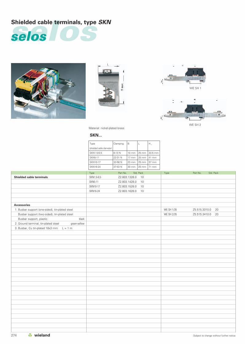
274 Subject to change without further notice
selosselosShielded cable terminals, type SKN
Type Part No. Std. Pack Type Part No. Std. Pack
SKN...
Material: nickel-plated brass
Shielded cable terminals
Accessories
1. Busbar support (one-sided), tin-plated steel
Busbar support (two-sided), tin-plated steel
Busbar support, plastic black
2. Ground terminal, tin-plated steel green-yellow
3. Busbar, Cu tin-plated 18x3 mm L = 1 m
WE SH 1/35 Z5.515.3310.0 20
WE SH 2/35 Z5.515.3410.0 20
SKN1,5-6,5 Z2.803.1328.0 10
SKN5-11 Z2.803.1428.0 10
SKN10-17 Z2.803.1528.0 10
SKN16-24 Z2.803.1628.0 10
WE SH 1
WE SH 2
Type Clamping B L Hmax
(shielded cable diameter)
SKN1.5-6.5 8-13 N 10 mm 25 mm 33.5 mm
SKN5-11 22-31 N 17 mm 25 mm 41 mm
SKN10-17 32-58 N 23 mm 25 mm 57 mm
SKN16-24 37-53 N 30 mm 25 mm 71 mm

275Subject to change without further notice
selos
Type Part No. Std. Pack Type Part No. Std. Pack
WE SH3
WE SH4
SKNSH/35/F Z1.980.0153.0 10
WAK35/4GN 30.494.4210.7 10
18 x 3MSN 98.291.1000.0 10
WESH3/35 Z5.519.0310.0 25
WESH4/35 Z5.519.0410.0 25
Shielded cable terminals, type SKN
SKN SH/35
WAK 35/4

276 Subject to change without further notice
selosselosBusbar components
Type Part No. Std. Pack
DIN VDE 0110
Approvals
V A500 V/6 kV/3
u
L l H h B
4 mm2 35.9 5 x 5.8 = 29 29 14 2010 mm2 64.5 5 x 10.5 = 52.5 36 14 27.5
Insulating housing: Polyamide66/6 - tracking resistantClamping body: nickel-plated brassWire protection: phosphor bronzeClamping screws: steel,zinc-plated and dichromated
Terminal block (up to 10 AWG)
Terminal block (up to 4 AWG)
Accessories for N and PE distribution terminals
1. PE and N rail carrier with sliding nut
2. Spacer for separating busbars
3. Slotted mounting rail
4. End clamp, 9 mm wide
5. Sliding nut
6. Jumper bar, insulated for KL28 2 pole
3 pole
to 6 pole
7. Marking stip rolls, 60 m each
for KL 28 and terminal block 1-99 Distance between figures: 6 mm
for KL 29 and terminal block 1-55 Distance between figures: 10.8 mm
Complete sheet-steel distribution systems in accordance with IEC 61 984 and VDE 0108 can beassembled using these components. The widths ofthe terminals are chosen so that it is easy to identifywhich terminal is allocated to each individual circuitand so that they match the spacing of the miniaturecircuit breakers.
The PE and N busbar (E-Cu 6 x 6 mm) are attached tothe busbar mounting brackets. The bare supply anddistribution board terminals are pushed onto 6 x 6 mmbusbars.
The PE busbar is attached to the top connection ofthe bracket and N busbar to the bottom one. Theinsulated terminals for the phase connections arepushed onto the perforated rail from the top.
For identifying the individual poles of the insulatedterminals, marker strips are available in rollsnumbered in sequences from 1 to 99 for AC circuitsand from 101 for DC circuits.
KL28/6DSPA 33.011.0653.0 50
KL29/6DSPA 33.041.0653.0 20
IVBIK4-2 Z7.255.0227.0 10
IVBIK4-3 Z7.255.0327.0 10
IVBIK4-6 Z7.255.0627.0 10
04.007.1080.0 1
04.007.3080.0 1

277Subject to change without further notice
selos
Type Part No. Std. Pack Type Part No. Std. Pack Type Part No. Std. Pack
05.592.1953.0 100
2163 Z5.522.1923.0 100
Z1.990.2030.0 50
98.310.0000.0 10
05.516.9510.0 100
Busbar components

selosselosModular N and PE distributor terminals
Type Part No. Std. Pack Type Part No. Std. Pack
EN 60998-2-1
Approvals igW CCA/CH igW CCA/CH
Bus bar distribution terminals with plasticcover, screw turret,screw break point, and marking ledge.
Distribution terminal 4 mm2
Distribution N terminal 4 mm2 Cap: blue
Distribution PE terminal 4 mm2 Cap: green-yellow
Distribution terminal 16 mm2
Distribution N terminal 16 mm2 Cap: blue
Distribution PE terminal 16 mm2 Cap: green-yellow
Distribution terminal 25 mm2
Distribution N terminal 25 mm2 Cap: blue
Distribution PE terminal 25 mm2 Cap: green-yellow
Distribution terminal 35 mm2
Distribution N terminal 35 mm2 Cap: blue
Distribution PE terminal 35 mm2 Cap: green-yellow
Neutral conductor rail 15 x 3 mm IN=140A L = 1 m
with DIN 85 screws and lock washers
without screws and washers
Distributor with busbar 6 x 6 mm according to A802
Accessories
1. Rail carrier base
2. Busbar 6 x 6 mm E-Cu IN=140A L = 2 m
3. Busbar 6 x 6 mm E-Cu IN=140A L = 1 m
4. Busbar 10 x 3 mm E-Cu IN=140A L = 1 m
Marking stip rolls, 60 m each
for KL 28 and terminal blocks 1-99 Distance between figures: 6 mm
for KL 29 and terminal blocks 1-55 Distance between figures: 10.8 mm
WAK4/3 30.494.0110.0 250
WAK4/3 bl 30.494.0110.6 500
WAK4/3 gr-gb 30.494.0110.7 500
WAK25/3 30.494.1110.0 100
WAK25/3 bl 30.494.1110.6 100
WAK25/3 gr-gb 30.494.1110.7 100
WAK35/3 30.494.2510.0 100
WAK35/3 bl 30.494.2510.6 100
WAK35/3 gr-gb 30.494.2510.7 100
KSO11/1ZKR 19.230.0040.0 65
98.320.0000.0 1
98.325.1000.0 1
98.290.0000.0 1
04.007.1080.0 1
04.007.3080.0 1
WAK4/1 30.494.0010.0 250
WAK4/1 bl 30.494.0010.6 500
WAK4/1 gr-gb 30.494.0010.7 500
WAK16/1 30.494.1010.0 250
WAK16/1 bl 30.494.1010.6 250
WAK16/1 gr-gb 30.494.1010.7 250
KSO11/1ZKR 19.230.0040.0 65
98.320.0000.0 1
98.325.1000.0 1
04.007.1080.0 1
04.007.3080.0 1
278 Subject to change without further notice
H h M B
4 mm2 23.6 16 M3,5 6.016 mm2 30.8 20.2 M5 9.5
H h h1
L M B
4 mm2 26 16 3 12 M3.5 6.016 mm2 33.5 20.2 3 12 M5 10.725 mm2 41.5 23.1 2.8 16 M6 11.535 mm2 44 25.2 2.8 16 M6 14.3
Material:Insulated Housing:Polyamide 66/6
Metal parts: Steel, zinc plateddichromated

279Subject to change without further notice
selos
Type Part No. Std. Pack Type Part No. Std. Pack
Standard neutral conductor rail screws can be usedto fasten the neutral conductor rail. Cross section ofthreaded holes to measure Ø 5.3 mm.
available on request
KSO11/1ZKR 19.230.0040.0 65
FFK18/2Z Z2.220.0321.0 10
FFK18/3Z Z2.220.0421.0 10
FFK18/1Z Z2.220.0121.0 10
FFK18/2 02.220.0321.0 1
FFK18/3 02.220.0421.0 10
FFK18/1 02.220.0121.0 1
KSO11/1ZKR 19.230.0040.0 65
Modular N and PE distributor terminals
Bus Bar: brassScrews and lock washer: Steel, zincplated dichromated
E-CuMetal parts: steel, galv. zinc-platedand dichromatedPlastic capPolyamide 66/6
measure in mmA M
FKK18/2... 9 4FKK18/3... 11.4 5FKK18/1... 20 5
= Length of attached blocks
Hole spacing, min =
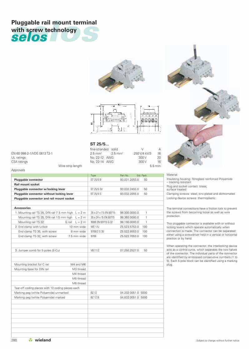
280 Subject to change without further notice
selosselosPluggable rail mount terminal
with screw technology
Type Part No. Std. Pack
EN 60 998-2-1/VDE 0613 T2-1UL ratingsCSA ratings
Wire strip lengthApprovals
ST 25/5...
fine-stranded solid V A2.5 mm2 2.5 mm2 250 V/4 kV/3 16No. 22-12 AWG 300 V 20No. 22-14 AWG 300 V 16
5.5 mm
Material:Insulating housing: fibreglass reinforced Polyamide – tracking resistantPlug and socket contact: brass, surface treatedClamping screws: steel, zinc-plated and dichromatedLocking device screws: thermoplastic
Pluggable connector
Rail mount socket
Pluggable connector w/locking lever
Pluggable connector without locking lever
Pluggable connector and rail mount socket
Accessories
1. Mounting rail TS 35, DIN rail 7 .5 mm high L = 2 m
Mounting rail TS 35, DIN rail 1.5 mm high L = 2 m
Mounting rail TS 32 G rail L = 2 m
2. End clamp with U-foot 10 mm wide
End clamp TS 35, with screw 8 mm wide
End clamp TS 32, with screw 7.5 mm wide
3. Jumper comb for 5 poles (E-Cu)
Mounting bracket for C rail M4 and M6
Mounting base for DIN rail M3 thread
M4 thread
M5 thread
M6 thread
Tear-off coding pieces with 10 coding pieces each
Marking peg (white Polyamide) unmarked
Marking peg (white Polyamide) marked
The terminal connections have a friction lock to preventthe screws from becoming loose as well as wire protection.
This pluggable connector is available with or withoutlocking levers which operate automatically whenconnection is made. The connector can be separatedeither using a screwdriver held in a vertical or horizontalposition or by hand.
When operating the connector, the interlocking deviceacts as a control curve, which separates the two halvesof the connector. The individual parts of the connectorare identified by embossed consecutive numbers (1 to5). Each 5 pole block can be identified using a markingplug.
ST 25/5 B 93.031.2055.0 50
ST 25/5 SV 93.032.2455.0 50
ST 25/5 S 93.032.2055.0 50
35 x 27 x 7,5 EN 60715 98.300.0000.0 1
35 x 24 x 15 EN 60715 98.360.0000.0 1
9006 EN 60715 G-32 98.190.0000.0 1
WE 1/U Z5.523.5753.0 100
9708/2 S 35 Z5.522.8553.0 100
9708 Z5.522.7053.0 100
VB 11/2 07.250.2527.0 50
BZ 12 04.232.0051.0 5000
BZ 12 B 04.832.0051.0 5000

281Subject to change without further notice
selos
Type Part No. Std. Pack Type Part No. Std. Pack
fine-stranded solid V A2.5 mm2 400 V/6 kV/3 16No. 22-12 AWG 300 V 20No. 22-14 AWG 300 V 16
5.5 mm
xzqw1st configuration
2nd configuration
3rd configuration
4th configuration
5th configuration
6th configuration
7th configuration
8th configuration
9th configuration
10th configuration
11th configuration
12th configuration
13th configuration
14th configuration
etc.
TS M 4/M 6-32 69.332.0000.0 100
TS M 3 S 35 69.335.0253.0 100
TS M 4 S 35 69.335.0453.0 100
TS M 5 S 35 69.335.0553.0 100
TS M 6 S 35 69.335.0653.0 100
ST 28/10 B 93.001.1055.0 10
ST 28/10 S 93.002.1055.0 10
ST 28/10 BS 93.003.1055.0 10
05.594.5153.0 100
Compact pluggable connector withcoding capability
Coding diagram for Wieland compact connector type ST 28/10
The plug and socket sections of the compactplug connector each have 8 slots for the codingbar. To do this, a coding piece is inserted in thesocket section at the points marked with “B”.Likewise, a coding piece is inserted in the plugsection at the points marked “S”. The best way tocode the parts is to separate the plug and socketsections and push the coding bars into thecoding slots now facing each other as shown inthe diagram.
Then reconnect the socket sections.
The coding bars are supplied in packages of 10which are connected together to facilitate insertion.
SSSSSSSBBBBBBB
BBBBBBSSSSSSSB
BBBBBSBBBBBBSS
BBBBSBBBBBBSBB
BBBSBBBBBBSBBB
BBSBBBBBBSBBBB
BSBBBBBBSBBBBB
SBBBBBBSBBBBBS
Width 11.5 mm TS M 4/M 6-32
Width 12 mm TS M ... S 35

282 Subject to change without further notice
selosselos
Type Part No. Std. Pack Type Part No. Std. Pack
Modular panel mount terminals with solder/push-on connectors
EN 60 947-7-1/DIN VDE 0611 T1UL ratingsCSA ratingsWidth Wire strip lengthApprovals
fine-stranded solid V A0.5 - 2.5 mm2 0.5 - 2.5 mm2 400 V/4 kV/3 10No. 22-12 AWG 150 V 20No. 22-14 AWG 300 V 106 mm 8 mm
qw
fine-stranded solid V A0.5 - 2.5 mm2 0.5 - 2.5 mm2 400 V/4 kV/3 10No. 22-12 AWG 150 V 20
6 mm 8 mm
qPanel mount terminal
Panel mount terminal without partition
- blue - for EEx i installations
Accessories
Marking strips, unmarked
Marking strips, marked
9290 L 59.900.2052.0 200
9290 L BLAU 59.900.2053.6 200
9290 S 59.900.2552.0 200
9003 C/6/10 04.241.8053.0 50
9003 C/6/10 B available on request
Solder tab connector 2.8 x 0.8 mm for push-onconnector B 2.8 x 1 according to DIN 46247 BI. 1
Solder tab connector 2.8 x 0.8 mm for push-onconnector B 2.8 x 1 according to DIN 46247 BI. 1
Number of terminals x 6

283
selos

284 Subject to change without further notice
selosselos Marking accessories for DIN rail terminal blockswith spring clamp connection
Description
With wiemarc you can create custom marking data
for standard Wieland marking tags on your PC. These
can then be output to the wieplot 500 plotter system
onto standard Wieland marking plates.
Resolution: 0.01 mm
Accuracy: +/- 0.05 mm
Power supply: 50/60 Hz, 100 – 240 V,
Output voltage
24 V DC 1.4 A
Power consumption: approx. 0.3 A at 220 V
Approvals: UL1950
CSA 950 and
VDE EN 60 950
Radio interference suppression: FCC class B
FCC part 15 and VDE class B
Dimensions: 660 mm x 440 mm x 125 mm
Weight: 8 kg
Interfaces: USB level 1.1, parallel
(Centronics)
Plotter wieplot 500 95.502.0603.0 1
Complete package 95.502.0604.0 1
consisting of:
– Plotter wieplot 500 (including data cable and manual)
– Receptacle for WSB* (4 pcs.)
– Accessories kit
– Software wiemarc
Receptacle for WSB* 95.502.0620.0 1
Receptacle for
BZ/WKF 1,5 95.502.0627.0 1
BZ/WKF 1,5/10 95.502.0628.0 1
* WSB (=Wieland standard marking system)
wieplot 500Type Part No. Std. Pack Type Part No. Std. Pack Type Part No. Std. Pack
wiemarcSoftware for DIN rail terminal blocks
wieplan
wieplan CD 95.502.1000.0 1
Description:
wieplan is software for terminal strip configuration.
The software provides the following modules:
– Project management
– Plausibility check
– Selection of components
– Selection of accessories
– Output of drawings
– Output of parts lists
– Order output
System requirements:
Pentium 2 or compatible; min. 200 MHz; CD-ROM
drive; 32 MByte RAM, VGA graphics adapter and
monitor.
wiemarc CD 95.502.0501.0 1
Discription
wiemarc is a Windows® based plotter software
(Windows 95/98/ME/NT/XP) that is able to drive the
following plotter systems:
– wieplot MUT (Mutoh system)
– wieplot 500
wiemarc makes preparing data for custom printing
easier and faster than ever.
Intuitive handling allows printing of marking tag cards in
single, multiple and series marking jobs.
Import of marking data from Excel files, text files and
CAD/CAE programs is possible.
wiemarc data file management is user-friendly as
print data can be stored and found very easily in the file
library.
wiemarc knows several special characters for
electrical marking.
wiemarc is able to mark tags with upward or downward
series, series steps can be chosen as well as leading or
following characters. Multiple line printing is possible
depending on tag size, number of digits and type size.
Automatic adaptation of type size according to tag size
and number of digits.
Requirements:
Pentium II PC or compatible, min. 200 MHz or higher,
64 MByte RAM, CD-ROM Drive, VGA Grafic Adaptor
and Monitor
wiemarc supports Windows 95®, Windows 98®,
Windows 2000®, Windows NT®, Windows ME® and
Windows XP® Professional.
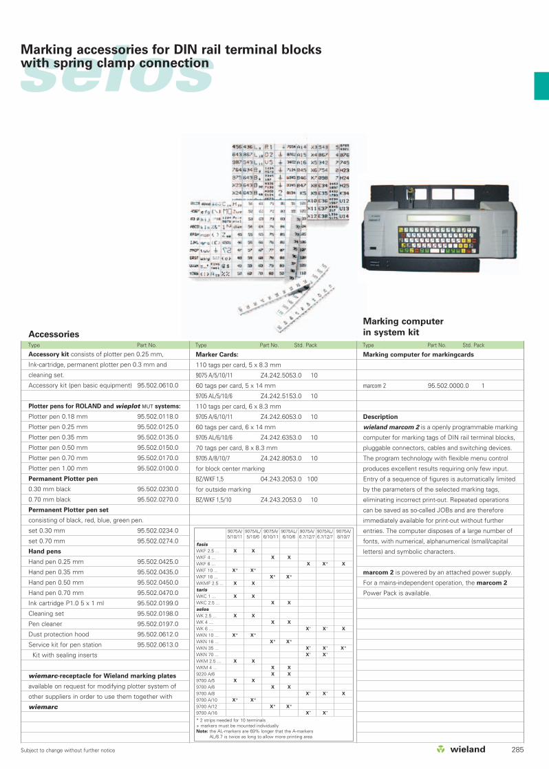
285Subject to change without further notice
Type Part No. Type Part No. Std. Pack Type Part No. Std. Pack
selosMarking accessories for DIN rail terminal blockswith spring clamp connection
Accessories
Accessory kit consists of plotter pen 0.25 mm,
Ink-cartridge, permanent plotter pen 0.3 mm and
cleaning set.
Accessory kit (pen basic equipment)
Plotter pens for ROLAND and wieplot MUT systems:
Plotter pen 0.18 mm
Plotter pen 0.25 mm
Plotter pen 0.35 mm
Plotter pen 0.50 mm
Plotter pen 0.70 mm
Plotter pen 1.00 mm
Permanent Plotter pen
0.30 mm black
0.70 mm black
Permanent Plotter pen set
consisting of black, red, blue, green pen.
set 0.30 mm
set 0.70 mm
Hand pens
Hand pen 0.25 mm
Hand pen 0.35 mm
Hand pen 0.50 mm
Hand pen 0.70 mm
Ink cartridge P1.0 5 x 1 ml
Cleaning set
Pen cleaner
Dust protection hood
Service kit for pen station
Kit with sealing inserts
wiemarc-receptacle for Wieland marking plates
available on request for modifying plotter system of
other suppliers in order to use them together with
wiemarc
95.502.0610.0
95.502.0118.0
95.502.0125.0
95.502.0135.0
95.502.0150.0
95.502.0170.0
95.502.0100.0
95.502.0230.0
95.502.0270.0
95.502.0234.0
95.502.0274.0
95.502.0425.0
95.502.0435.0
95.502.0450.0
95.502.0470.0
95.502.0199.0
95.502.0198.0
95.502.0197.0
95.502.0612.0
95.502.0613.0
Marking computer
in system kit
Marking computer for markingcards
marcom 2 95.502.0000.0 1
Description
wieland marcom 2 is a openly programmable marking
computer for marking tags of DIN rail terminal blocks,
pluggable connectors, cables and switching devices.
The program technology with flexible menu control
produces excellent results requiring only few input.
Entry of a sequence of figures is automatically limited
by the parameters of the selected marking tags,
eliminating incorrect print-out. Repeated operations
can be saved as so-called JOBs and are therefore
immediately available for print-out without further
entries. The computer disposes of a large number of
fonts, with numerical, alphanumerical (small/capital
letters) and symbolic characters.
marcom 2 is powered by an attached power supply.
For a mains-independent operation, the marcom 2
Power Pack is available.
9075A/5/10/11
9075AL/5/10/6
9075A/6/10/11
9075AL/6/10/6
9075A/6.7/12/7
9075AL/6.7/12/7
9075A/8/10/7
fasisWKF 2.5 ... X X
WKF 4 ... X X
WKF 6 ... X X* X
WKF 10 ... X* X*WKF 16 ... X* X*WKMF 2.5 ... X X
tarisWKC 1 ... X X
WKC 2.5 ... X X
selosWK 2.5 ... X X
WK 4 ... X X
WK 6 ... X+ X+ X
WKN 10 ... X* X*WKN 16 ... X* X*WKN 35 ... X+ X+ X*WKN 70 ... X+ X+
WKM 2.5 ... X X
WKM 4 ... X X
9220 A/6 X X
9700 A/5 X X
9700 A/6 X X
9700 A/8 X+ X+ X
9700 A/10 X* X*9700 A/12 X* X*9700 A/16 X+ X+
* 2 strips needed for 10 terminals + markers must be mounted individuallyNote: the AL-markers are 69% longer that the A-markers
AL/6.7 is twice as long to allow more printing area
9075 A/5/10/11 Z4.242.5053.0 10
9705 AL/5/10/6 Z4.242.5153.0 10
9705 A/6/10/11 Z4.242.6053.0 10
9705 AL/6/10/6 Z4.242.6353.0 10
9705 A/8/10/7 Z4.242.8053.0 10
BZ/WKF 1,5 04.243.2053.0 100
BZ/WKF 1,5/10 Z4.243.2053.0 10
Marker Cards:
110 tags per card, 5 x 8.3 mm
60 tags per card, 5 x 14 mm
110 tags per card, 6 x 8.3 mm
60 tags per card, 6 x 14 mm
70 tags per card, 8 x 8.3 mm
for block center marking
for outside marking

286 Subject to change without further notice
selosselos
Type Part No. Std. Pack Type Part No. Std. Pack Type Part No. Std. Pack
Marking accessories for DIN rail terminal blocks
2.5 mm2/5 mm width 4 mm2/6 mm width
Marking strips, unmarked
9705 A/5/10 04.242.5053.0 25
Marking strips, marked
9705 A/5/9 B 1 - 9 04.842.4953.0 25
9705 A/5/10 B* 04.842.5053.0 25
9705 A/5/10 B 1 - 10 04.845.0153.0 25
11 - 20 04.845.0253.0 25
21 - 30 04.845.0353.0 25
31 - 40 04.845.0453.0 25
41 - 50 04.845.0553.0 25
51 - 60 04.845.0653.0 25
61 - 70 04.845.0753.0 25
71 - 80 04.845.0853.0 25
81 - 90 04.845.0953.0 25
91 - 100 04.845.1053.0 25
(10 x) 04.855.0053.0 25
(10 x) 04.855.0153.0 25
+ (10 x) 04.855.0253.0 25
– (10 x) 04.855.0353.0 25
L1 (10 x) 04.855.0453.0 25
L2 (10 x) 04.855.0553.0 25
L3 (10 x) 04.855.0653.0 25
PE (10 x) 04.855.0753.0 25
SL (10 x) 04.855.3153.0 25
N (10 x) 04.855.3253.0 25
F1 (10 x) 04.855.0953.0 25
F2 (10 x) 04.855.1053.0 25
L1, L2, L3, N, PE (2 x) 04.855.0853.0 25
with enlarged marking area
9705 AL/5/10 04.242.5153.0 25
*Custom marking upon request
Marking strips, unmarked
9705 A/6/10 04.242.6053.0 25
Marking strips, marked
9705 A/6/9 B 1 - 9 04.842.5953.0 25
9705 A/6/10 B* 04.842.6053.0 25
9705 A/6/10 B 1 - 10 04.846.0153.0 25
11 - 20 04.846.0253.0 25
21 - 30 04.846.0353.0 25
31 - 40 04.846.0453.0 25
41 - 50 04.846.0553.0 25
51 - 60 04.846.0653.0 25
61 - 70 04.846.0753.0 25
71 - 80 04.846.0853.0 25
81 - 90 04.846.0953.0 25
91 - 100 04.846.1053.0 25
(10 x) 04.856.0053.0 25
(10 x) 04.856.0153.0 25
+ (10 x) 04.856.0253.0 25
– (10 x) 04.856.0353.0 25
L1 (10 x) 04.856.0453.0 25
L2 (10 x) 04.856.0553.0 25
L3 (10 x) 04.856.0653.0 25
PE (10 x) 04.856.0753.0 25
SL (10 x) 04.856.3153.0 25
N (10 x) 04.856.3253.0 25
F1 (10 x) 04.856.0953.0 25
F2 (10 x) 04.856.1053.0 25
L1, L2, L3, N, PE (2 x) 04.856.0853.0 25
with enlarged marking area
9705 AL/6/10 04.242.6353.0 25
6 mm2/8 mm width
Marking strips, unmarked
9705 A/8/10 04.242.8053.0 25
Marking strips, marked
9705 A/8/9 B 1 - 9 04.842.7953.0 25
9705 A/8/10 B* 04.842.8053.0 25
9705 A/8/10 B 1 - 10 04.848.0153.0 25
11 - 20 04.848.0253.0 25
21 - 30 04.848.0353.0 25
31 - 40 04.848.0453.0 25
41 - 50 04.848.0553.0 25
51 - 60 04.848.0653.0 25
61 - 70 04.848.0753.0 25
71 - 80 04.848.0853.0 25
81 - 90 04.848.0953.0 25
91 - 100 04.848.1053.0 25
(10 x) 04.858.0053.0 25
(10 x) 04.858.0153.0 25
+ (10 x) 04.858.0253.0 25
– (10 x) 04.858.0353.0 25
L1 (10 x) 04.858.0453.0 25
L2 (10 x) 04.858.0553.0 25
L3 (10 x) 04.858.0653.0 25
PE (10 x) 04.858.0753.0 25
SL (10 x) 04.858.3153.0 25
N (10 x) 04.858.3253.0 25
F1 (10 x) 04.858.0953.0 25
F2 (10 x) 04.858.1053.0 25
L1, L2, L3, N, PE (2 x) 04.858.0853.0 25
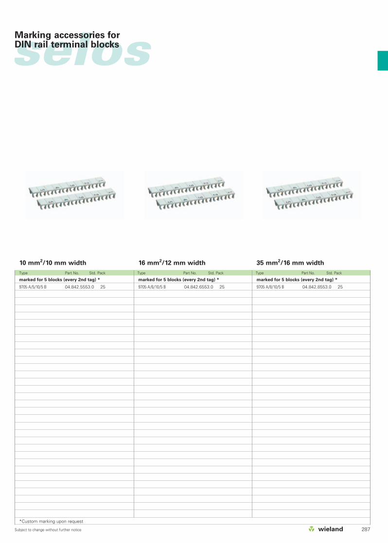
287Subject to change without further notice
Type Part No. Std. Pack Type Part No. Std. Pack Type Part No. Std. Pack
selos
35 mm2/16 mm width
marked for 5 blocks (every 2nd tag) *
9705 A/8/10/5 B 04.842.8553.0 25
16 mm2/12 mm width
marked for 5 blocks (every 2nd tag) *
9705 A/6/10/5 B 04.842.6553.0 25
10 mm2/10 mm width
marked for 5 blocks (every 2nd tag) *
9705 A/5/10/5 B 04.842.5553.0 25
*Custom marking upon request
Marking accessories for DIN rail terminal blocks

288 Subject to change without further notice
selosselos
Type Part No. Std. Pack Type Part No. Std. Pack
Marking accessories for DIN rail terminal blocks
Marking tag carrier
for all block widths with 4/6 digits
4 digits
9705 A/4 04.242.0950.0 200
6 digits
9705 A/6 04.242.1250.0 200
Marking tag carrier
45° angle
9705 A/4 W 04.242.2853.0 200
2 x 4 digits, 45°, 5 mm wide
makes the marking readable in every block position
45° angle
Assortment of marking
strips for
5/6/8 mm widths
for 5 mm spacing (type 9705 A/5/10 B)
1-100 04.855.1153.0 1
101-200 04.855.1253.0 1
Assortment of S0 1/5
04.900.2053.0 1
for 6 mm spacing (type 9705 A/6/10 B)
1-100 04.856.1153.0 1
101-200 04.856.1253.0 1
Assortment of S0 1/6
04.900.3053.0 1
for 8 mm spacing (type 9705 A/8/10 B)
1-100 04.858.1153.0 1
101-200 04.858.1253.0 1
Assortment of S0 1/8
04.900.4053.0 1
Assortment kit, empty, S01
04.900.0000.0 1
Assortment of marking strips:
1 standard pack includes
10 x 25 strips each = 259 strips
= 2500 single tags
Assortment with 500 markingstrips with 50 pcs. each
of 1-10, 11-20, ..., 91-100

289Subject to change without further notice
selosMarking accessories for DIN rail terminal blocks
Marking Type Part No. Std. Pack Marking Type Part No. Std. Pack Marking Type Part No. Std. Pack
Tear-off marking strip with 10 marking tags
marked with the same upper case letters
A 9704 A/AG B 04.841.2250.0 25
B 9704 A/BG B 04.841.2350.0 25
C 9704 A/CG B 04.841.2450.0 25
D 9704 A/DG B 04.841.2550.0 25
E 9704 A/EG B 04.841.2650.0 25
F 9704 A/FG B 04.841.2750.0 25
G 9704 A/GG B 04.841.2850.0 25
H 9704 A/HG B 04.841.2950.0 25
I 9704 A/IG B 04.841.3050.0 25
J 9704 A/JG B 04.841.3150.0 25
K 9704 A/KG B 04.841.3250.0 25
L 9704 A/LG B 04.841.3350.0 25
M 9704 A/MG B 04.841.3450.0 25
N 9704 A/NG B 04.841.3550.0 25
O 9704 A/OG B 04.841.3650.0 25
P 9704 A/PG B 04.841.3750.0 25
Q 9704 A/QG B 04.841.3850.0 25
R 9704 A/RG B 04.841.3950.0 25
S 9704 A/SG B 04.841.4050.0 25
T 9704 A/TG B 04.841.4150.0 25
U 9704 A/UG B 04.841.4250.0 25
V 9704 A/VG B 04.841.4350.0 25
W 9704 A/WG B 04.841.4450.0 25
X 9704 A/XG B 04.841.4550.0 25
Y 9704 A/YG B 04.841.4650.0 25
Z 9704 A/ZG B 04.841.4750.0 25
marked with the same lower case letters
a 9704 A/AK B 04.841.4850.0 25
b 9704 A/BK B 04.841.4950.0 25
c 9704 A/CK B 04.841.5050.0 25
d 9704 A/DK B 04.841.5150.0 25
e 9704 A/EK B 04.841.5250.0 25
f 9704 A/FK B 04.841.5350.0 25
g 9704 A/GK B 04.841.5450.0 25
h 9704 A/HK B 04.841.5550.0 25
i 9704 A/IK B 04.841.5650.0 25
j 9704 A/JK B 04.841.5750.0 25
k 9704 A/KK B 04.841.5850.0 25
l 9704 A/LK B 04.841.5950.0 25
m 9704 A/MK B 04.841.6050.0 25
n 9704 A/NK B 04.841.6150.0 25
o 9704 A/OK B 04.841.6250.0 25
p 9704 A/PK B 04.841.6350.0 25
q 9704 A/QK B 04.841.6450.0 25
r 9704 A/RK B 04.841.6550.0 25
s 9704 A/SK B 04.841.6650.0 25
t 9704 A/TK B 04.841.6750.0 25
u 9704 A/UK B 04.841.6850.0 25
v 9704 A/VK B 04.841.6950.0 25
w 9704 A/WK B 04.841.7050.0 25
x 9704 A/XK B 04.841.7150.0 25
y 9704 A/YK B 04.841.7250.0 25
z 9704 A/ZK B 04.841.7350.0 25
unmarked
9704 A 04.241.1150.0 25
marked with the same number
1 9704 A/1 B 04.841.1150.0 25
2 9704 A/2 B 04.841.1250.0 25
3 9704 A/3 B 04.841.1350.0 25
4 9704 A/4 B 04.841.1450.0 25
5 9704 A/5 B 04.841.1550.0 25
6 9704 A/6 B 04.841.1650.0 25
7 9704 A/7 B 04.841.1750.0 25
8 9704 A/8 B 04.841.1850.0 25
9 9704 A/9 B 04.841.1950.0 25
0 9704 A/0 B 04.841.2050.0 25
marked with consecutive numbers
1-0 9704 A/1-0 B 04.841.2150.0 25
marked with the same symbols
+ 9704 A/+ B 04.841.7450.0 25
– 9704 A/– B 04.841.7550.0 25
/ 9704 A// B 04.841.7650.0 25
. 9704 A/. B 04.841.7750.0 25
1 set of the same numbers
= 10 x 25 strips = 2500 numbers
111 to 000 04.841.9050.0 1
1 set of upper case letters
= 26 x 25 strips = 6500 letters
A to Z GB 04.841.9150.0 1
1 set of lower case letters
= 26 x 25 strips = 6500 letters
a to z KB 04.841.9250.0 1
Assortment with 50 numbers
1-0 04.900.1053.0 1
Material: Polyamide 66/6 white, marking in black Marking per strip