Lecture Notes on Requirements Elicitation - SEI Digital Library
Upload
khangminh22Category
view
1download
0
Technical ReportCMU/SEI-91-TR-002ESD-TR-91-002
1991 SEI Report on Graduate Software Engineering Education
Gary Ford
April 1991

Technical ReportCMU/SEI-91-TR-002
ESD-TR-91-002April 1991
Software Engineering InstituteCarnegie Mellon University
Pittsburgh, Pennsylvania 15213
1991 SEI Report on GraduateSoftware Engineering Education
___________________________________________________________________ ___________________________________________________________________ ___________________________________________________________________ ___________________________________________________________________ ___________________________________________________________________
Gary FordSoftware Engineering Curriculum Project
Unlimited distribution subject to the copyright
This report was prepared for the
SEI Joint Program OfficeHQ ESC/AXS5 Eglin StreetHanscom AFB, MA 01731-2116
The ideas and findings in this report should not be construed as an official DoD position. It is published in theinterest of scientific and technical information exchange.
FOR THE COMMANDER
(signature on file)
Thomas R. Miller, Lt Col, USAFSEI Joint Program Office
This work is sponsored by the U.S. Department of Defense.
Copyright © 1991 by Carnegie Mellon University.
Permission to reproduce this document and to prepare derivative works from this document for internal use isgranted, provided the copyright and “No Warranty” statements are included with all reproductions and derivativeworks.
Requests for permission to reproduce this document or to prepare derivative works of this document for externaland commercial use should be addressed to the SEI Licensing Agent.
NO WARRANTY
THIS CARNEGIE MELLON UNIVERSITY AND SOFTWARE ENGINEERING INSTITUTE MATERIALIS FURNISHED ON AN “AS-IS” BASIS. CARNEGIE MELLON UNIVERSITY MAKES NO WARRAN-TIES OF ANY KIND, EITHER EXPRESSED OR IMPLIED, AS TO ANY MATTER INCLUDING, BUT NOTLIMITED TO, WARRANTY OF FITNESS FOR PURPOSE OR MERCHANTIBILITY, EXCLUSIVITY, ORRESULTS OBTAINED FROM USE OF THE MATERIAL. CARNEGIE MELLON UNIVERSITY DOESNOT MAKE ANY WARRANTY OF ANY KIND WITH RESPECT TO FREEDOM FROM PATENT,TRADEMARK, OR COPYRIGHT INFRINGEMENT.
This work was created in the performance of Federal Government Contract Number F19628-95-C-0003 withCarnegie Mellon University for the operation of the Software Engineering Institute, a federally funded researchand development center. The Government of the United States has a royalty-free government-purpose license touse, duplicate, or disclose the work, in whole or in part and in any manner, and to have or permit others to do so,for government purposes pursuant to the copyright license under the clause at 52.227-7013.
This document is available through Research Access, Inc., 800 Vinial Street, Pittsburgh, PA 15212.Phone: 1-800-685-6510. FAX: (412) 321-2994. RAI also maintains a World Wide Web home page. The URL ishttp://www.rai.com
Copies of this document are available through the National Technical Information Service (NTIS). For informa-tion on ordering, please contact NTIS directly: National Technical Information Service, U.S. Department ofCommerce, Springfield, VA 22161. Phone: (703) 487-4600.
This document is also available through the Defense Technical Information Center (DTIC). DTIC provides ac-cess to and transfer of scientific and technical information for DoD personnel, DoD contractors and potential con-tractors, and other U.S. Government agency personnel and their contractors. To obtain a copy, please contactDTIC directly: Defense Technical Information Center, Attn: FDRA, Cameron Station, Alexandria, VA 22304-6145. Phone: (703) 274-7633.
Use of any trademarks in this report is not intended in any way to infringe on the rights of the trademark holder.

CMU/SEI-91-TR-2 i
Table of Contents
1. Introduction 1
2. A Model Curriculum for a Master of Software Engineering Degree 32.1. Summary of Changes Since 1989 32.2. Objectives 42.3. Prerequisites 62.4. Core Curriculum Content 92.5. Core Curriculum Topic Index 172.6. Curriculum Design 212.7. Project Experience Component 212.8. Electives 252.9. Pedagogical Considerations 252.10. The Structure of the MSE Curriculum 26
3. The SEI Academic Series Videotape Courses 293.1. Software Systems Engineering 303.2. Specification of Software Systems 333.3. Principles and Applications of Software Design 503.4. Software Creation and Maintenance 693.5. Software Verification and Validation 1203.6. Software Project Management 142
4. Survey of Graduate Degree Programs in Software Engineering 161
5. Survey of Comprehensive Software Engineering Textbooks 189
6. Survey of Software Engineering Research Journals 2076.1. Archival Journals 2076.2. Other Journals 212
Appendix 1. An Organizational Structure for Curriculum Content 217
Appendix 2. Bloom’s Taxonomy of Educational Objectives 225
Appendix 3. SEI Curriculum Modules and Other Publications 227
Appendix 4. History and Acknowledgements 237
Bibliography 239

CMU/SEI-91-TR-2 1
1991 SEI Report onGraduate Software Engineering Education
Abstract: This report on graduate software engineering education pre-sents a variety of information for university educators interested inestablishing a software engineering program. This includes a model cur-riculum, an annotated bibliography of software engineering textbooks,and descriptions of major software engineering research journals. It alsoincludes detailed descriptions of the the SEI Academic Series of videotapecourses, which constitute an example of an implementation of the modelcurriculum. Twenty-three university graduate programs in softwareengineering are surveyed. Software engineering textbooks and researchjournals are also surveyed.
1. Introduction
An ongoing activity of the SEI Education Program is the development and support ofa model graduate curriculum in software engineering. In such a rapidly changingdiscipline, it is important that the curriculum be reevaluated and revised frequentlyto reflect the state of the art. This report describes our recent efforts toward thatend.
Section 2 of this report presents our current recommendations for the content of aMaster of Software Engineering degree program. An implementation of these rec-ommendations, the SEI Academic Series, is described in Section 3. For comparison,the graduate software engineering programs of more than 20 universities are sur-veyed in Section 4.
In response to questions frequently asked of the SEI Education Program, this reportalso includes two other surveys. Section 5 presents an annotated bibliography ofgeneral software engineering textbooks, including comments from professors whohave used them. Section 6 lists the major software engineering journals.
Background material is presented in the appendices. Appendices 1 and 2 are takenfrom [Ford87]; they present, respectively, an organizational structure for discussingsoftware engineering curriculum content and a summary of Bloom’s taxonomy ofeducational objectives. Appendix 3 provides short descriptions of SEI publicationsthat support graduate education, and Appendix 4 describes the history of, andacknowledges the numerous contributors to, the recommendations in this report.

2 CMU/SEI-91-TR-2

CMU/SEI-91-TR-2 3
2. A Model Curriculum for a Master of SoftwareEngineering Degree
The academic community distinguishes two master’s level technical degrees. TheMaster of Science in Discipline is a research-oriented degree, and often leads to doc-toral study. The Master of Discipline is a terminal professional degree intended fora practitioner who will be able to rapidly assume a position of substantial responsi-bility in an organization. The former degree often requires a thesis, while the latterrequires a project or practicum as a demonstration of the level of knowledgeacquired. The Master of Business Administration (MBA) degree is perhaps the mostwidely recognized example of a terminal professional degree.
The SEI was chartered partly in response to the perceived need for a greatlyincreased number of highly skilled software engineers. It is our belief that the SEIcan best address this need by encouraging and helping academic institutions to offera Master of Software Engineering (MSE) degree, or a program with similar contentunder another title.
In this section we present our current recommendations for a model MSE curricu-lum. The first subsection (2.0) summarizes the changes since last year’s recommen-dations. The curriculum is then described in seven parts (subsections 2.2-2.8):program objectives, prerequisites, core curriculum content, core topic index, curricu-lum design for six core courses, the project experience component, and electives.These are followed by short discussions of pedagogical concerns (2.9) and the overallstructure of the curriculum (2.10). These recommendations continue to evolve, andwe expect to publish updated versions annually.
2.1. Summary of Changes Since 1989
In general, the curriculum recommendations in this report are the same as those inour previous report [Ardis89]. Two additions to the core content are notable.
First, statistical testing concepts and techniques have been added to the unit onsoftware testing. We believe that experiences such as those in [Musa90] indicateboth the importance and increased maturity of these techniques. Including thesetopics in the curriculum will help students gain an appreciation for an engineeringapproach to testing, rather than an ad hoc, heuristic approach.
Second, a new content unit has been added: Professional Issues. This unit includeslegal considerations and professional ethics for software engineers. A number ofinteresting issues can be discussed with students during the presentation of thesetopics, including the growing concerns regarding software safety, data security, net-work security (such as the 1988 Internet worm incident), software piracy, software
4 CMU/SEI-91-TR-2
warranties and licenses, and copyright and patent law applied to programs, algo-rithms, or user interfaces.
The designs of the six core courses presented in our previous report were developedover a period of several weeks in 1988. Improving those designs would depend inlarge part on the experiences gained by those who teach the courses. Several uni-versities are now teaching courses based on the designs, but it is too soon to examinetheir experiences systematically. Therefore, in this report we have neither reprintedthe original course designs nor presented improved ones. Instead, we have pre-sented (in Section 3) an example implementation of the designs: the SEI AcademicSeries. Five of the six courses have been taught, some more than once. Thus theyrepresent the best available example of continued development of the original corecourse designs.
2.2. Objectives
The goal of the MSE degree program is to produce a software engineer who canrapidly assume a position of substantial responsibility within an organization. Toachieve this goal, we propose a curriculum designed to give the student a body ofknowledge that includes balanced coverage of the software engineering processactivities, their aspects, and the products produced (see Appendix 1 for definitions ofthe terms activity, aspect , and product as used here), along with sufficient experienceto bridge the gap between undergraduate programming and professional softwareengineering.
Specific educational objectives are summarized below; they appear in greater detailin the descriptions of individual curriculum units in Section 3.3. We describe themusing a taxonomy adapted from [Bloom56], which has six levels of objectives:knowledge, comprehension, application, analysis, synthesis, and evaluation. (SeeAppendix 2 for a brief description of this taxonomy.)
Knowledge: In addition to knowledge about all the material described in the sub-sequent paragraphs, students should be aware of the existence of models, represen-tations, methods, and tools other than those they learn to use in their own studies.Students should be aware that there is always more to learn, and that they willencounter more in their professional careers, whatever they may have learned inschool.
Comprehension: The students should understand:
• the software engineering process, both in the sense of abstract models andin the various instances of the process as practiced in industry
• the activities and aspects of the process
• the issues (sometimes called the software crisis) that are motivating thegrowth and evolution of the software engineering discipline
CMU/SEI-91-TR-2 5
• the differences between academic or personal programming and softwareengineering; in particular, students should understand that software engi-neering involves the production of software systems under the constraintsof control and management activities (See Appendix 1 for definitions ofthese activities)
• a reasonable set of principles, models, representations, methods, and tools
• the role of analysis and evaluation in software engineering
• the existing design paradigms for well-understood systems
• the reasons for and the content of appropriate standards
• the fundamental economic, legal, and ethical issues of software engineering
Application: The students should be able to:
• apply fundamental principles in the performance of the various activities
• apply appropriate formal methods to achieve results
• use appropriate tools covering all activities of the software process
• collect appropriate data for project management purposes, and for analysisand evaluation of both the process and the product
• execute a plan, such as a test plan, quality assurance plan, or configurationmanagement plan; this includes the performance of several kinds of soft-ware tests
• apply documentation standards in the production of software engineeringdocuments
Analysis: The students should be able to:
• participate in technical reviews and inspections of various software workproducts, including documents, plans, designs, and code
• analyze the needs of customers
Synthesis: The students should be able to:
• perform the activities leading to various software work products, includingrequirements specifications, designs, code, and documentation
• develop plans, such as project plans, quality assurance plans, test plans,and configuration management plans
• design data for and structures of software tests
• prepare oral presentations, and plan and lead software technical reviewsand inspections
Evaluation: The students should be able to:
• evaluate software work products for conformance to standards
• use appropriate qualitative and quantitative measures in evaluation ofsoftware work products, as in the evaluation of requirements specificationsfor consistency and completeness, or the measurement of performance
6 CMU/SEI-91-TR-2
• perform verification and validation of software; these activities shouldconsider all system requirements, not just functional and performancerequirements
• apply and validate predictive models, such as those for software reliabilityor project cost estimation
• evaluate new technologies and tools to determine which are applicable totheir own work
The word appropriate occurs several times in the objectives above. The softwareengineering discipline is new and changing, and there is not a consensus on the bestset of representations, methods, or tools to use. Each implementation of the MSEcurriculum must be structured to match the goals and resources of the school and itsstudents. In subsequent reports, the SEI will offer recommendations on the mostpromising methods and technologies for many of the software engineering activities.
2.3. Prerequisites
Although an undergraduate degree in computer science is the “obvious” prerequisitefor the MSE degree, we cannot adopt such a simplistic approach to defining essentialprerequisites. We do not want to exclude experienced practitioners who do not havesuch a degree but still wish to pursue the MSE degree. Furthermore, students withbachelor’s degrees in computer science from different schools, or from the sameschool but five years apart, are likely to have substantially different knowledge.Thus the prerequisites for the MSE degree must be defined carefully, and must beenforceable and enforced.
The primary prerequisite, therefore, is substantial knowledge of programming-in-the-small. This includes a working knowledge of at least one modern, high-levellanguage (for example, Pascal, Modula-2, Ada) and at least one assembly language.Also important is a knowledge of fundamental concepts of programming, includingcontrol and data structures, modularity, data abstraction and information hiding,and language implementations (runtime environments, procedure linkage, andmemory management). Students should also be familiar with the “tools of thetrade,” meaning a user’s knowledge (not a designer’s knowledge) of computer organi-zation and architecture, operating systems, and typical software tools (such as aneditor, assembler, compiler, and linking loader). A basic knowledge of formal meth-ods and models (and their application) is also essential, including analysis of algo-rithms and the fundamentals of computability, automata, and formal languages.Most or all of this material is likely to be found in the first three years of an under-graduate computer science degree program.
Knowledge of one or more other major areas of computer science is highly desirable,but not absolutely necessary. Examples are: functional and declarative languages,numerical methods, database systems, compiler construction, computer graphics, or
CMU/SEI-91-TR-2 7
artificial intelligence. This material is usually found in senior-level electives in acomputer science degree program. Some schools may choose to allow advancedcomputer science courses as electives in the MSE program. Knowledge of majorapplications areas in the sciences and engineering may also be useful.
The mathematics prerequisites are those commonly required in an undergraduatecomputer science degree: discrete mathematics and some calculus. Some softwareengineering topics may require additional mathematical prerequisites, such as prob-ability and statistics. A student planning a career in a particular application areamay want additional mathematics, such as linear algebra or differential equations,but these are not essential prerequisites for any of the mainstream software engi-neering courses.
Enforcing the prerequisites can be difficult. A lesson may be learned from experi-ence with master’s degree programs in computer science. In the 1960s and 1970s,these programs often served almost exclusively as retraining programs for studentswith undergraduate degrees in other fields (notably mathematics and engineering)rather than as advanced degree programs for students who already had an under-graduate computer science degree. In several schools, undergraduate computerscience majors were not eligible for the master’s program because they had alreadytaken all or nearly all of the courses as undergraduates.
These programs existed because there was a clearly visible need for more program-mers and computer scientists, and the applicants for these programs did not want asecond bachelor’s degree. There were not enough applicants who already had acomputer science degree to permit enforcement of substantial prerequisites.
For the proposed MSE program to achieve its goals, it must take students a greatdistance beyond the undergraduate computer science degree. This, in turn, requiresthat students entering the program have approximately that level of knowledge.Because of the widely varying backgrounds of potential students, their level ofknowledge is very difficult to assess. Standardized examinations, such as theGraduate Record Examination in Computer Science, provide only part of thesolution.
We recommend that schools wishing to establish the MSE program consider institut-ing a leveling or immigration course to help establish prerequisite knowledge. Sucha course rarely fits into the normal school calendar. Rather, it is an intensive two tofour week course that is scheduled just before or just after the start of the schoolyear. (However, Texas Christian University has tried a full-semester levelingcourse; see [Comer86]). Students receive up to 20 hours a week of lectures summa-rizing all of the prerequisite material. The value of this course is not that thestudents become proficient in all the material, but that they become aware of defi-ciencies in their own preparation. Self-study in parallel with the first semester’scourses can often remove most of these deficiencies.
8 CMU/SEI-91-TR-2
Another important part of the immigration course is the introduction of the school'scomputing facilities, especially the available software tools. Ten to 20 hours eachweek can be devoted to demonstrations and practice sessions. Because proficiencywith tools can greatly increase the productivity of the students in later courses, thetime spent in the immigration course can be of enormous value.
Finally, the immigration course can be used to help motivate the study of softwareengineering. The faculty, and sometimes the students themselves, can present someof their own or others’ experiences that led to improved understanding of some of thesignificant problems of software engineering.
Another kind of prerequisite has been adopted by some MSE programs (includingthe University of St. Thomas, Seattle University, and Texas Christian University).All require the student to have at least one year of professional experience as a soft-ware developer. This requirement has the benefit of giving the students increasedmotivation for studying software engineering: professional experience exposes themto the problems of developing systems that are much larger than those seen in theuniversity, and makes them aware of economic and technical constraints on thesoftware development process. On the negative side, schools cannot control thequality of that experience, and students may acquire bad habits that must beunlearned.
We have not found the arguments for an experience prerequisite sufficiently com-pelling to recommend it for all MSE programs. Other engineering disciplines havesuccessful master’s level programs, and even undergraduate programs, without sucha prerequisite. Most graduate professional degrees in other disciplines do notrequire it.
As a discipline grows and evolves, it is a common phenomenon in education for newmaterial to be taught in courses that are simply added onto an existing curriculum.Over time, the new material is assimilated into the curriculum in a process calledcurricular compression. Obsolete material is taken out of the curriculum, but muchof the compression is accomplished by reorganization of material to get the mostvalue in the given amount of time.
In a rapidly growing and changing discipline, new material is added faster than cur-ricular compression can accommodate it. In some engineering disciplines, theproblem is acute. There is a growing sentiment that the educational requirement foran entry-level position in engineering should be a master’s degree or a five-yearundergraduate degree [NRC85]. This is especially true for a computer science/ soft-ware engineering career.
If this level of education is needed for a meaningful entry-level position, then wequestion the value of sending students out with a bachelor’s degree, hoping they willreturn sometime later for a software engineering degree. The professional experi-ence achieved during that time will not necessarily be significant. Also, the percent-
CMU/SEI-91-TR-2 9
age of students intending to return to school who actually do return declines rapidlyas time since graduation increases. Therefore, we believe that an MSE curriculumstructured to follow immediately after a good undergraduate curriculum offers thebest chance of achieving the goals of rapid increases in the quality and quantity ofsoftware engineers. Of course, such a program does not preclude admission of stu-dents with professional experience.
We do recognize that work experience can be valuable. The experience component ofthe MSE curriculum, which is discussed later in this report, might be structured toinclude actual work experience. It may be that the overall educational experience issignificantly enhanced if the work component is a coordinated part of the programrather than an interlude between undergraduate and graduate studies.
We also recognize that we must provide motivation for many of the activities in thesoftware engineering process. We see a great need to raise the level of awareness onthe part of both students and educators of the differences between undergraduateprogramming and professional software engineering. The SEI Education Program isworking at the undergraduate level to help accomplish this.
2.4. Core Curriculum Content
Software engineering is a broad and diverse discipline. To facilitate discussions ofthe content of software engineering curricula, we have found it helpful to develop anorganizational structure for the discipline; this is presented in Appendix 1. A brieflook at this structure is sufficient to conclude that all of software engineering cannotbe covered in any curriculum. Selecting a subset of that content appropriate for aparticular program and student population is the primary task of a curriculumdesigner.
We use a broad view of software engineering when choosing the content of thecurriculum, and we include several topics that are not part of a typical engineeringcurriculum. In this respect, we agree with this statement of the National ResearchCouncil about engineering curricula [NRC85]:
…[T]o make the transition from high school graduate to a competent practic-ing engineer requires more than just the acquisition of technical skills andknowledge. It also requires a complex set of communication, group-interaction, management, and work-orientation skills.
... For example, education for management of the engineering function (asdistinct from MBA-style management) is notably lacking in most curricula.Essential nontechnical skills such as written and oral communication,planning, and technical project management (including management of theindividual’s own work and career) are not sufficiently emphasized.
On the other hand, we have narrowed the curriculum by concentrating almost exclu-sively on software engineering (but including some aspects of systems engineering)
10 CMU/SEI-91-TR-2
and omitting applications area knowledge. The two major reasons for this arepragmatic: first, the body of knowledge known as software engineering is suffi-ciently large to require all the available time in a typical master’s degree program(and then some); and second, students cannot study all of the applications areas inwhich they might eventually work. We believe that students at the graduate levelshould have acquired the skills for self-education that will enable them to acquireneeded knowledge in an application area.
More important, however, is our strong belief that the variety of applications areasand the level of sophistication of hardware and software systems in each of thoseareas mandate a development team with a substantial range of knowledge andskills. Some members of the team must understand the capabilities of hardwareand software components of a system in order to do the highest level specification,while other members must have the skills to design and develop individual compo-nents. Software engineers will have responsibility for software components just aselectrical, mechanical, or aeronautical engineers, for example, will have responsibil-ity for the hardware components. Scientists, including computer scientists, will alsobe needed on development teams; and all the scientists and engineers must be ableto work together toward a common goal.
The core content of the MSE curriculum is described in units, each covering a majortopic area, rather than in courses. There are three reasons for this. First, not everytopic area contains enough material for a typical university course. Second, combin-ing units into courses can be accomplished in different ways for different organiza-tions. Third, this structure more easily allows each unit to evolve to reflect thechanges in software engineering knowledge and practice while maintaining thestability of the overall curriculum structure.
Because of strong relationships among topics and subtopics, we were unable to finda consensus on an appropriate order of topics. We do, however, recommend a top-down approach that begins with focus on the software engineering process; thisoverall view is needed to put the individual activities in context. Software manage-ment and control activities are presented next, followed by the development activi-ties and product view topics.
Social and ethical issues are also important to the education and development of aprofessional software engineer. Examples are privacy, data security, and softwaresafety. We do not recommend a course on these issues, but rather encourageinstructors to find opportunities to discuss them in appropriate contexts in allcourses and to set an example for students.
The curriculum topics are described below in units of unspecified size. Nearly allhave a software engineering activity as the focus. For each, we provide a shortdescription of the subtopics to be covered, the aspects of the activity that are mostimportant, and the educational objectives of the unit. (See Appendix 1 for defini-tions of the terms activity and aspect as they are used here.)
CMU/SEI-91-TR-2 11
1. The Software Engineering Process
Topics The software engineering process and software products. All of thesoftware engineering activities. The concepts of software process modeland software product life cycle model.
Aspects All aspects, as appropriate for the various activities.
Objectives Knowledge of activities and aspects. Some comprehension of the issues,especially the distinctions among the various classes of activities. Thestudents should begin to understand the substantial differencesbetween the programming they have done in an undergraduate programand software engineering as it is practiced professionally.
2. Software Evolution
Topics The concept of a software product life cycle. The various forms of asoftware product, from initial conception through development andoperation to retirement. Controlling activities and disciplines tosupport evolution. Planned and unplanned events that affect softwareevolution. The role of changing technology.
Aspects Models of software evolution, including development life cycle modelssuch as the waterfall, iterative enhancement, phased development, andspiral models.
Objectives Knowledge and comprehension of the models. Knowledge and compre-hension of the controlling activities.
3. Software Generation
Topics Various methods of software generation, including designing and codingfrom scratch, use of program or application generators and very highlevel languages, use of reusable components (such as mathematicalprocedure libraries, packages designed specifically for reuse, Adageneric program units, and program concatenation, as with pipes). Roleof prototyping. Factors affecting choice of a software generationmethod. Effects of generation method on other software developmentactivities, such as testing and maintenance.
Aspects Models of software generation. Representations for software genera-tion, including design and implementation languages, very high levellanguages, and application generators. Tools to support generationmethods, including application generators.
Objectives Knowledge and comprehension of the various methods of software gen-eration. Ability to apply each method when supported by appropriate
12 CMU/SEI-91-TR-2
tools. Ability to evaluate methods and choose the appropriate ones foreach project.
4. Software Maintenance
Topics Maintenance as a part of software evolution. Reasons for maintenance.Kinds of maintenance (perfective, adaptive, corrective). Comparison ofdevelopment activities during initial product development and duringmaintenance. Controlling activities and disciplines that affect mainte-nance. Designing for maintainability. Techniques for maintenance,including program reading and reverse engineering.
Aspects Models of maintenance. Current methods.
Objectives Knowledge and comprehension of the issues of software maintenanceand current maintenance practice. Ability to apply basic maintenancetechniques.
5. Technical Communication
Topics Fundamentals of technical communication. Oral and written communi-cation. Preparing oral presentations and supporting materials.Software project documentation of all kinds.
Aspects Principles of communication. Document preparation tools. Standardsfor presentations and documents.
Objectives Knowledge of fundamentals of technical communication and of softwaredocumentation. Application of fundamentals to oral and written com-munications. Ability to analyze, synthesize, and evaluate technicalcommunications.
6. Software Configuration Management
Topics Concepts of configuration management. Its role in controlling softwareevolution. Maintaining product integrity. Change control and versioncontrol. Organizational structures for configuration management.
Aspects Fundamental principles. Tools. Documentation, including configura-tion management plans.
Objectives Knowledge and comprehension of the issues. Ability to apply theknowledge to develop a configuration management plan and to useappropriate tools.
CMU/SEI-91-TR-2 13
7. Software Quality Issues
Topics Definitions of quality. Factors affecting software quality. Planning forquality. Quality concerns in each phase of a software life cycle, withspecial emphasis on the specification of the pervasive system attributes.Quality measurement and standards. Software correctness assessmentprinciples and methods. The role of formal verification and the role oftesting. Concepts of reliability and reliability modeling. Fundamentalissues of software security.
Aspects Assessment of software quality, including identifying appropriate mea-surements and metrics. Tools to help perform measurement.Correctness assessment methods, including testing and formal verifica-tion. Formal models of program verification.
Objectives Knowledge and comprehension of software quality issues and correct-ness methods. Knowledge and comprehension of concepts of softwarereliability modeling and software security. Ability to apply proof ofcorrectness methods.
8. Software Quality Assurance
Topics Software quality assurance as a controlling discipline. Organizationalstructures for quality assurance. Independent verification and valida-tion teams. Test and evaluation teams. Software technical reviews.Software quality assurance plans.
Aspects Current industrial practice for quality assurance. Documents includingquality assurance plans, inspection reports, audits, and validation testreports.
Objectives Knowledge and comprehension of quality assurance planning. Ability toanalyze and synthesize quality assurance plans. Ability to performtechnical reviews. Knowledge and comprehension of the fundamentalsof program verification and its role in quality assurance. Ability toapply concepts of quality assurance as part of a quality assurance team.
9. Software Project Organizational and Management Issues
Topics Project planning: choice of process model, project scheduling and mile-stones. Staffing: development team organizations, quality assuranceteams. Resource allocation.
Aspects Fundamental concepts and principles. Scheduling representations andtools. Project documents.

14 CMU/SEI-91-TR-2
Objectives Knowledge and comprehension of concepts and issues. It is not expectedthat a student, after studying this material, will be ready to manage asoftware project immediately.
10. Software Project Economics
Topics Factors that affect cost. Cost estimation, cost/benefit analysis, riskanalysis for software projects.
Aspects Models of cost estimation. Current techniques and tools for costestimation.
Objectives Knowledge and comprehension of models and techniques. Ability toapply the knowledge to tool use.
11. Software Operational Issues
Topics Organizational issues related to the use of a software system in anorganization. Training, system installation, system transition, opera-tion, retirement. User documentation.
Aspects User documentation and training materials.
Objectives Knowledge and comprehension of the major issues.
12. Requirements Analysis
Topics The process of interacting with the customer to determine systemrequirements. Defining software requirements. Identifying functional,performance, and other requirements: the pervasive system require-ments. Techniques to identify requirements, including prototyping,modeling, and simulation.
Aspects Principles and models of requirements. Techniques of requirementidentification. Tools to support these techniques, if available. Assessingrequirements. Communicating with the customer.
Objectives Knowledge and comprehension of the concepts of requirements analysisand the different classes of requirements. Knowledge of requirementsanalysis techniques. Ability to apply techniques and analyze and syn-thesize requirements for simple systems.
13. Specification
Topics Objectives of the specification process. Form, content, and users ofspecifications documents. Specifying functional, performance, reliabil-ity, and other requirements of systems. Formal models and representa-tions of specifications. Specification standards.
CMU/SEI-91-TR-2 15
Aspects Formal models and representations. Specification techniques and toolsthat support them, if available. Assessment of a specification forattributes such as consistency and completeness. Specificationdocuments.
Objectives Knowledge and comprehension of the fundamental concepts of specifi-cation. Knowledge of specification models, representations, and tech-niques, and the ability to apply or use one or more. Ability to analyzeand synthesize a specification document for a simple system.
14. System Design
Topics The role of system design and software design. How design fits into alife cycle. Software as a component of a system. Hardware versus soft-ware tradeoffs for system performance and flexibility. Subsystem defi-nition and design. Design of high-level interfaces, both hardware tosoftware and software to software.
Aspects System modeling techniques and representations. Methods for systemdesign, including object-oriented design, and tools to support thosemethods. Iterative design techniques. Performance prediction.
Objectives Comprehension of the issues in system design, with emphasis on engi-neering tradeoffs. Ability to use appropriate system design models,methods, and tools, including those for specifying interfaces. Ability toanalyze and synthesize small systems.
15. Software Design
Topics Principles of design, including abstraction and information hiding,modularity, reuse, prototyping. Levels of design. Design representa-tions. Design practices and techniques. Examples of design paradigmsfor well-understood systems.
Aspects Principles of software design. One or more design notations or lan-guages. One or more widely used design methods and supporting tools,if available. Assessment of the quality of a design. Design documenta-tion.
Objectives Knowledge and comprehension of one or more design representations,design methods, and supporting tools, if available. Ability to analyzeand synthesize designs for software systems. Ability to apply methodsand tools as part of a design team.
16 CMU/SEI-91-TR-2
16. Software Implementation
Topics Relationship of design and implementation. Features of modern proce-dural languages related to design principles. Implementation issues,including reusable components and application generators. Concepts ofprogramming support environment.
Aspects One or more modern implementation languages and supporting tools.Assessment of implementations: coding standards and metrics.
Objectives Ability to analyze, synthesize, and evaluate the implementation of smallsystems.
17. Software Testing
Topics The role of testing and its relationship to quality assurance. The natureand limitations of testing. Levels of testing: unit, integration, accep-tance, etc. Statistical testing methods. Detailed study of testing at theunit level. Formal models of testing. Test planning. Black box andwhite box testing. Building testing environments. Test case generation.Test result analysis.
Aspects Testing principles and models. Tools to support specific kinds of tests.Assessment of testing; testing standards. Test documentation.
Objectives Knowledge and comprehension of the role and limitations of testing.Ability to apply test tools and techniques. Ability to analyze test plansand test results. Ability to synthesize a test plan.
18. System Integration
Topics Testing at the software system level. Integration of software and hard-ware components of a system. Uses of simulation for missing hardwarecomponents. Strategies for gradual integration and testing.
Aspects Methods and supporting tools for system testing and system integration.Assessment of test results and diagnosing system faults.Documentation: integration plans, test results.
Objectives Comprehension of the issues and techniques of system integration.Ability to apply the techniques to do system integration and testing.Ability to develop system test and integration plans. Ability to interprettest results and diagnose system faults.
19. Embedded Real-Time Systems
Topics Characteristics of embedded real-time systems. Existence of hard tim-ing requirements. Concurrency in systems; representing concurrency in
CMU/SEI-91-TR-2 17
requirements specifications, designs, and code. Issues related to com-plex interfaces between devices and between software and devices.Criticality of embedded systems and issues of robustness, reliability,and fault tolerance. Input and output considerations, including unusualdata representations required by devices. Issues related to the cog-nizance of time. Issues related to the inability to test systemsadequately.
Objectives Comprehension of the significant problems in the analysis, design, andconstruction of embedded real-time systems. Ability to produce smallsystems that involve interrupt handling, low-level input and output,concurrency, and hard timing requirements, preferably in a high-levellanguage.
20. Human Interfaces
Topics Software engineering factors: applying design techniques to humaninterface problems, including concepts of device independence and vir-tual terminals. Human factors: definition and effects of screen clutter,assumptions about the class of users of a system, robustness and han-dling of operator input errors, uses of color in displays.
Objectives Comprehension of the major issues. Ability to apply design techniquesto produce good human interfaces. Ability to design and conduct exper-iments with interfaces, to analyze the results and use them to improvethe design.
21. Professional Issues
Topics Issues of professionalism in software engineering. Ethics. Legal issuesincluding intellectual property rights, warranties, and liability.
Objectives Comprehension of basic concepts and issues of professional behavior.Comprehension of major ethical issues. Knowledge of the major legalissues.
2.5. Core Curriculum Topic Index
The core curriculum topics presented in the previous section are organized into 21content units, each containing many related topics. Because there are many moretopics than units, it is not always obvious in which unit a topic may be found.Therefore, we have included here an alphabetical index of topics. The number aftereach topic is the content unit in which that topic may be found.
18 CMU/SEI-91-TR-2
abstraction 15application generator 3application generators 16assessment
design quality 15implementation 16of requirements 12of software correctness 7specification 13test 17test results 18
audits 8code metrics 16coding standards 16cognizance of time 19communication
oral 5with a customer 12written 5
completeness 13complex interfaces 19component 3computer-human interfaces 20concepts
programming support environments 16project management 9
concurrency 19conducting experiments with interfaces 20configuration management 6
plan 6tools 6
consistency 13controlling activity 2, 4controlling discipline 2, 4, 8correctness of software 7cost 10cost estimation 10cost/benefit analysis 10design
documentation 15for maintainability 4in life cycle 14language 3levels 15methods 15object-oriented 14paradigms 15practices 15principles 15quality assessment 15relationship to implementation 16representations 15software 14, 15subsystem 14system 14techniques 15
design (continued)techniques for human interfaces 20tools 15
device independence 20diagnosing system faults 18documentation
configuration management plan 6design 15integration plans 18principles 5project management 9specification 13standards 5test 17test results 18tools 5user 11
embedded systems 19environments
programming 16testing 17
ethics 21evolution 2fault tolerance 19formal models
program verification 7specification 13testing 17
formal verification 7functional requirements 12hard timing requirements 19hardware-software tradeoffs 14human factors 20human interfaces 20implementation 16implementation language 3, 16independent verification and validation 8industrial practice for quality assurance 8information hiding 15input and output in real-time systems 19inspection reports 8integration of systems 18intellectual property rights 21interfaces
between devices 19between devices and software 19hardware-software 14high-level 14human 20software-software 14
iterative design techniques 14iterative enhancement model 2languages
design 3, 15implementation 3, 16modern features 16
CMU/SEI-91-TR-2 19
languages (continued)procedural 16relationship to design principles 16very high level 3
legal issues 21liability 21life cycle 2life cycle model 1maintenance 4management issues 9measurement of quality 7methods
design 15formal verification 7maintenance 4software correctness assessment 7system design 14system integration 18system testing 18testing 7
metricscode 16software quality 7
milestones 9modeling 12models
cost estimation 10iterative enhancement 2life cycle 1maintenance 4phased development 2process 1program verification 7requirements 12software generation 3spiral 2testing 17waterfall 2
modularity 15notations for design 15object-oriented design 14operational issues 11organizational issues 9organizational structure 6, 8, 9paradigms of design 15performance prediction 14performance requirements 12pervasive system attributes 7pervasive system requirements 12phased development model 2planning
for quality 7project 9
plansconfiguration management 6project 9
plans (continued)quality assurance 8software quality 7test 17
presentation standards 5presentations 5principles
configuration management 6design 15documentation 5project management 9requirements 12software correctness assessment 7testing 17
process 1process model 1, 9product integrity 6professionalism 21program generator 3program reading 4programming support environments 16project documents 9project management 9project planning 9project scheduling 9prototyping 3, 12, 15quality
measurement 7standards 7
quality assurancedocuments 8plans 8teams 9
real-time systems 19reliability
concepts 7modeling 7of embedded systems 19
reportsinspection 8validation test 8
representationsdesign 15scheduling 9specification 13system modeling 14
requirementsanalysis 12assessment 12functional 12hard timing in real-time systems 19performance 12system 12
retirement of systems 11reusable components 16reuse 3, 15, 16

20 CMU/SEI-91-TR-2
reverse engineering 4risk analysis 10robustness of embedded systems 19scheduling 9security 7simulation
in requirements analysis 12of missing hardware 18
softwareas system component 14correctness 7design 14, 15documentation 5evolution 2, 4, 6factors affecting quality 7generation 3implementation 16maintenance 4quality 7security 7specification 13testing 17
software engineering process 1software process 1software product 2software product life cycle 2software project economics 10specification
assessment 13completeness 13consistency 13documents 13formal models 13objectives 13of functional requirements 13of performance requirements 13of reliability requirements 13pervasive system attributes 7quality attributes 7representations 13standards 13techniques 13tools 13
spiral model 2staffing 9standards
coding 16documentation 5presentations 5quality 7specification 13testing 17
subsystemdefinition 14design 14
systemdesign 14design methods 14design tools 14flexibility 14installation 11integration 18integration methods 18modeling representations 14modeling techniques 14performance 14requirements 12testing methods 18transition 11
team organizations 9technical writing 5techniques
cost estimation 10design 15iterative design 14maintenance 4program reading 4requirements identification 12reverse engineering 4specification 13system modeling 14
testdocumentation 17planning 17result analysis 17
test and evaluation team 8test case generation 17test result assessment 18testing
acceptance 17assessment 17black box and white box 17environments 17formal models 17inadequacy for real-time systems 19integration 17levels 17limitations of 17models 17nature of 17principles 17relationship to quality assurance 17role in software quality 7role of 17standards 17statistical methods 17system level 18tools 17unit 17
CMU/SEI-91-TR-2 21
toolsconfiguration management 6cost estimation 10design 15documentation 5implementation 16requirements identification 12scheduling 9software generation 3software quality measurement 7specification 13system design 14test 17
tradeoffs between hardware and software 14training 11training materials 11user documentation 11validation test reports 8very high level language 3virtual terminals 20warranties 21waterfall model 2writing, technical 5
2.6. Curriculum Design
The 21 content units described in Section 2.4 can be considered a specification forthe core curriculum; a design, then, is a description of the courses that present thecore material in an appropriate, coherent way. At the 1988 SEI Curriculum DesignWorkshop (described in [Ardis89]), participants developed six semester-lengthcourses as one such design. Forming the basis for the model MSE curriculum, thesecourses are:
Software Systems EngineeringSpecification of Software SystemsPrinciples and Applications of Software DesignSoftware Generation and MaintenanceSoftware Verification and ValidationSoftware Project Management
Detailed course descriptions may be found in a previous SEI report [Ardis89]. Wehave not redesigned these courses since that report was published. Instead ofrepeating those descriptions here, we have chosen to present an actual implementa-tion of five of those courses (see Section 3 of this report). The sixth course is beingimplemented and taught during the fall 1990 semester, and it will be described in alater report.
2.7. Project Experience Component
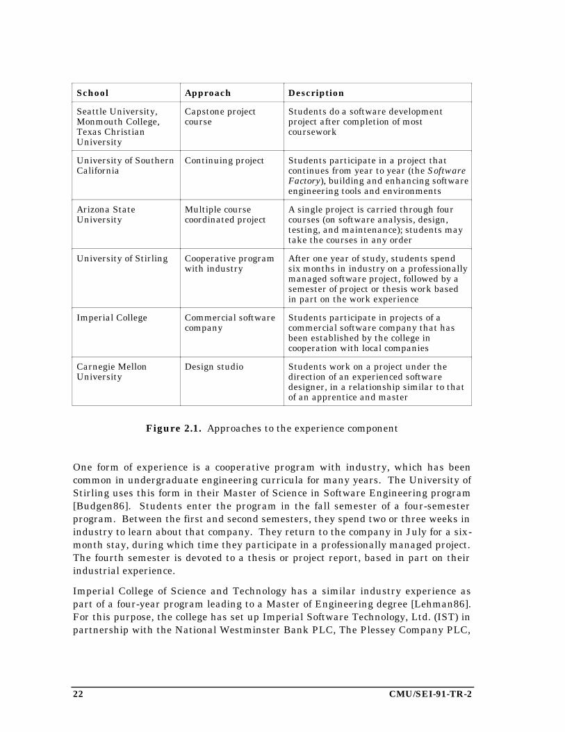
In addition to coursework covering the units described in Section 2.4, the curriculumshould incorporate significant software engineering experience representing at least30% of the student’s work. Universities have tried a number of approaches to givestudents this experience; examples are summarized in Figure 2.1.
22 CMU/SEI-91-TR-2
School Approach Description
Seattle University,Monmouth College,Texas ChristianUniversity
Capstone projectcourse
Students do a software developmentproject after completion of mostcoursework
University of SouthernCalifornia
Continuing project Students participate in a project thatcontinues from year to year (the SoftwareFactory), building and enhancing softwareengineering tools and environments
Arizona StateUniversity
Multiple coursecoordinated project
A single project is carried through fourcourses (on software analysis, design,testing, and maintenance); students maytake the courses in any order
University of Stirling Cooperative programwith industry
After one year of study, students spendsix months in industry on a professionallymanaged software project, followed by asemester of project or thesis work basedin part on the work experience
Imperial College Commercial softwarecompany
Students participate in projects of acommercial software company that hasbeen established by the college incooperation with local companies
Carnegie MellonUniversity
Design studio Students work on a project under thedirection of an experienced softwaredesigner, in a relationship similar to thatof an apprentice and master
Figure 2.1. Approaches to the experience component
One form of experience is a cooperative program with industry, which has beencommon in undergraduate engineering curricula for many years. The University ofStirling uses this form in their Master of Science in Software Engineering program[Budgen86]. Students enter the program in the fall semester of a four-semesterprogram. Between the first and second semesters, they spend two or three weeks inindustry to learn about that company. They return to the company in July for a six-month stay, during which time they participate in a professionally managed project.The fourth semester is devoted to a thesis or project report, based in part on theirindustrial experience.
Imperial College of Science and Technology has a similar industry experience aspart of a four-year program leading to a Master of Engineering degree [Lehman86].For this purpose, the college has set up Imperial Software Technology, Ltd. (IST) inpartnership with the National Westminster Bank PLC, The Plessey Company PLC,

CMU/SEI-91-TR-2 23
and PA International. IST is an independent, technically and commercially success-ful company that provides software technology products and services.
The more common form of experience, however, is one or more project courses aspart of the curriculum. Two forms are common: a project course as a capstone fol-lowing all the lecture courses, and a project that is integrated with one or more ofthe lecture courses.
The Wang Institute of Graduate Studies (before it closed in 1987), Texas ChristianUniversity, and Seattle University have each offered a graduate software engineer-ing degree for several years, and the University of St. Thomas has had a program forsix years. Each school incorporates a capstone project course into its curriculum.The Wang Institute often chose projects related to software tools that could be usefulto future students. TCU takes the professional backgrounds of its students intoconsideration when choosing projects. Seattle sometimes solicits real projects fromoutside the university. The University of St. Thomas allows students to work onprojects for their employers, if the projects are outside their normal work assign-ments.
It is worth noting that none of these institutions mention software maintenance intheir project course descriptions. Yet, educators and practitioners alike have longrecognized that maintenance requires the majority of resources in most large soft-ware systems. The lack of coverage of maintenance in software engineeringcurricula may be attributed to several factors. First, there does not appear to be acoherent, teachable body of knowledge on software maintenance. Second, currentthinking on improving the maintenance process is primarily based on improving thedevelopment process; this includes the capturing of development information formaintenance purposes. Finally, giving students maintenance experience requiresthat there already exists a significant software system with appropriate documenta-tion and change requests, the preparation of which requires more time and effortthan an individual instructor can devote to course preparation. (The SEI has pub-lished some materials to address this final problem [Engle89].)
The University of Southern California has built an infrastructure for student pro-jects that continue beyond the boundaries of semesters and groups of students. TheSystem Factory Project [Scacchi86] has created an experimental organizational envi-ronment for developing large software systems that allows students to encountermany of the problems associated with professional software engineering and to beginto find effective solutions to the problems. To date, more than 250 graduate stu-dents have worked on the project and have developed a large collection of softwaretools.
The University of Toronto has added the element of software economics to its projectcourse [Horning76, Wortman86]. The Software Hut (a small software house)approach requires student teams to build modules of a larger system, to try to selltheir module to other teams (in competition with teams that have developed the
24 CMU/SEI-91-TR-2
same module), to evaluate and buy other modules to complete the system, and tomake changes in purchased modules. At the end of the course, systems are “sold” toa “customer” at prices based on the system quality (as determined by the instructor’sletter grade for the system). The instructor reports that this course has a very dif-ferent character from previous project courses. The students’ attempts to maximizetheir profits gave the course the flavor of a game and helped motivate students touse many techniques for increasing software quality.
Arizona State University has built the project experience into a sequence of courses,combining lectures with practice [Collofello82]. The courses–Software Analysis(requirements and specifications), Software Design, Software Testing, and SoftwareMaintenance–were offered in sequence so that a single project could be continuedthrough all four. However, the students could take the courses in any order; andalthough many students did take them in the normal (waterfall model) order, theturnover in enrollment from one semester to the next gave a realistic experience.
Carnegie Mellon University has recently initiated an MSE degree program based inpart on the SEI curriculum described in this report. This program was originallydesigned to include a year-long design studio approach to the project experiencecomponent, in which students work closely with faculty on software development.This approach is similar to the master-apprentice model common in the education ofengineers and craftsmen in the 19th century, and it is specifically modeled after thestudio courses now common in architecture and fine arts programs. After a proto-type offering of the studio in the spring and summer of 1990, the course wasmodified. Students now register for one hour of studio during the fall semester,when they develop project requirements and specifications in conjunction with thesoftware systems engineering course; and they register for one hour in the springsemester, when they develop a project plan as part of the project managementcourse. They then execute the plan during a summer-fall design studio coursesequence. This new approach is expected to make better use of the students’ timeand to integrate the project work with the core courses.
We do not believe that there is only one correct way to provide software engineeringexperience. It can be argued that experience is the basis for understanding theabstractions of processes that make up formal methods and that allow reasoningabout processes. Therefore, we should give the students experience first, with someguidance, and then show them that the formalisms are abstractions of what theyhave been doing. It can also be argued that we should teach “theory” andformalisms first, and then let the students try them in capstone project courses.
No matter what form the experience component takes, it should provide as broad anexperience as possible. It is especially important for the students to experience, ifnot perform, the control activities and management activities (as defined inAppendix 1). Without these, the project can be little more than advancedprogramming.
CMU/SEI-91-TR-2 25
2.8. Electives
Electives may comprise 20% to 40% of a curriculum. Although software engineeringis a young discipline, it is already sufficiently broad that students can choosespecializations (such as project management, systems engineering, or real-timesystems); there is no “one size fits all” MSE curriculum. The electives provide theopportunity for that specialization.
In addition, there is a rather strong perception among industrial software engineersthat domain knowledge for their particular industry is essential to the developmentof effective software systems. Therefore, we also suggest that an MSE curriculumpermit students to choose electives from the advanced courses in various applicationdomains. Software engineers with a basic knowledge of avionics, radar systems, orrobotics, for example, are likely to be in great demand. Furthermore, there isincreasing evidence that better software project management can significantly influ-ence the cost of software, so electives in management topics are appropriate.
To summarize, there are five recommended categories of electives:
1. Software engineering subjects, such as software development environments
2. Computer science topics, such as database systems or expert systems
3. Systems engineering topics, especially topics at the boundary betweenhardware and software
4. Application domain topics
5. Engineering management topics
2.9. Pedagogical Considerations
Software engineering is difficult to teach for a variety of reasons. First, it is a rela-tively new and rapidly changing discipline, and it has aspects of an art and a craft aswell as a science and an engineering discipline. As a result, educators must developa variety of teaching techniques and materials in order to provide effective educa-tion.
Secondly, psychologists distinguish declarative knowledge and procedural knowledge[Norman88]. The former is easy to write down and easy to teach; the latter is nearlyimpossible to write down and difficult to teach. Procedural knowledge is largelysubconscious, and it is best taught by demonstration and best learned through prac-tice. It is because many of the processes of software engineering depend on procedu-ral knowledge that we recommend such a significant amount of project experience(see Section 2.7).

26 CMU/SEI-91-TR-2
Another aspect of experience that can be built into the curriculum involves “tricks ofthe trade.” Software engineers, during the informal apprenticeship of their firstseveral years in the profession, are likely to be exposed to a large number of recur-ring problems for which there are accepted solutions. These problems and solutionswill vary considerably from one application domain to another, but all softwareengineers seem to accumulate them in their “bags of tricks.”
We believe that students would receive some of the benefits of their “apprenticeship”period while still in school if these problems and solutions were included in thecurriculum. For this reason, we have included large course segments titled“Paradigms” in the specification and design courses (see the original designs of thesecourses in [Ardis89] and the course descriptions in Sections 3.3 and 3.4).
The principal definition of the word paradigm is “EXAMPLE, PATTERN; esp : anoutstandingly clear or typical example or archetype” [Webster83]. The wordarchetype is defined in the same source as “the original pattern or model of which allthings of the same type are representations or copies : PROTOTYPE; also : a perfectexample.” We believe that these definitions capture the notion of a widely acceptedor demonstrably superior solution to a recurring problem.
Unfortunately, there is no ready source of appropriate paradigms. The paradigmssections of the specification and design courses represent the current instructors’best thinking on appropriate paradigms. We hope to continue to identify the mostimportant recurring problems in many application domains and to incorporate thebest paradigms into these courses.
2.10. The Structure of the MSE Curriculum
A typical master’s degree curriculum requires 30 to 36 semester hours† of credit.The courses described in Section 3.4 require three hours each, totaling 18 semesterhours. This allows time for the project experience component and for some electives.
Because of the wide range of choices for electives, students can be well served bycreative course design. For example, several small units of material (roughly onesemester hour each) might be prepared by several different instructors. Three ofthese could then be offered sequentially in one semester under the title “Topics inSoftware Engineering,” with different units offered in different semesters.
†Note for readers not familiar with United States universities: A semester hour represents one contacthour (usually lecture) and two to three hours of outside work by the student per week for a semester ofabout fifteen weeks. A course covers a single subject area of a discipline; the class typically meets threehours per week, and the student earns three semester hours of credit. A graduate student withteaching or research responsibilities might take three courses (nine semester hours) each semester; astudent without such duties might take five courses.
CMU/SEI-91-TR-2 27
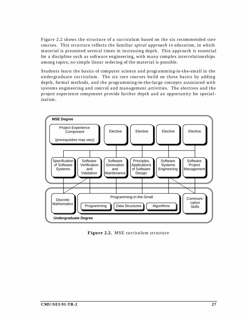
Figure 2.2 shows the structure of a curriculum based on the six recommended corecourses. This structure reflects the familiar spiral approach to education, in whichmaterial is presented several times in increasing depth. This approach is essentialfor a discipline such as software engineering, with many complex interrelationshipsamong topics; no simple linear ordering of the material is possible.
Students learn the basics of computer science and programming-in-the-small in theundergraduate curriculum. The six core courses build on these basics by addingdepth, formal methods, and the programming-in-the-large concepts associated withsystems engineering and control and management activities. The electives and theproject experience component provide further depth and an opportunity for special-ization.
Elective ElectiveElective
Specificationof SoftwareSystems
SoftwareProject
Management
SoftwareGeneration
and Maintenance
SoftwareVerification
andValidation
Principles,Applicationsof Software
Design
Elective
DiscreteMathematics
Programming-in-the-Small
Undergraduate Degree
SoftwareSystems
Engineering
Communi-cationSkillsProgramming AlgorithmsData Structures
Project ExperienceComponent
(prerequisites may vary)
MSE Degree
Figure 2.2. MSE curriculum structure

28 CMU/SEI-91-TR-2
CMU/SEI-91-TR-2 29
3. The SEI Academic Series Videotape Courses
In 1988, the SEI Education Program began teaching a series of graduate-level soft-ware engineering courses. Although Carnegie Mellon University students were ableto register for these courses, the primary purpose was to make the courses availableto other universities on videotape. These courses came to be known as the AcademicSeries courses; other SEI videotape courses are the Continuing Education Series andthe Technology Series.
The instructors for the courses used the course designs developed at the 1988 SEICurriculum Design Workshop (see [Ardis89]). As might be expected, the process ofimplementing the courses uncovered some rough areas in the designs. Some of thecourses have now been offered two or three times, and thus they represent a sub-stantial refinement of the original designs. Some remaining problems are that a fewof the individual topics in the core curriculum content (see section 2.4 of this report)are missing, and a few other topics show up in more than one course. Continueddevelopment of these courses is expected in conjunction with Carnegie Mellon’srecently established MSE program.
In this chapter, we describe in detail five of the six core courses. (The sixth coursewas implemented and taught during the fall 1990 semester, and it will be describedin a later report.) Each description includes:
• short discussions of student prerequisites, course objectives, and theinstructor’s philosophy
• a syllabus giving the titles of lectures
• a summary of each lecture (based on the instructor’s classroom trans-parencies), with reading assignments for the students
In some cases, the lecture summaries are quite short; this was necessary when thelecture was primarily a detailed presentation of a particular example, when thematerial covered was highly graphical or otherwise did not lend itself to a writtensummary, and when detailed instructor’s notes were not available.
Special acknowledgement goes to the three SEI staff members who implementedand taught these courses. Mark Ardis developed the courses Specification ofSoftware Systems and Software Verification and Validation. Robert Firth developedthe courses Principles and Applications of Software Design and Software Creationand Maintenance. James Tomayko developed Software Project Management.
Our goal in presenting this material is to help other instructors design courses orindividual lectures in these areas. We are also investigating the feasibility ofmaking individual videotape lectures available to universities, so this material canserve as a “catalog” of those tapes. For further information on the availability ofthese tapes, please contact the leader of the Software Engineering CurriculumProject at the SEI.
30 CMU/SEI-91-TR-2
3.1. Software Systems Engineering
A prototype version of this course was taught for the first time in the SEI AcademicSeries videotape courses during the fall semester 1990. A detailed summary of thelectures is not yet available. The information below is reprinted from the originalcourse design in [Ardis89].
Students’ Prerequisites
Students should have knowledge of software life cycle models, computer architec-tures, and basic statistics.
Objectives
After completing this course, students should comprehend the alternative tech-niques used to specify and design systems of software and hardware components.They should be able to find the data and create a requirements document and todevelop a system specification. They should understand the concepts of simulation,prototyping, and modeling. They should know what is needed to prepare a systemfor delivery to the user and what makes a system usable.
Philosophy of the Course
This course exposes students to the development of software systems at the veryhighest level. It introduces the system aspect of development and the related trade-offs required when software and hardware are developed together, especially withrespect to user interfaces. It exposes students to requirements analysis and tech-niques for developing a system from those requirements. System integration andtransition into use are also covered.
Syllabus
Wks Topics and Subtopics (Objective)
1 Introduction (Knowledge)
Students should see the “big picture” in this part of the course. The emphasisshould be on how software is only one component of a larger system.
Overview of topics
1 System Specification (Comprehension)
Contents
Standards
Global issues such as safety, reliability
CMU/SEI-91-TR-2 31
2 System Design (Comprehension)
Simulation
Queuing theory
Tradeoffs
Methods (levels, object-oriented, function-oriented)
3 Interfaces (Comprehension)
Both human interfaces and interfaces to hardware devices should be included.These areas require different skills but are logically combined here toemphasize the notion of encapsulation of software within larger systems.
Human factors
Guidelines
Experiments
Devices
1 System Integration (Comprehension)
Students should learn how to perform integration of entire systems, not justsoftware.
Simulation of missing components
System build
5 Requirements Analysis (Synthesis)
This is the largest part of the course. Students should learn the interpersonalskills as well as the technical skills necessary to elicit requirements fromusers. Expression and analysis of requirements are often performed withCASE tools.
Objectives
Interview skills
Needs and task analysis
Prototypes
SADT, RSL (and other specific methods)
1 Operations Requirements (Comprehension)
Students should understand and know how to satisfy the other operationsrequirements of systems, such as training and documentation.
Training
Online help
User documentation
32 CMU/SEI-91-TR-2
Pedagogical Concerns
Case studies should be available as assigned readings. A requirements analysis pro-ject should be assigned to students, with topics in the lectures sequenced to matchthe project schedule. A user interface prototype project should be assigned, includ-ing an exercise in user documentation. The students should give a presentation ontheir requirements study. An instructor of this course should have experience inrequirements analysis and system design.
Comments
We had a great deal of difficulty naming this course. Much of the work that stu-dents will perform as exercises and projects deals with requirements analysis. Onthe other hand, this course attempts to place software in perspective with other ele-ments of systems. The theme of the course is not just requirements analysis, buttotal systems engineering. We noted that universities often have courses titled“systems engineering” that cover the same topics from an electrical engineeringperspective.
An important goal of this course is that students achieve an understanding of therole of software engineering within the larger context of systems engineering. Theyshould understand, for example, that while ensuring that a software system satisfiesits specification is a software problem, getting the right specification is a systemsproblem. If software does not give the right system behavior, it must be determinedwhether the software fails to meet the specification or whether the specification doesnot define the right system behavior. These distinctions are critical as studentsleave the academic world, where the entire system is often a personal computer, andenter the “real world” of embedded systems.
CMU/SEI-91-TR-2 33
3.2. Specification of Software Systems
Students’ Prerequisites
Students must have a reasonable level of knowledge of:• set theory• functions and relations• predicate calculus• axioms• finite-state machines (transition mapping, nondeterminism)
Objectives
• Knowledge of major models of specification (sequential and concurrent systems)• Knowledge of existing standards and practices• Mastery of one method of describing functional behavior of simple sequential
systems• Appreciation of advantages and disadvantages of formality
Philosophy of the Course
A comparative survey approach serves to emphasize similarities and significantdifferences between languages and methods. For example, students specify thesame system with three or four different languages. Whenever possible, commonparadigms are translated into their language-specific idioms.
Students are expected to develop skills in reading formal specifications, reasoningabout formal descriptions, modelling “standard” paradigms, and translating modelsinto formal notations. The exercises and exams provide practice and feedback onthese skills, especially on small problems.
34 CMU/SEI-91-TR-2
Syllabus
The syllabus assumes 27 class meetings, including midterm and final examinations.Each meeting is planned to include approximately 55 to 60 minutes of lecture and 20minutes of class discussion.
1. Introduction2. Readers and Writers3. Standards4. Algebraic Model5. Larch6. State-Machine7. ASLAN8. Abstract Models9. VDM
10. Z11. Industrial Use12. Midterm Review13. Midterm Examination14. PAISLey 115. PAISLey 216. Concurrency Paradigms17. Petri Nets: Concepts18. Petri Nets: Modeling19. Communicating Sequential Processes (CSP) 120. Communicating Sequential Processes (CSP) 221. Synchronous Calculus of Communicating Systems (SCCS) 122. Synchronous Calculus of Communicating Systems (SCCS) 223. Temporal Logic24. Statecharts25. Final Review26. Final Examination
CMU/SEI-91-TR-2 35
Summaries of Lectures
1. Introduction
Reading: Cohen86, Chapter 1
The course will address these topics: what specifications are, the role of specificationin software development, the process of creating specifications, the process of usingspecifications, and the advantages and disadvantages of various notations forspecifications.
Current industrial practice includes specifications that are formal or informal,abstract or detailed, and standardized or ad hoc. Specifications may be written bythe client or by the developer, by the application specialist or the specificationspecialist. They are read by all these people.
There are several models for specifications. Sequential models and languagesinclude algebraic (exemplified by Larch), state-machine (ASLAN), abstract models(VDM, Z), and operational (Paisley). Concurrency models and languages includecommunicating processes (Paisley, CSP, CCS), state-machines (Petri nets,Statecharts), and predicate logic (temporal logic).
2. Readers and Writers
Reading: Parnas86
The IEEE Standard Glossary of Software Engineering Terminology definesspecification as “A document that prescribes, in a complete, precise, verifiablemanner, the requirements, design, behavior, or other characteristics of a system orsystem component. See also design specification, formal specification, functionalspecification, interface specification, performance specification, requirementsspecification.”
Two kinds of specifications may be distinguished: customer-oriented specifications(C-Specs) express requirements from the customer’s point of view; developer-oriented specifications (D-Specs) express requirements from the developer’s point ofview. Some C-Spec issues include why the user wants the system, how the userintends to use the system, and the expertise of people using the system. Some D-Spec issues include the behavioral attributes of the system, a functional description,and performance characteristics.
A specification may be viewed as a contract between the customer and the developer.It should be unambiguous, complete, verifiable, consistent, modifiable, traceable,and usable. Some common deficiencies are poor organization, boring prose,confusing and inconsistent terminology, and “myopia” (working at too low a level).
Some types of specifications are function (what the system must do), interface (howthe system will be used by other components, including people), and performance(how the system must perform, such as speed and accuracy). The organization of thespecification may be reference, historical, or ad hoc; the tone may be narrative ordeclarative.
Many people have a role in the specification process; these include users, customers,requirements analysts, designers, verification and validation staff, and maintainers.
36 CMU/SEI-91-TR-2
3. Standards
Reading: IEEE84, Jones89, Duce88, ANSI85
There are two important relationships between specifications and standards:standards for writing specifications and the specification of a standard. Twoexamples of standards for writing specifications are the IEEE Guide to SoftwareRequirements Specifications and the Department of Defense Military Standard2167A.
The IEEE standard includes a discussion of specification issues and suggests anoutline for specification documents. Four different organizations are provided forthe section “Specific Requirements.” The first has separate subsections forfunctional specifications, interface specifications, performance specifications, andconstraints. This approach has the advantage of avoiding duplication. The secondcombines functional with interface specifications, but has separate subsections forperformance and constraints. This approach emphasizes how to use the system.The third organization combines performance and constraints with each functionalrequirement, and then combines performance and constraints with each interfacespecification; this approach emphasizes the interface. The fourth organizationcombines all the issues, addressing interface, performance, and constraint issuesindividually for each functional requirements. This approach emphasizes theindependence of functional requirements from one another.
Some of the issues in specification are the relative sizes of the components of aspecification, the relative importance of the components, the ways in which thespecification will be read, and the ways in which it will be maintained.
Standards are different from systems in that: they describe systems; many systemsmay satisfy the same standard; it is difficult to create a standard before there areany systems; and a standard is an abstraction of a system. Standards should bespecified in a way that emphasizes the important abstractions and allows easyverification of conformance.
[The lecture includes a detailed example: the GKS (graphics kernel system)standard in its ANSI form (expressed in English) and in VDM form (as described inDuce88).]
4. Algebraic Model
Reading: Cohen86, Chapters 2-4
The main issues are notations and foundations, how to write algebraic specifications,and consistency and completeness. The algebraic view of specification is that alloperations are related to one another. Four basic idioms are: f undoes g, f isindependent of g, f ignores (part of) g, and f is (sometimes) the same as g.
The foundations include: a set of axioms defines a congruence relation—somesequences of operations are equivalent to other sequences; any implementation thatis equivalent up to isomorphism (operations may be consistently renamed) isconsidered correct; specified objects (types) may be used in other specifications; aconsistent set of axioms avoids contradictions of the form “true = false”; a completeset of axioms provides enough information to uniquely determine the result of anysequence of operations; those operations that return values in old types are behavior

CMU/SEI-91-TR-2 37
functions; those operations that return old values in the new type are modifierfunctions; those operations that return new values in the new type are constructorfunctions.
The components of an algebraic specification are the syntactic part (containing suchitems as the names of domains or types, the names of operations, and the domainsand ranges of operations), and the semantic part (containing the meanings ofoperations).
Current technology for working with algebraic specifications includes: Larch at MIT(Guttag), CMU (Wing), and DEC SRC (Horning); Hope, Clear at Edinburgh(Burstall); OBJ at UCLA and SRI (Goguen); and Project CIP at Munich (Bauer).
[The lecture includes detailed examples of the algebraic specification of stack, queue,and symbol table data types; the examples illustrate Guttag’s sufficiently completemethod of writing axioms.]
5. Larch
Reading: Guttag85; Roberts88 optional
The Larch language uses a two-tiered approach to specifications. The specificationlanguage is based on traits defined by axioms and on operators for combining traits.The interface language provides links between specification names and programnames, plus additional constraints. Programs typically include objects such astypes, packages, modules and procedures, and functions.
Traits may be combined in a number of ways. The “assumes” operator refers tocomponents of another trait; “includes” creates a larger trait by inclusion. Othercombining operators include generation, partitioning, conversion, exemption,substitution, and inclusion.
Interface languages are a mapping between a programming language and the LarchShared Language (LSL). For example, such a language mapping Pascal to LSL willmap Pascal types to LSL sorts , procedures and functions to operators, and abstractdata types to traits.
Assertions in Larch include “requires” for preconditions, “modifies” for side effects,and “ensures” for postconditions. All assertions are written in predicate calculus,with references to traits and to built-in predicates (from programming languagesemantics).
Practical advice for using Larch is to begin by finding a canonical representation—asequence of operations that can be used to create any value of the type of interest.Add behavior operators to simplify expressions; a condition that naturally arisesoften in describing behavior should be captured in a behavior operator. Then lookfor common right-hand sides. The four basic idioms: “nochange” indicates thatthere is no simpler description; “ignores” indicates that some operations arediscarded; “commutes” indicates the order of operations is reversed; “undoes”indicates that the effect of the last operation is undone.
38 CMU/SEI-91-TR-2
6. State-Machine
Reading: Parnas72
This method describes a data type as a state-machine inside a black box with pushbuttons. Some of the buttons change the state of the machine and others displayinformation about the state. The objective of the method is to hide as much aspossible, while providing access to as much as needed. This includes providing allneeded information to the user, and no more; providing all needed information toimplementor, and no more; using a formal model, so that consistency andcompleteness can be decided; and not inventing a new model.
State-changing operations are called O-functions; the description of each shouldinclude exceptions (error cases) and new values of V-functions. The information-displaying operations are called V-functions; the description of each includesexceptions and initial values.
The advantages of the state machine method include: they are minimal and do notbias the implementation; the basic idea of a state machine is already familiar tomost programmers; and completeness is easy to show. Disadvantages include: itmay require hidden functions; and the relationships between functions may beobscure, thus causing difficulty with demonstrating consistency. Some problemswith the method include specification of delayed effects and asymmetry (implicitoperands).
[The lecture includes detailed examples of the specification of the stack data typeand the Pascal file type.]
7. ASLAN
Reading: Auernheimer84, Kemmerer85
ASLAN is a language for writing state-machine specifications. The O- and V-functions of the state machine model can be translated to ASLAN. The O-functionsare called transitions and the V-functions are declared as variables (statecomponents). Initial values are collected together. Error cases for transitions arecalled entry conditions and those for variables are called invariants. A specificationconsists of declarations (types, constants, etc.), requirements (invariants, etc.), andtransitions.
Additional features of ASLAN include declarations (abstraction), implied “nochanges,” and a small programming language for added power of expression.
Correctness conjectures in ASLAN are addressed through invariants andconstraints,which express properties that should be true of the specified objects.ASLAN generates a set of verification conditions from these predicates. Axioms maybe used to simplify the verification conditions.
To begin the process of writing ASLAN specifications, model the problem domain interms of a collection of state-machines, identifying types and transitions. Thenidentify the state components, invariants, and constraints. Write the ASLANspecification, and then run the ASLAN processor to generate the verificationconditions. Finally, prove the verification conditions, iterating where necessary.
CMU/SEI-91-TR-2 39
[The lecture includes a detailed discussion of an ASLAN specification of a stack datatype.]
8. Abstract Models
Reading: Cohen86, Chapter 5; Bjørner 78, Bjørner87, Lucas87 for background
The major mathematical concepts behind abstract models include sets, lists, records,maps, and predicates. An abstract syntax is a system of functions for constructingand decomposing composite objects.
[The lecture includes a detailed discussion of the grocer example from Bjørner87.]
9. VDM
VDM (Vienna Development Method) was created at the IBM Vienna laboratory. Itis being used in programming language definition for compilers, for databasespecification, and in office automation applications.
The Meta-IV language includes elementary types (boolean, numbers, etc.), compositetypes (sets, tuples, etc.), and combinators (states, blocks, etc.). Normal use adheresto naming conventions. VDM specifications include semantic domains (abstractmodel), invariants (well-foundedness), and functions (operations). A British varianthas operations described via pre- and post-conditions, significant components of the“state” identified for each operation, and minor syntax variations.
The method of VDM is based on stepwise refinement (decomposition, reification) andproof obligations: at each step of the refinement a retrieve function is defined, itsadequacy proved, and commutativity of operations with respect to the function areproved.
[The lecture includes detailed discussions of VDM specifications of the stack andqueue data types, the bank example from Jones86, and a reification example.]
10. Z
Reading: Spivey89; Hayes87 and Spivey88 for background
Z (pronounced in the British manner as “zed”) is another model-theoretic method,with incrementality via schema calculus. It is founded on set theory and othermathematics (in a library), and on first-order predicate logic. Important featuresinclude schema notations, naming conventions, mathematical library, ways ofcombining schema (conjunction, disjunction, hiding, overriding, composition, andpiping).
The Z method is to introduce basic sets; define an abstract state in terms of sets,relations, functions, sequences, etc.; specify the initial state; define the pre- andpost-conditions of operations; state and prove theorems; and refine toward theconcrete, incurring proof obligations. Current technology to support the methodincludes text processing tools and consistency checkers; other tools are beingdeveloped.
[The lecture includes a detailed discussion of the symbol table example fromHayes87.]
40 CMU/SEI-91-TR-2
11. Industrial Use
Reading: Delisle89, Hayes85, Nix88, Ruggles88, Woodcock88
Four examples illustrate the use of Z in industry: the IBM CICS project, GKSstandardization, the GEC Telecom storage allocator, and the Tektronix oscilloscopedescription.
The IBM project was maintenance of the Customer Information Control System(CICS). Z was used to reverse engineer old code: the product was over 20 years old,over 500,000 lines of code, had many users and many configurations. Restructuringof the code was necessary before Z could be used; this was done independently of anymethod. Then the Z specifications were derived from manuals, developers, andexisting code. Ultimately about half of CICS was described in Z (230,000 lines ofcode), and modules were added or rewritten from the Z specifications. The normalIBM development process was used, including design reviews, code inspections, andtesting. The normal IBM programming languages were used, plus a guardedcommand language. It was necessary to retrain the staff in the use of Z; thisincluded existing IBM courses on discrete mathematics and a software engineeringworkshop, augmented with Z courses. The final results were that more time wasspent in design, inspections required less preparation but took longer to conduct,and more problems were found earlier in design and fewer problems found intesting. The product has been shipped and the developers are awaiting customerreaction.
The effort to standardize the graphics kernel system (GKS) via formal descriptionshas been under way for many years. The first GKS standard was released in 1985,written in a procedural style. VDM and algebraic methods have been used todescribe parts of the standard in a more abstract form; Z is now being tried.Originally VDM was the leading contender for the specification, but it was found tobe inadequate with respect to concurrency and modularity. A strong sense ofintuition is now developing that the main abstractions of GKS can best be describedalgebraically, but progress has been hindered by the lack of a standard for VDM andthe lack of a consensus on which method to use.
The GEC Telecom project used VDM in the maintenance of the storage allocator forthe operating system of digital exchanges. The project involved 12 staff members for1.5 years, producing 30,000 lines of code. Their process included training all staff inVDM, using reviews but not proofs, using a “scouting” strategy (in which expertslooked ahead for trouble spots), and a consensus strategy (the description of statewas resolved before moving on to the next stage). GEC’s results included findingthat education was difficult, due to the lack of special courses on the variant of VDMbeing used; the lack of standardization of VDM caused problems for the staff andtools; reworking specifications was at least as hard as writing them (two-thirds ofthe time was spent reviewing and reworking); changing requirements caused extrawork; the difficulty of project tasks was underestimated; newcomers to the projectwere able to contribute quickly; many errors were discovered early; the resultingdesign was simpler but similar to the original; and it was easier to implement fromthe design.
Tektronix undertook a small (two-person) research project to explore thespecification of devices. Previous device descriptions had been operational. Theproject team talked with engineers, tried to describe existing devices, and discussed
CMU/SEI-91-TR-2 41
the specifications with engineers. They found a useful abstraction that clarified therole of hardware and software engineers, and the specifications yielded insight intodesign tradeoffs for user interfaces, sampling methods, and hardware/softwarepartitioning. Lessons learned included: engineers in industry can understandformal specifications; abstraction was useful in focussing attention on the rightproblem; and specification was a process rather than a product.
Common themes in all four industry examples were: formal methods are more time-consuming, at least during early stages of the life cycle; traditional developmentprocesses may still be used; more errors are found earlier in development; andmodularity and standardization are important.
12. Midterm Review
13. Midterm Examination
14. PAISLey 1
Reading: Zave82, Horning73
Operational methods describe a system by a program or set of programs. They maybe formal if the programming language has a formal semantics; they may beexecutable if the programming language has an interpreter or compiler.
PAISLey (process-oriented, applicative, and interpretable specification language)allows writing an executable specification as a step between informal requirementsand code. It was designed for real-time and distributed systems and allowsspecification of performance. Several tools are available, including a parser forfinding syntax errors, an interpreter for performing simulations, a cross-referencer,and a consistency checker. It has been used for specification of a submarinelightguide system and a finite-element adaptive research solver.
The process model views a system as a set of asynchronous processes. Each newprocess cycles through a sequence of states described by a mapping from the oldstate to the new state. Processes communicate by “exchange functions” that may ormay not involve waiting. Processes have internal synchronous concurrency viacomponents of tuples. Exchange functions need to model synchronizing and free-running processes, and self-matching and competing processes.
The data model is based on types constructed from atomic values (such as integers,reals, strings, or symbolic values) and set operations (such as union, cross-product,and enumeration). Values may be either atomic or tuples.
The computational model is based on independently specified processes, withexchange functions (in terms of mappings) for communication. The interpreterselects a mapping to evaluate. Within a process this is done nondeterministically;between processes a first-in, first-out strategy is used for xm-type exchanges. Theinterpreter maintains a system-wide clock to be used in measuring performance.Concurrent evaluation occurs between processes (except for exchanges) and withintuple evaluation.
To specify performance requirements, timing constraints may be attached tomappings. These may be upper bounds, lower bounds, or constant time. Uniformlydistributed random values are used when the evaluation time is not constant.
42 CMU/SEI-91-TR-2
During interpretation (simulation), timing constraints are checked; violationsgenerate error messages.
15. PAISLey 2
Reading: Zave85; Bruns86 and Zave86 for background
The transformational method of developing a specification requires that a correctspecification be developed at each level of abstraction. Each level is refined to movecloser to implementation and to optimize inefficient solutions. The most significantissue is deciding which objects to refine at each level.
The JSD (Jackson System Development) method is based on entities that modelobjects in the real world and actions that model events in the real world. A processnetwork is a set of communicating concurrent processes. Its specification isdeveloped by identifying entities, identifying processes, arranging them in time-order, identifying inputs and outputs of processes, arranging them into a network,refining the network with functions, and refining the data with tuples andsequences.
The PAISLey method develops a specification by identifying entities, identifyingprocesses, describing them with a process model (cycle), identifying inputs andoutputs of processes, connecting them with exchange functions, refining processeswith functions, and refining data with tuples and sets.
Criteria for decomposing a system into processes include: each process correspondsto a “meaningful activity” of the system; the system is decomposed so that dataitems modified by a process are related; and each process contains activities withsimilar cycle times. Criteria for defining process cycles include: there is maximaluse of parallelism in process steps; each process step corresponds to a “meaningfulcycle” of the activity; process cycles are time-bounded unless there is a good reasonfor making an exception; bounded iteration is used to traverse homogeneous tuples.Criteria for defining inter-process interactions include: exchange-function types andchannels for all interactions are identified so that processes can satisfy timingconstraints; exchange-function names are clear; and buffered message passing is notintroduced for performance reasons only. An important criterion for deciding thelevel of abstraction in a specification is to avoid defining sets and mappings if theyare well-understood, available from a library, or better specified using anotherformalism. Criteria to divide specifications into modules include: information-hiding is used to partition the specification into files; abstract data types areidentified and placed in separate files; and the specification is partitioned into filesso that interesting, executable subsets can be run without manual intervention.
16. Concurrency Paradigms
Reading: Horning73, Andrews83
A process may be defined as a triple, consisting of a state space, a successor function,and initial states. The state space is a set of (variable, value) pairs. The successorfunction maps states into states, and it may be a deterministic function or anondeterministic relation. Combinations of processes are said to be disjoint if theirstate spaces are disjoint, serial if only one process may be active at a time,synchronous if each process takes one step at the same time, and asynchronous ifthe processes operate at different rates. Interactions between processes are called
CMU/SEI-91-TR-2 43
cooperation if they are anticipated and desired; interference if they areunanticipated or unacceptable; and competition if they are anticipated andacceptable, but undesirable.
Shared variable paradigms of concurrency involve concepts of mutual exclusion,busy waiting, semaphores, conditional critical regions, monitors, and pathexpressions. Message passing paradigms involve concepts of channels, pipelines,client/server relationships, ports, blocking, and buffering. Higher-level descriptionsinvolve concepts of remote procedure calls, rendezvous, and atomic transactions.
Two major properties of systems are important. Safety properties describesomething that should not happen or properties that hold over finite sequences ofevents. Liveness properties describe something that must happen or properties thathold over infinite sequences of events; three liveness properties are termination,deadlock, and starvation. The termination property specifies that every process thatshould terminate does. Deadlock is the condition in which all processes are blocked,waiting for conditions that can only be changed by blocked processes. Starvation isthe condition in which some process never gets unblocked, even though the system isnot deadlocked.
17. Petri Nets: Concepts
Reading: Peterson77
A Petri net is a bipartite directed graph (P, T, E), where P is a set of places; T is a setof transitions; and E is a set of directed edges from a place to a transition or from atransition to a place. A marking M of a Petri net is a mapping from P to the naturalnumbers; it assigns a number of tokens to places. Petri nets are often defined withan initial marking. A transition may fire if it is enabled . It is enabled if each of itsinput places has at least one token. Firing of a transition removes a token from eachinput place and produces a token at each output place. The state space of a Petri netis the set of all markings (a marking is a state). A marking m' is immediatelyreachable from marking m if the firing of some enabled transition in m yields m'.The reachable relation is the reflexive transitive closure of the immediatelyreachable relation. The reachability set is the set of all reachable states.
Important properties of Petri nets include: they allow concurrent execution (firing oftransitions); they are nondeterministic; synchronization may be specified; resourceallocation may be modeled.
A Petri net is said to be a safe net if it has no more than one token at any place. It isk-bounded if it has no more than k tokens at any place. It is bounded if it has nomore than k tokens at any place, but we don’t know the value of k. It is conservativeif the number of tokens in the net remains constant.
The liveness problem for Petri nets may be expressed as “are all transitionspotentially fireable?” The reachability problem is “is state m' reachable from statem?” The coverability problem is “given states m and m', does there exist a markingm" reachable from m, such that m" ≥ m'?” A reachability tree can be used to solvesafeness, boundedness, conservation, and coverability problems. The reachabilitytree is a finite representation of a potentially infinite structure.
[The lecture includes detailed examples of specification of an elevator system, aproducer/consumer problem, and mutual exclusion via Petri nets.]
44 CMU/SEI-91-TR-2
18. Petri Nets: Modeling
Reading: Agerwala79
[This lecture consists of detailed examples of Petri net modeling methods, includingsynchronization, shared resources, and semaphores.]
19. Communicating Sequential Processes (CSP) 1
Reading: Hoare78
Fundamental concepts of CSP include simple event sequences, recursively definedsequences, and choice of events. Several improvements to CSP from the definition inHoare78 have been introduced in Hoare85, including: change of symbol to reuselibraries, ports and channels, no assumption of automatic termination, traces-language of events, and proof methods to use when showing that two levels ofspecification are consistent.
[The lecture includes detailed examples of a vending machine, a producer/consumerproblem, and the dining philosophers problem.]
20. Communicating Sequential Processes (CSP) 2
Reading: Kallstrom88 and Wayman87 for background
Processes often interact. Processes are described by events. The set of all events ofa process is called its alphabet. If concurrent processes share alphabets, then theymust simultaneously participate in the events that they share.
There are algebraic laws that form a calculus for CSP. When trying to show that aproperty (theorem) is true for a given specification, we can manipulate CSPexpressions with these laws. Specifications can be written in CSP. Other importantconcepts are satisfaction, choice, communication, and livelock.
[The lecture includes detailed examples of interaction of processes using the vendingmachine and dining philosophers problems; an example of CSP specification for thevending machine problem; and a discussion of the bakery algorithm.]
21. Synchronous Calculus of Communicating Systems (SCCS) 1
Reading: Cohen86, Chapter 6; Milner83 and Diaz89 for background
CCS (calculus of communication systems) was invented first; afterward, Milnerrealized that a generalization yielded explicit modeling of time, hence SCCS. Asurprise was the discovery that CCS was a subcalculus of SCCS. It emphasizesinterfaces between agents (the action set). Time is modeled discretely. Semanticsare operationally based. It has as few operators as possible.
The action of delay has no externally observable effect (except to use time). Soadding a delay does not change the behavior of a process. Similarly, the internalcommunication between subprocesses yields only an externally visible delay. So, letdelay be represented by the identity element of the calculus (multiplication by 1),and let internal communication be shown by simultaneous execution of inverses.
CMU/SEI-91-TR-2 45
Two machines are observationally equivalent if they allow the same experiments tobe performed and they produce the same externally visible behavior for anyexperiment.
[The lecture includes a detailed comparison of examples of CSP and SCCS.]
22. Synchronous Calculus of Communicating Systems (SCCS) 2
Synchronous specifications are important, but many systems are asynchronous;communications protocols and airline reservation systems are examples. Thereforeit is worth examining CCS; a knowledge of SCCS is assumed.
Fundamental definitions include synchrony : synchronistic occurrence, arrangementor treatment; synchronous: happening, existing or arising at precisely the sametime; asynchrony: absence or lack of concurrence in time. Basic concepts includeevent sequences; unbuffered communication on channels known as ports (althoughthe calculus is asynchronous, communication synchronizes the agents); fairness;relabeling; restriction; summation and composition over a set; strong equivalence;observational equivalence.
CCS may be derived from SCCS. A convincing argument is to derive each CCSoperator from SCCS operators. The key step is the introduction of a new SCCSoperator, delay . We conclude that rather than use two different calculi forsynchrony and asynchrony, the synchronous calculus alone is sufficient. It is alsosimpler than the asynchronous calculus.
CCS has been used for protocol specification, and it forms the basis of LOTOS (anISO standard).
[The lecture includes detailed examples of a 1-place message buffer, a buffer with apersistent state, a nondeterministic choice, mutual recursion, a fair buffer, and a 2-place buffer.]
23. Temporal Logic
Reading: Barringer87, Lamport83, Pneuli85, Rescher71, and Wood89 for back-ground
Temporal logic extends predicate logic through the introduction of temporaloperators, such as eventually, henceforth, until , next , and previous. It can be used toreason about the behavior of systems through time.
An example application is the specification of the behavior of a simple elevatorsystem, including safety and liveness properties. The example demonstrates thattemporal logic can be the system specification; a finite state machine is the model ofoperation; underspecification is easy to accomplish, difficult to determine, andrelatively easy to correct; the system is allowed any behavior not explicitlyforbidden; and that an implementation can be derived from either the specificationor from the model. Verification of the specification can be handcrafted or toolsupported, both with difficulty. The handcrafted verification is too tedious to bedone without error, and the existing tools are often too limited for any but thesmallest of specifications.
[The lecture includes a detailed discussion of the temporal logic specification of theelevator system.]
46 CMU/SEI-91-TR-2
24. Statecharts
Reading: Harel87, Harel88
[This lecture provides a detailed introduction to the statechart notation andconcepts.]
25. Final Review
26. Final Examination
Bibliography
Agerwala79 Agerwala, Tilak. “Putting Petri Nets to Work.” Computer 12, 12(Dec. 1979), 85-94.
Andrews83 Andrews, Gregory R. and Schneider, Fred B. “Concepts andNotations for Concurrent Programming.” ACM ComputingSurveys 15, 1 (Mar. 1983), 3-43.
ANSI85 American National Standard for Information Systems —Computer Graphics — Graphical Kernel System (GKS) FunctionalDescription. ANSI X3.124-1985, American National StandardsInstitute, 1985.
Auernheimer84 Auernheimer, Brent and Kemmerer, Richard A. ASLAN User’sManual. Tech. Rep. TRCS84-10, Department of ComputerScience, University of California, Santa Barbara, Santa Barbara,Calif., Aug. 1984.
Barringer87 Barringer, H. “Up and Down the Temporal Way.” Computer J.30, 2 (Apr. 1987), 134-148.
Bjørner78 The Vienna Development Method: The Meta-Language. DinesBjørner; Cliff Jones, eds. Berlin: Springer-Verlag, 1978. Vol. 61,Lecture Notes in Computer Science.
Bjørner87 VDM ’87: VDM—A Formal Method at Work. VDM-EuropeSymposium 1987. D. Bjørner; C. B. Jones; M.Mac an Airchinnigh; E. J. Neuhold, eds. Berlin: Springer-Verlag,1987. Vol. 252, Lecture Notes in Computer Science.
Bruns86 Bruns, Glenn R. Technology Assessment: PAISLEY. Tech. Rep.MCC TR STP-296-86, MCC, Austin, Texas, Sept. 1986.
Cohen86 Cohen, B., Harwood, W. T., and Jackson, M. I. The Specificationof Complex Systems. Reading, Mass.: Addison-Wesley, 1986.This book is now out of print.
Delisle89 Delisle, Norman and Garlan, David. “Formally SpecifyingElectronic Instruments.” Proc. Fifth International Workshop onSpecification and Design. IEEE Computer Society, May 1989,242-248. Also published as ACM Software Engineering Notes 14(3).

CMU/SEI-91-TR-2 47
Diaz89 Diaz, M. and Vissers, C. “SEDOS: Designing Open DistributedSystems.” IEEE Software 6, 6 (Nov. 1989), 24-33.
Duce88 Duce, D. A., Fielding, E. V. C., and Marshall, L. S. “FormalSpecification of a Small Example Based on GKS.” ACMTransactions on Graphics 7, 7 (July 1988), 180-197.
Gehani86 Gehani, N. and McGettrick, A. Software Specification Techniques.Reading, Mass.: Addison-Wesley, 1986.
Guttag78 Guttag, John V., Horowitz, Ellis, and Musser, David R. “AbstractData Types and Software Validation.” Comm. ACM 21, 12 (Dec.1978), 1048-1064.
Guttag85 Guttag, John V., Horning, James J., and Wing, Jeanette M. “TheLarch Family of Specification Languages.” IEEE Software 2, 5(Sept. 1985), 24-36.
Harel87 Harel, David. “Statecharts: A Visual Formalism for ComplexSystems.” Science of Computer Programming 8 (1987), 231-274.
Harel88 Harel, D., Lachover, H., Naamad, A, A. Pnueli, Politi, M.,Sherman, R., and Shtul-Trauring, A. “Statemate: A WorkingEnvironment for the Development of Complex Reactive Systems.”10th International Conference on Software Engineering. IEEE,1988, 396-406.
Hayes85 Hayes, I. J. “Applying Formal Specification to SoftwareDevelopment in Industry.” IEEE Trans. Software EngineeringSE-11, 2 (Feb. 1985), 169-178.
Hayes87 Hayes, I. J. Specification Case Studies. Englewood Cliffs, N. J.:Prentice-Hall International, 1987.
Hoare78 Hoare, C. A. R. “Communicating Sequential Processes.” Comm.ACM 21, 8 (Aug. 1978), 666-677.
Hoare85 Hoare, C. A. R. Communicating Sequential Processes. London:Prentice-Hall International, 1985.
Holzmann91 Holzmann, Gerard J. Design and Validation of ComputerProtocols. Englewood Cliffs, N. J.: Prentice-Hall, 1991.
Horning73 Horning, J. J. and Randell, B. “Process Structuring.” ACMComputing Surveys 5, 1 (Mar. 1973), 5-30.
IEEE84 IEEE Guide to Software Requirements Specifications. Std. 830-1984, IEEE, 1984.
Jones86 Jones, Cliff. Systematic Software Development Using VDM.Englewood Cliffs, N. J.: Prentice-Hall International, 1986.
Jones89 Jones, Peggy. DASC Requirements Document. In SoftwareMaintenance Exercises for a Software Engineering Project Course,CMU/SEI-89-EM-1, Software Engineering Institute, CarnegieMellon University, Pittsburgh, Pa., Feb. 1989.
48 CMU/SEI-91-TR-2
Kallstrom88 Kallstrom, Marta and Thakkar, Shreekant S. “ProgrammingThree Parallel Computers.” IEEE Software 5, 1 (Jan. 1988), 11-22.
Kemmerer85 Kemmerer, Richard A. “Testing Formal Specifications to DetectDesign Errors.” IEEE Trans. Software Engineering SE-11, 1 (Jan.1985), 32-43.
Lamport83 Lamport, Leslie. “What Good is Temporal Logic.” InformationProcessing: Proceedings of the IFIP World Computer Congress.New York: Elsevier, 1983, 657-668.
Lucas87 Lucas, Peter. “VDM: Origins, Hopes and Achievements.”Proceedings of VDM-Europe Symposium ’87, Bjørner, Dines, et al,ed. Berlin: Springer-Verlag, 1987. Vol. 252, Lecture Notes inComputer Science.
Milner83 Milner, R. “Calculi for Synchrony and Asynchrony.” TheoreticalComputer Science 25 (Nov. 1983), 267-310.
Nix88 Nix, C. J. and Collins, B. P. “The Use of Software Engineering,Including the Z Notation, in the Development of CICS.” QualityAssurance 14, 3 (Sept. 1988).
Owicki82 Owicki, Susan and Lamport, Leslie. “Proving Liveness Propertiesof Concurrent Programs.” ACM Trans. Programming Lang. andSyst. 4, 3 (July 1982), 455-495.
Parnas72 Parnas, David L. “A Technique for Software Module Specificationwith Examples.” Comm. ACM 15, 5 (May 1972), 330-336. Also inGehani86, p. 75-88.
Parnas86 Parnas, David L. and Clements, Paul C. “A Rational DesignProcess: How and Why to Fake It.” IEEE Trans. SoftwareEngineering SE-12, 2 (Feb. 1986), 251-257.
Peterson77 Peterson, James L. “Petri Nets.” ACM Computing Surveys 9, 3(Sept. 1977), 223-252.
Pneuli85 Pneuli, A. “Application of Temporal Logic to the Specification andVerification of Reactive Systems: A Survey of Current Trends.”Current Trends in Concurrency: Overviews and Tutorials.deBakker, J. W., deRoever, W. P., and Rosenberg, G., eds. NewYork: Springer-Verlag, 1985, 510-584. Vol. 224, Lecture Notes inComputer Science.
Rescher71 Rescher, Nicholas and Urquart, Alasdair. Temporal Logic. NewYork: Springer-Verlag, 1971.
Roberts88 Roberts, W. T. “A Formal Specification of the QMC MessageSystem.” Computer Journal 31, 4 (Aug. 1988), 313-324.

CMU/SEI-91-TR-2 49
Ruggles88 Ruggles, Clive. “Towards a Formal Definition of GKS and OtherGraphics Standards.” VDM ’88: VDM — The Way Ahead,Bloomfield, R., Marshall, L., and Jones, R., eds. New York:Springer-Verlag, 1988, 64-73. Vol. 328, Lecture Notes inComputer Science.
Schwartz81 Schwartz, Richard L. and Melliar-Smith, P. M. “Temporal LogicSpecification of Distributed Systems.” Proc. 2nd Intl. Conf. onDistributed Computing Syst. New York: IEEE, 1981, 446-454.
Spivey88 Spivey, J. M. The Z Notation: A Reference Manual. EnglewoodCliffs, N. J.: Prentice-Hall, 1988.
Spivey89 Spivey, J. M. “An Introduction to Z and Formal Specifications.”Software Engineering Journal 4, 1 (Jan. 1989), 40-50.
Wayman87 Wayman, Russell. “OCCAM 2: An Overview from a SoftwareEngineering Perspective.” Microprocessors and Microsystems 11,8 (Oct. 1987).
Wood89 Wood, William G. Temporal Logic Case Study. Tech. Rep.CMU/SEI-89-TR-24, ADA219019, Software Engineering Institute,Carnegie Mellon University, Pittsburgh, Pa., 1989.
Woodcock88 Woodcock, J. C. P. and Dickinson, B. “Using VDM with Rely andGuarantee-Conditions.” VDM ’88: VDM — The Way Ahead,Bloomfield, R., Marshall, L., and Jones, R., eds. New York:Springer-Verlag, 1988, 449-455. Vol. 328, Lecture Notes inComputer Science.
Zave82 Zave, Pamela. “An Operational Approach to RequirementsSpecification for Embedded Systems.” IEEE Trans. SoftwareEngineering SE-8, 3 (May 1982), 250-269. Also in Gehani86, 131-169.
Zave85 Zave, Pamela. “A Distributed Alternative to Finite-State-MachineSpecifications.” ACM Trans. Prog. Lang. and Systems 7, 1 (Jan.1985), 10-36.
Zave86 Zave, Pamela and Schell, William. “Salient Features of anExecutable Specification Language and Its Environment.” IEEETrans. Software Engineering SE-12, 2 (Feb. 1986), 312-325.
50 CMU/SEI-91-TR-2
3.3. Principles and Applications of Software Design
Students’ Prerequisites
• computer science background• reasonable knowledge of programming• some experience of team software development• some exposure to the software development process• industrial experience is an advantage
Objectives
Help the student make the transition from programming-in-the-small toprogramming-in-the-large:
• appreciate the software development process• understand the role of design in that process• become familiar with the major design methods• be able to categorize and comprehend a new design method
Enable the student to undertake software design:• select an appropriate method• apply the method properly and intelligently• understand the strengths and weaknesses of the method• be aware of the major application domains and their appropriate design
paradigms
Enable the student to evaluate software design:• appropriateness of method• completeness and correctness of design• traceability to requirements and code• design quality• formal verification of design
Philosophy of the Course
The overall philosophy is that software is a product of value that is built in responseto a need, that is to be maintained as long as the need persists, and that is to evolveas circumstances change.
CMU/SEI-91-TR-2 51
Syllabus
The syllabus assumes 28 class meetings, including midterm and final examinations.Each meeting is planned to include approximately 55 to 60 minutes of lecture and 20minutes of class discussion.
1. The Software Development Process and the Role of Design2. Classification of Design Methods3. Basic Principles of Design Methods4. Statecharts: Description5. Statecharts: Worked Example6. MASCOT: Description7. MASCOT: Worked Example8. Object-Oriented Design: Description9. Object-Oriented Design: Worked Example
10. VDM: Description11. VDM: Worked Example12. Comparison and Critique of Design Methods13. Team Exercise: Presentation14. Team Exercise: Requirements Review15. Midterm Review16. Midterm Examination17. Application Domains and Design Paradigms18. Information Systems Design: Problems19. Information Systems Design: Paradigms20. Real-Time Systems Design: Problems21. Real-Time Systems Design: Paradigms22. Team Exercise: Design Reviews23. Team Exercise: Design Reviews (Continued)24. Software Development Environments25. User Interface Design: Problems26. User Interface Design: Paradigms27. Final Review28. Final Examination

52 CMU/SEI-91-TR-2
Summaries of Lectures
1. The Software Development Process and the Role of Design
Reading: none
The course is structured in two major parts: understanding design methods, and theapplication of those methods. The first part covers the software process and the roleof design, and the classification, underlying principles, and verification techniquesfor several methods. The second part covers assessment and comparison of methods,their strengths weaknesses, their application domains, and paradigms for their use.
A software design is a description of a system that will meet the requirements. Thedesign should be as complete as possible, and it is often represented formally usingspecial notation. The process of design consists of taking a specification (a descrip-tion of what is required) and converting it into a design (a description of what is tobe built). A good design is complete (it will build everything required), economical (itwill not build what is not required), constructive (it says how to build the product),uniform (it uses the same building techniques throughout), and testable (it can beshown to work).
The design activity is one part of a development process, and thus exhibits the char-acteristics of all activities: it occurs at a particular stage, it takes inputs from theprevious stage, it performs a specific task, it generates outputs to the subsequentstage, it yields feedback to earlier stages, it incorporates feedback from later stages,and it is assessable both independently and within context.
A design can be assessed independently by asking questions such as these. Is itclear what is to be built? Is it clear how it is to be built? Are the components mutu-ally consistent? Are the building techniques mutually compatible? Most of thesequestions look at the design representation—the object that embodies the design. Adesign can also be assessed in the context of the process by asking questions such asthese. Does the design address every part of the requirement? Does the design meetall constraints on the solution? Are specific design choices clearly recorded? Can thedesign be effectively implemented? Is the design robust against small changes inrequirements? Most of these questions look at the design documentation—theobjects that accompany the design and explain it.
Traceability is the single most important concept in software development. From acomponent of a design (or other) document, one should be able to determine why thatcomponent is present, a corresponding component in another document, the historyof the component across versions, alternative forms of the component across configu-rations, and the reasoning that created the component.
It is not possible mechanically to deduce a design from a requirement. Design istherefore necessarily a human activity. It consists of the intelligent application ofexpertise to the solution of problems and the realization of the solutions as softwareartifacts. This intelligence can be guided by design methods and techniques, but itcannot be replaced.
The development of large software systems, often called programming-in-the-large,is an activity very different from programming-in-the-small. In the latter case, pro-grammers write programs, but in the former, teams build software. This requireddifferent ways of thinking, different ways of behaving, and different tools and tech-
CMU/SEI-91-TR-2 53
niques. Team development of software is characterized by the division of labor,replacement of individuals, more thorough specification of components and inter-faces, more (and more formal) record keeping and communication, clearer separationof development stages, and much tighter control of feedback and consequentchanges.
When a team performs design, control is required to ensure consistent notation,division of work without gaps or overlap, and consistency between components. Theoverall design must remain within the solution envelope, which places limits oncomplexity and on resource consumption.
2. Classification of Design Methods
Reading: Firth87
Classification of design methods is helpful as an aid to explanation of designmethods, a help in understanding how methods differ, and a guide to selection ofappropriate methods. Classification can use several kinds of criteria. Attributes ofthe design object are the simplest criteria to apply. They include the kind of designnotation used (graphical, textual, mixed), degree of formalism (informal, such asnatural language or fuzzy blobs), semi-formal (such as stylized phrases, shapes, andicons), or formal (logical propositions, directed graphs). Attributes of the structure ofthe representation are another type of criteria. They include whether the design ishierarchical (each level expands into more detail) or flat (there is one key level thatis unique), and whether it provides a single view of the design or multiple views ofthe same design. Attributes of the design philosophy are perhaps the major guide toclassification.
Much of the philosophy of a design method hinges on the view it takes of the systemThe basic view of the system taken by a design method, and hence captured by adesign based on that method, can be functional, structural, or behavioral. With thefunctional view, the system is considered to be a collection of components, eachperforming a specific function, and each function directly answering a part of therequirement. The design describes each functional component and the manner of itsinteraction with the other components. With the structural view, the system isconsidered to be a collection of components, each of a specific type, each indepen-dently buildable and testable, and able to be integrated into a working whole.Ideally, each structural component is also a functional component. With the behav-ioral view, the system is considered to be an active object exhibiting specificbehaviors, containing internal state, changing state in response to inputs, and gen-erating effects as a result of state changes. This view is essentially dynamic ratherthan static. This is the basis of the classification scheme in Firth87. Observe that itcan be applied to more than just the design stage.
Attributes of the design process are also useful in classifying methods.
A design method can be categorized also by the way in which it is used. The princi-ple criterion is the manner in which the design object is supposed to be generated.This incorporates the design method’s view of the design process and how it shouldbe carried out. Some criteria imply alternatives—either this or that. Some criteriaimply gradations—either more or less.
Design methods seem to have three views on how the design is to be generated. Thetop-down approach is to create a single, high-level description of the system, then

54 CMU/SEI-91-TR-2
take each component in turn, elaborate its interfaces, and refine its internal details.This process continues hierarchically from component to subcomponent. Thebottom-up approach is to design in detail the lowest-level components, define themanner in which they can be composed, and then build higher-level components interms of the lower-level ones. This continues until the highest component—thesystem—is reached. The left-right approach is to take a plausible scenario, definethe information objects that flow through the system from initial input to finaloutput, define the processing nodes through which the information will flow, anddefine the data stores that will hold information between scenarios.
In addition, some methods encourage prototyping and reuse. Prototyping methodsprovide tools and techniques for rapid creation of user interfaces; simulation ofunimplemented components; scenario generation, recording and analysis; and ani-mation of designs. The advantages are that the designer gets user feedback at anearly stage, and the designer gets an assessment of how well the design fits withinthe specification constraints. Reuse methods provide libraries of standard compo-nents, ways to create new components and categorize them, ways to adapt orcustomize components, standard ways of interfacing components, and standards fordata validation and error handling. This allows a designer to reduce implementa-tion and testing costs.
There is some correlation between the design process and the view the method takesof the system. A functional view suggests top-down design; a structural view sug-gests bottom-up design; and a behavioral view suggests left-right design. There isalso some correlation with application domain, a topic for later discussion.
3. Basic Principles of Design Methods
Reading: none
Design principles help us understand design methods, apply design methods, graspthe underlying nature of software design, and provide a framework with which toanalyze the design process. There are two basic types of design principle: staticconcepts, which are things observable in design objects, and dynamic concepts,which are things observable in the design process. A design object exhibits struc-ture, modularity, abstraction, information hiding, and hierarchy. The evolution of adesign goes through three stages: derivation of a design object, examination of adesign object, and generalization and subsequent reuse of a design. Each systemcomponent passes through all stages, but not all components are at the same stageat the same time.
Derivation of design is the process of creating a design object. It employs the princi-ples of partitioning, deferral, refinement, composition, and elaboration.
Partitioning is the division of a problem into components, each with conceptualintegrity, each simpler than the whole problem, each with a defined interface, andcapable of being combined into a solution. A proper partitioning yields a modulardesign.
Deferral is conscious postponement of design issues: because they are global andcannot be assigned to one partition; because they are irrelevant and have no effecton this stage of design; or because a design choice requires more information.

CMU/SEI-91-TR-2 55
Refinement is adding more detail within an existing framework, with no extensionto prescribed functionality, and with no change in defined interface. This involvesmaking specific design choices: analyzing alternatives, selecting the most reason-able, and documenting the result. Refinement usually creates a lower level of detail.
Composition is combining already-designed objects into an object at a higher level,with consistency of interfaces, common understanding of data representations, andcooperating functionality. Refinement and composition processes help build hierar-chical structures.
Elaboration is adding extra functionality at a specific level (features previouslydeferred or features newly required) while maintaining the integrity of the whole(unchanged interface and original functionality undamaged).
Examination of design is the process of looking at a finished design object by verifi-cation, analysis, animation, execution, and quality assessment.
Designs and design objects of wide applicability are created by generalization,specialization, customization, enhancement. Such designs and design objects arecandidates for subsequent reuse.
4. Statecharts: Description
Reading: Harel87
Statecharts are a notation for capturing design. They exhibit a behavioral view, andthey are based on finite state machines. They use a graphical notation and display alimited hierarchy. They are incorporated in the Statemate system developmentenvironment supported by i-Logix Inc.
[The lecture includes a detailed description of statecharts.]
5. Statecharts: Worked Example
Reading: Bruns86
The problem for this example is the design of a simple elevator system. Inside theelevator there is a floor visit button for each floor, whose purpose is to cause the ele-vator to visit that floor. There are two elevator request buttons on each floor (up anddown), whose purpose is to cause the elevator to visit that floor and then move in theappropriate direction. Requests are cancelled by appropriate visits. Of course, thedoors must be opened and closed appropriately.
System inputs are floor visit requests (entered by pressing the button Visit(f) forfloor f), elevator requests (entered by pressing Up(f) or Down(f) on floor f), and eleva-tor location data (determined by an AtFloor(f) sensor near floor f). System actionsare specified for elevators (ascend, descend, stop), doors (open, close), and visitbuttons (cancel).
The system goal is to be able to cancel all buttons and go back to sleep. An imple-mentation goal is to have a car reverse direction as infrequently as possible.
[The lecture develops the solution to this problem in detail.]

56 CMU/SEI-91-TR-2
6. MASCOT: Description
Reading: Jackson84
MASCOT is an acronym for Modular Approach to System Construction Operationand Test. It was devised during 1971 to 1975, and is described in Official Definitionof MASCOT (MASCOT 1) 1978; The Official Handbook of MASCOT (MASCOT 2)1983; The Official Handbook of MASCOT (MASCOT 3) 1983. MASCOT has been arequired UK MoD software design method since 1981.
The development of MASCOT has addressed these issues: the proper design philos-ophy for real time systems; use of a clear and consistent standard design notation;reuse of components of real-time systems; automatic generation of code from designsand templates; and systematic testing and profiling of real-time components. Itexhibits a structural view of a system and is based on dataflow concepts. It uses agraphical notation and precise naming conventions. The design can be translatedinto code skeletons.
7. MASCOT: Worked Example
Reading: none
The problem for this example is the design of a message transfer system that iscircuit based, with connections made and broken dynamically, and that allows mes-sages to be transferred between connected nodes. The design also should include thedata handling component: lines built up from input characters; lines broken downinto output characters; and line buffers recycled around the system.
[The lecture develops this example in detail.]
8. Object-Oriented Design: Description
Reading: none
Object Oriented Design (OOD) attempts to partition the requirement into compo-nents, determine component relationships, classify the components, derive solutioncomponents, and implement and integrate solution components. It uses a singleparadigm—the object. An object possesses some or all of state, behavior, andattributes. It captures a concept or aspect of the requirements. It may be aninstance of a more general class, and it may perceive other objects in the system.
The approximate order of progress in the basic OOD method is inspect the require-ments; identify the objects; identify the states, attributes and operations; identifythe object interconnections; classify the objects; specify the object interfaces; imple-ment the objects; and build the solution.
9. Object-Oriented Design: Worked Example
Reading: none
The example is the document concordance problem from Booch83. The solutionmethod is to identify objects, identify operations, establish visibility, classify theobjects, and then establish the interfaces. At this point, the iconic graph can bedrawn.
CMU/SEI-91-TR-2 57
Identifying the objects begins with the simple step of underlining the nouns in therequirement, resulting in: concordance (1 occurrence), document (4), entry (4), line(4), occurrence (3), page (4), and word (5). This suggests that the four major objects(and their subcomponents) are document, concordance (entry), word, and occurrence(line, page).
The document is seen as an external file, so operations include open and close ; thereis a need to read it one word at a time, so other operations needed are at_eof andget_next (note that the get_next operation must yield both a word and an occurrence,which is a page and line number). The concordance is also an external file, so oper-ations include open and close ; it is built by adding one entry at a time, requiring anoperation add_entry ; and because we may be required to print it out, a print opera-tion is needed. We must create the concordance in alphabetic order, so we add anoperation “<” on words; in order to ensure each word appears only once, we also needa “=” operation; to print the word, we need a print operation. We need to create alist of occurrences in document order, so we need a “<” operation on occurrences; weprobably need to print the list, so we need a print operation.
Establishing the visibility of one object class by another is really done in parallelwith the previous step. Document sees word and occurrence; concordance sees wordand occurrence; word sees nothing; occurrence sees nothing. Finally, the require-ment specifies a root component make_concordance that sees everything.
The design presented here diverges from the reference in that it adds ordering oper-ations on words, uses occurrence as an abstract data type, and adds print operationsfor concordance components. The proper set of operations is not obvious. Objectscannot be elaborated in isolation—look especially at the operations on words.
Finding the objects in even this simple example is not automatic. Is “entry” (a wordrelated to a page and line) a top level object? Is “occurrence” an object, or should weuse page and line? Why isn’t “list” an object?
The solution has some defects or omissions: error conditions and error handling;and identification of actual files to be opened. There are also some open issues: whounderstands the lexis of a word; that is, what constitutes a word? Also, who isresponsible for formatting the output?
10. VDM: Description
Reading: Andrews87
The Vienna Development Method (VDM) was developed in the 1970s at the IBMVienna Research Laboratories. It was influenced by 1960s work that produced theVienna Definition Language (VDL). It has been applied in programming languagedefinition, database design, and office automation systems.
The formal specification language used in VDM is Meta-IV. It includes elementarytypes (boolean, numeric, quotations, tokens), composite types (sets, lists, tuples,maps, records), and combinators (clauses, statements, blocks). Naming conventionsare also followed. Fundamentals of Meta-IV specifications include semanticdomains, invariants, and functions.
58 CMU/SEI-91-TR-2
The VDM method is based on stepwise refinement (decomposition and reification)and proof obligations (at each step of refinement, define a retrieve function, prove itsadequacy, and prove commutativity of operations with respect to it).
[The lecture includes examples of Meta-IV syntax, a Meta-IV specification of a stack,and a reification example.]
11. VDM: Worked Example
Reading: none
An example of VDM is the design of a company’s security system. The systemshould record the names of employees who enter and leave the building, doors havebadge readers connected to the computers, and the doors can be opened by the com-puter. Basic operations include init() {building is empty}, enter(nm: Name) {nameread from card}, exit(nm: Name) {name read from card}, and is-present(nm: Name) r:Bool {check on name}. The basic model defines Work-force = set of Name {those whoare in the building}, and Name = (* to be defined *).
Subsequently, new requirements are defined: to select a list of volunteers, and tocount how many employees are present. Data reification results in a new modelWork-force1 = seq of Name and revised basic operations. [The lecture develops theexample in detail.]
A summary of the method is (1) choose a more concrete data representation Rep; (2)discover the retrieve function: retr: Rep → Abs; (3) prove adequacy; (4) rewrite theoperations; (5) prove that the invariant is preserved; and (6) prove acceptability andcommutativity. Some observations about the method: concrete representationsintroduce too many values, but invariants kill off the excess values; invariants alsorepresent common knowledge about the state of the system; the method emphasizesthe ability to state requirements at each level of the design in rigorous, mathemati-cal terms.
12. Comparison and Critique of Design Methods
Reading: Bergland81, Yau86
Common features of most design methods include some special design notation, pro-cedures for looking at requirements, procedures for creating designs, ways toanalyze designs, and some possibility of tool support.
Design notations seem to evolve in the same way: a basic notation for aspectsconsidered primary, followed by elaboration to capture more information, and thenannotations to overcome defects in the basic notation. A tentative conclusion is thatno single notation is adequate.
Most design methods start from the requirements as given, they assume a certainstyle of specification, expect design components to be extracted from it, and verifydesign correctness against it. Two kinds of approach to analysis are component ori-ented and scenario oriented. Some design methods expect to refine the requirement.
Design creation is usually incremental—composed of distinct stages. Design meth-ods require differing degrees of component isolation and backtracking, and theydiffer in how strictly they try to control this process.
CMU/SEI-91-TR-2 59
Design analysis serves different purposes: to verify proper design; to deduce proper-ties about the system being designed; to determine implementation strategies; andto determine implementation costs. Design methods provide different amounts ofhelp to the implementor.
Some design methods require tool support: the notation is impossible to maintain byhand; numerous consistency checks must be repeated; or rapid prototyping requiresautomation. Some design methods resist tool support: the notation is largely irrele-vant to the design process; design properties can be assessed only informally; or thebehavior of a prototype cannot be deduced from the design.
There are several key differences in philosophy among design methods, includingterminology (domain based or method based); order of work (linear or spiral); andreuse (by afterthought or by forethought). There are also differences in process thatarise from three causes: differences in philosophy, differences in view of the lifecycle, and differences in emphasis on design goals.
Philosophy can affect the process in these ways: special terminology forces earlyabstraction; linear work order implies hierarchical design; and emphasis on reuseencourages depth-first elaboration. The view of the life cycle can affect the processin these ways: the waterfall model implies that requirements are taken as givenand complete, a complete design must precede implementation, and design verifica-tion rarely addresses feasibility. The spiral model implies that requirements aresubject to refinement, a partial design should be prototyped or simulated, and designfeasibility can be tested on a prototype. Most design methods still use the waterfallmodel. Design goals can affect the process because design methods presume diversegoals: does the design criticize the requirement; should the design imply implemen-tation strategies; will the design be reviewed by the user of the system? Thesequestions imply differences in how the design is done and what kind of designobjects are created.
Different views of design have different advantages. With a behavioral view, it iseasy to create scenarios for user criticism; capturing time and event-dependentproperties is easier; and exhaustive testing of required invariants is allowed. With astructural view, it is possible to identify implementation components, distinguishactive from passive components, distinguish between persistent and dynamic data.A structural view also encourages reuse and allows subcomponents to be prototypedand tested. A functional view is easiest to verify against the requirement, usesmostly domain-related terminology, and makes later enhancement simpler. Aformal view builds on a very secure foundation, resists introduction of arbitraryassumptions, and proceeds by small and verifiable steps.
The strengths of design methods are that they generally help by introducing anagreed notation and terminology, provide rules for creating designs, provide ways toanalyze designs, and act as a basis for tool support. The weaknesses of many designmethods are that they promise too much, do not capture reasons for designdecisions, try to force all problems into one framework, and fail to deal with holisticproperties of the system (such as response time or storage consumption).
General conclusions are that there is no way to automate fully the process of design.Design methods are fundamentally a way for the designer to organize work, an aidto accurate and appropriate thinking, and a way to capture design in a communica-
60 CMU/SEI-91-TR-2
ble form. Design methods should treat differently the creative and the mechanicalparts of the design activity.
13. Team Exercise: Presentation
Reading: Floyd86
The team exercise is to be done during the second half of the course, and it formspart of the course assessment. It presents a problem in a major application domainfor which case studies already exist. It provides some practice in software designand builds on previous study of design methods. Students work in teams of three orfour, and the final design is assessed as a whole and equal credit given to each teammember.
The team exercise is based on Floyd86. The case study requirement will be used asthe basis for a software design.
The exercise begins with a requirements presentation, and proceeds through arequirements review, design consultation, formal design review, design revision, andsubmission of finished design.
Goals of the exercise are that students will perform a simple software design byselecting a design method, applying a design method, and documenting the processand the result. They will practice team working, division of work, and integration ofwork. They will also perform a software design review.
14. Team Exercise: Requirements Review
[This class is a requirements review for the team exercise. Its objectives are to clar-ify the requirements, agree on terminology, and confirm team composition. Itensures that all teams start with a common understanding of the requirement.Discussion by the teams is emphasized, with the instructor stepping in as needed toinitiate discussion, and to raise and illustrate important issues. In the absence of areal customer, the teams will decide on “reasonable” amplifications and clarifica-tions.]
15. Mid-term Review
Reading: Balzer85, Brooks86, Gomaa88, Parnas86
16. Mid-term Examination
17. Application Domains and Design Paradigms
Reading: Hesse84
An application domain is a separate discipline with requirements that recur, involv-ing a common set of objects or issues, and with its own technical expertise. Forexample, within engineering, there is a separate domain of bridge building. Domainspecific problems are those that recur in the majority of systems requirements, seemto be implied by the domain itself, and address fundamental issues in building solu-tions. The problems in the domain can affect the design process or design methodused.
CMU/SEI-91-TR-2 61
The term paradigm means a standard solution or solution method applied to adomain specific problem that can be independently taught and applied, and thatcaptures a major engineering insight.
The existence of paradigms influences design. First efforts at solving a new problemare unorganized. Gradually, solutions begin to exhibit common factors, and even-tually, some of these factors are isolated. A small number of standard solutionsbecomes part of the engineering expertise. The common problem factor and itsstandard solution then become a paradigm.
Once one knows a set of paradigms, one’s attitude to new problems changes. Onetries to relate the problem to one of the standard problems, in order to apply aparadigm. This is very helpful if the problem is indeed another example of thefamiliar type. But it can be a serious handicap if in fact the problem has genuinelynew aspects.
Paradigms can be explored and developed in isolation. They represent sets of solu-tions to common problems. They can lead to reusable components applicable to newproblems in the same domain. The properties of the solutions can be assessed andused to help select the right solution in each case. Access control mechanisms havereached this stage.
The existence of paradigms influences the way requirements are analyzed and hencethe way the solutions are designed. The analysis tends to search for familiarproblem components, and the design tends to structure the solution around the keycomponents for which paradigms are available. For example, in the construction ofoperating systems, one fundamental paradigm is that the function of the operatingsystem is to allocate system resources to user processes. Fundamental principlesinclude: resources represented by objects are allocated to processes, competition isarbitrated by a single scheduler, and processes wait until resources are available.The design of the operating system tends to focus on: the resources and their repre-sentation, fair and efficient allocation mechanisms, robust control of resources, andattributes of users or processes that affect their rights to resources.
18. Information Systems Design: Problems
Reading: none
Information systems manage data. Basic tasks include collection, validation, orga-nization, processing, and retrieval. Fundamental concepts include data, represen-tations, information, entities, attributes, and currency. Important problems aredata format, data validation, entities and attributes, data consistency, dataretrieval, and data presentation.
19. Information Systems Design: Paradigms
Reading: none
Each data type should be defined once, including name, explanation, language type,representation, display form, and constraints. This definition is written in a datadefinition language.
62 CMU/SEI-91-TR-2
There are three main issues for entity identification: by what attribute are entitiesidentified; how are attribute values assigned to new entities; and how is theattribute of the current entity captured.
The attribute that uniquely identifies an entity to the system is called its key.Attribute assignment, or determining to which entity an attribute belongs, is a fun-damental question. In the examples of the relationship of car to owner’s address, orof library book to borrower’s office, the attribute does not belong. The owner maymove and take the car, or the borrower may move and take the book.
There are two problems with maintaining current data: some data change sponta-neously (an example is a person’s age), and some data are derived from other data(an example is total sales). How can one ensure that all data remain current? Theupdate consistency problem arises when two or more data are related (such as in thecase of “spouse of,” “employee of,” or “employer of” relationships). An update mustleave both data in a consistent state. In particular, system failure must not causeinconsistency.
Data retrieval usually follows the relational model, with operations select (choose asubset of the set of entities); project (choose a subset of the set of attributes); join(combine attributes of one entity with those of a related entity); prune (removeduplicate information) count (determine cardinality of a subset); sum (total values ofan attribute across a subset); and sort (arrange the members of a subset in order).Every enquiry is phrased in terms of these operations
Some effects on system design are a need for clear definition of data types, reuse ofstandard types, careful identification of entities and attributes, and an awareness ofconsistency and currency issues. Other important ideas are the use of scenariosbased on a transaction model, that robustness is an integral part of system opera-tion, that retrieval operations are analyzed systematically, and that the systemmust be tuned for most frequent operations.
20. Real-Time Systems Design: Problems
Reading: Gomaa86, Kelly87
Real-time systems exhibit requirements involving time, response to external events,parallelism, and time-dependent behavior. Examples include: measure vehicleposition every 100 ms; reset all clocks on the hour; respond to a signal within 10 ms;process signals at a peak rate of 100/sec. The magnitude of the time interval varies;what matters is the importance of keeping to it.
Real-time systems typically interact closely with their environment; examplesinclude: whenever the telephone rings, answer it; whenever a button is pressed,light it; whenever a key is pressed, read a character; whenever the vehicle orienta-tion changes, update the heading data. The occurrence of these events is unpre-dictable.
Fundamental concepts for real-time systems include time, events, processes, andsynchronization. Major problem are representation of time, representation ofevents, implementation of parallelism, distribution of processing across processors,robust guarantees for timely response, and testing of time-dependent systems.
CMU/SEI-91-TR-2 63
21. Real-Time Systems Design: Paradigms
Reading: none
Some issues and paradigms include time as the basis of design, events as the basisof design, parallelism and synchronization, design for functional correctness, designfor trustworthy performance.
22. Team Exercise: Design Reviews
[This class period and the next are devoted design reviews for the student teamexercise.]
23. Team Exercise: Design Reviews (Continued)
24. Software Development Environments
Reading: Dart87
A software development environment (SDE) is an integrated set of methods, pro-cesses, and tools for the orderly construction of software; usually there is substantialautomated support. An SDE serves several purposes: consistency, economy ofeffort, speed of production, transition of product, productivity of staff,and manage-ment of process.
The following features are usually found in an SDE: an object base, a commandinterface, a tool set, training aids, and a component library.
The major advantages are clear: more efficient use of human effort; more robust,better organized and better tested products; consistency within products andbetween them; easier transition of products to an equipped site. There are somecorresponding disadvantages: expensive hardware and software support; SDEusually tied to a single design method; hard to incorporate familiar or third-partytools; reliance on one vendor for most tools; and the fact that the transition site mustbuy in to SDE to maintain the product.
A software development environment can have several effects on the design process.It usually mandates a specific design method. It allows larger projects to be orga-nized and managed. It allows more exploratory design and prototyping, andsupports a growing base of reusable components. It smooths the transition betweendevelopment and maintenance.
25. User Interface Design: Problems
Reading: Myers89
[Guest lecturer: Brad Myers, Carnegie Mellon University]
A user interface is the end-user-visible parts of software: all inputs from the user tothe computer, and all outputs from the computer to the user.
What does it mean to be a good user interface? Some proposed definitions are : “Ilike it,” “I always do it that way,” “That is the way the xxx system does it,” “It is easyto implement.” Much better are definitions such as: it can be learned in less than20 minutes; the error rate will be lower than 1 per 40 operations; tasks will be per-
64 CMU/SEI-91-TR-2
formed in 30% of the time it took before the system was used; users will have a highsatisfaction with the system as measured by a survey.
Some attributes of good user interfaces are that they are invisible, have minimaltraining requirements, people begin doing real work quickly, high transfer of train-ing, predictability, easy to recover from errors, people perform real tasks well,experts operate efficiently, it is flexible, people like it.
Why are user interfaces hard to design? There are many different aspects to thedesign that need to be taken into account: graphics (artistic design), human factorsprinciples, dialog control issues, implementation constraints, efficiency constraints,standards, analysis of existing systems. It is very hard to “know the user,” and itmay take years to learn the application area. Problems with users include that theydon’t care about elegance, sophistication, or complexity of the design, only what itcan and can’t do for them; they come in various levels of sophistication and experi-ence; they will do the unexpected; they will refuse at all costs to read the manuals;they will fail to observe even prominent instructions; and they won’t ask for helpwhen they need it. Problems with the software designers include that they assumetoo much about users; they assume users are just like them; they are sure that peo-ple can learn to use anything; they get “attached” to hardware and software; theymay never use the system they design; and they are suspicious of “soft” sciences likepsychology and human factors.
Global problems for user interface designers include that standards are adopted(and rejected) too quickly, and for political or economic reasons; economic incentivesoften promote the status quo; and there is a tendency to use old techniques on newtechnology. It is not sufficient just to use icons and windows. Graphics can some-times be worse; some experiments show that there may be no significant improve-ment with spatial (location) cues versus symbolic (name) cues on informationretrieval tasks; other experiments show that naive users performed more poorlywith iconic systems than with command or menu systems on filing tasks and thatusers performed more slowly (but more accurately) in a windowed environmentcompared to a non-windowed environment on editing tasks. It is not sufficient justto use a standard look and feel; the standard does not usually address all issues(such as insides of windows). Reasonable people can differ, so there is a need to testreal users. This usually implies a need for iterative design. Legal problems withcopying the “look and feel” of a user interface also exist.
User interfaces are hard to implement because of the need for iterative design; theneed for prototyping; the difficulty of getting the screen to look pretty; and asyn-chronous inputs. Usually there is a need for multiprocessing to deal with usertyping, window refresh, and multiple input devices. There is a need for efficiency inorder to address requirements such as output 60 times a second, keeping up withmouse tracking, or real-time programming. There is a need to handle prompts, feed-back, errors, help, and aborting. User interfaces are often hard to modularize; thedistinction between what is user interface and what is application is not clear.There is little language support; primitives in the programming language make baduser interfaces.
There are several user interface styles, meaning the method for getting informationfrom the user, and the choice of style will have a big impact on the software design.Some styles are question and answer, single character commands and/or functionkeys, command language, menus, forms/dialog boxes/property sheets, editing
CMU/SEI-91-TR-2 65
paradigm, direct manipulation, WYSIWYG, gestures, and natural language.Usually, interfaces provide more than one style, such as a command language forexperts with menus for novices, or menus plus single characters (Macintosh). Theappropriate style depends on the type of user and the task.
Major issues in user interface style include who has control, ease of use for novices,speed of use (efficiency) once the users become proficient, generality/flexibility/power(how much of the user interface will this technique cover?), ability to show defaultsand current values, and skill requirements required (such as touch typing).
[The lecture includes discussion of an in-class experiment in human factors that canaffect user interface design.]
26. User Interface Design: Paradigms
Reading: none
[Guest lecturer: Brad Myers, Carnegie Mellon University]
Components of user interface software normally include a window manager, agraphics package, a user interface toolkit, and a user interface management system.
A window manager manages and controls multiple contexts by separating them intodifferent physical parts of the screen. It can be part of operating systems, a separateprogram, or part of a program. It provides output graphics operations to drawclipped to a window, and channels input from a mouse and keyboard to the appro-priate window.
A graphics package provides the interface for doing graphics and getting input. It isoften standardized; it may be device independent; and it can exist in the windowmanager, on top of the window manager, or instead of the window manager.
A user interface toolkit is a library of interaction techniques that can be called byapplication programs; an interaction technique is a way of using a physical inputdevice to input a certain type of value. Toolkits contain procedures to do menus,scroll bars, buttons, window decorations, dialog boxes, etc. Normally, no higher-level or sequencing control is provided, so the toolkit can be hard to use.
A user interface management system (UIMS) helps the programmer create andmanage many aspects of the user interface. It may (or should) handle all input,validate user inputs, handle user errors, handle aborts and undo, provide appropri-ate feedback for input, provide help and prompts, help with screen layout andgraphic design, handle the updating of the screen when data changes, notify anapplication when the user changes graphics, deal with scrolling and refresh, handlethe sequencing of operations, insulate the application from the window manager,allow end-user customization of user interface, and automatically evaluate a userinterface and suggest improvements.
Window manager output models include a simple terminal model, a collection offunctions to be called, and a programming language. A major issue is deviceindependence.
Window manager input models include polling (which is inefficient, has no type-ahead or “mouse-ahead”), but all modern systems use same technique: events. An

66 CMU/SEI-91-TR-2
event manager maintains a queue per window for all events (keystroke, mouseaction, etc.). This is currently the best technique known.
Toolkits (such as the Macintosh Toolbox, NeXTStep, and Xtk) may be object-orientedor just a collection of procedures.
Components of user interface management systems include a toolkit; a design-timecomponent for the designer to specify the interface, such as some kind of compiler oreditor; and a run-time component to operate the interface at run-time (usuallylibraries of routines that the code links to).
Interface aspects covered by a user interface management systems include thedesign of graphical components: choosing the components that are in the interface,graphical layout of existing components, sequencing of actions, “insides” of applica-tion windows, and evaluation of the interface.
User interface management system styles include menu networks (simple trees orgraphs of menus), state transition networks (a picture of the sequence of actions),grammars (only good for command language syntax), event languages (input tokensare events that are sent to handlers, which then cause side effects and send newevents), declarative languages (that specify what should happen or what the con-tents are, not how to do it), object-oriented languages (the system provides higherlevel classes that the designer specializes), and direct graphical specification (definean interface by placing objects on the screen showing what the end user will see).
A major design issue is communication: how the application and the user interfaceexchange information. Solutions include the application calls the user interface pro-cedures; the user interface calls application procedures; mixed control where bothallowed; and parallel control. A related issue is how often the application and userinterface exchange information.
A process for building a user interface is: learn the application; learn the users;learn the hardware and environment constraints; evaluate user interfaces of similarproducts and other products for the same environment; determine the support toolsavailable (toolkits, user interface management systems); plan for more than one userinterface in the schedule and budget; involve graphic artists, user interface profes-sionals, and technical writers (for documentation); plan to incorporate undo, cancel,and help from the beginning; try to make the user interface as “direct” as possible;follow user interface guidelines in design; separate the user interface from the appli-cation; design the application assuming the user interface will change; use object-oriented architecture; and prototype and test with actual end users.
27. Final Review
28. Final Examination
CMU/SEI-91-TR-2 67
Bibliography
Andrews87 Andrews, Derek. “Data Reification and Program Decomposition.”VDM ’87: VDM—A Formal Method at Work. VDM-EuropeSymposium 1987, Bjørner, D., Jones, C. B., Mac an Airchinnigh,M., and Neuhold, E. J., eds. Berlin: Springer-Verlag, 1987, 389-422.
Balzer85 Balzer, Robert. “A 15 Year Perspective on AutomaticProgramming.” IEEE Trans. Software Engineering SE-11, 11(Nov. 1985), 1257-1268.
Bergland81 Bergland, G. D. “A Guided Tour of Program DesignMethodologies.” IEEE Computer 14, 10 (Oct. 1981), 13-37.
Booch83 Booch, Grady. Software Engineering with Ada. Menlo Park,Calif.: Benjamin/Cummings, 1983.
Brooks87 Brooks, Frederick P., Jr. “No Silver Bullet: Essence andAccidents of Software Engineering.” Computer 20, 4 (Apr. 1987),10-19. Originally published in Information Processing 86, H. J.Kugler, ed. Elsevier.
Bruns86 Bruns, G. L., S. L. Gerhart, I. Foreman, M. Graf. DesignTechnology Assessment: The Statecharts Approach. Tech. Rep.STP-107-86, MCC, Austin, Texas, 1986.
Dart87 Dart, Susan A., Ellison, Robert J., Feiler, Peter H., andHabermann, A. Nico. “Software Development Environments.”Computer 20, 11 (Nov. 1987), 18-28.
Fairley85 Fairley, Richard. Software Engineering Concepts. New York:McGraw-Hill, 1985.
Firth87 Firth, Robert, Wood, Bill, Pethia, Rich, Roberts, Lauren, VickyMosley, and Dolce, Tom. A Classification Scheme for SoftwareDevelopment Methods. Tech. Rep. CMU/SEI-87-TR-41,ADA200606, Software Engineering Institute, Carnegie MellonUniversity, Pittsburgh, Pa., 1987.
Floyd86 Floyd, Christiane. “A Comparative Evaluation of SystemDevelopment Methods.” Information Systems DesignMethodologies, Olle, T. W., Sol, H. G., and Verrijn-Stuart, A. A.,eds. Elsevier, 1986, 19-54.
Gomaa86 Gomaa, Hassan. “Software Development of Real-Time Systems.”Comm. ACM 29, 7 (July 1986), 657-668.
Gomaa88 Gomaa, Hassan. ADARTS — An Ada-based System DesignApproach for Real-Time Systems. Tech. Rep. SPC-TR-88-021,Software Productivity Consortium, Reston, Va., Aug. 1988.
Harel87 Harel, David. “Statecharts: A Visual Formalism for ComplexSystems.” Science of Computer Programming 8 (1987), 231-274.
68 CMU/SEI-91-TR-2
Hesse84 Hesse, Wolfgang. “A Systematics of Software Engineering:Structure, Terminology and Classification of Techniques.”Program Transformation and Programming Environments,Pepper, Peter, ed. Berlin: Springer-Verlag, 1984, 97-125.
Jackson84 Jackson, Ken. “MASCOT.” IEEE Colloquium on MASCOT. NewYork: IEEE, Dec. 1984, 1/1-1/14.
Kelly87 Kelly, John C. “A Comparison of Four Design Methods for Real-Time Systems.” Proc. 9th Intl. Conf. Software Engineering.Washington, D.C.: IEEE Computer Society Press, 1987, 238-252.
Linger79 Linger, Richard C., Mills, Harlan D., and Witt, Bernard I.Structured Programming: Theory and Practice. Reading, Mass.:Addison-Wesley, 1979.
Myers89 Myers, Brad A. “User-Interface Tools: Introduction and Survey.”IEEE Software 6, 1 (Jan. 1989), 15-23.
Parnas86 Parnas, David L. and Clements, Paul C. “A Rational DesignProcess: How and Why to Fake It.” IEEE Trans. SoftwareEngineering SE-12, 2 (Feb. 1986), 251-257.
Pressman87 Pressman, Roger S. Software Engineering: A Practitioner’sApproach, 2nd Ed. New York: McGraw-Hill, 1987.
Ward86 Ward, Paul and Mellor, Stephen. Structured Development forReal-Time Systems, Vol. 3: Implementation Modeling Techniques.New York: Yourdon Press, 1986.
Warnier76 Warnier, J. D. Logical Construction of Programs. New York:Van Nostrand Reinhold, 1976.
Yau86 Yau, Stephen S. and Tsai, Jeffrey J.-P. “A Survey of SoftwareDesign Techniques.” IEEE Trans. Software Engineering SE-12, 6(June 1986), 713-721.
Yourdon79 Yourdon, Ed and Constantine, Larry L. Structured Design:Fundamentals of a Discipline of Computer Program and SystemsDesign. Englewood Cliffs, N. J.: Prentice-Hall, 1979.
CMU/SEI-91-TR-2 69
3.4. Software Creation and Maintenance
Students’ Prerequisites
Students are expected to have a computer science background, reasonableknowledge of programming, some experience of team software development, andsome exposure to the software development process. Industrial experience is anadvantage.
Objectives
Help the student make the transition from programming for the short term toprogramming for the long term. The student will:
• appreciate the software development process• understand the role of creation and maintenance in that process• understand how to analyze and implement a software design• appreciate the need for software maintenance and evolution• understand when and how to perform software maintenance• learn how to plan for extended software life
Enable the student to create software from design. The student will learn to:• analyze a design• develop a “building plan” for the artifact described in the design• develop a test plan and quality assurance plan for the artifact and its
components• select and employ the appropriate software creation processes• build, integrate, and test the artifact• deploy the created artifact
Enable the student to manage software maintenance. The student will:• understand the basic purpose of maintenance• appreciate the need for good maintenance processes• understand the reasons for software change• learn to employ effective mechanisms to control software change• learn to apply proactive software improvement principles
Philosophy of the Course
The overall philosophy is that software is a product of value that is built in responseto a need, that will be maintained as long as the need persists, and that will evolveas circumstances change. The course stresses that software development mustfollow a process from requirements to maintenance with proper quality assuranceand traceability throughout. It further takes the view that maintenance is anintegral part of the life cycle that must be considered during earlier stages, and thatit operates not on the code but on all relevant documents. It includes costconsiderations as a necessary driver of evolution.
70 CMU/SEI-91-TR-2
The key concepts of the philosophy, relative to software creation, are:• a software artifact must be built against a design• this process must follow a proper building plan• testing and assessment is necessary at each stage• the entire process must be documented
Software creation ends with the act of deployment; what follows is maintenance.However, the entire design and creation history must be transferred to themaintenance organization. The purpose of maintenance is to preserve the value ofthe software over time. It is far more than mere error correction. It is driven largelyby estimates of costs and benefits. The course discusses three kinds of maintenance:corrective, adaptive, and perfective. It also distinguishes between reactive andproactive maintenance.
Syllabus
The syllabus assumes 31 class meetings, including midterm and final examinations.Each meeting is planned to include approximately 55 to 60 minutes of lecture and 20minutes of class discussion.
1. Introduction2. Software Creation Overview3. Analysis of Design Objects4. Building Software Artifacts5. Coding Styles and Standards6. Software Reuse: Principles7. Software Reuse: Practice8. Automatic Software Generation9. Software Prototyping Systems
10. Software Testing: Principles11. Software Testing: Practice12. Meeting Performance Constraints13. Implementation Metrics and Costing14. Midterm Review15. Midterm Examination16. Software Maintenance Overview17. Causes of Software Evolution18. Management of Software Evolution19. Maintenance Tools and Environments20. Dealing with Errors in Software21. Requirements Evolution22. Technology Evolution: Principles23. Technology Evolution: Practice24. Building Long-Lived Software25. Software Quality Assessment26. Reverse Engineering27. Software Performance Improvement28. Software Perfectability29. Final Review (Part 1)30. Final review (Part 2)31. Final Examination

CMU/SEI-91-TR-2 71
Summaries of Lectures
1. Introduction
Reading: none
The objectives of the course are to help the student make the transition fromprogramming for the short term to programming for the long term; to understandthe role of software creation and maintenance; to appreciate the need for evolution ofsoftware; to understand the need for cost-effective processes; and to learn how toplan for extended software life.
In particular, the course will enable the student to create software from design,which involves analyzing design, constructing software artifacts, assessingalternatives to coding from scratch, and testing and assessing software. It will alsoenable the student to manage software maintenance, including understanding theneed for good maintenance processes, the reasons for software change, effectivemechanisms for software change, and proactive software improvement.
The first part of the course addresses software creation, from design to deployment.This includes writing new software, software reuse, automatic software generation,software prototyping, testing performance assurance. and complexity and costestimation. The second part of the course addresses software maintenance process,dealing with errors, requirements evolution, technology evolution, and preservingsoftware quality.
2. Software Creation Overview
Reading: none
During this part of the course, we shall explore the software creation process, whythat process seems so simple and yet is so hard, what are some effective ways tocreate good software, how to manage software creation, and what tools can help us.There will be some small exercises along the way.
The ideal process follows several steps: analysis of design, identification ofstructural components, realization of abstractions, construction or acquisition ofcomponents, testing of components, integration of components, testing of the system,and deployment. The process actually followed is rarely ideal—there is often amismatch between function and structure, imperfect abstractions, pollution ofdesign by target machine details, components with excessive difficulty or risk, orproblems with ensuring “holistic” properties.
The goal in managing software creation is to be both effective and cost-effective,where effective means build a quality artifact as specified, and cost-effective meansdo so in a manner economical of people, time, and worry. A good software creationprocess will identify risks and difficulties early, address them promptly, and resolvethem satisfactorily. It will use several technical and management tools, includingprototyping and risk tracking.
Unfortunately, it is very tempting to defer problems. This gives an illusion of rapidprogress, maintains cash flow, keeps morale high for a while, and keeps thecustomer happy. The illusion is abetted by the fact that people tend tounderestimate the difficulty of problems not in their field.
72 CMU/SEI-91-TR-2
A good process requires a well-structured environment: effective support for work,comprehensive capture of information, tools to help with technical work, tools tohelp with clerical work, and painless enforcement of standards. In sum, it requires atypical software development environment.
There are several ways of creating software. Design analysis identifies structuralcomponents, and then each component must be realized in some way. Theconventional way is writing it from scratch. This is also the most expensive andrisky way. In an effective software creation environment, writing software fromscratch should be regarded as the last resort, not the first. There are many ways toavoid writing code: reuse an existing component, revise a similar component,generalize a similar component, generate the code automatically, or select orparameterize a component automatically.
3. Analysis of Design Objects
Reading: Prell84
Design analysis is a prelude to implementation. It guides the implementation, test,and build process. It involves specific decisions about how to build. The designmethod should produce a buildable design. It will not necessarily have identifiedstructural components. However, it will have partitioned the requirements,elaborated on the objects and attributes involved, identified major interfaces, andspecified resource constraints.
From inspection of the design, one should identify possible structural components,possible implementation layers, boundary conditions and constraints, problem areas,and test and integration strategies. Structural components include encapsulationsof application-level and low-level objects; resource allocators; input receivers,transducers, routers, and output generators; algorithmic subroutines; and datastores and managers. For example, as part of an information system, one findsrecords and record types, queries, and consistency checks. As part of a real-timesystem, one finds hardware devices and drivers, message queues, and messagetypes. For data processing applications, typical structural components are inputreader, input verifier, command decoder, message router, query processor, reportgenerator, output formatter, and output printer. Typical subroutines includemathematical functions, binary/ASCII conversions, sort routines, dictionarymanagers, statistical routines, curve fitting, and text justification. Typical datastores include conversion tables, data dictionary, dialogue menus, transaction log,and task schedule and time line.
One way to build a system is bottom-up: each layer is a level of abstraction; eachlayer uses the features of the lower layer; the bottom layer is the target machine;and the top layer is an abstract “application machine.” For example, a data basemay be structured in these layers: (1) hardware mass storage device, (2) physicaldisc block IO, (3) disc storage allocator and reclaimer, (3a) discverifier/diagnostic/repair program, (4) data base “realm” allocator, (5a) datadictionary manager, (5b) entity set manager. A graphical animator may bestructured in these layers: (1) bitmapped video terminal, (2) window manager, (3)icon definitions; (3a) icon definition language/editor, (4) icon overlay manager, (5)icon motion generator/smoother, and (6) scenario player.
CMU/SEI-91-TR-2 73
Boundary conditions represent the limits on the application objects, such asmaximum size, maximum number, limit of value range, attribute existence,attribute uniqueness, relationship existence, temporal limits, and temporal ordering.Size constraints imply the amount of hardware and the choice of allocation andmanagement algorithm. Existence and relationship constraints imply the structureof input verifiers and details of data store managers. Temporal conditions imply theuse of active processes (daemons and alarms). Resource constraints represent thelimits on the implementation: machine power, memory size, mass storage size,device latency time, and transaction response time. For example, the constraint oftoo small a memory may imply the need for code paging or overlays, data storepaging, data queue paging, algorithms to have high locality, or queues to be accessedlinearly. A time constraint such as device interrupt urgency may imply a highpriority handler, special fast context switching, or minimal processing at theinterrupt level. A time constraint such as transaction response limits may implyminimal data movement, pre-paging of code or data (very hard!), filtering of “easy”events, or background processing of other tasks.
The design analysis can also identify problems such as resource limits, eccentric andhard-to-abstract machine features, algorithms with variable performance,components that are stress points, and components that are hard to test. As anexample, consider an “eccentric” device. Most output managers adopt the model“send message (destination, message text).” You have a hardware terminal handlerthat interrupts with “(line number of terminal now ready for next character).” It isnot easy to layer the familiar model on top of it. Another example is an unpre-dictable algorithm. Many sort algorithms are have O(N log N) complexity. Some ofthese exhibit very bad worst-case performance, such as O(N2) on reverse-orderedinput, and very good usual-case performance, such as O(N) on nearly-sorted input.Are we building for predictability or throughput? A stress point is a component,failure of which will destroy the system; examples are the garbage collector intransaction-processing system, the clock handler in real-time system, and the fileserver in distributed system. These components must be built very carefully.Components may be hard to test because of many different inputs, many differentpossible outputs from one input, output very dependent on past history, output time-dependent or nondeterministic, or distribution of inputs largely unknown.
The design analysis helps define the test strategy for each component: test fromspecification (black box), test from structure (white box), examine input and output,examine internal state, or measure performance. For example, a lexical scannerreads characters and emits tokens; it uses negligible internal memory, it has exactspecification of input and output, its input characteristics are highly predictable,and the time taken is very predictable. A good test strategy is black box, fromspecification, covering the full input domain—test with every possible pair of tokens.As another example, consider a routine to compute the square root of a floating-pointnumber: it has a precise specification and a domain with sharp boundary conditions,full test is impossible, and an accuracy constraint must be met. A good test strategyis white box, stressing the boundaries of domain and all flow paths through the code.It is also desirable to test sparsely over the entire range of input, paying attention tovalues close to a power of the radix.
These are simple examples from a wide field. The key point is that the buildstrategy of a component must include also a test strategy, which depends on the
74 CMU/SEI-91-TR-2
component, its role in the whole system, and the constraints under which itfunctions.
The result of the analysis is a building plan that describes what the components are,in what (partial) order they will be built, how each component will be tested,problem areas to investigate immediately, and the outline resource budget for eachcomponent. At this stage, one can investigate prototyping and reuse.
In summary, software creation begins with the software design. This design isanalyzed to determine a build strategy. The result is a building plan traceable backto the design. Possible problem components have been identified. Resourcerequirements and constraints have been clarified.
4. Building Software Artifacts
Reading: none
Building software requires a building plan and a building team. Major concepts arethe structure of the team, team management, code production and adaptation, toolsand scaffolding, and configuration building.
The building plan contains the results of the design analysis (what the componentsare, in what (partial) order they will be built, how each component will be tested,and the outline resource budget for each component), and the instructions to thebuilding team. The team must be organized to support several functions: productand resource management, quality assurance, code production, and configurationbuilding. It must be managed efficiently and economically, and it must functionwithin an appropriate framework.
The team manager is responsible for the overall work of the team and performsthese duties: assigns resources, instructs in standards and procedures, monitorsprogress and budget, resolves implementation problems, handles emergencies, andkeeps risks under control.
Quality assurance support is responsible for quality of product; it assessescompliance with standards and procedures, checks that all documentation andhistory are present, ensures that the established build and test plan is followed,performs spot checks as necessary, and certifies each component to librarian.
Work groups are responsible for building and testing components: code production,code adaptation, test set generation, internal checking of code quality, and internalmonitoring of progress and resources.
The librarian is responsible for building final configuration, maintains appropriateinformation structures, accepts components when built and certified, ensuresintegration only of consistent versions, controls access to released documents,ensures proper revision procedures are followed, and maintains versions andconfigurations.
The work is assigned to the work groups by considering the order defined in thebuilding plan, the skills of group members, the availability of resources, and thetightness of the schedule. No initial assignment survives reality. Progress trackingis essential. The order of work should be adaptable to adjust for unforeseendifficulties, accommodate gaps in resource availability, allow reasonable slack aftereach major activity, provide time for review and reconsideration, and have clear and
CMU/SEI-91-TR-2 75
unambiguous dependencies. It should allow the work groups to manage their owntime as much as possible.
There are three keys to executing a successful build: regular progress tracking,rapid and effective response to emergencies, and continuous monitoring and re-evaluation of risks. The ideal is never to be surprised. The next best is to beequipped to deal with surprises.
Resources are the cost inputs to the process: people, equipment, and time.Resources available must be checked against estimates. Resources consumed mustbe checked against estimates. Major discrepancies must be resolved by reallocation.Only objective monitoring will convince the manager of the need for reallocation.Progress tracking measures the output value of the process: functioningcomponents, correct documentation and history, and complete configurations.Progress made must be checked against estimates. Major discrepancies must beresolved by rescheduling. Progress must be measured objectively and, preferably,independently of the work groups.
Alerts and exceptions are unanticipated events that affect the process, such as peopleproblems, equipment failures, or customer interference. The response must try tokeep the process on track, and it might include reallocation of resources, adjustmentof schedules and work order, or reconsideration of priorities. The manager mustrecognize failure of the process.
Risks are anticipated problems with the process, such as novel or difficult tasks, ormajor uncertainties in cost or performance. Risk management attempts to keep theprocess robust; it includes measurement and assessment of risk, strategies foravoiding risk, and contingency planning against risk. The manager must recognizeand admit unavoidable risk.
An effective build process needs tool support, such as planning, budgeting andscheduling tools, effective measurement of resources used, timely assessment ofprogress made, support for manager and worker enquiries, and tracking of ongoingtasks and prompting for action. Support first what people spend most time doing.
Code production is the main object of the process. The work teams perform threetypes of task: code generation (creating new components); code adaptation(converting one component into another); and code scaffolding (building temporarystructures). Component generation is the creation of new components according to aspecification, with the necessary properties, of satisfactory quality, by a documentedmethod. The same process should be followed, regardless of the method chosen tocreate the component. The process must therefore support all methods. Codeadaptation is the revision of an existing component to create a similar component, tocreate an alternative component, or to create a substitute component. The processmust capture and retain the properties of both the old and the new components. Itmay be possible later to recombine them. Scaffolding is code built as part of theprocess that is not part of the product. Examples are code components that createinput data, inspect output data, print internal data, set up internal state, monitorstate transitions, modify code dynamically, apply useful metrics, or make usefulmeasurements.
The major tasks in building data objects are mapping values onto representations,mapping aggregates onto storage structures, and implementing verifiers andconsistency checkers. The key system resources to budget are storage space and
76 CMU/SEI-91-TR-2
access time. Scaffolding is needed for all the above. The major tasks in buildingcode objects are selecting and implementing the algorithms, verifying the inputs andproving the outputs, and defining the persistent internal state. The key systemresources to budget are execution time and real time. Scaffolding is needed mainlyfor resource budgeting.
A configuration is a complete set of consistent components adapted to a specifictarget and implementing a specific requirement. The build process must recognizethat it will be called upon to build several configurations, identify common parts andkeep one version, identify similar parts and keep parallel versions, or highlightunique parts and keep justification. It is best to plan in advance for the likelyconfigurations.
Integration is the combining of consistent versions of all components intoconfigurations, with each component tested and assured. The end result is theproduct. There are several ways to perform integrations: bottom-up, left-right, andtop-down. Bottom-up integration is an effective way to build a layered system: thelowest layer is tested and proven; the layer above is integrated and proven,assuming correctness of lower layers but assuming nothing about higher layers. Thisprocess continues layer by layer, and the final integration builds and proves thesystem. Left-right integration is an effective way to build a transaction processingsystem: the initial input is prepared accurately; the input acceptor is tested andproven; the next downstream unit is integrated and proven, assuming correctness ofupstream producers but assuming nothing about downstream consumers. Thisprocesses continues along the dataflow path, and integrating the final outputgenerator builds the system. Top-down integration is an effective way to build acommand driven system: the command scenarios are generated accurately; the toplevel command interpreter is tested and proven assuming the lower levels exist butdo nothing; the next lower level is integrated and tested assuming it receives validcommands from above. This process proceeds level by level, and integrating theprimitive action routines builds the system.
System acceptance is the final assurance process that certifies the product. Itdetermines that all components are of known provenance and quality, integration isdone from a controlled configuration base, compliance with requirements is demon-strated, compliance with resource limits is proven, and the complete life history ispresent and well organized. Of course, the user may still be unhappy with it.
5. Coding Styles and Standards
Reading: Kernighan78
A style is a characteristic and recognizable manner of writing. A standard a set ofrules that attempt to establish or enforce a specific style. The rules for a specificcoding style are usually given in a document called a style guide. Typical stylisticfeatures influence use of layout and white space, position and content ofcommentary, use of mnemonic names, grouping of code fragments into units,relationships between code units, use or avoidance of language features.
Layout is the intelligent use of white space, such as pagination between majorcomponents, line breaks between minor components, indentation to show syntacticnesting, vertical alignment of parallel constructions, logical division of lengthyconstructions, and appropriate treatment of commentary. Good layout is the best

CMU/SEI-91-TR-2 77
aid to readability. Commentary is narrative explanation of code interleaved with it.There should be clear separation of code and comment and clear association ofcomment with code. Good commentary enhances understanding of code in that itexplains its relation to other code, elucidates the purpose of code, explainsdifficulties of an algorithm or representation, and alerts a maintainer to potentialproblems. Good mnemonic names convey information such as the purpose of thingnamed; distinction between types, objects, and values; distinction between objects,attributes, and operations; distinction between formal and actual parameters;distinction between global and local objects; and association of generic and specificobjects.
Related code fragments should be kept together; such fragments may representattributes of one type, operations on one data store, attributes of the target machine,or parameters controlling alternative configurations. Relationships between unitsshould be coherent, such as specific derived from generic, implementation dependenton specification, data transducers using data definitions, or higher layer using lowerlayer. Complex dependency graphs are a cause of confusion.
Language features affect coding style. There may be special ways to introducemnemonic names, special ways to customize code, language-enforced grouping ordependency rules, or language constructs with useful redundancy. Style guidesencourage use of such features. Language features also affect code clarity andefficiency, such as counterintuitive or hard to parse constructs, data structures withexcessive space or time overhead, language primitives with unacceptable cost, ordependency structures with hidden overhead. Style guides often deprecate suchfeatures and mandate alternatives.
The overall purpose of style rules is to make the code better: more uniform, morelegible, more understandable, traceable to other documents, more robust, moreeasily and safely modifiable, more portable, and more efficient. Uniformity is themost important reason for imposing a style. Code written by one coder is readableby another; code written this year is readable next year; units serving similarpurposes look similar. This simplifies training, resource allocation, maintenance,porting, and much more. It implies that standards be consistent over time.
The structure of the code should be clear from its layout: what is imported, what isdefined, the interfaces of closed units, the overall flow of control and its branchpoints, local objects and their purpose, and operations that change the values ofobjects. The meaning of code should be clear from its style: the purpose of this unit,the relation of this unit to other units, the types of all objects and values, thesignificance of all attributes, the effect of all operations, the algorithms used toperform computations, their domains, ranges and preconditions, and error situationsand their consequences.
Style rules can help improve traceability: each unit states its purpose, each unitnames what it imports and exports, each object states what entity it implements,each procedure states what operation it implements, each function states whatattribute it implements, non-portable units state what configuration they support.Changes in units are tracked by a history.
Good style helps avoid introducing errors. Good layout guards against errors incontrol structures; naming conventions guard against type or role errors; use ofredundancy helps the compiler find errors; good code grouping avoids unwanted

78 CMU/SEI-91-TR-2
dependencies; and a clean dependency graph avoids initialization errors.Experienced coders adopt robust coding styles.
Good style can make code easier to modify. It can isolate and explain configurationparameters; flag and explain temporary features; make dependencies clean, simple,and explicit; indicate where and how to enhance; and comment code with implicitproperties. Few style guides consider this issue.
Good style can help make code more portable. It can isolate system and machinedependencies; specify clearly all abstract machines or layers; document limits ofportability; use simple and unassuming type and object definitions; and avoidlanguage constructs that impair portability.
Good style can help make code more efficient. It can avoid expensive languagefeatures; specify accurate ranges for types and variables; encourage clean controlstructures easily optimizable; avoid global dependencies, side effects, aliasing, etc.
Good style must be supported by a good process. The key is training of, andcommitment by, the coders. This can be reinforced by style imposition during codecreation, style checking before code release, and style improvement of existing orimported code. Some tool support is feasible. The enforcement of correct styleduring code creation can be accomplished with tools that allow only good code to bewritten, tools that reject code in bad style, prompt “buddy check” of new codefragments, style assessment by the quality assurance function or librarian, and stylecertification as part of release protocol. The style assessment of existing coderequires reliance on code provenance or prior certification, tools that measurecompliance, spot checks of code by human assessors, or full checks of code bydesignated sponsors.
Modification of existing code to improve style may include efforts to revise layout,improve commentary, improve structure, remove ugly features (such as “magicnumbers”), regroup fragments into better units, simplify the dependency graph, andabstract system or machine dependencies. This is much harder on a large scale thanon a small scale.
Several tools can impose or enforce code style, such as a language-sensitive editor,style-sensitive compiler, dependency verifier, or code improver. A language-sensitive editor is a tool for entering or modifying code that understands some of theprogramming language. Most editors understand only syntax; a good editor mustunderstand also some semantics, such as the relation between declaration and use,contents of imported units, and name overload resolution. Such editors makecertain errors impossible and can impose certain styles. A style-sensitive compiler isone that can be set to reject legal but ugly code. It may enforce a ban on “magicnumbers,” enforce consistent use of letter case or number radix, require certainproportion of commentary, require systematic use of approved alternatives (example:named parameter association in Ada), or reject attempts to use deprecated features.A dependency verifier is a tool that ensures the unit dependency graph is coherent:no circular dependencies, no dependencies of “lower” on “higher,” dependencies ontarget machine isolated, and dependencies on data representations confined torelevant data processing algorithms. A code improver is a tool that can scan existingcode to detect style violations, recommend changes, make changes automatically, orapply stylistic metrics such as complexity measures. Most such tools are still verysimple and do very little.
CMU/SEI-91-TR-2 79
6. Software Reuse: Principles
Reading: Wegner86
The main reasons for software reuse are saving time, saving cost, and being able todepend on known quality and known performance. Note that even reused softwareshould be retested in its new environment. Saving time is the principal motivatorfor reuse. All software projects fall under time pressure; time saved early in theprocess is invaluable; an early choice to reuse saves time at every subsequent stage.However, a mistaken choice to reuse is very expensive. Saving cost is really savingexpert effort. The skill that created the reusable component is repaid many timesover during reuse; the expert is better employed on reusable components than oncustom components; and the ultimate goal is to embed the expertise in thecomponents. Known quality is an important reason for reuse because a reusablecomponent has already been proven. This reduces the risk of developing thatcomponent, and most quality attributes are preserved by reuse: documentation,traceability, and design history. Performance is usually carried over but must beretested specifically.
Reusable components may be identified at different stages: during requirementsanalysis, after design, after component specification, or after componentimplementation. Requirements analysis may uncover a typical feature that mayhave one or more standard implementations; an existing implementation can beselected directly, and it then becomes a constraint on the design that it incorporatethis specific component. As an example, consider a data management systemrequirement that calls for recovery after a system crash. One standard way toimplement this is by regular checkpointing, transaction serialization, transactionlogging, and rollback and replay after error. This paradigm can be adoptedimmediately in response to the requirement.
Reuse of design can occur when, during the design phase, a component is identifiedthat is a reasonable part of the final system, one for which a detailed design alreadyexists, possibly with a model implementation. The component design can beincorporated immediately into the system design. As an example, consider anapplication that calls for a dialogue-based user interface. A design already exists fora menu-driven interface using a standard window manager driving a commandinterpreter. This design can be assessed and adopted into the system. A prototypeimplementation could be adapted to use the specific dialogues called for.
Reuse of specification can occur when, during interface and component specification,the developer finds a specification very close to one that already exists for whichproven implementations exist that can be reused and reimplemented in this systemwith minimal perturbation of other components. As an example, consider anapplication that needs to control several output devices, the device interfacerequired is close to an existing one, and the existing interface is used in the system.Existing implementations (devices) are used as models from which to build the newimplementations (devices).
Reuse of implementation is the lowest level of reuse. It can occur when, aftercomponent specification, the developer finds a specified component already existsthat can be inserted into the system and will meet the requirements. As anexample, consider an application that needs to sort a set of records. The language or
80 CMU/SEI-91-TR-2
system support services already provide a sort routine that can be invoked directlyby the application. It will perform the sort according to the requirements.
Reuse occurs at several levels, and so reusability must be addressed at severalstages of development. The development process should recognize software reuse asa useful practice, encourage reuse during system design and development, identifynew components that might be reusable, and use and maintain a library of reusablecomponents. The component library is an organized collection of reusablecomponents that contains many types of component, each certified as reusable, andreadily accessible during software development. Every development effort shouldaim both to produce a product and to enrich the library. Approval to write newsoftware should be given only when reuse has been proved inappropriate.
The development process must provide guidelines for creating reusable components,addressing issues such as the limits of application domains, appropriateparameterizations, design and documentation standards, performance analysisprocedures, and certification procedures. An essential guideline is an interfacestandard that states how the component must interact with others, including controland data flow, visibility restrictions, and error detection and handling. A commoninterface standard is increasingly a feature of advanced software environments.
Reusable components must possess certain properties: they must be usable,applicable, findable, integrable, of adequate quality, and traceable. A key processissue is how such components can be built. Software must be usable before it can bereusable, so a reusable component must be fully documented, fully tested,benchmarked in a typical situation, and proven in a real system. Only then is itknown to be of reusable quality. For this reason, it is very hard to build a reusablefirst version of any component. Software must be not only usable but useful, so areusable component must perform useful work required by many applications in anappropriate manner. A useful component implements a functional unit that is acharacteristic of the application domain. Findability is important because if youcannot find it, it might as well not exist. Reusable components must be collected,classified, indexed appropriately, and held in a component library. Looking forreusable components should be a specific and simple part of the developmentprocess. The component library is part of the development environment. Acomponent is more than a functional unit; it is a unit that can be integrated withother units into a complete system. The interface of a reusable component must beaccurately described, appropriate for the context of use, consistent with theneighboring components, and suitable for unit and integration testing. This is madeeasier by a common component interface.
Quality is critically important; if it’s no good, who needs it? A reusable componentmust be of adequate quality. Sometimes, quality or performance requirements areso strict that a custom component is necessary. More often, the requirements arereasonable but the component fails to meet them. This is often because the builderof the component was not working to any standard of quality.
Traceability is also important; a software component must have a provenance:authors, original requirements specification, original design, test and certificationprocedures, and a history of relevant previous reuse attempts. The sametraceability is required for reused components as for new components.
[The lecture introduces a small case study for a student exercise.]

CMU/SEI-91-TR-2 81
7. Software Reuse: Practice
Reading: none
Software reuse in practice can be seen in four simple examples: a Fortranmathematical library, an Ada mathematical library, the PostScript language, and aqueue manager described in the case study.
Several characteristics of the Fortran mathematical library have made it successful:its specification is almost unchanged for 30 years; it is available in all languageimplementations, it is controlled as part of the language standard, and it issatisfactory to most users. The standard has some disadvantages: each data typeuses a different name (SIN, DSIN, CSIN), and there is only simplistic errorhandling. But its advantages are greater: it is integrated with language, usestypical language style, has concepts familiar to user, and has proven functionality.
In contrast, the Ada mathematical library has been under development for morethan 10 years; it is still a draft specification, it has no commercially availableimplementation, and it is not yet a success. The main reasons for the contrast arethat the Ada library is not developed and maintained as part of language, there is noquality assurance of implementations, and there has been no resolution of seriousinterface issues, such as subtypes and exceptions.
PostScript is a page description language, an interface language for programs andoutput devices. It was created by private venture, voluntarily adopted, supported bya growing number of programs and devices, and it is the form in which manydocuments are now distributed. It is likely to be a major success. Significantfeatures include a specification that met a clear need, commercial support, an initialbase of commercial products, a very clear and accurate specification suitable formachine processing, and a simple text representation that can be sent as ASCII.
The queue manager is a generic package specified in Ada. It addresses a familiarproblem with standard solutions, it is designed using good object-orientedtechniques and implemented as specified, and it has a test suite constructed fromthe specification. The component was abandoned in the second version of theproduct, hence reuse was not a success. The problem was apparently overgenerality:it included a complete set of operations not needed by any one user, a generalizeddata structure supporting all operations, and operations that were expensive toexecute yet required in time-critical situations. There was no initial performancerequirement, budget, or test, and the implementation was not tailorable forperformance.
Reuse success seems to depend on the perceived value of the component, an accurateperception of the context of use, good integration of the component with itsenvironment, and an initial quality product proving the component.
Lessons learned from hardware may apply to software reuse. Computer hardware istypically used for many different applications without customization or modification,and with reasonable success. This is a form of reuse. What features of hardwaredesign make this possible? Some principles can be elucidated: design against abroad set of requirements; design from a set of guiding principles; implement simple,fast and consistent primitives; avoid special-purpose features; do not let featuresunused damage features used. Recognize that there will be one or more layers ofdesign above the reusable level provided.
82 CMU/SEI-91-TR-2
The reusable component should be recognizable by the application developer, occupyan obvious place in the system, conform to the expected conventions, and be part of acomprehensive set of components. A set of reusable components should beindividually simple and obvious, collectively comprehensive, individually usable asrequired, and collectively consistent and integrable. A set of reusable componentsmust be at a common level: they should implement (most of) a layer of abstraction,be capable of being composed into higher layers, and assume only standard lowerlayers. A set of mathematical routines is an obvious example.
But consider the Ada mathematical library. It uses standard exceptions to signalerrors, requires a (missing) lower-level standard for error handling, and is notcomposable into a robust higher layer. It uses unconstrained data types, and it isnot composable into a higher layer with constrained types. Because of the lack ofother agreed standards, the design has to solve problems at different levels.
An application domain has its own architecture: layers that represent conceptualabstractions, interaction models that represent information transfers, objects thatare common structural components, and pervasive quality or performancerequirements. A domain analysis is an investigation of a domain. It requires studyof major working products in the domain to determine the key features of thedomain, identify common problems and solutions, and derive a domain architecture.This analysis, if done in the proper way, can define an architecture to supportsoftware reuse in the domain.
A paradigm is a common problem within a domain with a standard, proven set ofsolutions that can be reused in successive products. The paradigm is therefore areuse opportunity. As an example paradigm, consider the timeout : two parallelprocesses are coupled; one is blocked awaiting the other, but it dare not blockindefinitely. The paradigm solution is the timeout: the blocked process sets anupper bound on blocking time, and a watchdog guarantees to unblock the process ifnecessary. Design and implementation of the watchdog is a standard exercise forwhich several solutions exist.
A standard solution to a problem is not enough. It must be embodied in a structuralcomponent separately specifiable and buildable, independently testable andassessable, and subject to separate configuration management. Reuse of thesolution then implies reuse of the component. As an example, consider a transactionlog. It solves a standard problem, is implementable by a single component with aclear interface to the rest of the system, and is separately buildable and testable. Asa bad example, consider a garbage collector. It solves a standard problem, butdifferent applications impose incompatible constraints. The implementationrequires detailed knowledge of the rest of the application, and it is almost impossibleto generate realistic test scenarios. With luck, a high-level design may be reusable.
A component library is a set of reusable components of proven utility, under properconfiguration control, forming comprehensive sets of objects at appropriate levels ofabstraction. As an example, consider the X-windows specification. Practicalimplementations exist, versions are clearly differentiated and controlled, thespecification provides adequate functionality for driving a large class of terminals,the specification layers are clear and consistent (one layer of data structures, onelayer of routines), and the interface follows and builds on existing standards.
CMU/SEI-91-TR-2 83
8. Automatic Software Generation
Reading: Martin85; Ng90 for background
Very little software is written in machine code so, in a sense, almost all software isautomatically generated. The continuing goal of automatic software generation is toraise the level of abstraction of the human input. At present, we are moving fromtraditional programming languages to what are called fourth-generation languages.The jargon term for them is “4GL.” The third-generation languages are procedural,algorithmic higher level languages such as Pascal, C, and Ada. The next-generationlanguages are one or more of non-procedural, not wholly textual, specification orrequirements oriented, or more formal and algebraic.
Programming languages may be implemented in three ways: compilation to machinecode (code generation), compilation to threaded code, and direct interpretation.Each of these techniques is applicable to 4GL. For compiled implementations, theintelligence is embedded in a compiler: the source program is converted to machinecode, the machine code is constructed afresh each time, and different sourceprograms compile to different object programs with little in common. For threadedcode implementations, the source program compiles to a sequence of subroutinecalls, every primitive operation in the source language is implemented by asubroutine in a component library; this library is constructed once for each machine;every subsequent program is implemented by selecting and combining the reusablesubroutines; and the sequence of calls is unique to that source program. Forinterpreted implementations, the same component library is used as the basis. Thesource program is executed directly by a single interpreter, there is no persistenttransformed version of the program, and the interpreter identifies each operationand then immediately calls the corresponding subroutine.
All three techniques have these common features: an algorithmic source program,an engine that analyzes the source for its operational meaning, a means by whichthe target machine can perform the intended operations, and a way of ensuring themachine operations are invoked appropriately. The same features are found in thenext generation of languages. The main differences are that the source input is at ahigher level of abstraction, the input is not algorithmic or operational, and theanalysis engine must be more sophisticated. But the result must still beimplemented by machine operations.
Five examples of higher languages are an input description language, an outputdescription language, a functional language, a knowledge-based language, and agraphical application generator.
An input description language is a formal way of describing input data. From thedescription, a data recognizer can be built to validate input, accept legal input,transform it into appropriate internal form, and reject invalid input. An outputdescription language is a formal way of describing an output document (its formatand contents). From the description, a report generator can be built to extract therequired data, convert it to the required representation, and lay it out in therequired format. With a functional language, the source is a functional descriptionof the solution; that is, a mathematical formula with a defined value. Anappropriate engine can cause the formula to be evaluated, and the result is therequired output of the program. A knowledge-based language has source input thatis a set of rules that define necessary properties of input, invariant properties of

84 CMU/SEI-91-TR-2
persistent data, and required properties of output. The system must ensure therules are obeyed, thereby processing input, generating output, and preservinginformation. An application generator has source in the form (input/process/output).Input and output are separately defined, and the process is defined by decompositioninto subprocesses, ending with standard predefined primitives. This is convertedinto an application program that will execute the top-level process.
One finds 4GL in domains with persistent data, highly stylized data processing, verystable application needs, exact formulas defining output, exact rules describingsystem behavior, and precise graphical analogues of system operations.
In domains with persistent data, the intelligence of the system is in the datadictionary—the set of definitions of persistent objects. This is used by everyapplication; most applications perform standard operations on the persistent objects;and the application can be generated automatically from a statement of what is to bedone to whom. In domains with highly stylized data processing, almost allapplications require similar operations: locate, extract, reformat, update. A smallset of operations can be implemented once, and an application can be generatedsimply by composing the operations in the required order. Where the applicationdomain has a body of expertise that can be codified as rules or formulas (a number isprime if ...; a book is on loan if ...), an application is simply a set of rules to be obeyedor formulas to be evaluated. There is no machine code as such; the implementationengine interprets the rules and derives operational means to satisfy them. Indomains with graphical analogues, the applications typically perform processes onobjects; objects and processes can be represented by icons; their association can berepresented by an arc on a graph; each icon can be further elaborated by anappropriate 4GL.
Building a software generator is a difficult and costly task. We must analyze theapplication domain; identify objects, operations and rules; implement primitiveoperations as reusable components; define appropriate languages; build languageinterpreters; integrate the result with suitable development tools; explain how theobject base or rule base is to be created; and create model object and rule bases. Forexample, consider an information systems application generator. It will involve adata definition language (structure of stored objects), an input definition language(data entry and validation), an output definition language (report generation), datamanipulation primitives (allowed operations), a data manipulation language(composition rules), an application builder (associate input, process, output), a testgenerator, a model data generator, a scenario builder, etc. It needs a friendly userinterface and configuration control for all of the above.
Automatic software generation has its problems: very high initial cost; techniquesthat are often domain specific; difficulty in estimating or guaranteeing performance;difficulty in testing the application thoroughly; and basic assumptions deeply buriedin the system.
9. Software Prototyping Systems
Reading: Turner86
A prototype is an early version that will be discarded. A prototyping system is asoftware development system for the construction of prototypes. A prototypinglanguage is a language in which prototypes are written, usually supported by a
CMU/SEI-91-TR-2 85
prototyping system. Prototyping is the technique of assisting software developmentby the use of prototypes.
The purpose of a prototype is to answer a question. The developer lacks certaininformation that is important to the development, and it can be obtained from aprototype. Typical questions a prototype might answer are: is this really what theuser wants, how can we fit these components together, can we build this component,how likely is it that the system will perform as required? Naturally, differentquestions can imply different prototypes. A prototype can also be used forrequirements refinement: build a demonstration or working model, demonstrate itto the user, and amend requirements in light of user feedback. Usually, theprototype evolves during the interaction, and the revised requirement is thenreverse engineered.
As an example, consider a system in which the initial requirement calls for “a user-oriented query interface.” The prototype demonstrates a “query by example” systemusing a dummy data base. User feedback suggests, perhaps, better layout of formsand a prompt facility to help fill in forms. The requirement can now be revised andrefined.
How can existing components be integrated? A prototype can explore integrationissues such as data type commonality, proper data flow, and appropriate invocation,control, and error handling. For example, the requirement may call for “reuse of theAda mathlib.” The prototype builds a typical system component making use ofmathematical library, using application related data types, and implementingrequired data validation and error handling. If this component works, it is probablethat the other components also will work; if not, the requirement must bereconsidered.
Prototyping can help in feasibility analysis. Suppose the requirement calls forsomething novel and hard, such as a new target machine, some other new hardwarecomponent, a new programming language, or a new software development method.The prototype demonstrates that it is feasible to introduce the novelty into thesystem. For example, suppose the requirement specifies a new, difficult component:“data communication shall use the new X-bus.” The prototype builds a pair of busdrivers in order to verify the communication model, explore a range of protocols,demonstrate data transmission over the bus, and assess performance. If theprototype works, the component has been shown to be usable as required.
Prototyping can help in performance analysis. Suppose the requirement has strictperformance goals. The components crucial to meeting the goals can be identifiedand isolated, prototypes of each are built, and their performance is measured usingrealistic scenarios. This shows whether the goals are reasonable. For example,suppose the requirement sets a bound on transaction time: “radar image must beidentified within 200 ms.” The prototype takes a set of typical radar images offriendly and hostile vehicles, uses several image matching algorithms, and measuresthe average and worst-case time of each. If one or more algorithms meets thecriterion, the prototype shows that the performance can be achieved.
These examples have an obvious common factor: there is a key problem whosesolution is crucial to the development, we are not sure of the solution to the problem,and a prototype can increase our information and hence reduce the uncertainty.Prototyping is hence a risk reduction process.
86 CMU/SEI-91-TR-2
A prototyping system is a software base for building useful prototypes. It includes aprototyping language, component library, component simulator, scenario generator,and metrics support. The component library is a set of standard components forbuilding prototypes. They are customizable and integrable, capable of beingmeasured for (simulated) performance, and may include alternative algorithmswhere appropriate. These components are often domain-specific; the issues ofsoftware reuse also apply at the prototyping stage. The component simulator is away to pretend components are there when they aren’t; it may include stubs,“canned” value generators, input loggers, output prompters, or null transducers withartificial delays. The fake component does whatever is necessary to keep thescenario moving without loss of realism. Scenario generators simulate realisticoperating conditions; they generate appropriate sequences of data or eventscorresponding to a probable history; they therefore allow reasonable overall behaviorand performance to be verified and measured. Systems that maintain extensivehistory should be tested with lengthy scenarios.
It is often necessary to measure the performance of a prototype, so the system mustsupport the measuring process. This often includes data store sizes and activity,queue lengths and arrival rates, and (simulated) time to perform transactions. Thesystem must permit non-intrusive monitoring. The measures obtained must bescalable into estimates of target performance.
A prototyping language is the notation used to describe the prototype. It is writtenby the prototype engineer and executed in some way by the system to give anappropriate simulation of reality. A prototyping language has special features:flexibility; support for rapid incremental change; support for partial integrationusing novel, standard, and dummy components; and giving software artifacts thatare measurable overall and in detail. Example languages include Miranda (a purefunctional language with a formal bias), REFINE (a rule-based language with agraphical interface), and Proto (a graphical language with advanced tool support).
Prototyping has obvious advantages; it can help to obtain crucial information earlyin development, validate feasibility of key requirement, explore novel technology,demonstrate a model to the user and obtain feedback, select the best algorithm for akey component, and obtain timely performance estimates. Sometimes, onlyprototyping can meet these needs. However, prototyping has certain difficulties,including technical problems, process problems, and procurement problems. Atechnical problem is the trustworthiness of a prototype. A prototyping language isnot an implementation language, the prototype components are not real components,and simulated performance cannot be directly perceived. A good prototypingtechnique must be quite clear about how the prototype resembles real life and howthe prototype differs from real life. Remember that a prototype tries to answer aspecific question. Some process problems are: the need to keep both prototype andreal versions; traceability between the prototype and the real product; paralleldevelopment of requirements, design, and prototype; tension between the need forfast evolution and the need to keep proper development history; and the question ofwhether prototypes should be kept even during maintenance. Prototyping makeshard assumptions about the process: the requirement is subject to furthernegotiation, the user is available for lengthy and detailed interaction, adequatedomain knowledge and components exist, and, most important, enough time existsfor a prototyping cycle and the key risk issues can be identified and prototyped. It is

CMU/SEI-91-TR-2 87
sometimes hard to convince the customer of the need to spend time and effort onprototypes.
10. Software Testing: Principles
Reading: Beizer84, Myers79, Bastani85
Testing is a specific part of the software development process and serves a specificpurpose. It is applied to each component, however created, to groups of components,and to the system as a whole. Any software object must pass between two stages,development and deployment. The transition between them requires acceptance ofthe object. This acceptance implies a degree of confidence in the object beingaccepted. The purpose of testing is to increase confidence in the object under test.Every test should help build confidence. Testing is complete when a satisfactorylevel of confidence has been built. A tested object is then deliverable by its developerand acceptable to its customer. Note that both developer and customer must haveconfidence in the object.
Testing is a necessary part of the process; it provides confidence about certainproperties of the object that cannot be otherwise provided. Good testing thereforefocuses on the properties that must be tested, the degree of confidence required, andthe most effective way to achieve it.
The test process spans a large part of the development: test against specification,test against design, test of component interfaces, test of component function,integration testing, and system testing. It runs in parallel with the maindevelopment process. For each major test area, one must determine what is to betested, what it is to be tested for, how it is to be tested, who is to perform the tests,what the actual tests are, and how to interpret and act upon their results.
Every test provides information; ideally, every possible result should provideinformation: a positive result implies a possible error will not occur, and a negativeresult implies a specific error has occurred. In either case, the test should isolatewhat can now be assumed acceptable and what must now be repaired. All testing isagainst some requirement, and these requirements are imposed at different stages.For example, in specification: “the program shall accept only valid input,” in design:“input will be validated by module IVM,” in the building plan: “module IVM will usea finite state machine recognizer,” or in the implementation guide: “IVM will alwaysreset itself to state NULL before exit.” In each case, who delivers and to whatcustomer?
There are three main ways to test components: black box testing, white box testing,stress testing. There are two main ways to test larger pieces: probable-case input,and worst-case input.
In black box testing, the component is opaque to the tester, the tests are generatedfrom the specification, they are based on partitions of the input and output domain,and each test verifies correctness of part of the mapping between these domains. Itis very hard so to test modules with internal state. In white box testing, thecomponent is transparent to the tester, the tests are generated afterimplementation, they are based on control paths through the code, and each testdemonstrates successful traversal of a specific path. It is very hard to test moduleswith “spaghetti code.” In stress testing, the tester is trying to break the component.The tests emphasize probable hard cases: extremes of input and output domain,
88 CMU/SEI-91-TR-2
singular points or discontinuities, especially intricate control paths, andunreasonable error input.
In probable-case testing, the system is tested with typical input. If it handles themore likely cases, it will function correctly most of the time. The confidence level istherefore based on the probability of a correct response. This is analogous to themean time between failures. In worst-case testing, the system is tested with criticalinput (input for which failure would have disastrous results). If the system handlesthe critical cases, its failure will not cause major damage. The level of confidence istherefore based on the probable loss due to system failure.
The ideal test strategy combines all these approaches and has two drivingmotivations: to minimize the number of tests (accomplished if each test excludeslargest remaining error class) and to minimize the risk of using the deliveredcomponent (the product of failure probability and failure cost).
Testing can be performed by three groups: those building the deliverable, thoseaccepting the deliverable, or an independent test group. In practice, all three groupsshould test. For example, a component might be tested thus: white box by builders,to exercise the entire component; black box by customer, to prove full functionality;and under stress by a separate group, to assure robustness. Independent testers,and diverse test methods, build more confidence in the component.
Test interpretation is important. (If you can’t use the answer, don’t ask thequestion.) A test can give several results, and the tester should decide in advancewhat are the correct results and what to do with each incorrect result. Badlydesigned tests elicit the familiar responses, “That’s not a bug, it’s a feature,” and“Sorry, that’s not my bug.”
11. Software Testing: Practice
Reading: none
Testing must be considered at several stages in the development process, at severallevels of abstraction, as a process extended in time, and as a process involving manydifferent parties. The model of developer/customer is a unifying thread. Testspecifications descend the levels of abstraction (requirements, specification, design,build plan, interface, code), while testing ascends the levels of abstraction (white boxcomponent test, black box component test, integration test, system test, product test,acceptance test). Each level of testing in some sense assures the entire developmentprocess beneath it.
One can regard the testing activity in two ways: as a discrete, separate stage—athreshold—or as something done in parallel with development. The latter leads tothe notion of incremental testing: test as soon as able, and retest only on modifica-tion. Both approaches have their advantages. Staged testing has the followingadvantages: a single consistent object is tested, the tests are a complete indepen-dent check, test success is a milestone in the process, and the customer can view thetesting live. It is a necessary part of the acceptance process. Incremental testinghas other advantages: effort is spread over longer time, gives early feedback aboutdefects, allows regular progress tracking, and permits refinement of tests withexperience. However, earlier tests must not be invalidated by later componentdevelopment.

CMU/SEI-91-TR-2 89
Regression testing follows the rule “retest after change.” The purpose of a regressiontest is to reassure us that the change has not damaged the object. Regularregression testing is necessary during component evolution, and it is therefore anessential part of incremental testing. (It is also an essential software maintenancetool.)
Known defects can be tracked by specific tests: a test reminds us a defect is stillthere, a test assures us a defect has been cured, a test warns us if a defectreappears. Each test tracks a particular defect. Regular regression testing guardsagainst reappearance of known defects. A defect control process ensures that alldefects are tracked. The process steps are: from the error behavior determine thecause (defect), design a test specifically to demonstrate the defect, include the test inthe test set at the appropriate level, generalize the test if appropriate to look for aclass of defects, and repair the defect. Do not repair until you have a test to provethe repair works.
Tests are derived in three main ways: from specification, from component structure,and as stress tests. In practice, each process uses certain rules of analysis. Testingfrom specification uses functional partitioning, input domain partitioning, boundaryvalue analysis, and cause/effect analysis. Testing from structure uses control flowanalysis, basis path derivation, loop control determination, and data store transitionanalysis. Testing for stress may use both specification and structural details toidentify domain extrema, determine singularities in target representations, identifysize or quantity boundaries (“fire walls”), exercise implicit control paths, or violateassumptions or preconditions.
Tools support is very helpful in developing tests; for example, requirements orspecification analysis tools, domain analysis tools, and code analysis tools. They canoften generate the majority of the tests that are required in practice. Specificationanalysis tools work from a formal specification of the product to identify functionalareas, determine inputs and outputs, generate test data and model results, and flagareas of excessive complexity. This works best if the various functions can becleanly separated and described. Domain analysis tools work on a description of theapplication domain (objects, attributes, transformations, invariants). They generatetests to determine attributes are correct, transformations work, and invariants arepreserved. They are usually driven by a rule-based domain description. Codeanalysis tools use the structure of the code to generate tests, build a flow graph,generate basic path exercisers, generate loop iteration and termination tests, testexceptions or other implicit control actions, and check coverage of input domain.This analysis can generate proofs as well as tests.
Test-processing tools automate the process of testing: when to test, what to test,what has been tested, and what are the results of the tests. For each object, the toolmaintains the current set of tests with provenance of each, a test versusrequirements map, a test coverage map, a test result set and appropriate actions,and a current defect list. This is keyed to the object version and configuration. Thetest harness performs the tests: select a test subset, execute tests and log theresults, compare the results with stored result sets, modify the defect list asappropriate, and recognize anomalies and alert the appropriate manager.

90 CMU/SEI-91-TR-2
12. Meeting Performance Constraints
Reading: Graham77, Sha89
Performance requirements are normally expressed in three ways: response time,throughput, and flexibility. They also give some indication of normal workload andabnormal workload. Examples include response time: “not more than 10 ms”;throughput: “at least 100 per second” (note that these are not equivalent);flexibility: “must be able to handle 150% normal load for up to 2 seconds”; normalworkload: “not more than 100 per second”; abnormal workload: “up to 300 in 2seconds.”
The software design will have defined paths followed by each transaction, resourcesrequired by each transaction, arrival points of transactions, and internal buffers orqueues. The overall performance requirements can then be tied to specificcomponents or sequences of components. The simplest approach is to budget forperformance: each component is given a time budget and must be implementedwithin that budget; the sum over the transaction path must be within therequirement. If a component participates in many transactions, its budget is themaximum allowable for the most urgent transaction.
A simple budget process has these uncertainties: length of time to perform theoperation, arrival times of transactions, length of time waiting in queue, and lengthof time waiting for shared resources. The time to perform an operation is difficult todetermine because few algorithms can be timed exactly, and execution time is oftendata-dependent. Analysis can determine the best case, normal case, and worst case.Budgeting for worst case is usually too costly. The normal case is that most likely tooccur, but it is not the average case for several reasons: worst case can be very bad(even infinite), one slow transaction can delay later ones, and worst case instancescome in clusters. The last problem is a common pitfall.
Transactions arrive from the outside world at random, but there is usually someunderlying distribution amenable to formal analysis, such as mean time betweenarrivals and the probability of N simultaneous arrivals. There is a calculable trade-off between processing time and probable waiting time. Transactions within thesystem do not arrive at random, they cannot be generated faster than the producercan run, and they will arrive in bursts when the producer flushes its queue. Ingeneral, this rule applies: if consumers can keep up with producers, there will be nointernal delays. The system can then be treated as a black box with a single queueat the front. If all transactions are identical, queueing time can be estimatedaccurately. Several queue models exist with known properties: FIFO, round-robintime sliced, and priority based. If transactions are different, the problem is morecomplex.
Transactions may have to wait for resources, such as free buffers, access to shareddata structures, or specific hardware components. This is especially a problem withcommon resources since any transaction may then block any other. Shortages canbe reduced by permanent allocation of resources to transaction types, preemption ofresources by priority transactions, adaptive monitoring of resource usage, and loadbalancing. Usually, the difficulty is not in taking corrective action but in knowingwhich resource is scarce. In some cases, it is possible to preallocate all resources,including storage, processing components, and processing time. If arrival andprocessing times are known, then overall performance can be guaranteed.
CMU/SEI-91-TR-2 91
An overload is a load in excess of design or estimate. There are two key problems:handling a transient overload and returning to normal after an overload. There aretwo alternative strategies: load shedding and load deferral. Each solves oneproblem at the expense of the other.
There are several tools for estimating performance, including transaction cost andfrequency estimation, transaction cost summation, queueing theory, resourceestimation, and scheduling theory. Finally, performance can be estimated bymodelling and simulation.
Performance must always be measured to demonstrate to the user that therequirement is met, to confirm prediction or estimation, or to provide data forperformance improvement. Typically, specific improvement action is needed to meetreasonable performance goals. These measurements provide useful data:transaction arrival times, transaction waiting times at each handover point,transaction processing time (both overall and in detail, component by component),queue lengths and length distribution over time, and recovery time after overload.Measurement tools include instrumentation (special code inserted into componentsto record data), monitors (special devices attached to the system that capture data),and analyzers (code or devices that reduce data to useful information).
Performance improvement is usually based on the premise that most systemsexhibit hot spots (specific components that consume most of the time) andbottlenecks (specific places where transactions wait in bunches). If these can befound, a small and local change may yield a dramatic overall improvement inperformance. Code tuning is an iterative process: find the component taking themost time, extract it for revision, tune it until satisfied with the new performance,replace the tuned component, find the next hot spot. This is repeated until theperformance goal has been met or no further hot spots can be found. Bottleneckdeletion is also an iterative process: find the worst bottleneck, determine the reasonfor the blockage (such as insufficiency of one resource, inadequate priority ofconsumer, or inadequate performance of consumer), and repair as appropriate.Repeat until no bottlenecks remain.
13. Implementation Metrics and Costing
Reading: Boehm81, McCabe76
A cost-effective build process must estimate costs at the start, allocate resources asestimated, monitor actual costs and progress, detect potential problems, and takecorrective action. This requires good estimates, good monitoring, and sufficientflexibility in the process.
A metric is a standard for measuring something, such as the size of a softwarecomponent or the complexity of a software product. A cost is a quantifiable inputneeded to make something, such as time, staff, or money. A good metric allows oneto predict probable costs.
Various measures have been proposed for the size of a software product, but the onethat seems to yield the best metric is lines of code (LOC). This provides a standardof comparison for products in the same application domain written in the samelanguage using the same style and process. Novelty in any of the above createsuncertainty. The most common cost measure is man-months (MM). A givenorganization can usually convert this into money. Over a narrow range, staff levels
92 CMU/SEI-91-TR-2
can be traded for time: we can estimate time to deliver with given staff level andcan estimate staff level needed for given schedule.
A cost equation explicitly relates an attribute of a product with the probable cost ofproducing it. For example, if we measure size in thousand lines of code (KLOC) andcost in man-months (MM), then a sample cost equation is MM = 3.0 * KLOC1.12
[Boehm, Ch. 8, table 8-1]. For example, suppose we estimate a product to be 100KLOC. The basic cost equation tells us it will take us 3.0 * 1001.12 = 520 man-months. This is unrealistic for two reasons: neither LOC nor MM is preciselydefined, and the equation takes no account of team skills, problem complexity,availability of tool support, etc.
A cost driver is a quantifiable factor that affects cost, and may be an attribute ofsoftware product, target platform, building team, or build process. Estimated valuesof the attribute are converted into scaling factors by which the base cost ismultiplied. Product attributes are those that affect its cost, such as the requiredreliability or perceived complexity. Target attributes are features of the targetmachine, such as execution time constraints, memory constraints, or platformvolatility (likelihood target will change). Team skill cost drivers reflect the skills ofthe team in the given domain and with the given development tools, includingdomain experience, target machine experience, and language experience. Buildprocess attributes include use of managed process and use of tools.
For example, suppose the 100 KLOC product has the following features: very highcomplexity (1.30 scale factor), interactive development system (0.87), team havinglimited language experience (1.07), and only minimal software tools used (1.24).These cost factors multiply to yield 1.50. The weighted estimate is therefore 50%greater than nominal, or 780 man-months.
The basic size measure, lines of code, must be estimated before cost can be predicted.It is usually hard to get a good estimate before detailed design and build plans havebeen produced. Typically, large components are underestimated. Accordingly,estimates grow as components are refined and subcomponents are identified. Earlyestimates should be based on past projects.
The other cost drivers are also hard to estimate. Most of them imply theorganization has a body of past experience against which to compare this project.The reference gives some guidelines how to estimate. Note that the final result isvery sensitive to some drivers, especially product complexity.
Since a cost estimate depends on many factors, those factors can be changed tochange the cost. Some of these factors may be under project control, such as theskills of the implementation team, programming language, and implementationplatform.
Tracking costs implies knowing at any point how much have we spent and whathave we spent it on. Each cost must be charged to a process or product unit: “cost oftesting storage allocator is 2 MM to date.” The units to which costs are chargedmust be the units by which progress is measured.
It is harder to measure progress than cost. The best way to get a quantitativemeasure is to have a large number of units and have a firm yes/no criterion for eachunit: “storage allocator fully unit tested and installed in library.” Each unit
CMU/SEI-91-TR-2 93
represents one clear stage in the development of one definite component orsubcomponent. Costs are charged incrementally up the integration tree.
The first sign of a problem is a divergence between an estimate and actuality.Accurate and prompt measurement is needed. A cost overrun implies a falseestimate ; the estimate must be revised to yield a new cost and any related estimatesmust also be revised. It is not enough just to “eat” the cost and push on. Revisingestimates is done by determining the cost driver whose value is wrong, deciding on abetter value, examining other related components for which the same change mightbe appropriate, rerunning the estimating process with new values, and examiningnew cost estimates for sanity. This might require more than one iteration.
The test of a good process is its response to problems. Several kinds of response canbe taken: rebudget and press on regardless, apply more (or more skilled) effort,reduce the scale of the product, or improve the technology base. Some responses areshort term, some are longer term. Stretching the schedule is almost an instinctiveresponse; the solution is to slip the schedule and keep working. However, this isprobably the worst response. The manager is under pressure to make the minimumslip, and the consequences of the slip are also underestimated. The product deliverydate therefore recedes gradually into the future and the team become demoralized.This is another instinctive response: the deadline is held by throwing effort at theproblem. This usually fails because adding new people degrades the skill level of theteam (a typical degradation in application experience and programmer skillsincreases cost by 30%). Only more skilled people should ever be added to a team.Reducing functionality is often considered a last resort response. In effect, parts ofthe requirement are deferred. This is one of the better responses, since it is effectiveand it will probably happen anyway. This of course requires negotiation with thecustomer. Reducing constraints is the best short-term response. Negotiate awayexpensive and irrelevant constraints, such as a complex and unfamiliarprogramming language, inadequate and obsolete deployment platform, real-timerequirements unrelated to reality, or excessive volatility in requirements orplatform. These constraints are usually a result of overspecification. Unfortunately,the procurement process often encourages this folly.
A longer term response to habitual failure is to improve the software developmentprocess and its associated technology. This includes training people, evaluating andinstalling good software development tools, improving the project managementprocess, and improving cost estimation and budget planning. Improve in this order:processes, then people, then things.
Some projects prosper better than others. However, any organization has a baselevel of competence. This is sometimes called the process maturity level. This levelcan be determined by self-assessment and analysis of sample projects. Anorganization can become more cost-effective by raising its maturity level. Eachmaturity level has specific characteristics, such as use of advanced tools, defined andimposed quality assurance as an independent process, and regular staff trainingprograms. An organization advances from one level to the next by instituting theappropriate change in its process. It is important to avoid inappropriate change,such as introducing tools without proper training or attempting cost control withoutproper metrics.

94 CMU/SEI-91-TR-2
14. Midterm Review
15. Midterm Examination
16. Software Maintenance Overview
Reading: Glass81, Holbrook87
The purpose of software maintenance is to preserve the value of software over time.Anything done to a deployed software artifact with that purpose is maintenance.Maintenance ends only when the artifact is obsolete.
In order to preserve the value of software, we must know what gives software value,what enhances its value, and what detracts from its value. Appropriate actions thenneed to be taken, and appropriate processes instituted. Software is valuable becauseit meets a genuine customer need, it is easy to understand and use, it makesefficient use of resources, and it incorporates appropriate up-to-date technology.Accordingly, software can enhance its value by expanding the customer base,meeting additional requirements, becoming easier to use, becoming more efficient, oremploying newer technology. Factors that reduce the value of software includeerrors, contraction of the customer base, changes in customer requirements,problems with understanding and use, inefficiencies, and obsolescence of systemtechnology. Value reduction arises from several sources, including intrinsic errors,unfriendliness, and inefficiency; changes over time in customer and technology; andchanges in our paradigms—our view of how software should behave.
Maintenance is considered to fall into three classes: corrective (repairing intrinsicdefects), adaptive (responding to changed circumstances), and perfective (improvingworking software). Pressman estimates that 50% of all maintenance is perfective,25% adaptive, and only 21% corrective. (Other miscellaneous reasons account forthe last 4%.)
Effective software maintenance is difficult. It requires gathering information thatidentifies a need to change, deciding what changes to make, and deciding when tomake a change. Maintenance must preserve software quality under change. It isalso difficult to deploy maintenance resources effectively and to propagate changesthrough the installed base.
Information implying a need for change has many sources: existing customers,potential customers, market research, competitors’ products, or technical strategicplanning. The organization must often actively seek such information. There arethree factors driving change planning: technical issues (what changes should bemade), marketing issues (when to make changes), and budgeting issues (whatchanges are affordable). Any changes must be feasible, cost-effective, and timely.The organization should instigate changes for planned, timely introduction.Software changes are normally incorporated in versions (new releases that replaceold ones), configurations (additional releases alongside old ones), and patches (smallchanges to installed versions). In an ideal world, all configurations exist in the sameversion and there are no patches.
Managing software change involves these principles: keep an accurate history ofeach artifact, introduce new versions effectively, plan new configurationsappropriately, preserve all necessary expertise in-house, track the cost of each
CMU/SEI-91-TR-2 95
release and the income it yields, recognize a market opportunity and respond to it,and know when to retire a version, configuration, or product.
The cost of maintenance depends critically on how well the artifact has been built,the number of initial defects, the seriousness of defects, the degree of independenceof components, the degree of abstraction from specific target features, the adapt-ability of the system to incremental requirements change, and the extent to whichnew technology can be accommodated. There are specific techniques for achievingthese goals. Unfortunately, many organizations maintain software they did notbuild and over which they had no control of initial quality. They have no realawareness of customer requirements and have insufficient in-house expertise. Thesoftware may have an incomplete or missing development history and inadequatesupporting documentation. The maintenance process must address these problems.
Tool support for maintenance is almost essential, including a well-organizedinformation base; support for version and configuration control; support for testingand quality assurance processes, tracking costs and benefits, tracking persistentdefects, and recording and estimating market size and demand.
A successful product resembles a successful life form in that it exhibits initialnovelty, a small initial population, increasing complexity, increasing ability tocompete, a dispersal into diverse environments, adaptation to new circumstances,radiation into many related species, and gradual change into unrecognizable forms.This analogy is captured by the term software evolution . In the world wheresoftware is built for profit, a product will evolve until the marginal cost of changeexceeds the marginal benefit, a product will expand into new environments as longas the new customer base will pay for the new configuration, and a product willpersist until a decisively better product displaces it. Effective maintenancerecognizes these pressures and supports products for long life and wide distribution.
Maintenance costs gradually increase over time as the product eventually reachesits limit of adaptability and its old environment gradually erodes. The end result isanalogous to extinction. There is an optimal time to replace an old product, and agood maintenance process will estimate that time. The organization should thenplan such a replacement.
17. Causes of Software Evolution
Reading: Boehm88
Almost all deployed software changes over time, and the changes all haveunderlying reasons. Some change is in response to direct motivators; other changeis a consequence of earlier change. Good management accepts change as necessaryand plans for it.
Evolution is an accumulation of small changes, such as changes to individualcomponents or subcomponents, addition or removal of components, or regrouping ofcomponents. Sometimes the small changes are part of a larger design, andsometimes they are made in direct response to events. For example, consider a planto port a product to a new platform. This is a larger design that generates manysmall changes; when all the changes are done, the port is done. Consider now acorrected version of a product. This is simply an accumulation of small changes, andeach change is in response to a separate event.
96 CMU/SEI-91-TR-2
Behind every change there is some key reason, such as cost that can be avoided,benefit that will be incurred, or an identifiable source of cost or benefit. This keyreason is the change motivation. It usually has both economic and technicalcomponents. Changes in software can reduce the cost of demonstrating ormarketing, the cost of selling and installing, the cost of customer dissatisfaction/badreputation, the cost of defect correction, the cost of enhancing, and the cost ofporting. Costs can be divided into three types: cost to customer, cost of marketing,and cost of maintenance. Accurate estimation of these costs requires good feedbackmechanisms, both internal and external.
Change can reap these benefits: customer satisfaction and repeat business,increased market opportunities, increased market penetration, and opportunities tosell other products.
Any specific change can be considered corrective, adaptive, or perfective. However,often one change creates the need for another, and changes typically come insequences because the product enters a period of instability that ends when allconsequential changes are done.
Most major changes in a product are planned, because market research finds anopportunity, a technical study demonstrates feasibility, the business group finds thecost/benefit ratio satisfactory, and management agrees to implement the change.The product then enters a new evolutionary stage. Some key reasons to plan amajor product change are to meet an evolved customer requirement, to make use ofnovel technology, or to invade and capture a new market. As always, the estimatedbenefit must exceed the cost.
Evolution because of changed requirements usually has these stages: determinenew or changed requirements (consult), construct a revised specification (analyze),generate a revised design (modify), determine which components need not change(salvage), implement new components (build), reintegrate, retest, reassure qualityand performance (tune), and deliver to the customer. Evolution because of newtechnology has these stages: investigate promising new hardware (assess),determine how components can make use of it (redesign), demonstrate feasibility ofa new subsystem (prototype), implement new components (build), reintegrate theproduct, retest, assure quality, etc. (tune), prepare demonstration and sales material(package), and release the product (announce). Evolution to capture a new markethas these stages: adapt to a new platform (port), adapt to new customerexpectations (enhance), maintain robustness and overall quality (restructure),ensure adequate performance (tune), provide appropriate demonstrations andpublicity (package), and release the product (announce).
Most small changes to a product are unplanned: the customer encounters aproblem, the technical support group finds solution, implementing the solutionrequires a change or patch, the sales support group insists a rapid fix is vital, andmanagement approves implementation and release. The product now has anunplanned interim version. Unplanned changes are disruptive because they damagedevelopment schedules, generate unwanted versions, and probably reduce overallquality. These changes should always be reconsidered later, both the reason for thechange and the change made. The result is either to formally accept the change intothe product and propagate, or to reject the change and plan a new solution for nextversion. In any event, the unplanned version should be retired.
CMU/SEI-91-TR-2 97
18. Management of Software Evolution
Reading: none
If most software products change over time, that change should be plannedbeforehand, controlled while in progress, and understood afterwards. Changemanagement requires appropriate structures, processes, and strategies. Managersmust appreciate reasons for change, key motivators, costs and benefits, changeplanning to maximize benefit, and timely introduction of change. Change must betightly controlled to keep costs within limits, change only what needs to be changed,minimize unwanted consequences of change, and ensure changed products return tostability. Past experience is a guide to management; this includes the life cyclehistory of products, evolution of components and versions, growth and decline ofmarkets, trends and fashions, and symptoms of specific problems.
Adequate management of software evolution requires an extensive base ofinformation, an overall strategy, periodic consideration of tactical options, aneffective means of implementation, and systematic collection of feedback. Thisrequires support structures and processes. The management must have structuresto organize information about software objects; resources, costs and benefits;products; and customers, present and prospective. Maintaining this information issimple but costly; making effective use of it is difficult.
Components, versions, and configurations are the basic units of software aboutwhich information is kept, including the life cycle of each object, use of componentsby products, relationships between parallel configurations, and differences betweensuccessive versions. The goal is full traceability from any important fact to the basicreason for that fact.
The information base collects historical information—specific data about componentsand products. This can be consolidated into statistical information—summaries,averages, and correlations. One can then generate predictive information—trends,projections, and extrapolations. Information is maintained in the supportstructures; it is gathered from customers and market research, assigned to theappropriate software object, and analyzed for its implications. Plans are drawn upin response for products that need special action or opportunities that needconsideration. This also helps identify products that should be left alone.
There are effective ways of using the information base for managing versions andconfigurations, tracking and improving components, tracking and changingproducts, and estimating consequences of possible actions. These processes are thetactics of software marketing.
Version control is one process for managing software change. Anything a customerhas, the organization has; the organization knows what each customer has; alldifferences between versions are documented; and there is a clear upgrade path fromany installed version to the latest version. The ideal is that there should be only oneinstalled version and that it should change infrequently and smoothly.
Configuration planning requires that every configuration targets a knownenvironment, every specific component has a compelling rationale, commoncomponents exist in (ideally) one version, costs and benefits are maintained for eachconfiguration, and new environments can be targeted appropriately. The ideal is

98 CMU/SEI-91-TR-2
that every new configuration should yield more net benefit than any feasiblealternative.
Component tracking is an incremental route to quality and profit. Information iskept about each component: extent of use, maintenance cost, defect rate, andestimated replacement cost. The worst components are targeted for replacement,and the best components are targeted for reuse. Appropriate lessons are drawnabout the software process.
Product tracking is one basic guide to product development tactics. Theorganization maintains, for each product: historical costs and benefits, projectedcosts and benefits, market penetration, common positive and negative comments,and present and projected “product differentiation” features. This allows one to plandevelopment of existing products and introduction of new ones.
In summary, these are the basic principles for software maintenance management:software products are built for profit, change is needed to preserve theirprofitability, any change must serve a useful purpose, changes must preservesoftware quality and utility, and decisions must be based on adequate information.
The evolution of software products must be guided by an overall strategy based onorganizational objectives and marketing objectives. Two observations are relevant:an organization is defined by its current products, and an organization defines itselfby its future products. An organization may decide to change for several reasons: tobecome expert in a new domain, to lead in the use of new technology, to introducesoftware into new markets, and to become standard bearers of new paradigms. Newand revised products are a way both to implement the change and to fund it. Mostorganizations seek to expand, to find new markets and to increase penetration ofexisting markets. This implies evolutionary change to adapt products to a newenvironment, improve existing products, or increase product differentiation. Thechoice of which path to pursue is a strategic decision.
19. Maintenance Tools and Environments
Reading: Grady87, Ince85
A maintenance environment is a collection of integrated tools and organizedinformation to support software after its deployment. It is similar to a softwaredevelopment environment; ideally the same environment should be used for bothdevelopment and maintenance. The maintenance environment has the basicpurpose to facilitate all maintenance of the product during its life. To do this, itmust collect information, organize information, control versions and configurations,support version evolution, and support configuration planning and evolution.
The environment must gather technical information (new versions andconfigurations, changes in all documents, change requests and the responses) andmanagement information (resource utilization and consumption, sales and profits,and data on customers, markets, and competitors). The information collected mustbe organized: associated with the appropriate version and configuration, associatedwith the appropriate stage of life cycle, and tagged with importance or urgency. Allconsequent actions must be documented and a proper record appended. When aproduct reaches stability again, a complete set of data can be finally checked andclosed.
CMU/SEI-91-TR-2 99
Naturally, the environment must provide version and configuration control: everyentity must belong to some version and configuration, version and configurationinformation must be known for all customers, established change processes must beenforced, and external preconditions of all versions and configurations must bemaintained. The environment must recognize that versions evolve and thereforemust track change requests and defect reports, identify what should or should not bechanged, and maintain change rates and costs for all components. It must ensurethat the proper process is followed: that schedules are set and maintained, allrelevant documents are upgraded, testing and quality assurance are accomplishedprior to release, and superseded versions are replaced in a timely manner. Theenvironment must also support configuration planning: maintain commoncomponents properly, identify and maintain configuration-specific components,maintain the rationale for all differences in configurations, isolate or propagatedefect reports as appropriate, and maintain correct cost and sales information.
The environment clearly needs good general tools, including a data base, datacapture or entry tools, a data manipulation language, spreadsheets and financialtools, and statistical analysis tools. It also needs tools specific to its task, includingtechnical tools that assist the process of maintenance and management tools thatassist control and planning. Examples include tools to find and maintaininformation, such as browsers and annotators, and tools to identify where changesshould be made, such as defect locators, requirements tracers, change isolators,change propagators, and consistency checkers.
A browser allows one to navigate the information base: to move from module torelated module, go back from code to design to requirement, access and reviewrejected design alternatives, find changes from previous version and their reasons,and cross to the corresponding module in a related configuration. The maintainershould be able to find all relevant information using the browser. An annotatorallows one to augment the information base. Regular data collection adds newcomplete entities; annotation adds new information to existing entities. It isintended to capture anything important that occurs during the maintenanceprocesses.
A defect locator finds where a defect probably is. This can be done positively(construct a test that shows the defect and then find the components used by thattest) or negatively (successively eliminate components that cannot be the cause ofthe defect). A requirements tracer helps implement a requirements change bydetermining which components are affected. This can be done forwards by tracingfrom requirement through design to code, but it is often more easily done backwardsby determining which behavior should change, finding all tests that demonstratethat behavior, and determining which components are used by those tests. A changeisolator determines the limits of any change; it identifies components that willremain unaffected and associated documents that will not change. The method is todetermine the nature of the change, the primary affected entity, and all associatedentities that might be affected by a change of that kind. This determines themaximum extent of the change. A change propagator ensures that a change in oneversion and configuration is correctly propagated to other versions andconfigurations. Changes in common modules cause it to generate associated changerequests in other configurations, rebuild and retest, and prompt the manager for arelease schedule. Changes in configuration-specific modules prompt the supportgroup to check for similar defects. A consistency checker ensures that each version
100 CMU/SEI-91-TR-2
or configuration is consistent: that all documents have the correct version andconfiguration number, all change requests are closed or deferred, and all costs arecomputed and billed. They can go some way to ensuring the contents of the variousdocuments are in accord. However, the only practical way to do this is to generatethe documents from a single source.
The environment can preserve sanity by providing easy and effective capture of newdata, effortless browsing and annotation of existing data, trustworthy prompting forneeded data or actions, a single reference version of any significant information, andautomatic generation of as much as possible.
Management tools include those to determine the need for change, such as defecttrackers and change request trackers, and those to allow one to plan change, such ascost, resource and sales analyzers, scenario analyzers, and trend identifiers andanomaly finders.
A defect tracker computes the defect rate of components, versions andconfigurations. They allow one to identify abnormally bad components, abnormallytroublesome versions, or exceptionally difficult configurations. This permitsselective remedial action. Note that management should also be interested inabnormally defect-free entities! A change request tracker measures the stability ofthe software components: which ones change most frequently in response to usersand which ones remain unchanged over many versions. They also measure whichkinds of change are costly: those that involve many components or generate manydefects, and those that require market research or prototyping. This informationallows one to plan software restructuring. Cost and sales analyzers compute theprofitability of each product: the cost to build and maintain, the gross and net profitfrom sales, the change in profitability between versions, and the comparativeprofitability across configurations. This allows management to determine whichproducts to retire and which products to market more intensively. Scenarioanalyzers simulate products that do not exist in order to determine predicted coststo build and market, the rate of market penetration, the expected defect rate andcost to maintain, and the expected change request rate and version frequency. Theyuse historical data to estimate future data. They help management make aninformed choice of tactical options. Trend analyzers determine trends in temporaldata and anomalous departures from the trend. This alerts management to theneed to reconsider current plans in the light of changed circumstances.
The key to keeping management control is to collect and analyze all informationautomatically, filter all irrelevant information, prompt managers only withinformation requiring action, and prompt them only when it is the appropriate timefor action. This is called management by exception.
20. Dealing with Errors in Software
Reading: none
Management must expect defects and plan to deal with them adequately; it mustminimize customer cost and irritation, minimize repair and reissue cost, schedulerepairs in a timely manner, and be prepared for emergencies. The organizationshould be able to respond promptly to customers, locate defects rapidly, decidequickly what repair action to take, and cope with the consequences of defects andrepairs.

CMU/SEI-91-TR-2 101
Good defect processing requires a standard way for the customer to communicate thefact of a defect and all necessary information, an in-house copy of the product bymeans of which the defect can be replicated or simulated, a standard way ofincorporating corrections into scheduled releases, and a means of performing andissuing emergency repairs or patches. For every product, there must be amaintenance cell that retains all product history and documentation, keeps accuraterecords of releases and customers, has access to all necessary human expertise, andinteracts with product and version planners. This cell is the main agent in repairingthe product. Its cost is part of the ongoing cost of the product.
As well as dealing with individual defects, management should have defect controlprocedures for tracking the number and cost of defects, reducing abnormal defectrates, reducing average defect repair costs, and making important products morerobust. This is part of longer-term perfective maintenance.
There are four key stages to correcting a defect: understanding the defect, locatingthe defect, implementing the correction, and reverifying the corrected objects. Asymptom of a defect is that a software product has behaved in a way the user did notexpect, under a specific set of circumstances. The maintainer must understand twothings: what actually occurred, and what ought to have occurred. The first step isto replicate the defective behavior: determine which product is involved, determinethe behavior observed by the user, reproduce all relevant conditions, and execute theproduct and observe the same behavior. If the maintenance organization cannotreplicate the behavior, it should at least try to simulate it. As a last resort, someexecution trace can be used (‘“software flight recorder”). The second step is to decidewhat should happen: what behavior did the user expect, and what behavior does thedocumentation lead one to expect. In any event, there is some error, either agenuine defect in the product or a defect in the explanation of the product.
In general, a defect will appear in several related places; for example, an error in amodule specification affects the specification document, module definition code,module implementation code, module unit tests, and documentation of much of theabove. The maintainer must find all these places and then identify the primaryoccurrence. There are three steps: finding the first evidence of the defect’s cause,finding all related evidence, and determining the primary cause. The first is by farthe hardest and is all that is commonly understood as “bug finding.” The other stepsdepend on good traceability . Bug finding has been documented at great length; theessential principles are finding suspect components, eliminating innocentcomponents, isolating the culprit, and reconstructing the crime. The process usuallyforms hypotheses about the probable causes, tests them, and eliminates them.Reconstructing the defect is a key step too often omitted. To locate a defect, onemust find an error, determine that correcting the error will repair the defect, andprove that the error caused exactly the defect observed. Only after this last step canone be confident that the repair will be a complete one.
Implementing a correction is a lengthy but straightforward process: repair theprimary cause of the defect, construct a test that demonstrates the repair, derive theconsequent changes in other objects, derive appropriate tests for each of them, andrebuild and retest upward from the changed objects. Finally, rerun the originaldemonstration tests and show that the defective behavior has been corrected. Mostdefects have an identifiable primary cause, which is usually the erroneous objectfurthest upstream; earlier objects are correct and errors in later objects are effects,not causes. The primary object must be corrected so as to be consistent with the
102 CMU/SEI-91-TR-2
upstream objects. It must be demonstrated that the correction is a repair by meansof a specific test. All other erroneous objects must be changed. Ideally, this changeis implemented by rederiving the new object from a corrected upstream object. Ifnecessary, an object can be directly repaired. A proper consistency check is thenessential to determine that this change is consistent with the primary change andthis change can be traced back to the primary change. Similarly, new tests shouldbe derived or created. Reverifying the product proves two things: that all necessaryrepair has been done, and that the repair has not caused accidental damage. Thetwo processes that prove this are consistency checking and regression testing. It ishere again that good traceability is a great help.
Any product evolves naturally as circumstances change, which leads to a successionof scheduled versions. Ideally, defect repair should be a part of this process, whereeach version is issued as scheduled and each version repairs all known defects. Thisallows both maintainers and customers to plan appropriately. In anticipation of acoming release, it is desirable to set a cutoff date for defect reports, consolidatedefect reports, decide on component replacements (if any), consolidate repairs,integrate defect tests into product tests, and ensure that the version guide mentionsall corrected defects.
Often, many repairs have touched one object, so it is desirable to review all theserepairs together to look for possible underlying causes, ensure the repairs have notaffected each other, and ensure that the repair has maintained overall quality. Inbad cases, the component should be rewritten.
A patch is a repair issued in a special release of the product as a response to anemergency—a defect whose prompt repair is vital to the user. Ideally, patches neveroccur. If there are too many of them, the product is insufficiently robust and shouldbe revised. The steps in the patching process are to determine that there is anemergency, authorize emergency repair, repair and retest as fast as possible, issue arelease to complaining customer, notify all other customers with the defectiveproduct, and schedule a normal repair of the same defect. All patches musteventually become proper repairs. Patches should also be tracked againstcomponents, customers, and types of defect. This is useful data for productimprovement. Note that the need for patches can be reduced by reducing eitherdefect rate or user cost.
The key concept of robust software is to minimize the cost to the user of any defect.This implies two things: anticipate that defects will be present, and takeprecautions against their consequences. These precautions are then built into theproduct. We are familiar with hardware robustness: error detection logic, errorcorrection codes, and redundancy; similar techniques apply in software:postcondition checks, invariant checks, data redundancy, and recovery blocks.
21. Requirements Evolution
Reading: Poole77
A software product is designed to a requirement . However, requirements changeover time. If the product is to remain of value, it must change along with therequirement. This change is a part of product maintenance. It might be planned orunplanned. Often, we know that change will occur, but we don’t know exactly whatchanges.

CMU/SEI-91-TR-2 103
The customer is motivated to change. This creates a changed requirement, and wemust identify the change, analyze the change, determine the impact on the product,plan the appropriate product change, implement the change, and deploy theupgraded product. There are many reasons a requirement might change: a changein external circumstances, a change in internal procedures, a change of scale orscope, a change in the role of the computer system, or evolution of a new paradigmfor computer use. The consequential product changes are diverse.
If a software product is to work in the real world, it must accurately reflect part ofthat world. Hence, a change in real-world circumstances forces a change in the userrequirements. This change must be propagated into the product. In an extremecase, the product loses all value until the change can be implemented. Proceduralchanges in an organization can also create new requirements. The overall functionof the organization is the same, and external circumstances have not changed, butthe way the organization works has changed. This implies a change in the way theproduct supports the organization. Accordingly, the product must evolve. In othersituations, the overall requirements of the organization are the same, but that partof the requirement met by the software product has changed. What usually happensis that a computer system, once installed, is called upon to do more and more things.This causes continuous elaboration of its requirements.
Sometimes, requirements remain functionally the same but the scale changes. Overtime, the system processes more information, keeps a larger data base, or requiresanswers more quickly. However, a change of scale in the requirement may imply amajor change in software. In other cases, a change in requirement is a consequenceof a change in the way we view the system. The functional requirement is the same,but the way the requirement is met has changed, such as a new view of how thesystem should work or a new concept of how user and system interact. The result isa change in the behavior of the system.
The first stage in implementing a change is to determine its impact, or analyzing thechange for its effect on the software product. Typically, one finds three types ofimpact: evolutionary and planned, evolutionary but unplanned, and revolutionary.With evolutionary change, the fundamental design remains unchanged, the basicpartitioning of the system remains sound, details of some modules need to berevised, and possibly new modules need to be added. But they are very similar toexisting modules and use the same data and control interfaces. With revolutionarychange, the change in requirement might be quite small, but it implies afundamental change in any of the basic system design, functional partitioning, thesystem external interface, or internal data or control interfaces. In consequence, thesystem will need to be substantially revised or rewritten.
The key issues in implementing change are recognizing revolutionary change andimplementing evolutionary change. A revolutionary change requires systemredesign, and code can perhaps be salvaged later. Evolutionary change requiressystem upgrade—change occurs within existing structures.
Upgrade planning should try to maintain a balance of upgrade costs and benefits:set limits on the rate of product change, control costs of implementing change, andprioritize changes by cost/benefit ratio. Note that advance planning can reduceupgrade costs. In practice, products tend to change at the maximum affordable rate(but the market always wants more change). There are some strategies that makechange easier; for example, if several changes affect each other, do them together.
104 CMU/SEI-91-TR-2
Software design can anticipate change: expect objects to become richer over time,expect the command set to evolve, design against anticipated future size or scale,and identify and parameterize volatile features. Good design also documents theexpected limits of change. There is a limit to the flexibility of any design: basicnecessary assumptions that must be fixed, maximum size or scale that the systemcan handle, and the fundamental paradigm of work and user interaction. There isalso a limit to the justifiable cost of flexibility—the simpler and less flexible systemis a lot cheaper.
22. Technology Evolution: Principles
Reading: none
Rapid technological change is a feature of this field. These changes affect the waypeople use computers, the size of the problem a computer can solve, the cost of acomputer system, and the way software interacts with the machine. A product mustbe prepared to cope with these changes. There are at least three important types ofchange: increase in machine power, introduction of new machines, and changes ininterface technology.
Increase in machine power has two consequences: a machine of the same pricebecomes much faster, and a machine with the same speed becomes much cheaper.Software for the machine must evolve to take advantage of the speed increase and totake advantage of the new market for a cheaper machine. Increased speed creates aneed for software revision; for example, a batch program becomes fast enough foronline use, the processor can cope with a more advanced terminal, or processorpower is available for background tasks. The user probably wants more than “thesame but faster.” A decrease in cost can open up a different market, such asindividual workstations for all staff, personal computers for the home, and smallcomputers in schools. The software may again need revision so that the newpotential customers are happy with it.
The product developer should anticipate an increase in machine power. Planningincludes deciding what software or hardware component determines the overallspeed of the product, whether the product can take advantage of an improvedmachine, whether some components need to be revised, or what the product woulddo differently if it were faster. Adaptive maintenance is needed to cope with theproblem.
New types of machine are introduced quite frequently, and these represent newmarket opportunities. The software must be revised to run on the new machine; thisis traditionally called porting. Software that is easy to move is called portable.Software depends totally on the machine beneath it. Nevertheless, it can be madeportable—less dependent on a specific machine, insensitive to changes in machinecomponents, and structured to make revision easy. There is a body of design andimplementation techniques to do this.
Some important portability techniques are based on these principles: the softwarereflects applications, not implementations; the software assumes machine functions,not features; the design uses logical properties, not physical ones; and thecomponents know only what they need to know. One overall philosophy is that ofthe abstract machine. Some examples of the philosophy are: define data types interms of the application, define data structures appropriate to the information,
CMU/SEI-91-TR-2 105
distinguish conceptual values from representations, and decouple functionalcomponents.
In planning for portability, a good working principle is to expect machines to changefaster than applications. Features of a product that are essential to its function canbe presumed stable (for example, a data base will always have an enquiry function);features of a product that reflect a specific machine can be presumed unstable (forexample, a data base will not always use 2 kilobyte blocks).
[The lecture also discusses an extended example of the design for a portable objectbase manager.]
23. Technology Evolution: Practice
Reading: none
Two types of change are the introduction of new machines and operating systems,and changes in interface technology. These are examined through two examples.
The first example is the development of a portable IO library that is part of asystems implementation language (BCPL), embodies a philosophy of simple inputand output, has evolved through several versions, and illustrates how portabilityevolves. This history had some influence on other languages, such as C and Ada.The basic concepts discussed are how files are named, how data are transferred toand from files, and special treatment of online user interactions.
Originally, files were identified by channel numbers, as in findinput(6). Theactual files were specified by the job-control language, which is useful for batchrunning but not for online running. So later, files were identified by strings, as infindinput ("SOURCE.DAT"). This names the file according to the host operatingsystem conventions. However, online programs frequently need to inquire which fileto open, so the following convention evolved: findinput("?Give name of inputfile "). The string is a prompt; the user reply is the file name. On one system,mode information was included in the string: findoutput ("RESULTS.DAT/PR"),where the suffix /PR meant print after closing. Ada split name and mode into twostring parameters.
The basic design views a file as a stream of characters, with individual charactersare all treated identically. For formatting, some characters were given specialmeanings, such as *N for new line and *P for new page. The languageimplementation created an abstract terminal and printer, with the return keyalways causing the program to read *N and *N on output always causing “carriagereturn line feed.” On record-oriented file systems, each line became a record: outputroutines interpreted *N as end of record and input routines generated *N after end ofrecord. On systems with a maximum record size, an escape was sometimes used toindicate that the line is continued in the next record, and to suppress automaticgeneration of *N. The effect was to build a stream abstraction on an underlyingrecord-based IO system.
Originally, the user terminal was unbuffered, so a key pressed was available to theprogram immediately and a character written to the terminal appearedimmediately. Later, the terminal was line buffered; the input was buffered until acarriage return and output was buffered until *N. This causes a problem with userdialogue such as >Give number of turtles: 4. Language systems have
106 CMU/SEI-91-TR-2
provided several solutions, such as disallowing dialogue with the question andanswer on same line, a routine call to force pending output: forceout(), or aspecial character to force output: ...turtles : *F. The solution usually adoptedwas called an interlock, with reading from the keyboard automatically forcing screenoutput. This preserved the abstraction of synchronous IO.
The evolution of this IO system shows these features: conservatism (make smallchanges for preference; add new features within existing framework), abstraction(preserve higher-level concepts and make lower levels conform to them), andimplementation hiding (do not burden the user with details of the behavior of thelower levels).
Change in interface technology also provides an example. Recently, there has been aparadigm shift in our view of the user interface from a command-based view to amodel-based view. The paradigm shift had a technological cause, the developmentof large, fast, bitmapped displays; and it had also an intellectual cause, theexploration of icons as representations of entities. The change in technology madepossible cost-effective prototypes embodying the new philosophy. The consequentialevolution of the software involves new ways the user inputs commands, new waysthe system displays responses, and different techniques for designing userinteractions.
The older method is based on commands and parameters: the user types a givencommand, which is followed by parameters naming the objects on which thecommand is to operate. For example, to delete a file, one might type DELETERESULTS.DAT. The newer method has the user model the operation: point at theobject to be affected and perform an operation simulating the required effect. Forexample, to delete a file, one might move the cursor to the file icon, click to highlightthe file, type %D to invoke the delete operation, or alternatively drag the file icon tothe trash icon.
The principles illustrated include object-oriented (the object affected is indicatedfirst, then the operation to be performed), iconic (objects are not named, they arepointed at), window-based (the various objects are represented by icons distributedin a visible abstract space), and mimetic (the user does not give an imperativecommand, but rather performs an action for the machine to mimic).
A command-based system usually gives a written response, such as OK or Error22: you do not have delete access to this file. The response is part of adialogue between user and machine. This dialogue is composed of discretecommand/response transactions in linear sequence. The user inputs the wholecommand, and awaits the complete response when the command is done. In amodel-based system, the response is different. The relevant system state is visibleto the user, and this visible state changes to reflect the new situation; for example,the file icon disappears. Moreover, the state changes continuously as the commandis input; the file icon moves along with the cursor to the trash can. Errors arehandled by a separate mechanism, such as audible signals.
Command dialogue is often highly modal, in that a major command sets a systemmode and each mode recognizes several minor commands. There is a tree structureof commands and subcommands, and commands are explained by a separate facility.Model-based systems should be modeless, in that all commands are always availableand a command is always invoked in the same way. Any temporary state should be
CMU/SEI-91-TR-2 107
visible, such as when selected objects are highlighted. Complex commands areissued via menus, and a help facility is integrated with command input.
There are several implementation issues or principles. The software must build oruse specific abstractions; for example, each object has a name, icon, command set,and response set, and the object space holds icons in geometrical relationships. Thecommand interface must be richer to understand objects and operations, supportabstract operations with diverse implementations, and provide continuous feedbackduring command entry. The system must maintain a visible model of the processingbeing done by any program. There are some new quality and performance issuesthat the implementation must address: all important states must be visible (ahighlighted object must never be hidden), the visible model must change smoothlyand synchronously (cursor cannot lag behind mouse), and the user must bereassured that the program is still running (long commands must show wait icon or“% done” bar). The last is the hardest to retrofit to an existing product.
Various techniques are used to cope with these issues: object specification tools andtechniques, menu and command design tools, and a window manager separate fromprograms. In general, these lead to a clear separation of abstract objects andoperations used by program from the visible icons and manipulations displayed to auser.
[The lecture also introduces a student exercise, the adaptation of a text editor userinterface.]
24. Building Long-Lived Software
Reading: Lehman85, Clapp81, Parnas79
Ideally, a software product should remain deployed as long as it is useful, adapt tochanging requirements, adapt to changing technology, and remain error free andefficient. This requires continuous corrective and adaptive maintenance.Unfortunately, software often does not endure that long. The reason is that, while itremains useful, it becomes uneconomic, the cost of adaptation increases,maintenance costs increase, and the defect rate rises and efficiency falls.Eventually, the software becomes unmaintainable.
For a typical product, maintenance costs show clear trends: they are initially highas defects are shaken out, declining to a plateau as the product becomes mature,then gradually rising again as the product evolves and loses structure, andeventually reaching the point where cost exceeds benefit. It is this gradual rise incost that must be delayed or halted. The root cause of this cost increase isdegradation of product quality and structure, which can be reduced by planning forlonger life, adaptive maintenance techniques, and perfective maintenancetechniques.
There must be a good process supporting maintenance, including defect tracking,component stability tracking, and cost tracking. Resources must be budgeted forcomponent replacement, system restructuring, and port analysis. Products shouldundergo regular perfective maintenance.
To plan for longer life, the planning and design stages are the most important. Wemust plan for evolution of requirements, plan for changes in technology, plan forregular product revision to improve quality, and design the product to be readily
108 CMU/SEI-91-TR-2
adaptable. There are specific design techniques that help. Most of these have beendiscussed before: design against a reasonable superset of requirement, specify anddocument limits of adaptability, hide details of specific or changeable technology,build abstract machines that perform logical functions, and have components knowonly what they need to know.
For example, consider a product that was designed to sell in several countries andneeded to be multilingual. The design called for two special modules, a commanddecoder and an error message writer. Only these modules knew which language wasin use. Each configuration linked the correct pair of modules. As a bad example,consider another product that was developed in one country and later sold inanother. Its error reporting code looked rather like this:
IF file_not_found THEN#ifdef English
Write('I cannot find ', filename);#endif#ifdef German
Write('Ich kann ', filename, ' nicht finden');#endif
END IF;
The previous example illustrates two errors: first, the original design was at fault inembedding literal text throughout the code, because one can expect error messagesto change over time in response to user feedback. Secondly, the adaptation made adisastrous mistake; the code should first have been restructured to isolate the errormessages.
Adaptive maintenance tends to make products more complex, with an increasednumber of options or parameters, more complicated case analyses and logic,additional features, and wider and more complex interfaces. However, there aretechniques that fight this trend.
For example, consider a product that was ported from a PDP-11 to a PE3200. Afterthe first integration, a number of errors were found with the same root cause: somecomponents assumed they knew the order of bytes in a machine word. Naturally,the byte ordering was different on the two machines. Two obvious solutions are towrite alternative components for the new machine (each alternative appropriate toone byte order), and to parameterize the component with a byte ordering flag (thevalue may be compiled in or set at runtime). Both these solutions are initiallycheap, but they increase the product’s complexity and hence all subsequentmaintenance costs. The solution actually implemented was to rewrite the affectedcomponents so that they no longer have to assume byte order. It involved threecomponents and one interface. This was initially more costly, but it simplified allsubsequent maintenance and every later port. (This product has been ported to fourmore machines.)
Consider also an example of a host/target compiler. The code was compiled on thehost and downloaded to several targets. The downloaded binary code wassometimes corrupted, and the root cause was that the data link treated some bitpatterns (such as #XFFFF and #XFF00) as special and would not transmit them.One solution was to sanitize the binary data: look for any bit patterns that mightcause trouble, replace them with safe alternatives, and flag the replacements with a

CMU/SEI-91-TR-2 109
special prefix. The downloader program could then modify the data beforetransmission and reconstruct it after reception. Again, this seemed a cheap solutionbut at a cost of complicating subsequent maintenance and complicating adaptationto a new communication link. The solution actually implemented was to convert toASCII—the binary data was encoded into printable characters, with the result that16 bits became three characters and the amount of data transmitted increased 50%.This required two new modules—encoder and decoder. However, it was robustagainst almost any future change in the communications link, since almost any linkcan cope with printable ASCII characters.
One of the principles illustrated by these examples is that where possible, youshould choose a solution that simplifies the structure of code, subsequentmaintenance and testing, and subsequent adaptations or ports. One approach is toreduce the assumptions made by a component and the special knowledge it requiresto operate.
Perfective maintenance is proactive change; it is initiated specifically to improve aproduct. In practice, product quality can be maintained only by regular perfectivemaintenance. Otherwise, the product degrades and adaptive maintenance increasesat the expense of perfective. Several techniques reverse degradation. For example,consider a product that had a large set of user commands. The command set wasgradually increasing over time, and the cost of changing or adding a commandgradually rose. The root cause was that the command interpreter top level was aCASE statement, with commands considered simple implemented inline, butcommands considered complex invoked by subroutines. Accordingly, any scenariofollowed a complex path. The solution ultimately implemented was to restructurethe top levels: all commands invoked subroutines, every arm of the CASE statementhad the same pattern, system state was grouped into packages, each subroutineimported only the packages it needed, and transient information was passed asparameters. The result was a substantial decrease in maintenance costs. (Theprocess also uncovered a dozen or so bugs.)
As another example, consider an IO library that was written in a high-levellanguage, but using the same data structures as the underlying operating system(file control block, record descriptor block, device characteristics record). Theproduct was to be ported to another operating system. Virtually every line in the IOlibrary was affected, and the attempt to port was abandoned after three months.The solution ultimately implemented was to split the IO library into twocomponents: a lower level, implementing an abstract IO machine, written inassembler code and interfacing to the operating system; and a higher level, using theabstract machine, written in the high-level language and independent of theoperating system. The interface design took one week, and the three newcomponents were written by two people in six weeks. The operating systemdependencies had been isolated to 25% of the code.
Consider also the example of a program that was interactive and menu driven, inwhich the menus were frequently enhanced. For ease of maintenance, they werestored in an editable ASCII text file. However, interpreting this file at run time wascostly, and as the menu file grew, the program became more and more sluggish. Thesolution tried was to define a binary, indexed menu file format; at startup, read themenu text file and build the binary file; and then run the user dialogue from thebinary file. This greatly improved program response time, but program startup timewas 2 to 3 minutes. The users did not regard this as an improvement. The answer
110 CMU/SEI-91-TR-2
was to split the program into two programs: the builder , which creates the binaryfile and is run in batch whenever menus are changed; and the driver, which uses thebinary file for the dialogue and is the program invoked by the end user. Thiscombines fast response with rapid startup. Moreover, testing a revision built thebinary file “for free”.
The first and key principle illustrated by these examples is to keep track ofmaintenance costs and their causes. Other points are to allow time for proactiverevision of products, restructure to simplify and regroup components, and follow upany major change with a review.
25. Software Quality Assessment
Reading: Collofello87, Green76, Tsichritzis77
Software when deployed should be of good quality, and maintenance must notreduce its overall quality: it must preserve good quality and actively improve poorquality. To do this, we need to know what is software quality, how can it bemeasured, and how can it be preserved and improved.
Good software has these features: it conforms to all requirements and constraints, ithas been created using proper documented standards, and it possesses all implicitqualities of professional software. The last is rather a circular definition! Inpractice, quality must be measured, and this requires software quality metrics.They must be applicable to products and components.
One can construct a list of features that evidence quality in terms of current utility(efficiency, reliability, and usefulness) and future utility (testability, maintainability,modifiability, portability, and reusability). Similarly, one can list the factors thatcontrol the features: documentation, component defect rate, component stability,currency against requirement, currency against technology, structural integrity, andcomplexity. The main underlying factors that affect overall software quality aredocumentation quality, product complexity, component functional independence, andcomponent environment independence. All of these can be measured and henceassessed.
The main routine quality improvement tasks are improving quantity and structureof documentation, reducing unwanted complexity at all levels, and removingunnecessary dependencies. There are also some important specific actions,recreating missing documentation and performance and efficiency improvement.
The key to understanding a product is its documentation, including what (thefunction the product is to perform), why (the requirement it is to meet), how (theway it implements its function), with what (the platform it needs in order to run),and where (the market it is intended to serve). Subsequent maintenance depends onthis understanding. Document quality can be assessed by existence tests (whether aparticular component is explained, the source of an algorithm is referenced, or theformat of a command is documented) and by traceability tests (whether we can findall users of this interface, find all modules used by this command, or list all defectsfound in this component). Document quality can be improved and maintained byrecreating missing pieces (reverse engineering), revising data capture procedures,adding relations to the information base, determining the provenance of “orphan”data, and replacing untraceable components. A good environment enforces most ofthis.

CMU/SEI-91-TR-2 111
There are many kinds of software complexity: overall structural complexity, overallbehavioral complexity, interface complexity, module static complexity, and moduledynamic complexity. Each can be assessed and reduced. Structural complexity ismeasured by the number of relations between components, the depth of the importor dependency graph, the width of the dependency graph, and the existence oftangled cross-dependencies. It may be reduced by regrouping definition modules,hiding lower levels of abstraction better, and revising imperfect abstractions.Behavioral complexity is measured by the number of modules used by onetransaction, the amount of each module executed by one transaction, the number ofdata representation changes, and the number of error messages elicited by onetransaction. It can be reduced by shortening the transaction thread length,regrouping transaction processing code, redesigning internal data formats, andrethinking pre- and postconditions. Interface complexity is measured by the numberof parameters to procedures, the number of different parameter types, the usepattern of parameter values, and the number of exceptions that can be raised. It canbe reduced by using a common form for analogous operations, using commondefinitions for analogous attributes, and removing or defaulting little-used options.Module static complexity is the infamous “spaghetti code,” the number of controlstructures and average size, the number of branch and merge points, the number ofloop exit points, and the number of function return points. It can be reduced byjudicious use of state variables, unnesting of control structures and repetition ofcode, use of auxiliary functions, and redesign of persistently bad modules. Moduledynamic complexity is shown by a lot of persistent internal state, functions with“pernicious” side effects, the need to call several routines in a specific order, and theneed to perform initialization and finalization. It can be reduced by exporting visiblestate objects, using weak preconditions where possible, defining types withautomatic initialization and finalization, and replacing error returns withexceptions.
Functional independence is a major factor in the adaptability of software.Components with different functions should interact only when necessary. Changesin one component should not affect others, and changes in shared objects should beupward-compatible. Function interaction can be measured by functions that invokeothers at the same level, functions that rely on state set by others, and functionsthat leave state to be dealt with by others. It can be reduced by defining appropriatefunctional levels, revising pre- and postconditions, and making objects self-organizing. Component interaction can be measured by correlations betweeninternal states of components, components that repeat tests performed by others,and components that detect errors but pass them downstream. Unwantedinteractions can be reduced by resetting component state after all transactions,splitting components by transaction type, and using filters to remove and handleerroneous data.
Defects in object abstraction are shown by operations that must see irrelevantattributes, invariant relations that are hard to preserve, and inaccessible internalstate with visible effects. They can be corrected only by better abstraction: properuse of analogy to generalize operations and proper specification of pre- andpostconditions. This usually requires substantial revision of the object before thecode using it can be improved.
Environment independence is a key factor in the portability of software. One candirectly measure portability after a port, and one can estimate portability from
112 CMU/SEI-91-TR-2
representation independence, implementation independence, and sensitivity toresource availability. The portability measure of interest to management may becomputed as 1 - cost-of-port/cost-of-rewrite. This is governed by the number ofinterfaces that change, the number of modules that change, and the size andcomplexity of changed modules. It can be improved by reducing these numbers (orby creating reusable templates for specific modules).
Representation independence is achieved if operations on an object do not depend onrepresentation. Examples of representation dependencies include the length of amachine word, byte ordering, and order of components in a record. They may bereduced by defining types to reflect application constraints and by accessing datausing object-oriented abstractions. Implementation independence is achieved if theeffect of an operation does not depend on the algorithm. Examples ofimplementation dependencies include stable versus unstable sorting, bufferedversus unbuffered IO, and rounded versus unrounded floating-point operations.Implementation dependence may be reduced by using weakest preconditions andinvariants, tightening of functional requirements, and exact specification of abstractmachines. Examples of resource sensitivity include buffers or tables with hardwiredmaxima, arbitrary limits on the size or quantity of an object, and assumptions thattransactions will (or will not) execute in parallel. Sensitivity may be reduced byallowing dynamic growth of all objects or data stores (subject to some overall limit)and by using explicit synchronization where necessary.
26. Reverse Engineering
Reading: Britcher86
Reverse engineering is, essentially, the recreation of upstream objects fromdownstream ones. The object at hand had a history that is now partly missing. Weneed to create a plausible reconstruction. The motivation is straightforward: it isnecessary to maintain this product.
Maintenance requires a comprehensive product description and history, and if we donot have the history, we must fabricate it. This is all part of the cost of taking on theproduct. The overall goal is to integrate this product into our development andmaintenance system. We must create documents appropriate to our own system,complete and with full traceability, that, if part of true history, would have led towhat we see. For example, if a company has been given a product to maintain andthere is no accompanying design document, it is necessary to reconstruct the design.The goal should be to recreate a design object that comes as close as possible incontent to the original but with a style and notation that reflects our practices, notthose of the author.
There are other things we may wish to recreate, such as source code from objectcode, building plan from product structure, requirements from behavior, test setsfrom behavior, or change requests or bug reports from change logs. However, inmost cases, we are starting with source code. Such reverse engineering has severelimitations: rejected designs cannot be recreated, most design rationale is lostforever, and errors in the product will generate erroneous design. In addition, ourdesign notation may be inappropriate—there is no way it could ever generate thecode we see.
CMU/SEI-91-TR-2 113
There are several useful principles, among them analysis, transformation,archaeology, and historical investigation. Code analysis is the process of looking atcode to determine the purpose of each component and the reason for its structure.From that analysis, one obtains basic functions, underlying concepts, and a buildingplan. Code transformation is the conversion of a code object into another object; forexample, a design object, “black box” test set, or dependency graph fragment. Manyof these conversions can be partly automated. This gives us a missing object and atraceability arc. Software archaeology involves looking at successive versions of thecode to determine changes over time and to reconstruct reasons for changes. It canalso help us understand mature code, because earlier versions may be simpler,earlier versions better reflect original design, earlier functionality is probably moreimportant, and unstable fragments can reveal design problems. Historicalinvestigation tries to reconstruct history from external sources, such as interviewswith the authors, interviews with the customers or users, published articles, relatedproducts, and minutes of reviews and discussions. The pieces of information arefitted together into a picture of the missing object.
Before beginning the maintenance task, we should determine what comes with theproduct and find out what is needed but missing. Then we can determine thefeasibility of reverse engineering, estimate the cost of reverse engineering, estimatethe quality of existing and recreated objects, and decide whether some restructuringor rewriting is needed. It is not always easy to estimate these costs. The cost can besignificantly reduced by tool support, such as browsers and annotators, versiondifferencers, transformation tools (especially code into design), and test setgenerators. However, a lot of human detective work is necessary also.
27. Software Performance Improvement
Reading: none
The objective of performance maintenance is to maintain the efficiency of theproduct. Efficiency is not just absolute performance; it is performance relative toapplication and technology. The customer expects performance to remain constantover time for constant technology and to improve as technology evolves.Maintenance must address these expectations.
These are ways of measuring performance, including the size of the information basesupported, the number of transactions per second, the time to perform a transaction,and the latency before system response to an event. The appropriate metrics are theones the customer cares about. The required values depend on application context.Also, the average case or the worst case might matter more.
These are the system features that govern performance: IO bandwidth, the rapidityof access to the information base, memory size, processing power, and interrupt ortask latency. It is necessary to determine which drivers are important. Someapplications are compute bound, so processor speed is the sole performance driver;other applications are IO bound, so IO bandwidth is the driver. Usually, the issue isnot so clear cut.
Maintenance should be able to cope with these changes: gradual increase in the sizeof the information base, gradual rise in the transaction number or rate, gradualincrease in the number of simultaneous transactions, stepwise speed and capacityincreases in components, and abrupt changes in performance characteristics. This
114 CMU/SEI-91-TR-2
usually requires advance planning and specific responses to major changes. Overall,one might expect that an increase in traffic reduces performance, and an increase incapacity improves performance. This is broadly true, but, unfortunately, thedetailed relationship is critical to the behavior of the product. An increase in traffic(transaction rate, message size, etc.) may have various effects on performance:almost no effect, gradual decrease, proportionate decrease, disproportionatedecrease, or abrupt collapse at a critical threshold. To avoid a crisis, it is necessaryto predict the effect before the product becomes overloaded. Similarly, an increase insystem capacity can have little effect or none, proportionate increase in performance,disproportionate increase, or critical increase as a threshold is crossed. Again, onemust analyze the effect of changing each major system component.
Software maintenance must first maintain performance of the system as deployedand used. It must allow for gradual growth in traffic, know the effect of growth onkey performance drivers, ensure that projected growth stays below criticalthresholds, compare actual growth with projected growth, and plan for timelyrevision before growth limits are met. For example, what growth should a file storesystem expect? A rapid growth in physical disc size might lead to rapid growth indirectory size or abrupt increases in maximum file size. A moderate growth in thenumber of users may lead to moderate growth in files-per-user and moderate growthin transaction parallelism. Appropriate maintenance actions might be to implementsize-insensitive directory algorithms, check against simulated growth, and collectstatistics of actual usage; plan for higher parallelism by making most componentsreentrant, minimizing the time the directory is locked, and requiring multi-accessedfiles to be specially marked; and anticipate a critical threshold as parallelism growsand plan to revise the product well in advance.
Maintenance must next try to maintain efficiency as capacity changes yieldperformance changes. This again implies knowing the key performance drivers,recommending upgrades in critical components, maintaining the system in overallbalance, and delaying insertion of new technology that is not needed. One shouldtry to anticipate major innovations. For example, consider maintaining a file storeas technology evolves: a rapid fall in cost of memory means buffers and caches canget bigger, CPU speed increases faster than IO speed so that IO bound programswill become more so and CPU bound programs will suddenly hit IO limit. Theobvious action is to improve IO caching with larger caches, and with better and moreadaptive algorithms. Implementation involves user customization of cache size andalgorithms, IO system self-monitoring and self-adapting, and usage statisticscollected on IO performance. Also, track product performance to anticipate whenanother product might hit the IO bottleneck.
Maintenance should then try to improve efficiency, yielding better performance withexisting capacity. This is simply performance tuning after deployment, and the keyprinciple is the same as before: find the bottleneck, fix it, find the next bottleneck.However, one has the advantage of actual usage data. For example, consider acompiler that reused a general-purpose storage allocator and garbage collector. Itwas very slow, and profiling showed that the product spent over 40% of its timedoing storage allocation and deallocation. This was a clear candidate for perfectivemaintenance. The actions were based on actual usage patterns. The compilerassumed all allocated storage contained garbage; the change was to removeelaborate default initialization of objects. 90% of objects had one of three fixed sizes;the change was to replace a generalized “buddy algorithm” with FIFO free lists.

CMU/SEI-91-TR-2 115
80% of deallocations occurred at the end of a major phase; the change was to replacegarbage collection with block deallocation. The result was a new storage allocatorabout 20 times as fast and about one-fiftieth the size.
28. Software Perfectability
Reading: none
It is possible to improve code quality after deployment. This requires proactivemaintenance by dedicated people. It should focus on the most defective components,the major causes of defects, and the most beneficial remedial actions. The realisticgoal is a constant high level of quality with an affordable use of resources. The keyrule is always to take the most effective action. We would like to maximize benefitand minimize cost. What are the limits of the achievable?
One major goal of perfective maintenance is to reduce subsequent maintenancecosts. Rather than correct defects, reduce the propensity for defects; rather thancontinually adapt code, increase its generality; rather than create newconfigurations, improve portability. Good perfective maintenance involves decidingwhat attribute to change, selecting a metric to measure change, collectingappropriate data, selecting the target for change, implementing the change, andtracking the result of the change.
One should change attributes that affect cost or benefit, such as defect propensity,portability, adaptability, and scalability. The attribute chosen depends on productand marketing plans.
Before trying to change something, quantify it: determine what the unit ofmeasurement is, how to take a measurement, what its present value is, what valuewe seek to achieve, and what the equation is relating cost or benefit to this value.Data must be collected, or measurements made according to the metric for theproduct in question in sufficient detail to isolate targets for change. In practice, thismeans that each datum should be tied to a specific component, a specific part of thelife cycle, and a specific part of the requirement.
Target selection is the critical part of the process: deciding what to change to effectthe improvement. There are several guidelines that help, including Pareto analysis,cause/effect analysis, and leverage analysis. Pareto analysis is based on theprinciple that a few of the X exhibit most of the Y; for example, “20% of the modulescontain 80% of the bugs.” If it costs the same to rewrite any module, then we shouldrewrite that 20%. The analysis assigns defects to components and selects those withthe highest number of defects. Cause/effect analysis determines the root cause ofeach instance. It relies on the theory that some few causes are responsible for mostof the effects; for example, “Half the bugs are caused by uninitialized variables.”The most prolific causes are identified and dealt with (note that in the quotedexample the bugs will be scattered through many components). Leverage analysis isbased on the principle that small changes can have large consequences. For eachdefect, a possible corrective change is identified. Because some changes will correctmore than one defect, the change to perform first is the one that corrects most.
Change will usually involve some rewriting or restructuring of the product. Itshould be performed as part of the normal version development process, and therevised product is reissued as a new version. Data should be collected for the newversion to demonstrate that the change has worked.

116 CMU/SEI-91-TR-2
Unfortunately, there are other forces that set limits to software perfectibility, suchas diminishing returns, benefit tradeoffs, and opportunity costs. Diminishingreturns is the downside of the Pareto principle. For example, revise 20 modules andfix 80 bugs, revise 16 more modules and fix 16 more bugs, revise 13 more modulesand fix 3 bugs. At some point, cost will exceed benefit. But if several techniques areapplied, the level where further improvement is unreasonable is very low. Benefittradeoffs are required because some qualities can be improved only at the expense ofothers. Consider the tradeoff between portability and efficiency. Machine code canbe 100% efficient and 0% portable. Typically <10% machine code can yield >80%efficiency. Fully portable code might be very inefficient. Unfortunately, thistradeoff is a hard one, because the benefits accrue to different parties. In practice,maintenance resources are scarce and every use of them therefore has anopportunity cost—the cost of not doing the other things that need doing. Resourcesare deployed on one product only until it becomes more profitable to redeploy them.This will happen even though there is still beneficial work to do.
What is achievable at reasonable cost? Consider two ideal situations: zero defectrate (code that is completely bug free) and total portability (code that can movewithout change to a new machine).
Here are some historical data, in defects per million lines of code:Defects/MLOC Development method
60,000 code developed normally and untested10,000 code developed normally and tested1,000 the above plus code and design inspections300 the above plus formal design and verification100 the above plus “defect cause removal”40 software “cleanroom” experiment4 claimed limit of feasibility
Unfortunately, maintenance is too late for some of this. Some recommendedtechniques we can adopt are comprehensive acceptance testing, regression testing,operational simulations, inspection of all revisions, some defect cause removal,introduction of formalism in data specifications, and statistical quality control. Thisshould improve about tenfold both defect detection and the rate of introduction ofnew defects.
Here are some estimates from the history of a compiler for costs in man-days andefficiency of product.
Efficiency Cost Development or maintenance effort100% 400 original compiler100% 120 new code generator for new machine70% 60 adapting code generator from template10% 20 writing machine-code interpreter3% 4 porting interpreter written in existing language
Realistically, code written in standard languages can be 100% portable, so this is thebest route to good portability. However, this assumes a target environment that hasalready been built up to a certain level of abstraction. Other products must buildtheir own abstractions. A pessimistic estimate is that each layer of abstraction
CMU/SEI-91-TR-2 117
supports about five times its cost in portable code. Few products can afford theefficiency cost of many layers.
29. Final Review (Part 1)
[This lecture reviews software creation (planning, cost, and schedule; andtechniques), software testing (correctness, performance, quality), and softwaredeployment.]
30. Final review (Part 2)
[This lecture reviews software maintenance (procedures, types of maintenance, andtechniques), and building long-lived software (technical issues and quality issues).]
31. Final Examination
Bibliography
Arthur88 Arthur, L. J. Software Evolution. New York: John Wiley & Sons,1988. Required textbook for course.
Bastani85 Bastani, Farokh B. “On the Uncertainty in the Correctness ofComputer Programs.” IEEE Trans. Software Engineering SE-11,9 (Sept. 1985), 857-864.
Beizer84 Beizer, Boris. Software System Testing and Quality Assurance.New York: Van Nostrand Reinhold, 1984.
Boehm81 Boehm, Barry W. Software Engineering Economics. EnglewoodCliffs, N. J.: Prentice-Hall, 1981.
Boehm88 Boehm, Barry W. “A Spiral Model of Software Development andEnhancement.” Computer 21, 5 (May 1988), 61-72.
Britcher86 Britcher, Robert N. and Craig, James J. “Using Modern DesignPractices to Upgrade Aging Software Systems.” IEEE Software 3,3 (May 1986), 16-24.
Clapp81 Clapp, Judith A. “Designing Software for Maintainability.”Computer Design 20 (Sept. 1981), 197-204.
Collofello87 Collofello, James S. and Buck, Jeffrey J. “Software QualityAssurance for Maintenance.” IEEE Software 4, 9 (Sept. 1987), 46-51.
Glass81 Glass, Robert and Noiseux, R. A. Software MaintenanceGuidebook. Englewood Cliffs, N. J.: Prentice-Hall, 1981.
Grady87 Grady, Robert B. “Measuring and Managing SoftwareMaintenance.” IEEE Software 4, 9 (Sept. 1987), 35-45.
Graham77 Graham, R. M. “Performance Prediction.” Software Engineering,An Advanced Course, Bauer, F. L., ed. New York: Springer-Verlag, 1977, 396-463.
118 CMU/SEI-91-TR-2
Green76 Green, T. F., Schneidewind, N. F., Howard, G. T., and Pariseau,R. J. “Program Structures, Complexity and ErrorCharacteristics.” Proc. Symp. Computer Software Engineering.New York: Polytechnic Press, Apr. 1976, 139-154.
Holbrook87 Holbrook, H. B. and Thebaut, S. M. A Survey of SoftwareMaintenance Tools That Enhance Program Understanding. Tech.Rep. SERC-TR-9-F, Software Engineering Research Center,University of Florida, Gainesville, Fla., Sept. 1987.
Ince85 Ince, D. C. “A Program Design Language Based SoftwareMaintenance Tool.” Software—Practice and Experience 15, 6(June 1985), 83-94.
Kernighan78 Kernighan, Brian and Plauger, P. J. The Elements ofProgramming Style. New York: McGraw-Hill, 1978.
Lehman85 Lehman, Manny M. Program Evolution: Processes of SoftwareChange. Academic Press, 1985.
Martin83 Martin, James and McClure, Carma. Software Maintenance: TheProblem and its Solutions. Englewood Cliffs, N. J.: Prentice-Hall,1983. Required textbook for course.
Martin85 Martin, James and Leben, J. Fourth Generation Languages.Englewood Cliffs, N. J.: Prentice-Hall, 1985. Published as twovolumes; second volume published in 1986.
McCabe76 McCabe, Thomas J. “A Complexity Measure.” IEEE Trans.Software Engineering SE-2, 4 (Dec. 1976), 308-320.
Myers79 Myers, Glenford J. The Art of Software Testing. New York: JohnWiley & Sons, 1979.
Ng90 Modern Software Engineering; Foundations and CurrentPerspectives. Ng, P. A. and Yeh, Raymond T., eds. New York:Van Nostrand Reinhold, 1990.
Parnas79 Parnas, David L. “Designing Software for Ease of Extension andContraction.” IEEE Trans. Software Engineering SE-5, 2 (Mar.1979), 128-137.
Poole77 Poole, P. C. and Waite, W. M. “Portability and Adaptability.”Software Engineering, An Advanced Course, Bauer, F. L., ed.New York: Springer-Verlag, 1977, 183-277.
Prell84 Prell, Edward M. and Sheng, Alan P. “Building Quality andProductivity into a Large Software System.” IEEE Software 1, 3(July 1984), 47-54.
Pressman87 Pressman, Roger S. Software Engineering: A Practitioner’sApproach, 2nd Ed. New York: McGraw-Hill, 1987. Requiredtextbook for course.
CMU/SEI-91-TR-2 119
Sha89 Sha, Lui and Goodenough, John B. Real-Time Scheduling Theoryand Ada. Tech. Rep. CMU/SEI-89-TR-14, ADA211397, SoftwareEngineering Institute, Carnegie Mellon University, Pittsburgh,Pa., Apr. 1989.
Tsichritzis77 Tsichritzis, D. “Reliability.” Software Engineering, An AdvancedCourse, Bauer, F. L., ed. New York: Springer-Verlag, 1977, 319-373.
Turner86 Turner, David. “An Overview of Miranda.” SIGPLAN Notices 21,12 (Dec. 1986), 158-166.
Wegner84 Wegner, Peter. “Capital-Intensive Software Technology.” IEEESoftware 1, 3 (July 1984), 7-45.
120 CMU/SEI-91-TR-2
3.5. Software Verification and Validation
Students’ Prerequisites
Students should have familiarity with programming-in-the-small in block-structuredlanguages (such as Ada, C, or Pascal). They should be able to read and write firstorder predicate calculus formulae and know how to prove simple theorems, such asDeMorgan’s Laws.
Objectives
Students will learn how to evaluate software for correctness, efficiency, performance,and reliability. Specific skills they will master include program proving, codeinspection, unit-level testing, and system-level analysis. In addition, students willgain an appreciation for the difficulty and cost of some types of analysis and theneed for automation of tedious tasks.
Philosophy of the Course
This course stresses problem-solving skills, especially in analysis of code. Studentspractice several different kinds of analysis, including proofs, testing, and inspec-tions. One main example is used throughout the course so that students can see thedifference in methods applied to the same subject. Part of the course deals with atti-tudes in industry toward reliability and performance.
CMU/SEI-91-TR-2 121
Syllabus
The syllabus assumes 30 class meetings, including midterm and final examinations.Each meeting is planned to include approximately 55 to 60 minutes of lecture and 20minutes of class discussion.
1. Introduction2. Reviews: Walkthroughs3. Reviews: In-Class Review4. Reviews: Inspections5. Reviews: In-Class Inspection6. Reviews: Cleanroom7. Proofs: Natural Deduction8. Proofs: Invariant Assertions9. Proofs: Arrays
10. Proofs: Procedures11. Proofs: Weakest Preconditions12. Proofs: Symbolic Evaluation13. Proofs: Program Development14. Midterm Review15. Midterm Examination16. Unit Testing: Overview17. Unit Testing: Structural18. Unit Testing: Dataflow Analysis19. Unit Testing: Partition Analysis20. Unit Testing: Coverage21. Unit Testing: Limitations22. System Testing: Integration and System Testing23. System Testing: Performance Analysis24. System Testing: Regression25. System Testing: Performance Testing26. System Testing: Environments and Tools27. System Testing: Safety28. System Testing: Metrics and Reliability29. Final Review30. Final Examination
122 CMU/SEI-91-TR-2
Summaries of Lectures
1. Introduction
Reading: Beizer84, Chapters 1-2
Quality of a software product manifests itself in many dimensions. In the operationsdimension, we can consider correctness (does it do what I want?), reliability (does itdo it accurately all of the time?), efficiency (will it run on my hardware as well as itcan?), integrity (is it secure?), and usability (can I run it?). In the transition dimen-sion, we can consider portability (will I be able to use it on another machine?),reusability (will I be able to reuse some of the software?), interoperability (will I beable to interface it with another system?). In the revision dimension, we can con-sider maintainability (can I fix it?), flexibility (can I change it?), and testability (canI test it?).
Quality exists throughout a product, not just in the source code. This includes therequirements specification, the functional specification, the design, the implementa-tion, the test plan, and the documentation.
Validation is the process of determining that a product fulfills its requirements. (Isit the right product?) Verification is the process of determining that a productagrees with its specification. (Was it done right?) Verification can be formal (basedon mathematics, including logic; validity of statements can be mechanically checked)or rigorous (strictly following rules; compliance can be audited).
2. Reviews: Walkthroughs
Reading: Weinberg84
Software technical reviews come in many forms and should be conducted for severalreasons. Proofs of correctness are too hard, and testing is not sufficient. Someobjects, such as requirements, cannot be proved correct or tested. Reviews providefeedback about the development process, and they are educational.
The most common review types or methods include: walkthroughs, which focus onobjects; inspections, which focus on aspects; audits, which are a solitary exercisefocusing on defects; round-robins, which cycle through participants; and informal.The objects reviewed include requirements (to assess comprehension and complete-ness), specifications (to assess consistency and completeness), designs (to assessintegrity), code (to assess accuracy), documentation (to assess accuracy and clarity),and other work products.
A review is formal if its results are reported in written form, it is a public event, andall participants are responsible for the quality of the review. The advantages of for-mal reviews include that its reports serve as milestones for the project, the publicityencourages preparation, and personality conflicts can be addressed openly. The dis-advantages are the perception that too much reviewing leaves little time for “realwork,” and that formal meetings are sometimes too impersonal.
The preparation for conducting a walkthrough begins with selection of the partici-pants. These should include a review leader (or coordinator or moderator), arecorder (or secretary or scribe), a presenter (or producer), other producers, and pos-

CMU/SEI-91-TR-2 123
sibly user representatives, external reviewers, and others. Then the walkthrough isscheduled, an agenda prepared, and the materials are studied.
The review leader is responsible for scheduling the review, conducting the review(especially maintaining order, keeping the focus on the review, and assuring that allitems are covered), preparing the report, and following up on any action items. Therecorder is responsible for recording items of interest (especially defects and anoma-lies discovered and any action items discovered), and assisting the leader in prepar-ing the report. The presenter is responsible for preparing carefully for the review,being objective, and being accountable.
The report of the review should include a management summary, typically one pagethat describes what was reviewed, who participated (with signatures), and results ofthe review (as acceptance or rejection of the product). The main part of the reportaddresses technical issues: it lists all defects and anomalies and records actionitems. A related issues section may be used as a minority report; to removecontentious items from the technical issues section; and to address problems notsolvable by action items.
3. Reviews: In-Class Review
[This class period is used to conduct a review, rather than a lecture. The first part ofthe next class period is used as a debriefing to discuss what happened in the review,why, and what should have happened.]
4. Reviews: Inspections
Reading: Fagan76
A well-managed software process has identifiable stages. Exit criteria are used torecognize passage between stages; inspections are used to ensure satisfaction of exitcriteria. Walkthroughs and inspections differ in that a walkthrough is a developer’smethod, the focus is on the object, and the objective is understanding; whereas aninspection is a manager’s method, the focus is on aspects of the product, and theobjective is detection of defects. Audits and inspections differ in that inspections areconducted early in the process, they collect data to measure the process, and theobjective is defect detection and removal; whereas audits are conducted late in theprocess, they use data from the inspections, and the objective is monitoring.
The inspection process includes planning, presenting an overview of the product,preparation, the inspection itself, rework, and follow-up. The overview may beconducted by the producer, and its object is education. One overview may be suffi-cient for several subsequent inspections. The preparation includes studyingdistributed materials, studying previous inspections, studying checklists for findingdefects, identifying some defects and anomalies, and noting these or other trouble-some areas in a preparation log. The inspection consists of an introduction, readingthe material, recording defects, reviewing the defect list, and completing the reports.Rework removes defects or resolves them in some other way. The follow-up assuresthat all defects and issues have been resolved.
The roles of the participants are similar to those for a walkthrough. The reviewleader schedules the review, conducts it (maintains order, makes rulings on defectclassification, keeps the focus on the review, and assures that all items are covered),prepares reports, and follows up on defects and action items. The recorder records

124 CMU/SEI-91-TR-2
all items of interest, including defects and anomalies discovered and action itemsgenerated, and assists in the preparation of reports. The reader presents materialsduring the review, usually a paraphrasing of low-level detail. The reviewers mustprepare carefully for the review, be objective, and be accountable. Managers do notattend inspections, so the discussion can be candid.
The report consists of the preparation log (which lists potential defects, troublesomeareas, and other information such as the amount of time spent), a managementsummary (usually one page describing what was reviewed, a list of participants, anda description of the results of the review as acceptance or rejection of the product), adefect list (including a classification of each), a summary of defects (totals by type;useful to management to measure the processes of development and inspection).
5. Reviews: In-Class Inspection
[This class period is used to conduct an inspection, rather than a lecture. The firstpart of the next class period is used as a debriefing to discuss what happened in thereview, why, and what should have happened.]
6. Reviews: Cleanroom
Reading: Dyer87, Selby87; Linger88 and Mills86 for background
The cleanroom approach to software quality has its foundations in structuredprogramming (a restricted set of primitive control structures and stepwise refine-ment), functional correctness, and statistical sampling theory. The method usesincremental development, an approach derived from stepwise refinement; it requiresthat specifications be structured; it insures that the unit of verification is relativelysmall; and it allows for overlap of development and testing. Formal methods areused in specification and design. Functional verification is used instead of debug-ging: each language element has a verification rule (functional description), verifi-cation is composed of function compositions, and it is goal-directed and mostlybounded. After coding, statistically-based independent testing is used rather thanunit testing by the developers. The method is based on sampling of users’ frequencyof operations; additional tests are added to ensure coverage of all functionality;testing is performed by an independent group, a target “mean time to failure”(MTTF) rate is chosen as the criterion for completion of testing.
Comparison of cleanroom with other methods shows that it substitutes formal verifi-cation for debugging and unit-level testing; it emphasizes the importance offrequency of users’ operations; and the role of testing is to increase confidence bystatistical means. A University of Maryland study of 10 cleanroom teams vs. 5 non-cleanroom teams showed that the former delivered more product and made allintermediate deliverables, used a smaller subset of the programming language, andpassed more tests. An IBM effort to build a COBOL restructuring tool reportedsignificantly fewer defects in the delivered product. A 1980 census software systemof 25,000 lines of code developed with this method “...ran throughout the productionof the census (almost a year) with no errors detected.”

CMU/SEI-91-TR-2 125
7. Proofs: Natural Deduction
Reading: Gries81, Chapters 0-4
Some of the basic definitions include axioms , a recursive set of valid wffs (well-formed formula); rules , a finite set of mappings from valid wffs to valid wffs; andproof, a sequence of wffs, in which each wff is an axiom or is derived from wffs byrules. The last wff is said to be deduced or proven . A fundamental theorem is thatevery deducible wff is valid. These definitions may apply to systems (collections ofwffs). A model is an interpretation that makes all wffs of a system true. That a wffis valid is equivalent to its negation being unsatisfiable. Theorem provers try todemonstrate validity of an assertion by showing the unsatisfiability of its negation;natural deduction systems try to show the validity of the assertion directly.
Gries has introduced a variation of this approach in which there are no axioms;there are 10 rules (an introduction rule and an elimination rule for each operator);premises may appear as wffs in a proof; and premises and derived wffs may only beused if they are on a previous line in the same scope or on a previous line in anenclosing scope.
There are several important solvability and decidability results. Validity of wffs inpropositional calculus is decidable. Validity of wffs in first-order predicate calculusis undecidable, but partially solvable. Validity of wffs in second-order predicatecalculus is undecidable. First-order predicate calculus has a complete deductionsystem, but second-order does not. Validity is decidable if a Turing machine candecide if a wff is valid; validity is partially solvable if a Turing machine will(eventually) output “yes” to every valid wff. A complete deduction system is one thatcan be used to prove every valid wff.
Another important proof method is mathematical induction.
[The lecture includes a detailed discussion of inference rules and examples fromGries81.]
8. Proofs: Invariant Assertions
Reading: Hoare69
Program verification (and its foundations) is a very old idea; it was addressed byAristotle and Euclid, by Ada Lovelace in the 1840s, and by Turing in the 1940s. Itcan be approached in various ways, including invariant assertion (Hoare), weakestprecondition (Dijkstra), and functional (Mills). Some basic definitions include asser-tion, a valid wff that is interpreted relative to its location within a program; precon-dition , an assertion before a statement or program component; and postcondition, anassertion after a statement or program component. A program proof is a programannotated with assertions such that each assertion is justified by one of the follow-ing: it is a precondition of the program; it follows from the previous assertion bylogical consequence (using first-order predicate calculus); or it follows from theprevious program statement by application of a program inference rule. Partial cor-rectness is defined to mean that if the program terminates, then it is correct; statedanother way, if the precondition is true and the program terminates, then the post-condition will be true. Total correctness is defined as partial correctness and termi-nation is proven.
126 CMU/SEI-91-TR-2
Proof of termination of a loop is based on the idea of defining a function from theproduct of the data types of variables used in the loop to the natural numbers, andthen showing that the function is strictly decreasing and bounded below.
[The lecture includes discussions of many detailed examples of definitions; of infer-ence rules including the rule of composition, rules of consequence, assignmentaxiom, condition rule, and iteration rule; and examples of verification of multiplica-tion and square root programs.]
9. Proofs: Arrays
Reading: Gries81, Chapters 5-6
Proofs involving programs with arrays require some new and additional rules.Quantifiers for arrays include a universal quantifier with notation (Ai: R: E), mean-ing for all i satisfying R, expression E is true; an existential quantifier with notation(Ei: R: E), meaning there exists an i satisfying R, such that expression E is true; anda counting quantifier with notation (Ni: R: E), meaning the number of i satisfying R,such that expression E is true. A section of an array is a statement of the formX[a:b], meaning (Ai: a ≤ i ≤ b: X[i]). When b < a, X[a:b] is empty; anything can beasserted about the empty section.
[The lecture includes a detailed example of proofs involving arrays, using a sortingprogram.]
10. Proofs: Procedures
Reading: Gries81, Chapter 12
Proofs involving procedures require the introduction of several new rules, includingrules for nonrecursive procedures, a rule for local declarations, and a rule for recur-sive procedures. These include rules for procedure with no parameters, procedureswith actual parameters the same as the formal parameters, the rule of substitution,the rule of declaration, the rule of substitution and restrictions on it, and the rule ofadaptation and restrictions on it.
[The lecture includes detailed discussions of the proof rules and their notations. Italso includes detailed examples of proofs involving a nonrecursive procedure and arecursive procedure.]
11. Proofs: Weakest Preconditions
Reading: Gries81, Chapters 7-11
The weakest precondition approach to correctness proofs requires the introduction ofnew notation, including the conditional boolean operators cand and cor ; the domain,which is the set of all states where an expression is defined; the empty statementskip ; multiple assignment notation; case statement notation; and while loops andguards. A new concept is the implementation concept of evaluation. The proof rulesfor weakest preconditions include assignment, conditional, iteration, composition,and consequence.
[The lecture includes a detailed discussion of an example of a multiplicationprogram.]
CMU/SEI-91-TR-2 127
12. Proofs: Symbolic Evaluation
Reading: Hantler76, Kemmerer85
Symbolic execution uses a standard mathematical technique of letting symbols rep-resent arbitrary program inputs. What we need is a machine that performsalgebraic manipulation on the symbolic expressions. Inputs are represented symbol-ically. The program state includes the values of variables, the program counter, andthe path condition P.
A rule is defined for each statement in the language. For example, for the assign-ment statement X := E, the rule is to replace all variables in the expression E withtheir current values. The resulting expression becomes the new value of variable X.The program counter is set to the next instruction and path condition is unchanged.
The Unisex tool is a verification condition generator. It supports symbolic evalua-tion by automating path condition propagation.
For a statement of the form “assume (<boolean expression>)” the rule is that vari-ables in the boolean expression are replaced by their current symbolic values. Let Brepresent the resulting expression. Then the new path expression is defined byPnew = Pold & B.
For a statement of the form “prove (<boolean expression>)” the rule is to let B repre-sent the symbolic expression that results from replacing all the variables in theboolean expression with their current values. Then if P ⇒ B, the expression is veri-fied; otherwise it is not.
It is common to use a tree structure to represent the symbolic execution, where eachnode represents a statement in the program and each branch point corresponds to aforking IF statement.
For a statement of the form “WHILE <boolean expression> DO <statement>” therule is to let B represent the evaluated boolean expression. If P ⇒ B then executethe statement list followed by the same WHILE statement; if P ⇒ ~B then executethe statement following the WHILE construct. If P ⇒ B and P ⇒ ~B then two casesmust be considered. In the first case, where B is true, Pnew = Pold & B and thenexecute the statement list followed by the same WHILE statement. In the secondcase, where B is false, Pnew = Pold & B and then execute the statement following theWHILE construct.
For every statement in the language we must define its effect on the state (the effecton the variables, program counter, and path condition).
13. Proofs: Program Development
Reading: Gries81, Chapters 13-17
[Guest lecturer: David Gries, Cornell University]
Algorithms and programs can be developed simultaneously with proofs of their cor-rectness. The algorithm must first be specified rigorously.
The loop invariant is an important concept for developing correct loops in programs.At least an approximation for the loop invariant should be developed before the loop.
128 CMU/SEI-91-TR-2
Two heuristics for finding the invariant are replacing an expression in the postcon-dition by a fresh variable and deleting a conjunct of the postcondition.
In the notation { Q } do B → S od { R }, Q is the precondition, B the guard, S theloop body statement(s), and R the postcondition. Let P be the loop invariant for sucha loop. Find the guard B by solving for it in P ∧ ¬B ⇒ R. The first step in develop-ing the body S is to determine how to make progress. Given do B → ___ progressod , precede “progress” by a statement S' satisfying { P ∧ B } S' { wp(progress, P) }.If the body of the loop is too inefficient, try to strengthen the loop invariant so thatthe body can be improved.
To prove { Q } do B → S od { R } using invariant P and bound function t, prove: (0)Q ⇒ P; (1) { P ∧ B } S { P }; (2) P ∧ ¬B ⇒ R; and (3) the loop terminates, meaningthat execution of S decreases t and P ∧ B ⇒ t > 0.
[The lecture includes examples of application of these ideas to the development ofsome simple algorithms and programs.]
14. Mid-term Review
15. Mid-term Examination
16. Unit Testing: Overview
Reading: Beizer84 chapters 3-4; Beizer83 and Myers79 for background
Software testing is conducted at many phases of the development process. Unit test-ing is the lowest level, and it is conducted relatively soon after implementation of amodule or unit. Integration testing follows successful unit testing; system testing isperformed on the entire, integrated system; and acceptance testing is conducted bythe user just prior to taking delivery of the system. Regression testing is conductedduring maintenance.
Some of the methods of unit testing are classified as black-box or white-box, or astop-down or bottom-up. Top-down testing simulates unwritten pieces with stubsand replaces stubs with real pieces as they become available. Bottom-up testingsimulates unwritten pieces with drivers and replaces drivers with real pieces as theybecome available. Black-box or functional testing is based on the assumption thatthe inner details of a unit are unknown, and the tests are chosen in terms of specifi-cations of the unit. White-box or structural testing is based on the assumption thatthe inner details of the unit are known, and the tests are chosen in terms of thestructure of the unit.
Some black-box testing methods are equivalence partitioning (divide the input intoequivalence classes; each test point in a class tests the same properties of the sys-tem, so select only one test point from each class); boundary-value analysis (selecttest points at boundaries of input data equivalence classes—on either side and righton the boundary, and do the same for output classes); syntax testing (describe theinput in terms of a language, create artificial test points from boundary values ofgrammar); logic-based testing (create decision tables from the specification, andchoose test points to ensure coverage of the table); cause-effect graphing (similar todecision tables, but uses a graph instead to show combinations of decisions); anderror guessing (try to second-guess the developer of the code and generate test casesfor likely errors).

CMU/SEI-91-TR-2 129
Some white-box testing methods are symbolic execution (assign initial symbolicvalues to variables and inputs, execute the program by assigning symbolic valuesinstead of evaluating expressions, keep track of possible paths and try each seg-ment); statement coverage or branch testing (execute each statement in the code,identify unreachable code); path testing (execute each path in the code, some pathsmay be infeasible); transaction flows (invent a higher-level unit of control flow basedon the logical transaction of the system, execute each path in the higher-leveldescription); and state-transition testing (construct a state-machine description ofthe system and execute each path through the transition graph of the statemachine).
Test plans are an important part of testing. They should describe the responsibili-ties and strategies, and they should integrate with the project management plans. Atest plan typically includes a section on objectives (what is accomplished by testing)that may be different for each phase; completion criteria (when testing can stop, iferrors are still present, what else must be done); schedules (when the testing will bedone, and the dependencies on other project activities); responsibilities for designingtests, running tests, evaluating results, and responding to errors found; strategies(testing method, integration strategy); version control; and the tests themselves(descriptions, test inputs, expected results, and actual results).
[The lecture also includes a detailed discussion of the triangle example fromMyers79 and a multiplication example.]
17. Unit Testing: Structural
Reading: Howden76
One form of structural testing is based on the concept of a path , which is a sequenceof statements that correspond to some flow of control. If there is no input that cancause a path to be executed, then the path is infeasible . The subset Di of the inputdomain D that causes a particular path Pi to be executed is called the path domainof Pi. The sequence of computations i = (Pi) performed on a path Pi is called thepath computation . Two computations i and j are equivalent (i = j) if i and j aredefined over the same subset D' of D, and i(x) = j(x) for all x in D'.
Program correctness can be defined in terms of path computations. Suppose that P*is a correct version of program P, and that there is an isomorphism between thepaths of P and the paths of P*, such that ∀ i [ D(Pi) = D(P*i) ∧ (Pi) = (P*i) ]. Then Pis correct. Incorrect programs can exhibit several types of errors. A computationerror exists if some computation is incorrect. A domain error exists if some inputcauses execution of the wrong path. A subcase error exists if some path is missing.
P-Testing is a form of structural testing. Suppose that it were possible to identify allof the paths (a potentially infinite set), and that it were possible to find input data toexecute each of these paths. Selecting one input value for each path is called P-testing. For computation errors, P-testing is reliable only if computations on a pathare either correct for all input or incorrect for all input. For domain errors andsubcase errors, P-testing is reliable only if the domains of incorrect paths are com-pletely disjoint from the paths of correct programs.
In summary, P-testing is impossible because it is not possible to determine if theprogram terminates, and the number of tests may be infinite. P-testing is notreliable.

130 CMU/SEI-91-TR-2
[The lecture also includes detailed examples of a program, its path domains, its pathcomputations, the error types, how errors of each type may be found.]
18. Unit Testing: Dataflow Analysis
Reading: Rapps85
Dataflow analysis is a useful approach to structural testing. Dataflow anomaliesmay reveal errors. Path testing is impossible because of the potentially infinitenumber of paths. In enumerating paths, some paths are infeasible, but that cannotalways be determined. Dataflow analysis may discover the more “interesting” paths.
A fundamental concept is “def/use” (definition and use). A basic block contains notransfer of control statements; it is represented by a single node in a program graph;and definitions and uses within the block (local) are hidden. Def/use concepts forvariables include: an input statement “read V” defines V; an assignment statement“V := X” defines V and uses X; an output statement “print V” uses V; a conditionalstatement “if p(V) then goto m” uses V. Def/use concepts for paths include: a pathcontaining no def’s of a variable V is a def-clear path with respect to V; the existenceof a def-clear path before the first use of a variable may be an error; and two def’s ofthe same variable without an intervening use is probably an error. A du-path is apath from a definition to a use.
Several criteria and sets of criteria for testing have been proposed. The simplestinclude: all-nodes (every node is executed; same as statement coverage); all-edges(every edge is executed; same as branch testing); all-defs (every definition is exe-cuted and later used); all-uses (for each definition, for each use of that definitionthere is a path tested); and all-du-paths (for each definition, for each du-path fromthat definition there is a path tested).
Variables may be used in predicates or computationally. An example of p-use is inthe conditional statement “if p(V) then goto m”, which uses V in a predicate.Examples of c-use include the assignment statement “V := X” and the output state-ment “print X”, both of which use X computationally. A dpu set, denoted dpu(x,i), isthe set of all (j,k) edges such that x is an element of p-use(j,k) and there exists a def-clear path with respect to x from i to j. A dcu set, denoted dcu(x,i), is the set of jnodes such that x is an element of c-use(j) and there exists a def-clear path withrespect to x from i to j.
Additional testing criteria include: all-p-uses (for each definition, for each dpu thereis a path tested); all-p-uses/some-c-uses (for each def, for each dpu there is a pathtested; if for some def there is no dpu, choose some dcu); and all-c-uses/some-p-uses(for each def, for each dcu there is a path tested; if for some def there is no dcu,choose some dpu). The Rapps/Weyuker hierarchy of the relative power of the crite-ria is: all-nodes, all-edges, all-defs; all-uses, all-du-paths; all-p-uses; all-p-uses/some-c-uses; all-c-uses/some-p-uses.
All these testing criteria are interrelated, in that some imply others. For example,all-paths implies all-du-paths. A program graph may contain an infinite number ofpaths (if it contains a loop), but even graphs with loops contain a finite number ofdu-paths.
CMU/SEI-91-TR-2 131
In summary, dataflow analysis may discover “interesting paths” to test, and reducethe cost of path testing. Dataflow analysis cannot guarantee better reliability thanpath testing.
19. Unit Testing: Partition Analysis
Reading: Richardson85, Hamlet88
[Guest lecturer: Debra Richardson, University of California, Irvine]
Partition analysis is an analysis method based on the specification as well as theimplementation, and involving both static and dynamic analysis. The basic idea isto divide the input into a set of partitions, each of which might be studied exhaus-tively. The method partitions the input domain by analyzing the structure of bothrepresentations (specification and implementation). It produces the smallestdomains that can be analyzed independently; testing and verification can be appliedto each subdomain.
Symbolic evaluation provides common representations of specification and imple-mentation. Procedures can be partitioned in two ways: the specification partitionsthe domain into subsets of input data that should be processed uniformly; theimplementation partitions the domain into subsets that actually are processeduniformly.
Partition analysis testing provides a demonstration of the dynamic consistencybetween the specification and the implementation. For each procedure subdomain,test data is selected by computation testing criteria and domain testing criteria. Theprocedure partition decomposes structural and functional testing.
An experiment to evaluate the partition analysis method versus mutation analysislooked at 34 mutants of the same program. All known errors were found, all seedederrors (through mutation analysis) were found, and equivalence was demonstratedfor most correct procedures (mutants that were semantically equivalent).
Some advantages of the method are that it can be applied to several different typesof specification languages, it can be applied throughout the life cycle, it combines thebenefits of testing and verification, and it results in tests based on both the specifi-cation and the implementation (and so addresses missing path errors and not justdomain and computation errors).
[The lecture includes a detailed example of partitioning a prime number predicatefunction.]
20. Unit Testing: Coverage
Reading: DeMillo78, Hamlet77
[Guest lecturer: Dick Hamlet, Portland State University]
The deficiency in all variants of path testing is that although a path is traversed, thedata used does not explore the possible state space for that path. Just as an untriedpath could harbor an arbitrary defect, so a path tried only with a few values couldharbor an almost arbitrary defect. People (and symbolic-execution systems) oftenchoose nonrepresentative data.
132 CMU/SEI-91-TR-2
The idea of data coverage and mutation testing is, given a program P and a set of testdata T, the test is (mutation or data coverage) adequate if and only if (1) T succeeds,so P is not shown to be incorrect, and (2) no change to P could be made without alter-ing at least one test result. If any part of P can be changed without T detecting it, Tis inadequate, because it fails to properly cover that part.
Each expression in a program is textually altered to form a number of complete pro-gram mutants , each arising from one change to one expression. All mutants and theoriginal are executed on given test data. Any mutant whose output differs from theoriginal is said to be killed. If at the end of testing any mutants remain alive, thechanged expressions they contain correspond to expressions of the original programthat have not been adequately covered.
Mutation can replace path analysis, but in practice it is easier to first cover paths,then alter expressions. Mutation is expensive, because even severely limitedchanges produce far too many alternatives. Some mutations fail to halt, and mustremain alive or be arbitrarily eliminated. Equivalent programs may be difficult orimpossible to detect.
[The lecture includes detailed examples of implementation of mutation testing, onedue to Hamlet and one to DeMillo and Budd.]
21. Unit Testing: Limitations
Reading: Weyuker88
[Guest lecturer: Elaine Weyuker, Courant Institute, New York University]
Two significant problems concerning testing are that we don’t use adequacy criteriafor tests, and we don’t know whether an adequacy criterion is any good.Axiomatization is an approach to solving these problems, because it provides a basisfor the definition of new program-based adequacy criteria.
Fundamental questions to consider are the role of an adequacy criterion and therelationship between an adequately tested program and a correct program. Aprogram may be correct and it may be adequately tested, but neither condition nec-essarily implies the other. The correctness condition is the requirement that P(t) =S(t) for every t in T, which means that the program computes the same function asthe specification for all elements of the input domain.
Concepts of the axiomatic treatment of adequacy criteria include applicability (forevery program there exists an adequate test set; for every program there exists afinite adequate test set), non-exhaustive applicability (there is a program P and atest set T such that P is adequately tested by T and T is not an exhaustive test set);monotonicity, inadequate empty set, antiextensionality, programs of the sameshape, antidecomposition, Gödel numbering of programs, renaming, Gödel-classnumber, canonical form, and complexity of a test set.
[The lecture also includes a comparison of several popular testing criteria (black-box,path testing, etc.) in terms of the axioms discussed.]
CMU/SEI-91-TR-2 133
22. System Testing: Integration and System Testing
Reading: Beizer84, Chapters 5-6
Some conclusions about unit testing are that no single method is universally suc-cessful, the cost of testing is an implicit constraint, and reliability is not the same ascorrectness. Other kinds of testing are also important. Integration testing assumesthat unit testing was successful, and it focuses attention on interfaces among units.Interface problems include incorrect invocation syntax, incompatible types, andincorrect or incomplete specifications.
Integration strategies include top-down (test the higher level units first, incremen-tally integrating lower levels), bottom-up (inverse of top-down), and big-bang (testeverything at once). The advantages of top-down integration are that it is based onstepwise refinement and it exposes control flow errors early; its disadvantages arethat it requires stubs and that there may not be a clear “top.” The advantages ofbottom-up integration are that it allows more parallel activity of the testing teamand it allows reuse more easily; its disadvantages are that it requires drivers andthat system architecture flaws are discovered late. The advantage of big-bang inte-gration is that it avoids problems that never arise; its disadvantage is that it avoidsproblems until it is too late.
Integration procedures must specify who corrects defects found during integrationtesting and how much retesting must be performed after each such correction.
System testing looks at the whole systems, not just the software. It includes system-level functionality testing, performance testing, and acceptance testing. The accep-tance testing phase may include alpha testing (in-house) and beta testing (bycustomers).
Test plans are critical to the effectiveness of testing. An IEEE standard for testplans describes these major sections of the plan: test-plan identifier, introduction,test items, features to be tested, features not to be tested, approach, item pass/failcriteria, suspension criteria and resumption requirements, test deliverables (testdesign specification, test case specification, test procedure specification), testingtasks, environmental needs, responsibilities, staffing and training needs, schedule,risks and contingencies, and approvals.
A test design specification includes these sections: purpose, outline, test-designspecification identifier, features to be tested, approach refinements, test identifica-tion, and feature pass/fail criteria. A test case specification includes these sections:purpose, outline, test-case specification identifier, test items, input specifications,output specifications, environmental needs, special procedural requirements, andintercase dependencies. A test procedure specification includes these sections:purpose, outline, test-procedure specification identifier, purpose (of this procedure),special requirements, log, execution, and contingencies.
23. System Testing: Performance Analysis
Reading: Bentley84, Bentley87
A “back of the envelope” analysis is sometimes useful to get a feel for a particularvalue. For example, when does overnight mail beat direct transmission? Assuming24-hour delivery for overnight mail and 1200 baud direct transmission, a computa-
134 CMU/SEI-91-TR-2
tion yields direct transmission is limited to 12,960,000 bytes per day. Larger itemscan be sent faster by overnight mail.
Analysis of algorithms can be used to identify expensive code, identify significantconstants, and predict best and worst cases.
[The lecture includes discussion of heuristics for identifying best and worst casesfrom programming idioms. Sorting algorithms are used for examples.]
24. System Testing: Regression
Reading: Leung89, Beizer84, Chapter 8
[Guest lecturer: Liz Gensheimer, CONVEX Computer Corporation]
What is regression testing? The dictionary definition state: to regress is to return toa worse or more primitive state or condition. In the world of software, a regressionrepresents a perceived loss of functionality between evolutionary versions of thesame product. This view of regression has its roots in the assumption that alldirected evolutionary changes in a software product are positive; they are enhance-ments or improvements. Any change not in a positive direction is therefore aregression.
Regression testing is the testing phase of the software life cycle and includes thefollowing tasks: unit testing (the individual components are tested in isolation);integration testing (the individual components are put together to form the completeproduct); feature testing (major functional components are tested in isolation withinthe framework of the complete product); system testing (feature interactions aretested); performance testing (the product is tested against certain benchmarks, orperformance criteria); regression testing (the product is tested against a knownbaseline).
The purpose of regression testing is to verify that the new version of a softwareproduct is no less correct than the previous version. The dependency of regressiontesting on the existence of at least one previous version of the product sets it apartfrom other testing tasks.
There are two basic regression methodologies currently used in industry. Thesemethodologies differ in the composition of the tests that make up the regression testsuite. Although both methodologies test for continued functional correctness, thetype of the test used can reflect different attitudes toward product development. Thetwo methodologies are positive regression testing and negative regression testing.
The regression test suite is derived from the complete functional test suite. Onlytest cases that are known to pass are included. The regression suite becomes abaseline for validating that future releases are functionally equivalent. Because thetests selected represent historically validated, defect-free, functionality, this methodis termed “positive regression testing.” The purpose of positive regression testing isto prove that the evolutionary version of the software product is at least as correct asany previous version. Positive regression testing makes no direct statement regard-ing any defects that may have been removed except to show that the correctivemeasures did not adversely affect the basic functionality of the product. It is not arequirement that only test cases representing defect-free functionality be included ina positive regression suite. Good testing practice would suggest that test cases that

CMU/SEI-91-TR-2 135
currently fail or that test suspected weakness in the product be included as well(this practice acknowledges that software products are generally not guaranteed tobe defect-free).
A positive regression test suit is characterized by an emphasis on systemic testing(the product is tested as a complete entity rather than each feature being tested inisolation); tests represent commonly used paths; tests are pre-existing—they arederived from functional test suites (typically 20% of the available tests are used totest 80% of the code).
Some advantages of positive regression testing are the tests cover a majority of thecommonly used paths; failures represent true defects (assuming that individual testcases are correct)—there should be no user bias; the product as a whole is testedrather than testing features in isolation. Some disadvantages are the test suiterequires constant updating to include new functionality; the breadth of the test islimited by intimacy with the development effort; the tests do not cover all possiblepaths—the ones omitted are the least commonly used paths, which are in generalalso the less well test paths.
Many times a regression test suite will be constructed of test cases that representfailures reported by end users of the software product. Because each test case repre-sents a true or perceived defect in the product, the use of such a suite is termed“negative regression testing.” The purpose of negative regression testing is to verifythat defects found in previous versions of the product have been removed. Negativeregression testing does not verify that new defects have not been introduced duringthe defect removal.
A negative regression test suite is characterized by a wide variety of test casesrepresenting a relatively small percentage of the code (defects tend to cluster ratherthan be evenly distributed); these are “real world” scenarios (failures occurring inuser environments rather than artificial test environments). There are two types oftests in a negative regression test suite: tests that historically fail and tests thatfailed sometime in the past but now pass. A test case making a transition from failto pass indicates that the defect has been removed.
Some advantages of negative regression testing are the tests provide evidence thatdefects have been corrected; the tests are additions to the existing functional testsuite—this make the entire suite more complete. Some disadvantages are the testsrepresent failures only; uncommon, or least used, paths are tested rather thancommonly used paths; user bias is introduced into the defect analysis. A very realdanger in using a negative regression test suite is that failures are initially identi-fied by end users All user reported failures should be carefully screened to rejectinstances of user error. Because the test suit is based on user reported failures, itwill still be biased towards the users’ perception of the product functionality.
25. System Testing: Performance Testing
Reading: Dongarra87
[Guest lecturer: Nelson Weiderman, Software Engineering Institute]
Software testing normally includes testing for functionality (does it do what it issupposed to do?), reliability (does it have bugs?), usability (does it behave in afriendly manner during installation, operation, and maintenance?), and performance
136 CMU/SEI-91-TR-2
(does it perform its function fast enough, and predictably?). Performance testing canbe applied to processors, operating systems, applications programs, compilers,peripheral devices, networks, busses, memory hierarchies, and systems. Some mea-sures of performance are throughput (work per unit time), response time (time perunit of work), determinism (regularity of response), and the static and dynamic sizeof the product. Software performance must be measured in the context of a system;the performance of the product is influenced by the hardware/software system envi-ronment, the development tools (compiler, linker, operating system), the algorithmsused, and the coding techniques.
Benchmarks are used to measure both absolute performance and relative perfor-mance (relative to previous versions or to competing products). Performance shouldbe measured at each level of abstraction; Dongarra’s hierarchy of performance testsis: computer operations at the machine level, program kernels, basic routines orbuilding blocks for applications, stripped-down programs, full-scale programs, andexperimental techniques. Measurement tools include a stopwatch, software timers(provided by the programming language or the operating system), hardware timers,logic analyzers, and link maps.
The principles of benchmarking are to be sure you are measuring what you thinkyou are measuring, assess the costs and benefits of benchmarking, and carefully con-trol for sources of variation.
Sources of variation include systematic errors (effects that introduce a constantsource of bias independent of the number of repetitions of the measurement); andstatistical (random) errors (effects that introduce a variable source of bias dependingon environmental influences). Characteristics of statistical errors include that theymay occur frequently or rarely; they may have a large or small effect; and the fre-quency and magnitude are from known distributions or completely random. Notethat measurements may have both systematic and random errors.
Examples of systematic sources of variation are fast or slow system clocks, incorrect“overhead” adjustments, memory alignment problems, memory hierarchies, andpipelined architectures. Good benchmarking technique must try to eliminate orcompensate for such sources of variation. Examples of statistical sources of varia-tion are clocks with poor resolution, interrupts from clocks, daemons, or user actions;and the sharing of resources in a multiprogramming or timesharing environment.Statistical techniques can be used to compensate for these effects; measurements arerepeated until the statistical mean is within a given tolerance of the populationmean.
Performance data must be analyzed to compare machines, compilers, etc. It is oftendesired to have one number representing relative system performance, such as mips ,kwips, mflops, etc. The data analysis requires some statistical sophistication. It isnecessary to draw attention to exceptional results, to provide a profile of a multi-faceted resource (strengths and weaknesses), and to produce meaningful numbers(such as knowing to use the geometric mean rather than the arithmetic mean toaverage normalized numbers).
Some performance issues for compilers are compile time vs. link time vs. run time;time vs. space; micro vs. macro language features; generated code vs. runtimesystem code; performance at different levels of stress; thwarting the optimizers; andperformance of subsidiary components (debugger, program library system). Some

CMU/SEI-91-TR-2 137
“games” that compiler vendors play include modifying the benchmark, optimizingthe benchmark program, suppressing checks, reporting selectively, tuning theconfiguration, tuning the compiler to the benchmark, judicious choices of compileroptions, and judicious choices of operating system generation options.
In summary, performance testing is not for amateurs. The major issues are what tomeasure, how to measure, identifying and controlling sources of variation, andorganizing and reporting results.
[The lecture also includes several examples of benchmarks.]
26. System Testing: Environments and Tools
Reading: Craddock87, Brown89
Several kinds of system testing activities can be supported by tools. Programproving activities include writing specifications, massaging assertions, creatingassertions, and proving implications. Review activities include creating reviewmaterials, presenting, reviewing, recording, and reporting. Testing activitiesinclude generating tests, analyzing specifications, analyzing implementations,executing tests, comparing and analyzing results of tests.
Tools to assist program proving include verification condition generators, theoremprovers, symbolic executors, and assertion annotation support. Review tools includedocument preparation systems, electronic mail, version control and configurationmanagement tools, and demonstration equipment. Testing tools include staticanalyzers (such as syntax checkers, semantics checkers, and dataflow analyzers),dynamic analyzers (such as profilers, monitors, simulators, and debuggers), testdata generators, file comparators, and execution script support.
Some examples of environments for some of these activities include the CornellProgram Synthesizer and Turbo Pascal for debugging support; Apollo’s DSEE forsupport for versions and update procedures; and DEC’s VAXset for support forregression test suite management.
Current research is aimed at developing more specification languages and morepowerful theorem provers to assist in program proving, and systems to supportmutation and coverage testing, random testing, and hybrid testing methods.
27. System Testing: Safety
Reading: Leveson86
Software safety issues can be exemplified by the case of the Therac-25 therapeuticradiation machine. The machine evolved from earlier designs, with hardware func-tion being replaced by software. Software faults contributed to accidents resultingin at least 2 deaths.
Contributions to software safety can be made throughout the development of aproduct, including requirements analysis, specification and design, implementation,verification and validation, and operation and maintenance. A method is hazardanalysis, which includes a preliminary risk assessment; identification of potentialsubsystem hazards as the design evolves, especially those related to component fail-ure; detailed analysis of the design of the system, especially considering interfaces
138 CMU/SEI-91-TR-2
and total system failure; and an analysis of procedures for operating and supportingthe system.
Hazard analysis techniques include fault tree analysis (a search for causes ofhazards), event tree analysis (examination of the consequences of events), and simu-lation (using models to predict behavior). Fault tree analysis is performed afterpreliminary hazard analysis has identified the important hazards. It is a backwardtrace through the system to find all conditions that ultimately cause a hazard. Itoften is a mix of software fault tree analysis and hardware fault tree analysis. It iseffective when hazards are clearly identified, and it may be used to identify criticalcomponents. The system may be repaired to prevent hazardous conditions.
Safety and reliability are not the same. Reliability is freedom from failure, and canbe measured as the number of faults per unit time. Safety is freedom from mishaps,where the risk is less than some “magic number” that is a function of hazard prob-ability and hazard criticality.
Time Petri net analysis can be conducted after preliminary hazard analysis andpreliminary system design. It is a reachability analysis of a Petri net model to dis-cover hazardous states.
Some fundamental concepts of software safety are fault-tolerant (the system contin-ues to provide full functionality and performance in spite of faults), fail-soft (the sys-tem continues to operate, but at reduced performance and/or functionality), and fail-safe (damage is limited, but no guarantees of operations). Two locking concepts areinterlock (force the correct sequence of events by preventing an event from happen-ing too early) and critical section (prevent an event from occurring while a conditionholds). Recovery possibilities include backward (return to a previous state and tryagain), forward (repair the current state and continue), and shutdown (abort thecurrent process).
Procedures and regulations related to safety include licensing, which is regulation ofoperation of software systems, and standards, which address regulation of creation.For example, British Ministry of Defence draft standards MOD 00-55 and 00-56address procedures for safety-critical software. They require the use of formalmethods in software creation, and they forbid some “unsafe” practices includingfloating point arithmetic, recursion, assembly level programming languages, andinterrupts. They require testing legal values (such as with boundary value analysis)and illegal values and the use of randomly generated test cases.
Software safety is difficult because safety is a total system problem (includingpeople), there are multiple causes of hazards, and risk assessment involves personalvalues.
28. System Testing: Metrics and Reliability
Reading: Goel85, Beizer84, Chapters 9-10
[Guest lecturer: John Musa, AT&T Bell Labs]
Fundamental terminology for discussions of reliability includes the following. Afailure is a departure of program operation from the user requirements (customerneeds); it is a customer-oriented concept. An example of a failure metric is 3failures/1000 CPU hour. A fault is a defect in a program that causes failure; it is a
CMU/SEI-91-TR-2 139
developer-oriented concept. An example of a fault metric is 6 faults/1000 sourcelines. Failure intensity is the number of failures in a time period; an example of afailure intensity metric is 25 failures/1000 CPU hr. Reliability is the probability offailure-free operation for specified time; for example, 0.82 for 8 CPU hour day.
Software reliability is affected by fault introduction, fault removal, and the opera-tional profile of the software. Reliability models focus on fault removal, and theyassume that decreasing failure intensity is essentially a random process. Executiontime models may be based on actual execution time or on calendar time. Decreasingfailure intensity can be modeled with a basic distribution or a logarithmic Poissondistribution. The models use a level parameter and a decay rate parameter.
An advantage of the models is their predictive capability; a model allows predictionof the amount of additional execution time required to reach a particular failureintensity objective. The calendar time to execution time ratio is determined, basedon resource limitations that affect the pace of operations. Resource limitationsmight include failure correction personnel, failure identification personnel, andcomputer time. The current quality status of the software can be determined byrecording the execution times of failures, and then running a reliability estimationprogram based on the reliability model. Given a failure intensity objective, thisprogram can the predict when the software is of a quality satisfactory for release.
Reliability models can be used in other ways, such as evaluating the effect of newsoftware engineering technologies. It is useful to answer questions such as, with thefailure intensity objective and other variables constant, how much does the newtechnique decrease the amount of testing required? One experiment showed thatdesign inspections reduced testing by 17%. The models can also assist in getting theneeded software quality level, and in maintaining service standards while providingnew features. They can help increase software productivity by helping to definecustomer needs precisely, giving managers more quantitative information for mak-ing decisions, and for controlling development with earlier identification of problems.
29. Final Review
30. Final Examination
Bibliography
Beizer83 Beizer, Boris. Software Testing Techniques. New York: VanNostrand Reinhold, 1983. Second edition published 1990.
Beizer84 Beizer, Boris. Software System Testing and Quality Assurance.New York: Van Nostrand Reinhold, 1984.
Bentley84 Bentley, Jon. “Programming Pearls: Back of the Envelope.”Comm. ACM 27, 3 (Mar. 1984), 180-184.
Bentley87 Bentley, Jon. “Programming Pearls: Profilers.” Comm. ACM 30,7 (July 1987), 587-592.
Brown89 Brown, John M. and Gilg, Thomas J. “Sharing TestingResponsibilities in the Starbase/X11 Merge System.” Hewlett-Packard Journal (Dec. 1989), 42-46.
140 CMU/SEI-91-TR-2
Craddock87 Craddock, Linda L. “Automating a Software DevelopmentEnvironment.” Proc. Digital Equipment Corporation UsersSociety. DECUS, Dec. 1987, 147-153.
DeMillo78 DeMillo, Richard A., Lipton, Richard J., and Sayward, FrederickG. “Hints on Test Data Selection: Help for the PracticingProgrammer.” IEEE Computer 11, 4 (Apr. 1978), 321-328.
Dongarra87 Dongarra, Jack, Martin, Joanne L., and Worlton, Jack.“Computer Benchmarking: Paths and Pitfalls.” IEEE Spectrum24, 7 (July 1987), 38-43.
Dyer87 Dyer, Michael. “A Formal Approach to Software Error Removal.”J. Systems and Software 7, 2 (June 1987), 109-114.
Fagan76 Fagan, M. E. “Design and Code Inspections to Reduce Errors inProgram Development.” IBM Systems Journal 15, 3 (1976), 182-211.
Goel85 Goel, Amrit L. “Software Reliability Models: Assumptions,Limitations, and Applicability.” IEEE Trans. SoftwareEngineering SE-11, 12 (Dec. 1985), 1411-1423.
Gries81 Gries, David. The Science of Programming. New York: Springer-Verlag, 1981.
Hamlet77 Hamlet, Richard G. “Testing Programs with the Aid of aCompiler.” IEEE Trans. Software Engineering SE-3, 4 (July1977), 279-290.
Hamlet88 Hamlet, Richard G. and Taylor, Ross. “Partition Testing Does NotInspire Confidence.” Second Workshop on Software Testing,Verification, and Analysis. IEEE Computer Society Press, July1988, 206-215.
Hantler76 Hantler, Sidney L. and King, James C. “An Introduction toProving the Correctness of Programs.” ACM Computing Surveys8, 3 (Sept. 1976), 331-353.
Hoare69 Hoare, C. A. R. “An Axiomatic Basis for ComputerProgramming.” Comm. ACM 12, 10 (Oct. 1969), 576-583.
Howden76 Howden, William E. “Reliability of the Path Analysis TestingStrategy.” IEEE Trans. Software Engineering SE-2, 3 (Sept.1976), 37-44.
Kemmerer85 Kemmerer, Richard A. and Eckmann, Steven T. “UNISEX: AUNIx-based Symbolic EXecutor for Pascal.” Software—Practiceand Experience 15, 6 (May 1985), 439-458.
Leung89 Leung, Hareton K. N. and White, Lee. “A Study of RegressionTesting.” Sixth International Conference on Software Testing.U.S. Professional Development Institute, 1989.
CMU/SEI-91-TR-2 141
Leveson86 Leveson, Nancy G. “Software Safety: What Why, and How.”ACM Computing Surveys 18, 2 (June 1986), 125-163.
Linger88 Linger, R. and Mills, Harlan D. “A Case Study in CleanroomSoftware Engineering: The IBM COBOL Structuring Facility.”Proc. OMPSA 88. IEEE, 1988, 10-17.
Mills86 Mills, Harlan D. “Structured Programming: Retrospect andProspect.” IEEE Software 3, 6 (Nov. 1986), 58-66.
Myers79 Myers, Glenford J. The Art of Software Testing. New York: JohnWiley & Sons, 1979.
Rapps85 Rapps, Sandra and Weyuker, Elaine J. “Selecting Software TestData Using Data Flow Information.” IEEE Trans. SoftwareEngineering SE-11, 4 (Apr. 1985), 367-375.
Richardson85 Richardson, Debra J. and Clarke, Lori A. “Partition Analysis: AMethod Combining Testing and Verification.” IEEE Trans.Software Engineering SE-11, 12 (Dec. 1985), 1477-1490.
Selby87 Selby, Richard W., Basili, Victor R., and Baker, F. Terry.“Cleanroom Software Development: An Empirical Evaluation.”IEEE Trans. Software Engineering SE-13, 9 (Sept. 1987), 1027-1037.
Weyuker88 Weyuker, E. J. “The Evaluation of Program-Based Software TestData Adequacy Criteria.” Comm. ACM 31, 6 (June 1988), 668-675.
Wienberg84 Wienberg, Gerald M. and Freedman, Daniel P. “Reviews,Walkthroughs, and Inspections.” IEEE Trans. SoftwareEngineering SE-10, 1 (Jan. 1984), 68-72.
142 CMU/SEI-91-TR-2
3.6. Software Project Management
Students’ Prerequisites
• computer science background• reasonable knowledge of programming• some experience of team software development• some exposure to the software development process• industrial experience is an advantage
Objectives
• The student will understand the requirements for the content of a projectmanagement plan.
• The student will be able to write a plan for a small project according to anestablished standard.
• The student will understand the role of the manager in each phase of thesoftware development life cycle.
• The student will appreciate the key roles managers play in softwaredevelopment efforts.
• The student will appreciate economic and customer-driven factors and their rolein the eventual form of the software product.
Philosophy of the Course
Software project management remains different from project management in other,more established fields for a number of reasons: software is a brain product only,unconstrained by the laws of physics or by the limits of manufacturing processes. Itis difficult to detect and prevent defects in software. Software can be highlycomplex. Finally, as a discipline, software development is so young that measurable,effective techniques are not yet available, and those that are available are not well-calibrated. Despite these difficulties, there is an increasing body of knowledge aboutsoftware project management. This course presents that knowledge and also pointsto promising new conceptual material.
Because of the level of experience of typical graduate students and their probablecareer paths, the course emphasizes methods, tools, and techniques sufficient to runsmall projects of 15 persons or fewer. Students may eventually run larger groups,consisting of teams of such teams, so some discussion of scaling up is included. Also,information about assessing the efficacy of the software development process ispresented.
Software project management should be part of software engineering programsbecause the technology of developing software is so closely tied to the techniques ofmanagement. What is taught here is first-line management; product managementand higher levels of management are the domains of schools of business. Some of

CMU/SEI-91-TR-2 143
the material discussed in the course, such as scheduling tools like PERT and con-cepts like tracking progress, is also part of project management courses offered bybusiness schools; but the point of this course is to consider such tools and concepts inthe context of software development.
Syllabus
The syllabus assumes 29 class meetings, including midterm and final examinations.Each meeting is planned to accommodate both lecture and class discussion. Inaddition, two special lectures are included in the videotape package and may be usedat the instructor’s discretion.
The course has four major segments:• Estimating (What does it take to do the job?): classes 2-6• Planning (How will the job be done?): classes 7-13• Process Management (Executing the plan): classes 15-22• Special Topics and Circumstances: classes 23-28
1. The Nature of Software Production2. What Needs to be Estimated3. Understanding Software Costs4. Estimation Models I: COCOMO5. Estimation Models II: Function Points6. Risk Determination: Fallacies in Estimations7. Work Products; Using Standards8. Determining and Using Objectives and Milestones9. Risk Management: The Use of Prototypes
10. Team and Subteam Organization11. Resource Acquisition, Allocation, Training12. Contents of a Project Plan13. Discussion of Results of Estimation Exercise14. Midterm Examination15. The Role of Configuration Management16. Implementing Configuration Management17. The Role of Quality Assurance18. Implementing Quality Assurance19. Tracking, Reviewing, Adjusting Goals, Reporting20. People Management I: Managing Yourself21. People Management II: Analysts, Designers, and Programmers22. People Management III: Testers, Support Staff, Customers23. Assessment24. Managing Sustaining Engineering25. Legal Issues I: Patentability and Copyright26. Legal Issues II: Liability and Warranty27. Special Cases28. Assessing the Organization’s Ability to do the Process29. Final ExaminationSpecial Lecture 1. Causal Analysis: A Defect Prevention ProcessSpecial Lecture 2. Enhancing Professionalism

144 CMU/SEI-91-TR-2
Summaries of Lectures
1. The Nature of Software Production
The development of software products is different from the development of otherkinds of products, especially with respect to manufacturing differences and item vol-ume. Understanding the differences is important to software engineers. A criticalaspect of software engineering is management. Software engineering managementis sufficiently different from other kinds of management, including other engineer-ing management, to warrant detailed study by software engineers. The managerhas a key role in decreasing cost and improving productivity. Natural talent is afactor in management performance.
The course is organized as four major areas: estimating, planning, managing, andspecial topics. The issues in software estimating are determining what needs to beestimated, understanding the factors that affect software costs, estimation models,and fallacies in estimation. Planning issues are identifying work products, stan-dards, objectives, milestones, risk management, team organization, resource acqui-sition, resource allocation, training, and documenting the project plan. Issues inprocess management are configuration management, quality assurance, tracking,reviewing, adjusting goals, reporting, and people management. Special topicsinclude assessment; managing sustaining engineering (software maintenance); legalissues such as copyright, liability, and warrantees; taking over a project alreadyunderway; recovering when the project is failing; and evaluating the softwareproduction organization.
Students are assigned the task of writing a short essay on the question, “Whatmakes it difficult to tell how long it will take to make a software product?” The essaynot only sets the stage for the next class, but gives the instructor feedback on thestudents’ writing ability.
2. What Needs to be Estimated
Reading: Brooks75, Chapters 1, 8, 9
Software cost estimation is difficult for many reasons: software products are oftenunlike any that the development team has ever built before; the project usuallystarts with incomplete specifications; the specifications change throughout thedevelopment effort; skills and talents of individuals affect their contribution but aredifficult to predict; and the relationship between the size and the complexity of thecode is hard to establish.
The behavior of the development team is an especially difficult thing to predict.Studies have shown that two individuals with similar education and experience mayhave a 7 to 1 ratio of productivity. Small teams may be more productive than largeteams, due in part to the reduced number of communication paths and the ability ofthe team’s “stars” to be more dominant. Software development has exactingdemands that reduce productivity.
The major factors affecting software cost are product size, production time, complex-ity, effort, and resources. A software manager must develop an ability to estimateeach of these.

CMU/SEI-91-TR-2 145
3. Understanding Software Costs
Reading: Boehm87
The effects of software backlogs are that programs are rushed to completion due topressure to “get on to the next job.” The backlog in the data processing industry isabout five years.
Two categories of ways to understand software costs are influence-function (blackbox) approaches and cost-distribution (glass box) approaches. The former includetools and methods, people quality, hardware, and the software process; the latterincludes experience vs. new hires, upgrading the environment, labor vs. capital, andcode vs. documents. Essentially the black-box approaches assume that softwarecosts can be managed by concentrating on the structure of the development process.Glass-box approaches balance the set of opposing factors listed to manage costs.
Factors that affect productivity include volatility of requirements, the degree of reli-ability required in the product, the use of modern programming practices, the com-plexity of the product, and the capability of the personnel and the team. Managersneed to understand the degree to which each of these factors can affect productivity;experience has shown that the five factors above are listed in order of increasingimportance.
Productivity improvement opportunities include making people more effective,making development steps more efficient, eliminating steps, eliminating rework,building simpler products, and reusing previously built components.
4. Estimation Models I: COCOMO
Reading: Boehm81
COCOMO (COnstructive COst MOdel) is a cost estimation model developed byBoehm at TRW in the 1970s. The model can be used at three levels of detail: basic,intermediate, and detailed. It can be applied for three different kinds of product:organic, semi-detached, embedded, where organic is primarily for internal use in acompany, semi-detached is a product developed according to some standard, andembedded is usually a real-time system. The model assumes that the softwarerequirements are relatively stable (low volatility), that the organization uses goodsoftware engineering practice, and that the development team is well managed.
The model is used to predict effort measured in person-months as an exponentialfunction of the number of delivered source instructions (a term subject to manyinterpretations). In the basic model, the exponent in the function varies from 1.05 to1.20 depending on the product. The model also is used to predict development timeas an exponential function of the effort; the exponent ranges from 0.32 to 0.38depending on the product.
The model was developed by fitting a curve (the function) to data collected over anumber of projects. The coefficients and exponents were further validated withother project data. Different organizations with different development environmentswill need to modify these values based on their own past experiences. In particular,development in Ada is being studied to further refine the model.
The estimate of the size of the software product is the critical factor in the model.Size estimation can be done in a variety of ways, including by analogy with similar
146 CMU/SEI-91-TR-2
systems, wideband Delphi techniques, Putnam’s model, linguistic models, andfunction points.
5. Estimation Models II: Function Points
Reading: Albrecht83, Symon88
The wideband Delphi technique is used to achieve some consensus of the developerson the estimated size of the software product. It consists of the initial steps ofhaving developers examine the requirements, discuss the requirements as a group,and then independently and anonymously estimate the size of the product. Then thefollowing steps are repeated until some degree of convergence is achieved: the meanof the estimates is computed and compared to the individual estimates, the resultsare discussed, and new anonymous estimates are made.
Putnam’s model tries to temper estimates by adding four times the best guess oflines of code to the highest and lowest imaginable estimates, then dividing by six.
Function points are computed as the sum of several functional factors times a terminvolving weighting factors. The functional factors are the number of user inputs,the number of user outputs, the number of user inquiries, the number of files, andthe number of external interfaces. The weighting factors include whether or not thesystem requires reliable backup and recovery capability; data communications isrequired; there are distributed processing functions; performance is critical; the sys-tem will run in an existing heavily utilized operational environment; the system willrequire on-line data entry; on-line data entry requires input transactions to be builtover multiple screens or operations; the master files are updated on-line; the inputs,outputs, files, or inquiries are complex; the internal processing is complex; the codeis designed to be reusable; conversion and installation are included in the design;the system is designed for multiple installations in different organizations; theapplication is designed to facilitate change and ease of use. Other function pointmetrics are productivity, quality, cost, and documentation size. Studies have showna relationship between function points and lines of source code in various languages(examples: Ada 72, Fortran 105, C 128).
Advantages of effort estimation schemes include: aiding schedule generation,reasonableness, and simplicity. Disadvantages include they are too believable, toodependent on one variable, and subjective. The advantages of function points arethat they are based on a deeper understanding of software complexity, involve morethan one variable, include looking at requirements, and can involve the user. Thedisadvantages are that function point analysis is more complex, subjective, andbiased toward data processing applications.
[The lecture also introduces a student assignment: For the ITRAC (a softwaresystem for which the students are supplied a requirements document), calculatefunction points, size, person-months, time of development, number of full time per-sonnel, and person loading at 1/3 and 2/3 of the way through development. ]
6. Risk Determination: Fallacies in Estimations
Reading: Brooks75, Chapter 2, Abdel-Hamid86, Kemerer87
Estimation techniques are far from perfect. Software managers must understandthe risks associated with poor estimates. Studies indicate that requirements
CMU/SEI-91-TR-2 147
changes account for 85% of cost increases, while poor estimates account for only15%. Choosing a software contractor on the basis of cost estimates is risky.Estimates fail because of undue optimism, confusion between effort and progress,gutless estimating, poor progress monitoring, and adding staff late in a project.
Rules of thumb for distribution effort include Brooks’: 1/3 planning, 1/6 coding, 1/4unit test and early integration test, 1/4 integration test. Tomayko’s rule of thumbfor Ada development: 1/2 planning, 1/12 coding, 1/4 unit test and early system test,1/6 integration test.
Which development phase is the most dangerous to underestimate? Testing,because it is too late to accommodate schedule adjustments.
Different estimates make different projects: Abdel-Hamid has found some estimatesto be self-fulfilling prophecies.
Kemerer has surveyed several projects to attempt to validate the COCOMO andfunction point models. He found 600% overestimates of effort using the COCOMOmodel and 38% low estimates of software size using function points. The conclusionis that current estimation methods can not be applied blindly, and that fine-tuningto a particular company and development environment is necessary.
7. Work Products; Using Standards
Reading: DoD88
Typical work products in a poorly managed software project include only require-ments, and code. Standards, which suggest other documentation and their contents,may be external (2167, NASA, IEEE), internal (such as the Boeing EmbeddedSystem Standard), or project. Standards may specify process criteria and documen-tation criteria. Standards affect development in many ways, including improvingcommunication. The developers must allow time for producing the deliverablesrequired by the standard. Tools can help. Some standards are overkill for somekinds of projects. This can often be overcome with appropriate tailoring.
Examples of unique work products from in-house software tool development arespecifications, source code, user manual, tests, maintenance guide, and portinginformation. Examples from a commercial batch-type system are an installationguide and site dependencies. Examples from an embedded system delivered to thegovernment are memory maps and interface control documents.
8. Determining and Using Objectives and Milestones
Reading: Cori85
Reducing costs by not planning results in cost increases. Effective schedules havemany characteristics, such as being understandable, detailed, clear as to criticaltasks, flexible, reliable, cognizant of resources, compatible with competing plans.
Seven steps to planning are: define requirements, create the work breakdown struc-ture, define the sequence of activities, estimate the length of activities, adjust theschedule to the time constraints, adjust the schedule to the resource constraints, andthen review the plan.
148 CMU/SEI-91-TR-2
Milestones are used to create intermediate review points with specific documentsassociated with them.
Milestone tracking can be aided by graphical representations. Gantt charts are goodfor showing concurrent activities and time for each activity. They are useful forprojects with a small number of activities, and they can be derived from activitynetworks. PERT charts are activity networks that help identify dependencies. Thecritical path is the longest path through the network in terms of the total duration oftasks. In complicated projects many “near-critical” tasks and paths may exist.Delays in a non-critical path task may result in a new critical path. Lengtheningthe critical path lengthens the project. Critical path analysis can help determine theminimum elapsed time to complete the project, which tasks determine whether theproject is completed in the minimum time, and the latest time a particular activitycan be begun without changing the overall project completion time.
[Student assignment: Prepare a PERT chart and derived Gantt chart for the ITRACproject using estimates developed during the previous assignment.]
9. Risk Management: The Use of Prototypes
Reading: Brooks75, Chapter 11, Boehm84, Boehm88
Risk reduction is part of a product life cycle; risk management is part of softwareproject management. Product risk reduction activities include system test, reviews,and inspections. Another important way to reduce risks is through prototypes. Thiscan allow early user feedback on interfaces or usability, test technical concepts, andclarify requirements. A prototype can also be a sales tool. Boehm’s prototypingexperiment suggests that prototyping leads to less effort and code, higher user satis-faction, and more maintainable products.
The spiral or “risk-driven” life cycle is an iterative process. At each stage, it is nec-essary to identify objectives, examine alternative implementations, and determineconstraints on those alternatives. The model defers elaboration of low-riskelements, allows prototyping at any stage, and accommodates rework. Its majoradvantages include the facts that it focuses on reuse, allows for change, eliminateserrors early, uses only appropriate resources, and approaches development andmaintenance similarly. Its disadvantages are that it relies on risk assessmentexpertise and that it is not easily adapted to a project that requires compliance withmilitary standard 2167A.
A risk management plan should be developed for a software project. The projectmanager should identify the top ten risk items, develop a plan to deal with each,review the list of risks monthly, highlight the status of risk items in overall projectreviews, and take corrective action where necessary.
10. Team and Subteam Organization
Reading: Brooks75, Chapters 3 and 7, Mills83
A software manager must build appropriate teams. Issues include division of laborand specialization of function. Large organizational structures can be functional,project-oriented, or a matrix. Some software team structures include democratic,chief programmer, and “surgical.” A democratic team works by consensus; teammembers are equals and vote on decisions. A chief programmer team has a chief, an

CMU/SEI-91-TR-2 149
assistant programmer, and a librarian. The surgical team is actually a scaling up ofHarlan Mills’ three-person chief programmer team. The surgical team has memberswith very different and clearly defined roles, with the basic objective of letting thechief programmer do the main design work, with the supporting cast filling in theother roles. Successful organizations are designed around the people available; thisis the challenge to the manager.
11. Resource Acquisition, Allocation, Training
Reading: Dart87, Brooks75, Chapter 12, Cupello88
The resources needed for software projects come in several categories. Softwaretools include compilers or translators, editors, document processors, debuggers,specification and design tools, estimation tools, configuration management tools,system builders, and communications tools such as electronic mail.
Environments come in categories such as language-centered (Lisp machines,Rational Ada environments), method centered (Cadre’s Teamwork), and toolkit(Unix).
Training issues include deciding when to provide it, how much to provide, and itsstructure.
12. Contents of a Project Plan
Reading: Brooks75, Chapter 10, Fairley 86, NASA86a
Brooks identifies these key documents as part of the project plan: objectives, specifi-cation, schedule, budget, organization chart, space allocation, and estimate-forecast-price (the balance that determines the eventual profit margin).
Fairley suggests a structure for a project plan with five components. The introduc-tion includes a project overview, list of project deliverables, evolution of the plan, listof reference materials, and definitions and acronyms. The project organizationsection includes the process model, the organizational structure, the organizationalinterfaces, and the project responsibilities. The managerial process section describesmanagement objectives and priorities; assumptions, dependencies, and constraints;risk management plan; monitoring and controlling mechanisms; and staffing plan.The technical process describes methods, tools, and techniques; software documen-tation; and project support functions. The section on work elements, schedule, andbudget includes work packages, dependencies, resource requirements, budget andresource allocation, and a detailed schedule.
NASA has published a standard for a software project plan organized as ten parts.The introduction includes sections for identification, scope, purpose, organization,objectives, program constraints, program software schedules, and program controls.An applicable documents section lists reference documents, information documents,and parent documentation. The resources and organization section describes projectresources (contractor facilities; government-furnished equipment, software, andservices; and personnel), responsibilities, panels (review and advisory), and softwaredevelopment (organizational structure, personnel, resources, tools, techniques,methodologies, and the software environment). The life cycle management sectionincludes concept and project definition, initiation, requirements definition, prelimi-nary design, detailed design, implementation, software and system integration and
150 CMU/SEI-91-TR-2
testing, acceptance testing, and sustaining engineering. Management controlsincludes engineering master schedules and risk management (activities, activitynetwork), reviews and reporting policies, risk management (high risk areas, technol-ogy risks, and disaster risks and recovery), and status and problem reports. Thesoftware support environment section addresses software development, softwareacquisition, software integration, operation and maintenance, and software tools.The software product assurance section describes configuration management, inde-pendent verification and validation, security, product assurance, interface definitionand control, and waivers to policies and procedures (permanent, temporary, tool andtestbed). The plan concludes with notes, appendices, and a glossary.
[Student assignment: Project Plan Assignment: Using either the appropriateDoD2167A DID, the NASA DID, or Fairley’s outline, prepare a Project ManagementPlan for the ITRAC development.]
13. Discussion of Results of Estimation Exercise
Results of the estimation exercise from previous offerings of the course show consid-erable variation among students. Function points are made consistent by consis-tently interpreting the rules as stated by Albrecht. COCOMO is not very accuratefor a project as small as the example (ITRAC). Wideband Delphi technique shouldhave a moderator. Putnam’s model strengthens estimation by analogy.
14. Midterm Examination
15. The Role of Configuration Management
Reading: Bersoff84
Software product integrity depends on the combined effects of three categories ofdisciplines: development, management, and control. The development disciplinesinclude the common life cycle activities of specification, design, implementation, andtesting. Management disciplines include the usual activities of planning, estimat-ing, tracking, team-building, etc. The controlling disciplines are software qualityassurance, software configuration management, and independent verification andvalidation. A commitment to configuration management by the entire organizationis the key to its success.
Configuration management is responsible for maintaining the integrity of configu-ration items, evaluating and controlling changes, and making the product visible.Typical configuration items are: requirements, specifications, design documents,source code, object code, load modules, memory maps, tools, system descriptions, testplans, test suites, user manuals, maintenance manuals, and interface control docu-ments. Two major types of changes reports are discrepancy reports (requirementserrors, development errors, violations of standards) and change requests(unimplementable requirements, enhancements). The functions of the configurationmanagement library are software part naming, configuration item maintenance andarchiving, version control, and preparation of a product for release.
CMU/SEI-91-TR-2 151
16. Implementing Configuration Management
Reading: Harvey86
A major part of the configuration management organization is the configurationcontrol board (CCB). The principles guiding the CCB are the principle of authority,the principle of solitary responsibility, and the principle of specificity. Factorsdetermining the CCB characteristics include hierarchical structures (having severalboards for major subsystems of the overall system), scope, and composition.
Key factors considered by the CCB in evaluating proposed changes to the productinclude: size, complexity, CPU and memory impact, cost, test requirements, dateneeded, criticality of the area involved, resources available (skills, hardware, sys-tem), impact on current and subsequent work, approved changes already inprogress, and politics (customer or marketing desires). An overriding considerationfor all proposed changes is “is there an alternative?”
A typical process for evaluating a discrepancy report is: submit the report; log it;conduct a CCB evaluation of the report; if approved, then the development groupmakes the change; all affected configuration items are updated; the change closure isaudited and logged. The CCB may also grant a waiver (allowing the discrepancy toremain), which is also audited and logged. A typical process for evaluating a changerequest is: submit the request; log it; conduct a CCB evaluation of the request; ifauthorized, the development group makes the change; all affected configurationitems are updated, and the change closure is audited and logged. If the request isnot authorized, that also constitutes change closure to be audited and logged.
Configuration management helps solve the “simultaneous update” problem, in whichtwo or more developers work simultaneously on independent changes; both startfrom the same version of the code but the last one to save changes overwrites thechanges saved earlier by others.
Version control is the management of the various releases of the product and theintermediate developmental versions between releases. These are often displayedgraphically as a version tree. Tools for version control include sccs and rcs on UNIXsystems, CMS, CCC, and DOMAIN. System descriptions identify which versions ofwhich components constitute a particular version of a system. Tools for systemdescription include simple text files, make, MSS, and DOMAIN.
A configuration management organization is responsible for developing, maintain-ing, and executing a written configuration management plan. Standards for suchplans include: ANSI/IEEE 828-1983 and Department of Defense standards MIL-STD-483A (Air Force) and DoD-STD-2167A. A trend analysis of previous projectscan assist in configuration management planning; typical trends are a decreasingnumber of change requests during the months following a release, but a number ofdiscrepancy reports that starts low, increases for several months, and then declines.
[Note: The amount of material in this lecture was sufficiently large that some of itwas actually presented at the start of the class period for lecture 17.]
152 CMU/SEI-91-TR-2
17. The Role of Quality Assurance
Reading: Buckley84
How is quality exemplified in “hard” products? How is quality embodied in “hard”products? How is quality exemplified in software? How is quality embodied insoftware?
Software quality assurance grows out of quality assurance in other engineeringdisciplines, borrowing the body of experience, staffing, and tools.
18. Implementing Quality Assurance
Reading: Weinberg84; Basili87; Brooks75, Chapters 4, 5, 13
Software quality assurance is both a function performed in a software developmentorganization and a separate body within that organization. The separation is neces-sary because engineers often lack the ability to distance themselves from develop-ment so as to observe possible discrepancies. A separate quality assurance (QA)organization is more likely to find errors and report poor engineering practice.
Management receives a variety of information from both inside and outside thedevelopment process; results of tests, inspections, and reviews come from the devel-opers, while information on staff turnover, schedule slippages, and product failurescome from outside. Models of software quality assurance include “full service”(which treats the product the way an ignorant customer would , and also partici-pates fully in the process), “lip service” (which merely signs off on existing testingdone by developers), consulting, and project-specific. Techniques include technicalreviews, walkthroughs, and inspections of all the configuration items.Walkthroughs can often reveal the lack of “problems solved,” high-level logic errors,and dependency errors; they often fail to reveal missed details or missingrequirements, due to the relative informality in how they are conducted. Inspectionsreveal details, but they can be too low level, so that some of the larger issues such asthe architecture of the overall system are not reviewable.
Recent trends are toward quality-based software development processes. An exam-ple is the “cleanroom” technique. Its key elements are the use of formal methods forspecification and design, implementors that do not execute their code, and statisti-cally-based independent testing. The statistical approach to testing is to develop“normal” test cases, choose a random subset of the cases, test the code on thesecases, and then inform the implementors that the tests passed or failed but not whaterrors were found. This approach overcomes the problem of prejudiced results whenimplementors tested their own code. The cleanroom approach has resulted in sub-stantially fewer defects in delivered code.
19. Tracking, Reviewing, Adjusting Goals, Reporting
Reading: Brooks75, Chapters 6, 7, 14; Bernstein81; Crawford85
Software projects rarely fail because of large disasters, but because of a continuingseries of small problems and schedule slippages. It is important to solve small prob-lems before they become large ones. Project managers must maintain visibility ofthe process through written status reports, regularly scheduled review meetings, useof review boards, and use of audits. Status reports describe work accomplished since

CMU/SEI-91-TR-2 153
the previous report and estimates of the percentage of the work completed. Reviewmeetings concentrate on status vs. action; in the reviews, problems are identified,not solved on the spot. Independent audits can involve project managers and tech-nical staff to examine the development process, staff, products, quality assurance,and configuration management. Audits are not negative; they should be scheduledeven if a project is not in trouble.
Project communication is a critical factor in tracking. Methods include “the man-ual,” which is Brooks’ concept of a comprehensive document such as the System 360Principles of Operation, which guides the entire development, telephone logs, elec-tronic mail and bulletin boards.
20. People Management I: Managing Yourself
Reading: Metzger87, Chapter 1
The manager must set the tone for the project: fear vs. leadership, don’t hog credit,praise in public but criticize in private, stay technically competent, invite criticismand comment, fix your mistakes immediately, reward technical people the same asmanagers, instill the idea of service. The manager has a role as teacher for new staffmembers and for himself or herself. The manager should help project staff moveahead in their careers. The manager is a communicator: writing job descriptions,conducting project meetings, and effectively using the telephone, memos, and letters.The manager is a “historian” and should learn from mistakes and successes. Themanager be able to address issues of performance evaluations and salary determina-tion. The manager must pay attention to sources of potential conflict.
21. People Management II: Analysts, Designers, and Programmers
Reading: Metzger87, Chapters 2-4
What is the analyst’s job? How do analysts come to understand the customer’sproblem? It is important to write down not only what is to be in the product but alsowhat is not to be in the product. Risk reduction with analysts is improved by gettingincremental approval, using analysts with “people” skills, and using teams.
Designers are the bridge between analysts and programmers. Design quality is dif-ficult to judge, especially judging when a design is “good enough.”
Avoid the programmers that act like prima donnas. Make an orientation schedulefor new hires that is meaningful and helps them reach the point that they aremaking a contribution to the company.
22. People Management III: Testers, Support Staff, and Customers
Reading: Metzger87, Chapters 5-8
What are the personal characteristics of good testers? Managers can make testingbetter: review unit test plans—even if the reviews are informal; never dropacceptance-type tests; treat user documents as testable items; keep problems in per-spective; accept necessary restarts.
What sort of support staff are needed and where are they likely to come from. To getthe most out of support staff, the manager should recognize their contributions andretrain them as needed for additional or new responsibilities.
154 CMU/SEI-91-TR-2
The manager should ensure that the organization is faithful to the customer. Don’tlie to the customer and don’t move on before the first product is finished.
23. Assessment
Reading: NASA86b
How are post-mortems, histories, lessons-learned documents, etc. useful? Whatmakes an organization reluctant to share lessons learned?
A lessons-learned document typically contains: reference documents, parent docu-mentation, project description (including organization and delivered items), assess-ments, and project evaluations. The project description includes the structure, keypersonnel, actual milestones reached, effort totals, and work products delivered.The assessments cover methods, practices and standards; unique concepts used;effectiveness of the development plan; specification quality (measured against suchthings as frequency of change requests and discrepancy reports); design, code, andtest quality; personnel adequacy and effectiveness; and unusual problems and solu-tions. The project evaluation describes what worked and did not work in the actualproduct; what worked and did not work in the process; what can be done again; andwhat should never be done again.
24. Managing Sustaining Engineering
Reading: Collofello87
A variety of terms have been used to describe this part of the software process:maintenance, post-deployment software support, sustaining engineering, and soft-ware evolution. Some characteristics of software maintenance are that software isusually poorly designed for change; software degrades under maintenance, hardwaredoes not; hardware has idiosyncratic errors, software has mass propagation oferrors. The manager should prepare for maintenance during the development.
Studies of maintenance efforts have shown that most software defects after mainte-nance are caused by new features inducing defects in existing features, followed bydefects in the new features themselves, defects remaining from before the mainte-nance effort, and defects induced by corrective changes. The most common type ofdefect is incorrect program logic, followed by missing logic, documentation defects,interface defects, and extra-logic defects. An awareness of these tendencies helps themanager plan for maintenance.
Managing maintenance involves reverse engineering, modifying existing itemswhere safe, and making the task of doing maintenance clearly a valued one, so thatpeople will not be turned off by an assignment to a maintainer’s team.
25. Legal Issues I: Patentability and Copyright
Reading: Chisum86, Newell86
Software technology has given rise to a number of new legal questions. Shouldsoftware be treated as goods or services under commercial law? What are the taxconsequences? How should software be protected under intellectual property law:copyright, trade secret, patent, or a new form?
CMU/SEI-91-TR-2 155
Intellectual property law provides a framework for allocating rights in innovativetechnology, provides incentives for investing resources, and may limit rights toreuse, rehost, retarget, translate, or otherwise modify software. The systems ofintellectual property protection have developed independently but possess commonelements, and they can profoundly affect the software development process at in allphases. An intellectual property system has a structure consisting of subject matter;a set of requisites; a set of exclusive rights; a set of limitations on exclusive rights;and infringement standards, process, and remedies. The copyright law assigns fiverights to the creator of an intellectual property: the right to reproduce copies,prepare derivative works, distribute copies, perform publicly, and display publicly.
An item is not protected by an intellectual property system if it has been placed inthe public domain (not the same as publishing). Such an item is usable by thepublic, but ineligible for further protection (except for improvements).
Intellectual property protection for software should create an incentive for innova-tive developments. It might have been based on patent law, copyright law, or suigeneris (technology-specific) legislation. Congress chose copyright law as the basis.Courts now accept copyrightability of computer programs, including machine-read-able versions. Some unanswered questions involve the right to reverse engineersoftware, to reuse, enhance, or modify software. Also unanswered are the implica-tions of simultaneous copyright and trade secret protection.
In older cases software was never patentable, but courts have recently become morereceptive to software patents. For example, certain types of algorithms have beenheld to be patentable. Data processing methodology has also been found to bepatentable. To be patentable, a property must exhibit utility, novelty, and non-obvi-ousness. Excluded from patentability are business systems, printed matter, andmental steps.
Chisum’s definition of an algorithm: it is finite, definite, has specified inputs andoutputs, and it is effective. An important current legal question is whether algo-rithms should be patentable.
26. Legal Issues II: Liability and Warranty
Reading: Holmes82, Friedman87, Cottrell86
What is the difference between “express” and “implied” warranty? How can wedifferentiate between goods and services? Forms of protection from liability includelimited warranty, disclaimers, and limit of remedy. Fraud can be based on misrep-resentation of a capability, using the user as a beta test site, misrepresentation ofsuitability or fitness, misrepresentation of time or management savings.
27. Special Cases
Reading: unpublished manuscript by the guest lecturer
[Guest lecturer: Harvey Hallman, Software Engineering Institute]
Special cases in project management include what to do when a project is failing andtaking over a project already in progress.
There are three perspectives of a failing project: the team is failing, the team ofteams is failing, the personal project is failing. We assume that the basic project
156 CMU/SEI-91-TR-2
management structures exist: a build process is in place, an error tracking system isin place, there is a design change request and review process, inspection processesare in place, configuration management is under control, and a test plan is in place.
The manager should look for symptoms of trouble ahead, determine why the projectis failing, identify the reason for the failure, don’t keep it a secret, and be preparedto reassign responsibilities. The manager should concentrate on the build process,find the area with the highest error rates, and selectively reduce the functionality ofthe product (saving full functionality for a later release).
Symptoms of trouble ahead include: the first missed schedule, confusing technicalpresentations, daily acceptance of requirements changes, a high level of designchange requests, a high level of inspection and test problems, several reinspectionsof the same module, low morale, high employee overtime rate, build size growingfaster than planned, and regression testing taking longer than planned.
Determining why the project is failing may uncover bad schedules, bad technology,or bad people. To identify the reason for failure, conduct an in-depth technicalreview and a detailed schedule review (to identify areas behind schedule and aheadof schedule).
Concentrating on the build process requires weekly meetings of representatives ofeach team for the purpose of reviewing the previous meeting’s action items, thestatus of all activities in the current build path (code, error fixes, design changes,testing progress, and build bottlenecks), the progress on future activities. A result isto assign action items on each critical path item.
When your own personal project is failing: determine why is it failing; examine thepossibility of overtime; work at home to gain perspective; set intermediate check-points for possible recovery of the schedule; identify functions to be delayed; let yourboss know that you are not going to meet schedules.
When taking over a project already in progress, the most important step is to under-stand the project quickly: the architecture, terminology, the project plan and howwell progress tracks to the plan, and what the project staff intend to do to get the jobfinished. The manager should determine if the project is in trouble, identify missingpractices, determine the worry factor, identify the supporters and non-supporters,and search for depth of thought. The manager should act upon training and beliefs:don’t compromise. Obtain buy-in from the staff, convert the non-supporters, and putthe missing plans in place. Establish checkpoints, monitor the plans and check-points, shift people to reduce problem areas, and start recruiting immediately.Before taking over a project in mid-stream, understand why the job is available.The manager must believe in the project and believe that the team can be made suc-cessful. Be sure there is enough time to recover, not just enough time to take theblame for the failure.
28. Assessing the Organization’s Ability to do the Process
Reading: Humphrey88
The software process is a major opportunity area for software organizations. TheSEI has developed an approach to characterizing and assessing the software process.SEI software process assessments are an effective means for examining softwareprocesses and provide committed organizations a framework for action. The three

CMU/SEI-91-TR-2 157
leverage points are process, people, and technology; these are the determinants ofsoftware cost, schedule, and quality performance. The fundamental process man-agement premise is: “The quality of a software system is governed by the quality ofthe process used to develop and evolve it.”
The definition of a software process is: a set of activities, methods, and practiceswhich guide people (with their software tools) in the production of software. Theelements of process management are statistical control, process definition, processand product certification, and process support. The approach to the development ofa better process is examine the characteristics of successful software groups;consider other technical fields; develop a hierarchy of software process managementcapability; produce an evaluation method; and apply and refine the method. Animmature process is ad hoc and poorly controlled, highly dependent on current prac-titioners, and has unpredictable performance on cost, schedule, and quality. Amature process is defined and documented, well controlled, measured, focused onprocess improvement, and supported by technology. The benefits of a matureprocess are a more appropriate match between human skills and manual activities,increased likelihood of successful introduction of appropriate technology, andsustained orderly improvement of software production capabilities.
The SEI uses a five-level process maturity model; the levels are initial, repeatable,defined, managed, and optimizing. Each has recognizable characteristics and keyproblems; process improvement should be aimed at solving the problems at thecurrent level. A result of the improvement process is a steady reduction of risk andsteady growth of productivity and quality. Major changes in the process must startat the top of an organization; the process is a management responsibility.
Management must set challenging goals, provide the necessary resources, monitorthe progress, and insist on performance. The goal is to fix the process, not thepeople: avoid the tendency to search for the guilty when something goes wrong andrecognize that people, by nature, desire to do good work. A focus on people causesresistance to change.
An effective change program requires understanding of the current status. Fromthat point, change is continuous: reactive changes generally make things worse,every defect is an improvement opportunity, and crisis prevention is more importantthan crisis recovery. Improvement requires investment: to improve the process,someone must work on it. Unplanned process improvement is wishful thinking.Improvements should be made in small steps. Training is expensive—but not nearlyas expensive as not training.
The general improvement paradigm is: understand the current status, develop avision of the desired state, establish a list of improvement actions in priority order,produce a plan to accomplish these actions, and commit the resources needed toexecute the plan. Understanding the current status can begin with a processassessment. Its objectives are to understand an organization’s current softwareengineering practices, identify key areas for process improvement, and facilitate theinitiation of improvement actions by providing a framework for action and helping toobtain support for action. The benefits of an assessment include understanding anorganization’s software engineering capability with respect to the rest of the indus-try, preparing for potential contractor evaluations, providing an organization with astructured framework for periodic examination of status and needs, and helping tofocus improvement efforts.
158 CMU/SEI-91-TR-2
Assessment principles include involvement by senior management, a basis of processframework, confidentiality, collaboration, and action orientation. Some risks includemorale problems if the assessment is not followed by action, inappropriate findings ifthe assessment is conducted as an audit, and failure of the action plan if the organi-zation is not ready for change. The golden rule of assessment is, “Be prepared totake action or don’t assess.”
29. Final Examination
Bibliography
Abdel-Hamid86 Abdel-Hamid, Tarek K. and Madnick, Stuart E. “Impact ofSchedule Estimation on Software Project Behavior.” IEEESoftware 3, 4 (July 1986), 70-75.
Albrecht83 Albrecht, Allan J. and Gaffney, John E., Jr. “Software Function,Source Lines of Code, and Development Effort Prediction: ASoftware Science Validation.” IEEE Trans. Software Eng. SE-9,6 (Nov. 1983), 639-648.
Basili87 Basili, Victor R., Selby, Richard W., and Baker, F. Terry.“Cleanroom Software Development: An Empirical Evaluation.”IEEE Trans. Software Eng. SE-13, 9 (Sept. 1987), 1027-1037.
Bernstein81 Bernstein, L. “Software Project Management Audits.” J. Syst.and Software 2, 4 (Dec. 1981), 281-287.
Bersoff84 Bersoff, Edward H. “Elements of Software ConfigurationManagement.” IEEE Trans. Software Eng. SE-10, 1 (Jan. 1984),79-87.
Boehm81 Boehm, Barry W. Software Engineering Economics. EnglewoodCliffs, N. J.: Prentice-Hall, 1981.
Boehm84 Boehm, Barry W. “Software Engineering Economics.” IEEETrans. Software Eng. SE-10, 1 (Jan. 1984), 4-21.
Boehm87 Boehm, Barry W. “Improving Software Productivity.” Computer20, 9 (Sept. 1987), 43-57.
Boehm88 Boehm, Barry W. “A Spiral Model of Software Development andEnhancement.” Computer 21, 5 (May 1988), 61-72.
Brooks75 Brooks, Frederick P., Jr. The Mythical Man-Month: Essays onSoftware Engineering. Reading, Mass.: Addison-Wesley, 1975.The book was “reprinted with corrections” in January 1982.
Buckley84 Buckley, Fletcher J. and Poston, Robert. “Software QualityAssurance.” IEEE Trans. Software Eng. SE-10, 1 (Jan. 1984),36-41.
Chisum86 Chisum, Donald S. “The Patentability of Algorithms.” U. ofPittsburgh Law Review 47, 4 (Summer 1986), 959-1022.
CMU/SEI-91-TR-2 159
Collofello87 Collofello, James S. and Buck, Jeffrey J. “Software QualityAssurance for Maintenance.” IEEE Software 4, 9 (Sept. 1987),46-51.
Cori85 Cori, Kent A. “Fundamentals of Master Scheduling for theProject Manager.” Project Management J. 16, 2 (June 1985), 78-89.
Cottrell86 Cottrell, Paul and Maron, James. “Professional Liability forComputer Design.” The Computer Lawyer 3, 8 (Aug. 1986), 14-20.
Crawford85 Crawford, Stewart G. and Fallah, M. Hosein. “SoftwareDevelopment Process Audits—A General Procedure.” Proc. 8thIntl. Conf. on Software Engineering. Washington, D. C.: IEEEComputer Society Press, 1985, 137-141.
Cupello88 Cupello, James M. and Mishelevich, David J. “ManagingPrototype Knowledge/Expert System Projects.” Comm. ACM 31,5 (May 1988), 534-541.
Dart87 Dart, Susan A., Ellison, Robert J., Feiler, Peter H., andHabermann, Nico. “Software Development Environments.”Computer 20, 11 (Nov. 1987), 18-28.
DoD88 Military Standard for Defense System Software Development.DOD-STD-2167A, U. S. Department of Defense, Washington,D. C., Feb. 1988.
Fagan76 Fagan, Michael. “Design and Code Inspections to Reduce Errorsin Program Development.” IBM Systems J. 15, 3 (1976), 182-211.
Friedman87 Friedman, Marc S. and Hildebrand, Mary J. “ComputerLitigation: A Buyer’s Theories of Liability.” The ComputerLawyer 4, 12 (Dec. 1987), 34-38.
Harvey86 Harvey, Katherine E. Summary of the SEI Workshop onSoftware Configuration Management. Tech. Rep. CMU/SEI-86-TR-5, ADA200085, Software Engineering Institute, CarnegieMellon University, Pittsburgh, Pa., Dec. 1986.
Holmes82 Holmes, Robert A. “Application of Article Two of the UniformCommercial Code to Computer System Acquisitions.” RutgersComputer and Technology Law J. 9, 1 (1982), 1-26.
Humphrey88 Humphrey, Watts S. “Characterizing the Software Process: AMaturity Framework.” IEEE Software 5, 3 (Mar. 1988), 73-79.
Kemerer87 Kemerer, Chris F. “An Empirical Validation of Software CostEstimation Models.” Comm. ACM 30, 5 (May 1987), 416-429.
Metzger87 Metzger, Philip W. Managing Programming People: A PersonalView. Englewood Cliffs, N. J.: Prentice-Hall, 1987.
160 CMU/SEI-91-TR-2
Mills83 Mills, Harlan D. Software Productivity. Boston, Mass.: Little,Brown, 1983. Reprinted by Dorset House in 1988.
NASA86a Software Management Plan Data Item Description. NASA-Sfw-DID-02-ADA, National Aeronautics and Space Administration,Office of Safety, Reliability, Maintainability, and QualityAssurance, Washington, D. C., 1986.
NASA86b Lessons-Learned Document Data Item Description. NASA-Sfw-DID-41, National Aeronautics and Space Administration, Officeof Safety, Reliability, Maintainability, and Quality Assurance,Washington, D. C., 1986.
Newell86 Newell, Allen. “Response: The Models Are Broken, the ModelsAre Broken!” U. of Pittsburgh Law Review 47, 4 (Summer 1986),1023-1035.
Symons88 Symons, Charles R. “Function Point Analysis: Difficulties andImprovements.” IEEE Trans. Software Eng. SE-14, 1 (Jan.1988), 2-11.
Weinberg84 Weinberg, Gerald M. and Freedman, Daniel P. “Reviews,Walkthroughs, and Inspections.” IEEE Trans. Software Eng.SE-10, 1 (Jan. 1984), 68-72.
CMU/SEI-91-TR-2 161
4. Survey of Graduate Degree Programs in SoftwareEngineering
Graduate degree programs first appeared in the late 1970s at Texas ChristianUniversity, Seattle University, and the Wang Institute of Graduate Studies. Allthree programs responded to needs of local industry in the Dallas/Fort Worth,Seattle, and Boston areas, respectively. In 1985, three additional programs werestarted: at the College of St. Thomas in St. Paul, Minnesota (now the University ofSt. Thomas), at Imperial College of Science and Technology in London, and at theUniversity of Stirling in Scotland. The last five years have seen a significantincrease in the development of and interest in such programs. We know of at least adozen programs that either have been initiated or are under development.
In this section, we survey the programs for which we were able to obtain informa-tion. Readers will note substantial variation among the more established programs.This can be attributed to a number of factors:
• Most of the programs were developed in the absence of any recognizedmodel curriculum.
• Each school had a number of existing courses, mostly in computer science,that were incorporated into the new programs; and these courses differedgreatly among schools.
• Software engineering is a new discipline, and the developers of theseprograms had differing perceptions of the scope of the discipline, and itsprinciples and practices.
• Each school was responding to perceived needs that varied from onecommunity to another.
On the other hand, nine of the programs acknowledge being influenced by the SEImodel curriculum, either directly or through the courses in the Academic Series. Wehope that these schools’ experiences will suggest improvements in the modelcurriculum.
Another notable point of variation among these programs is the program title (seeFigure 4.1). Many of the programs were unable to use the word engineering in theirtitles because of legal or administrative restrictions. In one way, it is unfortunatethat the term software engineering is so nearly universally accepted as an informalname for the discipline: an inordinate amount of time and energy has been devotedto arguing semantic issues of whether software engineering is really engineering,rather than to defining what constitutes an appropriate body of knowledge forprofessionals to learn.
We believe it is valuable for a school considering the development of a graduateprogram in software engineering to examine not only the SEI recommendations butalso these existing programs. Therefore we have sketched the requirements for eachprogram below.

162 CMU/SEI-91-TR-2
Degree Title University
Master of Software Engineering Carnegie Mellon UniversitySeattle University[Wang Institute of Graduate Studies]
Master of Science in Software Engineering Andrews UniversityGeorgia Institute of TechnologyMonmouth CollegeNational UniversityUniversity of Houston-Clear LakeUniversity of PittsburghUniversity of ScrantonUniversity of Stirling
Master of Science inSoftware Systems Engineering
Boston UniversityGeorge Mason University
Master of Software Design and Development Texas Christian UniversityUniversity of St. Thomas
Master of Science inSoftware Development and Management
Rochester Institute of Technology
Master of Computer Science,Software Engineering Option
Florida Atlantic UniversityThe Wichita State University
Master of Science in Computer Science,Software Engineering Option
University of West Florida
Master of Science (Computer Science) Air Force Institute of Technology
Master of Science (Computer Systems) Air Force Institute of Technology
Master of Systems Analysis Miami University
Master of Science inSoftware Systems Management
Air Force Institute of Technology
Master of Science in Computational SystemsEngineering, Software Engineering Option
Instituto Tecnológico y de EstudiosSuperiores de Monterrey
Master of Engineering Imperial College of Science and Technology
Software Engineering Curriculum Master Polytechnic University of Madrid
Figure 4.1. Titles of software engineering degree programs
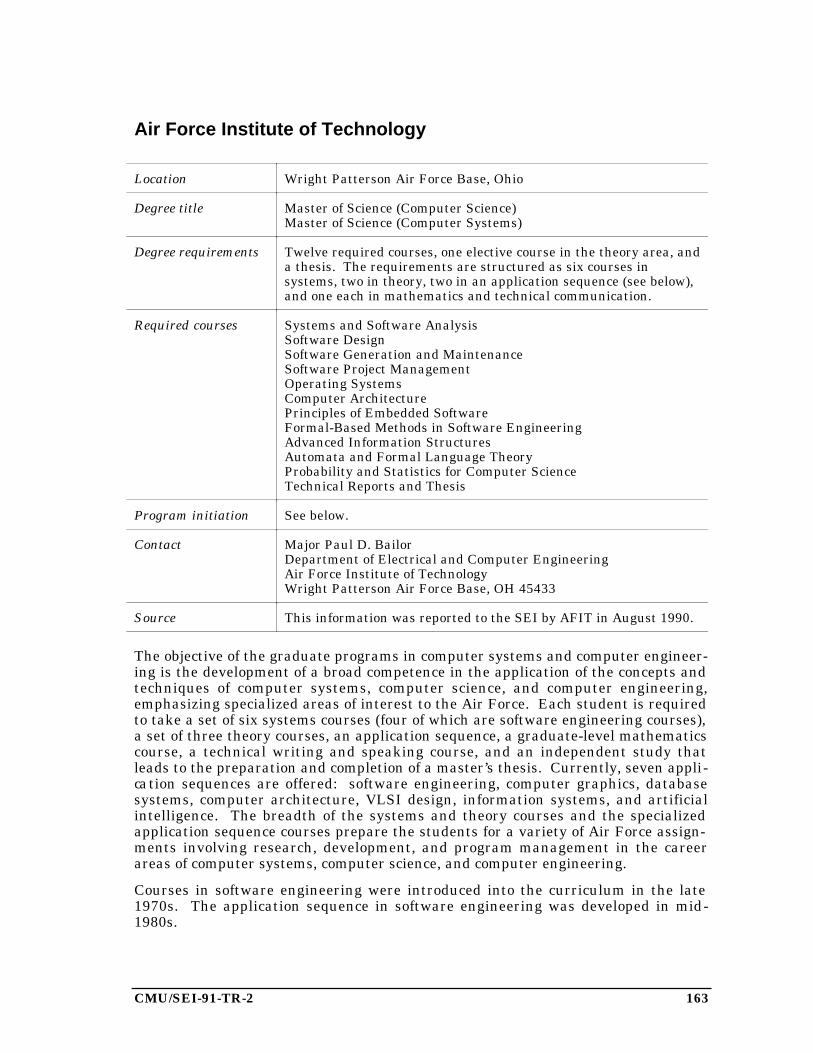
CMU/SEI-91-TR-2 163
Air Force Institute of Technology
Location Wright Patterson Air Force Base, Ohio
Degree title Master of Science (Computer Science)Master of Science (Computer Systems)
Degree requirements Twelve required courses, one elective course in the theory area, anda thesis. The requirements are structured as six courses insystems, two in theory, two in an application sequence (see below),and one each in mathematics and technical communication.
Required courses Systems and Software AnalysisSoftware DesignSoftware Generation and MaintenanceSoftware Project ManagementOperating SystemsComputer ArchitecturePrinciples of Embedded SoftwareFormal-Based Methods in Software EngineeringAdvanced Information StructuresAutomata and Formal Language TheoryProbability and Statistics for Computer ScienceTechnical Reports and Thesis
Program initiation See below.
Contact Major Paul D. BailorDepartment of Electrical and Computer EngineeringAir Force Institute of TechnologyWright Patterson Air Force Base, OH 45433
Source This information was reported to the SEI by AFIT in August 1990.
The objective of the graduate programs in computer systems and computer engineer-ing is the development of a broad competence in the application of the concepts andtechniques of computer systems, computer science, and computer engineering,emphasizing specialized areas of interest to the Air Force. Each student is requiredto take a set of six systems courses (four of which are software engineering courses),a set of three theory courses, an application sequence, a graduate-level mathematicscourse, a technical writing and speaking course, and an independent study thatleads to the preparation and completion of a master’s thesis. Currently, seven appli-cation sequences are offered: software engineering, computer graphics, databasesystems, computer architecture, VLSI design, information systems, and artificialintelligence. The breadth of the systems and theory courses and the specializedapplication sequence courses prepare the students for a variety of Air Force assign-ments involving research, development, and program management in the careerareas of computer systems, computer science, and computer engineering.
Courses in software engineering were introduced into the curriculum in the late1970s. The application sequence in software engineering was developed in mid-1980s.
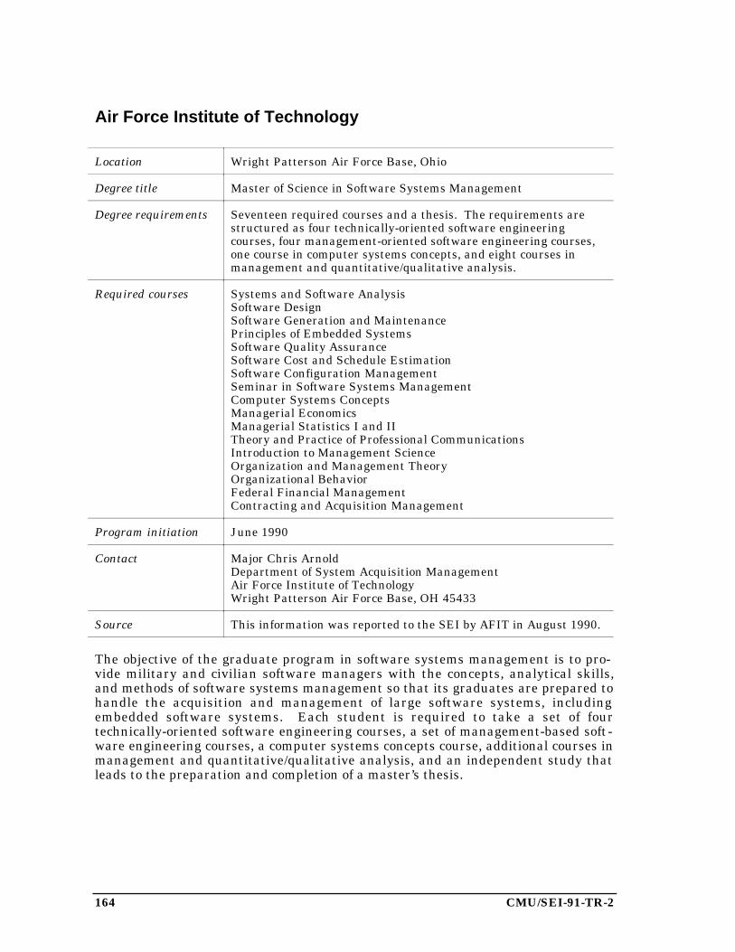
164 CMU/SEI-91-TR-2
Air Force Institute of Technology
Location Wright Patterson Air Force Base, Ohio
Degree title Master of Science in Software Systems Management
Degree requirements Seventeen required courses and a thesis. The requirements arestructured as four technically-oriented software engineeringcourses, four management-oriented software engineering courses,one course in computer systems concepts, and eight courses inmanagement and quantitative/qualitative analysis.
Required courses Systems and Software AnalysisSoftware DesignSoftware Generation and MaintenancePrinciples of Embedded SystemsSoftware Quality AssuranceSoftware Cost and Schedule EstimationSoftware Configuration ManagementSeminar in Software Systems ManagementComputer Systems ConceptsManagerial EconomicsManagerial Statistics I and IITheory and Practice of Professional CommunicationsIntroduction to Management ScienceOrganization and Management TheoryOrganizational BehaviorFederal Financial ManagementContracting and Acquisition Management
Program initiation June 1990
Contact Major Chris ArnoldDepartment of System Acquisition ManagementAir Force Institute of TechnologyWright Patterson Air Force Base, OH 45433
Source This information was reported to the SEI by AFIT in August 1990.
The objective of the graduate program in software systems management is to pro-vide military and civilian software managers with the concepts, analytical skills,and methods of software systems management so that its graduates are prepared tohandle the acquisition and management of large software systems, includingembedded software systems. Each student is required to take a set of fourtechnically-oriented software engineering courses, a set of management-based soft-ware engineering courses, a computer systems concepts course, additional courses inmanagement and quantitative/qualitative analysis, and an independent study thatleads to the preparation and completion of a master’s thesis.

CMU/SEI-91-TR-2 165
Andrews University
Location Berrien Springs, Michigan
Degree title Master of Science in Software Engineering
Degree requirements 48 quarter credits (typically 4 credits per course): 8 credits ofprojects, 16 credits core courses, 0-20 credits foundation courses, 4-24 credits electives.
Foundation courses Data StructuresData Base SystemsSystems Analysis ISystems Analysis IIOperating Systems
Core courses Computer ArchitectureSoftware Engineering ISoftware Engineering IIProgramming Project Management
Program initiation [unknown]
Contact Daniel R. BidwellComputer Information Science Dept.Andrews UniversityBerrien Springs, MI 49104
Source This information was reported to the SEI by Andrews University inApril 1989.
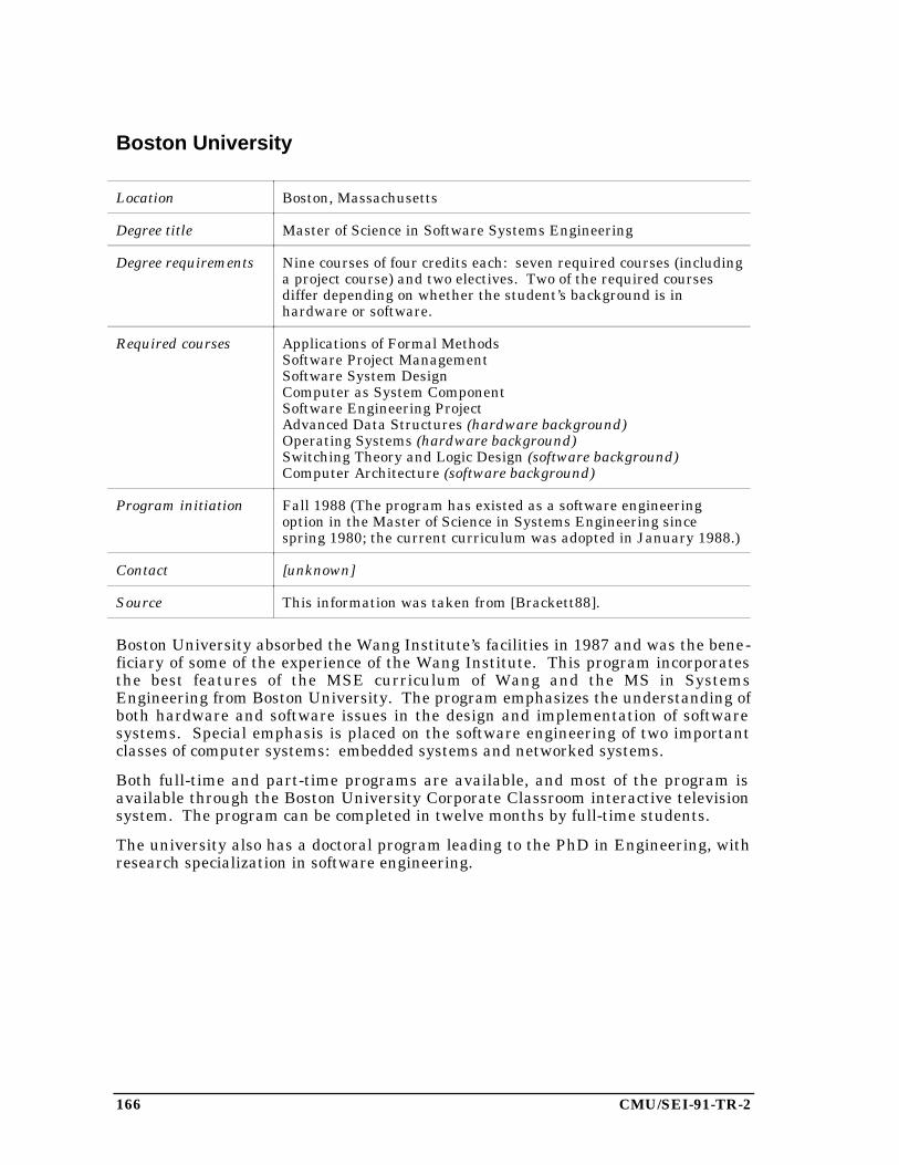
166 CMU/SEI-91-TR-2
Boston University
Location Boston, Massachusetts
Degree title Master of Science in Software Systems Engineering
Degree requirements Nine courses of four credits each: seven required courses (includinga project course) and two electives. Two of the required coursesdiffer depending on whether the student’s background is inhardware or software.
Required courses Applications of Formal MethodsSoftware Project ManagementSoftware System DesignComputer as System ComponentSoftware Engineering ProjectAdvanced Data Structures (hardware background)Operating Systems (hardware background)Switching Theory and Logic Design (software background)Computer Architecture (software background)
Program initiation Fall 1988 (The program has existed as a software engineeringoption in the Master of Science in Systems Engineering sincespring 1980; the current curriculum was adopted in January 1988.)
Contact [unknown]
Source This information was taken from [Brackett88].
Boston University absorbed the Wang Institute’s facilities in 1987 and was the bene-ficiary of some of the experience of the Wang Institute. This program incorporatesthe best features of the MSE curriculum of Wang and the MS in SystemsEngineering from Boston University. The program emphasizes the understanding ofboth hardware and software issues in the design and implementation of softwaresystems. Special emphasis is placed on the software engineering of two importantclasses of computer systems: embedded systems and networked systems.
Both full-time and part-time programs are available, and most of the program isavailable through the Boston University Corporate Classroom interactive televisionsystem. The program can be completed in twelve months by full-time students.
The university also has a doctoral program leading to the PhD in Engineering, withresearch specialization in software engineering.
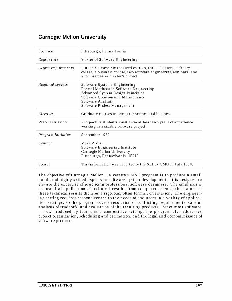
CMU/SEI-91-TR-2 167
Carnegie Mellon University
Location Pittsburgh, Pennsylvania
Degree title Master of Software Engineering
Degree requirements Fifteen courses: six required courses, three electives, a theorycourse, a business course, two software engineering seminars, anda four-semester master’s project.
Required courses Software Systems EngineeringFormal Methods in Software EngineeringAdvanced System Design PrinciplesSoftware Creation and MaintenanceSoftware AnalysisSoftware Project Management
Electives Graduate courses in computer science and business
Prerequisite note Prospective students must have at least two years of experienceworking in a sizable software project.
Program initiation September 1989
Contact Mark ArdisSoftware Engineering InstituteCarnegie Mellon UniversityPittsburgh, Pennsylvania 15213
Source This information was reported to the SEI by CMU in July 1990.
The objective of Carnegie Mellon University’s MSE program is to produce a smallnumber of highly skilled experts in software system development. It is designed toelevate the expertise of practicing professional software designers. The emphasis ison practical application of technical results from computer science; the nature ofthese technical results dictates a rigorous, often formal, orientation. The engineer-ing setting requires responsiveness to the needs of end users in a variety of applica-tion settings, so the program covers resolution of conflicting requirements, carefulanalysis of tradeoffs, and evaluation of the resulting products. Since most softwareis now produced by teams in a competitive setting, the program also addressesproject organization, scheduling and estimation, and the legal and economic issues ofsoftware products.
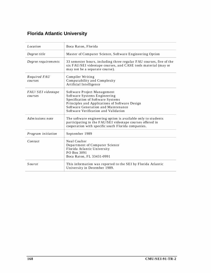
168 CMU/SEI-91-TR-2
Florida Atlantic University
Location Boca Raton, Florida
Degree title Master of Computer Science, Software Engineering Option
Degree requirements 33 semester hours, including three regular FAU courses, five of thesix FAU/SEI videotape courses, and CASE tools material (may ormay not be a separate course).
Required FAUcourses
Compiler WritingComputability and ComplexityArtificial Intelligence
FAU/SEI videotapecourses
Software Project ManagementSoftware Systems EngineeringSpecification of Software SystemsPrinciples and Applications of Software DesignSoftware Generation and MaintenanceSoftware Verification and Validation
Admissions note The software engineering option is available only to studentsparticipating in the FAU/SEI videotape courses offered incooperation with specific south Florida companies.
Program initiation September 1989
Contact Neal CoulterDepartment of Computer ScienceFlorida Atlantic UniversityPO Box 3091Boca Raton, FL 33431-0991
Source This information was reported to the SEI by Florida AtlanticUniversity in December 1989.
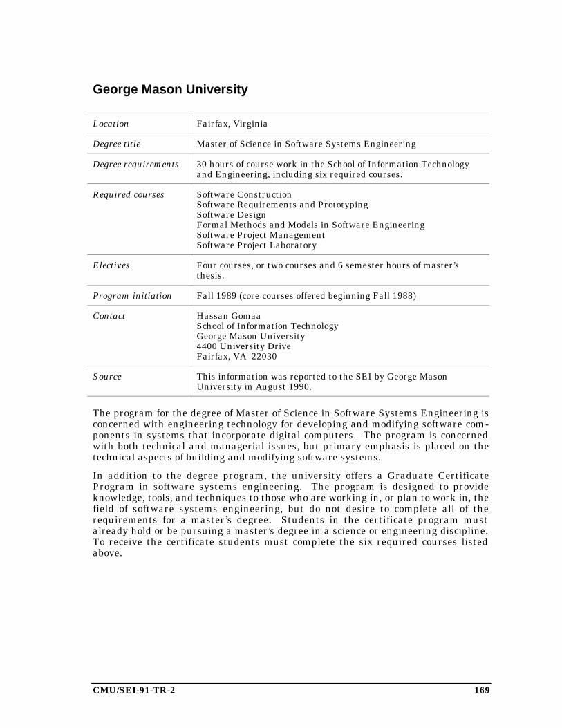
CMU/SEI-91-TR-2 169
George Mason University
Location Fairfax, Virginia
Degree title Master of Science in Software Systems Engineering
Degree requirements 30 hours of course work in the School of Information Technologyand Engineering, including six required courses.
Required courses Software ConstructionSoftware Requirements and PrototypingSoftware DesignFormal Methods and Models in Software EngineeringSoftware Project ManagementSoftware Project Laboratory
Electives Four courses, or two courses and 6 semester hours of master’sthesis.
Program initiation Fall 1989 (core courses offered beginning Fall 1988)
Contact Hassan GomaaSchool of Information TechnologyGeorge Mason University4400 University DriveFairfax, VA 22030
Source This information was reported to the SEI by George MasonUniversity in August 1990.
The program for the degree of Master of Science in Software Systems Engineering isconcerned with engineering technology for developing and modifying software com-ponents in systems that incorporate digital computers. The program is concernedwith both technical and managerial issues, but primary emphasis is placed on thetechnical aspects of building and modifying software systems.
In addition to the degree program, the university offers a Graduate CertificateProgram in software systems engineering. The program is designed to provideknowledge, tools, and techniques to those who are working in, or plan to work in, thefield of software systems engineering, but do not desire to complete all of therequirements for a master’s degree. Students in the certificate program mustalready hold or be pursuing a master’s degree in a science or engineering discipline.To receive the certificate students must complete the six required courses listedabove.
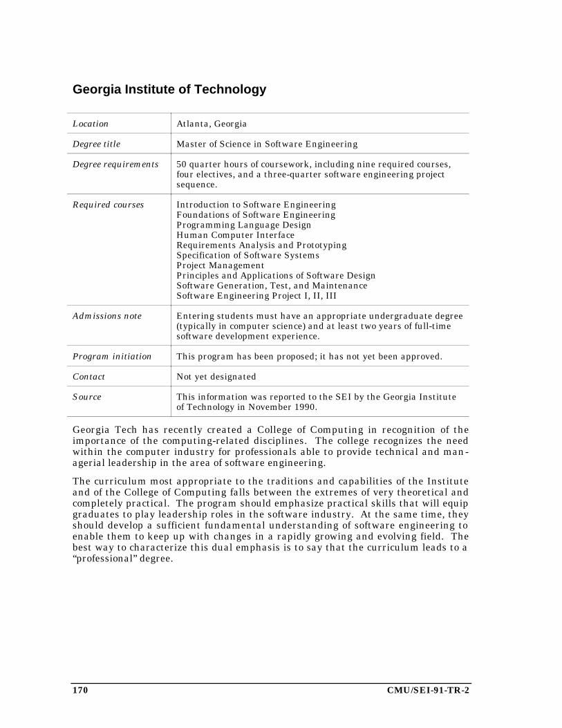
170 CMU/SEI-91-TR-2
Georgia Institute of Technology
Location Atlanta, Georgia
Degree title Master of Science in Software Engineering
Degree requirements 50 quarter hours of coursework, including nine required courses,four electives, and a three-quarter software engineering projectsequence.
Required courses Introduction to Software EngineeringFoundations of Software EngineeringProgramming Language DesignHuman Computer InterfaceRequirements Analysis and PrototypingSpecification of Software SystemsProject ManagementPrinciples and Applications of Software DesignSoftware Generation, Test, and MaintenanceSoftware Engineering Project I, II, III
Admissions note Entering students must have an appropriate undergraduate degree(typically in computer science) and at least two years of full-timesoftware development experience.
Program initiation This program has been proposed; it has not yet been approved.
Contact Not yet designated
Source This information was reported to the SEI by the Georgia Instituteof Technology in November 1990.
Georgia Tech has recently created a College of Computing in recognition of theimportance of the computing-related disciplines. The college recognizes the needwithin the computer industry for professionals able to provide technical and man-agerial leadership in the area of software engineering.
The curriculum most appropriate to the traditions and capabilities of the Instituteand of the College of Computing falls between the extremes of very theoretical andcompletely practical. The program should emphasize practical skills that will equipgraduates to play leadership roles in the software industry. At the same time, theyshould develop a sufficient fundamental understanding of software engineering toenable them to keep up with changes in a rapidly growing and evolving field. Thebest way to characterize this dual emphasis is to say that the curriculum leads to a“professional” degree.
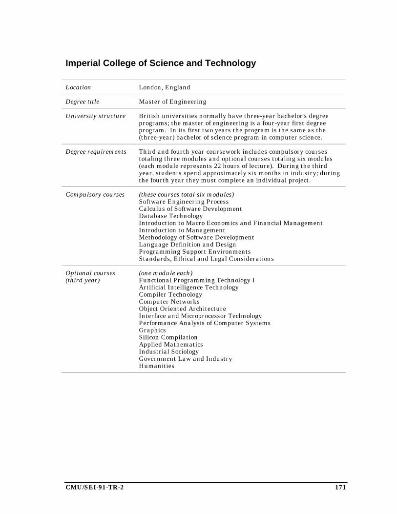
CMU/SEI-91-TR-2 171
Imperial College of Science and Technology
Location London, England
Degree title Master of Engineering
University structure British universities normally have three-year bachelor’s degreeprograms; the master of engineering is a four-year first degreeprogram. In its first two years the program is the same as the(three-year) bachelor of science program in computer science.
Degree requirements Third and fourth year coursework includes compulsory coursestotaling three modules and optional courses totaling six modules(each module represents 22 hours of lecture). During the thirdyear, students spend approximately six months in industry; duringthe fourth year they must complete an individual project.
Compulsory courses (these courses total six modules)Software Engineering ProcessCalculus of Software DevelopmentDatabase TechnologyIntroduction to Macro Economics and Financial ManagementIntroduction to ManagementMethodology of Software DevelopmentLanguage Definition and DesignProgramming Support EnvironmentsStandards, Ethical and Legal Considerations
Optional courses(third year)
(one module each)Functional Programming Technology IArtificial Intelligence TechnologyCompiler TechnologyComputer NetworksObject Oriented ArchitectureInterface and Microprocessor TechnologyPerformance Analysis of Computer SystemsGraphicsSilicon CompilationApplied MathematicsIndustrial SociologyGovernment Law and IndustryHumanities

172 CMU/SEI-91-TR-2
Optional courses(fourth year)
(one module each)Advanced LogicTheorem ProvingConcurrent ComputationHuman-Computer InteractionExpert Systems TechnologyFunctional Programming Technology IIAdvanced Operation SystemsParallel ArchitectureDistributed SystemsVLSIRoboticsComputing in EngineeringNatural Language ProcessingMicro-Economic ConceptsIndustrial RelationsInnovation and Technical ChangeHumanities
Program initiation Fall 1985
Contact [unknown]
Source This information was taken from [Lehman86].
Since British students normally must commit to either a three-year (bachelor’sdegree) or a four-year (master’s degree) program at the end of secondary school (thestudent cannot complete the bachelor’s degree and then decide to continue for themaster’s), the latter programs tend to attract the better students. Entrancerequirements are generally more stringent for the master’s programs, and the grad-uates are expected to advance rapidly once they enter industry.
The industry component of this program has been described earlier in this report(Section 2.7). This component is perceived to be somewhat analogous to the role ofteaching hospitals in the education of medical students.

CMU/SEI-91-TR-2 173
Instituto Tecnológico y de Estudios Superiores de Monterrey(Technological and Higher Learning Institute of Monterrey)
Location Monterrey, Nuevo León, Mexico
Degree title Master of Science in Computational Systems Engineering. SoftwareEngineering Option
Degree requirements Fourteen courses totalling 150 units: six core courses (72 units),three elective courses (36 units), two personal developmentworkshops (12 units), research methods seminar (6 units), andthesis (24 units).
Core courses Discrete MathematicsAnalysis of AlgorithmsTheory of ComputationSoftware Design and DevelopmentSoftware Analysis, Design and SpecificationSoftware Generation, Verification, and Maintenance
Program initiation 1990
Contact Prof. Carlos Scheel MayenbergerPrograma de Graduados en InformaticaInstituto Tecnologico y de Estudios Superiores de MonterreySucursal de Correos “J”C.P. 64849 Monterrey, N. L.México
Source This information was reported to the SEI by ITESM in October1990.
The software engineering option of the program is structured for completion in foursemesters, or three semesters and two summers. The program also has options indistributed systems and artificial intelligence.
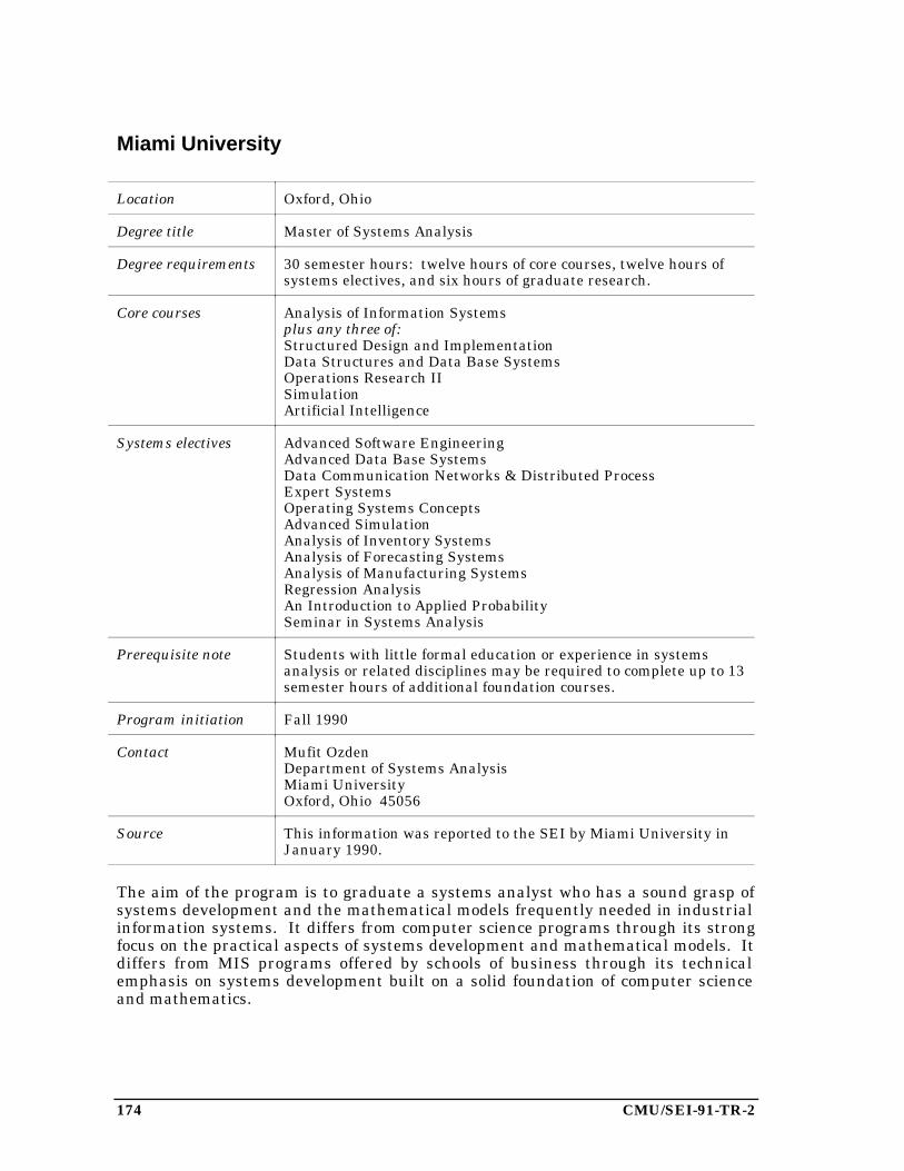
174 CMU/SEI-91-TR-2
Miami University
Location Oxford, Ohio
Degree title Master of Systems Analysis
Degree requirements 30 semester hours: twelve hours of core courses, twelve hours ofsystems electives, and six hours of graduate research.
Core courses Analysis of Information Systemsplus any three of:Structured Design and ImplementationData Structures and Data Base SystemsOperations Research IISimulationArtificial Intelligence
Systems electives Advanced Software EngineeringAdvanced Data Base SystemsData Communication Networks & Distributed ProcessExpert SystemsOperating Systems ConceptsAdvanced SimulationAnalysis of Inventory SystemsAnalysis of Forecasting SystemsAnalysis of Manufacturing SystemsRegression AnalysisAn Introduction to Applied ProbabilitySeminar in Systems Analysis
Prerequisite note Students with little formal education or experience in systemsanalysis or related disciplines may be required to complete up to 13semester hours of additional foundation courses.
Program initiation Fall 1990
Contact Mufit OzdenDepartment of Systems AnalysisMiami UniversityOxford, Ohio 45056
Source This information was reported to the SEI by Miami University inJanuary 1990.
The aim of the program is to graduate a systems analyst who has a sound grasp ofsystems development and the mathematical models frequently needed in industrialinformation systems. It differs from computer science programs through its strongfocus on the practical aspects of systems development and mathematical models. Itdiffers from MIS programs offered by schools of business through its technicalemphasis on systems development built on a solid foundation of computer scienceand mathematics.

CMU/SEI-91-TR-2 175
Monmouth College
Location West Long Branch, New Jersey
Degree title Master of Science in Software Engineering
Degree requirements 30 credit hours, consisting of six core and four elective courses.
Core courses Mathematical Foundations of Software Engineering ISoftware EngineeringProject ManagementFormal Methods in ProgrammingSoftware Systems DesignSystem Project Implementation (Laboratory Practicum)
Elective courses Mathematical Foundations of Computer Science IIComputer CommunicationsProgramming LanguagesDatabase SystemsSecurity Aspects of Systems DesignSystem Development Environment TechnologyAI Technology for Software EngineersSoftware Quality
Program initiation 1986
Contact Richard KuntzMonmouth CollegeWest Long Branch, New Jersey 07764
Source This information was taken from [Amoroso88] and frominformation reported to the SEI by Monmouth College in July 1990.
The program is offered through the departments of computer science and electricalengineering. The current enrollment is more than 100, and to date 50 students havecompleted the degree requirements.
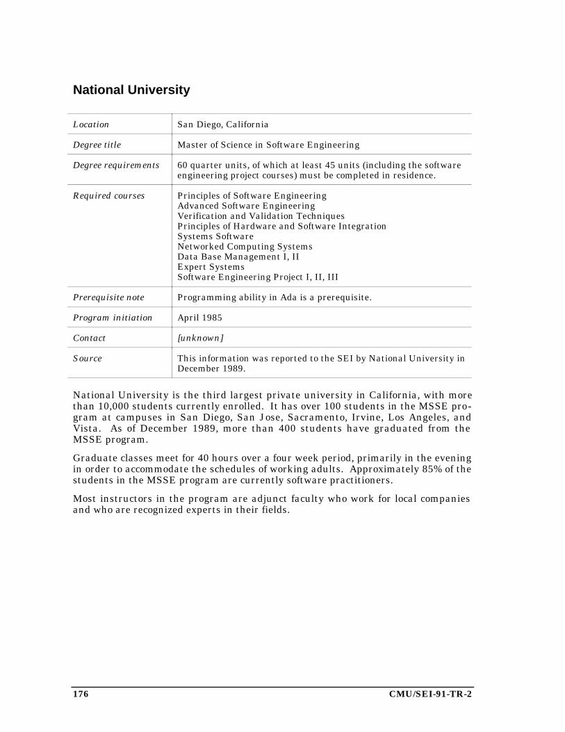
176 CMU/SEI-91-TR-2
National University
Location San Diego, California
Degree title Master of Science in Software Engineering
Degree requirements 60 quarter units, of which at least 45 units (including the softwareengineering project courses) must be completed in residence.
Required courses Principles of Software EngineeringAdvanced Software EngineeringVerification and Validation TechniquesPrinciples of Hardware and Software IntegrationSystems SoftwareNetworked Computing SystemsData Base Management I, IIExpert SystemsSoftware Engineering Project I, II, III
Prerequisite note Programming ability in Ada is a prerequisite.
Program initiation April 1985
Contact [unknown]
Source This information was reported to the SEI by National University inDecember 1989.
National University is the third largest private university in California, with morethan 10,000 students currently enrolled. It has over 100 students in the MSSE pro-gram at campuses in San Diego, San Jose, Sacramento, Irvine, Los Angeles, andVista. As of December 1989, more than 400 students have graduated from theMSSE program.
Graduate classes meet for 40 hours over a four week period, primarily in the eveningin order to accommodate the schedules of working adults. Approximately 85% of thestudents in the MSSE program are currently software practitioners.
Most instructors in the program are adjunct faculty who work for local companiesand who are recognized experts in their fields.

CMU/SEI-91-TR-2 177
Polytechnic University of Madrid
Location Madrid, Spain
Degree title Software Engineering Curriculum Master
University structure The Spanish university system organizes its programs differentlyfrom United States universities, so this program cannot bedescribed in terms of courses. For each of the subject areasdescribed below, the amount of time devoted to the area is given inunits. Each unit represents a 75-minute class meeting. Theprogram totals approximately 500 units.
Degree requirements Introduction to Software Engineering (3)Models of Computation (76)Computing Machinery (6)Software Production Technology and Methodology
Information SystemsIntroduction to Requirements Analysis (15)Formal Specification Techniques (25)Design (55)Implementation (85)Tools Evaluation (2)Software Engineering and Artificial Intelligence (11)
Product and Process ControlSystem Construction Management (20)Quality ControlProject Management (20)Documentation Process (25)
Software Product (8)Information Protection (14)Software Safety (8)Legal Aspects (6)Case Study (12)
Program initiation 1988
Contact [unknown]
Source This information was reported to the SEI by Polytechnic Universityin May 1989.
The Polytechnic University of Madrid is the largest (well over 100,000 students) andmost prestigious of the Spanish technical universities. It has large, well-establishedschools of engineering and informatics (computer science). The university is an aca-demic affiliate of the SEI and has incorporated a number of SEI recommendationsinto its initial curriculum.
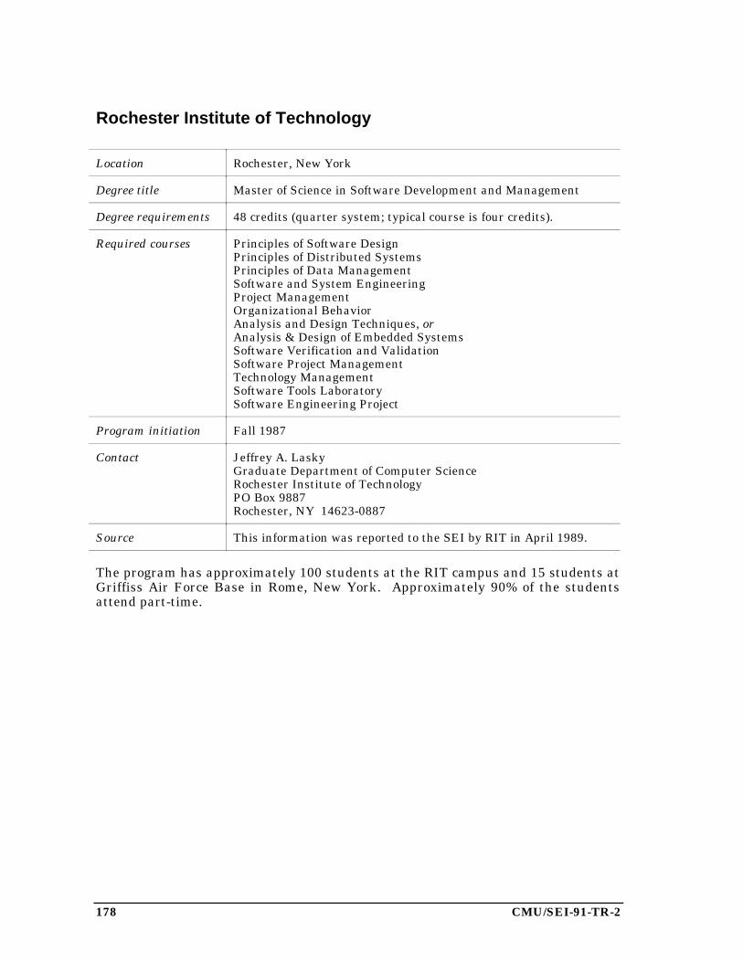
178 CMU/SEI-91-TR-2
Rochester Institute of Technology
Location Rochester, New York
Degree title Master of Science in Software Development and Management
Degree requirements 48 credits (quarter system; typical course is four credits).
Required courses Principles of Software DesignPrinciples of Distributed SystemsPrinciples of Data ManagementSoftware and System EngineeringProject ManagementOrganizational BehaviorAnalysis and Design Techniques, orAnalysis & Design of Embedded SystemsSoftware Verification and ValidationSoftware Project ManagementTechnology ManagementSoftware Tools LaboratorySoftware Engineering Project
Program initiation Fall 1987
Contact Jeffrey A. LaskyGraduate Department of Computer ScienceRochester Institute of TechnologyPO Box 9887Rochester, NY 14623-0887
Source This information was reported to the SEI by RIT in April 1989.
The program has approximately 100 students at the RIT campus and 15 students atGriffiss Air Force Base in Rome, New York. Approximately 90% of the studentsattend part-time.
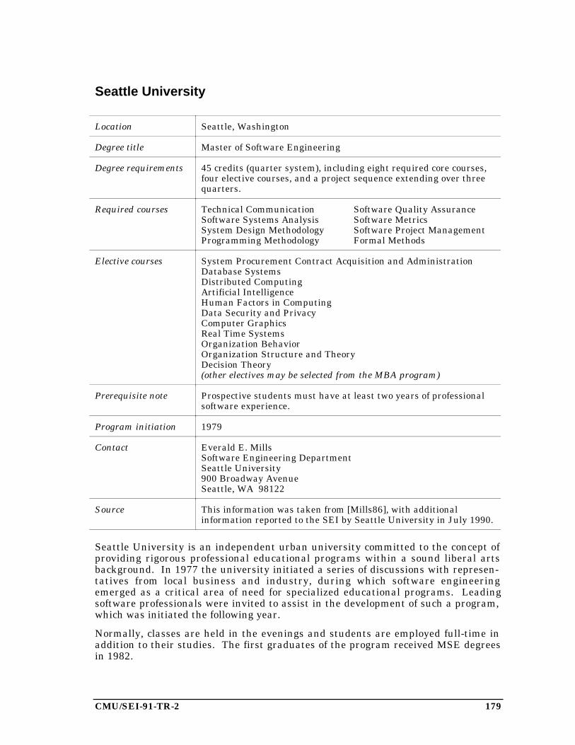
CMU/SEI-91-TR-2 179
Seattle University
Location Seattle, Washington
Degree title Master of Software Engineering
Degree requirements 45 credits (quarter system), including eight required core courses,four elective courses, and a project sequence extending over threequarters.
Required courses Technical Communication Software Quality AssuranceSoftware Systems Analysis Software MetricsSystem Design Methodology Software Project ManagementProgramming Methodology Formal Methods
Elective courses System Procurement Contract Acquisition and AdministrationDatabase SystemsDistributed ComputingArtificial IntelligenceHuman Factors in ComputingData Security and PrivacyComputer GraphicsReal Time SystemsOrganization BehaviorOrganization Structure and TheoryDecision Theory(other electives may be selected from the MBA program)
Prerequisite note Prospective students must have at least two years of professionalsoftware experience.
Program initiation 1979
Contact Everald E. MillsSoftware Engineering DepartmentSeattle University900 Broadway AvenueSeattle, WA 98122
Source This information was taken from [Mills86], with additionalinformation reported to the SEI by Seattle University in July 1990.
Seattle University is an independent urban university committed to the concept ofproviding rigorous professional educational programs within a sound liberal artsbackground. In 1977 the university initiated a series of discussions with represen-tatives from local business and industry, during which software engineeringemerged as a critical area of need for specialized educational programs. Leadingsoftware professionals were invited to assist in the development of such a program,which was initiated the following year.
Normally, classes are held in the evenings and students are employed full-time inaddition to their studies. The first graduates of the program received MSE degreesin 1982.
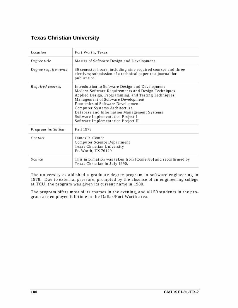
180 CMU/SEI-91-TR-2
Texas Christian University
Location Fort Worth, Texas
Degree title Master of Software Design and Development
Degree requirements 36 semester hours, including nine required courses and threeelectives; submission of a technical paper to a journal forpublication.
Required courses Introduction to Software Design and DevelopmentModern Software Requirements and Design TechniquesApplied Design, Programming, and Testing TechniquesManagement of Software DevelopmentEconomics of Software DevelopmentComputer Systems ArchitectureDatabase and Information Management SystemsSoftware Implementation Project ISoftware Implementation Project II
Program initiation Fall 1978
Contact James R. ComerComputer Science DepartmentTexas Christian UniversityFt. Worth, TX 76129
Source This information was taken from [Comer86] and reconfirmed byTexas Christian in July 1990.
The university established a graduate degree program in software engineering in1978. Due to external pressure, prompted by the absence of an engineering collegeat TCU, the program was given its current name in 1980.
The program offers most of its courses in the evening, and all 50 students in the pro-gram are employed full-time in the Dallas/Fort Worth area.
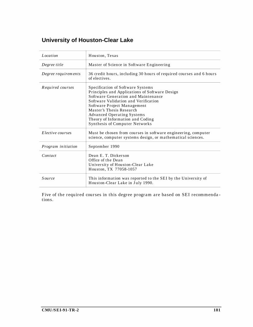
CMU/SEI-91-TR-2 181
University of Houston-Clear Lake
Location Houston, Texas
Degree title Master of Science in Software Engineering
Degree requirements 36 credit hours, including 30 hours of required courses and 6 hoursof electives.
Required courses Specification of Software SystemsPrinciples and Applications of Software DesignSoftware Generation and MaintenanceSoftware Validation and VerificationSoftware Project ManagementMaster’s Thesis ResearchAdvanced Operating SystemsTheory of Information and CodingSynthesis of Computer Networks
Elective courses Must be chosen from courses in software engineering, computerscience, computer systems design, or mathematical sciences.
Program initiation September 1990
Contact Dean E. T. DickersonOffice of the DeanUniversity of Houston-Clear LakeHouston, TX 77058-1057
Source This information was reported to the SEI by the University ofHouston-Clear Lake in July 1990.
Five of the required courses in this degree program are based on SEI recommenda-tions.
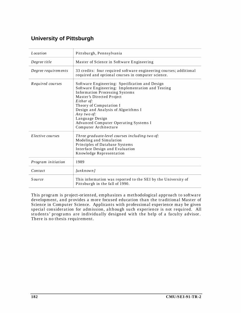
182 CMU/SEI-91-TR-2
University of Pittsburgh
Location Pittsburgh, Pennsylvania
Degree title Master of Science in Software Engineering
Degree requirements 33 credits: four required software engineering courses; additionalrequired and optional courses in computer science.
Required courses Software Engineering: Specification and DesignSoftware Engineering: Implementation and TestingInformation Processing SystemsMaster’s Directed ProjectEither of:Theory of Computation IDesign and Analysis of Algorithms IAny two of:Language DesignAdvanced Computer Operating Systems IComputer Architecture
Elective courses Three graduate-level courses including two of:Modeling and SimulationPrinciples of Database SystemsInterface Design and EvaluationKnowledge Representation
Program initiation 1989
Contact [unknown]
Source This information was reported to the SEI by the University ofPittsburgh in the fall of 1990.
This program is project-oriented, emphasizes a methodological approach to softwaredevelopment, and provides a more focused education than the traditional Master ofScience in Computer Science. Applicants with professional experience may be givenspecial consideration for admission, although such experience is not required. Allstudents’ programs are individually designed with the help of a faculty advisor.There is no thesis requirement.
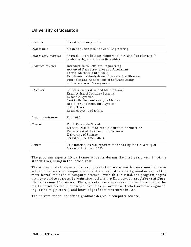
CMU/SEI-91-TR-2 183
University of Scranton
Location Scranton, Pennsylvania
Degree title Master of Science in Software Engineering
Degree requirements 36 graduate credits: six required courses and four electives (3credits each), and a thesis (6 credits)
Required courses Introduction to Software EngineeringAdvanced Data Structures and AlgorithmsFormal Methods and ModelsRequirements Analysis and Software SpecificationPrinciples and Applications of Software DesignSoftware Project Management
Electives Software Generation and MaintenanceEngineering of Software SystemsDatabase SystemsCost Collection and Analysis MetricsReal-time and Embedded SystemsCASE ToolsLegal Aspects and Ethics
Program initiation Fall 1990
Contact Dr. J. Fernando NavedaDirector, Master of Science in Software EngineeringDepartment of the Computing SciencesUniversity of ScrantonScranton, PA 18510-4664
Source This information was reported to the SEI by the University ofScranton in August 1990.
The program expects 15 part-time students during the first year, with full-timestudents beginning in the second year.
The student body is expected to be composed of software practitioners, most of whomwill not have a recent computer science degree or a strong background in some of themore formal methods of computer science. With this in mind, the program beginswith two bridge courses, Introduction to Software Engineering and Advanced DataStructures and Algorithms. The goals of these courses are to give the students themathematics needed in subsequent courses, an overview of what software engineer-ing is (the “big picture”), and knowledge of data structures in Ada.
The university does not offer a graduate degree in computer science.

184 CMU/SEI-91-TR-2
University of Stirling
Location Stirling, Scotland
Degree title Master of Science in Software Engineering
Degree requirements Semester 1 (September-December)Programming MethodsLanguage ConceptsIntroduction to Software EngineeringComputing Science Structures and Techniques
Initial industrial placement visits (January)Semester 2 (February-July)
Methods for Formal SpecificationConcurrency (half semester)Databases (half semester)Networks and CommunicationsElective: Expert Systems or Language Implementation
Industrial project (July-December)Dissertation (January-March)
Program initiation 1985
Contact [unknown]
Source This information was reported to the SEI by the University ofStirling in April 1989.
The MSc in Software Engineering is a “specialist conversion course” intended totrain graduates with a scientific background in the methods of software engineering.The students spend twelve months at the University of Stirling and six months at anindustrial research and development center. Through this approach students aregiven an understanding of both the current engineering technology and its applica-tion in an industrial context.
The six-month placement in industry enables each candidate to participate in a pro-ject and be responsible for a particular investigation. Where practical, this mayform the basis of the individual project that is undertaken during a final three-month period and then written up in the dissertation.
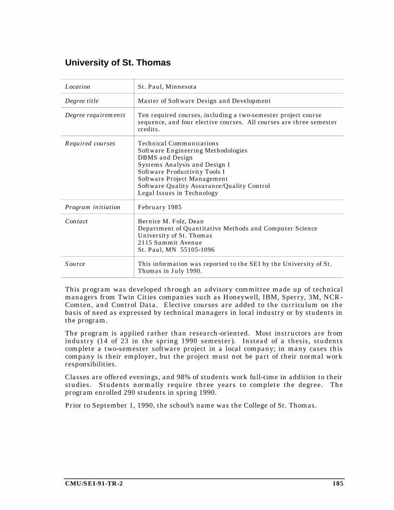
CMU/SEI-91-TR-2 185
University of St. Thomas
Location St. Paul, Minnesota
Degree title Master of Software Design and Development
Degree requirements Ten required courses, including a two-semester project coursesequence, and four elective courses. All courses are three semestercredits.
Required courses Technical CommunicationsSoftware Engineering MethodologiesDBMS and DesignSystems Analysis and Design ISoftware Productivity Tools ISoftware Project ManagementSoftware Quality Assurance/Quality ControlLegal Issues in Technology
Program initiation February 1985
Contact Bernice M. Folz, DeanDepartment of Quantitative Methods and Computer ScienceUniversity of St. Thomas2115 Summit AvenueSt. Paul, MN 55105-1096
Source This information was reported to the SEI by the University of St.Thomas in July 1990.
This program was developed through an advisory committee made up of technicalmanagers from Twin Cities companies such as Honeywell, IBM, Sperry, 3M, NCR-Comten, and Control Data. Elective courses are added to the curriculum on thebasis of need as expressed by technical managers in local industry or by students inthe program.
The program is applied rather than research-oriented. Most instructors are fromindustry (14 of 23 in the spring 1990 semester). Instead of a thesis, studentscomplete a two-semester software project in a local company; in many cases thiscompany is their employer, but the project must not be part of their normal workresponsibilities.
Classes are offered evenings, and 98% of students work full-time in addition to theirstudies. Students normally require three years to complete the degree. Theprogram enrolled 290 students in spring 1990.
Prior to September 1, 1990, the school’s name was the College of St. Thomas.
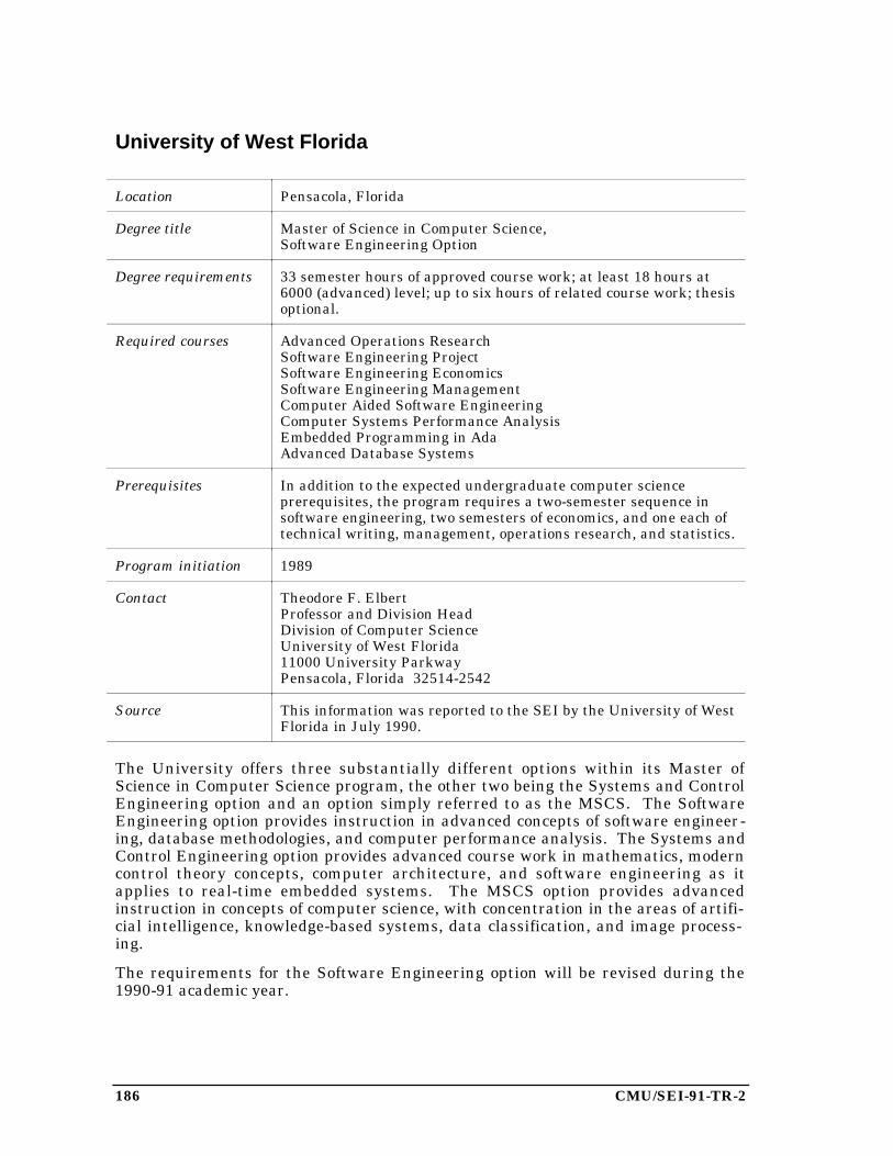
186 CMU/SEI-91-TR-2
University of West Florida
Location Pensacola, Florida
Degree title Master of Science in Computer Science,Software Engineering Option
Degree requirements 33 semester hours of approved course work; at least 18 hours at6000 (advanced) level; up to six hours of related course work; thesisoptional.
Required courses Advanced Operations ResearchSoftware Engineering ProjectSoftware Engineering EconomicsSoftware Engineering ManagementComputer Aided Software EngineeringComputer Systems Performance AnalysisEmbedded Programming in AdaAdvanced Database Systems
Prerequisites In addition to the expected undergraduate computer scienceprerequisites, the program requires a two-semester sequence insoftware engineering, two semesters of economics, and one each oftechnical writing, management, operations research, and statistics.
Program initiation 1989
Contact Theodore F. ElbertProfessor and Division HeadDivision of Computer ScienceUniversity of West Florida11000 University ParkwayPensacola, Florida 32514-2542
Source This information was reported to the SEI by the University of WestFlorida in July 1990.
The University offers three substantially different options within its Master ofScience in Computer Science program, the other two being the Systems and ControlEngineering option and an option simply referred to as the MSCS. The SoftwareEngineering option provides instruction in advanced concepts of software engineer-ing, database methodologies, and computer performance analysis. The Systems andControl Engineering option provides advanced course work in mathematics, moderncontrol theory concepts, computer architecture, and software engineering as itapplies to real-time embedded systems. The MSCS option provides advancedinstruction in concepts of computer science, with concentration in the areas of artifi-cial intelligence, knowledge-based systems, data classification, and image process-ing.
The requirements for the Software Engineering option will be revised during the1990-91 academic year.
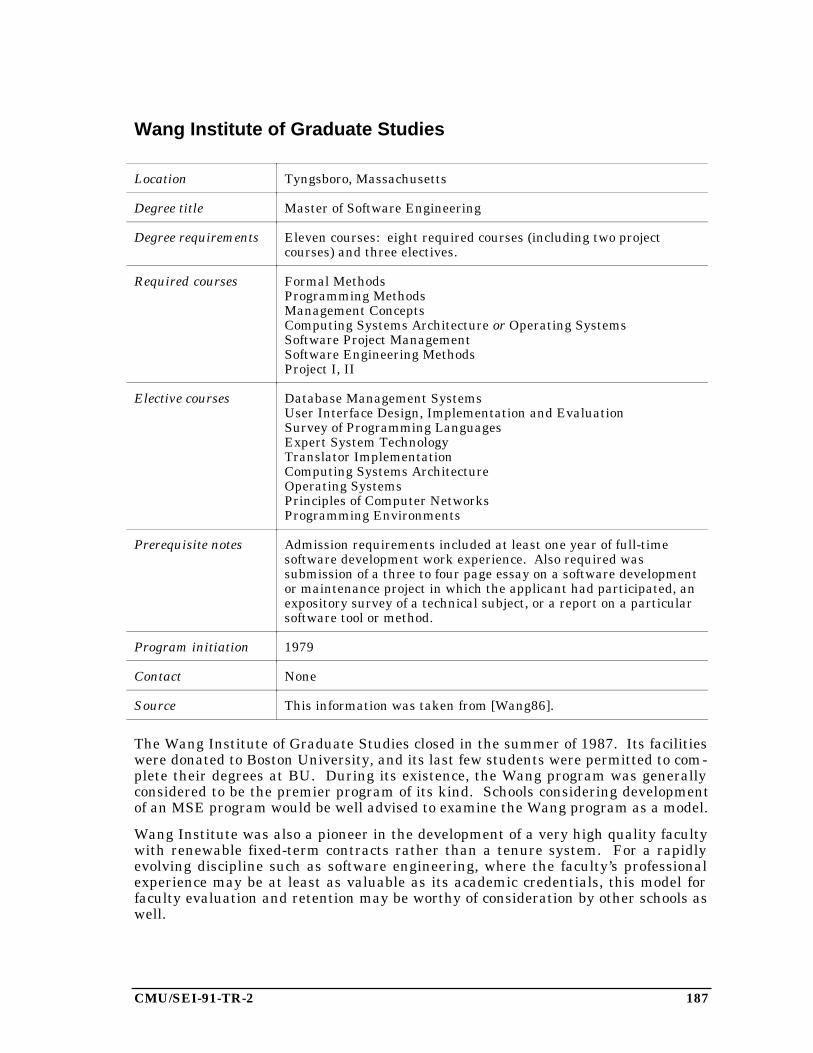
CMU/SEI-91-TR-2 187
Wang Institute of Graduate Studies
Location Tyngsboro, Massachusetts
Degree title Master of Software Engineering
Degree requirements Eleven courses: eight required courses (including two projectcourses) and three electives.
Required courses Formal MethodsProgramming MethodsManagement ConceptsComputing Systems Architecture or Operating SystemsSoftware Project ManagementSoftware Engineering MethodsProject I, II
Elective courses Database Management SystemsUser Interface Design, Implementation and EvaluationSurvey of Programming LanguagesExpert System TechnologyTranslator ImplementationComputing Systems ArchitectureOperating SystemsPrinciples of Computer NetworksProgramming Environments
Prerequisite notes Admission requirements included at least one year of full-timesoftware development work experience. Also required wassubmission of a three to four page essay on a software developmentor maintenance project in which the applicant had participated, anexpository survey of a technical subject, or a report on a particularsoftware tool or method.
Program initiation 1979
Contact None
Source This information was taken from [Wang86].
The Wang Institute of Graduate Studies closed in the summer of 1987. Its facilitieswere donated to Boston University, and its last few students were permitted to com-plete their degrees at BU. During its existence, the Wang program was generallyconsidered to be the premier program of its kind. Schools considering developmentof an MSE program would be well advised to examine the Wang program as a model.
Wang Institute was also a pioneer in the development of a very high quality facultywith renewable fixed-term contracts rather than a tenure system. For a rapidlyevolving discipline such as software engineering, where the faculty’s professionalexperience may be at least as valuable as its academic credentials, this model forfaculty evaluation and retention may be worthy of consideration by other schools aswell.
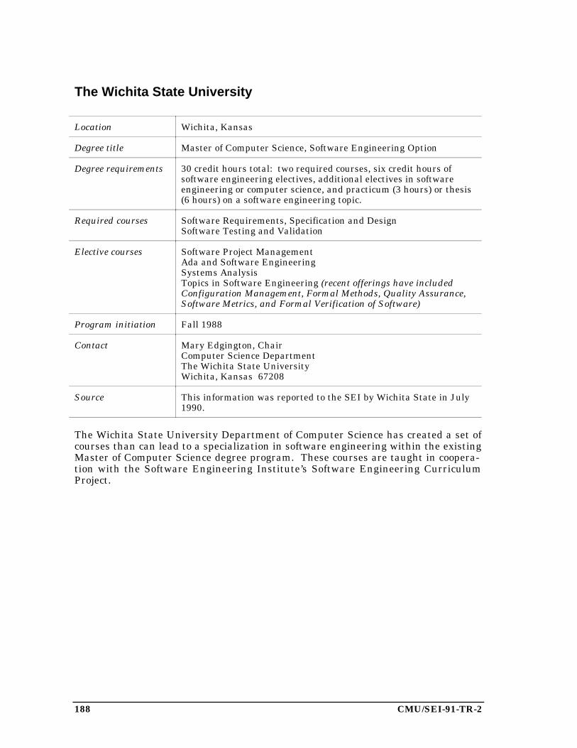
188 CMU/SEI-91-TR-2
The Wichita State University
Location Wichita, Kansas
Degree title Master of Computer Science, Software Engineering Option
Degree requirements 30 credit hours total: two required courses, six credit hours ofsoftware engineering electives, additional electives in softwareengineering or computer science, and practicum (3 hours) or thesis(6 hours) on a software engineering topic.
Required courses Software Requirements, Specification and DesignSoftware Testing and Validation
Elective courses Software Project ManagementAda and Software EngineeringSystems AnalysisTopics in Software Engineering (recent offerings have includedConfiguration Management, Formal Methods, Quality Assurance,Software Metrics, and Formal Verification of Software)
Program initiation Fall 1988
Contact Mary Edgington, ChairComputer Science DepartmentThe Wichita State UniversityWichita, Kansas 67208
Source This information was reported to the SEI by Wichita State in July1990.
The Wichita State University Department of Computer Science has created a set ofcourses than can lead to a specialization in software engineering within the existingMaster of Computer Science degree program. These courses are taught in coopera-tion with the Software Engineering Institute’s Software Engineering CurriculumProject.

CMU/SEI-91-TR-2 189
5. Survey of Comprehensive Software EngineeringTextbooks
The growth of software engineering education has stimulated the writing and publi-cation of many software engineering textbooks over the last few years. In responseto many requests, the SEI Software Engineering Curriculum Project has begundeveloping an annotated bibliography of these books. The bibliography includes notonly the usual information, but also the comments of professors who have used thebooks in their courses. From time to time we will publish the bibliography, orselected subsets of it, to aid other educators who wish to select appropriate texts fortheir courses.
The bibliography that follows contains comprehensive software engineering text-books, meaning those that present the broadest view of all aspects of software engi-neering. These books are suitable for a one- or two-semester course in softwareengineering. More specialized books, such as those covering only requirementsanalysis or only testing, will be presented in future reports.
Software engineering educators are invited to suggest other books to be included infuture bibliographies, and to submit comments or reviews of textbooks. These maybe addressed to the Software Engineering Curriculum Project at the SEI; electronicmail may be sent to [email protected] on the Internet.
Russell J. Abbott. An Integrated Approach to Software Development
New York: John Wiley & Sons Inc., 1986. ISBN 0-471-82646-4. 334 pages. $36.95.Includes exercises.
Table of Contents
1. IntroductionPart 1 Requirements
2. Requirements Discussion3. Requirements Document Outline
Part 2 System Specification4. Discussion5. Behavioral Specification Outline6. Procedures Manual7. Administrative Manual
Part 3 Design8. Design Discussion9. System Design Documentation
10. Component Documentation: Specification and DesignAppendix Abstraction and Specification
11. Abstraction and Specification

190 CMU/SEI-91-TR-2
Doug Bell, Ian Morrey, and John Pugh. Software Engineering—AProgramming Approach
Englewood Cliffs, N. J.: Prentice-Hall International, 1987. 250 pages.
Table of Contents
1. Goals and Problems2. Structured Programming3. Modularity4. Functional Decomposition5. The Michael Jackson Method6. Data Flow Analysis7. The Programming Language8. Object-Oriented Programming9. Functional Programming
10. Logic Programming11. Software Tools12. Testing and Implementation13. Software Fault Tolerance14. Structured Walkthroughs15. Chief Programmer Teams and Project Support Libraries16. Review
Frederick P. Brooks, Jr. The Mythical Man-Month: Essays on SoftwareEngineering
Reading, Mass.: Addison-Wesley, 1975. ISBN 0-201-00650-2. 195 pages. $20.50.
Table of Contents
1. The Tar Pit2. The Mythical Man-Month3. The Surgical Team4. Aristocracy, Democracy, and System Design5. The Second-System Effect6. Passing the Word7. Why Did the Tower of Babel Fail?8. Calling the Shot9. Ten Pounds in a Five-Pound Sack
10. The Documentary Hypothesis11. Plan to Throw One Away12. Sharp Tools13. The Whole and the Parts14. Hatching a Catastrophe15. The Other Face
Comment from the publisher
An eminent computer expert, Brooks has written a collection of thought-provokingessays on the management of computer programming projects. These essays drawfrom his own experience as project manager for the IBM System/360 and for OS/360,its operating system.
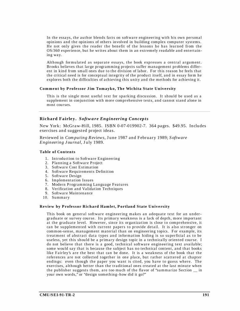
CMU/SEI-91-TR-2 191
In the essays, the author blends facts on software engineering with his own personalopinions and the opinions of others involved in building complex computer systems.He not only gives the reader the benefit of the lessons he has learned from theOS/360 experience, but he writes about them in an extremely readable and entertain-ing way.
Although formulated as separate essays, the book expresses a central argument.Brooks believes that large programming projects suffer management problems differ-ent in kind from small ones due to the division of labor. For this reason he feels thatthe critical need is for conceptual integrity of the product itself, and in essay form heexplores both the difficulties of achieving this unity and the methods for achieving it.
Comment by Professor Jim Tomayko, The Wichita State University
This is the single most useful text for sparking discussion. It should be used as asupplement in conjunction with more comprehensive texts, and cannot stand alone inmost courses.
Richard Fairley. Software Engineering Concepts
New York: McGraw-Hill, 1985. ISBN 0-07-019902-7. 364 pages. $49.95. Includesexercises and suggested project ideas.
Reviewed in Computing Reviews, June 1987 and February 1989; SoftwareEngineering Journal, July 1989.
Table of Contents
1. Introduction to Software Engineering2. Planning a Software Project3. Software Cost Estimation4. Software Requirements Definition5. Software Design6. Implementation Issues7. Modern Programming Language Features8. Verification and Validation Techniques9. Software Maintenance
10. Summary
Review by Professor Richard Hamlet, Portland State University
This book on general software engineering makes an adequate text for an under-graduate or survey course. Its primary weakness is a lack of depth, more importantat the graduate level. However, since its organization is close to comprehensive, itcan be supplemented with current papers to provide detail. It is also stronger oncommon-sense, management material than on engineering topics. For example, itstreatment of abstract data types and information hiding is so superficial as to beuseless, yet this should be a primary design topic in a technically oriented course. Ido not believe that there is a good, technical software engineering text available;some would say that is because the subject has no technical content, and that bookslike Fairley’s are the best that can be done. It is a weakness of the book that thereferences are not collected together in one place, but rather scattered at chapterendings: even though the paper you want is cited, you have to guess where. Theexercises, although better than the traditional ones created at the last minute whenthe publisher suggests them, are too much of the flavor of “summarize Section __ inyour own words,” or “design something–how did it go?”
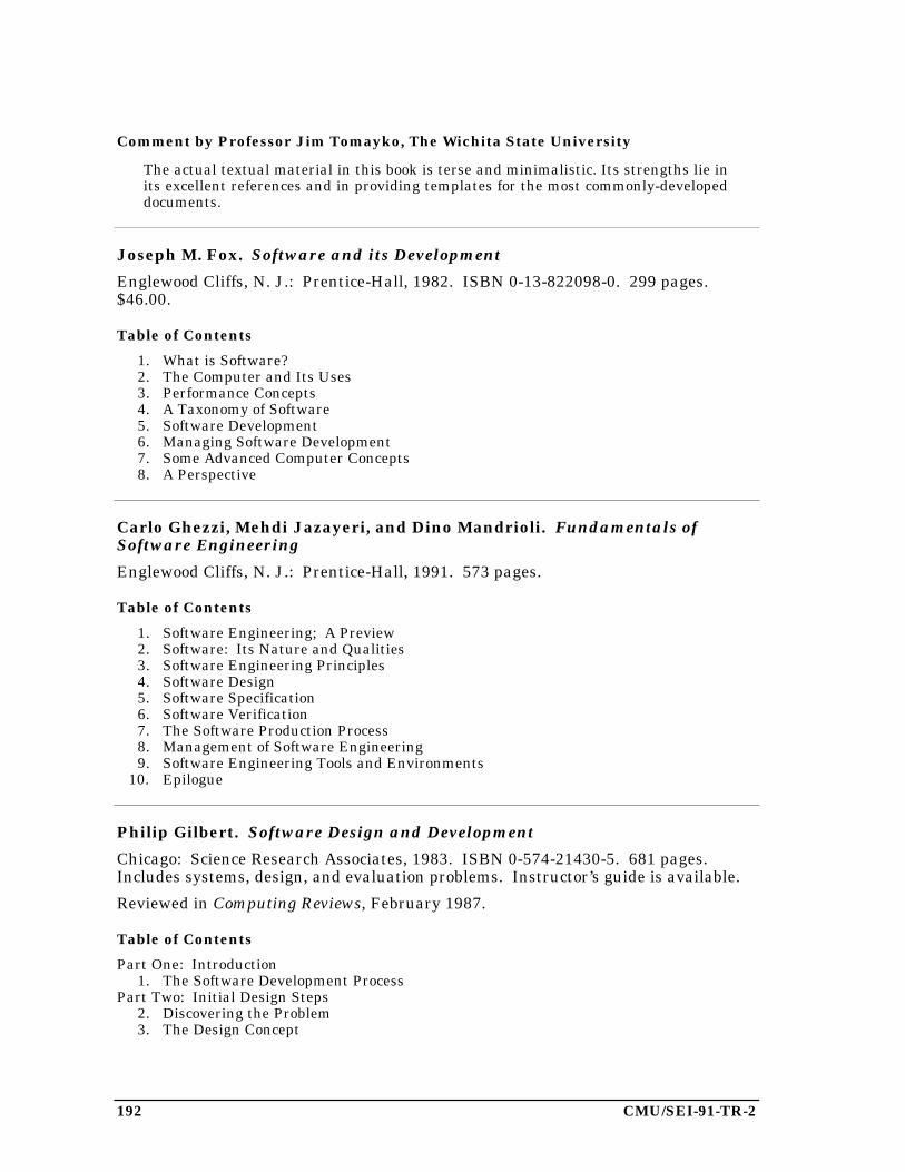
192 CMU/SEI-91-TR-2
Comment by Professor Jim Tomayko, The Wichita State University
The actual textual material in this book is terse and minimalistic. Its strengths lie inits excellent references and in providing templates for the most commonly-developeddocuments.
Joseph M. Fox. Software and its Development
Englewood Cliffs, N. J.: Prentice-Hall, 1982. ISBN 0-13-822098-0. 299 pages.$46.00.
Table of Contents
1. What is Software?2. The Computer and Its Uses3. Performance Concepts4. A Taxonomy of Software5. Software Development6. Managing Software Development7. Some Advanced Computer Concepts8. A Perspective
Carlo Ghezzi, Mehdi Jazayeri, and Dino Mandrioli. Fundamentals ofSoftware Engineering
Englewood Cliffs, N. J.: Prentice-Hall, 1991. 573 pages.
Table of Contents
1. Software Engineering; A Preview2. Software: Its Nature and Qualities3. Software Engineering Principles4. Software Design5. Software Specification6. Software Verification7. The Software Production Process8. Management of Software Engineering9. Software Engineering Tools and Environments
10. Epilogue
Philip Gilbert. Software Design and Development
Chicago: Science Research Associates, 1983. ISBN 0-574-21430-5. 681 pages.Includes systems, design, and evaluation problems. Instructor’s guide is available.
Reviewed in Computing Reviews, February 1987.
Table of Contents
Part One: Introduction1. The Software Development Process
Part Two: Initial Design Steps2. Discovering the Problem3. The Design Concept

CMU/SEI-91-TR-2 193
Part Three: System Design and Development4. Introduction to Module Organization5. Design and Development of Module Organization
Part Four: Module Development6. Design of Modules7. Module Implementation Using Top-Down Design8. Issues in Program Construction9. Verifying Program Correctness
Part Five: Other Perspectives10. Management Perspectives
Watts S. Humphrey. Managing the Software Process
Reading, Mass.: Addison-Wesley, 1989. ISBN 0-201-18095-2. 494 pages. $43.25.
Reviewed in American Programmer, January 1990; that is review condensed andreprinted in Data Processing Digest, May 1990.
Table of Contents
Part I: Software Process Maturity1. A Software Maturity Framework2. The Principles of Software Process Change3. Software Process Assessment4. The Initial Process
Part II: The Repeatable Process5. Managing Software Organizations6. The Project Plan7. Software Configuration Management8. Software Quality Assurance
Part III: The Defined Process9. Software Standards
10. Software Inspections11. Software Testing12. Software Configuration Management (Continued)13. Defining the Software Process14. The Software Engineering Process Group
Part IV: The Managed Process15. Data Gathering and Analysis16. Managing Software Quality
Part V: The Optimizing Process17. Defect Prevention18. Automating the Software Process19. Contracting for Software20. Conclusion
Comment by Professor Jim Tomayko, The Wichita State University
This is a good overview of the software development process, but it should begraduate-level only and should be used in conjunction with a more comprehensivetext that explains specific methods.
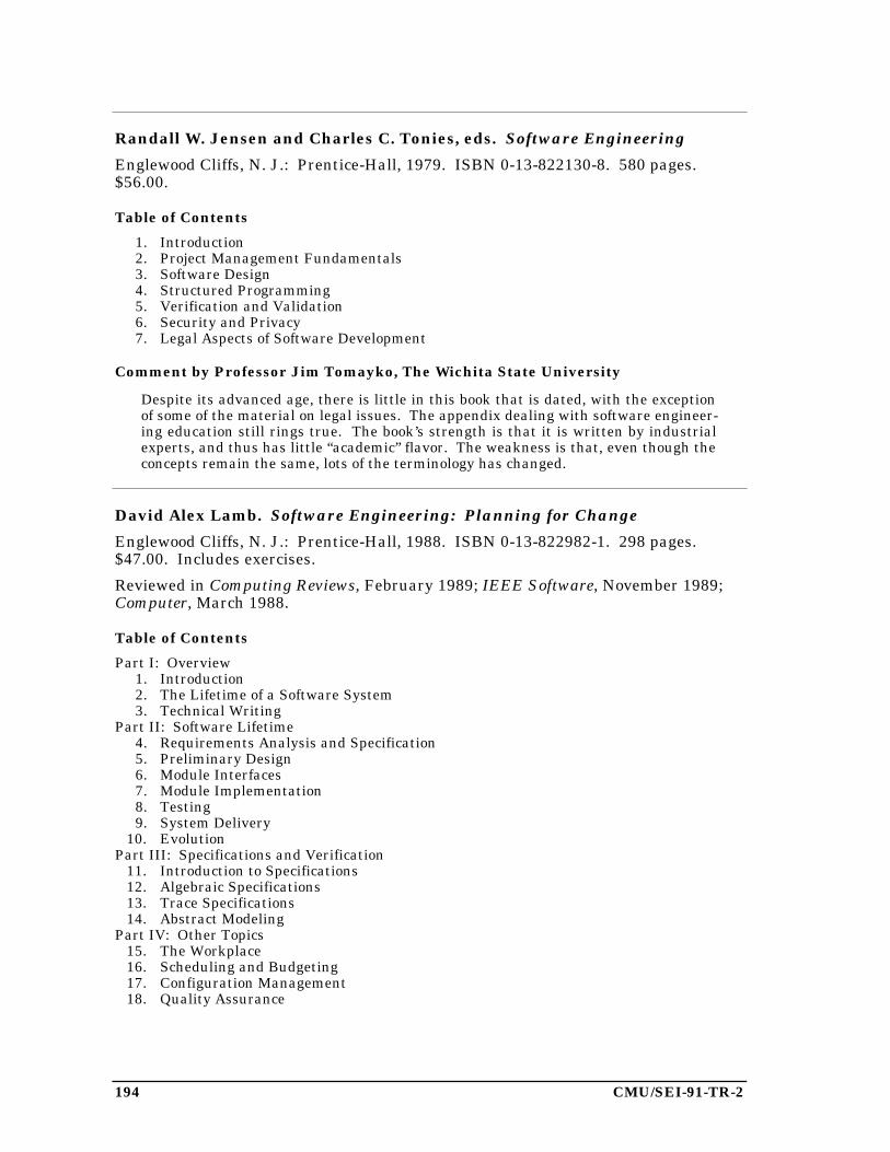
194 CMU/SEI-91-TR-2
Randall W. Jensen and Charles C. Tonies, eds. Software Engineering
Englewood Cliffs, N. J.: Prentice-Hall, 1979. ISBN 0-13-822130-8. 580 pages.$56.00.
Table of Contents
1. Introduction2. Project Management Fundamentals3. Software Design4. Structured Programming5. Verification and Validation6. Security and Privacy7. Legal Aspects of Software Development
Comment by Professor Jim Tomayko, The Wichita State University
Despite its advanced age, there is little in this book that is dated, with the exceptionof some of the material on legal issues. The appendix dealing with software engineer-ing education still rings true. The book’s strength is that it is written by industrialexperts, and thus has little “academic” flavor. The weakness is that, even though theconcepts remain the same, lots of the terminology has changed.
David Alex Lamb. Software Engineering: Planning for Change
Englewood Cliffs, N. J.: Prentice-Hall, 1988. ISBN 0-13-822982-1. 298 pages.$47.00. Includes exercises.
Reviewed in Computing Reviews, February 1989; IEEE Software, November 1989;Computer, March 1988.
Table of Contents
Part I: Overview1. Introduction2. The Lifetime of a Software System3. Technical Writing
Part II: Software Lifetime4. Requirements Analysis and Specification5. Preliminary Design6. Module Interfaces7. Module Implementation8. Testing9. System Delivery
10. EvolutionPart III: Specifications and Verification
11. Introduction to Specifications12. Algebraic Specifications13. Trace Specifications14. Abstract Modeling
Part IV: Other Topics15. The Workplace16. Scheduling and Budgeting17. Configuration Management18. Quality Assurance
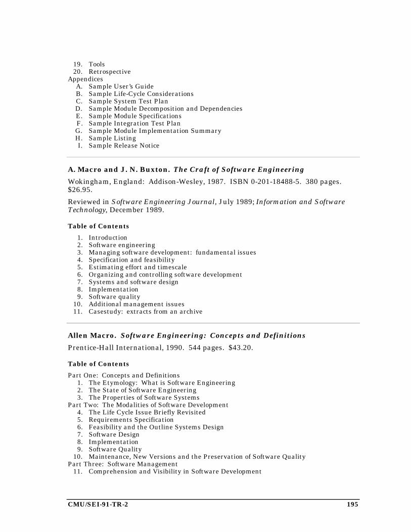
CMU/SEI-91-TR-2 195
19. Tools20. Retrospective
AppendicesA. Sample User’s GuideB. Sample Life-Cycle ConsiderationsC. Sample System Test PlanD. Sample Module Decomposition and DependenciesE. Sample Module SpecificationsF. Sample Integration Test PlanG. Sample Module Implementation SummaryH. Sample ListingI. Sample Release Notice
A. Macro and J. N. Buxton. The Craft of Software Engineering
Wokingham, England: Addison-Wesley, 1987. ISBN 0-201-18488-5. 380 pages.$26.95.
Reviewed in Software Engineering Journal, July 1989; Information and SoftwareTechnology, December 1989.
Table of Contents
1. Introduction2. Software engineering3. Managing software development: fundamental issues4. Specification and feasibility5. Estimating effort and timescale6. Organizing and controlling software development7. Systems and software design8. Implementation9. Software quality
10. Additional management issues11. Casestudy: extracts from an archive
Allen Macro. Software Engineering: Concepts and Definitions
Prentice-Hall International, 1990. 544 pages. $43.20.
Table of Contents
Part One: Concepts and Definitions1. The Etymology: What is Software Engineering2. The State of Software Engineering3. The Properties of Software Systems
Part Two: The Modalities of Software Development4. The Life Cycle Issue Briefly Revisited5. Requirements Specification6. Feasibility and the Outline Systems Design7. Software Design8. Implementation9. Software Quality
10. Maintenance, New Versions and the Preservation of Software QualityPart Three: Software Management
11. Comprehension and Visibility in Software Development

196 CMU/SEI-91-TR-2
12. Estimating Effort and Time-Scale13. Managing Software Development
EpilogPart Four: AppendicesAppendix 1. A Consolidated Case StudyAppendix 2. Specimen QuestionsAppendix 3. Glossary of TermsAppendix 4. References
Philip W. Metzger. Managing a Programming Project, 2nd Ed.
Englewood Cliffs, N. J.: Prentice-Hall, 1981. ISBN 0-13-550772-3. 244 pages.$50.00.
Table of Contents
Part I: The Programming Development Cycle1. Introduction2. The Definition Phase3. The Design Phase4. The Programming Phase5. The System Test Phase6. The Acceptance Phase7. The Installation and Operation Phase8. Special Considerations9. A War Story
10. A SummaryPart II: A Project Plan Outline
Comment by Gary Ford, SEI
As the title implies, this book focuses on project management. An especially usefulpart of the book is the detailed outline of a project plan, which runs 31 pages. Thebook can be a valuable resource to an instructor of a software engineering projectcourse, even when the students are using another book.
Barbee Teasley Mynatt. Software Engineering with Student ProjectGuidance
Englewood Cliffs, N. J.: Prentice-Hall, 1990. 429 pages.
Table of Contents
1. What is Software Engineering2. Requirements Analysis and Specification3. Preliminary Design: Designing the User Interface4. Preliminary Design: Designing the Software Structure and Data Structures5. Detailed Design and Choosing a Programming Language6. Coding and Integration7. Testing8. More about Software Engineering: Now and in the Future
AppendicesA. Sample Documents from the Rev-Pro Case StudyB. Writing a User’s Manual
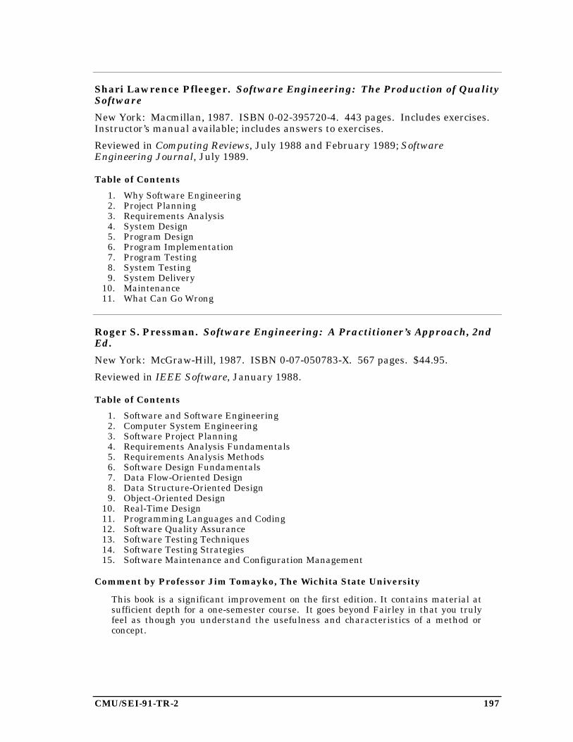
CMU/SEI-91-TR-2 197
Shari Lawrence Pfleeger. Software Engineering: The Production of QualitySoftware
New York: Macmillan, 1987. ISBN 0-02-395720-4. 443 pages. Includes exercises.Instructor’s manual available; includes answers to exercises.
Reviewed in Computing Reviews, July 1988 and February 1989; SoftwareEngineering Journal, July 1989.
Table of Contents
1. Why Software Engineering2. Project Planning3. Requirements Analysis4. System Design5. Program Design6. Program Implementation7. Program Testing8. System Testing9. System Delivery
10. Maintenance11. What Can Go Wrong
Roger S. Pressman. Software Engineering: A Practitioner’s Approach, 2ndEd.
New York: McGraw-Hill, 1987. ISBN 0-07-050783-X. 567 pages. $44.95.
Reviewed in IEEE Software, January 1988.
Table of Contents
1. Software and Software Engineering2. Computer System Engineering3. Software Project Planning4. Requirements Analysis Fundamentals5. Requirements Analysis Methods6. Software Design Fundamentals7. Data Flow-Oriented Design8. Data Structure-Oriented Design9. Object-Oriented Design
10. Real-Time Design11. Programming Languages and Coding12. Software Quality Assurance13. Software Testing Techniques14. Software Testing Strategies15. Software Maintenance and Configuration Management
Comment by Professor Jim Tomayko, The Wichita State University
This book is a significant improvement on the first edition. It contains material atsufficient depth for a one-semester course. It goes beyond Fairley in that you trulyfeel as though you understand the usefulness and characteristics of a method orconcept.

198 CMU/SEI-91-TR-2
Ronald A. Radice and Richard W. Phillips. Software Engineering: AnIndustrial Approach, Vol. 1
Englewood Cliffs, N. J.: Prentice-Hall, 1988. 457 pages. $37.00.
Reviewed in IEEE Software, September 1989.
Table of Contents
Part 1. The Basis of This Book1. The State of Software Engineering2. The Process of Software Production
Part 2. The Software Product3. Planning the Product4. Requirements Engineering5. Human Factors and Usability
Part 3. Software Engineering Methods6. Planning the Project7. Design of Software8. Validation and Verification
Part 4. Design and Coding Stages9. Product Level Design and Component Level Design
10. Module Level Design (MLD)11. Code
Part 5. AppendixesA. A Specification Language (ASL) ReferenceB. Design Programming Language (DPL) ReferenceC. A Design Language (ADL) Reference
B. Ratcliff. Software Engineering—Principles and Methods
Blackwell, 1987.
Reviewed in Software Engineering Journal, July 1989.
Kenneth D. Shere. Software Engineering and Management
Englewood Cliffs, N. J.: Prentice Hall, 1988. ISBN 0-13-822081-6.
Table of Contents
1. Introduction2. Structured Programming3. A Life-cycle Approach to Software Engineering4. Risk Management5. Cost Estimation6. Determining the System Legacy7. Life-cycle Products8. Case Study: Design of a Large, Complex System9. Overview of Structured Techniques
10. Data-base Design11. Quality Assurance12. Some Analytical Techniques13. Case Study: Design of an Office Automation System14. Designing an Integrated Home Computer: A Challenge to the Reader
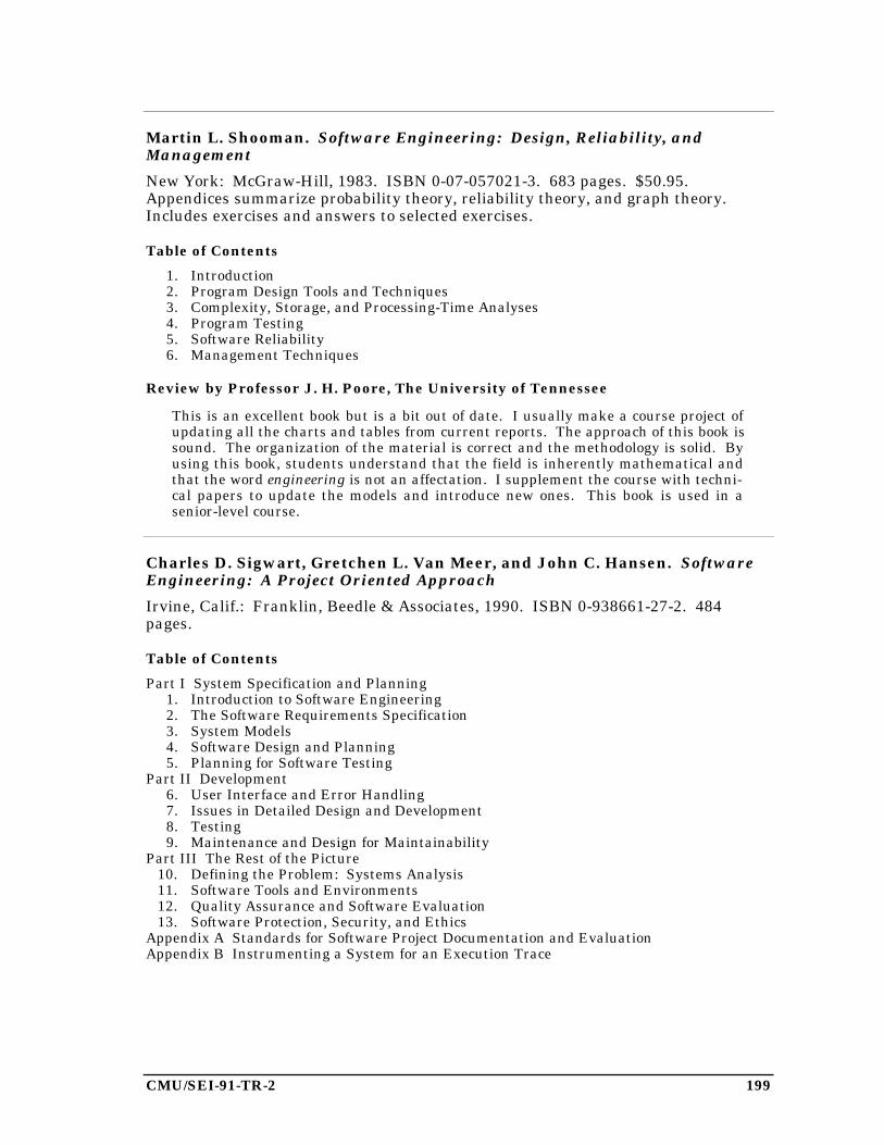
CMU/SEI-91-TR-2 199
Martin L. Shooman. Software Engineering: Design, Reliability, andManagement
New York: McGraw-Hill, 1983. ISBN 0-07-057021-3. 683 pages. $50.95.Appendices summarize probability theory, reliability theory, and graph theory.Includes exercises and answers to selected exercises.
Table of Contents
1. Introduction2. Program Design Tools and Techniques3. Complexity, Storage, and Processing-Time Analyses4. Program Testing5. Software Reliability6. Management Techniques
Review by Professor J. H. Poore, The University of Tennessee
This is an excellent book but is a bit out of date. I usually make a course project ofupdating all the charts and tables from current reports. The approach of this book issound. The organization of the material is correct and the methodology is solid. Byusing this book, students understand that the field is inherently mathematical andthat the word engineering is not an affectation. I supplement the course with techni-cal papers to update the models and introduce new ones. This book is used in asenior-level course.
Charles D. Sigwart, Gretchen L. Van Meer, and John C. Hansen. SoftwareEngineering: A Project Oriented Approach
Irvine, Calif.: Franklin, Beedle & Associates, 1990. ISBN 0-938661-27-2. 484pages.
Table of Contents
Part I System Specification and Planning1. Introduction to Software Engineering2. The Software Requirements Specification3. System Models4. Software Design and Planning5. Planning for Software Testing
Part II Development6. User Interface and Error Handling7. Issues in Detailed Design and Development8. Testing9. Maintenance and Design for Maintainability
Part III The Rest of the Picture10. Defining the Problem: Systems Analysis11. Software Tools and Environments12. Quality Assurance and Software Evaluation13. Software Protection, Security, and Ethics
Appendix A Standards for Software Project Documentation and EvaluationAppendix B Instrumenting a System for an Execution Trace
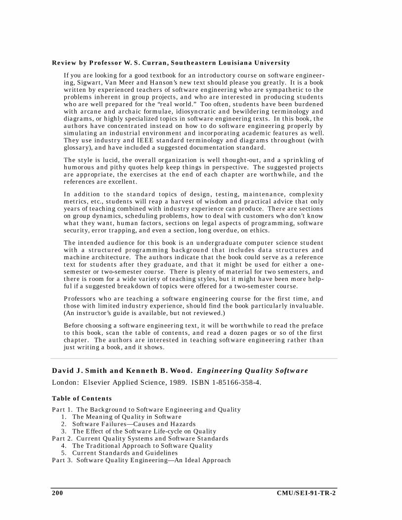
200 CMU/SEI-91-TR-2
Review by Professor W. S. Curran, Southeastern Louisiana University
If you are looking for a good textbook for an introductory course on software engineer-ing, Sigwart, Van Meer and Hanson’s new text should please you greatly. It is a bookwritten by experienced teachers of software engineering who are sympathetic to theproblems inherent in group projects, and who are interested in producing studentswho are well prepared for the “real world.” Too often, students have been burdenedwith arcane and archaic formulae, idiosyncratic and bewildering terminology anddiagrams, or highly specialized topics in software engineering texts. In this book, theauthors have concentrated instead on how to do software engineering properly bysimulating an industrial environment and incorporating academic features as well.They use industry and IEEE standard terminology and diagrams throughout (withglossary), and have included a suggested documentation standard.
The style is lucid, the overall organization is well thought-out, and a sprinkling ofhumorous and pithy quotes help keep things in perspective. The suggested projectsare appropriate, the exercises at the end of each chapter are worthwhile, and thereferences are excellent.
In addition to the standard topics of design, testing, maintenance, complexitymetrics, etc., students will reap a harvest of wisdom and practical advice that onlyyears of teaching combined with industry experience can produce. There are sectionson group dynamics, scheduling problems, how to deal with customers who don't knowwhat they want, human factors, sections on legal aspects of programming, softwaresecurity, error trapping, and even a section, long overdue, on ethics.
The intended audience for this book is an undergraduate computer science studentwith a structured programming background that includes data structures andmachine architecture. The authors indicate that the book could serve as a referencetext for students after they graduate, and that it might be used for either a one-semester or two-semester course. There is plenty of material for two semesters, andthere is room for a wide variety of teaching styles, but it might have been more help-ful if a suggested breakdown of topics were offered for a two-semester course.
Professors who are teaching a software engineering course for the first time, andthose with limited industry experience, should find the book particularly invaluable.(An instructor’s guide is available, but not reviewed.)
Before choosing a software engineering text, it will be worthwhile to read the prefaceto this book, scan the table of contents, and read a dozen pages or so of the firstchapter. The authors are interested in teaching software engineering rather thanjust writing a book, and it shows.
David J. Smith and Kenneth B. Wood. Engineering Quality Software
London: Elsevier Applied Science, 1989. ISBN 1-85166-358-4.
Table of Contents
Part 1. The Background to Software Engineering and Quality1. The Meaning of Quality in Software2. Software Failures—Causes and Hazards3. The Effect of the Software Life-cycle on Quality
Part 2. Current Quality Systems and Software Standards4. The Traditional Approach to Software Quality5. Current Standards and Guidelines
Part 3. Software Quality Engineering—An Ideal Approach
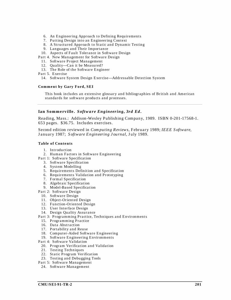
CMU/SEI-91-TR-2 201
6. An Engineering Approach to Defining Requirements7. Putting Design into an Engineering Context8. A Structured Approach to Static and Dynamic Testing9. Languages and Their Importance
10. Aspects of Fault Tolerance in Software DesignPart 4. New Management for Software Design
11. Software Project Management12. Quality—Can it be Measured?13. The Role of the Software Engineer
Part 5. Exercise14. Software System Design Exercise—Addressable Detection System
Comment by Gary Ford, SEI
This book includes an extensive glossary and bibliographies of British and Americanstandards for software products and processes.
Ian Sommerville. Software Engineering, 3rd Ed.
Reading, Mass.: Addison-Wesley Publishing Company, 1989. ISBN 0-201-17568-1.653 pages. $36.75. Includes exercises.
Second edition reviewed in Computing Reviews, February 1989; IEEE Software,January 1987; Software Engineering Journal, July 1989.
Table of Contents
1. Introduction2. Human Factors in Software Engineering
Part 1: Software Specification3. Software Specification4. System Modelling5. Requirements Definition and Specification6. Requirements Validation and Prototyping7. Formal Specification8. Algebraic Specification9. Model-Based Specification
Part 2: Software Design10. Software Design11. Object-Oriented Design12. Function-Oriented Design13. User Interface Design14. Design Quality Assurance
Part 3: Programming Practice, Techniques and Environments15. Programming Practice16. Data Abstraction17. Portability and Reuse18. Computer-Aided Software Engineering19. Software Engineering Environments
Part 4: Software Validation20. Program Verification and Validation21. Testing Techniques22. Static Program Verification23. Testing and Debugging Tools
Part 5: Software Management24. Software Management
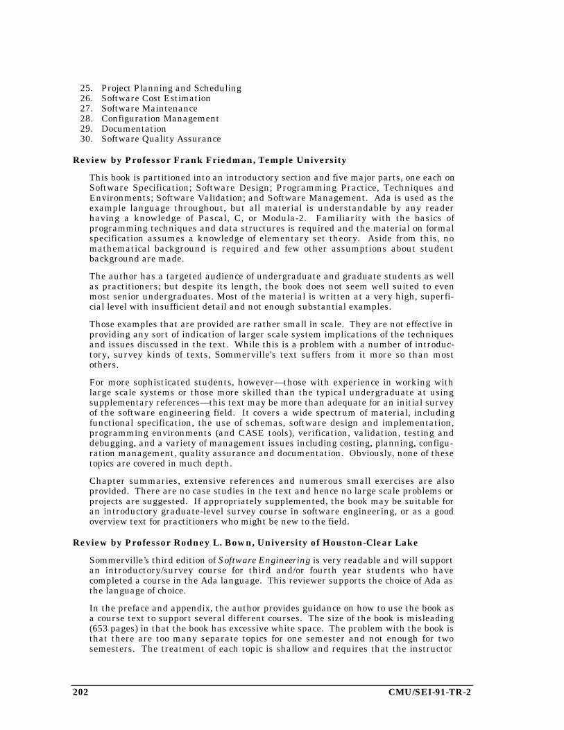
202 CMU/SEI-91-TR-2
25. Project Planning and Scheduling26. Software Cost Estimation27. Software Maintenance28. Configuration Management29. Documentation30. Software Quality Assurance
Review by Professor Frank Friedman, Temple University
This book is partitioned into an introductory section and five major parts, one each onSoftware Specification; Software Design; Programming Practice, Techniques andEnvironments; Software Validation; and Software Management. Ada is used as theexample language throughout, but all material is understandable by any readerhaving a knowledge of Pascal, C, or Modula-2. Familiarity with the basics ofprogramming techniques and data structures is required and the material on formalspecification assumes a knowledge of elementary set theory. Aside from this, nomathematical background is required and few other assumptions about studentbackground are made.
The author has a targeted audience of undergraduate and graduate students as wellas practitioners; but despite its length, the book does not seem well suited to evenmost senior undergraduates. Most of the material is written at a very high, superfi-cial level with insufficient detail and not enough substantial examples.
Those examples that are provided are rather small in scale. They are not effective inproviding any sort of indication of larger scale system implications of the techniquesand issues discussed in the text. While this is a problem with a number of introduc-tory, survey kinds of texts, Sommerville's text suffers from it more so than mostothers.
For more sophisticated students, however—those with experience in working withlarge scale systems or those more skilled than the typical undergraduate at usingsupplementary references—this text may be more than adequate for an initial surveyof the software engineering field. It covers a wide spectrum of material, includingfunctional specification, the use of schemas, software design and implementation,programming environments (and CASE tools), verification, validation, testing anddebugging, and a variety of management issues including costing, planning, configu-ration management, quality assurance and documentation. Obviously, none of thesetopics are covered in much depth.
Chapter summaries, extensive references and numerous small exercises are alsoprovided. There are no case studies in the text and hence no large scale problems orprojects are suggested. If appropriately supplemented, the book may be suitable foran introductory graduate-level survey course in software engineering, or as a goodoverview text for practitioners who might be new to the field.
Review by Professor Rodney L. Bown, University of Houston-Clear Lake
Sommerville’s third edition of Software Engineering is very readable and will supportan introductory/survey course for third and/or fourth year students who havecompleted a course in the Ada language. This reviewer supports the choice of Ada asthe language of choice.
In the preface and appendix, the author provides guidance on how to use the book asa course text to support several different courses. The size of the book is misleading(653 pages) in that the book has excessive white space. The problem with the book isthat there are too many separate topics for one semester and not enough for twosemesters. The treatment of each topic is shallow and requires that the instructor

CMU/SEI-91-TR-2 203
provide considerable support material. Chapters 7, 8, and 9 present topics which arerelated to formal methods. The coverage is too thin to support a complete teachingunit. Other examples would include the limited coverage in Chapter 11 on object-oriented design. This instructor uses supplementary material to support all teachingunits.
The book does not have a consistent case study to demonstrate each of the softwareengineering phases. The book should not be a survey of different applications.Chapter 10 uses as examples: a control system, compiler, radar system, andspellcheck. The weather station in Chapter 11 is an excellent example but it is veryincomplete. Chapter 11 also uses the heating system, address list, and counter asexamples. The author should recognize that a third or fourth year university studenthas limited to no real-world application knowledge to appreciate multiple examples.My first recommendation for a fourth edition is to examine the positive results fromusing a consistent case study to support the ideas and concepts presented in the book.
The instructor’s manual promised camera-ready figures to be used for production ofvisual aids by the instructor. This was a great disappointment in that the figureswere not enlarged from those contained in the textbook. Many pages in the manualwere used for programming lists and were of no value. The instructor’s manual hasprovided limited support to this instructor.
The list of references is excellent.
Bottom Line: This instructor will continue to use the book with local supplementarymaterial that supports a case study. This material includes but is not limited totopics such as IRDS, CAIS, DOD STD 2167, IEEE tutorial on Process Models, andbrochures on commercial CASE products.
Donald W. Steward. Software Engineering with Systems Analysis andDesign
Monterey, Calif.: Brooks/Cole Publishing Co., 1987. ISBN 0-534-07506-1.414 pages. $44.75. Includes exercises.
Reviewed in Computer, April 1988.
Table of Contents
Part 1: Introducing Software Engineering1. What is Software Engineering?2. Software Engineering Principles
Part 2: Describing the Product3. Data Flow Diagrams and Matrices4. Tree Structures
Part 3: Managing the Software Development Process5. Managing People and Expectations6. Estimating the Project7. Scheduling and Controlling the Project
Part 4: Applying the Technology8. Technical Considerations in Analysis and Design9. User Interfaces
Part 5: Stepping Through the Process10. Documenting the Project11. Planning the Project12. Analyzing the Current System and Expectations13. Specifying Requirements
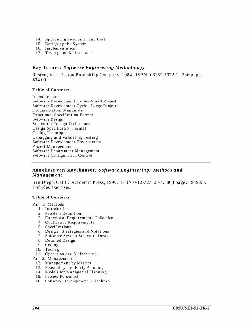
204 CMU/SEI-91-TR-2
14. Appraising Feasibility and Cost15. Designing the System16. Implementation17. Testing and Maintenance
Ray Turner. Software Engineering Methodology
Reston, Va.: Reston Publishing Company, 1984. ISBN 0-8359-7022-1. 236 pages.$34.00.
Table of Contents
IntroductionSoftware Development Cycle—Small ProjectSoftware Development Cycle—Large ProjectsDocumentation StandardsFunctional Specification FormatSoftware DesignStructured Design TechniquesDesign Specification FormatCoding TechniquesDebugging and Validating TestingSoftware Development EnvironmentProject ManagementSoftware Department ManagementSoftware Configuration Control
Anneliese von Mayrhauser. Software Engineering: Methods andManagement
San Diego, Calif.: Academic Press, 1990. ISBN 0-12-727320-4. 864 pages. $49.95.Includes exercises.
Table of Contents
Part 1: Methods1. Introduction2. Problem Definition3. Functional Requirements Collection4. Qualitative Requirements5. Specifications6. Design: Strategies and Notations7. Software System Structure Design8. Detailed Design9. Coding
10. Testing11. Operation and Maintenance
Part 2: Management12. Management by Metrics13. Feasibility and Early Planning14. Models for Managerial Planning15. Project Personnel16. Software Development Guidelines
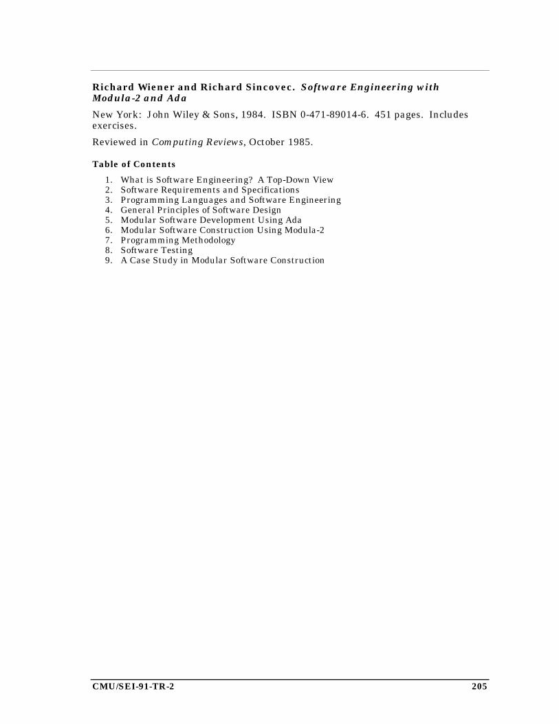
CMU/SEI-91-TR-2 205
Richard Wiener and Richard Sincovec. Software Engineering withModula-2 and Ada
New York: John Wiley & Sons, 1984. ISBN 0-471-89014-6. 451 pages. Includesexercises.
Reviewed in Computing Reviews, October 1985.
Table of Contents
1. What is Software Engineering? A Top-Down View2. Software Requirements and Specifications3. Programming Languages and Software Engineering4. General Principles of Software Design5. Modular Software Development Using Ada6. Modular Software Construction Using Modula-27. Programming Methodology8. Software Testing9. A Case Study in Modular Software Construction

206 CMU/SEI-91-TR-2
CMU/SEI-91-TR-2 207
6. Survey of Software Engineering Research Journals
Although the SEI curriculum recommendations are aimed at stimulating the growthof software engineering education, we hope that software engineering research willalso become more widespread in universities. Faculty members often find that doingresearch and teaching in the same area improves their ability to do both.
A first step in initiating software engineering research is an awareness of the cur-rent research literature. Software engineering has matured to the point that thereare now many research journals that report advances in the discipline. Many ofthese journals are relatively new and many professors are new to the discipline, sothese journals may not be widely known. The two sections below identify archivaljournals in software engineering and journals in related areas that frequentlyinclude papers on software engineering. We recommend that schools developingsoftware engineering degree programs ask their libraries to consider subscribing tothese journals.
The information describing each journal has been extracted from the journal’sinformation for authors and in most cases is a direct quotation.
6.1. Archival Journals
ACM Transactions on Software Engineering and Methodology
Publisher: Association for Computing Machinery.
This new journal (first issue in January 1991) will publish significant papers on allaspects of research related to complex software systems, generally characterized bya scale requiring development by teams, not individuals. It will include researchissues such as specific tools, methods, technologies, environments, and platforms;languages, algorithms data structures, theory as appropriate to the scale and com-plexity of the application domains and within context of large-scale systems; resultswhich are extensible, scalable with practical import; work demonstrating clearapplication of scientific method: thesis, development, experiment, evolution anditeration; empirical studies; application of innovative technologies, such as: dataand object management; intelligent systems and artificial intelligence; new pro-gramming styles; new hardware, systems, and graphics; methods for real-time andother time-constrained systems; techniques for prototyping and reuse; and riskevaluations and containment.
208 CMU/SEI-91-TR-2
Formal Aspects of Computing
Publisher: British Computer Society.
Computing science is developing and providing a basis on which complex systemscan be designed and analysed. Theories are evolving in terms of which a true under-standing of difficult computing concepts can be gained. To employ such theories indiscussions requires the use of formal notation. Although notation can present aninitial barrier, practitioners are now finding that the investment of effort isworthwhile.
The principal aims of this journal are to promote the growth of computing science, toshow its relationship to practice, and to help in the application of formalisms. Inparticular, contributions to the formal aspects of computing are to be published. Thefollowing fall within the scope of formal aspects: Well founded notations for systemdescription/specification, verifiable designs, proof methods, theories of objects usedin specifications and implementations, transformational design, formal approachesto requirements analysis, results on algorithm and problem complexity, fault-toler-ant design, descriptions of relevant “project support environments,” methods ofapproaching development.
Applications of known formal methods as well as new results would be suitable sub-jects for papers. Comprehensive surveys will also be published and there is hopethat some systematic coverage of major topics can be achieved over a period of years.Contributions to the teaching of formal aspects would also be welcome.
IEEE Transactions on Software Engineering
Publisher: Institute for Electrical and Electronic Engineers.
The IEEE Transactions on Software Engineering is an archival journal publishedmonthly. We are interested in well-defined theoretical results and empirical studiesthat have potential impact on the construction, analysis, or management of software.The scope of the Transactions ranges from the theoretical to the practical. Wewelcome treatments ranging from formal models to empirical studies, from softwareconstructive paradigms to assessment mechanisms, from the development of princi-ples to the application of those principles to specific environments. Since the journalis archival, it is assumed that the ideas presented are important, have been wellanalyzed and/or empirically validated and are of value to the software engineeringresearch or practitioner community.
Specific topic areas include: a) development and maintenance methods and models,e.g., techniques and principles for the specification, design, implementation of soft-ware systems including notations and process models; b) assessment methods, e.g.,software tests and validation, reliability models, test and diagnosis procedures,software redundancy and design for error control, and the measurements and evalu-ation of various aspects of the process and product; c) software project management,e.g., productivity factors, cost models, schedule and organizational issues, standards;
CMU/SEI-91-TR-2 209
d) tools and environments, e.g., specific tools, integrated tool environments includingthe associated architectures, databases, and parallel and distributed processingissues; e) system issues, e.g., hardware-software tradeoffs; and f) state-of-the-artsurveys that provide a synthesis and comprehensive review of the historical devel-opment of one particular area of interest.
Information and Software Technology
Publisher: Butterworth Heinemann, 80 Montvale Avenue, Stoneham, MA 02180.
Information and Software Technology focuses on international research on softwaredevelopment and its application in industry. The journal brings the results ofgovernment projects and academic and commercial research to its readers. Itdiscusses techniques for tailoring software and information systems for institutional,industrial and commercial use, and it explains in depth the technical needs of itsusers for more efficient and reliable systems. Emphasis is placed on the use ofproper methodologies and formal practices to improve software productivity.
Among the topics covered are software engineering development standards, toolsand methodologies, environments, metrics, automatic program development, qualityassurance and testing, formal methods, project management, and reliability andmaintenance.
International Journal of Computer and Software Engineering
Publisher: Ablex Publishing Corporation, 355 Chestnut Street, Norwood, NJ 07648.(The journal is scheduled to begin publication in 1991.)
The International Journal of Computer and Software Engineering will present state-of-the-art research and development in the area of computer engineering and soft-ware engineering. The journal will publish refereed papers relating to a widevariety of topics, theory, and practical applications in these areas.
The journal will be of interest to all those concerned with research and development,especially engineers, computer scientists, and those in allied disciplines. It willpublish original research, development, and state-of-the-art tutorials and relatedtopics. All papers submitted to the journal will be refereed by an internationalreview board.
Journal of Software Maintenance: Research and Practice
Publisher: John Wiley & Sons Ltd., Baffins Lane, Chichester, Sussex PO19 1UD,England.
The Journal of Software Maintenance publishes refereed papers in all aspects ofsoftware maintenance. We seek to include articles from practitioners working in thefield (including the user community) as well as research papers. It is not the inten-tion to publish papers on software development except where topics directly ofrelevance to maintenance are addressed. These could include (for example) the pro-
210 CMU/SEI-91-TR-2
duction of more maintainable software, or metrics produced during development topredict the maintainability, quality or reliability of software. Papers on the impactfor maintenance of new software practices will be welcomed.
Other journals do not cater well for “post-delivery” and operational support issues,and the Journal of Software Maintenance fills this need. The editors’ aim is toconvey the results of academic research and practical experience into the computingcommunity.
Topics on which papers will be published include: software evolution lifecycles,software maintenance management, tools, environments, metrics and productivitymethods, quality assurance, theory of software maintenance, maintainability of newsoftware, methods for software maintenance, impact for maintenance of new soft-ware practices.
Journal of Systems and Software
Publisher: Elsevier Science Publishing Co., Inc., 655 Avenue of the Americas, NewYork, NY 10010.
The Journal of Systems and Software publishes papers covering all aspects ofprogramming methodology, software engineering, and related hardware-software-systems issues. Topics of interest include, but are not limited to, software tools,programming environments, techniques for developing, validating, and maintainingsoftware systems, prototyping issues, high level specification techniques, proceduraland functional programming techniques, data flow concepts, multiprocessing, real-time, distributed concurrent, and telecommunications systems, software metrics,reliability models for software, performance issues, and management concerns. Thejournal publishes research papers, state-of-the-art surveys, and reports of practicalexperience.
Journal of Systems Integration
Publisher: Kluwer Academic Publishers, 101 Philip Drive, Norwell, MA 02061-1677.
The Journal of Systems Integration is a quarterly peer-reviewed technical publica-tion containing original, survey application, and research papers on all topics relatedto systems integration. The intent is to encompass a collection of papers that hereto-fore have been dispersed throughout a wide body of literature involving the interac-tion of disciplines, technologies, methods and machines necessary to integratevarious constituent systems.
The scope of this journal generally parallels the definition of the integration of com-puter systems. However, it also deals with the general integration of processes andsystems, and the development of mechanisms and tools enabling solutions to multi-disciplinary problems found in the computer services and manufacturing industries.This journal focuses on the following critical steps found in effective systems inte-grations: process characterization, re-engineering and simplification of processes,
CMU/SEI-91-TR-2 211
convergence on a common system architecture, and automation of the processes andsystems.
Since the successful implementation of these steps for systems integration requiresdiverse knowledge bases and expertise in various areas, the journal also emphasizesadditional topics such as managing knowledge and information that are physicallydistributed in various databases; computer communications impact on the systemprocess; dealing with heterogeneous computers and environments, and coordinatingdiverse computer communications networks with information networks.
Real-Time Systems
Publisher: Kluwer Academic Publishers, 101 Philip Drive, Norwell, MA 02061-1677.
Real-time systems are defined as those systems in which the correctness of thesystem depends not only on the logical result of computation, but also on the time atwhich the results are produced. Real-Time Systems is an archival, peer-reviewed,technical journal publishing the following types of papers, which concentrate on real-time computing principles and applications: research papers, invited papers, reportson projects and case studies, standards and corresponding proposals for generaldiscussion, and a partitioned tutorial on real-time systems as a continuing series.
Software Engineering Journal
Publisher: The Institution of Electrical Engineers (IEE), Savoy Place, LondonWC2R 0BL, United Kingdom.
Software Engineering Journal welcomes original contributions of interest to practi-tioners, researchers and managers engaged in software engineering. It is intendedthat the journal should cover the spectrum from reports on practical experienceusing software engineering methods and tools through to papers on longtermresearch activities. The Editors particularly welcome material which is of practicalbenefit today, or which could be brought into practical application in the foreseeablefuture.
The scope of the journal is the whole of software engineering, including, but not lim-ited to: management of software development; the development process; standards;support environments (IPSEs); development methods and tools; formal methods;software engineering training; software metrics and estimation methods; high-reliability systems.
Software: Practice and Experience
Publisher: John Wiley & Sons Ltd., Baffins Lane, Chichester, Sussex PO19 1UD,England.
To write successful software requires a great deal of know-how, and far too little ofthis is at present available in written form, which results in a duplication of inven-tive effort. Other journals do not cater well for the software writer and Software fills

212 CMU/SEI-91-TR-2
this need; the emphasis is on conveying the results of practical experience for thebenefit of the computing community. Both “systems” software and “applications”software, for use in batch, multi-access, interactive and real-time environments areincluded. Articles cover software design and implementation, case studies whichdescribe the evolution of systems and the thinking behind them, and criticalappraisals of software systems. Well-tried techniques that are not documented areincluded in articles of a tutorial nature. Although the emphasis is on practicalexperience, articles of a theoretical or mathematical nature will be included when itis felt that an understanding of theory will lead to better practical systems.
6.2. Other Journals
In addition to the journals that focus primarily on software engineering, there areseveral others that frequently include software engineering papers. These include:
ACM Transactions on Programming Languages and Systems
Publisher: Association for Computing Machinery.
The purpose of the ACM Transactions on Programming Languages and Systems(TOPLAS) is to provide a unified forum for the presentation of research and devel-opment results on all aspects of the design, definition, realization, and use ofprogramming languages and systems. In addition to the traditional research contri-butions, the journal includes reports of the insights and experience gained by thepractitioner in applying the fruits of that research.
Among the topics within the scope of TOPLAS are design or comparisons oflanguage features, analysis of the design or implementation of particular languages,description of novel program development tools and techniques, testing and verifi-cation methodology, user experience with languages or methodologies, programspecification languages and methods, storage allocation and garbage collection algo-rithms, methods for specifying programming language semantics, languageconstructs for and programming of asynchronous and distributed processes, andapplications of programming languages or methods to other areas such as databasesand office automation.
Communications of the ACM
Publisher: Association for Computing Machinery.
Communications of the ACM is a monthly magazine that publishes articles ofgeneral interest to the computing community. Papers of direct and immediate inter-est to practitioners are published in the Computing Practices section. Submittedmanuscripts should emphasize the skills and techniques used daily, including thedesign and construction of applications systems; discussion of computer systems andtools; methodologies for management; computer philosophy; and the implications of
CMU/SEI-91-TR-2 213
theoretical contributions to application areas. Papers submitted to ComputingPractices are reviewed by the Computing Practices Panel for content, definitiveness,interest, and importance to the practice of computing.
Case Studies are articles that report on experiences gained and lessons learnedconstructing and using major computer systems. They take a comprehensive view ofselected systems, covering them from requirements through design, implementation,and use. Case Studies should take a rigorously objective perspective on the systemsthey describe, and should be both evaluative and descriptive.
Computer
Publisher: Institute for Electrical and Electronic Engineers.
Computer covers all aspects of computer science, engineering, technology, and appli-cations. It is aimed at a broad audience. Articles in Computer are usually survey ortutorial in nature and cover the state of the art or important emerging develop-ments. Computer publishes technically substantive articles that are referencedextensively in the literature. One of the important purposes of Computer is to act asa technology transfer conduit to bring results and formalisms from university,industry and government research and development centers to the general practi-tioners in the field.
Computer Journal
Publisher: British Computer Society.
In order to maintain the Journal as a leading medium in all aspects of computerscience and compute applications, it has been agreed that future issues will identifystate-of-the-art themes and will publish new papers related to those themes. By“new” it is intended that papers would have been written no longer than six monthsbefore the press date. The list of themes to be chosen will be published approxi-mately 18 months in advance and submissions will be invited against the themes.
Future special issues include Concurrent Programming for the February 1991 issueand Methodologies (Software and Systems) for the April 1991 issue.
IEEE Software
Publisher: Institute for Electrical and Electronic Engineers.
IEEE Software emphasizes current practice and experience together with promisingnew ideas that are likely to be used in the near term. It is directed to the practice ofthe software profession. We welcome papers on topics across the software spectrum.Sample topics are data engineering and database software; programming environ-ments; languages and language-related issues; knowledge-based and decisionsupport systems; program and system debugging and testing; distributed, network,and parallel systems; education of software professionals; design, development, andprogramming methodologies; algorithms, their analysis and pragmatics;
214 CMU/SEI-91-TR-2
performance measurement and evaluation; program and system reliability, security,and verification; software-related social and legal issues; and human factors andsoftware metrics.
Articles describing how software is developed in specific companies, laboratories,and university environments, as well as articles describing new tools to aid in thesoftware and system development process, are welcome. The intent is to provide thereader with information on advances in software technology, specifics on novel fea-tures and applications, contrasts in designing and programming in the large versusdesigning and programming in the small, discussions of limitations and failures, andan awareness of the trends in this rapidly evolving area. Tutorials, survey articles,standards, guided tours through descriptions of projects, designs, or algorithms, andcase studies are also encouraged.
IEEE Transactions on Engineering Management
Publisher: Institute for Electrical and Electronic Engineers.
IEEE Transactions on Engineering Management is a research-based, refereed jour-nal in engineering management. The purpose of this Transactions is multifold: toassist in the establishment and recognition of the engineering management disci-pline; to provide the publications medium for authors at the leading edge of engi-neering management in academic institutions, industrial organizations, governmentagencies, or other settings; to establish the guidelines and identify the future direc-tions of critical issues in engineering management; and to become a forum for theresearchers and practitioners of engineering management, regardless of their tech-nical specialties.
IEEE Transactions on Parallel and Distributed Systems
Publisher: Institute for Electrical and Electronic Engineers.
The goal of the Transactions is to publish a range of papers, short notes, and surveyarticles that deal with the research areas of current importance to our readers.Current areas of particular interest include but are not limited to: a)architectures—design, analysis, and implementation of multiple-processor systems(including multiprocessors, multicomputers, and networks); impact of VLSI onsystem design; interprocessor communications; b) software—parallel languages andcompilers; scheduling and task partitioning, databases, operating systems, andprogramming environments for multiple-processor systems; c) algorithms andapplications—models of computation; analysis and design of parallel/distributedalgorithms; application studies resulting in better multiple-processor systems; d)other issues—performance measurements, evaluation, modeling and simulation ofmultiple-processor systems; real-time, reliability and fault-tolerance issues;conversion of software from sequential-to-parallel forms.
CMU/SEI-91-TR-2 215
Interacting with Computers
Publisher: Butterworth Heinemann Publishers.
The objective of the study of human-computer interaction (HCI) is to understandhow people communicate with computers so that the design and use of computersystems can be improved. HCI is an increasingly important, but diverse and frag-mented field. A new medium is needed to allow the communication and coordinationof expertise, findings and activities. Interacting with Computers is the internationalforum for just such communication. It makes information accessible not only tothose engaged in research but to all HCI practitioners.
Coverage includes: systems and dialogue design; evaluation techniques; user inter-face design, tools and methods; empirical evaluations; user features and usermodelling; new research paradigms; design theory, process and methodology; orga-nizational and societal issues; intelligent systems; training and education applica-tions; and emerging technologies.
Journal of Parallel and Distributed Computing
Publisher: Academic Press.
Among the areas in which papers are solicited are software tools and environments,real-time systems, performance analysis, and fault-tolerant computing.
Structured Programming
Publisher: Springer International.
The international journal Structured Programming will serve the professionalcomputing and engineering community. Its scope will include technical contribu-tions and short communications in the areas of programming, programmingmethodology and style, programming languages, programming environments, com-pilers, interpreters, and applications. It will report on technical advances in thefield, announce and review systems, implementations, and relevant publications.Structured Programming will emphasize innovative concepts in programming (suchas literate programming) and practical solutions to real problems. StructuredProgramming is not intended as an archival journal, but rather an informal forumfor the timely exchange of ideas and information.

216 CMU/SEI-91-TR-2
CMU/SEI-91-TR-2 217
Appendix 1. An Organizational Structure forCurriculum Content
The body of knowledge called software engineering consists of a large number ofinterrelated topics. We thought it impractical to attempt to capture this knowledgeas an undifferentiated mass, so an organizational structure was needed. Thestructure described below is not intended to be a taxonomy of software engineering.Rather, it is a guide that helps the SEI to collect and document software engineeringknowledge and practice, and to describe the content of some recommended coursesfor a graduate curriculum.
Discussions of software engineering frequently describe the discipline in terms of asoftware life cycle: requirements analysis, specification, design, implementation,testing, and maintenance. Although these life cycle phases are worthy of presenta-tion in a curriculum, we found this one-dimensional structure inadequate fororganizing all the topics in software engineering and for describing the curriculum.
A good course, whether a semester course in a university or a one-day trainingcourse in industry, must have a central thread or idea around which the presenta-tion is focused. Not every course can or should focus on one life cycle phase. In anengineering course (including software engineering), we can look at either the engi-neering process or the product that is the result of the process. Therefore, we havechosen these two views as the highest level partition of the curriculum content.Each is elaborated below.
The Process View
The process of software engineering includes several activities that are performed bysoftware engineers. The range of activities is broad, but there are many aspects ofeach activity that are similar across that range. Thus, we organize those topicswhose central thread is the process in two dimensions: activity and aspect (seeFigure A1.1).
The Activity Dimension
Activities are divided into four groups: development, control, management, andoperations. Each is defined and discussed below.
Development activities are those that create or produce the artifacts of a softwaresystem. These include requirements analysis, specification, design, implementation,and testing. Because a software system is usually part of a larger system, we some-times distinguish system activities from software activities; for example, systemdesign from software design. We expect that many large projects will include both
218 CMU/SEI-91-TR-2
systems engineers and software engineers, but it is important for software engineersto appreciate the systems aspects of the project, and system activities should beincluded in a curriculum.
Control activities are those that exercise restraining, constraining, or directing influ-ence over software development. These activities are more concerned with control-ling the way in which the development activities are performed than with producingartifacts. Two major kinds of control activities are those related to software evolu-tion and those related to software quality.
A software product evolves in the sense that it exists in many different forms as itmoves through its life cycle, from initial concept, through development and use, toeventual retirement. Change control and configuration management are activitiesrelated to evolution. We also consider software maintenance to be in this category,rather than as a separate development activity, because the difference betweendevelopment and maintenance is not in the activities performed (both involverequirements analysis, specification, design, implementation, and testing), but inthe way those activities are constrained and controlled. For example, thefundamental constraint in software maintenance is the pre-existence of a softwaresystem coupled with the belief that it is more cost-effective to modify that systemthan to build an entirely new one.
Software quality activities include quality assurance, test and evaluation, and inde-pendent verification and validation. These activities, in turn, incorporate such tasksas software technical reviews and performance evaluation.
Management activities are those involving executive, administrative, and supervi-sory direction of a software project, including technical activities that support theexecutive decision process. Typical management activities are project planning(schedules, establishment of milestones), resource allocation (staffing, budget),development team organization, cost estimation, and handling legal concerns(contracting, licensing). This is an appropriate part of a software engineering cur-riculum for several reasons: there is a body of knowledge about managing softwareprojects that is different from that about managing other kinds of projects; manysoftware engineers are likely to assume software management positions at somepoint in their careers; and knowledge of this material by all software engineersimproves their ability to work together as a team on large projects.
Operations activities are those related to the use of a software system by an organi-zation. These include training personnel to use the system, planning for the deliveryand installation of the system, transition from the old (manual or automated) systemto the new, operation of the software, and retirement of the system. Although soft-ware engineers may not have primary responsibility for any of these activities, theyare often participants on teams that perform them. Moreover, an awareness of theseactivities will often affect the choices software engineers make during the develop-ment of a system.
CMU/SEI-91-TR-2 219
The operation of software engineering support tools provides a case of special inter-est. These tools are software systems, and the users are the software engineersthemselves. Operations activities for these systems can be observed and experi-enced directly. An awareness of the issues related to the use of software tools canhelp software engineers not only develop systems for others but also adopt and usenew tools for their own activities.
The Aspect Dimension
Engineering activities traditionally have been partitioned into two categories:analytic and synthetic. We have chosen instead to consider an axis orthogonal toactivities that captures some of this kind of distinction, but that recognizes sixaspects of these activities: abstractions, representations, methods, tools, assessment,and communication.
Abstractions include fundamental principles and formal models. For example, soft-ware development process models (waterfall, iterative enhancement, etc.) are modelsof software evolution. Finite state machines and Petri nets are models of sequentialand concurrent computation, respectively. COCOMO is a software cost estimationmodel. Modularity and information hiding are principles of software design.
Representations include notations and languages. The Ada programming languagethus fits into the organization as an implementation language, while decision tablesand data flow diagrams are design notations. PERT charts are a notation useful forplanning projects.
Methods include formal methods, current practices, and methodologies. Proofs ofcorrectness are examples of formal methods for verification. Object-oriented designis a design method, and structured programming can be considered a current prac-tice of implementation.
Tools include individual software tools as well as integrated tool sets (and, implic-itly, the hardware systems on which they run). Examples are general-purpose tools(such as electronic mail and word processing), tools related to design and implemen-tation (such as compilers and syntax-directed editors), and project managementtools. Other types of software support for process activities are also included; theseare sometimes described by such terms as infrastructure, scaffolding, or harnesses.Sometimes the term environment is used to describe a set of tools, but we prefer toreserve this term to mean a collection of related representations, tools, methods, andobjects. Software objects are abstract, so we can only manipulate representations ofthem. Tools to perform manipulations are usually designed to help automate a par-ticular method or way of accomplishing a task. Typical tasks involve many objects(code modules, requirements specification, test data sets, etc.), so those objects mustbe available to the tools. Thus, we believe all four—representations, tools, methods,and objects—are necessary for an environment.
220 CMU/SEI-91-TR-2
Assessment aspects include measurement, analysis, and evaluation of both softwareproducts and software processes, and of the impact of software on organizations.Metrics and standards are also placed in this category. This is an area we believeshould be emphasized in the curriculum. Software engineers, like engineers in moretraditional fields, need to know what to measure, how to measure it, and how to usethe results to analyze, evaluate, and ultimately improve processes and products.
Communication is the final aspect. All software engineering activities include writ-ten and oral communication. Most produce documentation. A software engineermust have good general technical communication skills, as well as an understandingof forms of documentation appropriate for each activity.
By considering the activity dimension and the aspect dimension as orthogonal, wehave a matrix of ideas that might serve as the central thread in a course (FigureA1.1). It is likely that individual cells in the matrix represent too specialized a topicfor a full semester course. Therefore, we recommend that courses be designedaround part or all of a horizontal or vertical slice through that matrix.
The Product View
Often it is appropriate to discuss many activities and aspects in the context of aparticular kind of software system. For example, concurrent programming has avariety of notations for specification, design, and implementation that are notneeded in sequential programming. Instead of inserting one segment or lecture onconcurrent programming in each of several courses, it is probably better to gather allthe appropriate information on concurrent programming into one course. A similarargument can be made for information related to various system requirements; forexample, achieving system robustness involves aspects of requirements definition,specification, design, and testing.
Therefore we have added two additional categories to the organizational structurefor curriculum content: software system classes and pervasive system requirements.Although these may be viewed as being dimensions orthogonal to the activity andaspect dimensions, it is not necessarily the case that every point in the resultingfour-dimensional space represents a topic for which there exists a body of knowl-edge, or for which a course should be taught. Figure A1.2 shows an example of apoint for which there is probably a very small but nonempty body of knowledge.
Any of the various system classes or pervasive requirements described below mightbe the central thread in a course in a software engineering curriculum. We empha-size that the same material might be taught in courses whose central thread is oneof the activities mentioned earlier. For example, techniques for designing real-timesystems could be taught in a design course or in a real-time systems course. Testingmethods to achieve system robustness could be taught in a testing course or in a

CMU/SEI-91-TR-2 221
robustness course. The purpose of adding these two new dimensions to the struc-ture is to allow better descriptions of possible courses.
Activities
Aspects
Development
Control
Management
Operations
(requirements analysis, specification,design, implementation, testing, ...)
(quality assurance, configurationmanagement, independent V&V, ...)
(project planning, resource allocation,cost estimation, contracting, ...)
(training, system transition, operation,retirement, ...)
1. Ada2. Object-Oriented Design3. COCOMO Model4. Path Coverage Testing5. Interactive Video
6. Performance Evaluation 7. Configuration Management Plan 8. Waterfall Model 9. Code Inspection10. PERT Chart
Examples
AbstractionsRepresentationsM
ethodsTools
Assessment
Comm
unication
➀ ➁
➂
➃
➄
➅
➆
➇
➈
➉
Figure A1.1. The process view: examples of activities and aspects

222 CMU/SEI-91-TR-2
Act
ivit
ies
Methods forSpecification of Real-Time Systems
Methods for Specificationof Fault Tolerance inReal-Time Systems
Methods
Requirements
Specification
Design
Implementation
TestingDev
elo
pm
ent
Aspects
Figure A1.2. Organizational structure for curriculum content
Software System Classes
Several different classes can be considered. One group of classes is defined in termsof a system’s relationship to its environment; its members are described by termssuch as batch, interactive, reactive, real-time, and embedded. Another group hasmembers described by terms such as distributed, concurrent, or network . Anotherhas members defined in terms of internal characteristics, such as table-driven,process-driven, or knowledge-based. We also include generic or specific applicationsareas, such as avionics systems, communications systems, operating systems, ordatabase systems.
Clearly, these classes are not disjoint. Each class is composed of members that havecertain common characteristics, and there is or may be a body of knowledge thatdirectly addresses the development of systems with those characteristics. Thus eachclass may be the central theme in a software engineering course.
CMU/SEI-91-TR-2 223
Pervasive System Requirements
Discussions of system requirements generally focus on functional requirements.There are many other categories of requirements that also deserve attention.Identifying and then meeting those requirements is the result of many activities per-formed throughout the software engineering process. As with system classes, it maybe appropriate to choose one of these requirement categories as the central threadfor a course, and then to examine those activities and aspects that affect it.
Examples of pervasive system requirements are accessibility, adaptability, availabil-ity, compatibility, correctness, efficiency, fault tolerance, integrity, interoperability,maintainability, performance, portability, protection, reliability, reusability, robust-ness, safety, security, testability, and usability . Definitions of these terms may befound in the ANSI/IEEE Glossary of Software Engineering Terminology [IEEE83].

224 CMU/SEI-91-TR-2
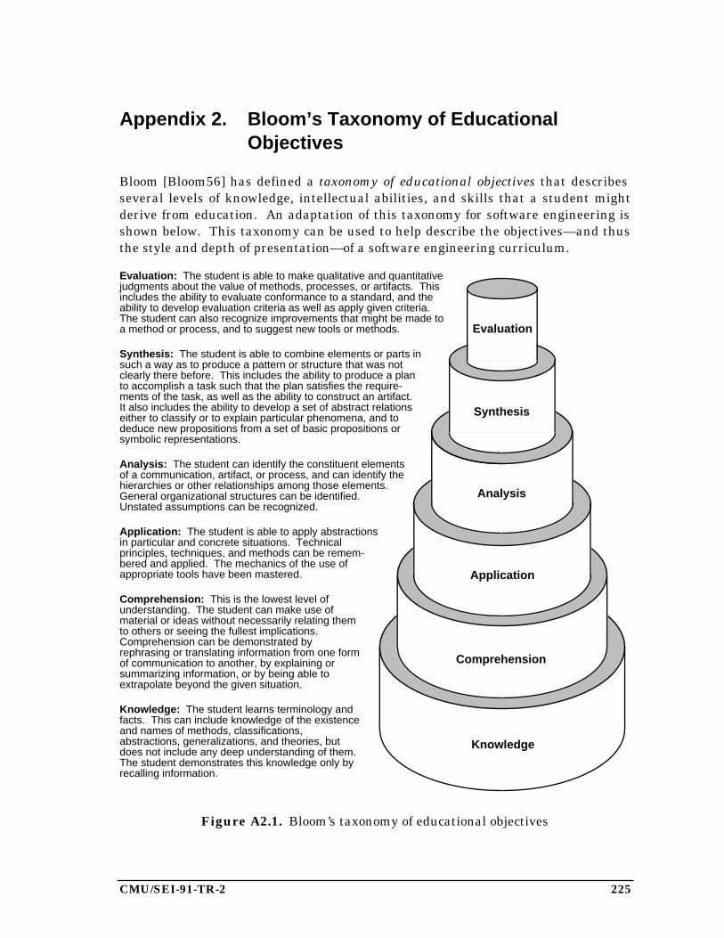
CMU/SEI-91-TR-2 225
Appendix 2. Bloom’s Taxonomy of EducationalObjectives
Bloom [Bloom56] has defined a taxonomy of educational objectives that describesseveral levels of knowledge, intellectual abilities, and skills that a student mightderive from education. An adaptation of this taxonomy for software engineering isshown below. This taxonomy can be used to help describe the objectives—and thusthe style and depth of presentation—of a software engineering curriculum.
Evaluation: The student is able to make qualitative and quantitativejudgments about the value of methods, processes, or artifacts. Thisincludes the ability to evaluate conformance to a standard, and theability to develop evaluation criteria as well as apply given criteria.The student can also recognize improvements that might be made toa method or process, and to suggest new tools or methods.
Synthesis: The student is able to combine elements or parts insuch a way as to produce a pattern or structure that was notclearly there before. This includes the ability to produce a planto accomplish a task such that the plan satisfies the require-ments of the task, as well as the ability to construct an artifact.It also includes the ability to develop a set of abstract relationseither to classify or to explain particular phenomena, and todeduce new propositions from a set of basic propositions orsymbolic representations.
Analysis: The student can identify the constituent elementsof a communication, artifact, or process, and can identify thehierarchies or other relationships among those elements.General organizational structures can be identified.Unstated assumptions can be recognized.
Application: The student is able to apply abstractionsin particular and concrete situations. Technicalprinciples, techniques, and methods can be remem-bered and applied. The mechanics of the use ofappropriate tools have been mastered.
Comprehension: This is the lowest level ofunderstanding. The student can make use ofmaterial or ideas without necessarily relating themto others or seeing the fullest implications.Comprehension can be demonstrated byrephrasing or translating information from one formof communication to another, by explaining orsummarizing information, or by being able toextrapolate beyond the given situation.
Knowledge: The student learns terminology andfacts. This can include knowledge of the existenceand names of methods, classifications,abstractions, generalizations, and theories, butdoes not include any deep understanding of them.The student demonstrates this knowledge only byrecalling information.
Knowledge
Comprehension
Application
Analysis
Synthesis
Evaluation
Figure A2.1. Bloom’s taxonomy of educational objectives

226 CMU/SEI-91-TR-2
CMU/SEI-91-TR-2 227
Appendix 3. SEI Curriculum Modules and OtherPublications
The SEI Education Program has produced a variety of educational materials to sup-port software engineering education. Those documents in the list below that haveDTIC numbers (of the form ADA000000) are available from the Defense TechnicalInformation Center (DTIC) and the National Technical Information Service (NTIS).Other documents (excluding conference proceedings) are available from the SEI;please send written requests, accompanied by a mailing label, to the SoftwareEngineering Institute, Carnegie Mellon University, Pittsburgh, PA 15213, Attn.:Publications Requests.
SEI Curriculum Modules and Support Materials
A curriculum module documents and explicates a body of knowledge within a rela-tively small and focused topic area of software engineering. Its major componentsare a detailed, annotated outline of the topic area, an annotated bibliography of theimportant literature in the area, and suggestions for teaching the material. Amodule is intended to be used primarily by an instructor in designing and teachingpart or all of a course.
A support materials package includes a variety of materials helpful in teaching acourse, such as examples, exercises, or project ideas. Contributions from softwareengineering educators are solicited.
The currently available modules and support materials packages are listed below.†
For each module, a capsule description, which is similar to a college catalog descrip-tion or the abstract of a technical paper, is included.
Introduction to Software Design
David Budgen,University of Stirling
SEI-CM-2-2.1
This curriculum module provides an introduction to the principlesand concepts relevant to the design of large programs and systems.It examines the role and context of the design activity as a form ofproblem-solving process, describes how this is supported by currentdesign methods, and considers the strategies, strengths, limita-tions, and main domains of application of these methods.
†CM-1, CM-15, and CM-18 do not appear in this list. CM-1 has been superseded by CM-19, CM-15 isstill under development, and CM-18 has been superseded by CM-23.
228 CMU/SEI-91-TR-2
The Software Technical Review Process
James Collofello,Arizona State University
SEI-CM-3-1.5
This curriculum module consists of a comprehensive examination ofthe technical review process in the software development and main-tenance life cycle. Formal review methodologies are analyzed indetail from the perspective of the review participants, project man-agement and software quality assurance. Sample review agendasare also presented for common types of reviews. The objective ofthe module is to provide the student with the information necessaryto plan and execute highly efficient and cost effective technicalreviews.
Support Materials for The Software Technical Review Process
Edited by John Cross,Indiana University ofPennsylvania
SEI-SM-3-1.0
This support materials package includes materials helpful in teach-ing a course on the software technical review process.
Software Configuration Management
James E. Tomayko,The Wichita StateUniversity
SEI-CM-4-1.3
Software configuration management encompasses the disciplinesand techniques of initiating, evaluating, and controlling change tosoftware products during and after the development process. Itemphasizes the importance of configuration control in managingsoftware production.
Support Materials for Software Configuration Management
Edited by James E.Tomayko, The WichitaState University
SEI-SM-4-1.0
This support materials package includes materials helpful in teach-ing a course on configuration management.
Information Protection
Fred Cohen,University of Cincinnati
SEI-CM-5-1.2
This curriculum module is a broad based introduction to informa-tion protection techniques. Topics include the history and presentstate of cryptography, operating system protection, network protec-tion, data base protection, physical security techniques, cost benefittradeoffs, social issues, and current research trends. The successfulstudent in this course will be prepared for an in-depth course in anyof these topics.
CMU/SEI-91-TR-2 229
Software Safety
Nancy Leveson,University of California,Irvine
SEI-CM-6-1.1
Software safety involves ensuring that software will execute withina system context without resulting in unacceptable risk. Buildingsafety-critical software requires special procedures to be used in allphases of the software development process. This module intro-duces the problems involved in building such software along withthe procedures that can be used to enhance the safety of the result-ing software product.
Assurance of Software Quality
Brad Brown,Boeing Military Airplanes
SEI-CM-7-1.1
This module presents the underlying philosophy and associatedprinciples and practices related to the assurance of software qual-ity. It includes a description of the assurance activities associatedwith the phases of the software development life-cycle (e.g.,requirements, design, test, etc.).
Formal Specification of Software
Alfs Berztiss,University of Pittsburgh
SEI-CM-8-1.0
This module introduces methods for the formal specification of pro-grams and large software systems, and reviews the domains ofapplication of these methods. Its emphasis is on the functionalproperties of software. It does not deal with the specification ofprogramming languages, the specification of user-computer inter-faces, or the verification of programs. Neither does it attempt tocover the specification of distributed systems.
Support Materials for Formal Specification of Software
Edited by Alfs Berztiss,University of Pittsburgh
SEI-SM-8-1.0
This support materials package includes materials helpful in teach-ing a course on formal specification of software.
Unit Testing and Analysis
Larry Morell,College of William andMary
SEI-CM-9-1.2
This module examines the techniques, assessment, and manage-ment of unit testing and analysis. Testing and analysis strategiesare categorized according to whether their coverage goal is func-tional, structural, error-oriented, or a combination of these.Mastery of the material in this module allows the software engineerto define, conduct, and evaluate unit tests and analyses and toassess new techniques proposed in the literature.
230 CMU/SEI-91-TR-2
Models of Software Evolution: Life Cycle and Process
Walt Scacchi,University of SouthernCalifornia
SEI-CM-10-1.0
This module presents an introduction to models of software systemevolution and their role in structuring software development. Itincludes a review of traditional software life-cycle models as well assoftware process models that have been recently proposed. It iden-tifies three kinds of alternative models of software evolution thatfocus attention to either the products, production processes, or pro-duction settings as the major source of influence. It examines howdifferent software engineering tools and techniques can supportlife-cycle or process approaches. It also identifies techniques forevaluating the practical utility of a given model of software evolu-tion for development projects in different kinds of organizationalsettings.
Software Specification: A Framework
Dieter Rombach,University of Maryland
SEI-CM-11-2.1
This module provides a framework for specifying software processesand products. The specification of a software product type describeshow the corresponding products should look. The specification of asoftware process type describes how the corresponding processesshould be performed.
Software Metrics
Everald Mills,Seattle University
SEI-CM-12-1.1
Effective management of any process requires quantification,measurement, and modeling. Software metrics provide a quantita-tive basis for the development and validation of models of thesoftware development process. Metrics can be used to improvesoftware productivity and quality. This module introduces the mostcommonly used software metrics and reviews their use in construct-ing models of the software development process. Although currentmetrics and models are certainly inadequate, a number of organiza-tions are achieving promising results through their use. Resultsshould improve further as we gain additional experience withvarious metrics and models.
Introduction to Software Verification and Validation
James Collofello,Arizona State University
SEI-CM-13-1.1
Software verification and validation techniques are introduced andtheir applicability discussed. Approaches to integrating thesetechniques into comprehensive verification and validation plans arealso addressed. This curriculum module provides an overviewneeded to understand in-depth curriculum modules in the verifica-tion and validation area.
CMU/SEI-91-TR-2 231
Intellectual Property Protection for Software
Pamela Samuelson andKevin Deasy,University of PittsburghSchool of Law
SEI-CM-14-2.1
This module provides an overview of the U.S. intellectual propertylaws that form the framework within which legal rights in softwareare created, allocated, and enforced. The primary forms of intellec-tual property protection that are likely to apply to software arecopyright, patent, and trade secret laws, which are discussed withparticular emphasis on the controversial issues arising in theirapplication to software. A brief introduction is also provided togovernment software acquisition regulations, trademark, tradedress, and related unfair competition issues that may affect soft-ware engineering decisions, and to the Semiconductor ChipProtection Act.
Software Development Using VDM
Jan Storbank Pedersen,Dansk Datamatik Center
SEI-CM-16-1.1
This module introduces the Vienna Development Method (VDM)approach to software development. The method is oriented towarda formal model view of the software to be developed. The emphasisof the module is on formal specification and systematic developmentof programs using VDM. A major part of the module deals with theparticular specification language (and abstraction mechanisms)used in VDM.
User Interface Development
Gary Perlman,Ohio State University
SEI-CM-17-1.1
This module covers the issues, information sources, and methodsused in the design, implementation, and evaluation of user inter-faces, the parts of software systems designed to interact withpeople. User interface design draws on the experiences of designers,current trends in input/output technology, cognitive psychology,human factors (ergonomics) research, guidelines and standards,and on the feedback from evaluating working systems. User inter-face implementation applies modern software development tech-niques to building user interfaces. User interface evaluation can bebased on empirical evaluation of working systems or on the predic-tive evaluation of system design specifications.
Support Materials for User Interface Development
Edited by Gary Perlman,Ohio State University
SEI-SM-17-1.0
This support materials package includes materials helpful in teach-ing a course on user interface development.
Software Requirements
John Brackett,Boston University
SEI-CM-19-1.2
This curriculum module is concerned with the definition of softwarerequirements—the software engineering process of determiningwhat is to be produced—and the products generated in that defini-tion. The process involves: (1) requirements identification, (2) re-quirements analysis, (3) requirements representation, (4) require-ments communication, and (5) development of acceptance criteriaand procedures. The outcome of requirements definition is aprecursor of software design.
232 CMU/SEI-91-TR-2
Formal Verification of Programs
Alfs Berztiss,University of Pittsburgh;Mark Ardis, SEI
SEI-CM-20-1.0
This module introduces formal verification of programs. It dealsprimarily with proofs of sequential programs, but also with consis-tency proofs for data types and deduction of particular behaviors ofprograms from their specifications. Two approaches are consid-ered: verification after implementation that a program is consis-tent with its specification, and parallel development of a programand its specification. An assessment of formal verification isprovided.
Software Project Management
James E. Tomayko,The Wichita StateUniversity;Harvey K. Hallman, SEI
SEI-CM-21-1.0
Software project management encompasses the knowledge, tech-niques, and tools necessary to manage the development of softwareproducts. This curriculum module discusses material that man-agers need to create a plan for software development, using effec-tive estimation of size and effort, and to execute that plan withattention to productivity and quality. Within this context, topicssuch as risk management, alternative life-cycle models, develop-ment team organization, and management of technical people arealso discussed.
Design Methods for Real-Time Systems
Hassan Gomaa,George Mason University
SEI-CM-22-1.0
This module describes the concepts and methods used in thesoftware design of real-time systems. It outlines the characteristicsof real-time systems, describes the role of software design in real-time system development, surveys and compares some softwaredesign methods for real-time systems, and outlines techniques forthe verification and validation of real-time designs. For each designmethod treated, its emphasis, concepts on which it is based, stepsused in its application, and an assessment of the method areprovided.
Technical Writing for Software Engineers
Linda Levine, Linda HutzPesante, Susan Dunkle,Carnegie MellonUniversity
SEI-CM-23
ADA223872
This module, which is directed specifically to software engineers,discusses the writing process in the context of software engineering.Its focus is on the basic problem-solving activities that underlieeffective writing, many of which are similar to those underlyingsoftware development. The module draws on related work in anumber of disciplines, including rhetorical theory, discourse analy-sis, linguistics, and document design. It suggests techniques forbecoming an effective writer and offers criteria for evaluatingwriting.
Concepts of Concurrent Programming
David Bustard,University of Ulster
SEI-CM-24
ADA223897
A concurrent program is one defining actions that may beperformed simultaneously. This module discusses the nature ofsuch programs and provides an overview of the means by whichthey may be constructed and executed. Emphasis is given to theterminology used in this field and the underlying concepts involved.

CMU/SEI-91-TR-2 233
Language and System Support for Concurrent Programming
Michael B. Feldman,George WashingtonUniversity
SEI-CM-25
ADA223760
This curriculum module is concerned with support for concurrentprogramming provided to the application programmer by operatingsystems and programming languages. This includes system callsand language constructs for process creation, termination, synchro-nization, and communication, as well as nondeterministic languageconstructs such as the selective wait and timed call. Several readilyavailable languages are discussed and compared; concurrentprogramming using system services of the UNIX operating systemis introduced for the sake of comparison and contrast.
Support Materials for Language and System Support for ConcurrentProgramming
Edited by Gary Ford, SEI
SEI-SM-25
ADA223760
This package contains examples of concurrent programs written inAda, Concurrent C, Co-Pascal, occam, and Modula-2. Machine-readable source code for the programs is available.
Understanding Program Dependencies
Norman Wilde,University of West Florida
SEI-CM-26
A key to program understanding is unravelling the interrelation-ships of program components. This module discusses the differentmethods and tools that aid a programmer in answering the ques-tions: “How does this system fit together?” and “If I change thiscomponent, what other components might be affected?”
234 CMU/SEI-91-TR-2
Selected SEI Educational Support Materials
Teaching a Project-Intensive Introduction to Software Engineering
James E. Tomayko
CMU/SEI-87-TR-20
ADA200603
This report is meant as a guide to the teacher of the introductorycourse in software engineering. It contains a case study of a coursebased on a large project. Other models of course organization arealso discussed. Appendices A-Z of this report contain materials usedin teaching the course and the complete set of student-producedproject documentation. These are available for $55.00 ($20.00 forthe first copy sent to an Academic Affiliate institution).
Software Maintenance Exercises for a Software Engineering Project Course
Charles B. Engle, Jr.,Gary Ford, Tim Korson
CMU/SEI-89-EM-1
This report provides an operational software system of 10,000 linesof Ada and several exercises based on that system. Concepts suchas configuration management, regression testing, code reviews, andstepwise abstraction can be taught with these exercises. Diskettescontaining code and documentation may be ordered for $10.00.(Please request either IBM PC or Macintosh disk format.)
The APSE Interactive Monitor: An Artifact for Software Engineering Education
Charles B. Engle, Jr.,Gary Ford, James E.Tomayko
CMU/SEI-89-EM-2
In 1987 the SEI began a search for a well-documented Ada system,developed under government contract, that could be used in soft-ware engineering education. The APSE Interactive Monitor (AIM)was determined to be appropriate for this purpose. This systemacts as an interface between a user of an Ada programming supportenvironment (APSE) and the programs that the user executes inthe APSE. It provides facilities to support the concurrent executionof multiple interactive programs, each of which has access to avirtual terminal. Educational uses of the system are described,including use as a case study and as the basis for exercises.Software engineering topics that can be taught with the systeminclude software maintenance, configuration management, softwaredocumentation, cost estimation, and object-oriented design.
Program Reading: Instructor’s Guide and Exercises
Lionel Deimel,Fernando Naveda
CMU/SEI-90-EM-3
ADA228026
The ability to read and understand a computer program is a criticalskill for the software developer, yet this skill is seldom developed inany systematic way in the education or training of software profes-sionals. These materials discuss the importance of programreading, and review what is known about reading strategies andother factors affecting comprehension. These materials also includereading exercises for a modest Ada program and discuss how educa-tors can structure additional exercises to enhance program readingskills.
CMU/SEI-91-TR-2 235
Conference Proceedings
The conference and workshop records below are available directly from Springer-Verlag. Prices are indicated. Please send orders directly to the publisher: BookOrder Fulfillment, Springer-Verlag New York, Inc., Service Center Secaucus, 44Hartz Way, Secaucus, NJ 07094. Please specify the ISBN number when ordering.
Software Engineering Education: The Educational Needs of the SoftwareCommunity
Norman E. Gibbs andRichard E. Fairley, editors
ISBN 0-387-96469-X
This volume contains the extended proceedings of the 1986Software Engineering Education Workshop, held at the SEI andsponsored by the SEI and the Wang Institute of Graduate Studies.This workshop of invited software engineering educators focused onmaster’s level education in software engineering, with some discus-sion of undergraduate and doctoral level issues. Hardback, $32.00.
Issues in Software Engineering Education: Proceedings of the 1987 SEIConference
Richard Fairley andPeter Freeman, editors
ISBN 3-540-96840-7
Proceedings of the 1987 SEI Conference on Software EngineeringEducation, held in Monroeville, Pa. Hardback, $45.00.
Software Engineering Education: SEI Conference 1988
Gary Ford, editor
ISBN 3-540-96854-7
Proceedings of the 1988 SEI Conference on Software EngineeringEducation, held in Fairfax, Va. (Lecture Notes in Computer ScienceNo. 327.) Paperback, $20.60.
Software Engineering Education: SEI Conference 1989
Norman E. Gibbs, editor
ISBN 3-540-97090-8
Proceedings of the 1989 SEI Conference on Software EngineeringEducation, held in Pittsburgh, Pa. (Lecture Notes in ComputerScience No. 376.) Paperback.
Software Engineering Education: SEI Conference 1990
Lionel E. Deimel, editor
ISBN 3-540-97274-9
Proceedings of the 1990 SEI Conference on Software EngineeringEducation, held in Pittsburgh, Pa. (Lecture Notes in ComputerScience No. 423.) Paperback.

236 CMU/SEI-91-TR-2
CMU/SEI-91-TR-2 237
Appendix 4. History and Acknowledgements
SEI curriculum development efforts began in the fall of 1985, when the staff of theSEI Graduate Curriculum Project developed a strawman description of the impor-tant subject areas and possible courses for a professional Master of SoftwareEngineering (MSE) degree. This document was reviewed by the participants at theFebruary 1986 SEI Software Engineering Education Workshop [Gibbs87], whooffered numerous suggestions for improvement.
We then wrote a revised version of the document, which was widely circulated foradditional comments. Those comments were analyzed over the winter of 1986-87,and in May 1987 the SEI published Software Engineering Education: An InterimReport from the Software Engineering Institute [Ford87]. This report was our firstpublication of curriculum recommendations, and it addressed not only curriculumcontent but also the related curriculum issues of educational objectives, prerequi-sites, student project work, electives, and resources needed to support the curricu-lum.
The interim report came to be regarded as a specification for an MSE curriculumbecause it concentrated on the content of the curriculum rather than how thatcontent might be organized into courses or how those courses might be taught. Weexpected future work to include curriculum design (the organization of that contentinto meaningful courses), implementation (the detailed description of each course byinstructors of the course), and execution , the process of teaching each course. (Wehave not yet planned a validation effort, though we see the need to do so.)
Two events in 1987 made it clear that a curriculum design was needed immediately.First, the SEI established a new project, the Video Dissemination Project, whichwould work with cooperating universities to offer graduate-level software engineer-ing courses on videotape. Second, Carnegie Mellon University made a commitmentto establish an MSE program within its School of Computer Science. Both of theseefforts needed a curriculum, including detailed designs for courses.
In February 1988, the SEI sponsored the Curriculum Design Workshop, whose goalwas to design an MSE curriculum that was consistent with the specification in theinterim report. The workshop produced designs for six core courses. Those courseswere described in our 1989 curriculum report [Ardis89].
The staff of the SEI Video Dissemination Project implemented and taught those sixcourses during the period 1988-1990. Those implementations are described inChapter 3 of this report.
The curriculum recommendations in this report have benefitted from the efforts ofmany people. We had valuable discussions with many members of the SEI technicalstaff, including Mario Barbacci, Dan Berry, Barbara Callahan, Maribeth Carpenter,Clyde Chittister, Lionel Deimel, Larry Druffel, Peter Feiler, Robert Firth, Priscilla

238 CMU/SEI-91-TR-2
Fowler, Dick Martin, Nancy Mead, John Nestor, Joe Newcomer, Mary Shaw, NelsonWeiderman, Chuck Weinstock, and Bill Wood, and with visiting staff members BobAiken, Alfs Berztiss, John Brackett, Brad Brown, David Budgen, Fred Cohen, JimCollofello, Chuck Engle, Bob Glass, Paul Jorgensen, Nancy Leveson, Ev Mills, LarryMorell, Dieter Rombach, Rich Sincovec, Joe Turner, and Peggy Wright. We alsoacknowledge ideas from Harlan Mills and John Musa.
Earlier versions of the MSE recommendations were written by Jim Collofello andJim Tomayko, and reviewed by Evans Adams, David Barnard, Dan Burton, PhilD’Angelo, David Gries, Ralph Johnson, David Lamb, Manny Lehman, John Manley,John McAlpin, Richard Nance, Roger Pressman, Dieter Rombach, George Rowland,Viswa Santhanam, Walt Scacchi, Roger Smeaton, Joe Touch, and K. C. Wong.
An early version of the MSE curriculum was the subject of discussion at theSoftware Engineering Education Workshop, which was held at the SEI in February1986 [Gibbs87]. In addition to several of the people mentioned above, the followingparticipants at the workshop contributed ideas to the current curriculum recom-mendations: Bruce Barnes, Victor Basili, Jon Bentley, Gordon Bradley, FredBrooks, James Comer, Dick Fairley, Peter Freeman, Susan Gerhart, NicoHabermann, Bill McKeeman, Al Pietrasanta, Bill Richardson, Bill Riddle, WalterSeward, Ed Smith, Dick Thayer, David Wortman, and Bill Wulf.
The six MSE core courses were developed by Mark Ardis, Jim Collofello, LionelDeimel, Dick Fairley, Gary Ford, Norm Gibbs, Bob Glass, Harvey Hallman, TomKraly, Jeff Lasky, Larry Morell, Tom Piatkowski, Scott Stevens, and Jim Tomayko.
The courses in the SEI Academic Series were developed by Mark Ardis, Dan Berry,Robert Firth, Harvey Hallman, and Jim Tomayko.
CMU/SEI-91-TR-2 239
Bibliography
Amoroso88 Amoroso, Serafino, Kuntz, Richard, Wheeler, Thomas, and Graff,Bud. “Revised Graduate Software Engineering Curriculum atMonmouth College.” Software Engineering Education: SEIConference 1988, Ford, Gary A., ed. New York: Springer-Verlag,1988, 70-80.
Ardis89 Ardis, Mark, and Ford, Gary. 1989 SEI Report on GraduateSoftware Engineering Education. Tech. Rep. CMU/SEI-89-TR-21,ADA219018, Software Engineering Institute, Carnegie MellonUniversity, Pittsburgh, Pa., June 1989.
Bloom56 Bloom, B. Taxonomy of Educational Objectives: Handbook I:Cognitive Domain. New York: David McKay, 1956.
Brackett88 Brackett, John, Kincaid, Thomas, and Vidale, Richard. “TheSoftware Engineering Graduate Program at the Boston UniversityCollege of Engineering.” Software Engineering Education: SEIConference 1988, Ford, Gary A., ed. New York: Springer-Verlag,1988, 56-63.
Budgen86 Budgen, David, Henderson, Peter, and Rattray, Chic.“Academic/Industrial Collaboration in a Postgraduate MSc Coursein Software Engineering.” Software Engineering Education: TheEducational Needs of the Software Community, Gibbs, Norman E.,and Fairley, Richard E., eds. New York: Springer-Verlag, 1986,201-211.
Collofello82 Collofello, James S. “A Project-Unified Software EngineeringCourse Sequence.” Proc. Thirteenth SIGCSE TechnicalSymposium on Computer Science Education. New York: ACM,Feb. 1982, 13-19.
Comer86 Comer, James R., and Rodjak, David J. “Adapting to ChangingNeeds: A New Perspective on Software Engineering Education atTexas Christian University.” Software Engineering Education:The Educational Needs of the Software Community, Gibbs,Norman E., and Fairley, Richard E., eds. New York: Springer-Verlag, 1986, 149-171.
Engle89 Engle, Charles B., Jr., Ford, Gary, and Korson, Tim. SoftwareMaintenance Exercises for a Software Engineering Project Course.Educational Materials CMU/SEI-89-EM-1, Software EngineeringInstitute, Carnegie Mellon University, Pittsburgh, Pa., Feb. 1989.Includes distribution diskettes for software.
Ford87 Ford, Gary, Gibbs, Norman, and Tomayko, James. SoftwareEngineering Education: An Interim Report from the SoftwareEngineering Institute. Tech. Rep. CMU/SEI-87-TR-8, ADA182003,Software Engineering Institute, Carnegie Mellon University,Pittsburgh, Pa., May 1987.

240 CMU/SEI-91-TR-2
Gibbs87 Software Engineering Education: The Educational Needs of theSoftware Community. Gibbs, Norman E., and Fairley, Richard E.,eds. New York: Springer-Verlag, 1987.
Horning76 Horning, J. J. “The Software Project as a Serious Game.”Software Engineering Education: Needs and Objectives:Proceedings of an Interface Workshop, Wasserman, Anthony, andFreeman, Peter, eds. New York: Springer-Verlag, 1976, 71-75.
IEEE83 IEEE Standard Glossary of Software Engineering Terminology.ANSI/IEEE Std 729-1983, IEEE, New York, 1983.
Lehman86 Lehman, Manny M. “The Software Engineering UndergraduateDegree at Imperial College, London.” Software EngineeringEducation: The Educational Needs of the Software Community,Gibbs, Norman E., and Fairley, Richard E., eds. New York:Springer-Verlag, 1986, 172-181.
Mills86 Mills, Everald. “The Master of Software Engineering [MSE]Program At Seattle University After Six Years.” SoftwareEngineering Education: The Educational Needs of the SoftwareCommunity , Gibbs, Norman E., and Fairley, Richard E., eds. NewYork: Springer-Verlag, 1986, 182-200.
Musa90 Musa, John D., Iannino, Anthony, and Okumoto, Kazuhira.Software Reliability: Measurement, Prediction, Application . NewYork: McGraw-Hill, 1990.
Norman88 Norman, Donald A. The Psychology of Everyday Things. NewYork: Basic Books, Inc. Publishers, 1988.
NRC85 National Research Council, Commission on Engineering andTechnical Systems. Engineering Education and Practice in theUnited States: Foundations of Our Techno-Economic Future.Washington, D.C.: National Academy Press, 1985.
Scacchi86 Scacchi, Walter. “The Software Engineering Environment for theSystem Factory Project.” Proc. Nineteenth Hawaii Intl. Conf.Systems Sciences. 1986, 822-831.
Wang86 Bulletin, School of Information Technology 1986-1987 . WangInstitute of Graduate Studies, July 1986.
Webster83 Webster’s Ninth New Collegiate Dictionary. Springfield, Mass.:Merriam-Webster Inc., 1983.
Wortman86 Wortman, David B. “Software Projects in an AcademicEnvironment.” Software Engineering Education: The EducationalNeeds of the Software Community, Gibbs, Norman E., and Fairley,Richard E., eds. New York: Springer-Verlag, 1986, 292-305.
Copyright © 2022 FDOKUMEN