Secure Authentication Schemes for Internet of Things (IoT) by ...
117
Secure Authentication Schemes for Internet of Things (IoT) by Moneer Ramadan Fakroon B.Sc., Faculty of Engineering/Misurata University, Libya, 2009 M.Sc., Nottingham Trent University, UK, 2012 M.Eng., Victoria University, Canada, 2018 A Dissertation Submitted in Partial Fulfillment of the Requirements for The Degree of DOCTOR OF PHILOSOPHY in the Department of Electrical and Computer Engineering c Moneer Fakroon, 2020 University of Victoria All rights reserved. This dissertation may not be reproduced in whole or in part, by photocopying or other means, without the permission of the author.
-
Upload
khangminh22 -
Category
Documents
-
view
3 -
download
0
Transcript of Secure Authentication Schemes for Internet of Things (IoT) by ...

Secure Authentication Schemes for Internet of Things (IoT)
by
Moneer Ramadan Fakroon
B.Sc., Faculty of Engineering/Misurata University, Libya, 2009
M.Sc., Nottingham Trent University, UK, 2012
M.Eng., Victoria University, Canada, 2018
A Dissertation Submitted in Partial Fulfillment of the Requirements for
The Degree of
DOCTOR OF PHILOSOPHY
in the Department of Electrical and Computer Engineering
c© Moneer Fakroon, 2020
University of Victoria
All rights reserved. This dissertation may not be reproduced in whole or in part, by
photocopying or other means, without the permission of the author.

ii
Secure Authentication Schemes for Internet of Things (IoT)
by
Moneer Ramadan Fakroon
B.Sc., Faculty of Engineering/Misurata University, Libya, 2009
M.Sc., Nottingham Trent University, UK, 2012
M.Eng., Victoria University, Canada, 2018
Supervisory Committee
Dr. Fayez Gebali, Supervisor
(Department of Electrical and Computer Engineering, University of Victoria)
Dr. T. Ilamparithi, Departmental Member
(Department of Electrical and Computer Engineering, University of Victoria)
Dr. Alex Thomo, Outside Member
(Department of Computer Science, University of Victoria)

iii
Supervisory Committee
Dr. Fayez Gebali, Supervisor
(Department of Electrical and Computer Engineering, University of Victoria)
Dr. T. Ilamparithi, Departmental Member
(Department of Electrical and Computer Engineering, University of Victoria)
Dr. Alex Thomo, Outside Member
(Department of Computer Science, University of Victoria)
Abstract
Smart home technology is an emerging application of Internet-of-Things (IoT)
where the user can remotely control home devices. Since the user/home communica-
tion channel is insecure, an efficient and anonymous authentication scheme is required
to provide secure communications in smart home environment. In this work, we pro-
pose a new scheme for user authentication that combines physical context awareness
and transaction history. The new scheme offers two advantages: it does not main-
tain a verification table and avoids clock synchronization problem. Communication
overhead and computational cost of the proposed scheme are analyzed and compared
with other related schemes. The security of the scheme is evaluated using three dif-
ferent methods: (1) formal analysis using the Burrows-Abadi-Needham logic (BAN);
(2) informal analysis; (3) model check using the automated validation of internet
security protocols and applications (AVISPA) tool. Also, we aim to propose a new
anonymous device to device mutual authentication and key exchange scheme. such
scheme enables IoT devices to authenticate in the network and agree on a shared
secret session key when communicating with each other via a trusted intermediary
(home gateway).
iv
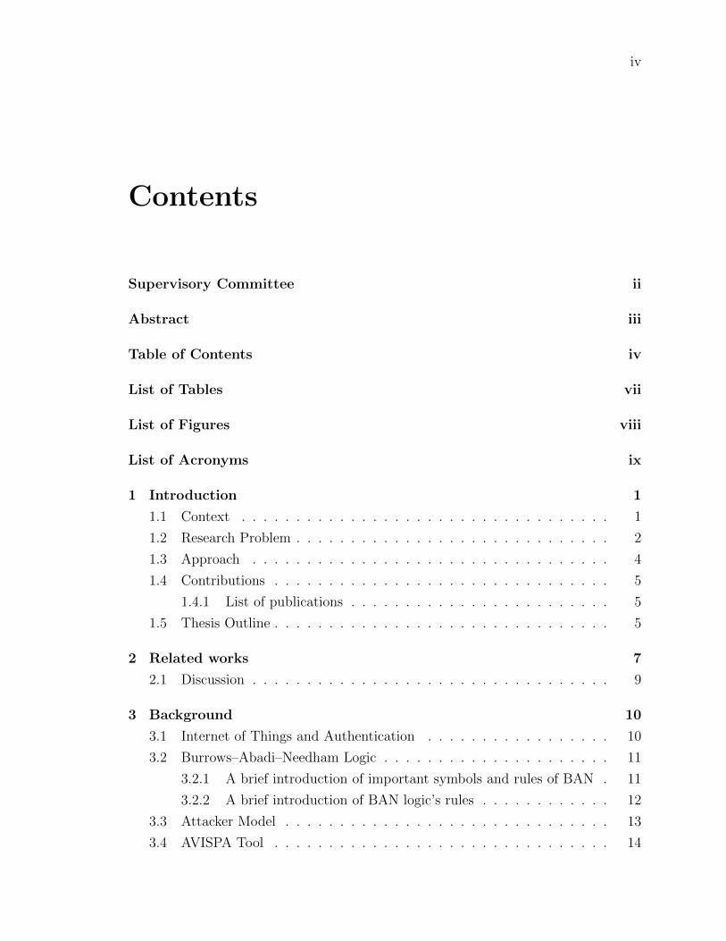
Contents
Supervisory Committee ii
Abstract iii
Table of Contents iv
List of Tables vii
List of Figures viii
List of Acronyms ix
1 Introduction 1
1.1 Context . . . . . . . . . . . . . . . . . . . . . . . . . . . . . . . . . . 1
1.2 Research Problem . . . . . . . . . . . . . . . . . . . . . . . . . . . . . 2
1.3 Approach . . . . . . . . . . . . . . . . . . . . . . . . . . . . . . . . . 4
1.4 Contributions . . . . . . . . . . . . . . . . . . . . . . . . . . . . . . . 5
1.4.1 List of publications . . . . . . . . . . . . . . . . . . . . . . . . 5
1.5 Thesis Outline . . . . . . . . . . . . . . . . . . . . . . . . . . . . . . . 5
2 Related works 7
2.1 Discussion . . . . . . . . . . . . . . . . . . . . . . . . . . . . . . . . . 9
3 Background 10
3.1 Internet of Things and Authentication . . . . . . . . . . . . . . . . . 10
3.2 Burrows–Abadi–Needham Logic . . . . . . . . . . . . . . . . . . . . . 11
3.2.1 A brief introduction of important symbols and rules of BAN . 11
3.2.2 A brief introduction of BAN logic’s rules . . . . . . . . . . . . 12
3.3 Attacker Model . . . . . . . . . . . . . . . . . . . . . . . . . . . . . . 13
3.4 AVISPA Tool . . . . . . . . . . . . . . . . . . . . . . . . . . . . . . . 14

v
3.5 Summary . . . . . . . . . . . . . . . . . . . . . . . . . . . . . . . . . 15
4 Secure remote anonymous user authentication scheme for smart
home environment 16
4.1 The proposed scheme . . . . . . . . . . . . . . . . . . . . . . . . . . . 16
4.1.1 Pre-deployment phase . . . . . . . . . . . . . . . . . . . . . . 17
4.1.2 Registration phase . . . . . . . . . . . . . . . . . . . . . . . . 19
4.1.3 Login phase . . . . . . . . . . . . . . . . . . . . . . . . . . . . 20
4.1.4 Authentication phase . . . . . . . . . . . . . . . . . . . . . . . 20
4.1.5 Password update phase . . . . . . . . . . . . . . . . . . . . . . 26
4.2 Security analysis of the proposed scheme . . . . . . . . . . . . . . . . 26
4.2.1 Formal proof based on BAN logic . . . . . . . . . . . . . . . . 26
4.2.2 Simulation based on AVISPA tool . . . . . . . . . . . . . . . . 37
4.2.3 Informal security analysis . . . . . . . . . . . . . . . . . . . . 42
4.2.4 Replay attack . . . . . . . . . . . . . . . . . . . . . . . . . . . 42
4.2.5 Eavesdropping attack . . . . . . . . . . . . . . . . . . . . . . . 42
4.2.6 Smart-phone device loss attack . . . . . . . . . . . . . . . . . 42
4.2.7 Impersonation attack . . . . . . . . . . . . . . . . . . . . . . . 42
4.2.8 Man-in-the-middle attack . . . . . . . . . . . . . . . . . . . . 43
4.2.9 Forward/backward secrecy . . . . . . . . . . . . . . . . . . . . 43
4.2.10 User credentials attack . . . . . . . . . . . . . . . . . . . . . . 43
4.2.11 Session key Guessing Attack . . . . . . . . . . . . . . . . . . . 43
4.2.12 User anonymity and untraceability . . . . . . . . . . . . . . . 44
4.2.13 Location-based authentication . . . . . . . . . . . . . . . . . . 44
4.2.14 User authentication based on transaction history information . 44
4.3 Performance comparison . . . . . . . . . . . . . . . . . . . . . . . . . 45
4.3.1 Storage cost . . . . . . . . . . . . . . . . . . . . . . . . . . . . 45
4.3.2 Communication overheads . . . . . . . . . . . . . . . . . . . . 45
4.3.3 Computational cost . . . . . . . . . . . . . . . . . . . . . . . . 46
4.4 Conclusion . . . . . . . . . . . . . . . . . . . . . . . . . . . . . . . . . 50
5 Multifactor authentication scheme using physically unclonable func-
tions 51
5.1 Notation & Terms Used . . . . . . . . . . . . . . . . . . . . . . . . . 51
5.2 Preliminaries . . . . . . . . . . . . . . . . . . . . . . . . . . . . . . . 51

vi
5.2.1 Silicon Physically Unclonable Function (PUF) . . . . . . . . . 53
5.2.2 Threat Model . . . . . . . . . . . . . . . . . . . . . . . . . . . 56
5.2.3 Network Model . . . . . . . . . . . . . . . . . . . . . . . . . . 57
5.2.4 Client Model . . . . . . . . . . . . . . . . . . . . . . . . . . . 58
5.2.5 Server Model . . . . . . . . . . . . . . . . . . . . . . . . . . . 58
5.2.6 Mobile Device Model . . . . . . . . . . . . . . . . . . . . . . . 60
5.2.7 Edge Device Model . . . . . . . . . . . . . . . . . . . . . . . . 60
5.2.8 Gateway Model . . . . . . . . . . . . . . . . . . . . . . . . . . 63
5.3 The Proposed Scheme . . . . . . . . . . . . . . . . . . . . . . . . . . 64
5.3.1 Predeployment Phase . . . . . . . . . . . . . . . . . . . . . . . 64
5.3.2 Registration phase . . . . . . . . . . . . . . . . . . . . . . . . 65
5.3.3 Login Phase . . . . . . . . . . . . . . . . . . . . . . . . . . . . 68
5.3.4 Authentication Phase . . . . . . . . . . . . . . . . . . . . . . . 69
5.3.5 Pasword Update Phase . . . . . . . . . . . . . . . . . . . . . . 74
5.4 Security Analysis of the Proposed Scheme . . . . . . . . . . . . . . . 74
5.4.1 Formal Proof Based on BAN Logic . . . . . . . . . . . . . . . 75
5.4.2 Informal Security Analysis . . . . . . . . . . . . . . . . . . . . 87
5.4.3 Simulation Based on AVISPA Tool . . . . . . . . . . . . . . . 89
5.4.4 Performance Comparison . . . . . . . . . . . . . . . . . . . . . 92
5.5 Conclusion . . . . . . . . . . . . . . . . . . . . . . . . . . . . . . . . . 94
6 Conclusion and Future Work 97
6.1 Conclusion . . . . . . . . . . . . . . . . . . . . . . . . . . . . . . . . . 97
6.2 Future Work . . . . . . . . . . . . . . . . . . . . . . . . . . . . . . . . 98
Bibliography 99

vii
List of Tables
Table 3.1 Notations in BAN logic. . . . . . . . . . . . . . . . . . . . . . . 12
Table 4.1 Notations used in our protocol. . . . . . . . . . . . . . . . . . . 18
Table 4.2 Notations in BAN logic. . . . . . . . . . . . . . . . . . . . . . . 27
Table 4.3 The communication overheads of our scheme. . . . . . . . . . . . 45
Table 4.4 Comparison of communication cost between the proposed scheme
and other most related schemes. . . . . . . . . . . . . . . . . . . 47
Table 4.5 Crypto-operations and the computational times needed . . . . . 47
Table 4.6 Comparison of computation cost between the proposed scheme
and other most related schemes in ms. . . . . . . . . . . . . . . 48
Table 4.7 Security and functionality features comparison. . . . . . . . . . . 49
Table 5.1 Notations Used in the Proposed Protocol . . . . . . . . . . . . 52
Table 5.2 Notations in BAN logic. . . . . . . . . . . . . . . . . . . . . . . 75
Table 5.3 Crypto-operations and the computational times needed. . . . . . 94
Table 5.4 Comparison of computation cost between the proposed scheme
and other most related schemes in ms. . . . . . . . . . . . . . . 95
Table 5.5 Security and functionality features comparison. . . . . . . . . . . 95

viii
List of Figures
Figure 4.1 high-level architecture of smart home environment . . . . . . . 17
Figure 4.2 Registration phase of the proposed scheme . . . . . . . . . . . . 19
Figure 4.3 Authentication phase of the proposed scheme . . . . . . . . . . 21
Figure 4.4 Authentication based on location . . . . . . . . . . . . . . . . . 23
Figure 4.5 The role played by the user Ui . . . . . . . . . . . . . . . . . . 36
Figure 4.6 The role played by the registration authority RA . . . . . . . . 36
Figure 4.7 The role played by the gateway GWN . . . . . . . . . . . . . . 38
Figure 4.8 The role played by the smart device SD . . . . . . . . . . . . . 38
Figure 4.9 Role session and environment . . . . . . . . . . . . . . . . . . . 39
Figure 4.10Result based on model checker OFMC . . . . . . . . . . . . . . 39
Figure 4.11Result based on model checker OFMC . . . . . . . . . . . . . . 40
Figure 5.1 Basic structure for the client-side IoT for telehealth system. . . 58
Figure 5.2 Basic structure for the server-side IoT for telehealth system. . 59
Figure 5.3 Basic structure of the fuzzy extractor at the server and client. 61
Figure 5.4 Basic structure of the fuzzy extractor at the server and client. 62
Figure 5.5 Registration phase for the the gateway, mobile devices and edge
devices using the server. . . . . . . . . . . . . . . . . . . . . . 65
Figure 5.6 Authentication phase of the proposed scheme. . . . . . . . . . 69
Figure 5.7 Role of S in HLPSL code. . . . . . . . . . . . . . . . . . . . . 90
Figure 5.8 Role of M in HLPSL code. . . . . . . . . . . . . . . . . . . . . 90
Figure 5.9 Role of G in HLPSL code. . . . . . . . . . . . . . . . . . . . . 91
Figure 5.10Role of D in HLPSL code. . . . . . . . . . . . . . . . . . . . . 91
Figure 5.11The protocol execution using SPAN. . . . . . . . . . . . . . . . 92
Figure 5.12Analysis of results using CL-AtSe. . . . . . . . . . . . . . . . . 93
Figure 5.13Analysis of results using OFMC. . . . . . . . . . . . . . . . . . 93

ix
List of Acronyms
AES Advanced Encryption Standard
AVISPA Automated Validation of Internet Security Protocols
and Applications
BAN Burrows–Abadi–Needham
CLAtSe Constraint-Logic-based Attack Searcher
ECC Elliptic Curve Cryptography
HLPSL High-Level Protocol Specification Language
ID Identification
IF Intermediate Format
IoT Internet of Things
OFMC On-the-fly Model-Checker
SATMC SAT-based Model-Checker
SPAN Security Protocol Animator
TA4SP Tree Automata based on Automatic Approximations for
the Analysis of Security Protocols
XOR Exclusive OR

1
Chapter 1
Introduction
1.1 Context
The term Internet of Things (IoT) was first coined by Kevin Ashton in 1999 in the
context of supply chain management [1]. The most recent IoT platforms were designed
based on a diverse mixture of readapting existing components, solutions, protocols,
and platforms for different purposes in terms of their development and enhancement.
IoT devices are often resource-constrained and deployed in unmonitored, physi-
cally unsecured environments. However, although there is an urgent need to secure
IoT infrastructures, this necessity is confronted with the aforementioned resource
limitations of the infrastructure underlying platforms and devices.
One of the essential aspects of securing an IoT infrastructure is the device identity
and the mechanisms to authenticate it. Authentication is one of the Achilles’ heels
of the current IoT infrastructure.
As a matter of fact, many IoT devices have weak passwords or are still using
manufacturer-issued default passwords, which make them vulnerable to botnets (e.g.,
the Mirai IoT botnet) [2] and exploit kits specially designed to target IoT networks.
At the same time, hackers can connect rogue devices to IoT networks using fake or
multiple identities without being caught.
The enactment of the above threats is made possible because the landscape of
IoT authentication is still in its infancy [3]. Furthermore, existing authentication
mechanisms involve heavy computations that cannot be afforded by IoT devices,
which, as mentioned earlier, are resource-constrained. Additionally, these authenti-
cation mechanisms also require a degree of user intervention in terms of configuration

2
and provisioning. Furthermore, many IoT devices have limited access, thus requiring
the initial configuration to be protected from tampering, theft and other forms of
compromise throughout the device’s usable life, which, in many cases, could be years.
1.2 Research Problem
Despite the growing interest in IoT products and services and the advancements in
its underlying technology, IoT devices and networks are exposed to a wide variety
of security threats, some of which are well-known and part of the existing attack
arsenal against conventional systems, while others involve novel attack vectors that
are specific to the IoT technology and remain unknown until they are detected in the
network [4], [5], [6] and [7].
One of the principal aspects in making an IoT infrastructure secure is the underly-
ing IoT node authentication mechanism. The resource-constrained IoT nodes cannot
afford the current authentication mechanisms due to the complex computations in-
volved in these mechanisms [8, 9]. Moreover, the existing authentication mechanisms
involve a high level of user intervention in configuring and controlling the devices.
Unlike conventional network devices, IoT nodes, which are usually deployed in
unmonitored and unsecured environments, have limited access; hence, their initial
configurations need to be protected against any kinds of external or insider threats or
compromises during the lifetime of the IoT node. Additionally, due to the fact that
most IoT devices are weak and resource constrained, the cryptographic techniques
used can easily be exploited and broken. Hence, compromising one node could lead
to the compromise of the entire IoT network.
Moreover, authentication necessitates identification through a unique identifier.
As time goes by, attackers can trace transactions linked to the same identity, thus
leading to privacy breach.
In an IoT domain such as smart home, transaction’s traceability may result in
tracing the lifestyle of the household or deducing from the data, sensitive informa-
tion, such as health and credit history, living arrangements, and so on [10]. Hence,
anonymity, unlinkability, and untraceability [11, 12, 13] are important key properties
when designing and operating authentication mechanisms for IoT networks, as these
prevent an adversary from obtaining the real identity of an IoT end device and from
linking any given session to any other session of the same device.
Consequently, there is a necessity to introduce new mechanisms to authenticate

3
and control IoT nodes in a secure way that must be compatible with the environmental
and engineering limitations underlying the IoT ecosystem. In this work, we present
different protocols to authenticate IoT nodes while addressing security and privacy,
and performance considerations.
The Internet of Things (IoT) defines an ecosystem where each thing can be any
physical or virtual object, identified and reached by other objects and showing smart
capabilities. Such smart things are characterized by embedded electronic components
that allow them to sense, compute, communicate and integrate seamlessly with the
rest of the network. It has been forecast, based on Moore’s law, that by 2025 the
number of IoT devices will exceed 7 trillion, distributed with an average of 1000
devices per person.
IoT devices are often resource-constrained, and deployed in unmonitored, physi-
cally unsecured environments. As such there is an urgent need to secure IoT infras-
tructure.
One of the fundamental elements in securing an IoT infrastructure is around de-
vice identity and mechanisms to authenticate it. However, existing authentication
mechanisms involve heavy computations which cannot be afforded by IoT devices,
which as mentioned earlier are resource-constrained. Many IoT devices do not have
the required compute power, memory or storage to support the current authenti-
cation protocols, which rely on computationally intensive cryptographic algorithms,
e.g., AES and RSA [14] and [15]. Additionally, these authentication mechanisms also
require a degree of user-intervention in terms of configuration and provisioning. How-
ever, many IoT devices will have limited access, thus requiring initial configuration
to be protected from tampering, theft and other forms of compromise throughout its
usable life, which in many cases could be years.
Recently, large swathe of the Internet was brought down in a distributed denial of
service (DDoS) attack carried out using the Mirai IoT botnet. Mirai propagates by
brute-forcing IoT device passwords via Telnet in a way that is much faster and less
resource-intensive than traditional botnet.
Hence, relying on only on password-based solutions is not a viable option, as
passwords can easily be broken, and many IoT devices do not provide an interface
through which password authentication can take place.

4
1.3 Approach
To address the aforementioned security challenges, we propose a new secure mutual
authentication and key exchange scheme for the IoT based on transient or dynamic
identities. The dynamic identity of IoT nodes (DIdoT) is a new concept for uniquely
identifying IoT nodes.
The DIdoT is constructed from fixed and variable components, and evolving time-
dependent component. The fixed component is created from fixed parameters of the
IoT node, which is the node ID. The variable component is created from a random
number generator.
The time-dependent component is created from the time stamp. These different
components are hashed together using SHA-3 as a hashing algorithm, which provides
a tunable parameter allowing a tradeoff between security and performance. The
real identity is kept secret and never transmitted by the IoT node. This guarantees
uniqueness of identities of the IoT nodes and mitigates the possibilities of identities
theft attacks such as impersonation and sybil attacks. Another new concept is tem-
poral keys (TKs) that change every session. The TKs are constructed from fixed and
variable components. The fixed component is created from a fixed parameter of the
IoT node, which is the node ID. The variable component is created from a random
number generator. These two different components are hashed together using SHA-3,
and as aforementioned, the hashing algorithm provides a tradeoff between security
and performance. This continuously variable nature of the identity significantly limits
the impact of brute-force attacks by limiting the session key lifetime.
According to a survey carried out by CA Technologies on the state of insider
threat in 2018 [16], 90% of surveyed organizations felt that they were vulnerable to
insider attacks and 53% of organizations pointed out that they have been the target
of insider attacks during the year.
Although most organizations focus on how to defend against external attacks,
they sometimes put considerably less efforts into defending against internal attackers
or rather ignore them. As the IoT devices are ubiquitous and unattended, internal
attackers will play a big role in cyber security threats and may cause serious issues.
Moreover, due to the fact that most IoT devices are weak and resource-constrained,
the cryptography techniques can easily be exploited and broken. Hence, compromis-
ing one node could make it easy to take control of the other IoT devices. By securing
IoT identities, we can maintain the CIA triad: confidentiality, integrity, and availabil-

5
ity. If an attacker succeeds in impersonating an identity on an IoT node, all security
measures, such as authentication and access protection, make no sense.
1.4 Contributions
In this thesis, we make two key contributions as follows:
1. Propose a new scheme for user authentication that combines physical context
awareness and transaction history.
2. Propose a secure telehealth system using multifactor authentication for the
mobile devices as well as the IoT edge devices in the system
1.4.1 List of publications
1. M. Fakroon, M. Alshahrani, F. Gebali, and I. Traor‘e, “Secure remote anony-
mous user authentication scheme for smart home environment,” Internet Things,
vol. 9, pp. 100–158, 2020.
2. M. Fakroon, F. Gebali, and M. Mamun, “Multifactor authentication scheme
using physically unclonable functions,” Internet of Things, p. 100343, 2020.
1.5 Thesis Outline
The remainder of this thesis is organized as follows.
Chapter 2 provides an overview of the literature underlying this research. It
provides a quick introduction to the Internet of Things and authentication. Also, this
chapter provides an outline of the related security methods and tools used in this
research.
Chapter 3 summarizes and discusses related work on authentication.
Chapter 4 describes our first proposed authentication scheme and introduces the
enforcement of the security policy. The proposed scheme achieves different security
properties, anonymity, unlinkability, and conditional traceability.
Chapter 5 presents the second proposed authentication scheme. The scheme
achieves different security properties, anonymity, unlinkability, and conditional trace-
ability, in addition to the important dual properties of confidentiality and integrity.

6
Chapter 6 concludes the thesis by discussing the contributions of the research
and outlining future work.

7
Chapter 2
Related works
In this section, we summarize and discuss related work on user authentication scheme
for smart home environment.
Jeong et al. [17] proposed a user authentication scheme based on one-time pass-
word (OTP) protocol. This scheme is lightweight because it uses one-way hash func-
tions. However, the mutual authentication between Gateway node (GWN) and the
smart device is not provided. Moreover, the anonymity and traceability properties
are not achieved as the real identity of the user is sent in plain-text. In addition, the
scheme is not immune from stolen smart card and privileged–insider attack.
Roman et al. [18] attempted to solve IoT security via different IoT topologies:
centralized architectures [19] and distributed architectures. Again, these solutions
does not consider the available resources in IoT devices and only emphasize high
level structures of these topologies.
Other research concentrates on the protected communication between IoT devices.
For instance, Mahalle et al. [20] proposed an Identity Authentication and Capability
based Access Control (IACAC) model to secure communication between IoT devices
and protect from replay, man-in-the-middle and denial of service (DoS) attacks.
Vaidya et al. [21] proposed one-time password authentication scheme for home
network environment. This scheme is also lightweight as it uses only hash-chaining
methods and hashed one-time password. Kim et al. [22] studied Vaidya et al.’s
scheme and indicated that it does not provide user anonymity and forward secrecy.
Furthermore, it is vulnerable to password guessing attack. An enhanced authentica-
tion scheme is proposed subsequently where they improved the weakness observed in
Vaidya et al.’s scheme [21]. However, Kim et al.’s scheme also suffered from guess-
ing attack, user impersonation attack and privileged-insider attack. Moreover, the

8
anonymity and traceability properties were not achieved.
Santoso et al. [23] proposed a user authentication scheme for a smart home system
based on elliptic curve cryptography (ECC). Similar to the schemes in [17, 21, 22],
the anonymity and traceability properties were not provided. In addition, the scheme
is not immune against privileged-insider attack and stolen smart card attack.
Kumar et al. [24] proposed a lightweight and secure session key establishment
scheme for smart home environments. Using a short authentication token, a session
key was established between GWN and smart device.
Wazid et al. [25] proposed a new secure remote user authentication scheme for
a smart home environment. The scheme only utilizes the one way hash function
and XOR operation as result it is efficient for resource-constrained smart devices.
However, this scheme uses a verification table saved in the GWN’s database which if
it was stolen by the attacker, then the result is disastrous. In addition, the proposed
scheme suffered from synchronization attack as it uses time stamp to resist replay
attack.
Shuai et al. [26] proposed a remote authentication scheme for smart home envi-
ronment using ECC. The scheme did not require to store the verification table for
authentication purposes. However, the scheme suffers from unsatisfactory perfor-
mance in terms of computational and communication costs.
Chen et al. [27, 28] proposed a new scheme for patient’s privacy based on the cloud
computing. Mobile device characteristics were used to allow people to use medical
resources on the cloud environment. The scheme did not support patient anonymity
or message authentication.
Chiou et al. [29] improved on the scheme proposed by Chen et al. [27] to reduce
computation costs while achieving patient anonymity and unlinkability, and message
authentication.
Mohit et al. [30] proposed a mutual authentication protocol for cloud computing
based telehealth system. However Li et al. [31] found design flaws in the proposed
protocol in that it did not provide security against health report revelation, inspection
report forgery and patient anonymity and unlinkability.
Yu and Li [32] proposed an anonymous authentication key agreement scheme
for multi-sensor home-based IoT. The proposed scheme used lightweight authentica-
tion and key agreement technology using pairing-based cryptography. A lightweight
scheme was used due to the limited communication and processing capabilities of the
edge devices.

9
The authors in [33] focused on reviewing data security using blockchain in the IoT
for telehealth. These authors summarized possible IoT attacks in general as physical
attacks, network attacks, software attacks and encryption attacks. The authors argue
that telehealth is at the top of digital technologies that are at risk from cyber attacks.
The authors stated that medical data is attacked where it is stored or when it is being
transferred from one location to another.
Islam et al. [34] provided a survey of IoT for telehealth including proposed archi-
tectures for efficient telehealth delivery. Telehealth implies delivery of telehealth to
stay-at-home patients through the internet cloud and remotely-located IoT networks.
2.1 Discussion
It appears from the above summary that most of the works on authentication proto-
cols are dependent on symmetric and asymmetric algorithms, and it is known that
asymmetric encryption requires much more computation than what the constrained
resource devices in IoT can afford. However, a number of research studies have intro-
duced the potential of using lightweight cryptographic functions such as hash function
and bitwise XOR, but they did not consider strong mutual authentication; thus an
efficient mutual authentication framework remains a challenge for the IoT ecosystem
[35], [36] and [37].

10
Chapter 3
Background
In this chapter, we provide background information on the Internet of Things and
authentication. Furthermore, we give an overview of the validation and evaluation
methods and tools used in our work.
3.1 Internet of Things and Authentication
The Internet of Things (IoT) is one of the most recent emerging and advanced comput-
ing paradigms set forth in the 21st century, which connects both living and non-living
things with non-living things into ecosystems. The IoT refers to everyday objects that
can sense the environment around them and communicate that data to other objects
and services via the Internet without any intervention from human or living bodies.
The IoT integrates several existing technologies, such as wireless sensor networks
(WSN), which appeared since the 1980s. WSN technology is an essential component of
IoT because it is composed of a collection of sensor nodes connected wirelessly to one
another, which provide digital interfaces to the real-world things [38]. However, WSN
is different from IoT in a number of respects. One of the important differences is that
WSN is comprised of a large number of connected sensors’ nodes that are capable of
performing sensing and data collection while IoT system consists of a large number of
interconnected objects, things, sensors, devices, etc., which are able to provide value-
added services such as location and analytic via utilizing intelligent data processing
and management for several applications. Another important difference is that in
the IoT infrastructure, it is required to provide the nodes with Internet connectivity,
whereas, Internet connectivity is not required in WSN.

11
Furthermore, many IoT devices do not have the required compute power, memory,
or storage to support the current authentication protocols, which rely on computa-
tionally intensive cryptographic algorithms, e.g., AES and RSA [39].
Authentication requires identification by means of a unique identifier, and over
time transactions associated with the same identity can be traceable, leading to pri-
vacy breach. In an IoT environment such as smart home, transactions traceability
can be used to track the lifestyle of the household or infer from the data, critical
information such as health and credit history, living arrangements and patterns, and
so on [40].
Anonymity and unlinkability are privacy-preserving mechanisms, which make user
transactions traceability much harder. Although a number of authentication schemes
have been proposed for IoT, to our knowledge, none of these contributions has con-
sidered full anonymity of the IoT sensor nodes during the authentication or access
control processes.
3.2 Burrows–Abadi–Needham Logic
Burrows et al. [41] introduced the Burrows–Abadi–Needham (BAN) logic, which is
used to describe and analyze the authentication protocols. The BAN logic has widely
been used for the formal verification of security protocols and to provide the proof of
correctness of any authentication protocol [42]. Hence, we capitalize on the widely-
accepted BAN logic to prove that our authentication scheme provides secure mutual
authentication between an IoT node N and the controller CRN. In this subsection,
we present a summarized introduction about the essential symbols and rules of BAN
logic.
3.2.1 A brief introduction of important symbols and rules of
BAN
The most important symbols and notations adapted from [41] which are given in
Table 4.2.

12
Table 3.1: Notations in BAN logic.
Notation Descriptions
P and Q PrincipalsP | ≡ X Principal P believes the state-
ment XP / X Principal P sees the statement XP | ⇒ X Principal P has jurisdiction over
the statement XP | ∼ X Principal P once said statement
X(X, Y ) The statement X or Y is one part
of message (X, Y)< X >Y The statement X is encrypted
with the key K(X)K The statement X is hashed with
the key K
PK←→ Q K is a secret parameter shared (or
to be shared) between P and Q
PK� Q X is a secret known only to P and
Q, and possibly to parties trustedby them.
# (X) The message X is fresh.
3.2.2 A brief introduction of BAN logic’s rules
The following commonly used BAN logic rules are utilized to prove that the authen-
tication scheme ensures secure mutual authentication and key agreement:
• Message-meaning rule:
If P believes that the key K is shared with Q and P sees X encrypted under K,
then P believes that Q once said X.
P | ≡ QK←→P, P / 〈X〉KP | ≡ Q| ∼ X
• Nonce verification rule:
If P believes X is fresh and P believes Q once said X, then P believes Q believes

13
X.
P | ≡ #(X), P | ≡ Q| ∼ X
P | ≡ Q| ≡ X
• Jurisdiction rule:
If P believes Q has jurisdiction over X and P believes Q believes X, then P
believes X.
P | ≡ Q| =⇒ X,P | ≡ Q| ≡ X
P | ≡ X
• Freshness conjuncatenation rule:
If one part of a statement is fresh, then the entire statement must also be fresh;
so if P believes X is fresh, then P believes X and Y are fresh.
P | ≡ #(X)
P | ≡ #(X, Y )
• Belief rule:
If P believes X and Y, then P believes X .
P | ≡ (X, Y )
P | ≡ X
• Session keys rule:
P | ≡ #(X), P | ≡ Q| ≡ X
P | ≡ P K←→Q
3.3 Attacker Model
A better understanding of threats helps us make better decisions about where to
deploy defensive techniques. Dolev–Yao’s threat model [13] is employed to anticipate
any security issues in our IoT network model. The attacker model is based on the
following two assumptions:
• Cryptography is secure:
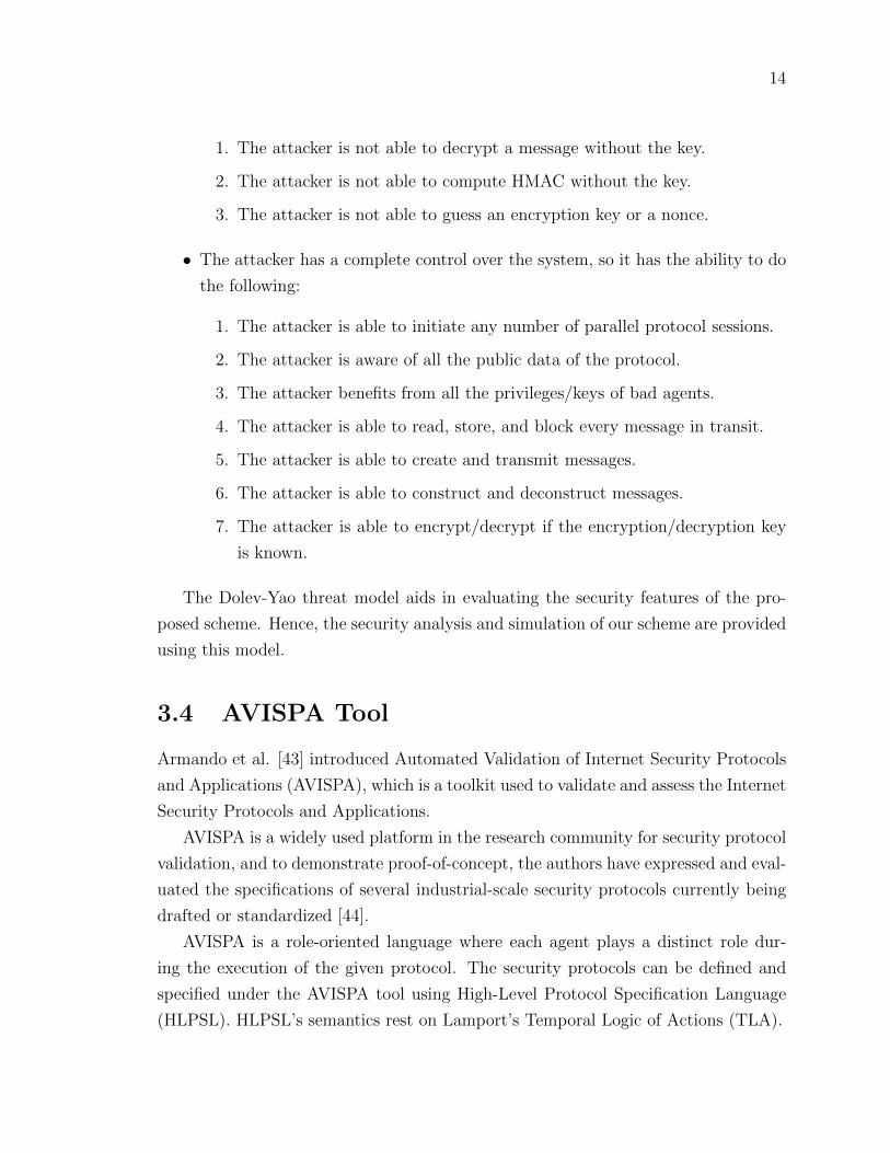
14
1. The attacker is not able to decrypt a message without the key.
2. The attacker is not able to compute HMAC without the key.
3. The attacker is not able to guess an encryption key or a nonce.
• The attacker has a complete control over the system, so it has the ability to do
the following:
1. The attacker is able to initiate any number of parallel protocol sessions.
2. The attacker is aware of all the public data of the protocol.
3. The attacker benefits from all the privileges/keys of bad agents.
4. The attacker is able to read, store, and block every message in transit.
5. The attacker is able to create and transmit messages.
6. The attacker is able to construct and deconstruct messages.
7. The attacker is able to encrypt/decrypt if the encryption/decryption key
is known.
The Dolev-Yao threat model aids in evaluating the security features of the pro-
posed scheme. Hence, the security analysis and simulation of our scheme are provided
using this model.
3.4 AVISPA Tool
Armando et al. [43] introduced Automated Validation of Internet Security Protocols
and Applications (AVISPA), which is a toolkit used to validate and assess the Internet
Security Protocols and Applications.
AVISPA is a widely used platform in the research community for security protocol
validation, and to demonstrate proof-of-concept, the authors have expressed and eval-
uated the specifications of several industrial-scale security protocols currently being
drafted or standardized [44].
AVISPA is a role-oriented language where each agent plays a distinct role dur-
ing the execution of the given protocol. The security protocols can be defined and
specified under the AVISPA tool using High-Level Protocol Specification Language
(HLPSL). HLPSL’s semantics rest on Lamport’s Temporal Logic of Actions (TLA).

15
The main goal of HLPSL is to provide a means for verifying security properties
such as data secrecy and authentication in message exchanges between agents. HLPSL
provides a separate section to define the security properties, named the goal section.
Thus, the security protocol is determined, whether SAFE or not based on predefined
goals.
HLPSL specifications are automatically translated into a lower language named
the Intermediate Format (IF) using the HLPSL2IF translator. The main goal of these
translations and designing the IF language is to offer and serve an adequate input to
the various back-ends of the AVISPA tool set.
AVISPA has the following four back-end tools:
• OFMC Model Checker: The On-the-Fly Model-Checker (OFMC) incorporates
several symbolic techniques and algebraic properties to explore the state space
in a demand-driven way.
• CL-AtSe Model Checker: The Constraint-Logic-based Attack Searcher (CL-
AtSe) translates any security protocol specification written as a transition rela-
tion in IF language into a set of constraints that are effectively used to discover
attacks if any on the protocol.
• SATMC Model Checker: SAT-based Model checker (SATMC) constructs a
propositional formula based on Transitional state obtained from the IF spec-
ification. The propositional formula represents any violation of the security
properties, which can be translated into an attack.
• TA4SP Model Checker: The Tree Automata based on Automatic Approxima-
tions for the Analysis of Security Protocols (TA4SP) identifies the vulnerability
of a protocol or predicts the protocol correctness by accurate estimation of the
intruder’s capabilities.
3.5 Summary
This chapter provided a brief overview of the concepts, paradigms, and tools used in
our work. The next chapter focuses on the main theme of this thesis by surveying
and discussing related work.

16
Chapter 4
Secure remote anonymous user
authentication scheme for smart
home environment
This chapter introduces secure remote anonymous user authentication scheme for
smart home environment.
4.1 The proposed scheme
In this section, we discuss our proposed secure remote anonymous user authentication
scheme. The proposed scheme uses context-awareness and transaction history to
achieve the desirable security features. A typical high-level architecture of smart
home environment is illustrated in Fig. 4.1 adapted from [24, 25, 26].
There are four types of participants: User devices, Home devices (smart devices),
gateway and registration authority. Every smart device, and GWN is securely regis-
tered offline at the registration authority (RA). At that point the user who needs to
access the smart device requires to register at the registration authority by offering
his/her necessary information.
Each user has a mobile device (MDi) capable of reading the credentials supplied
by that user, such as identity, password and biometrics (fingerprint scanning, etc.).
The gateway is responsible for managing the communication between the home

17
Figure 4.1: high-level architecture of smart home environment
devices and user devices. The authentication request of the authorized user is sent
to the GWN and then the GWN sends the request to target smart device. The
smart device sends corresponding reply to the GWN and then the GWN forwards the
response to the user. Our scheme has five phases:
1. Pre-deployment phase
2. Registration phase
3. Login phase
4. Authentication phase
5. Password update phase
For convenience, the notations mentioned in the proposed scheme presented in
the Table 4.1.
4.1.1 Pre-deployment phase
The pre-deployment phase takes place at the manufacturer’s site before the devices
are deployed. The mobile devices will be loaded with unique symmetric key Kur
shared between the registration authority and each mobile device. The smart devices
also will be loaded with unique symmetric key Ksr shared between the registration
authority and each smart device. Lastly, the gateway will be loaded with unique
symmetric key Kgr shared between the registration authority and gateway.

18
Table 4.1: Notations used in our protocol.
Notation Descriptions
Ui Mobile User
IDUi Identity of user
PWi Password of users
TIDUi Temporary identity of user
MDi Mobile device of ith user
GWN Gateway node
GID Unique identity of GWN
SDj Smart device in the home
SIDj Unique identity of SDj
RA Registration authority
Kur Symmetric key shared betweenthe registration authority andeach mobile device
LP , LC The previous and current loca-tion, respectively
Xn The history of all user locations
HMAC keyed-hash message authentica-tion code
N1, N2, N3 Current nonces generated by Ui,GWN and SDj, respectively
SK Session key
M1||M2 Concatenate operation
(X) K Message X encrypted with K
h(·) One-way hash function
⊕ XOR operation

19
4.1.2 Registration phase
Each smart device in the smart home and the gateway have to be register with the
RA. Moreover, each user needs to access a smart devices SDj has to register with the
RA. The registration phase consists of two parts.
Figure 4.2: Registration phase of the proposed scheme
Smart device and gateway registration step:
This step is done offline. Assuming in the smart home environment, there are jth
smart devices (SDj) and one gateway. The RA selects unique identity for the gateway
GID and each smart device SIDj.
User registration step:
Assume that there are ith users Ui. Each user selects the identity IDUi and a generates
password PWi, the user then needs to supply his/her identity and password to the
MDi, which then encrypts the IDUi and PWi using the symmetric key Kur and send
them to RA.
Ui → RA : (IDUi||PWi) KRA (4.1)
Upon receiving the IDUi and PWi, RA will look them up in its database. If they
exist, this indicates that the user is trying to update his/her credentials, the RA will
then ask the user to re-submit the identity and password again.
The identity and password update phase are explained in Section 4.1.5. Otherwise,
the RA generates a temporary identity for the user TIDUi and computes the following

20
parameters:
V1 = h(IDUi||PWi) (4.2)
V2 = h(GID||IDUi ⊕ PWi) (4.3)
V3 = h(GID⊕ IDUi||PWi) (4.4)
RA sends back TIDUi and V1 to the user, TIDUi and V3 to the smart device and
TID, V2 and V3 to the gateway as shown in Fig. 4.2.
When MDi receives the TIDUi and V1, it will generate variable Counter and set
it to 0. Finally, the user, gateway and smart device store the received parameters in
their databases.
4.1.3 Login phase
The user inputs his/her identity IDUi and password PWi into the mobile device,
which compute V ∗1 , and check if V ∗1 6= V1 then the mobile device terminates the
login request, increments the counter and check if it reaches predetermined value for
instance 3, this mean the mobile device is breached, then the mobile device terminates
the login request immediately until the user re-registers again. Otherwise, the user is
authenticated and can access the application on his/her mobile device.
4.1.4 Authentication phase
Referring to Fig. 4.3, the mobile device generates a nonce N1, then computes the
dynamic identity.
DIDUi = TIDUi ⊕ N1 (4.5)
The DIDUi will be unique in each session. Hence, the anonymity and untraceability
proprieties are achieved. Next, the user chooses target smart device, defined by its
identity SIDj.
The mobile device extracts its current location LC and performs the following
iterative hashing operation preformed at session n
Xn = h(Xn−1||LC), n > 0 (4.6)
X0 = 0 (4.7)
where Xn represents the hash of cumulative locations or the hashed history of all user

21
Figure 4.3: Authentication phase of the proposed scheme
locations at session n. Next, the mobile device computes V2 using Eq. (4.3). Using
V2, the MDi computes UG.
UG = (SIDj||N1||LC ||Xn)⊕ V2 (4.8)
Next, the MDi computes HUG:
HUG = h(SIDj||N1||LC ||Xn) (4.9)
The mobile sends the following message to the gateway through the public channel:
Ui → GWN : (DIDUi||UG||HUG) (4.10)
22
Upon receiving the message, the gateway will compute
(SIDj||N1||LC ||Xn) using the stored value V2:
(SIDj||N1||LC ||Xn) = UG⊕ V2 (4.11)
GWN now has the values of SIDj, N1, LC and Xn. Using those values and from Eq.
(4.9) the GWN computes HUG∗ and check if HUG∗ = HUG, then the integrity is
verified. Otherwise, the GWN will terminate the session with the user because the
message is modified before it reaches to GWN.
GWN then checks the freshness of received nonce N1. This will prevent the replay
attack.
Using N1, GWN computes TIDUi:
TIDUi = DIDUi ⊕ N1 (4.12)
GWN checks TIDUi and compares it with the stored value in its database. If TIDUi
does not match the stored value, GWN terminates the session with the user.
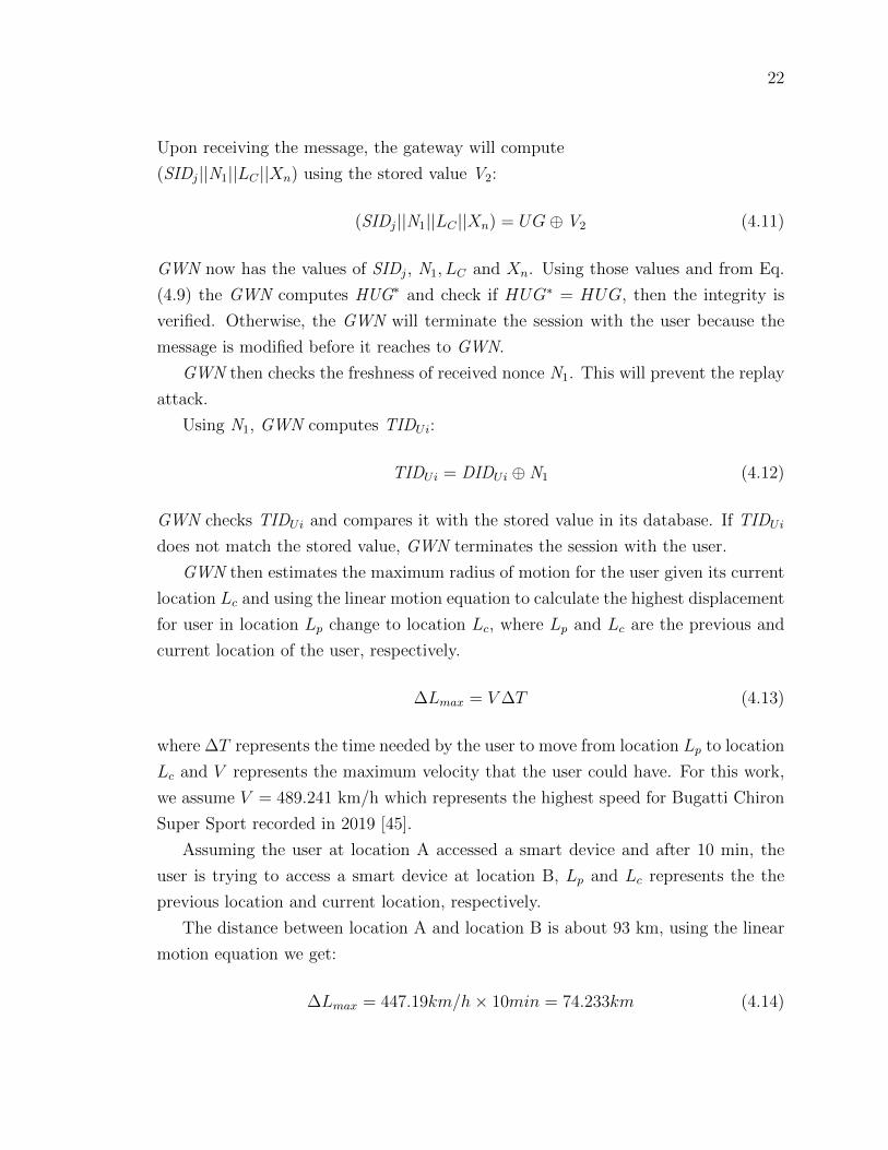
GWN then estimates the maximum radius of motion for the user given its current
location Lc and using the linear motion equation to calculate the highest displacement
for user in location Lp change to location Lc, where Lp and Lc are the previous and
current location of the user, respectively.
∆Lmax = V∆T (4.13)
where ∆T represents the time needed by the user to move from location Lp to location
Lc and V represents the maximum velocity that the user could have. For this work,
we assume V = 489.241 km/h which represents the highest speed for Bugatti Chiron
Super Sport recorded in 2019 [45].
Assuming the user at location A accessed a smart device and after 10 min, the
user is trying to access a smart device at location B, Lp and Lc represents the the
previous location and current location, respectively.
The distance between location A and location B is about 93 km, using the linear
motion equation we get:
∆Lmax = 447.19km/h× 10min = 74.233km (4.14)

23
Figure 4.4: Authentication based on location
Fig. 4.4, we consider the previous location at the center. The maximum radius
will be ∆Lmax, whereas the next authentication attempt is at 93 km from the previous
location. This is going to be flagged as malicious access because the user cannot be
93 km away from the previous location in 10 min. However, if current location is less
than maximum radius, the authentication attempt will be legitimate. Increasing the
value of V reduces the false alarm rate. If the gateway checks that the location is
within the expected range, it still needs to verify the consistency of the cumulative
hash history of all previous locations. This can be done by computing X∗n from Eq.
(4.6) and comparing it to the received Xn. If the two values match, this confirms that
the user has consistent locations with GWN and the user is authenticated by GWN.
Next, the gateway starts to prepare the message that will be sent to the smart
device. It will first generate a nonce N2 and forms the GS and HGS:
GS = (N1||N2)⊕ V3 (4.15)
HGS = h(N1||N2) (4.16)

24
Finally, the gateway sends the message to the smart device SDj:
GWN→ SDj : (GS||HGS) (4.17)
Once the smart device SDj receives the message, it computes the following:
(N1||N2) = GS ⊕ V3 (4.18)
First, SDj verifies the GID and TIDUi. Next, SDj checks the freshness of N1 and N2.
Next, to verify the integrity of the message, SDj computes HGS using Eq. (4.16) and
compare it with the received HGS, if it does not matches, the smart device terminates
the session with the gateway because the smart device might communicates with rogue
device as gateway. Otherwise, the smart device generates a nonce N3 and computes
the shared key as follows:
SK = h(N1||N2||N3) (4.19)
The smart device starts to prepare the reply to the gateway. First, it will compute
SG and HSG:
SG = (SIDj||N3)⊕ V3 (4.20)
HSG = h(N3||SK) (4.21)
Lastly, the smart device sends the following message to the gateway:
SIDj → GWN : (SG||HSG) (4.22)
Upon receiving the message, the gateway will extract N3:
(SIDj||N3) = SG⊕ V3 (4.23)
The gateway now has the value of N3 and can calculate SK using Eq. (4.19). Then
it will verify the integrity using Eq. (4.21). Finally, the gateway forwards N2 and N3
to the user:
GU = (GID||SIDj||N2||N3)⊕ V2 (4.24)
Next, the GWN computes HGU:
HGU = h(N2||N3||SK) (4.25)

25
The GWN sends the following message to the user:
GWN→ Ui : (GU||HGU) (4.26)
Upon receiving the message, the user will extract N2 and N3:
(N2||N3) = GU⊕ V2 (4.27)
Using N2 and N3 the mobile device will compute the session key using Eq. 4.19.
Finally, the mobile device verifies the integrity by calculate HGU from Eq. (4.25) and
compare it with the received HGU.
If for any reason the user failed to submit a correct location (ex. the user travels
by airplane and he/she is a legitimate user), we add a challenge for instance the
gateway sends a one of previous nonce (assume N5) as follows:
c = N5 ⊕ V2 (4.28)
HMAC = h(c,N5) (4.29)
GWN→ Ui : (c,HMAC) (4.30)
Upon receiving the challenge message, the mobile device computes the nonce:
N5 = c⊕ V2 (4.31)
Next, the mobile device computes the HMAC and verifies the integrity, if it matches
the received HMAC. Then mobile device checks its database for the value of X5 that
meet N5 and then sends back the response as follows:
R = X5 ⊕ V2 (4.32)
HMAC = h(R,N5) (4.33)
Upon receiving the response, the gateway will verify the HMAC and the value of X5
and based on that whether the user is authenticated by the gateway or not.
26
4.1.5 Password update phase
The proposed scheme offers a password update facility through which a permissible
user Ui can update his/her password at any time after user registration without
involving the RA. The User needs to provide his/her identity and old password into
mobile device. The mobile device calculates V1 from Eq. (4.2) and check if V ∗1 = V1.
If it is not, the mobile device refuses the request to change the password. Otherwise,
the mobile device believes that Ui is a legitimate user and enable him/her to change
the password. The mobile device asks the user to re-submit his/her identity and new
password then mobile will calculate the new V1 and store it in the mobile device.
Next, the mobile device computes the new V2 and V3, and send the new V2 and V3 to
GWN and V3 to SDj after being encrypted with SK.
4.2 Security analysis of the proposed scheme
In this section, we use three different approaches to validate the security of our pro-
posed protocol: informal security analysis, formal validation using BAN logic, model
checking and simulation using AVISPA tool.
4.2.1 Formal proof based on BAN logic
In this Subsection, we introduce a formal analysis for the proposed scheme using
widely accepted model called BAN logic, this model has been used for a formal
verification of security protocols which introduced in 1989 by Burrows et al. [41]. We
begin our analysis by introducing the most important symbols and notations adapted
from [25] which are given in Table 4.2.
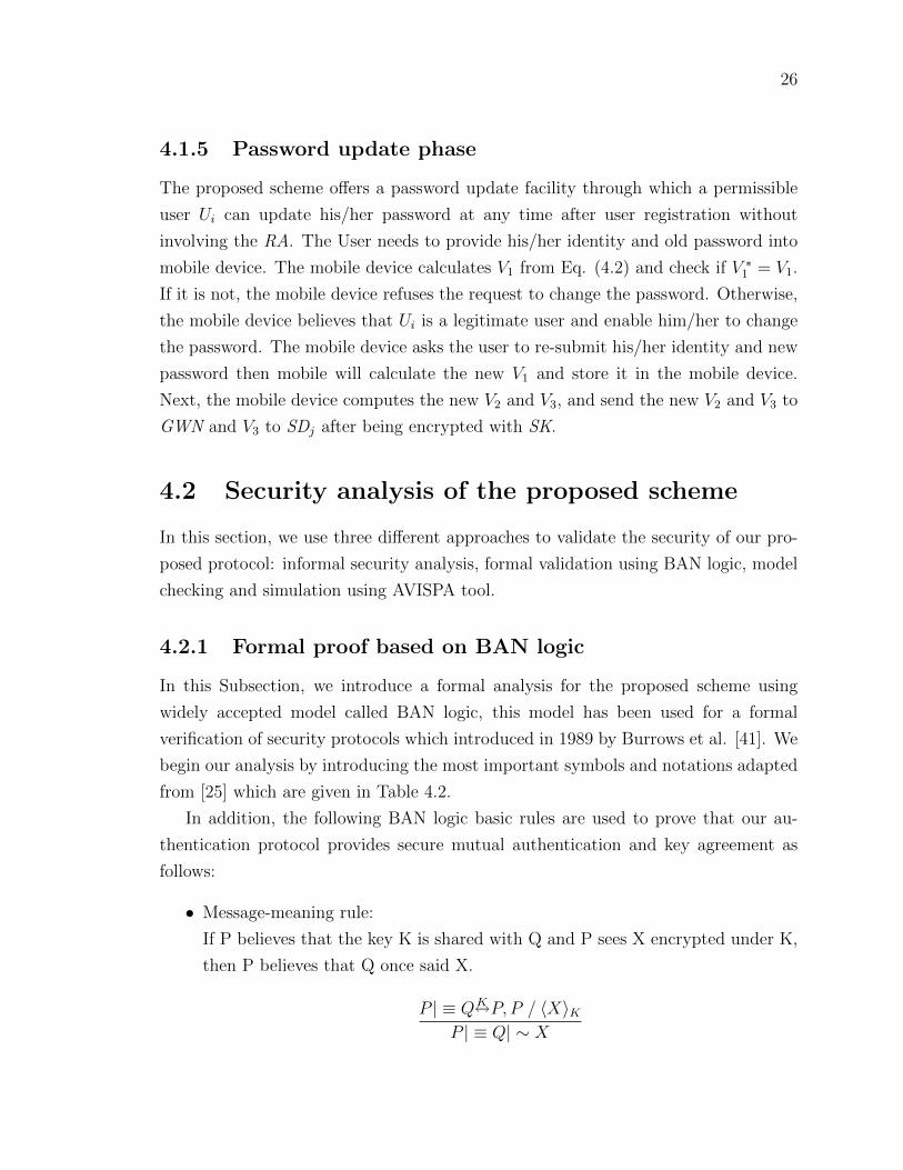
In addition, the following BAN logic basic rules are used to prove that our au-
thentication protocol provides secure mutual authentication and key agreement as
follows:
• Message-meaning rule:
If P believes that the key K is shared with Q and P sees X encrypted under K,
then P believes that Q once said X.
P | ≡ QK←→P, P / 〈X〉KP | ≡ Q| ∼ X

27
Table 4.2: Notations in BAN logic.
Notation Descriptions
P and Q Principals
P | ≡ X Principal P believes the state-ment X
P / X Principal P sees the statement X
P | ⇒ X Principal P has jurisdiction overthe statement X
P | ∼ X Principal P once said statementX
(X, Y ) The statement X or Y is one partof message (X, Y)
< X >Y The statement X is encryptedwith the key K
(X)K The statement X is hashed withthe key K
PK←→ Q K is a secret parameter shared (or
to be shared) between P and Q
PK� Q X is a secret known only to P and
Q, and possibly to parties trustedby them.
# (X) The message X is fresh.
• Nonce verification rule:
If P believes X is fresh and P believes Q once said X, then P believes Q believes
X.
P | ≡ #(X), P | ≡ Q| ∼ X
P | ≡ Q| ≡ X
• Jurisdiction rule:
If P believes Q has jurisdiction over X and P believes Q believes X, then P

28
believes X.
P | ≡ Q| =⇒ X,P | ≡ Q| ≡ X
P | ≡ X
• Freshness conjuncatenation rule:
If one part of a statement is fresh, then the entire statement must also be fresh;
so if P believes X is fresh, then P believes X and Y are fresh.
P | ≡ #(X)
P | ≡ #(X, Y )
• Belief rule:
If P believes X and Y, then P believes X .
P | ≡ (X, Y )
P | ≡ X
• Session keys rule:
P | ≡ #(X), P | ≡ Q| ≡ X
P | ≡ P K←→Q
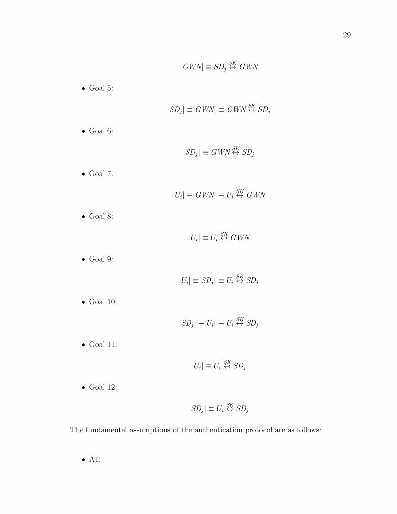
The proposed scheme must achieve the following goals:
• Goal 1
GWN| ≡ Ui| ≡ UiSK↔ GWN
• Goal 2:
GWN| ≡ UiSK↔ GWN
• Goal 3:
GWN| ≡ SDj| ≡ SDjSK↔ GWN
• Goal 4:
29
GWN| ≡ SDjSK↔ GWN
• Goal 5:
SDj| ≡ GWN| ≡ GWNSK↔ SDj
• Goal 6:
SDj| ≡ GWNSK↔ SDj
• Goal 7:
Ui| ≡ GWN| ≡ UiSK↔ GWN
• Goal 8:
Ui| ≡ UiSK↔ GWN
• Goal 9:
Ui| ≡ SDj| ≡ UiSK↔ SDj
• Goal 10:
SDj| ≡ Ui| ≡ UiSK↔ SDj
• Goal 11:
Ui| ≡ UiSK↔ SDj
• Goal 12:
SDj| ≡ UiSK↔ SDj
The fundamental assumptions of the authentication protocol are as follows:
• A1:

30
GWN| ≡ #(N1)
• A2:
GWN| ≡ #(N3)
• A3:
SDj| ≡ #(N2)
• A4:
Ui| ≡ UiV2↔ GWN
• A5:
GWN| ≡ UiV2↔ GWN
• A6:
SDj| ≡ SDjV3↔ GWN
• A7:
GWN| ≡ SDjV3↔ GWN
• A8:
Ui| ≡ SDj| ⇒ (N3, SIDj, SK)
• A9:
Ui| ≡ GWN| ⇒ (N2,V2, SK)
• A10:
GWN| ≡ Ui| ⇒ (N1,TIDUi,V2, SK)
• A11:

31
GWN| ≡ SDj| ⇒ (N3, SIDj,V3, SK)
• A12:
SDj| ≡ Ui| ⇒ (N1,TIDUi,V2, SK)
• A13:
SDj| ≡ GWN| ⇒ (N2,V3, SK)
Messages transferred in the authentication protocol:
• Msg 1:
Ui → GWN : (TIDUi||UG||HUG)Ui
V 2↔GWN
• Msg 2:
GWN→ SDj : (GID||GS||HGS)GWN
V3↔SDj
• Msg 3:
SIDj → GWN : (SG||HSG)SDj
V3↔GWN
• Msg 4:
GWN→ Ui : (GU ||HGU)GWN
V 2↔Ui
Analysis of our authentication scheme:
• S1: According to Msg 1, we get:
GWN / (TIDUi, UG,HUG)Ui
V 2↔GWN
• S2: Based on Assumption A5, S1 and message-meaning rule, we have:

32
GWN| ≡ UiV 2↔ GWN,GWN / (TIDUi, UG,HUG)
UiV 2↔GWN
GWN| ≡ Ui| ∼ (TIDUi, UG,HUG)Ui
V 2↔GWN
• S3: From A1 and freshness-conjuncatenation rule, we get:
GWN | ≡ # (TIDUi, UG,HUG)Ui
V 2↔GWN
• S4: From S3, S2 and nonce-verification rule, we get:
GWN| ≡ #(TIDUi, UG,HUG)Ui
V 2↔GWN,GWN| ≡ Ui| ∼ (TIDUi, UG,HUG)
UiV 2↔GWN
GWN| ≡ Ui| ≡ (TIDUi, UG,HUG)Ui
V 2↔GWN
• S5: According to the Msg 2, we get:
SDj / (GID, GS,HGS)GWN
V3↔SDj
• S6: From A6, S5 and message-meaning rule, we have:
SDj| ≡ (SDjV3↔ GWN), SDj / (GID, GS,HGS)
GWNV3↔SDj
SDj| ≡ GWN| ∼ (GID, GS,HGS)GWN
V3↔SDj
• S7: From A3 and freshness-conjuncatenation rule, we get:
SDj | ≡ # (GID, GS,HGS)GWN
V3↔SDj
• S8: From S6, S7 and nonce-verification rule, we get:
SDj | ≡ # (GID, GS,HGS)GWN
V3↔SDj
, SDj| ≡ GWN| ∼ (GID, GS,HGS)GWN
V3↔SDj
SDj| ≡ GWN| ≡ (GID, GS,HGS)GWN
V3↔SDj
• S9: According to the Msg3, we get:
GWN / (SG||HSG)SDj
V3↔GWN
• S10: From A7, S9 and message-meaning rule, we have:

33
GWN| ≡ (SDjV3↔ GWN),GWN / (SG||HSG)
SDjV3↔GWN
GWN| ≡ SDj| ∼ (SG||HSG)SDj
V3↔GWN
• S11: From A2 and freshness-conjuncatenation rule, we get:
GWN | ≡ # (SG,HSG)SDj
V3↔GWN
• S12: From S10, S11 and nonce-verification rule, we get:
GWN | ≡ # (SG,HSG)SDj
V3↔GWN,GWN| ≡ SDj| ∼ (SG,HSG)
SDjV3↔GWN
GWN| ≡ SDj| ≡ (SG,HSG)SDj
V3↔GWN
• S13: According to the Msg4, we get:
Ui / (GU ||HGU)GWN
V 2↔Ui
• S14: From A4, S13 and message-meaning rule, we have:
Ui| ≡ UiV2↔ GWN, Ui / (GU ||HGU)
GWNV2↔Ui
Ui| ≡ GWN| ∼ (GU ||HGU)GWN
V2↔Ui
• S15: From A1, A2, A3 and freshness-conjuncatenation rule, we get:
Ui | ≡ # (GU,HGU)GWN
V2↔Ui
• S16: From S14, S15 and nonce-verification rule, we get:
Ui | ≡ # (GU,HGU)GWN
V2↔Ui
, Ui| ≡ GWN| ∼ (GU,HGU)GWN
V3↔Ui
Ui| ≡ GWN| ≡ (GU,HGU)GWN
V2↔Ui
• S17: From A10, S4 and jurisdiction rule, we get:
GWN| ≡ Ui| ⇒ (N1, T IDUi,V2, SK),GWN| ≡ Ui| ≡ (T IDUi, UG,HUG)Ui
V2↔GWN
GWN| ≡ (T IDUi, UG,HUG)Ui
V2↔GWN

34
• S18: From S3, S4 and session keys rule, we get:
GWN| ≡ #(T IDUi, UG,HUG)Ui
V2↔GWN,GWN| ≡ Ui| ≡ (T IDUi, UG,HUG)
UiV2↔GWN
GWN| ≡ Ui| ≡ UiSK↔ GWN
(Goal 1)
• S19: From S18, A10 and jurisdiction rule, we get:
GWN| ≡ Ui| ⇒ (N1, T IDUi,V2, SK),GWN| ≡ Ui| ≡ UiSK↔ GWN
GWN| ≡ UiSK↔ GWN
(Goal 2)
• S20: From A11, S12 and jurisdiction rule, we get:
GWN| ≡ SDj| ⇒ (N3, SIDj,V3, SK),GWN| ≡ SDj| ≡ (SG,HSG)SDj
V3↔GWN
GWN| ≡ (SG,HSG)SDj
V3↔GWN
• S21: From S11, S12 and session keys rule, we get:
GWN | ≡ # (SG,HSG)SDj
V3↔GWN,GWN| ≡ SDj| ≡ (SG,HSG)
SDjV3↔GWN
GWN| ≡ SDj| ≡ SDjSK↔ GWN
(Goal 3)
• S22: From A11, S21 and jurisdiction rule, we get:
GWN| ≡ SDj| ⇒ (N3, SIDj,V3,GWN| ≡ SDj| ≡ SDjSK↔ GWN
GWN| ≡ SDjSK↔ GWN
(Goal 4)

35
• S23: From A13, S8 and jurisdiction rule, we get:
SDj| ≡ GWN| ⇒ (N2,V3, SK), SDj| ≡ GWN| ≡ (GID,GS,HGS)GWN
V3↔SDj
SDj| ≡ (GID,GS,HGS)GWN
V3↔SDj
• S24: From S7, S8 and session keys rule, we get:
SDj | ≡ # (GID,GS,HGS)GWN
V3↔SDj
, SDj| ≡ GWN| ≡ (GID,GS,HGS)GWN
V3↔SDj
SDj| ≡ GWN| ≡ SDjSK↔ GWN
(Goal 5)
• S25: From A13, S24 and jurisdiction rule, we get:
SDj| ≡ GWN| ⇒ (N2,V3, SK), SDj| ≡ GWN| ≡ GWNSK↔ SDj
SDj| ≡ GWNSK↔ SDj
(Goal 6)
• S26: From A9, S16 and jurisdiction rule, we get:
Ui| ≡ GWN| ⇒ (N2,V2, SK), Ui| ≡ GWN| ≡ (GU,HGU)GWN
V2↔Ui
Ui| ≡ (GU,HGU)GWN
V2↔Ui
• S27: From S15, S16 and session keys rule, we get:
Ui | ≡ # (GU,HGU)GWN
V2↔Ui
, Ui| ≡ GWN| ≡ (GU,HGU)GWN
V2↔Ui
Ui| ≡ GWN| ≡ UiSK↔ GWN
(Goal 7)

36
Figure 4.5: The role played by the user Ui
Figure 4.6: The role played by the registration authority RA
• S28: From A9, S27 and jurisdiction rule, we get:
Ui| ≡ GWN| ⇒ (N2,V2, SK), Ui| ≡ GWN| ≡ UiSK↔ GWN
Ui| ≡ UiSK↔ GWN
(Goal 8)
• S29: From S27 and S21, we get:
Ui| ≡ GWN| ≡ UiSK↔ GWN,GWN| ≡ SDj| ≡ SDj
SK↔ GWN
Ui| ≡ SDj| ≡ UiSK↔ SDj
(Goal 9)
• S30: From S24 and S18, we get:
SDj| ≡ GWN| ≡ SDjSK↔ GWN,GWN| ≡ Ui| ≡ Ui
SK↔ GWN
SDj| ≡ Ui| ≡ SDjSK↔ Ui

37
(Goal 10)
• S31: From A8, S29 and jurisdiction rule, we get:
Ui| ≡ SDj| ⇒ (N3, SIDj, SK), Ui| ≡ SDj| ≡ UiSK↔ SDj
Ui| ≡ UiSK↔ SDj
(Goal 11)
• S32: From A12, S30 and jurisdiction rule, we get:
SDj| ≡ Ui| ⇒ (N1,TIDUi,V2, SK), SDj| ≡ Ui| ≡ SDjSK↔ Ui
SDj| ≡ UiSK↔ SDj
(Goal 12)
To validate a protocol using BAN logic we established the participants and their be-
liefs at the beginning of the protocol. Also we expressed those beliefs using BAN
specific notation (see table 4.2 for BAN notation). Each of the messages exchanged
during the run of a protocol is then idealized (this is called the idealization process),
i.e., each message is represented by a logical formula using BAN symbols and no-
tation. These formulae are accompanied by a set of assertions, also represented in
BAN notation. The assertions express conclusions reached after sending the mes-
sage. Hence, the above BAN logic analysis formally proves that the proposed scheme
successfully achieves mutual authentication, and the session key SK is mutually es-
tablished between the Ui and the SDj through the GWN.
4.2.2 Simulation based on AVISPA tool
AVISPA, introduced by Armando et al. [43] is a toolkit based on the Dolev – Yao
threat model [46]. In this model, the adversary has the ability to change, forward
and modify messages. This toolkit is utilized to formally assess and validate Internet
security protocols. AVISPA is a widely recognized tool used to evaluate the speci-
fications of several industrial-scale security protocols [44]. Avispa uses a high level

38
Figure 4.7: The role played by the gateway GWN
Figure 4.8: The role played by the smart device SD
protocol specification language (HLPSL) to describe and define the security protocols.
Protocol specifications in HLPSL are break down into roles. Some roles are used to
define the actions of one single agent in a protocol run. Every agent plays a unique
role during the execution of a given protocol. The main objective of HLPSL is to
check security properties such as the message authentication, agent authentication
and secrecy. The security protocol is checked indicating whether or not it is secure
on the basis of the predefined goals. AVISPA includes four built-in model checkers,
defined as follows:
Preliminaries
1. On-the-fly model checker (OFMC): uses lazy data types as an easy way to create
an effective on-the-fly model for security protocols with infinite state spaces [47].
2. Constraint-logic-based attack searcher (CL-AtSe): The input of (CL-AtSe) is
protocol defined as a set of rewriting rules (IF format) into In a set of constraints
that help to detect the attacks on the security protocol [48].
3. SAT-based model checker (SATMC): produces a propositional formula based
on a transitional state obtained from the IF specification. The propositional

39
Figure 4.9: Role session and environment
Figure 4.10: Result based on model checker OFMC
formula defines any breach of the security properties that can be turned into
an attack [49].
4. Tree automata-based on automatic approximations for the analysis of security
protocols (TA4SP) model checker:It shows the vulnerability of the protocol and
predicts the correctness of the protocol by accurately estimating the capabilities
of the attacker.

40
Simulation details
We start writing the HLPSL script for our scheme by setting the simulation security
goals. Our main objective is to ensure the secrecy of a number of values such as V1,
V2, V3, N1, N2, N3. In addition, we define the six roles as follows: role(1) is role RA
which is played by the registration authority, role(2) is role Ui which is played by the
user, role (3) is role GWN which is played by the gateway, role(4) is role SD which
is played by the smart device, role(5) is role session which combine the basic roles
(RA, Ui, GWN and SD), role(6) is role environment which combines several sessions
and contains global variables, functions and define the simulation security goals of
the protocol.
Figure 4.11: Result based on model checker OFMC
Fig 4.5 shows the specification for role Ui which is played by the user. In this role,
the Ui recognizes all the agents (Ui, RA, GWN , SD), the symmetric key Kur which is
shared between the user and the RA, the hash function H(.) and send/receive channels
(SND, RSV). The (dy) notation shows that the channels follow the Dolev–Yao model.
Ui receives a start message (RCV(start)) as a signal to start the run of the protocol at
the first state (state 0), the user generate the identity IDUi and password PWi, then
user sends IDUi and PWi after being encrypted with Kur to the registration authority
in order to register. At state 2, the Ui receives TIDUi and V1 encrypted with Kur
coming from the RA. At state 4, the Ui generates a fresh value as a nonce N1. Next,
the Ui generates a fresh value LC which represent the location of Ui as if the Ui obtain
it from the GPS. Next, the Ui generates the X1 which has all the location’s history
of the Ui, this value is shared with GWN. Next, Ui computes X2, V2, UG and HUG.
Next, Ui sends (TIDUi, UG, HUG) to GWN. at the next transition, the Ui receives

41
the message (GU, HGU) coming from the GWN. Next, the Ui computes SK using
N1, N2 and N3. Finally, Ui computes HUG and compare it with the received HUG.
Fig. 4.6 illustrates the specification for role RA which is played by the registration
authority. In this role, the RA recognizes all the agents (Ui, RA, GWN, SD), the
symmetric keys Kur, Kgr and Ksr which are shared between the registration authority
and User, gateway and smart device, respectively. In addition, RA knows the hash
function H(.) and send/receive channels (SND, RSV). The (dy) notation shows that
the channels follow the Dolev–Yao model. The reset part of the specification describes
the different states of the protocol execution by RA.
Fig. 4.7 shows the specification for role GWN which is played by the gateway.
In this role, the GWN knows all the agents (Ui, RA, GWN, SD), the symmetric key
Kgr which is shared between the gateway and the RA, the hash function H(.) and
send/receive channels (SND, RSV). The (dy) notation shows that the channels follow
the Dolev–Yao model.
Fig. 4.9 shows the specification of the session and environment role. In the ses-
sion role, all roles (role RA, role Ui, role GWN, role SD) combine together. In the
environment role, one or more sessions are initiated. We defined the constants as
(ra,ui,gwn,sd) represents the agents (RA,Ui, GWN, SD), respectively. (kur,kgr,ksr)
represents the symmetric keys shared between RA and user, RA and gateway, RA
and smart device, respectively. h represents the hash function H. In the intruder
knowledge part, the relevant parameters that the intruder suppose to knows are de-
fined. We assume that the intruder knows all the agents (RA,Ui, GWN, SD). The
simulation goals are defined under goal keyword. We interested to check the secrecy
of the following parameters: IDUi, PWi, V1, V2, V3, N1, N2, N3.
Simulation results
In this section, we present the simulation results of our proposed scheme. The results
are based on AVISPA back-end model checker OFMC. The Security Protocol Ani-
mator (SPAN) is used to interactively create a message sequence chart (MSC) of the
HLPSL specification protocol previously described. Furthermore, SPAN automati-
cally generates attacks using the Dolev-Yao intruder model.
Fig. 4.10 shows the protocol execution using SPAN software [43], where the all
agents exchange the messages in registration and authentication phase.
Fig. 4.11 illustrates the report of model checker OFMC which clearly states that

42
the proposed scheme is safe. hence, all the security goals are meet.
4.2.3 Informal security analysis
In this section, the security of the protocol is discussed against various well-known
attacks. We explain how our protocol successfully resists these attacks.
4.2.4 Replay attack
The random number method is adopted to resist replay attack, so replay attack can
be prevented by using the nonces which change in every session.
4.2.5 Eavesdropping attack
In our protocol the attacker can easily intercept the message in transit between Ui,
GWN, and SD as the messages are all sent in plain-text. However, adversary cannot
obtain any confidential information from any messages because the secret information
are protected using secret parameters shared between the communicating parties
securely (Eg, V1 and V2), and shielded using one-way hash function and XOR bitwise
operator. Therefore, the attacker will be unable to unfold the transmitted parameters,
and thus cannot obtain any useful information.
4.2.6 Smart-phone device loss attack
In the proposed scheme, the smart-phone of the user stores the secret parameters
V1 = h(IDUi||PWi). Suppose that an adversary A steals the smart-phone and extracts
the stored secret value V1, A cannot obtain the identity and password because V1
is a hash value derived by application of a one-way hashing function. Hence, the
proposed protocol is secure even if the smart-phone is lost or stolen.
4.2.7 Impersonation attack
Suppose if an adversary A tries to impersonate the user, A cannot succeed because
does not know the user’s identity IDUi and password PWi as discussed in resisting
smart-phone device loss attack. Thus, the proposed protocol is secure from user
impersonation attack.

43
4.2.8 Man-in-the-middle attack
As discussed in BAN logic section 4.2.1, our proposed protocol provides mutual au-
thentication. Additionally, the transmitted messages are protected by the secret
values V1, V2, V3 and nonces, and no one would be able to forge legal authentication
messages without knowledge of these secret values. Therefore, the proposed protocol
can stop the Man-in-the-Middle attack.
4.2.9 Forward/backward secrecy
The session key SK is constructed using three different random numbers, namely
N1, N2 and N3 which are randomly generated in each session by Ui, GWN and SDj,
respectively. Therefore, if the SK is compromised by an adversary A, it cannot
compromise the confidentiality information of past or future communication sessions.
Therefore, forward/backward secrecy is achieved in the proposed scheme.
4.2.10 User credentials attack
When Ui registers at RA as a legitimate user in the proposed protocol, Ui sends the
registration message
(IDUi||PWi) KRA to RA. Next, RA computes V1 from Eq. (4.2) and sends V1 to
Ui. Ui will never store its identity and password credentials, and instead it will store
the hash value V1. An insider attacker targeting user credentials cannot obtain user
identity IDUi and password PWi from V1 as V1 is protected by the one-way hash
function. Thus, the proposed protocol can resist the user credentials attack.
4.2.11 Session key Guessing Attack
The session key SK is created by all communication participants, namely Ui, GWN
and SDj randomly chosen nonces. Therefore, SK depends on randomness of the Input
values N1, N2 and N3 and the one-way hash functions, which make it nearly impossible
for an adversary to extract it from the protocol. The probability of an adversary to
guess the correct SK key is so negligible, given that N1, N2 and N3 are randomly
chosen in every session.

44
4.2.12 User anonymity and untraceability
User anonymity and untracebility are two crucial security properties in authentica-
tion. Anonymity ensures the real identity of the mobile device is kept secure and
the mobile device remain unidentifiable among the other set of devices. Thus, the
attacker cannot identify the identities of the devices. Untraceability, on the other
hand, ensures the different sessions established by a particular mobile device cannot
be traced, so that an attacker cannot relate any sessions to the correct mobile device.
We achieved these two key security properties by using the dynamic identity of the
mobile user, where we use different ID in every session.
4.2.13 Location-based authentication
The physical context awareness (location) that is used in our protocol involves ver-
ifying whether the previous location of mobile device is proximate to the current
location. The location of the mobile device is checked using the linear motion equa-
tion to calculate the highest displacement for user in location LP change to location
LC as explained in Section 4.1.
4.2.14 User authentication based on transaction history in-
formation
Each mobile device and the gateway maintain a synchronized database of cumulative
hashes generated from the previous session based on the location as discussed in
Section 4.1. Therefore, when the transaction from the mobile device is not approved
(as discussed in Subsection 4.1.4, the gateway will challenge the knowledge of the
mobile device about the previous locations stored from the previous session. The
gateway will select one of previous nonce to represent one of the previous session,
and challenge the mobile device to send back the correct corresponding location Xn.
The gateway will approve the mobile device if it succeeds in sending the correct Xn;
otherwise the mobile device’s transaction is rejecting and flagged as malicious.

45
4.3 Performance comparison
In this Section, we evaluate the performance of our proposed scheme in terms of
storage cost, communication overhead, and computation costs. We also compare our
performance with other related works.
4.3.1 Storage cost
We analyze storage cost (in bits) for the three participants user Ui, gateway GWN,
and smart device SDj.
Ui is required to store GID, SID, TIDUi, Xn and V1. We use SHA-1 as an
example of hash function, and the output of SHA-1 is 160 bits. By applying SHA-1,
we obtain Xn=160 bits [50]. While TIDUi=GID =SID=128 bits. Thus, the total
storage required by Ui is 160 + (3 × 128)+ 160 = 704 bits.
GWN is required to store GID, SID, TIDUi, Xn, V2, and V3. By applying these
settings, we obtain Xn = 160 bits. The TIDUi=GID=SID=128 bits, and V2=512 and
V3=256 bits. Therefore, the total storage required by GWN is 160 + (3 × 128) +
(512) + (256) = 1056 bits.
SD is required to store SID and V3. SID=128 bits, V3=256 bits. Hence, the total
storage required by Ui is 128+256 =384 bits.
4.3.2 Communication overheads
Table 4.3: The communication overheads of our scheme.
Transmitted messages Communication cost in bits
Ui → GWN 800
GWN→ SD 416
SD→ GWN 416
GWN→ Ui 672
In this Subsection, we discuss the communication cost based on transmitted mes-
sages in both directions between these three participants. The communication costs
of our scheme are shown in Table 4.3.

46
To make a reasonable comparison, we assume that the length of the transmitted
messages’ parameters TIDUi, UG, HUG, GS, HGS, SG, HSG, GU , HGU are 128
bits, 512 bits, 160 bits, 256 bits, 160 bits, 256 bits, 160 bits, 512 bits, 160 bits,
respectively.
In our proposed scheme, the transmitted messages Ui → GWN : (T IDUi, UG,HUG),
GWN→ SD : (GS,HGS), SD → GWN : (SG,HSG) and GWN→ Ui : (GU,HGU)
require (128 + 512 + 160) = 800 bits, (256 +160) = 416 bits, (256 +160) = 416 bits,
(512 +160) = 672 bits, respectively.
Three existing relevant schemes, namely Wazid et al. [25], Shuai et al. [26]. Kumar
et al. [24]. In terms of number of exchanged messages and total number of bits for
a successful mutual authentication during authentication and key agreement phase.
Considering our proposed scheme, the total communication cost turns out to be 4
messages in terms of number of exchanged messages, and to be (800+416+416+672)
= 2304 bits in terms of total number of bits.
Table 4.4 shows a comparison of communication cost between the proposed scheme
and other relevant schemes in terms of number of exchanged messages and total num-
ber of bits for a successful mutual authentication. our scheme requires 4 messages
and 2304 bits total number of bits for a successful mutual authentication. The com-
parison, in general, shows that our scheme is comparatively more cost-efficient than
the other related works in terms of number of exchanged messages and total number
of bits , and just a little less cost efficient than that of Kumar et al.’s scheme [24] be-
cause our scheme adds additional functionality and security features are not provided
by Kumar et al.’s scheme [24] such as mutual authentication between user and smart
device, mutual authentication between user and gateway, password guessing attack,
password change attack, stolen smart phone/smart card attack and password change
phase, physical context awareness (i.e., location awareness), and transaction history
authentication.
Therefore, the communication cost analysis shows that our proposed scheme is
effective and feasible for smart homes.
4.3.3 Computational cost
In this Subsection, we conduct the computation cost analysis of our proposed protocol.
In order to ensure a precise computation cost of our protocol, the experimental data
reported in [51] [52] are applied. They defined the terms Texp, Th, and TE/TD as the

47
Table 4.4: Comparison of communication cost between the proposed scheme andother most related schemes.
Authenticationscheme
Number of exchangedmessages
Total number of bits
Wazid et al. [25] 4 3232
Shuai et al. [26] 4 2944
Kumar et al. [24] 3 1696
Santoso et al. [23] 3 4416
Kim et al. [22] 2 4352
Proposed scheme 4 2304
computational time for modular exponentiation operation, hash function h(.), and
symmetric encryption/decryption, respectively.
Table 4.5 shows the time needed for executing those operations. However, the
bitwise XOR operation execution time is negligible. Our protocol performs 10 hash
invocations and 8 XOR operations, which yields a total computation cost (10 × Th).
Hence, the computation cost of our proposed protocol is (10 × 0.32 ms)= 3.2 ms.
Table 4.5: Crypto-operations and the computational times needed
Crypto-operations Computational time
Modular exponentiation operation (Texp) 19.2 ms
Hash function (Th) 0.32 ms
Symmetric encryption or decryption (TE/TD) 5.6 ms
Table 5.4 shows a comparison of computation cost between the proposed scheme
and other most related schemes in ms. Table 5.5 provides security and functionality
features compared to other existing related schemes.
In summary, our scheme achieves significantly better performance, security and
functionality features as compared to those of other existing schemes.

48
Table 4.6: Comparison of computation cost between the proposed scheme and othermost related schemes in ms.
Authentication scheme Total cost Rough estimation
Wazid et al. [25] 4TE/TD + Tfe + 22Th 46.54 ms
Shuai et al. [26] 3Texp + 16Th 162.72 ms
Kumar et al. [24] 2TE/TD + Tmac + Thmac + 2Th 12.48 ms
Santoso et al. [23] 3Texp + 2Th 58.24 ms
Kim et al. [22] 3TE/TD + 30Th 26.40 ms
Proposed scheme 10Th 3.2 ms
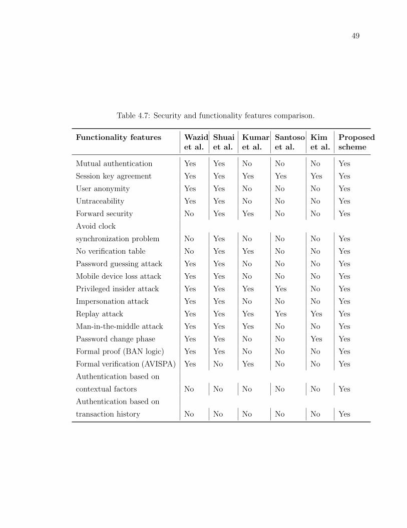
49
Table 4.7: Security and functionality features comparison.
Functionality features Wazidet al.
Shuaiet al.
Kumaret al.
Santosoet al.
Kimet al.
Proposedscheme
Mutual authentication Yes Yes No No No Yes
Session key agreement Yes Yes Yes Yes Yes Yes
User anonymity Yes Yes No No No Yes
Untraceability Yes Yes No No No Yes
Forward security No Yes Yes No No Yes
Avoid clock
synchronization problem No Yes No No No Yes
No verification table No Yes Yes No No Yes
Password guessing attack Yes Yes No No No Yes
Mobile device loss attack Yes Yes No No No Yes
Privileged insider attack Yes Yes Yes Yes No Yes
Impersonation attack Yes Yes No No No Yes
Replay attack Yes Yes Yes Yes Yes Yes
Man-in-the-middle attack Yes Yes Yes No No Yes
Password change phase Yes Yes No No Yes Yes
Formal proof (BAN logic) Yes Yes No No No Yes
Formal verification (AVISPA) Yes No Yes No No Yes
Authentication based on
contextual factors No No No No No Yes
Authentication based on
transaction history No No No No No Yes
50
4.4 Conclusion
Security and privacy issues are significant obstacles that impedes the large-scale ap-
plications of smart home. In previous research, there are almost no robust authenti-
cation schemes suitable for smart home ecosystem. As a step in the right direction,
we proposed a lightweight and secure two-factor anonymous authentication scheme.
The proposed scheme grants a legal user mutually authenticate with the smart device
through GWN. By the end of successful mutual authentication, a symmetric session
key SK for future secure communications is established between the user and the
smart device. The security of the proposed scheme is formally proved using widely-
accepted the BAN logic. Moreover, the informal security verification demonstrate
that the proposed scheme resists most common attacks. Finally, the formal security
is evaluated using the AVISPA tool and the results indicate that our scheme is safe.
The following are our plans for future work:
We will use OMNet++ to implement the proposed scheme which is used to simulate
computer networks protocols.

51
Chapter 5
Multifactor authentication scheme
using physically unclonable
functions
This chapter introduces a secure telehealth system using multifactor authentication
for the mobile devices as well as the IoT edge devices in the system. These two types
of devices constitute the weakest link in telehealth systems. The mobile devices and
edge devices are typically unsecured and contain vulnerable processors. The mobile
devices use the healthcare professional’s biometric and endowing the edge device with
biometrics is accomplished by using physically unclonable functions (PUFs). The
embedded PUF acts as a means of enabling mutual authentication and key exchange.
5.1 Notation & Terms Used
Table 5.1 summarizes the notations used in this work.
5.2 Preliminaries
In this section we describe the models and assumptions related to the agents or entities
interacting with the IoT telehealth system. The main actors in this system include
the threat/adversary, the edge devices and the users.

52
Table 5.1: Notations Used in the Proposed Protocol
Symbol Description
E Edge device: sensor or actuator
G Gateway
S Server
M Mobile device: cell phone, tablet, etc.
Healthcare Professional Person giving healthcare services such as a doctor or a nurseusing a mobile device M
IDs Identity of server S
IDg Identity of gateway G
IDm Identity of mobile device M
Bm Biometric of mobile device user
IDd Identity of edge device D
DBd CRP Dataset associate with built-in PUF of edge device D
K Session secret key
Ks Symmetric key of server S
Kg Symmetric key of gateway G
Km Symmetric key of mobile device M
Kd Symmetric key of edge device D
N Nonce
x PUF-based secret key
x == y Check equality of x and y
Es(K,m) Symmetric encryption of message m with secret key K
Ep(K,m) Public key encryption of message m with public key K
Ds(K,m) Symmetric decryption of message m with secret key K
Dp(K,m) Public key decryption of message m with secret key K
h(m) Collision-resistant one-way hash function of message M
h(K,m) Collision-resistant one-way cryptographic hash of message Musing secret key K
Request(IDs,IDd, m) Request to communication between source IDs and destina-tion IDd and an encrypted message
A→ B : m A sends a message to B through a communication channel
m1||M2 Concatenating two messages m1 and m2
m1 ⊕m2 Bitwise XOR operation between m1 and m2

53
5.2.1 Silicon Physically Unclonable Function (PUF)
The use of physically unclonable functions (PUF) for mutual authentication in IoT
devices has been the recognized solution to endowing IoT devices with a unique iden-
tity, akin to a fingerprint or retina image for humans. A PUF serves to authenticate
a device and also provides a measure of tamper resistance
Delvaux et al. [53, 54] reviewed designs of strong and weak PUFs and how they
can be used in entity authentication. The authors provided a review of the two types
of PUF circuits and their statistical properties. Delvaux also provided an excellent
survey of PUF-based key generation. Discussion was provided on how the helper data
algorithm can be used to extract a stable secret key from the noisy PUF response
(see Chapter 4 in [54]).
Dodis et al. [55, 56] provided efficient secure techniques for using biometrics to
provide secure device authentication and converting the noisy biometric data into
stable cryptographic keys. They indicated that any biometric signal inherently has
low entropy and is also noisy. On the other hand, any useful cryptographic key must
have high entropy and be stable and noise free. For this end, the technique they
introduced depends on a fuzzy extractor or helper data algorithm. Figure 5.3 in the
sequel shows the main building blocks of the secure sketch or fuzzy extractor. Figure
5.4 in the sequel shows only the secure key generation part of the fuzzy extractor.
Ravikanth [57, 58] discussed the concept of one-way functions in general and dis-
tinguished between the similarities between algorithmic one-way functions (e.g RSA
and Rabin functions) versus physical one-way functions (e.g. PUFs) which depend on
physical phenomena for their operation. He discussed the operation of optical one-
way functions and reported the like and unlike binomial distribution of the resulting
optical responses to ensure the uniqueness of the optical fingerprint of the devices.
Gassend et al. [59] discussed the more common silicon physical random functions,
which are now commonly known as physically unclonable functions (PUF). They
studied different types of delay-based PUF such as self-oscillating circuits exhibiting
monotonic and non-monotonic delays. They also discussed generating redundant
information to be added to the challenge-response pairs (CRP) as a means of error
correction to remove the noise from the responses and implemented the designs on
FPGA hardware.
Suh et al. [60] discussed two different types of delay-based silicon PUFs: ring oscil-
lator PUF and arbiter PUF. Techniques to generate sufficiently large number of CRP
54
by increasing the options for configuring or selecting the circuit delays. A low-cost
authentication scheme is proposed that does not use resource-hungry cryptographic
techniques. Error detection and correction techniques using BCH coding/decoding
are used for reliable cryptographic key generation based on the CRP used. The au-
thenticator generates the redundant information and sends it in the clear to the device
to be authenticated to remove the random process variations.
Guajardo et al. [61] proposed PUF SRAM structures suitable for today’s FPGA
technology. The statistical properties of the SRAM were investigated. The fuzzy
extractor or helper data algorithm was used to extract one or more secure keys. The
authenticator generates the helper data W based on the golden PUF response that
does not include thermal noise and sends this to the device. Referring to Fig. 5.3 and
Fig. 5.4 in the sequel, the device to be authenticated receives the helper data r and
uses it, together with the noise PUF response (w′), to generate a stable and secure
session secret key.
Maes et al. [62, 63, 64] reviewed electronic and non-electronic PUF types and dis-
cussed the Hamming inter-distance and intra-distance as a means of ensuring unique
device ID and to be able to distinguish between the different devices. Seven different
types of PUFs were reviewed. PUF-based key generation properties were identified
and the secure sketch, strong and fuzzy extractor technique proposed by Dodis et al.
[55, 56] were discussed.
Herder et al. [65] described using PUF for a low-cost authentication and key
generation applications. The thesis defined two primary PUF types: “strong PUFs”
and “weak PUFs”.
Operation of the PUF relies on a challenge-response pair (CRP) where the server
issues a challenge and the IoT device, or client, provides a response that is unique
to the device. The problem with PUF response is it is noisy but has low entropy.
Therefore techniques have been developed to recover a reliable and stable response
from the noisy responses using fuzzy extractor or secure sketch [66, 67, 56, 55]. The
advantage of the fuzzy extractor serves also to generate a secret key with high entropy
from the low-entropy noisy responses. Silicon Physically unclonable functions (PUF)
are circuits that make use of inevitable random process variations (RPV) and thermal
nose present in integrated-circuits (IC). A PUF operates on a challenge-response pair
(CRP) where each challenge or input to the PUF generates a response that is unique
to each manufactured IC and can not be repeated by an attacker or even the IC
manufacturer. The function produced by the PUF should be easy to evaluate but

55
hard to model or characterize by the designer, manufacturer or even the adversary.
Examples of PUFs include [60] arbiter PUFs, ring oscillator PUFs and SRAM PUFs
[68].
A black-box model of a silicon PUF is represented as
R[1 : M ] = PUF(C[1 : N ])
where C[1 : N ] is the N -bit challenge, R[1 : M ] is the M -bit response, and PUF(·) is
the one-way unique function characterizing the PUF given the physical parameters
of a particular IC.
The simple CRP set is not practical for authentication for the following reasons:
1. The responses are noisy since they are subject to processing variations and en-
vironmental factors such as temperature, supply voltage variations and ground
bounce [69].
2. A CRP can only be used once to prevent replay attack. Hence, a finite number
of authentication operations are feasible after which the device is withdrawn
from service.
3. There is nonzero probabilities of false rejection and false acceptance.
4. Publicly exchanging the CRP on an open and un-secure channel and to an un-
secure edge device significantly reduces the unpredicatability of the remaining
CRPs. An attacker using machine learning algorithms can quickly train for
responding to a new challenge [70, 54, 71].
PUF-Based Secret Key Generation and Storage
Countering random manufacturing variations, ambient effects, aging, and thermal
noise is feasible using helper data algorithm [72, 66, 61] or fuzzy extractors [55, 56, 63].
These approaches allow a PUF to resist forgery and duplication while generating
device-unique keys that are not visible when the device is powered off. Avoiding use
of nonvolatile memory to store secret keys prevents theft of the cryptographic keys.
However, associating a challenge response pair for each device is possible only after
the device is manufactured since no accurate model is possible to describe the PUF
of a given IC. Authenticating a PUF-based device and establishing a secret key are
done by the manufacturer for each device fabricated. This is because the fingerprint

56
of each device must be obtained by explicitly examining each device. Another reason
is that it is impossible to create an equivalent model for the PUF associated with a
specific device. The procedure for generating and regenerating the session key are
described in Sections 5.2.7.
PUF-Based Device Enrloment
Enrolment of a PUF-based device is done by the manufacturer where each device is
assigned a unique ID and a set of challenge-response pairs (CRP) and a secret key
associated with each CRP. In addition, the manufacturer generates publicly available
helper data for each CRP so that the device can use the noisy response together with
the helper data to can generate the same secret key to be used to help authenticate
the device, prove freshness of the session and encrypt/decrypt data [73, 54].
5.2.2 Threat Model
The adversary launches targeted attacks through either the edge device or the mobile
device or by intercepting the communication across the cloud. The weak link in the
IoT telehealth is the edge devices since they usually have limited compute resources
and seldom undergo a software/firmware updates. The Dolev-Yao model for the
adversary is assumed. In addition, the adversary can
1. Infer the device ID through brute force or guessing based on knowledge of the
device brand and ID sequence assignment.
2. Gain physical access to the edge devices in the field and extract stored infor-
mation.
3. Launch various attacks to steal the device secret keys through reading the flash
or solid-state drive (SSD) content through fault injection, memory permanence
or cold boot attacks for example.
4. Launch a passive attack using side-channel analysis on the edge devices.
5. Change the flash or SSD content to run malicious software.

57
5.2.3 Network Model
There communication network comprising the IoT-based healthcare system has the
following main entities
1. Internet cloud which could rely on 5G and Wi-Fi 6 technologies for increased
throughput and reduced latency.
2. Secure Server S connecting the mobile devices to the internet. The server could
be considered a hardware root-of-trust (HRoT) since it contains tamper-proof
security processors and implements layered security protocols.
3. Gateway G connecting the edge devices to the internet. The gateway could
be considered a hardware root-of-trust (HRoT) since there is one gateway in
each remote location so it would not impose too much expense on the system
deployment in relation to the security benefits dividents. G contains tamper-
proof security processors and implements layered security protocols also.
4. Mobile devices M which are used by the healthcare professionals to access tele-
health system through the server. The mobile devices are located where health-
care professionals practice their profession at clinics, hospitals, research centres,
etc). The mobile devices could be connected to the server through secure virtual
private networks (VPN) to reduce the number of possible attacks.
5. IoT edge devices D which are located at the local IoT network, which are
typically located at the patient’s home, or remote healthcare centre, and are
connected through a local-area network. These devices typically have limited
compute capabilities and small memory footprint. However, it is now not too
expensive to include PUF circuitry to help authenticate these devices and se-
curely generate secret keys.
Some authors added an extra entity to the above components— mainly “patients
without sensors”. We do not include such patients as a member of the IoT system
since interaction between those patients and healthcare professionals is done using
separate channels such as email, phone, virtual meetings, etc. The IoT system is in
charge of the hardware, sensors, and actuators in the patients’ home or the body area
network, if it exists.

58
5.2.4 Client Model
Figure 5.1 shows the client-side architecture of the IoT for the telehealth system un-
der consideration. The client-side IoT system represents the infrastructure at the
Gateway
(HRoT)
Internet
Cloud /
5G Network
D1 D2 Dn...
Figure 5.1: Basic structure for the client-side IoT for telehealth system.
patient’s home or the remote health care delivery site. The system consists of a
gateway that provides access to the Internet through its communication layers. In
addition the gateway maintains the local IoT security by serving as a local hardware-
based root-of-trust (HRoT). This is not a severe requirement since price of a trusted
platform module (TPM), or crypto processor, is getting lower and lower and the ben-
efits it provides far exceeds the cost [74]. In addition to the gateway, the client-side
IoT contains n edge devices (E1, E2, · · · , En) that serve as sensors and/or actuators
such as insulin pump, pacemaker, etc. In that sense, the gateway is the first line
of defence against local attacks emanating from malicious or compromised devices.
It also protects the system from remote attacks arriving through the Internet cloud.
Authentication of the devices is the responsibility of the gateway. The gateway re-
quires assistance naturally from a registration authority (RA) as well as the telehealth
server discussed in the paragraph below.
5.2.5 Server Model
Figure 5.2 shows the server-side architecture of the telehealth system under consid-
eration.
The server is located at the telehealth system infrastructure at the hospital or an
equivalent infrastructure. It is supported by information technology (IT) personnel
and security experts to maintain layered security measures. The computing resources
of the server can be assumed limitless. Security is maintained at the application level

59
Server
(HRoT)
Database
M1 Mn...
VPN
Internet
Cloud /
5G Network
Figure 5.2: Basic structure for the server-side IoT for telehealth system.
60
down to the hardware level. A hardware root-of-trust (HRoT) must be present in
order to secure the cryptographic keys and cryptographic primitives and protocols.
5.2.6 Mobile Device Model
Figure 5.2 shows the mobile devices of the IoT telehealth system which helps access
by the healthcare professionals. In addition, the mobile device could be replaced with
an app that runs at the remote telehealth authority and connects to a certain IoT
to poll the data of all edge devices and check the status of the actuators. This app
could be used later on using machine learning (ML) techniques to infer the behaviour
of the IoT and its connected devices.
The mobile devices are vulnerable to several types of attacks such as phishing,
theft, reverse engineering, etc.
5.2.7 Edge Device Model
The IoT edge device used for remote telehealth is an embedded system where secret
keys used for cryptographic primitives are PUF-based as was discussed in Section
5.2.1. Using a PUF ensures each device has a unique ID and a session secret key
that is generated by the hardware and not stored in vulnerable nonvolatile memory
[60, 63, 64, 59, 75].
Authentication of a device is essentially based on a challenge-response pair (CRP).
The server issues a challenge c and generates the expected response w. The client is
the edge device that receives c and generates a noisy response w′. Dodis et al. and
others [55, 76, 77, 54] provided a description of how the noisy data of a PUF can
be used to generate a consistent session key to be used for authentication and secure
message exchange.
Fuzzy Extractor
Figue 5.3 shows the basic structure of the fuzzy extractor technique for extracting
helper data from the PUF response at the server (left) and client or IoT device
(right) [54]. The server selects a challenge c and uses the dataset supplied by the
manufacturer to extract the expected response w. The server also performs forward
error correction coding (FEC) on the response to produce helper data r, session key
K and a hash value h. The hash value will serve establish mutual authentication

61
...
Encoderw w
Decoderr
r
h*
H(w)
h
Device
Datasetc
c c
Server Client
Encoderr
K
Key
Generator
Key
Extractor
H(w)
K
Figure 5.3: Basic structure of the fuzzy extractor at the server and client.

62
between the server (gateway in our case ) and the client (IoT edge device in our
case).
Figure 5.4 illustrates the key extraction process using the fuzzy extractor, also
known as secure sketch.
...
w Key
Generator
Key
Extractor
K
r
r
K
Server Client
Figure 5.4: Basic structure of the fuzzy extractor at the server and client.
At the server side, the key extractor block uses the low-entropy response w to
generate a stable high-entropy key using any technique such as hashing for example
as shown in Fig. 5.3.
The client receives the challenge c and helper data r and in response produces the
actual noisy response w′ and with the help of r it decodes w′ to produce a copy of the
error-free response w. The client then hashes this value and sends h∗ to the server to
establish mutual authentication. Having regenerated the error-free response w, the
server generates the secret key using the Key Generation block as shown in Fig. 5.3.
It should be noted that the secret key changes each time a new challenge c is
issued. In this thesis we will use this feature to generate a nonce which could be Nd
or a hashed value of Nd to increase its entropy. This will serve to construct a secret
key shared among the four entities of our system: mobile device (M) , server (S),
gateway (G) and IoT edge device (D).
Key extraction using the fuzzy extractor process can be expressed by the equation
(Kdg, Nd) = key regen(c, r) (5.1)
where Kdg is the secret key and Nd is the secret random number.
Some implementations were done in FPGA platforms [78, 63] and some were
implemented on microcontrollers [79]. Gao et al. [76] proposed an SRAM-based PUF
key generator on a microcontroller using radio frequency (RF) energy harvesting.
63
5.2.8 Gateway Model
The gateway is located at the IoT home location or it could be located at a medical
clinic at a geographically remote area. The compute resources at the gateway must
be able to implement layered security starting from the applications all the way down
to the hardware processors. A hardware root-of-trust (HRoT) could be implemented
in order to secure the cryptographic keys and cryptographic primitives and protocols.
The concomitant cost is justified by resulting enhanced security features.
A random number (nonce) Nd is generated at the gateway and applied to a crypto-
graphic hash function to generate the secret key Kdg with a predetermined number of
bits and high entropy. This serves two purposes, Nd serves to query the presence and
freshness of the connection with the IoT device and Kdg serves to generate a one-time
password (OTP) for use in cryptographic operations for the current session. The key
generation using the fuzzy extractor process can be expressed by the equation
(Kdg, r) = key gen(IDd, c, Nd) (5.2)
where Kdg is the secret key and r is the helper data. The authentication process
starts by the gateway to generate the quantities Nd, Kdg and r.
The authenticating device also queries the dataset associated with the device using
its identity IDd and a selected challenge c to obtain a response w. Nd is then encoded
using a linear block code such as BCH and the resulting redundant bit are XORed
with the PUF response to generate the helper data r. The helper data is public and
is transmitted, along with c, to the IoT edge device at the start of a session.
At the start of a session, the gateway computes a nonce Nd and chooses a challenge
c to generate a one-time password/secret key Kdg according to Eq. (5.2). The gateway
sends the chosen challenge and helper data to the edge device
G→ E : M = (c, r,Nd) (5.3)
The edge device is capable of generating its own copy of Kdg through the publicly
received quantities c and r. At this stage, both the gateway and edge device know
Kdg and Nd based on Eq. (5.1).

64
5.3 The Proposed Scheme
The gateway manages all communications between the edge devices and the server.
Similarly, the server manages all communications with the gateway as well as with
the mobile devices. The proposed protocol is divided into several phases.
1. Predeployment
2. Registration
3. Login
4. Authentication
5. Password update
5.3.1 Predeployment Phase
Server
As was mentioned in Sec. 5.2.5, the server establishes secure communication with
the RA through a symmetric secret key Ksr. The server is also assigned a unique
identity IDs. The server can be considered a HRoT and implements several layers of
security protocols. The server communicates with the RA to obtain credentials for
the gateways, mobile devices and edge devices comprising the main components of
the telehealth system in question.
Gateway
The manufacturer assigns to the gateway a symmetric secret key Kgs for communi-
cation with the server and also assigns a unique identity IDg.
Mobile Device
The mobile device is considered here as the access device used by the healthcare pro-
fessional to communicate with the IoT edge devices through the server and gateway.
The manufacturer assigns to each mobile device a symmetric secret key Kms for com-
munication with the server and also assigns a unique identity IDm. A password PWm
and a biometric Bm will be supplied by the user.

65
Edge Device
The manufacturer assigns a unique ID during manufacture (IDd) and after the device
is fabricated, the manufacturer generates the device CRP Dataset which must be kept
secret to be shared later by an authenticating entity. The fabricator also includes in
the CRP dataset the helper data as per Section 5.2.7.
5.3.2 Registration phase
The main parties involved in the operation of the telehealth system are the registra-
tion authority (RA), the server and the device fabricator (fab house) responsible for
manufacturing the gateway, mobile devices, and edge devices. The server and the fab
house establish secure communication with the RA through public key infrastructure
(PKI).
The administrator for the telehealth system establishes associations between
1. The server and the gateway
2. The server and the mobile devices connected to it
3. The gateway and the edge devices connected to it
Figure 5.5 shows the registration phase implemented by the manufacturer (fab house)
for the the gateway, mobile devices and edge devices, as will be explained below.
RA S
1
2
1: IDg, IDm , IDd
G21
2: Kgs , IDg , TIDg , Kms, IDm , TIDm , Kdg, IDd , TIDd , G, H, (n,k,d) , CRPd
3: Kgs , IDg , TIDg , Kdg, IDd , TIDd , G, H, (n,k,d), CRPd
3
Figure 5.5: Registration phase for the the gateway, mobile devices and edge devicesusing the server.
The following transactions take place.
Transaction #1: the server contacts the RA requesting data associated with the
gateway, mobile devices and edge devices.
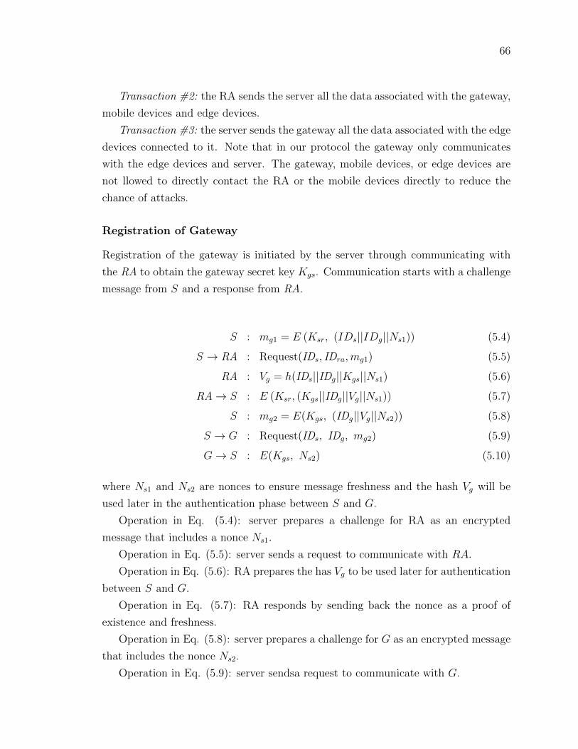
66
Transaction #2: the RA sends the server all the data associated with the gateway,
mobile devices and edge devices.
Transaction #3: the server sends the gateway all the data associated with the edge
devices connected to it. Note that in our protocol the gateway only communicates
with the edge devices and server. The gateway, mobile devices, or edge devices are
not llowed to directly contact the RA or the mobile devices directly to reduce the
chance of attacks.
Registration of Gateway
Registration of the gateway is initiated by the server through communicating with
the RA to obtain the gateway secret key Kgs. Communication starts with a challenge
message from S and a response from RA.
S : mg1 = E (Ksr, (IDs||IDg||Ns1)) (5.4)
S → RA : Request(IDs, IDra,mg1) (5.5)
RA : Vg = h(IDs||IDg||Kgs||Ns1) (5.6)
RA→ S : E (Ksr, (Kgs||IDg||Vg||Ns1)) (5.7)
S : mg2 = E(Kgs, (IDg||Vg||Ns2)) (5.8)
S → G : Request(IDs, IDg, mg2) (5.9)
G→ S : E(Kgs, Ns2) (5.10)
where Ns1 and Ns2 are nonces to ensure message freshness and the hash Vg will be
used later in the authentication phase between S and G.
Operation in Eq. (5.4): server prepares a challenge for RA as an encrypted
message that includes a nonce Ns1.
Operation in Eq. (5.5): server sends a request to communicate with RA.
Operation in Eq. (5.6): RA prepares the has Vg to be used later for authentication
between S and G.
Operation in Eq. (5.7): RA responds by sending back the nonce as a proof of
existence and freshness.
Operation in Eq. (5.8): server prepares a challenge for G as an encrypted message
that includes the nonce Ns2.
Operation in Eq. (5.9): server sendsa request to communicate with G.

67
Operation in Eq. (5.10): gateway responds to the challenge by sending back the
encrypted nonce Ns2.
Registration of the Mobile Device
Registration of the mobile device M is initiated by the mobile device through commu-
nicating with S that in turn communicates with the RA to obtain the mobile device
identity IDm. The server also informs RA of the password selected by the user PWm.
M : mm1 = E(Kms, (IDm||Nm)) (5.11)
M → S : Request(IDm, IDs, mm1) (5.12)
S : mm2 = E(Ksr, (IDs||IDm||Ns1)) (5.13)
S → RA : Request(IDs, IDra, m2) (5.14)
RA : Vm = h(IDm||PWm) (5.15)
RA→ S : E(Ksr, (IDm||Vm||Ns1)) (5.16)
S →M : E(Kms, (IDm||Vm||Ns2)||mm1) (5.17)
M → S : E(Kms, Ns2) (5.18)
where the hash Vm will be used later in the authentication phase between S and M .
The steps in Eq. (5.11)–Eq. (5.18) have the same meaning as was explained for steps
Eq. (5.4)–Eq. (5.10)
Registration of the Edge Device
The network administrator informs the server of all the entities forming the telehealth
system including server, mobile devices, gateway, and all the edge devices connected
to the gateway. As a result, registration of the edge devices is initiated by the server
through communicating with the RA to obtain each edge device secret key Kdg and
CRPd Dataset, corresponding to the built-in PUF, as well as fuzzy extractor data
such as BCH code with parameters (n, k, d) as well the generator matrix (G) and
parity check matrix (H). The server also communicates these information to the

68
gateway.
S : m1 = E(Ksr, (IDs||IDg||IDd||Ns1)) (5.19)
S → RA : Request(IDs, IDra, m1) (5.20)
RA : Vd = h(IDd||Kdg||Ns1) (5.21)
RA : m2 = TIDd||G||H||CRPd||(n, k, d)||
Vd||Ns1 (5.22)
RA→ S : E(Ksr,m2) (5.23)
S : m3 = E(Kgs, (IDd||Vd||Ns2)) (5.24)
S → G : Request(IDs, IDg, m3) (5.25)
G→ S : E(Kgs, Ns2) (5.26)
G : m4 = E(Kdg, (IDd||Vd||Ng)) (5.27)
G→ E : Request(IDg, IDd, m4) (5.28)
D → G : E(Kdg, Ng) (5.29)
where the hash Vd and TIDd will to be used for the duration of the session during
communication between the gateway and the edge device. The steps in Eq. (5.19)–Eq.
(??) have the same meaning as was explained for steps Eq. (5.4)–Eq. (5.10)
5.3.3 Login Phase
The healthcare professional logs in to the telehealth system through the mobile device
using three-factor authentication by what he/she has (mobile device), what he/she
knows (password), and what he/she is (biometric). The mobile device also computes
V ′m and sends it to the server.
M : V ′m = h(IDm||PWm) (5.30)
S : Vm == V ′m (5.31)
Login is successful when Vm matches V ′m. If first login in is not successful, another
login is established by asking for other personal information such as a security question
or reaching out to the system administrator. A limited number of login attempts
is allowed and if this number is exceeded, the device terminates the login request
immediately until the user re-registers again.

69
5.3.4 Authentication Phase
Mutual authentication is required between the communicating entities. We consider
here the case when a healthcare professional desires to communicate with an edge
device. In that case four entities are involved: mobile device M , server S, gateway
G and finally the edge device D. Figure 5.6 shows the authentication phase between
the four communicating entities. Authentication proceeds as three stages:
Mobile Device M
Gateway
G
Edge Device
D
Server S
Figure 5.6: Authentication phase of the proposed scheme.
1. Mobile device–server stage
2. Server–gateway stage
3. Gateway–edge device stage
Mobile Device–Server Stage
The mobile device chooses a nonce N1 and obtains its current location Lm and cal-
culates a dynamic identity
DIDm = IDm ⊕N1 (5.32)
The dynamic identity depends on the nonce N1 and becomes unique to each session
to preserve anonymity and untraceability.
The mobile device employs hash chains to calculate the quantities:
MS = (DIDm||N1||Lm)⊕ Vm (5.33)
Hms = h(DIDm||N1||Lm) (5.34)
where Vm was obtained from RA in Eq. (5.15).
The mobile device sends the following message to the server
M → S : (MS, Hms) (5.35)
This assures the server of the freshness and presence of the mobile device.

70
The server receives the message in Eq. (5.35), and computes MS using the stored
value Vm
DIDm||N1||Lm = MS⊕ Vm (5.36)
The server checks the freshness of received nonce N1 to prevent replay attack and
computes ID∗m and H∗ms
ID∗m = DIDm ⊕N1 (5.37)
H∗ms = h(DIDm||N1||Lm) (5.38)
The mobile device is authenticated when the following equalities are statisfied:
ID∗m == IDm
H∗ms = Hms
L∗m ≤ Lm−1 + ∆
where ∆ is the maximum change allowed in the location between two sessions. This
verifies the integrity of the message, otherwise the server will terminate the session
with the mobile device.
Server–Gateway Stage
The server prepares a message to send to the gateway. It starts by generating a nonce
N2 and computes a server dynamic identity DIDs:
DIDs = IDs ⊕N2 (5.39)
The server then computes:
SG = (DIDs||N1||N2)⊕ Vg (5.40)
Hsg = h(DIDs||N1||N2) (5.41)
The server sends the following message to the gateway
S → G : (SG, Hsg) (5.42)
The gateway receives the message in Eq. (5.42) from the server, and computes

71
SG using the stored value Vg
DIDs||N1||N2 = SG⊕ Vg (5.43)
The gateway computes ID∗s and H∗sg
ID∗s = DIDs ⊕N2 (5.44)
H∗sg = h(DIDs||N1||N2) (5.45)
The gateway compares H∗sg with the received value Hsg. This verifies the integrity of
the message, otherwise the gateway will terminate the session with the server.
Gateway–Edge Device Stage
The gateway prepares a message to send to the edge device. It starts by preparing a
nonce N3 and computes
GE = (N1||N2||N3)⊕ Vd (5.46)
Hge = h(N1||N2||N3) (5.47)
The gateway sends the following message to the edge device
G→ E : (GE, Hge) (5.48)
The edge device receives the message in Eq. (5.48) from the gateway, and computes
GD using the stored value Vd
N1||N2||N3 = GD⊕ Vd (5.49)
The edge device computes H∗ge
H∗ge = h(N1||N2||N3) (5.50)
The edge device compares H∗ge with the received value Hge. This verifies the integrity
of the message, otherwise the edge device will terminate the session with the gateway.

72
The Reverse Path
The edge device generates a nonce N4 and computes its dynamic identity DIDd and
the session key SK
DIDd = IDd ⊕N4 (5.51)
SK = h(N1||N2||N3||N4) (5.52)
The edge device collects the identities of all the edge devices it sees around it
through its Bluetooth or Zigbee connection:
Dd = {IDdi|i ∈ D} (5.53)
where Dd is the set of identities of all edge devices seen by the particular edge device
being authenticated and E is the set of all edge devices in the IoT network.
The edge device prepares a reply to the gateway by computing the following
quantities
DG = (DIDd||Dd||N4)⊕ Vd (5.54)
Hgd = h(N4||SK) (5.55)
The edge device sends the following message to the gateway
D → G : (DG, Hdg) (5.56)
When the gateway receives the message from the edge device, it will extract N4 and
Dd:
(DIDd||Dd||N4) = DG⊕ Vg (5.57)
The gateway then computes the device identity
IDd = DIDd ⊕N4 (5.58)

73
The edge device is authenticated when the following are satisfied
ID∗d == IDd
Dd 6= φ
Dd ⊂ D
H∗gd == Hgd
Having the value N4, the gateway verifies message integrity using Eq. (5.55) and
ensures the validity of the above equations.
The gateway now has the value N4 and can independently calculate its dynamic
identity and the session key SK using Eq. (5.52).
DIDg = IDg ⊕N3 (5.59)
The gateway embeds the values N3 and N4 in the following quantity
GS = (DIDg||N3||N4)⊕ Vg (5.60)
The gateway also computes Hgs
Hgs = h(N3||N4||SK) (5.61)
The gateway now sends the following message to the server
G→ S : (GS||Hgs) (5.62)
When the server receives the message from the gateway, it will extract N3 and N4
(DIDg||N3||N4) = GS⊕ Vg (5.63)
Using N3 and N4, the server will independently calculate the gateway dynamic iden-
tity DID∗g using Eq. (5.59) and the session key SK using Eq. (5.52).
The server verifies the integrity of the message by calculating H∗gs form Eq. (5.61)
and compare it with the received Hgs.
The server now has the values N2, N3 and N4. The server now embeds the values

74
N2, N3 and N4 in the following quantity
SM = (N2||N3||N4)⊕ Vm (5.64)
The server also computes Hsm
Hsm = h(N2||N3||N4) (5.65)
The server now sends the following message to the mobile device
S →M : (SM||Hsm) (5.66)
When the mobile device receives the message from the server, it will extract N2,
N3 and N4
(N2||N3||N4) = SM⊕ Vm (5.67)
Using N2, N3 and N4, the mobile device will independently calculate the session key
SK using Eq. (5.52).
The mobile device verifies the integrity of the message by calculating H∗sm form
Eq. (5.65) and compare it with the received Hsm.
5.3.5 Pasword Update Phase
The password update phase applies to the user of the mobile device. The user can
update the password after registration without involving the RA. In order to do
that, the user supplies IDm and the old password. The mobile device calculates
V ∗m according to Eq. (5.15) and compare this with Vm that was defined during the
registration phase. If the two values match, then the password update process can
proceed further. The mobile device calculates a new Vm based on the new password
and send this to the server.
5.4 Security Analysis of the Proposed Scheme
To analyze the security of our proposed scheme, we use BAN logic [80] and formal
model checking and simulations using AVISPA tool [81] and informal security analysis.

75
5.4.1 Formal Proof Based on BAN Logic
In this subsection, we introduce a formal analysis for the proposed scheme using widely
accepted model called BAN logic, this model has been used for a formal verification
of security protocols which introduced in 1989 by Burrows et al. [80]. We begin our
analysis by introducing the most important symbols and notations adapted from [82]
which are given in Table 5.2.
Table 5.2: Notations in BAN logic.
Notation Descriptions
P and Q Principals
P | ≡ X Principal P believes the statement X
P / X Principal P sees the statement X
P | ⇒ X Principal P has jurisdiction over the statement X
P | ∼ X Principal P once said statement X
(X, Y ) The statement X or Y is one part of message (X, Y )
< X >Y The statement X is encrypted with the key K
(X)K The statement X is hashed with the key K
PK←→ Q K is a secret parameter shared (or to be shared) between P and Q
PK� Q X is a secret known only to P and Q, and possibly to parties trusted by them.
#(X) The message X is fresh.
In addition, the following BAN logic basic rules are used to prove that our au-
thentication protocol provides secure mutual authentication and key agreement as
follows:
• Message-meaning rule:
If P believes that the key K is shared with Q and P sees X encrypted under
K, then P believes that Q once said X.
P | ≡ QK↔ P, P / 〈X〉K
P | ≡ Q| ∼ X
• Nonce verification rule:
If P believes X is fresh and P believes Q once said X, then P believes Q believes

76
X.
P | ≡ #(X), P | ≡ Q| ∼ X
P | ≡ Q| ≡ X
• Jurisdiction rule:
If P believes Q has jurisdiction over X and P believes Q believes X, then P
believes X.P | ≡ Q| =⇒ X,P | ≡ Q| ≡ X
P | ≡ X
• Freshness conjuncatenation rule:
If one part of a statement is fresh, then the entire statement must also be fresh;
so if P believes X is fresh, then P believes X and Y are fresh.
P | ≡ #(X)
P | ≡ #(X, Y )
• Belief rule: If P believes X and Y, then P believes X.
P | ≡ (X, Y )
P | ≡ X
• Session keys rule:P | ≡ #(X), P | ≡ Q| ≡ X
P | ≡ PK↔ Q
The proposed scheme must achieve the following goals:
• Goal 1
S| ≡M | ≡MSK↔ S
• Goal 2:
S| ≡MSK↔ S
• Goal 3:
G| ≡ S| ≡ SSK↔ G
• Goal 4:
G| ≡ SSK↔ G

77
• Goal 5:
D| ≡ G| ≡ GSK↔ D
• Goal 6:
D| ≡ GSK↔ D
• Goal 7:
G| ≡ D| ≡ GSK↔ D
• Goal 8:
G| ≡ GSK↔ D
• Goal 9:
S| ≡ G| ≡ SSK↔ G
• Goal 10:
S| ≡ SSK↔ G
• Goal 11:
M | ≡ S| ≡MSK↔ S
• Goal 12:
M | ≡MSK↔ S
• Goal 13:
M | ≡ G| ≡MSK↔ G
• Goal 14:
G| ≡M | ≡MSK↔ G
• Goal 15:
S| ≡ D| ≡ SSK↔ D
• Goal 16:
D| ≡ S| ≡ SSK↔ D
The fundamental assumptions of the authentication protocol are as follows:

78
• A1:
M | ≡ #(N2)
• A2:
M | ≡ #(N3)
• A3:
M | ≡ #(N4)
• A4:
S| ≡ #(N1)
• A5:
S| ≡ #(N3)
• A6:
S| ≡ #(N4)
• A7:
G| ≡ #(N2)
• A8:
G| ≡ #(N4)
• A9:
D| ≡ #(N1)
• A10:
D| ≡ #(N2)
• A11:
D| ≡ #(N3)
• A12:
S| ≡MVm↔ S
• A13:
G| ≡ SVg↔ G

79
• A14:
D| ≡ GVd↔ D
• A15:
G| ≡ DVd↔ G
• A16:
M | ≡ SVm↔ M
• A17:
S| ≡ GVg↔ S
• A18:
G| ≡ D| ⇒ (N4, IDd,Vd, SK)
• A19:
S| ≡ G| ⇒ (N3, N4, IDg,Vg, SK)
• A20:
M | ≡ S| ⇒ (N2, N3, N4,Vm, SK)
• A21:
D| ≡ G| ⇒ (N1, N2, N3,Vd, SK)
• A22:
S| ≡M | ⇒ (N1, IDm,Vm, Lm, SK)
• A23:
G| ≡ S| ⇒ (N1, N2, IDs, Vg, SK)
Messages transferred in the authentication protocol:
• Msg 1:
M → S : (MS, Hms)M
Vm↔S
• Msg 2:

80
S → G : (SG, Hsg)SVg↔G
• Msg 3:
G→ D : (GD, Hgd)G
Vd↔D
• Msg 4:
D → G : (DG, Hdg)D
Vd↔G
• Msg 5:
G→ S : (GS, HGS)SVg↔G
• Msg 6:
S →M : (SM, HSM)SVm↔M
Analysis of our authentication scheme:
• S1: According to Msg 1, we get:
S / (MS, Hms)M
Vm↔S
• S2: Based on Assumption A12, S1 and message-meaning rule, we have:
S| ≡MVm↔ S, S / (MS, Hms)
MVm↔S
S| ≡M | ∼ (MS, Hms)M
Vm↔S
• S3: From A4 and freshness-conjuncatenation rule, we get:
S | ≡ # (MS, Hms)M
Vm↔S
• S4: From S3, S2 and nonce-verification rule, we get:
S | ≡ # (MS, Hms)M
Vm↔ S, S| ≡ M| ∼ (MS, Hms)
S| ≡ M| ≡ (MS, Hms)M
Vm↔ S

81
• S5: According to the Msg 2, we get:
G / (SG, Hsg)SVg↔G
• S6: From A13, S5 and message-meaning rule, we have:
G| ≡ SVg↔ G,G / (SG, Hsg)
SVg↔G
G| ≡ S| ∼ (SG, Hsg)SVg↔G
• S7: From A7 and freshness-conjuncatenation rule, we get:
G | ≡ # (SG, Hsg)SVg↔G
• S8: From S7, S6 and nonce-verification rule, we get:
G | ≡ # (SG, Hsg)SVg↔G
, G| ≡ S| ∼ (SG, Hsg)SVg↔G
G| ≡ S| ≡ (SG, Hsg)SVg↔G
• S9: According to the Msg 3, we get:
D / (GD, Hgd)G
Vd↔D
• S10: From A14, S9 and message-meaning rule, we have:
D| ≡ (GVd↔ D), D / (GD, Hgd)
GVd↔D
D| ≡ G| ∼ (GD, Hgd)G
Vd↔D
• S11: From A11 and freshness-conjuncatenation rule, we get:
D | ≡ # (GD, Hgd)G
Vd↔D
• S12: From S11, S10 and nonce-verification rule, we get:
D | ≡ # (GD, Hgd)G
Vd↔D, D| ≡ G| ∼ (GD, Hgd)
GVd↔D
D| ≡ G| ≡ (GD, Hgd)G
Vd↔D

82
• S13: According to the Msg 4, we get:
G / (DG, Hdg)G
Vd↔D
• S14: From A15, S13 and message-meaning rule, we have:
G| ≡ DVd↔ G,G / (DG, Hdg)
GVd↔D
G| ≡ D| ∼ (DG, Hdg)G
Vd↔D
• S15: From A8 and freshness-conjuncatenation rule, we get:
G | ≡ # (DG, Hdg)G
Vd↔D
• S16: From S15, S14 and nonce-verification rule, we get:
G | ≡ # (DG, Hdg)G
Vd↔D, G| ≡ D| ∼ (DG, Hdg)
GVd↔D
G| ≡ D| ≡ (DG, Hdg)G
Vd↔D
• S17: According to the Msg 5, we get:
S / (GS, HGS)SVg↔G
• S18: From A17, S17 and message-meaning rule, we have:
S| ≡ GVg↔ S, S / (GS, HGS)
SVg↔G
S| ≡ G| ∼ (GS, HGS)SVg↔G
• S19: From A5, A6 and freshness-conjuncatenation rule, we get:
S | ≡ # (GS, HGS)SVg↔G
• S20: From S19, S18 and nonce-verification rule, we get:
S | ≡ # (GS, HGS)SVg↔G
, S| ≡ G| ∼ (GS, HGS)SVg↔G
S| ≡ G| ≡ (GS, HGS)SVg↔G

83
• S21: According to the Msg 6, we get:
M / (SM, HSM)SVm↔M
• S22: From A16, S21 and message-meaning rule, we have:
M | ≡ SVm↔M,M / (SM, HSM)
SVm↔M
M | ≡ S| ∼ (SM, HSM)SVm↔M
• S23: From A1, A2, A3 and freshness-conjuncatenation rule, we get:
M | ≡ # (SM, HSM)SVm↔M
• S24: From S23, S22 and nonce-verification rule, we get:
M | ≡ # (SM, HSM)SVm↔M
,M | ≡ S| ∼ (SM, HSM)SVm↔M
M | ≡ S| ≡ (SM, HSM)SVm↔M
• S25: From A22, S4 and jurisdiction rule, we get:
S| ≡ M| ⇒ (N1, IDm,Vm, Lm, SK), S| ≡ M| ≡ (MS, Hms)M
Vm↔ S
S| ≡ (MS, Hms)M
Vm↔ S
• S26: From S3, S4 and session keys rule, we get:
S | ≡ # (MS, Hms)M
Vm↔ S, S| ≡ M| ≡ (MS, Hms)
MVm↔ S
S| ≡ M| ≡ MSK↔ S
(Goal 1)
• S27: From A22, S26 and jurisdiction rule, we get:
S| ≡ M| ⇒ (N1, IDm,Vm, Lm, SK), S| ≡ M| ≡ MSK↔ S
S| ≡ MSK↔ S
(Goal 2)
• S28: From A23, S8 and jurisdiction rule, we get:
G| ≡ S| ⇒ (N1, N2, IDs, Vg, SK), G| ≡ S| ≡ (SG, Hsg)SVg↔G
G| ≡ (SG, Hsg)SVg↔G

84
• S29: From S7, S8 and session keys rule, we get:
G | ≡ # (SG, Hsg)SVg↔G
, G| ≡ S| ≡ (SG, Hsg)SVg↔G
G| ≡ S| ≡ SSK↔ G
(Goal 3)
• S30: From A23, S29 and jurisdiction rule, we get:
G| ≡ S| ⇒ (N1, N2, IDs, Vg, SK), G| ≡ S| ≡ SSK↔ G
G| ≡ SSK↔ G
(Goal 4)
• S31: From A21, S12 and jurisdiction rule, we get:
D| ≡ G| ⇒ (N1, N2, N3,Vd,SK), D| ≡ G| ≡ (GD, Hgd)G
Vd↔D
D| ≡ (GD, Hgd)G
Vd↔D
• S32: From S11, S12 and session keys rule, we get:
D | ≡ # (GD, Hgd)G
Vd↔D, D| ≡ G| ≡ (GD, Hgd)
GVd↔D
D| ≡ G| ≡ GSK↔ D
(Goal 5)
• S33: From A21, S32 and jurisdiction rule, we get:
D| ≡ G| ⇒ (N1, N2, N3,Vd, SK), D| ≡ G| ≡ GSK↔ D
D| ≡ GSK↔ D
(Goal 6)
• S34: From A18, S16 and jurisdiction rule, we get:
G| ≡ D| ⇒ (N4, IDd,Vd,SK), G| ≡ D| ≡ (DG, Hdg)G
Vd↔D
G| ≡ (DG, Hdg)G
Vd↔D

85
• S35: From S15, S16 and session keys rule, we get:
G | ≡ # (DG, Hdg)G
Vd↔D, G| ≡ D| ≡ (DG, Hdg)
GVd↔D
G| ≡ D| ≡ GSK↔ D
(Goal 7)
• S36: From A18, S35 and jurisdiction rule, we get:
G| ≡ D| ⇒ (N4, IDd,Vd, SK), G| ≡ D| ≡ GSK↔ D
G| ≡ GSK↔ D
(Goal 8)
• S37: From A19, S20 and jurisdiction rule, we get:
S| ≡ G| ⇒ (N3, N4, IDg,Vg,SK), S| ≡ G| ≡ (GS, HGS)SVg↔G
S| ≡ (GS, HGS)SVg↔G
• S38: From S19 and S20, we get:
S | ≡ # (GS, HGS)SVg↔G
, S| ≡ G| ≡ (GS, HGS)SVg↔G
S| ≡ G| ≡ SSK↔ G
(Goal 9)
• S39: From A19, S38 and jurisdiction rule, we get:
S| ≡ G| ⇒ (N3, N4, IDg,Vg, SK), S| ≡ G| ≡ SSK↔ G
S| ≡ SSK↔ G
(Goal 10)
• S40: From A20, S24 and jurisdiction rule, we get:
M | ≡ S| ⇒ (N2, N3, N4,Vm,SK),M | ≡ S| ≡ (SM, HSM )M
Vm↔S
M | ≡ (SM, HSM )M
Vm↔S

86
• S41: From S23, S24 and session keys rule, we get:
M | ≡ # (SM, HSM )SVm↔M
,M | ≡ S| ≡ (SM, HSM )SVm↔M
M | ≡ S| ≡MSK↔ S
(Goal 11)
• S42: From A20, S41 and jurisdiction rule, we get:
M | ≡ S| ⇒ (N2, N3, N4,Vm, SK),M | ≡ S| ≡MSK↔ S
M | ≡MSK↔ S
(Goal 12)
• S43: From S41, S30, we get:
M | ≡ S| ≡MSK↔ S,G| ≡ S
SK↔ G
M | ≡ G| ≡MSK↔ G
(Goal 13)
• S44: From S29, S42 and jurisdiction rule, we get:
G| ≡ S| ≡ SSK↔ G,M | ≡M
SK↔ S
G| ≡M | ≡MSK↔ G
(Goal 14)
• S45: From S38, S33 and jurisdiction rule, we get:
S| ≡ G| ≡ SSK↔ G,D| ≡ G
SK↔ D
S| ≡ D| ≡ SSK↔ D
(Goal 15)
• S46: From S32, S39 and jurisdiction rule, we get:
D| ≡ G| ≡ GSK↔ D,S| ≡ S
SK↔ G
D| ≡ S| ≡ SSK↔ D
(Goal 16)

87
Hence, the above BAN logic analysis formally proves that the proposed scheme suc-
cessfully achieves mutual authentication, and the session key SK, in Eq. (5.52), is
mutually established between the U and the Dj through the G.
5.4.2 Informal Security Analysis
In this section, we show how our protocol is robust against various well-known attacks.
Replay attack
To resist replay attack, the random number method is utilized, so replay attack can
be prevented by using the nonces which change in each session.
Eavesdropping attack
In our scheme, the adversary can easily intercept the messages between M , S, G and
D since all messages are sent in plain text. However, the attacker can not access
sensitive information from any messages because the confidential data is secured by
secret parameters shared securely between the entities (e.g., Vm and Vg), and shielded
by one-way hash function and bitwise XOR operator. The attacker would thus not
be able to unfold the transmitted parameters, and thus can not extract any useful
information.
Impersonation attack
Assume an attacker A attempts to impersonate a healthcare professional. A can
not succeed because he/she does not know the password or the biometric needed for
three-factor authentication to access the mobile device.
Man-in-the-middle attack
The proposed scheme offers mutual authentication, as stated in Section 5.4.1 of the
BAN logic. The transmitted messages are further protected by the secret values and
nonces, and no one could forge legally authenticated messages without knowing those
secret values. The proposed scheme hence prevents the Man-in-the-Middle attack.
88
Forward/backward secrecy
The session key is built using four different random numbers that are generated by
M , S, G and D in each session. Thus, if the session key SK is compromised by an
attacker, the confidential information of past or future communication sessions can not
be compromised. For this reason, the proposed scheme achieves forward/backward
secrecy.
Session key Guessing Attack
The session key SK is constructed by all communication participants, namely M , S,
G and D, and four randomly selected nonces. Thus security relies on the randomness
of the input values, which makes it difficult for an attacker to guess. An attacker’s
probability of guessing the right key SK is negligible, provided that N1, N2, N3 and
N4 are chosen randomly in every session.
User anonymity and untraceability
Anonymity of users and untraceability in authentication are two essential security
properties. Anonymity ensures that the mobile device’s real identity is maintained
secure, and that the mobile device stays unidentifiable among other devices. There-
fore, the attacker is unable to identify the devices’ identities. Untraceability, on the
other hand, means that the various sessions set up by a specific mobile device are
not traceable, so that an attacker can not relate any sessions to a specific mobile de-
vice. These two main security properties were achieved by the use of the healthcare
professional’s dynamic identity, where we use different ID in each session.
Location-based authentication
The physical context awareness (location in the IoT system) used in our scheme
involves checking the identities of the edge devices seen by the device D being au-
thenticated, see Eq. (5.53). If the subset Dd is valid and does not contain identities
of unkown devices, then the location of our device is authenticated.
Cloning attack
Cloning attack targets the unprotected IoT edge devices. Section 5.2.1 discussed
incorporating PUF modules in the edge devices which provides a high degree of

89
tamper-resistant unique identity (fingerprint) without incurring extra costs in area,
delay, power or specialized processing steps [68]. The unique device identity avoids
using nonvolatile memory, whose contents can be easily obtained by an unsophisti-
cated attacker. Instead the device ID is captured in the PUF circuitry which provides
a random response with low entropy that imparts sufficient differences between the
manufactured edge devices. Therefore, IoT edge devices are immune to cloning at-
tacks.
Physical attack
Physical attack attempts to obtain the secret key of the device knowing that secret
keys are typically stored in nonvolatile memories. The IoT edge devices are the most
vulnerable to this type of attack since they are usually located in unsecured locations.
We mentioned above in Sec. 5.2.1 PUF modules are installed in the edge devices which
provides a high degree of tamper-resistant unique identity (fingerprint). The PUF
response is used to extract the secret key instead of relying on nonvolatile memories.
Section 5.2.7 discussed how the secret key is extract from the noisy response of the
PUF. Therefore, IoT edge devices are immune to physical attacks.
5.4.3 Simulation Based on AVISPA Tool
The proposed scheme was formally validated by AVISPA that is a widely used tool for
security protocol assessments. The message exchanges and entities were defined in the
high-level property specification language (HLPSL). The definitions and information
in details can be found in [43].
This subsection explores several roles for system entities, the session, the goal and
the environment of proposed scheme. In Fig. 5.7-5.10, we illustrate HLPSL code
for our proposed scheme. These figures show the HLPSL language code that defines
the configuration of the sessions, the environment and security goals to be achieved
by our proposed scheme. The figures also show the definitions of the security goals
declared to be secrets in the entity’s functions and the values that are authenticated
by the entities.
Fig. 5.11 shows the protocol execution using SPAN software, where the all agents
exchange the messages in authentication phase.
In conclusion, the results shown in Fig. 5.12-5.13 clearly show that the the pro-
posed scheme is immune against man-in-the-middle and replay attacks.

90
Figure 5.7: Role of S in HLPSL code.
Figure 5.8: Role of M in HLPSL code.

91
Figure 5.9: Role of G in HLPSL code.
Figure 5.10: Role of D in HLPSL code.

92
Figure 5.11: The protocol execution using SPAN.
5.4.4 Performance Comparison
In this section, we assess the performance of our proposed scheme in terms of storage
cost, computation costs, and communication overhead.
Storage cost
We evaluate storage cost (in bits) for M , S, G and D of the four participants.
M stores IDm and Vm. As an example of hash function we utilize SHA3-384, and
output of SHA3-384 is 384 bits. Using SHA3-384 we get Vm = 384 bits [83]. While
IDm = 128 bits. Thus, the total storage required by M is 384+128=512 bits.
S stores IDs, IDm, IDg, Vm and Vg. By applying SHA3-384, we obtain Vm = Vg
= 384 bits. The IDs=IDm=IDg=128 bits. Therefore, the total storage required by S
is (2x384)+(3x128)= 1152 bits.
G stores IDg, IDs, IDd, Vg and Vd. The IDg=IDs=IDd = 128 bits and Vg = Vd =
384 bits. Therefore, the total storage required by G is (3x128)+(2x384)= 1152 bits.
D stores IDd and Vd. The IDd = 128 bits and Vd = 384 bits. Therefore, the total

93
Figure 5.12: Analysis of results using CL-AtSe.
Figure 5.13: Analysis of results using OFMC.

94
storage required by D is 128+384= 512 bits.
Computational cost
In this subsection, we provide the computation cost analysis of our proposed scheme.
In order to ensure a precise computation cost of our scheme, the experimental data
reported in [84] and [85] are used. The terms Th, Texp, and TE/TD as the computa-
tional time for hash function h(.), modular exponentiation operation, and symmetric
encryption/decryption, respectively.
Table 5.3 Shows the time required to conduct certain operations. However, the
execution time of the bitwise XOR operation is negligible. Our scheme performs 13
hash invocations and 19 XOR operations, which yields a total computation cost (13
× Th). Hence, the computation cost of our proposed protocol is (13 × 0.5 ms)= 6.5
ms.
Table 5.3: Crypto-operations and the computational times needed.
Crypto-operations Computationaltime
Execute/verify a signature (Tsign) 331.7 ms
Asymmetric encryption/ decryption operation (TA) 305.7 ms
Multiplication operation (TM) 50.3 ms
Bilinear pairing operation (TP ) 62.1 ms
Symmetric encryption/ decryption operation (TS) 8.7 ms
One-way hash function (TH) 0.5 ms
A comparison of the computation cost between the proposed scheme and the other
most related schemes in ms is shown in Table 5.4.
Table 5.5 provides security and functionality features compared to other existing
related schemes.
5.5 Conclusion
Basic security requirements such as privacy, authentication, integrity, non-repudiation
and key exchange are essential for telehealth delivery to remote communities and at-

95
Table 5.4: Comparison of computation cost between the proposed scheme and othermost related schemes in ms.
Authentication scheme Total cost Rough estimation
Kumar et al. [86] 8TS + 10TH 74.6 ms
Chen et al. [28] 2Tsign + 2TP + 6TS + 4TH 841.8 ms
Karthigaiveni et al. [87] 2TA + 3TH + 2TS 630.3 ms
Alzahrani et al. [88] 17TH + 5TS 52 ms
Proposed scheme 13Th 6.5 ms
Table 5.5: Security and functionality features comparison.
Functionality features [86] [28] [87] [88] Proposedscheme
Mutual authentication Yes Yes No No Yes
Session key agreement Yes Yes Yes Yes Yes
User anonymity Yes Yes No No Yes
Untraceability Yes Yes No No Yes
Forward security No Yes Yes No Yes
Password guessing attack Yes Yes No No Yes
Mobile device loss attack Yes Yes No No Yes
Privileged insider attack Yes Yes Yes Yes Yes
Impersonation attack Yes Yes No No Yes
Replay attack Yes Yes Yes Yes Yes
Man-in-the-middle attack Yes Yes Yes No Yes
Password change phase Yes Yes No No Yes
Formal proof (BAN logic) Yes Yes No No Yes
Formal verification(AVISPA)
Yes No Yes No Yes
Authentication based on
contextual factors No No No No Yes
Cloning attack No No No No Yes
Physical attack No No No No Yes
96
home patients. In this work a robust lightweight authentication and key exchange
scheme is proposed among four entities involved in an telehealth system. After a
round of secure authentication between a mobile device, server, gateway and an IoT
edge device, a symmetric session key is established. Security of the proposed scheme
is proved formally using BAN logic. In addition, informal security verification assures
resistance of the proposed scheme in the face of the most common attacks. Finally,
formal security of the proposed protocol is evaluated using the AVISPA tool that
assures us of the security of the protocol.

97
Chapter 6
Conclusion and Future Work
6.1 Conclusion
The Internet of Things (IoT) plays an important role in all facets of our daily lives.
It benefits different fields, including healthcare, industrial appliances, sports, homes,
etc. The IoT consists of billions of devices connected together over the internet that
are able to gather and exchange data using IoT nodes and controllers.
The number of IoT devices is increasing at a very fast pace. It has been predicted
by Gartner that the number of IoT devices will reach 20.4 billion by 2020 [89][90] and
25 billion by 2025 [91]. The anticipated fast growth of IoT devices has led to serious
security concerns for networks [92].
Cyber attackers are shifting their attention from traditional computers to IoT
devices for malignant activities like exposing smart homeowner private information
and/or to launch botnet attacks. As in conventional networks, the security of IoT
networks rests on how properly the authentication process is done. However, un-
like conventional networks, the IoT infrastructure faces an uphill battle in deploying
and operating strong authentication schemes because of inherent limitations on the
underlying storage and computation capability.
The first contribution of this work is the introduction of a new scheme for user
authentication that combines physical context awareness and transaction history The
new scheme offers two advantages: it does not maintain a verification table and
avoids clock synchronization problem. Moreover, the security of the proposed scheme
is augmented using dynamic identities and temporary secret session keys that change
in every session, and are exchanged in an unlinkable manner, improve the security of

98
the proposed scheme.
The second contribution is the introduction of a secure telehealth system using
multifactor authentication for the mobile devices as well as the IoT edge devices in
the system. These two types of devices constitute the weakest link in telehealth
systems. The mobile devices and edge devices are typically unsecured and contain
vulnerable processors. The mobile devices use the healthcare professional’s biometric
and endowing the edge device with biometrics is accomplished by using physically
unclonable functions (PUFs). The embedded PUF acts as a means of enabling mutual
authentication and key exchange.
Furthermore, through the rigorous formal and informal security analysis of our
protocols using the BAN logic and AVISPA tool, we show that our schemes are re-
silient against known attack methods. Besides, our schemes achieved the key security
properties (e.g., anonymity, unlinkability) with a relatively limited performance over-
head. Finally, we compared our schemes with other proposed schemes and showed
that our schemes are in general more efficient than recently proposed schemes.
6.2 Future Work
Our plans for future work include the following:
• We will extend the proposed protocol suite to consider cases where the IoT node
leaves one particular home network and joins another network.
• We will allow an IoT device in one home network to communicate with an IoT
device in another home network regardless of the underlying communication
protocols.
• We will also explore how to reinforce the current capability of our scheme to
thwart impersonation by adapting continuous authentication schemes, such as
the approach proposed by Tsai et al [93]. In their work [93], Tsai et al. presented
a passive contin- uous authentication system based on physiological and soft
biometrics technologies, namely face recognition and clothes’color recognition,
using interactive artificial bee colony algorithm. In the system, face recognition
is considered the key component to controlling the authentication process, while
soft biometric is seen as a support- ing factor to overcome and remedy any
potential security breach, such as account hijacking occurring while the user is
temporarily away from the device.

99
Bibliography
[1] K. Ashton et al., “That ‘internet of things’ thing,” RFID journal, vol. 22, no. 7,
pp. 97–114, 2009.
[2] C. Kolias, G. Kambourakis, A. Stavrou, and J. Voas, “Ddos in the iot: Mirai
and other botnets,” Computer, vol. 50, no. 7, pp. 80–84, 2017.
[3] Y. Lu and L. Da Xu, “Internet of things (iot) cybersecurity research: a review
of current research topics,” IEEE Internet of Things Journal, vol. 6, no. 2, pp.
2103–2115, 2018.
[4] M. Abomhara et al., “Cyber security and the internet of things: vulnerabilities,
threats, intruders and attacks,” Journal of Cyber Security and Mobility, vol. 4,
no. 1, pp. 65–88, 2015.
[5] N. Kshetri, “Can blockchain strengthen the internet of things?” IT professional,
vol. 19, no. 4, pp. 68–72, 2017.
[6] L. Pascu, “The iot threat landscape and top smart home vulnerabilities in 2018,”
2018.
[7] J. Wurm, K. Hoang, O. Arias, A.-R. Sadeghi, and Y. Jin, “Security analysis on
consumer and industrial iot devices,” in 2016 21st Asia and South Pacific Design
Automation Conference (ASP-DAC). IEEE, 2016, pp. 519–524.
[8] K. Gopalakrishnan et al., “Security vulnerabilities and issues of traditional wire-
less sensors networks in iot,” in Principles of Internet of Things (IoT) Ecosystem:
Insight Paradigm. Springer, 2020, pp. 519–549.
[9] A. Bhattacharjya, X. Zhong, J. Wang, and X. Li, “Present scenarios of iot
projects with security aspects focused,” in Digital Twin Technologies and Smart
Cities. Springer, 2020, pp. 95–122.
100
[10] P. Porambage, C. Schmitt, P. Kumar, A. Gurtov, and M. Ylianttila, “Two-
phase authentication protocol for wireless sensor networks in distributed iot ap-
plications,” in 2014 IEEE Wireless Communications and Networking Conference
(WCNC). IEEE, 2014, pp. 2728–2733.
[11] A. Pfitzmann and M. Kohntopp, “Anonymity, unobservability, and
pseudonymity—a proposal for terminology,” in Designing privacy enhancing
technologies. Springer, 2001, pp. 1–9.
[12] S. Steinbrecher and S. Kopsell, “Modelling unlinkability,” in International Work-
shop on Privacy Enhancing Technologies. Springer, 2003, pp. 32–47.
[13] V. Sureshkumar, R. Anitha, N. Rajamanickam, and R. Amin, “A lightweight
two-gateway based payment protocol ensuring accountability and unlinkable
anonymity with dynamic identity,” Computers & Electrical Engineering, vol. 57,
pp. 223–240, 2017.
[14] U. Blumenthal, F. Maino, and K. McCloghrie, “The advanced encryption stan-
dard (aes) cipher algorithm in the snmp user-based security model,” Internet
proposed standard RFC, vol. 3826, 2004.
[15] P. Barrett, “Implementing the rivest shamir and adleman public key encryption
algorithm on a standard digital signal processor,” in Conference on the Theory
and Application of Cryptographic Techniques. Springer, 1986, pp. 311–323.
[16] C. Insiders, “Insider threat-2018 report,” CA Technologies. Accessed Jun, vol. 20,
2018.
[17] J. Jeong, M. Y. Chung, and H. Choo, “Integrated otp-based user authentication
scheme using smart cards in home networks,” in Proceedings of the 41st Annual
Hawaii International Conference on System Sciences (HICSS 2008). IEEE,
2008, pp. 294–294.
[18] R. Roman, J. Zhou, and J. Lopez, “On the features and challenges of security and
privacy in distributed internet of things,” Computer Networks, vol. 57, no. 10,
pp. 2266–2279, 2013.
[19] P. Kumar, A. Braeken, A. Gurtov, J. Iinatti, and P. H. Ha, “Anonymous se-
cure framework in connected smart home environments,” IEEE Transactions on
Information Forensics and Security, vol. 12, no. 4, pp. 968–979, 2017.

101
[20] P. N. Mahalle, B. Anggorojati, N. R. Prasad, R. Prasad et al., “Identity authen-
tication and capability based access control (iacac) for the internet of things,”
Journal of Cyber Security and Mobility, vol. 1, no. 4, pp. 309–348, 2013.
[21] B. Vaidya, J. H. Park, S.-S. Yeo, and J. J. Rodrigues, “Robust one-time pass-
word authentication scheme using smart card for home network environment,”
Computer Communications, vol. 34, no. 3, pp. 326–336, 2011.
[22] H. J. Kim and H. S. Kim, “Auth hotp-hotp based authentication scheme over
home network environment,” in International Conference on Computational Sci-
ence and Its Applications. Springer, 2011, pp. 622–637.
[23] F. K. Santoso and N. C. Vun, “Securing iot for smart home system,” in 2015
International Symposium on Consumer Electronics (ISCE). IEEE, 2015, pp.
1–2.
[24] P. Kumar, A. Gurtov, J. Iinatti, M. Ylianttila, and M. Sain, “Lightweight and
secure session-key establishment scheme in smart home environments,” IEEE
Sensors Journal, vol. 16, no. 1, pp. 254–264, 2015.
[25] M. Wazid, A. K. Das, V. Odelu, N. Kumar, and W. Susilo, “Secure remote user
authenticated key establishment protocol for smart home environment,” IEEE
Transactions on Dependable and Secure Computing, 2017.
[26] M. Shuai, N. Yu, H. Wang, and L. Xiong, “Anonymous authentication scheme for
smart home environment with provable security,” Computers & Security, 2019.
[27] C. L. Chen, T. T. Yang, M. L. Chiang, and T. F. Shih, “A privacy authentication
scheme based on cloud for medical environment,” Journal of Medical Systems,
vol. 38, no. 143, 2014.
[28] C.-L. Chen, T.-T. Yang, and T.-F. Shih, “secure medical data exchange protocol
based on cloud environment,” Journal of medical systems, vol. 38, no. 9, p. 112,
2014.
[29] S.-Y. Chiou, Z. Ying, and J. Liu, “Improvement of a privacy authentication
scheme based on cloud for medical environment,” Journal of medical systems,
vol. 40, no. 4, p. 101, 2016.

102
[30] P. Mohit, R. Amin, A. Karati, G. Biswas, and M. K. Khan, “A standard mutual
authentication protocol for cloud computing based health care system,” Journal
of medical systems, vol. 41, no. 4, p. 50, 2017.
[31] C.-T. Li, D.-H. Shih, and C.-C. Wang, “Cloud-assisted mutual authentication
and privacy preservation protocol for telecare medical information systems,”
Computer Methods and Programs Biomedicine, vol. 157, pp. 191–203, 2018.
[32] B. Yu and H. Li, “Anonymous authentication key agreement scheme with pairing-
based cryptography for home-based multi-sensor internet of things,” Interna-
tional Journal of Distributed Sensor Networks, vol. 15, no. 9, 2019.
[33] R. Soni and G. Kumar, “A review on blockchain urgency in the internet of things
in healthcare,” in International Conference on Intelligent Sustainable Systems,
2019.
[34] S. M. R. Islam, D. Kwak, M. H. Kabir, M. Hossain, and K.-S. Kwak, “The
internet of things for health care: A comprehensive survey,” IEEE Access, vol. 3,
no. 6, Jun. 2015.
[35] N. Mitton, H. Chaouchi, T. Noel, T. Gabillon, and P. Capolsini, “Interoperabil-
ity, safety and security in iot,” in Second international conference, InterIoT 2016
and third international conference, SaSeIoT. Springer, 2016.
[36] A. Lohachab et al., “Ecc based inter-device authentication and authorization
scheme using mqtt for iot networks,” Journal of Information Security and Ap-
plications, vol. 46, pp. 1–12, 2019.
[37] L. Tanczer, I. Brass, M. Elsden, M. Carr, and J. J. Blackstock, “The united
kingdom’s emerging internet of things (iot) policy landscape,” Tanczer, LM,
Brass, I., Elsden, M., Carr, M., & Blackstock, J.(2019). The United Kingdom’s
Emerging Internet of Things (IoT) Policy Landscape. In R. Ellis & V. Mohan
(Eds.), Rewired: Cybersecurity Governance, pp. 37–56, 2019.
[38] J. A. Manrique, J. S. Rueda-Rueda, and J. M. Portocarrero, “Contrasting in-
ternet of things and wireless sensor network from a conceptual overview,” in
2016 IEEE International Conference on Internet of Things (iThings) and IEEE
Green Computing and Communications (GreenCom) and IEEE Cyber, Physical

103
and Social Computing (CPSCom) and IEEE Smart Data (SmartData). IEEE,
2016, pp. 252–257.
[39] N. Abbas, M. Asim, N. Tariq, T. Baker, and S. Abbas, “A mechanism for secur-
ing iot-enabled applications at the fog layer,” Journal of Sensor and Actuator
Networks, vol. 8, no. 1, p. 16, 2019.
[40] N. Saputro, A. I. Yurekli, K. Akkaya, and A. S. Uluagac, “Privacy preservation
for iot used in smart buildings,” in Security and Privacy in Internet of Things
(IoTs). CRC Press, 2016, pp. 155–186.
[41] M. Burrows, M. Abadi, and R. M. Needham, “A logic of authentication,” Pro-
ceedings of the Royal Society of London. A. Mathematical and Physical Sciences,
vol. 426, no. 1871, pp. 233–271, 1989.
[42] J. Wen, M. Zhang, and X. Li, “The study on the application of ban logic in for-
mal analysis of authentication protocols,” in Proceedings of the 7th international
conference on Electronic commerce. ACM, 2005, pp. 744–747.
[43] A. Armando, D. Basin, Y. Boichut, Y. Chevalier, L. Compagna, J. Cuellar, P. H.
Drielsma, P.-C. Heam, O. Kouchnarenko, J. Mantovani et al., “The avispa tool
for the automated validation of internet security protocols and applications,” in
International conference on computer aided verification. Springer, 2005, pp.
281–285.
[44] L. Vigano, “Automated security protocol analysis with the avispa tool,” Elec-
tronic Notes in Theoretical Computer Science, vol. 155, pp. 61–86, 2006.
[45] M. Branman, “6 fastest cars in the world right now,”
https://www.themanual.com/auto/fastest-cars-in-the-world/, online; accessed 3
November 2019.
[46] D. Dolev and A. Yao, “On the security of public key protocols,” IEEE Transac-
tions on information theory, vol. 29, no. 2, pp. 198–208, 1983.
[47] D. Basin, S. Modersheim, and L. Vigano, “An on-the-fly model-checker for secu-
rity protocol analysis,” in European Symposium on Research in Computer Secu-
rity. Springer, 2003, pp. 253–270.

104
[48] M. Turuani, “The cl-atse protocol analyser,” in International Conference on
Rewriting Techniques and Applications. Springer, 2006, pp. 277–286.
[49] A. Armando and L. Compagna, “Satmc: a sat-based model checker for security
protocols,” in European workshop on logics in artificial intelligence. Springer,
2004, pp. 730–733.
[50] O. Elkeelany, M. M. Matalgah, K. P. Sheikh, M. Thaker, G. Chaudhry, D. Medhi,
and J. Qaddour, “Performance analysis of ipsec protocol: encryption and authen-
tication,” in 2002 IEEE International Conference on Communications. Confer-
ence Proceedings. ICC 2002 (Cat. No. 02CH37333), vol. 2. IEEE, 2002, pp.
1164–1168.
[51] D. He, N. Kumar, J.-H. Lee, and R. S. Sherratt, “Enhanced three-factor se-
curity protocol for consumer usb mass storage devices,” IEEE Transactions on
Consumer Electronics, vol. 60, no. 1, pp. 30–37, 2014.
[52] C.-C. Lee, C.-T. Chen, P.-H. Wu, and T.-Y. Chen, “Three-factor control pro-
tocol based on elliptic curve cryptosystem for universal serial bus mass storage
devices,” IET Computers & Digital Techniques, vol. 7, no. 1, pp. 48–55, 2013.
[53] J. Delvaux, D. Gu, D. Schellekens, and I. Verbauwhede, “Helper data algorithms
for PUF-based key generation: Overview and analysis,” IEEE Transactions on
Computers, vol. 34, no. 6, pp. 889–902, 2014.
[54] J. Delvaux, “Security analysis of PUF-based key generation and entity authen-
tication,” Ph.D. dissertation, University of KU Leuven and ShangHai Jiao Tong
University, 2017.
[55] Y. Dodis, R. Ostrovsky, L. Reyzin, and A. Smith, “Fuzzy extractors: How to
generate strong keys from biometrics and other noisy data,” SIAM Journal on
Computing, vol. 38, no. 1, pp. 97–139, 2008.
[56] Y. Dodis, R. L., and A. Smith, “Fuzzy extractors: How to generate string keys
from biometrics and other noisy data,” in EUROCRYPT, C. Cachin and J. Ca-
menisch, Eds. Springer, 2004, p. 523–540.
[57] P. Ravikanth, “Physical one-way functions,” Ph.D. dissertation, Massachussetts
Institute of Technology, Mar. 2001.

105
[58] P. Ravikanth, B. Recht, J. Taylor, and N. Gershenfeld, “Physical one-way func-
tions,” Science, vol. 297, no. 5589, pp. 2026–2030, Sep. 2002.
[59] B. Gassend, D. Clarke, M. V. Dijk, and S. Devadas, “Silicon physical random
functions,” in Proceedings of the 9th ACM Conference on Computer and Com-
munications Security, 2002, pp. 148–160.
[60] G. E. Suh and S. Devadas, “Physical unclonable functions for device authenti-
cation and secret key generation,” in Design Automation Conference, 2007, pp.
9–14.
[61] G. J., K. S.S., S. G. J., and T. P, “FPGA intrinsic PUFs and their use for IP
protection,” in Cryptographic Hardware and Embedded Systems - CHES, P. P.
and V. I., Eds. Springer, 2007.
[62] R. Maes, P. Tuyls, and I. Verbauwhede, “Low-overhead implementation of a soft
decision helper data algorithm for SRAM PUFs,” in Cryptographic Hardware
and Embedded Systems (CHES), C. Clavier and K. Gaj, Eds. Springer, 2009,
pp. 332–347.
[63] R. Maes, A. van Herrewege, and I. Verbauwhede, “PUFKY: A fully functional
PUF-based cryptographic key generator,” in Cryptographic Hardware and Em-
bedded Systems (CHES), 2012.
[64] R. Maes, Physically Unclonable Functions: Constructions, Properties and Appli-
cations. Springer, 2013.
[65] C. Herder, M.-D. Yu, F. Koushanfar, and S. Devadas, “Physical unclonable
functions and applications: A tutorial,” Proceedings of the IEEE, vol. 102, no. 8,
pp. 1126–1141, 2014.
[66] J. P. Linnartz and P. Tuyls, “New shielding functions to enhance privacy and
prevent misuse of biometric templates,” in Audio- and Video-Based Biometric
Person Authentication. AVBPA, J. Kittler and M. S. Nixon, Eds. Springer,
2003.
[67] X. Boyen, “Reusable cryptographic fuzzy extractors,” in 11th ACM Conference
on Computer and Communications Security — CCS, Oct. 2004.

106
[68] D. E. Holcomb, W. P. Burleson, and K. Fu, “Power-up sram state as an iden-
tifying fingerprint and source of true random numbers,” IEEE Transactions on
Computers, vol. 58, no. 9, Sep. 2009.
[69] M. Hiller, “Key derivation with physical unclonable functions,” Ph.D. disserta-
tion, Universitat Munchen, 2016.
[70] D. P. Sahoo, P. H. Nguyen, D. Mukhopadhyay, and R. S. Chakraborty, “A case
of lightweight PUF constructions: cryptanalysis and machine learning attacks,”
IEEE Transactions on Computer-Aided Design of Integrated Circuits and Sys-
tems (TCAD), vol. 34, no. 8, pp. 1334–1343, Aug. 2015.
[71] M. Yu, D. M’Raihi, R. Sowell, and S. Devadas, “Lightweight and secure PUF
key storage using limits of machine learning,” in Cryptographic Hardware and
Embedded Systems (CHES), B. Preneel and T. Takagi, Eds. Springer, 2011, pp.
358–373.
[72] D. Mukhopadhyay and R. S. Chakraborty, Hardware Security: Design, Threats,
and Safeguards. CRC Press, 2015.
[73] S. Lin and D. Costello, Error Control Coding: Fundamentals and Applications,
2nd Ed. Prentice-Hall, Englewood Cliffs, NJ, 2004.
[74] Trusted Computing Group, “TPM certified products,”
https://trustedcomputinggroup.org/membership/certification/tpm-certified-
products/.
[75] H. Akhundov, E. van der Sluis, S. Hamdioui, and M. Taouil, “Public-key based
authentication architecture for IoT devices using PUF,” arXiv:2002.01277v1
[cs.CR], Feb. 2020.
[76] Y. Gao, Y. Su, W. Yang, S. Chen, S. Nepal, and D. C. Ranasinghe, “Building
secure SRAM PUF key generators on resource constrained devices,” in The Third
Workshop on Security, Privacy and Trust in the Internet of Things, 2019, pp.
912–917.
[77] J. Delvaux, “Machine learning attacks on PolyPUF, OB-PUF, RPUF, and
PUF–FSM,” in IACR Cryptology, 2017.

107
[78] A. V. Herrewege, S. Katzenbeisser, R. Maes, R. Peeters, A.-R. Sadeghi, I. Ver-
bauwhede, and C. Wachsmann, “Reverse fuzzy extractors: Enabling lightweight
mutual authentication for PUF-enabled RFIDs,” in International Conference on
Financial Cryptography and Data Security, 2012, pp. 374–389.
[79] A.Aysu, E.Gulcan, D.Moriyama, P.Schaumont, and M.Yung, “End-to-end design
of a PUF-based privacy preserving authentication protocol,” in International
Workshop on Cryptographic Hardware and Embedded Systems, 2015, pp. 556–
576.
[80] M. Burrows, M. Abadi, and R. M. Needham, “A logic of authentication,” Pro-
ceedings of the Royal Society of London. A. Mathematical and Physical Sciences,
vol. 426, no. 1871, pp. 233–271, 1989.
[81] AVISPA, “Automated Validation of Internet Security Protocols and Applica-
tions,” http://www.avispa-project.org.
[82] M. Fakroon, M. Alshahrani, F. Gebali, and I. Traore, “Secure remote anonymous
user authentication scheme for smart home environment,” Internet Things, vol. 9,
pp. 100–158, 2020.
[83] N. Bagheri, N. Ghaedi, and S. K. Sanadhya, “Differential fault analysis of sha-
3,” in International Conference on Cryptology in India. Springer, 2015, pp.
253–269.
[84] D. He, N. Kumar, J.-H. Lee, and R. S. Sherratt, “Enhanced three-factor se-
curity protocol for consumer usb mass storage devices,” IEEE Transactions on
Consumer Electronics, vol. 60, no. 1, pp. 30–37, 2014.
[85] C.-C. Lee, C.-T. Chen, P.-H. Wu, and T.-Y. Chen, “Three-factor control pro-
tocol based on elliptic curve cryptosystem for universal serial bus mass storage
devices,” IET Computers & Digital Techniques, vol. 7, no. 1, pp. 48–55, 2013.
[86] V. Kumar, S. Jangirala, and M. Ahmad, “An efficient mutual authentication
framework for healthcare system in cloud computing,” Journal of medical sys-
tems, vol. 42, no. 8, p. 142, 2018.
[87] M. Karthigaiveni and B. Indrani, “An efficient two-factor authentication scheme
with key agreement for iot based e-health care application using smart card,”
Journal of Ambient Intelligence and Humanized Computing, pp. 1–12, 2019.

108
[88] B. A. Alzahrani, “Secure and efficient cloud-based iot authenticated key agree-
ment scheme for e-health wireless sensor networks,” Arabian Journal for Science
and Engineering, pp. 1–16, 2020.
[89] R. van der Meulen, “Gartner says 8.4 billion connected ”things” will be in use
in 2017, up 31 percent from 2016,” https://urlzs.com/LCEHn, note = Online;
accessed 17 January 2021 ,.
[90] Nokia, “Nokia networks to power internet of things with 5g connectivity,” https:
//urlzs.com/55pv4, note = Online; accessed 17 January 2021 ,.
[91] I. GSMA, “The mobile economy (2013),” White Paper, 2015.
[92] A. Giaretta, S. Balasubramaniam, and M. Conti, “Security vulnerabilities and
countermeasures for target localization in bio-nanothings communication net-
works,” IEEE Transactions on Information Forensics and Security, vol. 11, no. 4,
pp. 665–676, 2015.
[93] P.-W. Tsai, M. K. Khan, J.-S. Pan, and B.-Y. Liao, “Interactive artificial
bee colony supported passive continuous authentication system,” IEEE Systems
Journal, vol. 8, no. 2, pp. 395–405, 2012.