Section 7 - MDC Precision
100
7 367 Motion & Manipulation Rotary Motion 378 Introduction 368 Motion 375 Magnetic Transporters 436 Manipulation 413 Linear Motion 386 Multi-Motion 403 Load-Lock Systems 430 In-Vacuum Accessories 443 XYZ Stages 414 V-Plane ® 416 Single, Dual and Triple Axis 422 Rotatable Axis 428 Quick-Access Doors 438 Port Aligners 440 Motorization 455 Motor Option Specifications 458 In-Vacuum Stepper Motors 462 Motor Controls 464 Section 7 Phone 800-443-8817 Phone 800-443-8817 www.mdcprecision.com MDC PRECISION
-
Upload
khangminh22 -
Category
Documents
-
view
3 -
download
0
Transcript of Section 7 - MDC Precision

7
367
Motion &Manipulation
Rotary Motion 378
Introduction 368
Motion 375
Magnetic Transporters 436
Manipulation 413
Linear Motion 386Multi-Motion 403
Load-Lock Systems 430
In-Vacuum Accessories 443
XYZ Stages 414V-Plane® 416Single, Dual and Triple Axis 422Rotatable Axis 428
Quick-Access Doors 438Port Aligners 440
Motorization 455Motor Option Specifications 458In-Vacuum Stepper Motors 462Motor Controls 464
Section 7
Phone 800-443-8817Phone 800-443-8817www.mdcprecision.comMDC PRECISION

Motion & Manipulation
368 Phone 800-443-8817
SectionM
otio
n &
Man
ipul
atio
n
Introduction7.1
Rotary, linear and multi-motion products page 376
Vacuum Environments
Vacuum environments are an essentialelement in the analysis, development andfabrication of some of the world’s most basicand sophisticated products. From complexexperiments in particle physics and delicatex-ray tomography of the human body to themass production of decorative coatings onautomobile grills and exacting anti-reflectivecoatings on precision optical elements,vacuum environments are crucial. These andmany other processes and products wouldbe impossible to reproduce in anatmospheric environment. Near perfectvacuum environments can be attained inlaboratory and production vacuum systemsby careful selection of the vacuumcomponents used in its design, constructionand operation, keeping in mind that thesystem’s ultimate vacuum level will belimited by its weakest component.
Motion Technology
Precise motion and manipulation of samplesin an atmospheric environment can be achallenging endeavor. The complexity of thetask is greatly increased if the samples areisolated from atmosphere inside a vacuumchamber while trying to effect precisemanipulation on them through the chamberwall, without compromising vacuumintegrity. This section represents MDC’songoing efforts in the development andproduction of practical and dependable air tovacuum sample motion and manipulationsolutions for the scientific and industrialvacuum community. It provides scientists,vacuum technologists and engineers withthe most comprehensive line of high andultrahigh vacuum motion and manipulationinstruments available from one source. Thissection is divided into three basic sections
including motion, manipulation andmotorization. MDC’s motion andmanipulation products are precision vacuuminstruments manufactured to exactingtolerances in a production facility by skilledcraftsmen, machinists and technicians usingadvanced robotic machining technology. Allvacuum components produced by MDC areconstructed of high grade vacuumcompatible materials required for today’smost demanding ultrahigh vacuumapplications. At the heart of MDC motion andmanipulation instrument design is thereliability and performance of edge weldedstainless steel bellows. The use of edgewelded stainless steel bellows has become avacuum industry standard and an essentialcomponent in the construction of qualityvacuum equipment. With the exception of asmall number of direct drive products, allMDC motion and manipulation actuator sealsare fitted with edge welded stainless steelbellows.
MDC rotary motion instruments allow thetransmission of rotation through a chamberwall via a unique bellows sealed wobbleshaft mechanism. Drive shaft bearingsupports on both the air and vacuum sidesof the drive shaft provide smooth rotarymotion. Bearings on all MDC motion andmanipulation instruments are coated with aDicronite® UHV compatible dry lubricantimpinged on to the metal bearing surfaces.Linear motion is transmitted through achamber wall using precision fine pitch leadscrews coupled to bellows sealed, bearingsupported shafts. MDC rotary and linearmotion instruments are ideal for continuousor intermittent rotary and linear motionwithin a vacuum system. Sample motion ismeasured along laser etched scales on anactuator housing. MDC precisionmicrometers are offered on select
Load-lock systems page 430
Triple axis micrometer driven XYZ stage page 426
■ Vacuum environments■ Motion Technology■ Product line■ Port mount flanges■ Custom products
All dimensions in this catalog are given ininches unless specified otherwise.
Caution
Anodized aluminum finishes will begin to dis-color when baked in excess of 150°C. This isonly a cosmetic condition which does notimpact performance or reliability.
367
www.mdcprecision.com MDC PRECISION

Motion & Manipulation Section
369Phone 800-443-8817
Introduction
Motion &
Manipulation
7.1
instruments. These micrometers employ aunique plus-minus scale which divides theoverall travel of a device into positive ornegative travel as measured from a centralstarting position. Products are offered instandard manual, pneumatic and motorizedconfigurations.
Product Line
The motion section details basic rotary,linear and multi-motion devices. Rotaryproducts are offered in standard, hightemperature, pneumatic, miniature,precision, magnetic and direct driveconfigurations. Linear products offer most ofthe configurations listed in the rotary sectionwith the addition of push-pull, rack andpinion and tunnel access drives. Multi-motion products offer both rotary and linearmotion within the same instrument instandard, precision and direct drives. Alsoavailable in the multi-motion products arevarious wobble stick configurations.
The manipulation section details XYZ stages,load-lock systems, port aligners and in-vacuum accessories. Stages are available invarious configurations including V-Plane®
modular building block stages. Single andmultiple axes stages are also available incompact, standard and heavy duty models.Stages are used for two and threedimensional sample manipulation inside UHVvacuum systems. Load-lock systems areavailable with circular or rectangular entryports and come equipped with magneticallycoupled sample transporters. Load-locksystems are sample staging chambers usedto introduce samples into larger vacuumsystems without breaking the largersystem’s vacuum. Port aligners areadjustable port flange interfaces designed tocorrect mate-up between components with
alignment imperfections. In-vacuumaccessories are available for most motionand manipulation products found in thiscatalog. Cab-Fast® sample holders provide aquick, simple and flexible solution to mostsample transfer applications. Mini-Scaffold™
mounting systems take advantage ofexisting vacuum ports for the permanent ortemporary installation of in-vacuum supportstructures. Rotary and linear in-vacuumaccessories are components designed toexpand the capabilities of motion productspresented in this catalog.
The motorization section includes AC, DCanalog, DC stepper motors and thenecessary controls required to optimize theiroperation. Motor specifications for allproduct motorization options are detailed inthis section. Motor specifications are listedas support information for the productsspecifying their use. In-vacuum steppermotors for both high and ultrahigh vacuumapplications are also offered.
Port Mount Flanges
Motion and manipulation product mountstyles include two industry standard flangeformats. Kwik-Flange™ ISO KF flanges areideal for 1x10⁻⁸ Torr high vacuum systemsrequiring frequent assembly anddisassembly. Fastening and sealing isachieved by a single hinged radial clamp,which provides compression of an elastomergasket. Kwik-Flange™ flanges comply withall ISO specifications for vacuum hardware.Select products are offered with Del-Base™
1" baseplate, elastomer seal mounts whichare also suitable for high vacuum service.
Ultrahigh vacuum products are supplied withDel-Seal™ CF Conflat® compatible metal sealflanges. A knife-edge sealing mechanism
produces a seal through cold-flowdeformation of a metal copper gasket. Del-Seal™ CF flanges are suitable for 1x10-13 Torr UHV environments where hightemperature bakeouts are a must. For acomplete line of vacuum connectionhardware refer to Section 1.
Custom Products
MDC’s technical sales engineers can assistyou with the modification of standard motionand manipulation products, as required byyour special application; or we can producecomponents to specifications on yourmanual or electronic AutoCAD® DWG andDXF drawings. Developing and producingsolutions to your vacuum needs is ourbusiness; we know that today’s custominquiries may become tomorrow’s standardproducts. From the simplest of airtight sealsto sophisticated motion and manipulationinstruments, MDC provides a completesolution for vacuum science and industry.
Motorization and controls page 456 Kwik-Flange™ ISO KF elastomer seal flange system Del-Seal™ CF metal seal flange system
www.mdcprecision.comMDC PRECISION
Motion & Manipulation
370 Phone 800-443-8817
SectionM
otio
n &
Man
ipul
atio
n
Glossary7.1
Abbe Error
Linear off-axis error introduced through amplification of tilt and wobble with a long moment arm. This type of error occurs when the point under measurement is at a relatively long distance from the axis of motion.
Accuracy
The maximum expected difference between the actual and a desired position for a given input. Highly dependent on method of actual position measurement.
Accuracy, Absolute
The output of a system versus the commanded or ideal input.
Accuracy, On-Axis
The uncertainty of position after all sources of linear error are eliminated. Linear errors include: cosine error, leadscrew pitch error, abbe error and thermal expansion effects.
Backlash
The maximum magnitude of an input that produces no measurable output upon reversing direction. Typically the result of poor meshing between drivetrain components as with lead screw threads.
Display Resolution
The smallest motion detectable by a motion device’s precision rule, micrometer or motor controls.
Eccentricity
Sometimes called concentricity, eccentricity in a rotary device is the deviation of the center of rotation from its mean position as the device turns.
Error
The difference between an obtained performance parameter and the ideal or desired result. Errors fall into two primary categories, on-axis and off-axis errors.
Friction
Friction is defined as the resistance to motion between surfaces in contact. Friction can be constant or it can vary with speed. Elements contributing to overall friction may be in the form of drag, sliding friction, system wear or lubricant viscosity.
Friction, Static
The friction that must be overcome toimpart motion to a body at rest. Since staticfriction is higher than sliding friction, theforce which must be applied to impartmotion is greater than the force required tokeep the body in motion. As a result, whena force is initially applied, the body willbegin to move with a jump in someunpredictable and unrepeatable manner,producing non-linear, non-repeatablemotion.
Gear Ratio, Drive Train
A motion instrument’s drive train gear ratiois the relationship between received inputmotion and the delivered output motion.Ratios are expressed in the numericalnotation a:b, where "a" represents thereceived motion or device input inrevolutions or some other unit, and "b"represents the delivered or resulting outputmotion in revolutions for rotary devices or1" of travel in linear motion instruments.
Hysteresis
The difference in the absolute position of anobject for a given commanded input whenapproached from opposite directions. It isdue to elastic forces accumulated invarious drivetrain components, leadscrewwind-up, for instance. Often confused withbacklash.
Load Capacity, Stage
The maximum centered load that can beplaced directly on an XYZ motion stage andis typically limited by the load capacity ofthe bearings.
Load Capacity, Lateral or Moment
Also called side or bending load capacity, itis the maximum load that can be appliedperpendicular to a shaft’s axis of motion.
Load Capacity, Axial
The maximum centered and balancedcompressive or tensile load that can beapplied to a stage’s or shaft’s longitudinalor parallel axis of motion.
Minimum Incremental Motion
The smallest motion a device is capable ofdelivering reliably, not the smallest displayresolution increment.
MDC precision micrometers measure along uniqueplus-minus laser etched scales.
www.mdcprecision.com MDC PRECISION

Motion & Manipulation Section
371Phone 800-443-8817
Glossary
Motion &
Manipulation
7.1
Play
Uncontrolled movement due to looseness of mechanical parts. Usually increases with the components age. Play is a contributor to backlash.
Position Stability
The ability to maintain a constant position over time. Variation from stable position is called drift. Contributors to drift include worn parts, migration of lubricant, and thermal variation.
Precision
Also known as repeatability, it is the range of deviations in output position that will occur for 95% of the motion excursions from the same error-free input. Accuracy and precision are not the same.
Repeatability
The ability of a motion instrument to reliably achieve a commanded position over many attempts regardless of the direction from which the position is approached.
Runout
The linear, not angular, portion of off-axis error. It is the deviation between ideal straight line motion and actual measured motion in a translation stage. Runout has two orthogonal components, straightness, a measure of in-plane deviation, and flatness, the out-of-plane deviation.
Sensitivity
The minimum input required to produce output motion or the ratio between output motion and input drive. Applicable particularly to manually actuated motion devices.
Tilt
The angular portion of off-axis error. It is the deviation between ideal straight line motion and actual measured motion in a translation stage. Tilt and wobble have three orthogonal components commonly referred to as roll, pitch, and yaw.
Wobble
Wobble is the angular deviation of the axis of rotation over one complete revolution.
0
0
Desired position
Starting position
Linear and rotary position error region
is shown in green.
Linear drive input mechanism
Wobble is the angular deviation of the shaft's axis of rotation over one complete revolution. The amount of deviation increases as the shaft is lengthened.
Rotary and linear output can be affected by the amount of play in an instrument's drive train mechanism. Play increases with the age of the product.
Rotary drive input mechanism
Display resolution is the smallest motion detectable by a motion instrument's scales or micrometers.
Port flange mount
Linear or rotary travel ending position. Drive train imperfections such as backlash, lead screw errors and wobble can contribute to linear and rotary travel deviation.
Common Motion Deviations
This illustration is provided for reference only. Linear and rotary deviations have been exaggerated
for illustration purposes.
www.mdcprecision.comMDC PRECISION

Motion & Manipulation
372 Phone 800-443-8817
SectionM
otio
n &
Man
ipul
atio
n
Reference Tables7.1
Shaft Deflection Graphs
These graphs represent the deflectioncaused by a lateral or moment load appliedto solid cylindrical cross section rods.
For test purposes, 0.250" diameter rods inlengths of one to nine inches and 0.375"and 0.500" diameter rods in lengths of twoto twelve inches were tested. Rods weremounted horizontally with one end fixedand supported while opposite ends wereleft free and unsupported. Rod enddeflection measurements were made afterapplying each sample load to eachunsupported rod length. Loads for the0.250" diameter rods ranged from one tofive pounds and five to twenty-five poundsfor the 0.375" and 0.500" diameter rods.Rod material is 304 stainless steel, as usedin the shaft construction of all MDC motionand manipulation instruments.
These graphs are for reference only and donot represent actual motion instrumentshaft deflection. They are provided as visualaids for understanding the effects of lateralloading of any stainless steel rod.
Since shaft deflection may have asignificant effect on the positioning ofsamples, careful consideration must begiven to shaft loading and whether theshaft needs to be supported. MDCrecommends that all shafts in excess oftwelve inches must have additional linear orradial support.
0.00
0.05
0.10
0.15
0.20
0.25
0 1 2 3 4 5 6 7 8 9
Permanent deformation
occurs5 lb
3 lb
2 lb
1 lb
Once past the elastic limit for a rod, permanent deformation occurs
.250" Shaft
Moment Arm (Inches)
Defle
ctio
n (In
ches
)
0.00
0.05
0.10
0.15
0.20
0.2512 lb
10 lb
8 lb
6 lb
0 2 4 6 8 1210
No permanent deformation
occurs
Once past the elastic limit for a rod, permanent deformation occurs
.375" Shaft
Moment Arm (Inches)
Defle
ctio
n (In
ches
)
0.00
0.05
0.10
0.15
0.20
0.25
25 lb
20 lb
15 lb
10 lb
0 2 4 6 8 1210
Permanent deformation
occurs
Once past the elastic limit for a rod, permanent deformation occurs
.500" Shaft
Moment Arm (Inches)
Defle
ctio
n (In
ches
)
www.mdcprecision.com MDC PRECISION
Manipulation Section
373Phone 800-443-8817
Motion &
Manipulation
7.1
www.mdcprecision.comMDC PRECISION

374 Phone 800-443-8817 www.mdcprecision.com MDC PRECISION

375
Motion
Magnetic 384
Pneumatic 381
Precision 383
Heavy Duty 398
Standard 386
Heavy Duty, Micrometer 402
Wobble Stick 407
Miniature 382
Direct 384
Linear Motion
Pneumatic 396
Heavy Duty, Tunnel Access 401
Rotary-Linear, Direct 406
High Temperature 388Miniature 390Push-Pull 392Rack & Pinion 394
Heavy Duty, Pneumatic 399Heavy Duty, Push-Pull 400
Multi-MotionRotary-Linear, Standard 403Rotary-Linear, Precision 404
Wobble Stick, Pincer 408Wobble Stick, Rotary Pincer 409Wobble Stick, Wide Angle 410
Standard 378
Introduction 376
Rotary Motion
High Temperature 380
Section 7.1
Section Contents 367
Phone 800-443-8817Phone 800-443-8817www.mdcprecision.comMDC PRECISION

Motion
376 Phone 800-443-8817
SectionM
otio
n &
Man
ipul
atio
n
Introduction7.1
Multi-motion wobble sticks with integral pincer,page 408
■ Motion in vacuum■ Rotary motion■ Linear motion■ Multi-motion
All dimensions in this catalog are given ininches unless specified otherwise.
Caution
Anodized aluminum finishes will begin to dis-color when baked in excess of 150°C. This isonly a cosmetic condition which does notimpact performance or reliability.
Rotary Motion
Standard rotary motion feedthroughs are apractical and economical solution for rotarymotion in most vacuum applications. Rotarymotion position is measured along a 360°laser etched scale graduated in 5°increments. Welded stainless steel bellowswith a unique off-axis wobble design,combined with rotary shaft bearing supports,provide rotary motion of unsurpassedreliability and performance. In contrast tostandard rotary motion products, the hightemperature standard rotary motion devicesare constructed entirely of 304 stainless steelto endure the rigors of high temperaturevacuum service.
Pneumatic drive rotary products are designedfor in-vacuum shutters and other light-dutytwo-position motion applications. Pneumaticdrive rotation is adjustable from 30° to 90°.
Miniature rotary motion feedthroughs arespecifically designed for in-vacuum light-dutyservice where torques will not exceed 20 oz-in. Their small footprint makes them ideal forapplications with severe space limitations.
Precision rotary motion instruments are astep higher than standard rotary motionproducts. They offer greater precision withvery low backlash and a display resolution of0.1°.
Magnetically coupled rotary motionfeedthroughs provide basic rotation and UHVcompatibility without the use of bellows . Thisproduct is intended for light-duty service notexceeding 20 oz-in of torque. Direct driverotary motion products provide basic rotationwith HV compatibility. Vacuum integrity ismaintained by a single preloaded Viton®
elastomer shaft seal. Fitted with dual rotarybearing shaft supports, this device can bemanually or mechanically operated atintermittent speeds of up to 300 rpm. Theyare mounted on MDC Del-Base™ 1"baseplate mounts.
Differentially pumped direct drive rotarymotion feedthroughs provide 100 lb-inmaximum rotational torque and 500 rpmmaximum rotation. The rotary shaft issupported by two radial bearings locatedinboard of dual Viton® elastomer shaft seals.The region between the seals can bedifferentially pumped through a 1/8" femalepipe thread port provided to attain UHVcompatibility to 10-9 Torr.
Motion In Vacuum
MDC motion products are vacuum compatible precision instruments ideal for demanding in-vacuum sample handling applications. The motion feedthrough product line presented in this section is divided into three basic categories including rotary, linear and multi-motion instruments. Each product category is comprised of one or more of the following drive configurations: standard, high-temperature, pneumatic, miniature, precision, magnetic and direct drive.
Motorization is available for most motion instruments featured throughout this catalog. High, medium and low torque, DC stepper motors as well as conventional AC motor options are available. Please note that motor controls are not included with motorization options and must be purchased separately. Detailed motor specifications as well as control electronics are offered in the motorization section beginning on page 455.
Precision motion instruments detailed herein are available for either high or ultrahigh vacuum service. High vacuum products are mounted on ISO standard KF flanges. Better known in the industry as the MDC Kwik-Flange™, these versatile flanges provide quick-make and quick-break installation, making them ideal for vacuum systems requiring frequent assembly and disassembly. Sealing is achieved by compressing a Viton® elastomer between two mating flanges fastened with a single, hinged aluminum clamp.
Ultrahigh vacuum devices are fitted with industry standard, Conflat® compatible, Del-Seal™ CF metal seal flanges. MDC Del-Seal™
CF flanges are designed with a standard knife-edge sealing geometry which produces a seal through cold-flow deformation of a copper gasket. Del-Seal™ CF flanges are typically used in UHV environments where high temperature bakeouts are a must. Bakeout temperatures greater than those specified may be achieved by disassembling and removing temperature sensitive components. Please reference feedthrough instruction manuals or contact MDC’s technical staff for higher temperature ratings and detailed instructions on instrument disassembly and low temperature component removal. For maximum vacuum integrity, reliability and extended service life all motion device actuator seals incorporate edge welded stainless steel bellows.375
368
www.mdcprecision.com MDC PRECISION

Motion Section
377Phone 800-443-8817
Introduction
Motion &
Manipulation
7.1
Rotary motion instruments page 378 Linear motion instruments page 386 Multi-motion instruments page 403
Miniature linear motion feedthroughs arespecifically designed for light-duty service.Full revolution of the barrel translates into0.025" of linear travel.
Push-pull linear motion feedthroughs are themost basic of the manual motion devicesoffered in this catalog. They provide quickaction linear motion via a stainless steelhand-held actuator shaft. They are typicallyoperated by observing instrument motionthrough a vacuum viewport. For quick andeasy positioning the feedthrough body hasbeen laser etched with linear travelgraduation marks in increments of 0.025".The actuator can be locked in position bytightening an integral lock knob located onthe actuator housing.
Rack and pinion linear motion feedthroughsare very similar to push-pull devices, butprovide finer control of linear motion. The 90°rack and pinion drive mechanism provides aquick-action drive with greater control thanpush-pull devices. For quick and easypositioning the feedthrough body has beenlaser etched with linear travel graduationmarks in increments of 0.025". A 1-1/4 turnon the handle generates 1 inch of lineartravel. The actuator can be locked in positionby tightening an integral lock knob located onthe actuator housing.
Pneumatic linear motion feedthroughsprovide two-position fast action linearmotion. Typical motion applications wouldinclude on-off, open-close and in-out motionssimilar to those of in-vacuum shutters. Lineartravel can be shortened or lengthened via anintegral stroke adjustment knob. For quickand easy positioning the feedthrough bodyhas been laser etched with linear travelgraduation marks in increments of 0.025"
Heavy duty manual, pneumatic and push pulllinear motion feedthroughs allow linear
displacement of heavier samples andcomponents. With the exception of theprecision micrometer fitted unit, thesedevices do not provide position indication.Position of samples or components beingmoved must be verified visually. Unlikeconventional motion feedthroughs, heavyduty models employ reentrant weldedbellows construction.
Multi-Motion
Multi-motion feedthroughs are instrumentswith more than one degree of freedom. Thisproduct category includes combinations oflinear, rotary and wobble motion.
Rotary-linear standard devices offer 360° ofrotation and one inch of linear travel via twoseparate drive knob actuators. Both rotaryand linear positions are measured along alaser etched actuator barrel and housing. The360° rotary scale is graduated in 5°increments. The linear scale has both a linearand rotary scale component, the linearportion is graduated in 0.050" incrementswhile the rotary portion is graduated in0.001" increments. Full revolution of thelinear scale produces 0.025" of travel.
Precision rotary-linear motion instrumentsare a step higher than the standard rotary-linear products. They offer greater precisionwith very low backlash, a rotary displayresolution of 0.1°, and 0.500" of micrometerprecision linear travel with 0.001" resolution.
Wobble stick multi-motion devices withlinear, angular wobble, rotary and articulatedpincer configurations are available in thisproduct category. The most elaborate deviceprovides 360° sample rotation, 4.50" ofpush-pull linear travel, 22° of angular tilt orwobble and a mechanical pincer jaw with0.880" diameter sample capacity.
Linear Motion
Standard linear motion feedthroughs are theperfect solution for most linear displacementvacuum applications. Linear position ismeasured along both radial and linear scaleslaser etched on actuator barrel and housing.Radial and linear scales are graduated in0.001" and 0.025" increments respectively.One revolution of the barrel translates into0.025" of linear travel. The housing’s linearscale also includes graduation in 1mmincrements for added convenience. Edgewelded stainless steel bellows, a 40 pitchlead screw design and the use of linearbearing shaft support provide devices withexcellent durability and performance. Unlikethe standard motion products the hightemperature linear motion feedthroughs areconstructed entirely of 304 stainless steel toendure the rigors of high temperaturevacuum service.
Compact high temperature linear motionfeedthroughs have a small footprint and areconstructed with high temperature vacuumgrade materials. Linear position is measuredalong a laser etched stainless steel barrelgraduated in 20 equally spaced increments.A full revolution of the barrel translates into1.25mm of linear travel. Formed stainlesssteel bellows, a 1.25mm fine pitch leadscrew design and the use of radial bearingsprovide this product with excellent durabilityand performance. All drive mechanismcomponents are located on the atmosphereside of the reentrant formed bellows.
1-3/4” and 1-1/3” Del-Seal™
Shaft to flange orientation
08-April-02
www.mdcprecision.comMDC PRECISION

Rotary Motion
378 Phone 800-443-8817
SectionM
otio
n &
Man
ipul
atio
n
Standard7.1
Features
■ Continuous rotary motion■ Manual or Motorized actuator■ Rotary position lock■ UHV or HV compatible materials■ Welded bellows seal■ Bakeable to 100°C■ Del-Seal™ CF and Kwik-Flange™ port mounts
Specifications
Material
Flange / Actuator body 304ss / Anodized aluminum
Shaft seal AM 350 welded bellows
Vacuum Range UHV / HV 1x10-11 Torr / 1x10⁻⁸ Torr
Temperature Range1 UHV / HV -20°C to 100°C
Speed 20 rpm
Torque 50 oz-in maximum
Axial load 6 lb maximum
Lateral load 10 lb maximum
Weight & Dimensions See table
0 30330
1.63 dia
.75 dia
1.47 dia
.250 dia
Position lock
Flange O.D.
1-1/3 1.332-3/4 2.73NW16 1.18NW25 1.57NW40 2.16NW50 2.95
A
B
1:1 Gear ratio
BRM-133
Description
MDC standard rotary motion feedthroughs are a popular andeconomical solution for in-vacuum sample or device rotation.They are constructed of the highest grade vacuum compatiblematerials. Position is measured along a 360° laser etched black-anodized barrel graduated in 5° increments. Welded stainlesssteel bellows, a unique off-axis wobble design and the use ofrotary shaft bearing supports provide devices of unsurpassedreliability and performance. Feedthroughs are available onindustry standard Conflat® compatible Del-Seal™ CF metal sealflanges or ISO KF Kwik-Flange™ elastomer seal port mounts.Automation can be achieved with one of four motorizationoptions and controls. Motor controls must be purchased sepa-rately. Motor control options, specifications and ordering infor-mation begin on page 464.
ULTRAHIGH & HIGH VACUUM SERIES
1 UHV units are bakeable to 230°C with actuator removed and 30°C maximum whenmotorized
• Shown with 2-3/4" Del-Seal™ CF flange.• Metal seal flanges are nonrotatable with
clearance holes.367
375
377
www.mdcprecision.com MDC PRECISION

REFERENCEPART
NUMBERFLANGE FLANGE WTSIZE O.D. A B M N LB
K075-BRM
K150-BRM
670020670022
NW16 1.18 1.45 4.42 5.75 4.86 1
NW40 2.16 1.62 4.25 5.58 4.69 2
REFERENCEPART
NUMBERFLANGE FLANGE WTSIZE O.D. A B M N LB
BRM-133
BRM-275
670000670002
1-1/3 1.33 1.57 4.30 5.63 4.64 1
2-3/4 2.73 1.57 4.30 5.63 4.64 2
ULTRAHIGH VACUUM SERIES
Del-Seal™ CF 100°C
HIGH VACUUM SERIES
Kwik-Flange™ ISO KF 100°C
Rotary Motion Section
379Phone 800-443-8817
Standard
Motion &
Manipulation
7.1
Motorization Options
M
2.98
2.47
2.38
3.65M
2.982.38
2.24
1.93M
N
1.88
3.09
1.78 dia
3.70
1.63 dia
1:1 Gear ratio
1:1 Gear ratio
1:1 Gear ratio
2.5:1 Gear ratio
OPTION -01INLINE 115V AC MOTOR
MOTOR ADD-ONMOTORIZATION 2 SPEC WT
OPTIONNUMBER
INLINE AC A 3
INLINE DC B 6
INLINE STEPPER D 2
SIDE-MOUNT DC C 2
-01-02-03-04
2 When ordering motorized options, add the option number andprice to the desired UHV or HV component part number listedabove. For example: 670002-03. For total unit weight, addoption weight to component weight. Motor specificationsbegin on page 458.
OPTION -02INLINE 90V DC MOTOR
OPTION -04SIDE MOUNT 12V DC MOTOR
OPTION -03INLINE STEPPER MOTOR
Option -01
Option -02
Option -03
Option -04
31-Aug-99
www.mdcprecision.comMDC PRECISION

ULTRAHIGH VACUUM SERIES
Rotary Motion
380 Phone 800-443-8817
Section
Features
■ Continuous rotary motion■ Manual actuator■ Rotary position lock■ UHV compatible materials■ Welded bellows seal■ Bakeable to 230°C■ Del-Seal™ CF port mounts■ Guide tube included on extended models
Mot
ion
& M
anip
ulat
ion
High Temperature Standard7.1
Specifications
Material
Flange / Actuator body 304ss
Shaft seal AM 350 welded bellows
Vacuum Range 1x10-11 Torr
Temperature Range -20°C to 230°C
Torque 50 oz-in maximum
Axial load 6 lb maximum
Lateral load 10 lb maximum
Weight & Dimensions See table
HTBRM-275-10
HTBRM-275
REFERENCEPART
NUMBERSHAFT WTLENGTH FLANGE LB
HTBRM-133
HTBRM-275
HTBRM-275-8
HTBRM-275-10
HTBRM-275-12
670004670005
670006670007670008
STANDARD
1.57 1-1/3 1
1.57 2-3/4 2
EXTENDED
8.00 2-3/4 8
10.00 2-3/4 9
12.00 2-3/4 10
Flange O.D.
1-1/3 1.332-3/4 2.73
0 30330 0 30330
2.00.750 dia
.75 dia
.250 dia
1.47 dia
4.30
1.57
.250 dia
1.63 dia
4.30
8.00 10.00 or 12.00
1.47 dia
Position lock
1.63 dia
.75 dia
1:1 Gear ratio
Description
MDC high temperature rotary motion feedthroughs are the per-fect solution for UHV sample rotation. They are constructed of304ss to endure the rigors of high temperature vacuum service.Rotation can be measured along a 360° laser etched barrelgraduated in 5° increments. Welded stainless steel bellows, aunique off-axis wobble design and the use of rotary shaft bear-ing supports provide a product of unsurpassed reliability andperformance. Extended length models are constructed withbearing fitted shaft support guide tubes for maximum rigidity.Feedthroughs are available on industry standard Conflat® com-patible Del-Seal™ CF metal seal flanges.
• Shown with 2-3/4" Del-Seal™ CF flange.• Metal seal flanges are nonrotatable with
clearance holes.
415
375
www.mdcprecision.com MDC PRECISION

Rotary Motion Section
381Phone 800-443-8817
Pneumatic
Motion &
Manipulation
7.1
Features
■ Adjustable 90° rotary motion■ Pneumatic actuator■ UHV or HV compatible materials■ Welded bellows seal■ Bakeable to 100°C■ Del-Seal™ CF and Kwik-Flange™ port mounts■ Solenoid air pressure to 100 PSIG maximum
Specifications
Material
Flange / Actuator body 304ss / Anodized aluminum
Shaft seal / Piston seal AM 350 welded bellows / Viton®
Vacuum Range UHV / HV 1x10-11 Torr / 1x10⁻⁸ Torr
Temperature Range1 UHV / HV -20°C to 100°C
Torque 50 oz-in maximum
Weight & Dimensions See table
ABRM-133
Includes solenoid
REFERENCEPART
NUMBERWT
DESCRIPTION LB
ABRM-133
ABRM-275
670050670051
1-1/3 UHV 2
2-3/4 UHV 3
REFERENCEPART
NUMBERWT
DESCRIPTION LB
K075-ABRM
K150-ABRM
670052670053
NW16 HV 2
NW40 HV 3
Flange O.D.
1-1/3 1.332-3/4 2.73NW16 1.18NW40 2.16
1.12
5.06 max
2.53
Flange Length
1-1/3 6.942-3/4 6.94NW16 7.23 NW40 7.06
Flange Length
1-1/3 1.572-3/4 1.57NW16 1.45 NW40 1.62
.250 dia
Solenoid valve remotely mounted (not shown)
Air fitting for .156" O.D. tube (2 places)
Adjustable stop (2 places)
Start end adjustment
Finish end adjustment
0
30
6090
Shaft end view
1.47 dia
0 30330
ULTRAHIGH & HIGH VACUUM SERIES
Description
MDC pneumatic rotary feedthroughs are designed for in-vacuumshutters and other light-duty two-position rotary motion applica-tions. Feedthrough rotation has two adjustable stops. Oneadjusts the start position from 0° to 30°, and the other adjuststhe finish position from 60° to 90°. One air control solenoid valve(120VAC 50/60Hz) is also included. Feedthroughs are availableon Del-Seal™ CF metal seal flanges or ISO KF Kwik-Flange™
elastomer seal port mounts.
1 UHV units are bakeable to 230°C with actuator removed.
2 When ordering solenoid options, add the option number and price to the desiredUHV or HV part number listed above. For example: 670050-02.
OPTION -01 and -02AIR CONTROL SOLENOID VALVES
OPTIONNUMBERDESCRIPTION 2
-01-02
24V DC AIR CONTROL SOLENOID VALVE
240V AC AIR CONTROL SOLENOID VALVE• Shown with 1-1/3"
Del-Seal™ CF flange.• Metal seal flanges are
nonrotatable withclearance holes. 375
• Solenoid valve remotelymounted (not shown)
11-Apr-02
www.mdcprecision.comMDC PRECISION

Rotary Motion
382 Phone 800-443-8817
Section
Features
■ Continuous rotary motion■ Manual or Motorized actuator■ Rotary position lock■ UHV or HV compatible materials■ Welded bellows seal■ Bakeable to 100°C■ Del-Seal™ CF and Kwik-Flange™ port mounts
Mot
ion
& M
anip
ulat
ion
Miniature7.1
Specifications
Material
Flange / Actuator body 304ss / Anodized aluminum
Shaft seal AM 350 welded bellows
Vacuum Range 1x10-11 Torr
Temperature Range1 Manual -20°C to 100°C
Torque 25 oz-in maximum
Axial load 2 lb maximum
Lateral load 6 lb maximum
Weight & Dimensions See table
MBR-133
REFERENCEPART
NUMBERWT
DESCRIPTION LB
MBR-133 6715001-1/3 UHV 2
REFERENCEPART
NUMBERWT
DESCRIPTION LB
K075-MBR 671501NW16 HV 2
0
.125 dia
1.00 dia
1.00 dia
Flange O.D.
1-1/3 1.33NW16 1.18
Position lock
0
Flange Length
1-1/3 1.00NW16 .88
Flange Length
1-1/3 6.04NW16 6.16
Flange Length
1-1/3 3.40NW16 3.52
1:1 Gear ratio
1:1 Gear ratio
1 UHV units are bakeable to 230°C with actuator removed and 30°Cmaximum when motorized.
2 When ordering motorized options, add the option number and priceto the desired UHV or HV component part number listed above. Forexample: 671500-02 For total unit weight, add option weight to com-ponent weight. Refer to page 459 for motor specifications.
OPTION -01 and -02INLINE 12V DC MOTOR
OPTIONNUMBER
MOTOR ADD-ONMOTORIZATION 2 SPEC WT
-01-02
MOTOR C 1
MOTOR & ENCODER C 1
ULTRAHIGH & HIGH VACUUM SERIES
Description
MDC miniature rotary feedthroughs are specifically designedfor in-vacuum light-duty applications where torques will notexceed 20 oz-in. Feedthroughs are available in both manual orlow voltage DC motor configurations. Motors can be fitted withoptional magnetic encoder. Motor controls must be purchasedseparately. Reference page 464 for motor control options.
• Shown with 1-1/3" Del-Seal™ CF flange.• Metal seal flanges are nonrotatable with
clearance holes.
375
www.mdcprecision.com MDC PRECISION

3.00 dia
4.60
A.375 dia
2-3/4" Del-Seal™ CF flange, 2.73" diameter, nonrotatable with clearance holes1.312 dia
.250-28 x .50 deep(use vented screw)
60 60035034033032031001020304050
Position lock
1:1 Gear ratio
Rotary Motion Section
383Phone 800-443-8817
Precision
Motion &
Manipulation
7.1
ULTRAHIGH VACUUM SERIES
Features
■ Continuous rotary motion■ Manual or Motorized actuator■ Rotary position lock■ UHV compatible materials■ Welded bellows seal■ Bakeable to 230°C■ Del-Seal™ CF port mounts■ Low backlash design
Specifications
Material
Flange / Actuator knob 304ss / Anodized aluminum
Shaft seal AM 350 welded bellows
Vacuum Range 1x10-11 Torr
Temperature Range -20°C to 230°C
Torque 7 lb-in maximum
Axial load 5 lb maximum
Lateral load 10 lb maximum
Weight & Dimensions See table
PBRM1-10
Description
Precision rotary motion feedthroughs are low backlash instru-ments with a display resolution of 0.1°. Welded stainless steelbellows, a unique off-axis wobble design and the use of rotaryshaft bearing supports provide long life and smooth operation.Feedthroughs are available on Conflat® compatible Del-Seal™ CFmetal seal flanges. Motorization option is available. Motor con-trols must be purchased separately. Reference page 465.
1 When ordering motorized options, add the option number and price tothe desired UHV component part number listed above. For example:670024-01. For total unit weight, add option weight to componentweight. Refer to page 459 for motor specifications.
REFERENCEPART
NUMBERWT
A FLANGE LB
PBRM1-10
PBRM1-15
PBRM1-23
PBRM1-31
670024670027670030670033
10.00 2-3/4 7
15.75 2-3/4 7
23.62 2-3/4 8
31.50 2-3/4 8
OPTION -01SIDE MOUNT STEPPER MOTOR
OPTIONNUMBER
MOTOR ADD-ONMOTORIZATION 1 SPEC WT
-01STEPPER MOTOR D 5
Manual actuator
4.98
50:1 Gear ratio
4.86
375
www.mdcprecision.comMDC PRECISION

Rotary Motion
384 Phone 800-443-8817
SectionM
otio
n &
Man
ipul
atio
n
Magnetic & Direct7.1
REFERENCEPART
NUMBERWT
DESCRIPTION LB
MRM-275 671000MANUAL ACTUATION 2-3/4 DEL-SEAL UHV 2
REFERENCEPART
NUMBERWT
DESCRIPTION LB
FRM-125 652000MANUAL ACTUATION 1" BASEPLATE HV 2
Description
MDC direct drive rotary motion feedthroughsprovide basic rotation and HV compatibility.Vacuum integrity is maintained by a single pre-loaded Viton® elastomer shaft seal. Fitted withdual rotary bearing shaft supports, this productcan be manually or mechanically operated atintermittent speeds up to 300rpm. It is mount-ed on the traditional 1" baseplate mount.
.250 dia
1.87
4.37
2.40
2.25 dia
2-3/4" Del-Seal™ CF flange,2.73" diameter, nonrotatable with clearance holes
1:1 Gearratio
Position lock not available
Description
MDC magnetically coupled rotary motionfeedthroughs provide basic rotation and UHVcompatibility without the use of bellows . Thisproduct is intended for manually operatedlight-duty service not exceeding 20 oz-in oftorque. Conflat® compatible 2-3/4" diameterDel-Seal™ CF metal seal flanges are the stan-dard mount.
Features
■ Continuous rotary motion■ Manual Actuator■ Bakeable to 100°C■ Del-Seal™ CF port mount■ Magnetically coupled
Specifications
Materials UHV compatible
Vacuum Range 1x10-11 Torr
Temperature Range -20°C to 100°C
Speed 50 rpm maximum
Torque 20 oz-in maximum
Axial load 2.5 lb maximum
Lateral load 5 lb @ 4" extension maximum
Ultrahigh Vacuum, Magnetic Drive
.250 dia1.50
.220 flat, typ
1.62
2.87
1.00 Maximum Wall Thickness
O-ring
1-20 UNEF
.50 flat, typ
.25
Hex nut 1.50 flat-to-flat (2 plcs)O-ring seals on vacuum side of chamber wall
Position lock not available
1:1 Gear ratio
Features
■ Continuous rotary motion■ Manual actuator■ Viton® elastomer shaft seal■ Bakeable to 100°C■ 1" bolt hole installation
Specifications
Materials HV compatible
Vacuum Range 1x10⁻⁸ Torr
Temperature Range -20°C to 100°C
Speed 300 rpm maximum
Torque 100 oz-in maximum
Axial load 2.5 lb maximum
Lateral load (higher loads at reduced rpm) 5 lb
High Vacuum, Direct Drive
MRM-275
FRM-125
375
375 • Hex nut 1.50 flat-to-flat (2 places)• O-ring seals on vacuum side of chamber wall• Position lock not available
• Position lock not available
20-Aug-99
www.mdcprecision.com MDC PRECISION

.220 flat, typ
.172 dia thru, 4 placesequally spaced on a1.72 dia bolt circle
.250 dia
2.00 dia
1.12 dia
.50 flat,typ
2.38" dia knob, includes 8-32 socket head set screw
1/8-27 NPT thread,hex socket head
Flange O.D.
2-3/4 2.73NW40 2.16
Flange Length
2-3/4 2.52NW40 2.47
Flange Length
2-3/4 .95NW40 1.00
.90
Knob omitted for clarity
Position locknot available
1:1 Gear ratio
Rotary Motion Section
385Phone 800-443-8817
Direct, Differentially Pumped
Motion &
Manipulation
7.1
Features
■ Continuous rotary motion■ Manual actuator■ UHV or HV compatible materials■ Differentially pumped, Dual Viton® elastomer
shaft seal■ Bakeable to 100°C■ Del-Seal™ CF and Kwik-Flange™ port mounts
Specifications
Material
Flange / Actuator body 304ss
Shaft seal Viton®
Vacuum Range 1x10⁻⁹ Torr
Temperature Range1 -20°C to 100°C
Speed 500 rpm maximum
Torque 100 lb-in maximum
Axial load 2.5 lb maximum
Lateral load (higher loads at reduced rpm) 5 lb
Weight & Dimensions See table
REFERENCEPART
NUMBERWT
DESCRIPTION LB
DDRM-275 6521002-3/4 UHV 2
REFERENCEPART
NUMBERWT
DESCRIPTION LB
K150-DDRM 652101NW40 HV 2
DDRM-275
Description
Differentially pumped direct drive rotary motion feedthroughsprovide 100 lb-in maximum rotational torque and 500rpm max-imum rotation. The rotary shaft is supported by two radial bear-ings located inboard of dual Viton® elastomer shaft seals. Theregion between the seals can be differentially pumped throughthe 1/8" female pipe thread port provided and thus attain UHVcompatibility to 10-9 Torr. Feedthroughs are available on industrystandard Conflat® compatible Del-Seal™ CF metal seal flangesor ISO KF Kwik-Flange™ port mounts.
ULTRAHIGH & HIGH VACUUM SERIES
1 UHV units are bakeable to 150°C with actuator removed.
• Shown with 2-3/4" Del-Seal™ CF flange.• Metal seal flanges are nonrotatable with
clearance holes.
• Position locknot available
• Knob omittedfor clarity intop view
www.mdcprecision.comMDC PRECISION

Linear Motion
386 Phone 800-443-8817
SectionM
otio
n &
Man
ipul
atio
n
Standard7.1
Features
■ 1 to 6 inch linear travel■ Manual or Motorized actuator■ Linear position lock■ UHV or HV compatible materials■ Welded bellows seal■ Bakeable to 100°C■ Del-Seal™ CF and Kwik-Flange™ port mounts
Specifications
Material
Flange / Actuator body 304ss / Anodized aluminum
Shaft seal AM 350 welded bellows
Vacuum Range UHV / HV 1x10-11 Torr / 1x10⁻⁸ Torr
Temperature Range1 UHV / HV -20°C to 100°C
Axial load 5 lb maximum
Lateral load 5 lb @ 2" extension maximum
Weight & Dimensions See table
1.0
.75
.50
.25
0
INMM
0
4
8
12
16
20
24
1.47 dia
1.63 dia
.75 dia
.250 dia
020 5
Position lock
Flange O.D.
1-1/3 1.332-3/4 2.73NW16 1.18NW40 2.16
B
A
40:1 Gear ratio
.75
.56
.18
.213
6-32 tappedthru, 2 places
BLM-133-1
Description
MDC standard linear motion feedthroughs are the perfect solu-tion for linear displacement of in-vacuum samples or devices.They are constructed of the highest grade vacuum compatiblematerials. Linear position is measured along a laser etchedblack-anodized barrel graduated in 0.001" increments. A fullrevolution of the barrel translates into 0.025" of linear travel. Alinear scale on the body is also provided and is marked in bothinch and metric units. The inch scale is graduated in incrementsof 0.025" while the metric scale is graduated in 1mm incre-ments. Welded stainless steel bellows, a 40 pitch lead screwdesign and the use of linear bearing shaft support providedevices with excellent durability and performance. They areavailable on industry standard Conflat® compatible Del-Seal™ CFmetal seal flanges or ISO KF Kwik-Flange™ port mounts.Automation can be attained with one of four motorization optionsand controls. Motor controls must be purchased separately.Motor control options, specifications and ordering informationbegin on page 464.
ULTRAHIGH & HIGH VACUUM SERIES
1 UHV units are bakeable to 230°C with actuator removed and 30°C maximum whenmotorized.
• Shown with 1-1/3" Del-Seal™ CF flange.• Metal seal flanges are nonrotatable with
clearance holes.
• Linear scale and shaft flatshown in line for clarity only.Actual orientation varies.
367
375
08-Apr-02
Please see page 377 forshaft orientation detail
377
www.mdcprecision.com MDC PRECISION

Linear Motion Section
387Phone 800-443-8817
Standard
Motion &
Manipulation
7.1
REFERENCEPART
NUMBERFLANGE LINEAR A WTSIZE TRAVEL MIN - MAX B M N LB
BLM-133-1
BLM-133-2
BLM-133-4
BLM-133-6
BLM-275-1
BLM-275-2
BLM-275-4
BLM-275-6
660000660004660008660012660002660006660010660014
1-1/3 1.00 3.55 4.55 5.50 6.76 5.76 1
1-1/3 2.00 3.55 5.55 7.00 8.26 7.26 2
1-1/3 4.00 3.55 7.55 10.08 11.76 10.76 3
1-1/3 6.00 3.55 9.55 12.55 14.76 13.76 4
2-3/4 1.00 3.55 4.55 5.50 6.76 5.76 2
2-3/4 2.00 3.55 5.55 7.00 8.26 7.26 2
2-3/4 4.00 3.55 7.55 10.08 11.76 10.76 3
2-3/4 6.00 3.55 9.55 12.55 14.76 13.76 4
ULTRAHIGH VACUUM SERIES
Del-Seal™ CF 100°C
HIGH VACUUM SERIES
Kwik-Flange™ ISO KF 100°C
REFERENCEPART
NUMBERFLANGE LINEAR A WTSIZE TRAVEL MIN - MAX B M N LB
K075-BLM-1
K075-BLM-2
K075-BLM-4
K075-BLM-6
K150-BLM-1
K150-BLM-2
K150-BLM-4
K150-BLM-6
660020660024660028660032660022660026660030660034
NW16 1.00 3.43 4.43 5.62 6.98 5.98 1
NW16 2.00 3.43 5.43 7.12 8.48 7.48 2
NW16 4.00 3.43 7.43 10.62 11.98 10.98 3
NW16 6.00 3.43 9.43 13.62 14.98 13.98 4
NW40 1.00 3.60 4.60 5.45 6.81 5.81 1
NW40 2.00 3.60 5.60 6.95 8.31 7.31 2
NW40 4.00 3.60 7.60 10.45 11.81 10.81 3
NW40 6.00 3.60 9.60 13.45 14.81 13.81 4
Motorization Options
M
2.98
2.47
2.38
3.65M
2.982.38
2.24
1.93M
N1.88
3.09
1.78 dia
3.70
1.63 dia
40:1 Gear ratio
40:1 Gear ratio
40:1 Gear ratio
100:1 Gear ratio
OPTION -01INLINE 115V AC MOTOR
MOTOR ADD-ONMOTORIZATION 2 SPEC WT
OPTIONNUMBER
INLINE AC A 3
INLINE DC B 6
INLINE STEPPER D 2
SIDE-MOUNT DC C 2
-01-02-03-04
2 When ordering motorized options, add the option number andprice to the desired UHV or HV component part number listedabove. For example: 660000-03. For total unit weight, addoption weight to component weight. Motor specificationsbegin on page 458.
OPTION -02INLINE 90V DC MOTOR
OPTION -04SIDE MOUNT 12V DC MOTOR
OPTION -03INLINE STEPPER MOTOR
Option -01
Option -02
Option -03
Option -04
www.mdcprecision.comMDC PRECISION

Linear Motion
388 Phone 800-443-8817
SectionM
otio
n &
Man
ipul
atio
n
High Temperature Standard7.1
ULTRAHIGH VACUUM SERIES
Features
■ 1 to 2 inch linear travel■ Manual actuator■ Linear position lock■ UHV compatible materials■ Welded bellows seal■ Bakeable to 230°C■ Del-Seal™ CF port mounts
Specifications
Material
Flange / Actuator body 304ss
Shaft seal AM 350 welded bellows
Vacuum Range 1x10-11 Torr
Temperature Range -20°C to 230°C
Axial load 5 lb maximum
Lateral load 5 lb @ 2" extension maximum
Weight & Dimensions See table
HTBLM-133-1
REFERENCEPART
NUMBERLINEAR WTTRAVEL FLANGE LB
HTBLM-133-1
HTBLM-275-1
HTBLM-133-2
HTBLM-275-2
660036660037660038660039
1.00 1-1/3 1
1.00 2-3/4 2
2.00 1-1/3 2
2.00 2-3/4 3
Description
MDC high temperature linear motion feedthroughs are the per-fect solution for linear displacement of in-vacuum samples ordevices. They are constructed of 304ss to endure the rigors ofhigh temperature vacuum service. Linear position is measuredalong a laser etched stainless steel barrel graduated in 0.001"increments. A full revolution of the barrel translates into 0.025"of linear travel. A linear scale on the body is also provided and ismarked in both inch and metric units. The inch scale is graduat-ed in increments of 0.025" while the metric scale is graduatedin 1mm increments. Welded stainless steel bellows, a 40 pitchlead screw design and the use of linear bearing shaft supportprovide devices with excellent durability and performance. Theyare available on industry standard Conflat® compatible Del-Seal™ CF metal seal flanges.
• Shown with 1-1/3" Del-Seal™ CF flange.• Metal seal flanges are nonrotatable with
clearance holes.
• Linear scale and shaft flatshown in line for clarity only.Actual orientation varies.
375
1.0
.75
.50
.25
0
INMM
0
4
8
12
16
20
24
1.47 dia
1.63 dia
.75 dia
.250 dia
0 520
Flange O.D.
1-1/3 1.332-3/4 2.73
Travel Length
1" 5.50 2" 7.00
Travel Length
1" 3.55 - 4.55 2" 3.55 - 5.55
Position lock
40:1 Gear ratio
.75
.56
.18
.213
6-32 tappedthru, 2 places
Please see page 377 forshaft orientation detail
08-Apr-02
www.mdcprecision.com MDC PRECISION

Linear Motion Section
389Phone 800-443-8817
High Temperature Compact
Motion &
Manipulation
7.1
ULTRAHIGH VACUUM SERIES
Features
■ 2 inch linear travel■ Manual actuator■ UHV compatible materials■ Formed bellows seal■ Bakeable to 230°C■ Del-Seal™ CF port mounts
Specifications
Material
Flange / Actuator body 304ss
Shaft seal Type 321stainless steel formed bellows
Vacuum Range 1x10-11 Torr
Temperature Range -20°C to 230°C
Axial load 10 lb maximum
Lateral load 5 lb @ 2" extension maximum
Weight & Dimensions See table
LMD-133-2
0
.13
.55 dia
4.38 min6.38 max
.42 across flats
8-32 x .38 deep, .06 dia vent hole
9 18 22.63 min4.63 max
Flange O.D.
1-1/3 1.332-3/4 2.73
1.19 dia
2.611:1.25metric (mm)Gear ratio
Position locknot available
Description
Compact high temperature linear motion feedthroughs have thesmallest atmosphere side envelope and are constructed withhigh temperature vacuum grade materials. Linear position ismeasured along a laser etched stainless steel barrel graduatedin 20 equally spaced increments. A full revolution of the barreltranslates into 1.25mm of linear travel. Air side linear clearancemust be considered to accommodate the rising lead screwmechanism. Formed stainless steel bellows, a 1.25mm pitchlead screw design and the use of radial bearings provide thisproduct with excellent durability and performance. All drivemechanism components are located on the atmosphere side ofthe formed bellows. Vacuum mounts include 1-1/3" or 2-3/4"diameter, industry standard, Conflat® compatible Del-Seal™ CFmetal seal flanges.
REFERENCEPART
NUMBERWT
DESCRIPTION LB
LMD-133-2
LMD-275-2
665514665515
1-1/3 UHV 1
2-3/4 UHV 3
• Shown with 1-1/3" Del-Seal™ CF flange.• Metal seal flanges are nonrotatable with
clearance holes.
• Position locknot available
www.mdcprecision.comMDC PRECISION

Linear Motion
390 Phone 800-443-8817
SectionM
otio
n &
Man
ipul
atio
n
Miniature7.1
0
.50
.25
0
124
1.00 dia
.187 dia.37
.125 dia
Position lock
Flange O.D.
1-1/3 1.33NW16 1.18
B
A
40:1 Gear ratio
Features
■ 1/2 to 1 inch linear travel■ Manual or Motorized actuator■ Linear position lock■ UHV and HV compatible materials■ Welded bellows seal■ Bakeable to 100°C■ Del-Seal™ CF and Kwik-Flange™ port mounts
Specifications
Material
Flange / Actuator body 304ss / Anodized aluminum
Shaft seal AM 350 welded bellows
Vacuum Range 1x10-11 Torr
Temperature Range1 Manual -20°C to 100°C
Axial load 2.5 lb maximum
Lateral load 6 lb maximum
Weight & Dimensions See table
MBL-133-1
Description
MDC miniature linear feedthroughs are specifically designedfor in-vacuum light-duty applications. Full revolution of the bar-rel translates into 0.025" of linear travel. These instruments areavailable in both manual or low voltage 12 VDC motor config-urations. Motor options with an integral magnetic encoder arealso available. See page 459 for complete motor specifications.
ULTRAHIGH & HIGH VACUUM SERIES
1 UHV units are bakeable to 230°C with actuator removed and 30°C maximum whenmotorized.
• Shown with 1-1/3" Del-Seal™ CF flange.• Metal seal flanges are nonrotatable with
clearance holes.
Motor controls are not included with the motor options and mustbe purchased separately. Motor controls and specifications aredetailed on page 464.
MDC miniature linear feedthroughs are available on industrystandard Conflat® compatible Del-Seal™ CF metal seal flangesor ISO KF Kwik-Flange™ port mounts.
375
www.mdcprecision.com MDC PRECISION

Linear Motion Section
391Phone 800-443-8817
Miniature
Motion &
Manipulation
7.1
REFERENCEPART
NUMBERFLANGE LINEAR A WTSIZE TRAVEL MIN - MAX B LB
MBL-133-0
MBL-133-1
660500660501
1-1/3 0.50 1.00 1.50 4.50 2
1-1/3 1.00 1.00 2.00 5.00 2
ULTRAHIGH VACUUM SERIES
Del-Seal™ CF 100°C
REFERENCEPART
NUMBERFLANGE LINEAR A WTSIZE TRAVEL MIN - MAX B LB
K075-MBL-0
K075-MBL-1
660502660503
NW16 0.50 1.00 1.50 4.62 2
NW16 1.00 1.00 2.00 5.12 2
HIGH VACUUM SERIES
Kwik-Flange™ ISO KF 100°C
MOTOR ADD-ONMOTORIZATION 2 SPEC WT
OPTIONNUMBER
MOTOR C 1
MOTOR & ENCODER C 1
-01-02
2 When ordering motorized options, add the option number andprice to the desired UHV or HV component part number listedabove. For example: 660502-02. For total unit weight, addoption weight to component weight. Refer to page 459 formotor specifications.
OPTION -02INLINE 12V DC MOTOR & ENCODER
OPTION -01INLINE 12V DC MOTOR
Motorization Options
01
24
1.00 dia
Travel Length
.50" 7.12 1.00" 7.62
40:1 Gear ratio
www.mdcprecision.comMDC PRECISION

Linear Motion
392 Phone 800-443-8817
SectionM
otio
n &
Man
ipul
atio
n
Push-Pull7.1
Features
■ 1 to 6 inch linear travel■ Manual actuator■ Linear position lock■ UHV or HV compatible materials■ Welded bellows seal■ Bakeable to 100°C■ Del-Seal™ CF and Kwik-Flange™ port mounts
Specifications
Material
Flange / Actuator body 304ss / Anodized aluminum
Shaft seal AM 350 welded bellows
Vacuum Range UHV / HV 1x10-11 Torr / 1x10⁻⁸ Torr
Temperature Range1 UHV / HV -20°C to 100°C
Axial load 10 lb maximum
Lateral load 5 lb @ 2" extension maximum
Weight & Dimensions See table
1.0
.75
.50
.25
0
INMM
0
4
8
12
16
20
24
1.25
B
A
1.60 dia
.250 dia
1.47 dia
Flange O.D.
1-1/3 1.332-3/4 2.73NW16 1.18 NW40 2.16
Position lock
.75
.56
.18
.213
6-32 tappedthru, 2 places
1.38 dia knob, .250-20 UNC thread
1:1 Gear ratio
SBLM-133-1
Description
MDC push-pull linear motion feedthroughs are the most basicof the manual motion devices offered in this catalog. They pro-vide quick action linear motion via a stainless steel hand-heldactuator shaft. They are typically operated by observing themotion process through a vacuum viewport. For quick andeasy positioning reference the feedthrough body has beenlaser etched with linear travel graduation marks in incrementsof 0.025". An attractive black anodized finish provides high con-trast visibility of the laser etched graduated scale. The actuatorcan be locked in position by simply tightening the position locklocated at the top end of the actuator body.
Push-pull linear motion feedthroughs are offered in travellengths between 1" and 6". They are constructed of the high-est grade vacuum compatible materials. Welded stainless steelbellows and the use of linear bearing shaft supports provide reli-ability and smooth operation. Push-pull feedthroughs are avail-able on industry standard Conflat® compatible Del-Seal™ CFmetal seal flanges or ISO KF Kwik-Flange™ elastomer seal portmounts.
ULTRAHIGH & HIGH VACUUM SERIES
1 UHV units are bakeable to 230°C with actuator removed.
• Shown with 1-1/3" Del-Seal™ CF flange.• Metal seal flanges are nonrotatable with
clearance holes.
• Linear scale and shaft flatshown in line for clarity only.Actual orientation varies.
375
Please see page 377 forshaft orientation detail
08-Apr-02
www.mdcprecision.com MDC PRECISION

Linear Motion Section
393Phone 800-443-8817
Push-Pull
Motion &
Manipulation
7.1
REFERENCEPART
NUMBERFLANGE LINEAR A B WTSIZE TRAVEL MIN - MAX MIN - MAX LB
SBLM-133-1
SBLM-133-2
SBLM-133-4
SBLM-133-6
SBLM-275-1
SBLM-275-2
SBLM-275-4
SBLM-275-6
663000663004663016663018663002663006663017663019
1-1/3 1.00 3.55 4.55 6.5 7.5 1
1-1/3 2.00 3.55 5.55 8.0 10.0 2
1-1/3 4.00 3.55 7.55 11.5 15.5 3
1-1/3 6.00 3.55 9.55 14.5 20.5 4
2-3/4 1.00 3.55 4.55 6.5 7.5 2
2-3/4 2.00 3.55 5.55 8.0 10.0 2
2-3/4 4.00 3.55 7.55 11.5 15.5 3
2-3/4 6.00 3.55 9.55 14.5 20.5 4
ULTRAHIGH VACUUM SERIES
Del-Seal™ CF 100°C
HIGH VACUUM SERIES
Kwik-Flange™ ISO KF 100°C
REFERENCEPART
NUMBERFLANGE LINEAR A B WTSIZE TRAVEL MIN - MAX MIN - MAX LB
K075-SBLM-1
K075-SBLM-2
K075-SBLM-4
K075-SBLM-6
K150-SBLM-1
K150-SBLM-2
K150-SBLM-4
K150-SBLM-6
663008663012663020663024663010663014663022663026
NW16 1.00 3.43 4.43 6.6 7.6 1
NW16 2.00 3.43 5.43 8.1 10.1 2
NW16 4.00 3.43 7.43 11.7 15.7 3
NW16 6.00 3.43 9.43 14.6 20.6 4
NW40 1.00 3.60 4.60 6.5 7.6 1
NW40 2.00 3.60 5.60 8.0 10.0 2
NW40 4.00 3.60 7.60 11.5 15.5 3
NW40 6.00 3.60 9.60 14.5 20.5 4
www.mdcprecision.comMDC PRECISION

Linear Motion
394 Phone 800-443-8817
SectionM
otio
n &
Man
ipul
atio
n
Rack & Pinion7.1
Features
■ 2 to 6 inch linear travel■ Manual actuator■ Linear position lock■ UHV or HV compatible materials■ Welded bellows seal■ Bakeable to 100°C■ Del-Seal™ CF and Kwik-Flange™ port mounts
Specifications
Material
Flange / Actuator body 304ss / Anodized aluminum
Shaft seal AM 350 welded bellows
Vacuum Range UHV / HV 1x10-11 Torr / 1x10⁻⁸ Torr
Temperature Range1 UHV / HV -20°C to 100°C
Axial load 10 lb maximum
Lateral load 5 lb @ 2" extension maximum
Weight & Dimensions See table
Flange O.D.
1-1/3 1.332-3/4 2.73NW16 1.18 NW40 2.16
1.0
.75
.50
.25
00
4
8
12
16
20
24
2.0
1.75
1.50
1.25
INMM
28
32
36
40
44
48
1.751.25
B
A
1.60 dia
.250 dia
1.47 dia
Position lock
1.25:1 Gear ratio
.75
.56
.18
.213
6-32 tappedthru, 2 places
RPLM-133-2
Description
MDC rack and pinion linear motion feedthroughs are very sim-ilar to push-pull devices, but provide finer control of linearmotion. The rack and pinion drive mechanism is still consid-ered quick-action when compared to rotating actuator, linearmotion devices. They too are operated by observing themotion process through a vacuum viewport. For quick andeasy positioning reference the feedthrough body has beenlaser etched with linear travel graduation marks in incrementsof 0.025". A 1-1/4 turn on the handle generates 1 inch of lin-ear travel. An attractive black anodized finish provides high con-trast and visibility of the laser etched graduated scale. The actu-ator can be locked in position by simply tightening the posi-tion lock located at the top end of the actuator body.
Rack and pinion linear motion feedthroughs are offered intravel lengths between 2" and 6". They are constructed of highgrade vacuum compatible materials. Welded stainless steel bel-lows and the use of linear bearing shaft supports provide relia-bility and smooth operation. Rack and pinion feedthroughs areavailable on industry standard Conflat® compatible Del-Seal™ CFmetal seal flanges or ISO KF Kwik-Flange™ elastomer seal portmounts.
ULTRAHIGH & HIGH VACUUM SERIES
1 UHV units are bakeable to 230°C with actuator removed.
• Shown with 1-1/3" Del-Seal™ CF flange.• Metal seal flanges are nonrotatable with
clearance holes.
• Linear scale and shaft flatshown in line for clarity only.Actual orientation varies.
Linear Scale
375
Please see page 377 forshaft orientation detail
08-Apr-02
www.mdcprecision.com MDC PRECISION

Linear Motion Section
395Phone 800-443-8817
Rack & Pinion
Motion &
Manipulation
7.1
REFERENCEPART
NUMBERFLANGE LINEAR A B WTSIZE TRAVEL MIN - MAX MIN - MAX LB
RPLM-133-2
RPLM-133-4
RPLM-133-6
RPLM-275-2
RPLM-275-4
RPLM-275-6
666000666002666004666001666003666005
1-1/3 2.00 3.55 5.55 6.5 8.5 2
1-1/3 4.00 3.55 7.55 10.0 14.0 3
1-1/3 6.00 3.55 9.55 13.0 19.0 4
2-3/4 2.00 3.55 5.55 6.5 8.5 3
2-3/4 4.00 3.55 7.55 10.0 14.0 4
2-3/4 6.00 3.55 9.55 13.0 19.0 5
ULTRAHIGH VACUUM SERIES
Del-Seal™ CF 100°C
HIGH VACUUM SERIES
Kwik-Flange™ ISO KF 100°C
REFERENCEPART
NUMBERFLANGE LINEAR A B WTSIZE TRAVEL MIN - MAX MIN - MAX LB
K075-RPLM-2
K075-RPLM-4
K075-RPLM-6
K150-RPLM-2
K150-RPLM-4
K150-RPLM-6
666006666010666014666008666012666016
NW16 2.00 3.43 5.43 6.62 8.62 2
NW16 4.00 3.43 7.43 10.12 14.12 3
NW16 6.00 3.43 9.43 13.12 19.12 4
NW40 2.00 3.60 5.60 6.45 8.45 2
NW40 4.00 3.60 7.60 9.95 13.95 3
NW40 6.00 3.60 9.60 12.95 18.95 4
www.mdcprecision.comMDC PRECISION

Linear Motion
396 Phone 800-443-8817
SectionM
otio
n &
Man
ipul
atio
n
Pneumatic7.1
Features
■ 1 to 2 inch linear travel■ Pneumatic actuator■ Adjustable linear travel stop■ UHV or HV compatible materials■ Welded bellows seal■ Bakeable to 100°C■ Del-Seal™ CF and Kwik-Flange™ port mounts■ Air control solenoid valve■ Solenoid air pressure to 100 PSIG maximum
Specifications
Material
Flange / Actuator body 304ss / Anodized aluminum
Shaft seal AM 350 welded bellows
Piston seal Viton® O-ring
Vacuum Range UHV / HV 1x10-11 Torr / 1x10⁻⁸ Torr
Temperature Range1 UHV / HV -20°C to 100°C
Axial load 20 lb maximum
Lateral load 5 lb @ 2" extension maximum
Actuator Pressure 60-80 psi
Piston Surface Area 0.88 in2
Solenoid Valve 120 VAC 50/60 Hz
Weight & Dimensions See table
1.0
.75
.50
.25
0
INMM
0
4
8
12
16
20
24
B
A
1.47 dia
.250 dia
Flange O.D.
1-1/3 1.332-3/4 2.73NW16 1.18 NW40 2.16
Air fitting for .156" O.D. tube (2 places)
Adjustable stop
.75
.56
.18
.213
6-32 tappedthru, 2 places
Solenoid valve remotely mounted (not shown)
ABLM-275-2
Includes solenoid
Description
Pneumatic linear motion feedthroughs provide two-position fastaction linear motion. Typical motion applications would includeon-off, open-close and in-out motions similar to those of in-vac-uum shutters. Linear travel can be shortened or lengthened byturning the adjustment knob located at the top end of the pneu-matic actuator. Once adjusted the jam nut locks the knob inplace. Linear travel adjustment is from 0" to 1" for one inchtravel devices and from 1" to 2" for two inch travel devices. Forquick and easy positioning the feedthrough body has been laseretched with linear travel graduation marks in increments of0.025". A black anodized finish provides high contrast and vis-ibility of the laser etched graduated scale. Pneumatic linearmotion feedthroughs are offered in travel lengths of 1" and 2".They are constructed of high grade vacuum compatible materi-als. Welded stainless steel bellows and the use of linear bearingshaft supports provide reliability and smooth operation.Pneumatic feedthroughs are available on industry standardConflat® compatible Del-Seal™ CF metal seal flanges or ISO KFKwik-Flange™ elastomer seal port mounts.
ULTRAHIGH & HIGH VACUUM SERIES
1 UHV units are bakeable to 230°C with actuator removed.
• Shown with 1-1/3" Del-Seal™ CF flange.• Metal seal flanges are nonrotatable with
clearance holes.
• Linear scale, shaft flat and airfittings shown in line for clarityonly. Actual orientation varies.
375
• Solenoid valve remotelymounted (not shown)
Please see page 377 forshaft orientation detail
11-Apr-02
www.mdcprecision.com MDC PRECISION

Linear Motion Section
397Phone 800-443-8817
Pneumatic
Motion &
Manipulation
7.1
REFERENCEPART
NUMBERFLANGE LINEAR A B WTSIZE TRAVEL MIN - MAX MIN - MAX LB
ABLM-133-1
ABLM-133-2
ABLM-275-1
ABLM-275-2
662000662004662002662006
1-1/3 1.00 3.55 4.55 8.5 9.5 2
1-1/3 2.00 3.55 5.55 11.0 13.0 3
2-3/4 1.00 3.55 4.55 8.5 9.5 3
2-3/4 2.00 3.55 5.55 11.0 13.0 3
ULTRAHIGH VACUUM SERIES
Del-Seal™ CF 100°C
HIGH VACUUM SERIES
Kwik-Flange™ ISO KF 100°C
REFERENCEPART
NUMBERFLANGE LINEAR A B WTSIZE TRAVEL MIN - MAX MIN - MAX LB
K075-ABLM-1
K075-ABLM-2
K150-ABLM-1
K150-ABLM-2
662008662012662010662014
NW16 1.00 3.43 4.43 8.6 9.6 2
NW16 2.00 3.43 5.43 11.1 13.1 3
NW40 1.00 3.60 4.60 8.5 9.5 2
NW40 2.00 3.60 5.60 11.0 13.0 3
Solenoid Options
DESCRIPTION 1OPTION
NUMBER
24V DC AIR CONTROL SOLENOID VALVE
240V AC AIR CONTROL SOLENOID VALVE
-01-02
1 When ordering solenoid options, add the option number to the end ofthe desired UHV or HV component part number listed above. Forexample: 662000-01. For total unit weight, add option weight to manual component weight.
OPTION -01 AND -02AIR CONTROL SOLENOID VALVE
www.mdcprecision.comMDC PRECISION

2.00 dia
1.30 dia
2-3/4" Del-Seal™CF flange,2.73" diameter, nonrotatable with clearance holes
Travel Length
2" 1.54 - 3.54 3" 2.10 - 5.10 4" 2.38 - 6.38 6" 3.22 - 9.22
6:1 Gear ratio
Nose piece face,10-32 x .37 deep, 4 places, equally spaced on a 1.00 BC with side vent
Travel Length
2" 4.28 3" 4.88 4" 6.28 6" 8.28
2.00 dia
Linear Motion
398 Phone 800-443-8817
SectionM
otio
n &
Man
ipul
atio
n
Heavy Duty7.1
Features
■ 2 to 6 inch linear travel■ Manual actuator■ UHV compatible materials■ Welded bellows seal■ Bakeable to 100°C■ Del-Seal™ CF port mounts
Specifications
Material
Flange / Actuator body 304ss / Anodized aluminum
Shaft seal AM 350 welded bellows
Vacuum Range 1x10-11 Torr
Temperature Range1 -20°C to 100°C
Axial load 20 lb maximum
Lateral load 20 lb @ 4" extension maximum
Weight & Dimensions See table
HLM-275-2
ULTRAHIGH VACUUM SERIES
REFERENCEPART
NUMBERLINEAR WTTRAVEL LB
HLM-275-2
HLM-275-3
HLM-275-4
HLM-275-6
661018661000661016661017
2.00 UHV 2
3.00 UHV 2
4.00 UHV 2
6.00 UHV 3
Description
Heavy duty linear motion feedthroughs allow linear displacementof larger in-vacuum samples and components. This feedthroughhas basic, rotary manual actuation and does not provide positionindication. Position must be determined by visual inspection ofthe in-vacuum sample or component. A heavy duty acme threadlead screw provides 1" of linear travel for every six revolutionsof the actuator knob. Unlike conventional motion feedthroughs,heavy duty models have a reentrant welded bellows configura-tion.
All feedthroughs are constructed using high grade vacuum com-patible materials. Feedthroughs are available on industry stan-dard Conflat® compatible Del-Seal™ CF metal seal flanges.
1 UHV units are bakeable to 230°C with actuator removed.
375
www.mdcprecision.com MDC PRECISION

Linear Motion Section
399Phone 800-443-8817
Heavy Duty, Pneumatic
Motion &
Manipulation
7.1
Air fitting for .156" O.D. tube, 2 placesFittings, flange and nose piece shown aligned for clarity only
Travel Length
1" 5.0 2" 7.0 3" 9.0
Nose piece face,10-32 x .37 deep, 4 places, equally spaced on a 1.00 BC with side vent
1.30 dia
Travel Length
1" 1.12 - 2.12 2" 1.54 - 3.54 3" 1.96 - 4.96
2-3/4" Del-Seal™ CF flange,2.73" diameter, nonrotatable with clearance holes
Solenoid valve remotely mounted (not shown)
1.71 dia
Features
■ 1 to 3 inch linear travel■ Pneumatic actuator■ UHV compatible materials■ Welded bellows seal■ Bakeable to 100°C■ Del-Seal™ CF port mounts■ Solenoid air pressure to 100 PSIG maximum
Specifications
Material
Flange / Actuator body 304ss / Anodized aluminum
Shaft seal AM 350 welded bellows
Actuator Gaskets Viton®
Vacuum Range 1x10-11 Torr
Temperature Range1 -20°C to 100°C
Axial load 20 lb maximum
Lateral load 20 lb @ 3" extension maximum
Weight & Dimensions See table
ALM-275-2
Includes solenoid
ULTRAHIGH VACUUM SERIES
REFERENCEPART
NUMBERLINEAR WTTRAVEL LB
ALM-275-1
ALM-275-2
ALM-275-3
661050661051661052
1.00 UHV 2
2.00 UHV 3
3.00 UHV 3
Description
Heavy duty pneumatic linear motion feedthroughs provide two-position fast action linear motion for heavy sample loads. Typicalmotion applications would include open-close or in-out motionssimilar to those used for in-vacuum shutters. Sample linearposition is not adjustable and is limited to the one, two or threeinch strokes available.
1 UHV units are bakeable to 230°C with actuator removed.
2 When ordering solenoid options, add the option number to the end ofthe desired UHV part number listed above. For example: 661050-02.
OPTION -01 and -02AIR CONTROL SOLENOID VALVES
OPTIONNUMBERDESCRIPTION 2
-01-02
24V DC AIR CONTROL SOLENOID VALVE
240V AC AIR CONTROL SOLENOID VALVE
375
• Solenoid valve remotelymounted (not shown)
11-Apr-02
www.mdcprecision.comMDC PRECISION
Linear Motion
400 Phone 800-443-8817
SectionM
otio
n &
Man
ipul
atio
n
Heavy Duty, Push-Pull7.1
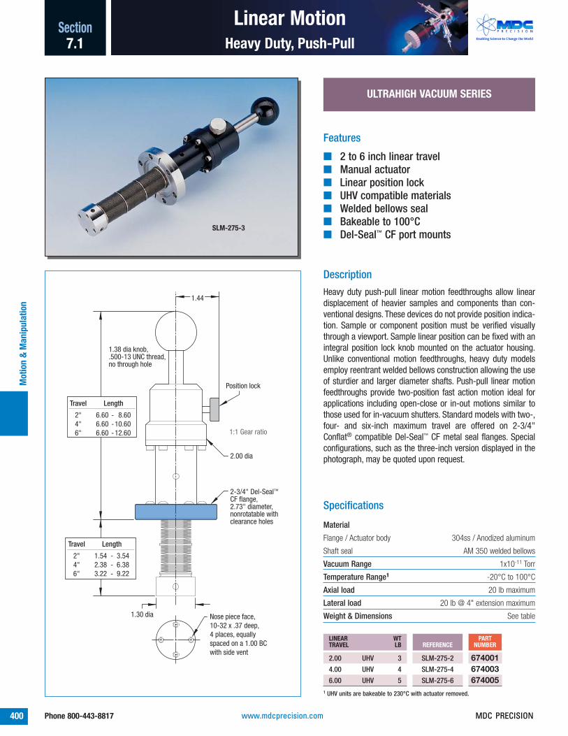
1.44
Position lock
Travel Length
2" 6.60 - 8.60 4" 6.60 - 10.60 6" 6.60 - 12.60
Travel Length
2" 1.54 - 3.54 4" 2.38 - 6.38 6" 3.22 - 9.22
1.38 dia knob, .500-13 UNC thread, no through hole
2-3/4" Del-Seal™ CF flange,2.73" diameter, nonrotatable with clearance holes
Nose piece face,10-32 x .37 deep, 4 places, equally spaced on a 1.00 BC with side vent
1.30 dia
2.00 dia
1:1 Gear ratio
Features
■ 2 to 6 inch linear travel■ Manual actuator■ Linear position lock■ UHV compatible materials■ Welded bellows seal■ Bakeable to 100°C■ Del-Seal™ CF port mounts
Specifications
Material
Flange / Actuator body 304ss / Anodized aluminum
Shaft seal AM 350 welded bellows
Vacuum Range 1x10-11 Torr
Temperature Range1 -20°C to 100°C
Axial load 20 lb maximum
Lateral load 20 lb @ 4" extension maximum
Weight & Dimensions See table
SLM-275-3
ULTRAHIGH VACUUM SERIES
REFERENCEPART
NUMBERLINEAR WTTRAVEL LB
SLM-275-2
SLM-275-4
SLM-275-6
674001674003674005
2.00 UHV 3
4.00 UHV 4
6.00 UHV 5
Description
Heavy duty push-pull linear motion feedthroughs allow lineardisplacement of heavier samples and components than con-ventional designs. These devices do not provide position indica-tion. Sample or component position must be verified visuallythrough a viewport. Sample linear position can be fixed with anintegral position lock knob mounted on the actuator housing.Unlike conventional motion feedthroughs, heavy duty modelsemploy reentrant welded bellows construction allowing the useof sturdier and larger diameter shafts. Push-pull linear motionfeedthroughs provide two-position fast action motion ideal forapplications including open-close or in-out motions similar tothose used for in-vacuum shutters. Standard models with two-,four- and six-inch maximum travel are offered on 2-3/4"Conflat® compatible Del-Seal™ CF metal seal flanges. Specialconfigurations, such as the three-inch version displayed in thephotograph, may be quoted upon request.
1 UHV units are bakeable to 230°C with actuator removed.
375
www.mdcprecision.com MDC PRECISION

Linear Motion Section
401Phone 800-443-8817
Heavy Duty, Tunnel Access
Motion &
Manipulation
7.1
.31 dia
1.25
1.44
.31 wide slot
Position lock
1-1/3 Del-Seal™ CF blank, nonrotatable flange included,
mounted to nose piece
.75
1.38 dia knob, .500-13 UNC thread
1.33 dia
.437 dia thru, .25 deep
Travel Length
2" 8.25 - 10.25 4" 8.25 - 12.25 6" 8.25 - 14.25
Travel Length
2" 1.79 - 3.79 4" 2.63 - 6.63 6" 3.47 - 9.47
.687 dia counterbore
8-32 x .50 deep,6 places, with side vent
2-3/4" Del-Seal™
CF flange,2.73" diameter, nonrotatable with clearance holes
2.00 dia
1:1 Gearratio
Features
■ 2 to 6 inch linear travel■ Manual actuator■ Linear position lock■ UHV compatible materials■ Welded bellows seal■ Bakeable to 100°C■ Del-Seal™ CF port mounts
Specifications
Material
Flange / Actuator body 304ss / Anodized aluminum
Shaft seal AM 350 welded bellows
Vacuum Range 1x10-11 Torr
Temperature Range1 -20°C to 100°C
Axial load 20 lb maximum
Lateral load 20 lb @ 4" extension maximum
Weight & Dimensions See table
TLM-275-2
ULTRAHIGH VACUUM SERIES
REFERENCEPART
NUMBERLINEAR WTTRAVEL LB
TLM-275-2
TLM-275-4
TLM-275-6
667000667001667002
2.00 UHV 3
4.00 UHV 4
6.00 UHV 5
Description
Heavy duty tunnel access, push-pull linear motion feedthroughsallow linear displacement of heavy samples and components.The push-pull shaft is hollow providing tunnel access for instru-mentation leads such as those used for thermocouple temper-ature measurements and other low voltage electrical applica-tions. The vacuum nose piece is shipped with a blank 1-1/3"Del-Seal™ CF mini flange which can be removed or modified toaccept electrical feedthroughs as required. These devices donot provide position indication. Sample or component positionmust be verified visually through a viewport. Sample linear posi-tion can be fixed with an integral position lock knob mounted onthe actuator housing. Unlike conventional motion feedthroughs,heavy duty models employ reentrant welded bellows construc-tion allowing the use of sturdier and larger diameter shafts.Models with two-, four- and six-inch maximum travel areoffered on 2-3/4" Conflat® compatible Del-Seal™ CF metal sealflanges.
1 UHV units are bakeable to 230°C with actuator removed.
375
www.mdcprecision.comMDC PRECISION

Linear Motion
402 Phone 800-443-8817
SectionM
otio
n &
Man
ipul
atio
n
Heavy Duty, Micrometer7.1
.2
.3
.4
.5
Nose piece face,10-32 x .37 deep, 4 places, equally spaced on a 1.00 BC with side vent
2-3/4" Del-Seal™ CF flange,2.73" diameter, nonrotatable with clearance holes
40:1 Gear ratio
1.54 min3.54 max
1.30 dia
Position locknot available
8.63 min 10.63 max
.6
.7
.8
.91.0
2.00 dia
Features
■ 2 inch linear travel■ Manual, precision micrometer actuator■ UHV compatible materials■ Welded bellows seal■ Bakeable to 100°C■ Del-Seal™ CF port mount
Specifications
Material
Flange / Actuator body 304ss / Anodized aluminum
Shaft seal AM 350 welded bellows
Vacuum Range 1x10-11 Torr
Temperature Range1 -20°C to100°C
Axial load 10 lb maximum
Lateral load 20 lb @ 4" extension maximum
Weight & Dimensions See table
LMM-275-2
ULTRAHIGH VACUUM SERIES
REFERENCEPART
NUMBERLINEAR WTTRAVEL LB
LMM-275-2 6680022.00 UHV 3
Description
Heavy duty, micrometer driven linear motion feedthroughs allowlinear displacement of heavier samples and components withthe accuracy and precision of fine pitch thread micrometers.These devices provide position indication on both rotary and lin-ear scales with display resolutions of 0.0001" on the rotaryscale and 0.025" on the linear scale. A full revolution of therotary scale translates into 0.025" of linear travel. Unlike con-ventional motion feedthroughs, heavy duty models employreentrant welded bellows construction allowing the use of stur-dier and larger diameter shafts. Models with two inch maximumtravel are offered on 2-3/4" Conflat® compatible Del-Seal™ CFmetal seal flanges.
1 UHV units are bakeable to 230°C with actuator removed.
Plus-Minus Scale
375
• Position locknot available
www.mdcprecision.com MDC PRECISION

Multi-Motion Section
403Phone 800-443-8817
Rotary-Linear, Standard
Motion &
Manipulation
7.1
Features
■ 360° rotary motion and 1 inch linear travel■ Manual actuator■ Rotary position lock■ UHV or HV compatible materials■ Welded bellows seal■ Bakeable to 100°C■ Del-Seal™ CF and Kwik-Flange™ port mounts
BRLM-133
Specifications
Material
Flange / Actuator body 304ss / Anodized aluminum
Shaft seal AM 350 welded bellows
Vacuum Range UHV / HV 1x10-11 Torr / 1x10⁻⁸ Torr
Temperature Range1 UHV / HV -20°C to 100°C
Torque 50 oz-in maximum
Axial load 4 lb maximum
Lateral load 4 lb @ 2" extension maximum
Weight & Dimensions See table
REFERENCEPART
NUMBERWT
DESCRIPTION LB
BRLM-133
BRLM-275
672000672002
1-1/3 UHV 3
2-3/4 UHV 3
REFERENCEPART
NUMBERWT
DESCRIPTION LB
K075-BRLM
K150-BRLM
672004672006
NW16 HV 3
NW40 HV 3
0
1.0
.75
.50
0 30330
.250 dia
Flange O.D.
1-1/3 1.332-3/4 2.73NW16 1.18 NW40 2.16
Flange Length
1-1/3 3.55 - 4.552-3/4 3.55 - 4.55 NW16 3.43 - 4.43NW 40 3.60 - 4.60
Flange Length
1-1/3 6.7 - 7.72-3/4 6.7 - 7.7 NW16 6.8 - 7.8NW 40 6.6 - 7.6
Rotary position lock
40:1 Linear gear ratio
1:1 Rotary gear ratio
.75
.56
.18
.213
6-32 tappedthru, 2 places
1.63 dia
2.25 dia
ULTRAHIGH & HIGH VACUUM SERIES
Description
Rotary-linear standard devices offer 360° of rotation and oneinch of linear travel via two separate drive knob actuators. Bothrotary and linear positions are measured along laser etchedscales on actuator barrel and housing. The 360° rotary scale isgraduated in 5° increments. The linear scale has both a linearand rotary scale components, the linear portion is graduated in0.025" increments while the rotary portion is graduated in0.001" increments. Full revolution of the linear scale produces0.025" of linear travel. These instruments are offered on bothDel-Seal™ CF metal seal flanges for ultrahigh vacuum serviceand Kwik-Flange™ ISO KF elastomer seal flanges for high vacu-um service.
1 UHV units are bakeable to 230°C with actuator removed.
• Shown with 1-1/3" Del-Seal™ CF flange.• Metal seal flanges are nonrotatable with
clearance holes.
• Linear scale and shaft flatshown in line for clarity only.Actual orientation varies.
367
• Linear position locknot available
Please see page 377 forshaft orientation detail
08-Apr-02
377
www.mdcprecision.comMDC PRECISION

415
Multi-Motion
404 Phone 800-443-8817
SectionM
otio
n &
Man
ipul
atio
n
Rotary-Linear, Precision7.1
ULTRAHIGH VACUUM
Features
■ Continuous rotary motion and 1/2 inch lineartravel
■ Manual or Motorized actuator■ Rotary position lock■ UHV compatible materials■ Welded bellows seal■ Bakeable to 230°C■ Del-Seal™ CF port mount
Specifications
Material
Flange / Actuator body 304ss / Aluminum
Shaft seal AM 350 welded bellows
Position knob & internal washer Brass
Vacuum Range 1x10-11 Torr
Temperature Range 1 -20°C to 230°C
Torque 7 lb-in maximum
Axial load
Rotary 5 lb maximum
Linear 1 lb maximum
Lateral load 10 lb @ 2" extension maximum
Weight & Dimensions See table
Linear Drive
PBRM2-10
Description
Precision rotary-linear motion feedthroughs are low backlashinstruments with a rotary display resolution of 0.1° and a lineardisplay resolution of 0.001". Full revolution of the linear drivetranslates into 0.025" of linear travel with a maximum overalllinear travel of 0.500". Welded stainless steel bellows, a uniqueoff-axis wobble design and the use of rotary shaft bearing sup-ports provide long life and smooth operation. Feedthroughs areavailable on 2-3/4" diameter Conflat® compatible Del-Seal™ CFmetal seal flanges. Motorization options are available for bothlinear and rotary drive components. If motorization is required onboth drives, add each option number to the end of the base partnumber. Note that the entire linear drive mechanism (manual ormotorized) will rotate when the rotary drive is actuated. Thismust be considered when allocating space for its installation.Motor controls are not included with the motorization optionsand must be purchased separately. Reference page 465 formotor controllers.
60 60035034033032031001020304050
3.00 dia
6.13
.375 dia
2-3/4" Del-Seal™ CF flange, 2.73" diameter, nonrotatable with clearance holes1.312 dia
Position lock
.125 dia
A
.50 retracted1.00 extended
40:1 Linear gear ratio
1:1 Rotary gear ratio
1 UHV units are bakeable to 30°C maximum when motorized.
375
421
www.mdcprecision.com MDC PRECISION

Multi-Motion Section
405Phone 800-443-8817
Rotary-Linear, Precision
Motion &
Manipulation
7.1
REFERENCEPART
NUMBERFLANGE FLANGE WTSIZE O.D. A LB
PBRM2-10
PBRM2-15
PBRM2-23
PBRM2-31
670025670028670031670034
2-3/4 2.73 10.00 8
2-3/4 2.73 15.75 8
2-3/4 2.73 23.62 9
2-3/4 2.73 31.50 9
ULTRAHIGH VACUUM SERIES
Del-Seal™ CF 230°C
Motorization Options
MOTOR ADD-ONMOTORIZATION 2 SPEC WT
OPTIONNUMBER
ROTARY AXIS D 5
LINEAR AXIS D 2
-01-02
2 When ordering motorized options, add the option number andprice to the desired UHV component part number listedabove. For example: 670025-01-02. For total unit weight, addoption weight to component weight. Refer to page 460 formotor specifications.
OPTION -02LINEAR MOTORIZATION
OPTION -01ROTARY MOTORIZATION
9.75
6.00 dia
4.86
4.64
3.39
6.10
3.00
Top view
50:1 Rotary gear ratio
40:1 Linear gear ratio
www.mdcprecision.comMDC PRECISION

.250 dia
1/8-27 NPT thread,hex socket head
Flange O.D.
2-3/4 2.73NW40 2.16
Travel stop Flange Min - Max
2-3/4 1.25 - 9.25NW40 1.30 - 9.30
Flange Min - Max
2-3/4 3.50 - 11.50NW40 3.45 - 11.45
8.00 travel
Position locknot available
1:1 Rotary andLinear gear ratios
2.38" dia knob, includes 8-32 socket head set screw
2.00 dia
Multi-Motion
406 Phone 800-443-8817
SectionM
otio
n &
Man
ipul
atio
n
Rotary-Linear, Direct7.1
Features
■ Continuous rotary motion and 8 inch lineartravel
■ Manual actuator■ UHV or HV compatible materials■ Differentially pumped, Dual Viton® elastomer
shaft seal■ Bakeable to 100°C■ Del-Seal™ CF and Kwik-Flange™ port mounts
CRPP-1
Specifications
Material
Flange / Actuator body 304ss
Shaft seal Viton®
Vacuum Range UHV / HV 1x10⁻⁹ Torr / 1x10⁻⁸ Torr
Temperature Range1 UHV / HV -20°C to 100°C
Torque 100 lb-in maximum
Axial load (no lock to support weight) 10 lb maximum
Lateral load 5 lb @ 2" extension maximum
Weight & Dimensions See table
REFERENCEPART
NUMBERWT
DESCRIPTION LB
CRPP-1 6720082-3/4 UHV 3
REFERENCEPART
NUMBERWT
DESCRIPTION LB
K-CRPP-1 672009NW40 HV 2
ULTRAHIGH & HIGH VACUUM SERIES
Description
Differentially pumped direct drive rotary-linear motionfeedthroughs are a basic and economical solution for vacuumapplications requiring both rotary and linear motion. Their sim-ple construction provides 100 lb-in of manual rotational torque.
The rotary shaft is supported by two phosphor bronze bearingsand uses dual Viton® elastomer shaft seals. The region betweenthe seals can be differentially pumped through the 1/8" femalepipe thread port provided and thus attain UHV compatibility to10-9 Torr. Feedthroughs are available on industry standardConflat® compatible 2-3/4" diameter Del-Seal™ CF metal sealflanges or ISO KF NW40 Kwik-Flange™ port mounts.
1 UHV units are bakeable to 150°C with actuator removed.
• Shown with 2-3/4" Del-Seal™ CF flange.• Metal seal flanges are nonrotatable with
clearance holes.375
www.mdcprecision.com MDC PRECISION

Flange O.D.
2-3/4 2.73NW40 2.16
22º
4.75 min 9.25 max
1.07 dia
.62 dia
8-32 set screw.250 dia x .375 deep
2.75 min 7.25 max
Angular position lockLinear position lock not available
1.46 dia
1.32 dia
1.38 dia knob, .500-13 UNC thread
1:1 Lineargear ratio
Multi-Motion Section
407Phone 800-443-8817
Wobble Stick
Motion &
Manipulation
7.1
Features
■ 4-1/2 inch linear travel and 22° wobblemotion
■ Manual actuator■ Angular position lock■ UHV or HV compatible materials■ Welded bellows seal■ Bakeable to 100°C■ Del-Seal™ CF and Kwik-Flange™ port mounts
SU-275
Specifications
Material
Flange / Actuator body 304ss
Shaft seal AM 350 welded bellows
Vacuum Range UHV / HV 1x10-11 Torr / 1x10⁻⁸ Torr
Temperature Range1 UHV / HV -20°C to 100°C
Axial load (no lock to support weight) 20 lb maximum
Lateral load 20 lb @ 4" extension maximum
Weight & Dimensions See table
REFERENCEPART
NUMBERWT
DESCRIPTION LB
SU-275 6960002-3/4 UHV 3
REFERENCEPART
NUMBERWT
DESCRIPTION LB
K150-SU 696001NW40 HV 2
• Requires 1.625" I.D. port forfull angular movement.
ULTRAHIGH & HIGH VACUUM SERIES
Description
Wobble stick linear-angular motion feedthroughs are basicand manual sample motion devices. They provide quick actionlinear travel and angular wobble motion via a stainless steelhand-held actuator shaft with a ball and socket joint design.They are typically operated by observing sample motionthrough a vacuum viewport. The actuators angular positioncan be locked in place by tightening the lock collar located onthe port mount flange. Wobble stick linear-angular motionfeedthroughs are offered with 4-1/2 inch linear travel and amaximum 22° of angular wobble with unrestricted matingflange and port diameter. Reentrant, welded stainless steel bel-lows are standard on these products. Feedthroughs are avail-able on industry standard Conflat® compatible Del-Seal™ CFmetal seal flanges or ISO KF Kwik-Flange™ port mounts.
1 UHV units are bakeable to 230°C with actuator removed.
• Shown with 2-3/4" Del-Seal™ CF flange.• Metal seal flanges are nonrotatable with
clearance holes.
Wobble Action
375
www.mdcprecision.comMDC PRECISION

22º
6.50 min 11.00 max
3.75 min 8.25 max
Flange O.D.
2-3/4 2.73NW40 2.16
1.46 dia
1.32 dia
1.38 dia knob, .500-13 UNC thread
1.25 closed2.75
1:1 Lineargear ratio
Angular position lockLinear position lock not available
Multi-Motion
408 Phone 800-443-8817
SectionM
otio
n &
Man
ipul
atio
n
Wobble Stick, Pincer7.1
Features
■ 4-1/2 inch linear travel and 22° wobble, withpincer-grip
■ Manual actuator■ Angular position lock■ UHV or HV compatible materials■ Welded bellows seal■ Bakeable to 100°C■ Del-Seal™ CF and Kwik-Flange™ port mounts
VGU-275
Specifications
Material
Flange / Actuator body 304ss
Shaft seal AM 350 welded bellows
Vacuum Range UHV / HV 1x10-11 Torr / 1x10⁻⁸ Torr
Temperature Range1 UHV / HV -20°C to 100°C
Axial load 2 lb maximum
Lateral load 2 lb maximum
Weight & Dimensions See table
REFERENCEPART
NUMBERWT
DESCRIPTION LB
VGU-275 6950002-3/4 UHV 3
REFERENCEPART
NUMBERWT
DESCRIPTION LB
K150-VGU 695001NW40 HV 2
REFERENCEPART
NUMBERWT
DESCRIPTION LB
DG-275-BJ 694001JAW KIT, BLANK 1
ULTRAHIGH & HIGH VACUUM SERIES
Description
Wobble sticks with pincer action are identical to the wobble-linear products, except for the addition of an integral and artic-ulated sample holding pincer mechanism. The pincer is acti-vated via two shaft mounted finger grips allowing the pincerjaws to grip 0.880" maximum sample diameters. Thesefeedthroughs provide quick action linear-angular motion via amanually activated shaft with ball and socket joint design.They are typically operated by observing sample motionthrough a vacuum viewport. Angular position can be lockedwith an integral lock collar located on the port mount flange.They are available on industry standard Conflat® compatibleDel-Seal™ CF metal seal flanges or Kwik-Flange™ port mounts.
1 UHV units are bakeable to 230°C with actuator removed.
• Requires 1.625" I.D. port forfull angular movement.
• Shown with 2-3/4" Del-Seal™ CF flange.• Metal seal flanges are nonrotatable with
clearance holes.
Blank Jaws
375
376
www.mdcprecision.com MDC PRECISION

22º
6.50 min 11.00 max
360º
30330 0
8.50 min 13.00 max
Flange O.D.
2-3/4 2.73NW40 2.16
Linear position lock
1.46 dia
1.32 dia
2.25 dia
2.00 dia
1.25 closed2.75
1:1 Rotary and Linear gear ratio
Angular position lockRotary position lock not available
Multi-Motion Section
409Phone 800-443-8817
Wobble Stick, Rotary Pincer
Motion &
Manipulation
7.1
Features
■ Continuous rotary motion, 4-1/2 inch lineartravel and 22° wobble, with pincer-grip
■ Manual actuator■ Linear and angular position locks■ UHV or HV compatible materials■ Welded bellows seal■ Bakeable to 100°C■ Del-Seal™ CF and Kwik-Flange™ port mounts
DG-275Patented Design
Specifications
Material
Flange / Actuator body 304ss / Aluminum
Shaft seal AM 350 welded bellows
Vacuum Range UHV / HV 1x10-11 Torr / 1x10⁻⁸ Torr
Temperature Range1 UHV / HV -20°C to 100°C
Torque 50 oz-in maximum
Axial load 2 lb maximum
Lateral load 2 lb maximum
Weight & Dimensions See table
REFERENCEPART
NUMBERWT
DESCRIPTION LB
DG-275 6940002-3/4 UHV 3
REFERENCEPART
NUMBERWT
DESCRIPTION LB
K150-DG 694002NW40 HV 2
REFERENCEPART
NUMBERWT
DESCRIPTION LB
DG-275-BJ 694001JAW KIT, BLANK 1
ULTRAHIGH & HIGH VACUUM SERIES
Description
These products are rotary-linear-pincer action wobble sticksidentical to the linear and linear-pincer wobble stick productswith the addition of full 360° rotary motion. The pincer mech-anism is activated via two shaft mounted finger grips allowingthe pincer jaws to grip up to 0.880" sample diameters. Thesefeedthroughs provide quick action rotary, linear and angularmotion with an actuator shaft ball and socket joint design.Angular and linear positions can be locked with integral lockcollars located on the port mount flange and actuator shaft.They are available on industry standard Del-Seal™ CF metal sealflanges or Kwik-Flange™ port mounts.
1 UHV units are bakeable to 230°C with actuator removed.
• Requires 1.625" I.D. port forfull angular movement.
• Shown with 2-3/4" Del-Seal™ CF flange.• Metal seal flanges are nonrotatable with
clearance holes.
Blank Jaws
375
www.mdcprecision.comMDC PRECISION

Flange O.D.
2-3/4 2.73NW40 2.16
60º
.25
4.00 min6.00 max
1.00
44º
Flange O.D.
1-1/3 1.33NW16 1.18
4.00 min6.00 max
.12
2.50 min3.00 max
.50
3.00 min3.50 max
1:1 Linear gear ratio
1:1 Linear gear ratio
Multi-Motion
410 Phone 800-443-8817
SectionM
otio
n &
Man
ipul
atio
n
Wobble Stick, Wide Angle7.1
Features
■ 1/2 or 2 inch linear travel and 44° or 60°wobble, respectively
■ Manual actuator■ UHV or HV compatible materials■ Welded bellows seal■ Bakeable to 230°C■ Del-Seal™ CF and Kwik-Flange™ port mounts
WS-133
Specifications
Material
Flange / Actuator body 304ss
Shaft seal AM 350 welded bellows
Vacuum Range UHV / HV 1x10-11 Torr / 1x10⁻⁸ Torr
Temperature Range
UHV -20°C to 230°C
HV -20°C to 150°C
Weight & Dimensions See table
REFERENCEPART
NUMBERWT
DESCRIPTION LB
WS-133
WS-275
693001693000
1-1/3 UHV 3
2-3/4 UHV 3
REFERENCEPART
NUMBERWT
DESCRIPTION LB
K075-WS
K150-WS
693002693003
NW16 HV 3
NW40 HV 3
• Requires 1.625" I.D. port for full angular movement.• Position lock not available
ULTRAHIGH & HIGH VACUUM SERIES
Description
Wide angle wobble sticks, the most basic products of the wob-ble stick family provide an economical solution for light dutysample motion and manipulation. They are stripped down wob-ble sticks ideally suited for user customization. Under vacuumload the bellows are compressed and the shaft completelyextended into the vacuum chamber. Offered in two models theyprovide 44° and 60° of angular displacement respectively. Theyare available with both Conflat® compatible Del-Seal™ CF metalseal flanges and Kwik-Flange™ ISO KF elastomer seal flanges.
375
1/2" Linear Travel, 44° Wobble
2" Linear Travel, 60° Wobble
www.mdcprecision.com MDC PRECISION

Multi-Motion Section
411Phone 800-443-8817
Motion &
Manipulation
7.1
www.mdcprecision.comMDC PRECISION

412 Phone 800-443-8817 www.mdcprecision.com MDC PRECISION

413
Manipulation
V-Plane® Guide Tube 420
Introduction 414
V-Plane® Single Axis Z 418
Rectangular Entry 434
Triple Axis, Standard XYZ 426
Port Aligners
Introduction 443
V-Plane® Dual Axis XY 416
Single Axis, Compact Z 422Triple Axis, Compact XYZ 424
Circular Entry 432
In-Vacuum Accessories
Rotatable Axis, 360° Adjustable 428
Load-Lock SystemsIntroduction 430
Magnetic Transporters 436Quick-Access Doors 438
Gimbal, Load-Lock 440Gimbal, Standard 441Off-Axis 442
Cab-Fast® Sample Handlers 444Mini-Scaffold Mounting System 446Rotary & Linear Motion 450
Introductions 414,
XYZ Stages
443430,
Section 7.2
Section Contents 367
Phone 800-443-8817Phone 800-443-8817www.mdcprecision.comMDC PRECISION

Single axis 360° rotating stages page 428
Manipulation
414 Phone 800-443-8817
SectionM
otio
n &
Man
ipul
atio
n
Introduction7.2
Dual axis, micrometer driven XY stage page 416
Triple axis micrometer driven XYZ Stages page 426
■ V-Plane® XY and Z stages■ V-Plane® Guide Tubes■ Compact XY and Z stages■ Heavy duty Z stages■ Standard XY and Z stages■ Rotatable axis stages
All dimensions in this catalog are given ininches unless specified otherwise.
Caution
Anodized aluminum finishes will begin to dis-color when baked in excess of 150°C. This isonly a cosmetic condition which does notimpact performance or reliability.
V-Plane® Guide Tubes
MDC guide tubes provide bellows support forV-Plane® manipulator stages fitted with long-stroke bellows as well as secondary rotaryand linear motion feedthroughs installed onthe stage. Guide tubes mount directly onto V-Plane® manipulator stages fitted with 2-3/4"Del-Seal™ CF port flanges with a boreclearance suitable for the 1.125" guide tubediameter. They are supplied with both rotaryand linear bearing supports. Rotary bearingsfor .250" and .375" diameter shafts are
V-Plane® XY and Z Stages
MDC’s V-Plane® modular stages are buildingblock components designed to streamlinethe implementation of a samplemanipulation system. They can be used asstand alone components or combined withother V-Plane® instruments to attaincustomized motion and manipulationsolutions. V-Plane® dual axis XY stages aremicrometer driven and guided by cross rollerbearing slides. MDC micrometers haveunique laser etched plus-minus scales thatindicate positive or negative portdisplacement. V-Plane® single axis stagesemploy handwheel and worm gear reductiondrive mechanisms with linear displacementmeasured along the stage’s frame mountedscale. Z axis linear travels of up to 36" areavailable. MDC V-Plane® stages provideprecise sample motion and manipulation ofsamples inside ultrahigh vacuumenvironments. V-Plane® Z stages can also befitted with guide tubes to further expandtheir capabilities. For a step-by-step pictorialdescription of a typical guide tubeinstallation and usage reference page 421 ofthis catalog.
included. For applications requiring sampleheating, cooling, high voltage biasing,thermocouple temperature measurements,etc., the guide tube tip has been fitted withtwo slots 180° apart through which wires ortubes can be fed. Four 1-1/3" and one 2-3/4" Del-Seal™ CF flange accessory portsallow the installation of up to five additionalaccessory components. When a manipulatorstage is not under vacuum or is let up to airwith the bellows in some state ofcompression, the compressed bellows’spring force may force the bellows to shiftoff-axis at some point during its travel. Theoff-axis shift could be sudden and violentcausing user injury or damage to thebellows. MDC recommends that all long-stroke 1.50" diameter bore Z axis V-Plane®
stages, with linear travels exceeding sixinches, be fitted with guide tubes.
Rotatable Axis Stages
Rotatable axis stages replace conventionalrotatable mounting tables previously offeredby MDC. They provide 360° positioning withgreater precision, control and ease of use.Rotatable stages are constructed with wormgear drive mechanisms which offersubstantial mechanical advantage over non-geared designs, a feature which allowseffortless manual operation, even under afull vacuum load. High torque stepper motorsare also available for these stages. MDCrotatable stages can be used to rotate heavysamples or sample support apparatus andstructures. Two spring energized PTFE faceseals are at the heart of the rotatable stage’ssealing mechanism. With provision fordifferential pumping between the seals,these rotatable stages can be used in UHVenvironments with bakeout temperatures ashigh as 200°C.
416
418
420
367
413
413
Chec
k pa
ge n
umbe
rs
www.mdcprecision.com MDC PRECISION

Manipulation Section
415Phone 800-443-8817
Introduction
Motion &
Manipulation
7.2
0
0
87
65
43
21
6030
90
120150
0
330300
210
240
XX
ZZ
YY
Standard XY and Z Stages
Standard XYZ stages are large bore stageswhich incorporate triple axis motion in asingle stage. The XY travels are micrometerdriven and guided by cross roller bearingslides. MDC micrometers have unique laseretched plus-minus scales that indicatepositive or negative port displacement andare available for 0.500" or 1.00" of linear XYdisplacement. The Z axis employs ahandwheel and worm gear reduction drivemechanism with displacement measuredalong the stage’s frame mounted scale. Zaxis linear travels of up to 12" are available.MDC standard stages provide precisesample motion and manipulation of samplesinside ultrahigh vacuum environments.
Compact XY and Z Stages
Compact stages are small footprint single ortriple axis stages and are ideally suited forapplications with limited space. They areavailable in a Z only or XYZ configuration.They provide the means for precise samplemanipulation inside ultrahigh vacuumenvironments.
Intermediate hardware may be required for joining components. These have been omitted for clarity.
Precision Rotary-Linear drivescan be found on page 404
Extended length rotary drivescan be found on page 380
V-Plane® Guide Tubes includefour 1-1/3" Del-Seal™ CF portsfor electrical accessories
V-Plane® Guide Tubes can befound on page 420
V-Plane® Z axis stages can befound on page 418
Linear and rotary bearingguides are included with theguide tubes
V-Plane® Dual axis XY stagescan be found on page 416
Rotatable stages provide 360°of positioning and can be foundon page 428
Updatedrawing
Typical Installation
www.mdcprecision.comMDC PRECISION

V-Plane®
416 Phone 800-443-8817
SectionM
otio
n &
Man
ipul
atio
n
Dual Axis XY Stage7.2
ULTRAHIGH VACUUM SERIES
DescriptionMDC’s V-Plane® modular stages are building block componentsdesigned to streamline the implementation of a sample manip-ulation system. They can be used as stand alone componentsor combined with other V-Plane® instruments to attain cus-tomized motion and manipulation solutions.
V-Plane® dual axis XY stages are micrometer driven and guidedby cross roller bearing slides. Micrometers have unique laseretched plus-minus scales that indicate positive or negative portdisplacement. MDC V-Plane® dual axis XY stages provide pre-cise motion and manipulation of samples inside ultrahigh vacu-um environments. Dual axis XY stages can be stacked with V-Plane® single axis Z stages and also fitted with guide tubes tofurther expand their capabilities. Look for the ➚ symbol forother mating building block components.
.2.3.4.5
.2
.3
.4
.5
Bore
Top flange, tapped holes
6.750
B
E
F
G
Bottom flange, tapped holes
9.84
40:1 Gearratio
5.65
4.375
2.188
40:1 Gear ratio
Outline for XY-15S only5.50 x 6.57 XX
YY
Features
➚ V-Plane® building block component1
■ Plus or minus 1/2 and 1 inch off center XY motion■ 1-1/2 to 4 inch bore diameters■ Manual or Motorized actuator■ UHV compatible materials■ Welded bellows seal■ Bakeable to 230°C■ Del-Seal™ CF port mounts
Specifications
Material
Flange 304ss
Actuator body Anodized aluminum
Bellows AM 350
Vacuum Range 1x10-11 Torr
Temperature Range 2 -20°C to 230°C
Weight & Dimensions See table
XY-15
1 Reference page 414 for related V-Plane® components.2 Units are bakeable to 30°C maximum when motorized.
Bottom view
Figure 1
415
367
413
414
www.mdcprecision.com MDC PRECISION

.2.3.4.5
.2
.3
.4
.5
D
BoreBottom flange, tapped holes
B
E G
F
Top flange, tapped holes
9.84
40:1Gearratio
4.375
2.188
5.65
40:1 Gear ratio
XX
YY
V-Plane®Section
417Phone 800-443-8817
Dual Axis XY Stage
Motion &
Manipulation
7.2
H
J
40:1 Gearratio
Far side
40:1 Gear ratioXX
YY
REFERENCEPART
NUMBERBORE TRAVEL 4 TOP BOTTOM WTSIZE ± FIGURE FLANGE FLANGE B D E F G H J LB
XY-15S
XY-15
XY-25
XY-26
LXY-25
LXY-26
XY-40
XY-44
LXY-40
LXY-44
677020677002677003677016677006677017677004677005677007677008
1.50 0.50 1 2-3/4 2-3/4 5.00 - 3.25 5.75 6.18 7.63 8.23 24
1.50 0.50 1 4-1/2 2-3/4 5.62 - 6.33 5.75 6.18 7.63 8.23 25
2.50 0.50 1 4-1/2 4-1/2 5.75 - 6.33 6.50 6.87 8.26 8.83 28
2.50 0.50 1 4-1/2 6 5.85 - 6.33 7.47 8.00 9.07 9.60 29
2.50 1.00 1 4-1/2 4-1/2 6.62 - 6.33 9.12 9.75 9.26 9.83 28
2.50 1.00 1 4-1/2 6 6.72 - 6.33 9.12 9.75 10.07 10.60 29
4.00 3 0.50 2 4-1/2 6 6.50 8.37 6.33 7.47 8.00 9.07 9.60 30
4.00 0.50 2 6 6 6.50 8.37 6.33 7.47 8.00 9.07 9.60 32
4.00 3 1.00 2 4-1/2 6 7.25 8.37 6.33 10.00 10.50 10.07 10.60 32
4.00 1.00 2 6 6 7.25 8.81 6.33 10.25 10.05 10.07 10.60 343 4.00" bore diameter is reduced to 2.50" at 4-1/2" top flange 4 Match sample support structure and stage bore for maximum XY travel.
MOTOR ADD-ONMOTORIZATION 5 SPEC WT
OPTIONNUMBER
XY INLINE STEPPER D 3 -01
5 When ordering motorized options,add the option number and price tothe desired UHV component partnumber listed above. For example:677020-01. For total unit weight,add option weight to componentweight. Refer to page 460 for motorspecifications.
OPTION -01INLINE STEPPER MOTOR
Motorization OptionsFigure 2
01-Oct-99
www.mdcprecision.comMDC PRECISION
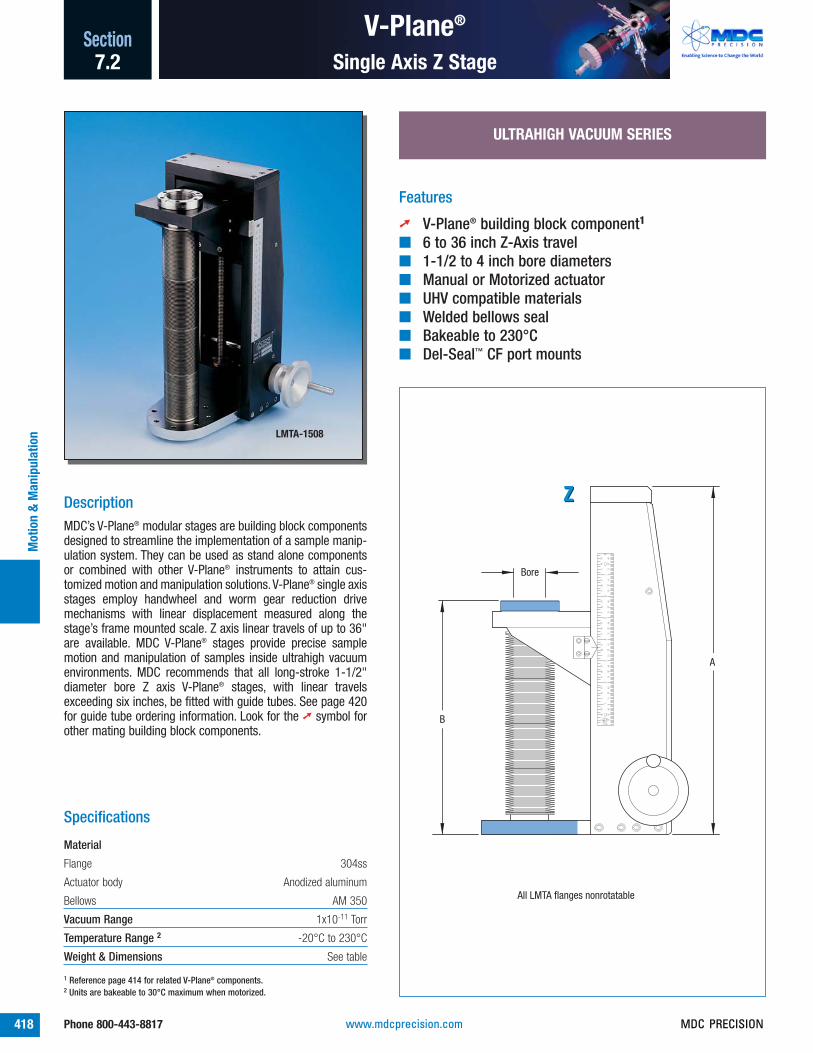
V-Plane®
418 Phone 800-443-8817
SectionM
otio
n &
Man
ipul
atio
n
Single Axis Z Stage7.2
ULTRAHIGH VACUUM SERIES
Features
➚ V-Plane® building block component1
■ 6 to 36 inch Z-Axis travel■ 1-1/2 to 4 inch bore diameters■ Manual or Motorized actuator■ UHV compatible materials■ Welded bellows seal■ Bakeable to 230°C■ Del-Seal™ CF port mounts
Specifications
Material
Flange 304ss
Actuator body Anodized aluminum
Bellows AM 350
Vacuum Range 1x10-11 Torr
Temperature Range 2 -20°C to 230°C
Weight & Dimensions See table
DescriptionMDC’s V-Plane® modular stages are building block componentsdesigned to streamline the implementation of a sample manip-ulation system. They can be used as stand alone componentsor combined with other V-Plane® instruments to attain cus-tomized motion and manipulation solutions. V-Plane® single axisstages employ handwheel and worm gear reduction drivemechanisms with linear displacement measured along thestage’s frame mounted scale. Z axis linear travels of up to 36"are available. MDC V-Plane® stages provide precise samplemotion and manipulation of samples inside ultrahigh vacuumenvironments. MDC recommends that all long-stroke 1-1/2"diameter bore Z axis V-Plane® stages, with linear travelsexceeding six inches, be fitted with guide tubes. See page 420for guide tube ordering information. Look for the ➚ symbol forother mating building block components.
87
65
43
21
64TH
S32
NDS
4824
3216
168
3248
1624
4824
168
3216
168
3248
1624
4816
248
3216
168
3248
1624
24 48168
1632
816
4832
2416
168
A
Bore
B
All LMTA flanges nonrotatable
ZZ
LMTA-1508
1 Reference page 414 for related V-Plane® components.2 Units are bakeable to 30°C maximum when motorized.
421
415
413
www.mdcprecision.com MDC PRECISION

REFERENCEPART
NUMBERBORE Z END B WTSIZE TRAVEL VIEW A MIN - MAX LB
LMTA-1506S
LMTA-1508S
LMTA-1512S
LMTA-1516S
LMTA-1524S
LMTA-1536S
LMTA-1506
LMTA-1508
LMTA-1512
LMTA-1516
LMTA-1524
LMTA-1536
LMTA-2506
LMTA-2508
LMTA-2512
LMTA-2516
LMTA-2524
LMTA-2536
LMTA-4006
LMTA-4008
LMTA-4012
LMTA-4016
LMTA-4024
LMTA-4036
665540665541665542665543665544665545665528665529665530665531665532665533665552665553665554665555665556665557665564665565665566665567665568665569
1.50 6.00 1 13.2 6.7 - 12.7 38
1.50 8.00 1 15.2 6.7 - 14.7 42
1.50 12.00 1 21.4 8.9 - 20.9 50
1.50 16.00 1 27.7 11.2 - 27.2 58
1.50 24.00 1 40.3 15.8 - 39.8 74
1.50 36.00 1 59.1 22.6 - 58.6 98
1.50 6.00 2 14.2 7.6 - 13.6 40
1.50 8.00 2 16.2 7.6 - 15.6 44
1.50 12.00 2 20.2 7.6 - 19.6 52
1.50 16.00 2 26.2 9.6 - 25.6 60
1.50 24.00 2 38.2 13.6 - 37.6 76
1.50 36.00 2 56.2 19.6 - 55.6 100
2.50 6.00 3 14.0 7.6 - 13.6 45
2.50 8.00 3 16.0 7.6 - 15.6 49
2.50 12.00 3 21.4 9.0 - 21.0 57
2.50 16.00 3 26.7 10.3 - 26.3 65
2.50 24.00 3 37.4 13.0 - 37.0 81
2.50 36.00 3 53.4 17.0 - 53.0 105
4.00 6.00 4 14.0 7.7 - 13.7 50
4.00 8.00 4 16.0 7.7 - 15.7 54
4.00 12.00 4 20.0 7.7 - 19.7 62
4.00 16.00 4 25.0 8.8 - 24.8 70
4.00 24.00 4 35.2 10.9 - 34.9 86
4.00 36.00 4 50.3 14.0 - 50.0 110
V-Plane®Section
419Phone 800-443-8817
Single Axis Z Stage
Motion &
Manipulation
7.2
5.50
7.75
2-3/4" Del-Seal™ flanges:top - tapped holesbottom - clearance holes
6.38
25:1Gearratio
2.25
8.846.59
6.75
25:1Gearratio
Del-Seal™ flanges:top - 2-3/4", tapped holesbottom - 4-1/2", clearance holes
2.83
8.846.59
6.75
4-1/2" Del-Seal™ flanges:top - tapped holesbottom - clearance holes
25:1Gearratio
2.83
10.637.63
8.25
6" Del-Seal™ flanges:top - tapped holesbottom - clearance holes
25:1Gearratio
3.37
ULTRAHIGH VACUUM SERIES
Del-Seal™ CF 230°C
2.24
4.4125:1 Gear ratio
ZZ
MOTOR ADD-ONMOTORIZATION 3 SPEC WT
OPTIONNUMBER
Z INLINE STEPPER F 3 -013 When ordering motorized options, add the option number and price to the desired UHV component part number listed above.
For example: 665540-01. For total unit weight, add option weight to component weight. Refer to page 461 for motor specifi-cations.
OPTION -01INLINE STEPPER MOTOR
Motorization Options
End View 1
End View 4
End View 3
End View 2
14-Mar-00
www.mdcprecision.comMDC PRECISION

V-Plane®
420 Phone 800-443-8817
SectionM
otio
n &
Man
ipul
atio
n
Z Axis Guide Tube7.2
80º
3.50
Linear bearing to be attached to baseplate of LMTA Z-only stage using the four 6-32 x .375" vented screws provided.
30º
1.62 I.D.
Flange 12-3/4" Del-Seal™CF flange, nonrotatable with clearance holes
A
30º, typ
.810 I.D., typ
Flange 31-1/3" Del-Seal™ CF flanges, 4 places,nonrotatable with tapped holes
Rotary bearing for .250 or .375 dia shaft, installed on guide tube
1.125 O.D.
1/2
1.5
Flange 22-3/4" Del-Seal™CF flange, nonrotatable with tapped holes
.687 I.D., typ
2.76, typ
2.50 O.D.
1.94 O.D.
ULTRAHIGH VACUUM SERIES
DescriptionMDC guide tubes provide bellows support for V-Plane® manip-ulator stages fitted with long-stroke bellows as well as sec-ondary rotary and linear motion feedthroughs installed on thestage. Guide tubes mount directly onto V-Plane® manipulatorstages fitted with 2-3/4" Del-Seal™ CF port flanges with a boreclearance suitable for the 1.125" guide tube diameter. They aresupplied with both rotary and linear bearing supports. Rotarybearings for .250" and .375" diameter shafts are included. Forapplications requiring sample heating, cooling, high voltagebiasing, thermocouple temperature measurements, etc., theguide tube tip has been fitted with two slots 180° apart throughwhich wires or tubes can be fed. Four 1-1/3" and one 2-3/4"Del-Seal™ CF flange accessory ports allow the installation of upto five additional accessory components. When a manipulatorstage is not under vacuum or is let up to air with the bellows insome state of compression, the compressed bellows’ springforce may force the bellows to shift off-axis at some point dur-ing its travel. The off-axis shift could be sudden and violentcausing injury or damage to the bellows. MDC recommends that all long-stroke 1.50" diameter bore Zaxis V-Plane® stages, with linear travels exceeding six inches,be fitted with guide tubes. Look for the ➚ symbol for other mat-ing building block components. Note that the linear bearingsupport on a guide tube requires a 2.5" bore in any matingcomponent.
Features
➚ V-Plane® building block component1
■ Used with 1-1/2 inch bore Z-axis V-Plane®
stages with greater than 6 inch travel■ Bakeable to 230°C■ 1-1/3 inch Del-Seal™ CF access ports■ Linear bearing guide tube support■ Includes 1/4 and 3/8 inch diameter shaft
rotary bearing supports
Specifications
Material
Flange / Body 304ss
Bearings 300 series stainless steel with Dicronite® coating
Vacuum Range 1x10-11 Torr
Temperature Range -200 to 230°C
Weight & Dimensions See table1 Reference page 414 for related V-Plane® components.
GT-1506
Accessory ports
418
415
413
21-Jan-00
www.mdcprecision.com MDC PRECISION

The guide tube extends into vacuumbeyond the linear bearing support.The rotary bearing radial screws,located at guide tube tip, may needremoving to properly fit guide tubethrough linear bearing housing.
Other motion products may beattached to the guide tube’s mainflange. Shown here is a precisionrotary-linear instrument found inSection 7.3, page 404.
The rotary-linear drive shaft extendsinto vacuum beyond the rotary bear-ing support on the guide tube tip.
Four mini Del-Seal™ CF ports can beused for the input or output of samplevoltage biasing as well as thermo-couple and other instrumentation sig-nals. Insulated wires exit into vacuumthrough slots on guide tube tip.
V-Plane®Section
421Phone 800-443-8817
Z Axis Guide Tube
Motion &
Manipulation
7.2
REFERENCEPART
NUMBERUSE 2 FLANGE FLANGE FLANGE WT
A WITH 1 2 3 LB
GT-1506
GT-1508
GT-1512
GT-1516
GT-1524
GT-1536
665576665577665578665579665580665581
19.50 665528 2-3/4 2-3/4 1-1/3 8
21.50 665529 2-3/4 2-3/4 1-1/3 8
25.50 665530 2-3/4 2-3/4 1-1/3 9
31.50 665531 2-3/4 2-3/4 1-1/3 10
43.50 665532 2-3/4 2-3/4 1-1/3 12
61.50 665533 2-3/4 2-3/4 1-1/3 14
ULTRAHIGH VACUUM SERIES
Del-Seal™ CF 230°C
2 Use with 1.50 inch bore, single axis Z stages on page 418.
The 4-1/2" Del-Seal™ CF base flangeon V-Plane® stages with 1-1/2" boreis fitted with a counterbore and fourtapped holes. This counterbore andtapped holes provide the means ofattaching the guide tube’s linearbearing support.
The linear bearing support is shownfastened to the 4-1/2" Del-Seal™ CFbase flange of a V-Plane® single axisZ stage using four vented stainlesssteel socket head screws suppliedwith each guide tube assembly. Thelinear bearing support requires a 2.5"bore in any mating component.
Six threaded studs are fastened tothe V-Plane® Z axis stage top flangeprior to inserting the guide tubethrough the top flange and bellows.
The guide tube assembly is securedto the V-Plane® Z axis stage topflange using the nuts and washerssupplied.
Typical Guide Tube Application
414
21-Jan-00
www.mdcprecision.comMDC PRECISION

Single Axis
422 Phone 800-443-8817
SectionM
otio
n &
Man
ipul
atio
n
Compact Z Stage7.2
ULTRAHIGH VACUUM SERIES
DescriptionCompact single axis Z stages have smaller footprints than V-Plane® and other stages. They are a practical and economicalsolution for applications with limited space. Models with one tofour inches of linear travel and bore diameters from 0.50" to2.50" are available. The instrument’s precision drive employs afine pitch lead screw mechanism. Approximate positions can bemeasured along a graduated machinist’s scale with both inchand millimeter units included. Top and bottom port flanges areavailable in 1-1/3", 2-3/4" and 4-1/2" Conflat® compatible,tapped Del-Seal™ CF metal seal flanges. Edge welded stainlesssteel bellows are used to connect the port flanges on all com-pact stages.
C
.54 Bore
2.34
A
B
E
D
1-1/3" Del-Seal™ CF flanges, nonrotatable with tapped holes
mm
32 NDS2
14
53
21
20:1Gearratio
.75
1.37 dia
Features
■ 1 to 4 inch Z-axis travel■ 1/2, 1-1/2 and 2-1/2 inch bore diameters■ Manual or Motorized actuator■ UHV compatible materials■ Welded bellows seal■ Bakeable to 230°C■ Del-Seal™ CF port mounts
LMT-151
Specifications
Material
Flange / Body 304ss
Bellows AM 350
Vacuum Range 1x10-11 Torr
Temperature Range 1 -20°C to 230°C
Weight & Dimensions See table1 Units are bakeable to 30°C maximum when motorized.
LMT-254
LMT-051
Figure 1
367
413
www.mdcprecision.com MDC PRECISION

Single Axis Section
423Phone 800-443-8817
Compact Z Stage
Motion &
Manipulation
7.2
REFERENCEPART
NUMBERBORE LINEAR FLANGE A B WTSIZE TRAVEL SIZE FIGURE MIN - MAX MIN - MAX C D E F G LB
LMT-051
LMT-052
LMT-151
LMT-152
LMT-154
LMT-156
LMT-251
LMT-252
LMT-254
6655166655176655 01665503665505665520665522665523665524
0.54 3 1.00 1-1/3 1 5.00 6.00 1.56 2.56 3.56 2.13 2.00 - - 5
0.54 3 2.00 1-1/3 1 6.40 8.40 2.00 4.00 3.56 2.13 2.00 - - 5
1.50 1.00 2-3/4 2 8.71 9.71 2.20 3.20 6.33 3.95 2.25 8.62 8.33 8
1.50 2.00 2-3/4 2 8.71 10.71 2.20 4.20 6.33 3.95 2.25 9.62 8.33 9
1.50 4.00 2-3/4 2 11.32 15.32 2.95 6.95 6.33 3.95 2.25 15.25 5.25 11
1.50 6.00 2-3/4 2 13.75 19.75 3.25 9.25 6.33 3.95 2.25 20.25 8.33 13
2.50 1.00 4-1/2 2 8.71 9.71 2.20 3.20 8.13 4.60 2.88 8.62 9.85 8
2.50 2.00 4-1/2 2 8.71 10.71 2.20 4.20 8.13 4.60 2.88 9.62 9.85 9
2.50 4.00 4-1/2 2 11.32 15.32 2.95 6.95 8.13 4.60 2.88 15.25 9.85 11
G
5.25
Fmax
225:1 Gear ratio
MOTOR ADD-ONMOTORIZATION 2 SPEC WT
OPTIONNUMBER
Z SIDE MOUNT E 3 -01
2 When ordering motorized options,add the option number and priceto the desired UHV component partnumber listed above. For example:665516-01. For total unit weight,add option weight to componentweight. Refer to page 460 formotor specifications.
3 Motorization not available on 0.54"bore diameter stages.
OPTION -01SIDE MOUNT STEPPER MOTOR
Motorization Options
mm
32 NDS2
14
53
21
34
109
87
6
E
D
C
Bore
A
B
Bottom flange, tapped holes
Top flange, tapped holes
18:1Gearratio
.875
2.00 dia
1/2" hex
Figure 2
09-Apr-0210-Apr-02
www.mdcprecision.comMDC PRECISION

Triple Axis
424 Phone 800-443-8817
SectionM
otio
n &
Man
ipul
atio
n
Compact XYZ Stage7.2
ULTRAHIGH VACUUM SERIES
DescriptionCompact triple axis XYZ stages have smaller footprints than V-Plane® stages. They are a practical and economical solution forapplications with limited space. Models with two and four inch-es of linear travel and bore diameter of 1.50" and 2.50" areavailable. The instruments precision Z drive employs a fine pitchlead screw mechanism with approximate positions measuredalong a graduated machinist’s scale with both inch and mil-limeter units included. The XY axes are micrometer driven andguided by cross roller bearing slides. Micrometers have uniquelaser etched plus-minus scales that indicate positive or nega-tive port displacement. MDC triple axis XY stages provide pre-cise motion and manipulation of samples inside ultrahigh vacu-um environments. Top and bottom port flanges are available in2-3/4" and 4-1/2" Conflat® compatible, tapped Del-Seal™ CFmetal seal flanges. Edge welded stainless steel bellows areused to connect the port flanges on all XYZ compact stages.
67
89
12
35
43
12
32 NDSm
m
.2.3.4.5
.2
.3
.4
.5
Bore
A
B
Bottom flange, tapped holes
F
E
CD
Top flange, tapped holes
18:1Gearratio
40:1Gearratio
40:1 Gear ratio
XXZZ
YY
2.25 dia
.500 hex
Features
■ 2 or 4 inch Z-axis travel■ Plus or minus 1/2 inch off center XY motion■ 1-1/2 and 2-1/2 inch bore diameters■ Manual or Motorized actuators■ UHV compatible materials■ Welded bellows seal■ Bakeable to 230°C■ Del-Seal™ CF port mounts
PSM-1504
Specifications
Material
Flange 304ss
Actuator body Anodized aluminum
Bellows AM 350
Vacuum Range 1x10-11 Torr
Temperature Range1 -20°C to 230°C
Weight & Dimensions See table1 Units are bakeable to 30°C maximum when motorized.
413
www.mdcprecision.com MDC PRECISION

Triple Axis Section
425Phone 800-443-8817
Compact XYZ Stage
Motion &
Manipulation
7.2
3.39
H225:1Gearratio
40:1Gearratio
40:1 Gear ratio
XX
ZZ
YY
Bore Travel Min - Max
1.50 2 inch 10.3 - 12.3 1.50 4 inch 12.3 - 16.3 2.50 4 inch 12.3 - 16.3
G
3.10
REFERENCEPART
NUMBERBORE ± XY Z A B WTSIZE TRAVEL TRAVEL FLANGE MIN - MAX MIN - MAX C D E F G H LB
PSM-1502
PSM-1504
PSM-2504
678004678005678006
1.50 0.50 2 2-3/4 9.8 11.8 4.9 6.9 6.45 4.13 2.75 5.90 8.50 7.78 24
1.50 0.50 4 2-3/4 11.8 15.8 4.9 8.9 6.45 4.13 2.75 5.90 8.50 7.78 25
2.50 0.50 4 4-1/2 13.92 17.92 5.8 9.8 7.00 5.25 3.40 6.37 8.96 8.21 28
Motorization Options
MOTOR ADD-ONMOTORIZATION 1 SPEC WT
OPTIONNUMBER
XY INLINE STEPPER D 3
Z SIDE MOUNT E 3
-01-02
1 When ordering motorized options, add the option number andprice to the desired UHV component part number listed above.For example: 678004-01-02. For total unit weight, add optionweight to component weight. Motor specifications are onpage 460.
OPTION -02Z MOTORIZATION
OPTION -01XY MOTORIZATION
www.mdcprecision.comMDC PRECISION

Triple Axis
426 Phone 800-443-8817
SectionM
otio
n &
Man
ipul
atio
n
Standard XYZ Stage7.2
ULTRAHIGH VACUUM SERIES
DescriptionStandard XYZ stages are large bore stages which incorporatetriple axis motion in a single stage. The XY travels are microm-eter driven and guided by cross roller bearing slides. MDCmicrometers have unique laser etched plus-minus scales thatindicate positive or negative port displacement and are avail-able with either 0.50" or 1.00" of linear XY displacement. The Zaxis employs a handwheel and worm gear reduction drivemechanism with displacement measured along the stage’sframe mounted machinist’s scale. Z axis linear travels of up to12" are available. MDC standard stages provide precise samplemotion and manipulation of samples inside ultrahigh vacuumenvironments. They are fitted with industry standard Conflat®
compatible Del-Seal™ CF port flanges.
J
Bore
Bottom flange: Tapped holes on 1500 SeriesClearance holes on 2500 & 4000 Series
B
C
D E
G
Top flange, tapped holes
.2 .3 .4 .5
.2
.3
.4
.5
32ND
S64
THS
12
34
56
40:1Gearratio
25:1 Gear ratio
A
3.75
40:1 Gear ratioXX
ZZ
YY
Bore XY Travel Clearance
1.50 0.50 3.00 2.50 0.50 3.78 2.50 1.00 4.90 4.00 0.50 4.50 4.00 1.00 5.63
Features
■ 4 to 12 inch Z-axis travel■ Plus or minus 1/2 and 1 inch off center XY motion■ 1-1/2, 2-1/2 and 4 inch bore diameters■ Manual or Motorized actuators■ UHV compatible materials■ Welded bellows seal■ Bakeable to 230°C■ Del-Seal™ CF port mounts
PSMA-1506
Specifications
Material
Flange 304ss
Actuator body Anodized aluminum
Bellows AM 350
Vacuum Range 1x10-11 Torr
Temperature Range1 -20°C to 230°C
Weight & Dimensions See table1 Units are bakeable to 30°C maximum when motorized.
413368
414
Updatedrawing
www.mdcprecision.com MDC PRECISION

4.41
40:1Gearratio
25:1 Gear ratio
40:1 Gear ratio
Bore XY Travel Length
1.50 0.50 8.50 2.50 0.50 8.96 2.50 1.00 8.95 4.00 0.50 10.41 4.00 1.00 8.53
Bore XY Travel Length
1.50 0.50 7.78 2.50 0.50 8.13 2.50 1.00 8.26 4.00 0.50 9.82 4.00 1.00 8.10
Triple Axis Section
427Phone 800-443-8817
Standard XYZ Stage
Motion &
Manipulation
7.2
REFERENCEPART
NUMBER± X-Y Z B WT
BORE TRAVEL TRAVEL FLANGE A MIN - MAX C D E G J LB
PSMA-1504
PSMA-1506
PSMA-1508
PSMA-1512
PSMA-2504
PSMA-2506
PSMA-2508
PSMA-2512
PSML-2504
PSML-2506
PSML-2508
PSML-2512
PSMA-4004
PSMA-4006
PSMA-4008
PSMA-4012
PSML-4004
PSML-4006
PSML-4008
PSML-4012
678026678027678028678029678034678035678036678037678010678011678012678013678042678043678044678045678018678019678020678021
1.50 0.50 4.00 2-3/4 10.8 7.0 11.0 5.90 6.45 7.00 5.50 1.25 20
1.50 0.50 6.00 2-3/4 12.8 7.0 13.0 5.90 6.45 7.00 5.50 1.25 25
1.50 0.50 8.00 2-3/4 15.9 8.2 16.2 5.90 6.45 7.00 5.50 1.25 42
1.50 0.50 12.00 2-3/4 22.2 10.5 22.5 5.90 6.45 7.00 5.50 1.25 46
2.50 0.50 4.00 4-1/2 11.7 8.3 12.3 6.37 7.00 7.70 7.12 2.25 44
2.50 0.50 6.00 4-1/2 13.7 8.3 14.3 6.37 7.00 7.70 7.12 2.25 46
2.50 0.50 8.00 4-1/2 16.0 8.5 16.5 6.37 7.00 7.70 7.12 2.25 48
2.50 0.50 12.00 4-1/2 20.2 8.8 20.8 6.37 7.00 7.70 7.12 2.25 51
2.50 1.00 4.00 4-1/2 12.4 9.0 13.0 8.12 8.87 9.00 7.35 2.25 48
2.50 1.00 6.00 4-1/2 14.4 9.0 15.0 8.12 8.87 9.00 7.35 2.25 50
2.50 1.00 8.00 4-1/2 16.7 9.3 17.3 8.12 8.87 9.00 7.35 2.25 52
2.50 1.00 12.00 4-1/2 20.63 9.39 21.39 9.95 10.15 9.00 7.35 2.16 55
4.00 0.50 4.00 6 12.4 9.0 13.0 7.25 7.68 9.90 8.37 2.50 48
4.00 0.50 6.00 6 14.6 9.3 15.3 7.25 7.68 9.90 8.37 2.50 50
4.00 0.50 8.00 6 16.9 9.5 17.5 7.25 7.68 9.90 8.37 2.50 52
4.00 0.50 12.00 6 21.0 9.7 21.7 7.25 7.68 9.90 8.37 2.50 56
4.00 1.00 4.00 6 13.2 9.7 13.7 10.00 10.50 10.40 8.81 2.50 52
4.00 1.00 6.00 6 15.3 9.8 15.8 10.00 10.50 10.40 8.81 2.50 54
4.00 1.00 8.00 6 17.7 10.2 18.2 10.00 10.50 10.40 8.81 2.50 56
4.00 1.00 12.00 6 21.7 10.2 22.2 10.00 10.50 10.40 8.81 2.50 60
MOTOR ADD-ONMOTORIZATION 1 SPEC WT
OPTIONNUMBER
XY INLINE STEPPER D 3
Z INLINE STEPPER F 3
-01-02
1 When ordering motorized options, add the option number andprice to the desired UHV component part number listed above.For example: 678026-01-02. For total unit weight, add optionweight to component weight. Motor specifications begin onpage 460.
OPTION -02Z MOTORIZATION
OPTION -01XY MOTORIZATION
Motorization Options
09-Jul-9911-Apr-02
www.mdcprecision.comMDC PRECISION

Rotatable Axis
428 Phone 800-443-8817
SectionM
otio
n &
Man
ipul
atio
n
360° Adjustable Stage7.2
HIGH VACUUM SERIES
DescriptionRotatable axis stages replace conventional rotatable mountingtables previously offered by MDC. They provide 360° position-ing with greater precision, control and ease of use. Rotatablestages are constructed with worm gear drive mechanismswhich offer substantial mechanical advantage over non-geareddesigns, a feature which allows effortless manual operation,even under a full vacuum load. High torque stepper motors arealso available for these stages.
MDC rotatable stages can be used to rotate heavy samples orsample support apparatus and structures. Two spring energizedPTFE face seals are at the heart of the rotatable stage’s sealingmechanism. With provision for differential pumping between theseals, these rotatable stages can be used in UHV environmentswith bakeout temperatures as high as 200°C. They are fittedwith industry standard Conflat® compatible Del-Seal™ CF portflanges.
Mini Flange
30
60
90120
150180
210
240
270
300
3300
C
1.50Bore
Mini Flange
A
B
D
60:1Gearratio
1.96 dia
1.45
4.58
E
2.24
Both top and bottom flanges have tapped holes
Features
■ 360° continuous rotary positioning■ Manual or motorized actuator■ Rotary position lock■ Differentially pumped, dual PTFE elastomer seals■ HV compatible materials■ Bakeable to 200°C■ Del-Seal™ CF port mounts
Specifications
Material
Flange 304ss
Actuator body Anodized aluminum
Gasket Seals PTFE
Vacuum Range
HV applications: 1x10⁻⁸ Torr
UHV applications: Differentially pumped to 10-2 Torr
Temperature Range1 -20°C to 200°C
Weight & Dimensions See table
RMTG-450
1 Units are bakeable to 30°C maximum when motorized.
5
367
413
Figure 1
11-Apr-02
414
www.mdcprecision.com MDC PRECISION

Rotatable Axis Section
429Phone 800-443-8817
360° Adjustable Stage
Motion &
Manipulation
7.2
Mini Flange
Mini Flange
0
180
60
30
90
120
150
330
300
210
240
A
Bore
C
BD
3.25 dia
1.94
6.92
E
Both top and bottom flanges have tapped holes
Bore Gear ratio
2.50 80:1 4.00 100:1 6.00 96:1 8.00 100:1
Bore Length
1.50 4.05 Others 5.38
Bore Length
1.50 2.24 Others 2.90
MOTOR ADD-ONMOTORIZATION 2 SPEC WT
OPTIONNUMBER
SIDE STEPPER E & F 3 -01
2 When ordering motorized options,add the option number and price tothe desired HV component partnumber listed above. For example:665410-01. For total unit weight,add option weight to componentweight. Refer to page 461 for motorspecifications.
3 The 1.50" bore stage uses specifi-cation E medium torque steppermotors.
OPTION -01SIDE MOUNT STEPPER MOTOR
Motorization Options
REFERENCEPART
NUMBERBORE FLANGE WTSIZE SIZE FIG. A B C D E LB
RMTG-275
RMTG-450
RMTG-600
RMTG-800
RMTG-1000
665410665411665412665413665414
1.50 3 2-3/4 1 4.00 2.25 2.49 0.31 2.18 10
2.50 4-1/2 2 6.81 2.19 4.50 0.44 2.67 20
4.25 6 2 8.35 2.19 4.82 0.38 4.67 25
6.25 8 2 12.25 2.44 6.25 0.38 6.75 40
8.25 10 2 12.75 2.44 7.25 0.38 7.00 55
HIGH VACUUM SERIES
Del-Seal™ CF 200°C
Figure 2
11-Apr-02
www.mdcprecision.comMDC PRECISION

Load-Lock Systems
430 Phone 800-443-8817
SectionM
otio
n &
Man
ipul
atio
n
Introduction7.2
Small bore Load-Lock system page 432 Viewport fitted Quick-Access doors page 438
Circular and rectangular entry Load-Lock systems,page 432
■ Load-lock systems■ Sample staging chamber■ Gate valves■ Magnetic transporters■ Quick-access doors■ Observation Viewports■ Port Aligners
All dimensions in this catalog are given ininches unless specified otherwise.
Caution
Anodized aluminum finishes will begin to dis-color when baked in excess of 150°C. This isonly a cosmetic condition which does notimpact performance or reliability.
Gate Valves
The stainless steel vacuum gate valves usedon load-lock systems incorporate a patentedgate valve locking mechanism. No contact ismade between the valve’s body and thelocking mechanism, a feature whichmarkedly decreases vibration and insuressmooth valve operation. Valve lowoutgassing characteristics can be attributedto a fusion welded stainless steel body, edgewelded stainless steel bellows as well assmall cross-section o-rings and theelimination of blind internal cavities.
The valve’s gate and carriage can beremoved through the valve’s bonnet flangefor gate seal replacement, cleaning, etc.,without removing the valve body from thesystem. MDC gate valves require about halfthe number of moving parts found incomparable valves. This reduction in movingcomponents minimizes wear and particulategeneration which in turn provides valves ofsuperior performance and reliability. Circularload-lock systems are offered with threegate valves sizes 1-1/2, 2-1/2 and 4 inchport diameters. Standard port mounts areDel-Seal™ CF metal seal flanges, which areideal for ultrahigh vacuum systems. Gatevalve actuation is manual withelectropneumatic configurations available onrequest.
Rectangular valves are designed for use inhigh vacuum applications includingsemiconductor processing. Flange-to-flangebody thickness is 2.75" (70mm). Load-locksystems are offered with a slit port 1.00" tallby 8.30" wide. These gate valves are fittedwith manual actuators but can be ordered inelectropneumatic configurations.
Load-Lock Systems
Load-lock systems are atmosphere tovacuum sample staging and entry systemstypically mounted to larger research orprocess systems. They are a convenient andpractical method for transferring samples inand out of vacuum systems. MDC load-locksystems are available with both circular andrectangular entry ports. Circular portsystems will accommodate sample sizes of1-3/8", 2-3/8" and 3-3/4" in diameter.Rectangular port systems will accommodatesample sizes 8" in diameter. All load-locksystems are comprised of five basiccomponents including a sample stagingchamber, gate valve, sample transporter,quick-access door and an observationwindow.
Sample Staging Chambers
Spherical sample staging chambers areconstructed with seven vacuum ports, six ofthese are arranged in a six-way crosspattern. Four of the seven ports are occupiedby load-lock system components including acircular gate valve, magnetic transporter, aside mounted quick-access door and anobservation viewport. Two additional portsare used for system pumpdown and venting.The seventh and final port is blanked off andavailable for customer disposition.
Rectangular sample staging chambers areconstructed with five vacuum ports, four ofwhich are arranged in a four-way crosspattern. Three of the five ports are occupiedby load-lock system components including arectangular gate valve, magnetic transporterand a top mounted quick-access door withan integral observation window. The tworemaining ports are used for systempumpdown and venting.
367
413
413
368
www.mdcprecision.com MDC PRECISION

Load-Lock Systems Section
431Phone 800-443-8817
Introduction
Motion &
Manipulation
7.2
HV and UHV Magnetic Transporters page 436 Transporter alignment gimbals page 440 Cab-Fast® and Auto-Dock™ components page 443
Magnetic Transporters
All load-lock systems are supplied with UHVmagnetically coupled sample transporters.Sample transporters provide manuallyactuated linear travel and a full 360° samplerotation, ideal for transporting samplesbetween the sample staging chamber and amain process chamber.
Linear positioning is controlled by sliding anexternal sleeve which is magneticallycoupled with the transporter rod and sampleholder inside the system. Optional linearguide rods can be added to circular entryload-lock systems. Rectangular entry load-lock systems include the guide rod optionsince rotation of large diameter samples isnot possible on these systems. Guide rodsprevent sample rotation during linear travel.
Magnetic transporters come ready to acceptthe complete range of Cab-Fast® in-vacuumsample handling accessories. Cab-Fast®
sample handlers are specifically designed foruse with the transporters featured in thiscatalog. Sample holding accessories are notincluded with base load-lock systems andmust be purchased separately. Referencepage 444 for the complete line of Cab-Fast®
sample handling components and theirspecifications.
directly to a quick-access door. The Kovar®
sleeve is a low expansion nickel-iron alloyideally suited for glass to metal bonding. Itprovides flexibility necessary for the survivalof the glass seal during thermal excursions.Care should be taken during the bakeoutprocess of any glass to metal sealedcomponent. The maximum recommendedthermal gradient for glass to metal sealedcomponents should not exceed 5°C perminute. Thermal gradients in excess of thiscan damage the glass to metal sealinterface.
Port Aligners
Port aligners are adjustable port flangeinterfaces designed to correct mate-upbetween components with alignmentimperfections.
Load-lock gimbals are unique port alignmentinstruments specifically designed for theprecision alignment of magnetically coupledtransporters as used with circular andrectangular entry load-lock systemspresented herein. Load-lock gimbal portaligners are fitted with precision micrometeradjustments for both horizontal tilt (aboveand below a horizontal plane of travel) andside to side parallel axial displacement. Theyinclude a stainless steel formed bellowsadapter which mates between the magnetictransporter and the sample staging chamber.See page 440 for more details on load-lockgimbal port aligners.
Quick-Access Doors
Quick-Access doors provide convenient andfast manual loading of samples in and out ofsample staging chambers. Circular load-locksystems are fitted with blank stainless steelquick-access doors while the rectangularsystems have quick-access doors withintegral glass observation ports. Circular
Other port alignment tools offered in thiscatalog include standard gimbals, precisionoff-axis and heavy duty off axis port aligners.For more details on these port alignmenttools please reference page 441.
load-lock systems can be fitted withviewport fitted doors if requested. All accessdoors are supplied with Viton® elastomerseals. High temperature Kalrez® elastomerscan be used to increase the systemsmaximum temperature rating.
Doors are hinged and use a swing-awayhand knob locking mechanism. Viewportfitted doors are constructed with Corningtype 7056 glass fused to Kovar® transitionsleeves.
Observation Viewports
Load-lock system viewports are centered onthe sample staging chamber directly aboveand perpendicular to the transporter’s axis ofmotion. They are observation ports that allowvisual monitoring of the sample loadingprocess as well as subsequent samplerotation during transfer between chambers.
Circular load-lock systems are fitted withflange mounted viewports bolted to thestaging chamber. Rectangular load-locksystems on the other hand have a limitednumber of ports and therefore haveviewports installed directly to the quick-access door. Regardless of the method ofinstallation, all viewports are constructed ofvacuum compatible materials suitable forhigh and ultrahigh vacuum service. Theviewport windows are manufactured ofoptical grade Corning type 7056 glass whichis suitable for most vacuum opticalapplications. These glass viewports arebakeable to 400°C and limited only byelastomer seals elsewhere in the system.The 7056 glass is fused to a Kovar® metalsleeve which in turn is fusion welded to astainless steel Del-Seal™ CF flange or
www.mdcprecision.comMDC PRECISION

Load-Lock Systems
432 Phone 800-443-8817
SectionM
otio
n &
Man
ipul
atio
n
Circular Entry7.2
Features
■ Circular port, manually actuated, UHV gate valve■ 1-3/8, 2-3/8 and 3-3/4 inch sample diameters■ Continuous rotary motion and 12 to 36 inch linear travel■ Magnetically coupled, guided or unguided transporters■ Rotary position lock on guided model transporters■ Sample chamber with viewport and quick-access door■ Vertical or horizontal installation■ UHV compatible materials■ Bakeable to 150°C■ Del-Seal™ CF port mounts
DescriptionCircular entry load-lock systems allow quick and easy loadingor unloading of samples between connected vacuum chamberswithout breaking the main system vacuum. Samples are loadedonto the magnetically coupled transporter through a quick-access door on the spherical sample staging chamber. Loadingcan be monitored through the viewport located directly abovethe access door. After the transfer chamber has been evacuat-ed to the desired vacuum level the chamber load-lock valve isopened for sample transfer into the main system chamber. Thesample can be moved from 12 to 36 linear inches, dependingon transporter model installed. Sample positioning is controlledby sliding an external actuator housing, fitted with permanentmagnets, which magnetically couples with the transporter rodinside the sample chamber. These transporters are UHV com-patible and fitted with a linear bearing shaft support. To preventsample rotation, an optional transporter guide rod can beinstalled. Optional transporter alignment gimbals provide com-pensation for chamber port misalignment and other minor sys-tem imperfections. Transporter alignment gimbals must be pur-chased separately and are detailed on page 440 of this catalog.
Quick-Access Doors See page 438
Vacuum Range 1x10⁻¹⁰ Torr
Temperature Range1 -20°C to 150°C
Weight & Dimensions See table
ULTRAHIGH VACUUM SERIES
LLC-412
1 Magnets must be removed for 150°C rating; 30°C maximum when attached.
The back side of circular entry load-lock systems are fitted with an auxiliary2-3/4" Del-Seal™ CF port for attach-ment of other vacuum hardware. Thisport is shipped blanked-off and is avail-able for customer hardware installa-tion. Just below and to the left of thisport is a 1-1/3" Del-Seal™ CF port usedfor the installation of an up to air valve.
The quick-access door swings clear forsample entry and removal. The tip ofthe magnetic transporter is accessiblethrough this door and is shown herewith a Cab-Fast® sample handling fork.The Viton® elastomer seal is mountedto the chamber face. High temperatureKalrez® elastomer seals can be pur-chased separately to increase the sys-tem’s bakeout temperature to 200°C.
This is the LLC-112 circular entry load-lock system, which is specificallydesigned for 1-3/8" or smaller samplediameters. The quick-access door onthese miniature load-lock systems hasbeen redesigned with a 2.00" apertureto allow easy sample entry andremoval. All load-lock systems are soldstandard with UHV rated magnetictransporters.
Specifications
Gate Valves See gate valve catalog
Transporter See page 436
413
430
430
www.mdcprecision.com MDC PRECISION

Load-Lock Systems Section
433Phone 800-443-8817
Circular Entry
Motion &
Manipulation
7.2
60
30
30
0
Door I.D.
G
L
A
B
Linear travel
C-Loc™ gate valve
Linear guide bar
Stop clamp
.250-28 x .50
Valve I.D.
0
REFERENCEPART
NUMBERSAMPLE LINEAR DOOR VALVE WTSIZE TRAVEL ID ID A LB
LLC-112
LLC-124
LLC-136
LLC-212
LLC-224
LLC-236
LLC-412
LLC-424
LLC-436
665080665081665082665083665084665085665086665087665088
1-3/8 12.0 2.00 1.50 27.50 20
1-3/8 24.0 2.00 1.50 41.00 22
1-3/8 36.0 2.00 1.50 53.00 24
2-3/8 12.0 2.38 2.50 27.50 36
2-3/8 24.0 2.38 2.50 41.00 38
2-3/8 36.0 2.38 2.50 53.00 40
3-3/4 12.0 3.83 4.00 27.50 55
3-3/4 24.0 3.83 4.00 41.00 57
3-3/4 36.0 3.83 4.00 53.00 59
ULTRAHIGH VACUUM SERIES
Del-Seal™ CF 150°C
Additional drawing dimensions
SAMPLESIZE B C D E F G H J K L
1-3/8 10.32 1.83 1.40 - 1.83 6.06 3.25 1.83 3.25 2.33
2-3/8 12.71 4.12 2.69 1.25 3.25 6.88 3.80 3.25 2.50 3.18
3-3/4 21.00 4.88 3.88 1.25 4.75 8.36 5.36 4.75 2.75 3.68
ADD-ONDESCRIPTION 2 WT
OPTIONNUMBER
TRANSPORTER GUIDE ROD 10 -01
2 When ordering guide rod option,add the option number and price tothe desired UHV component partnumber listed above. For example:678026-01. For total unit weight,add option weight to componentweight.
OPTION -01TRANSPORTER GUIDE ROD
D
Viewport
H
J
F
C
Mini-port detail
L
K
EMini-port detail
Reverse angle shownwithout transporter
www.mdcprecision.comMDC PRECISION

Load-Lock Systems
434 Phone 800-443-8817
SectionM
otio
n &
Man
ipul
atio
n
Rectangular Entry7.2
Features
■ Rectangular port, manually actuated, HV gate valve■ 8 inch maximum sample diameter■ 12 to 36 inch linear travel■ Magnetically coupled guided transporter■ Rotary position lock■ Sample chamber with viewport fitted quick-access door■ Horizontal installation recommended■ HV compatible materials■ Bakeable to 150°C■ Del-Seal™ CF port mounts
DescriptionRectangular entry load-lock systems allow quick and easy load-ing or unloading of samples between connected vacuum cham-bers without breaking the main system vacuum. Samples areloaded onto a magnetically coupled transporter through thequick-access door located on the rectangular sample stagingchamber. After the staging chamber has been evacuated to thedesired vacuum level, the rectangular load-lock valve is openedfor access into the main vacuum chamber. The sample can bemoved 12 to 36 linear inches, depending on transporter modelinstalled. Sample positioning is controlled by sliding an externalactuator housing, fitted with permanent magnets, which mag-netically couples with the transporter rod inside the samplechamber. These transporters are UHV compatible and fitted witha linear bearing shaft support. To prevent sample rotation trans-porter is fitted with an external linear guide rod. Optional trans-porter alignment gimbals provide compensation for chamberport misalignment and other minor system imperfections.Transporter alignment gimbals must be purchased separatelyand are detailed on page 440 of this catalog.
HIGH VACUUM SERIES
Quick-Access Door See page 438
Vacuum Range 1x10⁻⁸ Torr
Temperature Range1 -20°C to 150°C
Weight & Dimensions See table1 Magnets must be removed for 150°C rating; 30°C maximum when attached.
LLR-824
The quick-access door swings clear forsample entry and removal. The tip ofthe magnetic transporter is accessiblethrough this door. Various sample han-dling accessories including Cab-Fast®
and Auto-Dock™ sample handling sys-tems are available. Doors are sealedwith Viton® elastomer gaskets. Hightemperature Kalrez® elastomers canbe used to increase the systems bake-out temperature to 200°C.
Rectangular entry load-lock systemsare fitted with UHV rated magnetictransporters and include a transporterguide rod mechanism. The guide rodmechanism allows rotation lock duringsample transfer. The magnets in thetransporter actuator (black cylinder inphotograph) must be removed for150°C service or bakeout. The mag-nets must not be subjected to temper-atures in excess of 30°C.
Rectangular to circular flange adaptersprovide connectability between rectan-gular entry load-lock system gatevalves and any vacuum chamber fittedwith a 13-1/4" Del-Seal™ CF matingflange. These flange adapters are alsoavailable in other sizes for use with thefull range of MDC rectangular gatevalves. See page 435.
Magnetic Transporter See page 436
413
24-Mar-99
Specifications
Rectangular Gate Valve See page 182
www.mdcprecision.com MDC PRECISION

Load-Lock Systems Section
435Phone 800-443-8817
Rectangular Entry
Motion &
Manipulation
7.2
9.45
3.0 x 10.3 rectangular flange with clearance holes
1.00
2.362.36 typ
5.25
8.5013-1/4" Del-Seal™CF flange, nonrotatable with clearance holes
60
30
30
0
10.03
1.00 slot
6.31
5.38 view diameter8.30 door I.D.
8.30 slot
15.38
Quick-Access door
ALinear travel
Linear guide bar
Stop clamp
.250-28 x .50
0
REFERENCEPART
NUMBERSAMPLE LINEAR VALVE WTSIZE TRAVEL A APERTURE LB
LLR-812
LLR-824
LLR-836
665609665610665611
8 12.00 27.50 1.0 x 8.3 105
8 24.00 41.00 1.0 x 8.3 107
8 36.00 53.00 1.0 x 8.3 110
HIGH VACUUM SERIES
Elastomer Seal 150°C
This drawing only represents the flangeadapter used with the rectangular entry load-lock systems presented in this section. Aphotograph and description are detailed onthe previous page.
Flange Adapter
WTREFERENCE LB
PARTNUMBER
F1x8 46 665801
1.32
2.95
12.50
6.73
1.36
8.83Bottom view shownwithout transporter
26-Jun-0006-Feb-02
2.31
1.32 Mini-port detail
www.mdcprecision.comMDC PRECISION

Magnetic Transporter
436 Phone 800-443-8817
SectionM
otio
n &
Man
ipul
atio
n
Guided & Unguided7.2
Features
■ Continuous rotary motion when unguided■ 12, 24 and 36 inch linear travel■ Manual or Motorized linear travel actuator■ Rotary position lock when guided■ UHV or HV compatible materials■ Bakeable to 200°C■ Del-Seal™ CF port mounts
Specifications
Material
Flange and tube 304ss
Actuator housing and stop clamps Anodized aluminum
Bearings HV / UHV Vespel® / 300ss
Vacuum Range HV / UHV 1x10⁻⁹ Torr / 1x10-11 Torr
Temperature Range1 HV / UHV 150°C / 200°C
Decoupling Axial load 2 5 pounds maximum
Torque 8.5 lb-in maximum
Lateral load 20 lb maximum
Weight & Dimensions See table
60 30 3003300
0
2.91
Optional linear
guide barStop clamp
B
1.00
1.50 dia .500 dia
3.56.250-28 thread x .50 deep
1.00
Stop clamp
.376 dia .001
.3751.000
.312 dia thru
1.25
.500 dia
A
3.54
1.92
.140 dia thru
Linear stop
Rotary lock
.376 dia .001
.3751.000
.312 dia thru
1.25
.140 dia thru
.625 dia
UHV Detail A
HV Detail B
UHV Transporter
Detail A
HV Transporter
Detail B
DescriptionSample transporters provide manually actuated linear traveland full 360° sample rotation, ideal for transporting samplesbetween vacuum chambers. Linear positioning is controlled bysliding an external sleeve which is magnetically coupled withthe transporter’s rod and sample holder inside the system. Theshaft is supported with Vespel® or stainless steel linear bear-ings. Optional linear guide rods can be added to these trans-porters to prevent sample rotation during linear travel. Magnetictransporters accept a complete range of Cab-Fast® and Auto-Dock™ in-vacuum sample handling accessories. Cab-Fast® andAuto-Dock™ sample handlers are specifically designed for usewith the transporters featured in this catalog. Sample holdingaccessories are not included with transporters and must be pur-chased separately. Reference page 443 for the complete line ofsample handling components and their specifications.
MTM-12 with Option -01 Guide Rod
ULTRAHIGH & HIGH VACUUM SERIES
1 30°C maximum with magnets or motorized.2 Dual magnet configuration is available to increase axial load capacity.
High vacuum version
• All transporters have 2-3/4" Del-Seal™ CF flanges, 2.73" diameter, nonrotatable with clearance holes.
432
434
367
413
09-Apr-02
431
www.mdcprecision.com MDC PRECISION

Magnetic Transporter Section
437Phone 800-443-8817
Guided & Unguided
Motion &
Manipulation
7.2
REFERENCEPART
NUMBERTRANSPORTER NOMINAL FLANGE WTTYPE TRAVEL SIZE A LB
MTM-12
MTM-24
MTM-36
665700665701665702
UNGUIDED 12.00 2-3/4 27.50 10
UNGUIDED 24.00 2-3/4 41.00 12
UNGUIDED 36.00 2-3/4 53.00 14
ULTRAHIGH VACUUM SERIES
Ball Bearings 200°C
HIGH VACUUM SERIES
Vespel® Bearings 150°C
REFERENCEPART
NUMBERTRANSPORTER NOMINAL FLANGE WTTYPE TRAVEL SIZE B LB
MT-12
MT-24
MT-36
665100665101665102
UNGUIDED 12.00 2-3/4 23.00 10
UNGUIDED 24.00 2-3/4 36.50 12
UNGUIDED 36.00 2-3/4 48.50 14
Linear travel
3.75
3.87
1.75
1.00 retracted
.375-12 Acme lead screw
Linear guide bar
2-3/4" Del-Seal™ CF flange, nonrotatable with clearance holes
Ref. UHV HV
-12 30.12 25.62-24 43.62 39.12-36 55.62 51.12
Transporter Options
MOTOR ADD-ONDESCRIPTION 3 SPEC WT
OPTIONNUMBER
GUIDE ROD - 3
MOTOR 90V DC 4 B 3
-01-02
4 Variable speed motor controller must be purchased separately.Refer to page 464 for details.
OPTION -02INLINE 90V DC MOTOR
OPTION -01GUIDE ROD
Motorized UHV Transporter
Motorized option includes a linear guide bar
3 When ordering transporter options, add the option numberand price to the desired UHV or HV component part numberlisted above. For example: 665700-02. For total unit weight,add option weight to component weight. Refer to page 458 formotor specifications.
26-Jun-00
www.mdcprecision.comMDC PRECISION

Quick-Access Doors
438 Phone 800-443-8817
SectionM
otio
n &
Man
ipul
atio
n
Blank & Viewport7.2
Features
■ Blank or viewport fitted doors■ Viton® elastomer door seal■ HV compatible materials■ Bakeable to 150°C■ Del-Seal™ CF port mounts■ Tapped or clearance hole mounting port flange
DescriptionQuick-Access doors provide convenient and fast manual loading of samplesin and out of vacuum chambers. Doors are hinged and fitted with a swing-away hand knob locking mechanism. Viewport fitted doors are constructedwith Corning type 7056 glass fused to a Kovar® nickel-iron transition sleeve.All access doors are supplied with Viton® elastomer seals suitable for highvacuum service. High temperature Kalrez® elastomers can be used toincrease a door’s maximum temperature rating.
Quick-Access doors with clearance mounting holes are intended for installa-tion on chamber ports with tapped holes. To order this hardware, referencethe hardware table below. Note that the mounting hardware listed below isnot long enough to join a clearance hole door with a clearance hole flange.
Quick-Access doors with tapped mounting holes are intended for installationon chamber ports with clearance holes. The hardware required to mounttapped hole doors is the same as for joining a standard clearance hole andtapped hole Del-Seal™ CF flange combination. To order this hardware refer-ence Section 1.1 for Del-Seal™ CF flanges. Note that the mounting hardwarelisted below is not long enough for installation of a Quick-Access door withtapped mounting holes.
Non-opening viewports may be found in Section 5.1, page 306.
HIGH VACUUM SERIES
QD-275
REFERENCEPART
NUMBERDOOR BOLT QUANTITY WTFLANGE SIZE PER PACK LB
BQD-275-CH
BQD-450-CH
BQD-450-CH
BQD-800-CH
BQD-800-CH
BQD-800-CH
BQD-800-CH
BQD-1000-CH
BQD-1200-CH
BQD-1325-CH
BQD-1325-CH
BQD-1325-CH
190138190139190139190140190140190140190140190141190152190142190142190142
2-3/4 .250-28 x 1/2 6 1
3-3/8 .312-24 x 3/4 8 1
4-1/2 .312-24 x 3/4 8 1
4-5/8 .312-24 x 1 20 2
6 .312-24 x 1 20 2
6-3/4 .312-24 x 1 20 2
8 .312-24 x 1 20 2
10 .312-24 x 1-1/4 24 2
12 .312-24 x 1-1/2 32 3
13-1/4 .375-24 x 1-1/2 36 3
14 .375-24 x 1-1/2 36 3
16-1/2 .375-24 x 1-1/2 36 31 Contact factory for high temperature rating.
Bolt Kits for Quick-Access Doors with Clearance Holes
Specifications
Material
Flange 304ss
Door seal Viton®
Viewport 7056 Glass
Vacuum Range 1x10⁻⁸ Torr
Temperature Range1 -20°C to 150°C
Weight & Dimensions See table
Bolt Hole Orientation Reference
On centerline QD-275
QD-458
QD-675
Straddles centerline QD-338
QD-450
QD-600
QD-800
QD-1000
QD-1200
QD-1325
QD-1400
QD-1650
QD-450-VP
432
434
367
413
430
www.mdcprecision.com MDC PRECISION
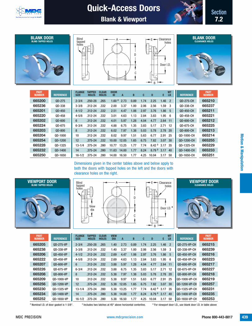
Quick-Access Doors Section
439Phone 800-443-8817
Blank & Viewport
Motion &
Manipulation
7.2
2-3/4 .250-28 .265 1.60 2 2.73 0.89 1.74 2.25 1.46 2
3-3/8 .312-24 .332 2.00 3.37 1.00 2.06 2.56 1.59 3
4-1/2 .312-24 .332 2.51 4.47 1.06 2.97 3.76 1.86 5
4-5/8 .312-24 .332 3.01 4.63 1.13 2.84 3.83 1.95 6
6 .312-24 .332 4.01 5.97 1.28 4.04 4.77 2.64 11
6-3/4 .312-24 .332 4.88 6.75 1.35 3.83 5.17 2.71 12
8 .312-24 .332 6.02 7.97 1.38 5.03 5.78 2.78 20
10 .312-24 .332 8.02 9.97 1.51 5.63 6.77 2.91 25
12 .375-24 .332 10.00 12.05 1.65 6.75 7.82 3.07 30
13-1/4 .375-24 .390 10.77 13.25 1.77 7.74 8.42 3 3.17 35
14 .375-24 .390 11.63 14.00 1.77 8.24 8.79 3 3.17 40
16-1/2 .375-24 .390 14.00 16.50 1.77 4.25 10.04 3.17 50
REFERENCEPART
NUMBERFLANGE TAPPED CLEAR DOOR WTSIZE HOLES HOLES ID A B C D E LB
QD-275-CH
QD-338-CH
QD-450-CH
QD-458-CH
QD-600-CH
QD-675-CH
QD-800-CH
QD-1000-CH
QD-1200-CH
QD-1325-CH
QD-1400-CH
QD-1650-CH
665210665237665211665221665212665225665213665214665255665229665233665251
REFERENCEPART
NUMBER
665200665236665201665220665202665224665203665204665254665228665232665250
QD-275
QD-338
QD-450
QD-458
QD-600
QD-675
QD-800
QD-1000
QD-1200
QD-1325
QD-1400
QD-1650
BLANK DOORBLIND TAPPED HOLES
BLANK DOORCLEARANCE HOLES
Door I.D.
A
D
C
B
E Clearance holes
Blind tapped holes
2 Nominal I.D. of door gasket is 1-3/8". 3 Includes two latches at 45° above horizontal centerline. 4 For viewport door I.D., use blank door I.D. in table above
2-3/4 .250-28 .265 1.40 2.73 0.89 1.74 2.25 1.46 2
3-3/8 .312-24 .332 1.40 3.37 1.00 2.06 2.56 1.59 3
4-1/2 .312-24 .332 2.69 4.47 1.06 2.97 3.76 1.86 5
4-5/8 .312-24 .332 2.69 4.63 1.13 2.84 3.83 1.95 6
6 .312-24 .332 3.88 5.97 1.28 4.04 4.77 2.64 11
6-3/4 .312-24 .332 3.88 6.75 1.35 3.83 5.17 2.71 12
8 .312-24 .332 5.38 7.97 1.38 5.03 5.78 2.78 20
10 .312-24 .332 5.38 9.97 1.51 5.63 6.77 2.91 25
12 .375-24 .332 5.38 12.05 1.65 6.75 7.82 3.07 30
13-1/4 .375-24 .390 5.38 13.25 1.77 7.74 8.42 3 3.17 35
14 .375-24 .390 5.38 14.00 1.77 8.24 8.79 3 3.17 40
16-1/2 .375-24 .390 5.38 16.50 1.77 4.25 10.04 3.17 50
REFERENCEPART
NUMBERFLANGE TAPPED CLEAR VIEW WTSIZE HOLES HOLES DIA A B C D E LB
QD-275-VP-CH
QD-338-VP-CH
QD-450-VP-CH
QD-458-VP-CH
QD-600-VP-CH
QD-675-VP-CH
QD-800-VP-CH
QD-1000-VP-CH
QD-1200-VP-CH
QD-1325-VP-CH
QD-1400-VP-CH
QD-1650-VP-CH
665215665239665216665223665217665227665218665219665257665231665235665253
REFERENCEPART
NUMBER
665205665238665206665222665207665226665208665209665256665230665234665252
QD-275-VP
QD-338-VP
QD-450-VP
QD-458-VP
QD-600-VP
QD-675-VP
QD-800-VP
QD-1000-VP
QD-1200-VP
QD-1325-VP
QD-1400-VP
QD-1650-VP
VIEWPORT DOORBLIND TAPPED HOLES
VIEWPORT DOORCLEARANCE HOLES
Door I.D.
A
D
C
B
E Clearance holes
Blind tapped holes
View dia
4
Dimensions given in the center tables above and below apply toboth the doors with tapped holes on the left and the doors withclearance holes on the right.
www.mdcprecision.comMDC PRECISION

Port Aligner
440 Phone 800-443-8817
SectionM
otio
n &
Man
ipul
atio
n
Load-Lock Gimbal7.2
02
10
02
10
3.60
Horizontal tilt adjustment 10º
2.25
4.54
5.42
1.37
5.51
Shaft extension
Parallel axis adjustment 1/8
3.60
.375.374
.500
6-32 UNC thru4.38
Features
■ 10° horizontal tilt■ 1/8 inch axial displacement■ Micrometer actuators with position lock■ Formed bellows seal■ Bakeable to 200°C■ Del-Seal™ CF port mounts■ Includes magnetic transporter extension kit■ Horizontal orientation
AG-150
Specifications
Material
Flange 304ss
Body Anodized Aluminum
Bellows, Formed 316ss
Vacuum Range 1x10-11 Torr
Temperature Range -20°C to 200°C
Maximum Load Rating 25 lbs
Weight & Dimensions See table
REFERENCEPART
NUMBERWT
DESCRIPTION LB
AG-150 665300ALIGNMENT GIMBAL 2
ULTRAHIGH VACUUM SERIES
DescriptionPort aligners are adjustable port flange interfaces that providemotion instruments with angular tilt and axial shift. They canalso be used to correct mate-up between components withminor alignment imperfections.
Load-lock gimbals are unique port alignment instrumentsspecifically designed for the precision alignment of magnetical-ly coupled transporters as used with circular and rectangularentry load-lock systems. Load-lock gimbal port aligners are fit-ted with precision micrometer adjustments for both horizontaltilt (above and below a horizontal plane of travel) and side toside parallel axis displacement. Load-lock gimbals are intendedfor horizontal installation with its tilt adjustment micrometer ata bottom 6 o’clock position. They include a stainless steelformed bellows adapter which mates between the magnetictransporter and the sample staging chamber. A transporter shaftextension kit to compensate for the increase in the transportersoverall length is also included. For bellows assembly replace-ments reference part number 400003 found in Section 1.1,page 68.
431
432
434
367
413
24-Mar-99
431
www.mdcprecision.com MDC PRECISION

Port Aligner Section
441Phone 800-443-8817
Standard Gimbal
Motion &
Manipulation
7.2
455 010
50
455 010
50
Plate I.D.
I.D. Length
2.73 4.63 4.47 6.63
I.D. Length
2.73 4.63 4.47 6.63
3.75
I.D. Nom. Ht.
2.73 3.0 4.47 6.0
Center of rotation, 2 places at 90º
Features
■ Independent planes provide 15° tilt about xand y axes
■ Tilt position lock for each plane■ Micrometer or screw adjustment actuators■ UHV compatible materials■ Bakeable to 230°C with screw type actuators■ Designed for use with Del-Seal™ CF port
mount formed bellows adaptersFGC-275-M
Specifications
Material
Flange 304ss
Body Anodized Aluminum
Vacuum Range 1x10-11 Torr
Temperature Range
Screw Type -20°C to 230°C
Micrometer Type -20°C to 100°C
Weight & Dimensions See table
REFERENCEPART
NUMBERPLATE WTI.D. TYPE LB
FGC-275-M
FGC-275-S
FGC-450-M
FGC-450-S
150-X
250-X
676000676001676002676003400003400005
2.73 MICROMETER 4
2.73 SCREW 4
4.47 MICROMETER 6
4.47 SCREW 6
2.73 BELLOWS 1
4.47 BELLOWS 4
ULTRAHIGH VACUUM SERIES
DescriptionThe standard gimbal geometry consists of three parallel andequidistant aluminum plates interconnected in a universal jointgeometry. The top and bottom plates are equally spaced fromthe center plate and held in a parallel and neutral position witheight coil springs. Top and bottom plates are fitted with preci-sion micrometers used to produce a 15° tilt about the centerplates X and Y axis respectively. When all adjustment mecha-nisms are disengaged the springs force the plates back to aneutral and parallel position. Economical screw type adjust-ments are also available in place of micrometers.
Standard gimbals are designed for use with MDC formed bel-lows flexible adapters with 1.25" and 2.00" bore diameters.Flexible bellows adapters are not included with standard gimbalassemblies and must be purchased separately.
• Shown with bellows• Bellows not included
431
413
www.mdcprecision.comMDC PRECISION

Port Aligner
442 Phone 800-443-8817
SectionM
otio
n &
Man
ipul
atio
n
Precision & Heavy Duty Off-Axis7.2
DescriptionHeavy duty port aligners provide up to 25° of angu-lar port adjustment. Tightening the clamp ring boltsto 100 lb-in of torque will allow this port aligner tosupport up to 15 pounds on a twelve inch momentarm. Metal seal flanges are 2-3/4" Del-Seal™ CFwith .250-28 threaded holes. Graduation for angu-lar displacement is not provided on the PA-25. Portalignment must be measured through externalmeans.
0 32112
321123 0
10
789
98
321123 0
All flanges are nonrotatable 2-3/4"
Del-Seal™ CF
A
2º or 10º maximum
A
Clearance holes
1.265" I.D.
2.73 dia
3.00 dia
Tapped holes
DescriptionPrecision port aligners provide 2° or 10° of off-axisangular displacement. Aligners are offered withtapped or clearance hole Del-Seal™ CF flanges.These port aligners are for light duty service andare not suitable for moment load conditions. Seeheavy duty port aligners below for 15 pound loadcapacity.
Features
■ 10° off-axis alignment■ Manual adjustment■ UHV compatible materials■ Welded bellows seal■ Del-Seal™ CF port mount
Specifications
Material
Flange 304ss
Adjustment rings Black oxide bronze
Seal AM 350 welded bellows
Vacuum Range 1x10-11 Torr
Temperature Range 230°C
Weight & Dimensions See table
Precision Off-Axis Port Aligner
1.63
3.93 dia
1.39 dia bore
2-3/4" Del-Seal™ CF flange, nonrotatable with tapped holes, both sides
Features
■ 25° off-axis alignment■ Moment loading to 15 lb■ Position lock■ UHV compatible materials■ Welded bellows seal■ Bakeable to 230°C■ Del-Seal™ CF port mount
Specifications
Material
Flange 304ss
Adjustment rings Anodized Aluminum
Seal AM 350 welded bellows
Vacuum Range 1x10-11 Torr
Temperature Range 230°C
Weight & Dimensions See table
Heavy Duty Off-Axis Port Aligner
REFERENCEPART
NUMBERGIMBAL HOLE OR A A A WTTYPE THREAD MAX AT 0° MAX AT 2° MAX AT 10° LB
PAT-2
PAT-10
PAC-2
PAC-10
675000675002675001675003
2° .250-28 1.59 1.64 - 2
10° .250-28 1.37 1.43 1.63 2
2° .265 2.27 2.33 - 2
10° .265 2.06 2.11 2.32 2
REFERENCEPART
NUMBERWT
DESCRIPTION LB
PA-25 675020HEAVY DUTY PORT ALIGNER 2
• Models with clearance holes include six eachthreaded studs, nuts and washers.
PAC-2 PAT-2
PA-25
413
17-Feb-99
www.mdcprecision.com MDC PRECISION

■ Cab-Fast®Right angle sample handlers
■ Auto-Dock™
Inline sample handlers■ Mini-Scaffold™ mounting system■ Rotary-linear accessories
In-Vacuum Accessories Section
443Phone 800-443-8817
Introduction
Motion &
Manipulation
7.2
Cab-Fast® and Auto-Dock™ sample handling
Cab-Fast® Right-Angle Sample Handlers
The Cab-Fast® sample handling systemprovides a simple yet versatile means ofloading samples for transportation tomanipulators, parking carousels, depositionstations and other locations inside ultrahighvacuum systems. They allow the transfer ofsamples between linear drive instrumentspositioned at right angles. Samples are firstsecured to platens using sample mountingstrips. The loaded platen is placed inside aload-lock sample staging chamber throughthe chambers quick-access door. Inside, theplaten is secured and attached to the platenfork previously installed to the tip of amagnetic transporter. Once the stagingchamber is evacuated to the desired vacuumlevel and the gate valve is opened the sampleis ready for transfer.
Auto-Dock™ Inline Sample Handlers
The MDC’s Auto-Dock™ sample handlingsystem is a patented group of modularsample handling components ideally suitedfor the transfer of samples betweenchambers and typically used in tandem withMDC magnetic transporters. In contrast withthe Cab-Fast® system, Auto-Dock™ allows thetransfer of samples between linear driveinstruments positioned inline with each other.The Auto-Dock™ system is comprised of threebasic components, a sample-holder plate, avacuum-dock and a transport-dock. Samplesare shuttled back and forth between avacuum process chamber and a load-lock’ssample staging chamber attached to it byfastening samples to the sample-holder plate.The sample-holder plate is manually securedto a transport-dock fixed to the tip of an MDCmagnetic transporter inside the load-lock’ssample staging chamber. The sample is thentransported to the process chamber wherethe vacuum-dock component is strategically
positioned and ready to receive the sample-holder plate.
Mini-Scaffold™ Mounting System
Mini-Scaffold™ mounting system is a versatilein-vacuum erector set comprised ofinterchangeable building block componentsthat can be assembled in a variety ofcombinations. This unique in-vacuum systemwas designed to take advantage of existingvacuum ports for the temporary or permanentinstallation of sample support structuresinside high and ultrahigh vacuumenvironments. They are ideally suited forsituations where permanent mounts are notincluded or to expand the capabilities ofexisting vacuum chambers. The in-vacuumstructure’s foundation is the Mini-Scaffold™
patented port clamp. The port clamp isfastened to the inside diameter of an available1-1/2" or 2-1/2" chamber port creating thebase from which an apparatus or structurewill rise. In addition to port clamps anassortment of components are available tocomplement the Mini-Scaffold™ system, someof these include extension rods, universal balljoints, rod clamps, sample mounting plates,specimen holders, rotary and linear bearingmounts, mirror and lens mounts, gear boxes,etc.
Rotary-Linear Accessories
Rotary-linear accessories are an assortmentof in-vacuum hardware components used tocomplement and expand the capabilities ofMDC rotary and linear motion andmanipulation instruments. Various drive shaftattachments are offered including universaljoints, bellows couplings, extension couplings,rotary and linear bearings and bearingmounts, ground shaft stock, set-screw collarsand vented cap screws.
Mini-Scaffold™ mounting system
Rotary-linear accessories for use with most rotaryand linear motion instruments page 450
All dimensions in this catalog are given in inches unless specified otherwise.
Caution
Anodized aluminum finishes will begin to dis-color when baked in excess of 150°C. This is only a cosmetic condition which does not impact performance or reliability.
436
367
413
431
www.mdcprecision.comMDC PRECISION

In-Vacuum Accessories
444 Phone 800-443-8817
SectionM
otio
n &
Man
ipul
atio
n
Sample Handling Systems7.2
Platen Fork
.100
8-32 thread
.605
3.3801.0002.630
2.2721.558
.828 .262
4-40 x 1/4"socket cap screw
2.00.374 dia
6-32 thread REFERENCEPART
NUMBER
FOR-1 665029
Cab-Fast® platen forks are designedto lock on to and hold Cab-Fast®platens during the transport andtransfer of samples between cham-bers or other motion and manipula-tion instruments. Quantity of 1.
Platen Sample Holder
.450
.875 dia
SAM-33" dia, includes 12 holes
.625 dia
8-32 x .25 dp
.110.080
SAM-22" dia,includes 8 holes
SAM-11" dia,includes 4 holes .075
4-40 thru, typ
REFERENCEPART
NUMBER
SAM-1
SAM-2
SAM-3
665026665027665028
Cab-Fast® sample platens aredesigned to hold samples during in-vacuum sample processing. Samplescan be secured in place using samplemounting strips and screws. Quantityof 1.
Features
■ UHV sample handling■ Fast sample transfer■ 304ss construction
Cab-Fast® Right-Angle Sample Handlers
The Cab-Fast® sample handling system provides asimple yet versatile means of loading samples fortransportation to manipulators, parking carousels,deposition stations and other locations inside ultra-high vacuum systems. They allow the transfer ofsamples between linear drive instruments positionedat right angles to each other. They are ideally suitedfor use with magnetically coupled transporters andother motion and manipulation instruments.
Auto-Dock™ Inline Sample Handlers
The Auto-Dock™ sample handling system is a groupof modular sample handling components ideally suit-ed for the transfer of samples between vacuumchambers when used with MDC magnetic trans-porters. Auto-Dock™ allows the transfer of samplesbetween linear drive instruments positioned inlinewith each other. The Auto-Dock™ system is com-prised of three basic components, a docking sample-holder, a vacuum-dock and a transport-dock.
Cab-Fast® sample handling tools are designed totransport samples in and out of vacuum systems. Thisdiagram shows a dual instrument arrangement whichallows right angle sample transfer.
Auto-Dock™ sample handling tools are ideally suitedfor for use with MDC magnetic transporters in sampletransfer load-lock systems. They are designed forinline sample transfer.
431
413
www.mdcprecision.com MDC PRECISION

In-Vacuum Accessories Section
445Phone 800-443-8817
Cab-Fast® Sample Handlers
Motion &
Manipulation
7.2
Sample Mount Strips
Dock Sample-Holder
Vacuum-Dock
1.25.123 dia.115
R .12
.13
.31
1.31.25 typ
.123 dia.115(5 places)
.015
.250
4-40 thru(6 places)
.200
1.500
.750 1.250
.240.125.500 typ
2.75
.312 dia
.127 dia thru(2 places)
1.850
.750
.50
1.25
REFERENCEPART
NUMBER
SAM-M1
SAM-M2
665039665040
MDC sample mounting strips offer aversatile means of fastening samplesto Cab-Fast® sample platens andAuto-Dock™ docking sample-holders.Sold in packages of 5.
REFERENCEPART
NUMBER
STA-1 665016
Auto-Dock™ docking sample-holdersare designed to hold samples duringin-vacuum sample processing.Samples are secured in place usingsample mounting strips and screws.Quantity of 1.
REFERENCEPART
NUMBER
STA-2 665017
Auto-Dock™ vacuum-docks aredesigned to receive and hold Auto-Dock™ sample-holders during in-vac-uum sample processing. They aretypically fixed inside a vacuum cham-ber as part of a sample processingstructure. Quantity of 1.
Transport-Dock
.50 .375 dia .186 dia
1.67
.79
REFERENCEPART
NUMBER
STA-3 665018
Auto-Dock™ transporter-docks aredesigned to receive, hold and trans-port Auto-Dock™ sample-holders inand out of vacuum sample process-ing chambers. They are attached tothe end of MDC magnetic transportershafts. Quantity of 1.
Screws, non-vented4-40 x .09 thread
REFERENCEPART
NUMBER
SAM-S1 665041
Socket head screws made of 300ssideal for Cab-Fast® and Auto-Dock™
sample handling systems and comein packages of 25 pieces. Thesescrews are not vented and shouldonly be installed into tapped throughholes.
SAM-M1
SAM-M2SAM-M1
SAM-M2
www.mdcprecision.comMDC PRECISION

In-Vacuum Accessories
446 Phone 800-443-8817
SectionM
otio
n &
Man
ipul
atio
n
Mini-Scaffold™ Mounting System7.2
.71
3.00
8 x 8-32 thru
3.303.05 2.05
.75
1.211.15 min2.36 max
1.43
Port Clamp Mount
Rod Clamp 90°
.38
1.27
.314 dia thru(2 places)
.41
1.20
.58
.38
REFERENCEPART
NUMBER
URC-1 680040
90° universal rod clamps provide themeans of fastening 5/16" diametershafts in right angle configurations.Socket head fasteners and washersare included with these products.Quantity of 1.
REFERENCEPART
NUMBER
PCM-1 680020
Port clamp mounts can be mountedto the inside diameter of any 1-1/2"or 2-1/2" vacuum port. Once they aresecured these clamps become thefoundation upon which other Mini-Scaffold™ components are attached.Quantity of 1.
Mini-Scaffold™ Mounting System
Mini-Scaffold™ mounting systems are versatile in-vacuum interchangeable building block componentsthat can be assembled in a variety of combinations.This unique in-vacuum system was designed to takeadvantage of existing vacuum ports for the tempo-rary or permanent installation of sample supportstructures inside ultrahigh vacuum environments.They are ideally suited for situations where perma-nent mounts are not included or to expand the capa-
bilities of existing vacuum chambers. The in-vacuumstructure’s foundation is the Mini-Scaffold™ patentedport clamp. The port clamp is fastened to the insidediameter of an available 1-1/2" or 2-1/2" chamberport creating the base from which an apparatus orstructure will rise. In addition to port clamps, anassortment of components are available to comple-ment the Mini-Scaffold™ system. The diagramsbelow depict the basic usage of Mini-Scaffold™ in-vacuum mounting systems.
Features
■ UHV sample handling■ Fast sample transfer■ 300 series stainless
steel
Using Mini-Scaffold™ guide rods incombination with inline and right-angle rod clamps, motion instru-ment drive shaft supports can beerected.
The port mount clamp is the foundationupon which all Mini-Scaffold™ structuresare erected. Simply insert the clamp tabsto the inside diameter of an available 1-1/2" to 2-1/2" vacuum port. Fasteningthe clamp is accomplished by spreadingthe clamp bars with the built in screws.
Mini-Scaffold™ is ideally suited forin-vacuum sample support structures. Thisdiagram depicts a typical installation ofMDC’s Auto-Dock™ vacuum sample dock.
413
09-Apr-02
www.mdcprecision.com MDC PRECISION

In-Vacuum Accessories Section
447Phone 800-443-8817
Mini-Scaffold™ Mounting System
Motion &
Manipulation
7.2
Universal Ball Joint
Specimen Holder
1.20.314 dia x .50 deep 8-32 thread
.625
.625 1.45 .20
.47
1.68
8-32 x .33 deep.094 dia thru
.44
.16.3127 dia.3117 dia
REFERENCEPART
NUMBER
UBJ-1 680080
Universal ball joints with built-in lockscrew provide infinite sample positionadjustment. One end accepts a .312"diameter shaft and the other is fittedwith an 8-32 UNC male thread forattaching to other Mini-Scaffold™
components. Quantity of 1.
REFERENCEPART
NUMBER
SH-1 680160
Specimen holders hold samples dur-ing sample processing inside a vacu-um chamber. Two socket headscrews and a blade clamp secure thesample to the holder. 8-32 UNCfemale thread allows attachment ofother Mini-Scaffold™ components.Quantity of 1 per pack.
Rod Clamp 180°1.37
.441.30
.58
.38
.38
.314 dia thru(2 places)
REFERENCEPART
NUMBER
URC-2 680041
180° universal rod clamps providethe means of fastening 5/16" diame-ter shafts in parallel configurationswith a .440" center to center spacing.Socket head fasteners and washersare included with these products.Quantity of 1.
1.00
8-32(8 places)
.25 typ
.75
1. 50 90º
.18
.37
.50
1. 00
Mounting Plate, Small
Mounting Plate, Large
2.00
8-32(16 places)
1.50
.75
2.00
1.00
.37
90º
.25 typ .18
REFERENCEPART
NUMBER
SMP-2 680121
Large mounting plates hold samplesor other structures during sampleprocessing inside a vacuum chamber.8-32 UNC female threads allow ameans of sample fastening or theattachment of other Mini-Scaffold™
components. Quantity of 1.
REFERENCEPART
NUMBER
SMP-1 680120
Small mounting plates hold samplesor other structures during sampleprocessing inside a vacuum chamber.8-32 UNC female threads allow ameans of sample fastening or theattachment of other Mini-Scaffold™
components. Quantity of 1.
09-Apr-02
www.mdcprecision.comMDC PRECISION

In-Vacuum Accessories
448 Phone 800-443-8817
SectionM
otio
n &
Man
ipul
atio
n
Mini-Scaffold™ Mounting System7.2
1.63
.19(3 places)
.25 dia(3 places)
.50
1.09
1.41
.11
.95.38
.69
.50
1.63
.50
8-32(5 places)
1.63Gear Box - 90°
Rod Guide60º
1.37.31 dia1.00
.31 dia
REFERENCEPART
NUMBER
RG-1 680220
Rod guides provide a means of sup-porting long shafts inside a vacuumsystem. They are an inexpensivesolution used in place of linear orrotary bearing mounts. They areintended for light duty rotation andlinear support. Quantity of 1 each perpackage.
REFERENCEPART
NUMBER
GB-1 680300
This 90° gear box provides three.250" drive shafts for in vacuumrotary motion. It provides output rota-tion to a shaft which is perpendicularto the input shaft. Drive shaft loca-tions are at 12, 3 and 6 o’clock posi-tions. Quantity of 1.
Bearing Mount, Radial
Bearing Mount, Linear
.50
8-32(3 places)
.50 dia thru
.25
.38
.75
.16.31
.631.00
.63.34
.50
8-32(3 places)
.50 dia thru
.25
.94.47
.75
.38
.63.34
1.00.63
REFERENCEPART
NUMBER
BMB-1 680180
Radial bearing mounts are made ofvacuum grade aluminum. They aredesigned to accept a radial bearingfor a .250" shaft diameter and usedwith part number 686000 found onpage 451. It includes two retainerrings to hold the bearing assembly inplace. Quantity of 1.
REFERENCEPART
NUMBER
BML-1 680200
Linear bearing mounts are made ofvacuum grade aluminum. They aredesigned to accept a linear bearingfor a .250" shaft diameter and usedwith part number 687000 found onpage 452. It includes two retainerrings to hold the bearing assembly inplace. Quantity of 1.
Mounting Strap.015
.18 dia thru(5 places)
1.311.00
.75.50.25
.31
REFERENCEPART
NUMBER
SMS-1 680140
Sample mounting straps offer a ver-satile means of fastening samples toMini-Scaffold™ small and largemounting holding plates. Quantity of5 per package.
451
1
2
2
09-Apr-02
www.mdcprecision.com MDC PRECISION

In-Vacuum Accessories Section
449Phone 800-443-8817
Mini-Scaffold™ Mounting System
Motion &
Manipulation
7.2
Mirror Mount
Lens Mount
Wrench Kit
.125
1.063 dia8-32
1.00
.6251.13
1.00
.50
1.000 I.D.x .185 deep
.71.57
.50
1/8 hex
.27
.25
.800-36 thread
8-32 thru
1.00
.63
1.13.12
.50
REFERENCEPART
NUMBER
MM-1 680240
MDC adjustable tilt mirror mounts areused for the installation of 1" diame-ter mirrors inside a vacuum system.They are constructed of vacuumgrade aluminum and are fitted withmirror tilt adjustment screws.Quantity of 1.
REFERENCEPART
NUMBER
MOM-1 680260
Microscope objective lens mounts aredesigned to accept standard opticallenses fitted with an .800-36 mount-ing thread. They are constructed ofvacuum grade aluminum and suitablefor UHV service. Quantity of 1.
REFERENCEPART
NUMBER
WK-1 680280
This is a set of three tempered steelAllen wrenches consisting of oneeach of the following hexagonalsizes: 5/64", 9/64" and 3/16". Theyare ideally suited for use with thecomplete line of Mini-Scaffold™
accessories and components.
Extension RodsLength
8-32 thread 8-32 x .25 deep2 x .094 dia thru
.50.50
.3127 dia
.3117 dia
Four standard lengths: ER-1 ER-2 ER-3 ER-41" 3" 6" 12"
REFERENCEPART
NUMBER
ER-1
ER-2
ER-3
ER-4
680060680061680062680063
Extension rods have 8-32 UNC maleand female threads on opposite ends.They can be connected end to end forcustom length structures. Quantity of 1.
Screws, non-ventedS-1Set screw, 8-32 x 5/16 thread
S-2Cap screw, 8-32 x 5/16 thread, with flat washer (not shown)
REFERENCEPART
NUMBER
S-1
S-2
680100680101
These are 300 series stainless steelsocket head screws for use with allMini-Scaffold™ hardware. They comein packages of 25 pieces. They arenot vented since all Mini-Scaffold™
components use through holes.
09-Apr-02
www.mdcprecision.comMDC PRECISION

In-Vacuum Accessories
450 Phone 800-443-8817
SectionM
otio
n &
Man
ipul
atio
n
Rotary & Linear Motion7.2
.187
.500 dia
2 x 6-32 set screw + .0005.2500 dia - .0000
.687
.125
.300
.625 dia pitch
Miter & Bevel Gear
Universal Joint
.450
.500 dia
1.50
.750
2 x 6-32 set screw
+ .0005.2500 dia - .0000
2 x pin spot
REFERENCEPART
NUMBER
AUJ-3 680000
Universal joints provide rotary motioninput with variable angle rotary out-put for .250" shaft diameters. Themaximum operating angle is 30° atlow speeds and 10° at high speeds.They are constructed of 300 seriesstainless steel and phosphor bronze.Quantity of 1.
REFERENCEPART
NUMBER
AM48-1-S 685000
Miter & bevel gears provide themeans of rotary input with 90° outputrotation. They accept .250" diametershafts and come in a set of two gearsfitted with 6-32 UNC set screws forfastening to shafts. Quantity of 1.
Miter & Bevel Gear
Motion Instrument Input Shaft
Universal Joint Coupling
Radial Bearing Blocks with Radial Bearings
Bellows Coupling
Output Shaft
MDC rotary and linear accessories can provide intricate motion paths to mobilize samples or devices inside a vacuum system.
Rotary-Linear Accessories
Rotary-linear accessories are an assortment of in-vacuum hardware components used to complementand expand the capabilities of MDC rotary and linearmotion and manipulation instruments. Various driveshaft attachments are offered including universaljoints, bellows couplings, extension couplings, rotaryand linear bearings and bearing mounts, groundshaft stock, set-screw collars and vented capscrews.
The components presented in this section can alsobe used in combination with products presented inthe Cab-Fast®, Auto-Dock™ and Mini-Scaffold™
accessories sections of this catalog. Customdesigned hardware is also available if required.Please contact MDC’s technical sales engineers withyour inquiries.
Features
■ UHV sample handling■ Fast sample transfer■ 300 series stainless
steel
413
09-Apr-02
443
www.mdcprecision.com MDC PRECISION

In-Vacuum Accessories Section
451Phone 800-443-8817
Rotary & Linear Motion
Motion &
Manipulation
7.2
.312
Retaining ring grooves
1.25
2 x .141 dia thru
.750
1.00
+ .0005.5000 dia - .0000
Bearing Mount, Radial REFERENCEPART
NUMBER
ABME-1 688000
Radial bearing mounts are made ofvacuum grade aluminum. They aredesigned to accept a radial bearingfor a .250" shaft diameter. Theyinclude two retainer rings to hold thebearing assembly in place. Also seepage 448 for alternate version.Quantity of 1.
.125
.500 dia
.250 dia
Radial Ball Bearing REFERENCEPART
NUMBER
ABI-32 686000
Rotary bearings are used to support.250" diameter rotary shafts. Theyare constructed of 440C stainlesssteel and coated with Dicronite® drylubricant suitable for UHV service.Rotary bearing housings are offeredbelow and on page 448. Quantity of 1.
Bellows Coupling
Sleeve Coupling
.281
.600 dia
4 x 6-32 set screw
.937
.252 dia .437 dia
.562
.500 dia
+ .0005.2498 dia - .0000
.140
2 x 6-32 set screw
2 x pin spot
REFERENCEPART
NUMBER
ACO4-4 682000
Bellows couplings for .250" shaftdiameters provide 50 oz-in maximumtorque at a maximum tilt angle of 5°or maximum axial misalignment of0.010". They provide zero backlashand uniform angular velocity with lowvibration. Quantity of 1.
REFERENCEPART
NUMBER
ACT-3 683000
Sleeve couplings are used to cus-tomize and extend .250" diametershafts inside a vacuum system. Theyare fitted with two 6-32 UNC setscrews to lock shafts in position andare constructed of 300 series stain-less steel. Quantity of 1.
.250
.500 diaSet screw
+ .0005.2500 dia - .0000
Set Screw Collar REFERENCEPART
NUMBER
ACS-22 690000
Set screw collars are used to createmechanical stops along a shaft’slength. They are constructed of 300series stainless steel and are sup-plied with 6-32 UNC set screws forposition lock. Quantity of 1.
448
www.mdcprecision.comMDC PRECISION

In-Vacuum Accessories
452 Phone 800-443-8817
SectionM
otio
n &
Man
ipul
atio
n
Rotary & Linear Motion7.2
These are 300 series stainless steel socket head screws ideally suited forfastening inside an ultrahigh vacuum system. The screws have been drilledthrough their entire length to eliminate the possibility of virtual leaks causedby the trapped volume of air at the bottom of blind tapped holes. They comein packages of 10 pieces.
Vented Screws REFERENCEHEAD
DESCRIPTION DIAMETERPART
NUMBER
AC-604
AC-608
AC-612
AC-804
AC-808
AC-812
AC-816
AC-1004
AC-1008
AC-1012
AC-1016
AC-1024
AC-2808
AC-2812
AC-2816
6-32 UNC x 1/4 .22
6-32 UNC x 1/2 .22
6-32 UNC x 3/4 .22
8-32 UNC x 1/4 .27
8-32 UNC x 1/2 .27
8-32 UNC x 3/4 .27
8-32 UNC x 1 .27
10-32 UNC x 1/4 .31
10-32 UNC x 1/2 .31
10-32 UNC x 3/4 .31
10-32 UNC x 1 .31
10-32 UNC x 1-1/2 .31
.250-28 UNF x 1/2 .37
.250-28 UNF x 3/4 .37
.250-28 UNF x 1 .37
691000691001691002691003691004691005691006691007691008691009691010691011691012691013691014
.937
Retaining ring grooves
1.25
4 x .141 dia thru
.750
1.00
+ .0005.5000 dia - .0000
.687Bearing Mount, Linear REFERENCE
PARTNUMBER
ALME-1 689000
Linear bearing mounts are made ofvacuum grade aluminum. They aredesigned to accept a linear bearingfor a .250" shaft diameter. Theyinclude two retainer rings to hold thebearing assembly in place. Also seepage 448 for alternate version.
Ground Stock A ± .125
+ .0005.2490 dia - .0000
Custom lengths available on request
Three standard lengths: ASI-6 ASI-12 ASI-246" 12" 24"
Thread length
REFERENCEPART
NUMBER
ASI-6
ASI-12
ASI-24
684000684001684002
Precision ground 304 stainless steelshafts offered in 6, 12 and 24 inchlengths. With coupling accessoriesthese shafts can be used to extendmotion instrument drive shafts.
.500 dia
.750.250 dia
Linear Ball Bearing REFERENCEPART
NUMBER
ALMB-1 687000
Linear bearings support .250" diame-ter linear motion drive shafts. Theyare constructed of 300 series stain-less steel and coated with Dicronite®
dry lubricant suitable for UHV service.Linear bearing housings are offeredbelow and on page 448.
448
www.mdcprecision.com MDC PRECISION

In-Vacuum Accessories Section
453Phone 800-443-8817
Motion &
Manipulation
7.2
www.mdcprecision.comMDC PRECISION

454 Phone 800-443-8817 www.mdcprecision.com MDC PRECISION

455
Motorization
Motor Spec D 460
Introduction 456
In-Vacuum Stepper Motors
DC Motor, 12V Output 464
Motor Spec C 459
Stepper Motors 465
Motor Option SpecificationsMotor Spec A 458Motor Spec B 458
Motor Spec E 460Motor Spec F 461
High Vacuum 462Ultrahigh Vacuum 463
Motor Controls
DC Motor, 90V Output 464
Section 7.3
Section Contents 367
Phone 800-443-8817Phone 800-443-8817www.mdcprecision.comMDC PRECISION

Motorization
456 Phone 800-443-8817
SectionM
otio
n &
Man
ipul
atio
n
Introduction7.3
Alternating current motors page 458
Motor Specifications
Featured throughout this catalog are motionand manipulation instruments which aresuitable for motorization. Motorizationoptions for specific instruments are listed onthe page in which they appear.Specifications for each motor option areidentified with a single letter code ("A"through "F") listed as “Motor Spec” in theoptions description table. Detailedspecifications for each motor are listed inthis section and are arranged alphabeticallyby letter code.
Alternating Current Motors
MDC reversible AC motors are aneconomical motorization solution forcontinuous motion applications. Thesemotors are equipped with a load limitingclutch rated for 50 oz-in of torque to preventinstrument overload conditions. Motors comewith three wire leads and a capacitor whichmust be wired by the customer to suitapplication circuit requirements. Motordirection reversal is accomplished by wiringreversal. Current applied to the blue and redleads produces a clockwise rotation whileapplying current to the blue and black leadsproduces counterclockwise rotation.
Direct Current Motors, Analog
MDC 90 volt direct current reversible motorsare of the permanent magnet type featuringhigh efficiency, no field supply requirement,low heat and linear speed-torquecharacteristics. Two leads with integralconnector provide easy mating with 90 voltmotor controller. These motors are furnishedwith an integral gear unit with 180:1 gear
reduction. The gearing is of the helical-spurdesign with helical gears in the primarystage for quiet operation and hardened spurgears in the secondary stages. Mountingdimensions conform to NEMA 2-11standards.
Miniature DC Motors
Miniature DC motors are used on all MDCmotorized miniature rotary and linear motioninstruments. The built in gear head with a262:1 gear ratio gives this motor amaximum torque load of 20 oz-in. Devicesfitted with these miniature motors areconstructed with a load limiting clutch toprevent motor burnout. Motors are mountedto motion instruments inside anodizedaluminum housings with inline or side mountdrive geometries. Inline geometries can alsobe purchased with a 16 pulse per revolutionmagnetic encoder.
DC Stepper Motors
Stepper motors are devices which positionloads by operating in discrete increments orsteps. The stepping action is accomplishedby switching the power to the motorwindings so that the motor phases areenergized in a specific sequence. Steppermotors are capable of very precisepositioning without the use of complicatedand expensive feedback devices.
MDC uses SLO-SYN® DC stepper motors onall motion and manipulation instrumentsfitted with stepper motors. These arebrushless, permanent magnet motors thathave full-step increments of 1.8°. They canalso be made to operate in increments of0.9° to 0.014° when half stepping or
Direct current, analog motors page 458
Direct current stepper motors page 460
■ Motor specifications■ AC motors■ Analog DC motors■ Miniature DC motors■ DC Stepper motors■ In-vacuum stepper motors■ Motor controls
All dimensions in this catalog are given ininches unless specified otherwise.
Caution
Anodized aluminum finishes will begin to dis-color when baked in excess of 150°C. This isonly a cosmetic condition which does notimpact performance or reliability.
455
369
www.mdcprecision.com MDC PRECISION

Number3762
Motorization Section
457Phone 800-443-8817
Introduction
Motion &
Manipulation
7.3
microstepping techniques are employed.SLO-SYN® motors have permanent magnetrotors and eight-pole stators. They do not have brushes, ratchets or detents towear out and they use shielded, lubricated-for-life ball bearings to insure maximumreliability and long life. Tests indicate atypical minimum life of five years. Thesestepper motors operate on phase-switchedDC power. The motor shaft advances insteps of 1.8° (200 steps per revolution)when a four step (full-step mode) inputsequence is used and in steps of 0.9° (400steps per revolution) when an eight-step(half-step mode) input sequence is used.
Microstepping is a method of stepper motorcontrol that allows the rotor to be positionedat places other than the 1.8° and 0.9°positions provided by the full-step and half-step methods. Microstepping occursbetween these two angular points in therotation of the rotor. These stepper motorsare suitable for 1/10 and 1/125 microstepincrements. A benefit of microstepping isthat it reduces the amplitude of theresonance which occurs when the motor isoperated at its natural frequency orsubharmonics of that frequency.
In-Vacuum Stepper Motors
In-vacuum stepper motors are ideally suitedfor the precision movement of delicatespecimens such as silicon wafers inultrahigh vacuum. The use of in-vacuumstepper motors results in considerablesavings in mechanical complexity withresultant gains such as cost reduction,improved reliability and decreased backlash.In some cases the use of in-vacuum motorscan mean the complete elimination of edge
welded bellows. The particulate generationof these stepper motors is minimized by thetotal absence of metal to metal slidingsurfaces. This and their low outgassingcharacteristics make these motors especiallysuitable for sensitive semiconductor handlingapplications. Other applications for whichthese motors have been employed includeprecision in-vacuum UHV manipulators,monochromator mechanisms forsynchrotrons, ion beam lithography andsample transport in UHV.
Motor Controls
All motor controls are sold separately andare not included in the motorization optionprices.
Alternating current (AC) motors do notrequire motor controls since they aredesigned to be wired directly into analternating current wall circuit.
DCM-SC-90 controllers are designed for usewith 90 VDC motorized instruments. Thiscontroller provides bidirectional motorcontrol in continuous and jog modes. Motorspeed is adjustable from 0 to 10 rpm viavoltage regulation. Feedback circuitry usesthe motor’s “Back-EMF” to provide a flattorque-speed curve. Additional featuresinclude transient and surge protection, linevoltage compensation, soft start, discretesilicon-controlled rectifiers and diodes forhigher amperage output and better heatdissipation. Controller is wired for 115VACinput and is provided with a 2 conductorcable for direct connection to MDC 90Vmotorized components.
DCM-SC-12 controllers are designed for use
with 12 VDC motorized instruments in thiscatalog. This controller provides bidirectionalmotor control in continuous and jog modes.It provides motor speed adjustment from 0to 20 rpm via voltage regulation. Feedbackcircuitry uses the motor’s “Back-EMF” toprovide a flat torque-speed curve. Thecontroller is wired for 115VAC input and isprovided with a 2 conductor cable for directconnection to MDC 12V motorizedcomponents via a standard 2.5-mm plug.Rear panel voltage switch allows the DCM-SC-12 to accept 110 or 220 VAC linevoltage.
SMC-M controllers are designed for all airand in-vacuum stepper motorizedinstruments. Current control output is vital inany stepper motor controller. MDC steppermotor controllers employ the time-testedbipolar chopper regulation of current. Outputcurrent is set to 0.6 amperes as required forthe low torque motors. Output current isadjustable for the medium and high torquemotors. Current output adjustment isaccomplished by resetting the six internalDIP switches.
The SMC-1 indexer is a powerful and userfriendly tool capable of complex motionprofile control when interfaced with an IBMcompatible PC. The indexer comes with thenecessary software for programming viaASCII commands and a 37 pin Type-Dsubminiature interface provides the userwith TTL input and output access.
Direct current miniature analog motors page 459 In-vacuum direct current stepper motors page 462 Motor controls and electronics page 464
Number
www.mdcprecision.comMDC PRECISION

Motorization
458 Phone 800-443-8817
SectionM
otio
n &
Man
ipul
atio
n
Specifications A and B7.3
MDC reversible AC motors are an economi-cal motorization solution for continuousmotion applications. These motors areequipped with a load limiting clutch rated for50 oz-in of torque to prevent instrumentoverload conditions. Motors come with threewire leads and a capacitor which must bewired by the customer to suit application cir-cuit requirements. Motor direction reversal isaccomplished by wiring reversal. Currentapplied to the blue and red leads produces aclockwise rotation while applying current tothe blue and black leads produces counter-clockwise rotation.
1.00
.594
.25
2.25
.625
.230
2.38
.468
.250
8-32, 4 places equally spaced on a 2.688 B.C.D.
Specifications
Connections
Type leads
Number of wires 3
Input Voltage 115 VAC / 60 Hz
Power 7.50 W
Temperature Range -40°C to 65°C
Dimensions See drawing
Torque
With load limiting Clutch 50 oz-in
Motor 126 oz-in @ 10 rpm
Weight 3 Lb
Motor Specification "A"115V AC MOTOR
MDC 90 volt direct current reversible motorsare of the permanent magnet type featuringhigh efficiency, no field supply requirement,low heat and linear speed-torque character-istics. Two leads with integral connector pro-vide easy mating with 90 volt motor con-troller. These motors are furnished with anintegral gear unit with 180:1 gear reduction.The gearing is of the helical-spur design withhelical gears in the primary stage for quietoperation and hardened spur gears in thesecondary stages. Mounting dimensionsconform to NEMA 2-11 standards.
2.38
8-32 screw, 2 places 180º apart on a 2.688 B.C.D.
3.44
.25
1.00
.625
.230
.34
.594
.468
.250
Specifications
Connections
Type Connector
Number of pins 2
Input Voltage 90 VDC
Power input 2.25 W
Temperature Range -20°C to 65°C
Dimensions See drawing
Torque
With load limiting clutch 50 oz-in
Motor Geared @ 180 : 1 72 oz-in @ 10 rpm
Speed 0.7 to 10 rpm
Weight 6 Lb
Motor Specification "B"90V DC MOTOR
379
387
464
437
455
455
367
456
456
www.mdcprecision.com MDC PRECISION

Motorization Section
459Phone 800-443-8817
Specification C
Motion &
Manipulation
7.3
Miniature DC motors are used on all MDCmotorized miniature rotary and linear motioninstruments. The built in gear head with a262:1 gear ratio gives this motor a maximumtorque load of 20 oz-in. Devices fitted withthese miniature motors are constructed witha load limiting clutch to prevent motorburnout. Motors are mounted to motioninstruments inside anodized aluminum hous-ings with inline or side mount drive geome-tries.
2.01
.669 dia
.559
.469
M2
.110 flat
2-56 UNC.430 B.C.D.
Specifications
Connections
Type 2 contact coaxial
Number of wires 2
As Motion Option 4 2.5 mm plug
Input Voltage 12 VDC
Input Current 140 mA
Temperature Range -30°C to 65°C
Dimensions See drawing
Torque
Friction 0.006 oz-in
Stall 0.13 oz-in
Motor Geared @ 262 : 1 20 oz-in
Armature Resistance 80 ohm
Armature Inductance 1.2 mH
Weight 0.43 oz
Motor Specification "C"12V DC MOTOR
382
383
390
391
464
455
DC Controller12V DC MOTOR
DC Controller90V DC MOTOR
DC Motor Controls, see page 464
Magnetic Encoder Specifications
Nominal Power Requirement
5mA max. @ 5 VDC @ 22°C
Max. Operating voltage 15.0 VDC
Signal Phase Shift and Tolerance
90° ±45° (2 phase signal)
Maximum Signal Frequency 7.2 kHz
Temperature Range
Operating -20°C to 85°C
Storage -40°C to 110°C
Connection Ansley low-profile DIP plug, 8-pin
Maximum Asymmetry 10°
Signal Rise Time less than 5 microseconds
Miniature rotary and linear motion instru-ments, which have inline geometries, canalso be purchased with a magnetic encoder.
■ Square wave output■ TTL / CMOS compatible■ 16 pulses per revolution■ 2 channels, 90° phase shift
28-Mar-00
457
www.mdcprecision.comMDC PRECISION

Motorization
460 Phone 800-443-8817
SectionM
otio
n &
Man
ipul
atio
n
Specifications D and E7.3
The KML061S04 stepper motor is designed toNEMA standards 23D frame size specifica-tions, and is ideally suited for use with variousMDC motion and manipulation devices. It hasa ±2% noncumulative step accuracy and canoperate in full-step (1.8°) or half-step (0.9°)increments. It can be microstepped to achieveincrements as small as .0072° and operate atrates to 20,000 steps per second (6,000 rpm).The motor specifications provided are for inseries bipolar wiring configuration.
2.24
1.502 dia1.4982.24
2.21
.76
.2500 dia.2495
.050
.205 dia, 4 places equally spaced on a 2.625 B.C.D.
Specifications
Connections
Type Connector
Number of pins 6
Input Voltage 3 VDC
Input Current 2 A
Temperature Range -40°C to 65°C
Dimensions See drawing
Steps per Revolution 200
Torque
Holding with 2 phases on 170 oz-in
Residual 1 oz-in
Rotor Inertia 0.0034 oz-in2
Overhang Load 15 Lb
Thrust Load 25 Lb
Weight 1.6 Lb
Motor Specification "E"MEDIUM TORQUE STEPPER MOTOR
455
423
The M061-CS02 stepper motor is designedto NEMA standards 23D frame size specifica-tions and is ideally suited for use on variousMDC motion and manipulation devices. It hasa ±3% noncumulative step accuracy and a48-50 tooth pitch configuration which give itsmooth operating soft step motion, less res-onance and instability. This motor is connec-tor fitted with 6 wire contacts. The motorspecifications provided are for an in seriesbipolar wiring configuration. Motors can beused in a unipolar configuration. However,current, voltage and torque ratings wouldchange. Contact factory for details.
2.24
1.502 dia1.498 2.24
2.02
.76
.2500 dia.2495
.050
.205 dia, 4 places equally spaced on a 2.625 B.C.D.
Specifications
Connections
Type Connector
Number of pins 6
Input Voltage 5 VDC
Input Current 0.7 A
Temperature Range -40°C to 65°C
Dimensions See drawing
Steps per Revolution 200
Torque
Holding with 2 phases on 75 oz-in
Residual 1 oz-in
Rotor Inertia 0.04 Lb-in2
Overhang Load 15 Lb
Thrust Load 25 Lb
Weight 1.5 Lb
Motor Specification "D"LOW TORQUE STEPPER MOTOR
455
405
417
425
427
465
19-Nov-99
456
www.mdcprecision.com MDC PRECISION

Motorization Section
461Phone 800-443-8817
Specification F
Motion &
Manipulation
7.3
KML062S04 stepper motors are designed toNEMA standards 23D frame size specifica-tions. The dual-stack construction of thismotor produces double the torque of stan-dard motors. It has a ±2% noncumulativestep accuracy and can operate in full-step(1.8°) or half-step (0.9°) increments. It canbe microstepped to achieve increments assmall as .0072° and operate at rates to20,000 steps per second (6,000 rpm). Motorspecifications represent an in series bipolarwiring configuration.
2.24
1.502 dia1.4982.24
3.06
.76
.2500 dia.2495
.050
.205 dia, 4 places equally spaced on a 2.625 B.C.D.
Specifications
Connections
Type Connector
Number of pins 6
Input Voltage 4.67 VDC
Input Current 2.12 A
Temperature Range -40°C to 65°C
Dimensions See drawing
Steps per Revolution 200
Torque
Holding with 2 phases on 250 oz-in
Residual 1.4 oz-in
Rotor Inertia 0.0056 oz-in2
Overhang Load 15 Lb
Thrust Load 25 Lb
Weight 2.3 Lb
Motor Specification "F"HIGH TORQUE STEPPER MOTOR
455
419
429Controller Indexer
Stepper Motor Controls, see page 465
www.mdcprecision.comMDC PRECISION

Motorization
462 Phone 800-443-8817
SectionM
otio
n &
Man
ipul
atio
n
In-Vacuum Stepper Motors7.3
With 200 steps per revolution, these in-vacu-um stepper motors are ideally suited for theprecision movement of delicate specimensinside a high vacuum system. Their low out-gassing characteristics, make these motorsespecially suitable for sensitive semiconduc-tor handling and many other high vacuumapplications.
REFERENCEPART
NUMBER
SM13-HV 665921
Specifications
Connections
Type Kapton® insulated 1 / 0.6mm
Electrical wires 4
Thermocouple wires Not available
Input Voltage 3.12 VDC
Input Current 1.2 A
Temperature Range -40°C to 150°C
Dimensions See drawing
Steps per Revolution 200
Vacuum Range 5x10⁻⁸ Torr
Torque
Holding 7.5 oz-in
Detent 0.5 oz-in
Winding Resistance 2.6 Ohm
Winding Inductance 1.2 mH
Weight 0.5 Lb
.320
.157 dia
M4 thread, 4 places equally spaced on a .980 B.C.D.
1.30 dia
.060
1.00(2 places)
1.65
M4 thread, 2 places 180º apart
.710 dia
MINIATURE HVHIGH VACUUM STEPPER MOTOR
465
367
455
With 200 steps per revolution, these in-vacu-um stepper motors are ideally suited for theprecision movement of delicate specimensinside a high vacuum system. Their low out-gassing characteristics, make these motorsespecially suitable for sensitive semiconduc-tor handling and many other high vacuumapplications.
REFERENCEPART
NUMBER
SM23-HV 665911
Specifications
Connections
Type Kapton® insulated 1 / 0.6mm
Electrical wires 4
Thermocouple wires Not available
Input Voltage 6.8 VDC
Input Current 1.2 A
Temperature Range -40°C to 150°C
Dimensions See drawing
Steps per Revolution 200
Vacuum Range 5x10⁻⁸ Torr
Torque
Holding 60 oz-in
Detent 4.5 oz-in
Winding Resistance 5.7 Ohm
Winding Inductance 6.7 mH
Weight 1.5 Lb
1.502 dia1.498
2.36
2.36
2.30
.79
.2500 dia.2495
.060
.205 dia, 4 places equally spaced on a 2.625 B.C.D.
2.22 dia
HIGH TORQUE HVHIGH VACUUM STEPPER MOTOR
457
www.mdcprecision.com MDC PRECISION

Motorization Section
463Phone 800-443-8817
In-Vacuum Stepper Motors
Motion &
Manipulation
7.3
With 200 steps per revolution, these in-vacu-um stepper motors are ideally suited for theprecision movement of delicate specimensinside ultrahigh vacuum system. The particu-late generation of these stepper motors isminimized by the total absence of metal tometal sliding surfaces. Their low outgassingcharacteristics, make these motors especial-ly suitable for many sensitive ultrahigh vacu-um applications.
REFERENCEPART
NUMBER
SM23-UHV 665912
Specifications
Connections
Type Kapton® insulated 1 / 0.6mm
Electrical wires 4
Type K thermocouple wires 2
Input Voltage 6.8 VDC
Input Current 1.2 A
Temperature Range -40°C to 250°C
Dimensions See drawing
Steps per Revolution 200
Vacuum Range 1x10⁻¹⁰ Torr
Torque
Holding 60 oz-in
Detent 4.5 oz-in
Winding Resistance 5.7 Ohm
Winding Inductance 6.7 mH
Weight 1.5 Lb
1.502 dia1.498
2.36
2.36
2.30
.79
.2500 dia.2495
.060
.205 dia, 4 places equally spaced on a 2.625 B.C.D.
2.22 dia
HIGH TORQUE UHVULTRAHIGH VACUUM STEPPER MOTOR
With 200 steps per revolution, these in-vacu-um stepper motors are ideally suited for theprecision movement of delicate specimensinside ultrahigh vacuum system. The particu-late generation of these stepper motors isminimized by the total absence of metal tometal sliding surfaces. Their low outgassingcharacteristics, make these motors especial-ly suitable for many sensitive ultrahigh vacu-um applications.
REFERENCEPART
NUMBER
SM13-UHV 665922
Specifications
Connections
Type Kapton® insulated 1 / 0.6mm
Electrical wires 4
Type K thermocouple wires 2
Input Voltage 3.12 VDC
Input Current 1.2 A
Temperature Range -40°C to 250°C
Dimensions See drawing
Steps per Revolution 200
Vacuum Range 1x10⁻¹⁰ Torr
Torque
Holding 7.5 oz-in
Detent 0.5 oz-in
Winding Resistance 2.6 Ohm
Winding Inductance 1.2 mH
Weight 0.5 Lb
.320
.157 dia
M4 thread, 4 places equally spaced on a .980 B.C.D.
1.30 dia
.060
1.00(2 places)
1.65
M4 thread, 2 places 180º apart
.710 dia
455MINIATURE UHVULTRAHIGH VACUUM STEPPER MOTOR
www.mdcprecision.comMDC PRECISION

Motorization
464 Phone 800-443-8817
SectionM
otio
n &
Man
ipul
atio
n
Controls7.3
REFERENCEPART
NUMBER
DCM-SC-90 692007
Standard 90V DC Motor Controller
Description
DCM-SC-90 controllers are designed for usewith MDC 90 VDC motors featured in this cat-alog. For detailed motor specifications refer-ence motor specification "B" on page 458.This controller provides bidirectional motorcontrol in both continuous and jog modes.Motor speed is adjustable from 0 to 10 rpmvia a convenient dial potentiometer. A feed-back circuit using the motor’s “Back-EMF”provides a flat torque-speed curve. Additionalbuilt-in features include transient and surgeprotection, line voltage compensation, softstart, discrete silicon-controlled rectifiers anddiodes for higher amperage output and betterheat dissipation. Controller comes factorywired for 115VAC input and is provided with apre-wired 2 conductor cable for direct con-nection to MDC 90V motorized components.Motor controls are not included as part offeedthrough motorization options and mustbe purchased separately.
REFERENCEPART
NUMBER
DCM-SC-12 692002
Miniature 12V DC Motor Controller
Specifications
Controls
Run / Jog Momentary toggle
Speed Adjustable voltage potentiometer
Input Voltage 115 / 220 VAC
Input Current 0.25 A maximum
Output Voltage Variable 0-12 VDC
Output Current 4 A maximum
Temperature Range -20°C to 85°C
Weight 2 lb
Dimensions 6.75 x 5.80 x 2.85
Description
DCM-SC-12 controllers are designed for usewith MDC 12 VDC motors featured in thiscatalog. For detailed motor specificationsreference motor specification "C" on page459. This controller provides bidirectionalmotor control in both continuous and jogmodes. Motor speed is adjustable from 0 to20 rpm via a convenient dial potentiometer.A feedback circuit using the motor’s “Back-EMF” provides a flat torque-speed curve.Controller comes factory wired for 115VACinput and is provided with a pre-wired 2conductor cable for direct connection toMDC 12V motorized components via a stan-dard 2.5-mm plug. A rear panel voltageswitch allows the DCM-SC-12 to accept 110or 220 line voltage. Motor controls are notincluded as part of feedthrough motorizationoptions and must be purchased separately.
Features
■ Run and jog modes■ Variable voltage speed control■ Forward and reverse operation■ 12 volt DC output
Specifications
Controls
Run / Jog Momentary toggle
Speed Adjustable voltage potentiometer
Input Voltage 115 VAC
Input Current 1 A
Output Voltage Variable 0-90 VDC
Output Current 0.50 A
Temperature Range -20°C to 85°C
Weight 2 lb
Dimensions 6.75 x 5.80 x 2.85
Features
■ Run and jog modes■ Variable voltage speed control■ Forward and reverse operation■ 90 volt DC output
378
382
386
390
437
367
455
455
459
457
www.mdcprecision.com MDC PRECISION

383
Motorization Section
465Phone 800-443-8817
Controls
Motion &
Manipulation
7.3
Stepper Motor Controller
This controller is also recommended for usewith the high and ultrahigh, in-vacuum step-per motors detailed on page 462. Currentcontrol output is vital in any stepper motorcontroller; MDC stepper motor controllersemploy the time-tested, bipolar chopperregulation of current. Output current is facto-ry set to 0.6 amperes required for the lowtorque "D" motor. Output current must beadjusted to 2.0 amperes for the medium andhigh torque motors, "E" and "F" respective-ly. Resetting current output for 2.0 amperesis accomplished by adjusting the six internalDIP switches to the off position. Steppermotor controls are not included with motor-ization options, and must be purchased sep-arately.
Specifications
Step Counter Four digit LED
Resolution Half-step increments
Controls Manual Dial, Forward / Reverse
Input Voltage 115 VAC
Input Current 1 A
Output Voltage 5 VDC, 2 Phase
Output Current Adjustable from 0.5 to 2.5 A
Temperature Range -20 to 85°C
Weight 9 Lb
Dimensions 8.60 x 9.50 x 5.05
Stepper Motor Indexer
Description
The SMC-1 indexer is a powerful and user friendly tool capable of complex motion pro-file control when interfaced with an IBM compatible PC. The indexer comes with the necessary software for programming via ASCII commands. The 37 pin Type-D sub-miniature interface provides the user with TTL input and output access. Please note that stepper motor controllers and indexer are not included with motorization options, and must be purchased separately.
Specifications
Interface RS-232C
Input / Output 37 pin Type-D subminiature
Controller Interface 9 pin Type-D subminiature
Memory 100 Block programs, 512 bytes
Control Via IBM compatible PC
Input Voltage 115 VAC
Speed 23,000 Steps / second maximum
Distance 65,000 Steps / move command
Temperature Range -20 to 85°C
Weight 4 Lb
Dimensions 8.50 x 9.50 x 2.85
REFERENCEPART
NUMBER
CONTROLLER SMC-M 692005
REFERENCEPART
NUMBER
INDEXER SMC-1 692006
Features
■ Run and jog modes■ Variable speed control■ Forward and reverse operation■ 5 volt DC output
Features
■ Bidirectional ramping■ RS-232C interface■ Programmable via host com-
puter
404
Description
SMC-M controllers are designed for use withMDC stepper motors featured in this catalog.Stepper motor specifications "D, E and F"can be found starting on page 460.
455
www.mdcprecision.comMDC PRECISION

466 Phone 800-443-8817 www.mdcprecision.com MDC PRECISION