
Scott Richardson - Major Projects - NSW Government
41
1 Scott Richardson From: Dean Goldsmith <[email protected]> Sent: Wednesday, 18 July 2018 1:43 PM To: Scott Richardson Cc: 'Tom Newton'; David Sanders; Jaryd Fulcher-Collin; Sharlene Paparoa; Tom Johnston Subject: RE: Alpolic/Alucobond Cladding to Offices Attachments: Alpolic FR - CodeMark Revision 2.pdf; Alpolic FR A2 - Certmark Evaluation Report - August 2016.pdf Scott, I have reviewed the advice from Travers and the Alpolic FR codemark certificate and can confirm that it is compliant with BCA Spec. C1.1 requirements for this building as it is Type C Construction and satisfies the Bushfire requirements subject to compliance with the conditions of the codemark – copied below: Regards,
-
Upload
khangminh22 -
Category
Documents
-
view
0 -
download
0
Transcript of Scott Richardson - Major Projects - NSW Government

1
Scott Richardson
From: Dean Goldsmith <[email protected]>Sent: Wednesday, 18 July 2018 1:43 PMTo: Scott RichardsonCc: 'Tom Newton'; David Sanders; Jaryd Fulcher-Collin; Sharlene Paparoa; Tom
JohnstonSubject: RE: Alpolic/Alucobond Cladding to OfficesAttachments: Alpolic FR - CodeMark Revision 2.pdf; Alpolic FR A2 - Certmark Evaluation Report -
August 2016.pdf
Scott, I have reviewed the advice from Travers and the Alpolic FR codemark certificate and can confirm that it is compliant with BCA Spec. C1.1 requirements for this building as it is Type C Construction and satisfies the Bushfire requirements subject to compliance with the conditions of the codemark – copied below:
Regards,

2
Dean Goldsmith M. 0417309034
SYDNEY + WOLLONGONG + NEWCASTLE T: 02 9211 7777 | E: [email protected] P: PO Box 167, BROADWAY NSW 2007 W: bmplusg.com.au
This e-mail and attachments (if any) is intended only for the addressee(s) and is subject to copyright. This email contains information which may be confidential or privileged. If you are not the intended recipient please advise the sender by return email, do not use or disclose the contents and delete the message and any attachments from your system. Unless specifically stated, this email does not constitute formal advice or commitment by the sender or Blackett Maguire + Goldsmith Pty Ltd or any of its subsidiaries.
From: Scott Richardson [mailto:[email protected]] Sent: Tuesday, 17 July 2018 12:39 PM To: Tom Johnston; Dean Goldsmith Cc: 'Tom Newton'; David Sanders; Jaryd Fulcher-Collin; Sharlene Paparoa Subject: RE: Alpolic/Alucobond Cladding to Offices Hi Tom and Dean, We engaged a bushfire consultant on the basis of the below emails to review the proposed use of Alpolic cladding material on the office facades for E Store and VFA. They have prepared the attached draft report (report will be issued as final shortly). By my interpretation, based on your previous email below and the findings of the report, we are ok to proceed with using Alpolic on the facade. Can you please confirm that you agree with this assessment? Thanks,
Scott Richardson | Project Manager | FDC Construction (NSW) Pty Ltd 22 - 24 Junction Street Forest Lodge NSW 2037 Sydney | Canberra | Melbourne | Adelaide | Brisbane | Perth T 61 2 8117 5189 | M 0434 563 386 | F 61 2 9566 2900 | www.fdcbuilding.com.au Accreditations: QA | WHS | EMS | FSC | NSW Government
Download vCard

3
Please consider the environment before printing this email
From: Scott Richardson Sent: Wednesday, 27 June 2018 11:37 AM To: Tom Johnston <[email protected]>; Dean Goldsmith <[email protected]> Cc: Tom Newton <tnewton@affinity‐eng.com>; David Sanders <[email protected]>; Jaryd Fulcher‐Collin <[email protected]>; Luke Corby <[email protected]>; Sharlene Paparoa <[email protected]> Subject: RE: Alpolic/Alucobond Cladding to Offices Tom, Thanks for the confirmation. We will have a bushfire consultant assess and advise if any issues are raised. Thanks,
Scott Richardson | Project Manager | FDC Construction (NSW) Pty Ltd 22 - 24 Junction Street Forest Lodge NSW 2037 Sydney | Canberra | Melbourne | Adelaide | Brisbane | Perth T 61 2 8117 5189 | M 0434 563 386 | F 61 2 9566 2900 | www.fdcbuilding.com.au Accreditations: QA | WHS | EMS | FSC | NSW Government
Download vCard
Please consider the environment before printing this email
From: Tom Johnston [mailto:[email protected]] Sent: Wednesday, 27 June 2018 11:15 AM To: Scott Richardson <[email protected]>; Dean Goldsmith <[email protected]> Cc: Tom Newton <tnewton@affinity‐eng.com>; David Sanders <[email protected]>; Jaryd Fulcher‐Collin <[email protected]>; Luke Corby <[email protected]>; Sharlene Paparoa <[email protected]> Subject: RE: Alpolic/Alucobond Cladding to Offices Scott,

4
As Type C Construction applies to both buildings, there are no requirements in the BCA for the external walls to be non‐combustible. If you have a bushfire consultant on board I would suggest running the proposed products by them, particularly in relation to the following draft condition:
Regards, Tom Johnston – 0401 196 730 Blackett Maguire + Goldsmith
SYDNEY + WOLLONGONG + NEWCASTLE
T: 02 9211 7777 | E: [email protected] P: PO Box 167, BROADWAY NSW 2007 W: bmplusg.com.au
This e-mail and attachments (if any) is intended only for the addressee(s) and is subject to copyright. This email contains information which may be confidential or privileged. If you are not the intended recipient please advise the sender by return email, do not use or disclose the contents and delete the message and any attachments from your system. Unless specifically stated, this email does not constitute formal advice or commitment by the sender or Blackett Maguire + Goldsmith Pty Ltd or any of its subsidiaries.
From: Scott Richardson <[email protected]> Sent: Wednesday, June 27, 2018 11:03 AM To: Dean Goldsmith <[email protected]>; Tom Johnston <[email protected]> Cc: Tom Newton <tnewton@affinity‐eng.com>; David Sanders <[email protected]>; Jaryd Fulcher‐Collin <[email protected]>; Luke Corby <[email protected]> Subject: RE: Alpolic/Alucobond Cladding to Offices Hi Dean and Tom. Have you had a chance to look at the below? This is becoming very urgent! Thanks,
Scott Richardson | Project Manager | FDC Construction (NSW) Pty Ltd 22 - 24 Junction Street Forest Lodge NSW 2037 Sydney | Canberra | Melbourne | Adelaide | Brisbane | Perth T 61 2 8117 5189 | M 0434 563 386 | F 61 2 9566 2900 | www.fdcbuilding.com.au Accreditations: QA | WHS | EMS | FSC | NSW Government
Download vCard

5
Please consider the environment before printing this email
From: Scott Richardson Sent: Monday, 25 June 2018 11:15 AM To: Dean Goldsmith <[email protected]>; Tom Johnston <[email protected]> Cc: 'Tom Newton' <tnewton@affinity‐eng.com>; David Sanders <[email protected]>; Jaryd Fulcher‐Collin <[email protected]>; Luke Corby <[email protected]> Subject: Alpolic/Alucobond Cladding to Offices Importance: High Hi Dean and Tom, Can you please confirm if it is acceptable to use Alpolic and/or Alucobond cladding to the offices on E Store and Valley Fresh? Cladding wouldn’t be used for soffits; these would be constructed from FC. Our preference is certainly to use one of these products (rather than Alcadex or similar), as it is much easier to work with, is readily available and matches the colours shown on DA drawings. I have attached a 3D render of the E Store office, to assist with visualisation. Can you please respond urgently, as this will affect design works currently underway. Thanks,
Scott Richardson | Project Manager | FDC Construction (NSW) Pty Ltd 22 - 24 Junction Street Forest Lodge NSW 2037 Sydney | Canberra | Melbourne | Adelaide | Brisbane | Perth T 61 2 8117 5189 | M 0434 563 386 | F 61 2 9566 2900 | www.fdcbuilding.com.au Accreditations: QA | WHS | EMS | FSC | NSW Government
Download vCard
Please consider the environment before printing this email ______________________________________________________________________ This email has been scanned by the Symantec Email Security.cloud service.

6
For more information please visit http://www.symanteccloud.com ______________________________________________________________________
______________________________________________________________________ This email has been scanned by the Symantec Email Security.cloud service. For more information please visit http://www.symanteccloud.com ______________________________________________________________________ ______________________________________________________________________ This email has been scanned by the Symantec Email Security.cloud service. For more information please visit http://www.symanteccloud.com ______________________________________________________________________ ______________________________________________________________________ This email has been scanned by the Symantec Email Security.cloud service. For more information please visit http://www.symanteccloud.com ______________________________________________________________________

TBE Environmental Pty Ltd
ABN 85 624 419 870 PO Box 7138 Kariong NSW 2250
38A The Avenue Mt Penang Parklands Central Coast Highway Kariong NSW 2250
t: 02 4340 5331
w:www.traversecology.com.au
Our Ref: 18FDC03: JT NSW DoPE Reference: SSD 8606
17 July 2018
Attention: Mr Richardson
Dear Scott
Re: Bushfire Compliance Certification Buildings 5 & 7, Lot 23 DP 262886, Hollinsworth Road, Blacktown
Travers bushfire & ecology (TBE) has been engaged to provide bushfire compliance certification for Building 5 and 7 confirming that the draft requirements of NSW Government Department of Planning and Environment (Application No. SSD 8606) Condition B38 and B39 have been complied with as follows;
Condition B38 – Throughout the life of the development, the Applicant must manage the whole site as an inner protection area as outlined in Section 4.1.3 and Appendix 5 of Planning for Bushfire Protection 2006 and the NSW Rural Fire Services’ publication Standards for asset protection zones.
TBE can confirm that the entire site has been cleared for earthworks and therefore is currently managed to the standards required for an inner protection area (IPA) in accordance with this condition.
Building 5 Warehouse (Valley Fresh)
TBE has reviewed the site plans prepared SBA Architects (drawing no. GA-100/P2, dated 18.06.18) and can confirm the IPA surround the Building 5 Warehouse will consist of a 6m wide perimeter fire trail (east and south), hardstand (west) and car parking (north).
Building 7 Warehouse (E – Store)
TBE has reviewed the site plans prepared by Nettletontribe Architects Pty Ltd (Ref: 10685_101, dated 14.06.18) and can confirm the IPA surrounding the Building 7 Warehouse will consist of a 6m wide perimeter fire trail (south and west), hardstand (east) and car parking (north).
The remainder of the site will be developed to include Buildings 1-5 and associated parking and hardstand areas.
Condition B39 (e) –construction must comply with sections 3 and 5 (BAL 12.5) Australian Standard AS3959-2009 ‘Construction of buildings in bush fire prone areas’ or NASH Standard (1.7.14 updated) ‘National Standard Steel Framed Construction in Bushfire Areas – 2014’ as appropriate and section A3.7 Addendum Appendix 3 of Planning for Bushfire Protection 2006.

2
Building 5 Warehouse (Valley Fresh)
TBE has reviewed the site plans prepared SBA Architects (drawing no. GA-100/P2, dated 18.06.18) and has identified the following compliant construction materials for proposed Building 5;
Warehouse: PIR precast panels to 7.1m, Colorbond cladding above, steel framedbracing, profiled metal roof sheeting, box gutters, Colorbond fascia and eaves,colorbond barge capping, Colorbond metal flashing and roller shutter doors.
Office (two storey): precast concrete panels at ground level, Alpolic cladding (referAttachment 1), Viridian 6mm EVAntage grey toughened glass (glazing),
In order to ensure warehouse compliance with bushfire attack level (BAL) 12.5; External glazing (windows) is to comply with AS3959 Section 5.5.2. Any sarking used for BAL 12.5 shall be non-combustible (Appendix A3.7 PBP) Warehouse roller shutter doors are to have guide tracks with a maximum gap no
greater than 3mm and shall be fitted with a nylon brush that is in contact with the door(AS3959 Section 5.5.5 (c))
Box gutters are to be non-combustible and flashed at the junction with the roof withnon-combustible material (AS3959 Section 5.6.6)
Building 7 Warehouse (E – Store)
TBE has reviewed the site plans prepared by Nettletontribe Architects Pty Ltd (Ref: 10685_101, dated 14.06.18) and has identified the following BAL 12.5 compliant construction materials for proposed Building 7;
Warehouse: Concrete precast panels, Colorbond cladding, steel framed bracing,profiled metal roof sheeting, box gutters, Colorbond fascia and eaves, v bargecapping, Colorbond metal flashing and roller shutter doors.
Office (single storey): Alpolic cladding (refer Attachment 1), Viridian 6mm EVAntagegrey toughened glass (glazing), profiled metal roof sheeting, Colorbond profiled metalwall sheeting, precast concrete.
In order to ensure compliance with BAL 12.5; External glazing (windows) is to comply with AS3959 Section 5.5.2. Any sarking used for BAL 12.5 shall be non-combustible (Appendix A3.7 PBP) Warehouse roller shutter doors are to have guide tracks with a maximum gap no
greater than 3mm and shall be fitted with a nylon brush that is in contact with the door(AS3959 Section 5.5.5 (c))
Box gutters are to be non-combustible and flashed at the junction with the roof withnon-combustible material (AS3959 Section 5.6.6)

3
If you require any further information please do not hesitate to contact the undersigned on (02) 4340 5331 or at [email protected]
Yours faithfully
John Travers
BA Sc. / Ass Dip / Grad Dip / BPAD-Level 3-15195 (FPA) Principal Bushfire Consultant– Travers bushfire & ecology
Travers bushfire & ecology is a certified BPAD Business (BPAD 15195). Accreditation by the Fire Protection Association Australia
Attachment 1 – Alpolic ‘fr’ Cladding System - Certificate of Conformity
John Travers and Nicole van Dorst are BPAD consultants. Both are certified by the Fire Protection Association. FPA Australia administers the Bushfire Planning and Design (BPAD) Accreditation Scheme. The Scheme accredits consultants who offer bushfire assessment, planning, design and advice services. It accredits practitioners who meet criteria based on specific accreditation and competency requirements, including a detailed knowledge of the relevant planning, development and building legislation for each State and Territory. Through the Accreditation Scheme, BPAD Accredited Practitioners are recognised by industry, regulators, fire agencies, end-users and the community as providers of professional bushfire assessment, planning, design and advice services. The Scheme provides an enhanced level of confidence for government and the community that practitioners are accredited by a suitably robust scheme that is administered by the peak national body for fire safety.

4
Attachment 1
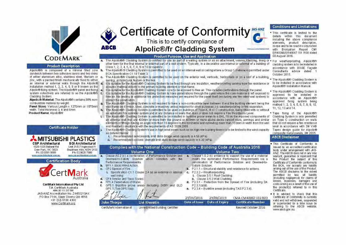

1 Product Information 1.1 Alpolic A2/fr Cladding System is composed of a minimum 70% mineral
matrix (fr) and 94% (A2) and polyethylene binding layers and two skins of aluminium alloy with a painted finish fixed to either an internal or external wall system or frame through the Alpolic A2/fr installation method 1, 2, 3, 4, 5, 8 or 9 known as the Alpolic A2/fr fixing system. The Alpolic A2/fr panel and fixing system collectively are referred to as the Alpolic A2/fr Cladding System. Both the Alpolic A2 and fr panel has been extensively tested and evaluated for compliance with the Building Code of Australia with respect to fire safety. The panels have proven not to present a fire safety hazard and do not contribute to the spread of fire.
1.2 Product Name: Two products are evaluated, the Alpolic A2 and fr. 1.3 Fixing Methods: Alpolic A2/fr installation method 1, 2, 3, 4, 5, 6, 7, 8, 9, 10,
11, 12, 13 and 14. 1.4 The Alpolic A2/fr Cladding System is recognised by the following
protective film. The protective film details both the A2 and fr branding. To identify the difference between the A2 and fr panel, refer to the specific printing on the back of the panel.
2 National Construction Code 2016 Volume One and Two– Building Code of Australia 2.1 Clause A0.2 (a) evidence to support the use of a material meets the
nominated Performance Requirements via a Performance Solution. 2.2 1.0.2 (c) evidence to support the use of a material meets the nominated
Performance Requirements via a combination of Performance Solution and Deemed-to-Satisfy Solution.
2.3 Clause A2.2 and 1.2.2 sub-clause (a)(iv) as evidence to support that the Alpolic A2/fr Cladding System meets the nominated Performance Requirements under a current certificate issued by a product certification body that has been accredited by the Joint Accreditation System of Australia and New Zealand.
Volume One Volume Two
BP1.1 (b)(iii) Wind Action CP2 Spread of Fire CP4 Smoke and Toxic Gases FP1.4 Penetration of Water GP5.1 Bushfire prone areas
P2.1.1 – Structural stability and resistance to actions P2.2.2 - Weatherproofing
a. Clause 3.5.1 Roof Cladding b. Clause 3.5.3 Wall Cladding
P2.3.1 - Protection from the Spread of Fire P2.3.4 – Bushfire areas
3 State and Territory Variations
State/Territory Application
Throughout
Australia
3.1 The Alpolic A2/fr Cladding System can be used in all States and Territories within Australia and complies with all relevant State and Territory variations related to the products use.
3.2 Including (NSW and QLD GP5.1, Tas GP5.1(a)) 3.3 SA P2.3.1(a)(ii) 3.4 TAS P2.3.4
CMI Evaluation Report Evaluation No.
CMI-ER40066/ER40067 [2016]
Technical Assessment and alternative solution of products
for compliance under the National Construction Code of Australia
This evaluation report serves as a certificate from a JAS-ANZ
accreditation body in accordance with Clause A2.2(a)(iv) and 1.2.2(a)(iv) of the
National Construction Code Volume One and Two Building Code of
Australia 2016 respectively
CERTMARK INTERNATIONAL
APPRAISAL
No. CMI-ER40066/ER40067
I01R01 Alpolic A2/fr
Aluminium Composite Panel
SGI Architectural Unit 31/5-7 Inglewood Place Baulkham Hills, NSW 2153
Ph: 02 9620 7988 www.sgi-architectural.com.au
11 August 2016 Date of Issue
30 April 2019
Date of Expiry
CSP Architectural 1029-1035 Ballarat Road
Deer Park, VIC 3023 Ph: 03 9361 9999
www.csparchitectural.com.au
CertMark International T/ACertMarkAustralia
ABN:80111217568JAS-ANZAccreditationNo.Z4450210AKPOBox7144,SippyDownsQld4556
+61(02)61004300www.CertMark.org

CertMark International www.certmark.org Your partner in conformity 2
4 Scope of Use The reference to the ‘Alpolic A2/fr Cladding System’ or ‘Alpolic’ in this
evaluation report relates to the Alpolic A2/fr product. 4.1 The Alpolic A2/fr Cladding System is certified for use as part of a walling system
or as an attachment, veneer, cladding, lining or other term for the final internal or external part of a wall system. Typically, in a decorative use internal or external of a building of Class 1, 2, 3, 4, 5, 6, 7, 8, 9 or 10 occupancy.
4.2 The Alpolic A2/fr cladding system is permitted to be used on buildings of Type A, B or C construction, being fitted with or without an automatic fire sprinkler system and at any distance on walls that does or does not require a Fire Resistance Level.
4.3 The Alpolic A2/fr Cladding System is permitted to be used on an internal wall or ceiling where a Group 1 material is permitted under BCA Specification C1.10 Table 3.
4.4 The Alpolic A2/fr Cladding System is permitted to be used on the exterior wall, vertically, horizontally or on a roof of a building, awning, architectural feature or the like.
4.5 It is suitable for the Alpolic A2/fr Cladding System to be fixed through any insulation, weatherproofing sarking-type fire resistance or acoustic material directly to the primary building element or wall frame.
4.6 It is suitable for the Alpolic A2/fr core to be exposed to free air. This includes perforations through the panel.
4.7 It is suitable for the Alpolic A2/fr Cladding System to have penetrations through the panel where the core material is left exposed to free air. No sealing or additional fire protection measures are required for the panel itself (excluding any fire rated wall system) to protect the penetration.
4.8 The Alpolic A2/fr Cladding System is not required to have a non-combustible layer between it and the building element being the wall frame be it timber, steel, concrete or masonry unless required for other purposes, i.e. weatherproofing or fire separation.
4.9 The Alpolic A2/fr cladding system is permitted to be installed on the exposed components of an external wall that are 400mm or more from the ground or 400mm or more above decks carport roofs, awnings and similar elements or fittings having an angle less than 19 degrees to the horizontal and extending more than 110mm in width from the wall and maintain compliance with the requirements of AS 3959:2009, Clause G5.2 and Part 3.7.4.
4.10 The Alpolic A2/fr cladding system’s use in high wind zones such as on high rise building towers is to be limited to the wind capacity as detailed below: • Recommended serviceability limit state design wind capacity is 4.58 (kPa) • Recommended cyclonic strength limit state design wind capacity is 6.30
(kPa)
5 Conditions and Limitations
5.1 This evaluation is limited to the details within this evaluation report including the above compliance elements, product description and scope. This evaluation report is to be read, considered and used as a whole document being 30 pages.
5.2 For weatherproofing, Alpolic/fr cladding system is to be installed in accordance with BG&E Façade Consultants advice dated 1 October 2015. Contact certificate holder for the advice
5.3 The Alpolic A2/fr Cladding System is to be installed in accordance with Alpolic A2/fr Installation Manual.
5.4 The Alpolic A2/fr Cladding System is approved to be installed in accordance with an Alpolic A2/fr approved fixing system being method 1, 2, 3, 4, 5, 6, 7, 8, 9, 10, 11, 12, 13 and 14.
5.5 Tape fixing of the Alpolic A2/fr cladding system is only permitted on Type C construction on walls that do not require a fire resistance level in accordance with 3M VHB Tapes design guide for Alpolic composite metal panels, 3M 2005.
CMI Evaluation Report Evaluation No.
CMI-ER40067/ER40066 [2016] Technical Assessment and alternative
solution of products for compliance under the National
Construction Code of Australia
This evaluation report serves as a certificate from professional engineer in accordance with Clause A2.2(a)(ii) and 1.2.2(a)(ii) of the National Construction Code Volume One and Two Building Code of Australia 2016 respectively
CERTMARK INTERNATIONAL
APPRAISAL
No. CMI-ER40079/ER40066
I01Draft 01
Alpolic A2/fr Aluminium Composite Panel
CertMark International T/ACertMarkAustralia
ABN:80111217568JAS-ANZAccreditationNo.Z4450210AKPOBox7144,SippyDownsQld4556
+61(02)61004300www.CertMark.org

CertMark International www.certmark.org Your partner in conformity 3
Fire Spread and Impact and Control
Brief of Proposed Performance Solution
Provision C1.1 of the BCA details that a Class 2 building with a rise in storeys of three or more is to be Type A construction. Clause 3.1(b) of Specification C1.1 requires that external walls of buildings of Type A construction must be non-combustible and Table 3 details the FRL of building elements for Type A construction. The Alpolic A2/fr Aluminium Composite Panel cladding product is certified under the CodeMark Certification Scheme CMA-CM40066 and CMA-CM40067 for compliance against the BCA for internal and external use in compliance with Performance Requirement CP2 and CP4. Further details of the products compliance can be found on the Australian Building Codes Board registry, see www.abcb.gov.au. A copy of the certificate available on the CertMark International product registry, see www.certmark.org. It is proposed to evaluate the Alpolic A2/fr panel for fire propagation characteristics of exterior wall assemblies containing combustible components against the primary performance requirement CP2, CP4 and P2.3.1. It is identified that multiple façade fires have occurred around the world including Australia (lacrosse fire November 2014) which has caused concern for their generic installation. These fires and associated spread are not to occur under compliance with the BCA even under the Performance Requirements. Research undertaken by the CSIRO sponsored by the Fire Protection Research Foundation, June 2014 detailed that the external façade fires typically involved highly combustible Exterior Insulation Finish Systems (EIFS) or polyethylene core (PE) Metal Composite Panels (MCP). The Alpolic A2/fr panel is not an EIFS or PE core MCP and does not pose the same risk. This evaluation demonstrates that the Alpolic A2/fr panel has been tested and demonstrated to not pose an undue risk of fire spread, impair any required FRL, when located near or directly above a required exit does not make the exit unusable in a fire contribute to an appropriate acoustic rating and for use within select bushfire prone areas.
Panel storage, handling, transport, fixing and installation
Storage, handling and transport The Alpolic A2/fr panel is shipped to Australia in wooden crates that can be stacked up to four crates high. The Alpolic A2/fr panel is a rigid panel. Physical impact may cause an edge deformation. Inclusion of hart particles such as grains of sand and cutting chips cast between the Alpolic A2/fr panels may cause visible dent-damages in one or more adjacent panels. The Alpolic A2/fr panel is to be stored in a covered area or protected by weather until fabrication and installation. The protective film, provided to protect the surface from scratching and soiling, will withstand up to six months of outdoor exposure without loosing any of its original peel-off characteristics or causing stains or other damage. It is recommended that the Alpolic A2/fr panels be stored in a dry indoor atmosphere, to minimize the natural degradation of the protective film. Unpacking and repacking of the Alpolic A2/fr panels should occur in a clean place. Removal of dust and chips from the Alpolic A2/fr packing as well as any hard particles should occur. The Alpolic A2/fr panel is to be handled on a worktable and not on a floor. The Alpolic A2/fr panel should be always handled by two persons with the external face upward to avoid damage. For transport, lay the packed Alpolic A2/fr horizontally and do not place heavy goods on it.

CertMark International www.certmark.org Your partner in conformity 4
Mark “Handle with Care”, “Keep Dry”, “No Hooks” and “This Side Up” clearly on the packaging. Additional and more specific detail on the products storage, handling and transport is provided in the Alpolic A2/fr fabrication and installation manual. Panel Fixing The Alpolic A2/fr panel can be mechanically (Type A, B or C) or flat stick adhesive fixed (Type C buildings) directly to the wall frame or be connected via a top hat sub-frame. The fixing technique is dependent on the fixing location and wind impact. Where fixed in high wind areas the system design is to be reviewed by an appropriately qualified façade engineer. Where the top hat sub frame system is used, they are to be spaced at intervals no greater than 600mm with the panel fixed on one side no greater than 1200mm. The various installation and approved fixing systems are detailed further below. Accessories The accessories for installation of the aluminium composite panel include the following items, these are generic items that can be interchanged:
1 – Aluminium profile and angles
5 – Hanger
2 – Weather resistant silicone
6 – Anchor Bolts
3 – Backing rods
7 – Rivets
4 – Self Drill Screws
Identifiable features The Alpolic A2/fr panel can be identified by the Alpolic protective film. The protective film is to be removed following installation and not to be exposed for more than six months to outdoor conditions. After six months exposure it is likely that the protective film will loose its original peel off characteristics.

CertMark International www.certmark.org Your partner in conformity 5
Installation information
The fabrication work of the Alpolic A2/fr panel is an integrated work with the installation of the panel. The fabrication consists of various machining procedures, assembling and inspection. The following figures detail a typical fabrication process for a standard tray type (route and return) Alpolic A2/fr panel. Given the core material has been proven a low hazard, protecting the core from free air is not a fire hazard. FIGURE 1: FABRICATION OF ALPOLIC A2/FR PANEL 1. Check fabrication drawings
2. Check raw Alpolic A2/fr panel
3. Marking on panels
Check fabrication drawings and confirm the details.
Confirm raw Alpolic A2/fr panels for size, colour and quantity with the drawings.
Mark cutting and grooving lines on the back of panels, based on the drawings.
4. Cut
5. Groove
6. Corner-notch
Cut the panel with a hand circular saw, based on marked lines.
Adjust the remaining thickness with pre-tests.
Remove the panel corner with a notching tool or a punching press.
7. Punch hanging holes
8. Cut aluminium extrusions
9. Fold
Making hanging holes with a punching press, if necessary
Cut aluminium extrusions, based on the drawings.
Fold the panel with a folding jig. Check 90-degree after folding.
10. Cut of protective film
11. Fix corner angle
12. Fix aluminium flange
Peel and cut off the protective film edge with a utility knife.
Fix the corner with corner angle piece and rivets.
Fix aluminium flange bars with rivets, to complete a tray type panel.
13. Apply sealant on panel corners
14. Final check
Apply sealant on panel corners from the back, if necessary.
Inspect the completed panels
The Alpolic/fr full scale test assembly to NFPA 285 was as follows: § Gypsum plasterboard § Steel studs § Foil backed R-11 glass fibre insulation § Air gap between top haps § Alpolic A2/fr Panels
The installation in the full scale fire test did not include a fire rated plasterboard or non-combustible lining behind the Alpolic A2/fr panel. A number of fixing methods have been detailed by CSP/SGI Architecture for the Alpolic A2/fr panel. The methods detailed below are examples of approved fixing techniques. As the core is proven and deemed non-combustible, its exposure to free air does not present a fire hazard.

CertMark International www.certmark.org Your partner in conformity 6
The panel in the following fixing methods can be installed within the horizontal or vertical plane, to the interior or exterior of a building. The following fixing methods detail in the horizontal position. 1 – External wall cladding – wet sealant joint This installation system, with tray type (route and return) panels and sealing joints, is one of the most common methods.
2 – External wall cladding – hanging method The hanging method includes fixing through a bolt where the panels not tightly fastened to the sub-frame but simply suspended.
3 – External wall cladding – dry gasket joint This method uses gaskets in the joints rather than sealant.
4 – External wall cladding – narrow open joint The narrow open joint method provides a narrow joint for aesthetic effect.

CertMark International www.certmark.org Your partner in conformity 7
5 – Roof covering The Alpolic A2/fr panel can be used as a roof covering. A water gutter or waterproof sheets is required to be installed behind the panel so that leaked water can drain outside.
6 – Back panel of glass curtain wall A glass curtain wall on occasion requires an opaque back panel behind glass for aesthetic and energy-saving purpose. The following details an option to use the Alpolic A2/fr panel. This fixing technique can also include the Alpolic A2/fr panel in place of the clear glass.
7 – Sunshade or cornice The Alpolic A2/fr panel can be used as a sunshade, cornice of the building or awning.

CertMark International www.certmark.org Your partner in conformity 8
8 – Ceiling panel with non-penetrating rivet The Alpolic A2/fr panel can be used as an indoor ceiling panel or soffit. The following method presents an installation method for a ceiling panel.
9 – Parapet and soffit, renovation The Alpolic A2/fr panel is permitted to be used as a parapet or soffit on a building in the following fixing method.

CertMark International www.certmark.org Your partner in conformity 9
10 – Corporate shop front signboard The Alpolic A2/fr panel is permitted to be used as a corporate shop front signboard.
11 – Roof of pedestrian passage The Alpolic A2/fr panel can be used as the roof of a pedestrian passage.
BCA Deemed-to-Satisfy Basis
The BCA does not exclusively provide a Deemed-to-Satisfy provision for the use of external combustible cladding systems. A number of Deemed-to-Satisfy Clauses detail the requirements to limit fire spread of combustible components of a wall. In accordance with Clause C1.10, compliance with Specification C1.10, Clause 7 Table 4 permits combustible products where the spread of flame and smoke development indices are less than that permitted by the BCA. Table 4 also requires the member or assembly to retain the protection in position so that it prevents ignition of the material and continues to screen it from access to free air for a period of not less than 10 minutes. Where the wall is to achieve a Fire Resistance Level, compliance with Specification C1.1 Clause 2.4 is required. This clause reiterates compliance with Specification C1.10, not located such to make the exit unusable in a fire and does not otherwise constitute an undue risk of fire spread via the façade of the building. The Australian Building Codes Board has detailed that Clause 2.4 of Specification C1.1 relates to awnings, sunscreen or similar shading devices, ground moisture barrier, guttering and downpipes and wallpaper applied to a dividing wall between residential units.
1 – Alpolic/fr 2 – Aluminium flange 3 – Water drip 4 – Drain hole 5 – Steel sub-structure 6 – Anchor 7 – Stiffener, aluminium square pipe 8 – Coner support plate 9 – Aluminium channel 10 – VHB tape

CertMark International www.certmark.org Your partner in conformity 10
Guidance on Performance Requirements
The Guide to the BCA is intended as a reference manual to provide clarification to the BCA and should be read in conjunction with the BCA. CP2 – Spread of fire The Guide to the BCA details that CP2 deals with the spread of fire both within the building and between buildings. It aims to avoid a situation where fire either endangers occupants evacuating by way of exits, or impedes the capacity of emergency services personnel to access the building and fight the fire or rescue occupants. In addition, CP2 aims to minimise the risk of fire spreading from one building to another that could endanger the occupants of both buildings and impede the actions of the fire brigade. The guide does detail that the term ‘to the degree necessary’ is used within CP2. This word usage is designed to provide flexibility in the way this provision is implemented. It means that the BCA recognises that different building elements require differing degrees of protection to avoid the spread of fire. The expression is intended to allow the appropriate authority to determine the degree of compliance necessary in each particular case after considering each building scenario. CP4 – Fire hazard properties of materials The Guide to the BCA details that CP4 deals with the fire hazard properties of materials used in the construction of a building. These include such matters as their smoke, toxic gas and heat generation capacities. The Guide further details that the Deemed-to-Satisfy Provision applicable to CP4 is C1.10. C1.10 limits the early fire hazard characteristics of materials susceptible to the effects of flame or heat, particularly during the early stages of a fire. The ABCB as well as guidance from the CSIRO and the test standards AS/NZS 3837 and AS 1530.3 detail the function of these tests for internal validation within buildings. C1.10 and therefore CP4 are considered relevant where the product is used within a building and most importantly in paths of egress.
BCA Performance Requirement
The primary relevant BCA Performance Requirements are CP2 for internal and external and CP4 for internal use addressing spread of fire and tenable conditions as detailed below. FIGURE 2: NCC –VOL 1 – PERFORMANCE REQUIREMENT CP2

CertMark International www.certmark.org Your partner in conformity 11
Source: ABCB NCC Volume One – Building Code of Australia 2016
FIGURE 3: NCC –VOL 1 – PERFORMANCE REQUIREMENT CP4
Source: ABCB NCC Volume One – Building Code of Australia 2016
Reason for deviation from Deemed-to-Satisfy Clause
As detailed above, as detailed by the ABCB, the BCA does not provide an exclusive Deemed-to-Satisfy clause for external combustible wall elements. The reason for this performance solution is to evaluate the use of the Alpolic A2/fr semi-combustible panels with respect to satisfying the nominated Performance Requirements in an absolute Performance Solution.
Meeting the Performance Requirements
Meeting the Performance Requirements is undertaken in accordance with BCA Provision A0.2 (c) A combination of (a) and (b) where (a) complies with the DtS and (b) formulating an alternative solution. The building is understood to comply with all requirements of the BCA DtS provisions with the exception of the external Alpolic A2/fr Panel installed on the outermost part of select walls.
Assessment Method
The assessment method undertaken is in accordance with BCA Provision A0.5 (b)(ii) Verification Methods as the appropriate authority accepts for determining compliance with the Performance Requirements.
Methodology
The following methodologies will be applied to the evaluation: þ Absolute þ Quantitative þ Deterministic o Comparative þ Qualitative o Probabilistic
Absolute approach As outlined in the International Fire Engineering Guideline an absolute approach is typically when an evaluation is carried out on an absolute basis, the results of the analysis of the trial design are matched, using the agreed acceptance criteria against the objectives or performance requirements without comparison to deemed-to-satisfy or prescriptive or “benchmark” designs. Qualitative approach A qualitative approach refers to descriptions or distinctions based on a quality or characteristic rather than on a quantity or measures value. The qualitative approach includes structured arguments to demonstrate compliance.

CertMark International www.certmark.org Your partner in conformity 12
Quantitative approach A quantitative approach refers to an analysis that involves numerical evaluation of an identified process. The quantitative approach includes detailed mathematical and engineering calculations.
Acceptance Criteria
The acceptance criteria for this alternative building solution is that the proposed elements of the building have sufficient measures to limit fire spread such that the BCA Performance Requirement CP2 and CP4 is satisfied to the degree necessary.
Identified Hazard
The potential hazard is fire spread external to the building. Testing of the core material detailing its reaction to radiation with additional review of the full scale testing and international application to that of AS 5113 (see evaluation below) has demonstrated a level of satisfaction that the core is not considered a fire spread risk. It is important to note that the Alpolic panel as proposed is not a full polyethylene panel and is not tape fixed as was the case on the Lacrosse docklands fire. The panel core has less than 30% polyethylene and does not present a fire risk anywhere near that of the Alucobest PE panel. By way of example an equivalent specified material (in core composition) subjected to the BS 8414 test does not result in the spread of fire outside of the test fire itself. Please see images detailed below which show the panel after 6 minutes and 14 minutes. The FR being equivalent to that of the Alpolic panel proposed in green does not react to the fire whilst the PE being similar to that of the Alucobest PE panel as installed on the Lacrosse building, contributes to fire spread and is therefore not compliant with the performance requirements of the BCA. The Alpolic A2/fr panel is not the PE panel and complies with the nominated Performance Requirements of the BCA. FIGURE 4: BS 8414 ALPOLIC DEMONSTRATION FIRE TEST
Source: Exova Warrington, Dubai – United Arab Emirates

CertMark International www.certmark.org Your partner in conformity 13
The Alpolic A2/fr Panel
Product The Alpolic A2/fr panel consists of a matrix core including a majority aluminium hydroxide and polyethylene mix. Testing to AS 1530.3 has proven the core to be non-combustible offering low risk fire safety qualities whilst maintaining the look of an aluminium panel for use on the interior or exterior of buildings. Alpolic A2/fr Panel: The Alpolic A2/fr Panel consists of six layers • Layer 1: 26-µm thick polyvinylidene fluoride (PVDF) coating; • Layer 2: 0.5-mm thick aluminium sheet; • Layer 3: 50-µm thick polymeric membrane; • Layer 4: 3-mm thick polyethylene/aluminium hydroxide mix core; • Layer 5: 50-µm thick polymeric membrane; • Layer 6: 0.5 -mm thick aluminium sheet.
The core material is available in 3, 4, 5 and 6mm thicknesses. The Alpolic A2/fr panel can be fixed to the interior or exterior of a façade substructure being an existing or constructed wall compliant with the requirements of the BCA. The Alpolic A2/fr panel can be penetrated by materials and building services without the requirement for additional protection measures. In addition, the panel can be perforated to have holes at regular intervals.
The Alpolic A2/fr Panel can be fixed to the interior or exterior of a façade substructure being an existing or constructed wall compliant with the requirements of the BCA. The Alpolic A2/fr Panel can be penetrated by materials and building services without the requirement for additional protection measures. In addition, the panel can be perforated to have holes at regular intervals.
CertMark International www.certmark.org Your partner in conformity 14
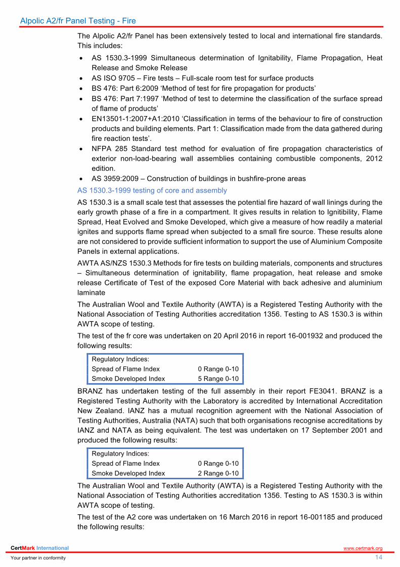
Alpolic A2/fr Panel Testing - Fire
The Alpolic A2/fr Panel has been extensively tested to local and international fire standards. This includes: • AS 1530.3-1999 Simultaneous determination of Ignitability, Flame Propagation, Heat
Release and Smoke Release • AS ISO 9705 – Fire tests – Full-scale room test for surface products • BS 476: Part 6:2009 ‘Method of test for fire propagation for products’ • BS 476: Part 7:1997 ‘Method of test to determine the classification of the surface spread
of flame of products’ • EN13501-1:2007+A1:2010 ‘Classification in terms of the behaviour to fire of construction
products and building elements. Part 1: Classification made from the data gathered during fire reaction tests’.
• NFPA 285 Standard test method for evaluation of fire propagation characteristics of exterior non-load-bearing wall assemblies containing combustible components, 2012 edition.
• AS 3959:2009 – Construction of buildings in bushfire-prone areas AS 1530.3-1999 testing of core and assembly AS 1530.3 is a small scale test that assesses the potential fire hazard of wall linings during the early growth phase of a fire in a compartment. It gives results in relation to Ignitibility, Flame Spread, Heat Evolved and Smoke Developed, which give a measure of how readily a material ignites and supports flame spread when subjected to a small fire source. These results alone are not considered to provide sufficient information to support the use of Aluminium Composite Panels in external applications. AWTA AS/NZS 1530.3 Methods for fire tests on building materials, components and structures – Simultaneous determination of ignitability, flame propagation, heat release and smoke release Certificate of Test of the exposed Core Material with back adhesive and aluminium laminate The Australian Wool and Textile Authority (AWTA) is a Registered Testing Authority with the National Association of Testing Authorities accreditation 1356. Testing to AS 1530.3 is within AWTA scope of testing. The test of the fr core was undertaken on 20 April 2016 in report 16-001932 and produced the following results:
Regulatory Indices: Spread of Flame Index 0 Range 0-10 Smoke Developed Index 5 Range 0-10
BRANZ has undertaken testing of the full assembly in their report FE3041. BRANZ is a Registered Testing Authority with the Laboratory is accredited by International Accreditation New Zealand. IANZ has a mutual recognition agreement with the National Association of Testing Authorities, Australia (NATA) such that both organisations recognise accreditations by IANZ and NATA as being equivalent. The test was undertaken on 17 September 2001 and produced the following results:
Regulatory Indices: Spread of Flame Index 0 Range 0-10 Smoke Developed Index 2 Range 0-10
The Australian Wool and Textile Authority (AWTA) is a Registered Testing Authority with the National Association of Testing Authorities accreditation 1356. Testing to AS 1530.3 is within AWTA scope of testing. The test of the A2 core was undertaken on 16 March 2016 in report 16-001185 and produced the following results:
CertMark International www.certmark.org Your partner in conformity 15
Regulatory Indices: Spread of Flame Index 0 Range 0-10 Smoke Developed Index 3 Range 0-10
The test of the A2 assembly was undertaken on 16 March 2016 in report 7-589724-co and produced the following results:
Regulatory Indices: Spread of Flame Index 0 Range 0-10 Smoke Developed Index 2 Range 0-10
AS ISO 9705 – Fire tests – Full-scale room test for surface products AS ISO 9705 is a full scale room/corner test to determine suitability as an internal wall or ceiling lining. Results are given as a Group number (1 to 4). This test is designed to test internal linings. It is not considered overly relevant for external fire spread applications, particularly between floors. BRANZ has undertaken testing of the full assembly in their report FI3525. BRANZ is a Registered Testing Authority with the Laboratory is accredited by International Accreditation New Zealand. IANZ has a mutual recognition agreement with the National Association of Testing Authorities, Australia (NATA) such that both organisations recognise accreditations by IANZ and NATA as being equivalent. The test was undertaken on 30 November 2005 and reviewed 30 November 2010 and produced the following results: • Flashover defined in the BCA as a heat release rate exceeding 1MW, flashover did not
occur. • The Smoke Grown Rate Index (SMOGRAC) calculated in accordance with BCA
Specification A2.4 Clause 4 is 2.4 (m2/S2 x 1000). • Building Code of Australia of Australia Group 1 classification based on AS ISO 9705 room
fire test and in accordance with BCA Specification C1.10. Based on the Smoke Growth Rate Index (SMOGRARC) not exceeding 100 (m2/S2 x 1000), the product may be used in buildings without a sprinkler system.
The test was undertaken on 22 March 2013 in report 7-589884-co and produced the following results:
Regulatory Indices: Group Number 1 Smoke Grown Rate Index 2.4 (m2/S2 x 1000)
AS 5637.1 details group numbers as follows: 1. A Group 1 material is one that does not reach flashover when exposed to 100kW for
600 seconds followed by exposure to 300kW for 600 seconds. 2. A Group 2 material is one that reaches flashover following exposure to 300kW within
600 seconds after not reaching flashover when exposed to 100kW for 600 seconds. 3. A Group 3 materials is one that reaches flashover in more than 120 seconds but with
a 600 seconds when exposed 100kW. 4. A Group 4 material is one that reaches flashover within 120 seconds when exposed to
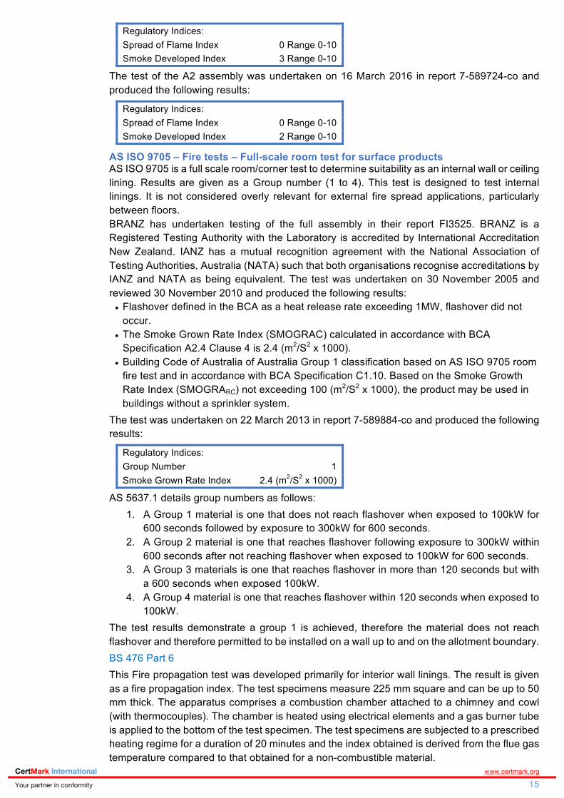
100kW. The test results demonstrate a group 1 is achieved, therefore the material does not reach flashover and therefore permitted to be installed on a wall up to and on the allotment boundary. BS 476 Part 6 This Fire propagation test was developed primarily for interior wall linings. The result is given as a fire propagation index. The test specimens measure 225 mm square and can be up to 50 mm thick. The apparatus comprises a combustion chamber attached to a chimney and cowl (with thermocouples). The chamber is heated using electrical elements and a gas burner tube is applied to the bottom of the test specimen. The test specimens are subjected to a prescribed heating regime for a duration of 20 minutes and the index obtained is derived from the flue gas temperature compared to that obtained for a non-combustible material.

CertMark International www.certmark.org Your partner in conformity 16
The Alpolic fr Panel was tested by TUV PSB Singapore. The test lab is registered with SAC-SINGLAS the Singapore Laboratory accreditation body. The following results were obtained for the specimens, which were tested.
Fire propagation index, I = 0.0 Subindex, i1 = 0.0 Subindex, i2 = 0.0 Subindex, i3 = 0.5
BS 476 Part 7 This surface spread of flame test is used to determine the tendency of materials to support lateral spread of flame. The test specimen is rectangular, 925 mm long x 280 mm wide with thickness up to 50 mm. The vertical specimen is mounted perpendicular to a large 900 mm square gas-fired radiant panel. The radiant heat flax along the specimen decreases from 30 kW/m2 at the near end to 5 kW/m2 at the far end. Depending on the extent of lateral flame spread along the specimen, the product is classified as Class 1, 2, 3 or 4 with Class 1 representing the best performance. The Alpolic fr Panel was tested by TUV PSB Singapore. The test lab is registered with SAC-SINGLAS the Singapore Laboratory accreditation body. The results classified the product as Class 1 surface spread of flame. EN13501-1:2007+A1:2010 The Euroclass system for characterising reaction to fire behaviour of construction products is applied throughout most of Europe and is specified in EN 13501-1. The Euroclass system was designed for controlling flammability of internal materials and does not specifically address exterior wall systems. However due to a lack of any uniform approach throughout Europe to control exterior wall systems via harmonised requirements for either small or large scale testing, individual European countries have resorted to either relying on Euroclasses or national large scale façade tests for control of exterior wall systems. It is often applied to exterior wall systems. The following table provides an overview of the various Euroclasses. FIGURE 5: EN13501-1 EUROCLASSES
Source: EN 13501-1
The Alpolic fr Panel was tested by Warrington fire research on Holmesfield Road. Warrington fire research is accredited with UKAS the United Kingdom Accreditation body. Following the testing of the Alpolic fr Panel, the Alpolic fr Panel achieved a fire reaction classification: Class B s2 d0. This result classifies it as a combustible material with very limited contribution to fire.

CertMark International www.certmark.org Your partner in conformity 17
The Alpolic A2 Panel was tested by Exova Warringtonfire on Holmesfield Road. Exova Warringtonfire is accredited with UKAS the United Kingdom Accreditation body. Following the testing of the Alpolic A2 Panel, the Alpolic A2 Panel achieved a fire reaction classification: Class A2 s1 d0. This result classifies it as a non-combustible material. Full Scale fire tests Australian Standard AS 5113:2016 has recently been published which references the full scale fire test to ISO 13785.2 and BS 8414. The Australian Standard AS 5113:2016 is not referenced in the BCA and the ABCB makes the following statement: ‘It is likely that AS 5113 will be referenced in a new NCC Volume One Verification Method in the next edition of the NCC, and will enable industry to verify the fire performance of external cladding systems against the relevant Performance Requirements of the NCC. This will improve compliance, promote innovative solutions and ensure the required fire performance is achieved’. The Alpolic panel has been tested to an alternative full scale fire test standard being NFPA 285. Details between the BS 8414 test and the NFPA 285 test as reported by the CSIRO are detailed below. BS 8414-1:2002, -2:2005 Fire performance of external cladding systems BS 8414 part 1 and part 2 were developed by BRE. BS 8414-1 is a full-scale fire test for non-load bearing external cladding systems applied to the face of a solid external building wall. The test simulates the scenario of flames emerging from a compartment fire via a window at the base of the wall. The test façade is installed as a re-entrant corner “L” arrangement. The test rig has a masonry block wall construction as the substrate for mounting test specimens to. The test wall extends at least 6 m above the window soffit. The main wall is at least 2.6 m wide and the wing wall is at least 1.5 m wide. The window opening is at the base of the main wall and is 2 m wide x 2 m high. The façade is installed around the window down to the bottom of the window. The façade is installed representative of the end use including all insulation, cavity air gaps, fixings and window details. The tested façade must be at least 2.4 m wide on the main wall and 1.2 m wide on the wing wall. FIGURE 6: BS 8414 FULL SCALE COMBUSTIBLE FAÇADE TEST RIG
Source: The fire protection research foundation

CertMark International www.certmark.org Your partner in conformity 18
The fire enclosure is 2 m wide x 1 m deep x 2.23 m high with a lintel at the front opening reducing the soffit height of the opening to 2 m. The standard fire source is a timber crib constructed of softwood sticks having a cross sectional area of 50 mm x 50 mm. The constructed timber crib is nominally 1.5 m wide x 1 m deep x 1 m high. The crib sits on a platform 400 mm above the base of the test frame and the front of the crib sits 100 mm in front of the outside surface of the masonry support wall. Therefore, the front of the crib is directly 600 mm under the soffit of the tested façade. The crib has a nominal heat output of 4500 MJ over 30 minutes and a peak HRR of 3±0.5 MW. The standard fire source achieves the following calibrated exposure. § The mean temperature across the top of the combustion chamber opening measured at 3
thermocouple locations exceeds 600 °C above ambient over a continuous 20 minute period. The variation between mean temperature and any individual thermocouple temperature shall not exceed ±20 °C
§ The mean temperature at level 1 height on the main wall face exceeds 500 °C above ambient over a continuous 20 minute period.
Alternative fuel sources such as gas burners can be used but must achieve the above temperature exposure and the following additional heat flux requirement for fuels other than cribs: • Mean heat flux measured at 1 m above the window soffit on the main wall shall remain
within the range of 45-95 kW/m2 over a continuous 20 minute period and typically achieves a steady state peak mean heat flux of approximately 75 kW/m2 within this period.
The fire source is extinguished 30 minutes after ignition and observations and measurements are continued for a total test period of 60 minutes or until all flaming ceases. Key observations are extent of flame spread on all surfaces, intermediate layers and cavities, the extent of burn away or detachment for the cladding system and any collapse or partial collapse of the cladding system. The performance criteria for BS8414-1 is given in BRE Report BR135 and is: • The fire spread start time is defined as the time when the temperature measured by any
external thermocouple at level 1 exceeds 200 °C above ambient • Failure due to external fire spread is determined when any external thermocouple at level
2 exceeds 600°C above ambient for a period of at least 30 s, within 15 minutes of the fire spread start time
• Failure due to internal fire spread is determined when any internal thermocouple at level 2 exceeds 600°C above ambient for a period of at least 30 s, within 15 minutes of the fire spread start time
BS8414-2 is a full-scale fire test for non-load bearing external cladding systems fixed to and supported by a structural steel frame. This test is essentially the same as BS8414-1 except that the test façade is mounted directly to a steel support frame without the masonry substrate. This tests curtain wall type construction where a solid concrete or masonry wall is not present. The dimensions of the test rig, the fire source and the test procedure are the same as for BS8414-1. The performance criteria for BS8414-2 is given in BRE Report BR135 and is the same as for BS8414-1 except for the following additional criteria for internal fire spread. • Failure due to internal fire spread is also determined when burn through of the façade
system with continuous flaming with a duration of at least 60 s is observed on the non-exposed side of the facade at a height of 0.5 m or greater above the window soffit within15 minutes of the fire spread start time.
A typical external thermocouple detail for an BS 8414 test is detailed below. As can be seen from this graph, the blue is the reading from the outermost thermocouple on the façade wall whilst the red and yellow detail the reading from the central thermocouples. Whilst the peak average temperatures are in the order of 750°C, the average temperatures centrally above the fire opening is in the order of 500°C.

CertMark International www.certmark.org Your partner in conformity 19
FIGURE 7: BS 8414 SAMPLE EXTERNAL THERMOCOUPLE RESULTS
Source: BRE Testing
NFPA 285 - Standard Fire Test Method for Evaluation of Fire Propagation Characteristics of Exterior Non-load-Bearing Wall Assemblies Containing Combustible Components This method tests façade claddings or complete external wall systems. The test wall is installed as a single wall surface. No re-entrant corner is installed. The test rig is a two storey steel framed structure with an open fronted test room on each storey constructed of concrete slabs and walls. Each test room has internal dimensions of approximately 3 m wide x 3 m deep x 2 m high. The bottom test room serves as the fire enclosure and the top test room simulates an enclosure on the level above with no window. The installed test wall is at least 5.3 m high x 4.1 m wide. The wall tested is a complete system including any external cladding, insulation, external substrate framing and internal wall membrane. The test wall construction and fastening to the test rig must be representative of the end use. The test wall is typically installed on a movable steel frame with is then attached to the front of the test rig concrete slabs. The test wall includes a single opening 1.98 m wide x 0.76 m high. The opening soffit is located 1.52 m above the fire enclosure floor. The fire source consists of two separate pipe type gas burners. One burner is placed in the centre of the fire enclosure and the other burner in a 1.52 m long linear burner located near the soffit of the opening. The room burner output is gradually increased from approximately 690 kW to 900 kW over the 30 minute test duration. The window burner is ignited 5 minutes after the room burner and is gradually increased from 160 kW to 400 kW over the remaining 25 minute test period. The burners are calibrated to achieve average heat fluxes at the surface of a non-combustible test wall of approximately 40 kW/m2 at 0.6 m and 0.9 m above the opening and 34 kW/m2 at 1.2 m above the opening during the peak fire source period of 25-30 minutes. During the test temperatures are measured at the front of the test wall and also in air cavity and insulation spaces within the wall at 305 mm intervals vertically from the opening soffit. Temperatures within the fire enclosure, at the rear of the test wall in the 2nd story test room are also measured. No Heat flux measurement is made during the test. The NFPA 285 standard provides a very detailed set of performance criteria which are briefly summarised as follows. Temperatures at exterior of wall must not exceed 538°C at a height of 3.05 m above the opening soffit. • Exterior flames must not extend vertically more than 3.05 m above the opening soffit. • Exterior flames must not extend horizontally more than 1.52 m from the opening centreline. • Fire spread horizontally and vertically within the wall must not result in designated internal

CertMark International www.certmark.org Your partner in conformity 20
wall cavity and insulation temperatures exceeding stated temperature limits. The position of the designated thermocouples and temperature limits depends on the type and thickness of insulation materials and whether or not an air gap cavity exists.
• Temperatures at the rear of the test wall in the second storey test room must not exceed 278 °C above ambient.
• Flames shall not occur in the second story test room • Flames must not occur horizontally beyond the intersection of the test wall and the side
walls of the test rig. The NFPA 285 test method is related to a larger façade test developed in 1980 which used a 26 ft (8m) two story outdoors building. A 1285 lb timber crib was used as the fire source in the lower floor which resulted in flames exiting the window and exposing the exterior face of the wall assembly at approximately 5 minutes. This test method was published in the 1988 UBC as test standard 17-6 and in the 1994 UBC as UBC test standard 26-4. In the early 1990’s a reduced scale, indoors version of the UBC 26-4 test was developed which replaced the wood crib with two gas burners to produce the same exposure. Testing was done to confirm that similar results were achieved for the same materials on the original large and new reduced scale tests. The reduced scale test became UBC 26-9 which eventually replaced UBC 26-4. NFPA 285 is technically equivalent to UBC 26-9. The NFPA 285 gas burner is set to simulate that of ASTM E119 using the standard fire curve. The standard fire curve is detailed in figure 2.3 of AS 1530.4 and provided below. The standard time-temperature curve is widely accepted and used by most of the standards and testing agencies. It is based on the maximum induction of the severity of a fire completely burning out an ordinary brick, wood-joisted building loaded with combustible contents. The use of this curve, together with information on the fire loading, is used to estimate the severity of a fire. The equivalent time-temperature curve for ASTM E119 is provided along side the AS 1530.4 test requirements below. FIGURE 8: STANDARD FIRE CURVE AS1530.4 AND ASTM E119-2011
Source: AS 1530.4 and ASTM E119-2011

CertMark International www.certmark.org Your partner in conformity 21
FIGURE 9: STANDARD FIRE CURVE DATA AS1530.4 AND ASTM E119-2011
Source: AS 1530.4 and ASTM E119-2011
FIGURE 10: STANDARD FIRE CURVE GRAPH AS1530.4 AND ASTM E119-2011
Source: AS 1530.4 and ASTM E119-2011
Further details of the specific NFPA 285 test of the Alpolic fr panel is detailed below. Over the 30 minute test, the test rig has burners apply a continuous flame to the product, with a peak heat release rate of 1.3MW and temperature in the order of 800ºC. This exceeds the temperatures experienced by the BS 8414 test. As detailed above, in the early 1990’s a reduced scale, indoors version of the UBC 26-4 test was developed which replaced the wood crib with two gas burners to produce the same exposure. This is the NFPA 285 test. Alpolic fr NFPA 285 - Standard Fire Test Method for Evaluation of Fire Propagation Characteristics of Exterior Non-load-Bearing Wall Assemblies Containing Combustible Components The NFPA 285 standard - Standard Fire Test Method for Evaluation of Fire Propagation Characteristics of Exterior Non-load-Bearing Wall Assemblies Containing Combustible Components, is intended to simulate the multi-storey flammability fire performance of an entire external wall assemblies. It involves the construction of a two-storey test rig clad in the subject product which is subjected to a fire source consisting of two gas burners – one situated inside the lower storey room and the second at the top edge of the ‘window’ opening of the lower storey room. Over the 30 minute test, the test rig has burners apply a continuous flame to the product, with a peak heat release rate of 1.3MW and temperature in the order of 800ºC. The pass/fail criteria is based on flame propagation vertically and laterally across the subject material, which is measured by various thermocouples and observations of flames emitting from the surface of the specimen at specific locations. This standard is considered to be a very

CertMark International www.certmark.org Your partner in conformity 22
good indicator of the ‘as-installed’ fire performance of an external cladding material because it is a large scale test designed to mimic real installations. The products testing to NFPA 285 was undertaken by Southwest Research Institute on 17 July 1998. The test report details that the NFPA test apparatus is used to evaluate the fire propagation characteristics of exterior non-load-bearing wall assemblies and panels used as components of curtain wall assemblies that are constructed using combustible materials or that incorporate combustible components within the wall assemblies as specified in the following:
• The ability of the wall assembly to resist flame propagation over the exterior face of the wall assembly.
• The ability of the wall assembly to resist vertical flame propagation within the combustible core or within other combustible components from one storey to the next.
• The ability of the wall assembly to resist vertical flame propagation over the interior surface of the wall assembly from one storey to the next.
• The ability of the wall assembly to resist lateral flame propagation from the compartment of fire origin to adjacent compartments or spaces.
The ABCB has published a discussion paper where they clarify that the use of an attachment is restricted to awnings, sunscreen or similar shading devices, ground moisture barrier, guttering and downpipes and wallpaper applied to a dividing wall between residential units. Clause 2.4 does detail the use of linings but the ABCB has not clarified this point. The Alpolic/fr full scale test assembly to NFPA 285 was as follows: § Gypsum plasterboard § Steel studs § Foil backed R-11 glass fibre insulation § Air gap between top haps § Alpolic A2/fr Panels
The tested prototype was the exterior most lining of the wall system and considered part of the wall. The following table details the results of the NFPA test.
Test Requirements Pass / Fail
No flame propagation beyond the area of flame plume impingement on the exterior face of the wall assembly
PASS
• Thermocouple Nos. 11. 14, 15, 16 and 17 did not exceed 1000°F (537°C) at any time during the test. The maximum temperature recorded was 674°F (356°C), which occurred at 29 min 45 sec on TC No.11.
• Flames emitting from the surface of the exterior face did not reach a vertical elevation of 10ft (3m) above the top of the window opening at any time during the test.
• Flames emitting from the surface of the exterior face did not reach a lateral distance of 5ft (1.5m) from the vertical centerline of the window opening any time during the test.
No flame propagation either vertically or laterally through the core components PASS • Thermocouples Nos. 28, 34, 35, 39, 40, 31, 32, 33, 36, 37 and 38 did not exceed 1000°F
(537°C) at any time during the test. The maximum temperature recorded was 392F which occurred at 30 min 00 sec on TC No. 28.
• Thermocouples Nos. 55, 56, 57, 58, 59, 60, 61, 62, 63, 64 and 65 did not exceed 750°F (400°C) above ambient at any time during the test. These TC temperatures were not recorded during the test due to equipment failure. Post test inspection of the panel and interior insulation found them in good condition, indicating that the temperature was well below the maximum allowable limit.
No flame propagation laterally through the core components in the first-floor area PASS • Flames did not occur over the surface of the exterior face beyond the concrete block walls
or beyond the intersection of the test wall assembly and the concrete block fixture walls. • Thermocouple No’s 18 and 19 did not exceed 1000°F (537°C) at any time during the test.
The maximum temperature recorded was 130°F (55°C), which occurred at 30 min 00 sec on TC No 19.
• Thermocouple No’s 66 and 67 did not exceed 750°F (400°C) above ambient at any time during the test. The temperature of these TC’s were not recorded. Post test inspection of the panel and interior insulation found them in good condition, indicating that the temperature could not have exceeded the maximum allowable limit.
No excessive temperature rise 1 in from the interior surface of the wall assembly PASS • Thermocouple Nos. 49, 50, 51, 52, 53 and 54 did not exceed 500°F (356°C) above their
initial ambient temperature at any time during the test. The maximum temperature recorded

CertMark International www.certmark.org Your partner in conformity 23
was 115°F (46°C), which occurred at 30 min 00 sec on TC No 53. No flame propagation within the second-floor room PASS • Review of the pertinent TC data, second-floor videotape, and post-test inspection indicate
that flame propagation did not occur in the second floor at any time during the test.
It can be seen from the test results that the panel when subjected to the testing does not contribute to the fire or propagate up the exterior of the test rig. It is therefore deemed that the results of the NFPA 285 test has demonstrated that the panel does not otherwise constitute an undue risk of fire spread via the façade of the building. The following figure details the instrument arrangement of the exterior face of the full scale NFPA 285 test. FIGURE 11: NFPA 285 TEST RIG SETUP
The following graph details the temperature profile over the test rig for thermocouples 1 to 10. The following graph, whilst in Fahrenheit, details that temperature do not exceed 760ºC (1400ºF). FIGURE 12: EXTERIOR WALL THERMOCOUPLES
Thermocouples 11 to 17 detail temperatures not exceeding 370ºC (700ºF) but has temperatures in the order of 650ºC highlighting substantial exposure greater than that of the BS 8414 test.

CertMark International www.certmark.org Your partner in conformity 24
FIGURE 13: EXTERIOR WALL THERMOCOUPLES
The following figure details the instrument arrangement of the interior face of the wall assembly on the 2nd floor room. FIGURE 14: INTERIOR WALL THERMOCOUPLES
The following figure details the result of thermocouples 49 to 54 on the interior face. The temperature from an ambient 35ºC had minimal change.

CertMark International www.certmark.org Your partner in conformity 25
FIGURE 15: INTERIOR WALL THERMOCOUPLES
The completed panels, test process and final result is detailed below. FIGURE 16: PANEL ASSEMBLY DURING TEST

CertMark International www.certmark.org Your partner in conformity 26
The above photos provide details of the test. This result shows that the fire intensity was enough to expose the core material from the top layer of aluminium. With the core material exposed directly to the test rig fire, it did not propagate the fire on its own past the burner.
Product Performance Evaluation
Clause A0.1 of the BCA details that compliance with the National Construction Code and subsequently Volume One – Building Code of Australia is achieved by satisfying the Performance Requirements. Performance Requirements CP2 and CP4 as identified by the project certifier will be evaluated below. Many elements of the performance requirements cross over between the functions. A matrix table is provided below of the elements relating to the nominated performance requirements. It is recommended that should the building be subject to performance solutions relating to CP2 or CP4 that the sub-elements of the performance requirements be reviewed inline with the building and proposed solution.
CP2 (a) A building must have the elements which will, to the degree necessary, avoid the spread of fire-
i. to exits; and ii. to sole-occupancy units and public corridors; and iii. between buildings; and iv. in a building
(b) Avoidance of the spread of fire referred to in (a) but be appropriate to- CP4 To maintain tenable conditions during occupant evacuation, a material and an assembly must, to the degree necessary, resist the spread of fire and limit the generation of smoke and heat, and any toxic gases likely to be produced, appropriate to-
CP2 CP4
the function or use of the building; and ✓ ✓ the fire load; and ✓ the potential fire intensity; and ✓

CertMark International www.certmark.org Your partner in conformity 27
the fire hazard; and ✓ the number of storeys in the building; and ✓ Its proximity to other property; and ✓ any active fire safety systems installed in the building; and
✓ ✓
the size of any fire compartment; and ✓ fire brigade intervention; and ✓ other elements they support; and ✓ the evacuation time. ✓ ✓ the number, mobility and other characteristics of occupants
✓
Source: BCA 2016 and CertMark
Further to the details within the guidance on Performance Requirements provided above, the following is provided for the performance requirements in general with each specific element addressed. CP2 – Fire Spread The principle requirements under CP2(a) is that building elements must avoid the spread of fire to exits, sole-occupancy units and public corridors, between buildings and in a building. The testing of the product has demonstrated that it presents a low risk in contributing to the spread of fire itself. Outside of the fire event, independent of the Alpolic A2/fr Panels, the panels themselves have been tested for its reaction when exposed to full scale internal and external fire tests. The product achieved a Group 1 result and passes the external fire tests. CP4 – Fire hazard properties of materials The compliance of the product for use within a building in accordance with CP4 and subsequently C1.10 is focused on internal use and to limit hazardous and toxic conditions in paths of egress. The Alpolic A2/fr Panel achieves a Group 1 rating and therefore complies with the requirements under the BCA.

CertMark International www.certmark.org Your partner in conformity 28
Structural Stability (wind action) Weatherproofing; and
Bushfire
Structural Stability The objective of structural requirements within the BCA are to: • Safeguard people from injury caused by structural
failure; and • Safeguard people from loss of amenity caused by
structural behaviour; and • Protect other property from physical damage by
structural failure; and • Safeguard people from injury that may be caused by
failure of, or impact with, glazing. The objective is based on the belief that people should not be subject to risk of injury from a building suffering structural failure. Nor should there be any amenity loss caused by structural behaviour. Additionally, other property should not be at risk of physical damage caused by structural failure and people should be safeguarded from injury due to failure or impact with glazing. The primary objective associated with this evaluation is that no amenity loss is to be caused by structural behaviour. With respect to the functional requirements, the building or structure is to withstand the combination of loads and other actions to which it may be reasonably subjected. In accordance with Clause A02 the structural evaluation is in accordance with a Performance Solution to BP1.1(a)(i) and (b)(iii) and P2.1.1(a)(i) and (b)(iii). The cyclone testing station at the School of Engineering and Physical Sciences at James Cook University in their test report TS805 dated 24 February 2011. The wind load tests were conducted in the airbox testing facility located in the Wind Tunnel Building at James Cook University. The Cyclone Testing Station is a NATA accredited testing laboratory. All trials for the testing program were performed in accordance with NATA requirements. The strength Limit State design pressure was 6.3kPa. Three trials were undertaken with a pass result for all trials.
The methods of testing (in accordance with AS 1562.1 and AS 4040.3) have been presented. The serviceability wind load results can be used to determine the Serviceability Limit State design wind capacity for both cyclonic and non-cyclonic regions. Table 5 provides the recommended Serviceability Limit state design wind capacities for both cyclonic and non-cyclonic regions, for the particular arrangements tested in the test program. The cyclic strength wind load test results can be used to determine the Ultimate Strength Limit State design wind
capacities for cyclonic regions. The following table provides the recommended Ultimate Strength Limit State design wind capacities for cyclonic regions, for the particular arrangements tested in this test program.
Weatherproofing The objective of weatherproofing under this evaluation is to safeguard occupants from illness or injury and protect the building from damage caused by surface water. The function of weatherproofing in relation to surface water is that the building is to be constructed in a way that protects people and other properties from the adverse effects of redirected surface water. BG&E Facades engineer Max Ahmed have undertaken an analysis of the Alpolic A2/fr cladding system with Wet Seal in their letter dated 1 October 2015 and provide the following opinion: 1. The cladding system is a faced sealed system which
primarily dependent on the sealant quality and site workmanship.
2. The system has not been tested to neither AS2047-2014 nor AS4284-2008, however, we note by adopting the performance based verification in the National Construction Code (NCC) and referring to NCTL test report, the system should meet the weatherproofing clause FP1.4 of the NCC for a positive serviceable static wind pressure of up to 600pa for weather resistance.
3. The Facade Contractor shall design, engineer, fabricate, supply and install the complete façade work strictly in accordance with these drawings, the Principal’s project’s requirements and the project’s specifications.
4. The drawings provided show a general design intentions of the cladding system. The structural capacity of the cladding system and stiffeners have to be designed for each specific project requirements.
5. Designers are required to design the cladding system to accommodate deflection movements due to all design loads and changes in temperature without any reduction in the project’s specified performance and the relevant Australian standards.
6. The façade contractor shall comply with manufacturer's instructions for all sealant materials, joint preparation, curing, joint dimensions and backer rods. Façade contractor to seal all joints in accordance with these drawings, approved shop drawings and project’s specifications.
7. The façade contractor shall install fixings in accordance with their manufacturer’s instructions and procedures. Fixings shall be made weather tight in a manner not restricting thermal or wind movements of the façade.
Based on adhering to the above, BG&E are of the opinion that the cladding system to provide a primary seal for weather proofing purpose satisfies the requirement of Performance Requirement FP1.4.
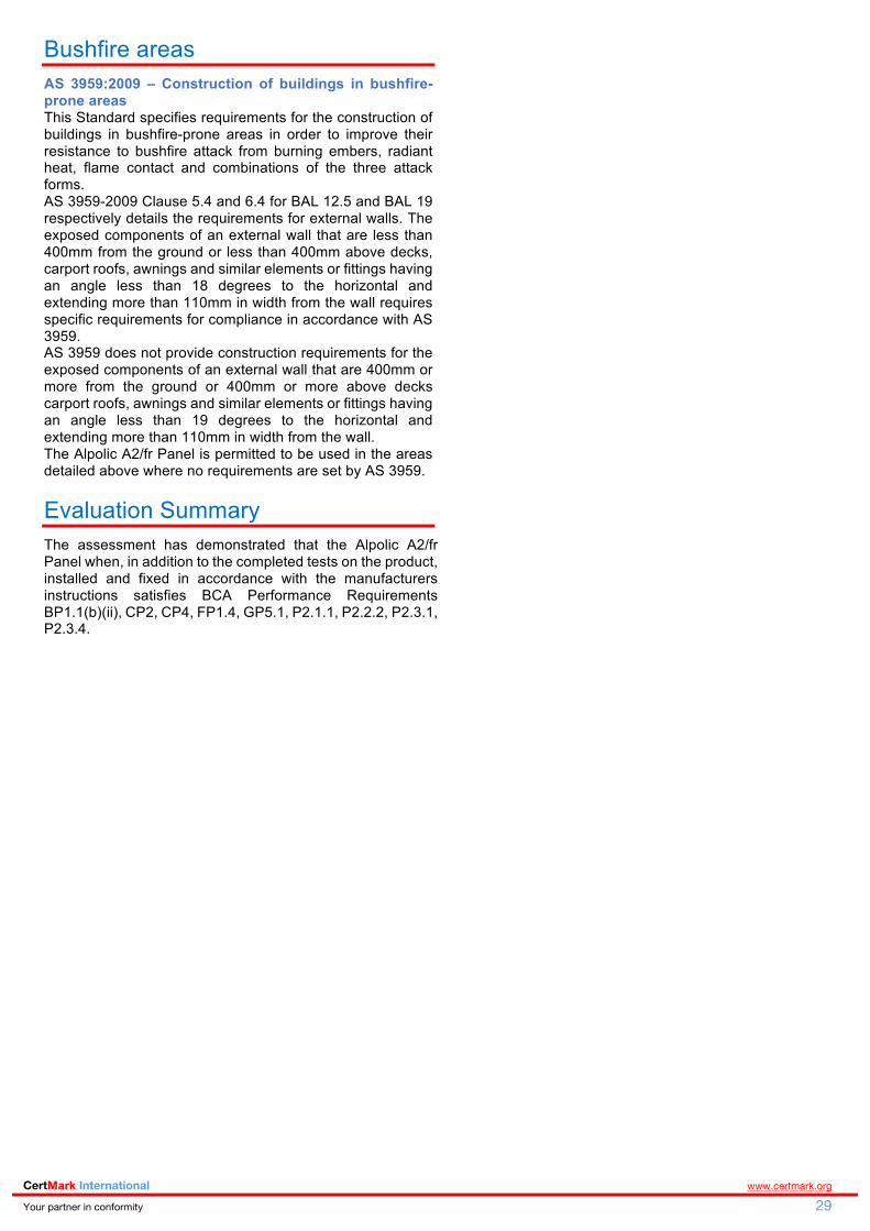
CertMark International www.certmark.org Your partner in conformity 29
Bushfire areas AS 3959:2009 – Construction of buildings in bushfire-prone areas This Standard specifies requirements for the construction of buildings in bushfire-prone areas in order to improve their resistance to bushfire attack from burning embers, radiant heat, flame contact and combinations of the three attack forms. AS 3959-2009 Clause 5.4 and 6.4 for BAL 12.5 and BAL 19 respectively details the requirements for external walls. The exposed components of an external wall that are less than 400mm from the ground or less than 400mm above decks, carport roofs, awnings and similar elements or fittings having an angle less than 18 degrees to the horizontal and extending more than 110mm in width from the wall requires specific requirements for compliance in accordance with AS 3959. AS 3959 does not provide construction requirements for the exposed components of an external wall that are 400mm or more from the ground or 400mm or more above decks carport roofs, awnings and similar elements or fittings having an angle less than 19 degrees to the horizontal and extending more than 110mm in width from the wall. The Alpolic A2/fr Panel is permitted to be used in the areas detailed above where no requirements are set by AS 3959.
Evaluation Summary The assessment has demonstrated that the Alpolic A2/fr Panel when, in addition to the completed tests on the product, installed and fixed in accordance with the manufacturers instructions satisfies BCA Performance Requirements BP1.1(b)(ii), CP2, CP4, FP1.4, GP5.1, P2.1.1, P2.2.2, P2.3.1, P2.3.4.

CertMark International www.certmark.org Your partner in conformity 30
Reference Documents
1. National Construction Code – 2016 – Volume One – Building Code of Australia Class 2 to 9 Buildings.
2. SGS test report SZIN1507007414ML to AS 1530.1-1994 dated 11 August 2015
3. CSIRO report FNC11569 to AS 1530.1-1994 dated 16 December 2015
4. CSIRO report FNE11541 to AS/NZS 1530.3:1999 dated 20 November 2015
5. BRANZ report FE3041 testing to AS1530.3 dated 17 September 2001
6. AWTA 16-001185 AS/NZS 1530.3-1999 dated 16 March 2016
7. AWTA 8. Southwest Research Institute report 01-2305-608
testing to NFPA 285 dated August 1999 9. James Cook University, School of Engineering and
Physical Sciences Cyclone Testing Station TS805 dated 24 February 2011.
10. BG&E Façade Consultants evaluation letter dated 1 October 2015
11. AIBS Member Statement 25 May 2016 12. AIBS Member Statement 30 June 2016-08-06 13. AIBS report, issues relating to the use of external wall
cladding systems in Australia June 2016-08-06 14. UAE Fire & Life Safety Code of Practice Annexure
A1.21. Rev 2 15. CSIRO Fire safety guideline for external walls Version 2
dated 18 April 2016 16. Peroni European Standard classifications Rev 02/2013 17. VBA Fact Sheet Non-Deemed-to-Satisfy External Wall
Cladding Systems issued April 2015 18. Victorian Building Control Commission, Fire Protection
for High-Rise Buildings 2000 19. The fire protection research foundation, fire hazards of
exterior wall assemblies containing combustible components June 2014
20. SAMFS Combustible external cladding materials to buildings letter dated 30 December 2015.
21. Australian Senate Economic References Committee, non-conforming building products interim report Safety – ‘not a matter of good luck’ May 2016
Written by Benjamin Hughes-Brown
FIEAust CPEng NER Chartered Professional Engineer
FPAA Professional Engineer CPEng, NER (Fire Safety / Mech) 2590091, RPEQ 11498,
BPB-C10-1875, EF-39394, TDJ-CC6504 MFireSafety (UWS), BEng (UTS), GradDipBushFire (UWS),
DipEngPrac (UTS), DipEng (CIT)
Initial review by Nicole Cocks
BEng (ANU) MIEAust MSFS
Formal reviewed by Livi Krevatin
Authorised by John Thorpe
CEO CertMark International
In the opinion of CertMark International, that the Alpolic A2/fr Cladding System is fit for purpose and will comply with the National Construction Code Volume One – Building Code of Australia 2015 to the extent specified in this Evaluation Report provided it is used, designed, installed and maintained as set out in this Evaluation Report. The Evaluation Report is issued only to CSP Architectural and SGI Architectural and is valid until expiry, subject to the Conditions of Evaluation Report. Conditions of Evaluation Report 1. This Evaluation Report:
(a) relates only to the product as described herein;
(b) must be read, considered and used in full together with the technical literature;
(c) does not address any Legislation, Regulations, Codes or Standards, not specifically named herein;
(d) is copyright of Benjamin Hughes-Brown.
2. CertMark International makes no representation or warranty as to:
(a) the nature of individual examples of, batches of, or individual installations of the product, including methods and workmanship;
(b) the presence or absence of any patent or similar rights subsisting in the product or any other product;
(c) any guarantee or warranty offered by CSP Architectural and SGI Architectural.
3. Any reference in this Evaluation Report to any other publication shall be read as a reference to the version of the publication specified in this Evaluation Report.
4. CertMark International provides no certification, guarantee, indemnity or warranty, to CSP Architectural and SGI Architectural or any third party.