
Movie Synopsis from Moviefone: Fred Tate (Adam Hann-Byrd ...
Upload
khangminh22Category
view
3download
0

Science Teacher Fred Holtzclaw Has Successfully Created Energy In A ClassrooIn.
In the nearly 20 years that Mr. Holtzclaw has been teaching high school science in Tennessee, he's learned a lot about energy. How to impart enthusiasm, for instance. The hard work needed to overcome inertia. And most difficult of all, what to do about burn-out.
He's not alone. Every day, teachers allover the country face the same challenges.
That's why Martin Marietta is helping to underwrite a new regional Academy for Teachers of Science and Math at the University of Tennessee. It's an intensive program of study and discussion for Martin Marietta Fellows; outstanding educators in all grade levels. Through the Academy, the private sector, government and academia are all joining together to support a critical educational initiative by President Bush.
It's important to help keep things moving in the classroom, and teachers like Fred Holtzclaw are the right place to start. If we want to fire-up the masterminds of tomorrow, the best thing we can do is keep our outstanding teachers energized today.
,
IWARTIN IWARIETTA
6801 ROCKLEDGE DRIVE, BETHESDA, MARYLAND 20817
MASTERMINDING TOMORROW; TEGINOLOGIE5

© 1990 Martin Mariena Corporalion

To some, 300 dots per inch may seem quite adequate. To old Spot here, the 300 dpi of conventional laser printers is good enough. But to those with a big investment in high resolution imaging systems, the lack of truly superior hard copy output can be a doggone shame. Fortunately, the Lasertechnics 300D continuous tone printer provides the highe t resolution, fllm or paper copy on the market today. Up to 2048 pixels per line with 256 levels of grey per pixel. Perfect for applications ranging from military reconnaissance to non-destructive testing and medical imaging workstations. Digital interfaces are available for most major computers. Finally an output system that matches your input in less than a minute for as little as 50 cents a page. Now, that's something to bark about!
The 300D Digital Image Recorder Circle Reader Action No. 600
~~ Lasertechnics 5500 Wilshire Avenue NE Albuquerque, NM 87113 800-227-9484 505-822-1123 FAX: 505-821-2213

WHY BUY A NEW CAR WHEN YOU DON'T HAVE TO?
You've seen the price or new cars ... they go up every year! Cars get nimsier ••• prices get higber .. .it never seems to end. There are lots or reasons to keep that nice car oryours on the road as long as possible. Car sales are down and Turoil sales are up. People are smart. •• they're taking the economical way out and what could be easier than Tufoil. Just add Turoil to the crankcase. You don't have to shake the container or add an engine flush. Just pour it in and drive away. Your throttle will get silky smooth .. .acceleration will improve. One customer said his car "takes off like a scared rabbit!" Tufoil works wonders for all known engine oils. It's actually slipperier than Teflon (according to a famous U.S. Government laboratory). You'll get astonishingly fast starts on cold mornings with both diesels and gas engines. The Canadian government tested Tufoil at it's cold ~ons lab. They showed faster cranking 'and significant fuel savings with Tufoil.
USE Tuloi/ ", AND YOUR ENGINE WILL LAST ••. AND
LAST ... AND LAST I
TREAT YOUR CAR TO ONE 8 OZ. BOTTLE OF
TUFOIL FOR ONE OIL CHANGE You'll notice quieter, smoother operation, quicker starting, snappy accelerationl If you don't, just Send us proof of purchase with a note describing the year and make of your car. We'll refund your $14.25 immediately . Send for Tufoil today and prove to yourself the amazing increase in your car's performance. Fill in the couQOn today or call TOLL-FREE any time, 24 hours a day.
Stalf u" ~ ""'" ~ eM! Engines last longer with Tufoil. Our 1976 476 T-Bird is now at 190,000 miles and purring.
A bunch of customers' cars have now passed 250,000 miles. Several months ago, a nice man I'd never seen before walked into my office, big smile on his face, sat down and said, "Would you believe 340,000 miles on a Tufoil engine?" He went on to rave about how well his engine has been running all these years. I couldn't get a word in edgewise. Recently, a truck driver called in with over 1,000,000 miles on a diesel using TufoiJ - WOW! A customer from Vermont added 10% TufoiJ to his sticky mechanical trans· mission, called in and said he couldn't believe it. .. "Shifting is like slicing butter now!" he said. SAAB owners are writing letters praising Tufoil in their "NINES" magazine. They report spectacular improvements in their engines and transmissions! Don't forget! Tufoil is the result of over 15 years of research and development. The U.S. government has awarded us 6 patents so far .. ,so have Germany, England, France and Canada.
What about additives that claim to be a one·time treatment that will last the life of an engine? Well, I've been following the scientific literature on lubrication for a very long time. As far as I know, there isn't a shred of scientific evidence for such a claim. So don't believe it! 1-800-922-0075. 4ifr No other lubricant eyen comes close.
(in New Jersey, call 201-825-8110.) ~ ~c-.~Products';sed ';;;' I FOILi~';;';logy~heCk ------------~Fluora;.lc_;:I~;;;:9 one with each order of 2 bottles or a quart. Check 2 for each rush my 0 order: .:J 18 Industrial Avenue gallon order. Values range from $3.98 to $9.95. b I f
DONE 8 oz. ott e ... treat one car or Mahwah, NJ 07430 D TUFOIL Gun-Coat - Super rust inhibited, smooth action I $14.25 (plus $3.50 shipping and D TUFOIL Compu- Lube - Low Viscosity for computer handling). See money back My check or money order for $ __ is enclosed.
h . I Charge my credit card: mec anlsms guarantee. D TUFOIL Lightning Grease - Easily sheared grease for 0 Am. Express OMasler Card o Visa
instruments D TWO 8 oz. bottles ... treat two cars Card No. __________ _ D TUFOIL Lublt-8 - General purpose, household use I for $25.00 (plus $4.00 shipping Exp. Dale __________ _
lubricant I and handling) SAVE 56.00 t- 1E brochures ... Phone No. _________ _ D 30 Questions/ Answers about TUFOIL D " Fun With Superconductors"-we're leading that fiel d I
too! I See NASA Tech Briefs for technical details. 1986, 1987 and 1988. "'1987 Fluoramic: • • Inc. fLUOM ' IS leg T M ollCI Ametlcas lnC TEFLON' IS reg T M 01 DuPont· TUFOIl < IS reg 1 M 01 FluoramlCs US Patenl No .. 28A 518 US Palenl No 4 224 173 US Patenl No 3933 656
I Other u S PfilenlS ISSUed and pendl"S)
D ONE Quart bottle ... treat 4 cars for $34.95 (plus $4.00 shipping and handling)
Name
Address
D ONE GALLON ... treat 16 cars for City $125.00 (plus $6.00 shipping and Slale Zip
handling.) (N.J. residents please add 6% sa- les-t-ax-).---We sh ip w ith in days!
.... ---- ..---- MONEY BACK GUARANTEE ON B-OZ. Canadian Distributor: 1·800-363-7753 J ~~~,-,-.-.----------------------------
Circle Reader Action No. 364
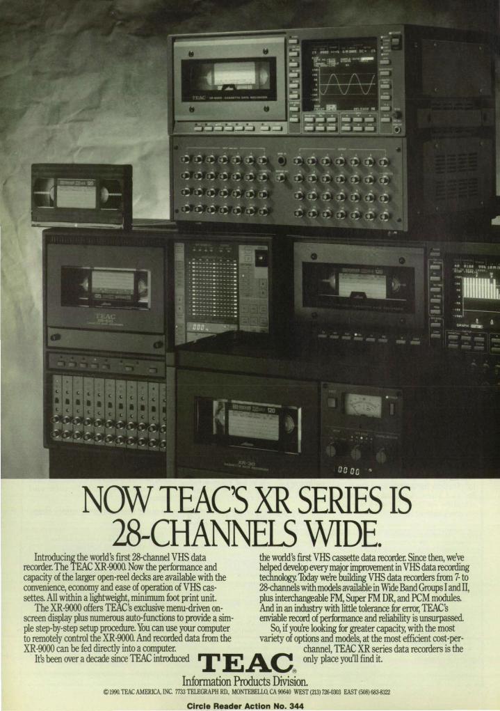
NOW TEAC'S XR SERIFS IS 28-CHANNELS WIDE.
Introducing!he world's first 28-channel VHS data the world's first VHS cassette data recorder. Since then, we've recorder. The TEAC XR-9OOO. Now the performance and helped develop every major improvement in VHS data recording capacity of the larger open-reel decks are available with the technology. Thday we're building VHS data recorders from 7- to convenience, economy and ease of operation of VHS cas- 28-channels with models available in Wide Band Groups I and IT, settes. All within a lightweight, minimum foot print unit. plus interchangeable FM, Super FM DR, and PCM modules.
The XR-9OOO offers TEAC's exclusive menu-driven on- And in an industry with little tolerance fur error, TEAC's screen display plus numerous auto-functions to provide a sim- enviable record of performance and reliability is unsurpassed. pIe step-by-step setup procedure. You can use your computer So, if you're looking for greater capacity, with the most to remotely control the XR-9OOO. And recorded data from the variety of options and models, at the most efficient cost-per-XR -9000 can be fed directly into a computer. channel, TEAC XR series data recorders is the
Ifs been over a decade since TEAC introduced T E AC only place you'll find it.
Information Products Division. © 1990. TEAC AMERICA. INC. 7733 TELEGRAPH RD.. MONTEBELLO, CA 90640 WEST (213) 72&0003 EAST (508) 683-8322
Circle Reader Action No. 344

LABTECH NOTEBOOK:
for DOS, OS/2, and the Macintosh
LABTECH NOTEBOOK has been the accepted standard for data acquisition and control software since we introduced NOTEBOOK for MS-DOS. Now, we've taken the next step into the future with NOTEBOOK for OS/2 and the Macintosh.
LABTECH NOTEBOOK now gives you a choice of platforms- The mM® PCIXT/AT, PS/2, compatibles, and the Apple® Macintosh. Setups and configurations are compatible - configure your system on one platform and run the same setup on another.
LABTECH NOTEBOOK collects data from multiple channels, displays the data graphically and stores it to disk in real-time. It features user defined acquisition, control and display setups; real-time mathematical, statistical and signal processing; sophisticated triggering; data replay; and continuous data collection while you work in other programs. Many input types, including analog, digital , thermocouple, RTD, strain
and pressure gages, resistance, counters and frequency, are supported by NOTEBOOK.
The DOS version supports foregroundlbackground operation and, as an option, expanded memory. The OS/2 version takes advantage of OS/2's multitasking capability and protected memory support. NOTEBOOK for the Macintosh works under Multifinder and follows the Macintosh menu and icon conventions.
LABTECH NOTEBOOK, with an installed base of 10,000 systems, supports hundreds of board-level data acquisition interfaces and distributed I/O systems from more than 30 manufacturers. NOTEBOOK can be found in most Fortune 500 companies, as well as in smaller enterprises.
New jill pro V e d G PI B SUp P 0 r t
lULABTECH Laboratory Technologies Corporation· 400 Research Drive· Wilmington, MA 01887·508-657-5400· FAX 508-658-9972
IBM Is a registered trademark and IBM XT, AT and PS/2 are trademarks of the International Business Machines Corporation. Apple is a registered trademark of Appte Computer, Inc. and Macintosh is a trademark licensed to Apple Computer, Inc.
Circle Reader Action No. 423

NJ\SI\ Tech Briefs Transferring Technology to American Industry and Government
JUNE 1990 Volume 14 Number 6 MP \VBPA
SPECIAL FEATURES 1990 Letter Writing Contest .......... 10
Hawaii Technology Report ............ 17
Mission Accomplished .............. .. 106
TECHNICAL SECTION
~J New Product Ideas .............. 16 ~ NASA TU Services .. ............ 25 a. Electronic Components _ and Circuits ......................... . 26 W' Electronic Systems .............. 36 • •• W PhYSical Sciences ................ 56
Materials .............................. 64 Computer Programs ............ 68 o Mech.anics .... ........................ 71 o Machinery .......................... 75
E! Fabrication Technology ........ 81 tJ Mathematics and X Information Sciences ......... .
~ Life Sciences ..................... . 86 95
101 o Subject Index ................. .
Photo courtesy NASA
Last November, President Bush approved a national space plan (page 10) that would send humans to the moon, then on to Mars. In its Exploration Technology Program, NASA is developing the enabling technologies for these 21 st century missions. One aim is to develop an autonomous planetary lander capable of avoiding surface hazards and landing at a preCise spot without the help of Earth-based control. This requires advances in realtime image processing, onboard computing, and sensors for hazard detection.
DEPARTMENTS On The Cover: The components of the Ingestible Thermal Monitoring System (ITMS), a silicone-covered capsule that "reads " deep body temperatures. The ITMS incorporates the latest advances in miniaturization of integrated circuits, batteries, and sensors. See page 106. (Photo concept and composition by Robert I. Johnson, director of advanced projects. Business Communications of America, Inc.)
New on the Market ........ 97
New Literature .... 99
Advertisers Index 105
Turn to page 10 for details on how to win a free stay at the United States Space Camp. Photo courtesy U.S. Space Camp
This document was prepared under the sponsorship of the National Aeronautics and Space Administration. Neither Associated Business Publications Co., Ltd. nor anyone acting on behalf of Associated Business Publications Co .• Ltd. nor the United States Government nor any person acting on behalf of the United States Government assumes any liability resulting from the use of the information contained in this document, or warrants that such use will be free from privately owned rights. The U.S. Government does not endorse any commercial product, process, or activity identified in this publication.
Permissions: Authonzation to photocopy items for internal or personal use. or the Internal or personal use of specific clients. is granted by Associated Business Publications. provided that the flat fee of $3.00 per copy is paid directly to the Copyright Clearance Center (21 Congress St. . Salem. MA 01970). For those organizations that have been granted a photocopy license by CCC. a separate system of payment has been arranged. The fee code for users of the Transactional Reporting Service is: ISSN 0145·319X190 $3.00+ .00
NASA Tech Bnefs. ISSN 0145-319X, USPS 750-070, copyright ~ 1990 in U.S., is published monthly by Associaled Business Publlcallons Co .. ltd .. 41 E. 42nd St .. New York. NY 10017-5391 . The copynghted Informalion does not include the individual tech briefs which are supplied by NASA. Editorial. sales, production and circulation offices at 4 I East 42nd Street. New York. NY 10017·5391 . Subscnption lor non-qualified subscribers in the U.S •• Panama Canal Zone, and Puerto RICO. $75.00 for I year; $125.00 for 2 years; $200.00 for 3 years. Single copies $10.00. Remit by check. draf1, postal or express orders. O1her remittances at sender's risk. Address all communications for subscriptions or circulation to NASA Tech Bnefs. 4 I East 42nd Street. New York, NY 10017·5391 . Second-class postage paid at New York. NY and additional mailing offices.
POSTMASTER: please send address changes to NASA Tech Briefs, 41 E. 42nd Street, Suite 921 , New York, NY 10017-5391 . 6 NASA Tech Briefs , June 1990

('.
(
(
r
(
Circle Reader Action

8
Real Time Video
On Workstation
Displays
RGB / View The RGB !ViewTM video d isplay controller
integrates real-time video with computer generated text and graphics on high resolution d isplays.
The RGB !View accepts composite video (NTSC or PAL) or RGB component signals
from a camera, tape recorder or video d isc. Full motion video is displayed as a w indow
on the workstation screen.
• Supports a ll d isp lays from 768 x 1024 to 1280 x 1024 p ixels
• Frame buffer independent
• Output to the computer monitor or to a high resolution projector
• No processing burden on the computer
·100% software compatib le
• Full 24-b it color; highest quality video image
• Text and graphics overlays on the video using a chroma keyer
• Standalone and board level models available
• Made in the USA
.4111.~ ~r3rn ~.r
SPECTRUM 2550 Ninth Street Berkeley, CA 94710
TEL: (415) 848-0180 FAX: (415) 848-0971
Circle Reader Action No. 467
NI\S/\ Tech Briefs Official Public ation of National Aeronautics and Space Administration
NASA Tech Briefs:
Published by ................... Assoclated Business Publications Editor·in-ChieflPublisher .......................... Bill Schnlrrlng Associate Publisher .............................. Frank Nothaft Editor .... . .............................. Joseph T. Pramberger Managing Ed itor ...................................... R. J. Laer Assistant Editor ............................... Theresa M. Detko Techn ical Adv isor ......•.•........•...... Dr. Robert E. Waterman Production Manager ................................ Rita Nothaft Traffic Manager ................................. James E. Cobb Circulation Manager .............................. Cheryl Golden Advertising Coordination Manager ...........•....... Maya V. Falek Telecommunications Specialist .........••........... Evelyn Mars Reader Servioe Manager ...........•......•....... Sylvia Valentin
Briefs & Supporting Uterature: Provided to National Aeronautics and Space Administration by International' Computers & Telecommunications, Inc., NY, NY with assistance from logical Technical Services, NY, NY Technical/Managing Editor ...............•.•......... Ted Sellnsky Art Director .............. . ....................... Luis Martinez Administrator. .. ...... . ........ . ......... Elizabeth Texeira Chief Copy Editor .................................. Lorne Bullen Staff Writers/Editors .......... Dr. James Boyd, Dr. Larry Grunberger,
Dr. Theron Cole, Jordan RandJelovlch, George Watson, Oden Browne
Graphics .. . ............... Vernald Gillman, Charles Sammartano
Editorial & Production . . . . .. Bill Uttle, Ivonne Valdes, Frank Ponce, Susan Finelli
NASA: NASA Tech Briefs are provided by the National Aeronautics and Space Administration, Technology Utilization Division, Washington, DC: Administrator ................ . ......... . ........ Richard H. Truly Assistant Administrator for Commercial Programs . . ... James T. Rose Deputy ASSistant Administrator (Programs) ........... Henry J. Clarks Acting Director TU Division (Publications Manage~ .... Leonard A. Ault Manager, Technology Utilization Office, NASA Scientific and
Technology Information Facility .... . ......... Walter M. Helland
Associated Business Publications 41 East 42nd Street, Suite 921, New York, NY 10017·5391 (212) 490·3999 FAX (212) 986·7864 President ........................................ Bill Schnlrring Executive Vice President . . . . . • . . . . . . • . . . . . ....... Frank Nothaft Vice President . . . . . ........ . ........... Domenlc A. Mucchettl Operations Manager . . . . . . . . . . . . • . . . .. Rita Nothaft Controller ... . . . . . . . . . . . . • . . . . • . . ......... Felecia Lahey
Advertising: New York Office: (212) 490·3999 FAX (212) 986·7864 Director of Advertising Sales . . ............. Domenlc A. Mucchettl Account Executive (NY, NJ) . . . ....... Brian Clerkin
at (201) 285·0880 Account Executive (VA, DC, MD, DE, WV) . .John D. Floyd
at (215) 399·3265 Account Executive . . . . ..... Debby Crane at (201) 967·9838 Account Executive (Midwest, Northwest) ......... Paul Lesher, CBe
at (708) 501-4140 Regional Sales Manager (South·Central) ............ Dougtas Shaller
at (212) 490·3999 Account Executives (Eastern MA, NH , ME, RI) , . , .. Paul Gillespie
at (508) 429·8907; Bill Doucette at (508) 429·9861 Account Executives (Western MA, CT, VT) ............ George Watts
or David Haggett at (413) 253·9881 Account Executives (Southeast) . . . . . . .. . Newton Collinson
or Jonathan Kiger or Lawrence Mischik at (404) 939·8391 Account Executives (Calif., AZ, NV, NM) ..... , ............. .
for Area Codes 818/213/805 - Thomas Stillman for Area Codes 4081415/916/209 - Elizabeth Cooper
and for Area Codes 619/714 - Karen Mock at (213) 372·2744
NTBM·Research Center Account Supervisor ..... . .... Lourdes Det Valle
NASA Tech Briefs, June 1990

LOW ssB PHASE NOISE OF - 140dBc
IInritsu ANRITSU AMERICA, INC. 15 Thornton Road, Oakland NJ 07436
800-255-7234 • (in NJ) 201-337-1111 • FAX 201-337-1033
Circle Reader Action No. 407

Editorial Notebook
NASA Tech Briefs/National Space Society 1990 Letter Writing Contest
At this time in 1988, we were in the backstretch of a presidential race. Did you know who was going to
win? We didn't. Did you know about the impending cataclysmic changes in Eastern Europe? We didn't, not even in our wildest dreams.
What we did know was that we were in an election year, and several congressmen had suggested that NASA contractors hire advertising agencies to generate support for NASA because they weren't hearing much from their constituents and thought that the American people didn't care about the space program. Dr. James C. Fletcher, then the administrator of NASA, warned, " .. . the nation's civil space program is facing extinction this year." We weren't thrilled with that prospect, and in this column in July 1988 I wrote :
I wondered what we at Associated Business Publications could do to help spread the word. I've long been a believer that a few determined people can make a difference, so I wrote to every representative, senator, and presidential aspirant, asking them to state whether they were for or against a strong national space program.
In total, I received 47 responses, all in favor of a strong space program. That leaves another 500 government decision-makers who did not respond. Which is why we need your help. From the thousands of feedback cards we read every month, we know that there are few Americans more aware of the benefits we have all obtained through the activity of NASA and its contractors than the readers of NTB. These feedback cards also attest that you 're eloquent letter writers.
10
Therefore, we thought this would be an apt time to announce a writing contest in which everybody wins. In honor of Independence Day, and in the interest of continuing a long line of future Independence Days, we hereby announce a contest for the best letters in support of NASA and U.S. space exploration written to government leaders.
It worked so well that NASA Tech Briefs ' editorial board was swamped with over 1000 letters. We had a difficult time determining the winner. Make that winners. We never dreamed that children would enter a contest in a highly technical magazine, but enter they did, and we decided to establish a children 's category.
Since then we have seen President Bush commit the U.S. to landing astronauts on Mars by 2019. In establishing the Space Exploration Initiative, which aims to send humans to the moon and then on to Mars, the President has requested $1 billion in the fiscal year 1991 budget. That's fine ... but congress has to appropriate the money. To help "raise the consciousness" of our representatives, we are initiating another contest, which we hope will be even more successful than the last.
One major improvement in this year's contest: We're not doing the judging. The National Space Society (NSS) is cosponsoring the contest with us, and will set up a blue-ribbon panel of judges. Letters will be judged on strength of argument and creativity.
Here's how the contest works: Write a letter of 500 words or less to the politician(s) of your choice, outlining your reasons for asking him or her to support the President's Space Exploration Ini-
tiative. Then send a copy of your letter(s) to the National Space Society at the address listed on page 12. All letters received by August 15, 1990 will be judged by the NSS panel , and the winning letters in the adults' and children's categories will be published in the October issues of both NASA Tech Briefs and Ad Astra, an official NSS magazine. All letter writers will be listed on an honor roll appearing in the October editions of both publications. Further, we plan to send copies of the letters to every congressman on the Hill.
The grand prize winners will receive a tuition-free stay at the United States Space Camp, an educational camp that simulates an astronaut's training program. Second prize in the adults' category is a VIP invitation to a space shuttle launch. Five merit winners will each receive one free category from the NTB:BASE software library, a PC-compatible database covering over 25 years of NASA technology.
Gentlepeople, we are all responsible for what will or will not happen to our" space program. We can't afford to wait for the other guy to do it for us. So please, start those letters flowing to the politicians. This is a contest in which every American will prove ultimately to be a winner. Thanks for your support. 0
America's Next Steps In Space Charles Walker National Space Society President
It is part of the human psyche to thirst for new frontiers. We are a pioneering species, continually on the move to
expand the horizons of our knowledge and to satisfy our curiosity about the unknown.
Today we see a trailway just as clear as the path taken by Lewis and Clark or that seen by settlers moving along the Oregon trail . It is a rocket trail. .. arching skyward into the new frontier of space.
Last July, in celebration of humanNASA Tech Briefs, June 1990

Primavera introduces some important new project management terminology.
Click-Click-use double clicks to add activities, define relationships, and modify activity data.
Zoom - five levels of detail for your network, from bird's-eye to close-up.
Explode - The Collapse command compresses several activities into one; Explode redisplays activities in thei r original positions.
Pop - highlights all predecessor-successor relationships and lets you click your way along any activity path .
Primavera Project Planner® 4.0 works like you think. Visually. Graphically. Intuitively. As quickly as \\ pop", \\click" , \\ zoom" ! Keeping you in touch with the big picture while giving you instant access to all the details.
Create an activity? Point, click-click.
Define a relationship? Two clicks and done.
Updates? Double click and enter progress.
P3®4.0 gives you copy, cut and paste, group and mark, and dozens of other powerful scheduling tools.
Pl us, you can output the schedule to your plotter or laser pri nter with a few quick keystrokes. This is whatyou-see-is-what-you-get schedule building. No sweat, no strain.
Now, the world's best high-performance project management software is even easier to access. And it's available today, running under DOS in 640K.
Circle Reader Action No. 663
See Primavera Project Planner 4.0 in action. Call 1-800-423-0245 today for your FREE video demo.
~ PRIMAVERA SYSTEMS, INC. Project Management Software Two Bala Plaza · Bala Cynwyd, PA 19004 (2 15) 667-8600 • FAX: (2 15) 667-7894
r---------------------------Please rush me my FREE video demo.
NAME ___________ TITLE _______ _
COMPANY ___________________ _
ADDRESS ____________ _______ _
C1TY ____________ .ST __ ZIP _ ____ _
I PHONE _____________ _______ __
NTB L ___________________________ _

kind's first step on the moon's surface, President Bush established a set of spacefaring goals for the 21 st century America. "First, for the coming decade-for the 1990s-space station Freedom-our critical next step in all our space endeavors. And next-for the new century-back to the moon. Back to the future. And this time, back to stay."
And, as part of his challenging speech, the President called for "a journey into tomorrow-a journey to another planeta manned mission to Mars."
Rhetoric does not a rocket make, however. The White House has since sought funding for what is now called the Space Exploration Initiative. Over $1 billion has been requested in the President's 1991 budget for this program, nearly $200 million of which is for
How To Enter The Rules: Write a letter to the politician(s) of your choice, outlining your reasons for asking him or her to support the Space Exploration Initiative. Then send a copy of the letter, listing your age and daytime phone number, to : Lori Garver Executive Director National Space Society 922 Pennsylvania Ave., SE Washington, DC 20003
Deadl ine: August 15, 1990
Prizes: Children's category (ages 16 and under) : One grand prize winner will have the choice of a week-long stay at the United States Space Camp in either Huntsville, Alabama or in the Space Coast area of Florida. The winner must provide his or her own transportation. Adults' category: One grand prize winner will attend the three-day adult session at the U.S. Space Camp in Huntsville.
new projects directly supporting a return to the moon and the exploration of Mars.
There are those who question placing adown payment on America's future in space. We at the National Space Society believe that such a down payment is crutial to the nation's technological leadership, key to rekindling the motivational energy of our youth, and necessary to build upon our space sprit de corps--earned after 30 years of spectacular achievement.
The Space Exploration Initiative has not caught Capitol Hill 's imagination, yet. Has it caught yours? Tell us-and your elected representatives-why. With your help, we can truly reach for the stars ... Ad Astra!
For information on joining the National Space Society, call (202) 543-1900
The second prize winner will attend a space shuttle launch at the Kennedy Space Center in Florida. This prize includes a guided tour of the launch area. (Prizes do not include transportation .) Five merit winners will each receive one NTB:BASE software category .
Where To Write:
To United States senators : United States Senate Washington, DC 20510
To members of the House of Representatives: U.S. House of Representatives Washington, DC 20515 When addressing a congressman, the title "Honorable" should precede the name, as in the Honorable John Smith. For the letter's salutation, "Mr." or "Ms." is acceptable. Remember: Send the original letter to the politician of your choice, and a copy to Lori Garver at the National Space Society.
Grand prize winners earn a free stay at the United States Space Camp, an educational camp that simulates an astronaut's training program. Photo courtesy U. S. Space Camp
~ foUowlng keys indiaIte spedaI momIog seminal&: (PM) Government PinanIdIaJs:.
Single Source for CompJe ,,~~:;:~.~ SolutiOnS to Goyemmeot Acoountlng Software
(G) Data Management and Connectivity Soluuons for Federal Information Man-agers and Developers
The foUOWUlg keys indicate special afternoon semmars: (C) CASE Productivity Tools
(F) Govenunent Financials: A Single Source for Complete Solutions to Government Accounting Software Needs
ORACLE FEDERAL DIVISION
To register for a seminar call:
1-800-345-DBMS Ext. 6764
Circle Ruder Action No. 494

TIlERE'S ONLY ONE THING TO
SAY ABOUT INFORMATION
SECURI1Y.
The term "state-of the-an database security" can be written more concisely:
Oracle.
That's because Oracle's commitment to providing leading edge information security solutions to numerous federal agencies and military branches is well established and growing.
Already, Oracle's relational DBlvlS sofuvare provides high-level data integrity and security on everything from micros and minis to workstations and mainframes.
Add Oracle's reputation for exceptional quality, service and support and you'll arrive at a winning combination for high-security software.
To learn more about how Oracle can help you manage information with security and integrity, register for an Oracle seminar, or call1-800-345-DBMS, ext. 6764 for a free brochure.
Incidentally, there's one more thing to say about infom1ation security: Authorized ADP Schedule Price List Contract No. GSOOK 88 AGS 5937.
FEDERAL DIVISION Compatibility. Portability. Connectability. Capability.
Oracle Federal Division 3 Bethesda Metro Center, Suite 1400
Bethesda, MD 20814 ORACLE is a regl"creti tmdemark "r Or:lde Corp(!r:l!ml1
Copyright IIOrade Co~lOr.1tion 1990 All nghts re;er\'ed Primed iI1 'he USA
Circle Reader Action No. 494

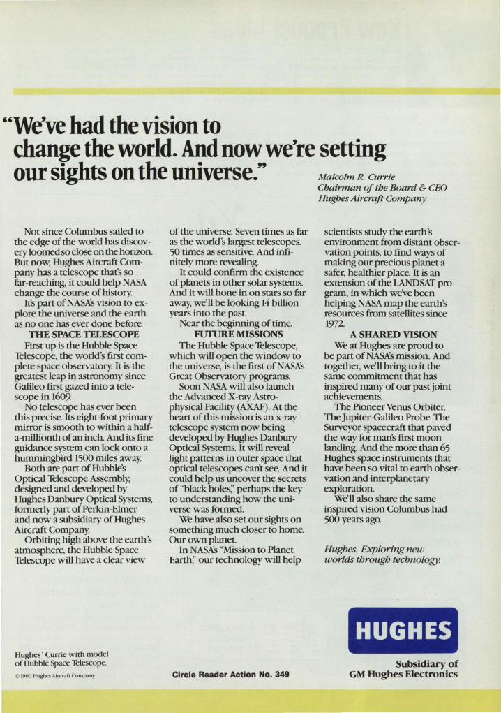
UWe've had the vision to change the world. And now we're setting our sights on the universe." MalcolmR. Currie
Not since Columbus sailed to the edge of the world has discovery loomed so close on the horizon But now, Hughes Aircraft Company has a telescope that's so far-reaching, it could help NASA change the course of history.
It's part ofNASKs vision to explore the universe and the earth as no one has ever done before.
THE SPACE TELESCOPE First up is the Hubble Space
Telescope, the world's first complete space observatory. It is the greatest leap in astronomy since Galileo first gazed into a telescope in 1609.
No telescope has ever been this precise. Its eight-foot primary mirror is smooth to within a haIfa-millionth of an inch. And its fine guidance system can lock onto a hummingbird 1500 miles away.
Both are part of Hubble's Optical Telescope Assembly, designed and developed by Hughes Danbury Optical Systems, formerly part of Perkin-Elmer and now a subsidiary of Hughes Aircraft Company.
Orbiting high above the earth ' atmosphere, the Hubble Space Telescope will have a clear view
Hughes' Currie with model of Hubble Space Telescope.
Cl I990 Hughes Aircraf, amp.ny
of the universe. Seven times as far as the world 's largest telescopes. 50 times as sensitive. And inftnitely more revealing.
It could confum the existence of planets in other solar systems. And it will hone in on stars so far away, we'll be looking 14 billion years into the past
Near the beginning of time. FUTURE MISSIONS
The Hubble Space Telescope, which will open the window to the universe, is the first of NASKs Great Observatory programs.
Soon NASA will also launch the Advanced X-ray Astrophysical Facility (AXAF). At the heart of this mission is an x-ray telescope system now being developed by Hughes Danbury Optical Systems. It will reveal light patterns in outer space that optical telescopes can't see. And it could help us uncover the secrets of "black holes;' perhaps the key to understanding how the universe was formed.
We have also set our sights on something much closer to home. Our own planet
In NASKs "Mission to Planet Earth;' our technology will help
Circle Reader Action No. 349
Chairman of the Board & CEO Hughes Aircraft Company
scientists study the earth 's environment from distant observation points, to find ways of making our precious planet a safer, healthier place. It is an extension of the LANDSAT program, in which we've been helping NASA map the earth's resources from satellites since 1972.
A SHARED VISION We at Hughes are proud to
be part ofNASKs mission. And together, we'll bring to it the same commitment that has inspired many of our past joint achievements.
The Pioneer Venus Orbiter. TheJupiter-Galileo Probe. The Surveyor spacecraft that paved the way for man's first moon landing. And the more than 65 Hughes space instruments that have been so vital to earth observation and interplanetary exploration.
We'll also share the same inspired vision Columbus had 500 years ago.
Hughes. Exploring new worlds through technology.
HUGHES Subsidiary of
GM Hughes Electronics
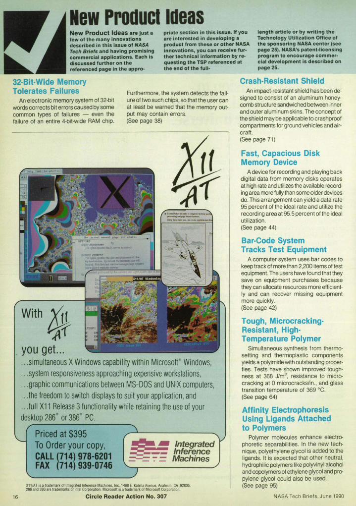
NewProduclldeas New Product Ideas are just a few of the many innovations described in this issue of NASA Tech Briefs and having promising commercial applications. Each is discussed further on the referenced page in the appro·
priate section in this issue. If you are interested in developing a product from these or other NASA innovations, you can receive fur· ther technical Information by requesting the TSP referenced at the end of the full ·
length article or by writing the Technology Utilization Office of the sponsoring NASA center (see page 25). NASA's patent-licensing program to encourage commercial development is described on page 25.
32-Bit-Wide Memory Tolerates Failures Furthermore, the system detects the fail
ure of two such chips, so that the user can at least be warned that the memory output may contain errors.
Crash-Resistant Shield An impact-resistant shield has been de
signed to consist of an aluminum honeycomb structure sandwiched between inner and outer aluminum skins. The concept of the shield may be applicable to crashproof compartments for ground vehicles and aircraft.
An electronic memory system of 32-bit words corrects bit errors caused by some common types of failures - even the failure of an entire 4-bit-wide RAM chip. (See page 38)
16
With ,111 qf
you get. .. ... simultaneous X Windows capability within Microsoft Windows, .. . system responsiveness approaching expensive workstations, ... graphic communications between MS-DOS and UNIX computers, .. . the freedom to switch displays to suit your application , and .. . full X11 Release 3 functionality while retaining the use of your desktop 286
3
or 386 ' PC.
Priced at $395 To Order your copy, CALL (714) 978-6201 FAX (714) 939-0746
:::g ~ Integrated __ --- Inference =-= ~ = Machines
XII /AT is a trademark of Integrated Inference Machines. Inc. 1468 E. Katelia Avenue. Anaheim . CA 92805. 286 and 386 are lrademarks of Intel Corporation. Microsoft is a trademark of Microsoft Corporation.
Circle Reader Action No. 307
(See page 71)
Fast, Capacious Disk Memory Device
A device for recording and playing back digital data from memory disks operates at high rate and utilizes the available recording area more fully than some older devices do. This arrangement can yield a data rate 95 percent of the ideal rate and utilize the recording area at 95.5 percent of the ideal utilization. (See page 44)
Bar-Code System Tracks Test Equipment
A computer system uses bar codes to keep track of more than 2,200 items of test equipment. The users have found that they save on equipment purchases because they can allocate resources more efficiently and can recover missing equipment more quickly. (See page 42)
Tough, MicrocrackingResistant, HighTemperature Polymer
Simultaneous synthesis from thermosetting and thermoplastic components yields a polyimide with outstanding properties. Tests have shown improved toughness at 368 J/m2, resistance to microcracking at 0 microcracks/in., and glass transition temperature of 369 °c . (See page 64)
Affinity Electrophoresis Using Ligands Attached to Polymers
Polymer molecules enhance electrophoretic separabilities. In the new technique, polyethylene glycol is added to the ligands. It is expected that other neutral, hydrophilic polymers like polyvinyl alcohol and copolymers of ethylene glycol and propylene glycol could also be used. (See page 95)
NASA Tech Briefs. June 1990


Photo courtesy Hawaii Naturat Energy Institute
Harnessing the power of nature: Wind turbines on the Big Island of Hawaii
The very things that make Hawaii a favorite vacation destination-pollutionfree, clear skies ; tropical sunshine ; balmy trade winds; and a mid-ocean
location-also conspire to make Hawaii a leader in several major high technology areas. Renewable energy, for instance-no other U.S. location offers the opportunity to develop virtually every known renewable energy resource.
Or space exploration-Hawaii looks into space from what is universally agreed to be the finest observatory platform on the planet, the mountain of Mauna Kea on the Big Island of Hawaii. Among the telescopes in operation or under construction on Mauna Kea is the threemeter NASA infrared telescope, which is pioneering the use of infrared detector arrays that function much like a charge-coupled device (CCD) but are sensitive to infrared light.
The Big Island is also the proposed site for what could be America's first commercial satellite launch facility. As the southernmost point in the country, it offers the potential for both polar and equatorial launches.
As an island state, Hawaii has a long history of both marine research and aquaculture. The ancient Hawaiians invented aquaCUlture; they built ingenious fish ponds which were closed on all sides except for small openings to the sea. Young fish could enter through a grating of bamboo to feed on the rich nutrients in the pond. As the little fish ate, they grew too big to get back through the grate and out of the pond. Today Hawaii is a center of aquaculture development for the world.
Other high-tech developments seem to be happy accidents. In electronics, communications, and biotechnology, innovative companies were formed because the people who founded them happened to be in Hawaii. And they had a chance to succeed because the state has made a commitment to the support of high-tech industry as part of its goal of a diversified economy.
Renewable Energy Since the 1973 oil crisis, Hawaii has en
couraged the development of renewable energy alternat ives aimed at energy self-sufficiency and has establ ished several organizations to conduct research and foster the commercialization of renewable energy.
The Hawaii Natural Energy Institute is a child of the gas lines, created in 1974 at the University of Hawaii at Manoa, to "coordinate
and undertake the development of non-polluting natural energy sources for Hawaii." Institute researchers calculate that Hawaii currently uses about 32 billion kilowatt hours equivalent of energy annually. In theory, any one of Hawaii's prime renewable energy resources-biomass, geothermal , ocean thermal energy conversion (OTEC) , solar, or wind -could produce more than enough power to meet this demand. And the maximum combined potential from all renewable energy sources would yield almost fifteen times the current demand.
The Pacific International Center for High Technology Research (PICHTR) was established in 1983 to assist the state's High Technology Development Corporation in promoting educational, scientific, technological , and literary pursuits in the areas of high technology and to support Hawaii technology industry. PICHTR has become a major player-along with the Natural Energy Laboratory of Hawaii (NELH)- in the development of both openand closed-cycle OTEC technology and is working to establish a model utility tied into natural energy sources on the island of Maui.
OTEC Research In open-cycle OTEC, warm surface ocean
water is brought into a vacuum chamberwhere itturns into steam to push a turbine. The steam is condensed by cold water pumped up from deep in the ocean. This maintains the vacuum and pressure on the turbine and also produces fresh water.
Closed-cycle OTEC uses warm surface water to evaporate ammonia, which expands and pushes the turbine, and is then condensed by cold, deep ocean water. In the late 1970s, the state conducted a mini-OTEC test project which showed a net gain in power after pumping the cold water up from two thousand feet below the surface. This provided conclusive proof of the concept, and could have led to commercialization of OTEC, had the price of oil not collapsed. Throughout the 1980s, NELH conducted experiments on bio-fouling of the plumbing that would handle the sea water. One of the high-expense items of OTEC in past analyses has been the heat exchanger, which had been made of titanium to prevent corrosion. A much less expensive alloy of aluminum that is resistant to sea water corrosion has been developed by the Argonne National Laboratory and tested at NELH, lowering the overall cost projections for success-
Produced by NASA Tech Briefs Magazine
ful OTEC operation. PICHTR, with grants from the U.S. Depart
ment of Energy and the state of Hawaii, along with private and international financial support, will build a net-power-producing, closed-cycle plant. It is expected that by 1992 the world's first land-based OTEC plant will be producing electricity .
Geothermal Energy Geothermal power is not a new idea-the
Italians built the first commercially successful geothermal plant at Lardarelio , Italy, in 1904. The Big Island, with two active volcanoes, is a prime geothermal location. The state had a demonstration plant producing about three megawatts of power on the Big Island from 1981 to 1989. Hawaiian Electric Company issued a request for proposals in May 1989 for development of geothermal power on the Big Island and delivery of the power generated to the island of Oahu, which contains 80 percent of the state's population. Five consortia responded and negotiations are under way with a group headed by Mission Power of Southern California and Bechtel.
Plants will be constructed in modules of 25 to 50 megawatts, adding up to a nominal 500 megawatts. To carry the power 300 miles from the Big Island to Oahu, an innovative deep water power cable is required. Research on the Hawaii Deep Water Cable Project ended with successful sea trials which laid a model cable early this year.
The Maul Model Maui Electric Company was chosen to
develop a model solar power project under the umbrella of a nationwide program, Photovoltaics for Utility Scale Applications (PVUSA), in which government and industry are working together to generate electricity cost-effectively using solar energy. The $500 thousand test system will produce 20 kilowatts of electricity.
Maui Electric is also the front-runner in a project headed by the Department of Energy to create a model Pacific utility, tying in several renewable energy sources. Maui Electric now has solar, wind, biomass, and hydroelectric power coming into its grid-in addition to power generated by fossil fuel-and looks to geothermal power for the future. The company is now interconnecting its neighboring islands of Lanai and Molokai. Therefore it can serve as a model power company for any Pacific island.
Basic Energy Sources In Hawaii the trade winds blow almost
continuously. On one hill on the Big Island alone, one can count 297 wind turbines at work. The problems with wind power under study by the Hawaii Natural Energy Institute and Hawaii 's power companies are : almost constant variation in output due to fluctuations in the wind force ; energy storage; and interface with the utility grid. One proposal would use excess wind power to pump water from the wet side of the island to a reservoir in the mountains, from which it could be released on the dry side to drive a hydroelectric plant and at the same time provide water for irrigation.
Hawaii 's sugar mills burn the sugar cane plants, after the sugar has been extracted, to generate power to run the mills. Biomass from wood chips and other sources is also used for power generation . Excess power is sold to utility companies.
ElectriCity, however, accounts for only about 30 percent of the state's energy needs.

The Other Maui The Maui Research & Technology Park is a new development on the island of Maui which boasts
the fastest economic growth in Hawaii. The Park is an ideal location for high-technology enterprises and supporting activities such as research and development, office and business, manufacturing and warehousing, and other uses consistent with its general plan. A special Maui County R& T Park ordinance has streamlined the permit process to facilitate development, and the Park's design guidelines will ensure the integrity of long-term investment.
Within the Park, a state of Hawaii-sponsored Research & Technology Center will provide incubator space for emerging technology-based businesses and a phase-in center for established companies considering a location in the Park. It will also contain centers for video and telecommunications, business support, and University of Hawaii-related activities.
Maui's special geographic position makes it an advantageous location for firms doing business in the Asian I Pacific sphere - exchanges between the East Coast and the Far East are possible on the same business day; frequent non-stop flights are available from Hawaii to most major domestic and Pacific Rim cities; and satellite and fiber optics cable allow excellent communication worldwide. In addition, the state provides monetary incentives that include low interest loans and tax advantages.
Excellent ocean and mountain views are available, and all sites offer open space, privacy and security in a controlled environment. Located on 330 acres of former ranch land, the R & T Park is buffered from the highway by an 18-hole golf course. Fee simple sites in the first 60-acre phase are now available for sale.
Far more energy is needed to fuel ships, aircraft , and surface vehicles. The Hawaii Natural Energy Institute and PICHTR are exploring ways in which methanol could be used to replace fossil fuel. This requires not only technical ability to create methanol from biomass, but also a parallel or alternative infrastructure which will provide methanol as a fuel, along with engines equipped to burn it.
Hydrogen may well be the fuel of choice in the 21 st century. And Hawaii is the site of World Hydrogen Energy Conference Number Eight, in July, reflecting the state's preeminence in natural energy research.
Ocean Science and Marine Research
International law now recognizes a 200 mile zone-the Exclusive Economic Zone (EEZ)-within which coastal nations have sovereign and exclusive rights over living and nonliving resources. For Hawaii, the increase was dramatic. With the 200 mile zone extending around the entire archipelago from the Big Island to Kure Atoll , Hawaii jumped from 47th to second among states (behind Alaska) in combined land and sea area.
Several sites on the ocean floor appear to be rich in manganese crusts, from which the strategiC metal cobalt can be extracted. There is potential for an undersea mining operation and a processing operation to extract the cobalt. Most estimates place this fifteen to twenty years away.
A growing area of research and development is the production of pharmaceutical products from the sea, which promises economic benefits from EEZ resources.
Hawaii is assuming a leadership position in ocean science and marine research. With one of the most extensive and accessible EEZs, Hawaii has the potential to become America's R&D center for EEZ use.
Deep Water Cable
An example is the Hawaii Deep Water Cable Project, designed to test the feasibility of carrying 500 megawatts of geothermal power from the island of Hawaii to Oahu. Most of the previous research on deep water cables remains the proprietary information of private companies outside the United States. The Deep Water Cable Project advances American scientific knowledge in this field to the cutting edge of current research activity. "The federal government doesn't care so much about geothermal energy in Hawaii," stated William A. Bonnet, director, engineering research, for Hawaiian Electric. ''They've funded this research to pick up technology which can be used by American industry in the United States and elsewhere."
And there is real international interest. Boston Edison, for instance, wants to bring up to 1200 megawatts of power from a coal-fired generator in Nova Scotia, 250 miles away by sea. Further, the Iceland Power Company would like to export power to the United Kingdom via a 600 mile cable from Iceland to Scotland at a maximum depth of 3000 feet.
Makai Ocean Engineering, a Hawaii firm conducting research and development of ocean systems, created a real-time model for laying the cable at a precise tension in a specific location. At a depth of 4000 feet, technicians will have to install three cables which
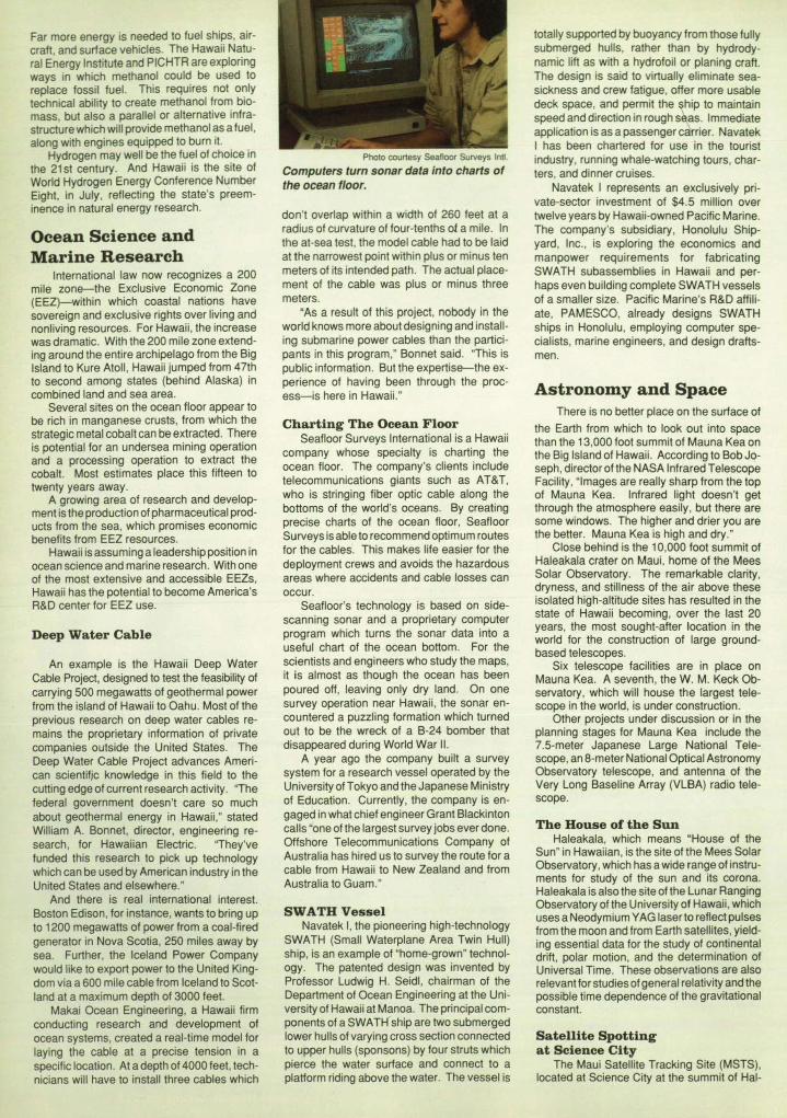
PholO courtesy Seafloor Surveys InU.
Computers turn sonar data into charts of the ocean floor.
don't overlap within a width of 260 feet at a radius of curvature of four-tenths of a mile. In the at-sea test, the model cable had to be laid at the narrowest point within plus or minus ten meters of its intended path. The actual placement of the cable was plus or minus three meters.
"As a result of this project, nobody in the world knows more about designing and installing submarine power cables than the participants in this program," Bonnet said. "This is public information. But the expertise-the experience of having been through the process-is here in Hawaii."
Chartin g The Ocean F loor Seafloor Surveys International is a Hawaii
company whose specialty is charting the ocean floor. The company's clients include telecommunications giants such as AT&T, who is stringing fiber optic cable along the bottoms of the world's oceans. By creating precise charts of the ocean floor, Seafloor Surveys is able to recommend optimum routes for the cables. This makes life easier for the deployment crews and avoids the hazardous areas where accidents and cable losses can occur.
Seafloor's technology is based on sidescanning sonar and a proprietary computer program which turns the sonar data into a useful chart of the ocean bottom. For the scientists and engineers who study the maps, it is almost as though the ocean has been poured off, leaving only dry land. On one survey operation near Hawaii, the sonar encountered a puzzling formation which turned out to be the wreck of a B-24 bomber that disappeared during World War II.
A year ago the company built a survey system for a research vessel operated by the University of Tokyo and the Japanese Ministry of Education. Currently, the company is engaged in what chief engineer Grant Blackinton calls "one of the largest survey jobs ever done. Offshore Telecommunications Company of Australia has hired us to survey the route for a cable from Hawaii to New Zealand and from Australia to Guam."
SWATH Vessel Navatek I, the pioneering high-technology
SWATH (Small Waterplane Area Twin Hull) ship, is an example of "home-grown" technology. The patented design was invented by Professor Ludwig H. Seidl, chairman of the Department of Ocean Engineering at the University of Hawaii at Manoa. The principal components of a SWATH ship are two submerged lower hulls of varying cross section connected to upper hulls (sponsons) by four struts which pierce the water surface and connect to a platform riding above the water. The vessel is
totally supported by buoyancy from those fully submerged hulls, rather than by hydrodynamic lift as with a hydrofoil or planing craft. The design is said to virtually eliminate seasickness and crew fatigue, offer more usable deck space, and permit the ~hip to maintain speed and direction in rough silas. Immediate application is as a passenger carrier. Navatek I has been chartered for use in the tourist industry, running whale-watching tours, charters, and dinner cruises.
Navatek I represents an exclUSively private-sector investment of $4.5 million over twelve years by Hawaii-owned Pacific Marine. The company's subsidiary, Honolulu Shipyard, Inc., is exploring the economics and manpower requirements for fabricating SWATH subassemblies in Hawaii and perhaps even building complete SWATH vessels of a smaller size. Pacific Marine's R&D affiliate, PAMESCO, already designs SWATH ships in Honolulu, employing computer specialists, marine engineers, and design draftsmen.
Astronomy and Space There is no better place on the surface of
the Earth from which to look out into space than the 13,000 foot summit of Mauna Kea on the Big Island of Hawaii. According to Bob Joseph, director of the NASA Infrared Telescope Facility, "Images are really sharp from the top of Mauna Kea. Infrared light doesn't get through the atmosphere easily , but there are some windows. The higher and drier you are the better. Mauna Kea is high and dry."
Close behind is the 10,000 foot summit of Haleakala crater on Maui. home of the Mees Solar Observatory. The remarkable clarity, dryness, and stillness of the air above these isolated high-altitude sites has resulted in the state of Hawaii becoming, over the last 20 years, the most sought-after location in the world for the construction of large groundbased telescopes.
Six telescope facilities are in place on Mauna Kea. A seventh, the W. M. Keck Observatory, which will house the largest telescope in the world, is under construction.
Other projects under discussion or in the planning stages for Mauna Kea include the 7.S-meter Japanese Large National Telescope, an 8-meter National Optical Astronomy Observatory telescope, and antenna of the Very Long Baseline Array (VLBA) radio telescope.
The House of the Sun Haleakala, which means "House of the
Sun" in Hawaiian, is the site of the Mees Solar Observatory, which has a wide range of instruments for study of the sun and its corona. Haleakala is also the site of the Lunar Ranging Observatory of the University of Hawaii, which uses a Neodymium YAG laser to reflect pulses from the moon and from Earth satellites, yielding essential data for the study of continental drift, polar motion, and the determination of Universal Time. These observations are also relevant for studies of general relativity and the possible time dependence of the gravitational constant.
Satellite Spotting at Science City
The Maui Satellite Tracking Site (MSTS), located at Science City at the summit of Hal-

eakala, operates several space-related programs. MOTIF (Maui Optical Tracking and Identification Facility) consists of twin 1.2 meter telescopes mounted on opposite sides of a single polar or right ascension axis, and attached to a common declination axis, so that they move precisely in unison. MOTIF operates every night, tracking satellites.
AMOS (Air Force Maui Optical Station) is dedicated to furthering research and development efforts in electro-optics. Using AMOS, Avco Research Laboratory (ARL) -TEXTRON, which manages the facility for the Air Force, has helped more than 20 government agencies and several universities run experiments. "We've worked with Jet Propulsion Laboratory, MIT/Lincoln Labs, and many others: said Tom Reed, managing director of ARL-TEXTRON. "We have tested cameras for the University of California (Berkeley) and the University of Arizona. And we have recently been doing polarization measurements over the open ocean for the Navy."
GEODSS (Ground-Based Electro-Optical Deep Space Surveillance), operated by Emhart Planning Research Corporation, is the backbone of Space Command's Electro-Optical Sensor Systems, and dovetails nicely with MOTIF, while its method of operation is unique. The GEODSS system consists of three telescopes-two primaries and one auxiliary-that are smaller than either the MOTIF or AMOS telescopes.
According to Major Richard Kelly, MSTS site commander, "Ground-Based Electro-Optical Deep Space Surveillance, as its name implies, is primarily used for tracking objects in deep space or beyond 3000 miles. Due to constraints in the design, we physically cannot get a good track on anything closer. " Unlike the other systems which lock onto particular objects and follow them as they pass overhead, GEODSS synchronizes its movement with the stars. "With GEODSS we can track an object the size of a grapefruit up to 20,000 miles out in space: said Kelly.
As the telescope slowly moves with the rotation of the Earth, the low-light-level TV cameras connected to GEODSS take a series of pictures which are overlaid and fed into a computer. The computer then erases the fixed star images, leaving visible only the trace of any non-fixed or orbiting object. Over a period of time these moving space objects produce a streak across the display screen which can be analyzed for poSition in orbits from 3000 to 22,000 miles. GEODSS tracks an average of 300 space objects a night, and with its close tolerances, Ihere isn't much that escapes its notice.
Spaceport Project Hawaii has been a part of America's space
effort since the days of the Mercury Program. The Kokee tracking station on Kauai has been an Integral part of manned space flight.
With one foot already on the stairway to the stars, Hawaii took another step toward space last year when Governor John D. Waihee named Admiral Thomas B. Hayward, retired U.S. Chief of Naval Operations, to serve as chairman of the Hawaii Space Development Authority and to be his special advisor on space.
State officials and consultants have been developing plans to build the world's first commercial launch center in Hawaii. If all goes well , by 1992-the International Space Yearground will be broken for a commercial launch facility for unmanned, small to mid-sized
rockets in the Ka'u region of the Big Island. This would take advantage of Hawaii 's unique geography. Hawaii is nearer the equator than any other place in the U.S., allowing rocket launches to take advantage of the Earth's spin. And it is the only site in the U.S. where rockets can be launched into either an equatorial or a polar orbit without overflying populated areas.
Two possible sites have been identified for the spaceport-Palima Point and Kahilipali Point on the Big Island- and draft environmental impact statements for each are expected this summer.
The commercial launch facility would handle expendable launch vehicles (ELVs). including those similar in scale to the Scout and Delta II vehicles, and up to the commercial Titan III vehicle. Sub-orbital sounding rockets also could be launched.
Following release of the draft environmental impact statements, Hawaii will still have much to accomplish. The site must be acquired. Funding-in the form or one or more partners, probably international in scope, quite likely from Japan-must be achieved. And a launch facility must be built. But if all goes well , "an ML V could be launched from Hawaii in late '93 or early '94: Admiral Hayward said.
InformationlElectronics
Hawaii designs and manufactures goods and services for telecommunications and electronics, and sells the products all over the world . With its mid-Pacific location, Hawaii is the hub for telecommunication flowing from the U.S. mainland to Asia and the Pacific.
"We have established Hawaii as a highspeed digital communications hub-both fiber and digital satellite: states Bill Martin of AT&T. "This means for businesses in Hawaii, service to the Pacific Rim is direct and less costly. Any place that AT&T goes by gateway is available from Hawaii ."
A major long distance carrier, Long Distance USA (which has since merged with Sprint), got its start in Hawaii. SoftStyle, a computer software company which designed and published drivers for many major computer peripherals, began in Hawaii, and is now a part of Phoenix Technologies. On the consumer side, Hawaii took to automatic teller machines with a passion, while the mainland
was still wondering if they weren 't just a passing fad. And the island of Kauai became the first rural service area in the U.S. for cellular telephone service, when GTE Mobilnet began service there in August 1989.
lntelectJ.Unndversary Intelect, Inc., an international supplier of
voice and data communications equipment for government and military systems, recently celebrated its 25th anniversary by moving into its new, 30,000 square foot facility at the Mililani Technology Park and announcing its entry into the commercial telecommunications market with its new Black Panther line of equipment.
The new product line begins with a digital voice-data switching platform from which Intelect plans to derive a family of advanced telecommunications products. The Black Panther is a digital multiple parallel bus system using pulse code modulation (PCM) time division switching. Two platforms using the same architecture will be available-one serving 32 to 1024 ports and the other 32 to 2048 ports.
Two key points differentiate the Black Panther from conventional PABXs and key systems: Each port card has its own microprocessor and memory, and each port has its own time slot. According to the company, "EPABXs are designed without a full complement of time slots for the absolute lowest manufacturing cost per port. EPABXs also can't afford the distributed processing that gives Intelect's Black Panther its full conferencing capacity and ease of adaptation to special consumer needs. The Black Panther line is aimed at a market that needs non-blocking, full availability traffic capacity."
Automation Leader VeriFone, Inc. was founded in Hawaii in
1981 by Bill Melton to develop, manufacture, market, and support transaction terminals and microcomputer systems. In eight years the company has become the international leader in the transaction automation business with 500 employees worldwide and offices throughoutthe U.S., Europe, the Far East, and Australia.
The company began in the new field of credit verification terminals, which check credit cards quickly and automatically. This
Hawaii offers the opportunity for both polar and equatorial launches of spacecraft. Photo courtesy Hawaii Space Oevelopment Authority
replaced the lengthy process by which the clerk had to place a phone call. wait while the records were checked. and receive a verification number. Hard work and aggressive sales have given the company a majority of the market. ·Since 1982, revenues have grown at 110 percent a year~mpounded annually," according to Hatim A. Tyabji, president and CEO. The company shipped its one millionth system in September.
A critical factor in VeriFone's rapid growth has been the backing it received from Bank of Hawaii. According to Robert Paris, senior vice president and senior lending officer of the bank, "We took some risk because we saw some potential there. This goes all the way back to when they were waiting for their first venture capital. We gave them a $7 million line of credit when they were waiting for $5 million."
According to Paris, the most important thing was that VeriFone's management grew to keep pace with the company's expansion. "Too often people try to take their company too big too fast and they crash and burn. Melton took it to the point where it was starting to get too big for his expertise, and he went beyond Hawaii to recruit the people he needed. He found a financial person who had taken other companies public. And he gotthe right venture capital group."
Soft Warehouse Founded in 1979 by Albert D. Rich, an
applied logician, and David R. Stoutemyer, a university engineering professor, Soft Warehouse, Inc., has found its niche with two software products for use on IBM PCs and compatibles. muLlSP-87 is a high-performance LISP language pseudo-code compiler, interpreter, and programming environment for the development of artificial intelligence software. Derive, A Mathematical Assistant, is a menudriven symbolic math system which intelligently applies the rules of algebra, trigonometry, calculus, and matrix algebra to solve a wide variety of mathematical problems.
"Derive lets you do symbolic math on a PC," said co-founder Rich. "It's taking the education world by storm. It's the way math is going to be taught in the next ten years."
Other software developers in Hawaii include Data House, Boeing Computer, SAIC, and Martin Mariena.
Biotechnology In the Manoa Valley, the Natural Products
Laboratory of the University of Hawaii is the sole national source of a blue-green marine algae strain which is being used in research on cures for cancer, AIDS, herpes, and several viruses. The laboratory provides cultures from 1000 blue-green algae to the National Cancer Institute (NCI), which screens them for anticancer activity against various human cancer cell lines. NCI is looking for activity which is selective : Activity in marine algae that will just kill breast cancer cells or colon cancer cells.
Since 1983, Hawaii Biotechnology Group, Inc., a genetic engineering company in Aiea, has received $2,311 ,697 in federal Small Business Innovative Research (SBIR) awards -71 percent of the total won by Hawaii companies. Hawaii Biotech's research includes development of a flightless female medfly which could provide a genetic answer to the fruitfly problem, and work on a vaccine against dengue fever. Among its other efforts is a longterm project looking at a potential cancer cure derived from Palythoa toxica, a seaweed
called in Hawaiian limu-make-o-Hana or "the deadly seaweed of Hana."
Another company, Moana Bioproducts, has developed an antibody for detecting ciguaterra, a poisonous substance that contaminates fish and shellfish in coral reefs. Funded in part by $45,000 in state and federal SBIR grants, the ciguaterra immunotoxin can be used by fishermen to do on-site testing. It changes the pigment of a fish's flesh from colorless to blue when the ciguaterra is present.
Valuable Waste Universal Synergetics, Inc. (Unisyn Ha
waii) takes waste material that nobody wants and turns it into something of value. The waste material is processed in an anaerobic digester, producing a biogas that is mostly methane and carbon dioxide. The methane is used as fuel to generate electricity. The carbon dioxide can be routed to an algae pond where Unisyn grows spirulina, which is then processed, freeze-dried, and sold in more than 350 health food stores on the mainland. Or C02 can be piped to Unisyn's three-and-a-half acre greenhouse to encourage plant growth. What remains in the digester is a single-cell protein which can be processed as either a feed for farm animals and aquaculture, or as an organic fertilizer.
In its current configuration, the Unisyn system starts with manure, but James D. McElvaney, vice president, biotechnology and development, points out that "this shouldn't be thought of as a manure process. We want to look at every kind of waste treatment."
In February, Unisyn's proprietary process was licensed by Ecotechniek bv, a pollution abatement firm located in Utrecht, the Netherlands, for use in the Netherlands, Austria, Belgium, Denmark, Luxembourg, Switzerland, and West Germany. Unisyn will receive a licensing fee for the technology and assistance associated with Ecotechniek's first plant, a $50 million manure processing plant near Dordrecht, scheduled for completion in 1991 .
''The Unisyn system gets rid of unwanted waste and produces products which otherwise would have to be imported," McElvaney said. "The integration of processes results in higher quality products at lower cost. For example,
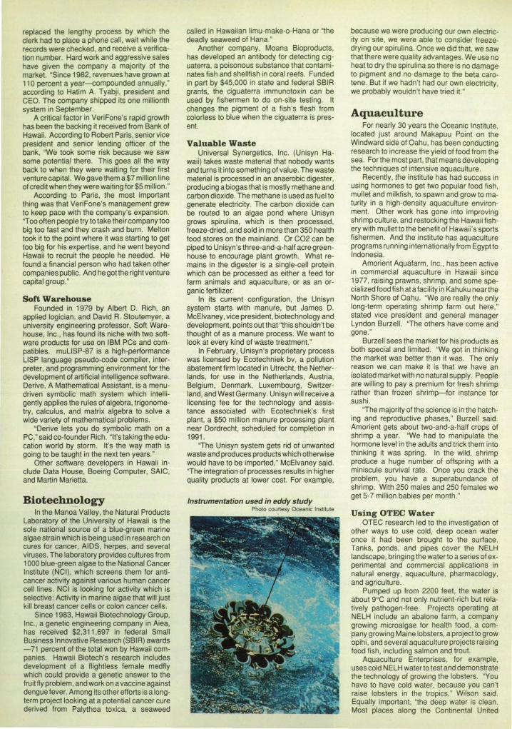
Instrumentation used in eddy study Photo courtesy Oceanic Institute
because we were producing our own electricity on site, we were able to consider freezedrying our spirulina. Once we did that, we saw that there were quality advantages. We use no heat to dry the spiru lina so there is no damage to pigment and no damage to the beta carotene. But if we hadn't had our own electricity, we probably wouldn't have tried it. '
Aquaculture For nearly 30 years the Oceanic Institute,
located just around Makapuu Point on the Windward side of Oahu, has been conducting research to increase the yield of food from the sea. For the most part, that means developing the techniques of intensive aquaculture.
Recently, the institute has had success in using hormones to get two popular food fish, mullet and milkfish, to spawn and grow to maturity in a high-density aquaculture environment. Other work has gone into improving shrimp culture, and restocking the Hawaii fishery with mullet to the benefit of Hawaii's sports fishermen . And the institute has aquaculture programs running internationally from Egypt to Indonesia.
Amorient Aquafarm, Inc., has been active in commercial aquaculture in Hawaii since 1977, raising prawns, shrimp, and some specialized food fish at a facility in Kahuku near the North Shore of Oahu. "We are really the only long-term operating shrimp farm out here," stated vice president and general manager Lyndon Burzell. "The others have come and gone."
Burzell sees the market for his products as both special and limited. "We got in thinking the market was better than it was. The only reason we can make it is that we have an isolated market with no natural supply. People are willing to pay a premium for fresh shrimp rather than frozen shrimp-for instance for sushi.
"The majority of the science is in the hatching and reproductive phases," Burzell said . Amorient gets about two-and-a-half crops of shrimp a year. "We had to manipulate the hormone level in the adults and trick them into thinking it was spring. In the wild, shrimp produce a huge number of offspring with a miniscule survival rate. Once you crack the problem, you have a superabundance of shrimp. With 250 males and 250 females we get 5-7 million babies per month."
Using OTEC Water OTEC research led to the investigation of
other ways to use cold, deep ocean water once it had been brought to the surface. Tanks, ponds, and pipes cover the NELH landscape, bringing the water to a series of experimental and commercial applications in natural energy, aquaculture, pharmacology, and agriculture.
Pumped up from 2200 feet , the water is about 9°C and not only nutrient-rich but relatively pathogen-free. Projects operating at NELH include an abalone farm, a company growing microalgae for health food, a company growing Maine lobsters, a project to grow opihi, and several aquaculture projects raising food fish, including salmon and trout.
Aquaculture Enterprises, for example, uses cold NELH water to test and demonstrate the technology of growing the lobsters. "You have to have cold water, because you can't raise lobsters in the tropics," Wilson said. Equally important, "the deep water is clean. Most places along the Continental United
States, the water is polluted." Raising the lobsters in this way has decreased the time it takes for a lobster to mature from seven years in nature to about two-and-a-half years under aquaculture conditions.
Ocean Farms Ocean Farms Hawaii has had so much
success in aquaculture using Keahole Point water that it has built three more ponds and installed four eighteen inch pipes to bring up the water from below 2000 feet. Early on, Ocean Farms found that both the abalone and the kelp to feed them grow more quickly and safely in Keahole water than in the natural conditions of the ocean off California. They also have about three million salmon and ten million oysters. "The combination of salmon and kelp is important," said company president George Lockwood. "The kelp absorbs the waste products of the salmon and produces a high level of oxygen, which the salmon need. And the oysters eat microalgae diatoms which otherwise would shade the kelp and retard growth."
Ocean Farms Hawaii expects to send to market this year 500,000 pounds of salmon, a million oysters, and 300,000 pounds of abalone.
State Resources
The state of Hawaii has placed substantial resources at the service of high-tech business in Hawaii.
High Technology Development Corporation
The HTDC is an independent corporation funded by the state to encourage, promote, and support the development of high technology industry in Hawaii. HTDC is responsible for development of major technology parks and incubator services. These include:
-The Kaimuki Technology Enterprise Center (KAITEC) for high-tecn start-up companies;
° The 547 -acre Hawaii Ocean Science and Technology (HOST) Park at Keahole Point on the Big Island, for companies with a use for Keahole's cold, nutrient-rich sea water;
-The 300-acre Maui Research and Technology Park at Kihei , planned for construction ;
-The Manoa Innovation Center, now vnder construction, which will include the headquarters for the Pacific International Center for High Technology Research, the Research Corporation of the University of Hawaii, and the University's Office ofTechnology Transfer and Economic Development, and will provide incubation space for up to 50 high-tech startup companies.
°A software service center. HTDC administers the state's supplemen
tary SBIR grants, and, assuming thatthe State High Tech Strategic Fund is passed by the state legislature, it will administer a fund of over $6 million to encourage high-tech business. It operates a resume summary service to match up technical graduates now on the mainland who would like to return to Hawaii with Hawaii companies looking for talent. And it publishes the Hawaii High Technology Business Directory.
For information about relocating a hightech business to Hawaii, or starting one in the state, contact:
William M. Bass, Executive Director High Technology Development Corp.,
Mililani Technology Park, Leilehua Building, Suite 35, Mililani, Hawaii 96789. Telephone (808) 625-5293 FAX: (808) 625-6363
Other Technology Parks Mililani Technology Park on Oahu is the
home of Intelect, Inc., VeriFone, Inc., the HTDC, and several other Hawaii high-tech businesses. For information contact:
Mililani Technology Park 650 Iwilei Road, Third Floor P.O. Box 2780 Honolulu, HI 96803 Telephone (808) 548-4885 FAX (808) 548-6690
Kapolei Business and Industrial Park is planned for Oahu's "second city: Kapolei, to
be constructed west of Honolulu. This represents the next major growth area on Hawaii's most populated island.
Situated on 800 acres, the park will be developed for light industrial and maritime-related use. It is adjacent to Barbers Point Harbor and the existing James Campbell Industrial Park, both of which are extensions of Foreign Trade Zone Number Nine. Nearby is the 1000-acre resort of Ko Olina, under construction, which will feature 4000 hotel rooms, 5200 residences, a 400 slip marina, and an 18-hole golf course. More than 40,000 residential units are slated to be built in the Kapolei area in the next ten years.
For information contact: The Estate of James Campbell 828 Fort Street Mall, Suite 500 Honolulu, HI 96813 0
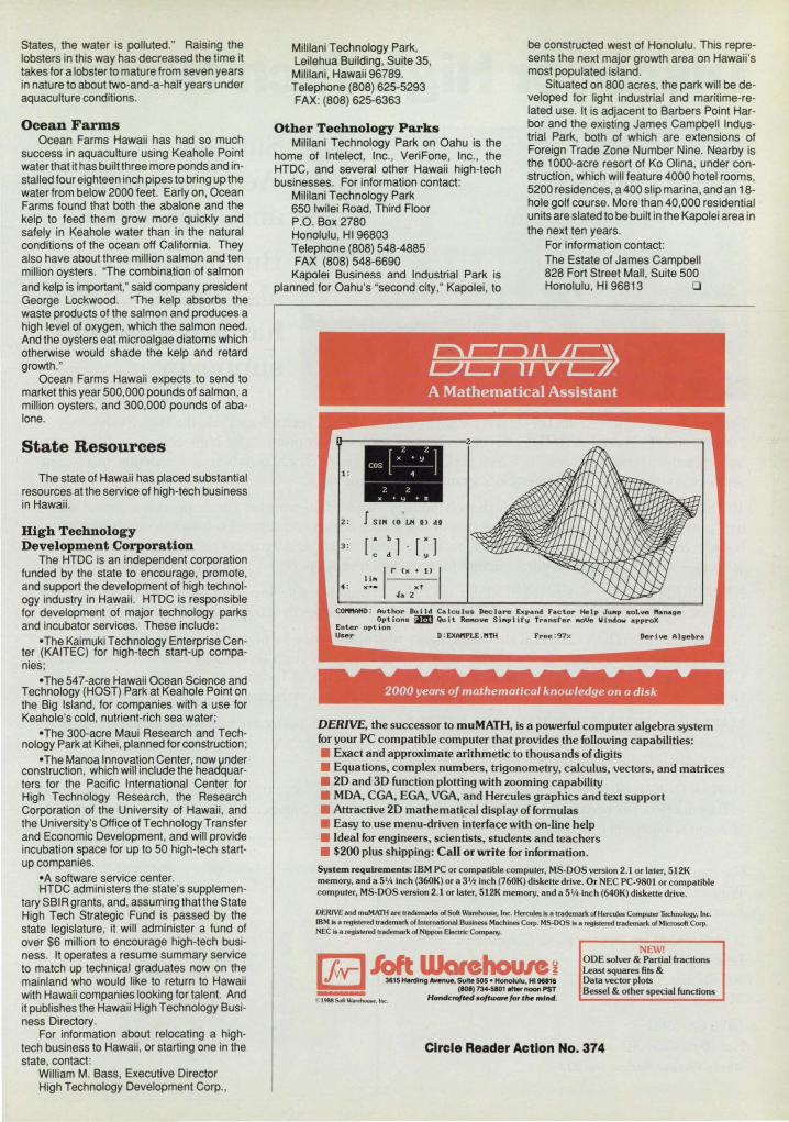
~ A Mathematical Assistant
COtftV'4D : Author Sui let ~Iculu. Declare Expand r .. clor Help JUMp soLue "'~ge Options ~ Qu it Re..oue Shllpliry Transrer IIIOVe ",ndow .pproX
Enter opt ion User D : £XMPLE ."TH Free:9?>'.
2000 years 0/ mathematical knowledge on a disk
DERIVE, the successor to muMATH, is a powerful computer algebra system for your PC compatible computer that provides the following capabilities: • Exact and approximate arithmetic to thousands of digits • Equations, complex numbers, trigonometry, calculus, vectors, and matrices • 20 and 30 function plotting with zooming capability • MOA, CGA, EGA, VGA, and Hercules graphics and text support • Attractive 20 mathemati.cal display of formulas • Easy to use menu-driven interface with on-line help • Ideal for engineers, scientists, students and teachers • $200 plus shipping: Call or write for information.
System requirements: IBM PC or compatible computer, MS·DOS version 2.1 or later, 512K memory, and a 5'A Inch (360K) or a 3 '/2 Inch (760K) diskette drive. Or NEC PC·9801 or compatible computer, MS-DOS version 2.1 or later, 512K memory, and a 5'/4 inch (640K) diskette drive.
DER1VE and muMATH are trademarks 01 Soft Warehouse. Inc. Hercules is II trademark of Hercules Computer Technology, Inc. IBM is a registered trademark of International Business Machines Corp. MS·OOS Is a rtg15terN trademark of Microsoft Corp. NEe is a registered trademark of Nippon Electric Company.
Ifw-J¥.l~~J (1011730·5101 ___ PST
1988 Soft W.~. Inc.. Hondc:rqfkd .o/twarejoT t"r: ",' nd'.
NEW! ODE solver & Partial fractions least squares fits & Data vector plots Bessel & other special functions
Circle Reader Action No. 374

Discover High Tech Hawaii Sure---We're beautiful and a lot of fun. . .
But did you also know we're hardworking and supportive?
From its headquarters in the Leilehua Building in Oahu's Mililani Technology Park, the High Technology Development Corporation (HTDC) directs a vigorous state support program for high technology businesses. This includes: Hawaii's largest high tech park, facilities for research and commercial production, incubation services, a software service center, SBIR grants, and much more.
The State of Hawaii is serious about high tech industry. We lead the world in astronomy research and alternate energy applications, and in many phases of electronics design and support software development, ocean science, telecommunications and information, and biotechnology. And we're not just sitting on our scenery-we're installing the infrastructure for true high tech support
KAlMUK! TECHNOLOGY ENTERPRISE CENTER is Hawaii's original incubator facility, managed by HTDC. The first eight companies resident at KMIEC showed revenue growth of 600 percent from 1988 to 1989.
MANOA INNOVATION CENTER stresses synergy with office space for fifty companies in the secondary stage of development alongside the Pacific International Center for High Technology Research, the Research Corporation of the University of Hawaii, and the University's Office of Technology Transfer and Economic Development. Ground breaking is scheduled for April of 1990 with occupancy anticipated a year later.
MAUl RESEARCH AND TECHNOLOGY CENTER will be a multi-use facility with space for University of Hawaii Research, an incubator facility for high tech companies, and a telecommunications center located at Maui Research and Technology Park.
HAWAII OCEAN SCIENCE AND TECHNOLOGY (HOSI) PARK located at Keahole Point on the Big Island of Hawaii offers 547 oceanfront acres with long-term leases for the commercial application and development of ocean science and technology.
For more information contact William M. Bass, Executive Director
High Technology Development Corporation Leilehua Building 300 Kahelu Avenue, Suite 35 Mililani, Hawaii 96789
(808) 625-5293 Fax (808) 625-6363 Circle Reader Action No. 371 n _lit I'
'-- -- n= tnt:!; ,.,»e
Manoa Innovation Center

HOW YOU CAli BEIIEFIT I f you're a regular reader of TECH BRIEFS, then you ' re already making use of one of the low· and no·cost services provided by NASA's Technology Utilization (TU) Network. But a TECH BRIEFS subscription represents only a fraction of the technical information and applicationslengineering services offered by the TU Network as a whole. In fact, when all of the components of NASA's Technology Utilization Network are considered, TECH BRIEFS represents the proverbial tip of the Iceberg.
FROM IIASA's TECHIIOLOGY UTILIZADOII SERVICES
We've outlined below NASA's TU Network-named the participants, described their services, and listed the individuals you can contact for more information relating to your specific needs. We encourage you to make use of the Information, access, and appilcations services offered by NASA's Technology Utilization Network.
How You Can Utilize NASA's Industrial Applications Centers-A nationwide network offering a broad range of technical services, including computerized access to over 100 million documents worldwide,
Y OU can contact NASA's network of Industrial Applications Centers (lACs) for assistance in solving a specific technical problem or meeting your information needs. The " user friendly" lACs are staffed by technology transfer experts who provide computerized information retrieval from one of
the world's largest banks of technical data. Nearly 500 computerized data bases, ranging from NASA's own data base to Chemical Abstracts and INSPEC, are accessible through the ten lACs located throughout the nation. The lACs also offer technical consultation services andlor linkage with other experts in the field . You can obtain more information about these services by calling or writing the nearest lAC. User fees are charged for lAC Information services. Aerospace Research Research Triangle Park, NASA/UK Technology NASA Industrial Applications Applications NC 27709·2235 Applications Program Center Center (ARAC) H.L. (Lynn) Reese, Director University of Kentucky University of Southern California Indianapolis Center for Advanced (919) 549·0671 109 Kinkead Hall Research Annex Research NASA Industrial Applications Lexington, KY 40506·0057 3716 South Hope Street 611 N. Capitol Avenue Ctr. 823 William Pitt Union William R. Strong, Director Los Angeles, CA 90007·4344 Indianapolis, IN 46204 University of Pittsburgh (606) 257·6322 Robert Stark, Director Dr. F. Timothy Janis, Director Pittsburgh, PA 15260 NERAC, Inc. (213) 743-6132 (317) 262·5036 Robert G. Konecny, One Technology Drive (800) 642·2872 (CA only) Central Industrial Applications Acting Director Toliand, CT 06084 (800) 872·7477 (toll·free US) CenterlNASA (CIAC) (412) 648·7000 Dr. Daniel U. Wilde, President NASA/SU Industrial Applications Rural Enterprises, Inc. NASA/Southern Technology (203) 872·7000 . Center P.O. Box 1335 Applications Center Technology Application Center Southern University Department Durant, OK 74702 Box 24 (TAC) of Computer Science Or. Dickie Deel, Director Progress Ctr. , One Progress Blvd. University of New Mexico P.O. Box 9737 (405) 924·5094 Alachua, FL 32615 Albuquerque, NM 87131 Baton Rouge, LA 70813·9737 Science and Technology J. Ronald Thornton, Director Dr. Stanley A. Morain, Director Dr. John Hubbell, Director Research Center (STRC) (904) 462·3913 (505) 277-3622 (504) 771·6272 Post Office Box 12235 (800) 354·4832 (FL only)
(800) 225·0308 (toli·free US)
If you represent a public sector organization with a particular need, you can contact NASA's Application Team for technology matching and problem solving assistance. Staffed by professional engineers from a variety of disciplines, the Application Team works with public sector organizations to identify and solve critical problems with existing NASA technology. Technology Application Team, Research Triangle Institute, P. O. Box 12194, Research Triangle Park, NC 27709. Doris Rouse, Director, (919) 541·6980
How You Can Access Technology Transfer Services At NASA Field Centers: Technology Utilization Officers & Patent Counsels-Each NASA Field Center has a Technology Utilization Officer (TUO) and a Patent Counsel to facilitate technology transfer between NASA and the private sector. If you need further information about new technologies presented in NASA Tech Briefs, request the Technical Support Package (TSP). lf a TSP is not available, you can contact the Technology Utilization Officer at the NASA Field Center that sponsored the research . He can arrange for assistance in applying the technology by putting you in touch with the people who developed it. If you want Information about the patent status of a technology or are interested in licensing a NASA invention, contact the Patent Counsel at the NASA Field Center that sponsored the research. Refer to the NASA reference number at the end of the Tech Brief.
Ames Research Ctr. Technology Utilization Officer: Laurance Milov Mail Code 223·3 Moffett Field, CA 94035 (415) 604·4044 Patent Counsel: Darrell G. Brekke Mall Code 200·11 Moffett Field, CA 94035 (415) 604·5104 Lewis Research Center Technology Utilization Officer: Anthony F. Ratajczak (acting) Mail Stop 7·3 21000 Brookpark Road Cleveland , OH 44135 (216) 433·5568 Patent Counsel: Gene E. Shook Mali Code LE·LAW 21000 Brookpark Road Cleveland, OH 44135 (216) 433·5753
John C. Stennis Space Center Technology Utilization Officer: Robert M. Barlow Code HA·32 Stennis Space Center, MS 39529 (601) 688·1929 John F. Kennedy Space Center Technology Utilization Officer: Thomas M. Hammond Mail Stop PT·PMO·A Kennedy Space Center, FL 32899 (407) 867·3017 Patent Counsel: James O. Harrell Mail Code PT· PAT Kennedy Space Center, FL 32899 (407) 867·2544
Langley Research Ctr. Technology Utilization Officer: John Samos Mail Stop 139A Hampton, VA 23665 (804) 864·2484 Patent Counsel: George F. Helfrich Mail Code 279 Hampton, VA 23665 (804) 864·3523 Goddard Space Flight Center Technology Utilization Officer: Donald S. Friedman Mail Code 702.1 Greenbelt, MD 20771 (301) 286·6242 Patent Counsel: R. Dennis Marchant Mail Code 204 Greenbelt, MD 20771 (301) 286·7351
A Shortcut To Software: COSMIc®- For software developed with NASA funding, contact COSMIC, NASA's Computer Software Manage· ment and Information Center. New and updated programs are announc· ed in the Computer Programs section. COSMIC publishes an annual software catalog. For more information call or write: COSMIC~ 382 East Broad Street, Athens, GA 30602 John A. Gibson, Dlr., (404) 542·3265
NASA Tech Briefs, June 1990
Jet Propulsion Lab. NASA Resident Office Technology Utilization Officer: Gordon S. Chapman Mail Stop 180·801 4800 Oak Grove Drive Pasadena, CA 91109 (818) 354·4849 Patent Counsel: Paul F. McCaul Mail Code 180·801 4800 Oak Grove Drive Pasadena, CA 91109 (818) 354·2734 Technology Utilization Mgr. for JPL: Dr. Nor· man L. Chalfin Mail Stop 156·211 4800 Oak Grove Drive Pasadena,CA 91109 (818) 354·2240
George C. Marshall Space Flight Center Technology Utilization Officer: Ismail Akbay Code ATOl Marshall Space Flight Center, AL 35812 (205) 544·2223 Fax (205) 544·3151 Patent Counsel: Bill Sheehan Mai l Code CCOl Marshall Space Flight Center, AL 35812 (205) 544·0021
Lyndon B. Johnson Space Center Technology Utilization Officer: Dean C. Glenn Mail Code IC·4 Houston, TX 77058 (713) 483·3809 Patent Counsel: Edward K. Fein Mail Code AL3 Houston, TX 77058 (713) 483·4871 NASA Headquarters Technology Utilization Officer: Leonard A. Ault Code CU Washington, DC 20546 (202) 453·8317 Assistant General Counsel for Patent Matters: Robert F. Kempf, Code GP Washington, DC 20546 (202) 453·2424
If You Have a Question .. . NASA Scientific & Technlcallnfor· matlon Facility can answer questions about NASA's Technology Utilization Network and its services and documents. The STI staff sup· plies documents and provides referrals . Cali, write or use the feedback card In this Issue to contact: NASA Scientific andTechnlcallnforma· tlon Facility, Technology Utilization Office, P.O. Box 8757, Baltimore, MD 21240·0757. Wa/terM. Heiland, Manager, (301) 859·5300, Ext. 242, 243
25

~I EleCironic Components and Circuits Hardware, Techniques, and Processes
26 Nitric Oxide Enhances Charge-Coupled Device
26 Iridium Film for ChargeCoupled Device
26 Silicide Schottky Barrier for Back-Surfaceilluminated CCD
28 Mobile Centers for Secondary Power Distribution
28 Analog Delta-BackPropagation NeuralNetwork Circuitry
30 Control Circuit for Two Stepping Motors
34 Mobile Unlnterruptlble Power Supply
34 Phase-Compensatlng System for Fiber-Optic Holography
~ Nitric Oxide Enhances Charge-Coupled Device The illuminated back surface is treated to raise the quantum efficiency.
NASA's Jet Propulsion Laboratory, Pasadena, California A simple treatment increases and stabi
lizes the quantum efficiency of a chargecoupled-device photodetector illuminated on its back surface at wavelengths less than 4,500 A. To obtain a high and stable quantum efficiency, the device must be biased in a strong accumulation mode. This, in turn, requires a high electric field at the back surface to repel photogenerated electrons and to direct those electrons toward potential wells on the front surface.
The physical principle of the enhancement is explained more fully in "Metal Rim Increases OCD Output" (NPO-16815), NASA Tech Briefs, Vol. 13, No. 4, page 24.
In the new treatment, the back side of a positively-doped silicon charged-coupled device is exposed to an atmosphere of nitric oxide, which is strongly electronegative and bonds strongly to the surface .. The nitric oxide adsorbed by the device forms a negative charge on the back surface. This
l'J Iridium Film for Cha~ge-Coupled Device Usability is extended to diffe rent environments.
NASA's Jet Propulsion Laboratory, Pasadena, California The application of a thin film of iridium to
the back surface of a back-surface-iliuminated charge-coupled device is .expected to increase and stabilize the quantum efficiency of the device at wavelengths less than 4,500 A. Like the surface layer of nitric oxide described in the preceding article, the iridium film would enhance the quantum efficiency according to the principle discussed in "Metal Rim Increases ceD Output" (NPO-16815), NASA Tech Briefs, Vol. 13, No.4, page 24.
The iridium would be deposited on a layer of silicon dioxide 30 A thick on the
back surface of the silicon charge-coupled device. Because iridium has a work function in the required range, this structure should constitute a metallinsulatorlsemiconductor Schottky barrier, which would repel photogene rated electrons to the front surface, thus assuring high quantum efficiency.
The device described in the referenced article is similar, except that its film is gold, nickel, or platinum. However, the platinumcoated device is sensitive to hydrogen unless oxygen is present, and the oxide in the platinum-coated device deteriorates in a
charge repels electrons toward the front, as required. Devices thus treated would be useful for imaging at wavelengths from Ultraviolet to blue; for example, in astronomical observations.
This work was done by Michael H. Hecht of Caltech and Edward H. Poindexter of the u. S. Army Electronics Technology and Device Laboratory for NASA's Jet Propul. slon Laboratory. For further information, Circle 101 on the TSP Request Card. NPO-17281
dry atmosphere. The new iridium film does not react with hydrogen, so that the device need not be kept in oxygen: This is an advantage where the high absorption of ultraviolet light by oxygen would be undesirable; for example, when the device is used to make astronomical observations from high altitudes.
This work was done by Michael H. Hecht of Caltech for NASA's Jet Propulsion Laboratory. For further information, Circle 116 on the TSP Request Card. NPO-17327
l'J Silicide Schottky Barrier for Back-Surface-liluminated CCD A less catalytic, less reactive film would still maintain high quantum efficiency.
NASA 's Jet Propulsion Laboratory, Pasadena, California The quantum efficiency of a back-sur
face-illuminated charge-coupled device (CCD) would be increased by coating the back su rface with a thin layer of PtSi or I rSi on a thin layer of Si02, according to a proposal. In its interaction with the positivelydoped bulk Si of the OCD, the silicide/oxide layer would form a Schottky barrier that INOOId repel electrons, thus promoting the accumUlation of the photogenerated charge carriers in the front-side CCD potential wells. The phYSical principle responsible
26
for the improvement is explained in "Metal Film Increases ceD Output" (NPO-16815), NASA Tech Briefs, Vol. 13, No.4, page 24.
The back-surface coat described in the noted article is PtlSi02. Because of a catalytic property of Pt, this combination of materials is sensitive to hydrogen unless oxygen is present; but oxygen is unsuitable in astronomical, airborne, or other operations that involve the detection of ultraviolet radiation, because it absorbs strongly in the Ultraviolet range. Furthermore, the oxide is
degraded by a dry atmosphere. Both PtSi and IrSi have the work func
tions necessary to bias the ceD strongly in the accumulation mode. Neither PtSi nor I rSi reacts with hydrogen. The degradation of the oxide can be corrected by use of a low-temperature oxide-deposition process.
This work was done by Michael H. Hecht of Caltech for NASA's Jet Propul· slon Laboratory. For further information, Circle 127 on the TSP Request Card. NPO-17328
NASA Tech Briefs, June 1990


~ Mobile Centers for Secondary Power Distribution Power sources on wheels would need only short cables to equipment, reducing hazards and obstacles .
John F. Kennedy Space Center, Florida A concept for the distribution of 6(}Hz
ac power in a large building devoted to the assembly and testing of equipment would improve safety, reduce the number of outlets and lengthy cables, and readily accommodate frequent changes in operations and configuration. According to the concept, power 'M)uld be fed from floor recesses by cable to secondary distribution centers in the areas (see figure). Instead of being mounted in fixed locations on the floor, the power panels would be in carts
Hooks (Four) for Input Cable
Storage
Circuit Breaker
Panel
From Power Source In
Floor Recess
and could be moved close to the equipment under test; multiple long cables on the floor 'M)uld not be needed. One cart 'M)uld furnish 25 kVA of power.
Where ordinary industrial loads are to be supplied, they could be connected directly to carts. For computers and other equipment susceptible to minor transient variations in voltage, instrumentation power isolated from the commercial powerlines would be provided. Two sources of power, industrial and instrumentation,
Variety of
OuUets
Lacing Bar
would be available to these carts. The instrumentation power would meet tighter standards to feed computers and delicate instruments. The industrial-grade power would be suitable for power tools and other hardware. Three-phase and single1)hase outlets 'M)uld be available from each.
This work was done by Robert L Mears of McDonnell Douglas Space Systems Co. for Kennedy Space Center. For further Information, Circle 24 on the TSP Request Card. KSC-11410
Emergency Power Off
I:
Power From Floor Recess would be fed via an unobtrusive cab le to a portable power management center. The center, a cart contain· ing a variety of outlets and circuit breakers, could be wheeled to a convenient location near equipment to be assembled or tested . The power distribution system would present a larger range of operational configurat ions than a fixed location.
~ Analog Delta-Back-Propagation Neural-Network Circuitry Changes in synapse weights due to circuit drifts would be suppressed.
NASA's Jet Propulsion Laboratory, Pasadena, California A proposed fully parallel analog version
of an electronic neural-net'MJrk processor woold be based on the deIta-back-pr~ation algorithm. The processor would be able to "learn" when provided with suitable c0m
binations of inputs and enforced ootputs. It woold include programmable resistive memory elements (corresp:n:ling to synapses), the conductances (synapse weights) of which could be adjusted during learning. It woold also ooude buffer arrpIifiers, summing circuits, and sarrpIe-and-hoI circuits arranged in layers of electronic neurons in accordance with the delta-back-propagation algorithm. The algorithm would be modified to suppress unintended changes 28
in synapse weights caused by circuit drifts. In the analog neural net'MJrk of Figure 1,
the neurons are represented by summers and threshold-function (f) circuits connected in series. The degree to which a given "neuron" is activated depends on the activation of the neurons in the preceding layer and on the conductances of the "synapses" leading to the neuron.
A major consideration in the design of neural net'MJrks is how to adjust the synaptic weights. In the delta-back-propagation scheme, the weights are adjusted (that is, the network is trained) by example. For the task at hand, the network is repeatedly trained by applying representative input
values and simultaneously applying the desired outputs to the net'MJrk. A backpropagation system is then used to modify the weights so that the target output is more likely to occur given the applied input. Because the weights cannot be changed greatly during a back-propagation pass (otherwise previously stored information may be corrupted), many thousands or millions of back-propagation training passes may be necessary to train such a net'MJrk fully.
The design and use of back-propagatlon circuitry is quite complicated. In one implementation, the back propagation is serially performed one layer at a time. In the exam-
NASA Tech Briefs, June 1990


Input
Buffer
Input
Buffer
INPUT LAYER HIDDEN LAYER
Figure 1. This Electronic Neural Network includes three synaptic layers. In general , the number of layers, the number of neurons in each layer, and the weights of the synapses are selected according to the task that the network is to carry out.
pie of Figure 2, the final synaptic layer of the circuit of Figure 1 is adjusted first. />ssuming that feedforward has been performed on one element of a training set, the difference between the actual output and the desired target value is calculated. This difference is an error signal, which is multiplied by the feedforward activation weighted by the derivative g' of the outputactivation function g. For each weight that is connected to that output neuron, the error signal is multiplied by the output of the
Figure 2. Delta·Back-Propagatlon Circuitry is incorporated into the network of Figure 1 to adjust the weights (conductances W" through W,.) of the synapses in the output layer. Similiar but more complicated circuitry is required to propagate the adjustments to the hidden and input layers.
~---~ Output
">---" Output
OUTPUT LAYER
Input
Input
Input
l'J Control Circuit for Two Stepping Motors Single or repeated steps are selectable.
Goddard Space Flight Center, Greenbelt, Maryland A control circuit operates two indepen
dent stepping motors, one at a time. The circuit provides the following operating features: • After a selected motor has been st~
to its chosen position, its power can be turned off to reduce dissipation.
• The control circuit includes two upldown counters that remember at which one of eight steps (each motor steps in 45° increments) each motor has been set. For the selected motor, this step is indicated by the illumination of one of eight lightemitting diodes (LED's) in a ring. (The number of revolutions of each motor must
30
be recorded separately to obtain a complete indication of position.)
• The selected motor can be advanced one step at a time or repeatedly (auto-stepping) at a rate that can be controlled.
• The motor current - 30 rnA at 90° positions, 60 rnA at 45° positions - is indicated by the high or low intensity of an LED that serves as a motor-current monitor.
• A power -on reset feature provides troublefree starts.
• To maintain synchronism between the control circuit and the motors, the stepping of the counters is inhibited when the motor power is turned off.
previous layer neuron, and the resultant product is used to adjust the weight by a small increment. The adjustment of weights in the preceding synaptic layers involves the back propagation of error signals through the layers in a recursive manner and requires storage of error signals in sample-and-hold converters.
This work was done by Silvio Eberhart of Caltech for NASA's Jet Propulsion laboratory. For further information, Circle 159 on the TSP Request Card.
This invention is owned by NASA, and a patent application has been filed. Inquiries concerning nonexclusive or exclusive license for its commercial development should be addressed to the Patent Counsel, NASA's Resident Office-JPL [see page 25]. Refer to NPO-17564
"'>e....--o Actual Output
Desired Output
":>-i_-o Actual Output
Desired Output
The upldown counters are C04516 integrated circuits, indicated in the figure as U4 and US. The three bits of lowest order of the counter selected by motor-selector switch SW4A are gated through U5 (a C04019 and/or-selecting circuit) to the inputs of U6, a C0402S binary-to-decimal decoder. The decoder interprets the output of the selected counter to cause only one of its eight connected output lines to be high.
The eight outputs of the decoder are connected through C04049 inverter buffers to the eight LED's that indicate the rotational-step position of the counter and the corresponding motor. The same eight outputs are also connected through four C04075 OR gates and four 2N2222 current<iriver transistors, in such a manner that when each of the eight outputs is high, it provides a current sink to one motor wind-
NASA Tech Briefs, June 1990

After centuries of practice, mankind perfects engineering
calculations: MathCAD. Announcing MathCAD 2.5: The Dawn of a New Age.
What the historians will call it, only time will tell.
Perhaps the Century of Speed , or the Era of Ease. But whatever the name, this is the age of MathCAD 2.5, the only math package that looks and works the way you think.
MathCAD 2 .5 incJwks 3-D plotting, HPGL sketch imJK!rt, R I PostScript OltP"t.
MathCAD is far and away the best-selling math package in the world. Because it lets you perform engineering and scientific calculations in a way that's faster, more natural and less error-prone than the way you're doing them nowwhether you're using a scratch pad, calculator, spreadsheet or program that you wrote yourself.
And now there's MathCAD 2 .5, a dramatically improved version that includes three-dimensional plotting, enhanced numerical analysis, PostScript<» printer support, and HPGL file import from popular CAD programs like AutoCAD~
And like before, MathCAD's live document interface'" lets you enter equations anywhere on the screen, add text to su pport your work, and graph the results . Then print your
analysis in presentation-quality documents .
It has over 120 commonly used functions built
UNIX verSIOn now
available.
righ tin, for handling equations and formulas, as well as exponentials, differentials, cubic splines, FITs and matrices.
No matter what kind of math you do, MathCAD 2.5 has a solution for you. In fact, it's used by over 90,000 engineers and scientists, including electrical, industrial, and mechanical engineers, physicists,
biologists and economists. r-;;;;;;;;;;;;;;;;;;;;;;;~ But don't take our word
for it; just ask the experts. PC Magazine recently described MathCAD as "everything you have ever dreamed ofin a mathematical toolbox."
And for Macintosh-
Man:b14, 1989iss~ .
Best of '88 &Stof'S7
users, we present MathCAD, rewritten to take full advantage of the Macintosh interface. Entering operators and Greek letters into equations is pure simplicity!
Look for MathCAD 2.5 at your local software dealer, or give us a call. For more information, a free demo disk, or upgrade information, diall-800-MATHCAD (in MA, 617-577-1017) .
Available for IBM- compatibles and Macintosh computers. Call for UNIX platform availability. TM and ® signify manu F"cturer's trademark or manuF"crure r's registered trademark respectively.
MatheA MatbSoft, Inc. 201 Broadway, Cambridge, MA 02139
22
U.K. : Adept Scientifi c 0462-480055; France: rSE "EGOS 1-46092768; Germany: Softlinc 07802-4036; Japan: eRe 03-665-9762; Finland: Zenex Oy 90-692 7677 PE
Circle Reader Action No. 682

Stepping Rate
Ul
n 11 PI
Al
~ RST
~
r ... Cl
R2
4060
().t
05 06 07 08 09
010 012 013 014
PO PO
+ 10V
7 Auto ~ (Repeated) A4 I--,-- Stepping 1M U2A rT-- rt. SW3 3 2 Clock f77- ~ ~ Single SW4A A &- Step 4049 B ~ I = I r+- Counl l ~ Enable
r2-~ )-'-'-
+10V
c31 All Direction
l.OMFD_T 1M of Rotation Power -On Reset of Motor
SW5 ~ +10V
Clockwise
Counterclackw~
-I * * "''!! ~., "'f~ N v '" ., 0",_ (?l(") N ~ -- --~~~~ ~~d:~ U4 1-1ICOlU ~~~~ 4516 ~d3n. U8
4516
Motor A Molor B 8~o8 Counter 8~o8 Counter
'",-NI:! -'" '", NI:! -'" A5 10K
~ 1 +10V
+10V A6 10K
n :!l Push -"' '" N "'''' '"'" To A3 I U2B Counter 'Q''U"MMN m:i U5 Slep 10K
: ~ 2 m«coc(m
SeleclA 4019 SW1A SYi.,2
I 4049 Counter selector - (AND/OA·Selecting +10V I -= I Circuli)
I ~
I ~ Counler v '" N
r~"': ' · .~~" '1 ~ I I 4049 3 U3B U2D I = I 4'.r---. 6 9 10
Inverter I :~w~~"'."'" J, '~~. ,I
Buffers I I I SW4 _ 4075 Oclal 4049 _ N '" 0 ~EI~10 I I - Decode ---- 11 12 I I Inhibit DOCIl e( US 4049 L~ I I I 4028
I I Octal Decode 14 15 I
~'5~11 I O>a)f"-.WIO'lfMN ..... O (Blnary-Io-
4049 ~~ I I 0000000000 Oecimal Decoder)
I Power Switch I uri'" '"'" -"' N~M U9~5~[J12 : SWl
I 14 15 I
4049 L~ I I I I U9E2~13 I I 11 12
I I 4049 IL~
I I I
9 U9Dl~14
I 10
I 4049 ~ I
~ : Slepping Molor A 42~15 I ;: 1,:=jO os ~11 4049 LED I
"'N_ '" ~~~16 I ~ I $-t- U3A r _N",
I Mot~ I 07 U7C U7B U7A
4049 L~ Motor Power on I o~ 4075 4075 4075 4075 Seleci I A ......
SW1 BI SW4B~ ""-1
~ +30V~reri ~ B Stepping Molor B
~'~' 6 9
3 2
A7 AS A9 Al0 4049 LED Olf ;: I~O OK 4_3K 4_3K 4.3K 01 02 03 04
::.0. \"'1 ~ 2N22: 2N22: 2N22: 2N2222
,..... ~I = ~
'----"'- 1
The Control Circuit operates two independent stepping motors, one at a time.
ing (90 0 positions) or two motor windings (45 0 positions).
The current for the motor windings is provided through the power switch, SW1 B, the motor-current-indicating LED, the motor-selector switch, SW4B, and the one or two motor windings selected by the count in the counter and the position of the motorselector switch. Eight diodes are used to provide isolation between the two motors.
Clock pulses are applied to both counters U4 and U5, but only the counter selected by switch SW4A is enabled to count. This same switch, acting through CD4049 inverters U2B and U2C, enables the outputs of only that counter to be gated through U5. The three-input CD4075 OR gate U3B with output pin 6, and inverter U2D with output pin 10, were incorporated 32
to prevent decoder U6 from interpreting its inputs as a zero during the transition time when switch SW4A is operated. This is accomplished by applying a high level to input pin 11 of U6 during the transition time, thereby forcing the decoder to put out an eight, which is not used.
The source of the clock pulses for the two counters is either the single-step pushbutton, SW2, circuit, if Single-step mode has been selected, or else the auto-stepping circuit, if it has been selected by switch SW3. In the single-step mode, the maximum width of the clock pulse is determined by the duration of closure of SW2. The minimum duration is determined by the values of the resistor and capacitor connected to SW2.
To prevent unintentional auto-stepping
of the motors in the auto-stepping mode, the circuit has been configured to require depressing switch SW2 in addition to selecting the auto-stepping mode with switch SW4. The repetition rate of the auto-stepping is determined by the fixed reistors, capacitor, potentiometer, and length of the divider chain selected.
The clock pulses from either circuit are inhibited when the motor-power switch, SW1, is off. This prevents advancement of the counters when the motors are not able to track them.
This work was done by Roger Ratliff, Kenneth Rehmann, and O1arles Backus of Goddard Space Right Center. For further information, Circle 19 on the TSP Request Card. GSC-13202
NASA Tech Briefs, June 1990

When it comes to meeting your video
When you come to Panasonic for your industrial video requirements you're getting more than the world 's largest selection of video components and accessories. You're also getting the quality and reliability that has long been a trademark of Panasonic.
Production For sophisticated productions Panasonic has just what you
need. Including a wide variety of single chip and three-chip cameras as well as special effects generators and W' editing systems-both VHS and S-VHS.
For documentation, there are a variety of lightweight cameras and portable VHS recorders and camcorders. All with features to make documentation simple and fast. Like One-Touch Recording, Auto-White Balance and Auto-Focus.
One number fits all - Panasonic GSOOK88AGS0130.
Surveillance For your security and surveillance operations Panasonic
offers a wide choice of CCTV components. Choose from cameras in both color and black and white. There are also small and ultra-durable solid-state color and black and white cameras, time-lapse VCR's and, of course, monitors in virtually every size and configuration.
By now it should be clear: there's only one number you need to know when it comes to industrial video. GSOOK88AGS0130.
Distribution For your video networks Panasonic offers a multitude of
VHS recorders and players. There are even video decks and monitors combined in a single unit. And of course you can't find a larger selection of black and white or color monitors.
For more information contact your local Panasonic Industrial Video Dealer. Federal Government Agencies: For your copy of the Authorized Communications Schedule Price List call or write the Government Marketing Department,
Panasonic AVSG, 52 West Gude Drive, Rockville, Maryland 20850. 3011738-3840.
Panasonic Industrial Company
Circle Reader Action No. 380

~ Mobile Uninterruptible Power Supply A unit would continue to supply electric power during interruptions of the normal power supply.
John F. Kennedy Space Center, Florida A proposed mobile unit would provide
20 kVA of uninterruptible power. The unit ....wid be used with rrcbile secondary pcmerdistribution centers to provide power to test equipment with minimal cabling, hazards, and obstacles. It would be wheeled close to the test equipment and the system being tested so that only short cable connections would be needed. It could be quickly moved and set up in a new location.
The mobile un interruptible power supply is intended for tests in which data would be lost or equipment....wld be damaged during even a transient power failure. It would provide power for 15 minutes after a failure in the main supply, thereby allowing the equipment to be turned off safely if the failure lasts longer.
The unit would include batteries and control circuitry on a cart (see figure). Selfcontained static rectifier inverters would charge the batteries continually with the
The Front Panel of the mobile uninterruptible power supply would hold outlets for power at a variety of voltages and frequencies, depending on local needs. Powerconditioning circuits in the control cabinet on the cart would make the necessary transformations of voltage and frequency.
alternating current from a mobile powerdistribution center. The unit would furnish ac power at rated voltage and frequency before, during, and after failure of the power supplied to it.
This work was done by Robert L. Mears of McDonnell Douglas Corp. for Kennedy Space Center. For further information, Circle 28 on the TSP Request Card. KSC-11400
~~ Phase-Compensating System for Fiber-Optic Holography Phase steps can be held to a precision of 0.02°.
Lewis Research Center, Cleveland, Ohio A phase-compensating system controls
the relative phase (8) of laser light emitted from two optical fibers. The phase can be
stabilized for conventional holographic applications, or it can be stepped through a sequence of goo phase shifts for phase-
Automotive. As o~ace. Marine. Military. Electronics. If you've got the application, Wardwell shield and harness braiders have the solution across a wide range of industries and applications. For braiding a protective jacket over a wire bundle or harness assembly, rely on Wardwell's harness braider. Available in 16, 20, 24, 32, 36, 48, 56, 64, and 72 carrier models, it can fabricate jackets of textile or wire. For fabrication of wire shielding over an insulated-wire core, our shielding braider comes equipped with 24" capstan, motor drive with start/stop controls, and many other options. It's available with carriers suitable for textile braiding as well.
@] Call Wardwell at (401) 724-8800 ••• ARDVVELL for more information and
• ,,~ a copy of our current brochure. Our experience ;s the difference WARDWElL BRAIDING MACHINE CO.
• 1211 Htgh Street, Central Falls, RI 02863 uSA (401) 724-8800 Fax: (401) 723-2690 TWX: 710 384-1305
Circle Reader Action No. 396
34
Piezoelectric Output Transducer Fib r Photodlode
,pzn'~~
Lens~
B -Phase· Control Circuit
Photodlode 1
The Ph888-Compensatlng System controls environmental fluctuations In the phases of light emitted by the output fibers.
NASA Tech Briefs, June 1990

stepping holographic interferometry. The closed-locp &)'Stem c::al1JE!I1Sates for J:tlase fluctuations caused by mechanical stresses and temperature changes in the fibers, providing long-term phase stability and phase steps that are accurate to within 0.02°.
The pha~ompensating system Is integral with a fiber-optic light<lelivering system (see figure). Light from a 25-mW Hel Ne laser fed into optical fiber 1 travels through a fiber coupler to output fibers 2 and 3. Rber 2 is wound tightly around piezoelectric transducer PZT2, and fiber 3 is wound around PZT1.The light emitted from one of the output fibers is used as the 0bject beam for an interferometric system; the light from the other output fiber creates the reference beam. The output fibers are shown forming an interferometer for direct detection of the relative phase 6, but one advantage of this system is that the phase control is independent of fiber placement, so that these fibers can be set in any configuration .
Some of the light traveling through the output fibers is reflected by the glass/air interface at the fiber faces and returns through the coupler, travels through optical fiber 4, and is detected by photodiode 1. A 1D-kHz sinusoidal voltage applied to PZT1 modulates the phase of the light traveling through fiber 3, thereby modulating the light detected by photodiode 1. A lock-in amplifier multiplies the signal generated by photodiode 1 by the modulation signal and filters the result, producing an error voltage that is proportional to sin 26. This voltage is applied to PZT2 to alter the optical path length of fiber 2 until the error voltage is nUlled, stabilizing 6.
Manipulating the sign of the output of photodiode 1 relative to the modulation signal forces 26 to be an even or odd multiple of 180 0, so that 6 can be set to any multiple of 90 0 . To produce a monotonically increasing sequence of 90 ° phase steps for phase-stepping interferometry, the phase controller is temporarily deactivated, and voltage steps are applied to PZT2 to change the relative phase by roughly 90°. When reactivated, the controller quickly provides the fine tuning that is required to produce and maintain an accurate 90 ° phase step.
7h1s oork was done by Carolyn R. Mercer and Glenn Beheim of lewis Research Center. Further information may be found in NASA TM-101295 [N88-26641]. "Active Phase Compensation System for Fiber Optic Holography."
Copies may be purchased [prepayment required] from the National Technical Information Service, Springfield, Virginia 22161, Telephone No. (703) 487-4650. Rush orders may be placed for an extra fee by calling (BOO) 336-4700. LEW-14864
NASA Tech Briefs, June 1990
l)'J'J\~\) CASES FOR ENSITIVE ELECTRONICS
Ptnltlv"nti-s/Jelr loeb. SISto rit: Dt:k moul/Is. Prevents lid separation from base Provide controlled shock and on impact. , vibration levels. Sway space
"'" allows good air flow for cooling.
~~ ~~~~~~~~~~ MoIdId-in tong"""grolWt pskelBtl prong lin ..
h,nlwlre. Fully protected from damage.
Rotational molding. Corners and edges are 10% to 20% thicker than flat walls. providing strength where you need it most. One piece stress-free ---~ molded lid and base.
Resifient polyethylene shell resists impact.
HIgh strBngth. h8l1-frBItsd
,'umlnum 19"f1It:k. Ughtweight, compact design withstands punishing drops.
Lightweight, MIl-SPEC, shock-mounted 19" rack cases for sensitive electronic systems.
SEE US AT AFCEA
BOOTH #4319 I!:!J HARDIGG INDUSTRIES, INC.
HA_D HARDIGG CONTAINERS
393 No. Main Street, P.o. Box 201, South Deerfield, MA 01373 (413) 665-2163 FAX: (413) 665-8061
Circle Reader Action No. 492
Here's an Easier Way to Do DSP!
For an easier way to do DSP, consider our way: an integrated group of DSP products based on the AT&T® DSP32C floating point processor, Burr-Brown's high performance ND converters, and our DSP development and analYSis software.
And, for those really tough problems, ask us about our application engineering services. • Easy-to-use, fully integrated
system • Single vendor source • Smooth transition from prototype
to production • Wornes about DSP and analog
I/O are removed-attention can be concentrated on solving the problem
• Clear results-you know when your design works.
For complete details, write: Burr-Brown Corp., P.O. Box 11400 Tucson, AI. 85734. Or, call toll-free 1-300-548-6132.
AT&Te DSP32C. AT&T Corp.
BURR-BRO'NN
1313
Signal Processing Solutions
Circle Reader Action No. 313 35

ElectroniC Systems Hardware, Techniques, and Processes
36 Parallel Architecture for Robotics Computation
38 Remote Maintenance Monitoring
38 32-Bit-Wide Memory Tolerates Failures
42 Bar-Code System Tracks Test Equipment
44 Fast, Capacious Disk Memory Device
46 Double Differential Encoding and Detection in MPSK
46 Programmable Remapper 48 Simplified Dynamic
Control of Redundant Manipulators
~ Parallel Architecture for Robotics Computation The system is a reconfigurable algorithmically specialized architecture with both MIMD and SIMD capabilities. NASA's Jet Propulsion Laboratory, Pasadena, California
50 Compact Analyzer/ Controller for OxygenEnrichment System
Books and Reports 53 Robust Adaptive Control in
Hilbert Space 54 Selecting Modulation
Indices for Telemetry and Ranging
The Universal Real·Time Robotic Controller and Simulator (URRCS) is a highly parallel computing architecture for the control and simulation of robot motion. URRCS is the result of an extensive algorithmic study of the different kinematic and dynamic computational problems arising in the control and simulation of robot motion. This study has led to the development of a class of efficient parallel algorithms for these problems. URRCS represents an algorithmically specialized architecture, in the sense that it is capable of exploiting the common properties of this class of parallel algorithms.
external host, controls the activities of the cells, and performs the inpuUoutput operations. Each cell is capable of exploiting fine grain parallelism. Specifically, each cell can perform two matrix-vector operations in parallel while fully exploiting parallelism in each operation. The cells' architecture is optimized for the size of matrices and vectors involved in the computation. However,
due to the architectural flexibility, paral· lelism can also be efficiently explOited in operations with matrices and vectors of larger size or in purely scalar operations.
Previous proposals for parallel computation of the kinematic and dynamic problems have been based on rather conventional parallel architectures; i.e., either MultipleInstruction/Multiple Data (MIMD)or SingleInstruction/Multiple-Data (SIMD). The drawback of these proposals is that they either require rather complex architectures (as in most SIMD proposals) or are capable of exploiting only one type of parallelism (mostly coarse grain parallelism as in MIMD proposals), which is not the most significant parallelism and leads to the inefficiency in the computation. In order to exploit different types of parallelism at different computational levels efficiently, URRCS is designed with the capability of both MIMDand SIMDtypesof parallel processing. In this sense, it is a reconfigurable parallel architecture that, depending on the algorithmic requirements, can perform the computation as an MIMD/SIMD or SIMD/SIMD architecture. Another possible configuration of the URRCS is MIMD/SIMD/SIMD. This is particularly suitable for inverse dynamics computation, which allows the exploitation of parallelism at three computational levels.
For the purpose of interfacing to the outside world, URRCS is an attached processor that can be interfaced to the bus of an external host as part of the bus memory (see figure). It includes n SIMD processors called "cells" and an internal host processor, which acts as an interface with the
36
Cell 1 (SIMD
Processor)
The cells are interconnected through a ring structure, which enables a rapid com· munication between adjacent cells as well as the reliable distribution of the global clock signal among the cells. The perfect·
Bus of Extemal Host
Internal Host
Processor
Bus of URRCS
Cell 2 (SIMD
Processor)
Cel l n (SIMD
Processor)
The URRCS can be regarded as a processor that is attached to the bus of an external host processor, as part of the bus memory.
NASA Tech Briefs, June 1990

o I'd like a FREE on-site demonstration.
• Name
• Title/Department
Information Handling Services® Organization
15 Inverness Way East Englewood, CO 80150 Outside the U.S. fax 303-799-4097 or telex 4322083 IHS UI.
Circle Re.er Action No. 478
Address
• City
Phone
State
o Please send me a FREE Demo Diskette.
Zip

shuffle topology, which is required for parallel computation of some kinematic and dynamic problems, and global broadcasting can be provided by synchronized message passing. The fast and synchronous communication among the cells reduces the overhead caused by message passing. The basic synchronization mechanism of the architecture is data-driven, which, similar to the wave front array processors, provides local synchronization among the cells. However, because all the cells are driven with the same global clock and because of the regularity of the computations, global clock-based synchronization similar to the systolic arrays can also be used.
The internal host controls the activities of the system by interpreting the instructions sent by the external host. The instruc-
tions are decomposed into a series of computationS to be performed by the cells. For the internal host, the cells are considered as memory units that are connected to its memory bus and can be accessed randomly. Depending on the required computation, the internal host distributes the data among the cells and initiates their actMties by procedure calls. The actMties of the cells are then carried out independently from the internal host. The end of the computation is indicated by the cells to the internal host, which then transforms the results to the external host.
URRCS represents a successful approach to the design of algorithmically specialized parallel architectures in which the algorithmic study has resulted in the practical implementation of a low-cost and high-performance architecture for a class
~~ Remote Maintenance Monitoring
of problems. For a six-degree-of-freedom general robot manipulator (with no 0ptimization), the computation time of the inverse dynamics problem, using the Newton-Euler formulation, has been measured as 187 JAS, and that of the forward kinematics plus Jacobian as 75 JAS.
This work was done by Amir Fijanyand Antal K Bejczy of Caltech for NASA's Jet Propulsion Laboratory. For further information, Circle 21 on the TSP Request Card.
This invention is owned by NASA, and a patent application has been filed. Inquiries concerning nonexclusive or exclusive license for its commercial development should be addressed to the Patent Counsel, NASA 's Resident Office-JPL [see page 25]. Refer to NPO-17629
An automated system gives new life to an aging network of computers.
John F. Kennedy Space Center, Florida A remote maintenance monitoring sys
tem Is being developed to diagnose protr lems In a large distributed computer network. The network consists of data links, displays, controls, software, and more than 200 computers. The computers, the average age of which is more than 10 years, have no built-in self-testing ability. The monitoring system uses sensors to collect data on failures and an expert system to examine the data, diagnose the causes of failures, and recommend cures.
The monitoring system was designed to be retrofitted into the launch processing system at Kennedy Space Center, which will not be replaced for several years. In the interim, the system will reduce downtime and lower the workload and expense of maintenance. It will also make the network less dependent on human expertise, which is becoming increasingly scarce.
The system is based on integrated diagnostics, a systems engineering approach In which all elements that affect maintenance are combined. These ele-
ments include built -in testing, maintenance aids, management tools, training, artificial Intelligence, logistics support, data bases, and automatic test equipment. Ideally, Integrated diagnostics should be included in the design of a network. Retrofitting integrated diagnostics into an existing network should nevertheless improve maintenance significantly.
Hardware monitors are implanted in the computers of the network. The monitors capture memory-dump data, back-trace instructions and addresses from the central processing unit, monitor regulated voltages, and record a variety of signals. In effect, the monitors integrate and automate the data-collection activities of maintenance personnel.
A UNIX-based workstation is used as a data manager. All of the data captured by the hardware monitors is transfered to and cataloged by the data manager. The information is then provided 10 various applications for display and analysis. A real-time coprocessor within the data manager moni-
~~ 32·Bit·Wlde Memory Tolerates Failures Correct data are supplied even if a whole RAM chip fails.
Lyndon B. Johnson Space Center, Houston, Texas An electronic memory system of 32-bit
words corrects bit errors caused by some common types of failures - even the failure of an entire 4-bit-wide random-access-memory (RAM) chip (one of eight such chips in the system). Furthermore, the system detects the failure of two such chips, so that the user can at least be warned that the output of the memory may contain errors.
38
Circuits to detect and correct errors are usually included in the memory subsystems of computers designed for high reliability. By use of Hamming encoding, a variety of commercially available circuits correct single-bit errors and detect (but do not correct) double-bit errors. Where the number of erroneous bits exceeds two, such a circuit may fail to detect the errors or may erroneously alter the erroneous
tors system message traffic and captures all relevant information. The message data allows a configuration status of the system to be maintained.
An expert system uses the monitor data to create probable failure scenarios and to determine the most likely cause of such things as memory parity errors and power-supply anomalies. The expert system employs knowledge acquired from maintenance personnel; the knowledge base explicitly defines the reasoning process used in diagnosis. Because maintenance personnel apply a mixture of heuristics and causal modeling to diagnose failures, the expert system is both rule-based and model-based.
This work was done by Richard C. Owens and Lorenz Simkins of Kennedy Space Center and Donn Rochette of Grumman Technical Services. For further Information, Circle 40 on the TSP Request card. KSC-11398
data in the attempt to correct them. Where low power, compactness, and
high performance are required in computer memories, 4-bit-wide dynamic RAM's (DRAM's) are usually the best choice. However, common types of failures In such a DRAM can cause errors in one, two, three, or all four bits. To overcome this disadvantage, the new 32-bitwide memory includes eight 4-bit-wide
NASA Tech Briefs, June 1990

..... AD~ FORTRAN VERSION
Get maximum compute-engine performance for every application, with Math Advantage® from QTC.
Math Advantage is the de facto standard for math libraries in highspeed computing environments. It's developed and optimized by QTC's team of mathematicians, applications engineers, and supercomputer experts. It features over 260 frequently used but hard-to-program subroutine . And it run on over 40 systems ranging from Cray X-MP
to IDM PC, Cyber to VAX, Sun to Mac.
Best of all, Math Advantage gives you FORTRAN, C, and Ada versions of algorithms like FFfs, eigensolvers, matrix operations, and BLAS, all completely ready-to-run. So it helps you optimize the most valuable resource of all-your time.
Because it's from QTC, the experts in highperformance development
Malh Advantage and Toolsmith Series. are registered trademark.s of Quantitative Technology Corporation. Copyright 0 1989 Quantitath" Technology COfJ'Oration.
TOOLSMITH SERIES~
tools, Math Advantage also comes with unmatched documentation, support, and technical exceIJence.
See for yourself-over 10,000 Math Advantage users already
have. Contact QTC at 1-800-234-0168, or
Telex 910 240 2827 for more information.
Buantltatlve "T\tchnalogy Carpal 'titian
Circle Reader Action No. 570
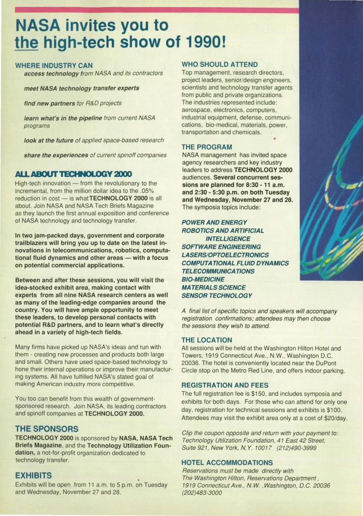
NASA invites you to the high-tech show of 1990! WHERE INDUSTRY CAN
access technology from NASA and its contractors
meet NASA technology transfer experts
find new partners for R&D projects
learn what's in the pipeline from current NASA programs
look at the future of applied space-based research
share the experiences of current spinoff companies
AU.ABOUI'TECHNOLOGY 3lOO High-tech innovation - from the revolutionary to the incremental, from the million dollar idea to the .05% reduction in cost - is whatTECHNOLOGY 2000 is all about. Join NASA and NASA Tech Briefs Magazine as they launch the first annual exposition and conference of NASA technology and technology transfer.
In two jam-packed days, government and corporate trailblazers will bring you up to date on the latest innovations in telecommunications, robotics, computational fluid dynamics and other areas - with a focus on potential commercial applications.
Between and after these sessions, you will visit the idea-stocked exhibit area, making contact with experts from all nine NASA research centers as well as many of the leading-edge companies around the country. You will have ample opportunity to meet these leaders, to develop personal contacts with potential R&D partners, and to learn what's directly ahead in a variety of high-tech fields.
Many firms have picked up NASA's ideas and run with them - creating new processes and products both large and small. Others have used space-based technology to hone their internal operations or improve their manufacturing systems. All have fulfilled NASA's stated goal of making American industry more competitive.
You too can benefit from this wealth of governmentsponsored research. Join NASA, its leading contractors and spinoff companies at TECHNOLOGY 2000.
THE SPONSORS TECHNOLOGY 2000 is sponsored by NASA, NASA Tech Briefs Magazine, and the Technology Utilization Foundation, a not-for-profit organization dedicated to technology transfer.
EXHIBITS . Exhibits will be open from 11 a.m. to 5 p.m. on Tuesday and Wednesday, November 27 and 28.
WHO SHOULD ATTEND Top management, research directors, project leaders, senior/design engineers, scientists and technology transfer agents from public and private organizations. The industries represented include: aerospace, electronics, computers, industrial equipment, defense, communications, bio-medical, materials, power, transportation and chemicals.
THE PROGRAM NASA management has invited space agency researchers and key industry leaders to address TECHNOLOGY 2000 audiences. Several concurrent sessions are planned for 8:30 - 11 a.m. and 2:30 - 5:30 p.m. on both Tuesday and Wednesday, November 27 and 28. The symposia topics include:
POWER AND ENERGY ROBOTICS AND ARTIFICIAL
INTELLIGENCE SOFTWARE ENGINEERING LASERS/OPTOELECTRONICS COMPUTATIONAL FLUID DYNAMICS TELECOMMUNICATIONS BID-MEDICINE MATERIALS SCIENCE SENSOR TECHNOLOGY
A final list of specific topics and speakers will accompany registration confirmations; attendees may then choose the sessions they wish to attend.
THE LOCATION All sessions will be held at the Washington Hilton Hotel and Towers, 1919 Connecticut Ave., NW., Washington D.C. 20036. The hotel is conveniently located near the DuPont Circle stop on the Metro Red Line, and offers indoor parking.
REGISTRATION AND FEES The full registration fee is $150, and includes symposia and exhibits for both days. For those who can attend for only one day, registration for technical sessions and exhibits is $100. Attendees may visit the exhibit area only at a cost of $20/day.
Clip the coupon opposite and return with your payment to: Technology Utilization Foundation, 41 East 42 Street, Suite 921, New York, N. Y. 10017 (212)490-3999
HOTEL ACCOMMODATIONS Reservations must be made directly with The Washington Hilton, Reservations Department , 1919 Connecticut Ave. , N. W. ,Washington, D.C. 20036 (202)483-3000

ec,
The Washington Hilton Washington, D. C.
November 27-28,1990
~------------------------------------------
)ro
rof ue re NO'
1500 tes ne n -epre
rat~ ms
Uege iform: 10-1500 ~
REGISTRATION FORM DEADLINE FOR RECEIPT: November 9, 1990 Please use separate form for each registrant. Type or print clearly.
Name _________________________________ _
Title _______________ Phone ________________ _
Company ______________________________ _
Address
City/State/Zip _________________ _
Which of the following best describes your industry or service? (Check one) A_ Aerospace G_ Government S_ Computers D_ Defense E_ Electronics Q_ lndustrial Eqpt. X_ Communications R_ Research Lab C_ Chemicals Y _ Consumer gds. P _ Power/Energy L_ Library
M_ Materials U_ Education K_ Consultant B_ Bio/Medical T_ Transportation Z_ Other ____ _
Your major responsibility is : (Check one) 1_ Mgt. other than engineering 3_ Engineering 2_ Engineering management 4_ Research
5_ 0ther (specify) _____ _
Your principal job function is: (Check one) 1_ General & Corporate Mgt. 2_ Design & Develop.Eng. 3_ Eng. Svc.-TestslQuality 4_ Basic Research 5_ Manufacturing & Prod'n. 6_ Purchasing & Procurement
a_ Other (specify) _____ _
Your engineering responsibility is: A_ Manage Eng. Dept. B_ Manage a Project Team C_ Manage a Project D_ Member of Project Team
E_ Other (specify) _____ _ REGISTRATION FEES
_ Full registration $150. $ ---_ One day $100.lday (Circle day:Tues. Wed.) $ __ _ _ Exhibits only $20.lday (Circle day:Tues. Wed.) $-__
Total amount due $ __ _
Return with your payment to : TECHNOLOGY U TILIZATION FOUNDATION, 41 East 42 Street, Suite 921 , New York, N.Y. 10017

~ 32·BIt O", Wo<d ~ WOrd A--1 r--WOfdB--1 t- WOlClC-j ~WOrd D
~ 20 Check Bits ~ Word A--j I--Word B --l I--Word C -1 r--w ord D
A A A A A B B B B B C C C C C D D D D D
C C C C C C C C C C C C C C C C C C C C 4 3 2 1 0 4 3 2 1 0 4 3 2 1 0 4 3 2 1 0
t I I I
I I
Figu re 1. Data Bits From Eight 4-Bit -Wide DRAM's are gro uped in to four parallel 8-bi t words to form a 32-bi t wo rd. Each 8-bit data word contains onl y 1 bit from each DRAM .
Figure 2. Check Bits From Five 4-Bit-Wide DRAM's are grouped into four 5-bit words, one for each 8-bit word of Figure 1. Each 5-bit check word contains only 1 bi t from each DRAM .
I: I : 4 4
I 0 [r- . 3 2
I -}b 1
00 ~ I 0 . - 1 0 3 2 1 0
DRAM's configured so that each bit of each DRAM is assigned to a different one of four parallel 8-bit words. Thus, each DRAM contributes only 1 bit to each 8-bit word.
Hamming encoding for single-bit correction/double-bit detection is applied to each 8-bit word. The requisite 8 bit modified Hamming error-correction algorithm can be implemented in each 8-bit word by an Advanced Micro Devices AM2960 (or equivalent) circuit. If an entire 4-bit-wide
DRAM C4
DRAM fails, no more than 1 bit in each 8-bit word Is in error. Thus, the resulting errors are corrected in all fou r eight-bit words, and the memory can still put out correct data. If two entire 4-bit-wide DRAM's fail , then no more than 2 bits in each 8-bit word are in error, and the error {jetecting circuits signal that an error or errors may be present.
The error-correction-and-detection scheme requires 5 check bits for each 8-bit data word, so that a total of 20 check bits is
DRAM co
required. The check bits are stored in five 4-bit-wide DRAM's. Each bit of each such DRAM is assigned to the set of check bits for a different one of the four parallel 8-bit data arrays, in a manner similar to that of the assignment of data bits (see Figure 2). Thus, a total of 13 4-bit-wide DRAM's (eight for data bits and five for check bits) is required.
This work was done by Glenn A. Buskirk of IBM for Johnson Space Center. No further documentation is available. MSC-21566
~J Bar-Code System Tracks Test Equipment Administration of a complicated system is speeded and simplified .
John F Kennedy Space Center, Florida A computer system uses bar codes to
keep track of more than 2,200 items of test eqUipment. The system, called BETUS for Barcode Equipment Tracking and Utilization System, maintains a data base on what items have been borrowed, who is using them and where, and when they have been calibrated. BETUS also keeps records on tools and small electronic components.
Each item holds an aluminum tag containing a unique six-character bar code. Each coded tag represents a record in the BETUS data base: • part number, • serial number, • manufacturer, • description, • date due for calibration, • calibration-cycle time, • malfunctions, • number of times and total number of days
the item has been checked out by technicians,
• number of times and total number of days the item has been in the calibration laboratory, and
• the supply area wherein the item resides or the name of the person who has checked it out.
42
Technicians and engineers who draw equipment from supply areas have their own bar-coded user cards, small enough to fit in wallets or on identification cards. Each card bears a three-digit number that is cross-referenced in the data base to the user's name, mail stop, and telephone number.
BETUS currently includes five terminals (see figure). Asynchronous modems, operating at 9,600 baud, connect the terminals to a host microcomputer. The host software is a multiuser, menu{jriven database-management package.
The Host Microcomp uter serves terminal areas 5 and 6mi (8 and 10km) distant. It also serves a terminal that generates reports and maintains the data base , one that determines the statuses of small parts, and one used to develop software.
Bar-Code
Bar-Code Reader
When a user checks out an item at a supply area, the supply clerk selects the check-in/checkout menu from the main menu and passes a bar -code wand over the equipment tag, the user's card, and the bar code on the checkout menu for the location to which the item will be taken. The information is fed to the data base, with the time of the transaction, as it is entered. When the item is subsequently checked back in, BETUS calculates the time during which it was in use.
BETUS prints daily activity reports that show the number of times equipment has been checked out to technicians or for
Administration (Reports. Data
Base Maintenance)
AreB
Tracki ng of Small Parts
NASA Tech Briefs, June 1990

Get a close look at the big picture.
With the new HI JetPro™ printer/plotter.
Select your drawing. Preview it on your monitor. Zoom in on the tightest detail. Clip it, scale it, mark a "window." Then press a key to get a high-quality hardcopy of the segment you want.
You can do all of this-plus high-speed draft and letter-quality printing-with one machine: the HI JetPro printer/plotter.
The flexible hardcopy control system
Whether it's an E-size drawing or a scanned data file, HI JetPro delivers the flexibility you need and the image you want. With HI's JetPro, you have a complete hardcopy control system that includes hardware and software for high-speed, high-resolution printing and plotting-in both vector and raster environments.
Convenient, quiet, and precise
HI JetPro produces your images on ordinary
paper, in sizes up to 16.5 x 23.3 inches (DIN A2), with the incredibly sharp clarity of 360 dpi. And because it's a bubble-jet, it prints and plots quickly and quietly_
Simple to use and easy to maintain, the HI JetPro printer/plotter is fully backed by Houston Instrument's reputation for price-performance, quality, and support.
To get a closer look, call 1-800-444-3425 or 512-835-0900.
HOUSTON INS I RUMENTM
8500 Cameron Road, Austin, TX 78753

tr--------20Check Bils _
Word A-1 /--- Word B-=1 Won
A A A A A 8 8 8 8 8 'C'C'C c c c c c c c c c c c c c .3:1 1 0
:::; rtIt ·-·-··-·-·- .. -.--~ .... DRAM 7 ~ 3 2 1 0
D ......
Figure 1. Data Bits From Eight 4 B' W' into four parallel 8.bit words to -f It- Id
3e DRAM's are grouped
data word contains only 1 b't f arm a 2-blt word. Each 8-bit I rom each DRAM.
.3:1 1 0 43:1
r
Figure 2. Check Bits From Fiv 4-B' . into four S-bit words, one for :ach '~~::de DRAM'~ are grouped S-blt check Word contains only 1 b 't f' word of FIgure 1. Each
' 34
- - -1 M. l 2 1 0 ' l±. ... . . . I rom each DRAM
DRAM's ~figured SO that each bit of D . . each DRAM IS aSSigned to a different one ~ f~tls, no more than 1 bit in each B-bit of four parallel 8-bit words. Thus, each word IS In erro~ Thus, the resulting errors DRAM contributes only 1 bit to each B-bit a~ corrected In all four eight-bit words word. a the memory can still put out correct
Hamming enCoding for singlei:lit data. If two entIre 4-bit-wide DRAM's fail rection/doublei:lit detection is appli~~r- the~ no more than 2 bits in each B-bit word ~ach B-bit word. The requisite 8 bit mod~ a.re In error, and the error-detecting Circuits fled Ha.mming error-correction algorithm sIgnal that an error or errors may be pre-can be Implemented in each B-bit word b sent. an ~anCed Micro Devices AM2960 ~ Y The erro~-correction-and-detection equIValent) circuit. If an entire 4-bit-Wi~; ~reqUlres5checkbitSforeaChB-bit
ata word, so that a total of 20 check bits is
DR"Me.
W) . ~~ Bar-COde System Tracks Test Eq ·
Ad " . ulpment
required. The check b 4-bit-wide DRAM's. Ec DRAM is aSSigned to 1 for a different one of tl data arrays, in a manr the assignment of date Thus, a total of 13 4-bit~ for data bits and five f( quired,
This work was done j of IBM for Johnson8pl ther documentation Is c
ministration of a complicated system' IS speeded and simplified
John F. Kennedy Space Center, Florida . A computer system uses bar codes to
keep track of more than 2,200 items of test eqUIpment. ~e system, called SETUS for ~rCode EqUIpment Tracking and UtilizatIon ~tem, maintains a data base on ~at items have been borrOWed who is uSIng them and where, and wh~n they have been calibrated. SETUS also keeps records on tOOls and small electronic components.
~echnicians and engineers who draw eqUIpment from supply areas have their OW~ t:>ar~ed user cards, small enou h to fit In wallets or on identification cards. ~ch card bears a three-digit nUmber that IS cr~-referenc~ in the data base to the user s name, mall stop, and telephone number.
S~Us currently includes five terminals (see fIgure). Asynchronous modems ope ating t 9 600 ba ' rt ha ,. lid, connect the terminals
. ~ach ite~ holds an aluminum tag contaIning a unique six-character bar COde
SEa ETCh coded tag represents a record in th~
US data base: • part number, • serial nUmber • manufacturer' • description, ' • date due for calibration • calibration-cycle time ' • malfunctions ' • nU~ber of ti~ and total nUmber of days ~e item has been checked out Of techn'Clans, I
• nU~ber of times ~ total nUmber of days the item has been In the calibration laboratory, and
• the supply area wherein the item resides or the name of the person who has checked it out.
42
a a ?St mIcrocomputer. The host soft-
baware IS a multiuser, menu-driven data
se-management package.
The Host Microcomputer serves terminal areas 5 and 6mi (8 and 10km) distant. It also serves a ter. minal that generates reports and maintains the data base, one that determines the statuses of small parts, and one used to develop software.
Bar.code Reader
Bar.cod. Reader
When a user checks supply area, the supply check-in/checkout men I menu and passes a bar the equipment tag, the USI bar code on the checkc ~ation to which the item ' I~formation is fed to the de tIme of the transaction, ' When the item is subsec back in, SETUS calculate' which it was in use. '
BEWS prints daily act; show the number of times been checked out to tee
AdmInistration (Reports, Data,
sa .. Maintenance)
NASA Tech Bri
calibration. SEWS prints monthly utilization reports based on surveys of selected locations conducted with a portable barcode reader. These reports give information on the items in use and help to find lost equipment.
The users of SEWS have found that they save on equipment purchases because they can allocate resources more efficiently and can recover missing equipment more quickly. They also have found that they have cut check~n and checkout
~J Fast, Capacious Disk Memory Device
time by 00 percent. This work was done by Jacob R. Rogers,
Lesa M. Benton, and Roberta A Perry of Kennedy Space Center. For further information, Orc/e 27 on the TSP Request Card. KSC-11370
Features include high data-transfer rates and fuller utilization of the recording area.
Goddard Space Flight Center, Greenbelt, Maryland A device for recording digital data on,
and playing back the data from, memory disks has a high recording or playback rate and utilizes the available recording area more fully than some older devices do. The underlying concept of the device is applicable to magnetiC or optical disks,
As shown in Figure 1, the device includes two reading/writing heads, one on each of two disks. (Alternatively, two heads on opposite sides of one disk could be used.) The data are recorded in concentric tracks on the disk. The tracks on one disk are numbered starting with track 1 near the outer edge, while the tracks on the outer disk are numbered starting with track 1 at the inner edge of the recording area. The combined lengths of the two tracks designated by the given number is constant, equal to the combined length of two tracks designated by any other number. If the data are recorded on all tracks at the same high density (number of bits per unit length of traCk), then the recording area is utilized fully, and the combined capacity of
every numbered pair of tracks is a constant.
To simplify control and access, the disks are turned at constant speed. This means that the data rate in each reading/writing head is proportional to the radius of its track, and the sum of the data rates in the two heads positioned on any numbered pair of tracks is a constant.
As shown in Figure 2, data to be recorded are first fed into a buffer. A master oscillator and programmable frequency synthesizers generate clock signals at the appropriate data rates, and these clock signals are used to transfer the data from the buffer to the recording circuits at the rates appropriate for the two tracks in use. During readout, data from the two reading circuits are fed into the buffer. With the help of either timing signals interspersed with the data or clock signals from the master oscillator, the buffer reassembles the data from the tracks into an output signal containing the sequence of data recorded previously. Since each numbered pair of
tracks contains the same constant number of bits, the data rate is also a constant.
If the number of tracks on each disk is large, the circuitry necessary to generate the correspondingly large number of recording and playback frequencies can be excessively complicated. In that case, it is more practical to group convenient numbers of adjacent tracks together and use the same data rate on all tracks within each group on a disk, For example, on a pair of disks with 100 tracks each, tracks could be arranged in groups of 10, with a combined data rate of 2.9 Mb/s on each numbered pair of tracks. In this example, tracks 91 through 100 would have a data rate of 1.0 Mbls on disk A and 1.9 Mb/s on disk S. On a disk on which the outermost track has twice the radius of the innermost track, this arrangement yields a data rate 95 percent of the ideal rate and utilizes the recording area at 95.5 percent of the ideal utilization.
This work was done by Ronald M. Muller of Goddard Space Flight Center. For fur-
Readlngl Writing Head A
Figure 2. This Timing, Motor-Drive, Recording, and Playback Circuitry is essential to the operation of the fast , high-capacity disk drive.
Disk A -~I!jiii=====~-
Figure 1. Two Disks, each with its own reading/writing head, are used to record data at the same time. The head on disk A op· erates on one of the tracks numbered from the outside in; the head on disk B operates on the track of the same number in a sequence from the inside out.
44
To Recording Circuit A
From Programmable Frequency Synlhe.lzer A
To RecOrding Circuit B
NASA Tech Briefs, June 1990

ther information, Circle 22 on the TSP Request Card.
This invenuon is owned by NASA, and a
patent application has been filed. Inquiries concerning nonexclusive or exclusive license for its commercial development
should be addressed to the Patent Counsel, Goddard Space Flight Center [see page 25]. Refer to GSG13196
~ Double Differential Encoding and Detection in M PSK It would not be necessary to estimate Doppler shifts.
NASA's Jet Propulsion Laboratory, Pasadena, California
A proposed communication system based on multiple-phase-shif1·keying (MPSK) modulation would include a double differential encoder in the transmitter and a double differential detector in the receiver. The overall effect of the double-
• differential scheme would be to cancel the effect of the Doppler shift on the modulation in the received signal. It would not be necessary to estimate the Doppler shift to correct for it - an important advantage where the Doppler shift is unknCM'T1 or is changing rapidly.
In the transmitter (see Figure 1), the baseband sinusoid s{t) with the original phase modulation +(t) (where t = time) would first be differentially encoded with delay T (where T = one symbol period) to obtain a Signal s 1{t) with phase modulation 81{t) = 81{t - 7) + +<t). This signal would be further differentially encoded with delay 2T to obtain the transmitted baseband signal, which would have phase modulation
8i-t) = 8i-t - 2 T) + 81(t) (see Figure 1).
At the receiver, the incoming baseband signal would be of the form
x{t) = p(t) exp}j[8i-t) + wdt + 1)(t}]} where p(t) = the amplitude of the received signal plus noise, wd = the Doppler shift in angular frequency, and 1)(t) = the phase noise. This signal would first be differentially detected with delay 2Tto obtain x1{t), in which the Doppler component of the phase would be " frozen" at 2wdT (see Figure 2). Signal x 1{t) would then be further differentially detected with delay T to remove the "frozen" Doppler component and recover the original phase modulation +<t). Specifically, the phase of the doubledifferentially detected signal xi-t) would be +<t) + O'1{t), where O'1{t) is the doubledifferential phase noise
1)(t) -I')(t - 2T) -I')(t -;- T) + 1)(t - 3T)
The decision regarding the received phase modulation +(t) would be made in the traditional manner for MPSK. The system would work as described as long as the Doppler component of phase would not vary appreciably during at least 4 T.
The double-differential scheme corrects for a phase error that has a first derivative (only) with respect to time. It could be generalized to a multiple·different ial scheme to correct for the rate of change of the Doppler frequency shift and other higher-order derivatives. In general, the output of the kth differential detector would be free of the first k derivatives of the phase error.
This work was done by D. Divsalar and M. K. Simon of Caltech for NASA's Jet Propulsion Laboratory. For further information, Circle 96 on the TSP Request Card. NPO-17666
Figure 1. The Double Differential Encoder in the transm itter would generate a phase-modulated Signal suitable for decoding and detection by the subsystem ill ustrated in Figure 2. The baseband Signals at three stages of the encoding process are represented in complex-number form .
x,(t) ~ P(t)P~ - 2T)exp u!~n - 92<t - 2T), + 2<.>. T +:'l.t) - ~t - 2T)!}
9,(t) A.,(t)
Differential Dlffetentlal Detec10r r------l
I X hl,-L-~----+-( I • I
S t(t) = exp U9,(t)} sIt) = exp U+tt)}
Differential Encoder Differential Encoder I I I I r------,
----L----;-'~ X I }--___ ......-,,-<-.... s2<t)
I I I
L ______ .J
I I
x2<t) = Pltl'(t - Tl'(t - 2T)P(t - 3T)
I I I I x expU[9,(t)-9,(t- T)+A.,(t)- A'IIt- TlJl
, J l J , L _____ ......J L ______ J +ttl 6'11t)
9,(t) = 9,(t- T)++(~
~t) = ~t-2T)+9,(t)
9~)-92<t-2T)-92<t- T)+~t-3T) = +ttl Figure 2. Double Differential Detector would remove the Doppler-frequency component from a noisy, Doppler-shifted Signal that had been encoded in a subsystem like that shown in Figure 1. The asterisk near each multiplier symbol denotes multiplication by the complex conjugate of one of its input signals .
~~ Programmable Remapper An input image is remapped rapidly and accurately onto a different coordinate grid.
Lyndon 8. Johnson Space Center, Houston, Texas An analog/digital electronic image-proc
essing system is being developed to warp input images onto arbitrary coordinate grids at video rates. In one potential application, the transformation of an image from Cartesian to polar-€xponential or logspiral coordinates would change rotational motions or simple magnifications in the input scene into translations in the output
46
scene, and the translation-invariant properties of the output scene could be utilized by a pattern-recognition robotic-vision subsystem. Other applications include realtime corrections of distortions in the input optics of image sensors, corrections for repeatable nonlinear scanning, and aiding persons of impaired vision by deliberately distorting images onto remaining function-
al portions of their retinas. The figure illustrates the many-to-one
aspect of the transformation performed by the system. First, each picture element of the 1,024- by 1,024-€lement input image is assigned a sequence number. The intensity of each picture element is digitized in sequence to 8 bits. The sequence number is used as an address pointer for two "lookup
NASA Tech Briefs, June 1990

Get a close a t the
big picture.
With the new HI JetPro™ printer Iplotter.
Select your drawing. Preview it on your monitor. Zoom in on the tightest detail. Clip it, scale it, mark a "window." Then press a key to get a high-quality hardcopy of the segment you want.
You can do all of this-plus high-speed draft and letter-quality printing-with one machine: the HI JetPro printer/plotter.
The flexible hardcopy control system
Whether it's an E-size drawing or a scanned data file, HI JetPro delivers the flexibility you need and the image you want. With HI's JetPro, you have a complete hardcopy control system that includes hardware and software for high-speed, high-resolution printing and plotting-in both vector and raster environments.
Convenient, quiet, and precise
HI JetPro produces your images on ordinary
paper, in sizes up to 16.5 x 23.3 inches (DIN A2), with the incredibly sharp clarity of 360 dpi. And because it's a bubble-jet, it prints and plots quickly and quietly.
Simple to use and easy to maintain, the HI JetPro printer/plotter is fully backed by Houston Instrument's reputation for price-performance, quality, and support.
To get a closer look, call 1-800-444-3425 or 512-835-0900.
HOUsrON INS I RUMENrM
8500 Cameron Road, Austin, TX 78753

SPECIFY INCO SPECIALTY POWDERS FOR WIDE RANGE OF
ELECTRONIC APPLICATIONS
Inco Type T 287 Filamentary Powder, particle size (FSSS) 2.6-3.3 microns, apparent density 0.75-0.95 glcc, relative surface resistivity 0.30 ohms per square (0).
Novamet HCA-1 Flake, screen mesh 98% minus 400, apparent density 0.90 glec, thickness 1.0-1.1 microns, surface resistivity 0.25 Q/o.
Inco Specialty Powder Products now has a wide range of nickel and coated powders with exceptional conductive and magnetic properties. These properties make them ideal for a spectrum of electronic applications such as conducting film technology, coatings, adhesives, gaskets and EMI shielding.
EXTENSIVE PRODUCT RANGE The development of computer processed control
coupled with the continuous powder production improvements enables us to meet your most stringent powder specifications for electronic applications.
In addition to the products pictured above, INCO SPP has available the following high performance powder products. Novamet Conductive Nickel Spheres, particle size (FSSS) 8-9 microns, apparent density 3.2-3.5 glcc , surface resistivity 1.0 ohms per square. Novamet 525 Conductive Nickel Pigment, screen mesh 100% minus 400, particle size 3.2 microns, 0.65 BET surface area m2/g, surface resistivity 0.35 ohms per square. Silver Coated Nickel Flake, 15% Ag, 2.6 glcc apparent density, particle size (FSSS) 15 microns, screen mesh 99% minus 200, surface resistivity 0.04 ohms per square.
Magnetic ferrites and surge arrestor applications also
Novamet Silver Coated Nickel Spheres, 15% Ag, 2.5 glcc apparent density, particle size 10 microns, screen mesh 99%-250, surface resistivity 0.03 Q/o.
Novamet Nickel Coated Graphite, 60% fully encapsulated Ni, apparent density 1.6 glcc, particle size (FSSS) 100 microns, screen mesh 63% - 1501+ 250, surface resistivity 0.3 Q/o .
use our specialized range of nickel oxides. High Purity Black Nickel Oxide, 77.2% Ni, BET 75 (m2/g) particle size (FSSS) 5.2 microns, minus 325 mesh 99% plus. Green Nickel Oxide, 78.5% Ni, BET 3 (m 2fg) particle size 1.6 microns, - 325 mesh 100%.
Inco Specialty Powder Products is your unique source for custom fitting high performance powders into electronic applications. Our customer focused, worldwide marketing service group is ready to help you with your current and future needs.
For more information write INCO Specialty Powder Products, Dept. 1-90, Park 80 West-Plaza Two, Saddle Brook, NJ 07662
INca spp Park 80 West-Plaza Two, Saddle Brook, NJ 07662 Shin-Muromachi Building, 4-3 Nihonbashi-Muromachi 2-Chome,
Chuo-ku , Tokyo 103 Japan 1-3 Grosvenor Place, London SW1X7EA England 15/FI Wilson House, 19-27 Wyndham Street Central , Hong Kong
Circle Reader Action No. 452

Address LooI<up Table.
Sequence 1 M Long. Number 16 Bltl Wide
8-BII Pixel Value
Sequence
Weighting· Faclor Lookup
Table. 1 M Long. 16 Bits Wide
Number ..... -----'
18-BIt Weighting
Factor
8-;'
Multiplier
I
Analog Oulput Image
The Many·to-One Processor performs a rapid geometric transformation of a higher·resolution Input image into a lower·resolution output im· age. The numerical values of the transformation are fetched from a "Iookup·table'; memory generated from the equations of the transforma· tion.
tables" contained in programmable ran· dom·access memories: One table con· tains the weighting factor of each picture element for the geometric transformation; the other table contains the address in an accumulator memory that corresponds to the location of the picture element in the 25& by 256-element output image onto which the input picture element is to be mapped.
The result of each weighting multiplication is accumulated at the appropriate address in the accumulator memory along with the results of any previous multiplications from other input picture elements that contribute to the same output picture element. After all the input elements in a frame have been so processed, the 8 most significant bits of each output picture element are dumped to an output memory, and the accumulator memory begins to accumulate the next frame. An output se-
quencer feeds the contents of the output memory to a digital system for further processing or to a digital-to-analog converter for display as the output image.
For simplicity, the figure does not include the subimage processor, which is a subsystem that performs a partly one-tomany mapping. The subimage processor synthesizes picture elements in the input image that lie between the actual elements; this is necessary in regions where the transformed coordinate grid becomes so fine that it requires picture-element spacings smaller than those of the input image. The subimage processor operates on 4- by 4-element patches of the input image, performing a combined interpolation of up to cubic order and remapping via an algorithm distinct from that of the many-toone processor. The many-to-one and subimage processors operate in parallel on each frame of data, and the outputs of both
are processed into one composite image. The principal advantages of the new
system include the antialiasing effect of the many-tex>ne data path and the speed of lookup-table operation. Furthermore, the lookup tables can be reprogrammed easily with the help of a computer that generates the table values from a mathematical description of the desired transformation.
This work was done by Richard D. Juday and Timothy E. Fisher of Johnson Space Center and Jeffrey B. Sampsell of Texas Instruments, Inc. For further information, Circle 136 on the TSP Request Card.
This invention is owned by NASA, and a patent application has been filed. Inquiries concerning nonexclusive or exclusive license for its commercial development should be addressed to the Patent Counsel, Johnson Space Center [see page 25]. Refer to MSC-21350
Simplified Dynamic Control of Redundant Manipulators Extra degrees of freedom are used to perform subtasks.
NASA's Jet Propulsion Laboratory, Pasadena, California A simplified scheme has been proposed
for the dynamic control of a robotic manipulator that has redundant jOints; that is. extra degrees of freedom beyond those needed to perform the task, which is to position and orient the end effector at a specified position and/or move it along a specified trajectory. The extra degrees of freedom can be used to perform a simultaneous subtask (for example, to avoid obstacles or to keep jOint angles within ranges that maximize manipulability). The new control scheme is adaptive and is based on the observed performance of the manipulator. It involves neither a complicated mathematical model of the dynamics of the manipulator nor a time-consuming inverse kinematic transformation.
In a system of n degrees of freedom, the
48
poSition and orientation of the end effector are represented by an m-dimensional coordinate vector Y. while the kinematic functions are represented by the (-dimensional vector +, where r + m = n. The redundancy can be utilized by placing kinematic equality constraints on + to specify the subtask. Then the task and subtask vectors can be combined to obtain X = (P, the augmented n-dimensional vector, which increases the apparent dimension of the task space from m to n. In this formulation, the configuration of the manipulator is fully specified and is not redundant.
The velocities of the manipulator are related via
X(t) = J(8)B(t) where t = time, 8 represents the joint angles, and
is the n x n augmented Jacobian matrix. The m xn submatrix Je(8) is associated with the end effector, while the (X n submatrix Jc(8) is related to the kinematic functions. The two submatrices Je and Jc combine to form the square augmented Jacobian matrixJ.
The problem is to devise a scheme that makes X(t) track the desired trajectory XJ.t) as closely as possible. In the control scheme shown in Figure 1, the actual endeffector coordinates Y(t) and the current values +(t) of the kinematic functions are computed and fed back to the controller. The controller uses this feedback information together with the commanded end-ef-
NASA Tech Briefs, June 1990

MATLABTM High-Performance Numeric Computation and Data Analysis
M ATLAB has rapidly become an industry standard for engineer
ing and scientific research. Its unique interactive interface, algorithmic foundation, easy extensibility, and speed make MA TLAB the software system of choice for high productivity and high creativity research.
P roblems and solutions are expressed just as they are written mathemat
ically - withoutthe needfor traditional programming. As a result, you can solve numerical problems in a fraction of the time required to write a program in Fortran, Basic, or C. Then plot the results as 2-D and 3-D graphics, with publication-quality output to plotters, dot-matrix printers, and laser printers.
"I can create algorithms so easily that it almost seems like cheating."
Amnon Aliphas, Personal Engineering & instrumentation News
N d to MA TLAB your choice of tools for digital signal processing,
system identification, control system design, and more. MATLAB's opensystem design lets you see the algorithms and the implementations, even change them to suit your specific requirements.
MA TLAB is developed by The MathWorks, a leader in software
for data analysis and mathematics. Our users- in thousands of companies and universities-know that MATLAB enables them to work more creatively and productively. Take a look at bow MATLAB can do the same for you.
MATLA8 is a trd.demark orThe MmbWork" Inc. Other product and brnnd names ore lrudemnrks or regish!red tro(lenutrks or their respectiye holders.
• eigenvalues '1-0 and 2-D FFTs • nonlinear optimization • matrix arithmetic • filtering • linear equation solving • matrix decompositions • curve fitting • differential equations • convolution • cubic splines • polynomial arithmetic • spectrum estimation • Bessel functions • descriptive statistics • complex arithmetic • elliptic functions • 2-D and 3-~ graphics
Plus Toolboxes for:
"MATLAB is the undisputed choice for computationintensive engineering work."
Charles Seiter, Macworld
"MATLAB's power and ease of use go a long way toward taking the drudgery out of repetitive analysis projects."
• digital signal processing • control system design Richard Santalesa, J EEE Spec/rum
• parametric modelling • chemometric analysis, and more
Computers supported
PCs and ATs 3S6-based PCs
Macintosh Sun
Apollo H P 9000 /300 DECstation VAX / VMS VAX / Ultrix
Stardent Convex Encore Alliant Cray
and more
To find out more about MATLAB, call us at (508) 653-1415. Or simply return the completed coupon to the address below.
,------------------1 I Name -------------------I Company _________________ __
I Department ________________ _
I I Address -----------------
I City, State ----------------I Zip Country ________ __
I Telephone ________________ _
: Com.puter(s) _________________ _
I The 21 Eliot Street I MATH South Natick, MA 01760
I WOR~ Phone: (508) 653-1415 ~ Fax: (508) 653-2997 L ________________ ~~~
Circle Reader Action No. 503

Desired End-Effector
Motion (Task)
Desired Evolution
of Specified Constraints
(Subtask)
Figure 1. The Control Scheme for the Redundant Manipulator makes the actual manipulator trajectory (1) track the desired trajectory (~) .
Figure 2. The Adaptive Controller implements a model-reference control law. The controller is very simple because the gains (represented by the symbols in the rectangles) are calculated by numerical integration using, for example, the trapezoidal rule. Thus, the time required for the computations is very short.
Joint Torques
T y
Manipulator
•
fector motion Y J..,t) and the desired kinematic functions +a<t) to compute the driving torques T(t) that are applied at the manipulator joints so as to meet the task and subtask requirements simultaneously.
The scheme involves feedforward and feedback paths with adjustable gains, which implement a control law based on the theory of model· reference adaptive control, and is illustrated in Figure 2. The control signal is produced on the basis of the performance of the manipulator, with minimal information on the manipulator and payload. Thus, the scheme can cope with unpredictable gross variations of the payload.
This work was done by Homayoun Seraji of Caltech for NASA's Jet Propulsion Laboratory. For further information, Circ/e 16 on the TSP Request Card. NPO-17593
~~ Compact Analyzer/Controller for Oxygen-Enrichment System This system controls hypersonic air-breathing engine tests.
Langley Research Center, Hampton, Virginia An 02-enrichment system was needed
for NASA Langley Research Center's new 8-ft (2.4-m) High-Temperature Tunnel (8/ HTT), which will be used for testing hypersonic air-breathing engines. To test this system, a compact analyzer/controller has been developed, built, and tested in a small-scale wind tunnel that is a prototype of the 8/ HTT.
The atmosphere in the system is sampled through a specially designed probe and transported to a platinum-coated zirconia cell kept at a temperature of 800 °c. This cell produces a voltage proportional to the difference between the 02 contents of the gases on the two faces of the cell. Air is used as the reference gas.
The sampling probe is cooled, thus cooling the sample gas and necessitating an inline heater to bring the sample back up to 300 to 800 °C to improve the response of the sensor. In addition, a compressor is
50
used to increase the flow of the sample to about 6,000 to 8,000 cm 3/min and to raise simultaneously the pressure of the gas sample. A vent to the atmosphere is provid· ed to ensure that the sample is at atmospheric pressure when it arrives at the face of the cell. This arrangement keeps the pressure constant across the zirconia cell and allows the use of relatively simple equations to calculate the O2 content of the sample gas.
The result of a typical run is shown in the upper right portion of the figure. 'Nhen the wind tunnel is started with air, the continuous-immersion probe displays the 20.95-percent 02 content of air. The accuracy of the readout is about to percent. The sensor reading is updated every 0.2 second, making the system capable of essentially real-time control of the liquid-oxygen valve. The response time of the detector is only about 30 ms, but the total response time of
the system is about 200 ms, achievable with short lengths of the probe-to-detector line.
When combustion is established, the 02 content drops rapidly to 5 percent or less. The system is brought to a stable total pressure and temperature, with typical values of 800 to 2,000 psia (5.5 to 14 MPa absolute) and 3,000 to 3,500 OR (1,700 to 1,000 K), respectively. The system for the addition and control of liquid oxygen is then brought on-line, and the 02 content rapidly rises. The addition of liquid oxygen is controlled manually and then switched to the automatic preset or closed-loop control to bring the 02 content to the desired level of 20.95 percent, simulating air.
The control of the system is remarkably stable, with very little overshoot, thus minimizing the time required before the engine could be inserted in the test medium. To determine fully the stability and controlla-
NASA Tech Briefs, June 1990

One thing NASA and modern medicine
have in common: 5eikosha video printers.
C 1990, Seiko,ha America, Inc., 10 Industrial Ave., Mahwah, NJ 07430
The high-resolution Seikosha VP-3500.
It was Seikosha, a Seiko Group company, that invented the first video printer in 1979.
And it was Seikosha that understood the importance of making a video printer with a line rate high enough for applications ranging from MRI to electron microscopy to industrial QC/QA.
The hard copy images NASA produced on the VP-3500 from geostationary satellite transmissions were used by the last four Space Shuttle crews.
Our 1280-line, multi-format video printer
can make things perfectly clear.
The bottom line for any application is picture quality. And the VP-3500's bottom line is very impressive.
The Seikosha VP-3500 gives you 1280 x 1240 resolution with full 64-tone gray-scale prints from any video source: NTSC, PAL, SECAM and RS-170. Plus you can choose multi-format prints.
Let us introduce you to the video printer with the resolution good enough for modern medicine and NASA.
For a demonstration, or additional information on the Seikosha VP-3500, call 1 800-338-2609 or 1 201-327-7227.
SEIKOSHA A SEIKO GROUP COMPANY
Serious printers for serious business. Circle Reader Action No. 462

bility of the system, preset values of 02 content greater and less than that of air were tried with equally good results and without any abnormality in the control.
The prototype system has been thoroughly tested and will serve as the basis for a similar system for use in the full-scale 8' HTT. For the full-scale system, control will be managed by a high-speed computer and control system with all of the logiC and controls emanating from the computer, except for an emergency manual override. The incorporation of an automatic oxygen control in the 8' HTI will ensure meaningful ground tests of hypersonic engines in the range of speeds from mach 4 to mach 7.
This work was done by Richard L Puster, Jag J. Singh, and Danny R. Sprinkle of Langley Research Center. Further information may be found in:
NASA TP-2218 [N84-11400J. "Proposed Fast Response Oxygen Monitoring and Control System for Langley B-Foot High Temperature Tunnel," NASA TP-2531 [N86-20753]. "New
Method for Determining Heats of Combustion of Gaseous Hydrocarbons," and
NASA TP-2682 [N87-20514J. "A Simp/ified Method for Determining Heat of Com-
ENOINE TEST IN WINO loft KTT
OUtlet
TEST OF 02 ANAL Y2ER IN 7-In. HTT
25
'" 0,5
J 10
Air
Interval. 0' Automatic ConltOt at Pruet lAveI,
Combustion Product,
CIt SENSOR READING
• Compactness - 2 In. 3 • Real TIme - 0.2 .. Update • Enhanced Productlvtty and
A exlblilty of Facility
BENEFITS
TIme
The Compact Analyzer/Controller monitors the level of oxygen and controls the ad dition of liquid oxygen to enrich the atmosphere for combustion .
bustion of Natural Gas." Copies may be purchased [prepayment
required] from the National Technical Information Service, Springfield, Virginia
22161, Telephone No. (703) 487-4650. Rush orders may be placed for an extra fee by calling (BOO) 336-4700. LAR-14016
Numerical Algorithms Group
52
NAG Fortran Library products enable you to spend your time and talents on genuine problem solving, not software development. 200 experts, recognized worldwide as the leaders in their fields, create the solutions in the NAG Library_ The accuracy, perfor. mance, and total capabilities of NAG software are unmatched in the industry_ Take advantage of NAG's expertise in any of these fine products:
NAG FORTRAN LmRARY
More than 700 user-level routines covering the principal areas of mathematics and statistics. Available on over 90 different computers from PC's to supercomputers.
NAG GRAPHICAL SUPPLEMENT
A convenient and versatile means for displaying numerical results generated by the Library. A facility not available with other libraries.
NAG ONLINE SUPPLEMENT
An interactive query system enabling the user to make maximum use of the NAG Library. The Online system provides hints on choice of routines, syntax assistance, and other forms of help.
An interactive CASE tool for vecrorizing and paralle1izing Fortran programs. Attain performance improvements beyond what optimizing compilers may provide. Ideal for "rejuvenating" older applications.
NAG Ada Library
The first commercially available math library designed and written completely in Ada. Shortens !be development cycle for embedded math operations in Ada programs.
GENSTAT and GUM
Interactive statistical analysis systems used for data exploration, linear modelling, time series analysis ... usefuJ applications in statistical quality control and product survival analysis.
THE NAG PRODUCT LINE OFFERS NUMERICAL AND GRAPInCAL ALGORITHMS FOR MANY SCIENTIFIC AND ENGINEERING
APPLICATIONS INCLUDING:
• SIGNAL PROCESSING • COMPUTATIONAL CHEMISTRY • OPERATIONS RESEARCH • ECONOMETRIC MODELS • APPLICATIONS DEVELOPMENT • STATISTICAL ANALYSIS
NUMERICAL ALGORITHMS GROUP 1400 Opus Place, Suite 200 Downers Grove, IL 60515·5702 (708) 971-2337 FAX : (708) 971 ·2706
Circle Re.der Action No. 377 NASA Tech Briefs, June 1990

Environmentally formula ted a nd technica lly designed for improved remova l of microscopic d ust. Miller-Stephenson's new CFC-Free Aero-Duster® is exce llent for:
• Micro-Minia ture Assemblies · Electro-mechanical Instruments • Magnetic Ta pe a nd Heads • Timing Devices · Servomecha nisms • Rotating Instruments • Op tics • Photographic Equipment
For sa mple fill out coupon below or ca ll (203) 743-4447. For technica l service ca ll 1-800-992-2424 (8-4 Ea stern Time). In Canad a call 1-800-323-4621 (8-4 Eastern Time).
;- - - - - - - - COMPlElECouP6NiiEi6W - - - - - - -l I Mail to: I .~. miller-stephenson chemical co., inc. I g Georg e Washing ton Highway I Da nbury, Connecticut 06810 U.S.A.
I I D Plea se send free sample of new MS-222
CFC-Free Aero-Duster®
NAME __________________________ __
I I I I I -9- DEPT./TITLE ----------- :
_ _ miller-stephenson chemical co., inc_ COMPANY I I
CANADA ADDRESS I CALIFORNIA IlliNOIS CONNECTICUT 514 Carling view Dr I ;e Rexda le. Ontario M9W 5R3 I ~
12261 Foothill Blvd 6348 Oakton SI GeorgeWashlnglon Hwy. Sylmar. Col. 91342 Morton Grove. III 60053 Danbury. Conn. 06810 818896·4714 708966-2022 203743-4447
Circle Reader Action No_ 583 416675·3204 L __________________ ~3~1~O _ -I
Books and Reports These reports, studies, handbooks are available from NASA as Technical Support Packages (TSP's) when a Request Card number is Cited; otherwise they are available from the National Technical Information Service.
Robust Adaptive Control in Hilbert Space
This analysis is particularly relevant to the control of large, flexible structures.
A paper discusses the generalization of a scheme for the adaptive control of a finite-dimensional system to an infinite-dimensional Hilbert space. This is an important topic because all physical systems are distributed, and therefore, complete representations would require, in principle, infinite numbers of degrees of freedom. These considerations are particularly relevant to systems for the active control (e.g., the suppression of vibrations) of large, flexible structures.
The goal of this study is to find a methodology for the design of model-reference adaptive controls for systems of both finite and infinite numbers of dimensions, of both single-inputlsingle-output and multiple-input/multiple-output, and in which the
NASA Tech Briefs, June 1990
orders of the plants to be controlled are unknown. The approach involves a generalization of the command-generator tracker (001) theory. The appeal of this method is that it does not require the reference model to be of the same order as that of the plant, and the knowledge of order of the plant is not needed. In fact, state space may even have an infinite number of dimensions. However, alternative assumptions are needed to ensure closed-loop stability.
This method is naturally suitable for application to high-order systems inasmuch as its main emphasis is on the adjustment of a low-orderfeedback-gain matrix. The disadvantage is that instead of the dimensionality requirement, there are other conditions to be satisfied. While the generalization of the CGT technique to the infinite-dimensional systems is not straightforward, it is very promising. The three principal obstacles to the generalization are the following: (1) the solution of the Lyapunov equation may not be coercive, (2) the invariance principle cannot be applied immediately, and (3) strict positive realness is never attainable without positive feedthrough.
A previous modification of the adaptive control law of the finite-dimensional controller partially overcame these obstacles. In exchange, only the Lagrange stability of the error signal has been shown. This paper suggests a further modification, in
which the error signal is shown to be driven to a residue set asymptotically.
It is shown that if there exists an output feedback in the further-modified controller such that the closed-loop system is close to positive realness On the sense that there exists a small fictitious feedforward that makes the closed-loop system positive real), then Lagrange stability is assured. This is an improvement in that stability is achieved in the original space and asymptotic stability is maintained for the finitedimensional case O.e. , the modification is a true generalization and the performance in the finite-dimensional case is not compromised). As an additional bonus, Lagrange stability is preserved under a variety of perturbations; e.g., singular and regular perturbations, bounded state and output noises, and the perturbation of the modelmatching condition (the OOT condition).
The example of a simple damped beam is presented to illustrate the techniques. The nominal , the sensor-actuator-mis· aligned, and the noise-disturbance cases are simulated to show that behavior of the closed-loop system agrees with the theory.
This work was done by John ring-Yung Wen of Caftech and Mark J. Balas of the University of Colorado for NASA's Jet Pr0-pulsion Laboratory. To obtain a copy of the re{X)rt, "Robust Adaptive Control in Hilbert ~ce," Circle 00 on the TSP Request Card. NPQ-17588
53

Selecting Modulation Indices for Telemetry and Ranging
optimum dMsion of power among the data, ranging, and carrier channels and reduces the degradation of performance by undesired interferences among signals.
The effects that one seeks to minimize are due mainly to the feedthrough of various modulation, intermodulation, crossmodulation, and noise components. The algorithm calculates the magnitudes of these effects and searches for the modulation indices for which (a) the radio-frequency-carrier demodulator does not degrade the threshold value of the signal-power-tcr noiS&density ratio (SNR) of the data channel, (b) the data channel achieves a desired performance in the presence of the ranging signal, (c) a specified ranging accuracy
Undesired signals are suppressed and power is divided optimally among channels.
A report describes an algorithm for the selection of optimum modulation indices in a system for communication between a ground station and a spacecraft, in which the ranging channel is operated simultaneously with the data (command and telemetry) channel . The algorithm provides for the
• SYNCHRONIZE PROCESSORS
54
• TIME TAG DATA
BUS LEVEL TIME CODE PRODUCTS PC XT/AT
" .' ; f f I " : ,':i- ~ '(".' 1. •
,,' ., ••
f
" .~I ,:n, "'i:;" w ." ,
f' ,',' . .. ' .. ~::,-_ ..... #
SI,INIIIJIIUlJII •• I ••• m.1
PC03XT Time Code Reader
IMMEDIATE SOLUTIONS TO YOUR TIMING PROBLEMS
Our off-the-shelf VMEbus and PC XT/AT bus level time code translators and generators are a convenient, accurate means of synchron izing data processing systems to each other or to standard time of day satellite transmissions.
VME bus
A time code generator or satellite receiver supplies Time of Day (TOO) and synchronization data via a
PC03VTime single coaxial cable connecting all processors. Inside Code Processor each processor, one of our time code 'readers' decodes the time code signal and supplies TOO across the bus. One millisecond accuracy is commonly achieved. One microsecond is achieved with proper choice of time receiver and code type.
IMMEDIATE DATA SHEETS-
Call or fax a request to us for any of these FAX SPECs: PC XT/AT:
PC03XT Time Code Reader PC05XT Time Code
Generator VMEbus:
PC03V Time Code Processor PC26V Time Display
Other: MSOD-LU Time Display Synchronization App. Note Model 9390 GPS Satellite Receiver
BANCOMM OIVISION OF OATUM. INC 6541 V ,a del Oro. San ..Jose. CA 95119
CALL: (4091 579-4 1 61 FAX: (4091 579-4165
Circle Reader Action No. 658
can be achieved, and (d) the useful power in the first-<lrder sidebands of both data and ranging channels is as large as possible while still consistent with constraints (a), (b), ard (c).
The algorithm consists of the following steps:
1. QjJculate the threshold requirements. 2. Using the results from step 1, calculate
the ratio of the SNR's of the data and carrier channels and the ratio of SNR's of the data and ranging channels.
3. ~ify the desired degradation Ad.d8) in the data channel due to interference from the ranging channel, the required bit-error rate, ard the required SNR; and calculate the maximum ranging power level P,(d8) that falls in the data channel.
4. Calculate the ranging suppression, AS' relative to the data channel for the specified AD'
5. Using the result from step 4, calculate the design factor k, which depends on (among other things) the SNR's of the ranging and data channels.
6. Using the value of k from step 5, determine whether too much power is being allocated to the data or to the ranging channel for the specified degradation AD'
7. For a particular modulation scheme, develop the expressions for the power in each channel as a function of the modulation indices.
S. Using the relation found in step 7, plot the ranging modulation index as a function of the data modulation index. A spec~ic set of modJlation indices can OON be ootained.
9. Rrd the ratios of first-<lrder data-sidebard and first-<lrder ranging-sidebard pcMIer to total power corresponding to the particular set of modulation indices; plot these power ratios as a function of the data modulations in the same plot described in step 8.
10. Bound the values of the modulation indices of the data ard ranging channels, d:>serving that these modulation irdices are mutually dependent subject to the requirement that the carrier threshold be equal to or lower than the data threshold.
11. Select the set of modJlation indices for the data and ranging channels that correspond to the largest values of the curves of step 9 that satisfy the specified degradation AD' constraining these values to within the boundary set established in step 10.
This 'MJrk was done by T/efl M. Nguyen of Caltech for NASA's Jet Propulsion laboratory. To obtain a copy of the report, "Technique To Select the Optimum Modulation Indices for Suppression of Undesired Signals for Simultaneous Range and Data Operations," Circle 152 on the TSP Re-quest Card. NPO-17535
NASA Tech Briefs, June 1990

The final
step is
clean room
packaging.
ACLAR: Packaging for all
the ins and outs of clean rooms.
Makers of advanced electronics, aerospace and medical technology demand that components arrive as clean as they left your clean room. Good reason to pack in ACLAR' fluoropolymer film.
ACLAR® can be cleaned, is physically and chemically stable and biochemically inert. It meets NASA's requirements for compatibility with LOX and other hypergols, plus their low outgassing requirements for deep space use. ACLAW won't support combustion and can be made static dissipative for sensitive electronic and satellite applications.
Take the final step in protection, pack in ACLAR ' film. For more information, and our latest literature, contact Allied-Signal Engineered Plastics, P.O. Box 2332R, Morristown, NJ 07960. Phone (201) 455-5010 or FAX (201) 455-3507.
ACLAR: A confidence level above the rest.
EngineeredP/astics 411ied
Signal Clrcl. R •• d., Action No. 101

PhYSiCal Sciences Hardware, Techniques, and Processes
60 F •• t Quenching for Hydrogen-Embrlttlement Test.
62 M.trlx-Vector Multlpllc.tlon In Thin Photorefr.ctlve Cryst.1 56 Compound. Gener.te
Optlc.1 Second H.rmonlcs 56 Determining Pol.rltle. of
Dlst.nt Ughtnlng Stroke. 58 CompKt Sun.h.de for
Telescope Antenn.
60 Me •• urlng Concentr.tlon of Ozone Autom.tlc.lly
61 Photochemlul Degr.detlon of Org.nlcSolvent Fume.
Books and Reports 63 N.no-G L8bor.tory 63 C.llbr.tlon of Airborn
VI.lbleflR Im.glng Spectrometer
... ~ Compounds Generate Optical Second Harmonics Large second-order nonlinear susceptibilities are observed.
NASA's Jet Propulsion Laboratory, Pasadena, California Newly synthesized organic salts have
been found to generate relatively large second·harmonic signals when illuminated by fundamental signals in the near-infrared spectrum. These and other compounds that have large nonlinear optical properties may eventually find use in electro-optical modulators, switches, and signal-processing equipment.
The new organic salts have the general formula R(CH = CH)n - (p - C5H4N -CH~ + X - , where R can be one of a variety of organic electron{jooor moieties; n = 1, 2, or 3; and X can be, for example, a - , CF~j", BFi, PF6", p-CH3 -C6H4SOj", CH 3S04- , or HSOi. These compounds were "designed" to have molecular structures that enhance second-order nonlinear electric susceptibilities. They are made by crystallizing, with appropriate counterions, organiC ions that have large molecular hyperpolarizibilities. By selection of the species of counterions, one can strongly affect the packing of molecules and the structures of crystals of these molecules. The species of counterions that yield structures favorable to second-order nonlinear susceptibilities can be found by experimentation.
The figure illustrates the experimental synthesis of one of the new salts. The two main ingredients shown at the top of the figure were reacted in methanol in the presence of piperidine at a temperature of 60 °C for 4 hours. The product was filtered
r-----------------------------------------,
SQj"
The Organic Salt synthesized by this process has the highest second-harmonic-generating efficiency of any compound tested thus far.
and precipitated with diethyt ether to obtain a 6O-percent yield of the salt, shown at the bottom.
The visible-absorption spectrum of this salt includes a charge-transfer band, the middle wavelength of which is sensitive to solvents. When the salt is dissolved in acetonitrile, this band lies at 468 nm; in methanol , it lies at 474 nm. When illuminated with 1.907-nm light (produced by Raman shifting, in hydrogen, the 1.064-J.d11 light of a neodymium:yttrium aluminum garnet laser), a powder of this salt exhibited
a second-harmonic~enerating efficiency 1()()()-2ClOO times that of a urea reference standard.
This work was done by Seth R. Marder and Joseph W. Perry of Caltech for NASA's Jet Propulsion Laboratory. For further information, Circle 58 on the TSP Request Card.
Inquiries concerning rights for the commercial use of this invention should be addressed to the Patent Counsel, NASA Resident Office-JPL [see page 25J. Refer to NPO-17731
Determining Polarities of Distant Lightning Strokes Two features of the signal from each stroke appear to be correlated.
M hI/ S Fl· ht C t AI b charge lowered to ground. The polarity is ars a pace Ig en er, a ama determined from the polarity of the initial
A method for determining the polarities ning networks can reliably determine the deflection in the very-low-frequency (up to of lightning strokes more than 400 km polarities of only those return strokes that 30 kHz) waveform of the electric and/or away is the subject of continuing research . occur within about 500 km of the receiving magnetic field radiated by the stroke. There is a growing awareness among sci- stations. When a receiving station is more than entists investigating lightning that the po- The return stroke is the main stroke, the about 500 km away from a lightning stroke, larities of return strokes may be important intensely luminous streamer that propa- the determination of polarity by the con-indicators of phenomena in thunderstorms gates upward from the ground in the last ventional method is subject to uncertainty and that the predominance of positive phase of each stroke of cloud-t~round because the signal includes a strongly at-strokes in winter thunderstorms may be lightning. The polarity of the return stroke is tenuated ground wave that mayor may not particularly significant. At present, light- defined as the polarity of the electric be detected and a much stronger wave of
56 NASA Tech Briefs, June 1990

The Standard for Circuit Simulation
HasExpanded
Fllter'Designer Bode Plot
Filter Designer: New Front End
Design Tool
Filter Designer, a member of the PSpice family, is an interactive design aid giving you the ability to design and analyze active filters. Features include a menu-driven interface, hard copy report summaries and plots, cascading multiple designs, and interfaces to PSpice and SWITCAP. Filter Designer uses a well e tablished methodology in applying clas ical approximations to your filter specification. Available filter types include low pass, high pass, band pa s, and band reject, all of which may be synthe ized by Butterworth , Chebyshev, Inverse Chebyshev, and Elliptic (Cauer) functions.
A full editing capability alJows you to insert, delete, and reorder stages, and modify coefficient values . The e editing features allow a filter expert to fme tune a design, or quickly make a small modification to an existing design.
Filter De igner supports both active RC and switched capacitor biquad filter structures. The components may be scaled or resized to center the values in preferred ranges.
Both Bode and pole-zero plots are available . Normally, you can determine the acceptability of your design by the inspection of it Bode plot. The Filter Designer plots gain, pha e, and delay vs . frequency . For sampled data designs, you can plot your choice of the s- or z-domain transfer function. Pole-zero plots allow you to inspect the foot of the tran fer function in either the -domain or z-domain.
Filter Designer work with our PSpice circuit imulation package. PSpice and it option form an
integrated package for the analy is of electronic and electrical circuits . The software enables you to create a "computer breadboard" of your circuit for te ting and refinement without building hardware.
Each copy of PSpice and Filter Designer comes with OUf exten ive product support. OUf technical staff has over 150 years of experience in CAD/CAE, and our oftware is supported by the engineers who wrote it. Since its introduction over six years ago, PSpice has old more copie than all other SPICE program combined.
For further information about Filter De igner or any other PSpice product, plea e call us at (714) 770-3022 or toll free (800) 245-3022.
20 Fairbanks · Irvine, CA 92718 SA · FAX (714) 455-0554

reverse polarity reflected from the ionosphere.
The very-low-frequency waveform includes a slow tail that is a lem-frequency dispersion effect in the zeroth mode of the waveguide formed by the ground and the ionosphere. Probably not all cloud-toground lightning produces a slow tail in the waveform. Hemever, there is some evidence that a slow tail indicates continuing current in the cloud-to-ground lightning flash. This continuing current is primarily responsible for lightning-caused forest fires and other lightning-related damage.
The new method is based on the fact that for each stroke observed thus far for which the polarity can be determined unambiguously, the initial polarity of the tail is the same as the polarity of the initial deflection before the initial<leflection signal is altered by propagation effects (see figure). In the new method, the receiving station is equipped with an electric-field-change antenna coupled to a charge amplifier that has a time constant of the order of 1 to 10 seconds. The output of the amplifier is fed to signal-processing circuitry, which determines the initial polarity of the tail.
This work was done by Richard J. Blakeslee of Marshall Space Aight Cen· ter and Marx Brook of New Mexico Tech. For further information, Circle 111 on the TSP Request Card.
Inquiries concerning rights for the commercial use of this invention should be addressed to the Patent Counsel, Marshall Space Flight Center [see page 25J. Refer to MFS-26102
Positive Inltlal___....
Deflection
Negative ~ Inltlal-----Deflection
Negative Initial Part of
Slow Tall
These E1ectrlc·Fleld Signals were received at Albany, NY from distant lightning strokes. The upper trace is from a stroke 895 km away at a bearing of 239° ; the lower trace is from a stroke 2054 km away at a bearing of 212°. In each case, the initial polarity of the slow tail is the same as the polarity of the initial deflection.
~J Compact Sunshade for Telescope Antenna An optical receiver could detect sources apparently close to the Sun.
NASA's Jet Propulsion Laboratory, Pasadena, California A proposed built·in sunshade would en
able a large-aperture reflecting telescope to view a laser transmitter apparently close to the &m, without adding excessive size or mass to the telescope. With the sunshade, a telescope would be able to discern signals from sources only 12° from the line of sight to the Sun.
The conceptual sunshade consists of a closely spaced set of hexagonal tubes (see figure). The tubes are positioned in front of the primary reflector of the telescope and are aligned with their axes parallel to the line of sight of the telescope. The hexagonal walls of the tubes correspond to the edges of the hexagonal segments of the primary reflector so that the walls do not obstruct the aperture appreciably.
The tubes extend downward temard the primary reflector, ending at the envelope of the focused beam of light from the primary to the secondary reflector. The outer ends of the tubes are trimmed so that they fit within a sphere, the diameter of which is 58
CUTAWAY VIEW OF OBSERVATORY, SHOWING SUNSHADE
PrlmOlY Rellector
Ught From Source In View Sunlight Stopped
1 / by the Sun,hld.
+-+--+ ...... 12-
, ///~ I .,,-' Spher.ol ~-- Rot.llon
r 'Swlng Sphere', of Telescope
CROSS SECnON SHOWING opnCAL SCHEME OF TELESCOPE
The Telescope Would Look through the sunshade from beh ind and below it. The tops of the heAagonal tubes would be trimmed to a spherical shape corresponding to the sphere of rotation of the telescope. The sunshade could support the secondary reflector.
NASA Tech Briefs, June 1990

beamforming, neural nerworking, peech recognition, synthetic aper
ture radar -and it'll handle the problem with speed and ease.
The DSP3 delivers 1 gigaflop per cubic foot of active area (up to 3.2 gigaflop in a single array). With an advanced package that gives you 800 megaflops in only 9 cubic inches.
Speed? 40 megabytes/second on each of four channels for an aggregate bandwidth of up to 160 megabytes/second.
Capacity is al 0 maximized. Using a
25 megaflop processing engine, the o P3 can handle multi-gigaflop computationalloads in a nerwork configu
ration of over 100 proces ors. The
powerful processing with the density you need, look to the AT&T DSP3. It can cut your algorithm problems down to size. For more information,
DSP3 also gives you extreme flexibility: it can be populated with one to
We've got solutions do\vn to a science.
call your AT&T Federal Systems Account
eight boards, each with 16 processing nodes, providing 400 megaflops of power and four megabytes of memory.
AT&T's DSP3 gives you access to high-level language software such as a C compiler and a wide library of signal processing subroutines. And it leads the industry in price per megaflop. Plus, of course, you get the unparalleled support and service of AT&T Bell Laboratorie and AT&T Field Applications Engineers.
So, for realtime parallel processing,
Executive, or 1800 553-8805. (N.C. residents, call collect: 919697-9580.) "Developed In Jl2rt undera Q\RIl\sponsore<l 00= .
AT&T The right choice. Circle Reader Action No. 665

only 20 percent greater than the diameter of the primary reflector.
In contrast, a conventional sunshade like a visor would be mounted outside the teIescqJe. To enable a teIescqJe 10 m in diameter to view a signal source within 12° of the Sun, a conventional sunshade would have to be 47 m Ioog. A telescq:le equiJ::ped with so long a sunshade would be unwieldy indeed, requiring a large, expensive ob-
servatory dome. The hexagonal sunshade structure would
be strong enough to support the secondary reflector. A separate support for the secondary reflector would not be necessary, and the mass and inertia of the telescope would thus be reduced further.
So that the telescope could track sources within even smaller angles of the line of sight to the Sun, the sunshade could
be equipped with internal vanes running the lengths of the tubes. The telescope could then receive signals from sources within 6° or even 3° of the apparent position of the Sun.
This work was done by E. L Kerr of Caltech for NASA's Jet Propulsion laboratory. For further information, Orele 131 on the TSP Request Card. NPO-17674
!J Fast Quenching for Hydrogen-Embrittlement Tests Hot specimens are cooled rapidly in high-pressure hydrogen.
Marshall Space Flight Center, Alabama An apparatus exposes hot metal speci
mens in hydrogen atmospheres to sudden cooling. The apparatus was developed to evaluate the susceptibilities of the specimens to embrittlement by hydrogen. The apparatus cools specimens by 1,050 OF (500 0c) in 160 s.
A specimen is enclosed in a cylindrical stainless-steel vessel pressurized with hydrogen. A resistance heater encircles the
HEATER SURROUNDS VESSEL
vessel and maintains it at 1,200 OF (650 OC). At the push of a button, the heater drops away from the vessel, sliding to a stop along a stainless-steel track (see figure).
As the heater falls, a spray bar is released from overhead. The bar falls into p0-sition around the vessel, triggering a microswitch that turns on a water supply at a pressure of 150 Ib/in.2 (1 MPa). Issuing from the spray bar, the spray engulfs the
HEATER FALLS AWAY AND SPRAY BAR BEGINS
TO DESCEND
vessel and chills its contents, trapping the absorbed hydrogen in the specimen.
This work was done by Mark J. Petri, Richard L Burkhart, and Joseph F. Koneel of Rockwell International Corp. for Marshall Space Right Center. For further information, Orcle 103 on the TSP Request Card. MFS-29549
VESSEL IS SPRAYED WITH COLD WATER
The Heater Surrounds the Pressure Vessel Initially. On command, the heater slides downward on the track, exposing the vessel. A spray bar falls over the vessel and directs high-pressure jets of cold water at It.
~J Measuring Concentration of Ozone Automatically An airborne photometer measures absorption of ultraviolet.
Ames Research Center, Moffett Field, California A photometer automatically measures
ozone concentrations in the atmosphere to an accuracy within 10 parts per billion. The compact, lightweight, low-power instrument was developed for use on a high-alti-60
tude research airplane. The instrument shines ultraviolet light at
a wavelength of 253.7 nm from a mercury lamp through a sample of air in a chamber (see figure). The light impinges on a vacu-
um phototube (the sample detector), the electrical output of which decreases with increasing concentration of ozone and the consequent increases in absorption of the ultraviolet light in the sample. An electrometer circuit processes the output of the phototube.
Air flO'vVs into the instrument from a NASA Tech Briefs, June 1990

probe on the outside of the airplane. An inlet valve admits the air once the airplane has attained an altitude of 1,500 m, where there is little chance of ingestion of airborne debris. A transfer valve switches the airflow alternately between the measurement chamber and a scrubber chamber in which manganese dioxide removes ozone from the air. Scrubbed and ozone-laden samples thus enter the chamber alternately. The instrument uses the scrubbed samples to compensate for variations in constituents other than ozone.
A beam splitter diverts parts of the ultraviolet beam as it leaves the mercury lamp. A second vacuum phototube (the reference detector) measures the diverted beam, which does not pass through the sample chamber. The output of this phototube is used to compensate for variations in the intensity of light emitted by the lamp. Both phototubes are "solar blind" devices. They do not respond to visible radiation, but only to a narrow wavelength band between 160 and 320 nm. There is therefore no need for extensive filtering of external light.
A microprocessor controls timing and the acquisition of data. A random-access memory backed by a battery stores data on the transmission of ultraviolet through the samples, on temperature, on pressure, and on navigation of the airplane. An experiment can last as long as 8 hours. When the airplane lands, the data are transferred to a portable computer.
A single{)oard computer in the instrument simultaneously calculates the concentration of ozone in real time (but with less resolution). This value is displayed on
Fllter~
~:I
Measurement
/Chamber
To Electronics
Mercury Ultraviolet
Lamp
Ozone Scrubber
Beam t Splitter
~-~
t
Inlet
Temperature Sensor
From Electronics I I
To Data I System ~
Exhaust
Isolation Valve
Air Collected Outside the airplane enters the photometer by way of the transfer valve. The pressure and temperature of the air are measured simultaneously with the transmissivity of the air to ultraviolet light from the lamp. The Instrument has a mass of 20.5 kg and fits in an aluminum box measuring 78 by 58 by 25 cm.
an analog meter in the cockpit to guide the pilot in seeking regions of various concentrations of ozone.
This work was done by Joseph R. Lavelle of Ames Research Center. Further information may be found in NASA TM-100064 [N88-21404]. "An Automated Ozone Photometer."
Copies may be purchased [prepayment required] from the National Technical Information Service, Springfield, Virginia 22161, Telephone No. (703) 487-4650. Rush orders may be placed for an extra fee by calling (BOO) 336-4700. ARC-12230
~ Photochemical Degradation of Organic-Solvent Fumes The quality of air would be enhanced.
Marshall Space Flight Center, Alabama
ceptable in degraded form, then no further processing would be needed. Mernatively, the degraded fumes could be removed by
fore, there has been no economical way to conventional scrubbing. The qJality of air in a iaOOratory or industrial ventilation airstream 'MX.J1d be enhanced by a proposed technique. It is desirable to remove the residual fumes of organic solvents from such airstreams, both to protect workers and to prevent the discharge of the fumes to the environment. Hereto-
do this. This work was done by James J. .According to the proposal, a source of ul- Herzstock of Rockwell International Corp.
traviolet light would be placed in the air- for Marshall Space Flight Center. No fur-stream (see figure) to degrade the fumes ther documentation is available. photochemically. If trhe:::.....:.fu::.:m.:..:.:::es::......:..:w~e~re::...=.ac=--_--.:.;M:.:.:F~S::..;-2~9::::596= _________ --,
Mirror Closed Tube (PoSSibly
With Mirrored Sides)
Exhauot Flow Containing Oagraded
Contaminants. (02. N2. H;20. C~. Chlorides. and Fluorides)
o Parabololdsl Reflector
Optional Injection WindoW of Reactant
Source of Hlgh·Energy Ultraviolet Radiation
Contamlnaled Airflow (02. N2. Chlorofluorocarbons and/
or Olher SOlvento)
DETAIL OF EXHAUST DUCT EQUIPPED FOR PHOTOCHEMICAL DEGRADATION OF SOLVENT
Ultraviolet Light would be projected along the exhaust duct to degrade toxic fumes photochemically.
NASA Tech Briefs, June 1990
Crane
61

Matrix ·Vector Multiplication in Thin Photorefractive Crystal A thin GaAs device could be integrated with other electronic and optoelectronic devices.
NASA's Jet Propulsion Laboratory, Pasadena, California Experiments have shcmn that matrix.
vector multiplication can be performed 0ptically by four-wave mixing in a thin crystal of GaAs. The concept is also applicable to thin crystals of other photorefractive materials that have suitable electro-optical properties and the same crystalline symmetry as that of GaAs.
Optical matrix.vector multiplication had been demonstrated previously in a bulk crystal of BaTt0s. HO'Never, photorefractive oxides like BaTt0s operate at visible wavelengths that are incompatible with
Y1Beam1 (Vertically Polarized)
Polarizing Beam
Splitter
B = MA
semiconductor injection lasers, are unsuitable for fast operation at high speed and Iov-I poNer in compact systems, and cannot be integrated with existing electronic and optoelectronic devices. Thin crystals of GaAs do not have these disadvantages and, therefore, are suitable for the development of compact, fast, concurrent processing of imagery and other data.
The multiplication of a three-cornponent vector by a 3-by-3 matrix is illustrated in Figure 1. Ught from a suitable laser (e.g., a wavelength of 1.06 I4T1 from an yttrium alu-
3
Malrlx M
A~.-F-~:::""--l
Thin. Photorefractive Crystal (e.g., GaAs)
~m3 (Polarized
Horizontally)
Figure 1. The Matrlx.Vector Multiplication b, = L mil al
is performed by four-wave mixing 1=1
In a thin photorefractlve crystal. The vector and matrix elements are represented by regions of different transmission that Intercept Incident laser beams 1 and 3.
Matl'h:
, Vector
(Expanded)
Image .
! I
Result.nt Vector
Intensity Trace
Figure 2. AFour·Dlmenslonal Matrix-Vector Multiplication was performed according to the principle illustrated in Figure 1. (However, here the vector is expanded horizontally instead of vertically as in Figure 1.) The intensity trace of the image of the resultant vector clearly shows the 2:1 ratio.
62
minum gamet laser) is expanded and split into vertically polarized beams 1 and 2 and horizontally polarized beam 3. Beam 1 passes through a transparency, the transmissions of three horizontally adjacent portions of which are proportional to the components aj of the vector to be multiplied. Horizontal cylindrical lenses then expand the beam vertically to form three column beams within each of which the intensity is uniform, and these beams strike perpendicularly the wide [001] face of the GaAs crystal.
A polarizing beam splitter reflects beam 2 perpendicularly onto the [110] face (the left edge) of the crystal. In the crystal, the interference of beam 2 with the column subbeams of beam 1 acts through the photo refractive effect to form three index-ofrefraction gratings that have strengths proportional to the components of the vector. Beam 3 passes through a transparency, the transmission of which varies spatially in proportion to the elements m Ii of the matrix and strikes the other wide face of the crystal perpendicularly.
Each element of the matrix beam is diffracted by the grating that ~ strikes, and the intensity of ~s contribution to the total diffracted beam is proportional to the product of the intensities of the matrix and vector elements. The diffracted beams travel from right to left in the figure so that all the diffracted beams from the elements in the ith rO'N of the matrix coincide spatially and are automatically summed. The diffracted beams, which are horizontally polarized, pass through the beam splitter. The pattern of intensity in these beams is proportional to the resultant vector
3
bl =~mli al 1=1
Rgure 2 illustrates the experimental result of a four-dimensional matrix.vector multiplication, in which the input matrix and vector elements were expressed as transparent squares on otherwise dark pieces of film.
This work was done by UJen Oleng and Gregory O. Gheen of Caltech for NASA's Jet Propulsion Laboratory. For further information, Circle 73 on the TSP Request Card.
Inquiries concerning rights for the commercia/ use of this invention should be addressed to the Patent Counsel, NASA Resident Office-JPL [see page 25]. Refer to NPO-17455
NASA Tech Briefs, June 1990

Books and Reports These reports, studies, handbooks are available from NASA as Technical Support Packages (TSP's) when a Request Card number is cited; otherwise they are available from the National Technical Information Service.
Nano·G Laboratory A freely floating platform would be isolated from all but gravity gradient forces.
A report describes a conceptual orbiting spacecraft laboratory that would create an environment in which acceleration would not exceed 10 - 9 that of the normal acceleration at the surface of the Earth. The laboratory would be used for research in such delicate phenomena as the A transition in helium, the growth of crystals, and the formation of alloys that would separate into their constituents before solidification if gravitation (G) were present.
The laboratory would consist of two parts: an outer part (the spacecraft) and a separable inner free-floating part that would house the experimental apparatus. During launch and insertion into orbit around the Earth, an arresting mechanism would hold the inner part rigidly within the outer part. Once in orbit, the spacecraft would be oriented with its main axis along the orbital velocity. The arresting mechanism would be deactivated to allow the inner part to float freely within the outer part.
As long as the inner part remained near the center of gravity and did not strike the outer part, the former would be subjected only to the gravitation that governs the orbit and would be protected against disturbances caused by spacecraft thrusters, vibrations, rotations of the spacecraft, atmospheric drag and the like. To keep the gravity gradient forces also small , the largest dimension of the experiment has to be aligned along the flight path (See von Bun et ai, Acta Astron. vol. A, No. 5, pp. 579-583, 1988). Sensors would measure the position of the inner part with respect to the outer part and would trigger the firing of thrusters to keep the center of gravity of the spacecraft at the designated position within the inner part of the laboratory and the axis of the spacecraft oriented along the orbital velOCity. In effect, once the inner part is set free, the trajectory of the spacecraft would be adjusted repeatedly to follow the .. real gravitational" trajectory of the inner part of the laboratory.
Power would be fed to the inner part via two equal microwave and/or laser beams from two opposite directions. Provided that the inner part is symmetrically shaped, the resulting radiation pressure would be
NASA Tech Briefs, June 1990
balanced and WOUld, therefore, produce no additional undesired acceleration of the inner part. The inner and outer parts would be equipped with radio andlor optical communication links for the control of the experiment and the recording of data. A battery that could be recharged by the microwave or laser beams could be used to supply power to the inner part when the demand for power is low.
This work was done by Friedrich 0. von Bun of Goddard Space Aight Center and 0. K. Garriott of Johnson Space Center. To obtain a copy of the report, '}\ Nano-g Research Laboratory for a Spacecraft," Circle 52 on the TSP Request Card.
This invention is owned by NASA, and a patent application has been filed. Inquiries concerning nonexclusive or exclusive license for its commercial development should be addressed to the Patent Counsel, Goddard Space Flight Center [see page 25J Refer to GSC-13197
Calibration of Airborne Visible/lR Imaging Spectrometer The calibration applies to all AVIRIS science data collected in 1987.
A paper describes the laboratory spectral and radiometric calibration of the Airborne Visiblellnfrared Imaging Spec-
. trometer (AVIRIS) that was applied to all AVIRIS science data collected in 1987. It describes the instrumentation and procedures used and demonstrates that the calibration accuracy achieved exceeds the design requirements. The AVIRIS was developed for use in remote-sensing studies in such disciplines as botany, geology, hydrology, and oceanography.
The AVIRIS includes four spectrometers, the spectral ranges of which overlap slightly, to acquire images in contiguous 1().nm spectral bands at wavelengths from 0.4 to 2.45!4Tl. Flown at an altitude of 20 km, the instrument scans through an angle of 30° to cover a swath 10.5 km wide on the ground. After processing, each scan line of the image contains 550 picture elements, each representing a surface area approximately 20 m across.
Optical fibers connect the foreoptics to the spectrometers. The first spectrometer has a 32-element line array of silicon detectors and covers the spectral range 0.4 to 0.71 !Jm. The remaining spectrometers cover the ranges 0.68 to 1.28, 1.24 to 1.86, and 1.83 to 2.45 !4Tl; each has a 64-element line array of indium antimonide detectors.
The spectral calibration determined the wavelength distribution of light falling on each detector element to an accuracy
within 2.1 nm, which is less than the 5-nm maximum allowable by design. The paper describes the steps required: calibrating a laboratory monochromator, aligning the monochromator with the AVIRIS, and recording the scan of a narrow spectral bandwidth of light from the monochromator across the AVIRIS detectors. Also included are a diagram of the laboratory apparatus and a graph showing the spectral response determined for one of the detector elements. A tabi lists the following spectral calibration parameters for each spectrometer: average bandwidth, spectral sampling interval per detector element, standard deviation of the linearity measurement, the uncertainty in the calibration of the monochromator, and the accuracy of the spectral calibration.
The radiometric calibration achieved an absolute accuracy of 7.3 percent (traceable to a National Bureau of Standards lamp), which is within the 10-percent design requirement. The steps described are the following: calibration of a spectroradiometer; calibration of the AVIRIS radiance source, an integrating sphere 40 in. (1 m) in diameter, with the spectroradiometer; acquisition of digital readings of the output of the integrating sphere from the AVIRIS detectors; and, finally, the calculation of a table of multipliers used to convert raw detector readings directly to radiance. A diagram shows the apparatus used in calibrating the spectroradiometer and integrating sphere.
The paper includes an error-budget analysis of the accuracy of the radiometric calibration, which takes into account the following: the accuracy of calibration of the integrating sphere, the temporal stability of the AVI RIS, the radiometric effect of uncertainty in the spectral calibration, sensitivity to polarization, and the effect of spectral and spatial stray light. Instrumental effects that limit temporal stability include thermally induced drift and vibrationally induced fluctuations in output levels.
Future plans for improving the stability and calibration accuracy of AVIRIS include the following: realignment of the foreoptics to eliminate vignetting, substitution of preamplifier and clock-driver circuit boards less vulnerable to vibration, reconfiguralion of the spectrometer heaters, installation of kinematic mounts to reduce the transmission of vibration to the instrument and of heat from the instrument, and improvements in the built-in calibrator.
This work was done by G. A. Vane, r G. Chrien, E. A. Miller, and J. H. Reimer of Caitech for NASA's Jet Propulsion Laboratory. To obtain a copy of the report, "Spectral and Radiometric Calibration of the Airborne Visible/Infrared Imaging Spectrometer," Circle 91 on the TSP Request Card. NPO-17582
63
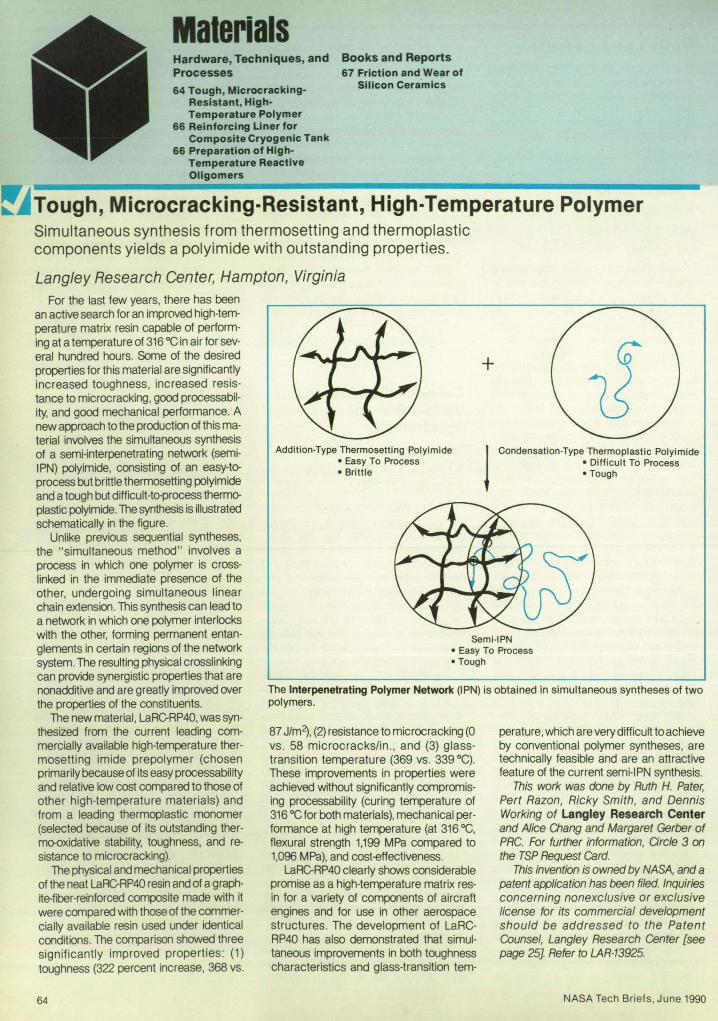
Malerials Hardware, Techniques, and Processes 64 Tough, Microcracking
Resistant, HighTemperature Polymer
66 Reinforcing Uner for Composite Cryogenic Tank
66 Preparation of HighTemperature Reactive Oligomers
Books and Reports 67 Friction and Wear of
Silicon Cera'mics
~~Tough, Microcracking-Resistant, High-Temperature Polymer Simultaneous synthesis from thermosetting and thermoplastic components yields a polyimide with outstanding properties.
Langley Research Center, Hampton, Virginia
For the last few years, there has been an active search for an improved high-temperature matrix resin capable of performing at a temperature of 316°C in air for several hundred hours. Some of the desired properties for this material are significantly increased toughness, increased resistance to microcracking, good processability, and good mechanical performance. A new approach to the production of this material involves the simultaneous synthesis of a semi-interpenetrating network (semiIPN) polyimide, consisting of an easy-toprocess but brittle thermosetting polyimide and a tough but difficult-to-process thermoplastiC poIyimide. The synthesis is illustrated schematically in the figure.
Unlike previous sequential syntheses, the "simultaneous method" involves a process in which one polymer is crosslinked in the immediate presence of the other, undergoing simultaneous linear chain extension. This synthesis can lead to a network in which one polymer interlocks with the other, forming permanent entanglements in certain regions of the network system. The resulting physical crosslinking can provide synergistic properties that are nonadditive and are greatly improved over the properties of the constituents.
The new material, LaRC-RP40, was synthesized from the current leading commercially available high-temperature thermosetting imide prepolymer (chosen primarily because of its easy processability and relative low cost compared to those of other high-temperature materials) and from a leading thermoplastic monomer (selected because of its outstanding thermo-oxidative stability, toughness, and resistance to microcracking).
The physical and mechanical properties of the neat LaRC-RP40 resin and of a graphrte-fiber-reinforced composite made with it were compared wrth those of the commercially available resin used under identical conditions. The comparison showed three significantly improved properties: (1) toughness (322 percent increase, 368 vs.
64
+
Addition-Type Thermosetting Polyimide • Easy To Process • Brittle j Condensation-Type Thermoplastic Polyimide
• Difficult To Process • Tough
Semi-IPN • Easy To Process • Tough
The Interpenetrating Polymer Network (IPN) is obtained in simultaneous syntheses of two polymers.
87 J/m2), (2) resistance to microcracking (0 vs. 58 microcracks/in ., and (3) glasstransition temperature (369 vs. 339°C). These improvements in properties were achieved without significantly compromising processability (curing temperature of 316°C for both materials), mechanical performance at high temperature (at 316 °C, flexural strength 1,199 MPa compared to 1,096 MPa), and cost-€ffectiveness.
LaRC-RP40 clearly shows considerable promise as a high-temperature matrix resin for a variety of components of aircraft engines and for use in other aerospace structures. The development of LaRCRP40 has also demonstrated that simultaneous improvements in both toughness characteristics and glass-transition tem-
perature, which are very difficult to achieve by conventional polymer syntheses, are technically feasible and are an attractive feature of the current semi-IPN syntheSiS.
This work was done by Ruth H. Pater; Pert Razon, Ricky Smith, and Dennis Working of Langley Research Center and Alice Cllang and Margaret Gerber of PRC. For further information, Orcle 3 on the TSP Request Card.
This invention is owned by NASA, and a patent application has been filed. Inquiries concerning nonexclusive or exclusive license for its commercial development should be addressed to the Patent Counsel, Langley Research Center [see page 25J Refer to LAR-13925.
NASA Tech Briefs, June 1990

That's why the IC/Discrete Parameter Database is on CD-ROM!
Now do component research a new way. Software for your IBM® AT® compatible and a database on CD-ROM provide fingertip access to over 1.1 million ICs and discrete semiconductors from 1,100 manufacturers.
• Search for active and discontinued devices, commercial and mil/high reI.
• Locate devices by component characteristic, IC generic number, manufacturer part number, Mil/ 883 part number, Mil slash sheet number, NSN or DESC drawing number.
• Access over 272,000 manufacturers ' datasheets and 19,000 Mil spec/ QPL 38510 and 19500 slash sheets. El(.acl images of the hardcopy version! And, all the text, application notes, mechanical data, outline drawings, packaging and ordering information can be printed in seconds.
All the critical information you need at the flip of a switch!
The results? Time saving searching-and time is money.
Circle Reader Action No. 546
For a free demo diskette return the coupon below or call toll-free:
800-241-7824 In Colorado and outside
the U.S.A.: 303-790-0600 ext. 59 Telex: 4322083 IHS VI
Fax: 303-799-4085 (U.S.A.); 303-799-4097 (outside the U.S.A.)
: Yes! Please send me a FREE DEMO DISKETTE and , more information. , Name __________________________________ __
, Dept./Title _______________ _
, Organ~ation ____________________________ _
, Address ______________________________ ___
, City _________ State ______ Zip ________ _
, Phone( __ ~ ____________________________ _
> Information Handling Services® 15 Inverness Way East; Englewood, Colorado 80150

~ Reinforcing Liner for Composite Cryogenic Tank The liner would prevent detachment of anti leakage foil from the shell. Marshall Space Flight Center, Alabama
A proposed fiber-reinforced liner for a graphite/epoxy fuel tank would prevent a metal-foil leakage barrier from detaching at low temperatures. The thin metal-foil barrier is necessary to prevent such fuels as liquid hydrogen and liquid methane from gradually oozing through the wall of the tank. HOINever, when the tank is filled, the temperature inside drops well below room temperature, causing the foil to contract while the graphite/epoxy composite shrinks very little. As a result, the foil tends to pull away from the composite wall.
The tank would be made of an outer layer of graphitelepoxy plies to which double layers of foil and a single layer of the liner would be attached by adhesive films (see figure). The sheets of foil would be placed on the inside of the tank. The edges of the sheets of foil would be resistance-welded to form leakproof seams.
The new liner would consist of epoxy containing fibers of Spectra 1000 (or equivalent), a high-strength, high-modulus material that expands with decreases of temperature in the temperature range in which the tank is to be used. However, in the same temperature range, the graphitelepoxy composite wall neither expands nor contracts significantly. As the temperature decreased in a tank of circular cross section, the liner would therefore compress the foil against the wall, preventing it from pulling away. Possible choices for the foil material include stainless steel, titanium, aluminum, copper, or bronze.
Because the liner would have to create a hoop stress in the foil , the thickness of the liner would have to be chosen in consideration of the tension properties of the foil -yield stress, ultimate stress, elongation, and modulus of elasticity. However, be-
cause the foil would be relatively thin, the liner could also be made thin in comparison with the wall.
The lined composite tank could be used to hold liquids from room temperature to cryogenic temperatures. For example, it could hold liquid helium at -452 OF ( - 269 "C). It is not suitable for oxygen, however, because the organic materials in
·the liner could be oxidized quickly. This work was dcxJe by John E Burgeson
of General Dynamics for Marshall Space Right Center. For further information, Orcle 10 on the TSP Request Card.
Inquiries concerning rights for the commercial use of this invention should be addressed to the Patent Counsel, Marshall Space Flight Center [see page 25]. Refer to MFS-28399.
Graphite/Epoxy Laminate Outer Surface dh . Metal Wall of Tank""" of Tank"", A eSlve .
fl722222777222222~22Z722222222222zzzZ>z2222222222;;;2~22222222222;;~22, >2222222222222222{
Spectra 1000 (or Equivalent) Epoxy Liner
Inner Surface of Tank
Resistance·Welded Seam in Metal Foil
The Graphite/Epoxy Wall of the Tank would hold inner layers of foil, adhesive, and the proposed liner. The liner would be much thinner than the shell, would add little weight, and would subtract little volume.
~J Preparation of High-Temperature Reactive Oligomers Very reactive materials form very-heat-stable polymers. Langley Research Center, Hampton, Virginia
A major goal in the field of high-temperature polymers is the preparation of aromatic polyimides that can be easily fabricated into parts that have thermal and physical properties required in aerospace applications. Recent research has been directed toward the synthesis of polyimides that are soluble in common organic solvents, melt-processable, and thermally curable without the evolution of volatile byproducts. Melt-processability can be enhanced by lowering the flow temperature via synthesis by such techniques as the incorporation of aryl ether and meta-phenytene linkages in the backbone of a polymer.
A previous approach to obtaining phenylated polyimides involved the Diels-A1der polymerization of phenylated biscyc\opentadienones with bismaleimides. One disadvantage of this process is that during the reaction, carbon monoxide is produced after the Diels-A1der addition. Furthermore, at temperatures >300 °C, dehydrogena-
66
tion and other decomposition processes occur, yielding polymers of poor solubility. Consequently, research was conducted to prepare, by Diels-A1der polymerization, high-temperature polymeriC materials that will maintain their integrities and toughnesses during long exposure times at elevated temperatures.
A unique monomer, N-phenyl-3,4-dimethylene-pyrrolidine can be modified to form a bis(exocyclodiene) (compound I in the figure) for the preparation of polyimides by the Diels-A1der process. This bis(exocyclodiene) undergoes Diels-A1der reaction with a bismaleimide (compound 1\ in the figure) without the evolution of gaseous byproducts. Dimerization, which can result from a Diels-A1der reaction between two exocyclic dienes, was observed in the Dlels-Alder Polymerization yields compounds that maintain their integrities and toughnesses during long exposure times at high temperatures.
~--------~y----------~ Compound I
o 0
~ II
~N-©-X-©-N~ o 0
~--------~yr---------J
Compound II
Notes: 1. Z = N or 0
I CH3
o II
2. X = 0 , C, or 502
NASA Tech Briefs, June 1990

case of N-phenyl-3,4-dimethylene-pyrrolidine. However, it was observed that bis [4~3,4<fimethylene-pfrrolidyl}fj1enyl] methane reacts very rapidly with bismaleimide by Diels-Alder addition. This polymerization was followed by 1H nuclear magnetic resonance (NMR) spectroscopy. At a temperature of 50 °C in trifluoroacetic acid, complete polymerization could be achieved within 48 hours. The polymerization yield was estimated to be 92 percent, based on the integration of the 1H NMR spectrum.
A polymer powder was prepared from the prepolymer solution, which contained equimolar amounts of bis[4~3,4-<limethylene-pyrrolidyl)-phenyl] methane (as compound I) and bismaleimide (as compound II) in solution. Good, flexible films were prepared by casting the prepolymer solu-
Books and Reports These reports, studies, handbooks are available from NASA as Technical Support Packages (TSP's) when a Request Card number is cited; otherwise they are available from the National Technical Information Service.
Friction and Wear of Silicon Ceramics A variety of ceramics are tested in friction against a nickel alloy.
A report presents the results of an experimental study of friction and wear in unlubricated sliding of silicon-based ceramics on Inconel* 718 nickel-based alloy. Both monolithic and fiber-reinforced ceramics were tested at temperatures from 25 to 8OQ°C.
The study was done to evaluate the ceramic materials for potential use as cylinder liners, piston caps, and other engine parts subjected to sliding or rubbing. Silicon carbide (SiC), fused silica (Sio~, syalon (a combination of silicon, yttrium, aluminum, oxygen, and nitrogen), silicon nitride (Si.JJ.v with tungsten and magnesium additives, and Si3N4 with yttria \'f20~ additive were tested. Also tested were reaction-bonded Si3N4 reinforced with SiC fibers and borosilicate glass reinforced with crossed layers (0°, 00°) of unidirectional carbon fibers.
Samples of the materials were rubbed against the edge of a rotating disk of Inconel* 718. Friction and wear were measured, and the worn surfaces were examined under a scanning electron microscope and by energy-<lispersive x-ray analysis.
At a temperature of 25 OC, the carbon-fiberlborosilicate glass exhibited a coefficient of friction of 0.18, which was the lowest of all. The total wear of this material was about 100 times as small as that of monolithic fused silica. The silicon carbide exhibited the lowest total wear (rub block + disk)
NASA Tech Briefs, June 1990
tion onto a clean glass surface. However, the original polymer film was insoluble in organiC solvents.
The thermal stability and decomposition temperature of the polymer films were analyzed by thermogravimetric analYSis (TGA). The measurements were carried out in nitrogen and in air, respectively. In nitrogen, the polymer film was thermally stable, with only 10 percent weight loss at 357°C and 20 percent weight loss at 413 OC. On the other hand, TGA plots in air showed different behavior. The first moderate weight loss occurred at a much lower temperature, 239°C. The second rapid weight loss occurred above 400 °C and was indicative of total decomposition of the polymer backbone.
High-temperature polymers can be syn-
at 25 OC. At a temperature of 800 °C, syalon had the lowest coefficient of friction , while sialon and Si3N4 (with Wand Mg) had the lowest wear. At temperatures of 550 OC and above, the oxidation products of the Inconel* 718 alloy transfer to the ceramic rub block, where they form a thin, lubricating glaze that reduces friction and wear in both the monolithic and reinforced materials. * "Inconel" is a registered trademark of the Inco family of companies.
This work was done by Daniel L. Deadmore and Harold E. Sliney of lewis
thesized by use of this technique. Rims and perhaps fibers can be fabricated from the prepolymer in solution. The major p0-
tential at this stage of the research appears to be limited to aerospace applications.
This work was done by Raphael M. Ottenbrite of Virginia OJmmonwealth University for Langley Research Center. For further information, Qrc/e 156 on the TSP Request Card.
This invention is owned by NASA (U.S. Patent No. 4,851,544). Inquiries concerning nonexclusive or exclusive license for its commercial development should be addressed to the Patent OJunsel, Langley Research Center [see page 25]. Refer to LAR-13965.
Research Center. Further information may be found in NASA TM-1oo294 [N88-17796], "Friction and Wear of Monolithic and Fiber Reinforced Silicon-Ceramics Sliding Against IN-718 Alloy at 25 to BOO °C in AtmospheriC Air at Ambient Pressure."
OJpies may be purchased [prepayment required] from the National Technical Information Service, Springfield, Virginia 22161, Telephone No. (703) 487-4650. Rush orders may be placed for an extra fee by calling (BOO) 3364700. LEW-14835
Circle Reader Action No. 422 67

Compuler ProgramS 68 Computing Mass Properties From AutoCAD
70 Flight Dynamics Analysis System
COSMIC: Transferring NASA Software
• • • Recognized the world over in holding COMPOSITE MATERIALS for machining!
COSMIC, NASA's Computer Software Management and information Center, distributes software developed with NASA funding to industry, other govemment agencies and academia
COSMIC's inventory is updated regular1y; new programs are reported in Tech Briefs. For additional information on any of the programs described here, circle the appropriate TSP number.
If you don't find a program in this issue that meets your needs, call COSMIC directly for a free
545 Blackhawk Park Avenue Rockford. il linoIs 61104-5135 Phone . (815) 962-8700 Telex 257312 Fax (815) 962-5568
Computer Programs
MAGNA-LOCK, U.S_A. These programs may be obtained at a very reasonable cost from COSMIC, a facility sponsored by NASA to make computer programs available to the public. For information on program price, size, and availability, circle the reference number on the TSP and COSMIC Request Card in this issue.
• Manufacturers of CUSTOM vacuum chucks
• We're proud of our elite customer base In the Aero-Space Industry
~ Malhemallcs and ~ Informallon Sciences 1-800-443-0760
68
Circle Reader Action No. 519
Take the guesswork out of solving deSign problems ELECTRO, MAGNETO, and COULOMB were cl1:ated for design engineers who must rely on accurat knowledge of electric and magnetic fields in their work. They allow you to explore alternatives, detel'lnine the perfonnance of designs, and avoid repeated t ling of co uy prototypes. Quickly. Accurately. Economically.
All are full integnlted packages that include geometric modelers, static and quasi-static field solvers, and a wide variety of Olltput options. The use ule Boundary Element Method which is fast , accurate, provid mooth results, cat rs to open region problems, and does not 1-eqWre a g.;d 0 1' finite element n h.
ELE TRO,MAG TO,and COULOMB areeasy to lean l and use. 0 speciaJ training or knowledge of nwnerical methods is reqtUred - just a basic undel'Slanding of elect!'Omagnetics. And you won' t need '--pensive hardware. You can solve large pl"Oblems on a
PC!
o othel-pl'O'!rams offel' the convenience, p recision, and economy of ELECTRO , MAGNETO, and COULOMB. Learn why more and mOI'e compani are switching f!'Om FEA. Call l IS to at-range a free 3O-day evaluation today!
-.== INTEGRATED ENGINEERING -- SOFlWARE
347 - 435 Ellice venue Winnipeg, Manjtoba R3B 1 Y6 Canada Phone: (204) 942-5636 Fax: (204) 944-8010
Circle Re.der Action No. 510
review of programs in your area of interest. You can also purchase the annual COSMIC Software Catalog, containing descriptions and ordering information for available software.
COSMIC is part of NASA's Technology Utilization NetworK
COSMIC' - John A. Gibson, Director, (404) 542-3265 The University of Georgia, 382 East Broad Street, Athens. Georgia 30602
Computing Mass Properties From AutoCAD Mass properties of structures are computed from data in drawings.
The AutoCAD to Mass Properties (ACTOMP) computer program was developed to facilitate quick calculations of the mass properties of structures that contain many simple elements in such complex configurations as trusses or sheet-metal containers. The calculation of the mass properties of structures of this type can be tedious and repetitive, but ACfOMP helps automate the calculations. A structure can be mathematically modeled in AutoCAD or a COf1'1I:Bti:>le computer -aided design (CAD) system in minutes by use of the thr~imensional elements. The resulting model provides all the geometric data necessary to calculate the mass properties of the structure.
ACTOMP reads the geometric data of a drawing from the Drawing Interchange File (DXF) used in AutoCAD. The geometric entities recognized by ACTOMP include POINTs, 3DLlNEs, and 3D FACEs. ACTOMP requests mass, linear density, or area density of the elements for each layer, sums all the elements, and calculates the total mass, the center of mass (CM), and the mass moments of inertia (MOl).
AutoCAD uses layers to define separate drawing planes. ACTOMP uses layers to differentiate between multiple types of similar elements. For example, if a structure is made of various types of beams, modeled as 3DLI NEs, each w~h a different linear denSity, the beams can be grouped by linear density, and each group placed on a separate layer. The program requests the mass information of 3DLlNEs for each nEl'-N layer ~ finds as it processes the drawing information. The same is true with POINTs and 3DFACEs.
By using layers this way, a very complex model can be created. POINTs are used for point masses like bolts, small machine
NASA Tech Briefs, June 1990

Part No. -SPrice ·3HPrice
94 - Stress Analysis $ 889 $ 1290
100 - StresS+Dynamics $ 1290 $ 1689
101 - Heat Transfer $ 1090 $ 1489
102 - 100+101 $1690 $ 2089
106 - Transient H.T: $ 300 $ 495
110 - AccuPak Nonlinear·· $ 895 $1295
109 - ElectroStat $ 995
3102 - FEA Demo $29
3106 - ElectroStat Demo $19
150D - PipePlus Demo $ 19
3101 - Algor Catalog NlC
• Adds to part 101 or 102. • •• "·3H" version not necessary.
• • Adds to part 100 or 102. Prices subject to change without notice.
"-S" Versions operate on 286. n·3H" Versions for 386 or 486 386. or 486 compu1ers running systems; directly u1ilize extend· under DOS. ed memory.
Weltek coprocessor support add $50 per Part No.
GSA Contract #GSOOK89AGS6270PS01
Other packages available: • Random Vibration Analysis
• Composite Element Analysis
• Buckling Analysis for Beam and Plate/Shell Elements
• Dynamic Analysis with Load Stiffening
• Nonlinear Gap AnalysiS
• PipePlus ASME Piping Analysis
• Beam DeSign Editor
• Paragen-Parametric Modeling
SuperCap-Compu1er·Aided Presentation and Animation
• Education Seminars. held monthly at various locations
Algor's Element Library Includes: Truss. Beam. Membrane. 20 Solid Elasticity • 3D Solid. 3D Plate/Shell. Pipe. Boundary. Rigid Unk. Nonlinear Gap. Thin and Sandwich Compos~e ; Nonlinear Truss. 20 and 3D Nonlinear Solid; Temperature Boundary. 20 and 3D Thermal Conductivity; 20 Planar, 20 Axisymmetric, 3D Solid, and Voltage Boundary Elements.
Separate CAD package not needed.
No artificial node or element limits.
Thousands of engineers use Algor FEA in 49 states
and 42 countries.
To place your order
PHONE
412-967-2700
FEA Since 1977
Algor Interactive Systems. Inc.
260 Alpha Drive • Pittsburgh PA • 15238
Fax: 412-967~2781 Circle Reader Actlo" No. 361

parts, or small electronic boxes. 3DLlNEs are used for beams, bars, rods, cables, and other similarly slender elements. 3DFACEs are used for planar elements. 3DFACEs can be created as three- or four-point faces. Some examples of elements that might be modeled by use of 3DFACEs are plates, sheet metal, fabric, boxes, large<1iameter hollow cylinders, and evenly distributed masses.
ACTOMP was written in Microooft OJickBasic (Version 2.0). It was developed for the IBM PC microcomputer and has been implemented on an IBM PCcompatibie c0m
puter under DOS 3.21. ACTOMPwas developed in 1988.
This program was written by A Jones for Goddard Space Aight Center. For further information, Circle 64 on the TSP Request Card. GSC-13228
Flight Dynamics Analysis System
This software assists in the development of software for for research in flight dynamics.
The Flight Dynamics Analysis System (FDAS) collection of computer programs
Circle Reader Action No. 692
70
provides an environment for the configuration and study of .Ada software. This program is designed to support flight-dynamics research and analysis activities concerning software models, algorithms, and techniques used within the flight Dynamics Division at the Goddard Space Flight Center.
The purpose of FDAS is to assist analysts and programmers in building, testing, and evaluating applications software by providing an integrated support system for the modification and reconfiguration of software. This includes the capability of assembling reusable software components into applications programs, as well as the capability of reconfiguring an assembled program after it has been partially or fully completed.
The stand-alone FDAS system-manager utility program creates, deletes, and maintains the user-information data base, and creates andlor sets up directory data bases for each new user. A directory data base contains a user's application-software components and program "trees" constructed from these components.
The installation utility program enables application programmers to install their developed Ada software components into their directory data bases under FDAS, thus making their code available to others working on the project. Upon invocation of the utility, the identity of a given user is validated against the information contained in the user-information data base.
The FDAS executive system program provides analysts and programmers with the ability to configure, test, and reconfigure program trees of their applicationsoftware components through the use of a window-based interface. This interface uses the user-information data base to validate the identities of users and to gain access to the application-software data bases.
It is anticipated that all of the software placed in the central FDAS library will be written in Ada. However, individual users will have the option of importing modified FORTRAN software via the Ada "import" pragma.
Future developments of FDAS are planned to combine the system-manager and installation utility functions into the executive program as well as provide access to the VAA Ada compiler and editors.
The system is developed in Ada for use on a DEC VAA computer operating under VMS 4.3 or higher and version 1.3 or higher of the VAA Ada Compilation System (ACS). FDAS has a central-memory requirement of approximately 360,000 bytes. This program was released in 1988.
This program was written by Keiji T asaki, Lenda Jun and Ed Seidewitz for Goddard Space Aight Center. For further information, Circle 69 on the TSP Request Card. GSC-13163
NASA Tech Briefs, June 1990

Mechanics Books and Reports Hardware, Techniques, and
Processes 71 Crash·Reslstant Shield 71 Combination of
Techniques for Computing Incompressible Flow
73 Numerical Simulation of Buckling In Waffle Panels
74 Aerothermodynamic Heating ofa Transatmospherlc Vehicle
72 Radial Cracks Would Signal Wearout of Turbine Blades
Crash·Resistant Shield Thick aluminum honeycomb provides protection with low weight.
NASA's Jet Propulsion Laboratory, Pasadena, California AA impact-resistant shield has been de
signed to consist of an aluminum honeycomb structure sandwiched between inner and outer aluminum skins. The shield, 6.275 in. (15.94 cm) thick, is intended to protect the radioisotope thermoelectric generator of a spacecraft from impact with ground or water after free fall from the upper atmosphere. The honeycomb is designed to absorb impact energy by buckling, while the inner and outer skins - 0.15 and 0.125 in. (0.38 and 0.32 cm, respectively) - are designed to protect against shrapnel, overpressure, and impact loads. The concept of the shield may be applicable to crashproof compartments for ground vehicles and aircraft.
Forward Motion
of
The shield is configured as a domed cylinder that surrounds the radioisotope thermoelectric generator (see figure). Pieces of honeycomb are to be welded together into a single unit. The outer skin is to be made in lapped sections and bonded to the core by adhesive. A pad of porous aluminum between the inner skin and the radioisotope thermoelectric generator at the front end gives extra protection against head-on impact.
The shield is 59.95 in. (152.3 cm) long and 30.35 in. (77.09 cm) in diameter. The density of the honeycomb is 38 Iblft3 (609 kg/m3). The overall weight of the shield is
The Crushable Aluminum Honeycomb Surrounds a thermoelectric generator. The honeycomb is intended to keep the generator intact in a crash or explosion.
629 Ib (285 kg). This work was done by Charles H. Bixler
of General Electric Co. for NASA's Jet
PropulsIon Laboratory. For further information, Orcle 12 on the TSP Request Card. NPO-17616
Combination of Techniques for Computing Incompressible Flow Pseudocompressibility, upwind differencing, and other techniques are used to solve the Navier-Stokes equations.
Ames Research Center, Moffett Field, California A scheme for the finitlKlifference numer
ical solution of the two-dimensional NavierStokes equations of incompressible flow combines several recently developed methods, each of which was developed to increase the speed ancVor accuracy of computations of this kind. Notable among the methods incorporated into this scheme is that of pseudocompressibility, in which the incompressible fluid is considered to have a small artificial compressibility.
The Navier -Stokes equations are written
NASA Tech Briefs, Ju ne 1990
in the form of conservation laws in nondimensional variables. A derivative of pressure with respect to pseudotime is added to the equation of continuity to couple the pressure directly to the velOCity. Iterations are performed to obtain the divergence-free velocity field that satisfies the equation of continuity. The equations are then advanced to the next step in physical time, and the iterations are performed in pseudotime until a divergence-free velocity field is obtained again.
AA upwind-differencing scheme based on flux-difference splitting is used to compute the convective terms. Upwind differencing increases the speed of computation by making the numerical process more stable. The upwind differencing is biased on the basis of the sign of the local eigenvalue of the Jacobian matrix. Third- or fifth-order spatial accuracy is maintained throughout the interior points of the grid.
Equations are solved in an implicit line relaxation scheme. This scheme is stable
71

and can accoomodate large steps in pseudotime, leading to fast convergence at each step in physical time. Implicit, nonreflective boundary conditions based on the method of characteristics enable the placement of the boundary relatively close to the body about which the flow is computed.
The scheme has been verified by application to several flows, ranging from very simple ones for which analytical solutions are available (see figure) to more complex flows that include the shedding of vortices and for which experimental data and other computational data are available. The predictions of the new scheme agree well with the previously obtained analytical , experimental, and numerical results.
This work was done by D. Kwak of Ames Research Center and S. E. Rogers of Sterling Software. Further information may be found in AIM paper 88A40752, "An Upwind Differencing Scheme for the Time-Accurate Incompressible NavierStokes Equations."
Copies may be purchased [prepayment required] from AIM T echnicallnformation Service Ubrary, 555 West 57th Street, New York, New York 10019, Telephone No. (212) 247-6500. ARC-12257
1.02 ,..-------------------------.
1.01
~
g 1.00 Ii >
0.99
0.98 '--__ L..-_---''--_---L __ -L.. __ ....I... __ -'--__ ..L-_~
o 2 3 4 5 6 7 8
Time
The Row In a One-Dimensional Channel with oscillating back pressure was computed by the scheme described in the text (solid lines) and by the exact analy1ical solution to the Navler-Stokes equations (x marks).
~J Radial Cracks Would Signal Wearout of Turbine Blades Nonfatal defects would be made to appear before fatal ones. Marshall Space Flight Center, Alabama of the wall. By judicious distribution of the
thicknesses on the concave and convex surfaces, the radial- and chordwise-crack lives could be adjusted.
It has been proposed to design turbine blades to crack radially before they crack chordwise (see Figure 1). Analysis of rocket tu rbine blades has shown that radial and chordwise cracks occur after various amounts of cyclic testing. Because radial cracks are relatively benign in comparison with chordwise cracks, the prior appearance of a radial crack or cracks in a used blade could serve as a warning that a
Figure 1. A Turbine Blade develops cracks as a result of cyclic stresses in operation.
t Centrifugal Load
~~;y
72
Radial Crack
more-threatening crorctvVise crack or cracks may subsequently appear. The blade could then be replaced before it fails.
Advance radial cracking could be promoted in design by adjusting thermal stresses and net bending stresses. Thermal stresses depend on the local thickness
Thin Wall In This Region To Increase Chordwlse-Crack Life
Net bending stresses are the sums of gas bending and tilt bending stresses. Gas bending stresses are caused by gas loads imparted to the blade in the turning of the mainstream flow. Tilt bending stresses are
Element 190: Cyclic Life = 250 Chordwlse Cracking Maximum Radial-Strain Range
+y
~§§EE~
Thicken Wall In This Region To Decrease
Radlal·Crack life
Element 9: Cyclic Life = 338 Radial Cracking Maximum Tangential-Strain Range
Note: X, Y Axes shown are the principal axes for the cross section.
+x
Figure 2. This is a Blade-Root Cross Section in a finite-element mathematical model of a turbine blade. The wall could be thinned and thickened as shown to increase the chordwisecrack life and decrease the radial-crack life, respectively.
NASA Tech Briefs, June 1990

caused by the centrifugal bending of a blade that has its cross-sectional centers of gravity offset from a radial line. Tilt bending stresses are normally designed to cancel the gas bending stresses at full power. By adjusting tilt bending, the resultant net bending stresses could be tailored to change the chordwise-crack life.
The analysis of thermal and bending stresses and the resulting effects upon crack lives could be performed with the help of MARC, a three-dimensional finiteelement computer program. One should start with a design, the cracking sequence of which is the opposite of the desired sequence, then proceed as foliONS: 1. Decrease the local thickness of the wall
in the region shown on the upper surface in Figure 2 to reduce the local thermal stresses and increase the chordwisecrack life.
2. Locally thicken the wall in the region shown on the lower surface in Rgure 2 to increase local thermal stresses and decrease the radial-crack life.
3. Increase the net bending about the - X principal axis to increase the chordwisecrack life of element 190. This work was done by Donald E. Paulus
of United Technologies Corp. for Marshall Space Right Center. No further documentation is available.
Inquiries concerning rights for the commercial use of this invention should be addressed to the Patent Counsel, Marshall Space Flight Center [see page 25]. Refer to MFS-28363
Books and Reports These reports, studies, handbooks are available from NASA as Technical Support Packages (TSP's) when a Request Card number is cited; otherwise they are available from the National Technical Information Service.
Numerical Simulation of Buckling in Waffle Panels Accurate results are obtained when fillet radii are considered.
Two reports describe a numerical and experimental study of the application of the PASCO and WAFFLE computer programs to the analysiS of buckling in an integrally machined, biaxially stiffened panel (which resembles a waffle). The waffle pockets of such panels are machined with rounded fillets, the radii of which were not taken into account in previous applications of pAS/X). As a result, previous panel designs were overconservative; that is, the structures were designed to be heavier than they had to be to withstand the anticipated buckling loads.
PASCO (Panel Analysis and Sizing Code) is a finite-element stress-and-strain code NASA Tech Briefs, June 1990
written for analysis and sizing of uniaxially stiffened panels. The mathematical model of the panel includes skin elements and assemblies of thin, flat, rectangular plate elements that represent the stiffening ribs. The loads on each plate element are calculated under the assumption of uniform longitudinal strain. The transverse load is assumed to be carried by the skin elements. In this application, a fillet is approximated by a stack of thin plate elements, the widths of which increase at the transition from the rib to the skin. This provides a stepped-cross-section approximation to the rounded cross section of the real fillet.
A biaxially stiffened panel can be analyzed by treating it as an assembly of uni-
For tracking and positioning anything from a cursor to a crane, MSI offers you the greatest range of high quality, displacement and force-operated joysticks. From the world's smallest fingertip model up to large handgrip joysticks, all offer you outstanding accuracy, reliability and options for complete customization.
From 1 to 6 axis capability, for any environment and application demanding
axially stiffened panels, the interfaces between which are the locations of the transverse stiffeners. However, PASCO alone cannot account for the boundary conditions (other than the simply-supported-beam condition) at the interfaces. Therefore, the WAFFLE program, which provides a comprehensive stress analysis of a waffle panel, can be used to determine bending moments at the interfaces.
The experiments consisted of buckling tests of waffle panels, which were instrumented with strain gauges. Stress readings taken in the buckled regions were compared, where applicable, with the predictions of WAFFLE, of PASCO without the fillet approximation, and of PASCO with the
the ultimate in hands on technology, spedfy and insist on MSI controls. All quality built for maximum value.
When you need a solution to a technical control problem, call us and we'll be there. More information about MSI preCision engineered joysticksincluding MSr s exclusive new generation force/displacement type-trackballs, handgrips and other controls is yours for the asking.
Hands on Technology Measurement Systems, Inc.,
121 Water Street, Dept. 162 South Norwalk, Connecticut 06854 USA Phone: (203) 838-5561 Fax: (203)853 -6244
AOover
Clrcl. R •• d.r Action No. 435 73

fillet approximation. The predictions of PASCO with the fillet approximation agreed with the e>q>erimental values within a few percent.
This work was done by Dah N. Yin and Vu M. Tran of Rockwelllntemational Corp. for Johnson Space Center. To obtain a copy of the reports, "Modeling Buckling by Special PASCO Technique" and "Local Stiffener and Skin Pocket Buckling Prediction by Special PASCO Modeling Technique: Correlation to Test Data," Circle 33 on the TSP Request Card. MSC-21599
Aerothennodynamic Heating of a Transatmospheric Vehicle
The vehicle would be heated more severely during ascent than during descent.
A report describes calculations of the aerothermodynamic heating of a conceptual transatmospheric vehicle (a vehicle with characteristics of both an airplane and a space shuttle, intended to take off and land at ordinary airports and to fly along tra-
!t:::/M E:~==:-!,J!! =-- ---:--- -;:==-~- = ~ = FULL FEA SYSTEMS FROM $995! • StaticslDynamics • Substructuring • HeatT ransfer • 3D Fluid Flow • Turbulent Flow • Composites • CAD Interfaces • Electromagnetics • Design Optimization
Stress/Thermal Contour Electromagoetics
• Large Strain • General 3D Contact • Nonconservative Loading • Large Deformations • Kinematic Hardening • Automatic Stepping • GapslFriction • Nonlinear Buckling
Fluid Flow
COMPUTERS SUPPORTED: 2861386/486 PC's, Mac II , Workstations.
Automatic Meshing
• Crash Dynamics • 15,000 Nodes/60,OOO D.O.F. • Automatic Adaptive Meshing • HIP Method • Fatigue , Kinematics
• Ansys'·lNastran'· Translators • Thermal Plasticity , CreeplViscoelasticity , Hyperelasticity
FREE OFFER: 213·452·2158
For a limited time, SRAC will send you a FREE 100 node working version of COSMOS/M which will enable you to run your own statics, dynamics and heat transfer problems. Introductory user guide plus shipping and handling fee $30.00.
25MHZ 486 POWER SYSTEM - S2,995** UP TO .l TIMES FASTER THAN A 2S MHz 386/381
• 16 Bit VGA Controller' 64Kbytes Memory Cache , 2~m RAM • Integrated XumericaJ Coprocessor' 5,25" 1.2MB Diskette Drive ' Enhanced 101 Keyboard
• 1 Parallel/2 Serial Ports • MS-DOS 4.01 • 1 Year On-Site Maintenance
6j~ ~ 1661 Lincoln Boulevard/Suite200 Santa MOllica, Califomia 90404 USA ~ TEl: (213) 452-2158/TLX: 705578
AN D ANALYSIS CORPORATION FAX: (213) 399-6421
74 Circle Reader Action No. 676
jectories that take it briefly into low orbits above the atmosphere). These calculations are important to future design studies because it is necessary to determine the need for COOling by transpiration or ablation of the most-severely heated surfaces.
Even approximate previous calculations had shown that the requirements for thermal protection would be determined by the conditions during ascent. This is because the vehicle would use primarily an airbreathing engine or engines, and consequentlythe ascent trajectory would have to involve a long flight through the atmosphere at up to nearly orbital speeds. The severe aerodynamic heat filuxes and total heat loads of such hypervelocity ascent through the atmosphere would be more severe than those to be encountered during entry and descent.
The calculations begin with the study of trajectories likely to be used, so that trajectories can be varied parametrically to obtain a range of realistic heating conditions. Rates of heating, temperatures of the walls, and total heat loads were calculated for laminar flow at the stagnation point and for laminar, transitional, and turbulent flows along the leading edge of a postulated wing, and on the centerline of the windward bottom surface. Calculated rates of heating were compared with data from flights of the Space Shuttle.
The numerical results of the calculations show that the combination of the high heating rates experienced by surfaces with small curvatures and the long ascent times would result in severe heating and large total heat loads. The peak equilibrium temperatures of the walls at the leading edge of the wing and at the stagnation point during ascent could reach values of 3,000 and 4,000 K, respectively, in trajectories of high dynamic pressure. Therefore active cooling, such as transpiration or ablation, may be required in these regions of the vehicle. (The corresponding temperatures during entry would be about 1,500 K lower.)
However, the temperature on the windward centerline would be lower, with peak values of about 1,500 K. Therefore, radiative cooling should be effective over large areas of the vehicle. In contrast with the heat loads at the stagnation point and at the leading edge ofthewing, the heat loads on the windward centerline would be relatively insensitive to the dynamic pressure of the ascent trajectory. The heat loads for the windvvard surface during entry would be much lower but would depend strongly on the flightpath .
This work was done by Michael E. Tauber of Ames Research Center and Henry G. Ade/man of the National Resarch Council. To obtain a copy of the report, "The Thermal Environment of Transatmospheric Vehicles," Circle 157 on the TSP Request Card, ARG-11854
NASA Tech Briefs, June 1990

Machinery Hardware, Techniques, and Processes
78 Rotary S1irling-Cycle Engine and Generator
75 Remotely-Controlled Variable-Orifice Valve
75 Heteropolar Magnetic Suspension
79 Securing Bearing Races to Turbopump Shafts
80 Mechanism for Guided Release
76 Intertia-Wheel VibrationDamping System
Remotely-Controlled Variable-Orifice Valve Features include compactness and reduction of perturbation.
Marshall Space F/ight Center, A/abama A remotely-controlled variable-orifice
valve is used to adjust the back pressure in tests of the flow of air in a duct. Although fixed orifices of similar configuration could be used, adjustments of the back pressure would require time-consuming removals and installations of different orifices. Mjustable valves of different configurations (e.g., gate and globe valves) that could handle the mass flows and pressures of the tests are too expensive and bulky, and they divert the flow away from straight streamlines to an extent that is undesirable for the purposes of the tests.
The valve includes an orifice housing, which is essentially a thick, stationary disk with six sectoral holes. Immediately upstream of the fixed disk is a rotatable disk with a similar pattern of holes. The angular position of the rotatable disk determines the area of overlap of the holes in the two
A Disk With Holes is rotated on a fixed disk with similiar holes to adjust the cross sectional area available to the flow.
disks; that is, the cross-sectional area open to the flow. As can be seen in the figure, the overlapping holes lie along or near most streamlines, so that the variable orifices effect minimal diversion of the flow.
The rotatable disk is turned by a hydraulic rotary actuator. The angular position of the actuator and rotatable disk is measured by a shaft-angle encoder. The valve can be calibrated in terms of angle or open flow area versus back pressure, so that the valve can be preset at the angle necessary to obtain the desired back pressure.
The remotely-controlled variable-orifice
valve is small in comparison with other types of valves designed to control similar flows and pressures. The valve can be moved easily from one flOW-test facility to another. It can be sandwiched between two 18-in. (46-cm) flanges and requires an axial gap of only 5 in. (13 cm) between the flanges once it is installed.
This vvork was done by Olen E. Hill of Marshall Space Aight Center. For further information, Circle 93 on the TSP Request Card. MFS-28369
~H~e~te~r~o~p~ol~a~r~M~a~g~n~e~t i~c~S~u~s~p~e~n~s~io~n~~~~~~~~~~~~~~ A compact permanent-magnet/electromagnet Nonmagnetic
Structure
actuator has six degrees of freedom.
Marshall Space Flight Center, A/abama A heteropolar magnetic actuator has
been conceived for use as an actively controlled vibration-isolating suspension device. The actuator would exert forces along, and torques about, all three principal coordinate axes to resist all three components of translational vibration and all three components of rotational vibration.
Back lIon
Retaining Nu.
Magnetically Sort Return
Path
The actuator has a cylindrically symmetrical design partly reminiscent of both a loudspeaker voice coil and an electric motor. An outer cylinder holds several four-pole sets of sectors of cylindrically symmetrical permanent magnets, which generate radial magnetic fields . An inner cylinder, which moves freely with respect to the outer cylinder, includes a magnetic return path (see Figure 1). Mounted on the inner
Figure 1. The Inner Cylinder is suspended magnetically within the outer cylinder. Electro-magnet coils (shown in Figure 2) interact with the fields of the permanent magnets to provide active control of the suspending force and torque.
Note: "N" and "5" denote magnellc north and SOUlh, respectively.
Four·PoIe Permanent·Magnel Ring
NASA Tech Briefs, June 1990
cylinder in the airgap between the permanent magnets and the magnetic return path are six layers of electromagnet coils oriented variously along the principal Cartesian and cylindrical coordinate axes (see Figure 2).
Because the interaction of a radial magnetic field with an electric current does not produce a radial force, the use of the radial magnetic fields eliminates undesired radial decentering forces. Furthermore, there is no spurious force produced by the interac-
75
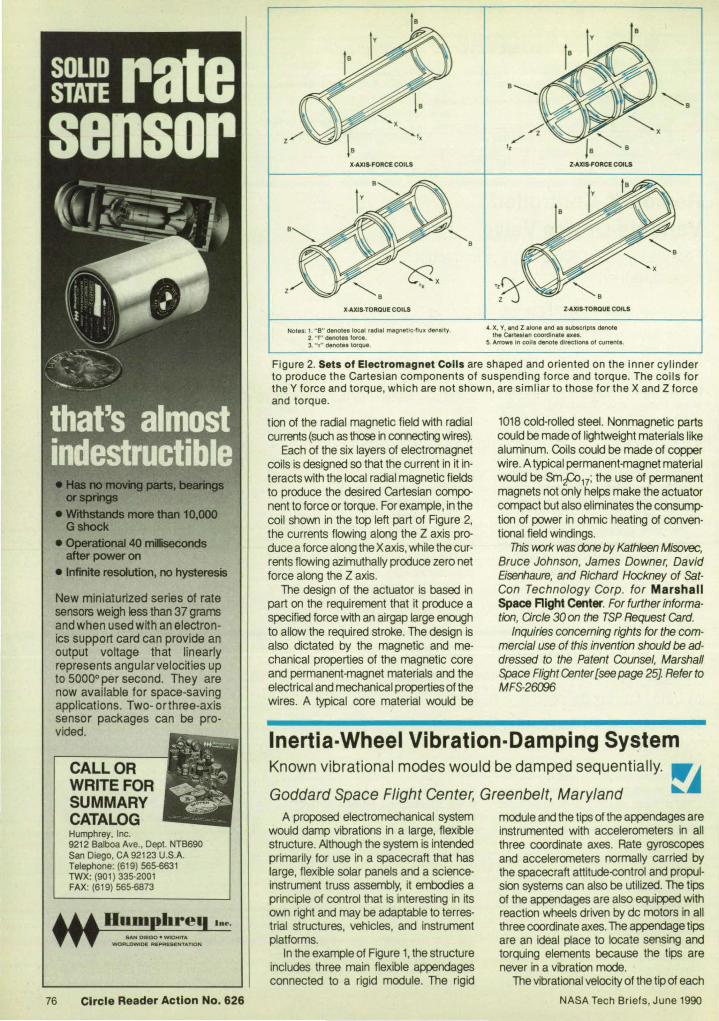
orsprlngs
• Withstands more than 10,000 Gshook
• Operational 40 miIseconds after power on
• Infinite resolution, no hysteresis
New miniaturized series of rate sensors weigh less than 37 grams and when used with an electronics support card can provide an output voltage that linearly represents angularvelocities up to 50000 per second. They are now available for space-saving applications. Two- orthree-axis sensor packages can be provided.
CALL OR WRITE FOR SUMMARY CATALOG Humphrey, Inc. 9212 Balboa Ave., Dept. NTB690 San Diego, CA 92123 U.S.A. Telephone: (61 9) 565-6631 TWX: (901) 335-2001 FAX: (619) 565·6873
In".
76 Circle Reader Action No. 626
X·AXIS-FORCE COILS
X·AXIS-TORQUE COILS
Notes: 1. " S" denotes local radial magnetic-flux denalty. 2. " f" denotes force. 3. " T" denotes torque,
Z·AXIS-FORCE COILS
Z·AXiS-TOROUE COILS
4. X, V, and Z alone and as subscripts denote the Cartesian coordinate axes.
5. Arrows In colla denote directions 01 currents.
Figure 2. Sets of Electromagnet Colis are shaped and oriented on the inner cylinder to produce the Cartesian components of suspending force and torque. The coils for the Y force and torque, which are not shown, are simliar to those for the X and Z force and torque.
tion of the radial magnetic field with radial currents (such as those in connecting wires).
Each of the six layers of electromagnet coils is designed so that the current in it in· teracts with the local radial magnetic flields to produce the desired Cartesian component to force or torque. For example, in the coil shown in the top left part of Figure 2, the currents flowing along the Z axis pro· duce a force along the Xaxis, while the cur· rents flowing azimuthally produce zero net force along the Z axis.
The design of the actuator is based in part on the requirement that it produce a specified force with an airgap large enough to allow the required stroke. The design is also dictated by the magnetic and me· chanical properties of the magnetic core and permanent·magnet materials and the electrical and mechanical properties of the wires. A typical core material would be
1018 cold·rolled steel. Nonmagnetic parts could be made of lightweight materials like aluminum. Coils could be made of copper wire. A typical permanent-magnet material would be Smt=:o17; the use of permanent magnets not only helps make the actuator compact but also eliminates the consump· tion of power in ohmic heating of conven· tional field windings.
This V\()rk was done by Kathleen Misovec, Bruce Johnson, James Downer, David Eisenhaure, and Richard Hockney of SatCon Technology Corp. for Marshall Space Aight Center. For further information, Circle 30 on the TSP Request Card.
Inquiries concerning rights for the com· mercial use of this invention should be addressed to the Patent Counsel, Marshall Space Flight ~nter [see page 25J Refer to MFS-26006
Inertia-Wheel Vibration-Damping Sy~tem Known vibrational modes would be damped sequentially, ""J Goddard Space Flight Center, Greenbelt, Maryland ~~
A proposed electromechanical system would damp vibrations in a large, flexible structure. Although the system is intended primarily for use in a spacecraft that has large. flexible solar panels and a science· instrument truss assembly, it embodies a principle of control that is interesting in its own right and may be adaptable to terrestrial structures, vehicles, and instrument platforms.
In the example of Figure 1, the structure includes three main flexible appendages connected to a rigid module. The rigid
module and the tips of the appendages are instrumented with accelerometers in all three coordinate axes. Rate gyroscopes and accelerometers normally carried by the spacecraft attitude-control and propul· sion systems can also be utilized. The tips of the appendages are also equipped with reaction wheels driven by dc motors in all three coordinate axes. The appendage tips are an ideal place to locate sensing and torquing elements because the tips are never in a vibration mode.
The vibrational velocity of the tip of each
NASA Tech Briefs, June 1990
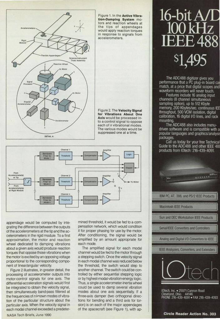
From Aceelerometert·)
at TIp
From Accelerometer(l) at Algid Module
DETAIL A
appendage would be computed by integ rating the difference between the outputs of the accelerometers at the tip and the accelerometers in the rigid module. To a first approximation, the motor and reaction wheel dedicated to damping vibrations about a given axis would produce reaction torques that oppose those vibrations when the motor is excited by an opposing voltage proportional to the corresponding component of linear/angular velocity.
Figure 2 illustrates, in greater detail, the processing of accelerometer outputs into motor-control signals for one axis. The differential-acceleration signals would first be integrated to obtain the velocity signal , then simultaneously band-pass filtered at the frequencies of n l<I1own modes of vibration of the particular structure about the particular axis. When the velocity signal in each modal channel exceeded a predeter-
NASA Tech Briefs, June 1990
Figure 1. In the Active Vibration-Damping System motors and reaction wheels at the ti ps of appendages would apply reaction torques in response to signals from accelerometers.
Figure 2. The Velocity Signal for Vibrations About One Axis would be processed into a control signal to oppose each of n vibrational modes. The various modes would be suppressed one at a time.
mined threshold, it would be fed to a compensation network, which would condition it for proper phasing for use by the motor. After conditioning, the signal would be amplified by an amount appropriate for each mode.
The amplified signal for each modal channel would be fed to the motor through a stepping switch. Once the velocity signal in each modal channel was reduced below the threshold, the switch would step to another channel. The switch could be controlled by either sequential stepping logic or by highest-modal-vibration-energy logic. Thus, a single accelerometer-inertia wheel could be used to damp several vibration modes about one axis sequentially. If a three-axis damper (two orthogonal directions for bending and a third axis for torsion) is on each of the major appendages of the spacecraft (see Figure 1), with ap-

propriate logic coordinating the dampers, then all of the significant system vibration modes can be damped.
This work was done by Joseph V. Fedor of Goddard Space Right Center. For fur-
ther information, Circ/e 120 on the TSP Request Card.
This invention is owned by NASA, and a patent application has been filed. Inquiries concerning nonexclusive or exclusive
license for its commercia/ development should be addressed to the Patent Counsel, Goddard Space Flight Center [see page 25]. Refer to GSC-13077
~ Rotary Stirling-Cycle Engine and Generator Advanced heat-engine and motor/generator concepts are combined.
Lyndon B. Johnson Space Center, Houston, Texas A proposed electric-power generator
would comprise three motor generators coordinated by a microprocessor and driven by a rotary Stirling-cycle heat engine. This combination of state-of·the-art components would offer the thermodynamic efficiency of the Stirling cycle, relatively low vibration, and automatic adjustment of operating parameters to suit the changing load on the generator.
Figure 1 is a partially schematic axial view of the inside of the rotary Stirling engine. Three rotors are mounted on concentric shafts in the cylindrical engine chamber. Each rotor is a pair of diametrically opposite, paddlelike sectors of cylinders that act as rotary pistons. Heat from an external source enters the working gas of the engine (for example, helium) through the right heat exchanger at the top of the engine. Exhaust heat from the engine leaves through the left heat exchanger at the bottom.
Each rotor moves clockwise at a speed that varies semisinusoidally with its angular position so that it alternately almost catches up with and then falls behind the rotor that moves in front of it. The motions of the rotors are coordinated in such a way that the following combination of compression and expansion cycles occurs: 1. Cool working gas is drawn into the
chamber through the lower left port as the rotary piston ahead of the valve races ahead of the piston behind the valve.
2. The piston ahead slows down, the piston behind races ahead, and the cool gas is compressed between the two pistons as they move toward the upper left port.
3. As the space enclosed by the two rotary pistons passes the upper left port, the compressed gas flows through the upper left heat exchanger, where it receives recycled heat, then flows through the upper right heat exchanger, where it receives heat from the extemal source.
4. The compressed, heated gas enters the space between two rotary pistons through the upper right port. This gas expands as the piston in front races ahead of the piston behind.
5. The piston ahead passes the lower right valve, allowing the expanded, hot gas to start escaping through the lower right heat exchanger, which recyles some of its heat to the upper left heat exchanger, then continues through the lower left heat
78
exchanger, which rejects the unusable heat to the environment. The piston behind catches up, helping to push the hot gas through the lower heat exchangers.
6. The cooled gas leaves the lCM'er heat exchangers and reenters the chamber through the lower left port, completing the cycle. Of course, six such compression/ex-
Figure 1. The Rotary Stirling Cycle Engine would convert heat to power via compression and expansion of a working gas between three pairs of rotary pistons on three concentric shafts in phased motion .
Figure 2. Three Motorl Generators each connected to one of the concentric shafts, would alternately move and be moved by the pistons. The microprocessor would coordinate their operation, including switching between the motor and generator modes at the appropriate t imes during each cycle.
pansion cycles occur Simultaneously, each lagging 60° in phase behind the preceding one. The shaft of each rotor is connected to a permanent-magnet, brushless dc motor/generator equipped with a shaft-angle encoder. The motions of the motor/generators are coordinated by the microprocessor so that the angular position of each as a function of time yields the required de-
He.t Exohangers
Wa,te Heat 10 Environment
Heat From External Source
Heat Exchangers
Rotary Stlrllng-Cycle
Engine
Motor/Generator Power Input/Output and
Phase Control
Concentric Shafts Generators
Power Output
NASA Tech Briefs, June 1990

pendence of speed on angular position to obtain the properly phased compression and expansion cycles.
The microprocessor switches each 1110-
torlgenerator between the motor and generator modes at the angular positions that define the boundaries between net expenditure and net generation of energy for the affected rotor. Although the motor/generators expend energy in compressing the gas, they generate energy during the expansion phases, and over the complete
cycle there is a net conversion of heat to electrical energy. If the microprocessor is suitably programmed and supplied with such additional sensor inputs as the inlet and heat-exchanger temperatures and the electrical load on the motor generators, it can optimize the compression/expansion cycles.
This work was done by Joseph A. O1andler of Johnson Space Center. For further information. Circle 70 on the TSP Request Card. MSC-21530
~~ Securing Bearing Races to Turbopump Shafts Tension bands would prevent races from loosening caused by differential thermal contraction.
Marshall Space Flight Center, Alabama A proposed method of attaching the in
ner race of a roller bearing to a shaft would prevent loosening that is now caused by the difference between the coefficients of thermal expansion of the race and shaft materials. The method is intended for a cryogenic turbopump in which the race is made of 440e stainless-steel alloy and the shaft is made of Inconel* 100 nickel alloy. The stainless-steel race material is chosen for its hardenability. The coefficient of thermal expansion of the stainless steel is more than 15 percent less than that of the nickel alloy. Therefore, as the cryogenic liquid cools the pump, the race loosens on the shaft because the shaft shrinks more than the race. The centrifugal force at the high rotational speed of the turbopump adds to the loosening of the race.
If the race were allowed to loosen enough to slip on the shaft, it would wear and gall the shaft. Accordingly, the practice has been to shrink-fit the race when it is installed on the shaft. But this creates tensile stresses in the race that can cause stresscorrosion cracking while the turbopump is stored at room temperature before use.
In the proposed new method of attaching the race, the guiderail flanges of the race, which guide the rollers, would be replaced by tension bands of a strong material that has a coefficient of thermal expansion greater than that of the 440e alloy. One such material is Waspalloy, which has a coefficient substantially larger than those of both the stainless-steel and nickel alloys. As the assembly would cool , the Waspalloy tension bands would shrink more than would the race or shaft, so that the tension bands would hold the race firmly on the shaft.
Like the stainless-steel alloy, Waspalloy is strong and resistant to corrosion. It cannot be hardened as much as the 440e alloy, but it is tougher. Inasmuch as the rollers make contact with the flanges only inter-
NASA Tech Briefs, June 1990
mittently, the tougher, slightly softer flange material may prove to be superior. * Inconel is a registered trademark of the INCO family of companies.
This work was done by Dale H. Blount of Marshall Space Aight Center. For further information, Circle 66 on the TSP Request Card.
Inquiries concerning rights for the commercial use of this invention should be addressed to the Patent Counsel, Marshall Space Flight Center [see page 25]. Refer to MFS-28384
"'-" --
.... The Roller Bearing Race is press-fit customarily onto the turbopump shaft (top). In the proposed version (bottom), the flanges of the race would be replaced by tension bands that shrink faster as they are cooled. A tension band in the alternative configuration shown in the inset would engage the race on a slightly sloping surface so that ax ial forces would not dislodge it.
Pure and
Simple. Introducing VAT's unique Mini Gate, IIIlnllOVative new vacuum valve.
Pure Y Virtually partlcle·free
willi ftO closlnglhock Y Low degaalng Y Fully blkeable to 2CJOOC Y Vacuum to UHV
Simple Y Patented lIaling principle
l1li only one mOVing part Y Extremely compact and lightweight Y 1", 1112", or 2" 1.0.
Y Vlluallndlcator for open/clll8d pllition
See ... e Mini Gates and other Innovative valves In our new 225 page catalog, 'Vacuum Valves go'.
INCORPORATED
600 Welt Cummings Park Woburn, MA 01881 Tel: (617) 935-1446
(800) 828-5625
Circle Reader Action No. 518 79

!~ Mechanism for Guided Release A shield would be thrown off a protected object.
NASA's Jet Propulsion Laboratory, Pasadena, California A proposed mechanism would retain a
protective shield until it is no longer needed, then release the shield and guide it away for safe ejection from a vehicle (a spacecraft, according to the original concept). The mechanism is intended for use with a shield like the one described in the preceding article "Crash-Resistant Shield" (NPO-17616).
The mechanism would include a seg-
mented-band device that would hold the shield on a base on which the equipment to be protected is mounted (see FlQure 1). An electrically actuated explosive separator would hold the band together. On command, the separator would release the segments of the band from each other (see Figure 2).
At separation, a pair of springs would push the shield away from the base.
The cost is less than a centrifugal blower with comparable air flow.
80
Plus these additional features: AMCO Engineering Co. • Static pressure up to 1.6" of H20. 3801 North Rose Street • Operating range from -30°C to +70°C. Schiller Park, IL 60176-2190 • Can be mounted in virtually any plane. TWX: 910-227-3152 • More air flow - SCFM Variable 445 to 540. FAX: 708-671-9469 • Quieter operation.
• Longer lif.e.. If "'"'"'\ I 'ilr:!,., • Less cabinet space required. ®
Call Toll Free1-S00·S33-3156 for further information and your free fUll line Cooling Devices Catalog #850. In Illinois Call 708/671-6670.
Rollers on the inside wall of the shield would ride in a pair of diametrically 0pposed tracks. The tracks would guide the shield along its entire length until it separates from, and is safely clear of. the object to be protected and the rest of the vehicle. A truss would be connected to the shield for support during maneuvers before ejection. Explosively retractable pins would join the truss to the shield. The command to jettison would cause the retraction of the pins so that the shield could move freely.
This work was done by Richard A. Kull of General Electric Co. for NASA's Jet Propulsion laboratory. For further information, Orcle 11 on the TSP Request card. NPO-17617
t Motion 01 &h1.Jet AfterSepMttlon
Figure 1. The Mechanism for Guided Release would separate the shield from the base and from a supporting truss on command.
Figure 2. The Band That Holds the Shield on the Base would be released by an explosive separator.
NASA Tech Briefs, June 1990

Fabrlcaaon Technology Hardwar., Technlqu •• , and Proc ..... 81 Spot-Welding Gun With
AdJust.ble Pneum.tlc Spring
82 Moving urge WiringH.rne .. Bo.rd.
83 Imp.ct Wire DI.lodge. Obstruction.
84 Centrlfug.1 a.rrel Flnl.hlng of Turblne-al.de "Fir Tr ... "
88 Etching Electrode Prevent. Arc.
Spot-Welding Gun With Adjustable Pneumatic Spring Controlled force would be applied at any position within the stroke.
Marshall Space Flight
Center, Alabama
ACSL A proposed spot-welding gun 'M)uld be equipped with a pneumatic spring instead of a conventional elastic spring. The pneumatic spring, which could be a bellows or a piston and cylinder, would exert a force independent of position along its stroke. Thus, the gun could apply an accurately controlled force to the joint to be welded, without precise positioning at a critical position within the stroke.
THE SIMULATION SOFTWARE STANDARD FOR MODELING/ANALYZING REAL-WORLD SYSTEM DYNAMICS
A conventional spot-welding gun includes a spring-loaded welding tip and a switch set at a tripping point within the stroke of the tip and spring, corresponding to a preset welding contact force. When the tip is pressed against the workpiece with the preset force, the switch initiates the pulse of welding current. However, once the welding current is initiated, the force can deviate from the preset value because it depends on how far the spring is subsequently compressed beyond the tripping point.
In the proposed spot-welding gun, the static contact force would depend only on the atmospheric pressure and the pressure inside the pneumatic spring. The tripping force could be adjusted easily and accurately by adjusting a pressure sensor andlor a pressure regulator that would feed the pneumatic spring. Pos an additional benefit, during the typical short duration of the welding pulse, the pressure in the pneumatic spring could momentarily be increased substantially to apply a welding contact force greater than the technician could exert by pushing against the weld. This mode of operation would rely on the mass of the gun and the technician to minimize recOil, in a manner similar to that of a firearm.
This YrOrk was done by Richard K. Burley of Rockwell International Corp. for Mar· shall Space Right Center. No further documentation is available. MFS-29569
NASA Tech Briefs, June 1990
• All the Power of FORTRAN • 75% Less Programming • Interactive, Friendly • Full Color Graphics • Variety of Well-Tested Algorithms · 17 Platforms, Micro to Supercomputer
ACSL ® (the Advanced Continuous Simuiation Language) is used by thousands of scientists and engineers daily for studying the behavior of nonlinear systems. Evolving from roots in the aerospace community, simulation is rapidly expanding across a broad spectrum of government, education, and industry. Why? Because of the productivities gained by understanding systems behavior prior to making key decisions. Simulation makes sense, and ACSL is the tool of choice by serious professionals.
FEATURES * Fully Interactive
* Free Format * Unlimited Model Size
* Eigenvalues, Eigenvectors, and Jacobians
* Symbolic Access to all Variables
* Bode, Nyquist, Nichols, and Root Locus Plots
* Discrete State Event Finder
* Numerous Algorithms, Including Fehlberg, Gear's Stiff, Runge-Kulta, FixedNariable Step
* Vector/Array Capabilities
* Powerful Macro Utility
* Links to Existing FORTRAN Routines/Libraries
• Interfaces to MATLAS'" and Other Popular Software Tools
~H5AllJt fNIlT515 1M fltElllfJCY ~11rt ~ ~ 05[0 LOOP ~ESf'CME tl:LAY .00150
l ~ --tHilttll-.trttI1l1l...J ~ ~~H-I-HttilH+ 1'-tl_::tttHffll
r.~ ':' ~·±;; .. ,-++I1'"f,~",,'-+ClJEHCY t~~CI 10"
o 'fiSSILE Rf:Sf>DHSf TO ONE II:GRU FJH STEP' r '~':"T" -- .... ~;~ < ~-- t- ~ -
ii:... :: ; ., fE'I'" _1 __ "_
'0.111 0 . ..., I fI'COfCSI1.,., I.. 1
Mitchell & Gauthier Associates (MGA) 73 Junction Square Drive' Concord MA 01742-3096 USA
TEL (508) 369-5115' FAX (508) 369-0013
Circle Reader Action No. 527 81

Moving Large Wiring-Harness Boards A rolling carrier makes the transfer of heavy boards
easy and safe.
Marshall Space Flight Center, Alabama A carrier for wiring-harness fabrication
boards enables a lone operator to move a board easily and safely. The carrier holds the harness while the operator is fabricating it, while it is being stored, and while it is being transported to an equipment frame for mounting. Previously, three people were needed to move the board, which measures 8 by 5 ft (2.4 by 1.5 m) and weighs 54 Ib (24 kg), exclusive of the harness.
cabinet for storage. At the cabinet, the ~ erator pushes the board along the roller track forward into a vertical storage slot.
When the time comes to take out the harness again, the operator reverses the procedure, sliding the board back onto the roiler track on the carrier. For fabrication, the carrier can be adjusted so that the board is at an angle of 30°, 45°, or 60°. Similarly, the board can be raised or low· ered by the switch-operated motor on the carrier.
This work was done by Samuel D. Shepherd and Isaac Gurman of Rockwell International Corp. for Marshall Space Aight Center. For further information, Circle 8 on the TSP Request Card. MFS-29510
ASSEMBLY OF HARNESS ON BOARD
Stored Board, VertIcal Stor.oe Slot
The operator assembles the harness on the board while the carrier holds the board in locking channels and supports it at a convenient height and angle (see figure). When the work is complete, the operator removes a safety lockpin from the carrier and lifts the right side of the board, tilting it to a vertical orientation. The operator locks a safety arm to maintain the board in the vertical orientation and presses an electri· cal switch on the carrier to lower the board onto a roller track on the base of the carrier. The operator unlocks the casters on the base and rolls the carrier and board to a
When Positioned for Assembly of the 1?:~~~I~1f, Wiring Harness, the board and carrier give an operator easy and convenient access to wires and cables, when positioned for transfer of the wiring harness to or from a storage area, the carrier holds the board securely while it is moved by one person. '--___ BO_A_RD_' N_ POSI_n_ON_F_OR_TR_AN_S_FE_RO_R_ST_ORA_G_E __ _
NEW!!! S PECIAL O FFER:
£BsyPlot™ plotting for the 90s
Lightning fast graphics, powerful data analysis. An indispensible tool for handling technical data.
Call 1-800-833-1511 or write for your
Free Working Demo Developed at MlT Lincoln Laboratory. Runs on PC with EGA, VGA. or Hercules graphics. Mouse is optional. Price: $299.
~ S· I S ft 6 Perry Sl. SuRe 2. Brookline. MA 02146 ~ plra 0 ware (617)739-1511. FAX: (617) 739-4836
82 Circle Reader Action No. 537
ApOLLO COMMEMORATIVE P OSTER
Actual size: 30" x 21 "-in full color! Relive mankind 's greate t adventure with this official
ASA commemorative po'ter. A gorgeous full -color rendition of the Apollo moon landing printed on highquality poster stock and shipped in a protecti ve tube. Special introductory price on ly $8.95 each. BONUS: Order now and receive three prints for
:..----- j ust $23.95. -----------------------Rush me __ Apollo commemorative poster(s). I have enclosed $ plus $3.00 for postage. (NY residents add sales tax.) Total enclosed: $ _ ___ _
Name -----____________ _
Company
Address _________________ _
City ___________ State _ _ Zip ___ _ Mai l wilh payment to: ASA Tech Briefs, Dept . F,
41 East 42nd St.. ew York. NY 1001 7
For credit card orders call: (212) 490-3999 NASA Tech Briefs, June 1990

Impact Wire Dislodges Obstructions Inaccessible debris are broken or shaken loose by impact.
Marshall Space Flight Center, Alabama A snakelike tool loosens trapped debris
that obstruct narrow passages in normally inaccessible locations. The tool is designed for use in the narrow, intricate coolant channels of a rocket engine. The tool lends itself readily to modification for use in engine blocks, heat exchangers, general plumbing, and the like.
through the impact mechanism into and along the inner tube until it emerges at the working end. The working end of the wire is capped with polytetrafluoroethylene to keep it from scratching the wall of the channel.
With the help of the borescope, the tip of the wire is guided into contact with the 0bstruction. The impact mechanism is then
used to apply an impact load to the wire; and the wire, in turn, strikes the obstruction, hopefully breaking it loose. The dislodgement of the obstruction should be visible through the borescope. The removal of debris is completed by flushing the passage at a high rate of flow and verified by radiographic or other suitable inspection.
This work was done by Steven K. Ricklefs and Jeffrey E. Anders of Rockwelllnternational Corp. for Marshall Space Aight Center. For further information, Circle 118 on the TSP Request Card. MFS-29513
The tool includes a long polytetrafluoroethylene outer tube that contains a corrosion-resistant stainless-steel inner tube covered with polytetrafluoroethylene. The working end of the inner tube may have to be bent to fit the narrow space in which it is to be used. The inside of the inner tube is lined with polytetrafluoroethylene.
The obstruction is located by a radiographic, infrared, or other suitable inspection technique. Together with a borescope, the tool is threaded into the blocked channel until the working end approaches the obstruction. Magnets can be attached to the working end of the outer tube to enable it to be pulled along the channel from outside. If the outer tube is prevented by the size of the channel from moving farther, the inner tt.be can be pushed farther in through the outer tube.
Miclofocus X-Ray System
A manual impact mechanism is attached to the outer end of the stainless-steel tube. A copper -coated stainless-steel wire is fed
TOOI..IH ust. VIEWED 'fIIOM ouq,Ol _ .....
--""'" ---
WOftKlNQ tHO Of TOOL '''''Of oa~UCTlD CKAHHn
The Flexible Tool is threaded into the obstructed channel, much like a common plumbing snake. The wire is fed along the inner tube of the tool until its tip reaches the obstruction. The wire delivers an impact from the impact tool to the obstruction.
NASA Tech Briefs, June 1990
Generate high resolution, magnified X-ray
images, quickly, on film or in real time with the KM Series Microfocus X-ray System. Switch easily from high resolution constant 10 watt power/10 micron focal spot mode to high contrast variable power/45 micron spot mode. Let the full range of settings from 20kV to 125kV, and up to 0.5mA and 62 Watts allow you to optimize the system for ceramics, PC boards, metals, composites ... or whatever your inspection needs are.
keJlex X-lttY
AppreCiate the flexibility of the air-cooled X-ray tube
with no bulky oil cooling lines. And, expect over 10,000 hours of reliable performance
from the compact, sealed tube. Choose the side or end window configuration, in titanium or beryllium. Program the regulated power supply for remote operation, if you wish, through m inputs. And, feel secure with arCing and excessive current protection. PCB solder pads
Go ahead, build the KM Series into your standard or custom cabinet system and enjoy the benefits of microfocus X-ray imaging.
P.O. Box 66860 Scotts Valley, CA 95066-0860 (408) 438-5940
FAX: (408) 438-5892
Circle Reader Action No. 531 83

TheReasons For Using Ceramic
PWBs In High
Performance Militaur
Applications Could Fill A Book.
~--
(Calll-SOO-237-4357 And It's Yours Free.) Call DuPont now and ask for our free Ceramic Printed WIring Board Handbook for Military Applications.
DuPont Electronics Share the power of our resources.
<[(JPOtID
84
Centrifugal Barrel Finishing of Turbine-Blade "Fir Trees" Residual compressive stresses and smooth surfaces
are obtained simultaneously.
Marshall Space Flight Center, Alabama
A m::xflf!ed centrifuJal barrel-finishing machine (see figure) irTlllrts desired residual compressive stresses to the "fir trees" of turbine blades - the wavy, keywaylike surfaces by which the roots of the blades are gripped by turbine disks. The use of the modified barrel finisher eliminates the need for shot peening (the conventional way to impart compressive stresses). It therefore eliminates the rounding of edges and burrs caused by shot peening and, consequently, the need for mass finishing operations to remove the burrs. In addition, the modified barrel finisher improves the surface finish of the "fir trees."
The turbine blades are suspended in a ceramic-based abrasive slurry that is contained along the periphery of the barrel finisher. The barrel finisher is rotated very rapidly to generate extremely high centrifugal loads, which are distributed evenly
over the surfaces of the blades by the slurry. These loads generate the residual compressive stresses.
Those portionS of the surfaces of the blades that are not to undergo compressive loading are masked with urethane or epoxy before insertion in the barrel finisher. The barrel-finishing process removes only about 10 -5 in. (0.25 J.II11) of material from the surfaces of the blades, yielding highly polished surfaces.
This work was done by Johnny L. Mandel of Rockwell International Corp. for Marshall Space Right Center. No further documentation is available.
Inquiries concerning rights for the commerciaI' use of this Invention should be addressed to the Patent Counsel, Marshall Space Flight Center [see page 25]. Refer to MFS-29553
Turbine Blade
Particles of Abrasive Slurry
ACTION WITHIN A CENTRIFUGAL BARREL MACHINE
Notes: 1."A" means "acceleration." 2."R" means " radius." 3."V" means "velocity."
In the Centrifugal Barrel Finisher, centrifugal forces generate compressive stresses, which are transmitted to the turbine blades through the abrasive slurries in which they are suspended.
Etching Electrode Prevents Arcs ~~ A wooden part replaces a stainless-steel part and works better.
Marshall Space Flight Center, Alabama A disposable electrode for etching Inco*
625 (or equivalent) alloy works better than does the previous, more expensive ver-
sion. The size and shape of the electrode make it easier than before to etch in narrow grooves and other confined spaces
NASA Tech Briefs, June 1990
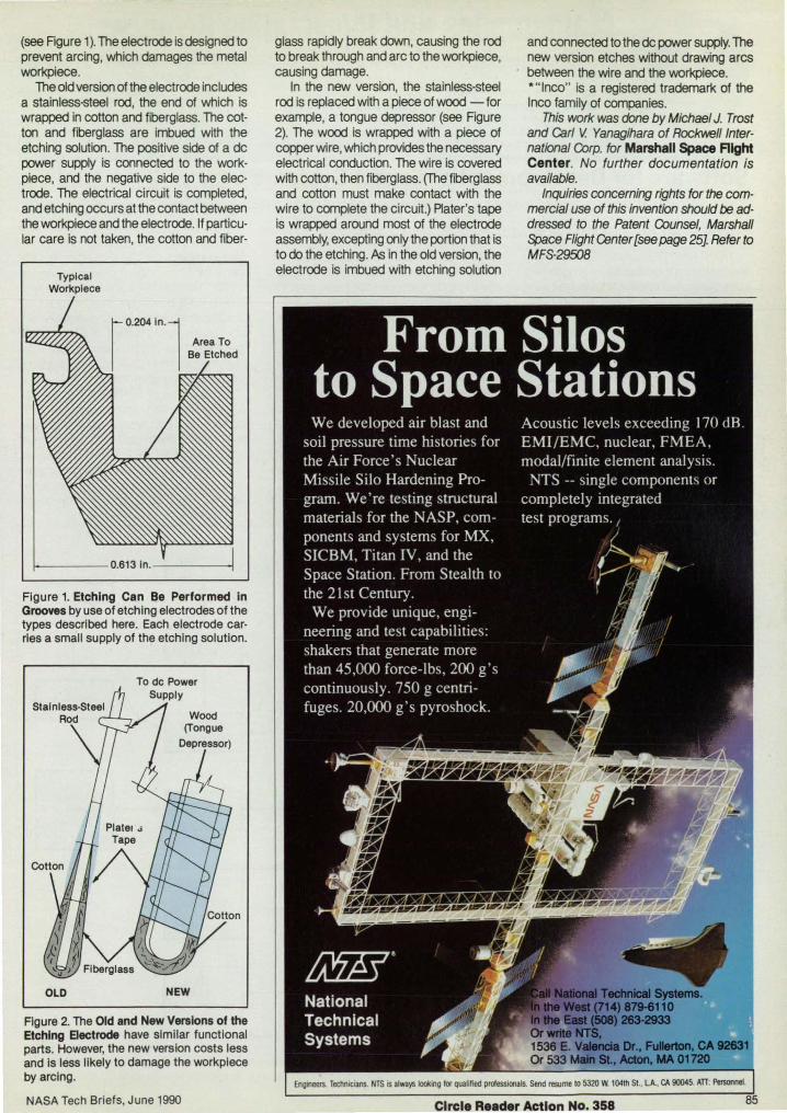
(see Rgure 1). The electrode is designed to prevent arcing, which damages the metal workpiece.
The old version of the electrode includes a stainless-steel rod, the end of which is wrapped in cotton and fiberglass. The cotton and fiberglass are imbued w~h the etching solution. The pos~ive side of a de power supply is connected to the workpiece, and the negative side to the electrode. The electrical circuit is completed, and etching occurs at the contact between the workpiece and the electrode. If particular care is not taken, the cotton and fiber-
Typical Workpiece
Figure 1. Etching Can Be Performed In Grooves by use of etching electrodes of the types described here. Each electrode carries a small supply of the etching solution.
Wood (Tongue
OLD NEW
Figure 2. The Old and New Versions of the Etching Electrode have similar functional parts. However, the new version costs less and Is less likely to damage the workpiece by arcing.
NASA Tech Briefs, June 1990
glass rapidly break down, causing the rod to break through and arc to the workpiece, causing damage.
In the new version, the stainless-steel rod is replaced w~h a piece of wood - for example, a tongue depressor (see Figure 2). The wood is wrapped with a piece of copper wire, which provides the necessary electrical conduction. The wire is covered with cotton, then fiberglass. (The fiberglass and cotton must make contact w~h the wire to complete the circuit.) Plater's tape is wrapped around most of the electrode assembly, excepting only the portion that is to do the etching. As in the old version, the electrode is imbued with etching solution
and connected to the dc power supply. The new version etches without drawing arcs between the wire and the workpiece. *" Inco" is a registered trademark of the Inco family of companies.
This work was done by Michael J. Trost and Carl V. Yanagihara of Rockwell International Corp. for Marshall Space Right Center. No further documentation is available.
Inquiries concerning rights for the commercial use of this invention should be addressed to the Patent Counsel, Marshall Space Flight Center [see page 25]. Refer to MFS-29508
Engmeers Technicians. NlS is always looking fur qualified professionals. Send resume to 5320 W. l04th St. LA. CA 90045. An: Personnel.
Circle Re.der Action No. 358

Mathematics and Inlormatlon SCiences Hardware, Techniques, and Processes 86 Software for Development
of Expert Systems 91 Connection Protocol for
Mobile/Seteliite Communications
92 Algorit hm Schedules Airplane Landings
93 Multlverlable PID Controller for Robotic Manipulator
94 Method for ModelReference Adapt ive Control
Software for Development of Expert Systems
Computer Programs 68 Compu1lng Mass
Properties From AutoCAD 70 flight Dynamics Analysis
System
A modular software system helps to create efficient artificial- intell igence computer programs.
NASA's Jet Propulsion Laboratory, Pasadena, California The STAR "TOOL system is a set of high
level software tools that assist programers in the creation of effICient knowIedge-based (expert) software systems. STAR"TooL provides the language and capabil ities for the compilation of application programs written in the Common LISP programming language. Unlike other expert-system "shell " programs, STAR"TooL features modularity that enables the elimination of unnecessary capabilities from the final application program and thereby achieves greater computing performance.
The unique approach of STAR "TOOL to the creation of knowledge-based systems is based in part on the use of sophisticated compiler techniques. STAR"TooL can be run on any computer that supports Common LISP and that has sufficient memory.
STAR"TooL provides the programmer with the necessary software tools to build a wide variety of reasoning and inference engines for such applications as planning, diagnosis and analysis, and simulation. The high efficiency of STAR"TOOL's implementation also enables the building of realtme systems, including those for monitoring real-time processes. Vv'hen STAR"TooL is run in an environment that supports multiple programming languages, STAR"TooLs capabilities can be utilized via local and remote procedure calls and through shared data structures. This enables portions of the application system to be developed in the most suitable programming language and allows such portions to be connected to the Common LISP STAR "TOOL application in a straightforward, natural way.
STAR"TooL enables and encourages the development of embedded expert systems. Thus, STAR"TooL could be a supervisor of many other systems written in either STAR"TooL or conventional programming languages. Most of the software tools provided by STAR " TOOL, such the blackboard, memory model, process model, and process scheduler, can operate independently of one another (see figure). However, when operated in combination, they form a fully integrated synergistiC set of software tools. Since the user is able to choose only those portions of STAR " TOOL that are applicable to a given application, the computational overhead of including unnecessary excess software is avoided,
86
resulting in greater application effiCiency. Thus, the resulting application program can run on a smaller computer than the one on "Yhich it was developed.
When an application program is developed in STAR "TOOL, STAR"TooL first translates the program to Common LISP code. It can then optionally pass the resulting Common LISP code through an extensive source-to-source LISP code optimizing compiler. STAR " TOO L generates code that is custom-tailored for each application. There are no intermediate levels of interpretation for execution, unlike many other knowledge-based system software shells. STAR"TooL programs are executed directly by Common LISP interpreter
Major Subsystems
of STAR-TOOL
Process Model and Scheduler
Native Common
LISP Complier
and compiled directly by Common LISP compiler. This results in greater speed and better portability to other computers. STAR " TOOL builds upon the Common LISP programming language and environment so that programs written in STAR " TOOL have direct use of all the features of the underlying Common LISP software systems and computing environment.
A single line of STAR " TOOL code can translate into many lines of Common LISP code. To support ease in application system development and subsequent software maintenance, all error messages generated from the STAR "TOOL compiler and run-time environment reference the original STAR"TooL source code. In the
LlSPComputer
Microcoded Constructs
Machine Object Code
Blackboard Message System
The STAR · TooL Software System comprises eight major subsystems that act in concert to produce Common LISP computer code tailored to specific applications.
NASA Tech Briefs, June 1990

WE COULDN'T PAY PEOPLE TO WRITE COpy THIS CONVINCING.
"NASA Tech Briefs is the winner! It generated 45% more reader inquiries than any other publication and telephone inquiries amounted to 50% more than the nearest competitor. "
Gary Kerr, Marketing Communications Manager The toline Corporation
"NASA Tech Briefs helped make our product a best-seller. It not only generates a good number of leads, but more importantly, an extremely high percentage of those leads are turned into sales. "
Alex Wellins, Director 01 Marketing The Visionics Corporation
"We rely on advertisements in NASA Tech Briefs to guide our purchasing. It's an unspoken thought on my part; if they advertise in the NASA publication, there must be something to it. "
Dr. IF. Korenowski, President TFK Company, Inc.
.... .......
' .. ~ ... ' . .. . ~.,. '.1.,
' ..... ~ ---~
..... 1:: ~
"Articles in NASA Tech Briefs help keep me abreast of many new developments. If I had to give up all my magazines except one, NASA Tech Briefs would be the one I'd keep. "
Perry D. Campbell, Jr., Engineer, Advanced Robotics Lockheed Engineering and Sciences Company
"NASA Tech Briefs is the single most important technical publication relating to aerospace, commercialization of space and technology transfer. Thanks for a great magazine!"
Jac B. Kadar, Senior Staff Engineer, Advanced Robotics Section, United Technologies-USBI
"Through NASA Tech Briefs we reach many qualified users of our products who were not available through other publications. We 'll continue to use this proven method for creating new sales. "
Michael Ryba, President/CEO Artisan Devetopment Corporation
Discover NASA Tech Briefs, your secret weapon in the high-tech media wars. There are literally thousands of similar testimonials. From readers who can't do without NASA Tech Briefs; from advertisers who wish they'd discovered us sooner.
personally sign for their subscriptions. And-proof that the word is getting out-pages are up more than 30% for the third consecutive year. That's a decidedly dynamic performance, in a static magazine market.
Our engineer subscribers react to the most timely editorial in the business press. Because all findings from NASA programs are published in NASA Tech Briefs first, before anyone. While advertisers applaud our book and their agencies for making such a low cost, high impact media buy. NASA Tech Briefs works because it's engineered for results, pure and simple.
You haven't heard of us? Here's a quick study: In just a little over five years our circulation has more than doubled, from 83,000 to 183,000. Our readers not only have the power to specify advertised products, but also
If you're targeting design engineers, here's a little secret: A schedule in NASA Tech Briefs is bound to make everyone heroes. Because it'll work wonders, without breaking the budget.
For a revealing media kit, call toll-free (800) 258-0201 today; in New York (212) 490-3999; FAX (212) 986-7864,
NI\S/\ Tech Briefs ENGINEERED FOR RESULTS
41 East 42nd Street, Suite 921, New York, New York 10017

Display t e eauty ... Complete, integrated DSP environment with true menu selection, frame-based waveform analysis with full zoom, pan, and random-access capability in time and frequency domains
rnlllJll7rboard manufacturers supincluding:
• Acrosysterns • Ariel • Burr-Brown® • CAC (Communications, Automation,
and Control) • Data Translation® • Motorola® • Spectrum Signal Processing (
ooroug/t Sound Images) • Texas InstrumenlS®
... and tame the beast in your DSP problems with Hypersignal-Workstation ™ DSP software.
Hypersignal-Workstation has become an industry standard in DSP and PC-based instrumentation software, supporting mor analog/DSP boards, more DSP chips, and more DSP functions, algorithm design tools, and analysis tools than any other softwar available, Before you end up with a shelf full of packages that won't talk to each other, consist of separate "modules" (with separat prices), or worse yet, weren't designed for real DSP problems, consider what more and more customers worldwide already have:
REAL· TIME SUPPORT ANALYSIS DESIGN & SIMULA TION • Integrates 320C25/C30, DSP32C, • Time waveform display, editing, and • Classical, arbitrary FIR/IIR filte
DSP56000, ADSP-2100, Data Transla- D/A playback design, including graphical filte tion®, Acrosystems TV, and Burr- • FFf processing, including window, editor and log or linear axes Brown® analog/DSP hardware framesize, and overlap control • Comprehensive difference equa
• Continuous hard disk acquisi- , • 3-D spectrogram, 2-D spectrographic tions, with math functions, sign~ tion/playback up to 150 KHz analysis and D/A playback arithmetic, and signal calculus
• Instrumentation sampling rates as high • Power spectra estimation • Arbitrary function generation as 1 MHz • Convolution, recursive filtering • Code generation and quantizatio
• Accelerated FFr processing • LPC autocorrelation, including win- simulation for Texas Instruments • DSP chip source code interface for al- dow, framesize, and overlap control TMS320xx, AT&T WE® DSP
gorithm simulatiOn/test Motorola® DSP5600x, Analo • Pole-zero, unwrapped phase, group- D' ADSP '2100 Sit bl • Dual-channel diaital osci1loscope and d I 1'!1 ' d eVlces -. e ec a
0- e ay, mear og magmtu e, etc, IJR d' t' spectrum analyzer structure an quantlZa lon, - - -Hypersignal-PlusDEMO FREE ___________________ ~
Nor t h Hypersignal-Plus 5489 _ _ -:: Americon Hypersignal-Workstation $989 := =~=--= :::: -=== -=.=- -===--=-:::: = Pricing: DSP Workstation-25 MHz $9995 -- - -
DSP Workstation-33 MHz CALL Hyperception Inc, 9550 Skillman LB125, DallDs, TX75243 TEL 214-343-8525,FAX214-343-245 WESTGERMANY-EkcJ""';c TooI.t,~: (02102) 841013, TLX 1631 +BTX021 02841013 I +J= (02102) 841000· UK,IREUND-l..cutioboroufi! Sound lmap, LTD.,~: (0509) 231843, TLX341409LUFB G·I= (0509) 262433 • FINUND -ITT,~: (90) 7J9100, TLX 121450 Multi~nJ, 1= (90) 712414 • FRANCE - BORES T<ehnicol Sote., plume CC# (04B3) 740138, 1= (04B3) 740136 • ITALY - M. InlF&nDi cl Con...IenJi,~: (I72) 422J71422J31,1= (I72) 431243 • JAPAN ' CADTECHS, INc..~: ~13-B222, TLX: 23528, 1= ~1B-7B88 • DENMARK - A-nJoft E~a, plume (~) 1629 26, fo (86) 162012 • ISRAEL - IES Ltd., phone: (OJ) 7526333,1= (OJ) 7510927
Circle Reader Action No. 445 ---------------------------------------------

case of run-time errors, the resulting Common LISP translation is also referenced_
Mail Stop 305-6 California Institute of Technology 1201 East California Boulevard Pasadena, CA 91125
This work was done by Mark L. James and David J. Atkinson of Ca/tech for NASA's Jet Propulsion Laboratory. For further information, Orcle 5 on the TSP Request Card.
In accordance with Public Law 96-517, the contractor has elected to retain title to this invention. Inquiries concerning rights for its commercial use should be addressed to
Edward Ansell Director of Patents and Ucensing
Refer to NPO-17536, volume and number of this NASA Tech Briefs issue, and the page number.
Connection Protocol for Mobile/Satellite Communications Throughput is increased by better resolution of competing simultaneous requests for connections. NASA's Jet Propulsion Laboratory, Pasadena, California
An improved protocol sorts out simultaneous competing requests by message-originating stations for connection to the satellite transmission link of a land-mobile/satellite digital communication system. The protocol applies to a muitiple-channel packetmessage system with synchronous timeslots on all channels. During each timeslot it is possible to transmit only one packet of data on each channel. Simultaneous requests from two or more originating stations for connection to the transmission medium can result in "collisions" between packets on a channel. The problem in devising a protocol is to resolve such collisions in a manner that is stable, prevents deadlocks, and provides for efficient utilization of channels and times lots.
The communication system has Q channels. Transmissions of packets are allowed to begin only at the beginnings of the timeslots. The system provides, to all users, binary feedback information on the state of the channel - namely, whether or not there is a collision - during each timeslot. When the round-trip propagation delay is negligible in comparison with the packettransmission time, the feedback information is known to the users immediately at the end of each timeslot.
Then the protocol is as follows: 1. An attempt is made to transmit a new
packet immediately at the start of the first timeslot that follO'NS its arrival by independently selecting one of the Q channels with probability 1/0.
25
20 'iii' ~ 15 !!2. ~ ~ 10
5
(Three Channels)
---OL-__ -L ____ L-__ -i __ ~
0.000 0.100 0.200 0.300 0.400
Throughput, Packets Per Channel PerTlmeslot
The New Collision-Resolution Protocol results In decreased delay and increased throughput.
NASA Tech Briefs, June 1990
2. Collisions in the channels during a timeslot are resolved on a channel-by-channel
basis. That is, the collisions Of any) in channel 1 during that timeslot are re-
Do It Yourself Test Systems For
Aerospace Engineers
Te tline means reliability, accuracy, durability, flexibility. Testline i actuator , control electronic ,
hydraulic power , upplies, fixturing and more. end for free literature on
Te tline Mechanical and Electronic Product , including the new T /RAC Realtime Active Te t Controller.
MTS
MTS SYSTEMS CORPORATION BOX 24012. MINNEAPOLIS. M INNESOTA 55424 TELEPHONE6 1 2~374000TELE X290521 MTSSYSENPE FAX 6 1 2 ·937 45 1 5
Circle Reader Action No. 440 91

RVI we've made it a science
See inside vacuum or pressure vessels • Remote Visual Inspection (RVI) with Olympus rigid and flexible scopes lets you see magnified, brilliantly lighted images inside vessels under vacuum or high pressure. You will be able to observe and record objects and phenomena, at close range, that you never could before.
Pressures as high as 2,250 psi (155bars). Vacuums to 10-6 tors and ultrahigh vacuums to lO'9tors.Temperatures t01 OOO"C.
Integrated illumination. Fiberoptic light guides inside scopes carry cool, brilliant illumination to the site. Lighting is even and high Kelvin temperature. Strobe light, ultraviolet, infrared and other special wavelengths are also available.
Image analysis. Scope images can be seen on a video monitor for observation by groups and for documentation. Olympus systems let you digitize color images and perform analysis, including measurement to one part in 1024, gray scale histograms, image enhancement, particle counts, area calculations, and much more. Gimballed access port lets you insert the rigid scope deep or shallow and sweep through a wide arc for complete scanning of chamber.
For more information, write or call today. Olympus Corporation,
Industrial Fiberoptics Division, 4 Nevada Drive, Lake Success, NY 11042
516-488-5888, FAX 516-222-0878.
OLYMPUS INDUSTRIAL
Circle Reader Action No. 424 92
solved first, followed by the collisions (If any) in channel 2 during that timeslot, and soon.
3. The next attempt to transmit the packets that collide in channel i will be made during a timeslot in which all collisions in channels 1 through i -1 shall have been resolved. This attempt will be made by independently selecting one of the Q channels with prd:>ability Q. When the roundtrip prcpagation delay is equal to d slots, the feedback information is known to the user d + 1 slots later. In this case, d + 1 interleaved copies of the above protocol are er1l>loyed. The throughput performance of the new
protocol was derived analytically and the delay performance obtained by computer
simulations, assuming an infinite number of users and a Poisson distribution of arrival times of packets at a rate of A packets per timeslot. As measured in terms of the average delay per packet necessitated by retransmission of colliding packets in a thr~hannel system, the new protocol is superior to a previous collision-resolution protocol (see figure). The maximum stable throughput of the new protocol is 0.402 packets per channel per timeslot, while that of the older protocol is 0.368 packets per channel per timeslot.
This work was done by Harry H. Tan and Tsun-Yee Yan of Caftech for NASA's Jet Propulsion Laboratory. For further information, Orcle 6 on the TSP Request Card. NPO-17735
Algorithm Schedules Airplane Landings The average landing delay is reduced. Ames Research Center, Moffett Field, California
All algorithm schedules the arrivals of airplanes to reduce the average or overall landing delay. In computer simulations, the algorithm increased the number of landings by 3 to 5 percent at a representative airport, Stapleton at Denver.
The algorithm rearranges the order of landing according to the weight class of each airplane. For example, inasmuch as a lighter airplane must follow a heavier one at a relatively large distance to avoid a dangerous wake, landings could be speeded ~ a group of heavy aircraft were made to follow a group of lighter ones. Of course, the algorithm limits the extent of one rearrangement to avoid penalizing any airplane or category of airplanes.
The algorithm is a version of a wellknown algorithm for the "traveling-salesman" problem, which selects an efficient itinerary for sales calls. The object of the aircraft-scheduling algorithm is to minimize the time in which the last airplane in a string of arriving airplanes is allowed to land. It observes the following rules: • The first airplane must still be scheduled
first in the revised schedule. • M airplane must be scheduled within a
preset number of landing slots of its orig~ nal position.
• Airplanes following the same incoming route may not pass one another. The algorithm takes the original order of
arrival as the initial schedule and computes the time to land all airplanes. It then randomly selects adjacent airplanes and interchanges their landing order. It generates a new schedule, but one that is still feasible according to the rules. Starting with the new schedule, the algorithm considers all feasible repositionings of a given airplane and the associated time to land the aircraft. It selects the best repositionings. The algorithm does this for each air-
c: fl 7.0
£ :; Q. r;
g 3.5 e ~ -= 3l ~ O~----~1~----~2------~3 u -= Maximum Position Shift (MPS)
The Increase In Throughput of an airport is increased in a simulation in which the order of landing of any airplane in the queue is permitted to shift by a number of positions up to the maximum position shift (MPS). The resulting new schedule is a suboptimum solution to the scheduling problem and approaches the optimum as the MPS increases.
craft to arrive at the solution - a nearly optimum schedule (see figure).
In simulations, the time required to schedule a queue of 40 aircraft on a V/lX computer ranged from 10 to 30 seconds. In general, the computation time increases only linearly with the number of airplanes in the queue.
This work was done by Robert A. Luenberger of Ames Research Center. Further information may be found in NASA TM-100062 [N88-19424], "A TravelingSalesman Based Approach to Aircraft Scheduling in the Terminal Area."
Copies may be purchased [prepayment required] from the National Technical Information Service, Springfield, Virginia 22161, Telephone No. (703) 487-4650. Rush orders may be placed for an extra fee by calling (800) 336-4700. ARC-12197
NASA Tech Briefs, June 1990
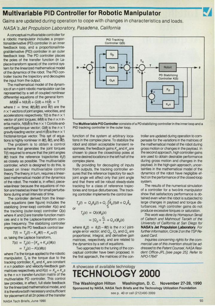
Multivariable PID Controller for Robotic Manipulator Gains are updated during operation to cope with changes in characteristics and loads.
NASA's Jet Propulsion Laboratory, Pasadena, California A conceptual multivariable controller for
a robotic manipulator includes a proportionallderivative (PO) controller in an inner feedback loop, and a proportionallintegrallderivative (PIO) controller in an outer feedback loop. The PO controller places the poles of the transfer function (in Laplace-transform space) of the control system for the linearized mathematical model of the dynamics of the robot. The PIO controller tracks the trajectory and decouples the input from the output.
The mathematical model of the dynamics of an n-joint robotic manipulator can be represented by a set of coupled nonlinear differential equations of the general form
M(B)B + N(B.9) + G(B) + H(9) = T where t = time; fX,t).9(t) and 8(t) are the n x 1 vectors of joint angles, velocities, and accelerations respectively; T(t) is the n x 1 vector of joint torques; M(fJ) is the n x n inertia matrix, N(B.U) is the n x 1 Coriolis-andcentrifugal-torque vector; G(B} is the n X 1 gravity-loading vector; and H (B) is the n x 1 frictional-torque vector. This s~t of eq~ations is highly nonlinear in fX,t), fX,t), and fX,t).
The problem is to obtain a control scheme that generates the jOint torques T(t) required to ensure that the joint angles fX,t) track the reference trajectories B/t) as closely as possible. The multivariable controller, which is designed to do this, is based on linear multivariable control theory. The theory, in turn, requires a linearized mathematical model of the dynamics of the robot. The model is, in effect, piecewise-linear because the equations of mer tion are treated as linear for small perturbations during small intervals of time.
The controller derived from the linearized equations (see figure) includes the stabilizing (inner-loop) controller K(s) and the tracking (outer-loop) controller O(s) where K and 0 are transfer-function matrices and s is the Laplace-transform complex frequency. The stabilizing controller implements the PO feedback control law
T(t) = Tq(t) - Kp8(t) - Kvw(t) or, taking the Laplace transform,
T(s) = T/s)-[Kp+KvS]8(s)
= T rf.s) - K(s)8(s)
where T is the torque applied to the robotic manipulator, Tq is the torque due to the tracking controller, Kp and Kvare constant n x n position- and velocity-feedback gain matrices respectively, and K(s) = Kp + KvS is the n xn transfer-function matrix of the multivariable PO controller. This control law provides, in effect, full state feedback for the linearized mathematical model, and it is therefore both necessary and sufficient for placement of all 2n poles of the transfer
NASA Tech Briefs, June 1990
9r
PIO Tracking Controller Q(S)
The Multlvarlable PI 0 Controller consists of a PO stabilizing controller in the inner loop and a PIO tracking controller in the outer loop.
function of the system at arbitrary locations in the complex plane. To stabilize the robot and obtain acceptable transient responses, the feedback gains Kpand Kvare chosen to place the closed-loop poles at some desired locations in the left half of the complex plane.
By providing for decoupling of inputs from outputs, the tracking controller ensures that the reference trajectory for each joint angle will affect only that joint angle and that there will be robust steady-state tracking for a class of reference trajectories and torque disturbances. The tracking controller implements the control law
or
t • Trf.t) = OpBe(t) + O,JBe(t)dt + OvBe
o
Trf.s) = O(s)Be(s) Q = [Op+;- +Ovs]8e(s)
where Be(t) = BJt) - fX,t) is the n x I jointangle error vector; and 0P' 0" and Ovare proportional, integral, and derivative gain matrices, respectively, and are related to the dynamics by a set of equations.
Two approaches to the tuning of the conceptual controller have been proposed. In the first approach, the matrices of the con-
A showcase of available technology
troller are updated during operation to compensate for the variations in the matrices of the mathematical model of the robot during gross motion or changes in the payload. In the second approach, high controller gains are used to obtain desirable performance during gross motion and changes in the payload. In the high-gain approach, uncertainties in the mathematical model of the dynamics of the robot have negligible effect on the performance of the closed-loop system.
The results of the numerical simulation of a controller for a twerlink manipulator show that satisfactory performance is 0btained even when the robot is subjected to large changes in payload and torque disturbances. High controller gains do not produce excessive torques or saturation.
This work was done by Homayoun ~raji of Caltech and Mahmoud Tarokh of the University of California at San Diego for NASA's Jet Propulsion .Laboratory. For further information, Circle 2 on the TSP Request Card.
Inquiries concerning rights for the commercial use of this invention should be addressed to the Patent Counsel, NASA Resident Office-JPL [see page 25]. Refer to NPO-17647
TECHNOLOGY 2000 The Washington Hilton Washington, D. C. November 27-28,1 990 Sponsored by NASA, NASA Tech Briefs and the Technology Utilization Foundation
see p. 40 or call (212)490-3999
93

Intelligent Data
Acquisition
DAP 1200'"
Data Acquisition Processor™ for mM PC/XT 1 AT 1386
Microstar's DAP"" manages the entire data acquisition and control interface inside a PC. Onboard intelligence in the DAP speeds development and increases performance.
• Onboard intelligence : 80186 coprocessor
• Acquires analog and digital inputs to 156,000 samples/seconds
• Buffers and processes input data • More than 100 commands without
programming • Commands include: Average ,
Scale, Peak Detection, Logic , Integration , Differentiation, Thermocouple Linearization, Closed Loop Control (PID) , Event Detection, Auto-Range, Waveform Generation
• FFT and FIR filtering without programming
• Custom commands may be written in C
DAP 24OO™ also includes:
• 10 MHz or 16 MHz 80C186 • 20 MHz DSP56oo1 for 10 MIPS
digital signal processing • Acquires analog and digital inputs
to 235,000 samples/seconds • Updates analog or digital outputs to
250,000 values/seconds • Performs 1,024 point complex FFT
in under 10 milliseconds • Executes FIR fIlters in less than 200
nanoseconds per tap
Call for FREE Demo Diskette
MtCROSTAR
LABORATORIES" j (206) 881-4286 2863 152 Ave. N.E. Redmond, WA 98052 Fax (206) 881·5494
94 Circle Reader Action No. 552
Method for Model-Reference Adaptive Control Synthesis of signals and adaptation of parameters are combined in a unified theory. NASA's Jet Propulsion Laboratory, Pasadena, California
A relatively simple method of model-reference adaptive control (MRAC) has been developed from two prior classes of MRAC techniques: the signal-synthesis method and the parameter-adaptation method. In the new method, the theories of the two prior methods are incorporated into a unified theory, which yields a more general adaptation scheme.
In the signal-synthesis method, an "auxiliary" signal is synthesized by the adaptation scheme and is fed into the system to supplement the operation of a nominal fixed controller. In the parameter-adaptation method, the gains of the controller are adjusted by the adaptation scheme; no external signals are introduced. In both methods, the objective is to match the response of the system with that of a predefined reference model.
The new method applies to an MRAC system that includes both an adjustable system and a reference model (see figure). The adjustable system contains both the plant to be controlled, which is fixed, and the controller, which can be adjusted. For instance, given the multivariable plant
M(t)y(t) + N(t)i/(t) = v(t) with the control law
v(t) = f (t) + K(t)[Yr(t) - y(t)] + O(t)Yr(t) the adjustable system is obtained as y(t) = [ - M -1(N + K)]y(t) +
[M -1(K + 0)] y~t) + [M- 1f(t)] where t = time, v is the m X 1 control vector, y and Yr are the m x 1 actual and reference output vectors, M and N are the m X m plant matrices with IMI *' 0, f is the m X 1 auxiliary input vector, and K and 0 are the m xm controller~ain matrices.
In general, the adjustable system can be represented by the state model
x(t) = A(t)x(t) + B(t)u(t) + w(t) where x(t) is the n X 1 state vector, u(t) is the m X 1 reference input vector, w(t) is the n x 1 auxiliary input vector to be synthesized, and A and Bare n xn and n xm time-varying matrices that contain adjustable parameters, and all entries of A, B, and w can be adjusted independently. The reference model expresses the desired performance of the system specified by the designer as
xm(t) = A~m(t) + Bmu(t) where xm(t) is the n x 1 model state vector, and Am and Bm are constant prespecified n X n and n X m matrices. The reference model is stable. The MRAC problem is to adjust the parameters of A(t) and B(t) and to synthesize the signal w(t) in such a way that for any arbitrary input u(t), the state x(t)
of the system approaches the model state xm(t) asymptotically.
The laws of the adaptation scheme are derived from the dynamics of the adaptatioo-error vector e(t) = x,J.t)-x(t). The derivatioo involves the use of an improved Lyapunov function. The results are given by t
w(t) = w(O) + O~Pe(t) + 0 0 1p Ie(t)dt
A(t) = A(0)+0;P[e(t)x '(t)](S~ -1 +
t 0 1 1p I[e(t)x'(t)}::It(S2)-1
and 8(t) = B(0)+0;P[e(t)u '(t)](RID -1 +
t Oi1p I[e(t)u '(t)}::It(R2)-1
where the O's, R's, and S's denote constant weighting matrices and P is the solution of the Lyapunov equation for the reference model.
It is interesting to note that the auxiliary signal w(t) can be generated by a proportionaHntegra! (PI) controller with constant gainsKp = OoPandK, = 0o'Pdrivenby the adaptation error e(t). The addition of the auxiliary signal to the parameter-adaptation laws results in improved transient performance and faster convergence. The auxiliary Signal also provides more flexibility in the design without increasing the computational time of the adaptation scheme.
This work was done by Homayoun Seraji of Caltech for NASA's Jet Propul· slon Laboratory. For further information, Circle 138 on the TSP Request Card. NPO-17717
u_-+-_~
Signal Parameter Synthesis Adaptation
The New Method of Model-Reference Adaptive Control combines elements of the signal-synthesis and parameter-estimation methods in a unified adaptation scheme.
NASA Tech Briefs, June 1990

Lila SCiences Hardwar., Technlqu •• , and Proc ..... 95 Affinity Electrophoresis
Using Ligands Attached to Polymers
96 Holiow-FIb.r Cllnostet 96 Self-Cellbretlng
R •• plretory-FIowm.t.r Comblnetlon
Affinity Electrophoresis Using Ligands Attached to Polymers Polymer molecules enhance electrophoretic separabilities.
Marshall Space Flight Center,
Alabama license for its commercia} development should be addressed to the Patent
Counsel, Marshall Space Flight Center [see page 25J Refer to MFS-26049.
Experiments have shown that neutral, hydrophilic polymer molecules can be covalently coupled to affinity ligand molecules to reduce the electrophoretic mobilities of cells in a specific and dose-dependent manner. Polyethylene glycol was used in the experiments, but it is expected that other neutral, hydrophilic polymers like polyvinyl alcohol and copolymers of ethylene glycol and propylene glycol could also be used.
The objective is to electrophoretically separate specific macromolecules, cells, or other particles on the basis of their specific interactions with immunoglobulins (immuno-affinity electrophoresis), alkyl hydrophobic molecules (hydrophobic-affinity electrophoresis), or other ligands (ligand-affinity electrophoresis). In a precursor to the new technique, reported in 1981, poIyethylene.glycol-linked dyes that have specific affinities for certain types of nucleic acids were used to carry out ligand-affinity electrophoresiS of fragments of deoxyribonucleic acid molecules.
In the new technique, the reduction of electrophoretic mobilities by the addition of polyethylene glycol to the ligands increases the electrophoretic separabilities. In immuno-affinity electrophoresis, this modification of the ligands extends the specificity of electrophoretic separation to particles that have surface electric-charge structures that would otherwise make them electrophoretically inseparable. Furthermore, the modification of the antibodies by polyethylene glycol greatly reduces their ability to aggregate while enhancing their ability to affect the electrophoretic mobilities of cells. In hydrophobic-affinity electrophoresis, the addition of polyethylene glycol also reduces the tendency toward the aggregation of cells or macromolecules.
This work was done by James M. Van Alstine, Robert S. Snyder. J. M. Harris, and O. E. Brooks of Universities Space Research Association for Marsha" Space Right Center. For further information, arcle 68 on the TSP Request Card.
This invention is owned by NASA, and a patent application has been filed. Inquiries concerning nonexclusive or exclusive
NASA Tech Briefs, June 1990
Other Canon State-of-the-Art Laser Encoders LASER ROTARY ENCODER Features: o COMPACT SIZE o LOW INERTIA o HIGH RESOLUTION o Direct Coupling o Pure Sine Wave Output o Either Sine or
Square Wave Output o Analog May Be Multiplied o Absolute Models Available
Applications: o Robotics o Machine Tool o Imaging Systems o Calibration Equipment o Surveying Equipment o Servo writers
LASER LINEAR ENCODER o Super high resolution
(O.01fLm minimum) o Ease of operation
(easy attachment and adjustment)
o More stable than conventional laser interferometers
o Much lower cost than interferometers
CANON INTERFACE DISPLAY UNIT IU 801120, CL-40 , CL-16 or CR-16 (optional)
Canon CANON U.S.A. INC. COMPONENTS DIVISION
New York Office, Headquarters One Canon Plaza, Lake Success. NY 11042
(516) 488-6700· FAX: (516) 354-1114 PLEASE CONTACT CANON DIRECTLY FOR SPECIAL APPLICATIONS
Santa Clara Office 4000 Burton Drive. Santa Clara, CA 95054
(408) 986-8780· FAX: (408) 986-1557 IN O.E.M. QUANTITIES.
Circle Reader Action No. 506 95

Hollow-Fiber Clinostat Cells are grown in an environment that simulates some of the effects of microgravity.
Marshall Space Flight Center, Alabama The hollow-fiber clinostat is a bioreactor
used to study the growth and other be-havior of cells in simulated microgravity. The cells under study are contained in a porous hollow fiber immersed in the culture medium inside a vessel. The pores in the hollow fiber allow exchange of gases, nutrients, and metabolic waste products between the IMng cells and the extemal culture media. The hollow fiber lies on the axis of the vessel (see figure), which is rotated by a motor equipped with torque and speed controls. The desired temperature is maintained by operating the clinostat in a standard tissue-culture incubator. The axis of rotation can be made horizontal or vertical.
Cells are Injected into the lumen of the fiber through a hypodermic needle. The ends of the fiber are then sealed by hot wax or by heat alone, and the fiber is mounted in a fiber holder under spring tension, which keeps it aligned with the axis. The holder is mounted in the vessel, the vessel is filled with the culture medium, and the vessel is sealed. Ports in the vessel provide access for exchange and sampling of the culture medium and for the injection of biochemical agents. The clinostat is designed for use with conventional methods of sterilization and sanitation to prevent contamination of the specimen. It is also designed for asepsis in assembly, injection of the specimen, and exchange of the medium.
Depending on the difference between the densities of the cells (or particles to which the cells are attached) and the liquid in which they are suspended, the particles may settle down to motion within circular trails about a horizontal axis of rotation. When the rotation is sufficiently rapid, mlcrogravity is simulated in the sense that
Wall of Vessel
Rotation
In the Hollow-FIber Cllnostat, shown here In simplified schematic form, specimen cells are suspended in liquid Inside a hollow fiber on the axis of a culture vessel. The vessel and fiber rotate about the axis to simulate some of the effects of mlcrogravlty.
the particles cease to move vertically. The simulation approaches 100 percent for particles In suspensions in which the centrifugal forces and Brownian motions offset each other. Operation with rotation about a vertical axis provides the motional condition for a control experiment in the sense that the gravitation is then constant along the axis. Another control condition is provided by non rotational operation with the axis horizontal.
The hollow-fiber-clinostat concept also embraces several alternative designs. Suspension cultures of cells or organisms can be studied by selecting speeds of rotation that maintain the positions of the cells within the fiber. Larger quantitites of cells or organisms can be tested by lengthening the fiber, fiber holder, and culture vessel.
Slip-type connectors and tubing can be added for continual circulation of the CUlture medium to enable monitoring and/or control of the concentrations of substanc· es in the medium. Cells or organisms de· pendent on anchorage could be grown on beads injected into the hollow fiber. This would facilitate removal of samples of cells from the fiber.
This work was done by Percy H. Rhodes, Teresa Y. Miller, and Robert S. Snyder of Marshall Space Right Center. For further information, Circle 89 on the TSP Request Card.
Inquiries concerning rights for the commercial use of this invention should be addressed to the Patent Counsel, Marshall Space Flight Center [see page 251. Refer to MFS-28370 rJ Self·Calibrating Respiratory·Flowmeter Combination
Dual flowmeters ensure accuracy over the full range of human respiratory flow rates.
Lyndon B. Johnson Space Center, Houston, Texas A system for the measurement of respi
ratory flow employs two flowmeters, which are complementary: one compensates for the deficiencies of the other. The combination yields an easily calibrated system that is accurate over a wide range of gas flow.
The flowmeters are in series in the flow path. A vortex flowmeter has stable characteristics, so that it rarely needs calibration. Its accuracy is independent of the composition, pressure, and temperature of the gas. However, it is not accurate over
96
the entire range of flow rates from rest to maximum exercise. A pneumotach flowmeter provides a linear output over the complete range of flow, but It tends to drift and needs frequent calibration. It also needs compensation for changes in the composition of the gas.
The vortex flowmeter, which can go for years without calibration, even in rugged duty, is therefore used as a calibration standard for the pneumotach flowmeter whenever the flow through the vortex flow-
meter exceeds its lower operating threshold. During each breath, the outputs of both flowmeters are stored in arrays of data. At the end of each breath, if enough data are recorded and if the peak flow was high enough, a linear regression between the two flowmeter signals is calculated, and the regression coefficient is used to calibrate the pneumotach.
This work was done by Dwayne R. Westenskow and Joseph A. Orr of the University of Utah for Johnson Space Center. For further information, Circle 124 on the TSP Request Card. MSG-21430
NASA Tech Briefs, June 1990

New on the Market
The compact S5 O-ring face seal from the Calnevar Seal Company. Oxnard. CA. is designed for applications in which using a standard seal is not possible. Besides aircraft,
I============================l engines. and missiles, the seal can be used in construction equipment, A new sub-subminiature snap
action switch from the Otto Controls Division of Otto Engineering. Carpentersville, IL, boasts a 2 ampere capacity for a minimum of 25,000 cycles, and can also switch low-level logic signals reliably. The B 1 Series switch is designed to meet MIL-S-8805/94 specifications and is avai lable with either solder or PC pin molded-in terminals.
• • •
Designed to reduce clean room contamination caused by traditional telephones, the Model 295 Clean Phone from GAI-Tronics Corp., Reading, PA, features a smooth, crevice-free front panel and an integral speaker/microphone. The microprocessor-based phone offers remote programming for two autodial numbers, call timeout, and auto answering and is available in flush- or wall-mount styles. Circle Reader Action Number 796.
Designed for vibration test engineers, the CASIO FX 730P personal computer from Ling Dynamic Systems Inc., Yalesville, CT, features ten random profile calculations as well as computations of parameters relating to sine and shock testing. Other functions include calculation of PSD in g2/Hz for a flat random spectrum; sweep rate for swept sine test; decibel/level relationsh ips; and peak velocity and displacement predictions for a defined shock pu lse. The handheld computer also serves as a scientific calculator with 61 functions, a 24-character display, and a function memory for additional formulas. Circle Reader Action Number 774.
NASA Tech Briefs, June 1990
Debug 1076T .. , a menu-driven VHDl debugger from Vantage Analysis Systems Inc. . Fremont, CA. provides the designer with a highly interactive graphical interface to track the execution of and debug parallel models in large simulations. The debugger supports design concurrency: breakpoints can be set for subprocesses, subprograms, source code line numbers, orfor simulation time points generated by the main simulation. Debug 1076's operations also include an understanding of simulation time and simulation delta times (internal model processing timesteps in VHDL) which are clearly displayed by the debugger. Circle Reader Action Number 792.
.. , ,,,... ~ , ......... 'J au: \3l _ I<.C I£D .lUI • ",,-,.>t ' • • • r - J .. - - .. ... ,.-.,,,,. ~ { 1 J. C _ It_ ~"""'... . , .... tv.> ,
"" "," "" ' -..,..,....~'''"
~i.'1"':r " \
A new noncontact red thermometer from Capintec Instruments Inc., Ramsey, NJ. offers accurate readings across a 50° to 1000°F temperature range. with 0.1 ° resolution and a 0.5 second response time. The HR-1 digital thermometer is available in a general purpose model for reading targets up to 20 feet away, and a closeup configuration for measuring targets as small as 0.16 inches in diameter. Circle Reader Action Number 776.
gear boxes, transmissions, machine tools, industrial pumps and turbines, and grinders. While the standard S5 seal can wi thstand pressure up to 250 psi and temperatures from -65° to 400° F. it can be designed for special applications to work up to 2000 psi and to 600° F. The seal can also hand le speeds ranging from 0 to 20,000 fpm.
The Elenco electronic temperature control soldering station permits a user to change the tip temperature from 150°C to 480°C without changing the tip or heating element. A temperature sensor located near the tip enables rapid response and excellent temperature stability. Electronic switching completely protects voltage- and current-sensitive components. Circle Reader Action Number 798.
Tefzel HT-2127 wire and cable insulation from the Du Pont Company, Wilmington, DE, combines the tensile strength and abrasion resistance of Du Pont's Tefzel fiuoropolymer with the flexibility and temperature to lerance of its Teflon fluorocarbon resin. The insulation is suited for use with cable constructions exposed to frigid weather, as well as in airframe components, inc luding aircraft hook-ups, and in back panel circuitry for computers and electronic boxes. Tefzel HT-2127 can withstand temperatures up to 180°C and is easily processed onto wire. Circle Reader Action Number 790.
A new VMEbus simulation engine from PsiTech Inc., Fountain Valley, CA, offers a real-time anti-aliasing solution to the "jaggies" and artifacts commonly found in simulation and training systems. Designated the VME!ll 00, the dual 6U graphics board set features a 24-bit frame buffer which is double buffered to display smooth animation of true color images. The extensive number of color shades available (16.7 million) is a key to the anti-aliasing performance. PsiTech uses four DSPs in parallel to achieve complete screen updates 60 times per second. Circle Reader Action Number 766.
SermeTel® 1083 . a hightemperature pol ymeric coat ing from Sermatech International Inc.. Limerick, PA, provides excellent resistance to corrosion, abrasion, and heat when applied to aluminum, magnesium. and other light metals. The coating is applied as a spray coating over anodized or conversion coated surfaces, providing uniform thickness even on parts of complex geometry. Circle Reader Action Number 800.
I process developed by Materials Innovation Inc. (Mil), Gilford, NH, makes it economical to cool electronic packages with composite metal matrix materials. Mil employs patented technology to blend elemental powders consisting of low-exp<lnsion, low-resistivity metals and nonmetals to yield new heterogeneous composite materials. Mil can furnish fully dense parts molded to net or near-net shapes with industry-standard to lerances for electronic packaging applications. Circle Reader Action Number 764.
IBM has introduced the SciBench, a general-purpose laboratory data acquisition and analysis package that allows a user to write simple data acquisition programs for displaying and plotting data on an OS/2 system. It offers a library of linkable software routines, including standard plotting, add, subtract, baseline smooth, differentiation, log, FFT. integral, and square root, as well as curve fitting routines such as least square, smooth, spline and polynomial fit. SciBench supports various industry-standard data acquisition boards, and allows for image acquisition and processing with 3D representation and wire frame drawing. Circle Reader Action Number 794.
97

HIGH STRENGTH
SAFETY SCREEN
Protect critical hydraulic components. These screens won't burst or collapse even with a full 6750 psi d ifferentia l. The unique one-piece design handles severe transients or complete clogging with ease.
• All 15-5ph stainless steel construction • Hole sizes from 100-400 microns • Wide choice of open areas • Flange, boss or fitting mount
For more information, refer to your Lee Technical Hydraulic Handbook, or send far your copy today. The Lee Company 2 Peltipaug Road P.O. Box 424 IMlstbroak. CT 06498 Tel: (203) 399-6281 Fax: (203) 399-7058
Circle Reader Action No. 597
HIGH PERFORMANCE ROTARY CONTACTS
THERMOCOUPLES, RTO's, LVOT's STRAIN GAUGES,
1 to 100 contacts!
Unlike conventional • Zero Electrical Noise slipring designs, the • Low And Stable Resistance unique ROTOCON • Compact Size Sealed Mercury Ro- • Zero Maintenance tary Contacts are low • Environmentally Sealed noise, low resistance, • Rugged And Reliable zero maintenance • Unaffected By Vibration links between sta- • Mount In Any Orientation tionary and rotating A variety of standard and custom components. 'I" ROTOCON models are available
e ~o'" S... to fit your mounting configuration, frY sefor rotation speed, and current re-
.. _ quirements (up to 2000 Amps!) . ~
Call: 800·234-4322 then dial 4721, 0' 608·836· 7571 (FAX 608-1131~300 TELEX 7543811
meridian laboratory 2415 Evergreen Road, P.O. Box 156, MIddleton, WI 53562-0156
98 Circle Re8der Action No. 596
New on the Market
The E-Series Ultrajet, an environmentally-safe, non-abrasive dust remover from Chemtronics Inc., Kennesaw, GA, delivers powerful jet blasts for cleaning critical electronic systems and has variable pressure up to 120 psi for maximum cleaning efficiency. Ultra-filtered to less than 0.2 microns, Ultrajet is suited for dusting of close tolerance instruments, optical and photographic surfaces, clean room procedures, and other PCB, system, and component manufacturing applications. Circle Reader Action Number 782.
The HP 48SX scientific expandable calculator from Hewlett-Packard's Corvallis Division offers automatic unit management; a serial interface to IBM and Macintosh PCs for computer printer and disk drive sharing; and a two-way infrared interface for data transmission from one HP 48SX to another. It provides graphics integrated with calculus functions for finding roots, intersections, local extremes, derivatives, slopes and areas under a curve; and an EquationWriter application for entering
I !!~~!~!!!!!!~ and viewing equations in textbook ~Un I e ot er scanning e ectron format.
microscopes which rely on a high- Circle Reader Action Number 778. vacuum environment and require extensive specimen preparation, the Environmental Scanning Electron Microscope (ESEM) from ElectroScan, Wilmington, MA, allows researchers to view untreated wet samples, examine microstructures of biological specimens in their natural state, and watch the mo-lecular dynamics of chemical change taking place. Applications include chemistry, biology, materials and laser research, pathology, petroleum and geology, coatings and catalysts, and semiconductors. Circle Reader Action Number 780.
The GripMaster'" from Exos Inc., Burlington, MA, tracks the motions of the wrist and measures the grip force of the hand. The sensor-lined device is worn on the hand and wrist and connects to a computer, which displays measurements in real time and stores them for later analysis. It shortens product development cycles and helps avoid costly redesigns by providing critical information on the comfort and ease-of-use of handheld products. Circle Reader Action Number 784.
The Cybotech Series H80, a jointed robot arm from Automaker Inc., Stafford, TX, offers high-accuracy positioning and repeatability over large work envelopes. It reaches vertically from 3 to 35 feet and horizontally from 3 to 1 0 feet. The robot is controlled from a mu lti-tasking RC-10 controller that can coordinate up to 12 axes of motion. Applications' include laser and waterjet cutting, welding, painting, plasma spraying, grit blasting, machining, NOT inspection, and palletizing. Circle Reader Action Number 788.
ElM Corp., West Lafayette, IN, has introduced a lubricant additive called Kronaplate®Gear Saver that extends the life of the base oil, increases tool life, lowers operating temperatures, repairs wear scars on damaged metal surfaces, and reduces energy consumption . The additive consists of molybdenum disulfide dispersed in a high-grade minera l oil. Developed for use on gears, the product is equally effective on metal working equipment, bearings, and machine tools. Circle Reader Action Number 786.
NASA Tech Briefs, June 1990

New Literature
A new 217-page catalog from Wavetek Corp., San Diego, CA, contains detai led descriptions and il lustrations of the company's signal sources and measurement equipment. Product categories inc lude VXI instruments, WaveTest developmentsoftware, function and arbitrary waveform generators, frequency synthesizers, microwave signal and sweep generators, microwave CW and peak power meters, digital multimeters, ca librators, data logger systems, signal processing filters, signal switching systems, CATV signal level meters, and radio frequency components. Circle Reader Action Number 710. The UniForum Association, Santa Clara, CA, has released the second edition of its UNIX Resources Guide. Designed as a reference guide to UNIX-oriented services, the publication includes updated listings of UN IX user groups, market research firms, periodicals, cata logs, directories, executive search firms, conferences and trade shows, book suppliers, and training organizations. Circle Reader Action Number 706.
IIIlDI .-A 24-page manual from the Furon Company' s Dixon Division, Bristol, R I, describes Dixon's line of self-lubricating RUlON® and CJ bearings. The manual features technical data such as application guidelines, design cri teria, and product properties. Performance charts, graphs, cut-away diagrams, and illustrations are also included. Circle Reader Action Number 702.
NASA Tech Briefs, June 1990
A six-page brochure from Holometrix Inc., Cambridge, MA, discusses the expanded research, testing, and consulting services of its Thermatest Measurements Division . Thermatest Measurements specializes in therma l property evaluation of insulation materials and systems over a -180 to + 1 OOO' C temperature range, and in a variety of controlled environments, including vacuum. The brochure spotlights the division's capabi lity for laser flash thermal diffusivity, field measurement strategies for insu lated systems, and cryogenic property measurements. Circle Reader Action Number 704.
A free report from Manufacturers Technologies, West Springfield, MA, examines the generic fu nctions, features, and potential benefits of computer-aided cost estimating (CACE) and process planning. It outlines the manufacturing processes covered by state- of-theart CACE-detailing how the technology increases estimating accuracy and shop productivity while reducing throughput time and di rect labor. Circle Reader Action Number 708.
Technology Access Report is a 16-page newsletter focused on technology development, transfer, and management. Published 18 times a year by Technology Access, Inverness, CA, the newsletter covers patents and licenses, strategic alliances, cooperative R&D agreements, university and state technology transfer acti vi ties, spinoffs, and major conferences and technica l meetings. Circle Reader Action Number 712.
A 60-page cata og rom Ba or E ectric Co., Fort Smith, AK, spotlights the company's line of industrial DC motors and tachometers. Available free of charge, the catalog features a variety of single- and three-phase motors, including explosion-proof, fan and blower, repu lsion/ induction, vacuum pump, Irrigation drive, gear, right angle, automotive, and brake motors. Circle Reader Action Number 714.
BOISE PBOBLEMS? rOAM DAMPIlIG
SREET-EMBOSSED IS A BOISE-VIBBMIOB "STOPPEB"
When there's noise inside a machine enclosure, there's
usually vibration. The practical solution is to
line the inside of the enclosure with a combination sound absorption and damping material. Soundcoat's FOAM DAMPlNG SHEETEMBOSSED consists of a thickness of
embossed foam bonded to a thin sheet of pre
cured, high efficiency damping compound. In this configuration,
FOAM DAMPING SHEETEMBOSSED has proved to be an effective solution to the problems of noise and vibration. I t's available with Soundcoat's own pressure sensitive adhesive backing and can be cut to fit any enclosure.
Foam Damping Sheet from Soundcoat. I t brings noise and vibration problems to a full stop.
The noise stops here.
Nt •• I •••• ~ ••• ~.~ ® One Burt Drive. Deer Park, NY 11729 • 516-242-2200 Ext. 56 · FAX: 516-242-2246
3002 Croddy Way, Santa Ana, CA 92704· 714-979-9202 • FAX: 714-979-0834 Send for your free noise control bulletin No. 704.
Circle Re.der Action No. 401
Multi-Channel Transient Waveform Recording Systems
.•• from DATALAB DATALAB has been manufacturing reliable, quality digital systems since 1962. Today these include manual and computer controlled turnkey multi-channel systems used in numerous applications including Ordnance Testing, Power Line Monitor· lng, and Component Testing. Configurations are available from small
portable units to largel!~r .... ~,~~IiI""''' computer controlled
• Systems sampling from 2 to 200 channels simutaneously
• Sample rates up to 100 MHz • Bandwidths up to 50 MHz • Resolution of 8, 10, and 12
bits • Memory up to 1 M words,
more with chaining
• Switched timebases - two or more simutaneously
• Pre-trigger, Pre NB, NB, Delayed, Delayed NB, Free Run. A/B/C/D with 2 timebases, and Delayed NB/C/D
• RS232, IEEE-488, and DMA interfaces
• IBM-PC and HP compatible 4 datalab Lucas Industrial Instruments
DATALAB Products 760 Ritchie Hwy, Suite N6 Severna Park, MD 21146
Telephone (301) 544-8773 FAX (301) 544-9054
Circle Reader Action No. 311 99

V.'han the ELEC I kOHIC AGE was born .•.
ANVIL CASES WERE THERE
• 6 distinct product lines -A.T.A. heavy-duty shipping to lightweight carrying cases
• Custom measuring and designing available • 15 attractive colors • Building quality cases since 1952
Call Today For More Information
~A~y:I~zS!§!! 15650 SIll LaIIe /We . CIty oIlnduslry. CA 91745 · PO. Box 1202. La Puente. CA 91747
(800) FLY-ANVIl (800) 359-2684
Become an EasyFlow CFO expert in one day! After a on e-day semin ar, you'll know how to set up and solve real CFD problems on your 386 Pc. EasyFlow is the industry'S first full-capability computational fluld dynamlcs software for the Pc. Based on CHAM's PHOENlCS and priced under $4,000, CHAM's EasyFlow is the easy way to solve real fl u id-flow and heat-transfer problems at your desk.
Free Hands-On Seminars Ch ' Icago __________________ September 11 , 1990 Detroit ________ ______ ___ _ September 13, 1990 Los Angeles _____________ September 25, 1990 Santa Clara __ __ __________ . September 27, 1990
(;) Call 205-830-2620 today to register for a free Han ds-On Sem inar. Call for information on locations, times and directions to the Hands-On Sem inar you want to attend. And hurry, CHAM registration is limi ted to 20 per class. Specialists in CFD
100 Circle Reader Action No. 417
New Literature
A new design guide from Utitec Inc., Watertown, CT, spotlights its high-speed deep-drawing process, capable of producing miniature metal tubular components with extremely tight tolerances. Parts less than 2.5" in length, with outside diameters from 0.02" to 1.5" can be provided. The process enables length-to-diameter ratios as high as 42 :1. The guide lists 35 copper-, aluminum-, iron-, and nickel -based alloys that can be used, in addition to exotic materials . Circle Reader Action umber 720.
" ' '''''IlU ~'''' ,,,,,'101 IH 1)('( 0'\1 f~III('"
Technical descriptions, photographs, electrical specifications, block diagrams, and dimensional illustrations for more than 260 standard power supply models are provided in a new catalog from International Power Devices, Brighton, MA. Featured products offer output ranges from 1/2 to 120 watts; wide inputs; multiple outputs; and are encapsu lated. Six-sided electromagnetic interference (EMI) shielding is standard . Circle Reader Action Number 722.
A 200-page catalog from Z-Communications Inc., FI. Lauderdale, FL, features more than 150 VCO and synthesizer products covering frequency ranges from 20 MHz to 3 G Hz. The catalog provides specifications, such as voltage versus frequency data, power output, and phase noise. Application notes with recommended layout and schematic examples are also included. Circle Reader Action Number 718.
Emphasizing a solutions approach to thermal management, a new catalog from Aavid Engineering Inc., Laconia, H, describes the company's line of fabricated extrusions for cooling power semiconductors . The extrusions come in standard and custom styles for virtually all medium- and high-power devices, including power modules and stud mount devices, transistors, rectifiers, GTOs, and SCRs. Featured models are available in a variety of anodize and chromate finishes . Circle Reader Action Number 724.
A new data sheet from Spectrum Coatings Laboratories Inc., Providence, RI , provides applicat ion criteria and recommends uses for the company's high-performa nce polyurethane coatings, and ranks each based upon its adhesion to metal or plastic; hardness; flexibility; chemica l and water resistance; and weatherdbility. Circle Reader Action Number 716.
Molecular micromapping, as performed with the Spectra-Tech I R~sn. System, is described in a new brochure from Spectra-Tech Inc., Stamford, CT. The IR~ system, which incorporates research light and FT-IR spectroscopy with computer software and a precis ion micropositioning stage, enables a user to map thousands of points (in a linear or pattern sequence) to obtain a chemical profile of a sample. This provides molecular characterization of microscopic samples, even those smaller than the molecular vibrational wavelengths. The maps can be used to determi ne the composition of polymeric substances, biological tissues, inorganic biological by-products, coatings, and thin films . Circle Reader Action Number 726.
NASA Tech Briefs, June 1990

SubJecl ATMOSPHERIC BUCKUNG CODING COORDINATE COMPOSITION Numerocal sllTlUlatlOO of Bar -code syslem tracks TRANSFORMATIONS Measurong coocentration buckling in waHle panels test equipment Programmable remapper of ozone automatically page 73 MSC21599 page 42 KSC11370 page 46 MSC21350
Index page 60 AACI2230
C COMPUTER STORAGE CRACKS
AUXIUARY POWER DEVICES Radial cracks would SOURCES Fast. capaCIOUS disk signal wearout of turblne Mobile cenlers for memory device blacles secondary power
CARTS page 44 GSC-13196 page 72 MFS-28363
distribution page 28 KSC11410 Moving large wiring- COMPUTER AIDED CRYOGENICS harness boards DESIGN Reinforcing liner for Mobile uninterruptible page 82 MFS-29510
A power supply Computing mass composite cryogenic tank page 34 KSC-11409 CELLS (BIOLOGY)
properties from AutoCAD page 66 MFS-28399 page 68 GSC-13228
Hollow-liber clinostat page 96 MFS-28370 CYBERNETICS
ADA (PROGRAMMING AIR TRAFFIC COMPUTER STORAGE Analog delta-back-LANGUAGE) CONTROL B DEVICES propagation neural-Flight dynamics analysis Algorithm schedules CERAMICS 32-bit-wide memory network circuitry system airplane landings Friction and wear of tolerates failures page 28 NPO-17564 page 70 GSC-13163 page 92 AAC12197 silicon ceramics page 38 MSC21566
BACKUPS page 67 LEW-I4835
D ADAPTIVE CONTROL AlR DUCTS Mobile uninterruptible CHANNELS (DATA
COMPUTER Method for model- Remotely-controlled power supply NETWORKS reference adaptNe variable-orifice valve page 34 KSC-11409 TRANSMISSION) Remote maintenance control page 75 MFS-28389 Connection protocol for monitoring page 94 NPO-17717 BIOINSTRUMENTATION mobile/satellite page 38 KSC-11398 DATA PROCESSING
AIR BREATHING Self-calibrating communications Parallel architecture for Robust adaptive control page 91 Nf'(}17735 robotics computation In Hilbert space ENGINES respiratory-flowmeter COMPUTERIZED page 36 NPO-17629 page 53 NPO-17588 Compact combination
CHARGE COUPLED SIMULATION
analyzer/controller for page 96 MSC21430 Numerical simulation of oxygen-enrichment DEVICES buckling in waHle panels DEFECTS
AERODYNAMIC Iridium film for charge- Radial cracks would HEATING system BIOPROCESSING page 73 MSC21599
page 50 lAA-14016 Affinity electrophoresis coupted device signal wearout of turbine Aerothermodynamic page 26 NPO-17327 blades heating of a USing ligands attached to CONTROL page 72 MFS-28363 transatmospheric vehicle ARRIVALS polymers Nitric oxide enhances Control circuit for two page 74 AACl1854 Algorithm schedules page 95 MFS-26049 charge-<:oupted device stepping motors
airplane landings page 26 NPO-I728t page 30 GSC-13202 DIELSALDER
AERODYNAMICS page 92 AAC12197 BIOREACTORS REACTIONS
Flight dynamics analysis Hollow-fiber clinostat Silicide Schottky barrier CONTROLLERS Preparation of high-
ARTIFICIAL page 96 MFS-28370 for back-surface- Compact temperature reaclive system
INTELUGENCE illuminated ceo analyzerlcontroller for oIigomers page 70 GSC-13163 Software for development BlOCKING page 26 NPO-17328 oxygen-enrichment page 66 lAA-13965
AFANITY of expert systems Impact wire dislodges system
AHinity electrophoresis page 86 NPO-I7536 obstructions CIRCUITS page 50 lAA-I4D16 DISTRIBUTED
using ligands attached to page 83 MFS-29513 Control circuit for two MultMlriable PID PROCESSING stepping motors Remote maintenance
polymers page 30 GSC-13202 controller for robotic monitoring
page 95 MFS-26049 manipulator page 38 KSC-11398 page 93 NPO-17647
IGRlpTM Simulation Software - THE COMPLETE TELEROBOTIC SOLUTION IGRIP"', FROM DENEB ROBOTICS, INC. , PROVIDES THE STATE-OF-THE-ART GRAPHICAL INTERFACE FOR TELEROBOTIC APPLICATION WITH ... • 3-D INTER-ACTIVE, SHADED GRAPHICS
• ARTICULATED MECHANISM DESIGN AND SIMULATION MODULE
• REAL-TIME, BI-DIRECTIONAL COMMUNICATION WITH REMOTE DEVICES
• AUTOMATIC COLLISION AVOIDANCE
• REAL-TIME FEEDBACK CONTROL
VISION AND SENSOR FEEDBACK
• OPEN ARCHITECTURE IGRIP'" PROVIDES YOU WITH THE SOFTWARE TOOLS TO:
--~~ TELEROBOTIC CONTROL
NASA Tech Briefs, June 1990
• INTEGRATE EXPERT SYSTEMS FOR MISSION CONTROL
• SIMULATE TASK PLANNING
• VALIDATE TASKS FOR COLLISION, MOTION, TORQUES AND FORCES
• MAINTAIN WORLD MODEL INTEGRITY BASED ON DYNAMIC REMOTE SENSOR INFORMATION
FOR MORE INFORMATION CONTACT:
DENEB ROBOTICS, INC. 1120 E. LONG LAKE ROAD SUITE 200 TROY, MI 48098 PHONE (313) 689-7763
Circle Reader Action No. 446
101

DOPPLER EFFECT EXPERT SYSTEMS 0abIe cifferentl3l SoItware for deIIeIopmenI encoding and detection 01 expert systems In MPSK page 86 Nf'O.17536 page 46 Nf'O.17666
DYNAMIC CONTROL F Simplified dynamrc control 01 redundant manipulators page 48 Nf'O.17593 FIBER OPTICS ,
Phase-<:ompensatrng
E system for fiber-optic holography page 34 LEW-I4864
EJECTION FLIGHT MECHANICS Mechanism for guided Flight dynamics analysis release system page 80 Nf'O.17617 page 70 GSC13163
ELECTRIC ARCS FLOWMETERS EtchIng electrode Sen-oallbrating prevents arcs respiratory-flowmeter page 84 MFS-29508 combination
page 96 MSC21430
ELECTRIC GENERAlORS FLUID FLOW Rotary Stirling-cycle Corrbinatlon 01 engine and generator techniques for computing page 78 MSC21530 incompressible flow
page 71 ARC-I2257
ELECTRIC MOTORS Control circuit for two FRICTION stepping motors Friction and wear of page 30 GSC13202 silicon ceramics
page 67 LEW-14835 ELECTRIC POWER SUPPLIES FUMES Mobile centers for Photochemical secondary power degradation of organic-distribution solvent lumes page 28 KSC11410 page 61 MFS-29596
Mobile uninterruptible power supply G page 34 KSC11409
ELECTRODES Etching electrode GALLIUM ARSENIDES prevents arcs Matrix-vector page 84 MFS-29508 multiplication in thin
ELECTROPHORESIS photorelractive crystal page 62 Nf'O.17455
Affinity electrophoresis using ligands attached to GAS-METAL polymers INTERACTIONS page 95 MFS-26049 Fast quenching for
hydrogen-embrittlement ENDOSCOPES tests Impact wire dislodges page 60 MFS-29549 obstructions page 83 MFS-29513 GRAPHITE-EPOXY
COMPOSITES ERROR CORRECTING Reinforcing liner for DEVICES composite cryogenic tank 32-bit-wide memory page 66 MFS-28399 tolerates lailures page 38 MSC-21566 GRINDING (MATERIAL
REMOVAL) ETCHING RemoYing burrs in Etching electrode confined spaces prevents arcs page 87 MFS-29392 page 84 MFS-29508
T EX
102
ISTHE SOFTWARE ENGINEERS & SCIENTISTS
PREFER FOR CREATING PERFECT DOCUMENTS
BECAUSE IT CAN HANDLE Mathematical Equations .Tables
Multi-column text. Complex page layoub
GUARDS (SHIELDS) MechanlSITl for guided release page eo Nf'O.17617
H HARMONICS Compounds generate optical second harmonics page 56 Nf'O.l7731
HARNESSES MoYrng large wiring-harness boards page 82 MFS-29510
HILBERT SPACE Robust adaptive control rn Hitlert space page 53 Nf'O.17588
HOLOGRAPHY Phase-compensating system for fiber-optic holography page 34 LEW-I4664
HONEYCOMB STRUCTURES Crash-reslstanl shield page 71 Nf'O.17616
HYDROGEN EMBRITTLEMENT Fast quenching for hydrogen-embrit1lernent tests page 60 MFS-29549
HYPERSONIC WIND TUNNELS Compact analyzer/controller lor oxygen-enrichment system page 50 LAR-I4016
I IMAGE PROCESSING Programmable remapper page 46 MSC21350
IMAGING SPECTROMETERS Calibration 01 airborne visible/IR imaging spectrometer page 63 Nf'O.17562
IMPACT RESISTANCE Crash-resistant shield page 71 NPO-17616
INCOMPRESSIBLE FLOW Combination of techr.lques for computing incompressible flow page 71 ARC-12257
INFRARED MAINTENANCE NITRIC OXIDE SPECTROMETERS Remote maintenance Nttric aooe enhances CaJilration 01 airbofne mOrl/toring charge=upled device visillel1R Imaging page 38 KSC11398 page 26 Nf'O.17281 spectrometer page 63 NPO-I7582 MANIPULAlORS NONUNEAR OPTICS
IRIDIUM Muttlvallable PIO Compounds generate
Iridium film for charge- controller for robotic optJcaI second harmonICS
coupled device manipulator page 56 NPO-I7731
page 26 NPO-17327 page 93 Nf'O.17647
0 L MAPPING Programmable remapper page 46 MSC21350
OPTOELECTRONIC LABORAlORIES MASS DISTRIBUTION DEVICES Nano-G laboratory Computing mass Matrix-vector page 63 GSC13197 properties from AutoCAO multiplication In thin
page 68 GSC13228 photorefractive crystal
LAND MOBILE page 62 Nf'O.17455
SATELUTE SERVICE MATRICES
Connection protocol for (MATHEMATICS) ORGANIC
mobile/satellite Matrix-vector COMPOUNDS multiplication In thin
communrcations photorefractive crystal Compounds generate page 91 NPO-I7735 page 62 NPO-17455 optical second harmonics
page 56 Nf'O.l7731
LANDING MATRIX MATERIALS AIgortttvn schedules "Klugh, microcracking- OXYGEN airplane landings resistant, high- Compact page 92 AAC12197 temperature polymer analyzer/controller for
page 64 LAR-13925 oxygerHlnrichment
LEARNING MACHINES syslem
Method for model- MEMORY page 50 LAR-I4016
reference adaptive (COMPUTERS) OZONE control Fast, capacious disk Measuring concentration page 94 NPO-I7717 memory device
page 44 GSC13196 of ozone automatically
LIGHTNING page 60 AACI2230
Determining polarities of METAL FILMS distant lightning strokes Iridium film for charge- p page 56 MFS-26102 coupled device
page 26 Nf'O.17327
LININGS Reinforcing liner for MODEL REFERENCE PANELS composite cryogenic tank ADAPTIVE CONTROL Numerical simulation 01
page 66 MFS-28399 Method for mode~ buckling in waffle panels reference adaptive page 73 MSC21599
LOGIC CIRCUIlS control Analog delta-back- page 94 Nf'O.l7717 PARALLEL propagation neural- PROCESSING network circuitry MODULATION (COMPUTERS) page 28 NPO-17564 Selecting modulallon Parallel architecture for
Indices for telemetry and robotics computation
LOGISTICS ranging page 36 Nf'O.17629
MANAGEMENT page 54 Nf'O.17535
Bar-code system tracks PHASE CONTROL test equipment N
Phase-compensating page 42 KSC11370 system for fiber-optic
holography
M page 34 LEW-I4864
NAVlER-5TOKES EQUATION PHASE SHIFT KEYING
Combination of Double differential
MAGNETIC DISKS techniques for computing encoding and detection
incompressible llow in MPSK Fast, capacious disk memory device page 71 AACI2257 page 46 Nf'O.17666
page 44 GSC13196 NEURAL NETS PHOTOCHEMICAL
MAGNETIC Analog de~a-back- REACTIONS propagation neural- Photochemical SUSPENSION network circuitry degradation of organic-Heteropolar magnetic page 28 Nf'O.17564 solvent fumes suspension
page 75 MFS-26096 page 61 MFS-29596
ISTHE SOFTWARE ENGINEERS & SCIENTISTS
PREFER FOR CREATING PERFECT DOCUMENTS BECAUSE IT COSTS AS LITTLE AS
$249 Circle Re.der Action No_ 599
NASA Tech Briefs, June 1990

"MURPHYS LAWS" 1. In any field of scientific endeavor,
anything that can go wrong , will go wrong.
2 . Nature always sides w ith the hidden flaw.
3 . If everything seems to be going well, you have obviously overlooked something.
4 . A mouse can ruin your w hole day ... try an Everg reen Trackball!
Evergreen +. 31336 Via Colinas Westlake Village,
sys~ California 9 I 362 INTERliATIOrtAI. (SISI 991 .7S35
'Fax: (SISI 991-4036
Circle Reaeler Action No. 573
Climb aboard the world's best fighter air· craft -the F·16 Falcon, F-15 Eagle, and F-111-for h igh fly ing adventure ! This actionpacked VHS v ideotape featu res real combat footage. $19.95 each plus $3.00 postage. NY res idents add sales tax.
Name Address _________ _
City State Zi p __ Total enclosed : _____ _ for ___ Jet v ideos.
Send check or money order to: NASA Tech Briefs, Dept . F
41 East 42nd St ., New York, NY 10017
NASA Tech B riefs, June 1990
To Advertise- Call (212) 490·3999
FOR IBM PC/XT/AT/3S6/486. PS/2. LAPTOPS " Add voice recognition to most existing MSDOS
programs. TSR program lets you define and activate keyboard macros by voice command. Great lor CAD and DTP.
• Record/playback speech and sounds lor voice mail. presentations. education. or entertainment. "Desktop audio" sound editing and compression utilities included.
A COMPLETE PRODUCT. Hardware attaches to parallel printer port No slots required. Sturdy vinyl·clad steel enclosure. Includes headseUmicrophone. pnnter cable. software and user manual.
MADE IN USA. ONLY $219.95 CALL OR WRITE FOR FREE PRODUCT CATALOG
@ covox iNC. TEL (503) 342-1271 675 Conger St. FAX (503) 342-1283 Eugene. OR 97402 BBS (503) 342-4135
Circle Reader Action No. 616
FREE! 130
Page Catalog
"Optics for
Industry" Free 130 page product catalog from Rolyn, world's largest supplier of " Off-the-Shelf" optics. 24-hour delivery of simple or compound lenses, filters, prisms, m irrors, beamsplitters, reticles, objectives, eyepieces plus thousands of other stock items. Rolyn also supplies custom products and coatings in prototype or production quantities. ROL YN OPTICS Co., 706 Arrowgrand Circle, Covina, CA 91722-2199, (818)915- 5707, FAX (818)915-1379
Build Your Own Space Shuttle
This ln2 scale model of the space shuttle Discovery features a huge 13" wingspan and in· cludes engraved tile detail, movable rudder and flap. authentic NASA decals, adjustable manipulator ann, opening cargo bay doors, and detailed Spllcelab pIIyload. Molded in white. Kits are $22.95 each + $3.50 postage and hIIndling. (NY residents add sales tax.) Send check or money order to: I"IA8A Tech BrIef .. DepL F, 41 Eat "2nd S L, New York, I'IY 10017. For credit card orders, call (800) 258 -0201 (I'IY . tate: 212-490-3999).
O r CAD, the world's largest supplier of electronic design automation tools, wants NASA Tech Briefs readers to
examine OrCAD/SDT III schematic capture tools for themselves. Please call for
a FREE evaluation kit including demonstration disk and documentation .
DreAD" lEI (503) 690-9881 (sales) (503) 690-9891 (fax)
Circle Reader Action No_ 399
Interconnect Components & Accessories: New T -17 catalog
' Specifications and photos 01 quality
hnes of HF. RF and Patching connectors lor coaxltwinaxl triax applications. Products Include In-line and Bulkhead jacks and plugs, patch'panels, patch-cords. looping· plugs. adapters. cable assemblies and accessories. Extensive list of cable manufacturers and their parameters plus a 'Technlcal GUide' for cable selection is Included.
Trompeter Electronics, Inc. 31186 La Baya Drive
Westlake Village, CA 91362-4047
(818) 707-2020 FAX (818) 706·1040 Circle Reader Action No. 373
• Direct sensor 10 R5-232C/RS-4S5 • Digital output In engineering units • 01911al 1/0 lor solid state relays ""~ ~,~ • Oig,lal limits and alarm capability • Simple ASCII commands o Small size filS in 8 thermowell
(603) 622-0452
Circle Reader Action No. 490
103

YOU'LL FIND THE ANSWERS TO YOUR TOUGHEST SENSOR PROBLEMS IN CHICAGO, SEPTEMBER 11-13
And meet the industry's leading suppliers.
All-New Conference Program SENSORS EXPO 90 will feature more than 25 expert presentations on a wide variety of current topics in sensing, including:
• Automotive applications • Aerospace applications • Data acquisition • Pressure sensing • Proximity and position • Fiber-optic sensors • Processing applications • Large-array radiotelescopes • Emerging technologies • Electroacoustic sensing • Sensors in manufacturing • Chemical sen ors • Temperature sensing • Extreme environments
NEW! Special Double Session on this important topicAccelerometers: A Critical Comparison of Current Technologies (Roundtable) • Silicon piezoresistive • Silicon capcitive • Quartz piezoelectric • Polymer film • Force sensing resistor
THE FIFTH INTERNATIONAL CONFERENCE AND EXPOSITION OF MACHINE PERCEPTION TECHNOLOGY
O'HARE EXPOSITION CENTER CHICAGO, ILUNOIS· SEPTEMBER 11-13, 1990
Sponsored by Sensors magazine and produced by Expocon Mangement Associates, Inc.
CIrcle Re.der ActIon No. 589
Practical solutions to real-life sensing problems
Bring your specs, bring your requirements, and bring your toughest problems! You're sure to find cost-effective solutions at SENSORS EXPO 90 in the 0 'Hare Exposition Center, September 11, 12, and 13 - easy to get to from anywhere in the country. With the high-quality conference program - plus the most comprehensive Exhibit Hall - SENSORS EXPO will give you the information you need to solve your toughest sensing problems, to fit your most intricate applications, to meet your most demanding requirements.
Leading-edge applications to shape the future
The SENSORS EXPO 90 Conference Program sessions will cover both the leading edge applications that are shaping the future of the industry plus practical solutions to real-life sensing problems. From proven everyday applications in the automotive and processing industries to the most advanced aerospace and environmental uses, your participation in this important professional education event will bring you up to the minute in the areas of sensing technology most important to your needs.
Get your FREE Conference Brochure Whether you're an OEM or in-plant user, or both,
SENSORS EXPO 90 will prove a valuable learning experience. Get your FREE Conference Brochure. Mail or FAX the coupon today.
~------------------, YES! I'm interested in SENSORS EXPO 90.
D D
I want solutions to my toughest sensing needs and problems! Send me my FREE Conference Brochure.
I'd like information on exhibiting. Please call me.
ame, _________________________________ _
Tille _________________________________ __
Company _______________________________ _
Addres,, _______________________________ ___
City, __________________ State ___ Zip, _______ _
Phone ( __ ) ___________________________ _
FAX: 203/374·9667 Phone: 203/374·1411 • Mail to: SENSORS EXPO. c/o Expocon, P,O, Box 1019. Trumbull . CT 06611 NA .J .._-----------------
Advertiser's Index AT&T Federal Syslems ....... (RAC 665) ... 59
2Q Aerospatlale . .. ... ..••••. (RAC 661 ) . Algor Interactive
Systems. Inc. • . .. ...... (RAC 361) . 69 Allied Engelneered Plastics . . . RAC 6(6) ........ . .. 55 Allied·Slgnal Aerospace Co. .. RAC 415). . .. COV III Amco Engineering Co. . . . • . . • (RAC 500) ..... .. 80 Anrltsu America, lnc. . . . . .. . .. (RAC 407) ... . . . .... 9 Apollo Poster. . . . . . . . . . . . . . . . . .. . ..............• 82 Bancomm ........•......... (RAC 658) .. . .• . ... 54 Burr·Brown Corporation . (RAC 313) .... . .35 Canon USA Inc. .. . . . . . . (RAC 506) .......... 95 Cham .. ......... . . . (RAC 417) .. . ...... 100 Covox, Inc. ........ ... ..... . (RAC 616) ....... . . 103 DGH Corporation . . . . . . . . . . . . (RAC 490) ....... . . 103 Deneb Robotlcs, lnc. . .. .•.. .. (RAC 446) .... . . . .101 DuPont Electronics ... . ........ . .. .. .. 84 EcoSphere .. . . . .. . . . . • . ... . 100 Evergreen Systems
International ...... . . ' " .. Fluoramics, Inc ... . Grumman Data Systems ..... . HardigQ Industries, Inc ..... . . HawaII High Tech Oevelopment
Corporation ........... . Houston Instrument . . .. .... . Hughes Aircraft Company ... . Humphrey Inc ...... . .... . •.. Hyperceptlon, Inc .......•.... IOtech, Inc .. .. Inca Specialty Powder Products Information Handling Services Integrated Engineering
Software . . ........ .. . Integrated Inference Machines Integrated Systems, Inc ...... . Kevex X·Ray Tube Division .. Laboratory Technologies
(RAC 573) ......... 103 (RAC 364) . .. ........ 3 (RAC 363) ........ . .. 7 (RAC 492) ..... . .... 35
(RAC 371) .......... 24 (RAC 550) .......•. .45 (RAC 349) ....... 14·15 (RAC 626) . . .. . ..... 76 (RAC 445) .. . ....... 88 (RAC 303) .. . . . .. . .. 77 (RAC 452) ••.....•.. 47 (RAC 478, 546) . .. . 37, 65
(RAC 510) . . ..... . .. 68 (RAC 307) .... . ... .. 16 (RAC 557) ......... . 43 (RAC 531) ....•.... . 63
Corporation .. . (RAC 423) ....•. .. .•. 5 Lasertechnics . ... . . ... (RAC 6(0) ....•. . .... 2 Lucas Industrial Instruments .. (RAC 31 t) . ..... . . . • 99 M'I S Systems Corporation . . .. (RAC 440) .........• 91 Magna·Lock, U.S.A. . . . ... . . .. (RAC 519) .......... 68 Martin Marietta ... . ...........•.......... COV 11·1 MathSoft, Inc. .. . .. (RAC 682) ..... . .. . . 3t Maul Research & Technology
Park .. . ...... . Measurement Systems, Inc. Meridian Laboratory ... . Micro Programs, lnc ....... . Micro Star Laboratories MlcroSlm Corporation Miller-Stephenson
Chemical Co., Inc .. . .... . Mitchell & Gauthier
Associates . .. ........ . . National Instruments .. National Technical Systems ... Nicolet Instruments . . Numerical Algorithms Group .. Olympus Corporation ....... . OrCAD LP . ... ....... . ...•.. Oracle Federal Division .. .... . Panasonic Industrial Co .... . Primavera Systems, Inc ...... . Quantitative Technology
Corporation . .... . . RGB Spectrum .... . • .. ...... Rolyn Optics Co ...... . ..... . Science Applications
(RAC 512) . . ........ 19 (RAC 435) ... 73 (RAC 596) .... . .... . 98 (RAC 599) ..... . .. 102 (RAC 552) ...... .. .. 94 (RAC 320) . ... . • .. .. 57
(RAC 563) . . ..•.•... 53
(RAC 527) ......•... 81 (RAC 681) . 103 (RAC 358) .......... 85 (RAC 696) .. . ....... 27 (RAC 377) .. . .52 (RAC 424) .. . ........ 92 (RAC 399) .. . .. .... 103 (RAC 494) ..... ... 12·13 (RAC 380) ...... . . . . 33 (RAC 663) •..... . ... 11
(RAC 570) .... . ..... 39 (RAC 467) .. . .. ...... 8 (RAC 551) .•.... .. . 103
International Corporation . (RAC 692) . ....... .. 70 Selko.a America . . . . . .. . . . . . (RAC 462) .......... 51 Sensors Expo '90 . . .. . . . .. . . (RAC 589) .. .. . .. . . 104 Soft Warehouse . . ..• . .. .. . . (RAC 374) . . .. . ..... 23 Space Shuttle Model . ... . . . . . . . .. . . . ... . ... . .. . . 103 Spiral Software •.. . ... .. .... (RAC 537) . . ... . .... 82 Structural Research and
Analysis Corporation .... (RAC 676) .....•.... 74 TEAC America, Inc. ..... (RAC 344) ....... . ... 4 Technology 2000 ..... . ............. . .. .. .• .. . . . 40·41 The Lee Company . . . . (RAC 597) ....•...•. 98 The Mathworks, Inc ......... ' (RAC 503) ...... . ... 49 The Soundcoal Company ..... (RAC 401) .....•... 99 Tiodize .... . ... . .. . .. . ..... (RAC 422) . . .. . ..... 67 Trompeter Electronics . . •. . .. (RAC 373) . . ... . ... 103 VAT Incorporated . . . . . . .. . . . (RAC 518) ...... . ... 79 Videotapes ......•............ . ..•. . . . ..... . ... 103 Wardwell Braiding Machine Co. (RAC 396) . . ...... . 34 Wolfrom Research . . . . . . . . . . . (RAC 620) ...... COV IV Zero Anvil Division •. . ....... (RAC 528) ••....... 100
" RAe stands for Reader Act ion Card. For further infor· mation on these advertisers, please circle the RAC numberon the Reader Action Card elsewhere In this Issue. This Index has been compiled as a service to our readers and advertisers. Every precaution Is taken to ensure Its accuracy, but the publisher as· sumes no lIabllily for errors or omissions.
PHOTOMETERS Nrtnc e»<1de enhances charge-coupled device page 26 Nf'O.17281
PNEUMATIC EQUIPMENT Spot-welding gun WIth adjustable pneumatic spring page 81 MF5-29569
POLARITY Determining polarities of distant Ioghtning strOkes page 56 MF5-26102
POLYIMIDE RESINS bugh, microcraeklng' resistant, high· temperature polymer page 64 LAR-13925
POLYIMIDES Preparation of high· temperature reactrve oligomers page 66 lAR·13965
PULSE COMMUNICATION ConnectlOll protocol lor mobile/satellite communications page 91 Nf'O. 17735
Q QUENCHING (COOLING) Fast quenching lor hydrogen-emtlrittlement tests page 60 MF5-29549
R RANDOM ACCESS MEMORY 32-bit-wide memory tolerates failures page 38 MSC21566
RANGEANDING Selecting modulation indices lor telemetry and ranging page 54 Nf'O.17535
REACTION WHEELS lnertia·wheel vibration' damping system page 76 GSCl3077
REDUCED GRAVITY Nano-G laboratory page 63 GSC13197
HoIIow·fiber clinestat page 96 MF5-28370
REFLECTING TELESCOPES Compact sunshade lor telescope antenna page 58 Nf'O.17674
RELEASING Mechanism lor guided release page 80 Nf'O.17617
REMOTE CONTROL Remotely-<:ontrolled variable-orHice vaNe page 75 MF5-28369
REMOTE MANIPULAlOR SYSTEM Simplified dynamic control of redundant manipulators page 48 Nf'O.17593
REMOTE SENSING Caliblation of airborne visible/IR Imaging spectrometer page 63 Nf'O.17582
RESINS bugh, microcracklngresistant. high· temperature polymer page 64 lAR·13925
RESPIROMETERS Seij-caliblatlng respiratory·flowmeter combination page 96 MSC21430
ROBOTICS MuHivariable PI D controller lor robotic manipulator page 93 Nf'O.17647
Parallel arcMecture lor robotics computation page 36 Nf'O.17629
Simplified dynamic control of redundant manipulators page 48 Nf'O.17593
ROBUSTNESS (MATHEMATICS) Robust adaptive control in Hilbert space page 53 Nf'O.17588
ROLLER BEARINGS Securing bearing races to turbopump shafts page 79 MF5-28384
ROTARY ENGINES Rotary Stirling-cycle engine and generator page 78 MSC2153D
s SCHOTTKY DIODES Silicide Schottl<y barrier lor back·surfaceilluminated CCD page 26 Nf'O.17328
SHADES Compact sunshade lor telescope antenna page 58 Nf'O.17674
SHAFTS (MACHfNE ELEMENTS) Securing bearing races to turbopump shafts page 79 MF5-28384
SHIELDING Crash-resistant shield page 71 Nf'O.17616
SIGNAL ENCODING Double differential encoding and detection in MPSK page 46 Nf'O.17666
SILICON COMPOUNDS Friction and wear of silicon ceramics page 67 LEW-l4835
SOFTWARE TOOLS Software lor development of expert systems page 86 Nf'O.17536
SOLID STATE DEVICES Silicide Schottky barrier lor back·surfaceilluminated CCO page 26 Nf'O.17328
SPOT WELDS Spot·welding gun with adjustable pneumatic spring page 81 MFS·29569
SPACECRAFT Nano-G laboratory page 63 GSC13197
STEPPING MOTORS Control circu~ lor two stepping motors page 30 GSC132D2
STIRLING ENGINES Rotary Stirling-cycle engine and generator page 78 MSC2153D
STRATOSPHERE Measuring concentration of ozone automatically page 60 ARC 12230
STRUCTURAL ANALYSIS Computing mass properties from AutoCAD page 68 GSC13228
STRUCTURAL VIBRATION lnertia·wheel vibration· damptng system page 76 GSCI3077
SUSPENDING (HANGING) Heteropolar magnetic suspension page 75 MF5-26096
T TANKS (CONTAINERS) Reinlorcing loner lor composite cryogenic tank page 66 MF5-28399
TELEMETRY Selecting modulation indices for telemetry and ranging page 54 Nf'O.17535
TELESCOPES Compact sunshade lor telescope antenna page 58 Nf'O.17674
TEST EQUIPMENT Bar -rode system tracks test equipment page 42 KSC11370
THERMAL PROTECTION AerOlhermodynamic heating of a transatmospheric vehicle page 74 ARC11854
THIN ALMS Preparation of high· temperature reactive oIigomers page 66 lAR·13965
THUNDERSTORMS Determining polarities of distant lightning strOkes page 56 MF5-26102
TOOLS Impact wire dislodges obstructions page 83 MF5-29513
TRANSATMOSPHERIC VEHICLES Aerothermociynamic heating of a transatmospheric vehicle page 74 ARC 11854
TRANSFORMERS Mobile centers lor secondary power distribution page 28 KSC11410
TURBINE BLADES Radial cracks would signal wearout of turbine blades page 72 MF5-28363
TURBOSHAFTS Securing bearing races to turbopump shafts page 79 MF5-28384
v VALVES Remotely-controlled variabl!HlrHice vaNe page 75 MF5-28369
VIBRATION ISOLAlORS Heteropolar magnetic suspension page 75 MF5-26096
Inertia-wheel vibration· damping system page 76 GSCI3077
VIDEO DISKS Fast, capacious disk memory device page 44 GSC13196
w WASTES Photochemical degradation of organic· solvent fumes page 61 Mr-5-29596
WEAR RESISTANCE Friction and wear of silicon ceramics page 67 LEW·I4835
WELDED JOINTS Spot·welding gun with adjustable pneumatic spring page 81 MF5-29569
WIRING Ma.ling large wiringharness boards page 82 MF5-29510
You are invited to exhibit
TECHNOLOGY 2000 The high tech show of 1990! November 27-28 Washington, DC Sponsored by NASA, NASA Tech Briefs and the Technology Utilization Foundation.
See page 40 for details, call (212)490-3999
or circle Reader Action No. 693
NASA Tech Briefs. ISSN 0145·319X, USPS 750·070, copyright C> 1990 In U.S., Is ptJbllshed monthly by Associated Business Publlcallons Co., lid. 41 E. 42nd 51., New Yor!<. NY HXl17-5391 . The copyrighted Informallon does not Include the IndividuaJ Tech Briefs which are SUCPhed by NASA EdltorlaJ, saI~rodUCtion and circulation offices at 41 E. 4200 Street, New York. NY 100'7·5391 . Subscriptions for non.qua1lfied subscl1bers
~,'~:~:~~s~~~u~~~'~:n:~~~~:~~~i'~~~'~N~SlYf:hS~~':' ~~rl ~~;Streetf,O~~!~~S~~~b6~~~~'~~:~r ~~~=d~~~~ry,::~~~~ ~~~9:i~At:~:I~~~I~~S:nder's risk. Address
POSTMASTER: pleu e sand address change. to NASA Tech Br.efs, 41 E. 42nd Street, Suite 921, Ne. York, NY 10017·5391.

Printed Circuits end Electronic Components on C.remic Substrates
Temp""'ture Sensing Crystel
Battery (NiCed)
lIIuslralion courtesy Johns Hopkins University Applied Physics Laboralory (APL) The temperature pill incorporates such aerospace technologies as integrated circuit miniaturization, sensor and microbattery developments, and telemetry.
It. ingestible pill capable of accurately measuring and relaying deep internal body temperatures
has been developed by the Johns Hopkins University Applied Physics Laboratory (APL) in collaboration with NASA's Goddard Space Flight Center. Marketed under the trade name CorTemp by Human Technologies Inc. of St. Petersburg, Florida, the Ingestible Thermal Monitoring System (ITMS) enables improved patient care in hospitals and offers opportunities in medical experimentation.
The 0.6" x 0.4" silicone capsule contains a telemetry system, a microbattery, and a quartz crystal temperature sensor. When the capsule is ingested, its sensor resonates a frequency that varies according to body temperature. The oscillation drives a circuit with an "air" core coil , which responds by generating a magnetic field that passes harmlessly through the body and is detected by a coil connected to a remote receiver. The receiver amplifies the signal and sends it to a frequency counter, which converts the frequency into temperature . The receiver can be connected to a digital readout, or to a computer for data analysis. The ITMS monitors continuously during the 24 to
106
72 hours it takes the capsule to travel through the digestive system. Its receiving unit can record a patient's temperature every 30 seconds, and can be programmed to sound an alarm if the temperature exceeds preset limits. The unit can record and store 4500 temperature readings, requiring only battery replacement and the use of a series of capsules.
Researchers developed the ITMS to obtain internal temperature readings for treatment of such emergency conditions as dangerously low (hypothermia) and high (hyperthermia) body temperatures. Extremely accurate temperature readings are vital in treating such cases. Whereas the average thermometer is accurate to 0.1°C , the ITMS is off no more than 0.05°C, and provides the only means of gauging deep body temperature.
Although the concept for the temperature pill dates back to the 1950s, until now technology could not produce components small enough for an ingestible capsule, while meeting reliability, accuracy, and cost objectives. "Fitting the components compatibly in the smallest possible volume was probably the most difficult problem to solve," said Dr. Russell Eberhart, project direr.-
tor at APL. "Achieving the system's power, performance, and high-density packing requirements was possible only by incorporating NASA's recent technological advances."
The ITMS features such space-based technologies as miniaturized integrated circuits, a rechargeable microbattery, and telemetry techniques originally developed for transmission of coded data signals to Earth from orbiting satellites.
The capsule is listed with the Federal Drug Administration for one-time use. It can be reused for animal research , however, since its outermost silicon coating remains unaltered. This coating can be removed, the inner cylinder sterilized, the battery recharged, and the capsule recoated.
To date, the system has been used for research in areas such as reproductive endocrinology, substance abuse, obesity related to metabolism, gerontology (aging), and radiation treatments in oncology. "The ITMS is now being utilized to monitor high-risk ambulatory patients in wards, one of the ultimate applications of the system," said Arthur Gimpelson, director of production at Human Technologies. "It is also aiding in monitoring patients' temperatures prior to and during cardiac surgery, as well as in the post-operative recovery period."
In addition to these medical applications, the ITMS may be used to measure the internal temperature of food during processing, and to study the reaction of foods to heat. Further, the military wants to use the system to detect when personnel in extremely hot or cold envi ronments are approaching li fe-threatening conditions.
APL researchers are working on an advanced, three-channel capsule that will simultaneously monitor temperature, heart rate, and inner body pressure.
THE DIGESTIVE TRACT
Illustration courtesy APL
NASA Tech Briefs. June 1990

WE'RE THE FIRST AND LAST WORD IN EXTRAVEHICUIAR ACITVTIY. WITH A
PIONEERING PAST AS NASA'S ORIGINAL PORTABLE LIFE SUPPORT SYSTEM SUPPLIER
AND CONTINUING LEADERSHIP IN ENVIRONMENTAL CONIROL/LIFE SUPPORT
SYSTEM TECHNOLOGY.
WE'VE WON THREE SPACE STATION FREEDOM PORTABLE LIFE SUPPORT SYSTEM
TECHNOLOGY CONTRACfS. DEVELOPING EFFICIENT NEW SUBSYSTEMS FOR VENTIlA-
TION, THERMAL CONIROLAND C02 REMOVAL.
NOT ONLY HAVE WE liVED WITH THIS UNPRECEDENTED NEW TECHNOLOGY FOR
SEVERAL YEARS, WE ARE THE PERFECT PARTNER TO TURN IT INTO HARDWARE.
UIooIO::OYo'_ 2525 WEST 19OTI1 STREETTORRANCE CA
90509 (213) 512-5488. WHERE THE ULTIMATE EFFICIENCY IS RELIABIUIY.
Allied-Signal Aerospace Company Circle Reader Action No. 415 ~llied
Signal

"'e impOlfAnce of the program cllnnot be o~erlooked _. it so fundamentJJlly lllrers the mechllnics of mllthemlltics ••
NewY",* rl1ll8S
-MllthemBticlI hils B relll chllnce of replBcing pencil and pllper as the stJJndllni desktop emronment for scientists lind engineelS. •
Will_Press Professa of AsrrophyslCS. /Wvard UnMlrSlty
Mathematica. A System for Doing Mathematics by Computer Some facts: Function: umerical, symbolic, graphical computation, interactive programming. Integrated technical computing environment.
Numerical Computation: Arbitrary precision arithmetic, complex numbers, special functions (hypergeometric, elliptic, etc.), combinatorial and integer functions. Matrix operations, root finding, function fitting, Fourier transfonns, numerical integration, minimization, linear programming.
In{l}:=
3"70 Out{l}=
2503155504993241601315571986085 849
In{2}:=
Hypergeometric2F1[7,5, 4 .1,3-I}
Out{2}-
-0.00403761 - 0.00295663 I
Numerical Computation
Symbolic Computation: Equation solving, symbolic integration, differentiation, power series, limits. Algebraic operations, polynomial expansion, factorization, simplification. Operations on matrices, tensors, lists.
Graphics: 20, 3D plots of functions, da ta, geometrical objects. Contour, density plots. 3D rendering with intersecting surfaces, lighting models, symbolic descriptions. Color POSTScRIPT output, publication quality graphics, animation (most versions).
Tn[l}:-
Integrate[x/(a + Exp[x}), x}
OuC{l)-
EX 2 x Log [1 + - }
JC a
2a a EX
PolyLog[2, -(- )} a
a
Symbolic Computlltion
Programming: High-level, interactive, symbolic system. Full procedural language, functional programming constructs. General transfonnation rule paradigm based on pattern matching.
External Interface: Input from external files, programs. Output in TeX, C, FORTRAN, POSTScRIPT. Interactive external process control (most versions). Graphics and Visulllizlltion
"MllthematiclI will re~olutionize the tellching lind learning of mllth by focusing on the prose of mllthemlltics, without getting lost in the grammllr .•
SrlM!ll Jobs President NeXT. Inc
Macintosh User Interface: otebook interactive documents mixing text, graphics, animations, Mathematica input, output. Macintosh front end can be used with kernels on other computers. Macintosh graphics standards used.
Documentation: "Mathematica: A System for Doing Mathematics by Computer" by Stephen Wolfram (Addison-Wesley, 1988) available at bookstores. Additional documentation supplied with specific versions. Mathematica Journal to be published in 1990.
Versions Now Available: Apple Macintosh: $495 (Plus, SE, etc.); $795 (II, Ilx, Hex, SE/30, etc.) • 386-based MS-DOS systems: $695 (no coprocessor); $995 (287/387); $1295 (Weitek) • Apollo ON 2500-4500, 10,000: from $2400 • Data General A ViiO : $2,800 • DEC V AX VMS, UL TRlX, RISC-based systems: from $2400 • Hewlett-Packard 9000/300, 800: from $2400 • IBM AIX/RT: $2400 • MIPS: from $2800 •
eXT: bundled as standard system software . Silicon Graphics IRIS: from $2800 • Sony NEWS: from $2400 • Sun 3, 4, 386i: from $2250 • Supercomputer and other versions also available . • Educational, volume, reseller, and other discounts available · Now shipping Version 1.2.
1og(l} o log[E} 1
log(x_ y_} : = log (x) + log(y}
log[x_ "n_} : = n log (x)
(tt derivative tt)
log/: InverseFunction(1og} = exp
log/: Series (log (x_) , (x_ , 1, n_)} .
Sum(-(-1}"k (x-l)"k/k , (k,l,n)] + O(x, l}"(n+l)
High-l.II~el Programming
Implementation: 770 pre-defined Mathematica functions (C source 180,000 lines). Design, development led by Stephen Wolfram. Version 1.0 released June 1988.
Typical Applications: Research, engineering, education, mathematical modeling, publication graphics, data analysis, visualization, systems analysis, algorithm development.
Awards: Best 10 ew Products, Business Week 1988 • Editor's Choice Award, MacUser 1989 . Award of Distinction, BYTE 1988.
Wolfram Research, Jnc. P.o. Box 6059, Champaign,lL 61826·6059, USA. Information: 217-398·0700 Orders: 800-441·MATH Or visit your local software dealer.
o 19!1) Wolfram Research. Irw; MalhematlCilIS' registered tIademart ofWQllram Research. Inc All olhet ttademart$ n trademarks of rheIf lespecIM! COOlpante$ PrICes and $peClltcatJons are 5ubJecilo change Without notlCEl Graphtc IS a pan 01 a tubular neighborhood of a SiX-Strand braid generated by MathemallCl
Circle Reader Action No. 620
Copyright © 2022 FDOKUMEN