SA R32 Sky-Air RZAG-L - daikintech.co.uk
124
Service Manual SA R32 Sky-Air RZAG-L ESIE16-03B Indoor unit Outdoor unit FCAHG71/100/125/140FVEB RZAG71/100/125/140L7V1B
-
Upload
khangminh22 -
Category
Documents
-
view
0 -
download
0
Transcript of SA R32 Sky-Air RZAG-L - daikintech.co.uk

Service Manual
SA R32 Sky-Air RZAG-L
ESIE16-03B
Indoor unit Outdoor unitFCAHG71/100/125/140FVEB RZAG71/100/125/140L7V1B

ESIE16-03B |
Page 2 22/08/16 | Version 1.1
SA R32 Sky-Air RZAG-L
The present publication is drawn up by way of information only and does not constitute an offer binding upon Daikin Europe N.V.. Daikin Europe N.V. has compiled the content of this publication to the best of its knowledge. No express or implied warranty is given for the completeness, accuracy, reliability or fitness for particular purpose of its content and the products and services presented therein. Specifications are subject to change without prior notice. Daikin Europe N.V. explicitly rejects any liability for any direct or indirect damage, in the broadest sense, arising from or related to the use and/or interpretation of this publication. All content is copyrighted by Daikin Europe N.V..
ESIE16-03B |
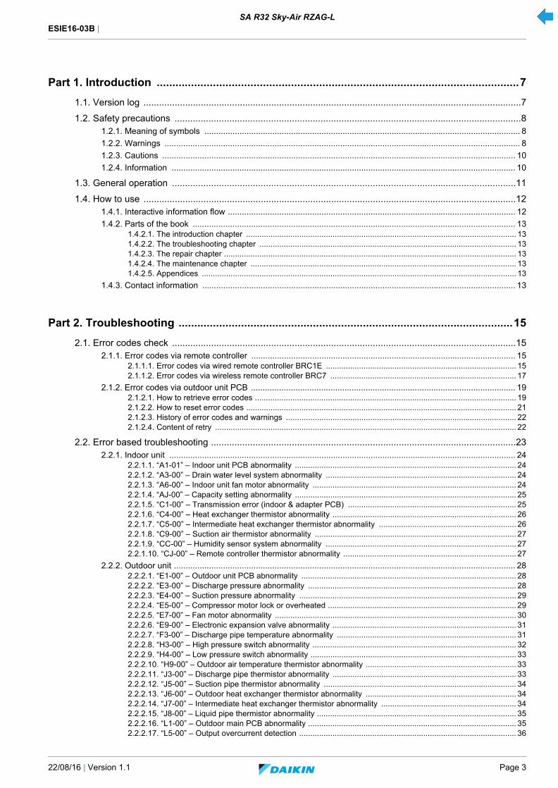
22/08/16 | Version 1.1 Page 3
SA R32 Sky-Air RZAG-L
Part 1. Introduction ....................................................................................................................7
1.1. Version log .................................................................................................................................................7
1.2. Safety precautions .....................................................................................................................................81.2.1. Meaning of symbols ....................................................................................................................................... 8
1.2.2. Warnings ........................................................................................................................................................ 8
1.2.3. Cautions ....................................................................................................................................................... 10
1.2.4. Information ................................................................................................................................................... 10
1.3. General operation ....................................................................................................................................11
1.4. How to use ...............................................................................................................................................121.4.1. Interactive information flow ........................................................................................................................... 12
1.4.2. Parts of the book .......................................................................................................................................... 131.4.2.1. The introduction chapter .......................................................................................................................... 131.4.2.2. The troubleshooting chapter .................................................................................................................... 131.4.2.3. The repair chapter .................................................................................................................................... 131.4.2.4. The maintenance chapter ........................................................................................................................ 131.4.2.5. Appendices .............................................................................................................................................. 13
1.4.3. Contact information ...................................................................................................................................... 13
Part 2. Troubleshooting ...........................................................................................................15
2.1. Error codes check ....................................................................................................................................152.1.1. Error codes via remote controller ................................................................................................................. 15
2.1.1.1. Error codes via wired remote controller BRC1E ...................................................................................... 152.1.1.2. Error codes via wireless remote controller BRC7 .................................................................................... 17
2.1.2. Error codes via outdoor unit PCB ................................................................................................................. 192.1.2.1. How to retrieve error codes ...................................................................................................................... 192.1.2.2. How to reset error codes .......................................................................................................................... 212.1.2.3. History of error codes and warnings ........................................................................................................ 222.1.2.4. Content of retry ........................................................................................................................................ 22
2.2. Error based troubleshooting .....................................................................................................................232.2.1. Indoor unit .................................................................................................................................................... 24
2.2.1.1. “A1-01” – Indoor unit PCB abnormality .................................................................................................... 242.2.1.2. “A3-00” – Drain water level system abnormality ...................................................................................... 242.2.1.3. “A6-00” – Indoor unit fan motor abnormality ............................................................................................ 242.2.1.4. “AJ-00” – Capacity setting abnormality .................................................................................................... 252.2.1.5. “C1-00” – Transmission error (indoor & adapter PCB) ............................................................................ 252.2.1.6. “C4-00” – Heat exchanger thermistor abnormality ................................................................................... 262.2.1.7. “C5-00” – Intermediate heat exchanger thermistor abnormality .............................................................. 262.2.1.8. “C9-00” – Suction air thermistor abnormality ........................................................................................... 272.2.1.9. “CC-00” – Humidity sensor system abnormality ...................................................................................... 272.2.1.10. “CJ-00” – Remote controller thermistor abnormality .............................................................................. 27
2.2.2. Outdoor unit .................................................................................................................................................. 282.2.2.1. “E1-00” – Outdoor unit PCB abnormality ................................................................................................. 282.2.2.2. “E3-00” – Discharge pressure abnormality .............................................................................................. 282.2.2.3. “E4-00” – Suction pressure abnormality .................................................................................................. 292.2.2.4. “E5-00” – Compressor motor lock or overheated ..................................................................................... 292.2.2.5. “E7-00” – Fan motor abnormality ............................................................................................................. 302.2.2.6. “E9-00” – Electronic expansion valve abnormality ................................................................................... 312.2.2.7. “F3-00” – Discharge pipe temperature abnormality ................................................................................. 312.2.2.8. “H3-00” – High pressure switch abnormality ............................................................................................ 322.2.2.9. “H4-00” – Low pressure switch abnormality ............................................................................................. 332.2.2.10. “H9-00” – Outdoor air temperature thermistor abnormality .................................................................... 332.2.2.11. “J3-00” – Discharge pipe thermistor abnormality ................................................................................... 332.2.2.12. “J5-00” – Suction pipe thermistor abnormality ....................................................................................... 342.2.2.13. “J6-00” – Outdoor heat exchanger thermistor abnormality .................................................................... 342.2.2.14. “J7-00” – Intermediate heat exchanger thermistor abnormality ............................................................. 342.2.2.15. “J8-00” – Liquid pipe thermistor abnormality .......................................................................................... 352.2.2.16. “L1-00” – Outdoor main PCB abnormality .............................................................................................. 352.2.2.17. “L5-00” – Output overcurrent detection .................................................................................................. 36
ESIE16-03B |
Page 4 22/08/16 | Version 1.1
SA R32 Sky-Air RZAG-L
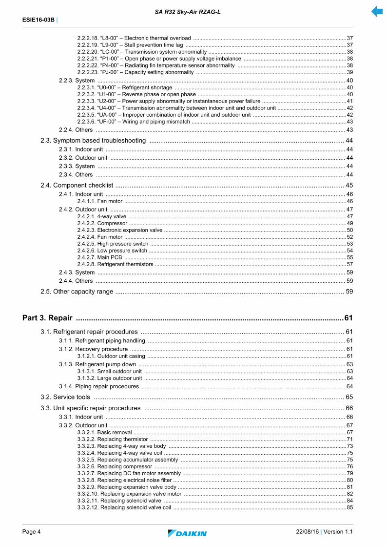
2.2.2.18. “L8-00” – Electronic thermal overload ....................................................................................................372.2.2.19. “L9-00” – Stall prevention time lag .........................................................................................................372.2.2.20. “LC-00” – Transmission system abnormality ..........................................................................................382.2.2.21. “P1-00” – Open phase or power supply voltage imbalance ...................................................................382.2.2.22. “P4-00” – Radiating fin temperature sensor abnormality .......................................................................382.2.2.23. “PJ-00” – Capacity setting abnormality ..................................................................................................39
2.2.3. System ......................................................................................................................................................... 402.2.3.1. “U0-00” – Refrigerant shortage ................................................................................................................402.2.3.2. “U1-00” – Reverse phase or open phase .................................................................................................402.2.3.3. “U2-00” – Power supply abnormality or instantaneous power failure .......................................................412.2.3.4. “U4-00” – Transmission abnormality between indoor unit and outdoor unit .............................................422.2.3.5. “UA-00” – Improper combination of indoor unit and outdoor unit .............................................................422.2.3.6. “UF-00” – Wiring and piping mismatch .....................................................................................................43
2.2.4. Others .......................................................................................................................................................... 43
2.3. Symptom based troubleshooting ............................................................................................................ 442.3.1. Indoor unit .................................................................................................................................................... 44
2.3.2. Outdoor unit ................................................................................................................................................. 44
2.3.3. System ......................................................................................................................................................... 44
2.3.4. Others .......................................................................................................................................................... 44
2.4. Component checklist ............................................................................................................................... 452.4.1. Indoor unit .................................................................................................................................................... 46
2.4.1.1. Fan motor .................................................................................................................................................46
2.4.2. Outdoor unit ................................................................................................................................................. 472.4.2.1. 4-way valve ..............................................................................................................................................472.4.2.2. Compressor ..............................................................................................................................................492.4.2.3. Electronic expansion valve .......................................................................................................................502.4.2.4. Fan motor .................................................................................................................................................522.4.2.5. High pressure switch ................................................................................................................................532.4.2.6. Low pressure switch .................................................................................................................................542.4.2.7. Main PCB .................................................................................................................................................552.4.2.8. Refrigerant thermistors .............................................................................................................................57
2.4.3. System ......................................................................................................................................................... 59
2.4.4. Others .......................................................................................................................................................... 59
2.5. Other capacity range ............................................................................................................................... 59
Part 3. Repair ............................................................................................................................61
3.1. Refrigerant repair procedures ................................................................................................................. 613.1.1. Refrigerant piping handling .......................................................................................................................... 61
3.1.2. Recovery procedure ..................................................................................................................................... 613.1.2.1. Outdoor unit casing ..................................................................................................................................61
3.1.3. Refrigerant pump down ................................................................................................................................ 633.1.3.1. Small outdoor unit ....................................................................................................................................633.1.3.2. Large outdoor unit ....................................................................................................................................64
3.1.4. Piping repair procedures .............................................................................................................................. 64
3.2. Service tools ........................................................................................................................................... 65
3.3. Unit specific repair procedures ............................................................................................................... 663.3.1. Indoor unit .................................................................................................................................................... 66
3.3.2. Outdoor unit ................................................................................................................................................. 673.3.2.1. Basic removal ...........................................................................................................................................673.3.2.2. Replacing thermistor ................................................................................................................................713.3.2.3. Replacing 4-way valve body ....................................................................................................................733.3.2.4. Replacing 4-way valve coil .......................................................................................................................753.3.2.5. Replacing accumulator assembly ............................................................................................................753.3.2.6. Replacing compressor .............................................................................................................................763.3.2.7. Replacing DC fan motor assembly ...........................................................................................................793.3.2.8. Replacing electrical noise filter .................................................................................................................803.3.2.9. Replacing expansion valve body ..............................................................................................................813.3.2.10. Replacing expansion valve motor ..........................................................................................................823.3.2.11. Replacing solenoid valve .......................................................................................................................843.3.2.12. Replacing solenoid valve coil .................................................................................................................85
ESIE16-03B |
22/08/16 | Version 1.1 Page 5
SA R32 Sky-Air RZAG-L
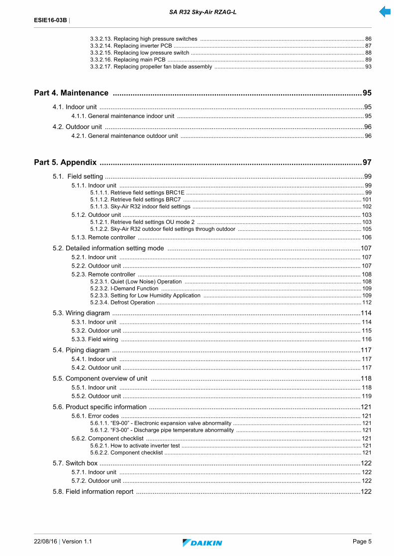
3.3.2.13. Replacing high pressure switches ......................................................................................................... 863.3.2.14. Replacing inverter PCB .......................................................................................................................... 873.3.2.15. Replacing low pressure switch ............................................................................................................... 883.3.2.16. Replacing main PCB .............................................................................................................................. 893.3.2.17. Replacing propeller fan blade assembly ................................................................................................ 93
Part 4. Maintenance .................................................................................................................95
4.1. Indoor unit ................................................................................................................................................954.1.1. General maintenance indoor unit ................................................................................................................. 95
4.2. Outdoor unit .............................................................................................................................................964.2.1. General maintenance outdoor unit ............................................................................................................... 96
Part 5. Appendix .......................................................................................................................97
5.1. Field setting .............................................................................................................................................995.1.1. Indoor unit .................................................................................................................................................... 99
5.1.1.1. Retrieve field settings BRC1E .................................................................................................................. 995.1.1.2. Retrieve field settings BRC7 .................................................................................................................. 1015.1.1.3. Sky-Air R32 indoor field settings ............................................................................................................ 102
5.1.2. Outdoor unit ................................................................................................................................................ 1035.1.2.1. Retrieve field settings OU mode 2 ......................................................................................................... 1035.1.2.2. Sky-Air R32 outdoor field settings through outdoor ............................................................................... 105
5.1.3. Remote controller ....................................................................................................................................... 106
5.2. Detailed information setting mode .........................................................................................................1075.2.1. Indoor unit .................................................................................................................................................. 107
5.2.2. Outdoor unit ................................................................................................................................................ 107
5.2.3. Remote controller ....................................................................................................................................... 1085.2.3.1. Quiet (Low Noise) Operation ................................................................................................................. 1085.2.3.2. I-Demand Function ................................................................................................................................ 1095.2.3.3. Setting for Low Humidity Application ..................................................................................................... 1095.2.3.4. Defrost Operation ................................................................................................................................... 112
5.3. Wiring diagram .......................................................................................................................................1145.3.1. Indoor unit .................................................................................................................................................. 114
5.3.2. Outdoor unit ................................................................................................................................................ 115
5.3.3. Field wiring ................................................................................................................................................. 116
5.4. Piping diagram .......................................................................................................................................1175.4.1. Indoor unit .................................................................................................................................................. 117
5.4.2. Outdoor unit ................................................................................................................................................ 117
5.5. Component overview of unit ..................................................................................................................1185.5.1. Indoor unit .................................................................................................................................................. 118
5.5.2. Outdoor unit ................................................................................................................................................ 119
5.6. Product specific information ...................................................................................................................1215.6.1. Error codes ................................................................................................................................................. 121
5.6.1.1. “E9-00” - Electronic expansion valve abnormality .................................................................................. 1215.6.1.2. “F3-00” - Discharge pipe temperature abnormality ................................................................................ 121
5.6.2. Component checklist .................................................................................................................................. 1215.6.2.1. How to activate inverter test ................................................................................................................... 1215.6.2.2. Component checklist .............................................................................................................................. 121
5.7. Switch box ..............................................................................................................................................1225.7.1. Indoor unit .................................................................................................................................................. 122
5.7.2. Outdoor unit ................................................................................................................................................ 122
5.8. Field information report ..........................................................................................................................122

ESIE16-03B |
Page 6 22/08/16 | Version 1.1
SA R32 Sky-Air RZAG-L
Figure 3-1: 1 service port at the stop valves ............................................................................................................ 62
Figure 3-2: 3 service ports at the stop valves .......................................................................................................... 63
Figure 3-3: Removing the top plate assembly .......................................................................................................... 67
Figure 3-4: Removing the front plate ........................................................................................................................ 68
Figure 3-5: Removing the front plate assembly ....................................................................................................... 68
Figure 3-6: Removing the cover ............................................................................................................................... 69
Figure 3-7: Removing the piping cover .................................................................................................................... 69
Figure 3-8: Removing the right side plate ................................................................................................................ 70
Figure 3-9: Thermistor location ................................................................................................................................ 71
Figure 3-10: Replacing a thermistor ......................................................................................................................... 72
Figure 3-11: Removing 4-way valve body ................................................................................................................ 73
Figure 3-12: Removing 4-way valve body ................................................................................................................ 75
Figure 3-13: Removing stop valve mounting plate ................................................................................................... 76
Figure 3-14: Removing compressor ......................................................................................................................... 77
Figure 3-15: Removing the DC fan motor assembly ................................................................................................ 79
Figure 3-16: Removing the electrical noise filter ...................................................................................................... 80
Figure 3-17: Removing expansion valve .................................................................................................................. 81
Figure 3-18: Removing expansion valve motor ........................................................................................................ 82
Figure 3-19: Removing expansion valve motor ........................................................................................................ 83
Figure 3-20: Removing solenoid valve ..................................................................................................................... 84
Figure 3-21: Removing solenoid valve coil .............................................................................................................. 85
Figure 3-22: Removing high pressure switches ....................................................................................................... 86
Figure 3-23: Removing low pressure switch ............................................................................................................ 88
Figure 3-24: Removing the main PCB assembly ..................................................................................................... 90
Figure 3-25: Stripping the main PCB assembly (front) ............................................................................................. 91
Figure 3-26: Stripping the main PCB assembly (rear) ............................................................................................. 92
Figure 3-27: Removing the propeller fan blade assembly ........................................................................................ 93
Figure 5-1: Wiring diagram - indoor unit ................................................................................................................. 114
Figure 5-2: Wiring diagram - outdoor unit 71 ......................................................................................................... 115
Figure 5-3: Wiring diagram - outdoor unit 100-140 ................................................................................................ 116
Figure 5-4: Piping diagram - indoor unit ................................................................................................................. 117
Figure 5-5: Piping diagram - outdoor unit ............................................................................................................... 117
Figure 5-6: Components overview - indoor unit ..................................................................................................... 118
Figure 5-7: Components overview - outdoor unit 71 .............................................................................................. 119
Figure 5-8: Components overview - outdoor unit 100-140 ..................................................................................... 120

ESIE16-03B | Part 1. Introduction 1.1. Version log
22/08/16 | Version 1.1 Page 7
SA R32 Sky-Air RZAG-L
Part 1. IntroductionThis part contains the following chapters:
1.1. Version log
Version log .............................................................................................................................................................................................7
Safety precautions..................................................................................................................................................................................8
General operation.................................................................................................................................................................................11
How to use ...........................................................................................................................................................................................12
Version code Description Date
ESIE16-03A Document release 19/07/2016
ESIE16-03B Update chapter 2.1.2.: correction of setting items in monitor mode for malfunction/con-tent of retry
Update chapter 3.3.2.2.: addition of 3D view of RZAG71
Update chapter 5.6.2.: component checklist added
22/08/2016

ESIE16-03B | Part 1. Introduction 1.2. Safety precautions
Page 8 22/08/16 | Version 1.1
SA R32 Sky-Air RZAG-L
1.2. Safety precautions
The precautions described in this document cover very important topics, follow them carefully.
All activities described in the service manual must be performed by an authorized person.
If you are not sure how to install, operate or service the unit, contact your dealer.
In accordance with the applicable legislation, it might be necessary to provide a logbook with the product containing at least: information on maintenance, repair work, results of tests, stand-by periods, …
Also, at least, following information must be provided at an accessible place at the product:
• Instructions for shutting down the system in case of an emergency
• Name and address of fire department, police and hospital
• Name, address and day and night telephone numbers for obtaining service
In Europe, EN378 provides the necessary guidance for this logbook.
1.2.1. Meaning of symbols
1.2.2. Warnings
WARNING
Indicates a situation that could result in death or serious injury.
WARNING: RISK OF ELECTROCUTION
Indicates a situation that could result in electrocution.
WARNING: RISK OF BURNING
Indicates a situation that could result in burning because of extreme hot or cold temperatures.
WARNING: RISK OF EXPLOSION
Indicates a situation that could result in explosion.
WARNING: RISK OF POISONING
Indicates a situation that could result in poisoning.
WARNING: RISK OF FIRE
Indicates a situation that could result in fire.
CAUTION
Indicates a situation that could result in equipment or property damage.
INFORMATION
Indicates useful tips or additional information.
WARNING
Improper installation or attachment of equipment or accessories could result in electric shock, short-circuit, leaks, fire or other damage to the equipment. Only use accessories, optional equipment and spare parts made or approved by Dai-kin.
ESIE16-03B | Part 1. Introduction 1.2. Safety precautions
22/08/16 | Version 1.1 Page 9
SA R32 Sky-Air RZAG-L
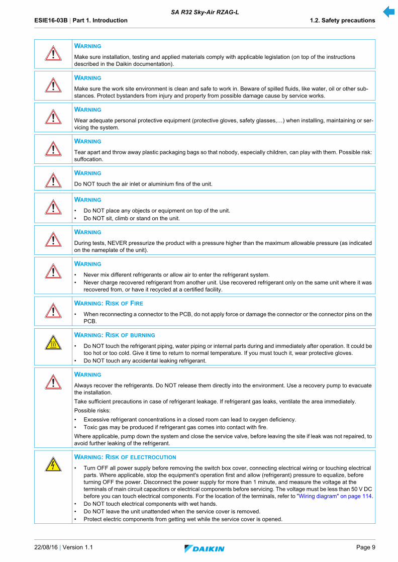
WARNING
Make sure installation, testing and applied materials comply with applicable legislation (on top of the instructions described in the Daikin documentation).
WARNING
Make sure the work site environment is clean and safe to work in. Beware of spilled fluids, like water, oil or other sub-stances. Protect bystanders from injury and property from possible damage cause by service works.
WARNING
Wear adequate personal protective equipment (protective gloves, safety glasses,…) when installing, maintaining or ser-vicing the system.
WARNING
Tear apart and throw away plastic packaging bags so that nobody, especially children, can play with them. Possible risk: suffocation.
WARNING
Do NOT touch the air inlet or aluminium fins of the unit.
WARNING
• Do NOT place any objects or equipment on top of the unit.• Do NOT sit, climb or stand on the unit.
WARNING
During tests, NEVER pressurize the product with a pressure higher than the maximum allowable pressure (as indicated on the nameplate of the unit).
WARNING
• Never mix different refrigerants or allow air to enter the refrigerant system.• Never charge recovered refrigerant from another unit. Use recovered refrigerant only on the same unit where it was
recovered from, or have it recycled at a certified facility.
WARNING: RISK OF FIRE
• When reconnecting a connector to the PCB, do not apply force or damage the connector or the connector pins on the PCB.
WARNING: RISK OF BURNING
• Do NOT touch the refrigerant piping, water piping or internal parts during and immediately after operation. It could be too hot or too cold. Give it time to return to normal temperature. If you must touch it, wear protective gloves.
• Do NOT touch any accidental leaking refrigerant.
WARNING
Always recover the refrigerants. Do NOT release them directly into the environment. Use a recovery pump to evacuate the installation.
Take sufficient precautions in case of refrigerant leakage. If refrigerant gas leaks, ventilate the area immediately.
Possible risks:
• Excessive refrigerant concentrations in a closed room can lead to oxygen deficiency.• Toxic gas may be produced if refrigerant gas comes into contact with fire.
Where applicable, pump down the system and close the service valve, before leaving the site if leak was not repaired, to avoid further leaking of the refrigerant.
WARNING: RISK OF ELECTROCUTION
• Turn OFF all power supply before removing the switch box cover, connecting electrical wiring or touching electrical parts. Where applicable, stop the equipment's operation first and allow (refrigerant) pressure to equalize, before turning OFF the power. Disconnect the power supply for more than 1 minute, and measure the voltage at the terminals of main circuit capacitors or electrical components before servicing. The voltage must be less than 50 V DC before you can touch electrical components. For the location of the terminals, refer to "Wiring diagram" on page 114.
• Do NOT touch electrical components with wet hands.• Do NOT leave the unit unattended when the service cover is removed.• Protect electric components from getting wet while the service cover is opened.

ESIE16-03B | Part 1. Introduction 1.2. Safety precautions
Page 10 22/08/16 | Version 1.1
SA R32 Sky-Air RZAG-L
1.2.3. Cautions
1.2.4. Information
WARNING
• Only use copper wires.• All field wiring must be performed in accordance with the wiring diagram and installation manual supplied with the
product.• If the power cable and lead wires have scratches or deteriorated, be sure to replace them. Damaged cable and wires
may cause an electrical shock, excessive heat generation or fire.• Secure all terminal connections and provide proper routing for cables, both inside and outside the switchbox.• NEVER squeeze bundled cables and make sure they do not come in contact with the piping and sharp edges.• Make sure no external pressure is applied to the terminal connections.• Make sure to check the earth wiring. Do NOT earth the unit to a utility pipe, surge absorber, or telephone earth.
Improper earth wiring may cause electrical shock.• Make sure to use a dedicated power circuit. NEVER use a power supply shared by another appliance.• Make sure to check the required fuses and/or circuit breakers before starting works.
WARNING
• After finishing the electrical work, confirm that each electrical component and terminal inside the electrical components box is connected securely.
• Make sure all covers are closed before starting the unit again.
CAUTION
Provide adequate measures to prevent that the unit can be used as a shelter by small animals. Small animals that make contact with electrical parts can cause malfunctions, smoke or fire.
CAUTION
• Make sure water quality complies with EU directive 98/83 EC.• Check the system for leaks after each repair/modification of the water side.• Check drainage system(s) after repairs.• Be careful when tilting units as water may leak.
INFORMATION
Make sure refrigerant piping installation complies with applicable legislation. In Europe, EN378 is the applicable stand-ard.
INFORMATION
Make sure the field piping and connections are not subjected to stress.

ESIE16-03B | Part 1. Introduction 1.3. General operation
22/08/16 | Version 1.1 Page 11
SA R32 Sky-Air RZAG-L
1.3. General operation
• The Sky-Air is typically used for cooling or heating in commercial applications. Some units also have settings to performtechnical cooling. The medium which is used to transfer the heat from inside to outside or vice versa, is refrigerant. In case ofthe RZAG-L, the refrigerant which is used, is R32.
• In case of heating, the compressor builds up pressure and hence the temperature of the refrigerant is increased. The hotrefrigerant is blown into the room by a fan which blows over a heat exchanger. Colder refrigerant flows back to the outdoorunit, where temperature is further decreased by expansion through an expansion valve. After the expansion valve, therefrigerant is capable of taking up heat again. This is enabled by a fan that sucks outdoor air over a heat exchanger. Thisrefrigerant is then transported to the compressor where temperature is further built up again and the cycle starts again. Forcooling, it’s just the other way round.
1. Compressor 4. Electronic expansion valve
2. Indoor heat exchanger 5. Outdoor heat exchanger
3. Fan
ESIE16-03B | Part 1. Introduction 1.4. How to use
Page 12 22/08/16 | Version 1.1
SA R32 Sky-Air RZAG-L
1.4. How to use
1.4.1. Interactive information flow
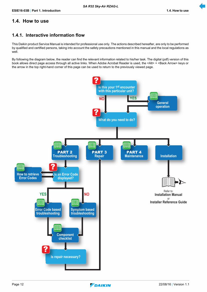
This Daikin product Service Manual is intended for professional use only. The actions described hereafter, are only to be performed by qualified and certified persons, taking into account the safety precautions mentioned in this manual and the local regulations as well.
By following the diagram below, the reader can find the relevant information related to his/her task. The digital (pdf) version of this book allows direct page access through all active links. When Adobe Acrobat Reader is used, the <Alt> + <Back Arrow> keys or the arrow in the top right-hand corner of this page can be used to return to the previously viewed page.
NO YES
NOYES
NNNNNNOOOOOO YYYYYYEEEEEESSSSSS
Is this your 1st encounterwith this particular unit? IIIsIsIsIsIs tttttthhhhiswith th
?
What do you need to do? WWhWhWhWhWhaat d?
Is an Error Codedisplayed?
IIIsIsIsIsIs aaa annn Erdispl
?
Is repair necessary? IIsIsIsIs re?
Generaloperation
Refer to:Installation Manual
orInstaller Reference Guide
??
PART 2Troubleshooting
How to retrieveError Codes
Componentchecklist
PART 3Repair
PART 4Maintenance Installation
Error Code basedtroubleshooting
Symptom basedtroubleshooting
Errroroorororrrrr CCoCoCoCoCoCoddde troublesho
SySySyympmpmpmpmpmptttototototomm btroublesho
ESIE16-03B | Part 1. Introduction 1.4. How to use
22/08/16 | Version 1.1 Page 13
SA R32 Sky-Air RZAG-L
1.4.2. Parts of the book
This Daikin product Service Manual is intended for professional use only. The actions described hereafter, are only to be performed by qualified and certified persons, taking into account the safety precautions mentioned in this manual and the local regulations as well.
As can be observed from the Table of Contents, this manual is split up into several chapters:
1.4.2.1. The introduction chapter
The chapter "Introduction" on page 7 includes the safety precautions, this topic and the general operation description of the product(s) this manual refers to.
1.4.2.2. The troubleshooting chapter
The chapter "Troubleshooting" on page 15 not only deals with the methods to recognize and resolve occurring error codes; it also describes the methods how to solve a problem that does not immediately trigger an error code. Such problems are referred to as 'symptom based'. Both the error code based and symptom based troubleshooting tables, indicate possible causes, the necessary checks and in case required, how to repair. The possible causes have been sorted to probability of occurrence and speed of execution.
1.4.2.3. The repair chapter
The chapter "Repair" on page 61 handles the removal and replacement of the major components in the product and discusses cleaning methods as well if applicable, such as for filters. Where applicable, refrigerant handling precautions are mentioned for certain actions; please consider these carefully for your own safety.
1.4.2.4. The maintenance chapter
The chapter "Maintenance" on page 95 of this manual describes the maintenance intervals and procedures to be performed on the product. Remember that a well maintained product, is a more reliable and efficient product.
1.4.2.5. Appendices
Finally, the service manual provides in chapter "Appendix" on page 97 valuable reference data such as piping/wiring diagrams, field settings overview and a checklist to be filled in when you need to escalate an issue to your dealer.
1.4.3. Contact information
This manual has been made with much care and effort. Use it in your daily jobs, as it has been made for you.
Despite our efforts, there is always a chance some cleric or other mistake has been made during the creation of this manual. We kindly ask you to send the found mistakes, or remarks for improvement, to the no-reply email address [email protected].
ESIE16-03B | Part 1. Introduction 1.4. How to use
Page 14 22/08/16 | Version 1.1
SA R32 Sky-Air RZAG-L
ESIE16-03B | Part 2. Troubleshooting 2.1. Error codes check
22/08/16 | Version 1.1 Page 15
SA R32 Sky-Air RZAG-L
Part 2. TroubleshootingThis part contains the following chapters:
2.1. Error codes check
2.1.1. Error codes via remote controller
2.1.1.1. Error codes via wired remote controller BRC1E
2.1.1.1.1 How to retrieve error codes
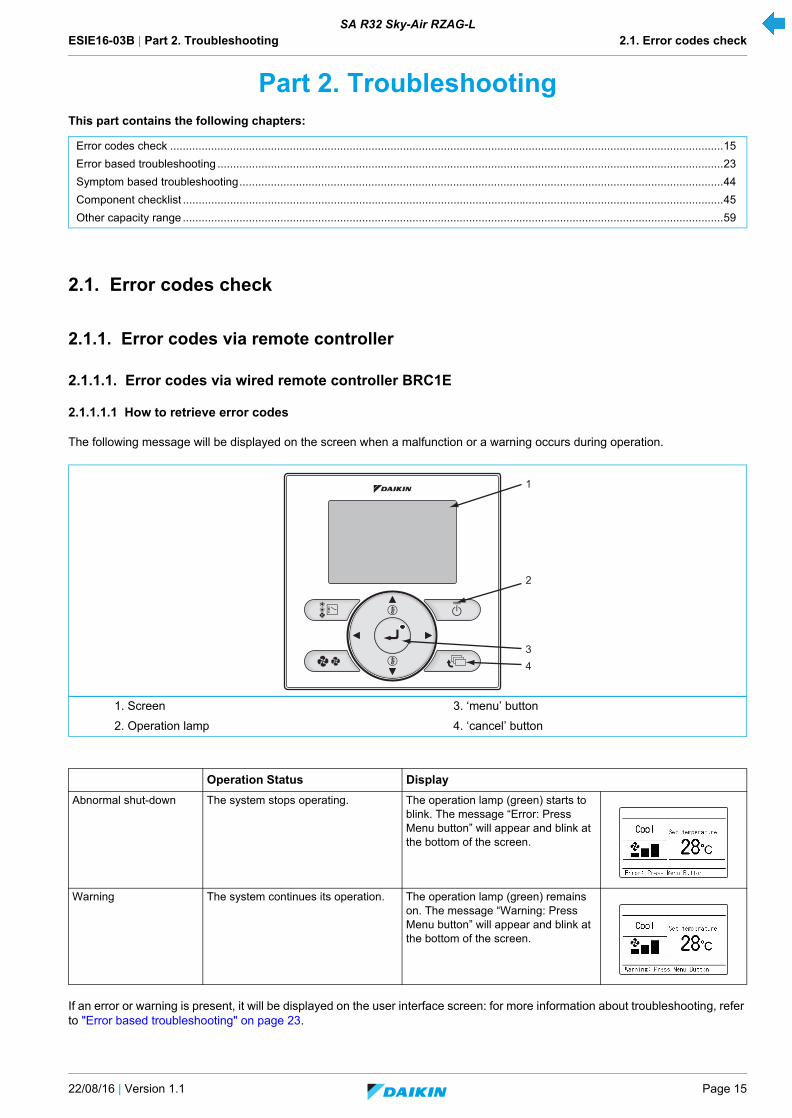
The following message will be displayed on the screen when a malfunction or a warning occurs during operation.
If an error or warning is present, it will be displayed on the user interface screen: for more information about troubleshooting, refer to "Error based troubleshooting" on page 23.
Error codes check ................................................................................................................................................................................15
Error based troubleshooting .................................................................................................................................................................23
Symptom based troubleshooting..........................................................................................................................................................44
Component checklist ............................................................................................................................................................................45
Other capacity range ............................................................................................................................................................................59
1. Screen 3. ‘menu’ button
2. Operation lamp 4. ‘cancel’ button
Operation Status Display
Abnormal shut-down The system stops operating. The operation lamp (green) starts to blink. The message “Error: Press Menu button” will appear and blink at the bottom of the screen.
Warning The system continues its operation. The operation lamp (green) remains on. The message “Warning: Press Menu button” will appear and blink at the bottom of the screen.
1
2
34
ESIE16-03B | Part 2. Troubleshooting 2.1. Error codes check
Page 16 22/08/16 | Version 1.1
SA R32 Sky-Air RZAG-L
2.1.1.1.2 How to reset error codes
In "Error based troubleshooting" on page 23 you find a description of how to reset the specific error or warning.
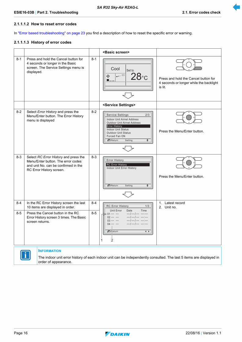
2.1.1.1.3 History of error codes
.
<Basic screen>
8-1 Press and hold the Cancel button for 4 seconds or longer in the Basic screen. The Service Settings menu is displayed.
8-1
Press and hold the Cancel button for 4 seconds or longer while the backlight is lit.
<Service Settings>
8-2 Select Error History and press the Menu/Enter button. The Error History menu is displayed
8-2
Press the Menu/Enter button.
8-3 Select RC Error History and press the Menu/Enter button. The error codes and unit No. can be confirmed in the RC Error History screen.
8-3
Press the Menu/Enter button.
8-4 In the RC Error History screen the last 10 items are displayed in order.
8-4 1. Latest record2. Unit no.
8-5 Press the Cancel button in the RC Error History screen 3 times. The Basic screen returns.
8-5
INFORMATION
The indoor unit error history of each indoor unit can be independently consulted. The last 5 items are displayed in order of appearance.
Cool Set to
28°C
2/3Indoor Unit Airnet AddressOutdoor Unit Airnet AddressError HistoryIndoor Unit StatusOutdoor Unit StatusForced Fan ON
Service Settings
SettingReturn
2/2RC Error HistoryIndoor Unit Error History
Error History
SettingReturn
1/3 Unit Error Date TimeRC Error History
Return
1 2
ESIE16-03B | Part 2. Troubleshooting 2.1. Error codes check
22/08/16 | Version 1.1 Page 17
SA R32 Sky-Air RZAG-L
2.1.1.2. Error codes via wireless remote controller BRC7
2.1.1.2.1 How to retrieve error codes
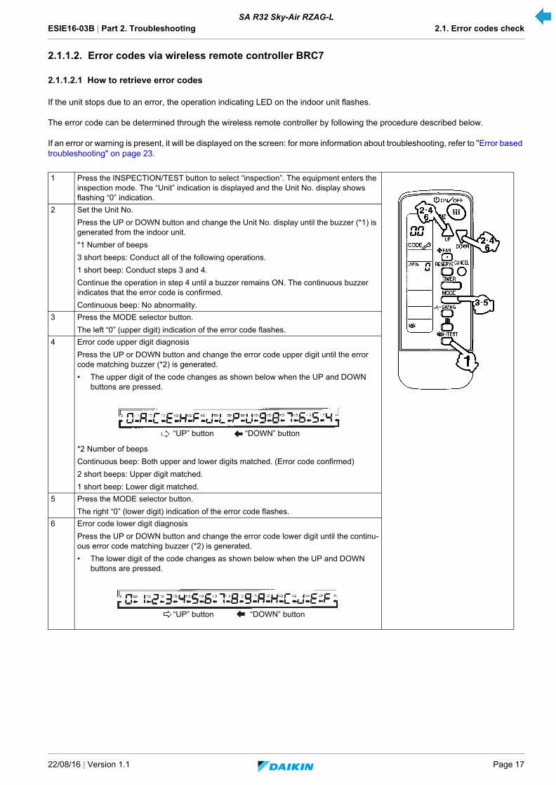
If the unit stops due to an error, the operation indicating LED on the indoor unit flashes.
The error code can be determined through the wireless remote controller by following the procedure described below.
If an error or warning is present, it will be displayed on the screen: for more information about troubleshooting, refer to "Error based troubleshooting" on page 23.
1 Press the INSPECTION/TEST button to select “inspection”. The equipment enters the inspection mode. The “Unit” indication is displayed and the Unit No. display shows flashing “0” indication.
2 Set the Unit No.
Press the UP or DOWN button and change the Unit No. display until the buzzer (*1) is generated from the indoor unit.
*1 Number of beeps
3 short beeps: Conduct all of the following operations.
1 short beep: Conduct steps 3 and 4.
Continue the operation in step 4 until a buzzer remains ON. The continuous buzzer indicates that the error code is confirmed.
Continuous beep: No abnormality.
3 Press the MODE selector button.
The left “0” (upper digit) indication of the error code flashes.
4 Error code upper digit diagnosis
Press the UP or DOWN button and change the error code upper digit until the error code matching buzzer (*2) is generated.
• The upper digit of the code changes as shown below when the UP and DOWN buttons are pressed.
*2 Number of beeps
Continuous beep: Both upper and lower digits matched. (Error code confirmed)
2 short beeps: Upper digit matched.
1 short beep: Lower digit matched.
5 Press the MODE selector button.
The right “0” (lower digit) indication of the error code flashes.
6 Error code lower digit diagnosis
Press the UP or DOWN button and change the error code lower digit until the continu-ous error code matching buzzer (*2) is generated.
• The lower digit of the code changes as shown below when the UP and DOWN buttons are pressed.
“UP” button “DOWN” button
“UP” button “DOWN” button
ESIE16-03B | Part 2. Troubleshooting 2.1. Error codes check
Page 18 22/08/16 | Version 1.1
SA R32 Sky-Air RZAG-L
2.1.1.2.2 How to reset error codes
In "Error based troubleshooting" on page 23 you find a description of how to reset the specific error or warning.
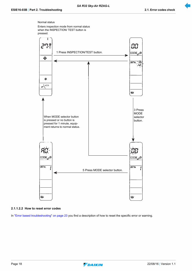
1 Press INSPECTION/TEST button.
Normal status
Enters inspection mode from normal status when the INSPECTION/ TEST button is pressed.
When MODE selector button is pressed or no button is pressed for 1 minute, equip-ment returns to normal status.
3 Press MODE selector button.
5 Press MODE selector button.

ESIE16-03B | Part 2. Troubleshooting 2.1. Error codes check
22/08/16 | Version 1.1 Page 19
SA R32 Sky-Air RZAG-L
2.1.2. Error codes via outdoor unit PCB
2.1.2.1. How to retrieve error codes
There are 2 ways to retrieve error codes through the outdoor unit:
1. Troubleshooting by LED on the outdoor main PCB
The following diagnosis can be conducted by turning on the power switch and checking the LED indication on the PCB of the outdoor unit.
w : LED on / x : LED off / c : LED blinks / — : Not used for diagnosis
.
.
2. Troubleshooting by LED on the outdoor service PCB
Take the following steps to check the error or warning (malfunction):
LED detection
DescriptionHAP H1P
(Green) (Red)
c x Normal
w — Faulty outdoor unit PCB (Information 1)
x — Power supply abnormality, or faulty outdoor unit PCB (Information 2)
c w Activation of protection device (Information 3)
INFORMATION
1. Turn off the power switch, and turn it on again after 5 seconds or more. Check the error condition, and diagnose the problem.
2. Turn off the power switch. After 5 seconds or more, disconnect the connection wire (2). Then turn on the power switch. If the HAP on the outdoor unit PCB flashes after about 10 seconds, the PCB A1P is faulty.
3. Also check for open phase.
INFORMATION
The error detection monitor continues to indicate the previously generated error until the power switch is turned off.
Be sure to turn off the power switch after inspection.
To enter "Monitor mode," push the MODE (BS1) button on A2P when in "Setting mode 1". (*)
<Display of RETURN 1>
<Display of RETURN 2>
<Display of RETURN 3>Push the SET (BS2) button to set the LED display to malfunction item according to binary counting. (**)
When SET (BS2) button is pushed, the LED display for RETURN 2 turns ON.
When SET (BS2) button is pushed, the LED display for RETURN 3 turns ON.
Check the error code that matches the LED sequence (see table on next page).
Push the RETURN (BS3) button to return the system to the initial state of "Monitor mode".
When the RETURN (BS3) button is pushed, the LED display for RETURN 1 turns ON.
! Pushing the MODE (BS1) button will bring the system to the "Setting mode 1".

ESIE16-03B | Part 2. Troubleshooting 2.1. Error codes check
Page 20 22/08/16 | Version 1.1
SA R32 Sky-Air RZAG-L
(*) Using the MODE button, the modes can be changed as follows.
(**)
HAP H1P H2P H3P H4P H5P H6P H7P
LED-status: w w w w w w w w
| | | | | | |
Binary counting: value: 64 32 16 8 4 2 1
| | | | | | |
Setting item: 14= latest error= w x x w w w x
15= previous error= w x x w w w w
16= 2 before= w x w x x x x
MODE
H1P
On Off Blinking
MODE
H1P
MODE
H1P
Setting mode 2 Setting mode 1 Monitor mode
Push and hold the BS1 (MODE button) for 5 seconds.
Push the BS1 (MODE button) one time.
Push the BS1 (MODE button) one time.
(Normal)

ESIE16-03B | Part 2. Troubleshooting 2.1. Error codes check
22/08/16 | Version 1.1 Page 21
SA R32 Sky-Air RZAG-L
For more information about troubleshooting, refer to "Error based troubleshooting" on page 23.
2.1.2.2. How to reset error codes
In "Error based troubleshooting" on page 23 you find a description on how to reset the specific error or warning.
w: ON x: OFF c: BLINK
Malfunc-tion code
Contents of retry or malfunction
Return 1 Return 2 Return 3
HAP
H1P
H2P
H3P
H4P
H5P
H6P
H7P
HAP
H1P
H2P
H3P
H4P
H5P
H6P
H7P
HAP
H1P
H2P
H3P
H4P
H5P
H6P
H7P
C4 Indoor heat exchanger thermistor c c w x x x c x c c w x x c x x c c w w x x x x
E1 Faulty outdoor PC board c c x w x x c c c c w x x x x c c c w w x x x xE3 Abnormal high pressure c c w x x x c c c c w w x x x xE4 Abnormal low pressure c c w x x c x x c c w w x x x xE5 Compressor motor lock c c w x x c x c c c w w x x x xE7 Abnormal
outdoor fan motor
DC motor 1 lock c c w x x c c c c c w w x x x cDC motor 2 lock c c w w x x c xAbnormal inverter transmission
c c w w x x c c
E9 Abnormal electronic expansion valve
Disconnected electronic expansion valve connector
c c w x c x x c c c w w x x x c
Malfunction due to wet conditions
c c w w x x c x
F3 Abnormal discharge pipe temperature
Abnormal discharge pipe temperature
c c x w x c x c c c w x x x c c c c w w x x x c
Disconnected discharge pipe thermistor
c c w w x x c x
H3 Abnormal high pressure switch c c x w x c x x c c w x x x c c c c w w x x x xH9 Abnormal outdoor air thermistor c c w x c x x c c c w w x x x xJ1 Abnormal pressure sensor c c x w x c c x c c w x x x x c c c w w x x x xJ3 Abnormal discharge pipe thermistor c c w x x x c c c c w w x x x xJ5 Abnormal suction pipe thermistor c c w x x c x c c c w w x x x xJ6 Abnormal heat exchanger distributor pipe
thermistorc c w x x c c x c c w w x x x x
J7 Abnormal intermediate heat exchanger thermistor
c c w x x c c c c c w w x x x x
J8 Abnormal liquid pipe thermistor c c w x c x x x c c w w x x x xL1 PC board failure c c x w x c c c c c w x x x x c c c w w x x x xL4 Elevated radiation fin temperature c c w x x c x x c c w w x x x xL5 Compressor instantaneous overcurrent c c w x x c x c c c w w x x x xL8 Compressor overload c c w x c x x x c c w w x x x xL9 Compressor lock c c w x c x x c c c w w x x x xLC Abnormal transmission (between the control
and the inverter)c c w x c c x x c c w w x x x x
P1 Unbalanced power supply voltage c c x w c x x x c c w x x x x c c c w w x x x xP4 Abnormal radiation fin thermistor c c w x x c x x c c w w x x x xPJ Faulty capacity setting c c w x c c x c c c w w x x x xU0 Abnormal gas
shortageGas shortage warning c c x w c x x c c c w x x x x x c c w w x x x cAbnormal gas shortage c c w w x x c x
U2 Abnormal power supply voltage
Inverter undervoltage and overvoltage
c c w x x x c x c c w w x x x c
SP-PAM overvoltage c c w w x x c xU4 Abnormal transmission (between indoor and
outdoor units)c c w x x c x x c c w w x x x x
UA Faulty field setting switch c c w x c x c x c c w w x x x xUF Improper piping and improper communication
wiringc c c c c c w w x x x x

ESIE16-03B | Part 2. Troubleshooting 2.1. Error codes check
Page 22 22/08/16 | Version 1.1
SA R32 Sky-Air RZAG-L
2.1.2.3. History of error codes and warnings
As described in above procedure, the latest error or warning codes can also be consulted in Monitor mode:
Setting item 5= latest error
Setting item 6= previous error
Setting item 7= 2 before
For the procedure and the meaning of the different displays, refer to "How to retrieve error codes" above.
2.1.2.4. Content of retry
Through the outdoor PCB, the content of retry can be determined.
Here, you can find the errors which are being created before they are being displayed on the user interface.
As described in below procedure, the content of retry can again be consulted in Monitor mode:
Setting item 2= latest retry
Setting item 3= 1 cycle before
Setting item 4= 2 cycles before
To enter "Monitor mode", press the MODE (BS1) button when in "Setting mode 1".
<Selection of retry or error item>
<Display of RETURN 1>
When the RETURN (BS3) button is pressed, the LED display for RETURN 1 turns ON.
When SET (BS2) button is pressed, the LED display for RETURN 2 turns ON.
When SET (BS2) button is pressed, the LED display for RETURN 3 turns ON.
Press the RETURN (BS3) button to return the system to the initial state of "Monitor mode".
* Pressing the MODE (BS1) button will bring the system to the "Setting mode 1".
Press the SET (BS2) button to set the LED display to retry item.
<Display of RETURN 2>
<Display of RETURN 3>
Check the retry that matches the LED sequence (see table above).
ESIE16-03B | Part 2. Troubleshooting 2.2. Error based troubleshooting
22/08/16 | Version 1.1 Page 23
SA R32 Sky-Air RZAG-L
2.2. Error based troubleshooting
Overview of error codes:
Indoor unit ............................................................................................................................................................................................24
“A1-01” – Indoor unit PCB abnormality ....................................................................................................................................24
“A3-00” – Drain water level system abnormality.......................................................................................................................24
“A6-00” – Indoor unit fan motor abnormality.............................................................................................................................24
“AJ-00” – Capacity setting abnormality ....................................................................................................................................25
“C1-00” – Transmission error (indoor & adapter PCB).............................................................................................................25
“C4-00” – Heat exchanger thermistor abnormality ...................................................................................................................26
“C5-00” – Intermediate heat exchanger thermistor abnormality...............................................................................................26
“C9-00” – Suction air thermistor abnormality............................................................................................................................27
“CC-00” – Humidity sensor system abnormality.......................................................................................................................27
“CJ-00” – Remote controller thermistor abnormality ................................................................................................................27
Outdoor unit..........................................................................................................................................................................................28
“E1-00” – Outdoor unit PCB abnormality..................................................................................................................................28
“E3-00” – Discharge pressure abnormality...............................................................................................................................28
“E4-00” – Suction pressure abnormality...................................................................................................................................29
“E5-00” – Compressor motor lock or overheated .....................................................................................................................29
“E7-00” – Fan motor abnormality .............................................................................................................................................30
“E9-00” – Electronic expansion valve abnormality ...................................................................................................................31
“F3-00” – Discharge pipe temperature abnormality..................................................................................................................31
“H3-00” – High pressure switch abnormality ............................................................................................................................32
“H4-00” – Low pressure switch abnormality .............................................................................................................................33
“H9-00” – Outdoor air temperature thermistor abnormality ......................................................................................................33
“J3-00” – Discharge pipe thermistor abnormality .....................................................................................................................33
“J5-00” – Suction pipe thermistor abnormality..........................................................................................................................34
“J6-00” – Outdoor heat exchanger thermistor abnormality.......................................................................................................34
“J7-00” – Intermediate heat exchanger thermistor abnormality................................................................................................34
“J8-00” – Liquid pipe thermistor abnormality ............................................................................................................................35
“L1-00” – Outdoor main PCB abnormality ................................................................................................................................35
“L5-00” – Output overcurrent detection ....................................................................................................................................36
“L8-00” – Electronic thermal overload ......................................................................................................................................37
“L9-00” – Stall prevention time lag ...........................................................................................................................................37
“LC-00” – Transmission system abnormality............................................................................................................................38
“P1-00” – Open phase or power supply voltage imbalance .....................................................................................................38
“P4-00” – Radiating fin temperature sensor abnormality..........................................................................................................38
“PJ-00” – Capacity setting abnormality ....................................................................................................................................39
System .................................................................................................................................................................................................40
“U0-00” – Refrigerant shortage ................................................................................................................................................40
“U1-00” – Reverse phase or open phase .................................................................................................................................40
“U2-00” – Power supply abnormality or instantaneous power failure.......................................................................................41
“U4-00” – Transmission abnormality between indoor unit and outdoor unit .............................................................................42
“UA-00” – Improper combination of indoor unit and outdoor unit .............................................................................................42
“UF-00” – Wiring and piping mismatch.....................................................................................................................................43
Others .................................................................................................................................................................................................43
ESIE16-03B | Part 2. Troubleshooting 2.2. Error based troubleshooting
Page 24 22/08/16 | Version 1.1
SA R32 Sky-Air RZAG-L
2.2.1. Indoor unit
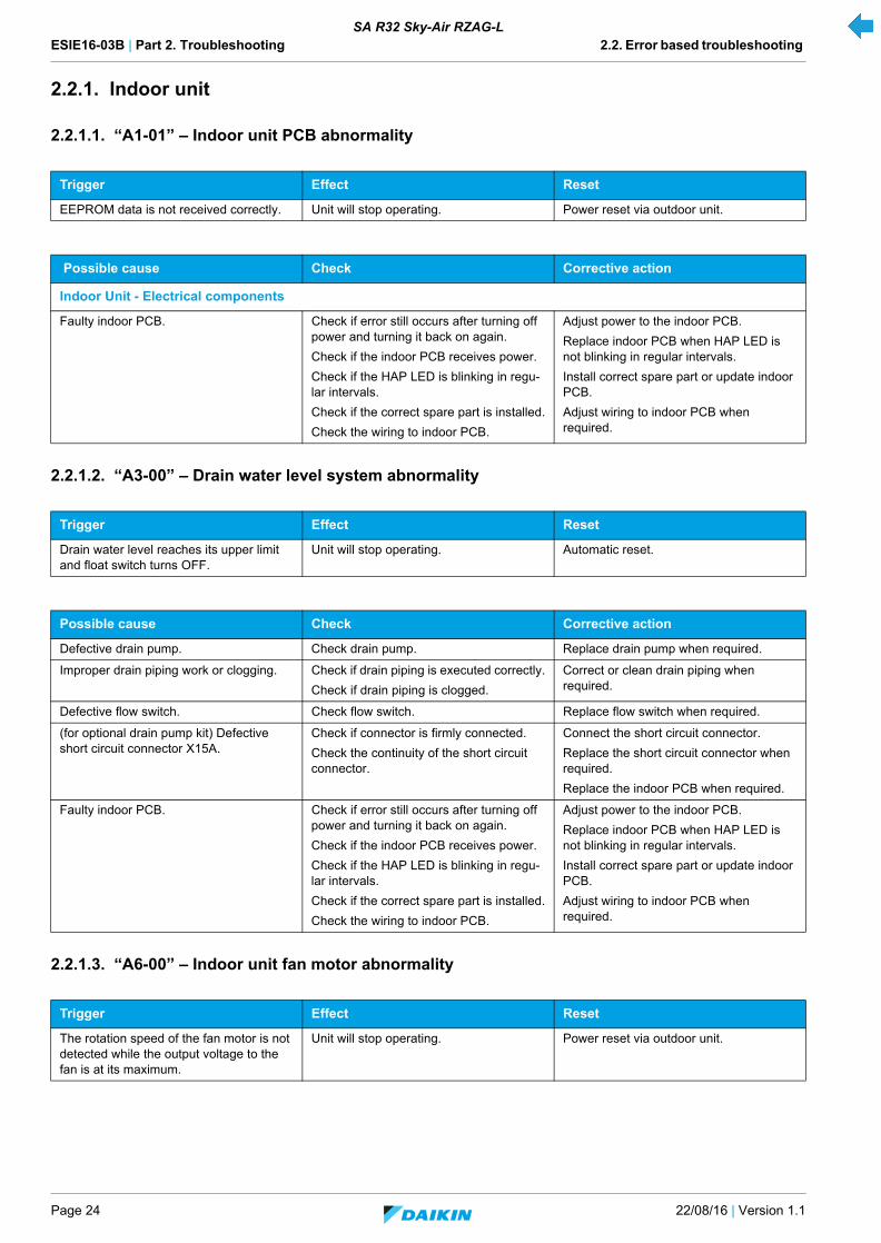
2.2.1.1. “A1-01” – Indoor unit PCB abnormality
2.2.1.2. “A3-00” – Drain water level system abnormality
2.2.1.3. “A6-00” – Indoor unit fan motor abnormality
Trigger Effect Reset
EEPROM data is not received correctly. Unit will stop operating. Power reset via outdoor unit.
Possible cause Check Corrective action
Indoor Unit - Electrical components
Faulty indoor PCB. Check if error still occurs after turning off power and turning it back on again.
Check if the indoor PCB receives power.
Check if the HAP LED is blinking in regu-lar intervals.
Check if the correct spare part is installed.
Check the wiring to indoor PCB.
Adjust power to the indoor PCB.
Replace indoor PCB when HAP LED is not blinking in regular intervals.
Install correct spare part or update indoor PCB.
Adjust wiring to indoor PCB when required.
Trigger Effect Reset
Drain water level reaches its upper limit and float switch turns OFF.
Unit will stop operating. Automatic reset.
Possible cause Check Corrective action
Defective drain pump. Check drain pump. Replace drain pump when required.
Improper drain piping work or clogging. Check if drain piping is executed correctly.
Check if drain piping is clogged.
Correct or clean drain piping when required.
Defective flow switch. Check flow switch. Replace flow switch when required.
(for optional drain pump kit) Defective short circuit connector X15A.
Check if connector is firmly connected.
Check the continuity of the short circuit connector.
Connect the short circuit connector.
Replace the short circuit connector when required.
Replace the indoor PCB when required.
Faulty indoor PCB. Check if error still occurs after turning off power and turning it back on again.
Check if the indoor PCB receives power.
Check if the HAP LED is blinking in regu-lar intervals.
Check if the correct spare part is installed.
Check the wiring to indoor PCB.
Adjust power to the indoor PCB.
Replace indoor PCB when HAP LED is not blinking in regular intervals.
Install correct spare part or update indoor PCB.
Adjust wiring to indoor PCB when required.
Trigger Effect Reset
The rotation speed of the fan motor is not detected while the output voltage to the fan is at its maximum.
Unit will stop operating. Power reset via outdoor unit.

ESIE16-03B | Part 2. Troubleshooting 2.2. Error based troubleshooting
22/08/16 | Version 1.1 Page 25
SA R32 Sky-Air RZAG-L
2.2.1.4. “AJ-00” – Capacity setting abnormality
2.2.1.5. “C1-00” – Transmission error (indoor & adapter PCB)
Possible cause Check Corrective action
Faulty indoor PCB. Check if error still occurs after turning off power and turning it back on again.
Check if the indoor PCB receives power.
Check if the HAP LED is blinking in regu-lar intervals.
Check if the correct spare part is installed.
Check the wiring to indoor PCB.
Adjust power to the indoor PCB.
Replace indoor PCB when HAP LED is not blinking in regular intervals.
Install correct spare part or update indoor PCB.
Adjust wiring to indoor PCB when required.
Faulty indoor fan motor. Check the fan motor (see "Fan motor" on page 46).
Check fan motor connections and wiring.
Replace fan motor when required.
Adjust wiring when required.
Indoor fan motor locked. Switch of the power.
Turn fan manually.
Replace fan motor when the fan does not turn smoothly.
Trigger Effect Reset
The capacity setting adaptor is not con-nected or not recognised by the indoor PCB.
Unit will stop operating. Power reset via outdoor unit.
Possible cause Check Corrective action
Faulty indoor PCB. Check if error still occurs after turning off power and turning it back on again.
Check if the indoor PCB receives power.
Check if the HAP LED is blinking in regu-lar intervals.
Check if the correct spare part is installed.
Check the wiring to indoor PCB.
Adjust power to the indoor PCB.
Replace indoor PCB when HAP LED is not blinking in regular intervals.
Install correct spare part or update indoor PCB.
Adjust wiring to indoor PCB when required.
Faulty capacity adapter on indoor PCB (in case of spare part PCB).
Check if the correct adapter is installed.
Check if the correct spare part is installed.
Adjust capacity adapter when required.
Trigger Effect Reset
When normal transmission between indoor unit PCB & adaptor PCB is not conducted for a certain duration (15 sec-onds or more).
Unit will stop operating. Power reset via outdoor unit.
Possible cause Check Corrective action
Faulty adaptor PCB. Check if the adaptor PCB is installed.
Check if the connector X8A on the adap-tor PCB is not circuited.
Check the wire harness.
Adjust when required.
ESIE16-03B | Part 2. Troubleshooting 2.2. Error based troubleshooting
Page 26 22/08/16 | Version 1.1
SA R32 Sky-Air RZAG-L
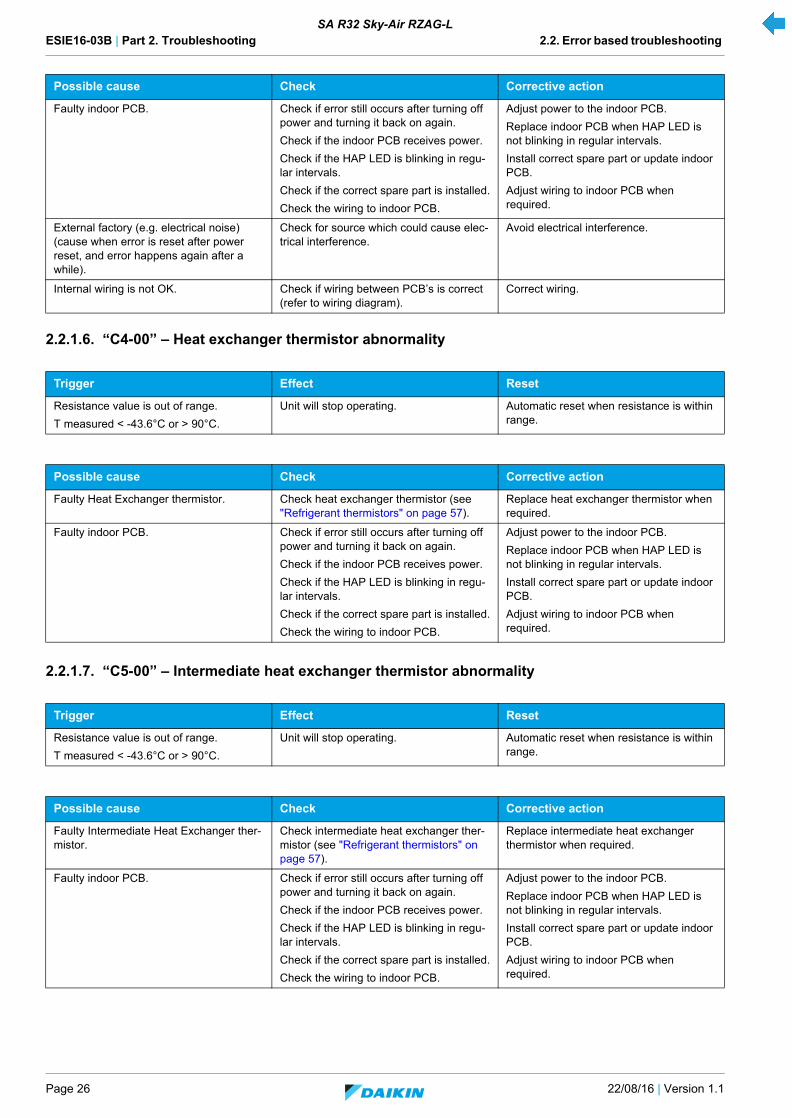
2.2.1.6. “C4-00” – Heat exchanger thermistor abnormality
2.2.1.7. “C5-00” – Intermediate heat exchanger thermistor abnormality
Faulty indoor PCB. Check if error still occurs after turning off power and turning it back on again.
Check if the indoor PCB receives power.
Check if the HAP LED is blinking in regu-lar intervals.
Check if the correct spare part is installed.
Check the wiring to indoor PCB.
Adjust power to the indoor PCB.
Replace indoor PCB when HAP LED is not blinking in regular intervals.
Install correct spare part or update indoor PCB.
Adjust wiring to indoor PCB when required.
External factory (e.g. electrical noise) (cause when error is reset after power reset, and error happens again after a while).
Check for source which could cause elec-trical interference.
Avoid electrical interference.
Internal wiring is not OK. Check if wiring between PCB’s is correct (refer to wiring diagram).
Correct wiring.
Trigger Effect Reset
Resistance value is out of range.
T measured < -43.6°C or > 90°C.
Unit will stop operating. Automatic reset when resistance is within range.
Possible cause Check Corrective action
Faulty Heat Exchanger thermistor. Check heat exchanger thermistor (see "Refrigerant thermistors" on page 57).
Replace heat exchanger thermistor when required.
Faulty indoor PCB. Check if error still occurs after turning off power and turning it back on again.
Check if the indoor PCB receives power.
Check if the HAP LED is blinking in regu-lar intervals.
Check if the correct spare part is installed.
Check the wiring to indoor PCB.
Adjust power to the indoor PCB.
Replace indoor PCB when HAP LED is not blinking in regular intervals.
Install correct spare part or update indoor PCB.
Adjust wiring to indoor PCB when required.
Trigger Effect Reset
Resistance value is out of range.
T measured < -43.6°C or > 90°C.
Unit will stop operating. Automatic reset when resistance is within range.
Possible cause Check Corrective action
Faulty Intermediate Heat Exchanger ther-mistor.
Check intermediate heat exchanger ther-mistor (see "Refrigerant thermistors" on page 57).
Replace intermediate heat exchanger thermistor when required.
Faulty indoor PCB. Check if error still occurs after turning off power and turning it back on again.
Check if the indoor PCB receives power.
Check if the HAP LED is blinking in regu-lar intervals.
Check if the correct spare part is installed.
Check the wiring to indoor PCB.
Adjust power to the indoor PCB.
Replace indoor PCB when HAP LED is not blinking in regular intervals.
Install correct spare part or update indoor PCB.
Adjust wiring to indoor PCB when required.
Possible cause Check Corrective action

ESIE16-03B | Part 2. Troubleshooting 2.2. Error based troubleshooting
22/08/16 | Version 1.1 Page 27
SA R32 Sky-Air RZAG-L
2.2.1.8. “C9-00” – Suction air thermistor abnormality
2.2.1.9. “CC-00” – Humidity sensor system abnormality
2.2.1.10. “CJ-00” – Remote controller thermistor abnormality
Trigger Effect Reset
Resistance value is out of range.
T measured < -43.6°C or > 90°C.
Unit will stop operating. Automatic reset when resistance is within range.
Possible cause Check Corrective action
Faulty suction air thermistor. Check suction air thermistor (see "Refrig-erant thermistors" on page 57).
Replace suction air thermistor when required.
Faulty indoor PCB. Check if error still occurs after turning off power and turning it back on again.
Check if the indoor PCB receives power.
Check if the HAP LED is blinking in regu-lar intervals.
Check if the correct spare part is installed.
Check the wiring to indoor PCB.
Adjust power to the indoor PCB.
Replace indoor PCB when HAP LED is not blinking in regular intervals.
Install correct spare part or update indoor PCB.
Adjust wiring to indoor PCB when required.
Trigger Effect Reset
The humidity sensor is disconnected or short circuit when the unit is running.
Unit will not stop operating. Manual reset via user interface.
Possible cause Check Corrective action
Faulty humidity sensor. Check good connection to indoor PCB. Replace the humidity sensor when required.
External factory (e.g. electrical noise) (cause when error is reset after power reset, and error happens again after a while).
Check for source which could cause elec-trical interference.
Avoid electrical interference.
Trigger Effect Reset
Disconnected or short circuit remote con-troller thermistor.
Unit will not stop operating. Automatic reset.
Possible cause Check Corrective action
Indoor Unit - Electrical components
Faulty remote controller thermistor. Erase the error record from the remote controller.
Push the ON/OFF button on the remote controller for 5 seconds in the check mode.
Replace the remote controller.
External factory (e.g. electrical noise) (cause when error is reset after power reset, and error happens again after a while).
Check for source which could cause elec-trical interference.
Avoid electrical interference.

ESIE16-03B | Part 2. Troubleshooting 2.2. Error based troubleshooting
Page 28 22/08/16 | Version 1.1
SA R32 Sky-Air RZAG-L
2.2.2. Outdoor unit
2.2.2.1. “E1-00” – Outdoor unit PCB abnormality
2.2.2.2. “E3-00” – Discharge pressure abnormality
Trigger Effect Reset
Outdoor main PCB detects that EEPROM is abnormal.
Unit will stop operating. Manual reset via user interface.
Power reset via outdoor unit.
Possible cause Check Corrective action
Faulty outdoor unit main PCB. Check if the HAP LED is blinking in regu-lar intervals (see "Main PCB" on page 55).
Check if the correct spare part is installed.
Check if the outdoor main PCB receives power.
Restore the power to the outdoor main PCB.
Replace outdoor main PCB when HAP LED is not blinking in regular intervals (see "Replacing main PCB" on page 89).
Faulty capacity adapter on outdoor main PCB installed.
Check if the correct capacity adapter is used.
Replace capacity adapter when required.
External factor (e.g. electrical noise) (cause when error is reset after power reset, and error happens again after a while).
Check for source which could cause elec-trical interference.
Faulty outdoor fan motor. Check the fan motor (see "Fan motor" on page 52).
Check fan motor connections and wiring.
Replace fan motor when required (see "Replacing DC fan motor assembly" on page 79).
Adjust wiring when required.
Faulty or disturbance of the power supply (imbalance > 10%). Power drop. Short cir-cuit.
Check if the power supply is conform with regulations. No fluctuations in frequency.
Adjust power supply when required.
Power reset via outdoor unit.
Trigger Effect Reset
High pressure switch opens due to meas-ure pressure > 41.7 bar.
Unit will stop operating. Manual reset via user interface.
High pressure control (measure pressure > 38 bar) occurs 16 times within 300 min-utes.
Possible cause Check Corrective action
Faulty high pressure switch. Check high pressure switch (see "High pressure switch" on page 53).
Replace high pressure switch (see "Replacing high pressure switches" on page 86).
Faulty outdoor unit main PCB. Check if the HAP LED is blinking in regu-lar intervals.
Check if the correct spare part is installed.
Check if the outdoor main PCB receives power.
Adjust the power to the outdoor main PCB.
Replace outdoor main PCB when HAP LED is not blinking in regular intervals (see "Replacing main PCB" on page 89).
Faulty capacity adapter on outdoor PCB. Check if the correct adapter is installed.
Check if the correct spare part is installed.
Adjust capacity adapter when required.
Refrigerant overcharge. Check for refrigerant overcharge. Refer to the nameplate for the correct charge.
Charge the correct refrigerant amount when required.
Humidity in refrigerant (ice formation in expansion valve).
Check for humidity in the refrigerant. In case of suspicion of humidity, recover, vacuum and recharge with virgin refriger-ant.
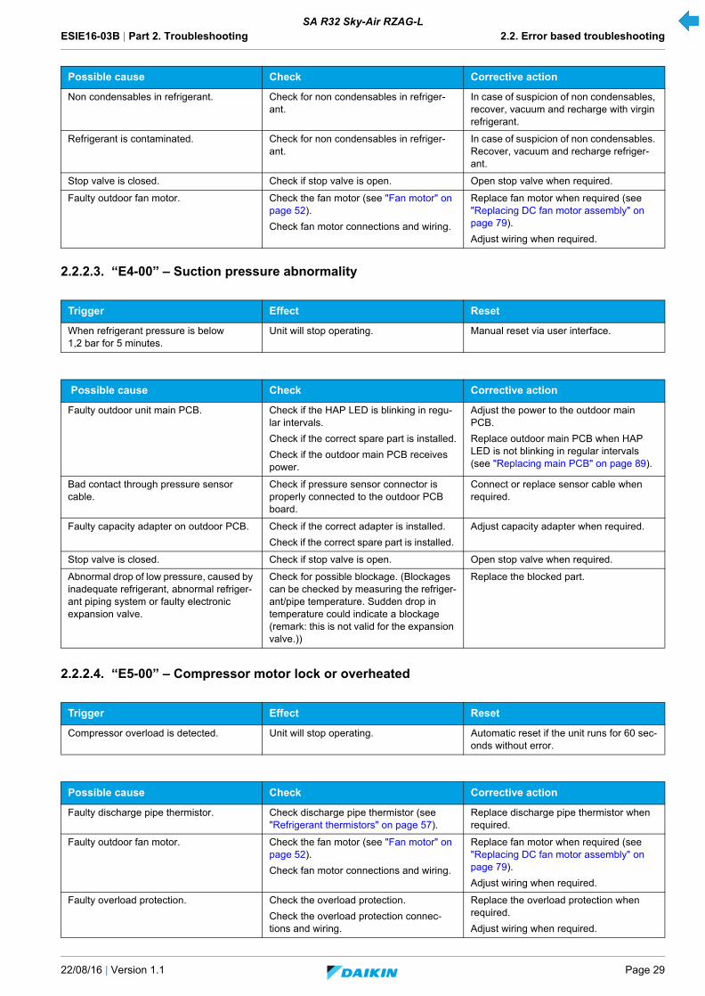
ESIE16-03B | Part 2. Troubleshooting 2.2. Error based troubleshooting
22/08/16 | Version 1.1 Page 29
SA R32 Sky-Air RZAG-L
2.2.2.3. “E4-00” – Suction pressure abnormality
2.2.2.4. “E5-00” – Compressor motor lock or overheated
Non condensables in refrigerant. Check for non condensables in refriger-ant.
In case of suspicion of non condensables, recover, vacuum and recharge with virgin refrigerant.
Refrigerant is contaminated. Check for non condensables in refriger-ant.
In case of suspicion of non condensables. Recover, vacuum and recharge refriger-ant.
Stop valve is closed. Check if stop valve is open. Open stop valve when required.
Faulty outdoor fan motor. Check the fan motor (see "Fan motor" on page 52).
Check fan motor connections and wiring.
Replace fan motor when required (see "Replacing DC fan motor assembly" on page 79).
Adjust wiring when required.
Trigger Effect Reset
When refrigerant pressure is below 1,2 bar for 5 minutes.
Unit will stop operating. Manual reset via user interface.
Possible cause Check Corrective action
Faulty outdoor unit main PCB. Check if the HAP LED is blinking in regu-lar intervals.
Check if the correct spare part is installed.
Check if the outdoor main PCB receives power.
Adjust the power to the outdoor main PCB.
Replace outdoor main PCB when HAP LED is not blinking in regular intervals (see "Replacing main PCB" on page 89).
Bad contact through pressure sensor cable.
Check if pressure sensor connector is properly connected to the outdoor PCB board.
Connect or replace sensor cable when required.
Faulty capacity adapter on outdoor PCB. Check if the correct adapter is installed.
Check if the correct spare part is installed.
Adjust capacity adapter when required.
Stop valve is closed. Check if stop valve is open. Open stop valve when required.
Abnormal drop of low pressure, caused by inadequate refrigerant, abnormal refriger-ant piping system or faulty electronic expansion valve.
Check for possible blockage. (Blockages can be checked by measuring the refriger-ant/pipe temperature. Sudden drop in temperature could indicate a blockage (remark: this is not valid for the expansion valve.))
Replace the blocked part.
Trigger Effect Reset
Compressor overload is detected. Unit will stop operating. Automatic reset if the unit runs for 60 sec-onds without error.
Possible cause Check Corrective action
Faulty discharge pipe thermistor. Check discharge pipe thermistor (see "Refrigerant thermistors" on page 57).
Replace discharge pipe thermistor when required.
Faulty outdoor fan motor. Check the fan motor (see "Fan motor" on page 52).
Check fan motor connections and wiring.
Replace fan motor when required (see "Replacing DC fan motor assembly" on page 79).
Adjust wiring when required.
Faulty overload protection. Check the overload protection.
Check the overload protection connec-tions and wiring.
Replace the overload protection when required.
Adjust wiring when required.
Possible cause Check Corrective action

ESIE16-03B | Part 2. Troubleshooting 2.2. Error based troubleshooting
Page 30 22/08/16 | Version 1.1
SA R32 Sky-Air RZAG-L
2.2.2.5. “E7-00” – Fan motor abnormality
Faulty expansion valve. Check the expansion valve (see "Elec-tronic expansion valve" on page 50).
Replace the expansion valve body (see "Replacing expansion valve body" on page 81) or motor (see "Replacing expan-sion valve motor" on page 82) when required.
Faulty 4-way valve. Check the 4-way valve (see "4-way valve" on page 47).
Replace the 4-way valve coil (see "Replacing 4-way valve coil" on page 75) or body (see "Replacing 4-way valve body" on page 73) when required.
Faulty outdoor unit main PCB. Check if the HAP LED is blinking in regu-lar intervals (see "Main PCB" on page 55).
Check if the correct spare part is installed.
Check if the outdoor main PCB receives power.
Restore the power to the outdoor main PCB.
Replace outdoor main PCB when HAP LED is not blinking in regular intervals (see "Replacing main PCB" on page 89).
Faulty power module = faulty outdoor inverter PCB.
Check outdoor inverter PCB.
Check if the HAP LED is blinking in regu-lar intervals (see "Main PCB" on page 55).
Check if the correct spare part is installed.
Restore the power to the outdoor inverter PCB.
Replace the outdoor inverter PCB when required (see "Replacing main PCB" on page 89).
Refrigerant shortage. Check for refrigerant shortage. Refer to the nameplate for the correct charge.
Charge the correct refrigerant amount when required.
Humidity in refrigerant (ice formation in expansion valve).
Check for humidity in the refrigerant. In case of suspicion of humidity, recover, vacuum and recharge with virgin refriger-ant.
Non condensables in refrigerant. Check for non condensables in refriger-ant.
In case of suspicion of non condensables, recover, vacuum and recharge with virgin refrigerant.
Stop valve is closed. Check stop valve. Open stop valve when required.
Trigger Effect Reset
Fan does not start in about 15~30 sec-onds = fan motor lock.
It can occur that E7-00 error is triggered even when the fan motor is running caused by a NG hall signal.
Unit will not stop operating. Automatic reset after a continuous run.
Refer to "“E7-00” – Fan motor abnormal-ity" on page 30.
Unit will stop operating. Manual reset via user interface.
Possible cause Check Corrective action
Faulty outdoor fan motor. Check the fan motor (see "Fan motor" on page 52).
Check fan motor connections and wiring.
Replace fan motor when required (see "Replacing DC fan motor assembly" on page 79).
Adjust wiring when required.
Faulty outdoor inverter PCB. Check outdoor inverter PCB.
Check if the HAP LED is blinking in regu-lar intervals (see "Main PCB" on page 55).
Check if the correct spare part is installed.
Restore the power to the outdoor inverter PCB.
Replace the outdoor inverter PCB when required (see "Replacing main PCB" on page 89).
Blown fuse. Check the fuse on the outdoor unit PCB's. Replace fuse when required.
Possible cause Check Corrective action

ESIE16-03B | Part 2. Troubleshooting 2.2. Error based troubleshooting
22/08/16 | Version 1.1 Page 31
SA R32 Sky-Air RZAG-L
2.2.2.6. “E9-00” – Electronic expansion valve abnormality
2.2.2.7. “F3-00” – Discharge pipe temperature abnormality
Trigger Effect Reset
1. No continuity of expansion valve.2. Minimum expansion valve opening
and suction superheat < A K and discharge superheat < B K (refer to "Product specific information" on page 121 for values of A and B).
Unit will stop operating. Manual reset via user interface.
Power reset via outdoor unit.
Possible cause Check Corrective action
Wet operation. Check for wet operation. (Wet operation can be detected by checking the suction superheat. If the suction superheat is 0°C then liquid refrigerant is returned to the compressor.)
In case wet operation was detected, con-firm the cause:
• Refrigerant overcharge.• Faulty expansion valve.
Faulty outdoor unit main PCB. Check if the HAP LED is blinking in regu-lar intervals.
Check if the correct spare part is installed.
Check if the outdoor main PCB receives power.
Adjust the power to the outdoor main PCB.
Replace outdoor main PCB when HAP LED is not blinking in regular intervals (see "Replacing main PCB" on page 89).
Faulty thermistor. Check thermistor (see "Refrigerant ther-mistors" on page 57).
Replace thermistor when required.
Faulty or disturbance of the power supply (imbalance >10%). Power drop. Short cir-cuit.
Check if the power supply is conform with regulations. No fluctuations in frequency.
Adjust power supply when required. Power reset via outdoor unit.
Faulty expansion valve. Check the expansion valve (see "Elec-tronic expansion valve" on page 50).
Replace the expansion valve body or motor (see "Replacing expansion valve body" on page 81) when required.
Faulty capacity adapter on outdoor PCB. Check if the correct adapter is installed.
Check if the correct spare part is installed.
Adjust capacity adapter when required.
External factory (e.g. electrical noise) (cause when error is reset after power reset, and error happens again after a while).
Check for source which could cause elec-trical interference.
Avoid electrical interference.
Trigger Effect Reset
Discharge temperature is too high:
• If the discharge temperature detected is above A°C, 10 times within 200 min.
• If within 200 min the discharge temperature detected is 10 times above B°C for 15 min.
Refer to "Product specific information" on page 121 for values of A and B.
Unit will not stop operating. Automatic reset when temperature drops below C°C.
Refer to "Product specific information" on page 121 for values of C.
Unit will stop operating. Manual reset via remote controller.
Possible cause Check Corrective action
Refrigerant shortage. Check for refrigerant shortage. Refer to the nameplate for the correct charge.
Charge the correct refrigerant amount when required.
Humidity in refrigerant (ice formation in expansion valve).
Check for humidity in the refrigerant. In case of suspicion of humidity, recover, vacuum and recharge with virgin refriger-ant.

ESIE16-03B | Part 2. Troubleshooting 2.2. Error based troubleshooting
Page 32 22/08/16 | Version 1.1
SA R32 Sky-Air RZAG-L
2.2.2.8. “H3-00” – High pressure switch abnormality
Non condensables in refrigerant. Check for non condensables in refriger-ant.
In case of suspicion of non condensables, recover, vacuum and recharge with virgin refrigerant.
Stop valve is closed. Check if stop valve is open. Open stop valve when required.
Faulty 4-way valve. Check the 4-way valve (see "4-way valve" on page 47).
Replace the 4-way valve coil (see "Replacing 4-way valve coil" on page 75) or body (see "Replacing 4-way valve body" on page 73) when required.
Faulty expansion valve. Check the expansion valve (see "Elec-tronic expansion valve" on page 50).
Replace the expansion valve body (see "Replacing expansion valve body" on page 81) or motor (see "Replacing expan-sion valve motor" on page 82) when required.
Faulty outdoor unit main PCB. Check if the HAP LED is blinking in regu-lar intervals (see "Main PCB" on page 55).
Check if the correct spare part is installed.
Check if the outdoor main PCB receives power.
Restore the power to the outdoor main PCB.
Replace outdoor main PCB when HAP LED is not blinking in regular intervals (see "Replacing main PCB" on page 89).
Faulty discharge thermistor. Check discharge thermistor (see "Refrig-erant thermistors" on page 57).
Replace discharge thermistor when required.
Faulty heat exchanger thermistor. Check heat exchanger thermistor (see "Refrigerant thermistors" on page 57).
Replace heat exchanger thermistor when required.
Faulty outdoor temperature thermistor. Check outdoor temperature thermistor (see "Refrigerant thermistors" on page 57).
Replace outdoor temperature thermistor when required.
Trigger Effect Reset
High pressure switch is activated when compressor is off.
Unit will stop operating. Manual reset via user interface.
Possible cause Check Corrective action
Stop valve is closed. Check if stop valve is open. Open stop valve when required.
Faulty outdoor unit main PCB. Check if the HAP LED is blinking in regu-lar intervals.
Check if the correct spare part is installed.
Check if the outdoor main PCB receives power.
Adjust the power to the outdoor main PCB.
Replace outdoor main PCB when HAP LED is not blinking in regular intervals (see "Replacing main PCB" on page 89).
Faulty outdoor inverter PCB. Check outdoor inverter PCB.
Check if the alive led is blinking in regular intervals.
Check if the correct spare part is installed.
Adjust the power to the outdoor inverter PCB.
Replace outdoor inverter PCB (see "Replacing main PCB" on page 89).
Faulty or disturbance of the power supply (imbalance > 10%). Power drop. Short cir-cuit.
Check if the power supply is conform with regulations.
No fluctuations in frequency.
Adjust power supply when required. Power reset via outdoor unit.
Faulty high pressure switch. Check high pressure switch (see"High pressure switch" on page 53).
Replace the high pressure switch (see "Replacing high pressure switches" on page 86).
Faulty capacity adapter on outdoor PCB. Check if the correct adapter is installed.
Check if the correct spare part is installed.
Adjust capacity adapter when required.
Possible cause Check Corrective action

ESIE16-03B | Part 2. Troubleshooting 2.2. Error based troubleshooting
22/08/16 | Version 1.1 Page 33
SA R32 Sky-Air RZAG-L
2.2.2.9. “H4-00” – Low pressure switch abnormality
2.2.2.10. “H9-00” – Outdoor air temperature thermistor abnormality
2.2.2.11. “J3-00” – Discharge pipe thermistor abnormality
Trigger Effect Reset
When there is no continuity in the low pressure switch during compressor start.
Unit will stop operating. Automatic reset.
Possible cause Check Corrective action
Refrigerant shortage. Check for refrigerant shortage. Refer to the nameplate for the correct charge.
Charge the correct refrigerant amount when required.
Stop valve is closed. Check if stop valve is open. Open stop valve when required.
Faulty outdoor unit main PCB. Check if the HAP LED is blinking in regu-lar intervals.
Check if the correct spare part is installed.
Check if the outdoor main PCB receives power.
Adjust the power to the outdoor main PCB.
Replace outdoor main PCB when HAP LED is not blinking in regular intervals (see "Replacing main PCB" on page 89).
Faulty expansion valve. Check the expansion valve (see "Elec-tronic expansion valve" on page 50).
Replace the expansion valve body (see "Replacing expansion valve body" on page 81) or motor (see "Replacing expan-sion valve motor" on page 82) when required.
Faulty low pressure switch. Check low pressure switch (see "Low pressure switch" on page 54).
Replace low pressure switch (see "Replacing low pressure switch" on page 88).
Trigger Effect Reset
Thermistor input voltage is > 4.96 V or < 0.04 V when power is on.
Unit will stop operating. Manual reset via user interface.
Possible cause Check Corrective action
Faulty outdoor air temperature thermistor. Check outdoor temperature thermistor (see "Refrigerant thermistors" on page 57).
Replace outdoor temperature thermistor when required.
Faulty outdoor unit main PCB. Check if the HAP LED is blinking in regu-lar intervals (see "Main PCB" on page 55).
Check if the correct spare part is installed.
Check if the outdoor main PCB receives power.
Restore the power to the outdoor main PCB.
Replace outdoor main PCB when HAP LED is not blinking in regular intervals (see "Replacing main PCB" on page 89).
Trigger Effect Reset
Thermistor input voltage is > 4.96 V or < 0.04 V when power is on.
Unit will stop operating. Manual reset via user interface.
Discharge pipe temperature is lower than the heat exchanger temperature.
Possible cause Check Corrective action
Faulty discharge pipe thermistor. Check discharge pipe thermistor (see "Refrigerant thermistors" on page 57).
Replace discharge pipe thermistor when required.
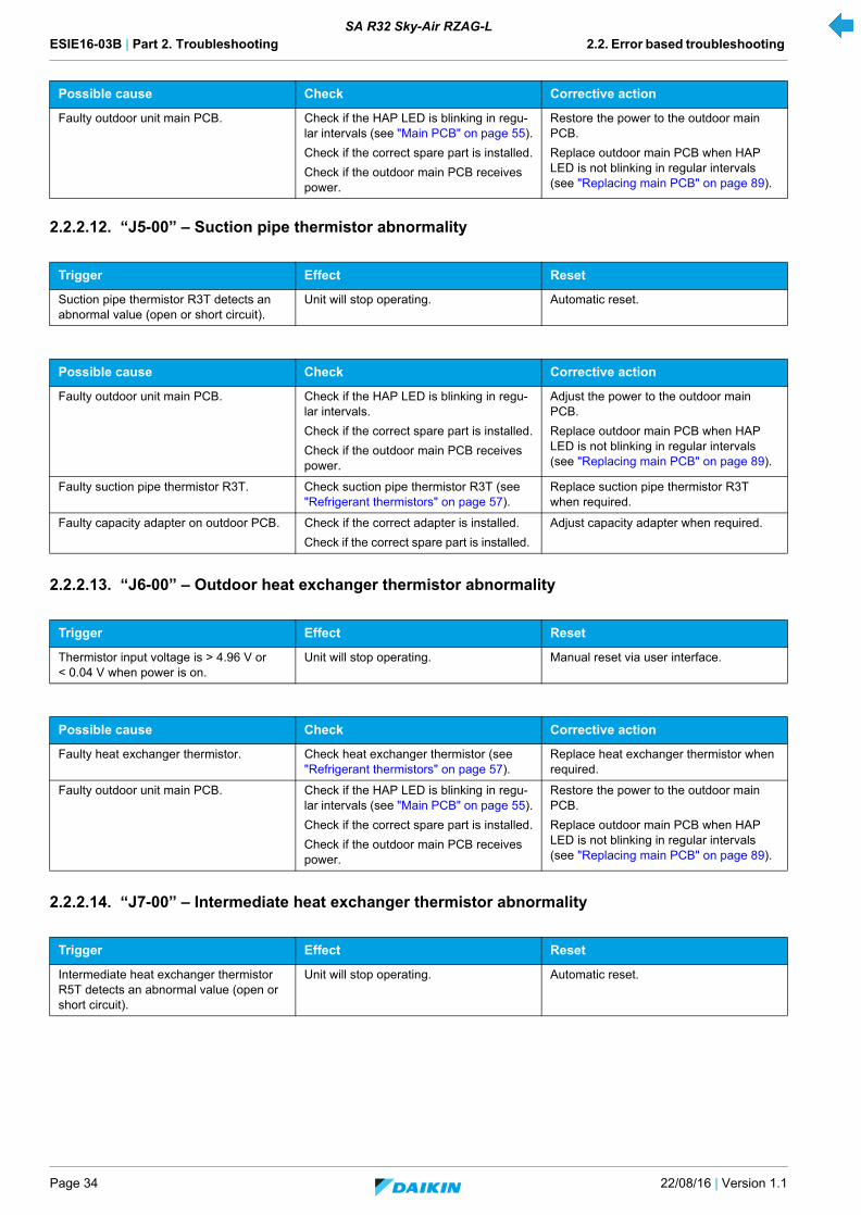
ESIE16-03B | Part 2. Troubleshooting 2.2. Error based troubleshooting
Page 34 22/08/16 | Version 1.1
SA R32 Sky-Air RZAG-L
2.2.2.12. “J5-00” – Suction pipe thermistor abnormality
2.2.2.13. “J6-00” – Outdoor heat exchanger thermistor abnormality
2.2.2.14. “J7-00” – Intermediate heat exchanger thermistor abnormality
Faulty outdoor unit main PCB. Check if the HAP LED is blinking in regu-lar intervals (see "Main PCB" on page 55).
Check if the correct spare part is installed.
Check if the outdoor main PCB receives power.
Restore the power to the outdoor main PCB.
Replace outdoor main PCB when HAP LED is not blinking in regular intervals (see "Replacing main PCB" on page 89).
Trigger Effect Reset
Suction pipe thermistor R3T detects an abnormal value (open or short circuit).
Unit will stop operating. Automatic reset.
Possible cause Check Corrective action
Faulty outdoor unit main PCB. Check if the HAP LED is blinking in regu-lar intervals.
Check if the correct spare part is installed.
Check if the outdoor main PCB receives power.
Adjust the power to the outdoor main PCB.
Replace outdoor main PCB when HAP LED is not blinking in regular intervals (see "Replacing main PCB" on page 89).
Faulty suction pipe thermistor R3T. Check suction pipe thermistor R3T (see "Refrigerant thermistors" on page 57).
Replace suction pipe thermistor R3T when required.
Faulty capacity adapter on outdoor PCB. Check if the correct adapter is installed.
Check if the correct spare part is installed.
Adjust capacity adapter when required.
Trigger Effect Reset
Thermistor input voltage is > 4.96 V or < 0.04 V when power is on.
Unit will stop operating. Manual reset via user interface.
Possible cause Check Corrective action
Faulty heat exchanger thermistor. Check heat exchanger thermistor (see "Refrigerant thermistors" on page 57).
Replace heat exchanger thermistor when required.
Faulty outdoor unit main PCB. Check if the HAP LED is blinking in regu-lar intervals (see "Main PCB" on page 55).
Check if the correct spare part is installed.
Check if the outdoor main PCB receives power.
Restore the power to the outdoor main PCB.
Replace outdoor main PCB when HAP LED is not blinking in regular intervals (see "Replacing main PCB" on page 89).
Trigger Effect Reset
Intermediate heat exchanger thermistor R5T detects an abnormal value (open or short circuit).
Unit will stop operating. Automatic reset.
Possible cause Check Corrective action

ESIE16-03B | Part 2. Troubleshooting 2.2. Error based troubleshooting
22/08/16 | Version 1.1 Page 35
SA R32 Sky-Air RZAG-L
2.2.2.15. “J8-00” – Liquid pipe thermistor abnormality
2.2.2.16. “L1-00” – Outdoor main PCB abnormality
Possible cause Check Corrective action
Faulty outdoor unit main PCB. Check if the HAP LED is blinking in regu-lar intervals.
Check if the correct spare part is installed.
Check if the outdoor main PCB receives power.
Adjust the power to the outdoor main PCB.
Replace outdoor main PCB when HAP LED is not blinking in regular intervals (see "Replacing main PCB" on page 89).
Faulty intermediate heat exchanger ther-mistor R5T.
Check intermediate heat exchanger ther-mistor (see "Refrigerant thermistors" on page 57).
Replace intermediate heat exchanger thermistor R5T when required.
Faulty capacity adapter on outdoor PCB. Check if the correct adapter is installed.
Check if the correct spare part is installed.
Adjust capacity adapter when required.
Trigger Effect Reset
Liquid pipe thermistor R6T detects an abnormal value (open or short circuit).
Unit will stop operating. Automatic reset.
Possible cause Check Corrective action
Faulty outdoor unit main PCB. Check if the HAP LED is blinking in regu-lar intervals.
Check if the correct spare part is installed.
Check if the outdoor main PCB receives power.
Adjust the power to the outdoor main PCB.
Replace outdoor main PCB when HAP LED is not blinking in regular intervals (see "Replacing main PCB" on page 89).
Faulty liquid pipe thermistor R6T. Check liquid pipe thermistor R6T (see "Refrigerant thermistors" on page 57).
Replace liquid pipe thermistor R6T when required.
Faulty capacity adapter on outdoor PCB. Check if the correct adapter is installed.
Check if the correct spare part is installed.
Adjust capacity adapter when required.
Trigger Effect Reset
Outdoor main PCB detects current/volt-age errors.
Unit will stop operating. Manual reset via user interface.
Power reset via outdoor unit.
Possible cause Check Corrective action
Blown fuse. Check fuse on outdoor main PCB. Replace fuse if blown.
Faulty outdoor unit main PCB. Check if the HAP LED is blinking in regu-lar intervals.
Check if the correct spare part is installed.
Check if the outdoor main PCB receives power.
Adjust the power to the outdoor main PCB.
Replace outdoor main PCB when HAP LED is not blinking in regular intervals (see "Replacing main PCB" on page 89).
Faulty outdoor inverter PCB. Check outdoor inverter PCB.
Check if the alive led is blinking in regular intervals.
Check if the correct spare part is installed.
Adjust the power to the outdoor inverter PCB.
Replace outdoor inverter PCB (see "Replacing main PCB" on page 89).

ESIE16-03B | Part 2. Troubleshooting 2.2. Error based troubleshooting
Page 36 22/08/16 | Version 1.1
SA R32 Sky-Air RZAG-L
2.2.2.17. “L5-00” – Output overcurrent detection
Faulty compressor. Check compressor (see "Compressor" on page 49).
Check connections and wiring of the com-pressor.
Check expansion valve (liquid back issue) (see "Electronic expansion valve" on page 50).
Check the refrigerant charge. Refer to the nameplate for correct charge.
Replace compressor when required (see "Replacing compressor" on page 76).
Investigate reason of breakdown.
Replace expansion valve when required (see "Replacing expansion valve body" on page 81).
Fix possible leak.
Faulty or disturbance of the power supply (imbalance > 10%). Power drop. Short cir-cuit.
Check if the power supply is conform with regulations. No fluctuations in frequency.
Adjust power supply when required. Power reset via outdoor unit.
Faulty outdoor fan motor. Check the fan motor (see "Fan motor" on page 52).
Check fan motor connections and wiring.
Replace fan motor when required (see "Replacing DC fan motor assembly" on page 79).
Adjust wiring when required.
Faulty capacity adapter on outdoor PCB. Check if the correct adapter is installed.
Check if the correct spare part is installed.
Adjust capacity adapter when required.
External factory (e.g. electrical noise). (cause when error is reset after power reset, and error happens again after a while).
Check for source which could cause elec-trical interference.
Avoid electrical interference.
Trigger Effect Reset
Outdoor inverter PCB detects overcurrent to power transistor.
Unit will stop operating. Manual reset via user interface.
Possible cause Check Corrective action
Refrigerant circuit is clogged. Check for possible blockage. Replace blocked part when required.
Humidity in refrigerant (ice formation in expansion valve).
Check for humidity in the refrigerant. In case of suspicion of humidity, recover, vacuum and recharge with virgin refriger-ant.
Non condensables in refrigerant. Check for non condensables in refriger-ant.
In case of suspicion of non condensables, recover, vacuum and recharge with virgin refrigerant.
Faulty outdoor inverter PCB. Check outdoor inverter PCB.
Check if the alive led is blinking in regular intervals.
Check if the correct spare part is installed.
Adjust the power to the outdoor inverter PCB.
Replace outdoor inverter PCB (see "Replacing main PCB" on page 89).
Faulty compressor. Check compressor (see "Compressor" on page 49).
Check connections and wiring of the com-pressor.
Check expansion valve (liquid back issue) (see"Electronic expansion valve" on page 50).
Check the refrigerant charge. Refer to the nameplate for correct charge.
Replace compressor when required (see "Replacing compressor" on page 76).
Replace expansion valve when required (see "Replacing expansion valve body" on page 81).
Fix possible leak.
Faulty or disturbance of the power supply (imbalance > 10%). Power drop. Short cir-cuit.
Check if the power supply is conform with regulations. No fluctuations in frequency.
Adjust power supply when required. Power reset via outdoor unit.
Possible cause Check Corrective action

ESIE16-03B | Part 2. Troubleshooting 2.2. Error based troubleshooting
22/08/16 | Version 1.1 Page 37
SA R32 Sky-Air RZAG-L
2.2.2.18. “L8-00” – Electronic thermal overload
2.2.2.19. “L9-00” – Stall prevention time lag
Trigger Effect Reset
When compressor overload (except dur-ing start-up) is detected.
Unit will stop operating. Manual reset via user interface.
Possible cause Check Corrective action
Refrigerant circuit is clogged. Check for possible blockage. Replace blocked part when required.
Refrigerant overcharge. Check for refrigerant overcharge. Refer to the nameplate for the correct charge.
Charge the correct refrigerant amount when required.
Refrigerant is contaminated. Replace refrigerant.
Faulty outdoor inverter PCB. Check outdoor inverter PCB.
Check if the alive led is blinking in regular intervals.
Check if the correct spare part is installed.
Adjust the power to the outdoor inverter PCB.
Replace outdoor inverter PCB (see "Replacing main PCB" on page 89).
Faulty compressor Check compressor (see "Compressor" on page 49).
Check connections and wiring of the com-pressor.
Check expansion valve (liquid back issue) (see"Electronic expansion valve" on page 50).
Check the refrigerant charge. Refer to the nameplate for correct charge.
Replace compressor when required (see "Replacing compressor" on page 76).
Investigate reason of breakdown.
Replace expansion valve when required (see"Replacing expansion valve body" on page 81).
Fix possible leak.
Trigger Effect Reset
Outdoor inverter PCB detects compressor overload at start up.
Unit will stop operating. Manual reset via user interface.
Possible cause Check Corrective action
Refrigerant circuit is clogged. Check for possible blockage. Replace blocked part when required.
Refrigerant condition is not OK (HP-LP > 0,2 MPa at start-up).
Check refrigerant condition.
Faulty outdoor inverter PCB. Check outdoor inverter PCB.
Check if the alive led is blinking in regular intervals.
Check if the correct spare part is installed.
Adjust the power to the outdoor inverter PCB.
Replace outdoor inverter PCB (see "Replacing main PCB" on page 89).
Faulty compressor. Check compressor (see "Compressor" on page 49).
Check connections and wiring of the com-pressor.
Check expansion valve (liquid back issue) (see "Electronic expansion valve" on page 50).
Check the refrigerant charge. Refer to the nameplate for correct charge.
Replace compressor when required (see "Replacing compressor" on page 76).
Investigate reason of breakdown.
Replace expansion valve when required (see "Replacing expansion valve body" on page 81).
Fix possible leak.
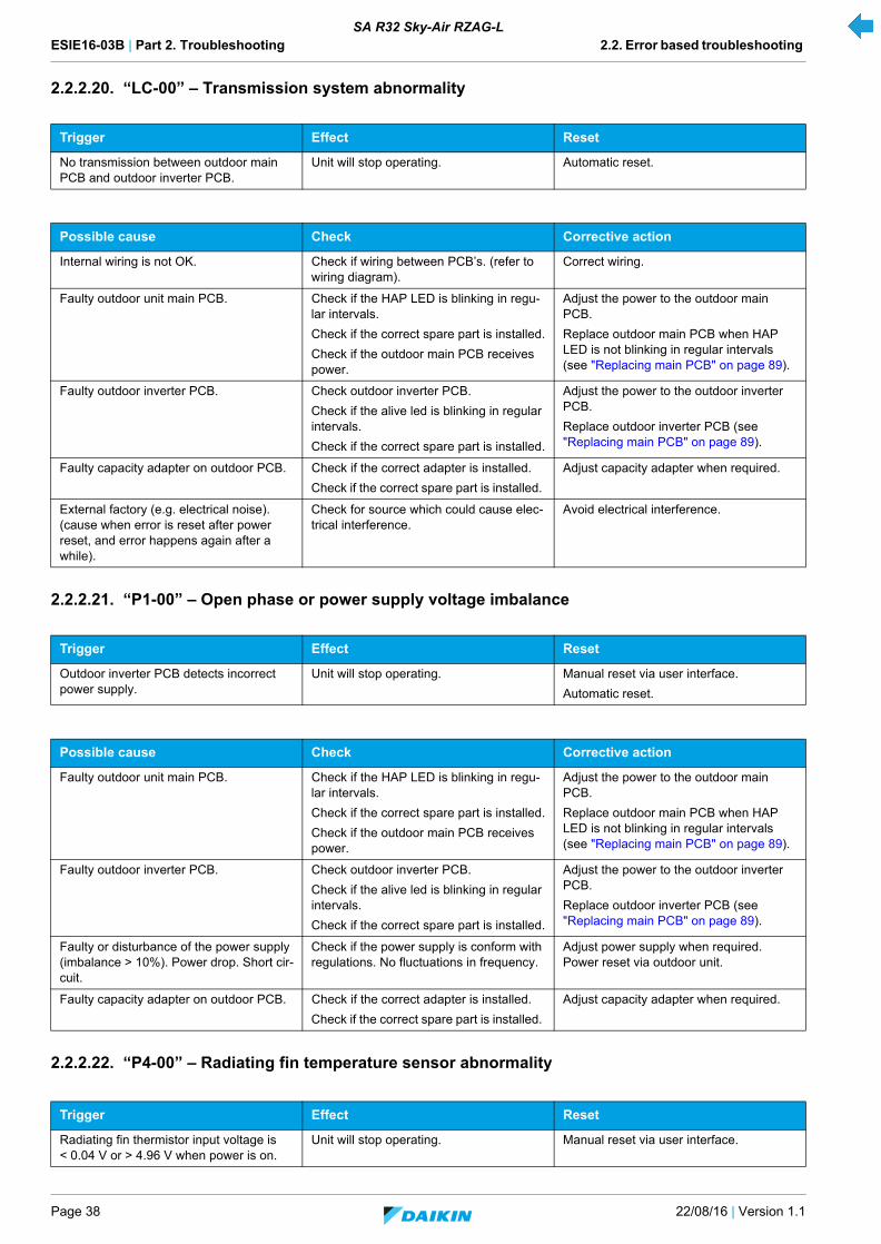
ESIE16-03B | Part 2. Troubleshooting 2.2. Error based troubleshooting
Page 38 22/08/16 | Version 1.1
SA R32 Sky-Air RZAG-L
2.2.2.20. “LC-00” – Transmission system abnormality
2.2.2.21. “P1-00” – Open phase or power supply voltage imbalance
2.2.2.22. “P4-00” – Radiating fin temperature sensor abnormality
Trigger Effect Reset
No transmission between outdoor main PCB and outdoor inverter PCB.
Unit will stop operating. Automatic reset.
Possible cause Check Corrective action
Internal wiring is not OK. Check if wiring between PCB’s. (refer to wiring diagram).
Correct wiring.
Faulty outdoor unit main PCB. Check if the HAP LED is blinking in regu-lar intervals.
Check if the correct spare part is installed.
Check if the outdoor main PCB receives power.
Adjust the power to the outdoor main PCB.
Replace outdoor main PCB when HAP LED is not blinking in regular intervals (see "Replacing main PCB" on page 89).
Faulty outdoor inverter PCB. Check outdoor inverter PCB.
Check if the alive led is blinking in regular intervals.
Check if the correct spare part is installed.
Adjust the power to the outdoor inverter PCB.
Replace outdoor inverter PCB (see "Replacing main PCB" on page 89).
Faulty capacity adapter on outdoor PCB. Check if the correct adapter is installed.
Check if the correct spare part is installed.
Adjust capacity adapter when required.
External factory (e.g. electrical noise). (cause when error is reset after power reset, and error happens again after a while).
Check for source which could cause elec-trical interference.
Avoid electrical interference.
Trigger Effect Reset
Outdoor inverter PCB detects incorrect power supply.
Unit will stop operating. Manual reset via user interface.
Automatic reset.
Possible cause Check Corrective action
Faulty outdoor unit main PCB. Check if the HAP LED is blinking in regu-lar intervals.
Check if the correct spare part is installed.
Check if the outdoor main PCB receives power.
Adjust the power to the outdoor main PCB.
Replace outdoor main PCB when HAP LED is not blinking in regular intervals (see "Replacing main PCB" on page 89).
Faulty outdoor inverter PCB. Check outdoor inverter PCB.
Check if the alive led is blinking in regular intervals.
Check if the correct spare part is installed.
Adjust the power to the outdoor inverter PCB.
Replace outdoor inverter PCB (see "Replacing main PCB" on page 89).
Faulty or disturbance of the power supply (imbalance > 10%). Power drop. Short cir-cuit.
Check if the power supply is conform with regulations. No fluctuations in frequency.
Adjust power supply when required. Power reset via outdoor unit.
Faulty capacity adapter on outdoor PCB. Check if the correct adapter is installed.
Check if the correct spare part is installed.
Adjust capacity adapter when required.
Trigger Effect Reset
Radiating fin thermistor input voltage is < 0.04 V or > 4.96 V when power is on.
Unit will stop operating. Manual reset via user interface.
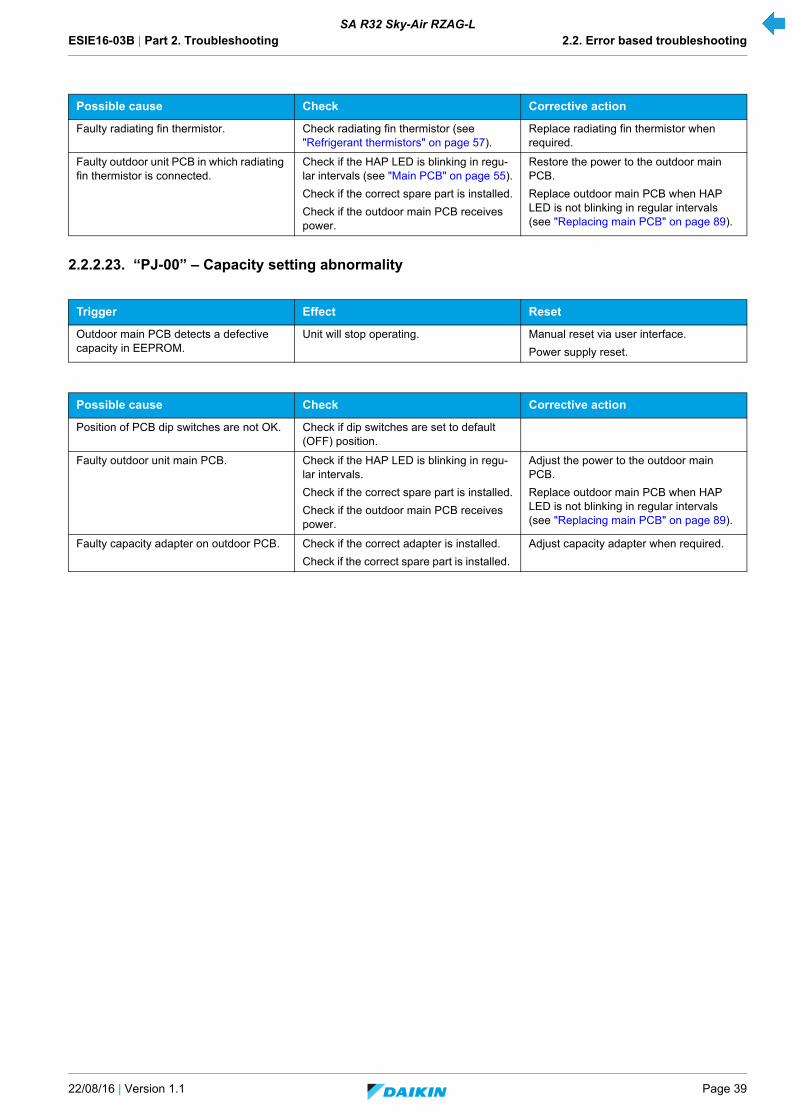
ESIE16-03B | Part 2. Troubleshooting 2.2. Error based troubleshooting
22/08/16 | Version 1.1 Page 39
SA R32 Sky-Air RZAG-L
2.2.2.23. “PJ-00” – Capacity setting abnormality
Possible cause Check Corrective action
Faulty radiating fin thermistor. Check radiating fin thermistor (see "Refrigerant thermistors" on page 57).
Replace radiating fin thermistor when required.
Faulty outdoor unit PCB in which radiating fin thermistor is connected.
Check if the HAP LED is blinking in regu-lar intervals (see "Main PCB" on page 55).
Check if the correct spare part is installed.
Check if the outdoor main PCB receives power.
Restore the power to the outdoor main PCB.
Replace outdoor main PCB when HAP LED is not blinking in regular intervals (see "Replacing main PCB" on page 89).
Trigger Effect Reset
Outdoor main PCB detects a defective capacity in EEPROM.
Unit will stop operating. Manual reset via user interface.
Power supply reset.
Possible cause Check Corrective action
Position of PCB dip switches are not OK. Check if dip switches are set to default (OFF) position.
Faulty outdoor unit main PCB. Check if the HAP LED is blinking in regu-lar intervals.
Check if the correct spare part is installed.
Check if the outdoor main PCB receives power.
Adjust the power to the outdoor main PCB.
Replace outdoor main PCB when HAP LED is not blinking in regular intervals (see "Replacing main PCB" on page 89).
Faulty capacity adapter on outdoor PCB. Check if the correct adapter is installed.
Check if the correct spare part is installed.
Adjust capacity adapter when required.
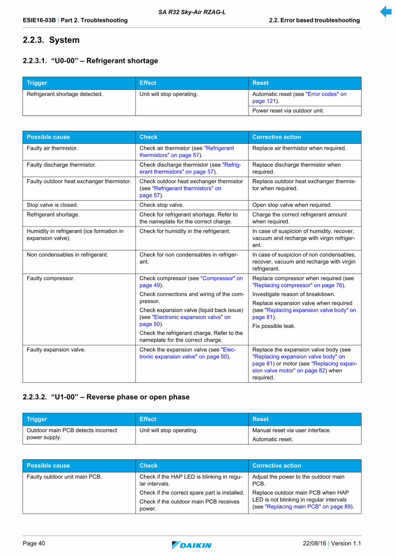
ESIE16-03B | Part 2. Troubleshooting 2.2. Error based troubleshooting
Page 40 22/08/16 | Version 1.1
SA R32 Sky-Air RZAG-L
2.2.3. System
2.2.3.1. “U0-00” – Refrigerant shortage
2.2.3.2. “U1-00” – Reverse phase or open phase
Trigger Effect Reset
Refrigerant shortage detected. Unit will stop operating. Automatic reset (see "Error codes" on page 121).
Power reset via outdoor unit.
Possible cause Check Corrective action
Faulty air thermistor. Check air thermistor (see "Refrigerant thermistors" on page 57).
Replace air thermistor when required.
Faulty discharge thermistor. Check discharge thermistor (see "Refrig-erant thermistors" on page 57).
Replace discharge thermistor when required.
Faulty outdoor heat exchanger thermistor. Check outdoor heat exchanger thermistor (see "Refrigerant thermistors" on page 57).
Replace outdoor heat exchanger thermis-tor when required.
Stop valve is closed. Check stop valve. Open stop valve when required.
Refrigerant shortage. Check for refrigerant shortage. Refer to the nameplate for the correct charge.
Charge the correct refrigerant amount when required.
Humidity in refrigerant (ice formation in expansion valve).
Check for humidity in the refrigerant. In case of suspicion of humidity, recover, vacuum and recharge with virgin refriger-ant.
Non condensables in refrigerant. Check for non condensables in refriger-ant.
In case of suspicion of non condensables, recover, vacuum and recharge with virgin refrigerant.
Faulty compressor. Check compressor (see "Compressor" on page 49).
Check connections and wiring of the com-pressor.
Check expansion valve (liquid back issue) (see "Electronic expansion valve" on page 50).
Check the refrigerant charge. Refer to the nameplate for the correct charge.
Replace compressor when required (see "Replacing compressor" on page 76).
Investigate reason of breakdown.
Replace expansion valve when required (see "Replacing expansion valve body" on page 81).
Fix possible leak.
Faulty expansion valve. Check the expansion valve (see "Elec-tronic expansion valve" on page 50).
Replace the expansion valve body (see "Replacing expansion valve body" on page 81) or motor (see "Replacing expan-sion valve motor" on page 82) when required.
Trigger Effect Reset
Outdoor main PCB detects incorrect power supply.
Unit will stop operating. Manual reset via user interface.
Automatic reset.
Possible cause Check Corrective action
Faulty outdoor unit main PCB. Check if the HAP LED is blinking in regu-lar intervals.
Check if the correct spare part is installed.
Check if the outdoor main PCB receives power.
Adjust the power to the outdoor main PCB.
Replace outdoor main PCB when HAP LED is not blinking in regular intervals (see "Replacing main PCB" on page 89).

ESIE16-03B | Part 2. Troubleshooting 2.2. Error based troubleshooting
22/08/16 | Version 1.1 Page 41
SA R32 Sky-Air RZAG-L
2.2.3.3. “U2-00” – Power supply abnormality or instantaneous power failure
Faulty or disturbance of the power supply (imbalance > 10%). Power drop. Short cir-cuit.
Check if the power supply is conform with regulations. No fluctuations in frequency.
Adjust power supply when required. Power reset via outdoor unit.
Faulty capacity adapter on outdoor PCB. Check if the correct adapter is installed.
Check if the correct spare part is installed.
Adjust capacity adapter when required.
Trigger Effect Reset
There is no zero-cross detected in approximately 10 seconds (indoor unit PCB).
Unit will stop operating. Power reset via outdoor unit.
Abnormal voltage drop (< 150-180 V) is detected by the DC voltage detection cir-cuit.
Unit will stop operating. Automatic restart after compressor stand-by of 3 minutes.
Abnormal voltage rise is detected by the over-voltage detection circuit.
Unit will stop operating. Automatic restart after compressor stand-by of 3 minutes.
Possible cause Check Corrective action
Faulty or disturbance of the power supply (imbalance > 10%). Power drop. Short cir-cuit.
Check if the power supply is conform with regulations. No fluctuations in frequency.
Adjust power supply when required. Power reset via outdoor unit.
Defective DC voltage detection circuit. Check PCB with DC voltage detection cir-cuit.
Replace PCB when required.
Defective over-voltage detection circuit. Check PCB with over-voltage detection circuit.
Replace PCB when required.
Defective PAM control part. Check PAM control part. Replace PAM control part when required.
Faulty compressor. Check compressor (see "Compressor" on page 49).
Check connections and wiring of the com-pressor.
Check expansion valve (liquid back issue) (see "Electronic expansion valve" on page 50).
Check the refrigerant charge. Refer to the nameplate for correct charge.
Replace compressor when required (see "Replacing compressor" on page 76).
Investigate reason of breakdown.
Replace expansion valve when required (see "Replacing expansion valve body" on page 81).
Fix possible leak.
Faulty outdoor fan motor. Check the fan motor (see "Fan motor" on page 52).
Check fan motor connections and wiring.
Replace fan motor when required (see "Replacing DC fan motor assembly" on page 79).
Adjust wiring when required.
Momentary drop of voltage. - Wait until compressor restarts.
Momentary power failure. - Wait until compressor restarts.
Faulty outdoor unit main PCB. Check if the HAP LED is blinking in regu-lar intervals (see "Main PCB" on page 55).
Check if the correct spare part is installed.
Check if the outdoor main PCB receives power.
Restore the power to the outdoor main PCB.
Replace outdoor main PCB when HAP LED is not blinking in regular intervals (see "Replacing main PCB" on page 89).
Faulty indoor unit main PCB. Check if the HAP LED is blinking in regu-lar intervals (see "Main PCB" on page 55).
Check if the correct spare part is installed.
Check if the indoor main PCB receives power.
Restore the power to the indoor main PCB.
Replace indoor main PCB when HAP LED is not blinking in regular intervals (see "Replacing main PCB" on page 89).
Possible cause Check Corrective action
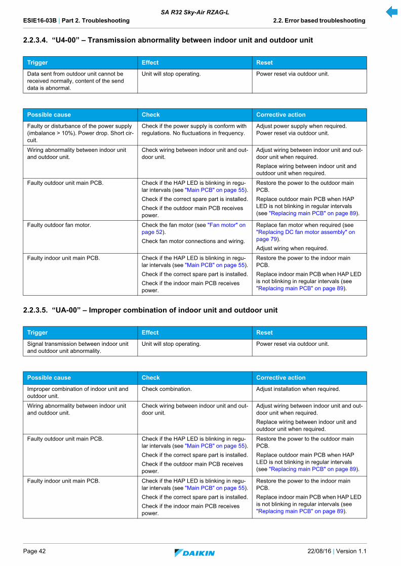
ESIE16-03B | Part 2. Troubleshooting 2.2. Error based troubleshooting
Page 42 22/08/16 | Version 1.1
SA R32 Sky-Air RZAG-L
2.2.3.4. “U4-00” – Transmission abnormality between indoor unit and outdoor unit
2.2.3.5. “UA-00” – Improper combination of indoor unit and outdoor unit
Trigger Effect Reset
Data sent from outdoor unit cannot be received normally, content of the send data is abnormal.
Unit will stop operating. Power reset via outdoor unit.
Possible cause Check Corrective action
Faulty or disturbance of the power supply (imbalance > 10%). Power drop. Short cir-cuit.
Check if the power supply is conform with regulations. No fluctuations in frequency.
Adjust power supply when required. Power reset via outdoor unit.
Wiring abnormality between indoor unit and outdoor unit.
Check wiring between indoor unit and out-door unit.
Adjust wiring between indoor unit and out-door unit when required.
Replace wiring between indoor unit and outdoor unit when required.
Faulty outdoor unit main PCB. Check if the HAP LED is blinking in regu-lar intervals (see "Main PCB" on page 55).
Check if the correct spare part is installed.
Check if the outdoor main PCB receives power.
Restore the power to the outdoor main PCB.
Replace outdoor main PCB when HAP LED is not blinking in regular intervals (see "Replacing main PCB" on page 89).
Faulty outdoor fan motor. Check the fan motor (see "Fan motor" on page 52).
Check fan motor connections and wiring.
Replace fan motor when required (see "Replacing DC fan motor assembly" on page 79).
Adjust wiring when required.
Faulty indoor unit main PCB. Check if the HAP LED is blinking in regu-lar intervals (see "Main PCB" on page 55).
Check if the correct spare part is installed.
Check if the indoor main PCB receives power.
Restore the power to the indoor main PCB.
Replace indoor main PCB when HAP LED is not blinking in regular intervals (see "Replacing main PCB" on page 89).
Trigger Effect Reset
Signal transmission between indoor unit and outdoor unit abnormality.
Unit will stop operating. Power reset via outdoor unit.
Possible cause Check Corrective action
Improper combination of indoor unit and outdoor unit.
Check combination. Adjust installation when required.
Wiring abnormality between indoor unit and outdoor unit.
Check wiring between indoor unit and out-door unit.
Adjust wiring between indoor unit and out-door unit when required.
Replace wiring between indoor unit and outdoor unit when required.
Faulty outdoor unit main PCB. Check if the HAP LED is blinking in regu-lar intervals (see "Main PCB" on page 55).
Check if the correct spare part is installed.
Check if the outdoor main PCB receives power.
Restore the power to the outdoor main PCB.
Replace outdoor main PCB when HAP LED is not blinking in regular intervals (see "Replacing main PCB" on page 89).
Faulty indoor unit main PCB. Check if the HAP LED is blinking in regu-lar intervals (see "Main PCB" on page 55).
Check if the correct spare part is installed.
Check if the indoor main PCB receives power.
Restore the power to the indoor main PCB.
Replace indoor main PCB when HAP LED is not blinking in regular intervals (see "Replacing main PCB" on page 89).

ESIE16-03B | Part 2. Troubleshooting 2.2. Error based troubleshooting
22/08/16 | Version 1.1 Page 43
SA R32 Sky-Air RZAG-L
2.2.3.6. “UF-00” – Wiring and piping mismatch
2.2.4. Others
Not applicable.
Trigger Effect Reset
When the interunit wiring between indoor and outdoor unit is incorrect.
Piping abnormality.
Unit will stop operating. Automatic reset.
Possible cause Check Corrective action
Faulty wiring between indoor and outdoor unit.
Check wiring between indoor and outdoor unit (see "Wiring diagram" on page 114).
Correct wiring.
Refrigerant shortage (incorrect charge/leakage).
Check for refrigerant shortage.
Perform a leak test.
If required, repair the leak and charge the correct amount of refrigerant.
Refrigerant circuit is clogged. Check for possible blockage (Blockages can be checked by measuring the refriger-ant/pipe temperature. Sudden drop in temperature could indicate a blockage. (Remark: This is not valid for the expan-sion valve.)).
ESIE16-03B | Part 2. Troubleshooting 2.3. Symptom based troubleshooting
Page 44 22/08/16 | Version 1.1
SA R32 Sky-Air RZAG-L
2.3. Symptom based troubleshooting
2.3.1. Indoor unit
Not available yet.
2.3.2. Outdoor unit
Not available yet.
2.3.3. System
Not available yet.
2.3.4. Others
Not available yet.

ESIE16-03B | Part 2. Troubleshooting 2.4. Component checklist
22/08/16 | Version 1.1 Page 45
SA R32 Sky-Air RZAG-L
2.4. Component checklist
Overview of component checklists:
Indoor unit ............................................................................................................................................................................................46
Fan motor .................................................................................................................................................................................46
Outdoor unit..........................................................................................................................................................................................47
4-way valve ..............................................................................................................................................................................47
Compressor..............................................................................................................................................................................49
Electronic expansion valve.......................................................................................................................................................50
Fan motor .................................................................................................................................................................................52
High pressure switch ................................................................................................................................................................53
Low pressure switch.................................................................................................................................................................54
Main PCB .................................................................................................................................................................................55
Refrigerant thermistors.............................................................................................................................................................57
System .................................................................................................................................................................................................59
Others .................................................................................................................................................................................................59
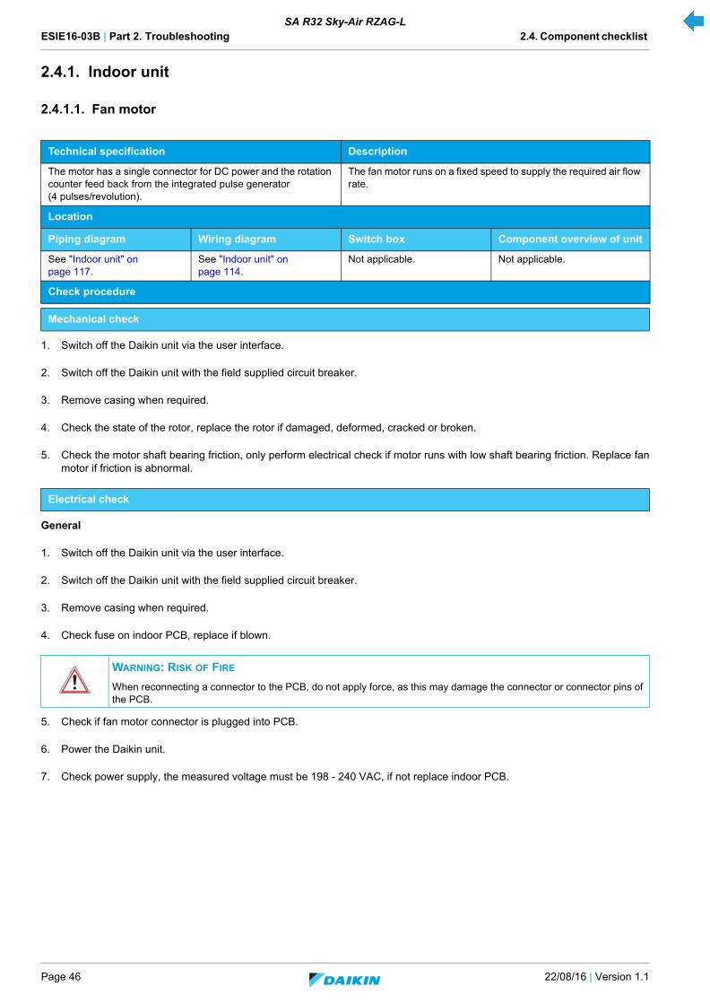
ESIE16-03B | Part 2. Troubleshooting 2.4. Component checklist
Page 46 22/08/16 | Version 1.1
SA R32 Sky-Air RZAG-L
2.4.1. Indoor unit
2.4.1.1. Fan motor
1. Switch off the Daikin unit via the user interface.
2. Switch off the Daikin unit with the field supplied circuit breaker.
3. Remove casing when required.
4. Check the state of the rotor, replace the rotor if damaged, deformed, cracked or broken.
5. Check the motor shaft bearing friction, only perform electrical check if motor runs with low shaft bearing friction. Replace fanmotor if friction is abnormal.
General
1. Switch off the Daikin unit via the user interface.
2. Switch off the Daikin unit with the field supplied circuit breaker.
3. Remove casing when required.
4. Check fuse on indoor PCB, replace if blown.
5. Check if fan motor connector is plugged into PCB.
6. Power the Daikin unit.
7. Check power supply, the measured voltage must be 198 - 240 VAC, if not replace indoor PCB.
Technical specification Description
The motor has a single connector for DC power and the rotation counter feed back from the integrated pulse generator (4 pulses/revolution).
The fan motor runs on a fixed speed to supply the required air flow rate.
Location
Piping diagram Wiring diagram Switch box Component overview of unit
See "Indoor unit" on page 117.
See "Indoor unit" on page 114.
Not applicable. Not applicable.
Check procedure
Mechanical check
Electrical check
WARNING: RISK OF FIRE
When reconnecting a connector to the PCB, do not apply force, as this may damage the connector or connector pins of the PCB.

ESIE16-03B | Part 2. Troubleshooting 2.4. Component checklist
22/08/16 | Version 1.1 Page 47
SA R32 Sky-Air RZAG-L
2.4.2. Outdoor unit
2.4.2.1. 4-way valve
1. Switch off the Daikin unit via the user interface.
2. Switch off the Daikin unit with the field supplied circuit breaker.
3. Remove plate work when required.
4. Loosen the screw and remove the coil from the 4-way valve (refer to "Replacing 4-way valve coil" on page 75).
5. Unplug 4-way valve connector from applicable PCB.
6. Switch on the Daikin unit via the user interface, start cooling/defrost operation.
If the temperature after the heat exchanger drops, proceed with next step.
If the temperature after the heat exchanger rises, the 4-way valve is stuck in heating position, replace the 4-way valve body (refer to "Replacing 4-way valve body" on page 73).
If the temperature after the heat exchanger does not rise, check the refrigerant pressure by connecting a manifold to one of the service ports.
- If no pressure is measured, perform a pressure test and fix any leaks.
- If pressure is measured, the 4-way valve is stuck in the middle, confirm by determining the position of the 4-way valve asdescribed below and replace the 4-way valve (refer to "Replacing 4-way valve body" on page 73).
7. While listening to the 4-way valve, place a round permanent magnet on the core of the solenoid valve. If you do not hear the4-way valve switching, it must be replaced (refer to "Replacing 4-way valve body" on page 73).
1. Switch off Daikin unit via the user interface.
2. Switch off Daikin unit with the field supplied circuit breaker.
3. Remove plate work when required.
4. Switch on the Daikin unit, start heating operation.
Technical specification Description
- The 4-way valve directs the super heated refrigerant discharged from the compressor to the indoor heat exchanger in case of heat-ing operation or to the outdoor heat exchanger in case of defrost-ing and cooling operation.
Location
Piping diagram Wiring diagram Switch box Component overview of unit
See "Outdoor unit" on page 117.
See "Outdoor unit" on page 115.
See "Outdoor unit" on page 122.
See "Outdoor unit" on page 119.
Check procedure
Mechanical check
WARNING: RISK OF FIRE
When reconnecting a connector to the PCB, do not apply force, as this may damage the connector or connector pins of the PCB.
CAUTION - RISK OF LIQUID ENTERING THE COMPRESSOR
To prevent damage to the compressor the step below must only be done once.
Electrical check

ESIE16-03B | Part 2. Troubleshooting 2.4. Component checklist
Page 48 22/08/16 | Version 1.1
SA R32 Sky-Air RZAG-L
5. Measure the voltage on 4-way valve connector: pin 1-3. If the measured voltage does not range 220-240 VAC during switching/ 15 VAC after switching, unplug 4-way valve connector from PCB and measure the voltage directly on the PCB: pin 1-3 of4-way valve connection.
- If the voltage, measured directly on the PCB does not range 220-240 VAC during switching / 15 VAC after switching,replace main PCB.
- If the voltage, measured directly on the PCB does range 220-240 VAC during switching / 15 VAC after switching, replacethe 4-way valve coil (refer to "Replacing 4-way valve coil" on page 75).
6. Unplug 4-way valve connector from PCB and measure the resistance of the 4-way valve coil. If the measured resistance doesnot range 1000 - 2000 Ω, replace the 4-way valve coil (refer to "Replacing 4-way valve coil" on page 75).
7. Switch on the Daikin unit, start cooling/defrost operation.
If the temperature after the plate type heat exchanger rises, the control of the 4-way valve is wrong. Replace main PCB.
1. Switch off Daikin unit via the user interface.
2. Switch off Daikin unit with the field supplied circuit breaker.
3. Slide a magnet over the front and the rear of the 4-way valve body and sense the attraction of the magnet to determine thevalve position.
4. If the magnet is attracted in positions A,A’ or B,B’, the 4-way valve is OK; if the magnet is attracted in positions C,C’ the 4-wayvalve must be replaced (refer to "Replacing 4-way valve body" on page 73).
WARNING: RISK OF FIRE
When reconnecting a connector to the PCB, do not apply force, as this may damage the connector or connector pins of the PCB.
WARNING: RISK OF FIRE
When reconnecting a connector to the PCB, do not apply force, as this may damage the connector or connector pins of the PCB.
Determine the position of the 4-way valve
A A’ B B’ C C’

ESIE16-03B | Part 2. Troubleshooting 2.4. Component checklist
22/08/16 | Version 1.1 Page 49
SA R32 Sky-Air RZAG-L
2.4.2.2. Compressor
1. Check if the Daikin unit is connected to earth.
2. Check if the stop valve is open.
1. Switch off the Daikin unit via the user interface.
2. Switch off the Daikin unit with the field supplied circuit breaker.
3. Remove plate work when required (refer to "Basic removal" on page 67).
4. Open the compressor insulation.
5. Check if the condition of the compressor dampers and piping is correct.
1. Switch off the Daikin unit via the user interface.
2. Switch off the Daikin unit with the field supplied circuit breaker.
3. Remove plate work when required.
4. Open the compressor insulation.
5. Switch on the Daikin unit and measure the U, V, W inverter voltages. All voltages must be identical, if not, replace the inverterPCB.
6. Switch off the Daikin unit via the user interface.
7. Switch off the Daikin unit with the field supplied circuit breaker.
8. Disconnect the Faston connectors U, V and W from the compressor, take picture.
9. Measure the compressor motor windings U-V, V-W and U-W (refer to "Product specific information" on page 121).
10. Megger the compressor using 500 or 1000 VDC, the insulation must be higher than 3 MΩ.
11. Replace the compressor if the windings and/or insulation measurements fail (refer to "Replacing compressor" on page 76).
12. Run the compressor and measure the current in each phase; the current for each phase should be identical (refer to "Productspecific information" on page 121). In that case it can be decided to preventively replace the compressor (refer to "Replacingcompressor" on page 76).
Technical specification Description
Type: inverter driven, swing double swing. The compressor compresses the refrigerant in the refrigerant cir-cuit.
Location
Piping diagram Wiring diagram Switch box Component overview of unit
See "Outdoor unit" on page 117.
See "Outdoor unit" on page 115.
See "Outdoor unit" on page 122.
See "Outdoor unit" on page 119.
Check procedure
Preliminary check
Mechanical check
Electrical check
INFORMATION
Note the position of the cables on the compressor wire terminals to allow identical wiring during reinstallation.
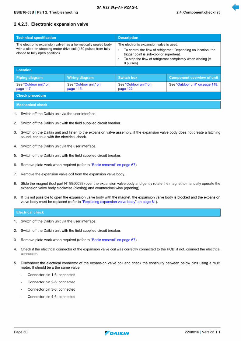
ESIE16-03B | Part 2. Troubleshooting 2.4. Component checklist
Page 50 22/08/16 | Version 1.1
SA R32 Sky-Air RZAG-L
2.4.2.3. Electronic expansion valve
1. Switch off the Daikin unit via the user interface.
2. Switch off the Daikin unit with the field supplied circuit breaker.
3. Switch on the Daikin unit and listen to the expansion valve assembly, if the expansion valve body does not create a latchingsound, continue with the electrical check.
4. Switch off the Daikin unit via the user interface.
5. Switch off the Daikin unit with the field supplied circuit breaker.
6. Remove plate work when required (refer to "Basic removal" on page 67).
7. Remove the expansion valve coil from the expansion valve body.
8. Slide the magnet (tool part N° 9950038) over the expansion valve body and gently rotate the magnet to manually operate theexpansion valve body clockwise (closing) and counterclockwise (opening).
9. If it is not possible to open the expansion valve body with the magnet, the expansion valve body is blocked and the expansionvalve body must be replaced (refer to "Replacing expansion valve body" on page 81).
1. Switch off the Daikin unit via the user interface.
2. Switch off the Daikin unit with the field supplied circuit breaker.
3. Remove plate work when required (refer to "Basic removal" on page 67).
4. Check if the electrical connector of the expansion valve coil was correctly connected to the PCB, if not, connect the electricalconnector.
5. Disconnect the electrical connector of the expansion valve coil and check the continuity between below pins using a multimeter. It should be ± the same value.
- Connector pin 1-6: connected
- Connector pin 2-6: connected
- Connector pin 3-6: connected
- Connector pin 4-6: connected
Technical specification Description
The electronic expansion valve has a hermetically sealed body with a slide-on stepping motor drive coil (480 pulses from fully closed to fully open position).
The electronic expansion valve is used:
• To control the flow of refrigerant. Depending on location, the trigger point is sub-cool or superheat.
• To stop the flow of refrigerant completely when closing (= 0 pulses).
Location
Piping diagram Wiring diagram Switch box Component overview of unit
See "Outdoor unit" on page 117.
See "Outdoor unit" on page 115.
See "Outdoor unit" on page 122.
See "Outdoor unit" on page 119.
Check procedure
Mechanical check
Electrical check

ESIE16-03B | Part 2. Troubleshooting 2.4. Component checklist
22/08/16 | Version 1.1 Page 51
SA R32 Sky-Air RZAG-L
6. If one or more of the windings have no continuity, replace the expansion valve coil.
Harness 5P
6P Connector Check
1
6
3
2 4
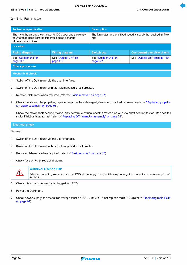
ESIE16-03B | Part 2. Troubleshooting 2.4. Component checklist
Page 52 22/08/16 | Version 1.1
SA R32 Sky-Air RZAG-L
2.4.2.4. Fan motor
1. Switch off the Daikin unit via the user interface.
2. Switch off the Daikin unit with the field supplied circuit breaker.
3. Remove plate work when required (refer to "Basic removal" on page 67).
4. Check the state of the propeller, replace the propeller if damaged, deformed, cracked or broken (refer to "Replacing propellerfan blade assembly" on page 93).
5. Check the motor shaft bearing friction, only perform electrical check if motor runs with low shaft bearing friction. Replace fanmotor if friction is abnormal (refer to "Replacing DC fan motor assembly" on page 79).
General
1. Switch off the Daikin unit via the user interface.
2. Switch off the Daikin unit with the field supplied circuit breaker.
3. Remove plate work when required (refer to "Basic removal" on page 67).
4. Check fuse on PCB, replace if blown.
5. Check if fan motor connector is plugged into PCB.
6. Power the Daikin unit.
7. Check power supply, the measured voltage must be 198 - 240 VAC, if not replace main PCB (refer to "Replacing main PCB"on page 89).
Technical specification Description
The motor has a single connector for DC power and the rotation counter feed back from the integrated pulse generator (4 pulses/revolution).
The fan motor runs on a fixed speed to supply the required air flow rate.
Location
Piping diagram Wiring diagram Switch box Component overview of unit
See "Outdoor unit" on page 117.
See "Outdoor unit" on page 115.
See "Outdoor unit" on page 122.
See "Outdoor unit" on page 119.
Check procedure
Mechanical check
Electrical check
WARNING: RISK OF FIRE
When reconnecting a connector to the PCB, do not apply force, as this may damage the connector or connector pins of the PCB.

ESIE16-03B | Part 2. Troubleshooting 2.4. Component checklist
22/08/16 | Version 1.1 Page 53
SA R32 Sky-Air RZAG-L
2.4.2.5. High pressure switch
1. Switch off the Daikin unit via the user interface.
2. Switch off the Daikin unit with the field supplied circuit breaker.
3. Remove plate work when required (refer to "Basic removal" on page 67).
4. Disconnect the high pressure switch connector from applicable PCB.
5. Recover the refrigerant.
6. Pressurize the refrigerant circuit at 41.7 bar with nitrogen.
7. Measure the switch contacts between high pressure switch connector: pins 1-2; the switch must be open.
8. Replace the high pressure switch if the contact is not open (refer to "Replacing high pressure switches" on page 86).
9. Lower the refrigerant circuit pressure to 30 bar.
10. Measure the switch contacts between high pressure switch connector: pins 1-2; the switch must be closed.
11. Replace the high pressure switch if the contact is not closed (refer to "Replacing high pressure switches" on page 86).
Technical specification Description
The high pressure switch has a normally closed contact. If the pressure exceeds 41.7 (+0 / -1) bar the contact will open; if the pressure drops below 32 (±2) bar the contact will close.
The high pressure switch is a safety component that stops the compressor if overpressure is detected in the refrigerant circuit.
Location
Piping diagram Wiring diagram Switch box Component overview of unit
See "Outdoor unit" on page 117.
See "Outdoor unit" on page 115.
See "Outdoor unit" on page 122.
See "Outdoor unit" on page 119.
Check procedure
Electrical check
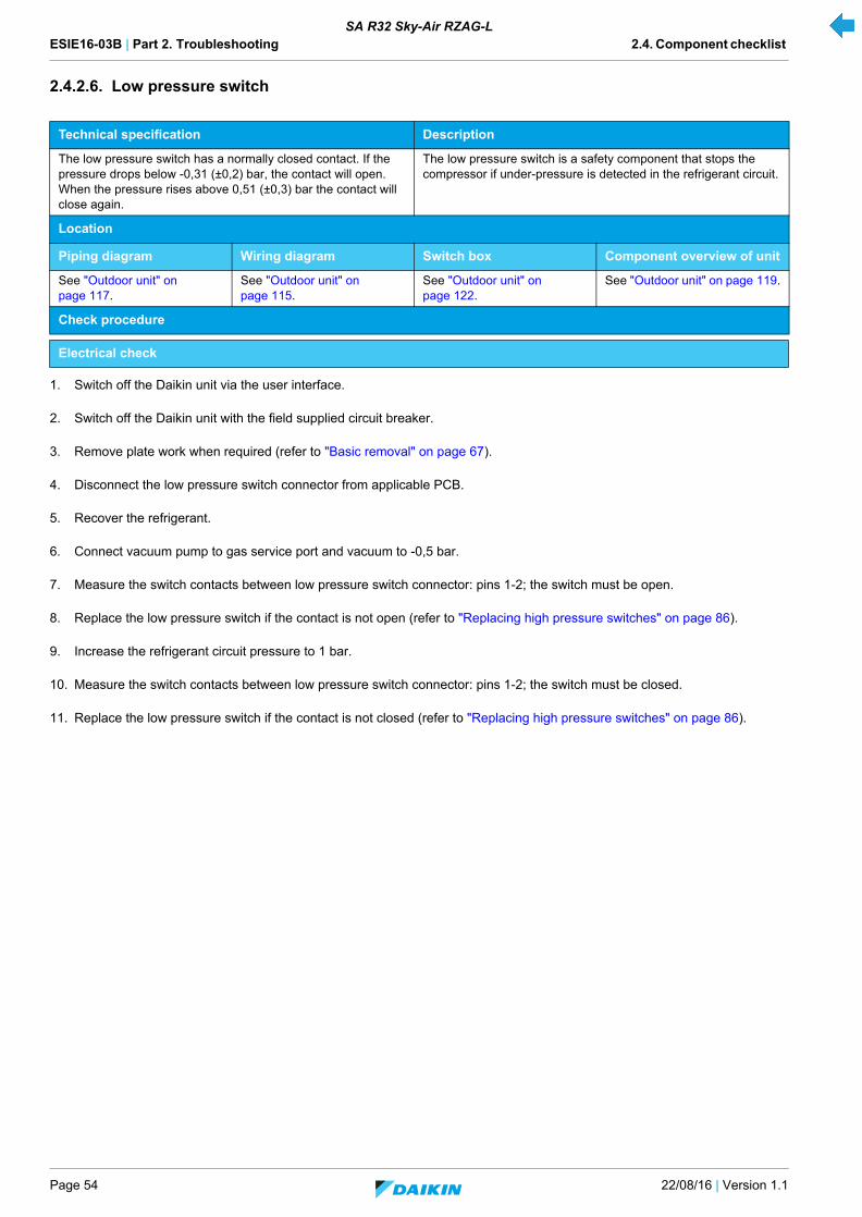
ESIE16-03B | Part 2. Troubleshooting 2.4. Component checklist
Page 54 22/08/16 | Version 1.1
SA R32 Sky-Air RZAG-L
2.4.2.6. Low pressure switch
1. Switch off the Daikin unit via the user interface.
2. Switch off the Daikin unit with the field supplied circuit breaker.
3. Remove plate work when required (refer to "Basic removal" on page 67).
4. Disconnect the low pressure switch connector from applicable PCB.
5. Recover the refrigerant.
6. Connect vacuum pump to gas service port and vacuum to -0,5 bar.
7. Measure the switch contacts between low pressure switch connector: pins 1-2; the switch must be open.
8. Replace the low pressure switch if the contact is not open (refer to "Replacing high pressure switches" on page 86).
9. Increase the refrigerant circuit pressure to 1 bar.
10. Measure the switch contacts between low pressure switch connector: pins 1-2; the switch must be closed.
11. Replace the low pressure switch if the contact is not closed (refer to "Replacing high pressure switches" on page 86).
Technical specification Description
The low pressure switch has a normally closed contact. If the pressure drops below -0,31 (±0,2) bar, the contact will open. When the pressure rises above 0,51 (±0,3) bar the contact will close again.
The low pressure switch is a safety component that stops the compressor if under-pressure is detected in the refrigerant circuit.
Location
Piping diagram Wiring diagram Switch box Component overview of unit
See "Outdoor unit" on page 117.
See "Outdoor unit" on page 115.
See "Outdoor unit" on page 122.
See "Outdoor unit" on page 119.
Check procedure
Electrical check

ESIE16-03B | Part 2. Troubleshooting 2.4. Component checklist
22/08/16 | Version 1.1 Page 55
SA R32 Sky-Air RZAG-L
2.4.2.7. Main PCB
Not applicable.
1. Switch off the Daikin unit via the user interface.
2. Switch off the Daikin unit with the field supplied circuit breaker.
3. Remove plate work when required (refer to "Basic removal" on page 67).
4. Switch on the Daikin unit with the field supplied circuit breaker.
5. Switch on the Daikin unit via the user interface.
6. Check if the HAP LED is blinking in regular intervals (1/0,5 sec), if not blinking, replace the main PCB board (refer to "Replacingmain PCB" on page 89).
7. Measure the supply voltage to the main PCB board: there should be ± 220 V between brown and blue cable. If not correctvoltage, replace the electrical noise filter PCB (refer to "Replacing electrical noise filter" on page 80).
8. Switch off the Daikin unit via the user interface.
9. Switch off the Daikin unit with the field supplied circuit breaker.
10. Remove plate work when required.
11. Open the compressor insulation.
12. Remove the terminal cover of compressor wiring.
13. Measure the voltage on S70: pin 7-4 and wait until it drops below 10 VDC.
14. Disconnect the compressor wires and connect the compressor wires to the Inverter Analyzer (SPP number 1368521).
Technical specification Description
Location
Piping diagram Wiring diagram Switch box Component overview of unit
See "Outdoor unit" on page 117.
See "Outdoor unit" on page 115.
See "Outdoor unit" on page 122.
See "Outdoor unit" on page 119.
Check procedure
Mechanical check
Electrical check
WARNING: RISK OF ELECTROCUTION
The smoothing capacitor must discharge below 10 VDC before removing the compressor wiring.
INFORMATION
Note the position of the cables on the compressor wire terminals to allow identical wiring during reinstallation.

ESIE16-03B | Part 2. Troubleshooting 2.4. Component checklist
Page 56 22/08/16 | Version 1.1
SA R32 Sky-Air RZAG-L
15. Power the Daikin unit.
16. Activate the inverter test (refer to "Component checklist" on page 121).
17. Check that all LED’s on the Inverter Analyzer are lit; if not, replace the inverter board (refer to "Replacing inverter PCB" onpage 87).
18. Switch off the Daikin unit with the field supplied circuit breaker.
19. Wait a few minutes and confirm that the LED's on the Inverter Analyzer are off.
20. Disconnect the Inverter Analyzer from the U V W wiring.
21. Reconnect the U V W leads to the compressor.
WARNING
Electrical shock hazard. Do not touch life wires.
CAUTION
When wiring the compressor, observe UV W as indicated on the compressor.
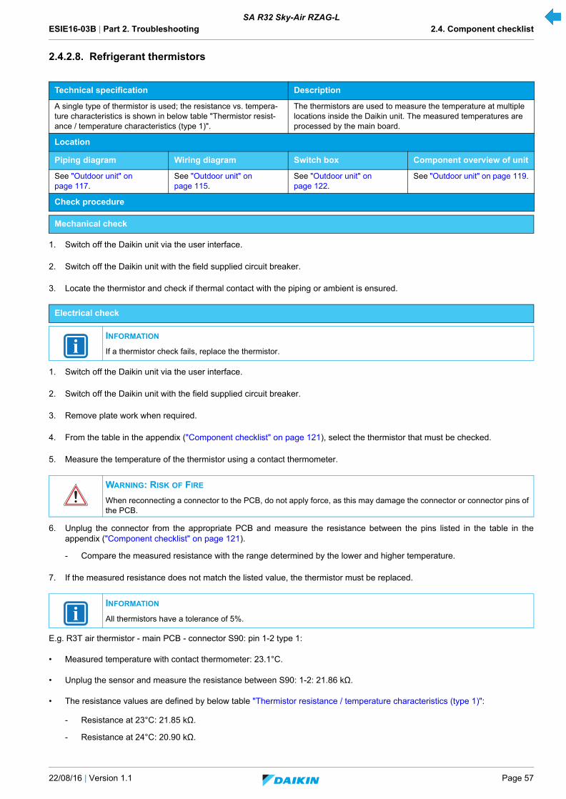
ESIE16-03B | Part 2. Troubleshooting 2.4. Component checklist
22/08/16 | Version 1.1 Page 57
SA R32 Sky-Air RZAG-L
2.4.2.8. Refrigerant thermistors
1. Switch off the Daikin unit via the user interface.
2. Switch off the Daikin unit with the field supplied circuit breaker.
3. Locate the thermistor and check if thermal contact with the piping or ambient is ensured.
1. Switch off the Daikin unit via the user interface.
2. Switch off the Daikin unit with the field supplied circuit breaker.
3. Remove plate work when required.
4. From the table in the appendix ("Component checklist" on page 121), select the thermistor that must be checked.
5. Measure the temperature of the thermistor using a contact thermometer.
6. Unplug the connector from the appropriate PCB and measure the resistance between the pins listed in the table in theappendix ("Component checklist" on page 121).
- Compare the measured resistance with the range determined by the lower and higher temperature.
7. If the measured resistance does not match the listed value, the thermistor must be replaced.
E.g. R3T air thermistor - main PCB - connector S90: pin 1-2 type 1:
• Measured temperature with contact thermometer: 23.1°C.
• Unplug the sensor and measure the resistance between S90: 1-2: 21.86 kΩ.
• The resistance values are defined by below table "Thermistor resistance / temperature characteristics (type 1)":
- Resistance at 23°C: 21.85 kΩ.
- Resistance at 24°C: 20.90 kΩ.
Technical specification Description
A single type of thermistor is used; the resistance vs. tempera-ture characteristics is shown in below table "Thermistor resist-ance / temperature characteristics (type 1)".
The thermistors are used to measure the temperature at multiple locations inside the Daikin unit. The measured temperatures are processed by the main board.
Location
Piping diagram Wiring diagram Switch box Component overview of unit
See "Outdoor unit" on page 117.
See "Outdoor unit" on page 115.
See "Outdoor unit" on page 122.
See "Outdoor unit" on page 119.
Check procedure
Mechanical check
Electrical check
INFORMATION
If a thermistor check fails, replace the thermistor.
WARNING: RISK OF FIRE
When reconnecting a connector to the PCB, do not apply force, as this may damage the connector or connector pins of the PCB.
INFORMATION
All thermistors have a tolerance of 5%.

ESIE16-03B | Part 2. Troubleshooting 2.4. Component checklist
Page 58 22/08/16 | Version 1.1
SA R32 Sky-Air RZAG-L
• The measured value 21.86 kΩ is inside the range, thermistor R3T passes the check.
Table 2-1: Thermistor resistance / temperature characteristics (type 1)
Table 2-2: Thermistor resistance / temperature characteristics (type 2)
INFORMATION
The user interface allows to monitor most thermistors.
If the measured resistance of the thermistor matches the temperature measured with the contact thermometer but the temperature for the corresponding thermistor is not correct on the user interface display, replace applicable PCB.
T °C kΩ T °C kΩ T °C kΩ T °C kΩ T °C kΩ
-20 197.81 0 65.84 20 25.01 40 10.63 60 4.87
-19
-18
-17
-16
-15
-14
-13
-12
-11
186.53
175.97
166.07
156.80
148.10
139.94
132.28
125.09
118.34
1
2
3
4
5
6
7
8
9
62.54
59.43
56.49
53.71
51.09
48.61
46.26
44.05
41.95
21
22
23
24
25
26
27
28
29
23.91
22.85
21.85
20.90
20.00
19.14
18.32
17.54
16.80
41
42
43
44
45
46
47
48
49
10.21
9.81
9.42
9.06
8.71
8.37
8.05
7.75
7.46
61
62
63
64
65
66
67
68
69
4.70
4.54
4.38
4.23
4.08
3.94
3.81
3.68
3.56
-10 111.99 10 39.96 30 16.10 50 7.18 70 3.44
-9
-8
-7
-6
-5
-4
-3
-2
-1
106.03
100.41
95.14
90.17
85.49
81.08
76.93
73.01
69.32
11
12
13
14
15
16
17
18
19
38.08
36.30
34.62
33.02
31.50
30.06
28.70
27.41
26.18
31
32
33
34
35
36
37
38
39
15.43
14.79
14.18
13.59
13.04
12.51
12.01
11.52
11.06
51
52
53
54
55
56
57
58
59
6.91
6.65
6.41
6.65
6.41
6.18
5.95
5.74
5.14
71
72
73
74
75
76
77
78
79
3.32
3.21
3.11
3.01
2.91
2.82
2.72
2.64
2.55
80 2.47
T °C kΩ T °C kΩ T °C kΩ T °C kΩ T °C kΩ
-20 192.08 0 64.17 20 24.45 40 10.41 60 4.87
-19
-18
-17
-16
-15
-14
-13
-12
-11
181.16
170.94
161.36
152.38
143.96
136.05
128.63
121.66
115.12
1
2
3
4
5
6
7
8
9
60.96
57.94
55.08
52.38
49.83
47.42
45.14
42.98
40.94
21
22
23
24
25
26
27
28
29
23.37
22.35
21.37
20.45
19.56
18.73
17.93
17.17
16.45
41
42
43
44
45
46
47
48
49
10.00
9.61
9.24
8.88
8.54
8.21
7.90
7.60
7.31
61
62
63
64
65
66
67
68
69
4.70
4.54
4.38
4.23
4.08
3.94
3.81
3.68
3.56
-10 108.96 10 39.01 30 15.76 50 7.04 70 3.44
-9
-8
-7
-6
-5
-4
-3
-2
-1
103.18
97.73
92.61
87.79
83.25
78.97
74.94
71.14
67.56
11
12
13
14
15
16
17
18
19
37.18
35.45
33.81
32.25
30.77
29.37
28.05
26.78
25.59
31
32
33
34
35
36
37
38
39
15.10
14.48
13.88
13.31
12.77
12.25
11.76
11.29
10.84
51
52
53
54
55
56
57
58
59
6.78
6.53
6.53
6.53
6.29
6.06
5.84
5.43
5.05
71
72
73
74
75
76
77
78
79
3.32
3.21
3.11
3.01
2.91
2.82
2.72
2.64
2.55
80 2.47

ESIE16-03B | Part 2. Troubleshooting 2.5. Other capacity range
22/08/16 | Version 1.1 Page 59
SA R32 Sky-Air RZAG-L
2.4.3. System
Not applicable.
2.4.4. Others
Not applicable.
2.5. Other capacity range
Not applicable.
0

ESIE16-03B | Part 2. Troubleshooting 2.5. Other capacity range
Page 60 22/08/16 | Version 1.1
SA R32 Sky-Air RZAG-L
ESIE16-03B | Part 3. Repair 3.1. Refrigerant repair procedures
22/08/16 | Version 1.1 Page 61
SA R32 Sky-Air RZAG-L
Part 3. RepairThis part contains the following chapters:
3.1. Refrigerant repair procedures
Overview:
3.1.1. Refrigerant piping handling
• Make sure the applied pressure is never higher than the unit design pressure as indicated on the nameplate (PS).
• Work according the F-gas regulation and/or local regulations.
• Make sure the correct amount according the F-gas regulation label on the unit (factory + additional where required) ofrefrigerant is charged after repair.
• Make sure to use the appropriate equipment and tools according to the refrigerant and unit type.
• Charge non-azeotropic refrigerant (e.g. R-410A) always in a liquid state.
• R32 can be charged in gas phase.
• Make sure to use a digital scale (no charging cylinder).
• Execute correct vacuum drying procedure after repair work:
- -0,1 MPa / -760 mmHg / -750 Torr / -1 bar for at least 1 hour.
- Connect the unit according the available service ports, refer to "Recovery procedure" on page 61.
- Use related field setting where necessary to open expansion valve/solenoid valve.
3.1.2. Recovery procedure
3.1.2.1. Outdoor unit casing
1. Switch off the Daikin unit via the user interface.
2. Manually open the expansion valve (located on the outdoor unit).
3. Connect the vacuum pump, manifold, recovery unit and refrigerant bottle to the service port as shown below.
For the location of the service ports, refer to "Outdoor unit" on page 117.
Refrigerant repair procedures ..............................................................................................................................................................61
Service tools.........................................................................................................................................................................................65
Unit specific repair procedures.............................................................................................................................................................66
Refrigerant piping handling ..................................................................................................................................................................61
Recovery procedure .............................................................................................................................................................................61
Refrigerant pump down ........................................................................................................................................................................63
Piping repair procedures ......................................................................................................................................................................64

ESIE16-03B | Part 3. Repair 3.1. Refrigerant repair procedures
Page 62 22/08/16 | Version 1.1
SA R32 Sky-Air RZAG-L
In case of 1 service port at the stop valves
Figure 3-1: 1 service port at the stop valves
.
In case of 2 service ports at the stop valves
Connect both stop valve service ports to the manifold.
In case of 3 service ports at the stop valves
Connect 1 hose to the suction stop valve service port and 1 hose to the service port between the expansion valve and outdoor H/E.
1. Vacuum pump 3. To recovery pump
2. Connect flexible hose to service port 3 stop valve
INFORMATION
See instruction of the recovery pump supplier how to recover the refrigerant.
1
3
2
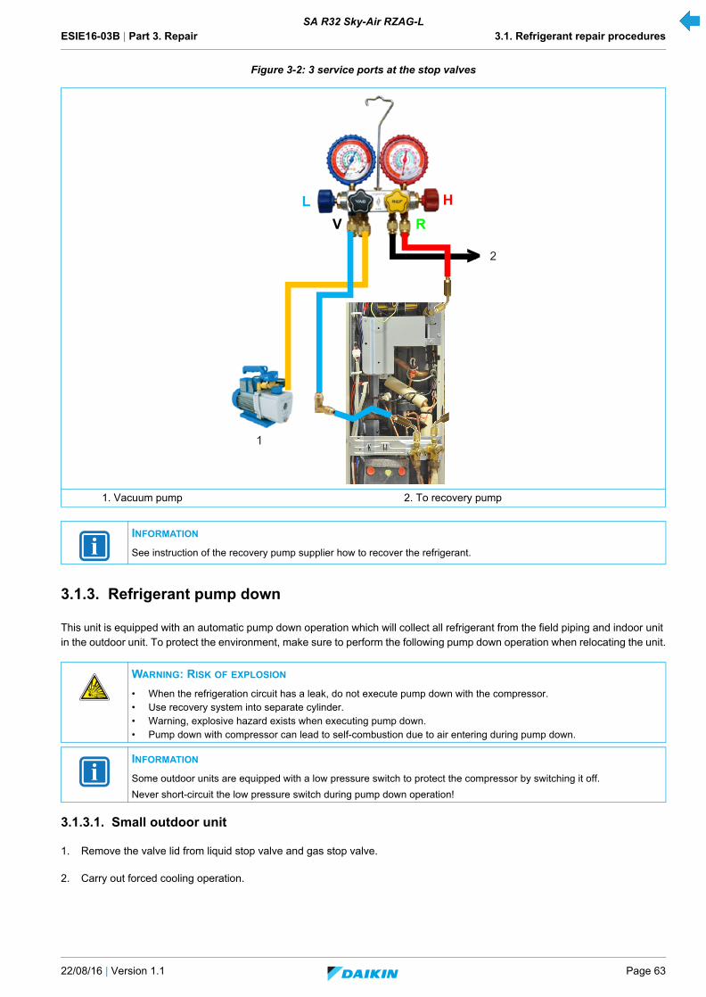
ESIE16-03B | Part 3. Repair 3.1. Refrigerant repair procedures
22/08/16 | Version 1.1 Page 63
SA R32 Sky-Air RZAG-L
Figure 3-2: 3 service ports at the stop valves
3.1.3. Refrigerant pump down
This unit is equipped with an automatic pump down operation which will collect all refrigerant from the field piping and indoor unit in the outdoor unit. To protect the environment, make sure to perform the following pump down operation when relocating the unit.
3.1.3.1. Small outdoor unit
1. Remove the valve lid from liquid stop valve and gas stop valve.
2. Carry out forced cooling operation.
1. Vacuum pump 2. To recovery pump
INFORMATION
See instruction of the recovery pump supplier how to recover the refrigerant.
WARNING: RISK OF EXPLOSION
• When the refrigeration circuit has a leak, do not execute pump down with the compressor.• Use recovery system into separate cylinder.• Warning, explosive hazard exists when executing pump down.• Pump down with compressor can lead to self-combustion due to air entering during pump down.
INFORMATION
Some outdoor units are equipped with a low pressure switch to protect the compressor by switching it off.
Never short-circuit the low pressure switch during pump down operation!
HV R
L
>
1
2

ESIE16-03B | Part 3. Repair 3.1. Refrigerant repair procedures
Page 64 22/08/16 | Version 1.1
SA R32 Sky-Air RZAG-L
3. After 5-10 min (after only 1-2 min in case of very low Ta < -10°C), close the liquid stop valve with a hexagonal wrench.
4. Check on manifold if vacuum is reached, close gas stop valve and forced cooling operation.
3.1.3.2. Large outdoor unit
1. Stop all demands for the Daikin unit.
2. Switch OFF / ON the power supply of the outdoor unit.
3. Carry out forced cooling operation.
4. The compressor and outdoor fan will start automatically.
5. Request heating via remote controller to prevent HE freeze-up.
6. a. Check on manifold if vacuum is reached, close gas stop valve and forced cooling operation.
b. Once operation stops (after 3 to 5 minutes), close the liquid and the gas stop valve.
7. Pump down is now finished. U4 may be displayed on the remote controller, this is not a malfunction.
8. (After “pump down/forced defrost” is finished or stopped, keep the circulation pump running for at least 5 minutes.)
9. Switch OFF the power supply of the outdoor unit.
3.1.4. Piping repair procedures
• Make sure to cover open pipe ends during repair work so no dust or moisture can enter.
• Make sure to re-apply insulation removed during repair.
• Pipe expansion / flare making:
- Remove any burrs on the cut surface and use correct tool such as reamer or scraper (note that excessive deburring canthin the pipe walls and cause cracking of the pipe).
- Make sure the flare has the correct size (use a flare gauge).
- Make sure no particles remain in the piping.
- Apply just a drop of refrigerant oil on the inner surface of the flare.
- Make sure the flare connection is tightened with the correct torque (torque values refer to installation manual).
• Brazing:
- Use correct brazing tool.
- Use a phosphor copper filler metal (silver composition of 0 to 2%). Do not use flux material.
- Flush the piping before brazing with nitrogen to avoid oxidation of the inside of the copper tubes (nitrogen purity ≥ 99,99%).
CAUTION
Refer to Installer Reference Guide for 'Forced cooling operation' procedure.
CAUTION
Refer to Installer Reference Guide for 'Forced cooling operation' procedure.
NOTE
• Make sure to re-open both stop valves before restart operation of the unit.• After a finished or stopped pump down, the unit will perform a test run at first operation (same as during
commissioning).
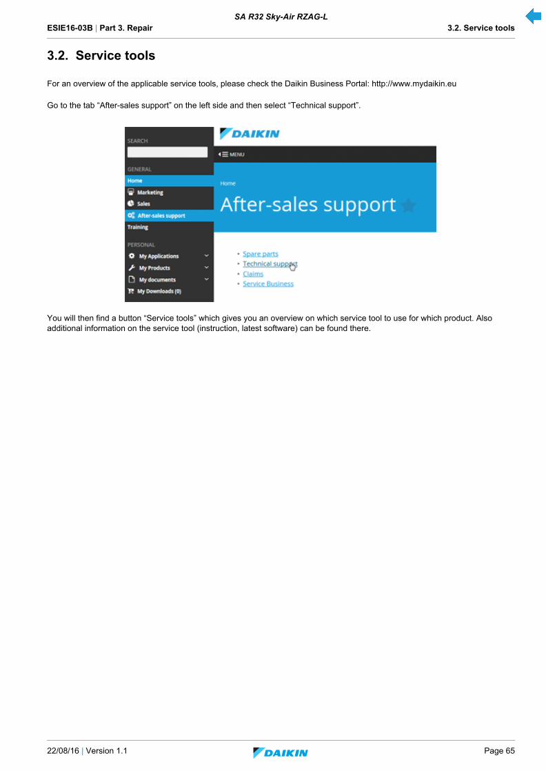
ESIE16-03B | Part 3. Repair 3.2. Service tools
22/08/16 | Version 1.1 Page 65
SA R32 Sky-Air RZAG-L
3.2. Service tools
For an overview of the applicable service tools, please check the Daikin Business Portal: http://www.mydaikin.eu
Go to the tab “After-sales support” on the left side and then select “Technical support”.
You will then find a button “Service tools” which gives you an overview on which service tool to use for which product. Also additional information on the service tool (instruction, latest software) can be found there.
ESIE16-03B | Part 3. Repair 3.3. Unit specific repair procedures
Page 66 22/08/16 | Version 1.1
SA R32 Sky-Air RZAG-L
3.3. Unit specific repair procedures
Overview:
3.3.1. Indoor unit
Not applicable.
Indoor unit............................................................................................................................................................................................ 66
Outdoor unit......................................................................................................................................................................................... 67
Basic removal .......................................................................................................................................................................... 67
Replacing thermistor................................................................................................................................................................ 71
Replacing 4-way valve body.................................................................................................................................................... 73
Replacing 4-way valve coil ...................................................................................................................................................... 75
Replacing accumulator assembly............................................................................................................................................ 75
Replacing compressor............................................................................................................................................................. 76
Replacing DC fan motor assembly .......................................................................................................................................... 79
Replacing electrical noise filter ................................................................................................................................................ 80
Replacing expansion valve body ............................................................................................................................................. 81
Replacing expansion valve motor............................................................................................................................................ 82
Replacing solenoid valve......................................................................................................................................................... 84
Replacing solenoid valve coil .................................................................................................................................................. 85
Replacing high pressure switches ........................................................................................................................................... 86
Replacing inverter PCB ........................................................................................................................................................... 87
Replacing low pressure switch ................................................................................................................................................ 88
Replacing main PCB ............................................................................................................................................................... 89
Replacing propeller fan blade assembly.................................................................................................................................. 93

ESIE16-03B | Part 3. Repair 3.3. Unit specific repair procedures
22/08/16 | Version 1.1 Page 67
SA R32 Sky-Air RZAG-L
3.3.2. Outdoor unit
3.3.2.1. Basic removal
1. Switch off the Daikin unit via the user interface.
2. Switch off the Daikin unit with the field supplied circuit breaker.
3. Loosen and remove the 9 screws (1) that fix the top plate assembly (2).
4. Lift the top plate assembly (2) and remove it from the Daikin unit.
Figure 3-3: Removing the top plate assembly
5. Loosen and remove the screw (1) that fixes the front plate (2).
6. Lift the front plate (2)and remove it from the unit.
1. Screw 2. Top panel
1 2 1 2 1
1 11111
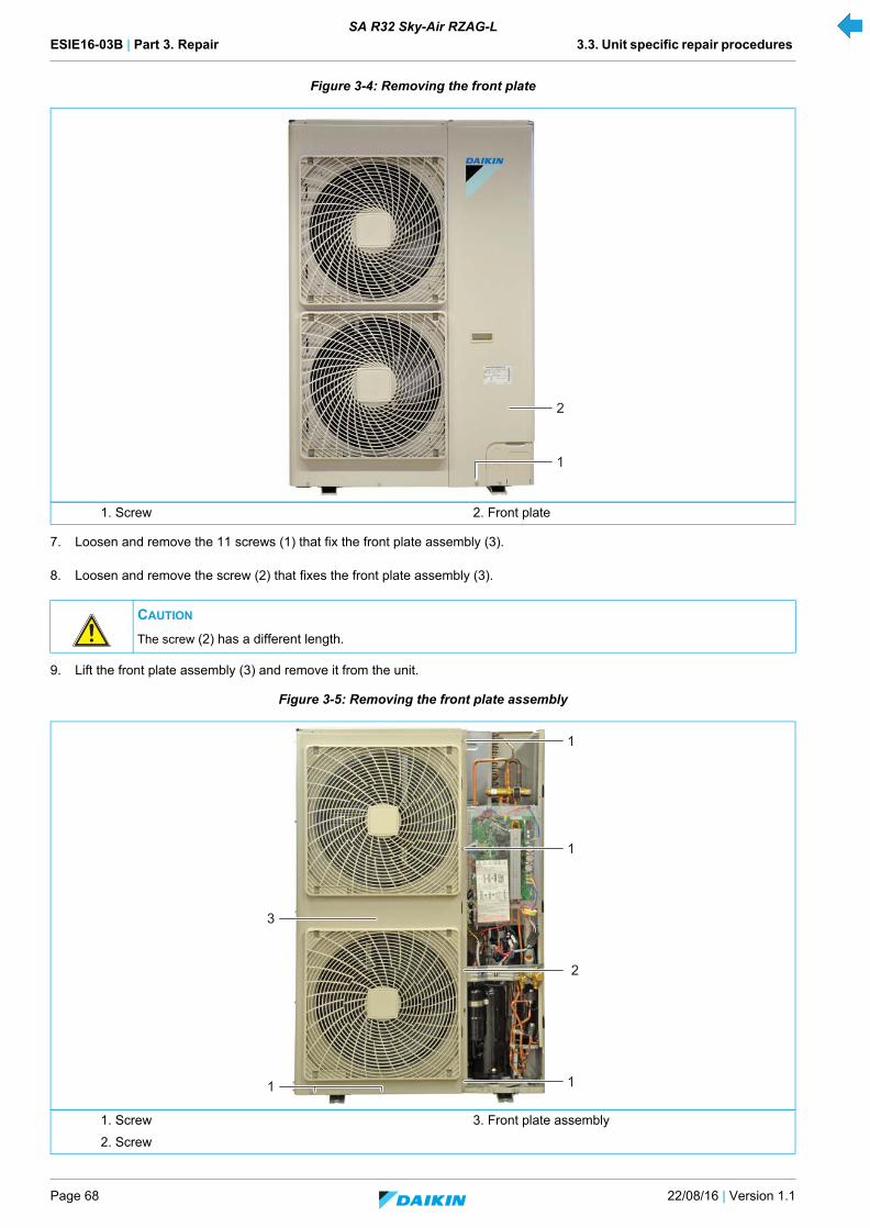
ESIE16-03B | Part 3. Repair 3.3. Unit specific repair procedures
Page 68 22/08/16 | Version 1.1
SA R32 Sky-Air RZAG-L
Figure 3-4: Removing the front plate
7. Loosen and remove the 11 screws (1) that fix the front plate assembly (3).
8. Loosen and remove the screw (2) that fixes the front plate assembly (3).
9. Lift the front plate assembly (3) and remove it from the unit.
Figure 3-5: Removing the front plate assembly
1. Screw 2. Front plate
CAUTION
The screw (2) has a different length.
1. Screw 3. Front plate assembly
2. Screw
2
1
1
1
3
1
2
1
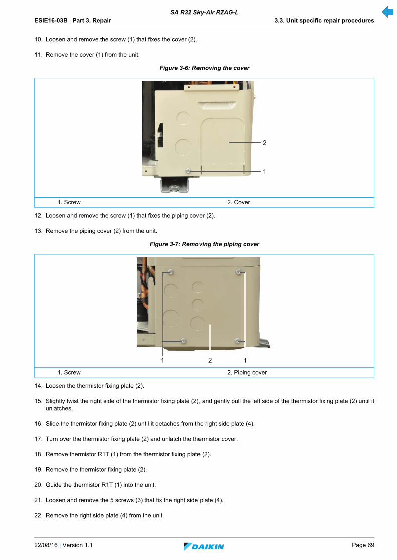
ESIE16-03B | Part 3. Repair 3.3. Unit specific repair procedures
22/08/16 | Version 1.1 Page 69
SA R32 Sky-Air RZAG-L
10. Loosen and remove the screw (1) that fixes the cover (2).
11. Remove the cover (1) from the unit.
Figure 3-6: Removing the cover
12. Loosen and remove the screw (1) that fixes the piping cover (2).
13. Remove the piping cover (2) from the unit.
Figure 3-7: Removing the piping cover
14. Loosen the thermistor fixing plate (2).
15. Slightly twist the right side of the thermistor fixing plate (2), and gently pull the left side of the thermistor fixing plate (2) until itunlatches.
16. Slide the thermistor fixing plate (2) until it detaches from the right side plate (4).
17. Turn over the thermistor fixing plate (2) and unlatch the thermistor cover.
18. Remove thermistor R1T (1) from the thermistor fixing plate (2).
19. Remove the thermistor fixing plate (2).
20. Guide the thermistor R1T (1) into the unit.
21. Loosen and remove the 5 screws (3) that fix the right side plate (4).
22. Remove the right side plate (4) from the unit.
1. Screw 2. Cover
1. Screw 2. Piping cover
2
1
2 11
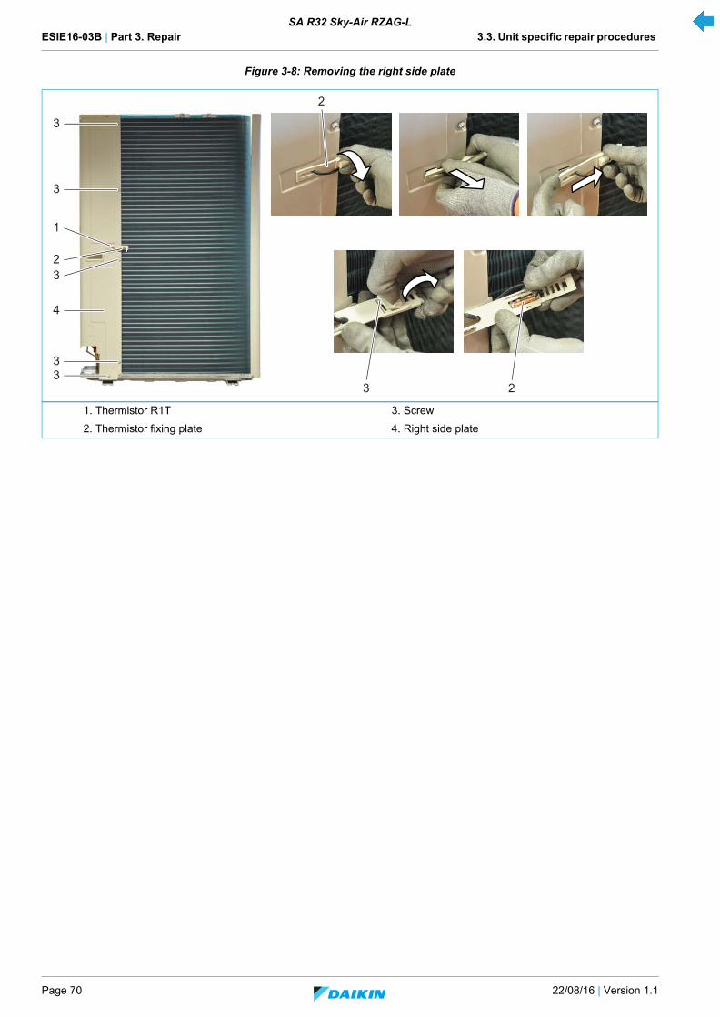
ESIE16-03B | Part 3. Repair 3.3. Unit specific repair procedures
Page 70 22/08/16 | Version 1.1
SA R32 Sky-Air RZAG-L
Figure 3-8: Removing the right side plate
1. Thermistor R1T 3. Screw
2. Thermistor fixing plate 4. Right side plate
3
3
4
32
1
33
23
2

ESIE16-03B | Part 3. Repair 3.3. Unit specific repair procedures
22/08/16 | Version 1.1 Page 71
SA R32 Sky-Air RZAG-L
3.3.2.2. Replacing thermistor
Removal
1. Switch off the Daikin unit via the user interface.
2. Switch off the Daikin unit with the field supplied circuit breaker.
3. Remove plate work when required (refer to "Basic removal" on page 67).
Figure 3-9: Thermistor location
Thermistor Processed on PCB Connector / colour
R1T (air) Main X11A
R2T (discharge) Main X12A / yellow
R3T (suction) Main X12A / green
R4T (heat exchanger) Main X12A / red
R5T (heat exchanger middle) Main X12A / white
R6T (liquid) Main X13A: / blue
R7T, R8T (Positive Temperature Coefficient) - -
1. R1T 4. R4T
2. R2T 5. R5T
3. R3T 6. R6T
2
5
3
1
5
3
1
4
6
2
4
6
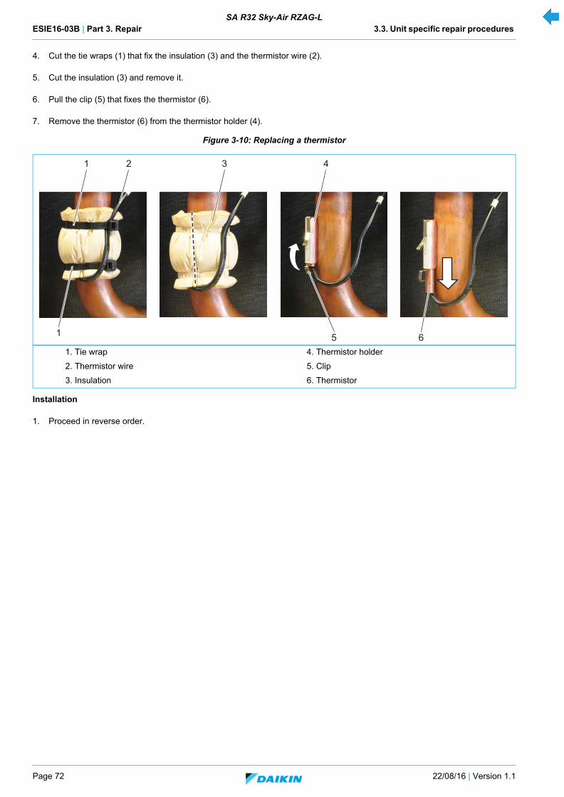
ESIE16-03B | Part 3. Repair 3.3. Unit specific repair procedures
Page 72 22/08/16 | Version 1.1
SA R32 Sky-Air RZAG-L
4. Cut the tie wraps (1) that fix the insulation (3) and the thermistor wire (2).
5. Cut the insulation (3) and remove it.
6. Pull the clip (5) that fixes the thermistor (6).
7. Remove the thermistor (6) from the thermistor holder (4).
Figure 3-10: Replacing a thermistor
Installation
1. Proceed in reverse order.
1. Tie wrap 4. Thermistor holder
2. Thermistor wire 5. Clip
3. Insulation 6. Thermistor
2 3 41
1 5 6
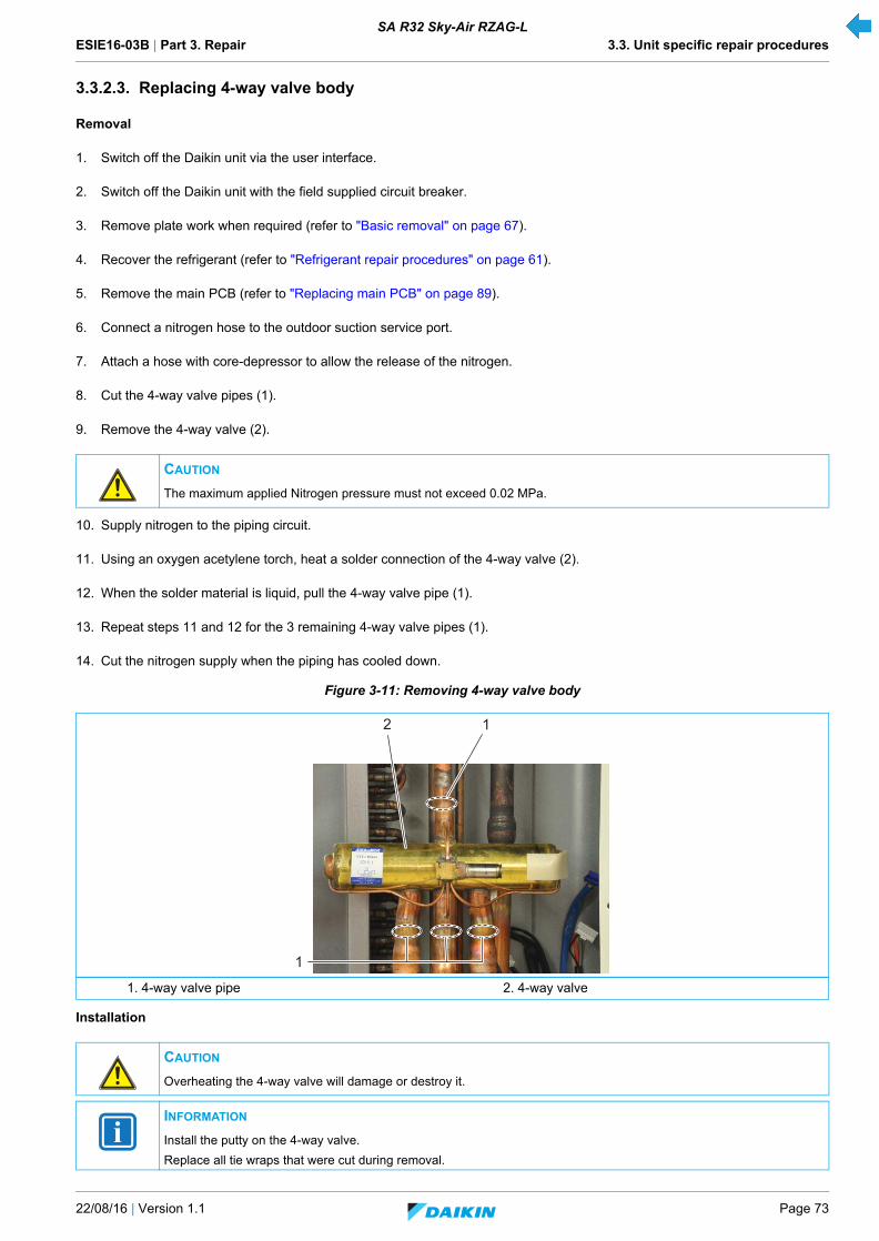
ESIE16-03B | Part 3. Repair 3.3. Unit specific repair procedures
22/08/16 | Version 1.1 Page 73
SA R32 Sky-Air RZAG-L
3.3.2.3. Replacing 4-way valve body
Removal
1. Switch off the Daikin unit via the user interface.
2. Switch off the Daikin unit with the field supplied circuit breaker.
3. Remove plate work when required (refer to "Basic removal" on page 67).
4. Recover the refrigerant (refer to "Refrigerant repair procedures" on page 61).
5. Remove the main PCB (refer to "Replacing main PCB" on page 89).
6. Connect a nitrogen hose to the outdoor suction service port.
7. Attach a hose with core-depressor to allow the release of the nitrogen.
8. Cut the 4-way valve pipes (1).
9. Remove the 4-way valve (2).
10. Supply nitrogen to the piping circuit.
11. Using an oxygen acetylene torch, heat a solder connection of the 4-way valve (2).
12. When the solder material is liquid, pull the 4-way valve pipe (1).
13. Repeat steps 11 and 12 for the 3 remaining 4-way valve pipes (1).
14. Cut the nitrogen supply when the piping has cooled down.
Figure 3-11: Removing 4-way valve body
Installation
CAUTION
The maximum applied Nitrogen pressure must not exceed 0.02 MPa.
1. 4-way valve pipe 2. 4-way valve
CAUTION
Overheating the 4-way valve will damage or destroy it.
INFORMATION
Install the putty on the 4-way valve.
Replace all tie wraps that were cut during removal.
1
2 1

ESIE16-03B | Part 3. Repair 3.3. Unit specific repair procedures
Page 74 22/08/16 | Version 1.1
SA R32 Sky-Air RZAG-L
1. Wrap a wet rag around the 4-way valve (2).
2. Proceed in reverse order.
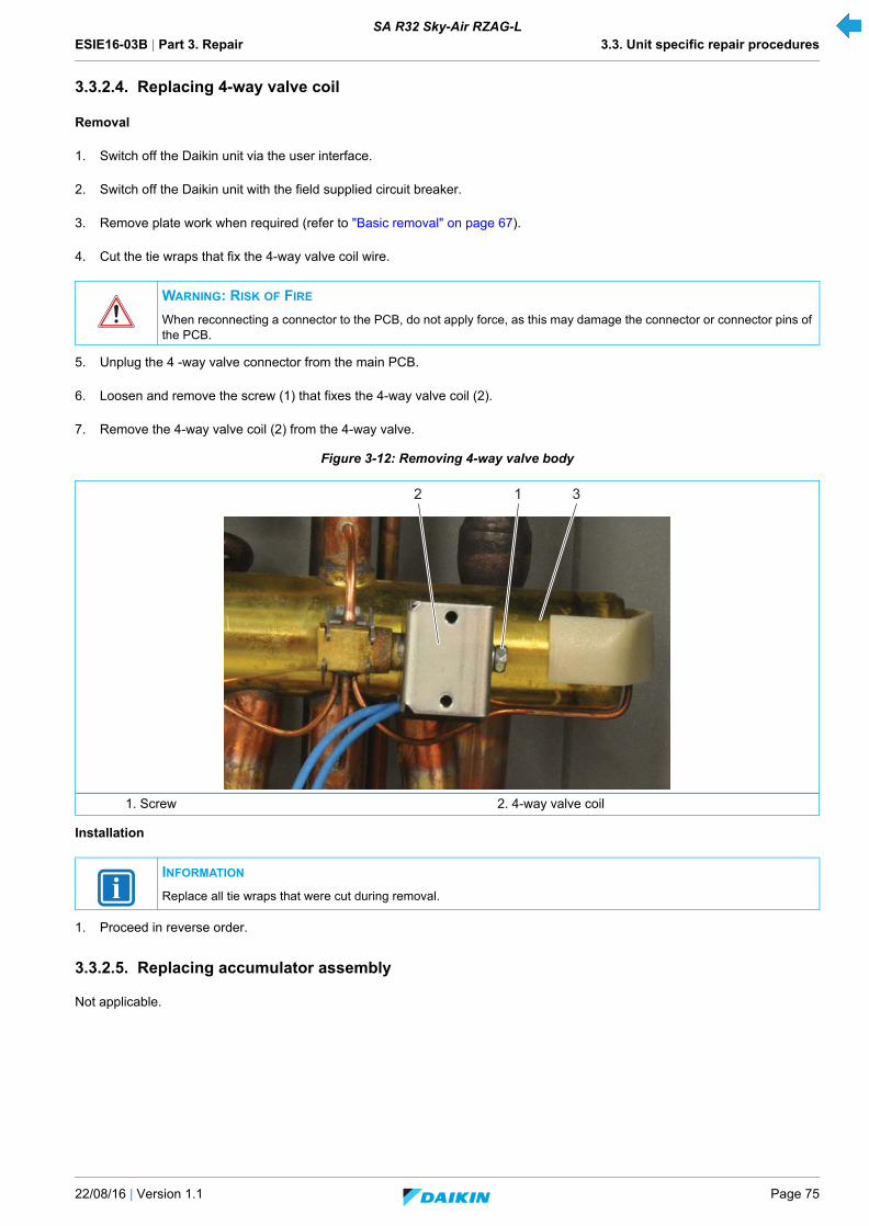
ESIE16-03B | Part 3. Repair 3.3. Unit specific repair procedures
22/08/16 | Version 1.1 Page 75
SA R32 Sky-Air RZAG-L
3.3.2.4. Replacing 4-way valve coil
Removal
1. Switch off the Daikin unit via the user interface.
2. Switch off the Daikin unit with the field supplied circuit breaker.
3. Remove plate work when required (refer to "Basic removal" on page 67).
4. Cut the tie wraps that fix the 4-way valve coil wire.
5. Unplug the 4 -way valve connector from the main PCB.
6. Loosen and remove the screw (1) that fixes the 4-way valve coil (2).
7. Remove the 4-way valve coil (2) from the 4-way valve.
Figure 3-12: Removing 4-way valve body
Installation
1. Proceed in reverse order.
3.3.2.5. Replacing accumulator assembly
Not applicable.
WARNING: RISK OF FIRE
When reconnecting a connector to the PCB, do not apply force, as this may damage the connector or connector pins of the PCB.
1. Screw 2. 4-way valve coil
INFORMATION
Replace all tie wraps that were cut during removal.
2 31
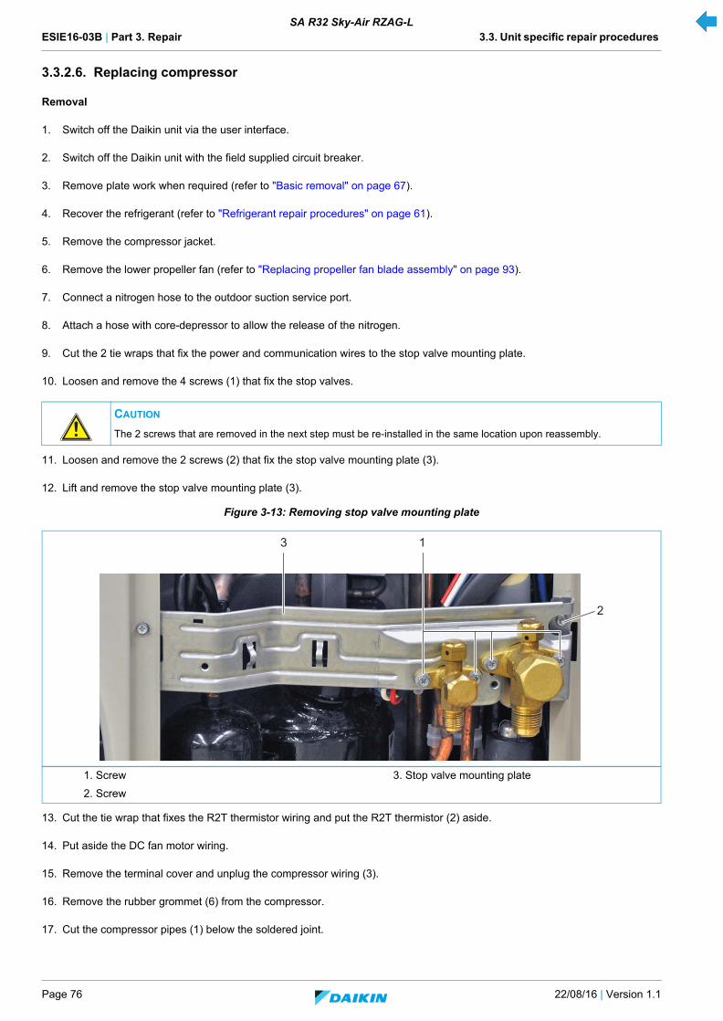
ESIE16-03B | Part 3. Repair 3.3. Unit specific repair procedures
Page 76 22/08/16 | Version 1.1
SA R32 Sky-Air RZAG-L
3.3.2.6. Replacing compressor
Removal
1. Switch off the Daikin unit via the user interface.
2. Switch off the Daikin unit with the field supplied circuit breaker.
3. Remove plate work when required (refer to "Basic removal" on page 67).
4. Recover the refrigerant (refer to "Refrigerant repair procedures" on page 61).
5. Remove the compressor jacket.
6. Remove the lower propeller fan (refer to "Replacing propeller fan blade assembly" on page 93).
7. Connect a nitrogen hose to the outdoor suction service port.
8. Attach a hose with core-depressor to allow the release of the nitrogen.
9. Cut the 2 tie wraps that fix the power and communication wires to the stop valve mounting plate.
10. Loosen and remove the 4 screws (1) that fix the stop valves.
11. Loosen and remove the 2 screws (2) that fix the stop valve mounting plate (3).
12. Lift and remove the stop valve mounting plate (3).
Figure 3-13: Removing stop valve mounting plate
13. Cut the tie wrap that fixes the R2T thermistor wiring and put the R2T thermistor (2) aside.
14. Put aside the DC fan motor wiring.
15. Remove the terminal cover and unplug the compressor wiring (3).
16. Remove the rubber grommet (6) from the compressor.
17. Cut the compressor pipes (1) below the soldered joint.
CAUTION
The 2 screws that are removed in the next step must be re-installed in the same location upon reassembly.
1. Screw 3. Stop valve mounting plate
2. Screw
2
13
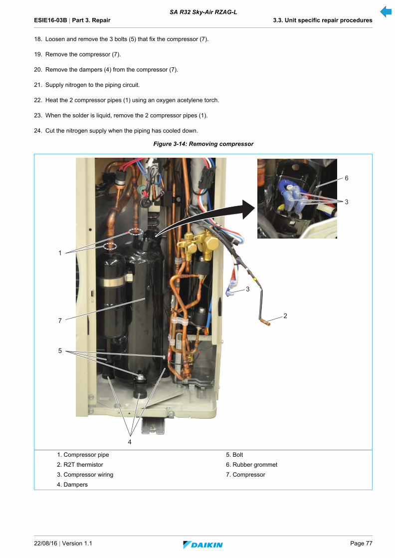
ESIE16-03B | Part 3. Repair 3.3. Unit specific repair procedures
22/08/16 | Version 1.1 Page 77
SA R32 Sky-Air RZAG-L
18. Loosen and remove the 3 bolts (5) that fix the compressor (7).
19. Remove the compressor (7).
20. Remove the dampers (4) from the compressor (7).
21. Supply nitrogen to the piping circuit.
22. Heat the 2 compressor pipes (1) using an oxygen acetylene torch.
23. When the solder is liquid, remove the 2 compressor pipes (1).
24. Cut the nitrogen supply when the piping has cooled down.
Figure 3-14: Removing compressor
1. Compressor pipe 5. Bolt
2. R2T thermistor 6. Rubber grommet
3. Compressor wiring 7. Compressor
4. Dampers
2
1
7
5
6
3
3
4

ESIE16-03B | Part 3. Repair 3.3. Unit specific repair procedures
Page 78 22/08/16 | Version 1.1
SA R32 Sky-Air RZAG-L
Installation
.
.
.
1. Check damper status, replace when worn.
2. First install the 3 (new) dampers on the new compressor.
3. When installing the new compressor, remove the caps from the compression pipe and the suction pipe as late as possible.
4. When soldering the compressor pipes, cover the compressor pipes with a wet cloth to prevent overheating the compressor(and the oil in the compression pipe).
5. Proceed in reverse order.
CAUTION
The oil in the compressor is hygroscopic. Remove the caps from the compressor piping as late as possible.
INFORMATION
Before installing a new compressor, determine the cause of the compressor failure and take all required corrective actions.
INFORMATION
If the dampers are worn, replace the dampers. The bushings inside the dampers are recuperated for use with the new dampers.
INFORMATION
Install the compressor sound insulation in the same location.
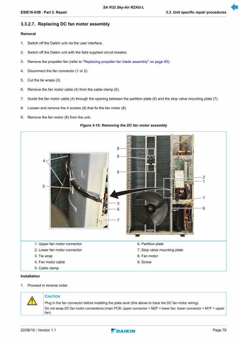
ESIE16-03B | Part 3. Repair 3.3. Unit specific repair procedures
22/08/16 | Version 1.1 Page 79
SA R32 Sky-Air RZAG-L
3.3.2.7. Replacing DC fan motor assembly
Removal
1. Switch off the Daikin unit via the user interface.
2. Switch off the Daikin unit with the field supplied circuit breaker.
3. Remove the propeller fan (refer to "Replacing propeller fan blade assembly" on page 93).
4. Disconnect the fan connector (1 or 2).
5. Cut the tie wraps (3)
6. Remove the fan motor cable (4) from the cable clamp (5).
7. Guide the fan motor cable (4) through the opening between the partition plate (6) and the stop valve mounting plate (7).
8. Loosen and remove the 4 screws (9) that fix the fan motor (8).
9. Remove the fan motor (8) from the unit.
Figure 3-15: Removing the DC fan motor assembly
Installation
1. Proceed in reverse order.
1. Upper fan motor connector 6. Partition plate
2. Lower fan motor connector 7. Stop valve mounting plate
3. Tie wrap 8. Fan motor
4. Fan motor cable 9. Screw
5. Cable clamp
CAUTION
Plug in the fan connector before installing the plate work (this allows to trace the DC fan motor wiring).
Do not swap DC fan motor connections (main PCB: upper connector = M2F = lower fan, lower connector = M1F = upper fan).
2
36
7
1
7
6
9
8
5
9
4
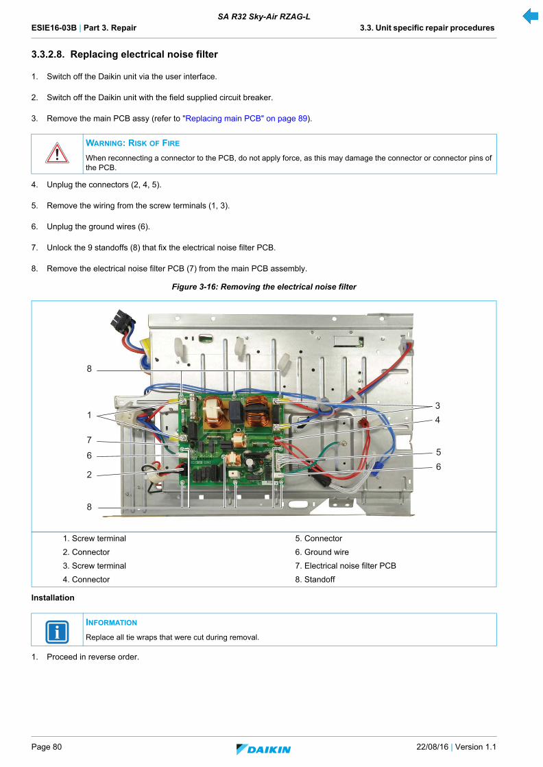
ESIE16-03B | Part 3. Repair 3.3. Unit specific repair procedures
Page 80 22/08/16 | Version 1.1
SA R32 Sky-Air RZAG-L
3.3.2.8. Replacing electrical noise filter
1. Switch off the Daikin unit via the user interface.
2. Switch off the Daikin unit with the field supplied circuit breaker.
3. Remove the main PCB assy (refer to "Replacing main PCB" on page 89).
4. Unplug the connectors (2, 4, 5).
5. Remove the wiring from the screw terminals (1, 3).
6. Unplug the ground wires (6).
7. Unlock the 9 standoffs (8) that fix the electrical noise filter PCB.
8. Remove the electrical noise filter PCB (7) from the main PCB assembly.
Figure 3-16: Removing the electrical noise filter
Installation
1. Proceed in reverse order.
WARNING: RISK OF FIRE
When reconnecting a connector to the PCB, do not apply force, as this may damage the connector or connector pins of the PCB.
1. Screw terminal 5. Connector
2. Connector 6. Ground wire
3. Screw terminal 7. Electrical noise filter PCB
4. Connector 8. Standoff
INFORMATION
Replace all tie wraps that were cut during removal.
56
1
8
7
6
2
34
8
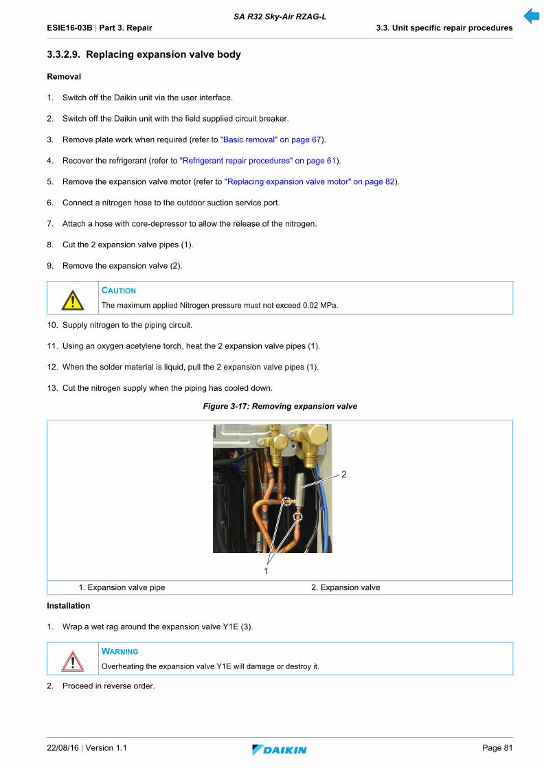
ESIE16-03B | Part 3. Repair 3.3. Unit specific repair procedures
22/08/16 | Version 1.1 Page 81
SA R32 Sky-Air RZAG-L
3.3.2.9. Replacing expansion valve body
Removal
1. Switch off the Daikin unit via the user interface.
2. Switch off the Daikin unit with the field supplied circuit breaker.
3. Remove plate work when required (refer to "Basic removal" on page 67).
4. Recover the refrigerant (refer to "Refrigerant repair procedures" on page 61).
5. Remove the expansion valve motor (refer to "Replacing expansion valve motor" on page 82).
6. Connect a nitrogen hose to the outdoor suction service port.
7. Attach a hose with core-depressor to allow the release of the nitrogen.
8. Cut the 2 expansion valve pipes (1).
9. Remove the expansion valve (2).
10. Supply nitrogen to the piping circuit.
11. Using an oxygen acetylene torch, heat the 2 expansion valve pipes (1).
12. When the solder material is liquid, pull the 2 expansion valve pipes (1).
13. Cut the nitrogen supply when the piping has cooled down.
Figure 3-17: Removing expansion valve
Installation
1. Wrap a wet rag around the expansion valve Y1E (3).
2. Proceed in reverse order.
CAUTION
The maximum applied Nitrogen pressure must not exceed 0.02 MPa.
1. Expansion valve pipe 2. Expansion valve
WARNING
Overheating the expansion valve Y1E will damage or destroy it.
2
1
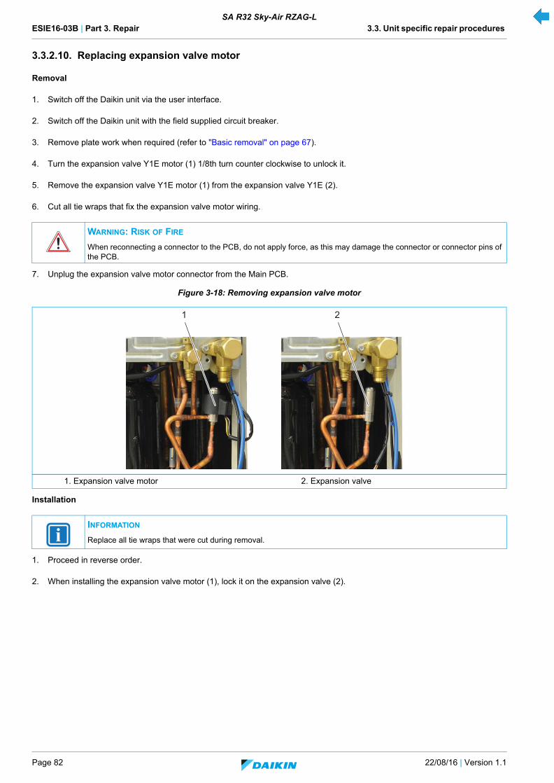
ESIE16-03B | Part 3. Repair 3.3. Unit specific repair procedures
Page 82 22/08/16 | Version 1.1
SA R32 Sky-Air RZAG-L
3.3.2.10. Replacing expansion valve motor
Removal
1. Switch off the Daikin unit via the user interface.
2. Switch off the Daikin unit with the field supplied circuit breaker.
3. Remove plate work when required (refer to "Basic removal" on page 67).
4. Turn the expansion valve Y1E motor (1) 1/8th turn counter clockwise to unlock it.
5. Remove the expansion valve Y1E motor (1) from the expansion valve Y1E (2).
6. Cut all tie wraps that fix the expansion valve motor wiring.
7. Unplug the expansion valve motor connector from the Main PCB.
Figure 3-18: Removing expansion valve motor
Installation
1. Proceed in reverse order.
2. When installing the expansion valve motor (1), lock it on the expansion valve (2).
WARNING: RISK OF FIRE
When reconnecting a connector to the PCB, do not apply force, as this may damage the connector or connector pins of the PCB.
1. Expansion valve motor 2. Expansion valve
INFORMATION
Replace all tie wraps that were cut during removal.
1 2
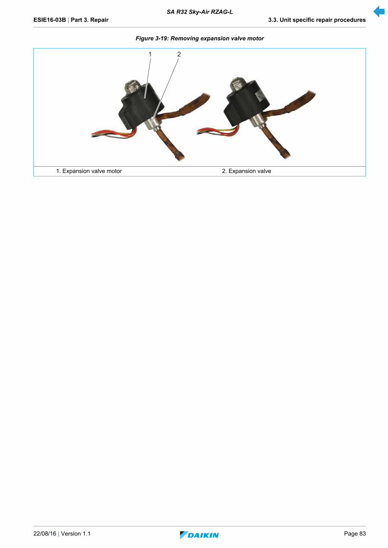
ESIE16-03B | Part 3. Repair 3.3. Unit specific repair procedures
22/08/16 | Version 1.1 Page 83
SA R32 Sky-Air RZAG-L
Figure 3-19: Removing expansion valve motor
1. Expansion valve motor 2. Expansion valve
1 2

ESIE16-03B | Part 3. Repair 3.3. Unit specific repair procedures
Page 84 22/08/16 | Version 1.1
SA R32 Sky-Air RZAG-L
3.3.2.11. Replacing solenoid valve
Removal
1. Switch off the Daikin unit via the user interface.
2. Switch off the Daikin unit with the field supplied circuit breaker.
3. Remove plate work when required (refer to "Basic removal" on page 67).
4. Recover the refrigerant (refer to "Refrigerant repair procedures" on page 61).
5. Connect a nitrogen hose to the outdoor suction service port.
6. Attach a hose with core-depressor to allow the release of the nitrogen.
7. Remove the solenoid valve coil (refer to "Replacing solenoid valve coil" on page 85).
8. Connect a nitrogen hose to the outdoor suction service port.
9. Attach a hose with core-depressor to allow the release of the nitrogen.
10. Cut the 2 solenoid valve pipes (1).
11. Remove the solenoid valve (2).
12. Supply nitrogen to the piping circuit.
13. Using an oxygen acetylene torch, heat the 2 solenoid valve pipes (1).
14. When the solder material is liquid, pull the 2 solenoid valve pipes (1).
15. Cut the nitrogen supply when the piping has cooled down.
Figure 3-20: Removing solenoid valve
Installation
1. Wrap a wet rag around the solenoid valve.
2. Proceed in reverse order.
CAUTION
The maximum applied Nitrogen pressure must not exceed 0.02 MPa.
1. Solenoid valve pipe 2. Solenoid valve
WARNING
Overheating the solenoid valve will damage or destroy it.
2
1
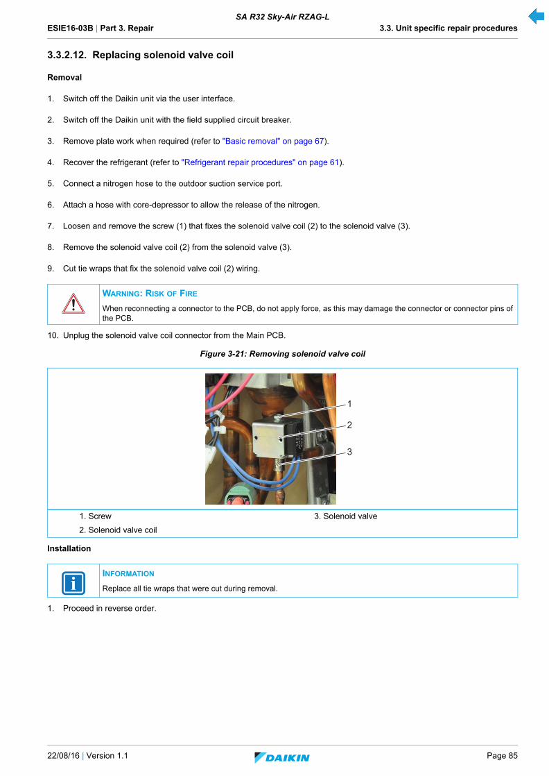
ESIE16-03B | Part 3. Repair 3.3. Unit specific repair procedures
22/08/16 | Version 1.1 Page 85
SA R32 Sky-Air RZAG-L
3.3.2.12. Replacing solenoid valve coil
Removal
1. Switch off the Daikin unit via the user interface.
2. Switch off the Daikin unit with the field supplied circuit breaker.
3. Remove plate work when required (refer to "Basic removal" on page 67).
4. Recover the refrigerant (refer to "Refrigerant repair procedures" on page 61).
5. Connect a nitrogen hose to the outdoor suction service port.
6. Attach a hose with core-depressor to allow the release of the nitrogen.
7. Loosen and remove the screw (1) that fixes the solenoid valve coil (2) to the solenoid valve (3).
8. Remove the solenoid valve coil (2) from the solenoid valve (3).
9. Cut tie wraps that fix the solenoid valve coil (2) wiring.
10. Unplug the solenoid valve coil connector from the Main PCB.
Figure 3-21: Removing solenoid valve coil
Installation
1. Proceed in reverse order.
WARNING: RISK OF FIRE
When reconnecting a connector to the PCB, do not apply force, as this may damage the connector or connector pins of the PCB.
1. Screw 3. Solenoid valve
2. Solenoid valve coil
INFORMATION
Replace all tie wraps that were cut during removal.
1
2
3
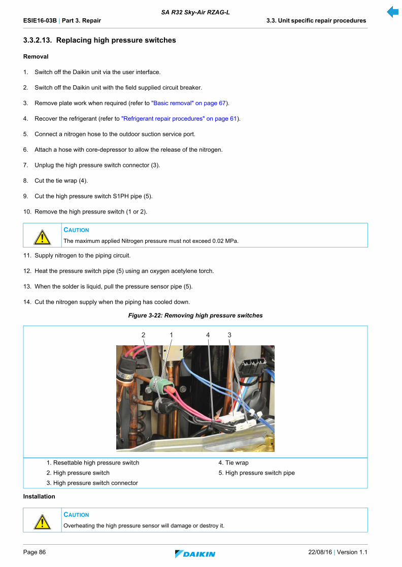
ESIE16-03B | Part 3. Repair 3.3. Unit specific repair procedures
Page 86 22/08/16 | Version 1.1
SA R32 Sky-Air RZAG-L
3.3.2.13. Replacing high pressure switches
Removal
1. Switch off the Daikin unit via the user interface.
2. Switch off the Daikin unit with the field supplied circuit breaker.
3. Remove plate work when required (refer to "Basic removal" on page 67).
4. Recover the refrigerant (refer to "Refrigerant repair procedures" on page 61).
5. Connect a nitrogen hose to the outdoor suction service port.
6. Attach a hose with core-depressor to allow the release of the nitrogen.
7. Unplug the high pressure switch connector (3).
8. Cut the tie wrap (4).
9. Cut the high pressure switch S1PH pipe (5).
10. Remove the high pressure switch (1 or 2).
11. Supply nitrogen to the piping circuit.
12. Heat the pressure switch pipe (5) using an oxygen acetylene torch.
13. When the solder is liquid, pull the pressure sensor pipe (5).
14. Cut the nitrogen supply when the piping has cooled down.
Figure 3-22: Removing high pressure switches
Installation
CAUTION
The maximum applied Nitrogen pressure must not exceed 0.02 MPa.
1. Resettable high pressure switch 4. Tie wrap
2. High pressure switch 5. High pressure switch pipe
3. High pressure switch connector
CAUTION
Overheating the high pressure sensor will damage or destroy it.
2 341
ESIE16-03B | Part 3. Repair 3.3. Unit specific repair procedures
22/08/16 | Version 1.1 Page 87
SA R32 Sky-Air RZAG-L
1. Wrap a wet rag around the pressure sensor.
2. Proceed in reverse order.
3.3.2.14. Replacing inverter PCB
The inverter is integrated in the main PCB, see "Replacing main PCB" on page 89.
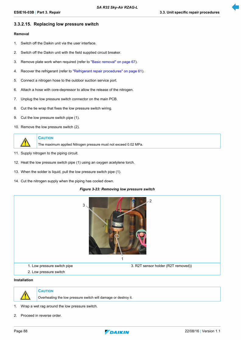
ESIE16-03B | Part 3. Repair 3.3. Unit specific repair procedures
Page 88 22/08/16 | Version 1.1
SA R32 Sky-Air RZAG-L
3.3.2.15. Replacing low pressure switch
Removal
1. Switch off the Daikin unit via the user interface.
2. Switch off the Daikin unit with the field supplied circuit breaker.
3. Remove plate work when required (refer to "Basic removal" on page 67).
4. Recover the refrigerant (refer to "Refrigerant repair procedures" on page 61).
5. Connect a nitrogen hose to the outdoor suction service port.
6. Attach a hose with core-depressor to allow the release of the nitrogen.
7. Unplug the low pressure switch connector on the main PCB.
8. Cut the tie wrap that fixes the low pressure switch wiring.
9. Cut the low pressure switch pipe (1).
10. Remove the low pressure switch (2).
11. Supply nitrogen to the piping circuit.
12. Heat the low pressure switch pipe (1) using an oxygen acetylene torch.
13. When the solder is liquid, pull the low pressure switch pipe (1).
14. Cut the nitrogen supply when the piping has cooled down.
Figure 3-23: Removing low pressure switch
Installation
1. Wrap a wet rag around the low pressure switch.
2. Proceed in reverse order.
CAUTION
The maximum applied Nitrogen pressure must not exceed 0.02 MPa.
1. Low pressure switch pipe 3. R2T sensor holder (R2T removed))
2. Low pressure switch
CAUTION
Overheating the low pressure switch will damage or destroy it.
2
1
3

ESIE16-03B | Part 3. Repair 3.3. Unit specific repair procedures
22/08/16 | Version 1.1 Page 89
SA R32 Sky-Air RZAG-L
3.3.2.16. Replacing main PCB
Removal
1. Switch off the Daikin unit via the user interface.
2. Switch off the Daikin unit with the field supplied circuit breaker.
3. Remove plate work when required (refer to "Basic removal" on page 67).
4. Flip over the protection sheet (1).
5. Remove the power and remote control wiring from the terminal block (2).
6. Cut the 5 tie wraps (3).
7. Unplug all connectors (4) from the main PCB (5).
8. Remove the 4-way valve coil (6) from the 4-way valve (refer to "Replacing 4-way valve coil" on page 75).
9. Remove the wiring from the cable clamp (9).
10. Remove the 3 screws (8) that fix the heat sink with a ring spanner or a wrench/socket.
11. Remove the 4 screws (7) that fix the main PCB support to the Daikin unit.
12. Lift and turn the lid (10) to the left.
13. Lift the main PCB (5) to release it from the unit.
14. Slightly tilt (max. 15°) the main PCB (5) and disconnect 2 connectors at the rear of the main PCB panel.
15. Guide the wiring (11) through the slots.
WARNING: RISK OF FIRE
When reconnecting a connector to the PCB, do not apply force, as this may damage the connector or connector pins of the PCB.
CAUTION
Due to the large size of the PCB it is sensitive to bending.
Only use a wrench/socket or a ring spanner to loosen or fasten the heat sink screws.
Do not use a screwdriver.
CAUTION
Do not remove the main PCB assembly yet, it is still attached by wiring.
CAUTION
Tilting the main PCB stresses the heat pipe, doe not tilt more than 15°.

ESIE16-03B | Part 3. Repair 3.3. Unit specific repair procedures
Page 90 22/08/16 | Version 1.1
SA R32 Sky-Air RZAG-L
Figure 3-24: Removing the main PCB assembly
16. Cut the tie wraps (1) that fix the protection sheet (2); remove the protection sheet (2).
17. Cut the tie wrap (3).
18. Loosen and remove the 2 screws (4) that fix the wiring.
1. Protection sheet 7. Screw
2. Terminal block 8. Screw
3. Tie wrap 9. Cable clamp
4. Connectors 10. Compressor connector
5. Main PCB 11. Wiring
6. 4-way valve coil 12. Lid
1 64
3
3
411
7
2
5
8
7
12
7
10
4
9

ESIE16-03B | Part 3. Repair 3.3. Unit specific repair procedures
22/08/16 | Version 1.1 Page 91
SA R32 Sky-Air RZAG-L
19. Loosen and remove the 3 screws (5) that fix the wiring.
20. Loosen and remove the 2 screws (6) that fix the wiring.
21. Loosen and remove the 2 screws (7) that fix the wiring.
22. Disconnect the 3 connectors (8) from the terminal block.
23. Loosen and remove the 2 screws (9) that fix the terminal block.
Figure 3-25: Stripping the main PCB assembly (front)
24. Loosen and remove the 2 screws (1) that fix the wiring.
25. Cut the 2 tie wraps (2) that fix the wiring.
26. Unlock the 9 standoffs (3) that fix the electrical noise filter PCB.
27. Remove the wiring from the cable clamp (4).
28. Remove the electrical noise filter PCB (5).
1. Tie wrap 6. Screw
2. Protection sheet 7. Screw
3. Tie wrap 8. Plug
4. Screw 9. Screw
5. Screw
1
1
2
3
3
4
6
45
6
7
9
9
8
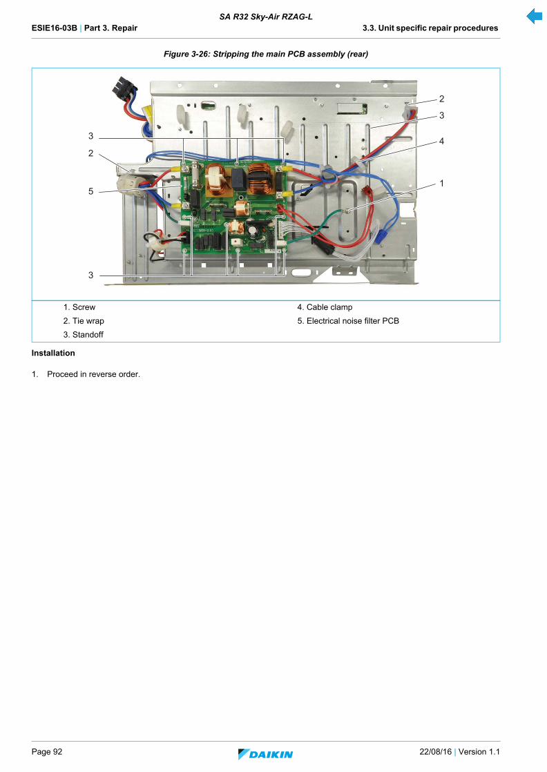
ESIE16-03B | Part 3. Repair 3.3. Unit specific repair procedures
Page 92 22/08/16 | Version 1.1
SA R32 Sky-Air RZAG-L
Figure 3-26: Stripping the main PCB assembly (rear)
Installation
1. Proceed in reverse order.
1. Screw 4. Cable clamp
2. Tie wrap 5. Electrical noise filter PCB
3. Standoff
1
2
3
5
3
2
4
3

ESIE16-03B | Part 3. Repair 3.3. Unit specific repair procedures
22/08/16 | Version 1.1 Page 93
SA R32 Sky-Air RZAG-L
3.3.2.17. Replacing propeller fan blade assembly
1. Switch off the Daikin unit via the user interface.
2. Switch off the Daikin unit with the field supplied circuit breaker.
3. Loosen and remove the 4 nuts (1) that fix the air discharge grill (2).
4. Press (A) the 2 latches to release the air discharge grill (2).
5. Tilt (B) the air discharge grill (2) and remove it from the Daikin unit.
6. Remove the nut (3) that fixes the propeller fan (4).
7. Pull the propeller fan blade assembly (2) from the fan motor (5).
Figure 3-27: Removing the propeller fan blade assembly
1. Nut 4. Propeller fan
2. Air discharge grill 5. Fan motor
3. Nut
1 2 3 4
5
1 2
A
B
AA

ESIE16-03B | Part 3. Repair 3.3. Unit specific repair procedures
Page 94 22/08/16 | Version 1.1
SA R32 Sky-Air RZAG-L
ESIE16-03B | Part 4. Maintenance 4.1. Indoor unit
22/08/16 | Version 1.1 Page 95
SA R32 Sky-Air RZAG-L
Part 4. MaintenanceThis part contains the following chapters:
4.1. Indoor unit
4.1.1. General maintenance indoor unit
1. Optimal operation conditions
2. Correlation of air-conditioner's operation status, pressure and running current
* Water in the refrigerant freezes inside the electronic expansion valve and is basically the same phenomenon as pump down.
** Dirt in the refrigerant clogs filters inside the piping and is basically the same phenomenon as pump down.
*** Pressure differential between high and low pressure becomes low.
Indoor unit ............................................................................................................................................................................................95
Outdoor unit..........................................................................................................................................................................................96
Cooling Heating
Differential between suction temperature and discharge temperature
8~18°C 14~30°
DB 27°C 20°C
WB 19°C NA
COOLING Low pressure High pressure Running current
Dirty air filter Lower Lower Lower
Short circuit of air inlet/outlet Lower Lower Lower
Air mixed in refrigerant Higher Higher Higher
Water mixed in refrigerant Lower* Lower Lower
Dirt mixed in refrigerant Lower** Lower Lower
Refrigerant shortage (gas) Lower Lower Lower
Unsatisfactory compression Higher*** Lower Lower

ESIE16-03B | Part 4. Maintenance 4.2. Outdoor unit
Page 96 22/08/16 | Version 1.1
SA R32 Sky-Air RZAG-L
4.2. Outdoor unit
4.2.1. General maintenance outdoor unit
1. Outdoor unit coil
- Straighten hair fins.
- Clear coil from dust, leaves, etc. with a fin-comb, or compressed air/N2. Avoid bending or damaging of the Alu fins duringthe cleaning process.
2. Correlation of air-conditioner's operation status, pressure and running current.
* Water in the refrigerant freezes inside the electronic expansion valve and is basically the same phenomenon as pump down.
** Dirt in the refrigerant clogs filters inside the piping and is basically the same phenomenon as pump down.
*** Pressure differential between high and low pressure becomes low.
CAUTION
Make sure not to bend the hair fins.
COOLING Low pressure High pressure Running current
Dirty air filter Higher Higher Higher
Short circuit of air inlet/outlet Higher Higher Higher
Air mixed in refrigerant Higher Higher Higher
Water mixed in refrigerant Lower* Lower Lower
Dirt mixed in refrigerant Lower** Lower Lower
Refrigerant shortage (gas) Lower*** Lower Lower
ESIE16-03B | Part 5. Appendix
22/08/16 | Version 1.1 Page 97
SA R32 Sky-Air RZAG-L
Part 5. AppendixThis part contains the following chapters:
Field setting ..........................................................................................................................................................................................99
Detailed information setting mode......................................................................................................................................................107
Wiring diagram ...................................................................................................................................................................................114
Piping diagram ...................................................................................................................................................................................117
Component overview of unit...............................................................................................................................................................118
Product specific information ...............................................................................................................................................................121
Switch box ..........................................................................................................................................................................................122
Field information report ......................................................................................................................................................................122

ESIE16-03B | Part 5. Appendix
Page 98 22/08/16 | Version 1.1
SA R32 Sky-Air RZAG-L
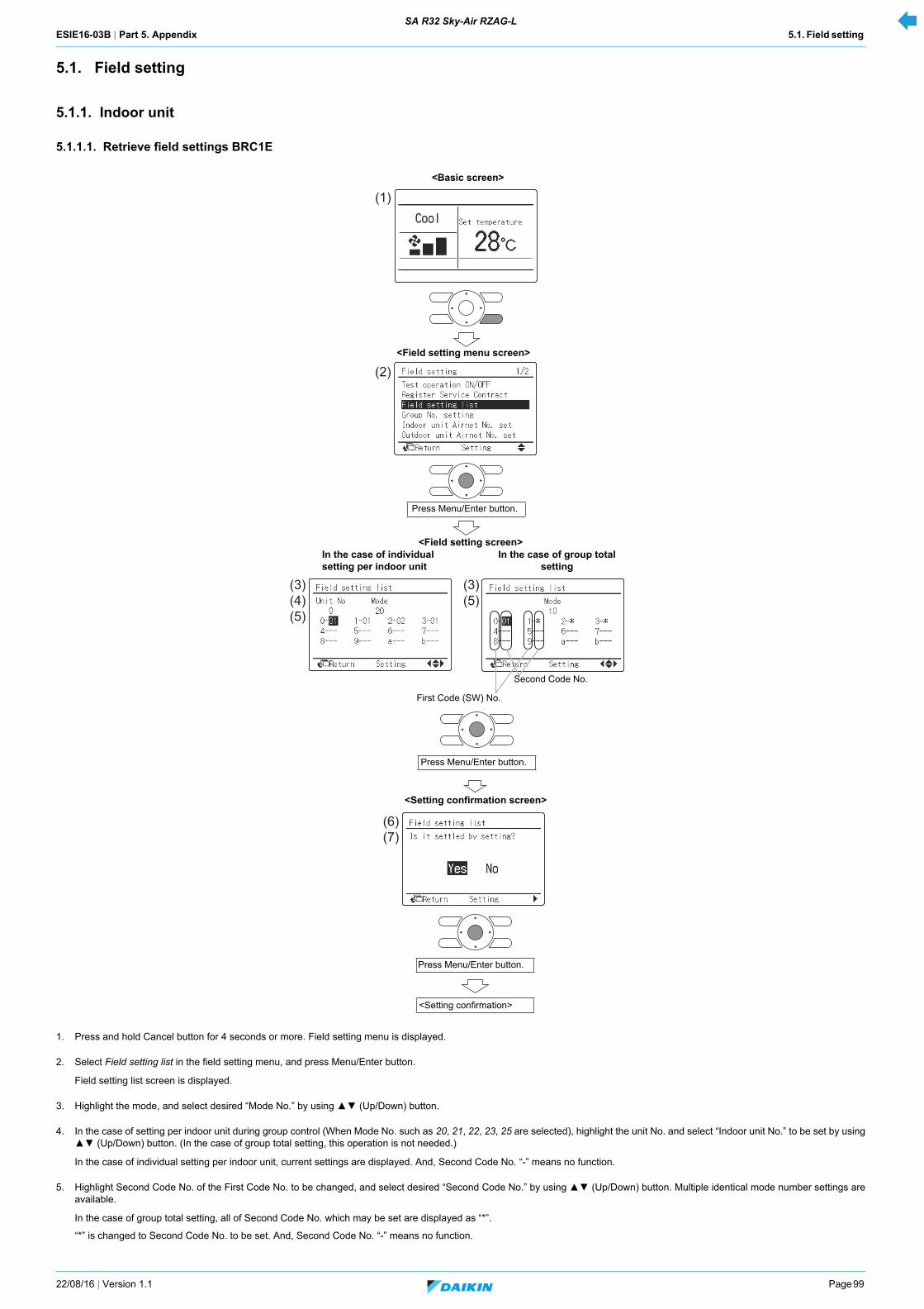
ESIE16-03B | Part 5. Appendix 5.1. Field setting SA R32 Sky-Air RZAG-L
22/08/16 | Version 1.1 Page 99
5.1. Field setting
5.1.1. Indoor unit
5.1.1.1. Retrieve field settings BRC1E
1. Press and hold Cancel button for 4 seconds or more. Field setting menu is displayed.
2. Select Field setting list in the field setting menu, and press Menu/Enter button.
Field setting list screen is displayed.
3. Highlight the mode, and select desired “Mode No.” by using (Up/Down) button.
4. In the case of setting per indoor unit during group control (When Mode No. such as 20, 21, 22, 23, 25 are selected), highlight the unit No. and select “Indoor unit No.” to be set by using (Up/Down) button. (In the case of group total setting, this operation is not needed.)
In the case of individual setting per indoor unit, current settings are displayed. And, Second Code No. “-” means no function.
5. Highlight Second Code No. of the First Code No. to be changed, and select desired “Second Code No.” by using (Up/Down) button. Multiple identical mode number settings areavailable.
In the case of group total setting, all of Second Code No. which may be set are displayed as “*”.
“*” is changed to Second Code No. to be set. And, Second Code No. “-” means no function.
(1)
(2)
(3)(4)(5)
(3)(5)
(6)(7)
<Basic screen>
<Field setting menu screen>
<Field setting screen>In the case of individual setting per indoor unit
Second Code No.
Press Menu/Enter button.
In the case of group total setting
<Setting confirmation screen>
Press Menu/Enter button.
First Code (SW) No.
<Setting confirmation>
Press Menu/Enter button.

ESIE16-03B | Part 5. Appendix 5.1. Field setting SA R32 Sky-Air RZAG-L
Page 100 22/08/16 | Version 1.1
6. Press Menu/Enter button. Setting confirmation screen is displayed.
7. Select Yes and press Menu/Enter button. Setting details are determined and field setting list screen returns.
8. In the case of multiple setting changes, repeat “(3)” to “(7)”.
9. After all setting changes are completed, press Cancel button twice.
10. Backlight goes out, and “Connection under check Please wait for a moment” is displayed for initialization. After the initialization, the basic screen returns.
CAUTION
• When an optional accessory is installed on the indoor unit, settings of the indoor unit may be changed. See the manual of the optional accessory.• For field setting details of the outdoor unit, see installation manual attached to the outdoor unit.
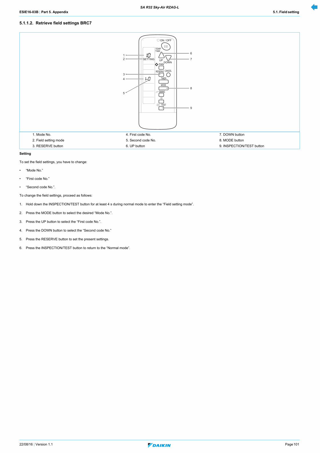
ESIE16-03B | Part 5. Appendix 5.1. Field setting SA R32 Sky-Air RZAG-L
22/08/16 | Version 1.1 Page 101
5.1.1.2. Retrieve field settings BRC7
Setting
To set the field settings, you have to change:
• “Mode No.”
• “First code No.”
• “Second code No.”.
To change the field settings, proceed as follows:
1. Hold down the INSPECTION/TEST button for at least 4 s during normal mode to enter the “Field setting mode”.
2. Press the MODE button to select the desired “Mode No.”.
3. Press the UP button to select the “First code No.”.
4. Press the DOWN button to select the “Second code No.”
5. Press the RESERVE button to set the present settings.
6. Press the INSPECTION/TEST button to return to the “Normal mode”.
1. Mode No. 4. First code No. 7. DOWN button
2. Field setting mode 5. Second code No. 8. MODE button
3. RESERVE button 6. UP button 9. INSPECTION/TEST button
3
9
12
6
7
4
58
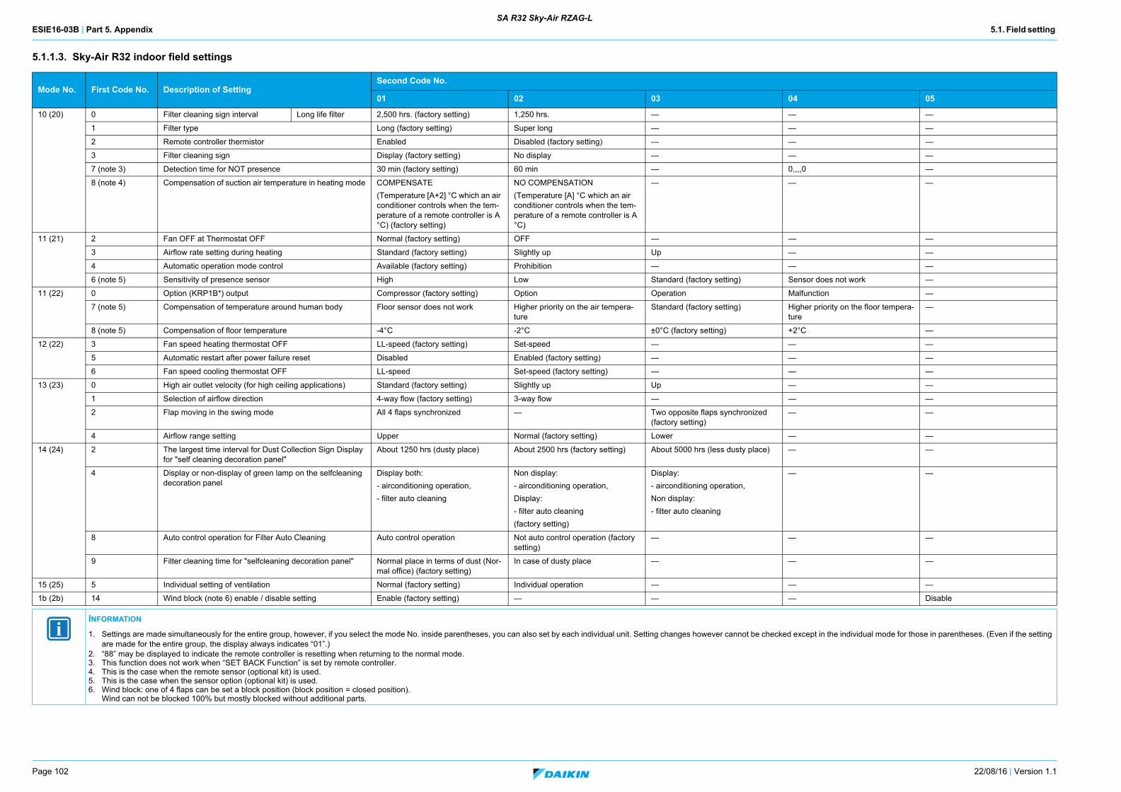
ESIE16-03B | Part 5. Appendix 5.1. Field setting
Page 102 22/08/16 | Version 1.1
SA R32 Sky-Air RZAG-L
5.1.1.3. Sky-Air R32 indoor field settings
Mode No. First Code No. Description of SettingSecond Code No.
01 02 03 04 05
10 (20) 0 Filter cleaning sign interval Long life filter 2,500 hrs. (factory setting) 1,250 hrs. — — —
1 Filter type Long (factory setting) Super long — — —
2 Remote controller thermistor Enabled Disabled (factory setting) — — —
3 Filter cleaning sign Display (factory setting) No display — — —
7 (note 3) Detection time for NOT presence 30 min (factory setting) 60 min — 0,,,,0 —
8 (note 4) Compensation of suction air temperature in heating mode COMPENSATE
(Temperature [A+2] °C which an air conditioner controls when the tem-perature of a remote controller is A °C) (factory setting)
NO COMPENSATION
(Temperature [A] °C which an air conditioner controls when the tem-perature of a remote controller is A °C)
— — —
11 (21) 2 Fan OFF at Thermostat OFF Normal (factory setting) OFF — — —
3 Airflow rate setting during heating Standard (factory setting) Slightly up Up — —
4 Automatic operation mode control Available (factory setting) Prohibition — — —
6 (note 5) Sensitivity of presence sensor High Low Standard (factory setting) Sensor does not work —
11 (22) 0 Option (KRP1B*) output Compressor (factory setting) Option Operation Malfunction —
7 (note 5) Compensation of temperature around human body Floor sensor does not work Higher priority on the air tempera-ture
Standard (factory setting) Higher priority on the floor tempera-ture
—
8 (note 5) Compensation of floor temperature -4°C -2°C ±0°C (factory setting) +2°C —
12 (22) 3 Fan speed heating thermostat OFF LL-speed (factory setting) Set-speed — — —
5 Automatic restart after power failure reset Disabled Enabled (factory setting) — — —
6 Fan speed cooling thermostat OFF LL-speed Set-speed (factory setting) — — —
13 (23) 0 High air outlet velocity (for high ceiling applications) Standard (factory setting) Slightly up Up — —
1 Selection of airflow direction 4-way flow (factory setting) 3-way flow — — —
2 Flap moving in the swing mode All 4 flaps synchronized — Two opposite flaps synchronized (factory setting)
— —
4 Airflow range setting Upper Normal (factory setting) Lower — —
14 (24) 2 The largest time interval for Dust Collection Sign Display for "self cleaning decoration panel"
About 1250 hrs (dusty place) About 2500 hrs (factory setting) About 5000 hrs (less dusty place) — —
4 Display or non-display of green lamp on the selfcleaning decoration panel
Display both:
- airconditioning operation,
- filter auto cleaning
Non display:
- airconditioning operation,
Display:
- filter auto cleaning
(factory setting)
Display:
- airconditioning operation,
Non display:
- filter auto cleaning
— —
8 Auto control operation for Filter Auto Cleaning Auto control operation Not auto control operation (factory setting)
— — —
9 Filter cleaning time for "selfcleaning decoration panel" Normal place in terms of dust (Nor-mal office) (factory setting)
In case of dusty place — — —
15 (25) 5 Individual setting of ventilation Normal (factory setting) Individual operation — — —
1b (2b) 14 Wind block (note 6) enable / disable setting Enable (factory setting) — — — Disable
INFORMATION
1. Settings are made simultaneously for the entire group, however, if you select the mode No. inside parentheses, you can also set by each individual unit. Setting changes however cannot be checked except in the individual mode for those in parentheses. (Even if the setting are made for the entire group, the display always indicates “01”.)
2. “88” may be displayed to indicate the remote controller is resetting when returning to the normal mode.3. This function does not work when “SET BACK Function” is set by remote controller.4. This is the case when the remote sensor (optional kit) is used.5. This is the case when the sensor option (optional kit) is used.6. Wind block: one of 4 flaps can be set a block position (block position = closed position).
Wind can not be blocked 100% but mostly blocked without additional parts.
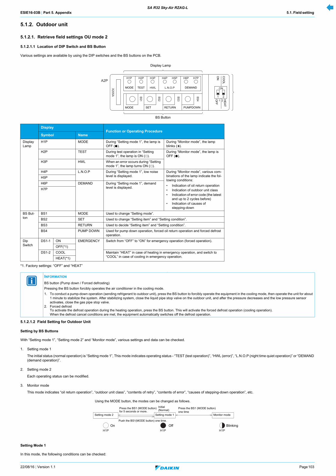
ESIE16-03B | Part 5. Appendix 5.1. Field setting SA R32 Sky-Air RZAG-L
22/08/16 | Version 1.1 Page 103
5.1.2. Outdoor unit
5.1.2.1. Retrieve field settings OU mode 2
5.1.2.1.1 Location of DIP Switch and BS Button
Various settings are available by using the DIP switches and the BS buttons on the PCB.
*1. Factory settings: “OFF” and “HEAT”
.
5.1.2.1.2 Field Setting for Outdoor Unit
Setting by BS Buttons
With “Setting mode 1”, “Setting mode 2” and “Monitor mode”, various settings and data can be checked.
1. Setting mode 1
The initial status (normal operation) is “Setting mode 1”, This mode indicates operating status - “TEST (test operation)”, “HWL (error)”, “L.N.O.P (night time quiet operation)” or “DEMAND (demand operation)”.
2. Setting mode 2
Each operating status can be modified.
3. Monitor mode
This mode indicates “oil return operation”, “outdoor unit class”, “contents of retry”, “contents of error”, “causes of stepping-down operation”, etc.
Setting Mode 1
In this mode, the following conditions can be checked:
DisplayFunction or Operating Procedure
Symbol Name
Display Lamp
H1P MODE During “Setting mode 1”, the lamp is OFF (h).
During “Monitor mode”, the lamp blinks (l).
H2P TEST During test operation in “Setting mode 1”, the lamp is ON (k).
During “Monitor mode”, the lamp is OFF (h).
H3P HWL When an error occurs during “Setting mode 1”, the lamp turns ON (k).
H4P L.N.O.P During “Setting mode 1”, low noise level is displayed.
During “Monitor mode”, various com-binations of the lamp indicate the fol-lowing conditions:
• Indication of oil return operation• Indication of outdoor unit class• Indication of error code (the latest
and up to 2 cycles before) • Indication of causes of
stepping-down
H5P
H6P DEMAND During “Setting mode 1”, demand level is displayed.H7P
BS But-ton
BS1 MODE Used to change “Setting mode”.
BS2 SET Used to change “Setting item” and “Setting condition”.
BS3 RETURN Used to decide “Setting item” and “Setting condition”.
BS4 PUMP DOWN Used for pump down operation, forced oil return operation and forced defrost operation.
Dip Switch
DS1-1 ON EMERGENCY Switch from “OFF” to “ON” for emergency operation (forced operation).
OFF(*1)
DS1-2 COOL Maintain “HEAT” in case of heating in emergency operation, and switch to “COOL” in case of cooling in emergency operation.HEAT(*1)
INFORMATION
BS button (Pump down / Forced defrosting)
Pressing the BS button forcibly operates the air conditioner in the cooling mode.
1. To conduct a pump-down operation (sending refrigerant to outdoor unit), press the BS button to forcibly operate the equipment in the cooling mode, then operate the unit for about 1 minute to stabilize the system. After stabilizing system, close the liquid pipe stop valve on the outdoor unit, and after the pressure decreases and the low pressure sensor activates, close the gas pipe stop valve.
2. Forced defrostTo activate the defrost operation during the heating operation, press the BS button. This will activate the forced defrost operation (cooling operation).When the defrost cancel conditions are met, the equipment automatically switches off the defrost operation.
Display Lamp
BS Button
X205A
H1P H2P H3P H4P H5P H6P H7P
ON
1 221
BS2
BS1
BS3
BS4
A2P
HWL L.N.O.PMODE TEST DEMAND
PUMPDOWNRETURNSETMODEH
EA
TC
OO
L
ON
OF
F
Using the MODE button, the modes can be changed as follows.
H1PH1PH1P
Initial(Normal)
Push the BS1(MODE button) one time.
Press the BS1 (MODE button) one time
Setting mode 2 Setting mode 1 Monitor mode
Blinking
Press the BS1 (MODE button) for 5 seconds or more.
OffOn
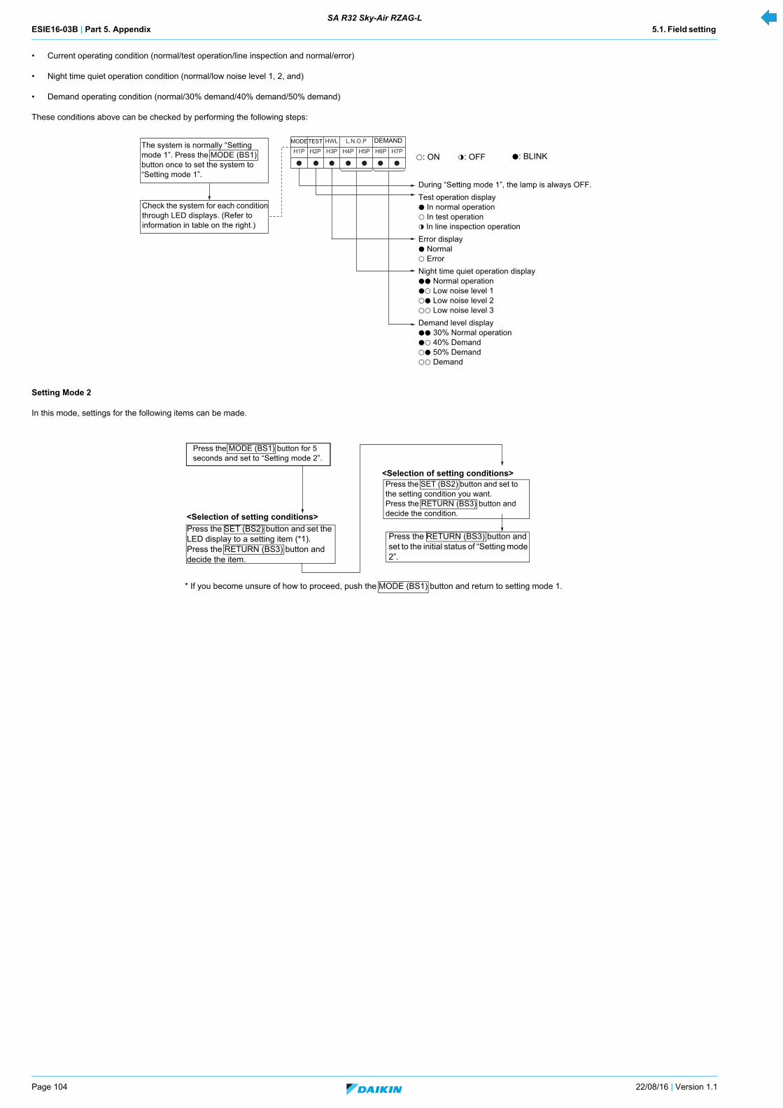
ESIE16-03B | Part 5. Appendix 5.1. Field setting SA R32 Sky-Air RZAG-L
Page 104 22/08/16 | Version 1.1
• Current operating condition (normal/test operation/line inspection and normal/error)
• Night time quiet operation condition (normal/low noise level 1, 2, and)
• Demand operating condition (normal/30% demand/40% demand/50% demand)
These conditions above can be checked by performing the following steps:
Setting Mode 2
In this mode, settings for the following items can be made.
H1P H2P H3P H4P H5P H6P H7P
HWL L.N.O.P
h h h h h h h
The system is normally “Setting mode 1”. Press the MODE (BS1) button once to set the system to “Setting mode 1”.
Check the system for each condition through LED displays. (Refer to information in table on the right.)
During “Setting mode 1”, the lamp is always OFF.
Test operation displayh In normal operationk In test operationl In line inspection operation
Error displayh Normalk Error
Night time quiet operation displayhh Normal operationhk Low noise level 1kh Low noise level 2kk Low noise level 3
Demand level displayhh 30% Normal operation hk 40% Demandkh 50% Demandkk Demand
h: BLINK
MODETEST DEMAND
k: ON l: OFF
<Selection of setting conditions>
<Selection of setting conditions>
Press the SET (BS2) button and set to the setting condition you want.Press the RETURN (BS3) button and decide the condition.
Press the MODE (BS1) button for 5 seconds and set to “Setting mode 2”.
* If you become unsure of how to proceed, push the MODE (BS1) button and return to setting mode 1.
Press the SET (BS2) button and set the LED display to a setting item (*1).Press the RETURN (BS3) button and decide the item.
Press the RETURN (BS3) button and set to the initial status of “Setting mode 2”.
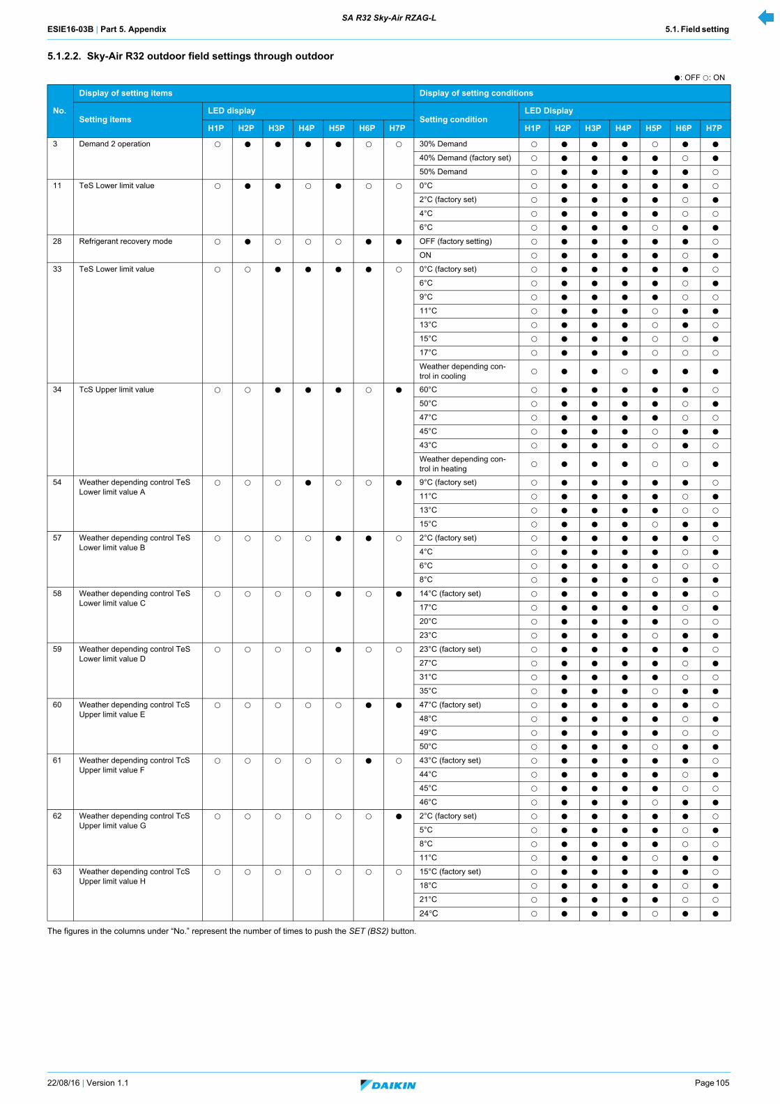
ESIE16-03B | Part 5. Appendix 5.1. Field setting SA R32 Sky-Air RZAG-L
22/08/16 | Version 1.1 Page 105
5.1.2.2. Sky-Air R32 outdoor field settings through outdoor
The figures in the columns under “No.” represent the number of times to push the SET (BS2) button.
h: OFF k: ON
No.
Display of setting items Display of setting conditions
Setting itemsLED display
Setting conditionLED Display
H1P H2P H3P H4P H5P H6P H7P H1P H2P H3P H4P H5P H6P H7P
3 Demand 2 operation bck h h h h bck bck 30% Demand k h h h k h h
40% Demand (factory set) k h h h h k h
50% Demand k h h h h h k
11 TeS Lower limit value bck h h bck h bck bck 0°C k h h h h h k
2°C (factory set) k h h h h k h
4°C k h h h h k k
6°C k h h h k h h
28 Refrigerant recovery mode k h k k k h h OFF (factory setting) k h h h h h k
ON k h h h h k h
33 TeS Lower limit value k k h h h h k 0°C (factory set) k h h h h h k
6°C k h h h h k h
9°C k h h h h k k
11°C k h h h k h h
13°C k h h h k h k
15°C k h h h k k h
17°C k h h h k k k
Weather depending con-trol in cooling
k h h k h h h
34 TcS Upper limit value k k h h h k h 60°C k h h h h h k
50°C k h h h h k h
47°C k h h h h k k
45°C k h h h k h h
43°C k h h h k h k
Weather depending con-trol in heating
k h h h k k h
54 Weather depending control TeS Lower limit value A
k k k h k k h 9°C (factory set) k h h h h h k
11°C k h h h h k h
13°C k h h h h k k
15°C k h h h k h h
57 Weather depending control TeS Lower limit value B
k k k k h h k 2°C (factory set) k h h h h h k
4°C k h h h h k h
6°C k h h h h k k
8°C k h h h k h h
58 Weather depending control TeS Lower limit value C
k k k k h k h 14°C (factory set) k h h h h h k
17°C k h h h h k h
20°C k h h h h k k
23°C k h h h k h h
59 Weather depending control TeS Lower limit value D
k k k k h k k 23°C (factory set) k h h h h h k
27°C k h h h h k h
31°C k h h h h k k
35°C k h h h k h h
60 Weather depending control TcS Upper limit value E
k k k k k h h 47°C (factory set) k h h h h h k
48°C k h h h h k h
49°C k h h h h k k
50°C k h h h k h h
61 Weather depending control TcS Upper limit value F
k k k k k h k 43°C (factory set) k h h h h h k
44°C k h h h h k h
45°C k h h h h k k
46°C k h h h k h h
62 Weather depending control TcS Upper limit value G
k k k k k k h 2°C (factory set) k h h h h h k
5°C k h h h h k h
8°C k h h h h k k
11°C k h h h k h h
63 Weather depending control TcS Upper limit value H
k k k k k k k 15°C (factory set) k h h h h h k
18°C k h h h h k h
21°C k h h h h k k
24°C k h h h k h h
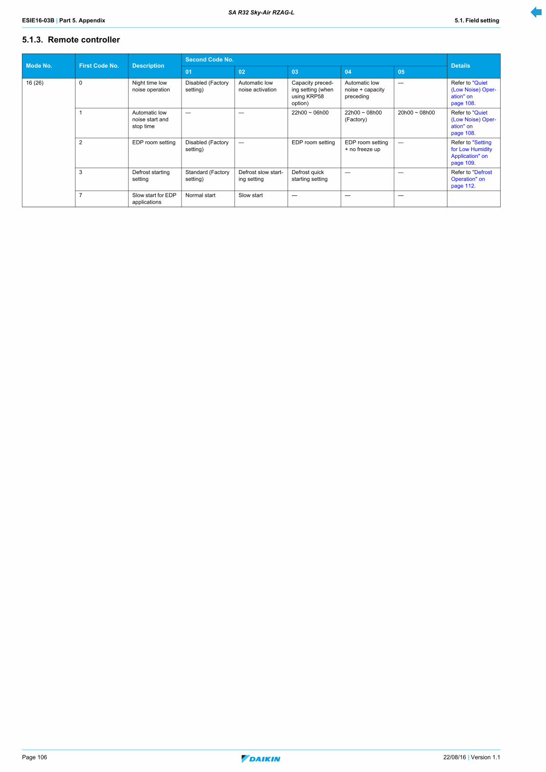
ESIE16-03B | Part 5. Appendix 5.1. Field setting SA R32 Sky-Air RZAG-L
Page 106 22/08/16 | Version 1.1
5.1.3. Remote controller
Mode No. First Code No. DescriptionSecond Code No.
Details01 02 03 04 05
16 (26) 0 Night time low noise operation
Disabled (Factory setting)
Automatic low noise activation
Capacity preced-ing setting (when using KRP58 option)
Automatic low noise + capacity preceding
— Refer to "Quiet (Low Noise) Oper-ation" on page 108.
1 Automatic low noise start and stop time
— — 22h00 ~ 06h00 22h00 ~ 08h00 (Factory)
20h00 ~ 08h00 Refer to "Quiet (Low Noise) Oper-ation" on page 108.
2 EDP room setting Disabled (Factory setting)
— EDP room setting EDP room setting + no freeze up
— Refer to "Setting for Low Humidity Application" on page 109.
3 Defrost starting setting
Standard (Factory setting)
Defrost slow start-ing setting
Defrost quick starting setting
— — Refer to "Defrost Operation" on page 112.
7 Slow start for EDP applications
Normal start Slow start — — —

ESIE16-03B | Part 5. Appendix 5.2. Detailed information setting mode SA R32 Sky-Air RZAG-L
22/08/16 | Version 1.1 Page 107
5.2. Detailed information setting mode
5.2.1. Indoor unit
Not applicable.
5.2.2. Outdoor unit
Setting of Demand 2 operation
With this setting, compressor operation can be controlled to reduce power consumption. (60% - 80% demand is available when a demand adapter (optional accessory) is used.)
[Work procedure]
Setting of Refrigerant Recovery Mode
When a refrigerant recovery unit is connected onsite to recover refrigerant, fully open the expansion valve of the outdoor unit to help the recovery.
1. Stop operation.
2. Turn ON refrigerant recovery mode by performing the following steps.
3. Connect a refrigerant recovery unit to perform refrigerant recovery.
4. Upon completion of refrigerant recovery, turn OFF refrigerant recovery mode by taking the following steps or turning OFF the power of outdoor unit.
Setting item Setting condition Description
Demand 2 operation 30% demand Operates with 30% of rated power consumption.
40% demand (factory setting) Operates with 40% of rated power consumption.
50% demand Operates with 50% of rated power consumption.
h: OFF l: BLINK k: ON
Operating procedure H1P H2P H3P H4P H5P H6P H7P
Push and hold the MODE (BS1) button of “Setting mode 1” for 5 seconds or more and set to “Setting mode 2". k h h h h h h
Push the SET (BS2) button three times to set the LED display as shown in the table on the right. k h h h h k k
Push the RETURN (BS3) button once. (Present settings are displayed.) k h h h h l h
Push the SET (BS2) button to set the LED display as shown in the table on the right.
30% of rated power consumption k h h h l h h
40% of rated power consumption k h h h h l h
50% of rated power consumption k h h h h h l
Push the RETURN (BS3) button once to make a decision. 30% of rated power consumption k h h h k h h
40% of rated power consumption k h h h h k h
50% of rated power consumption k h h h h h k
Push the RETURN (BS3) button once again for execution (The LED display is in the initial status of “Setting mode 2”.) k h h h h h h
Push the MODE (BS1) button once to return to Setting mode 1 (normal operation). h h h h h h h
h: OFF l: BLINK k: ON
Operating procedure H1P H2P H3P H4P H5P H6P H7P
Press the MODE (BS1) button of “Setting mode 1" for 5 seconds or more and set to “Setting mode 2”. k h h h h h h
Press the SET (BS2) button 28 times to set the LED display as shown in the table on the right. (*1) k h k k k h h
Press the RETURN (BS3) button once. (Present settings are displayed.) k h h h h h l
Press the SET (BS2) button once to set the LED display as shown in the table on the right. k h h h h l h
Press the RETURN (BS3) button once to make a decision. k h h h h k h
When the RETURN (BS3) button is pressed once again, the electronic expansion valve opens fully. k h h h h h h
Operating procedure H1P H2P H3P H4P H5P H6P H7P
Press the SET (BS2) button 28 times to set the LED display as shown in the table on the right. (*1) k h k k k h h
Press the RETURN (BS3) button once. (Present settings are displayed.) k h h h h l h
Press the SET (BS2) button once to set the LED display as shown in the table on the right. k h h h h h l
Press the RETURN (BS3) button once to make a decision. k h h h h h k
When the RETURN (BS3) button is pressed once again, the electronic expansion valve fully opens. k h h h h h h
INFORMATION
*1: If you become unsure how many times you have pushed the button, push the MODE (BS1) button once to return to “Setting mode 1” and start the operating procedure all over again.
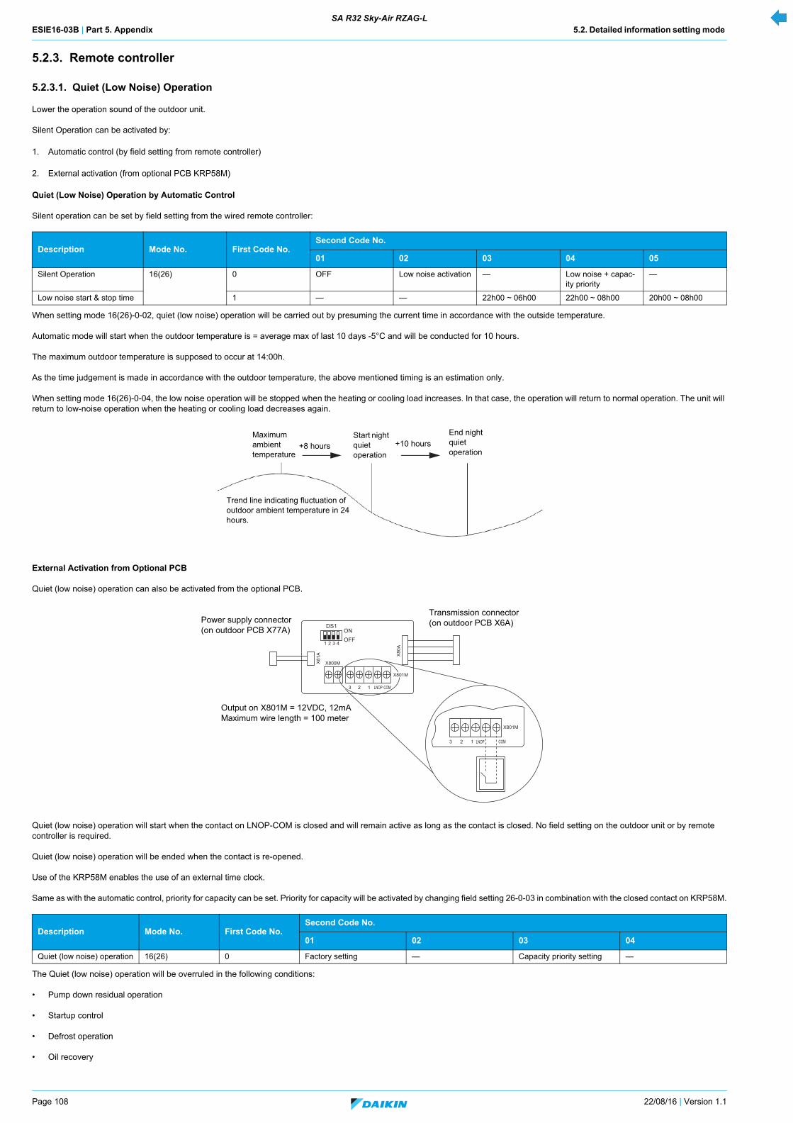
ESIE16-03B | Part 5. Appendix 5.2. Detailed information setting mode SA R32 Sky-Air RZAG-L
Page 108 22/08/16 | Version 1.1
5.2.3. Remote controller
5.2.3.1. Quiet (Low Noise) Operation
Lower the operation sound of the outdoor unit.
Silent Operation can be activated by:
1. Automatic control (by field setting from remote controller)
2. External activation (from optional PCB KRP58M)
Quiet (Low Noise) Operation by Automatic Control
Silent operation can be set by field setting from the wired remote controller:
When setting mode 16(26)-0-02, quiet (low noise) operation will be carried out by presuming the current time in accordance with the outside temperature.
Automatic mode will start when the outdoor temperature is = average max of last 10 days -5°C and will be conducted for 10 hours.
The maximum outdoor temperature is supposed to occur at 14:00h.
As the time judgement is made in accordance with the outdoor temperature, the above mentioned timing is an estimation only.
When setting mode 16(26)-0-04, the low noise operation will be stopped when the heating or cooling load increases. In that case, the operation will return to normal operation. The unit will return to low-noise operation when the heating or cooling load decreases again.
External Activation from Optional PCB
Quiet (low noise) operation can also be activated from the optional PCB.
Quiet (low noise) operation will start when the contact on LNOP-COM is closed and will remain active as long as the contact is closed. No field setting on the outdoor unit or by remote controller is required.
Quiet (low noise) operation will be ended when the contact is re-opened.
Use of the KRP58M enables the use of an external time clock.
Same as with the automatic control, priority for capacity can be set. Priority for capacity will be activated by changing field setting 26-0-03 in combination with the closed contact on KRP58M.
The Quiet (low noise) operation will be overruled in the following conditions:
• Pump down residual operation
• Startup control
• Defrost operation
• Oil recovery
Description Mode No. First Code No.Second Code No.
01 02 03 04 05
Silent Operation 16(26) 0 OFF Low noise activation — Low noise + capac-ity priority
—
Low noise start & stop time 1 — — 22h00 ~ 06h00 22h00 ~ 08h00 20h00 ~ 08h00
Description Mode No. First Code No.Second Code No.
01 02 03 04
Quiet (low noise) operation 16(26) 0 Factory setting — Capacity priority setting —
Maximum ambient temperature
+8 hours
End night quiet operation
Trend line indicating fluctuation of outdoor ambient temperature in 24 hours.
+10 hoursStart night quiet operation
ONOFF
DS1
1 2 3 4
X81
A X80
A
X800M
X801M
X801M
1 LNOP COM23
1 LNOP COM23
Power supply connector (on outdoor PCB X77A)
Transmission connector (on outdoor PCB X6A)
Output on X801M = 12VDC, 12mA Maximum wire length = 100 meter
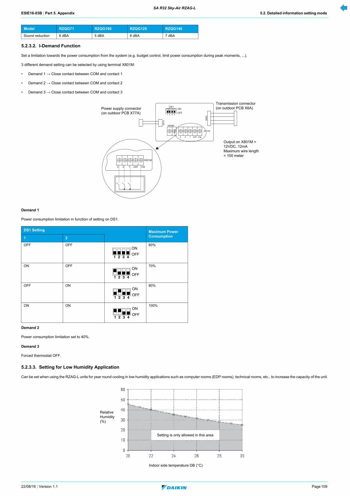
ESIE16-03B | Part 5. Appendix 5.2. Detailed information setting mode SA R32 Sky-Air RZAG-L
22/08/16 | Version 1.1 Page 109
5.2.3.2. I-Demand Function
Set a limitation towards the power consumption from the system (e.g. budget control, limit power consumption during peak moments, ...).
3 different demand setting can be selected by using terminal X801M:
• Demand 1 → Close contact between COM and contact 1
• Demand 2 → Close contact between COM and contact 2
• Demand 3 → Close contact between COM and contact 3
Demand 1
Power consumption limitation in function of setting on DS1.
Demand 2
Power consumption limitation set to 40%.
Demand 3
Forced thermostat OFF.
5.2.3.3. Setting for Low Humidity Application
Can be set when using the RZAG-L units for year round cooling in low humidity applications such as computer rooms (EDP rooms), technical rooms, etc...to increase the capacity of the unit.
Model RZQG71 RZQG100 RZQG125 RZQG140
Sound reduction 6 dBA 5 dBA 6 dBA 7 dBA
DS1 Setting Maximum Power Consumption1 2
OFF OFF 60%
ON OFF 70%
OFF ON 80%
ON ON 100%
ONOFF
DS1
1 2 3 4
X81
A X80
A
X800M
X801M
X801M
1 LNOP COM23
1 LNOP COM23
Output on X801M = 12VDC, 12mA Maximum wire length = 100 meter
Transmission connector (on outdoor PCB X6A)Power supply connector
(on outdoor PCB X77A)
Relative Humidity (%)
Setting is only allowed in this area
Indoor side temperature DB (°C)
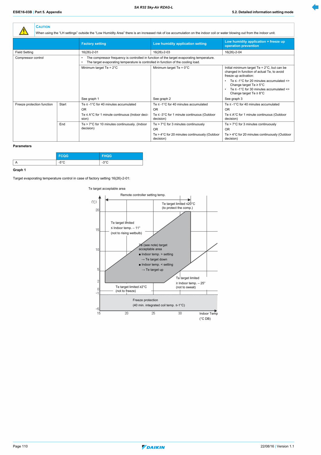
ESIE16-03B | Part 5. Appendix 5.2. Detailed information setting mode SA R32 Sky-Air RZAG-L
Page 110 22/08/16 | Version 1.1
Parameters
Graph 1
Target evaporating temperature control in case of factory setting 16(26)-2-01:
CAUTION
When using the “LH settings” outside the “Low Humidity Area” there is an increased risk of ice accumulation on the indoor coil or water blowing out from the indoor unit.
Factory setting Low humidity application settingLow humidity application + freeze up operation prevention
Field Setting 16(26)-2-01 16(26)-2-03 16(26)-2-04
Compressor control • The compressor frequency is controlled in function of the target evaporating temperature.• The target evaporating temperature is controlled in function of the cooling load.
Minimum target Te = 2°C Minimum target Te = 0°C Initial minimum target Te = 2°C, but can be changed in function of actual Te, to avoid freeze up activation:
• Te ≤ -1°C for 20 minutes accumulated => Change target Te ≥ 5°C
• Te ≤ -1°C for 30 minutes accumulated => Change target Te ≥ 8°C
See graph 1 See graph 2 See graph 3
Freeze protection function Start Te ≤ -1°C for 40 minutes accumulated
OR
Te ≤ A°C for 1 minute continuous (Indoor deci-sion)
Te ≤ -1°C for 40 minutes accumulated
OR
Te ≤ -3°C for 1 minute continuous (Outdoor decision)
Te ≤ -1°C for 40 minutes accumulated
OR
Te ≤ A°C for 1 minute continuous (Outdoor decision)
End Te > 7°C for 10 minutes continuously. (Indoor decision)
Te > 7°C for 3 minutes continuously
OR
Te > 4°C for 20 minutes continuously (Outdoor decision)
Te > 7°C for 3 minutes continuously
OR
Te > 4°C for 20 minutes continuously (Outdoor decision)
FCQG FHQG
A -5°C -3°C
Te target limited
≤ Indoor temp. – 11°
(not to rising wetbulb)
Te target limited ≤20°C (to protect the comp.)
Remote controller setting temp.
Te (see note) target acceptable area
Indoor temp. > setting
→ Te target down
Indoor temp. < setting
→ Te target up
Te target limited ≥2°C (not to freeze)
Te target limited
≥ Indoor temp. – 25° (not to sweat)
Freeze protection
(40 min. integrated coil temp. ≤-1°C)
Te target acceptable area
Indoor Temp
(°C DB)
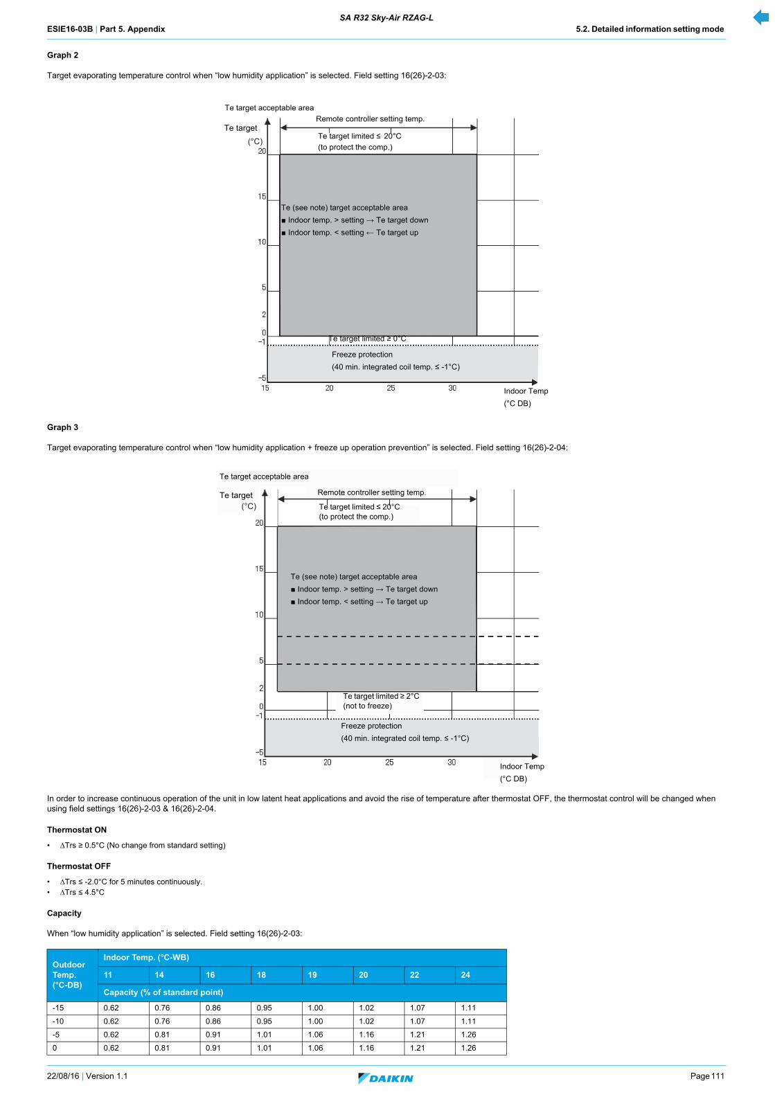
ESIE16-03B | Part 5. Appendix 5.2. Detailed information setting mode SA R32 Sky-Air RZAG-L
22/08/16 | Version 1.1 Page 111
Graph 2
Target evaporating temperature control when “low humidity application” is selected. Field setting 16(26)-2-03:
Graph 3
Target evaporating temperature control when “low humidity application + freeze up operation prevention” is selected. Field setting 16(26)-2-04:
In order to increase continuous operation of the unit in low latent heat applications and avoid the rise of temperature after thermostat OFF, the thermostat control will be changed when using field settings 16(26)-2-03 & 16(26)-2-04.
Thermostat ON
• ∆Trs ≥ 0.5°C (No change from standard setting)
Thermostat OFF
• ∆Trs ≤ -2.0°C for 5 minutes continuously.• ∆Trs ≤ 4.5°C
Capacity
When “low humidity application” is selected. Field setting 16(26)-2-03:
Outdoor Temp. (°C-DB)
Indoor Temp. (°C-WB)
11 14 16 18 19 20 22 24
Capacity (% of standard point)
-15 0.62 0.76 0.86 0.95 1.00 1.02 1.07 1.11
-10 0.62 0.76 0.86 0.95 1.00 1.02 1.07 1.11
-5 0.62 0.81 0.91 1.01 1.06 1.16 1.21 1.26
0 0.62 0.81 0.91 1.01 1.06 1.16 1.21 1.26
(°C)
Te target acceptable area
Te targetRemote controller setting temp.
Te (see note) target acceptable area
Indoor temp. > setting → Te target down
Indoor temp. < setting ← Te target up
Te target limited ≥ 0°C
Freeze protection
(40 min. integrated coil temp. ≤ -1°C)
Indoor Temp
(°C DB)
Te target limited ≤ 20°C
(to protect the comp.)
(°C)
Te (see note) target acceptable area
Indoor temp. > setting → Te target down
Indoor temp. < setting → Te target up
Te target limited ≤ 20°C (to protect the comp.)
Freeze protection
(40 min. integrated coil temp. ≤ -1°C)
Indoor Temp
(°C DB)
Remote controller setting temp.
Te target acceptable area
Te target
Te target limited ≥ 2°C (not to freeze)

ESIE16-03B | Part 5. Appendix 5.2. Detailed information setting mode SA R32 Sky-Air RZAG-L
Page 112 22/08/16 | Version 1.1
When “low humidity application + freeze up operation prevention” is selected. Field setting 16(26)-2-04:
5.2.3.4. Defrost Operation
When in heating mode, a defrost operation will be conducted in order to avoid ice formation on the outdoor unit heat exchanger.
Starting conditions
Defrost will start when the following conditions have been realized:
Defrost conditions
Defrost upper limit A
Depending on the defrost start setting (field setting mode of the indoor unit remote controller), frost upper limit time A becomes as shown in the table below.
5 0.62 0.81 0.91 1.01 1.06 1.16 1.21 1.26
10 0.62 0.81 0.91 1.01 1.06 1.16 1.21 1.26
15 0.62 0.81 0.91 1.01 1.12 1.14 1.19 1.24
20 0.62 0.81 0.91 1.07 1.10 1.12 1.16 1.21
25 0.62 0.81 0.91 1.05 1.07 1.09 1.13 1.18
30 0.61 0.81 0.91 1.01 1.04 1.06 1.10 1.14
35 0.61 0.81 0.94 0.98 1.00 1.02 1.06 1.11
40 0.61 0.81 0.90 0.94 0.96 0.98 1.02 1.06
Outdoor Temp. (°C-DB)
Indoor Temp. (°C-WB)
11 14 16 18 19 20 22 24
Capacity (% of standard point)
-15 0.51 0.68 0.78 0.95 1.01 1.06 1.16 1.26
-10 0.51 0.68 0.78 0.95 1.01 1.06 1.16 1.26
-5 0.51 0.68 0.78 0.95 1.01 1.06 1.16 1.26
0 0.51 0.68 0.78 0.95 1.01 1.06 1.16 1.26
5 0.51 0.68 0.78 0.95 1.01 1.06 1.16 1.26
10 0.51 0.68 0.78 0.95 1.01 1.06 1.16 1.26
15 0.51 0.68 0.78 0.95 1.01 1.06 1.16 1.24
20 0.51 0.68 0.78 0.95 1.01 1.06 1.16 1.21
25 0.51 0.68 0.78 0.95 1.00 1.06 1.13 1.18
30 0.51 0.68 0.78 0.95 1.00 1.05 1.10 1.14
35 0.51 0.68 0.78 0.95 1.00 1.02 1.06 1.11
40 0.51 0.67 0.78 0.94 0.96 0.98 1.02 1.06
INFORMATION
• Operation range on indoor side expanded from minimum 12°CWB to 11°CWB when using LH setting.• Do not use a setpoint below 20°C to avoid operation out of the indoor operation range (11°CWB).• Be sure to set the indoor fan to high speed.
& • Integrated compressor running time is 25 minutes or more since the completion of the previous defrost operation.
OR • Defrost upper limit time A is met.• Outdoor unit heat exchanger temperature is within the defrost request area.
When quick defrost starting is set Factory setting When slow defrost starting is set
Outdoor air temperature > -5°C 40 minutes 2 hours 6 hours
Outdoor air temperature ≤ -5°C 40 minutes 6 hours 8 hours
Outdoor Temp. (°C-DB)
Indoor Temp. (°C-WB)
11 14 16 18 19 20 22 24
Capacity (% of standard point)
-20 -15 -10
5
0
-3
-5-6
-10
-7
-15
-20
-23
-17
-10
-7
-4 -7
-5
-5
-8
-13
-16
-19-21
-12
-9
-6
-24
-27-28
-14
-11
-8 -8
-2
-25
-30
1552
-1-4-1
-11
10
Defrost permit area
Factory setting (Request)
Factory setting (permit)When slightly quick defrost starting is set (Request)When slightly slow defrost starting is set (Permit)
Outdoor unit heat exchanger temperature (°C)
When slightly quick defrost starting is set (Permit)
Outdoor temperature (°C)
When slightly slow defrost starting is set (Request)
Defrost request area
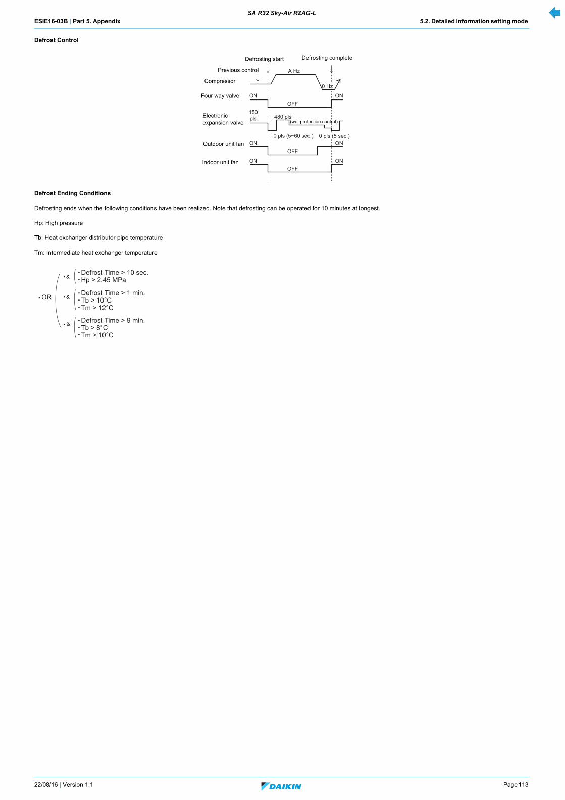
ESIE16-03B | Part 5. Appendix 5.2. Detailed information setting mode SA R32 Sky-Air RZAG-L
22/08/16 | Version 1.1 Page 113
Defrost Control
Defrost Ending Conditions
Defrosting ends when the following conditions have been realized. Note that defrosting can be operated for 10 minutes at longest.
Hp: High pressure
Tb: Heat exchanger distributor pipe temperature
Tm: Intermediate heat exchanger temperature
OFF
A Hz
ON ON
OFFON ON
OFFON ON
0 Hz
150pls 480 pls
0 pls (5~60 sec.) 0 pls (5 sec.)
Compressor
Four way valve
Electronic expansion valve
Outdoor unit fan
Indoor unit fan
Previous control
Defrosting start Defrosting complete
(wet protection control)
Defrost Time > 10 sec.Hp > 2.45 MPa
Defrost Time > 1 min.Tb > 10°CTm > 12°C
Defrost Time > 9 min.Tb > 8°CTm > 10°C
OR
&
&
&
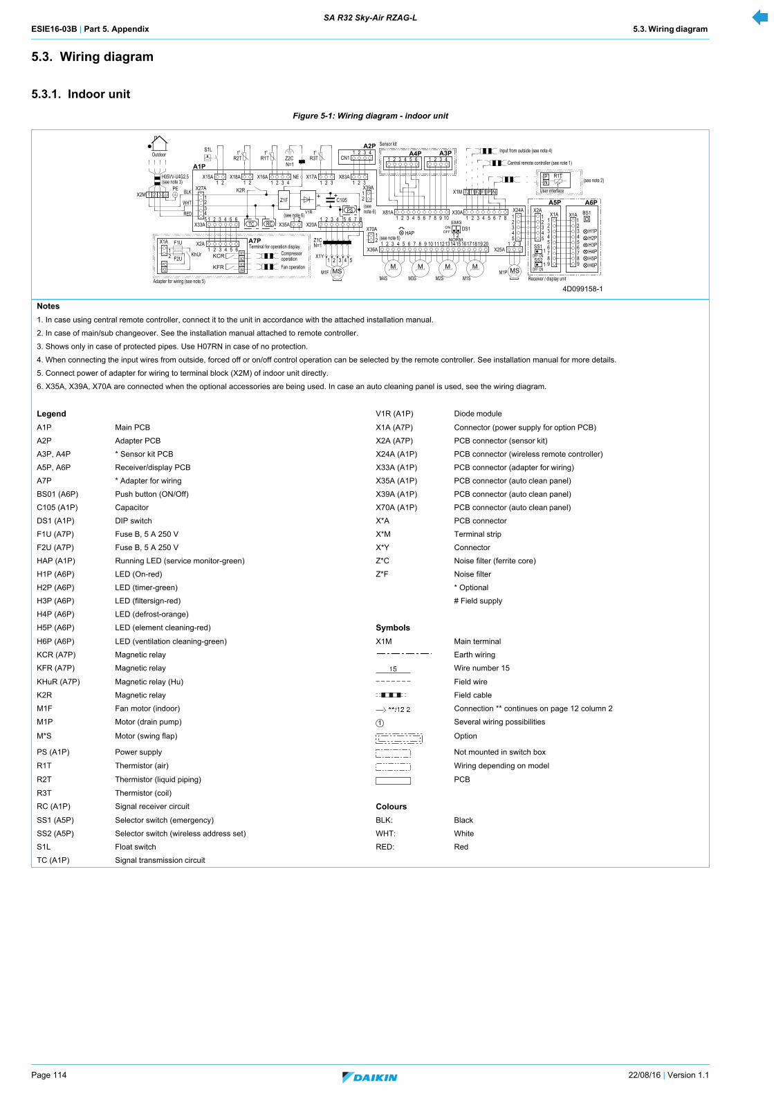
ESIE16-03B | Part 5. Appendix 5.3. Wiring diagram SA R32 Sky-Air RZAG-L
Page 114 22/08/16 | Version 1.1
5.3. Wiring diagram
5.3.1. Indoor unit
Figure 5-1: Wiring diagram - indoor unit
Notes
1. In case using central remote controller, connect it to the unit in accordance with the attached installation manual.
2. In case of main/sub changeover. See the installation manual attached to remote controller.
3. Shows only in case of protected pipes. Use H07RN in case of no protection.
4. When connecting the input wires from outside, forced off or on/off control operation can be selected by the remote controller. See installation manual for more details.
5. Connect power of adapter for wiring to terminal block (X2M) of indoor unit directly.
6. X35A, X39A, X70A are connected when the optional accessories are being used. In case an auto cleaning panel is used, see the wiring diagram.
Legend V1R (A1P) Diode module
A1P Main PCB X1A (A7P) Connector (power supply for option PCB)
A2P Adapter PCB X2A (A7P) PCB connector (sensor kit)
A3P, A4P * Sensor kit PCB X24A (A1P) PCB connector (wireless remote controller)
A5P, A6P Receiver/display PCB X33A (A1P) PCB connector (adapter for wiring)
A7P * Adapter for wiring X35A (A1P) PCB connector (auto clean panel)
BS01 (A6P) Push button (ON/Off) X39A (A1P) PCB connector (auto clean panel)
C105 (A1P) Capacitor X70A (A1P) PCB connector (auto clean panel)
DS1 (A1P) DIP switch X*A PCB connector
F1U (A7P) Fuse B, 5 A 250 V X*M Terminal strip
F2U (A7P) Fuse B, 5 A 250 V X*Y Connector
HAP (A1P) Running LED (service monitor-green) Z*C Noise filter (ferrite core)
H1P (A6P) LED (On-red) Z*F Noise filter
H2P (A6P) LED (timer-green) * Optional
H3P (A6P) LED (filtersign-red) # Field supply
H4P (A6P) LED (defrost-orange)
H5P (A6P) LED (element cleaning-red) Symbols
H6P (A6P) LED (ventilation cleaning-green) X1M Main terminal
KCR (A7P) Magnetic relay Earth wiring
KFR (A7P) Magnetic relay Wire number 15
KHuR (A7P) Magnetic relay (Hu) Field wire
K2R Magnetic relay Field cable
M1F Fan motor (indoor) Connection ** continues on page 12 column 2
M1P Motor (drain pump) Several wiring possibilities
M*S Motor (swing flap) Option
PS (A1P) Power supply Not mounted in switch box
R1T Thermistor (air) Wiring depending on model
R2T Thermistor (liquid piping) PCB
R3T Thermistor (coil)
RC (A1P) Signal receiver circuit Colours
SS1 (A5P) Selector switch (emergency) BLK: Black
SS2 (A5P) Selector switch (wireless address set) WHT: White
S1L Float switch RED: Red
TC (A1P) Signal transmission circuit
A1P
A3PA4P
A7P
A2P
X2AF1UX1A
KhUr
KFR
KCR
X2M 1 2 3
21 3 4 5 6
X33A X35A X20A1 2 3 4 5 6
1
3
5
2
4
BLK
WHT
RED
1 2 31 2 3 4 1 2 321 21X17AX16A X83AX15A X18A
X39A12
PS
H05VV-U4G2,5
Z2C R3TS1L
R2T R1Tt°t° t° 1 2 3 4
HAP
1 2 3 4 5 6 7 8 9 10 111213141516171819 2012
1 2 3 5 64 7 8 9 10 1 2 3 5 64 7 8X81A X30A
ONOFF
1 2 3
12345
321
45
123456789
321
456789
H1PH2PH3PH4PH5PH6P
X70A
5 81 2 21 3 6 74
M M M M
X36A X25AOFF ON
OFF ON
1
1
M4S M3S M2S M1S
N=1CN1
F2U12
RCTC
A5P A6P
M1F M1P
1 2 3 41 2 3 4 5 6
t°R1T
Y2YC
X1X2X3X4
NORM.
EMG
BS1
NP
4D099158-1
1 2
X2AX1A X1A
X24A
SS1
SS2
T2 T1 F2 F1 P N
DS1
X27A K2R X1MC105
V1R
MS
Z1F
NE
PE
Z1C N=1
X1Y1 2 3 4 5
MS
Terminal for operation displayCompressoroperation
Sensor kit
User interface
Central remote controller (see note 1)
Input from outside (see note 4)
Fan operation
Adapter for wiring (see note 5) Receiver / display unit
(see note 6)
(seenote 6)
(see note 6)
(see note 3)
Outdoor
(see note 2)

ESIE16-03B | Part 5. Appendix 5.3. Wiring diagram SA R32 Sky-Air RZAG-L
22/08/16 | Version 1.1 Page 115
5.3.2. Outdoor unit
Figure 5-2: Wiring diagram - outdoor unit 71
Legend TC Signal transmission circuit
A1P Printed circuit board (main) V1D-V3D Diode
A2P Printed circuit board V1R IGBT power module
BS1-BS4 Push button switch V2R Diode module
C1-C3 Capacitor V1T, V2T Insulated Gate Bipolar Transistor (IGBT)
DS1 DIP switch X1M Terminal strip
E1H Bottom plate heater (option) Y1E Electronic expansion valve
F1U, F2U Fuse Y3E Electronic expansion valve
F6U Fuse (T 3.15 A / 250 V) Y1S Solenoid valve (4-way valve)
F7U, F8U Fuse (F 1.0 A / 250 V) Y2S Solenoid valve
H1P-H7P Light-emitting diode (service monitor is orange) Z1C-Z6C Noise filter (ferrite core)
HAP Light-emitting diode (service monitor is green) Z1F-Z3F Noise filter
K1R Magnetic relay (Y1S)
K2R Magnetic relay (Y2S) Symbols
K2R, K10R Magnetic relay L Live
K11M Magnetic contactor N Neutral
K13R-K15R Magnetic relay Field wiring
L1R Reactor Terminal strip
M1C Motor (compressor) Terminal
M1F Motor (fan) Connector
PS Switching power supply Connection
01DI Earth leakage circuit breaker (30 mA) Protective earth
R2, R5, R6 Resistor Noiseless earth
R1T Thermistor (air) Option
R2T Thermistor (discharge)
R3T Thermistor (suction) Colours
R4T Thermistor (heat exchanger inlet) BLK: Black
R5T Thermistor (heat exchanger middle) BLU: Blue
R6T Thermistor (liquid) BRN: Brown
R7T, R8T Thermistor (Positive Temperature Coefficient) GRN: Green
RC Signal receiver circuit PPL: Purple
S1PH-A Automatic high pressure switch RED: Red
S1PH-M Manual high pressure switch WHT: White
S1PL Low pressure switch YLW: Yellow
+ -
220-240 V1N~ 50 Hz
NL L NX1M
RED BLUNALA
F2U
F1U
Z6CN=1 GRN/YLW
Z1CN=5
X11A X12A X13A X21AX803A
X5AX26A
X22A
BLK
WHT
RED
Z3CN=1
Z2CN=3
2 31
R3TR1T R6TR2T R4T R5T
t°t° t°t° t° t°
M M
Y2S
K2RK14R
K2R
X6A
X28A
A1P
A2P
Y3E
Y1E
(Y1E,Y3E)Y1E Y3E
ONOFF
BS1 BS2 BS3 BS4
X205AH1P H3P H5P H7P
H2P H4P H6P
2D099152-1
Z1F
Z2F
Z3F
GRN E1
WHT
BRN
PPL
RED
HR1
HR3
HR4
HR2
Z5CN=6
C1V3D
V1TV2T
V2D
R2
+
RED WHT BLU
M1C
WVU
U V W
MSM1FX502A
Z4CN=4
X25AK1R R8T
+t° Y1S
PS
X804A
X806A
X805A
R6K15RC2
C3
TC
RC
X31AX32A
X77A
S1PH-M S1PLS1PH-AP> P<P>
L1RA1P
X1M
HAPA2P
F8UF7U
E1H
HAP
L1R
K10R K11M
V2R
R7T
F6U
K13R
R4
V1D
R5
X106A
V1R
21
6 86Q1DI
DS1
X1M
+t°
+ -
3~MS
W
VU
Electronic component assemblyPosition of elements
Rear viewFront view
See note 7
Position of compressor terminal

ESIE16-03B | Part 5. Appendix 5.3. Wiring diagram SA R32 Sky-Air RZAG-L
Page 116 22/08/16 | Version 1.1
Figure 5-3: Wiring diagram - outdoor unit 100-140
5.3.3. Field wiring
Not applicable.
Legend S1PL Low pressure switch
A1P Printed circuit board (main) TC Signal transmission circuit
A2P Printed circuit board V1D-V4D Diode
BS1-BS4 Push button switch V1R IGBT power module
C1-C3 Capacitor V2R Diode module
DS1 DIP switch V1T, V3T Insulated Gate Bipolar Transistor (IGBT)
E1H Bottom plate heater (option) X1M Terminal strip
F1U-F4U Fuse Y1E Electronic expansion valve
F6U Fuse (T 5.0 A / 250 V) Y3E Electronic expansion valve
F7U, F8U Fuse (F 1.0 A / 250 V) Y1S Solenoid valve (4-way valve)
H1P-H7P Light-emitting diode (service monitor is orange) Y2S Solenoid valve
HAP Light-emitting diode (service monitor is green) Z1C-Z6C Noise filter (ferrite core)
K1R Magnetic relay (Y1S) Z1F-Z6F Noise filter
K2R Magnetic relay (Y2S)
K10R Magnetic relay Symbols
K11M Magnetic contactor L Live
K13R-K15R Magnetic relay N Neutral
K4R Magnetic relay E1H (option) Field wiring
L1R-L3R Reactor Terminal strip
M1C Motor (compressor) Terminal
M1F Motor (fan) (upper) Connector
M2F Motor (fan) (lower) Connection
PS Switching power supply Protective earth
01DI Earth leakage circuit breaker (30 mA) Noiseless earth
R1-R5 Resistor Option
R1T Thermistor (air)
R2T Thermistor (discharge) Colours
R3T Thermistor (suction) BLK: Black
R4T Thermistor (heat exchanger inlet) BLU: Blue
R5T Thermistor (heat exchanger middle) BRN: Brown
R6T Thermistor (liquid) GRN: Green
R7T Thermistor (fin) PPL: Purple
RC Signal receiver circuit RED: Red
S1PH-A Automatic high pressure switch WHT: White
S1PH-M Manual high pressure switch YLW: Yellow
2D099153-1
A2P
A1P
GRN
U V W
R2F6U
X107AX106AV1R
RED WHT BLU
M1C
M2FM1FX502A
3~MS
MS
W
VU
X111A X6AX77A
K1R K4RK2R
ONOFF
X11A X12A X13A
R3TR1T R6TR2T R4T R5T
t°t° t°t° t° t°
BS1 BS2 BS3 BS4
R7T
21
H1P H3P H5P H7PH2P H4P H6P
X28A
X31A
X32A
X21A
X22A
P>
P<
P>
A1P A2P
X1M
HAP
L3RL2RL1R
V3DV2DV1D
V2TV1T
V3T
Z5CN=1
X801A X25A X26A
HAP
X99ANCLC
K10RK11M
R1
V2RX804A
X806A
X805A
Z6F
RED BLUZ3CN=2
F3UNBLB
GRNX98A
Z1F
Z4F
Z3F
Z2F
E3
BLK
BLU
RED
RED BLU
Z5F
GRN E2
NALAF2U F1U
F4U
X803A
K14R
R4
R3K15RC3
C2
X802A
Y1S Y2S
TC RC
Z1CN=2
Z2CN=2
X1M L N GRN/YLWZ6CN=1N
LQ1DI
Y3EY1E
(Y1E,Y3E)
WVUMS
Z4CN=6
+ -
+ C1
E1
PSR5
K13R V4D
DS1
t°
M
M
6
6
S1PH-A
S1PL
Y1E
S1PH-M
Y3E
F8UF7U
E1H
220-240 V1N~ 50 Hz
X1M2 31
Electronic component assemblyPosition of elements
Rear viewFront view
See note 7
See note 7
Position of compressor terminal
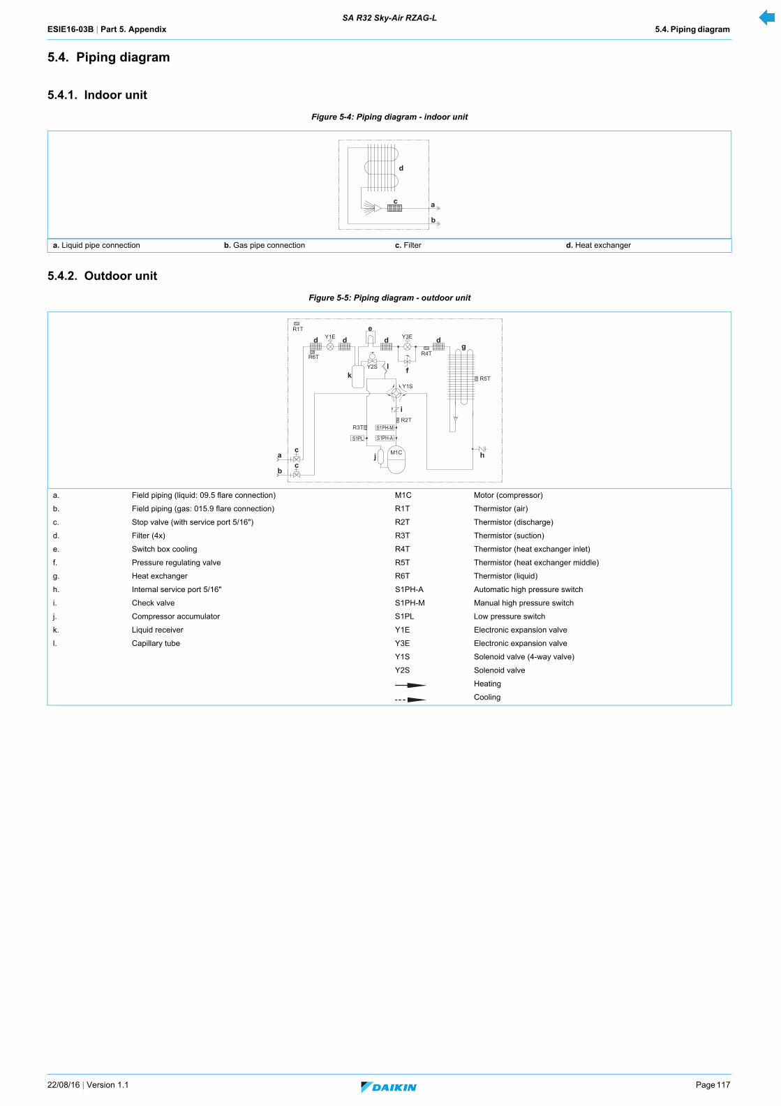
ESIE16-03B | Part 5. Appendix 5.4. Piping diagram SA R32 Sky-Air RZAG-L
22/08/16 | Version 1.1 Page 117
5.4. Piping diagram
5.4.1. Indoor unit
Figure 5-4: Piping diagram - indoor unit
5.4.2. Outdoor unit
Figure 5-5: Piping diagram - outdoor unit
a. Liquid pipe connection b. Gas pipe connection c. Filter d. Heat exchanger
a. Field piping (liquid: 09.5 flare connection) M1C Motor (compressor)
b. Field piping (gas: 015.9 flare connection) R1T Thermistor (air)
c. Stop valve (with service port 5/16") R2T Thermistor (discharge)
d. Filter (4x) R3T Thermistor (suction)
e. Switch box cooling R4T Thermistor (heat exchanger inlet)
f. Pressure regulating valve R5T Thermistor (heat exchanger middle)
g. Heat exchanger R6T Thermistor (liquid)
h. Internal service port 5/16" S1PH-A Automatic high pressure switch
i. Check valve S1PH-M Manual high pressure switch
j. Compressor accumulator S1PL Low pressure switch
k. Liquid receiver Y1E Electronic expansion valve
l. Capillary tube Y3E Electronic expansion valve
Y1S Solenoid valve (4-way valve)
Y2S Solenoid valve
Heating
Cooling
b
ac
d
S1PL
S1PH-M
S1PH-A
ac
d d de
d
cb
R2T
R6T
R1T
R4T
i
j
kl
h
gY1E
Y1S
Y2S
M1C
R5T
R3T
f
Y3E

ESIE16-03B | Part 5. Appendix 5.5. Component overview of unit SA R32 Sky-Air RZAG-L
Page 118 22/08/16 | Version 1.1
5.5. Component overview of unit
5.5.1. Indoor unit
Figure 5-6: Components overview - indoor unit
a. Switch box d. Drain pipe connection (VP25) g. Fan motor
b. Gas pipe connection e. Drain pump h. Heat exchanger
c. Liquid pipe connection f. Float switch i. Hanger bracket
f
g
h
i
cb
a
ed
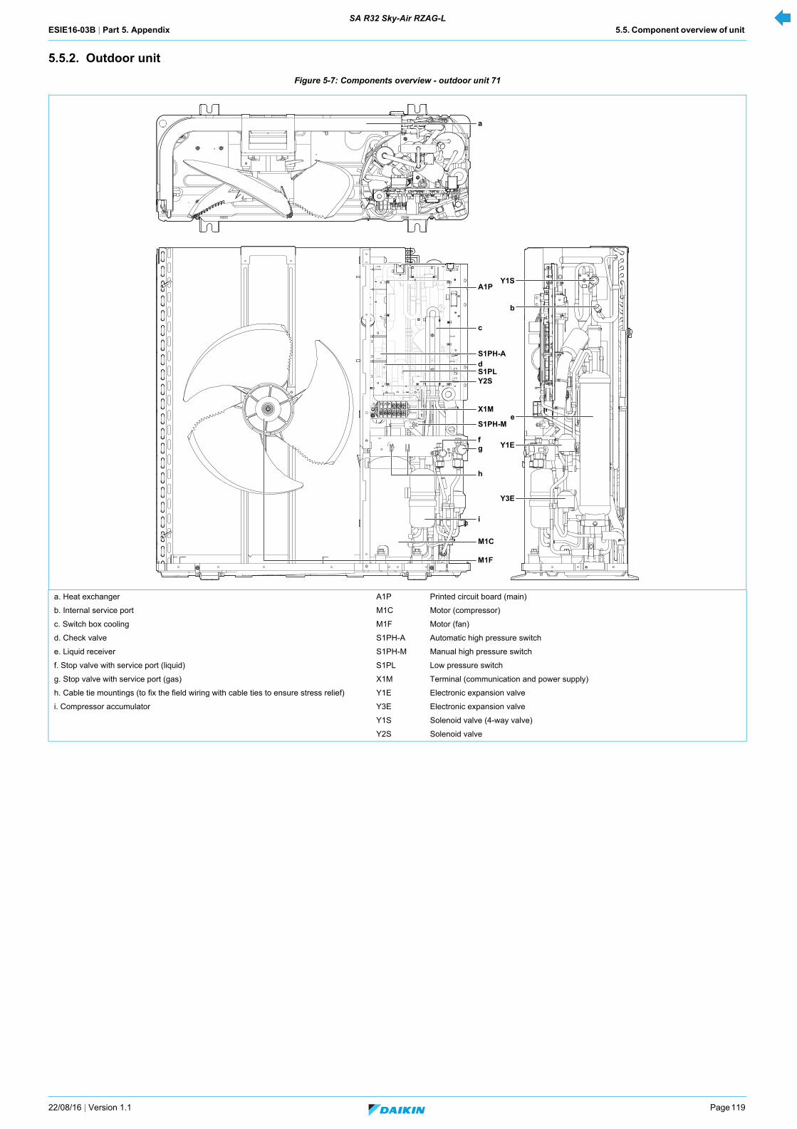
ESIE16-03B | Part 5. Appendix 5.5. Component overview of unit SA R32 Sky-Air RZAG-L
22/08/16 | Version 1.1 Page 119
5.5.2. Outdoor unit
Figure 5-7: Components overview - outdoor unit 71
a. Heat exchanger A1P Printed circuit board (main)
b. Internal service port M1C Motor (compressor)
c. Switch box cooling M1F Motor (fan)
d. Check valve S1PH-A Automatic high pressure switch
e. Liquid receiver S1PH-M Manual high pressure switch
f. Stop valve with service port (liquid) S1PL Low pressure switch
g. Stop valve with service port (gas) X1M Terminal (communication and power supply)
h. Cable tie mountings (to fix the field wiring with cable ties to ensure stress relief) Y1E Electronic expansion valve
i. Compressor accumulator Y3E Electronic expansion valve
Y1S Solenoid valve (4-way valve)
Y2S Solenoid valve
Y3E
Y1E
e
b
Y1S
a
c
A1P
S1PH-AdS1PLY2S
X1M
S1PH-M
g
M1C
i
f
h
M1F

ESIE16-03B | Part 5. Appendix 5.5. Component overview of unit SA R32 Sky-Air RZAG-L
Page 120 22/08/16 | Version 1.1
Figure 5-8: Components overview - outdoor unit 100-140
a. Heat exchanger A1P Printed circuit board (main)
b. Internal service port M1C Motor (compressor)
c. Switch box cooling M1F Motor (upper fan)
d. Check valve M2F Motor (lower fan)
e. Liquid receiver S1PH-A Automatic high pressure switch
f. Stop valve with service port (liquid) S1PH-M Manual high pressure switch
g. Stop valve with service port (gas) S1PL Low pressure switch
h. Cable tie mountings (to fix the field wiring with cable ties to ensure stress relief) X1M Terminal (communication and power supply)
i. Compressor accumulator Y1E Electronic expansion valve
Y3E Electronic expansion valve
Y1S Solenoid valve (4-way valve)
Y2S Solenoid valve
b
e
Y1E
Y3E
a
A1P
c
Y1S
S1PLS1PH-MS1PH-A
dY2S
X1M
g
i
M1C
f
M2F
M1F
h

ESIE16-03B | Part 5. Appendix 5.6. Product specific information SA R32 Sky-Air RZAG-L
22/08/16 | Version 1.1 Page 121
5.6. Product specific information
5.6.1. Error codes
5.6.1.1. “E9-00” - Electronic expansion valve abnormality
Trigger conditions
• A = 4 K
• B = 10 K
5.6.1.2. “F3-00” - Discharge pipe temperature abnormality
5.6.2. Component checklist
5.6.2.1. How to activate inverter test
Not available yet.
5.6.2.2. Component checklist
Compressor A (°C) B (°C) C (°C)
2YC71 120 110 /
2YC100 120 110 /
ComponentComponent name Connector on 71-class Connector on 100/140-class PCB Specific
Outdoor unit
M1C Motor (compressor) X502A X502A A1P
M1F Motor (upper fan) X106A X106A A1P
M2F Motor (lower fan) X107A A1P
S1PH-A Automatic high pressure switch X32A X32A A1P
S1PH-M Manual high pressure switch X32A X32A A1P
S1PL Low pressure switch X31A X31A A1P
Y1E Electronic expansion valve X21A X21A A1P
Y3E Electronic expansion valve X22A X22A A1P
Y1S Solenoid valve (4-way valve) X25A X25A A1P
Y2S Solenoid valve X26A X26A A1P
R1T Thermistor (air) X11A X11A A1P Type 1
R2T Thermistor (discharge) X12A X12A A1P Type 2
R3T Thermistor (suction) X12A X12A A1P Type 1
R4T Thermistor (heat exchanger inlet) X12A X12A A1P Type 1
R5T Thermistor (heat exchanger middle) X12A X12A A1P Type 1
R6T Thermistor (liquid) X13A X13A A1P Type 1

ESIE16-03B | Part 5. Appendix 5.7. Switch box SA R32 Sky-Air RZAG-L
Page 122 22/08/16 | Version 1.1
5.7. Switch box
5.7.1. Indoor unit
Not applicable.
5.7.2. Outdoor unit
Not applicable.
5.8. Field information report
See next page.
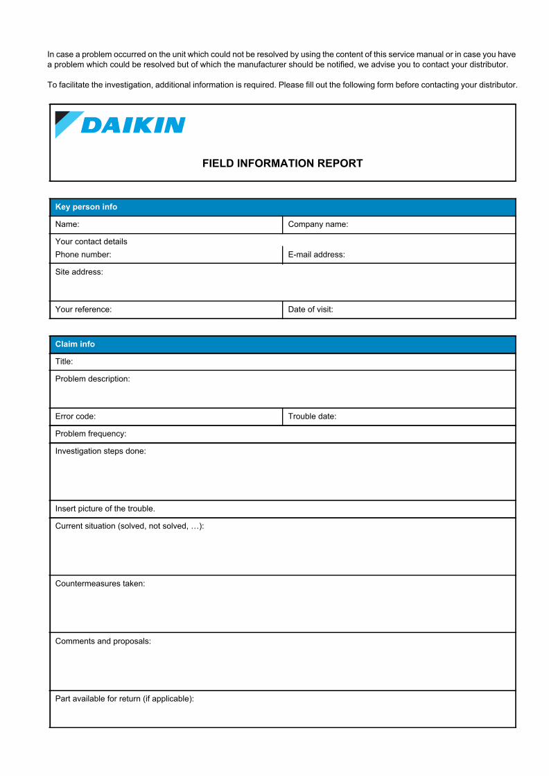
In case a problem occurred on the unit which could not be resolved by using the content of this service manual or in case you have a problem which could be resolved but of which the manufacturer should be notified, we advise you to contact your distributor.
To facilitate the investigation, additional information is required. Please fill out the following form before contacting your distributor.
FIELD INFORMATION REPORT
Key person info
Name: Company name:
Your contact detailsPhone number: E-mail address:
Site address:
Your reference: Date of visit:
Claim info
Title:
Problem description:
Error code: Trouble date:
Problem frequency:
Investigation steps done:
Insert picture of the trouble.
Current situation (solved, not solved, …):
Countermeasures taken:
Comments and proposals:
Part available for return (if applicable):

Application info
Application (house, apartment, office, …):
New project or refurbishment:
Heat emitters (radiators / under floor heating / fan coils / …):
Hydraulic layout (simple schematic):
Unit / Installation info
Model name: Serial number:
Installation / commissioning date: Software version hydro PCB A1P:
Software version hydro PCB A5P:
Software version user interface: Software version outdoor PCB:
Minimum water volume: Maximum water volume:
Brine composition and mixture:
Brine freeze up temperature:
Space heating control (leaving water temperature, room thermostat, ext. room thermostat):
Space heating setpoint:
Domestic hot water control (reheat only, schedule only, reheat + schedule):
Domestic hot water setpoint:
Provide pictures of the field settings overview (viewable on the user interface).