Roofing Applicator Handbook - Sika USA
109
ROOFING APPLICATOR HANDBOOK
-
Upload
khangminh22 -
Category
Documents
-
view
3 -
download
0
Transcript of Roofing Applicator Handbook - Sika USA

ROOFINGAPPLICATOR HANDBOOK

ii Sika Corporation – Roofing Applicator Handbook
Welcome to Sika Corporation – Roofing’s Applicator Handbook. This pocket guide is intended to serve as a quick “on the roof” reference to the techniques used when installing Sarnafil and Sikaplan membranes. This pocket guide contains the latest information for continued success in installing Sika roof systems.*
As an authorized Sika - Roofing applicator, you have committed to uphold Sika’s high standards during the installation of our roofing and waterproofing systems. Our goal is to help you provide the building owner with a high quality installation.
As the world’s leader in thermoplastic roofing systems, Sika - Roofing has manufactured billions of square feet of roofing and waterproofing membrane since 1964. Sika roofing systems can be found on many well known facilities including numerous stadiums, schools, libraries, museums, hospitals, retail establishments and commercial buildings.
Sika is committed to provide you with the finest roofing and waterproofing products available and spares no effort in helping you achieve a quality installation.
This applicator handbook contains installation instructions for Sarnafil and Sikaplan roofing systems per Sika - Roofing’s requirements. More information about Sika - Roofing products and individual product properties can be found on individual guide specifications and data sheets on the Sika website.
The online version of the handbook contains interactive links to help navigate the document easier. Links in the Table of Contents will lead to their respective sections and links in the footers lead back to the Table of Contents.
* Although accurate at the time of printing, in our constant quest to continuously improve our system and service offerings things can change and evolve. Please check usa.sika.com/sarnafil and the online version of the handbook regularly to insure you have the latest information.
Introduction
Sika Roofing Website Roofing Applicator Handbook

Sika Corporation – Roofing Applicator Handbook iii
Office Locations
REGIONAL OFFICES
NEW ENGLAND REGION225 Dan Road
Canton, MA 02021Phone: (781) 821-0865
Fax: (781) 821-9205
SOUTHWEST REGION 3000 FM 3538
Sealy, Texas 77474Phone: (979) 472-2015
Fax: (979) 627-7952
EASTERN REGIONOne Park Way 3rd Floor
Upper Saddle River, NJ 07458Phone: (201) 327-0479
Fax: (201) 327-4069
MOUNTAIN REGION 2881 South 900 West
Salt Lake City, UT 84119Phone: (801) 575-8648
Fax: (801) 355-4407
SOUTHERN REGION3483 Satellite Boulevard
Duluth, GA 30096Phone: (770) 495-0025
Fax: (770) 495-0027
WESTERN REGION NORTH 15616 Euclid Avenue
Chino, CA 91708Phone: (909) 393-5100
MIDWEST REGION200 W. 22nd St., Suite 216
Lombard, IL 60148Phone: (800) 532-5123
Fax: (630) 620-9646
WESTERN REGION SOUTH 15616 Euclid Avenue
Chino, CA 91708Phone: (909) 393-5100
SIKA CORPORATION U.S. usa.sika.com
SIKA CORPORATION - ROOFINGusa.sika.com/sarnafil
EMAIL ADDRESS:[email protected]
SIKA CANADA - ROOFING 6915 Davand Drive
Mississauga, ON L5T 1L5Phone: (905) 795-3177
Fax: (905) 795-3192can.sika.com
Contents
Sika Corporation – Roofing Applicator Handbook iv
Tools & EquipmentHot-air Welding Equipment - Hand Tools/Automatic Welder ............................1Hot-air Welding Equipment - Decor Profile Kit/Generator ................................3MaterialsProduct Delivery, Storage, and Handling ........................................................5Job Conditions ...............................................................................................6Vapor Retarder InstallationVapor Retarder PE 10 / Vapor Retarder SA 31 ...............................................7Vapor Retarder SA 106 ...................................................................................8Vapor Retarder TA 138 and Ply Sheet TA 87 .................................................10Ply Sheet HA 87 and Ply Sheet HA 118 ........................................................11Insulation or Roof Board InstallationMechanical Attachment within M-A Membrane Systems ...............................12Mechanical Attachment within Adhered Membrane Systems.........................13Urethane Adhesive Attachment .....................................................................16Attachment with Hot Asphalt Type III or Type IV ...........................................19Mechanically Attached SystemsIn-Seam Attached Sarnafast System ............................................................21In-Seam Disc Placement Details / Membrane Installation .............................22Perimeter and Corner Layout for Sarnafast In-Seam ....................................23Bar and Coverstrip Engineered System ........................................................24Bar and Coverstrip Engineered System Membrane Installation ....................26RhinoBond SystemIntroduction ..................................................................................................27Induction Tool Field Calibration.....................................................................28Membrane Installation Systems ....................................................................29Membrane Installation ..................................................................................30Fastener Spacing & Wind Classification .......................................................31Grid Patterns ................................................................................................32Adhered Systems Introduction ..................................................................................................33Solvent Based Adhesive Installation (Bareback Membrane) .........................34Solvent Based Adhesive Installation (Feltback Membrane) ...........................35Water Based Adhesive Installation (Roller) ...................................................36Water Based Adhesive Installation (Spray) ...................................................38Urethane Adhesive Installation Using Feltback Membrane ...........................40Self-Adhered Membrane ...............................................................................42Hybrid SystemsIntroduction ..................................................................................................43Base Sheet Installation .................................................................................44Décor Roof Systems Introduction ..................................................................................................45General Preparation and Installation ............................................................46Rib Spacing Layout ......................................................................................51Rib Installation .............................................................................................52Décor Flashing .............................................................................................55Décor Repairs ..............................................................................................56

Sika Corporation – Roofing Applicator Handbook v
Contents
Décor Snow Guards .....................................................................................57Edge Metal / Night Tie In ..............................................................................58WeldingGeneral / Hand Welding ...............................................................................59 Sarnamatic ...................................................................................................60Quality Control .............................................................................................61Typical Flashing ProceduresGeneral ........................................................................................................62How To Flash An Outside Corner ..................................................................65How To Flash An Inside Corner ....................................................................67How To Flash A Curb ....................................................................................69How To Flash A Vent Stack ...........................................................................71How To Flash A Conical Stack (option 1) ......................................................73How To Flash A Conical Stack (option 2) ......................................................74How To Flash A Conical Stack (option 3) ......................................................75How To Flash A Clamping Ring Drain ...........................................................77How To Flash A Steep Sump Drain ...............................................................79Liquid Flashing ProceduresGeneral ........................................................................................................81Application ...................................................................................................82Inspection and Quality Control ......................................................................85Mixing Rates ................................................................................................86Metal FlashingsSarnaclad Metal Base Flashings ..................................................................87Sarnaclad Metal Edge ..................................................................................88Metal Flashings ............................................................................................89Overnight Tie-InGeneral ........................................................................................................90Walkway InstallationSarnatred V ..................................................................................................91Crossgrip XTRA............................................................................................92Perimeter WarningGeneral ........................................................................................................93Special InstructionsTear-off Instructions ......................................................................................94Membrane Cleaning .....................................................................................95Welding ........................................................................................................97Repairing Vapor Retarders ..........................................................................98Adhesive SelectionCoverage Rates Table ..................................................................................99Troubleshooting General ......................................................................................................101Comments for Use General ......................................................................................................103

1 Sika Corporation – Roofing Applicator Handbook
Hand Welder and Accessories
Sika – Roofing Sarnamatic 681
Tools & EquipmentHot-air Welding Equipment - Hand Tools/Automatic Welder

Sika Corporation – Roofing Applicator Handbook 2
Tools & EquipmentHot-air Welding Equipment - Hand Tools/Automatic Welder
Hand Welder and Accessories: Leister Triac hand welder with 0 - 10 heat settings, ¾” (20 mm) nozzle, 1 ½” (40 mm) nozzle, 5 mm nozzle with PVC cord attachment, Silicone rubber hand roller.
Sarnamatic Welder The Sarnamatic hot-air welder was developed and is supplied by Sika - Roofing. It is specifically designed for use with Sarnafil and Sikaplan membranes.
The speed, air flow and welding temperature of the Sarnamatic can be adjusted to accommodate changes in ambient temperature.
Each Sarnamatic unit comes packed in a sturdy box, complete with detailed operating and maintenance instructions.
Sarnamatic Technical Information Power requirements: 230 - volt, 30 - ampere, single-phase current.
Extension cord: Use a 14 AWG (2.5 mm2) 3 - conductor type cord, 50 ft (15 m) length.
For longer distances, consult an electrical contractor.
Adjustment tools (supplied): Phillips screwdriver, open-end and allen wrenches.

3 Sika Corporation – Roofing Applicator Handbook
Décor Profile Kit
Tools & EquipmentHot-air Welding Equipment - Decor Profile Kit/Generator
Generator

Sika Corporation – Roofing Applicator Handbook 4
Tools & EquipmentHot-air Welding Equipment - Decor Profile Kit/Generator
Sarnamatic Precautions Run machine on the cooling setting for at least 5 minutes before turning it off to prevent damage to the ceramic heating element. Avoid power interruptions or power surges. Always check the condition of the power cord and all connectors prior to connecting the power. Never use electrical equipment under wet conditions. Sika - Roofing recommends the use of a properly sized portable generator.
Décor Profile Kits The patented Décor Kits were developed and are supplied by Sika - Roofing. Using specially designed compression wheels allowing for continuous, consistent heat and pressure to be applied to Décor Profiles and the membrane.
Generator When a generator is required for running the Sarnamatic welder it should be a minimum of 7,500 watts, 30 amps, 230 volts single phase. The generator or power source should be dedicated to the Sarnamatic machine. Running additional equipment from the generator during operation of the Sarnamatic may result in inconsistent welds.

5 Sika Corporation – Roofing Applicator Handbook
1. All products delivered to the job site shall be in the original unopened containers or wrappings.
2. Handle all materials to prevent damage. Place all materials on pallets, and fully protect from moisture with clean breathable tarpaulins.
3. Membrane rolls shall be stored lying down on pallets, and fully protected from moisture with breathable tarpaulins.
4. Insulation and roof boards shall be stored and fully protected from moisture with breathable tarpaulins. Slit shipping wrap for CG and HD boards before covering. Refer to PIMA Technical Bulletin 109: ‘Storage and Handling Recommendations for Polyiso Roof Insulation’ for further information.
5. Store adhesives, primers, and sealants according to Sika’s product data sheets. 6. All flammable materials shall be stored in a cool, dry area away from sparks and
open flames. Follow precautions outlined on containers and supplied by material manufacturer.
7. Any materials that are determined by the owner’s representative and Sika - Roofing to be unsuitable for use are to be removed from the job site and replaced at no cost to the owner.
MaterialsProduct Delivery, Storage, and Handling

Sika Corporation – Roofing Applicator Handbook 6
MaterialsJob Conditions
1. Only as much of the new roofing as can be made weather tight each day, including all flashing and detail work, shall be installed. All seams shall be properly heat- welded before leaving the job site that day.
2. The surface of the insulation shall be inspected prior to installation of any roof membrane. The substrate shall be clean, dry, free from debris and smooth with no surface roughness or contamination. Broken, delaminated, wet, or damaged insulation boards shall be removed and replaced.
3. All surfaces to receive new insulation, membrane, or flashings shall be clean, smooth, dry, and free from flaws, sharp edges, loose foreign material, oil, and grease. Should surface moisture occur, the applicator shall provide the necessary equipment to dry the surface prior to application. Roofing shall not start until all defects have been corrected.
4. Uninterrupted waterstops shall be installed at the end of each day’s work, and shall be completely removed before proceeding with the next day’s work. Waterstops shall not remain in contact with the finished roof as the installation progresses. Contaminated membrane shall be replaced at no cost to the owner.
5. The applicator is cautioned that Sika – Roofing membranes may be incompatible with polystyrene, asphalt, coal tar, heavy oils, roofing cements, creosote and some preservative materials. Such materials shall not remain in contact with the membranes. The Applicator shall consult Sika - Roofing regarding compatibility, precautions, and recommendations.
6. Arrange work sequence to avoid use of newly constructed roofing as a walking surface or for equipment movement and storage. Where such access is absolutely required, the Applicator shall provide all necessary protection and barriers to segregate the work area and to prevent damage to adjacent areas. A substantial protection layer consisting of plywood over insulation board shall be provided for new and existing roof areas which receive rooftop traffic during construction.
7. The Applicator shall take precautions such that storage and/or application of materi-als and/or equipment does not overload the roof deck or building structure.
8. Installation of a Sika – Roofing membrane over coal tar pitch, or a re-saturated roof, requires special consideration to protect the membrane from volatile fumes and materials. Consult Sika - Roofing for precautions prior to bid and installation.
9. Flammable adhesives shall not be stored and shall not be used in the vicinity of open flames, sparks and excessive heat.
10. Precautions shall be taken when using Sarnacol adhesives at or near rooftop vents or air intakes. Adhesive odors could enter the building. Coordinate the operation of vents and air intakes in such a manner as to avoid the intake of adhesive odor while ventilating the building. Keep lids on unused cans at all times. Wherever possible, air intakes should be sealed off during adhesive application.
11. Appropriate protective wear shall be worn when using solvents or adhesives and as required by job conditions.
12. Workers shall follow OSHA safety procedures.

7 Sika Corporation – Roofing Applicator Handbook
Vapor Retarder PE 101. Vapor Retarder PE 10 is loose
laid over suitable substrates.2. Overlap all edges 4” (10.2 cm)
and seal between overlap with Sikalastomer-65.
3. Extend Vapor Retarder PE 10 to the perimeter and deck penetrations and seal to provide continuity of the vapor retarder.
4. Vapor Retarder PE 10 may also be sealed on the vertical surface at roof penetrations.
Vapor Retarder SA 311. All surfaces must be clean,
sound, dry, and free of loose materials or contaminants such as water, frost, ice, oil and grease that would interfere with proper adhesion and compromise the performance of the product.
2. Sharp ridges or other projections above the surface shall be removed before roofing. In accordance with the ICRI
Technical Guideline No. 310.2R-2013, newly poured concrete surfaces must be finished by forming, wood float, steel or power trowel, or broom finished to meet a concrete surface profile (CSP) of 2 - 5.
3. Vapor Retarder Primer SB, Vapor Retarder Primer VC or Vapor Retarder Primer WB is required on all substrates except for steel. Shake or stir primer before applying. Apply the primer with a brush, roller, or spray (WB only) and allow primer to dry completely before applying Sika’s self-adhered vapor retarder. Install Sika’s self-adhered vapor retarder on the same day as the application of primer. Priming laps may be required at cold temperatures. If used, allow primer to dry completely before forming seams and overlaps.
4. Begin the installation at the low point of the roof. Unroll Vapor Retarder SA 31 onto the substrate for alignment. Overlap each sheet by 3” (7.6 cm) on the side lap and 6” (15.2 cm) on the end laps.
Vapor Retarder InstallationVapor Retarder PE 10 / Vapor Retarder SA 31
Vapor Retarder PE 10
Vapor Retarder SA 31 laid in place

Sika Corporation – Roofing Applicator Handbook 8
5. Once the roll is aligned, peel back a portion of the silicone release film and press Vapor Retarder SA 31 onto the substrate. When securely adhered, remove the remaining release film from the roll.
6. On steel decks install a 6” x 42” (15.2 cm x 1.1 m) metal plate under the end lap to support the membrane between the steel flutes. Stagger the end laps by at least 12” (30.5 cm).
7. Use a minimum 75 lb (34 kg) steel roller to press the Vapor Retarder SA 31 onto the substrate including the laps. Use the roller to push out any air bubbles out to the edge of the membrane. Do not cut the membrane to remove a bubble.
8. Apply Sika’s Mastic to seal around penetrations, T-joints, and fishmouths. Use a trowel to mound the Mastic around the penetrations to seal the opening. Do not apply Mastic where it may come into direct contact with the membrane or where ponding water may occur.
Vapor Retarder SA 1061. All surfaces must be clean,
smooth, sound, dry, and free of loose materials, debris or contaminants such as water, moisture, frost, ice, oil and grease that would interfere with proper adhesion and compromise the performance of the product.
2. Sharp ridges or other projections above the surface shall be removed before roofing.
In accordance with the ICRI Technical Guideline No. 310.2R-2013, newly poured concrete surface must be finished by forming, wood float, steel or power trowel, or broom finished to meet a CSP of 2 - 5.
Vapor Retarder InstallationVapor Retarder SA 106
Vapor Retarder SA 31 cut tight around penetrations
Vapor Retarder SA 106

9 Sika Corporation – Roofing Applicator Handbook
3. Vapor Retarder Primer SB, Vapor Retarder Primer VC or Vapor Retarder Primer WB is required on all substrates except for steel. Concrete surfaces may be dry before installation. Shake or stir primer before applying. Apply the primer with a brush, roller, or spray (WB only) and allow primer to dry completely before applying Sika’s self-adhered vapor retarder. Install Sika’s self-adhered vapor retarder on the same day as the application of primer.
4. Begin the installation at the low point of the roof. Chalk a line on the deck to align the sheet. Unroll, position, and align Vapor Retarder SA 106 with the release poly covered selvage edge on the up-slope side. After the sheet is placed in its final position, loosely reroll half of the sheet toward the center of the roll.
5. Carefully score the release liner across the width of the roll with a
straight blade utility knife. Roll Vapor Retarder SA 106 into its final position as the release liner is being removed. Re-roll the remaining Vapor Retarder SA 106 and repeat the process. Roll Vapor Retarder SA 106 with a 75 lb (34 kg) steel roller to ensure full contact with the substrate.
6. Align successive sheets with 3” (7.6 cm) side laps and 6” (15.2 cm) end laps. The seam area has a pre-applied primer/adhesive on one side for mating with the bottom of the next sheet. Remove the release film from the seam area and mate the top sheet to the bottom. Roll the seam area to ensure constant contact.
7. Hot air weld the end laps. Hot air welded laps may show approximately ½” (1.3 cm) bleed out. Stagger adjacent end laps a minimum of 12” (30.5 cm).
8. Apply Mastic to seal around penetrations. Use a trowel to mound the Mastic around the penetrations to seal the opening. Do not apply Mastic where it may come into direct contact with the membrane.
Vapor Retarder InstallationVapor Retarder SA 106
Hot-air weld Vapor Retarder SA 106 end laps
Hot-air weld Vapor Retarder SA 106 end laps

Sika Corporation – Roofing Applicator Handbook 10
Vapor Retarder TA 138 and Ply Sheet TA 87
1. All surfaces must be clean, smooth, sound, dry, and free of loose materials, debris or contaminants such as water, moisture, frost, ice, oil and grease that would interfere with proper adhesion and compromise the performance of the product.
2. Sharp ridges or other projections above the surface shall be removed before roofing. In accordance with the ICRI Technical Guideline No. 310.2R-2013, newly poured concrete surface must be finished by forming, wood float, steel or power trowel, or broom finished to meet a CSP of 2 - 5.
3. Torch applied products should only be installed by trained personnel. It is imperative that the NRCA safety guidelines, as outlined in their Certified Roofing Torch Applicator Program (CERTA), and good industry practices be followed.
4. Prime concrete surface with Vapor Retarder Primer TA or Vapor Retarder Primer BE. Concrete surfaces may be dry before installation. Shake or stir primer before applying. Let the primer dry completely.
5. After the primer has dried completely, install TA 87 and TA 138 in a shingle fashion starting at the low point of the deck so the laps shed water.
6. Chalk a line on the deck to align the first sheet. Unroll TA 87 and TA 138 and align the side lap with the chalk line. Back roll the sheet halfway. Begin torching the bottom side of TA 87 and TA 138. As the bitumen begins to soften pull the roll forward with a metal pole. When heated properly there should be a bleed out of approximately ½” (1.3 cm). Back roll the other half of the roll and repeat the process.
7. Kick out the next roll and align the side lap. Side laps may be a minimum of 3” (7.6 cm). End laps should be a minimum of 6” (15.2 cm). Stagger adjacent end laps a mini-mum of 12” (30.5 cm). Cut the lower outside corner of the end lap at a 45 degree angle to minimize material build-up where it will be covered by the next roll.
8. When heating the membrane move the torch in an ‘ L ’ pattern to ensure heating of the lap area on the bottom sheet. Proper heating will create approximately ½” (1.3 cm) bleed out. Walk in the seam area or use a weighted roller to ensure proper adhesion and bleed out. Ensure that all laps are firmly and smoothly adhered without wrinkles, voids or fishmouths.
9. Check the seams with the edge of a trowel. Any loose areas should be lifted with the trowel, re-heated and pushed back down to achieve the bleed out.
10. Apply Mastic to seal around penetrations and at roof edges. Use a trowel to mound the Mastic around the penetrations to seal the opening. Do not apply Mastic where it may come into direct contact with the membrane.
11. Do NOT torch apply TA 87 and TA 138 to combustible substrates or substrates with a combustible backing. In such locations Vapor Retarder SA 106 may be used.
Vapor Retarder InstallationVapor Retarder TA 138 and Ply Sheet TA 87
Vapor Retarder TA 138
11 Sika Corporation – Roofing Applicator Handbook
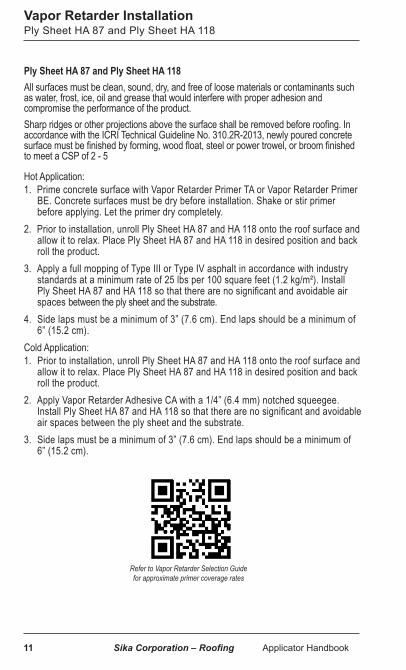
Vapor Retarder InstallationPly Sheet HA 87 and Ply Sheet HA 118
Ply Sheet HA 87 and Ply Sheet HA 118 All surfaces must be clean, sound, dry, and free of loose materials or contaminants such as water, frost, ice, oil and grease that would interfere with proper adhesion and compromise the performance of the product.Sharp ridges or other projections above the surface shall be removed before roofing. In accordance with the ICRI Technical Guideline No. 310.2R-2013, newly poured concrete surface must be finished by forming, wood float, steel or power trowel, or broom finished to meet a CSP of 2 - 5
Hot Application: 1. Prime concrete surface with Vapor Retarder Primer TA or Vapor Retarder Primer
BE. Concrete surfaces must be dry before installation. Shake or stir primer before applying. Let the primer dry completely.
2. Prior to installation, unroll Ply Sheet HA 87 and HA 118 onto the roof surface and allow it to relax. Place Ply Sheet HA 87 and HA 118 in desired position and back roll the product.
3. Apply a full mopping of Type III or Type IV asphalt in accordance with industry standards at a minimum rate of 25 lbs per 100 square feet (1.2 kg/m²). Install Ply Sheet HA 87 and HA 118 so that there are no significant and avoidable air spaces between the ply sheet and the substrate.
4. Side laps must be a minimum of 3” (7.6 cm). End laps should be a minimum of 6” (15.2 cm).
Cold Application: 1. Prior to installation, unroll Ply Sheet HA 87 and HA 118 onto the roof surface and
allow it to relax. Place Ply Sheet HA 87 and HA 118 in desired position and back roll the product.
2. Apply Vapor Retarder Adhesive CA with a 1/4” (6.4 mm) notched squeegee. Install Ply Sheet HA 87 and HA 118 so that there are no significant and avoidable air spaces between the ply sheet and the substrate.
3. Side laps must be a minimum of 3” (7.6 cm). End laps should be a minimum of 6” (15.2 cm).
Refer to Vapor Retarder Selection Guide for approximate primer coverage rates

Sika Corporation – Roofing Applicator Handbook 12
Insulation or Roof Board InstallationMechanical Attachment within M-A Membrane Systems
1. Insulation / Roof Boards (Boards) shall be installed over an acceptable substrate which shall be clean, dry, free of dirt, dust, debris, oils and other contaminants that may result in a surface that is not sound or is uneven.
2. Do not install more boards that can be covered with membrane by the end of the day, or the onset of inclement weather.
3. Use 2 layers of insulation when total thickness exceeds 2.7”. (69 mm). 4. Stagger all boards within the system in both directions at least 12”. (30.0 cm)
between layers.5. Boards shall be installed with tight joints with gaps no more than ¼”. (6 mm).6. Boards shall be neatly cut to fit around all penetrations and projections. Install tapered
insulation around drains to create sumps.7. Boards shall be secured to the deck with fasteners and plates, with 1”. (25 mm)
penetration into steel or plywood decks, and embedment into concrete or wood plank decks. Minimum of 6 fasteners per board.
8. Fasteners are to be installed consistently in accordance with fastener manufacturer’s and Sika’s recommendations. Fasteners must be tight enough so plates do not turn, but not so tight as to deform them or break through board face. Use fastener tools with a depth locator and torque-limiting attachment to ensure proper installation.
(6) FASTENERS PER BOARD 1 EVERY 5.33 FT2
4’
8’
Refer to Fastener Selection Guide for additional information on fastener usage
13 Sika Corporation – Roofing Applicator Handbook
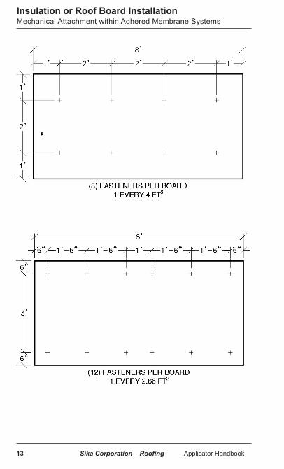
Insulation or Roof Board InstallationMechanical Attachment within Adhered Membrane Systems

Sika Corporation – Roofing Applicator Handbook 14
Insulation or Roof Board InstallationMechanical Attachment within Adhered Membrane Systems

15 Sika Corporation – Roofing Applicator Handbook
Insulation or Roof Board InstallationMechanical Attachment within Adhered Membrane Systems

Sika Corporation – Roofing Applicator Handbook 16
Insulation or Roof Board InstallationUrethane Adhesive Attachment
General1. All work surfaces must be clean, dry, free of dirt, dust, debris, oils and other
contaminants that may result in a surface that is not sound or is uneven.2a. With cartridge applications remove plastic plug and attach supplied
mixing tip to the threaded mixing head. Place the cartridge into proper applicator.
2b. With cart or drum applications, install both Part components according to machine manufacturer’s instructions. Always insure the same Part is used with the same dispensing holder and hose. All valves on the dispensing unit must be completely opened so a 1:1 ratio is achieved when moving the adhesive through the supplied mixing tip and onto the substrate.
3. With any new urethane application some of the material should be pumped into a bucket to insure a proper mix ratio.
4. Apply using a ribbon pattern at a maximum of 12” (30 cm) o.c. Tighter ribbon spacing may be necessary depending on the wind uplift rating required.
5. After boards are placed ensure full embedment by walking boards in and ballasting. CAUTION: Walking insulation boards in after placement into adhesive may cause slippage/movement until adhesive starts to set up. On roof slopes greater than 1/2” (13 mm) in 12” (31 cm), begin adhering insulation at low point and work upward to avoid added slippage.
6. Ballast is required when using any foam board.7. Only apply adhesive in areas that can be made completely watertight in the
same day’s operations.
Typical insulation or roof board layouts shown, number of fasteners to be used will be in accordance with specification uplift pressures. Dimensions from each plate or edge may be different per product used.
Refer to Adhesive Selection Guide for additional information on adhesive usage

17 Sika Corporation – Roofing Applicator Handbook
Sarnacol 2163 Board Adhesive1. Apply by hand with a dual
component caulk gun over properly installed and prepared substrates.
2. Apply a 1/4” to 1/2” (6 to 13 mm wet ribbon.
3. Immediately place boards into wet adhesive.
Sarnacol AD Board Adhesive; Sarnacol OM Board Adhesive;Sarnacol OM Board Adhesive WG (Winter Grade)1. Apply a 1/2” (13 mm) wet ribbon. 2. Allow the adhesive to begin to rise before placing the insulation or roof board
into the adhesive. Open times will vary depending on weather conditions. Do not allow adhesive to skin over.
Sarnacol AD or OM Board Adhesive (>10 gallon sets)1. Apply adhesive with a high pressure spray applicator. The Part components
must fill the lines. The Part components should be sprayed at a 1:1 ratio.2. Sarnacol OM Board Adhesive is dispensed in a spray that rises 1/8” (3.2 mm) to
1/4” (6.4 mm) above the substrate. Place the board stock into the adhesive shortly after it has reached its maximum rise while it is still wet and tacky and before it reaches its tack free state. Maximum rise typically occurs within 2 minutes of application. The tack free time is usually 3 to 5 minutes. Walk the boards into place and ballast.
3. A chemical cure takes place securing the board in approximately 4 to 8 minutes after application, depending on temperature and weather conditions. The set up time is typically 10 to 12 minutes. The tack free time and set up time will decrease as temperature increases. Multiple layers of boards should use the staggered joint method of application.
Typical Foamed Urethane Installation Pattern
Insulation or Roof Board InstallationUrethane Adhesive Attachment

Sika Corporation – Roofing Applicator Handbook 18
Insulation or Roof Board InstallationUrethane Adhesive Attachment

19 Sika Corporation – Roofing Applicator Handbook
Insulation or Roof Board InstallationAttachment with Hot Asphalt Type III or Type IV
Attachment with Hot Asphalt Type III or Type IV1. Insulation shall be adhered to the concrete deck or another approved substrate
with hot Type III or Type IV asphalt according to the asphalt manufacturer’s instructions. The temperature of the asphalt shall be at the asphalt manufacturers instructions for EVT. The asphalt temperature and application methodology shall be maintained throughout the installation as recommended by the asphalt manufacturer, the NRCA and ARMA. The hot asphalt is to be applied at a rate of approximately 30 lbs per 100 ft2 (1.5 kg/m2). Irregular or porous substrates may require a greater amount of asphalt. The installation shall be such to cause the insulation boards to rest evenly on the roof deck/substrate so that there are no significant and avoidable air spaces between the boards and the substrate. The maximum board size with hot-asphalt attachment is 4 ft x 4 ft (1.2 m x 1.2 m). With the perforated side of the board set into the hot asphalt, each board shall be installed tightly against the adjacent boards on all sides and walked-in-place to assure even and consistent contact with the substrate. Aluminum tape shall be installed over joints where asphalt has been pushed to the board’s surface.
2. When hot asphalt is used to attach the insulation board to the deck, a Sarnastop shall be installed above the adhered roof membrane 3 ft (0.9 m) from the edge of the roof along the entire perimeter. The Sarnastop shall be fastened 12” (0.3 m) on center and a membrane cover strip is welded over it.
The requirements for adhering the Sarnatherm insulation boards with hot asphalt are:
a) The asphalt shall be applied at a temperature approximately 60°F to 70°F (15°C - 21°C) lower than the inter-ply hand mopping EVT.
b) The temperature of the asphalt at the point of contact with the Sarnatherm insulation board shall not be greater than 390°F (200°C).

Sika Corporation – Roofing Applicator Handbook 20
Insulation or Roof Board Installation
Refer to Insulation Selection Guide for additional information on available insulation and roof boards

21 Sika Corporation – Roofing Applicator Handbook
Mechanically Attached SystemsIn-Seam Attached Sarnafast System
In-Seam System
In-Seam Attached Sarnafast SystemThe Sarnafil or Sikaplan membrane is fastened in the seam overlap along one long side of the membrane directly into the roof deck. The adjacent membrane panels are then heat-welded together with a Sarnamatic hot air welder.
The roof membrane is marked at the factory with seam overlap lines and fastener location markings for ease of installation. Half width rolls of membrane are available for use in the critical perimeter and corner areas of the building.
Note: Before installing textured membrane, make sure the textured side of the membrane is facing up.
1. Unroll the membrane and position it with a 5½” (14 cm) overlap for Sarnadisc XPN or Sikaplan Disc and a 7” (17.8 cm) overlap for Sarnadisc MAXLoad over the properly prepared substrate.
2. Position discs and Sarnafasteners along membrane edge on the guidelines marked on the membrane as per “In-seam disc placement details.”
3. Install Sarnafasteners using proper equipment at the specified spacing requirement so that they clamp the roof membrane to the substrate without deforming the plate.
4. Weld membrane overlaps using approved hot-air welding equipment. Refer to WELDING section for seam welding procedures.
5. Tack welding of membrane field sheets for purposes of temporary restraint during installation is not permitted.

Sika Corporation – Roofing Applicator Handbook 22
Sarnadisc–XPN
Sarnadisc-MAXLoad
Sikaplan Disc
Mechanically Attached SystemsIn-Seam Disc Placement Details / Membrane Installation
In-Seam Disc Placement Details
23 Sika Corporation – Roofing Applicator Handbook
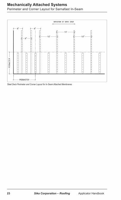
Mechanically Attached SystemsPerimeter and Corner Layout for Sarnafast In-Seam
Steel Deck Perimeter and Corner Layout for In-Seam Attached Membranes

Sika Corporation – Roofing Applicator Handbook 24
Engineered SystemThe Engineered System uses Sarnabar, a U-shaped steel bar that is fastened over Sarnafil S 327 membrane and into the roof deck, effectively clamping the membrane in place. The Sarnabar is then covered with a strip of pre-cut flashing membrane. Sarnabars are not to be installed in the seam overlap.
Note: Before installing textured membrane, make sure the textured side of the membrane is facing up.
Mechanically Attached SystemsBar and Coverstrip Engineered System
Engineered System

25 Sika Corporation – Roofing Applicator Handbook
Mechanically Attached SystemsBar and Coverstrip Engineered System
Installing Sarnafasteners
Note: Sarnabar and fastener spacing layout are noted in the project specifications.
1. Unroll Sarnafil S 327 and position with a 3” (76 mm) overlap over the properly prepared substrate.
2. Weld membrane overlaps using approved hot-air welding equipment. Note: metal tracks may be required for the automatic welder to run on to minimize wrinkles when welding.
3. Position Sarnabar on top of the roof membrane according to the specified spacing requirement.
4. Leave a ¼” (6.4 mm) gap at the ends of the Sarnabar. Install an extra piece of roof membrane as a protection pad over and under.
5. Install Sarnafasteners into the holes in the Sarnabar according to specified spacing require-ment. Install Sarnafasteners into structural deck using proper equipment. Sarnafasteners are to be tight to the Sarnabar.
Protection pad at joint

Sika Corporation – Roofing Applicator Handbook 26
Welding protection pad
Welding coverstrip
Mechanically Attached SystemsBar and Coverstrip Engineered System Membrane Installation
6. Tack weld the protection pad in place.
7. Hot-air weld a 8” (20.3 cm) S 327 coverstrip over the Sarnabar with approved hot-air welding equipment.
8. Refer to WELDING section for seam welding procedures.

27 Sika Corporation – Roofing Applicator Handbook
RhinoBond SystemThe RhinoBond system uses the Sarnadisc RhinoBond which is a polymer coated plate used with S 327 and Sikaplan Fastened membrane and Sarnafasteners to attach the insulation or cover boards directly to the roof deck or structural purlins. The roof membrane is then welded to the Sarnadisc RhinoBond by induction welding
Note: Before installing textured membrane, make sure the textured side of the membrane is facing up.
Roof Deck Attached Grid System
RhinoBond SystemIntroduction
Purlin Attached Metal Retrofit
Sika Corporation – Roofing Applicator Handbook 28
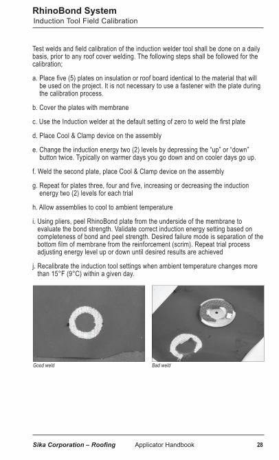
Good weld Bad weld
Test welds and field calibration of the induction welder tool shall be done on a daily basis, prior to any roof cover welding. The following steps shall be followed for the calibration;
a. Place five (5) plates on insulation or roof board identical to the material that will be used on the project. It is not necessary to use a fastener with the plate during the calibration process.
b. Cover the plates with membrane
c. Use the Induction welder at the default setting of zero to weld the first plate
d. Place Cool & Clamp device on the assembly
e. Change the induction energy two (2) levels by depressing the “up” or “down” button twice. Typically on warmer days you go down and on cooler days go up.
f. Weld the second plate, place Cool & Clamp device on the assembly
g. Repeat for plates three, four and five, increasing or decreasing the induction energy two (2) levels for each trial
h. Allow assemblies to cool to ambient temperature
i. Using pliers, peel RhinoBond plate from the underside of the membrane to evaluate the bond strength. Validate correct induction energy setting based on completeness of bond and peel strength. Desired failure mode is separation of the bottom film of membrane from the reinforcement (scrim). Repeat trial process adjusting energy level up or down until desired results are achieved
j. Recalibrate the induction tool settings when ambient temperature changes more than 15°F (9°C) within a given day.
RhinoBond SystemInduction Tool Field Calibration

29 Sika Corporation – Roofing Applicator Handbook
Two RhinoBond systems are offered:• Grid System• Metal Retrofit (for purlin attachment)
Grid System - Fasten the insulation to the substrate using the Sarnadisc RhinoBond and the appropriate Sarnafastener at the rates noted in Table 1 for the corresponding uplift approval. Plates and fasteners should be installed in a “grid like” pattern. See images on page 32 for corner and perimeter Sarnadisc RhinoBond plate layout. Top board can be soldiered (not staggered) to maintain grid pattern, however board joints must be staggered from any underlying board layers.
Metal Retrofit System- Fasten the insulation to the purlins using the Sarnadisc RhinoBond and Sarnafasteners at the rates noted in Table 2 for the corresponding uplift approval. The insulation boards will need additional fastening to ensure a minimum of 6 fasteners per 4 ft x 8 ft (1.2 by 2.4 m) board. Standard insulation fastening components may be used for this fastening, rather than Sarnadisc RhinoBond.
RhinoBond SystemMembrane Installation Systems

Sika Corporation – Roofing Applicator Handbook 30
1. Weld membrane overlaps using hot-air welding equipment. Refer to WELDING section for seam welding procedures. The membrane seam laps shall not be over/next to a Rhinobond plate.
2. Welding of the membrane to the Sarnadisc RhinoBond shall be done with the RhinoBond induction welding tool. Center the induction welder over the center of the Sarnadisc RhinoBond +/- 1” (25 mm) and weld the plate to the membrane underside.
3. When the induction welding cycle is complete, immediately place a Cool & Clamp magnetic weight on the welded assembly. This device must remain in place for at least 60 seconds. Keep Cool & Clamp wiped clean, magnets attract metal pieces which may create holes in the membrane over plates.
4. A standard plunger can be used to verify if there are plates that are not welded.
RhinoBond SystemMembrane Installation
Membrane Overlaps Welded
Welding of Membrane to the Disk
Cool & Clamp Weights (new clamps)
Plunger Test
31 Sika Corporation – Roofing Applicator Handbook
RhinoBond System
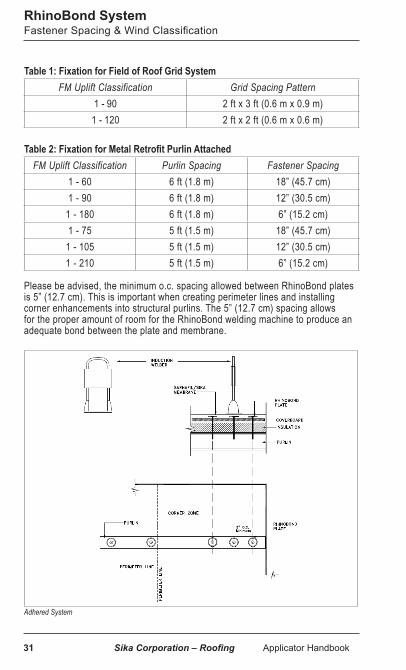
Table 1: Fixation for Field of Roof Grid SystemFM Uplift Classification Grid Spacing Pattern
1 - 90 2 ft x 3 ft (0.6 m x 0.9 m)1 - 120 2 ft x 2 ft (0.6 m x 0.6 m)
Table 2: Fixation for Metal Retrofit Purlin AttachedFM Uplift Classification Purlin Spacing Fastener Spacing
1 - 60 6 ft (1.8 m) 18” (45.7 cm) 1 - 90 6 ft (1.8 m) 12” (30.5 cm)
1 - 180 6 ft (1.8 m) 6” (15.2 cm) 1 - 75 5 ft (1.5 m) 18” (45.7 cm)
1 - 105 5 ft (1.5 m) 12” (30.5 cm) 1 - 210 5 ft (1.5 m) 6” (15.2 cm)
Fastener Spacing & Wind Classification
Please be advised, the minimum o.c. spacing allowed between RhinoBond plates is 5” (12.7 cm). This is important when creating perimeter lines and installing corner enhancements into structural purlins. The 5” (12.7 cm) spacing allows for the proper amount of room for the RhinoBond welding machine to produce an adequate bond between the plate and membrane.
Adhered System

Sika Corporation – Roofing Applicator Handbook 32
RhinoBond SystemGrid Patterns
2’x3’ Insulation Fastening Grid
2’x2’ Insulation Fastening Grid

33 Sika Corporation – Roofing Applicator Handbook
Adhered Systems Introduction
Adhered System Sika - Roofing has four types of Adhered Systems using either solvent based, water based, or urethane low rise foam Sarnacol adhesives or self-adhered membrane. When adhering membrane direct to approved substrates or pre-secured insulation / roof boards, surfaces must be free and clear of dirt, dust, and debris. The insulation / roof boards shall be secured to the roof deck by either fasteners and plates or Sarnacol insulation adhesive.
Note: Before installing textured membrane, make sure the textured side of the membrane is facing up.
Adhesive coverage rates vary by substrate and ambient weather conditions. Refer to the coverage rate table in the Insulation or Roof Board Installation section or Sika’s Adhesive Selection Guide on the Sika - Roofing website for typical coverage rates and limitations.
Adhered System

Sika Corporation – Roofing Applicator Handbook 34
Adhered Systems Solvent Based Adhesive Installation (Bareback Membrane)
Sarnacol 2170 / Sarnacol 2170 VC ApplicationNotes: i. Do not install when air temperature is within 5º of dew point.ii. No adhesive shall be applied in seam areas. iii. Coverage rate averages 60 – 70 ft2/gal (5.6 – 6.5 m2/L). The coverage rate may vary depending on substrate porosity, ambient temperature, and experience.iv. The Applicator shall count the number of pails of adhesive used per area per day to verify conformance to the specified adhesive rate.1. Over the properly installed and prepared substrate surface, adhesive shall be
applied using solvent-resistant 3/4” (19 mm) nap rollers. The adhesive shall be applied to the substrate at a rate according to Sika - Roofing requirements.
2. The adhesive shall be applied in smooth, even coats with no gaps, globs, puddles or other inconsistencies. Only an area which can be completely covered by membrane in the same day’s operations shall be coated with adhesive. Substrate adhesive shall be allowed to dry completely
3. Unroll membrane over dried adhesive, adjacent sheets shall be overlapped 3” (75 mm). Fold back half of the membrane to receive adhesive. Apply to the back of membrane.
4. Wait for adhesive on the underside of the membrane to become “tacky” to the touch. (produces strings when touched with dry finger). Roll onto previously coated substrate. Do not allow adhesive on underside of membrane to dry.
5. Roll membrane using a 75 lb (34 kg) minimum steel weighted roller immediately after laying the membrane into place to insure full contact with the adhesive. The remaining unbonded half of the sheet shall be folded back and the procedure repeated.
6. Weld membrane overlaps using hot-air welding equipment. Refer to WELDING section for seam welding procedures.
Apply Substrate Adhesive Apply Adhesive to back of membrane
“Tacky” Adhesive Rolling Membrane

35 Sika Corporation – Roofing Applicator Handbook
Adhered Systems Solvent Based Adhesive Installation (Feltback Membrane)
Feltback MembraneGeneral
Feltback membrane may be difficult to reposition over irregular surfaces. To minimize repositioning, unroll the membrane 6 ft. (1.8 m) and line up with the lap line. Then completely unroll the membrane. Alternately, a layer of polyethylene can be unrolled prior to unrolling the feltback membrane. The polyethylene will act as a slip sheet for positioning the feltback membrane. Remove the polyethylene sheet after the feltback membrane is in position.
a. Over the properly installed and prepared substrate surface, Sarnacol 2170 or Sarnacol 2170 VC adhesive shall be applied using solvent-resistant ¾” (19 mm) nap paint rollers. The adhesive shall be applied to the substrate at a rate according to Sika - Roofing requirements. No adhesive is applied to the back of the feltback membrane. The adhesive shall be applied in smooth, even coats with no gaps, globs, puddles or other inconsistencies. Only an area which can be completely covered with membrane in the same day’s operations shall be coated with adhesive. The first coat of adhesive shall be allowed to dry completely prior to installing a second coat of 2170 or 2170 VC.
b. Apply the second coat of 2170 or 2170 VC the width of the membrane roll. The feltback roof membrane is unrolled immediately into the second coat of wet adhesive. Adjacent to the first installed roll of membrane, another second coat of wet adhesive is applied and the second roll of membrane is immediately unrolled into it, overlapping the first roll by 3” (75 mm) or butt felt backing. This process is repeated throughout the roof area. Immediately after application into adhesive, each roll shall be pressed firmly in place with a minimum 75 lb (34 kg) steel weighted roller by rolling in both directions. Do not allow the second application of adhesive to dry before installing the membrane.
c. Weld coverstrips at all feltback roll ends and other seams that do not have a factory selvage edge.
d. Night Tie In: Unprotected feltback membrane will wick and hold substantial amounts of water. It is important that the night tie in protect the edges of the feltback to prevent wicking and adhesion/welding problems.

Sika Corporation – Roofing Applicator Handbook 36
Water Based Adhesive Installation (Roller)Adhered Systems
Sarnacol 2121 / Sikaplan Single-Step (SSS) Roller ApplicationNotes: i. Use Sarnacol 2121 / SSS adhesives for bonding membranes to acceptable
substrates up to 2/12 slope. ii. Do not allow adhesive to skin-over or surface-dry prior to membrane installation.iii. Coverage rate averages 100 ft2/gal (2.47 m2/L). The coverage rate may vary
depending on substrate porosity, ambient temperature, and experience.iv. The Applicator shall count the number of pails of adhesive used per area per day to
verify conformance to the specified adhesive rate. v. No adhesive shall be applied in seam areas. vi. Initial set time is 24 - 72 hours or more depending on substrate, ambient
temperature, and humidity. Set up time increases due to an increase in humidity and/or a decrease in temperature. Do not install when outdoor or substrate temperatures during drying period are expected to fall below 40ºF (5ºC).
vii. Newly installed areas of roofing must be protected from exposure to high winds and/or pressure from the underside. This may include edge securement and temporary ballast.
1. Mix adhesive with a mechanical mixer until a smooth consistency is achieved. 2. Apply using a 3/8” - 1/2” (9.5 mm – 12.7 mm) medium nap roller. The adhesive is
applied to the substrate only. 3. The adhesive is poured onto the
substrate and is rolled and spread evenly. Using rollers up to 18” (45.7 cm) wide will improve application time
4. To insure a wet lay in, it is recommended that only 3 - 4 ft (0.9 - 1.2 m) is coated ahead of the membrane.
5. The membrane should be aligned by pulling the sheets back lengthwise rather than using the “barn door” method. The barn door method will result in long open times likely resulting in dry laid membrane.
Pouring Sarnacol 2121
Rolling Sarnacol 2121

37 Sika Corporation – Roofing Applicator Handbook
6. The membrane is then rolled into the adhesive while it is still wet and immediately broomed into place with a medium bristle push broom to work out any air bubbles. Push the broom down the center of the sheet followed by brooming out from the center on both sides.
7. Immediately after brooming, roll the membrane in both directions with a minimum 75 lb (34 kg), steel, roller.
8. Clean any adhesive residue on the seams while still wet and before welding. If the adhesive dries in the seam it will require a solvent to clean it.
9. Weld membrane overlaps. Refer to WELDING section for seam welding procedures.
Water Based Adhesive Installation (Roller)Adhered Systems
Brooming Membrane
Rolling Membrane
Feltback Membrane - GeneralFeltback membrane may be difficult to reposition over irregular surfaces. To minimize repositioning, unroll the membrane 6 ft. (1.8 m) and line up with the lap line. Then completely unroll the membrane. Alternately, a layer of polyethylene can be unrolled prior to unrolling the feltback membrane. The polyethylene will act as a slip sheet for positioning the feltback membrane. Remove the polyethylene sheet after the feltback membrane is in position.a. Over the properly installed and prepared substrate surface, apply Sarnacol 2121 adhesive according to the application instructions above for Roller Method or Spray Method. No adhesive is applied to the back of feltback membrane. Wet lay in is required, do not allow the adhesive to skin over or surface to dry prior to the installation of the feltback membrane.b. Weld coverstrips at all feltback roll ends and other seams that do not have a factory selvage edge.c. Weld all seams.

Sika Corporation – Roofing Applicator Handbook 38
Sarnacol 2121 / Sikaplan Single-Step (SSS) Spray ApplicationNotes: i. Use Sarnacol 2121 / SSS adhesive for bonding membranes to acceptable
substrates up to 2/12 slope. ii. Do not allow adhesive to skin-over or surface-dry prior to membrane installation.iii. Coverage rate averages 133 ft2/gal (2.47 m2/L). The coverage rate may vary
depending on substrate porosity, ambient temperature, and experience. iv. The Applicator shall count the number of pails of adhesive used per area per day to
verify conformance to the specified adhesive rate. v. Initial set time is 24 - 72 hours or more depending on substrate, ambient tempera-
ture, and humidity. Set up time increases due to an increase in humidity and/or a decrease in temperature. Do not install when outdoor or substrate temperatures during drying period are expected to fall below 40º F (5º C).
vi. Newly installed areas of roofing must be protected from exposure to high winds and/or pressure from the underside. This may include edge securement and temporary ballast.
vii. No adhesive shall be applied in seam areas.
Prepare the membrane to be adhered by aligning as many rolls as are to be installed in a day. Unroll the membrane completely and position it to achieve the required overlap. The membrane can be either rolled back or pulled back as shown below. Do not use the “barn door” method of opening the sheets when spraying adhesive as this will result in long open times and likely dry laid membraneStart the airless sprayer with the pressure setting low and make adjustments upwards until the spray pattern is even without “tails” or “fingers”. Run the spray pump at the lowest pressure setting possible while still achieving a good spray pattern. The lower the pressure the less overspray and bounce back preserving material and minimizing cleanup.Adhesive should not be applied more than 3 - 4 ft (0.9 - 1.2 m) in front of the membrane. While moving the gun from side to side it is recommended to trigger the gun on and off when reaching the edge. This will prevent buildup at the edges and prevent contaminating the seams when rolled with the weighted roller. It is not necessary to overlap the preceding pass assuming proper coverage is obtained. The membrane is rolled/pulled into place immediately. The membrane must be broomed immediately if there are air bubbles. Run the broom down the middle of the sheet and then push from the middle out to each edge. Brooming works much better in removing air pockets but rolling with the 75 lb (34 kg) weighted roller immediately after or concurrent with brooming is also critical to insure proper embedment into the adhesive. Clean all overspray out of the laps while the adhesive is still wet and before welding. Most airless sprayers have the capability of attaching one or more pressure rollers. With a pressure roller, the adhesive is pumped through the spray gun to a slotted, medium nap roller and controlled by the gun trigger. This can be a good option on windy days.
Adhered Systems Water Based Adhesive Installation (Spray)

39 Sika Corporation – Roofing Applicator Handbook
Membrane Rolled Back Method By rolling the membrane back evenly there is very little chance of dry laying the sheet as brooming and rolling can follow immediately behind the sheet while the adhesive is wet.
This is typically a 5 man operation.1 - Spray operator1 - Hose man/monitor keeping the hose out of the way and alerting the spray operator of roof obstacles and roof perimeter.1 - Man rolling membrane into place and following right behind with a weighted roller.1 - Man assisting with rolling and making sure any overspray is quickly removed from the seam area of the preceding sheet.1 - Man attending the spray rig and assuring adhesive is mixed and the spray bucket is full.
Adhered Systems Water Based Adhesive Installation (Spray)
Membrane Pulled Back MethodWhen the sheets are pulled back rather than rolled back, it takes 2 workers to pull the sheet into the wet adhesive and it delays brooming and rolling until the top sheet is out of the way.
This method requires a minimum of 6 workers. 1 - Spray operator1 - Hose man/monitor keeping the hose out of the way and alerting the spray operator of roof obstacles and roof perimeter.2 - Men pulling the sheet into place.1 - Man brooming/rolling with a weighted roller.1 - Man attending spray rig and assuring adhesive is mixed and the spray bucket is fullFeltback Membrane, General Feltback membrane may be difficult to reposition over irregular surfaces. To minimize repositioning, unroll the membrane 6 ft. (1.8 m) and line up with the lap line. Then completely unroll the membrane. Alternately, a layer of polyethylene can be unrolled prior to unrolling the feltback membrane. The polyethylene will act as a slip sheet for positioning the feltback membrane. Remove the polyethylene sheet after the feltback membrane is in position.a. Over the properly installed and prepared substrate surface, apply Sarnacol 2121
adhesive according to the application instructions above for Roller Method or Spray Method. No adhesive is applied to the back of feltback membrane. Wet lay in is required, do not allow the adhesive to skin over or surface to dry prior to the installation of the feltback membrane.
b. Weld coverstrips at all feltbackroll ends and other seams that do not have a factory selvage edge.
c. Weld all seams.
Rolling back membrane
Pulling back membrane

Sika Corporation – Roofing Applicator Handbook 40
A. Sarnacol AD Feltback Membrane Adhesive:Application rates vary depending on surface roughness, absorption rate of the substrate, and wind speed approvals. Typical coverage rates for the box sets are 25 - 30 squares per 10 gallons. Coverage rates are based on 12” (30.4 cm) on center maximum spacing.
1. Box Sets: Install Part A and Part B components following instructions on the packaging. Always insure that the Part A and Part B containers are always hooked to the same dispensing holders or hoses (i.e. do not reverse the dispenser holders and hoses between Part A and Part B). All valves on the dispensing unit must be completely opened so a 1:1 ratio is achieved when moving the adhesive through the disposable mix tip and onto the substrate in a semi-liquid state. Apply the Sarnacol AD Feltback Membrane Adhesive directly to the substrate, using a ribbon pattern. Space the 1” (25 mm) wide beads at a maximum of 12” (30 cm) o.c. to achieve proper coverage rate. Actual ribbon spacing will depend on the wind uplift rating required. Allow the adhesive to begin to rise before placing the feltback membrane into the adhesive. The adhesive is designed to provide approximately 5 - 10 minutes of open time during a typical summer day. The membrane must be positioned and rolled into place quickly. A heavy steel roller must be used to roll the membrane.
2. Cartridge Application: Remove the plastic plugs from the cartridge mixing head. Attach a mixing tip to the threaded mixing head. Place the cartridge into the applicator. When starting a new tube, some of the material should be pumped out initially into a bucket or other suitable receptacle to make sure of a proper mix. Apply the Sarnacol AD Feltback Membrane Adhesive directly to the substrate, using a ribbon pattern. Space the 1” (25 mm) wide beads at a maximum of 12” (30 cm) o.c. to achieve proper coverage rate. Actual ribbon spacing will depend on the wind uplift rating required. Allow the adhesive to begin to rise before placing the feltback membrane into the adhesive. The adhesive is designed to provide approximately 5 - 10 minutes of open time during a typical summer day. The membrane must be positioned and rolled into place quickly. A heavy steel roller must be used to roll the membrane.
Adhered Systems Urethane Adhesive Installation Using Feltback Membrane
Gun application

41 Sika Corporation – Roofing Applicator Handbook
B. Sarnacol OM Feltback Membrane Adhesive:Application rates vary depending on surface roughness, absorption rate of the substrate, and wind speed approvals. Typical coverage rates for the box sets are 10 - 20 squares per 10 gallons. Typical coverage rates when using the cartridge is 4 - 6 squares per case (four 1500 ml cartridges). All coverage rates are based on 12” (30.5 cm) on center maximum spacing.
1. PaceCart2 Installation: Install Part A and Part B components following instructions on the packaging. Always insure that the Part A and Part B containers are always hooked to the same dispensing holders or hoses (i.e. do not reverse the dispenser holders and hoses between Part A and Part B). All valves on the dispensing unit must be completely opened so a 1:1 ratio is achieved when moving the adhesive through the disposable mix tip and onto the substrate in a semi-liquid state. Apply the adhesive directly to the substrate, using a ribbon pattern. Space the 1” (25 mm) wide beads at a maximum of 12” (30 cm) o.c. to achieve proper coverage rate. Actual ribbon spacing will depend on the wind uplift rating required. Allow the adhesive to turn to a caramel color (normally 10 - 15 minutes) before placing the feltback membrane into the adhesive. The adhesive is designed to provide approximately 10 - 15 minutes of open time during a typical summer day. The membrane must be positioned and rolled into place quickly. A heavy steel roller must be used to roll the membrane.
2. SpotShot Applicator: Remove the plastic plugs from the cartridge mixing head. Attach a mixing tip to the threaded mixing head. Place the cartridge into the applicator. When starting a new tube, some of the material should be pumped out initially into a bucket or other suitable receptacle to make sure of a proper mix. Apply the Sarnacol OM adhesive directly to the substrate, using a ribbon pattern. Space the 1” (25 mm) wide beads at a maximum of 12” (30 cm) o.c. to achieve proper coverage rate. Actual ribbon spacing will depend on the wind uplift rating required. Allow the adhesive to turn to a caramel color (normally 10 - 15 minutes) before placing the feltback membrane into the adhesive. The adhesive is designed to provide approximately 10 - 15 minutes of open time during a typical summer day. The membrane must be positioned and rolled into place quickly. A heavy steel roller must be used to roll the membrane. Unused adhesive can be used at a later date by simply replacing the mixing tip.
Adhered Systems Urethane Adhesive Installation Using Feltback Membrane
Cart and hose application

Sika Corporation – Roofing Applicator Handbook 42
C. Sarnafil G 410 SA Membrane:The surface of the insulation or substrate shall be inspected prior to installation of the Sarnafil roof membrane. The substrate shall be clean, dry, free from debris and smooth with no surface roughness or contamination. Broken, delaminated, wet or damaged insulation boards shall be removed and replaced.
1. Sarnafil G 410 SA Membrane is installed after proper preparation of the approved substrate.
2. The membrane is unrolled and positioned in place with the selvage edge lapping the adjacent roll to allow for the 3” (76 mm) side lap.
3. Fold back half the sheet onto itself in the long direction and carefully cut the release liner without damaging the membrane. Peel back 3 - 5” (76 - 127 mm) of the release liner and press firmly into the substrate. Weight may be necessary on the membrane when first starting.
4. Continue removing the release liner from the membrane in a smooth, wrinkle-free manner while maintaining the 3” (76 mm) side lap. Immediately roll the membrane with a minimum 75 lb (34 kg) steel roller.
5. Remove the remaining release liner from the other half of the membrane using the same process as described above and immediately broom and then roll the membrane with the steel roller.
6. Sarnafil G 410 SA Membrane side lap seams are heat-welded together by trained operators using hot-air welding equipment. End laps and all cut edges are butted together and an 8” (20.3 cm) Sarnafil G 410 coverstrip is hot-air welded over the butt and cut edge joints.
Adhered Systems Self-Adhered Membrane

43 Sika Corporation – Roofing Applicator Handbook
Hybrid SystemsIntroduction
Sika - Roofing has a Hybrid System that makes use of a top G 410 Feltback Membrane with SBS modified bitumen products in the layers below.
Although Hybrid systems are layered differently, and SBS modified bitumen layers are included, installation instructions for the other layers remain the same as they are in Adhered Sarnafil systems. However, the order of installation may vary depending on the specified system. Refer to the appropriate section(s) in this handbook for the proper installation instructions.
Hybrid Systems

Sika Corporation – Roofing Applicator Handbook 44
Hybrid SystemsBase Sheet Installation
Base Sheet NB 48 and Base Sheet NB 120: Notes: i. Base sheets shall be installed according to manufacturer’s instructions.
ii. Base sheets shall be neatly cut to fit around penetrations and projections.
iii. Do not install more base sheets than can be covered with membrane by the end of the day or the onset of inclement weather.
1. Unroll Base Sheet NB 48 or NB 120 and allow it to relax. Mechanically fasten Base Sheet NB 48 or NB 120 to the deck with approved fasteners and plates at a rate according to Sika’s recommendations for fastening rates and patterns.
2. Apply uniform tension to Base Sheet NB 48 or NB 120 and begin fastening at the center of the sheet. Work toward the end laps pushing out all wrinkles and buckles.
3. Install fasteners in accordance with fastener manufacturer’s recommendations achieving minimum penetration into the LWIC deck as recommended by the fastener manufacturer and Sika.
4. Overlap each sheet by 3” (76 mm) on the side lap and 6” (15.2 cm) on the end laps.
45 Sika Corporation – Roofing Applicator Handbook
Décor Roof Systems Introduction
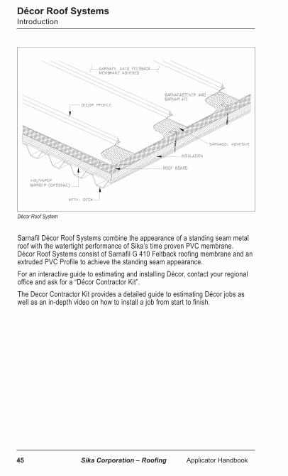
Sarnafil Décor Roof Systems combine the appearance of a standing seam metal roof with the watertight performance of Sika’s time proven PVC membrane. Décor Roof Systems consist of Sarnafil G 410 Feltback roofing membrane and an extruded PVC Profile to achieve the standing seam appearance.For an interactive guide to estimating and installing Décor, contact your regional office and ask for a “Décor Contractor Kit”.The Decor Contractor Kit provides a detailed guide to estimating Décor jobs as well as an in-depth video on how to install a job from start to finish.
Décor Roof System

Sika Corporation – Roofing Applicator Handbook 46
Décor Roof SystemsGeneral Preparation and Installation
General***Special Note: Décor Roof Systems are an aesthetic roofing system. Extra time should be allowed when installing a Décor Roof System. Applicators who have not previously installed a Décor roof are required to attend a Décor training seminar. In addition, a Sika - Roofing technician must be on site for the first day of rib installation.Working on SlopesSteeper slopes present numerous challenges. Appearance is an important feature of a Décor roof. The steeper the roof, the greater the care required to achieve aesthetic objectives during installation.Membranes are slippery when wet or covered with snow, frost or ice. Working on sloped surfaces under these conditions is hazardous. Appropriate safety measures must be implemented prior to working on such surfaces. Always follow OSHA and other relevant fall protection standards when working on sloped roofs.A properly staged roof can keep foot traffic to a minimum and reduce the likelihood of slips and falls. An applicator who decides to eliminate the staging and just go with harnesses may not only be putting his workers at more risk but ultimately be hurting his chances of installing a great looking roof. Workers who feel safe on the roof will be more likely to take their time and install the roof properly than to rush the job so that they can get done faster.Wearing the proper footwear will make working on slopes safer and more comfortable. Certain slip resistant shoes or overshoes are available from a number of different suppliers. The overshoes can be put on as needed when working directly on the membrane providing the added benefit of having clean soles and not scuffing the membrane or transferring contaminants. Please see Technical Bulletin: Slippery Roof Personal Protection Equipment #02 - 10.Roof SubstratesThe condition of the roof deck is of utmost importance. A concrete deck which is spalled or uneven may cause the finished assembly to look uneven. Surface preparation to fill low spots or grind down high spots may be required. The same is true for steel or wood that may be loose or uneven. Thin gauge metal decking, (less than 22 gauge) can cause the finished product to look uneven and create telegraphing of the underlying substrate due to deflection. In all cases a pre-inspection of the roof deck must be conducted prior to installation to determine what remedial action, if any, should be taken.Insulation InstallationPlease refer to the “Insulation Installation” in the Insulation Attachment section for the proper installation of insulation.It is critical that all insulation layers and cover boards be installed properly. Board joints must be butted tightly and all cut edges must be straight and even to prevent gaps. Gaps or high spots will telegraph through the membrane affecting the final appearance. When using mechanical fastening for the insulation or roof board, it is important not to overdrive the fasteners. It is recommended that the low profile insulation plates be used or that the top layer be adhered whenever possible. Low profile plates have a slight protrusion on the bottom side which will make it difficult to install flush on hard surfaces.

47 Sika Corporation – Roofing Applicator Handbook
When a roof board is installed, it may be necessary to countersink the screw hole to allow for the metal protrusion to penetrate. This can be done simply by taking the corner of the low profile plate and turning it with hand pressure to score the top of the facer sufficiently for the plate to penetrate. Standard Sarnaplates can be used but may telegraph through the membrane more so than the low profile plate. Use 4 ft x 8 ft (1.2 m x 2.4 m) insulation and or roof boards where possible to reduce the amount of board joints.When using an insulation adhesive to secure the top layer it is critical that all rising adhesive be kept away from board joints and removed from the finished surface. To avoid getting too much adhesive in the board joints, a good recommendation is to place the adhesive on the underside of the board before lying in place rather than applying the adhesive directly to the substrate. On sloped or uneven surfaces it may be necessary to provide temporary securement to the boards while the insulation adhesive is curing. This can usually be done by adding a few screws (which should be removed after the adhesive has cured). Scoring the insulation or roof board facer to make the board conform better is unacceptable as this practice could lead to facer delamination and decreased wind uplift performance.Membrane InstallationPlease refer to the “Installation of Feltback Membrane” in the Adhered Systems section for general installation of membrane. Adhesive ApplicationThe feltback membrane only has one selvage edge. Sheet layout will determine whether welding will be done upslope or down. See “welding membrane” section for more on this. To achieve a consistent looking finished surface, the adhesive must be applied in a smooth even manner avoiding puddles and dry spots. Puddles of adhesive may result in blistering while dry laid areas may wrinkle or sag. All temperature and weather restrictions for storage and application are the same as with any Sika - Roofing adhered application. With a Décor system these precautions are even more critical, especially with adhesive application regarding blistering and condensation. Late afternoon adhesive application could result in condensation forming and resulting in poor adhesion. When the temperature is within 5 degrees of the dew point, condensation can occur and roofing should be suspended. In extreme heat, the bonding adhesives will dry quickly. It is critical that no more adhesive is applied ahead of the membrane than can be covered before drying. Dry laid membrane may not be visible right away but the use of a plunger after a reasonable drying period can help determine whether the membrane is properly adhered. When laying out membrane, the butterfly (or barn door) method is not recommended. This method is more likely to result in dry laid membrane and it may also leave a crease down the middle of the sheet where it was folded. By using the “back rolled method” where the membrane is pulled back lengthwise, it is easier to control adhesive drying time and eliminate creases.When aligning seam overlaps, it is critical to use the red line for sheet alignment rather than butting the edges of felt. As the width of the selvage edge may vary from roll to roll, aligning on the red line may result in the felt overlapping and creating a slight high spot along the seam. This high spot should not be a concern as a rib will be positioned alongside making the felt overlap much less noticeable.
Décor Roof Systems General Preparation and Installation
Sika Corporation – Roofing Applicator Handbook 48
If the seam alignment is done by butting the edges of the felt there will be inconsistent rib spacing. The distance of felt from the edge may vary but the red line position should be very consistent.The width of the membrane selvage edge may vary slightly and is typically wider than the weld area. It is important to apply adhesive to the back side of the selvage edge area to avoid an unadhered strip running the length of the sheet. Adhesive must be kept away from the 1.5” weld area.After the membrane is laid into the adhesive it should be immediately broomed followed immediately by rolling with a 75 lb (34 kg), or heavier, weighted roller. Brooming alone is not sufficient. On steep slopes the roller will need to be tied off and lowered down from above. Ensuring that the feltback membrane is sufficiently rolled into the adhesive is one of the most important aspects to achieving a smooth looking finished product. A 75 lb (34 kg) minimum, weighted roller is recommended wherever practical. The weight concentrated into the small, hard, steel rollers, which can move independently, works well to force the felt into the wet adhesive. It is important to take care when turning the roller to prevent wrinkling of the sheet.On very steep slopes or vertical applications it can be difficult to roll properly. Rolling should not be taken lightly as it is a critical component to a proper looking Décor roof. Brooming alone is not sufficient. Large, steel hand rollers can make rolling much easier and more effective when working on hard to reach areas. Rolling on vertical surfaces is dependent on sufficient hand pressure to force the felt into the adhesive.Welding MembraneTo prevent blistering near the seam area, welding must be done either immediately after the sheet is adhered or waiting a minimum of 2 hours.Welding seams on slopes can be done either upslope or down slope. Membrane layout, (left to right or right to left) must be established based on welding direction as the selvage edge is only available on one side of the sheet. When membrane is unrolled from high to low the selvage edge will be aligned for downhill welding. The sheets will have to be turned for uphill welding. It is preferable to weld uphill as downhill welding could strain the Sarnamatic drive gear and cause premature wear. In either case a rope should be tied to the Sarnamatic for safety. If welding downhill, the rope should be held by another person above the machine keeping tension on the rope to reduce tension on the drive gear.When welding upslope it may be necessary to increase the speed beyond what would normally be used on a flat surface to prevent burning. When welding downhill it may be necessary to decrease the speed to insure a proper weld. The best approach is to first run the welder cold to see if it is capable of traveling uphill or downhill on the slope without slipping. Cleaning the Sarnamatic wheels with a solvent based cleaner will improve traction and also help to keep the membrane clean. Do not use solvent based cleaners on the exposed membrane. The use of solvent based cleaner may cause a slight discolor-ation to the membrane if you go beyond the overlap or use directly on the surface of the membrane.
Décor Roof SystemsGeneral Preparation and Installation

49 Sika Corporation – Roofing Applicator Handbook
Décor ProfileA 1-¼ x ¾” (32 x 19 mm) high x 10 ft. (3.05 m) long PVC extrusion, used to simulate the appearance of a standing seam metal rib roof system.
Either the Sarnamatic hot-air welder with the appropriate “kit” or a hand welder can be used to attach the Décor Profile (ribs) to the membrane. The following instructions apply to both methods.
The Décor ribs shall be installed parallel with the roof slope where possible. The top surface of membrane must be clean to obtain a proper weld of the Décor ribs and to enable positive traction for the Sarnamatic welding equipment. Clean and dry the welding area of roof membrane. If the membrane is only slightly dirty it can be cleaned with water and a damp rag. Otherwise, a sponge or mop and a solvent-free cleaner such as Simple Green or Orange ZEP can be used. Use only solvent-free cleaners on Décor membranes. It is advantageous to install the Décor ribs as soon after membrane installation as possible to avoid the need for heavy cleaning.
Preparation for Installation Pre-assemble the Décor ribs to create the required length using the plastic connectors provided. Insert a connector into the end of one Décor rib and insert the exposed portion of the connector into a second Décor rib.
Décor ProfileFor the Décor Profile leave approximately ½” (12.7 mm) between the two preassembled Décor Profile sections. While kneeling down, place a hand welder between your knees with the nozzle facing away from you. Holding the Décor Profile sections on each end near the dowel, heat the ends of the Décor Profile for several seconds and firmly press the two sections together. A tack weld is sufficient to hold the sections together. Failure to weld sections together may result in separation while welding the profile to the membrane.
General Preparation for InstallationDécor Roof Systems
Fig. 1.1 Preassembling Décor Profiles

Sika Corporation – Roofing Applicator Handbook 50
Décor ribs should be installed on the top of the overlap directly next to the seam whenever possible. Do not cover the seam. This practice helps to hide the membrane overlaps.
Décor Rib Spacing Additional intermediate rows of Décor ribs may be installed between those on the overlaps according to project specifications. Décor ribs installed on the overlaps will be spaced approximately 75” (1.9 m) apart. The following can be used as a guide for intermediate Décor placement to achieve the look of a metal roof:
Approximate on center distance for Décor profiles2m (6.56 ft) sheet 3m (10 ft) sheet
37-1/2” (95.2 cm) 58” (147.3 cm) One additional intermediate row
25” (63.5 cm) 38-1/2” (97.8 cm) Two additional intermediate rows
18-3/4” (47.6 cm) 29” (73.7 cm) Three additional intermediate rows
Always measure the distance between seams to verify correct Décor rib spacing. Seam width can vary and the distance between the ribs may therefore need to be adjusted on the roof. A closer rib spacing is more effective at masking substrate irregularities. This is a decision based on the designer’s preference but the spacing must be done in such a manner as to allow for even spacing and ribs being positioned alongside every seam.
Once the proper spacing is determined, chalk a line to mark the correct placement of the rib. The chalk line should be adjusted from the correct “on center” spacing to account for the Décor profile flange width of 1-¼” (32 mm)
The chalk line should always be made along the edge of the rib, not at the “on center” measurement. The chalk line placement will depend on the direction the Sarnamatic machine will be welding (up slope vs. down slope) as well as the direction of the membrane overlap. Some chalks, will permanently stain the membrane. Be sure to confirm that chalk can be easily removed before proceeding.
It is recommended that ribs be left short of the eaves and the peak. This is due to the difficulty in running the welder over the edge and secondly, if there is a coverstrip and edge metal at the eave, the additional thickness may cause the rib to look uneven.
Décor Roof SystemsGeneral Preparation for Installation
Fig. 1.2 Positioning Décor on membrane overlap
Fig. 1.3

51 Sika Corporation – Roofing Applicator Handbook
Décor Profile Spacing Layout for 2 m (6.56 ft) Wide Sheet
Décor Profile Spacing Layout for 3 m (10 ft) Wide Sheet
Décor Roof SystemsRib Spacing Layout

Sika Corporation – Roofing Applicator Handbook 52
The Sarnamatic can run either up or down the slope, although up the slope is recommended. Running the machine down the slope could result in premature wear on the drive gears if proper tension is not kept on the machine while welding.
Position the flange of the first rib along the chalk line. Run the rib on the right side of the of the chalk line if you are looking up the slope in order to see the chalked line while welding (left side looking up slope if you are running the machine down slope). The rib must be positioned as close to the line as possible. The rib may stick to the membrane, especially in warm weather. Therefore, do not rely on the Sarnamatic to automatically position and align the rib. Do not tack weld the rib into position as this will interfere with the Sarnamatic welding process.
A safety rope should be used to tie off above the Sarnamatic. One worker should hold the rope to help guide. (Fig. 1.5 & 1.9). The proper speed and temperature of the Sarnamatic are the same as for membrane hot air welding. Position the Sarnamatic with the guide centered on the Décor rib. Using the front guide, position the Décor rib on the chalk line or seam line.
Décor Roof SystemsRib Installation
Fig. 1.5 Safety rope securely attached to the Sarnamatic
Fig. 1.4 Laying out Décor on the chalked lines
Fig. 1.6 Positioning the Décor Guide on the Profile

53 Sika Corporation – Roofing Applicator Handbook
As the machine starts to move keep the guide on the chalk line or seam line. It is critical that the guide remains on the chalk or the seam line. Slight variations in the machine’s direction will result in ribs that are not straight. Regularly check the guide to insure it is tightly secured and cannot move laterally. See Fig. 1.6 for correct guide position. Aesthetics are critical to a satisfactory Décor installation. Allow adequate time to insure a continuous straight line. Due to the slope of the roof, misalignment of Décor is visible from the ground.
Carefully guide the Sarnamatic during the welding process.
Stop the machine approximately 6” (15.2 cm) from the point at which the rib ends. The ribs can stretch during the welding process depending on temperature. The ribs will need to be trimmed evenly.
When welding downhill the ribs may stretch. Welding uphill may cause the rib to shrink as the weight of the welder may cause the rib to contract. This contraction or growth should not affect the appearance or perfor-mance of the membrane but may require adjustments of adding rib length or cutting back on rib length
Stop the ribs 8 to 12” (20.3 - 30.5 cm) before the roof edge. Once trimmed to the proper length, hand weld the last few inches of the ribs. The first few inches of the rib will also need to be hand welded.
Fig. 1.9 Guiding the Sarnamatic along the correct line
When starting a rib weld, it is recommended that a flat piece of metal approximately 6” x 12” be placed in the weld area. This start area will need to be hand welded later. Using a flat screwdriver, lift the rib near the rear wheel and insert the Sarnamatic nozzle underneath, see Fig. 1.8. Then immediately engage the Sarnamatic drive.
Fig. 1.8 Lifting the rib to insert the Sarnamatic nozzle
Décor Roof SystemsRib Installation

Sika Corporation – Roofing Applicator Handbook 54
Using a Hand WelderThere may be situations where the rib will need to be hot-air welded by hand. This will normally occur on very steep sloped roofs (9/12+), when welding short sections of the rib, or when a Sarnamatic is not available.
Membrane preparation is the same as that described for Sarnamatic welding.
Grasp the raised portion of the rib with one hand and lift it off of the membrane enough to get the welder nozzle tip under it. Heat the membrane and the underside of the rib and then press the rib to the membrane using a rubber roller. Follow the chalk line or seam line for a straight weld. Continue in a steady, consistent manner.
Trim the Décor to the proper length as previously described, in the last section.
A method for keeping ribs straight when hand welding is to use a simple straight edge made of sheet metal as shown here. See Fig 1.12
Rib FinishCutting the ribs can be done with a fine toothed saw or with a Rigid pipe cutting tool as shown here. See Fig 1.13. Optional: At the open ends of the decor profile, weld a piece of membrane to close the profile.
Décor Roof SystemsRib Installation
Fig. 1.10 Hand Welding Décor
Fig. 1.12 Simple straight edge
Fig. 1.13 Rib Finish

FlashingWhen flashing penetrations on sloped roofs it is important to cut the flashing membrane to account for the slope and avoid uneven flashings. An example of flashing a pipe penetration on a slope is shown below. Measure slope at pipe base.
Cut membrane at measured angle.
After stretching the flange, flashing is installed over base flashing. Flange is equal width all around.
Décor Roof SystemsDécor Flashing
Sika Corporation – Roofing Applicator Handbook 55

Décor Roof SystemsDécor Repairs
PatchesWhen repairs are required due to punctures, cold welds, misaligned ribs, etc., the repair must be made of membrane that is cut straight and extends from one rib to another. This repair method will maintain the continuity of the system by keeping lines straight whether vertical or horizontal. In other words, small round patches will be very noticeable and not look like something typically seen on a metal roof. For repairs to a puncture where the feltback membrane is left in place the repair can be done with bareback membrane directly over the felt back. If the repair involves cutting out a rib or removing the feltback membrane, the void created by the removal of feltback must be filled completely with new feltback to avoid a crater. The filled space is then overlaid with bareback membrane.
Patches on a Décor roof must be wide enough to cover the surface between adjacent profiles and be no less than 6” (15.2 cm) in height.
CleanersSolvent based cleaners will remove the lacquer finish from the PVC membrane. When the lacquer finish is removed, a dull finish is left behind and the membrane is more susceptible to dirt pick up making these cleaned areas very obvious. Solvent based cleaners should only be used on heavily soiled membrane in seam areas or in locations that are not noticeable.
For general cleaning of lightly soiled membrane or scuff marks in the visible field of the roof, non-solvent based cleaners such as Simple Green or Orange ZEP work well without removing the lacquer coating. After cleaning with these products a dry film may be left behind which should be removed with water.
Patching a Décor Roof
Sika Corporation – Roofing Applicator Handbook 56

57 Sika Corporation – Roofing Applicator Handbook
Décor Roof SystemsDécor Snow Guards
Snow GuardsIn snow prone areas, snow guards are recommended on sloped roof areas to prevent snow from sliding off the roof.
#90 Hybrid Pad-Pipe Style Snow Guard for Membrane Roofs

Sika Corporation – Roofing Applicator Handbook 58
Edge MetalThe Sarnaclad edge metal design is a common choice for Décor due to the available matching colors of the metal and membrane.
Edge metal must be fastened sufficiently to prevent bowing and buckling. Slight irregularities in the edge metal will transfer through the membrane cover strip and take away from the roof’s overall appearance. There are two detail options with Sarnaclad metal, one with a metal fascia cover plate on top, the other eliminating the fascia cover plate on top by using a continuous cleat below, bent at 90 degrees.
Night Tie InUnprotected feltback membrane will wick and hold substantial amounts of water. It is important that the night tie in protect the edges of the feltback to prevent wicking and adhesion/welding problems.
Night tie-ins must be done in such a manner that no cutting of the sheet the next day is required. If the membrane is cut due to contaminants from tie in material, rib alignment will be off due to a shorter distance to the next seam.
One method to tie in is done by using Aluminum Tape and polyethylene. Tape the poly on the membrane side and use one of the urethane foam type products to embed the poly on the deck side. The Aluminum Tape will stick well to the membrane and leave little residue behind. Aluminum Tape is only 2” wide and may require multiple strips to achieve more width for sufficient adhesion. Duct tape or other tapes may leave a stain on the membrane creating long term discoloration or contaminating the weld.
Décor Roof SystemsEdge Metal / Night Tie In

59 Sika Corporation – Roofing Applicator Handbook
General1. All membrane overlaps shall be hot-air welded. Field membrane overlaps
for automatic machine-welding shall be 3” (76 mm) in width. A minimum of 4” (10.2 cm) wide overlap is required at end laps.
2. All mechanics shall have successfully completed a course of instruction provided by a Sika – Roofing representative prior to welding.
3. All surfaces to be welded shall be clean and dry. No adhesive, dirt, or any other material shall be present within the lap areas.
Hand WeldingHand welded seams shall be completed in two stages. Equipment shall be allowed to warm up for at least one minute prior to the start of welding.
1. The back edge of the lap shall be welded with a thin, continuous pre-weld to prevent the loss of hot air during the final welding. Tack welding is not permitted on field sheets.
2. The nozzle shall be inserted into the seam at a 45° angle to the edge of the membrane. Once the proper welding temperature has been reached and the membrane begins to “flow”, the hand roller is positioned perpendicular to the nozzle and pressed lightly. For straight seams, the 1-½” (38 mm) wide nozzle is recommended for use. For corners and compound connections, the ¾” (19 mm) wide nozzle shall be used.
WeldingGeneral / Hand Welding
Pre-Weld Finish Weld

Sika Corporation – Roofing Applicator Handbook 60
Sarnamatic Welding1. Machine welded seams are achieved by the use of Sika – Roofing’s Sarnamatic.
When using this equipment, Sika – Roofing instructions shall be followed and local codes for electric supply, grounding, etc. observed.
2. Dedicated circuit house power or a dedicated portable generator is required. No other equipment shall be operated off the generator.
3. Never tack weld membranes prior to machine welding.4. With any non-adhered membrane, weighted straight 2 x lumber or metal tracks
may be laid on the top sheet approximately 4” (10.2 cm) past the edge of the seam to prevent wrinkles in the sheets while welding to hold in place on windy days.
5. When starting and stopping a weld, it is recommended that a flat piece of metal approximately 6” x 12” be placed in the weld area. These areas will need to be hand welded later.
6. Tack welding of sheets is not an accepted method for holding sheets in place prior to machine welding.
Welding Sarnamatic
Sarnamatic Welder Sarnamatic Seam Weld

61 Sika Corporation – Roofing Applicator Handbook
Quality Control of Welded Seams1. Visible evidence that welding is proceeding acceptably is smoke during the
welding operation, shiny membrane surfaces, and an uninterrupted flow of gray material from the edge of completed welds.
2. On-site evaluation of welded seams shall be made daily by the applicator. 1” (25 mm) wide cross-section samples of welded seams shall be taken at least two times a day, once in the morning and once in the afternoon. Correct welds display failure from shearing of the membrane prior to separation of the weld.
3. Each test cut shall be patched by the applicator at no extra charge to the owner. All completed welded seams shall be checked after cooling for continuity using a rounded flat head screw driver or other suitable blunt object by the roofing applicator.
Quality Control
Checking Seams
Typical seam break of good welds.Top: Polyester scrim reinforced sheet seemsMiddle: Waterproofing glass mat reinforced sheet seemsBottom: Glass mat reinforced sheet seems
Example of seam testing on the field of the roof
Welding

Sika Corporation – Roofing Applicator Handbook 62
This section provides the basic procedures for the flashing of common roof penetrations - outside corner, inside corner, curb, vent stack, and drains. The following is a list of guidelines to follow when installing flashings.
1. All flashings shall extend a minimum of 8” (2.3 cm) above roof level unless otherwise accepted in writing by the owner’s representative and Sika – Roofing Technical Dept.
2. All flashing membranes shall be mechanically fastened along the top edge.3. All details are to be installed concurrently with the remainder of the roofing. No
temporary flashings are acceptable unless approved in writing by the owner’s representative and Sika - Roofing.
4. All flashings are adhered.5. All adhered flashings that exceed 45” (1.14 m) in height shall receive additional
securement, unless applying Sarnafil G 410 SA membrane to plywood, approved gypsum board with primed facer, glass-faced polyisocyanurate, or concrete with a concrete surface profile range of CSP 1 to CSP 4 according to ICRI Technical Guideline No. 310.2R-2013.
6. If any water is allowed to enter under newly completed roofing due to incomplete flashings, the affected area shall be removed and replaced at the applicator’s expense.
Notes:Acceptance of all detail work by Sika – Roofing is subject to the following requirements:
a) All detail work is to be completed by Sika – Roofing trained and authorized roof mechanics.
b) All detail work must be installed in accordance with Sika – Roofing recommended details.
c) If no standard detail applies to a particular field condition, the applicator shall submit a drawing of the proposed detail to the Sika – Roofing Technical Department for consultation and acceptance.
Typical Flashing ProceduresGeneral

63 Sika Corporation – Roofing Applicator Handbook
Typical Flashing ProceduresGeneral
Flashing with MembraneApply a coat of Sarnacol 2170 or 2170 VC adhesive at a rate of ½ gallon per square (0.61 L/m2) onto the flashing substrate and allow to dry. Coverage rate may vary depending on porosity of substrate. The Sarnacol adhesive shall be applied in smooth, even coats with no gaps, globs, or similar inconsistencies. Precut membrane flashing to desired dimension. The membrane flashing shall extend min. 5” (12.7 cm) onto the deck sheet. Apply Sarnacol 2170 or 2170 VC adhesive to the underside of the membrane flashing at a rate of ½ gallon per square (0.61 L/m2).
Do not allow any adhesive in overlaps. When the adhesive on the membrane flashing becomes tacky to the touch (DO NOT LET DRY), apply membrane flashing to the previously-coated flashing substrate being careful to avoid wrinkles. The membrane flashing is to be rolled with a silicone hand roller to ensure full adhesion.
Flashing over Asphalt contaminated surfacesUse G 459, which is a fiberglass-reinforced membrane which can be adhered directly to asphalt flashings and asphalt contaminated surfaces.
Install per instructions above.
Tie-ins between Sika - Roofing membranes and existing asphaltic B.U.R. can be performed with G 459 membrane. Consult Sika – Roofing when tying into coal tar pitch roofs.
Factory-Prefabricated FlashingsFactory-prefabricated flashings are also available for vents and inside and outside corners.
Custom-Prefabricated FlashingsCustom-prefabricated flashings are also available for odd shaped penetrations.
Flashing Overlaps to be Hot-Air WeldedAll overlaps of flashing membrane are to be hot-air welded. For this reason, care must be taken during the application of adhesives to avoid contaminating flashing surfaces that are to be hot-air welded.

Sika Corporation – Roofing Applicator Handbook 64
TerminationsTerminate flashings in accordance with Sika - Roofing recommended details (see Typical Details). Flashings are always hot-air welded to the field sheet to ensure permanent, watertight seams.
Mechanically Attached SystemsThe base of all walls, curbs and penetrations must be secured at the same fastener spacing as the field sheets, to a maximum of 12” (30.5 cm) on center (minimum 4 per penetration). On Engineered Systems, use Sarnabar and cord.
Adhered SystemsThe base of all walls, curbs, penetrations and any angle change greater than 2/12, must be secured using Sarnastop or Sarnadiscs fastened 12” (30.5 cm) on center. When insulation is adhered to the substrate, additional bars may be required in the perimeter zone. Contact Sika - Roofing Technical Department.
Detail Work1. All detail work must be installed in accordance with Sika - Roofing recommend-
ed details.2. If no standard detail applies to a particular field condition, the applicator shall
submit a drawing of the proposed detail to the Sika - Roofing Technical Department for consultation and acceptance.
For Further InformationShould you require additional information, please remember that Sika - Roofing’s in-house technical assistance and training services are available from your regional office. Their purpose is to answer your questions and to provide any other technical information - including application techniques - that you may need to know to install Sika - Roofing systems.
We are here to serve your professional needs. Please contact your local Sika - Roofing regional office if you wish to arrange for a training session or an inspection for system warranties.
Typical Flashing ProceduresGeneral
Refer to Sika website for the most updated details

65 Sika Corporation – Roofing Applicator Handbook
Typical Flashing ProceduresHow To Flash An Outside Corner
1. Install field sheet tight to curb or wall per General instructions.
2. Coat the curb or wall with Sarnacol 2170 or 2170 VC adhesive. Allow adhesive to dry.
3. Cut flashing from membrane in workable lengths. For the height of the flashing membrane, allow 5” (12.7 cm) more than the height of the curb or wall to overlap onto the field sheet.
4. Coat the underside of the precut flashing with Sarnacol 2170 or 2170 VC adhesive. Do not allow adhesive in areas that will be hot air welded. Install flashings when adhesive strings to finger touch.
5. Set flashing in place. Overlap previous flashing sheet by 4” (10.2 cm). Keep top edge of flashing level with termination line. Do not allow flashing membrane to bridge at base of curb or wall.
6. Cut the flashing square at the base of the curb or wall and wrap it around the corner. Rub in flashings with a hand roller to ensure full adhesion.

Sika Corporation – Roofing Applicator Handbook 66
7. Hot-air weld all overlaps.
8. Cut oversize piece from membrane; cut rounded corners. Enlarge one of the corners by heating and flanging it so that it will extend over the base of the outside corner (this step may be replaced by using a Sarnacorner).
9. Trim the patch so that it extends neatly past the outside corner and overlaps the flashing a minimum of ¾” (19 mm) in all directions (this step is not needed if Sarnacorner is being used).
10. Hot-air weld the corner patch in place.
11. After welds are thoroughly cooled, check all welds with a rounded screwdriver blade. Re-weld any inconsistencies.
12. Prefabricated outside corners or circle patches are available.
How To Flash An Outside CornerTypical Flashing Procedures

67 Sika Corporation – Roofing Applicator Handbook
Typical Flashing ProceduresHow To Flash An Inside Corner
1. Install field sheet tight to curb or wall. Notes: a. In the Mechanically-Attached Sarnafast
System install Sarnadisc at base of curb or wall.
b. In a Mechanically-Attached (Engineered), or Ballasted System, install Sarnabar and cord at base of curb or wall.
c. In an Adhered System, install Sarnastop at base of curb or wall and fasten 12” (30.5 cm) on center.
d. Termination bar fastening should stay 6” out of the corners to avoid having to weld on top of.
2. Coat the curb or wall with Sarnacol 2170 or 2170 VC adhesive. Allow adhesive to dry.
3. Cut flashing from membrane in workable lengths. For the height of the flashing membrane, allow 5” (12.7 cm) more than the height of the curb or wall to overlap onto the field sheet.
4. Coat the underside of the precut Sarnafil flashing with Sarnacol 2170 or 2170 VC adhesive. Do not allow adhesive in areas that will be hot air welded. Install flashings when adhesive strings on finger touch. Set Sarnafil flashing in place.
5. Overlap previous flashing sheet by 4”

Sika Corporation – Roofing Applicator Handbook 68
How To Flash An Inside Corner
(10.2 cm). Keep top edge of flashing level with termination line. Do not allow flashing membrane to bridge at base of curb or wall.
6. Create “V” or “Pig’s Ear” in membrane with 4” overlapping membrane in corner.
7. Weld non folded membrane piece to vertical surface.
8. Insert hot-air welder nozzle into fold and pinch-weld membrane undersides together.
9. Weld fold and other half of membrane onto vertical surface covering previously welded piece.
10. Prefabricated inside corners are available.
Typical Flashing Procedures

69 Sika Corporation – Roofing Applicator Handbook
Typical Flashing ProceduresHow To Flash A Curb
1. Install Sika Sarnafil field sheet tight to curb or wall. Notes: a. In the Mechanically-Attached
Sarnafast System install Sarnadisc at base of curb or wall.
b. In the Mechanically-Attached Express System use either Sarnadisc or Sarnarail at base of curb or wall.
c. In a Mechanically-Attached (Engineered), or Ballasted System, install Sarnabar and cord at base of curb or wall.
d. In an Adhered System, install Sarnastop at base of curb or wall and fasten 12” (30.5 cm) on center.
2. Coat the curb or wall with Sarnacol 2170 adhesive. Allow adhesive to dry.
3. Cut two flashings the width “C” of the curb from membrane. Allow enough material to run the flashing up and turn inside the curb. Cut flashings for the other two sides, shown as dimension “A”, 10” longer than the curb, allowing for an approximate 5” (12.7 cm) wrap on each side.
4. Coat the underside of the two flashings intended to wrap around the corners with Sarnacol 2170 or 2170 VC adhesive. Do not allow adhesive in areas that will be hot-air welded.
5. Install flashings when adhesive strings to finger touch. Cut the flashings square at corners, and wrap 5” (12.7 cm) flaps onto sides of the curb.
6. Apply Sarnacol 2170 or 2170 VC adhesive to the two remaining flashings. Do not allow adhesive in areas that will be hot-air welded.

Sika Corporation – Roofing Applicator Handbook 70
How To Flash A CurbTypical Flashing Procedures
7. Install flashing when adhesive strings to finger touch. Rub in flashings with hand rollers to ensure full adhesion. Hot-air weld all overlaps and flashing exteriors.
8. Cut oversize piece from membrane; cut rounded corners. Enlarge one of the corners by heating and flanging it so that it will extend over the base of the outside corner (this step may be replaced by using a Sarnacorner).
9. Trim the piece so that it extends neatly past the outside corner and overlaps the flashing a minimum of ¾” (19 mm) in all directions weld the corner piece in place.
10. After welds are thoroughly cooled, check all welds with a rounded screwdriver blade. Re-weld any inconsistencies.
Special Note: Use prefabricated Sarnacorner - Outside wherever possible.

71 Sika Corporation – Roofing Applicator Handbook
Typical Flashing ProceduresHow To Flash A Vent Stack
1. Cut field sheet tight to the vent stack. From membrane, cut a base plate large enough to provide a 5” (12.7 cm) flange. Note: a. In all systems, install a minimum of
four Sarnadisc around the base of the vent stack.
2. Cut a hole in the center of the baseplate membrane that is ½” (13 mm) smaller than outside diameter of the stack. Stretch the base plate down over the stack until it is flat on the field sheet, except where it will neck up the base of the stack.
3. Install a spacing strip slightly longer than the height of the vent stack loosely to the vent stack. Wrap the vent stack with flashing membrane, allowing for an approximately 1” (25 mm) overlap, and hot-air weld the overlap Note: a. Use aluminum tape as a barrier if the
vent stack is contaminated.4. Slide out the spacing strip and remove the
now tubular flashing. Flange the bottom of the flashing by applying moderate heat and stretching the membrane, creating a scalloped effect.

Sika Corporation – Roofing Applicator Handbook 72
How To Flash A Vent Stack
5. Slide the flashing, scalloped-end down, back onto the vent. Hot-air weld the scalloped flange to the base plate. Hot-air weld the base plate to the field sheet. Trim the top of the flashing even with the top of the stack. Finish with clamping ring and sealant 8” (20.3 cm) above the field sheet.
6. Install a separate piece of membrane flashing so that it extends into the stack (dark side of membrane should be facing out) a minimum of 4” (10.2 cm), tight to the inside diameter of the stack and extending a minimum of 1” (25 mm) above the stack. Bend the protruding part of the internal flashing so that it is tight to the external stack flashing. Hot-air weld the overlap.
7. After welds are thoroughly cooled, check all welds with a rounded screwdriver blade. Reweld any inconsistencies.
Special Note: Use prefabricated Cone Flashings wherever possible.
Typical Flashing Procedures

73 Sika Corporation – Roofing Applicator Handbook
The overlap is not accounted for in the diagram below and is made by stretching the top of the pipe flashing. This also creates a flat area for the hose clamp.
Step #1 chalk line
Step #2 mark circumference of pipe
Height of boot flashing
Step #5 is to chalk lines from center point and corners of triangle intersecting through bottom of pipe flashing
Step #6, Cut arc lines that outline boot flashingStep #7, Stretch top of boot flashing to achieve a 1 inch vertical overlapStep #8, Stretch bottom flange to achieve a minimum 1 inch flange for hot air welding onto base flashing.Step #9, Hot air weld vertical seam with the same overlap on top and bottom. Use pipe for support backing when weldingStep# 10, Hot air weld bottom flange to base flashingStep #11, Probe welded seams and repair any voids. Install S.S. Hose clamp and sealant
Step #3 is to create a equal side triangle with circumference of pipe and create center point
Step #4 is to create arc with pen and chalk line from center point and corners of triangle
Center Point
Typical Flashing ProceduresHow To Flash A Conical Stack (option 1)
Option 1 This can be used for any size pipe.

Sika Corporation – Roofing Applicator Handbook 74
The overlap is not accounted for in the diagram below and is made by stretching the top of the pipe flashing. This also creates a flat area for the hose clamp.
Height of boot flashing
Step #3, mark the height of the pipe flashing. Using chalk line and pen, create Arc from center point
Step #5, Stretch top of boot flashing to achieve a 1 inch vertical Seam overlap. Step #6, Stretch bottom of flashing to achieve a minimum 1 inch flange for welding on to the base membrane. Step #7, Hot air weld vertical seam with the same overlap on top and bottom. Use pipe for support backing when welding.Step #8, Hot air weld bottom flange to base membrane.Step #9, Probe welded seams and repair any voids. Install S.S. Hose clamp and caulking.
Step #4, cut pipe flashing on Arc lines.
Step #2 Using chalk line and pen and create arc from center point
Step #1 measure diameter of pipe, double that dimension and mark from corner point Diameter of pipe
Flashing Times 2
Center Point
How To Flash A Conical Stack (option 2)
Option 2This pipe flashing method made from a 90 degree corner of flashing membrane and is used for 1 “ to 3 “ pipes sizes
Typical Flashing Procedures

75 Sika Corporation – Roofing Applicator Handbook
The overlap is not accounted for in the diagram below and is made by stretching the top of the pipe flashing. This also creates a flat area for the hose clamp.
Height of boot flashing
Step #5, Stretch top of boot flashing to achieve a 1 inch vertical Seam overlap. Step #6, Stretch bottom of flashing to achieve a minimum 1 inch flange for welding on to the base membrane. Step #7, Hot air weld vertical seam with the same overlap on top and bottom. Use pipe for support backing when welding.Step #8, Hot air weld bottom flange to base membrane.Step #9, Probe welded seams and repair any voids. Install S.S. Hose clamp and caulking.
Step #2 Using chalk line and pen and create arc from center point
Step #1 measure diameter of pipe, mark from corner point
Step #3 mark the height of the pipe flashing. Using chalk line and pen, create Arc from center point
Center PointDiameter of Pipe
Step #4, cut pipe flashing on Arc lines.
Typical Flashing ProceduresHow To Flash A Conical Stack (option 3)
Option 3 For smaller pipe penetrations 1” and smaller due to the width of the base of the pipe flashing.

Sika Corporation – Roofing Applicator Handbook 76
Typical Flashing Procedures

77 Sika Corporation – Roofing Applicator Handbook
Typical Flashing Procedures How To Flash A Clamping Ring Drain
1. Install accepted tapered insulation to drain elevation. For Adhered Systems apply Sarnacol 2170 / 2170 VC adhesive adhesive to the tapered insulation and allow it to dry. Trim the field sheet where tapered insulation starts. Note: a. Install Sarnadiscs, Sarnarail or
Sarnastop at insulation transition.2. Cut flashing membrane, allowing for a 4”
(10.2 cm) overlap onto field sheet. Trim excess membrane at the drain bowl, leaving a minimum of 1” (25 mm) of membrane extending into the drain bowl past the clamping ring.
3. For Adhered Systems, coat the underside of the flashing with Sarnacol 2170 / 2170 VC adhesive. Do not allow adhesive in areas that will be hot-air welded.

Sika Corporation – Roofing Applicator Handbook 78
How To Flash A Clamping Ring DrainTypical Flashing Procedures
4. Install one full tube of Sikaflex-1A sealant under flashing membrane at clamping ring and drain flange.
5. Install clamping ring and tighten fasteners.
6. Trim excess membrane in drain, and install strainer onto clamping ring.
7. After welds are thoroughly cooled, check all welds with a rounded screwdriver blade. Re-weld any inconsistencies.
Note: Membrane must lay flat within sump, if this cannot be achieved use Steep Sump detail shown on next page.

79 Sika Corporation – Roofing Applicator Handbook
Typical Flashing ProceduresHow To Flash A Steep Sump Drain
1. Position the field membrane and trim close to the drain bowl. Membrane is to lay flat. Pie shape relief cuts may be required. Install the specified fasteners and plates to secure the field membrane. Installing the fasteners in the sump rather than on the flat area will make it easier to transition the target patch without wrinkling.
2. Cut a round target patch. The target patch must be large enough so when installed there will be a minimum of 2” - 3” (51 mm - 76 mm) coverage past the fasteners / plates and relief cuts. Cut the target from one edge to the center as shown. Cut the hole in the target patch slightly larger than the diameter of the drain pipe.
3. Center the target patch over the drain pipe and allow it to conform to the sump. Lightly tack the lap to hold the target in the desired shape.
4. Flip the target patch over and trim off excess membrane leaving 2” - 3” (51 mm - 76 mm), round the top layer and cut the bottom layer

Sika Corporation – Roofing Applicator Handbook 80
at a 45° angle.5. Pre-weld and finish weld the back side
lap completely. This step is critical to prevent water migration into the roofing system in case of a drain back up. Chamfer finish weld using the hot air gun, smoothing the weld.
6. Weld the top lap. The entire lap is fully welded from the center of the target patch to the outside.
7. Place the bolts to hold the target in place. Do not place welded seam on a bolt. When possible, position seam away from direct water flow (high side) of drain.
8. Apply one full tube of Sikaflex-1A to the drain bowl flange.
9. Pre-weld the target patch flange.10. Finish weld the target patch flange. Apply
a T-patch over seam weld and field sheet intersection.
11. Install the drain clamping ring.
How To Flash A Steep Sump DrainTypical Flashing Procedures

81 Sika Corporation – Roofing Applicator Handbook
Surface Preparation1. All surfaces should be clean, dry, free of dirt, dust, debris, loose particles,
loose paint, rust and other contaminants.2. Clean new roofing membrane with cleaner which will not remove the lacquer
coating from the membrane. If the membrane is old or extremely soiled Sika Seam Cleaner should be used to restore the membrane to a `like new’ condition before applying Liquid Flashing.
3. Clean and prepare metal surfaces to near white metal in accordance with SSPC-SP3 (power tool clean). If power tools are not available, use abrasive paper with a grain size of 20 to 40 to remove all loose particles including paint flakes and rust.
4. Grind concrete and masonry surfaces with diamond cup wheel to remove laitance and contaminants.
5. Lightly sand rigid PVC and plastic surfaces. Extend surface preparation a minimum of 1/8” (3 mm) beyond the termination of the flashing.
6. Wipe metal surfaces with Sika’s Seam Cleaner and allow to dry. 7. For repairs or touch-up, wipe previously installed Liquid Flashing with Sika’s
Seam Cleaner to clean and reactivate the Liquid Flashing and allow to dry.8. Prime wood and concrete surfaces with Liquid Flashing Primer. Allow Liquid
Flashing Primer to cure completely before applying Liquid Flashing.9. Apply painters tape to `picture frame’ and mask the outside edge of the
detail. Place the tape 1/2” (12.7 mm) beyond where the Liquid Flashing Fleece will terminate.
10. Pre-cut Liquid Flashing Fleece to fit around the penetration. Vertical flashing pieces must extend 2” (51 mm) from the base onto the horizontal and horizontal flashing pieces must extend 4” (10.2 cm) out from the base of any penetration. Flashing height should be a minimum of 8” (20.3 cm).
Liquid Flashing ProceduresGeneral

Sika Corporation – Roofing Applicator Handbook 82
Liquid Flashing ProceduresApplication
1. Horizontal flashing fleece pieces must extend a minimum of 4” (10.2 cm) beyond the leading edge of the penetration.
1a. Or a minimum of 2” (51 mm) beyond the edge of the fastening plate.
2. Once the edges of the fleece are determined, mark a line on the membrane ½” (13 mm) beyond the edge of the fleece and apply painter’s tape. This will accommodate the ½” (13 mm) of non-reinforced Liquid Flashing needed to terminate to the membrane. With the tape in place, clean the membrane within the area using Sika Seam Cleaner, acetone, or methyl ethyl ketone (MEK) including the plates and the penetration.
3. Vertical flashing pieces should be a minimum of 8” (20.3 cm) above the roof where possible.
3a. Vertical flashing pieces must extend 2” (51 mm) onto the roof membrane.
4. Pre-cut horizontal pieces to fit around the

83 Sika Corporation – Roofing Applicator Handbook
penetration allowing for a 2” (51 mm) overlap with adjoining pieces.
5. Thoroughly stir the entire container of Liquid Flashing with a slow-speed (200 to 400 rpm) mechanical mixer (electric drill with a mixing blade) for two minutes.
6. Pour 1 liter of Liquid Flashing into a clean plastic container. Add Liquid Flashing Catalyst to Liquid Flashing SW at rates depending on ambient temperature (see Mixing Rates table). Mix using a slow-speed mechanical mixer with a separate mixing paddle for two minutes. Once mixed, the pot life is approximately 10 - 15 minutes depending on the ambient temperature.
7. Using a small ½” (13 mm) nap roller with rounded edges or 2” (51 mm) disposable paint brush apply 55 mils (1.4 mm) of catalyzed Liquid Flashing onto the penetration up to the finished flashing height and 2” (51 mm) onto the roof membrane.
8. Embed the pre-cut vertical Liquid Flashing Fleece into the wet Liquid Flashing. Use the roller or brush to eliminate wrinkles and air bubbles while completely saturating the Liquid Flashing Fleece. Apply additional catalyzed Liquid Flashing at the 2” (51 mm) overlap between the vertical Liquid Flashing Fleece layers.
Liquid Flashing ProceduresApplication

Sika Corporation – Roofing Applicator Handbook 84
Liquid Flashing ProceduresApplication
9. Apply 55 mils (1.4 mm) of catalyzed Liquid Flashing onto the roof membrane extending slightly onto the painters tape, also coat the 2” (51 mm) fingers from the vertical Liquid Flashing Fleece.
10. Embed the pre-cut horizontal Liquid Flashing Fleece into the wet Liquid Flashing. Use the roller or brush to eliminate wrinkles and air bubbles while completely saturating the Liquid Flashing Fleece. Apply additional catalyzed Liquid Flashing at the 2” (51 mm) overlap between the horizontal Liquid Flashing Fleece layers.
11. Apply 25 mils (0.6 mm) of catalyzed Liquid Flashing over the entire exposed vertical and horizontal flashing fleece terminating at the finished flashing height on the vertical and onto the painters tape on the roof. Make sure the fleece is fully saturated without any dry spots.
12. Remove the painters tape immediately after finishing applying the final 25 mils (0.6 mm) of catalyzed Liquid Flashing.
Note: Complex and/or irregular shapes including nuts, bolts, etc. may require an additional 25 mils (0.6 mm) of catalyzed Liquid Flashing to ensure full coverage. Wait one hour before applications. For repairs or touch-up, wipe cured Liquid Flashing with Sika’s Seam Cleaner to clean and allow to dry.Coverage: 43 ft2 (4 m2) per 2.6 gal (10 L) pail at 115 mil (2.9 mm) total thickness.

85 Sika Corporation – Roofing Applicator Handbook
Liquid Flashing ProceduresInspection and Quality Control
Inspection1. Inspection of completed detail should be done by visual means only. 2. Touch after 60 minutes to determine if Liquid Flashing is cured, uncured
material will be soft and may transfer to the glove. 3. Remove uncured Liquid Flashing, clean off completely and re-flash with new
Liquid Flashing. If fishmouths, gaps, voids, openings, or exposed fleece is found after Liquid Flashing has cured, solvent clean and re-flash over these exposed areas.
Quality Control 1. If an adhesion test is required, cut a 3” (76 mm) x 12” (30.5 cm) piece of
flashing fleece, embed half the strip in Liquid Flashing following guidelines for installation as stated above, leaving 6” (15.2 cm) of fleece exposed. The quality control test can be performed to the penetration, next to the penetration onto the membrane, or both.
2. After 2 hours, pull on the exposed fleece at a 90° angle. Adhesion is acceptable if the fleece flashing strip pulls with resistance.
3. If the flashing strip is easily removed from the substrate, remove all of the Liquid Flashing, check the substrate preparation, and repeat the test.
4. If the flashing strip was tested on the penetration, remove any loose material and complete detail with new Liquid Flashing while covering the test strip.
5. If the flashing strip was tested to the membrane, and the specifier requires clean membrane next to the penetration, cut out Liquid Flashing test area completely and weld a membrane patch over the cut area.

Sika Corporation – Roofing Applicator Handbook 86
Liquid Flashing Procedures
Mixing RatesLiquid Flashing SW
Temperature Range Amount of Liquid Flashing Catalyst to Add
50°F (10°C) to 68°F (20°C) 5 tablespoons (50 g)
68°F (20°C) to 95°F (35°C) 2.5 tablespoons (25 g)
Liquid Flashing WWTemperature Range Amount of Liquid Flashing Catalyst to Add
23°F (-5°C) to 37°F (3°C) 7 tablespoons (70 g)
37°F (3°C) to 50°F (10°C) 5 tablespoons (50 g)
50°F (10°C) to 68°F (20°C) 2.5 tablespoons (25 g)
Liquid Flashing PrimerTemperature Range Amount of Liquid Flashing Catalyst to Add
32°F (0°C) to 50°F (10°C) 6 tablespoons (60 g)
50°F (10°C) to 68°F (20°C) 4 tablespoons (40 g)
68°F (20°C) to 95°F (35°C) 2 tablespoons (20 g)
Mixing Rates

87 Sika Corporation – Roofing Applicator Handbook
Metal FlashingsSarnaclad Metal Base Flashings
1. Sarnaclad metal flashings shall be formed and installed per the contract documents. 2. The nailing flange of the Sarnaclad metal shall be a minimum of 4” (10.2 cm) in width. 3. All metal flashings shall be fastened into solid wood nailers with two rows of 4” on
center staggered 1-1/4” galvanized annular ring nails (min.) or appropriate fastener. 4. Metal shall be installed to provide adequate resistance to bending and allow for
normal expansion and contraction. 5. Adjacent sheets of Sarnaclad metal shall be spaced ¼” (6 mm) apart. The ends
of the Sarnaclad metal shall be fastened 6” (15.2 cm) on center. The joint shall be covered with 2” (51 mm) wide aluminum foil tape. A strip of flashing membrane shall be hot-air welded over the joint (see detail below).
6. When the height of a Sarnaclad metal base flashing exceeds 45” (76.2 cm), an intermediate row of grommeted fasteners shall be installed at mid-height of the flashing (see detail below).
7. Sarnaclad shall be terminated with an approved Sika detail. Top edge of Sarnaclad shall be secured 12” (30.5 cm) on center.
8. Exercise caution at perimeter of roof. Workers must follow OSHA safety procedures.
Adhered System

Sika Corporation – Roofing Applicator Handbook 88
Metal FlashingsSarnaclad Metal Edge
1. Sarnaclad metal flashings shall be formed and installed per the contract documents.
2. The nailing flange of the Sarnaclad metal shall be a minimum of 4” (10.2 cm) in width.
3. All metal flashings shall be fastened into solid wood nailers with two rows of post galvanized flat head annular ring nails, 4” (10.2 cm) on center staggered. Fasteners shall penetrate the nailer a minimum of 1” (25 mm). Note: hold back nails 1” (25 mm) from outside edge of Sarnaclad metal so that membrane and/or flashing can be welded to the Sarnaclad completely covering all nails by 1” (25 mm) minimum.
4. Metal shall be installed to provide adequate resistance to bending and allow for normal thermal expansion and contraction.
5. Adjacent sheets of Sarnaclad metal shall be spaced ¼” (6 mm) apart. Sarnaclad shall be secured at joint. The joint shall be covered with 2” (51 mm) wide aluminum foil tape. A 4” (10.2 cm) wide strip of flashing membrane shall be hot air welded over the joint (see detail below).
6. 24 - gauge (minimum) hook strips are required behind the Sarnaclad metal. The hook strip is to be fastened 12” (30.5 cm) on center into the wood nailer or the masonry wall. Alternatively the Sarnaclad can be face fastened with grommeted face screw fasteners.
7. Install Sarnaclad and metal hook strip in accordance with ANSI SPRI ES-1 (latest issue) and Sheet Metal and Air Conditioning Contractors National Association, Inc. (SMACNA) latest issue.
8. Exercise caution at perimeter of roof. Workers shall follow OSHA safety procedures.

89 Sika Corporation – Roofing Applicator Handbook
Metal FlashingsMetal Flashings
1. Metal details, fabrication practices and installation methods shall conform to the applicable requirements of the following. a. Factory Mutual Loss Prevention Data Sheet 1 - 49 (latest issue) b. Sheet Metal and Air Conditioning Applicators National Association, Inc. (SMACNA) latest issue.
2. Complete all metal work in conjunction with roofing and flashings so that a watertight condition exists daily.
3. Metal shall be installed to provide adequate resistance to bending and to allow for normal thermal expansion and contraction.
4. Metal joints shall be watertight. 5. Metal flashings shall be securely fastened into solid wood blocking. Fasteners
shall penetrate the wood nailer a minimum of 1” (25 mm). 6. Airtight and continuous metal hook strips are required behind metal fascias.
Hook strips are to be fastened 12” (30.5 cm) on center into the wood nailer or masonry wall.
7. Counter flashings shall overlap base flashings at least 4” (100 mm). 8. Hook strips shall extend past wood nailers over wall surfaces by 1-½”
(38 mm) minimum and shall be securely sealed against air entry. 9. Exercise caution at perimeter of roof. Workers shall follow OSHA safety
procedures.10. Pre-formed metal flashing shall be installed according to metal
manufacturer’s guidelines.

Sika Corporation – Roofing Applicator Handbook 90
Overnight Tie-InGeneral
1. When a break in the day’s work occurs a temporary waterstop shall be constructed to provide a 100% watertight seal. When work on the new system is suspended, the stagger of the insulation joints shall be maintained by installing partial fillers. The new membrane shall be carried into the waterstop. The waterstop shall be sealed to the deck and/or substrate so that water will not be allowed to travel under the new or existing roofing. The edge of the membrane shall be sealed in a continuous heavy application of sealant (see detail below).
2. If inclement weather occurs while a temporary waterstop is in place, the applicator shall provide the labor necessary to monitor the situation to maintain a watertight condition.
3. If any water is allowed to enter under newly completed roofing, the affected area shall be removed and replaced at the applicator’s expense.
Notes: i. Where possible, work shall be laid out so that the tie-in is at a high spot on the
roof. Tie-in should not buck water.
ii. To seal the feltbacked edge of the membrane, weld an 8” (20.3 cm) strip of bareback membrane to the membrane edge and seal the remainder of the flashing strip as described above. Unprotected feltback membrane will wick and hold substantial amounts of water. It is important that the night tie-in protect the edges of the feltback to prevent wicking and adhesion / welding problems.
iii. In a tearoff situation, it may be necessary to seal the new roof system to the deck and to the existing roofing.
*Depending on substrates, the following sealants are options for temporary overnight tie-ins, Type III hot asphalt conforming to ASTM D312 (latest revision), Sarnafiller, multiple layers of roofing cement and felt, spray applied water resistant urethane foam, mechanical attachment with rigid bars and compressed sealant.
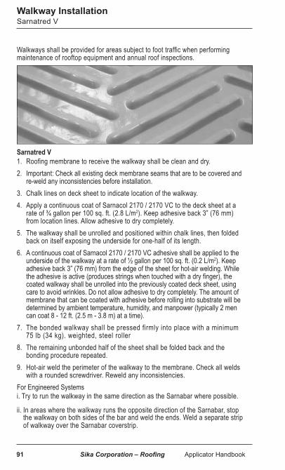
91 Sika Corporation – Roofing Applicator Handbook
Sarnatred V1. Roofing membrane to receive the walkway shall be clean and dry.2. Important: Check all existing deck membrane seams that are to be covered and
re-weld any inconsistencies before installation.3. Chalk lines on deck sheet to indicate location of the walkway.4. Apply a continuous coat of Sarnacol 2170 / 2170 VC to the deck sheet at a
rate of ¾ gallon per 100 sq. ft. (2.8 L/m2). Keep adhesive back 3” (76 mm) from location lines. Allow adhesive to dry completely.
5. The walkway shall be unrolled and positioned within chalk lines, then folded back on itself exposing the underside for one-half of its length.
6. A continuous coat of Sarnacol 2170 / 2170 VC adhesive shall be applied to the underside of the walkway at a rate of ½ gallon per 100 sq. ft. (0.2 L/m2). Keep adhesive back 3” (76 mm) from the edge of the sheet for hot-air welding. While the adhesive is active (produces strings when touched with a dry finger), the coated walkway shall be unrolled into the previously coated deck sheet, using care to avoid wrinkles. Do not allow adhesive to dry completely. The amount of membrane that can be coated with adhesive before rolling into substrate will be determined by ambient temperature, humidity, and manpower (typically 2 men can coat 8 - 12 ft. (2.5 m - 3.8 m) at a time).
7. The bonded walkway shall be pressed firmly into place with a minimum 75 lb (34 kg). weighted, steel roller
8. The remaining unbonded half of the sheet shall be folded back and the bonding procedure repeated.
9. Hot-air weld the perimeter of the walkway to the membrane. Check all welds with a rounded screwdriver. Reweld any inconsistencies.
For Engineered Systemsi. Try to run the walkway in the same direction as the Sarnabar where possible.
ii. In areas where the walkway runs the opposite direction of the Sarnabar, stop the walkway on both sides of the bar and weld the ends. Weld a separate strip of walkway over the Sarnabar coverstrip.
Walkways shall be provided for areas subject to foot traffic when performing maintenance of rooftop equipment and annual roof inspections.
Walkway InstallationSarnatred V

Sika Corporation – Roofing Applicator Handbook 92
Crossgrip XTRA1. Crossgrip XTRA Walkway is installed loose on top of completed roof assem-
blies. Unroll and position within specified areas and cut to desired length.2. Connecting clips are available for butting two ends together.3. Important: Check all existing deck membrane seams that are to be covered and
re-weld any inconsistencies before installation.For Engineered Systemsi. Try to run the walkway in the same direction as the Sarnabar where possible.
ii. In areas where the walkway runs the opposite direction of the Sarnabar, stop the walkway on both sides of the bar
Precast concrete paver installationInstall concrete pavers over a protection layer such as an extra layer of membrane or compatible pedestals.
Walkway InstallationCrossgrip XTRA
93 Sika Corporation – Roofing Applicator Handbook
Perimeter WarningGeneral
Membrane must be cleaned to a “like new” condition in “warning” area. Failure to properly clean the membrane will result in less than satisfactory adhesion or welding. The membrane should be cleaned as follows:1. New membrane: Remove loose dirt and dust by wiping clean with water. For
areas where dirt is embedded, scrub the application area with a commercial cleaner such as Simple Green, 409 or other similar all-purpose cleaner using a Scotch Brite scrubbing pad or similar product. Wash away residual cleaning material with clean water.
2. Weathered membrane: For older membranes or areas where there is excessive dirt buildup, use the above cleaning procedure followed by cleaning with a natural fiber rag wet with Seam Cleaner, and wipe away all residual cleaning solution and remaining dirt until membrane has a “like new” appearance.
After surface is clean and dry, apply:1. Tape: Apply Perimeter Warning Tape to membrane by smoothing over with hand
pressure, taking care to avoid trapping air and creating blisters. If a chalk line is used, be sure to keep chalk dust clear of application area. Do not apply Perimeter Warning Tape to surfaces where the temperature is below 40°F (4°C).
2. Membrane: Perimeter Warning Membrane is hot-air welded to the top of PVC roofing membrane in the areas required.
Perimeter Warning Tape or Membrane may be slippery when wet.

Sika Corporation – Roofing Applicator Handbook 94
On a tear-off situation, Sika recommends that the entire existing roofing and insulation be torn off prior to the installation of any membrane where possible.
Precautions and Recommendations
1. The applicator may want to make a roof plan with building heights for the total job during the pre-job walk. Also locate on the plan the proper job-start location, dumpster locations, and expected prevailing winds.
2. Locate dumpsters to minimize traffic over the completed roof areas. Start tear-off on the highest roof, if there are various heights, to eliminate contamination from high roof areas. Start tear-off upwind of prevailing winds. Take roof drainage into consideration.
3. Applicator should cover installed membrane with asphalt-free tarpaulins or a large sheet of polyethylene for approximately 15 - 20 ft. (4.6 m - 6.1 m) along the tear-off area to minimize asphalt contamination.
4. Applicator may want to build up some type of wind dam at the transition from the new membrane to the tear-off area to minimize asphalt contamination.
5. Applicator should have a hose available to wash dust off newly installed roof daily.
6. Applicator should have soft, clean bristle brushes to sweep asphalt dust off the new membrane. If the membrane is warm, this may spread the contamination source.
7. Everyone working on the roof should take precautions to minimize asphalt contamination. The general applicator should inform all trades.
8. Crew members should have asphalt-free shoes, clothes, and tools when working on the membrane.
9. Applicator should plan to clean the contamination from the top surface of the membrane daily. If heavy areas of contamination are left in place for a long period of time, the contaminated membrane may be required to be cut out and patched. The applicator should have mineral spirits or a non solvent type cleaner and plenty of clean cotton rags on-site. Many solvent based cleaners will remove the lacquer coating from Sika membranes. In exposed areas the removal of lacquer will leave a dull finish and be more susceptible to dirt pick up.
10. If large areas of asphalt contamination occur on the top surface of the membrane, the applicator should plan to clean the entire contaminated area with power floor scrubbers with soft clean bristles and acceptable cleaner and water. All asphalt contamination on the top surface of the membrane is to be removed.
11. All asphalt contamination below the membrane, normally visible by a browning of the membrane, is to be removed. The membrane is to be cut open, the insulation or substrate cleaned with the contamination source completely removed, and a patch installed in a neat fashion. The existing membrane is to be cleaned with an approved solvent prior to welding. In areas of localized contamination, utilize large replacement sheets of membrane to minimize the number of patches.
Special InstructionsTear-off Instructions

95 Sika Corporation – Roofing Applicator Handbook
Special InstructionsMembrane Cleaning
Roof cleaning can be an important part of any roof maintenance program. To maintain optimum reflectivity levels, roofs should be cleaned annually. The ideas outlined below are the most common methods used. Extra care should be taken to make sure that the cleaning process does not cause physical damage to the membrane. Workers performing the washing should be made aware that excessive foot traffic, the use of sharp tools, and excessive pressure can and will cause damage to the roofing membrane. In all instances, be sure to use a non-abrasive cleaner. Most work well, try a number in different areas and choose the cleaner with the best results.
Airborne Dirt1. Sponge, mop, or brush cleaning are the least aggressive methods of cleaning.
These works well on new material and is typically used in smaller areas. Apply water and a non-abrasive cleaner to the area and sponge, mop, or brush off. Wire brushes should never be used as they scratch the material and may puncture the membrane.
2. When using a rotary buffer to clean the roof, use a small buffer with a 12 - 15” (30.5 - 38.1 cm) base. Use only the synthetic buffing pad or polishing pad, as stripping pads are too aggressive and will damage the membrane.
3. Pressure washing can be used to clean large surfaces. There are a large variety of machines available and they are all calibrated differently. Some machines do not allow a pressure to be dialed in. A lower pressure is preferable. Using too high a pressure will cut right into or through the membrane causing leaks and possibly damage other components of the roof system. A wide dispersal nozzle should be used. Narrow dispersal nozzles will create too fine a spray and can damage the membrane. The wand itself should be kept at a constant 16 – 24” (40.6 - 61.0 cm) above the membrane. Lowering the wand in an effort to concentrate the spray can damage the membrane. The spray must be directed over the overlap and not against it. Washing against the overlap could damage the edge of the material or the weld.
Notes: Seams should be washed by hand, as water could be sprayed up under a seam. On large roofing projects this may be difficult. If using a pressure washer wash from the field sheet over the overlap.
As with any cleaning process using a small test area and some common sense should lead to the desired results.

Sika Corporation – Roofing Applicator Handbook 96
Special InstructionsMembrane Cleaning
Asphalt or Coal Tar Pitch Asphalt and coal tar pitch can be removed from the top of membranes by applying, Mineral Spirits onto a clean, soft cotton rag, and wiping thoroughly until the asphalt is removed. Solvents should not be poured directly on to the membrane, and any spills should be wiped up immediately. If large areas of roofing are to be cleaned, automatic equipment such as floor scrubbers with soft brushes, with mild detergents are acceptable. Check with the Sika Technical Department. For removing imbedded dirt or moisture which cannot be removed by Mineral Spirits, use Sika Seam Cleaner. Sika Seam Cleaner should be applied onto a clean, soft cotton rag and wiped thoroughly until the contamination is removed. Workers should use proper precautions when using Sika Seam Cleaner. Sika Seam Cleaner should not be poured directly on the membrane, and any spills should be wiped up immediately. Hose down the area with water. If required consult the Sika Technical Department for cleaning off other contaminates.
Organic Soiling Roofs in certain geographic locations may be subject to greater degrees of organic soiling. Organic soiling may not wash off the roof membrane as easily as other forms of dirt and debris. A 3% concentration of bleach to water may be effective in these instances. The use of bleach will not harm the membrane, affect its longevity or negatively affect any existing warranty coverage. Extra care should be taken when using a bleach solution as “run-off” can affect grass, trees and shrubs and landscaping. As always, comply with all local regulations with regard to “run-off” for all cleaning solutions used.
Note: Sika Seam Cleaner will remove the lacquer coating making the membrane more susceptible to soiling.

97 Sika Corporation – Roofing Applicator Handbook
Special InstructionsWelding
Thick Membrane T-Joints (three-way overlaps) Patches are required at all T-Joint intersections for membrane thickness 72 mil and above. The second layer (middle layer) of the thick membrane must be shaved down to create a smooth transition for the top layer of membrane prior to hot-air welding. A 4” (10.2 cm) round or square (with rounded corners) patch of maximum 60 mil membrane must be hot-air welded over the center of the T-Joint intersection. The edges of the membrane forming the T-Joint must be shaved to provide a smooth transition for the patch.
Welding To Aged Membrane Clean the existing membrane of heavy dirt in the areas of welding with household liquid soap and water using clean, soft cotton rags or soft cotton mops. Do not use abrasive cleaners. To remove embedded dirt and moisture use Sika Seam Cleaner applied to a clean, soft cotton rag. Wipe thoroughly over the prepared area until the membrane is clean. Workers should use proper precautions when using Sika Seam Cleaner. Sika Seam Cleaner should not be poured directly onto the membrane, and any spills should be wiped up immediately. Allow the Sika Seam Cleaner to completely evaporate. Weld slowly and with reduced heat. Hand Welding The preliminary weld should be a continuous weld. Complete the final weld. Weld slowly. Bleed out should be visible along the entire edge of the completed joint. Machine Welding Visible evidence that welding is proceeding acceptably is smoke during the welding operation, shiny membrane surfaces, and bleed out should be visible along the entire edge of the completed joint.Two 1” (25 mm) wide cross-sectional test samples shall be taken through completed seams. Correct welds display failure from shearing of the membrane prior to separation of the weld. All completed welded seams shall be checked after cooling for continuity using a rounded screwdriver or other suitable blunt object by the roofing applicator.
T-Joint

Sika Corporation – Roofing Applicator Handbook 98
Special InstructionsRepairing Vapor Retarders
When Sika vapor retarders (VR) are installed and repairs are required, the following procedures will outline how to get the VR back to near original condition.
Self-adhered productsPatches or Small repairs:
1. Clean VR to like new condition removing all dirt, dust, and debris. 2. Over a clean and dry substrate, prime with self-adhered solvent based primer a
minimum of 6” (15.2 cm) beyond required repair area in all directions.3. Cut patch the same area of primed area.4. Peel back release liner and install. *If the project is still being used as a temporary roof, do not let bitumen exposed to UVs.
When VR is used as a temporary roof and the product has been exposed beyond its allowable time period, full recover is required:1. Cut out and remove any non-adhered VR.2. Clean VR to like new condition removing all dirt, dust, and debris.3. Over clean and dry substrate, prime with self-adhered solvent based primer.4. Install new rolls of VR, when using SA 31 lap over the ¼” extension.
Torch down productsPatches or Small repairs: 1. Clean VR to like new condition removing all dirt, dust, and debris. 2. Cut patch a minimum of 6” or 6” beyond required repair area.3. Torch down repair according to CERTA guidelines.
When VR is used as a temporary roof and the product has been exposed beyond its allowable time period, full recover is required:1. Cut and remove non-adhered VR.2. Clean VR to like new condition removing all dirt, dust, and debris.3. Torch down new rolls according to CERTA guidelines, more heat may be
required to soften sanded top surface.

99 Sika Corporation – Roofing Applicator Handbook
Adhesive SelectionCoverage Rates Table
(1) Adhesive shall not be used if temperatures are expected below listed temperature during application or subsequent drying time. Check individual product data sheets for proper storage and conditioning temperatures.
(2) Contact Sika Corporation - Roofing Technical Department for an OTC or SCAQMD approved adhesive.
(3) Do not install when air temperature is within 5° of dew point.(4) Feltback Membrane only(5) Coverage rate displayed as an average range, bareback vs feltback membrane as
well as porous vs non-porous substrates, application method, temperature, and experience with product are some variables which will effect listed values.
AdhesiveISO organic face & DensDeck &
OSB(4) Concrete(4) (structural, structural lightweight, LWIC)
ISO/ HD glassface & DensDeck Prime & Smooth Plywood & Securock Fiber(4)
Coverage Rate(5) ft2 per gallon
Sikaplan Single-Step 100 [500] 100 -133 [500-665]
Sarnacol 2121 100 [500] 100 -133 [500-665]
Sarnacol 2170(6) 44 - 57 [220 - 285] 50 - 67 [250- 335]
Sarnacol 2170 VC(6) 44 - 57 [220 - 285] 50 - 67 [250- 335]
Sarnacol AD Feltback Membrane(7)
[600](8)
250 - 300 [2,500 - 3,000] 250 - 300 [7,500 -9,000]
250 - 300 [25,000 - 30,000]
[600](8)
250 - 300 [2,500 - 3,000] 250 - 300 [7,500 -9,000]
250 - 300 [25,000 - 30,000]
Sarnacol OM Feltback Membrane(7)
[600](8)
100 - 200 [1,000 - 2,000] [600](8)
170 - 200 [1,700 - 2,000]
Sarnacol 2163(7)(8) [600] [600]
Sarnacol AD Board(7)250 - 300 [2,500 - 3,000] 250 - 300 [7,500 -9,000]
250 - 300 [25,000 - 30,000]
250 - 300 [2,500 - 3,000] 250 - 300 [7,500 -9,000]
250 - 300 [25,000 - 30,000]
Sarnacol OM Board(7)
[600](8)
100 - 200 [1,000 - 2,000] 250 - 300 [7,500 -9,000]
250 - 300 [25,000 - 30,000]
[600](8)
170 - 200 [1,700 - 2,000] 100 [3,000] 100 [11,000]
Sarnacol OM Board WG(7)(8) [600] [600]
Sarnacol OM Adhesive(9) [3,500] [3,500]
Vapor Retarder Adhesive CA 50 [250] 50 [250]

Sika Corporation – Roofing Applicator Handbook 100
Gypsum Deck(4) & Aged Smooth Asphalt(4)
& Granular Asphalt(4)
Polystyrene Insulation & Cementitious Wood Fiber Deck Packaging
[total ft2 per packaging]
NA NA 5 gal. pail
NA NA 5 gal. pail
NA NA 5 gal. pail
NA NA 5 gal. pail
[600](8)
250 - 300 [2,500 - 3,000] 250 - 300 [7,500 -9,000]
250 - 300 [25,000 - 30,000]
NA NA NA NA
(4) 1.5L cartridges (2) 5 gal.bag-in-boxes
(2) 15 gal. drums (2) 50 gal. drums
[600](8)
100 - 170 [1,000 - 1,700]NA NA
(4) 1.5L cartridges (2) 5 gal.bag-in-boxes
[600] [600] (4) 1.5L cartridges
250 - 300 [2,500 - 3,000] 250 - 300 [7,500 -9,000]
250 - 300 [25,000 - 30,000]
250 - 300 [2,500 - 3,000] 250 - 300 [7,500 -9,000]
250 - 300 [25,000 - 30,000]
(2) 5 gal.bag-in-boxes (2) 15 gal. drums (2) 50 gal. drums
[600](8)
100 - 170 [1,000 - 1,700] 100 [3,000] 100 [11,000]
[600](8)
100 - 120 [1,000 - 1,200] 100 [3,000] 100 [11,000]
(4) 1.5L cartridges (2) 5 gal.bag-in-boxes
(2) 15 gal. drums (2) 55 gal. drums
[600] [600] (4) 1.5L cartridges
[3,500] [3,500] (2) canisters
50 [250] NA 5 gal. pail
(6) 2-sided application method(7) Coverage based on 12” o.c. bead spacing(8) Coverage based on total ft2 of (4) 1.5L cartridges(9) Coverage based on total ft2 of (1) 48 lb canister of
Part A and (1) 44 lb canister of Part BAdhesive coverage rates vary by substrate and ambient weather conditions. The typical coverage rates listed on the table are accurate at time of printing. For most up to date information, refer to Adhesive Selection Guide on the Sika website.
Refer to Adhesive Selection Guide for additional information
on adhesive usage

101 Sika Corporation – Roofing Applicator Handbook
Troubleshooting General
Problem: Voids in the welded seams. Solution: Check all seams daily for voids using a rounded screwdriver. Open void along seam to a solid weld. Solvent clean the area and reweld or patch. Problem: Punctures in the membrane. Solution: Inspect the membrane for punctures. Solvent clean the punctured area and handweld a patch in place. Problem: Contaminates on the membrane. Solution: Inspect the membrane for contamination. Clean the contaminated area with approved solvents using clean, cotton rags. Problem: Contaminates under the membrane. Solution: Cut out the contaminate and clean the membrane to receive the patch with an acceptable solvent. Weld patch in place. Problem: Debris on the membrane. Solution: Sweep the membrane free of all debris with a soft bristle broom. Problem: Unadhered flashing areas. Solution: Cut open all unadhered flashings and fold back until fully adhered.
Apply Sarnacol 2170 / 2170 VC to the substrate and let dry. Apply Sarnacol 2170 / 2170 VC to the underside of the flashing at a rate of ½ gallon per 100 sq. ft. (0.2 L/m²). Apply flashing into the previously coated area while the adhesive on the underside of the flashing is tacky to the touch. Do not let the adhesive completely dry. Rub in the flashing to ensure full adhesion. Clean the membrane in areas to be welded with an approved solvent. Weld a patch strip over the cuts in the flashing mem-brane. Check all welds. Note: If large areas of the flashing are unadhered, remove the entire flashing and adhere new flashing material.
Problem: No termination of flashings at non-removable curbs. Solution: Install a metal extender piece on all non-removable curbs. Secure with grommeted fasteners 12” (30.5 cm) on center. Problem: No vertical termination of flashing. Solution: Terminate all vertical flashings with metal, sealant, and grommeted fasteners 12” (30.5 cm) on center. Problem: No sealant at details. Solution: Apply an acceptable (compatible) sealant to the drains, vent stacks, reglets, etc. All surfaces to receive the sealant must be cleaned. Problem: No hose clamps on vent stacks or other round penetrations. Solution: Install stainless steel hose clamp and Sikaflex-1A. Problem: Loose insulation. Solution: Secure all loose insulation panels with acceptable fasteners and plates. Clean the membrane around the plates with an acceptable solvent. Hand weld a patch in place. Check all seams with a rounded screwdriver.Problem: Blisters in the membrane. Solution: Cut out and install a patch.

Sika Corporation – Roofing Applicator Handbook 102
Troubleshooting General
Measures To Be Taken When Welding
TYPE OF BLISTER FORMATION
Blister formation due to moisture in membrane
Blisters of irregular diameters
FEATURES Blisters of consistent1/16 - 1/4” (2 - 5 mm) diameter
Solvents in membrane due to:- cleaning with solvents- adhesive solvents which
have not evaporated
CAUSES Storage of membrane:- in water- in humid conditions
Solvents in membrane due to:- cleaning with solvents- adhesive solvents which
have not evaporated
RECOMMENDATIONS FOR HAND AND AU-TOMATIC WELDING
- Expose affected areas and allow membrane to dry in the sun
- Use Sika Seam Cleaner- Weld slowly at low tem-
peratures
- When cleaning with solvents, weld immediately or wait 2 - 4 hours before welding
- In the case of adhesive solvents, weld immediately or wait 2 - 4 hours before welding
MEASURES TO PRE-VENT BLISTERS
Store membrane under dry conditions on pallets and completely cover with canvas tarpaulins- At high humidity, weld the
membrane immediately after laying out
- Do not damage packaging- Storage time on the
building site should be minimized
Use solvents sparingly- For cleaning use recom-mended cleaners
By following these principles satisfactory welding of Sarnafil and Sikaplan membranes can be achieved.

103 Sika Corporation – Roofing Applicator Handbook
Sarnafil and Sikaplan membranes are defined as “Articles” and are therefore exempt from the requirements of the OSHA Hazard Communication Standard (29CFR 1910).
This handbook is provided as a guide and cannot be considered all inclusive or absolute. Heat sealing, and other heat applications, may subject personnel to potentially hazardous situations, particularly in closed or confined areas.
The safety of every roofing mechanic on all jobs should always be ensured. It is the responsibility of the management of the roofing company to educate and inform its employees in the particular precautions and safety measures which should be observed at the job site.
DisclaimerThis information and recommendations contained herein are offered as a service to our customers and are not intended to relieve the user from responsibility. The information and recommendations provided are believed by Sika Sarnafil to be accurate at the time of preparation, or obtained from sources believed to be generally reliable. Sika Sarnafil makes no warranty concerning their accuracy and will not be liable for claims relating to any use regardless of whether it is claimed that the information or recommendations are inaccurate, incomplete, or otherwise misleading.
Comments for Use General

Your Local Partner with a Global Presence
WHO WE ARE
The commercial roofing industry has relied on thermoplastic roofing systems from Sika for more than 50 years to achieve sustainable roofing and waterproofing solutions. The company manufactures long-lasting membranes and systems, vapor retarders, insulation, fasteners, adhesives and proprietary hot-air seam welding equipment.
SIKA CORPORATION • ROOFING100 Dan Road • Canton, MA 02021 • USATel: 781-828-5400 • Fax: 781-828-5365usa.sika.com/sarnafil
SIKA CANADA INC.6915 Davand Drive • Mississauga, Ontario L5T 1L5 • CanadaTel: 905-795-3177 • Fax: 905-795-3192can.sika.com 13
28/5
M/0
4202
2 ©
Sik
a Co
rpor
atio
n