Road and Bridge Design Publications - Monthly Update
44
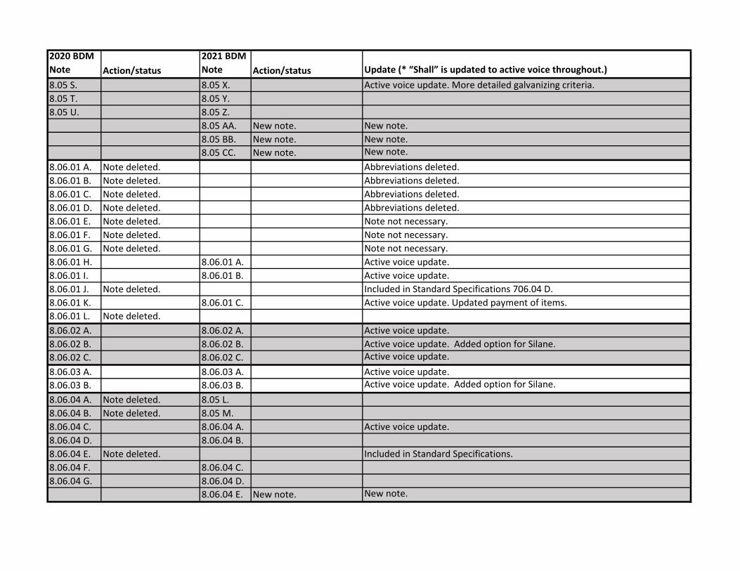
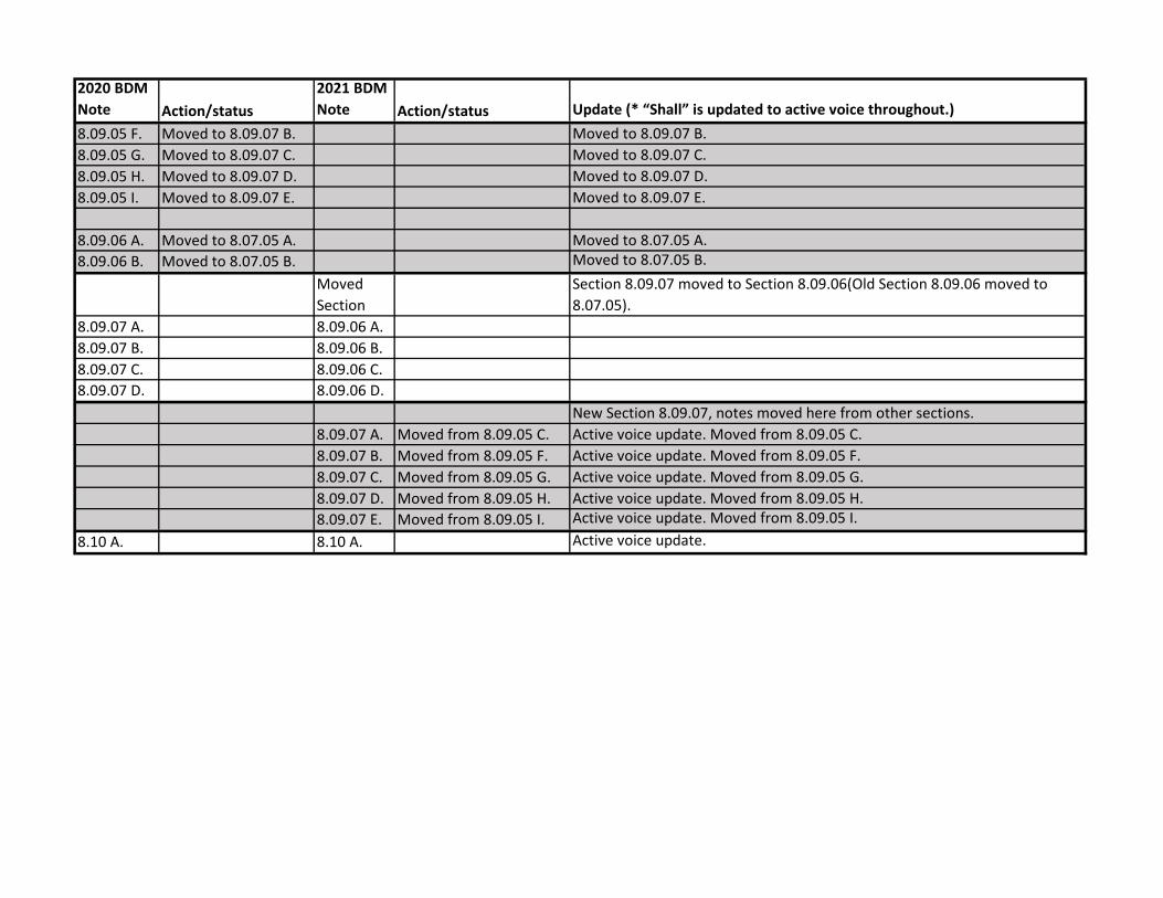
Road & Bridge Design Publications Special Update – April 2021 This Special Update is issued in advance of our soon to be issued regular Monthly Update. Details for this Special Update are listed and displayed below. E-mail questions to MDOT- [email protected] Bridge Design Manual Chapter 8: This is a complete rewrite of Chapter 8 notes. Use this version of the Chapter 8 notes with projects using the 2020 MDOT Standard Specifications for Construction, August 2021 letting. Use the previous Chapter 8 version for projects let using the 2012 Standard Specifications. Updates include re-lettering about 60% of the notes, deleting notes that are in the 2020 Standard Specifications, deleting notes that are no longer relevant or used on plan sheets. Notes were moved from one section to another to better align notes with work type. Notes may also be appropriate in many different work types (projects), add notes if they apply even if they are not in a particular section. The entire chapter was rewritten to be in active voice. Notes with more than one issuance(change/update) date have been updated to include only the latest date. New dates have been added to changes deemed policy, payment, or other significant reasons. Changes for active voice or re-lettering are generally not included in these new dates. A cross reference chart/table has been provided which shows the notes from 2020 versus the notes in the 2021 version (current), including a brief synopsis of changes. Section 8.01 has been updated with more guidance for creating unique plan notes and using the ones in Chapter 8. Section 8.01 also mentions that some notes are for LFRD and some are for LFD exclusively. With that, Chapter 8 LFD has been deleted and all LFD exclusive notes are now included in one Chapter 8. Note also that cross references from other chapters have not been updated at this time. About 20 instances exist that need updating, mostly in Chapters 7 and 12. The same is true with the Bridge Design Guides. These updates will occur in the near future. Updates to the MDOT Cell Library, Sample Plans, and other automated tools may be required in tandem with some of this month's updates. Until such updates can be made, it is the designer's/detailer's responsibility to manually incorporate any necessary revisions to notes and plan details to reflect these revisions.
-
Upload
khangminh22 -
Category
Documents
-
view
0 -
download
0
Transcript of Road and Bridge Design Publications - Monthly Update

Road & Bridge Design Publications
Special Update – April 2021
This Special Update is issued in advance of our soon to be issued regular Monthly Update. Details for this Special Update are listed and displayed below. E-mail questions to [email protected]
Bridge Design Manual Chapter 8: This is a complete rewrite of Chapter 8 notes. Use this version of the Chapter 8 notes with projects using the 2020 MDOT Standard Specifications for Construction, August 2021 letting. Use the previous Chapter 8 version for projects let using the 2012 Standard
Specifications. Updates include re-lettering about 60% of the notes, deleting notes that are in the 2020 Standard Specifications, deleting notes that are no longer relevant or used on plan sheets. Notes were moved from one section to another to better align notes with work type. Notes may also be appropriate in many different work types (projects), add notes if they apply
even if they are not in a particular section. The entire chapter was rewritten to be in active voice. Notes with more than one issuance(change/update) date have been updated to include only the latest date. New dates have been added to changes deemed policy, payment, or other significant reasons. Changes for active voice or re-lettering are generally not included in
these new dates. A cross reference chart/table has been provided which shows the notes from 2020 versus the notes in the 2021 version (current), including a brief synopsis of changes. Section 8.01 has been updated with more guidance for creating unique plan notes and using the ones in Chapter 8. Section 8.01 also mentions that some notes are for LFRD and some are
for LFD exclusively. With that, Chapter 8 LFD has been deleted and all LFD exclusive notes are now included in one Chapter 8. Note also that cross references from other chapters have not been updated at this time. About 20 instances exist that need updating, mostly in Chapters 7 and 12. The same is true with the Bridge Design Guides. These updates will occur in the
near future. Updates to the MDOT Cell Library, Sample Plans, and other automated tools may be required in tandem with some of this month's updates. Until such updates can be made, it is the
designer's/detailer's responsibility to manually incorporate any necessary revisions to notes and plan details to reflect these revisions.

2020 BDM
Note Action/status
2021 BDM
Note Action/status Update (* “Shall” is updated to active voice throughout.)
8.01 8.01Expounded with more guidance for creating unique plan notes and using the
ones in Chapter 8.
8.02 A1. 8.02 A. Active voice update.
8.02 A2. 8.02 B.
8.02 A3. 8.02 C.
8.02 B1. 8.02 D. Active voice update.
8.02 B2. 8.02 E. Use note only for Load Factor Design (LFD) method of design.
8.02 C. 8.02 F. Active voice update.
8.02 D. 8.02 G. Active voice update.
8.02 E. 8.02 H.
8.02 F. 8.02 I.
8.02 G. 8.02 J.
Updates include concrete grades, structural steel grades and foundation
piling.
8.02 H. Note deleted. Traffic data replaced by standardized drafting/detailing cell.
8.02 I. 8.02 K. Active voice update.
8.02 J. Note deleted.
8.02 K. 8.02 L.
8.02 L. 8.02 M.
8.02 M. Note deleted. Foundation materials moved to 8.02.J
8.02 N. 8.02 N.
8.02 O. 8.02 O.
8.02 P. 8.02 P. Active voice update.
8.02 Q. 8.02 Q.
8.03 A. 8.03 A.
8.03 B. 8.03 B.
Deleted criteria portion requiring note to be used on Preliminary Estimate of
Cost.
8.03 C. 8.03 C.
8.03 D. Note deleted.
8.03 E. 8.03 D.
8.03 F. 8.03 E. Active voice update.

2020 BDM
Note Action/status
2021 BDM
Note Action/status Update (* “Shall” is updated to active voice throughout.)
8.03 G. 8.03 F. Active voice update.
8.03 H. 8.03 G.
8.03 I. 8.03 H.
8.03 J. 8.03 I. Active voice update.
8.03 K. 8.03 J. Active voice update.
8.03 L. 8.03 K. Active voice update.
8.03 M. 8.03 L.
8.03 N. Note deleted. Not used
8.03 O. 8.03 M.
8.03 P. 8.03 N.
8.03 Q. 8.03 O.
8.03 R. 8.03 P.
8.03 S. 8.03 Q.
8.03 T. 8.03 R. Active voice update.
8.03 U. Note deleted. Called out on elevation view and included in quantities.
8.03 V. 8.03 S.
8.03 W. 8.03 T. Active voice update.
8.03 X. 8.03 U.
8.03 Y. 8.03 V. Active voice update. Updated payment of items.
8.03 Z. 8.03 W. Active voice update.
8.03 AA. 8.03 X. Active voice update.
8.03 BB. Note deleted.
When haul route is used, details and quantities and unique notes will be
included.
8.03 CC. 8.03 Y.
8.04 A. 8.04 A. Updated criteria to indicate hammer type.
8.04 B. 8.04 B.
8.04 C. 8.04 C.
8.04 D. 8.04 D.
8.04 E. 8.04 E.
8.04 F. 8.04 F.
8.04 G. 8.04 G.

2020 BDM
Note Action/status
2021 BDM
Note Action/status Update (* “Shall” is updated to active voice throughout.)
8.04 H. 8.04 H.
8.04 I. 8.04 I.
8.04 J. New note. New note.
8.04 K. New note. New note.
8.04 L. New note. New note.
8.04 M. New note. New note.
8.04 N. New note. New note.
8.05 A1. 8.05 A. Active voice update.
8.05 A2. 8.05 B.
8.05 A3. 8.05 C.
8.05 B1. 8.05 D. Active voice update.
8.05 B2. 8.05 E. Use note only for Load Factor Design (LFD) method of design.
8.05 C. 8.05 F. Added standard disclaimer regarding Water Surface Elevations.
8.05 D. 8.05 G.
8.05 E. 8.05 H.
8.05 F. 8.05 I.
8.05 G. 8.05 J.
8.05 H. 8.05 K. Active voice update.
8.05 I.
8.05 L. &
8.05 M. One note split into two based on gross or effective footing witdth.
8.05 N. New note. Use note only for Load Factor Design (LFD) method of design.
8.05 J. 8.05 O. Added use criteria.
8.05 K. 8.05 P.
8.05 L. 8.05 Q. Active voice update.
8.05 M. 8.05 R.
8.05 N. 8.05 S. Active voice update.
8.05 O. 8.05 T. Added use criteria.
8.05 P. 8.05 U. Active voice update.
8.05 Q. 8.05 V.
8.05 R. 8.05 W. Active voice update.
2020 BDM
Note Action/status
2021 BDM
Note Action/status Update (* “Shall” is updated to active voice throughout.)
8.05 S. 8.05 X. Active voice update. More detailed galvanizing criteria.
8.05 T. 8.05 Y.
8.05 U. 8.05 Z.
8.05 AA. New note. New note.
8.05 BB. New note. New note.
8.05 CC. New note. New note.
8.06.01 A. Note deleted. Abbreviations deleted.
8.06.01 B. Note deleted. Abbreviations deleted.
8.06.01 C. Note deleted. Abbreviations deleted.
8.06.01 D. Note deleted. Abbreviations deleted.
8.06.01 E. Note deleted. Note not necessary.
8.06.01 F. Note deleted. Note not necessary.
8.06.01 G. Note deleted. Note not necessary.
8.06.01 H. 8.06.01 A. Active voice update.
8.06.01 I. 8.06.01 B. Active voice update.
8.06.01 J. Note deleted. Included in Standard Specifications 706.04 D.
8.06.01 K. 8.06.01 C. Active voice update. Updated payment of items.
8.06.01 L. Note deleted.
8.06.02 A. 8.06.02 A. Active voice update.
8.06.02 B. 8.06.02 B. Active voice update. Added option for Silane.
8.06.02 C. 8.06.02 C. Active voice update.
8.06.03 A. 8.06.03 A. Active voice update.
8.06.03 B. 8.06.03 B. Active voice update. Added option for Silane.
8.06.04 A. Note deleted. 8.05 L.
8.06.04 B. Note deleted. 8.05 M.
8.06.04 C. 8.06.04 A. Active voice update.
8.06.04 D. 8.06.04 B.
8.06.04 E. Note deleted. Included in Standard Specifications.
8.06.04 F. 8.06.04 C.
8.06.04 G. 8.06.04 D.
8.06.04 E. New note. New note.

2020 BDM
Note Action/status
2021 BDM
Note Action/status Update (* “Shall” is updated to active voice throughout.)
8.06.05 A. 8.06.05 A.
8.06.05 B. New note. Use note only for Load Factor Design (LFD) method of design.
8.06.05 C. New note. Use note only for Load Factor Design (LFD) method of design.
8.06.05 B. 8.06.05 D. Active voice update.
8.06.05 C. 8.06.05 E.
8.06.05 D. 8.06.05 F. Active voice update.
8.06.05 E. 8.06.05 G. Active voice update.
8.06.05 F. 8.06.05 H. Active voice update. Updated use statement.
8.06.05 G. Note deleted. Included in 8.05 J.
8.06.05 H. 8.06.05 I. Active voice update.
8.06.05 I. Note deleted. Included in 8.05 J.
8.06.05 J. 8.06.05 J.
8.06.05 K. 8.06.05 K.
8.06.05 L. 8.06.05 L.
8.06.05 M. 8.06.05 M. Added use criteria.
8.06.05 N. New note. New note.
8.06.06 A. Note/Section deleted. Note/Section deleted. Included in Standard Specifications 706.03
New
Section Section 8.06.07 moved to Section 8.06.06 (deleted).
8.06.07 A. 8.06.06 A.
8.06.07 B. 8.06.06 B. Active voice update.
8.06.07 C. 8.06.06 C. Active voice update.
8.06.06 D. New note. New note.
New
Section
8.06.08 A. Note deleted. Included in Standard Specifications.
8.06.08 B. 8.06.07 A. Active voice update. Added option for Silane.
8.06.08 C. 8.06.07 B. Active voice update. Added option for Silane.
8.06.08 D. 8.06.07 C. Active voice update.
8.06.08 E. Note deleted. Included in Standard Specifications 712.02 M.
8.06.08 F. Note deleted.

2020 BDM
Note Action/status
2021 BDM
Note Action/status Update (* “Shall” is updated to active voice throughout.)
New
Section
8.06.09 A. Note deleted. Abbreviations deleted.
8.06.09 B. 8.06.08 A.
8.06.09 C. 8.06.08 B.
8.06.09 D. 8.06.08 C.
8.06.09 E. 8.06.08 D.
8.06.09 F. 8.06.08 E.
8.06.09 G. 8.06.08 F.
8.06.09 H. 8.06.08 G. Updated pay item to match 2020 Special Provision.
8.06.09 I. 8.06.08 H.
8.06.09 J. 8.06.08 I.
8.06.09 K. 8.06.08 J. Active voice update.
8.06.09 L. Note deleted. Frequently Used Special Provision, no reference required.
8.06.09 M. 8.06.08 K. Active voice update.
8.06.08 L. New note. New note.
8.06.08 M. New note. New note.
8.07.01 A. Note deleted. Abbreviations deleted.
8.07.01 B. Note deleted. Abbreviations deleted.
8.07.01 C. Note deleted. Note not necessary.
8.07.01 D. Note deleted. Note not necessary.
8.07.01 E. Note deleted. Included in Standard Specifications.
8.07.01 F. Note deleted. Note not necessary.
8.07.01 G. Note deleted. Not used. Included in Standard Specifications.
8.07.01 H. 8.07.01 A.
8.07.01 I. 8.07.01 B. Active voice update. Added concrete pour criteria.
8.07.01 J. 8.07.01 C. Added concrete pour criteria.
8.07.01 K. 8.07.01 D. Active voice update.
8.07.01 L. 8.07.01 E. Active voice update.
8.07.01 M. 8.07.01 F. Active voice update. Matches Standard Specifications 706.03.D.2
8.07.01 N. Note deleted. Included in Standard Specifications 706.03 H.1.

2020 BDM
Note Action/status
2021 BDM
Note Action/status Update (* “Shall” is updated to active voice throughout.)
8.07.01 O. Note deleted. Included in Standard Specifications 706.03 I.
8.07.01 P. Note deleted. Note not necessary.
8.07.01 Q. Note deleted. Note not necessary.
8.07.01 R. 8.07.01 G. Active voice update. Updated use statement and to match new policy.
8.07.01 S. 8.07.01 H. Active voice update.
8.07.01 T. 8.07.01 I. Active voice update.
8.07.01 U. 8.07.01 J. Active voice update. Updated payment of items.
8.07.01 V. 8.07.01 K. Active voice update.
8.07.01 W. Note deleted.
8.07.01 X. Note deleted. Included in Standard Specifications 706.03 D.1.
8.07.01 Y. 8.07.01 L.
8.07.01 Z. 8.07.01 M.
8.07.01 N. New note. New note.
8.07.01 O. Moved from 8.07.06 B. Moved from 8.07.06 B.
8.07.02 A. Note deleted. Included in Standard Specifications 706.03 T.
8.07.02 B. Note deleted. Detailed on plans.
8.07.03 A. 8.07.02 A. Active voice update. Section 8.07.03 moved to Section 8.07.02(deleted).
New
Section Section 8.07.04 moved to Section 8.07.03(moved).
8.07.04 A. 8.07.03 A. Active voice update.
8.07.04 B. 8.07.03 C. Active voice update. The use of 0.5" diameter strand has ceased.
8.07.04 C. 8.07.03 S.
8.07.04 D. 8.07.03 D. Active voice update.
8.07.04 E. 8.07.03 E.
8.07.04 F. 8.07.03 F.
8.07.04 G. 8.07.03 G.
8.07.04 H. 8.07.03 H. Active voice update.
8.07.04 I. Note deleted.
8.07.04 J. 8.07.03 I. Active voice update.
8.07.04 K. 8.07.03 J. Active voice update.

2020 BDM
Note Action/status
2021 BDM
Note Action/status Update (* “Shall” is updated to active voice throughout.)
8.07.04 L. Note deleted.
8.07.04 M. 8.07.03 K. Active voice update.
8.07.04 N. Note deleted.
8.07.04 O. 8.07.03 B. Active voice update. The use of 0.5" diameter strand has ceased.
8.07.04 P. 8.07.03 L. Active voice update.
8.07.04 Q. Note deleted. Included in Standard Specifications 708.03 C.13.c.
8.07.04 R. 8.07.03 M.
8.07.04 S. 8.07.03 N.
8.07.04 T. Note deleted. Included in Standard Specifications 708.02
8.07.04 U. 8.07.03 O. Active voice update.
8.07.04 V. 8.07.03 Q.
8.07.04 W. 8.07.03 R.
8.07.04 X.
Combined with new
note 8.07.03 S. and
old note 8.07.04 C. 8.07.03 S.
8.07.04 Y. Note deleted.
8.07.04 Z. 8.07.03 P. Active voice update.
8.07.03 T. New note.
8.07.03 U. New note.
8.07.03 V. New note.
New
Section Section 8.07.05 moved to Section 8.07.04(moved).
8.07.05 A. 8.07.04 A.
8.07.05 B. 8.07.04 B. Active voice update.
8.07.05 C. 8.07.04 C.
8.07.05 D. 8.07.04 D. Active voice update.
8.07.05 E. 8.07.04 E. Active voice update.
8.07.05 F. 8.07.04 F.
8.07.05 G. 8.07.04 G.

2020 BDM
Note Action/status
2021 BDM
Note Action/status Update (* “Shall” is updated to active voice throughout.)
New
Section
8.07.06 A. Note deleted. Note not necessary.
8.07.06 B. Moved to 8.07.01 O. Moved to 8.07.01 O.
New
Section Sectioin 8.07.05 moved to Section 8.07.04(moved).
8.07.05 A. Moved from 8.09.06 A. Moved from 8.09.06 A.
8.07.05 B. Moved from 8.09.06 B. Moved from 8.09.06 B.
New
Section
8.07.07 A. Note deleted. Note not necessary.
8.07.07 B. Note deleted. Included in Standard Specifications.
8.07.07 C. Note deleted. Included in Standard Specifications.
8.07.07 D. 8.07.06A. Active voice update. Structural Steel quantity portion of note deleted.
8.07.07 E. 8.07.06 B.
8.07.07 F. 8.07.06 C. Active voice update.
8.07.07 G. 8.07.06 D. Active voice update.
8.07.07 H. 8.07.06 E. Active voice update.
8.07.07 I. Note deleted. Contractor option, note not necessary.
8.07.07 J. 8.07.06 F.
8.07.07 K. Note deleted. Included in Standard Specifications 715 & 712
8.07.07 L. 8.07.06 G.
8.07.07 M. 8.07.06 H. Active voice update.
8.07.07 N. 8.07.06 I. Active voice update.
8.07.08 A. Section Deleted Section deleted. Note not used.
8.07.08 B. Section Deleted Section deleted. Note not used.
8.07.08 C. Section Deleted Section deleted. Note not used.
8.07.08 D. Section Deleted Section deleted. Note not used.
8.07.08 E. Section Deleted Section deleted. Note not used.
8.07.08 F. Section Deleted Section deleted. Note not used.
8.07.08 G. Section Deleted Section deleted. Note not used.

2020 BDM
Note Action/status
2021 BDM
Note Action/status Update (* “Shall” is updated to active voice throughout.)
New
Section Section 8.07.09 moved to Section 8.07.08(deleted).
8.07.09 A. 8.07.07 A.
8.08.02 A. 8.08.02 A.
8.08.02 B. 8.08.02 B. Active voice update.
8.08.03 A. 8.08.03 A.
8.08.03 B. 8.08.03 B.
8.08.03 C. 8.08.03 C.
8.08.03 D. 8.08.03 D.
8.08.04 A. 8.08.04 A.
8.08.05 A. 8.08.05 A. Active voice update.
8.08.06 A. 8.08.06 A. Active voice update.
8.08.06 B. 8.08.06 B.
8.08.06 C. 8.08.06 C. Active voice update.
8.08.06 D. 8.08.06 D.
8.09.01 A. Section Deleted Included in Standard Specifications.
8.09.01 B. Section Deleted Included in Standard Specifications.
8.09.01 C. Section Deleted Included in Standard Specifications.
8.09.01 D. Section Deleted Included in Standard Specifications.
New Section. Original Section 8.09.01 deleted.
8.09.01 A. Moved from 8.09.03 I. Moved from 8.09.03 I.
8.09.01 B. Moved from 8.09.02 S. Active voice update. Moved from 8.09.02 S. Added option for silane.
8.09.01 C. Moved from 8.09.02 O. Active voice update. Moved from 8.09.02 O.
8.09.01 D. Moved from 8.09.03 E. Active voice update. Moved from 8.09.03 E.
8.09.01 E. Moved from 8.09.04 H. Active voice update. Moved from 8.09.04 H.
8.09.01 F. Moved from 8.09.05 D. Moved from 8.09.05 D.
8.09.01 G. New Note New Note.
8.09.02 A. Note deleted.
8.09.02 B. Note deleted.
8.09.02 C. 8.09.02 A. Update payment.
8.09.02 D. Note deleted.

2020 BDM
Note Action/status
2021 BDM
Note Action/status Update (* “Shall” is updated to active voice throughout.)
8.09.02 E. Note deleted.
8.09.02 F. 8.09.02 B. Active voice update.
8.09.02 G. Note deleted. Included in Standard Specifications.
8.09.02 H. 8.09.02 C. Active voice update.
8.09.02 I. Note deleted. Note not used, information available in construction files.
8.09.02 J. 8.09.02 D.
8.09.02 K. 8.09.02 E.
8.09.02 L. 8.09.02 F. Active voice update.
8.09.02 M. Note deleted. Included in Standard Specifications.
8.09.02 N. Note deleted. Included in Standard Specifications.
8.09.02 O. Moved to 8.09.01 C. Moved to 8.09.01 C.
8.09.02 P. 8.09.02 G. Revised to match 712.03 G.
8.09.02 Q. 8.09.02 H. Active voice update.
8.09.02 R. 8.09.02 I. Active voice update.
8.09.02 S. Moved to 8.09.01 B Moved to 8.09.01 B
8.09.03 A. Note deleted. Moved to 8.09.01 A.
8.09.03 B. Note deleted. Note not necessary.
8.09.03 C. Note deleted. Note not necessary.
8.09.03 D. 8.09.03 A.
8.09.03 E. Moved to 8.09.01 D.
8.09.03 F. 8.09.03 B. Active voice update.
8.09.03 G. Note deleted.
Included in Standard
Specifications 706.02 Included in Standard Specifications 706.02
8.09.03 H. 8.09.03 C.
8.09.03 I. Moved to 8.09.01 A. Moved to 8.09.01 A.
8.09.04 A. 8.09.04 A.
8.09.04 B. 8.09.04 B.
8.09.04 C. 8.09.04 C.
8.09.04 D. 8.09.04 D.
8.09.04 E. 8.09.04 E.

2020 BDM
Note Action/status
2021 BDM
Note Action/status Update (* “Shall” is updated to active voice throughout.)
8.09.04 F. Note deleted.
Included in Standard
Specifications 713.03 C.3. Included in Standard Specifications 713.03 C.3.
8.09.04 G. 8.09.04 F. Active voice update.
8.09.04 H. Moved to 8.09.01 E. Moved to 8.09.01 E.
8.09.04 I. 8.09.04 G. Active voice update.
8.09.04 J. 8.09.04 H. Active voice update.
8.09.04 K. 8.09.04 I. Active voice update.
8.09.04 L. 8.09.04 J.
8.09.04 M. 8.09.04 K. Active voice update.
8.09.04 N. 8.09.04 L. Active voice update.
8.09.04 O. 8.09.04 M. Active voice update.
8.09.04 P. 8.09.04 N. Active voice update.
8.09.04 Q. 8.09.04 O. Active voice update.
8.09.04 R. 8.09.04 P. Active voice update.
8.09.04 S. 8.09.04 Q. Active voice update.
8.09.04 T. 8.09.04 R. Active voice update.
8.09.04 U. 8.09.04 S. Active voice update.
8.09.04 V. 8.09.04 T.
8.09.04 W. 8.09.04 U. Active voice update.
8.09.04 X. 8.09.04 V. Active voice update.
8.09.04 Y. 8.09.04 W. Active voice update.
8.09.04 Z. 8.09.04 X. Active voice update.
8.09.04 AA. 8.09.04 Y.
8.09.04 BB. Note deleted. Not filled in and from construction records.
8.09.05 A. 8.09.05 A. Active voice update.
8.09.05 B. Note deleted.
Included in Standard
Specifications 713.03 C.3. Included in Standard Specifications 713.03 C.3.
8.09.05 C. Moved to 8.09.07 A. Moved to 8.09.07 A.
8.09.05 D. Moved to 8.09.01 F. Moved to 8.09.01 F.
8.09.05 E. 8.09.05 B. Active voice update.
2020 BDM
Note Action/status
2021 BDM
Note Action/status Update (* “Shall” is updated to active voice throughout.)
8.09.05 F. Moved to 8.09.07 B. Moved to 8.09.07 B.
8.09.05 G. Moved to 8.09.07 C. Moved to 8.09.07 C.
8.09.05 H. Moved to 8.09.07 D. Moved to 8.09.07 D.
8.09.05 I. Moved to 8.09.07 E. Moved to 8.09.07 E.
8.09.06 A. Moved to 8.07.05 A. Moved to 8.07.05 A.
8.09.06 B. Moved to 8.07.05 B. Moved to 8.07.05 B.
Moved
Section
Section 8.09.07 moved to Section 8.09.06(Old Section 8.09.06 moved to
8.07.05).
8.09.07 A. 8.09.06 A.
8.09.07 B. 8.09.06 B.
8.09.07 C. 8.09.06 C.
8.09.07 D. 8.09.06 D.
New Section 8.09.07, notes moved here from other sections.
8.09.07 A. Moved from 8.09.05 C. Active voice update. Moved from 8.09.05 C.
8.09.07 B. Moved from 8.09.05 F. Active voice update. Moved from 8.09.05 F.
8.09.07 C. Moved from 8.09.05 G. Active voice update. Moved from 8.09.05 G.
8.09.07 D. Moved from 8.09.05 H. Active voice update. Moved from 8.09.05 H.
8.09.07 E. Moved from 8.09.05 I. Active voice update. Moved from 8.09.05 I.
8.10 A. 8.10 A. Active voice update.

MICHIGAN DESIGN MANUAL BRIDGE DESIGN
CHAPTER 8
PLAN NOTES 8.01 INTRODUCTION 8.02 TITLE SHEET 8.03 GENERAL PLAN OF SITE SHEET 8.04 LOG OF BORING SHEET 8.05 GENERAL PLAN OF STRUCTURE SHEET 8.06 SUBSTRUCTURE 8.06.01 Miscellaneous Notes 8.06.02 Abutment Notes 8.06.03 Pier Notes 8.06.04 Footing Notes 8.06.05 Pile Notes 8.06.06 Steel Sheet Pile Notes 8.06.07 Substructure Repair Notes 8.06.08 MSE Wall Notes (8-20-2009) 8.07 SUPERSTRUCTURE 8.07.01 Miscellaneous Notes 8.07.02 Elastomeric Bearings 8.07.03 Prestressed Concrete I-Beam, Bulb-Tee Beam and Box Beam Notes 8.07.04 Screed Notes 8.07.05 Deck Replacement Notes (4-19-2021) 8.07.06 Structural Steel Notes 8.07.07 Treatment of Epoxy-Coated Bars

MICHIGAN DESIGN MANUAL BRIDGE DESIGN
CHAPTER 8 PLAN NOTES INDEX (continued) 8.08 RAILROAD OVERPASS 8.08.01 Introduction 8.08.02 Title Sheet 8.08.03 General Plan of Site Sheet 8.08.04 General Plan of Structure Sheet 8.08.05 Structural Steel Notes 8.08.06 Temporary Trestle 8.09 REHABILITATION PROJECTS 8.09.01 Miscellaneous Notes
8.09.02 Bridge Deck Repair Notes (9-18-1998)
8.09.03 Railing Replacement Notes 8.09.04 Maintenance Painting Notes
8.09.05 Hanger Assembly Replacement Notes 8.09.06 Existing Plan Sheet Notes (4-19-2021) 8.09.07 Temporary Support Notes 8.10 STEEL REINFORCEMENT (9-1-1988)

MICHIGAN DESIGN MANUAL BRIDGE DESIGN
CHAPTER 8
PLAN NOTES
8.01
INTRODUCTION (4-19-2021) This section contains general notes that should be placed on the sheet indicated or where applicable. The notes on each plan sheet should be grouped according to subject matter. Blanks are to be filled in with the appropriate word or words. Words in parentheses show the most common options used in the note; other wordings may be necessary to fit the particular option. Words in brackets give instruction on when to use the note or give a general description of additional information that may be needed in the note. These notes are intended as a guide, not as a complete list for all cases. Care should be taken when writing unique plan notes. Do not use notes to add work to standard pay items or to add requirements to the contractor that are not already included in the spec book or special provisions. Use unique plan notes for the following cases:
Convey information regarding design methodology.
Explain the purpose or intent of an unusual item of work so that the project engineer or contractor can judge the accuracy required or whether alternatives are suitable.
Coordinate details across the plan set.
Specify extents of application of standard and special pay items.
Indicate specific materials or items to be use when the Standard Specifications language provides for a broader application.
8.01 (continued)
Specify intended sequence of
activities.
Emphasize (but not modify) critical
elements of Standard Specification language.
Convey information that cannot be reasonably included in plan details.
Care should be taken to ensure that the notes appearing on plan sheets apply to the work being performed on the project. A few notes contained herein are for Load Factor Design (LFD) projects. Most notes are for LRFD projects and some are specifically designated for LRFD projects. Use caution when modifying notes contained herein or adding non-standard plan notes. If modifying a standard plan note, consider re-wording the entire note in lieu of changing a single word or phrase to ensure that it is clear that the note is unique.

MICHIGAN DESIGN MANUAL BRIDGE DESIGN
8.02
TITLE SHEET A. The design of (this) (these) structure(s)
(except the railroad overpass(es) (is) (are) based on 1.2 times the current AASHTO LRFD Bridge Design Specification HL93 loading with the exception that the design tandem portion of the HL-93 load definition is replaced by a single 60 kip axle load before application of this 1.2 factor. The resulting load is designated HL-93 Mod. Live load plus dynamic load allowance deflection does not exceed (1/425*) (1/800) (1/1000**) of span length (and (1/375) (1/300) of cantilever arm). [*Wood construction.] [**Use for structures with pedestrian loads.]
(8-20-2009) B. The design of this structure is based on
current AASHTO LRFD Bridge Design Specification pedestrian loading of 90 psf (and a maintenance vehicle (H5) (H10) loading, not acting concurrently). Live load deflection does not exceed 1/360 of span length and 1/220 of cantilever arm. [Use for pedestrian bridges. For Clear Bridge Width, w, greater than 10'0", use an H10 truck. For w between 7'-0" and 10'-0", use an H5 truck. For w less than 7'-0" the bridge does not need to be designed for a maintenance vehicle.]
(5-25-2015) C. The design of the deck slab is based upon
the strip method as defined in the current AASHTO LRFD Bridge Design Specification. (8-20-2009)
8.02 (continued) D. The (reconstruction) (rehabilitation)
design is based on 1.2 times the current AASHTO LRFD Bridge Design Specification HL93 loading with the exception that the design tandem portion of the HL-93 load definition is replaced by a single 60 kip axle load before application of this 1.2 factor. The resulting load is designated HL-93 Mod. Live load plus dynamic load allowance deflection does not exceed (1/425**) (1/800) (1/1000***) of span length (and 1/375) (1/300) of cantilever arm. The original structure was designed for (and alternate military*) loading (based on AASHTO Standard Specifications for Highway Bridges). [*Used only for structures on interstate routes.] [**Wood construction.] [***Use for structures with pedestrian loads.] [See Subsection 7.01.06 for deflection limits.] (8-20-2009)
E. [Load Factor Design (LFD)] The (reconstruction) (rehabilitation)
design is based on the 17th Edition of AASHTO Standard Specifications for Highway Bridges (HS25) (HS20-44) (and alternate military*) loading. Live load plus impact deflection does not exceed (1/425) (1/800) (1/1000) of span length (and 1/375) (1/300) of cantilever arm. The original structure was designed for (and alternate military*) loading based on AASHTO Standard Specifications for Highway Bridges. [*Use only for structures on interstate routes.] [See 17th Edition of AASHTO for deflection limits.] [Use note for Load Factor Design (LFD) method of design.] (8-20-2009)
F. Except where otherwise indicated on
these plans, or in the proposal and supplemental specifications contained herein, perform all work according to the Michigan Department of Transportation Standard Specifications for Construction Edition.

MICHIGAN DESIGN MANUAL BRIDGE DESIGN
8.02 (continued) TITLE SHEET
G. The stationing as shown on these plans for the intersection of the centerline of bridge and the (roadway) (railroad) centerline is believed to be correct. Check stationing at the time of starting construction. If the stationing shown on the plans is incorrect, notify the Engineer, and stake out the structure using the actual intersection of the centerline of bridge and the (roadway) (railroad) centerline as the control point. [Use when the project includes proposed survey stationing.]
H. This contract is for "Structural
Steel, , Furn and Fab" only. Other items of work indicated on these plans are not a part of this contract. [Use when structural steel furnishing and fabricating must be done early in project to ensure timely delivery for construction.] (12-5-2005)
I. The Regulated Waste Activity
Identification Numbers for this project are as follows:
Control Section Number
[Use when hazardous material removal, cleaning or working on painted steel structure constructed prior to 1978 or when hydrodemolition is part of the project work. Place note directly above title block and use lettering twice the size of the other notes.] (1-27-2020)
8.02 (continued) J. The design of the structural members is
based on material of the following grades and stresses:
Concrete: Grade 3500, 3500HP* f'c = 3,000 psi Concrete: Grade 4000 f'c = 3,500 psi Concrete: Grade 4500, 4500HP* f'c = 4,000 psi Steel Reinforcement fy = 60,000 psi Steel Reinforcement: (Stirrups for Prestressed Beams fy = 60,000 psi) (Stirrups for (17”) (21”) Box Beams
fy = 40,000 psi) Structural Steel: AASHTO M270 Grade 36 Fy = 36,000 psi Structural Steel (including H-Piles, splices
and pile points): AASHTO M270 Grade 50, 50W Fy = 50,000 psi Structural Steel Pins: ASTM A276 UNS Designation S20161 or S21800 Fy = 50,000 psi Temp Support Hanger Rods: ASTM A 193 Grade B7 (AISI 4140)
2½” and under Fu =125,000 psi Fy =105,000 psi
Over 2½” to 4” Fu =115,000 psi Fy = 95,000 psi
Over 4” to 7” Fu =100,000 psi Fy = 75,000 psi Prestressed Concrete f'c = psi Prestressed Concrete Compressive Strength at Release f'ci = psi Prestressing Strands fpu = 270,000 psi Foundation Piling (Steel Shells): ASTM A 252 Grade 3 Fy = 45,000 psi Grade 3 Modified Fy = 50,000 psi Foundation Piling (Timber) FCO = 900 psi
[*Use Grade 3500HP and 4500HP in all trunkline projects in Metro, University, Grand, Bay, Southwest and North Regions. Use Grade 3500 and 4500 in Superior Region and on non-trunkline projects.] (4-19-2021)
MICHIGAN DESIGN MANUAL BRIDGE DESIGN
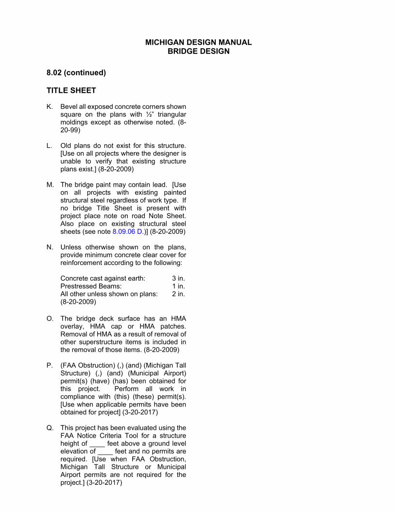
8.02 (continued) TITLE SHEET K. Bevel all exposed concrete corners shown
square on the plans with ½” triangular moldings except as otherwise noted. (8-20-99)
L. Old plans do not exist for this structure.
[Use on all projects where the designer is unable to verify that existing structure plans exist.] (8-20-2009)
M. The bridge paint may contain lead. [Use
on all projects with existing painted structural steel regardless of work type. If no bridge Title Sheet is present with project place note on road Note Sheet. Also place on existing structural steel sheets (see note 8.09.06 D.)] (8-20-2009)
N. Unless otherwise shown on the plans,
provide minimum concrete clear cover for reinforcement according to the following:
Concrete cast against earth: 3 in. Prestressed Beams: 1 in. All other unless shown on plans: 2 in. (8-20-2009)
O. The bridge deck surface has an HMA
overlay, HMA cap or HMA patches. Removal of HMA as a result of removal of other superstructure items is included in the removal of those items. (8-20-2009)
P. (FAA Obstruction) (,) (and) (Michigan Tall
Structure) (,) (and) (Municipal Airport) permit(s) (have) (has) been obtained for this project. Perform all work in compliance with (this) (these) permit(s). [Use when applicable permits have been obtained for project] (3-20-2017)
Q. This project has been evaluated using the
FAA Notice Criteria Tool for a structure height of ____ feet above a ground level elevation of ____ feet and no permits are required. [Use when FAA Obstruction, Michigan Tall Structure or Municipal Airport permits are not required for the project.] (3-20-2017)

MICHIGAN DESIGN MANUAL BRIDGE DESIGN
8.03 GENERAL PLAN OF SITE SHEET A. The work covered by these plans includes
(channel excavation), (maintaining traffic), construction of the proposed bridge and placing (slope protection) (scour countermeasures) (riprap) to the limits shown. All other work is included in the road plans that are a part of this contract. [Used where bridge is part of a road-bridge package.]
B. The work covered by these plans includes
(clearing), (grubbing), (tree removal), (channel excavation), (earth excavation), (maintaining traffic), (construction of the temporary road), (construction and removal of temporary trestle), (grading for temporary and permanent track work), construction of the proposed bridge and placing (granular material), (sodding or seeding) and (slope protection) (scour countermeasures) (riprap) to the limits shown. All other work is to be done by others and is not a part of this contract. [Used where bridge contractor constructs bridge only and approach work is done by a separate contract. Any work that is to be done by others prior to starting work on bridge contract is to be noted.]
(4-19-2021) C. Removal of (fences and) buildings is not a
part of this contract. D. Removal of temporary structure and
approaches (is) (is not) a part of this contract.
E. Locate all active underground utilities prior
to starting work and conduct operations in such a manner as to ensure that those utilities not requiring relocation will not be disturbed.
F. Remove unsuitable material under
____ and backfill with .
8.03 (continued) G. Remove ( cubic yards of) peat and
other unsuitable material below proposed approach fill location and backfill with ( cubic yards of) “Embankment, Structure, CIP” (see Road Plans for treatment limits, method and quantity). [Use when large peat deposits must be removed by surcharging.] (12-5-2005)
H. (Scarify*) (Remove) roadway surfacing in
area beneath proposed abutments prior to placing of fills. [Use for pile-supported abutments or where fill is 3'-0" or less.] [*Use when roadway surfacing is gravel or crushed stone with or without a seal coat.] (8-6-1992)
I. Construct and backfill piers 1 and
____ prior to the placement of abutment fills. [Use where piers are within or at toes of slope.]
J. Grade the ground adjacent to the tracks
and structure to provide drainage. K. (Maintain) (detour) …… traffic over (the
bridge) (the bridge by part-width construction) (other existing roads) (the temporary road). [Specify facility and other modes of transportation on the project. Use multiple notes if modes are detoured or maintained in separate ways.](12-16-2019)
L. This bridge is part of an interchange and
all area shown is within MDOT rightofway.
M. Plan elevations refer to datum. N. Topography shown here represents
conditions existing at the time the field survey was made. However, these conditions (may) have been materially altered by the operations of others prior to this contract. [Use when definite information exists that work has been done in the area.]

MICHIGAN DESIGN MANUAL BRIDGE DESIGN
8.03 (continued) GENERAL PLAN OF SITE SHEET O. The train movement and speed
information shown in the proposal does not represent a commitment by the _____ railroad and is subject to change without notice.
P. Excavate crosshatched area to El .
[Place this note in the vicinity to which it applies.]
Q. Fill hatched area to El with material
from channel excavation. [Place this note in the vicinity to which it applies.]
R. Water level is subject to change. Make a
determination of water levels that may exist during construction. [Use on all projects over water where the water level may impact the project work.]
S. Remove cubic yards of topsoil (and
unsuitable material) and place cubic yards of “(Embankment, Structure,) (*Embankment,) CIP”. [*Use with pile supported footing.] (12-5-2005)
T. Undercut soil classified as and replace
with “Embankment, Structure, CIP” compacted to 100 percent of maximum unit weight. Excavation and backfill quantities are based on an estimated undercut to elevation . The Engineer will determine actual limits of excavation at the time of construction. (12-5-2005)
U. The following item(s) (is/are) railroad
owned (fittings, ties, rails, etc.) and any of these items salvaged shall become the property of the railroad.
8.03 (continued) V. Implement measures to prevent debris
from falling from the structure. (*If debris falls into the waterway, remove it within 24 hours. Since disturbance of the waterway bottom may be as harmful as the debris itself, the preventive measures must be effective.) Removal of debris is included in related items of work. . [*Use for bridges over waterways.] (4-19-2021)
W. Immediately after the construction of an
abutment is completed, place slope protection and seeding or sodding on the adjacent embankment slopes. [Use for bridges over waterways.] (9-1-1988)
X. The haul route shown has been approved
by the Michigan Department of Environment, Great Lakes and Energy (MDEGLE). If desired, propose a detailed alternate route for MDOT review and submittal to the appropriate permitting agency. No payment will be made for additional time, project costs and project delays resulting from submittal, approval, and/or denial of an alternate route request. Implementation will be the responsibility of the contractor. [Use for bridges over waterways or wetlands.] (6-24-2019)
Y. Coordinates are not available for this
project. [Use when coordinates not available due to lack of survey for project.] (12-5-2005)

MICHIGAN DESIGN MANUAL BRIDGE DESIGN
8.04
LOG OF BORING SHEET A. Numbers in circles denote number of
blows required to drive a 2" O.D. (1½” I.D.) split spoon sampler 3 successive 6" increments using a 140 lbs. (automatic)(safety) hammer falling 30".
12 14 15
(Where the sampler is driven distances
other than 18", the distance is shown in the circle with the number of blows in the form of a fraction.) [Indicate actual hammer type used] (4-19-2021)
31 Number of blows
4" Distance driven
B. Consistency was determined by
inspection of samples and substantiated by soils resistance to drilling tools. [This note shall be as written in field notes.]
C. Bottom of footing (Abut. ) (Pier ),
El. .* D. Estimated total scour limit (Abut. )
(Pier ), El. .* (8-6-1992) *Show on plotted borings. E. Minimum pile penetration (Abut. ) (Pier
), El. .* F. Estimated bottom of piles (Abut. )
(Pier ), El. .*
8.04 (continued) G. Water levels may be influenced by
residual boring water. [Use when borings are made by hydraulic, rotary, or coring methods.]
H. Free water was first noted feet below
the surface. The water level was feet below ground ( hours after) (at) completion with the casing (in) (out). [Place under each soil boring log if applicable.] (9-1-1988)
I. The soil boring logs represent point
information. Presentation of this information in no way implies that subsurface conditions are the same at locations other than the exact location of the boring.
J. See General Plan of Structure Sheet for soil
boring locations. (4-19-2021) K. Drilling was performed with a ____ drill rig
utilizing ____ drilling methods. [Include hammer type and drilling method. Include changes in drilling methods and/or coring as well].
(4-19-2021) L. Elevations reference the top of the
standard penetration test (SPT), rock core run interval or Shelby tube sample.
(4-19-2021) M. The numbers in split circles denote rock
recovery and rock quality designation (RQD) for each rock core run.
(4-19-2021)
50 Recovery (%)
25 RQD (%)
N. Circles with ST are Shelby tube samples pushed 2 ft unless otherwise noted.
(4-19-2021)
ST Shelby Tube
4" Recovery (%)

MICHIGAN DESIGN MANUAL BRIDGE DESIGN
8.05
GENERAL PLAN OF STRUCTURE SHEET A. The design of this structure is based on
1.2 times the current AASHTO LRFD Bridge Design Specification HL-93 loading with the exception that the design tandem portion of the HL-93 load definition is replaced by a single 60-kip axle load before application of this 1.2 factor. The resulting load is designated HL-93 Mod. Live load plus dynamic load allowance deflection does not exceed (1/425*) (1/800) (1/1000**) of span length (and 1/375) (1/300) of cantilever arm. [*Wood construction.] [**Use for structures with pedestrian loads.] [See Subsection 7.01.06 for deflection limits.] (8-20-2009)
B. The design of this structure is based on
current AASHTO LRFD Bridge Design Specification pedestrian loading of 90 psf (and a maintenance vehicle (H5) (H10) loading, not acting concurrently). Live load deflection does not exceed 1/360 of span length and 1/220 of cantilever arm. [Use for pedestrian bridges. For Clear Bridge Width, w, greater than 10'0", use an H10 truck. For w 26between 7'-0" and 10'-0", use an H5 truck. For w less than 7'-0" the bridge does not need to be designed for a maintenance vehicle.]
(5-25-2015) C. The design of the deck slab is based upon
the strip method as defined in the current AASHTO LRFD Bridge Design Specification, utilizing HL-93 Loading.
(5-27-2020)
8.05 (continued) D. The (reconstruction) (rehabilitation)
design is based on 1.2 times the current AASHTO LRFD Bridge Design Specification HL93 loading with the exception that the design tandem portion of the HL-93 load definition is replaced by a single 60 kip axle load before application of this 1.2 factor. The resulting load is designated HL-93 Mod. Live load plus dynamic load allowance deflection does not exceed (1/425**) (1/800) (1/1000***) of span length (and 1/375) (1/300) of cantilever arm. The original structure was designed for (and alternate military*) loading (based on AASHTO Standard Specifications for Highway Bridges). [*Used only for structures on interstate routes.] [**Wood construction.] [***Use for structures with pedestrian loads.] [See Subsection 7.01.06 for deflection limits.] [Use note for LRFD method of design.] (8-20-2009)
E. [Load Factor Design (LFD)] The (reconstruction) (rehabilitation)
design is based on the 17th Edition of AASHTO Standard Specifications for Highway Bridges (HS25) (HS20-44) (and alternate military*) loading. Live load plus impact deflection does not exceed (1/425) (1/800) (1/1000) of span length (and 1/375) (1/300) of cantilever arm. The original structure was designed for (and alternate military*) loading based on AASHTO Standard Specifications for Highway Bridges. [*Use only for structures on interstate routes.] [See 17th Edition of AASHTO for deflection limits.] [Use note for Load Factor Design (LFD) method of design.]
(8-20-2009) (4-19-2021)

MICHIGAN DESIGN MANUAL BRIDGE DESIGN
8.05 (continued) GENERAL PLAN OF STRUCTURE SHEET F. [Place a chart similar to the following on all
plans where applicable:]
SUMMARY OF HYDRAULIC ANALYSIS
EXISTING PROPOSED
FLOOD DATA
DISCHARGE (CFS)
WATER SURFACE ELEV. AT U/S FACE OF STRUCTURE
VELOCITY IN D/S CHANNEL (FPS)
WATER SURFACE ELEV. AT U/S FACE OF STRUCTURE
VELOCITY IN D/S CHANNEL (FPS)
WATERWAY AREA (SFT) AT D/S FACE
CHANGE IN WS EL ___ U/S OF PROPOSED STRUCTURE
50-YEAR
100-YEAR
MAXIMUM BRIDGE AREA BELOW LOW CHORD IS SQUARE FEET
The water surface and/or energy grade elevations shown on the above hydraulic table are to be used for comparison purposes only and are not to be used for establishing a regulatory floodplain. The elevations may be used, provided they are verified with the Land and Water Management Division, Michigan Department of Environment, Great Lakes, and Energy. (4-19-2021) G. The drainage area contributory to this
crossing is square miles. H. The water surface and/or energy grade
elevations shown on the above hydraulic table are to be used for comparison purposes only and are not to be used for establishing a regulatory floodplain.
(9-2-2003) I. The (existing) (adjacent) structure,
(feet) (miles) (upstream) (downstream), provides a waterway area of square feet to (high water) (underclearance*) elevation . [*Use only if high water elevation is not available.]
J. Without the preventive measures shown
on these plans, there is a possibility that stream bed scour may occur. The estimated total scour depth is calculated to be feet at (Abutment ) (Pier ). These depths are based on a year runoff event. (8-6-1992)
K. Place geotextile liner on all slopes prior to
placing riprap. Payment for geotextile liner is included in payment for riprap. [Use when recommended by the Hydraulics/Hydrology Engineer.]
(9-18-1998)

MICHIGAN DESIGN MANUAL BRIDGE DESIGN
8.05 (continued) GENERAL PLAN OF STRUCTURE SHEET L. The (abutment) (pier) maximum average
foundation pressure(s) is (are) calculated to be_____ psf for Service Limit State, and _____ psf for Strength Limit State and are based on a gross footing width of _____ ft. [ Use for LRFD projects when gross footing width assumptions are used for footing designs. Create one note for abutments and one note for piers. MDOT designed projects.] (8-20-2009)
M. The (abutment) (pier) maximum
foundation pressure(s) is (are) calculated to be_____ psf for Service Limit State based on an effective footing width of _____ ft, and _____ psf for Strength Limit State based on an effective footing width of _____ ft. [ Use for LRFD projects when effective footing width assumptions are used for footing designs. Create one note for abutments and one note for piers. Consultant designed projects.]
(8-20-2009) N. [Load Factor Design (LFD)] The maximum unfactored foundation
pressures are calculated to be: Avg. D.L. only Case Abutments psf Piers psf Avg. D.L. + L.L. Case Abutments psf Piers psf
[Note only on Preliminary Plans][Use Avg. D.L. Case for cohesive soils only.][Use for Load Factor Design (LFD) projects.] (4-19-2021)
O. For details of concrete slope paving
protection, see Standard Plan B102Series. [Use for projects with slope paving.] (6-29-2020)
8.05 (continued) P. The nominal fatigue resistance is based
on a design life of 75 years (and an average daily truck traffic of ). [Use for steel bridges only and add ADTT if applicable/available.] (3/16/2015)
Q. A cofferdam has not been provided for this
structure. Use other means of water control as approved by the Engineer. Do not disturb the stream bed. Water control, whether it be by cofferdam or other approved means, is included in the bid item “Excavation, Fdn”. [Use on stream crossings when water control measures other than a cofferdam are appropriate. See Subsection 7.03.04.] (12-5-2005)
R. The tremie seal design was based on a
water surface at El. . S. Place (standard) (and) (limited deflection)
temporary barrier according to (Standard Plan R-53-Series,) Standard Plan R-126-Series or as approved by the Engineer. (Place portable water-filled barrier as specified by the Engineer.) [Use on all projects requiring standard temporary barrier, limited deflection temporary barrier, and/or portable water-filled barrier. Modify paragraph as needed depending on the temporary barrier type(s) required on each project. Delete references to Standard Plan R-53-Series when limited deflection temporary barrier is not required according to Standard Plan R-126-Series. Place note on staging sheet(s) where applicable.] (12-28-2015)
T. The riprap quantity is based on the lateral
dimensions of the area to be protected, regardless of the number of layers required. The estimated weight of riprap is tons. [Use only if riprap is paid by the square yard.] (4-19-2021)

MICHIGAN DESIGN MANUAL BRIDGE DESIGN
8.05 (continued) GENERAL PLAN OF STRUCTURE SHEET U. Submit alternate methods of stream
diversion to the Engineer for approval. [Use when stream diversion method is detailed on Plan Sheet.] (9-18-1998)
V. Place riprap from El to El . [Place
this note in the vicinity to which it applies, when lateral limits are not fixed.]
W. False decking includes the area bounded
by (Reference Lines & ) (edges of shoulders) and outside flange fascias of fascia beams. The estimated area is ____square feet during removal (and ____square feet during proposed construction). [Detail limits on the plans and include areas in note.] (4-19-2021)
X. When casting items into structural precast
concrete to facilitate bridge construction (forming, finishing, etc.) use items that are galvanized in accordance with ASTM B633, Service Condition 4 or epoxy coated. Inserts shall be cast with the beams. Field installation of inserts is not allowed. [Use for box and three-sided culverts, MSE walls, sound walls, precast bridge element systems, etc.](4-19-2021)
Y. Do not use wheeled, roller based or
machine mounted compaction equipment to compact the subgrade, subbase, and base within 10’ of the sleeper slab after it is built. Use only hand/plate compactors. Contact pressure of compaction equipment shall not exceed 10 psi. [Use on all projects with a sleeper slab.]
(3-17-2014)
8.05 (continued) Z. Design headwalls to develop an ultimate
moment capacity (about the horizontal axis) to resist a horizontal load of 24 k (kips) distributed over 3.5 feet applied 32 inches above top of pavement, and to develop an ultimate moment capacity (about the vertical axis) of 16.7 kft (kip feet), per foot of headwall height. Design headwall connection to deck and/or other precast units to resist these loads. Space blockouts for thrie beam guardrail at a distance of 10’-7¾” or less, center to center, along headwall. [Use when thrie beam guardrail is attached to the culvert headwalls and/or return walls. Use with Standard Plan B-23-Series.] (5-27-2014)
AA. Contact the Region Soils Engineer to
perform a footing check at least 48 hours prior to excavating to the bottom of the excavation. [Use this note for spread footings and box culverts]. (4-19-2021)
BB. Contact the Region Soils Engineer to
witness the Design Builder’s Geotechnical Engineer perform a footing check at least 48 hours prior to excavating to the bottom of excavation. [Use this note for spread footings and box culverts on Design-Build projects only]. (4-19-2021)
CC. Install sheet piling using either an impact
hammer or a variable moment driver/extractor operated to minimize vibrations. Do not use vibratory hammers that are not variable moment. [Use this note at the direction of the Geotechnical Engineer when there is concerns regarding potential vibration and/or settlement issues. For sensitive structures, alternate non-vibratory means should be considered instead of sheet piling.] (4-19-2021)

MICHIGAN DESIGN MANUAL BRIDGE DESIGN
8.06 SUBSTRUCTURE
8.06.01 Miscellaneous Notes A. (Bolts) (Position dowels) may be adhesive
anchored in holes drilled in the concrete at (Pier ) (Abutment ). [Use this note for steel beam or prestressed concrete beam bridges, where drilling holes will not damage substructure reinforcement.] (9-18-1998)
B. Uplift will occur at abutment(s) (and
pier(s) ) during construction of the superstructure. Place anchor bolt nuts and jam nuts immediately after erection of the girders in Span(s) _____.
C. Apply low temperature protection of concrete according to Section 706.03 J. of the Standard Specifications for Construction. Low temperature protection of concrete is included in the related items of work. [Use when possibility of pouring concrete during cold weather. With known cold weather pours use the pay item for cold weather protection.] (4-19-2021)
8.06.02 Abutment Notes See Section 7.03.11 for usage and descriptions of concrete sealers. A. Apply Substructure Horizontal Surface
Sealer to the top horizontal surface of abutment (and ) (prior to placing masonry plates) (after the elastomeric bearings have been placed in final position on the structure). Clean accidentally coated vertical surfaces at the contractor’s expense. [Use when joint in deck exists above.] (12-5-2005)
B. Apply (Penetrating Water Repellent
Treatment) (Concrete Surface Coating) (Silane) to the entire exposed surface of abutment (and ) (except the tops) and the front face of independent backwall (prior to placing new masonry plates) (after the new elastomeric bearings have been placed in final position on the structure). (Use concrete surface coating AMSSTD595 color number [insert number], [insert color].) [Use when no joint exists above. Apply to tops when Horizontal surface sealer is not applied to tops. Use Concrete Surface Coating when requested by Region or Roadside Development section.] (4-19-2021)
C. Prior to erecting the beams, do not backfill
the backside of the abutment higher than the backfill on the front side. [Use on integral abutments.] (8-20-1999)

MICHIGAN DESIGN MANUAL BRIDGE DESIGN
8.06.03 Pier Notes See Section 7.03.11 for usage and descriptions of concrete sealers. A. Apply Substructure Horizontal Surface
Sealer to the top horizontal surface of pier (and ) (prior to placing masonry plates) (after the elastomeric bearings have been placed in final position on the structure). Clean accidentally coated vertical surfaces at the contractor’s expense. [Use only when superstructure transverse joints are directly above the pier.] [Use for new construction.] (12-5-2005)
B. Apply (Penetrating Water Repellent
Treatment) (Concrete Surface Coating) (Silane) to the entire exposed surface of piers (except the tops) (prior to placing new masonry plates) (after the new elastomeric bearings have been placed in final position on the structure.) (Use concrete surface coating AMSSTD-595 color number [insert number], [insert color].) [Use when no joint exists above. Apply to tops when Horizontal Surface Sealer is not applied to tops. Use Concrete Surface Coating when requested by Region or Roadside Development section.] (4-19-2021)
8.06.04 Footing Notes A. Pour footings against undisturbed soil. No
allowance will be made in concrete quantities due to excavation outside of the footing neat lines. [Use when required by design.]
B. Construction joints in footings are optional.
[Use unless design considerations deem the joints necessary.]
C. The footings are designed specific to the
detailed (Box-Arch) (Arch) (Flat Top) structure. [Use for precast concrete three-sided or arch culverts.]
(12-28-2015) D. The footings are designed to resist an
applied vertical load of ______ kip/ft and horizontal load of ______ kip/ft (toward the center of the structure) (away from the center of the structure). [Use for precast concrete three-sided or arch culverts.] (12-28-2015)
E. Water mains and sewers must be cased
within the influence zone of spread footings. [Use on project with water mains and sewers beneath spread footings].
(4-19-2021)

MICHIGAN DESIGN MANUAL BRIDGE DESIGN
8.06.05 Pile Notes A. Drive all piles to a nominal pile driving
resistance not less than _____ kips. Determine nominal pile driving resistance (Rndr) using (the FHWA Modified Gates Dynamic Formula) (dynamic test with signal matching (P.D.A. testing)) (static load tests). [Provided by MDOT Geotechnical Services Section or Geotechnical consultant. See section 7.03.09 for values and criteria. Use for LRFD projects only.] (8-20-2009)
B. [Load Factor Design (LFD)] Drive all piles to a minimum bearing
capacity of tons. [Use for Load Factor Design (LFD) projects]
C. [Load Factor Design (LFD)] Do not use the pile driving formulas in the
Standard Specifications to determine battered pile capacity. Drive battered piles to the elevation established for vertical piles. [Use on Load Factor Design (LFD) projects when piles are driven to a 2.5V:1H batter or flatter.]
D. Use pile shells with a minimum of
(0.375”)(0.312) nominal wall thickness, (16”)(14”)(12”) O.D. [Use with C.I.P. concrete piles.] (8-20-2012)
E. The estimated pile length is based on the
static analysis. (8-20-2009) F. Drive batter piles for Abutment(s) to a
3V:1H (2.5V :1H) batter angle. (9-18-1998)
G. Use (HP 10X42) (HP 10X57) (HP 12X53) (HP 12X74) (HP 12X84) (HP 14X73) (HP 14X89) Steel piles. (11-28-2011) H. Drive piles to such accuracy that the ends
of the piles to be embedded in the concrete are within 3" of the location shown on the plans. [Use for pile bents and integral abutments with one row of piles.] (4-19-2021)
8.06.05 (continued) I. Drive piles in a sequence that begins with
the center of the pile group and proceeds outward in both directions or from one side of the pile group to the other side. The contractor may request Engineer approval to sequence the pile driving from the center of the pile group outward in a clockwise or counterclockwise pattern if four or more rows of piles exist. [Use for pipe piles to alleviate soil pressure from driven piles. A pile driving sequence will minimize detrimental effects of heave and lateral displacement of the ground as well as the influence the new construction has on adjacent structures.] (8-20-2009)
J. The estimated loss of nominal pile
resistance due to scour after driving is _____ kips. [For information only. Use for LRFD projects only.] (8-20-2009)
K. The estimated factored downdrag after
pile driving is _____ kips. [For information only. LRFD projects only.] (8-20-2009)
L. The factored pile resistance available to
resist all factored loads (including the estimated factored downdrag) is equal to (50) (65) percent of nominal pile driving resistance (that is reduced by the loss due to scour). [For information only. Add downdrag and scour when appropriate. See section 7.03.09 for values and criteria. Use for LRFD projects only.]
(11-28-2011)
M. Steel piles used for pile bents are
considered main members and all welding must be according to AASHTO/AWS D1.5 Bridge Welding Code, as modified by the current Special Provision for Structural Steel and Aluminum Construction. [Use only when piles project above surface and function as a true pile bent. Do not use for integral abutment piles.] (4-19-2021)

MICHIGAN DESIGN MANUAL BRIDGE DESIGN
8.06.05 (continued) Pile Notes N. Use only the pile splice details within the
plans. [Use on piles for integral abutment, pile bents or any other piles that must resist bending. Do not include alternate splice (sleeve) details in plans].
(4-19-2021)
8.06.06 Steel Sheet Pile Notes A. The substructure excavation and concrete
quantities take into consideration the additional concrete and excavation necessary to excavate and pour to the Permanent Steel Sheet Piling. [Use on all projects where concrete is to be poured against Permanent Steel Sheet Piling.]
B. Provide hot-dip galvanized sheet piling at
___________ [Specify location and use when sheet piling will be subjected to heavy chlorides or sulfates. Include a Special Provision.] (3-18-2013)
C. Provide ______ Permanent Steel Sheet
Piling. Where allowed by the Engineer, select alternate hot rolled sheet piling with a nominal section modulus of at least ______ in3/ft or cold rolled sheet piling with a nominal section modulus of at least ______ in3/ft. [Specify designation and appropriate section modulus. Refer to Section 7.03.08 D. for design criteria.] (12-5-2005)
D. Provide hot rolled permanent steel sheet
piling. Do not use cold rolled piling. [Use when recommended by the geotechnical engineer.] (4-19-2021)
8.06.07 Substructure Repair Notes A. Apply (Penetrating Water Repellent
Treatment) (Concrete Surface Coating) (Silane) to the entire exposed surface of abutment (and ) (except the tops) (and the front face of the independent backwall). (Use concrete surface coating AMSSTD-595 color number [insert number], [insert color].) [Use when no joint exists above or the abutment is adjacent to a pavement. Apply to tops when Horizontal Surface Sealer is not applied to tops. Use Concrete Surface Coating when requested by Region or Roadside Development section.]
(2-26-2018) B. Apply (Penetrating Water Repellent
Treatment) (Concrete Surface Coating) (Silane) to entire exposed surfaces of pier(s) ____ (except top). (Use concrete surface coating AMSSTD-595 color number [insert number], [insert color].) [Use when no joint exists above or the pier is adjacent to a pavement. Apply to tops when Horizontal Surface Sealer is not applied to tops. Use Concrete Surface Coating when requested by Region or Roadside Development section.]
(4-19-2021) C. Apply Substructure Horizontal Surface
Sealer to the top of (all) Pier(s) (___ & ___) (and) Abutment(s) (___ & ___). Clean accidentally coated vertical surfaces at contractor’s expense. [Use when the abutment or pier has been repaired and there is a superstructure transverse joint directly above or the unit is adjacent to a pavement.] (12-5-2005)

MICHIGAN DESIGN MANUAL BRIDGE DESIGN
8.06.08 MSE Wall Notes (8-20-2009) A. Use soil reinforcement for MSE walls of a
length not less than ______ percent of the wall height (H), as defined by these plans, or 8 feet (whichever is greater). [Use this note when the soil reinforcement length required by the Geotechnical investigation exceeds the minimum length (0.7H) required by the specifications.]
B. The factored bearing resistance of the
subgrade is psf at abutment A and psf at abutment B.
C. Adjust MSE soil reinforcement to avoid
foundation piles. Do not cut soil reinforcement.
D. Use precast concrete facing panels with a
nominal height of _____ feet and nominal width of _____ feet for MSE walls. [Use this note if aesthetic or design concerns dictate the panel size beyond what is allowed by the MSE specifications.]
E. Use either precast or cast in place (CIP)
MSE wall coping unless specified to be cast in place. [Include this note only if there are areas where cast in place coping is required and other areas may utilize precast coping.]
F. Use cast in place (CIP) MSE wall coping.
[Use this note only if coping is required to be cast in place.]
G. Texture the exposed face of the precast
concrete facing panels with a _____ pattern meeting the approval of the Engineer. Payment for texturing panels is included in the bid item “Mechanically Stabilized Earth Wall, Precast, Furn”. (4-19-2021)
H. Coordinate placement of soil reinforcement
with drainage structures and pipes and other obstructions.
8.06.08 (continued) I. The 100 year flood elevation is _____.
[Use where MSE walls are placed near areas subject to fluctuations in water level.]
J. Do not cut MSE soil reinforcement. K. Set the top row of soil reinforcement a
minimum of 6” below the bottom of footing. [Use on abutment sheet.]
L. Water mains and sewers must be cased
within the influence zone of MSE walls. [Use on projects with water mains and sewers beneath MSE walls.] (4-19-2021)
M. Do not place electric lines within or near
MSE walls. [Use on projects with electric lines.] (4-19-2021)

MICHIGAN DESIGN MANUAL BRIDGE DESIGN
8.07 SUPERSTRUCTURE
8.07.01 Miscellaneous Notes A. Alphabetical designation of deck pours is
not to be construed as a pour sequence. [Use for simple spans.]
B. Place deck pours according to the
following sequence , , and . Do not begin placement of subsequent pours for a minimum of 15 hours after completing placement of adjacent pours. This includes sections separated by longitudinal as well as transverse joints. [Use with continuous steel spans.]
(8-20-2009) C. Alphabetical designation of deck pours is
not a pour sequence. Cast deck pours over piers after other deck pours have been cast. Do not begin placement of subsequent pours for a minimum of 15 hours after completing placement of adjacent pours. This includes sections separated by longitudinal as well as transverse joints. [Use for prestressed concrete beams that are continuous for live load.] (8-20-2009)
D. Apply low temperature protection of
concrete according to Section 706.03 J. of the Standard Specifications for Construction. Low temperature protection of concrete is included in the related items of work. [Use when possibility of pouring concrete during cold weather. With known cold weather pours use the pay item for cold weather protection.] (4-19-2021)
E. Over active roadbeds, maintain formwork
above the bottom of beams. [Use where bridge deck is to be cast over traffic.]
(4-19-2021)
8.07.01 (continued) F. Notify the utility company one week prior
to beginning installation of the ducts in the (sidewalk) (barrier). [Use when ducts are to be installed by others.] (9-18-1998)
G. The contractor may use permanent metal
deck forms. If used, corrugations must be filled with polystyrene foam. [Use when metal stay in place forms are permitted.] (4-19-2021)
H. Do not use permanent metal deck forms.
Remove all materials used to form the deck prior to opening the bridge to traffic. [Use where beam spacing or form loads preclude the use of stay-in-place forms.] (9-2-2003)
I. Saw-cut the deck on both the top and
bottom surface prior to deck removal procedures. [Use with bridge widening or with removal procedures required for stage construction.] (8-20-2009)
J. Fill perpendicular railing joints with 1” joint
filler to ½” from the bevels of railing and seal remaining ½” with a polyurethane or polyurethane hybrid sealant. Included in the bridge railing pay item(s) [Use in all concrete railings over the piers of continuous deck, at midspan on all structures with a span greater than 100'0" and cantilever decks where the cantilever is more than 10'-0” long.]
(4-19-2021)
K Provide a sawed joint 1½” deep by 1/8” wide (minimum) in the top of slab at the locations shown in section(s) . Saw the joint within 24 hours of placing the curing and fill to ¼” below top of concrete with polyurethane or polyurethane hybrid sealant. (Included in the bid item "Superstructure Conc, Form, Finish, and Cure, Night Casting (Structure Identification)"). [Use at all locations shown for continuous for live load slabs (generally at piers).] (8-24-2020)
MICHIGAN DESIGN MANUAL BRIDGE DESIGN
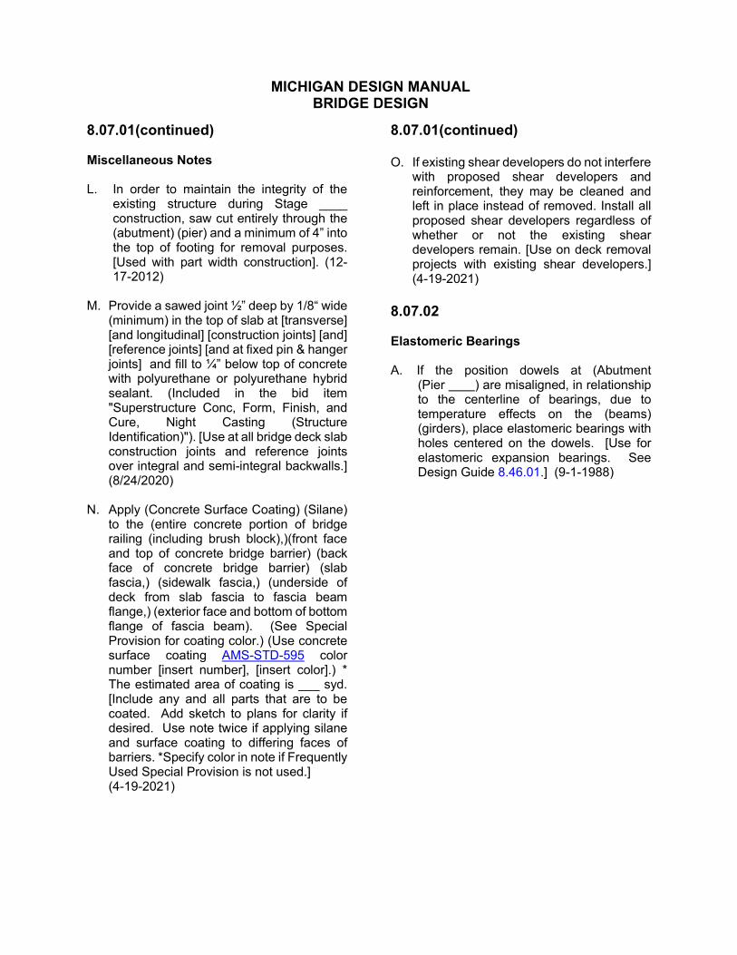
8.07.01(continued) Miscellaneous Notes L. In order to maintain the integrity of the
existing structure during Stage ____ construction, saw cut entirely through the (abutment) (pier) and a minimum of 4” into the top of footing for removal purposes. [Used with part width construction]. (12-17-2012)
M. Provide a sawed joint ½” deep by 1/8“ wide
(minimum) in the top of slab at [transverse] [and longitudinal] [construction joints] [and] [reference joints] [and at fixed pin & hanger joints] and fill to ¼” below top of concrete with polyurethane or polyurethane hybrid sealant. (Included in the bid item "Superstructure Conc, Form, Finish, and Cure, Night Casting (Structure Identification)"). [Use at all bridge deck slab construction joints and reference joints over integral and semi-integral backwalls.] (8/24/2020)
N. Apply (Concrete Surface Coating) (Silane)
to the (entire concrete portion of bridge railing (including brush block),)(front face and top of concrete bridge barrier) (back face of concrete bridge barrier) (slab fascia,) (sidewalk fascia,) (underside of deck from slab fascia to fascia beam flange,) (exterior face and bottom of bottom flange of fascia beam). (See Special Provision for coating color.) (Use concrete surface coating AMSSTD-595 color number [insert number], [insert color].) * The estimated area of coating is ___ syd. [Include any and all parts that are to be coated. Add sketch to plans for clarity if desired. Use note twice if applying silane and surface coating to differing faces of barriers. *Specify color in note if Frequently Used Special Provision is not used.]
(4-19-2021)
8.07.01(continued) O. If existing shear developers do not interfere
with proposed shear developers and reinforcement, they may be cleaned and left in place instead of removed. Install all proposed shear developers regardless of whether or not the existing shear developers remain. [Use on deck removal projects with existing shear developers.] (4-19-2021)
8.07.02 Elastomeric Bearings A. If the position dowels at (Abutment
(Pier ) are misaligned, in relationship to the centerline of bearings, due to temperature effects on the (beams) (girders), place elastomeric bearings with holes centered on the dowels. [Use for elastomeric expansion bearings. See Design Guide 8.46.01.] (9-1-1988)

MICHIGAN DESIGN MANUAL BRIDGE DESIGN
8.07.03 Prestressed Concrete I-Beam, Bulb-Tee Beam and Box Beam Notes A. The contractor is responsible for
accurately locating the rod connection between box beams. [Use when widening box beam structures.]
B. Use 0.6” nominal diameter prestressing
strand meeting the requirements of AASHTO M203 (ASTM A416), Grade 270, low relaxation strand. (4-19-2021)
C Tension 0.6” dia. prestressing strands to
an initial prestress of 44,000 lbs. (4-19-2021) D. Provide concrete inserts for drain casting
assembly brackets according to Standard Plan B-101-Series. Cast inserts with the beams. Do not field install inserts. (911988)
E. End blocks are (required) (optional). [Use
for I-Beams.] (9-1-1988) F. Total estimated change of length of
bottom flange at transfer of prestress force is “.
G. The estimated beam camber at release
is ____“. This camber is due to prestress and dead load of the beam only and is measured in the erected position.(8-6-92)
H. During handling and transportation,
support beams feet from the end. If two additional strands are draped, support beams _____ feet from the end. [Use with 70" deep beam, Michigan 1800 beam and Bulb-Tee beams.] (4-17-2017)
I. Beams in span(s) may be laterally
unstable. Take precautions to ensure that beams are not damaged during handling and transportation. [Use when factor of safety for lateral buckling is 1.2 or less.] (8-6-1992)
8.07.03 (continued) J. Threading of reinforcement and installation
into concrete inserts is included in the bid item ("Prest Conc I Beam, Furn, inch") (“Prest Conc Box Beam, Furn, inch”) (“Prest Conc BulbTee Beam, Furn, ___ inch by ___ inch”). (4-17-2017)
K. Remove lifting devices after beams are
erected. Removal is included in the bid item ("Prest Conc I Beam, Erect, inch") (“Prest Conc Box Beam, Erect, inch”) (“Prest Conc BulbTee Beam, Erect, ___ inch by ___ inch”). (12-17-2018)
L. Fill holes cast or formed in the beam with
non-shrinking grout. Included in the bid item (“Prest Conc 1800 Beam, Erect”) (Prest Conc Bulb-Tee Beam, Erect, ___ inch by ___ inch”). [Use for Michigan 1800 Prestressed I-Beam and Bulb-Tee Beams.] (4-17-2017)
M. At the locations shown on these plans,
coat the beams using a material selected from the Special Provision for Concrete Surface Coatings. Apply the coating in the manner specified in the Special provision for a distance of ______ feet, starting from the beam end at the joint, coating both sides and bottom of beam. (Use concrete surface coating AMSSTD595 color number [insert number], [insert color].) [Use on Prestressed I-Beam, Bulb-Tee Beams and Spread box beam projects with expansion joints on the bridge. Show the locations to be coated on the erection diagram (new) or on existing General Plan of Structure sheet for existing beams.] (2-26-2018)

MICHIGAN DESIGN MANUAL BRIDGE DESIGN
8.07.03 (continued) Prestressed Concrete I-Beam, Bulb-Tee Beam and Box Beam Notes N. Coat the entire outside and bottom of the
fascia beam using a material selected from the Special Provision for Concrete Surface Coatings. Apply the coating according to the Special Provision. (Use concrete surface coating AMSSTD-595 color number [insert number], [insert color].) [Use on Prestressed I-Beam, Bulb-Tee Beams and spread box beam projects where the beam ends are being coated and where coating fascia beams will not significantly affect the maintaining traffic scheme of the project.] (2-26-2018)
O. Provide Grade 60 (ksi) beam steel
reinforcement, including stirrups. [Use for all I-Beams, Bulb-Tee Beams and all box beams except 17” & 21" box beams.]
(4-17-2017) P. Provide Grade 60 (ksi) longitudinal beam
steel reinforcement (EA bars). The design of transverse beam steel reinforcement, slab ties (epoxy coated ED bars) and stirrups (uncoated black steel D bars) is based on Grade 40 (ksi); use either Grade 40 or Grade 60 in construction of the beam. [Use for 17” & 21” box beams.] (11-24-2014)
Q. Field drilling is allowed for sign support
anchors only. Location of anchors is as detailed on Traffic & Safety Sign Support Special Details. Repair any damage to the beams at the contractor’s expense as approved by the Engineer. (8-20-2009)
R. Items cast into the beams to facilitate
bridge construction (forming, finishing, etc.) shall be galvanized or epoxy coated. (6-17-2013)
8.07.03 (continued) S. Use (¾”) (1”) diameter concrete inserts;
Dayton Superior, Type B-1 Two Strut Coil Tie - (Heavy) [¾“] (Standard) [1”] or Type B18 Single Flared Coil Loop Insert; Williams Form, Type C12 Two Strut Coil Tie or Type C19 Flared Coil Loop Insert; Meadow Burke, Type CX-4 Coil Loop Insert-Flared; or Engineer approved equal. Electroplate galvanize coil inserts in accordance with ASTM B633, Service Condition 4. Cast inserts with the beams. Do not field install inserts. [Use for IBeams, Bulb-Tee beams and spread box beams at backwalls or concrete diaphragms.] (4-19-2021)
T. Use (¾”) (1”) diameter concrete inserts;
Dayton Superior, F63 Flared Thin Slab Coil Insert; Williams Form, C18 Coil Wingnut Insert; Meadow Burke, CX-28 Coil Wingnut Insert ; or Engineer approved equal. Electroplate galvanize coil inserts in accordance with ASTM B633, Service Condition 4. Cast inserts with the beams. Do not field install inserts. [Use for Michigan (MI) 1800 beams at backwalls or concrete diaphragms.] (4-19-2021)
U. Use 7/8” bolt diameter concrete inserts;
Dayton Superior, F42 or F64 Ferrule Loop Insert; Williams Form, F15 or F16 Ferrule Loop Insert; Meadow Burke, FX-2 or FX-5 Ferrule Insert - Loop; or Engineer approved equal. Electroplate galvanize ferrule inserts and bolts in accordance with ASTM B633, Service Condition 4. Cast inserts with the beams. Do not field install inserts. . [Use with 70" deep beam, Type III & IV beams and Bulb-Tee beams with steel diaphragms.]
(4-19-2021) V. Use 7/8” bolt diameter, 4 ½ “(4 5/8”) long
concrete inserts; Dayton Superior, F42 or F64 Loop Ferrule Insert; Williams Form, F15 or F16 Ferrule Loop Insert; Meadow Burke, FX-2 or FX-5 Ferrule Insert - Loop; or Engineer approved equal. Electroplate galvanize ferrule inserts and bolts in accordance with ASTM B633, Service Condition 4. Cast inserts with the beams. Do not field install inserts. [Use for Michigan 1800 beams and Type I & II beams with steel diaphragms.]
(4-19-2021)

MICHIGAN DESIGN MANUAL BRIDGE DESIGN
8.07.04 Screed Notes A. Bottom of slab elevations (are at right
angles to the beam centerline and*) are based on the condition that the beams and diaphragms are completely erected with no other loads applied. (No temporary supports are allowed at this time.) These elevations include allowance for vertical curve and deflection due to forms, steel reinforcement, concrete slab, (sidewalks, railing) (barrier) and utilities. [*Use when dual bottom of slab elevations are shown.]
B. If screeds are affected by loads in other
spans, set to the elevations shown before casting any concrete. Cast concrete in the suspended span(s) before the concrete in the anchor spans.
C. Screed elevations are based on the
condition that no slab concrete has been cast and that formwork (shear developers) and steel reinforcement are in place (and the temporary supports are brought to a snug fit under each beam).
D. (On span(s) ,) provide transverse
finishing parallel to reference lines. [Use when the angle of crossing is less than or equal to 45°.]
E. Locate (outer*) screed rails for finishing of
structural concrete over fascia beams (and over the beam adjacent to the open joint**).
* Omit the word "outer" on narrow
decks, one pour wide. ** Add this where diaphragms are not
continuous across wide decks. F. Stage A is beams and diaphragms erected
with no other loads applied. [For use with top of beam elevations.] (9-1-88)
G. Stage B is forms and steel reinforcement
in place (all spans complete). [For use with top of beam and bulkhead elevations.] (9-1-1988)
8.07.05
Deck Replacement Notes (4-19-2021) A. Obtain the Engineer’s written approval for
proposed sequence and methods of removal before removing portions of the bridge superstructure according to Subsection 712.03 of the Standard Specifications.
B. If removal operations result in damage to
the retained portions of the structure, submit a corrective action plan to the Engineer according to Subsection 712.03.C of the Standard Specifications.
(9-18-1998)

MICHIGAN DESIGN MANUAL BRIDGE DESIGN
8.07.06
Structural Steel Notes
A. Elastomeric bearing pads (1/8") used under steel masonry plates are included in the quantity for Structural Steel.
(9-2-2003)
B. Anchor bolt lengths shown are minimum. Bolts longer than those shown may be furnished at no additional cost.
C. Coat structural steel according to Section 716 of the Standard Specifications. Use light gray urethane protective coat, AMSSTD-595 color number 16440. [Use with shop or field coating. Check with Roadside Development Unit if other color is desired.] (12-26-2017)
D. Provide structural steel conforming to
AASHTO M270, Grade 50, or AASHTO M270, Grade 50W. (AASHTO M270, Grade 36, steel may be used in lieu of these steels for bearings, diaphragms, and cross frames.) (9-18-1998)
E. Use steel for cross frames meeting the
impact test requirements for main structural members shown in Subsection 906.04 of the Standard Specifications. [Use when bridge has horizontally curved girders.]
F. Field splice(s) , if used, is (are)
optional and will not be paid for. G. The following steel bridge members and
member components have been designated as fracture critical, regardless of the direction of stress: ___*. Steel and fabrication procedures must conform to the requirements of the Special Provision for Fracture Critical Members. [*Identify component] [Use for structures that have fracture critical members other than pins and link plates.] (11-23-2015)
8.07.06 (continued) H. Field drill and bolt end diaphragms to the
existing beams prior to pouring the deck. Field drill and bolt intermediate diaphragms to the existing beams after pouring the deck. [Use when widening structural steel bridge with diaphragms.] (9-18-1998)
I. The plate surfaces of the main girder
splices, and all other bolted connections are considered Slip Critical Connections unless noted otherwise. (8-20-2009)
8.07.07 Treatment of Epoxy-Coated Bars A. Shop cut reinforcement as shown. Repair
the epoxy coating according to Subsection 706.03.E.8 of the Standard Specifications. [Place near cutting diagrams.] (8-6-1992)

MICHIGAN DESIGN MANUAL BRIDGE DESIGN
8.08 RAILROAD OVERPASS
8.08.01 Introduction The railroad overpass general notes are to be used in conjunction with the general notes.
8.08.02 Title Sheet A. The design of the railroad overpass(es) is
based on the current American Railway Engineering and Maintenance-of-Way Association Specifications, Cooper's E 80 * Loading, and percent of the specified impact. [This note is to replace or be used in conjunction with general note 8.02 A.]
* Or as specified by the railroad company B. Except where otherwise indicated on
these plans or in the proposal and supplemental specifications contained herein, perform all work according to the current American Railway Engineering and Maintenance-of-Way Association Specifications.
8.08.03 General Plan of Site Sheet A. Railroad traffic will be maintained on a
temporary trestle. B. The railroad will furnish all ties, ballast,
rails, and all necessary materials and labor for all track work on a force account basis. [This note should be amended for each job by consulting the railroad agreement on each project.]
C. The information concerning the
movements of trains and speed thereof does not represent any commitment on the part of the railroad to continue them unchanged, inasmuch as they are subject to change without notice.
8.08.03 (continued) D. Details of temporary steel sheet piling and
bracing must meet with the approval of the railroad.
8.08.04 General Plan of Structure Sheet A. The design of this structure is based on
the current American Railway Engineering and Maintenance-of-Way Association Specifications, Cooper's E 80 * Loading, and percent of the specified impact.
* Or as specified by the railroad company
8.08.05 Structural Steel Notes A. Shop and field coat steel according to
Subsections 716 & 715 of the Standard Specifications.
8.08.06 Temporary Trestle A. Maintain the temporary trestle throughout
the entire construction period as directed by the Engineer.
B. The design of the temporary trestle is
based on the American Railway Engineering and Maintenance-of-Way Association Specifications, Cooper's Loading, and percent of the specified impact.
C. At any stage of construction, do not cause
unreasonable delay to the railroad traffic, as per the agreement with the railroad.
D. Coating of structural steel is not required
on the temporary trestle.

MICHIGAN DESIGN MANUAL BRIDGE DESIGN
8.09 REHABILITATION PROJECTS
8.09.01(4-19-2021) Miscellaneous Notes A. The work covered by these plans includes
(resurfacing the existing bridge deck), (replacing the existing barriers) (removing) (retaining) the existing railing and constructing a new concrete block retrofit railing, B-50-Series, at the curb line atop the existing sidewalk or brush block), and maintaining traffic.
(11-25-2019) B. Apply (Concrete Surface Coating) (Silane)
to the (entire concrete portion of bridge barrier (including brush block),)(front face and top of concrete bridge barrier) (back face of concrete bridge barrier) (slab fascia,) (sidewalk fascia,) (underside of deck from slab fascia to fascia beam flange,) (exterior face and bottom of bottom flange of fascia beam). (See Special Provision for coating color.) (Use concrete surface coating AMSSTD-595 color number [insert number], [insert color].) * The estimated area of coating is ___ syd. [Include any and all parts that are to be coated. Add sketch to plans for clarity if desired. Use note twice if applying silane and surface coating to differing faces of barriers. *Specify color in note if Frequently Used Special Provision is not used.] (4-19-2021)
C. Apply low temperature protection of
concrete according to Section 706.03 J. of the Standard Specifications for Construction. Low temperature protection of concrete is included in related items of work. (12-5-2005)
8.09.01 (continued) D. Implement measures to prevent debris
from falling from the structure. (*If debris falls into the waterway, remove it within 24 hours. Since disturbance of the waterway bottom may be as harmful as the debris itself, the preventive measures must be effective.) Removal of debris is included related items of work. [*Use for bridges over waterways.] (4-19-2021)
E. Notify each utility company a minimum of
three full working days in advance of work impacting that company's conduits or facilities. (8-20-2009)
F. Do not weld on existing girders (beams)
(except as noted). G. Remove all accumulated foreign matter
from the (bridge deck including (sidewalk)(curbs)(expansion joints)),(tops of abutments (including bearings)), (tops of piers (including bearings)) (lower flanges of (beams)(girders) (within (___) feet of reference line(s) (___)). Stage work such that elements are clean and free of debris after completion of all bridge work. If cleaning of elements is required for access or to safely perform work operations, cleaning may be required before and after other items of work. Included in the bid item “Bridge Cleaning (Structure Identification)”. (Payment for cleaning area of steel requiring painting is included in the cleaning and coating pay items.) [Use when requested by Region Bridge Engineer for bridges receiving preventative maintenance or rehabilitation work. Include all parts that are to be cleaned. Include Special Provision for Bridge Cleaning.]

MICHIGAN DESIGN MANUAL BRIDGE DESIGN
8.09.02 Bridge Deck Repair Notes A. The volume of “Conc (Bridge Deck Ovly)
(Silica Fume Modified)” is based on the overlay and an estimated quantity to replace unsound concrete and to make (crown) (superelevation) (grade) adjustments as determined by the Engineer. (12-5-2005)
B. Remove and replace only that portion of
the (barrier) (sidewalk)(brush block) that is necessary for installation of the deck joint.
C. Sound concrete before overlaying to
determine whether the removal at either side of transverse joints will be adequate. Increase the removal limits as approved by the Engineer. (5-22-2017)
D. Silica Fume Modified Concrete or Latex
Modified Concrete may be selected for the bridge deck overlay concrete.
(9-2-2003) E. False decking includes the area bounded
by (Reference Lines & ) (edges of shoulders) and outside flange fascias of fascia beams. [Use when limits are not detailed on the plans.] (4-19-2021)
F. Construct bridge overlay to a cross slope
of (2%)(1.5%)( to match existing slope). [Use 2% cross slope unless compelling reasons warrant the use of 1.5% or existing cross slope. See Section 7.02.19 G. for additional information.] (8-20-2009)
G. Heavy equipment, including concrete
trucks and vacuum trucks for removing concrete debris, are not allowed on hydrodemolished surfaces of the deck.
(4-19-2021) H. Do not scarify or hydrodemolish the
area(s) designated as link slab(s). [Detail limits on deck plan.] (12-5-2005)
I. Over active roadbeds, maintain formwork
above the bottom of beams. [Use where bridge deck is to be cast over traffic.]
(4-19-2021)
8.09.03 Railing Replacement Notes A. Removal of existing guardrail is included
in the bid item “Guardrail, Type ”. [Applies to projects where the quantity is low or is not included in road plans.]
B. Do not coat the metal expansion joint
except for exposed metal surfaces at the concrete barrier. Shop and/or field coat according to Subsections 716 & 715 of the Standard Specifications. (Included in the bid item “Bridge Joint, Revise Expansion Device”.) [Use when revising existing metal expansion joints.]
C. Remove rail and posts from parapet railing
and retain anchor bolts. (Included in the bid item, “Bridge Railing, Thrie Beam Retrofit”.) [Use when circumstances such as sight distance or poor condition warrant rail and post removal.] (8-20-2009)

MICHIGAN DESIGN MANUAL BRIDGE DESIGN
8.09.04 Maintenance Painting Notes A. This bridge is coated with lead based
paint. [Existing bridge was built before 1967, has never been repainted, and has the original paint system (i.e. not uncoated A588 steel).] (8-20-2009)
B. This bridge is coated with lead based
paint. The structural steel has been blast cleaned prior to coating. The additional effort to clean the structural steel will not be paid for separately but will be considered included in the bid items. [Existing bridge was built between 1967 and 1978, has never been repainted, and has the original paint system (i.e. not uncoated A588 steel).] (8-20-2009)
C. This bridge is coated with a lead based
coating system. The structural steel has been blast cleaned prior to coating. The additional effort to clean the structural steel will not be paid for separately but will be considered included in the bid items. [Existing bridge was repainted between 1967 and 1978.] (8-20-2009)
D. This bridge is coated with a zinc based
coating system. The structural steel has been blast cleaned prior to coating. The additional effort to clean the structural steel will not be paid for separately but will be considered included in the bid items. [Existing bridge was built after 1978, or was repainted after 1978. It does not have uncoated A588 steel.]
(8-20-2009) E. This bridge has uncoated A588 structural
steel. The additional effort to clean the structural steel and the additional coating material required due to excessive surface profile will not be paid for separately but will be considered included in the bid items. [Existing bridge has uncoated A588 steel.] (1-23-2012)
8.09.04 (continued) F. (*Do not) clean and coat (conduits)
(mains). (*See Subsection 715 of the Standard Specifications.) [*Use for Johns Manville Transite (asbestos) ducts or when protective shielding is requested by the utility company.] (8-6-1992)
G. Remove and replace end diaphragms of
spans _____ to permit proper cleaning and coating. Included in the bid item “End Diaphragm, Rem and Replace”. See Subsection 715.03 E. of the Standard Specifications. [Use when clearance between end diaphragms and backwall or adjacent diaphragms is 14" or less and the slab above the diaphragms is not to be removed.]
(8-6-1992) H. When hanger assemblies are not to be
replaced, protect the existing paint under the link plates from damage due to blast cleaning by inserting an approved material around the periphery of the link plates. Remove the material prior to coating. (Included in the bid item “Steel Structure, Cleaning, Type 4 (Structure Identification)".) (12-5-2005)
I. The Engineer will inspect the structural
steel parts that have been blast cleaned for evidence of cracks or loss of section due to corrosion of more than 25 percent. The Engineer will report deterioration in writing to the Region Bridge Engineer. [Use on all projects with blast cleaning and coating structural steel.] 2-16-2016)
J. The estimated area of structural steel to
be coated is square feet. K. Apply Substructure Horizontal Surface
Sealer to the top of Abutment ___ (and ) (and the front face of the independent backwall). Clean accidentally coated vertical surfaces at contractor’s expense. [Use when there is a superstructure transverse joint directly above or the unit is adjacent to a pavement.] (12-5-2005)
MICHIGAN DESIGN MANUAL BRIDGE DESIGN
8.09.04 (continued) Maintenance Painting Notes L. Apply Substructure Horizontal Surface
Sealer to the top of (all) Pier(s) (___ & ___). Clean accidentally coated vertical surfaces at contractor’s expense. [Use only when superstructure transverse joints are directly above the pier.] (12-5-2005)
M. Remove shear locks by methods
approved by Engineer before structure is blast cleaned. (Included in the bid item “Steel Structure, Cleaning, Type 4 (Structure Identification)".) (12-5-2005)
N. Remove the sign(s) over (description of
location) to permit proper cleaning and coating of the fascia beam(s). Reinstall sign(s) using new connection hardware according to Subsection 919.02 of the Standard Specifications. (Included in the bid items for cleaning and coating existing steel structures.) [Use where it has been determined that signs must be removed to allow cleaning and coating of fascia beams.] (9-18-1998)
O. Apply sealant around the perimeter of
bearing plate to concrete contact surfaces after cutting away any protruding portion of lead plate. [Use when superstructure transverse joints are directly above pier or abutment.]
(9-18-1998) P. Apply sealant around the perimeter of
bolted end diaphragm connection plates and angles. [Use when end diaphragms are under an open transverse deck joint.] (9-18-1998)
Q. Apply sealant around the perimeter of all
riveted girder plates and angles. [Use at riveted plate girders.] (9-18-1998)
R. Apply sealant around the perimeter of all
beam ends where encased in the backwalls. (9-18-1998)
8.09.04 (continued) S. Apply sealant to the perimeter of all riveted
(bolted) girder plate and angle contact surfaces at the outside face of the fascia beams for the entire length and at each girder end, below deck joints, for a total length of 5'-0" [Use at riveted or bolted plate girders on outside of fascia only.] (9-18-1998)
T. Blast clean and prime faying surfaces prior
to erecting (diaphragms) (bent plates). Included in the pay items for cleaning and coating existing structural steel. [Use where project includes field coating and steel members will be added or replaced.] (9-18-1998)
U. Apply sealant around the perimeter of
riveted pin plates and stiffeners. (9-18-1998) (11-26-2012) V. Apply sealant shall be applied around the
connection of new structural steel member to existing structural steel member. (9-18-1998)
W. Use light gray urethane protective coat,
AMS-STD-595 color number 16440. [Use with shop or field coating. Check with Roadside Development Unit if other color is desired.] (12-26-2017)
X. Protect portions of the structure, including
superstructure, substructure, slope protection, and highway appurtenances from spatter and overspray of coating material. Included in the bid item “Steel Structure, Coating, Type 4 (Structure Identification)"). (12-5-2005)
Y. The plate surfaces of the main girder
splices, and all other bolted connections are considered Slip Critical Connections unless noted otherwise. (4-19-2021)

MICHIGAN DESIGN MANUAL BRIDGE DESIGN
8.09.05 Hanger Assembly Replacement Notes A. Clean and coat the area within 3 feet each
side of the centerline of the hanger assembly prior to installing the new link plates and pins. Shop coat proposed link plates. (Field coat proposed stiffeners.) (12-5-2005)
B. Repair the end diaphragm after installation
of the new hanger assembly as shown on the plans. [Use if diaphragm repair is required.]
8.09.06 (4-19-2021) Existing Plan Sheet Notes A. Do not work from this sheet. The
information shown here is for reference only. No pay items are shown. [Use on existing plan sheets used for information only.] (9-18-1998)
B. The only items of work to be done from this
sheet are identified by the legend box below, labeled with this project’s job number. [Use on existing plan sheets used for removal and proposed work. Add the legend box below.] (9-18-1998)
JOB NO. <New Number>
Proposed Work
Denotes Removal Portions
C. Only the hatched areas, indicating
removals, are to be used for bidding purposes. [Use if just removals are shown, with no legend box.] (9-18-1998)
D. The bridge paint may contain lead. [Use
on all projects with existing painted structural steel regardless of work type.]
(8-20-2009)
8.09.07 (4-19-2021) Temporary Support Notes
A. Contact the Region/TSC Soils Engineer to
request a foundation inspection prior to the placement of the temporary support footing (or the "Embankment, Structure, CIP"). (12-5-2005)
B. Use structural grade timber with a
minimum flexural strength of 1,200 psi and a minimum horizontal shear strength of 100 psi.
C. Do not load temporary supports for a
continuous period greater than four weeks. [Use when footing is placed on soil or paved surface.]
D. Use temporary concrete barrier to protect
the temporary support as shown on the plans or as directed by the Engineer. [Use when protection of temporary support is not covered in maintaining traffic.]
E. Base alternate designs of the temporary
support on loads as follows: tons vertical girder load. psf allowable soil pressure. (8-20-2009)
8.10 STEEL REINFORCEMENT (9-1-1988) A. Bundle and tag reinforcement according to
the location as shown on this sheet.