
SORBENT DISPERSION TECHNIQUES IN FLUE GAS FOR REMOVAL OF TOXICS
Upload
khangminh22Category
view
2download
0
RIKU MERIKOSKI FLUE GAS PROCESSING IN AMINE-BASED CARBON CAPTURE SYSTEMS Master of Science Thesis
Examiner: Professor Risto Raiko Examiner and topic approved at the Faculty Council of the Faculty of Science and Environmental Engineering on 8 February 2012

ii
ABSTRACT TAMPERE UNIVERSITY OF TECHNOLOGY Master’s Degree Programme in Environmental and Energy Technology MERIKOSKI, RIKU: Flue Gas Processing in Amine-Based Carbon Capture Systems Master of Science Thesis, 102 pages May 2012 Major: Power Plant and Combustion Technology Examiner: Professor Risto Raiko Keywords: carbon capture and storage (CCS), amines, absorption, carbon dioxide, post-combustion capture, flue gas treatment, CO2 conditioning, CO2 purification, CO2 quality, climate change Carbon dioxide (CO2) has been proven to have an adverse effect on world climate and its atmospheric levels are increasing at an accelerating pace. Because carbon dioxide is the most important greenhouse gas, its emission levels should be cut to slow down climate change. A large proportion of the anthropogenic emissions of this gas are produced by power plants combusting fossil fuels. Consequently, carbon capture and storage (CCS) has been proposed as a way to cut such emissions in power plants.
Amine absorption is currently the leading carbon capture method. Amines are chemical derivatives of ammonia that are able to first absorb CO2 and then release it when heated. There are health and environmental concerns related to amines and their degradation products, so amine emissions to the environment should be minimised. This thesis thus contains recommendations for acceptable amine levels in the atmosphere.
The amine absorption process is sensitive to SOx, NOx and particulates that may, depending on the fuel, be present in the flue gas from conventional combustion. The normal emission control systems are often adequate to control the other pollutants, but SOx must be reduced to even lower levels before the absorber. This often requires additional investment. The absorber operates at fairly low temperatures, so the flue gas must also be cooled before the absorber. This increases the cooling demand of the plant.
There are two actively marketed amine absorption technologies in which commercial experience exists. One uses a simpler and less expensive solvent while the other consumes less energy and has smaller amine losses. Amines are lost in the absorption process due to amine vapourisation, amine entrainment in the flue gas and amine degradation. The two first losses occur in the absorber, so they cause amine emissions to the air. However, degradation accounts for the greatest losses because the amine reclaimer purifying the amine solution to ensure reliable operation of the process removes the degraded amines from circulation.
After absorption and subsequent desorption, the CO2 is not yet ready for transportation or storage because it must first be purified and compressed to meet the CO2 quality requirements for its further use. The requirements for ship transport are stricter than those for pipeline transport, and enhanced oil recovery by CO2 injection needs purer CO2 than storage in saline aquifers. Amine absorption produces CO2 of good quality, so usually only compression and drying are needed before it is ready for transportation and storage.
The thesis shows that it is technically possible to build and operate a large-scale CCS plant with existing amine absorption technology and thus markedly reduce emissions. However, today this is not yet economically feasible because the process consumes much energy and requires much investment.

iii
TIIVISTELMÄ TAMPEREEN TEKNILLINEN YLIOPISTO Ympäristö- ja energiatekniikan koulutusohjelma MERIKOSKI, RIKU: Savukaasujen käsittely amiineihin perustuvissa hiilidioksidin talteenottojärjestelmissä Diplomityö, 102 sivua Toukokuu 2012 Pääaine: Voimalaitos- ja polttotekniikka Tarkastaja: professori Risto Raiko Avainsanat: Hiilidioksidin talteenotto ja varastointi (CCS), ilmastonmuutos, absorptio, amiinit, hiilidioksidin käsittely ja puhdistus, hiilidioksidin laatu, savukaasun käsittely Hiilidioksidin (CO2) on todettu vaikuttavan maailman ilmastoon, ja sen pitoisuus ilma-kehässä lisääntyy kiihtyvällä vauhdilla. Koska hiilidioksidi on kasvihuonekaasuista tärkein, sen päästöjä tulisi vähentää ilmastonmuutoksen hidastamiseksi. Suuri osa hiilidioksidin ihmisen toiminnasta peräisin olevista päästöistä muodostuu fossiilisia polttoaineita käyttävissä voimaloissa, joten hiilidioksidin talteenottoa ja varastointia (CCS) on ehdotettu käytettäväksi voimalaitosten yhteydessä päästöjen vähentämiseksi.
Amiinien avulla tapahtuva absorptio on tällä hetkellä johtava hiilidioksidin talteen-ottomenetelmä. Amiinit ovat ammoniakin kemiallisia johdannaisia, jotka pystyvät absorboimaan hiilidioksidia ja jälleen vapauttamaan sen lämmitettäessä. Amiinien ja niiden hajoamistuotteiden pelätään aiheuttavan ympäristö- ja terveyshaittoja, joten niiden päästöt ympäristöön tulisi pitää vähäisinä.
SOx, NOx ja pienet kiinteät hiukkaset aiheuttavat ongelmia amiiniabsorptio-menetelmälle, ja joidenkin polttoaineiden savukaasuissa niitä on paljon. Voimalaitoksissa käytössä olevat tavalliset päästöjen rajoittamismenetelmät pystyvät yleensä pitämään muut päästöt riittävän alhaisina, mutta rikin oksidien määrää savukaasussa on vähennettävä selvästi tavanomaista enemmän. Koska absorptioprosessi vaatii alhaista lämpötilaa, savukaasuja on myös jäähdytettävä ennen absorptiota.
Kahdesta aktiivisesti markkinoidusta amiinimenetelmästä on kaupallista kokemusta. Niistä toinen käyttää yksinkertaista ja melko halpaa amiinia, kun taas toinen kuluttaa vähemmän energiaa ja amiineja. Amiinia menetetään prosessin aikana amiinien hajoamisen ja höyrystymisen vuoksi, ja myös amiinipisaroiden kulkeutuessa ulos virtaavan savukaasun mukaan. Hajoaminen aiheuttaa suurimmat amiinimenetykset, koska prosessin toimivuutta turvaava amiinien puhdistus poistaa hajonneita amiineja kierrosta, mutta toisaalta mainitut kaksi muuta syytä aiheuttavat amiinipäästöjä ilmaan.
Kun hiilidioksidi on ensin sitoutunut amiiniin ja sitten jälleen vapautunut siitä, se ei ole vielä valmista kuljetettavaksi tai varastoitavaksi, vaan se on ensin puhdistettava ja paineistettava. Hiilidioksidin laatuvaatimukset riippuvat sen myöhemmästä käytöstä. Laivakuljetuksen laatuvaatimukset ovat tiukemmat kuin putkikuljetuksen, ja hiilidioksidin käyttö tehostetussa öljyntuotannossa (EOR) vaatii puhtaampaa kaasua kuin varastointi maanalaisiin suolavesikerrostumiin. Amiinimenetelmä tuottaa kuitenkin hyvälaatuista hiilidioksidia, joten yleensä sille riittää käsittelyksi kuivaus ja paineistus kuljetusta ja varastointia varten.
Tämä diplomityö näyttää, että on teknisesti täysin mahdollista rakentaa suurimittai-nen ja toimiva CCS-laitos käyttäen hyvin tunnettuja amiiniabsorptiomenetelmiä, ja näin vähentää hiilidioksidipäästöjä merkittävästi. Tämä ei kuitenkaan nykyään ole taloudelli-sesti kannattavaa, sillä menetelmä kuluttaa paljon energiaa ja vaatii suuria investointeja.
iv
PREFACE Work on this thesis began in September 2011 and the thesis has continued to evolve during the writing process. For the last two months I have worked hard to see its completion and I confess that I am now happy to have finally reached this stage. I have learned much about amine absorption technology and its potential, but the actual writing process for this thesis has also proved to be very effective language training.
The thesis is part of Carbon Capture and Storage Program (CCSP) of Cleen Ltd. This program is funded by the Finnish Funding Agency for Technology and Innovation (Tekes) and several companies. More specifically, the thesis is a part of Work Package 4 of the program. It is headed by Eerik Järvinen from Ramboll Finland, whom I wish to thank for his valuable and informative comments on the effects of amines and especially measuring the amines. The other people working on this part of the program were also helpful in providing different insights into the carbon capture process.
I am, of course, grateful to my supervisor, Professor Risto Raiko, for his guidance throughout the work. The language reviewer, Alan Thompson, is thanked for his thorough and extensive work to improve the style and language of the thesis. However, he also mentioned that the English language of the thesis was of high quality even prior to his revision.
Ultimately, my most important support came from my family and friends, who have had to put up with my long working days during the most demanding stages of this thesis. My activities at the Student Union of Tampere University of Technology and the Guild of Environmental and Energy Technology have provided me with many friends and a great atmosphere in which to study and work, both during my earlier studies and during the thesis work. Without these organisations, my time at the university would have been much duller and I would have learned far less.
I also want to thank my girlfriend, Mirka, for her support. She has often excelled at taking my mind off the work whenever I have needed rest. Such help has been valuable throughout the thesis process. Tampere 2.5.2012 Riku Merikoski [email protected]

v
CONTENTS 1 Introduction........................................................................................................... 1 2 Post-combustion carbon capture methods .............................................................. 6
2.1 Capture with Chemical Absorption ................................................................ 8 2.1.1 Amine-Based Systems ...................................................................... 9 2.1.2 Carbonate-Based Systems ............................................................... 11 2.1.3 Ammonia-Based Systems ............................................................... 12
2.2 Capture with Membranes ............................................................................. 15 2.3 Capture with Solid Sorbents ........................................................................ 18
2.3.1 Chemical adsorbents ....................................................................... 19 2.3.2 Physical adsorbents......................................................................... 21
3 Amines as chemical compounds .......................................................................... 22 3.1 Amines relevant for post-combustion carbon capture ................................... 23
3.1.1 Monoethanolamine ......................................................................... 25 3.1.2 Diethanolamine .............................................................................. 26 3.1.3 Methyldiethanolamine .................................................................... 27 3.1.4 Aminomethylpropanol .................................................................... 28 3.1.5 Piperazine ....................................................................................... 29 3.1.6 Other amine solvents ...................................................................... 30
3.2 Health and Environmental Effects ............................................................... 31 3.2.1 The effects of amines ...................................................................... 32 3.2.2 Effects of degradation products ....................................................... 34
4 Flue gas pre-treatment ......................................................................................... 37 4.1 NOx removal ................................................................................................ 39 4.2 SOx removal ................................................................................................ 40 4.3 Particulate removal ...................................................................................... 41 4.4 Flue gas cooling .......................................................................................... 42
5 The carbon capture process ................................................................................. 44 5.1 Commercial amine systems for power plant use ........................................... 45
5.1.1 Fluor’s Econamine technology ........................................................ 47 5.1.2 Mitsubishi Heavy Industries KM CDR technology ......................... 51
5.2 Amine losses and their prevention ............................................................... 54 5.2.1 Amine losses from the absorber ...................................................... 55 5.2.2 Amine losses from the reclaimer ..................................................... 59
5.3 Handling of process waste ........................................................................... 62 6 Carbon dioxide processing .................................................................................. 64
6.1 Gas quality requirements for CO2 ................................................................ 65 6.1.1 Gas quality requirements for pipeline transport of CO2 ................... 66 6.1.2 Gas quality requirements for ship transport of CO2 ......................... 68 6.1.3 Gas quality requirements for geological storage of CO2 .................. 70
6.2 Processing the carbon dioxide after capture ................................................. 73 7 Conclusions......................................................................................................... 79 References .................................................................................................................. 84

vi
TERMS AND DEFINITIONS Acid gas Natural gas or any other gas mixture which contains
significant amounts of hydrogen sulfide (H2S), carbon dioxide (CO2) or other similar contaminants
AMP 2-amino-2-methyl-1-propanol, C4H11NO CCS Carbon capture and storage DEA Diethanolamine, C4H11NO2 DGA Diglycolamine, also called 2-2-aminoethoxy-ethanol,
C4H11NO2 DIPA Diisopropanolamine, C6H15NO2 EOR Enhanced oil recovery is a generic term for techniques
which can be used to increase the amount of crude oil that can be extracted from an oil field. CO2 injection into the oil field is one of the techniques used.
FGD Flue gas desulphurisation Flash gas Gas produced spontaneously when a condensed liquid boils
due to change in conditions. Occurs, for example, after CO2 liquefaction, when the liquid CO2 is allowed to expand.
IEA International Energy Agency MDEA Methyldiethanolamine, C5H13NO2 MEA Monoethanolamine, C2H7NO mol-% Molar percent Nm3 Normal cubic meter NOAA National Oceanic and Atmospheric Administration, a U.S.
federal agency focused on the condition of the oceans and the atmosphere.
PIPA or PZ Piperazine, C4H10N2
ppm Parts per million ppmv Parts per million by volume PSA Pressure swing adsorption Saline aquifers Underground geological formations consisting of water
permeable rocks that are saturated with salt water. A possible site for CO2 storage.
tCO2 Tonnes of CO2
TEA Triethanolamine, C6H15NO3 TSA Temperature swing adsorption WEO World Energy Outlook, an annual publication by the
International Energy Agency. Recognized as one of the most authoritative sources for global energy projections and analysis.
wt% Weight percent

1
1 INTRODUCTION
As long as 150 years ago John Tyndall (1861) published findings that water vapour, carbon dioxide and methane are able to absorb much more heat than air, which consists primarily of oxygen and nitrogen. He also speculated that if enough of such gases were added to the atmosphere, climate changes could occur (Tyndall 1861). A few decades later, Swedish scientist Svante Arrhenius argued that carbon dioxide is able to change the climate markedly and even predicted how temperatures would change if the amount of atmospheric CO2 changed. Arrhenius realised that great variations naturally occur in the amount of water vapour in the atmosphere, even on a daily basis, but understood that the same was not true for CO2. He was also one of the first scientists to consider that even anthropogenic carbon dioxide emissions could have an impact on climate. (Arrhenius 1896.)
Arrhenius’s theory received considerable attention, but it still had many physical problems which led to widespread rejection of the idea that CO2 could cause climatic changes (see for example, Brooks 1951). However, not everyone accepted this view and continued the research. Callendar (1938) demonstrated that atmospheric carbon dioxide
was increasing. He also argued that it must have an absorptive effect, in addition to the effect caused by water vapour (Callendar 1941). His views were considered controver-sial at the time and generally dismissed by the scientific community.
Atmospheric research intensified after the Second World War thanks to increased funding for science. Using carbon isotope measurements, Suess (1955) showed that it was specifically fossil carbon which was increasing in the atmosphere. Revelle and Suess (1957) also discovered that the oceans cannot be expected to absorb all the carbon dioxide emitted by humans. These results prompted many scientists to try to measure carbon dioxide levels accurately and reliably. Eventually, Keeling (1960) was able to prove unequivocally that levels of atmospheric carbon dioxide are increasing. Since then, the level of carbon dioxide in the atmosphere has been followed closely and its possible effects have been studied with considerable interest.
Keeling’s measurement series is still being continued at Mauna Loa, Hawaii and it provides clear evidence that the concentration of carbon dioxide in the air continues to increase year by year (Tans & Keeling 2011). In 2011, the atmospheric concentration of carbon dioxide reached 390 ppm and during the last 30 years it has risen globally at an average rate of approximately 1.68 ppm/year (Conway & Tans 2012). The present level is about 40 % more than the pre-industrial level of 280 ppm (Petit et al. 1999). During this thirty-year period the growth rate has also increased markedly (Conway & Tans 2012), which is not surprising given the growth in anthropogenic CO2 emissions.

1. Introduction 2
However, it should be noted that carbon dioxide is not the only significant greenhouse gas. Ramanathan (1975) showed that chlorofluorocarbons are extremely potent at absorbing infrared radiation and Wang et al. (1976) proved that methane and nitrous oxide must also be taken into account. Their concentration in the atmosphere is also increasing (Butler 2011) and so they also add to the overall effect of greenhouse gases. To measure the effect of all the greenhouse gases, the concept of radiative forcing has been developed (Ramaswamy et al. 2001). In simple terms, higher radiative forcing means that more energy than before remains in the atmosphere.
Using this measure it has been calculated that the total effect of greenhouse gases is currently about 2.8 W/m2 greater than in 1750, which has been arbitrarily chosen as the comparison year. It is also over 60 % more than in 1979 which shows that most of the increase is recent. According to NOAA (National Oceanic and Atmospheric Administration) carbon dioxide alone represents two-thirds of this increase. (Butler 2011.) Based on this information and various other studies, Montzka et al. (2011) conclude that even if all anthropogenic non-CO2 greenhouse gas emissions were cut to zero immediately, the radiative forcing would continue to increase as a result of growing carbon dioxide emissions. As a result, Montzka et al. (2011) claim that the sustained stabilisation of radiative forcing is only possible if carbon dioxide emissions are substantially reduced.
In consequence, it is extremely important to develop economic and effective methods for cutting carbon dioxide emissions as soon as possible. IEA (2011) emissions statistics show that 41 % of anthropogenic carbon dioxide emissions were produced in the electricity and heat generation sector while transport, industry and other sectors are each responsible for about 20 %. It is, therefore, generally accepted that a large part of the emission reductions have to be made in the power sector (e.g. European Commission 2011, US EPA 2011). During the last 15 years the emission intensity (measured in grams of CO2 per kWh electricity produced) of fossil fuel combusting power plants has hardly decreased at all in industrialized countries (IEA 2011), so it is unlikely that conventional technological development will solve the problem.
One of the newly proposed solutions is carbon capture and storage (CCS). Numerous international organizations, for example European Commission (2011a), IEA (2009a) and IPCC (2005, p. 348-359) regard it as a possible key technology in tackling climate change. IEA (2009a) even states that the overall costs of reducing emissions to 2005 levels by 2050 would increase by 70 % without the use of CCS. However, it should also be noted that no single technological solution is enough to cut the emissions by the amount required (IEA 2009a) as Figure 1.1 shows. Therefore, much research is needed in a number of fields if the atmospheric concentration of carbon dioxide is to be limited to levels which are considered safe by the scientific community. IEA (2009b) has assumed this level to be 450 ppm CO2-equivalent since this would limit the temperature increase to about 2 °C, but they admit that this target has already become very challenging.

1. Introduction 3
Figure 1.1. The role of different technologies if carbon dioxide emissions are to be cut to half by 2050 and the atmospheric concentration of carbon dioxide is stabilized at 450 ppm according to the BLUE Map scenario. CCS represents about one-fifth of the emis-sion cuts. (IEA 2010.)
Understandably, the estimates of IEA, one of which is shown above, and various other organizations have led to a rapid increase in CCS research funding in industrialised countries. This increase has only been slowed by the recent global financial problems (Global CCS Institute 2011). One of the largest research investments still to come is the European Union’s NER 300 Programme which aims to distribute several billion euros to various low-carbon demonstration projects in the member states (European Commission 2011b). An equal amount of funding for the projects will come from industry and the member states themselves. According to the call for proposals of NER 300, at least eight of the funded projects have to be CCS projects (European Commission 2010).
The minimum capacity threshold for projects participating in the NER 300 programme is 250 megawatts of electricity before carbon capture for power plants and 500 kilotonnes of stored carbon dioxide per year for CCS applications in other industries (European Commission 2010). This size is already quite large and the European Union is not the only area in the world where large-scale CCS projects are being planned (Global CCS Institute 2011). If CCS becomes economically viable many more and even larger projects can be expected worldwide. This creates an urgent need to research different carbon capture methods, their technical requirements and the possible health and environmental effects.
The current leading carbon capture technologies developed for power plant use can be divided to three methods which are characterized according to how or where the carbon dioxide is removed. These methods are called post-combustion capture, pre-combustion capture and oxyfuel combustion capture (Teir et al. 2010). Post-combustion capture means that the carbon dioxide is captured from the flue gas stream of a fairly conventional power plant. These methods have an initial advantage because such methods have been used to capture carbon dioxide in industrial applications for decades,

1. Introduction 4
although on a smaller scale than required for big power plants (IPCC 2005). This makes post-combustion capture methods a prime candidate for many early CCS solutions. Their other important advantage is that they can be installed as retrofits to existing power plants which significantly reduces the investment requirements (Teir et al. 2010).
Currently, the amine absorption method, which is the primary topic of this thesis, is the leading alternative for post-combustion carbon capture (Figueroa et al. 2008). Logically, the capture method has an impact on both the required flue gas pre-treatment and the required carbon dioxide processing after capture. Therefore, the primary goal of this thesis is first of all to discover how flue gas from a conventional power plant must be processed in order to fulfill the requirements set by an amine absorber unit. Another goal is to determine how an economical, reliable and environmentally safe carbon capture process with amines can be operated with such flue gases. To complete the entire capture process, the carbon dioxide must also be processed after capture to meet the required conditions for transportation or storage. This gas treatment also falls within the scope of this thesis though the actual transportation and storage are not discussed.
After this introduction, the thesis begins by providing some important technical background information. The second chapter provides an overview of several technolo-gies which can be used for post-combustion capture in conventional power plants. Firstly, the amine absorption and two other chemical absorption methods are briefly introduced. The overview also describes two other, somewhat less developed post-combustion capture methods, namely capture with membranes and capture with solid sorbents, because these two methods may become serious competitors for the amine absorption technology in the future.
The third chapter of the thesis focuses on amines as chemical compounds. Firstly, the amines relevant to post-combustion CCS purposes are identified. The chapter then describes these amines, the differences between them and their impact on health and the environment. This is important information because the typical amine absorption systems can be expected to have at least some amine emissions.
After this background information, the thesis goes on to describe the amine-based carbon capture processes in detail. Even though it was stated that post-combustion carbon capture methods can capture carbon dioxide from a normal flue gas stream, it does not mean that the power plant would need no modification at all. In the case of amine absorption, the absorption process sets technical requirements for the flue gas stream, and these requirements are stricter than those without a carbon capture system. This means that the flue gas stream must be processed before it can enter the amine absorption system. The required pretreatment is the topic of Chapter 4.
The fifth chapter focuses on the actual carbon dioxide capture process. Initially, a general description of the process is given as a starting point. Two most successful commercial amine absorption methods are then introduced. These are important also because they use somewhat different ways of capturing the carbon dioxide and dealing with potential problems. The chapter then continues by describing methods which can

1. Introduction 5
be used to prevent amine losses and emissions. The handling of the waste products of the process is also considered.
However, when the carbon dioxide has been absorbed and then desorbed, it is not yet ready for storage or transportation. The gas needs to be processed to reach acceptable levels of purity and to meet other criteria, which will depend on how the captured carbon dioxide is disposed of. The first subchapter of Chapter 6 therefore describes the recommended quality requirements and the second subchapter describes how these can be met. After processing, the carbon dioxide can be transported and stored, but this part of the CCS process lies outside the scope of this thesis.
The final chapter concludes the thesis and summarizes the most important findings. It also summarizes the needs of a complete amine-based carbon capture system, starting from the flue gas pre-treatment and ending with transportable and storable carbon dioxide.
6 6
2 POST-COMBUSTION CARBON CAPTURE METHODS
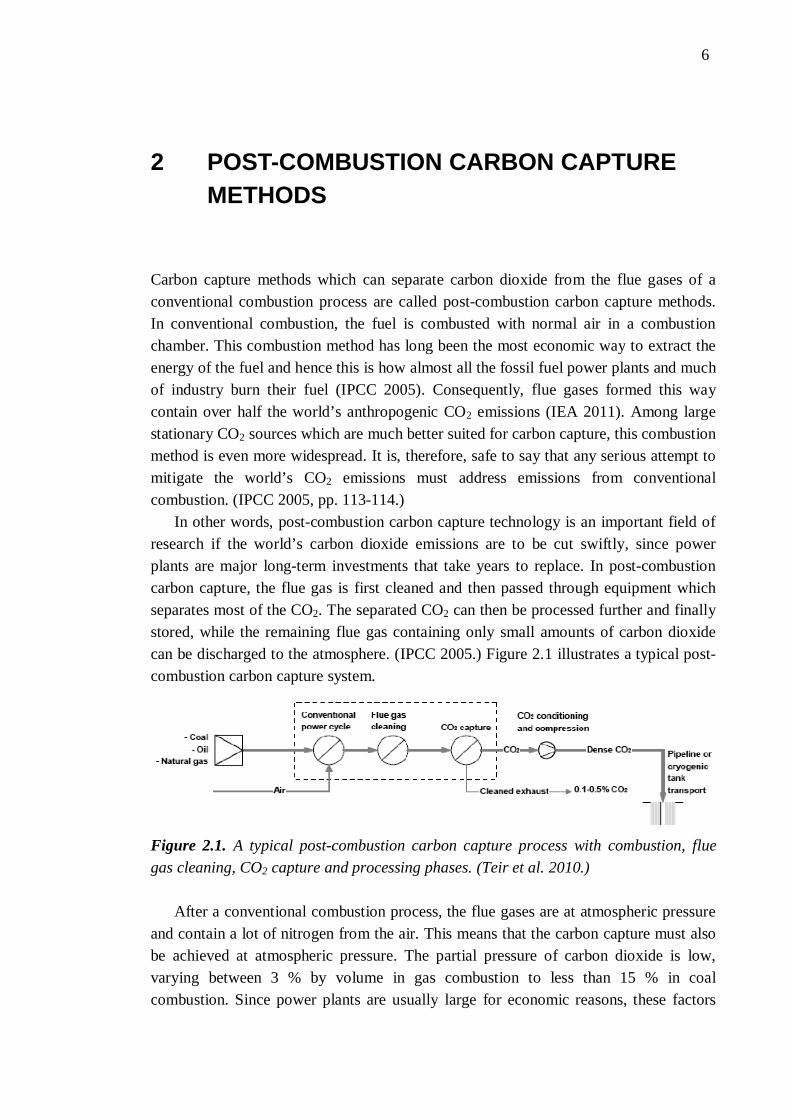
Carbon capture methods which can separate carbon dioxide from the flue gases of a conventional combustion process are called post-combustion carbon capture methods. In conventional combustion, the fuel is combusted with normal air in a combustion chamber. This combustion method has long been the most economic way to extract the energy of the fuel and hence this is how almost all the fossil fuel power plants and much of industry burn their fuel (IPCC 2005). Consequently, flue gases formed this way contain over half the world’s anthropogenic CO2 emissions (IEA 2011). Among large stationary CO2 sources which are much better suited for carbon capture, this combustion method is even more widespread. It is, therefore, safe to say that any serious attempt to mitigate the world’s CO2 emissions must address emissions from conventional combustion. (IPCC 2005, pp. 113-114.)
In other words, post-combustion carbon capture technology is an important field of research if the world’s carbon dioxide emissions are to be cut swiftly, since power plants are major long-term investments that take years to replace. In post-combustion carbon capture, the flue gas is first cleaned and then passed through equipment which separates most of the CO2. The separated CO2 can then be processed further and finally stored, while the remaining flue gas containing only small amounts of carbon dioxide can be discharged to the atmosphere. (IPCC 2005.) Figure 2.1 illustrates a typical post-combustion carbon capture system.
Figure 2.1. A typical post-combustion carbon capture process with combustion, flue gas cleaning, CO2 capture and processing phases. (Teir et al. 2010.)
After a conventional combustion process, the flue gases are at atmospheric pressure and contain a lot of nitrogen from the air. This means that the carbon capture must also be achieved at atmospheric pressure. The partial pressure of carbon dioxide is low, varying between 3 % by volume in gas combustion to less than 15 % in coal combustion. Since power plants are usually large for economic reasons, these factors
2. Post-combustion carbon capture methods 7
together mean that the flue gas flows are often immense, sometimes with volumes measured in millions of cubic meters per hour.
For this reason any capture technology used must be able to continually handle large gas flows. All the above factors set important requirements for the capture technology. (IPCC 2005.) Currently, chemical solvents, usually aqueous amines, are seen as the best option for separating carbon dioxide from other gases in such conditions (Kohl & Nielsen 1997; Figueroa et al. 2008). This thesis therefore focuses on carbon capture with amines.
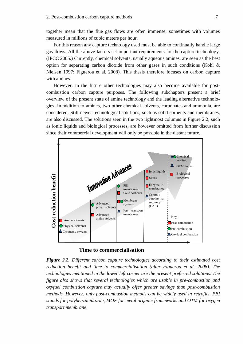
However, in the future other technologies may also become available for post-combustion carbon capture purposes. The following subchapters present a brief overview of the present state of amine technology and the leading alternative technolo-gies. In addition to amines, two other chemical solvents, carbonates and ammonia, are considered. Still newer technological solutions, such as solid sorbents and membranes, are also discussed. The solutions seen in the two rightmost columns in Figure 2.2, such as ionic liquids and biological processes, are however omitted from further discussion since their commercial development will only be possible in the distant future.
Figure 2.2. Different carbon capture technologies according to their estimated cost reduction benefit and time to commercialisation (after Figueroa et al. 2008). The technologies mentioned in the lower left corner are the present preferred solutions. The figure also shows that several technologies which are usable in pre-combustion and oxyfuel combustion capture may actually offer greater savings than post-combustion methods. However, only post-combustion methods can be widely used in retrofits. PBI stands for polybenzimidazole, MOF for metal organic frameworks and OTM for oxygen transport membrane.
Cos
t red
uctio
n be
nefit
Time to commercialisation
Key:
Post-combustion
Pre-combustion
Oxyfuel combustion
Amine solvents
Physical solvents
Cryogenic oxygen
Advanced phys. solvents Advanced amine solvents
PBI membranes Solid sorbents Membrane systems
Ion transport membranes
Ionic liquids
MOFs
Enzymatic membranes
Ceramic autothermal recovery (CAR)
Chemical looping
OTM boiler Biological processes

2. Post-combustion carbon capture methods 8
This chapter should also provide a better understanding of why amines are still the preferred solution in many applications despite their apparent shortcomings. As Figure 2.2 shows, other technologies may offer greater cost reduction potential than amines in the long run. As discussed below, amines may nevertheless find a use as additives in many of the alternative technological solutions.
2.1 Capture with Chemical Absorption
In absorption methods the gas separation is achieved by putting the flue gas in physical contact with an absorbent which is capable of capturing the CO2 (IPCC 2005). In post-combustion applications, this is achieved with absorbents which are able to form chemical compounds with CO2. These methods are therefore called chemical absorption methods. Today, they are clearly the preferred solution for CO2 separation at low or moderate CO2 partial pressures (Olajire 2010). However, it is worth noting that physical absorption methods also exist. In the latter, the CO2 is physically dissolved without a chemical reaction. This means that the solvent can also be regenerated without a chemical reaction, which saves a lot of energy, but physical absorption methods are inapplicable to flue gases which have low pressure and low carbon dioxide content (Olajire 2010). Hence they are not discussed further in this thesis.
Figure 2.3 presents a general scheme of an absorption process. First, the flue gas containing CO2 enters a vessel where the sorbent is present. The sorbent is usually in an aqueous solution (IPCC 2005). In this first vessel, the sorbent captures most of the CO2
while the other gases are allowed to pass through. Then, the sorbent with the CO2 is taken to another vessel where the CO2 is released by a chemical reaction (chemical desorption) or by a change in temperature or pressure (physical desorption). Then the CO2 is removed from the process and can be processed further and the sorbent can be recycled in the same way as before. However, a small part of the sorbent is always destroyed or degraded, which means that a little sorbent has to be added and a little removed. Naturally, the desorption process requires some energy to be added to the system. The amount of energy needed varies according to the technology used and this has a major effect on the overall economics of the carbon capture process (Olajire 2010).
Figure 2.3. A general scheme for an absorption process (IPCC 2005).
2. Post-combustion carbon capture methods 9
This subchapter discusses three different chemical absorption systems. The first of these is the amine-based capture system, which is also the most developed of these systems. As amine-based systems are the primary subject of this thesis, they will be discussed in greater depth in later chapters. However, alternative chemical absorbents are also being developed and two of these, carbonates and ammonia, are briefly reviewed here.
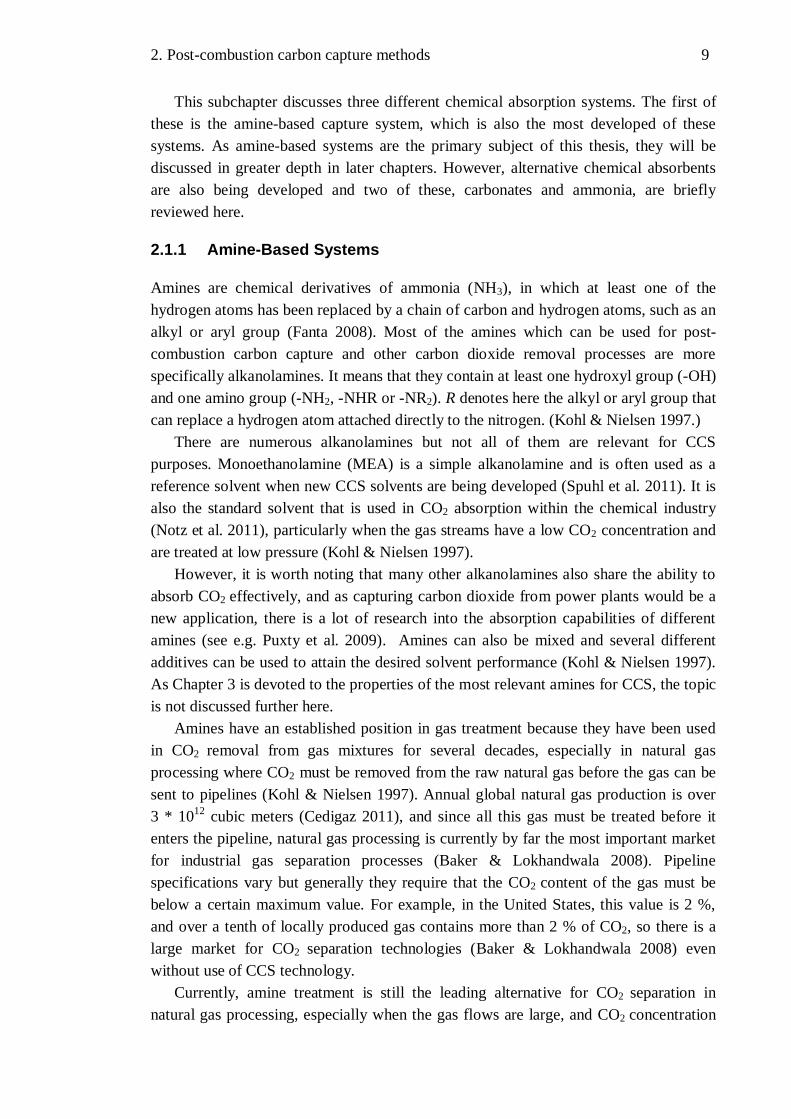
2.1.1 Amine-Based Systems
Amines are chemical derivatives of ammonia (NH3), in which at least one of the hydrogen atoms has been replaced by a chain of carbon and hydrogen atoms, such as an alkyl or aryl group (Fanta 2008). Most of the amines which can be used for post-combustion carbon capture and other carbon dioxide removal processes are more specifically alkanolamines. It means that they contain at least one hydroxyl group (-OH) and one amino group (-NH2, -NHR or -NR2). R denotes here the alkyl or aryl group that can replace a hydrogen atom attached directly to the nitrogen. (Kohl & Nielsen 1997.)
There are numerous alkanolamines but not all of them are relevant for CCS purposes. Monoethanolamine (MEA) is a simple alkanolamine and is often used as a reference solvent when new CCS solvents are being developed (Spuhl et al. 2011). It is also the standard solvent that is used in CO2 absorption within the chemical industry (Notz et al. 2011), particularly when the gas streams have a low CO2 concentration and are treated at low pressure (Kohl & Nielsen 1997).
However, it is worth noting that many other alkanolamines also share the ability to absorb CO2 effectively, and as capturing carbon dioxide from power plants would be a new application, there is a lot of research into the absorption capabilities of different amines (see e.g. Puxty et al. 2009). Amines can also be mixed and several different additives can be used to attain the desired solvent performance (Kohl & Nielsen 1997). As Chapter 3 is devoted to the properties of the most relevant amines for CCS, the topic is not discussed further here.
Amines have an established position in gas treatment because they have been used in CO2 removal from gas mixtures for several decades, especially in natural gas processing where CO2 must be removed from the raw natural gas before the gas can be sent to pipelines (Kohl & Nielsen 1997). Annual global natural gas production is over 3 * 1012 cubic meters (Cedigaz 2011), and since all this gas must be treated before it enters the pipeline, natural gas processing is currently by far the most important market for industrial gas separation processes (Baker & Lokhandwala 2008). Pipeline specifications vary but generally they require that the CO2 content of the gas must be below a certain maximum value. For example, in the United States, this value is 2 %, and over a tenth of locally produced gas contains more than 2 % of CO2, so there is a large market for CO2 separation technologies (Baker & Lokhandwala 2008) even without use of CCS technology.
Currently, amine treatment is still the leading alternative for CO2 separation in natural gas processing, especially when the gas flows are large, and CO2 concentration

2. Post-combustion carbon capture methods 10
and partial pressure are fairly low (Baker & Lokhandwala 2008). These conditions closely resemble the requirements that a good post-combustion carbon capture technology must meet. It is therefore understandable that amine-based systems are thought likely to play an important role in decreasing the carbon dioxide emissions of conventional power plants.
As noted earlier with regard to chemical absorption systems, amines are capable of capturing carbon dioxide by chemical reactions. In amine-based systems this is achieved by letting an aqueous amine solvent react with the carbon dioxide present in the flue gas. They form a water soluble compound (Figueroa et al. 2008) and the reaction can be quite easily reversed, which allows continuous operation (IPCC 2005). Generally, the unit where the carbon dioxide is absorbed from the flue gas is called an absorber, and the unit where the CO2 is again released is called a desorber or stripper.
A typical amine-based CO2 absorption process is shown in Figure 2.4. As the figure shows, the flue gas must first be cooled for absorption. For amines, this means reducing the temperature to 40-60 °C. Then, the lean solvent is brought into contact with the flue gas in a packed absorber tower, which operates at close to atmospheric pressure. The flue gas exiting the top of the absorber is water-washed to reduce amine loss, after which the flue gas can be vented to the atmosphere. (Rackley 2010.)
The rich solvent containing the CO2 exits the base of the tower and is pumped to the top of the amine stripping tower. The solvent is first heated with the help of a heat exchanger, which recovers heat from the regenerated solvent because the temperature in the stripper tower is 100-140 °C. The stripper operates at marginally higher pressure than the absorber. To reach such temperature in the stripper, more heat must be added and this is supplied by a reboiler, which would typically be integrated into the steam cycle of the host plant. The stripping releases the amine solvent for reuse at the base of the tower while the steam and CO2 exit the top of the tower. The steam is then con-densed and the CO2 can then be moved on for further processing. (Rackley 2010.) Figure 2.4. A typical flow scheme for an amine absorption unit for CO2 recovery from flue gas (after Rackley 2010).
Flue gas cooler
Wash water cooler cooler Lean solvent
cooler
Reflux condenser
Solvent reboiler Heat
exchanger
Abs
orbe
r to
wer
Stri
pper
tow
er
Ref
lux
drum
Flue gas to stack
Water wash
Flue gas
Water make-up
Lean solvent
Rich solvent
CO2 to compression

2. Post-combustion carbon capture methods 11
As noted earlier, the compound formation in the absorber tower allows CO2 capture from streams with low CO2 partial pressure, such as flue gases from conventional combustion, but the capacity is inevitably limited by equilibrium (Figueroa et al. 2008). The regeneration of the solvent at high temperature requires a lot of energy, which leads to a cost and efficiency penalty (IPCC 2005). Other drawbacks of amine solutions are that they are generally corrosive to the process equipment and the amines degrade because of impurities in the flue gas, which induces a high amine make-up rate (Olajire 2010). This means that SOx and NOx must be removed from the flue gas before the absorption process. However, in practice some impurities are always left in the gas, so the degradation of amines due to impurities remains a problem (Olajire 2010). Solutions to these problems are being sought and these are discussed in Chapters 4 and 5.
2.1.2 Carbonate-Based Systems
Carbonates are salts of carbonic acid (H2CO3) and they contain the carbonate ion CO32-.
Carbonate-based carbon capture systems are based on the ability of a soluble carbonate to react with CO2. This reaction forms bicarbonate which releases the CO2 when heated, thus reverting to a carbonate. (Figueroa et al. 2008.) In other words, the process is very similar to the amine system described above. The best results with CO2 separation have been achieved with sodium and potassium carbonates (Kohl & Nielsen 1997), so these form the focus of the present subchapter.
Carbonate systems actually preceded amine systems in CO2 separation. As early as the beginning of the 20th century, sodium carbonate (Na2CO3) solutions were used in dry ice factories to separate CO2 from flue gas (Howe 1928). However, the introduction of amines for the same purpose led to a rapid decline in the use of carbonates. The main reasons were that the CO2 absorption is faster in amine systems and it is easier to achieve very high CO2 removal efficiencies with them. (Knuutila 2009.)
These problems have been overcome in the widely used hot carbonate process, also known as the Benfield process, by raising the partial pressure of CO2 in the absorber. In this process, which was developed in the 1950s, the absorption takes place at high pressure, around 20 bar, and at temperatures around 100 °C. The absorbent used is aqueous potassium carbonate (K2CO3). Nowadays, promoters, often different amines, are added to the process to further increase the absorption rate. In the regeneration phase the pressure of the solvent is decreased, which decreases the solubility of CO2 in the solvent, thus releasing a significant part of the CO2. This pressure swing means that much less heat is needed for the regeneration. As a consequence, the total energy requirement is relatively low, but the need for a high pressure in the absorber makes the Benfield process uneconomical for post-combustion applications. (Kohl & Nielsen 1997; Knuutila 2009.)
However, the lower total energy requirement for carbonate systems applies even at normal pressure and temperature, which has led to renewed interest in carbonate systems in recent years. The heat of reaction of CO2 absorption by aqueous sodium carbonate is only a third of the heat of reaction for MEA, which is a common amine
2. Post-combustion carbon capture methods 12
used for CO2 separation. Several additives to increase the CO2 absorption rate, usually referred to as promoters or activators, were discovered in 1930s (Killeffer 1937). Amines, glycine and arsenious acid have been used commercially as promoters in carbonate systems (Kohl & Nielsen 1997) and recently piperazine has been studied intensively because of its good performance (Cullinane & Rochelle 2004; Knuutila 2009). However, piperazine is more expensive than some other amine additives, which may limit its use (Figueroa et al. 2008).
Carbonates also have other advantages because they are environmentally safe (OSPAR Commission 2008), non-volatile and do not degrade (Knuutila 2009). Sodium-based chemicals are already used in some power plants for SO2 removal. In the future a method could, therefore, be developed to combine CO2 and SO2 removal that would reduce costs significantly (Knuutila 2009). Despite some promising test results, overall development of carbonate systems for post-combustion applications still lags behind that of amine systems (Figueroa et al. 2008). Consequently, they are not discussed further in this thesis.
2.1.3 Ammonia-Based Systems
Ammonia (NH3) is a chemical compound consisting of nitrogen and hydrogen, and it is widely used in the fertilizer and other chemical industries and also as a refrigerant and a cleaning or neutralising agent. It is, in fact, one of the most important chemicals produced in the world, not only financially but also because ammonia and its derivatives play a vital role in the food production chain as fertilizers. (Kent 2007.) The large production volumes mean that ammonia is cheap compared to the alternative chemicals for carbon dioxide absorption (Resnik et al. 2004). In CO2 capture, ammonia systems work in a similar way to amine-based systems (Figueroa et al. 2008).
Ammonia and its derivatives can react with CO2 via various mechanisms, one of which is the reaction of ammonium carbonate, CO2 and water to form ammonium bicarbonate. This reaction has a much lower heat of reaction than amine systems, which results in energy savings if the absorption/desorption cycle can be limited to this mechanism. Relatively low price, potential for high CO2 capacity, lack of degradation during absorption and regeneration and tolerance to oxygen and many impurities in the flue gas are other advantages ammonia-based systems can offer. Ammonia may also be simultaneously used to capture SOx and NOx gases, which are often present in flue gases. Additionally, the end products, ammonium sulphate and ammonium nitrate, would be saleable by-products (Figueroa et al. 2008).
Ammonia-based CO2 absorption methods for synthesis gas treatment were already developed by the middle of the 20th century, as they had the above-mentioned advantage of being unaffected by several impurities in the processed gas. However, the process was more complex than alternative processes such as amine systems, and too much CO2
was left in the purified gas, so these methods fell largely out of use. (Kohl & Nielsen 1997.) Ammonia is also more volatile than the alternative compounds, which creates some safety risks (Figueroa et al. 2008).

2. Post-combustion carbon capture methods 13
However, the advance of climate change and the need for new carbon dioxide capture methods have generated new interest in ammonia systems. The complexity of ammonia systems stems largely from the fact that the flue gases must be cooled to fairly low temperatures (15 – 30 °C) to enhance the CO2 absorptivity of the ammonia compound and to minimize ammonia vapour losses. The ammonia losses must also be prevented in the regeneration phase, where the temperature is higher. (Figueroa et al. 2008.) Bai & Yeh (1997) have presented a design where the loss problems in the absorber are addressed by a mist eliminator. This conceptual design can be seen in Figure 2.5. More recently several researchers have reported very promising performances for ammonia systems that show clear advantages over traditional amine systems (Yeh & Bai 1999; Resnik et al. 2004; Yeh et al. 2005).
Figure 2.5. Conceptual design of an ammonia-based carbon capture process proposed by Bai & Yeh (1997). The absorber unit is on the left and the desorber on the right. The resemblance to Figure 2.4 can easily be seen.
A variation on the ammonia-based process is the chilled ammonia process (CAP) which is being developed by Alstom. This process uses the same ammonium carbonate (AC) / ammonium bicarbonate (ABC) absorption chemistry as the aqueous system described above, but differs in that no fertilizer is produced. Another difference is that it is actually a slurry of aqueous AC and ABC and solid ABC, which is circulated to capture the CO2. The absorption occurs at cool temperatures (0 – 10 °C) to improve performance and to prevent the ammonia losses, so the flue gases must be cooled considerably. (Figueroa et al. 2008.) Ideally, the regeneration is realized at 100 – 150 °C while the pressure is in the range of 0.2 – 138 MPa, which is already significantly above ambient pressure (Darde et al. 2010). A flow schematic of the process is shown in

2. Post-combustion carbon capture methods 14
Figure 2.6. On the right are the direct contact cooling (DCC) towers, in the middle the absorption equipment and on the left the regeneration equipment. In the figure it is clear that much cooling and heat exchanging is needed.
Figure 2.6. A schematic flow diagram of the chilled ammonia process (Kozak et al. 2009).
The complexity of the system and the problems mentioned above create various technical drawbacks. However, the successful demonstration at a coal-fired AEP Mountaineer power plant in West Virginia, USA, suggests that the chilled ammonia process is, in fact, one of the most promising post-combustion capture technologies under development. The demonstration was on a fairly large scale, because about 100 kt of CO2 was captured in a year and the amount of flue gas processed was equivalent to the flue gas stream of a coal plant with 54 MW thermal power. (Telikapalli et al. 2011.)
However, despite their various advantages over amine systems, it remains to be seen if ammonia systems can challenge amine systems as the baseline technology in the future. The AEP Mountaineer project is currently the largest operational ammonia-based carbon capture project, since no large commercial ammonia-based carbon capture systems have yet been built (Telikapalli et al. 2011). Since amine-based systems form the main topic of this thesis, ammonia-based processes will not be discussed further.
2. Post-combustion carbon capture methods 15
2.2 Capture with Membranes
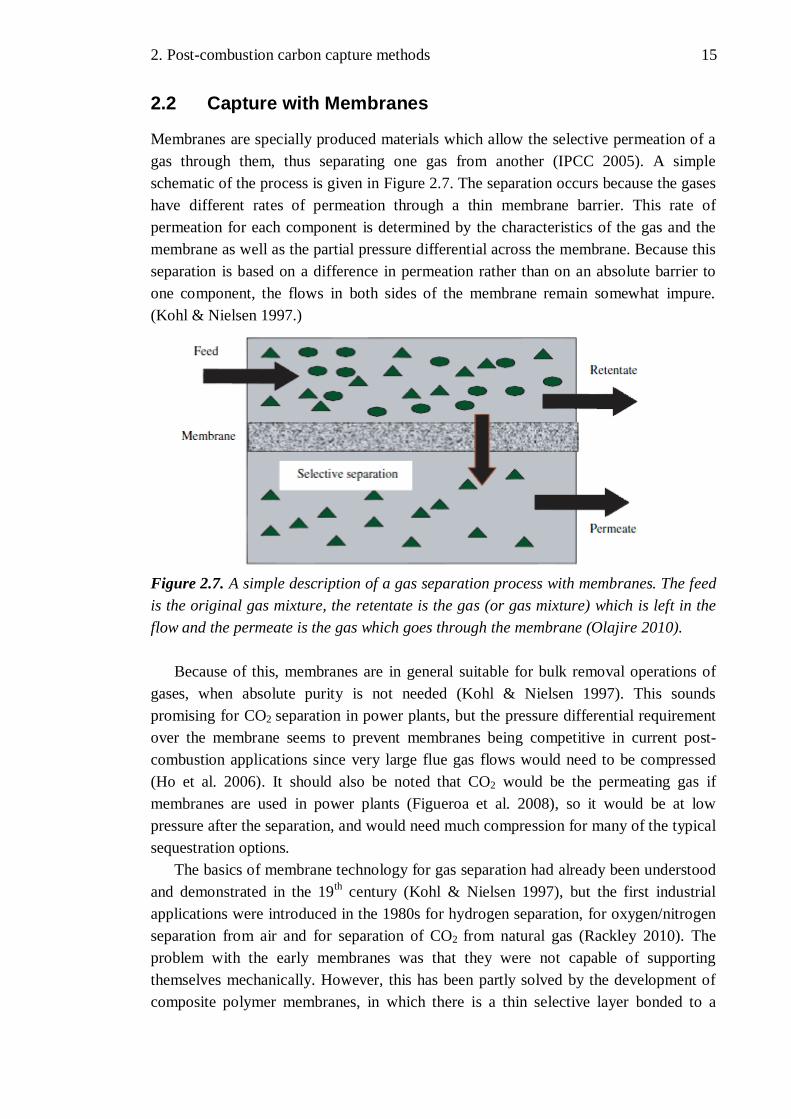
Membranes are specially produced materials which allow the selective permeation of a gas through them, thus separating one gas from another (IPCC 2005). A simple schematic of the process is given in Figure 2.7. The separation occurs because the gases have different rates of permeation through a thin membrane barrier. This rate of permeation for each component is determined by the characteristics of the gas and the membrane as well as the partial pressure differential across the membrane. Because this separation is based on a difference in permeation rather than on an absolute barrier to one component, the flows in both sides of the membrane remain somewhat impure. (Kohl & Nielsen 1997.)
Figure 2.7. A simple description of a gas separation process with membranes. The feed is the original gas mixture, the retentate is the gas (or gas mixture) which is left in the flow and the permeate is the gas which goes through the membrane (Olajire 2010).
Because of this, membranes are in general suitable for bulk removal operations of gases, when absolute purity is not needed (Kohl & Nielsen 1997). This sounds promising for CO2 separation in power plants, but the pressure differential requirement over the membrane seems to prevent membranes being competitive in current post-combustion applications since very large flue gas flows would need to be compressed (Ho et al. 2006). It should also be noted that CO2 would be the permeating gas if membranes are used in power plants (Figueroa et al. 2008), so it would be at low pressure after the separation, and would need much compression for many of the typical sequestration options.
The basics of membrane technology for gas separation had already been understood and demonstrated in the 19th century (Kohl & Nielsen 1997), but the first industrial applications were introduced in the 1980s for hydrogen separation, for oxygen/nitrogen separation from air and for separation of CO2 from natural gas (Rackley 2010). The problem with the early membranes was that they were not capable of supporting themselves mechanically. However, this has been partly solved by the development of composite polymer membranes, in which there is a thin selective layer bonded to a
2. Post-combustion carbon capture methods 16
thicker, non-selective and inexpensive layer providing mechanical support. Neverthe-less, mechanical weakness remains one of membranes’ problems. (Rackley 2010.)
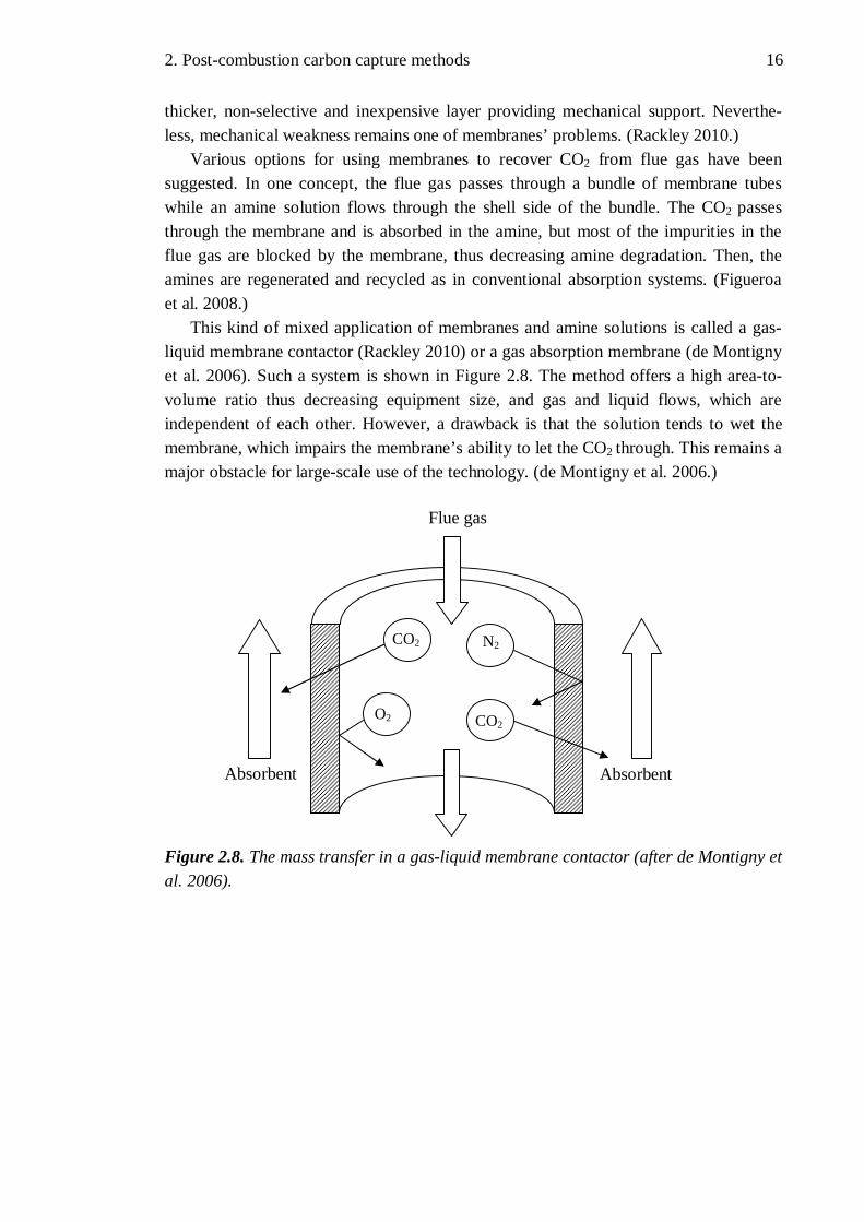
Various options for using membranes to recover CO2 from flue gas have been suggested. In one concept, the flue gas passes through a bundle of membrane tubes while an amine solution flows through the shell side of the bundle. The CO2 passes through the membrane and is absorbed in the amine, but most of the impurities in the flue gas are blocked by the membrane, thus decreasing amine degradation. Then, the amines are regenerated and recycled as in conventional absorption systems. (Figueroa et al. 2008.)
This kind of mixed application of membranes and amine solutions is called a gas-liquid membrane contactor (Rackley 2010) or a gas absorption membrane (de Montigny et al. 2006). Such a system is shown in Figure 2.8. The method offers a high area-to-volume ratio thus decreasing equipment size, and gas and liquid flows, which are independent of each other. However, a drawback is that the solution tends to wet the membrane, which impairs the membrane’s ability to let the CO2 through. This remains a major obstacle for large-scale use of the technology. (de Montigny et al. 2006.) Figure 2.8. The mass transfer in a gas-liquid membrane contactor (after de Montigny et al. 2006).
Flue gas
Absorbent
CO2
N2
O2
CO2
Absorbent

2. Post-combustion carbon capture methods 17
Other membrane concepts are also being developed. In facilitated transport membranes an amine carrier has been incorporated into a polymer membrane (Rackley 2010). In these membranes the carrier substance is able to react reversibly with the CO2. This means that the CO2 not only diffuses through the membrane as a gas but is also transported through by the carrier. The other gases in the flue gas use only the normal diffusion method through the membrane as they do not react with the carrier, so their permeation rate is much lower. (Huang et al. 2008.) A schematic of the facilitated transport mechanism is shown in the Figure 2.9. On a laboratory scale facilitated transport membrane systems have shown promising results, but they are still far from large-scale use (Rackley 2010).
Figure 2.9. A schematic of the facilitated transport mechanism (Huang et al. 2008).
Inorganic membranes are another membrane-using CO2 capture option. Amine functional groups can be added to microporous silica membranes to better separate CO2
from flue gas (Figueroa et al. 2008) since silica membranes generally have a low selectivity in this application (Rackley 2010). This modification of the membrane should allow selective diffusion of CO2 in the membrane, while still blocking the unwanted gases. However, the balance between permeance and selectivity remains a challenge. (Figueroa et al. 2008.)
Zeolite membranes are also being studied for post-combustion carbon capture applications. Zeolites have well-defined and uniform-sized pores of molecular dimensions, so small-pore zeolites are well-suited to gas separation if the gas molecules are different enough in size. This application has been successfully used in natural gas processing when carbon dioxide needs to be separated from methane. Unfortunately, however, CO2 and N2 which are the main gases in flue gas are very similar in size. Zeolites with larger pores have also been tested in CO2 separation, but here some competitive adsorption favouring CO2 is needed as additional assistance to enhance the selectivity. (Olajire 2010.)
In conclusion, there is a lot of research into membranes for CO2 separation, both in natural gas processing and also for CCS applications. Their use in natural gas processing is growing and they have an especially strong position in offshore platforms because of the smaller size of the membrane systems as well as various other advantages (Baker & Lokhandwala 2008). However, for post-combustion carbon

2. Post-combustion carbon capture methods 18
capture applications which have a fairly low CO2 content, no membrane technology seems to be able to compete with amine systems. This has been the conclusion of several studies (see Ho et al. 2005; Favre 2007; Yang et al. 2011).
It is, however, worth noting that all the studies mentioned above consider membrane technology to be a possible serious competitor to amine technology in the future. Indeed the cost estimates for membrane capture systems are not so much higher as to be excluded from consideration. Yang et al. (2011) also note that current membrane technology is not as mature as amine technology, so there may well be further scope for development. However, in this thesis membrane technology is not given further consideration.
2.3 Capture with Solid Sorbents
A number of solids can also be used to interact or react with CO2 to form stable compounds under certain operating conditions. Then, under different conditions, the solids can release the CO2 and re-form the original compound (Figueroa et al. 2008). The process is similar to that described in Figure 2.3 though it should be noted that, in the case of solids, the process is an adsorption process. The difference is that in adsorp-tion the adsorbed molecules remain on the surface of the sorbent whilst in absorption the absorbed component enters into the bulk of the solvent to form a solution. However, as in absorption, the adsorption can also be either chemical or physical. (Rackley 2010.)
Because adsorption occurs on the surface of the adsorbent, the quantity of material adsorbed is directly related to the area of surface available for adsorption, and the usual adsorbents are prepared in such a way as to have a large surface area per unit weight (Kohl & Nielsen 1997). The most important characteristic of a sorbent is, in fact, the quantity of sorbate that a given quantity of sorbent can hold at the operating temperatures and pressures. This can also be called working capacity. As the CCS application requires that CO2 is separated from the flue gas, which is a mixture of gases, it is equally important that the sorbent is selective for CO2. In other words, the adsorbent needs to adsorb plenty of CO2 but it should not adsorb much of any of the other gases. (Rackley 2010.)
Different adsorption methods are often named after the condition which is changed during the process. The two main methods relevant for CO2 capture are temperature swing adsorption (TSA) and pressure swing adsorption (PSA). These can also be combined to form a hybrid or PTSA process. Interesting variants of these include electric swing adsorption (ESA), in which the temperature swing is achieved rapidly by passing a current through the sorbent material, and vacuum swing adsorption (VSA), where a partial vacuum is used in the desorption phase, thus minimising or avoiding the need for feed gas compression. The magnitude of the required temperature or pressure change, of course, depends on the sorbent used (Rackley 2010).
In common with the absorption processes, gas separation or purification based on adsorption has a long history of industrial application (Rackley 2010). Silica gel, which

2. Post-combustion carbon capture methods 19
is often found inside packages to prevent moisture damage, is actually an everyday adsorbent application, because the silica gel is able to adsorb water from the air (Kohl & Nielsen 1997). However, for industrial purposes the adsorbent must be reused many times unlike the silica gel in packages, so there is a need for a process where the adsorption and the desorption alternate. In principle, solid adsorbents have a number of advantages over absorption with liquids, including the absence of liquid waste streams, a wide range of operating temperatures and the formation of solid wastes which are often fairly easy to handle (Rackley 2010). However, it has not proved easy to find suitable solid sorbents for CO2 separation from flue gases and no large-scale systems have been commercialized (Figueroa et al. 2008). Choi et al. (2009) note that in general, there is no reason to suggest that adsorption is the ideal way to achieve efficient CCS, though certain adsorbents do show some promise.
In recent decades there has been a rapid expansion in the application of adsorption as a gas separation technology and a versatile range of adsorbents is now under development for CO2 separation from flue gases (Rackley 2010). These include both chemical and physical solid adsorbents and these different types are introduced in next two subchapters. A more detailed account of solid adsorbents suitable for CO2
adsorption in power plants can be found in Choi et al. (2009). In general, physical adsorbents have weaker binding forces resulting in a lower heat of adsorption, while the chemical adsorbents have a higher heat of adsorption. This means that chemical sorbents are usually used at high operating temperatures while physical sorbents are used at lower temperatures. (Rackley 2010.)
2.3.1 Chemical adsorbents
The properties sought for chemical absorbents are similar to those for chemical adsorbents. They should be selective for CO2, heat of adsorption should be low in order to minimise the energy penalty in the desorption stage, and they should maintain their performance through many cycles. As with all adsorbents, it is also, of course, beneficial if the substance can adsorb as much CO2 per unit as possible. (Rackley 2010.)
One way to answer to such challenges is to look at the substances already used in power plants in other applications. Shimizu et al. (1999) proposed using calcium oxide (CaO) for CO2 capture from flue gas as CaO and calcium carbonate (CaCO3) are already often used in power plants for flue gas desulphurisation. Calcium carbonate is readily available in the form of natural limestone and therefore inexpensive. (Ströhle et al. 2009).
This is a temperature swing adsorption process where CaO is used as a solid chemi-cal adsorbent which can be regenerated. Using CaO for CO2 capture was already pro-posed in the 19th century and other metal oxides have also been considered as chemical adsorbents for the same purpose (Rackley 2010), so this was not a totally new idea. For CaO, the carbonation reaction combining CaO and CO2 to CaCO3 proceeds rapidly and high sorbent capacity is achieved at around 600-800 °C. The calcining reaction, releasing the CO2 is favoured at >900 °C. (Rackley 2010.)

2. Post-combustion carbon capture methods 20
This method, sometimes called CaO looping, has shown promising research results (Ströhle et al. 2009). The concept is shown in Figure 2.10. However, the ability of CaO to adsorb CO2 decreases over time when it is recycled, so fresh CaCO3 must be steadily supplied to the process (Ströhle et al. 2009). However additional advantage is the potential for combining desulphurisation with carbon capture in the future, thus reducing investment costs.
Figure 2.10. Process scheme for a CaO looping process (Ströhle et al. 2009).
Another potential TSA method to remove CO2 from hot flue gas uses is the use of lithium compounds. Lithium zirconate (Li2ZrO3) is able to capture CO2 by forming lithium carbonate (Li2CO3) and zirconium oxide (ZrO2) and the reaction is reversible in the temperature range of 450-590 °C (Yang et al. 2008), so this system also uses chemical adsorption. The adding of eutectic salts further improves the adsorption capacity (Fauth et al. 2005). Yang et al. (2008) also note that lithium silicate (Li4SiO4) is another possible candidate for a competitive future CO2 adsorbent in high temperatures. These compounds also lose their sorption capacity much more slowly in repeated cycling than calcium-based minerals mentioned above (Rackley 2010).
However, amines have also found some use in solid adsorbents. As Gray et al. (2005) note, immobilized amine sorbents have already found some use for CO2 level control in aircraft, spacecraft and submarine applications, but their price remains too high for large-scale applications in the utility industry. However, since the good CO2 sorption capacity of amines is widely recognised, immobilized amine sorbents are also being studied for their potential to capture carbon dioxide from flue gas streams in a conventional power plant (see Samanta et al. 2012).

2. Post-combustion carbon capture methods 21
2.3.2 Physical adsorbents
The binding forces between the gas molecules and the surface of the adsorbent are weaker for physical than for chemical adsorbents. Consequently, the adsorbent must have a very high selectivity for CO2 as it would be uneconomical to adsorb a lot of nitrogen or other gases from the flue gas. The heat of adsorption should be low and the sorbent should have a high working capacity to reduce the energy consumption and the required volume of the sorbent, as is also the case for chemical adsorbents. Additionally, it is important that the physical adsorbent has a steep adsorption isotherm which means that the change in condition required for desorption is as small as possible. This isotherm should also be maintained through many adsorption-desorption cycles, as adsorption hysteresis tends to increase the required condition change over time. (Rackley 2010.)
Numerous physical adsorbents are being researched. Activated carbon has very good adsorption capability and a steep adsorption isotherm, though its isotherm shows major problems with hysteresis. This reduces working capacity over time. Various zeolite materials generally have a lower adsorption capacity but suffer less from hysteresis. Activated alumina, silica gel and ion-exchange resins are among other proposed adsorbents. (Rackley 2010.) In general, physical adsorbents function better at higher pressures and at fairly low temperatures but their performance is impaired by moisture which is usually present in flue gas. There are thus several major obstacles to their use in post-combustion carbon capture (Choi et al. 2009).

22 22
3 AMINES AS CHEMICAL COMPOUNDS
As noted earlier, amines are chemical derivatives of ammonia (NH3) in which at least one of the hydrogen atoms has been replaced by a chain of carbon and hydrogen atoms. These replacements can be, for example, alkyl or aryl groups. (Fanta 2008.) The amines best suited for post-combustion carbon capture and other carbon dioxide removal processes are more specifically alkanolamines, which contain at least one hydroxyl group (-OH) and one amino group (-NH2, -NHR or -NR2). (Kohl & Nielsen 1997.) Here R denotes an alkyl or aryl group.
In general, it can be considered that the hydroxyl group serves to reduce the vapour pressure and increase the water solubility, while the amino group provides the necessary alkalinity in water solutions to cause the absorption of acidic gases, such as CO2. Amines can be divided into three groups: primary, secondary and tertiary amines and the members of each group tend to have similar properties to each other. Primary amines have two hydrogen atoms attached directly to the nitrogen (-NH2), secondary amines only one (-NHR) and tertiary amines no hydrogen atoms at all attached to the nitrogen (-NR2). Primary amines are usually the most alkaline. (Kohl & Nielsen 1997.)
Several alkanolamines can be and have been used for CO2 removal in various appli-cations (Kohl & Nielsen 1997; Ritter & Ebner 2007) and possible new amine solvents are being researched (see e.g. Puxty et al. 2009). However, here the focus is on the most important and common amines in order to summarize their properties as well as their health and environmental impacts. According to Ritter & Ebner (2007), monoethanolamine (MEA), diethanolamine (DEA), methyldiethanolamine (MDEA) and piperazine (PIPA or PZ) are the most important substances for carbon dioxide removal from gas streams since these have received much more scientific attention than the others.
However, Olajire (2010) notes that in recent years sterically hindered amines such as 2-amino-2-methyl-1-propanol (AMP) have also been investigated for their potential to remove CO2 from acidic gases. The importance of sterically hindered amines is confirmed by Desideri (2010) who states that MEA and a sterically hindered amine solvent called KS-1 are the only amines currently being used commercially for CO2 recovery from power plant flue gases.
The five substances mentioned above are discussed further in the following subchapter. Many recent studies suggest that these amines could be used in combination with each other or with other amines to achieve the desired properties (Olajire 2010) and so it is important to be acquainted with a number of them. The second subchapter summarizes the findings on the health and environmental effects of the most important

3. Amines as chemical compounds 23
amines. The degradation products of these amines are also discussed because several studies suggest that they may pose more danger to health and the environment than the amines themselves.
3.1 Amines relevant for post-combustion carbon capture
As noted above, several amines can be considered relevant for post-combustion capture. A recent scientific review (Olajire 2010), an industry report (Ritter & Ebner 2007) and the report by Norwegian health officials (Låg et al. 2011) all acknowledge MEA, DEA, MDEA, PIPA and AMP to be among the most important amines for this purpose. Figure 3.1 shows their structural formulas. The figure also includes the formulas of three other amines, which are important mainly in natural gas treatment but also have particularly historical significance for the absorption technology.
Figure 3.1. The structural formulas of 8 different amines. The empty line ends mean that a hydrogen atom is linked to the carbon atom, so the complete structural formula of monoethanolamine is NH2-CH2-CH2-OH, for example. (Kohl & Nielsen 1997.)
As Figure 3.1 shows, monoethanolamine (MEA), AMP and 2-2-aminoethoxy-
ethanol, often called diglycolamine (DGA), are primary amines because they have two hydrogen atoms linked directly to the nitrogen atom. Diethanolamine (DEA) and diisopropanolamine (DIPA) are secondary amines, and
3. Amines as chemical compounds 24
methyldiethanolamine (MDEA) and triethanolamine (TEA) are tertiary amines. Piperazine is different in two ways because it has two amine groups and it does not contain a hydroxyl group. Therefore, it is not an alkanolamine but only an amine with two secondary amine groups.
Because MEA is often used as a reference solvent for other solvents and is also widely used in industry (Spuhl et al. 2011), it is introduced first, followed by DEA, MDEA, AMP and PIPA. The other amines in Figure 3.1 are discussed only briefly. Moreover, the exact physical properties of the substances are not treated since they are not relevant to this thesis. Kohl & Nielsen (1997) is still a good source of information about these substances and their industrial use for acid gas removal. In general, corrosion and amine losses are the major economic issues for any amine plant (Kohl & Nielsen 1997), so these problems are given special attention here.
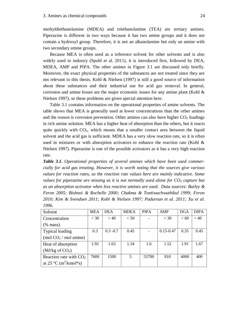
Table 3.1 contains information on the operational properties of amine solvents. The table shows that MEA is generally used at lower concentrations than the other amines and the reason is corrosion prevention. Other amines can also have higher CO2 loadings in rich amine solution. MEA has a higher heat of absorption than the others, but it reacts quite quickly with CO2, which means that a smaller contact area between the liquid solvent and the acid gas is sufficient. MDEA has a very slow reaction rate, so it is often used in mixtures or with absorption activators to enhance the reaction rate (Kohl & Nielsen 1997). Piperazine is one of the possible activators as it has a very high reaction rate. Table 3.1. Operational properties of several amines which have been used commer-cially for acid gas treating. However, it is worth noting that the sources give various values for reaction rates, so the reaction rate values here are mainly indicative. Some values for piperazine are missing as it is not normally used alone for CO2 capture but as an absorption activator when less reactive amines are used. Data sources: Bailey & Feron 2005; Bishnoi & Rochelle 2000; Chakma & Tontiwachwuthikul 1999; Feron 2010; Kim & Svendsen 2011; Kohl & Nielsen 1997; Padurean et al. 2011; Xu et al. 1996. Solvent MEA DEA MDEA PIPA AMP DGA DIPA Concentration (% mass)
< 30 < 40 < 50 - < 30 < 60 < 40
Typical loading (mol CO2 / mol amine)
0.3 0.3 -0.7 0.45 - 0.15-0.47 0.35 0.45
Heat of absorption (MJ/kg of CO2)
1.92 1.63 1.34 1.6 1.52 1.91 1.67
Reaction rate with CO2 at 25 °C (m3/kmol*s)
7600 1500 5 53700 810 4000 400
3. Amines as chemical compounds 25
Kim & Svendsen (2011) also contains information about several other amines, and it shows that primary amines generally have the highest heats of absorption and tertiary amines the lowest while secondary amines lie in the middle. This is a benefit for tertiary amines, but on the other hand they also have the slowest reaction rates while primary amines have the fastest. As Kim & Svendsen (2011) note, no solvent system is likely to have entirely ideal properties because of the inverse correlation between some properties.
3.1.1 Monoethanolamine
At room temperature, monoethanolamine (MEA) is a liquid. It is completely miscible with water and it has an ammonia-like odour. MEA is a strong base like many other primary amines, and it readily forms salts with inorganic and organic acids. (Låg et al. 2011.) MEA solutions have been widely used for the removal of CO2 and H2S from natural gas and certain synthesis gases (Kohl & Nielsen 1997). It also has other industrial uses such as in the production of soaps and detergents, as a cleaning and cooling agent, as an ingredient in cosmetic formulations, in the synthesis of dyestuffs and in rubber accelerators. MEA also occurs naturally in animal phospholipids. (Låg et al. 2011.)
However, in acid gas treatment, MEA solutions are rapidly being replaced by other, more efficient systems, particularly for the treatment of high-pressure natural gases. However, for gas streams containing low CO2 and H2S concentrations and essentially no minor contaminants, MEA is still often preferred. (Kohl &Nielsen 1997.) Low treatment pressure and the need for maximum acid gas removal are also factors which favour the use of MEA (Kohl & Nielsen 1997) and make it a good candidate for an early CCS solution.
MEA has low molecular weight, resulting in high solution capacity at moderate concentrations, it is highly alkaline and it is relatively easy to reclaim from contami-nated solutions. These are all significant advantages compared to some other solvents. However, MEA solutions are appreciably more corrosive than solutions of most other amines, particularly if the amine concentrations exceed 20 %. (Kohl & Nielsen 1997.)
DuPart et al. (1993) provide some values for corrosion rates and show that corrosion is a significant problem for high-concentration MEA systems. The corrosion problems are even greater when amine systems are processing oxygen-containing gases such as flue gas (Barchas & Davis 1992), so this is a problem which needs to be addressed. If only CO2 needs to be removed from the gas stream, corrosion inhibitors may be used to allow the use of MEA at concentrations of up to 30 %. Consequently, both commer-cial MEA-based systems suitable for flue gas processing have used careful process de-sign and a corrosion inhibitor to control corrosion (Barchas & Davis 1992; Sander & Mariz 1992). These technologies are introduced later in this thesis.
Another significant problem of MEA is that it has a tendency to degrade over time. Oxygen, CO2, CO, SOx, NOx and fly ash are all usually present in the flue gas and have an effect on the degradation. MEA degradation increases the need for addition of

3. Amines as chemical compounds 26
replacement MEA, it introduces waste disposal costs and it may worsen the corrosion problems. Thus a degradation prevention strategy needs to be formulated to operate an MEA plant economically. (Bello & Idem 2006.) Degradation prevention strategies are also introduced later in this thesis. However, it is worth noting that degradation is generally a problem with many other amines too (Lepaumier et al. 2009), but MEA is, by and large, more vulnerable to oxygen-induced degradation than secondary or tertiary amines (Kohl & Nielsen 1997).
Another problem with MEA is its high heat of reaction with CO2, which is considerably greater than for most of the other possible amines. In practice, this means higher regeneration energy costs, which may, in the future, lead to the use of other solvents for CCS. (Chowdhury et al. 2011.) MEA also has a relatively high vapour pressure which causes significant vapourisation losses, particularly in low-pressure operations (Kohl & Nielsen 1997). However, this difficulty can be overcome by simple water wash treatment of the purified gas. Such a system was used from the start in both the commercial MEA-based CCS technologies suitable for flue gas treatment (Barchas & Davis 1992; Sander & Mariz 1992).
MEA currently costs about 1450 €/tonne in Europe and about a third less in Asia (ICIS Pricing 2012). Price estimates for future power plant use are also of this order (IEA GHG 2004). According to Rochelle (2009), MEA is one of the least expensive amines and the amine losses are expected to be worth a few euros per tonne of CO2. However, Weissermel & Arpe (2003a; 2003b) note that natural gas and naphtha are the ultimate feedstocks for manufacturing MEA and many other amines, so natural gas and oil prices will have a marked impact on the future prices of amines. Rao et al. (2004) also estimate that the cost of MEA accounts for about 8 % of the total operational costs of the CO2
capture unit. It has a significant but not a decisive effect on overall costs. However, it must be remembered that such estimates depend not only on the solvent used but also on the process design.
3.1.2 Diethanolamine
Diethanolamine (DEA) is a secondary amine which is either in the form of colourless crystals or a syrupy, white liquid with a mild ammonia-like odour. The compound is water miscible. DEA is used in surfactants, in gas purification and in textile processing. In contrast to MEA, DEA does not occur naturally in animals. (Låg et al. 2011.)
Diethanolamine has been used for many years in the treatment of refinery gases containing appreciable amounts of COS and CS2, which would degrade some alternative amines too fast (Kohl & Nielsen 1997). However, these substances are rare in the flue gases of a power plant, so this advantage is not relevant for post-combustion carbon capture. DEA is suitable for low-pressure operation since it has a low vapour pressure leading to low vapourisation losses, but it has also been used in the treatment of high-pressure natural gases (Kohl & Nielsen 1997).
In contrast to MEA, DEA can be difficult to reclaim from contaminated solutions. A greater disadvantage is that DEA undergoes numerous irreversible reactions with CO2,

3. Amines as chemical compounds 27
forming corrosive degradation products. As a result, DEA is not usually the optimum choice for treating gases with high CO2 content. These reactions are probably one of the main reasons DEA by itself seems to have little potential as a solvent in post-combustion carbon capture. However, if the corrosive degradation products are not allowed to build up in the solution, DEA solutions are less corrosive than MEA solutions. Filtration through activated carbon is one of the methods which can be used to remove DEA decomposition products from the solution. (Kohl & Nielsen 1997).
Even though DEA is not a prime candidate for post-combustion CCS by itself, it might still have a role in mixtures with other amines (see e.g. Padurean et al. 2011), where it may help to achieve certain desired characteristics. Even if DEA itself is never actually used in CCS applications, it will still be important to research its properties because studies have shown that MEA can degrade to DEA if NOx is present, as is the case with normal flue gases. Under such conditions secondary amines, such as DEA, may also degrade further to nitrosamines, many of which are carcinogenic (Fostås et al. 2011). This creates potential health and environmental problems, which are discussed in Subchapter 3.2. Overall, the potential dangers from degradation products are another obstacle to using secondary amines for CCS on a large scale.
Present prices for DEA are around 1050 €/tonne in Europe, but in Asia DEA is a little more expensive than MEA, so the price difference is largely market-based (ICIS Pricing 2012). Like MEA, DEA is produced by the reaction between ethylene oxide and ammonia. As ethylene oxide is produced from ethylene and ethylene mainly from natural gas or naphtha, the long-term price of DEA will depend on crude oil and natural gas prices. (Weissermel & Arpe 2003a; 2003b.)
3.1.3 Methyldiethanolamine
Methyldiethanolamine (MDEA) is a liquid at room temperature and like the other amines introduced above it has an ammonia-like odour. It is also completely miscible with water. MDEA is used, for example, as a gas treating agent for absorption and removal of H2S and CO2, a urethane catalyst, a textile softener, an epoxy curing agent and in pH control. (Låg et al. 2009.)
In commercial use, MDEA was first used primarily for selective H2S removal from gases containing high levels of carbon dioxide but only small amounts of hydrogen sulphide. This is obviously not very useful for CCS purposes, but MDEA does, nevertheless, have potential as a CCS solvent. MDEA has a low vapour pressure, which permits its use in high concentrations without appreciable evaporation losses. Furthermore, it is highly resistant to thermal and chemical degradation and it is essentially noncorrosive, as DuPart et al. (1993) have demonstrated. It also has a low specific heat and low heats of reaction with both CO2 and H2S, and these properties save energy when it is used. (Kohl & Nielsen 1997.)
Despite its numerous advantages, MDEA also has its drawbacks. Its principal disadvantage is its low rate of reaction and therefore also slow absorption of CO2. It is clearly beneficial for selective H2S removal, but to capture CO2 from power plants this

3. Amines as chemical compounds 28
rate must be enhanced. The addition of primary or secondary amines, such as MEA and DEA, has been found to increase the reaction rate without jeopardising MDEA’s advantages. Mixed amine processes containing MDEA are offered for acid gas removal by several licensors. Piperazine, with its very high reaction rate, has also been used as such an activator. Mixed amine systems have also shown their usefulness because the formulation of the mixed amines can be modified to meet site-specific requirements. (Kohl & Nielsen 1997.)
In the absence of any recent industry pricing report for MDEA, data is based on figures given by Sigma-Aldrich, a large producer of laboratory chemicals. According to this data, MDEA is somewhat more expensive than MEA (Sigma-Aldrich 2012) and Kohl & Nielsen (1997, p. 49) support this conclusion. However, because MDEA has several advantages, it was the most widely studied amine for CO2 removal in the chemical and petrochemical industries in the period 2000-2007 (Ritter & Ebner 2007). Since ethylene oxide is needed for MDEA production (DOW 2010), as was also the case for MEA and DEA, natural gas and crude oil prices are again important factors having an influence on the price of MDEA.
3.1.4 Aminomethylpropanol
Aminomethylpropanol (AMP), more specifically 2-amino-2-methyl-1-propanol is either a colourless liquid or a white crystalline solid. It is sometimes also called isobutanolamine. Since the melting point is slightly above room temperature, AMP may also appear as a paste. In liquid form AMP has a slight amine-like odour, while in solid form it is odourless. AMP is widely used in cosmetics, as an emulsifying agent, as a pH adjuster and to regulate the solubility, flexibility and tackiness in cosmetic creams, lotions, soaps, shampoos, shaving creams, hair sprays, hair dyes and colours. The con-tent of AMP in such products is commonly in the range of 0.1 % - 1 %, so the substance is clearly not very dangerous. (Låg et al. 2009.) AMP is miscible with water, but a good deal less soluble to water than the three amines presented above (Padurean et al. 2011).
AMP is a primary amine, but as Figure 3.1 shows, it has a somewhat different structural formula than the amines presented previously. This difference explains why it is called a sterically hindered amine. Such an amine is defined structurally as a primary amine in which the amino group is attached to a tertiary carbon atom, or a secondary amine in which the amino group is attached to a secondary or a tertiary carbon atom. (Sartori & Savage 1983.) These amines react with CO2 in a somewhat different way to conventional amines, so they can achieve higher mol CO2 / mol amine ratios. This means that less amine is needed to capture the same amount of CO2. It is also claimed that sterically hindered amines could have a higher selectivity with regard to either CO2 or H2S, if a suitable molecular structure is discovered. (Kohl & Nielsen 1997.)
Sartori & Savage (1983) reported the “unique capacity and rate advantages of hindered amines in CO2 absorption processes” thus prompting considerable research into their properties. As a result, Exxon’s (now ExxonMobil’s) Flexsorb technologies use several proprietary hindered amines for acid gas removal in tens of plants

3. Amines as chemical compounds 29
worldwide. However, it is worth mentioning that these systems are more often mainly for H2S removal than for just CO2 removal. Hindered amines are also used as promoters in hot potassium carbonate systems, which are discussed in Subchapter 2.1. (Kohl & Nielsen 1997).
A major reason for the continued interest in AMP and other sterically hindered amines is that Mitsubishi Heavy Industries (MHI) has developed a flue gas treatment system based on a proprietary hindered amine which the company is marketing for CCS applications. The claimed advantages of their solvent are that it has a lower circulation rate, lower regeneration temperature and lower heat of reaction with CO2 compared to many other alternatives (Al-Masabi 2011). It is also fairly non-corrosive (Al-Masabi 2011) and has significantly smaller solvent losses than competing technologies (Reddy et al. 2003). The formula of the solvent has not been made public, but AMP has properties seemingly similar to MHI’s solvent, so it is an interesting solvent for research (Al-Masabi 2011). Padurean et al. (2011) also suggest that AMP would be an interesting solvent in amine mixtures.
A problem with the sterically hindered amines is that they are often more expensive than the simpler conventional amines. For example, Reddy et al. (2003) claim that the MHI solvent is about 5 times more expensive than MEA. AMP also seems to cost more than MEA according to Sigma-Aldrich (2012), but it must be noted that no exact match of product purities was found. Though it is rather more complicated to produce AMP (Merck 1989; Johnson & Degering 1943) than the other amines presented, the ultimate feedstock is still natural gas or crude oil, so their price also has an impact on the AMP price.
3.1.5 Piperazine
Piperazine is white or translucent, and occurs as rhomboid or flake-like crystals which are highly hygroscopic at room temperature. They form a white mass in water and the solution is highly basic (Låg et al. 2011). Piperazine is freely soluble in water (Merck 1989). It is used in veterinary pharmaceuticals as an anthelmintic, that is as a drug for infections caused by parasitic worms. In the past, piperazine was also used in human medicine. Other common uses are as a hardener for pre-polymers for glue, as an intermediate for urethane catalysts, in gas washer formulations and in synthesis of pharmaceuticals. (Låg et al. 2011.)
Unlike the four amines introduced earlier, piperazine does not contain a hydroxyl group and is thus not an alkanolamine. As Figure 3.1 shows, piperazine consists of a six-membered ring containing two opposing nitrogen atoms. It is therefore a diamine with two secondary amine groups. This feature allows it to reach very high loadings, measured in mol CO2 / mol amine (Ma’mun et al. 2007). It also helps it to absorb CO2 very rapidly, as Table 3.1 shows and as Ma’mun et al. (2007) have demonstrated.
Piperazine has not been widely used in the gas treatment industry, but it has been used as an activator in some MDEA systems (Kohl & Nielsen 1997). According to the latest research findings, piperazine may have significant advantages in gas treatment as

3. Amines as chemical compounds 30
such. It can withstand temperatures up to 150 °C without significant thermal degradation, which allows better energy performance. It is also resistant to oxidative degradation, less volatile than MEA and non-corrosive to stainless steel. Reclaiming is not expected to be a problem, either. Since the reaction of CO2 with piperazine is much faster than the reaction with MEA, the resulting absorption rate is about twice as fast. This should offer savings in capital costs as smaller equipment is then sufficient. (Rochelle et al. 2011.)
All these properties appear very promising, but health and environmental concerns have cast doubt on the large-scale use of piperazine. It appears that it is more harmful to humans than many alternative solvents (Låg et al. 2011) and it degrades slowly in a marine environment (Eide-Haugmo et al. 2009). These issues are considered in detail in the Subchapter 3.2. However, data on the environmental effects are rather limited, so the risk estimates have a large uncertainty factor (Låg et al. 2011).
Piperazine is assumed to cost 2-4 times more than MEA, equivalent to a price of about 5 000 €/tonne. It is a co-product of ethylenediamine production and can also be produced from MEA, so again the ultimate feedstock is natural gas or crude oil. (Rochelle et al. 2011.)
3.1.6 Other amine solvents
The other amines presented in Figure 3.1, namely triethanolamine (TEA), diisopropanolamine (DIPA) and 2-2-aminoethoxy-ethanol, often called diglycolamine (DGA) seem to have little potential for new CO2 removal applications. This is reflected in the low number of recent research publications (Ritter & Ebner 2007). Triethanolamine was the first commercially available alkanolamine, so it was used in the early gas-treating plants. Nowadays it has been largely replaced because of its low capacity, low reactivity and relatively poor stability (Kohl & Nielsen 1997).
Diisopropanol is still being used to some extent in a few processes, but MDEA seems to be gradually displacing it. Diglycolamine combines the stability and reactivity of MEA with a low vapour pressure and hygroscopicity, so it can be used in more concentrated solutions than MEA. (Kohl & Nielsen 1997.) It is used in Econamine technology, which is the precursor of the modern Econamine FG technology that is suitable for power plant CO2 capture applications. There are over 50 plants in operation using Econamine technology and the largest can treat gas streams of several hundred thousands of cubic meters per hour. Although this is a considerable amount, it is still much less than the flue gas flows from large power plants. (Ritter & Ebner 2007.)
Amines can also be used in various mixtures, but the three amines mentioned above do not show much potential even in such a role. Neither Kohl & Nielsen (1997) nor more recent Padurean et al. (2011) suggest using them in mixtures despite referring to these compounds in their studies. However, several other amines are being researched as potential solvents. Puxty et al. (2009) has made an extensive study of the carbon dioxide absorption performance of a large number of amines, and Ma’mun et al. (2007) and Kim & Svendsen (2011) are some of the many studies in which the various
3. Amines as chemical compounds 31
characteristics of possible novel solvents are compared to those of more conventional amine solvents. Investigation into the characteristics of new solvents and solvent mixtures has become a very active field of research.
3.2 Health and Environmental Effects
In recent years the possible health and environmental effects of amines have become a cause of concern. As is stated in the previous subchapter, many of these amines have been used in the industry for a long time but their application in power plants would make them many times more widespread than they are today. To gain some understanding of the potential emissions, Karl et al. (2009) estimate that a gas-fired power plant capturing 1 Mt CO2 per year and having only 1 ppmv of amines in the treated gas would still emit about 40 tonnes of amines per year.
Consequently, several organizations, such as IEA (IEA GHG 2010) and Norwegian state officials (Knudsen et al. 2009), are actively studying these health and environmental impacts. IEA GHG (2010) considers the implications of such estimates so important that they could stop the deployment of full scale CO2 post-combustion capture using amines even before it begins. This subchapter is based largely on information provided by the recent research of IEA and the Norwegian officials.
Thitakamol et al. (2007) identify leakage from equipment, amine reclaimer producing amine waste, and entrainment in the flue gas as the possible emission routes for amines. Leakage or mechanical losses have been shown to be an important cause of amine losses for some amine-using plants (Stewart & Lanning 1994), though Thitakamol et al. (2007) consider these losses less important than the other losses in power plant CCS applications. In any case such losses are unlikely to pose risks to the general public since they are probably confined to the plant itself. Though such losses can be minimized by good plant maintenance, this subject lies outside the scope of this thesis and is not considered further.
Amine waste handling is briefly discussed in Chapter 5, but its effects should also be largely confined to the plant and the possible waste treatment facility. As another possible emission route, Thitakamol et al. (2007) mention large releases as a result of an accident or an emergency situation. Such incidents could be the result of process equipment failure or improper operation. In the worst case situation, amine release to the environment could occur, posing possible risks to the general public. However, since such cases are rare and hard to predict, they are not discussed further in the thesis.
It can thus be claimed that the most important emission route to the environment is probably the entrainment of amines in the treated flue gas. This emission route is also the main topic of concern for IEA GHG (2010) and the Norwegian state officials and this explains why it has been studied so extensively. In general, amines in themselves pose little risk to human health and the environment, but amine emissions will contribute to the nitrogen load, thus potentially contributing to eutrophication of certain sensitive ecosystems. (Knudsen et al. 2009.)

3. Amines as chemical compounds 32
However, various compounds formed from the amines during the carbon dioxide capture process or after they have been first emitted to the atmosphere may pose potential risks to human health and the environment. Of these degradation products, nitrosamines and nitramines, in particular, can be harmful at very low levels. (Knudsen et al. 2009.) Consequently, Subchapter 3.2.1 focuses on the impacts of the amines themselves, and Subchapter 3.2.2 deals with the impacts of the degradation products.
3.2.1 The effects of amines
As Knudsen et al. (2009) note, amines themselves are not very dangerous, but this does not mean that they are entirely non-harmful. Some effects on human health have been observed and such cases are, of course, investigated. In general, amines are much less dangerous than certain other chemical compounds which may be present in the flue gas even under normal power plant operation without CCS, as Thitakamol et al. (2007) have demonstrated. However, the quantity of amines present would certainly be higher than the quantity of these more dangerous compounds, so the effects of amines must be studied in any case (Thitakamol et al. 2007).
Table 3.2 contains toxicity, ecotoxicity and biodegradability values for the most common amines. For comparison, LD50 for sodium chloride, known as common table salt is 3000 mg/kg in rats and LD50 for acetylsalicylic acid, better known as aspirin, is 200 mg/kg in rats (Sciencelab 2012). Therefore, aspirin is clearly more toxic than any of these amines. The Finnish authorities consider a substance toxic if LD50 is under 200 mg/kg and only harmful if LD50 is 200-2000 mg/kg (A 26.9.2001/807). According to this definition, some amines are harmful and some even less dangerous. However, LD50 measures acute toxicity, but does not measure the long-term effects of a substance.
Table 3.2. Toxicity, ecotoxicity and biodegradability data for the most common amines. LD50 is the median lethal dose of a toxin required to kill half the members of a tested population after a specific test duration. Ecotoxicity is shown as the concentration where compounds inhibit algal growth by 50% (EC50). Biodegradability shown as percent degraded with regard to the theoretical oxygen demand (ThOD). Data sources and sources of further information: Eide-Haugmo et al. 2009; European Commission 2005; Thitakamol et al. 2007; Padurean et al. 2011. LD50 oral (mg/kg)
Rabbit Rat Ecotoxicity (mg/l) Biodegradability
(% ThOD) MEA 1000 1720 250 27 DEA 2200 710 500 42 MDEA - 1945 200 2 PIPA - 2600 260 3 AMP 2900 2900 100 2

3. Amines as chemical compounds 33
Acute toxicity is not a good measure of whether a substance has some effect on humans, either. All the amines have been shown to cause eye and skin irritation (Thitakamol et al. 2007; Knudsen et al. 2009). DEA is somewhat more toxic than the others and Thitakamol et al. (2007) note that it may be harmful if swallowed. Piperazine has been found to have a sensitizing effect and there are indications that PIPA and MEA may have some reproductive and developmental toxicity. None of the amines has been reported to be carcinogenic, but information is limited in this regard. (Knudsen et al. 2009.) Furthermore, despite a long history of industrial use, Rao et al. (2004) claim that no signs or symptoms of chronic exposure to MEA have been reported in humans.
The ecotoxicity values in Table 3.2 are fairly high so the amines themselves do not seem to be very dangerous. However, the lowest observable effect concentration in chronic studies was found to be 0.5 mg/l for MEA and 0.75 mg/l for MDEA, which is much less than the values for acute effect. (Knudsen et al. 2009.) Karl et al. (2011) claim that MEA toxicity for aquatic organisms could even become a problem, but they assume no biodegradation at all in their worst case calculations. However, according to another study, MEA and DEA degrade sufficiently fast in a marine environment, so they are not expected to accumulate in the environment. On the other hand, the other three amines degrade slowly in such an environment, so they could pose problems in the long run. According to the biodegradability measure used, 20 % would be the lowest acceptable value for a chemical released in a marine environment. (Eide-Haugmo et al. 2009.)
Overall, Knudsen et al. (2009) conclude that amines do not pose significant risks to human health or the environment, but that more research is needed to remove some uncertainties. It is also noted that if several amines are used simultaneously, they might have additive or synergistic effects, and this is an area that requires further investigation. Nevertheless, Knudsen et al. (2009) give some preliminary guidelines for human exposure over time. The values they give, which are based on inhalation exposure risk, are presented in Table 3.3. The underlying idea is that the general public should not be exposed to levels higher than these.
Table 3.3. Highest acceptable amine levels in air, based on long-term inhalation exposure (Knudsen et al. 2009). Since MDEA has low vapour pressure and is thus expected to have lower vapourisation losses than MEA, MDEA seems to have an advantage in this regard. Solvent Limit (µg/m3) MEA 10 MDEA 120 AMP 6 PIPA 5

3. Amines as chemical compounds 34
Knudsen et al. (2009) also conclude that while the amines themselves may not be very dangerous in the environment, there is much uncertainty as to what happens to them after they are emitted into the atmosphere. Harmful compounds may be formed from the amines not only during the carbon dioxide capture process but also in the atmosphere after they have been emitted. As a result more research is needed before amine emissions can be declared safe for the environment.
Amine emission may also have impacts on weather conditions both locally and regionally because amines lower the surface tension of water droplets, which may lead to precipitation in some cases. (Knudsen et al. 2009.) It is important to remember, however, that a single CCS plant is unlikely to cause significant problems with amine emissions. Nevertheless, for large scale use of the technology such effects must be taken seriously. (Knudsen 2010). All in all, Låg et al. (2009; 2011) currently provide one of the most comprehensive studies into the effects of many amines on human health. Aarrestad & Gjershaug (2009) and Brooks (2008) are good sources of information on the environmental effects.
3.2.2 Effects of degradation products
It has long been known that amine degradation is a problem for plants using alkanolamines. Oxygen and carbon dioxide which are present in any flue gas degrade amines, but so do numerous impurities such as HCl, SO2, NH3 and many other compounds which may also be present, although in significantly smaller quantities. (Kohl & Nielsen 1997.) However, the problem with NOx has received less attention since it only becomes relevant when amines are used for treatment of flue gases. According to Fostås et al. (2011), any amine exposed to NOx, whether in the process or in the atmosphere after the emission, can lead to nitrosamine and nitramine formation.
Nitrosamines are of particular concern because they can be toxic and carcinogenic at extremely low levels. Nitramines are also suspected of being carcinogenic, though less potent than nitrosamines, but they are claimed to have a longer life-time in the atmosphere, which may lead to higher exposure values. (Knudsen et al. 2009.) Today, these substances have become a major focus of environmental concern regarding the large scale deployment of post-combustion CCS, and because of this, they are being widely researched.
Pedal et al. (1982) report that the oral LD50 of N-Nitrosodimethylamine (NDMA) is about 15 mg/kg in rabbits, so it is clearly very toxic compared to the common alkanolamines. Just 1 – 10 % of this dose may cause severe liver damage if taken regularly. NDMA is one of the most dangerous nitrosamines and is also the most thoroughly studied, so it can be used to estimate the risks related to nitrosamines (Låg et al. 2011). It is worth noting that trace amounts of NDMA have also been found in tobacco smoke condensates (Merck 1989), so some people are regularly exposed to the substance even today.
However, acute toxicity is not the only or even most important problem of nitrosamines. It has been shown that many nitrosamines are also carcinogenic and

3. Amines as chemical compounds 35
mutagenic. Låg et al. (2011), therefore, recommend setting the values for acceptable nitrosamine levels in air at 0.3 ng/m3. This is several thousand times lower than the limits set for amines, so Knudsen et al. (2009) suggest that the worst case emissions of an amine-using CCS plant could cause nitrosamine levels of about the same order in the air.
Data on the effects of nitramines is very limited so that proper health effect evaluation is not possible at the moment. (Låg et al. (2011.) In general they seem to be less potent as mutagens and carcinogens than the corresponding nitrosamines. Neverthe-less the most widely-studied nitramine, N-nitrodimethylamine, can still be regarded as a carcinogen of high potency. Because of this the Norwegian health authorities have decided to use a conservative estimate. They suggest that the nitrosamine level quoted above could actually be used to limit the total amount of nitramines and nitrosamines to reduce the cancer risks to the general public. (Låg et al. 2011.)
It is known that nitrosamines and nitramines are possible degradation products of amines and they are dangerous to human health and also to the environment. However, it is far from certain how much of these substances will actually form during the capture process and in the atmosphere after emission. It is also not known well known how long it takes these components to degrade into less dangerous compounds in the atmosphere or in other parts of the environment under various conditions. (Knudsen et al. 2009.) However, Karl et al. (2011) report that in a sunlit atmosphere, nitrosamines are removed from the atmosphere in a few hours while nitramines generally have a lifetime of more than two days.
The atmospheric chemistry of amines is complicated and is beyond the scope of this thesis, but Bråten et al. (2009) provide a major theoretical study on the subject. Knudsen et al. (2009) emphasize the need of experimental data in different atmospheric conditions. Nielsen et al. (2011) and Fostås et al. (2011) are studies of the atmospheric reactions but it is clear from both that much more research is needed to reach conclusive results. The levels which are potentially dangerous are also so low that the methods used to detect them in laboratories may not be suitable for constant surveillance in power plants. As a result, new detection methods are needed even to measure their concentrations with sufficient precision in industrial operation. (Järvinen 2012.)
In conclusion, a lot of uncertainty surrounds the amount of dangerous compounds that are actually formed and it is also unclear what their actual effects are. Commercial licensors of amine technologies suitable for CCS are working hard to reduce amine emissions (Kamijo 2010; Reddy 2010). The authors also report that it will be possible to achieve amine emission levels in the order of 0.2 ppm in treated gas in the future as opposed to values of 1-4 ppmv quoted by Karl et al. (2011). If these new emission levels had been used in risk estimates, the risks would probably have been considered to be lower.
However, the problem is not only a technical one since the suggested health effects might also raise public concern. The effects may even be used as an excuse against CCS by both environmentalists as well as industry groups, who may oppose CCS because of

3. Amines as chemical compounds 36
vested interests. In any case, partly due to health concerns, the large CCS project in Mongstad, Norway, was recently postponed in order to gain more information on the associated risks (Teknisk Ukeblad 2010). At present, it remains unclear just how significant these effects are and if the actual or even hypothetical health and environmental effects impact on the future of amines in CCS technology.

37 37
4 FLUE GAS PRE-TREATMENT
Most post-combustion carbon capture systems require pre-treatment of the flue gas before it can enter the CO2 capture process and this also applies to amine-based systems. Therefore, to understand the requirements of the complete CO2 removal process, it is reasonable to start by describing the pre-treatment which the amine system needs to function properly.
In general, the amines are sensitive to impurities such as NOx and SOx, so they must be reduced to low values before the capture process. Solid particles present in the flue gas might also be problematic in some cases. (IPCC 2005.) Additionally, flue gas cooling, amine absorption and CO2 compression increase the overall power plant cooling duty, which means that more cooling water or at least higher water discharge temperatures are needed (IEA GHG 2007). This might be problematic in some arid regions of the world. Figure 4.1 provides a schematic of a power plant with an amine-based CO2 capture system and also shows the typical sequence of other necessary emission controls. These emission control systems are explained in the following subchapters.
Figure 4.1. Schematic of a pulverised coal fired power plant with an amine-based CO2 capture and other emission control systems (after IPCC 2005). The SCR system reduces NOx emissions by ammonia injection, ESP removes particles from the flue gas and FGD reduces SOx emissions.
However, before any impurity removal systems can be introduced, it is important to know which impurities are present in the flue gases and this will obviously depend on the type of fuel used. The most important fuels to be considered in relation to post-combustion capture from power plants are coal and natural gas. Typical compositions of
Boiler
Selective catalytic reduction
(SCR)
Electrostatic precipitator
(ESP) Stack
Air heater
NH3 CO2
Flue gas desulphurisation
(FGD) CO2 recovery

4. Flue gas pre-treatment 38
the flue gas with these fuels are given in Table 4.1 in which it can be clearly seen that the flue gas from coal contains much more CO2 and much less oxygen. In both cases about 75 % of the gas is nitrogen. The flue gas from natural gas normally has no sulphur oxides unlike the flue gas from coal but both contain some NOx. Table 4.1. Typical composition of untreated flue gas from coal-fired and natural gas fired power plants. Only the main gases and the most important impurities are given. Data for coal from Granite & Pennline (2002) and for gas from Zevenhoven & Kilpinen (2005). Fuel Species
Low sulphur bituminous coal, concentration by volume
Natural gas, concentration by volume
CO2 15 – 16 % 3 % H2O 5 – 7 % 6 % O2 3 – 4 % 14 % N2 balance (~75 %) balance (~76 %) SO2 800 ppm - SO3 10 ppm - NOx 500 ppm 10 - 300 ppm
Several things must be done before the flue gas can enter the CO2 absorption system. As noted above, amines are sensitive to certain impurities in the flue gas, so these must be removed before the absorption process begins. Sensitivity means that the acidic gas components such as SOx and NOx can react chemically with the amines, but unlike the normal reaction between amines and CO2, these reactions are irreversible. These reactions lead to the formation of heat stable salts which causes a loss of absorption capacity and poses the risk of solids forming in the solution. In addition to the costs of this amine loss, an undesired stream of waste is produced that will require some treatment process.
Allowing the untreated flue gas to enter the amine absorber would thus be both undesirable and costly. It is, therefore, essential that some SOx and NOx is removed beforehand. It is generally considered that SOx levels are a significant problem for amine absorption systems while the problems with NOx are less common. (IPCC 2005.)
In some coal-fired power plants the solid particles in the flue gas might also pose problems for the absorption system since they may plug the absorber. However, the requirements for other flue gas treatment systems are such that some mechanism for particle removal is usually already in place. Finally, before absorption the flue gas must be cooled to the required operating temperatures of the absorber (IPCC 2005). Nevertheless, it is also the case that the technology used in flue gas pre-treatment is well-proven in industrial applications. It is therefore unlikely that the installation of such a system for amine-based carbon capture processes would pose any major engineering problems. (IEA GHG 2007.)
4. Flue gas pre-treatment 39
4.1 NOx removal
According to IEA (2007), the NOx levels of flue gases are normally not a serious problem for post-combustion capture systems since NO, the major component of NOx, does not react with amines. Desideri (2010) reports that there have been no problems with NOx in Econamine systems, which is the most widely-used commercial technology for CO2 absorption from power plants, though problems have been encountered in other systems. In any case, NO2 can react with amines, but IEA (2007) reports that in coal-fired power plants no more than 5 % of NOx is NO2. In natural gas fired power plants this value is 10 % at most (Flagan & Seinfeld 1988, p. 8) so having more than 30 ppm NO2 in the untreated flue gas is unlikely in either case if the total NOx levels seen in Table 4.1 are taken into account. IEA (2007) considers 40 mg/Nm3, corresponding to about 20 ppm, as an acceptable NO2 level for the flue gas in an amine scrubber.
Based on this information, it may seem that some extra removal due to the absorption process is needed. However, current environmental regulations for power plants exceeding 50 MWth in the European Union set the total NOx emission limit for large coal-fired power plants at 600 mg/m3 for coal power plants and 300 mg/m3 for natural gas power plants. For new plants the limits are even stricter. (European Parliament and Council Directive 2001/80/EC.) These limits are already enough to require some reductions in NOx emissions and the maximum limit allowed for NO2 then becomes about 30 mg/Nm3, which means that the installation of an amine absorber does not usually require extra de-NOx measures.
As Figure 4.1 shows, selective catalytic reduction (SCR) by ammonia injection is one method to reduce emissions of nitrogen oxides. Another alternative is selective non-catalytic reduction (SNCR), though using only in-furnace NOx control methods, such as low NOx burners and two stage combustion air are actually sufficient for reaching acceptable levels for the amine absorber (IEA GHG 2007). However, for certain coals post-combustion de-NOx methods are clearly necessary (IEA GHG 2007), especially as the environmental regulation is tighter for large power plants with over 500 MW
thermal power (European Parliament and Council Directive 2001/80/EC). It is also worth noting that NOx emissions and the ammonia use of the SCR system per MWh electricity produced are both expected to increase somewhat, because the installation of a carbon capture system lowers the overall efficiency of the power plant (Rubin et al. 2007).
In conclusion, it is clear that the need for possible extra de-NOx equipment in Europe is driven by legislation rather than by any technical limitations associated with CO2 capture. On the other hand, in other parts of the world legislation may be less strict, so an amine-based capture system could require additional NOx control equipment in such countries.

4. Flue gas pre-treatment 40
4.2 SOx removal
In contrast to NOx, sulphur oxides are a significant problem for amine absorbers. As Table 4.1 shows, most of SOx is SO2, so it is the primary problem. To avoid excessive amine degradation in the absorber unit, SO2 levels in the flue gas must be in the order of 10 to 30 mg/Nm3 (IEA GHG 2007), which is equivalent to 4 - 10 ppm. This requirement is much lower than the 400 mg/Nm3 limit for existing large power plants or even the 200 mg/Nm3 limit for new large power plants set by the European Union (European Parliament and Council Directive 2001/80/EC). However, these limits are already a lot lower than the 800 ppm level (about 2250 mg/Nm3) in the raw flue gas given in Table 4.1 so some SOx removal systems are already in use in coal-fired power plants. As already noted, there are no significant amounts of SOx in the flue gas of gas-fired power plants so SOx removal is not needed.
Because the SO2 requirements of the amine absorber are so low, something must be done. In a new power plant, this simply means that the chosen flue gas desulphurisation (FGD) method must be able to achieve these very low levels. Such systems are commercially available, but they probably require additional initial investment and increase the operating expenses of the plant (IEA GHG 2007). In a large coal-fired power plant it has been estimated that the additional investment needed for SOx removal would increase the total cost of a complete amine-based carbon capture system by 3 – 4 % (IEA GHG 2004).
In existing power plants it may be possible to upgrade the SOx removal system by mechanical or chemical enhancement, such as adding more spray banks or using different chemicals to reach the limit. Another possibility is to add a smaller secondary, polishing FGD scrubber, but this requires some free space adjacent to the main FGD unit. (IEA GHG 2007.)
In general, the most important FGD systems fall into two groups: wet and dry systems. The wet systems have a high SO2 removal efficiency and they are cost-effective. As a result, they have a predominant position in the FGD system market. The modern wet systems also produce a saleable by-product, gypsum, which is an additional advantage in commercial use. (Srivastava 2000.) For post-combustion carbon capture power plants, a wet FGD system has the added advantage of capturing some NO2 as well. Such FGD systems are also very effective in removing solid particles from flue gas, which is a major benefit since the particles might cause problems in the absorber. (IEA GHG 2007.) Together these properties of wet FGD systems for SO2 removal make them the preferred technology for amine-based carbon capture systems.
The addition of a better SOx removal system is not expected to cause harmful environmental effects. In fact, the SOx emissions of the power plant to air will decrease due to the strict requirement, which is a clear environmental and health benefit (Srivastava 2000). However, the install of a more effective SOx removal system will increase the need of fresh water, the electricity consumption and the use of limestone, which is often used as a reagent in a wet FGD process (IEA GHG 2004). These changes
4. Flue gas pre-treatment 41
are not major compared to the other changes required for the whole carbon capture system so IEA (2007) does not consider them as problems. In addition, the increased use of limestone also leads to increased production of saleable gypsum (IEA GHG 2004).
Chapel et al. (1999) suggest that SO3 may also present problems in some systems. Like SO2, it leads to the formation of non-reclaimable heat stable salts but it can also form corrosive sulphuric acid (H2SO4) aerosol in wet FGD scrubbers. The FGD systems are usually not very good in removing SO3 and less than one third of it may be removed by them, so most of SO3 actually ends up in the absorber, unless a special mist eliminator is used. The fraction of SOx which is in the form of SO3 is a function of fuel composition, combustion and flue gas processing factors, so the minimisation of SO3 is preferably a boiler design issue. In this way, problems with SO3 are prevented upstream of the flue gas treatment equipment, so it cannot cause harm in the absorption or in any other process. (Chapel et al. 1999.)
4.3 Particulate removal
Like SOx removal, particulate removal is only necessary for coal-fired power plants, as the flue gases from natural gas do not contain significant amounts of particulates. The amount of particulates in the coal flue gas depends on the combustion technology and the coal used but it is usually in the order several grams per cubic meter and can even reach 20 g/m3. Emitting such amounts of solid particles into the air would be unaccept-able for a number of reasons, so normally an emission control system with an efficiency of 95 - 99 % is installed in any case ((Zevenhoven & Kilpinen 2005). The current environmental regulation of the EU sets the limit to 100 mg/Nm3 for existing power plants under 500 MWth and to 50 mg/Nm3, if they are larger than that. For new power plants over 100 MWth, the limit is 30 mg/Nm3. (European Parliament and Council Directive 2001/80/EC.)
Common methods for reaching these limits in power plants are electrostatic precipi-tators (ESP) or bag filters (IEA GHG 2007). Both are able to remove over 99 % of the particles over 3 µm in size, but for smaller particles only filters reach such levels. ESP can remove about 98 % of particles between 1 and 3 µm and 96.5 % of smaller particles. (Zevenhoven & Kilpinen 2005.)
However, the suppliers of amine scrubbers are only willing to accept particulate levels of at most 5 mg/Nm3 because the presence of more dust might become problematic for the operation in the long term (IEA GHG 2007). Fly ash in the absorption solvent may cause foaming in the absorber and stripper, plugging of equipment, erosion and crevice corrosion. It may even increase solvent losses through chemical degradation and physical association with sludge which has to be removed. In addition, some fuels, such as heavy fuel oil, may produce soot that stabilizes an amine mist above the CO2 absorption zone leading to amine losses because such mist is not captured by the normal water wash. (Chapel et al. 1999.)

4. Flue gas pre-treatment 42
As the untreated flue gases might contain thousand of milligrams of particulates per cubic meter (Zevenhoven & Kilpinen 2005), even 99 % particulate removal efficiency is actually not always enough. Based on this information, it would seem that additional particulate removal capacity might be needed in some cases. In practice, this would not be so common because a wet FGD system and a direct contact type flue gas cooler would contribute to the particulate removal so that acceptable levels are reached. Even if the FGD method used is a dry method, the contribution of the direct contact flue gas cooler should be enough. However, if the gas cooler uses some other method to cool the flue gas, additional particulate removal equipment or flue gas humidification upstream of the ESP may be needed to make the installation of an amine-based carbon capture system possible (IEA GHG 2007).
As the particulate removal rate is already high even without any carbon capture system, the increased need of particulate removal does not increase the amount of waste significantly. It should also be noted that dry FGD systems are already fairly uncommon in power plants (Srivastava 2000) and it can be assumed that they will be even rarer in future carbon capture plants. As a result, cases where additional particulate removal capacity is needed because of the carbon capture system will probably be rare. It can thus be assumed that the low particulate levels needed by the absorber will probably not add any extra equipment to the system, so they will not increase the consumption of electricity or any other resources.
4.4 Flue gas cooling
The flue gases from a normal combustion power plant are usually above 100 °C, which means that they need to be cooled down for the absorption process (IPCC 2005). Rackley (2010) notes that the operating temperature for the amine absorption process is 40 – 60 °C, which means that a significant amount of cooling water is needed (IEA GHG 2007). IPCC (2005) and IEA (2007) suggest that the cooling could be done in a cooler with direct water contact, as this process would also act as an additional flue gas wash removing fine particulates from the flue gas. Furthermore, a wet FGD system can also double up as a direct contact cooler to cool down the flue gas (IPCC 2005).
In addition to the flue gas cooling system, the amine absorber and the CO2
compression plant both increase the power plant demand for cooling. However, this does not necessarily mean that more cooling water is needed because the steam turbine low pressure section will see a major flow reduction as almost half of this steam is needed for use in the amine absorber unit. This means that less cooling water is needed for the main turbine condenser and the extra cooling water can be used elsewhere, for example in the flue gas cooler. Therefore, the total plant cooling water mass flow rate can be maintained at a similar level with and without the capture system if the turbine exhaust pressure is also maintained. (IEA GHG 2007.)
Nevertheless, as the total cooling demand increases, this configuration means that the discharge temperature of the water increases if a once-through cooling system is

4. Flue gas pre-treatment 43
used. In some places, the environmental regulations or the local conditions may not permit this and additional cooling water would then indeed be required. If cooling towers are used instead, some space is needed at the power plant site for the installation of new cooling tower modules. (IEA GHG 2007.) However, additional cooling water or additional space for cooling towers might be too difficult or too expensive to obtain in some locations, and in these cases the whole post-combustion carbon capture system may become unrealisable or may require very much different cooling solutions.
The Trailblazer Energy Center in Texas, for example, is considering the use of dry cooling with air even though such a system has a high investment cost and requires a lot of space. In their local conditions, water is considered to be too expensive to cool the plant and the additional cooling needed for the CO2 capture would only accentuate the problem. In this project, the cooling water demand would have increased by at least 25 % because of the carbon capture system. (Tenaska 2011.)
As a conclusion, an amine-based carbon capture system certainly increases the power plant cooling demand. It depends on the location and the local regulation if this becomes a problem for the installation of the system. In any case, if the carbon capture system is added to an existing power plant, some space will be needed for the pipes and other equipment which are necessary to provide cooling for the flue gases, as the operating temperature of the amine absorber is fairly low. (IEA GHG 2007.)
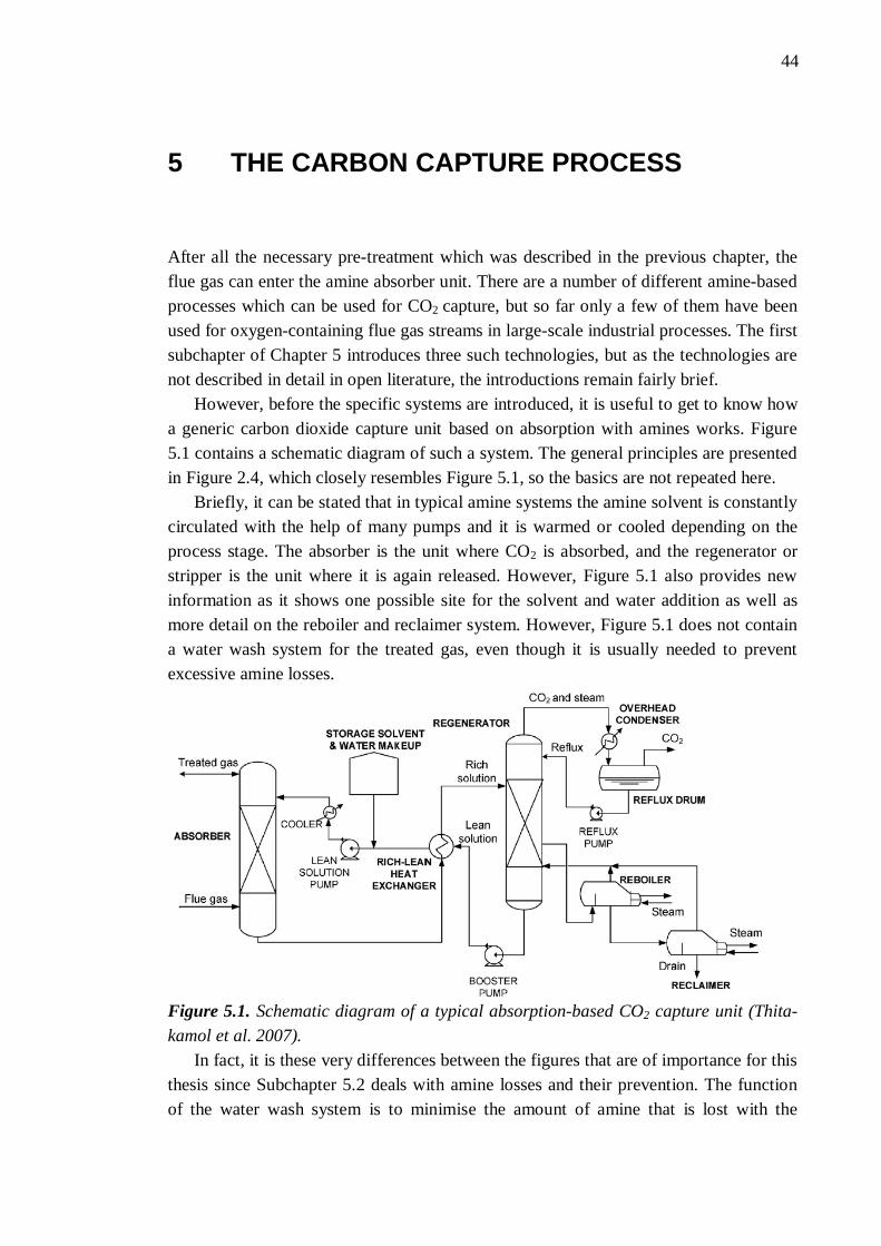
44 44
5 THE CARBON CAPTURE PROCESS
After all the necessary pre-treatment which was described in the previous chapter, the flue gas can enter the amine absorber unit. There are a number of different amine-based processes which can be used for CO2 capture, but so far only a few of them have been used for oxygen-containing flue gas streams in large-scale industrial processes. The first subchapter of Chapter 5 introduces three such technologies, but as the technologies are not described in detail in open literature, the introductions remain fairly brief.
However, before the specific systems are introduced, it is useful to get to know how a generic carbon dioxide capture unit based on absorption with amines works. Figure 5.1 contains a schematic diagram of such a system. The general principles are presented in Figure 2.4, which closely resembles Figure 5.1, so the basics are not repeated here.
Briefly, it can be stated that in typical amine systems the amine solvent is constantly circulated with the help of many pumps and it is warmed or cooled depending on the process stage. The absorber is the unit where CO2 is absorbed, and the regenerator or stripper is the unit where it is again released. However, Figure 5.1 also provides new information as it shows one possible site for the solvent and water addition as well as more detail on the reboiler and reclaimer system. However, Figure 5.1 does not contain a water wash system for the treated gas, even though it is usually needed to prevent excessive amine losses.
Figure 5.1. Schematic diagram of a typical absorption-based CO2 capture unit (Thita-kamol et al. 2007).
In fact, it is these very differences between the figures that are of importance for this thesis since Subchapter 5.2 deals with amine losses and their prevention. The function of the water wash system is to minimise the amount of amine that is lost with the

5. The carbon capture process 45
outgoing flue gas. The reclaiming unit cleaning the solvent of impurities also causes some losses because it removes degraded amines from circulation. Any amine system inevitably involves some amine loss, though these losses should be kept to a minimum as they incur costs. As explained in Chapter 3, amine emissions may also cause harm to the environment, so there is another good reason to limit the emissions. Firstly, an overview to the different causes of amine loss is given, and the thesis then continues with a description of the main methods to prevent or at least limit the losses. Naturally, the amount of losses and the prevention methods used depend somewhat on the technology employed. However, certain common solutions exist, so these are described.
Subchapter 5.3 focuses on the formation and handling of process waste, which is mostly collected in the reclamation process. In particular, the impurities present in the flue gas can degrade the amines to compounds which are left in the circulating amine solution. If these compounds were not regularly removed from the amine solution, they would build up and cause problems for the operation of the plant. Such purification or cleaning system of the solvent necessarily produces some amine-derived waste. This waste is usually toxic to humans and the environment (Thitakamol et al. 2007), so it is important to dispose of it in an environmentally acceptable way. Therefore, it can be argued that a waste handling plan is also an important part of the responsible operation of an amine-based carbon capture unit and, as such, falls within the scope of this thesis.
5.1 Commercial amine systems for power plant use
As stated earlier, amine-based carbon dioxide removal systems are mature technology, but they are not commonly used for carbon dioxide capture from power plants. Only three companies have significant experience of offering such systems commercially, and these companies are Fluor, Mitsubishi Heavy Industries (MHI) and ABB Lummus Global. (IEA GHG 2004.)
These three companies have their own licensed technologies and several CO2
capture plants using these technologies have been built for use in the food or chemical industries or for enhanced oil recovery (EOR) purposes. The capture capacity of these plants varies from a few tonnes per day up to a thousand tonnes per day. This is still much less than the daily emissions of a large coal-fired power plant that can be thousands or even tens of thousands tonnes CO2 per day. All these technologies have at least been tested with coal-derived flue gas but most operating plants use natural gas combustion as a CO2 source. (IEA GHG 2004; MHI 2012a.)
Table 5.1 shows some characteristics of these technologies. As we can see, the process developed by Kerr-McGee Chemical uses more heat and electricity than the other systems. The system has a clear advantage in better SO2 tolerance and it was already being used for flue gases from coal-fired power plants in the 1990s, albeit on a scale of just hundreds of tonnes per day (Barchas & Davis 1992). The system uses 15 – 20 % monoethanolamine (MEA) without any inhibitors, so the solution is quite dilute. This creates a need for large scale equipment and a high solvent flow rate, which

5. The carbon capture process 46
cause significant economic disadvantages for the system (Rao et al. 2004). ABB Lummus Global was bought by CB&I in 2007 (ABB 2007) and the new owner does not seem to be actively marketing the technology for CCS projects. Moreover, this technology is rarely mentioned in the most recent scientific literature and so it is given no further consideration in this thesis. Table 5.1. Characteristics of the three commercial amine-based carbon capture tech-nologies (Data from Bailey & Feron 2005). PC stands for power plants using pulver-ized coal and NGCC for natural gas combined cycle. Because Fluor and MHI actively research and develop their technologies, the values are nowadays likely to be better. Kerr-McGee/ABB
Lummus Crest Process
(Barchas & Davis 1992)
Econamine FG (Sander & Mariz 1992;
Chapel et al. 1999)
Mitsubishi KS-1 (Mimura et al. 1997; 1999)
Original Devel-oper
Kerr-McGee Chemical
Dow Chemical Mitsubishi Heavy Industries (MHI)
Current Licenser Lummus Technol-ogy (CB&I owned)
Fluor MHI
Heat for solvent regeneration
5 – 6.5 GJ/tCO2 4.2 GJ/tCO2 3.2 GJ/tCO2
Solvent flow rate 25 m3/tCO2
(estimated) 17 m3/tCO2 11 m3/tCO2
(estimated) Electricity for fans and pumps
100-300 kWh/tCO2 110 kWh/tCO2 (NGCC) 40 kWh/tCO2 (PC)
11 kWh/tCO2
(PC) Cooling water 75-150 m3/tCO2 165 m3/tCO2
T=10 °C) 150 m3/tCO2
(estimated) Solvent con-sumption
0.45 kg/tCO2 1.5-2.0 kg/tCO2 0.35 kg/tCO2
SO2 tolerance < 100 ppm < 10 ppm < 10 ppm
However, the two other technologies are still being actively developed, and they are also being marketed for CCS solutions. The company websites (Fluor 2012a; MHI 2012a) provide clear evidence of this. The recent report by Folger (2010) confirms that Fluor and MHI have a leading position in amine-based CCS applications for power plants. These two technologies also merit further consideration because they differ in their approach. Fluor uses an inexpensive MEA-based solvent with inhibitors whereas MHI uses a proprietary hindered amine, which is more expensive (Reddy et al. 2003). However, the MHI technology has smaller amine loss, so the amine replacement cost is expected to be almost the same (IEA GHG 2004). The estimates of total costs and total efficiency penalties of these technologies are not discussed here but such estimates and comparisons to other CO2 capture technologies can be found in the study by Davison (2007).

5. The carbon capture process 47
Although only these technologies are introduced here, it is worth noting that other companies are also working hard to develop amine-based carbon capture systems suitable for power plants. The study by Ritter & Ebner (2007, p. 105) contains information about many different CO2 separation process licensors, although most of these processes are not currently applicable to power plants.
Cousins et al. (2011) note that the Canadian HTC Purenergy is already offering its amine-based capture process commercially, but the company has no commercial references yet, so this technology is excluded from this thesis. Aker Clean Carbon (2012) is another such vendor, and other less significant companies certainly exist. However, in general Cousins et al. (2011) state that little detailed information about the commercial technologies is openly available, so it is fairly hard to introduce even the most common technologies objectively, let alone the newer less-known ones. As a result, only the two most successful technologies are described here, though this should not be viewed as a recommendation for these technologies.
5.1.1 Fluor’s Econamine technology
Fluor has fairly long experience of CO2 capture technology. Its early separation processes include Fluor Solvent process, which uses a dry propylene solvent to remove H2S and CO2 from gas streams, and Econamine process, which uses an aqueous diglycolamine (DGA) solution for the same purpose. (Fluor 2012b.) The Econamine FG process, which was developed in the late 1970s and early 1980s, is different from them because it can also be used for low pressure, oxygen-containing streams such as flue gases. It was developed for use in food and chemical process industries but already in the 1990s it was recognised that the technology could offer a technically feasible means of reducing atmospheric CO2 emissions of power plants. (Sander & Mariz 1992.)
The Econamine FG process combines a 30 wt% MEA solution (Chapel et al. 1999) with an inhibitor and special solution maintenance techniques to permit the use of MEA solutions with such high concentration without the use of costly corrosion-resistant metal alloys. The corrosion inhibitor will be quickly deactivated by reducing gases, such as CO, or a lack of adequate oxygen content, so these conditions must be avoided. As the inhibitor allows the use of a fairly high MEA concentration, the solvent flow rate needed per cubic meter of CO2 is much lower than for many alternative solvents.
The technology is able to recover between 85 % and 95 % of the CO2 present in atmospheric pressure flue gases, and it was tested for flue gas streams from both natural gas and coal fired power plants already at the beginning of the 1990s. The process can achieve a CO2 stream with a CO2 content in excess of 99.9 % on a dry basis by volume but the stream contains some water, which might be problematic for some purposes. (Sander & Mariz 1992.)
The process was successfully used for over ten years for flue gas of a commercial scale gas turbine in Bellingham, Massachusetts, USA. This plant had a capacity of 330 t/d, but operation stopped in 2005 due to increased natural gas prices. (Reddy et al. 2008.) However, Reddy et al. (2003) state that plants up to 8 000 t/d could be built with

5. The carbon capture process 48
a single absorber and even larger with multiple absorbers. In any case, Fluor can claim with some justification that no other vendor matches its long-term commercial operating experience with CO2 recovery from flue gas with a high oxygen concentration (Reddy et al. 2008).
The most modern version of the technology is named Econamine FG Plus. It can use MEA concentrations greater than 30 wt%, though the present solvent is actually no longer only MEA, even though it remains the main ingredient. The improved solvent formulation results in increased reaction rates, which decreases the required packing volume in the absorber, thus lowering capital cost. The new solvent also has higher solvent carrying capacity for CO2, so the plant steam requirement is lower than before. (Reddy el al. 2008.) Fluor has not revealed what the new components are, but their statement supports the conclusion that new and better solvents are being constantly researched. The same proprietary corrosion inhibitor is still being used (Reddy et al. 2003), though what it actually is has not been made public.
The two presentations by Reddy et al. (2003; 2008) provide much information on the specific improvements Fluor has achieved in recent years, but these are not the main interest of this thesis. However, since Econamine FG Plus is certainly one of the most advanced carbon dioxide capture systems available for power plants, it is instructive to include the flow sheet of the process. It can be seen in Figure 5.2, and provides more detail than the previous flow diagrams in this thesis.
The top left corner of Figure 5.2 shows the water wash section with its cooling and filtering systems. Its purpose is to prevent solvent losses. This process is explained in Subchapter 5.2, which deals with the amine losses. In the lower left corner is the direct contact cooling system and the polishing SO2 scrubber. The scrubber helps to reach the required 10 ppmv level of SO2 in the flue gas by using a 20 wt% solution of sodium hydroxide (NaOH). It reacts with SO2 by forming sodium sulphite (Na2SO3), which can be removed from the system. However, it should be remembered that in coal plants, the main FGD system located upstream of the cooling unit has already removed most of the sulphur from the flue gas before this stage. (NETL 2011.)
The absorber section also shows an interesting variation on the previous flow diagrams, the intercooler system. As heat is released in the absorber due to the heat of reaction from the absorption of CO2 in MEA, the solvent heats up. In a standard Econamine FG plant, the operating temperature can only be controlled by manipulating the flue gas inlet temperature and/or the lean solvent inlet temperature, but the intercooling system creates an additional temperature control system. This is necessary in certain cases because higher temperatures lead to faster reaction kinetics, but also reduce the solvent’s carrying capacity, so an optimum temperature has to be found. If the flue gas contains rather high levels of CO2 as in the case of flue gas from coal combustion, such an intercooling system may be particularly beneficial. (Reddy et al. 2008.)

5. The carbon capture process 49
Figure 5.2. Typical flow diagram of Fluor Econamine FG Plus (NETL 2011).
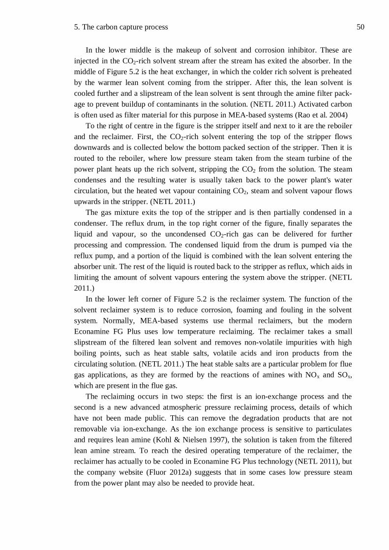
5. The carbon capture process 50
In the lower middle is the makeup of solvent and corrosion inhibitor. These are injected in the CO2-rich solvent stream after the stream has exited the absorber. In the middle of Figure 5.2 is the heat exchanger, in which the colder rich solvent is preheated by the warmer lean solvent coming from the stripper. After this, the lean solvent is cooled further and a slipstream of the lean solvent is sent through the amine filter pack-age to prevent buildup of contaminants in the solution. (NETL 2011.) Activated carbon is often used as filter material for this purpose in MEA-based systems (Rao et al. 2004)
To the right of centre in the figure is the stripper itself and next to it are the reboiler and the reclaimer. First, the CO2-rich solvent entering the top of the stripper flows downwards and is collected below the bottom packed section of the stripper. Then it is routed to the reboiler, where low pressure steam taken from the steam turbine of the power plant heats up the rich solvent, stripping the CO2 from the solution. The steam condenses and the resulting water is usually taken back to the power plant's water circulation, but the heated wet vapour containing CO2, steam and solvent vapour flows upwards in the stripper. (NETL 2011.)
The gas mixture exits the top of the stripper and is then partially condensed in a condenser. The reflux drum, in the top right corner of the figure, finally separates the liquid and vapour, so the uncondensed CO2-rich gas can be delivered for further processing and compression. The condensed liquid from the drum is pumped via the reflux pump, and a portion of the liquid is combined with the lean solvent entering the absorber unit. The rest of the liquid is routed back to the stripper as reflux, which aids in limiting the amount of solvent vapours entering the system above the stripper. (NETL 2011.)
In the lower left corner of Figure 5.2 is the reclaimer system. The function of the solvent reclaimer system is to reduce corrosion, foaming and fouling in the solvent system. Normally, MEA-based systems use thermal reclaimers, but the modern Econamine FG Plus uses low temperature reclaiming. The reclaimer takes a small slipstream of the filtered lean solvent and removes non-volatile impurities with high boiling points, such as heat stable salts, volatile acids and iron products from the circulating solution. (NETL 2011.) The heat stable salts are a particular problem for flue gas applications, as they are formed by the reactions of amines with NOx and SOx, which are present in the flue gas.
The reclaiming occurs in two steps: the first is an ion-exchange process and the second is a new advanced atmospheric pressure reclaiming process, details of which have not been made public. This can remove the degradation products that are not removable via ion-exchange. As the ion exchange process is sensitive to particulates and requires lean amine (Kohl & Nielsen 1997), the solution is taken from the filtered lean amine stream. To reach the desired operating temperature of the reclaimer, the reclaimer has actually to be cooled in Econamine FG Plus technology (NETL 2011), but the company website (Fluor 2012a) suggests that in some cases low pressure steam from the power plant may also be needed to provide heat.

5. The carbon capture process 51
As Figure 5.2, shows, soda ash is injected to the reclaimer to facilitate precipitation of any degradation byproducts and heat stable salts, thus leading to better amine purification (Chakravarti et al. 2001). Soda ash also helps to prevent corrosion (Kohl & Nielsen 1997). After reclaiming, the reclaimed solvent is returned to the circulation in the solvent stripper and the degraded solvent with the undesired components is pumped to the solvent reclaimer drain tank. (NETL 2011.)
The liquid entering the drain tank consists of the amine itself and its degradation products, such as the heat stable salts. Therefore, the reclaiming operation causes unavoidable amine loss and creates some waste, but Fluor claims that their new reclaiming technology significantly reduces the quantity of reclaimer waste (Reddy et al. 2008). In general, any reclaiming operation causes some amine losses and creates waste, so reclaiming systems are considered in detail in Subchapters 5.2 and 5.3, which deal with amine losses and amine waste handling.
In conclusion, Fluor’s Econamine FG Plus and the earlier versions of the technology are well-designed systems which can be used for CO2 removal from the flue gases of a normal power plant. Fluor has also announced that it is ready to deliver CO2 removal systems for both coal and natural gas fired power plants (Reddy et al. 2008). As Fluor is an American company and actively markets its CO2 removal solutions, its technology is also often cited in the scientific literature. However, many details of the process remain trade secrets and are thus unavailable for this thesis.
Therefore, reliable performance data of the Econamine FG Plus process are also missing, though Abu Zahra (2009) reports that Fluor claims to have reached an energy requirement of about 2.9 GJ/tCO2, which is much lower than the heat requirement given for the Econamine FG system in Table 5.1. The improvements are based on process integration and solvent improvement, details of which are given in Reddy et al. (2008). Additionally, the solvent circulation rate, electricity requirement and solvent consumption should be lower than the values in Table 5.1 due to the mentioned improvements (Reddy et al. 2008). However, Abu Zahra (2009) notes that none of the improvements in Econamine FG Plus have been validated for a large-scale process, so the reported new performance results have yet to be proven.
5.1.2 Mitsubishi Heavy Industries KM CDR technology
Mitsubishi Heavy Industries (MHI) is a somewhat newer vendor of CO2 removal technology. Their technology is nowadays marketed as KM CDR process. Mimura et al. (1995) was one of the first publications to introduce it scientifically As a result of screening tests, a sterically hindered amine was chosen for CO2 removal from the flue gas of a conventional power plant (Mimura et al. 1995). As mentioned earlier, sterically hindered amines can reach higher CO2 / amine loadings and have lower heats of absorption than MEA. The chosen amine was named KS-1 and it has been shown to be almost noncorrosive compared to uninhibited MEA. (Mimura et al. 1995.)
Other advantages of KS-1 are a large difference between lean and rich loading, lead-ing to a large CO2 capture capacity, and a rather low regeneration temperature (110 °C),
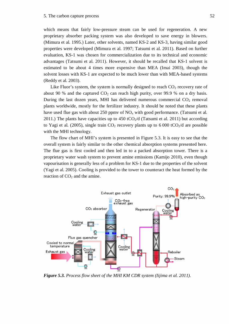
5. The carbon capture process 52
which means that fairly low-pressure steam can be used for regeneration. A new proprietary absorber packing system was also developed to save energy in blowers. (Mimura et al. 1995.) Later, other solvents, named KS-2 and KS-3, having similar good properties were developed (Mimura et al. 1997; Tatsumi et al. 2011). Based on further evaluation, KS-1 was chosen for commercialization due to its technical and economic advantages (Tatsumi et al. 2011). However, it should be recalled that KS-1 solvent is estimated to be about 4 times more expensive than MEA (Imai 2003), though the solvent losses with KS-1 are expected to be much lower than with MEA-based systems (Reddy et al. 2003).
Like Fluor’s system, the system is normally designed to reach CO2 recovery rate of about 90 % and the captured CO2 can reach high purity, over 99.9 % on a dry basis. During the last dozen years, MHI has delivered numerous commercial CO2 removal plants worldwide, mostly for the fertilizer industry. It should be noted that these plants have used flue gas with about 250 ppmv of NOx with good performance. (Tatsumi et al. 2011.) The plants have capacities up to 450 tCO2/d (Tatsumi et al. 2011) but according to Yagi et al. (2005), single train CO2 recovery plants up to 6 000 tCO2/d are possible with the MHI technology.
The flow chart of MHI’s system is presented in Figure 5.3. It is easy to see that the overall system is fairly similar to the other chemical absorption systems presented here. The flue gas is first cooled and then led in to a packed absorption tower. There is a proprietary water wash system to prevent amine emissions (Kamijo 2010), even though vapourisation is generally less of a problem for KS-1 due to the properties of the solvent (Yagi et al. 2005). Cooling is provided to the tower to counteract the heat formed by the reaction of CO2 and the amine.
Figure 5.3. Process flow sheet of the MHI KM CDR system (Iijima et al. 2011).

5. The carbon capture process 53
The lean amine is cooled before entering the absorber and the lean and rich amine exchange heat in the same way as in most amine systems. The heat for the stripper is provided by steam from the power plant in the reboiler and the condensation of water from the CO2 product is also very similar to the other systems.
Since the flow chart is so similar, the basics are not discussed further here, but the article by Mitchell (2007) provides a good basic explanation of the process and its oper-ating temperatures. The company website (MHI 2012a) has much information about the process and also about recent developments in the technology. There is also information about recent commercial and demonstration projects, which show that MHI has found some customers for CO2 removal technology even in the present situation (MHI 2012a).
However, there are also differences, even though it should be noted that Figure 5.3 is less detailed than Figure 5.2. Some amine loss can be expected, so some amine must certainly be added to the system but due to the noncorrosive properties of KS-1, no corrosion inhibitor is needed, unlike in Fluor’s and many other amine-based systems. In general, the noncorrosiveness also means that less expensive carbon steel can be used for most of the construction within the CO2 capture plant (Mitchell 2007).
Another significant difference in the figures is that the reclaiming unit is missing in Figure 5.3. This is no mistake since KS-1 is very resistant to degradation, so the concentration of heat stable salts in the solution increases slowly compared to MEA-based systems (Grønvold et al. 2005). Iijima (2006) even asserts that reclaiming is only needed once in six months with KS-1. No information of the reclaiming technology used is provided, but it can be reasonably argued that reclaiming does not form a significant part of the operational costs of the CO2 recovery plant because it is carried out so rarely.
The company website (MHI 2012a) with its numerous recent commercial orders demonstrates clearly that MHI’s technology is competitive in the present market for CO2 removal technologies. This is not surprising because MHI has worked hard to improve the performance of its technology. MHI currently guarantees that the regenera-tion energy of the solvent is less than 2.9 GJ/tCO2, but expects it normally to be under 2.8 GJ/tCO2 (MHI 2012b). These reductions in energy use have been achieved by using a patented and commercially proven concept that utilizes heat from the lean solvent and steam condensate for regeneration inside the stripper. Based on pilot plant results, MHI expects to achieve regeneration energy consumption of about 2.5 GJ/tCO2 with its new recently developed solvents. (Tatsumi et al. 2011.)
Additionally, Yagi et al. (2005) report that solvent consumption can be markedly decreased from present low levels through new absorber design, but it is worth noting that amine losses as low as 0.2 kg/tCO2 have only been reached with flue gas containing very low SOx and low NOx levels. MHI’s commercial experience is based mainly on flue gases from natural gas fired boilers containing no SOx, but the company is presently working intensively to leverage this experience for application in large scale CO2 removal from the flue gas of coal-fired power plants. (Endo et al. 2011.)

5. The carbon capture process 54
Therefore, much testing has been carried out on coal derived flue gas over the years, and recently MHI has successfully deployed its technology at a coal-fired power plant in Plant Barry Power Station in Alabama, USA. The plant has a capacity of 500 tCO2/d. However, as this project is not commercial, it can be stated that MHI does not yet have commercial experience in CO2 removal from coal derived flue gas. (Endo et al. 2011; MHI 2012a.)
In conclusion, MHI is clearly an active and interesting player in the field of CO2 removal from power plants. The company has a wealth of experience in using and selling its technology also in less developed countries (Endo et al. 2011), which are presently the sources of the largest increases in CO2 emissions (IEA 2011). It may be that such experience will become even more valuable in the future when emissions are to be cut worldwide.
5.2 Amine losses and their prevention
The operating U.S. gas and liquid treating plants using alkanolamines were estimated to have a yearly loss of over 40 000 tonnes of amines 20 years ago (Stewart & Lanning 1994). This is already a lot, but the amount would multiply if similar technology was used widely for CO2 removal from power plant flue gas. Today’s amine-using plants are generally smaller than would be needed for large power plants, but Stewart & Lanning (1994) note that excessive amine losses have a negative impact on the economics of operating any amine unit. As Chapter 3 shows, amine losses to the atmosphere are also undesirable from an environmental point of view. Together these factors provide a clear incentive to prevent or at least limit amine losses.
To reduce solvent losses in amine-using plants, a systematic approach is needed. Therefore, it is important to first identify the main causes of amine loss in such plants. Thitakamol et al. (2007) classifies amine losses into three groups: losses from normal operation, fugitive emissions such as leaks from valves, tanks and pumps, and accidental releases. Accidental releases can be caused by process equipment failure, equipment malfunction, improper operation or various other reasons. The resulting release, spill or discharge can be large and may cause major damage. (Thitakamol et al. 2007.) However, such accidents are rare and unpredictable, so such emissions and their prevention are beyond the scope of this thesis.
Fugitive emissions or mechanical losses, as Stewart & Lanning (1994) call them, are another cause of amine loss. In some amine-using plants, mechanical losses have been the largest source of amine loss. They can be defined as physical removal of solvent from the closed circulation system due to normal deterioration of process equipment and pipes. (Stewart & Lanning 1994.) Such losses do not, therefore, generally pose risks to the public or the environment because they are limited to the plant area itself.
However, these losses occur at the solvent operating concentration, so the amount of actual solvent lost can still be high. Fortunately, these losses are often visible as drips or sprays from equipment, so they can be repaired before they cause significant problems.
5. The carbon capture process 55
Correct and well-planned maintenance practices are good ways to prevent and limit these losses. It is also advisable to return the amine-rich flushing waters of equipment and amine-rich liquids from changeable filters back to the amine circulation system in order to minimise the losses (Stewart & Lanning 1994).
To control and prevent fugitive emissions it is important to know where the prob-lems are usually to be found. According to the European Sealing Association (ESA) (2009), the following items of equipment are the major sources of losses: valves (60 %), relief valves (15 %), tanks (10 %) and pumps (10 %). In practice, this means equipment leakage, and such leaks may, for example, be caused by corrosion, impact damage or vibration. These emissions are unpredictable, intermittent and random, and can occur anywhere on the plant site. Some amine losses can also be caused by open storage tanks during filling of the tanks since some amount of amine is normally vapourised. Increased daytime temperatures may also cause such losses from storage. (Thitakamol et al. 2007.)
In the event, the data provided by Thitakamol et al. (2007) shows that fugitive emissions should not incur large costs for well-maintained amine-using plants. Their estimate is that pressure relief valves, being the largest cause of fugitive emissions, cause an amine loss of the order of a few grams per tonne of CO2 captured. Valves cause a loss of 1.5 g/tCO2 captured, pump seals under half a gram and other equipment even less. These values are much smaller than the values given in Table 5.1, for exam-ple, so the most important causes of amine loss lie elsewhere. (Thitakamol et al. 2007.)
This means that most amine loss is actually caused by the normal operation of the plant. Such losses are intentional, predictable and quantifiable on the basis of the plant’s operating conditions. The point of discharge is also planned and well-known. In amine-using plants, such amine emissions are the treated gas released from the top of the absorber and the waste of process solution from solution reclamation and other purification units. (Thitakamol et al. 2007.) In general, the amine losses from the absorber are caused by amine vapourisation and amine entrainment in the treated gas, while the losses from the reclaiming unit are caused mainly by the removal of amine degradation products (Stewart & Lanning 1994). As these losses were shown to be the most significant, they are considered further in the following two subchapters.
5.2.1 Amine losses from the absorber
As already noted, the absorber for CO2 removal is a high structure with packed columns (Desideri 2010) and the treated gas from which the CO2 has been removed is continuously released from the absorber top to the atmosphere. The treated gas is basically flue gas with a reduced CO2 content, but some vapours of process solution are mixed with this gas. (Thitakamol et al. 2007.) Most of the process solution is, of course, usually water which is normally present in the flue gas even before it enters the absorber, so it does not change anything but after the absorber there are also some amines in the treated gas. As losing amines incurs costs and the amines may cause environmental problems, it is reasonable to try to limit their emission.

5. The carbon capture process 56
As noted above, vapourisation of the amine is one of the causes of amine loss from the absorber. Naturally, vapourisation is only a significant problem for amines which have a relatively high vapour pressure, like MEA. Without a water-wash system, the total MEA losses at 40 °C, which is a usual operating temperature of an amine absorber, would be about 0.7 kg per tonne of CO2 captured. (Thitakamol et al. 2007.) Besides temperature, pressure and amine concentration also have an effect on the vapourisation. Naturally, higher pressure means less vapourisation and higher concentration means more vapourisation. (Stewart & Lanning 1994.)
To reduce vapourisation losses in any amine system, conditions of the gas/solvent equilibrium should be manipulated to return the amine to the liquid phase. Cooling the treated gas near the top of the absorber returns a portion of the vapourised amine to the main circulation system, and such cooling systems can also be found in Figures 5.2 and 5.3. However, this is normally not enough; a water wash system is also needed. (Stewart & Lanning 1994.) This is certainly true for units treating large flows of flue gas from power plants, and both Fluor and MHI have incorporated a water wash system in their technology (Kamijo 2010; Reddy 2010).
Stewart & Lanning (1994) state that there are two typical water wash designs for amine systems: a set of trays above the feed point of the lean amine plus a separate tray or a separate packed water wash vessel downstream of the absorber. Figure 5.4 contains a simple illustration of a separate water wash system downstream of the amine absorber. However, both Fluor and MHI have incorporated a packed water wash section in their absorbers (Kamijo 2010; Reddy 2010), so it seems to be a popular choice in modern applications for power plant use.
Figure 5.4. Separate gas water-wash system (Stewart & Lanning 1994). LC stands for level controller, which is used to control the liquid level at the bottom of the vessel.
A proper absorber with a well-designed water-wash section can decrease the MEA emissions from the mentioned 0.7 kg/tCO2 to about 0.03 kg/tCO2. With DEA the emissions would be of this order even without a water wash system because of DEA’s

5. The carbon capture process 57
low vapour pressure, and the water wash system can further decrease the emissions. (Thitakamol et al. 2007.) It can be estimated that with MDEA the emissions with or without water wash would normally be somewhere between these two figures (Stewart & Lanning 1994). Another source estimates with computer simulations that the vapouri-sation losses in a MEA-based system at 45 °C would be about 3 kg/tCO2 without water wash, but only 11 g/tCO2 after wash. MDEA losses from the absorber after wash in the same study are estimated to be practically non-existent. (Dave et al. 2010.)
However, vapourisation is not the only possible cause of amine loss from the absorber. The amine can form small amine droplets, often described as a mist or spray depending on the droplet size, and these droplets may be carried out of the absorber in some conditions. Another potential cause for amine loss is foaming due to contaminants in the solution because these contaminants may stabilise the foam. If this happens, the foam will move up the tower and continue into downstream equipment. (Stewart & Lanning 1994.)
The first of these causes of amine loss, entrainment with the treated gas, depends largely on the velocity of the gas in the absorber. The faster the gas flows, the larger amine droplets it can carry. As long as the amine droplets remain very small, the amount of amine they contain also remains small. High entrainment losses are often caused by operating an absorber beyond design gas flows, or in other words, having too small absorber tower diameter for the gas flow, or operating the absorber below design pressure. Damaged equipment may also lead to excessive entrainment losses. (Stewart & Lanning 1994.) In addition, Chapel et al. (1999) note that soot from heavy fuel oil can cause problematic mist formation leading to amine loss.
Some entrainment losses can be expected under normal operation of the absorber, but mist eliminators in the very top of the absorber are commonly used to limit these losses to acceptable levels (Kohl & Nielsen 1997). Actually, mechanical damage to this eliminator is mentioned as another possible reason for high entrainment losses. It is also fairly common to install a separate knockout drum downstream of the absorber to further reduce the losses. The purpose of both the eliminator and this knockout drum is to make the gas take a tortuous course through, so the forward momentum of the droplets carries them on to the mist elimination surfaces. (Stewart & Lanning 1994.)
Veldman (1989) states that entrainment losses of amines should average less than 8 mg/Nm3 of treated gas in a properly designed absorber, but notes that many times higher values are also not uncommon. Dave et al. (2010) estimate by simulations that the entrainment losses of a generic MEA-based process with proper mist eliminators would be in the order of 10 – 50 g/tCO2, but state that absorber design and temperature, the type of mist eliminator and various other factors have a significant impact on the actual emissions. Technological development and environmental concerns about the amines can be expected to cut these emissions to lower levels if amine-based CCS is widely deployed because Dave et al. (2010) acknowledge using very conservative estimates to reach these figures.

5. The carbon capture process 58
The third cause of amine loss from the absorber, foaming, is probably the most common operating problem in amine treating units. It is caused by the formation of stable bubbles which build to a foam. As the surface area to weight ratio of these bubbles is high, the gas can carry the foam upwards in the absorber. Some foam or froth in the absorber is normal in plants using amines, but this foam is normally not stable and breaks down quickly. However, sometimes the foam stabilizes and starts to move upwards, possibly going all the way out of the absorber at the top, causing amine loss and possibly other operational problems as well. (Kohl & Nielsen 1997; Stewart & Lanning 1994.)
Therefore, it is best to try to prevent excessive foaming by preventing the stabilisa-tion of the foam. The stabilisation can be caused by impurities from makeup water, the flue gas itself or the amine degradation products which circulate in the solution. For example, fly ash from the flue gas is cited as a possible foaming agent (Chapel et al. 1999). This means that the impurities should be prevented from entering the amine system. In power plant use, the direct contact coolers and other particulate control methods discussed in Chapter 4 also serve this purpose.
In addition to this prevention, the amine solution quality is often maintained by mechanical and carbon filtration. A common design for such filtering is shown in Figure 5.5 and a fairly similar system is included in Fluor’s Econamine FG Plus system, as shown in Figure 5.2. Because the carbon filter itself can introduce solids to the circula-tion, a mechanical filter is also included on the outlet of the carbon filter, before the filtered amine solution re-enters the normal amine circulation. (Stewart & Lanning 1994.) Such a filtering system usually handles from 10 % to 20 % of the circulating solution. (Kohl & Nielsen 1997.) As Rao et al. (2004) note, the activated carbon in the filter has to be replaced every few months, and this incurs some recurrent costs.
Figure 5.5. Carbon filtering of lean amine (Stewart & Lanning 1994).

5. The carbon capture process 59
However, in certain cases even this filtering is not enough to prevent foaming. Having over 10 % of the amine in the form of heat stable salts, which the filtering does not remove, is known to cause foaming. Thus too infrequent reclaiming can lead to foaming problems. Antifoam agents are available for foaming control, but of course using them incurs extra costs as well and they may cause other operational problems. Therefore, they are not recommended as a permanent solution. (Kohl & Nielsen 1997.) Overall, Desideri (2010) considers that foaming remains a technical issue worth more research with regard to using amines for CO2 removal from the flue gases of power plants.
In conclusion, vapourisation and entrainment are the causes of continuous MEA loss from the absorber since foaming should normally not occur. This makes vapourisa-tion and entrainment losses from the absorber the only continuous sources of amine emissions to air from the CO2 capture unit. As noted in Chapter 3, this means that they are also probably the emissions which may cause harm to the general public and the environment. As a result, these emissions have been studied intensively and some recent information is available from different test units. Karl et al. (2011) state that the total amine emissions from a modern absorber are of the order of 1-4 ppmv in the treated gas. For MEA, this means 3 – 11 mg/Nm3. Of course, in the atmosphere their concentration will quickly dilute to very low levels, so the risk of acute toxic impacts can be assumed to be low (Thitakamol et al. 2007).
However, Fluor reports that amine emissions at its Bellingham plant were under 1 ppmv and their new more advanced system can reduce the emissions to 0.1 – 0.2 ppmv (Reddy 2010). MHI has reported numbers of the same order recently (Kamijo 2010). These reductions in emissions have been reached by new unpublished modifications of the absorption processes, but such systems understandably consume more power and/or reagents. There is a clear need of official and reasonable amine emission limits as otherwise it is impossible for the vendors to design systems capable of reaching the limits with reasonable costs. (Reddy 2010.) The limits of acceptable amine concentration in air given in Table 3.3 would probably be an important step in this direction.
5.2.2 Amine losses from the reclaimer
The general practice for gas treatment processes is that a sidestream of process solution is purified to remove process contaminants so that the concentration of the active solvent is maintained. A part of this system is mechanical filtration and filtration with activated carbon that is introduced in Subchapter 5.2.1. However, over time this is not enough and reclaiming is also needed to remove heat stable salts, non-volatile organics and suspended solids. (Thitakamol et al. 2007.) The heat stable salts are a particular problem for flue gas applications so SOx and NO2, which degrade the amine and lead to the formation of these salts, should mostly be removed from the flue gas stream before the absorber, as shown in Chapter 4. However, a proportion of these flue gas impurities always remains and then forms heat stable salts with the amine.

5. The carbon capture process 60
Thermal reclaiming, or reclaiming with the help of low pressure steam from the power plant, is a common method for impurity removal from amine solutions, but other amine solution purification methods also exist. The choice of purification method depends on the amine used and the needs of the process. Mechanical filtration only removes particulate matter, and an activated carbon filter does not remove the problematic heat stable salts (Kohl & Nielsen 1997), so these methods cannot be used alone for amine solvents in flue gas treatment. Newer purification methods include ion exchange and electrolysis, which have become more common recently. They are less energy intensive than conventional thermal reclaiming, which partly explains their success. They do not remove non-ionic substances from the circulation, but on the other hand they cause significantly smaller amine losses. (Kohl & Nielsen 1997.)
In any case, whatever purification system is used, it will create some waste, with which some amine may be lost. This loss is not significant for the filters, only about 1 % of the treated amine for ion exchange methods and 2 % for electrodialysis, but for thermal reclaiming it is 5 – 15 %. (Kohl & Nielsen 1997.) This largely explains the difference in solvent consumption seen between Fluor’s and MHI’s technology in Table 5.1 because Econamine FG uses thermal reclaiming continuously (Sander & Mariz 1992) whereas MHI’s system needs only infrequent reclaiming (Iijima 2006). However, with its new advanced reclaiming processes in Econamine FG Plus, Fluor can certainly decrease the solvent loss if it is needed (Reddy et al. 2008).
As demonstrated by the difference between the two technologies, the purification systems may be used continuously, semi-continuously or only periodically, depending on the needs of the process. In continuous operation of thermal reclaiming, it is applied to a small sidestream, usually 0.5 – 2 % of the main flow, to prevent foaming and other problems by keeping the concentration of the heat stable salts under 10 % of the total amine concentration. (Kohl & Nielsen 1997.) Of course, the frequency of the reclaiming operation has a large effect on the amine loss and also waste formation.
Thermal reclaiming of MEA is usually done at a pressure around 2 bar, though atmospheric reclaiming is also possible for MEA. For secondary and tertiary amines, thermal reclaiming under vacuum is preferred in order to prevent excessive degradation during reclaiming. However, as the operation in vacuum involves costly and more complex operation, the reclaiming of these amines has often been done in mobile units brought in as required. (Kohl & Nielsen 1997.) It remains to be seen how this would be done in large units processing the flue gas flows from power plants, but the required large circulation flows of solvents can be assumed to favour on-site installations.
When the thermal reclaimer is operating, heat is provided to the reclaimer by low pressure steam coming from the power plant (Reddy et al. 2008). This boils the amine and concentrates the salt ions and substances with high boiling points into a sludge which can then be purged (Stewart & Lanning 1994). The amine and water vapour can then be returned to the main circulation. However, when the amine and water concentration in the boiling liquid gradually decreases, higher temperature is needed to continue the boiling of the liquid. If the heating was continued, the amines and the salts

5. The carbon capture process 61
would eventually degrade, causing excessive amine losses. Therefore, not all of the amine can be vapourised from the liquid containing mostly heat stable salts, and it is lost when this sludge is purged. (Kohl & Nielsen 1997.)
According to Chapel et al. (1999) the thermal reclaiming in Econamine FG system created about 0.003 m3 waste per tonne of CO2 captured. Additionally, they state that the amount of amine waste generated in the process is a function of plant operating conditions and flue gas composition. The SOx content of the gas coming in the absorber has an especially strong effect on the amount of solvent lost and waste created. Simmonds et al. (2003) estimate that with the same technology, capturing 1.8 million tonnes of CO2 yearly from gas turbine flue gas would generate 100 tonnes of reclaimer waste per week, which means about 3 kg/tCO2 captured.
IEA GHG (2004) estimates the cost of disposal for this waste to be 250 US dollars/tonne, so the waste disposal cost per tonne of CO2 captured would be in the order of 0.8 $/tCO2. Thitakamol et al. (2007) estimate that the waste generated with a generic MEA-based process will be about 4 kg/tCO2 captured when a slipstream of 0.5 % of the amine is used in reclaiming, and up to 15 kg/tCO2 with a slipstream of 2 %.
In the study of Thitakamol et al. (2007) the reclaimer waste did not contain signifi-cant amounts of amine, but naturally the degraded amine in this waste still represents an amine loss. In other words, amines less prone to degradation produce less reclaimer waste. On the other hand, in the study by Strazisar et al. (2003) the reclaimer bottoms were found to contain a substantial amount of MEA, so a good deal of still active amine may also be lost in the reclaiming. IEA GHG (2004) reports 6000 ppm or 0.6 % as the MEA concentration in the reclaimer waste of the Econamine FG system and considers the waste of this system fairly similar to any refinery MEA reclaimer waste.
In summary, it is argued that reclaimer waste is the largest emission in size in the system studied and contributes most to the environmental impacts since it is certainly hazardous waste. However, provided the waste is not released uncontrollably to the environment but disposed of responsibly, the environmental impacts can be mitigated. (Thitakamol et al. 2007.)
Little information is currently available about the reclaimer waste which would be created in large plants treating flue gases of power plants with other amines than MEA since such plants are rare. Even the experience from natural gas treatment does not help very much because the formation of waste depends on the composition of the incoming gas (Chapel et al. 1999). Reclaiming is not even needed in clean natural gas service with DEA or MDEA (Stewart & Lanning 1994).
The new reclaiming technologies can certainly reduce reclaimer waste as Econamine FG Plus technology shows, but the ion exchange and electrodialysis processes also create some waste, even though this waste is considered less hazardous (Kohl & Nielsen 1997). The MEA-based processes need some occasional thermal reclaiming and will do so even in the future. They will thus continue creating hazardous waste, so it is still important to design environmentally responsible waste management systems. In addition, the waste created by the mechanical and activated carbon filters

5. The carbon capture process 62
can also be considered hazardous (Kohl & Nielsen 1997). Consequently, Subchapter 5.3 focuses on the handling of process waste from CO2 removal units.
5.3 Handling of process waste
It can reasonably be assumed that the CO2 capture unit creates some waste which would not otherwise be formed without it. The mechanical filtration equipment, which is often present to remove particulates from the solvent, produces waste in the form of filter sludge, filter bags, and cartridges, and this waste can be considered hazardous. Using activated carbon filters means producing spent carbon and filter waste. (Kohl & Nielsen 1997.) However, if the flushing waters and other amine-rich liquids from such filters are returned to amine circulation when possible, some amine is saved and the amount of waste produced decreases (Stewart & Lanning 1994). Furthermore, the total volume of the waste produce from the filters can be expected to be low (Kohl & Nielsen 1997).
The newer amine solution purification techniques like electrodialysis and ion exchange processes create some waste as well, but as it is not considered hazardous, it can be assumed not to cause significant extra costs (Kohl & Nielsen 1997). Overall, the largest source of waste is the thermal reclaimer (Thitakamol et al. 2007), which is needed especially in MEA-based systems. As the previous subchapter shows, it produces a few kilograms of waste per tonne of CO2 captured. This waste is hazardous (Kohl & Nielsen 1997) and thus costly to dispose of.
The waste sludge from the thermal reclaimer can be expected to be alkaline (IEA GHG 2004) and consists mostly of heat stable salts and solid precipitates. However, it also contains small amounts of the absorption solvent itself, corrosion inhibitor and other possible additives. Water is certainly present in this waste too; in Econamine FG technology, for example, a third of the waste has been found to be water (IEA GHG 2004). In particular, the corrosion inhibitors present in the waste are considered to make the waste toxic to humans and the environment, though it should be noted that not all CO2 removal systems require corrosion inhibitors. Some degradation products, especially heat stable salts, are also being regulated by law. Typically, such products cause mostly irritation and burns if people are in contact with the waste and so they increase the overall harmfulness of the waste. (Thitakamol et al. 2007.)
The normal process for handling this waste is to remove any possible metals from the reclaimer waste and incinerate the remainder. If the mentioned disposal cost of 250 $/tonne of waste were applied to large CO2 capture units at power plants, the annual cost would be millions of dollars per power plant with the estimate of 100 tonnes waste per week provided by Simmonds et al. (2003). Since current amine scrubbing plants are small, such costs per tonne paid to the specialist waste disposal companies may be tolerable but by the time large scale capture is implemented in power plants, much cheaper solutions will probably have been developed. It is reasonable to assume that an in-process treatment step would be used to at least minimize the amount of costly and hazardous waste that has to be taken away from the power plant site. (IEA GHG 2004.)

5. The carbon capture process 63
The incineration of the waste produces some energy that can, of course, be used though this also produces ashes of the degradation products and additives and vapourises the remainder of the amine solvents. These ashes and vapours are often still harmful to the environment so the ashes must be disposed of properly, which entails transportation to a landfill. The vapours must be cleaned of the most harmful products before they are released to the atmosphere, so the incineration plant must have good emission controls. An alternative to incineration is to take the process waste directly to a landfill, which minimizes any emissions to air, but no energy is then created and anyway the process waste has to be neutralized prior to depositing in landfills. (Thitakamol et al. 2007.) Apart from the filter and reclaimer waste, the CO2 removal unit can be expected to pro-duce some waste water. The flue gas coolers and the possibly needed polishing FGD unit will result in additional waste water. Some amine-containing liquid waste may also be created. These new effluents may also require different treatment to the existing waste water streams. Therefore, in some cases the power plant’s waste water treatment operations will need to be extended in order to treat all the effluents properly. (IEA GHG 2007.)

64 64
6 CARBON DIOXIDE PROCESSING
The CO2 capture and storage (CCS) is often considered as an interconnected sequence of three separate phases: capture, transport and storage of the CO2. Transport and storage lie outside the scope of this thesis, but they still have an impact on the capture process and these impacts are the theme of this chapter. In practice, this means that both the transport process and the requirements of the storage must be taken into account in the capture process, as the requirements for the CO2 product depend on the chosen transport and storage methods. (Aspelund 2010.)
It seems unlikely that the future power plants capturing CO2 would all be sited in places where the CO2 could be directly injected to underground storage without the need for transportation. This means that any widely used carbon capture process must first satisfy the requirements of the transport system. Consequently, it is widely assumed in the literature that after absorption, the CO2 is dried, cleaned and compressed at the power plant to meet the transport requirements (see, for example, Rao et al. 2004; IEA GHG 2007; NETL 2011).
The methods suggested for transportation of CO2 are pipelines and ships. These methods have different requirements for the transported CO2 (Aspelund 2010). The final destination of CO2, such as storage in underground saline formations or depleted oil fields, use in enhanced oil recovery, direct injection deep into the oceans or accelerated mineral carbonation (IPCC 2005), may also set requirements on the CO2 quality.
The focus in this thesis is on the most common solutions, so only the requirements of ship and pipeline transport and underground storage in saline aquifers and use in enhanced oil recovery are considered. These different requirements form the topic of Subchapter 6.1. As any CO2 in the CCS sequence will normally undergo both the transport and storage, it is clear that it is the more stringent requirement which has to be obeyed if the requirements for a particular impurity differ. Aspelund & Jordal (2007) note that it is not always clear which of the phases sets the more stringent requirements, so also the reasons for the limits are explained.
After the requirements for the CO2 are made clear, Subchapter 6.2 considers the ways in which these requirements can be met. As noted above, the processing equipment for reaching the required conditions would often be located at the power plant capturing CO2, so this would have an effect on the power plant, for example, through increased power consumption. However, since this thesis concerns only the stages up to when the CO2 is ready for transport, it does not deal with the methods for keeping the CO2 within the specifications during transportation and injection to underground storage.

6. Carbon dioxide processing 65
6.1 Gas quality requirements for CO2
As already noted, the specifications set for the captured CO2 will depend on the trans-port and storage methods. Choosing CO2 specifications which would cover all possible situations will lead to overly strict requirements and thus increase costs unnecessarily. Therefore, the different parts of the CCS chain should set minimum requirements and it should be generally understood which part of the chain imposes each restriction. For example, an insignificant impurity in the capture process may incur costs later in the CCS chain and removing some purification equipment from CO2 injection process may require installing such equipment in capture plants. Consequently, the companies in the chain should work together to prevent such problems. (Aspelund 2010.)
In general, the CO2 from an amine absorption unit is of very good quality. All three vendors, Fluor, MHI and ABB Lummus, which have experience of capturing CO2 from the flue gas of power plants report that they have achieved a CO2 stream with over 99.9 % purity on a dry basis (Barchas & Davis 1992; MHI 2012b; Reddy et al. 2003). Another indicator of the quality is that amine absorption has been used to provide food grade CO2 for the food industry at numerous plants worldwide (Barchas & Davis 1992; Chapel et al. 1999). The only impurities present in significant quantities in the CO2 stream after the amine stripper are water and amine vapour (NETL 2011). Water amounts to about 5.5 % of the unconditioned CO2 stream in a generic amine process (Aspelund & Jordal 2007).
The condenser and the reflux drum shown in Figures 5.2 and 5.3 condense most of the water and practically all the amine and return them to the amine circulation so that already at this stage the CO2 is almost pure. However, it is not yet ready for transporta-tion because both transportation methods require pressurization of the CO2. Additionally, the suggested storage methods also have their own requirements. In general, other CO2 capture methods require various purification steps for the CO2 stream in order to reach the requirements for transport and storage (Aspelund & Jordal 2007), however, the amine-based systems that are the main interest of this thesis can usually fulfill the requirements fairly easily.
Transporting CO2 in large-scale pipelines is not a new technology as CO2 is trans-ported in onshore pipelines and used for enhanced oil recovery (EOR) purposes in both the USA and Canada (Aspelund 2010). CO2 is also separated from natural gas, trans-ported in onshore or subsea pipelines and injected to underground saline aquifers in Norway and in Algeria (Michael et al. 2009). Shipping CO2 is rarer, but food grade CO2 is already transported by small ships. Large-scale CO2 shipping is a relatively new idea, but it is considered promising enough for research for CCS purposes. (Aspelund 2010.) Consequently, pipelines and ships are the transport options, and saline aquifers and the use of CO2 for enhanced oil recovery are the storage methods, which are discussed in this thesis.
Subchapter 6.1.1 considers the requirements for pipeline transport and Subchapter 6.1.2 considers the requirements for ship transport. Subchapter 6.1.3 deals with the

6. Carbon dioxide processing 66
requirements of the storage methods. This thesis focuses solely on the requirements and the reasons for them, so the costs or technical details of transport and storage are not considered here, but the report by IPCC (2005) and the two books by Maroto-Valer (2010a; 2010b) are extensive sources of information on these topics.
6.1.1 Gas quality requirements for pipeline transport of CO2
To transport large amounts of CO2 efficiently, it must be converted into a form with high density. This means that transport can be considered in liquid, solid or supercritical form. In pipelines, the best way to transport CO2 is to have it at supercritical pressure in the range of 80-150 bar. (Aspelund 2010.) IEA (2007) suggests 110 bar for transport pressure and Aspelund & Jordal (2007) and NETL (2011) about 150 bar. The pipeline pressures in use today vary according to a number of factors (Seevam et al. 2010), but in any case, the CO2 always needs to be pressurised for pipeline transport.
Seevam et al. (2010) report ambient temperatures for the pipelines ranging from 4 to 38 °C. The ambient temperatures usually determine the operating temperatures of the pipelines (Seevam et al. 2010), so in a cold climate such as in northern Europe an ambient ground temperature of 5 to 10 °C is assumed suitable for long-distance transportation (de Visser et al. 2008).
According to de Visser et al. (2008) inert gases as well as hydrogen, oxygen and methane in the transported CO2 stream are more likely to cause problems at higher pressures while water must be controlled more strictly at lower pressures. Additionally, having low operating temperatures means that less water can be admitted into the CO2 stream. However, in general it can be argued that the pipeline quality CO2 specifications must be such that normal pressure and temperature changes during operation do not cause severe problems, and so the specifications must include a margin of safety anyway.
The pipeline specifications for CO2 are shown in Table 6.1. With the amine absorption method, the only critical component for pipeline transport is water as it is the main impurity of the CO2 product stream from amine absorption (Aspelund & Jordal 2007). The 500 ppm water level should be taken as an indicative figure, but the main idea is to prevent free water formation in the pipeline because it may cause operational problems (de Visser & Hendriks 2007). Such problems include gas hydrate formation, freezing and corrosion (Aspelund & Jordal 2007). However, it should be noted that in the past much lower water limits have also been suggested, though de Visser & Hendriks (2007) consider them too stringent.
The solubility of water to CO2 at possible operating temperatures above 15 °C is over 500 ppm for all pressures ranging from 0 to 200 bar. Deep in the sea or in a cold climate the pipeline operating temperatures could be near 0 °C, and below 40 bar pressure at such temperatures the water solubility drops to about 400 ppm, so in these cases the limit could possibly be lowered for safety. (de Visser & Hendriks 2007.) However, as noted above, the pipelines do not use such low pressures during normal operation.

6. Carbon dioxide processing 67
With proper design, the vapour-liquid separators associated with the CO2 pressurisation can reduce water to approximately 400-500 ppm, which is considered acceptable according to Table 6.1. If lower water levels are needed, regenerative adsorption columns can be used to dry the CO2 stream, so the water content is reduced to a few ppm level. (Aspelund & Jordal 2007.) Such water removal processes are described in detail in Subchapter 6.2.
Table 6.1. CO2 quality recommendations for pipeline transport. Data from de Visser & Hendriks (2007) and Aspelund (2010). 1The concentration of all the five featured non-condensable gases together should not exceed 4 % by volume. Component Concentration Reason for limitation H2O 500 ppm Technical problems, such as corrosion and hydrates in
the pipeline H2S 200 ppm Health & safety, short-term exposure limit CO 2000 ppm Health & safety, short-term exposure limit O2
1 < 4 % Costs, technical problems? CH4
1 < 4 % Costs, energy content
N21 < 4 % Costs
Ar1 < 4 % Costs H2
1 < 4 % Costs, further reduction recommended because of the energy content of hydrogen
SOx 100 ppm Health & safety considerations NOx 100 ppm Health & safety considerations CO2 > 95.5 % Balanced with other compounds
The limits for hydrogen sulphide (H2S) and carbon monoxide (CO) in Table 6.1 are given for health and safety reasons. In case of sudden leakage from the CO2 pipelines, these substances might pose a risk to the general public if large amounts of them were present in the CO2 stream. Of course, in case of leaks from pipelines to the atmosphere, the CO2 stream flowing out of the pipeline would be quickly diluted by air, but in the immediate vicinity of the leak location some risk would still exist. (de Visser et al. 2008.)
The H2S and CO limits seen in Table 6.1 are based on the use of the most stringent short-time exposure limits for the gases in the EU and applying a safety factor of 5 (de Visser et al. 2008). According to Anheden et al. (2005) no H2S and only 10 ppm of CO are expected to be present in the CO2 stream from a MEA-based absorption process, and Seevam et al. (2010) give similar figures. Therefore, these gases are not expected to cause problems for an amine absorption process. Such low levels can be also assumed for any amine-based process because Zevenhoven & Kilpinen (2005) report no significant quantities of these gases to be present in the flue gas of normal gas or coal-fired power plants even immediately after combustion before any clean-up.
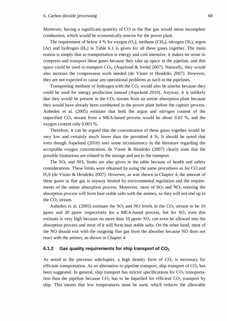
6. Carbon dioxide processing 68
Moreover, having a significant quantity of CO in the flue gas would mean incomplete combustion, which would be economically unwise for the power plant.
The requirement of below 4 % for oxygen (O2), methane (CH4), nitrogen (N2), argon (Ar) and hydrogen (H2) in Table 6.1 is given for all these gases together. The main reason is simply that as transportation is energy and cost intensive, it makes no sense to compress and transport these gases because they take up space in the pipeline, and this space could be used to transport CO2. (Aspelund & Jordal 2007). Naturally, they would also increase the compression work needed (de Visser et Hendriks 2007). However, they are not expected to cause any operational problems as such in the pipelines.
Transporting methane or hydrogen with the CO2 would also be unwise because they could be used for energy production instead (Aspelund 2010). Anyway, it is unlikely that they would be present in the CO2 stream from an amine absorption plant because they would have already been combusted in the power plant before the capture process. Anheden et al. (2005) estimate that both the argon and nitrogen content of the unpurified CO2 stream from a MEA-based process would be about 0.02 %, and the oxygen content only 0.003 %.
Therefore, it can be argued that the concentration of these gases together would be very low and certainly much lower than the permitted 4 %. It should be noted that even though Aspelund (2010) sees some inconsistency in the literature regarding the acceptable oxygen concentration, de Visser & Hendriks (2007) clearly state that the possible limitations are related to the storage and not to the transport.
The SOx and NOx limits are also given in the table because of health and safety considerations. These limits were obtained by using the same procedures as for CO and H2S (de Visser & Hendriks 2007). However, as was shown in Chapter 4, the amount of these gases in flue gas is anyway limited by environmental regulation and the require-ments of the amine absorption process. Moreover, most of SO2 and NO2 entering the absorption process will form heat stable salts with the amines, so they will not end up in the CO2 stream.
Anheden et al. (2005) estimate the SO2 and NO levels in the CO2 stream to be 10 ppmv and 20 ppmv respectively for a MEA-based process, but for SO2 even this estimate is very high because no more than 10 ppmv SO2 can even be allowed into the absorption process and most of it will form heat stable salts. On the other hand, most of the NO should exit with the outgoing flue gas from the absorber because NO does not react with the amines, as shown in Chapter 4.
6.1.2 Gas quality requirements for ship transport of CO2
As noted in the previous subchapter, a high density form of CO2 is necessary for efficient transportation. As an alternative to pipeline transport, ship transport of CO2 has been suggested. In general, ship transport has stricter specifications for CO2 transporta-tion than the pipeline because CO2 has to be liquefied for efficient CO2 transport by ship. This means that low temperatures must be used, which reduces the allowable
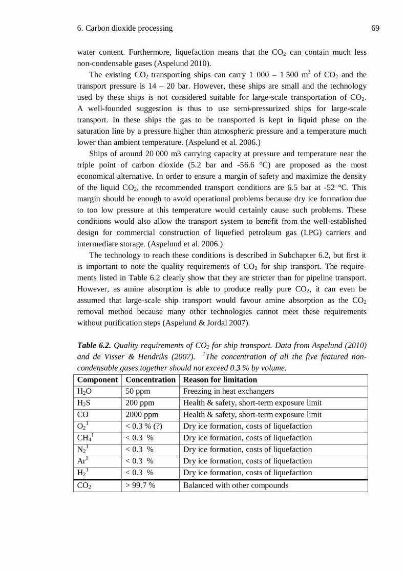
6. Carbon dioxide processing 69
water content. Furthermore, liquefaction means that the CO2 can contain much less non-condensable gases (Aspelund 2010).
The existing CO2 transporting ships can carry 1 000 – 1 500 m3 of CO2 and the transport pressure is 14 – 20 bar. However, these ships are small and the technology used by these ships is not considered suitable for large-scale transportation of CO2. A well-founded suggestion is thus to use semi-pressurized ships for large-scale transport. In these ships the gas to be transported is kept in liquid phase on the saturation line by a pressure higher than atmospheric pressure and a temperature much lower than ambient temperature. (Aspelund et al. 2006.)
Ships of around 20 000 m3 carrying capacity at pressure and temperature near the triple point of carbon dioxide (5.2 bar and -56.6 °C) are proposed as the most economical alternative. In order to ensure a margin of safety and maximize the density of the liquid CO2, the recommended transport conditions are 6.5 bar at -52 °C. This margin should be enough to avoid operational problems because dry ice formation due to too low pressure at this temperature would certainly cause such problems. These conditions would also allow the transport system to benefit from the well-established design for commercial construction of liquefied petroleum gas (LPG) carriers and intermediate storage. (Aspelund et al. 2006.)
The technology to reach these conditions is described in Subchapter 6.2, but first it is important to note the quality requirements of CO2 for ship transport. The require-ments listed in Table 6.2 clearly show that they are stricter than for pipeline transport. However, as amine absorption is able to produce really pure CO2, it can even be assumed that large-scale ship transport would favour amine absorption as the CO2 removal method because many other technologies cannot meet these requirements without purification steps (Aspelund & Jordal 2007).
Table 6.2. Quality requirements of CO2 for ship transport. Data from Aspelund (2010) and de Visser & Hendriks (2007). 1The concentration of all the five featured non-condensable gases together should not exceed 0.3 % by volume. Component Concentration Reason for limitation H2O 50 ppm Freezing in heat exchangers H2S 200 ppm Health & safety, short-term exposure limit CO 2000 ppm Health & safety, short-term exposure limit O2
1 < 0.3 % (?) Dry ice formation, costs of liquefaction CH4
1 < 0.3 % Dry ice formation, costs of liquefaction
N21 < 0.3 % Dry ice formation, costs of liquefaction
Ar1 < 0.3 % Dry ice formation, costs of liquefaction H2
1 < 0.3 % Dry ice formation, costs of liquefaction CO2 > 99.7 % Balanced with other compounds

6. Carbon dioxide processing 70
The required concentration of water is so low that the regenerative adsorption or other drying methods are now definitely needed after the last vapour-liquid separators (Aspelund & Jordal 2007). The low acceptable water content can be easily explained by the sub-zero target temperatures because the water would otherwise cause freezing problems in the heat exchangers.
The limits given for hydrogen sulphide and carbon monoxide are the same as in Table 6.1, but actually these specifications might be made less stringent since leaks are much less likely in ships owing to the transport tank technology used. (Aspelund 2010.) It can be assumed that the same would apply to SOx and NOx limits because their quantities are even smaller. However, as the previous chapter shows, none of these four gases pose problems for amine-based systems.
For the non-condensable gases the requirement is much stricter than for pipeline transport. This is because the liquid CO2 cannot contain more than about 0.3 mol-% of these gases since they facilitate dry ice formation. Naturally, they also increase the costs of liquefaction. (Aspelund 2010.) This certainly means that CO2 often needs to be purified to remove some impurity gases if such gases are present. This has particularly important implications for the oxyfuel combustion technology for CO2 removal because it is hard to reach such low oxygen content using oxyfuel methods. However, as mentioned above, amine absorption has no problems with these specifications. (Aspelund & Jordal 2007.) It should be noted that the O2 limit in Table 6.2 is somewhat uncertain, but de Visser & Hendriks (2007) clearly state that such levels of oxygen do not cause operational problems during transportation.
As a result of the more stringent requirements, the CO2 transported by ships is purer. It should be noted that the complete transport phase of the CCS chain may include both pipeline and ship transport, so in such cases the more stringent requirements will apply. In general, ship transport necessitates greater investment and demands more energy and this is largely due to the difference in cost between pressurization for pipelines and liquefaction for ships. Another notable difference is that the liquefied CO2 from ships would have to be heated and pressurized before it can be injected to underground storage whereas the CO2 from pipelines may be directly ready for injection. (Aspelund 2010.)
6.1.3 Gas quality requirements for geological storage of CO2
As shown in IPCC (2005), several methods have been proposed for the storage of CO2. However, storage in saline aquifers and use in enhanced oil recovery (EOR) are the only alternatives for which commercial experience exists (Michael et al. 2010). Naturally, one important requirement for the CO2 which is to be stored underground is that it meets the rules and regulation set by governments and organizations (Aspelund 2010).
However, such rules do not yet generally exist (Aspelund 2010) and in any case these legislative issues lie outside the scope of this thesis. The London Protocol, a pact to prevent marine pollution by regulating waste dumping at sea, states only that the stored CO2 must consist overwhelmingly of carbon dioxide, though the gas may

6. Carbon dioxide processing 71
“contain incidental associated substances derived from the source material and the capture and sequestration processes used”. However, no wastes or other matter are al-lowed to be added for the purpose of disposing of them. (IMO 2007.) The wording of the existing EU directive is very similar (European Parliament and Council Directive 2009/31/EC).
This cannot be considered very strict regulation, but much stricter suggestions have been made (de Visser & Hendriks 2007). Nevertheless, it is important for the whole CCS chain that the legislation is not unduly strict since such regulation would entail even higher costs for the technology (Aspelund 2010), which is still largely in the research phase.
In general, storage in saline aquifers is not considered to create extra requirements for the CO2 stream. In other words, the CO2 which can be transported should also be injectable. However, little information is available on the effects of oxygen underground. (de Visser & Hendriks 2007.) This is partly because the present plants which inject CO2 to saline aquifers obtain their CO2 from natural gas treatment and they use amine absorption (Teir et al. 2009) so that their CO2 streams contain practically no oxygen.
It is known that oxygen changes the reduction-oxidation conditions underground (Anheden et al. 2005), and in the presence of water it could accelerate oxidation reactions, which in practice means increased corrosion rates in the equipment. There are also concerns that oxygen would induce biological growth underground, but it is unknown whether such an effect would be significant. (de Visser & Hendriks 2007.) In any case, this means that no completely safe O2 limit for storage in saline aquifers can be given, but based on experience from EOR operations, de Visser & Hendriks (2007) recommend a figure of 100 – 1000 ppm. However, for amine-based CO2 removal systems this is not expected to be a problem because the oxygen concentration in the CO2 stream is expected to be on a single digit ppm level (Anheden et al. 2005).
However, the requirements for EOR use of CO2 are generally somewhat stricter than those of storage in saline aquifers, since some gases may hinder oil recovery instead of facilitating it. The basic idea of EOR is that the injected gas, such as CO2, dissolves in oil at the temperature and pressure conditions of the oil reservoir. The smallest pressure at which the injected gas achieves multiple-contact miscibility with the reservoir oil is called minimum miscibility pressure (MMP). Impurities in the injected CO2 may change this MMP and if MMP rises, the injected gas must be at higher pressure. (de Visser & Hendriks 2007.) This incurs costs and is thus undesirable.
Gases like oxygen, nitrogen, argon, hydrogen, carbon monoxide and methane increase MMP, thus decreasing oil recovery potential if nothing else is changed, so they are therefore undesirable. Methane is a usable fuel and is known to cause problems with MMP, so it is recommended to limit the CH4 concentration to less than 2 % of volume, which is stricter than for pipeline transport. Again it should be remembered that the CO2 stream from the amine absorption does not contain methane, so this is not problematic for amine systems. On the other hand, other impurities, such as H2S, SO2 and

6. Carbon dioxide processing 72
hydrocarbons heavier than methane, none of which is present in the same CO2 stream, actually decrease the MMP, so they may actually be beneficial for the oil recovery. However, intentionally adding such gases to the injected gas might lead to legal problems. (de Visser & Hendriks 2007.)
Oxygen is a particularly undesirable substance for EOR because of fears of oil oxidation and biological growth in the reservoir. For EOR operation the recommended oxygen concentration is less than 100 ppm, and oil field operators actually prefer to use CO2 with only 10 ppm of oxygen in it. One reason for this is the risk that the injected oxygen might reach the production well and react exothermically with the oil. Such a reaction increases the temperatures near the wellhead and may damage the equipment. (de Visser & Hendriks 2007.)
Although it was said that the requirements for EOR operations are generally more stringent, the composition of the gas injected at the large Weyburn EOR project does not fulfil all the requirements given for transportable CO2 because it contains a fair amount of hydrogen sulphide, about 2 % (Wilson & Monea 2005). This is possible as the pipeline crosses sparsely populated areas where leaks are not problematic. Corrosion problems have been prevented with good material selection, use of very dry CO2 and corrosion inhibitors. (de Visser & Hendriks 2007.) This serves as an example of the fact that quality requirements are not unconditional and that other requirements may also be set depending on the CCS chain in question. However, some common international quality standards would certainly help in creating an international market for CCS-related knowledge and equipment.

6. Carbon dioxide processing 73
6.2 Processing the carbon dioxide after capture
As discussed in the previous subchapter, the available transport and storage options each set their own requirements for CO2 streams. Because the amine absorption method can produce CO2 of very good quality, the processing required is simpler than for some other carbon capture methods (Aspelund & Jordal 2007). Another observation in Subchapter 6.1 is that any CO2 stream from the amine absorption process that is fit for transport will also be fit for injection to saline aquifers and fit for use in enhanced oil recovery.
Consequently, this subchapter considers only those methods that treat the CO2 stream into a form in which it can be transported. Pipeline transport is the alternative considered first because there is more experience in its use (Aspelund 2010). Though variations exist in the treatment processes suggested for CO2 conditioning by different scientists, the essentials of the treatment systems are similar. This subchapter makes reference to the work of Aspelund & Jordal (2007) and Aspelund (2010) for its main sources.
The basic operations of CO2 processing for transport are as follows: compression and cooling, removal of water and other liquids, removal of volatile gases and other unwanted components, condensation, pumping and liquefaction. Not all of these opera-tions are needed for all capture and transport technologies. For the CO2 stream from amine absorption, removal of volatile gases is usually unnecessary, and liquefaction is not needed for pipeline transport. (Aspelund 2010.)
The temperature of the water available for cooling also has an effect on the choice of the CO2 treatment process. If water is available at a temperature lower than 15 ° C, which is the case in Northern Europe, the process shown in Figure 6.1 can be used. The top of the figure shows compressors driven by an electric motor, which serves a reminder that the process consumes electricity. The first vapour-liquid separator on the left is the first separator immediately after the absorber in Figures 5.2 and 5.3, so it removes most of the water and the remaining amine with it, and returns them to the amine plant. (Aspelund 2010.)

6. Carbon dioxide processing 74
Figure 6.1. The conditioning of the CO2 stream for pipeline transport. The numbers shown in squares are temperatures in °C and the numbers in circles are pressures in bars. The numbers given should be considered as guidelines. (Aspelund & Jordal 2007.)
6. Carbon dioxide processing 75
After each separator, the gas is led to a compressor, which increases the pressure of the gas to 3 – 4 times the value that it was before. Centrifugal compressors are the natural choice for this application and they have a polytropic efficiency of 80 – 85 %. Even a fivefold pressure increase is possible but it is less energy-efficient. As the figure shows, intermediate cooling is needed after each compressor because the temperature of the gas increases in the compressor. Cold seawater is a natural source of cooling for the heat exchangers, but freshwater and ambient air can also be used if available at cool temperatures. After cooling, there is another separator reducing the water content further. (Aspelund 2010.)
This cycle is repeated a few times until the last separator at 35 bar sends the gas to the regenerative adsorption dryers, if necessary. The multiple vapour-liquid separators can lower the water content to 400 – 500 ppm, so according to the pipeline specifica-tions this may not be always necessary. On the other hand, the regenerative adsorption columns, which use molecular sieves or silica for water removal, do not significantly increase energy use, investment costs or operational expenses, so they should normally be included. They can dry the CO2 to a level of a few ppm so that the gas becomes very dry. This dried CO2 can actually be used for the regeneration of the adsorbers if it is first heated, as is seen in Figure 6.1. (Aspelund 2010.)
After the driers the gas is sent to the last compressor, which increases the pressure to about 60 bar. The gas is again cooled and fully or partly condensed, so the resulting liquid part contains a proportion of the volatile, non-condensable gases, such as nitrogen and oxygen. With the heat provided by the reboiler, volatile gas concentrations up to 3 – 5 mol-% can be reduced to 0.25 mol-% because these gases are more easily revapourised by the heat and exit the top of the volatile removal column. However, in order not to lose too much CO2 with this gas stream, it goes through another condenser, which is shown in the top right corner of Figure 6.1. It operates at subambient tempera-ture and returns some of the CO2 to the column. (Aspelund 2010)
The volatile removal column is actually not needed if the volatile gas content is already under 0.2 %, as is usually the case for CO2 streams from amine absorption. Naturally, this means less investment is needed, which is an additional benefit of amine systems. However, regardless of the need of a volatile removal column, the liquid after the condenser or the removal column then flows to the CO2 pump, which pumps the CO2 to transport pressure. Pumping the CO2 from 60 bar to the transport pressure of 150 bar is a better alternative than compression of the CO2 because it is more energy-efficient. (Aspelund 2010.)
Nevertheless, for the CO2 from amine absorption it is certainly possible to directly compress the CO2 to transport pressure, as is shown in the flow diagram of such a process in Aspelund & Jordal (2007). This process is simpler but offers no possibility for volatile gas removal and consumes over 10 % more energy. On the other hand, it should be noted that the temperature of the available cooling water and the amount of volatile gas in the CO2 stream have a marked effect on energy consumption, so that in certain conditions direct compression might be preferable. (Aspelund 2010.)

6. Carbon dioxide processing 76
The other transport alternative, ship transportation, requires full liquefaction of CO2 and significant cooling of the CO2 to reach the required shipping conditions of -52 °C and 6.5 bar. A flow diagram of this process is shown in Figure 6.2. As can be easily seen, up to the last compressor the system is similar to that presented in Figure 6.1. (Aspelund & Jordal 2007.)
Figure 6.2. Process flow diagram of ship transport conditioning of CO2. HX stands for heat exchanger. The numbers are only guidelines. (Aspelund & Jordal 2007.)
Separator drum
Separator drum
Water to treatm
ent

6. Carbon dioxide processing 77
The process shown in Figure 6.2 is again best for conditions where cold seawater, below 15 °C, is available. The process operates in the same way as the pipeline transport conditioning process until the gas exits the final compressor. The minor differences in the suggested temperatures and pressures in the separators are not significant. As noted above, volatile removal is done if needed, though it should be noted that much less volatile gas can be allowed in ship transport, as shown in Subchapter 6.1.
However, after the CO2 exits the volatile removal column it needs to be expanded in stages to reach the ship transport conditions. The required full liquefaction is best achieved in an open cycle using the CO2 feed as the refrigerant, which means that the refrigeration is at least partly provided by the CO2 itself. This explains the many heat exchangers in the process, which exchange heat between the different stages of the process. Such a system may seem complicated, but it reduces the heat exchanger exergy losses to a minimum. (Aspelund & Jordal 2007.)
When the CO2 is expanded in stages, some flash gas (in other words CO2 which is boiled) is formed in each stage, and this flash gas can be used to subcool the liquid CO2. After this, the flash gas is sent back to the compressor train at the appropriate pressure level for recompression, as shown in Figure 6.2. This flash gas can also be reheated to regenerate the adsorptive driers. The system is more complicated than pipeline conditioning process and adds the expansion phase of the CO2 liquid to the process, so it naturally requires more energy. (Aspelund & Jordal 2007; Aspelund 2010.)
It has been estimated that the difference in energy requirements between pipeline and ship transport processes is about 20 %. The pipeline transport process introduced in Figure 6.1 consumes approximately 96 kWh/tCO2 and the ship transport process in Figure 6.2 about 105 kWh/tCO2, but the more recent study seems to suggest about 110 kWh/tCO2 for the ship transport conditioning process. In any case, these figures are mainly indicative because the actual consumption depends on a number of factors including seawater temperature, feed gas pressure and volatile content of the treated CO2. (Aspelund & Jordal 2007; Aspelund 2010.)
Additionally, the operational and capital costs of the various transport conditioning processes are expected to differ by 20 – 30 %, pipeline conditioning being cheaper. On the other hand, it is noted that the feed gas quality has a large impact on the energy requirements as well as costs. This difference may well be more than the difference between the transport methods, so amine absorption methods with their good quality CO2 may have a significant advantage in this regard. (Aspelund 2010.)

6. Carbon dioxide processing 78
In conclusion, it is, of course, important that the processes which make the CO2 transportable are efficient, especially as electricity prices are increasing. More research is needed to enhance the processes because the large CO2 transport ships, in particular, are not a commercially proven concept. (Aspelund 2010.) On the other hand, it is important to remember that the absorption process consumes many times more energy than the CO2 purification and conditioning, which is shown by the figures above and in Table 5.1. It is, in fact, the capture process that consumes most of the energy and causes most of the costs for the whole CCS chain. Consequently, it is the phase which has the greatest effect on the overall economics of CCS. (IPCC 2005, pp. 339-362; Viebahn et al. 2007).

79 79
7 CONCLUSIONS
The primary goal of this thesis is, as previously stated, to describe the gas processing methods of a complete carbon capture process in conventional power plants starting with the untreated flue gas and ending with a transportable CO2 stream. The whole process must also be economical, reliable and environmentally safe. Naturally, the required processing methods depend on the carbon capture technology employed. Because the amine absorption methods are the most advanced technology suitable for power plant CO2 capture, they form the focus of this thesis. The advantages of the amine systems are fully discussed along with an evaluation of the relatively extensive commercial experience gained in using them. However, a basic introduction to the possible future competitors of amine absorption technology is also provided in order to facilitate comparison between different technologies.
One of the most important requirements for a widely used CCS technology is that the technology must not endanger human health and it must be environmentally safe. This applies also to amine absorption and so Chapter 3 provides a large amount of information about the amines as chemical substances as well as their effects. Monoethanolamine (MEA), diethanolamine (DEA), methyldiethanolamine (MDEA), 2-amino-2-methyl-1-propanol (AMP) and piperazine (PIPA) are currently considered the most relevant amines for carbon capture purposes. Their similarities and differences are described along with their advantages and disadvantages. However, it should also be noted that new solvents with better properties as absorption solvents are actively being developed and studied.
Due to health and environmental concerns the thesis includes values on the toxicity, ecotoxicity and biodegradability of amine solvents in Table 3.2. It clearly shows that amines not acutely toxic, but there is little information on their long-term effects and so caution is necessary before they can be widely used. Using very conservative estimates and safety factors, Table 3.3 provides the amine limits for air on the basis of long-time inhalation exposure. The licensors of amine absorption systems have stated that at least some official air quality and amine emission limits should be set fairly soon because this would allow the companies to modify their technology to reach such limits if required.
There is a dearth of information on the environmental effects of the amines, but in general the simpler amines, such as MEA, are more readily biodegradable and thus have less potential to harm the environment. Though more research in this topic is clearly needed, the present lack of precise information should not be used to prevent the building of the first CCS plants because a single plant is unlikely to have significant effects.

7. Conclusions 80
While amines in themselves are not dangerous, another cause of concern is their degradation products. Nitrogen oxides, which are present in the flue gases of a normal power plant, can degrade amines to nitrosamines and nitramines. Many of these compounds are proven to be very toxic as well as carcinogenic and mutagenic even in small amounts.
However, it is not fully known how much of these compounds will actually be formed during the capture process or in the atmosphere after the amine emission. Another uncertainty is the time it takes for these compounds to degrade to less dangerous substances in the atmosphere in different conditions. Additionally, the potentially dangerous concentrations of these compounds are so low that it is even hard to measure them in continuous industrial operation. Consequently, much research is needed into the degradation products, their formation and effects in order to dispel the uncertainties and ease public concern, which may otherwise hinder the development of amine absorption technology for CCS.
Another goal of the thesis is to find out how to ensure economical and reliable operation of a carbon capture plant using amines. This task must be started by considering the required flue gas pre-treatment. As shown in Chapter 4, the substances having most potential to cause harm to the absorption process are NOx, SOx and particu-lates. They may cause operational problems in the absorber and degrade the amines, thereby incurring increased amine replacement costs.
NOx is found in both the flue gas from natural gas combustion and in coal-derived flue gas, but most of it is NO, which does not react with amines. This is demonstrated by the fact that the two most successful licensors of amine absorption processes report no problems with normal NOx levels in the flue gas. Additionally, environmental regulations in the European Union require much lower NOx emissions than the operation of the absorption process, so it is unlikely that the addition of the absorption process would require extra de-NOx equipment.
On the other hand, the absorption process is very sensitive to SOx and the environ-mental regulations allow much higher SOx emissions, so the CO2 removal requires better flue gas desulphurisation (FGD) methods. The acceptable SOx level is often found to be as low as 10 ppm in the incoming flue gas. These levels are, nevertheless, achievable with existing and well-proven technology, so the better FGD method only causes a slight increase in the investment costs of a power plant with CCS. As SOx is harmful for human health and the environment, reducing SOx emissions has also some incidental benefits. Wet FGD systems are found to be better for CCS plants than dry FGD systems because they can double up as a particulate removal and flue gas cooling system.
Particulates as well as SOx are only a problem in flue gas from coal because flue gas from natural gas combustion contains neither. They are already removed in all coal plants because of environmental regulations, but the needs of the absorption process are still stricter. However, it is estimated that the normal particulate control devices,

7. Conclusions 81
such as electrostatic precipitators or bag filters, together with a wet FGD system and a direct contact cooling system can reduce the particulate to low enough levels.
As the amine absorber operates at temperatures only slightly higher than ambient temperature, the hot flue gas from the power plant must be cooled before the absorption. This is done preferably in coolers where the cooling water is in direct contact with the hot flue gas because such a system also removes particulates from the gas stream. In total, the cooling of the flue gas and the absorption process itself increase the total cooling demand of the plant. This increases either the amount of cooling water needed or the cooling water discharge temperature of the plant. If cooling towers are used, new ones requiring plenty of space may have to be built. If water is scarce or expensive at the plant site, air cooling is another possibility, but this increases the total investment costs. In such conditions the cost of increased cooling may pose a major economic problem for the CCS plant.
After the description of the pre-treatment processes, the thesis focuses on the amine absorption process. Three commercial amine-based methods are introduced, and two of them are explained in detail to provide an understanding of the process. Their differences and advantages are given special attention. However, rather little informa-tion has been made public about these commercial processes since many details are trade secrets. Therefore, it is more useful to focus on the more general problems of the amine-based processes.
From an economic and environmental point of view, amine losses are one of the most important operational issues in a CCS plant. The main causes of amine loss are amine vapourisation in the absorber, amine entrainment in the treated flue gas and amine degradation. Vapourisation and entrainment cause amine losses from the absorber, and the operating temperature of the absorber has a significant effect on these losses. Naturally, the properties of the amine used, such as vapour pressure of the amine, have an even greater effect. It is found that water wash systems and mist eliminators are commonly used to limit these losses from the absorber. Foaming, which is a quite common operational problem of amine absorbers, is another possible cause of amine loss, but it should be prevented by filtering the amine solution regularly.
However, the largest amine losses are caused by the reclaimer, which purifies the amine solution of degraded amines. These losses depend heavily on the reclaiming method used. Thermal reclaiming, which is used especially in MEA-based processes, creates more waste than the alternative technologies and this waste is usually hazardous. A few kilograms of such waste can be expected per tonne of CO2 captured, which would incur significant waste disposal costs for the CCS plant. Alternative reclaiming techniques are thus actively being sought for amine-based processes. On the other hand, some other amines than MEA require much less frequent reclaiming and so they have an advantage over MEA systems.
Incineration is a common method to dispose of the reclaimer waste. It must be done in a plant with first class emission controls in order to prevent harmful emissions to the environment. However, the incineration produces some ash, which is also usually
7. Conclusions 82
hazardous waste and has to be taken to a landfill. Apart from the reclaimer waste, the absorption process is expected to create some additional waste water, which may require expansion of the existing waste water treatment plant.
After the CO2 has been captured, it is not yet ready for transport or storage. The various transport and storage methods each have their own quality requirements for CO2. The usual transport options are pipeline and ship transport, so these two are considered in the thesis. For storage, there are more alternatives, but storage in underground saline aquifers and the use of carbon dioxide in enhanced oil recovery (EOR) are the only alternatives in which there is commercial experience, so the requirements of other storage options are excluded from this thesis.
Since one of the goals of the thesis is to determine the technical requirements of transportable and storable CO2, these requirements are shown in the tables in Subchapter 6.1. It can be clearly seen that the requirements of ship transport are more stringent than those of pipeline transport. Regarding the CO2 for storage, the quality requirements for CO2 injection to saline aquifers are not strict, but for enhanced oil recovery (EOR) the quality must be better, as otherwise the injected gas does not enhance the oil recovery.
The main reason for the different transportation requirements is the liquefaction needed for ship transport of carbon dioxide. Pipeline transport is usually done at pres-sures over 100 bar and at ambient temperature, but the ship transport is preferably done at moderate pressure and at very cold temperatures. If too large amounts of other gases were present in the CO2 before liquefaction, there would be a risk of dry ice formation during liquefaction or the actual shipping, which would lead to operational problems.
For the storage alternatives, the problematic substance is oxygen. The effects of pumping O2 underground are not well-known, so a completely safe O2 limit cannot be given. More research in this topic is needed, but for EOR use it can be assumed that the O2 limit will continue to be very low in the future because of fears of oxygen reacting with the oil in the reservoir.
However, none of these transport or storage requirements causes significant problems for CO2 from the amine absorption process. It is able to produce a CO2 stream with very high quality, over 99.9 % on a dry basis. This means that water is the only significant impurity present after the first vapour-liquid separator. This is also demonstrated by the fact that there are numerous plants worldwide using this method to produce food grade CO2. As a result, amine absorption has an advantage over several other CO2 capture technologies regarding the conditioning of CO2 for transport and storage.
Water removal from the CO2 stream is a well-known and common technology and is unlikely to be expensive. Most of the water can be removed in further vapour-liquid separators between the compression stages of the CO2 conditioning process and the water content can finally be reduced to very low levels in adsorptive driers before last compression stage. The complete CO2 conditioning processes needed for this are fully described in Subchapter 6.2.

7. Conclusions 83
As previously noted, ship and pipeline transport conditioning processes are fairly similar, but the liquefaction process needed for the ship transport moderately increases the operational and capital costs. However, it should be noted that for other carbon capture technologies having different CO2 streams, the conditioning for transport and storage might pose larger problems.
Nevertheless, it is important to remember that the absorption process represents the most energy-consuming phase of the complete carbon capture and storage chain. It also causes most of the costs, so it is clearly the phase that needs most improvement in order to make future CCS systems more economical. This should not imply, however, neglecting development of other parts of the CCS chain.
By carefully explaining each process stage and its requirements, this thesis has achieved its stated goals. It also demonstrates that it is technically entirely possible to build and operate a large-scale CCS plant with existing technology. As with any technology, there might be initial problems, but amine emissions to the environment are unlikely to prove insurmountable obstacles, as recent technological development has shown. If the anthropogenic carbon dioxide emissions are to be cut as suggested above to prevent the worst effects of climate change, there is not much time left to act.
Today, CCS seems to be one of the less expensive ways to cut CO2 emissions, so the technology should be actively developed further and later deployed on a large scale. However, the continuing dearth of commercial orders for CCS plants clearly shows that cuts in emissions will not start until the economic incentives in place are strong enough. Thus it is not primarily a technological issue if we are able to reduce the emissions but rather a political one of whether we are willing to pay the costs to reduce carbon dioxide emissions.
84 84
REFERENCES A 26.9.2001/807. Finnish Ministry of Social Affairs and Health Decree on chemical classification principles and labeling. Aarrestad, P. & Gjershaug, J. 2009. Effects on terrestrial vegetation, soil and fauna of amines and possible degradation products relevant for CO2 capture: A review [WWW]. Norwegian Institute for Air Research. Available from: http://co2.nilu.no/LinkClick.aspx?fileticket=7QAmOGCgzOg%3d&tabid=2549&mid=5547 [Accessed 23.2.2012]. ABB. 2007. ABB completes sale of Lummus Global [WWW]. Updated 19.11.2007. ABB. Available from: http://www.abb.com/cawp/seitp202/84f37af6b75268e6c125739800227a07.aspx [Accessed 22.2.2012]. Abu Zahra, M. 2009. Carbon Dioxide Capture from Flue Gas: Development and Evalu-ation of Existing and Novel Process Concepts. Dissertation. Delft. Delft University of Technology, Faculty of Mechanical, Maritime and Materials Engineering. 128 pp. Aker Clean Carbon. 2012. Technology [WWW]. Aker Clean Carbon. Available from: http://www.akercleancarbon.com/section.cfm?path=418,456 [Accessed 1.3.2012]. Al-Masabi, F.H. & Castier, M. 2011. Simulation of carbon dioxide recovery from flue gases in aqueous 2-amino-2-methyl-1-propanol solutions. International Journal of Greenhouse Gas Control, vol. 5, no. 6, pp. 1478-1488. Anheden, M., Andersson, A., Bernstone, C., Eriksson, S., Yan, J., Liljemark, S. & Wall, C. 2005. CO2 quality requirement for a system with CO2 capture, transport and storage. In: Rubin, E.S., Keith, D.W., Gilboy C.F., Wilson, M., Morris, T., Gale, J. & Thambimuthu, K. (eds.) Greenhouse Gas Control Technologies 7. Oxford, Elsevier Science Ltd, pp. 2559-2564. Arrhenius, S. 1896. On the Influence of Carbonic Acid in the Air upon the Temperature of the Ground. Philosophical Magazine, ser. 5, vol. 41, pp. 237–276. Aspelund, A. 2010. Gas purification, compression and liquefaction processes and tech-nology for carbon dioxide (CO2) transport. In: Maroto-Valer, M. M. (ed.) Developments and Innovation in Carbon Dioxide (CO2) Capture and Storage Technology, Volume 1 - Carbon Dioxide (CO2) Capture, Transport and Industrial Applications. Cambridge, United Kingdom, Woodhead Publishing, pp. 381-407. Online version available from: http://www.knovel.com/web/portal/browse/display?_EXT_KNOVEL_DISPLAY_bookid=4360

References 85
Aspelund, A., Mølnvik, M.J. & De Koeijer, G. 2006. Ship Transport of CO2: Technical Solutions and Analysis of Costs, Energy Utilization, Exergy Efficiency and CO2 Emis-sions. Chemical Engineering Research and Design, vol. 84, no. 9, pp. 847-855. Aspelund, A. & Jordal, K. 2007. Gas conditioning – The interface between CO2 capture and transport. International Journal of Greenhouse Gas Control, vol. 1, no. 3, pp. 343-354. Bai, H. & Yeh, A.C. 1997. Removal of CO2 Greenhouse Gas by Ammonia Scrubbing. Industrial & Engineering Chemistry Research, vol. 36, no. 6, pp. 2490-2493. Bailey, D., W. & Feron, P., H.M. 2005. Post-combustion Decarbonisation Processes. Oil & Gas Science and Technology - Rev.IFP, vol. 60, no. 3, pp. 461-474. Baker, R.W. & Lokhandwala, K. 2008. Natural Gas Processing with Membranes: An Overview. Industrial & Engineering Chemistry Research, vol. 47, no. 7, pp. 2109-2121. Barchas, R. & Davis, R. 1992. The Kerr-McGee/ABB Lummus Crest technology for the recovery of CO2 from stack gases. Energy Conversion Management, vol. 33, no. 5-8, pp. 333-340. Bello, A. & Idem, R.O. 2006. Comprehensive Study of the Kinetics of the Oxidative Degradation of CO2 Loaded and Concentrated Aqueous Monoethanolamine (MEA) with and without Sodium Metavanadate during CO2 Absorption from Flue Gases. In-dustrial & Engineering Chemistry Research, vol. 45, no. 8, pp. 2569-2579. Bishnoi, S. & Rochelle, G.T. 2000. Absorption of carbon dioxide into aqueous piperazine: reaction kinetics, mass transfer and solubility. Chemical Engineering Sci-ence, vol. 55, no. 22, pp. 5531-5543. Brooks, C.E.P. 1951. Geological and Historical Aspects of Climatic Change. In: Malone, T.F. (ed.) Compendium of Meteorology. Boston, MA, USA, American Meteor-ological Association, pp. 1004-18. Brooks, S. 2008. The toxicity of selected primary amines and secondary products to aquatic organisms: A review [WWW]. Norwegian Institute for Air Research. Available from: http://co2.nilu.no/LinkClick.aspx?fileticket=zgmHr6lHBGQ%3d&tabid=2549& mid=5547 [Accessed 24.2.2012].
References 86
Bråten, H. B., Bunkan, A. J., Bache-Andreassen, L., Solimannejad, M. & Nielsen, C. J. 2009. Final report on a theoretical study on the atmospheric degradation of selected amines [WWW]. Norwegian Institute for Air Research. Available from: http://co2.nilu.no/LinkClick.aspx?fileticket=cCbJgoyMfrI%3d&tabid=2549&mid=5547 [Accessed 21.2.2012]. Butler, J.H. 2011. The NOAA Annual Greenhouse Gas Index (AGGI) [WWW]. Updated Fall 2011. NOAA Earth System Research Laboratory. Available from: http://www.esrl.noaa.gov/gmd/aggi/ [Accessed 24.1.2012]. Callendar, G.S. 1938. The artificial production of carbon dioxide and its influence on temperature. Quarterly Journal of the Royal Meteorological Society, vol. 64, no. 275, pp. 223-240. Callendar, G.S. 1941. Infra-red absorption by carbon dioxide, with special reference to atmospheric radiation. Quarterly Journal of the Royal Meteorological Society, vol. 67, no. 291, pp. 263-275. Cedigaz 2011. 2010 Natural Gas Year in Review: Cedigaz' First Estimates [WWW]. Updated April 2011. Centre International d’Information sur le Gaz Naturel et tous Hydrocarbures Gazeux. Available from: http://www.cedigaz.org/Fichiers/FEstimates2010.pdf [Accessed 20.1.2012]. Chakma, A. & Tontiwachwuthikul, P. 1999. Designer solvents for energy efficient CO2 separation from flue gas streams. In: Proceedings of the Fourth International Confer-ence on Greenhouse Gas Control Technologies, Interlaken, Switzerland, August 30 – September 2, 1998. Oxford, United Kingdom, Elsevier Science, pp. 35-42. Chakravarti, S., Gupta, A. & Hunek, B. 2001. Advanced Technology for the Capture of Carbon Dioxide from Flue Gases [WWW]. Presented in the First National Conference on Carbon Sequestration, Washington, DC, USA, May 15-17, 2001. Available from: http://www.netl.doe.gov/publications/proceedings/01/carbon_seq/carbon_seq01.html [Accessed 8.3.2012.] Chapel, D., Mariz, C & Ernst, J. 1999. Recovery of CO2 from Flue Gases: Commercial Trends [WWW]. Presented in Canadian Society of Chemical Engineers annual meeting, Saskatoon, Canada, October 4-6, 1999. Available from: http://prod75-inter1.netl.doe.gov/publications/proceedings/01/carbon_seq/2b3.pdf [Accessed 9.2.2012.]

References 87
Choi, S., Drese, J. & Jones, C. 2009. Adsorbent Materials for Carbon Dioxide Capture from Large Anthropogenic Point Sources. ChemSusChem, vol. 2, no. 9, pp. 796-854. Chowdhury, F.A., Okabe, H., Yamada, H., Onoda, M. & Fujioka, Y. 2011. Synthesis and selection of hindered new amine absorbents for CO2 capture. Energy Procedia, vol. 4, no. 0, pp. 201-208. Conway, T. & Tans, P. 2012. Trends in Atmospheric Carbon Dioxide – Recent Global CO2 [WWW]. Updated January 2012. NOAA Earth System Research Laboratory. Available from: http://www.esrl.noaa.gov/gmd/ccgg/trends/global.html [Accessed 20.1.2012]. Cousins, A., Wardhaugh, L.T. & Feron, P.H.M. 2011. A survey of process flow sheet modifications for energy efficient CO2 capture from flue gases using chemical absorp-tion. International Journal of Greenhouse Gas Control, vol. 5, no. 4, pp. 605-619. Cullinane, J.T. & Rochelle, G.T. 2004. Carbon dioxide absorption with aqueous potas-sium carbonate promoted by piperazine. Chemical Engineering Science, vol. 59, no. 17, pp. 3619-3630. Darde, V., Thomsen, K., van Well, W.J.M. & Stenby, E.H. 2010. Chilled ammonia pro-cess for CO2 capture. International Journal of Greenhouse Gas Control, vol. 4, no. 2, pp. 131-136. Dave, N., Do, T., Jackson, P., Feron, P., Azzi, M. & Attalla, M. 2010. CO2 Capture Mongstad: Project B – Theoretical evaluation of the potential to form and emit harmful compounds, Task 1: Process Chemistry [WWW]. Commonwealth Scientific and Industrial Research Organisation (CSIRO). Available from: http://www.gassnova.no/frontend/files/CONTENT/Rapporter/ProcessFormation_CSIRO.pdf [Accessed 11.4.2012]. Davis, J.W. & Carpenter, C.L., 1997. Environmental assessments of the alkanolamines. Reviews of Environmental Contamination and Toxicology, vol. 149, pp. 87-137. Davison, J. 2007. Performance and costs of power plants with capture and storage of CO2. Energy, vol. 32, no. 7, pp. 1163-1176. de Montigny, D., Tontiwachwuthikul, P. & Chakma, A. 2006. Using polypropylene and polytetrafluoroethylene membranes in a membrane contactor for CO2 absorption. Jour-nal of Membrane Science, vol. 277, no. 1–2, pp. 99-107.

References 88
Desideri, U. 2010. Advanced absorption processes and technology for carbon dioxide (CO2) capture in power plants. In: Maroto-Valer, M. M. (ed.). Developments and Inno-vation in Carbon Dioxide (CO2) Capture and Storage Technology, Volume 1 - Carbon Dioxide (CO2) Capture, Transport and Industrial Applications. Cambridge, United Kingdom, Woodhead Publishing, pp. 155-182. Online version available from: http://www.knovel.com/web/portal/browse/display?_EXT_KNOVEL_DISPLAY_bookid=4360 de Visser, E. & Hendriks, C. 2007. Dynamis CO2 quality recommendations [WWW]. Dynamis Consortium. Available from: http://www.sintef.no/project/dynamis-hypogen/Publications/D3-1-3%20DYNAMIS%20CO2%20quality%20recommendations%5b1%5d.pdf [Accessed 7.4.2012]. de Visser, E., Hendriks, C., Barrio, M., Mølnvik, M.J., de Koeijer, G., Liljemark, S. & Le Gallo, Y. 2008. Dynamis CO2 quality recommendations. International Journal of Greenhouse Gas Control, vol. 2, no. 4, pp. 478-484. DOW 2010. Product Safety Assessment DOW N-Methyldiethanolamine [WWW]. The Dow Chemical Company. Available from: http://www.dow.com/webapps/lit/litorder.asp?filepath=productsafety/pdfs/noreg/233-00470.pdf&pdf=true [Accessed 7.3.2012]. DuPart, M., Bacon, T. & Edwards, D. 1993. Understanding corrosion in alkanolamine gas treating plants. Hydrocarbon Processing, April 1993, pp. 75-80 and May 1993, pp. 89-94. Eide-Haugmo, I., Brakstad, O.G., Hoff, K.A., Sørheim, K.R., da Silva, E.F. & Svendsen, H.F. 2009. Environmental impact of amines. Energy Procedia, vol. 1, no. 1, pp. 1297-1304. Endo, T., Kajiya, Y., Nagayasu, H., Iijima, M., Ohishi, T., Tanaka, H. & Mitchell, R. 2011. Current status of MHI CO2 capture plant technology, large scale demonstration project and road map to commercialization for coal fired flue gas application. Energy Procedia, vol. 4, no. 0, pp. 1513-1519. European Commission. 2005. European Union risk assessment report: piperazine [WWW]. Institute for Health and Consumer Protection. Available from: http://esis.jrc.ec.europa.eu/doc/existing-chemicals/risk_assessment/REPORT/piperazine report324.pdf [Accessed 15.3.2012].
References 89
European Commission. 2010. Commission decision C(2010) 7499 of 3.11.2010 laying down criteria and measures for the financing of commercial demonstration projects that aim at the environmentally safe capture and geological storage of CO2 as well as demonstration projects of innovative renewable energy technologies under the scheme for greenhouse gas emission allowance trading within the Community established by Directive 2003/87/EC of the European Parliament and of the Council. European Commission. 2011a. COM (2011) 112 of 8.3.2011. Communication from the Commission to the European Parliament, the Council, the European Economic and So-cial Committee and the Committee of the Regions. A Roadmap for moving to a compet-itive low carbon economy in 2050. European Commission. 2011b. NER 300 [WWW]. Updated 24.3.2011. European Commission. Available from: http://ec.europa.eu/clima/policies/lowcarbon/ner300_en.htm [Accessed 21.1.2012]. European Parliament and Council Directive 2001/80/EC of 23 October 2001 on the lim-itation of emissions of certain pollutants into the air from large combustion plants. Offi-cial Journal of the European Union L 309, 27.11.2001, pp. 1-21. European Parliament and Council Directive 2009/31/EC of 23 April 2009 on the geo-logical storage of carbon dioxide and amending Council Directive 85/337/EEC, Euro-pean Parliament and Council Directives 2000/60/EC, 2001/80/EC, 2004/35/EC, 2006/12/EC, 2008/1/EC and Regulation (EC) No 1013/2006. Official Journal of the European Union L 140, 5.6.2009, pp. 114-135. European Sealing Association. 2009. Sealing technology - BAT guidance notes [WWW]. ESA Publication No. 014/09, revision 1 of 014/05. Available from: http://www.europeansealing.com/uploads/resources/publications/ESA-Sealing-BAT-014_09_ENG_rev1.pdf [Accessed 5.4.2012]. Fanta, P. E. 2008. Amine [WWW]. In: AccessScience. McGraw-Hill Companies. Available from: http://www.accessscience.com/content/Amine/028000 [Accessed 14.2.2012]. Fauth, D.J., Frommell, E.A., Hoffman, J.S., Reasbeck, R.P. & Pennline, H.W. 2005. Eutectic salt promoted lithium zirconate: Novel high temperature sorbent for CO2 cap-ture. Fuel Processing Technology, vol. 86, no. 14–15, pp. 1503-1521. Favre, E. 2007. Carbon dioxide recovery from post-combustion processes: Can gas permeation membranes compete with absorption? Journal of Membrane Science, vol. 294, no. 1–2, pp. 50-59.

References 90
Feron, P.H.M. 2010. Exploring the potential for improvement of the energy perfor-mance of coal fired power plants with post-combustion capture of carbon dioxide. In-ternational Journal of Greenhouse Gas Control, vol. 4, no. 2, pp. 152-160. Figueroa, J.D., Fout, T., Plasynski, S., McIlvried, H. & Srivastava, R.D. 2008. Advanc-es in CO2 capture technology – The U.S. Department of Energy's Carbon Sequestration Program. International Journal of Greenhouse Gas Control, vol. 2, no. 1, pp. 9-20. Flagan, R. C. & Seinfeld, J. H. 1988. Fundamentals of air pollution engineering. Eng-lewood Cliffs, New Jersey, USA, Prentice-Hall. 542 p. Online version available from: http://resolver.caltech.edu/CaltechBOOK:1988.001 Fluor. 2012a. Econamine FG Plus [WWW]. Fluor Corporation. Available from: http://www.fluor.com/econamine/Pages/ [Accessed 22.2.2012]. Fluor. 2012b. Carbon Capture Recovery Technologies for Flue Gas Streams [WWW]. Fluor Corporation. Available from: http://www.fluor.com/business_segments/energy_chemicals/Pages/carbon_capture.aspx [Accessed 23.2.2012]. Folger, P. 2010. Carbon Capture: A Technology Assessment [WWW]. Congressional Research Service report for Congress. Available from: http://www.cmu.edu/epp/iecm/rubin/PDF%20files/2010/CRS_Carbon%20Capture%20Tech%20Assessment_R41325_July%2019,%202010.pdf [Accessed 5.3.2012]. Fostås, B., Gangstad, A., Nenseter, B., Pedersen, S., Sjøvoll, M. & Sørensen, A.L. 2011. Effects of NOx in the flue gas degradation of MEA. Energy Procedia, vol. 4, no. 0, pp. 1566-1573. Global CCS Institute. 2011. The global status of CCS: 2010 [WWW]. Global CCS In-stitute & IEA. Available from: http://www.globalccsinstitute.com/publications/global-status-ccs-2010 [Accessed 8.12.2011]. Granite, E.J. & Pennline, H.W. 2002. Photochemical Removal of Mercury from Flue Gas. Industrial & Engineering Chemistry Research, vol. 41, no. 22, pp. 5470-5476. Gray, M.L., Soong, Y., Champagne, K.J., Pennline, H., Baltrus, J.P., Stevens Jr., R.W., Khatri, R., Chuang, S.S.C. & Filburn, T. 2005. Improved immobilized carbon dioxide capture sorbents. Fuel Processing Technology, vol. 86, no. 14–15, pp. 1449-1455.

References 91
Grønvold, M.S., Falk-Pedersen, O., Imai, N. & Ishida, K. 2005. Chapter 7 - Kps Mem-brane Contactor Module Combined with Kansai/Mhi Advanced Solvent, KS-1 for CO2 Separation from Combustion Flue Gases. In: Carbon Dioxide Capture for Storage in Deep Geologic Formations. Amsterdam, Netherlands, Elsevier Science, pp. 133-155. Ho, M.T., Allinson, G. & Wiley, D.E. 2006. Comparison of CO2 separation options for geo-sequestration: are membranes competitive? Desalination, vol. 192, no. 1-3, pp. 288-295. Howe, H.E. 1928. Manufacture of Carbon Dioxide. Industrial & Engineering Chemis-try, vol. 20, no. 10, pp. 1091-1094. Huang, J., Zou, J. & Ho, W.S.W. 2008. Carbon Dioxide Capture Using a CO2-Selective Facilitated Transport Membrane. Industrial & Engineering Chemistry Research, vol. 47, no. 4, pp. 1261-1267. ICIS Pricing. 2012. Ethanolamines (Europe), Pricing report 29.2.2012. ICIS Pricing. Commercial pricing report. 2 p. Available by request from: http://www.icispricing.com/ IEA. 2009a. Technology Roadmap – Carbon capture and storage [WWW]. International Energy Agency. Available from: http://www.iea.org/papers/2009/CCS_Roadmap.pdf [Accessed 20.1.2012]. IEA. 2009b. World Energy Outlook 2009 [WWW]. International Energy Agency. Available from: http://www.iea.org/weo/2009.asp [Accessed 18.1.2012]. IEA. 2010. Energy Technology Perspectives 2010 [WWW]. International Energy Agen-cy. Available from: http://www.iea.org/techno/etp/index.asp [Accessed 20.1.2012]. IEA. 2011. CO2 emissions from fuel combustion – Highlights, 2011 Edition [WWW]. International Energy Agency. Available from: http://www.iea.org/co2highlights/co2highlights.pdf [Accessed 20.1.2012]. IEA GHG. 2004. Improvement in power generation with post-combustion capture of CO2 [WWW]. International Energy Agency Greenhouse Gas R&D Programme. Report number PH4/33. Available from: http://www.canadiancleanpowercoalition.com/pdf/AS5%20-%20PH4-33%20post%20combustion.pdf [Accessed 6.3.2012]. IEA GHG. 2007. CO2 capture ready plants [WWW]. International Energy Agency Greenhouse Gas R&D Programme. Report number 2007/4. Available from: www.iea.org/papers/2007/CO2_capture_ready_plants.pdf [Accessed 20.3.2012].
References 92
IEA GHG. 2010. Environmental Impacts of Post Combustion Capture [WWW]. International Energy Agency Greenhouse Gas R&D Programme. Available from: http://www.ieaghg.org/index.php?/environmental-impacts-of-post-combustion-capture.html [Accessed 1.3.2012]. Iijima, M. 2006. CO2 Recovery from Flue Gas Using Hindered Amines [WWW]. Mitsubishi Heavy Industries. Presented in 1st Regional Symposium on Carbon Man-agement, Dhahran, Saudi Arabia, May 22-24. Available from: http://www.co2management.org/proceedings/Masaki_Iijima.pdf [Accessed 15.3.2012]. Iijima, M., Nagayasu, T., Kamijyo, T. & Nakatani, S. 2011. MHI’s Energy Efficient Flue Gas CO2 Capture Technology and Large Scale CCS Demonstration Test at Coal-fired Power Plants in USA. Mitsubishi Heavy Industries Technical Review, vol. 48, no. 1, pp. 26-32. Imai, N. 2003. Advanced solvent to capture CO2 from flue gas [WWW]. Mitsubishi Heavy Industries. Presented in 2nd International forum on geological sequestration of CO2 in deep, unmineable coal seams, Washington, DC, USA, March 6-7. Available from: http://www.coal-seq.com/Proceedings2003/Imai.pdf [Accessed 15.3.2012]. IPCC. 2005. IPCC Special Report on Carbon Dioxide Capture and Storage. Prepared by Working Group III of the Intergovernmental Panel on Climate Change [Metz, B., O. Davidson, H. C. de Coninck, M. Loos, and L. A. Meyer (Eds.)]. Cambridge, United Kingdom and New York, NY, USA, Cambridge University Press. 442 pp. Johnson, K. & Degering, E. 1943. The utilization of aliphatic nitro compounds v. reduc-tion of nitro alcohols and nitro glycols to the corresponding amines. The Journal of Or-ganic Chemistry, vol. 8, no. 1, pp. 7-9. Järvinen, E. 2012. Research Manager at Ramboll Analytics. Espoo, Finland, personal communication 1.2.2012. Kamijo, T. 2010. MHI amine emission control technology [WWW]. Mitsubishi Heavy Industries. Presented in Environmental Impacts of Amine Emission during Post Com-bustion Capture, Oslo, Norway, February 16, 2010. Available from: http://www.ieaghg.org/docs/General_Docs/Env_Impacts/11-%20MHI_Kamijo.pdf [Accessed 15.2.2012]. Karl, M., Wright, R.F., Berglen, T.F. & Denby, B. 2011. Worst case scenario study to assess the environmental impact of amine emissions from a CO2 capture plant. International Journal of Greenhouse Gas Control, vol. 5, no. 3, pp. 439-447.
References 93
Keeling, C.D. 1960. The Concentration and Isotopic Abundances of Carbon Dioxide in the Atmosphere. Tellus, vol. 12, no. 2, pp. 200-203. Kent, J. A. 2007. Kent and Riegel's Handbook of Industrial Chemistry and Biotechnol-ogy, Volumes 1 & 2 (11th Edition). New York, NY, USA, Springer - Verlag. 1876 pp. Online version available from: http://www.knovel.com/web/portal/browse/display?_EXT_KNOVEL_DISPLAY_bookid=1930 Killeffer, D.H. 1937. Absorption of Carbon Dioxide. Industrial & Engineering Chemis-try, vol. 29, no. 11, pp. 1293-1293. Kim, I. & Svendsen, H.F. 2011. Comparative study of the heats of absorption of post-combustion CO2 absorbents. International Journal of Greenhouse Gas Control, vol. 5, no. 3, pp. 390-395. Knudsen, S., Karl, M. & Randall, S. 2009. Summary Report: Amine Emissions to Air During Carbon Capture - Phase I: CO2 and Amines Screening Study for Effects to the Environment [WWW]. Norwegian Institute for Air Research. Available from: http://co2.nilu.no/LinkClick.aspx?fileticket=m5iQC0a%2fPqg%3d&tabid=2549&mid=5547 [Accessed 14.2.2012]. Knudsen 2010. Amines to air – Problem description [WWW]. The Norwegian Institute for Air Research. Presented in Environmental Impacts of Amine Emission during Post Combustion Capture, Oslo, Norway, February 16, 2010. Available from: http://www.ieaghg.org/docs/General_Docs/Env_Impacts/2-%20Amines%20to%20air_NILU_Knudsen.pdf [Accessed 10.2.2012]. Knuutila H. 2009. Carbon dioxide capture with carbonate systems. Dissertation. Trond-heim. Norwegian University of Science and Technology, Faculty of Natural Science and Technology. Doctoral theses at NTNU, 2009:115. 216 pp. Kohl, A. & Nielsen, R., 1997. Gas Purification (5th Edition). Houston, TX, USA, Elsevier. 1439 pp. Online version available from: http://www.knovel.com/web/portal/browse/display?_EXT_KNOVEL_DISPLAY_bookid=1709 Kozak, F., Petig, A., Morris, E., Rhudy, R. & Thimsen, D. 2009. Chilled ammonia pro-cess for CO2 capture. Energy Procedia, vol. 1, no. 1, pp. 1419-1426.
References 94
Lepaumier, H., Picq, D. & Carrette, P. 2009. New Amines for CO2 Capture. II. Oxida-tive Degradation Mechanisms. Industrial & Engineering Chemistry Research, vol. 48, no. 20, pp. 9068-9075. Låg, M., Andreassen, Å., Instanes, C. & Lindeman, B. 2009. Health effects of different amines relevant for CO2 capture [WWW]. The Norwegian Institute for Air Research. Available from: http://co2.nilu.no/LinkClick.aspx?fileticket=nb9UzjagD7A%3d& tabid=2549&mid=5547 [Accessed 16.2.2012]. Låg, M., Lindeman, B., Instanes, C., Brunborg, G. & Schwarze, P. 2011. Health effects of amines and derivatives associated with CO2 capture [WWW]. The Norwegian Insti-tute of Public Health, Division of Environmental Medicine. Available from: www.klif.no/publikasjoner/2806/ta2806.pdf [Accessed 17.2.2012]. Ma’mun, S., Svendsen, H.F., Hoff, K.A. & Juliussen, O. 2007. Selection of new absor-bents for carbon dioxide capture. Energy Conversion and Management, vol. 48, no. 1, pp. 251-258. Maroto-Valer, M. 2010a. Developments and Innovation in Carbon Dioxide (CO2) Cap-ture and Storage Technology, Volume 1 - Carbon Dioxide (CO2) Capture, Transport and Industrial Applications. Woodhead Publishing. 574 pp. Online version available from: http://www.knovel.com/web/portal/browse/display?_EXT_KNOVEL_DISPLAY_bookid=4360 Maroto-Valer, M. 2010b. Developments and Innovation in Carbon Dioxide (CO2) Cap-ture and Storage Technology, Volume 2 - Carbon Dioxide (CO2) Storage and Utilisa-tion. Woodhead Publishing. 547 pp. Online version available from: http://www.knovel.com/web/portal/browse/display?_EXT_KNOVEL_DISPLAY_bookid=4361 Merck. 1989. The Merck Index: An Encyclopedia of Chemicals, Drugs, and Biologicals (11th edition). Budavari, S., O’Neil, M., Smith, A., Heckelman, P. (Eds.). Rahway, NJ, USA, Merck & Co. Entries 461: 2-amino-2-methyl-propanol, 6548: 1-nitropropane, 6558: N-nitrosodimethylamine and 7431: Piperazine. MHI. 2012a. KM CDR Process [WWW]. Updated 15.3.2012. Mitsubishi Heavy Industries. Available from: http://www.mhi.co.jp/en/products/detail/km-cdr_process.html [Accessed 23.3.2012].
References 95
MHI. 2012b. Flow of the Standard Process [WWW]. Mitsubishi Heavy Industries. Available from: http://www.mhi.co.jp/en/products/detail/km-cdr_process_flow.html [Accessed 5.4.2012]. Michael, K., Allinson, G., Golab, A., Sharma, S. & Shulakova, V. 2009. CO2 storage in saline aquifers II – Experience from existing storage operations. Energy Procedia, vol. 1, no. 1, pp. 1973-1980. Michael, K., Golab, A., Shulakova, V., Ennis-King, J., Allinson, G., Sharma, S. & Ai-ken, T. 2010. Geological storage of CO2 in saline aquifers – A review of the experience from existing storage operations. International Journal of Greenhouse Gas Control, vol. 4, no. 4, pp. 659-667. Mimura, T., Shimojo, S., Suda, T., Iijima, M. & Mitsuoka, S. 1995. Research and de-velopment on energy saving technology for flue gas carbon dioxide recovery and steam system in power plant. Energy Conversion and Management, vol. 36, no. 6–9, pp. 397-400. Mimura, T., Simayoshi, H., Suda, T., Iijima, M. & Mituoka, S. 1997. Development of energy saving technology for flue gas carbon dioxide recovery in power plant by chem-ical absorption method and steam system. Energy Conversion and Management, vol. 38, Supplement, no. 0, pp. S57-S62. Mimura, T., Satsumi, S., Iijima, M. & Mitsuoka, S. 1999. Development on Energy Sav-ing Technology for Flue Gas Carbon Dioxide Recovery by the Chemical Absorption Method and Steam System in Power Plant, Greenhouse Gas Control Technologies. In: Proceedings of the Fourth International Conference on Greenhouse Gas Control Tech-nologies, Interlaken, Switzerland, August 30 – September 2, 1998. Oxford, United Kingdom, Elsevier Science, pp. 71-76. Mitchell, R. 2008. Mitsubishi's carbon capture technology. Carbon Capture Journal 20.11.2007. Online version available from: http://www.carboncapturejournal.com/displaynews.php?NewsID=97 Montzka, S.A., Dlugokencky, E.J. & Butler, J.H. 2011. Non-CO2 greenhouse gases and climate change. Nature, vol. 476, no. 7358, pp. 43-50. NETL. 2011. Cost and performance baseline for fossil energy plants volume 3b: low rank coal to electricity: combustion cases [WWW]. U.S. Department of Energy, Nation-al Energy Technology Laboratory. Available from: http://www.netl.doe.gov/energy-analyses/pubs/LR_PCCFBC_FR_20110325.pdf [Accessed 22.3.2012].

References 96
Nielsen, C.J., D’Anna, B., Dye, C., Graus, M., Karl, M., King, S., Maguto, M.M., Mül-ler, M., Schmidbauer, N., Stenstrøm, Y., Wisthaler, A. & Pedersen, S. 2011. Atmos-pheric chemistry of 2-aminoethanol (MEA). Energy Procedia, vol. 4, no. 0, pp. 2245-2252. Notz, R., Tönnies, I., Mangalapally, H.P., Hoch, S. & Hasse, H. 2011. A short-cut method for assessing absorbents for post-combustion carbon dioxide capture. Interna-tional Journal of Greenhouse Gas Control, vol. 5, no. 3, pp. 413-421. Olajire, A.A. 2010. CO2 capture and separation technologies for end-of-pipe applica-tions – A review. Energy, vol. 35, no. 6, pp. 2610-2628. OSPAR Commission. 2008. OSPAR list of substances / preparations used and dis-charged offshore which are considered to pose little or no risk to the environment (PLONOR) [WWW]. OSPAR Commission, an organization for the protection of the marine environment of the North-East Atlantic. Available from: http://www.ospar.org/documents/DBASE/DECRECS/Agreements/04-10_PLONOR%202008%20REVISION.doc [Accessed 15.2.2012]. Padurean, A., Cormos, C., Cormos, A. & Agachi, P. 2011. Multicriterial analysis of post-combustion carbon dioxide capture using alkanolamines. International Journal of Greenhouse Gas Control, vol. 5, no. 4, pp. 676-685. Pedal, I., Besserer, K., Goerttler, K., Heymer, B., Mittmeyer, H., Oehmichen, M. & Schmähl, D. 1982. Fatal nitrosamine poisoning. Archives of Toxicology, vol. 50, no. 2, pp. 101-112. Petit, J.R., Jouzel, J., Raynaud, D., Barkov, N.I., Barnola, J.-., Basile, I., Bender, M., Chappellaz, J., Davis, M., Delaygue, G., Delmotte, M., Kotlyakov, V.M., Legrand, M., Lipenkov, V.Y., Lorius, C., PEpin, L., Ritz, C., Saltzman, E. & Stievenard, M. 1999. Climate and atmospheric history of the past 420,000 years from the Vostok ice core, Antarctica. Nature, vol. 399, no. 6735, pp. 429-436. Puxty, G., Rowland, R., Allport, A., Yang, Q., Bown, M., Burns, R., Maeder, M. & At-talla, M. 2009. Carbon Dioxide Postcombustion Capture: A Novel Screening Study of the Carbon Dioxide Absorption Performance of 76 Amines. Environmental science & technology, vol. 43, no. 16, pp. 6427-6433. Rackley, S.A. 2010. Carbon Capture and Storage. Oxford, United Kingdom, Butterworth-Heinemann. 435 pp.
References 97
Ramanathan, V. 1975. Greenhouse Effect Due to Chlorofluorocarbons: Climatic Impli-cations. Science, vol. 190, no. 4209, pp. 50-52. Ramaswamy, V., Boucher, O., Haigh, J., Hauglustaine, D., Haywood, J., Myhre, G., Nakajima, T., Shi, G.Y. & Solomon, S. 2001. Radiative Forcing of Climate Change. In: Climate Change 2001: The Scientific Basis. Contribution of Working Group I to the Third Assessment Report of the Intergovernmental Panel on Climate Change [Hough-ton, J.T.,Y. Ding, D.J. Griggs, M. Noguer, P.J. van der Linden, X. Dai, K. Maskell, and C.A. Johnson (eds.)]. Cambridge, United Kingdom and New York, NY, USA, Cam-bridge University Press, 881 pp. Rao, A., Rubin, E. & Berkenpas, M. 2004. An integrated modeling framework for car-bon management technologies, Volume 1 – Technical Documentation: Amine-Based CO2 Capture and Storage Systems for Fossil Fuel Power Plant [WWW]. National Ener-gy Technology Laboratory. Available from: www.cmu.edu/epp/iecm/documentation/tech_04.pdf [Accessed 22.3.2012]. Reddy, S., Scherffius, J., Freguia, S. & Roberts, C. 2003. Fluor's Econamine FG Plus Technology – An Enhanced Amine-Based CO2 Capture Process [WWW]. Fluor Corporation. Presented in the Second National Conference on Carbon Sequestra-tion, Alexandria, VA, USA, May 5-8, 2003. Available from: http://www.netl.doe.gov/publications/proceedings/03/carbon-seq/PDFs/169.pdf [Accessed 26.3.2012]. Reddy, S., Johnson, D. & Gilmartin, J. 2008. Fluor’s Econamine FG Plus Technology for CO2 Capture at Coal-fired Power Plants [WWW]. Fluor Corporation. Presented in Power Plant Air Pollutant Control “Mega” Symposium, Baltimore, MD, USA, August 25-28, 2008. Available from: http://web.mit.edu/mitei/docs/reports/reddy-johnson-gilmartin.pdf [Accessed 26.3.2012]. Reddy, S. 2010. Econamine FG+ process: Recent advance in emissions control [WWW]. Fluor Corporation. Presented in Environmental Impacts of Amine Emission during Post Combustion Capture, Oslo, Norway, February 16, 2010. Available from: http://www.ieaghg.org/docs/General_Docs/Env_Impacts/12-Air%20Emissions_Fluor_Reddy.pdf [Accessed 15.2.2012]. Resnik, K.P., Yeh, J.T. & Pennline, H.W. 2004. Aqua ammonia process for simultane-ous removal of CO2, SO2 and NOx. International Journal of Environmental Technology and Management vol. 4, no. 1/2, pp.89–104.
References 98
Revelle, R. & Suess, H.E. 1957. Carbon Dioxide Exchange Between Atmosphere and Ocean and the Question of an Increase of Atmospheric CO2 during the Past Decades. Tellus, vol. 9, no. 1, pp. 18-27. Ritter, J. & Ebner, A. 2007. Carbon Dioxide Separation Technology: R&D Needs for the Chemical and Petrochemical Industries [WWW]. Chemical Industry Vision 2020 Technology Partnership. Available from: http://www.chemicalvision2020.org/pdfs/CO2_Separation_Report_V2020_final.pdf [Accessed 23.2.2012]. Rochelle, G. 2009. Amine Scrubbing for CO2 Capture. Science, vol. 325, no. 5948, pp. 1652-1654. Rochelle, G., Chen, E., Freeman, S., Van Wagener, D., Xu, Q. & Voice, A. 2011. Aqueous piperazine as the new standard for CO2 capture technology. Chemical Engi-neering Journal, vol. 171, no. 3, pp. 725-733. Rubin, E.S., Chen, C. & Rao, A.B. 2007. Cost and performance of fossil fuel power plants with CO2 capture and storage. Energy Policy, vol. 35, no. 9, pp. 4444-4454. Samanta, A., Zhao, A., Shimizu, G.K.H., Sarkar, P. & Gupta, R. 2012. Post-Combustion CO2 Capture Using Solid Sorbents: A Review. Industrial & Engineering Chemistry Research, vol. 51, no. 4, pp. 1438-1463. Sander, M.T. and Mariz, C.L. 1992. The Fluor Daniel® Econamine™ FG process: past experience and present day focus. Energy Conversion Management, vol. 33, no. 5-8, pp. 341-348. Sartori, G. & Savage, D.W. 1983. Sterically hindered amines for carbon dioxide remov-al from gases. Industrial & Engineering Chemistry Fundamentals, vol. 22, no. 2, pp. 239-249. Sciencelab. 2012. Material Safety Data Sheet Listing [WWW database]. ScienceLab.com. Entries: Sodium chloride MSDS, Acetylsalicylic acid MSDS. Available from: http://www.sciencelab.com/msdsList.php [Accessed 16.2.2012].

References 99
Seevam, P., Race, J. & Downie, M. 2010. Infrastructure and pipeline technology for carbon dioxide (CO2) transport. In: Maroto-Valer, M. M. (ed.). Developments and Inno-vation in Carbon Dioxide (CO2) Capture and Storage Technology, Volume 1 - Carbon Dioxide (CO2) Capture, Transport and Industrial Applications. Cambridge, United Kingdom, Woodhead Publishing. pp. 408-434. Online version available from: http://www.knovel.com/web/portal/browse/display?_EXT_KNOVEL_DISPLAY_bookid=4360 Shimizu, T., Hirama, T., Hosoda, H., Kitano, K., Inagaki, M. & Tejima, K. 1999. A Twin Fluid-Bed Reactor for Removal of CO2 from Combustion Processes. Chemical Engineering Research and Design, vol. 77, no. 1, pp. 62-68. Sigma-Aldrich. 2012. Product information [WWW database]. Sigma-Aldrich. Entries: Ethanolamine, N-Methyldiethanolamine, 2-Amino-2-methyl-1-propanol. Available from: http://www.sigmaaldrich.com/ [Accessed 16.2.2012]. Simmonds, M., Hurst, P., Wilkinson, M., Reddy, S. & Khambaty, S. 2003. Amine Based CO2 Capture from Gas Turbines [WWW]. BP and Fluor Corporation. Presented in Second Annual Conference on Carbon Sequestration, Alexandria, VA, USA, May 5-8, 2003. Available from: http://www.netl.doe.gov/publications/proceedings/03/carbon-seq/PDFs/194.pdf [Accessed 29.3.2012]. Spuhl, O., Garcia, H., Sieder, G. & Notz, R. 2011. Comparison and limitation of different evaluation methods for novel PCC solvents. Energy Procedia, vol. 4, no. 0, pp. 51-58. Srivastava, R. 2000. Controlling SO2 emissions: a review of technologies [WWW]. U.S. Environmental Protection Agency report EPA/600/R-00/093. Available from: http://cfpub.epa.gov/si/si_public_file_download.cfm?p_download_id=438450 [Accessed 22.3.2012]. Stewart, E & Lanning, R. 1994. Reduce amine plant solvent losses: Part 1 & 2. Hydro-carbon Processing, May 1994, pp. 67-81 and June 1994, pp. 51-54. Strazisar, B.R., Anderson, R.R. & White, C.M. 2003. Degradation Pathways for Monoethanolamine in a CO2 Capture Facility. Energy Fuels, vol. 17, no. 4, pp. 1034-1039. Ströhle, J., Galloy, A. & Epple, B. 2009. Feasibility study on the carbonate looping pro-cess for post-combustion CO2 capture from coal-fired power plants. Energy Procedia, vol. 1, no. 1, pp. 1313-1320.
References 100
Suess, H. E. 1955. Radiocarbon Concentration in Modern Wood. Science, vol. 122, no. 3166, pp. 415-417. Tans, P. & Keeling, R. 2011. Trends in Atmospheric Carbon Dioxide – Recent Mauna Loa CO2 [WWW]. Updated November 2011. NOAA Earth System Research Laboratory. Available from: http://www.esrl.noaa.gov/gmd/ccgg/trends/ [Accessed 15.12.2011]. Tatsumi, M., Yagi, Y., Kadono, K., Kaibara, K., Iijima, M., Ohishi, T., Tanaka, H., Hi-rata, T. & Mitchell, R. 2011. New energy efficient processes and improvements for flue gas CO2 capture. Energy Procedia, vol. 4, no. 0, pp. 1347-1352. Teir, S., Tsupari, E., Koljonen, T., Pikkarainen, T., Kujanpää, L., Arasto, A., Tourunen, A., Kärki, J., Nieminen, M. & Aatos, S. 2009. Hiilidioksidin talteenotto ja varastointi (CCS). Espoo, Finland. VTT Tiedotteita - Research Notes 2503. 61 pp. Teir, S., Hetland, J., Lindeberg, E., Torvanger, A., Buhr, K., Koljonen, T., Gode, J., Onarheim, K., Tjernshaugen, A., Arasto, A., Liljeberg, M., Lehtilä, A., Kujanpää, L. & Nieminen, M. 2010. Potential for carbon capture and storage (CCS) in the Nordic region. Espoo, Finland. VTT Tiedotteita – Research Notes 2556. 188 pp. + app. 28 pp. Teknisk ukeblad. 2010. Hevder kreftfrykt bidro til Mongstad-utsettelse. Teknisk ukeb-lad 4.5.2010. Online version available from: http://www.tu.no/miljo/2010/05/04/hevder-kreftfrykt-bidro-til-mongstad-utsettelse Telikapalli, V., Kozak, F., Francois, J., Sherrick, B., Black, J., Muraskin, D., Cage, M., Hammond, M. & Spitznogle, G. 2011. CCS with the Alstom chilled ammonia process development program – Field pilot results. Energy Procedia, vol. 4, no. 0, pp. 273-281. Tenaska. 2011. Cooling alternatives evaluation for a new pulverized coal power plant with carbon capture [WWW]. Tenaska Trailblazer Partners. Available from: http://cdn.globalccsinstitute.com/sites/default/files/publications/24367/cooling-study-report-2011-09-06-final-w-attachments.pdf [Accessed 2.3.2012]. Thitakamol, B., Veawab, A. & Aroonwilas, A. 2007. Environmental impacts of absorp-tion-based CO2 capture unit for post-combustion treatment of flue gas from coal-fired power plant. International Journal of Greenhouse Gas Control, vol. 1, no. 3, pp. 318-342. Tyndall, J. 1861. On the Absorption and Radiation of Heat by Gases and Vapours, and on the Physical Connection of Radiation, Absorption, and Conduction. Philosophical Magazine ser. 4, vol. 22, pp. 169-194, 273-285.
References 101
US EPA. 2011. Inventory of U.S. greenhouse gas emissions and sinks: 1990 – 2009 [WWW]. U.S. Environmental Protection Agency report EPA 430-R-11-005. Available from: http://www.epa.gov/climatechange/emissions/downloads11/US-GHG-Inventory-2011-Complete_Report.pdf [Accessed 23.1.2012]. Veldman, R. 1989. How to reduce amine losses. Presented in Petroenergy Conference, Houston, TX, USA, October 23-27. Viebahn, P., Nitsch, J., Fischedick, M., Esken, A., Schüwer, D., Supersberger, N., Zuberbühler, U. & Edenhofer, O. 2007. Comparison of carbon capture and storage with renewable energy technologies regarding structural, economic, and ecological aspects in Germany. International Journal of Greenhouse Gas Control, vol. 1, no. 1, pp. 121-133. Wang, W.C., Yung, Y.L., Lacis, A.A., Mo, T. & Hansen, J.E. 1976. Greenhouse Effects due to Man-Made Perturbations of Trace Gases. Science, vol. 194, no. 4266, pp. 685-690. Weissermel, K. & Arpe, H. 2003a. Olefins in Industrial Organic Chemistry, 4th edition. Weinheim, Germany, Wiley-VCH Verlag GmbH, pp. 59-89. Weissermel, K. & Arpe, H. 2003b. Oxidation Products Ethylene in Industrial Organic Chemistry, 4th edition. Weinheim, Germany, Wiley-VCH Verlag GmbH, pp. 145-192. Wilson, M. & Monea, M. 2005. IEA GHG Weyburn CO2 Monitoring and Storage Pro-ject, Summary Report, 2000-2004 [WWW]. Petroleum Technology Research Center, Canada. Available from: www.ptrc.ca/siteimages/Summary_Report_2000_2004.pdf [Accessed 7.4.2012]. Xu, S., Wang, Y., Otto, F.D. & Mather, A.E. 1996. Kinetics of the reaction of carbon dioxide with 2-amino-2-methyl-1-propanol solutions. Chemical Engineering Science, vol. 51, no. 6, pp. 841-850. Yagi, Y., Mimura, T., Iijima, M., Ishida, K., Yoshiyama, R., Kamijo, T. & Yonekawa, T. 2005. In: Rubin, E.S., Keith, D.W., Gilboy C.F., Wilson, M., Morris, T., Gale, J. & Thambimuthu, K. (eds.) Greenhouse Gas Control Technologies 7. Oxford, United Kingdom, Elsevier Science Ltd, pp. 1139-1145. Yang, H., Xu, Z., Fan, M., Gupta, R., Slimane, R.B., Bland, A.E. & Wright, I. 2008. Progress in carbon dioxide separation and capture: A review. Journal of Environmental Sciences, vol. 20, no. 1, pp. 14-27.

References 102
Yang, H., Fan, S., Lang, X., Wang, Y. & Nie, J. 2011. Economic Comparison of Three Gas Separation Technologies for CO2 Capture from Power Plant Flue Gas. Chinese Journal of Chemical Engineering, vol. 19, no. 4, pp. 615-620. Yeh, A.C. & Bai, H. 1999. Comparison of ammonia and monoethanolamine solvents to reduce CO2 greenhouse gas emissions. Science of The Total Environment, vol. 228, no. 2-3, pp. 121-133. Yeh, J.T., Resnik, K.P., Rygle, K. & Pennline, H.W. 2005. Semi-batch absorption and regeneration studies for CO2 capture by aqueous ammonia. Fuel Processing Technolo-gy, vol. 86, no. 14-15, pp. 1533-1546. Zevenhoven, R. & Kilpinen, P. 2005. Control of pollutants in flue gases and fuel gases [WWW]. Helsinki University of Technology. Available from: http://users.abo.fi/rzevenho/gasbook.html [Accessed 9.3.2012].
Copyright © 2022 FDOKUMEN